172RMM15 172 SERIES (1996 & ON) Cessna_172R_1996on_MM_C172RMM Cessna 172R 1996on MM C172RMM
User Manual: Cessna_172R_1996on_MM_C172RMM
Open the PDF directly: View PDF ![]() .
.
Page Count: 961 [warning: Documents this large are best viewed by clicking the View PDF Link!]
- 172RMM15 - MODEL 172 SERIES (1996 & ON)
- INTRODUCTION - LIST OF EFFECTIVE PAGES
- RECORD OF REVISIONS
- RECORD OF TEMPORARY REVISIONS
- TABLE OF CONTENTS
- LIST OF MANUFACTURERS' TECHNICAL PUBLICATIONS
- SERVICE BULLETIN LIST
- INTRODUCTION
- GENERAL
- CROSS-REFERENCE LISTING OF POPULAR NAME VERSES MODEL NUMBERS AND SERIALS
- COVERAGE AND FORMAT
- TEMPORARY REVISIONS
- SERIALIZATION
- MATERIAL PRESENTATION
- SERVICE BULLETINS
- USING THE MAINTENANCE MANUAL
- EFFECTIVITY PAGES
- REVISION FILING INSTRUCTIONS
- IDENTIFYING REVISED MATERIAL
- WARNINGS, CAUTIONS AND NOTES
- PROPELLER AIRCRAFT CUSTOMER CARE SUPPLIES AND PUBLICATIONS CATALOG
- CUSTOMER COMMENTS ON MANUAL
- LIST OF REVISIONS
- LIST OF CHAPTERS
- CHAPTER 5 - TIME LIMITS/ MAINTENANCE CHECKS
- LIST OF EFFECTIVE PAGES
- RECORD OF TEMPORARY REVISIONS
- CONTENTS
- TIME LIMITS/MAINTENANCE CHECKS
- AIRWORTHINESS LIMITATIONS - FAA APPROVED DATA
- INSPECTION TIME INTERVALS
- INSPECTION TIME LIMITS
- COMPONENT TIME LIMITS
- PROGRESSIVE CARE PROGRAM
- INSPECTION OPERATION 1
- INSPECTION OPERATION 2
- INSPECTION OPERATION 3
- INSPECTION OPERATION 4
- INSPECTION OPERATION 5
- INSPECTION OPERATION 7
- INSPECTION OPERATION 9
- INSPECTION OPERATION 10
- INSPECTION OPERATION 11
- INSPECTION OPERATION 12
- INSPECTION OPERATION 13
- INSPECTION OPERATION 14
- INSPECTION OPERATION 15
- INSPECTION OPERATION 16
- INSPECTION OPERATION 17
- INSPECTION OPERATION 18
- INSPECTION OPERATION 19
- INSPECTION OPERATION 20
- INSPECTION OPERATION 21
- INSPECTION OPERATION 22
- INSPECTION OPERATION 23
- INSPECTION OPERATION 24
- INSPECTION OPERATION 25
- UNSCHEDULED MAINTENANCE CHECKS
- CHAPTER 6 - DIMENSIONS AND AREAS
- CHAPTER 7 - LIFTING AND SHORING
- CHAPTER 8 - LEVELING AND WEIGHING
- CHAPTER 9 - TOWING AND TAXIING
- CHAPTER 10 - PARKING AND MOORING
- CHAPTER 11 - PLACARDS AND MARKINGS
- CHAPTER 12 - SERVICING
- LIST OF EFFECTIVE PAGES
- RECORD OF TEMPORARY REVISIONS
- CONTENTS
- SERVICING - GENERAL
- REPLENISHING - DESCRIPTION AND OPERATION
- NOSE LANDING GEAR SHOCK STRUT - SERVICING
- NOSE LANDING GEAR SHIMMY DAMPENER - SERVICING
- HYDRAULIC BRAKES - SERVICING
- FUEL AND ENGINE OIL - DESCRIPTION AND OPERATION
- FUEL - SERVICING
- ENGINE OIL - SERVICING
- INDUCTION AIR FILTER - SERVICING
- VACUUM SYSTEM FILTERS - SERVICING
- BATTERY- SERVICING
- TIRES - SERVICING
- SCHEDULED SERVICING - DESCRIPTION AND OPERATION
- LUBRICANTS - DESCRIPTION AND OPERATION
- BATTERY TERMINALS - SERVICING
- LANDING GEAR AND PARKING BRAKE - SERVICING
- FLIGHT CONTROLS - SERVICING
- ENGINE CONTROL CABLES - SERVICING
- HEATING AND VENTILATION CONTROL CABLES - SERVICING
- AIRPLANE EXTERIOR - CLEANING/PAINTING
- AIRPLANE INTERIOR - CLEANING/PAINTING
- EXTERIOR GRAPHICS - MAINTENANCE PRACTICES
- GENERAL
- TOOLS AND EQUIPMENT
- NOTE 1: THIS PRODUCT IS FOR AIRPLANES MANUFACTURED BEFORE JUNE 2002
- NOTE 2: THIS PRODUCT IS FOR AIRPLANES MANUFACTURED AFTER JUNE 2002
- NOTE 3: THIS PRODUCT IS FOR AIRPLANES MANUFACTURED BEFORE JANUARY 2004
- NOTE 4: THIS PRODUCT IS FOR AIRPLANES MANUFACTURED AFTER JANUARY 2004
- GRAPHICS REMOVAL/INSTALLATION
- EXTERIOR GRAPHICS PRESERVATION
- UNSCHEDULED SERVICING - DESCRIPTION AND OPERATION
- CHAPTER 20 - STANDARD PRACTICES AIRFRAME
- LIST OF EFFECTIVE PAGES
- RECORD OF TEMPORARY REVISIONS
- CONTENTS
- STANDARD PRACTICES AIRFRAME - GENERAL
- MATERIAL AND TOOL CAUTIONS - DESCRIPTION AND OPERATION
- TORQUE DATA - MAINTENANCE PRACTICES
- SAFETYING - MAINTENANCE PRACTICES
- SEALING - DESCRIPTION AND OPERATION
- ACCEPTABLE REPLACEMENTS FOR CHEMICALS AND SOLVENTS - DESCRIPTION AND OPERATION
- GENERAL SOLVENTS/CLEANERS - MAINTENANCE PRACTICES
- INTERIOR AND EXTERIOR FINISH - CLEANING/PAINTING
- FUEL, WEATHER AND HIGH-TEMPERATURE SEALING - MAINTENANCE PRACTICES
- CONVERSION DATA - DESCRIPTION AND OPERATION
- CHAPTER 21 - AIR CONDITIONING
- LIST OF EFFECTIVE PAGES
- RECORD OF TEMPORARY REVISIONS
- CONTENTS
- AIR CONDITIONING - GENERAL
- FRESH AIR DISTRIBUTION - DESCRIPTION AND OPERATION
- FRESH AIR DISTRIBUTION - MAINTENANCE PRACTICES
- AVIONICS COOLING FAN - MAINTENANCE PRACTICES
- GENERAL
- COOLING FAN REMOVAL/INSTALLATION
- PRIMARY FUNCTION DISPLAY (PFD) FAN REMOVAL/INSTALLATION
- MULTI-FUNCTION DISPLAY (MFD) FAN REMOVAL/INSTALLATION
- DECK SKIN FAN REMOVAL/INSTALLATION
- TAILCONE AVIONICS FAN REMOVAL/INSTALLATION
- PRIMARY FLIGHT DISPLAY (PFD) AND MULTI-FUNCTION DISPLAY (MFD) FAN OPERATIONAL CHECK
- HEATING AND DEFROSTING - MAINTENANCE PRACTICES
- CHAPTER 22 - AUTO FLIGHT
- CHAPTER 23 - COMMUNICATIONS
- CHAPTER 24 - ELECTRICAL POWER
- LIST OF EFFECTIVE PAGES
- RECORD OF TEMPORARY REVISIONS
- CONTENTS
- ELECTRICAL POWER - GENERAL
- ALTERNATOR - TROUBLESHOOTING
- ALTERNATOR - MAINTENANCE PRACTICES
- BATTERY - TROUBLESHOOTING
- BATTERY - MAINTENANCE PRACTICES
- STANDBY BATTERY - MAINTENANCE PRACTICES
- 12-VOLT CABIN POWER SYSTEM - TROUBLESHOOTING
- POWER JUNCTION BOX - MAINTENANCE PRACTICES
- ALTERNATOR CONTROL UNIT - MAINTENANCE PRACTICES
- CIRCUIT BREAKER - MAINTENANCE PRACTICES
- ESSENTIAL AND CROSSFEED BUS DIODES - MAINTENANCE PRACTICES
- ELECTRICAL LOAD ANALYSIS - DESCRIPTION AND OPERATION
- CHAPTER 25 - EQUIPMENT/ FURNISHINGS
- LIST OF EFFECTIVE PAGES
- RECORD OF TEMPORARY REVISIONS
- CONTENTS
- EQUIPMENT/FURNISHING - GENERAL
- FLIGHT COMPARTMENT - MAINTENANCE PRACTICES
- INFLATABLE RESTRAINT SYSTEM - MAINTENANCE PRACTICES AIRPLANES WITH AMSAFE INFLATABLE RESTRAINT SYSTEM
- PASSENGER COMPARTMENT- MAINTENANCE PRACTICES
- INTERIOR UPHOLSTERY - MAINTENANCE PRACTICES
- CARGO TIE-DOWNS - MAINTENANCE PRACTICES
- POINTER EMERGENCY LOCATOR TRANSMITTER - MAINTENANCE PRACTICES
- ARTEX C406-N EMERGENCY LOCATOR TRANSMITTER - MAINTENANCE PRACTICES
- ARTEX C406-N EMERGENCY LOCATOR TRANSMITTER - INSPECTION/CHECK
- ARTEX ME406 EMERGENCY LOCATOR TRANSMITTER SYSTEM - DESCRIPTION AND OPERATION
- ARTEX ME406 EMERGENCY LOCATOR TRANSMITTER SYSTEM - TROUBLESHOOTING
- ARTEX ME406 EMERGENCY LOCATOR TRANSMITTER SYSTEM - MAINTENANCE PRACTICES
- ARTEX ME406 EMERGENCY LOCATOR TRANSMITTER (ELT) SYSTEM - INSPECTION CHECK
- CARBON MONOXIDE DETECTOR - MAINTENANCE PRACTICES
- SOUNDPROOFING AND INSULATION - MAINTENANCE PRACTICES
- CHAPTER 26 - FIRE PROTECTION
- CHAPTER 27 - FLIGHT CONTROLS
- LIST OF EFFECTIVE PAGES
- RECORD OF TEMPORARY REVISIONS
- CONTENTS
- FLIGHT CONTROLS - GENERAL
- CONTROL CABLE WIRE BREAKAGE AND CORROSION LIMITATIONS - MAINTENANCE PRACTICES
- AILERON CONTROL SYSTEM - TROUBLESHOOTING
- AILERON CONTROL SYSTEM - MAINTENANCE PRACTICES
- RUDDER CONTROL SYSTEM - TROUBLESHOOTING
- RUDDER CONTROL SYSTEM - MAINTENANCE PRACTICES
- ELEVATOR CONTROL SYSTEM - TROUBLESHOOTING
- ELEVATOR CONTROL SYSTEM - MAINTENANCE PRACTICES
- ELEVATOR TRIM CONTROL - TROUBLESHOOTING
- ELEVATOR TRIM CONTROL - MAINTENANCE PRACTICES
- STALL WARNING SYSTEM - MAINTENANCE PRACTICES
- FLAP CONTROL SYSTEM - TROUBLESHOOTING
- FLAP CONTROL SYSTEM - MAINTENANCE PRACTICES
- FLAP FOLLOW UP AND INDICATING SYSTEM - MAINTENANCE PRACTICES
- CHAPTER 28 - FUEL
- LIST OF EFFECTIVE PAGES
- RECORD OF TEMPORARY REVISIONS
- CONTENTS
- FUEL - GENERAL
- FUEL STORAGE AND DISTRIBUTION - DESCRIPTION AND OPERATION
- FUEL STORAGE AND DISTRIBUTION - MAINTENANCE PRACTICES
- GENERAL
- PRECAUTIONS
- FUEL DRAIN VALVE REMOVAL/INSTALLATION
- FUEL LEVEL SENDER REMOVAL/INSTALLATION
- FUEL LEVEL INDICATOR REMOVAL/INSTALLATION
- FUEL RESERVOIR REMOVAL/INSTALLATION
- FUEL SELECTOR SHAFT REMOVAL/INSTALLATION
- FUEL SELECTOR VALVE REMOVAL/INSTALLATION
- FUEL RETURN VALVE REMOVAL/INSTALLATION
- FUEL SHUTOFF VALVE CONTROL CABLE/ARM ADJUSTMENT
- ELECTRIC AUXILIARY FUEL PUMP REMOVAL/INSTALLATION
- FUEL BAY VENTS ADJUSTMENT/TEST
- FUEL VENT CHECK VALVE REMOVAL/INSTALLATION
- VENTED FUEL FILLER CAP ADJUSTMENT/TEST
- FUEL STRAINER DISASSEMBLY/CLEANING/ASSEMBLY
- AUXILIARY FUEL PUMP SERVICEABLE TEST
- FUEL STORAGE AND DISTRIBUTION - ADJUSTMENT/TEST
- GENERAL
- FUEL QUANTITY CALIBRATION AND CHECK (AIRPLANES WITHOUT GARMIN G1000)
- FUEL QUANTITY CALIBRATION AND FUEL FLOW TEST (AIRPLANES WITH GARMIN G1000 WITH SOFTWARE VERSION 563.01 OR EARLIER)
- FUEL QUANTITY CALIBRATION AND FUEL FLOW TEST (AIRPLANES WITH GARMIN G1000 WITH SOFTWARE VERSION 563.01 OR LATER)
- FUEL BAY SEALING - MAINTENANCE PRACTICES
- CHAPTER 31 - INDICATING/ RECORDING SYSTEMS
- LIST OF EFFECTIVE PAGES
- RECORD OF TEMPORARY REVISIONS
- CONTENTS
- INDICATING/RECORDING SYSTEMS - GENERAL
- INSTRUMENT AND CONTROL PANELS - MAINTENANCE PRACTICES
- INSTRUMENT AND CONTROL PANELS - MAINTENANCE PRACTICES AIRPLANES WITH GARMIN G1000
- DIGITAL CLOCK - MAINTENANCE PRACTICES
- HOUR METER - MAINTENANCE PRACTICES
- ANNUNCIATOR PANEL - MAINTENANCE PRACTICES
- CHAPTER 32 - LANDING GEAR
- LIST OF EFFECTIVE PAGES
- RECORD OF TEMPORARY REVISIONS
- CONTENTS
- LANDING GEAR - GENERAL
- MAIN LANDING GEAR - TROUBLESHOOTING
- MAIN LANDING GEAR - MAINTENANCE PRACTICES
- NOSE LANDING GEAR - TROUBLESHOOTING
- NOSE LANDING GEAR - MAINTENANCE PRACTICES
- DESCRIPTION AND OPERATION
- NOSEWHEEL SPEED FAIRING REMOVAL/INSTALLATION
- NOSE LANDING GEAR REMOVAL/INSTALLATION
- NOSE LANDING GEAR STEERING TUBE REMOVAL/INSTALLATION
- TORQUE LINK REMOVAL/INSTALLATION
- SHIMMY DAMPER REMOVAL/DISASSEMBLY/INSTALLATION
- SHOCK STRUT DISASSEMBLY/INSPECTION/ASSEMBLY
- STEERING ROD ASSEMBLY ADJUSTMENT
- MAIN LANDING GEAR WHEEL AND AXLE - MAINTENANCE PRACTICES
- NOSE LANDING GEAR WHEEL - MAINTENANCE PRACTICES
- BRAKES - TROUBLESHOOTING
- BRAKE SYSTEM - MAINTENANCE PRACTICES
- CHAPTER 33 - LIGHTS
- LIST OF EFFECTIVE PAGES
- RECORD OF TEMPORARY REVISIONS
- CONTENTS
- LIGHTING - GENERAL
- FLOOD LIGHTING - MAINTENANCE PRACTICES
- GLARESHIELD LIGHTING - MAINTENANCE PRACTICES
- PEDESTAL LIGHTING - MAINTENANCE PRACTICES
- INSTRUMENT LIGHTING - MAINTENANCE PRACTICES
- RADIO LIGHTING - MAINTENANCE PRACTICES
- PILOT CONTROL WHEEL LIGHTING - MAINTENANCE PRACTICES
- NAVIGATION AND STROBE LIGHTS - MAINTENANCE PRACTICES
- VERTICAL FIN BEACON - MAINTENANCE PRACTICES
- LANDING/TAXI LIGHTS - TROUBLESHOOTING
- LANDING/TAXI LIGHTS - MAINTENANCE PRACTICES
- COURTESY WING LIGHTS - MAINTENANCE PRACTICES
- CHAPTER 34 - NAVIGATION
- LIST OF EFFECTIVE PAGES
- RECORD OF TEMPORARY REVISIONS
- CONTENTS
- NAVIGATION - GENERAL
- PITOT/STATIC SYSTEM - MAINTENANCE PRACTICES
- DESCRIPTION AND OPERATION
- PITOT TUBE REMOVAL/INSTALLATION
- SUMP ASSEMBLY REMOVAL/INSTALLATION
- PITOT TUBE HEATER INSULATION REMOVAL/ INSTALLATION
- VERTICAL SPEED INDICATOR REMOVAL/INSTALLATION
- ALTERNATE STATIC SOURCE VALVE REMOVAL/INSTALLATION
- BLIND ENCODER REMOVAL/INSTALLATION (FOR AIRPLANES WITHOUT GARMIN G1000)
- ALTIMETER REMOVAL/INSTALLATION
- AIRSPEED INDICATOR REMOVAL/INSTALLATION
- PITOT SYSTEM LEAK TEST
- STATIC SYSTEM LEAK TEST
- BLOW OUT THE LINES
- OUTSIDE AIR TEMPERATURE INDICATOR - MAINTENANCE PRACTICES
- AIR DATA COMPUTER - MAINTENANCE PRACTICES
- ATTITUDE AND DIRECTION - MAINTENANCE PRACTICES
- GENERAL
- OPERATION NOTES
- PRECAUTIONS
- PREPARE THE GYROSCOPIC INSTRUMENTS FOR SHIPPING
- HORIZON ATTITUDE GYRO DESCRIPTION AND OPERATION
- HORIZON GYRO REMOVAL AND INSTALLATION
- HORIZON ATTITUDE GYRO OPERATIONAL CHECK
- DIRECTIONAL GYRO DESCRIPTION AND OPERATION
- DIRECTIONAL GYRO REMOVAL AND INSTALLATION (AIRPLANES WITHOUT GARMIN G1000)
- DIRECTIONAL GYRO OPERATIONAL TEST
- TURN COORDINATOR REMOVAL AND INSTALLATION (AIRPLANES WITH GARMIN G1000)
- TURN COORDINATOR REMOVAL AND INSTALLATION (AIRPLANES WITH GARMIN G1000)
- COMPASS INSTALLATION - MAINTENANCE PRACTICES
- MAGNETOMETER - MAINTENANCE PRACTICES
- ATTITUDE HEADING REFERENCE SYSTEM (AHRS) - MAINTENANCE PRACTICES
- MARKER BEACON - MAINTENANCE PRACTICES
- NAV/COM - MAINTENANCE PRACTICES
- GIA 63 INTEGRATED AVIONICS INSTALLATION - MAINTENANCE PRACTICES
- GPS - MAINTENANCE PRACTICES
- KR-87 ADF SYSTEM - MAINTENANCE PRACTICES
- KT76C TRANSPONDER - MAINTENANCE PRACTICES
- KT-73 MODE S TRANSPONDER - MAINTENANCE PRACTICES
- GTX 33 TRANSPONDER - MAINTENANCE PRACTICES
- GDL-69A FIS - DESCRIPTION AND OPERATION
- GDL-69A FIS - MAINTENANCE PRACTICES
- DME - MAINTENANCE PRACTICES
- KMD-540 MULTI-FUNCTION DISPLAY - MAINTENANCE PRACTICES
- GARMIN DISPLAY UNIT (GDU) - MAINTENANCE PRACTICES
- CHAPTER 37 - VACUUM
- LIST OF EFFECTIVE PAGES
- RECORD OF TEMPORARY REVISIONS
- CONTENTS
- VACUUM - GENERAL
- VACUUM - TROUBLESHOOTING
- VACUUM SYSTEM - MAINTENANCE PRACTICES
- DESCRIPTION AND OPERATION
- VACUUM PUMP REMOVAL/INSTALLATION
- VACUUM MANIFOLD REMOVAL/INSTALLATION
- REGULATOR VALVE FILTER REMOVAL/INSTALLATION
- GYRO FILTER REMOVAL/INSTALLATION
- VACUUM GAGE REMOVAL/INSTALLATION
- VACUUM TRANSDUCER REMOVAL/INSTALLATION
- VACUUM MANIFOLD TESTING (FOR AIRPLANES WITH THE PARKER AIRBORNE MANIFOLD)
- VACUUM PRESSURE ADJUSTMENT/TEST (FOR AIRPLANES WITH THE PARKER AIRBORNE REGULATOR VALVE OR THE AERO ACCESSORIES REGULATOR VAL
- CHAPTER 51 - STANDARD PRACTICES -STRUCTURES
- CHAPTER 52 - DOORS
- LIST OF EFFECTIVE PAGES
- RECORD OF TEMPORARY REVISIONS
- CONTENTS
- DOORS - GENERAL
- CABIN DOORS - DESCRIPTION AND OPERATION
- CABIN DOORS - MAINTENANCE PRACTICES
- GENERAL
- CABIN DOOR REMOVAL/INSTALLATION
- CABIN DOOR WEATHERSTRIP REMOVAL/INSTALLATION
- CABIN DOOR LATCH LOCK REMOVAL/INSTALLATION
- CABIN DOOR LATCH ASSEMBLY REMOVAL/INSTALLATION
- CABIN DOOR LATCH CABLE ASSEMBLY INSTALLATION
- CABIN DOOR LOCK ASSEMBLY REMOVAL/INSTALLATION (ON AIRPLANES WITH STANDARD LOCKS)
- CABIN DOOR LOCK ASSEMBLY REMOVAL/INSTALLATION (ON AIRPLANES WITH MEDECO LOCKS)
- CABIN DOOR LOCK CAM ASSEMBLY REMOVAL/INSTALLATION (ON AIRPLANES WITH STANDARD LOCKS)
- CABIN DOOR LOCK CAM ASSEMBLY REMOVAL/INSTALLATION (ON AIRPLANES WITH MEDECO LOCKS)
- CABIN DOOR ADJUSTMENT/TEST
- CABIN DOOR LATCH CABLE ASSEMBLY RIGGING
- LATCH ASSEMBLY ADJUSTMENT/TEST
- BAGGAGE DOOR - MAINTENANCE PRACTICES
- CHAPTER 55 - STABILIZERS
- CHAPTER 56 - WINDOWS
- CHAPTER 57 - WINGS
- CHAPTER 61 - PROPELLERS
- CHAPTER 71 - POWER PLANT
- LIST OF EFFECTIVE PAGES
- RECORD OF TEMPORARY REVISIONS
- CONTENTS
- POWERPLANT - GENERAL
- ENGINE - DESCRIPTION AND OPERATION
- IO-360-L2A - TROUBLESHOOTING
- IO-360-L2A - MAINTENANCE PRACTICES
- COWL - MAINTENANCE PRACTICES
- ENGINE MOUNT - MAINTENANCE PRACTICES
- AIR INDUCTION SYSTEM - MAINTENANCE PRACTICES
- DRAIN LINES - MAINTENANCE PRACTICES
- CHAPTER 73 - ENGINE FUEL AND CONTROL
- CHAPTER 74 - IGNITION
- CHAPTER 76 - ENGINE CONTROLS
- CHAPTER 77 - ENGINE INDICATING
- CHAPTER 78 - EXHAUST
- CHAPTER 79 - OIL
- CHAPTER 80 - STARTING
Maintenance
Manual
1 9 9 6
&
O
N~~~
OV
Member
of GAMA
MOE
172
COPYRIGHT
©
1996
CESSNA
AIRCRAFT
COMPANY
WICHITA, KANSAS,
USA
2
DECEMBER
1996
172RMM15
~~REVISION
15
1JUY20
1
JULY
2007
172RMM15
CESSNA
AIRCRAFT
COMPANY
MODEL
172
MAINTENANCE
MANUAL
LIST
OF
EFFECTIVE
PAGES
CHAPTER-SECTION-SUBJECT
00-Title
00-List
of
Effective
Pages
00-Record
of
Revisions
00-Record
of
Temporary
Revisions
00-Table
of
Contents
LIST
OF
MANUFACTURERS'
TECHNICAL
PUBLICATIONS
SERVICE
BULLETIN
LIST
INTRODUCTION
LIST
OF
REVISIONS
LIST
OF
CHAPTERS
©
Cessna
Aircraft Company
00
-
LIST
OF
EFFECTIVE PAGES
Page
1
of
1
Jul
1/2007
PAGE
DATE
Jul
3/2006
Jul
1/2007
Jun
7/2004
Jul
1/2007
Jul
1/2007
Pages
1-6
Pages
1-6
Pages
1-6
Page
1
Page
1
Revision
Date
Date
Page
Revision
Date Date Page
Number
Inserted
Removed Number
Number
Inserted
Removed
Number
Temporary
Revision
Number
RECORD
OF
TEMPORARY
REVISIONS
Page
Number
Issue
Date
By
Date
Removed
By
CESSNA
AIRCRAFT
COMPANY
MODEL
172
MAINTENANCE
MANUAL
CONTENTS
LIST
OF
MANUFACTURERS' TECHNICAL
PUBLICATIONS..............Page
1
List of
Manufacturers'
Technical
Publications
..................
Page
1
SERVICE
BULLETIN
LIST
.............................
Page
1
Service Bulletins
...............................
Page
1
INTRODUCTION
.................................
Page
1
General
...................................
Page
1
Cross-Reference
Listing
of
Popular
Name
Versus Model
Numbers
and
Serials
..
Page
1
Coverage
and
Format...............
Temporary
Revisions
.............................
Page
2
Serialization
.................................
Page
2
Material
Presentation
.............................
Page
2
Service
Bulletins
...............................
Page
2
Using
the
Maintenance
Manual.........................Page
3
Effectivity
Pages
5
Revision
Filing
Instructions...........................Page
5
Identifying
Revised
Material
..........................
Page
6
Warnings,
Cautions
and
Notes.........................Page
6
Propeller
Aircraft
Customer
Care
Supplies
and
Publications
Catalog
.
......
Page
6
Customer Comments
on
Manual........................Page
6
LIST
OF
REVISIONS................................Page
1
Revisions
..................................
Page
1
LIST
OF
CHAPTERS................................Page
1
00
-CONTENTS
Pagel1of
1
©
Cessna
Aircraft Company
Jul
1/2007
CESSNA
AIRCRAFT
COMPANY
MODEL
172
MAINTENANCE
MANUAL
LIST
OF
MANUFACTURERS'
TECHNICAL
PUBLICATIONS
1.
List
of
Manufacturers'
Technical
Publications
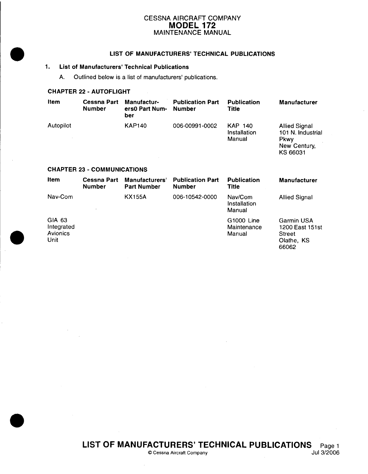
A.
Outlined
below
is
a
list
of
manufacturers'
publications.
CHAPTER
22
-
AUTOFLIGHT
Cessna
Part
Manufactur-
Publication
Part
Number
ersO
Part
Num-
Number
ber
KAP140
006-00991-0002
Publication
Title
KAP
140
Installation
Manual
Manufacturer
Allied
Signal
101
N.
Industrial
Pkwy
New
Century,
KS
66031
CHAPTER
23
-
COMMUNICATIONS
Cessna Part
Manufacturers'
Publication
Part
Number
Part
Number Number
KX155A
006-10542-0000
Publication
Title
Nav/Com
Installation
Manual
G1000
Line
Maintenance
Manual
Manufacturer
Allied
Signal
Garmin
USA
1200
East
151st
Street
Olathe,
KS
66062
LIST
OF
MANUFACTURERS'
TECHNICAL
PUBLICATIONS
Page
1
©
Cessna Aircraft
Company
Jul
3/2006
Item
Autopilot
Item
Nav-Com
GIA
63
Integrated
Avionics
Unit
CESSNA
AIRCRAFT
COMPANY
MODEL
172
MAINTENANCE
MANUAL
CHAPTER
24
-
ELECTRICAL
POWER
Cessna
Part
Number
Manufacturers
Part
Number
TSC-01V
AVT-200413
Publication
Part
Number
Publication
Title
Teledyne
Battery Products
TSC-01V
24
Volt
Battery
Charger
Cyclon
Selection
Guide
(Third
Edition)
(NOTE
1)
Manufacturer
Teledyne
Continental
Motors Battery
Products
840
W.
Brockton
Avenue
Redlands,
CA
92374
Phone:
1-800-
456-0070
AVT
Inc.
DBA
Electritek
-
AVT
400
East
Mineral
Avenue
Littleton,
CO
80122-2604
Hawker
617
North
Ridgeview
Drive
Warrensburg,
MO
64093-9301
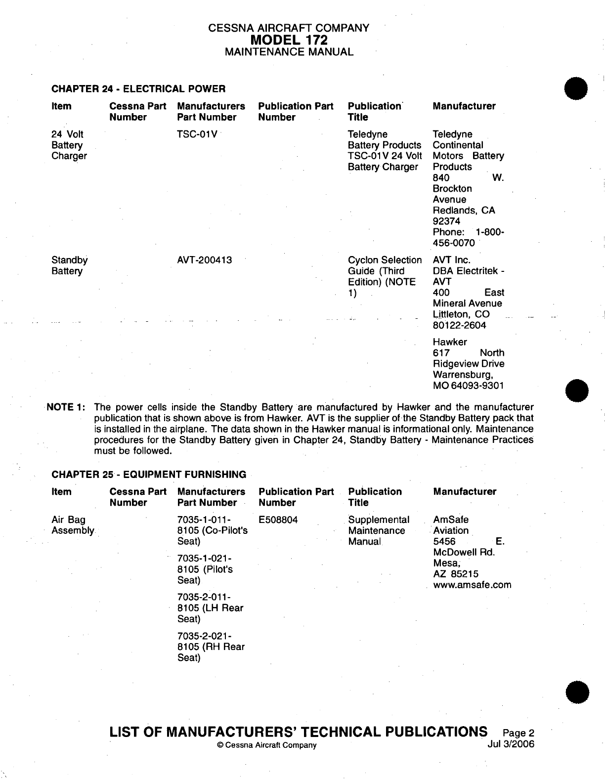
NOTE
1:
The
power
cells inside
the
Standby
Battery are
manufactured
by
Hawker and
the
manufacturer
publication
that
is
shown
above
is
from
Hawker.
AVT
is
the
supplier
of-the
Standby
Battery
pack
that
is
installed
in
the
airplane. The
data
shown
in
the
Hawker
manual
is
informational
only.
Maintenance
procedures
for
the
Standby
Battery
given
in
Chapter
24,
Standby
Battery
-
Maintenance
Practices
must
be
followed.
CHAPTER
25
-
EQUIPMENT
FURNISHING
Cessna
Part
Number
Manufacturers
Part
Number
7035-1-011-
8105
(Co-Pilot's
Seat)
7035-1-021-
8105
(Pilot's
Seat)
Publication
Part
Number
E508804
Publication
Title
Supplemental
Maintenance
Manual
Manufacturer
AmSafe
Aviation
5456
E.
McDowell
Rd.
Mesa,
AZ
85215
www.amsafe.com
7035-2-011-
8105
(LH
Rear
Seat)
7035-2-021-
8105
(RH
Rear
Seat)
LIST
OF
MANUFACTURERS'
TECHNICAL
PUBLICATIONS
Page
2
©
Cessna
Aircraft
Company
Jul 3/2006
Item
24
Volt
Battery
Charger
Standby
Battery
Item
Air
Bag
Assembly
CESSNA
AIRCRAFT
COMPANY
MODEL
172
MAINTENANCE
MANUAL
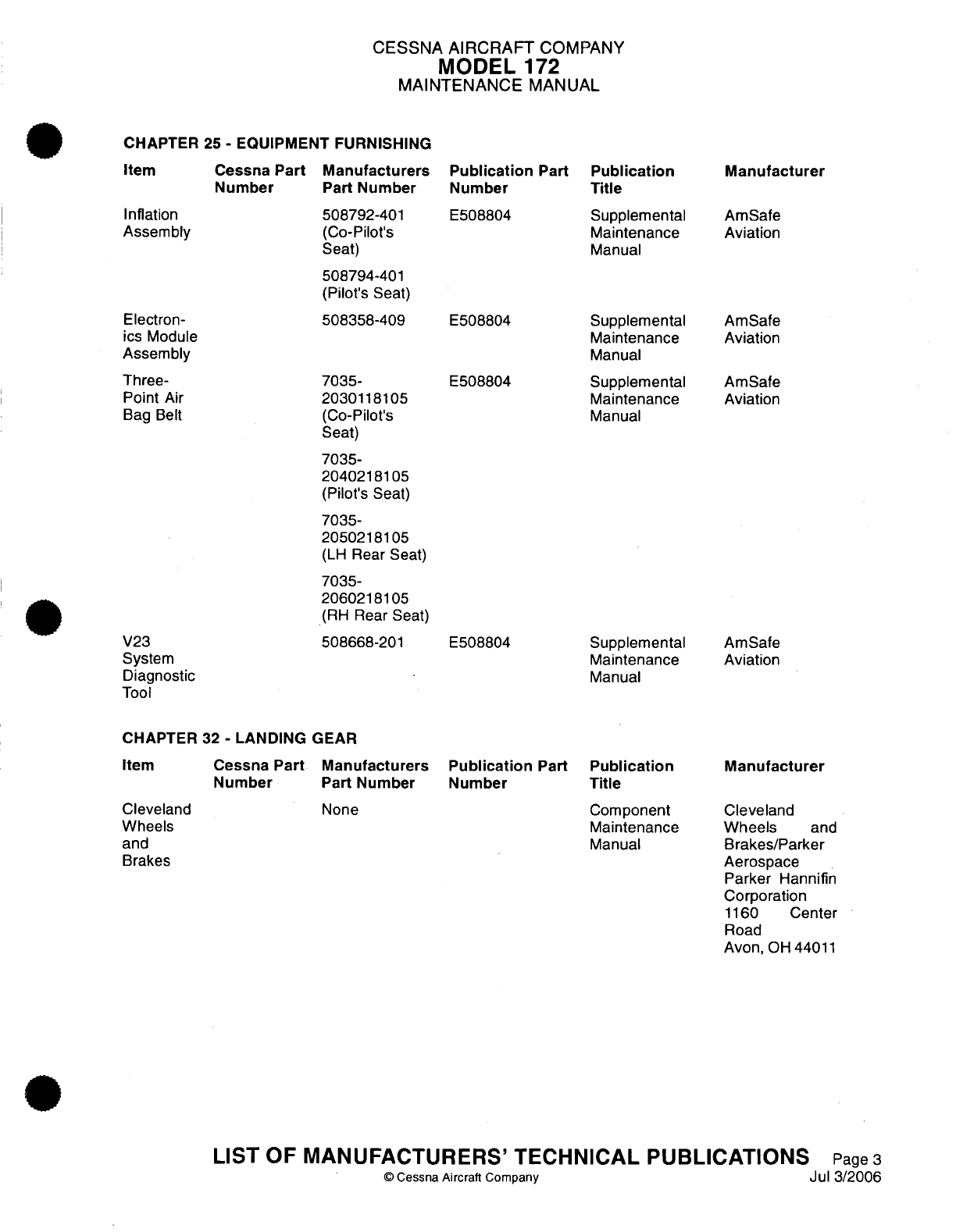
CHAPTER
25
-
EQUIPMENT FURNISHING
Cessna
Part
Number
Manufacturers
Part Number
508792-401
(Co-Pilot's
Seat)
508794-401
(Pilot's
Seat)
508358-409
7035-
2030118105
(Co-Pilot's
Seat)
7035-
2040218105
(Pilot's
Seat)
7035-
2050218105
(LH
Rear
Seat)
7035-
2060218105
(RH
Rear
Seat)
508668-201
Publication
Part
Number
E508804
E508804
E508804
E508804
Publication
Title
Supplemental
Maintenance
Manual
Supplemental
Maintenance
Manual
Supplemental
Maintenance
Manual
Supplemental
Maintenance
Manual
Manufacturer
AmSafe
Aviation
AmSafe
Aviation
AmSafe
Aviation
AmSafe
Aviation
CHAPTER
32
-
LANDING
GEAR
Cessna
Part
Number
Manufacturers
Part
Number
None
Publication
Part
Number Publication
Title
Component
Maintenance
Manual
Manufacturer
Cleveland
Wheels
and
Brakes/Parker
Aerospace
Parker
Hannifin
Corporation
1160
Center
Road
Avon,
OH
44011
LIST
OF MANUFACTURERS'
TECHNICAL PUBLICATIONS
Page
3
O
Cessna
Aircraft
Company
Jul
3/2006
Item
Inflation
Assembly
Electron-
ics
Module
Assembly
Three-
Point
Air
Bag
Belt
V23
System
Diagnostic
Tool
Item
Cleveland
Wheels
and
Brakes
CESSNA
AIRCRAFT
COMPANY
MODEL
172
MAINTENANCE
MANUAL
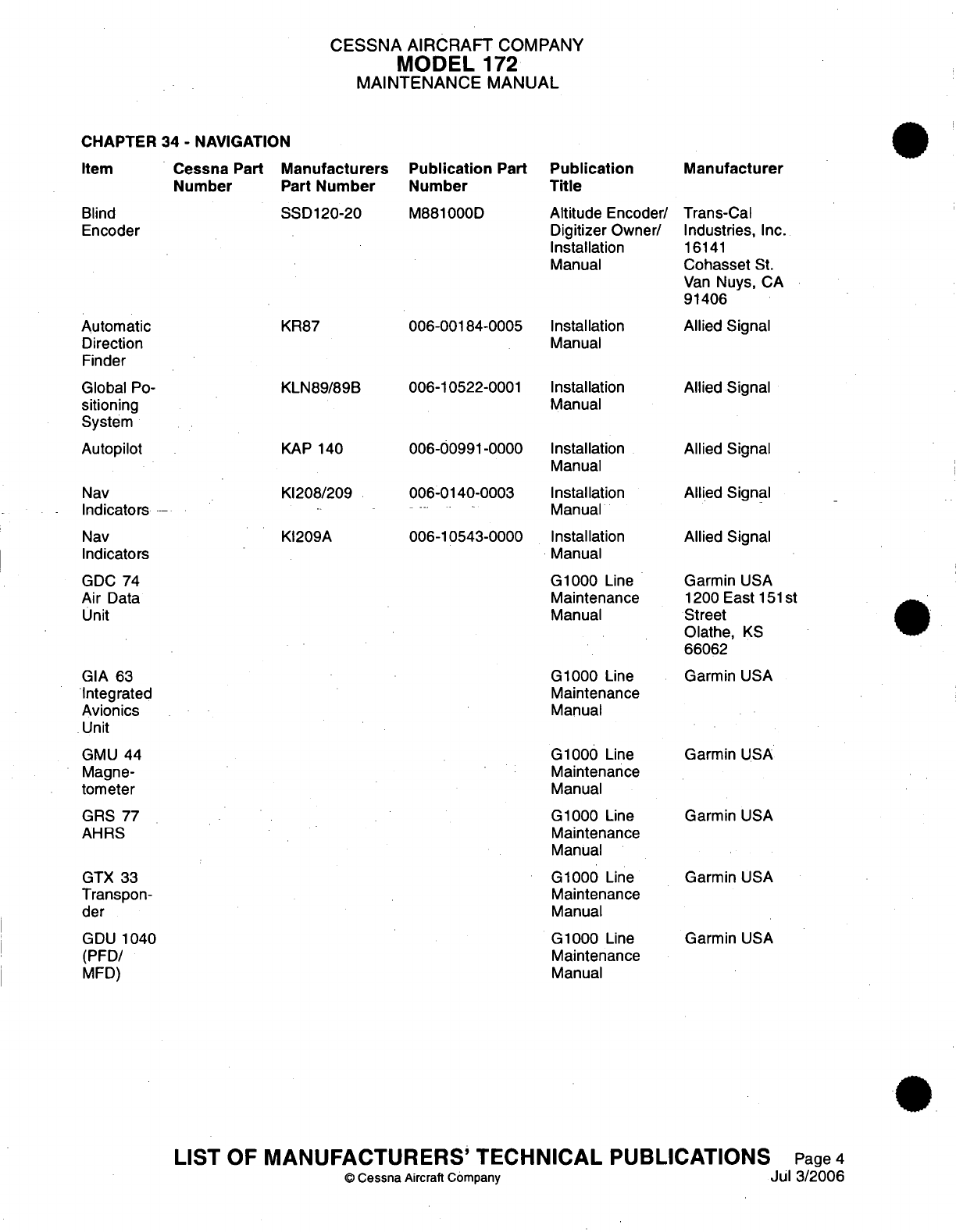
CHAPTER 34
-
NAVIGATION
Cessna
Part
Number
Manufacturers
Part
Number
Publication
Part
Number
Publication
Title
Manufacturer
M881000D
006-00184-0005
006-10522-0001
006-00991-0000
006-0140-0003
006-10543-0000
Altitude
Encoder/
Digitizer
Owner/
Installation
Manual
Installation
Manual
Installation
Manual
Installation
Manual
Installation
Manual
Installation
Manual
G1000
Line
Maintenance
Manual
G1000
Line
Maintenance
Manual
G1000
Line
Maintenance
Manual
G1000 Line
Maintenance
Manual
G1000
Line
Maintenance
Manual
G1000
Line
Maintenance
Manual
Trans-Cal
Industries,
Inc.
16141
Cohasset
St.
Van
Nuys,
CA
91406
Allied
Signal
Allied
Signal
Allied
Signal
Allied
Signal
Allied
Signal
Garmin
USA
1200
East
151st
Street
Olathe,
KS
66062
Garmin
USA
Garmin
USA
Garmin
USA
Garmin
USA
Garmin
USA
LIST
OF
MANUFACTURERS'
TECHNICAL
PUBLICATIONS
Page
4
C
Cessna
Aircraft Company
Jul 3/2006
Blind
Encoder
SSD120-20
KR87
Automatic
Direction
Finder
Global
Po-
sitioning
System
Autopilot
KLN89/89B
KAP
140
K1208/209
K1209A
Nav
Indicators
Nav
Indicators
GDC
74
Air
Data
Unit
GIA 63
Integrated
Avionics
Unit
GMU
44
Magne-
tometer
GRS
77
AHRS
GTX
33
Transpon-
der
GDU 1040
(PFD/
MFD)
Item
CESSNA
AIRCRAFT
COMPANY
MODEL
172
MAINTENANCE
MANUAL
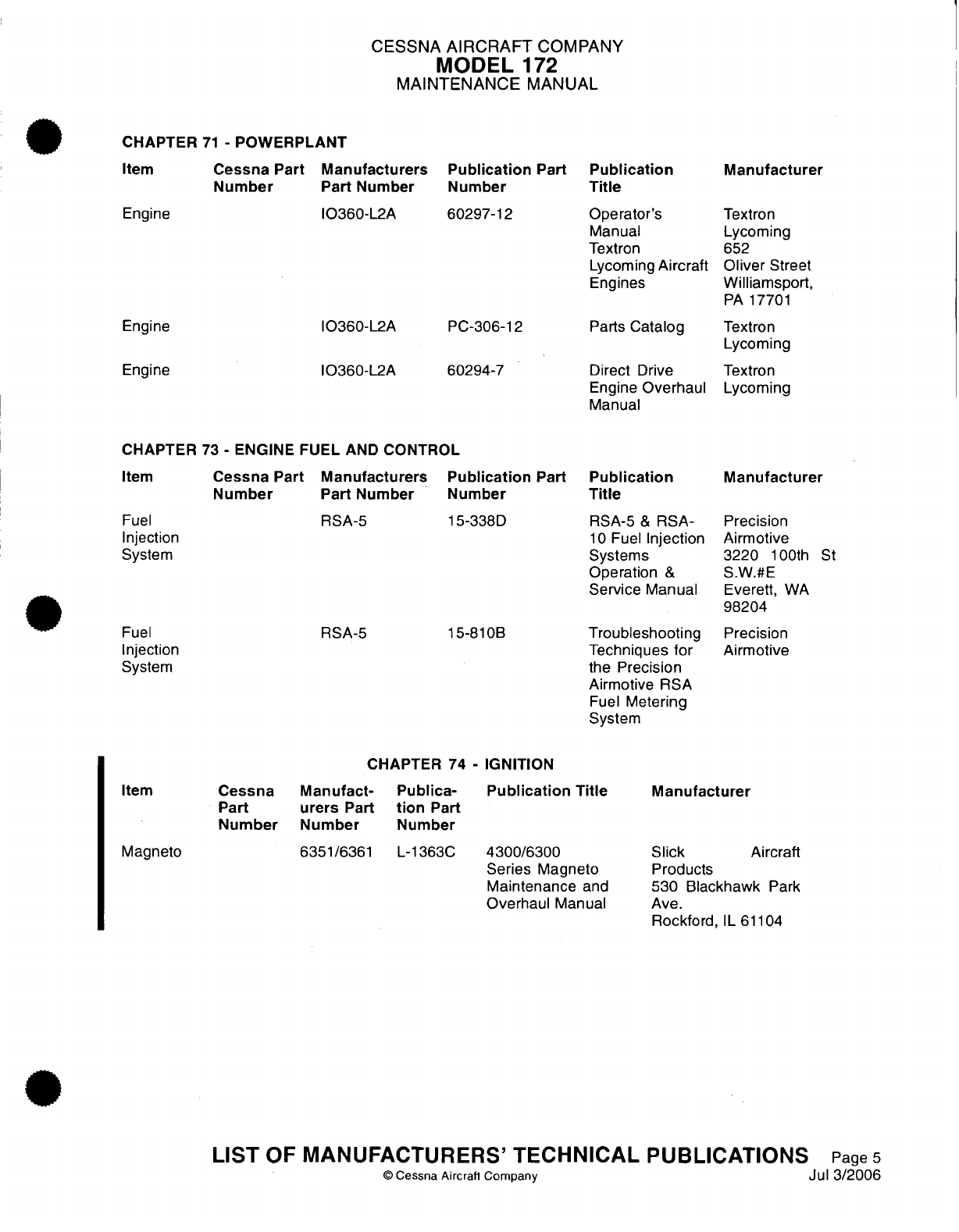
CHAPTER
71
-
POWERPLANT
Cessna Part
Manufacturers
Number
Part
Number
Publication
Part
Number
Publication
Title
Manufacturer
Engine
10360-L2A
Engine 10360-L2A
Engine 10360-L2A
CHAPTER
73
-
ENGINE
FUEL
AND
CONTROL
60297-12
PC-306-12
60294-7
Operator's
Manual
Textron
Lycoming
Aircraft
Engines
Parts
Catalog
Direct
Drive
Engine
Overhaul
Manual
Textron
Lycoming
652
Oliver
Street
Williamsport,
PA
17701
Textron
Lycoming
Textron
Lycoming
Cessna Part
Manufacturers
Number
Part
Number
RSA-5
RSA-5
Publication
Part
Number
15-338D
15-810B
Publication
Title
RSA-5
&
RSA-
10
Fuel
Injection
Systems
Operation
&
Service
Manual
Troubleshooting
Techniques
for
the
Precision
Airmotive
RSA
Fuel
Metering
System
Manufacturer
Precision
Airmotive
3220
100th
St
S.W.#E
Everett,
WA
98204
Precision
Airmotive
CHAPTER 74
-
IGNITION
Manufact-
urers
Part
Number
Publica-
tion
Part
Number
Publication
Title
6351/6361
L-1363C
4300/6300
Series
Magneto
Maintenance
and
Overhaul
Manual
Manufacturer
Slick Aircraft
Products
530
Blackhawk
Park
Ave.
Rockford,
IL
61104
LIST
OF
MANUFACTURERS'
TECHNICAL
PUBLICATIONS
Page
5
©
Cessna Aircraft
Company
Jul
3/2006
Item
Fuel
Injection
System
Fuel
Injection
System
Item
Cessna
Part
Number
Magneto
Item
CESSNA AIRCRAFT
COMPANY
MODEL
172
MAINTENANCE
MANUAL
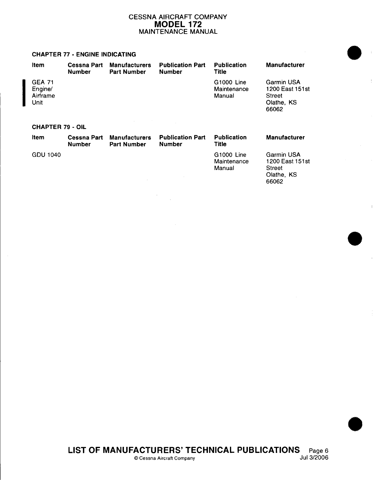
CHAPTER
77
-
ENGINE
INDICATING
Cessna
Part
Number
Manufacturers
Part
Number
Publication
Part
Number
Publication
Title
G1000
Line
Maintenance
Manual
Manufacturer
Garmin
USA
1200
East
151st
Street
Olathe,
KS
66062
CHAPTER
79
-
OIL
Cessna
Part
Number
Manufacturers
Part
Number
Publication
Part
Number
Publication
Title
G1000
Line
Maintenance
Manual
Manufacturer
Garmin
USA
1200
East
151
st
Street
Olathe,
KS
66062
LIST
OF
MANUFACTURERS'
TECHNICAL
PUBLICATIONS
Page
6
©
Cessna Aircraft
Company
Jul
3/2006
Item
GEA
71
Engine/
Airframe
Unit
Item
GDU
1040
CESSNA AIRCRAFT
COMPANY
MODEL
172
MAINTENANCE
MANUAL
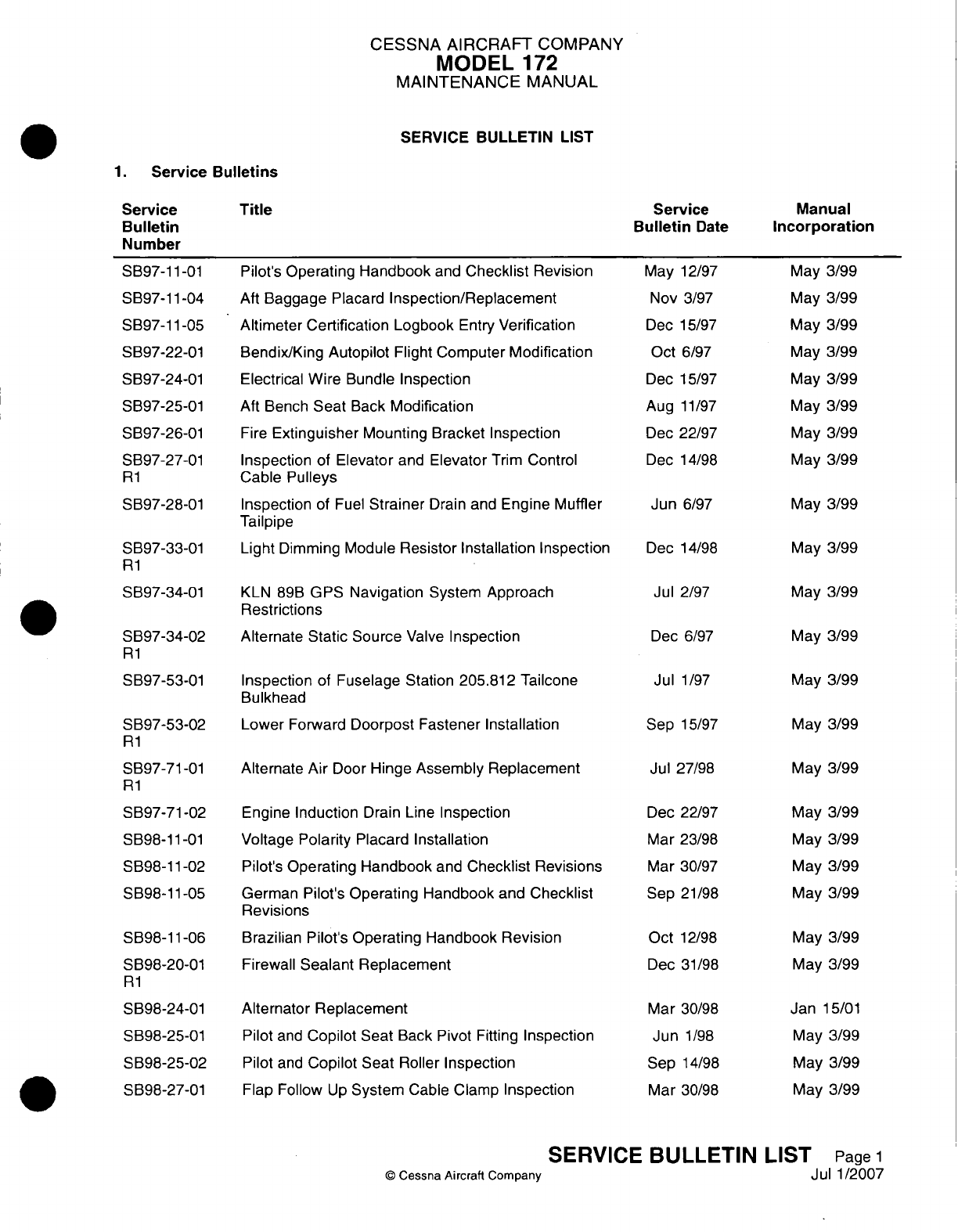
SERVICE
BULLETIN
LIST
1
.
Service
Bulletins
Service
Bulletin
Date
Manual
Incorporation
Pilot's
Operating
Handbook
and
Checklist
Revision
Aft
Baggage
Placard
Inspection/Replacement
Altimeter
Certification Logbook
Entry
Verification
Bendix/King
Autopilot
Flight Computer
Modification
Electrical
Wire
Bundle
Inspection
Aft Bench
Seat
Back
Modification
Fire
Extinguisher
Mounting
Bracket
Inspection
Inspection of
Elevator
and
Elevator
Trim
Control
Cable Pulleys
Inspection
of
Fuel
Strainer
Drain
and
Engine Muffler
Tailpipe
Light
Dimming
Module
Resistor
Installation
Inspection
KLN
89B
GPS
Navigation
System
Approach
Restrictions
Alternate
Static
Source
Valve
Inspection
Inspection
of
Fuselage Station
205.812
Tailcone
Bulkhead
Lower
Forward
Doorpost Fastener Installation
Alternate
Air
Door
Hinge
Assembly Replacement
Engine
Induction
Drain Line
Inspection
Voltage
Polarity Placard Installation
Pilot's
Operating Handbook
and
Checklist Revisions
German Pilot's
Operating Handbook
and
Checklist
Revisions
Brazilian
Pilot's
Operating Handbook Revision
Firewall
Sealant
Replacement
Alternator
Replacement
Pilot
and
Copilot
Seat
Back
Pivot
Fitting
Inspection
Pilot
and
Copilot
Seat
Roller
Inspection
Flap
Follow
Up
System
Cable
Clamp
Inspection
©
Cessna
Aircraft
Company
SERVICE
BULLETIN
LIST
Pagel1
Jul
1/2007
Service
Bulletin
Number
Title
SB97-1
1 -01
SB97-1
1-04
SB97-1
1-05
SB97-22-01
SB97-24-01
SB97-25-01
SB97-26-01
SB97-27-01
Rl
SB97-28-01
SB97-33-01
Rl
SB97-34-01
SB97-34-02
Rl
SB97-53-01
SB97-53-02
Rl
SB97
71
-01
Rl
SB97-71
-02
SB98-1
1-01
SB98-1
1-02
SB98-1
1-05
SB98-1
1-06
SB98-20-01
Rl
SB98-24-01
SB98-25-01
SB98-25-02
SB98-27-01
May
12/97
Nov
3/97
Dec
15/97
Oct
6/97
Dec
15/97
Aug
11/97
Dec
22/97
Dec
14/98
Jun
6/97
Dec
14/98
Jul
2/97
Dec
6/97
Jul
1/97
Sep
15/97
Jul
27/98
Dec
22/97
Mar 23/98
Mar
30/97
Sep
21/98
Oct
12/98
Dec
31/98
Mar
30/98
Jun
1/98
Sep
14/98
Mar
30/98
May 3/99
May 3/99
May
3/99
May
3/99
May
3/99
May
3/99
May 3/99
May
3/99
May
3/99
May 3/99
May
3/99
May
3/99
May
3/99
May
3/99
May
3/99
May
3/99
May
3/99
May
3/99
May
3/99
May 3/99
May 3/99
Jan
15/01
May 3/99
May
3/99
May
3/99
CESSNA
AIRCRAFT
COMPANY
MODEL
172
MAINTENANCE
MANUAL
Service
Bulletin
Date
Manual
Incorporation
Aileron
Control
Cable
Routing
Inspection
Aileron
Primary Control
Cable-to-Drum
Lock Clamp
Inspection
Right
Wing Aileron
Control
Cable
Routing
Inspection
Flight Control Cables
and
Travel
Inspection
Control
Yoke
Attach Bushing
Installation
Engine
Fuel
Pressure
Transducer
Inspection
and
Replacement
Wing
to
Fuselage
Fuel
Hose Clamp
Inspection
Fuel
Shutoff
Valve
Cable Clamp
Inspection
KLN
89B GPS
Navigation System
IFR
Non-Precision
Approach
Limitation
Airborne
Vacuum Pump
Inspection
Baggage
Door
Seal
Replacement
Firewall
Rivet
Inspection
Firewall
Inspection
and
Cowl Mount
Alignment
Elevator
Stop
Bolt
Bracket Nutplate
and
Horizontal
Stabilizer
Installation
Inspection
Horizontal
Stabilizer
Inboard
Skin
Rivet
Inspection
Wing
Strut
Attach
Bolts
Nut
Torque
Inspection
Forward
Engine Baffle
and
Heat
Shroud
Modification
Engine
Air Filter
Replacement
Engine Exhaust
Muffler Inspection
and
Replacement
Pilot's
Operating
Handbook
Revision
Fresh
Air
Vent
Replacement
Electrical
Power
System
Modification
Circuit
Panel
Assembly
Cover
Installation
Emergency Locator
Transmitter
(ELT)
Operational
Test
Control
Yoke
Pivot
Bolt
Inspection/Replacement
Wing
Fuel Tank
Vent
Check
Valve
Inspection
KLN 89B GPS
Navigation
System
Modification
SERVICE
BULLETIN
©
Cessna
Aircraft
Company
LIST
Page
2
Jul
1/2007
Service
Bulletin
Number
Title
SB98-27-02
R1
S
B98-27-03
SB98-27-05
R2
SB98-27-06
SB98-27-07
SB98-28-01
SB98-28-02
R1
SB98-28-03
SB98-34-01
R1
SB98-37-01
R1
SB98-52-01
SB98-53-01
R1
SB98-53-02
R2
SB98-55-01
SB98-55-02
SB98-57-01
SB98-71
-01
SB98-71
-02
SB98-78-01
SB99-1 1-01
SB99-21
-01
SB99-24-01
SB99-24-02
SB99-25-01
R1
SB99-27-01
SB99-28-01
SB99-34-01
R1
May
3/99
May
3/99
May
3/99
May
3/99
May
3/99
May
3/99
Aug
1/00
May
3/99
May
3/99
Aug
1/00
May
3/99
May
3/99
Aug
18/01
May
3/99
May
3/99
May
3/99
May
3/99
May
3/99
May
3/99
Jan
15/01
Jan
15/01
Aug
1/00
Aug
1/00
Jan
15/01
Dec
31/98
Jun
1/98
Dec
31/98
Jun
15/98
Sep 21/98
Mar
2/98
Feb
1/99
May 4/98
Aug 3/98
Nov
2/98
Feb
23/98
Dec
14/98
Dec
26/00
Jul
6/98
Jul
27/98
Jun
1/98
Jul
27/98
Jul
27/98
Jan
10/98
Sep 27/99
Mar
15/99
Mar
15/99
Dec
27/99
Dec
27/99
Jul
12/99
Apr 26/99
Apr
24/00
Aug
1/00
Aug
1/00
Jan
15/01
0
CESSNA
AIRCRAFT
COMPANY
MODEL
172
MAINTENANCE
MANUAL
Service
Bulletin
Date
Manual
Incorporation
Vacuum
Hose
Modification
Elevator
Control
Yoke
Roller
Engagement
Inspection/Modification
Vertical
Fin
Aft
Spar
Inspection
Engine
Piston
Pin
Plug
Wear
Inspection
Engine
Oil
Filler
Tube
to
Engine
Mount
Clearance
Engine
Valve
Seat
Inspection
Engine
Fuel
Manifold
Spring
Replacement
Engine
Fuel
Injector
Unit
Inspection
German
Pilot's
Operating Handbook Revision
Pilot's
Operating
Handbook
and
Pilot's
Checklist
Revisions
Pilot's
Operating Handbook
and
Pilot's
Checklist
Revisions
KAP-1
40
Autopilot
Servo
Inspection/Modification
Main
Power
Junction
Box
Circuit Breaker Retrofit
Kit
Installation
Electrical
Panel
Wiring
Modifications
Pitot
Tube
Heater
Assembly
Insulation
Installation
Vacuum System Air
Filter Element
Inspection!
Replacement
Rudder
Attach
Bolt Torque
Inspection
Flap
Track
and
Wing
Inboard
Trailing
Edge Inspection
Propeller
Hub
Inspection
Engine
Fuel
Injection
Lines and
Support
Clamps
Inspection
Engine
Low
Oil
Pressure
Switch
Replacement
Pitot
Tube Heater
Insulation
Installation
Pilot's
Operating Handbook Revisions
Pilot's
Operating
Handbook
and
Pilot's
Checklist
Revisions
Elevator
Trim
Tab
Control
Cable Stop
Block
Inspection
Fuel
Shutoff
Valve
Control Cable
Inspection
Engine
Fuel Flow
Divider
Installation
Modification
©
Cessna
Aircraft
Company
SERVICE
BULLETIN LIST
Page
3
Jul
1/2007
Service
Bulletin
Number
Title
SB99-37-01
SB99-53-03
SB99-55-01
SB99-71
-01
R2
SB99-71
-02
SB99-71
-05
SB99-73-01
SB99-73-02
SB00-1
1-01
5800-1
1-03
SB00-11-04
SBOO-22-01
SBOO-24-01
SBOO-24-02
SBOO-34-01
S
BOO-37-01
SBOO-55-01
SBOO-57-01
R1
SBOO-61
-02
SBOO-73-01
R2
SBOO-79-01
Ril
SBOO-34-01
5801
-1
1-01
SBO1
-1
1-02
SBO1
-27-01
R1
SBO1l-28-03
SBO1l-71-01
Dec
27/99
Dec
6/99
Mar
29/99
Jul
12/99
Aug
12/99
Oct
25/99
Jan
8/99
Feb
1/99
Mar
13/00
May
22/00
Aug
14/00
Feb 14/00
Mar
13/00
Jun
5/00
Apr
10/00
Aug
14/00
Apr
10/00
Apr
28/03
Aug
14/00
Dec
24/01
Feb
21/00
Apr
1
0/00
Feb
5/01
Mar
5/01
Feb
19/01
Jul
23/01
Jan
22/01
Aug
1/00
Aug
1/00
May
3/99
Aug
1/00
Aug
1/00
Aug
1/00
Aug
1/00
Aug
1/00
Aug
1/00
Jan
15/01
No
Effect
Aug
1/00
Aug
1/00
Jan
15/01
Jan
15/01
Jan
15/01
Jan
15/01
No
Eff
ect
Jan
15/01
No
Effect
Jan
15/01
Feb
15/02
No
Eff
ect
No
Eff
ect
No Eff
ect
Feb
15/02
No Eff
ect
CESSNA AIRCRAFT
COMPANY
MODEL
172
MAINTENANCE
MANUAL
Service
Bulletin
N
umber
SB01l-74-0
1
S1BO1
-53-01
SB01l-55-0
1
SBOl-71-02
SBO01
-27-02
SBO1
-28-02
SBO1
-73-01
R2
SB02-22-01
SB02-52-01
SB02-37-02
SB02-37-03
SB02-25-01
SB02-37-04
SB02-53-02
SB02-61
-01
SB02-61
-02
SB03-1
1-02
SB03-1
1-04
SB03-23-01
SB03-24-01
S
B03-24-02
SB03-25-01
SB03-27-02
SB03-28-01
SB03-32-01
SB03-34-01
SB03-34-02
R1
SB03-37-01
Title
Service
Bulletin
Date
Ignition
Switch
Center Ground
Terminal
Inspection
Battery
Box
Support
Inspection
Modification
Elevator
Balance Weight
Attach Screw
Inspection/Installation
Engine
Crankshaft Inspection
Control Yoke
Assembly
Inspection
Fuel
Selector
Shaft
Assembly Inspection/
Replacement
Engine
Driven
Fuel
Pump
Inspection
Honeywell
KAP
140
Autopilot
System
Modification
Cabin Door
Handle
Replacement
Dry
Vacuum
Pump
and
Coupling
Replacement
Requirements
Vacuum
System
Reducer
Fitting
Pilot
and
Copilot
Shoulder
Harness
Removal
Airborne
Air and
Fuel
Products
Check
Valve
Manifold
Inspection
Firewall
Sealant Installation
Propeller
Spinner
and
Bulkhead Inspection
Propeller
Blade
Inspection
Pilot's
Operating
Handbook
and
Pilot's
Checklist
Revisions
Pilot's
Operating Handbook
and
Pilot's
Checklist
Revision
Honeywell
KMA 26
Audio
Panel
Modification
Alternator
Replacement
MC01-3A
Main
Electrical
Power
Junction
Box
Modification
Armrest
Shield
Installation
Flap
Control
Bracket Attach
Bolts
Replacement
Fuel
Cap
Lanyard
Removal
Nose
Landing
Gear Wheel
Fairing
Modification
Honeywell
KS270C,
KS271
C,
and KS272C
Servo
Friction
Inspection
Altimeter Inspection
Vacuum
Manifold
Inspection/Replacement
Jun
25/01
Feb
05/01
Apr
2/01
Apr
2/01
May
28/01
May
28/01
Oct
17/05
Nov
25/02
Jan
21/002
Feb
18/02
Feb
18/02
Apr
28/02
Oct
28/02
Dec 16/02
Jan
21/02
Dec
16/02
Apr 14/03
Oct 27/03
Jul
28/03
Jul
28/03
Oct
13/03
Feb
3/03
Dec
22/03
Oct
27/03
Sep 29/03
Oct 27/03
Feb
16/04
Nov
10/03
Manual
Incorporation
No
Eff
ect
Apr
7/03
No
Eff
ect
No
Eff
ect
No
Eff
ect
Apr
7/03
No
Eff
ect
No
Effect
No
Eff
ect
No
Eff
ect
Apr
7/03
Apr
7/03
Apr
7/03
No
Effect
Feb
15/02
No
Eff
ect
No
Eff
ect
No
Eff
ect
No
Eff
ect
No
Eff
ect
No
Eff
ect
No
Eff
ect
No
Eff
ect
Jan
2/06
No
Effect
No
Eff
ect
No
Eff
ect
Apr
7/03
©
Cessna Aircraft
Company
SERVICE
BULLETIN
LIST
Page
4
Jul
1/2007
CESSNA AIRCRAFT
COMPANY
MODEL
172
MAINTENANCE
MANUAL
Title
Service
Bulletin
Date
Engine
Fuel
Supply
System
Modification
Fuel
Injection
Servo
Inspection
Throttle
Arm
Retention Inspection
Pilot's
Operating
Handbook
Revision
Alternator
Control
Unit
Inspection/Replacement
Crew
Seat
Recline Modification
Crew
Seat
Back
Cylinder
Lock
Inspection
and
Crank
Arm
Modification
Passenger
Bench
Seat
Bolt
Installation
Crew
Seat
Back
Cylinder
Lock
Control
Inspection/Adjustment
Elevator
Trim
Tab
Control Cable
Inspection
Fuel
Hose
Inspection
Engine
Fuel
Return
System Installation
Landing
Gear
Shock
Strut
Metering
Pin
Replacement
Nose
Security
Lock
Installation
Horizontal
Stabilizer
Attach Bolt Holes
Inspection
Engine
Starter
Inspection/Replacement
Engine
Fuel
Injection
Lines
and
Support
Clamps
Inspection
Engine
Fuel
Manifold
Spring
Replacement
Pilot's
Operating
Handbook Revisions
Pilot's
Operating
Handbook
Temporary
Revision
2
Trim
Servo
Cable
Chain
Inspection
MC01
-3A
Main
Electrical
Power Junction
Box
Circuit
Breakers
Inspection
Inflatable
Seat Belt
Restraint
Installation
Inspection
Inflatable
Seat
Restraints
Installation
Fuel
Strainer
Gasket
Inspection
High
Intensity
Discharge
(HID)
Landing
and
Taxi
Light
Installation
Garmin
G1000
Obstacle
and
Terrain
Avoidance
System
Database
Update
May
26/03
May
26/03
Nov
.4/03
Aug
30/04
Mar
1/04
Dec
26/06
Oct
17/05
Jul
19/04
Oct
11/04
Oct
11/04
Mar
15/04
Aug
30/04
Feb
2/04
Jun 28/04
Jun
20/05
Nov
8/04
Aug
30/04
Oct
11/04
Jul
29/05
Aug
29/05
Dec
5/05
Jan
31/05
Mar
7/05
Apr
25/05
Jan
17/05
May
9/05
Sep
26/05
Manual
Incorporation
No
Eff
ect
No
Eff
ect
No
Eff
ect
No
Eff
ect
No
Eff
ect
No
Effect
No
Effect
No Eff
ect
No
Eff
ect
No
Eff
ect
No
Eff
ect
No
Eff
ect
No
Eff
ect
No
Eff
ect
No
Eff
ect
Jan
2/06
No
Eff
ect
No
Eff
ect
No
Eff
ect
No
Eff
ect
No
Effect
No
Eff
ect
No
Effect
No
Effect
Jul
1/05
No
Eff
ect
©
Cessna
Aircraft Company
SERVICE
BULLETIN
LIST
Page
5
Jul
1/2007
Service
Bulletin
Number
SB03-71
-01
SB03-71
-02
SB03-73-01
SB04-1
1-02
SB04-24-01
SB04-25-01
R4
SB04-25-02
R1
SB04-25-03
SB04-25-04
SB04-27-02
R1
SB04-28-01
R1
SB04-28-03
SB04-32-01
SB04-52-01
SB04-55-01
R1
SB04-71
-02
SB04-73-01
SB04-73-02
SB05-1
1-02
SB05-1
1-03
SB05-22-01
SB05-24-01
SB05-25-01
SB05-25-02
SB05-28-01
SB05-33-01
SB05-34-07
CESSNA
AIRCRAFT
COMPANY
MODEL
172
MAINTENANCE
MANUAL
Service
Bulletin
Number
SB05-34-08
SB05-34-09
SB05-34-1
1
SB05-34-1
2
SB05-37-01
SB05-53-03
SBOS-57-01
SB05-73-01
SB06-11
1-01
SB06-11-02
SB06-1
1-03
SB06-22-01
SB06-24-01
S
B06-24
-02
R1
SB06-24-03
S
B06-24
-04
SB06-24-05
SB06-27-01
SB06-32-01
SB06-34-01
SB06-34-02
R1
SB06-34-03
SB06-34-04
SB06-52-01
SB06-57-01
SB06-71
-02
Title
Service
Bulletin
Date
Garmin
G1000
System Software Upgrade
Garmin
G1
000
GDL-69A Weather
And
Digital
Audio
Entertainment
Interface
Installation
Garmin
Gia
63
Integrated
Avionics
Unit
Outside
Cover Replacement
Garmin
G1
000
Display
Unit
(GDU)
1040
Cover
Glass
Delamination
Vacuum Pump
Inspection/Replacement
Floorboard
Bulkhead
Rivet Inspection
Wing
Trailing
Edge
Rib
Inspection
Engine
Driven
Fuel
Pump
Inspection
Pilot's
Operating Handbook Revisions
Pilot's
Operating Handbook Revisions
Pilot's
Operating
Handbook
and
Pilot's
Checklist
Revisions
Honeywell
KS270C
Pitch
Servo
and
KS271C
Roll
Servo
Tach
Generator
Modification
Electrical Ground
Strap
Inspection
60
Ampere
Alternator
Rotor
Replacement
60
Ampere
Alternator
Brush
Replacement
Circuit Breaker Inspection
Circuit Breaker
Panel
Assembly
Inspection
Flap
Aft
Roller
Bearing
Installation
Modification
Brake
Master
Cylinder
Covers
Inspection
Honeywell
KT
73
MODE
S
Transponder
Installation
Garmin
G1000
System
Software
Upgrade
Enablemnent
of
Garmin
G
1000
Terrain
Awareness
Warning
System
CLASS-B3
(TAWS-B)
Automatic
Direction
Finder
(ADF)
and
Distance
Measuring
Equipment
(DME)
Installation
Cabin
Door
Modification
Upper
Wing
Skin
Modification
Engine
Compartment
Fuel
Hoses
Security Inspection
Sep
26/2005
Sep
26/05
Nov
21/05
Dec
5/05
Nov 7/05
Dec 19/05
Oct
10/05
Mar
7/05
Mar
27/06
Nov 6/06
Dec 18/06
Apr 24/06
May
8/06
Dec
26/06
Dec
18/06
Dec
26/06
Dec
26/06
Apr
10/06
Sep
25/06
Feb
27/06
Nov
6/06
May
22/06
Oct
23/06
Mar
27/06
Nov
6/06
Jun
19/06
Manual
Incorporation
No
Effect
No
Eff
ect
No
Eff
ect
No Eff
ect
No
Eff
ect
No Eff
ect
No
Effect
No
Eff
ect
No
Eff
ect
No
Effect
No
Eff
ect
No
Effect
No
Eff
ect
No
Eff
ect
No
Eff
ect
No
Eff
ect
No
Eff
ect
No
Eff
ect
No
Eff
ect
No
Eff
ect
No Eff
ect
No
Eff
ect
No
Eff
ect
No
Eff
ect
No
Eff
ect
No
Eff
ect
C
Cessna
Aircraft Company
SERVICE
BULLETIN
LIST
Page
6
Jul
1/2007
CESSNA
AIRCRAFT
COMPANY
MODEL
172
MAINTENANCE
MANUAL
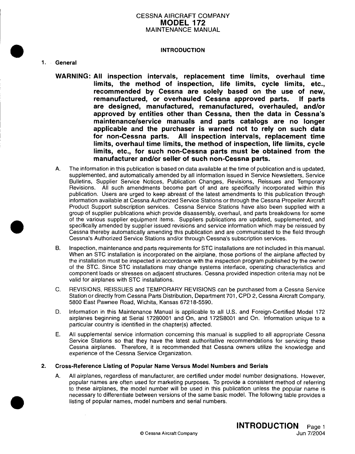
INTRODUCTION
1.
General
WARNING:
All
Inspection
Intervals,
replacement
time
limits, overhaul
time
limits,
the method
of
Inspection,
life
limits,
cycle
limits,
etc.,
recommended
by
Cessna are
solely
based
on
the
use
of
new,
remanufactured,
or
overhauled
Cessna
approved
parts.
If
parts
are
designed,
manufactured,
remanufactured, overhauled,
and/or
approved
by
entitles
other
than
Cessna,
then
the
data
In
Cessna's
maintenance/service
manuals
and
parts
catalogs
are
no
longer
applicable
and
the
purchaser
Is
warned
not
to
rely on
such
data
for
non-Cessna
parts.
All
Inspection
Intervals, replacement time
limits, overhaul
time
limits,
the
method
of
Inspection,
life limits,
cycle
limits,
etc.,
for
such
non-Cessna
parts
must
be
obtained
from the
manufacturer
and/or
seller
of
such
non-Cessna
parts.
A.
The
information
in
this
publication
is
based
on
data available
at
the
time
of
publication
and
is
updated,
supplemented,
and
automatically
amended
by
all
information
issued
in
Service
Newsletters,
Service
Bulletins,
Supplier
Service
Notices,
Publication
Changes,
Revisions,
Reissues
and
Temporary
Revisions.
All
such amendments
become
part
of
and
are
specifically
incorporated within
this
publication.
Users
are
urged to
keep
abreast
of
the
latest
amendments
to
this
publication
through
information
available
at
Cessna
Authorized
Service Stations or
through
the
Cessna
Propeller
Aircraft
Product
Support
subscription
services. Cessna
Service
Stations have
also
been
supplied
with
a
group
of
supplier publications
which
provide
disassembly,
overhaul,
and
parts
breakdowns
for
some
of
the
various
supplier
equipment
items.
Suppliers publications
are
updated,
supplemented,
and
specifically
amended
by
supplier
issued
revisions
and
service
information
which
may
be
reissued
by
Cessna
thereby
automatically
amending
this
publication
and
are
communicated
to
the
field
through
Cessna's Authorized
Service Stations
and/or
through
Cessna's subscription
services.
B.
Inspection,
maintenance
and
parts
requirements
for
STC
installations
are
not
included
in
this
manual.
When
an
STC
installation
is
incorporated
on
the
airplane,
those portions
of
the
airplane
affected
by
the
installation
must
be
inspected
in
accordance
with
the
inspection
program
published
by
the
owner
of
the STC.
Since
STC
installations
may
change systems
interface, operating
characteristics
and
component
loads or
stresses
on
adjacent
structures. Cessna
provided
inspection
criteria
may
not
be
valid
for
airplanes
with
STC
installations.
C.
REVISIONS,
REISSUES
and
TEMPORARY
REVISIONS
can
be
purchased
from
a
Cessna Service
Station
or directly
from
Cessna
Parts
Distribution,
Department
701,
CPD
2,
Cessna
Aircraft
Company,
5800
East
Pawnee
Road,
Wichita,
Kansas
67218-5590.
D.
Information
in
this
Maintenance
Manual
is
applicable
to
all
U.S.
and
Foreign-Certified
Model
172
airplanes
beginning
at
Serial
17280001
and
On,
and
172S8001
and
On. Information
unique to
a
particular country
is
identified
in
the
chapter(s)
affected.
E.
All
supplemental service
information
concerning this
manual
is
supplied
to
all
appropriate
Cessna
Service
Stations
so
that they
have
the
latest
authoritative
recommendations for
servicing
these
Cessna
airplanes.
Therefore,
it
is
recommended
that
Cessna
owners
utilize
the
knowledge
and
experience
of
the
Cessna Service Organization.
2.
Cross-Reference
Listing
of
Popular
Name
Versus
Model
Numbers
and
Serials
A.
All
airplanes,
regardless
of
manufacturer,
are
certified
under
model
number
designations.
However,
popular
names are often used
for
marketing
purposes.
To
provide
a
consistent
method
of
referring
to
these
airplanes,
the
model
number
will be
used
in
this
publication
unless
the popular
name
is
necessary
to
differentiate
between
versions
of
the
same
basic
model.
The following table
provides
a
listing
of
popular
names, model numbers
and
serial
numbers.
INTRODUCTION
Page
1
©
Cessna
Aircraft
Company
Jun
7/2004
CESSNA
AIRCRAFT
COMPANY
MODEL
172
MAINTENANCE MANUAL
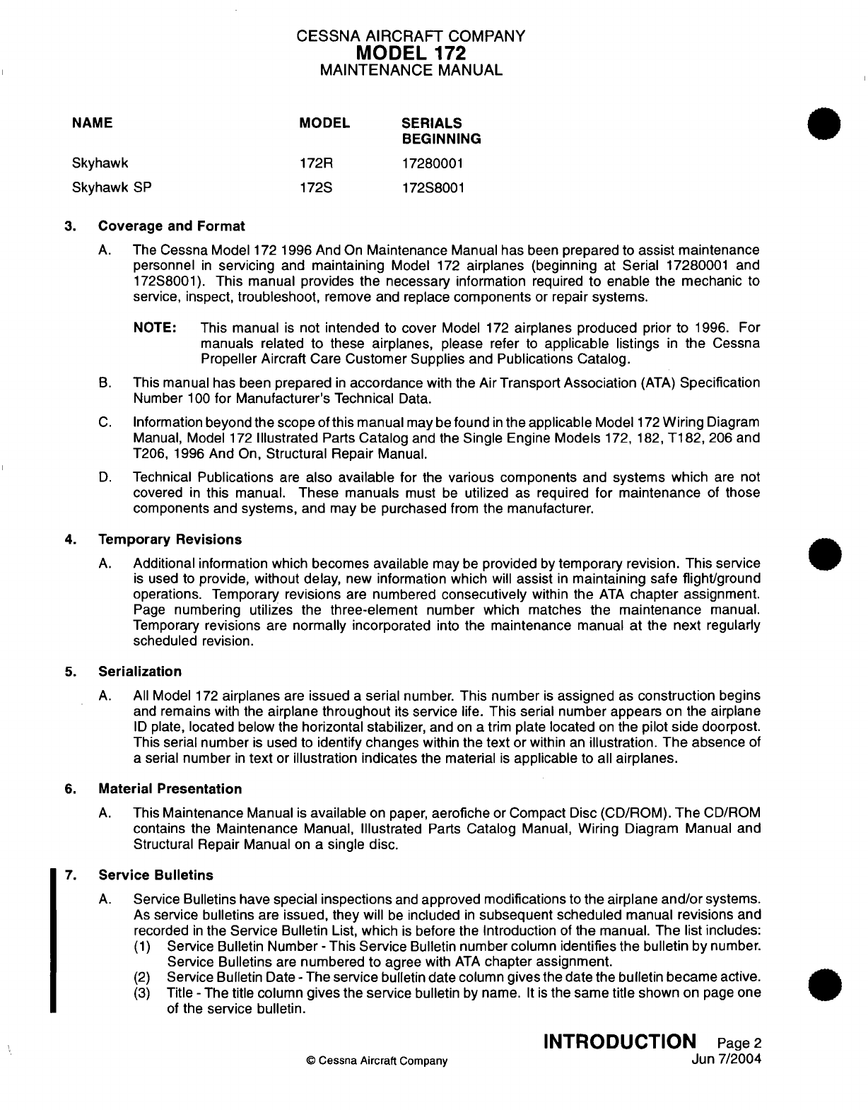
NAME
MODEL
SERIALS
BEGINNING
Skyhawk
172R
17280001
Skyhawk
SP
172S
172S8001
3.
Coverage
and
Format
A.
The Cessna Model
172
1996
And
On
Maintenance
Manual has
been
prepared
to
assist
maintenance
personnel
in
servicing
and
maintaining
Model
172
airplanes
(beginning
at
Serial
17280001
and
172S8001).
This manual provides
the
necessary
information
required
to
enable
the
mechanic
to
service, inspect,
troubleshoot,
remove
and
replace
components
or
repair
systems.
NOTE:
This
manual
is
not intended
to
cover
Model
172
airplanes
produced
prior to
1996. For
manuals related
to
these
airplanes,
please
refer
to
applicable
listings
in
the
Cessna
Propeller
Aircraft
Care
Customer
Supplies
and
Publications Catalog.
B.
This
manual
has
been
prepared
in
accordance
with
the
Air
Transport
Association
(ATA)
Specification
Number
100
for
Manufacturer's
Technical
Data.
C.
Information
beyond the
scope
of
this
manual
may
be
found
in
the applicable
Model
172
Wiring
Diagram
Manual, Model
172
Illustrated
Parts
Catalog
and the
Single
Engine
Models
172,
182,
T182,
206
and
T206,
1996
And
On,
Structural
Repair
Manual.
D.
Technical
Publications
are
also
available
for
the
various components
and
systems
which
are
not
covered
in
this manual.
These manuals
must
be
utilized
as
required
for
maintenance
of
those
components and
systems, and
may
be
purchased
from
the
manufacturer.
4.
Temporary
Revisions
A.
Additional
information which
becomes available
may
be
provided
by
temporary revision.
This
service
is
used
to
provide, without
delay,
new
information
which
will
assist
in
maintaining
safe
flight/ground
operations. Temporary
revisions
are
numbered
consecutively
within
the
ATA
chapter
assignment.
Page
numbering
utilizes
the
three-element
number
which
matches the
maintenance
manual.
Temporary
revisions
are
normally incorporated
into
the
maintenance
manual
at
the
next
regularly
scheduled
revision.
5.
Serialization
A.
All
Model
172
airplanes
are
issued
a
serial
number.
This
number
is
assigned
as
construction
begins
and
remains
with the
airplane
throughout
its
service
life.
This
serial
number
appears
on
the airplane
ID
plate,
located below
the
horizontal stabilizer,
and
on
a
trim
plate
located
on
the
pilot
side
doorpost.
This
serial number
is
used
to
identify
changes within
the
text
or within
an
illustration.
The
absence
of
a
serial
number
in
text
or
illustration indicates
the material
is
applicable
to all
airplanes.
6.
Material
Presentation
A.
This
Maintenance
Manual
is
available
on
paper,
aerofiche
or
Compact
Disc
(CD/ROM).
The
CD/ROM
contains
the
Maintenance
Manual,
Illustrated
Parts
Catalog
Manual,
Wiring
Diagram Manual
and
Structural Repair
Manual
on a
single
disc.
7.
Service
Bulletins
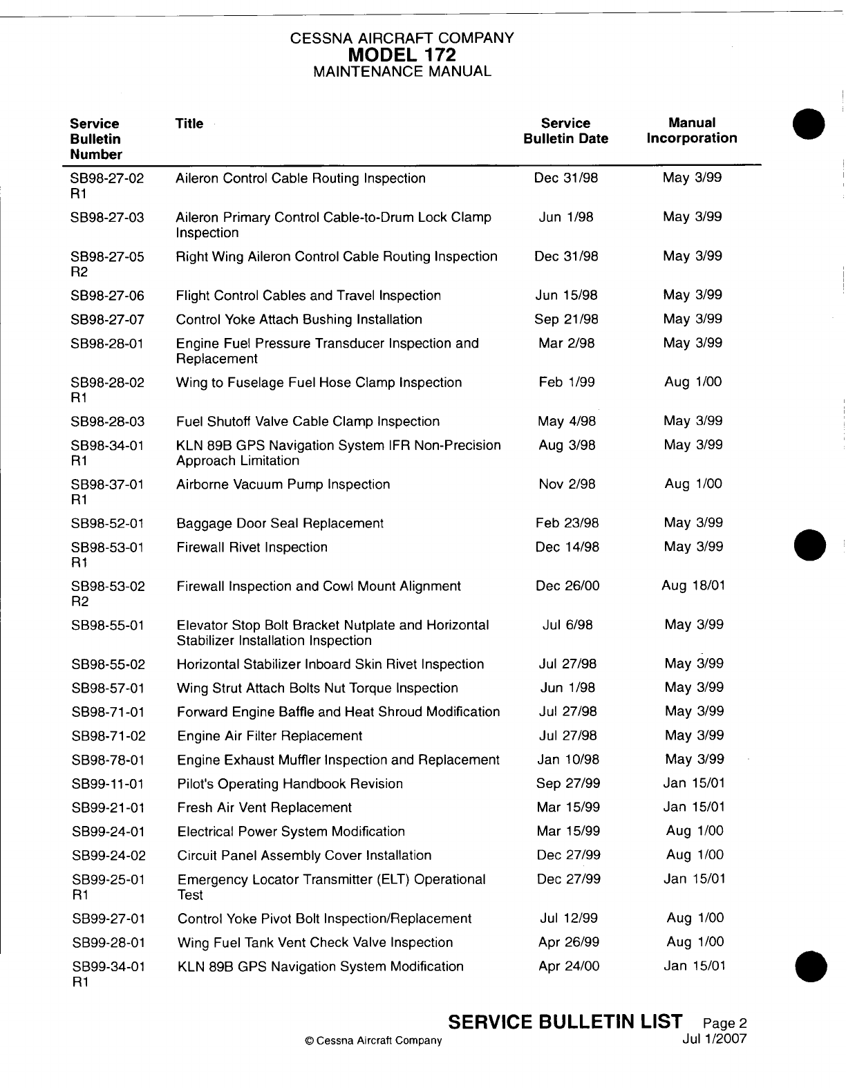
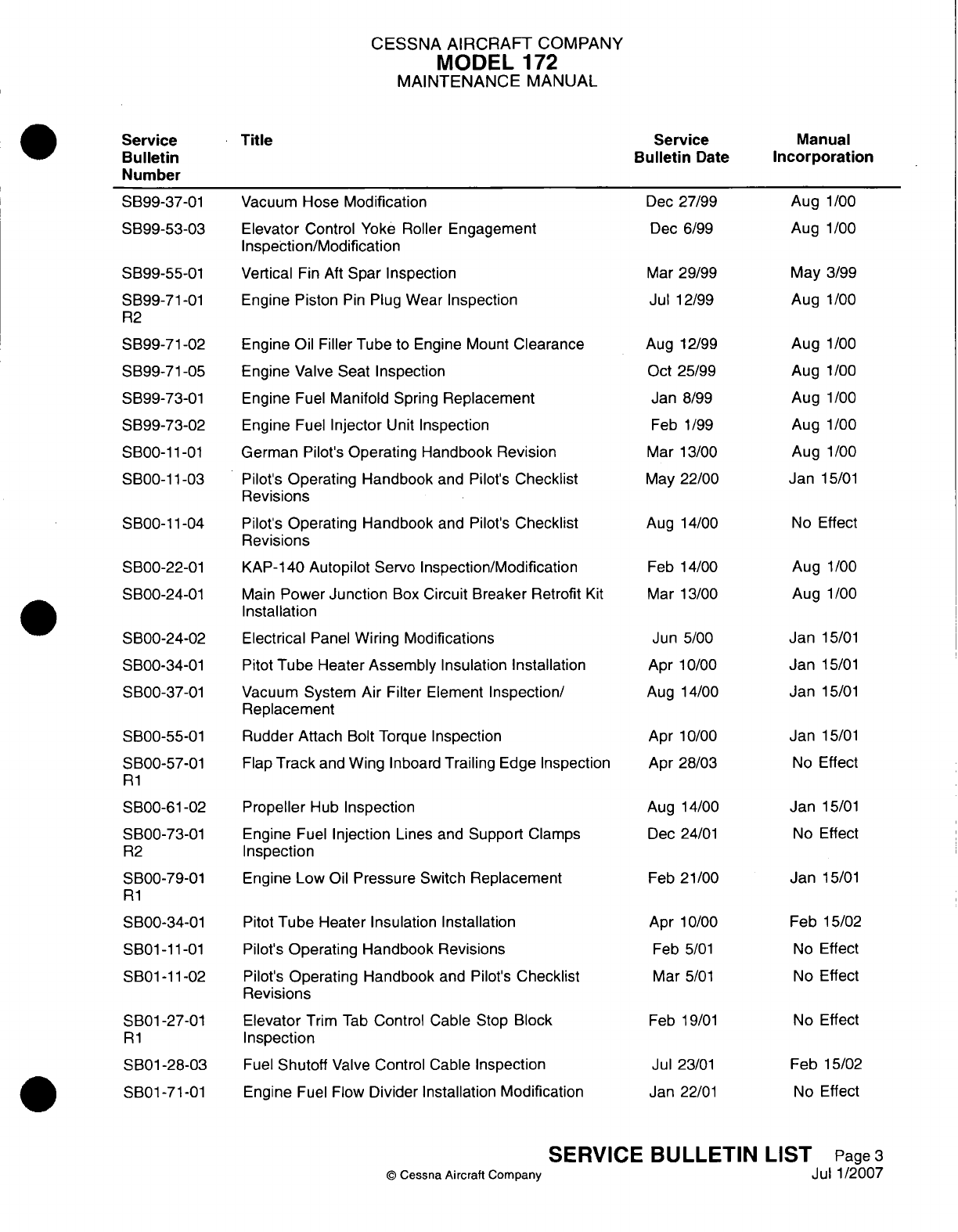
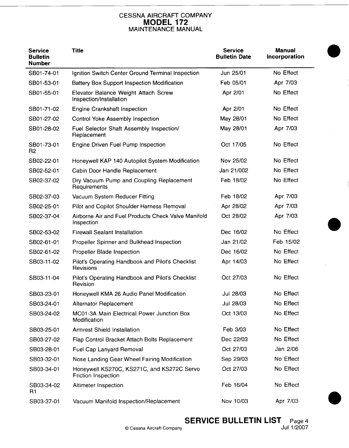
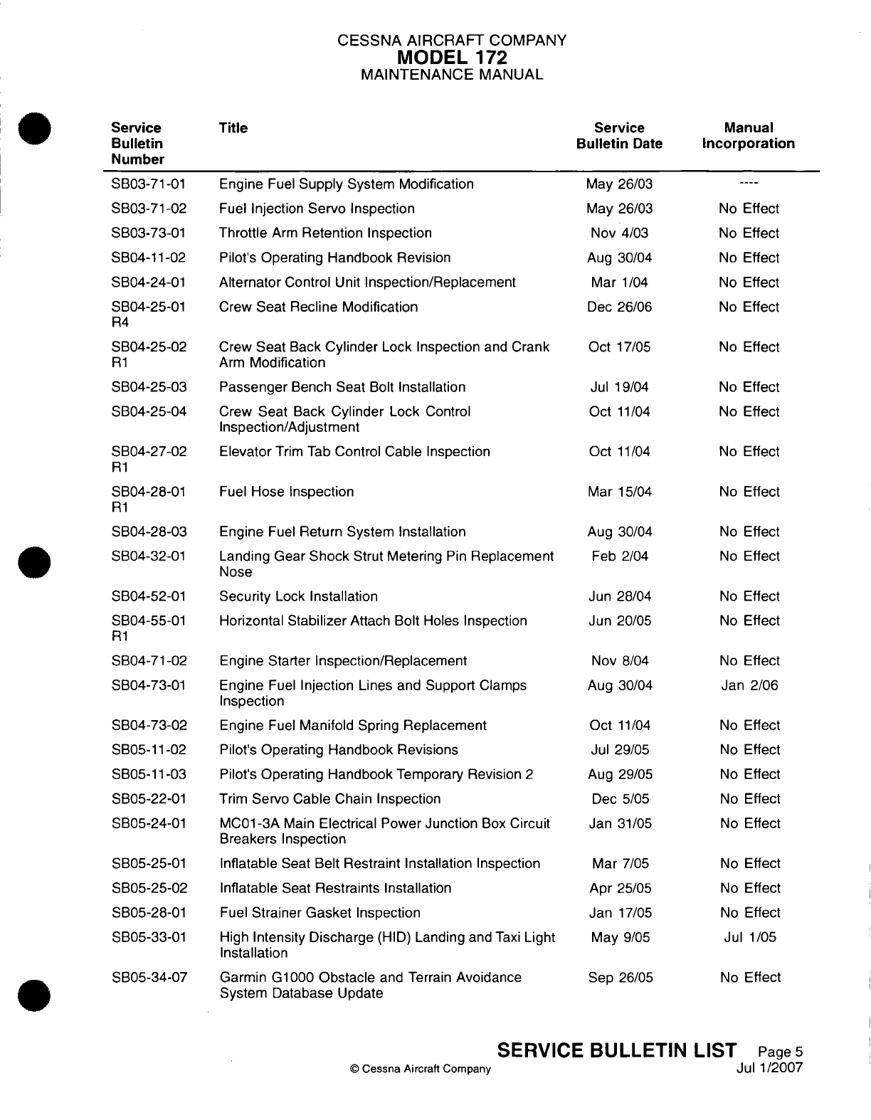
A.
Service
Bulletins
have
special
inspections
and
approved
modifications
to
the airplane
and/or
systems.
As
service
bulletins
are
issued,
they will
be
included
in
subsequent
scheduled
manual
revisions
and
recorded
in
the
Service
Bulletin List,
which
is
before
the
Introduction
of
the
manual.
The
list
includes:
(1)
Service Bulletin
Number
-
This
Service
Bulletin
number column
identifies
the
bulletin by
number.
Service Bulletins
are
numbered
to
agree with
ATA
chapter assignment.
(2)
Service
Bulletin
Date
-
The
service
bulletin
date
column
gives
the
date
the
bulletin became active.
(3)
Title
-
The
title
column
gives
the
service
bulletin
by
name.
It is
the same
title
shown
on
page
one
of
the
service
bulletin.
INTRODUCTION
Page
2
©
Cessna
Aircraft
Company
Jun
7/2004
CESSNA
AIRCRAFT
COMPANY
MODEL
1
72
MAINTENANCE
MANUAL
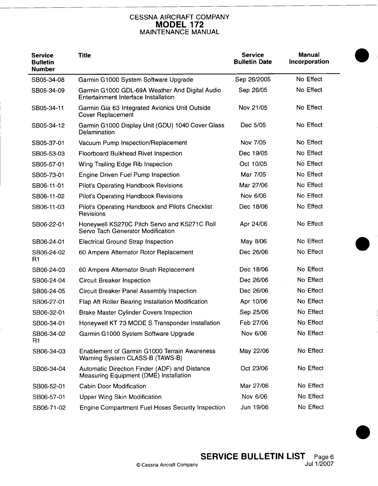
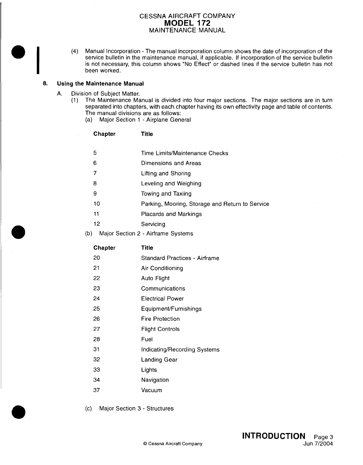
(4)
Manual Incorporation
-
The
manual incorporation
column
shows
the
date
of
incorporation
of the
service
bulletin
in
the
maintenance
manual,
if
applicable.
If
incorporation
of
the
service bulletin
is
not
necessary,
this
column
shows
"No
Effect"
or
dashed
lines
if
the
service bulletin
has
not
been
worked.
8.
Using
the
Maintenance
Manual
A.
Division
of
Subject
Matter.
(1)
The
Maintenance
Manual
is
divided
into
four
major
sections.
The
major
sections
are
in
turn
separated
into
chapters,
with
each
chapter
having
its
own
effectivity
page
and
table
of
contents.
The manual
divisions
are
as
follows:
(a)
Major
Section
1 -
Airplane
General
Chapter
Title
5
6
7
8
9
10
11
12
(b)
Major
Section
Chapter
20
21
22
23
24
25
26
27
28
31
32
33
34
37
Time
Limits/Maintenance
Checks
Dimensions
and
Areas
Lifting
and
Shoring
Leveling
and
Weighing
Towing
and
Taxiing
Parking,
Mooring,
Storage
and
Return
to
Service
Placards
and
Markings
Servicing
2
-
Airframe
Systems
Title
Standard
Practices
-
Airframe
Air
Conditioning
Auto
Flight
Communications
Electrical
Power
Equipment/Furnishings
Fire
Protection
Flight
Controls
Fuel
Indicating/Recording
Systems
Landing
Gear
Lights
Navigation
Vacuum
(c)
Major
Section
3
-
Structures
©
Cessna
Aircraft
Company
INTRODUCTION
Page
3
Jun
7/2004
I
CESSNA
AIRCRAFT
COMPANY
MODEL
172
MAINTENANCE
MANUAL
Title
Standard
Practices
and
Structures
-
General
Doors
Stabilizers
Windows
Wings
(d)
Major
Section
4
-
Power
Plant
Chapter
Title
61
Propeller
71
Power Plant
Engine
Fuel
and
Control
Ignition
Engine
Controls
Engine
Indicating
Exhaust
Oil
Starting
B.
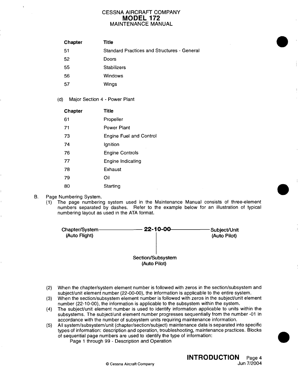
Page
Numbering
System.
(1)
The
page
numbering
system
used
in
the
Maintenance Manual
consists
of
three-element
numbers
separated
by
dashes. Refer
to
the
example
below
for
an
illustration
of
typical
numbering
layout
as
used
in
the
ATA
format.
Chapter/System
(Auto
Flight)
22-10-00
Subject/Unit
(Auto Pilot)
Section/Subsystem
(Auto
Pilot)
(2)
When
the
chapter/system
element
number
is
followed
with
zeros
in
the
section/subsystem
and
subject/unit
element
number (22-00-00), the information
is
applicable
to
the
entire
system.
(3)
When the
section/subsystem element
number
is
followed
with
zeros
in
the
subject/unit
element
number
(22-10-00),
the
information
is
applicable
to
the
subsystem
within
the
system.
(4)
The
subject/unit
element
number
is
used to
identify
information
applicable
to
units
within
the
subsystems. The
subject/unit
element
number
progresses
sequentially
from
the
number
-01
in
accordance
with
the
number
of
subsystem
units
requiring
maintenance
information.
(5)
All
system/subsystem/unit (chapter/section/subject)
maintenance data
is
separated
into
specific
types
of
information:
description
and operation,
troubleshooting, maintenance
practices.
Blocks
of
sequential
page
numbers
are
used
to
identify
the
type
of
information:
Page
1
through
99
-
Description
and
Operation
©
Cessna
Aircraft Company
INTRODUCTION
Page
4
Jun
7/2004
Chapter
51
52
55
56
57
73
74
76
77
78
79
80
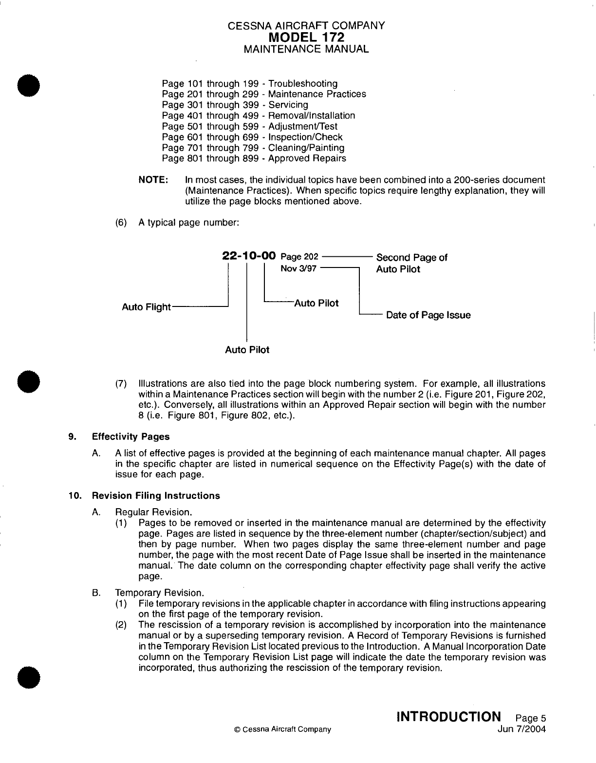
CESSNA
AIRCRAFT
COMPANY
MODEL
172
MAINTENANCE
MANUAL
Page
101
through
199
-
Troubleshooting
Page
201
through 299
-
Maintenance
Practices
Page
301
through
399
-
Servicing
Page
401
through
499
-
Removal/Installation
Page
501
through
599
-
Adjustment/Test
Page
601
through
699
-
Inspection/Check
Page
701
through
799
-
Cleaning/Painting
Page
801
through
899
-
Approved
Repairs
NOTE:
In
most
cases,
the
individual
topics
have been
combined
into
a
200-series
document
(Maintenance
Practices).
When
specific
topics
require
lengthy
explanation,
they
will
utilize
the
page
blocks mentioned
above.
(6)
A
typical
page
number:
22-1
0-00
Page
202
Second
Page
of
Nov
3/97
Auto
Pilot
Auto Flight
Auto
Pilot
Date
of
Page
Issue
Auto Pilot
(7)
Illustrations
are
also
tied
into
the page
block
numbering
system.
For
example,
all
illustrations
within
a
Maintenance
Practices
section
will begin
with
the
number
2
(i.e.
Figure
201,
Figure
202,
etc.).
Conversely,
all
illustrations
within
an
Approved Repair
section
will
begin
with
the number
8
(i.e.
Figure
801,
Figure
802,
etc.).
9.
Effectivity
Pages
A.
A
list
of
effective pages
is
provided
at
the
beginning
of
each
maintenance
manual
chapter.
All
pages
in
the
specific
chapter
are
listed
in
numerical
sequence
on the
Effectivity
Page(s)
with
the
date
of
issue
for
each
page.
10.
Revision
Filing
Instructions
A.
Regular
Revision.
(1)
Pages
to
be
removed or
inserted
in
the
maintenance
manual are
determined
by
the
effectivity
page. Pages
are
listed
in
sequence
by
the
three-element
number
(chapter/section/subject)
and
then
by
page number.
When two pages
display
the
same
three-element
number
and
page
number,
the
page
with the
most
recent
Date
of
Page
Issue
shall
be
inserted
in
the
maintenance
manual.
The
date
column
on
the
corresponding chapter effectivity
page
shall
verify the active
page.
B.
Temporary
Revision.
(1)
File
temporary
revisions
in
the
applicable
chapter
in
accordance
with
filing
instructions
appearing
on
the
first
page
of
the
temporary
revision.
(2)
The
rescission
of
a
temporary
revision
is
accomplished
by
incorporation
into
the
maintenance
manual
or
by
a
superseding
temporary
revision.
A
Record
of
Temporary
Revisions
is
furnished
in
the
Temporary
Revision
List located
previous
to
the
Introduction.
A
Manual
Incorporation
Date
column
on
the
Temporary
Revision
List page
will
indicate
the
date
the
temporary
revision
was
incorporated,
thus
authorizing
the
rescission
of
the
temporary revision.
INTRODUCTION
Page
5
©
Cessna
Aircraft
Company
Jun
7/2004
CESSNA AIRCRAFT
COMPANY
MODEL
172
MAINTENANCE
MANUAL
11.
Identifying
Revised
Material
A.
Additions
or
revisions
to
text
in
an
existing
section
will
be
identified
by
a
revision
bar
in
the
left
margin
of
the
page
and
adjacent
to
the
change.
B.
When
technical
changes
cause
unchanged
text
to
appear
on
a
different
page(s),
a
revision
bar
will
be
placed
in
the
left
margin
opposite
the
chapter/section/subject,
page
number and
date
of
all
affected
pages,
providing
no
other revision
bar
appears
on
the page.
These pages
will
display
the
current
revision date
in
the
Date
of
Page
Issue location.
C.
Chapter
5
may
contain
revision
bars
to
indicate revised text.
Inspection
items
in
section
5-10-01
are
also noted
as
revised,
added
or
deleted
by
the
date
of
changed
item
code.
A
revision
date
is
indicated
below
the
page
number.
D.
When
extensive
technical
changes
are
made to
text
in
an
existing
section
that
requires
extensive
revision,
revision
bars will
appear
the
full
length
of
text.
E.
Revised
and new
illustrations
will
be
indicated
by
either
a
revision
bar
along
the
side
of
the
page
or
a
hand
indicator directing
attention
to
the area.
12.
Warnings, Cautions
and
Notes
A.
Throughout
the
text
in
this
manual,
warnings, cautions
and
notes
pertaining
to
the
procedures
being
accomplished
are
utilized.
These adjuncts
to
the
text
are
used to
highlight
or
emphasize
important
points. Warnings and
Cautions precede
the
text
they pertain
to,
and
Notes
follow
the
text
they
pertain
to.
(1)
WARNING
-
Calls
attention
to
use
of
materials,
processes,
methods,
procedures
or
limits
which
must
be
followed
precisely
to
avoid
injury
or
death
to
persons.
(2)
CAUTION
-
Calls
attention
to
methods and
procedures which
must
be
followed
to
avoid
damage
to
equipment.
(3)
NOTE
-
Calls
attention
to
methods
which
will
make the
job
easier.
13.
Propeller
Aircraft
Customer
Care
Supplies
and
Publications
Catalog
A.
A
Cessna Propeller Aircraft Customer
Care
Supplies
and
Publications
Catalog
is
available
from
a
Cessna Service
Station or
directly
from
Cessna
Propeller
Product Support
Dept.751,
Cessna Aircraft
Company,
P.O.
Box
7706,
Wichita,
Kansas
67277-7706.
This
catalog
lists
all
publications
and
Customer
Care
Supplies
available
from
Cessna for prior year
models as well
as
new
products.
To
maintain
this catalog
in
a
current
status,
it
is
revised
yearly
and
issued
in
paper
and
aerofiche
form.
14.
Customer
Comments
on
Manual
A.
Cessna Aircraft
Company
has endeavored
to
furnish
you with
an
accurate,
useful
and
up-to-date
manual.
This
manual
can
be
improved
with
your
help.
Please
use the
return
card,
provided
with
your
manual,
to
report
any
errors,
discrepancies,
and
omissions
in
this manual as
well
as any
general
comments
you
wish
to
make.
INTRODUCTION
Page
6
©
Cessna
Aircraft Company
Jun
7/2004
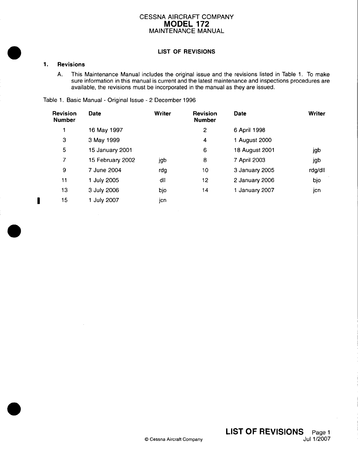
CESSNA AIRCRAFT
COMPANY
MODEL
172
MAINTENANCE
MANUAL
LIST
OF
REVISIONS
1.
Revisions
A.
This
Maintenance
Manual
includes
the
original issue
and
the
revisions
listed
in
Table
1.
To
make
sure
information
in
this
manual
is
current
and
the
latest
maintenance
and
inspections
procedures
are
available,
the
revisions
must
be
incorporated
in
the
manual
as
they
are
issued.
Table
1.
Basic
Manual
-
Original
Issue
-
2
December
1996
Date
Writer
1
16
May
1997
3
3
May
1999
5
15
January
2001
7
lS
February 2002
9 7
June
2004
11
1
July
2005
13
3
July
2006
15
1
July
2007
jgb
rdg
dll
bjo
jcn
Revision
Number
2
4
6
8
10
12
14
©
Cessna
Aircraft
Company
Date
6
April
1998
1
August
2000
1 8
August
2001
7
April
2003
3
January
2005
2
January
2006
1
January
2007
Rei
Nu
wisiofl
mber
Writer
I
jgb
jgb
rdg/dll
bjo
jcn
LIST
OF
REVISIONS
Page
1
Jul
1/2007
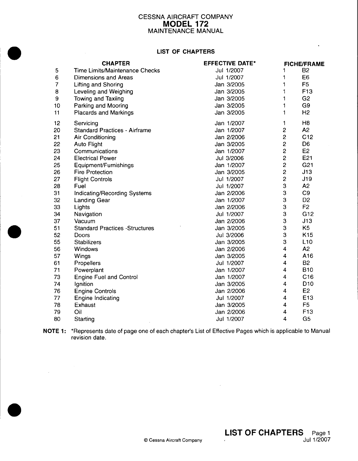
CESSNA
AIRCRAIFT
COMPANY
MODEL
172
MAINTENANCE
MANUAL
LIST
OF
CHAPTERS
CHAPTER
Time
Limits/Maintenance
Checks
Dimensions
and Areas
Lifting
and
Shoring
Leveling
and
Weighing
Towing
and
Taxiing
Parking
and Mooring
Placards
and Markings
Servicing
Standard
Practices
-
Airframe
Air
Conditioning
Auto
Flight
Communications
Electrical
Power
Equipment/Furnishings
Fire
Protection
Flight Controls
Fuel
Indicating/Recording Systems
Landing
Gear
Lights
Navigation
Vacuum
Standard
Practices
-Structures
Doors
Stabilizers
Windows
Wings
Propellers
Powerplant
Engine
Fuel and
Control
Ignition
Engine
Controls
Engine
Indicating
Exhaust
Oil
Starting
EFFECTIVE
DATE*
Jul
1/2007
Jul
1/2007
Jan
3/2005
Jan
3/2005
Jan
3/2005
Jan
3/2005
Jan
3/2005
Jan
1/2007
Jan
1/2007
Jan
2/2006
Jan
3/2005
Jan
1/2007
Jul
3/2006
Jan
1/2007
Jan
3/2005
Jul
1/2007
Jul
1/2007
Jan
2/2006
Jan
1/2007
Jan
2/2006
Jul
1/2007
Jan
2/2006
Jan
3/2005
Jul 3/2006
Jan
3/2005
Jan
2/2006
Jan
3/2005
Jul
1/2007
Jan
1/2007
Jan
1/2007
Jan
3/2005
Jan
2/2006
Jul
1/2007
Jan 3/2005
Jan 2/2006
Jul
1/2007
FICHE/FRAME
1 B2
1 E6
1 F5
1
F13
1
G2
1
G9
1
H2
H8
A2
C12
D6
E2
E2
1
G21
Ji13
Ji19
A2
C9
D2
F2
G12
Ji13
KS
K15
L10
A2
A16
B2
B10
Cl16
D10
E2
El13
F5
F13
G5
NOTE
1:
*Represents
date
of
page
one
of
each
chapter's
List
of
Effective
Pages
which
is
applicable
to
Manual
revision
date.
Q
Cessna
Aircrafl
Company
LIST
OF
CHAPTERS
Page
1
Jul 1/2007
5
6
7
8
9
10
1
1
12
20
21
22
23
24
25
26
27
28
31
32
33
34
37
51
52
55
56
57
61
71
73
74
76
77
78
79
80
CHAPTER
TIME
LIMITS/
MAINTENANCE
CHECKS
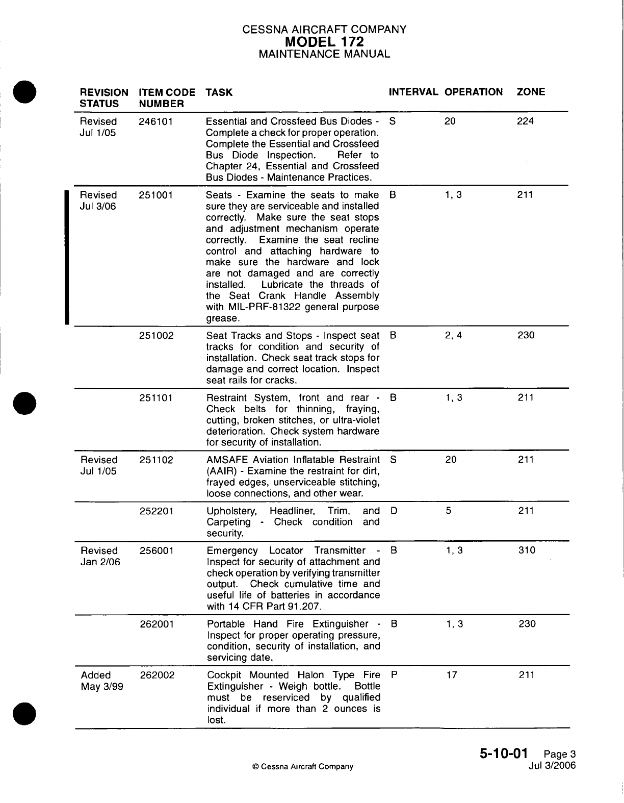
CESSNA
AIRCRAFT
COMPANY
MODEL
172
MAINTENANCE
MANUAL
REVISION
ITEM
CODE
STATUS
NUMBER
TASK INTERVAL
OPERATION
Revised
246101
Essential
and
Crossfeed
Bus
Diodes
-
5
20
224
Jul
1/05
Complete
a
check
for proper
operation.
Complete
the
Essential
and
Crossfeed
Bus
Diode
Inspection.
Refer
to
Chapter
24,
Essential
and
Crossfeed
Bus
Diodes
-
Maintenance Practices.
Revised
251001
Seats
-
Examine
the
seats
to
make
B 1, 3
211
Jul
3/06
sure
they
are
serviceable
and
installed
correctly.
Make sure
the
seat
stops
and
adjustment
mechanism operate
correctly.
Examine
the
seat recline
control
and
attaching
hardware
to
make
sure the
hardware
and
lock
are not
damaged
and
are
correctly
installed.
Lubricate
the
threads
of
the
Seat
Crank Handle
Assembly
with
MlIL-PRF-81
322
general
purpose
grease.
251002
Seat
Tracks
and
Stops
-
Inspect seat
B 2, 4
230
tracks
for
condition
and
security
of
installation.
Check
seat
track
stops
for
damage
and correct
location.
Inspect
seat
rails
for
cracks.
251101
Restraint
System,
front
and
rear
-
B 1,
3
211
Check
belts
for
thinning, fraying,
cutting,
broken
stitches,
or
ultra-violet
deterioration.
Check
system
hardware
for
security
of
installation.
Revised 251102
AMSAFE
Aviation
Inflatable Restraint
5
20
211
Jul
1/05
(AAIR)
-
Examine
the
restraint
for
dirt,
frayed
edges,
unserviceable stitching,
loose
connections,
and
other
wear.
252201
Upholstery,
Headliner,
Trim,
and
D 5
211
Carpeting
-
Check
condition
and
security.
Revised
256001
Emergency Locator
Transmitter
-
B 1, 3
310
Jan 2/06
Inspect
for
security
of
attachment
and
check
operation
by
verifying transmitter
output.
Check
cumulative
time
and
useful
life
of
batteries
in
accordance
with
14
CFR
Part
91
.207.
262001
Portable
Hand
Fire
Extinguisher
-
B 1, 3
230
Inspect
for
proper
operating
pressure,
condition, security
of
installation,
and
servicing
date.
Added
262002
Cockpit
Mounted
Halon
Type
Fire
P
17 211
May 3/99
Extinguisher
-
Weigh
bottle.
Bottle
must
be
reserviced
by
qualified
individual
if
more
than
2
ounces
is
lost.
5-10-01
Page
3
Jul 3/2006
0
Cessna
Aircraft
Company
ZONE
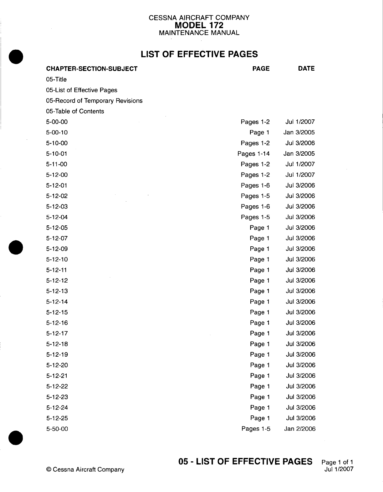
CESSNA AIRCRAFT
COMPANY
MODEL
172
MAINTENANCE
MANUAL
LIST
OF
EFFECTIVE PAGES
CHAPTER-SECTION-SUBJECT
05-Title
05-List
of
Effective Pages
05-Record
of
Temporary
Revisions
05-Table
of
Contents
5-00-00
5-00-10
5-1
0-00
5-1
0-01
5-11
-00
5-1
2-00
5-1
2-01
5-1
2-02
5-1
2-03
5-12-04
5-1
2-05
5-1
2-07
5-1
2-09
5-12-10
5-12-11
5-12-12
5-12-13
5-12-14
5-12-15
5-12-16
5-12-17
5-12-18
5-12-19
5-1
2-20
5-12-2
1
5-1
2-22
5-1
2-23
5-1
2-24
5-1
2-25
5-50-00
©
Cessna
Aircraft
Company
05
-
LIST
OF
EFFECTIVE PAGES
Page
1
of
1
Jul
1/2007
PAGE
Pages
1-2
Page
1
Pages
1-2
Pages
1-14
Pages
1-2
Pages
1-2
Pages
1-6
Pages
1-5
Pages
1-6
Pages
1-5
Page
1
Page
1
Page
1
Page
1
Page
1
Page
1
Page
1
Page
1
Page
1
Page
1
Page
1
Page
1
Page
1
Page
1
Page
1
Page
1
Page
1
Page
1
Page
1
Pages
1-5
DATE
Jul
1/2007
Jan
3/2005
Jul
3/2006
Jan
3/2005
Jul
1/2007
Jul
1/2007
Jul
3/2006
Jul
3/2006
Jul
3/2006
Jul
3/2006
Jul
3/2006
Jul
3/2006
Jul 3/2006
Jul 3/2006
Jul 3/2006
Jul
3/2006
Jul
3/2006
Jul
3/2006
Jul
3/2006
Jul
3/2006
Jul
3/2006
Jul
3/2006
Jul
3/2006
Jul
3/2006
Jul
3/2006
Jul
3/2006
Jul
3/2006
Jul
3/2006
Jul
3/2006
Jan
2/2006
Temporary
Revision
Number
RECORD
OF
TEMPORARY
REVISIONS
Page
Number
Issue
Date
By
Date
Removed
By
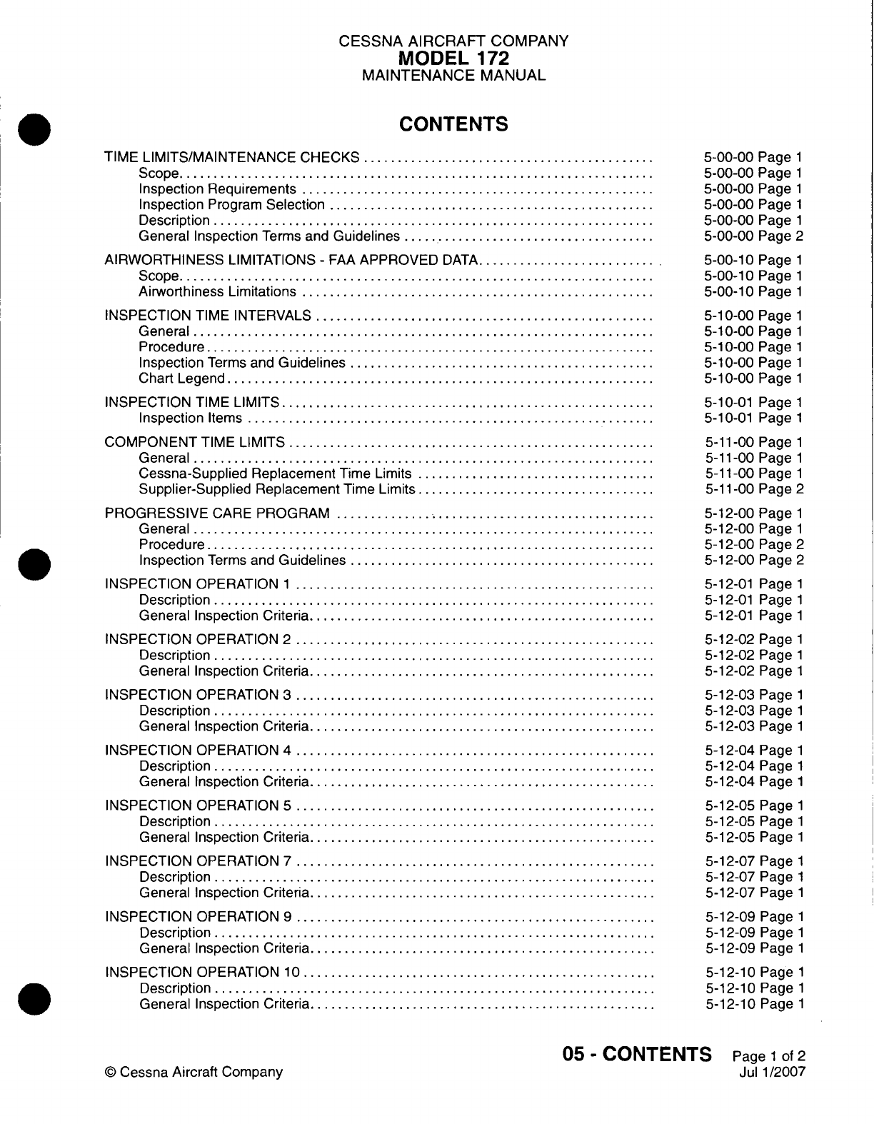
CESSNA AIRCRAFT
COMPANY
MODEL
172
MAINTENANCE
MANUAL
CONTENTS
TIME
LIMITS/MAINTENANCE
CHECKS
......................
Scope....................................
Inspection
Requirements...........................
Inspection
Program
Selection.........................
Description
.................................
General
Inspection
Terms
and
Guidelines....................
AIRWORTHINESS
LIMITATIONS
-
FAA
APPROVED
DATA..............
Scope....................................
Airworthiness
Limitations...........................
INSPECTION
TIME
INTERVALS..........................
General...................................
Procedure..................................
Inspection
Terms
and
Guidelines
.......................
Chart Legend
................................
INSPECTION
TIME
LIMITS
............................
Inspection
Items...............................
COMPONENT
TIME
LIMITS............................
General...................................
Cessna-Supplied
Replacement
Time Limits
..................
Supplier-Supplied Replacement
Time
Limits
..................
PROGRESSIVE
CARE
PROGRAM
........................
General...................................
Procedure..................................
Inspection
Terms
and
Guidelines
.......................
INSPECTION
OPERATION
1 ...........................
Description
.................................
General
Inspection
Criteria
..........................
INSPECTION
OPERATION
2 ...........................
Description
.................................
General
Inspection
Criteria
..........................
INSPECTION OPERATION
3 ...........................
Description
.................................
General
Inspection Criteria
..........................
INSPECTION
OPERATION
4 ...........................
Description
.................................
General
Inspection
Criteria
..........................
INSPECTION
OPERATION 5
...........................
Description
.................................
General
Inspection Criteria
..........................
INSPECTION OPERATION
7 ...........................
Description
.................................
General
Inspection Criteria
..........................
INSPECTION
OPERATION
9 ...........................
Description
.................................
General Inspection
Criteria
..........................
INSPECTION
OPERATION
10...........................
Description
.................................
General Inspection
Criteria
..........................
5-00-00
Page
1
5-00-00
Page
1
5-00-00
Page
1
5-00-00
Page
1
5-00-00
Page
1
5-00-00
Page
2
5-00-10
Page
1
5-00-10
Page
1
5-00-10
Page
1
5-1
0-00
Page
1
5-10-00
Page
1
5-10-00
Page
1
5-10-00
Page
1
5-10-00
Page
1
5-10-01
Page
1
5-10-01
Page
1
5-11
-00
Page
1
5-1
1-00 Page
1
5-1
1-00 Page
1
5-1
1-00
Page
2
5-12-00
Page
1
5-12-00
Page
1
5-12-00
Page
2
5-12-00
Page
2
5-12-01
Page
1
5-12-01
Page
1
5-12-01
Page
1
5-12-02
Page
1
5-12-02
Page
1
5-12-02
Page
1
5-12-03
Page
1
5-12-03
Page
1
5-12-03
Page
1
5-12-04
Page
1
5-12-04
Page
1
5-12-04
Page
1
5-12-05
Page
1
5-12-05
Page
1
5-12-05
Page
1
5-12-07
Page
1
5
12
07
Page
1
5-12-07
Page
1
5-12-09
Page
1
5-12-09
Page
1
5-12-09
Page
1
S-1
2-1
0
Page
1
5-12-1
0
Page
1
5-12-1
0
Page
1
05
-
CONTENTS
Page
1
of
2
Jul
1/2007
©
Cessna
Aircraft
Company
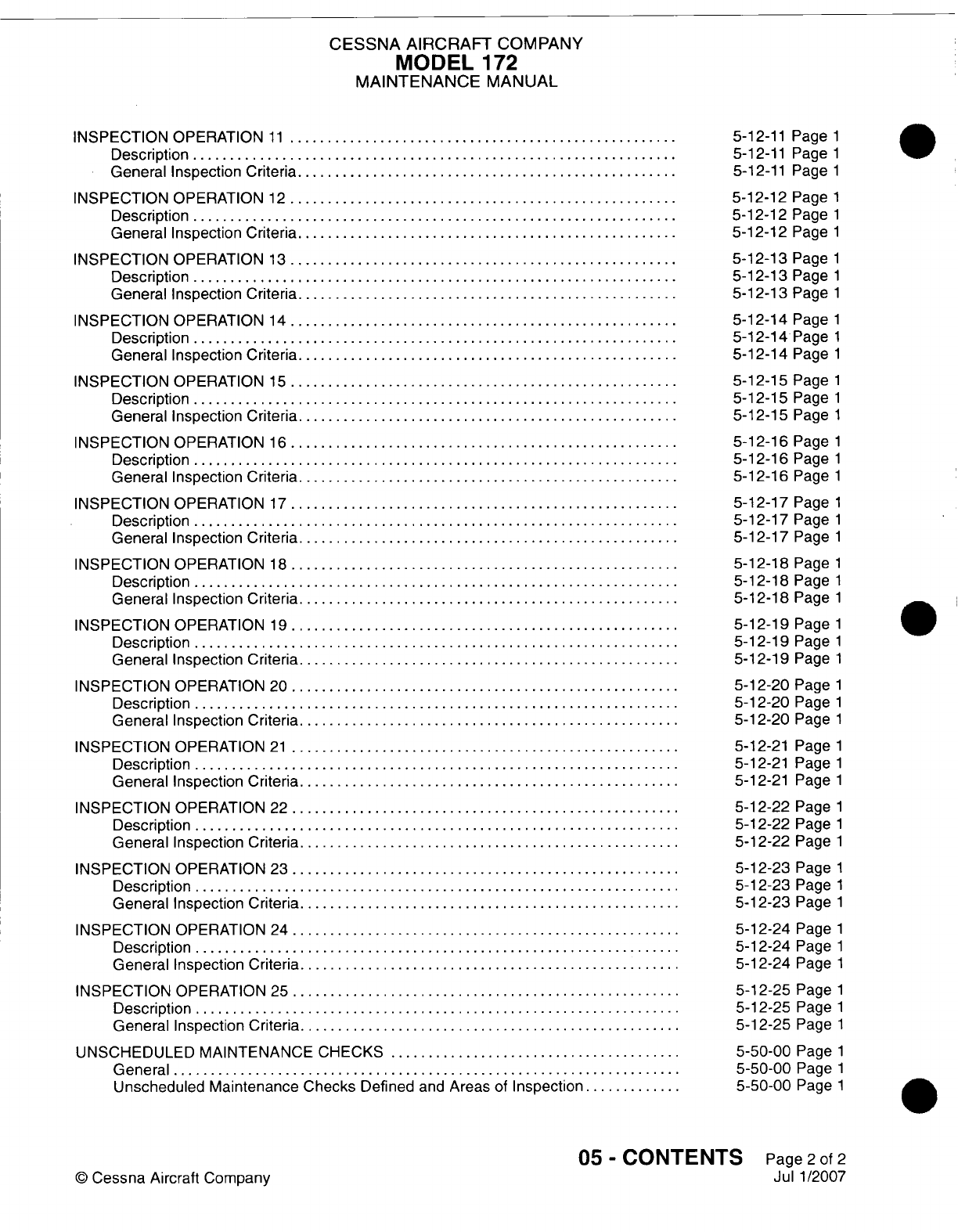
CESSNA
AIRCRAFT
COMPANY
MODEL
172
MAINTENANCE
MANUAL
INSPECTION
OPERATION
11...........................
Description
.................................
General
Inspection
Criteria
..........................
INSPECTION OPERATION
12...........................
Description
.................................
General
Inspection Criteria
..........................
INSPECTION
OPERATION
13...........................
Description
.................................
General
Inspection Criteria
..........................
INSPECTION
OPERATION
14...........................
Description
.................................
General Inspection
Criteria
..........................
INSPECTION
OPERATION
15...........................
Description
.................................
General Inspection
Criteria
..........................
INSPECTION
OPERATION
16...........................
Description
.................................
General Inspection
Criteria
..........................
INSPECTION
OPERATION
17...........................
Description
.................................
General Inspection
Criteria
..........................
INSPECTION OPERATION
18...........................
Description
.................................
General
Inspection
Criteria
..........................
INSPECTION
OPERATION
19...........................
Description
.................................
General
Inspection
Criteria
..........................
INSPECTION
OPERATION
20...........................
Description
.................................
General
Inspection Criteria
..........................
INSPECTION
OPERATION
21...........................
Description
.................................
General
Inspection
Criteria
..........................
INSPECTION
OPERATION
22...........................
Description
.................................
General
Inspection Criteria
..........................
INSPECTION OPERATION
23...........................
Description
.................................
General
Inspection Criteria
..........................
INSPECTION
OPERATION
24...........................
Description
.................................
General
Inspection Criteria
..........................
INSPECTION
OPERATION
25...........................
Description
.................................
General
Inspection Criteria
..........................
UNSCHEDULED MAINTENANCE
CHECKS
....................
General...................................
Unscheduled Maintenance
Checks
Defined
and
Areas
of
Inspection
.......
5-12-11
Page
1
5-12-11
Page
1
5-12-11
Page
1
5-12-12
Page
1
5-12-12
Page
1
5-12-12
Page
1
5-12-13
Page
1
5-12-13
Page
1
5-12-13
Page
1
5-12-14
Page
1
5-12-14
Page
1
5-12-14
Page
1
5-12-15
Page
1
5-12-15
Page
1
5-12-15
Page
1
5-12-16
Page
1
5-12-16
Page
1
5-12-16
Page
1
5-12-17
Page
1
5-12-17
Page
1
5-12-17
Page
1
5-12-18
Page
1
5-12-18
Page
1
5-12-18
Page
1
5-12-19
Page
1
5-12-19
Page
1
5-12-19
Page
1
5-12-20
Page
1
5-12-20
Page
1
5-12-20
Page
1
5-12-21 Page
1
5-12-21 Page
1
5-12-21
Page
1
5-12-22
Page
1
5-12-22
Page
1
5-12-22
Page
1
5-12-23
Page
1
5-12-23
Page
1
5-12-23
Page
1
5-12-24
Page
1
5-12-24
Page
1
5-12-24
Page
1
5-12-25
Page
1
5-12-25
Page
1
5-12-25
Page
1
5-50-00
Page
1
5-50-00
Page
1
5-50-00
Page
1
05
-
CONTENTS
Page
2
of
2
Jul
1/2007
©0
Cessna
Aircraft
Company
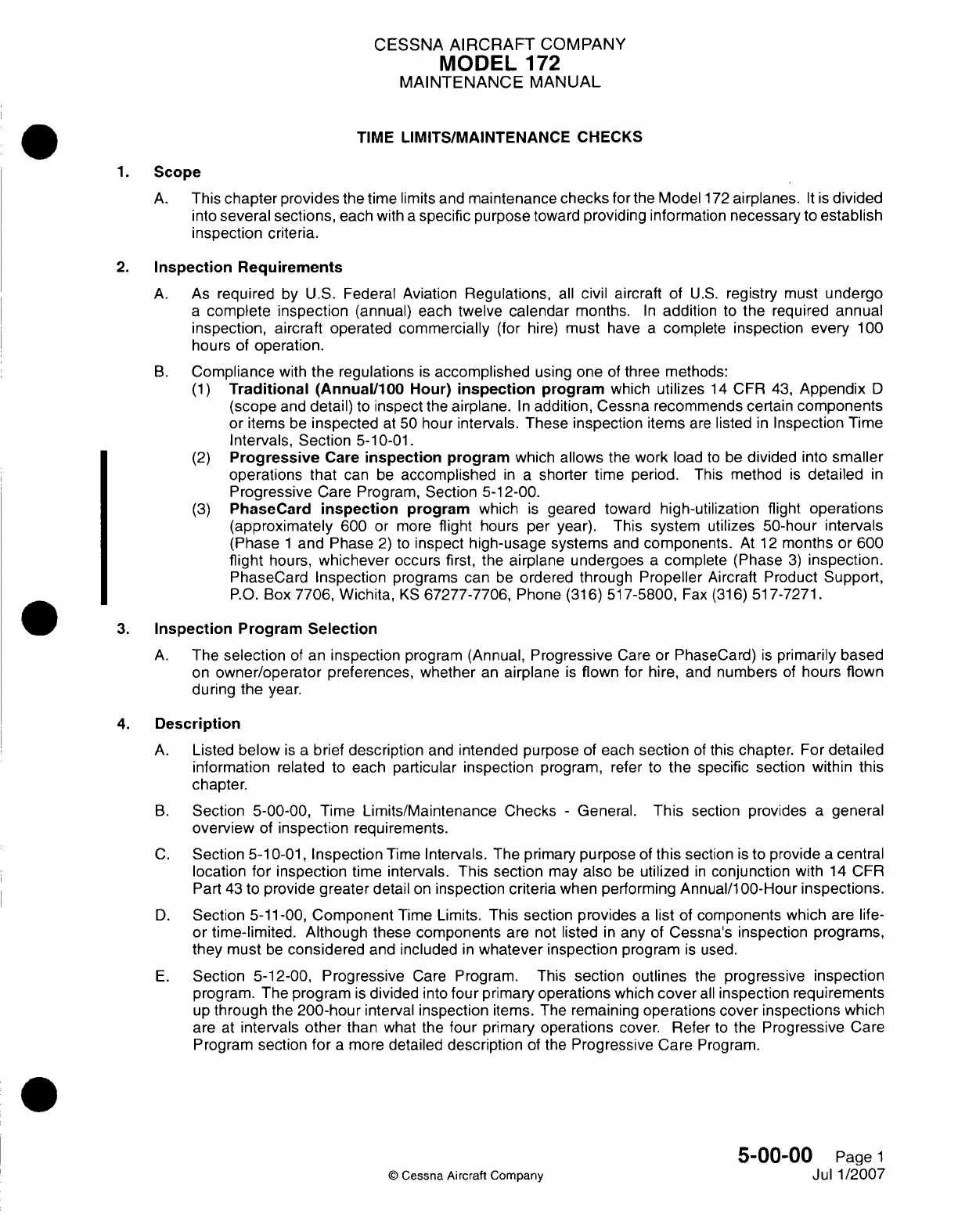
CESSNA
AIRCRAFT
COMPANY
MODEL
172
MAINTENANCE
MANUAL
TIME
LIMITS/MAINTENANCE
CHECKS
1.Scope
A.
This
chapter
provides
the
time
limits
and
maintenance
checks
for
the
Model
172
airplanes.
It is
divided
into
several
sections,
each
with
a
specific
purpose
toward
providing
information
necessary
to
establish
inspection
criteria.
2.
Inspection
Requirements
A.
As
required
by
U.S.
Federal
Aviation
Regulations,
all
civil
aircraft
of
U.S.
registry
must
undergo
a
complete
inspection
(annual)
each
twelve
calendar
months.
In
addition
to
the
required annual
inspection,
aircraft operated
commercially
(for
hire)
must
have
a
complete
inspection
every
100
hours
of
operation.
B.
Compliance
with
the
regulations
is
accomplished
using
one
of
three methods:
(1)
Traditional
(Annual/1OU
Hour)
inspection
program which
utilizes
14
CFR
43,
Appendix
D
(scope
and
detail)
to
inspect
the
airplane.
In
addition,
Cessna recommends certain
components
or
items
be
inspected
at
50
hour
intervals. These
inspection
items
are
listed
in
Inspection
Time
Intervals, Section
5-10-01.
(2)
Progressive
Care
inspection
program
which
allows
the
work
load
to
be
divided
into
smaller
operations
that
can
be
accomplished
in a
shorter
time
period.
This
method
is
detailed
in
Progressive
Care
Program,
Section
5-12-00.
(3)
PhaseCard
inspection
program
which
is
geared toward
high-utilization
flight
operations
(approximately
600
or
more
flight
hours
per
year).
This
system
utilizes
50-hour
intervals
(Phase
1
and Phase
2)
to
inspect
high-usage
systems
and
components.
At
12
months
or 600
flight
hours,
whichever
occurs
first,
the
airplane
undergoes
a
complete
(Phase
3)
inspection.
PhaseCard
Inspection
programs can
be
ordered
through
Propeller
Aircraft
Product
Support,
P.O.
Box
7706, Wichita,
KS
67277-7706,
Phone
(316)
517-5800,
Fax (316)
517-7271.
3.
Inspection
Program
Selection
A.
The
selection
of
an
inspection
program
(Annual,
Progressive
Care
or
PhaseCard)
is
primarily based
on
owner/operator
preferences, whether
an
airplane
is
flown
for hire,
and
numbers
of
hours
flown
during
the
year.
4.
Description
A.
Listed
below
is a
brief
description
and
intended purpose
of
each
section
of
this
chapter.
For
detailed
information
related to
each
particular
inspection
program,
refer
to
the specific section within
this
chapter.
B.
Section
5-00-00,
Time
Limits/Maintenance
Checks
-
General.
This
section
provides
a
general
overview
of
inspection
requirements.
C.
Section
5-1
0-01,
Inspection
Time
Intervals.
The
primary
purpose
of
this
section
is
to
provide
a
central
location
for inspection
time
intervals.
This section
may
also
be
utilized
in
conjunction
with
14
CFR
Part
43
to
provide
greater
detail
on
inspection
criteria
when performing
Annual/i
00-Hour
inspections.
D.
Section
5-11-00,
Component
Time
Limits.
This
section provides
a
list
of
components
which
are life-
or
time-limited.
Although
these
components
are
not
listed
in
any
of
Cessna's inspection
programs,
they
must
be
considered
and
included
in
whatever
inspection
program
is
used.
E.
Section
5-12-00,
Progressive
Care
Program. This
section
outlines
the
progressive
inspection
program.
The
program
is
divided
into
four
primary
operations
which
cover
all
inspection requirements
up
through
the
200-hour
interval
inspection
items.
The
remaining
operations
cover
inspections which
are
at
intervals
other
than
what
the
four
primary
operations
cover.
Refer
to
the
Progressive
Care
Program
section
for
a
more
detailed
description
of the
Progressive
Care
Program.
5-00-00
Page
1
©
Cessna
Aircraft
Company
Jul
1/2007
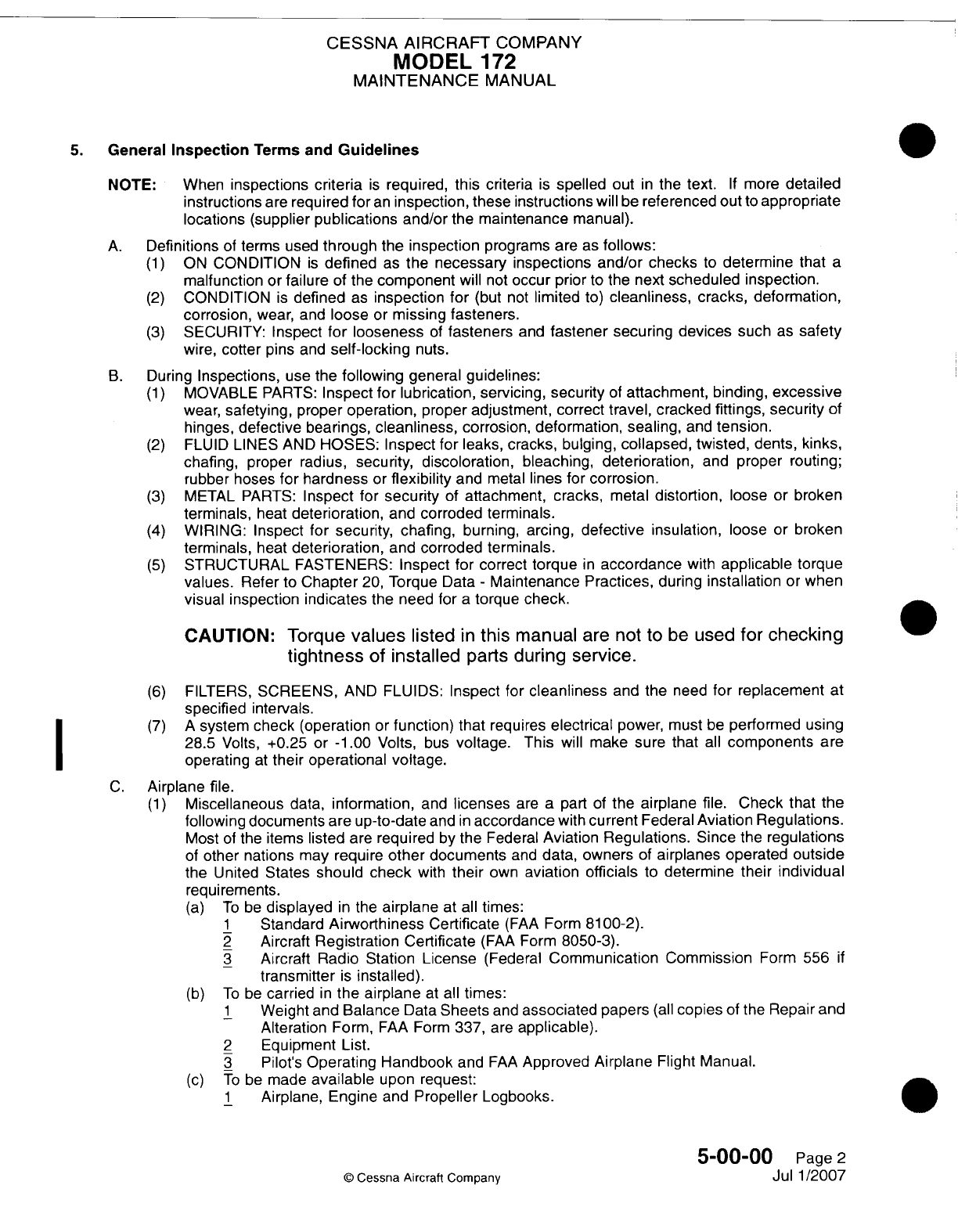
CESSNA
AIRCRAFT
COMPANY
MODEL
172
MAINTENANCE
MANUAL
5.
General
Inspection
Terms and
Guidelines
NOTE:
When
inspections
criteria
is
required,
this
criteria
is
spelled
out
in
the
text.
If
more
detailed
instructions
are
required
for
an
inspection, these instructions
will
be
referenced
out
to
appropriate
locations
(supplier publications and/or
the
maintenance
manual).
A.
Definitions
of
terms used
through
the
inspection
programs
are
as
follows:
(1)
ON
CONDITION
is
defined
as
the
necessary inspections
and/or
checks
to
determine
that
a
malfunction
or
failure
of
the
component
will
not
occur
prior
to
the
next
scheduled
inspection.
(2)
CONDITION
is
defined
as
inspection for
(but
not
limited
to)
cleanliness,
cracks, deformation,
corrosion,
wear, and
loose
or
missing fasteners.
(3)
SECURITY:
Inspect
for
looseness
of
fasteners
and
fastener
securing devices
such
as
safety
wire,
coffer
pins and
self-locking
nuts.
B.
During
Inspections,
use
the
following
general
guidelines:
(1)
MOVABLE PARTS:
Inspect
for
lubrication,
servicing,
security
of
attachment, binding,
excessive
wear,
safetying, proper
operation,
proper
adjustment,
correct
travel,
cracked
fittings, security
of
hinges,
defective
bearings,
cleanliness,
corrosion,
deformation,
sealing,
and
tension.
(2)
FLUID
LINES
AND
HOSES:
Inspect
for leaks,
cracks,
bulging,
collapsed,
twisted,
dents,
kinks,
chafing,
proper radius,
security,
discoloration, bleaching, deterioration,
and
proper
routing;
rubber
hoses
for
hardness
or
flexibility
and
metal
lines for
corrosion.
(3)
METAL
PARTS:
Inspect
for
security
of
attachment,
cracks,
metal
distortion,
loose
or
broken
terminals,
heat
deterioration,
and
corroded
terminals.
(4)
WIRING:
Inspect
for
security,
chafing,
burning,
arcing,
defective
insulation,
loose
or
broken
terminals,
heat
deterioration,
and
corroded terminals.
(5)
STRUCTURAL
FASTENERS:
Inspect
for
correct
torque
in
accordance
with
applicable
torque
values.
Refer
to
Chapter
20,
Torque
Data
-
Maintenance
Practices,
during
installation
or
when
visual
inspection
indicates
the
need for
a
torque
check.
CAUTION: Torque
values
listed
in
this
manual
are
not
to
be
used
for
checking
tightness
of
installed
parts
during service.
(6)
FILTERS,
SCREENS,
AND
FLUIDS:
Inspect
for
cleanliness
and
the
need
for
replacement
at
specified
intervals.
(7) A
system
check
(operation
or
function) that
requires
electrical
power, must
be
performed
using
28.5
Volts,
+0.25
or
-1
.00
Volts,
bus
voltage.
This
will
make
sure that
all
components are
I ~ ~~~operating
at
their operational
voltage.
C.
Airplane file.
(1)
Miscellaneous
data,
information,
and
licenses
are
a
part
of
the
airplane
file.
Check that
the
following documents
are
up-to-date
and
in
accordance
with
current
Federal
Aviation
Regulations.
Most
of
the
items
listed
are
required
by
the
Federal
Aviation
Regulations.
Since
the
regulations
of
other
nations
may
require
other
documents
and
data,
owners
of
airplanes
operated
outside
the
United
States
should
check
with
their
own
aviation
officials
to
determine their
individual
requirements.
(a)
To
be
displayed
in
the
airplane
at
all
times:
1
Standard
Airworthiness
Certificate
(FAA
Form
81
00-2).
2
Aircraft
Registration
Certificate
(FAA
Form
8050-3).
3
Aircraft
Radio
Station License
(Federal
Communication Commission
Form
556
if
transmitter
is
installed).
(b)
To
be
carried
in
the airplane
at
all
times:
.1
Weight
and
Balance
Data
Sheets
and
associated
papers
(all
copies
of
the
Repair
and
Alteration
Form,
FAA
Form
337,
are
applicable).
2
Equipment List.
3
Pilot's
Operating
Handbook
and
FAA
Approved
Airplane
Flight Manual.
(c)
To
be
made
available
upon
request:
1
Airplane, Engine
and
Propeller
Logbooks.
5-00-00
Page
2
©
Cessna
Aircraft Company
Jul
1/2007
CESSNA
AIRCRAFT
COMPANY
MODEL
172
MAINTENANCE
MANUAL
AIRWORTHINESS
LIMITATIONS
-
FAA
APPROVED
DATA
1.
Scope
A.
The
Airworthiness
Limitations section
is
FAA-approved
and
specifies
maintenance required under
Parts
43.16
and
91.403
of
Title
14
of
the
Code
of Federal
Regulations
unless
an
alternative
program
has
been
FAA-approved.
2.
Airworthiness
Limitations
A.
There
are
no
airworthiness
limitations
associated
with
this
airplane.
5-00-10
Page
1
Jan 3/2005
©
Cessna
Aircraft
Company
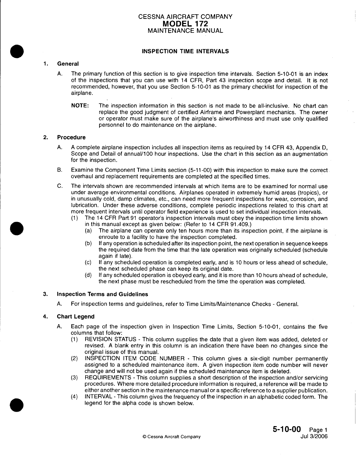
CESSNA
AIRCRAFT
COMPANY
MODEL
172
MAINTENANCE
MANUAL
INSPECTION
TIME
INTERVALS
1.
General
A.
The
primary
function
of
this
section
is
to
give
inspection
time
intervals.
Section
5-10-01
is
an
index
of
the
inspections
that
you
can
use
with
14
CFR,
Part
43
inspection
scope
and
detail.
It
is
not
recommended,
however,
that
you
use
Section
5-10-01
as the
primary
checklist
for
inspection
of
the
airplane.
NOTE:
The
inspection
information
in
this section
is
not
made
to
be
all-inclusive.
No
chart
can
replace
the
good
judgment
of
certified
Airframe
and
Powerplant
mechanics. The
owner
or
operator
must
make sure
of
the
airplane's airworthiness
and
must
use
only
qualified
personnel
to
do
maintenance
on
the
airplane.
2.
Procedure
A. A
complete airplane
inspection
includes
all
inspection
items
as
required
by
14
CFR 43,
Appendix
D,
Scope and
Detail
of
annual/100
hour
inspections.
Use
the
chart
in
this
section
as
an
augmentation
for
the
inspection.
B.
Examine the
Component
Time
Limits
section
(5-11-00)
with
this
inspection
to
make
sure
the
correct
overhaul
and
replacement requirements
are
completed
at
the
specified
times.
C.
The
intervals
shown
are
recommended
intervals
at
which
items
are
to
be
examined
for
normal
use
under
average environmental
conditions. Airplanes operated
in
extremely
humid
areas
(tropics),
or
in
unusually
cold,
damp
climates,
etc.,
can
need
more
frequent
inspections for
wear,
corrosion,
and
lubrication.
Under
these adverse
conditions,
complete periodic inspections
related
to
this
chart
at
more
frequent
intervals
until
operator
field
experience
is
used
to
set individual
inspection intervals.
(1)
The
14
CFR
Part
91
operator's
inspection intervals
must
obey
the
inspection
time
limits
shown
in
this
manual
except
as
given below: (Refer
to
14
CFR
91.409.)
(a)
The
airplane
can
operate
only
ten
hours
more
than
its
inspection
point,
if
the
airplane
is
enroute
to
a
facility
to have
the
inspection
completed.
(b)
If
any operation
is
scheduled
after
its
inspection
point,
the
next
operation
in
sequence
keeps
the
required
date
from
the
time
that
the
late
operation
was
originally
scheduled
(schedule
again
if
late).
(c)
If
any
scheduled operation
is
completed
early,
and
is
10
hours
or
less
ahead
of
schedule,
the
next
scheduled
phase
can
keep
its
original
date.
(d)
If
any
scheduled
operation
is
obeyed
early, and
it
is
more
than
10
hours
ahead
of
schedule,
the
next phase must
be
rescheduled
from
the
time
the
operation
was
completed.
3.
Inspection
Terms and
Guidelines
A.
For
inspection
terms
and
guidelines,
refer
to
Time
Limits/Maintenance
Checks
-
General.
4.
Chart
Legend
A.
Each
page
of
the inspection
given
in
Inspection
Time Limits,
Section
5-10-01,
contains
the
five
columns
that
follow:
(1)
REVISION
STATUS
-
This
column
supplies
the date
that
a
given
item
was added,
deleted
or
revised.
A
blank
entry
in
this column
is
an
indication
there
have
been
no
changes
since
the
original
issue
of
this
manual.
(2)
INSPECTION
ITEM
CODE NUMBER
-
This column
gives
a
six-digit
number permanently
assigned
to
a
scheduled maintenance
item.
A
given
inspection
item
code number will
never
change
and
will
not
be
used
again
if
the scheduled
maintenance
item
is
deleted.
(3)
REQUIREMENTS
-
This column
supplies
a
short
description
of
the
inspection
and/or servicing
procedures. Where
more
detailed procedure information
is
required,
a
reference
will
be
made
to
either
another
section
in
the
maintenance
manual
or
a
specific
reference
to
a
supplier publication.
(4)
INTERVAL
-
This
column
gives
the
frequency
of
the
inspection
in
an
alphabetic
coded
form.
The
legend
for
the
alpha code
is
shown below.
5-10-00
Page
1
©
Cessna Aircraft
Company
Jul
3/2006
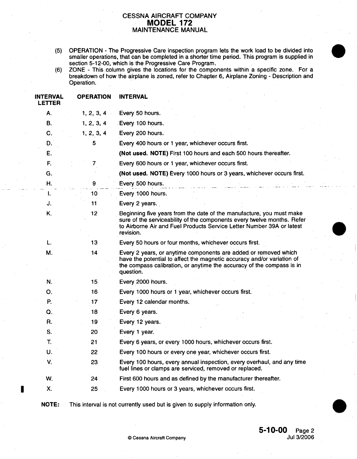
CESSNA
AIRCRAFT
COMPANY
MODEL
172
MAINTENANCE
MANUAL
(5)
OPERATION
-
The
Progressive
Care
inspection
program lets the
work
load
to
be
divided
into
smaller
operations,
that
can
be
completed
in a
shorter
time period.
This
program
is
supplied
in
section 5-12-00, which
is
the
Progressive
Care
Program.
(6)
ZONE
-
This
column
gives the locations
for
the
components
within
a
specific
zone.
For
a
breakdown of
how
the
airplane
is
zoned,
refer
to
Chapter
6,
Airplane
Zoning
-
Description
and
Operation.
INTERVAL
OPERATION
INTERVAL
LETTER
A.
1,
2, 3, 4
Every
50
hours.
B. 1,
2, 3, 4
Every
100
hours.
C. 1,
2, 3, 4
Every
200
hours.
D.
5
Every
400 hours
or
1
year,
whichever
occurs
first.
E.
(Not
used.
NOTE)
First
100
hours
and
each
500
hours thereafter.
F.
7
Every
600 hours
or
1
year,
whichever occurs first.
G.
(Not
used. NOTE)
Every
1000
hours
or
3
years,
whichever occurs
first.
H. 9
Every
500 hours.
I.
10
Every
1000 hours.
J.
11
Every
2
years.
K.
12
Beginning
five
years
from the
date
of
the
manufacture,
you must
make
sure
of
the
serviceability
of
the
components
every
twelve
months.
Refer
to
Airborne
Air
and
Fuel
Products
Service
Letter Number
39A
or latest
revision.
L.
13
Every
50
hours
or
four
months,
whichever
occurs
first.
M.
14
Every
2
years,
or anytime
components
are
added
or
removed
which
have
the
potential
to
affect
the
magnetic accuracy and/or
variation
of
the
compass
calibration,
or
anytime the
accuracy
of
the
compass
is
in
question.
N.
15
Every
2000
hours.
O.
16
Every
1000
hours
or
1
year,
whichever
occurs first.
P.
17
Every
12
calendar
months.
Q.
18
Every
6
years.
R.
19
Every
12
years.
S.
20
Every
1
year.
T.
21
Every
6
years,
or
every
1000
hours,
whichever
occurs
first.
U.
22
Every
100
hours or
every
one
year, whichever
occurs first.
V.
23
Every
100
hours,
every
annual
inspection,
every
overhaul,
and
any
time
fuel
lines or clamps
are
serviced, removed
or
replaced.
W.
24
First
600 hours
and
as
defined
by
the
manufacturer
thereafter.
X.
25
Every 1000
hours or
3
years,
whichever
occurs
first.
NOTE:
This
interval
is not
currently
used
but
is
given
to
supply
information
only.
5-10-00
Page
2
©
Cessna
Aircraft Company
Jul
3/2006
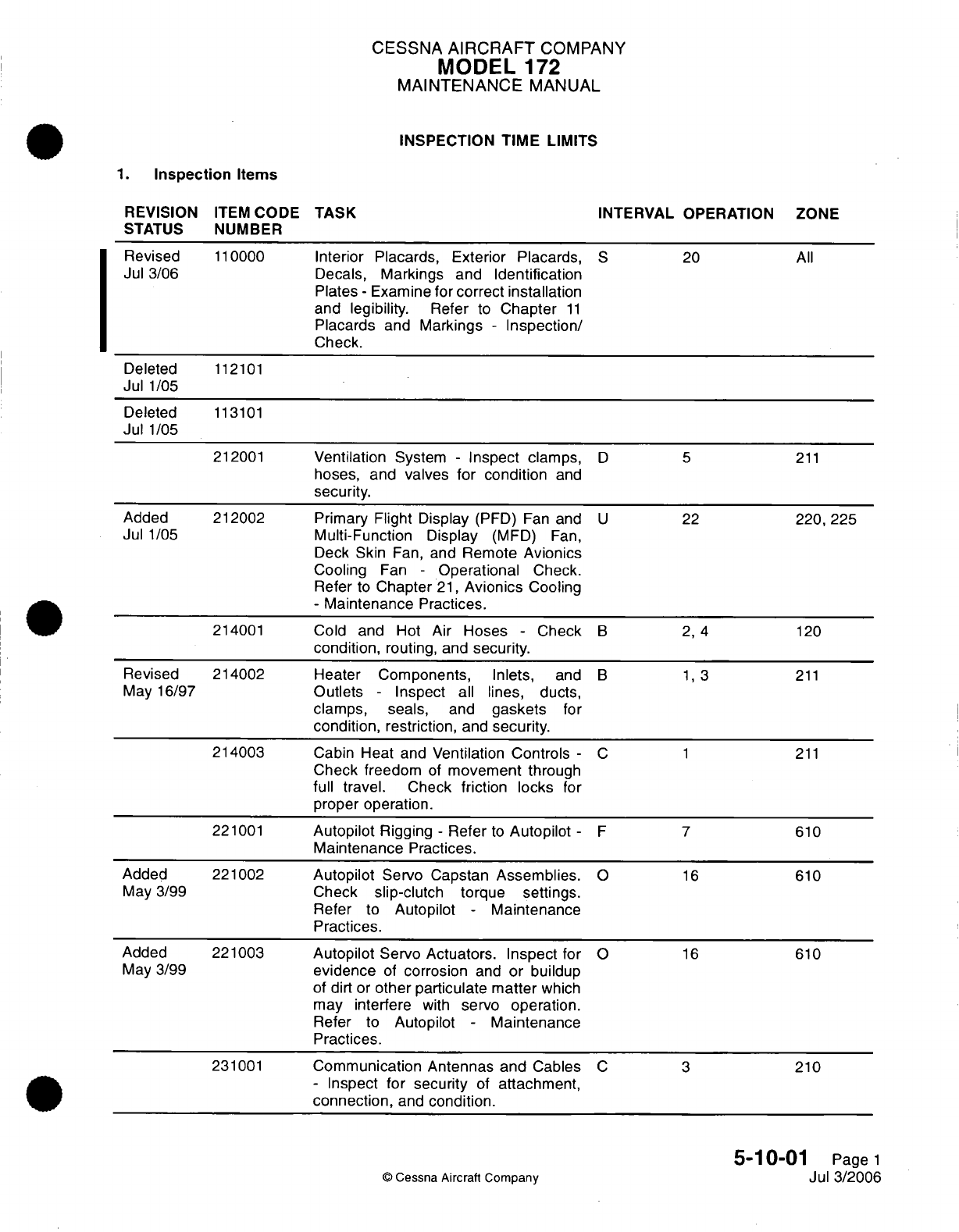
CESSNA
AIRCRAFT
COMPANY
MODEL
172
MAINTENANCE
MANUAL
INSPECTION TIME
LIMITS
1.
Inspection
Items
REVISION
ITEM
CODE
TASK
INTERVAL OPERATION
ZONE
STATUS
NUMBER
Revised
110000
Interior Placards, Exterior Placards,
S
20
All
Jul
3/06
Decals,
Markings
and
Identification
Plates
-
Examine
for correct
installation
and legibility.
Refer
to
Chapter
11
Placards
and
Markings
-
Inspection/
Check.
Deleted
112101
Jul
1/05
Deleted
113101
Jul
1/05
212001
Ventilation
System
-
Inspect
clamps,
D 5
211
hoses,
and
valves for
condition
and
security.
Added
212002 Primary
Flight Display
(PFD) Fan
and
U
22
220,
225
Jul
1/05
Multi-Function
Display
(MFD)
Fan,
Deck Skin
Fan,
and
Remote
Avionics
Cooling
Fan
-
Operational
Check.
Refer
to
Chapter
21,
Avionics
Cooling
-
Maintenance
Practices.
214001
Cold and
Hot Air
Hoses
-
Check
B 2, 4
120
condition,
routing,
and
security.
Revised
214002
Heater
Components, Inlets,
and
B 1, 3
211
May
16/97
Outlets
-
Inspect
all
lines, ducts,
clamps,
seals,
and
gaskets
for
condition,
restriction,
and
security.
214003
Cabin
Heat
and
Ventilation
Controls
-
C 1
211
Check
freedom
of
movement
through
full travel.
Check
friction locks
for
proper operation.
221001
Autopilot
Rigging
-
Refer
to
Autopilot
- F
7
610
Maintenance
Practices.
Added
221002
Autopilot
Servo Capstan
Assemblies.
O
16
610
May
3/99
Check
slip-clutch
torque settings.
Refer
to
Autopilot
-
Maintenance
Practices.
Added
221003
Autopilot
Servo
Actuators.
Inspect for O
16
610
May
3/99
evidence
of
corrosion
and
or buildup
of
dirt or
other
particulate
matter
which
may
interfere
with
servo
operation.
Refer
to
Autopilot
-
Maintenance
Practices.
231001
Communication
Antennas
and
Cables
C 3
210
-
Inspect for
security
of
attachment,
connection,
and
condition.
5-10-01
Page
1
©
Cessna
Aircraft
Company
Jul
3/2006
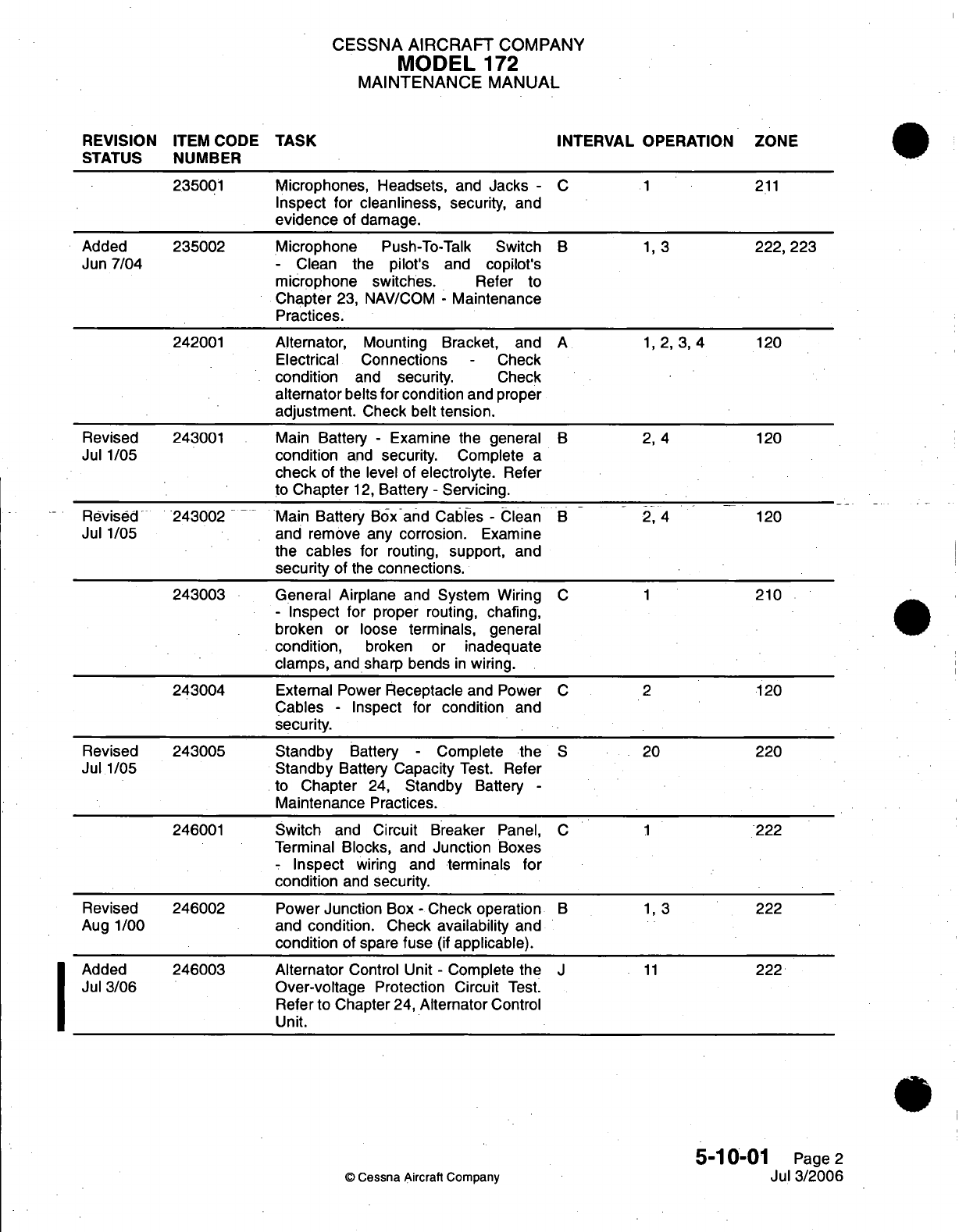
CESSNA
AIRCRAFT
COMPANY
MODEL
172
MAINTENANCE
MANUAL
REVISION
ITEM CODE
TASK
INTERVAL
OPERATION
ZONE
STATUS
NUMBER
235001
Microphones, Headsets,
and
Jacks
-
C
1
211
Inspect
for
cleanliness,
security,
and
evidence
of
damage.
Added
235002
Microphone
Push-To-Talk
Switch
B 1,
3
222,
223
Jun
7/04
-
Clean
the
pilot's
and
copilot's
microphone switches.
Refer to
Chapter
23,
NAV/COM
-
Maintenance
Practices.
242001
Alternator,
Mounting Bracket,
and
A
1, 2, 3,
4
120
Electrical Connections
-
Check
condition
and
security.
Check
alternator
belts
for
condition
and
proper
adjustment.
Check
belt
tension.
Revised
243001 Main
Battery
-
Examine
the
general
B
2, 4
120
Jul
1/05
condition
and
security.
Complete
a
check
of
the
level
of
electrolyte.
Refer
to
Chapter
12,
Battery
-
Servicing.
Revised
243002
.-
Main
Battery
Box
and
Cables
-
Clean
B
2, 4
120
Jul
1/05
and
remove
any
corrosion.
Examine
the
cables
for routing,
support,
and
security
of
the
connections.
243003 General
Airplane
and
System
Wiring
C 1
210
-
Inspect
for
proper
routing,
chafing,
broken
or
loose
terminals,
general
condition,
broken or
inadequate
clamps,
and
sharp
bends
in
wiring.
243004
External Power
Receptacle
and
Power
C 2
120
Cables
-
Inspect
for
condition
and
security.
Revised
243005 Standby
Battery
-
Complete
the
S
20
220
Jul
1/05
Standby
Battery
Capacity
Test.
Refer
to
Chapter
24,
Standby
Battery
-
Maintenance
Practices.
246001
Switch
and
Circuit
Breaker
Panel,
C 1
222
Terminal
Blocks,
and
Junction
Boxes
-
Inspect
wiring
and
terminals
for
condition
and
security.
Revised
246002
Power
Junction
Box
-
Check
operation
B 1, 3
222
Aug
1/00
and
condition.
Check
availability
and
condition
of
spare
fuse
(if
applicable).
Added
246003 Alternator
Control Unit
-
Complete
the
J
11
222
Jul
3/06
Over-voltage
Protection Circuit
Test.
Refer
to Chapter
24,
Alternator
Control
Unit.
5-10-01
Page
2
©
Cessna Aircraft
Company
Jul
3/2006

CESSNA
AIRCRAFT
COMPANY
MODEL
172
MAINTENANCE
MANUAL
REVISION
ITEM
CODE
TASK
INTERVAL
OPERATION
ZONE
STATUS
NUMBER
Revised
246101
Essential
and
Crossfeed
Bus
Diodes
-
S
20 224
Jul
1/05
Complete
a
check for
proper
operation.
Complete
the
Essential
and
Crossfeed
Bus Diode
Inspection.
Refer
to
Chapter
24,
Essential
and Crossfeed
Bus
Diodes
-
Maintenance
Practices.
Revised
251001
Seats
-
Examine
the
seats
to
make
B
1,3
211
Jul
3/06 sure
they
are
serviceable
and installed
correctly.
Make sure
the
seat
stops
and
adjustment
mechanism
operate
correctly. Examine
the
seat
recline
control
and
attaching
hardware
to
make
sure
the hardware and
lock
are
not
damaged
and
are
correctly
installed.
Lubricate
the
threads
of
the
Seat
Crank Handle Assembly
with
MIL-PRF-81322
general
purpose
grease.
251002
Seat
Tracks
and
Stops
-
Inspect
seat
B
2,
4
230
tracks
for
condition
and
security
of
installation.
Check seat
track
stops
for
damage
and
correct
location.
Inspect
seat
rails
for cracks.
251101
Restraint
System, front
and
rear
- B 1, 3
211
Check
belts
for
thinning,
fraying,
cutting,
broken
stitches,
or
ultra-violet
deterioration.
Check
system hardware
for
security
of
installation.
Revised
251102
AMSAFE
Aviation
Inflatable
Restraint
S
20
211
Jul
1/05
(AAIR)
-
Examine
the
restraint
for
dirt,
frayed
edges,
unserviceable
stitching,
loose
connections,
and
other
wear.
252201
Upholstery, Headliner,
Trim,
and
D
5 211
Carpeting
-
Check
condition
and
security.
Revised
256001
Emergency
Locator Transmitter
- B 1,
3
310
Jan
2/06 Inspect for
security
of
attachment
and
check
operation
by
verifying transmitter
output. Check
cumulative
time
and
useful
life
of batteries
in
accordance
with
14
CFR
Part
91.207.
262001
Portable Hand
Fire
Extinguisher
-B 1,
3
230
Inspect
for
proper
operating
pressure,
condition,
security
of
installation,
and
servicing
date.
Added
262002 Cockpit
Mounted
Halon
Type
Fire
P
17
211
May
3/99
Extinguisher
-
Weigh bottle.
Bottle
must
be
reserviced
by
qualified
individual
if
more
than
2
ounces
is
lost.
5-10-01
Page
3
©
Cessna
Aircraft
Company
Jul
3/2006
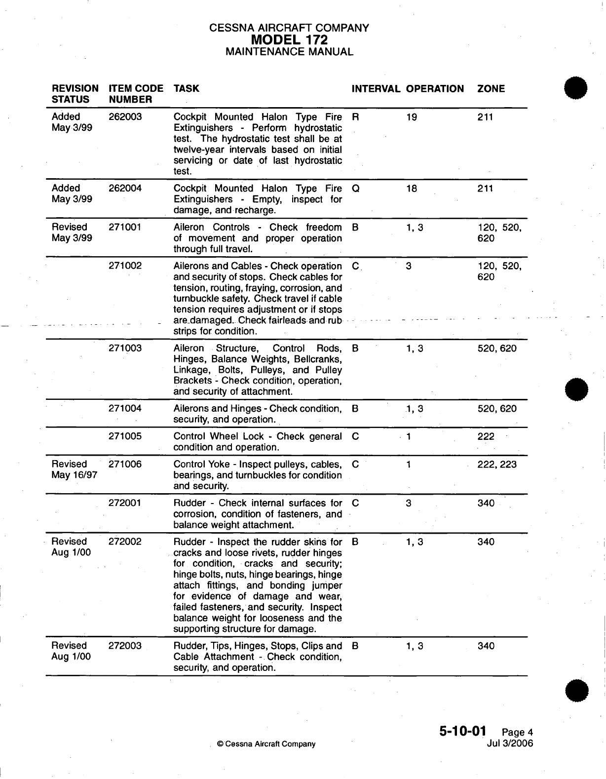
CESSNA AIRCRAFT
COMPANY
MODEL
172
MAINTENANCE
MANUAL
REVISION
ITEM
CODE TASK
INTERVAL
OPERATION ZONE
STATUS
NUMBER
Added
262003
Cockpit
Mounted Halon
Type
Fire
R
19
211
May
3/99
Extinguishers
-
Perform
hydrostatic
test.
The
hydrostatic
test shall
be at
twelve-year
intervals
based
on
initial
servicing
or
date
of
last
hydrostatic
test.
Added
262004
Cockpit
Mounted Halon
Type
Fire Q
18
211
May
3/99 Extinguishers
-
Empty,
inspect
for
damage,
and
recharge.
Revised
271001
Aileron
Controls
-
Check
freedom
B 1, 3
120,
520,
May
3/99
of
movement
and
proper
operation
620
through
full
travel.
271002 Ailerons and
Cables
-
Check
operation
C
3 120,
520,
and
security
of
stops.
Check
cables
for
620
tension,
routing,
fraying,
corrosion,
and
turnbuckle
safety.
Check travel
if
cable
tension
requires
adjustment
or
if
stops
are
damaged.
Check
fairleads
and
rub
strips
for
condition.
271003
Aileron
Structure,
Control
Rods,
B 1, 3
520,
620
Hinges,
Balance Weights, Bellcranks,
Linkage,
Bolts,
Pulleys,
and Pulley
Brackets
-
Check
condition,
operation,
and
security
of
attachment.
271004
Ailerons
and
Hinges
-
Check
condition,
B 1, 3
520,
620
security,
and
operation.
271005
Control
Wheel Lock
-
Check general
C
1
222
condition
and
operation.
Revised
271006
Control
Yoke
-
Inspect pulleys,
cables,
C 1
222,
223
May
16/97
bearings,
and
turnbuckles
for
condition
and
security.
272001
Rudder
-
Check internal surfaces
for
C
3
340
corrosion,
condition
of
fasteners,
and
balance
weight attachment.
Revised 272002
Rudder
-
Inspect
the
rudder
skins
for
B 1,
3
340
Aug
1/00
cracks and
loose rivets, rudder hinges
for
condition, cracks
and
security;
hinge
bolts,
nuts, hinge
bearings,
hinge
attach
fittings,
and
bonding jumper
for
evidence
of damage and
wear,
failed
fasteners,
and security.
Inspect
balance
weight
for
looseness
and the
supporting structure
for damage.
Revised
272003
Rudder,
Tips,
Hinges,
Stops, Clips and
B 1, 3
340
Aug
1/00
Cable
Attachment
-
Check
condition,
security,
and
operation.
5-10-01
Page
4
©
Cessna
Aircraft
Company
Jul
3/2006
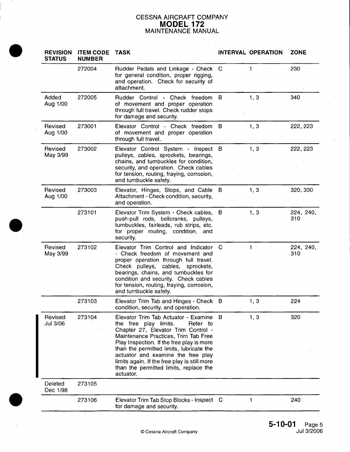
CESSNA
AIRCRAFT
COMPANY
MODEL
172
MAINTENANCE
MANUAL
REVISION
ITEM
CODE
TASK
INTERVAL OPERATION ZONE
STATUS
NUMBER
272004
Rudder
Pedals
and
Linkage
-
Check
C 1
230
for
general
condition, proper
rigging,
and
operation.
Check for
security
of
attachment.
Added
272005 Rudder
Control
-
Check
freedom
B 1,
3
340
Aug
1/00
of
movement
and
proper
operation
through
full
travel.
Check
rudder
stops
for
damage
and
security.
Revised
273001
Elevator
Control
-
Check
freedom
B 1,
3
222,
223
Aug
1/00
of
movement
and
proper operation
through
full
travel.
Revised
273002
Elevator
Control
System
-
Inspect
B 1, 3
222,223
May 3/99
pulleys,
cables, sprockets, bearings,
chains,
and
turnbuckles
for
condition,
security,
and
operation.
Check
cables
for
tension,
routing,
fraying, corrosion,
and
turnbuckle
safety.
Revised
273003
Elevator,
Hinges,
Stops,
and
Cable
B 1, 3
320,
330
Aug
1/00
Attachment
-
Check
condition,
security,
and operation.
273101
Elevator
Trim
System
-
Check
cables,
B 1, 3
224, 240,
push-pull
rods,
bellcranks,
pulleys,
310
turnbuckles,
fairleads,
rub
strips,
etc.
for
proper
routing,
condition,
and
security.
Revised
273102
Elevator
Trim
Control
and
Indicator
C 1
224,
240,
May
3/99
-
Check
freedom
of
movement
and
310
proper
operation
through
full
travel.
Check
pulleys,
cables,
sprockets,
bearings, chains,
and
turnbuckles
for
condition
and
security.
Check
cables
for
tension,
routing,
fraying, corrosion,
and
turnbuckle
safety.
273103
Elevator
Trim
Tab
and
Hinges
-
Check
B 1, 3
224
condition,
security,
and
operation.
Revised
273104
Elevator
Trim
Tab
Actuator
-
Examine
B 1, 3
320
Jul
3/06
the
free
play
limits.
Refer
to
Chapter
27,
Elevator
Trim
Control
-
Maintenance
Practices,
Trim
Tab Free
Play
Inspection.
If
the
free
play
is
more
than
the
permitted
limits,
lubricate
the
actuator
and examine
the
free play
limits
again.
If
the
free
play
is
still
more
than
the permitted limits,
replace
the
actuator.
Deleted
273105
Dec
1/98
273106
Elevator
Trim
Tab
Stop
Blocks
-
Inspect
C 1
240
for
damage
and
security.
5-10-01
Page
5
©
Cessna
Aircraft
Company
Jul
3/2006
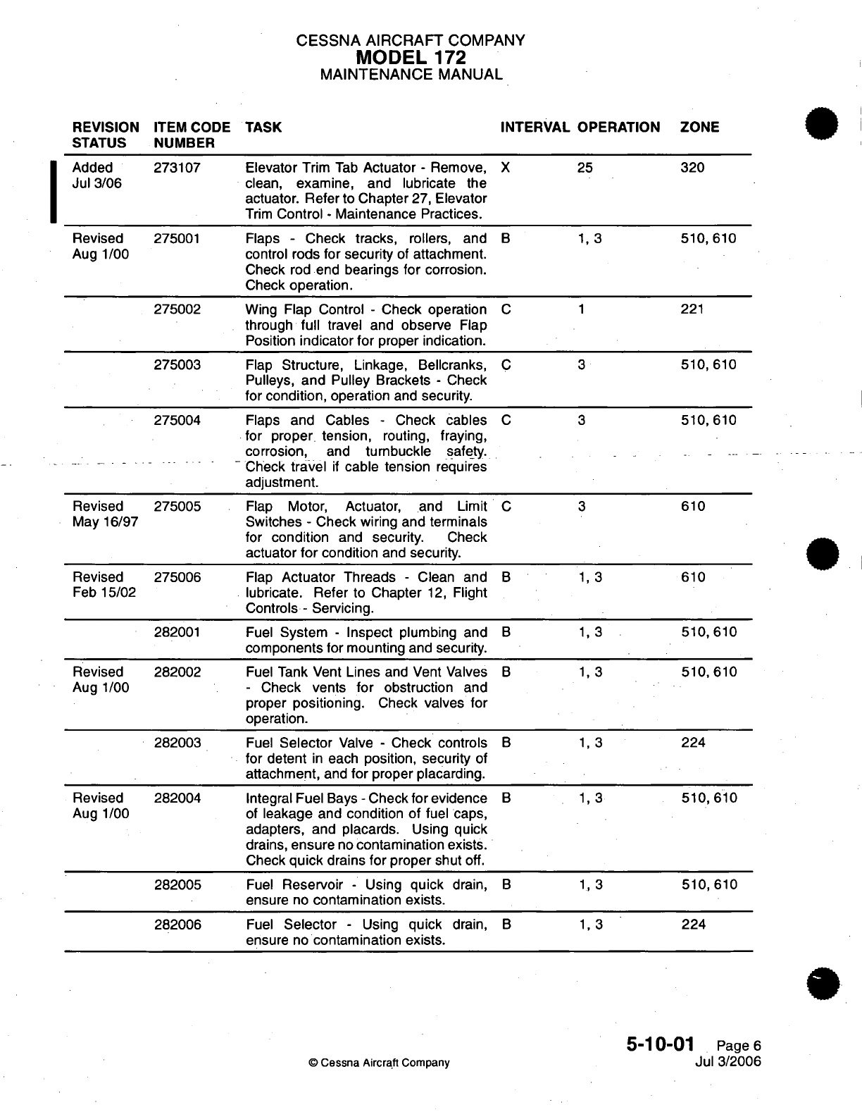
CESSNA
AIRCRAFT
COMPANY
MODEL
172
MAINTENANCE
MANUAL
REVISION
ITEM
CODE
TASK
INTERVAL OPERATION ZONE
STATUS
NUMBER
Added
273107 Elevator
Trim
Tab
Actuator
-
Remove,
X
25
320
Jul 3/06
clean,
examine, and lubricate
the
actuator.
Refer to Chapter
27,
Elevator
Trim
Control
-
Maintenance
Practices.
Revised
275001
Flaps
-
Check
tracks,
rollers,
and
B 1,
3
510,610
Aug
1/00
control
rods
for security
of
attachment.
Check
rod
end
bearings
for
corrosion.
Check
operation.
275002
Wing Flap Control
-
Check operation
C 1
221
through
full
travel and
observe
Flap
Position
indicator
for
proper
indication.
275003
Flap
Structure, Linkage,
Bellcranks,
C 3
510,
610
Pulleys,
and Pulley
Brackets
-
Check
for
condition,
operation
and
security.
275004
Flaps
and
Cables
-
Check
cables
C 3
510,
610
for
proper
tension,
routing,
fraying,
corrosion,
and
tumbuckle
safety.
- - - ---
Check
travel
if
cable
tension
requires
adjustment.
Revised
275005
Flap
Motor,
Actuator, and
Limit
C 3
610
May
16/97
Switches
-
Check
wiring and
terminals
for
condition
and
security.
Check
actuator
for
condition
and security.
Revised
275006
Flap
Actuator
Threads
-
Clean
and
B 1, 3
610
Feb
15/02
lubricate. Refer
to Chapter
12,
Flight
Controls
-
Servicing.
282001 Fuel
System
-
Inspect
plumbing
and
B 1, 3
510,
610
components
for mounting
and
security.
Revised
282002
Fuel
Tank Vent
Lines
and
Vent
Valves
B 1,
3
510,
610
Aug 1/00
-
Check
vents
for
obstruction
and
proper
positioning.
Check
valves
for
operation.
282003
Fuel
Selector
Valve
-
Check
controls
B 1, 3
224
for
detent
in
each
position,
security
of
attachment,
and
for
proper
placarding.
Revised
282004
Integral
Fuel
Bays
-
Check
for
evidence
B 1, 3
510,
610
Aug 1/00
of
leakage
and
condition
of
fuel
caps,
adapters,
and placards. Using quick
drains,
ensure
no
contamination
exists.
Check
quick
drains
for
proper
shut
off.
282005
Fuel
Reservoir
-
Using
quick
drain,
B 1, 3
510,
610
ensure
no
contamination
exists.
282006
Fuel
Selector -
Using
quick
drain,
B 1, 3
224
ensure
no
contamination
exists.
5-10-01
Page
6
©
Cessna
Aircraft
Company
Jul
3/2006
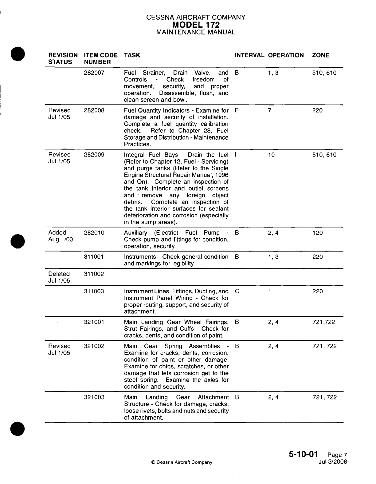
CESSNA AIRCRAFT
COMPANY
MODEL
172
MAINTENANCE
MANUAL
REVISION
ITEM
CODE
TASK INTERVAL OPERATION
ZONE
STATUS NUMBER
282007
Fuel
Strainer,
Drain Valve, and
B
1,3
510,
610
Controls
-
Check
freedom
of
movement,
security,
and
proper
operation.
Disassemble,
flush,
and
clean
screen and
bowl.
Revised 282008
Fuel
Quantity
Indicators
-
Examine
for
F
7
220
Jul
1/05
damage
and
security
of
installation.
Complete
a
fuel quantity
calibration
check.
Refer
to
Chapter
28,
Fuel
Storage
and
Distribution
-
Maintenance
Practices.
Revised 282009
Integral
Fuel
Bays
-
Drain
the
fuel
I
10
510,
610
Jul
1/05
(Refer to
Chapter
12,
Fuel
-
Servicing)
and
purge
tanks
(Refer
to
the Single
Engine
Structural
Repair
Manual,
1996
and
On).
Complete
an
inspection
of
the
tank interior
and
outlet
screens
and
remove
any
foreign object
debris. Complete
an
inspection
of
the
tank
interior surfaces
for
sealant
deterioration
and corrosion
(especially
in
the
sump areas).
Added
282010 Auxiliary
(Electric)
Fuel
Pump
- B
2,
4
120
Aug
1/00
Check
pump
and
fittings
for
condition,
operation,
security.
311001
Instruments
-
Check
general
condition
B 1,
3
220
and
markings
for
legibility.
Deleted
311002
Jul
1/05
311003
Instrument Lines,
Fittings, Ducting, and
C
1
220
Instrument
Panel Wiring
-
Check
for
proper routing, support,
and
security
of
attachment.
321001
Main
Landing
Gear
Wheel
Fairings,
B
2, 4
721,722
Strut Fairings,
and Cuffs
-
Check
for
cracks,
dents, and
condition
of
paint.
Revised
321002
Main
Gear
Spring
Assemblies
- B
2, 4
721,
722
Jul
1/05
Examine for
cracks,
dents,
corrosion,
condition
of
paint
or
other
damage.
Examine
for
chips,
scratches,
or
other
damage that
lets corrosion
get
to
the
steel spring.
Examine
the
axles
for
condition
and
security.
321003
Main
Landing
Gear Attachment
B
2, 4
721,722
Structure
-
Check
for
damage,
cracks,
loose
rivets,
bolts
and
nuts and
security
of
attachment.
5-10-01
Page
7
©
Cessna
Aircraft
Company
Jul 3/2006
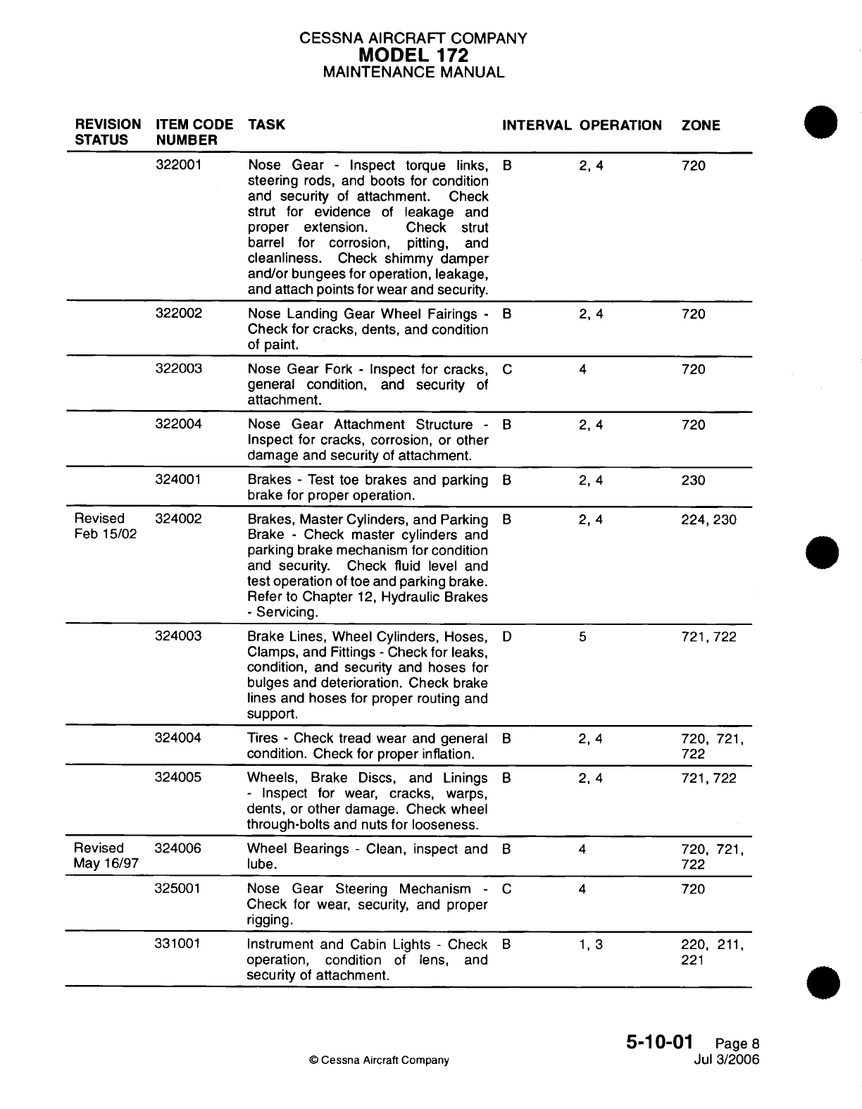
CESSNA AIRCRAFT
COMPANY
MODEL
172
MAINTENANCE
MANUAL
REVISION
ITEM
CODE
TASK
INTERVAL
OPERATION ZONE
STATUS
NUMBER
322001
Nose
Gear
-
Inspect torque
links,
B
2, 4
720
steering
rods, and
boots for
condition
and
security
of
attachment.
Check
strut
for
evidence
of
leakage
and
proper extension.
Check
strut
barrel
for
corrosion, pitting,
and
cleanliness.
Check
shimmy
damper
and/or
bungees
for
operation,
leakage,
and attach
points for
wear
and
security.
322002
Nose
Landing Gear Wheel
Fairings
-
B 2,
4
720
Check
for
cracks,
dents,
and
condition
of paint.
322003 Nose
Gear
Fork
-
Inspect for
cracks,
C 4
720
general
condition,
and
security
of
attachment.
322004
Nose
Gear
Attachment
Structure
-
B 2, 4
720
Inspect
for
cracks,
corrosion,
or
other
damage
and
security
of
attachment.
324001
Brakes
-
Test toe
brakes
and
parking
B 2,
4
230
brake
for proper operation.
Revised 324002
Brakes,
Master Cylinders,
and Parking
B 2, 4
224,
230
Feb
15/02
Brake
-
Check
master
cylinders
and
parking
brake
mechanism
for
condition
and
security.
Check
fluid
level
and
test operation
of
toe and
parking
brake.
Refer
to
Chapter
12,
Hydraulic
Brakes
-
Servicing.
324003
Brake Lines,
Wheel
Cylinders,
Hoses,
D 5
721,722
Clamps,
and
Fittings
-
Check
for
leaks,
condition,
and
security
and
hoses
for
bulges
and
deterioration.
Check
brake
lines and
hoses for
proper
routing
and
support.
324004 Tires
-
Check tread
wear
and
general
B 2, 4
720,
721,
condition.
Check
for proper inflation.
722
324005
Wheels,
Brake Discs,
and
Linings
B
2,
4
721,722
-
Inspect for
wear,
cracks,
warps,
dents,
or
other
damage.
Check
wheel
through-bolts
and
nuts
for
looseness.
Revised 324006 Wheel
Bearings
-
Clean,
inspect
and
B 4
720,
721,
May
16/97
lube. 722
325001
Nose
Gear
Steering Mechanism
-
C 4
720
Check
for
wear,
security,
and
proper
rigging.
331001
Instrument
and
Cabin
Lights
-
Check
B 1, 3
220,
211,
operation,
condition
of
lens,
and
221
security
of
attachment.
5-10-01
Page
8
©
Cessna
Aircraft
Company
Jul
3/2006
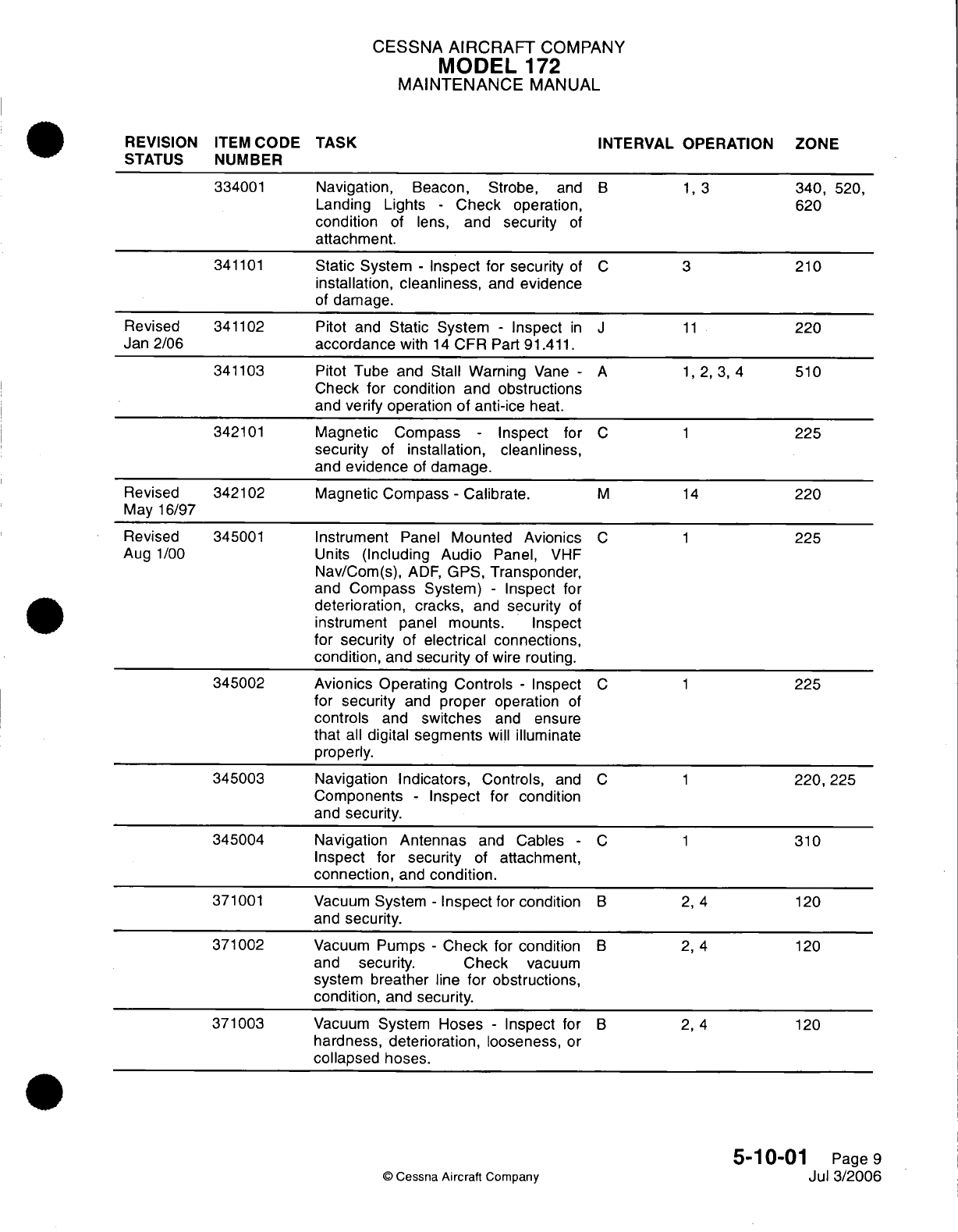
CESSNA
AIRCRAFT
COMPANY
MODEL
172
MAINTENANCE
MANUAL
REVISION
ITEM
CODE
TASK INTERVAL OPERATION
ZONE
STATUS
NUMBER
334001
Navigation,
Beacon, Strobe,
and
B 1,
3
340,
520,
Landing Lights
-
Check
operation,
620
condition
of
lens,
and
security
of
attachment.
341101
Static
System
-
Inspect for
security
of
C
3
210
installation,
cleanliness,
and
evidence
of
damage.
Revised
341102
Pitot and
Static
System
-
Inspect
in
J
11
220
Jan
2/06
accordance
with
14
CFR Part
91.411.
341103
Pitot Tube
and
Stall
Warning
Vane
-
A
1,
2,
3,
4
510
Check
for
condition
and
obstructions
and
verify
operation
of
anti-ice
heat.
342101
Magnetic Compass
-
Inspect
for
C
1
225
security
of
installation,
cleanliness,
and
evidence
of
damage.
Revised
342102
Magnetic Compass
-
Calibrate.
M
14
220
May
16/97
Revised
345001
Instrument
Panel
Mounted
Avionics
C
1
225
Aug
1/00
Units
(Including
Audio
Panel,
VHF
Nav/Com(s),
ADF,
GPS,
Transponder,
and
Compass
System)
-
Inspect
for
deterioration,
cracks,
and
security
of
instrument
panel
mounts.
Inspect
for
security
of
electrical connections,
condition,
and
security
of
wire
routing.
345002
Avionics
Operating
Controls
-
Inspect
C
1
225
for
security
and
proper
operation
of
controls
and
switches
and
ensure
that
all
digital segments
will
illuminate
properly.
345003
Navigation Indicators,
Controls,
and
C
1
220,
225
Components
-
Inspect
for
condition
and
security.
345004
Navigation
Antennas
and
Cables
-
C
1
310
Inspect
for
security
of
attachment,
connection,
and
condition.
371001 Vacuum
System
-
Inspect
for
condition
B
2, 4
120
and
security.
371002
Vacuum
Pumps
-
Check
for
condition
B
2, 4
120
and
security.
Check
vacuum
system
breather
line
for
obstructions,
condition,
and
security.
371003
Vacuum
System
Hoses
-
Inspect
for
B
2,
4
120
hardness,
deterioration, looseness,
or
collapsed hoses.
5-10-01
Page
9
©
Cessna
Aircraft Company
Jul 3/2006
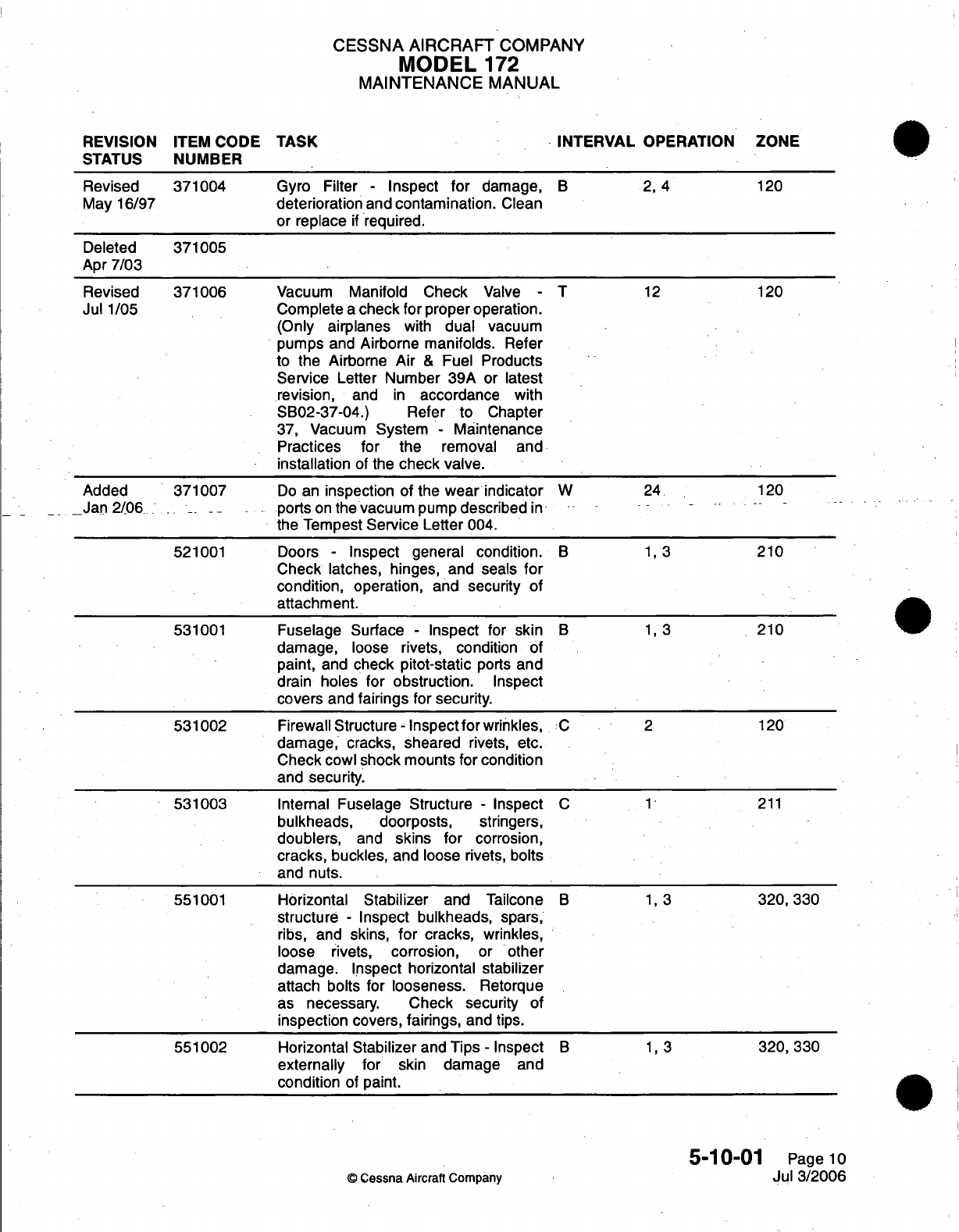
CESSNA
AIRCRAFT
COMPANY
MODEL
172
MAINTENANCE
MANUAL
REVISION
ITEM
CODE
TASK
INTERVAL
OPERATION
ZONE
STATUS
NUMBER
Revised 371004
Gyro Filter
-
Inspect
for
damage,
B 2,
4
120
May
16/97
deterioration
and
contamination.
Clean
or
replace
if
required.
Deleted
371005
Apr
7/03
Revised
371006
Vacuum
Manifold
Check
Valve
-
T
12
120
Jul
1/05
Complete
a
check
for
proper operation.
(Only
airplanes
with
dual
vacuum
pumps
and
Airborne
manifolds.
Refer
to
the
Airborne
Air
&
Fuel
Products
Service
Letter Number 39A
or
latest
revision,
and
in
accordance
with
SB02-37-04.) Refer
to
Chapter
37,
Vacuum
System
-
Maintenance
Practices
for
the
removal
and
installation
of
the
check
valve.
Added
371007
Do
an
inspection
of
the
wear
indicator
W
24
120
Jan
2/06
. -- --
ports
on
the
vacuum
pump
described
in
-
the
Tempest
Service
Letter
004.
521001
Doors
-
Inspect general condition.
B 1, 3
210
Check
latches, hinges, and
seals
for
condition, operation,
and
security
of
attachment.
531001
Fuselage Surface
-
Inspect
for
skin
B 1,
3
210
damage,
loose rivets,
condition
of
paint,
and
check
pitot-static
ports
and
drain
holes
for
obstruction.
Inspect
covers
and
fairings
for
security.
531002
Firewall
Structure-
Inspect
for
wrinkles,
C 2
120
damage, cracks, sheared
rivets,
etc.
Check cowl shock
mounts
for condition
and
security.
531003
Internal
Fuselage
Structure
-
Inspect
C 1
211
bulkheads,
doorposts,
stringers,
doublers,
and
skins
for
corrosion,
cracks,
buckles,
and
loose rivets,
bolts
and nuts.
551001
Horizontal
Stabilizer
and
Tailcone
B 1, 3
320,
330
structure
-
Inspect
bulkheads,
spars,
ribs, and
skins,
for
cracks,
wrinkles,
loose
rivets,
corrosion,
or
other
damage. Inspect horizontal
stabilizer
attach
bolts
for
looseness.
Retorque
as necessary.
Check security
of
inspection
covers,
fairings,
and tips.
551002
Horizontal
Stabilizer
and
Tips
-
Inspect
B 1,
3
320, 330
externally
for skin
damage
and
condition
of
paint.
5-10-01
Page
10
©
Cessna
Aircraft
Company
Jul
3/2006
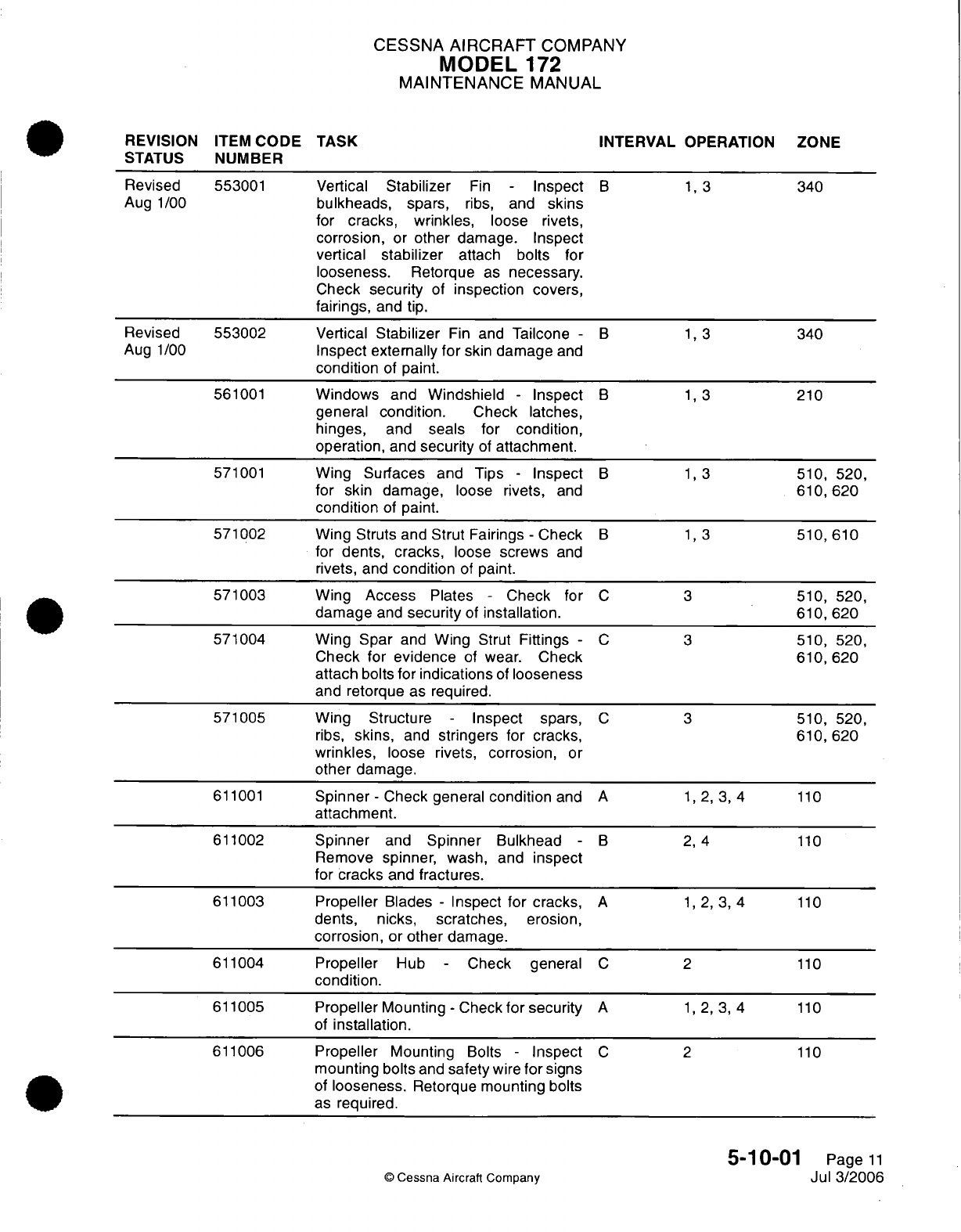
CESSNA
AIRCRAFT
COMPANY
MODEL
172
MAINTENANCE
MANUAL
REVISION
ITEM
CODE
TASK
INTERVAL
OPERATION
ZONE
STATUS
NUMBER
Revised
553001
Vertical
Stabilizer
Fin
-
Inspect
B 1,
3
340
Aug
1/00
bulkheads,
spars,
ribs,
and
skins
for
cracks,
wrinkles,
loose rivets,
corrosion,
or
other
damage.
Inspect
vertical
stabilizer
attach
bolts
for
looseness.
Retorque
as
necessary.
Check
security
of
inspection covers,
fairings,
and
tip.
Revised
553002
Vertical
Stabilizer
Fin
and
Tailcone
- B 1,
3
340
Aug
1/00
Inspect externally
for
skin
damage
and
condition
of
paint.
561001
Windows
and
Windshield
-
Inspect
B 1,
3
210
general
condition.
Check latches,
hinges,
and
seals
for
condition,
operation,
and
security
of
attachment.
571001
Wing
Surfaces and
Tips
-
Inspect
B
1,3
510,
520,
for
skin damage,
loose
rivets,
and
610,620
condition
of
paint.
571002
Wing Struts
and
Strut
Fairings
-
Check
B
1,3
510,610
for
dents,
cracks,
loose
screws
and
rivets,
and
condition
of
paint.
571003
Wing
Access
Plates
-
Check
for
C
3
510,
520,
damage
and
security
of
installation.
610,
620
571004
Wing
Spar
and
Wing
Strut
Fittings
-
C
3
510,
520,
Check
for
evidence
of
wear.
Check
610,620
attach
bolts
for
indications
of
looseness
and
retorque
as
required.
571005
Wing Structure
-
Inspect
spars,
C
3
510,
520,
ribs,
skins,
and
stringers for
cracks,
610,620
wrinkles,
loose
rivets,
corrosion,
or
other
damage.
611001
Spinner
-
Check general
condition
and
A
1,2,
3, 4
110
attachment.
611002
Spinner
and
Spinner
Bulkhead
- B
2, 4
110
Remove
spinner,
wash, and
inspect
for
cracks
and
fractures.
611003
Propeller
Blades
-
Inspect for cracks,
A
1,
2, 3, 4
110
dents,
nicks,
scratches,
erosion,
corrosion,
or
other
damage.
611004
Propeller
Hub
-
Check general
C
2
110
condition.
611005
Propeller
Mounting
-
Check
for
security
A
1,
2, 3,
4
110
of
installation.
611006
Propeller
Mounting
Bolts
-
Inspect
C
2
110
mounting
bolts
and
safety
wire
for
signs
of
looseness.
Retorque mounting
bolts
as
required.
5-10-01
Page
11
©
Cessna Aircraft
Company
Jul
3/2006
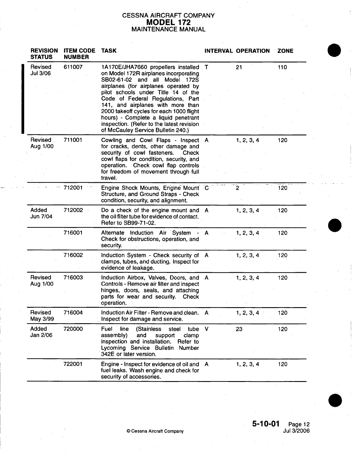
CESSNA AIRCRAFT
COMPANY
MODEL
172
MAINTENANCE
MANUAL
REVISION
ITEM
CODE
TASK INTERVAL OPERATION
ZONE
STATUS
NUMBER
Revised
611007
1A170E/JHA7660
propellers installed
T
21
110
Jul
3/06
on
Model
172R
airplanes
incorporating
SB02-61-02
and
all
Model
172S
airplanes (for
airplanes
operated
by
pilot
schools
under Title
14
of
the
Code
of
Federal Regulations,
Part
141,
and
airplanes
with
more
than
2000
takeoff
cycles
for
each
1000
flight
hours)
-
Complete
a
liquid
penetrant
inspection.
(Refer to
the
latest revision
of McCauley
Service
Bulletin
240.)
Revised
711001
Cowling
and Cowl
Flaps
-
Inspect
A
1, 2,
3,
4
120
Aug 1/00
for
cracks,
dents,
other
damage
and
security
of
cowl fasteners.
Check
cowl
flaps
for
condition,
security,
and
operation. Check
cowl flap
controls
for
freedom
of
movement
through
full
travel.
-
-712001
-
-
Engine Shock
Mounts,
Engine
Mount
C 2
120
Structure,
and
Ground Straps
-
Check
condition,
security,
and
alignment.
Added
712002
Do
a
check
of
the
engine
mount
and
A 1, 2, 3,
4
120
Jun
7/04
the
oil
filter
tube
for
evidence
of
contact.
Refer to
SB99-71-02.
716001
Alternate Induction Air
System
-
A 1, 2, 3,
4
120
Check
for
obstructions,
operation,
and
security.
716002
Induction
System
-
Check security
of
A 1, 2, 3,
4
120
clamps,
tubes,
and
ducting.
Inspect for
evidence
of
leakage.
Revised
716003 Induction
Airbox,
Valves, Doors,
and
A 1, 2, 3,
4
120
Aug 1/00
Controls
-
Remove
air
filter
and
inspect
hinges,
doors,
seals, and attaching
parts
for
wear
and
security.
Check
operation.
Revised 716004
Induction
Air
Filter-Remove
and clean.
A
1,2,3,4
120
May
3/99
Inspect for damage
and
service.
Added
720000
Fuel
line
(Stainless
steel
tube
V
23
120
Jan
2/06
assembly)
and
support
clamp
inspection
and
installation.
Refer
to
Lycoming
Service
Bulletin
Number
342E
or
later
version.
722001
Engine
-
Inspect
for evidence
of
oil
and
A 1, 2, 3,
4
120
fuel
leaks.
Wash
engine
and
check
for
security
of
accessories.
5-10-01
Page
12
©
Cessna
Aircraft Company
Jul
3/2006
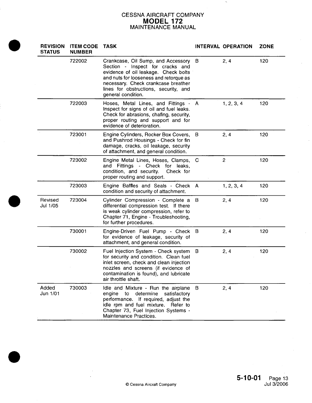
CESSNA
AIRCRAFT
COMPANY
MODEL
172
MAINTENANCE
MANUAL
REVISION
ITEM
CODE
TASK
INTERVAL OPERATION
ZONE
STATUS
NUMBER
722002 Crankcase,
Oil
Sump,
and
Accessory
B
2, 4
120
Section
-
Inspect for
cracks
and
evidence
of
oil
leakage.
Check
bolts
and
nuts
for
looseness
and
retorque
as
necessary.
Check
crankcase
breather
lines
for
obstructions,
security,
and
general
condition.
722003
Hoses,
Metal
Lines,
and
Fittings
-
A
1,
2,
3, 4 120
Inspect
for
signs
of
oil
and
fuel
leaks.
Check
for
abrasions,
chafing,
security,
proper routing
and
support
and
for
evidence
of
deterioration.
723001
Engine
Cylinders,
Rocker
Box
Covers,
B
2, 4
120
and Pushrod
Housings
-
Check
for
fin
damage, cracks,
oil
leakage, security
of
attachment,
and
general
condition.
723002
Engine
Metal
Lines,
Hoses, Clamps,
C
2
120
and Fittings
-
Check
for
leaks,
condition,
and
security.
Check
for
proper routing
and
support.
723003
Engine Baffles
and
Seals
-
Check
A
1,
2,
3,
4
120
condition
and
security
of
attachment.
Revised
723004
Cylinder Compression
-
Complete
a
B
2, 4
120
Jul
1/05
differential compression
test.
If
there
is
weak
cylinder
compression,
refer
to
Chapter
71,
Engine
-
Troubleshooting,
for
further procedures.
730001
Engine-Driven
Fuel
Pump
-
Check
B
2,
4
120
for
evidence
of
leakage,
security
of
attachment,
and
general condition.
730002
Fuel
Injection
System
-
Check system
B
2, 4
120
for
security
and
condition.
Clean
fuel
inlet screen, check
and
clean
injection
nozzles
and screens
(if
evidence
of
contamination
is
found),
and
lubricate
air
throttle shaft.
Added
730003
Idle
and
Mixture
-
Run
the
airplane
B
2,
4
120
Jun
1/01
engine
to
determine
satisfactory
performance.
If
required,
adjust
the
idle
rpm
and
fuel
mixture. Refer
to
Chapter
73,
Fuel
Injection
Systems
-
Maintenance
Practices.
5-10-01
Page
13
©
Cessna
Aircraft
Company
Jul 3/2006
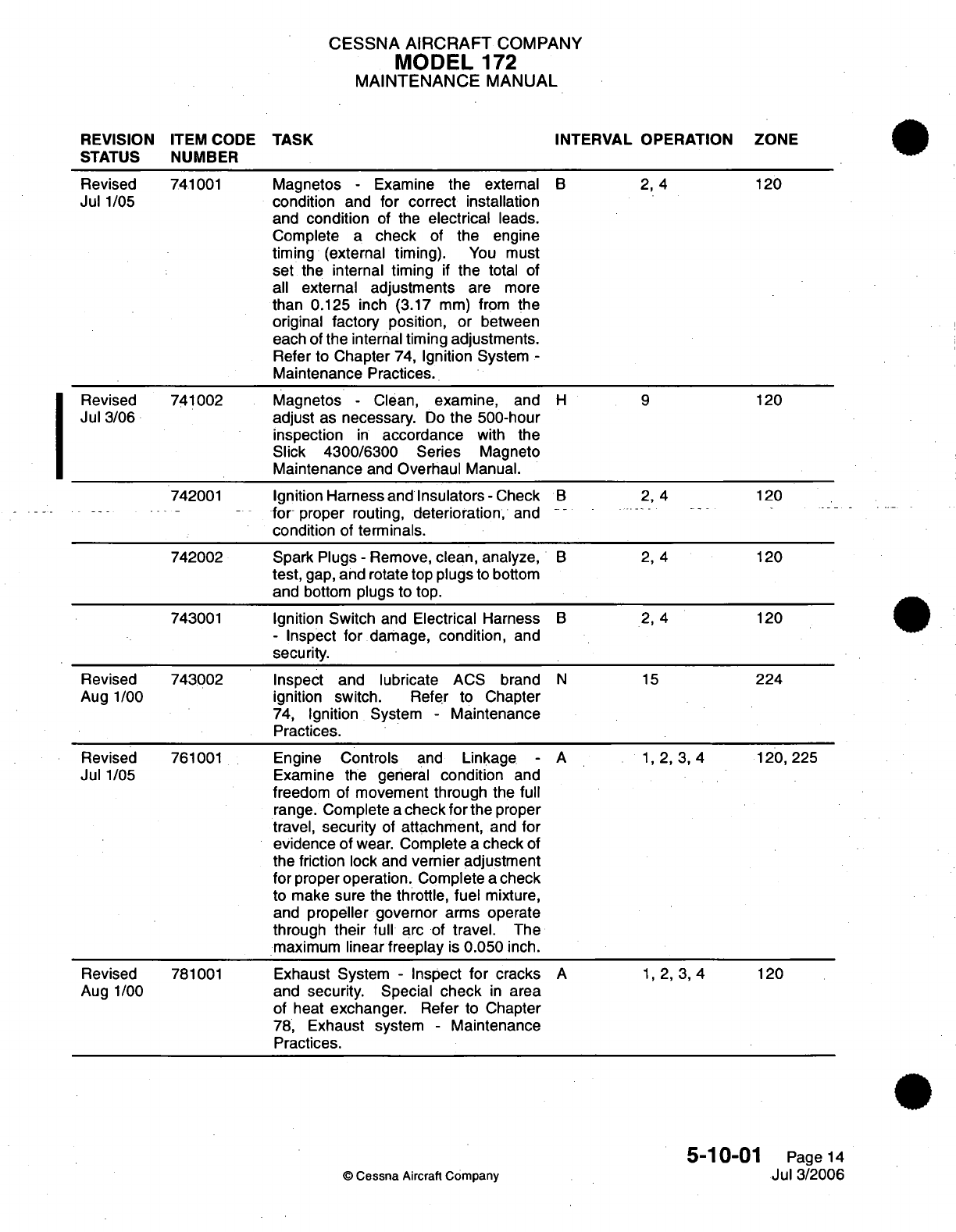
CESSNA AIRCRAFT
COMPANY
MODEL
172
MAINTENANCE
MANUAL
REVISION
ITEM
CODE
TASK
INTERVAL OPERATION ZONE
STATUS
NUMBER
Revised
741001
Magnetos
-
Examine
the
external
B 2,
4 120
Jul
1/05
condition
and
for
correct
installation
and
condition
of the
electrical
leads.
Complete
a
check
of
the
engine
timing (external timing).
You
must
set
the
internal
timing
if
the
total
of
all
external
adjustments
are
more
than 0.125
inch
(3.17
mm)
from
the
original
factory
position, or
between
each
of
the
internal
timing adjustments.
Refer
to
Chapter
74,
Ignition
System
-
Maintenance
Practices.
Revised
741002
Magnetos
-
Clean,
examine, and
H 9
120
Jul
3/06
adjust
as
necessary.
Do
the
500-hour
inspection
in
accordance
with
the
Slick
4300/6300
Series
Magneto
Maintenance
and
Overhaul
Manual.
742001
Ignition Harness
and
Insulators-Check
B
2, 4 120
for-
proper
routing,
deterioration,
and
condition
of
terminals.
742002
Spark
Plugs
-
Remove,
clean,
analyze,
B 2,
4 120
test,
gap,
and
rotate
top plugs
to
bottom
and
bottom
plugs
to
top.
743001
Ignition
Switch
and
Electrical
Harness
B
2, 4 120
-
Inspect
for
damage,
condition,
and
security.
Revised
743002 Inspect
and
lubricate
ACS
brand
N
15
224
Aug
1/00
ignition switch. Refer
to
Chapter
74,
Ignition
System
-
Maintenance
Practices.
Revised
761001
Engine
Controls
and
Linkage
-
A
1,
2,
3,
4 120, 225
Jul
1/05
Examine the general
condition
and
freedom
of
movement
through the
full
range.
Complete
a
check
for
the
proper
travel,
security
of
attachment,
and
for
evidence
of
wear.
Complete
a
check
of
the
friction
lock
and
vernier
adjustment
for proper operation.
Complete
a
check
to
make
sure
the
throttle,
fuel
mixture,
and
propeller
governor
arms
operate
through
their
full
arc of
travel.
The
maximum
linear
freeplay
is
0.050
inch.
Revised
781001
Exhaust
System
-
Inspect
for
cracks
A
1, 2,
3,
4
120
Aug
1/00
and
security.
Special
check
in
area
of
heat
exchanger.
Refer
to
Chapter
78,
Exhaust
system
-
Maintenance
Practices.
5-10-01
Page
14
©
Cessna
Aircraft
Company
Jul
3/2006
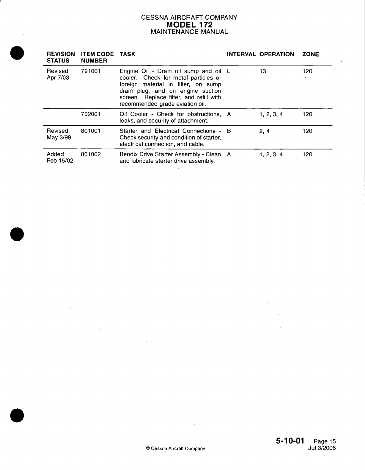
CESSNA AIRCRAFT
COMPANY
MODEL
172
MAINTENANCE
MANUAL
REVISION
ITEM
CODE
TASK
STATUS
NUMBER
Revised
Apr 7/03 791001
792001
Revised
May 3/99
Added
Feb 15/02
801001
801002
Engine
Oil
-
Drain
oil
sump
and
oil
L
cooler.
Check for
metal
particles
or
foreign material
in
filter,
on
sump
drain
plug,
and
on
engine suction
screen.
Replace filter,
and
refill
with
recommended
grade
aviation
oil.
Oil
Cooler
-
Check
for
obstructions,
A
leaks,
and
security
of
attachment.
Starter
and
Electrical Connections
-
Check
security
and
condition
of
starter,
electrical
connection,
and
cable.
B
Bendix
Drive
Starter Assembly
-
Clean
A
and
lubricate
starter
drive
assembly.
©
Cessna Aircraft
Company
INTERVAL
OPERATION
13
1,
2,3,
4
2,
4
1,2,3,4
ZONE
120
120
120
120
5-10-01
Page
15
Jul
3/2006
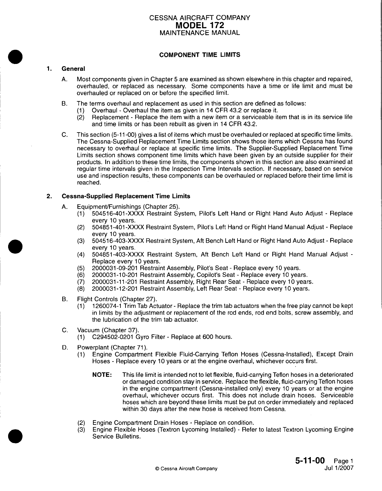
CESSNA
AIRCRAFT
COMPANY
MODEL
172
MAINTENANCE
MANUAL
COMPONENT
TIME
LIMITS
General
A.
Most components
given
in
Chapter
5
are
examined
as
shown
elsewhere
in
this
chapter
and
repaired,
overhauled,
or
replaced
as
necessary.
Some
components
have
a
time
or
life
limit
and
must
be
overhauled
or
replaced
on or
before
the
specified
limit.
B.
The
terms
overhaul
and
replacement
as
used
in
this section
are
defined
as
follows:
(1)
Overhaul
-
Overhaul
the
item
as
given
in
14
CFR
43.2
or
replace
it.
(2)
Replacement
-
Replace
the
item
with
a
new item
or
a
serviceable
item
that
is in
its
service
life
and
time
limits
or
has
been rebuilt
as
given
in
14
CER
43.2.
C.
This section
(5-11
-00)
gives
a
list
of
items
which must
be
overhauled
or
replaced
at
specific
time
limits.
The
Cessna-Supplied
Replacement
Time Limits
section
shows
those
items
which
Cessna
has
found
necessary
to
overhaul
or
replace
at
specific time
limits.
The
Supplier-Supplied Replacement
Time
Limits
section
shows
component
time
limits
which
have been
given
by
an
outside
supplier
for their
products.
In
addition
to
these
time
limits,
the
components
shown
in
this section
are
also
examined
at
regular
time intervals
given
in
the
Inspection Time
Intervals
section.
If
necessary,
based
on
service
use
and
inspection
results,
these components
can
be
overhauled
or
replaced
before
their
time
limit
is
reached.
2.
Cessna-Supplied
Replacement
Time
Limits
A.
Equipment/Furnishings
(Chapter
25).
(1)
504516-401
-XXXX
Restraint
System,
Pilot's
Left
Hand
or
Right
Hand
Auto
Adjust
-
Replace
every
10
years.
(2)
504851-401
-XXXX
Restraint
System, Pilot's Left
Hand
or
Right
Hand
Manual
Adjust
-
Replace
every
10
years.
(3)
50451
6-403-XXXX
Restraint
System,
Aft
Bench
Left
Hand
or
Right
Hand
Auto
Adjust
-
Replace
every
10
years.
(4)
504851
-403-XXXX
Restraint
System,
Aft
Bench
Left
Hand
or
Right
Hand
Manual
Adjust
-
Replace
every
10
years.
(5)
2000031
-09-201
Restraint
Assembly,
Pilot's
Seat
-
Replace every
10
years.
(6)
2000031-10-201 Restraint
Assembly,
Copilot's
Seat
-
Replace every
1 0
years.
(7)
2000031-11-201 Restraint Assembly,
Right
Rear
Seat
-
Replace
every
1 0
years.
(8)
2000031-12-201 Restraint
Assembly,
Left
Rear
Seat
-
Replace
every
10
years.
B.
Flight
Controls
(Chapter
27).
(1)
1260074-1
Trim
Tab
Actuator
-
Replace
the
trim
tab
actuators
when
the
free
play
cannot
be
kept
in
limits
by
the
adjustment
or
replacement
of
the
rod
ends,
rod
end
bolts,
screw
assembly,
and
the
lubrication
of
the
trim
tab
actuator.
C.
Vacuum
(Chapter
37).
(1)
0294502-0201
Gyro
Filter
-
Replace
at
600
hours.
D.
Powerplant
(Chapter
71).
(1)
Engine Compartment Flexible
Fluid-Carrying
Teflon
Hoses (Cessna-Installed), Except
Drain
Hoses
-
Replace
every
1 0
years
or
at
the
engine
overhaul,
whichever occurs first.
NOTE:
This
life
limit
is
intended
not
to
let
flexible, fluid-carrying
Teflon
hoses
in a
deteriorated
or
damaged condition
stay
in
service.
Replace
the
flexible,
fluid-carrying
Teflon
hoses
in
the
engine
compartment
(Cessna-installed
only)
every
1 0
years
or
at
the engine
overhaul,
whichever
occurs
first.
This
does
not
include
drain
hoses.
Serviceable
hoses which
are
beyond these limits
must
be
put
on
order
immediately
and
replaced
within
30
days
after
the
new
hose
is
received
from
Cessna.
(2)
Engine
Compartment
Drain
Hoses
-
Replace
on
condition.
(3)
Engine
Flexible
Hoses
(Textron
Lycoming
Installed)
-
Refer
to
latest
Textron
Lycoming
Engine
Service
Bulletins.
5-1
1-00
Page
1
©
Cessna
Aircraft
Company
Jul
1/2007
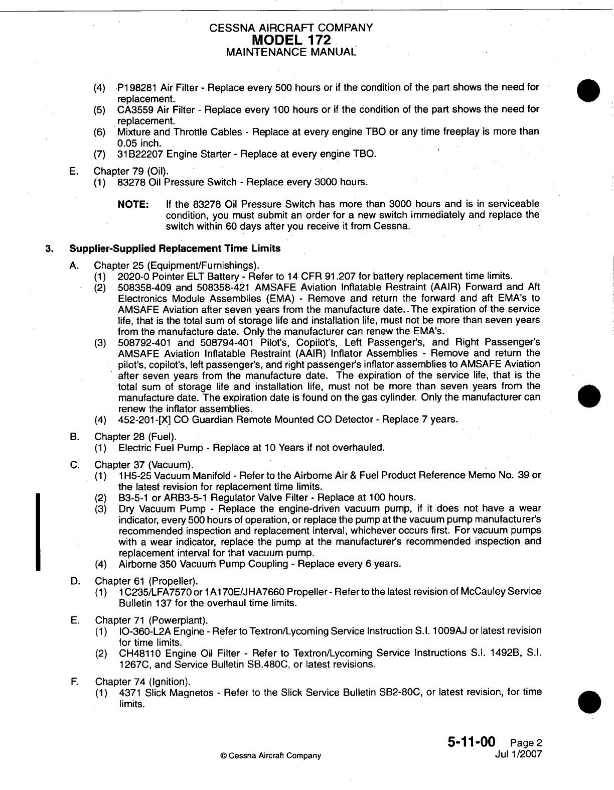
CESSNA
AIRCRAFT
COMPANY
MODEL
172
MAINTENANCE
MANUAL
(4)
P1
98281
Air
Filter
-
Replace
every
500
hours
or
if
the condition
of
the
part
shows
the
need
for
replacement.
(5)
CA3559
Air
Filter
-
Replace every
100
hours
or
if
the condition
of
the
part
shows
the
need
for
()replacement.
6)Mixture
and.Throttle
Cables
-
Replace
at
every
engine
TBO
or any time
freeplay
is
more
than
0.05
inch.
(7)
31
B22207
Engine
Starter
-
Replace
at
every
engine
TBO.
E.
Chapter
79
(Oil).
(1)
83278
Oil
Pressure Switch
-
Replace
every
3000
hours.
NOTE:
If
the 83278
Oil
Pressure Switch
has
more
than
3000
hours
and
is in
serviceable
condition,
you must
submit
an
order for
a
new
switch
immediately
and
replace the
switch
within
60
days
after
you
receive
it
from
Cessna.
3.
Supplier-Supplied
Replacement
Time
Limits
A.
Chapter
25
(Equipment/Furnishings).
(1)
2020-0
Pointer
ELT
Battery
-
Refer
to
14
CFR
91
.207
for
battery
replacement
time
limits.
(2)
508358-409
and 508358-421 AMSAFE
Aviation Inflatable
Restraint
(AAIR)
Forward
and
Aft
Electronics
Module
Assemblies
(EMA)
-
Remove
and
return
the
forward
and
aft
EMA's
to
AMSAFE
Aviation
after
seven years
from
the
manufacture
date.-The
expiration
of
the
service
life,
that
is
the
total sum
of
storage
life
and
installation
life,
must
not
be
more than
seven
years
from
the
manufacture
date.
Only
the
manufacturer
can
renew the EMA's.
(3)
508792-401 and
508794-401
Pilot's,
Copilot's,
Left
Passenger's,
and
Right
Passenger's
AMSAFE
Aviation Inflatable
Restraint
(AAIR)
Inflator Assemblies
-
Remove
and
return the
pilot's,
copilot's,
left
passeanger's,
and right
passenger's
inflator
assemblies
to AMSAFE
Aviation
after
seven
years
from
the
manufacture
date.
The expiration
of
the
service
life,
that
is
the
total
sum
of
storage
life
and
installation
life, must
not
be
more
than
seven
years
from
the
manufacture
date.
The
expiration
date
is
found
on
the
gas
cylinder. Only
the
manufacturer
can
renew
the
inflator
assemblies.
(4)
452-201
-[X]
CO
Guardian Remote
Mounted
CO
Detector
-
Replace
7
years.
B.
Chapter
28
(Fuel).
(1)
Electric
Fuel Pump
-
Replace
at
10
Years
if
not
overhauled.
C.
Chapter
37
(Vacuum).
(1) 1
H-5-25
Vacuum
Manifold
-
Refer
to
the
Airborne
Air
&
Fuel
Product
Reference
Memo
No.
39
or
the
latest revision for
replacement
time
limits.
(2)
B33-5-1
or
ARB33-5-1
Regulator
Valve
Filter
-
Replace
at
1
00
hours.
(3)
Dry
Vacuum
Pump
-
Replace
the
engine-driven
vacuum
pump,
if it
does
not have a
wear
indicator,
every
500
hours
of
operation,
or replace
the
pump
at
the vacuum pump
manufacturer's
recommended
inspection
and
replacement
interval,
whichever occurs
first.
For
vacuum
pumps
with
a
wear indicator, replace
the pump at the
manufacturer's
recommended inspection
and
replacement
interval
for that
vacuum
pump.
(4)
Airborne
350 Vacuum
Pump
Coupling
-
Replace
every
6
years.
D.
Chapter
61
(Propeller).
(1)
1lC235/LFA7570
orl1Al
70E/JHA7660
Propeller
-Refer
to
the
latest revision
of
McCauley
Service
Bulletin
137
for
the
overhaul
time limits.
E.
Chapter
71
(Powerplant).
(1)
10-360-L2A
Engine
-
Refer
to
Textron/Lycoming
Service
Instruction
S.l.
100O9AJ
or
latest
revision
for
time
limits.
(2)
CH48110 Engine
Oil
Filter
-
Refer
to
Textron/Lycoming
Service
Instructions
S.I.
1492B,
S.1.
1267C, and
Service
Bulletin
SB.480C,
or latest
revisions.
F.
Chapter
74
(Ignition).
(1)
4371
Slick
Magnetos
-
Refer
to
the
Slick
Service
Bulletin
S1B2-80C,
or
latest revision,
for
time
limits.
5-11-00
Page
2
©
Cessna Aircraft
Company
Jul
1/2007
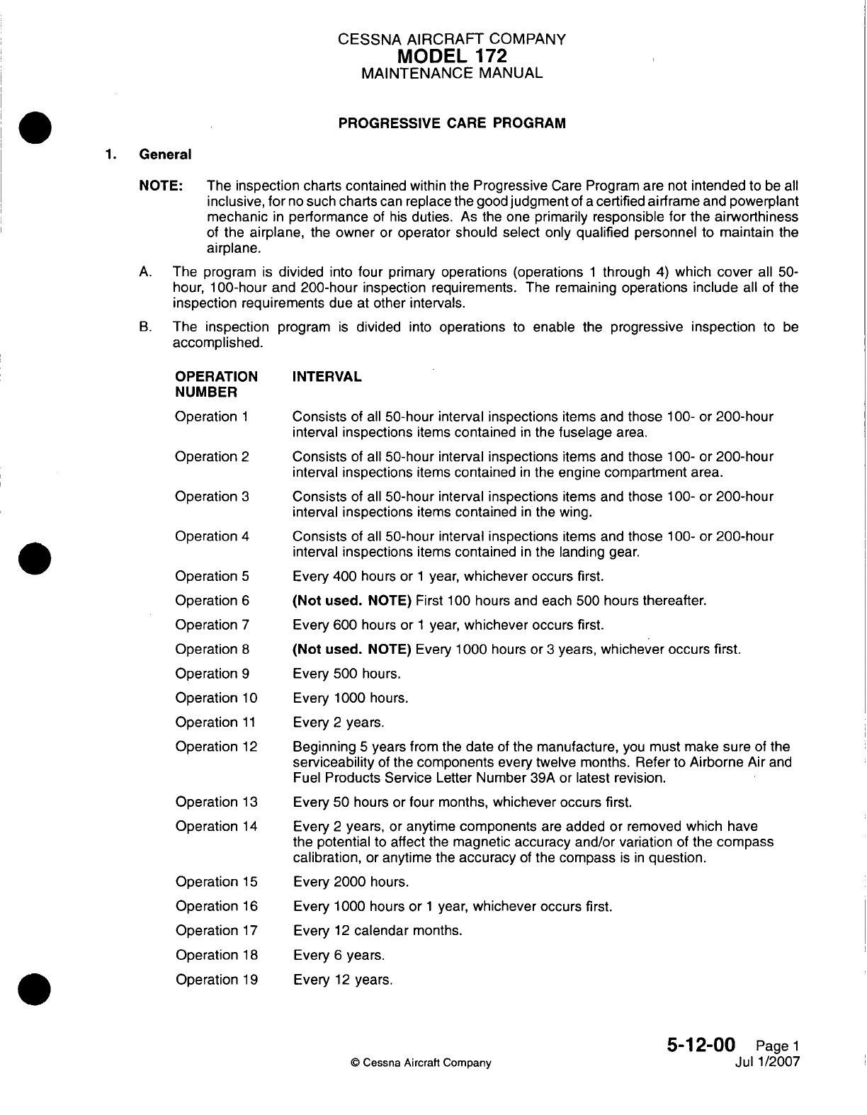
CESSNA AIRCRAFT
COMPANY
MODEL
172
MAINTENANCE
MANUAL
PROGRESSIVE
CARE
PROGRAM
General
NOTE:
The
inspection
charts
contained
within
the
Progressive
Care
Program
are
not
intended
to
be
all
inclusive,
for
no
such
charts
can
replace the good
judgment
of
a
certified
airframe
and
powerplant
mechanic
in
performance
of
his
duties.
As
the
one
primarily
responsible
for
the
airworthiness
of
the
airplane,
the
owner
or
operator
should select
only
qualified personnel
to
maintain
the
airplane.
A.
The
program
is
divided
into
four
primary
operations (operations
1
through
4)
which
cover
all 50-
hour,
100-hour
and
200-hour
inspection requirements.
The remaining
operations
include
all of
the
inspection
requirements
due
at
other
intervals.
B.
The
inspection
accomplished.
OPERATION
NUMBER
Operation
1
Operation
2
Operation
3
Operation
4
Operation
5
Operation
6
Operation
7
Operation
8
Operation
9
Operation
1
0
Operation
11
Operation
12
Operation
13
Operation
14
Operation
15
Operation
16
Operation
17
Operation
1
8
Operation
19
program
is
divided
into
operations
to
enable
the
progressive
inspection
to
be
INTERVAL
Consists
of
all
50-hour
interval
inspections
items
and
those
1
00-
or
200-hour
interval
inspections
items
contained
in
the
fuselage
area.
Consists
of
all
50-hour
interval
inspections
items
and
those
1
00- or
200-hou
r
interval
inspections
items
contained
in
the
engine
compartment
area.
Consists
of
all
50-hour
interval
inspections
items
and
those
100- or
200-hour
interval
inspections
items
contained
in
the wing.
Consists
of
all
50-hour
interval
inspections
items
and
those
1
00- or
200-hour
interval
inspections
items
contained
in
the
landing
gear.
Every 400
hours
or
1
year,
whichever
occurs
first.
(Not
used.
NOTE)
First
100
hours and each 500 hours
thereafter.
Every
600
hours or
1
year,
whichever
occurs
first.
(Not
used. NOTE)
Every
1
000
hours
or
3
years,
whichever occurs first.
Every 500
hours.
Every 1000
hours.
Every
2
years.
Beginning
5
years
from
the
date
of
the
manufacture,
you
must
make
sure
of
the
serviceability
of
the
components
every
twelve
months.
Refer
to
Airborne
Air
and
Fuel
Products Service
Letter
Number
39A
or
latest
revision.
Every
50
hours
or
four
months,
whichever
occurs
first.
Every
2
years,
or
anytime
components
are
added
or
removed
which
have
the
potential
to
affect
the
magnetic
accuracy
and/or
variation
of
the
compass
calibration,
or
anytime
the
accuracy
of
the
compass
is in
question.
Every 2000
hours.
Every
1000
hours
or
1
year,
whichever
occurs
first.
Every
12
calendar
months.
Every
6
years.
Every
12
years.
5-12-00
Page
1
Jul
1/2007
Q
Cessna Aircraft
Company
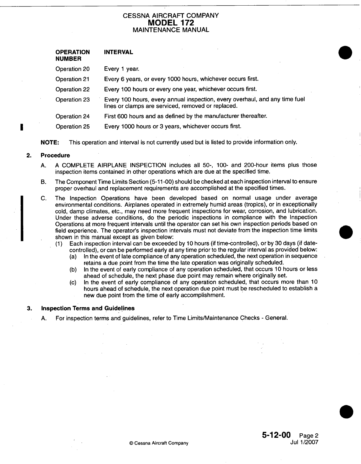
CESSNA
AIRCRAFT
COMPANY
MODEL
172
MAINTENANCE
MANUAL
OPERATION
NUMBER
Operation
20
Operation
21
Operation
22
Operation
23
Operation
24
Operation
25
INTERVAL
Every
1
year.
Every
6
years,
or
every
1
000
hours,
whichever
occurs
first.
Every
1
00
hours
or
every
one
year,
whichever
occurs
first.
Every
1
00 hours,
every annual
inspection,
every overhaul,
and
any
time
fuel
lines
or
clamps
are
serviced,
removed
or
replaced.
First 600
hours
and
as
defined
by
the
manufacturer thereafter.
Every
1
000
h~ours
or
3
years,
whichever
occurs first.
NOTE:
This
operation
and
interval
is
not
currently
used
but
is
listed
to
provide
information
only.
2.
Procedure
A.
A
COMPLETE
AIRPLANE INSPECTION includes
all
50-,
100-
and
200-hour
items
plus
those
inspection
items
contained
in
other operations
which are
due
at
the
specified
time.
B.
The
Component
Time
Limits
Section
(5-11
-00)
should
be
checked
at
each
inspection
interval
to
ensure
proper
overhaul
and
replacement
requirements
are
accomplished
at
the
specified
times.
C.
The
Inspection
Operations
have been
developed
based
on
normal
usage
under
average
environmental
conditions.
Airplanes operated
in
extremely
humid
areas (tropics),
or
in
exceptionally
cold,
damp
climates,
etc.,
may
need
more
frequent
inspections
for
wear,
corrosion,
and
lubrication.
Under
these
adverse
conditions,
do the
periodic
inspections
in
compliance
with
the
Inspection
Operations
at
more
frequent
intervals
until
the
operator
can
set his
own
inspection
periods based
on
field
experience.
The operator's
inspection intervals
must
not
deviate
from
the
inspection
time
limits
shown
in
this manual
except
as
given
below:
(1)
Each
inspection
interval
can
be
exceeded
by
1
0
hours
(if
time-controlled),
or
by
30
days
(if
date-
controlled),
or
can
be
performed
early
at
any time prior
to
the
regular
interval
as
provided
below:
(a) In
the
event
of
late
compliance
of
any operation
scheduled, the
next
operation
in
sequence
retains
a
due
point
from
the
time
the
late
operation
was
originally scheduled.
(b) In
the
event
of
early
compliance
of
any
operation scheduled,
that
occurs
10
hours
or
less
ahead
of
schedule, the
next
phase
due
point
may
remain
where
originally
set.
(c) In
the
event
of
early compliance
of
any
operation
scheduled,
that
occurs
more
than
10
hours
ahead
of
schedule, the
next
operation
due
point
must
be
rescheduled
to
establish
a
new
due
point
from
the
time
of
early
accomplishment.
3.
Inspection
Terms
and
Guidelines
A.
For
inspection
terms
and
guidelines,
refer
to
Time
Limits/Maintenance
Checks
-
General.
©
Cessna Aircraft
Company
5-12-00
Page
2
Jul
1/2007
I
0
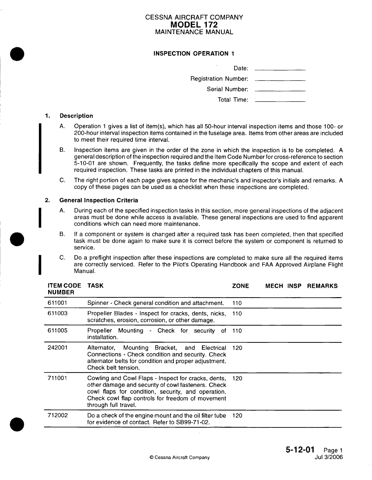
CESSNA
AIRCRAFT
COMPANY
MODEL
172
MAINTENANCE
MANUAL
INSPECTION
OPERATION
1
Date:
Registration
Number:
Serial
Number:
Total
Time:
1.
Description
A.
Operation
1
gives
a
list
of
item(s),
which
has
all
50-hour
interval
inspection
items
and
those
100-
or
200-hour
interval inspection
items
contained
in
the
fuselage
area. Items
from
other
areas
are
included
to
meet
their
required
time
interval.
B.
Inspection
items
are
given
in
the
order
of the
zone
in
which the
inspection
is
to
be
completed.
A
general
description
of
the
inspection
required
and
the
Item
Code
Number
for
cross-reference
to
section
5-10-01
are
shown. Frequently,
the
tasks
define
more
specifically
the
scope
and extent
of
each
required
inspection.
These
tasks
are
printed
in
the
individual chapters
of
this
manual.
C.
The
right
portion
of each page
gives
space
for
the
mechanic's
and
inspector's initials
and
remarks.
A
copy
of
these
pages
can
be
used as
a
checklist
when
these
inspections
are
completed.
2.
General
Inspection
Criteria
A.
During
each
of
the
specified
inspection tasks
in
this
section,
more
general
inspections
of
the
adjacent
areas
must
be
done
while
access
is
available.
These general
inspections
are used
to
find
apparent
conditions
which
can
need
more
maintenance.
B. If
a
component
or
system
is
changed
after
a
required
task has
been
completed,
then
that specified
task
must
be
done
again
to
make
sure
it
is
correct
before the
system or
component
is
returned
to
service.
C.
Do
a
preflight
inspection
after these
inspections
are
completed
to
make
sure
all
the
required
items
are
correctly serviced.
Refer
to
the
Pilot's
Operating
Handbook
and
FAA
Approved
Airplane
Flight
Manual.
ITEM
CODE
TASK
ZONE
MECH
INSP
REMARKS
NUMBER
611001
Spinner
-
Check
general
condition
and
attachment.
110
611003
Propeller Blades
-
Inspect
for
cracks,
dents, nicks,
110
scratches, erosion,
corrosion,
or
other
damage.
611005
Propeller
Mounting
-
Check
for
security
of
110
installation.
242001
Alternator,
Mounting
Bracket, and
Electrical
120
Connections
-
Check
condition
and
security.
Check
alternator
belts
for
condition
and
proper
adjustment.
Check
belt
tension.
711001
Cowling
and
Cowl Flaps
-
Inspect
for
cracks, dents,
120
other damage
and
security
of
cowl
fasteners.
Check
cowl
flaps
for
condition,
security,
and
operation.
Check
cowl flap controls
for freedom
of
movement
through full
travel.
712002
Do a
check
of the
engine
mount
and
the
oil
filter
tube
120
for
evidence
of
contact.
Refer
to
SB99-71-02.
5-12-01
Page
1
©
Cessna Aircraft
ComDanv
Jul 3/2006
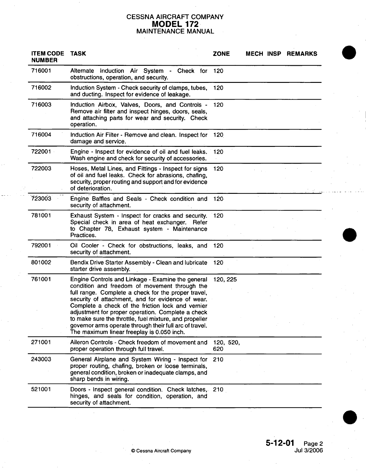
CESSNA
AIRCRAFT
COMPANY
MODEL
172
MAINTENANCE
MANUAL
ITEM CODE
TASK
ZONE
MECH
INSP
REMARKS
NUMBER
716001
Alternate
Induction
Air
System
-
Check
for
120
obstructions,
operation, and security.
716002
Induction
System
-
Check security
of
clamps, tubes,
120
and
ducting. Inspect
for evidence
of
leakage.
716003
Induction
Airbox,
Valves,
Doors,
and
Controls
-
120
Remove
air
filter
and
inspect
hinges, doors,
seals,
and
attaching
parts
for
wear
and
security.
Check
operation.
716004
Induction
Air
Filter
-
Remove
and
clean.
Inspect
for
120
damage
and
service.
722001
Engine
-
Inspect for
evidence
of
oil
and
fuel
leaks.
120
Wash
engine and
check
for
security
of
accessories.
722003
Hoses,
Metal
Lines, and
Fittings
-
Inspect
for signs
120
of
oil
and
fuel
leaks.
Check
for
abrasions,
chafing,
security,
proper routing
and
support
and
for
evidence
of
deterioration.
723003
Engine Baffles
and
Seals
-
Check
condition
and
120
security
of
attachment.
781001
Exhaust
System
-
Inspect
for
cracks
and
security.
120
Special
check
in
area
of
heat
exchanger.
Refer
to
Chapter
78,
Exhaust
system
-
Maintenance
Practices.
792001 Oil
Cooler
-
Check
for obstructions,
leaks,
and
120
security
of
attachment.
801002
Bendix
Drive
Starter
Assembly -
Clean
and
lubricate
120
starter
drive
assembly.
761001
Engine
Controls
and
Linkage
-
Examine the general
120,
225
condition
and
freedom
of
movement through
the
full
range.
Complete
a
check
for
the proper
travel,
security
of
attachment, and
for evidence
of
wear.
Complete
a
check
of
the friction
lock and vernier
adjustment
for
proper
operation.
Complete
a
check
to
make
sure
the
throttle,
fuel
mixture,
and
propeller
governor
arms
operate
through their
full
arc
of
travel.
The
maximum
linear
freeplay
is
0.050
inch.
271001
Aileron Controls
-
Check
freedom
of
movement
and
120,
520,
proper
operation through
full
travel.
620
243003
General Airplane
and
System
Wiring
-
Inspect
for
210
proper
routing,
chafing,
broken
or loose
terminals,
general
condition,
broken
or
inadequate clamps,
and
sharp bends
in
wiring.
521001
Doors
-
Inspect general
condition. Check
latches,
210
hinges,
and
seals
for
condition, operation,
and
security
of
attachment.
5-12-01
Page
2
©
Cessna
Aircraft
Company
Jul 3/2006
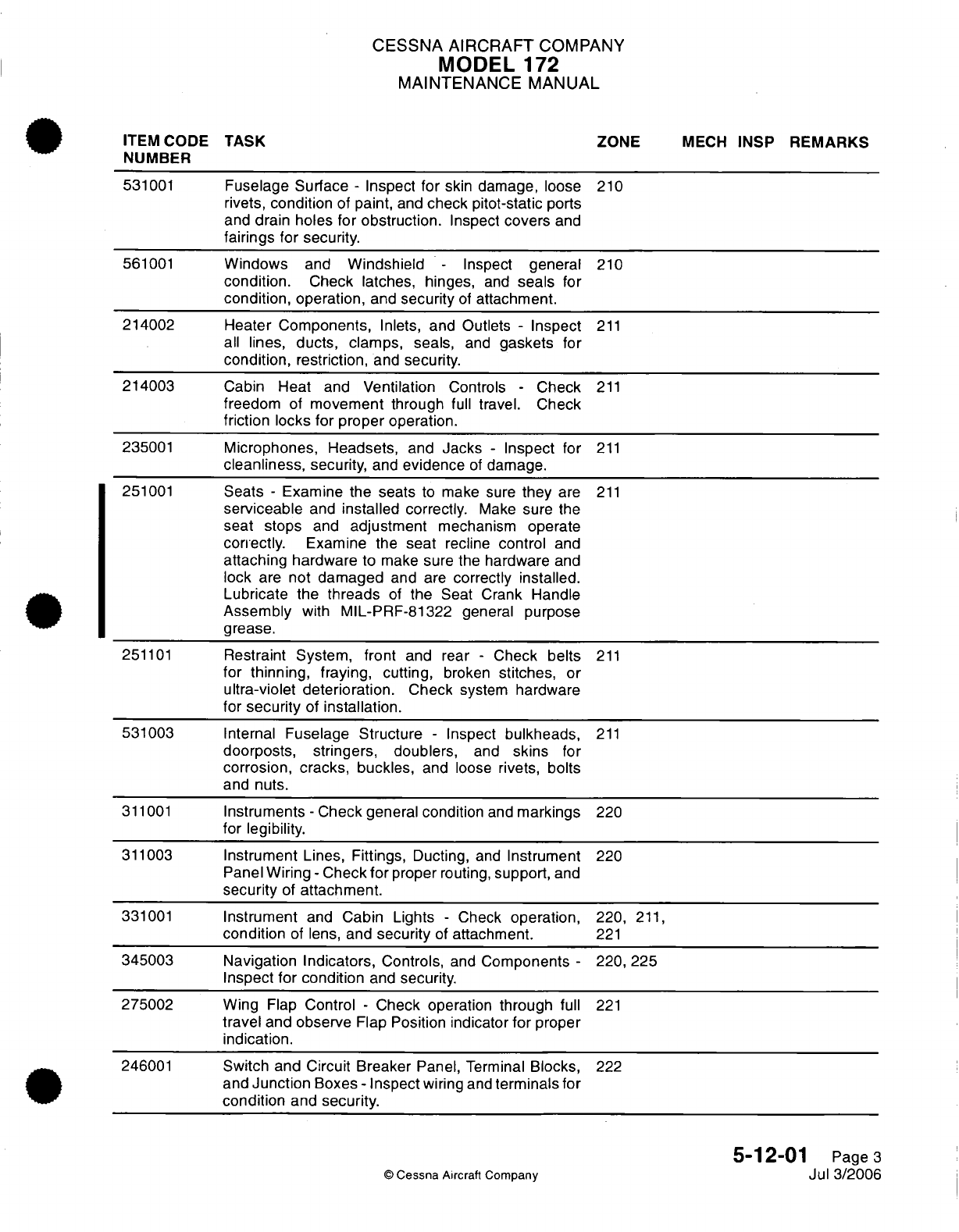
CESSNA AIRCRAFT
COMPANY
MODEL
172
MAINTENANCE
MANUAL
ITEM
CODE
TASK ZONE
MECH
INSP
REMARKS
NUMBER
531001
Fuselage
Surface
-
Inspect
for
skin
damage,
loose
210
rivets,
condition
of paint,
and
check
pitot-static
ports
and
drain
holes for
obstruction.
Inspect
covers
and
fairings
for
security.
561001
Windows
and
Windshield
-
Inspect
general
210
condition.
Check
latches, hinges,
and
seals
for
condition,
operation,
and
security
of
attachment.
214002 Heater
Components,
Inlets,
and
Outlets
-
Inspect
211
all
lines,
ducts,
clamps,
seals,
and
gaskets
for
condition,
restriction,
and
security.
214003
Cabin
Heat
and
Ventilation
Controls
-
Check
211
freedom
of
movement
through
full
travel. Check
friction
locks
for
proper
operation.
235001
Microphones, Headsets,
and
Jacks
-
Inspect
for
211
cleanliness,
security,
and
evidence
of
damage.
251001
Seats
-
Examine the seats
to
make sure
they
are
211
serviceable
and
installed
correctly.
Make
sure
the
seat stops
and
adjustment
mechanism
operate
correctly.
Examine
the
seat
recline
control
and
attaching
hardware
to
make
sure the
hardware
and
lock
are
not
damaged
and
are
correctly installed.
Lubricate
the
threads
of
the
Seat Crank
Handle
Assembly
with
MIL-PRF-81322
general
purpose
grease.
251101
Restraint
System,
front
and rear
-
Check
belts
211
for
thinning, fraying,
cutting,
broken
stitches,
or
ultra-violet
deterioration.
Check
system
hardware
for
security
of
installation.
531003 Internal
Fuselage Structure
-
Inspect
bulkheads,
211
doorposts, stringers, doublers,
and
skins
for
corrosion,
cracks,
buckles,
and
loose
rivets,
bolts
and
nuts.
311001
Instruments
-
Check
general condition
and
markings
220
for
legibility.
311003
Instrument
Lines,
Fittings, Ducting,
and
Instrument
220
Panel
Wiring
-
Check
for
proper
routing,
support,
and
security
of
attachment.
331001
Instrument
and
Cabin Lights
-
Check
operation,
220,
211,
condition
of
lens,
and
security
of
attachment.
221
345003 Navigation
Indicators,
Controls,
and
Components
-
220,
225
Inspect
for
condition
and
security.
275002
Wing
Flap
Control
-
Check operation
through
full
221
travel
and
observe
Flap
Position
indicator
for
proper
indication.
246001
Switch and Circuit Breaker
Panel,
Terminal
Blocks,
222
and
Junction
Boxes
-
Inspect
wiring
and
terminals
for
condition
and
security.
5-12-01
Page
3
©
Cessna
Aircraft
Company
Jul
3/2006
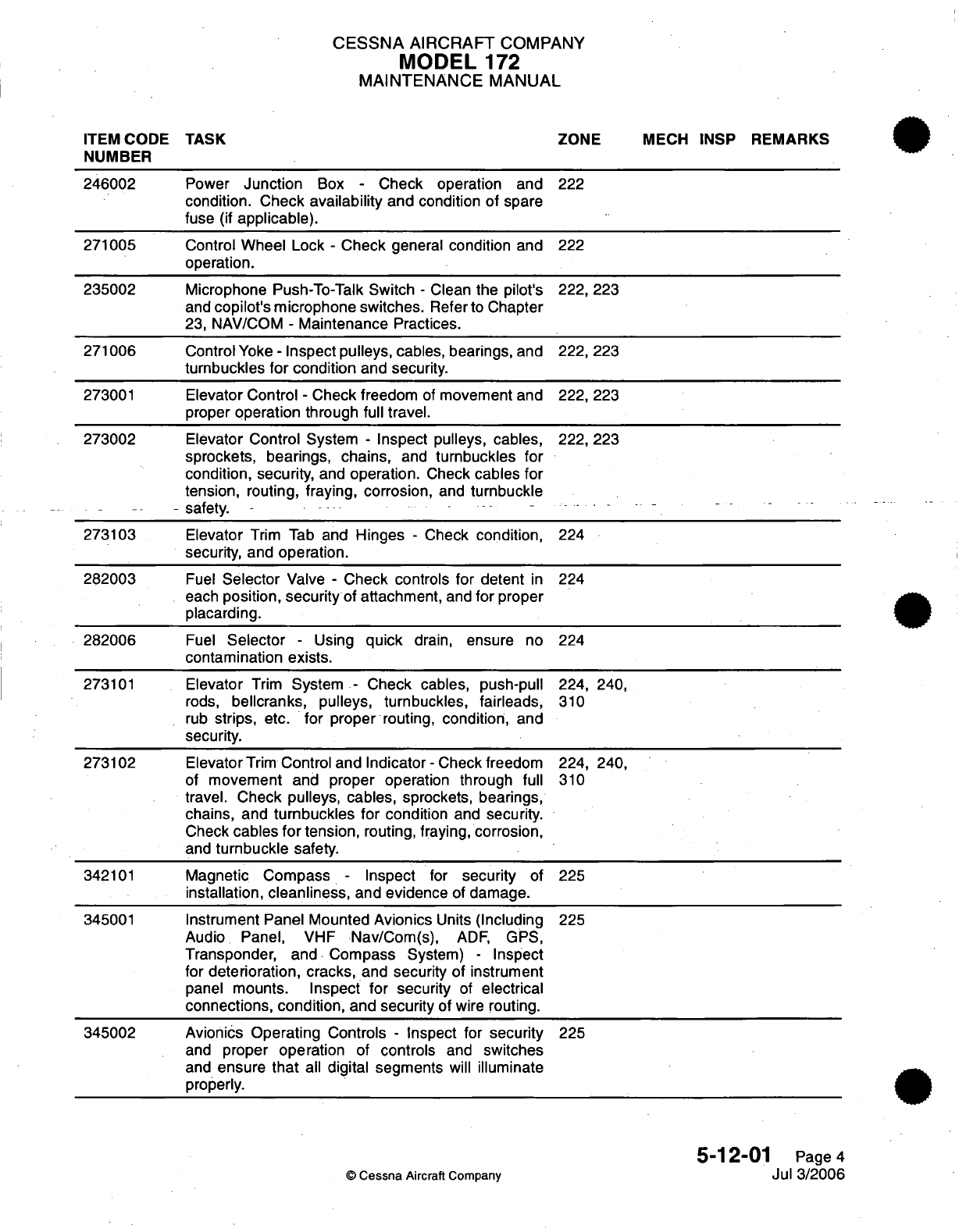
CESSNA
AIRCRAFT
COMPANY
MODEL
172
MAINTENANCE
MANUAL
ITEM CODE
TASK
ZONE
MECH
INSP
REMARKS
NUMBER
246002
Power
Junction
Box
-
Check
operation
and
222
condition.
Check
availability
and condition of
spare
fuse
(if
applicable).
271005
Control
Wheel
Lock
-
Check
general
condition
and
222
operation.
235002
Microphone
Push-To-Talk
Switch
-
Clean
the
pilot's
222,
223
and
copilot's
microphone
switches.
Refer
to
Chapter
23,
NAV/COM
-
Maintenance
Practices.
271006
Control
Yoke
-
Inspect
pulleys,
cables, bearings,
and
222,
223
turnbuckles
for
condition
and
security.
273001
Elevator Control
-
Check freedom
of
movement
and
222,
223
proper
operation
through
full travel.
273002
Elevator Control
System
-
Inspect pulleys, cables,
222,
223
sprockets,
bearings,
chains,
and
turnbuckles
for
condition,
security,
and
operation.
Check
cables
for
tension,
routing,
fraying,
corrosion,
and
turnbuckle
.- .-
safety.
273103
Elevator
Trim
Tab
and
Hinges
-
Check
condition,
224
security,
and
operation.
282003
Fuel
Selector
Valve
-
Check
controls
for
detent
in
224
each
position,
security
of
attachment,
and
for
proper
placarding.
282006
Fuel
Selector
-
Using
quick
drain,
ensure
no
224
contamination
exists.
273101
Elevator
Trim
System
-
Check cables, push-pull
224,
240,
rods,
bellcranks,
pulleys, turnbuckles,
fairleads,
310
rub
strips,
etc.
for
proper routing,
condition,
and
security.
273102
Elevator
Trim
Control and
Indicator
-
Check freedom
224,
240,
of
movement
and proper operation through
full
310
travel. Check
pulleys,
cables,
sprockets,
bearings,
chains, and
turnbuckles
for
condition
and
security.
Check
cables
for
tension,
routing, fraying,
corrosion,
and
turnbuckle safety.
342101
Magnetic
Compass
-
Inspect
for
security
of 225
installation,
cleanliness,
and evidence
of
damage.
345001
Instrument
Panel
Mounted
Avionics
Units
(Including
225
Audio
Panel,
VHF
Nav/Com(s),
ADF,
GPS,
Transponder,
and
Compass
System)
-
Inspect
for
deterioration,
cracks,
and
security
of
instrument
panel
mounts.
Inspect for
security
of
electrical
connections, condition,
and
security
of wire
routing.
345002 Avionics
Operating
Controls
-
Inspect
for
security
225
and
proper
operation
of
controls
and
switches
and
ensure
that
all
digital segments
will
illuminate
properly.
5-12-01
Page
4
©
Cessna
Aircraft
Company
Jul 3/2006
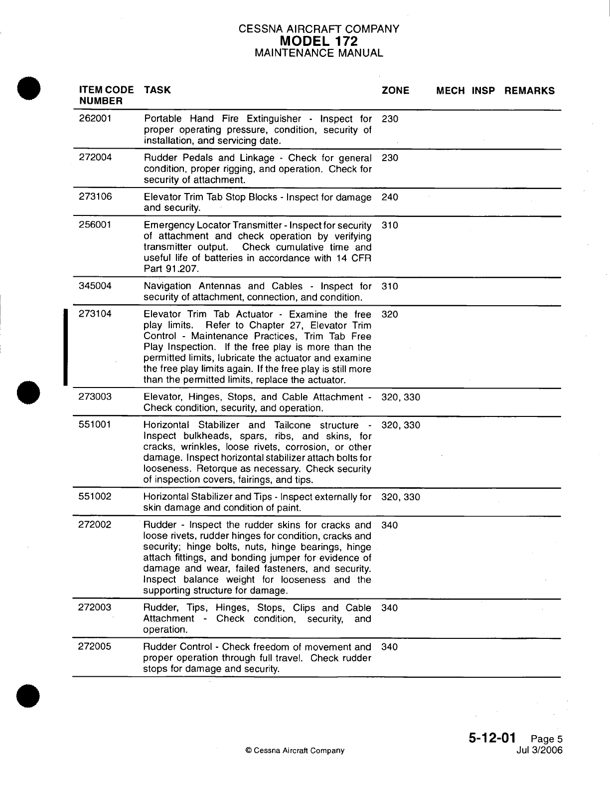
CESSNA
AIRCRAFT
COMPANY
MODEL
172
MAINTENANCE
MANUAL
ITEM
CODE
TASK
ZONE
MECH
INSP
REMARKS
NUMBER
262001
Portable
Hand
Fire
Extinguisher
-
Inspect for
230
proper
operating
pressure,
condition, security
of
installation,
and
servicing
date.
272004
Rudder
Pedals
and
Linkage
-
Check
for
general
230
condition,
proper
rigging,
and
operation.
Check
for
security
of
attachment.
273106
Elevator
Trim
Tab
Stop
Blocks
-
Inspect for
damage
240
and
security.
256001
Emergency
Locator
Transmitter
-
Inspect for
security
310
of
attachment
and
check
operation
by
verifying
transmitter
output.
Check
cumulative
time
and
useful
life of
batteries
in
accordance
with
14
CFR
Part
91.207.
345004
Navigation
Antennas
and
Cables
-
Inspect for
310
security
of
attachment,
connection,
and
condition.
273104
Elevator
Trim
Tab
Actuator
-
Examine
the
free
320
play
limits.
Refer
to
Chapter
27,
Elevator
Trim
Control
-
Maintenance
Practices,
Trim Tab
Free
Play
Inspection.
If
the
free play
is
more
than
the
permitted limits,
lubricate
the
actuator
and
examine
the
free
play
limits
again.
If
the
free
play
is
still
more
than
the permitted
limits,
replace the actuator.
273003
Elevator, Hinges,
Stops,
and
Cable
Attachment
-
320,
330
Check
condition,
security,
and
operation.
551001
Horizontal Stabilizer
and
Tailcone
structure
-
320,330
Inspect
bulkheads,
spars,
ribs,
and
skins,
for
cracks, wrinkles,
loose
rivets,
corrosion,
or
other
damage. Inspect
horizontal
stabilizer
attach
bolts for
looseness.
Retorque
as
necessary.
Check security
of
inspection
covers,
fairings,
and
tips.
551002
Horizontal
Stabilizer
and
Tips
-
Inspect
externally
for
320,
330
skin
damage
and
condition
of
paint.
272002
Rudder
-
Inspect
the
rudder
skins
for
cracks
and
340
loose
rivets,
rudder
hinges
for
condition,
cracks
and
security;
hinge
bolts,
nuts,
hinge
bearings,
hinge
attach fittings,
and
bonding
jumper
for
evidence
of
damage
and
wear,
failed fasteners,
and
security.
Inspect
balance
weight
for
looseness
and the
supporting
structure
for damage.
272003
Rudder,
Tips,
Hinges,
Stops,
Clips
and Cable
340
Attachment
-
Check
condition,
security,
and
operation.
272005
Rudder
Control
-
Check
freedom
of
movement
and
340
proper
operation
through
full
travel.
Check
rudder
stops
for
damage
and
security.
5-12-01
Page
5
©
Cessna
Aircraft
Company
Jul
3/2006
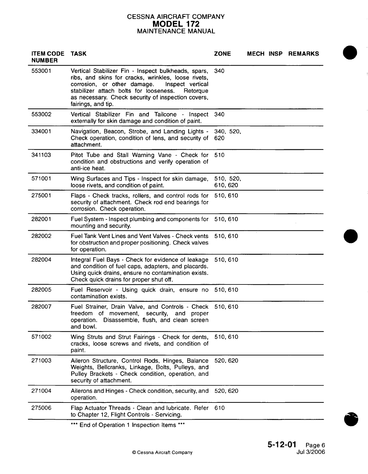
CESSNA
AIRCRAFT
COMPANY
MODEL
172
MAINTENANCE
MANUAL
ITEM
CODE
TASK ZONE
MECH
INSP
REMARKS
NUMBER
553001
Vertical
Stabilizer
Fin
-
Inspect
bulkheads,
spars,
340
ribs,
and
skins
for
cracks,
wrinkles,
loose
rivets,
corrosion,
or
other
damage. Inspect
vertical
stabilizer
attach
bolts
for looseness.
Retorque
as
necessary.
Check
security
of
inspection covers,
fairings,
and tip.
553002
Vertical
Stabilizer
Fin
and Tailcone
-
Inspect
340
externally
for
skin
damage
and
condition
of paint.
334001
Navigation,
Beacon,
Strobe, and
Landing
Lights
-
340, 520,
Check
operation,
condition
of
lens, and
security
of 620
attachment.
341103
Pitot
Tube and
Stall
Warning
Vane
-
Check
for
510
condition
and
obstructions
and verify
operation
of
anti-ice
heat.
571001
Wing
Surfaces and Tips
-
Inspect
for skin
damage, 510, 520,
loose rivets,
and
condition
of
paint.
610,
620
275001
Flaps
-
Check
tracks,
rollers,
and
control
rods
for
510,
610
security
of
attachment.
Check
rod
end
bearings
for
corrosion.
Check
operation.
282001 Fuel
System
-
Inspect plumbing
and
components
for
510,
610
mounting and
security.
282002
Fuel
Tank Vent
Lines
and
Vent
Valves
-
Check
vents 510,
610
for obstruction
and
proper positioning. Check
valves
for operation.
282004
Integral
Fuel
Bays
-
Check
for evidence
of
leakage 510,
610
and condition
of
fuel
caps, adapters,
and
placards.
Using
quick
drains, ensure
no
contamination
exists.
Check
quick
drains
for
proper
shut
off.
282005
Fuel
Reservoir
-
Using
quick
drain,
ensure
no
510,
610
contamination exists.
282007
Fuel
Strainer,
Drain
Valve,
and
Controls
-
Check
510,
610
freedom
of
movement,
security,
and
proper
operation.
Disassemble,
flush,
and
clean
screen
and
bowl.
571002
Wing
Struts
and
Strut
Fairings
-
Check
for
dents,
510,
610
cracks,
loose
screws
and
rivets,
and
condition
of
paint.
271003
Aileron Structure, Control
Rods,
Hinges,
Balance
520,
620
Weights,
Bellcranks, Linkage,
Bolts,
Pulleys,
and
Pulley
Brackets
-
Check
condition, operation,
and
security
of
attachment.
271004 Ailerons
and
Hinges
-
Check
condition,
security,
and 520,
620
operation.
275006
Flap
Actuator
Threads
-
Clean
and
lubricate.
Refer
610
to
Chapter
12,
Flight
Controls
-
Servicing.
***
End
of
Operation
1
Inspection
Items
***
5-12-01
Page
6
©
Cessna
Aircraft
Company
Jul
3/2006
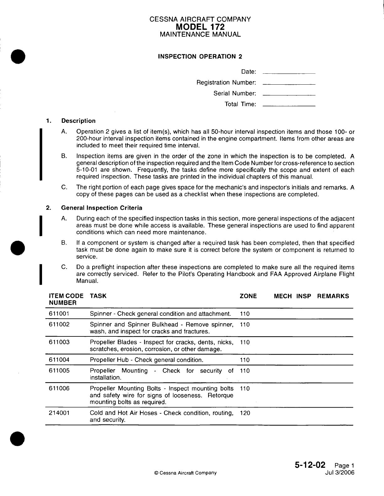
CESSNA
AIRCRAFT
COMPANY
MODEL
172
MAINTENANCE
MANUAL
INSPECTION OPERATION
2
Date:
Registration
Number:
Serial
Number:
Total
Time:
1.
Description
A.
Operation
2
gives
a
list
of
item(s),
which
has
all
50-hour
interval
inspection
items and
those
100-
or
200-hour
interval
inspection
items
contained
in
the
engine
compartment.
Items
from
other areas
are
included
to
meet
their
required
time
interval.
B.
Inspection
items
are
given
in
the
order
of
the
zone
in
which
the
inspection
is
to
be
completed.
A
general
description
of
the
inspection
required
and
the
Item
Code Number
for
cross-reference
to
section
5-10-01
are
shown. Frequently,
the
tasks
define
more
specifically
the scope
and
extent
of
each
required
inspection.
These
tasks
are
printed
in
the
individual
chapters
of
this
manual.
C.
The
right
portion
of
each
page
gives
space
for
the
mechanic's
and
inspector's
initials
and
remarks.
A
copy
of
these
pages
can
be
used
as
a
checklist
when
these
inspections
are
completed.
2.
General
Inspection
Criteria
A.
During
each
of
the
specified
inspection tasks
in
this
section,
more
general
inspections
of
the
adjacent
areas must
be
done
while
access
is
available.
These
general
inspections
are
used
to
find apparent
conditions
which
can
need
more
maintenance.
B. If
a
component
or system
is
changed after
a
required task
has been
completed,
then
that
specified
task must
be
done
again
to
make
sure
it
is
correct
before the
system
or
component
is
returned
to
service.
C.
Do
a
preflight inspection
after
these
inspections
are
completed
to
make
sure
all
the
required
items
are
correctly
serviced.
Refer
to
the
Pilot's
Operating
Handbook
and
FAA
Approved Airplane
Flight
Manual.
ITEM
CODE
TASK
ZONE
MECH
INSP
REMARKS
NUMBER
611001
Spinner
-
Check
general
condition
and
attachment.
110
611002
Spinner
and
Spinner
Bulkhead
-
Remove
spinner,
110
wash, and
inspect
for
cracks
and
fractures.
611003
Propeller
Blades
-
Inspect for cracks, dents,
nicks,
110
scratches,
erosion, corrosion,
or
other
damage.
611004
Propeller
Hub
-
Check
general
condition.
110
611005
Propeller Mounting
-
Check
for
security
of
110
installation.
611006
Propeller
Mounting
Bolts
-
Inspect
mounting bolts
110
and
safety
wire
for
signs
of
looseness.
Retorque
mounting
bolts
as
required.
214001
Cold
and
Hot
Air
Hoses
-
Check
condition,
routing,
120
and
security.
5-12-02
Page
1
©
Cessna Aircraft
Companv
Jul
3/2006
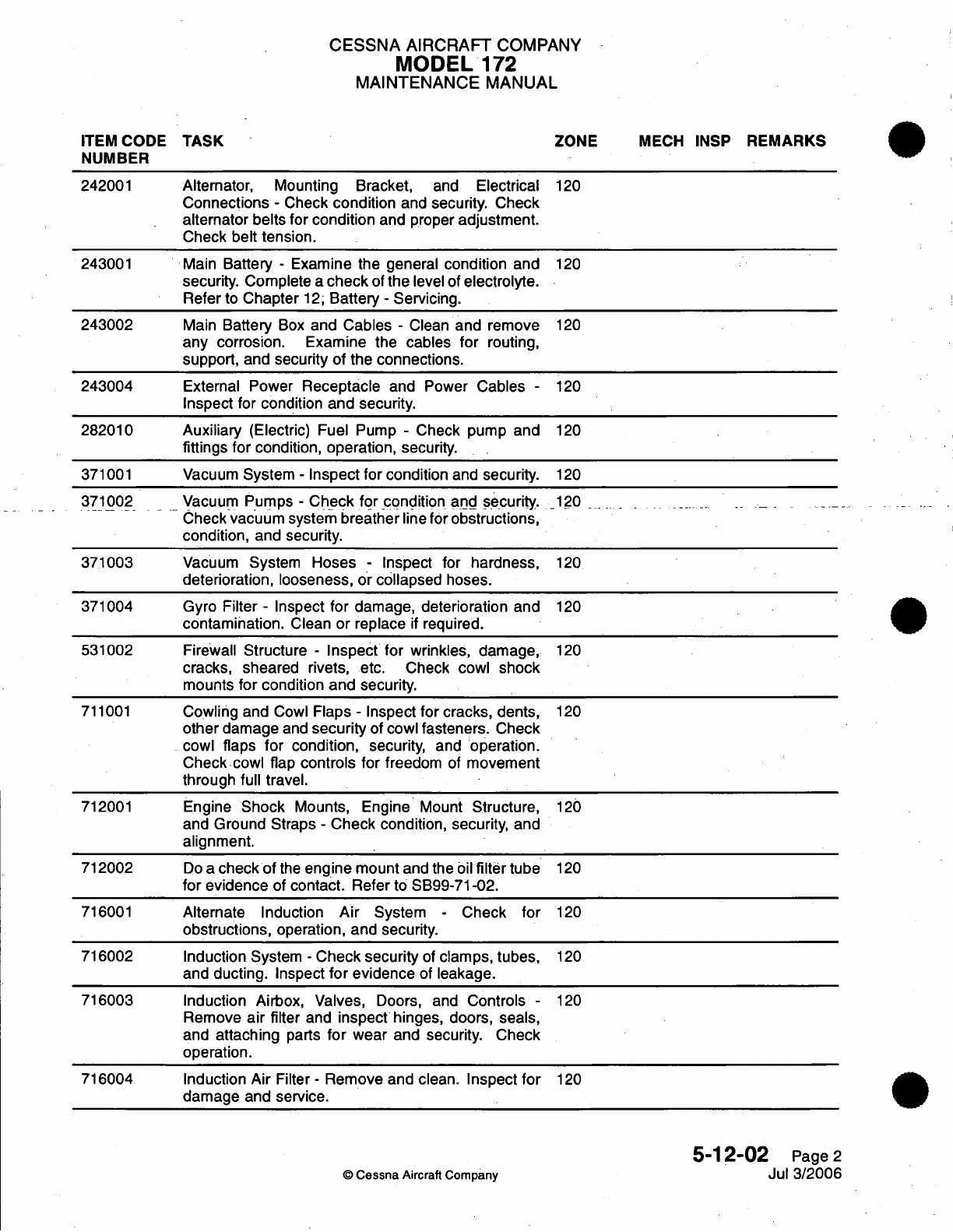
CESSNA
AIRCRAFT
COMPANY
MODEL
172
MAINTENANCE
MANUAL
ITEM
CODE
TASK
ZONE
MECH INSP
REMARKS
NUMBER
242001
Alternator,
Mounting Bracket,
and
Electrical
120
Connections
-
Check
condition
and
security. Check
alternator belts
for condition
and
proper
adjustment.
Check
belt tension.
243001
Main
Battery
-
Examine the general
condition
and
120
security.
Complete
a
check
of
the
level
of electrolyte.
Refer
to
Chapter
12,
Battery
-
Servicing.
243002
Main
Battery
Box
and
Cables
-
Clean
and
remove
120
any
corrosion. Examine
the
cables
for
routing,
support,
and
security
of
the connections.
243004
External
Power
Receptacle
and
Power
Cables
-
120
Inspect for condition and security.
282010 Auxiliary
(Electric)
Fuel Pump
-
Check pump
and
120
fittings
for condition,
operation,
security.
371001
Vacuum
System
-
Inspect for
condition
and
security.
120
371002
Vacuum
Pumps
-
Check
for
condition and
security.
120
Check
vacuum
system
breather
line
for
obstructions,
condition,
and
security.
371003
Vacuum
System
Hoses
-
Inspect for hardness,
120
deterioration, looseness, or
collapsed
hoses.
371004 Gyro Filter
-
Inspect for
damage,
deterioration
and
120
contamination.
Clean or
replace
if
required.
531002
Firewall
Structure
- Inspect
for
wrinkles,
damage,
120
cracks, sheared rivets,
etc.
Check
cowl
shock
mounts
for
condition and
security.
711001
Cowling and
Cowl
Flaps
-
Inspect
for
cracks, dents,
120
other
damage
and
security
of
cowl
fasteners.
Check
cowl
flaps
for
condition,
security,
and
operation.
Check
cowl
flap
controls for
freedom
of
movement
through full
travel.
712001
Engine
Shock
Mounts, Engine
Mount
Structure,
120
and
Ground Straps
-
Check condition,
security,
and
alignment.
712002
Do
a
check
of
the
engine
mount
and the
oil
filter
tube
120
for
evidence
of
contact. Refer
to
SB99-71-02.
716001
Alternate Induction
Air
System
-
Check
for
120
obstructions,
operation, and
security.
716002 Induction
System
-
Check security
of
clamps,
tubes,
120
and
ducting.
Inspect
for
evidence
of
leakage.
716003
Induction Airbox,
Valves,
Doors, and
Controls
-
120
Remove
air
filter
and
inspect
hinges, doors,
seals,
and
attaching
parts
for
wear
and
security. Check
operation.
716004
Induction Air
Filter
-
Remove
and clean.
Inspect
for
120
damage
and
service.
5-12-02
Page
2
©
Cessna
Aircraft
Company
Jul
3/2006
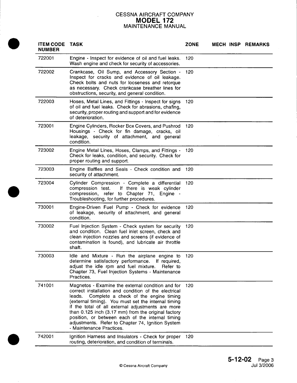
CESSNA
AIRCRAFT
COMPANY
MODEL
172
MAINTENANCE
MANUAL
ITEM
CODE
TASK
ZONE
MECH
INSP
REMARKS
NUMBER
722001
Engine
-
Inspect
for
evidence
of
oil
and
fuel
leaks.
120
Wash
engine
and
check
for
security
of
accessories.
722002 Crankcase,
Oil
Sump, and
Accessory
Section
-
120
Inspect
for
cracks
and
evidence
of
oil
leakage.
Check
bolts and
nuts
for looseness
and
retorque
as necessary.
Check
crankcase breather
lines
for
obstructions,
security,
and
general
condition.
722003 Hoses,
Metal
Lines,
and Fittings
-
Inspect for
signs
120
of
oil
and
fuel
leaks. Check for
abrasions,
chafing,
security,
proper
routing
and
support
and
for
evidence
of
deterioration.
723001
Engine
Cylinders,
Rocker
Box
Covers, and Pushrod
120
Housings
-
Check
for
fin
damage,
cracks,
oil
leakage,
security
of
attachment,
and
general
condition.
723002
Engine
Metal
Lines,
Hoses, Clamps,
and Fittings
-
120
Check
for
leaks,
condition,
and
security.
Check
for
proper
routing
and
support.
723003
Engine
Baffles
and
Seals
-
Check
condition
and
120
security
of
attachment.
723004
Cylinder
Compression
-
Complete
a
differential
120
compression
test.
If
there
is
weak
cylinder
compression,
refer
to
Chapter
71,
Engine
-
Troubleshooting,
for
further
procedures.
730001
Engine-Driven
Fuel Pump
-
Check
for
evidence
120
of leakage,
security
of
attachment,
and
general
condition.
730002
Fuel
Injection
System
-
Check system
for
security
120
and
condition.
Clean
fuel
inlet
screen,
check
and
clean
injection nozzles
and
screens
(if
evidence
of
contamination
is
found),
and
lubricate
air
throttle
shaft.
730003
Idle
and
Mixture
-
Run
the
airplane
engine
to
120
determine
satisfactory
performance.
If
required,
adjust
the idle
rpm
and
fuel
mixture.
Refer
to
Chapter
73,
Fuel
Injection
Systems
-
Maintenance
Practices.
741001
Magnetos
-
Examine
the
external
condition
and
for
120
correct
installation
and condition
of
the
electrical
leads.
Complete
a
check
of
the engine
timing
(external
timing).
You
must
set
the
internal timing
if
the
total
of
all
external adjustments
are
more
than
0.125
inch (3.17
mm)
from
the
original factory
position,
or
between each
of
the
internal timing
adjustments.
Refer
to
Chapter
74,
Ignition
System
-
Maintenance
Practices.
742001
Ignition
Harness
and
Insulators
-
Check
for
proper
120
routing,
deterioration,
and
condition
of
terminals.
5-12-02
Page
3
©
Cessna
Aircraft
Company
Jul
3/2006
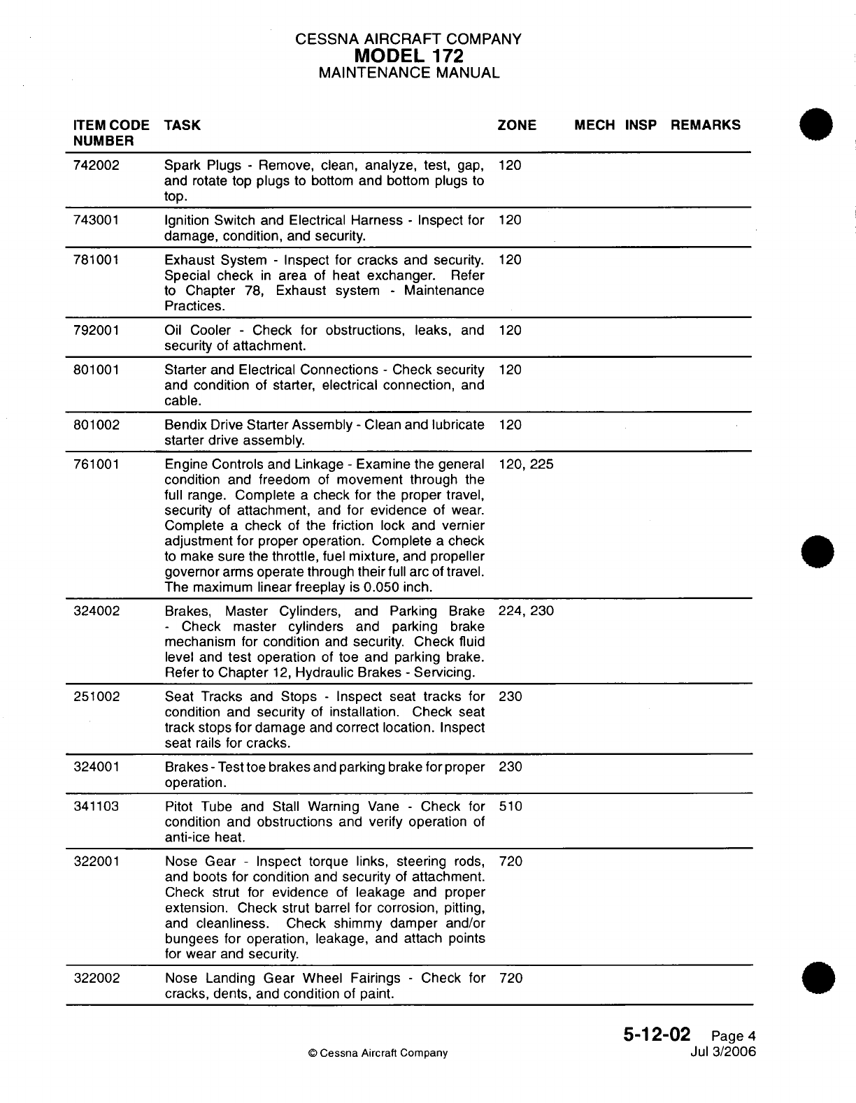
CESSNA AIRCRAFT
COMPANY
MODEL
172
MAINTENANCE
MANUAL
ITEM
CODE
TASK ZONE
MECH
INSP
REMARKS
NUMBER
742002 Spark
Plugs
-
Remove,
clean,
analyze, test,
gap,
120
and
rotate
top plugs
to
bottom
and
bottom
plugs
to
top.
743001
Ignition
Switch
and
Electrical Harness
-
Inspect for
120
damage,
condition,
and
security.
781001
Exhaust
System
-
Inspect for
cracks
and
security.
120
Special
check
in
area
of
heat
exchanger.
Refer
to
Chapter
78,
Exhaust system
-
Maintenance
Practices.
792001
Oil
Cooler
-
Check
for obstructions,
leaks,
and
120
security
of
attachment.
801001
Starter
and
Electrical
Connections
-
Check
security
120
and
condition
of
starter,
electrical
connection,
and
cable.
801002
Bendix
Drive
Starter
Assembly
-
Clean
and lubricate
120
starter drive assembly.
761001
Engine
Controls
and
Linkage
-
Examine the
general
120,
225
condition
and
freedom
of
movement through
the
full
range.
Complete
a
check
for
the proper
travel,
security
of
attachment,
and
for
evidence
of
wear.
Complete
a
check
of
the
friction
lock
and
vernier
adjustment
for
proper
operation.
Complete
a
check
to
make
sure
the
throttle,
fuel
mixture,
and
propeller
governor
arms
operate through
their
full
arc of
travel.
The
maximum
linear
freeplay
is
0.050
inch.
324002
Brakes,
Master
Cylinders,
and Parking
Brake
224, 230
-
Check
master
cylinders
and
parking
brake
mechanism
for
condition
and
security.
Check
fluid
level
and
test
operation
of
toe and parking
brake.
Refer
to
Chapter
12,
Hydraulic
Brakes
-
Servicing.
251002 Seat Tracks
and
Stops
-
Inspect
seat
tracks
for
230
condition
and
security
of
installation.
Check
seat
track
stops
for
damage
and
correct
location.
Inspect
seat
rails
for
cracks.
324001
Brakes
-
Test
toe brakes
and
parking
brake
for
proper
230
operation.
341103 Pitot
Tube and Stall
Warning
Vane
-
Check
for
510
condition
and
obstructions
and
verify
operation
of
anti-ice
heat.
322001
Nose
Gear
-
Inspect
torque
links,
steering
rods,
720
and
boots
for
condition
and
security
of
attachment.
Check strut
for
evidence
of
leakage
and proper
extension.
Check
strut
barrel
for
corrosion,
pitting,
and
cleanliness.
Check shimmy damper
and/or
bungees for
operation,
leakage,
and
attach points
for wear
and
security.
322002
Nose
Landing Gear
Wheel
Fairings
-
Check
for
720
cracks, dents,
and
condition
of
paint.
5-12-02
Page
4
©
Cessna
Aircraft Company
Jul
3/2006
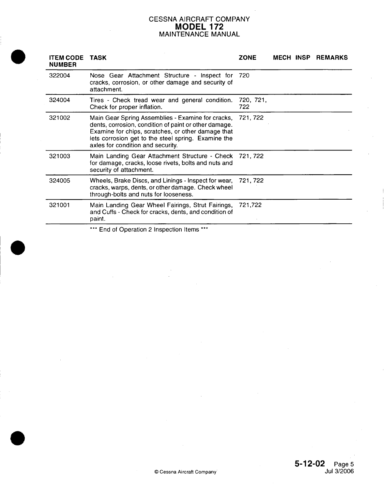
CESSNA
AIRCRAFT
COMPANY
MODEL
172
MAINTENANCE
MANUAL
ITEM
CODE
NUMBER
322004
324004
321002
321003
324005
321001
TASK
Nose
Gear
Attachment
Structure
-
Inspect
for
cracks, corrosion,
or
other
damage
and
security
of
attachment.
Tires
-
Check
tread
wear
and
general
condition.
Check
for
proper
inflation.
Main
Gear
Spring
Assemblies
-
Examine
for
cracks,
dents, corrosion,
condition
of
paint or
other damage.
Examine
for
chips,
scratches,
or
other
damage
that
lets
corrosion
get
to
the steel
spring.
Examine
the
axles
for
condition
and
security.
Main
Landing
Gear
Attachment
Structure
-
Check
for
damage,
cracks,
loose
rivets,
bolts
and nuts
and
security
of
attachment.
Wheels,
Brake
Discs,
and
Linings
-
Inspect
for
wear,
cracks,
warps,
dents,
or
other
damage.
Check wheel
through-bolts
and nuts
for
looseness.
Main
Landing Gear Wheel
Fairings, Strut
Fairings,
and
Cuffs
-
Check
for
cracks,
dents,
and
condition
of
paint.
***
End of
Operation
2
Inspection
Items
***
ZONE
MECH
INSP
REMARKS
720
720,
721,
722
721,722
721,722
721,722
721,722
5-12-02
Page
5
Jul
3/2006
©
Cessna
Aircraft
Company
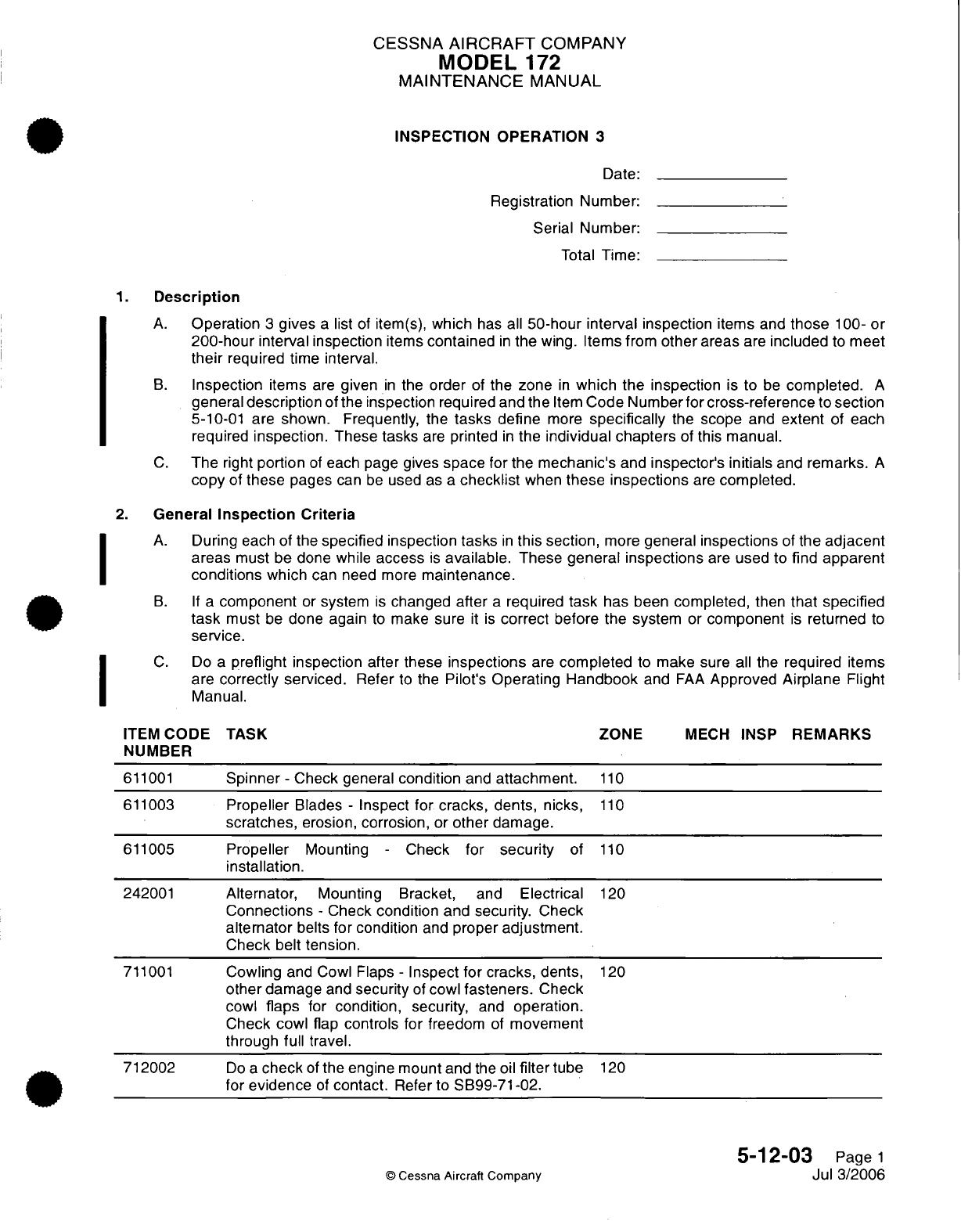
CESSNA
AIRCRAFT
COMPANY
MODEL
172
MAINTENANCE
MANUAL
INSPECTION OPERATION
3
Date:
Registration
Number:
Serial
Number:
Total
Time:
1.
Description
A.
Operation
3
gives
a
list
of
item(s),
which
has all
50-hour
interval
inspection
items
and
those
100-
or
200-hour
interval inspection
items
contained
in
the
wing.
Items
from
other
areas
are
included
to
meet
their
required time interval.
B.
Inspection
items
are
given
in
the
order
of
the
zone
in
which the
inspection
is
to
be
completed.
A
general
description
of the
inspection
required
and
the
Item
Code
Numberfor
cross-reference
to
section
5-10-01
are
shown.
Frequently,
the
tasks
define
more
specifically
the
scope and
extent
of
each
required
inspection.
These
tasks
are
printed
in
the
individual chapters
of
this manual.
C.
The
right
portion
of
each
page
gives
space
for
the
mechanic's
and
inspector's
initials
and
remarks.
A
copy
of
these
pages
can
be
used
as
a
checklist
when
these
inspections
are
completed.
2.
General
Inspection Criteria
A.
During
each
of
the
specified
inspection tasks
in
this
section,
more
general
inspections
of the
adjacent
areas
must
be
done while
access
is
available.
These
general
inspections
are
used
to
find
apparent
conditions
which
can
need
more
maintenance.
B. If
a
component
or
system
is
changed after
a
required
task
has been
completed,
then
that specified
task
must
be
done again
to
make sure
it
is
correct
before the system
or
component
is
returned
to
service.
C.
Do
a
preflight inspection
after
these
inspections
are
completed
to
make
sure
all
the
required
items
are
correctly
serviced.
Refer
to
the
Pilot's
Operating
Handbook
and
FAA
Approved
Airplane
Flight
Manual.
ITEM
CODE
TASK
ZONE
MECH
INSP
REMARKS
NUMBER
611001
Spinner
-
Check general
condition
and
attachment.
110
611003
Propeller
Blades
-
Inspect
for
cracks, dents, nicks,
110
scratches,
erosion,
corrosion,
or
other
damage.
611005
Propeller
Mounting
-
Check
for
security
of
110
installation.
242001
Alternator,
Mounting
Bracket,
and
Electrical
120
Connections
-
Check
condition
and
security. Check
alternator
belts
for
condition
and
proper
adjustment.
Check
belt
tension.
711001
Cowling
and
Cowl Flaps
-
Inspect for
cracks,
dents,
120
other
damage
and
security
of
cowl
fasteners.
Check
cowl
flaps
for
condition,
security,
and
operation.
Check
cowl
flap
controls for
freedom
of
movement
through
full
travel.
712002
Do a
check
of
the
engine mount
and
the oil
filter
tube
120
for
evidence
of
contact.
Refer to
SB99-71-02.
5-12-03
Page
1
©
Cessna
Aircraft
Company
Jul
3/2006
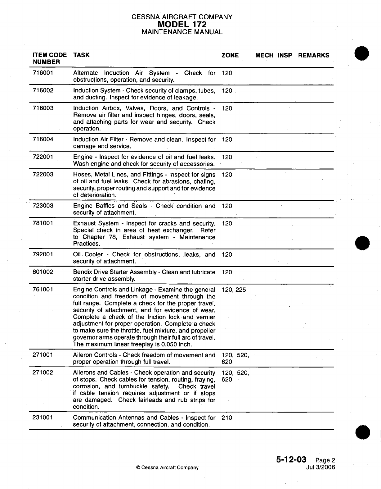
CESSNA
AIRCRAFT
COMPANY
MODEL
172
MAINTENANCE
MANUAL
ITEM
CODE
TASK ZONE
MECH
INSP
REMARKS
NUMBER
716001
Alternate Induction Air
System
-
Check
for
120
obstructions,
operation,
and
security.
716002 Induction
System
-
Check
security
of
clamps,
tubes,
120
and
ducting.
Inspect
for
evidence
of
leakage.
716003 Induction
Airbox,
Valves, Doors,
and Controls
-
120
Remove
air
filter
and
inspect
hinges,
doors,
seals,
and
attaching
parts
for
wear
and
security.
Check
operation.
716004 Induction Air
Filter
-
Remove and
clean.
Inspect
for
120
damage
and
service.
722001
Engine
-
Inspect
for
evidence
of
oil
and
fuel
leaks.
120
Wash
engine
and
check
for
security
of
accessories.
722003 Hoses,
Metal
Lines,
and
Fittings
-
Inspect for
signs
120
of
oil
and
fuel
leaks.
Check
for
abrasions,
chafing,
security,
proper routing
and
support
and
for
evidence
of
deterioration.
723003
Engine Baffles
and
Seals
-
Check
condition
and
120
security
of
attachment.
781001
Exhaust
System
-
Inspect for
cracks and
security.
120
Special
check
in
area
of
heat
exchanger.
Refer
to
Chapter
78,
Exhaust system
-
Maintenance
Practices.
792001
Oil
Cooler
-
Check
for
obstructions,
leaks,
and
120
security
of attachment.
801002
Bendix
Drive
Starter
Assembly
-
Clean
and
lubricate
120
starter
drive assembly.
761001
Engine
Controls
and
Linkage
-
Examine
the
general
120,
225
condition
and
freedom
of
movement
through
the
full
range.
Complete
a
check
for
the
proper travel,
security
of
attachment,
and
for evidence
of wear.
Complete
a
check
of
the
friction
lock
and vernier
adjustment
for
proper
operation.
Complete
a
check
to make sure
the
throttle,
fuel
mixture, and
propeller
governor
arms
operate
through
their
full
arc
of
travel.
The
maximum
linear
freeplay
is
0.050 inch.
271001
Aileron Controls
-
Check
freedom
of
movement
and
120,
520,
proper operation through
full travel.
620
271002 Ailerons
and
Cables
-
Check
operation
and
security
120,
520,
of
stops.
Check
cables
for tension,
routing,
fraying,
620
corrosion,
and
turnbuckle
safety.
Check
travel
if
cable
tension
requires
adjustment or
if
stops
are
damaged.
Check
fairleads
and
rub
strips
for
condition.
231001
Communication Antennas and Cables
-
Inspect
for
210
security
of
attachment,
connection,
and
condition.
5-12-03
Page
2
C
Cessna
Aircraft
Company
Jul 3/2006
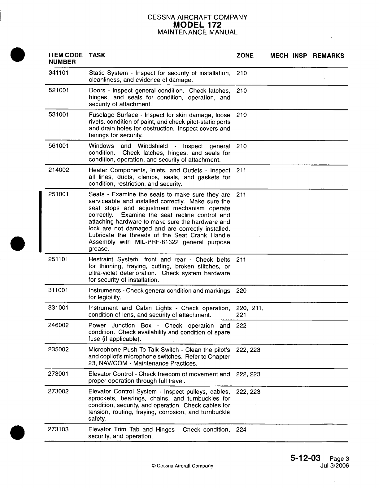
CESSNA
AIRCRAFT
COMPANY
MODEL
172
MAINTENANCE
MANUAL
ITEM
CODE
TASK ZONE
MECH
INSP
REMARKS
NUMBER
341101
Static
System
-
Inspect
for security
of
installation,
210
cleanliness,
and
evidence
of
damage.
521001
Doors
-
Inspect
general
condition.
Check
latches,
210
hinges,
and
seals
for
condition, operation,
and
security
of
attachment.
531001
Fuselage
Surface
-
Inspect for skin damage, loose
210
rivets,
condition of
paint,
and
check
pitot-static
ports
and
drain
holes for
obstruction.
Inspect
covers
and
fairings
for security.
561001
Windows
and
Windshield
-
Inspect
general
210
condition.
Check
latches, hinges,
and
seals
for
condition,
operation,
and
security
of
attachment.
214002 Heater
Components,
Inlets,
and
Outlets
-
Inspect
211
all
lines,
ducts,
clamps,
seals, and
gaskets
for
condition, restriction,
and
security.
251001
Seats
-
Examine
the
seats
to
make
sure
they
are
211
serviceable
and
installed correctly.
Make
sure the
seat
stops
and
adjustment
mechanism
operate
correctly.
Examine
the
seat recline
control
and
attaching
hardware
to
make sure
the hardware
and
lock
are
not
damaged
and
are
correctly
installed.
Lubricate
the
threads
of
the
Seat
Crank
Handle
Assembly
with MIL-PRF-81322
general purpose
grease.
251101
Restraint
System,
front
and
rear
-
Check
belts
211
for
thinning, fraying,
cutting,
broken
stitches,
or
ultra-violet deterioration.
Check system
hardware
for
security
of
installation.
311001
Instruments
-
Check
general
condition
and
markings
220
for
legibility.
331001
Instrument
and Cabin Lights
-
Check
operation,
220,
211,
condition
of lens,
and
security
of
attachment.
221
246002
Power
Junction
Box
-
Check
operation
and
222
condition.
Check
availability
and
condition
of
spare
fuse
(if
applicable).
235002 Microphone
Push-To-Talk
Switch
-
Clean
the
pilot's
222,
223
and
copilot's
microphone switches.
Referto
Chapter
23,
NAV/COM
-
Maintenance Practices.
273001
Elevator Control
-
Check
freedom of
movement
and 222,
223
proper
operation
through
full travel.
273002
Elevator
Control
System
-
Inspect
pulleys,
cables,
222,
223
sprockets,
bearings, chains,
and
turnbuckles
for
condition,
security,
and
operation.
Check
cables
for
tension,
routing, fraying, corrosion,
and
turnbuckle
safety.
273103
Elevator
Trim
Tab
and
Hinges
-
Check
condition,
224
security,
and operation.
5-12-03
Page
3
©
Cessna
Aircraft
Company
Jul
3/2006
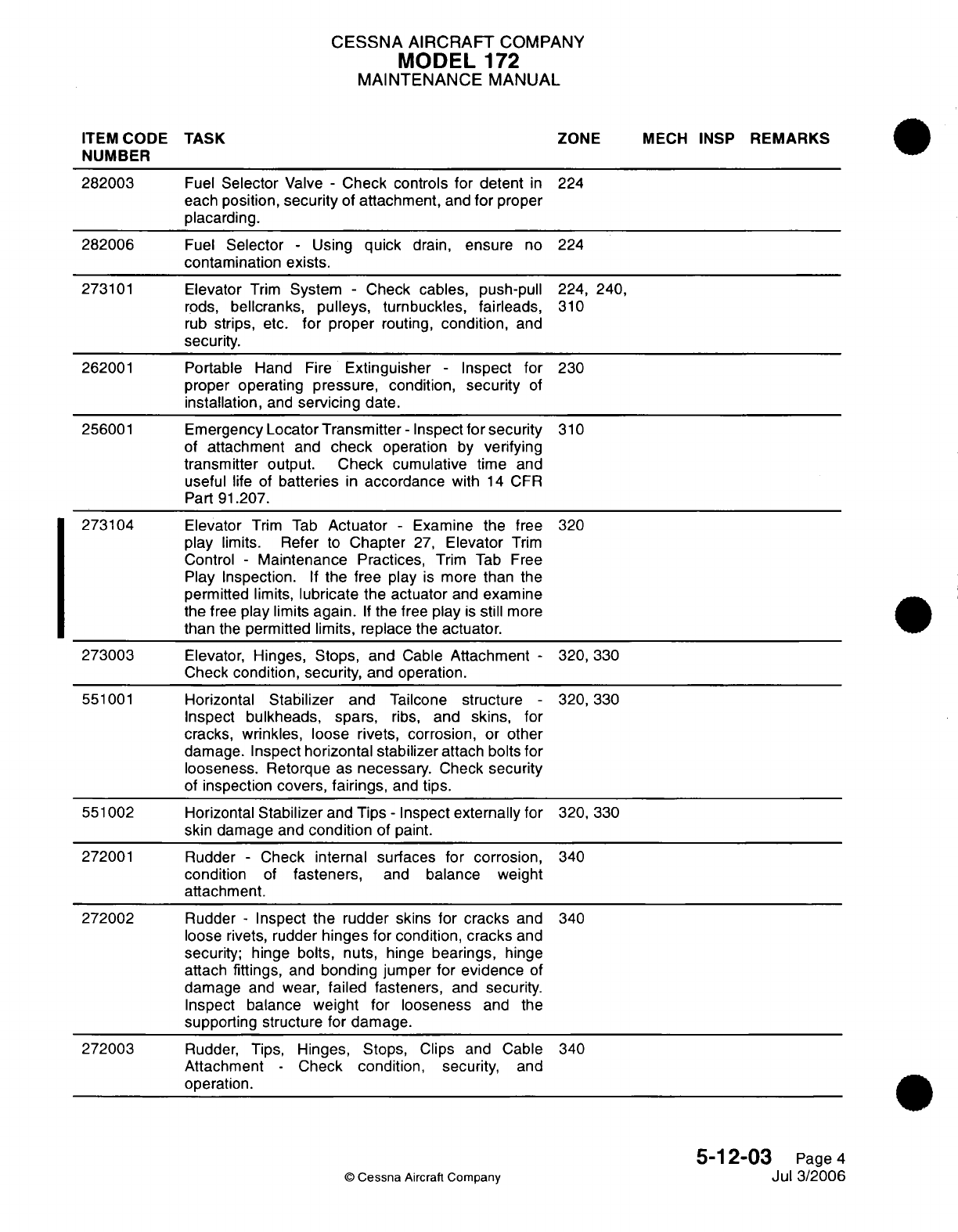
CESSNA
AIRCRAFT
COMPANY
MODEL
172
MAINTENANCE
MANUAL
ITEM
CODE
TASK
ZONE
MECH
INSP
REMARKS
NUMBER
282003
Fuel
Selector
Valve
-
Check
controls
for
detent
in
224
each
position,
security
of
attachment,
and
for
proper
placarding.
282006
Fuel
Selector
-
Using
quick
drain,
ensure
no
224
contamination
exists.
273101
Elevator
Trim
System
-
Check
cables, push-pull
224,
240,
rods,
bellcranks,
pulleys,
turnbuckles, fairleads,
310
rub
strips,
etc.
for
proper
routing,
condition,
and
security.
262001
Portable
Hand
Fire
Extinguisher
-
Inspect
for
230
proper
operating pressure, condition, security
of
installation,
and
servicing
date.
256001
Emergency
Locator
Transmitter
-
Inspect
for
security
310
of
attachment
and
check
operation
by
verifying
transmitter
output.
Check
cumulative
time
and
useful
life
of
batteries
in
accordance
with
14
CFR
Part
91.207.
273104
Elevator
Trim
Tab
Actuator
-
Examine
the
free
320
play
limits. Refer
to
Chapter
27,
Elevator
Trim
Control
-
Maintenance Practices,
Trim
Tab Free
Play Inspection.
If
the free play
is
more
than
the
permitted
limits,
lubricate
the
actuator
and
examine
the
free
play
limits
again.
If
the
free
play
is
still
more
than
the
permitted limits, replace
the
actuator.
273003
Elevator,
Hinges,
Stops, and
Cable
Attachment
-
320,
330
Check
condition, security,
and
operation.
551001
Horizontal
Stabilizer
and
Tailcone
structure
-
320,330
Inspect
bulkheads,
spars,
ribs,
and
skins,
for
cracks,
wrinkles,
loose rivets, corrosion,
or other
damage.
Inspect
horizontal
stabilizer
attach bolts
for
looseness.
Retorque
as
necessary.
Check
security
of
inspection
covers,
fairings,
and
tips.
551002 Horizontal
Stabilizer
and
Tips
-
Inspect
externally
for
320,
330
skin damage
and
condition
of
paint.
272001
Rudder
-
Check
internal surfaces
for
corrosion,
340
condition
of
fasteners,
and
balance
weight
attachment.
272002
Rudder
-
Inspect
the
rudder
skins
for
cracks
and
340
loose rivets, rudder
hinges
for
condition,
cracks
and
security; hinge bolts,
nuts,
hinge
bearings,
hinge
attach
fittings,
and
bonding
jumper for
evidence
of
damage
and
wear,
failed
fasteners,
and
security.
Inspect balance
weight
for
looseness
and the
supporting structure
for
damage.
272003
Rudder,
Tips, Hinges,
Stops,
Clips
and
Cable
340
Attachment
-
Check
condition,
security,
and
operation.
5-12-03
Page
4
©
Cessna
Aircraft
Company
Jul 3/2006
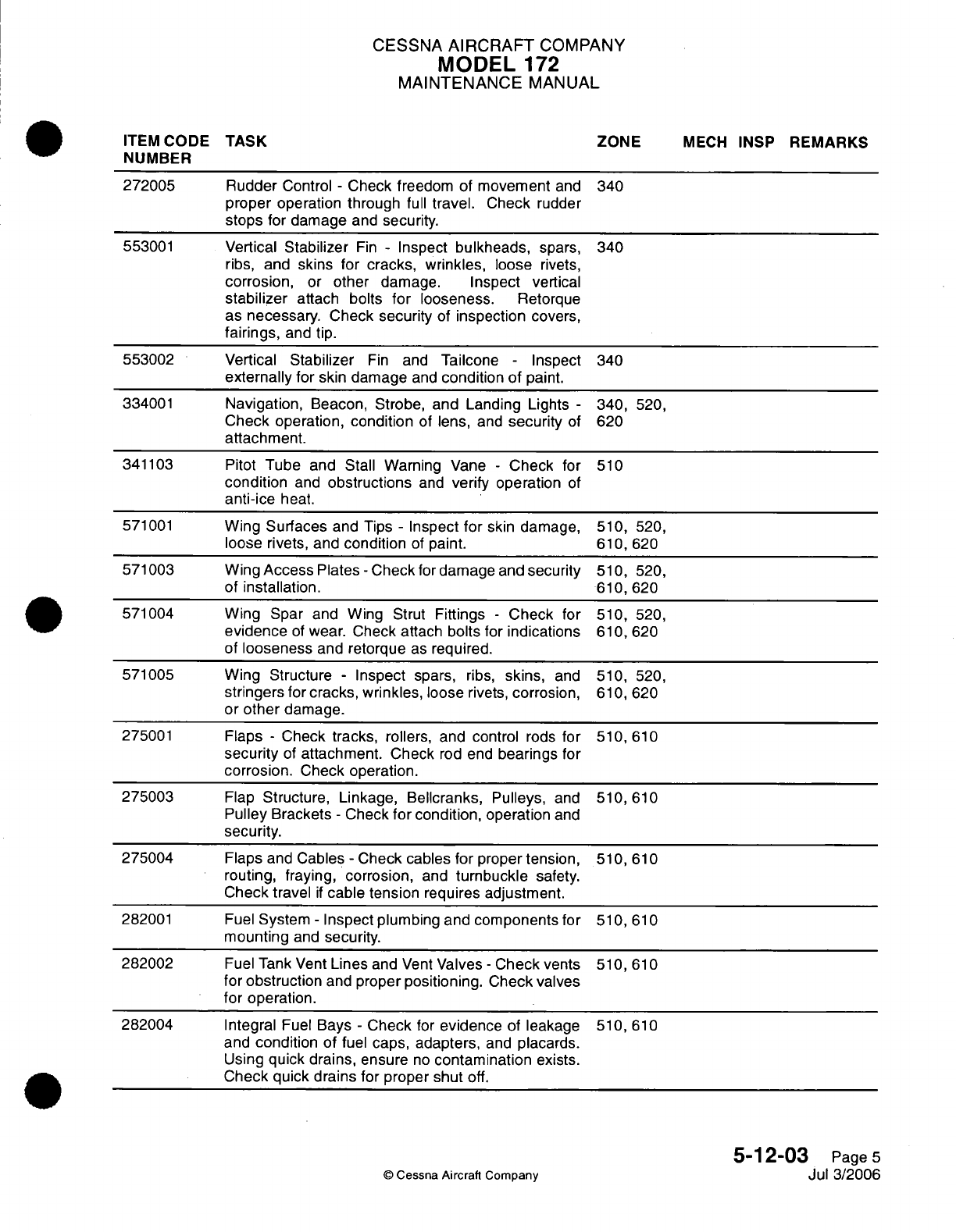
CESSNA
AIRCRAFT
COMPANY
MODEL
172
MAINTENANCE
MANUAL
ITEM
CODE
TASK ZONE
MECH
INSP
REMARKS
NUMBER
272005
Rudder
Control
-
Check freedom
of
movement
and
340
proper
operation through
full
travel.
Check
rudder
stops
for damage
and security.
553001
Vertical
Stabilizer
Fin
-
Inspect
bulkheads,
spars,
340
ribs, and
skins for
cracks, wrinkles,
loose
rivets,
corrosion,
or
other
damage.
Inspect
vertical
stabilizer
attach
bolts
for
looseness.
Retorque
as
necessary.
Check
security
of
inspection
covers,
fairings,
and
tip.
553002 Vertical
Stabilizer
Fin
and
Tailcone
-
Inspect
340
externally
for
skin
damage
and
condition
of
paint.
334001
Navigation,
Beacon, Strobe,
and
Landing Lights
-
340,
520,
Check
operation,
condition
of lens,
and
security
of
620
attachment.
341103
Pitot
Tube
and
Stall
Warning
Vane
-
Check for
510
condition
and
obstructions
and
verify operation
of
anti-ice
heat.
571001
Wing
Surfaces
and Tips
-
Inspect
for
skin damage,
510,
520,
loose rivets,
and
condition
of
paint.
610,
620
571003
Wing
Access
Plates
-
Check
for
damage
and
security
510,
520,
of installation.
610,
620
571004
Wing
Spar
and
Wing Strut
Fittings
-
Check
for
510,
520,
evidence
of
wear.
Check
attach bolts
for
indications
610,
620
of
looseness
and
retorque
as
required.
571005
Wing
Structure
-
Inspect
spars,
ribs,
skins,
and
510,
520,
stringers for cracks, wrinkles,
loose
rivets,
corrosion, 610,
620
or
other
damage.
275001
Flaps
-
Check
tracks,
rollers,
and
control
rods
for
510,
610
security
of
attachment. Check
rod end
bearings
for
corrosion.
Check
operation.
275003
Flap
Structure, Linkage,
Bellcranks,
Pulleys,
and
510,610
Pulley
Brackets
-
Check
for
condition,
operation
and
security.
275004
Flaps
and
Cables
-
Check cables
for
proper
tension,
510,
610
routing,
fraying, corrosion,
and
turnbuckle
safety.
Check travel
if
cable tension
requires
adjustment.
282001
Fuel
System
-
Inspect
plumbing and
components for
510,
610
mounting
and
security.
282002
Fuel
Tank Vent
Lines
and
Vent
Valves
-
Check
vents
510,
610
for
obstruction
and
proper
positioning.
Check
valves
for
operation.
282004
Integral
Fuel
Bays
-
Check
for
evidence
of
leakage
510,
610
and
condition
of
fuel
caps, adapters,
and
placards.
Using
quick drains,
ensure
no
contamination
exists.
Check quick drains for
proper
shut
off.
5-12-03
Page
5
©
Cessna
Aircraft
Company
Jul
3/2006
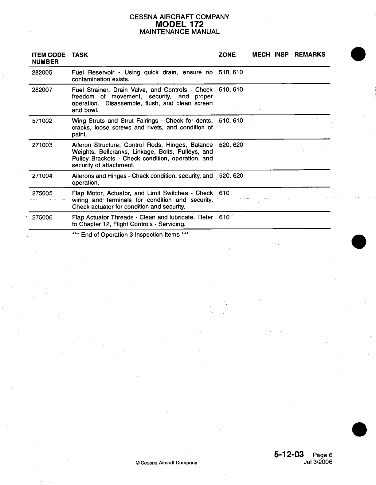
CESSNA
AIRCRAFT
COMPANY
MODEL
172
MAINTENANCE
MANUAL
Fuel
Reservoir
-
Using
quick
drain,
ensure
no 510,
610
contamination
exists.
Fuel
Strainer,
Drain
Valve,
and Controls
-
freedom
of
movement,
security,
and
operation. Disassemble,
flush,
and
clean
and
bowl.
Check
proper
screen
Wing Struts
and
Strut Fairings
-
Check
for
dents,
cracks,
loose
screws
and
rivets, and
condition
of
paint.
Aileron Structure,
Control Rods,
Hinges, Balance
Weights,
Bellcranks,
Linkage,
Bolts,
Pulleys,
and
Pulley Brackets
-
Check
condition,
operation,
and
security
of attachment.
510,610
510,610
520,620
Ailerons and Hinges
-
Check
condition,
security,
and 520,
620
operation.
Flap
Motor,
Actuator,
and
Limit
Switches
-
Check
610
wiring and-
terminals for
condition and
security.
Check
actuator
for
condition
and
security.
Flap
Actuator Threads
-
Clean and
lubricate.
Refer
610
to
Chapter
12,
Flight
Controls
-
Servicing.
***
End of
Operation
3
Inspection
Items
***
5-12-03
Page
6
Jul
3/2006
©
Cessna
Aircraft
Company
TASK
ZONE
MECH
INSP
REMARKS
ITEM
CODE
NUMBER
282005
282007
571002
271003
271004
275005
275006
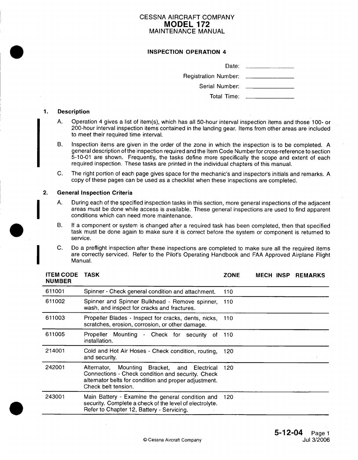
CESSNA
AIRCRAFT
COMPANY
MODEL
172
MAINTENANCE
MANUAL
INSPECTION OPERATION
4
Date:
Registration Number:
Serial
Number:
Total
Time:
1.
Description
A.
Operation
4
gives
a
list
of
item(s),
which
has
all
50-hour
interval
inspection
items
and
those
100-
or
200-hour
interval
inspection
items
contained
in
the landing
gear.
Items
from
other areas
are
included
to
meet
their
required time
interval.
B.
Inspection
items
are
given
in
the
order
of
the zone
in
which
the
inspection
is
to
be
completed.
A
general
description
of
the
inspection
required
and the
Item
Code Number
for cross-reference
to
section
5-10-01
are
shown.
Frequently,
the
tasks
define
more
specifically
the
scope
and
extent
of each
required
inspection.
These tasks
are
printed
in
the
individual chapters
of
this
manual.
C.
The right
portion
of
each page
gives
space
for
the
mechanic's
and
inspector's
initials
and
remarks.
A
copy
of
these
pages
can
be
used
as
a
checklist
when
these
inspections
are
completed.
2.
General
Inspection
Criteria
A.
During
each
of
the
specified
inspection tasks
in
this section,
more
general
inspections
of
the
adjacent
areas
must
be
done
while
access
is
available.
These
general inspections
are
used to
find
apparent
conditions
which
can need
more
maintenance.
B. If
a
component
or
system
is
changed after
a
required task
has
been
completed,
then that
specified
task
must
be
done
again
to
make
sure
it
is
correct
before
the
system
or
component
is
returned
to
service.
C.
Do
a
preflight
inspection
after
these
inspections
are
completed
to
make
sure
all
the
required
items
are
correctly
serviced.
Refer
to
the
Pilot's
Operating
Handbook
and
FAA
Approved
Airplane
Flight
Manual.
ITEM
CODE TASK
ZONE
MECH
INSP
REMARKS
NUMBER
611001
Spinner
-
Check
general
condition
and
attachment.
110
611002
Spinner
and
Spinner
Bulkhead
-
Remove
spinner,
110
wash,
and
inspect
for cracks
and
fractures.
611003
Propeller
Blades
-
Inspect for cracks, dents,
nicks,
110
scratches,
erosion,
corrosion,
or
other
damage.
611005
Propeller
Mounting
-
Check
for security
of
110
installation.
214001
Cold
and
Hot
Air
Hoses
-
Check
condition,
routing,
120
and
security.
242001
Alternator, Mounting Bracket, and
Electrical
120
Connections
-
Check
condition
and
security.
Check
alternator
belts
for condition
and
proper
adjustment.
Check
belt
tension.
243001
Main
Battery
-
Examine
the
general
condition
and
120
security.
Complete
a
check
of
the
level
of
electrolyte.
Refer
to
Chapter
12,
Battery
-
Servicing.
5-12-04
Page
1
©
Cessna
Aircraft
Company
Jul
3/2006
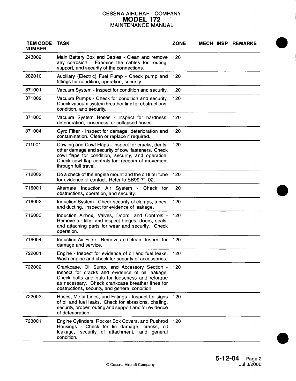
CESSNA
AIRCRAFT
COMPANY
MODEL
172
MAINTENANCE
MANUAL
ITEM
CODE
TASK
ZONE
MECH
INSP
REMARKS
NUMBER
243002
Main
Battery
Box
and
Cables
-
Clean
and
remove
120
any corrosion.
Examine
the
cables
for
routing,
support,
and
security
of
the
connections.
282010 Auxiliary (Electric)
Fuel
Pump
-
Check
pump
and
120
fittings
for condition,
operation, security.
371001 Vacuum
System
-
Inspect for
condition
and
security.
120
371002
Vacuum
Pumps
-
Check for
condition
and
security.
120
Check
vacuum
system
breather
line
for obstructions,
condition,
and
security.
371003
Vacuum
System
Hoses
-
Inspect for
hardness,
120
deterioration,
looseness,
or
collapsed
hoses.
371004
Gyro
Filter
-
Inspect
for
damage,
deterioration
and
120
contamination.
Clean
or
replace
if
required.
711001
Cowling and
Cowl Flaps
-
Inspect for
cracks,
dents,
120
other damage
and
security
of
cowl
fasteners.
Check
cowl
flaps
for
condition,
security,
and
operation.
Check
cowl flap
controls for
freedom
of
movement
through
full travel.
712002
Do
a
check
of
the
engine mount
and
the
oil
filter
tube
120
for
evidence
of
contact.
Refer
to
SB99-71-02.
716001
Alternate
Induction Air System
-
Check
for
120
obstructions,
operation,
and
security.
716002
Induction System
-
Check
security
of
clamps,
tubes,
120
and
ducting. Inspect for
evidence
of
leakage.
716003
Induction
Airbox,
Valves, Doors,
and
Controls
-
120
Remove
air
filter
and
inspect
hinges, doors,
seals,
and
attaching
parts
for
wear
and
security.
Check
operation.
716004
Induction Air
Filter
-
Remove
and clean.
Inspect
for
120
damage
and
service.
722001
Engine
-
Inspect
for
evidence
of
oil
and
fuel
leaks.
120
Wash
engine
and
check
for
security
of
accessories.
722002 Crankcase,
Oil
Sump,
and
Accessory
Section
-
120
Inspect
for
cracks
and
evidence
of
oil
leakage.
Check
bolts
and
nuts
for
looseness
and
retorque
as
necessary. Check
crankcase breather lines
for
obstructions,
security,
and
general
condition.
722003
Hoses,
Metal
Lines,
and
Fittings
-
Inspect
for
signs
120
of
oil
and
fuel
leaks.
Check
for
abrasions, chafing,
security,
proper routing
and
support
and
for
evidence
of
deterioration.
723001 Engine
Cylinders,
Rocker
Box
Covers,
and Pushrod
120
Housings
-
Check
for
fin
damage,
cracks,
oil
leakage,
security
of
attachment,
and
general
condition.
5-12-04
Page
2
©
Cessna
Aircraft
Company
Jul
3/2006
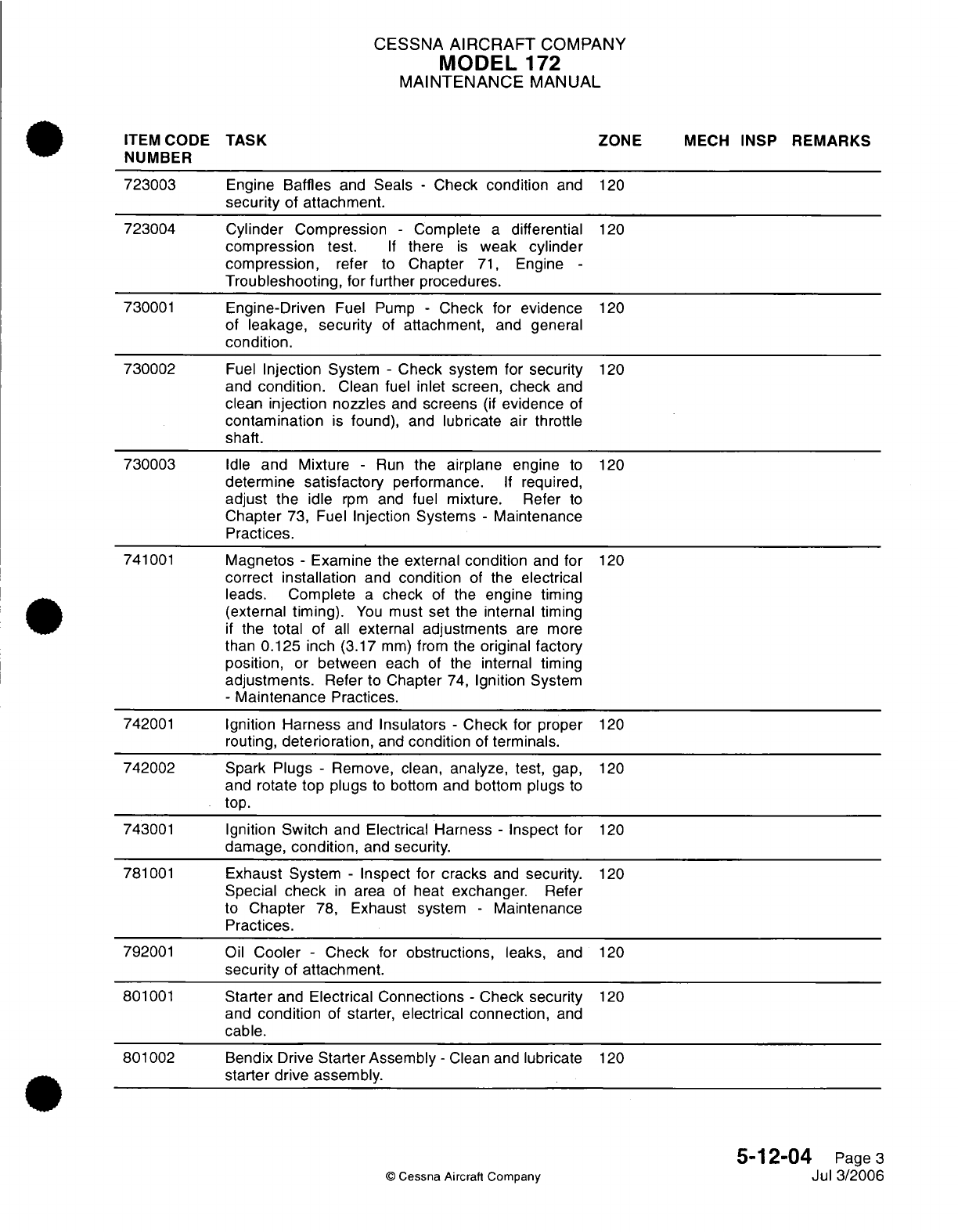
CESSNA
AIRCRAFT
COMPANY
MODEL
172
MAINTENANCE
MANUAL
ITEM
CODE
TASK
ZONE
MECH
INSP
REMARKS
NUMBER
723003
Engine
Baffles
and
Seals
-
Check
condition
and
120
security
of
attachment.
723004
Cylinder
Compression
-
Complete
a
differential
120
compression
test.
If
there
is
weak cylinder
compression,
refer to
Chapter
71,
Engine
-
Troubleshooting,
for
further procedures.
730001
Engine-Driven
Fuel Pump
-
Check
for
evidence
120
of
leakage,
security
of
attachment,
and
general
condition.
730002
Fuel
Injection
System
-
Check system
for
security
120
and
condition.
Clean
fuel
inlet
screen,
check
and
clean
injection nozzles
and
screens
(if
evidence
of
contamination
is
found),
and
lubricate air throttle
shaft.
730003
Idle
and
Mixture
-
Run
the
airplane
engine
to
120
determine
satisfactory
performance.
If
required,
adjust
the idle
rpm
and
fuel
mixture.
Refer
to
Chapter
73,
Fuel
Injection
Systems
-
Maintenance
Practices.
741001
Magnetos
-
Examine
the
external
condition
and
for
120
correct
installation
and
condition
of
the
electrical
leads.
Complete
a
check
of
the
engine
timing
(external timing).
You
must
set
the
internal
timing
if
the total
of
all
external
adjustments
are
more
than
0.125
inch (3.17
mm)
from the
original
factory
position,
or
between
each
of
the
internal
timing
adjustments.
Refer
to
Chapter
74,
Ignition
System
-
Maintenance
Practices.
742001
Ignition
Harness
and
Insulators
-
Check for
proper
120
routing,
deterioration,
and
condition
of
terminals.
742002
Spark
Plugs
-
Remove,
clean,
analyze,
test,
gap,
120
and rotate top
plugs
to
bottom
and
bottom
plugs
to
top.
743001
Ignition
Switch
and Electrical
Harness
-
Inspect for
120
damage,
condition,
and
security.
781001
Exhaust
System
-
Inspect
for
cracks
and
security.
120
Special
check
in
area
of
heat exchanger.
Refer
to
Chapter
78,
Exhaust system
-
Maintenance
Practices.
792001
Oil
Cooler
-
Check for
obstructions,
leaks,
and
120
security
of
attachment.
801001
Starter
and
Electrical
Connections
-
Check
security
120
and
condition
of
starter,
electrical
connection,
and
cable.
801002
Bendix
Drive
Starter
Assembly
-
Clean and
lubricate
120
starter drive assembly.
5-12-04
Page
3
©
Cessna
Aircraft
Company
Jul
3/2006
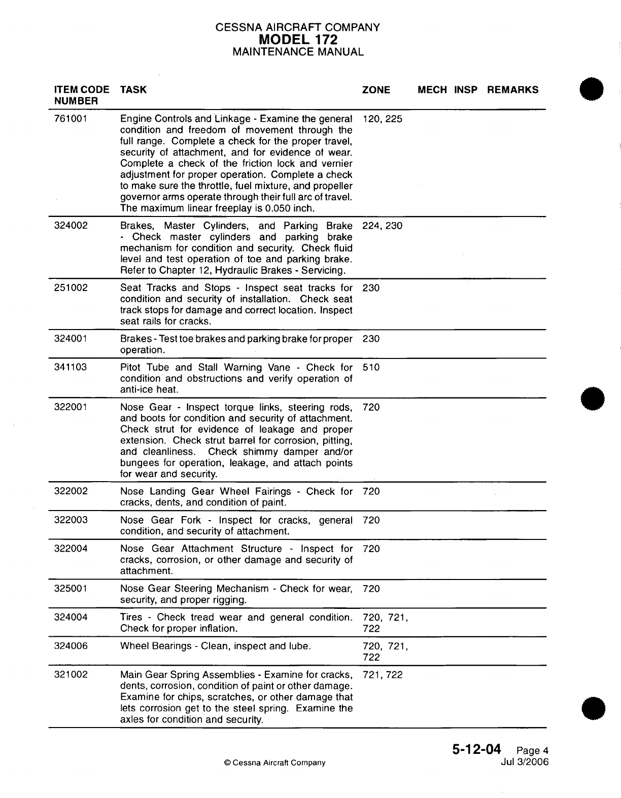
CESSNA
AIRCRAFT
COMPANY
MODEL
172
MAINTENANCE
MANUAL
ITEM
CODE
TASK
ZONE
MECH
INSP
REMARKS
NUMBER
761001
Engine
Controls
and
Linkage
-
Examine
the
general
120,
225
condition
and
freedom
of
movement through
the
full
range.
Complete
a
check
for
the
proper
travel,
security
of
attachment,
and
for
evidence
of
wear.
Complete
a
check
of
the friction
lock
and vernier
adjustment
for
proper
operation.
Complete
a
check
to
make
sure
the
throttle,
fuel
mixture,
and propeller
governor
arms
operate
through their
full
arc
of
travel.
The
maximum
linear
freeplay
is
0.050
inch.
324002 Brakes, Master
Cylinders,
and
Parking
Brake
224,230
-
Check
master
cylinders
and
parking
brake
mechanism
for
condition
and
security.
Check
fluid
level and
test
operation
of
toe
and
parking
brake.
Refer
to
Chapter
12,
Hydraulic
Brakes
-
Servicing.
251002 Seat Tracks
and
Stops
-
Inspect seat
tracks
for
230
condition
and
security
of
installation.
Check
seat
track stops
for
damage
and
correct
location.
Inspect
seat
rails
for
cracks.
324001
Brakes
-
Test
toe
brakes
and
parking
brake
for
proper
230
operation.
341103
Pitot Tube
and Stall
Warning
Vane
-
Check
for
510
condition
and
obstructions
and verify operation
of
anti-ice
heat.
322001
Nose
Gear
-
Inspect
torque
links,
steering
rods, 720
and
boots
for
condition
and
security
of
attachment.
Check
strut
for
evidence
of
leakage
and
proper
extension.
Check
strut
barrel
for
corrosion,
pitting,
and
cleanliness.
Check shimmy
damper
and/or
bungees
for operation,
leakage,
and
attach
points
for
wear
and
security.
322002
Nose
Landing
Gear
Wheel
Fairings
-
Check
for
720
cracks,
dents,
and
condition
of paint.
322003
Nose
Gear
Fork
-
Inspect
for
cracks,
general
720
condition,
and
security
of attachment.
322004
Nose
Gear
Attachment
Structure
-
Inspect for
720
cracks,
corrosion,
or
other
damage
and
security
of
attachment.
325001
Nose
Gear
Steering
Mechanism
-
Check
for
wear,
720
security,
and
proper
rigging.
324004
Tires
-
Check
tread
wear
and general
condition.
720,
721,
Check
for proper
inflation.
722
324006 Wheel
Bearings
-
Clean,
inspect
and
lube.
720,
721,
722
321002
Main
Gear
Spring
Assemblies
-
Examine
for cracks,
721,
722
dents,
corrosion,
condition
of
paint
or
other
damage.
Examine
for
chips,
scratches,
or
other
damage
that
lets
corrosion
get
to
the
steel
spring. Examine
the
axles
for
condition
and
security.
5-12-04
Page
4
©
Cessna
Aircraft
Company
Jul 3/2006
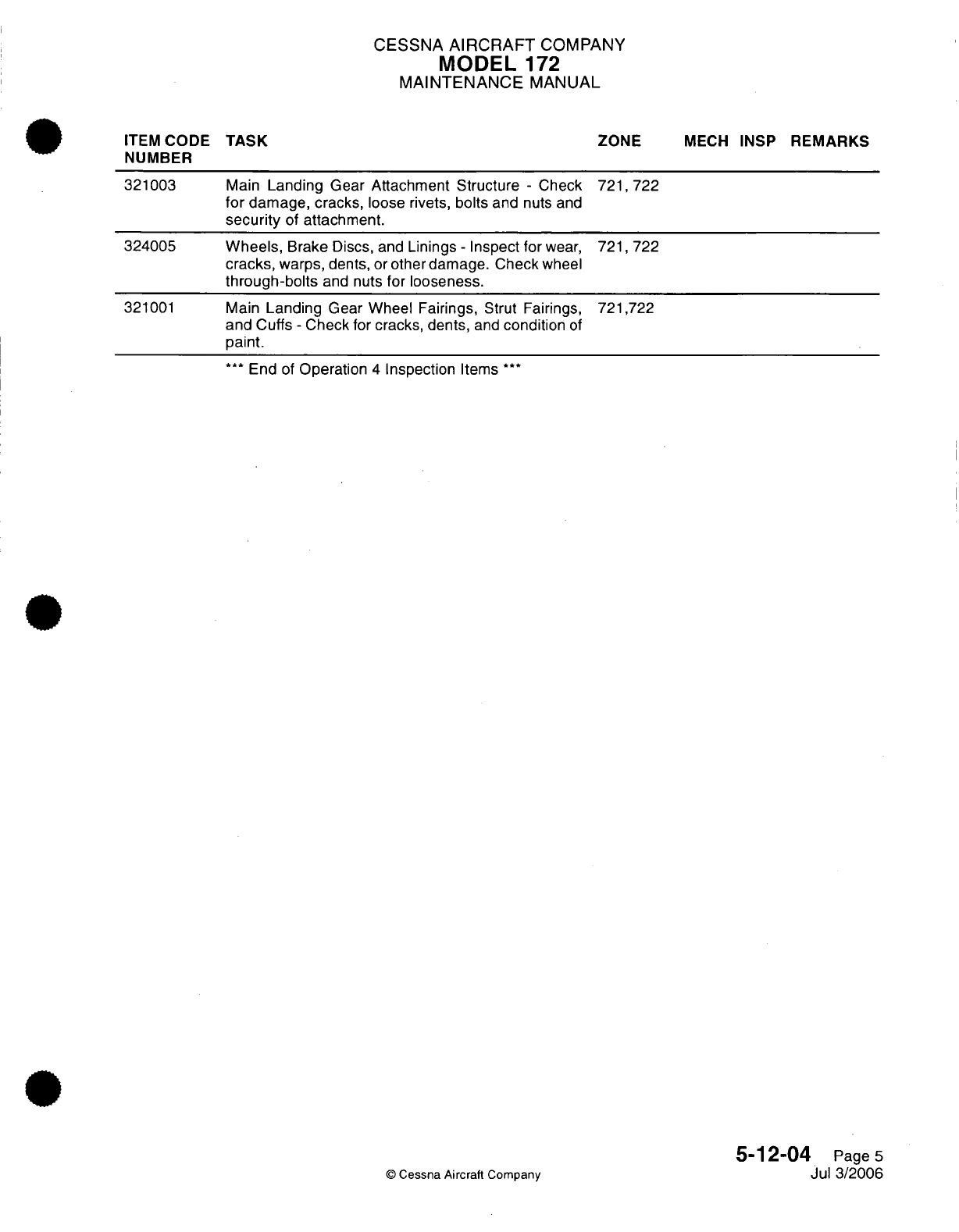
CESSNA
AIRCRAFT
COMPANY
MODEL
172
MAINTENANCE
MANUAL
ITEM
CODE
TASK
NUMBER
321003
324005
321001
ZONE
Main
Landing
Gear
Attachment Structure
-
Check
721,722
for
damage, cracks,
loose
rivets,
bolts
and
nuts
and
security
of
attachment.
Wheels,
Brake
Discs,
and
Linings
-
Inspect
for
wear,
721,
722
cracks,
warps,
dents,
or
other
damage.
Check
wheel
through-bolts
and
nuts
for
looseness.
Main
Landing
Gear Wheel
Fairings,
Strut Fairings,
721,722
and
Cuffs
-
Check for
cracks, dents,
and
condition
of
paint.
***
End
of
Operation
4
Inspection
Items
***
©
Cessna
Aircraft
Company
MECH
INSP
REMARKS
I
5-12-04
Page
5
Jul
3/2006
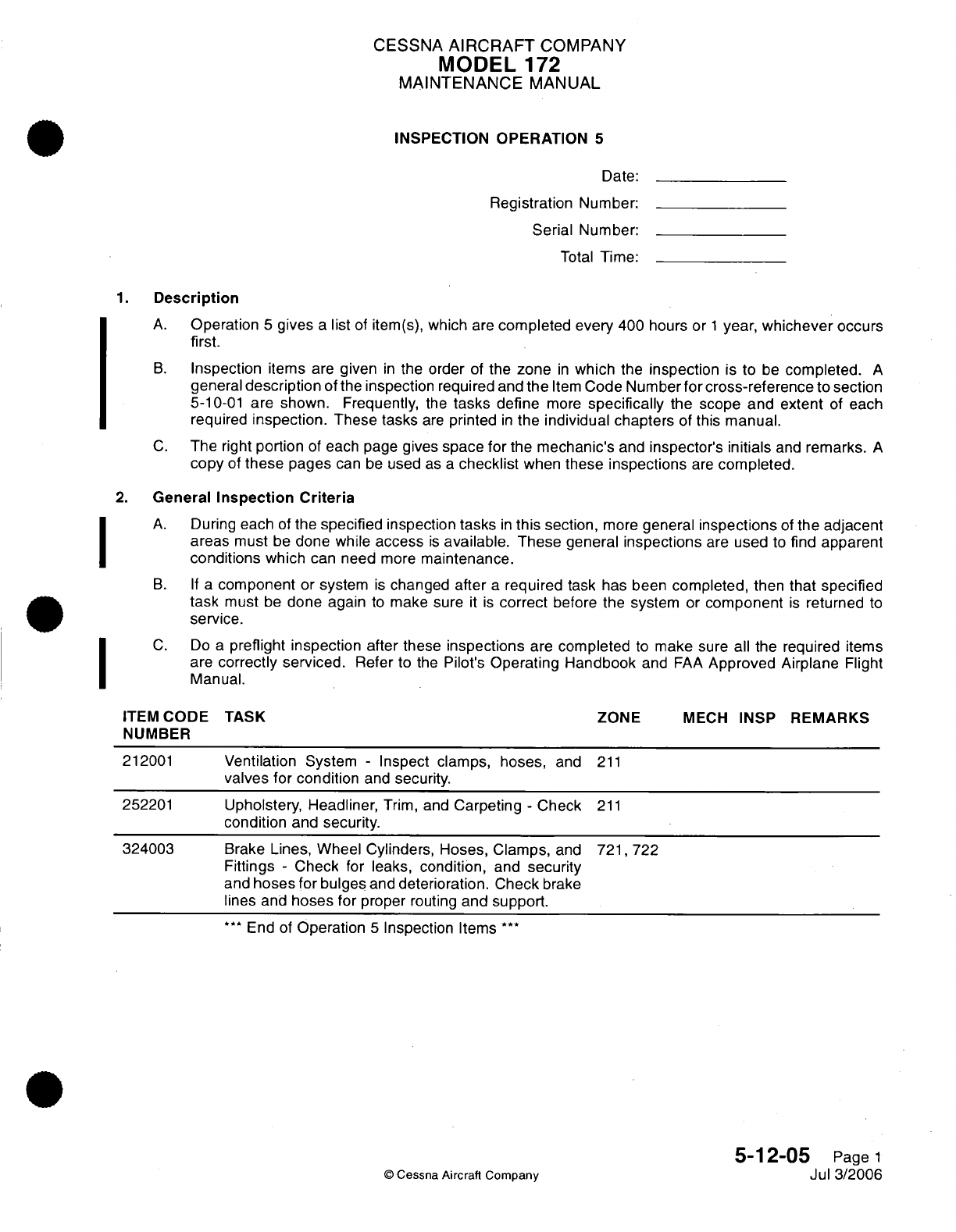
CESSNA
AIRCRAFT
COMPANY
MODEL
172
MAINTENANCE
MANUAL
INSPECTION OPERATION
5
Date:
Registration Number:
Serial Number:
Total
Time:
1.
Description
A.
Operation
5
gives
a
list
of
item(s),
which
are
completed
every
400
hours
or
1
year,
whichever occurs
first.
B.
Inspection
items
are
given
in
the
order
of
the
zone
in
which
the
inspection
is
to
be
completed.
A
general
description
of
the inspection
required
and
the
Item
Code
Number
for
cross-reference
to
section
5-10-01
are shown. Frequently,
the
tasks
define
more
specifically
the
scope and extent
of
each
required
inspection.
These tasks
are
printed
in
the
individual chapters
of
this
manual.
C.
The
right
portion
of
each page
gives
space for
the
mechanic's
and
inspector's
initials
and
remarks.
A
copy
of
these
pages
can
be
used
as
a
checklist
when
these
inspections
are
completed.
2.
General
Inspection
Criteria
A.
During
each
of
the
specified
inspection
tasks
in
this
section,
more
general
inspections
of
the
adjacent
areas
must
be
done while
access
is
available.
These
general
inspections
are
used
to
find
apparent
conditions
which
can
need
more
maintenance.
B. If
a
component
or
system
is
changed
after
a
required
task has been
completed,
then
that
specified
task
must
be
done
again
to
make sure
it
is
correct
before the
system
or
component
is
returned
to
service.
C.
Do
a
preflight inspection after
these
inspections
are
completed
to
make
sure
all
the
required
items
are
correctly serviced.
Refer
to
the
Pilot's
Operating Handbook
and
FAA
Approved Airplane
Flight
Manual.
ITEM
CODE TASK ZONE
MECH
INSP
REMARKS
NUMBER
212001
Ventilation
System
-
Inspect clamps, hoses,
and
211
valves
for
condition
and
security.
252201
Upholstery,
Headliner,
Trim,
and
Carpeting
-
Check
211
condition
and
security.
324003
Brake Lines,
Wheel Cylinders, Hoses, Clamps,
and
721,
722
Fittings
-
Check
for
leaks,
condition,
and
security
and
hoses
for bulges
and
deterioration. Check
brake
lines
and
hoses
for
proper
routing
and support.
**
End
of
Operation
5
Inspection
Items
***
5-12-05
Page
1
©
Cessna
Aircraft Company
Jul
3/2006
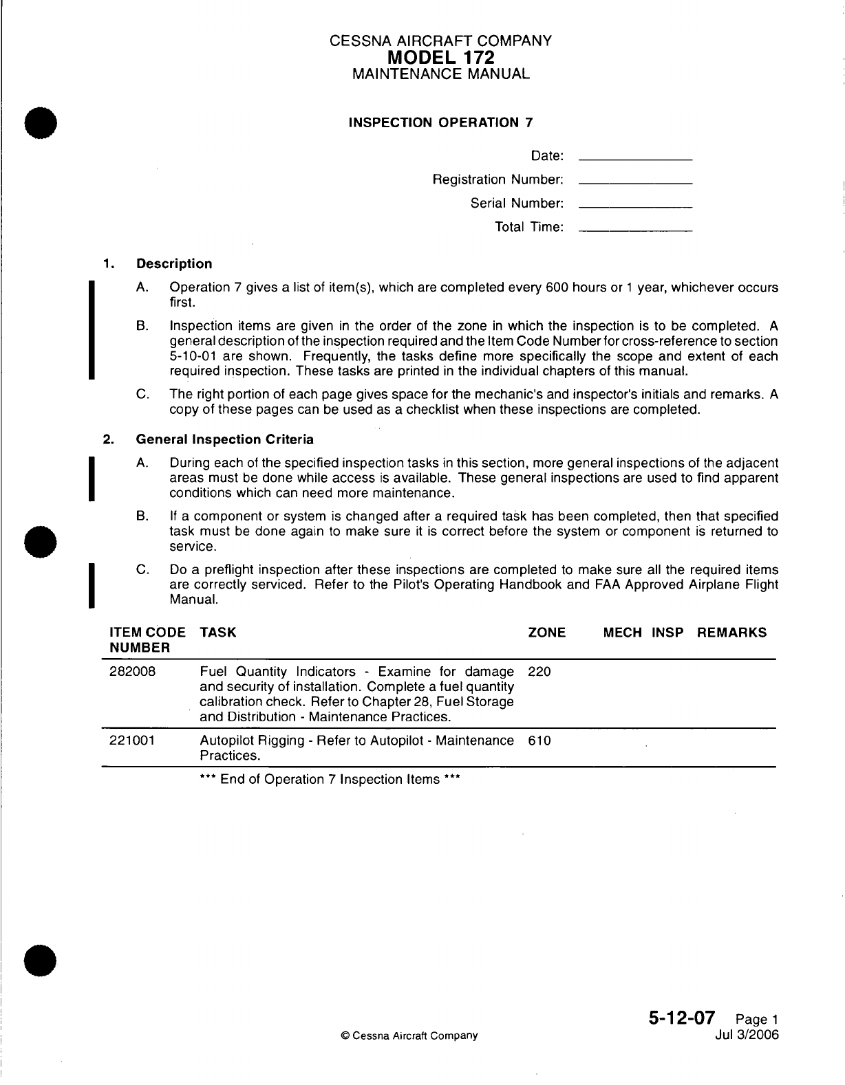
CESSNA
AIRCRAFT
COMPANY
MODEL
172
MAINTENANCE
MANUAL
INSPECTION OPERATION
7
Date:
Registration
Number:
Serial Number:
Total
Time:
1.
Description
A.
Operation
7
gives
a
list
of
item(s),
which
are
completed
every
600
hours
or
1
year,
whichever
occurs
first.
B.
Inspection
items
are
given
in
the order
of
the zone
in
which
the
inspection
is
to
be
completed.
A
general
description
of
the
inspection
required
and
the
Item
Code Number
for
cross-reference
to
section
5-10-01
are shown.
Frequently,
the
tasks define
more
specifically
the scope
and
extent
of each
required
inspection.
These
tasks
are
printed
in
the
individual chapters
of
this
manual.
C.
The right
portion
of each
page gives
space
for
the
mechanic's
and
inspector's
initials
and
remarks.
A
copy
of
these
pages
can
be
used
as
a
checklist
when
these
inspections
are
completed.
2.
General
Inspection Criteria
A.
During each
of
the
specified inspection
tasks
in
this
section,
more
general
inspections
of the
adjacent
areas
must
be
done
while
access
is
available.
These general
inspections
are
used to
find apparent
conditions
which
can need
more
maintenance.
B. If
a
component
or
system
is
changed
after
a
required task
has
been
completed,
then
that
specified
task
must
be
done
again
to
make sure
it
is
correct
before
the
system
or
component
is
returned
to
service.
C.
Do
a
preflight inspection
after
these
inspections
are
completed
to
make
sure
all
the
are
correctly
serviced.
Refer
to
the
Pilot's
Operating Handbook
and
FAA
Approved
Manual.
required
items
Airplane
Flight
ITEM
CODE
NUMBER
282008
221001
TASK
Fuel
Quantity
Indicators
-
Examine for
damage
and
security
of
installation.
Complete
a
fuel
quantity
calibration check.
Refer
to
Chapter
28,
Fuel
Storage
and
Distribution
-
Maintenance Practices.
Autopilot
Rigging
-
Refer
to
Autopilot
-
Maintenance
Practices.
***
End
of
Operation
7
Inspection
Items
***
ZONE
MECH
INSP
220
610
5-12-07
Page
1
Jul
3/2006
©
Cessna
Aircraft
Company
I
I
REMARKS
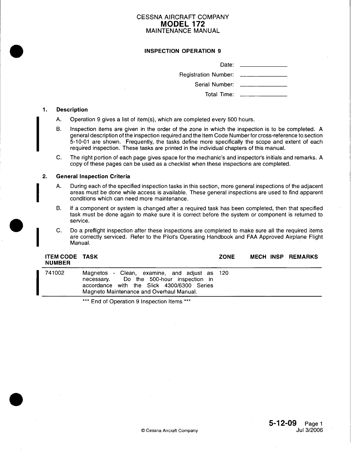
CESSNA AIRCRAFT
COMPANY
MODEL
172
MAINTENANCE
MANUAL
INSPECTION OPERATION
9
Date:
Registration
Number:
Serial
Number:
Total Time:
1.
Description
A.
Operation
9
gives
a
list
of
item(s),
which
are
completed
every
500
hours.
B.
Inspection
items
are
given
in
the
order
of
the
zone
in
which
the
inspection
is
to
be
completed.
A
general
description
of
the
inspection
required and
the
Item
Code Number for
cross-reference
to
section
5-10-01
are
shown. Frequently,
the
tasks define
more
specifically
the
scope
and
extent
of
each
required
inspection.
These
tasks
are
printed
in
the
individual chapters
of
this
manual.
C.
The right
portion
of
each
page
gives space
for
the
mechanic's
and
inspector's
initials
and
remarks.
A
copy
of
these
pages
can
be
used
as
a
checklist
when
these inspections
are
completed.
2.
General
Inspection
Criteria
A.
During
each
of
the
specified inspection
tasks
in
this
section,
more
general
inspections
of
the
adjacent
areas must
be
done
while
access
is
available.
These
general
inspections
are
used
to find
apparent
conditions
which can
need more
maintenance.
B.
If
a
component
or
system
is
changed
after
a
required
task
has
been
completed,
then
that
specified
task
must
be
done again
to
make
sure
it
is
correct
before
the
system
or
component
is
returned
to
service.
C.
Do
a
preflight inspection
after these inspections
are
completed
to
make
sure
all
the
required
items
are
correctly
serviced.
Refer
to
the
Pilot's
Operating
Handbook
and
FAA
Approved
Airplane
Flight
Manual.
TASK
ZONE
MECH
INSP
REMARKS
Magnetos
-
Clean,
examine,
and
adjust
as
necessary.
Do
the
500-hour inspection
in
accordance
with
the
Slick
4300/6300
Series
Magneto
Maintenance
and
Overhaul
Manual.
***
End
of
Operation
9
Inspection
Items
***
120
5-12-09
Page
1
Jul
3/2006
©
Cessna Aircraft Company
I
I
I
I
ITEM
CODE
NUMBER
741002
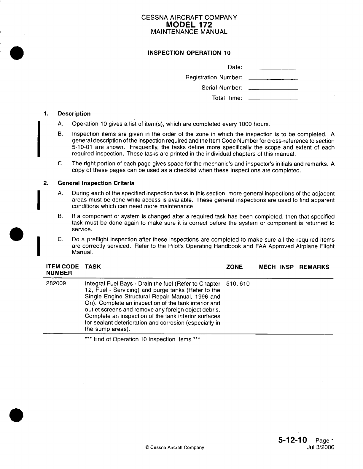
CESSNA
AIRCRAFT
COMPANY
MODEL
172
MAINTENANCE
MANUAL
INSPECTION
OPERATION
10
Date:
Registration
Number:
Serial
Number:
Total
Time:
1.
Description
A.
Operation
10
gives
a
list
of
item(s),
which
are
completed
every
1000
hours.
B.
Inspection
items
are
given
in
the
order
of
the
zone
in
which
the
inspection
is
to
be
completed.
A
general
description
of
the
inspection
required and the
Item
Code
Number for
cross-reference
to
section
5-10-01
are shown. Frequently,
the
tasks
define
more
specifically
the
scope
and
extent
of
each
required
inspection.
These tasks
are
printed
in
the
individual chapters
of
this
manual.
C.
The
right
portion
of each
page
gives
space
for
the
mechanic's
and
inspector's
initials
and
remarks.
A
copy
of
these
pages
can
be
used
as
a
checklist
when
these
inspections
are
completed.
2.
General
Inspection
Criteria
A.
During
each
of
the specified
inspection
tasks
in
this
section,
more
general
inspections
of
the
adjacent
areas
must
be
done
while
access
is
available.
These
general
inspections
are
used
to
find apparent
conditions
which
can need
more
maintenance.
B.
If
a
component
or
system
is
changed after
a
required task
has been
completed,
then
that
specified
task must
be
done
again
to
make sure
it
is
correct
before
the system
or
component
is
returned
to
service.
C.
Do
a
preflight
inspection
after
these
inspections
are
completed
to
make
sure
all
the required
items
are
correctly
serviced.
Refer
to
the
Pilot's
Operating
Handbook
and
FAA
Approved
Airplane
Flight
Manual.
ITEM
CODE
TASK
ZONE
MECH
INSP
REMARKS
NUMBER
282009 Integral
Fuel
Bays
-
Drain
the fuel
(Refer
to Chapter
510,
610
12,
Fuel
-
Servicing)
and
purge
tanks
(Refer
to the
Single
Engine
Structural
Repair
Manual,
1996
and
On).
Complete
an
inspection
of
the
tank interior
and
outlet
screens
and remove
any
foreign
object
debris.
Complete
an
inspection
of the
tank
interior
surfaces
for sealant
deterioration
and
corrosion
(especially
in
the
sump
areas).
***
End of
Operation
10
Inspection
Items
***
5-12-10
Page
1
©
Cessna
Aircraft
Company
Jul
3/2006
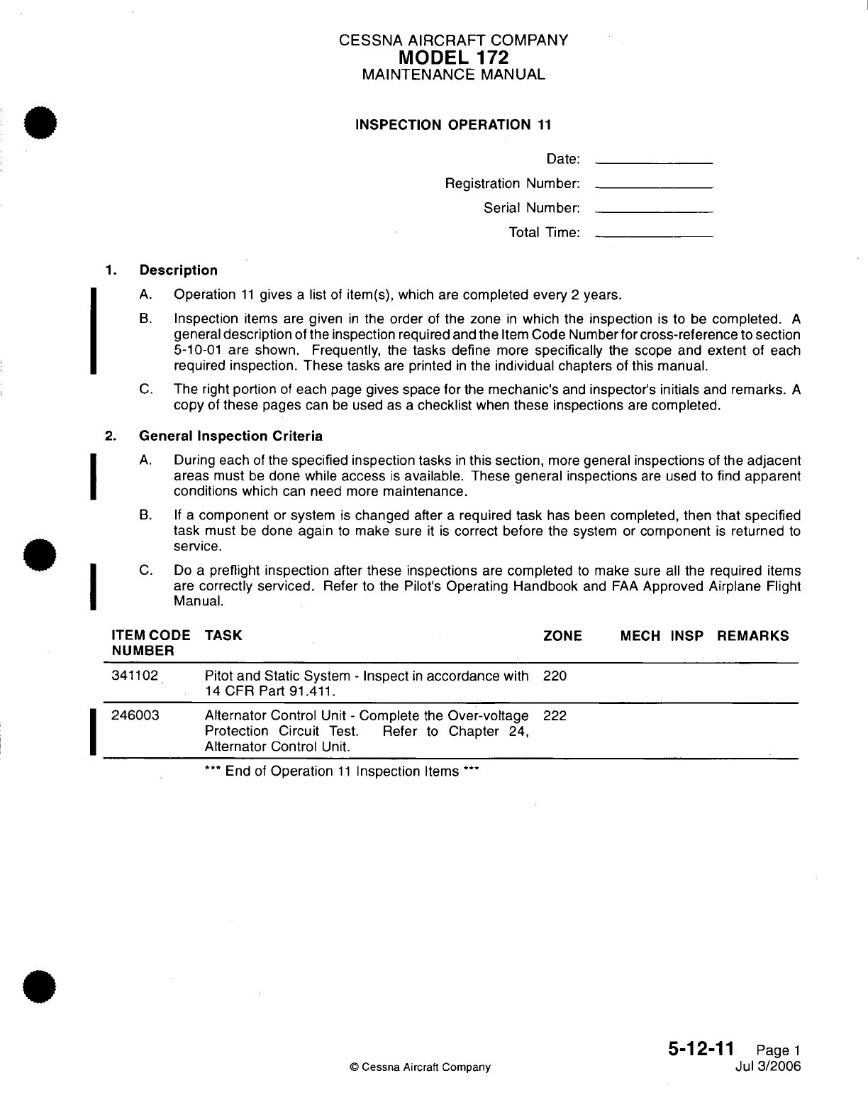
CESSNA
AIRCRAFT
COMPANY
MODEL
172
MAINTENANCE
MANUAL
INSPECTION OPERATION
11
Date:
Registration
Number:
Serial Number:
Total Time:
1.
Description
A.
Operation
11
gives
a
list
of
item(s),
which
are
completed
every
2
years.
B.
Inspection
items
are
given
in
the order
of
the zone
in
which
the
inspection
is
to
be
completed.
A
general
description
of the
inspection
required
and the
Item
Code Number
for
cross-reference
to
section
5-10-01
are
shown. Frequently, the
tasks
define
more
specifically
the
scope
and
extent
of
each
required
inspection.
These tasks
are
printed
in
the
individual
chapters
of
this
manual.
C.
The
right
portion
of
each
page
gives space
for
the
mechanic's
and
inspector's
initials
and
remarks.
A
copy
of
these
pages
can
be
used
as
a
checklist
when
these inspections
are
completed.
2.
General
Inspection
Criteria
A.
During
each
of
the
specified
inspection
tasks
in
this
section,
more
general
inspections
of
the
adjacent
areas
must
be
done while
access
is
available.
These
general
inspections
are
used
to find
apparent
conditions
which
can need
more
maintenance.
B. If
a
component
or
system
is
changed
after
a
required
task
has
been
completed,
then that
specified
task
must
be
done
again
to
make
sure
it
is
correct
before
the system
or
component
is
returned
to
service.
C.
Do
a
preflight
inspection
after these
inspections
are
completed
to
make
sure
all
the required
items
are
correctly
serviced.
Refer
to
the
Pilot's
Operating
Handbook
and
FAA
Approved
Airplane
Flight
Manual.
ITEM
CODE TASK
ZONE
MECH
INSP
REMARKS
NUMBER
341102
Pitot
and
Static
System
-
Inspect
in
accordance
with
220
14
CFR Part
91.411.
246003
Alternator
Control
Unit
-
Complete
the
Over-voltage
222
Protection Circuit
Test.
Refer
to
Chapter
24,
Alternator
Control
Unit.
***
End
of
Operation
11
Inspection
Items
**
5-12-11
Page
1
©
Cessna
Aircraft
Company
Jul 3/2006
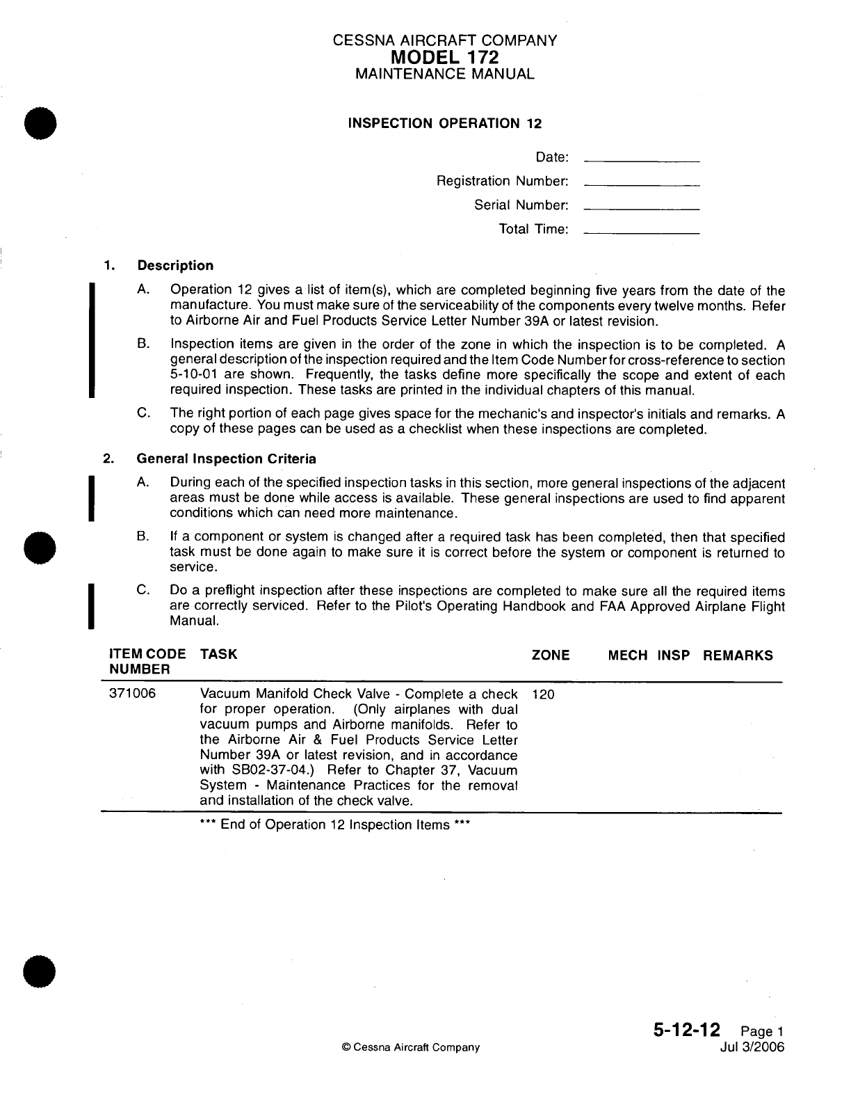
CESSNA
AIRCRAFT
COMPANY
MODEL
172
MAINTENANCE
MANUAL
INSPECTION OPERATION
12
Date:
Registration Number:
Serial
Number:
Total Time:
1.
Description
A.
Operation
12
gives
a
list
of
item(s),
which
are
completed
beginning
five years
from
the
date
of
the
manufacture.
You
must
make
sure
of
the
serviceability
of
the
components
every
twelve
months.
Refer
to
Airborne
Air
and
Fuel
Products
Service Letter
Number
39A or
latest
revision.
B.
Inspection
items
are
given
in
the
order
of
the
zone
in
which
the
inspection
is
to
be
completed.
A
general
description
of
the
inspection
required
and
the
Item
Code
Numberfor
cross-reference
to
section
5-10-01
are shown. Frequently,
the
tasks
define
more
specifically
the scope
and
extent
of each
required
inspection.
These
tasks
are
printed
in
the
individual chapters
of
this
manual.
C.
The
right
portion
of
each page
gives
space
for
the
mechanic's
and
inspector's
initials
and
remarks.
A
copy
of
these
pages
can
be
used
as
a
checklist
when
these
inspections
are
completed.
2.
General
Inspection Criteria
A.
During
each
of the
specified inspection
tasks
in
this section,
more
general
inspections
of the
adjacent
areas
must
be
done
while
access
is
available.
These general
inspections
are
used
to
find
apparent
conditions
which
can
need
more
maintenance.
B. If
a
component
or
system
is
changed after
a
required task
has
been
completed,
then
that
specified
task must
be
done
again
to
make
sure
it
is
correct
before
the
system
or
component
is
returned
to
service.
C.
Do
a
preflight
inspection after
these
inspections
are
completed
to
make
sure
all the
required
items
are
correctly
serviced.
Refer
to
the
Pilot's
Operating
Handbook
and
FAA
Approved Airplane
Flight
Manual.
ITEM
CODE
TASK
ZONE
MECH
INSP
REMARKS
NUMBER
371006
Vacuum
Manifold
Check
Valve
-
Complete
a
check
120
for
proper
operation.
(Only
airplanes
with
dual
vacuum
pumps
and
Airborne
manifolds.
Refer
to
the
Airborne
Air
&
Fuel
Products
Service
Letter
Number
39A
or latest
revision,
and
in
accordance
with
SB02-37-04.)
Refer
to
Chapter
37,
Vacuum
System
-
Maintenance Practices
for
the
removal
and installation
of
the
check
valve.
***
End
of
Operation
12
Inspection
Items
***
5-12-12
Page
1
©
Cessna
Aircraft
Company
Jul
3/2006
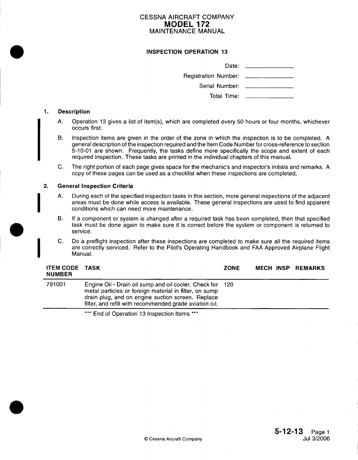
CESSNA
AIRCRAFT
COMPANY
MODEL
172
MAINTENANCE
MANUAL
INSPECTION OPERATION
13
Date:
Registration
Number:
Serial
Number:
Total
Time:
1.
Description
A.
Operation
13
gives
a
list
of
item(s),
which
are
completed
every
50
hours
or
four
months,
whichever
occurs
first.
B.
Inspection
items
are
given
in
the
order
of
the
zone
in
which
the inspection
is
to
be
completed.
A
general
description
of
the inspection required
and
the
Item
Code
Numberfor
cross-reference
to
section
5-10-01
are
shown.
Frequently,
the
tasks
define
more
specifically
the
scope and
extent
of
each
required
inspection.
These
tasks
are
printed
in
the
individual chapters
of
this
manual.
C.
The right
portion
of
each
page
gives
space
for
the
mechanic's
and
inspector's
initials
and
remarks.
A
copy
of
these
pages
can
be
used
as
a
checklist
when
these
inspections
are
completed.
2.
General
Inspection
Criteria
A.
During
each
of
the
specified
inspection tasks
in
this
section,
more
general
inspections
of
the
adjacent
areas
must
be
done while
access
is
available.
These
general
inspections
are
used to
find
apparent
conditions
which can
need
more
maintenance.
B.
If
a
component
or system
is
changed after
a
required
task
has
been
completed, then that specified
task
must
be
done again
to
make sure
it
is
correct
before
the
system
or
component
is
returned
to
service.
C.
Do
a
preflight
inspection
after these
inspections
are
completed
to
make
sure
all
the
are
correctly
serviced.
Refer
to the Pilot's
Operating
Handbook
and
FAA
Approved
Manual.
ITEM
CODE
NUMBER
791001
TASK
Engine
Oil
-
Drain
oil
sump
and
oil
cooler.
Check
for
metal
particles
or
foreign
material
in
filter,
on
sump
drain
plug, and
on
engine suction screen.
Replace
filter,
and
refill
with recommended
grade
aviation
oil.
***
End of
Operation
13
Inspection
Items
***
ZONE
MECH
INSP
required
items
Airplane
Flight
REMARKS
120
5-12-13
Page
1
Jul
3/2006
©
Cessna Aircraft
Company
I
I
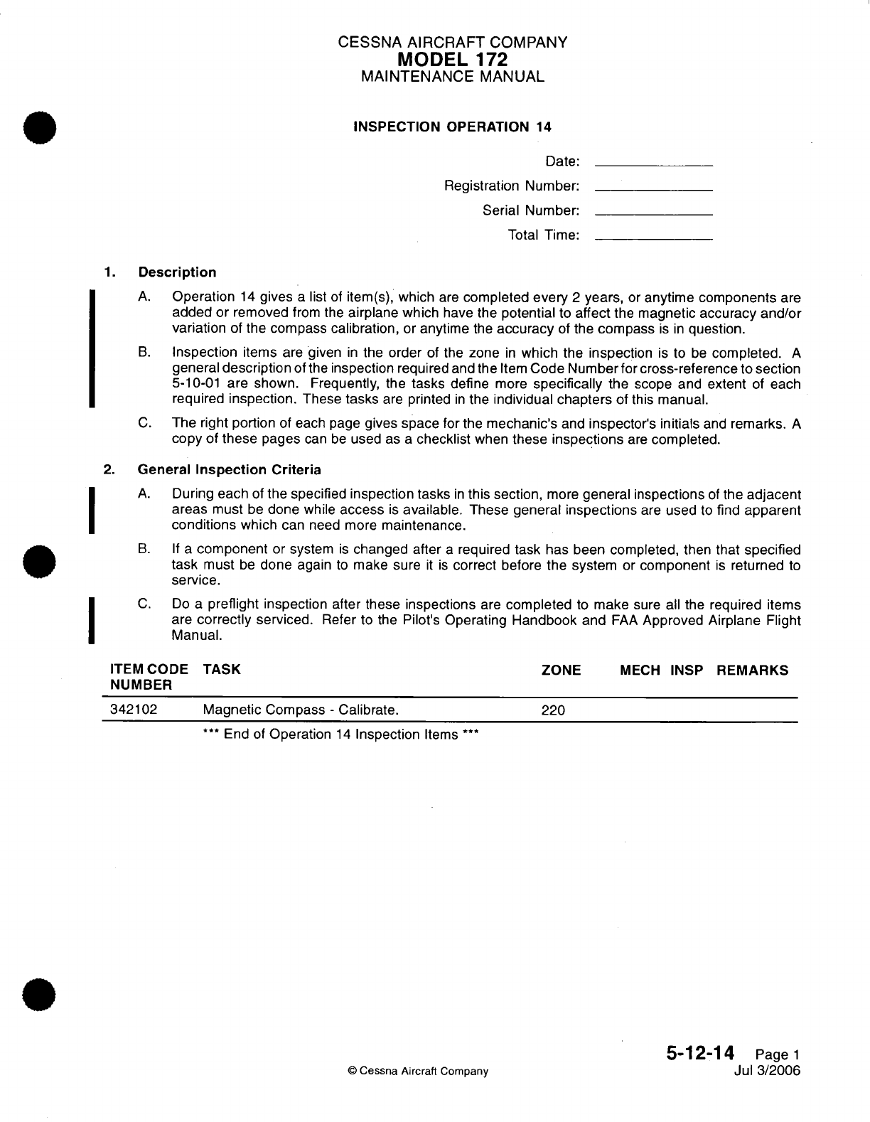
CESSNA
AIRCRAFT
COMPANY
MODEL
172
MAINTENANCE
MANUAL
INSPECTION
OPERATION
14
Date:
Registration
Number:
Serial
Number:
Total
Time:
1.
Description
A.
Operation
14
gives
a
list
of
item(s),
which
are
completed
every
2
years,
or
anytime
components
are
added
or
removed
from
the
airplane which
have
the
potential
to
affect
the
magnetic
accuracy
and/or
variation
of
the
compass calibration,
or
anytime
the
accuracy
of
the
compass
is
in
question.
B.
Inspection
items
are
given
in
the order
of
the
zone
in
which
the
inspection
is
to
be
completed.
A
general
description
of
the
inspection
required
and the
Item
Code
Number
for
cross-reference to
section
5-10-01
are shown.
Frequently, the
tasks
define
more
specifically
the
scope
and
extent
of
each
required
inspection.
These
tasks
are
printed
in
the
individual chapters
of
this
manual.
C.
The right
portion
of each
page
gives
space
for
the
mechanic's
and
inspector's
initials
and
remarks.
A
copy
of
these
pages
can
be
used
as
a
checklist
when
these
inspections
are
completed.
2.
General
Inspection
Criteria
A.
During
each
of
the
specified
inspection
tasks
in
this
section,
more
general
inspections
of
the
adjacent
areas
must
be
done
while
access
is
available. These general
inspections
are
used
to
find
apparent
conditions
which
can need
more
maintenance.
B. If
a
component
or
system
is
changed
after
a
required
task
has been
completed,
then
that
specified
task
must
be
done
again
to
make sure
it
is
correct
before
the
system
or
component
is
returned
to
service.
C.
Do
a
preflight
inspection
after
these inspections
are
completed
to
make
sure
all
the required
items
are
correctly
serviced.
Refer
to the
Pilot's
Operating
Handbook
and
FAA
Approved
Airplane
Flight
Manual.
ITEM
CODE
TASK
ZONE
MECH
INSP
REMARKS
NUMBER
342102
Magnetic
Compass
-
Calibrate.
220
***
End
of
Operation
14
Inspection
Items
***
5-12-14
Page
1
©
Cessna Aircraft Company
Jul
3/2006
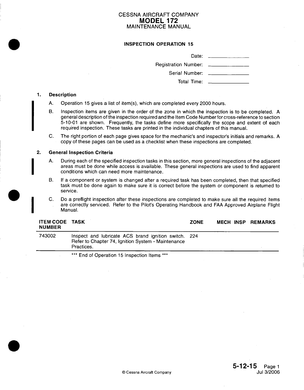
CESSNA
AIRCRAFT
COMPANY
MODEL
172
MAINTENANCE
MANUAL
INSPECTION OPERATION
15
Date:
Registration
Number:
Serial
Number:
Total
Time:
1.
Description
A.
Operation
15
gives
a
list
of
item(s),
which
are
completed
every
2000
hours.
B.
Inspection
items are
given
in
the
order
of
the zone
in
which
the
inspection
is
to
be
completed.
A
general
description of
the
inspection
required
and
the
Item
Code
Number
for
cross-reference
to
section
5-10-01
are shown.
Frequently,
the
tasks
define
more
specifically
the scope
and
extent
of each
required
inspection.
These tasks
are
printed
in
the
individual chapters
of
this
manual.
C.
The
right
portion
of
each
page
gives space
for
the
mechanic's
and
inspector's
initials
and
remarks.
A
copy
of
these
pages
can
be
used
as
a
checklist
when
these inspections
are
completed.
2.
General
Inspection
Criteria
A.
During
each
of
the
specified
inspection
tasks
in
this
section,
more
general
inspections
of
the
adjacent
areas
must
be
done while
access
is
available.
These
general
inspections
are
used
to
find
apparent
conditions
which
can
need
more
maintenance.
B.
If
a
component
or
system
is
changed after
a
required task
has
been
completed,
then
that specified
task
must
be
done
again
to
make
sure
it
is
correct
before
the
system
or
component
is
returned
to
service.
C.
Do
a
preflight inspection
after
these
inspections
are
completed
to
make
sure
all the
required
items
are
correctly
serviced.
Refer to
the
Pilot's
Operating
Handbook
and
FAA
Approved
Airplane
Flight
Manual.
ITEM
CODE
TASK
ZONE
MECH
INSP
REMARKS
NUMBER
743002
Inspect
and
lubricate
ACS
brand
ignition
switch.
224
Refer
to
Chapter
74,
Ignition
System
-
Maintenance
Practices.
***
End of
Operation
15
Inspection
Items
***
5-12-15
Page
1
©
Cessna
Aircraft
Company
Jul
3/2006
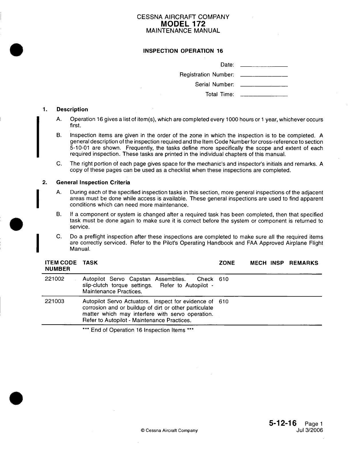
CESSNA
AIRCRAFT
COMPANY
MODEL
172
MAINTENANCE
MANUAL
INSPECTION OPERATION
16
Date:
Registration
Number:
Serial Number:
Total Time:
1.
Description
A.
Operation
16
gives
a
list
of
item(s),
which
are
completed every
1000
hours
or
1
year,
whichever occurs
first.
B.
Inspection
items
are
given
in
the
order
of the
zone
in
which
the
inspection
is
to
be
completed.
A
general
description
of
the
inspection
required
and
the
Item
Code
Number
for
cross-reference
to
section
5-10-01
are
shown.
Frequently,
the
tasks
define
more
specifically
the
scope
and extent
of
each
required
inspection.
These tasks
are
printed
in
the
individual chapters
of
this manual.
C.
The
right
portion
of
each page
gives
space for
the
mechanic's
and
inspector's
initials
and
remarks.
A
copy
of
these
pages
can
be
used
as
a
checklist
when
these
inspections
are
completed.
2.
General
Inspection
Criteria
A.
During
each
of
the
specified
inspection tasks
in
this
section,
more
general
inspections
of
the
adjacent
areas
must
be
done while
access
is
available. These
general
inspections
are
used to
find
apparent
conditions
which
can need
more
maintenance.
B. If
a
component
or
system
is
changed
after
a
required task
has been
completed,
then
that
specified
task
must
be
done
again
to
make sure
it
is
correct
before the
system
or
component
is
returned
to
service.
C.
Do
a
preflight inspection
after these
inspections
are
completed
to
make sure
all
the
required
items
are
correctly
serviced.
Refer
to
the
Pilot's
Operating Handbook
and
FAA
Approved Airplane
Flight
Manual.
ITEM
CODE TASK
ZONE
MECH
INSP
REMARKS
NUMBER
221002 Autopilot
Servo
Capstan Assemblies. Check
610
slip-clutch
torque settings.
Refer
to
Autopilot
-
Maintenance
Practices.
221003 Autopilot
Servo
Actuators. Inspect
for
evidence
of
610
corrosion
and
or
buildup
of
dirt
or
other
particulate
matter
which
may
interfere
with
servo
operation.
Refer
to
Autopilot
-
Maintenance
Practices.
***
End
of
Operation
16
Inspection
Items
***
5-12-16
Page
1
©
Cessna
Aircraft
Company
Jul
3/2006
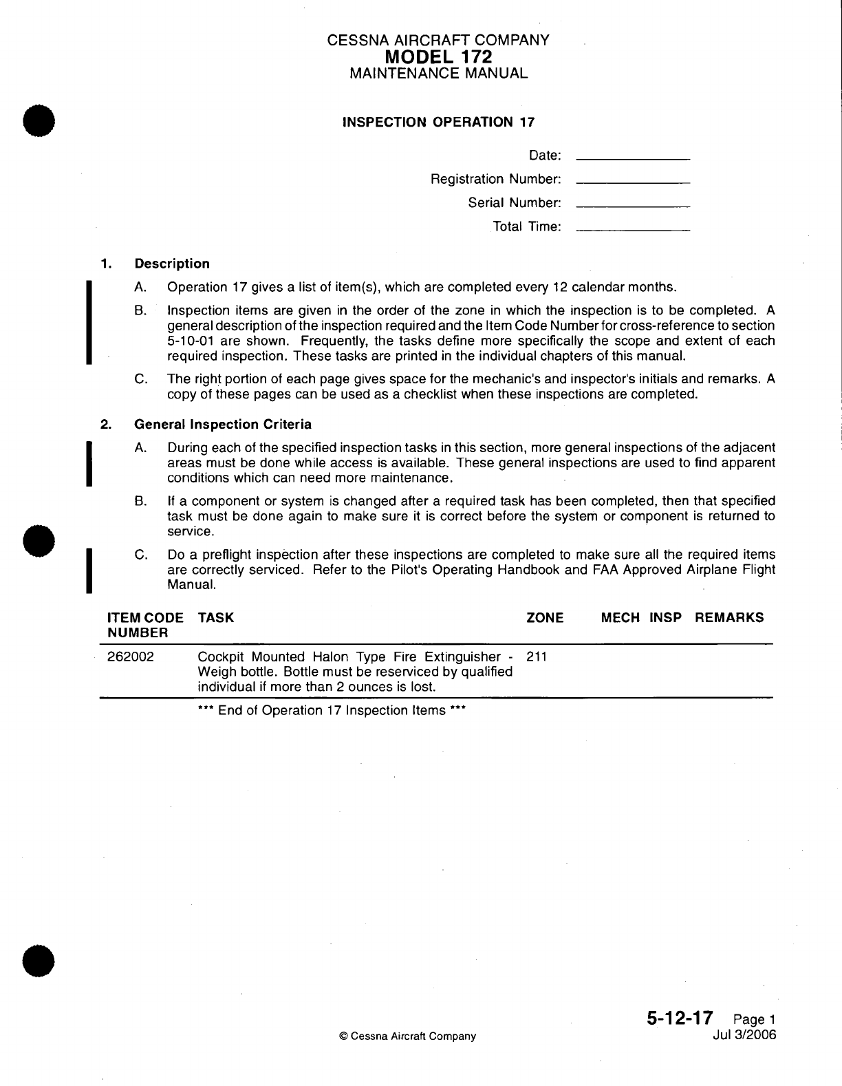
CESSNA
AIRCRAFT
COMPANY
MODEL
172
MAINTENANCE
MANUAL
INSPECTION
OPERATION
17
Date:
Registration
Number:
Serial
Number:
Total
Time:
1.
Description
A.
Operation
17
gives
a
list
of item(s),
which
are
completed
every
12
calendar
months.
B.
Inspection
items
are
given
in
the
order
of the
zone
in
which
the
inspection
is
to
be
completed.
A
general
description
of
the
inspection required
and the
Item
Code
Number
for cross-reference
to
section
5-10-01
are
shown.
Frequently, the
tasks
define
more
specifically
the
scope
and
extent
of each
required
inspection. These tasks
are
printed
in
the
individual
chapters
of
this
manual.
C.
The
right
portion
of
each
page
gives
space
for
the
mechanic's
and
inspector's
initials
and
remarks.
A
copy
of
these
pages
can
be
used
as
a
checklist
when
these inspections
are
completed.
2.
General
Inspection
Criteria
A.
During
each
of
the
specified
inspection
tasks
in
this section,
more
general
inspections
of
the
adjacent
areas
must
be
done
while
access
is
available.
These
general
inspections
are
used
to
find
apparent
conditions
which
can
need
more
maintenance.
B. If
a
component
or
system
is
changed
after
a
required
task
has
been
completed, then
that specified
task
must
be
done
again
to
make sure
it
is
correct
before
the
system
or
component
is
returned
to
service.
C.
Do
a
preflight inspection after these
inspections
are
completed
to
make
sure
all
the
required
items
are
correctly
serviced.
Refer
to
the
Pilot's
Operating
Handbook
and
FAA
Approved Airplane
Flight
Manual.
ITEM
CODE
NUMBER
262002
TASK
Cockpit
Mounted
Halon
Type
Fire
Extinguisher
-
Weigh
bottle. Bottle
must
be
reserviced
by
qualified
individual
if
more
than
2
ounces
is
lost.
***
End of
Operation
17
Inspection
Items
***
ZONE
MECH
INSP
REMARKS
211
5-12-17
Page
1
Jul 3/2006
©
Cessna Aircraft
Company
I
I
I

CESSNA
AIRCRAFT
COMPANY
MODEL
172
MAINTENANCE
MANUAL
INSPECTION
OPERATION
18
Date:
Registration
Number:
Serial
Number:
Total
Time:
1.
Description
A.
Operation
18
gives
a
list
of
item(s),
which
are
completed
every
6
years.
B.
Inspection
items
are
given
in
the
order
of the
zone
in
which
the
inspection
is
to
be
completed.
A
general
description
of
the
inspection
required
and
the
Item
Code
Number
for
cross-reference
to
section
5-10-01
are
shown. Frequently,
the
tasks
define
more
specifically
the
scope
and extent
of
each
required
inspection.
These tasks
are
printed
in
the
individual chapters
of
this
manual.
C.
The
right
portion
of
each page
gives
space
for
the
mechanic's
and inspector's
initials
and
remarks.
A
copy
of
these pages
can
be
used
as
a
checklist
when
these
inspections
are
completed.
2.
General
Inspection
Criteria
A.
During
each
of
the
specified
inspection tasks
in
this section,
more
general
inspections
of
the
adjacent
areas
must
be
done
while
access
is
available.
These general
inspections
are
used
to
find
apparent
conditions
which
can need
more
maintenance.
B. If
a
component
or system
is
changed after
a
required task
has
been
completed,
then
that
specified
task
must
be
done
again
to
make
sure
it
is
correct
before the
system
or
component
is
returned
to
service.
C.
Do
a
preflight
inspection
after these
inspections
are
completed
to
make
sure
all
the
required
items
are
correctly serviced.
Refer
to
the
Pilot's
Operating
Handbook
and
FAA
Approved
Airplane
Flight
Manual.
ITEM
CODE
NUMBER
262004
TASK
Cockpit
Mounted Halon
Type
Fire
Extinguishers
-
Empty,
inspect
for
damage,
and recharge.
***
End
of
Operation
18
Inspection
Items
***
5-12-18
Page
1
Jul 3/2006
©
Cessna Aircraft
Company
I
I
ZONE
MECH
INSP
REMARKS
211
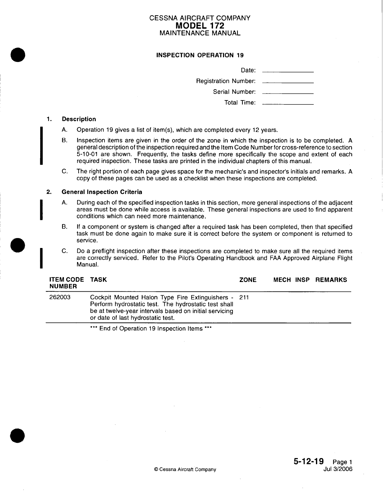
CESSNA
AIRCRAFT
COMPANY
MODEL
172
MAINTENANCE
MANUAL
INSPECTION
OPERATION
19
Date:
Registration
Number:
Serial
Number:
Total Time:
1.
Description
A.
Operation
19
gives
a
list
of
item(s), which
are
completed
every
12
years.
B.
Inspection
items
are
given
in
the order
of the
zone
in
which
the
inspection
is
to
be
completed.
A
general
description
of
the
inspection
required
and
the
Item
Code
Number
for
cross-reference
to
section
5-10-01
are
shown.
Frequently,
the
tasks
define
more
specifically
the
scope
and
extent
of each
required
inspection.
These
tasks
are
printed
in
the
individual
chapters
of
this manual.
C.
The
right
portion
of
each
page
gives
space
for
the
mechanic's
and
inspector's
initials
and
remarks.
A
copy
of
these
pages
can
be
used
as
a
checklist
when
these inspections
are
completed.
2.
General
Inspection Criteria
A.
During
each
of the
specified
inspection
tasks
in
this section,
more
general
inspections
of
the
adjacent
areas
must
be
done
while
access
is
available.
These general inspections
are
used
to
find
apparent
conditions
which
can
need
more
maintenance.
B.
If
a
component
or
system
is
changed
after
a
required task
has
been
completed,
then
that specified
task
must
be
done again
to
make
sure
it
is
correct
before the
system
or
component
is
returned
to
service.
C.
Do
a
preflight inspection
after these
inspections
are
completed
to
make
sure
all
the
required
items
are
correctly
serviced.
Refer
to the
Pilot's
Operating
Handbook
and
FAA
Approved
Airplane
Flight
Manual.
TASK
Cockpit
Mounted
Halon
Type
Fire
Extinguishers
-
Perform
hydrostatic
test.
The
hydrostatic
test
shall
be
at
twelve-year
intervals
based
on
initial
servicing
or
date
of
last
hydrostatic test.
***
End of
Operation
19
Inspection
Items
***
ZONE
MECH
INSP
REMARKS
211
5-12-19
Page
1
Jul
3/2006
©
Cessna Aircraft
Company
I
I
I
ITEM
CODE
NUMBER
262003
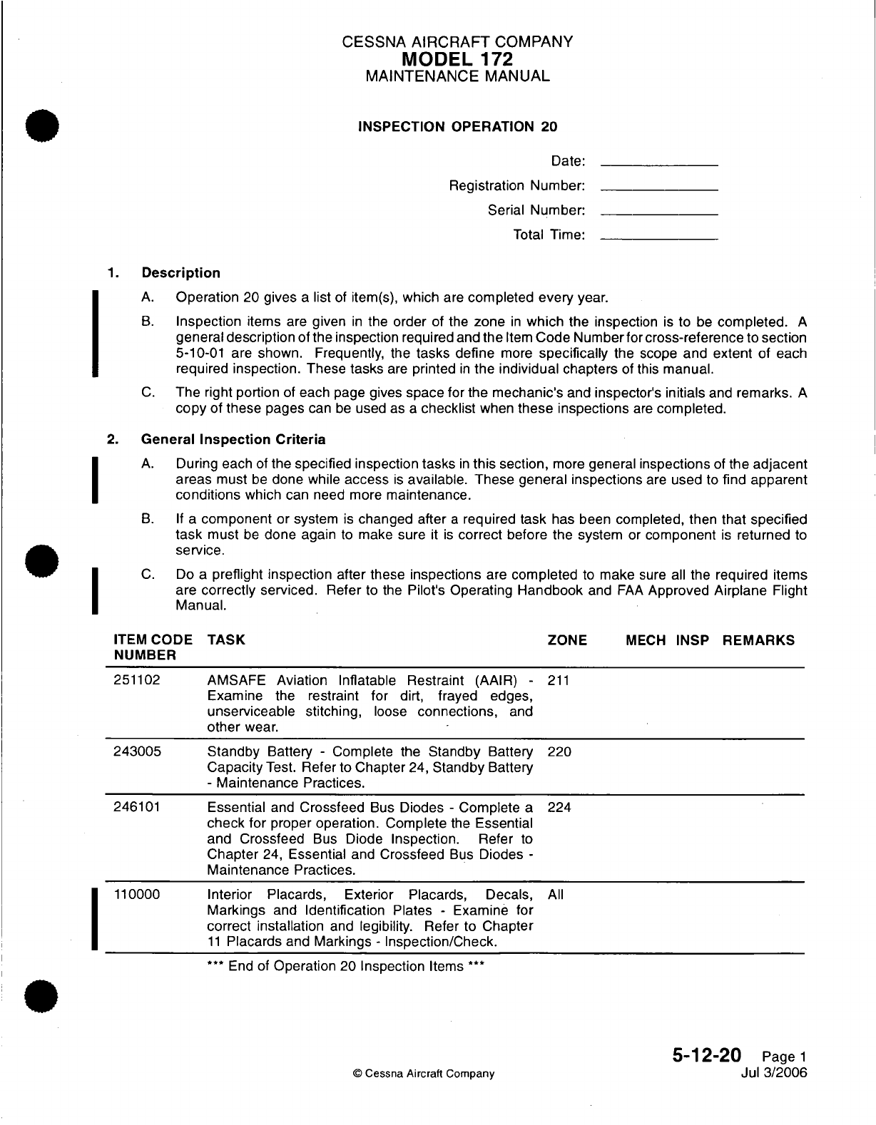
CESSNA
AIRCRAFT
COMPANY
MODEL
172
MAINTENANCE
MANUAL
INSPECTION
OPERATION
20
Date:
Registration
Number:
Serial Number:
Total
Time:
1.
Description
A.
Operation
20
gives
a
list
of
item(s),
which
are
completed
every year.
B.
Inspection
items
are
given
in
the
order
of
the
zone
in
which
the inspection
is
to
be
completed.
A
general
description
of
the
inspection
required
and
the
Item
Code
Numberfor
cross-reference
to
section
5-10-01
are shown. Frequently,
the
tasks
define
more
specifically
the scope
and
extent
of
each
required
inspection. These
tasks
are
printed
in
the
individual chapters
of
this
manual.
C.
The
right
portion
of
each
page
gives
space
for
the
mechanic's
and
inspector's
initials
and
remarks.
A
copy
of
these
pages
can
be
used
as
a
checklist
when
these inspections
are
completed.
2.
General
Inspection
Criteria
A.
During
each
of
the
specified
inspection
tasks
in
this
section,
more
general
inspections
of
the adjacent
areas
must
be
done while
access
is
available. These general inspections
are
used
to
find
apparent
conditions
which
can need
more
maintenance.
B. If
a
component
or system
is
changed
after
a
required
task
has been
completed,
then
that
specified
task
must
be
done again
to
make
sure
it is
correct
before
the
system
or
component
is
returned
to
service.
C.
Do
a
preflight inspection after
these
inspections
are
completed
to
make
sure
all
the
required
items
are
correctly
serviced.
Refer
to
the
Pilot's
Operating
Handbook
and
FAA
Approved
Airplane
Flight
Manual.
ITEM
CODE
TASK
ZONE
MECH
INSP
REMARKS
NUMBER
251102
AMSAFE
Aviation
Inflatable
Restraint
(AAIR)
-
211
Examine
the
restraint
for
dirt,
frayed
edges,
unserviceable stitching,
loose
connections,
and
other
wear.
243005 Standby
Battery
-
Complete
the
Standby
Battery
220
Capacity
Test.
Refer
to
Chapter
24,
Standby
Battery
-
Maintenance
Practices.
246101
Essential
and
Crossfeed
Bus
Diodes
-
Complete
a
224
check
for
proper operation. Complete
the
Essential
and
Crossfeed
Bus
Diode
Inspection.
Refer
to
Chapter
24,
Essential
and
Crossfeed
Bus
Diodes
-
Maintenance
Practices.
110000
Interior Placards, Exterior
Placards,
Decals,
All
Markings
and
Identification
Plates
-
Examine
for
correct
installation
and
legibility.
Refer
to
Chapter
11
Placards
and
Markings
-
Inspection/Check.
***
End of
Operation
20
Inspection
Items
**
5-12-20
Page
1
©
Cessna
Aircraft Company
Jul
3/2006
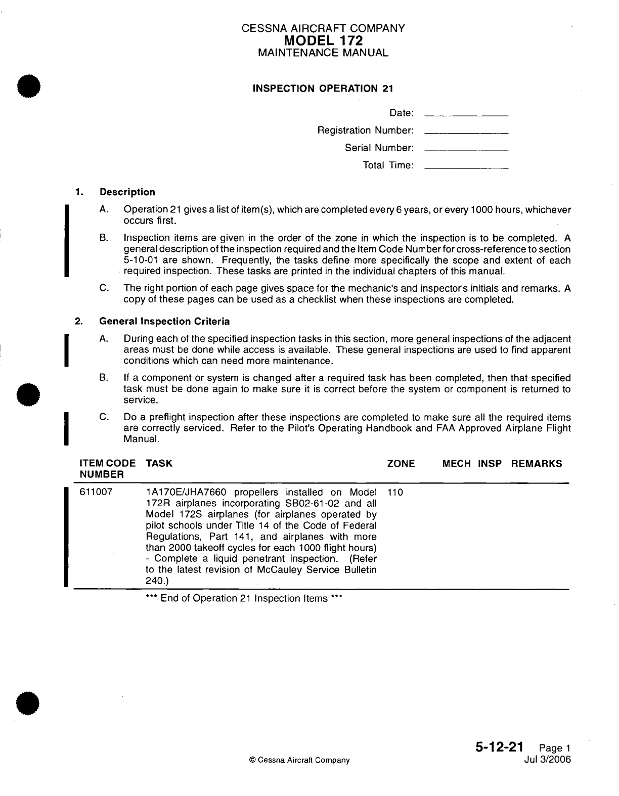
CESSNA
AIRCRAFT
COMPANY
MODEL
172
MAINTENANCE
MANUAL
INSPECTION
OPERATION
21
Date:
Registration
Number:
Serial
Number:
Total
Time:
1.
Description
A.
Operation
21
gives
a
list
of
item(s),
which
are
completed
every
6
years,
or
every
1000
hours,
whichever
occurs first.
B.
Inspection
items
are
given
in
the
order
of
the
zone
in
which
the
inspection
is
to
be
completed.
A
general
description
of
the
inspection
required
and
the
Item
Code
Number
for cross-reference to
section
5-10-01
are
shown.
Frequently,
the
tasks
define
more
specifically
the
scope
and extent
of
each
required
inspection. These tasks
are
printed
in
the
individual
chapters
of
this
manual.
C.
The
right
portion
of
each
page
gives
space
for
the
mechanic's
and
inspector's
initials
and
remarks.
A
copy
of
these
pages
can
be
used
as
a
checklist
when
these
inspections
are
completed.
2.
General
Inspection
Criteria
A.
During
each
of
the
specified
inspection tasks
in
this
section,
more
general
inspections
of
the
adjacent
areas
must
be
done
while
access
is
available.
These general
inspections
are
used
to
find
apparent
conditions
which
can need
more
maintenance.
B.
If
a
component
or
system
is
changed after
a
required task
has
been
completed,
then
that specified
task
must
be
done
again
to
make sure
it
is
correct
before the
system
or
component
is
returned
to
service.
C.
Do
a
preflight inspection
after
these
inspections
are
completed
to
make
sure all
the required
items
are
correctly
serviced.
Refer
to
the
Pilot's
Operating
Handbook
and
FAA
Approved Airplane
Flight
Manual.
ITEM
CODE TASK
ZONE
MECH
INSP
REMARKS
NUMBER
611007
1A170E/JHA7660 propellers
installed
on Model
110
172R
airplanes
incorporating
SB02-61-02
and
all
Model
172S
airplanes
(for
airplanes
operated
by
pilot
schools under
Title
14
of
the
Code
of
Federal
Regulations,
Part
141,
and
airplanes
with
more
than
2000
takeoff cycles
for
each
1000
flight
hours)
-
Complete
a
liquid
penetrant inspection.
(Refer
to
the
latest
revision
of
McCauley Service
Bulletin
240.)
***
End of
Operation
21
Inspection
Items
***
5-12-21
Page
1
©
Cessna
Aircraft Company
Jul
3/2006
,
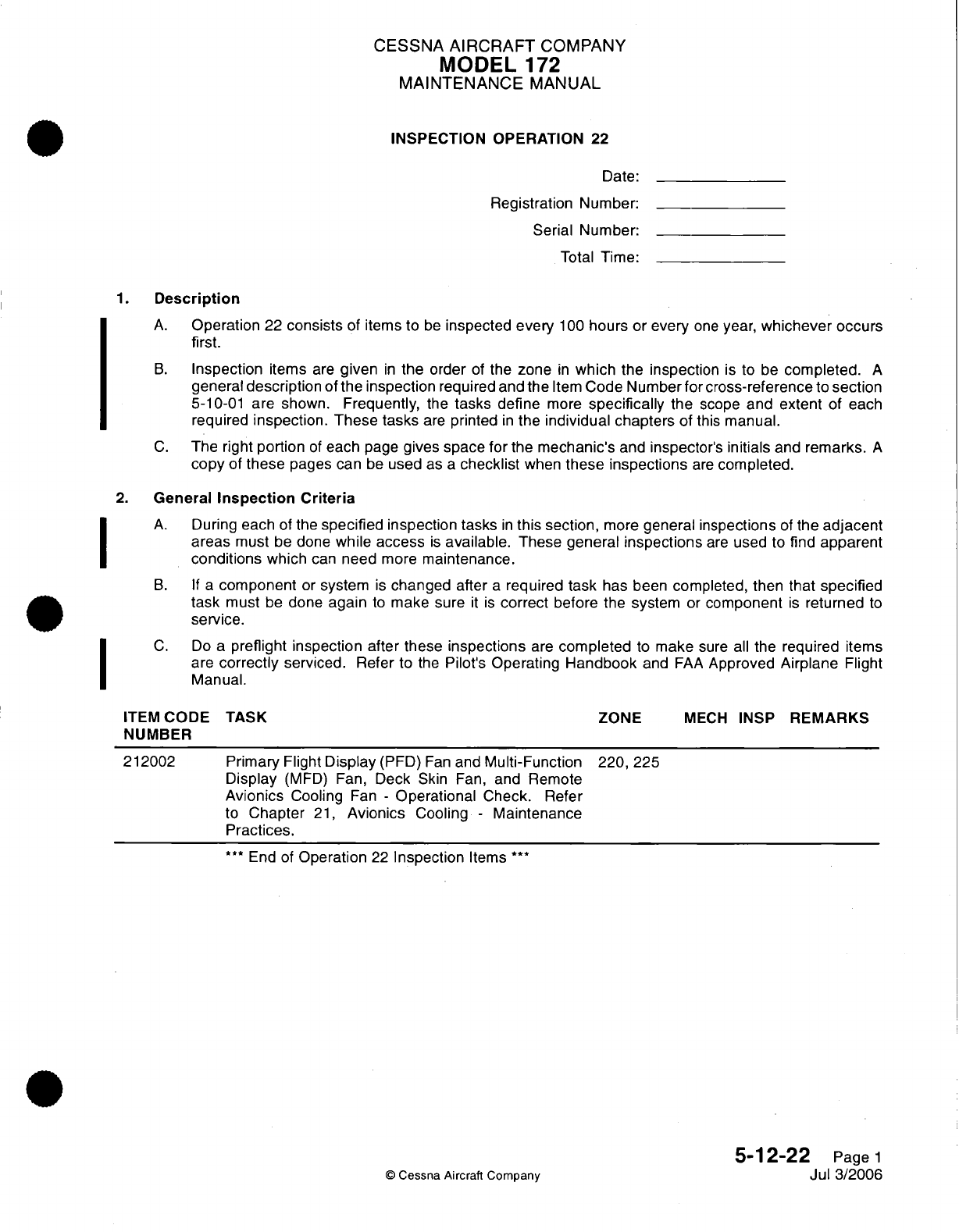
CESSNA
AIRCRAFT
COMPANY
MODEL
172
MAINTENANCE
MANUAL
INSPECTION
OPERATION
22
Date:
Registration
Number:
Serial
Number:
Total
Time:
1.
Description
A.
Operation
22
consists
of items to
be
inspected
every
100
hours
or
every
one
year,
whichever
occurs
first.
B.
Inspection
items
are
given
in
the
order
of
the
zone
in
which
the
inspection
is
to
be
completed.
A
general
description
of
the inspection
required and
the
Item
Code
Number for
cross-reference
to
section
5-10-01
are
shown.
Frequently,
the
tasks
define
more
specifically
the
scope
and
extent
of
each
required
inspection. These tasks
are
printed
in
the
individual
chapters
of
this
manual.
C.
The right
portion
of
each
page
gives
space for
the
mechanic's
and
inspector's
initials
and
remarks.
A
copy
of
these
pages
can
be
used
as
a
checklist
when
these inspections
are
completed.
2.
General
Inspection
Criteria
A.
During
each
of the
specified
inspection
tasks
in
this section,
more
general
inspections
of the
adjacent
areas
must
be
done
while
access
is
available.
These
general
inspections
are
used
to
find
apparent
conditions
which
can
need
more
maintenance.
B.
If
a
component
or
system
is
changed
after
a
required
task
has been
completed,
then
that
specified
task
must
be
done
again
to
make
sure
it
is
correct
before
the
system
or
component
is
returned
to
service.
C.
Do
a
preflight inspection after
these
inspections
are
completed
to make
sure
all
the
required
items
are
correctly
serviced.
Refer
to
the
Pilot's
Operating
Handbook
and
FAA
Approved
Airplane
Flight
Manual.
ITEM
CODE TASK
ZONE
MECH
INSP
REMARKS
NUMBER
212002
Primary
Flight Display
(PFD)
Fan
and
Multi-Function
220,
225
Display
(MFD)
Fan,
Deck
Skin
Fan,
and Remote
Avionics
Cooling
Fan
-
Operational
Check.
Refer
to
Chapter
21,
Avionics
Cooling
-
Maintenance
Practices.
***
End of
Operation
22
Inspection
Items
**
5-12-22
Page
1
©
Cessna Aircraft
Company
Jul
3/2006
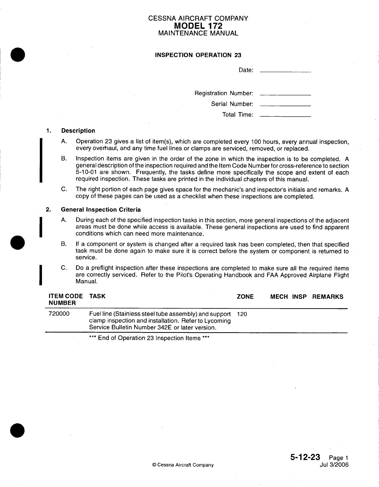
CESSNA
AIRCRAFT
COMPANY
MODEL
172
MAINTENANCE
MANUAL
INSPECTION OPERATION
23
Date:
Registration
Number:
Serial
Number:
Total
Time:
1.
Description
A.
Operation
23
gives
a
list
of
item(s),
which
are
completed
every
100
hours,
every
annual
inspection,
every overhaul,
and
any
time
fuel
lines
or
clamps
are
serviced,
removed,
or
replaced.
B.
Inspection
items
are
given
in
the
order
of the
zone
in
which
the
inspection
is
to
be
completed.
A
general
description
of
the
inspection
required
and
the
Item
Code
Number for
cross-reference
to
section
5-10-01
are shown. Frequently, the
tasks
define
more
specifically
the
scope
and
extent
of
each
required
inspection.
These
tasks
are
printed
in
the
individual
chapters
of
this
manual.
C.
The
right
portion
of
each
page
gives
space
for
the
mechanic's
and
inspector's
initials
and
remarks.
A
copy
of
these
pages
can
be
used as
a
checklist
when
these inspections
are
completed.
2.
General
Inspection
Criteria
A.
During
each
of
the
specified
inspection
tasks
in
this
section,
more
general
inspections
of
the
adjacent
areas
must
be
done
while
access
is
available.
These
general
inspections
are
used
to
find
apparent
conditions
which
can
need
more
maintenance.
B.
If
a
component
or
system
is
changed
after
a
required task
has
been
completed,
then
that
specified
task
must
be
done again
to
make sure
it
is
correct
before
the
system
or
component
is
returned
to
service.
C.
Do
a
preflight
inspection
after these
inspections
are
completed
to
make
sure
all
the
required
items
are
correctly serviced.
Refer
to
the
Pilot's
Operating Handbook
and
FAA
Approved
Airplane
Flight
Manual.
ITEM
CODE
NUMBER
720000
TASK
ZONE
MECH
INSP
REMARKS
Fuel
line
(Stainless
steel
tube
assembly)
and
support
clamp
inspection
and
installation.
Refer
to
Lycoming
Service Bulletin
Number
342E
or
later version.
***
End
of
Operation
23
Inspection
Items
***
120
5-12-23
Page
1
Jul
3/2006
©
Cessna Aircraft
Company
*I
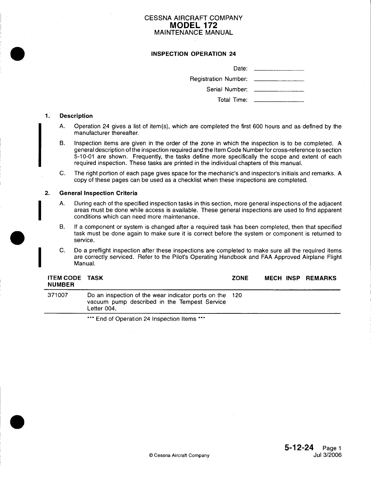
CESSNA
AIRCRAFT
COMPANY
MODEL
172
MAINTENANCE
MANUAL
INSPECTION OPERATION
24
Date:
Registration
Number:
Serial
Number:
Total Time:
1.
Description
A.
Operation
24
gives
a
list
of
item(s),
which
are
completed
the
first 600 hours
and as
defined
by
the
manufacturer
thereafter.
B.
Inspection
items
are
given
in
the
order
of
the zone
in
which
the
inspection
is
to
be
completed.
A
general
description
of
the
inspection
required and the
Item
Code
Number
for
cross-reference
to
section
5-10-01
are
shown.
Frequently, the
tasks
define
more
specifically
the
scope and extent
of
each
required
inspection.
These
tasks
are
printed
in
the
individual
chapters
of
this
manual.
C.
The
right
portion
of each page
gives
space
for
the
mechanic's
and
inspector's
initials
and
remarks.
A
copy
of
these
pages
can
be
used
as
a
checklist
when
these
inspections
are
completed.
2.
General
Inspection
Criteria
A.
During
each
of
the
specified
inspection tasks
in
this
section,
more
general
inspections
of
the
adjacent
areas must
be
done
while
access
is
available.
These
general
inspections
are
used to find
apparent
conditions
which
can
need
more
maintenance.
B. If
a
component
or
system
is
changed after
a
required
task
has
been
completed, then that
specified
task
must
be
done
again
to
make
sure
it
is
correct
before
the
system
or
component
is
returned
to
service.
C.
Do
a
preflight inspection after
these
inspections
are
completed
to
make sure
all
the required
items
are
correctly
serviced.
Refer
to the
Pilot's
Operating
Handbook
and
FAA
Approved Airplane
Flight
Manual.
TASK
Do
an
inspection
of
the
wear
indicator
ports
on
the
vacuum
pump
described
in
the
Tempest
Service
Letter
004.
***
End
of
Operation
24
Inspection
Items
***
ZONE
MECH
INSP
REMARKS
120
5-12-24
Page
1
Jul 3/2006
O
Cessna Aircraft
Company
I
I
I
ITEM
CODE
NUMBER
371007
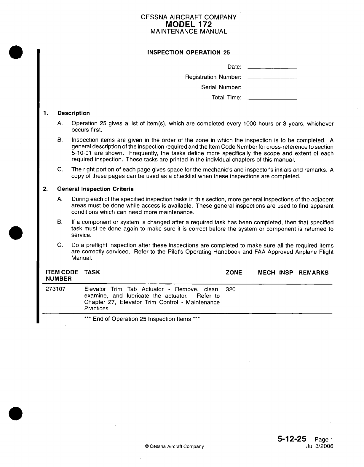
CESSNA
AIRCRAFT
COMPANY
MODEL
172
MAINTENANCE
MANUAL
INSPECTION
OPERATION
25
Date:
Registration
Number:
Serial
Number:
Total
Time:
1.
Description
A.
Operation
25
gives
a
list
of
item(s),
which
are
completed
every
1000
hours or
3
years,
whichever
occurs
first.
B.
Inspection
items
are
given
in
the
order
of the
zone
in
which
the
inspection
is
to
be
completed.
A
general
description
of the
inspection
required and
the
Item
Code
Number for
cross-reference
to
section
5-10-01
are shown.
Frequently, the
tasks
define
more
specifically
the
scope
and
extent
of
each
required
inspection.
These
tasks
are
printed
in
the
individual
chapters
of
this
manual.
C.
The
right
portion
of
each
page
gives
space for
the
mechanic's
and
inspector's
initials
and
remarks.
A
copy
of
these
pages
can
be
used as
a
checklist
when
these inspections
are
completed.
2.
General
Inspection
Criteria
A.
During
each
of
the
specified
inspection
tasks
in
this
section,
more
general
inspections
of
the adjacent
areas
must
be
done while
access
is
available.
These
general
inspections
are
used
to
find
apparent
conditions
which can need
more
maintenance.
B.
If
a
component
or
system
is
changed after
a
required task
has been
completed,
then
that specified
task
must
be
done again
to
make
sure
it
is
correct
before
the
system
or
component
is
returned
to
service.
C.
Do
a
preflight
inspection
after
these
inspections
are
completed
to
make sure
all
the
required items
are
correctly
serviced.
Refer
to
the
Pilot's
Operating Handbook
and
FAA
Approved
Airplane
Flight
Manual.
ITEM
CODE
NUMBER
273107
TASK
Elevator
Trim
Tab
Actuator
-
Remove,
clean,
examine,
and
lubricate
the
actuator.
Refer
to
Chapter
27,
Elevator
Trim
Control
-
Maintenance
Practices.
***
End
of
Operation
25
Inspection
Items
***
ZONE
MECH
INSP
REMARKS
320
5-12-25
Page
1
Jul
3/2006
©
Cessna
Aircraft
Company
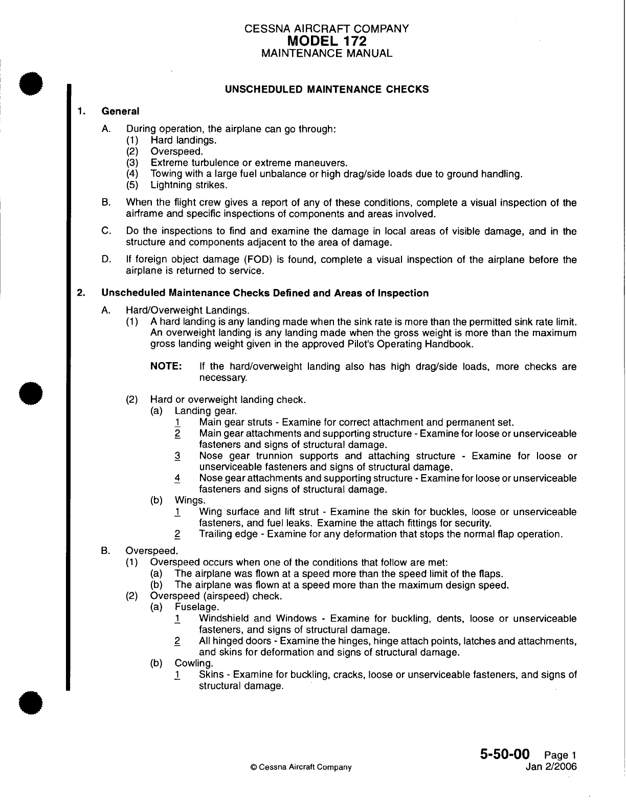
CESSNA
AIRCRAFT
COMPANY
MODEL
172
MAINTENANCE
MANUAL
UNSCHEDULED MAINTENANCE CHECKS
1.
General
A.
During
operation,
the
airplane
can
go
through:
(1)
Hard
landings.
(2)
Overspeed.
(3)
Extreme
turbulence or
extreme
maneuvers.
(4)
Towing with
a
large
fuel
unbalance
or
high
drag/side
loads
due to ground
handling.
(5)
Lightning strikes.
B.
When
the
flight
crew gives
a
report
of
any
of
these conditions, complete
a
visual
inspection
of
the
airframe
and
specific
inspections
of
components
and
areas
involved.
C.
Do
the inspections
to find
and
examine
the
damage
in
local areas
of
visible
damage,
and
in
the
structure
and
components
adjacent
to
the
area
of
damage.
D. If
foreign
object
damage
(FOD)
is
found,
complete
a
visual inspection
of
the
airplane
before
the
airplane
is
returned
to
service.
2.
Unscheduled
Maintenance
Checks
Defined
and
Areas
of
Inspection
A.
Hard/Overweight Landings.
(1)
A
hard
landing
is
any
landing
made
when the
sink
rate
is
more
than the
permitted
sink
rate
limit.
An
overweight
landing
is
any
landing
made
when
the gross
weight
is
more
than
the
maximum
gross landing
weight
given
in
the
approved
Pilot's
Operating
Handbook.
NOTE:
If
the
hard/overweight
landing
also
has high
drag/side
loads,
more
checks
are
necessary.
(2)
Hard
or
overweight
landing check.
(a)
Landing
gear.
1
Main
gear
struts
-
Examine
for
correct
attachment
and
permanent
set.
2
Main
gear
attachments
and
supporting
structure
-
Examine for loose or
unserviceable
fasteners
and
signs
of
structural
damage.
3
Nose
gear
trunnion
supports
and
attaching
structure
-
Examine
for
loose
or
unserviceable fasteners
and
signs
of
structural damage.
4
Nose
gear
attachments
and
supporting
structure
-
Examine
for
loose
or
unserviceable
fasteners
and
signs
of
structural
damage.
(b)
Wings.
1
Wing
surface
and
lift
strut
-
Examine
the
skin
for buckles,
loose
or
unserviceable
fasteners,
and
fuel leaks. Examine
the
attach
fittings for
security.
2
Trailing edge
-
Examine
for
any
deformation that
stops
the
normal
flap
operation.
B.
Overspeed.
(1)
Overspeed occurs
when
one
of
the
conditions
that
follow
are
met:
(a)
The
airplane
was
flown
at
a
speed
more
than
the
speed
limit
of
the
flaps.
(b)
The
airplane
was
flown
at
a
speed
more
than
the
maximum
design speed.
(2)
Overspeed
(airspeed)
check.
(a)
Fuselage.
1
Windshield
and Windows
-
Examine for
buckling,
dents,
loose or
unserviceable
fasteners,
and
signs
of
structural
damage.
2
All
hinged
doors
-
Examine
the
hinges,
hinge attach
points,
latches
and
attachments,
and
skins for
deformation
and
signs
of
structural
damage.
(b)
Cowling.
1
Skins
-
Examine for
buckling,
cracks,
loose
or
unserviceable fasteners,
and
signs
of
structural
damage.
5-50-00
Page
1
©
Cessna Aircraft Company
Jan
2/2006
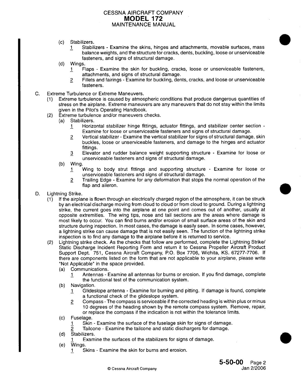
CESSNA
AIRCRAFT
COMPANY
MODEL
172
MAINTENANCE
MANUAL
(c)
Stabilizers.
1
Stabilizers
-
Examine the
skins, hinges
and
attachments,
movable surfaces,
mass
balance
weights,
and
the structure
for
cracks,
dents,
buckling,
loose
or
unserviceable
fasteners,
and
signs
of
structural damage.
(d)
Wings.
1
Flaps
-
Examine
the
skin
for
buckling, cracks,
loose
or unserviceable
fasteners,
attachments,
and
signs
of
structural
damage.
2
Fillets
and
fairings
-
Examine
for
buckling, dents, cracks,
and loose
or
unserviceable
fasteners.
C.
Extreme
Turbulence
or
Extreme
Maneuvers.
(1)
Extreme
turbulence
is
caused
by
atmospheric
conditions
that
produce
dangerous quantities
of
stress
on
the
airplane.
Extreme
maneuvers
are
any
maneuvers
that
do
not
stay
within
the
limits
given
in
the
Pilot's
Operating
Handbook.
(2)
Extreme
turbulence
and/or
maneuvers
checks.
(a)
Stabilizers.
1
Horizontal
stabilizer
hinge
fittings, actuator fittings,
and
stabilizer
center
section
-
Examine for
loose
or
unserviceable
fasteners
and
signs
of
structural
damage.
2
Vertical
stabilizer
-
Examine
the
vertical
stabilizer
for signs
of
structural
damage,
skin
buckles,
loose
or
unserviceable fasteners,
and
damage
to
the hinges
and
actuator
fittings.
3
Elevator
and
rudder balance
weight
supporting
structure
-
Examine
for
loose
or
unserviceable fasteners
and
signs
of
structural damage.
(b)
Wing.
1
Wing
to
body
strut
fittings
and
supporting structure
-
Examine
for
loose
or
unserviceable
fasteners
and
signs
of
structural
damage.
2
Trailing
Edge
-
Examine for
any
deformation
that
stops
the
normal
operation
of
the
flap
and
aileron.
D.
Lightning
Strike.
(1) If
the
airplane
is
flown
through
an
electrically
charged
region
of
the
atmosphere,
it
can
be
struck
by
an
electrical
discharge
moving
from
cloud
to
cloud
or
from
cloud
to
ground.
During
a
lightning
strike,
the current
goes
into the
airplane
at one
point and
comes
out
of
another,
usually
at
opposite extremities.
The
wing
tips,
nose
and
tail
sections
are
the
areas
where
damage
is
most
likely
to
occur.
You
can
find
burns
and/or erosion
of
small
surface
areas
of the
skin
and
structure
during inspection.
In
most
cases,
the damage
is
easily
seen.
In
some
cases, however,
a
lightning
strike
can
cause
damage that
is
not
easily
seen.
The
function
of the
lightning
strike
inspection
is
to
find
any damage
to
the
airplane
before
it
is
returned
to
service.
(2)
Lightning
strike check.
As
the
checks
that follow
are
performed,
complete
the
Lightning
Strike/
Static
Discharge Incident Reporting
Form
and
return
it
to
Cessna Propeller Aircraft
Product
Support
Dept.
751,
Cessna
Aircraft
Company,
P.O.
Box
7706,
Wichita,
KS.
67277-7706.
If
there
are
components
listed
on
the
form
that
are
not
applicable
to
your
airplane,
please
write
"Not
Applicable"
in
the
space
provided.
(a)
Communications.
1
Antennas
-
Examine
all
antennas
for
burns
or
erosion.
If
you
find
damage,
complete
the
functional test
of
the
communication
system.
(b)
Navigation.
1
Glideslope
antenna
-
Examine
for burning
and
pitting.
If
damage
is
found,
complete
a
functional check
of
the
glideslope
system.
2
Compass
-
The
compass
is
serviceable
if
the
corrected heading
is
within
plus
or
minus
10
degrees
of the
heading
shown
by
the remote
compass
system. Remove,
repair,
or replace
the
compass
if
the
indication
is
not
within
the tolerance
limits.
(c)
Fuselage.
1
Skin
-
Examine
the
surface
of
the
fuselage
skin for
signs
of
damage.
2
Tailcone
-
Examine
the tailcone
and
static
dischargers
for
damage.
(d)
Stabilizers.
1
Examine
the
surfaces
of
the
stabilizers
for
signs
of
damage.
(e)
Wings.
1
Skins
-
Examine
the
skin for
burns
and
erosion.
5-50-00
Page
2
©
Cessna Aircraft
Company
Jan
2/2006
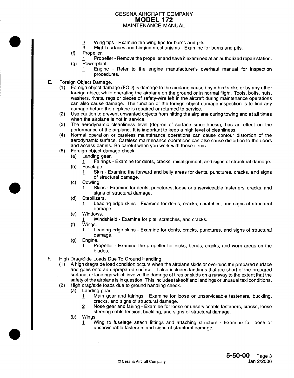
CESSNA
AIRCRAFT
COMPANY
MODEL
172
MAINTENANCE
MANUAL
2
Wing
tips
-
Examine
the
wing
tips
for
burns
and
pits.
3
Flight
surfaces
and
hinging mechanisms
-
Examine
for
burns and
pits.
(f)
Propeller.
1
Propeller
-
Remove
the
propeller
and
have
it
examined at
an
authorized
repair
station.
(g)
Powerplant.
1
Engine
-
Refer
to
the
engine
manufacturer's
overhaul
manual for
inspection
procedures.
E.
Foreign
Object
Damage.
(1)
Foreign
object
damage
(FOD) is
damage
to
the
airplane
caused
by
a
bird
strike
or
by
any
other
foreign
object
while
operating
the
airplane
on
the ground
or
in
normal
flight.
Tools,
bolts,
nuts,
washers, rivets,
rags
or
pieces
of safety-wire
left
in
the
aircraft
during
maintenance
operations
can
also
cause
damage.
The
function
of the
foreign
object
damage
inspection
is
to
find
any
damage
before
the
airplane
is
repaired
or returned
to
service.
(2)
Use
caution
to
prevent
unwanted
objects
from
hitting
the
airplane
during
towing
and
at all
times
when
the
airplane
is
not
in
service.
(3)
The
aerodynamic
cleanliness
level
(degree
of
surface
smoothness),
has
an
effect
on
the
performance
of the
airplane.
It
is
important
to
keep
a
high
level of
cleanliness.
(4)
Normal
operation
or
careless maintenance
operations
can
cause
contour distortion
of
the
aerodynamic
surface.
Careless
maintenance
operations
can
also
cause
distortion
to
the
doors
and
access
panels.
Be
careful when you work
with
these
items.
(5)
Foreign
object
damage
check.
(a)
Landing gear.
1
Fairings
-
Examine
for dents, cracks, misalignment,
and
signs
of
structural damage.
(b)
Fuselage.
1
Skin
-
Examine
the
forward
and
belly areas
for dents,
punctures,
cracks,
and
signs
of
structural
damage.
(c)
Cowling.
1
Skins
-
Examine for dents,
punctures,
loose
or
unserviceable fasteners,
cracks,
and
signs
of
structural damage.
(d)
Stabilizers.
1
Leading
edge
skins
-
Examine
for
dents,
cracks,
scratches,
and
signs
of
structural
damage.
(e)
Windows.
1
Windshield
-
Examine for
pits, scratches, and
cracks.
(f)
Wings.
1
Leading
edge
skins
-
Examine
for
dents,
cracks,
punctures,
and
signs
of
structural
damage.
(g)
Engine.
1
Propeller
-
Examine
the
propeller
for
nicks, bends, cracks,
and
worn
areas
on
the
blades.
F.
High
Drag/Side Loads
Due
To
Ground
Handling.
(1) A
high
drag/side
load
condition occurs
when
the
airplane skids
or
overruns
the
prepared
surface
and
goes
onto
an
unprepared surface.
It
also
includes landings
that
are
short
of the
prepared
surface,
or
landings
which involve
the
damage
of
tires
or
skids
on
a
runway to
the
extent that
the
safety
of
the
airplane
is in
question. This includes
takeoff
and
landings
or
unusual taxi
conditions.
(2)
High
drag/side
loads
due to ground
handling
check.
(a)
Landing
gear.
1
Main
gear
and
fairings
-
Examine
for
loose
or
unserviceable
fasteners,
buckling,
cracks,
and
signs
of
structural
damage.
2
Nose
gear
and
fairing
-
Examine
for
loose or
unserviceable
fasteners,
cracks,
loose
steering
cable
tension,
buckling,
and
signs
of
structural
damage.
(b)
Wings.
1
Wing to
fuselage attach
fittings
and
attaching
structure
-
Examine
for
loose
or
unserviceable fasteners
and
signs
of
structural
damage.
5-50-00
Page
3
©
Cessna
Aircraft
Company
Jan
2/2006
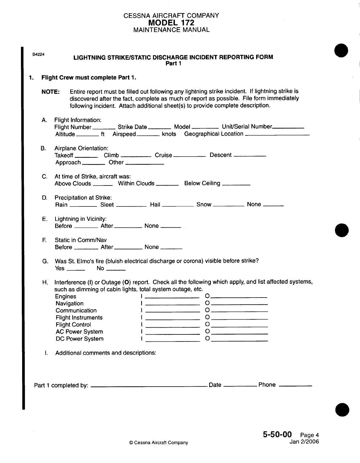
CESSNA AIRCRAFT
COMPANY
MODEL
172
MAINTENANCE
MANUAL
B4224
LIGHTNING
STRIKE/STATIC DISCHARGE
INCIDENT REPORTING
FORM
Part
1
1.
Flight
Crew
must complete
Part
1.
NOTE:
Entire
report
must
be
filled
out
following
any
lightning strike
incident.
If
lightning
strike
is
discovered after
the
fact,
complete
as
much
of report
as possible.
File
form
immediately
following incident. Attach
additional
sheet(s)
to
provide
complete description.
A.
Flight
Information:
Flight
Number
_
Strike
Date_
Model
Unit/Serial
Number
Altitude
ft
Airspeed knots
Geographical
Location
B.
Airplane Orientation:
Takeoff
__
Climb
Cruise
Descent
Approach
_
Other
C.
At
time
of Strike,
aircraft
was:
Above
Clouds__
Within
Clouds
__
Below
Ceiling
D.
Precipitation
at Strike:
Rain
Sleet
Hail
Snow
None
E.
Lightning
in
Vicinity:
Before
After
None
F
Static
in
Comm/Nav
Before
After
None
G.
Was
St.
Elmo's fire
(bluish
electrical discharge
or
corona)
visible
before
strike?
Yes
__
No
H.
Interference
(I)
or
Outage
(0)
report.
Check
all
the following which
apply,
and
list
affected systems,
such
as
dimming
of
cabin
lights,
total
system
outage,
etc.
Engines
I
Navigation
I
Communication
O
Flight Instruments
I
Flight Control
I
AC
Power
System
I
DC
Power
System
I
I.
Additional
comments and
descriptions:
Part
1
completed
by:
Date
Phone
5-50-00
Page
4
©
Cessna
Aircraft
Company
Jan
2/2006
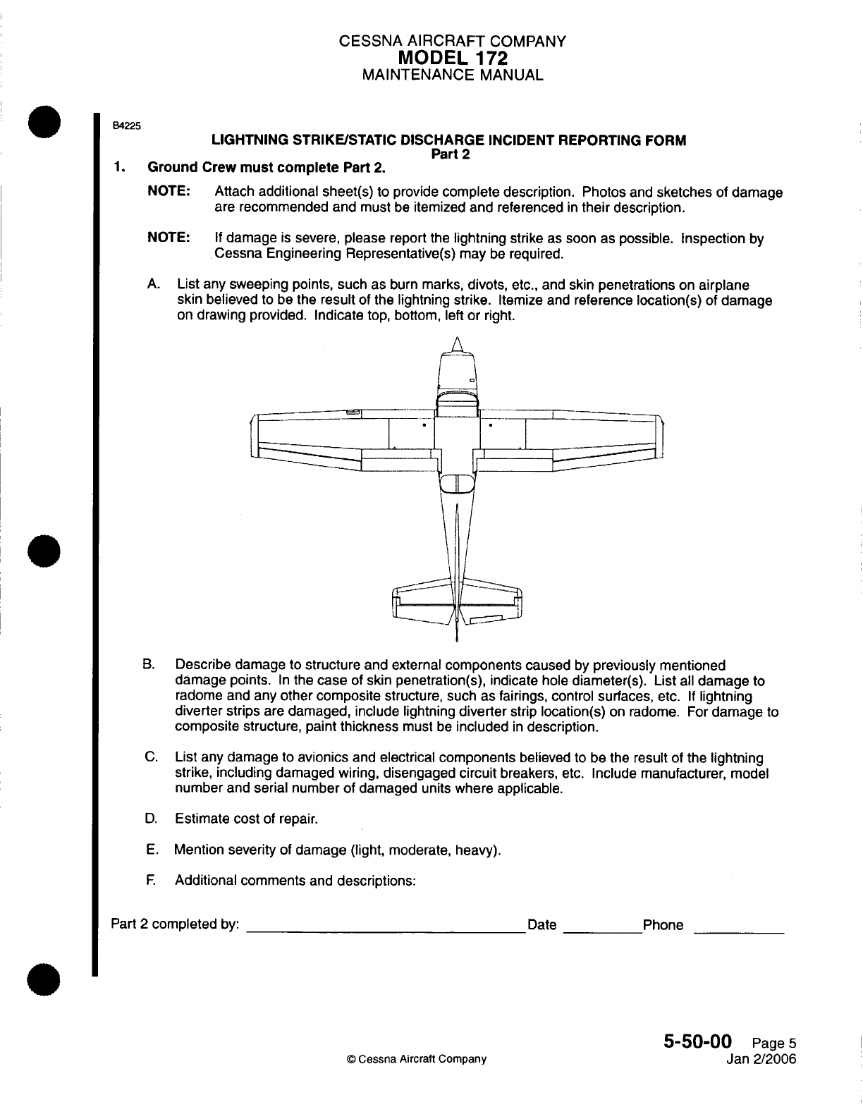
CESSNA
AIRCRAFT
COMPANY
MODEL
172
MAINTENANCE
MANUAL
B4225
LIGHTNING
STRIKE/STATIC
DISCHARGE
INCIDENT REPORTING
FORM
Part
2
1.
Ground
Crew
must
complete
Part
2.
NOTE:
Attach
additional sheet(s) to
provide
complete description.
Photos
and
sketches
of damage
are
recommended
and
must
be
itemized
and
referenced
in
their
description.
NOTE:
If
damage
is
severe,
please
report
the
lightning
strike
as
soon
as
possible.
Inspection
by
Cessna Engineering
Representative(s)
may
be
required.
A.
List
any
sweeping
points, such
as
burn
marks,
divots,
etc.,
and
skin penetrations
on
airplane
skin
believed
to
be
the
result
of the
lightning strike.
Itemize
and
reference
location(s)
of
damage
on
drawing
provided. Indicate top,
bottom,
left or right.
r1I
1.1
1.
B.
Describe
damage
to
structure
and external
components
caused
by
previously mentioned
damage points.
In
the
case
of
skin penetration(s),
indicate
hole
diameter(s).
List
all
damage
to
radome and
any
other
composite
structure,
such as
fairings,
control
surfaces,
etc.
If
lightning
diverter
strips
are
damaged,
include
lightning
diverter
strip
location(s)
on
radome.
For
damage
to
composite structure,
paint
thickness
must
be
included
in
description.
C.
List
any
damage
to
avionics
and
electrical components
believed
to be the
result
of
the
lightning
strike,
including
damaged
wiring,
disengaged
circuit
breakers,
etc.
Include manufacturer,
model
number and
serial
number
of
damaged units where
applicable.
D.
Estimate
cost
of
repair.
E.
Mention
severity
of
damage (light,
moderate, heavy).
F.
Additional comments
and
descriptions:
Part
2
completed
by:
Date
©
Cessna Aircraft
Company
Phone
5-50-00
Page
5
Jan 2/2006
CHAPTER
DIMENSIONS
AND
AREAS
CESSNA
AIRCRAFT
COMPANY
MODEL
172
MAINTENANCE
MANUAL
LIST
OF
EFFECTIVE PAGES
CHAPTER-SECTION-SUBJECT
06-Title
06-List
of
Effective
Pages
06-Record
of
Temporary
Revisions
06-Table
of
Contents
6-00-00
6-10-00
6-15-00
6-2000
6-20-02
©
Cessna Aircraft
Company
06
-
LIST
OF
EFFECTIVE
PAGES
Page
1
of
1
Jul
1/2007
PAGE DATE
Apr
7/2003
Apr
7/2003
Apr
7/2003
Jul 1/2007
Jul
1/2007
Page
1
Pages
1-4
Pages
1-3
Pages
1-4
Pages
1-11
Temporary
Revision
Number
RECORD
OF
TEMPORARY
REVISIONS
Page
Number Issue
Date
By
Date
Removed
By
CESSNA
AIRCRAFT
COMPANY
MODEL
172
MAINTENANCE
MANUAL
CONTENTS
DIMENSIONS
AND
AREAS
-
GENERAL
......................
Scope...
.................................
Definition
..................................
AIRPLANE
DIMENSIONS
AND
SPECIFICATIONS
-
DESCRIPTION
AND
OPERATION
General...................................
AIRPLANE
STATIONS
-
DESCRIPTION
AND
OPERATION..............
General...................................
AIRPLANE
ZONING
-
DESCRIPTION
AND
OPERATION...............
General...................................
Description
.................................
ACCESS/INSPECTION
PLATES
-
DESCRIPTION
AND
OPERATION.........
General...................................
Access/Inspection
Panel
Numbering......................
Description
.................................
6-00-00
Page
1
6-00-00
Page
1
6-00-00
Page
1
6-1
0-00
Page
1
6-1
0-00
Page
1
6-15-00
Page
1
6-15-00
Page
1
6-20-00
Page
1
6-20-00
Page
1
6-20-00
Page
1
6-20-02
Page
1
6-20-02
Page
1
6-20-02
Page
1
6-20-02
Page
1
06
-
CONTENTS
Page
1
of
1
Jul
1/2007
©
Cessna
Aircraft Company
CESSNA
AIRCRAFT
COMPANY
MODEL
172
MAINTENANCE
MANUAL
DIMENSIONS AND
AREAS
-
GENERAL
1.
Scope
A.
This
chapter includes illustrations
and
statistical
information concerning
the
Model
172
airplane.
Provided
are
the
overall airplane dimensions, surface
areas,
station
locations,
zones
and
access
plate
locations.
B.
Dimensions
and
measurements
are
presented
to
aid
the
operator and/or
maintenance
personnel
in
ground
handling
the
airplane
and locating
components.
2.
Definition
A.
Airplane
Dimensions
and
Areas.
(1)
The
section
on
airplane dimensions
and
areas
provides airplane dimensions
and
identifies
areas
of
the
airplane.
B.
Airplane
Stations.
(1)
The
section
on
stations
provides
illustrations
to
identify
reference
points
on
the
airplane
along
a
three
axis division.
C.
Airplane
Zoning.
(1)
The
section
on
zoning provides
illustrations
of
all
airplane
zones.
D.
Access Plates/Panels.
(1)
The
section
on
access plates/panels
provides
numbering
of
all
plates
and
panels based
on
specific
airplane zones.
6-00-00
Page
1
©
Cessna
Aircraft Company
Apr
7/2003
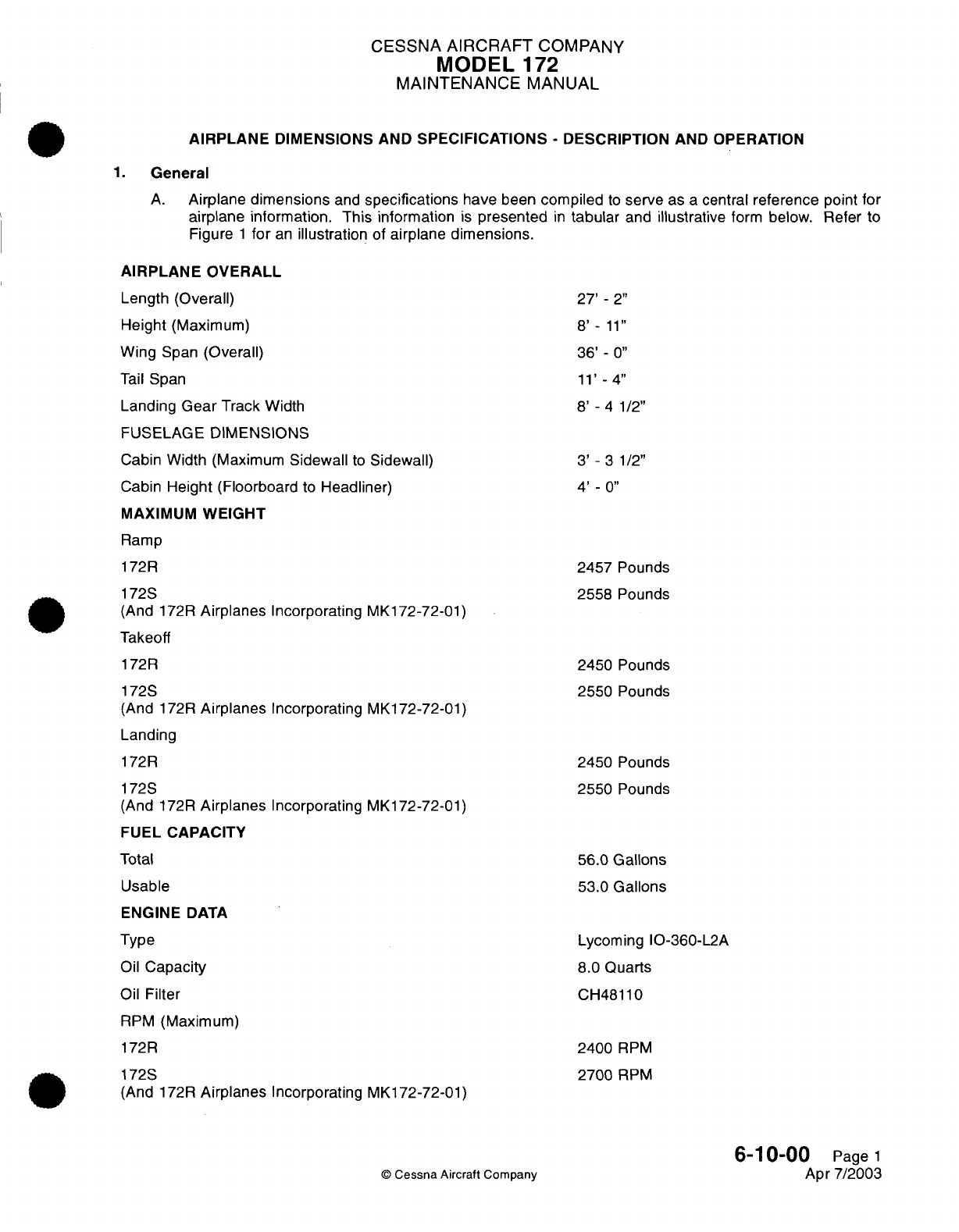
CESSNA
AIRCRAFT
COMPANY
MODEL
172
MAINTENANCE
MANUAL
AIRPLANE
DIMENSIONS AND
SPECIFICATIONS
-
DESCRIPTION AND
OPERATION
1.
General
A.
Airplane
dimensions
and
specifications
have
been
compiled
to
serve
as
a
central
reference
point
for
airplane information.
This
information
is
presented
in
tabular
and
illustrative
form
below.
Refer
to
Figure
1
for
an
illustration
of
airplane
dimensions.
AIRPLANE
OVERALL
Length
(Overall)
Height
(Maximum)
Wing
Span
(Overall)
Tail
Span
Landing
Gear
Track
Width
FUSELAGE
DIMENSIONS
Cabin Width (Maximum
Sidewall
to
Sidewall)
Cabin
Height
(Floorboard
to
Headliner)
MAXIMUM
WEIGHT
Ramp
172R
172S
(And
172R
Airplanes
Incorporating
MK172-72-01)
Takeoff
172R
172S
(And
172R
Airplanes
Incorporating
MK172-72-01)
Landing
172R
172S
(And
172R
Airplanes
Incorporating
MK172-72-01)
FUEL CAPACITY
Total
Usable
ENGINE
DATA
Type
Oil
Capacity
Oil
Filter
RPM
(Maximum)
172R
172S
(And
172R
Airplanes
Incorporating
MK172-72-01)
27'
-
2"
8'
-
11"
36'
-
0"
11'
-4"
8'
-
4
1/2"
3'
-
3 1/2"
4'
-
0"
2457
Pounds
2558
Pounds
2450
Pounds
2550
Pounds
2450
Pounds
2550
Pounds
56.0
Gallons
53.0
Gallons
Lycoming IO-360-L2A
8.0
Quarts
CH48110
2400
RPM
2700
RPM
6-1
0-00
Page
1
Apr
7/2003
©
Cessna
Aircraft
Company
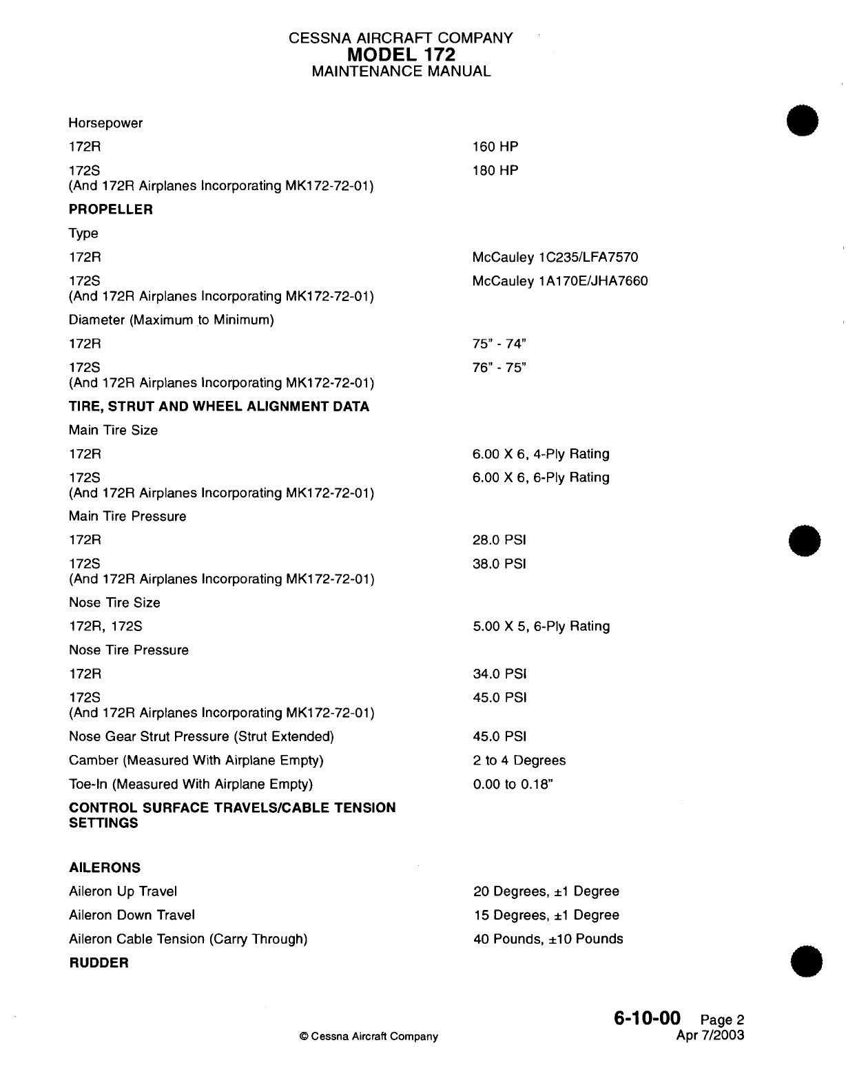
CESSNA AIRCRAFT
COMPANY
IVIODEL
172
MAINTENANCE
MANUAL
Horsepower
172R
172S
(And
172R
Airplanes
Incorporating
MK172-72-01)
PROPELLER
Type
172R
172S
(And 172R
Airplanes Incorporating
MK172-72-01)
Diameter
(Maximum
to
Minimum)
172R
172S
(And
172R
Airplanes
Incorporating
MK172-72-01)
TIRE,
STRUT AND
WHEEL
ALIGNMENT
DATA
Main
Tire
Size
172R
172S
(And 172R
Airplanes
Incorporating
MK172-72-01)
Main
Tire
Pressure
172R
172S
(And 172R
Airplanes
Incorporating
MK172-72-01)
Nose
Tire
Size
172R,
172S
Nose
Tire
Pressure
172R
172S
(And 172R
Airplanes
Incorporating
MK172-72-01)
Nose
Gear
Strut
Pressure
(Strut
Extended)
Camber
(Measured
With
Airplane
Empty)
Toe-In
(Measured
With
Airplane
Empty)
CONTROL
SURFACE
TRAVELS/CABLE
TENSION
SETTINGS
AILERONS
Aileron
Up
Travel
Aileron
Down
Travel
Aileron
Cable Tension
(Carry
Through)
RUDDER
160
HP
180
HP
McCauley
1C235/LFA7570
McCauley 1A170E/JHA7660
75"
-
74"
76"
-
75"
6.00
X
6,
4-Ply
Rating
6.00
X
6,
6-Ply
Rating
28.0
PSI
38.0
PSI
5.00
X
5,
6-Ply
Rating
34.0
PSI
45.0
PSI
45.0
PSI
2
to
4
Degrees
0.00
to
0.18"
20
Degrees,
±1
Degree
15
Degrees,
±1
Degree
40
Pounds, ±10
Pounds
6-10-00
Page
2
Apr
7/2003
©
Cessna
Aircraft
Company
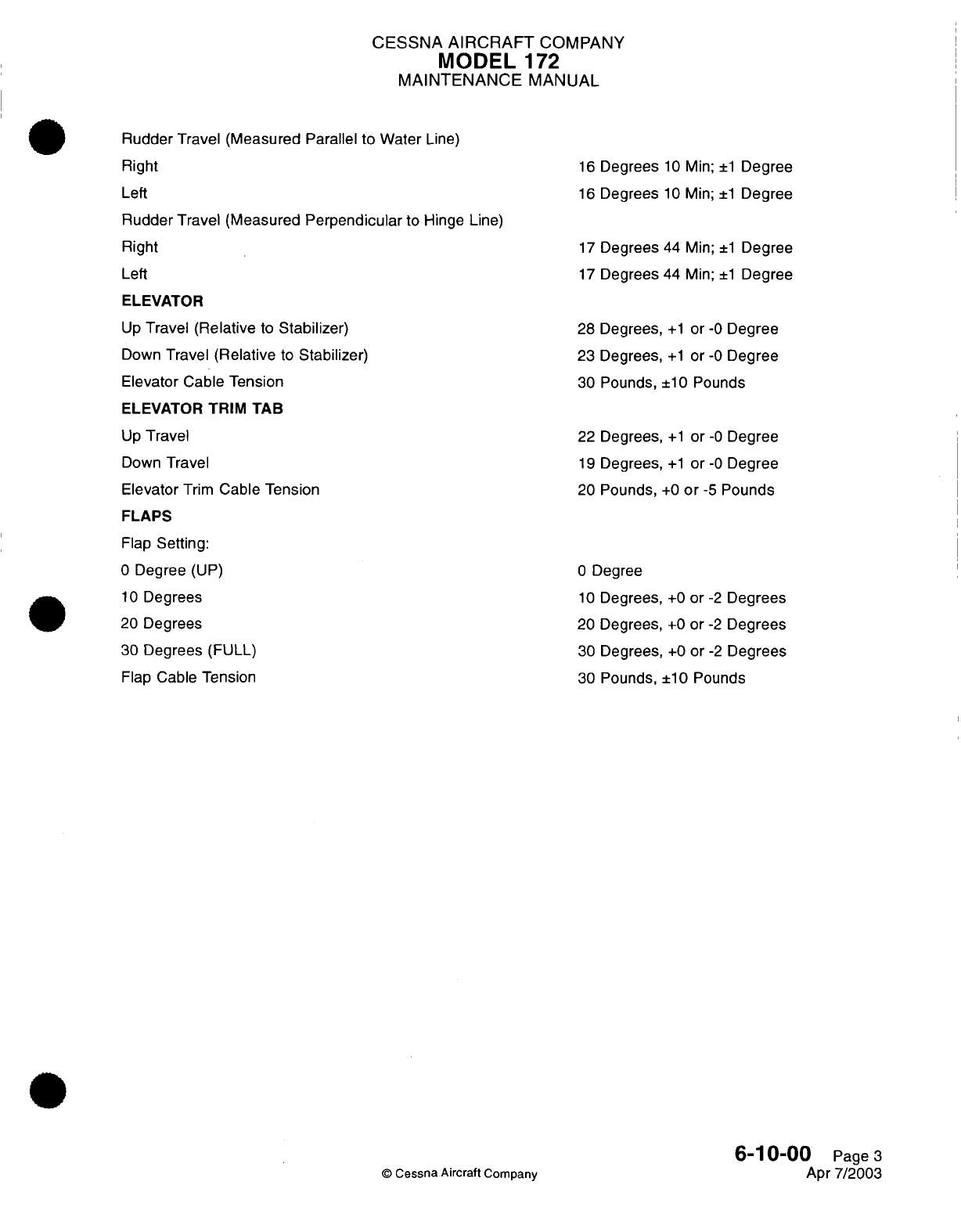
CESSNA
AIRCRAFT
COMPANY
MODEL
172
MAINTENANCE
MANUAL
Rudder
Travel (Measured
Parallel
to
Water
Line)
Right
Left
Rudder Travel (Measured
Perpendicular
to
Hinge
Line)
Right
Left
ELEVATOR
Up
Travel
(Relative
to
Stabilizer)
Down
Travel
(Relative
to
Stabilizer)
Elevator Cable
Tension
ELEVATOR
TRIM
TAB
Up
Travel
Down
Travel
Elevator
Trim
Cable
Tension
FLAPS
Flap
Setting:
0
Degree
(UP)
10
Degrees
20
Degrees
30
Degrees
(FULL)
Flap
Cable
Tension
©
Cessna Aircraft
Company
16
Degrees
10
Min;
±1
Degree
16
Degrees
10
Min;
±1
Degree
17
Degrees
44
Min;
±1
Degree
17
Degrees
44
Min;
±1
Degree
28
Degrees,
+1
or
-0
Degree
23
Degrees,
+1
or
-0
Degree
30
Pounds,
±10
Pounds
22
Degrees,
+1
or
-0
Degree
19
Degrees,
+1
or
-0
Degree
20
Pounds,
+0
or -5
Pounds
0
Degree
10
Degrees,
+0
or
-2
Degrees
20
Degrees,
+0
or
-2
Degrees
30
Degrees,
+0
or
-2
Degrees
30
Pounds,
±10 Pounds
6-10-00
Page
3
Apr
7/2003
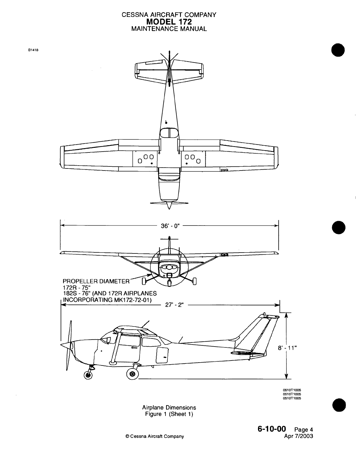
CESSNA AIRCRAFT
COMPANY
MODEL
172
MAINTENANCE
MANUAL
B1418
o
0 0 .Oo
0
36'
-
0"
PROPELLER
DIAMETER
14 7 ^ "-'I
I /1
-
13
182S-76"
(AND
172R
AIRPLANES
INCORPORATING
MK172-72-01)
.4[
.fi-
-. /
27'
-
2"
A
'-11"
v
051OT
1005
051OT
1005
0510T
1005
Airplane
Dimensions
Figure
1
(Sheet
1)
6-10-00
Page
4
Apr
7/2003
©
Cessna
Aircraft
Company
I
S
=d
J-
--
CESSNA
AIRCRAFT
COMPANY
MODEL
172
MAINTENANCE
MANUAL
AIRPLANE
STATIONS
-
DESCRIPTION
AND
OPERATION
1.
General
A.
The
airplane
is
laid
out
according
to
fuselage stations
(FS)
and
wing
stations
(WS).
These
stations
provide fixed
reference
points
for
all
components
located
on
or
within
the
airplane.
Fuselage
Stations
begin
at
the
firewall
(FS
0.00)
and
extend
to
the
tailcone
area
(FS
230.18).
Wing
Stations
begin
at
the
root (WS
23.62)
and
extend
to
the
tip
(WS
208.00).
Both
Fuselage
Stations
and
Wing
Stations
are
measured
in
inches.
For
example,
FS
185.50
is
185.50
inches
aft of
the
firewall
(FS
0.00).
B.
For
an
illustration
of
Fuselage
Stations,
refer to Figure
1.
For
an
illustration
of
Wing
Stations,
refer
to
Figure
2.
6-15-00
Page
1
©
Cessna Aircraft
Company
Apr
7/2003
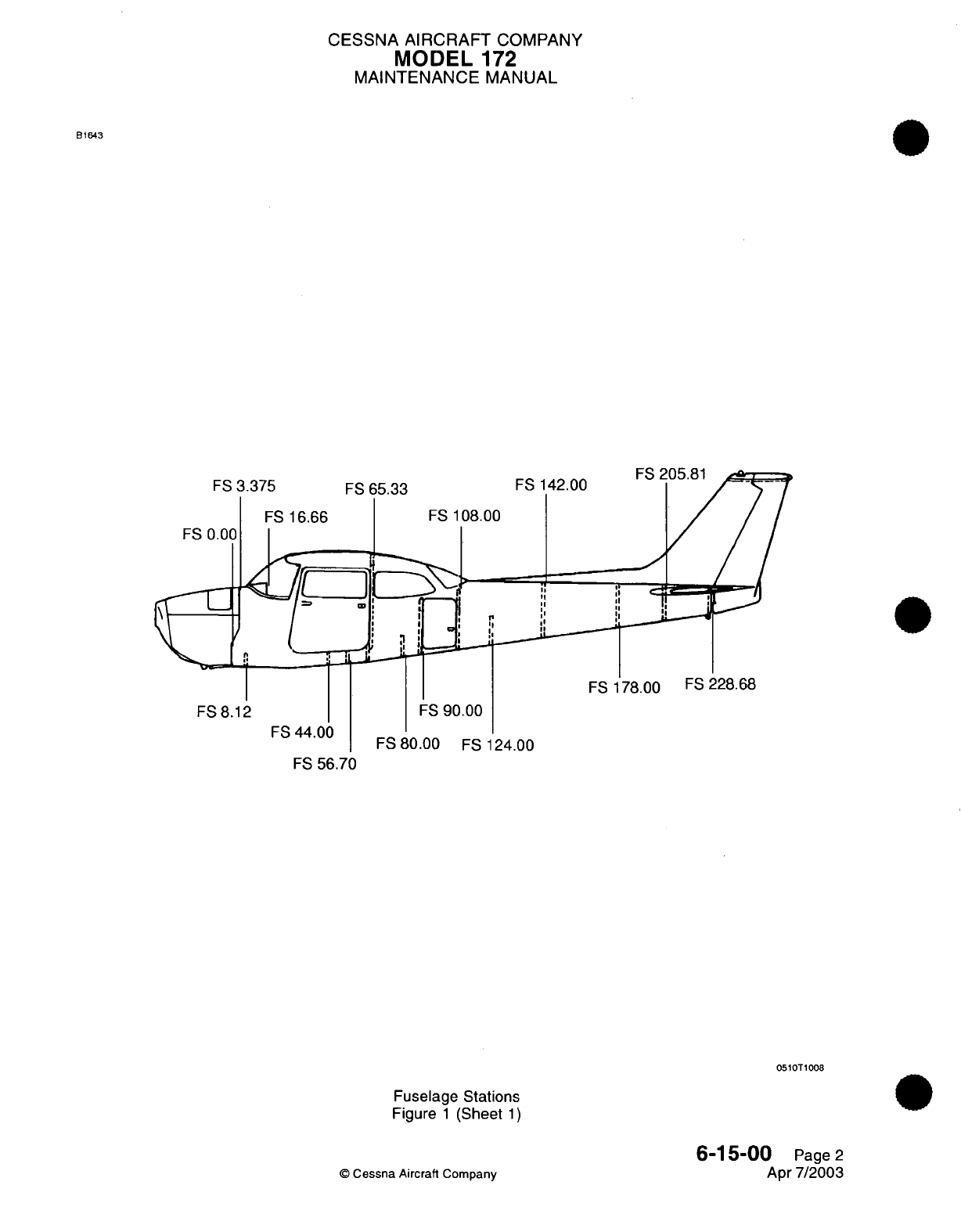
CESSNA
AIRCRAFT
COMPANY
MODEL
172
MAINTENANCE
MANUAL
65.33
[
D
L,
j
FS
142.00
FS
108.00
,I
\III
II
I
I
rI
I,
V
I,
II
FS
8.12
FS
44.00
FS
56.70
FS
90.00
FS
80.00
FS
124.00
0510T1008
Fuselage
Stations
Figure
1
(Sheet
1)
6-15-00
Page
2
Apr
7/2003
©
Cessna Aircraft
Company
B1643
FS
3.375
FS
0.00
FS
16.66
FS
178.00
FS
228.68
FS
65.33
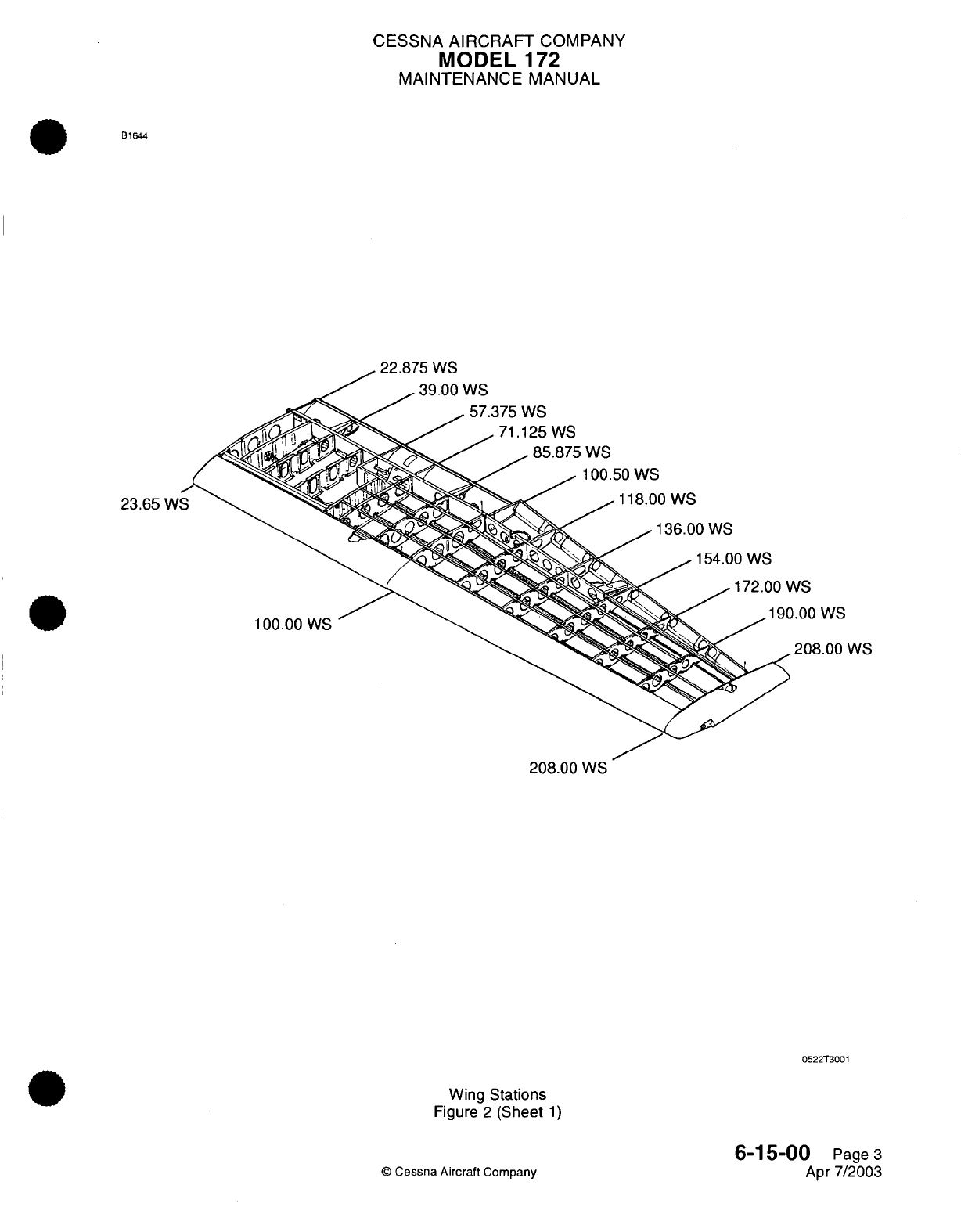
CESSNA
AIRCRAFT
COMPANY
MODEL
1
72
MAINTENANCE
MANUAL
B1644
99
F7r; WC
23.65
W
c
NS
).00
WS
100.00
WS
208.00
WS
208.00
WS
0522T3001
Wing
Stations
Figure
2
(Sheet
1)
6-15-00
Page
3
Apr
7/2003
©
Cessna Aircraft
Company
CESSNA AIRCRAFT
COMPANY
MODEL
172
MAINTENANCE
MANUAL
AIRPLANE
ZONING
-
DESCRIPTION
AND OPERATION
General
A.
The
Model
172
is
divided
into
numbered
zones
to
provide
a
method
for
locating
components
and/or
placards
throughout
the
airplane.
The
zones
are
identified
by
a
three-digit
number
as
shown
in
the
example
below.
The
first
digit
in
the
sequence
denotes
the
major
zone
(300
series
for
aft
of cabin,
500 series
for
left
wing,
etc.).
The
second
digit
in
the
sequence
further
divides
the
zone
into
submajor
zone
(Zone
51
0
for
inboard portion
of
the
left
wing
and
Zone
520 for
outboard portion
of
the
left
wing,
etc..).
The
third
digit further
divides
the
submajor
zones
into
subdivisions
(if
no
subdivision
is
needed,
this
digit
is
typically
assigned
as
0
(zero).
EXAMPLE
310
Major
Zone
I I
Subdivision Zone
Submajor
Zone
B.
Major
Zones.
(1)
100
-
Forward
side
of
firewall
and
forward.
(2)
200
-
Aft
side
of
firewall.
(3)
300
-
Aft
of
cabin
to
end
of
airplane.
(4)
500
-
Left wing.
(5)
600
-
Right
wing.
(6)
700
-
Landing
gear.
2.
Description
A.
For
a
breakdown
of
the
airplane
zones,
refer
to
Figure
1.
6-20-00
Page
1
Jul
1/2007
©
Cessna
Aircraft
Company
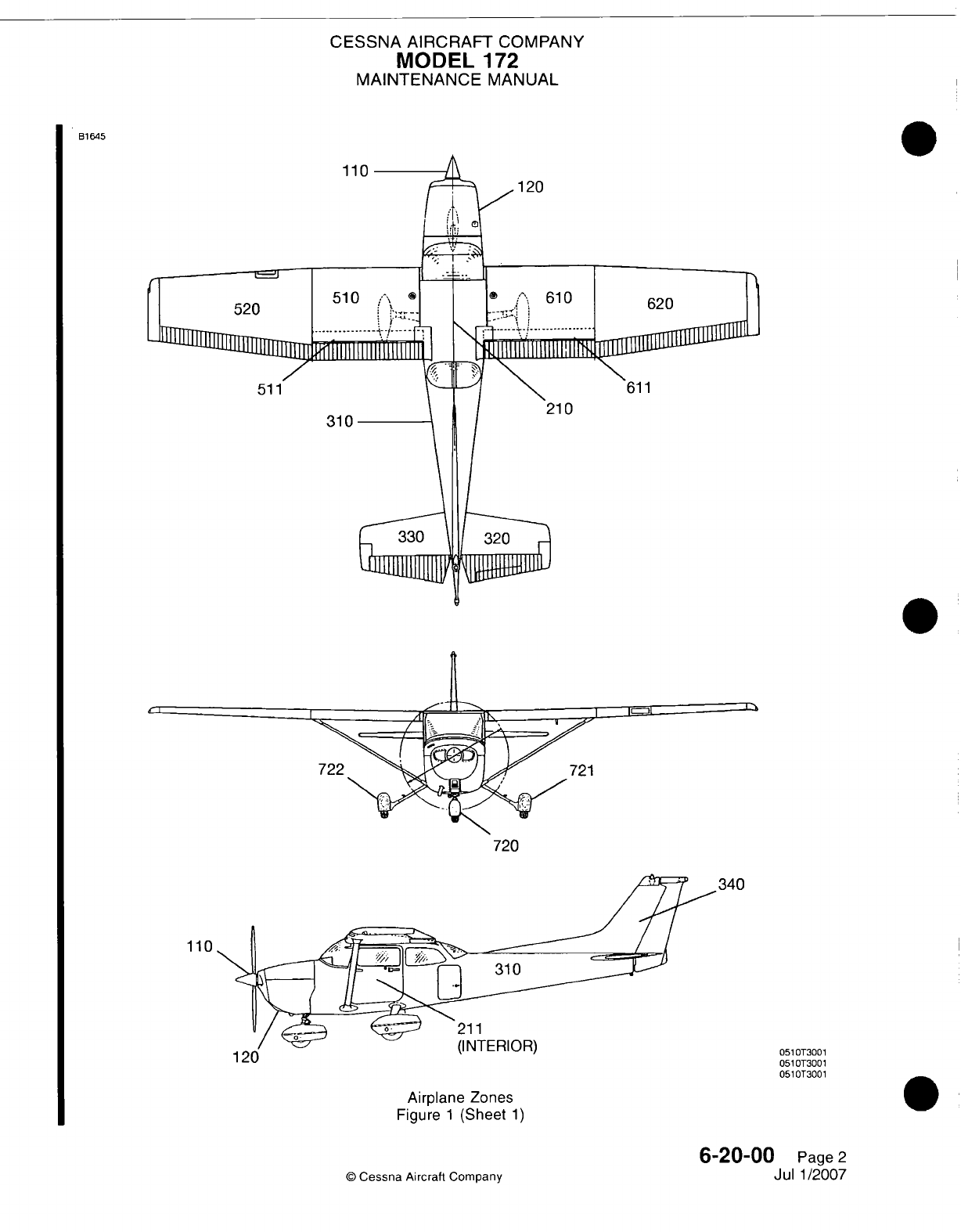
CESSNA
AIRCRAFT
COMPANY
MODEL
172
MAINTENANCE
MANUAL
B1645
110
310
120
210
720
340
110
211
(INTERIOR)
051
0T3001
051
0T3001
051
0T3001
Airplane Zones
Figure
1
(Sheet
1)
©
Cessna
Aircraft
Company
6-20-00
Page
2
Jul
1/2007
0
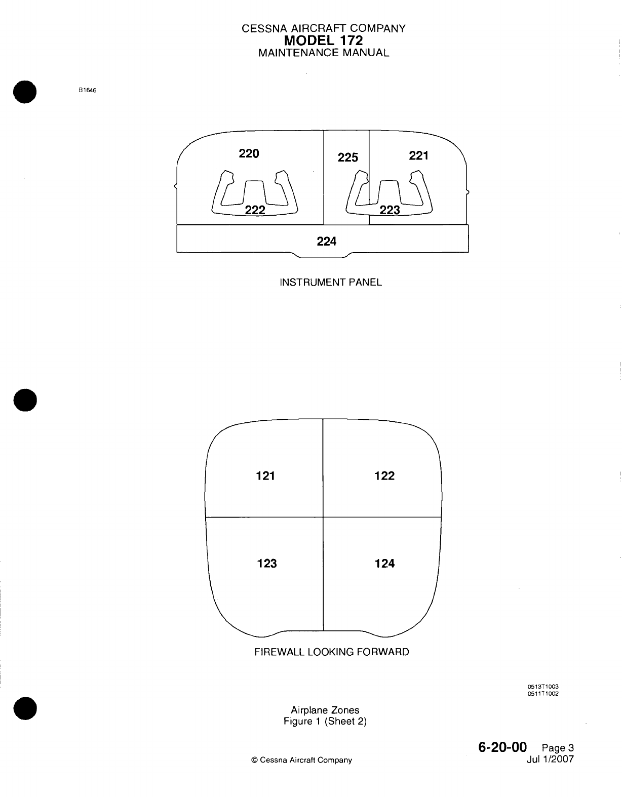
CESSNA
AIRCRAFT
COMPANY
MODEL
172
MAINTENANCE
MANUAL
B1646
INSTRUMENT
PANEL
FIREWALL
LOOKING
FORWARD
0513T
1003
051
1T1002
Airplane
Zones
Figure
1
(Sheet
2)
6-20-00
Page
3
Jul
1/2007
Cessna
Aircraft
Company
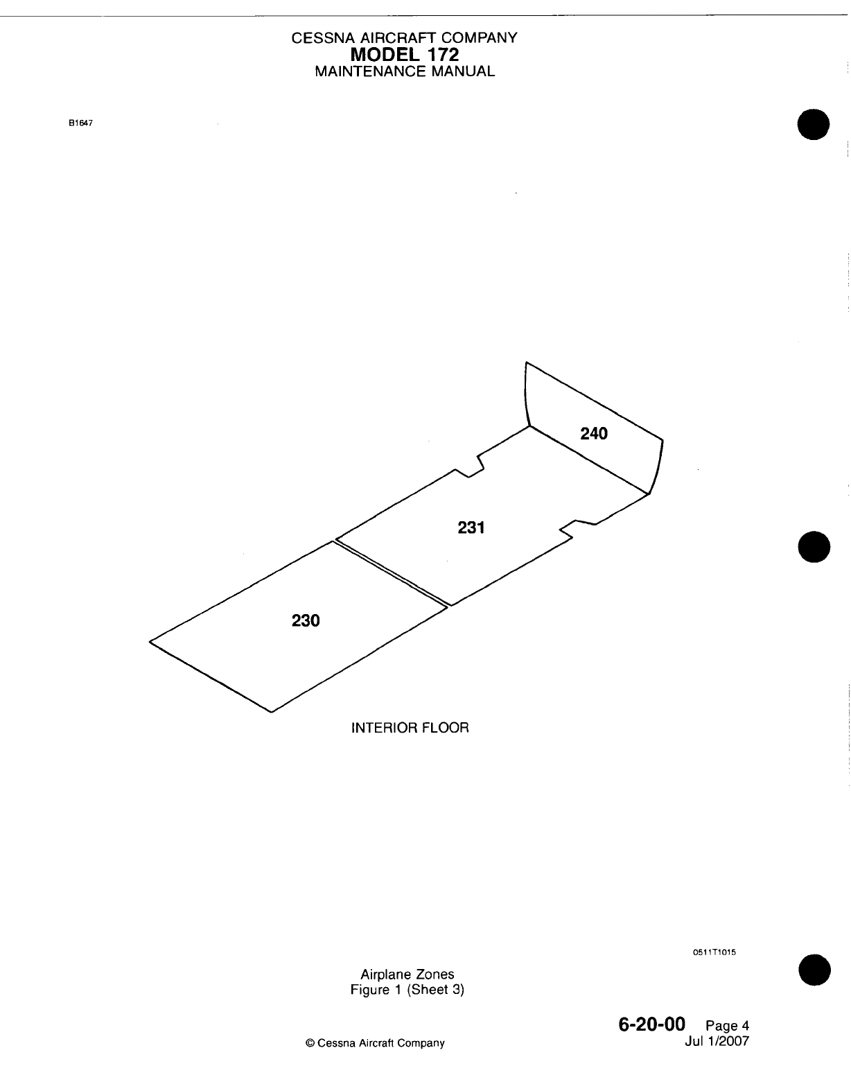
CESSNA
AIRCRAFT
COMPANY
MODEL
172
MAINTENANCE
MANUAL
B1647
INTERIOR
FLOOR
051
1T1015
Airplane Zones
Figure
1
(Sheet
3)
6-20-00
Page
4
Jul
1/2007
©
Cessna
Aircrafl
Company
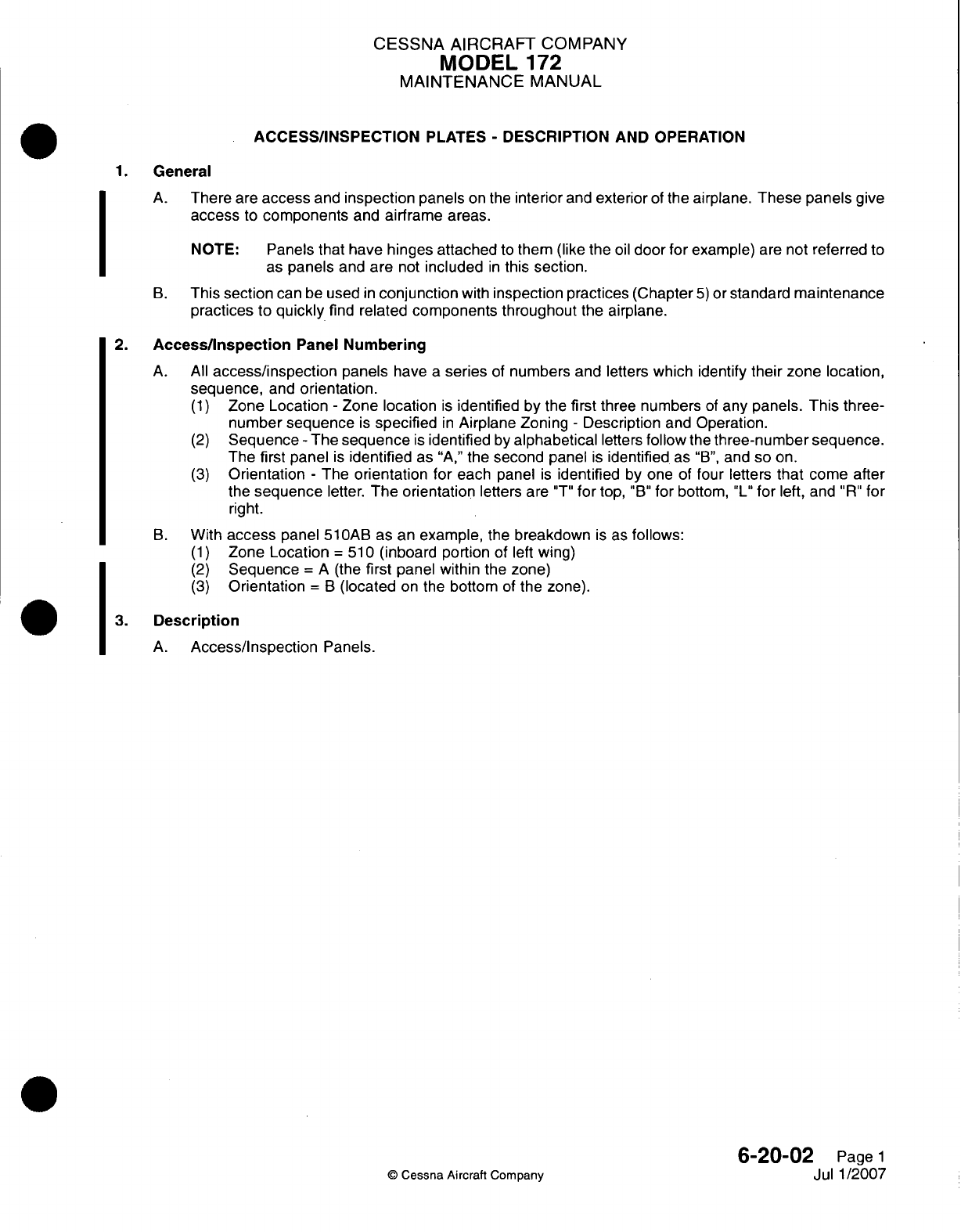
CESSNA AIRCRAFT
COMPANY
MODEL
172
MAINTENANCE
MANUAL
ACCESS/INSPECTION
PLATES
-
DESCRIPTION
AND OPERATION
1.
General
A.
There
are
access
and
inspection
panels
on
the
interior
and
exterior
of
the
airplane.
These panels
give
access
to
components
and
airframe
areas.
NOTE:
Panels that
have
hinges
attached
to
them
(like
the
oil
door
for
example)
are
not
referred
to
as
panels
and
are
not
included
in
this
section.
B.
This
section
can
be
used
in
conjunction
with
inspection
practices
(Chapter
5)
or
standard
maintenance
practices
to
quickly
find
related
components throughout
the
airplane.
2.
Access/inspection
Panel
Numbering
A.
All
access/inspection
panels
have
a
series
of
numbers
and
letters
which identify
their zone
location,
sequence,
and
orientation.
(1)
Zone
Location
-
Zone
location
is
identified
by
the
first
three
numbers
of
any
panels. This
three-
number
sequence
is
specified
in
Airplane
Zoning
-
Description
and
Operation.
(2)
Sequence
-
The
sequence
is
identified
by
alphabetical
letters
follow
the
three-number sequence.
The
first
panel
is
identified
as
"A,"
the
second
panel
is
identified.
as
"B",
and so
on.
(3)
Orientation
-
The
orientation
for
each
panel
is
identified
by
one
of
four
letters
that
come
after
the
sequence
letter.
The
orientation
letters
are
"T"
for
top,
"B"
for
bottom,
"L"
for
left,
and
"R"
for
right.
B.
With
access
panel
510AB
as
an
example,
the
breakdown
is
as
follows:
(1)
Zone
Location
=
51
0
(inboard
portion
of
left wing)
(2)
Sequence
A
(the
first
panel
within
the
zone)
(3)
Orientation
B
(located
on
the
bottom
of
the
zone).
3.
Description
A.
Access/Inspection
Panels.
6-20-02
Page
1
Jul
1/2007
©
Cessna
Aircraft
Company
I
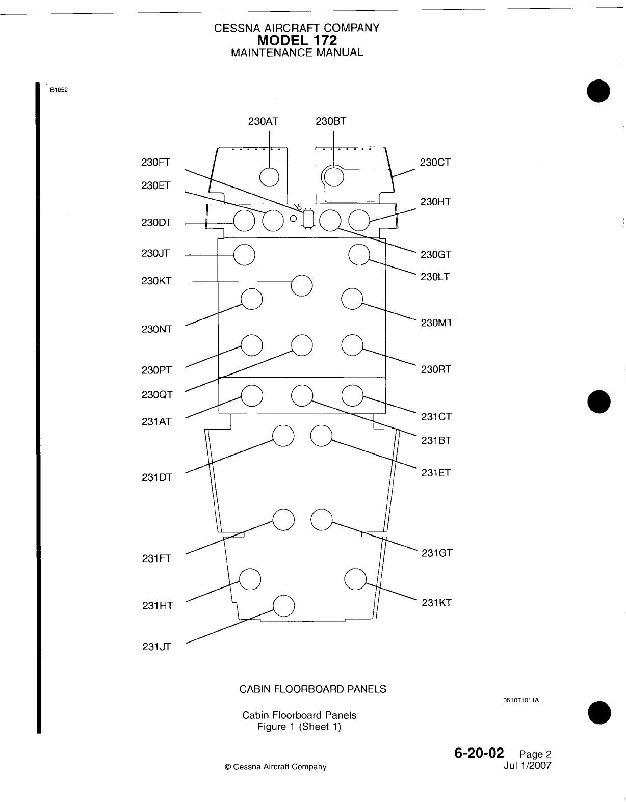
CESSNA AIRCRAFT
COMPANY
MODEL
172
MAINTENANCE
MANUAL
B1652
230AT
230FT
230EFT
230DT
230JT
230KT
230NT
230
PT
230QT
231
AT
231
DT
231
FT
231
HT
231
JT
230BT
CABIN
FLOORBOARD PANELS
051
OTi
01
1A
Cabin Floorboard
Panels
Figure
1
(Sheet
1)
6-20-02
Page
2
Jul
1/2007
©
Cessna Aircraft
Company
2300T
230HT
230GT
230LT
230MT
230RT
231
CT
231
BT
231
ET
231
GT
231
KT
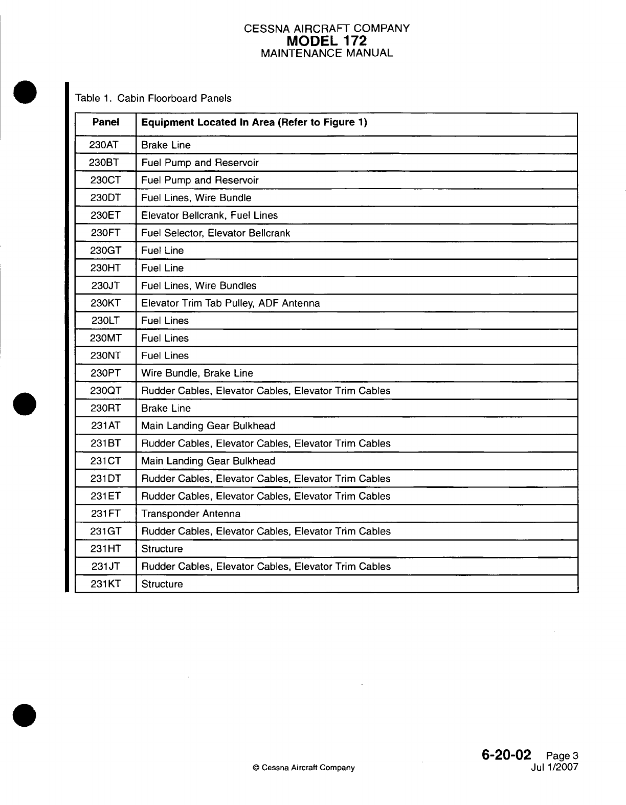
CESSNA
AIRCRAFT
COMPANY
MODEL
172
MAINTENANCE
MANUAL
Table
1.
Cabin Floorboard
Panels
Panel
Equipment Located
In
Area
(Refer
to
Figure
1)
230AT Brake
Line
230BT
Fuel
Pump
and
Reservoir
2300T
Fuel
Pump
and
Reservoir
2300T
Fuel
Lines, Wire
Bundle
230ET
Elevator Bellcrank,
Fuel
Lines
230FT
Fuel
Selector, Elevator
Bellcrank
230GT
Fuel
Line
230HT
Fuel
Line
230JT
Fuel
Lines, Wire
Bundles
230KT Elevator
Trim
Tab
Pulley,
ADF
Antenna
230LT
Fuel
Lines
230MT
Fuel
Lines
230NT
Fuel
Lines
230PT
Wire
Bundle.
Brake Line
230QT
Rudder Cables, Elevator
Cables,
Elevator
Trim
Cables
230RT
Brake
Line
231
AT
Main
Landing
Gear Bulkhead
231
BT
Rudder Cables,
Elevator
Cables,
Elevator
Trim
Cables
231
CT
Main
Landing
Gear
Bulkhead
231
DT
Rudder Cables,
Elevator
Cables,
Elevator
Trim
Cables
231
ET
Rudder Cables,
Elevator
Cables,
Elevator
Trim
Cables
231
FT
Transponder
Antenna
231
GT
Rudder
Cables,
Elevator
Cables,
Elevator
Trim
Cables
231
HT
Structure
231
JT
Rudder
Cables, Elevator
Cables,
Elevator
Trim
Cables
231
KT
Structure
©
Cessna
Aircraft
Company
6-20-02
Page
3
Jul
1/2007
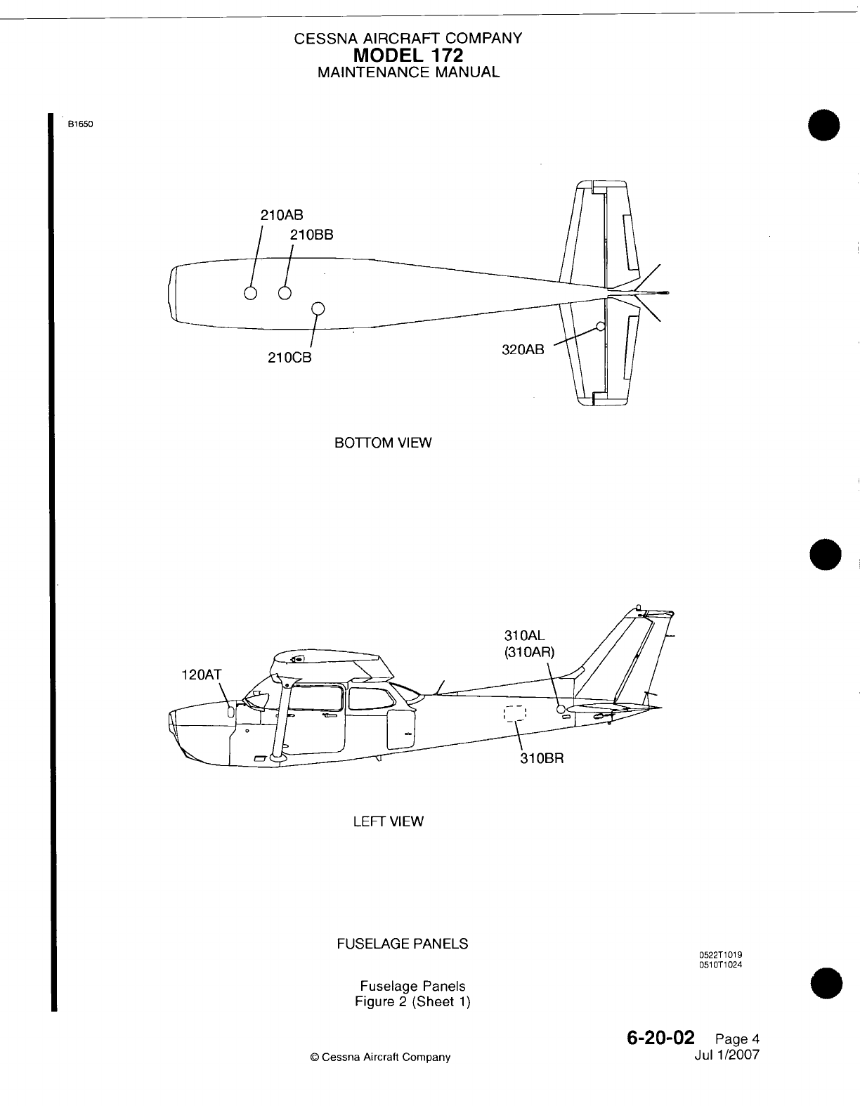
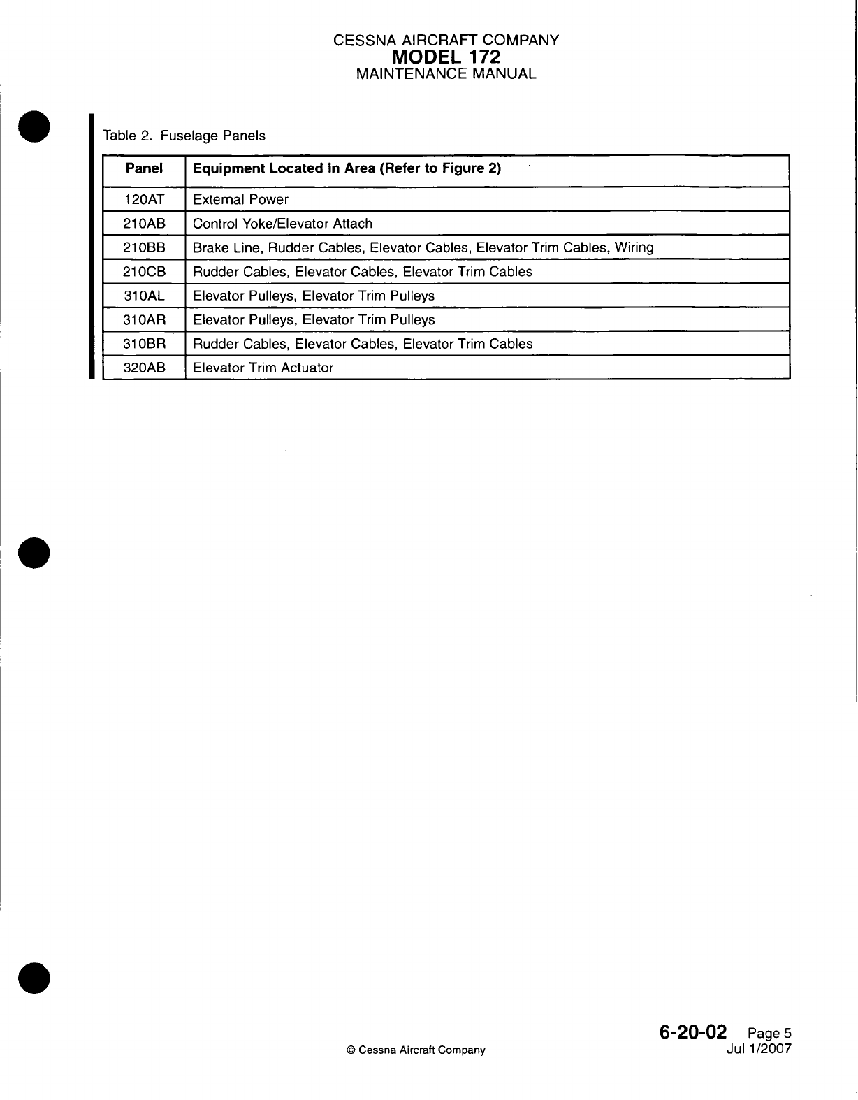
CESSNA AIRCRAFT
COMPANY
MODEL
172
MAINTENANCE
MANUAL
Table
2.
Fuselage
Panels
Panel
Equipment
Located
In
Area
(Refer to
Figure
2)
120AT
External
Power
21
OAB
Control
Yoke/Elevator
Attach
21
OBB
Brake
Line,
Rudder
Cables,
Elevator
Cables,
Elevator
Trim
Cables,
Wiring
21
OCI3
Rudder
Cables,
Elevator
Cables, Elevator
Trim
Cables
31
OAL
Elevator
Pulleys, Elevator
Trim
Pulleys
31
OAR
Elevator
Pulleys,
Elevator
Trim
Pulleys
31
OBR
Rudder
Cables,
Elevator
Cables, Elevator
Trim
Cables
320AB Elevator
Trim
Actuator
6-20-02
Page
5
Jul
1/2007
Q
Cessna
Aircratt
Company
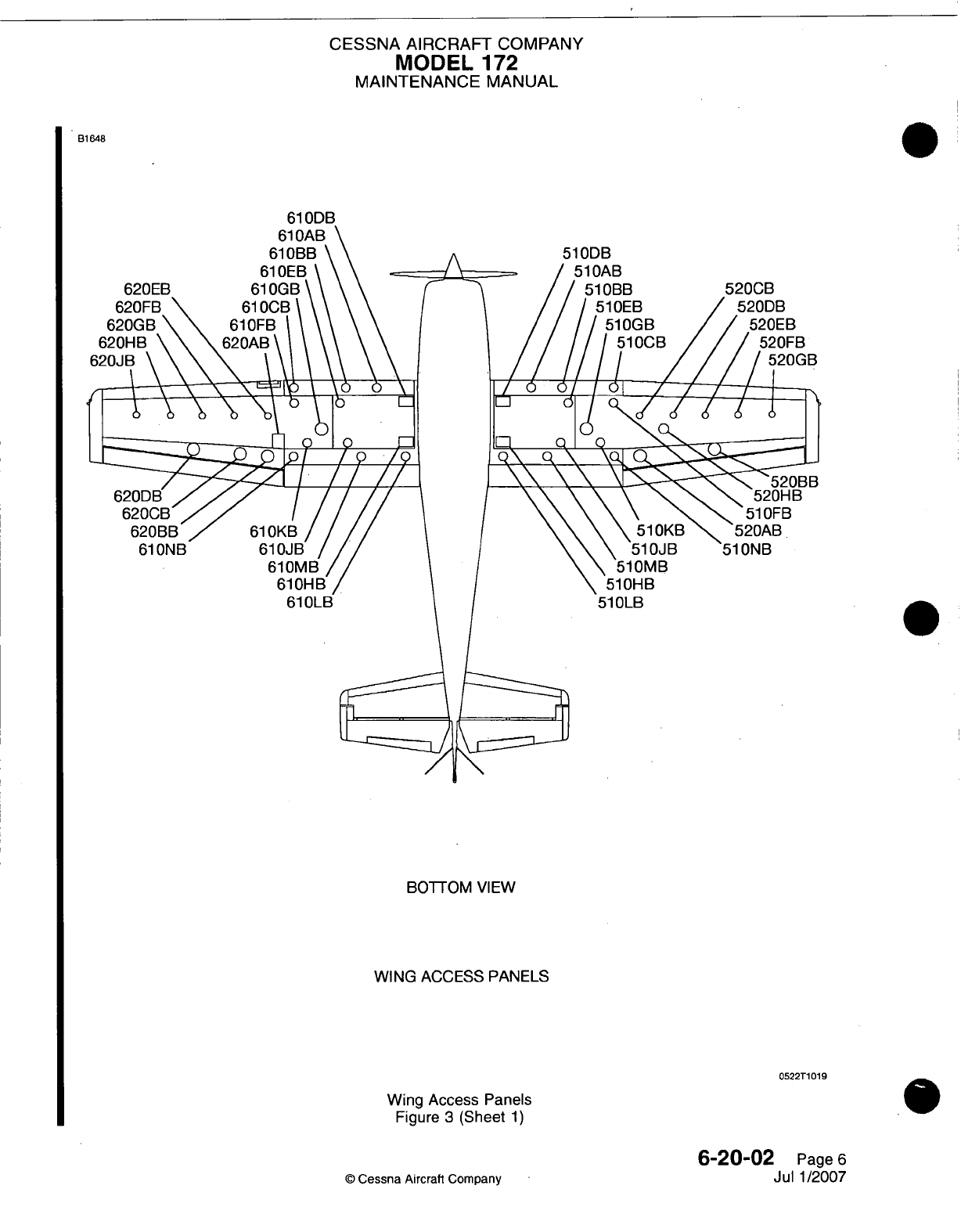
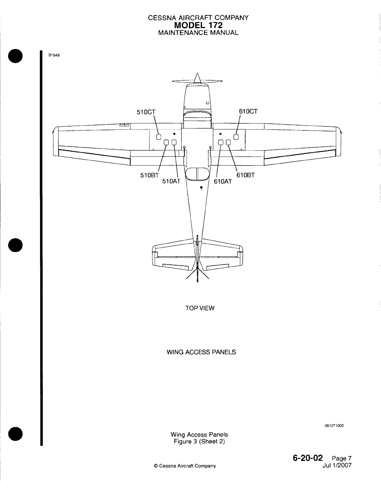
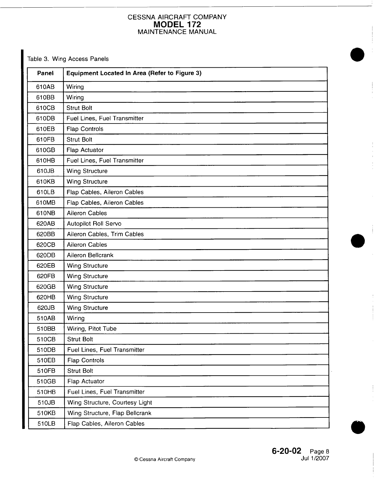
CESSNA AIRCRAFT
COMPANY
MODEL
172
MAINTENANCE
MANUAL
Table
3.
Wing
Access
Panels
Panel
Equipment
Located
In
Area
(Refer
to
Figure
3)
610OAB
Wiring
61
OBB
Wiring
6100CB
Strut
Bolt
61
0DB
Fuel
Lines,
Fuel
Transmitter
610OEB
Flap
Controls
610OFB
Strut
Bolt
61
0GB Flap
Actuator
610HB
Fuel
Lines,
Fuel
Transmitter
610JB
Wing
Structure
61
0KB
Wing
Structure
610OLB
Flap
Cables,
Aileron Cables
61
0MB Flap
Cables,
Aileron
Cables
61ONB
Aileron
Cables
620AB
Autopilot
Roll
Servo
620BB
Aileron
Cables,
Trim
Cables
620CB
Aileron Cables
620DB
Aileron Bellcrank
620EB
Wing
Structure
620FB
Wing
Structure
620GB
Wing
Structure
620HB
_Wing
Structure
620JB
Wing
Structure
51
OAB
Wiring
51
OBB
Wiring,
Pitot
Tube
510OCB
Strut
Bolt
510DB
Fuel
Lines,
Fuel
Transmitter
51lOEB
Flap
Controls
51
OFB
Strut
Bolt
51
0GB Flap
Actuator
51
OHB
Fuel
Lines,
Fuel
Transmitter
510JB Wing
Structure, Courtesy
Light
51
0KB
Wing
Structure,
Flap
Bellcrank
510OLB
Flap
Cables,
Aileron
Cables
6-20-02
Page
8
Jul
1/2007
©
Cessna
Aircrafl
Company
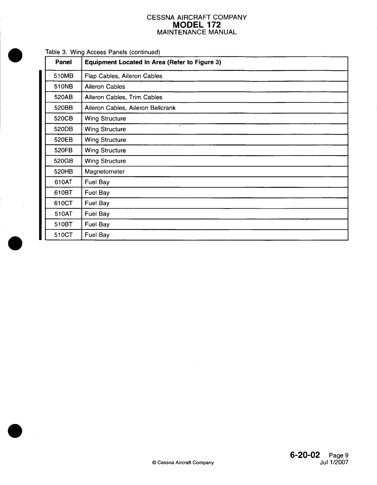
CESSNA
AIRCRAFT
COMPANY
MODEL
172
MAINTENANCE
MANUAL
Table
3.
Wing
Access Panels (continued)
Panel
Equipment
Located
In
Area (Refer
to
Figure
3)
51
0MB Flap
Cables,
Aileron Cables
51
ONB
Aileron
Cables
520AB
Aileron Cables,
Trim
Cables
520BB
Aileron Cables, Aileron Bellcrank
520CB
_Wing
Structure
520DB
Wing
Structure
520EB
Wing
Structure
520FB
Wing
Structure
520GB
Wing
Structure
520HB Magnetometer
61
OAT
Fuel
Bay
61
OBT
Fuel
Bay
61
OCT
Fuel
Bay
51lOAT
Fuel
Bay
51
OBT
Fuel
Bay
51lOCT
Fuel
Bay
6-20-02
Page
9
Jul
1/2007
©
Cessna
Aircraft
Company
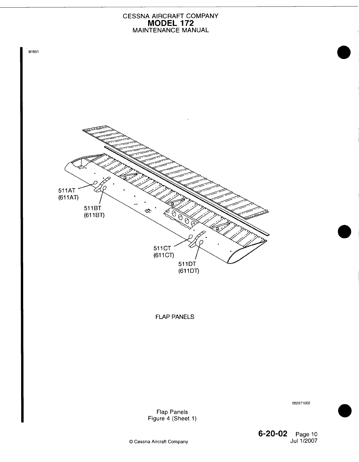
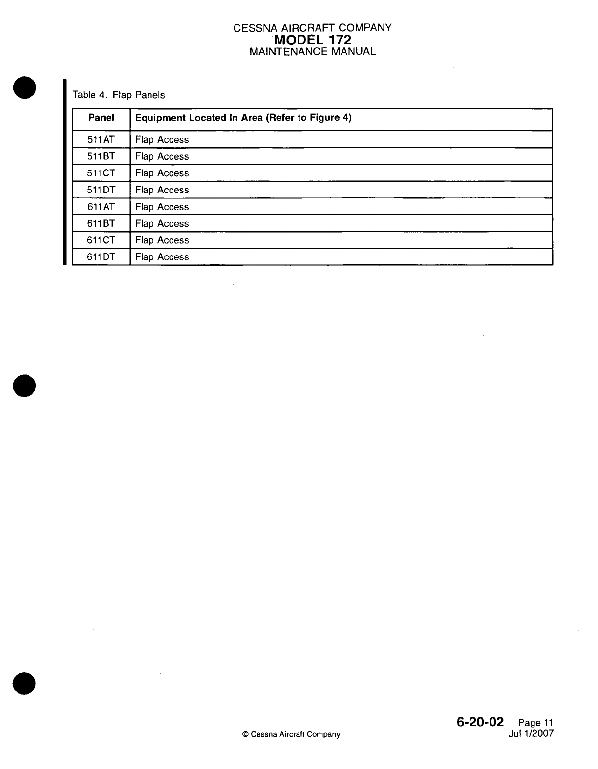
CESSNA
AIRCRAFT
COMPANY
.MODEL
172
MAINTENANCE
MANUAL
Table
4.
Flap Panels
Panel
Equipment
Located
In
Area
(Refer
to
Figure
4)
51
1AT Flap
Access
511
BT Flap
Access
51liCT
Flap
Access
511
DT
Flap
Access
61
1AT Flap
Access
611
BT Flap
Access
611
CT
Flap
Access
611
DT
Flap
Access
6-20-02
Page
11
Jul
1/2007
©
Cessna
Aircraft
Company

CHAPTER
LIFTING
AND
SHORING

CESSNA
AIRCRAFT
COMPANY
MODEL
172
MAINTENANCE
MANUAL
LIST
OF
EFFECTIVE
PAGES
CHAPTER-SECTION-SUBJECT
07-Title
07-List
of
Effective
Pages
07-Record
of
Temporary
Revisions
07-Contents
7-00-00
7-10-00
7-11-00
PAGE
Page
1
Pages 201-202
Page
201
©
Cessna Aircraft
Company
07
-
LIST
OF
EFFECTIVE
PAGES
Page
1
of
1
Jan 3/2005
DATE
Apr
7/2003
Apr
7/2003
Apr
7/2003
Temporary
Revision
Number
RECORD
OF
TEMPORARY
REVISIONS
Page
Number Issue
Date
By
Date
Removed
By
CESSNA
AIRCRAFT
COMPANY
MODEL
172
MAINTENANCE
MANUAL
CONTENTS
LIFTING AND
SHORING
-
GENERAL
....................
.........................
S
cope......................................................................
Tools,
Equipment
and
Material
...............................................
Definition
.................................................
................
JACKING
-
MAINTENANCE PRACTICES
........................................
General
....................................................................
Tools,
Equipment
and
Materials
..............................................
Jacking
Procedure
..........................................................
EMERGENCY
LIFTING/HOISTING
-
MAINTENANCE
PRACTICES
..................
Lifting
Procedure
............................
............................
7-00-00
Page
1
7-00-00
Page
1
7-00-00
Page
1
7-00-00
Page
1
7-10-00
Page
201
7-10-00
Page
201
7-10-00
Page
201
7-10-00
Page
201
7-11-00
Page
201
7-11-00
Page
201
CONTENTS
Page
1
of
1
Jan 3/2005
©
Cessna
Aircraft
Company
CESSNA
AIRCRAFT
COMPANY
MODEL
172
MAINTENANCE
MANUAL
LIFTING
AND
SHORING
-
GENERAL
1.
Scope
A.
This
chapter
describes
both
standard
and
emergency
procedures
used
to
lift
the
airplane
off the
ground.
2.
Tools,
Equipment
and
Material
NOTE:
Equivalent
substitutes
may
be
used
for
the
following
listed
items:
NAME
Jack
NUMBER
2-170
Leg
Extension
Slide
Tube
Extension
Universal
Tail
Stand
Padded
Block
2-109
2-70
2-168
MANUFACTURER
Cessna
Aircraft
Company
Cessna Parts
Department
P.O.
Box
949
Wichita,
KS
67201
Cessna
Aircraft
Company
Cessna
Aircraft
Company
Cessna Aircraft
Company
Fabricate
locally
USE
To
jack
wing.
To
extend
legs
on
jack.
To
extend
jack
height.
To
secure
tail.
To
provide
cushion
between
wing
jack
and
wing
spar.
3.
Definition
A.
This
chapter
is
divided
into
sections
to
aid
maintenance
personnel
in
locating
information.
Consulting
the Table
of
Contents
will
further
assist
in
locating
a
particular subject.
A
brief
definition
of
the
sections
incorporated
in
this chapter
is
as
follows:
(1)
The
section
on
Jacking
provides
normal
procedures
and
techniques
used
to
Jack
the
airplane
off
the
ground.
(2)
The
section
on
emergency
lifting
provides
procedures,
techniques
and
fabrication
information
needed
to
lift
the
airplane
by
overhead
means.
7-00-00
Page
1
©
Cessna
Aircraft Company
Apr
7/2003
CESSNA
AIRCRAFT
COMPANY
MODEL
172
MAINTENANCE
MANUAL
JACKING
-
MAINTENANCE PRACTICES
1.
General
CAUTION: JACKING
BOTH
WHEELS
SIMULTANEOUSLY
AT
BUILT-IN
JACK
PADS
IS
NOT
RECOMMENDED.
WHEN
USING
BUILT-IN
JACK
PAD,
FLEXIBILITY
OF
THE
MAIN
GEAR
STRUT WILL
CAUSE
THE
MAIN
WHEEL TO
SLIDE
INBOARD
AS
THE
WHEEL
IS
RAISED, TILTING
THE
JACK.
IF
THIS
OCCURS,
THE
JACK
MUST
BE
LOWERED
FOR
A
SECOND OPERATION.
A.
Normal
Jacking
procedures involve
lifting
one main
wheel
at
a
time. This
procedure
is
best
accomplished
using
a
floor
jack
in
conjunction
with
the
built-in
jack
pad
(located
directly
below
the
step
on
each
strut).
2.
Tools,
Equipment
and
Materials
A.
For
a
list of
required
tools,
equipment
and
materials,
refer
to
Lifting
and
Shoring
-
General.
3.
Jacking
Procedure
NOTE: When
the
airplane needs
to
be
raised
off
the
ground
at
all
points, the
following
procedure
should
be
used.
A.
Raise
Airplane
(Refer
to
Figure
201).
CAUTION:
WHEN PLACED
ON
JACKS,
THE
AIRPLANE
IS
NOSE
HEAVY.
TAIL
STANDS
MUST
WEIGH ENOUGH
TO
KEEP
THE
TAIL
DOWN UNDER
ALL
CONDITIONS.
ADDITIONALLY,
THE
TAIL
STAND
MUST
BE
STRONG
ENOUGH
TO
SUPPORT
ANY
WEIGHT
WHICH
MIGHT
BE
TRANSFERRED
TO
THE
TAILCONE AREA
DURING
MAINTENANCE,
CREATING
A
TAIL
HEAVY
CONDITION.
(1)
Carefully attach
tail
stand
to
tail
tie-down
ring.
(2)
Place
wing
jacks
and
padded
blocks
under
front spar,
just
outboard
of
wing
strut
(Wing
Station
118.00).
Ensure
that
padded
block
(1
inch
X
4
inch
X
4
inch
with
0.25
inch
rubber
pad)
is
resting
securely
between
spar
and
jack.
(3)
Raise
wing
jacks evenly
until
desired
height
is
reached.
B.
Lower Airplane
(Refer to Figure
201).
(1)
Slowly lower
wing
jacks
simultaneously
until main
tires
are
(2)
Remove
wing
jacks
and
pads
from
wing
area.
(3)
Detach
tail stand
from
tie-down
ring.
©
Cessna Aircraft
Company
resting
on
ground.
7-1
0-00
Page
201
Apr
7/2003
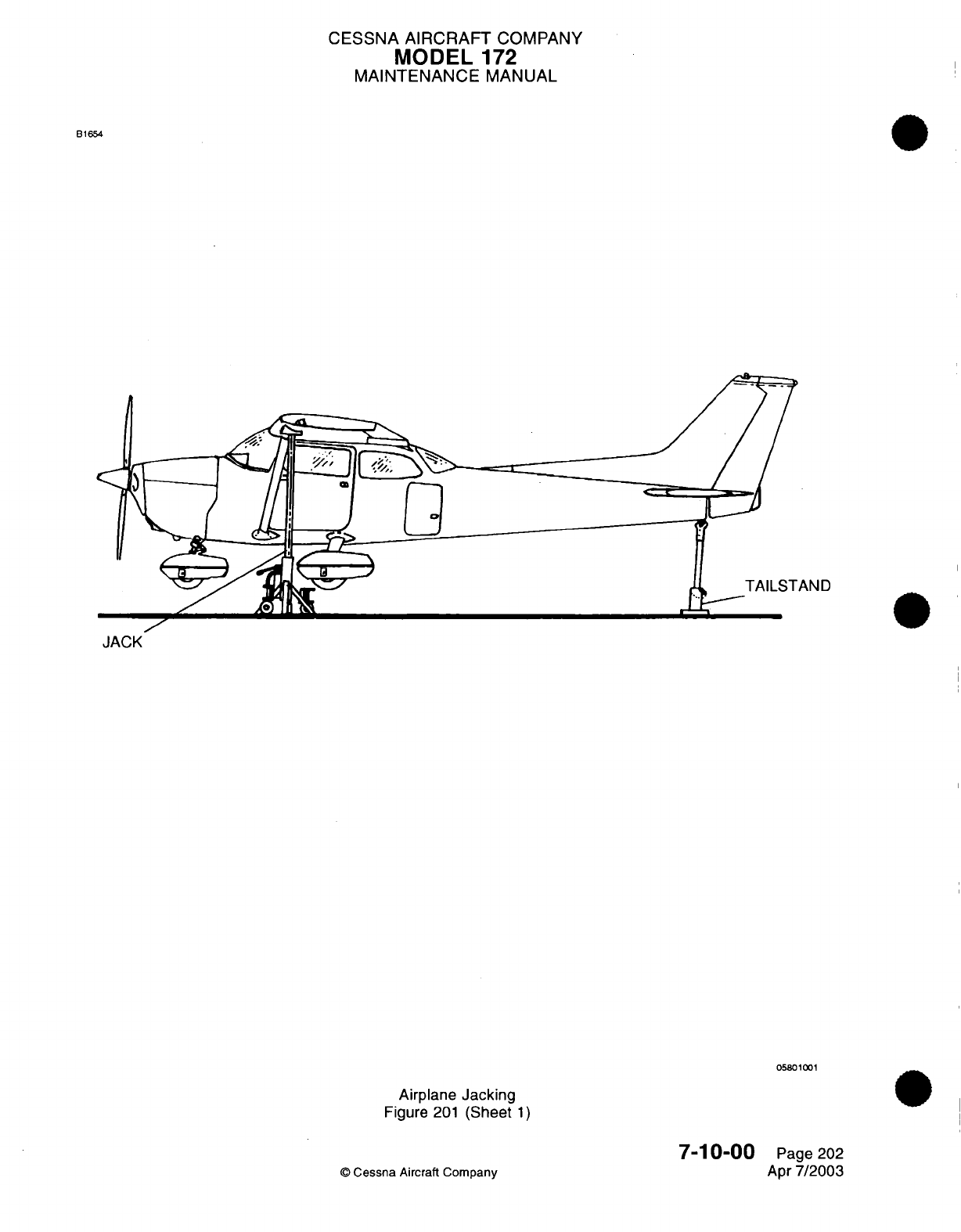
CESSNA
AIRCRAFT
COMPANY
MODEL
172
MAINTENANCE
MANUAL
B1654
II,
05801001
Airplane
Jacking
Figure
201
(Sheet
1)
©
Cessna
Aircraft Company
7-10-00
Page
202
Apr
7/2003
<1c
CESSNA
AIRCRAFT
COMPANY
MODEL
172
MAINTENANCE
MANUAL
EMERGENCY
LIFTING/HOISTING
-
MAINTENANCE
PRACTICES
1.
Lifting
Procedure
A.
The
airplane
may
be
lifted
with
a
hoist
of
two-ton
capacity
attached
by
rings,
which are
optional
equipment
installed
by
Service
Kit, or
by
means
of
suitable
slings.
The front
sling should
be
hooked
to
each
upper engine
mount,
and the
aft
sling
should
be
positioned
around
the
fuselage
at
the
first
bulkhead
forward
of the
leading
edge
of
the
stabilizer.
If
the
optional
hoisting
rings
are
used,
a
minimum
cable
length
of 60
inches
for each
cable
is
required
to
prevent
bending
of
the
eyebolt-type
hoisting rings.
If
desired,
a
spreader
jig
may
be
fabricated
to
apply vertical
force
to
the
eyebolts.
7-11-00
Page
201
©
Cessna
Aircraft
Company
Apr
7/2003

CHAPTER
LEVELING
AND
WEIGHING

CESSNA
AIRCRAFT
COMPANY
MODEL
172
MAINTENANCE
MANUAL
LIST
OF
EFFECTIVE
PAGES
CHAPTER-SECTION-SUBJECT
08-Title
08-List
of
Effective
Pages
08-Record
of
Temporary
Revisions
08-Contents
8-00-00
8-10-00
PAGE
Page
1
Pages
201-202
©
Cessna Aircraft
Company
08
-
LIST
OF
EFFECTIVE
PAGES
Page
1
of
1
Jan
3/2005
DATE
Apr
7/2003
Jan
3/2005
Temporary
Revision
Number
RECORD
OF
TEMPORARY
REVISIONS
Page
Number
Issue
Date
By
Date
Removed
By
CESSNA
AIRCRAFT
COMPANY
MODEL
172
MAINTENANCE MANUAL
CONTENTS
LEVELING
AND
WEIGHING
-
GENERAL
..........................................
Scope......................................................................
Tools,
Equipment and
Material
...............................................
Definition...................................................................
LEVELING
-
MAINTENANCE
PRACTICES.........................................
G
en
eral
....................................................................
Tools,
Equipment
and
Materials
..............................................
Leveling
Points
.............................................................
8-00-00
Page
1
8-00-00
Page
1
8-00-00
Page
1
8-00-00
Page
1
8-10-00
Page
201
8-10-00
Page
201
8-10-00
Page
201
8-10-00
Page
201
CONTENTS
Page
1
of
1
Jan 3/2005
©
Cessna
Aircraft
Company
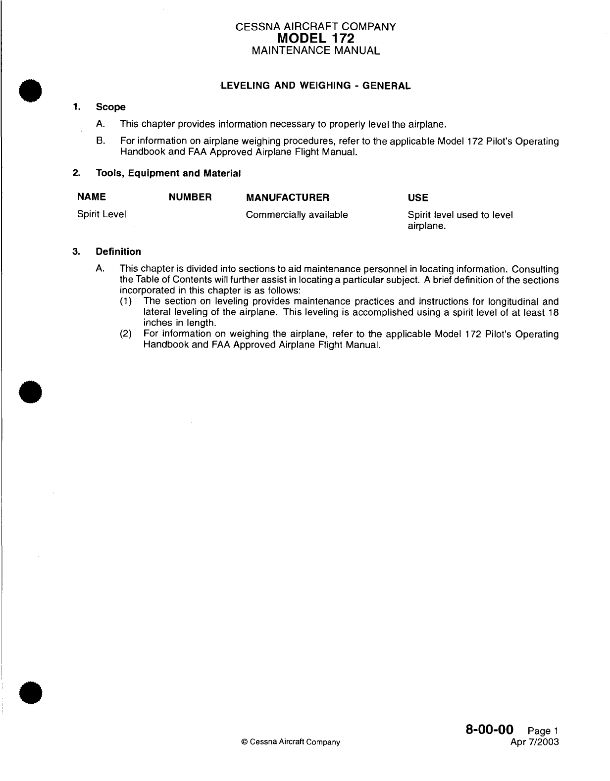
CESSNA
AIRCRAFT
COMPANY
MODEL
172
MAINTENANCE
MANUAL
LEVELING AND WEIGHING
-
GENERAL
1.
Scope
A.
This
chapter
provides
information
necessary
to
properly
level
the
airplane.
B.
For
information
on
airplane weighing
procedures,
refer
to
the
applicable
Model
172
Pilot's
Operating
Handbook
and
FAA
Approved
Airplane
Flight
Manual.
2.
Tools,
Equipment
and
Material
MANUFACTURER
Commercially
available
USE
Spirit
level
used to level
airplane.
3.
Definition
A.
This
chapter
is
divided
into
sections
to
aid
maintenance
personnel
in
locating
information.
Consulting
the
Table
of
Contents
will
further assist
in
locating
a
particular
subject.
A
brief
definition
of
the sections
incorporated
in
this
chapter
is
as
follows:
(1)
The
section
on
leveling
provides
maintenance
practices
and
instructions
for
longitudinal
and
lateral leveling
of
the
airplane. This
leveling
is
accomplished
using
a
spirit level
of at
least
18
inches
in
length.
(2)
For
information
on
weighing
the
airplane,
refer
to
the
applicable
Model
172
Pilot's Operating
Handbook
and
FAA
Approved Airplane
Flight Manual.
8-00-00
Page
1
©
Cessna
Aircraft Company
Apr
7/2003
NAME
Spirit Level
NUMBER
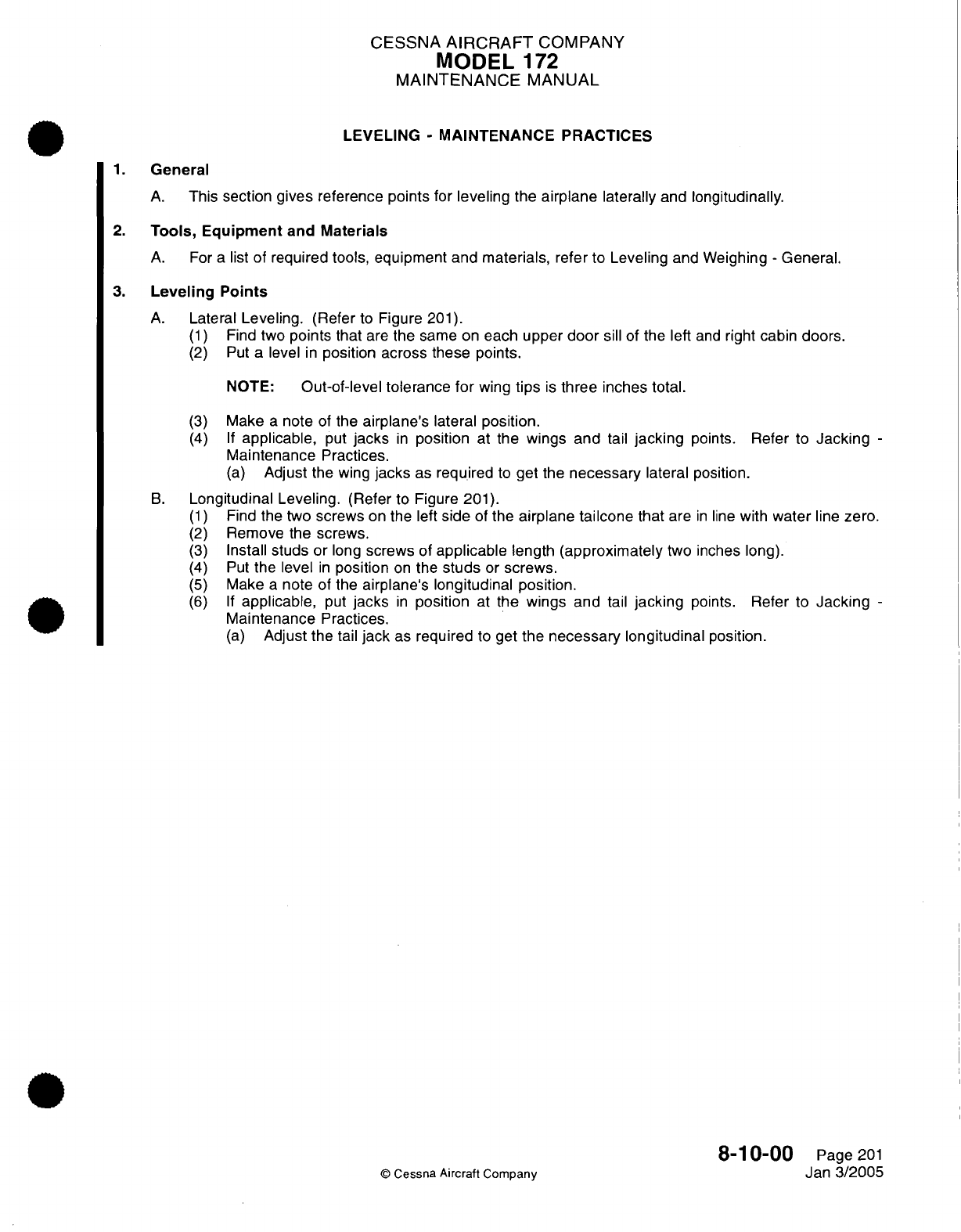
CESSNA
AIRCRAFT
COMPANY
MODEL
172
MAINTENANCE
MANUAL
LEVELING
-
MAINTENANCE PRACTICES
1.
General
A.
This
section
gives
reference
points
for
leveling
the
airplane
laterally and
longitudinally.
2.
Tools,
Equipment
and
Materials
A. For
a
list
of
required
tools,
equipment and materials, refer
to
Leveling
and
Weighing
-
General.
3.
Leveling Points
A.
Lateral
Leveling.
(Refer
to
Figure
201).
(1)
Find
two
points
that
are
the same
on
each upper
door
sill
of the
left
and
right
cabin
doors.
(2)
Put a
level
in
position
across these
points.
NOTE:
Out-of-level tolerance
for
wing
tips
is
three
inches
total.
(3)
Make
a
note
of
the
airplane's
lateral
position.
(4) If
applicable,
put
jacks
in
position
at
the
wings and
tail
jacking
points.
Refer
to
Jacking
-
Maintenance
Practices.
(a)
Adjust
the
wing
jacks
as
required
to
get
the
necessary
lateral
position.
B.
Longitudinal Leveling.
(Refer
to
Figure
201).
(1)
Find
the two
screws
on
the
left
side
of
the
airplane
tailcone
that
are
in
line
with
water
line
zero.
(2)
Remove the
screws.
(3)
Install
studs
or
long
screws
of
applicable
length
(approximately
two inches
long).
(4)
Put
the
level
in
position
on
the
studs
or
screws.
(5)
Make
a
note
of the
airplane's
longitudinal position.
(6) If
applicable,
put
jacks
in
position
at
the
wings
and
tail
jacking
points.
Refer
to
Jacking
-
Maintenance
Practices.
(a)
Adjust the
tail
jack
as
required
to get
the
necessary
longitudinal
position.
8-1
0-00
Page
201
©
Cessna
Aircraft
Company
Jan
3/2005
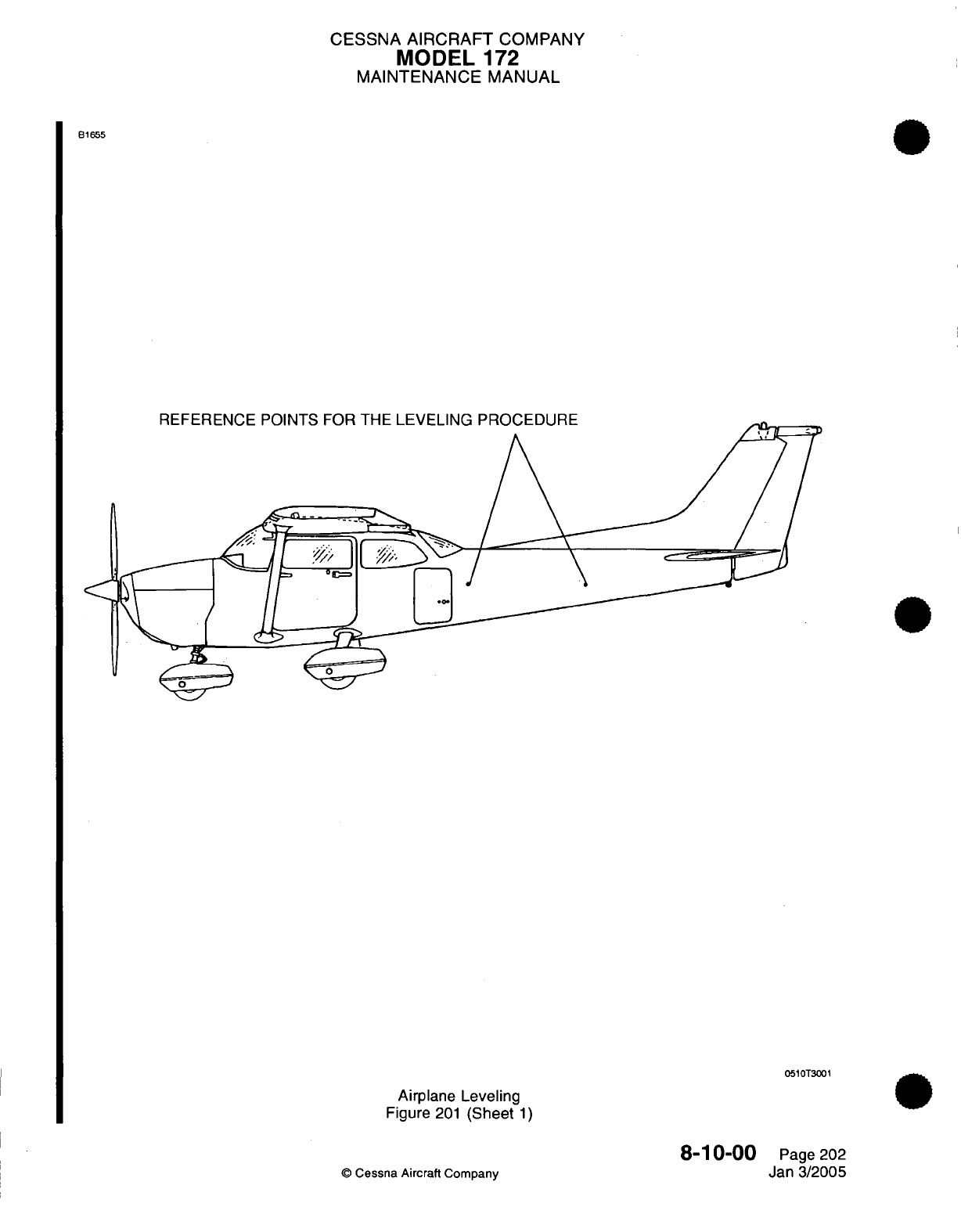
CESSNA
AIRCRAFT
COMPANY
MODEL
172
MAINTENANCE
MANUAL
B1655
REFERENCE
POINTS
FOR
THE
LEVELING
PROCEDURE
0510T3001
Airplane
Leveling
Figure
201
(Sheet
1)
©
Cessna
Aircraft
Company
8-10-00
Page 202
Jan
3/2005
REFERENCE
POINTS
FOR
THE
LEVELING
PROCEDURE

CHAPTER
TOWING
AND
TAXIING

CESSNA
AIRCRAFT
COMPANY
MODEL
172
MAINTENANCE
MANUAL
LIST
OF
EFFECTIVE
PAGES
CHAPTER-SECTION-SUBJECT
09-Title
09-List
of
Effective
Pages
09-Record
of
Temporary
Revisions
09-Contents
9-00-00
9-10-00
PAGE
Page
1
Pages
201-202
©
Cessna Aircraft
Company
09
-
LIST
OF
EFFECTIVE
PAGES
Page
1
of
1
Jan
3/2005
DATE
Apr
7/2003
Apr
7/2003
Temporary
Revision
Number
RECORD OF
TEMPORARY REVISIONS
Page
Number
Issue
Date
By
Date
Removed
By
CESSNA
AIRCRAFT
COMPANY
MODEL
172
MAINTENANCE
MANUAL
CONTENTS
TOWING
AND TAXIING
-
GENERAL
..............................................
S
cope......................................................................
Definition
...................................................................
TOWING
-
MAINTENANCE
PRACTICES
..........................................
General
....................................................................
9-00-00
Page
1
9-00-00
Page
1
9-00-00 Page
1
9-10-00
Page
201
9-10-00
Page
201
CONTENTS
Page
1
of
1
Jan
3/2005
©
Cessna Aircraft
Company
CESSNA
AIRCRAFT
COMPANY
MODEL
172
MAINTENANCE
MANUAL
TOWING
AND TAXIING
-
GENERAL
1.
Scope
A.
This
chapter describes
towing
procedures
for
movement
of
the
airplane
on
the
ground.
For
taxiing
procedures,
refer to
the
applicable
Pilots's
Operating Handbook
and
FAA
Approved
Airplane Flight
Manual.
2.
Definition
A.
The
section
on
towing
describes
towing
procedures
and
cautions
applicable
to
the Model
172.
9-00-00
Page
1
©
Cessna
Aircraft
Company
Apr
7/2003
CESSNA
AIRCRAFT
COMPANY
MODEL
172
MAINTENANCE
MANUAL
TOWING
-
MAINTENANCE
PRACTICES
1.
General
CAUTION:
WHEN
TOWING
THE
AIRPLANE,
NEVER
TURN THE
NOSE
WHEEL
MORE
THAN
30
DEGREES
EITHER
SIDE
OF
CENTER,
OR
THE
GEAR
WILL
BE
DAMAGED.
DO
NOT
PUSH
ON
CONTROL
SURFACES
OR
ANY PORTION
OF THE
HORIZONTAL
STABILIZER.
WHEN
PUSHING
ON
THE
TAILCONE,
ALWAYS
APPLY
PRESSURE
AT
A
BULKHEAD TO
AVOID
DAMAGING
THE
SKIN.
A.
Towing.
(1)
Moving
the
airplane
by
hand
is
accomplished
by
using the
wing
struts
and
landing gear
struts
as
push
points.
A
tow
bar
attached
to
the nose gear
should
be
used
for
steering
and
maneuvering
the
airplane
on
the
ground.
When
no
tow bar
is
available,
press
down
on
the
tailcone
at
a
bulkhead
to
raise
the
nose
wheel
off
the
ground. With the
nose wheel clear
of the
ground,
the
airplane
can
be
turned
by
pivoting
about
the
main
wheels.
9-10-00
Page
201
©
Cessna
Aircraft
Company
Apr
7/2003
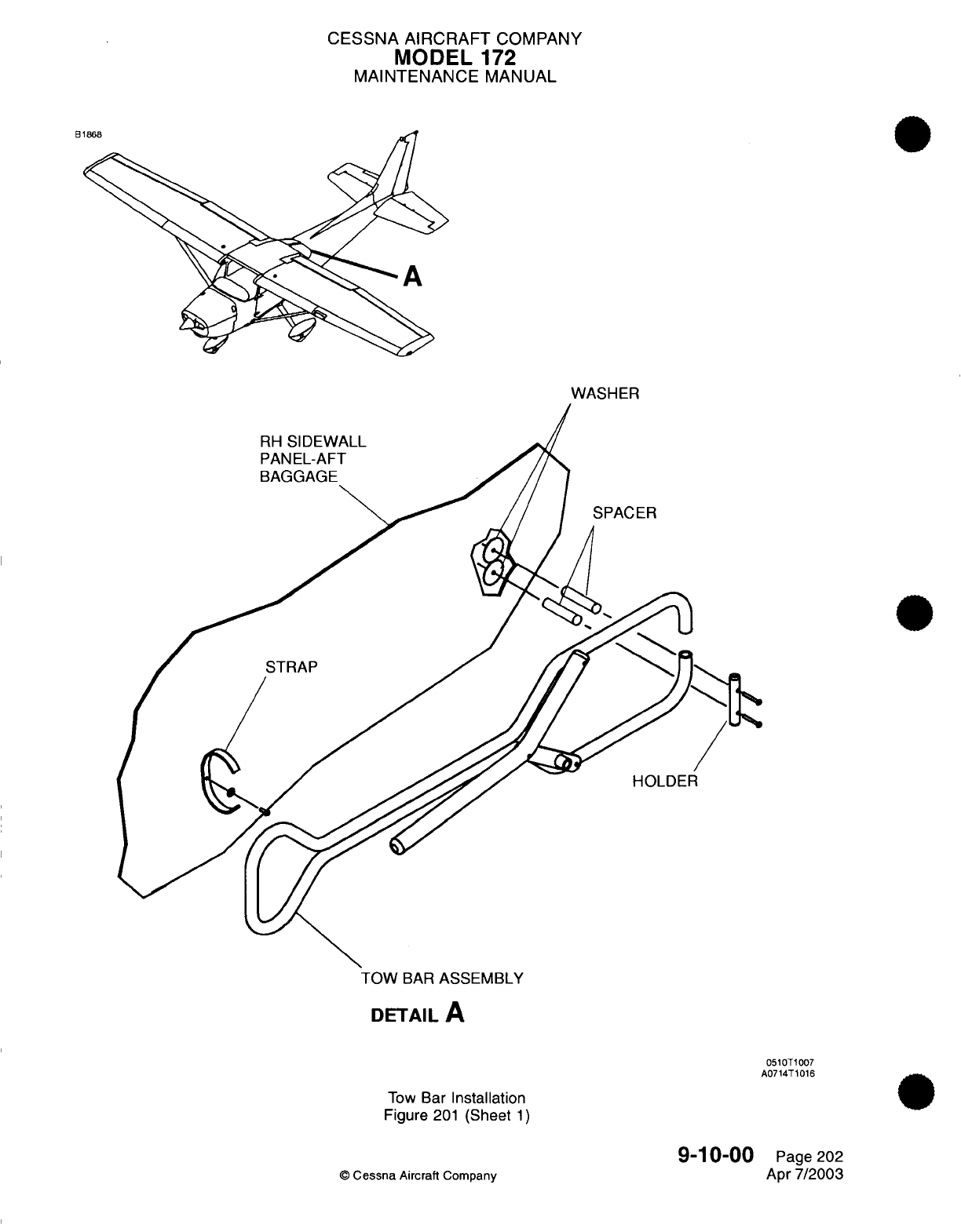
CESSNA
AIRCRAFT
COMPANY
MODEL
172
MAINTENANCE
MANUAL
WASHER
RH
SIDEWALL
PANEL-AFT
BAGGAGE
SPACER
HOLDER
TOW
BAR
ASSEMBLY
DETAIL
A
0510T1007
A0714T1016
Tow
Bar
Installation
Figure
201
(Sheet
1)
©
Cessna
Aircraft
Company
9-10-00
Page
202
Apr
7/2003

CHAPTER
PARKING
AND
MOORING
CESSNA
AIRCRAFT
COMPANY
MODEL
172
MAINTENANCE
MANUAL
LIST
OF
EFFECTIVE
PAGES
CHAPTER-SECTION-SUBJECT
10-Title
10-List
of
Effective Pages
10-Record
of
Temporary
Revisions
10-Contents
10-00-00
10-10-00
10-11-00
10-20-00
10-30-00
©
Cessna Aircraft
Company
10
-
LIST
OF
EFFECTIVE
PAGES
Page
1
of 1
Jan
3/2005
PAGE
DATE
Apr
7/2003
Apr
7/2003
Jan
3/2005
Apr
7/2003
Apr
7/2003
Page
1
Page 201
Pages
1-3
Page
201
Page
201
Temporary
Revision
Number
RECORD
OF
TEMPORARY REVISIONS
Page
Number
Issue
Date
By
Date
Removed
By
CESSNA
AIRCRAFT
COMPANY
MODEL
172
MAINTENANCE
MANUAL
CONTENTS
PARKING,
MOORING,
STORAGE
AND RETURN TO
SERVICE
-
GENERAL
.........
S
c
o
pe
......................................................................
Tools,
Equipment
and
Materials
..............................................
Definition
...................................................................
PARKING
-
MAINTENANCE
PRACTICES..........................................
General
....................................................................
Parking Instructions
.........................................................
STORAGE
-
DESCRIPTION
AND
OPERATION
....................................
General
....................................................................
Flyable
Storage
.........
..............................
.....................
Temporary
Storage..........................................................
Inspection
During
Storage
...................................................
MOORING
-
MAINTENANCE
PRACTICES.........................................
Mooring
....................................................................
RETURN
TO
SERVICE
-
MAINTENANCE
PRACTICES
.............................
Flyable
Storage
Return
to
Service
............................................
Temporary Storage
Return
to
Service
.........................................
10-00-00
Page
1
10-00-00
Page
1
10-00-00
Page
1
10-00-00
Page
1
10-10-00
Page
201
10-10-00
Page
201
10-10-00
Page
201
10-11-00 Page
1
10-11-00 Page
1
10-11-00 Page
1
10-11-00 Page
1
10-11-00 Page
3
10-20-00
Page
201
10-20-00
Page
201
10-30-00
Page
201
10-30-00
Page
201
10-30-00
Page
201
CONTENTS
Page
1
of
1
Jan
3/2005
©
Cessna Aircraft
Company
CESSNA
AIRCRAFT
COMPANY
MODEL
172
MAINTENANCE
MANUAL
PARKING, MOORING,
STORAGE
AND
RETURN TO
SERVICE
-
GENERAL
1.
Scope
A.
This
chapter
describes
and
provides
maintenance
instructions
for parking,
storing,
mooring
and
returning the
airplane
to
service.
2.
Tools,
Equipment
and
Materials
NOTE:
Equivalent
substitutes
may
be
used
for
the
following
items:
NAME NUMBER
Wheel
Chocks
Engine
Air
Inlet
Cover
Pitot
Tube
Cover
Static Ground
Cable
Rope
(0.375
inch
diameter
minimum)
or
equivalent
MANUFACTURER
Available Commercially
Cessna
Aircraft
Cessna
Aircraft
Available Commercially
Available Commercially
USE
To
chock
landing
wheels.
To
prevent
entry
of
moisture
and/or
foreign
particles
through
cowling.
To
prevent
entry
of
moisture
and/or
foreign
particles
in
pitot
tubes.
To
static
ground
airplane.
To
tie
down
wing
and
tail.
3.
Definition
A.
This
chapter
is
divided
into
sections
to
aid
maintenance
personnel
in
locating
information. Consulting
the
Table
of
Contents
will
further assist
in
locating
a
particular
subject.
A
brief
definition
of
the
sections
incorporated
in
this chapter
is
as
follows:
(1)
The
section
on
parking
describes
methods,
procedures
and
precautions
used
when
parking
the
airplane.
(2)
The
section
on
storage
provides
information
on
recommended
storage
procedures.
Recommendations
vary
with
the length
of
time
the
airplane
is to
be
stored.
(3)
The
section
on
mooring
describes
procedures
and
equipment
used
to moor
the
airplane.
(4)
The
section
on
return to
service describes procedures
used
when
returning the
airplane
to
service
from
storage.
10-00-00
©
Cessna Aircraft
Company
Page
1
Apr
7/2003
CESSNA
AIRCRAFT
COMPANY
MODEL
172
MAINTENANCE
MANUAL
PARKING
-
MAINTENANCE
PRACTICES
1.
General
A.
This
maintenance
practice
covers
procedures
used
to
park
the
airplane.
B.
The
airplane
should
be
moored
if
high
winds
are
anticipated
or
anytime
the
airplane
remains
outside
for
extended
periods
of
time. Refer
to
Mooring
-
Maintenance
Practices for
mooring
procedures.
Refer
to
Storage
-
Maintenance
Practices
for
detailed
instructions
regarding
storage.
2.
Parking
Instructions
A.
Hard
Surface
and
Sod.
CAUTION:
ANY TIME
THE
AIRPLANE
IS
LOADED
HEAVILY,
THE
FOOTPRINT
PRESSURE (PRESSURE
OF
THE
AIRPLANE
WHEELS
UPON
THE
CONTACT
SURFACE
OF
THE
PARKING
AREA
OR RUNWAY)
WILL
BE
EXTREMELY
HIGH,
AND
SURFACES
SUCH
AS
HOT
ASPHALT
OR
DAMP
SOD
MAY
NOT
ADEQUATELY
SUPPORT
THE
WEIGHT
OF
THE
AIRPLANE.
PRECAUTIONS SHOULD
BE
TAKEN TO AVOID
AIRPLANE
PARKING
OR
MOVEMENT
ON
SUCH
SURFACES.
(1)
Position
airplane
headed
into
wind,
on
level
surface.
CAUTION:
DO
NOT
SET
PARKING
BRAKE
DURING COLD
WEATHER,
WHEN ACCUMULATED
MOISTURE
MAY
FREEZE
BRAKES,
OR
WHEN BRAKES
ARE
HOT.
(2)
Set
parking
brake
or
chock
main
gear
wheels.
(3)
Install
control
column
lock.
©
Cessna
Aircraft
Company
10-10-00
Page
201
Apr
7/2003
CESSNA
AIRCRAFT
COMPANY
MODEL
172
MAINTENANCE
MANUAL
STORAGE
-
DESCRIPTION AND OPERATION
1.
General
A.
As a
result
of
corrosion,
it is
possible that
some
piston
engines
will
not complete
the
usual
service
life.
Moisture
from
the
air
and
material
from
combustion
mix
to
cause corrosion
on
cylinder
walls
and
bearing
surfaces
when the
engine
is
not
in
operation.
A
thin
layer of corrosion
inhibitor
is
used
to
help
prevent
corrosion.
NOTE:
The
owner
or
operator
of
the
airplane
must
make
a
decision
if
preservation
is
necessary
as
a
result
of
environmental
conditions
and
frequency
of
airplane
use.
NOTE:
The time
periods
given
in
this
document
are
recommendations
as given
for
normal
conditions.
B. In
areas
of
high
humidity, corrosion
can
start
in
a
short
period
of
time.
Corrosion
is
found
on
cylinder
walls
of
new
engines
that
have
not operated
for
a
period as short
as
two
days.
C. In
engines
that have
50
hours
or
more
time
of
service
in a
short
period,
the
cylinder
walls
will
have
a
varnish
that
will
help
protect
from
corrosion.
These engines
in
good
atmospheric
conditions
can
stay
inactive
for
many
weeks without indication
of
corrosion.
2.
Flyable
Storage
A.
The
flyable
storage
is
a
maximum
of
30
days storage
with
no
engine
operation
and/or
the
first
25
hours
of
intermittent
engine operation.
B.
Engine
temperature
and
length
of
operation
time
are
very
important
in
the control
of
corrosion.
The
desired
flight
time
for
air
cooled engines
is
at
least
one
continuous hour
at
oil
temperatures
of
165
degrees
F
(74
degrees
C)
to
200
degrees
F
(93
degrees
C)
at
intervals
not
to
exceed
30
days.
The
one
hour
does
not
include
taxi,
take-off
and landing
time.
C.
The
aircraft temperature
gages
must operate
correctly.
D.
The
cooling
air
baffles
must
be
in
good
condition
and
fitted properly.
E.
The
oil
cooler
system must
be
of the
proper
size
for
the engine
and airframe
installation.
Oil
coolers
that
are
not
the
correct
size
can
cause
an
engine
overheat
condition
or
below
minimum
temperatures.
Low
temperatures
are
as
dangerous
as
high
temperatures because
of
build-up
of
water
and
acids.
F.
Pulling
engines
through
by
hand when
the
airplane
is
not
operated
for
approximately
a
week
is
not
recommended.
Pulling
the engine through by hand
before you
start
the
engine
or
to
minimize
corrosion
can
cause
damage. The
cylinder
walls, pistons, rings,
cam
and
cam
follower
receive
minimum
lubrication.
When
the
prop
is
pulled
through
by
hand,
the rings
remove
oil
from the
cylinder
walls.
The
cam load
made
by
the
valve
train
removes
oil
from
the
cam
and
followers.
After
two
or
three
times
of
pulling
the
engine
through
by
hand
without
engine starts,
the
cylinders,
cam
and
followers
are
left
without
the
correct
quantity
of
oil
film.
Engine
starts without
the
correct
lubrication
can
cause
the
engine
parts
to
score
which
can
cause damage
to the
engine.
G.
The pitot tube,
static
air
vents, air
vents,
openings
in
the
engine cowl, and other
openings
must
have
protective
covers
installed
to
prevent entry
of
foreign
object
debris.
3.
Temporary
Storage
A.
Temporary
airplane
storage.
(1)
Temporary
storage
is
when
the
airplane
does
not
operate
in
a
maximum
of
90
days.
The
airplane
is
made
of
corrosion resistant,
epoxy
primed
aluminum,
which
will
last
a
long
time
in
normal
conditions.
But
these
alloys
can
have
oxidation.
The
first
indication
of
corrosion
on
surfaces
without
paint
is
white
deposits
or spots.
Corrosion
on
surfaces
with
paint
is
discoloration
or
blistered
paint. Storage
in
a
dry
hangar
is
very
important
for
good
preservation.
Different
conditions will
change
the
measures
of
preservation, but
for
normal
conditions
in
a
dry
hangar,
and
for
storage
periods
not
to
exceed
90
days,
the
procedures
that follow are
recommended.
1
0-11
-00
Page
1
©
Cessna
Aircraft Company
Jan
3/2005
CESSNA AIRCRAFT
COMPANY
MODEL
172
MAINTENANCE
MANUAL
WARNING:
For
procedures
that require
fuel,
fire
equipment
must
be
available.
Two
ground
wires
from
different
points
on
the
airplane
connected
to
separate,
approved
ground stakes
must
be
used
In
case
of
accidental
disconnection of
one
ground
wire.
Make
sure
the
fuel
nozzle
Is
grounded
to
the
airplane
(a)
Fill
the
fuel
tanks
with
the
correct
grade
of
fuel.
(b)
Use
tie-down
rings
for
ground
points
for
the
fuel
procedure.
(c)
Clean
the
airplane fully.
(d)
Clean
oil
or grease
from
the
tires.
(e)
Put
a
thin layer
of
tire
preservative
on
the
tires.
(f)
Put
a
cover
on
the tires
to
keep
grease
and
oil
from the
tires.
(g)
Keep
the
tires
from
deformation.
1
Put
the
fuselage
on
blocks
to
relieve pressure
on
the
tires
or
rotate the
wheels
every
30
days
to
keep
the
tires
from
flat
spots.
(h)
Lubricate
all
airframe
items.
(i)
Put
a
cover
on
openings
which
let
moisture
and/or
dust
to
enter.
B.
Temporary
engine storage.
(1) If it
is
known
that
an
aircraft
is
to
be
out
of
operation
for
30
or
more
days,
the
procedures
that
follow
must
be
applied
to
the engine.
(a)
Put
a
preservative
in
the
engine
by
one of the
methods
that
follow.
1
Drain
the
oil
from
the
sump
or system
and
replace
with
a
preservative
oil
mixture.
This
preservation
mixture
is
one
part by
volume
of
MIL-C-6529C
Type
I
concentrated
preservative compound
added
to
three
parts
by
volume
of
MIL-L-6082C
(SAE
J1966),
Grade
1100,
mineral aircraft engine
oil
or
oil
that agrees
to
MIL-C-6529C
Type
II.
Carefully
follow
the
manufacturer's
instructions
before use.
2
An
alternative method
is
the use
of
Cortec
VC1
-326
preservative concentrate
added
to
the
original
oil
at
a
ratio of
one
part
VC1-326
to
ten
parts
of
oil.
(b)
Operate
the
engine
to
get
the
normal
temperatures of
operation.
1
Do
not
stop the
engine
until
the
oil
temperature
is
180
degrees
F
(82
degrees
C).
If
weather
conditions
are below
32
degrees
F (0
degrees
C),
oil
temperature
must
be
at
least
165
degrees
F
(73
degrees
C)
before
shutdown.
(c)
Remove the engine
cowl
to
get access
to
the
top
spark
plugs.
(d)
Remove
the
spark
plugs.
NOTE:
Oils
of
the
type
given are
to
be used
in
Lycoming aircraft
engines
for
preservation
only
and not
for
lubrication.
(e)
Through the spark plug hole,
spray
the interior
of
each
cylinder
with
approximately
two
ounces
of
the
preservative
oil mixture
with
an
airless
spray
gun
(Spraying
Systems
Co.,
Gunjet
Model
24A-8395
or
equivalent).
If
an
airless
spray
gun
is
not
available,
a
moisture
trap
can
be
installed
in
the
air
line
of
a
conventional spray
gun.
(f)
Install the
spark
plugs.
(g)
Do
not
turn
the
crankshaft
after
the
cylinders
have
been
sprayed.
(h) If
the aircraft
is
stored
in
a
region
of
high
humidity,
or
near
a
sea
coast,
it
is
better
to
use
dehydrator
plugs and not
the
spark
plugs.
Cylinder dehydrator
plugs,
MS-27215-2
or
equivalent,
can
be
used.
(i)
Before
the
engine
has
cooled,
install
small
bags
of
desiccant
in
the
exhaust
and
intake
ports and
seal
with
a
moisture
impervious material and
pressure
sensitive
tape.
(j)
Firmly
attach
red
cloth
streamers
to
any
desiccant
bags
installed
in
the
intake
and
exhaust
passages
to make
sure
the
material
is
removed
when the
engine
is
made
ready
for
flight.
Streamers must
be
visible
from
outside
the
aircraft.
Thr
propeller
must
have
a
label
that
says
"Engine
preserved
-
do
not
turn
propeller".
(k)
Seal
all
engine
openings
with
plugs. Attach a
red
streamer
at
each
point that
a
plug
is
installed.
1
0-11-00
Page
2
©
Cessna
Aircraft
Company
Jan
3/2005
CESSNA
AIRCRAFT
COMPANY
MODEL
172
MAINTENANCE
MANUAL
(I) If
the
airplane
is
to
be
stored
outside,
the
pitot
tube,
static
source
vents,
air
vent
openings
in
the
engine
cowl,
and
other openings
must
have
protective
covers
installed
to
prevent
entry
of
foreign object
debris.
(m)
Attach
a
warning
placard
to
the propeller
that
says
the
propeller
must
not
be
moved
while
the
engine
is
in
storage.
(n)
At
15-day
maximum
intervals,
a
periodic check
must
be
made
of
the
cylinder
dehydrator
plugs
and
desiccant.
When
the
color
of
the
desiccant
has
changed
from blue to
pink
the
preservation
procedure
must
be
repeated.
WARNING:
To
prevent
serious
bodily
Injury
or
death,
before the
propeller
Is
moved, obey
all
precautions to
prevent
the
engine start.
Disconnect
the
spark
plug
leads.
Make
sure
the magnetos
are
switched
off
and
P-leads
are
grounded.
Make
sure
the
throttle
Is
closed
and
the
mixture
Is
In
Idle
cut-off.
Do
not
stand
within
the
arc of
the
blade.
Even
without
spark,
compression
can
cause
the propeller to
move
with
sufficient
force to
cause
serious
Injury.
C.
Return
the
airplane to
service.
(1)
To
return
the
airplane
to
service,
remove
seals,
tape,
and
desiccant
bags.
Use
solvent
to
remove
tape
residue.
Remove
spark
plugs
or dehydrator
plugs. With the
magnetos
off,
turn
the
propeller
by
hand
through
sufficient
rotation to
remove
excess preservative
oil
from
the
cylinders.
Drain
the
remaining
preservatives
from
the engine
through
the
sump.
(2)
Install
spark
plugs
and
reconnect
all
parts
in
accordance
with
manufacturer's
instructions.
Service
the
engine
with
approved
lubrication
oil.
4.
Inspection
During Storage
A.
Do
an
inspection
of the
airplane.
(1)
Do
an
inspection
of
the
airframe
for
corrosion
at
least
once
a
month
and
remove
dust
collection
as
frequently
as
possible.
Clean
the
airplane
as
required.
(2)
Do
an
inspection
of
the
interior
of
at
least one
cylinder
through
the
spark
plug
hole for
corrosion
at
least
once
a
month.
NOTE:
Do
not
move
crankshaft
when the interior
of
the
cylinders
is
examined
for corrosion.
(3) If
at
the
end
of the
90
day
period,
the
airplane
is
to
be
continued
in
storage,
repeat the
90-day
storage
procedure.
10-11-00
Page
3
©
Cessna Aircraft
Company
Jan
3/2005
CESSNA
AIRCRAFT
COMPANY
MODEL
1
72
MAINTENANCE
MANUAL
MOORING
-
MAINTENANCE PRACTICES
1.
Mooring
A.
When
mooring
the
airplane
in
the
open, head
into
the
wind
if
possible.
Tie
down the
airplane
as
follows:
(1)
Secure
control surfaces
with
the
internal
control
lock
and
set
brakes.
(2)
Tie
ropes,
cables,
or
chains
to the
wing tie-down
fittings,
located
at
the
upper
end
of
each
wing
strut.
Secure
the
opposite
ends
of
ropes,
cables,
or
chains
to
ground anchors.
(3)
Secure
rope
(no
chains
or
cables)
to
forward
mooring
ring
and
secure
opposite
end to ground
anchor.
(4)
Secure
the
middle
of
a
rope
to
the
tail
tie-down
ring.
Pull
each
end
of
rope
away
at
a
45
degree
angle and
secure
to
ground
anchors
at
each
side
of
tail.
(5)
Secure control
lock
on
pilot
control column.
If
control
lock
is
not
available,
tie pilot
control
wheel
back with
front
seat
belt.
(6)
These
airplanes
are
equipped
with
a
spring-loaded
steering system
which
affords protection
against
normal
wind gusts.
However,
if
extremely
high
wind
gusts
are
anticipated,
additional
external locks
may
be
installed.
10-20-00
Page
201
©
Cessna
Aircraft Company
Apr
7/2003
CESSNA
AIRCRAFT
COMPANY
MODEL
172
MAINTENANCE
MANUAL
RETURN TO
SERVICE
-
MAINTENANCE
PRACTICES
1.
Flyable
Storage
Return
to
Service
A.
Flyable
storage
is
defined
as
a
maximum
of
30
days nonoperational
storage
and/or
the
first
25
hours
of
intermittent
engine
operation.
After
flyable
storage, returning
the
airplane
to
service
is
accomplished
by
performing
a
thorough preflight inspection.
At
the end of
the
first
25
hours
of
engine
operation,
drain
engine
oil
and
replace
oil
filter.
Service
engine
with
correct
grade
and
quantity
of
engine
oil.
2.
Temporary
Storage
Return
to
Service
A.
Temporary
storage
is
defined
as
airplane
in
a
nonoperational status
for
a
maximum
of
90
days.
After
temporary
storage,
use
the following
procedures
to
return
the
airplane
to
service:
(1)
Remove
airplane
from
blocks
and
check
tires
for proper
inflation.
Check
for
proper
nose
gear
strut
inflation.
(2)
Check
battery
and
install.
(3)
Check
that
oil
sump
has
proper grade
and quantity
of
engine
oil.
(4)
Service
induction
air filter
and
remove
warning placard
from
propeller.
(5)
Remove
materials
used
to
cover openings.
(6)
Remove
spark plugs
from
engine.
(7)
While
spark
plugs are
removed,
rotate
propeller several revolutions
to
clear
excess
oil from
cylinders.
(8)
Clean,
gap
and
install spark
plugs.
Torque
spark
plugs
to
the
proper
value
and
connect
spark
plug
leads.
(9)
Check
fuel
strainer.
Remove
and
clean
filter
screen
if
necessary.
Check fuel
tanks
and
fuel
lines
for
moisture
and
sediment.
Drain
enough
fuel
to
eliminate any
moisture
and
sediment.
(10)
Perform
a
thorough preflight
inspection,
then
start
and
warm
up
engine.
10-30-00
Page
201
©
Cessna Aircraft Company
Apr
7/2003

CHAPTER
PLACARDS
AND
MARKINGS

CESSNA AIRCRAFT
COMPANY
MODEL
172
MAINTENANCE
MANUAL
LIST
OF
EFFECTIVE
PAGES
CHAPTER-SECTION-SUBJECT
11-Title
11-List
of
Effective Pages
11-Record
of Temporary
Revisions
11-Table of
Contents
11-00-00
11-00-00
©
Cessna Aircraft Company
11
-
LIST
OF
EFFECTIVE
PAGES
Page
1
of
1
Jul
1/2005
PAGE DATE
Jan
3/2005
Jul
1/2005
Page
1
Page
601
Temporary
Revision
Number
RECORD
OF
TEMPORARY
REVISIONS
Page
Number
Issue
Date
By
Date
Removed
By

CESSNA AIRCRAFT
COMPANY
MODEL
172
MAINTENANCE
MANUAL
CONTENTS
PLACARDS
AND
MARKINGS
-
GENERAL..........
...........
...................
General
....................................................................
PLACARDS
AND
MARKINGS
-
INSPECTION/CHECK
..............................
Scope......................................................................
Interior
and
Exterior Placard
and
Decal
Inspection
.............................
11-00-00
Page
1
11-00-00
Page
1
11-00-00
Page
601
11-00-00 Page
601
11-00-00 Page
601
CONTENTS
Page
1
of
1
Jul
1/2005
©
Cessna
Aircraft Company
CESSNA
AIRCRAFT
COMPANY
MODEL
172
MAINTENANCE
MANUAL
PLACARDS AND
MARKINGS
-
GENERAL
1.
General
A.
Placards
and
markings
on
the
exterior surfaces
of
the
airplane
are
found
in
the
Model
172
Illustrated
Parts
Catalog, Chapter
11.
11-00-00
Page
1
©
Cessna
Aircraft
Company
Jan
3/2005
CESSNA
AIRCRAFT
COMPANY
MODEL
172
MAINTENANCE
MANUAL
PLACARDS
AND
MARKINGS
-
INSPECTION/CHECK
1.
Scope
A.
This section
has
inspection
data for
the
interior
and
exterior
placards.
2.
Interior
and
Exterior
Placard
and
Decal
Inspection
NOTE:
This
section
gives
an
inspection
procedure
for
all
placards, decals,
and
markings
on
the
airplane.
A. Do
an
inspection
of
the placards, decals,
and
markings.
(1)
Examine
the
interior
of
the
airplane.
Include
the aft
baggage areas
for
the
installation of
all
required
placards,
decals,
and
markings.
(a)
For
required
placards, decals,
and
markings,
refer
to the
Model
172R
Illustrated
Parts
Catalog.
(2)
Examine
the
exterior
of
the
airplane for
the
installation
of
all
required
placards, decals,
and
markings.
(a)
For
required
placards,
decals,
and
markings,
refer
to
the
Model
172R
Illustrated
Parts
Catalog.
(3)
Examine
the
airplane
identification
(ID)
plate.
(a)
The
ID
plate
is
found
on
the
left
side
of the
stinger,
Zone
310.
Refer
to the
Model
172R
Illustrated
Parts Catalog
and
Chapter
6,
Airplane
Zoning
-
Description
and
Operation.
11-00-00
Page
601
©
Cessna
Aircraft
Company
Jul 1/2005
CHAPTER
SERVICING
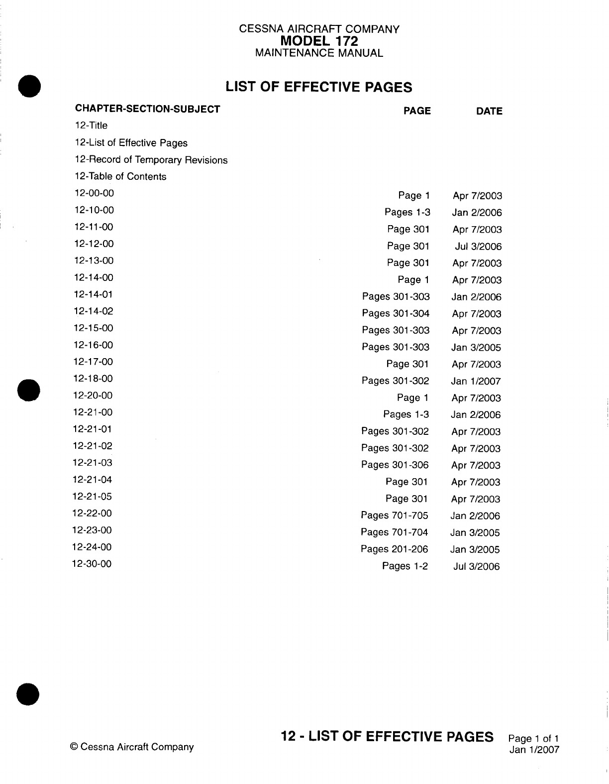
CESSNA
AIRCRAFT
COMPANY
MODEL
172
MAINTENANCE
MANUAL
LIST
OF
EFFECTIVE PAGES
CHAPTER-SECTION-SUBJECT
12-Title
12-List
of
Effective Pages
12-Record
of Temporary
Revisions
12-Table
of
Contents
12-00-00
12-10-00
12-11-00
12-12-00
12-13-00
12-14-00
12-14-01
12-14-02
12-15-00
12-16-00
12-17-00
12-18-00
12-20-00
12-21-00
12-21-01
12-21
-02
12-21-03
12-21
-04
12-21-05
12-22-00
12-23-00
12-24-00
12-30-00
©0
Cessna
Aircraft
Company
PAGE
Page
1
Pages
1-3
Page
301
Page
301
Page
301
Page
1
Pages
301-303
Pages
301-304
Pages
301
-303
Pages
301-303
Page
301
Pages
301-302
Page
1
Pages
1-3
Pages
301-302
Pages
301
-302
Pages
301-306
Page
301
Page
301
Pages
701
-705
Pages
701
-704
Pages
201
-206
Pages
1-2
DATE
Apr
7/2003
Jan
2/2006
Apr
7/2003
Jul
3/2006
Apr
7/2003
Apr
7/2003
Jan
2/2006
Apr
7/2003
Apr
7/2003
Jan
3/2005
Apr
7/2003
Janl1/2007
Apr
7/2003
Jan
2/2006
Apr
7/2003
Apr
7/2003
Apr
7/2003
Apr
7/2003
Apr
7/2003
Jan
2/2006
Jan
3/2005
Jan
3/2005
Jul
3/2006
12
-
LIST
OF
EFFECTIVE
PAGES
Page
1
of
1
Jan-1/2007

Temporary
Revision
Number
RECORD
OF
TEMPORARY
REVISIONS
Page
Number
Issue
Date
By
Date
Removed
By
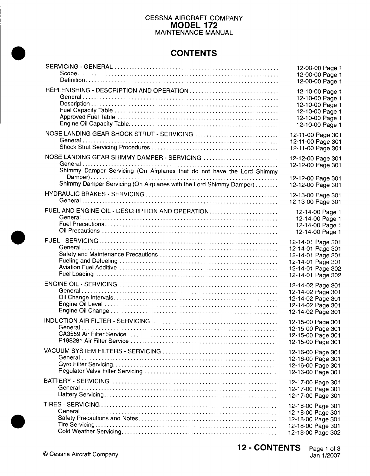
CESSNA
AIRCRAIFT
COMPANY
MODEL
172
MAINTENANCE
MANUAL
CONTENTS
SERVICING
-
GENERAL
.............................
Scope....................................
Definition
..................................
REPLENISHING
-
DESCRIPTION
AND
OPERATION
................
General...................................
Description
.................................
Fuel
Capacity
Table
.............................
Approved
Fuel
Table.............................
Engine
Oil
Capacity
Table...........................
NOSE
LANDING
GEAR
SHOCK
STRUT
-
SERVICING
...............
General...................................
Shock
Strut
Servicing
Procedures.......................
NOSE
LANDING GEAR
SHIMMY
DAMPER
-
SERVICING..............
General...................................
Shimmy
Damper
Servicing
(On
Airplanes
that
do
not
have
the
Lord
Shimmy
Damper)
.................................
Shimmy
Damper
Servicing
(On
Airplanes
with the
Lord
Shimmy
Damper).....
HYDRAULIC
BRAKES
-
SERVICING........................
General...................................
FUEL
AND
ENGINE
OIL
-
DESCRIPTION
AND
OPERATION.............
General...................................
Fuel
Precautions...............................
Oil
Precautions
...............................
FUEL
-
SERVICING................................
General...................................
Safety
and
Maintenance
Precautions
.....................
Fueling
and
Defueling
............................
Aviation
Fuel
Additive
............................
Fuel
Loading
................................
ENGINE
OIL
-
SERVICING
............................
General...................................
Oil
Change Intervals
.............................
Engine
Oil
Level...............................
Engine
Oil
Change..............................
INDUCTION
AIR
FILTER
-
SERVICING.......................
General
...................................
CA3559
Air
Filter
Service...........................
P1
98281
Air
Filter
Service
..........................
VACUUM
SYSTEM
FILTERS
-
SERVICING.....................
General...................................
Gyro
Filter
Servicing
.............................
Regulator
Valve
Filter
Servicing........................
BATTERY
-
SERVICING..............................
General...................................
Battery
Servicing...............................
TIRES
-
SERVICING
...............................
General...................................
Safety
Precautions
and
Notes.........................
Tire
Servicing
................................
Cold
Weather
Servicing............................
12-00-00
Page
1
12-00-00
Page
1
12-00-00
Page
1
12-10-00
Page
1
12-10-00
Page
1
12-10-00
Page
1
12-1
0-00
Page
1
12-10-00
Page
1
12-10-00
Page
1
12-11
-00
Page
301
12-1
1-00
Page
301
12-11
-00
Page
301
12-12-00
Page
301
12-12-00
Page
301
12-12-00
Page
301
12-12-00
Page
301
12-13-00
Page
301
12-13-00
Page
301
12-14-00
Page
1
12-14-00
Page
1
12-14-00
Page
1
12-14-00
Page
1
12-14-01
Page
301
12-14-01
Page
301
12-14-01
Page
301
12-14-01
Page
301
12-14-01
Page
302
12-14-01
Page
302
12-14-02
Page
301
12-14-02
Page
301
12-14-02
Page
301
12-14-02
Page
301
12-14-02
Page
301
12-15-00
Page
301
12-15-00
Page
301
12-15-00
Page
301
12-15-00
Page
301
12-16-00
Page
301
12-16-00 Page
301
12-16-00
Page
301
12-16-00
Page
301
12-17-00
Page
301
12-17-00
Page
301
12-17-00 Page
301
12-18-00
Page
301
12-18-00
Page
301
12-18-00
Page
301
12-18-00 Page
301
12-18-00 Page
302
12
-
CONTENTS
Page
1
of
3
Janl1/2007
©
Cessna Aircraft
Company
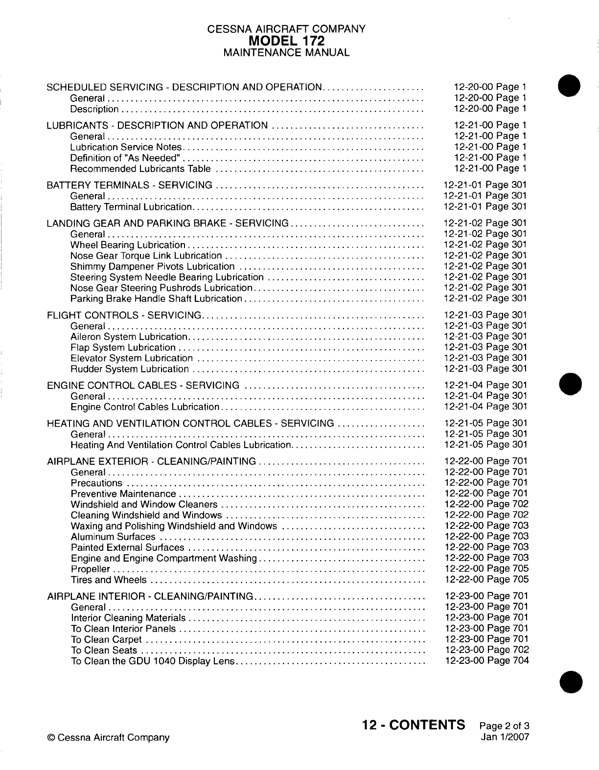
CESSNA
AIRCRAFT
COMPANY
MODEL
172
MAINTENANCE
MANUAL
SCHEDULED SERVICING
-
DESCRIPTION
AND
OPERATION............
General...................................
Description
.................................
LUBRICANTS
-
DESCRIPTION
AND
OPERATION
.................
General...................................
Lubrication
Service
Notes...........................
Definition
of
"As
Needed"............................
Recommended
Lubricants
Table
.......................
BATTERY
TERMINALS
-
SERVICING
.......................
General...................................
Battery
Terminal
Lubrication..........................
LANDING
GEAR
AND
PARKING
BRAKE
-
SERVICING
...............
General...................................
Wheel
Bearing
Lubrication
..........................
Nose Gear
Torque
Link Lubrication
......................
Shimmy
Dampener
Pivots
Lubrication.....................
Steering System
Needle
Bearing
Lubrication..................
Nose
Gear Steering
Pushrods
Lubrication
...................
Parking
Brake
Handle Shaft
Lubrication
....................
FLIGHT
CONTROLS
-
SERVICING.........................
General...................................
Aileron
System
Lubrication
..........................
Flap
System
Lubrication
...........................
Elevator System
Lubrication.
...... ................... .
Rudder System
Lubrication..........................
ENGINE
CONTROL
CABLES
-
SERVICING
....................
General...................................
Engine Control
Cables
Lubrication.......................
HEATING
AND
VENTILATION
CONTROL
CABLES
-
SERVICING
..........
General.
.................................
Heating
And
Ventilation
Control
Cables Lubrication
...............
AIRPLANE
EXTERIOR
-
CLEANING/PAINTING...................
General...................................
Precautions.................................
Preventive
Maintenance
...........................
Windshield
and
Window
Cleaners.......................
Cleaning
Windshield
and
Windows
......................
Waxing
and
Polishing
Windshield
and
Windows
................
Aluminum
Surfaces
.............................
Painted
External
Surfaces
..........................
Engine
and
Engine
Compartment
Washing...................
Propeller
..................................
Tires
and
Wheels
..............................
AIRPLANE INTERIOR
-
CLEANING/PAINTING
...................
General...................................
Interior
Cleaning
Materials
..........................
To
Clean
Interior
Panels
...........................
To
Clean
Carpet...............................
To
Clean
Seats
...............................
To
Clean
the
GDU
1040
Display Lens
.....................
12-20-00
Page
1
12-20-00
Page
1
12-20-00
Page
1
12-21-00
Page
1
12-21
-00
Page
1
12-21
-00
Page
1
12-21
-00
Page
1
12-21
-00
Page
1
12-21
-01
Page
301
12-21
-01
Page
301
12-21
-01
Page
301
12-21
-02
Page
301
12-21
-02
Page
301
12-21-02 Page
301
12-21
-02
Page
301
12-21-02
Page
301
12-21-02
Page
301
12-21
-02
Page
301
12-21
-02
Page
301
12-21
-03
Page
301
12-21-03 Page
301
12-21-03 Page
301
12-21-03
Page
301
12-21-03 Page
301
12-21
-03
Page
301
12-21
-04
Page
301
12-21-04
Page
301
12-21-04
Page
301
12-21
-05
Page
301
12-21
-05
Page
301
12-21
-05
Page
301
12-22-00
Page
701
12-22-00
Page
701
12-22-00
Page
701
12-22-00
Page
701
12-22-00
Page
702
12-22-00
Page
702
12-22-00
Page
703
12-22-00
Page
703
12-22-00
Page
703
12-22-00
Page
703
12-22-00
Page
705
12-22-00 Page
705
12-23-00
Page
701
12-23-00
Page
701
12-23-00
Page
701
12-23-00
Page
701
12-23-00
Page
701
12-23-00
Page
702
12-23-00
Page
704
12-
CONTENTS
Page2of
3
Jan
1/2007
©
Cessna
Aircraft Company
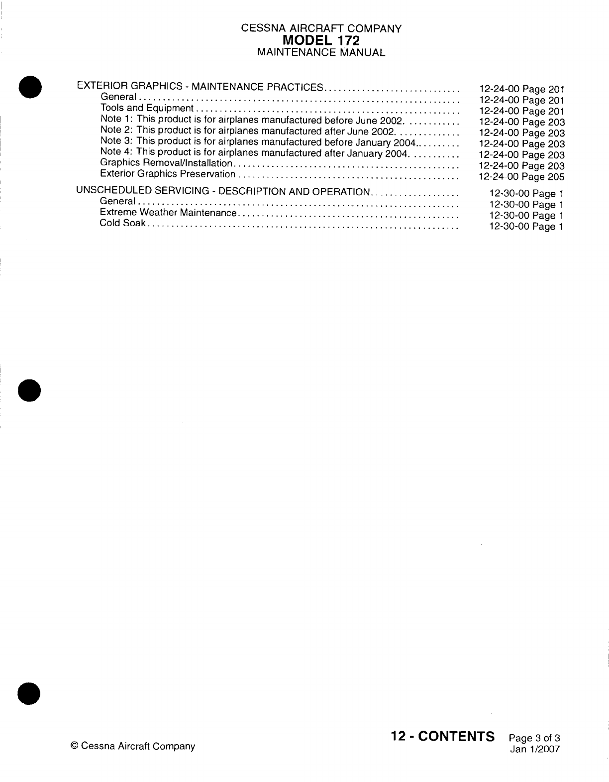
CESSNA
AIRCRAFT
COMPANY
MODEL
172
MAINTENANCE
MANUAL
EXTERIOR GRAPHICS
-
MAINTENANCE PRACTICES
...............
General...................................
Tools
and
Equipment.............................
Note
1:
This
product
is
for
airplanes
manufactured
before June
2002
.......
Note
2:
This product
is
for
airplanes
manufactured
after
June
2002........
Note
3:
This
product
is
for
airplanes
manufactured
before
January
2004......
Note
4:
This
product
is
for
airplanes
manufactured
after
January
2004
......
Graphics
Removal/Installation.........................
Exterior Graphics
Preservation
........................
UNSCHEDULED SERVICING
-
DESCRIPTION
AND
OPERATION
..........
General...................................
Extreme
Weather
Maintenance
........................
Cold
Soak..................................
©
Cessna
Aircraft
Company
12-24-00
Page
201
12-24-00
Page
201
12-24-00
Page
201
12-24-00
Page
203
12-24-00
Page
203
12-24-00
Page 203
12-24-00
Page
203
12-24-00
Page
203
12-24-00
Page
205
12-30-00
Page
1
12-30-00
Page
1
12-30-00
Page
1
12-30-00
Page
1
12
-
CONTENTS
Page
3
of
3
Janl1/2007
CESSNA
AIRCRAFT
COMPANY
MODEL
172
MAINTENANCE
MANUAL
SERVICING
-
GENERAL
1.
Scope
A.
This
chapter
provides
instructions
for
the
replenishment
of
fluids,
scheduled and
unscheduled
servicing applicable
to
the
entire
airplane. Personnel
shall
observe
safety
precautions pertaining
to
the
individual servicing
application.
2.
Definition
A.
This
chapter
is
divided
into
sections
to
aid
maintenance personnel
in
locating
information.
Consulting
the
Table
of
Contents
will
further
assist
in
locating
a
particular
subject.
A
brief
description
of
each
section follows.
(1)
The
section
on
replenishing
is
subdivided
into
categories
to
group servicing
information
such
as
systems
requiring
hydraulic
fluid
or
compressed
gas.
A
brief
description
of the
subdivision
subjects
follows.
(a)
Replenishing
charts
forthe
liquids
most
commonly
used to
service
the
airplane
are
grouped
together
to
aid
maintenance
personnel
in
servicing.
(b)
The
subdivision
of
fuel
and
oil
provides maintenance
personnel
with
general
servicing
procedures.
Safety precautions
and
servicing
procedures
required
by
federal
and
local
regulations
may
supersede
the
procedures
described.
(c)
The
subject
on
hydraulic
fluid
servicing
provides
servicing
procedures
for
the
airplane
hydraulic
brake
system, nose
gear shimmy
damper
and
nose
gear
strut.
(d)
The
remaining
subject
subdivisions
provide
service
information
on
either
a
system,
an
assembly
or
a
component.
(2)
The
section
on
scheduled servicing includes
lubrication
information,
external
cleaning
and
internal
cleaning.
The
section
is
subdivided
to
provide
individual
system,
assembly
or
component service
information.
(3)
The
section
on
unscheduled
servicing
provides information
on
deicing
an
airplane
or
portions
of
an
airplane.
12-00-00
Page
1
©
Cessna
Aircraft Company
Apr
7/2003
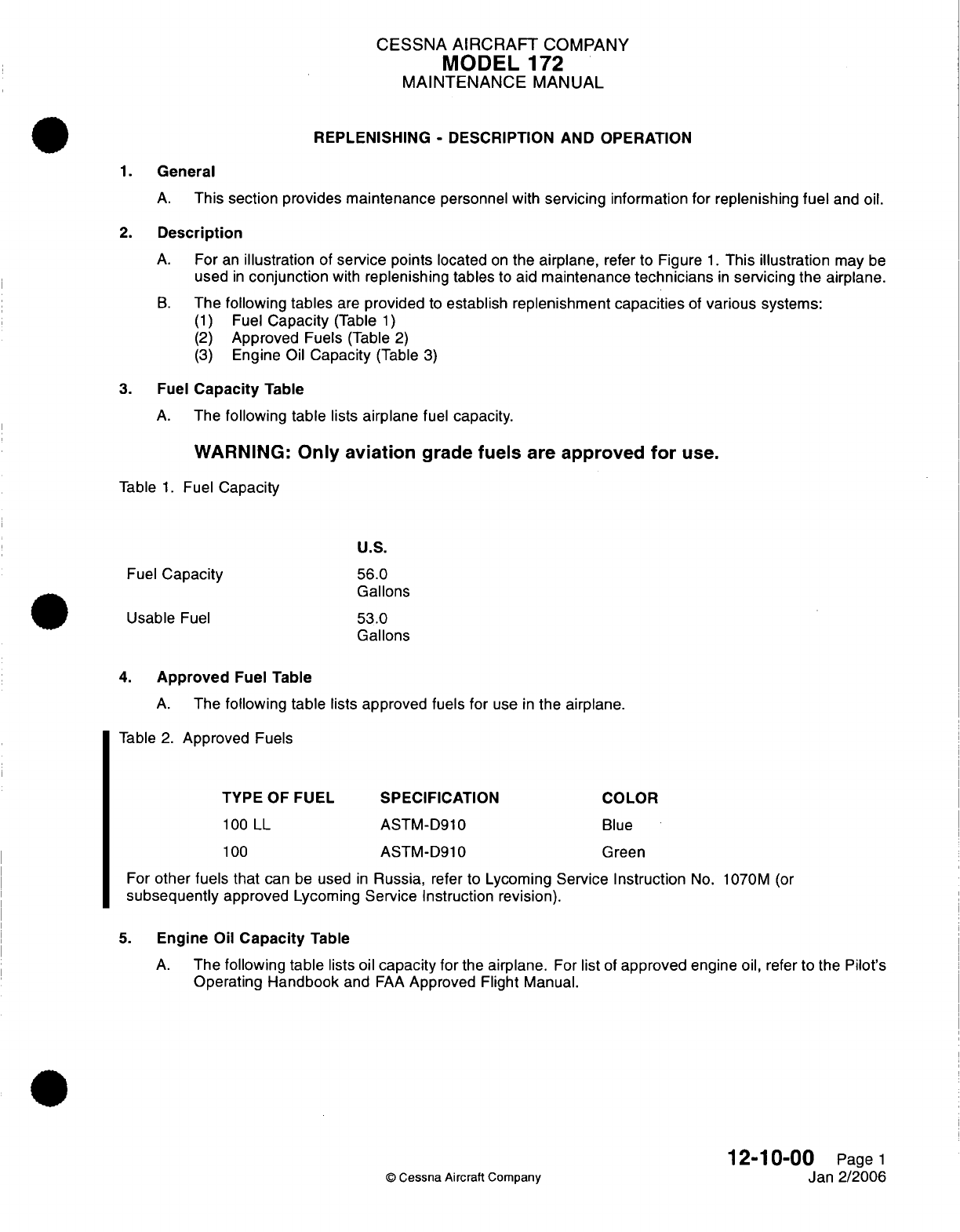
CESSNA
AIRCRAFT
COMPANY
MODEL
172
MAINTENANCE
MANUAL
REPLENISHING
-
DESCRIPTION AND OPERATION
1.
General
A.
This
section
provides
maintenance
personnel with
servicing
information
for
replenishing
fuel
and
oil.
2.
Description
A.
For
an
illustration
of
service points
located
on
the airplane,
refer
to Figure
1.
This illustration
may
be
used
in
conjunction
with
replenishing
tables
to
aid
maintenance
technicians
in
servicing
the
airplane.
B.
The
following tables
are
provided
to
establish replenishment
capacities
of
various
systems:
(1)
Fuel
Capacity
(Table
1)
(2)
Approved
Fuels
(Table
2)
(3)
Engine
Oil
Capacity
(Table
3)
3.
Fuel
Capacity
Table
A.
The
following table
lists
airplane
fuel capacity.
WARNING:
Only
aviation
grade
fuels
are
approved
for
use.
Table
1.
Fuel
Capacity
U.S.
Fuel
Capacity
56.0
Gallons
Usable
Fuel
53.0
Gallons
4.
Approved
Fuel Table
A.
The
following table
lists
approved fuels
for
use
in
the
airplane.
Table
2.
Approved
Fuels
TYPE
OF
FUEL
SPECIFICATION
COLOR
100
LL
ASTM-D910
Blue
100
ASTM-D910
Green
For
other
fuels
that
can
be
used
in
Russia,
refer
to
Lycoming
Service
Instruction
No.
1070M
(or
subsequently
approved
Lycoming
Service
Instruction
revision).
5.
Engine
Oil
Capacity
Table
A.
The
following table
lists oil
capacity
for
the
airplane.
For
list
of
approved
engine
oil,
refer
to the
Pilot's
Operating Handbook
and
FAA
Approved
Flight
Manual.
12-10-00
Page
1
©
Cessna Aircraft Company
Jan 2/2006
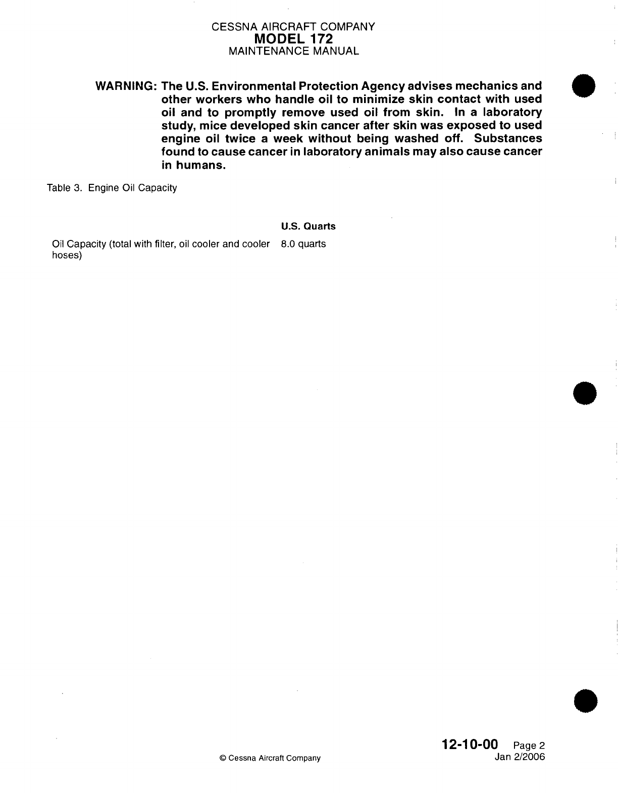
CESSNA
AIRCRAFT
COMPANY
MODEL
172
MAINTENANCE
MANUAL
WARNING:
The
U.S.
Environmental
Protection
Agency
advises
mechanics
and
other
workers
who handle
oil
to
minimize
skin contact
with
used
oil
and
to
promptly
remove
used
oil
from
skin.
In
a
laboratory
study,
mice
developed
skin
cancer after
skin
was
exposed
to
used
engine
oil
twice
a
week
without
being
washed
off.
Substances
found
to
cause
cancer
in
laboratory
animals
may
also
cause
cancer
in
humans.
Table
3.
Engine Oil
Capacity
U.S.
Quarts
Oil
Capacity
(total with
filter,
oil
cooler
and
cooler
8.0
quarts
hoses)
12-10-00
Page
2
Jan
2/2006
©
Cessna
Aircraft Company
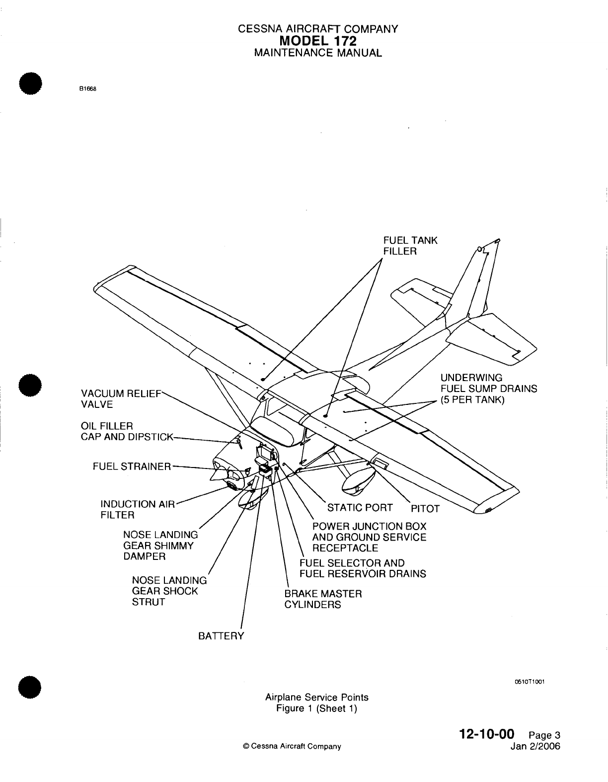
CESSNA
AIRCRAFT
COMPANY
MODEL
172
MAINTENANCE
MANUAL
B1668
FUEL
STRAINER-
INDUCTION
AIR-
FILTER
NOSE LANDING
GEAR
SHIMMY
DAMPER
NOSE
LANDING
GEAR
SHOCK
STRUT
STATIC
PORT
PITOT
POWER
JUNCTION
BOX
AND
GROUND
SERVICE
RECEPTACLE
FUEL
SELECTOR
AND
FUEL
RESERVOIR
DRAINS
BRAKE MASTER
CYLINDERS
BATTERY
0510T1001
Airplane
Service
Points
Figure
1
(Sheet
1)
12-10-00
Page
3
Jan 2/2006
©
Cessna
Aircraft
Company
T A
k
11/
CESSNA
AIRCRAFT
COMPANY
MODEL
172
MAINTENANCE
MANUAL
NOSE
LANDING
GEAR SHOCK
STRUT
-
SERVICING
1.
General
A.
The
nose
gear
shock
strut
requires
a
periodic
check
to
make
sure
the
strut
is
filled
with
hydraulic
fluid
and
is
inflated
to
the
correct
air
pressure.
The procedures
give
only replenishing
and
servicing
instructions.
For
the
disassembly
and
repair
procedures,
refer
to
Chapter
32,
Nose
Landing
Gear
-
Maintenance
Practices.
2.
Shock
Strut Servicing
Procedures
A.
The
nose
landing
gear shock
strut
must
be
serviced
every
100
hours.
B.
To
service
the nose
gear
shock
strut,
proceed
as
follows:
(1)
Raise
airplane
nose
to
remove
pressure
from
shock
strut.
(2)
Remove
valve
cap
and
release
all
air.
(3)
Remove
valve housing assembly.
(4)
Compress
strut
completely
(stops
in
contact
with
outer
barrel
hub).
(5)
Check
and
replenish
oil
level.
NOTE:
Fluid
used
must
comply
with
specification
MIL-PRF-5606.
(a)
Fill
strut
to
bottom
of
valve installation
hole.
(b)
Maintain
oil
level
at
bottom
of
valve
installation
hole.
(6)
Fully
extend strut.
(7)
Reinstall valve housing
assembly.
(8)
With
strut
fully
extended
and
nose wheel
clear
of
ground, inflate
strut
to
45
PSI.
NOTE:
The
nose
landing
gear
shock
strut
will
normally
require only
a
minimum
amount
of
service.
Strut
extension
pressure
must
be
maintained
at
45
PSI.
Machined
surfaces
must
be
wiped
free
of
dirt
and
dust
using
a
clean,
lint-free
cloth
saturated
with
MIL-
PRF-5606
or
kerosene.
All
surfaces
must
be
wiped
free
of
excessive
hydraulic
fluid.
12-11-00
©
Cessna Aircraft
Company
Page
301
Apr
7/2003
I
I
CESSNA
AIRCRAFT
COMPANY
MODEL
172
MAINTENANCE
MANUAL
NOSE
LANDING
GEAR
SHIMMY
DAMPER
-
SERVICING
1.
General
A.
This
procedure
gives
servicing instructions
for
the
shimmy damper.
To
disassemble
the shimmy
damper,
refer
to
Chapter
32,
Nose
Gear
-
Maintenance Practices.
2.
Shimmy
Damper
Servicing
(On
Airplanes
that
do not
have
the Lord
Shimmy
Damper)
A.
Service
the
shimmy
damper every
100
hours.
B.
Service
the
shimmy
damper
as
follows:
(1)
Remove
the
shimmy
damper
from the
airplane.
Refer
to
Chapter
32,
Nose
Landing
Gear
-
Maintenance
Practices.
(2)
While
you
hold
the
damper
in a
vertical position
with
the
fitting
end
pointed
down,
pull
the
fitting
end
of
the
damper
shaft
to
its
limit
of
travel.
(3)
While
you
hold
the
damper
in
this position,
fill
the
damper
through
the
open
end
of
the
cylinder
with
hydraulic
fluid.
(4)
Push
the
shaft
up
slowly
to
seal off the
filler
hole.
(5)
Clean
the
damper
with
solvent.
Make
sure
that
the
shaft
comes out through
the
filler
hole
until
the
damper
is
installed
on
the
aircraft.
(6)
Install
the
damper
on
the
airplane.
Refer
to
Chapter
32,
Nose
Landing
Gear
-
Maintenance
Practices.
C.
Keep the
shimmy damper clean.
(1)
Clean
the
shimmy
damper
with
a
clean, lint-free
cloth
to
prevent
the
collection
of
dust and
grit.
(2)
Make
sure
that
the
part
of
the
damper
piston
shaft
that
you
can
see
is
always
clean.
(3)
Clean
the
machined
surfaces
of
the
shimmy
damper.
(a)
Use a
clean,
lint-free
cloth
soaked
with
hydraulic
fluid
to
clean
the
machined
surfaces.
(b)
After
the
surfaces
are
clean,
remove
the
remaining
hydraulic
fluid from
them
with
a
clean,
lint-free cloth.
3.
Shimmy
Damper
Servicing
(On
Airplanes
with the Lord Shimmy
Damper)
A.
Lord
Shimmy
Dampers
do
not
need
special
servicing.
However,
you
must
lubricate
the
nose
wheel
shimmy
damper
pivots
with
general
purpose
oil
MIL-L-7870.
B.
Keep
the
shimmy damper
clean.
(1)
Clean
the
shimmy
damper
with
a
clean,
lint-free
cloth
to
prevent
the
collection
of
dust and
grit.
(2)
Make
sure
that
the
part
of the
damper
piston
shaft
that
you
can
see
is
always
clean.
(3)
Clean
the
machined
surfaces
of
the
shimmy damper
with
a
clean,
lint-free cloth
to
prevent
the
collection
of
dust
and
dust.
C. If
necessary,
exercise
a
shimmy
damper
before
installation.
(1) If a
shimmy
damper
has
been
in
storage for
a
long
period,
make
sure
that
it
moves
freely
before
you
install
it.
CAUTION:
Make
sure
that
you
do not
push
or
pull
on
the
shaft
of
the
shimmy
damper after
it
has
reached
its
limit
in
either the
up
or
the down
position.
If
you
continue
to push
a
fully compressed, bottomed-
out
shaft,
you can
cause damage
to
the shimmy
damper.
If
you
continue
to
pull
on
a
fully
extended
shaft,
you
can
cause damage
to
the
shimmy
damper.
(2) If
the
shimmy
damper
does
not
move
freely,
push
and
pull
the shaft
through complete cycles
until
it
does
move
freely.
When
the shimmy
damper shaft
has
come
to
its
limit
of
travel
up
and
down as
you
push and
pull, make
sure
that
you
do not
continue
to
push
or
pull
it
beyond
that
limit
of
travel.
12-12-00
Page
301
©
Cessna Aircraft Company
Jul 3/2006
CESSNA AIRCRAFT
COMPANY
MODEL
1
72
MAINTENANCE
MANUAL
HYDRAULIC BRAKES
-
SERVICING
1.
General
A.
The
brake
master
cylinders
must
be
serviced every
100
hours.
B.
The brake
master
cylinders
are
on
the pilot's rudder pedals
and are
filled
with
MIL-PRF-5606
hydraulic
fluid.
NOTE:
For
bleeding
procedures,
refer
to
Chapter
32,
Brakes
-
Maintenance
Practices.
(1)
Remove
the
filler
plug
on
the
top
of
each
master
cylinder
to
fill
the
brake
master
cylinders.
(2)
Fill
to
the
top
of the
internal
reservoir
with
MIL-PRF-5606
hydraulic
fluid.
12-13-00
Page
301
©
Cessna
Aircraft
Company
Apr
7/2003
CESSNA
AIRCRAFT
COMPANY
MODEL
172
MAINTENANCE MANUAL
FUEL
AND ENGINE
OIL
-
DESCRIPTION
AND
OPERATION
1.
General
A.
This
section
provides servicing procedures for
the fuel
and engine
oil
system.
It
is
subdivided
as
follows:
(1)
The
fuel
system section includes
procedures for
adding
fuel,
defueling
the
airplane
and
mixing
anti-icing
additives
to
the
fuel.
(2)
The
engine
oil
section
includes procedures
for
checking,
adding
and
changing engine
oil.
2.
Fuel
Precautions
A.
Safety Precautions.
(1)
The
safety
precautions
on
fueling
and
defueling
may
be
superseded
by
local
directives.
However,
following
is
a
typical
list
of
precautions.
(a)
Ground,
by
designated grounding cables,
the
fueling
and/or
defueling
vehicle
to
the
airplane.
Also,
a
static
ground
device
shall
contact
the
fueling
or
defueling
vehicle
and
ground.
(b)
Fire
fighting equipment
shall
be
immediately
available.
(c)
Wear
proper
clothing.
1
Do
not
wear clothing
that
has
a
tendency
to
generate
static
electricity
such as nylon
or
synthetic
fabrics.
2
Do
not
wear
metal
taps
on
shoes
when
working
in
areas
where
fuel fumes
may
accumulate
at
ground
level.
(d)
The
airplane
shall
be
in
a
designated
fuel loading
or
unloading
area.
(e)
High
wattage,
pulse transmitting
avionics
equipment shall
not
be
operated
in
the
immediate
vicinity.
B.
Maintenance Precautions.
(1)
Use
designated
equipment
for
fuel
loading
and
unloading
to
prevent contamination.
(2)
Use
proper
procedures
when
adding
fuel
inhibitors.
(3)
Use
specified
type
of
fuel.
3.
Oil
Precautions
A.
Maintenance
Precautions.
(1)
Use
proper
servicing procedures;
do not
overfill,
do
not
mix
manufacturer's brands
of
oil.
1
2-1
4-00
Page
1
©
Cessna
Aircraft
Company
Apr 7/2003
CESSNA
AIRCRAFT
COMPANY
MODEL
172
MAINTENANCE
MANUAL
FUEL
-
SERVICING
1.
General
A.
Fuel
Tanks.
(1)
Each
wing
contains
an
integral fuel
bay,
located
between the
front
and rear
spars,
extending
from
WS
31.38
to WS
65.125.
Fuel
bays
should
be
filled
immediately after
each
flight
to
lessen
condensation
in
the
tanks
and
lines.
A
fuel
filler
cap
is
located
on
top
of
each
wing and
provides
a
fueling/defueling
point
for
each
fuel
bay.
B.
Fuel
Drains.
(1)
Fuel
drains
are
located
at
various places
on the
underside
of each
integral
fuel
bay
and
throughout
the
fuel
system.
These
drains
are
utilized
to
collect
fuel
samples
for
analysis.
This
sampling
is
accomplished
by
placing
the
fuel
sample
cup
up
to
the
drain
valve,
and
depressing
the
valve
with
rod
protruding
from
the
cup.
NOTE:
For
detailed description
and
maintenance practices
related
to
the
fuel system,
refer
to
Chapter
28,
Fuel
-
General.
2.
Safety
and
Maintenance Precautions
A.
Safety Precautions.
WARNING:
During
all fuel
system
servicing
procedures,
fire
fighting
equipment
must
be
available.
Two
ground wires
from
tiedown
rings
on
the
airplane
to
approved
ground
stakes
shall
be
used
to prevent
accidental
disconnection
of
one
ground
wire.
Make
sure
battery
switch
is
turned
off,
unless otherwise
specified.
(1)
Establish
ground
as
follows:
(a)
Ground
airplane first.
(b)
Ground
vehicle
(or hose
cart)
to
the
same
ground
as
the
airplane.
(c)
Bond
vehicle
(or
hose
cart)
to
airplane.
(d)
Bond
refuel
nozzle
to
airplane.
(2)
Ensure fire
fighting equipment
is
positioned
and
immediately
available.
(3)
Do
not
wear
clothing
that
has
a
tendency
to
generate
static
electricity
such as
nylon
or
synthetic
fabrics.
(4)
Do
not
wear
metal
taps
on
shoes.
(5)
The
airplane should
be
in
a
designated fuel
loading/unloading
area.
(6)
High
wattage,
pulse
transmitting
avionics
equipment
shall
not
be
operated
in
the
vicinity
of
the
fueling/defueling
operation.
B.
Maintenance
Precautions.
(1)
Use
designated
equipment for fuel
loading/unloading
to
prevent
contamination.
(2)
Due
to the
chemical composition
of
anti-ice
additive,
improper
blending
of
fuel
and
anti-icing
additive
may
cause
the
deterioration
of
the
integral fuel
tanks
interior
finish,
thus
promoting
corrosion.
It
is
very important
that
the
proper
anti-ice additive blending procedures
be
followed.
(3)
Use
authorized
type
of
fuel
and
anti-ice
additive.
(4)
During
defueling,
ensure
anti-ice additive
blended
fuel
and
unblended
fuel are
not
mixed.
3.
Fueling
and
Defueling
A.
Fueling
Procedures.
12-14-01
Page
301
©
Cessna Aircraft
Company
Jan
2/2006
CESSNA AIRCRAFT
COMPANY
MODEL
172
MAINTENANCE
MANUAL
CAUTION:
Make
sure
that
the
correct
grade and
type
of
fuel
is
used
to
service
the
airplane.
Refer
to
Pilot's
Operating
Handbook
and
FAA
Approved
Airplane
Flight Manual
for
a
list
of
approved
fuels.
(1)
Ground
airplane
and
vehicle
as
outlined
above.
(2)
Ensure
battery
switch
is
turned
OFF.
(3)
Place
protective
mat
around
fuel filler
area
and
remove
fuel
filler
caps.
(4)
Fuel
airplane.
Ensure
correct
grade of
aviation
fuel
is
used.
(5)
Replace
filler
caps.
Wipe
up
excess
fuel
from
wing area.
(6)
Remove
grounding
equipment.
B.
Defueling Procedures.
(1)
Ground
airplane
and
vehicle
as
outlined
above.
(2)
Ensure
battery
switch
is
turned
OFF.
(3)
Remove fuel
filler caps.
(4)
Insert
defueling nozzle
into
fuel
bay
and
begin
defueling.
(5)
Remove
as
much
fuel
as
possible
with
defueling
nozzle.
(6)
Drain
fuel
from
drains located
on
underside
of
fuselage.
(7)
Remove drain
valves
from
bottom
of
fuel
tank
and
drain
remaining
fuel.
(8)
Remove
grounding
equipment.
4.
Aviation
Fuel
Additive
A.
When
servicing
fuel
with
anti-icing additive
containing
diethylene
glycol
monomethyl ether
(DiEGME),
remember
that
it is
harmful
if
inhaled, swallowed
or
absorbed
through
the
skin,
and
will
cause
eye
irritation.
Also,
it
is
combustible.
Before using
this
material,
refer
to
all
safety
information
on
the
container.
B. In
cases
of
acute
exposure,
DiEGME
is
an
eye and
mucous
membrane
irritant,
a
nephrotoxin
and
central nervous
system
depressant.
It is
toxic
by
skin
absorption.
Inhalation
may
cause
irritation
to
mucous membranes,
although,
due to
it's
low
volatility
this
is not
an
extreme
hazard
at
room
temperature
or
below.
If
DiEGME
contacts
the eye,
it
may
cause
pain
and
transient
injury.
It
is
absorbed through the
skin
in
toxic
amounts.
C. In
the
event
DiEGME
contact
is
experienced,
the
following
emergency
and
first
aid
procedures
should
be
used.
(1) If
ingested
(swallowed),
drink
large
quantities
of
water.
Then
induce
vomiting
by
placing
a
finger
far
back
into
the
throat. Contact
a
physician
immediately.
If
vomiting
cannot
be
induced,
take
victim
immediately
to
the
hospital
or
a
physician.
If
victim
is
unconscious
or
in
convulsions,
take
victim
immediately
to
the
hospital
or
a
physician.
Do
not
induce vomiting
or
give
anything
by
mouth
to
an
unconscious
person.
(2) If
eye
or
skin
contact
is
experienced,
flush
with
plenty
of
water
(use
soap and water
for
skin) for
at
least
15
minutes
while removing
contaminated clothing
and
shoes.
Call
a
physician. Thoroughly
wash
contaminated clothing
and
shoes
before
reuse.
5.
Fuel
Loading
CAUTION:
Make
sure
that
the
correct
grade
and
type
of
fuel
is
used
to
service
the
airplane.
Refer
to
Pilot's
Operating
Handbook
and
FAA
Approved
Airplane
Flight
Manual
for
a
list of
approved
fuels.
A.
Approved
fuel
for
the
Model
172
airplane
may or
may
not
contain
an
anti-ice additive.
The
additive
incorporates
a
biocidal chemical
which
inhibits
growth of
fungal
and
bacterial
organisms
in
fuel storage
reservoirs. Mixing
anti-ice additive
and
fuel
during
refueling
involves
the
utilization
of
an
aerosol
or
proportioned
dispenser.
12-14-01
Page
302
©
Cessna
Aircraft
Company
Jan
2/2006
CESSNA
AIRCRAFT
COMPANY
MODEL
172
MAINTENANCE
MANUAL
B.
Mixing
Icing
Inhibitor
Procedures.
NOTE:
Equivalent procedures
may be
substituted.
(1)
When
using
aerosol cans,
utilize
the
following
procedures.
(a)
Insert
the
fueling nozzle
and fuel
additive
nozzle
into
the
fuel
filler.
WARNING:
CAUTION:
Anti-icing
additives containing
DiEGME
are
harmful
if
inhaled,
swallowed
or
absorbed
through
the
skin
and
will
cause
eye
irritation.
Ensure
that
additive
is
directed
into
flowing fuel
stream
and
additive
flow
is
started
after
fuel
flow
starts
and
is
stopped
before fuel
flow
stops.
Do
not
allow
concentrated
additive
to
contact coated
interior
of fuel
tank
or
airplane
painted
surface.
(b)
Start
refueling;
then, direct
the
fuel
additive
into
the
fuel
stream
so
as
to
blend the
additive
simultaneously
with
the
fuel
as
it
fills
the
tank.
The
additive
concentration
range
shall
be
maintained
in
accordance
with
instructions
in
the
Pilot's
Operating
Handbook
and
FAA
Approved
Airplane
Flight
Manual.
12-14-01
Page
303
©
Cessna
Aircraft
Company
Jan 2/2006
CESSNA
AIRCRAFT
COMPANY
MODEL
172
MAINTENANCE
MANUAL
ENGINE
OIL
-
SERVICING
1.
General
A.
This
section
gives
instructions
to
examine
and
replace
the engine
oil.
2.
Oil
Change
Intervals
A.
Oil
Change
Intervals.
NOTE:
An
inspection
of
the
oil
filter
will
help
find
unusual engine
wear.
Refer
to
the Lycoming
Service Bulletin
480D
or
the
latest
revision.
(1)
You
must
frequently
do
a
check
of
the
oil during
the
first
25
hours
of
engine
operation
and
add
oil
as
necessary.
Use
an
aviation
grade
mineral
oil
of
the
required
viscosity
which
agrees
with
SAE
J1966.
Refer
to
Engine
Oil
Check.
(2)
After the
first
25
hours,
drain
the
engine
oil
and
replace
the
oil
filter.
Fill the
engine
through
the
oil
filler tube
with
aviation
grade
mineral oil
of
the
required
viscosity
which agrees
with
SAE
J1966.
Refer
to Engine
Oil
Change.
(3)
Continue
to
use
the aviation
grade mineral
oil
until
the
airplane
completes
a
total
of 50
hours
of
engine operation or
oil
consumption
is
stabilized.
You
must
then
drain
the
engine
oil,
replace
the oil
filter
and
add
ashless dispersant
oil
to
the
engine.
Refer
to
Engine
Oil
Change.
(4)
For
more
information
on
engine
oil
replacement
intervals,
refer to
Chapter
5,
Inspection
Time
Limits.
3.
Engine
Oil
Level
A.
Engine
Oil
Check (Refer
to Figure
301).
(1)
Make
sure
the
airplane
is
in
a
level
position for
the
best
indication.
(2)
Wait
five
to
ten
minutes
after
the
engine
has
stopped,
then
examine
the
engine
oil
level
on
the
dipstick.
(a)
Open
engine
oil
door
on
the top
cowl.
(b)
Remove the
dipstick
from
the engine.
(c)
Wipe
the
dipstick
with
a
clean
cloth.
(d)
Fully insert
the
dip
stick
into the
oil
filler
tube
and
remove
the
dipstick.
(e)
Read
oil
level
on
dipstick.
CAUTION:
THE
AIRPLANE
CAN
OPERATE
WITH
SAE
J1966
STRAIGHT
MINERAL OIL
DURING
THE
INITIAL
BREAK-IN
PERIOD
OR
AFTER
AN
OVERHAUL.
AFTER
THE
BREAK-IN
PERIOD,
USE
AN
ASHLESS DISPERSANT
OIL
THAT
AGREES
WITH
SAE
J1899.
MAKE
SURE YOU
USE
THE
CORRECT
OIL
TYPE
WHEN
YOU SERVICE
THE
ENGINE.
(3) If
the
oil
is
low,
add
the
correct
quantity
and
viscosity
of
aviation
grade
engine
oil.
Refer
to
Replenishing
-
Description
and
Operation.
(4)
Insert
the
dipstick
into the
oil
filler
tube.
(5)
Do
a
check
for
the
correct
fit
of
the
dipstick
to
make
sure
it
is
not
loose.
(6)
Close
engine
oil
door.
4.
Engine
Oil
Change
A.
Change
the
Engine
Oil
(Refer
to Figure
301).
(1)
Operate
engine
until
oil
temperature
is
at
a
normal
operating
temperature.
NOTE:
Normal
temperature operation
is
within
the
green
arc
of
the
oil
temperature
gage.
The
engine
oil
must
drain while
the engine
is
still
warm.
12-14-02
Page
301
©
Cessna
Aircraft
Company
Apr
7/2003
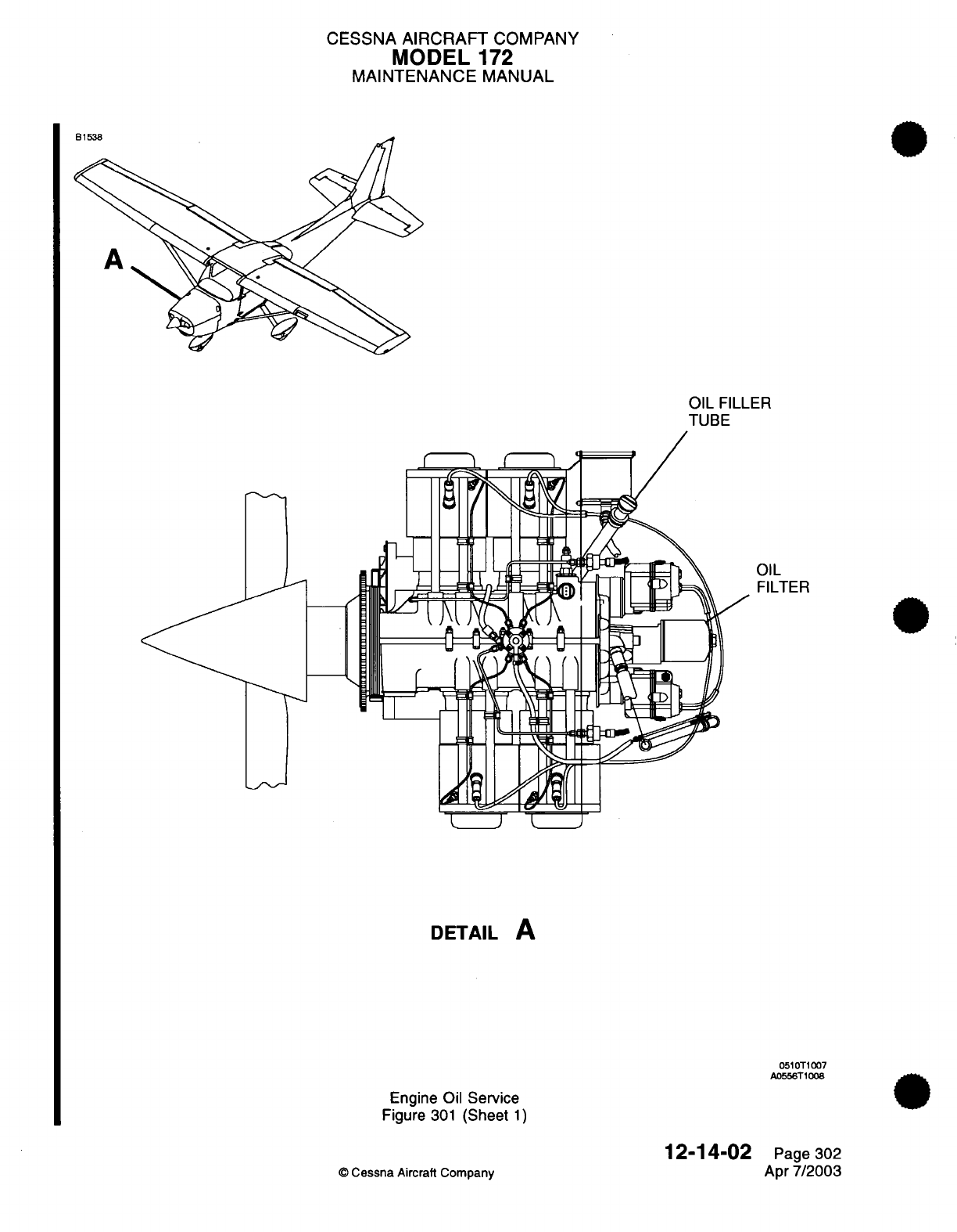
CESSNA
AIRCRAFT
COMPANY
MODEL
172
MAINTENANCE
MANUAL
OIL
FILLER
TUBE
OIL
FILTER
;
I
) I
DETAIL
A
0510T1007
A0556T1008
Engine
Oil
Service
Figure
301
(Sheet
1)
12-14-02
©
Cessna
Aircraft Company
Page 302
Apr
7/2003
^ 4 PA
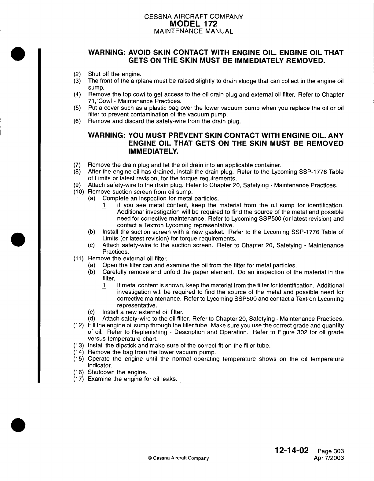
CESSNA
AIRCRAFT
COMPANY
MODEL
172
MAINTENANCE
MANUAL
WARNING:
AVOID
SKIN
CONTACT
WITH
ENGINE
OIL.
ENGINE
OIL THAT
GETS
ON
THE
SKIN
MUST
BE
IMMEDIATELY
REMOVED.
(2)
Shut
off
the
engine.
(3)
The
front
of
the airplane must
be
raised
slightly
to
drain sludge
that
can
collect
in
the
engine
oil
sump.
(4)
Remove
the top
cowl
to
get
access
to
the
oil drain
plug
and
external
oil
filter.
Refer
to
Chapter
71,
Cowl
-
Maintenance
Practices.
(5)
Put a
cover
such as
a
plastic
bag
over
the lower vacuum
pump
when
you
replace the
oil
or
oil
filter
to
prevent contamination
of
the
vacuum
pump.
(6)
Remove
and discard
the
safety-wire
from the
drain
plug.
WARNING:
YOU
MUST
PREVENT SKIN
CONTACT
WITH
ENGINE
OIL.
ANY
ENGINE
OIL
THAT
GETS
ON
THE
SKIN
MUST
BE
REMOVED
IMMEDIATELY.
(7)
Remove
the
drain plug
and let
the
oil
drain
into
an
applicable
container.
(8)
After
the
engine
oil
has
drained,
install the
drain
plug.
Refer
to
the
Lycoming
SSP-1776
Table
of
Limits
or
latest
revision,
for
the
torque
requirements.
(9)
Attach
safety-wire
to
the
drain
plug.
Refer
to
Chapter
20,
Safetying
-
Maintenance Practices.
(10)
Remove
suction
screen
from
oil
sump.
(a)
Complete
an
inspection
for
metal
particles.
1 If
you see metal
content,
keep
the
material
from
the
oil
sump
for
identification.
Additional investigation
will
be
required
to
find
the
source
of
the metal
and
possible
need
for
corrective
maintenance.
Refer
to
Lycoming
SSP500
(or
latest
revision)
and
contact
a
Textron
Lycoming
representative.
(b)
Install
the suction
screen
with
a
new
gasket.
Refer
to
the
Lycoming
SSP-1776
Table
of
Limits
(or
latest
revision)
for
torque
requirements.
(c)
Attach
safety-wire
to
the suction
screen.
Refer
to
Chapter
20, Safetying
-
Maintenance
Practices.
(11)
Remove
the external
oil
filter.
(a)
Open
the filter
can
and
examine
the
oil from
the
filter
for
metal particles.
(b)
Carefully
remove
and
unfold the paper element.
Do
an
inspection
of
the material
in
the
filter.
1 If
metal
content
is
shown, keep
the
material
from
the
filter
for
identification.
Additional
investigation
will
be
required
to
find
the
source
of
the
metal
and
possible
need
for
corrective maintenance.
Refer
to
Lycoming
SSP500
and
contact
a
Textron
Lycoming
representative.
(c)
Install
a
new
external
oil
filter.
(d)
Attach
safety-wire
to
the
oil
filter.
Refer
to
Chapter
20,
Safetying
-
Maintenance
Practices.
(12)
Fill
the
engine
oil
sump
through
the
filler
tube.
Make
sure
you
use
the
correct
grade
and
quantity
of
oil.
Refer
to
Replenishing
-
Description
and
Operation. Refer
to
Figure
302
for
oil
grade
versus
temperature
chart.
(13)
Install
the
dipstick
and
make sure
of the
correct
fit
on
the
filler
tube.
(14)
Remove the
bag
from
the
lower
vacuum
pump.
(15)
Operate the engine
until
the
normal
operating temperature shows
on
the
oil
temperature
indicator.
(16)
Shutdown
the
engine.
(17)
Examine
the
engine
for
oil
leaks.
12-14-02
Page
303
©
Cessna
Aircraft
Company
Apr
7/2003
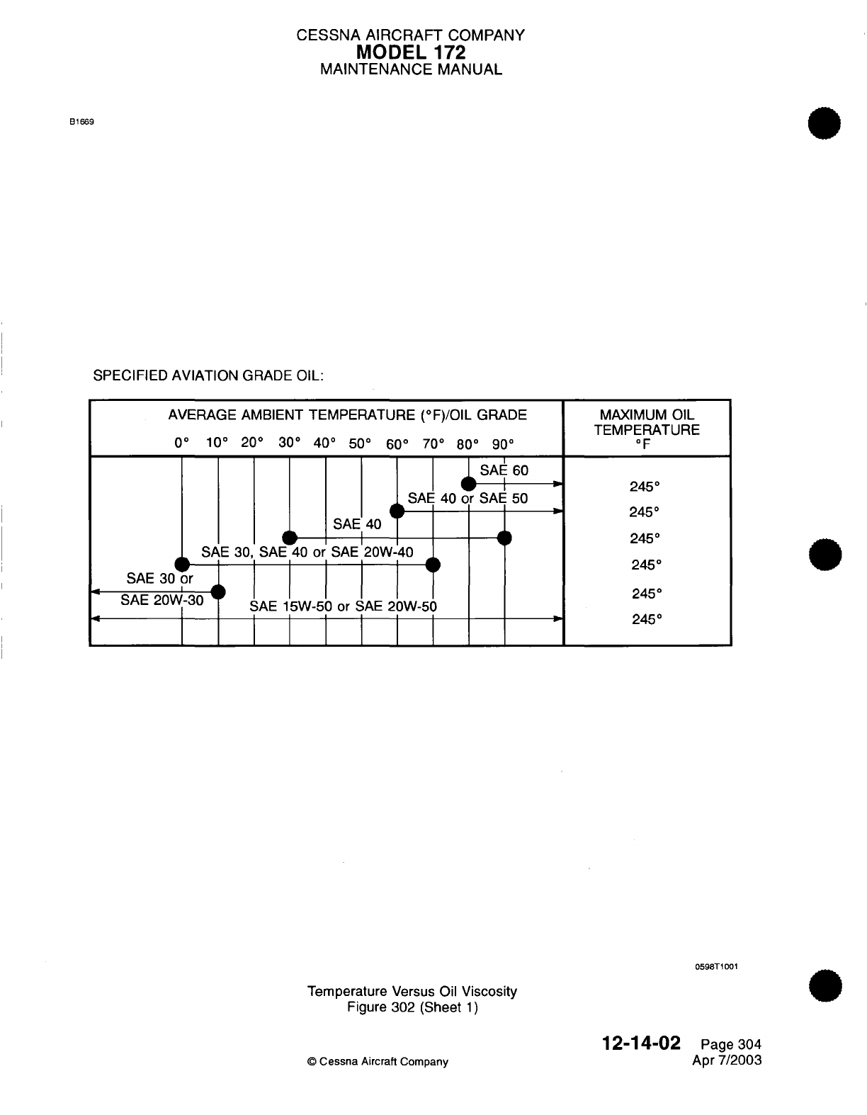
CESSNA AIRCRAFT
COMPANY
MODEL
172
MAINTENANCE MANUAL
B1669
SPECIFIED
AVIATION
GRADE
OIL:
AVERAGE
AMBIENT
TEMPERATURE
(°F)/OIL
GRADE
0°
10°
20° 30°
40°
50°
60°
70°
80°
90°
SAE
60
SAE
40
or
SAE
50
SAE
40
SAE
30,
SAE
40
or
SAE
20W-40
SAE
30
or
SAE
20W-30
SAE
15W-50
or
SAE
20W-50
I
MAXIMUM
OIL
TEMPERATURE
°F
245°
245°
245°
245°
245°
245°
0598T1001
Temperature
Versus
Oil
Viscosity
Figure 302
(Sheet
1)
12-14-02
©
Cessna
Aircraft
Company
Page
304
Apr 7/2003
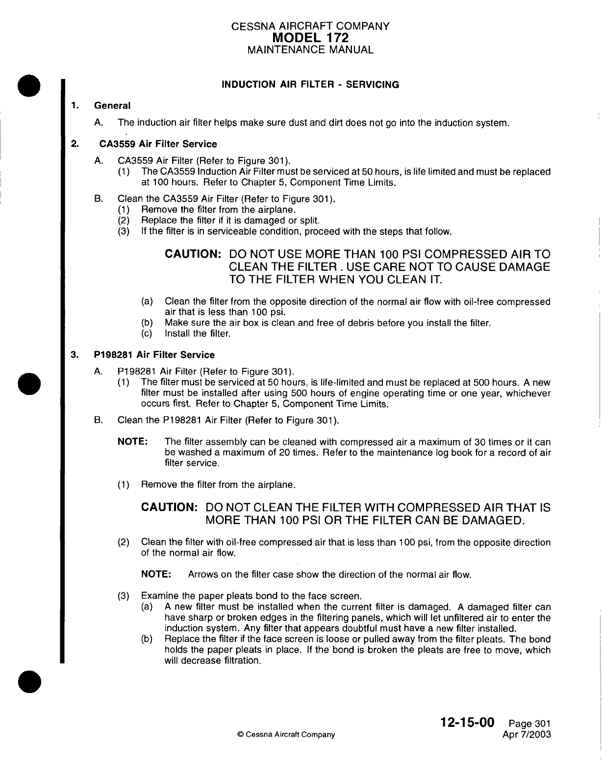
CESSNA
AIRCRAFT
COMPANY
MODEL
1
72
MAINTENANCE
MANUAL
INDUCTION AIR FILTER
-
SERVICING
1.
General
A.
The
induction
air
filter
helps
make
sure dust
and
dirt
does
not
go
into
the
induction
system.
2.
CA3559
Air
Filter Service
A.
CA3559 Air
Filter (Refer
to
Figure
301).
(1)
The
CA3559
Induction
Air
Filter must
be
serviced
at
50
hours,
is
life
limited
and must
be
replaced
at
100
hours.
Refer
to
Chapter
5,
Component
Time
Limits.
B.
Clean
the
CA3559 Air Filter (Refer
to
Figure
301).
(1)
Remove the
filter
from
the
airplane.
(2)
Replace
the
filter
if it
is
damaged
or
split.
(3) If
the filter
is in
serviceable condition,
proceed
with
the
steps
that
follow.
CAUTION:
DO
NOT
USE
MORE THAN
100
PSI
COMPRESSED
AIR TO
CLEAN
THE
FILTER
.
USE
CARE NOT
TO
CAUSE
DAMAGE
TO
THE
FILTER
WHEN
YOU
CLEAN
IT.
(a)
Clean the
filter
from
the
opposite direction
of the
normal
air
flow
with
oil-free
compressed
air that
is
less
than
100
psi.
(b)
Make
sure
the
air
box
is
clean
and
free
of
debris
before
you install the
filter.
(c)
Install
the
filter.
3.
P198281
Air
Filter Service
A.
P198281
Air
Filter
(Refer
to
Figure
301).
(1)
The
filter
must
be
serviced
at
50
hours,
is
life-limited
and
must
be
replaced
at
500
hours.
A
new
filter
must
be
installed
after using
500
hours
of
engine
operating
time
or
one year,
whichever
occurs first.
Refer
to
Chapter
5,
Component
Time
Limits.
B.
Clean
the
P198281
Air
Filter
(Refer
to
Figure
301).
NOTE:
The
filter
assembly
can
be
cleaned
with
compressed air
a
maximum
of
30
times or
it
can
be
washed
a
maximum
of
20
times.
Refer
to
the
maintenance
log
book
for
a
record
of
air
filter service.
(1)
Remove
the
filter
from
the
airplane.
CAUTION:
DO
NOT
CLEAN
THE
FILTER
WITH
COMPRESSED
AIR
T-IAT
IS
MORE
THAN
100
PSI
OR
THE
FILTER
CAN
BE
DAMAGED.
(2)
Clean
the
filter
with
oil-free
compressed
air
that
is
less
than
100
psi,
from
the
opposite
direction
of
the
normal
air
flow.
NOTE:
Arrows
on
the
filter
case
show
the
direction
of
the
normal
air
flow.
(3)
Examine
the
paper
pleats
bond
to the
face
screen.
(a) A
new
filter
must
be
installed
when
the
current filter
is
damaged.
A
damaged
filter
can
have
sharp
or
broken
edges
in
the
filtering
panels,
which will
let
unfiltered
air
to
enter
the
induction system.
Any
filter
that
appears doubtful
must have
a new
filter
installed.
(b)
Replace
the
filter
if
the
face
screen
is
loose
or
pulled
away
from the
filter
pleats.
The
bond
holds
the
paper
pleats
in
place.
If
the
bond
is
broken
the
pleats
are
free
to
move,
which
will
decrease filtration.
12-15-00
Page
301
©
Cessna
Aircraft
Company
Apr
7/2003
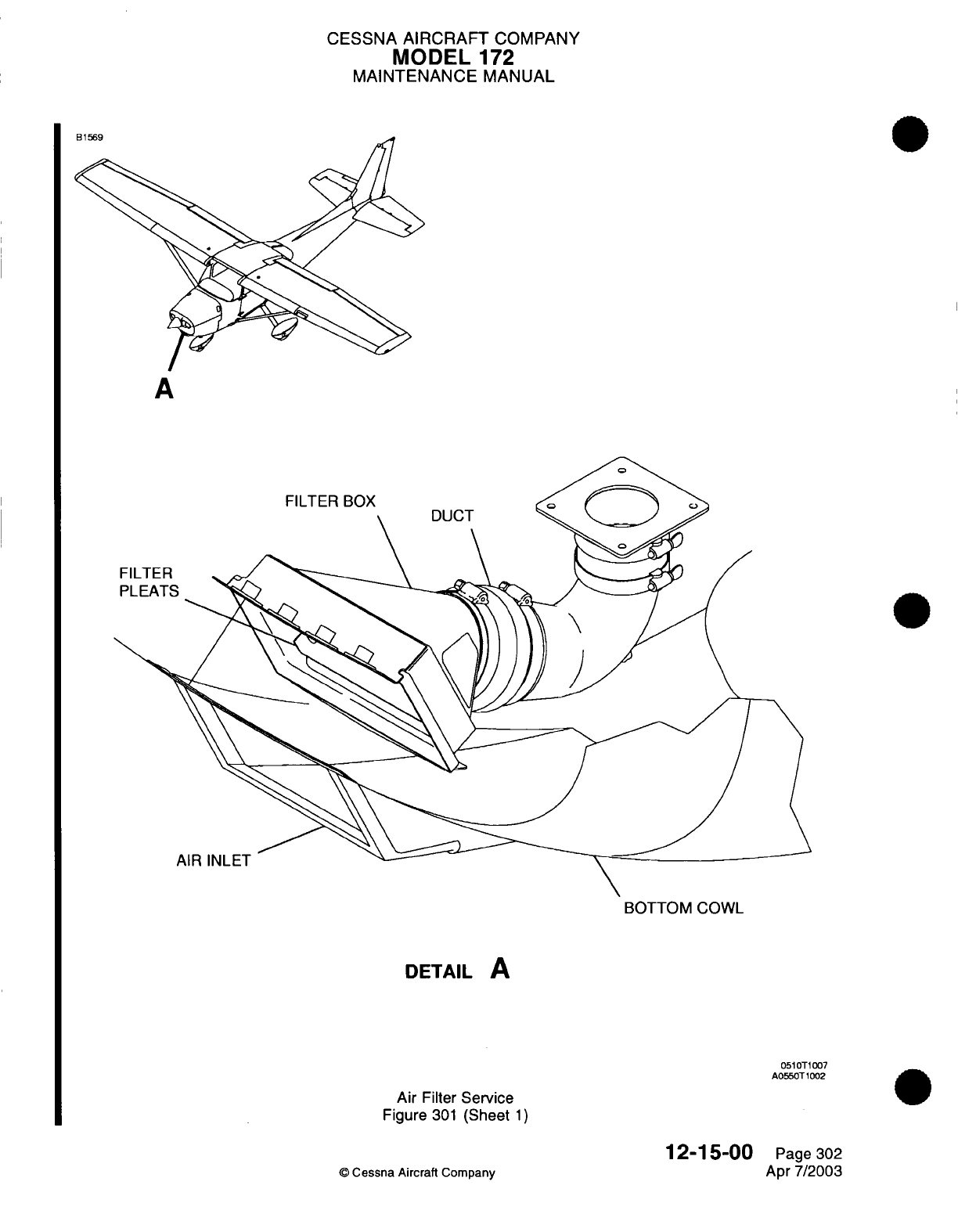
CESSNA
AIRCRAFT
COMPANY
MODEL
172
MAINTENANCE
MANUAL
A
BOTTOM
COWL
DETAIL
A
0510T1007
A0550T1002
Air
Filter
Service
Figure
301
(Sheet
1)
12-15-00
©
Cessna Aircraft
Company
Page
302
Apr 7/2003
B1569
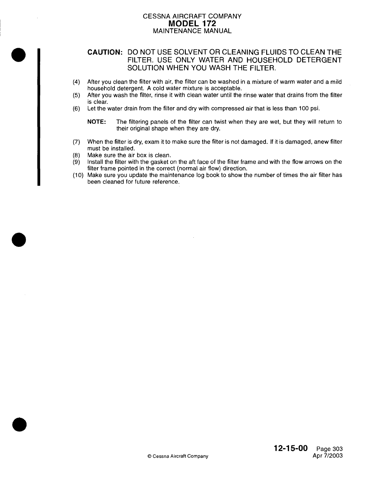
CESSNA
AIRCRAFT
COMPANY
MODEL
172
MAINTENANCE
MANUAL
CAUTION:
DO
NOT
USE
SOLVENT
OR
CLEANING
FLUIDS
TO
CLEAN
THE
FILTER.
USE
ONLY
WATER AND
HOUSEHOLD DETERGENT
SOLUTION
WHEN YOU
WASH
THE
FILTER.
(4)
After
you
clean
the
filter
with
air,
the
filter
can
be
washed
in
a
mixture
of
warm
water
and
a
mild
household
detergent.
A
cold water mixture
is
acceptable.
(5)
After you
wash
the
filter,
rinse
it
with clean
water
until
the
rinse
water
that
drains
from
the
filter
is
clear.
(6)
Let
the
water
drain from
the
filter
and dry
with
compressed
air
that
is
less
than
100
psi.
NOTE:
The
filtering
panels
of
the
filter
can
twist
when
they
are
wet,
but
they will
return
to
their
original
shape
when
they
are
dry.
When
the
filter
is
dry,
exam
it
to
make
sure
the
filter
is not
damaged.
If it
is
damaged, anew
filter
must
be
installed.
Make
sure the air box
is
clean.
Install
the
filter
with
the
gasket
on
the
aft
face
of
the
filter
frame
and
with
the
flow arrows
on
the
filter
frame pointed
in
the
correct
(normal
air
flow)
direction.
Make sure
you update the
maintenance
log
book
to
show
the number
of
times
the
air
filter
has
been
cleaned
for future reference.
12-15-00
Page
303
©
Cessna Aircraft Company
Apr
7/2003
(7)
(8)
(9)
(10)
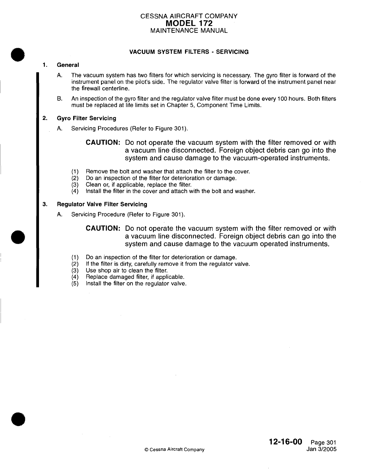
CESSNA
AIRCRAFT
COMPANY
MODEL
172
MAINTENANCE
MANUAL
VACUUM
SYSTEM FILTERS
-
SERVICING
1.
General
A.
The
vacuum
system
has
two
filters
for
which
servicing
is
necessary.
The
gyro
filter
is
forward
of
the
instrument
panel
on
the
pilot's
side.
The
regulator valve
filter
is
forward
of
the
instrument
panel
near
the
firewall
centerline.
B.
An
inspection
of
the
gyro
filter
and
the regulator
valve
filter
must
be
done every
100
hours.
Both
filters
must
be
replaced
at life
limits
set
in
Chapter
5,
Component
Time
Limits.
2.
Gyro
Filter
Servicing
A.
Servicing
Procedures
(Refer
to
Figure
301).
CAUTION:
Do
not
operate
the vacuum system
with
the
filter
removed
or with
a
vacuum
line disconnected. Foreign
object
debris
can
go
Into
the
system
and
cause
damage
to
the vacuum-operated Instruments.
(1)
(2)
(3)
(4)
Remove the
bolt
and
washer
that
attach
the
filter
to
the
cover.
Do
an
inspection
of
the
filter for
deterioration
or damage.
Clean
or,
if
applicable,
replace the
filter.
Install the
filter
in
the
cover
and
attach
with
the
bolt and
washer.
3.
Regulator
Valve
Filter
Servicing
A.
Servicing Procedure
(Refer
to
Figure
301).
CAUTION:
Do
not
operate
the
vacuum
system
with
the
filter removed
or with
a
vacuum line
disconnected.
Foreign
object
debris can
go
Into
the
system
and
cause
damage
to
the
vacuum operated
Instruments.
(1)
(2)
(3)
(4)
(5)
Do
an
inspection
of
the
filter
for
deterioration
or
damage.
If
the
filter
is
dirty,
carefully
remove
it
from
the
regulator
valve.
Use
shop
air
to
clean
the
filter.
Replace damaged
filter,
if
applicable.
Install
the
filter
on
the
regulator valve.
©
Cessna
Aircraft
Company
12-16-00
Page
301
Jan
3/2005
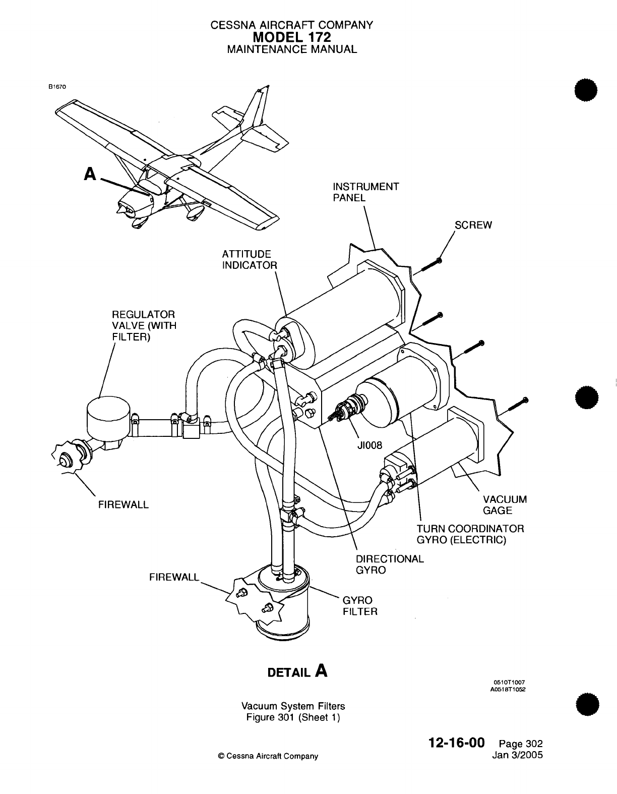
CESSNA AIRCRAFT
COMPANY
MODEL
172
MAINTENANCE
MANUAL
INSTRUMENT
PANEL
REGULATOF
VALVE
(WITI
FILTER)
FIREWALL
FIREWALL
DIRECTIONAL
GYRO
DETAIL
A
Vacuum
System
Filters
Figure
301
(Sheet
1)
12-16-00
©
Cessna Aircraft Company
GYRO
FILTER
0510T1007
A0518T1052
Page
302
Jan
3/2005
I
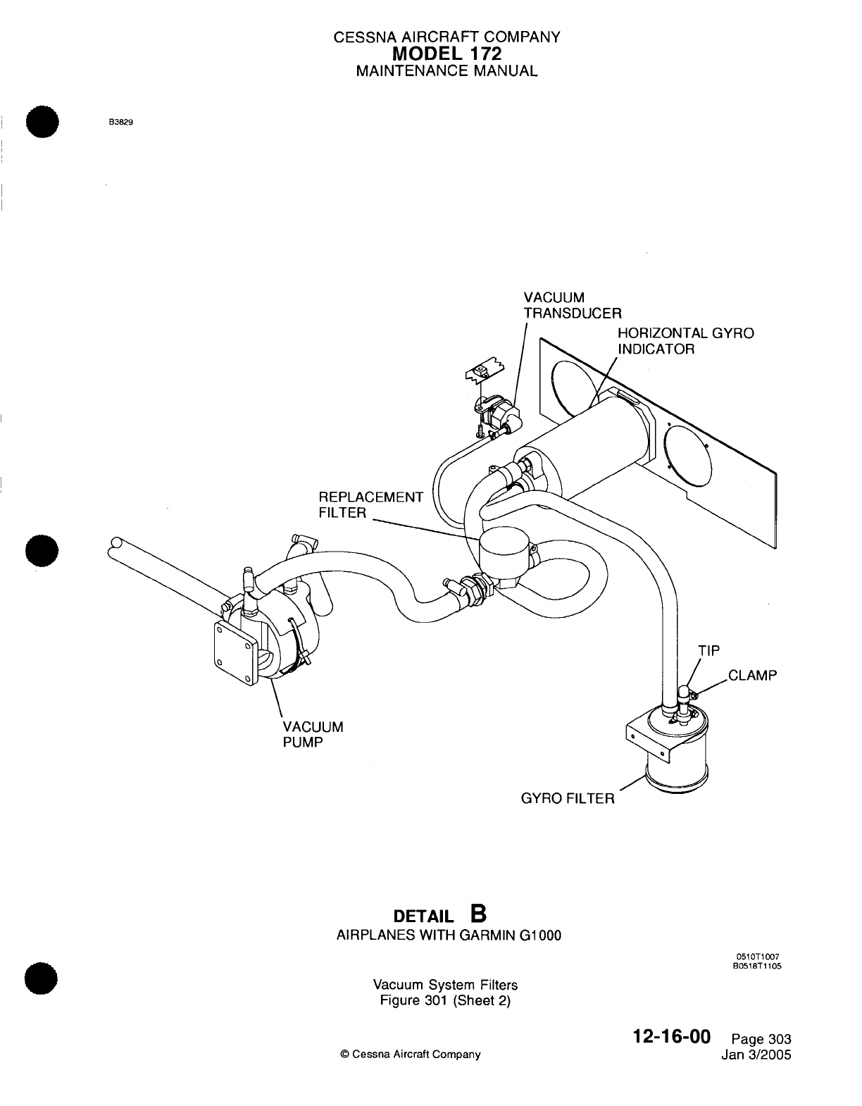
CESSNA
AIRCRAFT
COMPANY
MODEL
172
MAINTENANCE
MANUAL
B3829
VACUUM
TRANSDUCER
REPLACEMENT
FILTER
VACUUM
PUMP
GYRO
FILTER
DETAIL
B
AIRPLANES
WITH GARMIN
G1000
0510T1007
B0518T1105
Vacuum
System Filters
Figure
301
(Sheet
2)
12-16-00
©
Cessna Aircraft
Company
v
-o
Page
303
Jan
3/2005
I
CESSNA
AIRCRAFT
COMPANY
MODEL
-172
MAINTENANCE
MANUAL
BATTERY
-
SERVICING
1.
General
A.
This
procedure
provides
instructions
for
adding
water
to
the
battery.
For
testing, charging
and
maintenance
on
the
battery,
refer
to
Chapter
24,
Battery
-
Maintenance
Practices.
2.
Battery
Servicing
A.
The
battery should
be
serviced every
100
hours.
B.
Battery
servicing involves
adding
distilled
water
to
maintain
the
electrolyte
even
with
the
horizontal
baffle
plate
at
the
bottom of
the
filler
holes, checking
the
battery
cable
connections,
and
neutralizing
and
cleaning
off
any
spilled
electrolyte
or
corrosion.
Use
bicarbonate
of
soda (baking
soda)
and
water
to
neutralize
electrolyte
or
corrosion.
Follow
with
a
thorough flushing
with
a
wire
brush,
then
coat
with
petroleum
jelly
before
connecting.
The battery
box
should
also
be
checked
and
cleaned
if
any
corrosion
is
noted.
Distilled
water,
not acid
or
"re-juvenators"
should
be used
to
maintain
electrolyte
level.
Inspect
the
battery
in
accordance
with
time
limits
spelled
out
in
Chapter
5,
Inspection
Time
Limits.
12-17-00
Page
301
©
Cessna
Aircraft
Company
Apr
7/2003
CESSNA AIRCRAFT
COMPANY
MODEL
172
MAINTENANCE
MANUAL
TIRES
-
SERVICING
1.General
A.
Servicing
the
tires
by
maintaining correct
inflation pressure
is
the
most
important
job
in
any
tire
preventative
maintenance
program.
Improper
inflation
pressure
causes
uneven
tread
wear.
(1)
Under
inflation,
indicated
by
excessive
wear
in
the
shoulder
area,
is
particularly
damaging.
It
increases
the
chance
of
bruising
sidewalls
and
shoulders against
rim
flanges.
In
addition,
it
shortens
tire
life by
permitting
excessive
heat
buildup.
(2)
Over inflation
is
indicated
by
excessive
wear
in
the
center
of
the
tire.
This
condition
reduces
traction, increases
tire growth
and
makes
treads
more
susceptible
to
cutting.
2.
Safety
Precautions
and
Notes
A.
Safety
Precautions.
(1)
Tire
should
be
allowed
to
cool
before
attempting
to
service.
WARNING:
Do
not
stand
in
front
of
the
bead
area.
The
tendency
of
a
bursting
tire
is
to
rupture along
the
bead.
Standing
in
any
position
in
front
of
either
bead
area
could
cause
injury
if
the
tire should
burst.
(2)
Personnel
should stand
at
a
90-degree
angle
to
the
axle
along
the
centerline
of
the tire
during
servicing.
CAUTION:
Applying
a
tire
sealant
to
the
tire
may
cause
wheel
corrosion.
(3)
The
use
of
tire
sealant
is
not
recommended.
B.
Notes.
(1) A
tube-type
tire
that
has
been
freshly
mounted
and
installed should
be
closely
monitored during
the
first week
of
operation,
ideally
before
every takeoff.
Air
trapped between
the
tire
and the
tube
at
the
time
of
mounting
could
seep
out
under
the
bead,
through
sidewall
vents
or
around
the
valve
stem,
resulting
in
an
under
inflated
assembly.
(2)
The
initial
stretch
or
growth
of
a
tire
results
in a
pressure
drop
after
mounting.
Consequently,
tires
should
not
be
placed
in
service
until
the have
been
inflated
a
minimum
of
12
hours,
pressures
rechecked,
and
tires
reinflated
if
necessary.
(3)
Inaccurate
tire
pressure
gages
are
a
major
cause
of
improper inflation pressures. Ensure
gages
used
are
accurate.
3.
Tire
Servicing
A.
Check
tire
pressure regularly.
(1)
Tire
pressure
should
be
checked
when
tire
is
cold
(at
least
2
or
3
hours
after
flight)
on
a
regular
basis.
Tire
pressure
should
be
checked prior
to
each
flight
when
practical.
(2)
When
checking
tire
pressure, examine
tires
for
wear,
cuts,
and
bruises.
Remove
oil,
grease
and
mud
from
tires
with
soap
and
water.
B.
Use
recommended
tire
pressure.
Consult
the
table
below.
NOTE:
Recommended
tire
pressures
should
be
maintained,
especially
in
cold
weather.
Any
drop
in
temperature
of
the air
inside
a
tire
causes
a
corresponding
drop
in
air
pressure.
Main
Gear
Tire
Type
I
Pressure
MODEL
172R
6.00
x 6,
4-ply
rated
tire
29
PSI
MODEL
172S
6.00
x 6,
6-ply
rated
tire
42
PSI
12-18-00
©
Cessna
Aircraft
Company
Page
301
Janl1/2007
CESSNA
AIRCRAFT
COMPANY
MODEL
172
MAINTENANCE
MANUAL
Nose
Gear
Tire
Type
Pressure
MODEL
172R
5.00
x 5,
6-ply
rated
tire
34
PSI
MODEL
172S
5.00
x 5,
6-ply
rated
tire
45
PSI
4.
Cold
Weather
Servicing
A.
Cold
Weather
Servicing.
(1)
Check
tires
for
excessive
deflation.
NOTE:
Tire
air
pressure
will
decrease somewhat
as
the
temperature
drops,
but
excessive
deflation
could
indicate
cold
weather
leakage
at
the
air
valve.
Avoid
unnecessary
pressure
checks.
(2) If it is
necessary
to
pressure
check
tires
in
cold
climates, always apply
heat
to
air
valves
and
surrounding
areas before
unseating
valves.
(3)
Continue
application
of
heat
during
reinflation
to
ensure
air
valve
seal
flexibility
when
valve
(4)
(5)
closes.
Do
not
allow
tires
to
stand
in
snow
soaked
with
fuel,
or
on
fuel
covered
ramp
areas.
If
tires
become frozen
to
parking
ramp,
use
hot
air
or water
to
melt
ice
bond before
attempting
to
move
airplane.
©
Cessna Aircraft Company
1
2-1
8-00
Page 302
Janl1/2007
CESSNA
AIRCRAFT
COMPANY
MODEL
-172
MAINTENANCE
MANUAL
SCHEDULED
SERVICING
-
DESCRIPTION AND
OPERATION
1.
General
A.
This section provides
instructions necessary
to
carry
out
scheduled
servicing
as
well
as
internal/external
cleaning.
It
also
includes
instructions
for
lubricating
specific points
identified
in
periodic
inspection
and/or
preventive
maintenance
programs.
This
section
does
not
include
lubrication procedures required
for
the
accomplishment
of
maintenance
practices.
2.
Description
A.
This section
is
subdivided
to
provide
maintenance personnel
with
charts, text
and
illustrations
to
prevent
confusion.
Also
included
in
this section
is
a
table
containing
a
list
of
lubricants.
(1)
The
subdivisions
are
separated
according
to
airplane systems. This
aids
maintenance
personnel
in
locating service
information.
12-20-00
Page
1
©
Cessna Aircraft
Company
Apr
7/2003
CESSNA
AIRCRAFT
COMPANY
MODEL
172
MAINTENANCE
MANUAL
LUBRICANTS
-
DESCRIPTION AND OPERATION
1.
General
A.
This section
is
designed
to
assist
the
operator
in
selecting
recommended
lubricants.
For
best
results
and
continued
trouble
free
service,
use
clean and approved
lubricants.
B.
For
a
list of
recommended
lubricants,
refer
to
Recommended
Lubricants
Table.
2.
Lubrication
Service
Notes
A.
Lubricant
Application.
(1)
Cleanliness
is
essential
to
good
lubrication.
Lubricants
and
dispensing
equipment
must
be
kept
clean.
Use
only
one
lubricant
in
a
grease
gun
or oil
can.
(2)
Store
lubricants
in a
protected
area.
Containers should
be
closed
at
all
times
when
not
in
use.
(3)
Wipe
grease
fittings
and
areas
to
be
lubricated
with
clean,
dry
cloths
before
lubricating.
(4)
When
lubricating bearings
which
are
vented, force grease
into
fitting
until
old
grease
is
extruded.
(5)
After
any lubrication,
clean
excess lubricant
from
all
but
actual
working
parts.
(6)
All
sealed
or
prepacked
antifriction
bearings
are
lubricated
with
grease
by
the
manufacturer
and
require no
further
lubrication.
(7)
Friction
bearings
of
the porous, sintered
type
are
prelubricated.
An
occasional
squirt
can
oiling
of
such
bearings
with
general
purpose
oil
(MIL-PRF-7870)
extends
its
service
life.
(8)
Lubricate unsealed pulley
bearings,
rod
ends,
pivot
end
hinge
points
and
any other
friction
point
obviously
needing
lubrication,
with
general
purpose
oil
(MIL-L-
7870).
(9)
Paraffin
wax
rubbed
on
seat
rails
will
ease
sliding
the
seats
fore
and
aft.
(10)
Do
not
lubricate roller
chains
or
cables
except
under sea
coast
conditions.
Wipe
with
a
clean,
dry
cloth.
(11)
All
piano hinges
may
be
lubricated
using
(PG)
powdered
graphite
(SS-G-659)
when
assembly
is
installed.
(12)
Lubricate door latching mechanism
with
MIL-PRF-81322
general
purpose
grease,
applied
sparingly
to
friction points,
if
binding
occurs.
No
lubrication
is
recommended
on
the
rotary
clutch.
3.
Definition
of
"As
Needed"
A. In
the
following
sections,
time
requirements
for
lubrication
are
presented
in
one
of
two formats. When
specific
time
intervals
for
lubrication
exist,
those intervals
are
defined
in
Chapter
5,
Inspection
Time
Limits. When
no time limit
has
been
established,
lubrication
is
on
an
"as
needed"
basis. This
leaves
much of
the
decision
making
process
in
the
hands
of
the airframe
and
powerplant mechanic,
who
has
been
trained
to
make
these types
of
decisions.
B. In
an
effort
to
standardize
the
decision
making
process,
the
following guidelines
may
be
considered
to
determine
if
a
component
needs lubrication. Any one
of
the
following conditions
would indicate
a
need
for
lubrication,
and
may
additionally
indicate
the
need
for
inspection:
(1) A
visual
inspection
which
indicates
dirt
or
wear
residue
near
the movement
contact
area.
(2)
An
audible
inspection
which indicates
squeaks,
grinding
or
other
abnormal
sounds.
(3) A
tactile
(touch
and
feel)
inspection
which
indicates
jerky
or
restricted movement
throughout
portions
of the
travel
range.
4.
Recommended
Lubricants
Table
NOTE:
Equivalent substitutes
may
be
used for
the
following
items:
12-21-00
Page
1
©
Cessna Aircraft
Company
Jan
2/2006
CESSNA AIRCRAFT
COMPANY
MODEL
172
MAINTENANCE
MANUAL
Table
1.
Recommended
Lubricants
PROCUREMENT
SPECIFICATION
LUBRICANT
DESCRIPTION
MIL-PRF-81322
MIL-PRF-23827
Grease,
wide
temperature
range.
Grease,
aircraft
and
instrument,
gear
and
actuator
screw.
Mobil-
Mobil
Oil
Corp.
grease
28
150
E.
42nd
Street
New York,
NY
10017
Royco
22C Royal
Lubricants
Co.,
Inc.
River
Road
East
Hanover,
NJ
07936
Aeroshell
Shell
Oil
Co.
grease
22
One Shell
Plaza
Houston,
TX
77001
Southwest
Grease
16215
Aeroshell
grease
7
Southwest
Petro- Chem,
Inc.
Division
-
Witco
1400
S.
Harrison
Olathe,
KS
66061
Shell Oil
Co.
Royco
27A
Royal
Lubricants
Co.,
Inc.
Supermil
Amoco
Oil Co.
grease
No.
200
East
Randolph
Dr.
A72832
Chicago,
IL
60601
Braycote
Burmah-Castrol,
Inc.
6275
Bray
Products
Div.
16815
Von
Karman Ave.
Irving,
CA
92714
Cas-
trolease
A1
TG-11900
low
temp
grease
EP
Burmah-Castrol,
Inc.
Southwest
Petro-
Chem,lnc.
Brayco
885
Brumah-Castrol,
Inc.
OG
MIL-PRF-7870
OG
(Cont.)
MIL-PRF-7870
Oil,
general
purpose
Oil,
general
purpose
Royco
363
Royal
Lubricants
Co.,
Inc.
Petrotect
Penreco
7870A
106
South
Main
Street
Butler,
PA
16001
Windsor
lube
L-1018
Anderson
Oil
&
Chemical
Co.,
Inc.
Portland,
CT
06480
Octoil
70
Octagon Process,
Inc.
596
River
Road
Edgewater,
NJ
07020
12-21-00
Page
2
© Cessna
Aircraft
Company
Jan
2/2006
SYMBOL
GR
PRODUCT
PART
NUMBER
SUPPLIER
GH
CESSNA
AIRCRAFT
COMPANY
MODEL
172
MAINTENANCE
MANUAL
Table
1.
Recommended
Lubricants
(continued)
SYMBOL
PROCUREMENT
LUBRICANT
SPECIFICATION
DESCRIPTION
PL
VV-P-236
Petrolatum
technical
PG
SS-G-659
Powdered
Graphite
GL MIL-G-21164
High
and
Low
Temperature
Grease
NONE
VV-L-800
PRODUCT
PART
NUMBER
Everlube
211-G
Moly
Grease
Royco
64
Number
10
weight,
non-detergent
oil
Light
Oil
Grease, general
U000992
purpose
©
Cessna
Aircraft
Company
SUPPLIER
Available
Commercially
Available
Commercially
E/M
Corporation
Box
2200
Highway
52
N.W.
West
Lafayette,
IN
47906
Royal
Lubricants
Co.,
Inc.
Available
Commercially
Available
Commercially
Cessna
Aircraft
Co.
1
Cessna
Blvd.
Wichita,
Ks
67277-7704
12-21-00
Page
3
Jan 2/2006
GP
OL
I
CESSNA
AIRCRAFT
COMPANY
MODEL
172
MAINTENANCE
MANUAL
BATTERY
TERMINALS
-
SERVICING
1.
General
A. It
is
recommended the airplane
be
secured
in
an
area
free
of
contamination
from
sand,
dust
or
other
environmental
conditions
that
may
contribute
to
improper
lubrication
practices.
2.
Battery
Terminal
Lubrication
A.
Battery
terminals should
be
lubricated
when
cables
are
installed
to
terminals.
B.
Refer
to
Figure
301
for
lubrication
requirements
of
the
battery terminals.
12-21-01
Page
301
©
Cessna
Aircraft
Company
Apr
7/2003
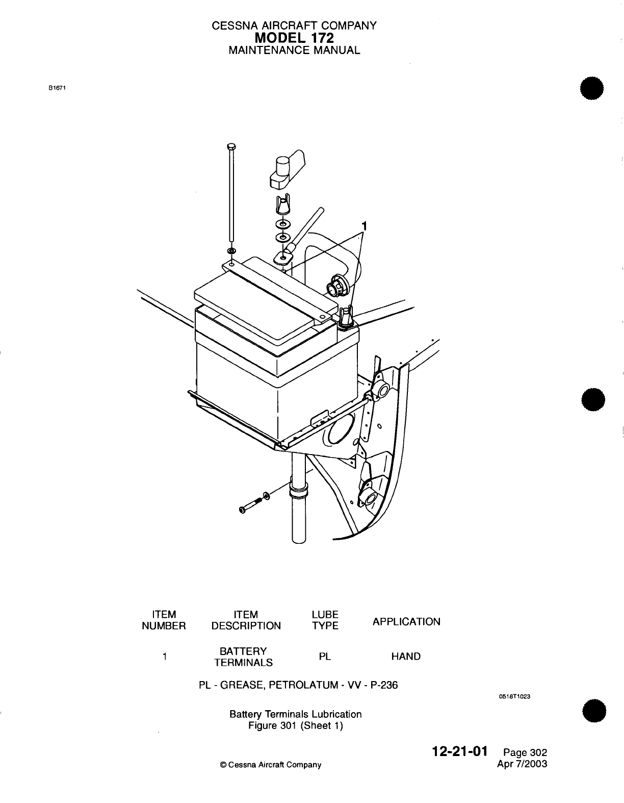
CESSNA
AIRCRAFT
COMPANY
MODEL
172
MAINTENANCE
MANUAL
LANDING
GEAR
AND
PARKING
BRAKE
-
SERVICING
1.
General
A. It is
recommended that
the
airplane
be
secured
in
an
area free
of
contamination
from
sand,
dust
or
other
environmental
conditions
that
may
contribute
to
improper
lubrication
practices.
2.
Wheel
Bearing
Lubrication
A.
Wheel
bearings should
be
lubricated
every
100
hours.
WARNING:
WIEN
CLEANING
WHEEL BEARINGS,
USE
LOW
PRESSURE
SHOP
AIR
TO
DRY
BEARINGS.
DO
NOT
SPIN
BEARING
CONES
WITH
COMPRESSED AIR.
DRY
BEARINGS WITHOUT
LUBRICATION
MAY
EXPLODE
AT
HIGH
RPM.
B.
Refer
to
Figure
301
for lubrication
requirements
of
the
wheel
bearings.
3.
Nose
Gear
Torque
Link Lubrication
A.
Nose
gear
torque
links should
be
lubricated
every
50
hours.
B.
Refer
to
Figure
301
for
lubrication
requirements
of
the nose
gear
torque
links.
4.
Shimmy
Dampener
Pivots
Lubrication
A.
Shimmy
dampener
pivots
should
be
lubricated
on
an
"as
needed"
basis
and
when
assembled
or
installed.
B.
Refer
to
Figure
301
for lubrication
requirements
of
the
shimmy
dampener
pivots.
5.
Steering
System
Needle
Bearing
Lubrication
A.
Steering system needle
bearings should
be
lubricated
on
an
"as
needed"
basis
and
when
assembled
or
installed.
B.
Refer to
Figure
301
for
lubrication
requirements
of
the
steering
system
needle
bearings.
6.
Nose
Gear
Steering
Pushrods
Lubrication
A.
Nose
gear
steering
pushrods should
be
lubricated every
100
hours
using
OG
lubricant
applied
with
an oil
can.
7.
Parking
Brake
Handle
Shaft
Lubrication
A.
The
parking
brake
handle
shaft
should
be
lubricated
on an
"as
needed"
basis
and
when
assembled
or
installed.
B.
Refer
to
Figure
301
for
lubrication
requirements
of the
parking
brake handle
shaft.
12-21-02
Page
301
©
Cessna
Aircraft Company
Apr
7/2003
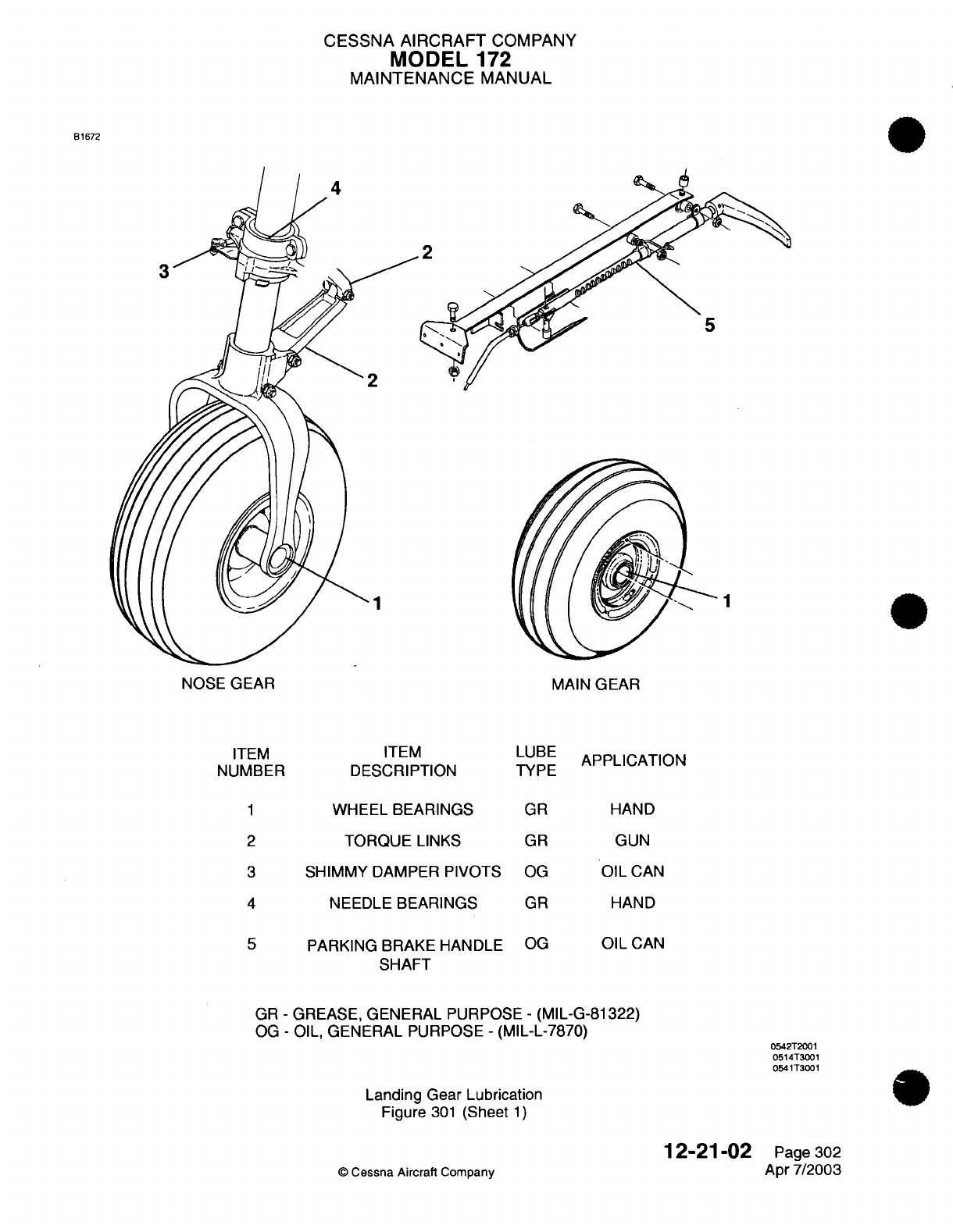
CESSNA AIRCRAFT
COMPANY
MODEL
172
MAINTENANCE
MANUAL
B1672
2
5
1
NOSE GEAR
ITEM
NUMBER
MAIN
GEAR
ITEM
DESCRIPTION
LUBE
TYPE
APPLICATION
1
WHEEL BEARINGS
2
TORQUE LINKS
3
SHIMMY
DAMPER
PIVOTS
4
NEEDLE
BEARINGS
5
PARKING BRAKE HANDLE
SHAFT
GR
GR
OG
GR
OG
HAND
GUN
OIL
CAN
HAND
OIL
CAN
GR
-
GREASE,
GENERAL
PURPOSE
-
(MIL-G-81322)
OG
-
OIL,
GENERAL
PURPOSE
-
(MIL-L-7870)
Landing Gear Lubrication
Figure
301
(Sheet
1)
12-21-02
©
Cessna Aircraft
Company
0542T2001
0514T3001
0541T3001
Page 302
Apr
7/2003
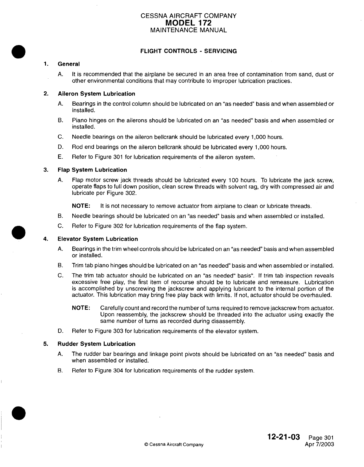
CESSNA
AIRCRAFT
COMPANY
MODEL
1
72
MAINTENANCE
MANUAL
FLIGHT
CONTROLS
-
SERVICING
1.
General
A. It
is
recommended
that the
airplane
be
secured
in
an
area free
of
contamination
from
sand,
dust
or
other environmental conditions that
may
contribute
to
improper
lubrication
practices.
2.
Aileron
System
Lubrication
A.
Bearings
in
the
control
column
should
be
lubricated
on
an
"as
needed"
basis
and
when
assembled
or
installed.
B.
Piano
hinges
on
the
ailerons should
be
lubricated
on
an
"as
needed"
basis
and
when
assembled
or
installed.
C.
Needle
bearings
on
the
aileron
bellcrank
should
be
lubricated
every
1,000
hours.
D.
Rod
end
bearings
on
the
aileron
bellcrank
should
be
lubricated
every 1,000
hours.
E.
Refer
to
Figure
301
for
lubrication
requirements
of
the
aileron
system.
3.
Flap
System
Lubrication
A.
Flap
motor
screw
jack
threads
should
be
lubricated every
100
hours.
To
lubricate
the
jack
screw,
operate
flaps
to
full
down
position,
clean
screw
threads
with
solvent
rag,
dry
with
compressed
air
and
lubricate
per
Figure
302.
NOTE:
It is
not
necessary
to remove
actuator
from
airplane
to
clean or lubricate
threads.
B.
Needle
bearings should
be
lubricated
on an
"as
needed"
basis
and
when assembled
or
installed.
C.
Refer
to
Figure
302
for
lubrication
requirements
of
the
flap
system.
4.
Elevator
System
Lubrication
A.
Bearings
in
the
trim
wheel
controls
should
be
lubricated
on
an
"as
needed"
basis
and
when
assembled
or
installed.
B.
Trim
tab
piano
hinges
should
be
lubricated
on an
"as
needed"
basis
and
when
assembled
or
installed.
C.
The
trim
tab
actuator
should
be
lubricated
on an
"as
needed"
basis".
If
trim
tab
inspection
reveals
excessive
free
play,
the
first
item
of
recourse
should
be
to
lubricate
and
remeasure.
Lubrication
is
accomplished
by unscrewing the
jackscrew
and
applying
lubricant
to
the
internal portion
of
the
actuator.
This lubrication
may
bring
free
play
back
with
limits.
If
not,
actuator
should
be
overhauled.
NOTE:
Carefully
count
and
record the
number
of
turns required
to
remove
jackscrew
from
actuator.
Upon
reassembly,
the
jackscrew
should
be
threaded
into
the actuator
using
exactly
the
same
number
of
turns
as
recorded during
disassembly.
D.
Refer
to
Figure
303
for
lubrication requirements
of
the
elevator
system.
5.
Rudder
System
Lubrication
A.
The
rudder
bar
bearings
and
linkage
point pivots
should
be
lubricated
on
an
"as
needed"
basis
and
when
assembled
or
installed.
B.
Refer
to
Figure
304
for
lubrication requirements
of the
rudder
system.
12-21-03
Page
301
©
Cessna
Aircraft
Company
Apr 7/2003
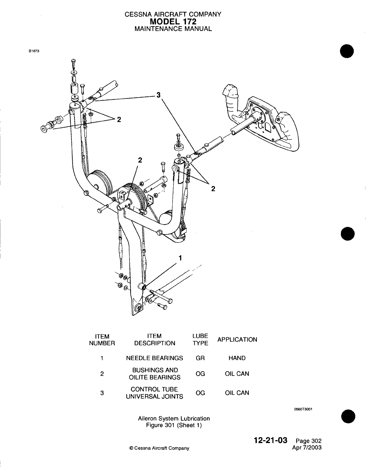
CESSNA
AIRCRAFT
COMPANY
MODEL
172
MAINTENANCE
MANUAL
B1673
3
2
2
-
1
\
1^
-z
ITEM
ITEM
NUMBER
DESCRIPTION
1
NEEDLE
BEARINGS
2
BUSHINGS
AND
OILITE
BEARINGS
CONTROL
TUBE
UNIVERSAL
JOINTS
LUBE
TYPE
GR
OG
OG
APPLICATION
HAND
OIL
CAN
OIL
CAN
0560T3001
Aileron
System
Lubrication
Figure
301
(Sheet
1)
12-21-03
©
Cessna
Aircraft Company
Page
302
Apr
7/2003
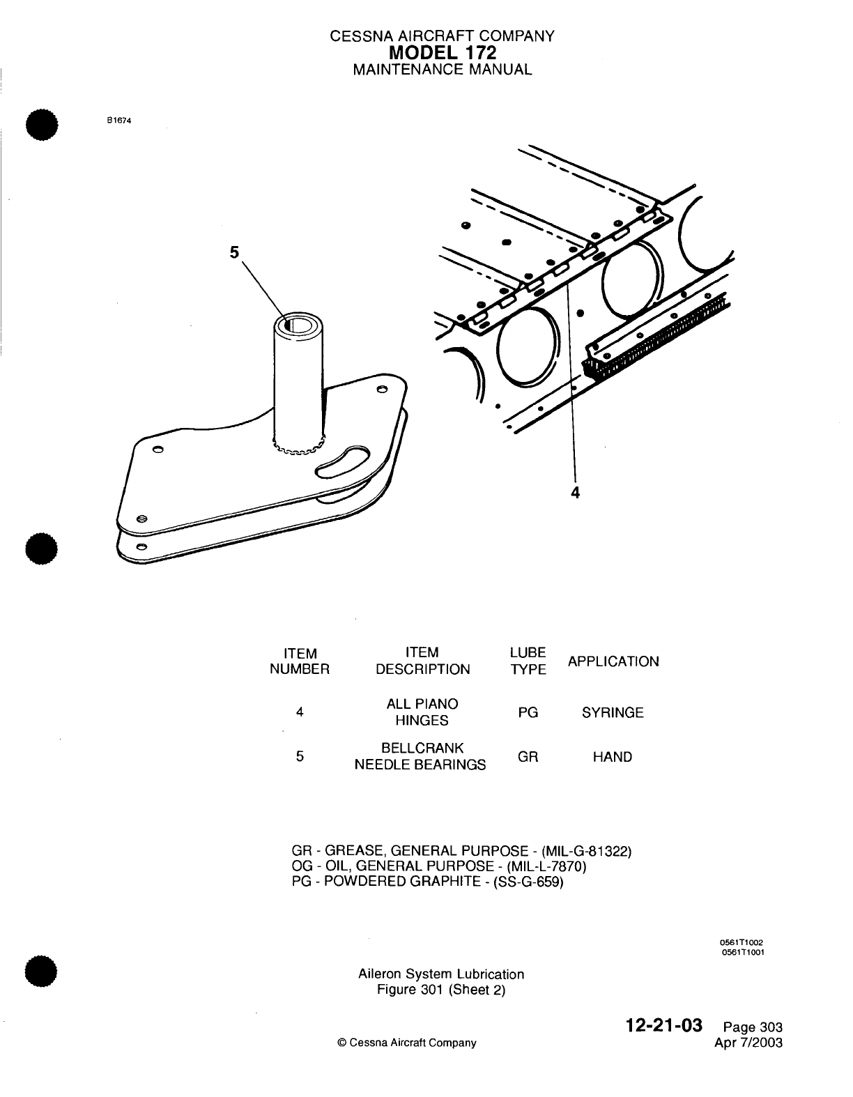
CESSNA AIRCRAFT
COMPANY
MODEL
1
72
MAINTENANCE
MANUAL
B1674
5
4
ITEM
ITEM
NUMBER DESCRIPTION
ALL PIANO
HINGES
5
BELLCRANK
NEEDLE
BEARINGS
LUBE
TYPE
APPLICATION
PG
SYRINGE
GR
HAND
GR
-
GREASE,
GENERAL
PURPOSE
-
(MIL-G-81322)
OG
-
OIL, GENERAL
PURPOSE
-
(MIL-L-7870)
PG
-
POWDERED
GRAPHITE
-
(SS-G-659)
0561T1002
0561T1001
Aileron System
Lubrication
Figure
301
(Sheet
2)
©
Cessna
Aircraft
Company
12-21-03
Page
303
Apr
7/2003
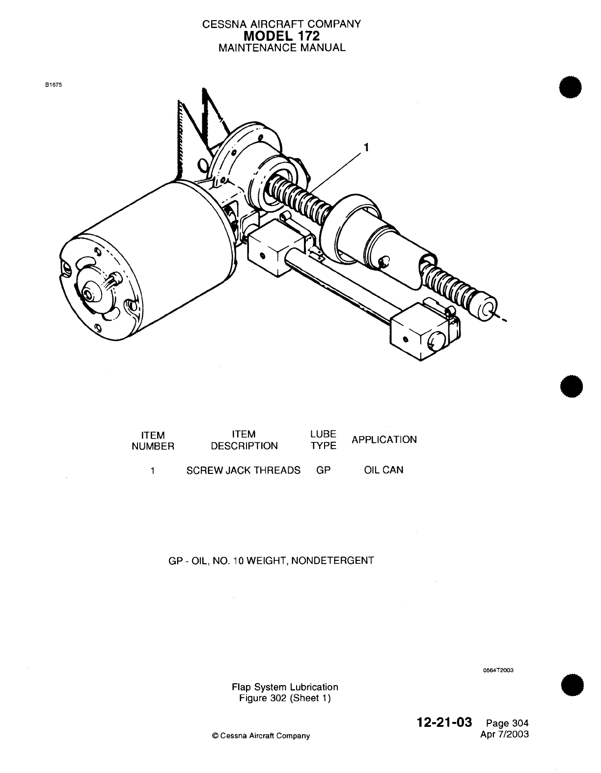
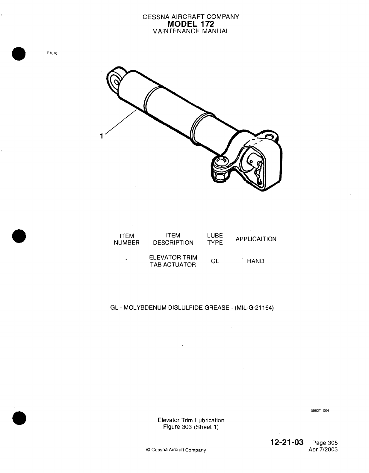
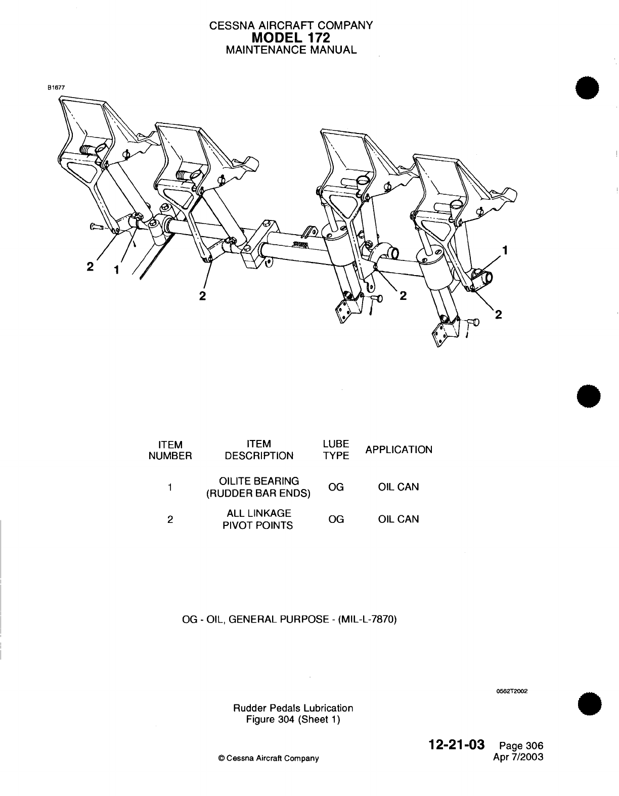
CESSNA
AIRCRAFT
COMPANY
MODEL
172
MAINTENANCE
MANUAL
B1677
EM
ITEM
MBER
DESCRIPTION
1
OILITE BEARING
(RUDDER
BAR ENDS)
ALL
LINKAGE
PIVOT
POINTS
LUBE
TYPE
OG
OG
APPLICATION
OIL
CAN
OIL
CAN
OG
-
OIL,
GENERAL PURPOSE
-
(MIL-L-7870)
0562T2002
Rudder Pedals
Lubrication
Figure
304
(Sheet
1)
12-21-03
©
Cessna Aircraft Company
IT
NU
Page
306
Apr
7/2003
CESSNA
AIRCRAFT
COMPANY
MODEL
172
MAINTENANCE
MANUAL
ENGINE
CONTROL CABLES
-
SERVICING
1.
General
A. It is
recommended
that
the
airplane
be
secured
in
an
area
free
of
contamination
from
sand,
dust
or
other
environmental
conditions
that
may
contribute to
improper
lubrication
practices.
2.
Engine
Control
Cables
Lubrication
A.
All
housed,
pull-type,
push-pull
or
vernier
controls
should have
each
outer
housing
lightly
lubricated
internally
with
VV-L-800
General
Purpose
Lube
Oil.
12-21-04
Page
301
©
Cessna
Aircraft
Company
Apr
7/2003
CESSNA
AIRCRAFT
COMPANY
MODEL
1
72
MAINTENANCE
MANUAL
HEATING
AND
VENTILATION
CONTROL
CABLES
-
SERVICING
1.
General
A. It
is
recommended that
the
airplane
be
secured
in
an
area
free
of
contamination
from
sand,
dust
or
other
environmental conditions
that
may
contribute
to
improper
lubrication practices.
2.
Heating And
Ventilation
Control
Cables
Lubrication
A.
All
housed,
pull-type,
push-pull
or
vernier
controls
should
have each
outer
housing lightly
lubricated
internally
with VV-L-800
General Purpose
Lube
Oil.
12-2'1-05
Page
301
©
Cessna
Aircraft Company
Apr
7/2003
CESSNA
AIRCRAFT
COMPANY
MODEL
172
MAINTENANCE
MANUAL
AIRPLANE
EXTERIOR
-
CLEANING/PAINTING
1.
General
A.
The
airplane
should
be
washed
frequently
in
order
to
maintain
its
appearance
and
minimize corrosion.
The painted area
of the
airplane
should
be
polished
at
periodic
intervals
to
remove
chalking
paint
and
restore
its
gloss.
B.
Water/detergent
cleaning
is
the
preferred
method
to
clean
the
exterior
surface
of
the
airplane.
2.
Precautions
A.
Read
and adhere
to
all
manufacturers instructions, warnings
and
cautions
on
the
cleaning/solvent
compounds
used.
B.
Do
not
use
silicone
based wax
to
polish
the
airplane
exterior.
Silicone based
wax,
especially
if
buffed
to
produce
a
high
shine,
will
contribute
to
the build
up
of P-static.
C.
Do
not
park
or
store
airplane
where
it
might
be
subjected
to
direct
contact
with
fluid
or
vapors
from
methanol, denatured
alcohol,
gasoline, benzene, xylene,
methyl n-propyl
ketone,
acetone,
carbon
tetrachloride, lacquer thinners,
commercial
or
household window cleaning
sprays, paint
strippers
or
other types
of
solvents.
D.
Do
not
leave
sun
visors
up
against
windshield
when not
in
use.
The reflected
heat
from
these
items
causes
elevated temperatures
on
the
windshield.
If
solar
screens
are
installed
on
the
inside
of
the
airplane,
ensure
they
are
the
silver
appearing,
reflective
type.
3.
Preventive
Maintenance
A.
Keep
all
surfaces
of
windshields
and
windows
clean.
B. If
desired,
wax
acrylic surfaces.
C.
Carefully
cover
all
surfaces
during any
painting,
powerplant cleaning
or
other
procedure
that calls
for
use
of
any
type
of
solvent
or
chemical.
Table
701
lists
approved
coatings
for
use
in
protecting
surfaces
from
solvent
attack.
Table
701.
Approved
Protective Coatings
NAME
Spray
Masking
Paper
Poly-Spotstick
NUMBER
MIL-C-6799,
Type
1,
Class
II
WPL-3
SXN
Protex
40
MANUFACTURER
Available
Commerically
Champion
Intl.
Corp.
Forest
Product Division
7785
Bay
Meadows
Way
Jacksonville,
FL
32256
Champion
Intl.
Corp.
Mask Off Company
345
Marie
Avenue
Monrovia,
CA
USE
Protect
surfaces
from
solvents.
Protect
surfaces
from
solvents.
Protect
surfaces
from
solvents.
Protect
surfaces
from
solvents.
12-22-00
©
Cessna
Aircraft
Company
Page
701
Jan
2/2006
CESSNA
AIRCRAFT
COMPANY
MODEL
172
MAINTENANCE
MANUAL
4.
Windshield
and
Window
Cleaners
CAUTION:
Do
not
use
gasoline, alcohol, benzene, acetone,
carbon
tetrachloride,
fire
extinguisher
fluid,
deicer
fluid,
lacquer
thinner
or
glass window cleaning
spray.
These
solvents
will
soften
and
craze the
plastic.
NOTE:
Equivalent
substitutes
may
be
used
for
the
following
items:
Table
702.
Windshield
and
Window
Cleaners/Polishers
NAME
Mild
soap
or
detergent
(hand
dishwashing
type
without abrasives)
Aliphatic Naphtha
Type
II
NUMBER
Federal
Specification
TT-N-95
Turtle
Wax
(paste)
MANUFACTURER
Commercially
Available
Commercially
Available
Commercially
Available
USE
Cleaning
windshields
and
windows.
Removing
deposits
which
cannot
be
removed
with
mild
soap
solution
on
acrylic
windshields
and
windows.
Waxing
acrylic
windshields
and
windows.
Permatex
Plastic
Cleaner
No.
403D
Soft
cloth
(cotton
flannel
or
cotton
terry
cloth)
Federal
Specification
P-P-560
Permatex
Company,
Inc.
Kansas City,
KS
66115
Commercially
Available
Waxing
acrylic
windshields
and
windows.
Applying
and
removing
wax
and
polish.
5.
Cleaning
Windshield
and
Windows
CAUTION:
Windshields
and
windows
are
easily
damaged
by
improper handling
and
cleaning
techniques.
CAUTION:
Do
not
use
any of
the
following
for cleaning
windshields
and
windows:
methanol,
denatured
alcohol, gasoline,
benzene,
xylene,
methyl
n-propyl
ketone,
acetone,
carbon
tetrachloride, lacquer thinners,
commercial
or
household
window
cleaning
sprays.
A.
Refer
to
Table
702
for
cleaning
materials.
B.
Windshield
Cleaning Procedures.
(1)
Place
airplane
inside
hanger
or
in
shaded area
and
allow
to
cool
from
heat
of
sun's
direct
rays.
(2)
Using
clean
(preferably
running) water, flood
surface.
Use
bare
hands
with
no
jewelry
to
feel
and
dislodge any
dirt
or
abrasive
materials.
(3)
Using
a
mild
soap
or
detergent
(such
as dish
washing
liquid)
in
water,
wash surface.
Again
use
only
bare
hands
to
provide rubbing force.
(A
clean
cloth
may
be
used
to
transfer
soap
solution
to
surface,
but
extreme care must
be
exercised
to
prevent
scratching
surface.)
(4)
On
acrylic windshields
and
windows
only,
if
soils
that
cannot
be
removed
by
a
mild
detergent
remain,
Type
II
aliphatic
naphtha
applied
with
a
soft
clean cloth
may be used
as
a
cleaning
solvent.
Be
sure
to
frequently
refold
cloth
to
avoid
redepositing
soil
and/or
scratching
windshield
with
any
abrasive
particles.
12-22-00
Page 702
©
Cessna
Aircraft
Company
Jan
2/2006
CESSNA
AIRCRAFT
COMPANY
MODEL
172
MAINTENANCE
MANUAL
(5)
Rinse
surface
thoroughly
with
clean
fresh
water
and
dry
with
a
clean
cloth.
6.
Waxing
and
Polishing
Windshield
and
Windows
CAUTION:
Do
not use
rain
repellent
on
acrylic
surfaces.
NOTE:
Windshields
and
windows
must
be
cleaned
prior
to
application
of
wax.
When
applying
and
removing wax
and
polish,
use
a
clean
soft
cloth.
A.
Refer
to Table
702
for
polishing
materials.
B.
Hand
polishing
wax
(or
other
polish
meeting
Federal
Specification
P-P-560)
should
be
applied
to
acrylic
surfaces.
The
wax
has
an
index
of
refraction nearly the
same
as
transparent acrylic
and
tends
to
mask
any
scratches
on
windshield
surface.
7.
Aluminum
Surfaces
A.
Aluminum
surfaces
require
a
minimum
of
care,
but
should never
be
neglected.
The
airplane
may
be
washed
with
clean water
to
remove
dirt
and may
be
washed
with
non
alkaline
grease
solvents
to
remove
oil
and/or
grease.
Household
type
detergent
soap
powders
are
effective cleaners,
but
should
be
used
cautiously,
since
some
of
them are
strongly
alkaline.
Many
good
aluminum
cleaners,
polishes
and
waxes
are
available
from
commercial
suppliers
of
airplane
products.
8.
Painted
External Surfaces
CAUTION:
Do
not
let
solvents
come
in
contact
with
the
external
graphics.
The
external graphics
can
be
easily
damaged
by
contact
with
solvents.
For
care
and
cleaning
of
the
external graphics,
refer
to
Chapter
12,
Exterior
Graphics
-
Maintenance
Practices.
A.
Generally,
the
painted surfaces
can
be
kept
bright
by
washing
with
water
and mild
soap,
followed
by
a
rinse with water
and
drying
with
cloths
or
a
chamois.
Harsh
or
abrasive
soaps
or
detergents
which
could
cause
corrosion
or
scratches
should
never
be
used. Remove
stubborn
oil
and
grease
with
a
cloth moistened
with
Stoddard
solvent.
B.
To
seal
any minor
surface
chips
or scratches
and
protect
against
corrosion,
the airplane
should
be
waxed
regularly
with
a
good
automotive
wax applied
in
accordance
with
the manufacturer's
instructions.
If
the
airplane
is
operated
in a
seacoast
area or
other
salt water
environment,
it
must
be
washed and waxed
more
frequently
to
assure adequate protection.
Special
care
should
be
taken
to
seal
around rivet
heads
and
skin
laps,
which
are
the
areas
susceptible
to
corrosion.
A
heavier
coating
of
wax
on
the
leading
edges
of
the
wings
and
tail
and
on
the
cowl
nose
cap
and
propeller
spinner
will help
reduce
the
abrasion
encountered
in
these
areas.
Reapplication
of
wax
will
generally
be
necessary
after
cleaning
with
soap
solutions
or
after
chemical
deicing
operations.
9.
Engine
and
Engine
Compartment
Washing
A.
Notes
and
Precautions.
(1)
An
engine
and
accessories
wash
down
should
be
accomplished
during
each
100
hour
inspection
to
remove
oil,
grease,
salt
corrosion
or
other
residue
that might
conceal component defects
during
inspection.
Also, periodic
cleaning
can
be
very
effective
In
preventive
maintenance.
(2)
When
working
with
cleaning
agents,
protective devices
(rubber gloves, aprons,
face
shields,
etc...)
should
be
worn.
Use
the
least
toxic
of
available
cleaning
agents that
will
satisfactorily
accomplish
the
work.
(3)
All
cleaning
operations
should
be
performed
in a
well
ventilated
work
area.
(4)
Adequate
fire
fighting
and
safety
equipment
should
be
available.
12-22-00
Page
703
©
Cessna
Aircraft
Company
Jan
2/2006
CESSNA AIRCRAFT
COMPANY
MODEL
172
MAINTENANCE
MANUAL
WARNING:
Do
not
smoke
or
expose
a
flame
within
100
feet
of
the
cleaning
area.
(5)
Compressed
air,
if
used
to
apply
solvent
or
to
dry
components,
should
be
regulated to
lowest
practical pressure.
(6)
Use
of
a
stiff
bristle
brush
(as
opposed
to
a
steel
brush)
is
recommended
if
cleaning
agents
do
not
remove
excess
grease
and grime
during
spraying.
B.
Cleaning Procedures.
(1)
Remove
engine
cowling.
(2)
Carefully
cover
the
coupling
area
between
vacuum
pumps
and
engine drive
shafts
so
no
cleaning
solvent
can
reach
coupling
or
seal.
(3)
Cover
open
end
of
the vacuum
discharge
tubes.
(4) If
engine
is
contaminated
with
salt
or
corrosive chemicals, first
flush
engine
compartment
with
fresh
water.
CAUTION:
Do
not use
gasoline
or
other highly
flammable
substances
for
wash
down.
CAUTION:
Do
not
attempt
to
wash
an
engine
which
is
still
hot
or
running.
Allow
engine
to
cool
before
cleaning.
CAUTION:
Care
should
be
exercised
to
not direct
cleaning
agents
or
water
streams
at
openings
on
the
starter,
magnetos,
alternator
or
vacuum
pump.
(5)
Apply
solvent
or
cleaning
agent
to
engine
compartment.
The
following
solutions
(or
their
equivalent) can
be
used
to
satisfactorily
clean
the
engine compartment:
(a)
Stoddard
Solvent (Specification
P-D-680,
Type
II).
(b)
Water
alkaline
detergent
cleaner
(MIL-C-25769
mixed
1
part
cleaner, with
2
to
3
parts
water
and
8
to
12
parts
Stoddard
Solvent).
(c)
Solvent based emulsion
cleaner
(MIL-C-4361
mixed
1
part
cleaner
with
3
parts
Stoddard
Solvent).
(6)
After
applying
solvent, thoroughly
rinse
with
clean
warm
water.
NOTE:
Cleaning
agents should
never
be
left
on
engine
components
for
an
extended
period
of
time.
Failure
to
remove them
may
cause damage
to
components
such
as
neoprene
seals
and
silicone
fire
sleeves,
and
could cause
additional
corrosion.
(7)
Completely
dry
engine
and
accessories
using
clean,
dry
compressed
air.
(8)
Remove
protective
cover
over
coupling
area.
(9)
Remove
protective
cover
from
vacuum
discharge
tube.
(10)
If
desired,
engine cowling
may
be
washed
with
the same
cleaning agents,
then
rinsed
thoroughly
and
wiped
dry.
After
cleaning
engine,
relubricate
all
control
arms
and
moving
parts
as
required.
(11)
Reinstall
engine
cowling.
WARNING:
Ensure
magneto
switches
are
off,
throttle
is
closed,
mixture
control
is
in
the idle
cutoff
position,
and
the
airplane
is
secured
before
rotating
propeller
by
hand.
Do
not
stand
within
arc
of
the
propeller
blades
while
turning
propeller.
(12)
Before
starting
engine,
rotate
propeller
by
hand
no
less
than
four
complete revolutions.
12-22-00
Page
704
©
Cessna
Aircraft Company
Jan
2/2006
CESSNA
AIRCRAFT
COMPANY
MODEL
172
MAINTENANCE
MANUAL
10.
Propeller
A.
The
propeller
should
be
wiped
occasionally
with
an
oily
cloth
to
remove grass
and
bug
stains.
In
salt
water
areas,
this
will
assist
in
corrosion proofing
the
propeller.
11.
Tires
and
Wheels
A.
Remove
oil,
grease,
and
mud
from
tires
and
wheels
with
soap and
water.
12-22-00
Page
705
©
Cessna
Aircraft Company
Jan
2/2006
CESSNA
AIRCRAFT
COMPANY
MODEL
172
MAINTENANCE
MANUAL
AIRPLANE
INTERIOR
-
CLEANING/PAINTING
1.
General
A.
Airplane
Interior
-
Cleaning/Painting gives procedures
for
different
types
of
cleaning
agents
and
cleaning
procedures
for
the
interior
of
the
airplane.
2.
Interior
Cleaning
Materials
NOTE:
Equivalent
alternatives
can
be
used
for
the items
that
follow.
NAME
Son
Of
A
Gun
NUMBER
Fantastic
Aliphatic
Naphtha TT-N-95
Rug
Shampoo
Perchloroethylene
Cleaning Solvent
Stoddard Solvent
MANUFACTURER
Commercially
available
Commercially available
Commercially available
Commercially available
Commercially available
Commercially available
Ivory
Liquid
(White
or
colorless)
Cheer
Commercially available
Commercially available
Commercially available
Mr.
Clean
USE
To
give
protection
for
interior
components
(does
not
include fabric
materials).
To
general purpose
clean
interior
components
and
recommended
to
clean
Morbern
vinyl.
To
remove
tar,
asphalt,
etc.,
from
interior.
To
clean
carpet.
To
spot
clean
carpet
and
seats.
To
clean
nylon
safety
belts.
To
clean
seat
fabric.
To
clean
seat
fabric.
Recommended
to
clean
Morbern
vinyl.
3.
To
Clean
Interior
Panels
A.
Interior
panels
are made
of
a
heavy
vinyl
and can
have
a
softer Morbern
vinyl
cover.
You
can
clean
the
interior
panels
with
a
mild
detergent solution or
with
pre-mixed commercial
cleaners.
You
can
remove
contamination
that
is
not
easily
removed
with
aliphatic
naphtha.
Make
sure
the
cleaners
will
work
on
the
interior without
damge.
If
it
is
not
sure
that the
cleaner
will
cause
damage
to
the
interior,
apply
a
small
quantity
of
cleaner
to
a
not
visible
location
and
do a
test
to
see
if it
will
cause damage.
4.
To
Clean Carpet
A.
The
carpet
is
made
of
a
polypropylene
weave
put
together
with
a
fire
retardant backing.
The
polypropylene
gives
stain
resistant
qualities
and
normally only
minimal maintenance
is
required.
B. If
the
carpet
becomes contaminated,
it
can
be
cleaned
with
a
commercially available carpet
cleaning
agent.
12-23-00
©
Cessna
Aircraft
Company
Page
701
Jan 3/2005
CESSNA
AIRCRAFT
COMPANY
MODEL
172
MAINTENANCE
MANUAL
5.
To
Clean
Seats
A.
Fabric
seats
of
the 172R
and
some
172S
are made
of
a
flame retardant Trevira
polyester
fiber
and
have
fire-retardant
and
stain-resistant
properties.
You
must clean
the
seats
regularly.
Contamination
and
stains
must
be
cleaned
up
immediately
and
the
fabric
cleaned
before
the
stains
set
up
in
the
fabric.
B.
Table
701
(Procedures
to
Clean
Trevira
Fabric
on
Seats)
and
Table
702
(Procedures
to
Clean
Morbern
Vinyl on
Cabin Panels)
are
given
to
help
in
stain removal.
The
tables
have
two
columns;
one
with
the
stain and the
other
with
the
procedure
to
remove
the
stain.
For
example,
coffee
and
tea
stains
are
removed with
processes
2, 4, 5
and
1.
The
first
step
is
the
application
of
process
2
(dishwashing
liquid
with
warm
water)
to
the
stain.
The
second
step
is
the
application
of
process
4
(vinegar
and water)
to
the
stain.
The
third
step
is
the application
of
process
5
(laundry
powder
and
warm
water
followed
by
blotting)
to
the
stain.
The
final
step
is
the
application
of
process
1
(dry
cleaning solvent applied
to
the
stain).
Table
701.
Procedures
to Clean
Trevira
Fabric
on
Seats
STAIN
Antacid
(Maalox)
Betadine
(Iodine)
Blood
Catsup
Chewing
Gum
Chocolate
Syrup
Coffee/Tea
Cola
Cough
Syrup
Egg
Grape
Drink
Ice
Cream
PROCESS/SEQUENCE
STAIN
1
2,3,4,6
2,3,5
2,3,5
7,1,2
5,1
2,4,5,1
2,3,4
2
2,3,5,1
2,3,4,5
2,3,4,5,1
Infant Formula
Ink
(ball
point)
Motor
Oil
Mud
Petroleum
Jelly
Pepto
Bismol
Urine
Suntan
Lotion
Shoe
Polish
Vomit
Wax
PROCESS/SEQUENCE
2,1
8
1,2,3,4
2,1
1,2
6,1
2,3,4
1,2
1,2,3
2,3,4,5
7,1
1.
Apply
a
small
quantity
of
dry
cleaning solvent
to
the
stain.
Do
not
smoke
or
use
near an
open
flame.
Use
sufficient airflow.
2.
Mix
one
teaspoon
of
white
or
colorless
dishwashing
liquid
with
a
cup
of
lukewarm water.
3.
Mix one
tablespoon
of
household
ammonia
with
half
a
cup of
water.
4.
Mix one
part
household
vinegar
with
two
parts water.
5.
Mix
a
solution
of
laundry
powder
with
water
and
leave
on
the
stain
according
to
the
label
directions.
Flush
with
warm
water
and
wipe
dry.
6.
Mix
one
part
household
bleach
with nine parts
water.
Use
a
dropper
to
apply
the
solution
to
the
stain.
Flush
with
water and
wipe
dry.
7.
Chill
area
with
an
ice
cube
wrapped
in
a
plastic
bag.
Remove
the
gum
or
wax
from
the
surface
of
the
fabric.
8.
Apply
a
small
quantity
of
rubbing alcohol
to
the
ink
stain and blot
to
remove
the
ink.
Continue
until
the
ink
is
removed.
NOTE: All
solutions
must
be
cool
when
applied
to
the
stain.
Heat from
the
solutions
will permanently
set
the
stain.
12-23-00
©
Cessna
Aircraft
Company
Page
702
Jan
3/2005
CESSNA
AIRCRAFT
COMPANY
MODEL
172
MAINTENANCE
MANUAL
Table
702.
Procedures
to
Clean
Morbern
Vinyl
on
Cabin
Panels
STAIN
PROCESS/SEQUENCE
STAIN
PROCESS/SEQUENCE
Blood
4
Mud
3,6
Candy,
Ice
Cream
14,6
Mustard
3,12,8,6
Chewing
Gum
11,6
Paint,
Latex
9,6
Crayon
3,12,8,6
Paint,
Oil base
2,3
Fruit
Stains 14,6
Shoe
Polish
13,6
Ink
(ballpoint)
1
Soft Drinks
14,6
Ketchup
3,12,8,6
Surface
Mildew
8,6
Lipstick,
Eyeshadow 13,6
Tar,
Asphalt
10,3
Liquor,
Wine
14,6
Urine
7,6
Motor Oil,
Grease
13,6
Vomit
5,6
1.
Apply
a
small
quantity
of
rubbing
alcohol to
the
ink
stain
and
blot
to
remove
the
ink.
Continue
until
the
ink
is
removed.
2.
Turpentine
in
a well
ventilated
area will
remove fresh paint.
Dried
paint
must
be
moistened
carefully
with
a
semi-solid
gel-type stripper
so
that
the
softened paint
can
be
gently
scraped
away.
CAUTION:
Direct
contact
with
paint
strippers
will
remove
the
print
pattern
from
vinyl.
Paint
strippers
are very
corrosive.
Be
careful
to avoid
skin
and
eye
contact.
Wear
safety
equipment,
If
applicable.
3.
Flush
with mild
soap
and water.
4.
Rub
out
any
spots
with
a
clean
cloth
soaked
in
cool
water.
If
spots
remain, use
household
ammonia
and flush
with
a
clean,
wet
cloth.
5.
Sponge the
stained
area
with
soapy
water
that
contains
diluted
bleach
until
the stain
is
removed.
6.
Flush
thoroughly
with
clean,
cool
water.
7.
Sponge
with
soapy
water
that
contains
a
small
quantity
of
household ammonia.
8.
Wash
with
diluted
bleach
and
use
a
soft brush for
difficult
stains.
9.
Fresh
paint
can
be
wiped
off
with
a
damp cloth.
Hot,
soapy
water
will
normally
remove
dried
latex.
10.
Remove
immediately, as prolonged
contact
will
result
in a
permanent
stain.
Use
a
cloth
lightly
dampened
with mineral
spirits
or
kerosene
and
rub
the
stain
gently. Work
from
the
outer
edge
of
the
stain
towards
the
center
in
order
to
prevent
the
spread
of
the
stain.
11.
Scrape
off
as
much
as
possible
with
a
dull
knife.
Rub
with
an
ice
cube
to
help
make
it
easier
to
remove
the
gum.
The
remaining
gum
can then be
removed
in a
well
ventilated area
with
a
cloth
saturated
with mineral
spirits.
Rub
lightly.
12.
Flush with
a
mild
detergent
and water.
13.
Apply
a
small
quantity
of
mineral
spirits
with
a
clean soft
cloth.
Rub
gently.
Be
careful
to
not
spread
the
stain.
Remove
shoe
polish
as
soon
as
possible,
as
it
contains
a
dye
which
will
cause
a
permanent
stain.
14.
Flush
thoroughly
with
clean, lukewarm water.
Repeat
as
necessary.
Scrape
the
area gently
with
a
dull
knife
to
remove
any
loose material. Any
soiled area
remaining after
the
area
dries
can
be
gently
rubbed
with
a
cloth
spotted with
a
small
quantity
of
alcohol.
NOTE: All
solutions
must
be
cool
when
applied
to
the stain.
Heat
from
the
solutions
will
permanently
set
the
stain.
12-23-00
Page
703
©
Cessna
Aircraft
Company
Jan
3/2005
CESSNA
AIRCRAFT
COMPANY
MODEL
172
MAINTENANCE MANUAL
6.
To
Clean
the
GDU
1040
Display
Lens
NOTE: The
Primary
Flight
Display
(PFD)
and
Multi-Function
Display
(MFD)
are
the
GDU
1040
displays
in
airplanes
with
Garmin
G1000.
CAUTION:
If
possible,
do
not
touch
the lens.
The
GDU
1040
lens
has
a
layer
of
anti-
reflective
material
which
Is
very
sensitive
to
skin
oils,
waxes
and
abrasive
cleaners.
CAUTION:
Do
not use
cleaners
that
contain ammonia.
Ammonia
will
cause
damage
to
the
anti-reflective
material.
A.
Clean
the
GDU
1040
Display Lens.
(1)
Use
a
clean,
lint-free
cloth
and
an
eyeglass
lens
cleaner
that
is
specified
as
safe for
anti-reflective
material
to
clean the
lens.
12-23-00
Page
704
©
Cessna
Aircraft
Company
Jan
3/2005
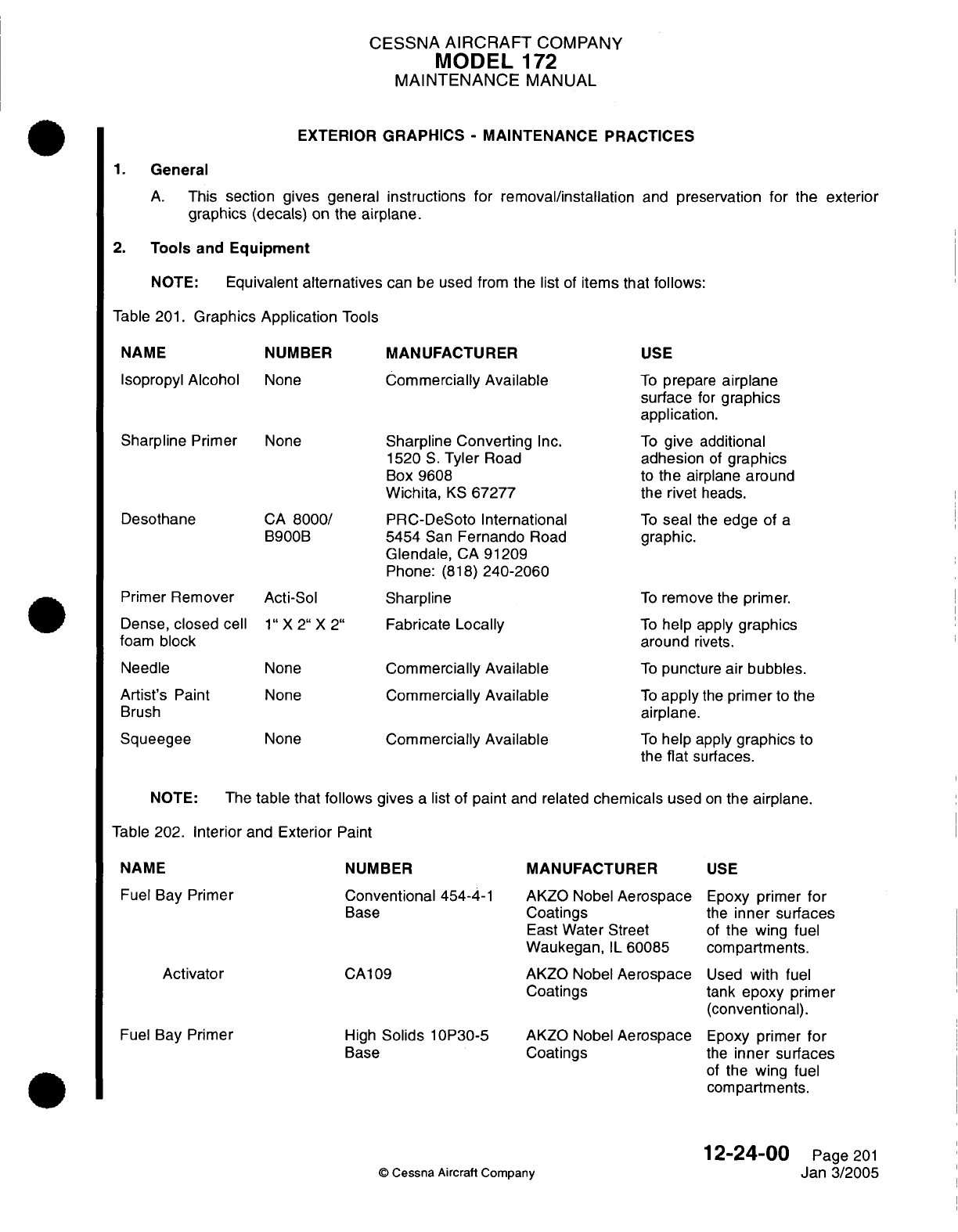
CESSNA
AIRCRAFT
COMPANY
MODEL
172
MAINTENANCE
MANUAL
EXTERIOR
GRAPHICS
-
MAINTENANCE PRACTICES
1.
General
A.
This
section
gives
general
instructions
for
removal/installation
and
preservation
for
the exterior
graphics
(decals)
on
the
airplane.
2.
Tools
and
Equipment
NOTE:
Equivalent
alternatives
can
be
used
from
the
list
of
items that
follows:
Table
201.
Graphics
Application
Tools
NAME
Isopropyl
Alcohol
Sharpline
Primer
Desothane
Primer
Remover
Dense,
closed
cell
foam
block
Needle
Artist's
Paint
Brush
Squeegee
NUMBER
None
None
CA
8000/
B900B
Acti-Sol
1"
X 2" X 2"
None
None
None
MANUFACTURER
Commercially
Available
Sharpline Converting
Inc.
1520
S.
Tyler
Road
Box
9608
Wichita,
KS
67277
PRC-DeSoto International
5454
San
Fernando
Road
Glendale,
CA
91209
Phone:
(818)
240-2060
Sharpline
Fabricate
Locally
Commercially
Available
Commercially
Available
Commercially
Available
USE
To
prepare
airplane
surface
for
graphics
application.
To
give
additional
adhesion
of
graphics
to
the
airplane
around
the
rivet
heads.
To
seal
the
edge of
a
graphic.
To
remove
the
primer.
To
help
apply
graphics
around
rivets.
To
puncture
air
bubbles.
To
apply
the
primer
to
the
airplane.
To
help
apply
graphics
to
the
flat
surfaces.
NOTE:
The
table
that
follows
gives
a
list
of
paint
and related
chemicals
used
on
the
airplane.
Table
202.
Interior
and
Exterior
Paint
NAME
Fuel
Bay
Primer
Activator
Fuel
Bay
Primer
NUMBER
Conventional
454-4-1
Base
CA109
High
Solids
10P30-5
Base
MANUFACTURER
AKZO
Nobel
Aerospace
Coatings
East
Water
Street
Waukegan,
IL
60085
AKZO
Nobel
Aerospace
Coatings
AKZO Nobel
Aerospace
Coatings
USE
Epoxy
primer
for
the
inner
surfaces
of
the
wing
fuel
compartments.
Used
with
fuel
tank
epoxy
primer
(conventional).
Epoxy
primer
for
the
inner surfaces
of
the
wing
fuel
compartments.
©
Cessna
Aircraft
Company
12-24-00
Page
201
Jan
3/2005
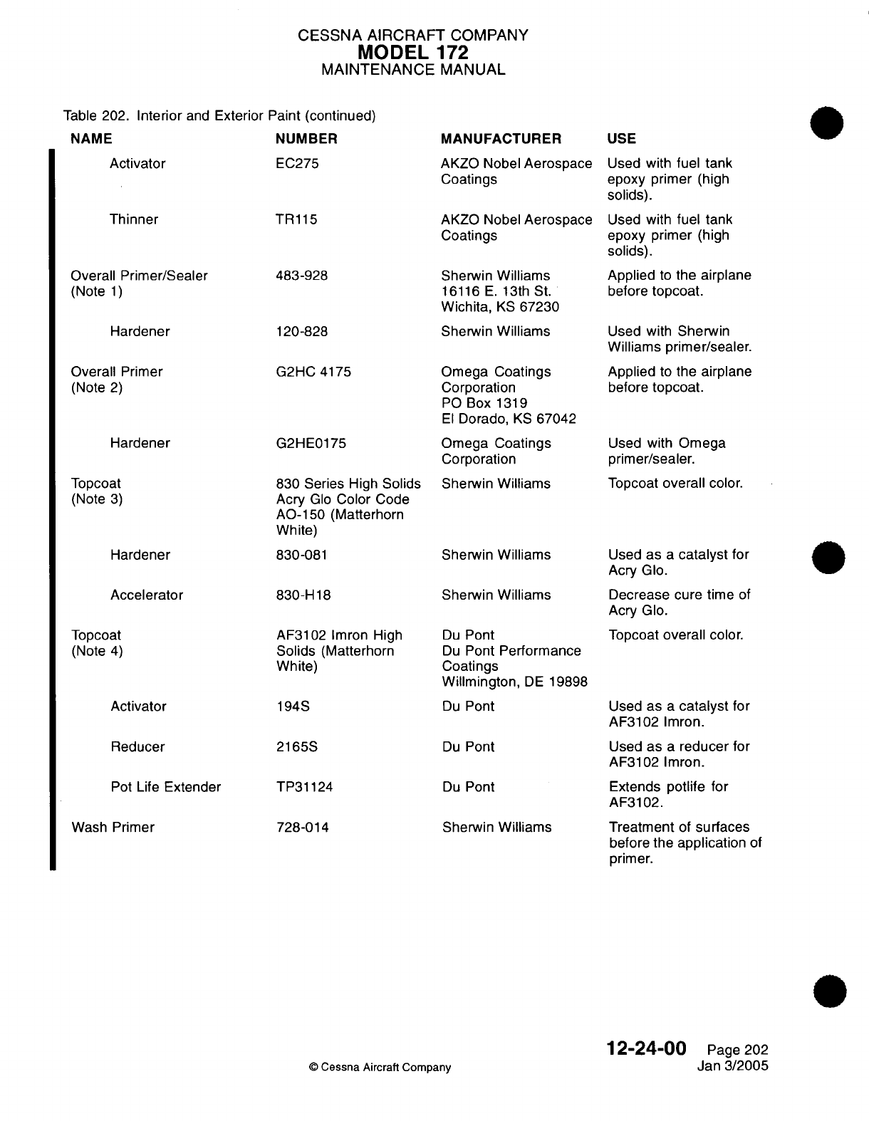
CESSNA
AIRCRAFT
COMPANY
MODEL
172
MAINTENANCE
MANUAL
Table
202.
Interior
and
Exterior
Paint (continued)
NAME NUMBER
Activator
EC275
Thinner
Overall
Primer/Sealer
(Note
1)
Hardener
Overall
Primer
(Note
2)
Hardener
Topcoat
(Note
3)
Hardener
Accelerator
Topcoat
(Note
4)
Activator
Reducer
Pot
Life
Extender
Wash
Primer
TR115
483-928
120-828
G2HC
4175
G2HE0175
830 Series
High
Solids
Acry
Glo
Color
Code
AO-150 (Matterhorn
White)
830-081
830-H
18
AF3102
Imron High
Solids
(Matterhorn
White)
194S
2165S
TP31124
728-014
MANUFACTURER
AKZO
Nobel
Aerospace
Coatings
AKZO
Nobel
Aerospace
Coatings
Sherwin
Williams
16116
E.
13th
St.
Wichita,
KS
67230
Sherwin
Williams
Omega
Coatings
Corporation
PO
Box
1319
El
Dorado,
KS
67042
Omega Coatings
Corporation
Sherwin
Williams
Sherwin
Williams
Sherwin
Williams
Du
Pont
Du
Pont
Performance
Coatings
Willmington,
DE
19898
Du
Pont
Du
Pont
Du
Pont
Sherwin
Williams
USE
Used
with
fuel
tank
epoxy
primer
(high
solids).
Used
with
fuel
tank
epoxy primer
(high
solids).
Applied
to
the
airplane
before
topcoat.
Used
with
Sherwin
Williams
primer/sealer.
Applied
to
the
airplane
before
topcoat.
Used
with Omega
primer/sealer.
Topcoat
overall
color.
Used
as
a
catalyst
for
Acry
Glo.
Decrease
cure
time
of
Acry
Glo.
Topcoat
overall
color.
Used
as
a
catalyst
for
AF3102
Imron.
Used
as
a
reducer
for
AF3102
Imron.
Extends
potlife
for
AF3102.
Treatment
of
surfaces
before
the
application
of
primer.
©
Cessna
Aircraft Company
12-24-00
Page
202
Jan 3/2005
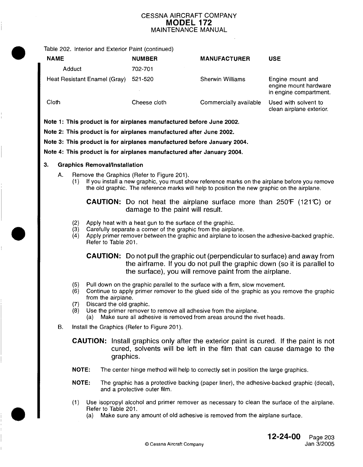
CESSNA
AIRCRAFT
COMPANY
MODEL
172
MAINTENANCE
MANUAL
Table
202.
Interior
and
Exterior
Paint
(continued)
NAME NUMBER
MANUFACTURER
USE
Adduct
702-701
Heat
Resistant
Enamel
(Gray)
521-520
Sherwin
Williams
Engine mount
and
engine
mount
hardware
in
engine compartment.
Cloth
Cheese
cloth
Commercially available
Used
with
solvent
to
clean
airplane
exterior.
Note
1:
This
product
is
for
airplanes
manufactured
before
June 2002.
Note
2:
This
product
is
for
airplanes
manufactured
after
June
2002.
Note
3:
This
product
is
for
airplanes
manufactured
before
January
2004.
Note 4:
This
product
is
for
airplanes
manufactured after
January
2004.
3.
Graphics Removal/Installation
A.
Remove the
Graphics
(Refer
to
Figure
201).
(1) If
you
install
a
new
graphic,
you
must show
reference
marks
on
the airplane
before
you
remove
the
old
graphic.
The
reference
marks
will help
to
position
the
new
graphic
on
the
airplane.
CAUTION:
Do
not
heat
the airplane
surface
more
than
250°F
(12°1C) or
damage
to
the paint
will
result.
(2)
Apply
heat
with
a
heat
gun to
the
surface
of
the
graphic.
(3)
Carefully
separate
a
corner
of
the
graphic
from
the
airplane.
(4)
Apply
primer remover
between
the
graphic
and
airplane
to loosen
the
adhesive-backed graphic.
Refer
to
Table
201.
CAUTION:
Do
not
pull
the graphic out
(perpendicularto
surface)
and
away
from
the
airframe.
If
you
do
not
pull
the graphic
clown
(so
It
Is
parallel
to
the
surface),
you
will
remove
paint
from
the
airplane.
(5)
Pull
down
on
the
graphic
parallel
to
the
surface
with
a
firm,
slow
movement.
(6)
Continue
to
apply
primer
remover
to the
glued
side of the
graphic
as
you
remove
the
graphic
from
the
airplane.
(7)
Discard
the
old graphic.
(8)
Use
the
primer
remover
to
remove
all
adhesive
from
the
airplane.
(a)
Make
sure
all
adhesive
is
removed
from
areas
around the
rivet
heads.
B.
Install
the
Graphics
(Refer
to
Figure
201).
CAUTION:
Install
graphics
only
after
the
exterior
paint
Is
cured.
If
the paint
Is
not
cured,
solvents
will
be left
In
the film
that
can
cause damage
to the
graphics.
NOTE:
The
center
hinge
method
will
help
to
correctly set
in
position
the
large
graphics.
NOTE:
The
graphic
has
a
protective backing
(paper
liner),
the
adhesive-backed
graphic (decal),
and
a
protective
outer
film.
(1)
Use
isopropyl
alcohol
and
primer
remover
as
necessary
to
clean
the
surface
of
the
airplane.
Refer
to
Table
201.
(a)
Make
sure any
amount
of
old
adhesive
is
removed
from
the airplane
surface.
12-24-00
Page
203
©
Cessna
Aircraft
Company
Jan
3/2005
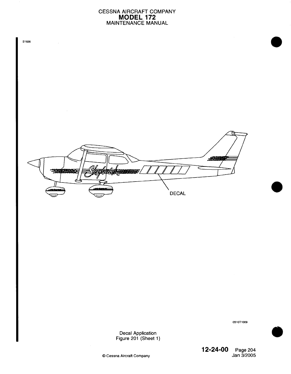
CESSNA
AIRCRAFT
COMPANY
MODEL
172
MAINTENANCE
MANUAL
B1656
/////7
DECAL
0510T1009
Decal
Application
Figure
201
(Sheet
1)
12-24-00
©
Cessna
Aircraft
Company
Page
204
Jan
3/2005
CESSNA
AIRCRAFT
COMPANY
MODEL
172
MAINTENANCE
MANUAL
(2)
Apply
Sharpline
Primer
on
and
around
each rivet
approximately
0.25
inch
(6.35
mm)
beyond
the
head
with
a
small
artist's
paint brush.
Let
the primer
dry
for
15
minutes
at
75°F
(24°C).
(3)
To
help
install
large
graphics,
use
reference
marks
from
the
old
graphic
and
set
the
new
graphic
in
position
with
a
piece
of
masking tape
installed
vertically
across
the
center
of
the
graphic.
NOTE:
The
use
of
the masking
tape set
vertically across
the
center of
the
graphic
is
known
as
the
center
hinge
method.
(4)
Remove
the
paper liner
from
the
back
of
the
new
graphic
to
show
the
adhesive.
For large
graphics
that
use
the
center
hinge
method, remove
one
half of
the
graphic paper liner.
(5)
Apply
the
graphic
to airplane.
(a)
Use
the
reference
marks from the
old
graphic
to
position
the new
graphic
on
the
airplane.
(b)
Use
a
squeegee
to
make
sure
that
no
wrinkles
or
bubbles
show
on
the
surfaces
of
the
airplane.
At
the
area
where the
graphic
overlays
on
rivets,
the
graphic
must
be
stretched
over
the rivet
heads
to
prevent
a
wrinkle
development.
(c)
The
graphic
must
adhere
to
the top
of
the
rivet
and
to
the
area
around the
airplane structure.
Air
that
has been
trapped around
the
base
of
the rivets will be
removed
in
a
later
step.
(6)
For large
graphics
that
use the
center
hinge
method, remove
the
second
half of
the
graphic
paper
lining.
(a)
Use
the
reference
marks
from
the
old
graphic
to
position
the
new
graphic
on
the
airplane.
(b)
Use
a
squeegee
to
make
sure
that
no
wrinkles or
bubbles show
on
the
surfaces of
airplane.
At
the
area
where the
graphic overlays
on rivets, the
graphic
must
be
stretched over
the
rivet
heads
to
prevent
a
wrinkle
development.
(c)
The
graphic
must
adhere to the top
of
the
rivet
and
to
the
surrounding airplane
structure.
Air
that
has
been
trapped around
the
base
of
the rivets
will be
removed
in a
later
step.
(7)
Remove
the
premask
(outer
protective
film)
from
the
graphic
when
it
has
been
fully
applied
to
the
airplane.
(a)
Use
Desothane
as
an
edge
sealer
to
minimize
graphic
delamination
and
peel
at
the
vinyl
leading
edges. Desothane must
also
be
used
to
promote graphic
adhesion
where rivets
are
0.25
inch
(6.35
mm)
from
the
vinyl
edges.
(8)
Remove
any
air
bubbles
from
rivets
in
the
steps
that follow.
(a)
Puncture the air
bubble
8
to
12
places
around the
rivet
with
a
small
needle.
(b)
Use a
heat
gun to
warm
the
graphic and
structure around
each
rivet
to
approximately
125°F
(52°C).
(c)
Use a
dense,
closed
cell
foam
block
(Temperfoam
or
equivalent to work
out
all
bubbles
from
around
the
rivet
head).
(9)
Use
a
needle
to
puncture
any
air
bubbles
from the
flat
areas
of
the
graphic.
(10)
Use
a
squeegee
to
smooth
the graphic.
(11)
When
all
bubbles
have
been
removed,
warm
the
full graphic
for
10
minutes
to
15
minutes
at
125°F
(52°C)
to
130°F
(54°C).
(12)
Remove
any
primer
with
primer
remover
after
the
surface
has
cooled
to
room
temperature.
(13)
Trim
the
graphics
to
be
flush
with
the
areas
of
termination such as
the
doors and cowl.
(14)
Adhesive
cure time
must
be
a
minimum
of
72
hours
and
recorded
in
the
maintenance
log.
4.
Exterior Graphics Preservation
A.
Clean
the
Exterior
Graphics.
NOTE:
The
procedures
that
follow
must
be
obeyed
to make
sure
of
the
maximum
service
life
for
the
graphic.
(1)
Wash
the
graphic
with soap
and
water.
(2)
Rinse
the
graphic after
you
wash
it.
(3) If
you
use
a
high
pressure
washer,
keep
the
nozzle
at
least
two
feet
from
the
edge
of
the
graphic.
(4)
Do
not
use
acetone,
methyl n-propyl
ketone,
toluene,
paint
thinner,
lacquer
thinner
or other
aromatic
solvents
to
clean
the
graphic.
(5)
Test
other cleaning
solutions
on a
small
corner
of
the
graphic
before
you
use
it.
(6)
Do
not
overcoat
the
graphic
with
clear
paint.
12-24-00
Page
205
©
Cessna Aircraft Company
Jan 3/2005
CESSNA
AIRCRAFT
COMPANY
MODEL
172
MAINTENANCE
MANUAL
not
let
fuel
spill
on
the
graphics.
Wipe off and flush
with
water
immediately
if
fuel
spills
on
the
graphics.
not
paint
over
the
graphics.
not
apply
wax
over
the
graphics.
12-24-00
Page
206
©
Cessna Aircraft
Company
Jan 3/2005
I
(7)
Do
(a)
(8)
Do
(9)
Do
CESSNA
AIRCRAFT
COMPANY
MODEL
172
MAINTENANCE
MANUAL
UNSCHEDULED
SERVICING
-
DESCRIPTION AND
OPERATION
1.
General
A.
This
section
gives procedures
and
recommendations
for
normally unscheduled
servicing.
B.
Instructions
are
given
in
the
Cold
Soak
procedures
for operation
of
the
airplane
during
very
cold
temperatures.
NOTE:
During
operation
at
outside
air
temperatures
below International Standard
Atmosphere
(ISA)
Standard,
the
engine
can
develop
more
than
its
rated
power
at
normal-rated
RPM.
This
occurs
more at
lower
altitudes.
2.
Extreme Weather
Maintenance
A.
Seacoast
and
Humid
areas.
(1) In
salt
water areas,
special
care
should
be
taken
to
keep engine,
accessories,
and
airframe
clean
to
help
prevent oxidation.
(2) In
humid
areas,
fuel
and
oil
should
be
checked frequently
and
drained
of
condensation
to
prevent
corrosion.
3.
Cold
Soak
cold soak.
If
the
airplane
has cold
soaked
for
more
than two
hours
at
temperatures colder
than
-10°C
(14°F),
refer
to
this
procedure
and
the
Pilot's
Operating
Handbook
and
FAA
Approved Airplane
Flight
Manual
to
prepare
the
airplane
for
flight.
(1)
Cold
temperatures
have
an
effect
on
control
cable
tension.
Refer to
Chapter 27,
Aileron
Control
System
-
Maintenance Practices, Elevator
Control
System
-
Maintenance
Practices,
Elevator
Trim
Control
-
Maintenance
Practices,
and
Flap
Control
System
-
Maintenance
Practices
for
flight control cable tensions.
(2)
For
information
on
lubrication and
greasing
of
moving
parts, refer to
Chapter
12,
Lubricants
-
Description
and
Operation.
(3)
Refer
to
the
Pilot's
Operating
Handbook
and
FAA
Approved
Airplane
Flight
Manual
for
the
correct
engine
oil
viscosity.
(4)
Refer
to
the
Pilot's
Operating
Handbook
and
FAA
Approved
Airplane
Flight
Manual
for
additional
information
on
procedures
for
operation
of
the
airplane
in
cold
temperatures.
B.
The
engine
must
be
preheated
before
an
engine start
when
exposed
to
very
cold temperatures.
Preheat
the
engine
as
follows:
(1)
Direct
warm
air
into the
engine
cooling
inlets
behind the
propeller.
CAUTION:
Do
not
use
air
with
a
temperature
of
more
than
120°C
(248°F)
when
you
preheat the
engine.
Air
with
a
temperature
of
more
than
120°C
(248°F)
can do
damage
to
the
exterior
paint
of
the
airplane.
(2)
Make
sure
that the
temperature
of the warm
air
is
no
more
than
120°C
(248°F).
WARNING:
Never
bring
open
flames
near
the
airplane.
Use
of
a
heater
with
an
open
flame
to
preheat the engine
can
cause
damage
to
the
airplane
and
injury
to
personnel.
(3)
Do
not
use
a
heater
with
open
flames
to
supply
the
warm
air to
preheat the
engine.
(4)
Preheat
the
engine
before
an
engine start
if
the
engine temperature
is
less
than
-6°C
(20°F).
12-30-00
Page
1
©
Cessna
Aircraft
Company
Jul
3/2006
CESSNA
AIRCRAFT
COMPANY
MODEL
172
MAINTENANCE
MANUAL
(5)
When
the
temperature
is
less
than
0°C
(32°F),
preheat
the
engine
to
more
than
0°C
(32°F)
before
you start
the
engine
again
after
an
engine
start
and
stop.
NOTE: When
the temperature
is
less
than
0°C (32°F),
water
from
combustion
can
freeze
to
the
engine
spark
plugs
if
the
engine
does
not
continue
to
operate
after
it is
started.
This
will prevent
the
engine
from
starting
again.
C.
The
Garmin
GDU
1040
PFD/MFD
requires
warm-up
time when
exposed
to
very
cold
temperatures.
(1) A
warm-up
time
of
up
to
30
minutes
is
necessary
when the
GDU
is
exposed
to
down
to
-40°C
(-40°F)
for
an
extended
period.
(2) A
warm-up
time
of
up
to
15
minutes
is
necessary
when the
GDU
is
exposed
to
down
to
-30°C
(-22°F)
for
an
extended
period.
D.
Before
takeoff,
preheat
the
airplane
cabin to
more
than
-30°C
(-22°F) for correct
operation
of the
standby
altimeter.
NOTE:
If
there
is
no
warning
that
an
instrument
is
not
operating
correctly,
all
other
instruments
will
operate
continuously
until
at
the
minimum
temperature
of the
airplane.
12-30-00
Page
2
©
Cessna
Aircraft
Company
Jul 3/2006
I

CHAPTER
STANDARD
PRACTICES
AIRFRAME
CESSNA
AIRCRAFT
COMPANY
MODEL
172
MAINTENANCE
MANUAL
LIST
OF
EFFECTIVE
PAGES
CHAPTER-SECTION-SUBJECT
20-Title
20-List
of
Effective
Pages
20-Record
of
Temporary
Revisions
20-Table
of
Contents
20-00-00
20-10-00
20-11-00
20-1
2-00
20-30-00
20-3
1-00
20-3
1-00
20-3
1-00
20-32-00
20-50-00
©
Cessna Aircraft
Company
PAGE
Page
1
Pages
1-4
Pages
201-206
Pages
201
-211
Page
1
Pages
1-3
Pages
201-204
Pages
701
-705
Pages
201
-218
Page
1
DATE
Apr
7/2003
Jun
7/2004
Janl1/2007
Jun
7/2004
Apr
7/2003
Apr
7/2003
Apr
7/2003
Apr
7/2003
Jul
3/2006
Apr
7/2003
20
-
LIST
OF
EFFECTIVE
PAGES
Page
1
of
1
Janl1/2007

Temporary
Revision
Number
RECORD
OF
TEMPORARY
REVISIONS
Page
Number
Issue
Date By
Date
Removed
By
CESSNA AIRCRAFT
COMPANY
MODEL
172
MAINTENANCE
MANUAL
CONTENTS
STANDARD
PRACTICES
AIRFRAME
-
GENERAL
.................
Scope....................................
Definition
..................................
MATERIAL
AND
TOOL
CAUTIONS
-
DESCRIPTION
AND
OPERATION........
Titanium...................................
Mercury...................................
Asbestos
..................................
Cadmium
Plated
Fasteners..........................
Maintenance
Precautions...........................
General
Usage
Solvents
...........................
National
Emissions
Standards
for
Hazardous
Air
Pollutants
...........
Facilities
and
Equipment
...........................
TORQUE
DATA
-
MAINTENANCE
PRACTICES...................
General...................................
Torque
Requirements
for
Bolts,
Screws
and
Nuts................
Torque
Requirements
for
Hi-Lok
Fasteners...................
Torque
Requirements
for
Electrical
Current Carrying
And
Airframe
Ground
Fasteners.................................
Torque
Requirements
for
Rigid
Tubing
and
Hoses................
SAFETYING
-
MAINTENANCE PRACTICES
....................
General...................................
Safety
Wire
.................................
Safety
Wire
Installation............................
Cotter
Pin
Installation.............................
Safetying
Turnbuckles
............................
SEALING
-
DESCRIPTION
AND
OPERATION....................
General...................................
ACCEPTABLE
REPLACEMENTS
FOR
CHEMICALS
AND
SOLVENTS
-
DESCRIPTION
AND OPERATION
................................
General...................................
Hand-Wipe
Cleaning
Operations
.......................
Priming
Operations..............................
Topcoat
Operations
.............................
Paint
Stripping
Operations
..........................
GENERAL SOLVENTS/CLEANERS
-
MAINTENANCE PRACTICES
.........
General...................................
Tools,
Equipment
and
Materials........................
Safety
Precautions..............................
Description
.................................
INTERIOR
AND
EXTERIOR
FINISH
-
CLEANING/PAINTING.............
General...................................
Interior
and
Exterior
Finishes
.........................
Paint
Facility.................................
Sanding
Surfacer
..............................
Paint
Stripping................................
Hand
Solvent
Cleaning............................
Maintenance
of
the
Interior
and
Exterior
Primary Coatings
and
Topcoat......
20-00-00
Page
1
20-00-00
Page
1
20-00-00
Page
1
20-10-00
Page
1
20-10-00
Page
1
20-10-00
Page
1
20-10-00
Page
1
20-10-00
Page
1
20-10-00
Page
1
20-1
0-00
Page
2
20-1
0-00
Page
3
20-10-00
Page
3
20-11
-00
Page
201
20-11
-00
Page
201
20-11
-00
Page
204
20-1
1-00
Page
204
20-11
-00
Page
205
20-11
-00
Page
206
20-12-00
Page
201
20-12-00
Page
201
20-12-00
Page
201
20-12-00
Page
202
20-12-00
Page
207
20-12-00
Page
207
20-30-00
Page
1
20-30-00
Page
1
20-31
-00
Page
1
20-3
1
-00
Page
1
20-31
-00
Page
1
20-31
-00
Page
1
20-3
1
-00 Page
2
20-31
-00
Page
3
20-31
-00
Page
201
20-31
-00
Page
201
20-31
-00
Page
201
20-31
-00
Page
201
20-31
-00
Page
201
20-3
1
-00
Page
701
20-31
-00
Page
701
20-31
-00
Page
701
20-31
-00
Page
701
20-31 -00
Page
701
20-31
-00
Page
702
20-31
-00 Page
705
20-31
-00
Page
705
20
-
CONTENTS
Page
1
of
2
Janl1/2007
©
Cessna
Aircraft
Company
CESSNA AIRCRAFT
COMPANY
MODEL
172,
MAINTENANCE
MANUAL
FUEL, WEATHER
AND
HIGH-TEMPERATURE
SEALING
-
MAINTENANCE
PRACTICES
...................................
General...................................
Tools and
Equipment.............................
Definition
of
Sealing
Terms
..........................
Materials
..................................
General
Requirements............................
Sealant
Curing................................
Mixing
of
Sealants..............................
Cleaning
..................................
Sealing
Application..............................
Sealant
Repair................................
CONVERSION
DATA
-
DESCRIPTION
AND
OPERATION
..............
General...................................
Conversion
Factors
.............................
20-32-00
Page
201
20-32-00
Page
201
20-32-00
Page
201
20-32-00
Page
204
20-32-00
Page
205
20-32-00
Page
206
20-32-00
Page
207
20-32-00
Page
208
20-32-00
Page
21
0
20-32-00
Page
211
20-32-00
Page
217
20-50-00
Page
1
20-50-00
Page
1
20-50-00
Page
1
20
-
CONTENTS
Page
2
of
2
Janl1/2007
©
Cessna
Aircraft Company
CESSNA
AIRCRAFT
COMPANY
MODEL
1
72
MAINTENANCE
MANUAL
STANDARD PRACTICES
AIRFRAME
-
GENERAL
1.
Scope
A.
This
Chapter describes standard
maintenance
practices
and
safety
precautions
applicable
to
all
aspects
of
the airframe
and
related
systems.
Maintenance
practices which
are
unique
to
a
particular
system
or
subject
are
described
in
the
appropriate
chapter
and
section
in
the
maintenance manual.
B.
For
repairs
beyond
the
scope
of
this
manual, refer
to the
1996
and
On
100
Series
Structural
Repair
Manual.
2.
Definition
A.
This
chapter
is
divided
into
sections
to
aid
maintenance personnel
in
locating information.
Consulting
the
Table of
Contents
will
further
assist
in
locating
a
particular subject.
A
brief
definition
of
the
subjects
and
sections
incorporated
in
this
chapter
is
as
follows.
(1)
The
section
on
Material
and
Tool
Cautions
describes
general
cautions
and
warnings
applicable
to
maintenance
on
or
around
the
airplane.
(2)
The
section
on
Torque
Data
provides
tables,
formulas, requirements
and
torque
limits
for
various
type
fasteners.
(3)
The
section
on
Safetying
describes
the
proper methods
and
use
of
safety
wire/lockwire, cotter
pins
and
lock
clip
installations.
(4)
The
section
on
Solvents
describes
characteristics
of
solvents
which
are
commonly
used
during
maintenance,
cleaning
and
inspection
of
various
airframe
and
related
components.
(5)
The
section
on
conversion
data provides
tables
for
converting
english
to
metric
measurements.
20-00-00
Page
1
©
Cessna
Aircraft
Company
Apr
7/2003
CESSNA AIRCRAFT
COMPANY
MODEL
1
72
MAINTENANCE
MANUAL
MATERIAL AND
TOOL
CAUTIONS
-
DESCRIPTION
AND OPERATION
1.
Titanium
CAUTION:
Do
not
use cadmium-plated
tools
on
titanium
parts.
Cadmium
particles
can
stay
on
such
parts. The
cadmium
particles
will
cause
an
unwanted
condition
with
the titanium
when
heated.
The
titanium
part
will become
brittle
In
the
area
of
the
unwanted
condition
and
make
cracks.
CAUTION:
Do
not
let
cadmium-plated
fasteners
touch
titanium
parts.
2.
Mercury
CAUTION:
Do
not
use
thermometers
and
other
mercury-based
test
equipment
on
the
airplane.
A.
Corrosion Caused
by Mercury.
(1)
There
is
no
known
procedure
to
stop
corrosion
when
it
has
started.
(2)
Mercury
can go
into
any crack
in
the finish,
paint,
or
seal layer
of
a
metal. An
oxide
layer
on
a
dry
metal
surface
will
prevent corrosion.
A
bright
surface,
a
polished
surface, or
a
surface with
scratches
will
increase
the
rate
of
corrosion.
(3)
Dirt,
grease,
or
other
contaminants
that
have
no
effect
on
the
metal
surfaces
will help prevent
corrosion.
(4)
The
corrosion
and
the
embrittlement caused
by
corrosion
can
be
very
fast
in
structural
members.
3.
Asbestos
WARNING:
Do
not
let
asbestos
fibers
make
entry
Into
the
body
of
personnel.
Asbestos
fibers
can
cause
Injury
or
death.
A.
Do
not
breathe
the
dust
of
asbestos
fibers.
To
not
breathe
the
dust
of
asbestos fibers,
use
either
of
the
methods
that
follows.
(1)
Use
engineering
control,
which
includes
work
in a
correctly
filtered
exhaust
chamber.
Use
wet
procedures
to
keep
personnel exposure
limits
less than
those
recommended
by
the
Occupational
Safety
Health
Administration
(OSHA).
(2)
Use
breathing
equipment
with
high
quality
filters. Other protection
must
include
protective
clothing,
gloves
and
eye
protection.
B.
Refer
to
all
local,
state,
and
federal regulations
to
discard asbestos
material.
4.
Cadmium
Plated Fasteners
CAUTION:
Put
a
complete
layer
of
fuel
sealant
on
cadmium-plated
fasteners
that
are
used
In
fuel
areas.
Cadmium
particles
from
cadmium-plated
fasteners
can
cause
damage
to
the
engine.
5.
Maintenance
Precautions
WARNING:
Obey
the precautions during
maintenance,
repair, and
service
procedures
of
the
airplane
to
prevent
the
risk
of
Injury because
of
the
different
materials
and
environmental
conditions.
A.
Carefully
read and
follow
all
instructions.
(1)
Obey
all
cautions
and
warnings
given
by
the
manufacturer
of
the
product
that
is
used.
(a)
Use
the
applicable
safety
equipment such
as
goggles,
face
shields, breathing equipment,
protective
clothing
and
gloves.
(2)
Do
not
get
dangerous
chemicals
in
the
eyes
or
on
the skin.
20-1
0-00
Page
1
©
Cessna Aircraft
Company
Jun
7/2004
CESSNA
AIRCRAFT
COMPANY
MODEL
172
MAINTENANCE
MANUAL
(3)
Do
not
breathe the
fumes
of
dangerous
chemicals.
(4)
Make
sure
the
work
area
has
good
airflow
and
the
applicable
breathing
equipment
is
used
when
composites
or
metals
are
sanded
or
work
is
done
in
an
area
where
small
particles
can be
made.
6.
General Usage
Solvents
A.
Airplane
maintenance
procedures
frequently
use
solvents.
A
solvent
is
a
material,
usually
a
liquid,
that
can
break down
another
material.
Solvents usually
have
no
color,
dry
quickly,
and give
off
fumes
in
high
quantities.
Examples
of
general
use
solvents
are as
follows:
·
Methyl
n-Propyl
Ketone
Toluene
·
Isopropyl Alcohol
Acetone
·
Methylene
Chloride
1,1,1
-
Trichlorethane
·
Naptha
ASTM
D4080
B.
Solvents
can
cause
injury or death.
Solvents usually
have
no
color,
dry
quickly,
and
give off
fumes in
high
quantities.
The
fumes
are
usually
heavier
than
air. The fumes
can
collect
in
low-level
areas
and
push
air
out of
the areas
that
are
not
ventilated.
This
can remove
the
supply
of
oxygen
from
the
area.
(1)
The
solvent
fumes
are
usually heavier
than
air.
(2)
The
solvent
fumes
can
be
breathed.
Use
applicable
breathing
equipment.
(3)
Solvents
can
cause
damage
to
the hands
and
the
skin.
(a)
Solvents
dry out
the
skin
and
remove
the natural oils.
Damaged
skin
can
cause
other
contamination
to
make
the condition
worse.
(b)
The
contamination
has
easier
access
to
the lowest
levels
of the
skin.
1
The
human
body
can
filter
small
amounts
of
solvents
out
of
itself.
This
filtration
function takes
place
in
the
liver.
The
liver
receives
blood
which
can
be
contaminated
with
solvents
from
both
the
lungs and
the
skin.
If
the
quantities
are
low
enough
and
not
too
frequent,
the
liver
can
filter
out
the contaminants.
This
is
one
of the
scientific
facts
on
which
OSHA
based
its
Permissible
Exposure Limits.
However,
when
exposures
are
constantly
above these levels
and
extend
for
many years,
the
filter
(liver)
becomes
clogged
and the
solvents
can
then
have
an
unwanted effect
on
other
parts/portions
of the
body.
C.
Solvents
are
hazardous materials because
of
flammability.
The
rate
of
evaporation
is
related
to
flammability.
The
fumes
are
usually
needed to
ignite
the
liquid. Any ignition
source
can
ignite
solvent
fumes. The
low
flash
point
of the
solvent
shows
that
the
solvent
can ignite
easily.
Usually
the flash
points
of
less
than
100°F
(37.8°C)
are
thought
to
be
flammable.
Examples
of
solvent
flash
points
are
as
follows:
SOLVENT
FLASH
POINT
Methyl
n-Propyl
45°F
(7.2°C)
Ketone
Toluene
39°F
(3.9°C)
Isopropyl
Alcohol
53.6°F
(12°C)
Acetone
1.4°F
(-17°C)
D.
Solvents
can
be
explosive
when mixed with
chemicals
that
release
oxygen
(oxidizer).
For
this
reason,
it
is
very important
for
personnel
to
know
which
chemicals
are
in
use
in
the
work
area
to
avoid
accidental
mixture
of
solvents
and
oxidizers.
(1)
Know
the
container
labels.
(a)
Chemical manufacturers
are
required
to
put
a
label
with
a
diamond-shaped
symbol
on
each
container.
1
The
red
symbol
on
the
label
shows
that
the
contents
are
flammable.
2
The yellow symbol
on the
label
shows that
the
contents
are
oxidizers.
20-10-00
Page
2
©
Cessna
Aircraft
Company
Jun
7/2004
CESSNA
AIRCRAFT
COMPANY
MODEL
172
MAINTENANCE
MANUAL
7.
National
Emissions Standards
for
Hazardous
Air
Pollutants
A.
National
Emissions Standards for Hazardous
Air
Pollutants
(NESHAP).
(1)
The
NESHAP
standards
have
put
a
limit
on
the
use
of
certain
chemicals
and
solvents.
(2)
For
complete details
of
the
regulatory standards,
see
the
Federal
Register,
40
CFR
Part
63,
[Ad-FRL-5636-1],
RIN
2060-AG65.
B.
NESHAP
Requirements.
(1)
Hand-Wipe
Cleaning.
(a)
All
hazardous
air
pollutants
or
organic compounds
that release dangerous
fumes that
are
used
as
hand
wipe cleaning
solvents
must meet
a
composition
requirement
and
have
a
vapor
pressure
less than
or equal
to
1.75
Hg
at
69°(45
mm
Hg
at
20°C.)
(b)
The
requirements
specified
can
be
met by
an
alternative compliance
plan
used
by
the
applicable authority
and
approved
under
Section
112(1)
of
the
Clean
Air
Act.
(2)
Primer
Application.
(a)
The
organic hazardous
air
pollutant content
is
limited to 350
g/l
(2.9
pounds-per-gallon),
less
water,
as
applied.
(b)
The
volatile organic
compound
limit
is
350
g/l
(2.9
pounds-per-gallon),
less
water,
as
applied.
(c)
Use
coatings
below
the
content
limit
or
use
monthly volume-weighted
averaging
to
get
the
content
limits
to
meet
content
limits.
(3)
Topcoat
Application.
(a)
The
base
coat
organic
hazardous
air
pollutant content
must
be
less than
420
g/l
(3.5
pounds-per-gallon),
less
water,
as
applied.
(b)
The
volatile
organic compound
limit
is
420
g/l
(3.5
pounds
per
gallon), less
water,
as
applied.
(c)
The
topcoats
must
meet the
requirements
of
MIL-PRF-85285D.
(d)
Stripe
paint
requirements
are
the
same
as
the base coat
requirements.
If
the
recommended
supplier
cannot
be
used, then
use
base
coat materials
to
paint
stripes.
NOTE:
All
paints
and
primers must have
specific
application
techniques.
If
an
alternative
is
supplied,
use
only the materials
that
are
less
than
or
equal
in
emissions,
to
less
than
the
HVLP
or
electrostatic
spray
application
techniques.
NOTE:
Operate
all
application
equipment
according
to
the
manufacturer's
specifications,
company procedures
or
locally
specified
operating
procedures.
(4)
Paint
Removal
(a)
Paint
removal
operations apply
to
the
outer
surface
of
the
airplane
and do
not apply
to
parts
or
units
normally
removed. Fuselage,
wings
and
stabilizers
are
covered.
Parts
that
are
normally
removed
are
exempt
from
the
requirements
that
follow:
1
No
organic
hazardous
air
pollutants
are
to
come
from
chemical
strippers or
softeners.
2
Inorganic hazardous air
pollutant fumes
must
be
kept
to
a
minimum
during
periods
of
non-chemical
based
equipment malfunctions.
3
The
use
of
organic
hazardous
air
pollutant
material
for
spot
stripping
and
decal
removal
is
kept
to
a
minimum
of
190
pounds
per
airplane
per
year.
(b)
Operating requirements
for
paint
removal
operations
that
give
airborne inorganic
hazardous
air
pollutants include
control with
particulate filters
or
water wash
systems.
(c)
Mechanical
and
hand
sanding
are
exempt
from
these requirements.
8.
Facilities
and
Equipment
A.
Facilities
(1) A
system
must
be
supplied
to
collect
processing waters
to
treat
or remove
chromium
and
pH.
(2)
Facilities
must
have
proper safety
equipment.
B.
Equipment
(1)
Applied
spray
of
cleaning solvents,
paint removers
or
color chemical
film
treatment
solutions
is
to
be
prevented unless
all
requirements
of
NESHAP
are
met.
20-10-00
Page
3
© Cessna Aircraft Company
Jun
7/2004
©
Cessna
Aircraft
Company
CESSNA
AIRCRAFT
COMPANY
MODEL
172
MAINTENANCE
MANUAL
(2)
Spraying equipment
to
wash
the
airplane
with
alkaline
cleaner
can
be
used.
This
equipment
is
sufficient
to
spray
deoxidizer,
chemical
film
solutions
and
rinse
water.
(3) A
high
pressure washer
is
recommended,
with
or
without
hot
water.
(4)
Respirators and/or
dust masks
must
be
used.
20-10-00
Page
4
©
Cessna
Aircraft
Company
Jun
7/2004
I
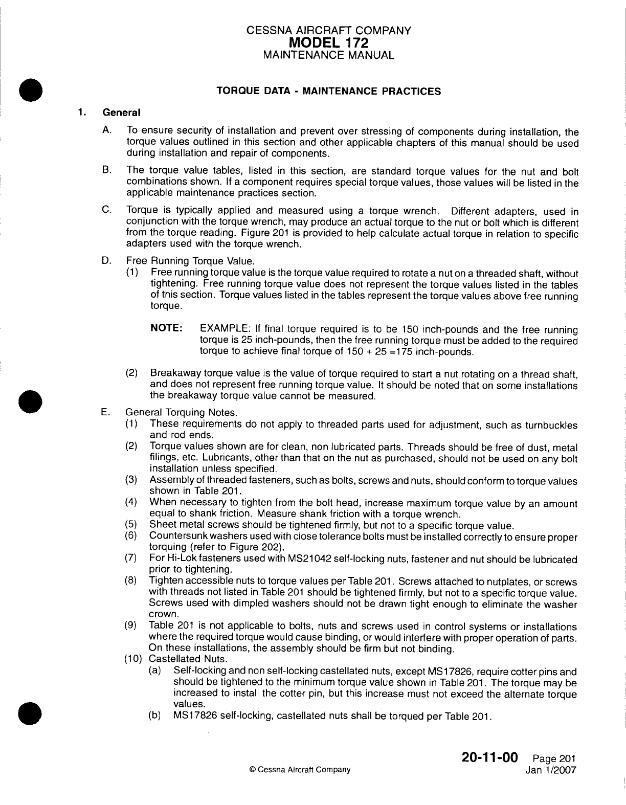
CESSNA
AIRCRAFT
COMPANY
MODEL
172
MAINTENANCE
MANUAL
TORQUE
DATA
-
MAINTENANCE PRACTICES
General
A.
To
ensure
security
of
installation
and
prevent over
stressing
of
components
during
installation,
the
torque
values
outlined
in
this section
and
other
applicable chapters
of
this
manual
should
be
used
during installation
and
repair
of
components.
B.
The
torque
value
tables,
listed
in
this section,
are
standard
torque values
for
the
nut
and
bolt
combinations
shown.
If a
component
requires
special torque
values,
those
values
will be
listed
in
the
applicable
maintenance
practices section.
C.
Torque
is
typically
applied
and
measured
using
a
torque
wrench.
Different
adapters,
used
in
conjunction
with the
torque
wrench,
may
produce
an
actual
torque
to the nut
or
bolt
which
is
different
from
the
torque
reading. Figure
201
is
provided
to
help
calculate
actual
torque
in
relation
to
specific
adapters
used
with
the
torque wrench.
D.
Free
Running
Torque Value.
(1)
Free
running
torque
value
is
the
torque
value
required
to
rotate
a
nut
on
a
threaded shaft,
without
tightening.
Free
running
torque
value does
not
represent
the
torque
values
listed
in
the
tables
of
this
section.
Torque
values
listed
in
the
tables represent
the
torque
values
above
free running
torque.
NOTE:
EXAMPLE:
If
final
torque required
is
to
be
150
inch-pounds
and the
free
running
torque
is
25
inch-pounds,
then
the
free running
torque
must be
added
to
the
required
torque
to
achieve
final
torque
of 150
+
25
=1
75
inch-pounds.
(2)
Breakaway
torque
value
is
the
value
of
torque required
to
start
a
nut
rotating
on
a
thread
shaft,
and
does
not
represent
free
running
torque value.
It
should
be
noted
that
on
some
installations
the
breakaway torque
value cannot
be
measured.
E.
General
Torquing
Notes.
(1)
These
requirements
do
not
apply
to
threaded
parts
used
for
adjustment,
such
as
turnbuckles
and
rod
ends.
(2)
Torque
values
shown
are
for
clean,
non
lubricated
parts.
Threads
should
be
free
of
dust,
metal
filings,
etc.
Lubricants,
other
than
that
on
the nut
as
purchased,
should
not
be
used
on
any
bolt
installation
unless
specified.
(3)
Assembly
of
threaded fasteners,
such
as
bolts,
screws
and
nuts,
should
conform
to
torque
values
shown
in
Table
201.
(4)
When
necessary
to
tighten
from
the
bolt
head,
increase
maximum
torque
value
by
an
amount
equal
to
shank friction.
Measure
shank
friction
with
a
torque
wrench.
(5)
Sheet
metal
screws should
be
tightened
firmly,
but
not
to
a
specific
torque
value.
(6)
Countersunk
washers
used
with
close
tolerance
bolts
must
be
installed
correctly
to
ensure
proper
torquing
(refer
to
Figure 202).
(7)
For
Hi-Lok
fasteners
used
with
MS21
042
self-locking
nuts,
fastener
and nut
should
be
lubricated
prior
to
tightening.
(8)
Tighten
accessible
nuts
to
torque
values
per Table
201.
Screws
attached
to
nutplates,
or
screws
with threads
not
listed
in
Table
201
should
be
tightened
firmly,
but
not
to
a
specific
torque
value.
Screws
used
with
dimpled washers should
not
be
drawn
tight
enough
to
eliminate
the
washer
crown.
(9)
Table
201
is
not
applicable
to
bolts,
nuts
and
screws
used
in
control
systems
or
installations
where
the required torque would cause binding,
or
would
interfere
with
proper
operation
of
parts.
On
these
installations,
the
assembly
should
be firm
but
not
binding.
(1 0)
Castellated
Nuts.
(a)
Self-locking
and
non
self-locking
castellated
nuts,
except
MS1
7826,
require
cotter
pins
and
should
be
tightened
to
the
minimum torque
value
shown
in
Table
201.
The
torque
may
be
increased
to
install
the
cotter
pin,
but
this
increase
must
not
exceed
the
alternate
torque
values.
(b)
M51 7826
self-locking,
castellated
nuts
shall
be
torqued
per
Table
201.
20-1
1-00
Page
201
©
Cessna
Aircraft
Company
Janl1/2007
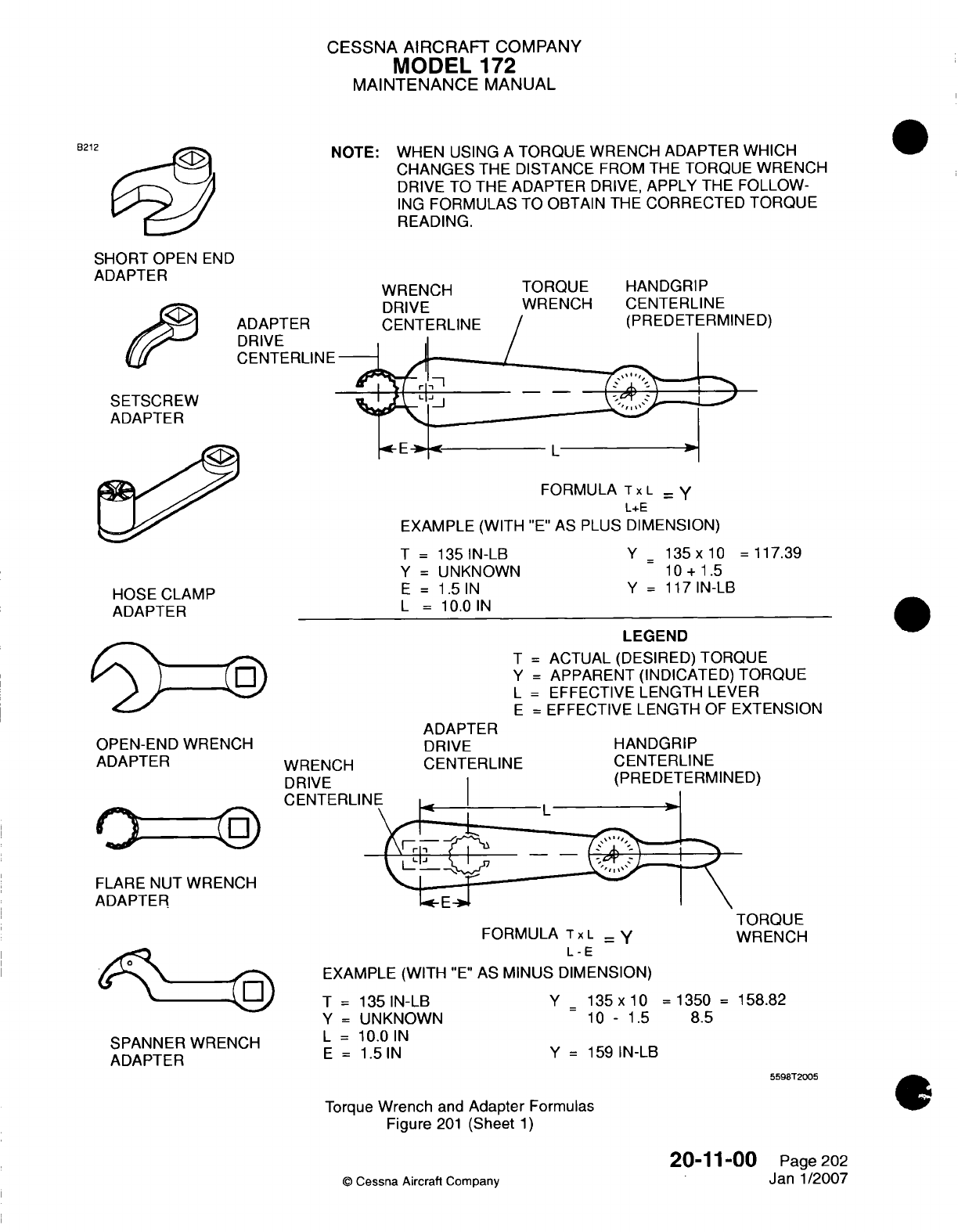
CESSNA
AIRCRAFT
COMPANY
MODEL
172
MAINTENANCE
MANUAL
NOTE:
WHEN
USING
A
TORQUE WRENCH ADAPTER
WHICH
CHANGES
THE
DISTANCE
FROM THE
TORQUE WRENCH
DRIVE
TO THE
ADAPTER
DRIVE,
APPLY
THE
FOLLOW-
ING
FORMULAS
TO
OBTAIN THE
CORRECTED
TORQUE
READING.
B212
SHORT
OPEN
END
ADAPTER
ADAPTER
DRIVE
CENTERLINE
WRENCH
DRIVE
TORQUE
HANDGRIP
WRENCH
CENTERLINE
SETSCREW
ADAPTER
FORMULA
Tx
L
- Y
L+E
EXAMPLE
(WITH
"E"
AS
PLUS
DIMENSION)
T
=
135
IN-LB
Y
=
UNKNOWN
E
=
1.5
IN
L
=
10.0
IN
HOSE
CLAMP
ADAPTER
Y_
135x10
=117.39
10
+
1.5
Y
=
117
IN-LB
OPEN-END
WRENCH
ADAPTER
FLARE
NUT
WRENCH
ADAPTER
SPANNER
WRENCH
ADAPTER
WRENCH
DRIVE
CENTERLI
ADAPTER
DRIVE
CENTERLINE
LEGEND
T
=
ACTUAL
(DESIRED)
TORQUE
Y
=
APPARENT
(INDICATED)
TORQUE
L
=
EFFECTIVE
LENGTH
LEVER
E
=
EFFECTIVE
LENGTH
OF
EXTENSION
HANDGRIP
CENTERLINE
FORMULA
Tx
L=
L-
E
EXAMPLE
(WITH
"E"
AS
MINUS
DIMENSION)
T
=
135
IN-LB
Y
=
UNKNOWN
L
=
1
0.0
IN
E
=
1.5
IN
TORQUE
WRENCH
Y_
135
x
10
=
1350
=
158.82
10
-
1.5
8.5
Y
=
159
IN-LB
5598T2005
Torque
Wrench
and
Adapter
Formulas
Figure
201
(Sheet
1)
0Cessna
Aircraft
Company
20-1
1-00
Page 202
Jan
1/2007
D)
jg)
6_1
U)
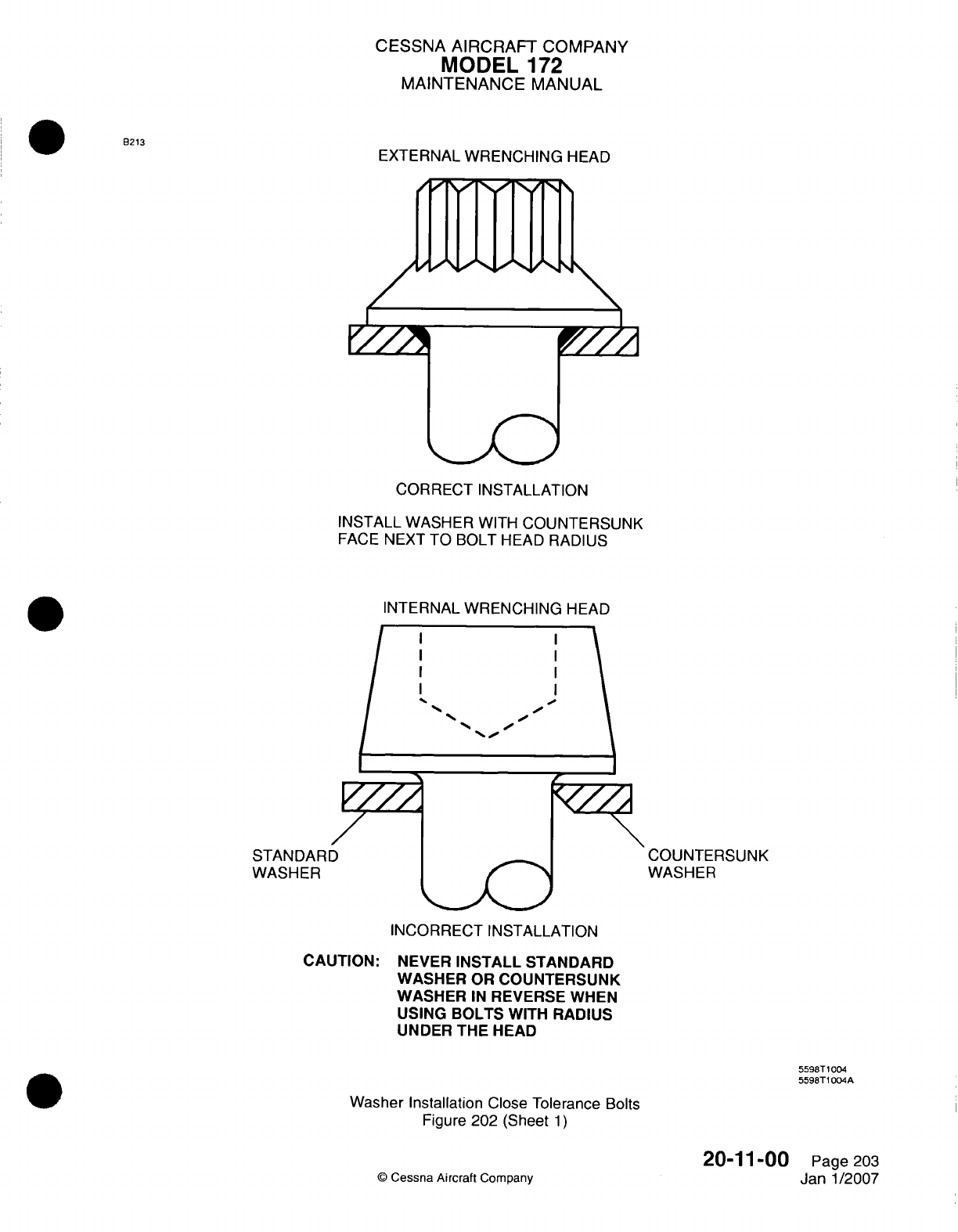
CESSNA AIRCRAFT
COMPANY
MODEL
172
MAINTENANCE
MANUAL
EXTERNAL
WRENCHING
HEAD
CORRECT INSTALLATION
INSTALL
WASHER
WITH
COUNTERSUNK
FACE
NEXT
TO
BOLT
HEAD
RADIUS
INTERNAL WRENCHING
HEAD
COUNTERSUNK
WASHER
INCORRECT INSTALLATION
CAUTION:
NEVER
INSTALL
STANDARD
WASHER
OR
COUNTERSUNK
WASHER
IN
REVERSE
WHEN
USING
BOLTS
WITH
RADIUS
UNDER THE
HEAD
5598T
1004
5598T1 004A
Washer Installation
Close
Tolerance
Bolts
Figure
202 (Sheet
1)
0
Cessna
Aircraft
Company
20-11-00
Page
203
Janl1/2007
93213
STAN
DAR
I
WASHER
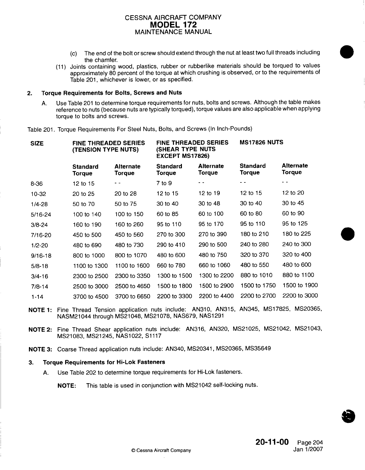
CESSNA
AIRCRAFT
COMPANY
MODEL
172
MAINTENANCE
MANUAL
(c)
The
end
of
the
bolt
or screw
should
extend through
the
nut
at
least
two
full
threads
including
the
chamfer.
(11)
Joints containing
wood,
plastics,
rubber
or
rubberlike
materials
should
be
torqued
to
values
approximately
80
percent
of
the
torque
at
which
crushing
is
observed,
or
to
the
requirements
of
Table
201,
whichever
is
lower,
or
as
specified.
2.
Torque
Requirements
for
Bolts,
Screws
and
Nuts
A.
Use
Table
201
to
determine
torque requirements for
nuts,
bolts
and
screws.
Although
the
table
makes
reference
to nuts
(because
nuts
are
typically
torqued),
torque
values
are
also
applicable
when
applying
torque
to
bolts and screws.
Table
201.
Torque
Requirements
For Steel
Nuts, Bolts,
and
Screws
(in
Inch-Pounds)
FINE
THREADED
SERIES
(TENSION
TYPE
NUTS)
FINE
THREADED
SERIES
(SHEAR TYPE
NUTS
EXCEPT
IVS1
7826)
Standard
Torque
12
to
15
20
to
25
50
to
70
1
00
to 140
160
to 190
450
to
500
480
to
690
800
to
1
000
1
100
to
1300
2300
to
2500
2500
to
3000
3700
to
4500
Alternate
Standard
Torque Torque
--
~~7
to
9
20
to
28
12
to
15
50
to
75 30
to
40
lO00tolSO0
60 to
85
160
to 260
95
to
110
450
to
560 270
to
300
480
to
730
290
to41
0
800
to
1070 480
to
600
llO
00tol1600
660
to
780
2300
to
3350
1300
to
1500
2500
to
4650
1500
to
1800
3700
to
6650
2200
to
3300
Alternate
Standard
Torque
Torque
12
to
19
30
to
48
60
to
100
95
to
170
270
to
390
290
to
500
480
to
750
660
to 1060
1300 to
2200
1500 to
2900
2200
to
4400
12
to
15
30
to
40
60
to
80
95 to
110
180 to
210
240
to
280
320
to
370
480
to
550
880
to
1
01
0
1500
to
1750
2200
to 2700
Alternate
Torque
12
to
20
30
to
45
60
to
90
95
to
125
180
to
225
240
to 300
320
to 400
480
to
600
880
to
1
100
1500
to 1900
2200
to
3000
NOTE
1:
Fine
Thread Tension
application
nuts
include:
AN310,
AN315,
NASM21044 through
MS211048,
MS21
078,
NAS679,
NASi
291
AN345,
MS17825, MS20365,
NOTE
2:
Fine
Thread
Shear
application
nuts
include:
AN316,
AN320, MS21025, MS21042, MS21043,
MS21083, MS21245, NAS1022,
S1117
NOTE
3:
Coarse
Thread
application
nuts
include:
AN340,
MS20341,
MS20365,
MS35649
3.
Torque
Requirements
for
Hi-Lolk Fasteners
A. Use
Table 202
to
determine
torque
requirements
for
Hi-Lok
fasteners.
NOTE:
This table
is
used
in
conjunction
with
MS21042
self-locking
nuts.
20-1
1-00
Page 204
©
Cessna
Aircraft
Company
Janl1/2007
SIZE
MS17826
NUTS
8-36
10-32
1/4-28
5/16-24
3/8-24
7/16-20
1/2-20
9/16-18
5/8-18
3/4-16
7/8-14
1-14
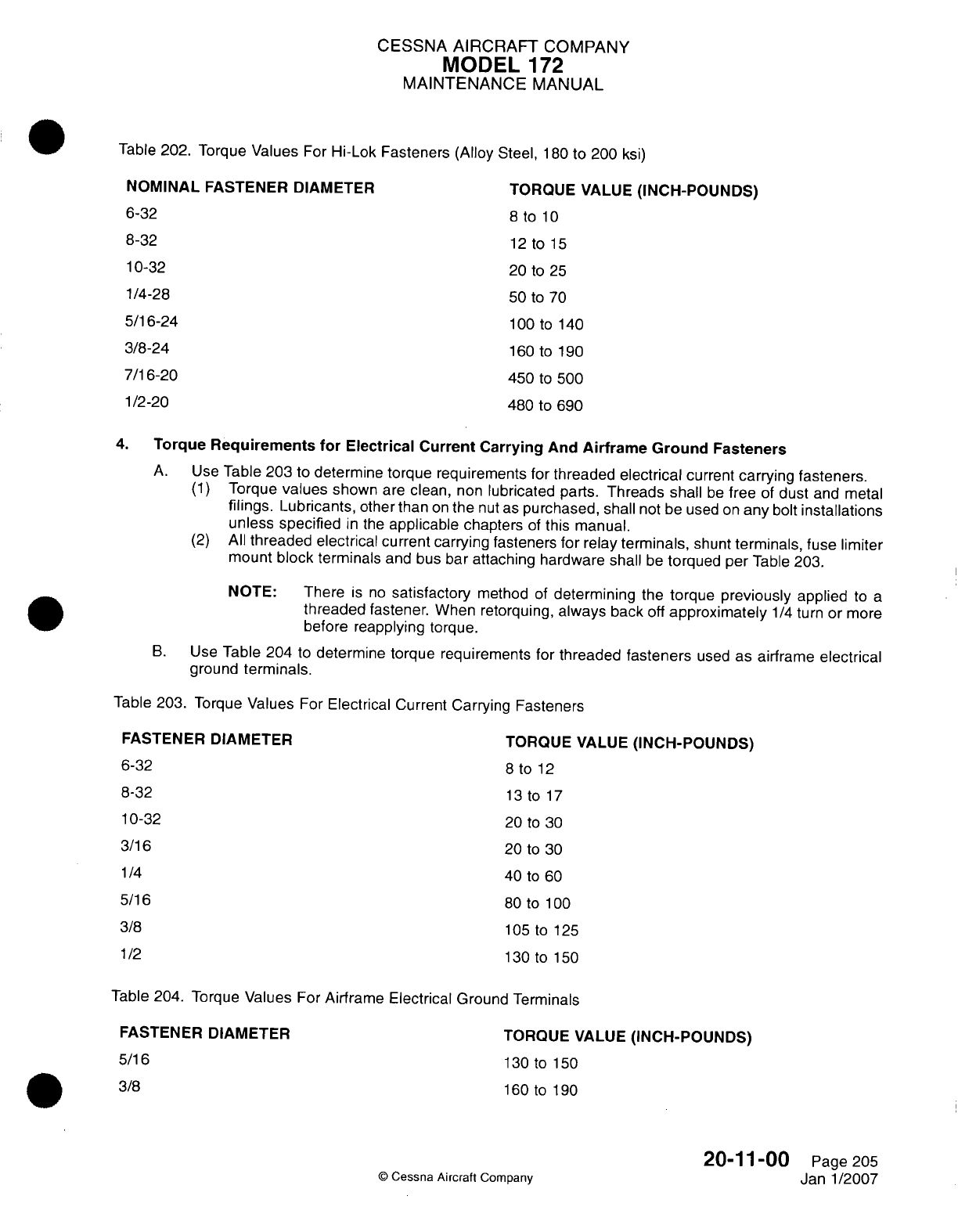
CESSNA
AIRCRAFT
COMPANY
MODEL
172
MAINTENANCE
MANUAL
Table
202.
Torque
Values
For
Hi-Lok Fasteners (Alloy
Steel,
180
to
200
ksi)
NOMINAL
FASTENER DIAMETER
6-32
8-32
10-32
1/4-28
5/16-24
3/8-24
7/16-20
1/2-20
TORQUE
VALUE
(INCH-POUNDS)
8
to
10
12 to
15
20
to
25
50
to
70
100 to
140
160 to 190
450
to
500
480
to
690
4.
Torque
Requirements
for
Electrical
Current Carrying
And
Airframe Ground
Fasteners
A.
Use
Table
203
to
determine
torque
requirements for
threaded
electrical
current
carrying fasteners.
(1)
Torque
values
shown
are
clean,
non
lubricated
parts.
Threads
shall
be
free
of
dust
and
metal
filings.
Lubricants,
other
than
on
the
nut
as
purchased,
shall
not
be
used
on
any
bolt
installations
unless specified
in
the
applicable
chapters
of
this
manual.
(2)
All
threaded electrical current
carrying fasteners
for
relay
terminals,
shunt
terminals,
fuse
limiter
mount
block
terminals
and
bus bar
attaching hardware
shall
be
torqued
per
Table
203.
NOTE:
There
is
no
satisfactory
method
of
determining
the
torque
previously
applied
to
a
threaded
fastener.
When
retorquing,
always
back
off
approximately
1/4
turn or more
before reapplying torque.
B.
Use
Table 204
to
determine
torque
requirements
for
threaded
fasteners
used
as
airframe
electrical
ground
terminals.
Table
203.
Torque
Values
For
Electrical
Current
Carrying
Fasteners
FASTENER
DIAMETER
6-32
8-32
10-32
3/16
1/4
TORQUE
VALUE
(INCH-POUNDS)
8
to
12
13
to
17
20
to
30
20
to
30
40
to
60
80
to
1 00
105
to 125
130 to
1590
5/16
3/8
11/2
Table
204.
Torque
Values
For
Airframe Electrical Ground
Terminals
FASTENER DIAMETER
5/16
3/8
TORQUE
VALUE
(INCH-POUNDS)
130
to
150
160
to
190
©
Cessna
Aircraft
Company
20-11-00
Page
205
Janl1/2007
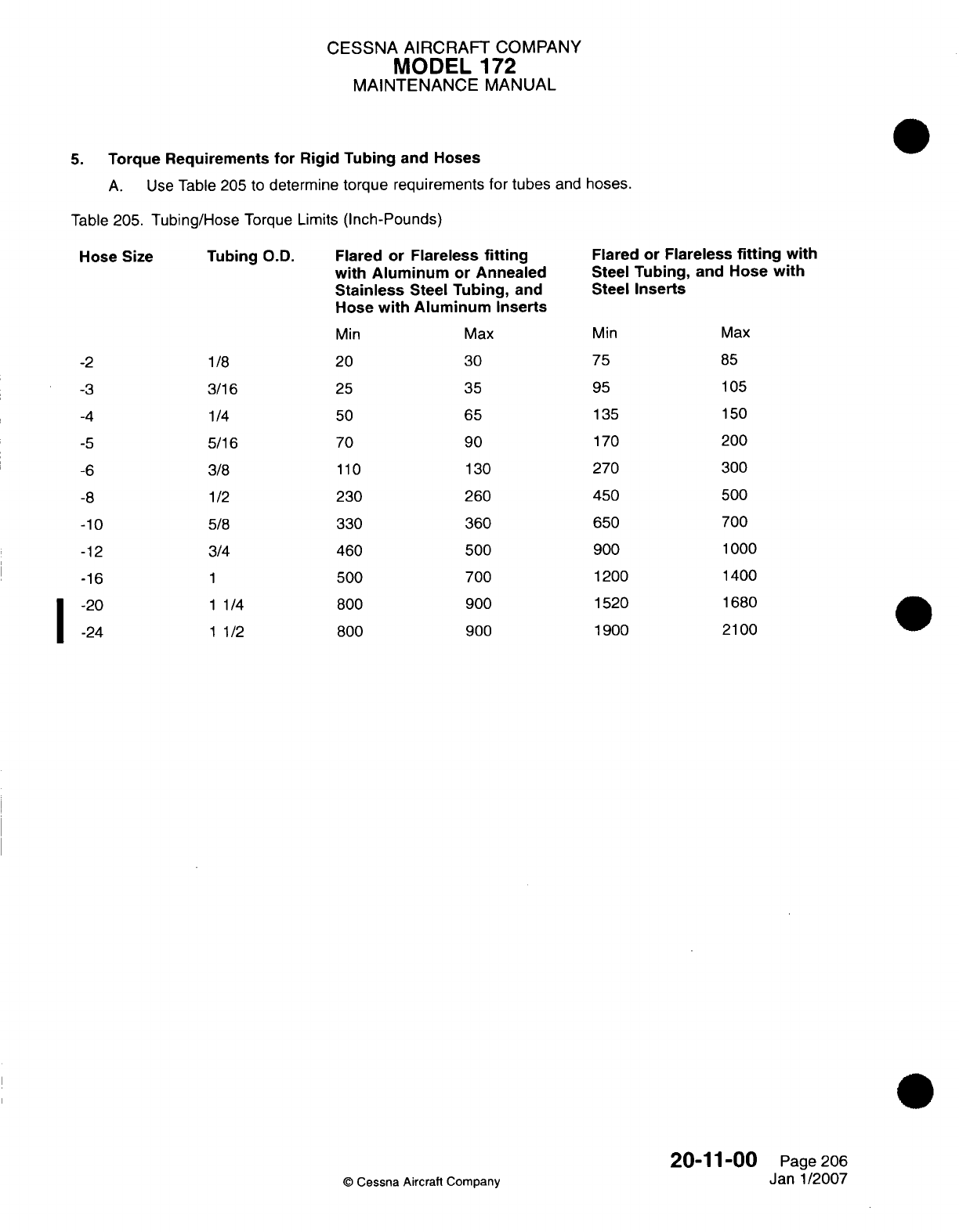
CESSNA AIRCRAFT
COMPANY
MODEL
172
MAINTENANCE
MANUAL
5.
Torque
Requirements for
Rigid
Tubing
and
Hoses
A.
Use
Table
205
to
determine
torque
requirements
for
tubes
and
hoses.
Table
205.
Tubing/Hose
Torque
Limits
(Inch-Pounds)
Tubing
O.D.
1/8
3/16
1/4
5/16
3/8
1/2
5/8
3/4
1
1 1/4
1 1/2
Flared
or
Flareless
fitting
with Aluminum
or
Annealed
Stainless
Steel
Tubing,
and
Hose
with
Aluminum
Inserts
Min Max
20
30
25 35
50 65
70
90
110
130
230 260
330 360
460
500
500 700
800 900
800
900
Flared
or Flareless
fitting
with
Steel
Tubing,
and
Hose
with
Steel
Inserts
Min
75
95
135
170
270
450
650
900
1200
1520
1900
Max
85
105
150
200
300
500
700
1000
1400
1680
2100
C
Cessna
Aircraft Company
20-1
1-00
Page
206
Janl1/2007
Hose Size
-2
-3
-4
-5
-6
-8
-10
-12
-16
-20
-24
I
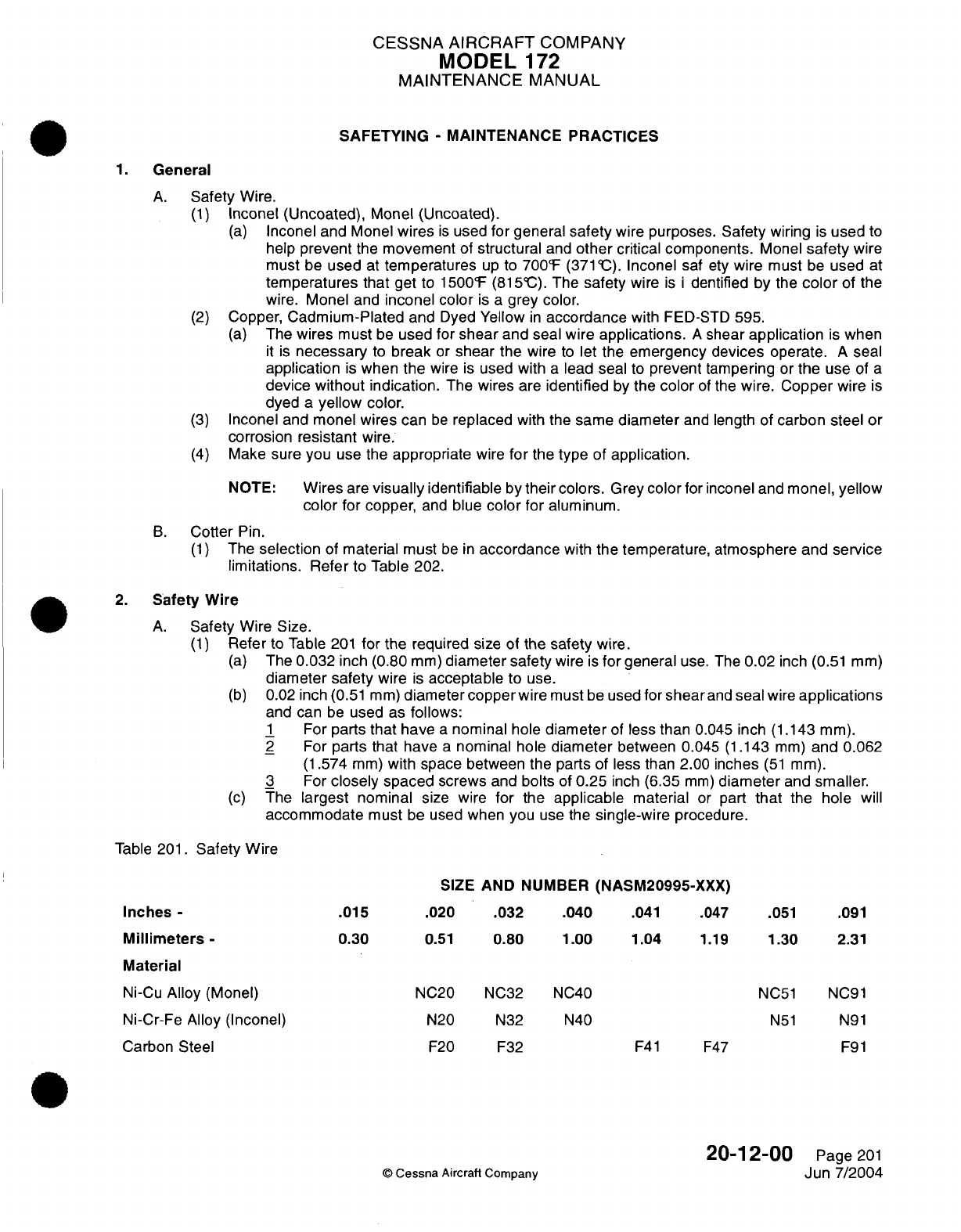
CESSNA
AIRCRAFT
COMPANY
MODEL
172
MAINTENANCE
MANUAL
SAFETYING
-
MAINTENANCE PRACTICES
1.
General
A.
Safety
Wire.
(1)
Inconel (Uncoated),
Monel (Uncoated).
(a)
Inconel and Monel
wires
is
used
for
general
safety
wire
purposes.
Safety
wiring
is
used
to
help
prevent
the
movement
of
structural
and
other
critical components.
Monel
safety
wire
must be
used
at
temperatures
up
to
700°F
(371
C).
Inconel
saf
ety
wire
must
be
used
at
temperatures that
get
to
1500°F (815°C).
The
safety
wire
is i
dentified
by
the
color
of
the
wire.
Monel
and
inconel
color
is
a
grey
color.
(2)
Copper,
Cadmium-Plated
and
Dyed
Yellow
in
accordance
with
FED-STD
595.
(a)
The
wires
must
be
used
for
shear
and seal
wire
applications.
A
shear
application
is
when
it is
necessary
to
break
or
shear
the
wire
to
let the
emergency devices
operate.
A
seal
application
is
when
the
wire
is
used
with
a
lead seal
to
prevent
tampering
or
the
use
of
a
device without indication.
The
wires
are
identified
by
the
color
of
the
wire.
Copper
wire
is
dyed
a
yellow
color.
(3)
Inconel and
monel
wires
can
be
replaced
with
the
same
diameter
and
length of
carbon steel
or
corrosion
resistant
wire.
(4)
Make
sure you use the
appropriate
wire
for
the
type of
application.
NOTE:
Wires
are
visually
identifiable
by
their
colors.
Grey
color
for inconel
and
monel,
yellow
color
for
copper,
and
blue
color
for aluminum.
B.
Cotter
Pin.
(1)
The
selection
of
material
must
be
in
accordance
with
the
temperature, atmosphere
and
service
limitations.
Refer
to Table 202.
2.
Safety
Wire
A.
Safety
Wire
Size.
(1)
Refer
to
Table
201
for
the required
size
of
the
safety
wire.
(a)
The
0.032
inch
(0.80
mm)
diameter safety
wire
is
for
general
use.
The
0.02
inch
(0.51
mm)
diameter
safety
wire
is
acceptable to
use.
(b)
0.02
inch
(0.51 mm)
diameter
copper
wire
must
be
used
for
shear
and
seal
wire
applications
and
can
be
used
as
follows:
1
For
parts
that
have
a
nominal
hole
diameter
of
less than
0.045
inch
(1.143
mm).
2
For
parts
that
have
a
nominal
hole
diameter
between
0.045
(1.143
mm)
and
0.062
(1.574
mm)
with space between
the
parts
of less than 2.00
inches
(51
mm).
3
For
closely spaced
screws
and
bolts
of
0.25
inch
(6.35
mm)
diameter
and
smaller.
(c)
The
largest nominal
size wire
for
the
applicable
material
or
part
that
the hole
will
accommodate
must
be
used
when you
use the
single-wire
procedure.
Table
201.
Safety Wire
SIZE
AND NUMBER
(NASM20995-XXX)
Inches
-
.015
.020
.032 .040
.041
.047
.051
.091
Millimeters-
0.30
0.51
0.80
1.00 1.04
1.19
1.30
2.31
Material
Ni-Cu
Alloy
(Monel)
NC20
NC32 NC40
NC51
NC91
Ni-Cr-Fe
Alloy
(Inconel)
N20 N32 N40
N51
N91
Carbon
Steel
F20
F32
F41
F47
F91
20-12-00
Page
201
©
Cessna
Aircraft Company
Jun 7/2004
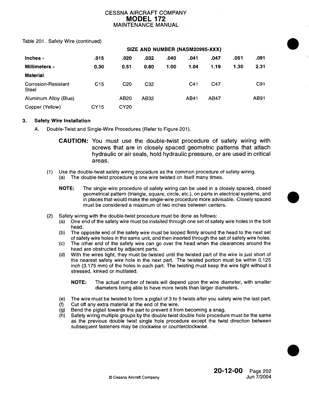
CESSNA
AIRCRAFT
COMPANY
MODEL
172
MAINTENANCE
MANUAL
Table
201.
Safety
Wire
(continued)
SIZE
AND
NUMBER
(NASM20995-XXX)
Inches
-
.015
.020 .032 .040
.041
.047
.051
.091
Millimeters-
0.30
0.51
0.80
1.00
1.04
1.19
1.30
2.31
Material
Corrosion-Resistant
C15
C20
C32
C41
C47
C91
Steel
Aluminum
Alloy
(Blue)
AB20
AB32
AB41
AB47
AB91
Copper
(Yellow)
CY15
CY20
3.
Safety
Wire
Installation
A.
Double-Twist and
Single-Wire
Procedures (Refer
to
Figure
201).
CAUTION:
You
must
use the
double-twist
procedure
of
safety
wiring
with
screws
that
are
In
closely
spaced
geometric
patterns
that
attach
hydraulic
or
air
seals,
hold
hydraulic pressure,
or
are
used
In
critical
areas.
(1)
Use
the
double-twist
safety
wiring
procedure
as the common
procedure
of
safety
wiring.
(a)
The
double-twist
procedure
is
one
wire twisted
on
itself
many
times.
NOTE:
The
single-wire
procedure
of
safety
wiring
can
be
used
in
a
closely
spaced,
closed
geometrical
pattern
(triangle,
square,
circle,
etc.),
on
parts
in
electrical
systems,
and
in
places that
would
make
the single-wire
procedure
more
advisable.
Closely
spaced
must
be
considered
a
maximum
of
two
inches
between
centers.
(2)
Safety
wiring
with
the
double-twist
procedure
must
be
done
as
follows:
(a)
One end of
the
safety
wire
must
be
installed
through
one
set
of
safety
wire
holes
in
the
bolt
head.
(b)
The
opposite
end of
the
safety
wire must
be
looped
firmly around
the
head
to
the
next
set
of
safety
wire
holes
in
the
same unit,
and
then
inserted
through
the
set
of
safety
wire
holes.
(c)
The
other
end
of
the
safety
wire
can
go
over
the
head
when
the
clearances
around
the
head
are
obstructed
by
adjacent
parts.
(d)
With the
wires
tight,
they
must
be
twisted
until
the twisted
part
of
the
wire
is
just
short
of
the
nearest
safety
wire
hole
in
the
next
part.
The
twisted portion
must
be
within
0.125
inch
(3.175
mm)
of the
holes
in
each part.
The
twisting
must
keep the
wire
tight
without
it
stressed, kinked
or
mutilated.
NOTE:
The
actual number
of
twists
will
depend
upon
the
wire
diameter,
with
smaller
diameters
being able
to
have
more
twists
than
larger
diameters.
(e)
The wire must
be
twisted
to
form
a
pigtail
of
3
to
5
twists
after
you
safety
wire
the last part.
(f)
Cut
off
any
extra
material
at
the
end of the
wire.
(g)
Bend
the pigtail
towards
the
part
to
prevent
it
from
becoming
a
snag.
(h)
Safety
wiring multiple groups
by
the
double
twist
double
hole
procedure must
be
the
same
as
the
previous double
twist
single
hole
procedure
except the
twist direction
between
subsequent fasteners
may
be
clockwise
or
counterclockwise.
20-12-00
Page
202
©
Cessna
Aircraft
Company
Jun 7/2004
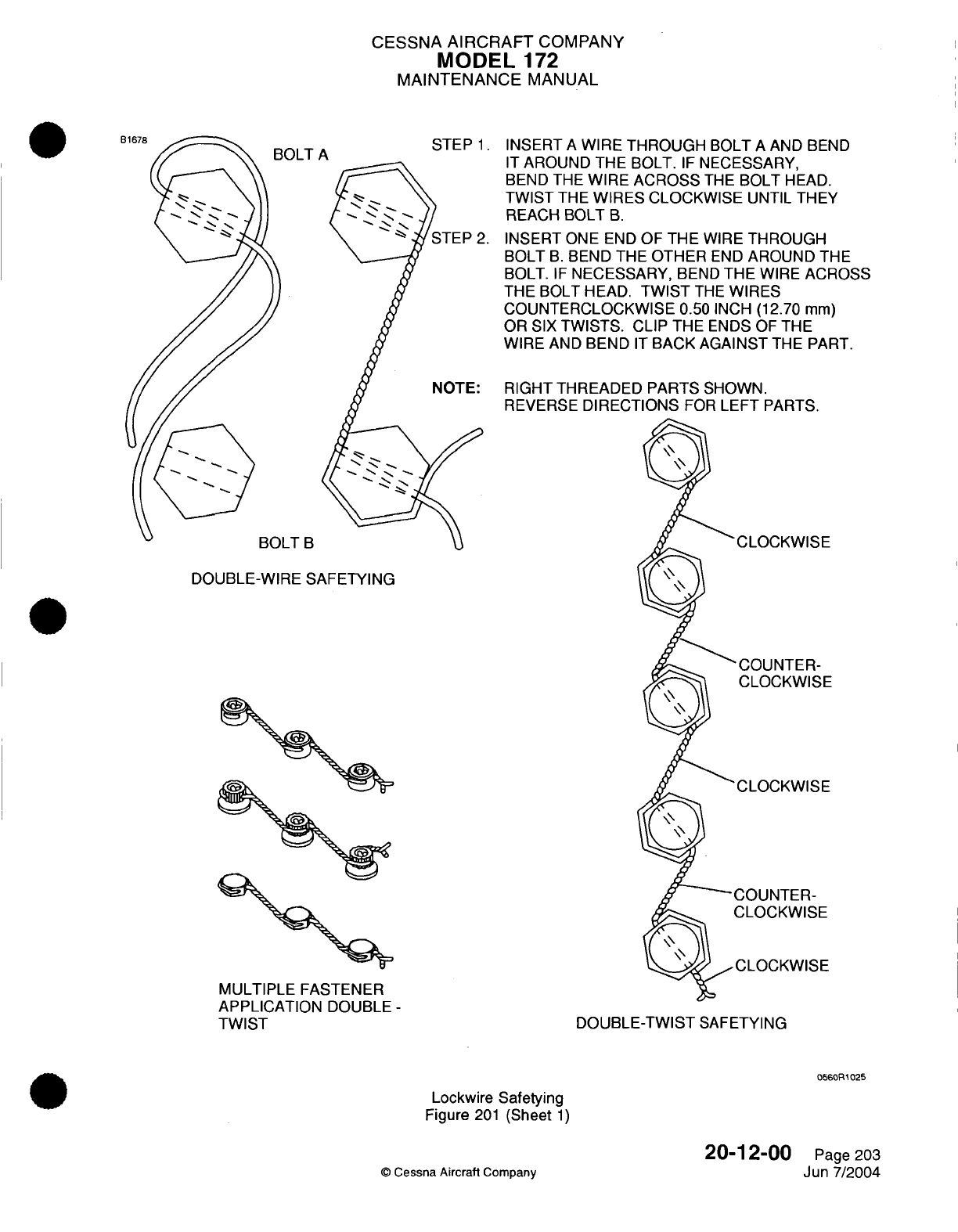
CESSNA
AIRCRAFT
COMPANY
MODEL
172
MAINTENANCE
MANUAL
BOLT
A
STEP
1.
INSERT
A
WIRE
THROUGH
BOLT
A
AND
BEND
IT1
A
fll
kin
TIf 5-
rIfl
5
r
k
r-,r~
'r A
rfl\V
II 1
MnUIUMU
I n
DUL
I. Ir
icLrtO,3n
T,
BEND THE
WIRE
ACROSS
THE
BOLT
HEAD.
TWIST
THE
WIRES
CLOCKWISE
UNTIL
THEY
REACH BOLT
B.
.INSERT
ONE
END
OF
THE
WIRE
THROUGH
BOLT
B.
BEND
THE
OTHER
END
AROUND
THE
BOLT.
IF
NECESSARY,
BEND
THE
WIRE
ACROSS
THE BOLT
HEAD.
TWIST
THE
WIRES
COUNTERCLOCKWISE
0.50
INCH
(12.70
mm)
OR
SIX
TWISTS.
CLIP
THE
ENDS
OF
THE
WIRE
AND
BEND
IT
BACK
AGAINST
THE PART.
RIGHT
THREADED
PARTS
SHOWN.
REVERSE
DIRECTIONS
FOR
LEFT
PARTS.
BOLT
B
DOUBLE-WIRE
SAFETYING
-COUNTER-
CLOCKWISE
MULTIPLE FASTENER
APPLICATION
DOUBLE
-
TWIST
DOUBLE-TWIST
SAFETYING
Lockwire
Safetying
Figure
201
(Sheet
1)
20-1
2-00
©
Cessna
Aircraft
Company
IT
D
Page
203
Jun
7/2004
.
E
-
0560MR
025
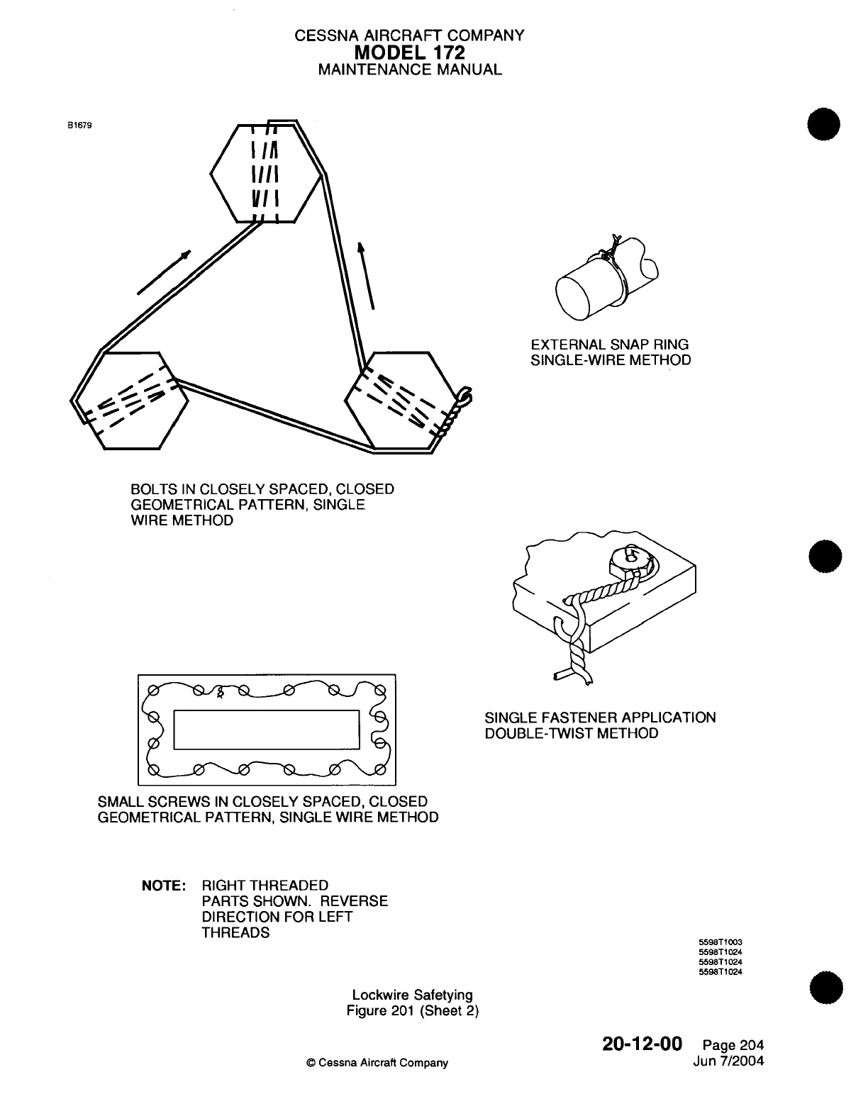
CESSNA AIRCRAFT
COMPANY
MODEL
172
MAINTENANCE
MANUAL
EXTERNAL SNAP
RING
SINGLE-WIRE
METHOD
BOLTS
IN
CLOSELY SPACED,
CLOSED
GEOMETRICAL
PATTERN,
SINGLE
WIRE
METHOD
SINGLE
FASTENER
APPLICATION
DOUBLE-TWIST
METHOD
SMALL
SCREWS
IN
CLOSELY
SPACED,
CLOSED
GEOMETRICAL
PATTERN,
SINGLE
WIRE METHOD
NOTE:
RIGHT
THREADED
PARTS
SHOWN.
REVERSE
DIRECTION
FOR
LEFT
THREADS
Lockwire Safetying
Figure
201
(Sheet
2)
20-12-00
©
Cessna Aircraft
Company
5598T1003
5598T1024
5598T1024
5598T1024
Page 204
Jun
7/2004
E
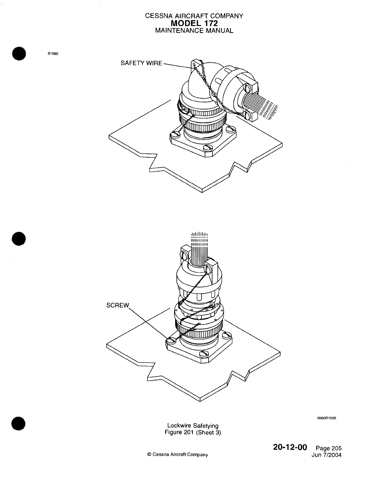
CESSNA
AIRCRAFT
COMPANY
MODEL
172
MAINTENANCE
MANUAL
B1680
0560R1026
Lockwire
Safetying
Figure
201
(Sheet
3)
©
Cessna
Aircraft
Company
20-12-00
Page
205
Jun
7/2004
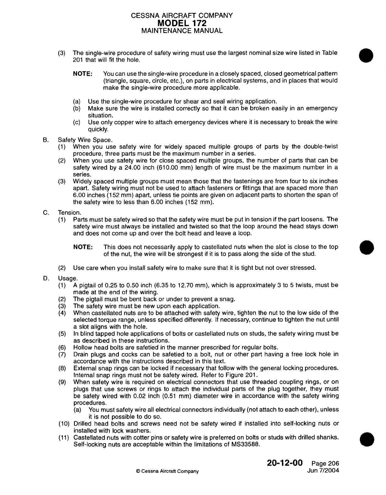
CESSNA
AIRCRAFT
COMPANY
MODEL
172
MAINTENANCE
MANUAL
(3)
The
single-wire procedure
of
safety
wiring must
use
the
largest nominal
size
wire
listed
in
Table
201
that will
fit the
hole.
NOTE:
You
can
use
the
single-wire
procedure
in a
closely
spaced,
closed
geometrical
pattern
(triangle,
square,
circle,
etc.),
on
parts
in
electrical
systems,
and
in
places
that
would
make
the
single-wire
procedure
more
applicable.
(a)
Use
the single-wire
procedure
for shear
and
seal
wiring
application.
(b)
Make sure
the
wire
is
installed
correctly
so
that
it
can
be
broken
easily
in
an
emergency
situation.
(c)
Use
only
copper
wire
to
attach
emergency devices
where
it
is
necessary
to
break
the
wire
quickly.
B.
Safety
Wire
Space.
(1)
When you
use
safety
wire
for
widely spaced
multiple groups
of
parts
by
the
double-twist
procedure,
three
parts
must
be
the
maximum
number
in
a
series.
(2)
When
you
use
safety
wire
for close spaced multiple groups,
the
number
of
parts
that
can
be
safety
wired
by
a
24.00
inch
(610.00
mm)
length
of
wire must
be
the
maximum number
in
a
series.
(3)
Widely spaced
multiple
groups must
mean
those that
the
fastenings
are
from
four
to
six
inches
apart.
Safety
wiring
must
not
be
used
to
attach
fasteners
or
fittings that
are
spaced
more
than
6.00
inches
(152
mm)
apart,
unless
tie
points
are
given
on
adjacent
parts
to
shorten the
span
of
the safety wire
to less
than 6.00 inches
(152
mm).
C.
Tension.
(1)
Parts
must
be
safety
wired
so
that
the
safety
wire must
be
put
in
tension
if
the
part
loosens.
The
safety
wire
must
always
be
installed
and
twisted
so
that the
loop
around
the
head
stays
down
and
does not
come
up
and
over
the
bolt
head
and
leave
a
loop.
NOTE:
This does
not
necessarily
apply
to
castellated
nuts when
the slot
is
close to
the
top
of
the nut,
the
wire
will
be
strongest
if it
is
to
pass
along
the
side of
the
stud.
(2)
Use
care
when
you
install
safety
wire
to
make
sure
that
it
is
tight
but not
over stressed.
D.
Usage.
(1) A
pigtail
of
0.25
to
0.50
inch
(6.35
to
12.70
mm),
which
is
approximately
3
to
5
twists,
must
be
made at
the
end
of
the
wiring.
(2)
The
pigtail must
be
bent
back
or
under
to
prevent
a
snag.
(3)
The
safety
wire
must
be
new
upon
each
application.
(4)
When
castellated
nuts
are
to
be
attached
with
safety wire,
tighten
the nut
to
the
low
side
of
the
selected
torque
range,
unless
specified
differently.
If
necessary, continue
to
tighten
the nut
until
a
slot
aligns
with the
hole.
(5) In
blind
tapped
hole
applications
of
bolts
or
castellated
nuts
on
studs,
the
safety
wiring
must
be
as
described
in
these
instructions.
(6)
Hollow
head bolts
are
safetied
in
the manner
prescribed
for
regular
bolts.
(7)
Drain
plugs
and
cocks
can
be
safetied
to a
bolt,
nut
or
other
part
having
a
free
lock
hole
in
accordance
with
the instructions described
in
this
text.
(8)
External
snap
rings
can
be
locked
if
necessary
that
follow
with
the
general
locking
procedures.
Internal
snap
rings must
not
be
safety
wired.
Refer
to
Figure
201.
(9)
When
safety
wire
is
required
on
electrical
connectors
that
use
threaded
coupling
rings,
or
on
plugs
that
use
screws
or
rings
to
attach
the
individual
parts
of
the plug together,
they
must
be
safety
wired
with 0.02
inch
(0.51
mm)
diameter
wire
in
accordance
with the
safety wiring
procedures.
(a)
You
must
safety
wire
all
electrical
connectors
individually
(not
attach
to
each
other),
unless
it
is
not
possible
to do
so.
(10)
Drilled
head
bolts
and
screws
need
not be
safety
wired
if
installed
into
self-locking
nuts
or
installed
with lock
washers.
(11)
Castellated
nuts
with
cotter
pins
or
safety
wire
is
preferred
on
bolts
or
studs
with
drilled
shanks.
Self-locking
nuts
are
acceptable
within
the
limitations
of MS33588.
20-12-00
Page
206
©
Cessna
Aircraft
Company
Jun
7/2004
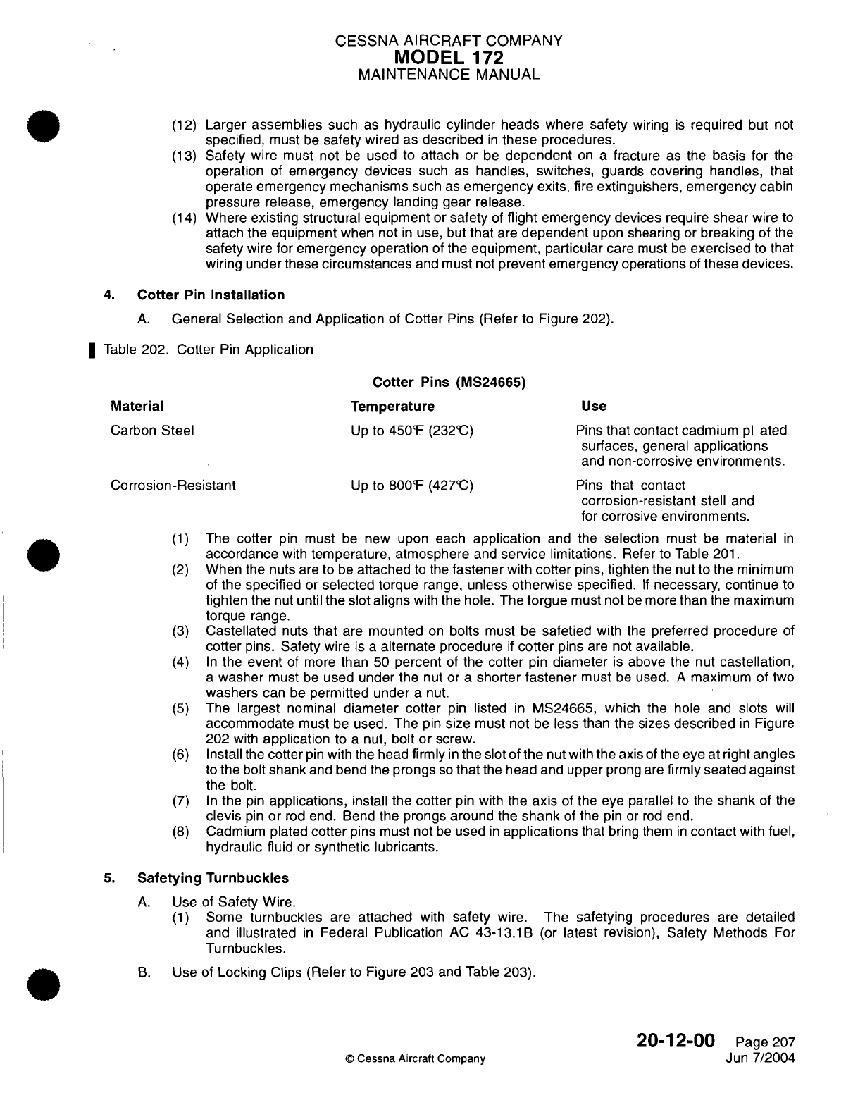
CESSNA
AIRCRAFT
COMPANY
MODEL
172
MAINTENANCE
MANUAL
(12)
Larger
assemblies
such
as
hydraulic
cylinder
heads
where
safety
wiring
is
required but
not
specified,
must
be
safety
wired as
described
in
these
procedures.
(13)
Safety wire
must not
be
used
to attach
or
be
dependent
on
a
fracture
as
the
basis for
the
operation
of
emergency
devices
such
as
handles, switches,
guards
covering
handles,
that
operate
emergency
mechanisms
such
as
emergency
exits,
fire
extinguishers,
emergency
cabin
pressure
release,
emergency
landing
gear
release.
(14)
Where
existing
structural
equipment
or
safety
of
flight
emergency devices
require
shear
wire to
attach the
equipment
when
not
in
use, but
that
are
dependent
upon
shearing
or
breaking of
the
safety
wire
for
emergency
operation
of
the
equipment, particular
care
must
be
exercised
to
that
wiring
under
these
circumstances
and
must
not
prevent emergency
operations
of
these
devices.
4.
Cotter
Pin
Installation
A.
General
Selection
and
Application
of
Cotter
Pins
(Refer
to
Figure
202).
Table
202. Cotter
Pin
Application
Cotter
Pins
(MS24665)
Material
Temperature
Use
Carbon
Steel
Up
to
450°F
(232°C)
Pins
that contact
cadmium
pl
ated
surfaces,
general
applications
and
non-corrosive
environments.
Corrosion-Resistant
Up
to
800°F
(427°C)
Pins
that
contact
corrosion-resistant
stell
and
for
corrosive
environments.
(1)
The
cotter
pin
must
be
new
upon each
application
and
the
selection
must
be
material
in
accordance
with
temperature, atmosphere
and
service
limitations.
Refer to
Table
201.
(2)
When the
nuts
are
to
be
attached
to
the
fastener
with
cotter
pins,
tighten
the
nut to
the minimum
of
the
specified
or
selected torque
range,
unless
otherwise specified.
If
necessary,
continue
to
tighten the
nut
until
the
slot aligns
with
the
hole. The
torgue
must not
be
more
than
the
maximum
torque
range.
(3)
Castellated
nuts
that
are
mounted
on
bolts
must
be
safetied
with
the
preferred
procedure
of
cotter
pins.
Safety
wire
is
a
alternate
procedure
if
cotter
pins
are
not
available.
(4)
In
the
event
of more
than
50
percent
of
the
cotter
pin
diameter
is
above the
nut
castellation,
a
washer
must
be
used
under the
nut
or
a
shorter
fastener
must
be
used.
A
maximum
of
two
washers
can
be
permitted under
a
nut.
(5)
The
largest
nominal
diameter cotter
pin
listed
in
MS24665, which
the hole and
slots
will
accommodate
must
be
used.
The
pin
size
must
not
be
less than
the sizes
described
in
Figure
202
with
application
to
a
nut,
bolt
or
screw.
(6)
Install the
cotter
pin
with
the
head
firmly
in
the slot
of
the
nut
with
the
axis
of
the eye at
right
angles
to
the
bolt
shank
and
bend
the
prongs
so
that
the
head
and
upper
prong
are
firmly
seated
against
the bolt.
(7)
In
the
pin
applications,
install the
cotter
pin with
the
axis
of
the
eye
parallel
to the
shank
of
the
clevis
pin
or
rod
end. Bend
the prongs around
the
shank
of
the pin
or
rod
end.
(8)
Cadmium
plated
cotter
pins
must not
be
used
in
applications
that
bring them
in
contact
with
fuel,
hydraulic
fluid
or
synthetic lubricants.
5.
Safetying Turnbuckles
A.
Use of
Safety
Wire.
(1)
Some
turnbuckles
are
attached
with
safety
wire.
The
safetying
procedures
are
detailed
and
illustrated
in
Federal
Publication
AC
43-13.1B
(or
latest
revision),
Safety
Methods
For
Turnbuckles.
B.
Use
of
Locking
Clips
(Refer
to
Figure
203 and
Table
203).
20-12-00
Page
207
©
Cessna
Aircraft
Company
Jun
7/2004
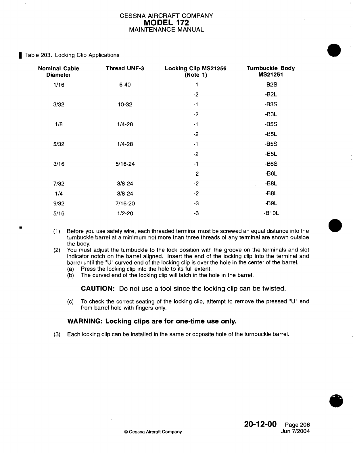
CESSNA
AIRCRAFT
COMPANY
MODEL
172
MAINTENANCE
MANUAL
I
Table
203.
Locking Clip
Applications
Nominal
Cable
Thread
UNF-3
Diameter
1/16
6-40
3/32 10-32
Locking
Clip
MS21256
(Note 1)
-1
-2
-1
-2
1/8
1/4-28
-1
-2
5/32 1/4-28
-1
-2
3/16
7/32
1/4
9/32
5/16
5/16-24
3/8-24
3/8-24
7/16-20
1/2-20
-1
-2
-2
-2
-3
-3
Turnbuckle
Body
MS21251
-B2S
-B2L
-B3S
-B3L
-B5S
-B5L
-B5S
-B5L
-B6S
-B6L
-B8L
-B8L
-B9L
-B10L
(1)
Before
you
use
safety
wire, each
threaded terminal
must
be
screwed
an
equal
distance
into the
turnbuckle
barrel
at
a
minimum
not
more
than
three
threads
of
any
terminal
are
shown
outside
the
body.
(2)
You
must
adjust
the
turnbuckle
to
the
lock position
with
the
groove
on
the
terminals
and slot
indicator
notch
on
the
barrel
aligned.
Insert
the
end
of
the
locking
clip
into
the
terminal
and
barrel until
the
"U"
curved
end of the
locking
clip
is
over
the hole
in
the
center
of
the
barrel.
(a)
Press
the locking
clip
into
the
hole
to
its
full
extent.
(b)
The
curved
end
of
the locking
clip will
latch
in
the
hole
in
the
barrel.
CAUTION:
Do
not
use
a
tool
since
the locking
clip
can be
twisted.
(c)
To
check
the correct
seating
of
the locking
clip,
attempt
to
remove
the
pressed
"U"
end
from
barrel hole with
fingers
only.
WARNING:
Locking
clips
are
for
one-time
use
only.
(3)
Each
locking clip
can
be
installed
in
the
same
or
opposite
hole
of
the
turnbuckle
barrel.
20-12-00
Page
208
©
Cessna
Aircraft
Company
Jun
7/2004
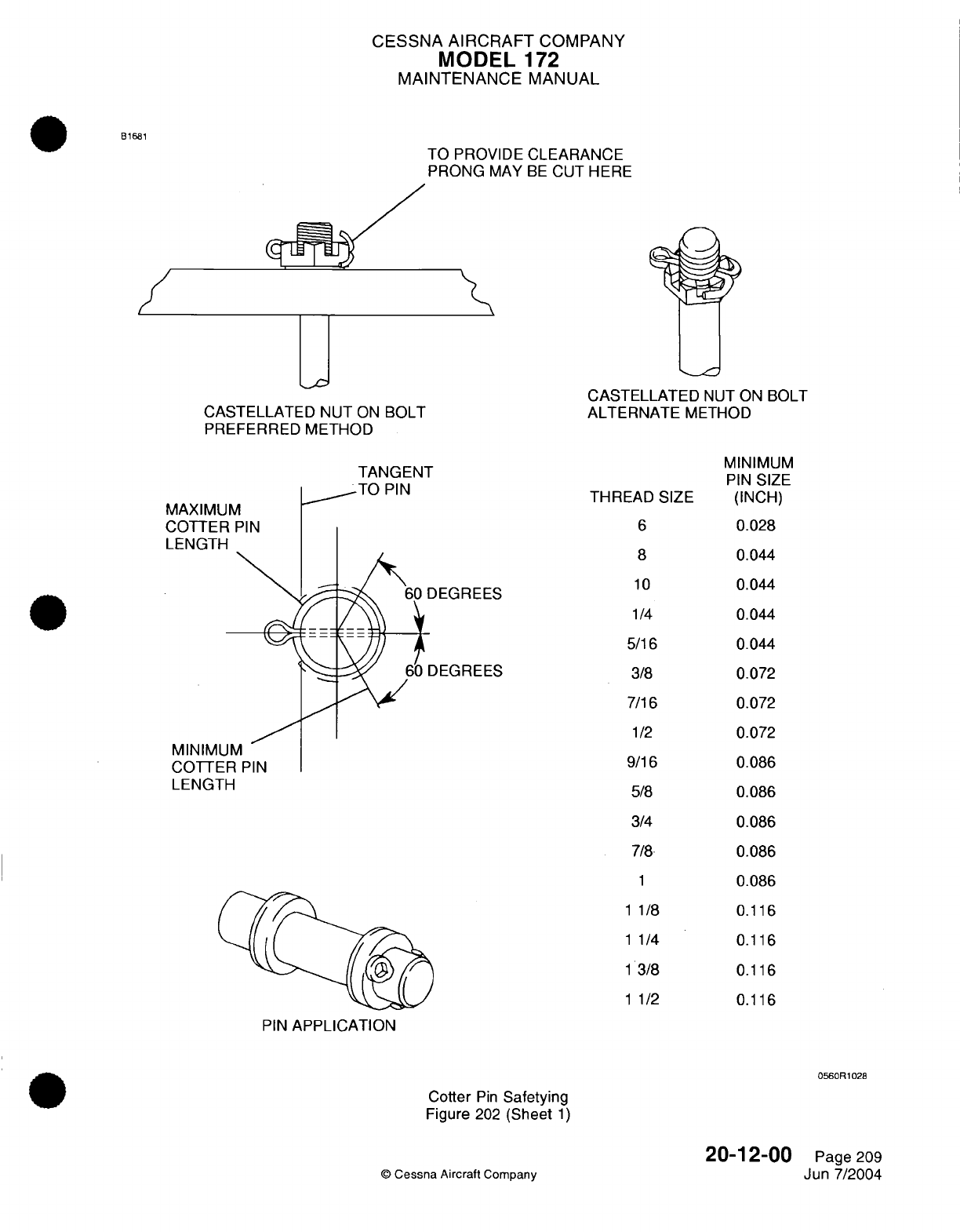
CESSNA AIRCRAFT
COMPANY
MODEL
172
MAINTENANCE
MANUAL
B1681
TO PROVIDE
CLEARANCE
PRONG
MAY
BE
CUT
HERE
CASTELLATED
NUT
ON
BOLT
PREFERRED METHOD
CASTELLATED
NUT
ON
BOLT
ALTERNATE
METHOD
TANGENT
TO
PIN
MAXIMUM
COTTER
PIN
LENGTH
DEGREES
DEGREES
MINIMUM
COTTER
PIN
LENGTH
THREAD
SIZE
6
8
10
1/4
5/16
3/8
7/16
1/2
9/16
5/8
3/4
7/8
1
1
1/8
1
1/4
1
1
3/8
1/2
PIN
APPLICATION
0560R1028
Cotter
Pin
Safetying
Figure
202
(Sheet
1)
20-1
2-00
©
Cessna
Aircraft
Company
MINIMUM
PIN
SIZE
(INCH)
0.028
0.044
0.044
0.044
0.044
0.072
0.072
0.072
0.086
0.086
0.086
0.086
0.086
0.116
0.116
0.116
0.116
Page
209
Jun
7/2004
'"""
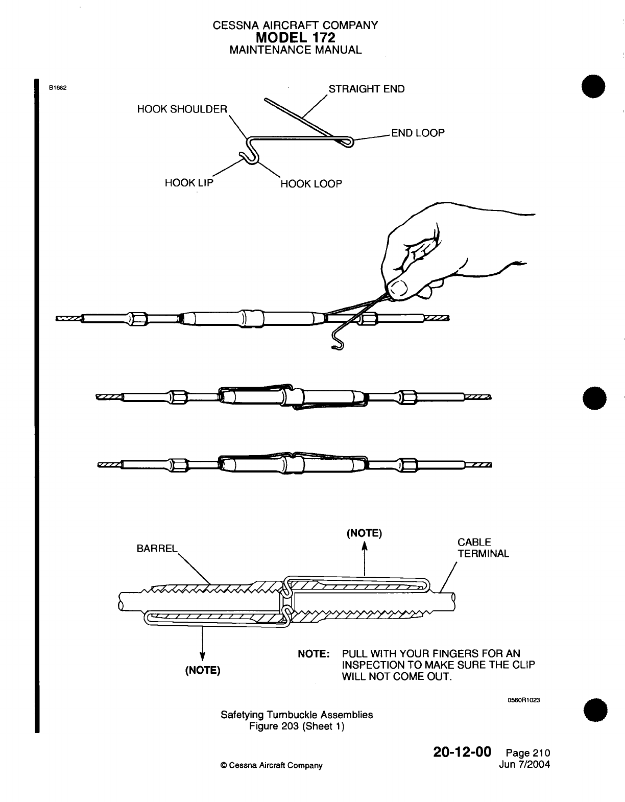
CESSNA
AIRCRAFT
COMPANY
MODEL
172
MAINTENANCE
MANUAL
STI
HOOK
SHOULDER
RAIGHT
END
END
LOOP
HOOK
LIP
HOOK
LOOP
T5 F^~ -fr
L T(NOTE)
(NOTE)
BARREL
I
I,
,z
, ,
, , ,
<(''
''
','
' d
E)
(NOTE)
SABLE
TERMINAL
NOTE: PULL WITH
YOUR FINGERS
FOR AN
INSPECTION
TO
MAKE
SURE
THE
CLIP
WILL
NOT
COME
OUT.
0560R1023
Safetying
Tumbuckle Assemblies
Figure
203 ISheet
1)
20-1
2-00
©
Cessna
Aircraft
Company
B1682
Page
210
Jun
7/2004
I I
/
I
IL
QgL1
pi
)
~ 2
~)
)
1
,~~-c~-
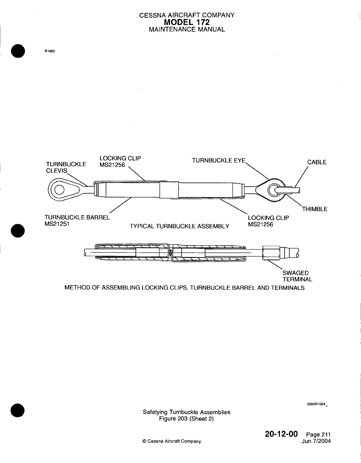
CESSNA
AIRCRAFT
COMPANY
MODEL
1
72
MAINTENANCE
MANUAL
B1683
TURNBUCKLE
BARREL
MS21251
LOCKING
CLIP
MS21256
'1
1
TURNBUCKLE
EYE
CABLE
THIMBLE
TYPICAL TURNBUCKLE ASSEMBLY
LOCKING
CLIP
MS21256
'
\
\ \
,
I
I
.11
l.-
I \ N \ \
'
\ \ \ \ \ \
'
SWAGED
TERMINAL
METHOD
OF
ASSEMBLING
LOCKING
CLIPS,
TURNBUCKLE
BARREL
AND
TERMINALS
0560R1024
Safetying Turnbuckle
Assemblies
Figure
203
(Sheet
2)
20-1
2-00
©
Cessna Aircraft
Company
TURNBUCKLE
Page
211
Jun
7/2004
1{
CESSNA
AIRCRAFT
COMPANY
MODEL
1
72
MAINTENANCE
MANUAL
SEALING
-
DESCRIPTION AND
OPERATION
1.
General
A. A
list
of
the
various sealants
used
throughout
the
airplane
can
be
found
in
the
Tools,
Equipment
and
Materials
table
of
the
effected chapters.
20-30-00
Page
1
©
Cessna
Aircraft Company
Apr
7/2003
CESSNA
AIRCRAFT
COMPANY
MODEL
172
MAINTENANCE
MANUAL
ACCEPTABLE REPLACEMENTS
FOR
CHEMICALS AND
SOLVENTS
-
DESCRIPTION
AND OPERATION
1.
General
A.
In
response
to the
Aerospace
National
Emissions
Standards
for
Hazardous
Air
Pollutants
(NESHAP),
this
data
is
being issued
to
inform
customers
of
acceptable
replacements
for
chemicals
and
solvents
in
the
Maintenance
Manual
that
have
been
restricted
or
prohibited
by
the
standards.
B.
For
complete
details
of
the
regulatory standards,
refer to
Federal
Register,
40
CFR
Part
63
(Ad-FRL-
5636-1),
RIN
2060-AG65.
C.
Compliance
with
the
standard
is
mandatory
by
September
1,
1998.
2.
Hand-Wipe
Cleaning Operations
NOTE:
All
hazardous
air
pollutants
(HAP) or
volatile
organic compounds
(VOC)
hand-wipe
cleaning
solvents
must
meet
a
composition requirement, have
a
vapor
pressure
less
than or
equal
to
45
MM
Hg
at
20@C,
or
meet
the
requirements
speci
fied
in
an
alternative
compliance
plan
administered by the permitting authority and
approved
under Section
112
(1)
of the
Clean
Air
Act.
Table
1.
Replacement
Products
for
Hand-Wipe
Cleaning
Operations
APPROVED
PRODUCT/
NUMBER
Methyl
n-propyl
ketone
(CAS
No.
107-87-9)
Desoclean
110
(020K19)
Isopropyl
Alcohol
(TT-1-735)
All
Rubber
(Natural or
Synthetic)
Isopropyl
Alcohol
(TT-1-735)
and
Silicone
SUPPLIER
ADDRESS
Eastman
Chemical
Products
Wilcox
Dr.
And
Lincoln
St.
Kingsport,
TN
Dynamold Solvents,
Incorporated
2905
Shamrock
Ave.
Fort
Worth,
TX
76107
Available
Commercially
Available
Commercially
3.
Priming
Operations
NOTE:
Priming
operations
may
not
exceed
a
maximum
Hazardous
Air
Pollutant
(HAP)
limit
of
2.9
lb./Gallon
(350
Grams/Liter)
(less water)
per
application.
Priming
operations
may
not
exceed
a
volatile
organic
compounds
(VOC)
limit
of
2.9
lb./Gallon
(350
Grams/Liter)
(less
water
and
exempt
solvents) per
application. Compliance
of
this
limit
may be
achieved
through the
use
of
coatings
which fall
below
content limits,
or
by
using
monthly volume-weighted
averaging
to
meet
content
limits.
Table
2.
Replacement
Products for
Priming
Operations
PRIMER
APPLICATION
Corrosion
Primer
(See
Notes
1,4)
APPROVED
PRODUCT/
NUMBER
Corrosion
Primer
(513
X
419)
(910
X
942)
Corrosion Primer
(02-Y-40)
(02-4-40
CATA)
©
Cessna
Aircraft Company
SUPPLIER
ADDRESS
Courtaulds
Aerospace
1608 Fourth
St.
Berkeley,
CA
94710
DEFT,
Inc.
17451 Von
Karman
Ave.
Irvine,
CA
92714
20-31
-00
Page
1
Apr
7/2003
SURFACE
All
Metals and Painted
Surfaces
All
Plastics
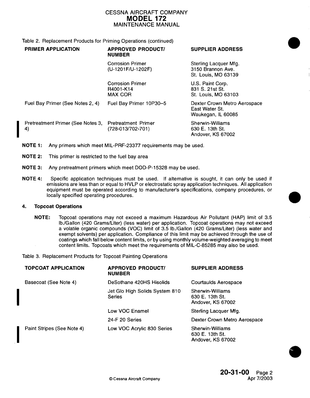
CESSNA
AIRCRAFT
COMPANY
MODEL
172
MAINTENANCE
MANUAL
Table
2.
Replacement
Products
for
Priming
Operations
(continued)
PRIMER
APPLICATION
Fuel
Bay
Primer
(See
Notes
2,
4)
Pretreatment
Primer
(See
Notes
3,
4)
APPROVED
PRODUCT/
NUMBER
Corrosion
Primer
(U-1201F/U-1202F)
Corrosion
Primer
R4001-K14
MAX
COR
Fuel
Bay
Primer
10P30-5
Pretreatment
Primer
(728-013/702-701)
SUPPLIER ADDRESS
Sterling
Lacquer
Mfg.
3150 Brannon
Ave.
St.
Louis,
MO
63139
U.S.
Paint
Corp.
831 S.
21st
St.
St.
Louis,
MO
63103
Dexter
Crown
Metro
Aerospace
East
Water
St.
Waukegan,
IL
60085
Sherwin-Williams
630
E.
13th
St.
Andover,
KS
67002
NOTE
1:
Any primers
which meet
MIL-PRF-23377 requirements
may
be
used.
NOTE
2:
This primer
is
restricted
to
the
fuel bay
area
NOTE
3:
Any
pretreatment
primers
which meet
DOD-P-15328
may
be
used.
NOTE
4:
Specific
application
techniques
must
be
used.
If
alternative
is
sought,
it
can
only
be
used
if
emissions
are
less
than
or equal
to
HVLP
or
electrostatic spray
application
techniques.
All
application
equipment must
be
operated according
to
manufacturer's
specifications,
company
procedures,
or
locally
specified operating
procedures.
4.
Topcoat Operations
NOTE: Topcoat
operations
may
not
exceed
a
maximum
Hazardous
Air
Pollutant
(HAP)
limit of
3.5
lb./Gallon
(420
Grams/Liter)
(less
water)
per
application.
Topcoat
operations
may
not
exceed
a
volatile organic compounds
(VOC)
limit
of 3.5
lb./Gallon
(420
Grams/Liter)
(less water
and
exempt
solvents)
per
application. Compliance
of
this
limit
may
be
achieved through
the
use
of
coatings
which
fall
below
content
limits,
or
by
using
monthly
volume-weighted
averaging
to
meet
content
limits.
Topcoats
which
meet
the requirements
of MIL-C-85285
may
also
be used.
Table
3.
Replacement Products for
Topcoat
Painting
Operations
TOPCOAT
APPLICATION
Basecoat
(See
Note
4)
I
I
Paint
Stripes
(See
Note
4)
APPROVED
PRODUCT/
NUMBER
DeSothane
420HS
Hisolids
Jet
Glo
High
Solids
System
810
Series
Low
VOC
Enamel
24-F
20 Series
Low
VOC
Acrylic
830
Series
SUPPLIER ADDRESS
Courtaulds
Aerospace
Sherwin-Williams
630
E.
13th
St.
Andover,
KS
67002
Sterling
Lacquer
Mfg.
Dexter
Crown
Metro
Aerospace
Sherwin-Williams
630
E.
13th
St.
Andover,
KS
67002
20-31-00
Page
2
Apr
7/2003
©
Cessna
Aircraft Company
I
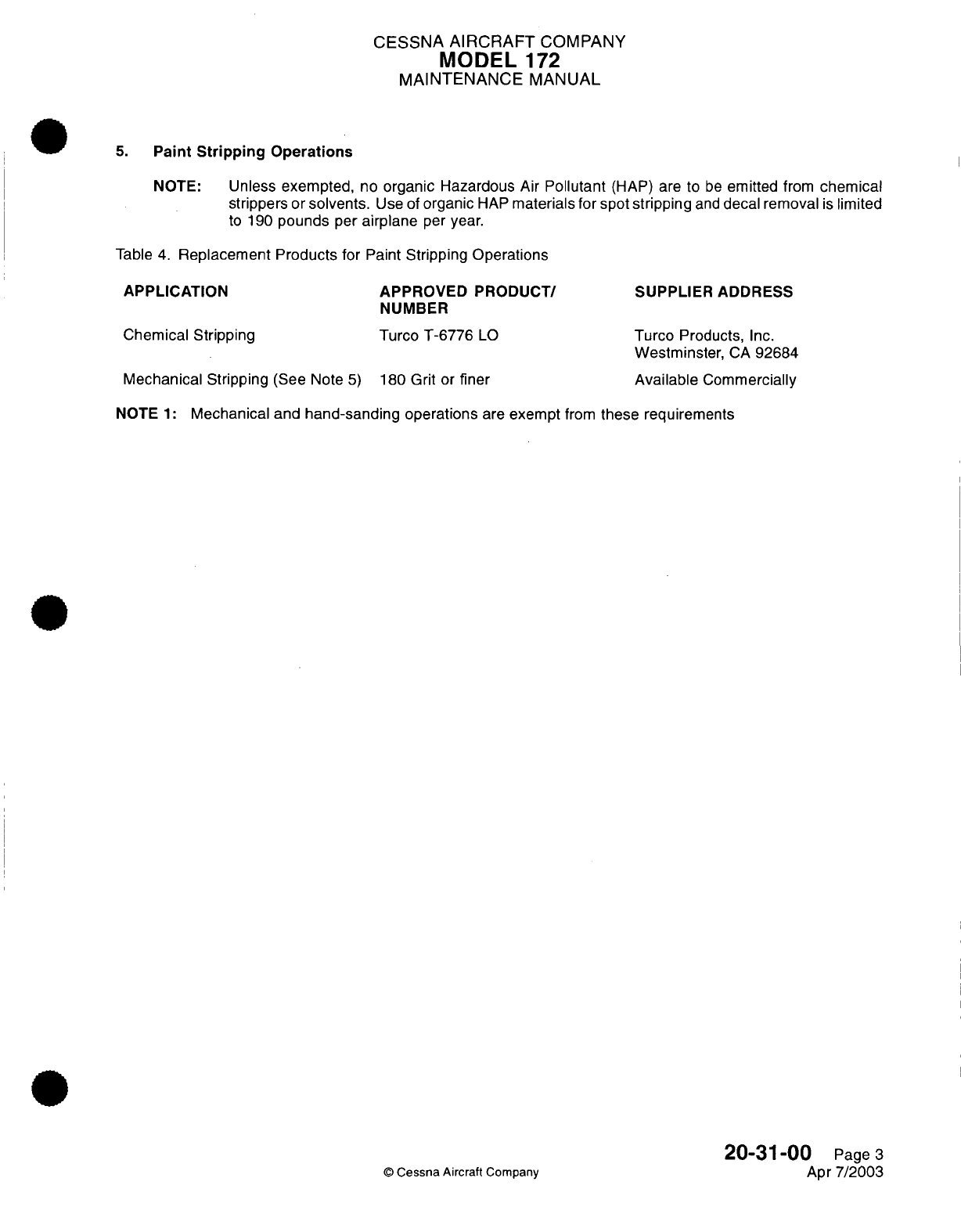
CESSNA
AIRCRAFT
COMPANY
MODEL
172
MAINTENANCE
MANUAL
5.
Paint
Stripping
Operations
NOTE:
Unless
exempted,
no
organic
Hazardous
Air
Pollutant
(HAP)
are
to
be
emitted
from
chemical
strippers
or
solvents.
Use of
organic
HAP
materials
for
spot
stripping
and
decal removal
is
limited
to
190
pounds
per
airplane
per
year.
Table
4.
Replacement Products
for Paint
Stripping
Operations
APPLICATION
APPROVED
PRODUCT/
SUPPLIER
ADDRESS
NUMBER
Chemical
Stripping
Turco
T-6776
LO
Turco Products,
Inc.
Westminster,
CA
92684
Mechanical
Stripping
(See
Note
5)
180
Grit
or
finer
Available
Commercially
NOTE
1:
Mechanical
and
hand-sanding operations
are
exempt
from
these
requirements
20-31-00
Page
3
Apr
7/2003
©
Cessna
Aircraft
Company
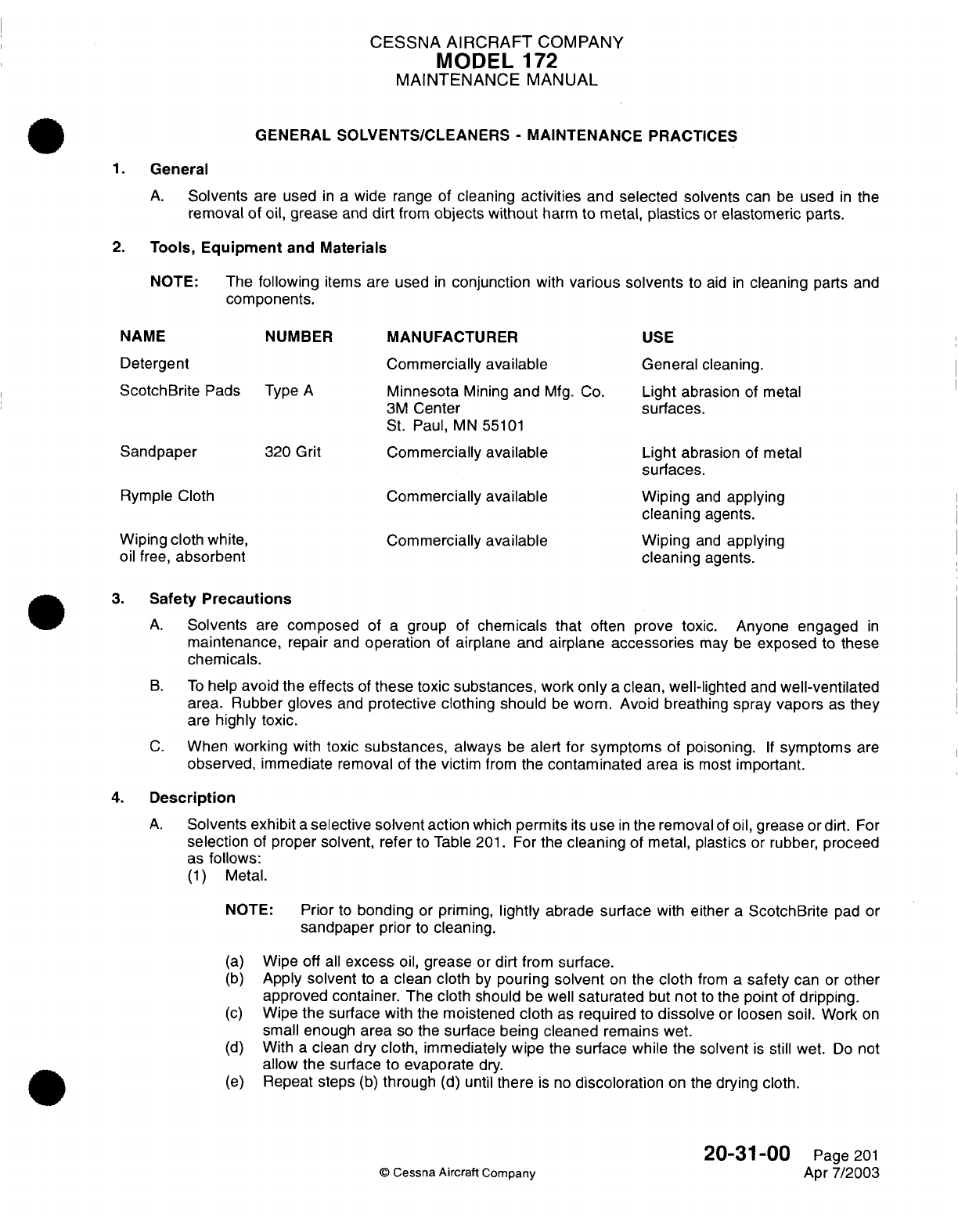
CESSNA
AIRCRAFT
COMPANY
MODEL
1
72
MAINTENANCE
MANUAL
GENERAL
SOLVENTS/CLEANERS
-
MAINTENANCE
PRACTICES
1.
General
A.
Solvents
are used
in
a
wide
range
of
cleaning
activities
and selected
solvents
can
be
used
in
the
removal
of oil,
grease
and
dirt
from
objects without
harm
to metal,
plastics
or
elastomeric
parts.
2.
Tools,
Equipment
and
Materials
NOTE:
The
following
items are
used
in
conjunction
with
various solvents
to
aid
in
cleaning
parts
and
components.
NAME NUMBER
MANUFACTURER
USE
Detergent Commercially
available
General
cleaning.
ScotchBrite
Pads
Type
A
Minnesota
Mining
and
Mfg.
Co.
Light
abrasion
of
metal
3M
Center
surfaces.
St.
Paul,
MN
55101
Sandpaper
320
Grit
Commercially
available
Light
abrasion
of
metal
surfaces.
Rymple Cloth
Commercially
available
Wiping
and
applying
cleaning
agents.
Wiping
cloth white, Commercially
available
Wiping
and
applying
oil
free,
absorbent
cleaning
agents.
3.
Safety
Precautions
A.
Solvents
are
composed
of
a
group
of
chemicals
that
often prove
toxic. Anyone engaged
in
maintenance,
repair and
operation
of
airplane
and airplane
accessories
may
be
exposed
to
these
chemicals.
B.
To
help
avoid the effects
of
these toxic
substances,
work
only
a
clean,
well-lighted
and
well-ventilated
area. Rubber
gloves
and
protective clothing should
be
worn.
Avoid breathing
spray
vapors
as
they
are
highly toxic.
C.
When
working
with
toxic substances,
always
be
alert
for
symptoms
of
poisoning.
If
symptoms
are
observed,
immediate
removal
of
the
victim
from
the
contaminated
area
is
most
important.
4.
Description
A.
Solvents
exhibit
a
selective
solvent
action
which
permits
its
use
in
the removal
of
oil,
grease
or
dirt.
For
selection
of
proper
solvent,
refer
to
Table
201.
For
the
cleaning
of
metal,
plastics
or
rubber, proceed
as
follows:
(1)
Metal.
NOTE:
Prior
to
bonding
or
priming,
lightly
abrade
surface
with
either
a
ScotchBrite
pad
or
sandpaper
prior
to
cleaning.
(a)
Wipe off
all
excess
oil,
grease
or
dirt
from
surface.
(b)
Apply solvent
to
a
clean
cloth
by
pouring
solvent
on
the
cloth
from
a
safety
can
or
other
approved container.
The
cloth
should
be
well
saturated
but
not
to
the
point
of
dripping.
(c)
Wipe
the
surface
with
the
moistened
cloth
as
required
to
dissolve
or
loosen
soil.
Work
on
small enough
area
so
the
surface being cleaned
remains
wet.
(d)
With
a
clean
dry
cloth, immediately wipe
the
surface
while
the
solvent
is
still
wet.
Do
not
allow
the surface
to
evaporate
dry.
(e)
Repeat
steps
(b)
through
(d)
until
there
is
no
discoloration
on the
drying
cloth.
20-31-00
Page
201
©
Cessna Aircraft Company
Apr
7/2003
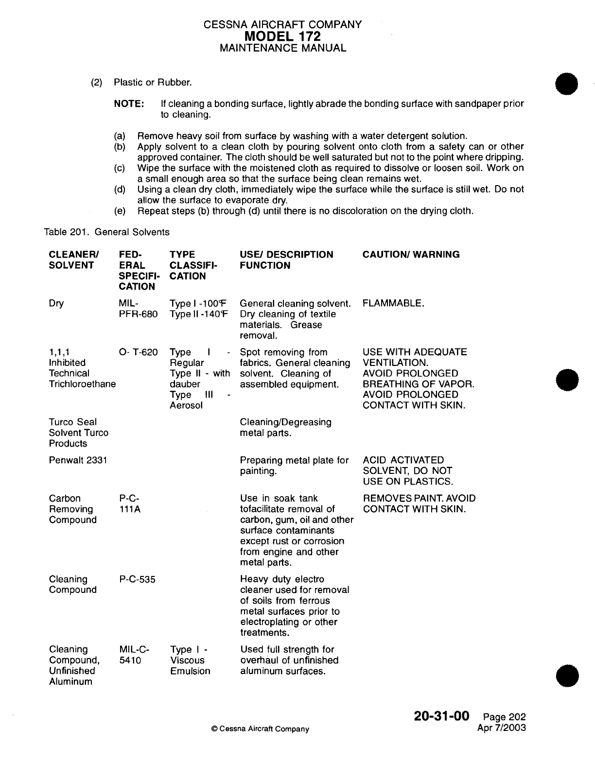
CESSNA
AIRCRAFT
COMPANY
MODEL
172
MAINTENANCE
MANUAL
(2)
Plastic
or
Rubber.
NOTE:
If
cleaning
a
bonding surface,
lightly abrade
the
bonding
surface
with
sandpaper
prior
to
cleaning.
(a)
Remove
heavy soil
from
surface
by
washing
with
a
water
detergent solution.
(b)
Apply
solvent
to
a
clean
cloth
by
pouring
solvent
onto
cloth
from
a
safety
can
or
other
approved
container.
The cloth
should
be well
saturated
but
not
to
the
point
where
dripping.
(c)
Wipe
the
surface
with
the
moistened
cloth
as
required
to
dissolve
or
loosen
soil.
Work
on
a
small
enough area
so
that
the
surface
being
clean
remains
wet.
(d)
Using
a
clean
dry cloth,
immediately
wipe
the
surface while
the
surface
is
still
wet.
Do
not
allow the
surface
to
evaporate dry.
(e)
Repeat
steps
(b)
through
(d)
until
there
is
no
discoloration
on
the
drying
cloth.
Table
201.
General
Solvents
FED-
ERAL
SPECIFI-
CATION
TYPE
CLASSIFI-
CATION
MIL-
Type
I
-100°F
PFR-680
Typell-140°F
1,1,1
O-
T-620
Type
I
Inhibited
Regular
Technical Type
II -
with
Trichloroethane
dauber
Type
III
-
Aerosol
USE/
DESCRIPTION
FUNCTION
General
cleaning solvent.
Dry
cleaning
of
textile
materials. Grease
removal.
Spot
removing
from
fabrics. General
cleaning
solvent.
Cleaning
of
assembled equipment.
CAUTION/
WARNING
FLAMMABLE.
USE
WITH ADEQUATE
VENTILATION.
AVOID
PROLONGED
BREATHING
OF
VAPOR.
AVOID
PROLONGED
CONTACT
WITH
SKIN.
Cleaning/Degreasing
metal parts.
Turco
Seal
Solvent
Turco
Products
Penwalt
2331
Preparing
metal plate
for
painting.
P-C-
111A
P-C-535
MIL-C-
Type
I -
5410
Viscous
Emulsion
Use
in
soak
tank
tofacilitate
removal
of
carbon,
gum,
oil
and
other
surface
contaminants
except
rust
or
corrosion
from
engine
and other
metal parts.
Heavy
duty
electro
cleaner
used
for
removal
of
soils
from
ferrous
metal
surfaces
prior
to
electroplating
or
other
treatments.
Used
full
strength
for
overhaul
of
unfinished
aluminum
surfaces.
ACID ACTIVATED
SOLVENT,
DO
NOT
USE
ON
PLASTICS.
REMOVES
PAINT.
AVOID
CONTACT
WITH
SKIN.
20-31-00
©
Cessna Aircraft Company
CLEANER/
SOLVENT
Dry
Carbon
Removing
Compound
Cleaning
Compound
Cleaning
Compound,
Unfinished
Aluminum
Page
202
Apr
7/2003
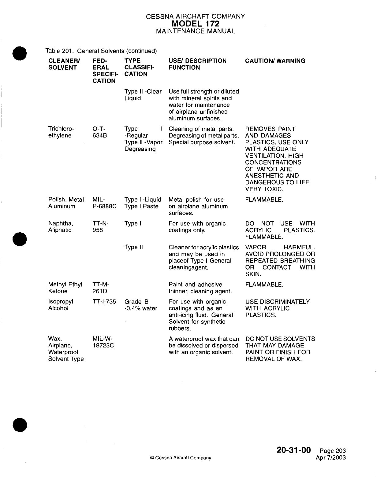
CESSNA
AIRCRAFT
COMPANY
MODEL
1
72
MAINTENANCE
MANUAL
Table
201.
General
Solvents (continued)
CLEANER/
FED-
TYPE
SOLVENT ERAL
CLASSIFI-
SPECIFI-
CATION
CATION
Type
II
-Clear
Liquid
Type
I
-Regular
Type
II-Vapor
Degreasing
USE/
DESCRIPTION
FUNCTION
Use
full
strength
or
diluted
with mineral
spirits
and
water
for
maintenance
of
airplane unfinished
aluminum
surfaces.
Cleaning
of
metal
parts.
Degreasing
of
metal
parts.
Special purpose
solvent.
CAUTION/
WARNING
REMOVES
PAINT
AND
DAMAGES
PLASTICS.
USE
ONLY
WITH ADEQUATE
VENTILATION.
HIGH
CONCENTRATIONS
OF VAPOR
ARE
ANESTHETIC
AND
DANGEROUS
TO
LIFE.
VERY TOXIC.
Polish,
Metal
Aluminum
Naphtha,
Aliphatic
MIL-
Type
I
-Liquid
P-6888C Type
IIPaste
TT-N-
958
Type
I
Metal
polish
for
use
on
airplane aluminum
surfaces.
For use
with
organic
coatings
only.
FLAMMABLE.
DO
NOT
ACRYLIC
FLAMMABLE
USE
WITH
PLASTICS.
Type
II
Methyl
Ethyl
Ketone
Isopropyl
Alcohol
Wax,
Airplane,
Waterproof
Solvent
Type
TT-M-
261D
TT-I-735
Grade
B
-0.4%
water
MIL-W-
18723C
Cleaner for
acrylic
plastics
and
may
be
used
in
placeof
Type
I
General
cleaningagent.
Paint
and
adhesive
thinner,
cleaning
agent.
For use with
organic
coatings
and
as
an
anti-icing fluid.
General
Solvent for
synthetic
rubbers.
A
waterproof
wax
that
can
be
dissolved
or
dispersed
with
an
organic solvent.
VAPOR
HARMFUL.
AVOID
PROLONGED
OR
REPEATED
BREATHING
OR
CONTACT
WITH
SKIN.
FLAMMABLE.
USE
DISCRIMINATELY
WITH ACRYLIC
PLASTICS.
DO
NOT
USE
SOLVENTS
THAT
MAY
DAMAGE
PAINT OR FINISH
FOR
REMOVAL
OF
WAX.
20-31-00
©
Cessna
Aircraft Company
Trichloro-
ethylene
O-T-
634B
Page
203
Apr
7/2003
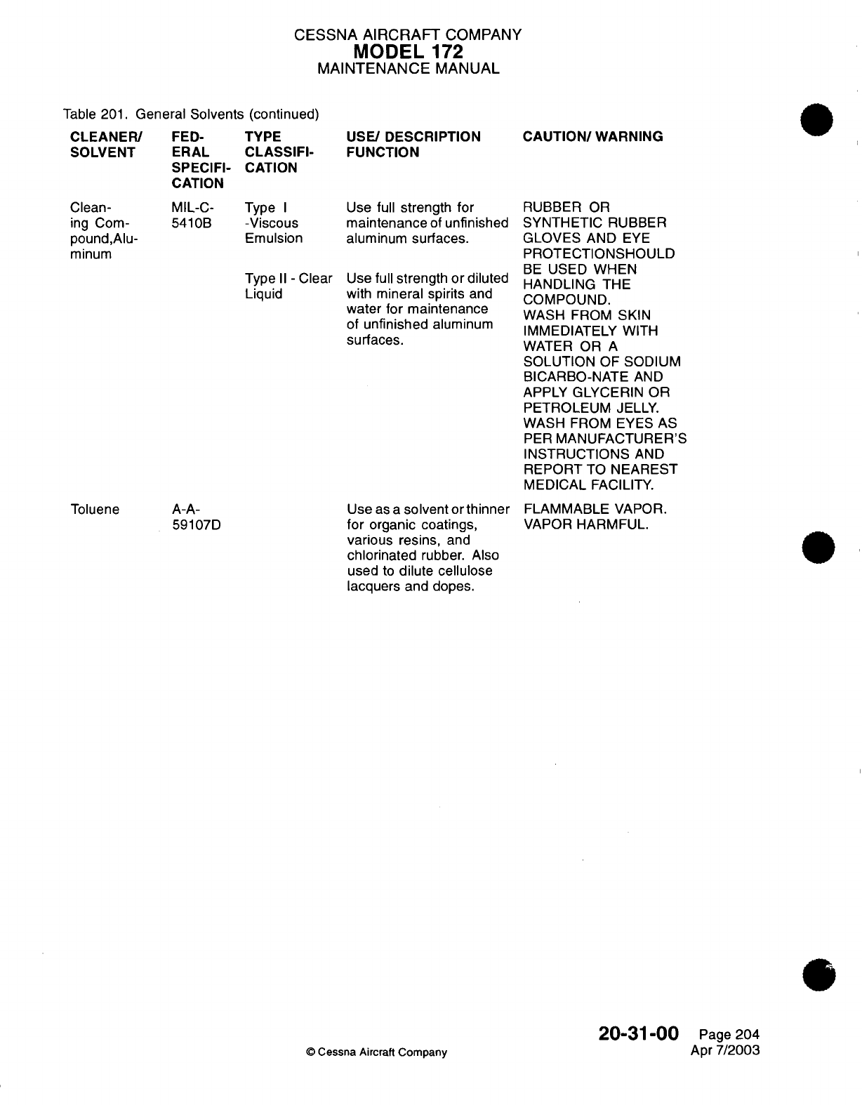
CESSNA
AIRCRAFT
COMPANY
MODEL
172
MAINTENANCE
MANUAL
Table
201.
General
Solvents
(continued)
FED-
ERAL
SPECIFI-
CATION
TYPE
CLASSIFI-
CATION
MIL-C-
Type
I
5410B
-Viscous
Emulsion
Type
II -
Clear
Liquid
A-A-
59107D
USE/
DESCRIPTION
FUNCTION
Use
full
strength
for
maintenance
of
unfinished
aluminum
surfaces.
Use
full
strength or
diluted
with
mineral spirits
and
water
for
maintenance
of
unfinished
aluminum
surfaces.
Use
as
a
solvent
or
thinner
for
organic
coatings,
various
resins,
and
chlorinated
rubber.
Also
used
to
dilute cellulose
lacquers
and
dopes.
CAUTION/
WARNING
RUBBER
OR
SYNTHETIC
RUBBER
GLOVES
AND
EYE
PROTECTIONSHOULD
BE
USED
WHEN
HANDLING
THE
COMPOUND.
WASH
FROM
SKIN
IMMEDIATELY WITH
WATER
OR
A
SOLUTION
OF
SODIUM
BICARBO-NATE
AND
APPLY
GLYCERIN
OR
PETROLEUM
JELLY.
WASH
FROM EYES
AS
PER
MANUFACTURER'S
INSTRUCTIONS
AND
REPORT
TO
NEAREST
MEDICAL
FACILITY.
FLAMMABLE VAPOR.
VAPOR
HARMFUL.
20-31-00
©
Cessna Aircraft
Company
CLEANER/
SOLVENT
Clean-
ing
Com-
pound,Alu-
minum
Toluene
Page
204
Apr
7/2003
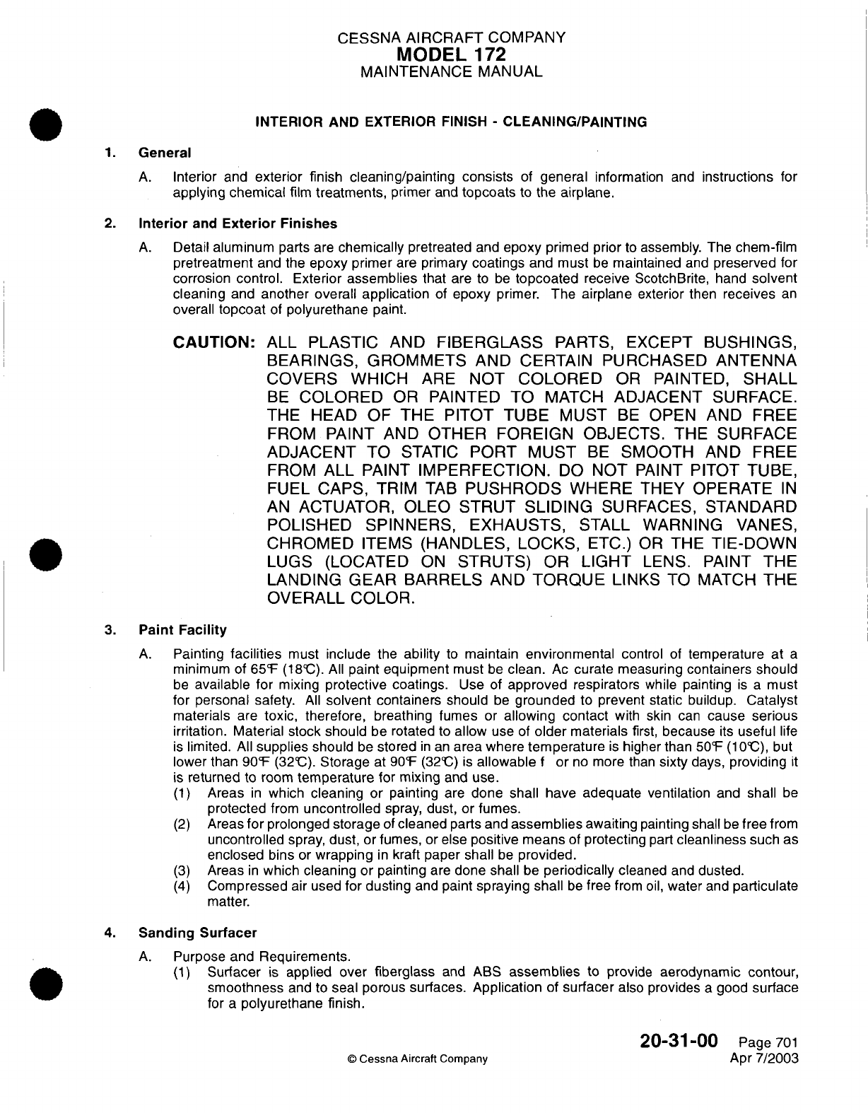
CESSNA
AIRCRAFT
COMPANY
MODEL
172
MAINTENANCE
MANUAL
INTERIOR AND
EXTERIOR FINISH
-
CLEANING/PAINTING
1.
General
A.
Interior
and
exterior
finish cleaning/painting
consists
of
general
information
and
instructions
for
applying chemical
film
treatments,
primer
and
topcoats
to
the
airplane.
2.
Interior
and
Exterior Finishes
A.
Detail
aluminum
parts
are
chemically
pretreated
and
epoxy
primed
prior
to
assembly.
The
chem-film
pretreatment
and the
epoxy primer
are primary
coatings
and
must
be
maintained
and
preserved
for
corrosion
control.
Exterior
assemblies
that
are
to be
topcoated
receive
ScotchBrite,
hand
solvent
cleaning
and
another
overall application
of
epoxy primer.
The
airplane
exterior
then
receives
an
overall
topcoat
of
polyurethane
paint.
CAUTION:
ALL
PLASTIC
AND
FIBERGLASS
PARTS,
EXCEPT
BUS-INGS,
BEARINGS, GROMMETS
AND
CERTAIN
PURCHASED
ANTENNA
COVERS
WHICH
ARE NOT
COLORED
OR
PAINTED,
SHALL
BE
COLORED
OR
PAINTED
TO
MATCH
ADJACENT
SURFACE.
THE
HEAD
OF THE
PITOT TUBE
MUST
BE
OPEN
AND
FREE
FROM PAINT
AND
OTHER
FOREIGN
OBJECTS.
THE
SURFACE
ADJACENT
TO
STATIC
PORT
MUST
BE
SMOOTH
AND
FREE
FROM
ALL
PAINT
IMPERFECTION.
DO
NOT
PAINT
PITOT TUBE,
FUEL
CAPS,
TRIM
TAB
PUSHRODS
WHERE
THEY
OPERATE
IN
AN
ACTUATOR,
OLEO
STRUT
SLIDING
SURFACES,
STANDARD
POLISHED
SPINNERS, EXHAUSTS,
STALL WARNING
VANES,
CHROMED
ITEMS
(HANDLES,
LOCKS,
ETC.)
OR
THE
TIE-DOWN
LUGS
(LOCATED
ON
STRUTS)
OR
LIGHT
LENS. PAINT
THE
LANDING
GEAR
BARRELS
AND
TORQUE
LINKS
TO
MATCH
THE
OVERALL COLOR.
3.
Paint
Facility
A.
Painting
facilities
must
include
the
ability
to
maintain environmental
control
of
temperature at
a
minimum of
65°F
(18°C).
All
paint equipment
must
be
clean.
Ac
curate
measuring
containers
should
be
available
for
mixing
protective
coatings.
Use
of
approved
respirators
while
painting
is
a
must
for personal safety.
All
solvent
containers should
be
grounded
to
prevent
static
buildup.
Catalyst
materials
are
toxic,
therefore,
breathing fumes
or
allowing contact
with skin
can
cause serious
irritation. Material stock
should
be rotated to
allow
use
of
older
materials
first,
because
its
useful
life
is
limited.
All
supplies
should
be
stored
in
an
area
where
temperature
is
higher
than
50°F
(1
0C),
but
lower than
90°F
(32°C).
Storage
at
90°F
(32°C)
is
allowable
f
or
no
more
than
sixty
days,
providing
it
is
returned
to
room
temperature for
mixing
and
use.
(1)
Areas
in
which
cleaning
or
painting
are
done
shall
have
adequate
ventilation
and
shall
be
protected
from
uncontrolled
spray, dust, or
fumes.
(2)
Areas
for
prolonged
storage
of
cleaned
parts
and
assemblies
awaiting
painting shall
be
free
from
uncontrolled spray,
dust,
or
fumes,
or
else
positive means
of
protecting
part
cleanliness
such
as
enclosed
bins
or
wrapping
in
kraft paper
shall
be
provided.
(3)
Areas
in
which cleaning
or
painting
are
done
shall
be
periodically
cleaned
and
dusted.
(4)
Compressed
air
used
for dusting
and
paint
spraying
shall
be
free
from
oil,
water
and
particulate
matter.
4.
Sanding
Surfacer
A.
Purpose and Requirements.
(1)
Surfacer
is
applied
over
fiberglass
and
ABS
assemblies
to
provide
aerodynamic
contour,
smoothness
and to
seal porous
surfaces.
Application
of
surfacer
also
provides
a
good
surface
for
a
polyurethane
finish.
20-31-00
©
Cessna
Aircraft
Company
Page
701
Apr
7/2003
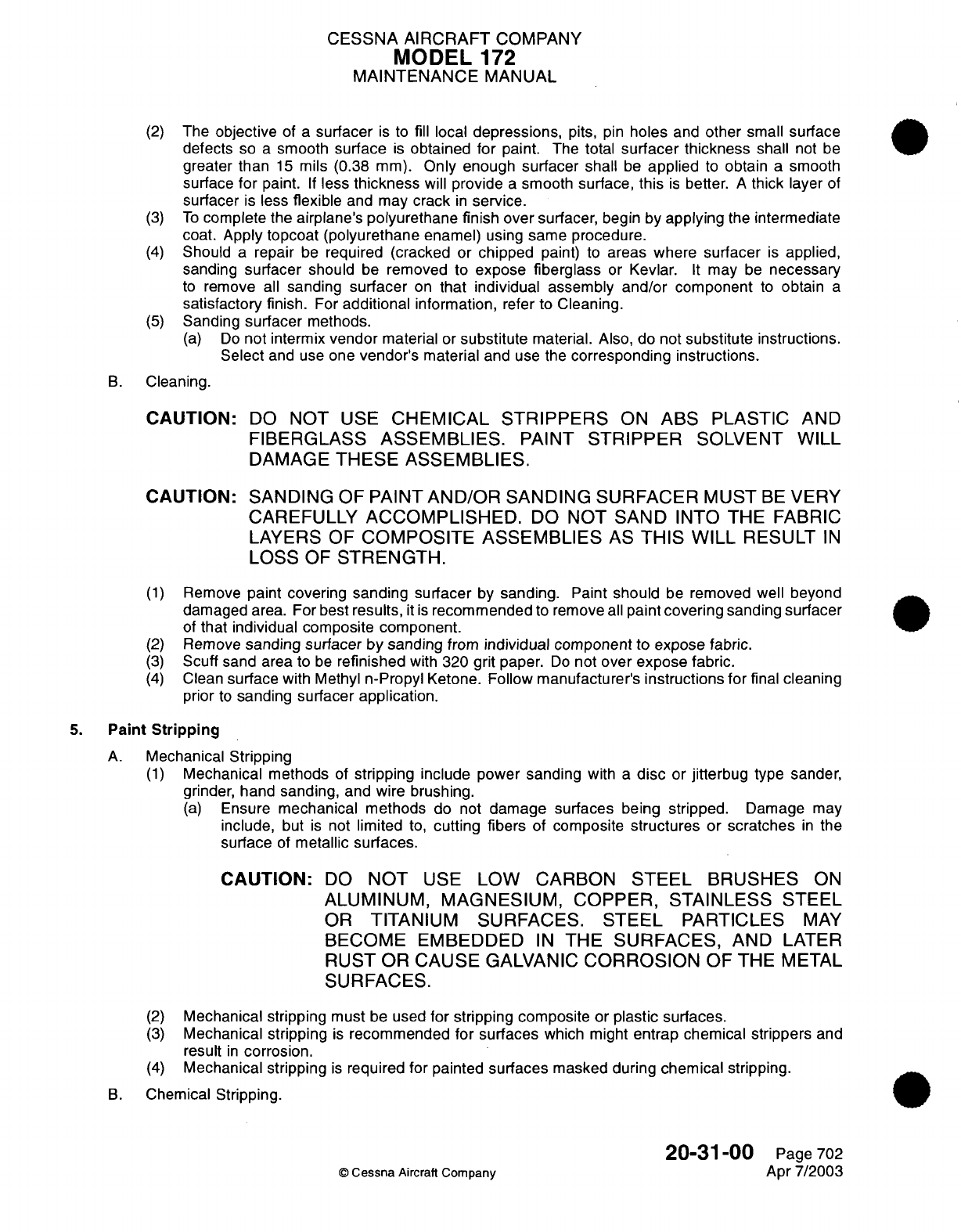
CESSNA AIRCRAFT
COMPANY
MODEL
172
MAINTENANCE
MANUAL
(2)
The
objective
of
a
surfacer
is
to
fill
local
depressions,
pits,
pin
holes
and
other
small
surface
defects
so
a
smooth
surface
is
obtained
for
paint.
The
total
surfacer thickness
shall
not
be
greater than
15
mils
(0.38
mm).
Only
enough
surfacer
shall
be
applied
to
obtain
a
smooth
surface
for
paint.
If
less
thickness
will
provide
a
smooth
surface,
this
is
better.
A
thick
layer
of
surfacer
is
less
flexible
and may
crack
in
service.
(3)
To
complete
the
airplane's
polyurethane
finish
over surfacer,
begin
by
applying
the
intermediate
coat.
Apply topcoat (polyurethane
enamel)
using
same procedure.
(4)
Should
a
repair
be
required (cracked
or
chipped
paint)
to
areas
where
surfacer
is
applied,
sanding
surfacer should
be
removed
to
expose
fiberglass
or
Kevlar.
It
may
be
necessary
to
remove all
sanding
surfacer
on
that individual
assembly
and/or
component
to
obtain
a
satisfactory
finish.
For
additional
information,
refer to
Cleaning.
(5)
Sanding
surfacer
methods.
(a)
Do
not intermix
vendor
material
or
substitute
material.
Also,
do
not
substitute
instructions.
Select
and
use
one
vendor's
material
and use the
corresponding
instructions.
B.
Cleaning.
CAUTION:
CAUTION:
DO
NOT
USE
CHEMICAL
STRIPPERS
ON
ABS
PLASTIC
AND
FIBERGLASS
ASSEMBLIES.
PAINT
STRIPPER
SOLVENT WILL
DAMAGE
THESE ASSEMBLIES.
SANDING
OF
PAINT
AND/OR
SANDING
SURFACER
MUST
BE
VERY
CAREFULLY
ACCOMPLISHED.
DO
NOT
SAND INTO
THE
FABRIC
LAYERS OF
COMPOSITE
ASSEMBLIES
AS
THIS
WILL
RESULT
IN
LOSS
OF
STRENGTH.
(1)
Remove
paint covering
sanding surfacer
by
sanding.
Paint
should
be
removed well
beyond
damaged
area. For
best
results,
it
is
recommended
to remove
all
paint
covering
sanding
surfacer
of
that
individual
composite
component.
(2)
Remove
sanding surfacer
by
sanding
from
individual
component
to
expose fabric.
(3)
Scuff sand
area
to
be
refinished
with
320 grit
paper.
Do
not
over
expose fabric.
(4)
Clean
surface
with
Methyl
n-Propyl
Ketone.
Follow
manufacturer's
instructions for
final
cleaning
prior
to
sanding
surfacer application.
5.
Paint
Stripping
A.
Mechanical
Stripping
(1)
Mechanical methods
of
stripping
include
power
sanding
with
a
disc
or
jitterbug
type
sander,
grinder,
hand sanding, and wire brushing.
(a)
Ensure
mechanical methods
do not
damage
surfaces
being
stripped.
Damage
may
include,
but
is
not
limited
to,
cutting fibers
of
composite
structures
or
scratches
in
the
surface
of
metallic
surfaces.
CAUTION:
DO
NOT
USE
LOW
CARBON
STEEL
BRUSHES
ON
ALUMINUM,
MAGNESIUM,
COPPER, STAINLESS
STEEL
OR
TITANIUM SURFACES.
STEEL
PARTICLES
MAY
BECOME
EMBEDDED
IN
THE
SURFACES,
AND
LATER
RUST
OR
CAUSE
GALVANIC
CORROSION
OF THE
METAL
SURFACES.
(2)
Mechanical stripping
must
be
used
for
stripping composite
or
plastic surfaces.
(3)
Mechanical
stripping
is
recommended
for surfaces
which might
entrap chemical strippers
and
result
in
corrosion.
(4)
Mechanical
stripping
is
required
for painted
surfaces
masked during
chemical
stripping.
B.
Chemical
Stripping.
©
Cessna
Aircraft Company
20-31-00
Page
702
Apr
7/2003
CESSNA
AIRCRAFT
COMPANY
MODEL
172
MAINTENANCE
MANUAL
WARNING:
ALL
PAINT
STRIPPERS
ARE
HARMFUL
TO
EYES
AND
SKIN.
ALL
OPERATORS SHOULD
WEAR
GOGGLE-TYPE
EYEGLASSES,
RUBBER
GLOVES,
APRONS
AND
BOOTS.
IN
CASE
OF
CONTACT
WITH
SKIN,
FLUSH
WITH
WATER.
IN
CASE
OF
CONTACT
WITH
EYES,
FLUSH
EYES
THOROUGHLY
WITH
WATER
AND
CONSULT
PHYSICIAN
IMMEDIATELY.
PAINT
STRIPPING SHOULD
BE
DONE
IN
A
WELL
VENTILATED
AREA.
WARNING:
USE
OF
A
HEATER WITH
AN
OPEN
FLAME
IN
AN
AREA
IN WHICH
STRIPPING
WITH
A
METHYLENE CHLORIDE
TYPE
STRIPPER
IS
USED
PRODUCES
HYDROCHLORIC
ACID
FUMES.
IF
ACID
IS
DEPOSITED
ON
AIRPLANE
IT
WILL
CORRODE
ALL
SURFACES.
(1)
Thoroughly clean airplane surfaces
to
remove
all
grease
and
other
dirt
which
might
keep
stripping agent
from
attacking
paint.
(2)
All
seams
and
joints
must
be
protected by
applying
a
tape,
resistant
to
strippers,
to
every
joint
to
prevent
stripping chemicals
from
entering
the
skin
joints.
Chemicals
used
for stripping
polyurethane paint
are
very difficult
to
remove
from
joints,
and
may
promote
corrosion
or
deteriorate
bonding agents
used
in
assembly
of
airplane.
(3)
Mask
following
surfaces
using
plastic sheeting
or
waxed
paper
and
plastic tape
so
as
to
make
a
safety
margin
of
at
least
one-half
inch
(13
mm)
between
protected
surface
and
surface
to
be
stripped.
NOTE:
Do
not
use
masking
tape.
(a)
Mask
all
windows
and transparencies.
CAUTION:
ACRYLIC
WINDOWS
MAY BE
SOFTENED
OR
OTHERWISE
DAMAGED
BY
PAINT
STRIPPER,
SOLVENT
OR
PAINT.
USE
WATER
AND
GREASE-PROOF
BARRIER
MATERIAL
AND
POLYETHYLENE
COATED
TAPE
TO
PROTECT WINDOWS.
1
Place
barrier
material
over
window
and
seal around periphery
with
polyethylene
backed masking
tape.
2
Cut
second sheet
of
barrier material
an
inch
(26
mm)
or
more
larger
than
window.
3
Place
second sheet
of
barrier material
over
window
and
seal with
polyethylene
tape.
(b)
Mask
all
rubber
and
other
non
metals.
(c)
Composites
if
possible,
shall
be
removed
from
airplane prior
to
stripping.
(d)
Mask
all
honeycomb
panels
and
all
fasteners
which
penetrate
honeycomb panels.
(e)
Mask
all
pivots, bearings
and
landing
gear.
(f)
Titanium,
if
used
on
airplane,
must
be
protected
from
strippers.
(g)
Mask
all
skin
laps,
inspection
holes, drain
holes, or
any opening
that
would allow
stripper
to
enter
airplane
structure.
CAUTION:
DO
NOT
ALLOW
PAINT
STRIPPER
TO
CONTACT
HIGH
HEAT
TREATED
STEEL
PINS,
SUCH
AS
PINS
ATTACI-IING
LANDING
GEAR
COMPONENTS.
PAINT
STRIPPERS
MAY
INDUCE
HYDROGEN
EMBRITTLEMENT
IN
HIGH
HEAT
TREATED
STEEL.
(4)
Apply
approved
stripper
by
spray
or
brush
method.
20-31-00
Page
703
©
Cessna
Aircraft
Company
Apr
7/2003
CESSNA
AIRCRAFT
COMPANY
MODEL
172
MAINTENANCE
MANUAL
WARNING:
USE
NORMAL
SAFETY PRECAUTIONS
WHEN
USING
FLAMMABLE
MATERIALS
DURING
CLEANING
AND PAINTING
PROCEDURES.
WARNING:
PAINT
STRIPPER
SOLUTION
IS
HARMFUL
TO
EYES
AND
SKIN.
WEAR
GOGGLES,
RUBBER
GLOVES,
APRON
AND BOOTS
WHEN
WORKING
WITH PAINT
STRIPPER.
ALSO
WEAR
APPROPRIATE
RESPIRATOR
WHEN
APPLYING
"SPRAY-ON"
STRIPPERS.
THE
CHEMICAL
SUPPLIER
BULLETINS
AND
INSTRUCTIONS SHOULD
BE
CLOSELY
FOLLOWED
FOR
PROPER
MIXING OF
SOLUTION,
APPILICATION
METHODS
AND SAFETY
PRECAUTIONS.
(a) If
using
spray
method,
apply
a
mist
coat
to
area
to
be
stripped,
then when
paint begins
to
lift,
apply
a
second
heavy
coat.
(b) If
applying
with
brush,
brush
across
the
surface
only
once,
in
one
direction.
(5)
Allow
stripper coating
to
lay
on
the
surface
until
paint
lifts.
(6)
After
paint
begins
to
lift,
use a
propylene
bristle
brush
to
agitate
stripper
to
allow
deeper
penetration
of
stripper.
(7)
Remove
lifted
paint
with
a
plastic squeegee.
Dispose of residue
in
accordance
with local
regulations.
(8)
Inspect all
surfaces
for
incomplete
paint
removal.
(a)
Repeat
previous
procedural steps
as
necessary
until
all
paint
is
removed.
(9)
After stripping
airplane,
thoroughly
rinse
to
remove
any
stripping
residue.
(10)
Remove
tape
applied
to
protect
joints
and
other
masked
areas.
(11)
Carefully
remove
remaining paint
at
skin
joints
and
masked
areas
by
sanding
with
a
hand
or
jitterbug
type
sander.
(12)
If
necessary
to
remove paint
from
inside
skin
joints,
refer
to
Cleanout
of
Skin
Joints.
(13)
If
corrosion
is
encountered,
refer
to
Structural Repair
Manual,
Chapter
51,
Corrosion/Repair,
for
corrosion treatment.
C.
Cleanout of
Skin
Joints.
(1)
Install
a
surface
conditioning
disc
on a
pneumatic
drill.
(2)
Taper
edge
of
disc
to
an
edge
which
will
allow
edge
to
fit
into
skin
joint
seam.
(a)
Run
disc
against
a
piece
of
coarse
abrasive
paper
or
a
mill
file
until
edge
is
tapered.
CAUTION:
EXCESSIVE
PRESSURE
OR
DWELL TIME
WILL
CAUSE
SCRATCHES
OR
GROOVES
IN
METAL.
ENSURE
DOUBLER
AT
BOTTOM OF
JOINT
IS
NOT DAMAGED
OR
GOUGED
IN
ANY
WAY
BY
THIS PROCESS.
(3)
Using
tapered
surface
conditioning
disc,
remove
paint
and
other
material from
joint
seams.
(4)
Carefully,
and using as
low
speed
as
possible,
remove
paint
and
all
other material
from
joint.
NOTE:
Surface
conditioning
disc will wear
rapidly,
it
will
be
necessary
to
resharpen
(retaper)
disc
frequently.
20-31-00
Page
704
©
Cessna
Aircraft
Company
Apr
7/2003
CESSNA
AIRCRAFT
COMPANY
MODEL
172
MAINTENANCE
MANUAL
6.
Hand
Solvent
Cleaning
WARNING:
WORK
IN
A
WELL
VENTILATED
AREA
FREE
FROM
SOURCES
OF
IGNITION.
USE
ONLY
APPROVED
SOLVENTS
AND
MATERIALS.
CAUTION:
AIRPLANE
SHALL
BE
GROUNDED
DURING SOLVENT WIPE.
A.
Surface Cleaning.
(1)
Apply
solvent
to
a
clean
wiping
cloth
by
pouring
from
a
safety
can
or
other
approved container.
The
cloth
should
be
well saturated
with
solvent.
Avoid
dipping
wipers
into
open
solvent
containers
as
this contaminates
the
solvent.
(2)
Wipe the
surface
with
the wet
cloth
as
required
to
dissolve
or
loosen
soils.
Work
on
a
small
enough area
so
that the area
being
cleaned
remains
wet with
solvent.
(3)
With
a
clean
dry
cloth,
immediately
wipe
dry the
area being
cleaned.
Do
not
allow
the surface
to
evaporate
dry.
(4)
Repeat
steps
(1)
through
(3)
as
required
and change
cloths
often.
7.
Maintenance
of
the
Interior
and
Exterior
Primary
Coatings
and
Topcoat
A.
Rework
and
repair
primary
coatings
on
airplane interior
and
exterior
surfaces
for protection
and
corrosion
control.
(1)
Minor
scratches
or
defects,
which
do
not
penetrate
the
epoxy
primer
or which
penetrate
the
primer
and
expose
bare
metal,
with the
total
area
of
exposed
bare
metal
less
than the size
of
a
dime,
touch
up
as
follows:
(a)
Hand
solvent
clean
and
sand
with
320
grit
or
finer
sandpaper.
(b)
Clean
with
compressed
air,
hand
solvent
clean
again, then
wipe
with
a
tack
rag.
(c)
Mix
and
reapply epoxy
primer
(MIL
P-23377
or
equivalent)
as
directed
by
the primer
manufacturer
or
supplier.
(d)
On
a
properly prepared
surface,
mix
and
apply
polyurethane
topcoat
as
directed
by
the
paint
manufacturer
or
supplier.
(2)
Major
defects
which
expose
bare
metal to
an
area
larger
than
the
size
of
a
dime,
touch
up
as
follows:
(a)
Hand
solvent
clean
and
sand
with
320
grit
or
finer
sandpaper.
(b)
Clean
with
compressed
air,
hand
solvent
clean again,
then wipe
with
a
tack
rag.
(c)
Apply
a
spray wash primer
or
(preferred
method) brush
chem
film
primer.
Mask
the
area
to
minimize
the
amount
of
primer
from
spreading
over
the existing
epoxy
primer.
Let
cure
according
to
the product
manufacturers
recommendations.
(d)
Mix
and
apply
epoxy
primer
(MIL
P-23377
or
equivalent)
to
the
affected area
within
four
hours.
(e) If
an
exterior
painted
surface,
mix
and
apply
polyurethane topcoat
as
directed
by
the
paint
manufacturer
or
supplier.
20-31-00
Page
705
©
Cessna
Aircraft
Company
Apr
7/2003
CESSNA
AIRCRAFT
COMPANY
MODEL
172
MAINTENANCE
MANUAL
FUEL,
WEATHER AND
HIGH-TEMPERATURE
SEALING
-
MAINTENANCE PRACTICES
1.
General
A.
Procedures for
application
of
sealants
are
provided
for
various
types
of
sealing
required
for
the
airplane.
2.
Tools
and
Equipment
NOTE:
Specified sealants,
cleaning
solvents,
parting
agents, adhesion
inhibitors
and
equipment
are
listed
for
use.
Suitable
substitutes
may
be
used
for
sealing
equipment
only.
Table
201.
Sealants
Type
I,
Class
A-1/2,
or
A-2-AMS-S-8802
NUMBER
GC-408
Pro-Seal
890
PR-1440
MANUFACTURER
Goal Chemical
Sealant
Corp.
3137
East
26th
Street
Los
Angeles,
CA
90023
PRC-DeSoto
International
5454
San
Fernando
Rd.
Glendale,
CA
91209
PRC-DeSoto
International
USE
Fuel,
pressure
and
weather sealant
brush
application.
Table 202.
Sealants
Type
I,
Class
B-1/4,
Quick
Repair-MIL-S-83318
GC-435
Goal Chemical
Sealant
Corp.
Fuel,
pressure
and
weather
sealant.
For
limited repairs requiring
rapid
curing
sealant.
Table
203.
Sealants
Type
I,
Class
B-1/2,
B-2
or
B-4-AMS-S-8802
MANUFACTURER
PRC-DeSoto International
USE
Fuel
pressure
and
weather sealant,
suitable
for
application
by
extrusion
gun
and
spatula.
AC-236
CS
3204
Pro
Seal
890
Advanced
Chemistry
And
Technology
Flamemaster
Corporation
PRC-DeSoto
International
20-32-00
©
Cessna Aircraft Company
NAME
Sealants
Sealant
NAME
Sealants
NUMBER
PR-1440
Page
201
Jul
3/2006
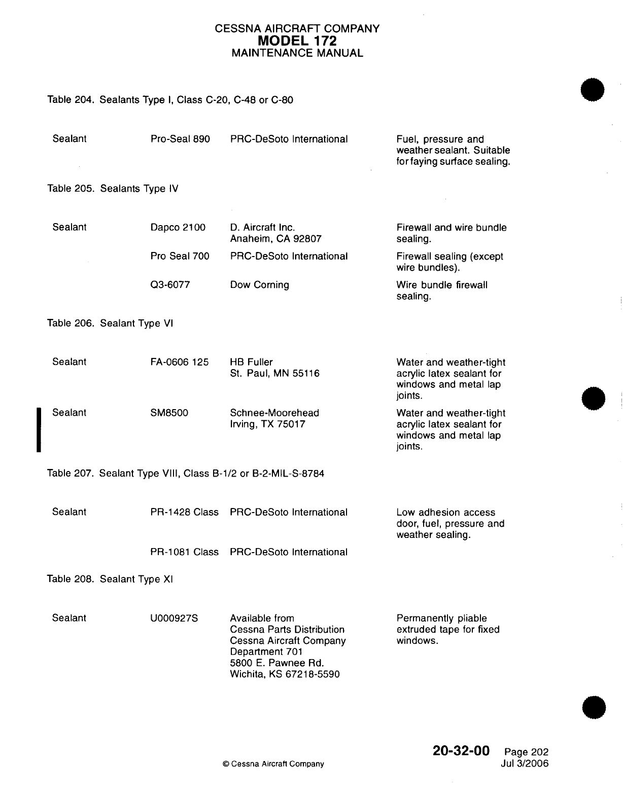
CESSNA AIRCRAFT
COMPANY
MODEL
172
MAINTENANCE
MANUAL
Table
204.
Sealants
Type
I,
Class
C-20, C-48
or
C-80
Pro-Seal
890
PRC-DeSoto
International
Fuel,
pressure
and
weather
sealant.
Suitable
for
faying
surface
sealing.
Table
205. Sealants
Type IV
Dapco
2100
Pro
Seal
700
Q3-6077
D.
Aircraft
Inc.
Anaheim,
CA
92807
PRC-DeSoto
International
Dow
Corning
Firewall
and
wire
bundle
sealing.
Firewall
sealing
(except
wire
bundles).
Wire
bundle
firewall
sealing.
Table
206.
Sealant
Type
VI
FA-0606
125
SM8500
HB
Fuller
St.
Paul,
MN
55116
Schnee-Moorehead
Irving,
TX
75017
Water and
weather-tight
acrylic
latex
sealant
for
windows
and
metal
lap
joints.
Water and
weather-tight
acrylic
latex
sealant
for
windows
and
metal
lap
joints.
Table
207.
Sealant
Type
VIII,
Class
B-1/2
or
B-2-MIL-S-8784
PR-1428 Class
PRC-DeSoto
International
Low
adhesion access
door,
fuel,
pressure
and
weather sealing.
PR-1081
Class
PRC-DeSoto
International
Table
208.
Sealant
Type
Xl
Available
from
Cessna
Parts
Distribution
Cessna Aircraft
Company
Department
701
5800
E.
Pawnee
Rd.
Wichita,
KS
67218-5590
©
Cessna
Aircraft Company
Permanently
pliable
extruded
tape
for
fixed
windows.
20-32-00
Page
202
Jul
3/2006
Sealant
Sealant
Sealant
I
Sealant
Sealant
Sealant
U000927S
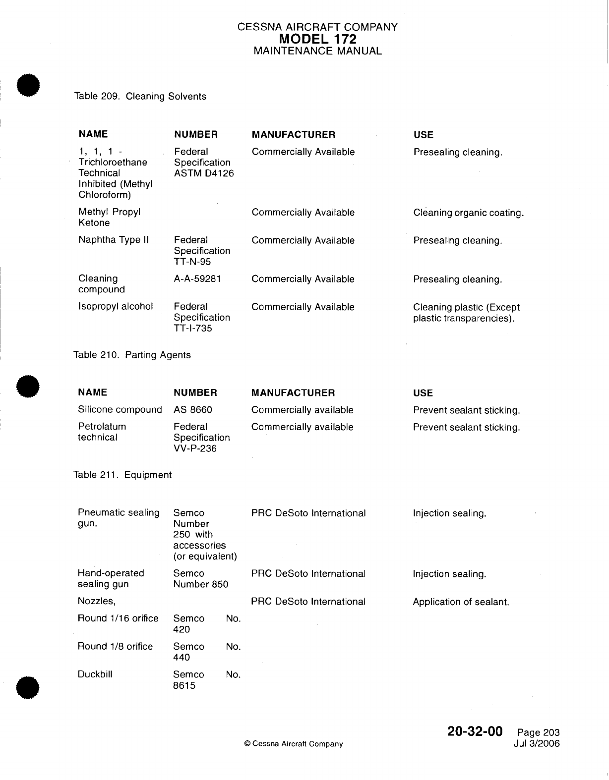
CESSNA
AIRCRAFT
COMPANY
MODEL
172
MAINTENANCE
MANUAL
Table
209.
Cleaning
Solvents
NAME
1,
1,
1 -
Trichloroethane
Technical
Inhibited
(Methyl
Chloroform)
Methyl
Propyl
Ketone
Naphtha
Type
II
Cleaning
compound
Isopropyl
alcohol
Table 210.
Parting
NAME
Silicone
compounc
Petrolatum
technical
NUMBER
Federal
Specification
ASTM
D4126
Federal
Specification
TT-N-95
A-A-59281
Federal
Specification
TT-I-735
Agents
NUMBER
AS
8660
Federal
Specification
VV-P-236
MANUFACTURER
Commercially
Available
Commercially Available
Commercially
Available
Commercially Available
Commercially Available
MANUFACTURER
Commercially
available
Commercially available
USE
Presealing
cleaning.
Cleaning
organic coating.
Presealing
cleaning.
Presealing
cleaning.
Cleaning
plastic
(Except
plastic transparencies).
USE
Prevent
sealant
sticking.
Prevent
sealant
sticking.
Table
211.
Equipment
Pneumatic sealing
gun.
Hand-operated
sealing
gun
Nozzles,
Round
1/16
orifice
Round
1/8
orifice
Duckbill
Semco
Number
250
with
accessories
(or
equivalent)
Semco
Number
850
Semco
420
Semco
440
Semco
8615
PRC
DeSoto International
PRC
DeSoto International
PRC
DeSoto
International
Injection
sealing.
Injection
sealing.
Application
of
sealant.
No.
No.
No.
©
Cessna
Aircraft
Company
20-32-00
Page
203
Jul
3/2006
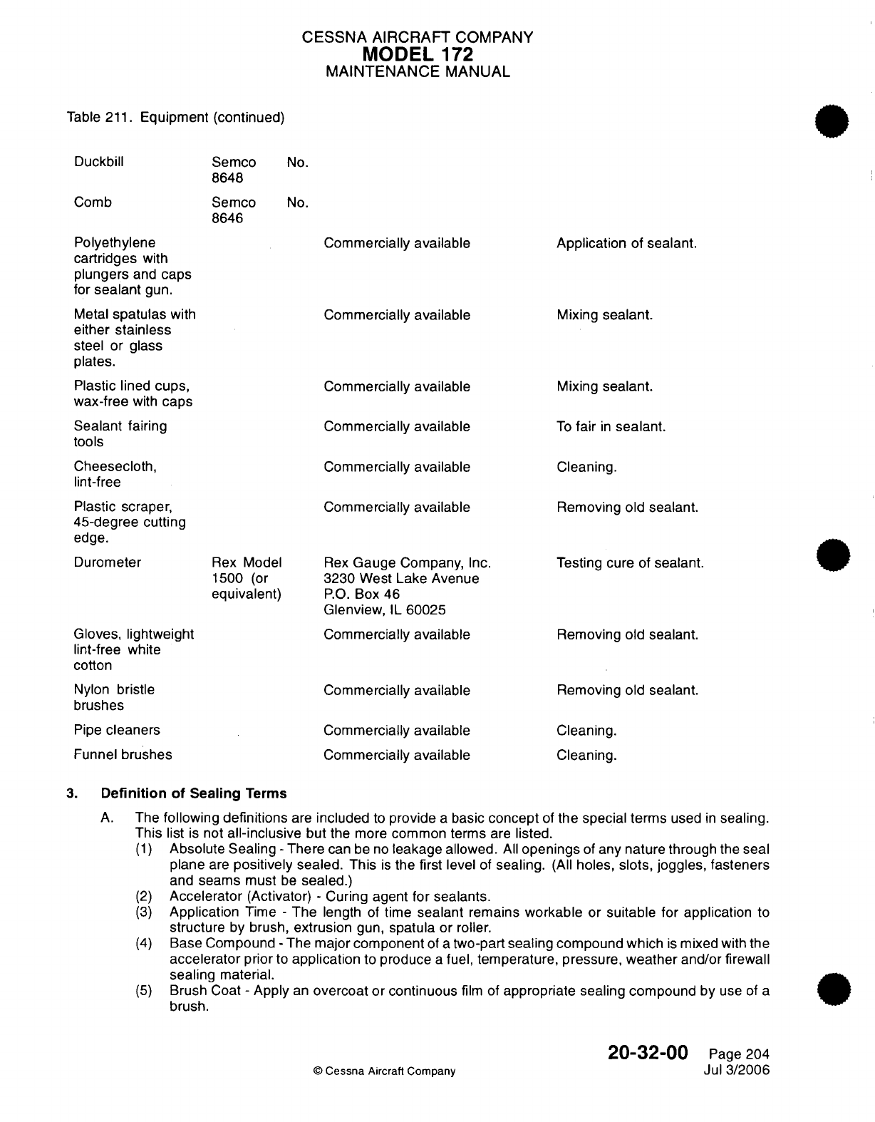
CESSNA AIRCRAFT
COMPANY
MODEL
172
MAINTENANCE
MANUAL
Table
211.
Equipment
(continued)
Duckbill
Semco
8648
Semco
8646
Comb
No.
No.
Polyethylene
cartridges
with
plungers
and
caps
for
sealant
gun.
Metal
spatulas
with
either
stainless
steel
or
glass
plates.
Plastic
lined
cups,
wax-free
with
caps
Sealant
fairing
tools
Cheesecloth,
lint-free
Plastic
scraper,
45-degree
cutting
edge.
Durometer
Rex
Model
1500
(or
equivalent)
Gloves,
lightweight
lint-free
white
cotton
Nylon
bristle
brushes
Pipe
cleaners
Funnel
brushes
Commercially
available
Commercially
available
Commercially
available
Commercially
available
Commercially
available
Commercially
available
Rex
Gauge
Company,
Inc.
3230
West Lake Avenue
P.O.
Box
46
Glenview,
IL
60025
Commercially
available
Commercially
available
Commercially
available
Commercially
available
Application
of
sealant.
Mixing
sealant.
Mixing
sealant.
To
fair
in
sealant.
Cleaning.
Removing old
sealant.
Testing cure
of
sealant.
Removing
old sealant.
Removing
old
sealant.
Cleaning.
Cleaning.
3.
Definition of
Sealing
Terms
A.
The
following
definitions
are
included
to
provide
a
basic
concept
of
the special terms
used
in
sealing.
This
list
is
not
all-inclusive
but
the
more
common
terms
are
listed.
(1)
Absolute Sealing
-
There
can
be
no
leakage
allowed.
All
openings
of
any
nature through the
seal
plane
are
positively
sealed.
This
is
the
first level
of
sealing.
(All
holes,
slots, joggles, fasteners
and
seams
must
be
sealed.)
(2)
Accelerator
(Activator)
-
Curing
agent
for
sealants.
(3)
Application
Time
-
The
length
of
time
sealant
remains
workable
or
suitable
for
application
to
structure
by
brush,
extrusion
gun,
spatula
or
roller.
(4)
Base
Compound
-
The major
component
of
a
two-part
sealing compound which
is
mixed with
the
accelerator
prior
to
application
to
produce
a
fuel,
temperature, pressure,
weather
and/or
firewall
sealing
material.
(5)
Brush
Coat
-
Apply
an
overcoat
or
continuous
film
of
appropriate sealing compound
by
use
of
a
brush.
20-32-00
©
Cessna
Aircraft
Company
Page
204
Jul
3/2006
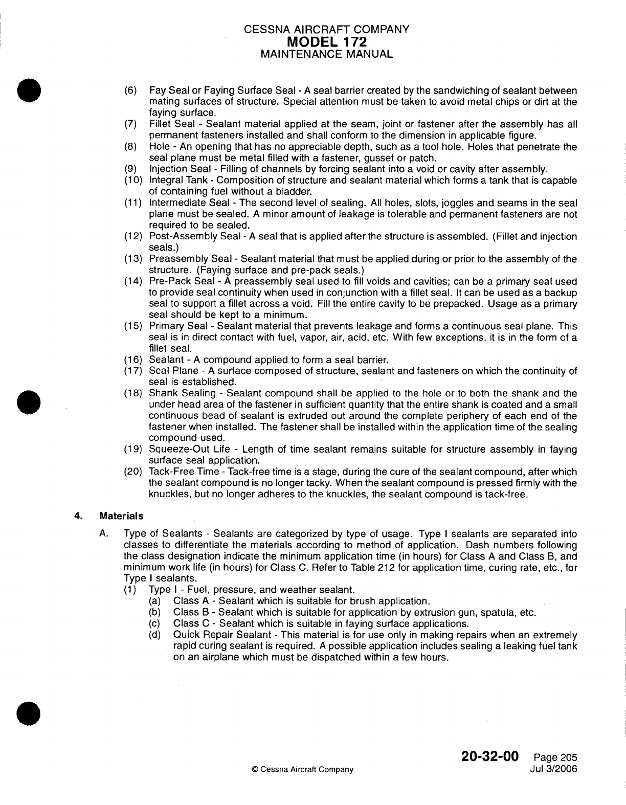
CESSNA
AIRCRAFT
COMPANY
MODEL
172
MAINTENANCE
MANUAL
(6)
Fay
Seal
or
Faying
Surface
Seal
-
A
seal
barrier
created
by
the
sandwiching
of
sealant
between
mating
surfaces
of
structure. Special
attention
must
be
taken
to
avoid
metal
chips
or
dirt
at
the
faying surface.
(7)
Fillet Seal
-
Sealant
material
applied
at
the
seam,
joint
or
fastener
after the
assembly
has
all
permanent
fasteners
installed
and
shall
conform
to
the dimension
in
applicable
figure.
(8)
Hole
-
An
opening that has
no
appreciable
depth, such
as
a
tool
hole. Holes
that
penetrate
the
seal
plane
must
be
metal
filled
with
a
fastener,
gusset
or
patch.
(9)
Injection Seal
-
Filling
of
channels
by
forcing
sealant
into
a
void
or
cavity after
assembly.
(10)
Integral Tank
-
Composition
of
structure
and
sealant
material
which forms
a
tank
that
is
capable
of
containing
fuel
without
a
bladder.
(11)
Intermediate
Seal
-
The
second
level
of
sealing.
All
holes, slots,
joggles
and
seams
in
the
seal
plane must
be
sealed.
A
minor
amount
of
leakage
is
tolerable
and
permanent
fasteners
are
not
required
to
be
sealed.
(12)
Post-Assembly
Seal
-
A
seal that
is
applied
after
the
structure
is
assembled.
(Fillet
and injection
seals.)
(13)
Preassembly
Seal
-
Sealant
material
that
must
be
applied
during or prior
to
the
assembly
of
the
structure.
(Faying
surface
and
pre-pack
seals.)
(14)
Pre-Pack
Seal
-
A
preassembly
seal
used to fill
voids
and
cavities;
can
be a
primary seal
used
to
provide seal
continuity
when
used
in
conjunction
with
a
fillet
seal.
It
can
be
used
as
a
backup
seal
to
support
a
fillet
across
a
void.
Fill
the entire
cavity
to
be
prepacked.
Usage
as
a
primary
seal
should
be
kept
to
a
minimum.
(15)
Primary Seal
-
Sealant
material
that prevents
leakage
and
forms
a
continuous
seal
plane.
This
seal
is
in
direct
contact
with
fuel,
vapor,
air,
acid,
etc.
With
few
exceptions,
it
is
in
the
form
of
a
fillet
seal.
(16)
Sealant
-
A
compound
applied
to
form
a
seal
barrier.
(17)
Seal
Plane
-
A
surface
composed
of
structure, sealant
and
fasteners
on
which
the
continuity
of
seal
is
established.
(18)
Shank Sealing
-
Sealant
compound
shall
be
applied
to
the hole
or
to
both
the
shank
and
the
under head area
of the
fastener
in
sufficient
quantity
that
the
entire
shank
is
coated
and
a
small
continuous
bead
of
sealant
is
extruded
out
around
the
complete
periphery
of
each
end
of
the
fastener
when
installed.
The
fastener
shall
be
installed within
the
application
time
of
the sealing
compound
used.
(19)
Squeeze-Out
Life
-
Length
of
time
sealant
remains
suitable for
structure
assembly
in
faying
surface
seal
application.
(20)
Tack-Free
Time
-
Tack-free
time
is
a
stage, during
the cure
of
the
sealant
compound, after
which
the
sealant
compound
is
no
longer tacky.
When
the
sealant
compound
is
pressed firmly
with
the
knuckles,
but
no
longer
adheres
to
the
knuckles,
the
sealant
compound
is
tack-free.
4.
Materials
A.
Type
of
Sealants
-
Sealants
are
categorized
by
type
of
usage.
Type
I
sealants
are
separated
into
classes
to
differentiate
the
materials according to
method
of
application.
Dash
numbers
following
the
class
designation indicate
the minimum
application
time
(in
hours)
for
Class
A
and Class
B,
and
minimum
work
life
(in
hours)
for
Class
C.
Refer to
Table
212
for
application
time,
curing
rate,
etc.,
for
Type
I
sealants.
(1)
Type
I -
Fuel,
pressure,
and
weather
sealant.
(a)
Class
A
-
Sealant
which
is
suitable
for
brush
application.
(b)
Class
B
-
Sealant
which
is
suitable
for application
by
extrusion
gun,
spatula,
etc.
(c)
Class
C
-
Sealant
which
is
suitable
in
faying
surface
applications.
(d)
Quick
Repair
Sealant
-
This
material
is
for
use
only
in
making
repairs
when
an
extremely
rapid
curing
sealant
is
required.
A
possible
application includes
sealing
a
leaking
fuel
tank
on an
airplane
which must
be
dispatched
within
a
few hours.
20-32-00
Page
205
©
Cessna
Aircraft
Company
Jul
3/2006
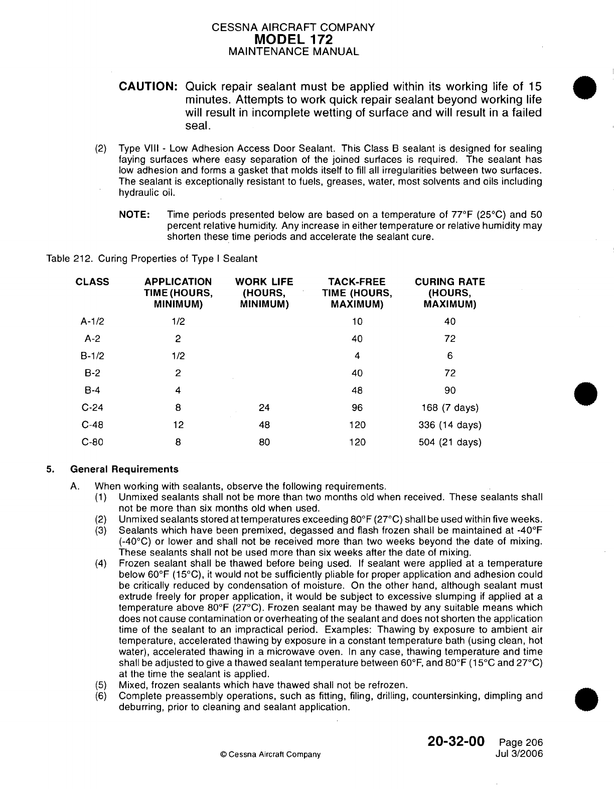
CESSNA
AIRCRAFT
COMPANY
MODEL
172
MAINTENANCE
MANUAL
CAUTION:
Quick
repair
sealant
must
be
applied
within
its
working
life
of
15
minutes. Attempts to
work
quick
repair
sealant
beyond working
life
will
result
in
incomplete wetting
of
surface
and
will
result
in
a
failed
seal.
(2)
Type
VIII
-
Low
Adhesion
Access
Door
Sealant. This
Class
B
sealant
is
designed
for
sealing
faying surfaces where
easy
separation
of
the
joined
surfaces
is
required. The
sealant
has
low
adhesion
and
forms
a
gasket
that
molds
itself
to fill
all
irregularities
between
two
surfaces.
The
sealant
is
exceptionally
resistant to
fuels,
greases,
water,
most
solvents
and
oils including
hydraulic
oil.
NOTE:
Time
periods
presented below
are
based
on a
temperature of
77°F
(25°C)
and
50
percent
relative
humidity.
Any increase
in
either
temperature
or
relative
humidity
may
shorten
these
time
periods
and
accelerate
the
sealant
cure.
Table
212.
Curing
Properties
of
Type
I
Sealant
CLASS
APPLICATION WORK
LIFE
TACK-FREE
CURING
RATE
TIME(HOURS,
(HOURS,
TIME (HOURS,
(HOURS,
MINIMUM) MINIMUM) MAXIMUM)
MAXIMUM)
A-1/2
1/2
10
40
A-2
2
40
72
B-1/2
1/2
4
6
B-2
2
40
72
B-4
4
48
90
C-24
8
24
96
168
(7
days)
C-48
12
48
120
336
(14
days)
C-80
8
80
120
504
(21
days)
5.
General
Requirements
A.
When
working
with
sealants, observe
the
following
requirements.
(1)
Unmixed
sealants
shall
not be more
than
two
months
old when
received.
These
sealants
shall
not
be
more
than
six months
old
when used.
(2)
Unmixed
sealants
stored
at
temperatures exceeding
80°F
(27°C)
shall
be
used
within
five
weeks.
(3)
Sealants
which have
been
premixed,
degassed
and flash frozen
shall
be
maintained
at
-40°F
(-40°C)
or
lower
and
shall not
be
received
more
than
two
weeks beyond
the
date
of
mixing.
These
sealants
shall
not
be
used
more
than
six
weeks
after the
date of
mixing.
(4)
Frozen
sealant
shall
be
thawed
before being used.
If
sealant
were
applied
at
a
temperature
below
60°F
(15°C),
it
would not
be
sufficiently
pliable for
proper
application
and
adhesion could
be
critically
reduced
by
condensation
of moisture.
On
the
other
hand,
although
sealant
must
extrude
freely
for proper
application,
it
would
be
subject
to
excessive
slumping
if
applied
at
a
temperature above
80°F
(27°C).
Frozen
sealant
may
be
thawed
by
any suitable
means
which
does
not
cause contamination or
overheating
of
the
sealant
and
does not
shorten
the
application
time
of
the
sealant
to
an
impractical
period. Examples:
Thawing
by
exposure
to
ambient
air
temperature,
accelerated
thawing
by
exposure
in
a
constant
temperature
bath
(using
clean,
hot
water),
accelerated
thawing
in
a
microwave
oven.
In
any case,
thawing
temperature
and time
shall
be
adjusted
to give
a
thawed
sealant
temperature
between 60°F,
and 80°F
(15°C and
27°C)
at
the
time
the
sealant
is
applied.
(5)
Mixed,
frozen
sealants
which
have
thawed
shall
not
be
refrozen.
(6)
Complete
preassembly
operations,
such
as
fitting,
filing,
drilling,
countersinking,
dimpling
and
deburring,
prior
to
cleaning
and
sealant application.
20-32-00
Page
206
©
Cessna
Aircraft
Company
Jul
3/2006
CESSNA
AIRCRAFT
COMPANY
MODEL
172
MAINTENANCE
MANUAL
(7)
Surfaces
must
be
clean
and
dry,
free
from
dust,
lint,
grease,
chips,
oil
condensation
or
other
moisture
and
all
other contaminating substances
prior
to
the
application
of
sealant.
(a)
All
exposed
bonding
primer
or
bonded
assemblies
which
are
to
be
sealed
shall
be
cleaned
using
Scotch
Brite
followed
by
solvent cleaning
using
Trichloroethane.
NOTE:
Bond
primer shall
not
be
removed,
just lightly
scuffed
with
Scotch
Brite.
(8)
Sealant
materials
may
be
applied
to
unprimed
or
primed
surfaces.
Nonchromated
or
epoxy
primers shall
have good
adhesion
to the
substrate
material and
shall have
aged
at least
48
hours
prior
to
sealant application.
Adhesive
bonding primer
shall
be
scotchbrited
and
cleaned
before
applying sealant.
(9)
Sealants
shall
not
be
applied
when
the
temperature
of
either
the
sealant
or
the
structure
is
below
60°F
(15°C).
(10)
Sealant
applied
by
the
fillet
or
brush coat
methods shall
always
be
applied
to the
pressure
side
of
a
joint
if
possible.
(11)
After
application, sealants
shall
be
free
of
entrapped air
bubbles
and
shall
not
exhibit
poor
adhesion.
All
fillets
shall
be
smoothed down
and
pressed
into
the
seam
or
joint
with
a
filleting
tool
before
the
sealant application
time
has expired.
(12)
Where
fasteners
have
been
shank
or
under
head
sealed,
extruded sealant
shall
be
evident
around the
complete
periphery
of
the
fastener
to
indicate
adequate
sealing. Sealant
extruded
through
a
hole
by
a
rivet
shall
be
wiped
from the
end
of
the
rivet
before
bucking.
Threaded
fasteners
which have been
shank
or
under head sealed
shall
not
be retorqued
after the
expiration
of
the application
time
of
the
sealant. Prior
to
torquing,
sealant
shall
be
removed
from
the
threads.
In
torquing,
turn
the
nut
rather
than
the bolt,
if
possible.
(13)
Pressure
testing
shall
not
be
accomplished
until
the
sealant
is
cured.
(14)
Sealant
shall
not
be
applied
over
ink,
pencil
or
wax
pencil
marks.
If
these
materials extend
into
the
sealing
area,
they must
be
removed.
(15)
If
sealing
is
to
be
accomplished
over
primer
and
the
primer
is
removed
during
the
cleaning
process,
it
is
permissible
to
seal directly
over
the
cleaned
area
and
then
touch
up
the
exposed
areas
after
the
sealant
has
been
applied and
is
tack
free.
(16)
Sealed
structure
shall
not
be
handled
or moved
until
sealant
is
tack
free
(sealant
may
be
dislodged
or
have
the
adhesion
damaged).
Excessive
vibration
of
structure,
such
as riveting,
engine
run up,
etc.
is
not
permitted.
(17)
Drilling
holes
and
installing
fasteners
through
a
fay
sealed
area shall
be
performed
during
the
working
life of
the
faying sealant
or the
entire shank
and
area under
fastener
head
shall
be
fay
sealed.
6.
Sealant
Curing
A.
Room
Temperature.
(1)
Room
temperature
curing
properties
are
based
on
a
temperature
of
77°F,
+5
or
-5°F
(25°C,
+3
or
-
3°C) and
a
relative humidity
of
50
percent
unless
otherwise
indicated.
(2)
Room
temperature
curing
properties
of
Type
I
sealants
are
given
in
Table
212.
(3)
Curing
properties
of
Type
VIII,
Class
B
sealants
are
the
same
as
for
Type
I,
Class
B.
Adhesion
to
aluminum
should
be
(peel)
less
than
two
pounds
per
inch
width
(1.4
N
per
10
mm
width).
B.
Accelerated
Curing.
(1)
Accelerated
curing of
sealant
can
be
accomplished
in
several
ways.
The
procedure
to
be
used
is
dependent
on
the
type
of
sealant
and
other
factors.
(2)
The
cure
of
Type
I
sealants
can
be
accelerated
by
an
increase
in
temperature
and/or
relative
humidity.
Warm
circulating
air
at
a
temperature
not
to
exceed
140°F
(60°C)
may
be
used
to
accelerate
cure.
Heat
lamps
may
be
used
if
the
surface temperature
of
the
sealant
does
not
exceed
140°F
(60°C).
At
temperatures above
120°F
(49°C),
the
relative
humidity will
normally
be
so
low (below
40
percent)
that
sealant
curing
will
be
retarded.
If
necessary,
the relative
humidity
may
be
increased
by
the
use of
water
containing
less
than
100
parts
per
million
total
solids
and
less
than
10
parts
per
million
chlorides.
20-32-00
Page
207
©
Cessna Aircraft
Company
Jul
3/2006
CESSNA
AIRCRAFT
COMPANY
MODEL
172
MAINTENANCE
MANUAL
7.
Mixing
of
Sealants
A.
Requirements.
(1)
Sealants shall
be
mixed
or
thinned
in
accordance
with
the
manufacturers
recommendations
and
thoroughly
blended
prior to
application.
All
mixed
sealant
shall
be
as
void free
as
possible.
(2)
Prior
to
mixing,
the
sealing
compound
base
and
its
curing
agent,
both
in
their
respective
original
unopened
containers,
shall
be
brought
to
a
temperature
between
75°F
and 90°F
(24°C
and
32°C)
along
with
all
required
mixing
equipment.
B.
Sem-Kit
Mixing.
(Refer
to
Figure
201)
WARNING:
The
cartridge
should
be
held
firmly,
but
must
not
be
squeezed,
as
the dasher
blades
may
penetrate
the
cartridge
and
injure
the
hand.
(1)
Pull
dasher
rod
to
the
FULL
OUT position
so
that
the
dasher
is
at
the
nozzle
end
of the
cartridge.
(2)
Insert
ramrod
in
the
center
of the
dasher
rod
against
the
piston
and
push
the piston
in
approximately
one inch (25
mm).
NOTE: Extra
force
will
be
needed
on
the
ramrod at the
beginning
of
accelerator
injection
into
the
base
material.
(3)
Move
the
dasher
rod
in
approximately
one
inch
(25
mm),
then
push
piston
in
another
inch
(25
mm).
Repeat
this
action
until
accelerator
is
distributed
along
the entire length
of
the
cartridge.
NOTE:
The
accelerator
has
been
fully
injected
into
the
cartridge
when
the
ramrod
is
fully
inserted
into
the dasher
rod.
(4)
Remove
and properly
discard
the
ramrod.
NOTE:
Mixing the
accelerator
and
base
material
can
be
accomplished
manually,
or
as
an
alternate
method, with
the
use
of
a
drill
motor.
(5)
Manual
Mixing.
(a)
Begin
mixing
operation
by
rotating the
dasher
rod
in a
clockwise direction
while
slowly
moving
it
to
the
FULL
OUT position.
NOTE:
Do
not rotate
the
dasher
rod
counterclockwise;
the
four-blade
dasher
inside
the
cartridge
will
unscrew
and
separate
from
the
dasher
rod.
(b)
Continue
clockwise
rotation
and
slowly
move the
dasher
rod to
the
FULL
IN
position.
1 A
minimum
of
five
full clockwise revolutions
must
be
made
for
each
full
out
stroke
and
for
each
full
in
stroke
of
the
dasher
rod.
Approximately
sixty
strokes
are
necessary
for
a
complete
mix.
NOTE:
If
streaks
are
present
in
the
sealant (viewing
through
the
side
of
the
cartridge),
the
sealant
is
not
completely
mixed.
(c)
End
mixing
operation
with
the
four
blade
dasher
at
the
bottom
of
the
cartridge.
(d)
Hold
cartridge
upright; unscrew
dasher
rod
from
the
four blade
dasher
by
gripping
the
cartridge
at
the
four
blade
dasher
and
turn
the
dasher
rod
counterclockwise.
Remove
dasher
rod.
(e)
Screw
appropriate
nozzle
into
the
cartridge.
If
sealant
gun
is
to
be
used,
install
cartridge
in
gun.
20-32-00
Page 208
©
Cessna
Aircraft
Company
Jul
3/2006
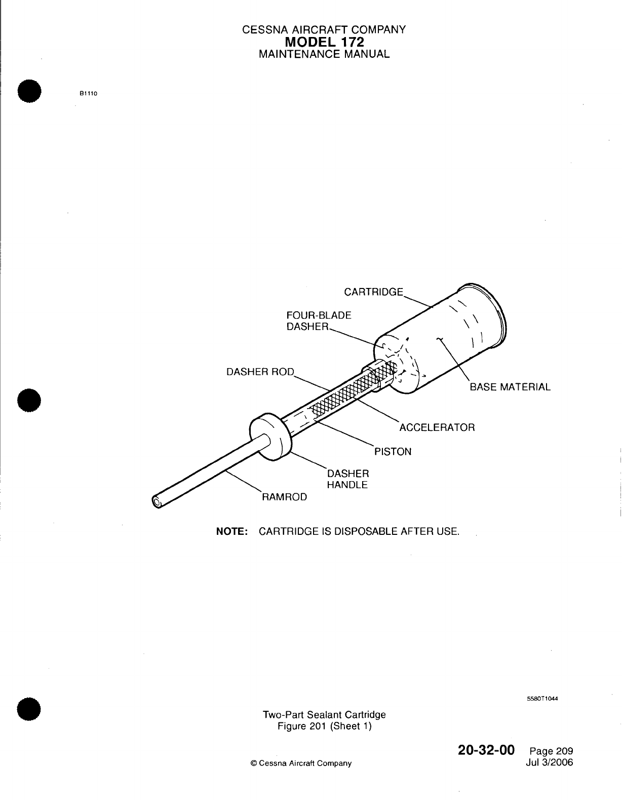
CESSNA
AIRCRAFT
COMPANY
MODEL
172
MAINTENANCE
MANUAL
B1110
CARTRIDGE
FOUR-BLADE
DASHER
ATERIAL
ACCELERATOR
DASHER
HANDLE
NOTE:
CARTRIDGE
IS
DISPOSABLE
AFTER
USE.
5580T1044
Two-Part
Sealant
Cartridge
Figure
201
(Sheet
1)
20-32-00
©
Cessna
Aircraft
Company
Page
209
Jul
3/2006
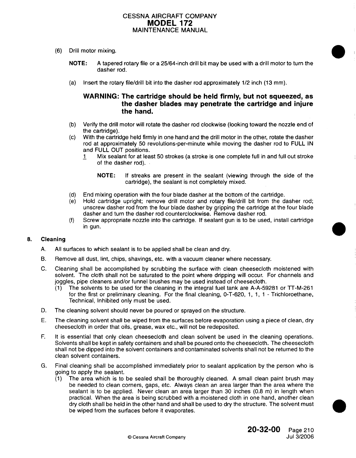
CESSNA
AIRCRAFT
COMPANY
MODEL
172
MAINTENANCE
MANUAL
(6)
Drill
motor mixing.
NOTE:
A
tapered
rotary file
or
a
25/64-inch
drill
bit
may
be
used
with
a
drill
motor
to
turn
the
dasher
rod.
(a)
Insert
the
rotary
file/drill
bit
into
the
dasher
rod
approximately
1/2
inch
(13
mm).
WARNING:
The
cartridge should
be
held
firmly,
but
not
squeezed,
as
the dasher
blades
may
penetrate
the
cartridge
and
injure
the
hand.
(b)
Verify
the drill
motor
will
rotate
the dasher
rod
clockwise
(looking
toward
the
nozzle
end
of
the
cartridge).
(c)
With
the
cartridge
held
firmly
in
one hand
and
the drill motor
in
the
other,
rotate
the
dasher
rod
at
approximately
50
revolutions-per-minute
while
moving
the dasher
rod
to
FULL
IN
and
FULL
OUT
positions.
1
Mix
sealant
for
at
least
50
strokes
(a
stroke
is
one
complete full
in
and
full
out
stroke
of
the
dasher
rod).
NOTE:
If
streaks
are
present
in
the
sealant
(viewing through
the
side
of the
cartridge),
the
sealant
is
not
completely
mixed.
(d)
End
mixing
operation
with
the
four
blade
dasher
at
the bottom
of
the
cartridge.
(e)
Hold
cartridge
upright;
remove
drill
motor
and
rotary
file/drill
bit
from
the
dasher
rod;
unscrew dasher
rod
from the
four
blade
dasher
by
gripping
the
cartridge
at the
four
blade
dasher
and
turn
the
dasher
rod
counterclockwise.
Remove
dasher
rod.
(f)
Screw
appropriate
nozzle
into
the
cartridge.
If
sealant
gun
is
to
be
used,
install
cartridge
in
gun.
8.
Cleaning
A.
All
surfaces
to
which
sealant
is
to
be
applied shall
be
clean and
dry.
B.
Remove
all
dust, lint,
chips, shavings,
etc.
with
a
vacuum
cleaner
where
necessary.
C.
Cleaning
shall
be
accomplished
by
scrubbing
the
surface
with
clean
cheesecloth
moistened with
solvent. The
cloth
shall
not
be
saturated
to the
point
where
dripping
will
occur.
For
channels
and
joggles,
pipe
cleaners
and/or
funnel brushes
may
be
used
instead of
cheesecloth.
(1)
The
solvents
to
be
used for
the
cleaning
in
the
integral
fuel
tank
are
A-A-59281
or
TT-M-261
for
the
first
or
preliminary
cleaning.
For
the
final
cleaning,
0-T-620,
1, 1, 1 -
Trichloroethane,
Technical,
Inhibited only
must
be
used.
D.
The
cleaning
solvent
should
never
be
poured
or
sprayed
on
the structure.
E.
The
cleaning solvent
shall
be
wiped
from
the
surfaces
before
evaporation
using
a
piece
of
clean,
dry
cheesecloth
in
order
that
oils,
grease,
wax
etc.,
will
not
be
redeposited.
F.
It
is
essential
that
only
clean
cheesecloth
and
clean
solvent
be
used
in
the
cleaning
operations.
Solvents shall
be
kept
in
safety
containers
and
shall
be
poured onto
the
cheesecloth.
The
cheesecloth
shall
not
be
dipped
into
the
solvent
containers
and
contaminated
solvents
shall
not be
returned
to
the
clean
solvent
containers.
G.
Final
cleaning
shall
be
accomplished
immediately
prior
to
sealant application
by
the person
who
is
going
to
apply
the
sealant.
(1)
The
area
which
is
to
be
sealed
shall
be
thoroughly
cleaned.
A
small
clean
paint
brush
may
be
needed
to
clean corners,
gaps,
etc.
Always clean
an
area
larger
than
the
area
where the
sealant
is
to
be
applied.
Never
clean
an
area larger
than
30
inches
(0.8
m)
in
length when
practical.
When
the
area
is
being
scrubbed
with
a
moistened
cloth
in
one
hand,
another
clean
dry
cloth
shall
be
held
in
the
other
hand
and
shall
be
used
to
dry
the
structure.
The
solvent
must
be
wiped
from
the
surfaces
before
it
evaporates.
20-32-00
Page
210
©
Cessna
Aircraft Company
Jul
3/2006
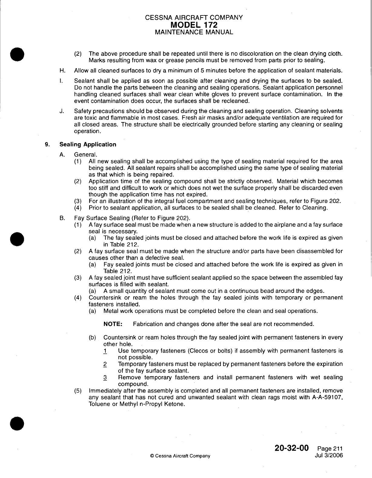
CESSNA
AIRCRAFT
COMPANY
MODEL
172
MAINTENANCE
MANUAL
(2)
The
above procedure
shall
be
repeated
until
there
is
no
discoloration
on
the
clean
drying
cloth.
Marks
resulting
from
wax
or
grease pencils
must
be
removed
from
parts
prior
to
sealing.
H.
Allow
all
cleaned
surfaces
to
dry
a
minimum of
5
minutes
before the
application
of
sealant
materials.
I.
Sealant
shall
be
applied
as
soon
as
possible
after cleaning
and
drying
the
surfaces
to
be
sealed.
Do
not
handle the
parts
between
the cleaning
and
sealing
operations. Sealant
application
personnel
handling
cleaned
surfaces
shall
wear clean white
gloves
to
prevent surface
contamination.
In
the
event
contamination
does occur,
the
surfaces
shall
be
recleaned.
J.
Safety
precautions
should
be
observed
during
the
cleaning
and
sealing
operation.
Cleaning
solvents
are
toxic
and
flammable
in
most
cases.
Fresh
air
masks
and/or adequate ventilation
are
required
for
all
closed
areas. The
structure
shall
be
electrically
grounded
before
starting
any
cleaning
or
sealing
operation.
9.
Sealing
Application
A.
General.
(1)
All
new
sealing shall
be
accomplished
using
the
type
of
sealing
material
required
for
the
area
being
sealed.
All
sealant
repairs
shall
be
accomplished
using
the same
type
of sealing
material
as
that
which
is
being
repaired.
(2)
Application
time
of the
sealing
compound
shall
be
strictly
observed.
Material which
becomes
too
stiff
and
difficult
to
work
or
which does
not
wet
the
surface
properly
shall
be
discarded
even
though
the
application
time
has
not
expired.
(3)
For
an
illustration
of
the
integral
fuel
compartment and sealing
techniques,
refer
to
Figure
202.
(4)
Prior to
sealant application,
all
surfaces
to
be
sealed
shall
be
cleaned.
Refer
to
Cleaning.
B.
Fay
Surface
Sealing
(Refer
to Figure
202).
(1) A
fay
surface seal
must
be
made
when
a
new
structure
is
added
to
the
airplane
and
a
fay
surface
seal
is
necessary.
(a)
The
fay
sealed joints
must
be
closed and
attached
before
the
work
life
is
expired as
given
in
Table
212.
(2) A
fay
surface
seal
must
be
made
when
the
structure and/or
parts
have
been
disassembled
for
causes
other than
a
defective
seal.
(a)
Fay
sealed joints
must
be
closed
and
attached
before the
work
life
is
expired
as
given
in
Table
212.
(3) A
fay sealed
joint
must
have
sufficient
sealant applied
so
the
space
between
the assembled
fay
surfaces
is
filled
with
sealant.
(a) A
small
quantity
of
sealant
must
come
out
in a
continuous
bead
around
the
edges.
(4)
Countersink
or
ream
the
holes
through the
fay
sealed
joints
with
temporary
or
permanent
fasteners
installed.
(a)
Metal
work
operations
must
be
completed
before
the
clean
and seal
operations.
NOTE:
Fabrication
and
changes
done
after
the
seal
are
not
recommended.
(b)
Countersink
or
ream
holes
through
the
fay
sealed
joint
with
permanent
fasteners
in
every
other
hole.
1
Use
temporary fasteners
(Clecos
or
bolts)
if
assembly
with
permanent
fasteners
is
not
possible.
2
Temporary
fasteners
must
be
replaced
by
permanent
fasteners
before
the
expiration
of
the
fay
surface sealant.
3
Remove temporary
fasteners
and
install permanent fasteners
with
wet
sealing
compound.
(5)
Immediately
after
the
assembly
is
completed and
all
permanent
fasteners
are
installed,
remove
any
sealant
that
has
not
cured
and
unwanted
sealant
with
clean
rags
moist
with
A-A-59107,
Toluene or
Methyl
n-Propyl
Ketone.
20-32-00
Page
211
©
Cessna
Aircraft Company
Jul
3/2006
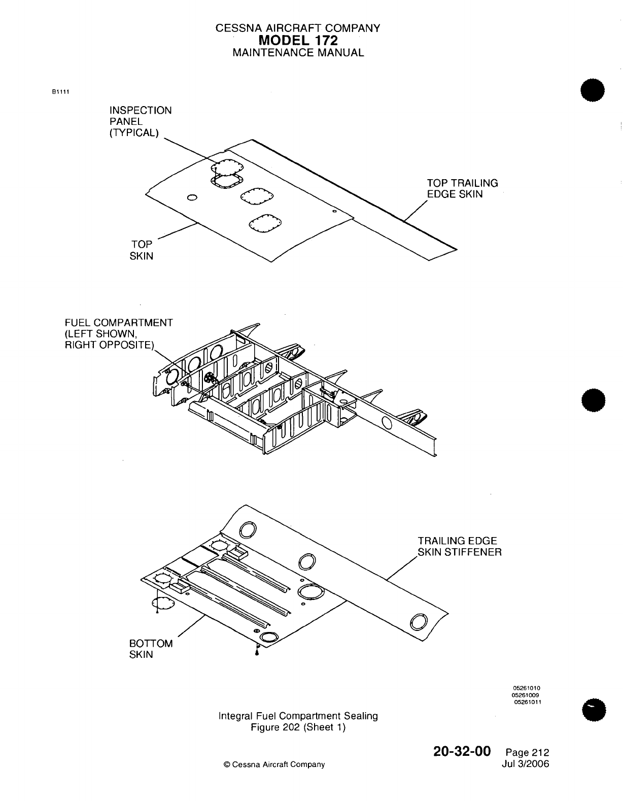
CESSNA
AIRCRAFT
COMPANY
MODEL
172
MAINTENANCE
MANUAL
B1111
INSPECTION
PANEL
(TYPICAL)
RAILING
SKIN
TO
SKI
rii
-'
Tf~
n A T-ri jrkI
TRAILING
EDGE
05261010
05261009
05261011
Integral
Fuel
Compartment Sealing
Figure
202 (Sheet
1)
20-32-00
©
Cessna
Aircraft
Company
Page
212
Jul 3/2006
B(
RSt
v .....
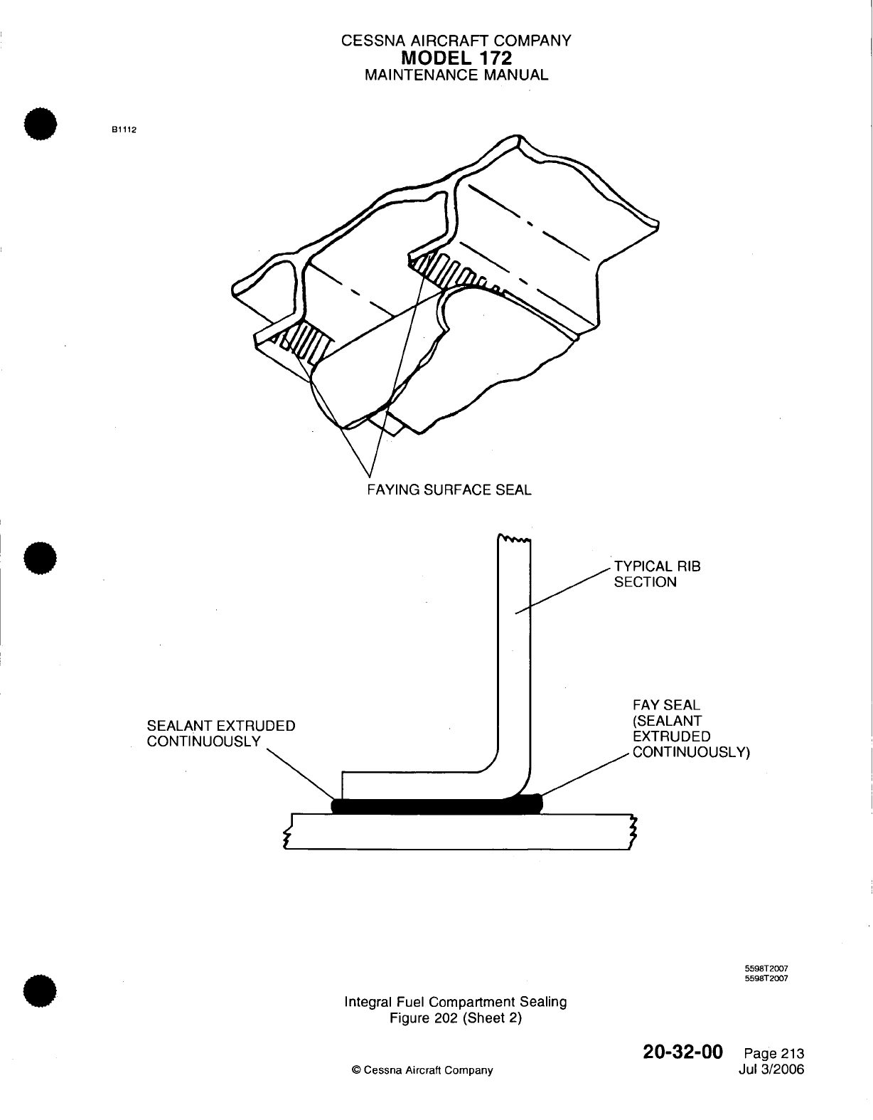
CESSNA
AIRCRAFT
COMPANY
MODEL
172
MAINTENANCE
MANUAL
B1112
FAYING
SURFACE SEAL
TYPICAL
RIB
SECTION
SEALANT
EXTRUDED
CONTINUOUSLY
\I~~~~~~~~~~~
J
FAY
SEAL
(SEALANT
EXTRUDED
CONTINUOUSLY)
Integral
Fuel
Compartment
Sealing
Figure
202
(Sheet
2)
©
Cessna
Aircraft
Company
5598T2007
5598T2007
20-32-00
Page
213
Jul
3/2006
_ _
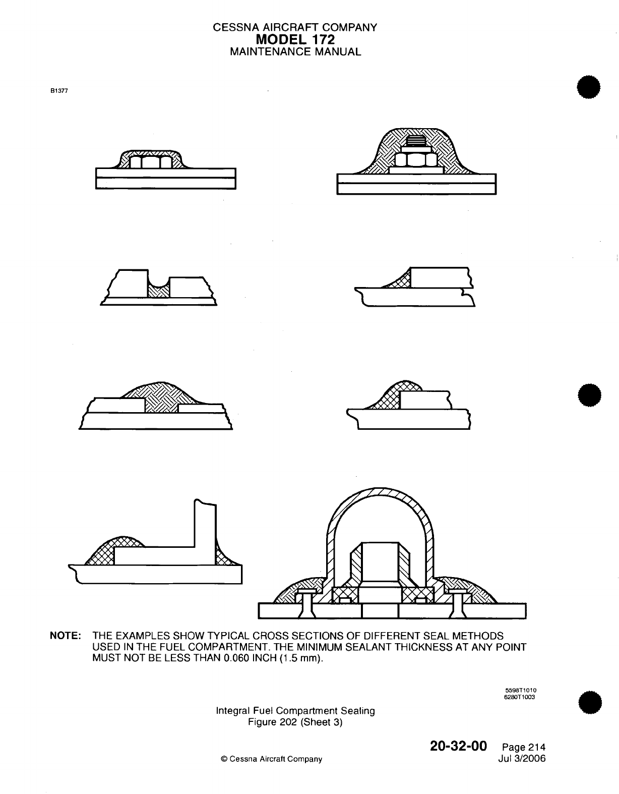
CESSNA AIRCRAFT
COMPANY
MODEL
172
MAINTENANCE
MANUAL
B1377
/y7
f4•4
1
PSh
NOTE:
THE EXAMPLES
SHOW TYPICAL CROSS SECTIONS
OF DIFFERENT SEAL
METHODS
USED
IN
THE
FUEL
COMPARTMENT.
THE
MINIMUM
SEALANT
THICKNESS
AT
ANY
POINT
MUST
NOT
BE
LESS THAN 0.060
INCH
(1.5
mm).
5598T1010
6280T1003
Integral
Fuel
Compartment
Sealing
Figure
202
(Sheet
3)
©
Cessna
Aircraft
Company
20-32-00
Page 214
Jul 3/2006
11 I I \,\
I
I
I
I
Arl""
I
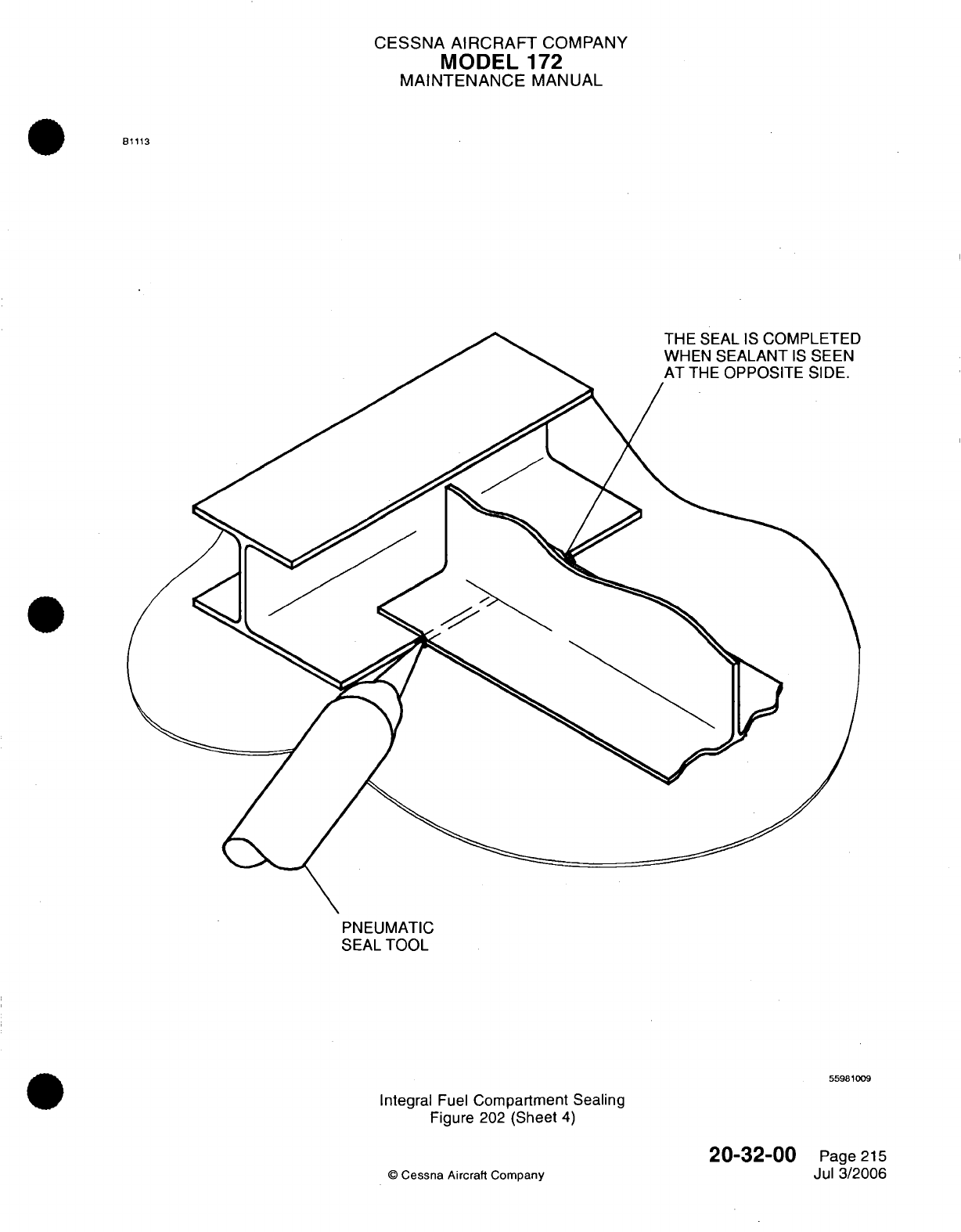
CESSNA
AIRCRAFT
COMPANY
MODEL
172
MAINTENANCE
MANUAL
B1113
PNEUMATIC
SEAL
TOOL
55981009
Integral
Fuel
Compartment
Sealing
Figure
202
(Sheet
4)
20-32-00
©
Cessna
Aircraft Company
Page
215
Jul 3/2006
)
CESSNA
AIRCRAFT
COMPANY
MODEL
172
MAINTENANCE
MANUAL
C.
Injection
Sealing
(Refer
to
Figure
202).
(1)
Sealant
must
be
put
into the
channel,
void,
or
any open space
from
one
point
only
with
a
pneumatic
sealant tool.
(a)
After sealant
is
added,
air
must
not
be
trapped
in
the
channel, void,
or any
open
area.
(b)
Sealant
must be
seen
at the
opposite
opening.
1
Cause
a
blockage
at each
channel
or
exit
as
the sealer
is
applied
in
the
area
so
that
sealant
is
seen
at
the
openings
of
all
applicable
channels.
(2)
Sealant
must
be
put
into wire
bundles that
go
through
firewalls
and
bulkheads
to fill
any voids
and open areas
between
the wires.
(a)
Bundle
ties
must
be
no
more
than
6
inches
(152.4
mm)
from
the
location
to
be
sealed.
(b)
Pull
the wires
apart
from
each
other.
1
Layer
each
wire
with
sealant
over
the
length
which
goes
through
the
bulkhead
or
seal
assembly.
2
Layer
each
wire
with
sealant
0.5
inch
(12.7
mm)
added
length
on
each
side
of
the
bulkhead
or
seal
assembly.
3
Pull the
wires
through
the
bulkhead
or
seal
assembly
into
position.
4
Fill
the
open
areas
of the
wires
that
remain until
the
sealant
is
seen
from
the
opposite
side.
(3)
Remove unwanted
sealant
before the
work
life
of
the
sealant
is
expired.
(4)
Use
an
applicable
tool
to
make
the
sealant
smooth
and
flush
with
the
surface.
D.
Fillet
Sealing.
(1)
Fastener
considerations:
(a)
Do
not
fillet
seal any
parts
until
they
are
held
completely
together
by
permanent fasteners.
(b)
Prior
to
filleting the
periphery
of
bolted structure
and fittings,
it
is
necessary
that
all
bolts,
accomplishing
the
attachment,
be
properly
torqued.
(2)
The
sealant
shall
be
applied
using
a
sealant
gun
or
spatula.
(3)
When
using
a
sealant
gun
for fillet sealing,
the
nozzle
tip
shall
be
pointed
into
the
seam
or
joint
and
shall
be
maintained
nearly
perpendicular
to
the
line
of
travel.
A
continuous
bead
of
sealant
shall precede
the
tip
and
the
tip
size,
shape and
rate
of
travel
shall
be
such
that
sufficient
sealant
shall
be
applied
to
produce
the
required
fillet.
(4)
Fillets shall
be
shaped
or
formed
to
meet
the
size
and
shape requirements
as
shown
in
applicable
figures
using
the
nozzle
tip
and/or
fairing
tools
to
press
against
the
sealant
while
moving
parallel
to
the
bead.
Exercise
caution
to
prevent
folds
and
entrapment
of
air
during
application
and
shaping
of
the
fillet
and
work
out
any
visible
air
bubbles.
The
fillet
shall
be
formed
so
that
the
highest
portion
of
the
fillet
is
centered
over
the edge of
the structure
or
fitting.
Lubrication
in
any
form
shall
not
be
used
for
smoothing
purposes.
In
all
cases,
fillet
size
shall
be
kept
as
near
minimum as
practical.
(5)
Where
it
is more
convenient
or fillet slumping
is
encountered,
the
fillet
may
be
applied
in
two
stages.
A
small
first
fillet
should
be
applied
which
is
allowed
to
cure
to
a
tack-free
state,
followed
by
a
second
application
of
sealant
sufficient
to
form
the
final
fillet conforming
to
the
specified
dimensions
for
a
fillet
seal.
If
the
first
fillet
has cured,
it
must
be
cleaned before
the
second
application
of
sealant
is
made.
If
the
fillet
has
only
cured
to
a
tack-free
state,
it
shall
be
wiped
lightly
with
a
gauze
pad
or
cheesecloth
pad
dampened with
cleaning
solvent.
(6)
Allow the
sealant to
cure
to
a
tack-free condition
prior
to
the
airplane
being
moved,
handled
and/or
worked
on.
(7)
In
cases
where
a
fillet
seal
connects
to
an
injection
seal,
the
full
bodied fillet
shall
extend past
the
end
of
the injection
and
then
taper
out.
(8)
Lap
joint
and
seam
fillets
shall
be
as
shown
in
Figure
202
.
(9)
Butt
joint
fillets
shall
be
as
shown
in
Figure
202.
(10)
Bolts
shall
be
fillet
sealed
as
shown
in
Figure
202.
The
area
for
sealing shall
consist
of
the area
of
the
structure
surrounding
the
base of
the
fastener
end
plus
the
entire
exposed
area
of the
fastener.
An
optional
method
of
sealing
threaded
fasteners
is
to
apply
a
brush
coat
of
Type
I,
Class
A
sealant. Where
brush
coating
is
used
as
the
method
of
sealing
threaded
fasteners,
the
sealant
must be
worked
around
each
fastener
with
a
stiff
brush
and
considerable
care
to
be
effective.
A
simple
pass
of
the
brush
with
the
sealant
is
not
sufficient
to
produce
an
effective
seal.
20-32-00
Page
216
©
Cessna
Aircraft
Company
Jul 3/2006
CESSNA AIRCRAFT
COMPANY
MODEL
172
MAINTENANCE
MANUAL
(11)
Dome
type
nutplates
shall
be
fillet
sealed
as
shown
in
Figure
202.
The
area
for
sealing
shall
consist
of
the area
of the
structure
surrounding
the
base
of the
fastener
and from
there
up
over
the
rivets
to
the
dome.
(12)
Hole
filling
and slot
fillets
shall
be
as
shown
in
Figure
202.
(a)
Tooling
holes
shall
be
plugged
with
a
shank
sealed
soft
rivet
and
then brush
coated
with
Type
I,
Class
A
sealant.
10.
Sealant
Repair
A.
Materials
-
Repairs,
in
general,
shall
be
accomplished
with
the
same
type of
material
as
that
being
repaired.
NOTE: Type
I,
Class
B-1/2
is
recommended
for
use
during
cold
weather
to
obtain
an
accelerated
cure.
NOTE:
Type
I,
Quick
Repair
sealant
may
be
used
as
a
repair
for sealant
in
fuel
tanks
if
desired
for
fast
cure
and
rapid
dispatch.
B.
Temperature
Requirements.
(1)
The
structure
shall
be
above 60°F
(15°C)
before
the
sealant
is
applied
and
shall
remain
above
60°F
(15°C)
until
the
sealant
is
tack-free.
NOTE:
For
outside operations
only,
the
temperature
of
the structure
may be
allowed
to
drop
below
60°F
(15°C)
but
not
below 58°F
(14°C),
after
application
for
a
period
of
time
not
to
exceed
48
hours; however,
the
structure
must
be
subsequently
heated
to
above
60°F
(15°C)
and
the
sealant
allowed
to
become
tack-free
before
the
tanks
are
refueled.
(2)
The
maximum
air
temperature allowed
to
come
in
contact
with
the
curing
sealant
is
120°F
(49°C).
C.
Fillet
and
Fastener
Sealing Repairs.
(1)
Repair
of
damaged
or
faulty
sealant
applications
shall
be
accomplished
as
follows:
(a)
Remove
all
damaged
or
faulty sealant
to
ensure solid residual
material.
(b)
Sealant
shall
be
cut
to
produce
a
smooth
continuous
scarfed
face. The
sealant
shall
be
completely
removed
in
the
affected
areas.
The
cutting
tools
should
only
be
made
from
nonmetallic
materials
that
are
softer
than
aluminum.
(c)
Inspect
repair
areas
for
clean
and
smooth
cuts. Loose
chunks
or
flaps
of
sealant
on
the
cut
areas
shall
be
removed.
(d)
Clean
the
area
to
be
sealed,
including
the
scarfed
face
of
the
old
seal.
Refer
to
Cleaning.
(e)
Apply
new
fillet
seals.
Slight
overlapping
of
the
fresh
material
over
the
existing
fillet
is
permissible.
A
large
buildup
of
sealant
shall not
be
allowed.
(f)
Rework
of
a
fillet
which
has
been
oversprayed
or
brushed with
primer
shall
be
accomplished
by
a
scarfed
joint
and
removal of
the
fillet
having
primer
on
it, in
the
area
of
the
repair. The
primer
shall
not
be
sandwiched
between
the
old
and new
sealants.
(g) If
the primer
is
removed
during
the
cleaning
operation,
it
is
permissible
to
apply
the
new
fillet
seal
directly
over
the
clean
bare
metal and then
touch
up
with
the
proper primer
all
exposed
areas
of
bare
metal
after
the
sealant
has been
applied.
D.
Faying
Surface
Sealing
Repair
-
After
determining
the
area
which
contains
the
faulty
and/or
leaking
faying
surface
seal, the
repair
shall
be
accomplished
by
applying
a
fillet
seal
along
the edge
of
the
part
adjacent
to
the
faying
surface
seal
long
enough
to
fully cover
the
area
of
the
faulty and/or
leaking
seal.
E.
Brush
Coat
Sealing
Repair
-
Repair of
damaged
or
leaking
brush
coat
seals shall
be
accomplished
by
removing
the
discrepant
brush
coat.
Clean
the
area
of
sealant
removal
and
the
surrounding
structure
and
sealant.
Refer
to
Cleaning. Apply
a
new
brush
coat
of
sealant.
F.
Integral
Fuel Tank
Sealing
Using
PR-1826
Class
B
Rapid
Curing
Sealant.
(1)
Remove
damaged section of
sealant
with
a
sharp
plexiglass scraper.
Taper
all
cuts
in
old
sealant
at
45-degree angles.
20-32-00
Page
217
C
Cessna
Aircraft
Company
Jul
3/2006
CESSNA
AIRCRAFT
COMPANY
MODEL
172
MAINTENANCE
MANUAL
(2)
Thoroughly
clean with
solvent
and
abrade
old
areas which
are
to
be
over
coated.
Clean
one
small
area
at
a
time,
then
dry with
a
clean
cloth
before
the
solvent
evaporates.
NOTE:
Always pour
solvent
on
the
cloth
to
maintain
a
clean
solvent
supply.
NOTE:
In
fuel
tanks
which
have
been
in
operation,
the
sealant
will
be
soaked
and
should
be
dried
in
area
of
the
repair
with
a
vapor
proof heat
lamp
or
hot air
blower
before
new
sealant
is
applied.
(3)
After
the
surface
has been
cleaned
and
dried,
apply
a
heavy
layer
of
PR-
1826
Adhesion
Promoter
with
a
clean
brush
or
gauze
pad.
Allow adhesion
promoter
a
minimum
of
30
minutes
to
dry.
NOTE:
Care must
be
taken
to
obtain
a
uniform
thin
coat
of
adhesion
promoter.
Thin
enough
to
cover
the
surface,
but
not
heavy
enough
to
run.
(4)
(5)
Mix
PR-1826
Class
B
sealant
according
to
instructions
supplied
with the
material.
Apply PR-1826
Class
B
sealant,
0.125
to
0.375
inch
(3.2
to 9.5
mm)
thick,
to
the
repair
area
with
a
spatula
or paddle shaped
tool.
Firmly
press
sealant
in
place
and
form
to
desired
shape.
Overlap
PR-1826
Class
B
sealant
over
old
sealant
from
0.125
to
0.25
inch
(3.2 to 6.4
mm).
NOTE:
Sealant
may
be
applied
up
to
8
hours
after
the
application
of
adhesion
promoter.
After
8
hours,
the
surface
should
be
recleaned
and
adhesion promoter reapplied.
(6)
Allow
sealant
to
cure
a
minimum
of
2
hours
at
77°F
(25°C) before
refueling.
Curing
time
is
based
solely
on
temperature
and
will
be
halved
for
every
18°F
(10°C)
increase,
and
doubled
for
every
18°F
(10°C)
decrease
from
the
standard
77°F
(25°C).
G.
Firewall
Wire Bundle
Seal
Assembly.
(1)
Complete
fay
surface
sealing
of the
mating
parts
of
the seal
assembly
plate
and
the
firewall.
Refer
to
Sealing
Application.
(a)
Seal
only
with Type
IV
Dapco
2100
or
seal
with
Type
IV
Q3-6077.
Refer
to
Tools
and
Equipment.
(2)
Complete
injection
sealing
of
the
wire
bundle that
passes through
the
seal
assembly.
Refer
to
Sealing Application.
(a)
Seal
only
with Type
IV
Dapco
2100
or
seal
with
Type
IV
Q3-6077.
Refer
to Tools
and
Equipment.
20-32-00
©
Cessna
Aircraft Company
Page
218
Jul
3/2006
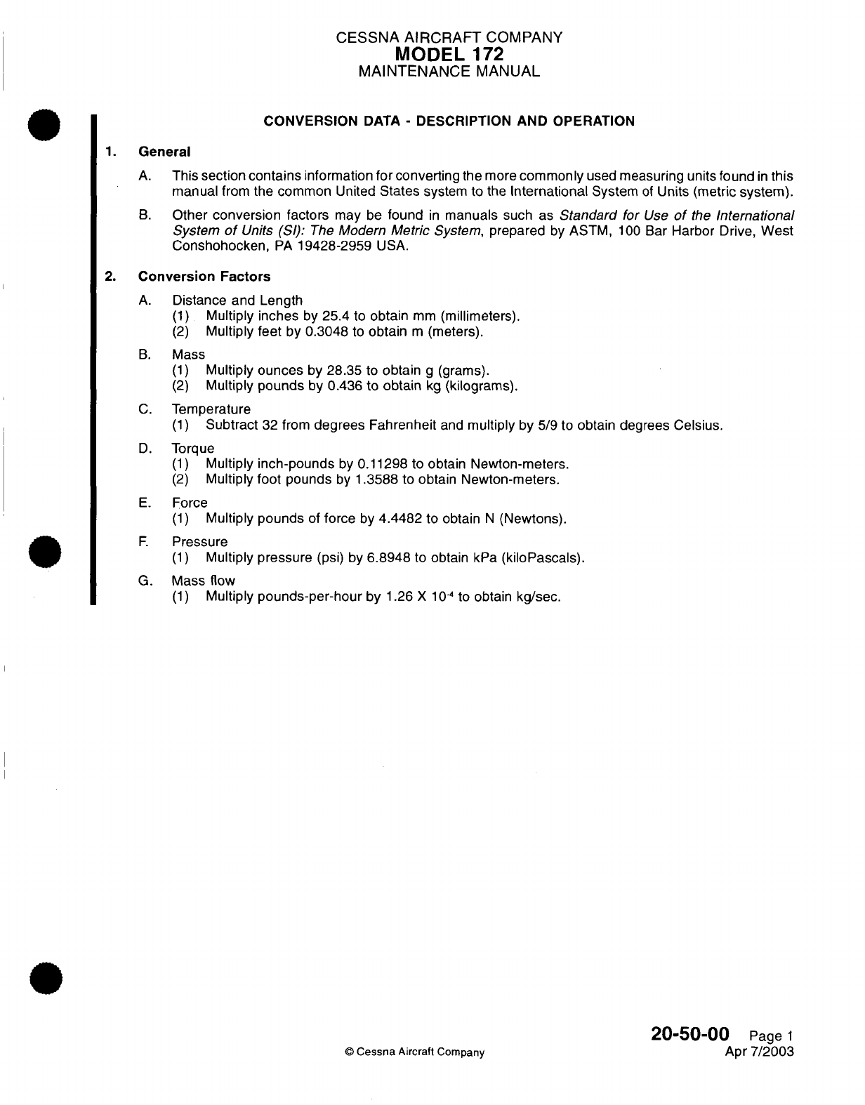
CESSNA
AIRCRAFT
COMPANY
MODEL
172
MAINTENANCE
MANUAL
CONVERSION
DATA
-
DESCRIPTION
AND
OPERATION
1.
General
A.
This
section
contains
information
for
converting
the
more
commonly
used
measuring
units
found
in
this
manual
from
the common
United
States
system
to
the
International
System
of
Units (metric
system).
B.
Other
conversion
factors
may
be
found
in
manuals
such
as
Standard
for
Use
of
the
International
System
of
Units
(SI):
The
Modern
Metric
System,
prepared
by
ASTM,
100
Bar
Harbor
Drive,
West
Conshohocken,
PA
19428-2959
USA.
2.
Conversion
Factors
A.
Distance
and
Length
(1)
Multiply inches
by
25.4
to
obtain
mm
(millimeters).
(2)
Multiply
feet
by 0.3048
to
obtain
m
(meters).
B.
Mass
(1)
Multiply
ounces
by
28.35
to
obtain
g
(grams).
(2)
Multiply
pounds
by
0.436
to obtain
kg
(kilograms).
C.
Temperature
(1)
Subtract
32
from
degrees Fahrenheit
and
multiply
by
5/9 to
obtain
degrees Celsius.
D.
Torque
(1)
Multiply
inch-pounds
by
0.11298
to
obtain Newton-meters.
(2)
Multiply
foot
pounds
by
1.3588
to
obtain Newton-meters.
E.
Force
(1)
Multiply pounds
of
force
by
4.4482
to
obtain
N
(Newtons).
F.
Pressure
(1)
Multiply pressure
(psi) by
6.8948
to
obtain
kPa
(kiloPascals).
G.
Mass flow
(1)
Multiply
pounds-per-hour
by
1.26
X
10-
4
to
obtain
kg/sec.
20-50-00
Page
1
©
Cessna
Aircraft
Company
Apr
7/2003
CHAPTER
AIR
CONDITIONING

CESSNA
AIRCRAFT
COMPANY
MODEL
172
MAINTENANCE
MANUAL
LIST
OF
EFFECTIVE
PAGES
CHAPTER-SECTION-SUBJECT
21-Title
21-List
of
Effective
Pages
21-Record
of
Temporary
Revisions
21-Table
of
Contents
21-00-00
21-20-00
21-20-00
21-21-00
21-40-00
PAGE
Page
1
Page
1
Pages
201-203
Pages
201-206
Pages
201-203
©
Cessna
Aircraft
Company
21
-
LIST
OF
EFFECTIVE
PAGES
Page
1
of
1
Jan
2/2006
DATE
Apr
7/2003
Apr
7/2003
Apr
7/2003
Jan
2/2006
Apr
7/2003

Temporary
Revision
Number
RECORD
OF
TEMPORARY
REVISIONS
Page
Number
Issue
Date
By
Date
Removed
By
CESSNA
AIRCRAFT
COMPANY
MODEL
172
MAINTENANCE
MANUAL
CONTENTS
AIR
CONDITIONING
-
GENERAL
.................................................
Scope
......................................................................
Tools,
Equipment
and
Materials
.........
.........
............................
Definition...................................................................
FRESH
AIR
DISTRIBUTION
-
DESCRIPTION
AND
OPERATION
....................
G eneral
....................................................................
Description
.........
...........
.............................................
System
Operation
..........................................................
FRESH
AIR
DISTRIBUTION
-
MAINTENANCE
PRACTICES
........................
General
....................................................................
Air
Outlet
Valve
Removal/nstallation
..........................................
AVIONICS
COOLING
FAN
-
MAINTENANCE
PRACTICES
..........................
General...................................................................
Cooling
Fan
Removal/nstallation
.............................................
Primary
Function
Display
(PFD)
Fan
Removal/Installation
......................
Multi-Function
Display
(MFD)
Fan
Removal/Installation.........................
Deck
Skin
Fan
Removal/Installation
..........................................
Tailcone
Avionics
Fan
Removal/Installation
....................................
Primary Flight Display
(PFD)
and
Multi-Function
Display
(MFD) Fan
Operational
Check
...................................................................
HEATING
AND
DEFROSTING
-
MAINTENANCE PRACTICES
......................
General
...................................................................
System
Operation...........................................................
System
Troubleshooting
.....................................................
Heat
Exchanger Removal/Installation
.........................................
Shutoff
Valve
Removal/nstallation
............................................
Control
Cable
Removal/Installation
...........................................
Distribution
System
Components
Removal/Installation..........................
21-00-00
Page
1
21-00-00
Page
1
21-00-00
Page
1
21-00-00
Page
1
21-20-00
Page
1
21-20-00
Page
1
21-20-00
Page
1
21-20-00
Page
1
21-20-00
Page
201
21-20-00
Page
201
21-20-00
Page
201
21-21-00
Page
201
21-21-00
Page
201
21-21-00
Page
201
21-21-00
Page
201
21-21-00
Page
201
21-21-00
Page
204
21-21-00
Page
204
21-21-00
Page
206
21-40-00
Page
201
21-40-00
Page
201
21-40-00
Page
201
21-40-00
Page
201
21-40-00
Page
201
21-40-00
Page
201
21-40-00
Page
203
21-40-00
Page
203
21
-
CONTENTS
Page
1
of
1
Jan
2/2006
©
Cessna
Aircraft
Company
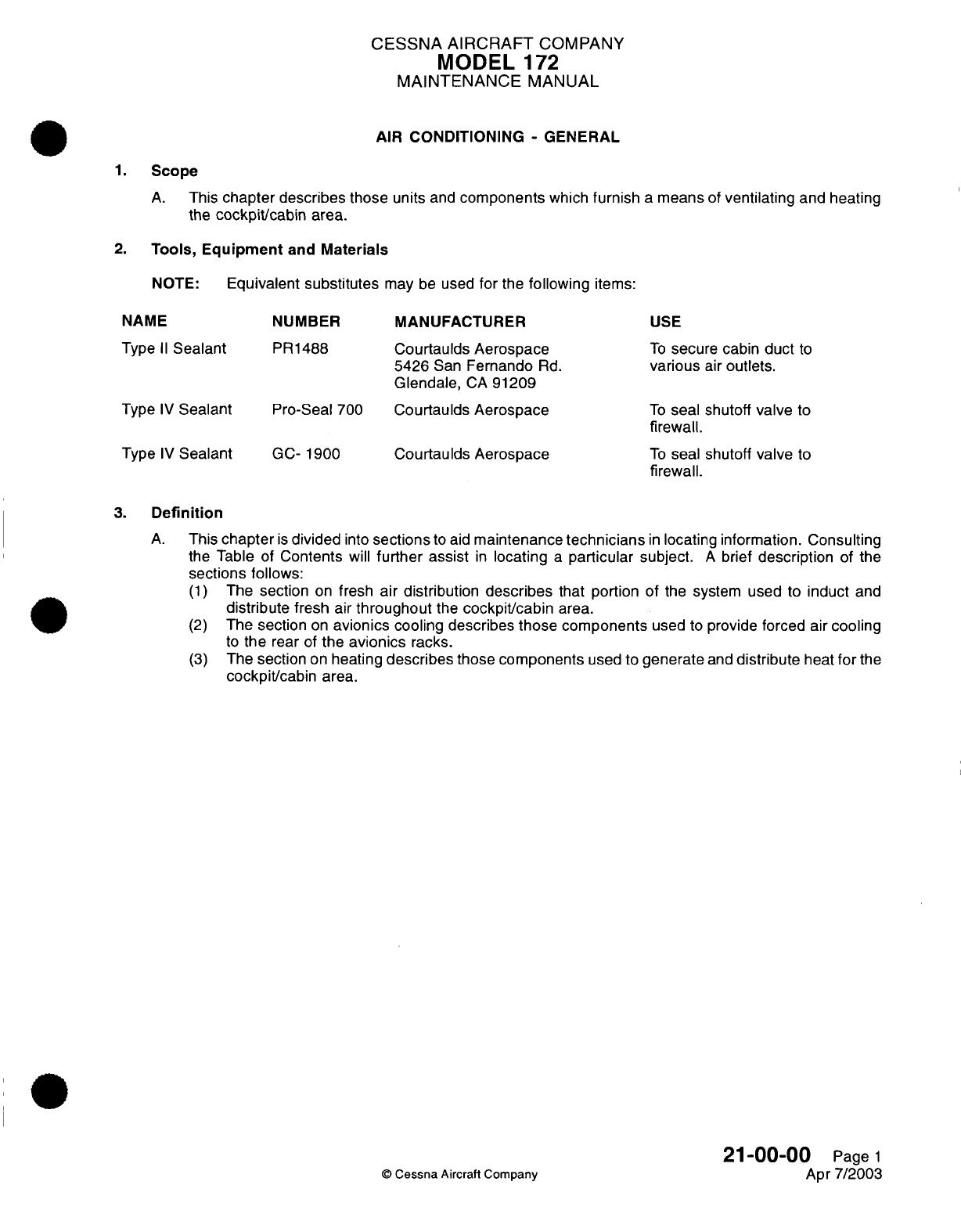
CESSNA
AIRCRAFT
COMPANY
MODEL
172
MAINTENANCE
MANUAL
AIR
CONDITIONING
-
GENERAL
1.
Scope
A.
This
chapter
describes those
units
and
components
which
furnish
a
means
of
ventilating
and heating
the
cockpit/cabin
area.
2.
Tools,
Equipment
and
Materials
NOTE:
Equivalent
substitutes
may
be
used
for
the
following
items:
NAME
Type
II
Sealant
Type
IV
Sealant
NUMBER
PR1488
Pro-Seal
700
MANUFACTURER
Courtaulds Aerospace
5426
San
Fernando
Rd.
Glendale,
CA
91209
Courtaulds
Aerospace
USE
To
secure
cabin
duct
to
various
air
outlets.
To
seal shutoff
valve
to
firewall.
Type
IV
Sealant
GC-
1900
Courtaulds Aerospace
To
seal shutoff
valve
to
firewall.
3.
Definition
A.
This
chapter
is
divided
into
sections
to
aid
maintenance
technicians
in
locating
information.
Consulting
the
Table of
Contents
will
further
assist
in
locating
a
particular
subject.
A
brief
description
of
the
sections
follows:
(1)
The
section
on
fresh
air distribution
describes
that
portion
of the system
used
to
induct
and
distribute
fresh
air
throughout
the
cockpit/cabin
area.
(2)
The
section
on
avionics
cooling describes
those
components
used
to
provide
forced
air
cooling
to
the
rear
of
the
avionics
racks.
(3)
The
section
on
heating
describes
those
components
used to
generate
and
distribute
heat
for
the
cockpit/cabin
area.
21-00-00
Page
1
©
Cessna
Aircraft Company
Apr
7/2003
CESSNA
AIRCRAFT
COMPANY
MODEL
172
MAINTENANCE
MANUAL
FRESH
AIR
DISTRIBUTION
-
DESCRIPTION
AND
OPERATION
1.
General
A.
The
cockpit/cabin
area
is
ventilated
with
fresh
air
by
means
of external
wing root
openings,
an
adjustable
air
scoop,
and
internal ducting.
2.
Description
A.
Fresh
air
enters
into
the cabin
from
one
of
five
sources.
Four
of
those
sources
are
located
in
the
leading
edge
area
of
the
wing
(two left
and
two right)
and
the
fifth
source
is
located
on the
right
side
of
the
fuselage,
between
the
firewall and
the
forward
door
post.
(1)
Each
wing
leading
edge
area
contains
two
inlet
scoops.
One
inlet
scoop
feeds
an
air
valve
located
at
the wing leading
edge/windshield
intersection; and the other
inlet
scoop
(located
in
the
wing-to-fuselage
fairing) feeds
a
pair
of
air
valves located near
the
mid
torso
area
(front seat)
and
overhead
area
(rear
seat).
(2)
Fresh air
may
also
be
introduced
by
an
adjustable door located
on
the
fuselage.
This air
is
routed
directly
into
the heated air
plenum
and
is
distributed through
the
heated
air
distribution
system.
3.
System
Operation
A.
The
amount
of
fresh
air
entering
the
cabin
can
be
controlled
by
any
of
the
six
air
valves.
Rotating
the
air
valve
will
vary
the
airflow
from
fully closed
to
fully
open.
B.
Air
flow
into
the
cabin
can
also
be
controlled
by
the
CABIN
AIR
control
cable. Pulling
the
control
aft
allows
the
maximum
amount
of
fresh
air
to
flow through the
heated
air
distribution
system.
Pushing
the
control
forward
closes
the door and allows
no
fresh
air
to
flow through the
heated distribution
system.
NOTE: Air
temperature
in
the
heated
air
distribution
system
can be
altered
by
use of the
CABIN
HT
control
in
conjunction
with
the
CABIN
AIR
control.
With the
CABIN
AIR control fully
aft
and
the
CABIN
HT
control full
forward,
only
ambient temperature
air
fill
flow through
the
heated
air distribution
system.
As
the
CABIN
HT
control
is
gradually pulled
out,
more
and
more
heated
air
will
blend
with
ambient
temperature
air
and
be
distributed
through
the
heated
air
distribution
system.
Either
one
or
both
of
the
controls
may
be
set
at
any
position
from
full
open
to
full closed.
21-20-00
Page
1
©
Cessna
Aircraft
Company
Apr
7/2003
CESSNA
AIRCRAFT
COMPANY
MODEL
172
MAINTENANCE
MANUAL
FRESH
AIR
DISTRIBUTION
-
MAINTENANCE PRACTICES
1.
General
A.
Fresh
air
outlet
valves
are
located
in
the
cockpit/cabin
area
at
upper
corners
of
the
windshield,
in
the
sidewalls just
aft
of
the
instrument
panel,
and
above
the
passenger
seat.
Air
outlet
valve removal/
installation
is
typical
at
each
location.
2.
Air Outlet
Valve
Removal/Installation
A.
Remove
Air
Outlet
Valve
(Refer
to Figure
201).
(1)
Remove
retaining
ring
from air
outlet
valve.
(2)
Remove
upholstery
panel.
Refer
to
Chapter
25,
Interior
Upholstery
-
Maintenance
Practices.
(3)
Remove
clamp securing
ducting
hose
to
air
outlet valve
adapter.
(4)
Remove
air
outlet valve
and
adapter.
B.
Install
Air
Outlet
Valve
(Refer
to
Figure
201).
(1)
Install
air
outlet
valve
and
valve
adapter
to
ducting.
Secure
with
clamp.
(2)
Install
upholstery
panel.
Refer
to
Chapter
25, Interior Upholstery
-
Maintenance
Practices.
(3)
Install
retaining
ring to
air
outlet
valve.
21-20-00
Page
201
©
Cessna
Aircraft Company
Apr
7/2003
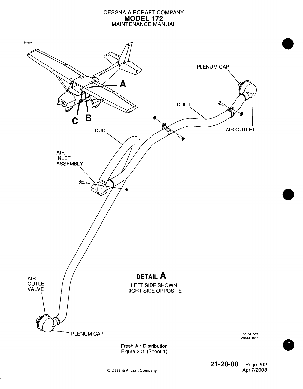
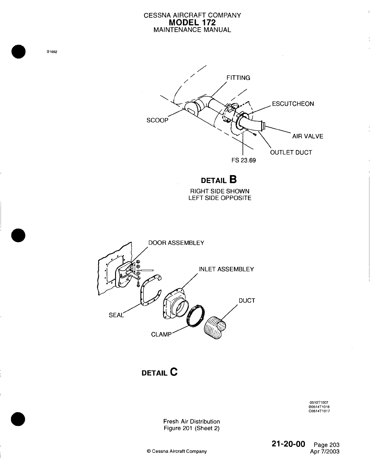
CESSNA
AIRCRAFT
COMPANY
MODEL
172
MAINTENANCE
MANUAL
B1692
FITTING
/
CHEON
AIR VALVE
TDUCT
FS
23.69
DETAIL
B
RIGHT
SIDE
SHOWN
LEFT SIDE
OPPOSITE
DETAIL
C
0510T1007
B0514T1016
C0514T1017
Fresh
Air
Distribution
Figure
201
(Sheet
2)
©
Cessna
Aircraft
Company
21-20-00
Page
203
Apr
7/2003
I
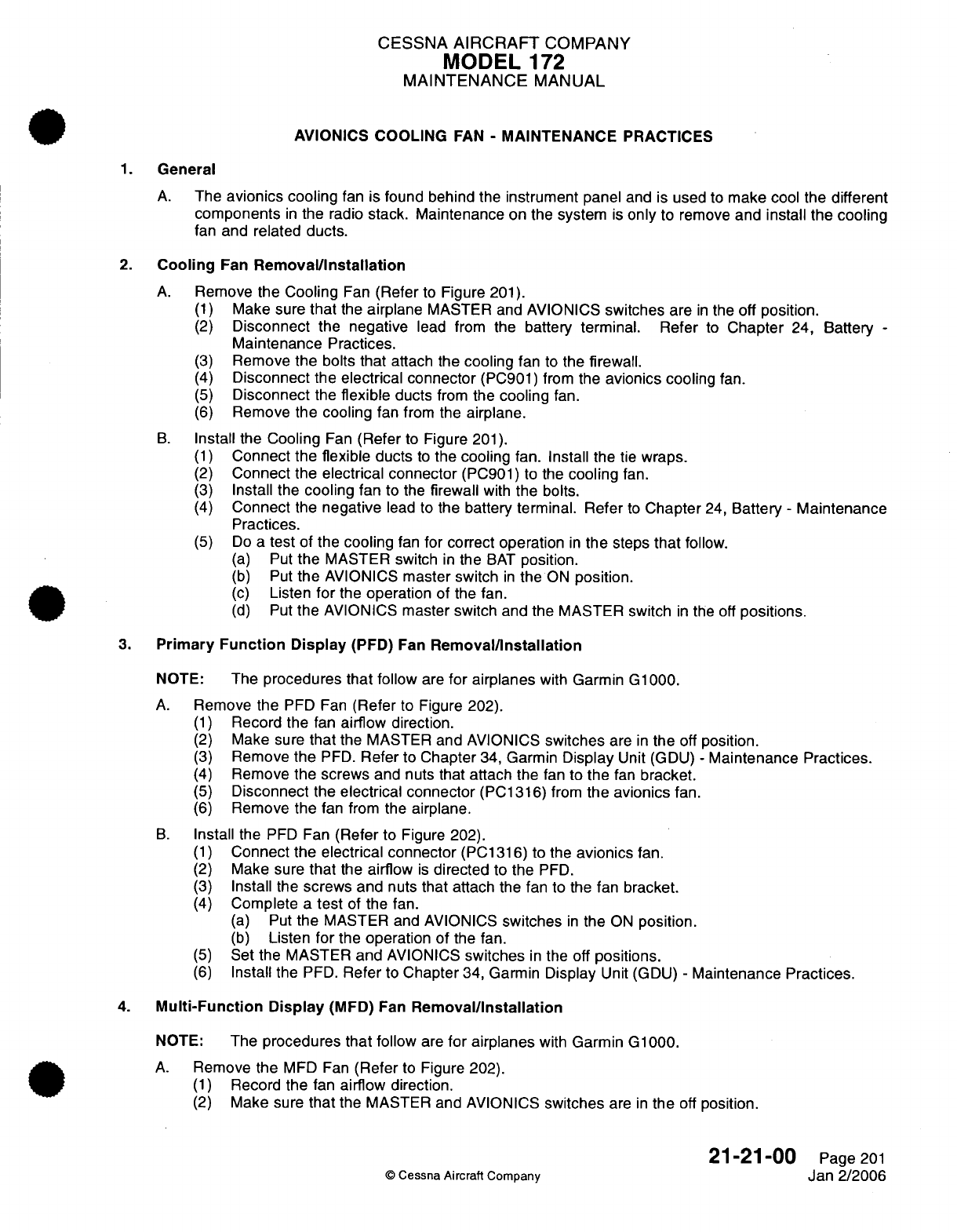
CESSNA
AIRCRAFT
COMPANY
MODEL
172
MAINTENANCE
MANUAL
AVIONICS
COOLING
FAN
-
MAINTENANCE
PRACTICES
1.
General
A.
The
avionics
cooling
fan
is found behind
the
instrument
panel
and
is
used
to
make
cool
the different
components
in
the
radio
stack.
Maintenance
on the
system
is
only
to
remove
and
install
the cooling
fan
and
related
ducts.
2.
Cooling
Fan
Removal/Installation
A.
Remove
the
Cooling
Fan
(Refer
to
Figure
201).
(1)
Make
sure
that
the
airplane
MASTER and
AVIONICS
switches
are
in
the off
position.
(2)
Disconnect
the
negative
lead from
the
battery
terminal.
Refer
to
Chapter
24,
Battery
-
Maintenance
Practices.
(3)
Remove
the
bolts
that
attach
the
cooling
fan
to
the
firewall.
(4)
Disconnect
the
electrical connector
(PC901)
from
the
avionics
cooling
fan.
(5)
Disconnect
the
flexible
ducts
from
the
cooling
fan.
(6)
Remove
the
cooling
fan
from
the
airplane.
B.
Install
the
Cooling
Fan
(Refer
to
Figure
201).
(1)
Connect
the
flexible
ducts
to
the
cooling
fan.
Install
the
tie
wraps.
(2)
Connect
the
electrical connector
(PC901)
to
the
cooling
fan.
(3)
Install
the
cooling
fan
to
the
firewall
with
the
bolts.
(4)
Connect
the
negative
lead to
the
battery terminal. Refer
to
Chapter
24,
Battery
-
Maintenance
Practices.
(5)
Do
a
test
of
the
cooling
fan
for
correct operation
in
the
steps
that
follow.
(a)
Put
the
MASTER switch
in
the
BAT
position.
(b)
Put
the
AVIONICS
master switch
in
the
ON
position.
(c)
Listen
for
the
operation
of the fan.
(d)
Put
the
AVIONICS
master
switch
and
the
MASTER
switch
in
the
off
positions.
3.
Primary
Function
Display
(PFD) Fan
Removal/nstallation
NOTE:
The
procedures that follow
are
for airplanes
with
Garmin
G1000.
A.
Remove
the
PFD
Fan
(Refer
to
Figure
202).
(1)
Record
the
fan
airflow
direction.
(2)
Make sure
that
the MASTER
and
AVIONICS
switches
are
in
the
off
position.
(3)
Remove
the
PFD.
Refer
to
Chapter
34,
Garmin
Display
Unit
(GDU)
-
Maintenance
Practices.
(4)
Remove
the screws
and
nuts
that attach
the
fan
to
the
fan
bracket.
(5)
Disconnect
the
electrical connector
(PC1316)
from
the avionics
fan.
(6)
Remove
the
fan from
the
airplane.
B.
Install
the
PFD
Fan
(Refer
to
Figure
202).
(1)
Connect
the electrical connector
(PC1316)
to the
avionics
fan.
(2)
Make
sure
that
the
airflow
is
directed
to
the
PFD.
(3)
Install
the
screws and
nuts
that attach
the fan to
the
fan
bracket.
(4)
Complete
a
test
of
the fan.
(a)
Put
the
MASTER
and AVIONICS
switches
in
the
ON
position.
(b)
Listen
for
the
operation of
the fan.
(5)
Set
the MASTER
and
AVIONICS
switches
in
the off
positions.
(6)
Install
the
PFD.
Refer
to
Chapter
34, Garmin
Display
Unit
(GDU)
-
Maintenance
Practices.
4.
Multi-Function
Display
(MFD)
Fan
Removal/Installation
NOTE:
The
procedures that follow
are
for
airplanes
with
Garmin
G1000.
A.
Remove
the
MFD
Fan
(Refer
to
Figure
202).
(1)
Record
the
fan
airflow
direction.
(2)
Make sure
that
the
MASTER and AVIONICS
switches
are
in
the
off
position.
21-21-00
Page
201
©
Cessna
Aircraft Company
Jan 2/2006
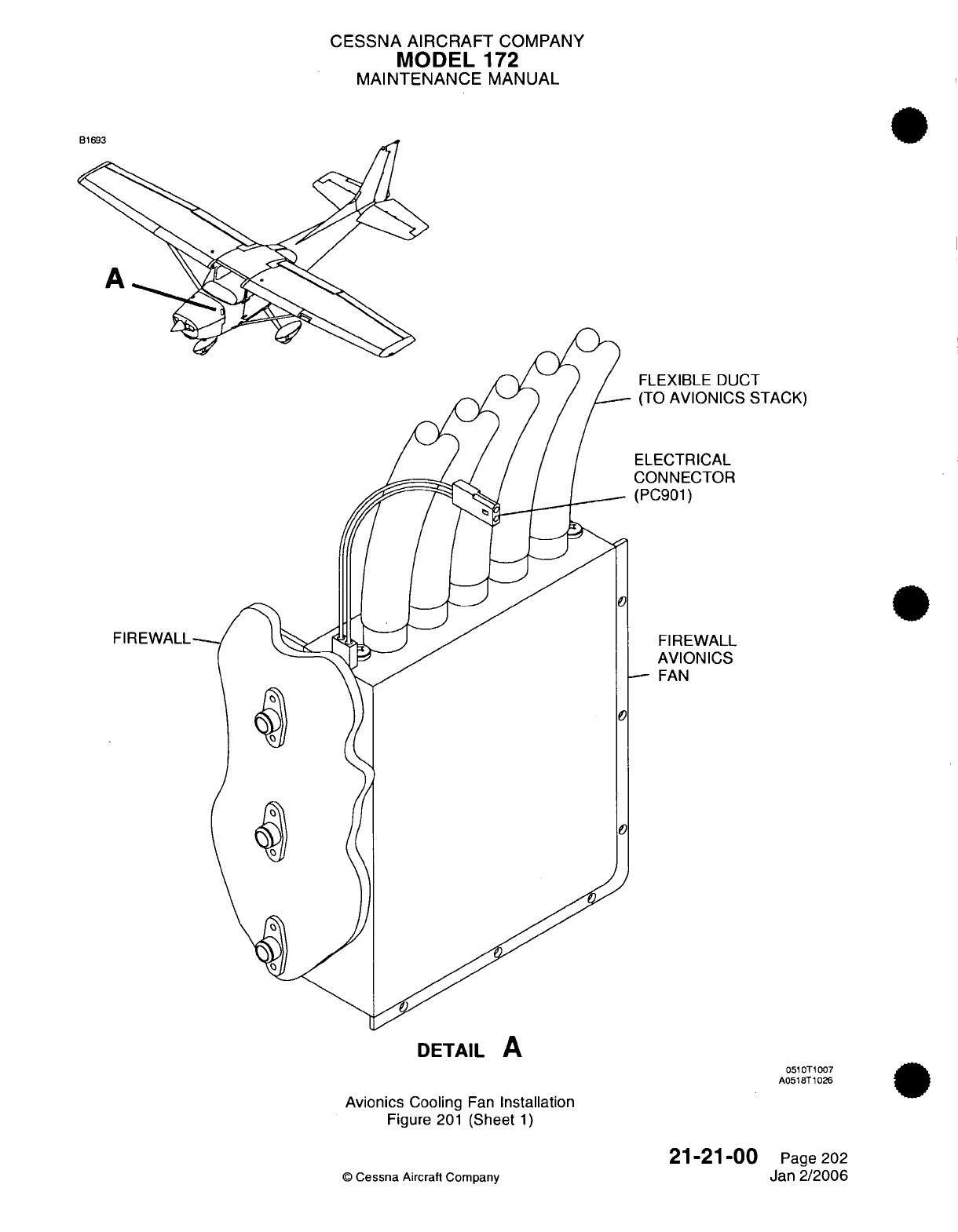
CESSNA AIRCRAFT
COMPANY
MODEL
172
MAINTENANCE
MANUAL
FLEXIBLE
DUCT
-
(TO
AVIONICS
STACK)
ELECTRICAL
CONNECTOR
(PC901)
FIREWALL
AVIONICS
-
FAN
DETAIL
A
051
T1
007
A0518T1026
Avionics
Cooling
Fan
Installation
Figure
201
(Sheet
1)
21-21-00
©
Cessna
Aircraft Company
Page 202
Jan
2/2006
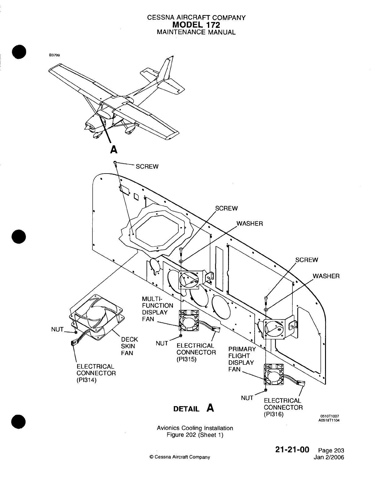
CESSNA
AIRCRAFT
COMPANY
MODEL
172
MAINTENANCE
MANUAL
A
HER
NUT
ELECTRICAL
DETAIL
A
CONNECTOR
(P1316)
0510T1007
A0518T1104
Avionics
Cooling
Installation
Figure 202
(Sheet
1)
©
Cessna
Aircraft
Company
21-21-00
Page
203
Jan
2/2006
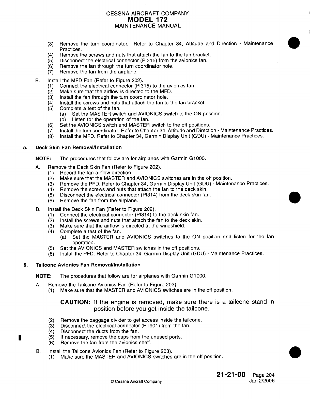
CESSNA
AIRCRAFT
COMPANY
MODEL
172
MAINTENANCE
MANUAL
(3)
Remove
the
turn
coordinator.
Refer
to
Chapter
34,
Attitude
and
Direction
-
Maintenance
Practices.
(4)
Remove
the
screws
and
nuts
that
attach the
fan
to the fan
bracket.
(5)
Disconnect
the
electrical
connector
(PI315)
from
the
avionics
fan.
(6)
Remove
the fan
through
the
turn
coordinator
hole.
(7)
Remove
the fan
from
the airplane.
B.
Install
the
MFD
Fan
(Refer
to
Figure
202).
(1)
Connect
the
electrical
connector
(PI315)
to
the
avionics
fan.
(2)
Make
sure
that
the airflow
is
directed
to
the
MFD.
(3)
Install
the fan
through the
turn
coordinator
hole.
(4)
Install
the
screws
and
nuts
that
attach
the
fan
to
the fan
bracket.
(5)
Complete
a
test
of
the
fan.
(a)
Set
the
MASTER
switch
and
AVIONICS
switch
to
the
ON
position.
(b)
Listen
for
the
operation
of the fan.
(6)
Set
the AVIONICS
switch
and MASTER
switch
to
the
off
positions.
(7)
Install
the
turn
coordinator. Refer
to
Chapter
34,
Attitude
and
Direction
-
Maintenance
Practices.
(8)
Install
the
MFD.
Refer
to
Chapter
34,
Garmin Display
Unit
(GDU)
-
Maintenance
Practices.
5.
Deck
Skin
Fan
RemovalInstallation
NOTE:
The
procedures that
follow
are for
airplanes
with
Garmin
G1000.
A.
Remove
the Deck
Skin
Fan
(Refer
to
Figure
202).
(1)
Record
the fan
airflow direction.
(2)
Make
sure
that
the
MASTER and
AVIONICS
switches
are
in
the
off
position.
(3)
Remove
the PFD.
Refer to
Chapter
34,
Garmin
Display
Unit
(GDU)
-
Maintenance
Practices.
(4)
Remove
the
screws
and
nuts
that
attach
the
fan to
the
deck
skin.
(5)
Disconnect
the
electrical connector
(PI314) from
the
deck
skin fan.
(6)
Remove
the
fan
from
the
airplane.
B.
Install
the
Deck
Skin
Fan
(Refer
to
Figure 202).
(1)
Connect
the
electrical
connector
(PI314)
to
the
deck
skin fan.
(2)
Install
the
screws
and
nuts
that
attach
the
fan
to
the
deck skin.
(3)
Make
sure
that
the
airflow
is
directed
at
the windshield.
(4)
Complete
a
test
of the fan.
(a)
Set
the MASTER and
AVIONICS
switches
to the
ON
position
and
listen
for
the
fan
operation.
(5)
Set
the AVIONICS
and
MASTER
switches
in
the off
positions.
(6)
Install
the
PFD.
Refer
to
Chapter
34,
Garmin
Display
Unit
(GDU)
-
Maintenance Practices.
6.
Tailcone
Avionics
Fan
Removal/nstallation
NOTE:
The
procedures that follow
are
for
airplanes
with
Garmin
G1000.
A.
Remove
the
Tailcone
Avionics
Fan
(Refer
to
Figure
203).
(1)
Make
sure
that
the
MASTER and
AVIONICS
switches
are
in
the
off
position.
CAUTION:
If
the
engine
is
removed,
make
sure there
is
a
tailcone
stand
in
position before
you
get
inside the
tailcone.
(2)
Remove
the
baggage
divider
to get
access
inside
the
tailcone.
(3)
Disconnect
the
electrical
connector
(PT901)
from
the
fan.
(4)
Disconnect
the
ducts
from
the
fan.
(5) If
necessary,
remove
the
caps
from
the
unused
ports.
(6)
Remove the
fan
from
the
avionics
shelf.
B.
Install
the
Tailcone
Avionics
Fan
(Refer
to
Figure
203).
(1)
Make
sure the
MASTER
and
AVIONICS
switches
are
in
the
off
position.
21-21-00
Page
204
©
Cessna
Aircraft
Company
Jan
2/2006
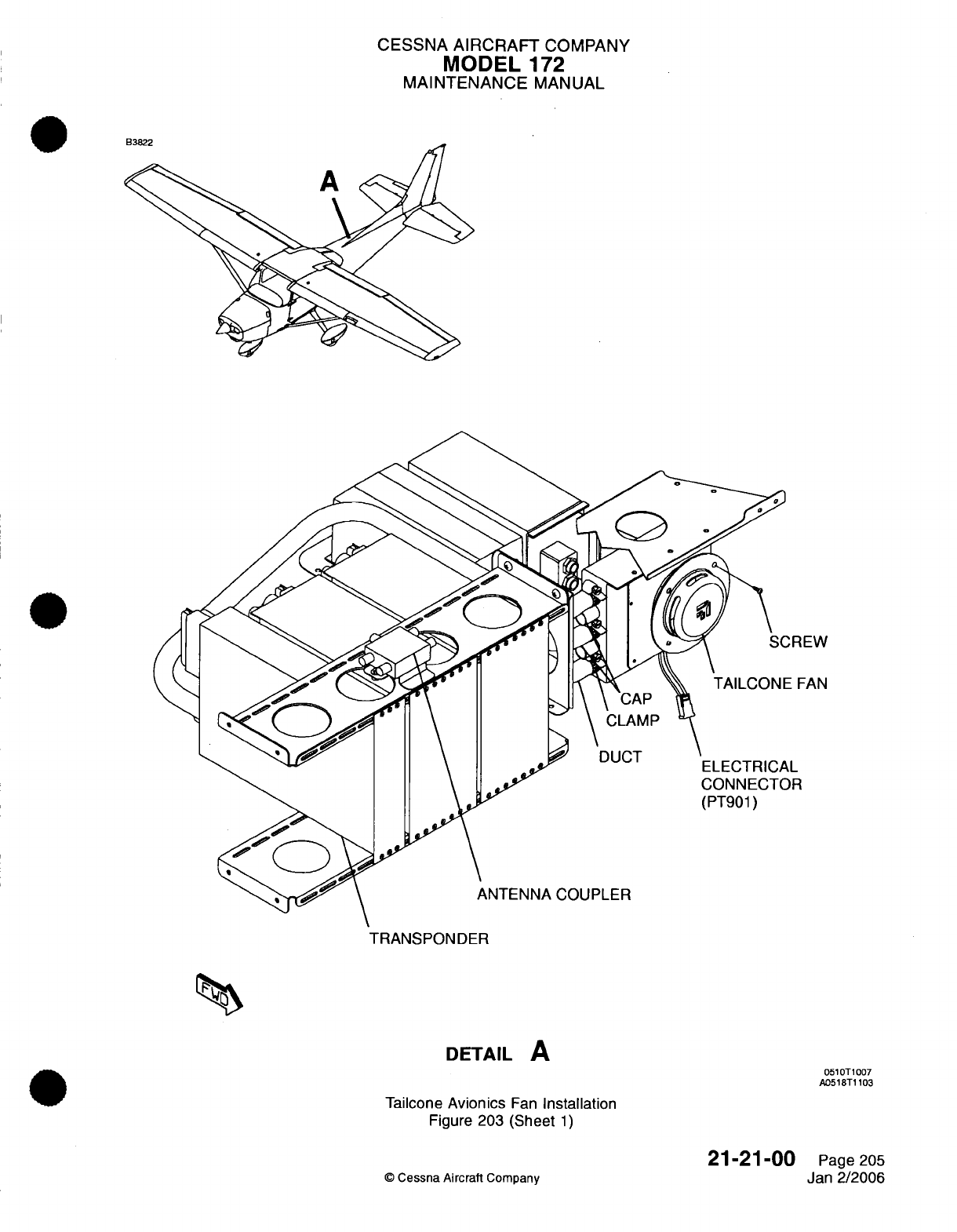
CESSNA
AIRCRAFT
COMPANY
MODEL
172
MAINTENANCE
MANUAL
EW
AN
TRANSPONDER
DETAIL
A
0510T1007
A0518T1103
Tailcone
Avionics
Fan
Installation
Figure
203
(Sheet
1)
21-21-00
©
Cessna Aircraft
Company
Page
205
Jan
2/2006
CESSNA
AIRCRAFT
COMPANY
MODEL
172
MAINTENANCE
MANUAL
CAUTION:
If
the
engine
is
removed,
make
sure
there
is
a
tailcone
stand
in
position
before
you get
inside the
tailcone.
(2)
(3)
(4)
(5)
(6)
(7)
(8)
Set
the
fan
in
position
and
attach
it
to the
avionics
shelf.
Connect
the
ducts
to
the
fan.
If
necessary,
install
the
caps
on
the unused
ports.
Connect the
electrical
connector
(PT901)
to
the
fan.
Set
the
MASTER
and
AVIONIC
switches
to
the
ON
position.
Examine
the
fan to make sure
it
operates.
Set
the
baggage
divider
in
position.
7.
Primary
Flight
Display
(PFD)
and
Multi-Function
Display
(MFD)
Fan
Operational
Check
A.
PFD
and
MFD
Fan
Operational Check
(Refer
to
Figure 202).
(1)
Remove
the
PFD
and
the
MFD.
Refer
to
Garmin
Display
Unit
(GDU)
-
Maintenance Practices.
(2)
Put
the MASTER
and
AVIONICS
switches
in
the
ON
position.
(3)
Listen
and
look for
the
correct
operation
of
both
fans.
(4)
Install
the
PFD
and
MFD.
Refer
to
Garmin
Display
Unit
(GDU)
-
Maintenance
Practices.
21-21-00
Page
206
©
Cessna
Aircraft Company
Jan
2/2006
I
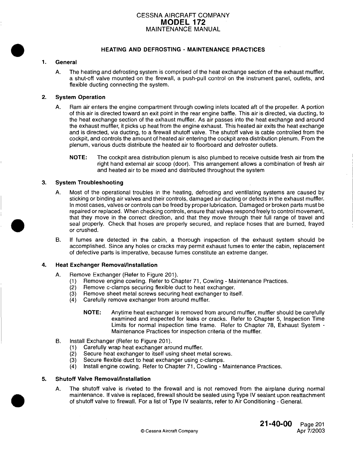
CESSNA
AIRCRAFT
COMPANY
MODEL
172
MAINTENANCE
MANUAL
HEATING
AND DEFROSTING
-
MAINTENANCE
PRACTICES
1.
General
A.
The
heating and
defrosting
system
is
comprised
of
the
heat
exchange
section
of the
exhaust
muffler,
a
shut-off
valve
mounted
on
the
firewall,
a
push-pull control
on
the
instrument
panel,
outlets,
and
flexible
ducting
connecting
the
system.
2.
System
Operation
A.
Ram
air
enters
the
engine compartment
through
cowling inlets
located aft
of
the propeller.
A
portion
of
this
air
is
directed toward
an
exit point
in
the
rear
engine
baffle.
This
air
is
directed,
via ducting,
to
the
heat
exchange
section
of
the
exhaust
muffler.
As
air passes
into
the
heat
exchange
and
around
the
exhaust
muffler,
it
picks
up
heat
from the
engine
exhaust.
This
heated
air
exits the
heat
exchange
and
is
directed,
via
ducting,
to
a
firewall shutoff valve. The
shutoff valve
is
cable
controlled
from
the
cockpit,
and
controls
the
amount
of
heated air entering the
cockpit
area
distribution
plenum.
From
the
plenum,
various
ducts
distribute
the
heated
air to
floorboard
and
defroster
outlets.
NOTE:
The
cockpit
area distribution
plenum
is
also plumbed
to
receive
outside
fresh
air
from
the
right
hand
external
air
scoop
(door).
This arrangement
allows
a
combination
of
fresh
air
and heated
air
to
be
mixed
and
distributed
throughout
the system
3.
System
Troubleshooting
A.
Most
of
the
operational troubles
in
the
heating,
defrosting
and
ventilating
systems
are
caused
by
sticking
or
binding
air
valves
and
their controls,
damaged
air
ducting
or
defects
in
the
exhaust
muffler.
In
most
cases, valves
or
controls
can
be
freed
by
proper
lubrication.
Damaged
or broken
parts
must
be
repaired or
replaced.
When
checking controls,
ensure that
valves
respond freely
to
control movement,
that they
move
in
the
correct direction,
and
that
they
move
through
their
full
range of
travel
and
seal properly.
Check
that
hoses
are
properly
secured,
and
replace
hoses
that
are
burned,
frayed
or
crushed.
B. If
fumes
are
detected
in
the
cabin,
a
thorough
inspection
of the
exhaust
system
should
be
accomplished.
Since
any
holes
or
cracks
may
permit
exhaust
fumes
to
enter the cabin,
replacement
of
defective
parts
is
imperative,
because
fumes
constitute
an
extreme
danger.
4.
Heat
Exchanger
Removal/Installation
A.
Remove
Exchanger
(Refer
to
Figure
201).
(1)
Remove
engine
cowling.
Refer
to Chapter
71,
Cowling
-
Maintenance
Practices.
(2)
Remove
c-clamps
securing
flexible
duct
to heat
exchanger.
(3)
Remove
sheet
metal
screws
securing
heat
exchanger
to
itself.
(4)
Carefully
remove
exchanger
from
around muffler.
NOTE:
Anytime
heat
exchanger
is
removed
from
around muffler,
muffler
should
be
carefully
examined
and
inspected
for
leaks
or
cracks.
Refer
to
Chapter
5,
Inspection
Time
Limits
for
normal
inspection
time
frame.
Refer
to
Chapter
78,
Exhaust
System
-
Maintenance Practices for
inspection criteria
of
the
muffler.
B.
Install
Exchanger
(Refer
to Figure
201).
(1)
Carefully
wrap
heat
exchanger
around
muffler.
(2)
Secure
heat
exchanger
to
itself
using
sheet
metal screws.
(3)
Secure
flexible
duct
to heat
exchanger
using
c-clamps.
(4)
Install
engine
cowling.
Refer
to
Chapter
71,
Cowling
-
Maintenance
Practices.
5.
Shutoff
Valve
Removal/Installation
A.
The
shutoff
valve
is
riveted
to
the
firewall
and
is
not
removed
from
the
airplane during
normal
maintenance.
If
valve
is
replaced, firewall should
be
sealed
using
Type
IV
sealant
upon
reattachment
of
shutoff
valve
to
firewall.
For
a
list of Type
IV
sealants, refer
to
Air
Conditioning
-
General.
21-40-00
Page
201
©
Cessna Aircraft Company
Apr
7/2003
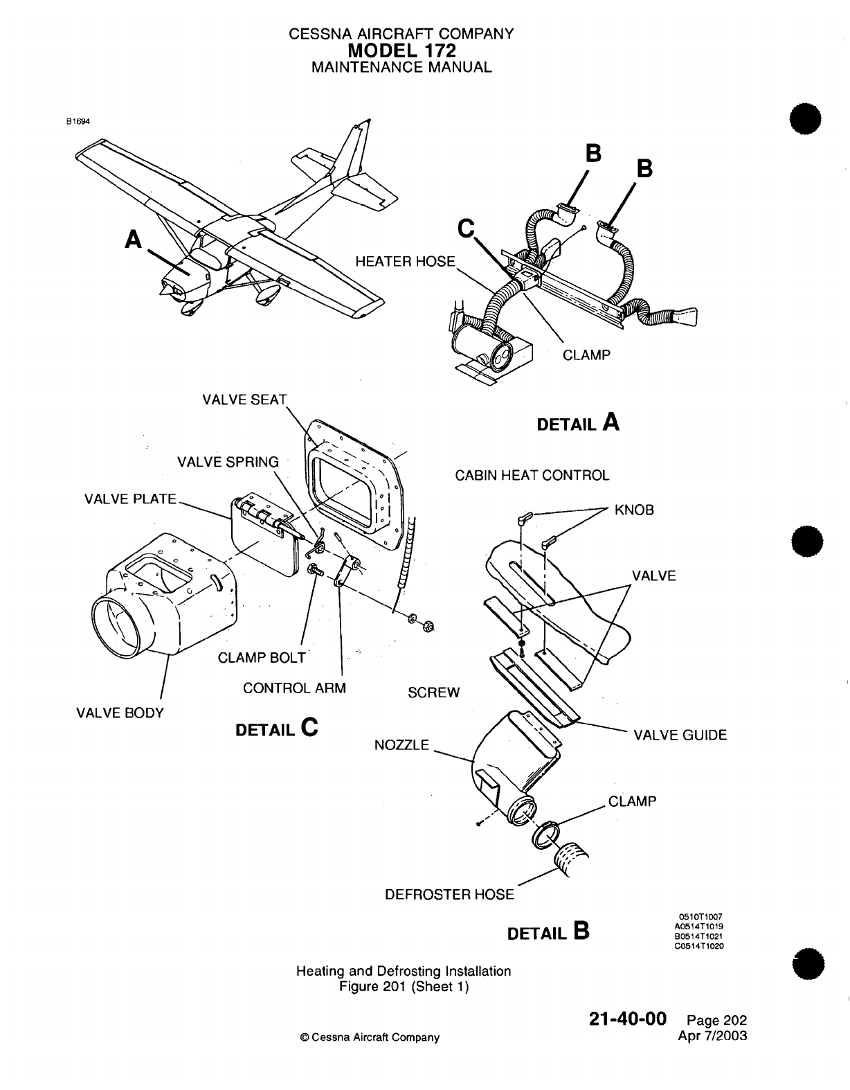
CESSNA
AIRCRAFT
COMPANY
MODEL
172
MAINTENANCE
MANUAL
B1
B
,
CLAMP
DETAIL
A
CABIN
HEAT
CONTROL
IUI
VALVE
IEW
VALVE
BODY
DETAIL
C
VALVE
GUIDE
NOZZLE
AMP
DEFROSTER
HOSE
DETAIL
B
Heating and Defrosting Installation
Figure
201
(Sheet
1)
21-40-00
©
Cessna
Aircraft
Company
0510T1007
A0514T1019
B0514T1021
C0514T1020
Page
202
Apr
7/2003
I
I 1. /"~
r-
CESSNA
AIRCRAFT
COMPANY
MODEL
172
MAINTENANCE
MANUAL
6.
Control
Cable
Removal/Installation
A.
Remove
Control
Cable (Refer
to
Figure
201).
(1)
Remove
engine
cowling.
Refer
to
Chapter
71,
Cowling
-
Maintenance
Practices.
(2)
Carefully straighten
end
of
cabin
heat control
cable.
(3)
Loosen
clamp
bolt
on
control
arm
and withdraw cable
from
control
arm.
(4)
Loosen
screws securing
clamp
bolt
to
firewall.
(5)
From
inside
the cabin,
gain
access
to
the
backside
of
the
CABIN
HT
control
cable.
(6)
Loosen
nut
on
backside
of
control cable.
(7)
Carefully
withdraw cable
from
instrument
panel
and
firewall.
B.
Install
Control
Cable
(Refer
to
Figure
201
).
(1)
Thread
end of
control
cable
through
hole
in
instrument
panel
and
through
hole
in
firewall.
(2)
Secure
CABIN
HT
control
cable
to
backside
of
instrument
panel using
existing
jam nut.
(3)
Thread
end of
control cable
through the
clamp
bolt.
(4)
Tighten
clamp
bolt
and
test
control
cable
to
ensure
full
range
of
travel.
(5)
When
full
range
of
travel
has
been
established,
bend
end
of
control
cable
around
clamp
bolt
area.
(6)
Install
engine
cowling.
Refer
to
Chapter
71,
Cowling
-
Maintenance
Practices.
7.
Distribution
System
Components Removal/Installation
A.
The
majority
of
heated
air
distribution
system
components
are
riveted
to
the
airframe
and
do
not
require
replacement during
normal
maintenance.
Ducts
are
secured
to
these
components
using
c-clamps.
If
ducts become
damaged
or worn,
they
should
be replaced
with
new
hose
of
equal
length.
B.
Ducts
are
typically
attached
to
various
outlets
using
Type
II
sealant.
For
a list
of
Type
II
sealants,
refer
to
Air
Conditioning
-
General.
21-40-00
Page
203
©
Cessna
Aircraft
Company
Apr
7/2003

CHAPTER
AUTO
FLIGHT
CESSNA
AIRCRAFT
COMPANY
MODEL
'172
MAINTENANCE
MANUAL
LIST
OF
EFFECTIVE
PAGES
CHAPTER-SECTION-SUBJECT
22-Title
22-List
of
Effective Pages
22-Record
of
Temporary
Revisions
22-Contents
22-00-00
22-10-00
22-10-00
PAGE
Page
1
Pages
201-209
Pages 601-606
©
Cessna Aircraft
Company
22
-
LIST
OF EFFECTIVE
PAGES
Page
1
of
1
Jan
3/2005
DATE
Jan
3/2005
Jan
3/2005
Jan
3/2005
Temporary
Revision
Number
RECORD
OF
TEMPORARY REVISIONS
Page
Number
Issue
Date
By
Date
Removed
By
CESSNA
AIRCRAFT
COMPANY
MODEL
-172
MAINTENANCE
MANUAL
CONTENTS
AUTO
FLIGHT
-
GENERAL.......................................................
Scope and Definition
........................................................
Tools,
Equipment
and
Materials
.........
.....................................
AUTOPILOT
-
MAINTENANCE
PRACTICES
.......................................
General
....................................................................
Roll
Servo
Removal/Installation
..............................................
Pitch
Servo
Removal/Installation
.............................................
Pitch
Trim
Servo
Removal/Installation.........................................
Servo
Capstan Clutch
Adjustment
............................................
Set
the Autopilot
Roll Null
....................................................
KAP-140
Autopilot Controller Removal/Installation
.............................
AUTOPILOT
SERVO
-
INSPECTION/CHECK
......................................
General
....................................................................
Roll
Servo
Inspection........................................................
Pitch
Servo
Inspection.......................................................
Pitch
Trim
Servo
Inspection
..................................................
Pitch Trim
Rigging
Inspection
................................................
22-00-00
Page
1
22-00-00
Page
1
22-00-00
Page
1
22-10-00
Page
201
22-10-00
Page
201
22-10-00
Page
201
22-10-00
Page
201
22-10-00
Page
205
22-10-00
Page 206
22-10-00
Page
207
22-10-00
Page 207
22-10-00
Page
601
22-10-00
Page
601
22-10-00
Page
601
22-10-00
Page
601
22-10-00
Page
605
22-10-00
Page
605
CONTENTS
Page
1
of
1
Jan
3/2005
©
Cessna Aircraft
Company
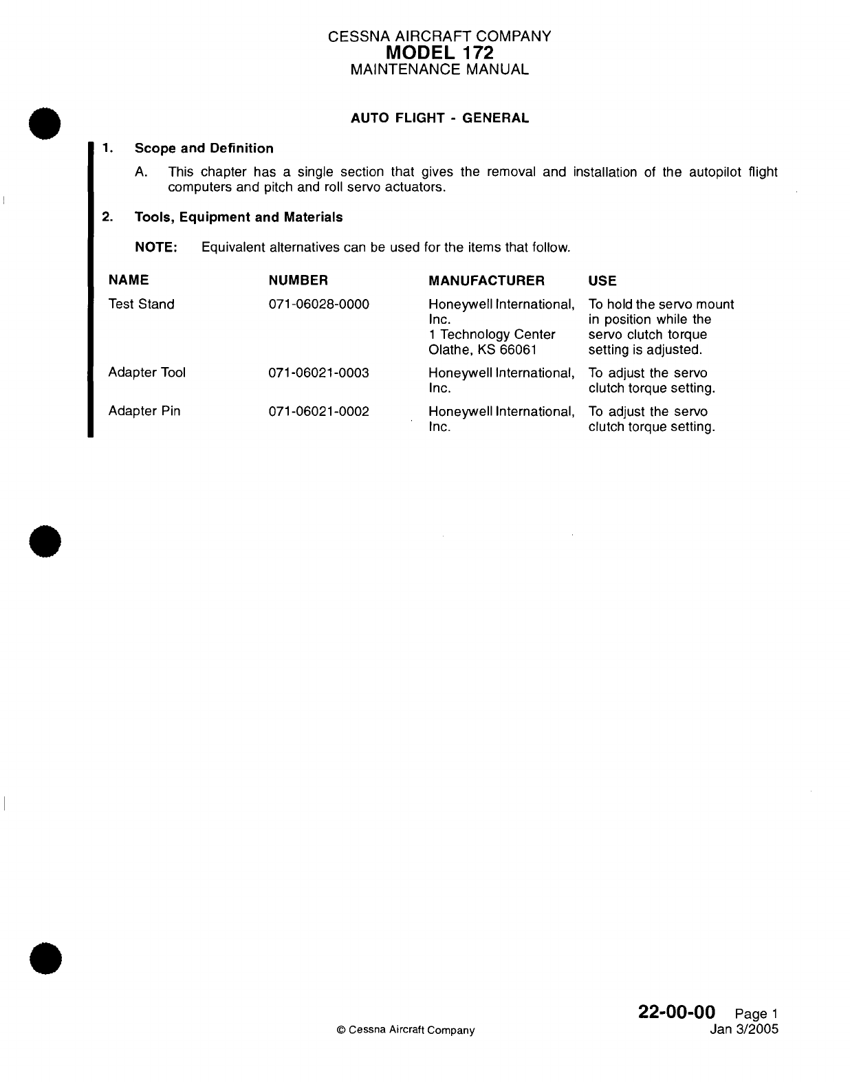
CESSNA
AIRCRAFT
COMPANY
MODEL
172
MAINTENANCE
MANUAL
AUTO
FLIGHT
-
GENERAL
1.
Scope
and
Definition
A.
This
chapter
has
a
single
section that gives
the
removal
and installation
of
the
autopilot flight
computers
and
pitch
and
roll
servo
actuators.
2.
Tools, Equipment
and
Materials
NOTE:
Equivalent
alternatives
can
be
used
for
the
items
that
follow.
NAME
NUMBER
MANUFACTURER
USE
Test
Stand
071-06028-0000
Honeywell
International,
To
hold
the
servo
mount
Inc.
in
position
while
the
1
Technology
Center
servo
clutch
torque
Olathe,
KS
66061
setting
is
adjusted.
Adapter
Tool
071-06021-0003 Honeywell
International,
To
adjust
the
servo
071-06021-0002
Inc.
Honeywell
International,
Inc.
clutch
torque
setting.
To
adjust
the
servo
clutch
torque
setting.
22-00-00
Page
1
Jan
3/2005
©
Cessna Aircraft
Company
Adapter
Pin
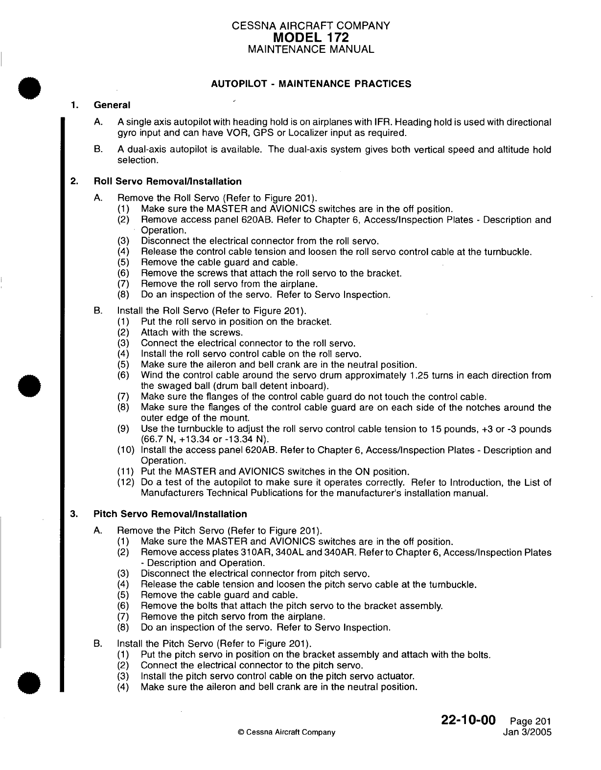
CESSNA
AIRCRAFT
COMPANY
MODEL
1
72
MAINTENANCE
MANUAL
AUTOPILOT
-
MAINTENANCE
PRACTICES
1.
General
A. A
single
axis
autopilot
with
heading
hold
is
on
airplanes
with
IFR.
Heading
hold is
used
with
directional
gyro
input
and
can have
VOR,
GPS
or
Localizer
input
as
required.
B.
A
dual-axis
autopilot
is
available.
The
dual-axis
system
gives
both
vertical speed
and
altitude
hold
selection.
2.
Roll
Servo
Removal/Installation
A.
Remove
the
Roll
Servo
(Refer
to
Figure
201).
(1)
Make
sure
the
MASTER
and AVIONICS
switches
are
in
the
off
position.
(2)
Remove
access
panel
620AB.
Refer
to
Chapter
6,
Access/Inspection
Plates
-
Description
and
Operation.
(3)
Disconnect
the
electrical connector
from
the
roll
servo.
(4)
Release the control
cable tension
and
loosen
the
roll
servo
control
cable
at
the
turnbuckle.
(5)
Remove
the
cable guard and
cable.
(6)
Remove
the
screws
that
attach
the
roll
servo
to
the
bracket.
(7)
Remove
the
roll
servo
from
the
airplane.
(8) Do
an
inspection
of
the servo.
Refer
to
Servo
Inspection.
B.
Install
the Roll
Servo
(Refer
to
Figure
201).
(1)
Put
the
roll
servo
in
position
on
the
bracket.
(2)
Attach
with
the
screws.
(3)
Connect
the
electrical connector
to
the
roll
servo.
(4)
Install
the
roll
servo control
cable
on
the
roll
servo.
(5)
Make
sure
the aileron
and
bell
crank
are
in
the neutral
position.
(6)
Wind
the
control
cable around
the
servo
drum
approximately
1.25
turns
in
each
direction
from
the
swaged
ball
(drum
ball
detent
inboard).
(7)
Make
sure
the
flanges
of
the
control
cable
guard
do
not
touch
the control
cable.
(8)
Make
sure
the
flanges
of
the control cable
guard
are
on
each
side
of
the
notches
around
the
outer
edge
of the
mount.
(9)
Use
the
turnbuckle
to
adjust
the
roll
servo
control
cable
tension
to
15
pounds,
+3
or
-3
pounds
(66.7
N,
+13.34
or
-13.34
N).
(10)
Install the
access
panel
620AB.
Refer
to
Chapter
6,
Access/Inspection
Plates
-
Description
and
Operation.
(11)
Put
the
MASTER
and
AVIONICS
switches
in
the
ON
position.
(12)
Do
a
test
of
the
autopilot
to
make sure
it
operates
correctly.
Refer
to
Introduction,
the
List
of
Manufacturers
Technical
Publications
for
the
manufacturer's
installation
manual.
3.
Pitch
Servo
Removal/Installation
A.
Remove
the
Pitch
Servo (Refer
to Figure
201).
(1)
Make
sure
the
MASTER
and
AVIONICS
switches
are
in
the
off
position.
(2)
Remove
access plates
31
OAR,
340AL
and 340AR.
Refer
to
Chapter
6,
Access/Inspection
Plates
-
Description
and
Operation.
(3)
Disconnect
the
electrical
connector
from pitch
servo.
(4)
Release
the
cable
tension
and
loosen
the pitch
servo cable
at the
turnbuckle.
(5)
Remove
the
cable
guard and
cable.
(6)
Remove
the
bolts
that
attach
the
pitch
servo
to
the
bracket
assembly.
(7)
Remove
the
pitch
servo
from
the
airplane.
(8) Do
an
inspection
of
the
servo.
Refer
to
Servo
Inspection.
B.
Install the Pitch
Servo (Refer
to
Figure
201).
(1)
Put
the
pitch servo
in
position
on
the
bracket
assembly
and
attach
with
the bolts.
(2)
Connect
the
electrical connector
to
the pitch servo.
(3)
Install
the
pitch
servo
control
cable
on
the
pitch
servo
actuator.
(4)
Make
sure
the
aileron
and
bell
crank
are
in
the
neutral
position.
22-10-00
Page
201
©
Cessna Aircraft Company
Jan
3/2005

CESSNA
AIRCRAFT
COMPANY
MODEL
172
MAINTENANCE
MANUAL
C
ROLL
SERVO
CONTROL
CABLE
GUARD
(NOTE)
OL
CABLE
LEG
AL)
0
CONTROL
CABLE
L
AILERON LOCATION
OF
RFI
I
rtRAlK'
crWArFn
RAI
I
VIEW
A-A
TURNBUCKLE
ROLL
SERVO
NOTE: THE
CONTROL
CABLES
MUST
NOT TOUCH
THE
CONTROL
CABLE
GUARD
LEGS
DETAIL
A
0510T1007
A0560T1011
AA0760T1009
Autopilot
Servo
Installation
Figure
201
(Sheet
1)
22-10-00
©
Cessna
Aircraft
Company
Page
202
Jan 3/2005
D
I
-
b-
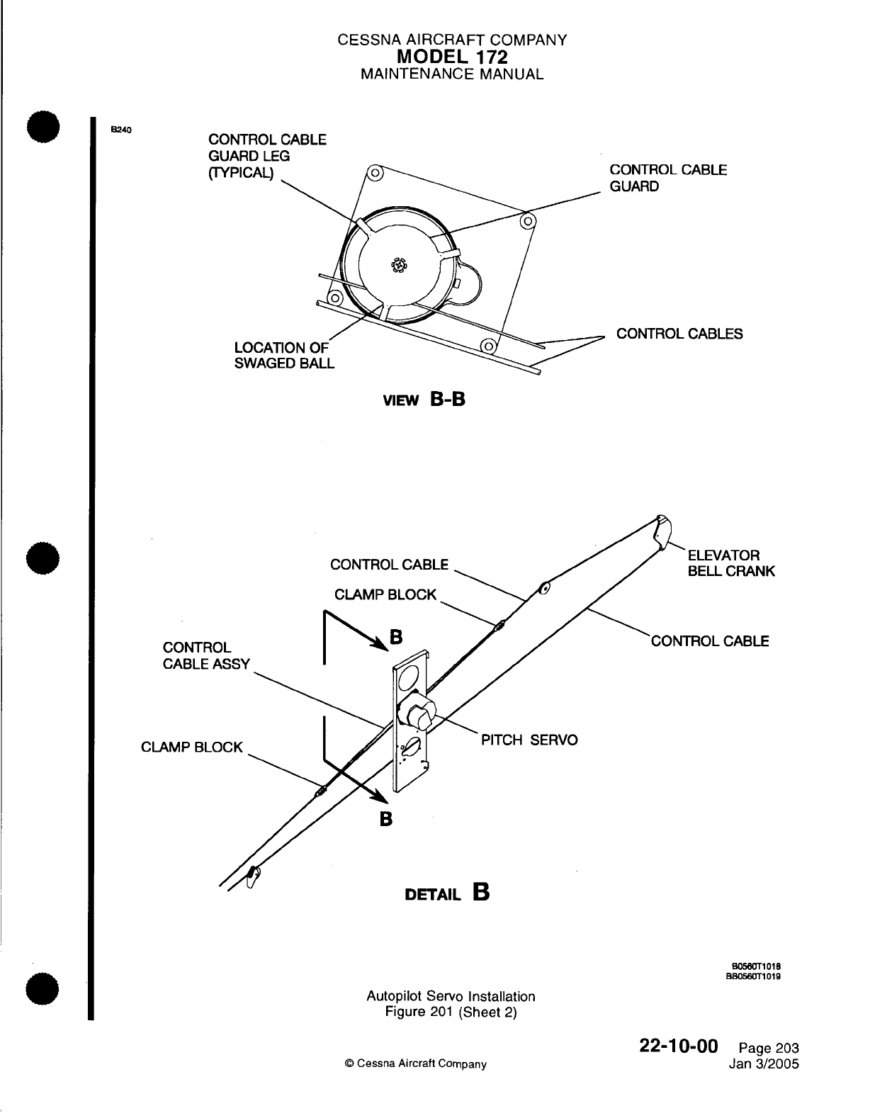
CESSNA
AIRCRAFT
COMPANY
MODEL
'172
MAINTENANCE
MANUAL
CONTROL
CABLE
GUARD
LEG
(TYPICAL)
LOCAT
SWAGI
CONTROL
CABLE
GUARD
CONTROL
CABLES
VIEW
B-B
CONTRC
CABLE
/
CLAMP
BLC
CONTROL
CABLE
CLAMP
BLOCK
PITCH SERVO
B
UlIRIL
.
B0560T1018
BB0560T101
Autopilot
Servo
Installation
Figure
201
(Sheet
2)
22-1
0-00
©
Cessna
Aircraft
Company
B240
K
Page 203
Jan
3/2005
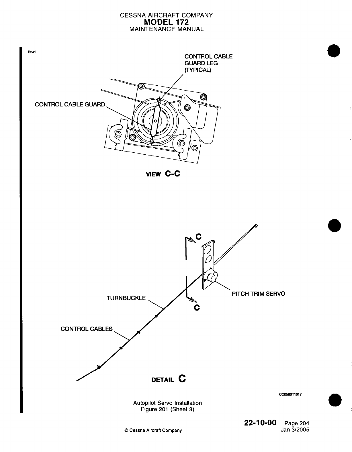
CESSNA
AIRCRAFT
COMPANY
MODEL
172
MAINTENANCE
MANUAL
CONTROL CABLE
GUARD
LEG
(TYPICAL)
CONTROL
CABLE
GUAR
VIEW
C-C
C
CONTROL
CABLES
PITCH
TRIM
SERVO
CC0560T1017
Autopilot
Servo
Installation
Figure
201
(Sheet
3)
22-10-00
©
Cessna
Aircraft
Company
Page
204
Jan
3/2005
B241

CESSNA
AIRCRAFT
COMPANY
MODEL
172
MAINTENANCE
MANUAL
(5)
Wind
the
control
cable
around
the
servo
drum
approximately
1.25
turns
in
each
direction from
the
swaged ball
(drum
ball
detent
inboard).
(6)
Make
sure
the
flanges
of
the control
cable
guard
do
not touch
the
control
cable.
(7)
Make
sure
the
flanges
of
the
control
cable
guard
are
on
each
side
of
the
notches
around
the
outer
edge
of
the
mount.
(8)
Use
the turnbuckle
to
adjust
the
pitch
servo cable
tension
to
15
pounds,
+3
or
-3
pounds
(66.7
N,
+13.34
or
-13.34
N).
(9)
Install
access
plates
31
OAR,
340AL
and
340AR.
Refer
to Chapter
6,
Access/Inspection
Plates
-
Description
and Operation.
(10)
Put
the MASTER
and
AVIONICS
switches
in
the
ON
position.
(11)
Do
a
test
of
the autopilot
to
make
sure
it
operates correctly.
Refer
to
Introduction,
the
List
of
Manufacturers
Technical
Publications
for
the
manufacturer's
installation manual.
4.
Pitch
Trim
Servo
Removal/Installation
A.
Remove
the
Pitch Trim
Servo
(Refer to Figure
201).
(1)
Make
sure
the
MASTER and AVIONICS
switches
are
in
the off
position.
(2)
Remove
access
plates
31
OAR,
340AL
and
340AR.
Refer
to
Chapter
6,
Access/Inspection
Plates
-
Description
and
Operation.
(3)
Disconnect
the
electrical connector
from
the
pitch
trim
servo.
(4)
Release
the
cable
tension
and
loosen
the
pitch
trim
servo
cable at
the
turnbuckle.
(5)
Remove the
cable
guard and the
cable.
(6)
Remove
the
bolts
that
attach
the
pitch trim
servo
to
the
bracket
assembly.
(7)
Remove the
pitch
trim
servo
from
the
airplane.
(8)
Do
an
inspection
of
the servo.
Refer
to
Servo Inspection.
B.
Install
the Pitch
Trim
Servo (Refer
to
Figure
201).
(1)
Put
the pitch
trim
servo
in
position
on the
bracket
assembly
and
attach
with
the
bolts.
(2)
Connect
the
electrical
connector
to
the
pitch
trim
servo.
(3)
Install the
pitch
trim
servo
cable
on
the
pitch
trim
servo actuator.
(4)
Make
sure the
flanges
of
the
control
cable
guard
do
not
touch
the
control
cable.
(5)
Make sure
the
flanges
of
the control
cable
guard
are
on
either
side
of
the
notches
around
the
outer
edge
of
the
mount.
(6)
Use
the turnbuckle
to
adjust
the
pitch
trim
servo control
cable
tension
to
15
pounds
to
20 pounds
(66.7
N
to
88.9
N).
(7)
Install
access
plates
31
OAR,
340AL
and
340AR.
Refer to
Chapter
6,
Access/Inspection
Plates
-
Description and
Operation.
(8)
Put
the MASTER
and
AVIONICS
switches
in
the
ON
position.
(9)
Do
a
test
of
the autopilot
to
make
sure
it
operates
correctly.
Refer
to
Introduction,
the
List
of
Manufacturers
Technical
Publications,
for
the
manufacturer's
installation manual.
C.
Do
a
check
of the pitch trim
rigging.
(1)
Attach
an
inclinometer
to
the
trim
tab.
(2)
Put
the
trim
tab
in
the
0
degree
position.
(3)
Manually operate
the
trim
tab
to
the
up
and
down limits.
(4)
Record
the
limits of travel.
(5)
Put
an
observer
at
the
right-hand
access
opening of
the
tailcone.
(6)
Put
the electrical
trim
to the
full
nose-up
position
until the
observer
sees
the
clutch
slip.
(7)
Turn the
manual
trim
wheel
nose-up
(test
load
condition)
1/4
turn
more
while
the
clutch
slips.
(8)
Make sure the
swaged ball
on
the
control
cable
assembly
does
not
turn
aft
of
the
tangent
point.
(9)
Release
the
trim
wheel
and
disengage
the
autopilot.
(10)
Manually
operate
the
trim
to
the
full
nose-up
position.
(11)
Do
a
check
of the trim tab
position with
an
inclinometer.
(12)
Trim
tab
position that
is
greater
than
the
limits
of
travel values
recorded
is
an
indication
that
the
stop
blocks
slipped.
(a)
Do
the
trim
system
rigging
again.
(b)
Make
sure
the
stop
block bolts torque
is
correct.
(c)
Repeat the
check
of
the
pitch trim
rigging.
22-10-00
Page
205
©
Cessna
Aircraft
Company
Jan
3/2005
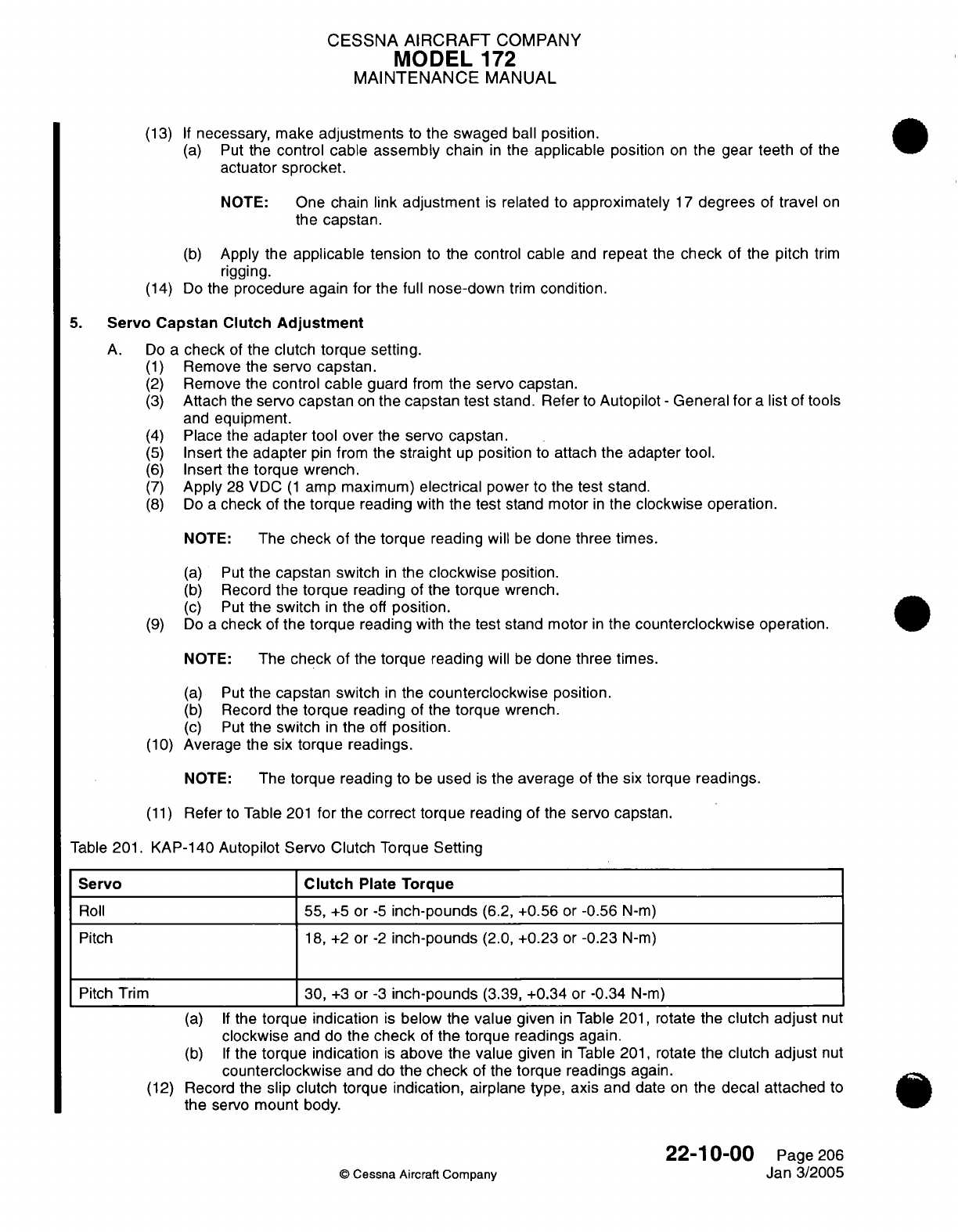
CESSNA
AIRCRAFT
COMPANY
MODEL
172
MAINTENANCE
MANUAL
(13)
If
necessary,
make
adjustments
to
the swaged
ball
position.
(a)
Put
the
control cable
assembly
chain
in
the
applicable
position
on
the gear
teeth
of
the
actuator
sprocket.
NOTE:
One
chain link
adjustment
is
related
to
approximately
17
degrees
of
travel
on
the
capstan.
(b)
Apply the
applicable
tension
to
the control
cable
and
repeat
the
check
of
the pitch
trim
rigging.
(14)
Do
the
procedure again for
the
full
nose-down
trim
condition.
5.
Servo Capstan
Clutch
Adjustment
A.
Do
a
check
of
the
clutch
torque setting.
(1)
Remove
the
servo
capstan.
(2)
Remove
the
control
cable
guard
from
the
servo
capstan.
(3)
Attach
the
servo
capstan
on
the
capstan
test
stand. Refer
to
Autopilot
-
General
for
a
list
of tools
and
equipment.
(4)
Place
the
adapter
tool
over
the
servo
capstan.
(5)
Insert
the
adapter
pin
from
the
straight
up
position
to
attach the
adapter
tool.
(6)
Insert
the
torque
wrench.
(7)
Apply
28
VDC
(1
amp maximum)
electrical
power
to
the
test
stand.
(8)
Do
a
check
of
the
torque
reading
with
the
test
stand motor
in
the
clockwise operation.
NOTE:
The
check
of
the
torque
reading
will
be
done
three
times.
(a) Put
the
capstan
switch
in
the
clockwise
position.
(b)
Record
the
torque
reading
of
the
torque
wrench.
(c)
Put
the
switch
in
the
off
position.
(9)
Do
a
check
of
the
torque
reading
with
the
test
stand
motor
in
the
counterclockwise
operation.
NOTE:
The
check
of
the
torque
reading
will
be
done
three
times.
(a)
Put
the
capstan switch
in
the
counterclockwise
position.
(b)
Record
the
torque
reading
of
the
torque
wrench.
(c)
Put
the switch
in
the
off
position.
(10)
Average the six
torque readings.
NOTE:
The
torque
reading
to
be
used
is
the
average
of
the six
torque
readings.
(11)
Refer
to
Table
201
for
the correct torque
reading
of
the
servo
capstan.
Table
201.
KAP-140
Autopilot
Servo
Clutch
Torque
Setting
Servo
Clutch
Plate Torque
Roll
55,
+5
or
-5
inch-pounds
(6.2,
+0.56
or
-0.56
N-m)
Pitch
18,
+2
or
-2
inch-pounds
(2.0,
+0.23
or
-0.23
N-m)
Pitch
Trim
30,
+3
or
-3
inch-pounds
(3.39,
+0.34 or
-0.34
N-m)
(a)
If
the
torque indication
is
below
the
value
given
in
Table
201,
rotate
the
clutch
adjust
nut
clockwise
and do the
check
of
the
torque
readings
again.
(b) If
the
torque indication
is
above
the
value
given
in
Table
201,
rotate
the
clutch
adjust
nut
counterclockwise
and
do
the
check
of
the
torque
readings
again.
(12)
Record
the
slip
clutch
torque
indication,
airplane
type,
axis
and
date
on
the
decal
attached
to
the
servo
mount
body.
22-10-00
Page
206
©
Cessna
Aircraft
Company
Jan
3/2005
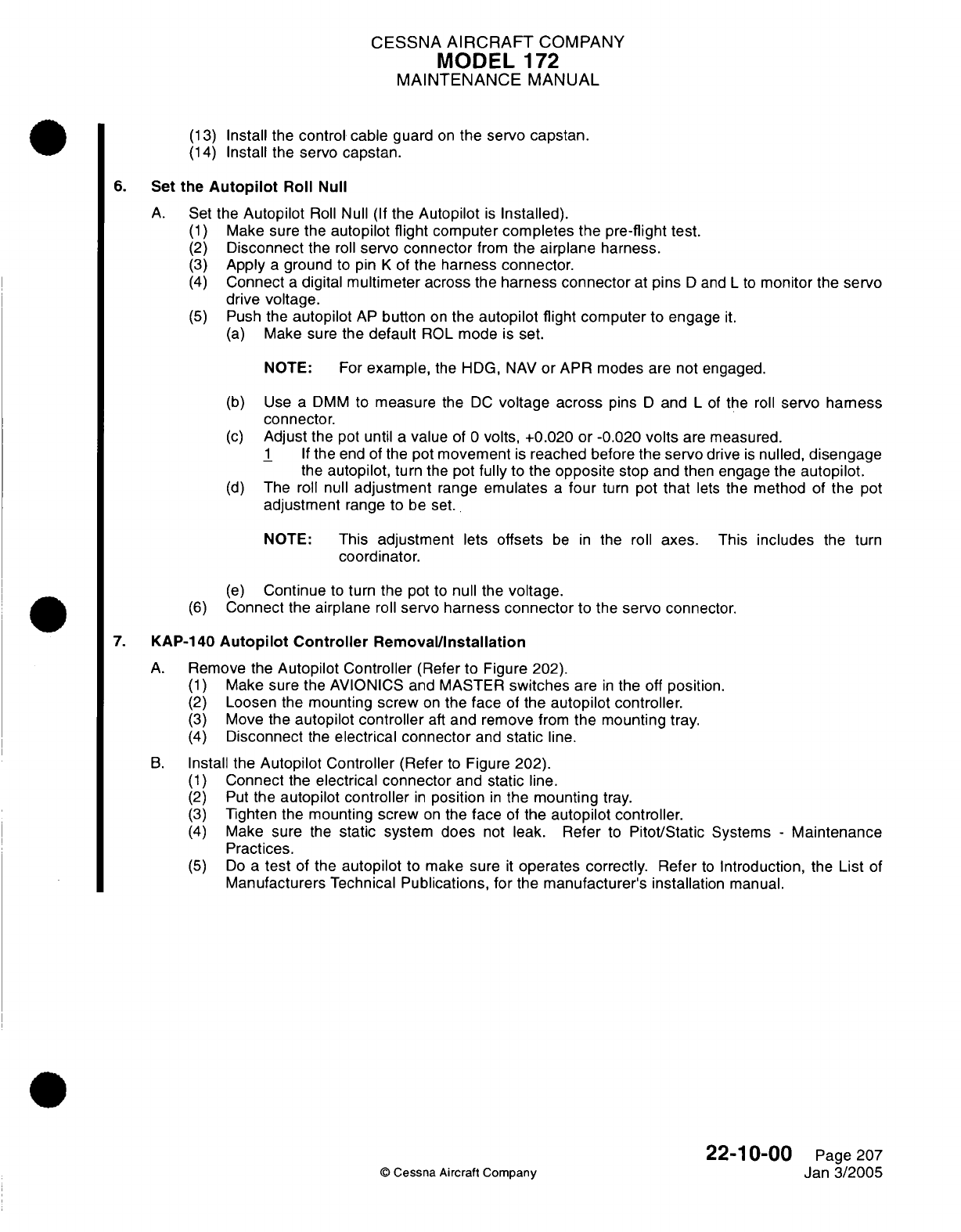
CESSNA
AIRCRAFT
COMPANY
MODEL
1
72
MAINTENANCE
MANUAL
(13)
Install the
control
cable
guard
on
the
servo capstan.
(14)
Install the servo capstan.
6.
Set
the
Autopilot
Roll
Null
A.
Set
the
Autopilot
Roll
Null
(If
the
Autopilot
is
Installed).
(1)
Make
sure
the
autopilot
flight
computer
completes
the
pre-flight
test.
(2)
Disconnect
the
roll
servo
connector
from
the
airplane
harness.
(3)
Apply
a
ground
to
pin
K
of
the
harness connector.
(4)
Connect
a
digital multimeter
across
the
harness
connector
at
pins
D
and
L
to
monitor the
servo
drive
voltage.
(5)
Push
the
autopilot
AP
button
on
the autopilot flight
computer
to
engage
it.
(a)
Make sure
the
default
ROL
mode
is
set.
NOTE:
For
example,
the
HDG,
NAV
or APR modes
are
not engaged.
(b)
Use a
DMM
to
measure
the
DC
voltage
across
pins
D
and
L
of
the
roll
servo harness
connector.
(c)
Adjust
the
pot
until
a
value
of
0
volts, +0.020
or -0.020
volts
are
measured.
1
If
the
end of
the pot
movement
is
reached
before
the servo
drive
is
nulled,
disengage
the
autopilot,
turn
the pot
fully
to the
opposite
stop
and then
engage
the
autopilot.
(d)
The
roll
null
adjustment
range
emulates
a
four
turn
pot
that
lets
the
method
of
the
pot
adjustment
range to
be
set.
NOTE:
This
adjustment
lets
offsets
be
in
the roll
axes.
This
includes
the
turn
coordinator.
(e)
Continue
to
turn
the
pot
to
null
the
voltage.
(6)
Connect
the
airplane
roll
servo
harness
connector
to
the
servo
connector.
7.
KAP-140
Autopilot
Controller
Removal/nstallation
A.
Remove
the
Autopilot Controller
(Refer
to Figure 202).
(1)
Make
sure
the AVIONICS and MASTER
switches
are
in
the
off
position.
(2)
Loosen
the
mounting
screw
on
the face
of
the
autopilot
controller.
(3)
Move
the
autopilot
controller
aft
and
remove
from
the mounting
tray.
(4)
Disconnect
the
electrical
connector
and
static
line.
B.
Install
the
Autopilot
Controller
(Refer
to
Figure
202).
(1)
Connect
the
electrical connector
and
static
line.
(2)
Put
the
autopilot
controller
in
position
in
the
mounting
tray.
(3)
Tighten the mounting screw
on
the
face
of
the
autopilot controller.
(4)
Make
sure
the
static
system
does
not
leak. Refer
to
Pitot/Static
Systems
-
Maintenance
Practices.
(5)
Do
a
test
of the
autopilot
to
make
sure
it
operates
correctly.
Refer
to
Introduction,
the
List
of
Manufacturers
Technical
Publications,
for
the
manufacturer's
installation
manual.
22-10-00
Page 207
©
Cessna
Aircraft
Company
Jan
3/2005
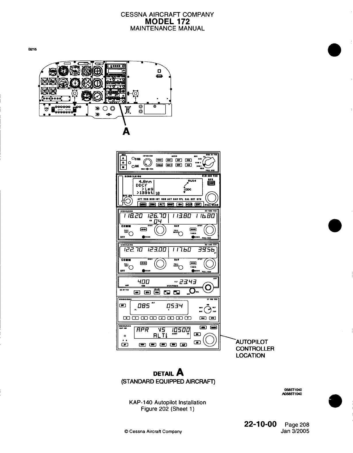
CESSNA
AIRCRAFT
COMPANY
MODEL
172
MAINTENANCE
MANUAL
B215
^^
i==i
*
d^.'
'*e^'i
" *
d
.e
o
oo0oo0
.. :
@@@@@@ 3:
*
*.
.
A
.....
v
........
r o ri
i-
-
-i
*..
|
E1IIs2D
1E1 n
111
10
4.0nn
.RU
4
I
DDCf
/
ro
I IDDC
mI"
t>l9kt,
10
£
AT
. ..
.E
. .
MIT
VI
A«€T IMA
I.L
CAL
SIT oT
j
,
T/zo
Ei.3
o
()
:o (/,,
/("I
11820
12E.710
113B0
IhBOI
1I
4
ID
COMM
""
'---\
M-A
co
M
..
i,.
1|22.10
123.00
1
11bO
3f5b]
U"
O
OFF
*
.
.....
RPR VS
11n
FI
-
Ul
oI
085t
053lY
1
^
(STANDARD
EQUIPPES
D
0500AIRCRAF
oRP
RLTI
*'o'
"
^/^N
-
(3lr
[-}
B
I[j'\\
[
AUTOPILOT
CONTROLLER
LOCATION
DETAIL
A
(STANDARD
EQUIPPED
AIRCRAFT)
05B5T1040
A0585T140
KAP-140
Autopilot
Installation
Figure
202
(Sheet
1)
22-10-00
Page
208
©
Cessna
Aircraft Company
Jan
3/2005
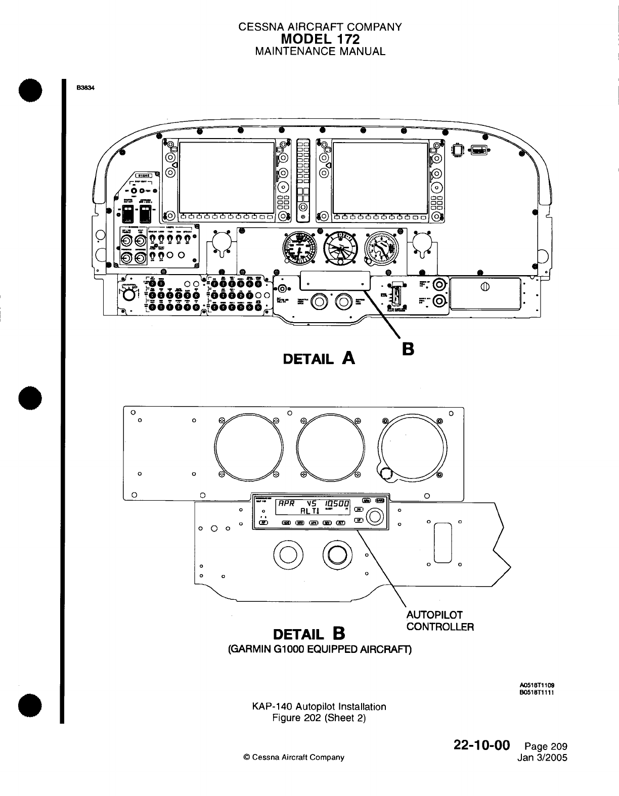
CESSNA
AIRCRAFT
COMPANY
MODEL
'172
MAINTENANCE
MANUAL
B3834
*0
oo
00
IOtIObOOion
(9
O
Q
C ©00 O
o
C,
/
I.
B
'
-ooooo
o6o6600oo
!
.000000.000OOOk
o0
00
oo
oo
00
00oo
00
00
e
* *
U
0
00
@
P®
300
00
6j~
b~bhbhbhbbon
ar-
-I _
@
B ?~©©!"-\
I,
"*
^
"
*-^"
DETAIL
A
0
0
0
0
o
'
RPR
VS5
°
o
I
RLTI
o
D ©I i
o
0 0
0
o
0
o
A
DETAIL
B
c
(GARMIN
G1000
EQUIPPED
AIRCRAFT)
0
o
0
o
o
UTOPILOT
,ONTROLLER
A0518T1109
B0518T1111
KAP-140
Autopilot
Installation
Figure
202
(Sheet
2)
22-10-00
©
Cessna Aircraft
Company
la
!m
©
a
0
®D
1
0
o
0
B
0
y^°
0
Page
209
Jan 3/2005
-^ *-*
----------- I
C
bb
a
-
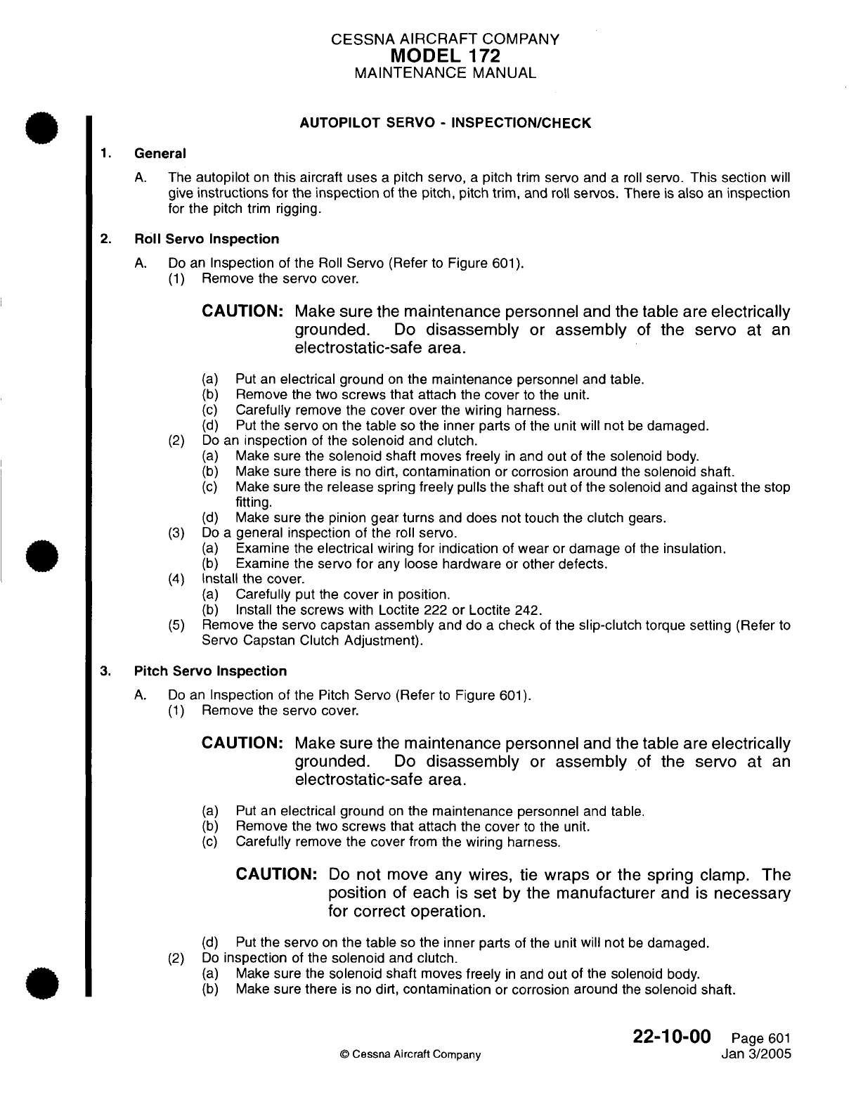
CESSNA
AIRCRAFT
COMPANY
MODEL
172
MAINTENANCE
MANUAL
AUTOPILOT
SERVO
-
INSPECTION/CHECK
1.
General
A.
The
autopilot
on
this
aircraft
uses
a
pitch
servo,
a
pitch
trim
servo
and
a roll
servo.
This
section
will
give
instructions
for
the
inspection
of
the pitch,
pitch
trim, and
roll
servos.
There
is
also
an
inspection
for
the
pitch
trim
rigging.
2.
Roll
Servo
Inspection
A.
Do
an
Inspection
of
the
Roll
Servo
(Refer
to
Figure
601).
(1)
Remove
the servo
cover.
CAUTION:
Make
sure
the
maintenance
personnel
and
the table
are
electrically
grounded.
Do
disassembly
or
assembly
of
the
servo
at
an
electrostatic-safe
area.
(a)
Put an
electrical ground
on
the
maintenance
personnel and
table.
(b)
Remove the two
screws
that
attach the
cover
to
the unit.
(c)
Carefully
remove
the
cover
over
the
wiring
harness.
(d)
Put
the servo
on
the
table
so
the inner parts
of
the unit will not
be
damaged.
(2)
Do
an
inspection
of
the
solenoid
and
clutch.
(a)
Make
sure
the
solenoid
shaft
moves
freely
in
and
out
of
the
solenoid
body.
(b)
Make
sure there
is
no
dirt,
contamination
or
corrosion around
the
solenoid
shaft.
(c)
Make
sure
the
release
spring
freely
pulls the shaft
out
of
the
solenoid
and
against
the
stop
fitting.
(d)
Make
sure
the
pinion
gear
turns
and
does
not
touch
the
clutch
gears.
(3)
Do
a
general
inspection of
the
roll
servo.
(a)
Examine
the
electrical
wiring
for indication
of
wear
or
damage
of
the
insulation.
(b)
Examine the
servo
for
any
loose
hardware
or
other defects.
(4)
Install
the
cover.
(a)
Carefully
put
the
cover
in
position.
(b)
Install
the screws
with
Loctite
222
or
Loctite
242.
(5)
Remove
the
servo
capstan assembly
and
do
a
check
of the
slip-clutch
torque
setting
(Refer
to
Servo Capstan
Clutch
Adjustment).
3.
Pitch
Servo
Inspection
A.
Do
an
Inspection
of
the Pitch
Servo
(Refer
to
Figure
601).
(1)
Remove
the
servo
cover.
CAUTION:
Make
sure
the
maintenance
personnel
and the
table
are
electrically
grounded.
Do
disassembly
or
assembly
of
the
servo
at
an
electrostatic-safe
area.
(a)
Put
an
electrical
ground
on
the
maintenance
personnel
and
table.
(b)
Remove
the
two
screws
that
attach
the
cover
to
the
unit.
(c)
Carefully
remove
the
cover
from the
wiring
harness.
CAUTION:
Do
not
move any
wires,
tie
wraps or
the
spring
clamp.
The
position
of
each
Is
set
by
the
manufacturer
and
Is
necessary
for correct
operation.
(d)
Put
the
servo
on
the
table
so
the
inner
parts
of
the
unit will
not
be
damaged.
(2)
Do
inspection
of
the
solenoid
and
clutch.
(a)
Make
sure
the
solenoid
shaft
moves
freely
in
and
out of
the
solenoid
body.
(b)
Make
sure
there
is
no
dirt,
contamination
or
corrosion around
the
solenoid
shaft.
22-10-00
Page
601
©
Cessna
Aircraft
Company
Jan
3/2005
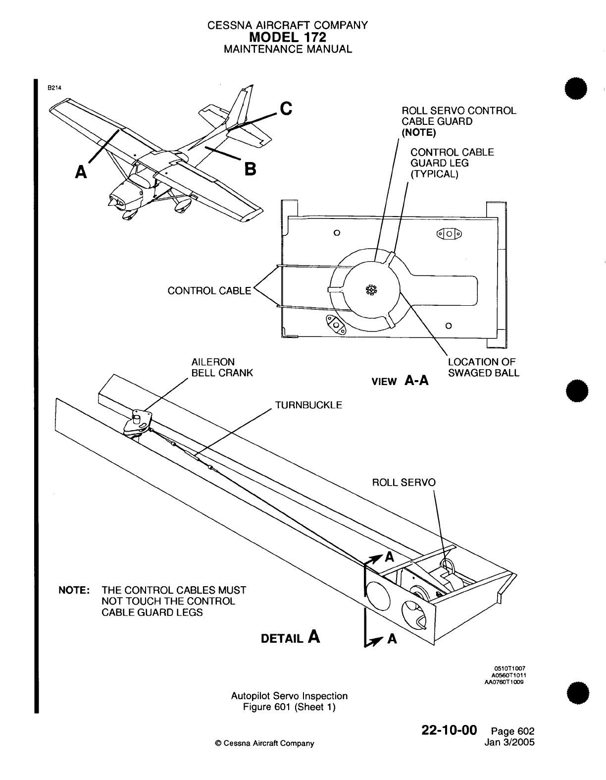
CESSNA AIRCRAFT
COMPANY
MODEL
172
MAINTENANCE MANUAL
C
ROLL
SERVO
CONTROL
CABLE
GUARD
(NOTE)
0
CONTROL
CABLE
L
AILERON LOCATION OF
D
I
r'DAhIV
COA/Ar-Cln
DAI
I
VIEW
A-A
TURNBUCKLE
ROLL SERVO
NOTE:
THE
CONTROL
CABLES
MUST
NOT TOUCH
THE CONTROL
CABLE
GUARD LEGS
DETAIL
A
0510T1007
A0560T1011
AA0760T1009
Autopilot
Servo
Inspection
Figure
601
(Sheet
1)
22-1
0-00
©
Cessna
Aircraft
Company
3L
CABLE
LEG
AL)
1
Page
602
Jan
3/2005
D
L-
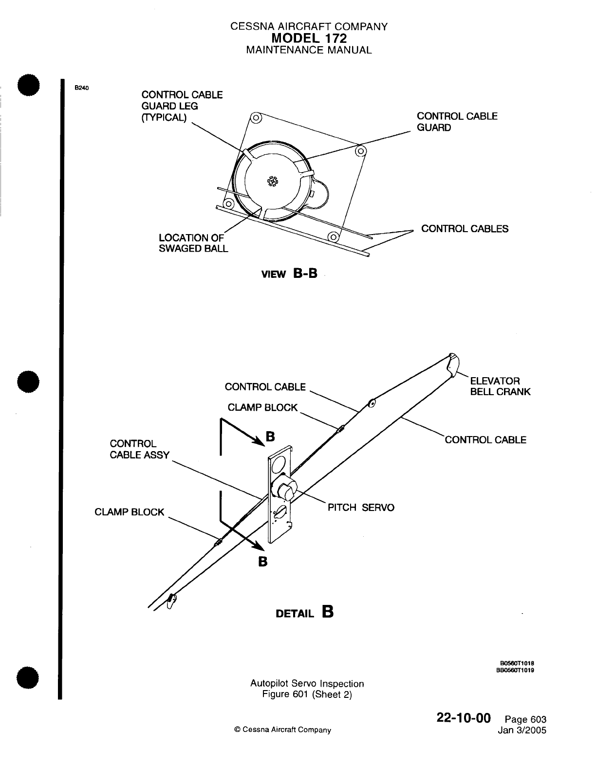
CESSNA
AIRCRAFT
COMPANY
MODEL
'172
MAINTENANCE
MANUAL
CONTROL
CABLE
GUARD
LEG
(TYF
CONTROL CABLE
GUARD
CONTROL
CABLES
VIEW
B-B
CONTRC
CABLE
A
CLAMP
BLC
CONTROL
CABLE
CLAMP
BLOCK
CABLE
SERVO
B
DETAIL
D
B0560T101B
BB0560T1019
Autopilot
Servo
Inspection
Figure
601
(Sheet
2)
22-1
0-00
©
Cessna
Aircraft
Company
B240
Page
603
Jan
3/2005

CESSNA
AIRCRAFT
COMPANY
MODEL
172
MAINTENANCE
MANUAL
CONTROL
CABLE
GUARD
LEG
(TYPICAL)
CONTROL
CABLE
GUAR
VIEW
C-C
C
°
P
D
C
CON1
PITCH
TRIM
SERVO
CCo05OT1017
Autopilot
Servo
Inspection
Figure
601
(Sheet
3)
© Cessna
Aircraft
Company
B241
22-10-00
Page
604
Jan
3/2005
"
"_
. .
CESSNA
AIRCRAFT
COMPANY
MODEL
'172
MAINTENANCE
MANUAL
(c)
Make
sure
the
release
spring
freely
pulls
the
shaft
out
of
the
solenoid
and
against
the
stop
fitting.
(d)
Make
sure
the
pinion
gear
turns
and
does
not
touch
the
clutch
gears.
(3)
Do
a
general inspection.
(a)
Examine
the
electrical
wiring
for
indication
of
wear
or
damage
of
the
insulation.
(b)
Examine
the servo
for
any
loose
hardware
or
other
defects.
(4)
Do
an
inspection
of
the pitch
servo
motor.
(a) Put
the
servo
in
position
so
the
baseplate
is
on
the
bottom
side
of
the
unit.
(b)
Hold
the
top
section
of the
motor
and
carefully
turn
the
motor
shaft.
(c)
The
motor shaft
must
turn
freely
from
side
to
side
a
small
quantity.
(5)
Install the
cover.
(a)
Carefully
put
the
cover
in
position.
(b)
Use
screws
with
Loctite
222
or
Loctite
242.
(6)
Remove
the
servo
capstan
assembly
and
do
a
check
of
the
slip-clutch
torque
setting
(Refer
to
Servo Capstan
Clutch
Adjustment).
4.
Pitch
Trim
Servo
Inspection
A.
Do
an
Inspection of
the
Pitch
Trim
Servo (Refer
to
Figure
601).
(1)
Remove
the
servo
cover.
CAUTION:
Make
sure
the
maintenance personnel
and
the
table
are
electrically
grounded.
Do
disassembly
or
assembly
of
the
servo
at
an
electrostatic-safe
area.
(a) Put
an
electrical
ground
on
the
maintenance
personnel
and
table.
(b)
Remove
the
two
screws that
attach
the cover
to
the
unit.
(c)
Carefully
remove
the
cover over
the
wiring
harness.
(d)
Put
the
servo
on
the
table
so
the
inner
parts
of
the
unit
will
not
be
damaged.
(2)
Do
inspection
of the
solenoid and
clutch.
la)
Make
sure
the
solenoid
shaft
moves
freely
in
and
out
of
the
solenoid
body.
(b)
Make
sure there
is
no
dirt,
contamination
or
corrosion
around
the
solenoid shaft.
(c)
Make
sure
the
release
spring
freely
pulls
the
shaft
out
of
the
solenoid
and
against
the
stop
fitting.
(d)
Make
sure
the
pinion
gear
turns
and
does
not
touch
the
clutch
gears.
(3)
Do
a
general
inspection.
(a)
Examine
the
electrical
wiring
for
indication
of
wear
or
damage
of
the
insulation.
(b)
Examine
the servo
for
any
loose
hardware
or
other
defects.
(4)
Install
the
cover.
(a)
Carefully
put
the
cover
in
position.
(b)
Install
the
screws
with
Loctite
222
or Loctite
242.
(5)
Remove the
servo
capstan
assembly
and
check
the
slip-clutch
torque setting (Refer
to
Servo
Capstan
Clutch Adjustment).
5.
Pitch
Trim
Rigging
Inspection
A.
Do
a
check
of
the pitch
trim
rigging.
(1)
Attach
an
inclinometer
to
the trim tab.
(2)
Put
the
trim
tab
in
the
0
degree
position.
(3)
Manually
operate
the
trim
tab
to
the
up
and
down
limits.
(4)
Record
the
limits
of
travel.
(5)
Put
an
observer
at
the
right-hand
access
opening
of
the tailcone.
(6)
Put
the
electrical
trim
to
the
full
nose-up
position until the
observer
sees the
clutch slip.
(7)
Turn
the
manual
trim
wheel
nose-up
(test load
condition)
1/4
turn more
while
the clutch
slips.
(8)
Make
sure
the swaged
ball
on
the
control
cable
assembly
does
not
turn aft
of
the
tangent
point.
(9)
Release
the
trim
wheel
and
disengage
the
autopilot.
(10)
Manually
operate
the
trim
to
the full
nose-up position.
(11)
Do
a
check
of
the
trim
tab
position
with
an
inclinometer.
22-10-00
Page
605
©
Cessna
Aircraft
Company
Jan
3/2005
CESSNA
AIRCRAFT
COMPANY
MODEL
172
MAINTENANCE
MANUAL
(12)
Trim
tab
position
that
is
greater than
the
limits
of
travel
values
recorded
is
an
indication that
the
stop
blocks
slipped.
(a)
Do
the
trim
system
rigging
again.
(b)
Make
sure
the
stop
block
bolts
torque
is
correct.
(c)
Repeat
the
check
of
the pitch
trim
rigging.
(13)
If
necessary,
make
adjustments
to
the
swaged
ball
position.
(a)
Put
the
control cable
assembly
chain
in
the
applicable
position
on
the
gear
teeth
of the
actuator sprocket.
NOTE: One
chain
link
adjustment
is
related to
approximately
17
degrees
of
travel
on
the
capstan.
(b)
Apply the
applicable
tension
to
the
control
cable
and
repeat
the
check
of
the pitch
trim
rigging.
(14)
Do
the
procedure
again
for
the
full
nose-down
trim
condition.
22-10-00
Page
606
©
Cessna
Aircraft
Company
Jan 3/2005

CHAPTER
COMMUNICATIONS

CESSNA AIRCRAFT
COMPANY
MODEL
172
MAINTENANCE
MANUAL
LIST
OF
EFFECTIVE
PAGES
CHAPTER-SECTION-SUBJECT
23-Title
23-List
of
Effective
Pages
23-Record
of
Temporary
Revisions
23-Table
of
Contents
23-00-00
23-1
0-00
23-50-00
23-60-00
PAGE
Page
1
Pages
201-209
Pages
201-204
Pages
201
-202
©
Cessna Aircraft
Company
23
-
LIST
OF
EFFECTIVE
PAGES
Page
1
of
1
Janl1/2007
DATE
Apr
7/2003
Janl1/2007
Jan 3/2005
Apr
7/2003
Temporary
Revision
Number
RECORD
OF
TEMPORARY
REVISIONS
Page
Number
Issue
Date
By
Date
Removed
By
CESSNA AIRCRAFT
COMPANY
MODEL
172
MAINTENANCE
MANUAL
CONTENTS
COMMUNICATIONS
-
GENERAL
.........................
S
cope
.....
. . . . ...... . . . ...... . . . ..........
Tools
and
Equipment.............................
Definition
..................................
NAV/COM
-
MAINTENANCE
PRACTICES
.....................
General...................................
Troubleshooting
...............................
NAV/COM
Radio Removal
and
Installation...................
GIA 63
Integrated
Avionics
Unit
Removal/Installation
..............
VHF
Antenna
Removal/installation.......................
Microphone
Switch
Removal/installation....................
Microphone
Switch
Button
Cleaning......................
AUDIO
PANEL
-
MAINTENANCE
PRACTICES
...................
General...................................
Troubleshooting
...............................
Audio
Panel
Removal/Installation
.......................
Intercom
Jacks
Removal/Installation......................
Rear
Passenger
Intercom
Jacks
Removal/installation..............
STATIC
WICKS
-
MAINTENANCE
PRACTICES...................
General...................................
Tools and
Equipment.............................
Static
Wicks
Removal/installation
.......................
Bonding
Straps
Removal/installation......................
©
Cessna
Aircraft
Company
23-00-00
Page
1
23-00-00
Page
1
23-00-00
Page
1
23-00-00
Page
1
23-1
0-00
Page
201
23-1
0-00
Page
201
23-1
0-00
Page
201
23-10-00
Page
201
23-10-00
Page
201
23-1
0-00
Page
205
23-1
0-00
Page
205
23-10-00
Page
205
23-50-00
Page
201
23-50-00
Page
201
23-50-00
Page
201
23-50-00
Page
201
23-50-00
Page
201
23-50-00
Page 204
23-60-00
Page
201
23-60-00
Page
201
23-60-00
Page
201
23-60-00
Page
201
23-60-00
Page
201
23
-CONTENTS
Pagel1
of
1
Janl1/2007
CESSNA
AIRCRAFT
COMPANY
MODEL
172
MAINTENANCE
MANUAL
COMMUNICATIONS
-
GENERAL
1.
Scope
A.
This
chapter describes
and
provides
maintenance instructions
for
equipment which
furnishes
a
means
of
communicating
from
one
part of
the
airplane
to
another,
and
between
the
airplane
and
other
airplanes
or
ground stations
B.
Additional
information
on
communications
equipment
can
be
found
in
the
Wiring Diagram Manual
supplied
with
the
airplane.
C.
Technical
publications
available
from
the manufacturer
of
the
various components
and
systems which
are
not
covered
in
this manual
must
be
utilized
as required
for
maintenance
of
those
components
and
systems.
2.
Tools
and
Equipment
NOTE:
Equivalent
substitutes
may
be
used
for
the following
items:
NAME
Type
I,
Class
B-2
Sealant
NUMBER
PR1440
MANUFACTURER
Courtaulds
Aerospace
5426
San
Fernando
Rd.
Glendale,
CA
91209
USE
To
fay
seal
antenna
to
fuselage.
Bonding
meter
Megohmmeter
Keithley
Model
580
Model
2850
Keithley
Instruments,
Inc.
To
check
electrical bonding
Instrument Division
connections.
28775
Aurora
Rd.
Cleveland,
OH
44139
Associated
Research,
To
check
resistance
of
static
Inc.
wicks.
3773
W.
Belmont
Ave.
Chicago,
IL
60618
3.
Definition
A.
Information
contained
in
this
chapter
provides
the
basic
procedures which
can
be
accomplished
at
the
flight
line
level;
such
as,
removal
and
installation
of
components
and
system
operation.
B.
This
chapter
is
divided
into
sections
to
aid
maintenance
personnel
in
locating
information.
A
brief
description
of
each
section
is
as
follows:
(1)
The
speech
communication
section
describes
radio
equipment
used
for
reception
and
transmission
of
voice communication.
(2)
The
audio
integrating
system
section
describes
that
portion
of
the
system
which
controls
the
output
of the
communications
and
navigation receivers
into
the
pilot
and
passengers
headphones
and
speakers,
and
the output
of
the
pilot's
microphone
into
the
communications
transmitters.
(3)
The
static
discharging
section
describes
the
static
discharge
wicks
used
to
dissipate
static
electricity.
©
Cessna
Aircraft
Company
23-00-00
Page
1
Apr
7/2003
CESSNA
AIRCRAFT
COMPANY
MODEL
172
MAINTENANCE
MANUAL
NAV/COM
-
MAINTENANCE PRACTICES
1.General
A.
Maintenance
practices
for
the
navigation/communications
(NAV/COM) units
have
procedures
for
the
removal and
installation
of
the
different
components.
B.
The
dual
NAV/COM
radio
is in
the
instrument panel.
C.
For
airplanes
with
the
Garmin
G1000,
the
center
of
the
Garmin
G1000
is
the
GIA
63
Integrated
Avionics
Unit
(IAUI),
which
is in
the
tailcone.
The
GIA 63
operates
as
a
primary
communications
center
that
connects
all
of
the
Line
Replaceable
Units
(LRUs)
with
the Primary
Function
Display
(PFD)
and
Multi-Function Display
(MFD).
The
GIA
63
has the GPS
receiver,
VHF
NAV/COM
receivers,
and
system
integration
microprocessors.
The
GIA
63W
has
the
Wide
Area
Augmentation
System
(WAAS)
installed.
The
GIA
63
transmits directly
to
the
PFD
and
MFD
by
a
High-Speed
Data
Bus
(HSDB)
Ethernet
connection.
Software
and
configurations
are
sent
from the
displays through
the
GIA
63
to
the
LRUL's
in
the
system.
2.
Troubleshooting
A.
For
troubleshooting
procedures
of
the
GIA 63
Integrated
Avionics
Units
in
airplanes
with
Garmin
G1lOQO,
refer
to
the
Garmin
G1
000
Line
Maintenance
Manual.
3.
NAV/COM
Radio
Removal
and
Installation
NOTE:
The
procedures that
follow
are
for
airplanes without
Garmin
G1lOCO.
CAUTION:
Do
not
interchange
the
KX-
155A
and
KX-
165A NAV/COM
Radios.
You
can
cause
damage
to
the
NAV/COM
Radio.
A.
Remove
the
NAV/COM
(Refer
to
Figure
201).
(1)
Put
the
MASTER
switch
in
the
OFF
position.
(2)
Disengage
the
NAV/COM
1
and/or
NAV/COM
2
circuit
breaker.
(3)
Turn
the
recessed
mounting
screw
on
the
face
of
the
NAV/COM
unit
counterclockwise
until
the
locking
paw
releases
from the
mounting
tray.
(4)
Move
the
NAV/COM
unit
aft
out
of
the
mounting
tray
to
disconnect
the
electrical connectors
(PI1000,
P11002,
and
P11004).
(5)
Remove
the
NAV/COM
unit from
the
mounting
tray.
B.
Install
the
NAV/COM
(Refer
to
Figure
201).
(1)
Put
the
NAV/COM
unit
in
the
mounting
tray
and
move
the
unit
forward.
(2)
Connect
the
electrical
connectors
(PI1000,
P11002
and
P11004).
(3)
Turn the
recessed
mounting screw
on
the
face
of
the
NAV/COM unit
clockwise
until the
NAV/
COM unit
is
attached
to
the
mounting
tray.
(4)
Engage
the
NAV/COM
1
and/or
NAV/COM
2
circuit
breaker.
(5)
Put
the
MASTER
switch
in
the
ON
position.
(6)
Put the
NAV/COM
switch
in
the
ON
position.
(7)
Do
a
check
for
correct
operation.
(8)
Put the
MASTER
and
NAV/COM
switches
in
the OFF
position.
4.
GIA 63
Integrated
Avionics
Unit Removal/Installation
NOTE:
The
procedures
that
follow
are
for
airplanes
with
Garmin
G1000.
NOTE:
The
airplane
has dual
integrated
avionics
units
installed.
The
removal/installation
is
typical.
A.
Remove
the
Integrated Avionics
Unit
(Refer
to
Figure
202).
(1)
Put
the MASTER switch
in
the
off
position.
(2)
Disengage
the
NAV/COM
1
and/or
NAV/COM
2
circuit breaker.
23-1
0-00
Page
201
0
Cessna
Aircraft
Company
Janl1/2007
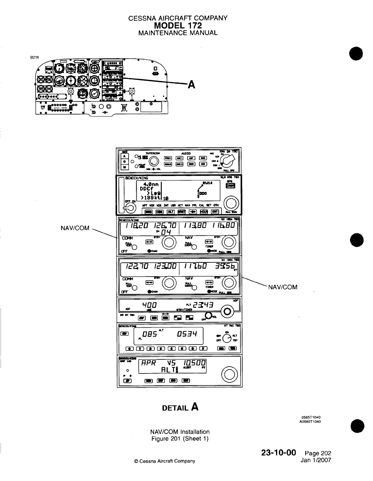
CESSNA
AIRCRAFT
COMPANY
MODEL
172
MAINTENANCE
MANUAL
NAWVC
OM
DETAIL
A
0585T
1040
A0585T1040
NAV/COM
Installation
Figure
201
(Sheet
1)
23-10-00
©
Cessna
Aircraft
Company
NAV/COM
Page
202
Janl1/2007
------
A
.11.

CESSNA
AIRCRAFT
COMPANY
MODEL
172
MAINTENANCE
MANUAL
AIR
DATA
TRANSPONDER
DETAIL
A
AIRPLANES
THAT
HAVE
THE
GARMIN
G1
000
Tailcone
Avionics Installation
Figure 202
(Sheet
1)
©
Cessna Aircraft
Company
23-10-00
Page
203
Janl1/2007
051
0T1007
A0518
TI
103
P-1
CESSNA
AIRCRAFT
COMPANY
MODEL
172
MAINTENANCE
MANUAL
(3)
Remove
the aft
seat
to get
access
to
the
integrated
avionics
units.
Refer to
Chapter
25,
Passenger
Compartment
-
Maintenance
Practices.
(4)
Remove
the
baggage
compartment
closeout
to
get
access
to
the integrated
avionics
units.
Refer
to
Chapter
25,
Interior
Upholstery
-
Maintenance
Practices.
(5)
Disconnect
the
duct
from
the
aft
side
of
the
unit.
Refer
to
Avionics
Cooling
-
Maintenance
Practices.
(6)
Release
the
unit handle.
(a)
For
units with
a
Phillips
screw,
loosen
the
screw
to
unlock
the
unit
handle.
(b)
For
units with
a
D-Ring,
push
on
the
D-Ring
and
turn
it
90
degrees
counterclockwise
to
unlock
the
unit
handle.
(7)
Move the
lever
up
to
disengage
the
locking
stud
with
the
dog
leg
slot
in
the mounting
rack.
(8)
Remove
the
unit
from
the
mounting rack.
B.
Install
the
Integrated
Avionics
Unit
(Refer
to
Figure
202).
NOTE:
If
the
unit
from
the
initial
installation
is
installed
in
its
initial
position,
it is
not
necessary
to
load
the
software
or
configuration.
NOTE:
If
the unit
from
the
initial
installation
is
installed
in
the
opposite position,
it is
not
necessary
to
load
the
software
but
the
units
must
be
configured.
NOTE:
If a
new
unit
is
installed, the
software
and
configuration
must
be
loaded.
CAUTION:
Make
sure
the
unit
goes into position
without
resistance.
Damage
to
the
connectors,
unit,
or
mounting
rack
will
occur
if
the
unit
is
pushed
into
position
with
force.
NOTE: The unit
must
be
in
position
in
the
mounting
rack
to
let
the
locking stud
engage
the
channel.
(1)
Make sure
the
connector
and
connector
pins
have
no
damage.
(a)
Replace
the
connector
or
connector
pins
if
applicable.
Refer
to
the Wiring Diagram Manual
and
the
Garmin
G1000 Line
Maintenance
Manual.
(2)
Carefully
put
the
unit
in
position
in
the
mounting
rack.
CAUTION:
Make
sure
the
lever
moves
without resistance.
Damage
to
the
unit
wilt
occur
it
the
lever
is
pushed
into
position
with
force.
(3)
Push the
lever
down toward
the
bottom
of the unit to
engage
the
locking
stud
with
the
dog
leg
slot
in
the
mounting
rack.
(4)
Lock
the
handle
in
position.
(a)
For
units
with
a
Phillips
screw,
tighten
the
screw
to
lock the
unit
handle.
(b)
For
units
with
a
D-Ring,
push
on
the
D-Ring and
turn
it
90
degrees
clockwise
to
lock
the
unit
handle.
(5)
Connect
the
duct
to
the
aft
side
of
the
unit.
Refer
to
Avionics
Cooling
-
Maintenance
Practices.
(6)
Do
a
check
for
correct operation
or
configure
the
unit.
Refer
to
Test
and/or Configure
Integrated
Avionics
Unit.
(7)
Install
the
baggage
compartment
closeout.
Refer
to
Chapter
25,
Interior
Upholstery
-
Maintenance Practices.
(8)
Install
the aft seat.
Refer
to
Chapter
25,
Passenger
Compartment
-
Maintenance
Practices.
C.
Test
and/or
Configure Integrated
Avionics
Unit.
(1)
Initial unit
installed
in
initial
position.
NOTE:
If
the unit from the
initial
installation
is
installed
in
its
initial
location,
it
is
not
necessary
to
load
the
software
or
configuration.
(a)
Do
a
check
to
make
sure the
unit
operates
correctly.
Refer
to
the Garmin
G1000 Line
Maintenance
Manual.
23-1
0-00
Page 204
C
Cessna Aircraft Company
Janl1/2007
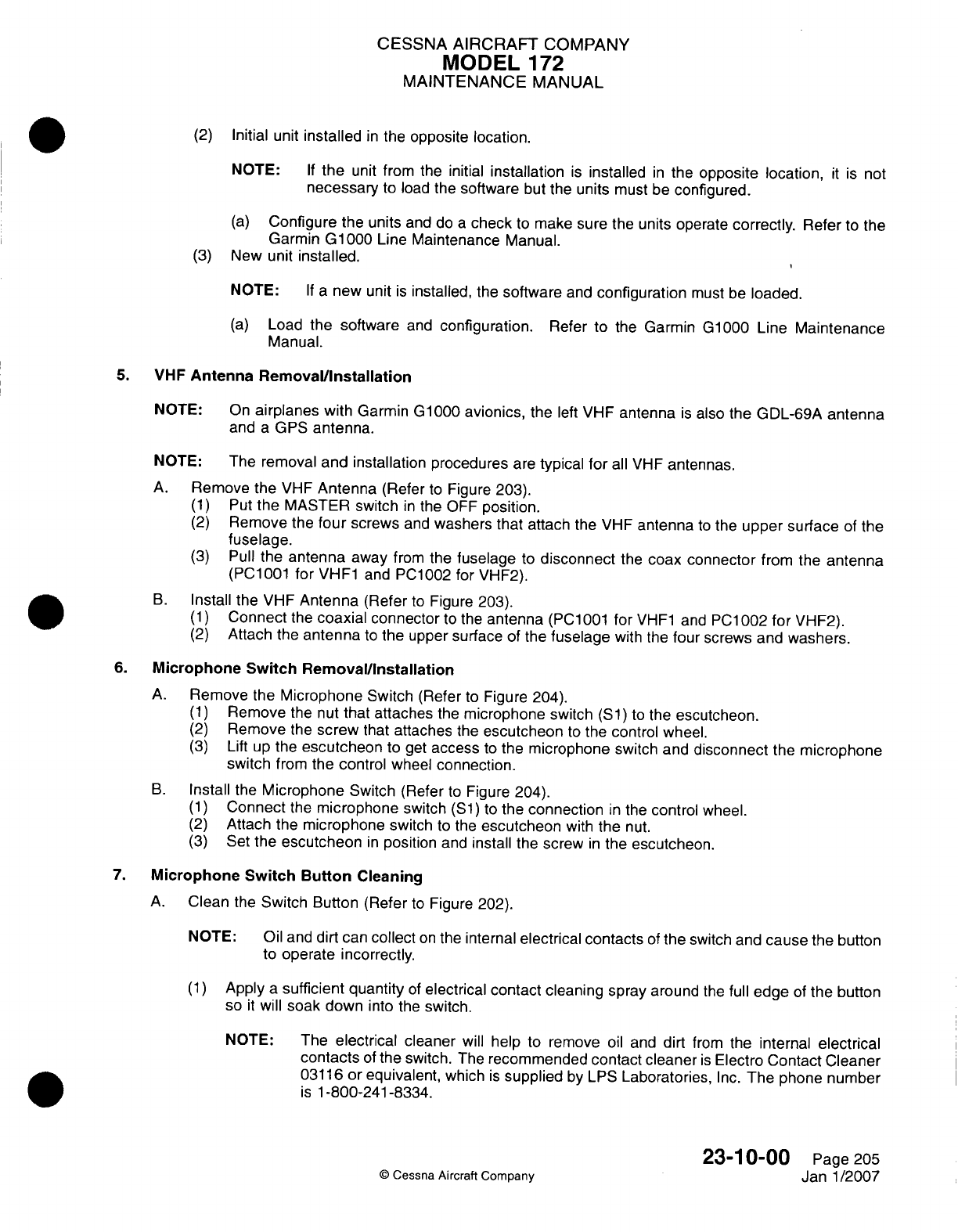
CESSNA AIRCRAFT
COMPANY
MODEL
172
MAINTENANCE
MANUAL
(2)
Initial
unit
installed
in
the
opposite location.
NOTE:
If
the
unit
from
the
initial
installation
is
installed
in
the
opposite
location,
it is
not
necessary
to
load the
software
but the
units
must
be
configured.
(a)
Configure
the
units
and do
a
check
to
make
sure
the
units operate
correctly.
Refer
to
the
Garmin
GlOQO0
Line
Maintenance Manual.
(3)
New
unit
installed.
NOTE:
If a
new unit
is
installed,
the
software
and
configuration
must be
loaded.
(a)
Load
the
software
and
configuration.
Refer
to
the
Garmin
G1000 Line
Maintenance
Manual.
5.
VHF
Antenna Remova~llnstallation
NOTE:
On
airplanes
with
Garmin
G1000
avionics,
the
left
VHF
antenna
is
also
the
GDL-69A
antenna
and
a
GPS
antenna.
NOTE: The
removal
and
installation
procedures
are
typical
for
all
VHF
antennas.
A.
Remove
the
VHF
Antenna
(Refer
to
Figure
203).
(1)
Put
the
MASTER
switch
in
the
OFF
position.
(2)
Remove
the
four
screws
and
washers
that attach
the
VHF
antenna
to
the
upper surface
of
the
fuselage.
(3)
Pull
the
antenna
away
from
the
fuselage
to
disconnect
the
coax connector
from
the
antenna
(PC1
001
for
VHF1
and
P01
002
for
VHF2).
B.
Install
the VHF
Antenna
(Refer
to
Figure
203).
(1)
Connect
the
coaxial
connector
to
the
antenna
(PC1001
for
VHF1
and
PC1002
for
VHF2).
(2)
Attach the
antenna
to
the upper
surface
of the
fuselage
with the
four
screws
and
washers.
6.
Microphone
Switch
Removal/Installation
A.
Remove
the
Microphone
Switch
(Refer
to
Figure
204).
(1)
Remove
the
nut
that
attaches
the
microphone
switch
(51)
to
the
escutcheon.
(2)
Remove
the
screw
that
attaches
the
escutcheon
to
the
control
wheel.
(3)
Lift up
the
escutcheon
to
get
access
to
the
microphone
switch and
disconnect
the
microphone
switch
from
the
control
wheel
connection.
B.
Install
the
Microphone
Switch
(Refer
to
Figure
204).
(1)
Connect
the
microphone
switch
(51)
to
the
connection
in
the
control
wheel.
(2)
Attach
the
microphone
switch
to
the
escutcheon
with
the
nut.
(3)
Set the
escutcheon
in
position
and
install
the screw
in
the
escutcheon.
7.
Microphone
Switch Button
Cleaning
A.
Clean
the
Switch
Button
(Refer
to
Figure
202).
NOTE:
Oil
and
dirt
can
collect
on
the
internal
electrical
contacts
of
the
switch and
cause
the
button
to
operate incorrectly.
(1)
Apply
a
sufficient
quantity
of
electrical
contact
cleaning spray
around
the full
edge
of
the
button
so
it
will
soak
down
into the
switch.
NOTE: The
electrical cleaner
will
help
to
remove
oil
and
dirt
from
the
internal
electrical
contacts
of
the
switch.
The
recommended
contact
cleaner
is
Electro
Contact Cleaner
03116
or
equivalent,
which
is
supplied
by
LPS
Laboratories,
Inc.
The
phone number
is
1-800-241-8334.
23-1
0-00
Page 205
©
Cessna
Aircraft
Company
Janl1/2007
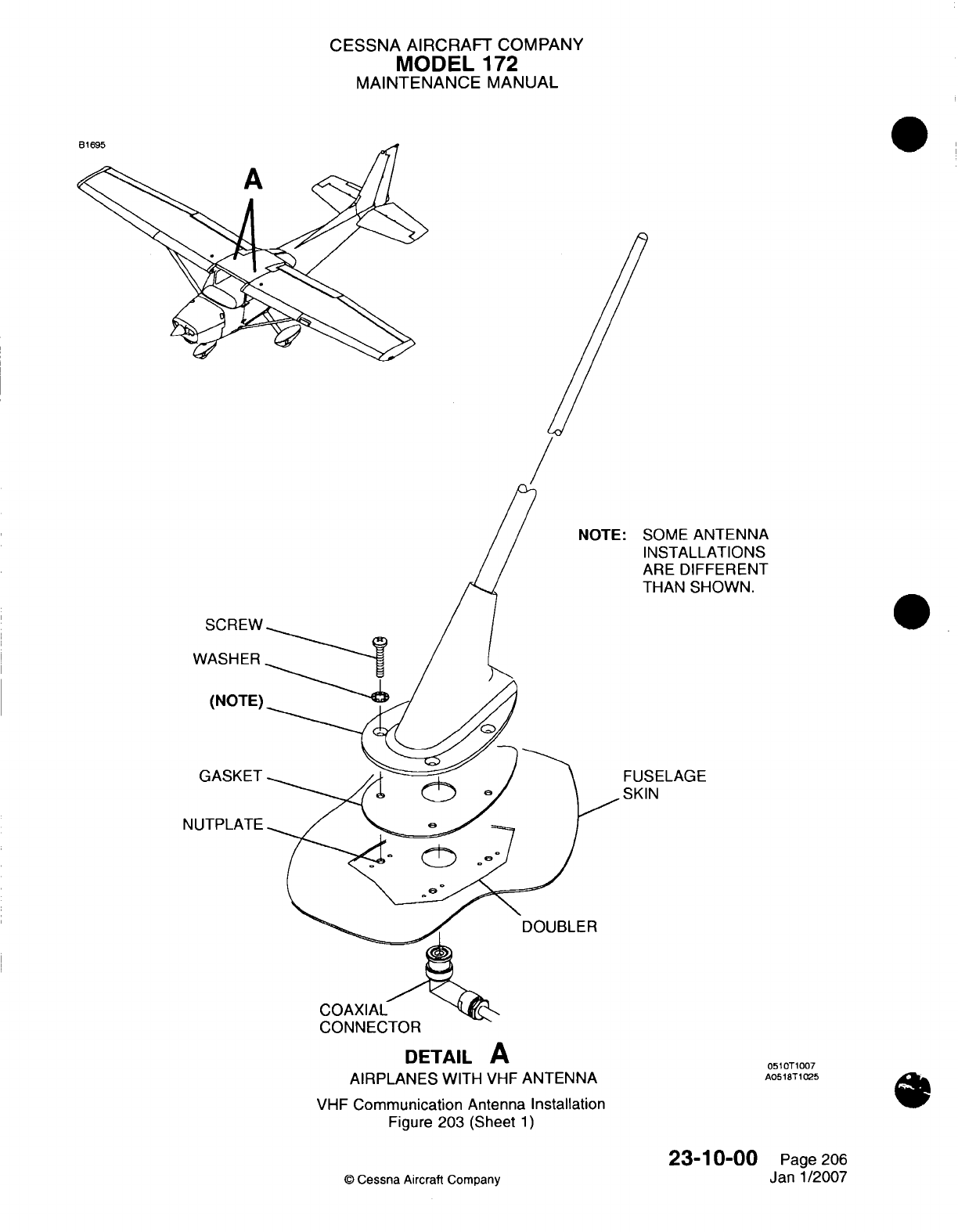
CESSNA
AIRCRAFT
COMPANY
MODEL
172
MAINTENANCE
MANUAL
'OME
ANTENNA
NSTALLATIONS
kRE
DIFFERENT
-HAN
SHOWN.
3ELAGE
N
DOUBLER
CONNECTOR
DETAIL
A
AIRPLANES
WITH
VHF
ANTENNA
VHF
Communication
Antenna
Installation
Figure
203
(Sheet
1)
23-10-00
©
Cessna
Aircraft
Company
SCREW
WASHER
(NOTE)
GASKET
NUTPLATE
051OT1007
A0518T
1025
Page
206
Janl1/2007
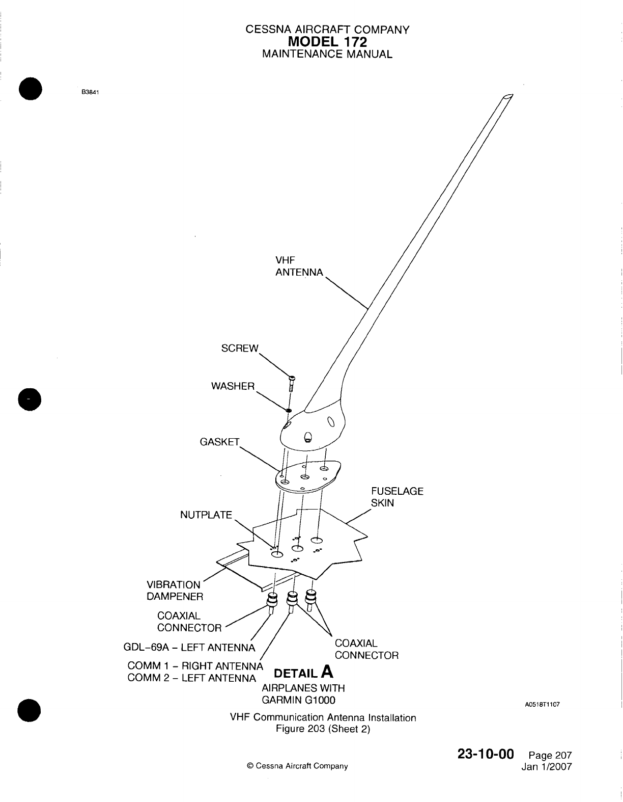
CESSNA AIRCRAFT
COMPANY
MODEL
172
MAINTENANCE
MANUAL
MM84
VHF
ANTENNA
SCREW
WASHER
GASKET
VIBRA]
DAMPE
COAL
CON
GDL-69A
-
COMM
1
-RIGHT
ANTENNA
DE
AI
COMM
2
-
LEFT
ANTENNA
DTAL
AIRPLANES
WITH
GARMIN
G1000
FUSELAGE
SKIN
COAXIAL
CONNECTOR
A051
8T1
107
VHF
Communication Antenna Installation
Figure
203
(Sheet
2)
©
Cessna
Aircraft
Company
23-1
0-00
Page 207
Janl1/2007
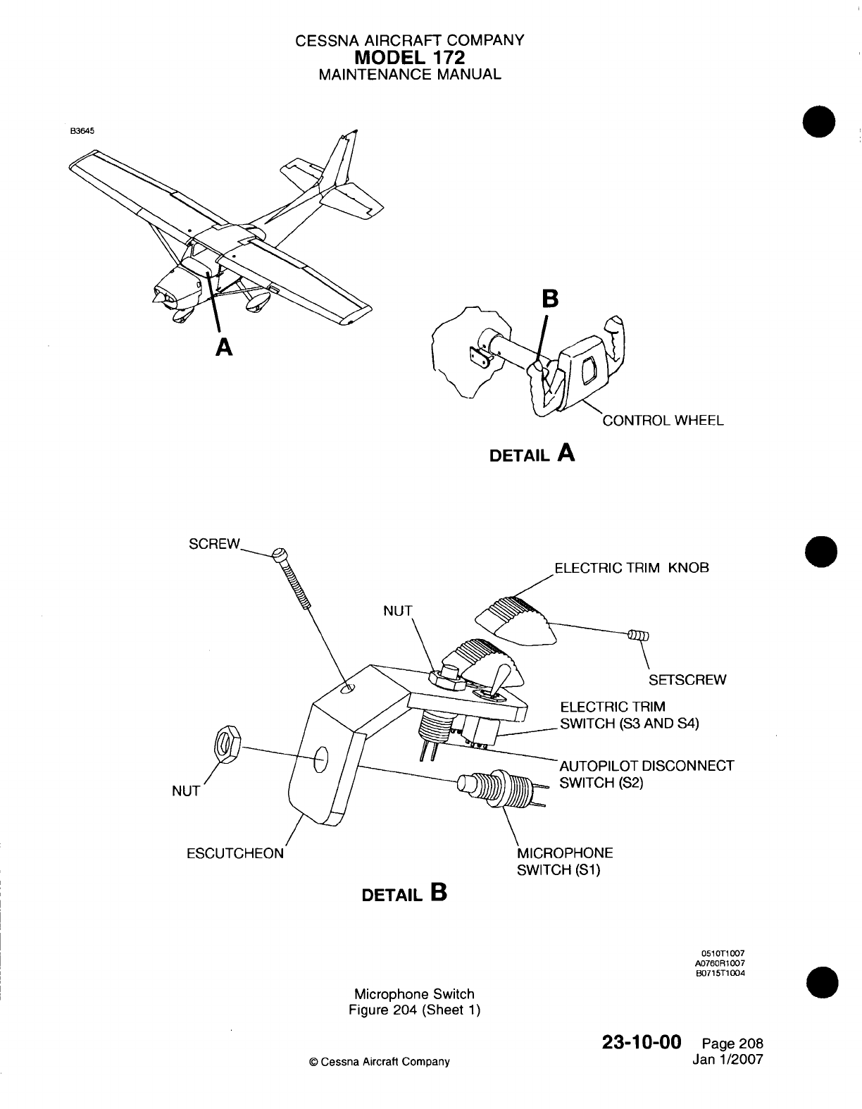
CESSNA AIRCRAFT
COMPANY
MODEL
172
MAINTENANCE
MANUAL
B3
A
WHEEL
DETAIL
A
.q~RFW-v
A
KNOB
NUT
METSCREW
ND
S4)
SCONNECT
NL
SWITCH
(Si)
DETAIL
B
Microphone
Switch
Figure
204
(Sheet
1)
23-10-00
0
Cessna Aircraft
Company
051
T1
007
A076OR
1007
B0715T1 004
Page
208
Janl1/2007
0
----
I
CESSNA
AIRCRAFT
COMPANY
MODEL
172
MAINTENANCE
MANUAL
Press
the
button
many
times
to
make
sure
the
cleaner
gets
into
the
internal
electrical contacts
of
the
switch.
Complete
an
operational
check
of
the
switch.
NOTE: The
transmit
light
on
the
COM
radio will
come
on
when
the
power
is
turned
on.
If
the button
does
not
operate
after
the
first
application
of
the
electric
cleaner,
apply
more
cleaner.
If
the
button
continues
to
operate
incorrectly,
replace
the
microphone
switch.
Refer to
Microphone
Switch
Removal/Installation.
23-1
0-00
Page
209
©
Cessna Aircraft
Company
Janl1/2007
(2)
(3)
(4)
(5)
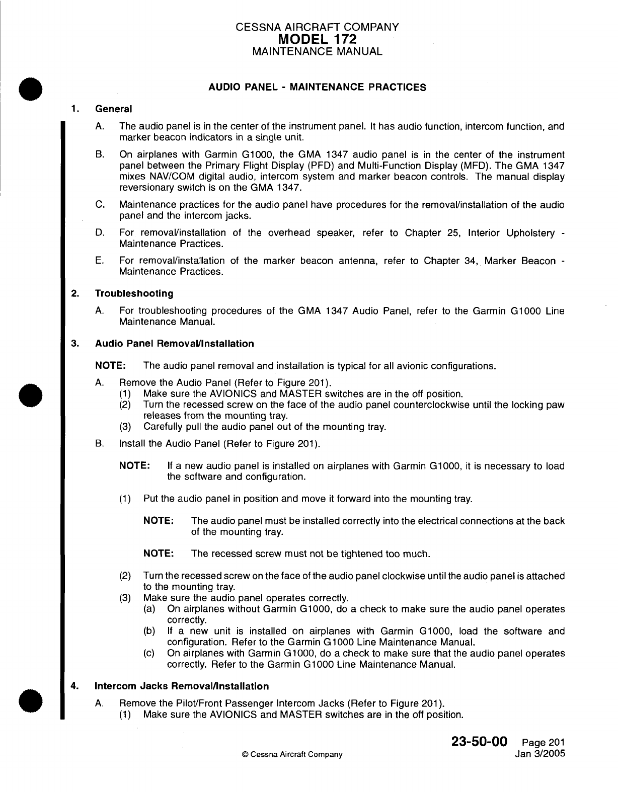
CESSNA
AIRCRAFT
COMPANY
MODEL
172
MAINTENANCE
MANUAL
AUDIO
PANEL
-
MAINTENANCE
PRACTICES
1.
General
A.
The
audio
panel
is in
the
center
of
the
instrument
panel.
It
has
audio
function,
intercom
function,
and
marker beacon
indicators
in
a
single
unit.
B.
On
airplanes
with
Garmin
G1000,
the
GMA
1347
audio
panel
is
in
the
center
of
the
instrument
panel between
the Primary
Flight
Display
(PFD)
and
Multi-Function
Display
(MFD).
The
GMA
1347
mixes
NAV/COM
digital
audio,
intercom
system
and
marker beacon
controls.
The
manual
display
reversionary switch
is
on the
GMA 1347.
C.
Maintenance
practices for
the
audio
panel
have
procedures for
the
removal/installation
of the
audio
panel
and
the intercom
jacks.
D.
For
removal/installation
of the
overhead
speaker,
refer
to
Chapter
25,
Interior
Upholstery
-
Maintenance
Practices.
E.
For
removal/installation
of
the
marker
beacon
antenna,
refer
to
Chapter
34,
Marker
Beacon
-
Maintenance
Practices.
2.
Troubleshooting
A.
For
troubleshooting
procedures of
the
GMA
1347
Audio
Panel,
refer
to
the
Garmin
G1000
Line
Maintenance
Manual.
3.
Audio
Panel
Removal/Installation
NOTE:
The audio panel
removal
and
installation
is
typical
for
all
avionic configurations.
A.
Remove
the
Audio
Panel
(Refer
to
Figure
201).
(1)
Make
sure the AVIONICS
and
MASTER
switches
are
in
the
off
position.
(2)
Turn
the
recessed screw
on
the
face
of
the
audio
panel
counterclockwise
until
the
locking
paw
releases
from
the mounting
tray.
(3)
Carefully
pull
the
audio
panel
out
of the
mounting
tray.
B.
Install
the
Audio Panel
(Refer
to Figure
201).
NOTE:
If a
new
audio
panel
is
installed
on
airplanes
with
Garmin
G1000,
it
is
necessary
to
load
the
software
and
configuration.
(1)
Put
the
audio
panel
in
position
and
move
it
forward
into
the mounting
tray.
NOTE:
The
audio
panel
must
be
installed
correctly
into
the
electrical
connections
at
the
back
of the
mounting
tray.
NOTE:
The
recessed
screw
must
not
be
tightened
too
much.
(2)
Turn
the
recessed
screw
on
the
face
of
the
audio
panel
clockwise
until
the
audio
panel
is
attached
to
the
mounting
tray.
(3)
Make
sure the
audio
panel
operates correctly.
(a)
On
airplanes
without
Garmin G1000,
do
a
check
to
make sure
the
audio
panel
operates
correctly.
(b) If a
new
unit
is
installed
on
airplanes
with Garmin
G1000,
load
the
software
and
configuration.
Refer
to
the Garmin
G1000
Line
Maintenance
Manual.
(c)
On
airplanes
with Garmin
G1000,
do
a
check
to
make sure
that
the
audio
panel
operates
correctly. Refer
to
the
Garmin
G1000
Line
Maintenance Manual.
4.
Intercom
Jacks
Removal/Installation
A.
Remove
the
Pilot/Front Passenger
Intercom
Jacks
(Refer
to
Figure
201).
(1)
Make
sure
the
AVIONICS
and
MASTER
switches
are
in
the
off
position.
23-50-00
Page
201
©
Cessna
Aircraft
Company
Jan
3/2005
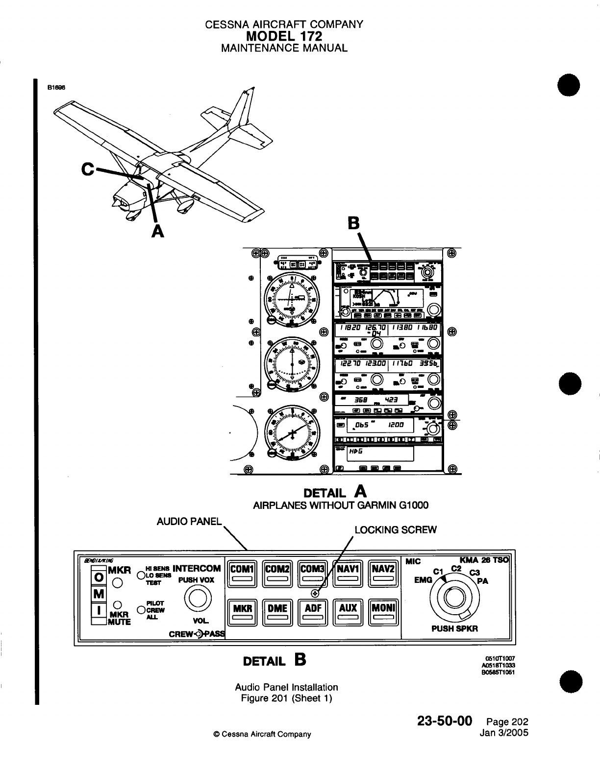
CESSNA
AIRCRAFT
COMPANY
MODEL
172
MAINTENANCE
MANUAL
B
L
I
"
.
anI
i*,acu
ic. ilu Iiu la
IiOU
Ii
-"O1"I
I
G0 B-
©
jf
u©
0- 0
122.10
12(001
11bO
3S
b=
0a r)0 0 w-
0
o- _
-
__
--.
WI~~
_
__
Cl
|Ob5"
1200
|
-"|HD
I
al
- ---
DETAIL
A
AIRPLANES
WITHOUT
GARMIN
G1000
AUDIO
PANEL
H
ENS
INTERCOM
OLTE
N
PUSH VOX
TEfr
PILOT
L
VOL
CREW-PASS
LOCKING
SCREW
\
,
h
/
I
MIC
|COM|
||COM2|
|COM3'IL
NAi
NAV2
ic
11 M I c ME 1 F1 |
I
|
MKR
|
|DME
|
ADF
||
|AUX
||1
MONIM
I, I* I* I*
DETAIL
B
Audio
Panel
Installation
Figure
201
(Sheet
1)
©
Cessna
Aircraft Company
23-50-00
Page 202
Jan
3/2005
o
0
S
S
/as
(H3
-MKR
M
- O
_
MKR
mMUTE
KMA 26
TSO
PUSH
SPKR
0510T1007
A0518T1033
B0585T1051
~ ana
B1
\
i
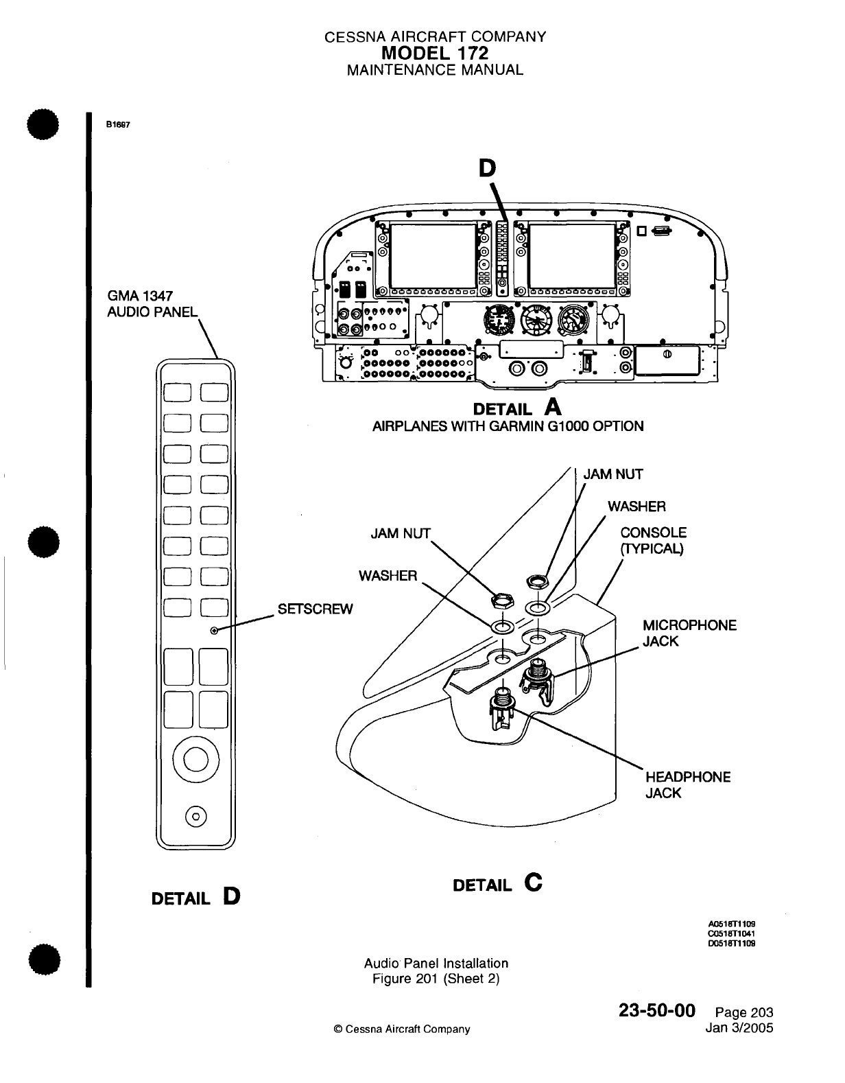
CESSNA
AIRCRAFT
COMPANY
MODEL
172
MAINTENANCE
MANUAL
B1697
GMA 1347
AUDIO
PANEL
I
0
[
E[D
0
[I
77
77
_.
I
77
77
77
D
S0
*
j g:\.
00
®
i
©
0000
*0000000000
.oo
* .
I
.
c~99O0
I.
t?
,00
00000oo
1.000000*
0000000
DETAIL
A
AIRPLANES
WITH
GARMIN
G1000
OPTION
ER
ISOLE
'ICAL)
SETSCRI
MICROPHONE
IACK
HEADPHONE
JACK
0
E]E
El]
DETAIL
C
DETAIL
D
A0518T1109
C0518T1041
D0518T1109
Audio
Panel
Installation
Figure
201
(Sheet
2)
23-50-00
©
Cessna
Aircraft
Company
Page 203
Jan
3/2005
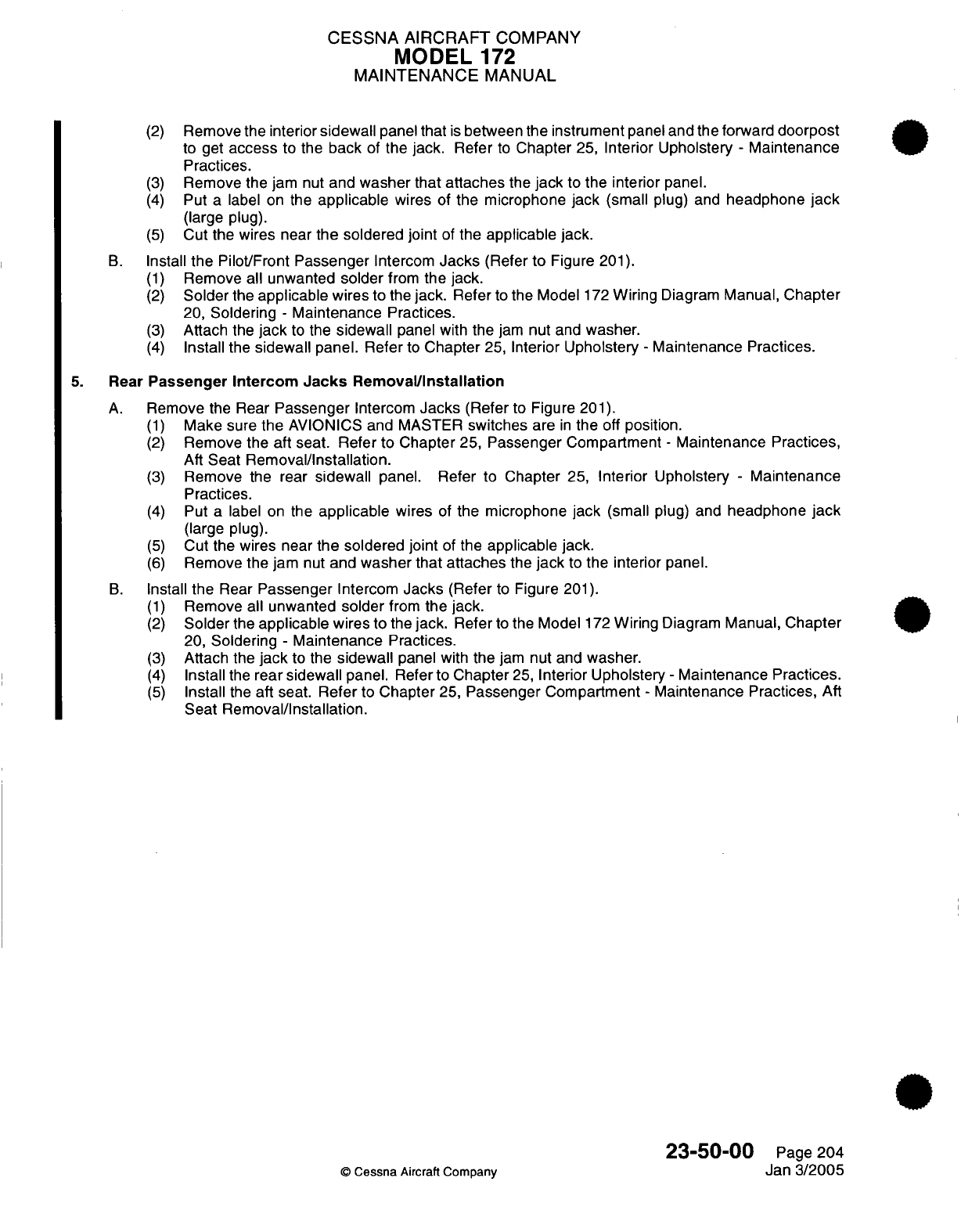
CESSNA AIRCRAFT
COMPANY
MODEL
172
MAINTENANCE
MANUAL
(2)
Remove
the interior
sidewall
panel
that
is
between the
instrument
panel
and the forward
doorpost
to
get
access
to the
back
of
the
jack.
Refer
to
Chapter
25,
Interior Upholstery
-
Maintenance
Practices.
(3)
Remove
the
jam
nut
and
washer
that
attaches
the
jack
to
the
interior
panel.
(4)
Put
a
label on
the
applicable
wires
of
the
microphone
jack
(small
plug)
and
headphone
jack
(large plug).
(5)
Cut
the
wires near
the soldered
joint
of
the
applicable
jack.
B.
Install
the
Pilot/Front
Passenger
Intercom
Jacks
(Refer
to
Figure
201).
(1)
Remove all
unwanted
solder
from
the
jack.
(2)
Solder
the
applicable
wires
to
the
jack.
Refer
to
the Model
172
Wiring
Diagram
Manual,
Chapter
20,
Soldering
-
Maintenance
Practices.
(3)
Attach
the
jack
to the
sidewall
panel
with
the
jam
nut
and
washer.
(4)
Install
the
sidewall
panel.
Refer
to
Chapter
25,
Interior
Upholstery
-
Maintenance
Practices.
5.
Rear
Passenger Intercom
Jacks
Removal/Installation
A.
Remove
the
Rear
Passenger
Intercom
Jacks
(Refer
to
Figure
201).
(1)
Make
sure
the
AVIONICS and
MASTER
switches
are
in
the off
position.
(2)
Remove
the
aft seat.
Refer
to Chapter
25,
Passenger Compartment
-
Maintenance Practices,
Aft
Seat
Removal/Installation.
(3)
Remove
the rear
sidewall
panel. Refer
to
Chapter
25,
Interior Upholstery
-
Maintenance
Practices.
(4)
Put
a
label on
the
applicable
wires
of
the
microphone
jack
(small
plug) and
headphone
jack
(large plug).
(5)
Cut
the
wires
near
the soldered
joint
of the
applicable
jack.
(6)
Remove the jam
nut
and
washer that
attaches
the
jack
to
the interior
panel.
B.
Install
the
Rear
Passenger
Intercom
Jacks
(Refer
to
Figure
201).
(1)
Remove
all
unwanted
solder
from
the
jack.
(2)
Solder
the
applicable
wires
to
the
jack.
Refer
to
the
Model
172
Wiring
Diagram
Manual,
Chapter
20,
Soldering
-
Maintenance
Practices.
(3)
Attach
the
jack
to the
sidewall
panel with
the
jam
nut
and
washer.
(4)
Install
the
rear
sidewall
panel.
Refer
to
Chapter
25,
Interior
Upholstery
-
Maintenance
Practices.
(5)
Install
the
aft
seat.
Refer
to
Chapter
25,
Passenger
Compartment
-
Maintenance Practices,
Aft
Seat
Removal/Installation.
23-50-00
Page
204
©
Cessna
Aircraft
Company
Jan
3/2005
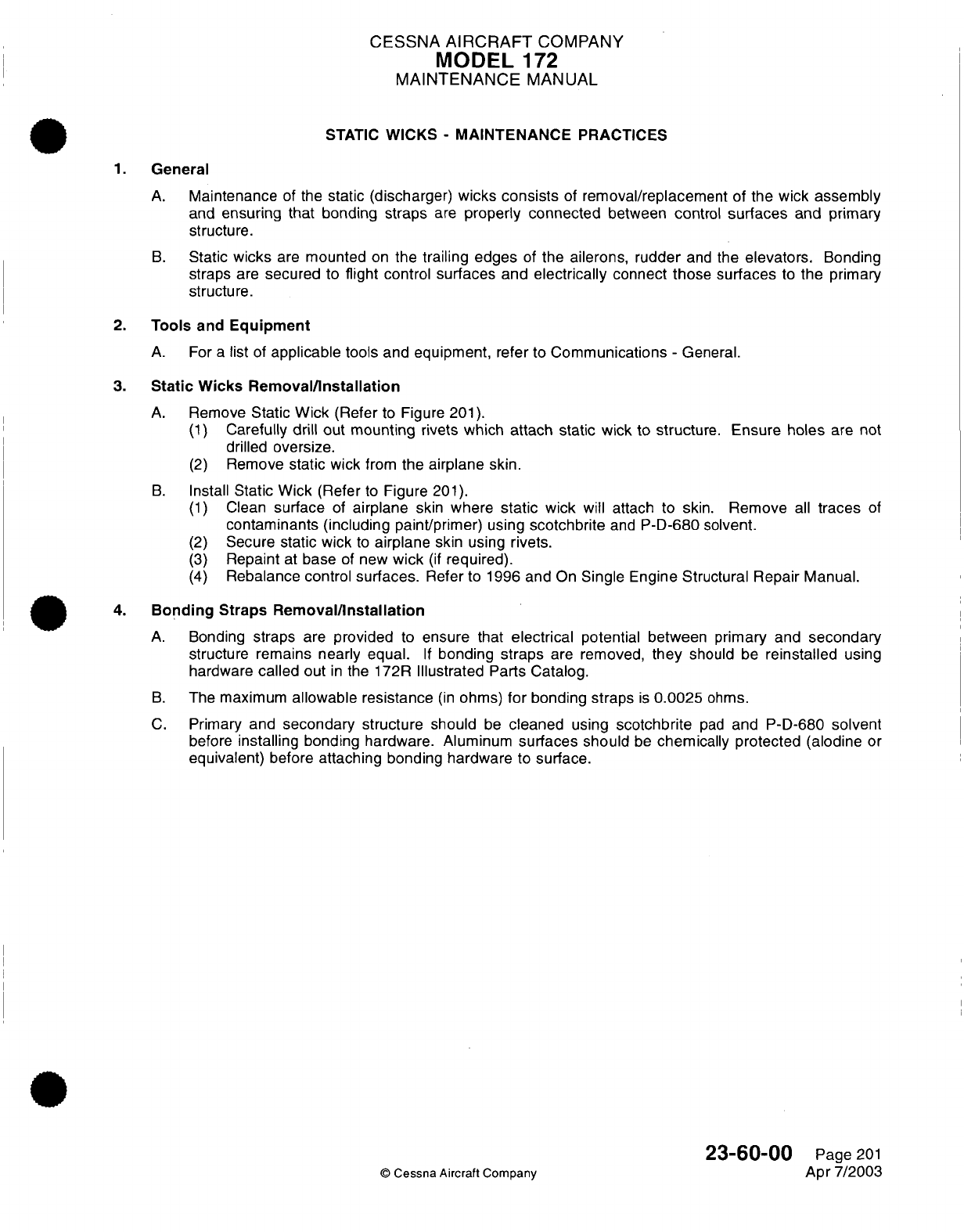
CESSNA
AIRCRAFT
COMPANY
MODEL
172
MAINTENANCE
MANUAL
STATIC
WICKS
-
MAINTENANCE
PRACTICES
1.
General
A.
Maintenance
of
the
static
(discharger)
wicks
consists
of
removal/replacement
of
the wick
assembly
and
ensuring that
bonding straps
are
properly connected
between control
surfaces
and
primary
structure.
B.
Static
wicks
are
mounted
on
the
trailing
edges
of
the
ailerons,
rudder
and
the
elevators.
Bonding
straps
are
secured
to
flight
control
surfaces
and
electrically
connect
those surfaces
to
the primary
structure.
2.
Tools
and
Equipment
A.
For
a
list of
applicable
tools
and
equipment,
refer
to
Communications
-
General.
3.
Static
Wicks Removal/Installation
A.
Remove
Static
Wick
(Refer
to
Figure
201).
(1)
Carefully
drill
out
mounting
rivets
which attach static
wick
to
structure. Ensure
holes
are
not
drilled
oversize.
(2)
Remove
static
wick
from
the
airplane
skin.
B.
Install
Static
Wick
(Refer
to
Figure
201).
(1)
Clean
surface
of
airplane
skin
where
static
wick
will attach to skin.
Remove
all
traces
of
contaminants
(including
paint/primer)
using
scotchbrite
and
P-D-680 solvent.
(2)
Secure
static
wick
to
airplane
skin using
rivets.
(3)
Repaint
at
base
of
new
wick
(if
required).
(4)
Rebalance control
surfaces.
Refer
to
1996
and
On
Single
Engine
Structural
Repair
Manual.
4.
Bonding
Straps
Removal/Installation
A.
Bonding
straps
are
provided
to
ensure that
electrical
potential between
primary
and
secondary
structure remains
nearly equal.
If
bonding
straps
are
removed,
they
should
be
reinstalled
using
hardware
called
out
in
the 172R
Illustrated
Parts
Catalog.
B.
The
maximum
allowable resistance
(in
ohms)
for
bonding straps
is
0.0025
ohms.
C.
Primary
and
secondary
structure should
be
cleaned
using
scotchbrite
pad
and
P-D-680
solvent
before
installing
bonding hardware. Aluminum
surfaces should
be
chemically protected (alodine
or
equivalent)
before
attaching
bonding
hardware
to
surface.
23-60-00
©
Cessna Aircraft
Company
Page
201
Apr
7/2003
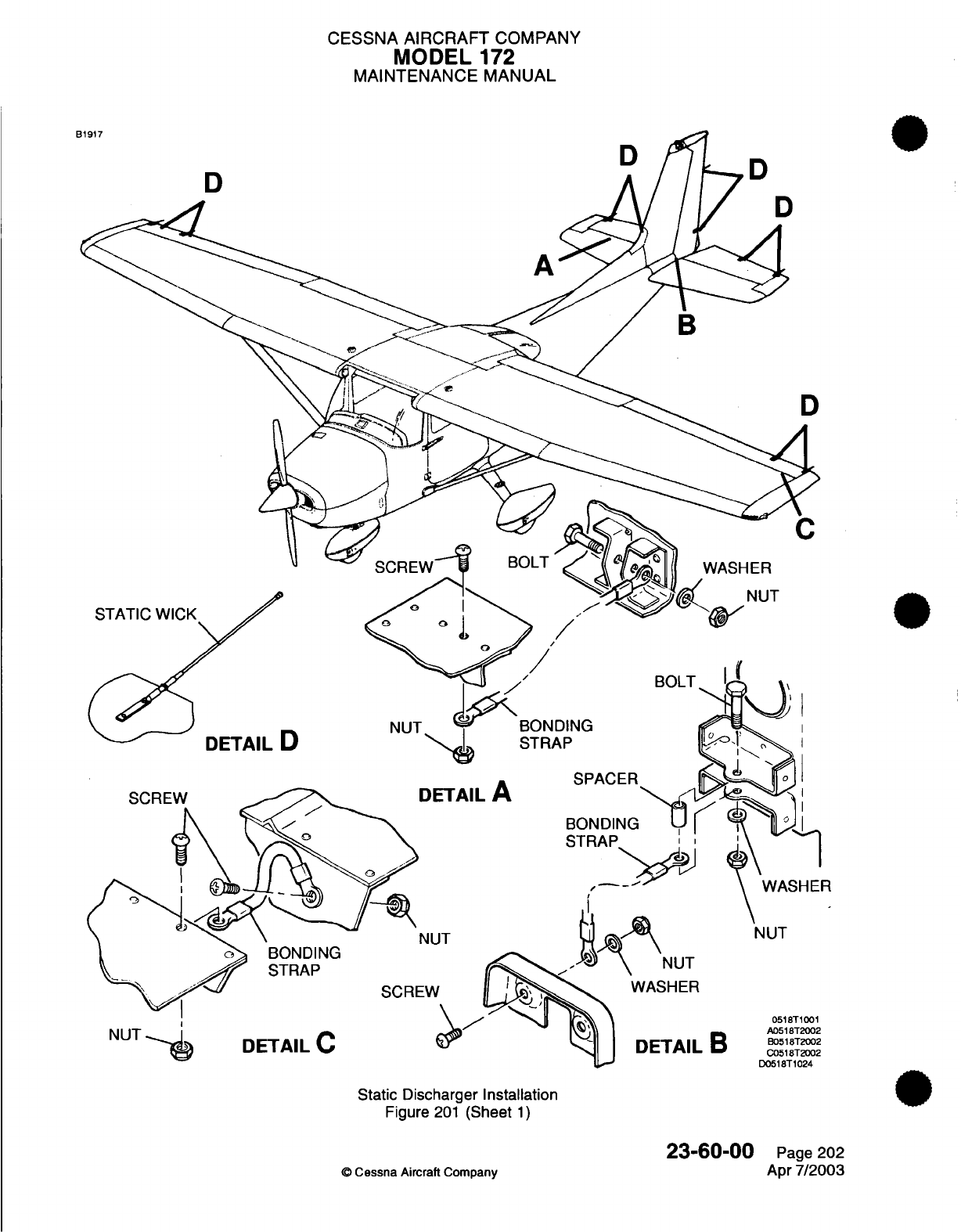
CESSNA AIRCRAFT
COMPANY
MODEL
172
MAINTENANCE
MANUAL
D
D
BONC
STRA
A
DETAIL
A
NUT
NUT
NUT
0518T1001
A0518T2002
B0518T2002
C0518T2002
D0518T1024
Static Discharger Installation
Figure
201
(Sheet
1)
©
Cessna
Aircraft
Company
23-60-00
Page
202
Apr
7/2003
DD
NUT
DETAIL
D
I
:W
.B

CHAPTER
ELECTRICAL
POWER
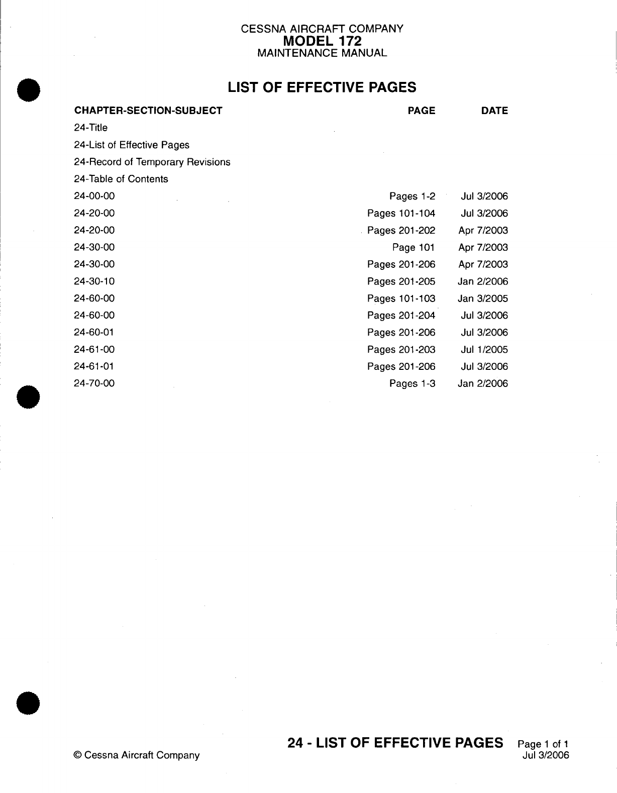
CESSNA
AIRCRAFT
COMPANY
MODEL
172
MAINTENANCE
MANUAL
LIST
OF
EFFECTIVE
PAGES
CHAPTER-SECTION-SUBJECT
24-Title
24-List
of
Effective
Pages
24-Record
of
Temporary
Revisions
24-Table
of
Contents
24-00-00
24-20-00
24-20-00
24-30-00
24-30-00
24-30-10
24-60-00
24-60-00
24-60-01
24-61-00
24-61-01
24-70-00
©
Cessna Aircraft
Company
PAGE
Pages
1-2
Pages
101-104
Pages 201-202
Page
101
Pages
201-206
Pages
201-205
Pages
101-103
Pages
201-204
Pages
201-206
Pages
201-203
Pages 201-206
Pages
1-3
DATE
Jul
3/2006
Jul
3/2006
Apr
7/2003
Apr
7/2003
Apr
7/2003
Jan
2/2006
Jan
3/2005
Jul
3/2006
Jul
3/2006
Jul
1/2005
Jul
3/2006
Jan
2/2006
24
-
LIST
OF
EFFECTIVE
PAGES
Page
1
of
1
Jul
3/2006
Temporary
Revision
Number
RECORD
OF
TEMPORARY
REVISIONS
Page
Number
Issue
Date
By
Date
Removed
By
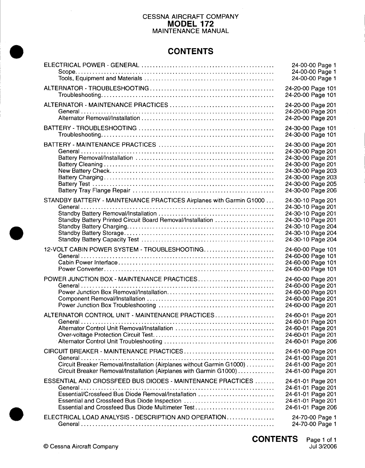
CESSNA
AIRCRAFT
COMPANY
MODEL
172
MAINTENANCE
MANUAL
CONTENTS
ELECTRICAL
POWER
-
GENERAL
...............................................
Scope......................................................................
Tools,
Equipment
and
Materials
..............................................
ALTERNATOR
-
TROUBLESHOOTING
...........................................
Troubleshooting
.............................................................
ALTERNATOR
-
MAINTENANCE PRACTICES
.....................................
General
....................................................................
Alternator
Removal/Installation
...............................................
BATTERY
-
TROUBLESHOOTING
.........
.......................................
Troubleshooting
.............................................................
BATTERY
-
MAINTENANCE PRACTICES
.........................................
General
....................................................................
Battery
Removal/Installation
.................................................
Battery
Cleaning
............................................................
New
Battery
Check..........................................................
Battery
Charging............................................................
Battery
Test
................................................................
Battery
Tray
Flange
Repair
..................................................
STANDBY BATTERY
-
MAINTENANCE
PRACTICES
Airplanes
with
Garmin
G1000
...
General
....................................................................
Standby
Battery
Removal/Installation
.........................................
Standby
Battery
Printed
Circuit
Board
Removal/Installation
.....................
Standby
Battery
Charging....................................................
Standby
Battery
Storage.....................................................
Standby
Battery
Capacity
Test
...............................................
12-VOLT CABIN
POWER
SYSTEM
-
TROUBLESHOOTING.........................
General
....................................................................
Cabin
Power
Interface
......................................................
Power
Converter............................................................
POWER
JUNCTION
BOX
-
MAINTENANCE
PRACTICES...........................
General
....................................................................
Power
Junction
Box
Removal/Installation......................................
Component
Removal/Installation
.............................................
Power
Junction
Box
Troubleshooting
.........................................
ALTERNATOR
CONTROL
UNIT
-
MAINTENANCE
PRACTICES.....................
General
....................................................................
Alternator
Control
Unit
Removal/Installation
...................................
Over-voltage
Protection
Circuit
Test...........................................
Alternator
Control
Unit
Troubleshooting
.......................................
CIRCUIT
BREAKER
-
MAINTENANCE
PRACTICES
...............................
General
....................................................................
Circuit
Breaker Removal/Installation
(Airplanes
without
Garmin
G1000)
..........
Circuit
Breaker
Removal/Installation
(Airplanes
with
Garmin
G1000).............
ESSENTIAL
AND
CROSSFEED
BUS
DIODES
-
MAINTENANCE PRACTICES
.......
G
eneral
....................................................................
Essential/Crossfeed
Bus
Diode
Removal/Installation
...........................
Essential
and
Crossfeed
Bus Diode
Inspection
................................
Essential
and
Crossfeed
Bus Diode
Multimeter
Test
............................
ELECTRICAL
LOAD
ANALYSIS
-
DESCRIPTION
AND
OPERATION
................
General
....................................................................
24-00-00
Page
1
24-00-00
Page
1
24-00-00
Page
1
24-20-00
Page
101
24-20-00
Page
101
24-20-00
Page
201
24-20-00
Page
201
24-20-00
Page
201
24-30-00
Page
101
24-30-00
Page
101
24-30-00
Page
201
24-30-00
Page
201
24-30-00
Page
201
24-30-00
Page
201
24-30-00
Page
203
24-30-00
Page
203
24-30-00
Page
205
24-30-00
Page
206
24-30-10
Page
201
24-30-10
Page
201
24-30-10
Page
201
24-30-10
Page
201
24-30-10
Page
204
24-30-10
Page
204
24-30-10
Page
204
24-60-00
Page
101
24-60-00
Page
101
24-60-00
Page
101
24-60-00
Page
101
24-60-00
Page
201
24-60-00
Page
201
24-60-00
Page
201
24-60-00
Page
201
24-60-00
Page
201
24-60-01
Page
201
24-60-01
Page
201
24-60-01
Page
201
24-60-01
Page
201
24-60-01
Page
206
24-61-00
Page
201
24-61-00
Page
201
24-61-00
Page
201
24-61-00
Page
201
24-61-01
Page
201
24-61-01
Page
201
24-61-01
Page
201
24-61-01
Page
201
24-61-01
Page
206
24-70-00
Page
1
24-70-00
Page
1
CONTENTS
Page
1
of
1
Jul
3/2006
©
Cessna Aircraft
Company
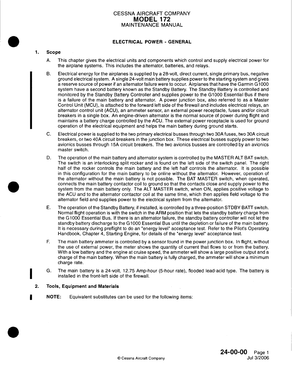
CESSNA
AIRCRAFT
COMPANY
MODEL
172
MAINTENANCE
MANUAL
ELECTRICAL
POWER
-
GENERAL
1.
Scope
A.
This
chapter
gives
the
electrical
units
and
components which control
and
supply
electrical
power
for
the
airplane
systems.
This
includes
the
alternator,
batteries, and relays.
B.
Electrical
energy for
the
airplanes
is
supplied
by
a
28-volt, direct
current,
single
primary
bus,
negative
ground
electrical
system.
A
single 24-volt
main
battery
supplies
power
to
the
starting
system
and
gives
a
reserve
source
of
power
if
an
alternator
failure
were
to
occur.
Airplanes
that
have the
Garmin
G
1000
system
have
a
second battery
known
as
the
Standby
Battery.
The
Standby
Battery
is
controlled
and
monitored by
the
Standby
Battery
Controller
and
supplies
power
to
the
G1000
Essential
Bus
if
there
is
a
failure of
the
main
battery
and
alternator.
A
power
junction
box,
also
referred
to
as
a
Master
Control
Unit
(MCU),
is
attached
to
the
forward
left
side
of
the
firewall
and
includes electrical
relays,
an
alternator control
unit
(ACU), an
ammeter
sensor,
an
external power receptacle,
fuses
and/or circuit
breakers
in
a
single
box.
An
engine-driven
alternator
is
the
normal
source
of
power during
flight
and
maintains
a
battery
charge controlled
by
the
ACU.
The
external
power
receptacle
is
used
for
ground
operation
of the
electrical equipment
and
helps
the
main
battery during
ground
starts.
C.
Electrical
power
is
supplied
to
the
two
primary
electrical
busses
through
two
30A
fuses,
two
30A
circuit
breakers,
or
two
40A
circuit
breakers
in
the
junction
box.
These electrical
busses
supply
power
to
two
avionics busses
through
15A
circuit
breakers.
The
two
avionics busses
are
controlled
by
an
avionics
master
switch.
D.
The
operation
of
the
main
battery
and
alternator
system
is
controlled
by
the MASTER
ALT
BAT
switch.
The
switch
is
an
interlocking
split rocker
and
is
found
on
the
left
side
of
the
switch
panel.
The
right
half
of
the rocker
controls
the
main
battery
and
the
left
half
controls
the
alternator.
It
is
possible
in
this
configuration for
the
main
battery
to
be
online without
the
alternator. However, operation
of
the
alternator
without
the
main
battery
is
not
possible. The
BAT
MASTER
switch,
when
operated,
connects the
main
battery
contactor
coil
to
ground
so
that
the
contacts
close
and
supply
power
to
the
system
from
the
main
battery only.
The
ALT
MASTER
switch,
when
ON,
applies positive
voltage
to
the
ACU
and
to
the
alternator contactor
coil
at
the same
time,
which
then
applies
field
voltage
to
the
alternator
field
and
supplies
power
to
the
electrical
system
from
the
alternator.
E.
The
operation
of
the
Standby
Battery,
if
installed,
is
controlled
by
a
three-position
STDBY
BATT
switch.
Normal
flight
operation
is
with
the
switch
in
the
ARM
position that
lets
the
standby battery charge
from
the G1000 Essential
Bus.
If
there
is
an
alternator
failure, the
standby
battery
controller
will
not
let
the
standby battery
discharge
to
the
G1000
Essential
Bus
until
the
depletion
or
failure
of the main
battery.
It
is
necessary
during
preflight
to
do
an
"energy
level"
acceptance
test.
Refer
to
the
Pilot's Operating
Handbook,
Chapter
4,
Starting
Engine,
for
details
of
the
"energy
level"
acceptance test.
F.
The
main
battery
ammeter
is
controlled
by
a
sensor
found
in
the
power
junction
box.
In
flight, without
the
use
of
external
power, the
meter
shows the
quantity
of
current that
flows
to
or
from
the
battery.
With
a
low
battery and the
engine
at
cruise speed,
the
ammeter
will
show
a
large
positive
output
and
a
charge
of
the
main
battery.
When
the
main
battery
is
fully
charged,
the
ammeter
will
show
a
minimum
charge
rate.
G.
The
main
battery
is
a
24-volt,
12.75
Amp-hour (5-hour
rate),
flooded lead-acid
type.
The
battery
is
installed
in
the
front-left
side
of
the
firewall.
2.
Tools,
Equipment
and
Materials
NOTE:
Equivalent
substitutes
can
be
used
for
the
following
items:
24-00-00
Page
1
©
Cessna Aircraft
Comoanv
Jul
3/2006
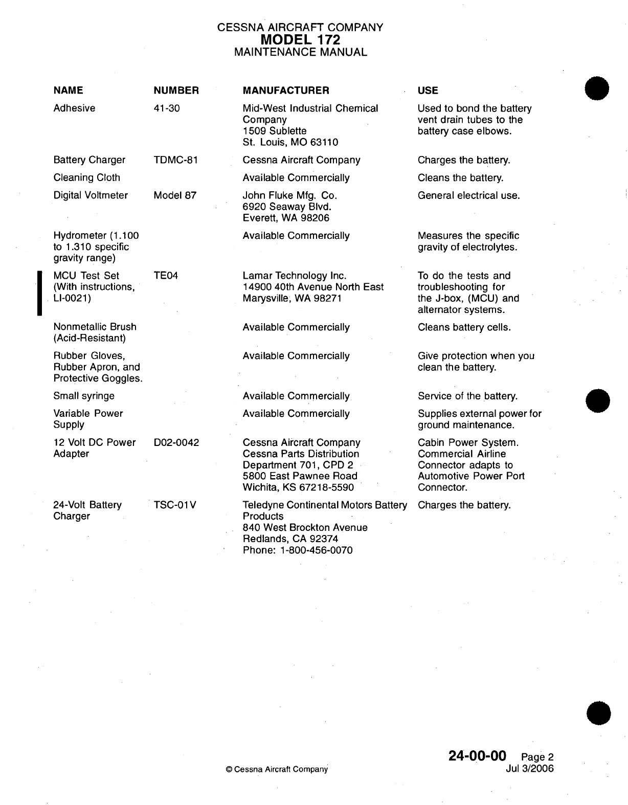
NAME
NUMBER
Adhesive
Battery
Charger
Cleaning
Cloth
Digital
Voltmeter
Hydrometer
(1.100
to
1.310
specific
gravity
range)
MCU
Test
Set
(With
instructions,
LI-0021)
41-30
TDMC-81
Model
87
TE04
Nonmetallic
Brush
(Acid-Resistant)
Rubber
Gloves,
Rubber Apron,
and
Protective
Goggles.
Small
syringe
Variable
Power
Supply
12
Volt
DC
Power
D02-0042
Adapter
24-Volt
Battery
Charger
TSC-01
V
CESSNA
AIRCRAFT
COMPANY
MODEL
172
MAINTENANCE
MANUAL
MANUFACTURER
Mid-West Industrial Chemical
Company
1509
Sublette
St.
Louis,
MO
63110
Cessna Aircraft
Company
Available
Commercially
John
Fluke
Mfg. Co.
6920
Seaway
Blvd.
Everett,
WA
98206
Available
Commercially
Lamar Technology
Inc.
14900
40th
Avenue
North East
Marysville,
WA
98271
Available
Commercially
Available
Commercially
Available
Commercially
Available
Commercially
Cessna
Aircraft
Company
Cessna
Parts
Distribution
Department
701,
CPD
2
5800
East
Pawnee
Road
Wichita,
KS
67218-5590
Teledyne
Continental
Motors Battery
Products
840
West Brockton
Avenue
Redlands,
CA
92374
Phone:
1-800-456-0070
USE
Used
to
bond
the battery
vent drain
tubes
to
the
battery
case
elbows.
Charges
the
battery.
Cleans
the
battery.
General
electrical
use.
Measures
the
specific
gravity
of
electrolytes.
To
do
the
tests
and
troubleshooting
for
the
J-box,
(MCU)
and
alternator
systems.
Cleans battery
cells.
Give
protection
when you
clean
the battery.
Service
of the
battery.
Supplies
external
power
for
ground
maintenance.
Cabin
Power System.
Commercial
Airline
Connector adapts
to
Automotive Power Port
Connector.
Charges
the
battery.
©
Cessna
Aircraft
Company
24-00-00
Page
2
Jul
3/2006
I
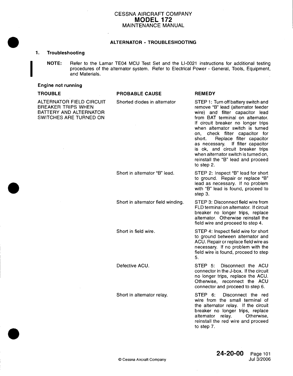
CESSNA
AIRCRAFT
COMPANY
MODEL
172
MAINTENANCE
MANUAL
ALTERNATOR
-
TROUBLESHOOTING
1.
Troubleshooting
NOTE:
Refer
to
the
Lamar
TE04
MCU
Test
Set
and the
LI-0021
instructions
for
additional
testing
procedures
of
the
alternator
system.
Refer
to
Electrical
Power
-
General,
Tools,
Equipment,
and Materials.
Engine
not
running
TROUBLE
ALTERNATOR
FIELD
CIRCUIT
BREAKER
TRIPS
WHEN
BATTERY
AND
ALTERNATOR
SWITCHES
ARE
TURNED
ON
PROBABLE
CAUSE
Shorted
diodes
in
alternator
Short
in
alternator
"B"
lead.
Short
in
alternator
field
winding.
Short
in
field
wire.
Defective
ACU.
Short
in
alternator
relay.
©
Cessna
Aircraft Company
REMEDY
STEP
1:
Turn
off
battery switch
and
remove
"B"
lead
(alternator
feeder
wire)
and
filter capacitor
lead
from
BAT
terminal
on
alternator.
If
circuit
breaker
no
longer
trips
when
alternator
switch
is
turned
on,
check
filter
capacitor
for
short.
Replace
filter
capacitor
as
necessary.
If
filter
capacitor
is
ok,
and
circuit
breaker trips
when
alternator
switch
is
turned
on,
reinstall
the
"B"
lead
and
proceed
to
step
2.
STEP
2:
Inspect
"B"
lead
for
short
to
ground.
Repair
or
replace
"B"
lead
as
necessary.
If
no
problem
with
"B"
lead
is
found,
proceed
to
step
3.
STEP
3:
Disconnect
field
wire
from
FLD
terminal
on
alternator.
If
circuit
breaker
no
longer
trips,
replace
alternator. Otherwise reinstall
the
field
wire
and
proceed
to
step
4.
STEP
4:
Inspect
field
wire
for
short
to
ground
between
alternator
and
ACU.
Repair or
replace
field
wire
as
necessary.
If
no
problem with
the
field
wire
is
found,
proceed to
step
5.
STEP
5:
Disconnect
the
ACU
connector
in
the J-box.
If
the
circuit
no
longer trips, replace
the
ACU.
Otherwise, reconnect
the
ACU
connector
and
proceed
to
step
6.
STEP
6:
Disconnect
the
red
wire
from
the
small terminal
of
the
alternator
relay.
If
the
circuit
breaker
no
longer
trips,
replace
alternator
relay.
Otherwise,
reinstall
the
red
wire
and proceed
to
step
7.
24-20-00
Page
101
Jul
3/2006
I
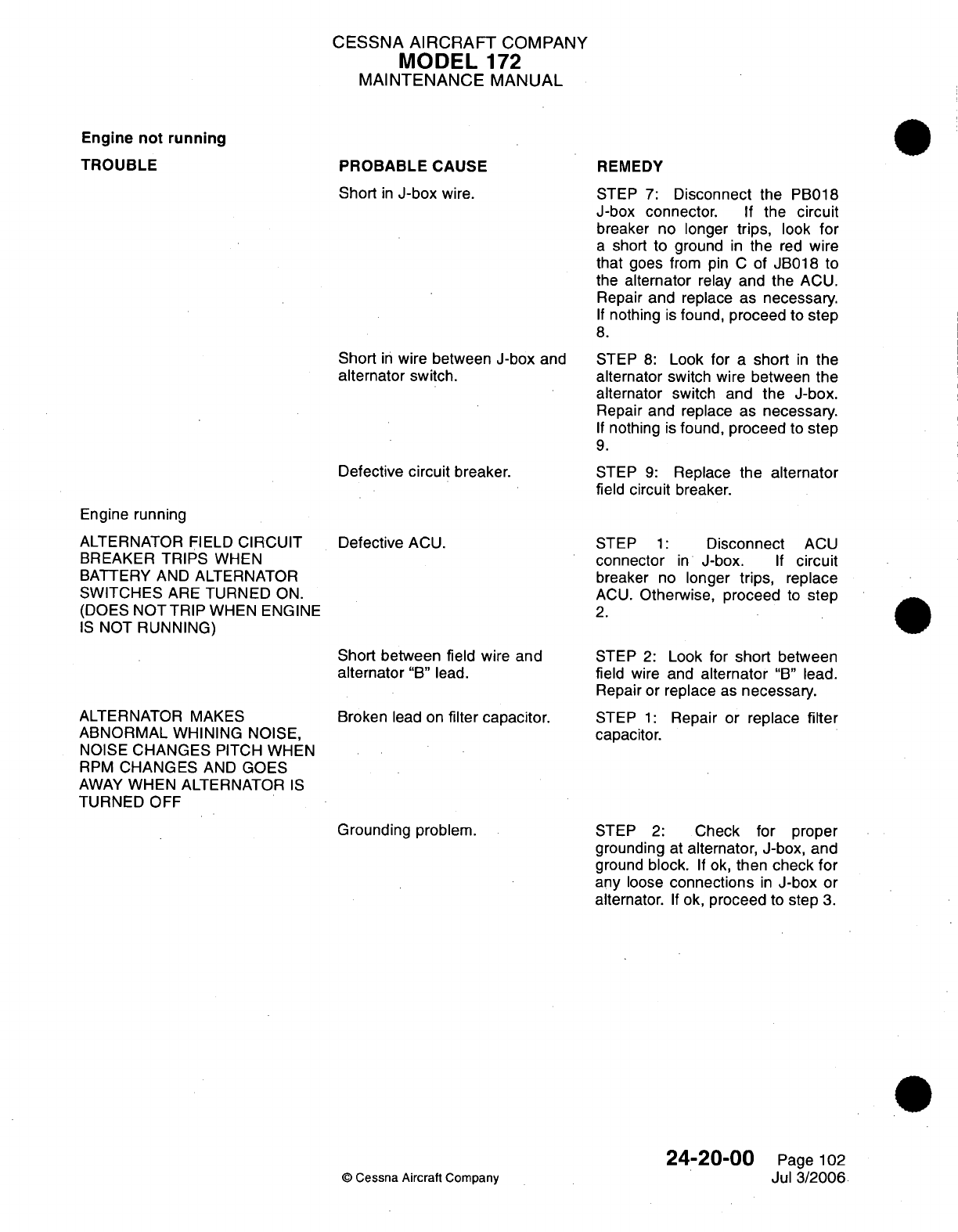
CESSNA
AIRCRAFT
COMPANY
MODEL
172
MAINTENANCE
MANUAL
Engine
not
running
TROUBLE
Engine
running
ALTERNATOR
FIELD
CIRCUIT
BREAKER
TRIPS
WHEN
BATTERY AND
ALTERNATOR
SWITCHES
ARE
TURNED
ON.
(DOES
NOT
TRIP
WHEN
ENGINE
IS
NOT
RUNNING)
PROBABLE
CAUSE
Short
in
J-box
wire.
Short
in
wire between
J-box
and
alternator
switch.
Defective
circuit
breaker.
Defective
ACU.
REMEDY
STEP
7:
Disconnect the
PB018
J-box connector.
If
the
circuit
breaker
no
longer
trips,
look
for
a
short
to
ground
in
the
red
wire
that
goes
from
pin
C
of
JB018
to
the
alternator
relay
and the
ACU.
Repair
and
replace as
necessary.
If
nothing
is
found, proceed to step
8.
STEP
8:
Look
for
a
short
in
the
alternator
switch wire between
the
alternator
switch and
the
J-box.
Repair and
replace as
necessary.
If
nothing
is
found,
proceed
to
step
9.
STEP
9:
Replace
the alternator
field
circuit
breaker.
STEP
1:
Disconnect
ACU
connector
in
J-box.
If
circuit
breaker
no
longer
trips,
replace
ACU.
Otherwise, proceed
to
step
2.
Short
between
field
wire
and
alternator
"B"
lead.
ALTERNATOR MAKES
ABNORMAL
WHINING NOISE,
NOISE
CHANGES
PITCH
WHEN
RPM
CHANGES
AND
GOES
AWAY
WHEN ALTERNATOR
IS
TURNED OFF
Broken
lead on
filter
capacitor.
STEP
2:
Look
for
short
between
field
wire
and
alternator
"B"
lead.
Repair
or
replace
as
necessary.
STEP
1:
Repair
or
replace
filter
capacitor.
Grounding
problem.
©
Cessna Aircraft
Company
STEP
2:
Check
for
proper
grounding
at
alternator,
J-box,
and
ground
block.
If
ok,
then
check
for
any
loose
connections
in
J-box
or
alternator.
If
ok,
proceed
to
step
3.
24-20-00
Page
102
Jul
3/2006
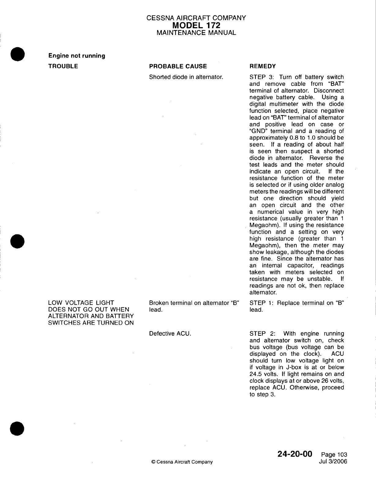
CESSNA
AIRCRAFT
COMPANY
MODEL
172
MAINTENANCE
MANUAL
Engine not
running
TROUBLE
LOW
VOLTAGE
LIGHT
DOES NOT
GO
OUT
WHEN
ALTERNATOR
AND
BATTERY
SWITCHES
ARE
TURNED
ON
PROBABLE
CAUSE
Shorted diode
in
alternator.
Broken
terminal
on
alternator
"B"
lead.
REMEDY
STEP
3:
Turn
off
battery switch
and
remove
cable
from
"BAT"
terminal
of
alternator.
Disconnect
negative battery
cable.
Using
a
digital
multimeter
with
the
diode
function
selected,
place
negative
lead
on
"BAT"
terminal
of
alternator
and
positive
lead
on
case
or
"GND"
terminal
and
a
reading
of
approximately
0.8
to
1.0
should
be
seen.
If a
reading
of
about
half
is
seen
then
suspect
a
shorted
diode
in
alternator.
Reverse
the
test
leads
and
the meter
should
indicate
an
open
circuit.
If
the
resistance
function
of
the
meter
is
selected
or
if
using
older
analog
meters
the
readings
will
be
different
but
one
direction should
yield
an
open
circuit
and
the
other
a
numerical
value
in
very
high
resistance (usually greater
than
1
Megaohm).
If
using
the
resistance
function
and
a
setting
on
very
high
resistance
(greater
than
1
Megaohm),
then
the meter
may
show
leakage,
although
the
diodes
are
fine.
Since
the
alternator
has
an
internal
capacitor,
readings
taken
with
meters
selected
on
resistance
may
be
unstable.
If
readings
are
not
ok,
then
replace
alternator.
STEP
1:
Replace
terminal
on
"B"
lead.
Defective
ACU.
STEP
2:
With engine
running
and
alternator
switch
on,
check
bus
voltage (bus
voltage
can
be
displayed
on
the
clock).
ACU
should
turn
low
voltage
light
on
if
voltage
in
J-box
is
at
or
below
24.5 volts.
If
light remains
on and
clock displays
at
or
above
26
volts,
replace
ACU.
Otherwise,
proceed
to
step
3.
24-20-00
©
Cessna Aircraft
Company
Page
103
Jul 3/2006
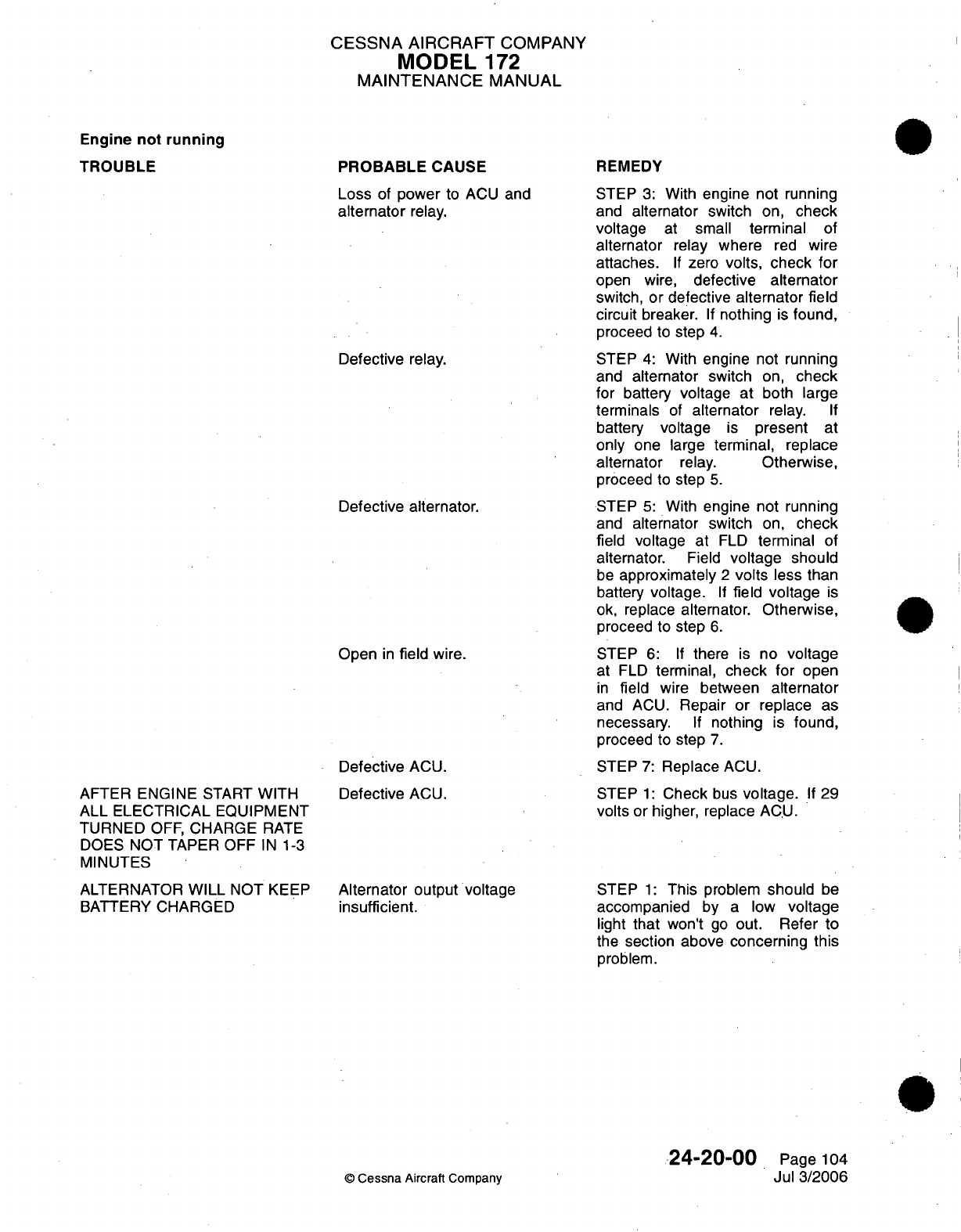
CESSNA
AIRCRAFT
COMPANY
MODEL
172
MAINTENANCE
MANUAL
Engine
not
running
TROUBLE
AFTER ENGINE
START
WITH
ALL ELECTRICAL
EQUIPMENT
TURNED
OFF,
CHARGE
RATE
DOES
NOT
TAPER
OFF
IN
1-3
MINUTES
ALTERNATOR
WILL
NOT
KEEP
BATTERY
CHARGED
PROBABLE
CAUSE
Loss
of
power
to ACU
and
alternator
relay.
Defective relay.
Defective
alternator.
Open
in
field
wire.
Defective
ACU.
Defective
ACU.
Alternator output voltage
insufficient.
REMEDY
STEP
3:
With
engine
not
running
and
alternator
switch
on,
check
voltage
at
small
terminal
of
alternator
relay
where
red
wire
attaches.
If
zero
volts,
check
for
open
wire,
defective
alternator
switch,
or defective
alternator
field
circuit
breaker.
If
nothing
is
found,
proceed
to
step
4.
STEP
4:
With
engine
not
running
and
alternator
switch
on,
check
for
battery
voltage at
both
large
terminals
of
alternator
relay.
If
battery
voltage
is
present
at
only
one
large
terminal, replace
alternator
relay.
Otherwise,
proceed
to
step
5.
STEP
5:
With
engine not running
and
alternator switch
on,
check
field
voltage at
FLD
terminal
of
alternator.
Field
voltage
should
be
approximately
2
volts
less
than
battery
voltage.
If
field
voltage
is
ok,
replace
alternator.
Otherwise,
proceed
to
step
6.
STEP
6:
If
there
is
no
voltage
at
FLD
terminal,
check
for
open
in
field
wire
between
alternator
and
ACU.
Repair
or
replace
as
necessary.
If
nothing
is
found,
proceed
to
step
7.
STEP
7:
Replace
ACU.
STEP
1:
Check
bus
voltage.
If 29
volts
or
higher, replace
AC.U.
STEP
1:
This
problem
should
be
accompanied
by
a
low
voltage
light
that
won't
go
out.
Refer
to
the
section above
concerning
this
problem.
24-20-00
© Cessna
Aircraft
Company
Page
104
Jul 3/2006
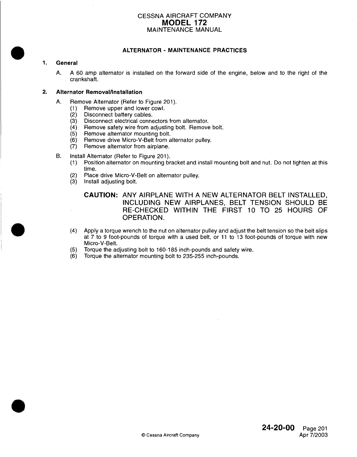
CESSNA
AIRCRAFT
COMPANY
MODEL
172
MAINTENANCE
MANUAL
ALTERNATOR
-
MAINTENANCE
PRACTICES
1.
General
A. A
60
amp
alternator
is
installed
on
the forward
side
of
the
engine,
below
and
to
the right
of the
crankshaft.
2.
Alternator
Removal/Installation
A.
Remove
Alternator
(Refer
to
Figure
201).
(1)
Remove
upper and
lower
cowl.
(2)
Disconnect battery cables.
(3)
Disconnect
electrical connectors
from
alternator.
(4)
Remove
safety
wire
from
adjusting
bolt.
Remove
bolt.
(5)
Remove
alternator
mounting bolt.
(6)
Remove
drive Micro-V-Belt
from
alternator
pulley.
(7)
Remove
alternator
from
airplane.
B.
Install
Alternator
(Refer
to
Figure
201).
(1)
Position
alternator
on
mounting
bracket
and install
mounting
bolt
and
nut.
Do
not
tighten
at
this
time.
(2)
Place
drive
Micro-V-Belt
on
alternator
pulley.
(3)
Install
adjusting
bolt.
CAUTION: ANY AIRPLANE
WITH
A
NEW
ALTERNATOR
BELT
INSTALLED,
INCLUDING
NEW
AIRPLANES,
BELT
TENSION
SHOULD
BE
RECHECED
WITHIN
THE
FIRST
10
TO
25
HOURS
OF
OPERATION.
(4)
Apply
a
torque
wrench
to
the
nut
on
alternator
pulley and
adjust
the
belt
tension
so
the belt
slips
at
7
to
9
foot-pounds
of
torque
with
a
used belt,
or
11
to
13
foot-pounds
of
torque
with
new
Micro-V-Belt.
(5)
Torque
the
adjusting
bolt
to
160-185
inch-pounds
and
safety
wire.
(6)
Torque
the
alternator
mounting
bolt
to
235-255
inch-pounds.
24-20-00
Page 201
©
Cessna Aircraft
Company
Apr
7/2003
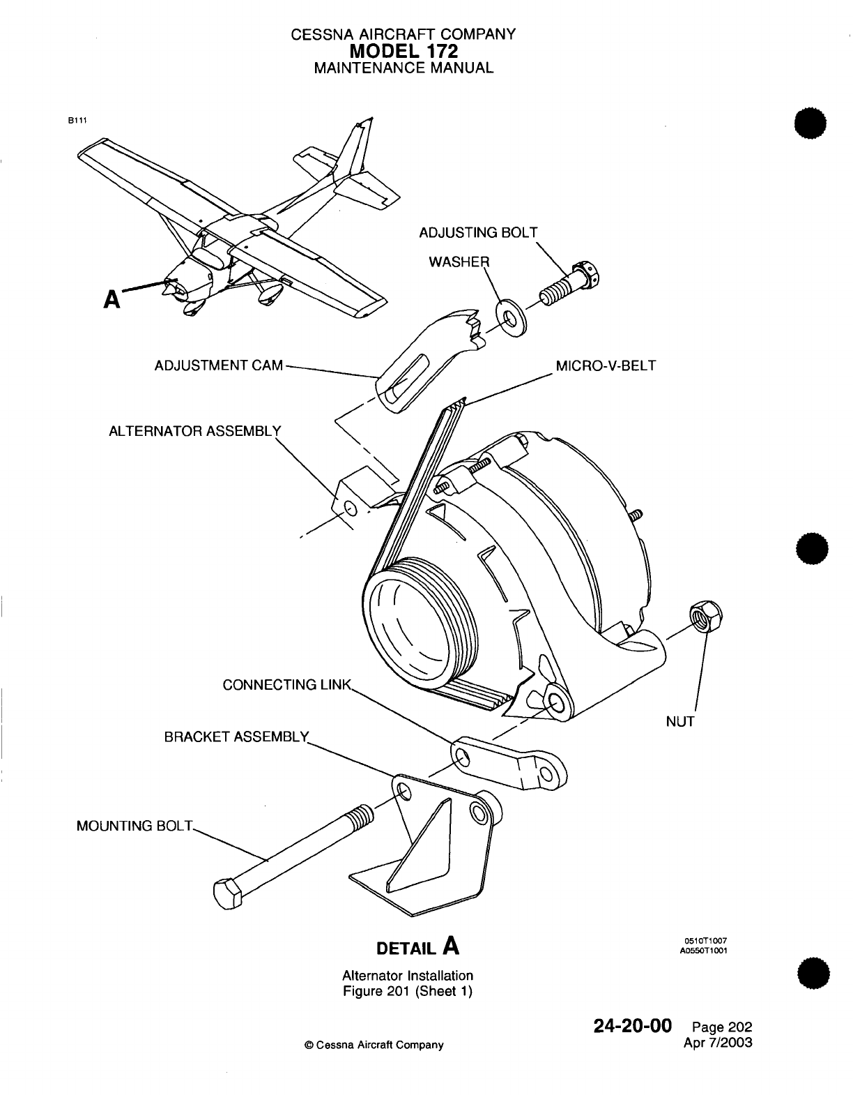
CESSNA AIRCRAFT
COMPANY
MODEL
172
MAINTENANCE
MANUAL
B
ADJUSTING
BOLT
MICRO-V-BELT
ALTERNATO
BRA
MOUNTING
BOLT
CONNECTING
LINK
ET
ASSEMBLY
DETAIL
A
Alternator
Installation
Figure
201
(Sheet
1)
©
Cessna Aircraft
Company
24-20-00
Page
202
Apr
7/2003
ADJUSTMENT
CAM
NUT
0510T1007
A0550T1001
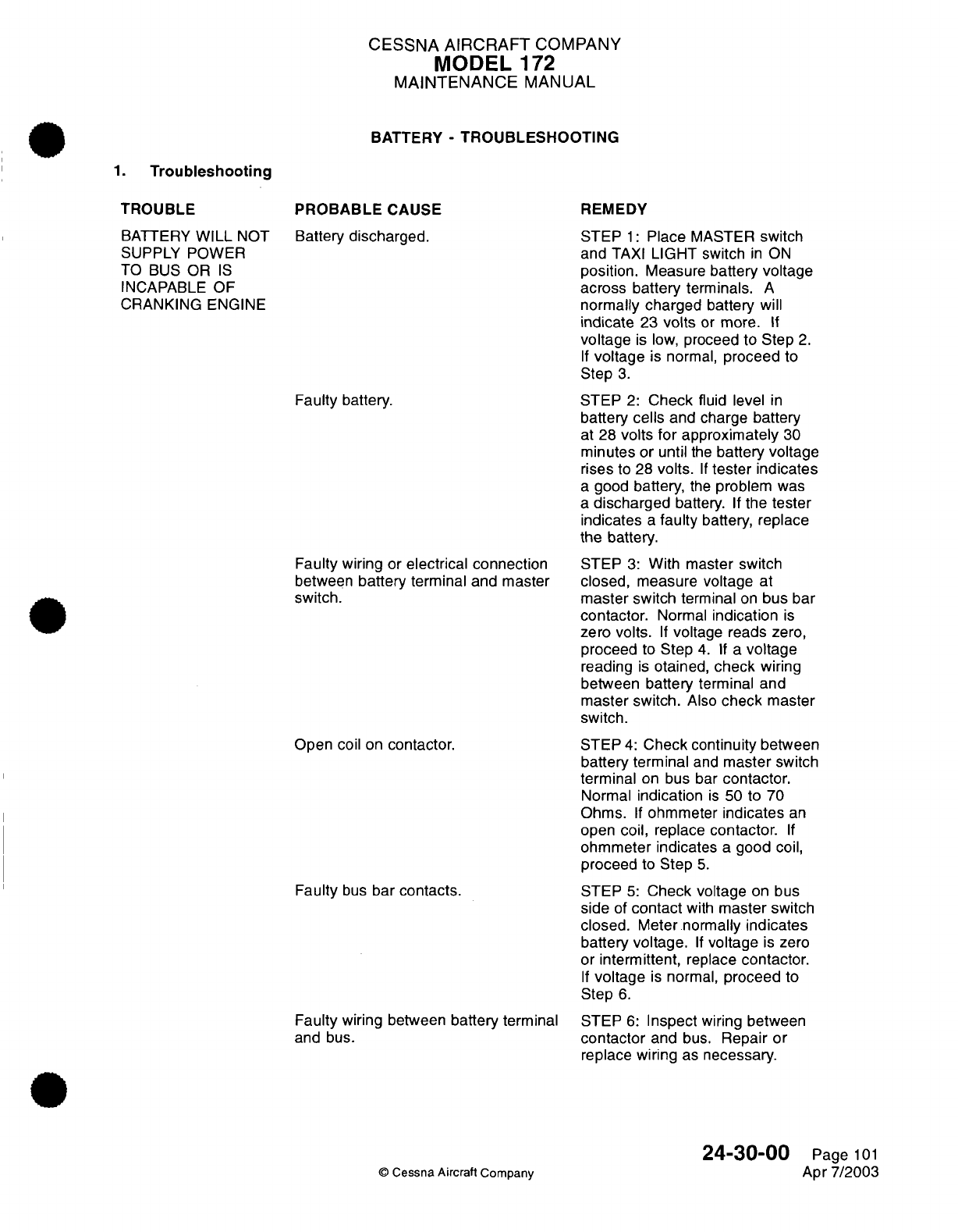
CESSNA
AIRCRAFT
COMPANY
MODEL
172
MAINTENANCE
MANUAL
BATTERY
-
TROUBLESHOOTING
1.
Troubleshooting
TROUBLE
BATTERY
WILL
NOT
SUPPLY POWER
TO
BUS
OR
IS
INCAPABLE OF
CRANKING ENGINE
PROBABLE
CAUSE
Battery
discharged.
Faulty battery.
Faulty wiring
or
electrical connection
between
battery
terminal
and
master
switch.
Open coil
on
contactor.
Faulty
bus
bar
contacts.
Faulty
wiring
between
battery
terminal
and
bus.
©
Cessna
Aircraft
Company
REMEDY
STEP
1:
Place
MASTER
switch
and
TAXI
LIGHT switch
in
ON
position.
Measure
battery
voltage
across battery
terminals.
A
normally charged
battery
will
indicate
23
volts
or more.
If
voltage
is
low,
proceed
to
Step
2.
If
voltage
is
normal,
proceed
to
Step
3.
STEP
2:
Check
fluid level
in
battery
cells
and
charge
battery
at 28
volts
for
approximately
30
minutes
or
until
the
battery voltage
rises
to 28
volts.
If
tester indicates
a
good battery,
the
problem
was
a
discharged
battery.
If
the
tester
indicates
a
faulty
battery,
replace
the battery.
STEP
3:
With
master
switch
closed,
measure voltage
at
master
switch
terminal
on
bus
bar
contactor.
Normal
indication
is
zero
volts.
If
voltage
reads
zero,
proceed
to
Step
4.
If a
voltage
reading
is
otained,
check
wiring
between battery terminal
and
master switch.
Also
check
master
switch.
STEP
4:
Check
continuity
between
battery terminal
and
master switch
terminal
on
bus
bar
contactor.
Normal
indication
is
50
to
70
Ohms.
If
ohmmeter
indicates
an
open
coil,
replace
contactor.
If
ohmmeter indicates
a
good
coil,
proceed
to
Step
5.
STEP
5:
Check voltage
on
bus
side
of
contact
with
master switch
closed.
Meter normally
indicates
battery
voltage.
If
voltage
is
zero
or
intermittent,
replace
contactor.
If
voltage
is
normal,
proceed
to
Step
6.
STEP
6:
Inspect
wiring
between
contactor
and bus.
Repair
or
replace wiring
as
necessary.
24-30-00
Page
101
Apr
7/2003
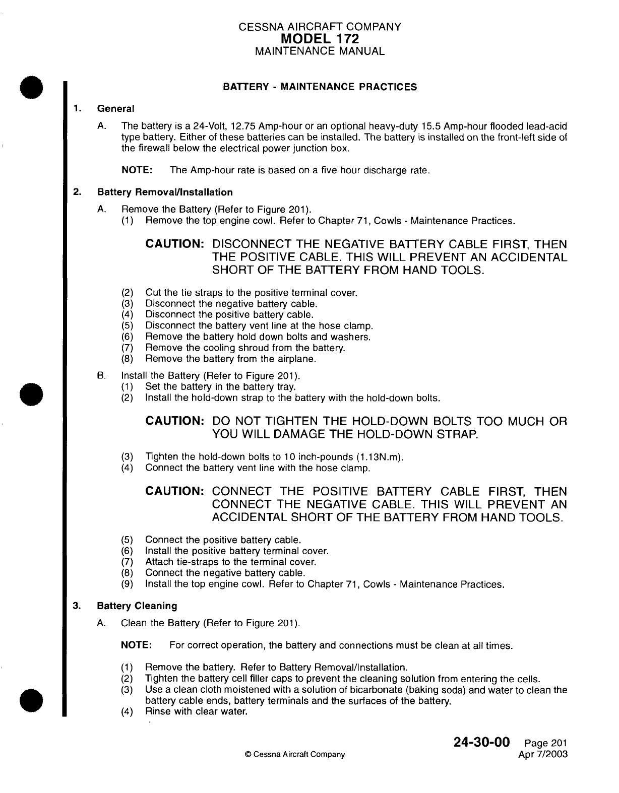
CESSNA
AIRCRAFT
COMPANY
MODEL
1
72
MAINTENANCE
MANUAL
BATTERY
-
MAINTENANCE
PRACTICES
1.
General
A.
The
battery
is
a
24-Volt,
12.75
Amp-hour
or
an
optional
heavy-duty
15.5
Amp-hour
flooded
lead-acid
type
battery.
Either
of
these
batteries can
be
installed.
The
battery
is
installed
on
the
front-left
side
of
the
firewall below
the
electrical
power
junction
box.
NOTE:
The
Amp-hour
rate
is
based
on
a
five
hour
discharge
rate.
2.
Battery
Removal/Installation
A.
Remove the
Battery (Refer
to
Figure
201).
(1)
Remove
the top
engine
cowl.
Refer
to
Chapter
71,
Cowls
-
Maintenance Practices.
CAUTION:
DISCONNECT
THE
NEGATIVE
BATTERY
CABLE
FIRST,
THEN
THE
POSITIVE
CABLE.
THIS
WILL
PREVENT
AN
ACCIDENTAL
SHORT
OF
THE BATTERY
FROM
HAND
TOOLS.
(2)
Cut
the
tie
straps
to
the
positive
terminal
cover.
(3)
Disconnect
the
negative
battery
cable.
(4)
Disconnect
the
positive
battery cable.
(5)
Disconnect
the
battery vent
line
at the
hose
clamp.
(6)
Remove the
battery
hold
down
bolts
and
washers.
(7)
Remove
the
cooling
shroud
from
the
battery.
(8)
Remove
the battery
from
the
airplane.
B.
Install
the
Battery
(Refer
to
Figure
201).
(1)
Set the
battery
in
the
battery
tray.
(2)
Install
the hold-down
strap
to
the
battery
with
the
hold-down
bolts.
CAUTION:
DO
NOT
TIGHTEN
THE
HOLD-DOWN
BOLTS
TOO
MUCH OR
YOU
WILL
DAMAGE
THE
HOLD-DOWN
STRAP.
(3)
Tighten
the
hold-down
bolts
to
10
inch-pounds
(1.13N.m).
(4)
Connect
the
battery vent
line with
the hose
clamp.
CAUTION: CONNECT
THE POSITIVE
BATTERY
CABLE
FIRST,
THEN
CONNECT
THE
NEGATIVE CABLE.
THIS
WILL
PREVENT
AN
ACCIDENTAL
SHORT
OF THE BATTERY
FROM
HAND
TOOLS.
(5)
Connect
the
positive
battery
cable.
(6)
Install
the
positive
battery
terminal
cover.
(7)
Attach
tie-straps
to
the
terminal cover.
(8)
Connect
the
negative
battery cable.
(9)
Install
the top engine
cowl.
Refer
to
Chapter
71,
Cowls
-
Maintenance
Practices.
3.
Battery
Cleaning
A.
Clean
the
Battery
(Refer
to
Figure
201).
NOTE:
For
correct
operation,
the
battery
and
connections
must
be
clean
at
all
times.
(1)
Remove
the
battery.
Refer
to
Battery
Removal/Installation.
(2)
Tighten
the
battery cell
filler
caps
to
prevent
the
cleaning solution
from
entering
the
cells.
(3)
Use
a
clean cloth moistened
with
a
solution
of
bicarbonate
(baking
soda)
and
water
to clean
the
battery
cable
ends, battery
terminals
and
the
surfaces
of
the
battery.
(4)
Rinse
with
clear
water.
24-30-00
Page
201
©
Cessna
Aircraft Company
Apr
7/2003
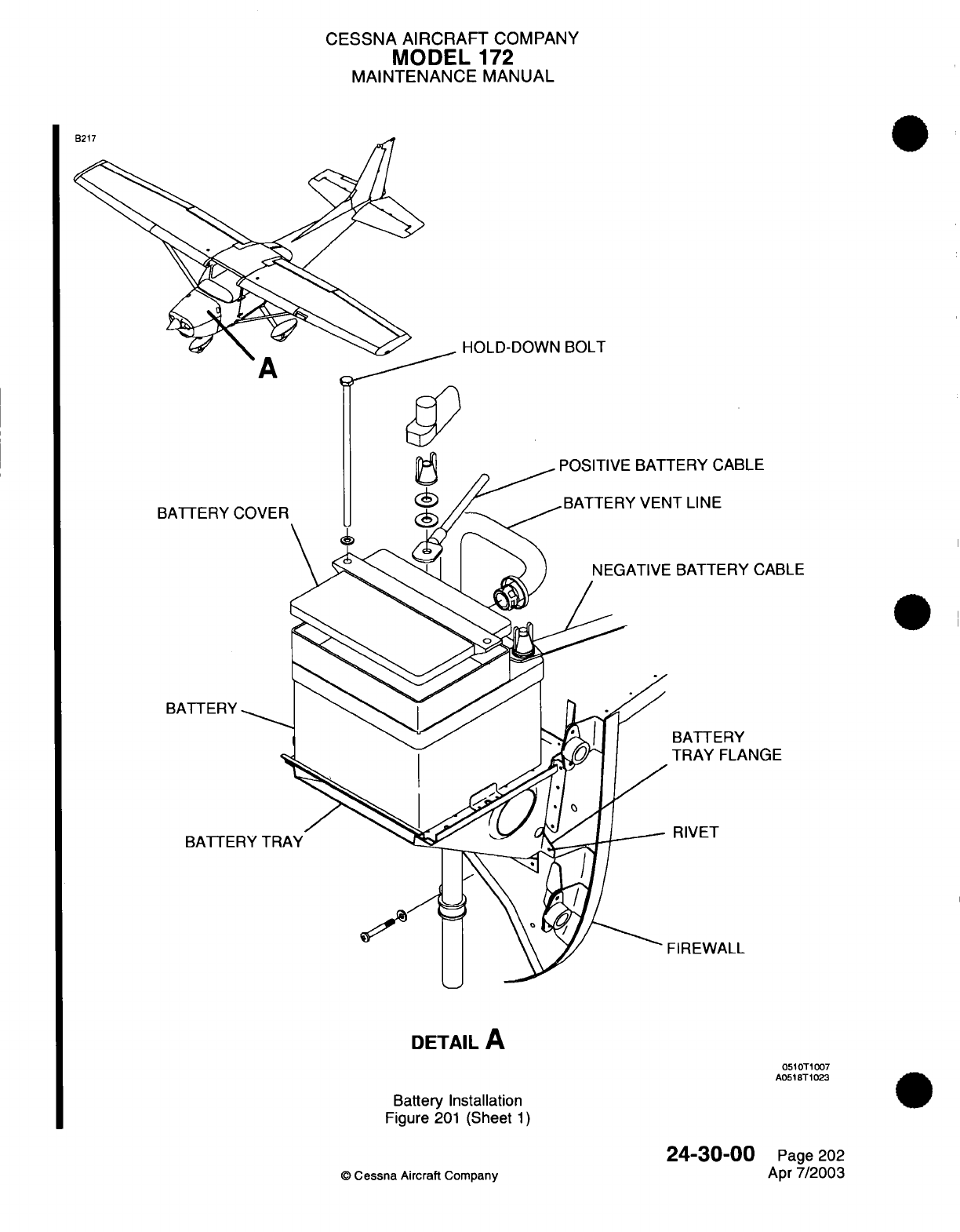
CESSNA
AIRCRAFT
COMPANY
MODEL
172
MAINTENANCE
MANUAL
HOLD-DOWN
BOLT
A
LE
CABLE
,NGE
DETAIL
A
0510T1007
A0518T1023
Battery
Installation
Figure
201
(Sheet
1)
24-30-00
©
Cessna
Aircraft
Company
Page 202
Apr
7/2003
CESSNA
AIRCRAFT
COMPANY
MODEL
172
MAINTENANCE
MANUAL
(5)
Use
a
dry
cloth
to
clean
off
the
water
and let
the
battery
dry.
(6)
Polish
the
cable
ends
and
battery
terminals
with
an
emery
cloth
or
a
wire
brush.
(7)
Install
the
battery.
Refer to Battery
Removal/Installation.
(8)
Apply petroleum
jelly
or
an
ignition spray
product
to
the battery terminals
to
decrease corrosion.
4.
New
Battery
Check
A.
Complete
a
New
Battery
Check.
(1)
Do
a
specific
gravity
check
to
make
sure
the
correct
strength
of
electrolyte
is
used. The
electrolyte
must
be
1.285
+0.005
or
-0.005
specific
gravity
when
it is
measured
between
75F
to
85°F
(24°C
to
30°C).
(2)
To
charge
a
new
battery,
use
the
manufacturer's
instructions
supplied
with
the
battery.
(3)
Before
you
install
the
battery,
clean
the
battery
box.
Refer
to
Chapter
12,
Battery
-
Servicing.
(4)
Install the
battery
in
the
airplane.
Refer
to Battery
Removal/Installation.
5.
Battery
Charging
NOTE:
The
procedures that
follow
are
for batteries
that
use
a
Gill
TSC-01V
or a
Gill
TDMC
Battery
Charger.
WARNING:
YOU
MUST
KEEP
SPARKS
AND
OPEN
FLAME
AWAY
FROM
THE
BATTERY.
THE
BATTERY
MAKES
HYDROGEN
AND
OXYGEN
GASES
WHEN
IT
IS
CHARGED.
THE
GASES
WILL
COLLECT AND CAUSE
A
HAZARDOUS,
EXPLOSIVE CONDITION.
YOU
MUST
HAVE
FREE
VENTILATION
OF THE
BATTERY
AREA
WHEN
YOU
CHARGE
IT.
WARIING:
THE
BATTERY
CELL
TEMPERATURE
MUST
NOT
BE
MORE
THAN
115°F
(46°C).
DECREASE
THE
CHARGE
RATE
IF
THE
TEMPERATURE
INCREASES
MORE
THAN
1-15°F
(46°C).
THE
CHARGE
MUST
NOT
CAUSE
ACID
TO
BE
BLOWN
FROM
THE
VENTS.
A. If
you
use
a
Gill
TSC-01V battery charger,
do
the
instructions
that
follow.
NOTE:
The
Gill
TSC-01V
is
automated
with
a
typical charge
time
of
approximately
two
hours.
Some
batteries
will take
more time
to
charge
as
a
result
of
the
battery
condition.
(1)
Remove
the
battery
from
the airplane
and
place
it in
a
well
ventilated
area
to
charge. Refer
to
Battery
Removal/Installation.
(2)
Remove
the
vent
caps
and
make
sure
the
electrolyte
level
is
above
the
plates
and
separator
material.
Do
not
fill
the battery
to
the
split
rings at
this
time.
(3)
Do
a
specific
gravity check
of
the
battery
electrolyte
with
a
hydrometer
such
as the
Gill
FR-1
(or
equivalent)
to
determine
the
battery
charge.
Refer
to
Table
201
and
Table
202.
(4)
Record
the
value
for
each
battery cell.
(5)
Install
the vent
caps.
(6)
Attach
the
red
cable
to
the
positive battery
terminal and
the
black
cable
to
the
negative
battery
terminal.
(7)
Connect
the
charger
to
AC
power.
The
procedures
that follow
will
result:
(a)
The
AC
POWER
ON
indicator
light
will
come
on.
(b)
The
three
battery
level
indicators
will
flash
one
time.
(c)
The
EMPTY
battery
level
indicator
will
flash
on
and
remain
on.
NOTE:
The
EMPTY
battery
level
indicator
shows
that
the battery
is
correctly
connected.
24-30-00
Page
203
©
Cessna
Aircraft Company
Apr
7/2003
CESSNA
AIRCRAFT
COMPANY
MODEL
172
MAINTENANCE
MANUAL
(8) If
the
battery
is
not
fully
charged, the
PARTIALLY
CHARGED
indicator
light
will come
on.
Make
sure
that
the
battery
stays
connected
at
this
time.
NOTE: Make sure
that
you
let
the
battery
fully
charge.
This
will
make
sure
of
a
good
battery
life
and
performance.
(a)
Do
not
disconnect
the battery.
The
charger
will
not
operate
correctly
if
the
battery
is
disconnected
and then
connected
after
the
PARTIALLY
CHARGED
indicator
light
comes
on.
If
the
battery
is
disconnected,
you must
disconnect
and
connect
the
charger
at
the
electrical
outlet
to
start
the charge process.
(9)
When
the
battery
is
fully
charged,
the
BATTERY
READY
indicator
will
come
on.
(10)
The
electrolyte
level must
touch
the bottom
of the
split
ring
while
the
battery
is
warm
and
still
on
the
charger.
(a) If
the
electrolyte
level
needs
to
be
increased,
use
only
distilled
or mineral free water
to
adjust
the
electrolyte
level.
The
battery must
be
warm
when the
electrolyte
level
is
increased.
NOTE:
The
electrolyte
level
decreases
as
the
battery
temperature decreases.
(11)
Do
not
add
any
more
fluid after these
instructions
unless
the
battery
electrolyte spills.
(a)
If
the fluid
level
is
below
the
plates
and
separator
material
because
a
spill occurs,
add
electrolyte
with
a
value
of
1.285
specific
gravity.
(12)
When
the
BATTERY READY
indicator
light
comes
on,
turn
the
AC
power
off.
(13)
Disconnect
the
battery
charger
from
the
electrical outlet.
(14)
Disconnect
and
remove
the
battery
from
the
charger.
(15)
Do
a
specific
gravity check
of
the
battery electrolyte.
Refer
to
Table
201
and
Table
202.
(a)
The
specific
gravity
values
between cells
must
not
have
a
difference
of
more
than
0.020.
(b)
Acceptable
specific
gravity
values
that
are
adjusted for
temperature,
must
be
between
1.260
and 1.290.
(c) If
the battery does not
give
sufficient
power
to
crank
the
engine
with
the
starter,
then
replace
it
with
a
new battery.
Refer
to
New
Battery
Activation.
B. If
you
use
a
Gill TDMC
battery charger,
do the
instructions
that
follow.
(1)
Remove the battery
from
the
airplane
and
place
it in
a
well
ventilated
area
to
charge.
Refer
to
Battery
Removal/Installation.
(2)
Remove
the
vent
caps
and
make sure
the
electrolyte
level
is
above
the
plates
and
separator
material.
Do
not
fill
the
battery
to the
split
rings
at
this
time.
(3)
Do
a
specific
gravity check
of
the
battery electrolyte
with
a
hydrometer
such
as
the
Gill
FR-1
(or
equivalent)
to
determine
the battery
charge.
Refer to
Table
201
and Table
202.
(4)
Record
the
value
for each
battery cell.
(5)
Install
the
vent caps.
(6)
Click the
Gill
TDMC
charger
ON
button
two times
to
select
the
24
volt position.
(7)
Set
the
timer
for
8
to
10
hours.
NOTE:
The
charger
is
in
a
constant
current
mode
when
the
timer
is
on.
(8)
Set
the charge
rate
to
1.5
amps.
CAUTION:
DO
NOT
LET
THE
BATTERY
CHARGER CHARGE
AT 32
VOLTS
FOR
MORE
THAN
THIRTY
MINUTES.
(9)
Charge
the
battery
until
the
voltage
stabilizes
for three
consecutive
hours
or
shows
32
volts,
whichever
occurs
first.
NOTE:
The
charge
is
measured
across
the
battery
terminals
with
the
charger
on.
24-30-00
Page
204
©
Cessna
Aircraft Company
Apr
7/2003
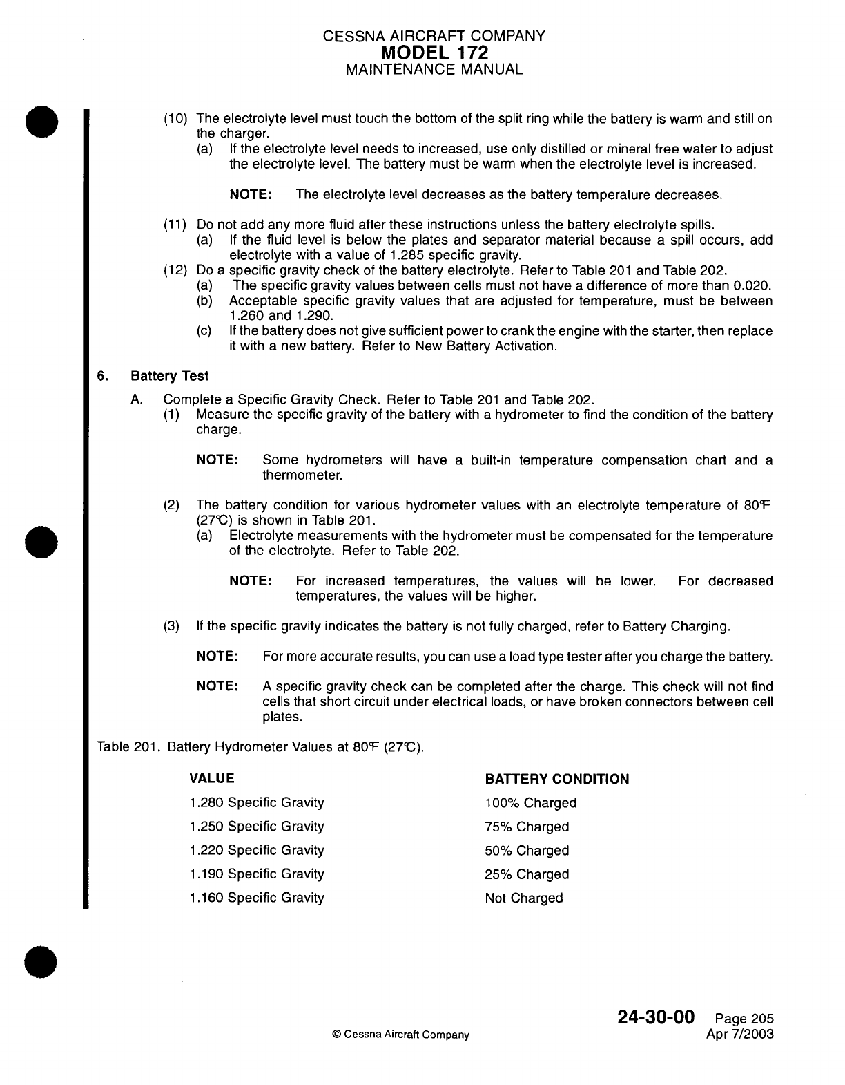
CESSNA
AIRCRAFT
COMPANY
MODEL
172
MAINTENANCE
MANUAL
(10)
The
electrolyte
level
must touch the
bottom
of
the split
ring
while
the
battery
is
warm
and
still
on
the
charger.
(a) If
the
electrolyte
level
needs to
increased,
use
only
distilled
or
mineral
free
water to
adjust
the
electrolyte
level.
The
battery
must
be
warm
when
the
electrolyte
level
is
increased.
NOTE:
The
electrolyte
level
decreases
as
the
battery
temperature
decreases.
(11)
Do
not
add
any
more
fluid
after
these
instructions
unless
the
battery
electrolyte spills.
(a) If
the fluid
level
is
below
the
plates
and
separator
material
because
a
spill
occurs,
add
electrolyte
with
a
value
of
1.285
specific
gravity.
(12) Do
a
specific
gravity
check
of
the
battery
electrolyte.
Refer
to
Table
201
and
Table
202.
(a)
The
specific
gravity values
between
cells
must
not
have
a
difference
of
more
than 0.020.
(b)
Acceptable specific
gravity
values that
are
adjusted
for temperature,
must
be
between
1.260
and
1.290.
(c) If
the battery
does
not
give
sufficient
power
to
crank
the
engine
with
the
starter,
then
replace
it
with
a
new
battery.
Refer to
New
Battery Activation.
6.
Battery
Test
A.
Complete
a
Specific
Gravity
Check. Refer
to
Table
201
and
Table
202.
(1)
Measure
the
specific
gravity
of
the
battery
with
a
hydrometer
to
find
the
condition
of
the
battery
charge.
NOTE:
Some
hydrometers
will have
a
built-in
temperature
compensation chart
and
a
thermometer.
(2)
The
battery
condition
for
various
hydrometer
values
with
an
electrolyte
temperature
of
80°F
(27°C)
is
shown
in
Table
201.
(a)
Electrolyte
measurements
with
the
hydrometer
must
be
compensated
for
the
temperature
of
the
electrolyte.
Refer
to
Table
202.
NOTE:
For
increased
temperatures,
the
values
will
be
lower.
For
decreased
temperatures,
the
values
will
be
higher.
(3) If
the
specific
gravity
indicates
the
battery
is
not
fully
charged, refer
to
Battery
Charging.
NOTE:
For
more
accurate
results,
you can use
a
load type
tester
after
you
charge
the
battery.
NOTE:
A
specific gravity
check
can
be
completed after
the
charge.
This check
will
not
find
cells
that
short
circuit under
electrical
loads, or
have broken
connectors
between
cell
plates.
Table
201.
Battery
Hydrometer
Values
at
80°F
(27°C).
VALUE
BATTERY
CONDITION
1.280
Specific
Gravity
100%
Charged
1.250
Specific
Gravity
75%
Charged
1.220
Specific
Gravity
50%
Charged
1.190
Specific
Gravity
25%
Charged
1.160
Specific
Gravity
Not
Charged
24-30-00
Page 205
©
Cessna
Aircraft Company
Apr 7/2003
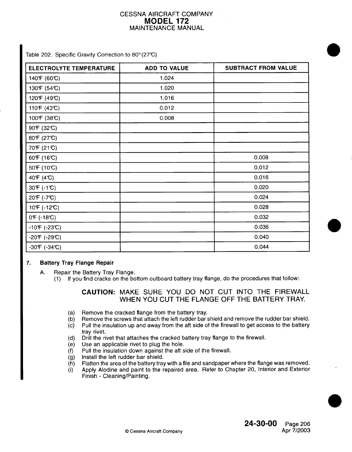
CESSNA
AIRCRAFT
COMPANY
MODEL
172
MAINTENANCE
MANUAL
Table
202.
Specific
Gravity Correction
to
80°(27°C)
ELECTROLYTE TEMPERATURE
140°F
(60C)
130°F
(54°C)
120°F
(49°C)
110°F
(43°C)
100°F (38°C)
90°F
(32C)
80°F
(27°C)
70°F
(21°C)
60°F
(16°C)
50°F
(10°C)
40°F
(4°C)
30°F
(-1C)
20°F
(-7°C)
10°F
(-12C)
0°F
(-18°C)
-10°F
(-23°C)
-20°F
(-29°C)
-30-F
(-34°C)
7.
Battery
Tray Flange Repair
ADD
TO
VALUE
1.024
1.020
1.016
0.012
0.008
SUBTRACT
FROM
VALUE
0.008
0.012
0.016
0.020
0.024
0.028
0.032
0.036
0.040
0.044
A.
Repair
the
Battery Tray
Flange.
(1)
If
you
find
cracks
on
the
bottom
outboard
battery
tray
flange, do
the
procedures
that follow:
CAUTION:
MAKE
SURE
YOU
DO
NOT
CUT
INTO
THE
FIREWALL
WHEN
YOU
CUT THE FLANGE
OFF
THE BATTERY
TRAY.
(a)
(b)
(c)
(d)
(e)
(f)
(g)
(h)
(i)
Remove
the
cracked
flange
from
the
battery
tray.
Remove
the
screws
that
attach
the
left
rudder
bar
shield
and
remove
the
rudder
bar
shield.
Pull
the
insulation
up
and
away
from
the
aft
side
of
the
firewall
to
get access
to the
battery
tray rivet.
Drill
the rivet
that
attaches
the
cracked
battery
tray flange
to
the
firewall.
Use
an
applicable
rivet
to plug
the
hole.
Pull
the
insulation
down
against
the
aft
side of
the
firewall.
Install
the
left
rudder bar
shield.
Flatten
the
area
of
the
battery
tray
with
a
file
and
sandpaper
where
the
flange
was removed.
Apply Alodine
and
paint
to the repaired
area.
Refer
to
Chapter
20,
Interior and
Exterior
Finish
-
Cleaning/Painting.
24-30-00
Page 206
©
Cessna
Aircraft Company
Apr
7/2003
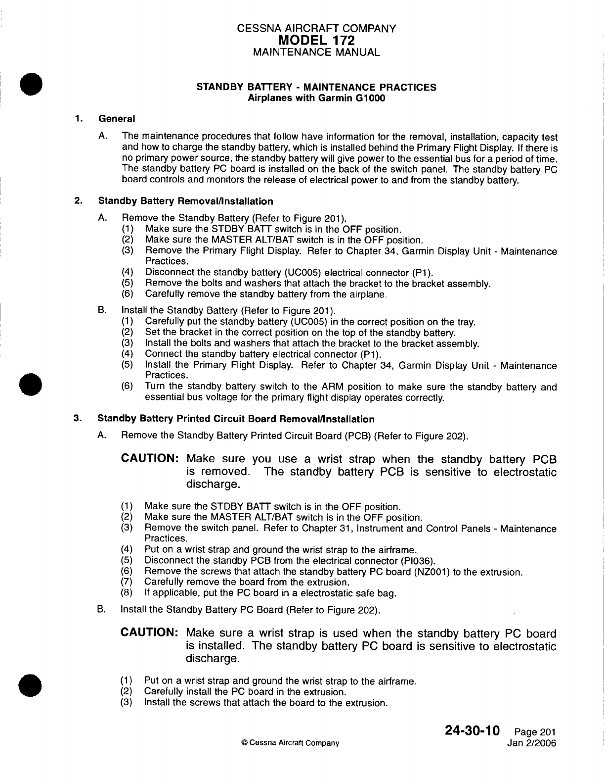
CESSNA
AIRCRAFT
COMPANY
MODEL
172
MAINTENANCE
MANUAL
STANDBY
BATTERY
-
MAINTENANCE PRACTICES
Airplanes with
Garmin
G1000
1.
General
A.
The
maintenance
procedures
that
follow
have information
for
the
removal,
installation,
capacity
test
and
how
to
charge
the
standby
battery, which
is
installed behind
the
Primary Flight
Display.
If
there
is
no
primary
power
source,
the
standby
battery will
give
power
to
the
essential
bus
for
a
period
of
time.
The
standby
battery
PC
board
is
installed
on
the
back
of
the
switch
panel.
The
standby battery
PC
board
controls
and
monitors
the
release
of
electrical
power
to
and
from
the
standby
battery.
2.
Standby Battery
Removal/nstallation
A.
Remove the
Standby
Battery
(Refer
to
Figure
201).
(1)
Make
sure
the STDBY
BATT
switch
is
in
the
OFF
position.
(2)
Make
sure
the
MASTER
ALT/BAT
switch
is
in
the OFF
position.
(3)
Remove
the Primary Flight
Display.
Refer
to
Chapter
34, Garmin
Display
Unit
-
Maintenance
Practices.
(4)
Disconnect
the
standby
battery
(UC005)
electrical
connector
(P1).
(5)
Remove
the
bolts
and
washers
that attach
the
bracket to
the
bracket assembly.
(6)
Carefully
remove
the
standby
battery
from
the
airplane.
B.
Install
the Standby
Battery
(Refer to
Figure
201).
(1)
Carefully
put
the standby battery
(UC005)
in
the
correct
position
on the
tray.
(2)
Set
the bracket
in
the
correct
position
on
the
top
of
the
standby
battery.
(3)
Install
the
bolts and
washers
that attach
the
bracket
to
the
bracket
assembly.
(4)
Connect
the
standby
battery electrical
connector
(P1).
(5)
Install
the
Primary
Flight Display.
Refer
to
Chapter
34,
Garmin
Display
Unit
-
Maintenance
Practices.
(6)
Turn
the
standby
battery
switch
to
the
ARM
position
to make
sure the
standby
battery
and
essential
bus
voltage
for
the
primary
flight display
operates
correctly.
3.
Standby
Battery
Printed
Circuit
Board
Removal/nstallation
A.
Remove
the
Standby
Battery Printed
Circuit
Board
(PCB)
(Refer
to
Figure
202).
CAUTION:
Make
sure
you
use
a
wrist
strap when
the
standby
battery
PCB
is
removed. The
standby
battery
PCB
is
sensitive
to
electrostatic
discharge.
(1)
Make
sure
the STDBY
BATT
switch
is in
the
OFF
position.
(2)
Make
sure
the
MASTER
ALT/BAT
switch
is
in
the OFF
position.
(3)
Remove
the switch
panel.
Refer
to
Chapter
31,
Instrument
and
Control Panels
-
Maintenance
Practices.
(4)
Put on
a
wrist
strap
and
ground
the
wrist
strap
to
the
airframe.
(5)
Disconnect
the
standby
PCB from
the
electrical
connector
(PI036).
(6)
Remove
the
screws
that
attach
the
standby
battery
PC
board
(NZ001)
to
the
extrusion.
(7)
Carefully
remove
the board
from
the
extrusion.
(8) If
applicable,
put
the
PC
board
in
a
electrostatic
safe
bag.
B.
Install the
Standby
Battery
PC
Board
(Refer to
Figure
202).
CAUTION:
Make
sure
a
wrist
strap
is
used
when
the
standby
battery
PC
board
is
installed.
The
standby
battery
PC
board
is
sensitive
to
electrostatic
discharge.
(1)
Put on a
wrist
strap
and
ground
the
wrist
strap
to
the airframe.
(2)
Carefully
install
the
PC
board
in
the
extrusion.
(3)
Install
the
screws that
attach
the
board to the
extrusion.
24-30-10
Page
201
©
Cessna
Aircraft
Company
Jan
2/2006
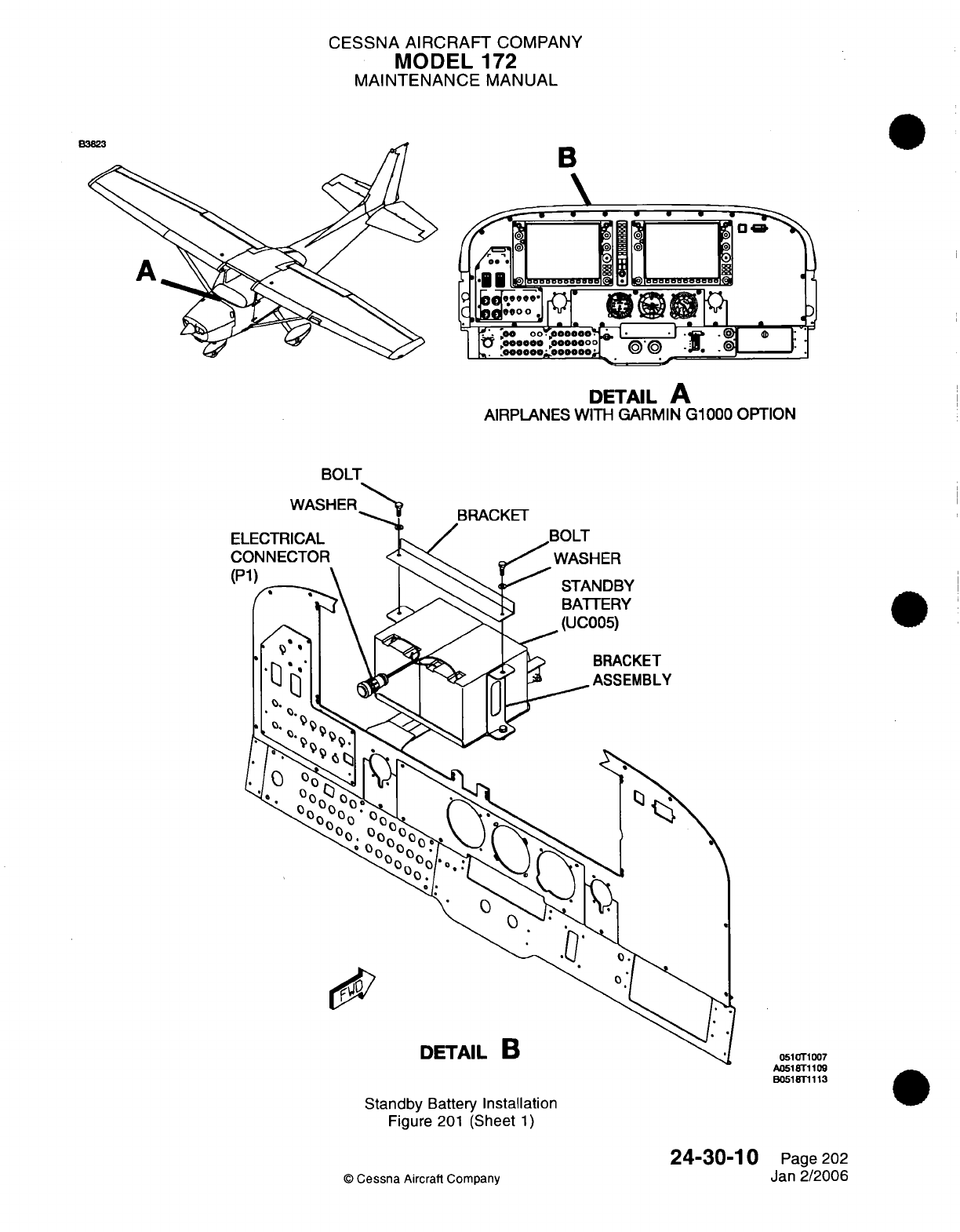
CESSNA
AIRCRAFT
COMPANY
MODEL
172
MAINTENANCE
MANUAL
B
DETAIL
A
AIRPLANES
WITH
GARMIN
G1000
OPTION
BOLT
051rT1007
A0518T1109
B0518T1113
Standby
Battery
Installation
Figure
201
(Sheet
1)
24-30-10
©
Cessna
Aircraft Company
Page
202
Jan
2/2006
B
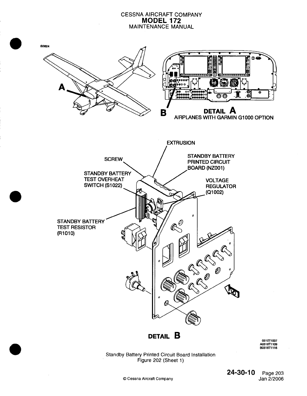
CESSNA
AIRCRAFT
COMPANY
MODEL
172
MAINTENANCE
MANUAL
B
DETAIL
A
AIRPLANES
WITH GARMIN
G1000
OPTION
EXTRUSION
SCREW
STANDBY
BATTERY
TEST
OVERHEAT
SWITCH
(S1022)
STANDBY
TEST
RESI
(R1010)
DETAIL
B
Standby
Battery
Printed Circuit
Board
Installation
Figure
202
(Sheet
1)
©
Cessna Aircraft
Company
0510T1007
A0518T1109
B051
8T1116
24-30-10
Page
203
Jan
2/2006
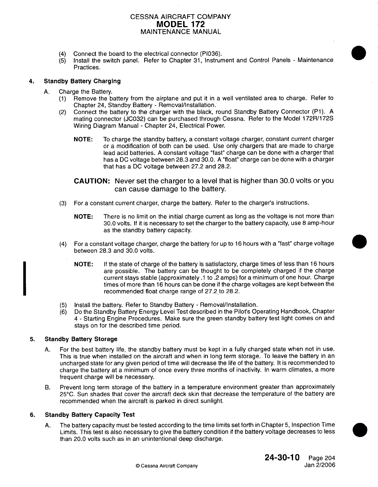
CESSNA AIRCRAFT
COMPANY
MODEL
172
MAINTENANCE
MANUAL
(4)
Connect
the board
to
the
electrical
connector
(PI036).
(5)
Install the
switch
panel.
Refer
to
Chapter
31,
Instrument
and Control Panels
-
Maintenance
Practices.
4.
Standby
Battery
Charging
A.
Charge
the
Battery.
(1)
Remove
the
battery
from the
airplane
and
put
it in a
well
ventilated area
to
charge. Refer
to
Chapter
24,
Standby
Battery
-
Removal/Installation.
(2)
Connect
the
battery
to
the
charger
with
the
black,
round
Standby
Battery
Connector
(P1).
A
mating
connector
(JC032)
can
be
purchased
through
Cessna. Refer
to
the
Model
172R/172S
Wiring
Diagram
Manual
-
Chapter
24,
Electrical
Power.
NOTE:
To
charge
the
standby
battery,
a
constant
voltage
charger,
constant
current
charger
or a
modification
of
both
can
be
used.
Use
only chargers
that
are
made
to
charge
lead acid
batteries.
A
constant
voltage
"fast"
charge
can
be
done
with
a
charger that
has
a
DC
voltage
between
28.3
and 30.0.
A
"float"
charge
can be done
with
a
charger
that
has
a
DC
voltage
between
27.2
and
28.2.
CAUTION:
Never
set
the
charger
to
a
level
that
is
higher
than
30.0
volts
or
you
can
cause
damage
to
the
battery.
(3)
For
a
constant
current
charger,
charge the battery. Refer
to
the
charger's
instructions.
NOTE:
There
is
no
limit
on
the
initial charge
current
as
long
as
the
voltage
is
not
more
than
30.0 volts.
If it is
necessary
to
set
the
charger
to
the
battery capacity,
use
8
amp-hour
as
the
standby
battery
capacity.
(4)
For
a
constant
voltage
charger,
charge the battery
for
up
to
16
hours
with
a
"fast"
charge
voltage
between
28.3
and
30.0
volts.
NOTE:
If
the
state
of
charge
of
the
battery
is
satisfactory,
charge
times
of
less
than
16
hours
are
possible.
The battery
can
be
thought
to
be
completely
charged
if
the charge
current
stays
stable
(approximately
.1
to
.2
amps)
for
a
minimum
of
one
hour.
Charge
times
of
more
than
16
hours
can
be
done
if
the charge
voltages
are
kept between
the
recommended
float
charge
range of
27.2
to
28.2.
(5)
Install
the battery. Refer
to
Standby
Battery
-
Removal/Installation.
(6)
Do
the
Standby
Battery
Energy
Level
Test
described
in
the
Pilot's
Operating
Handbook,
Chapter
4
-
Starting
Engine
Procedures.
Make
sure
the green
standby
battery
test
light
comes
on
and
stays
on
for
the
described
time period.
5.
Standby
Battery
Storage
A.
For
the
best
battery
life,
the
standby
battery
must
be
kept
in a
fully
charged
state when
not
in
use.
This
is
true
when
installed
on
the
aircraft
and
when
in
long
term
storage.
To
leave
the
battery
in
an
uncharged
state for
any
given
period
of
time
will
decrease
the
life
of
the
battery.
It
is
recommended
to
charge
the
battery
at
a
minimum
of
once
every three
months
of
inactivity.
In
warm
climates,
a
more
frequent
charge
will
be
necessary.
B.
Prevent
long term
storage
of
the battery
in
a
temperature
environment greater
than
approximately
25°C.
Sun
shades
that cover the aircraft
deck
skin
that
decrease
the
temperature
of
the
battery
are
recommended
when the
aircraft
is
parked
in
direct
sunlight.
6.
Standby
Battery
Capacity
Test
A.
The
battery
capacity
must
be
tested
according
to
the
time
limits
set
forth
in
Chapter
5,
Inspection
Time
Limits.
This
test
is
also necessary
to
give
the battery
condition
if
the battery
voltage
decreases
to
less
than
20.0
volts such
as
in
an
unintentional
deep
discharge.
24-30-10
Page
204
©
Cessna
Aircraft
Company
Jan
2/2006
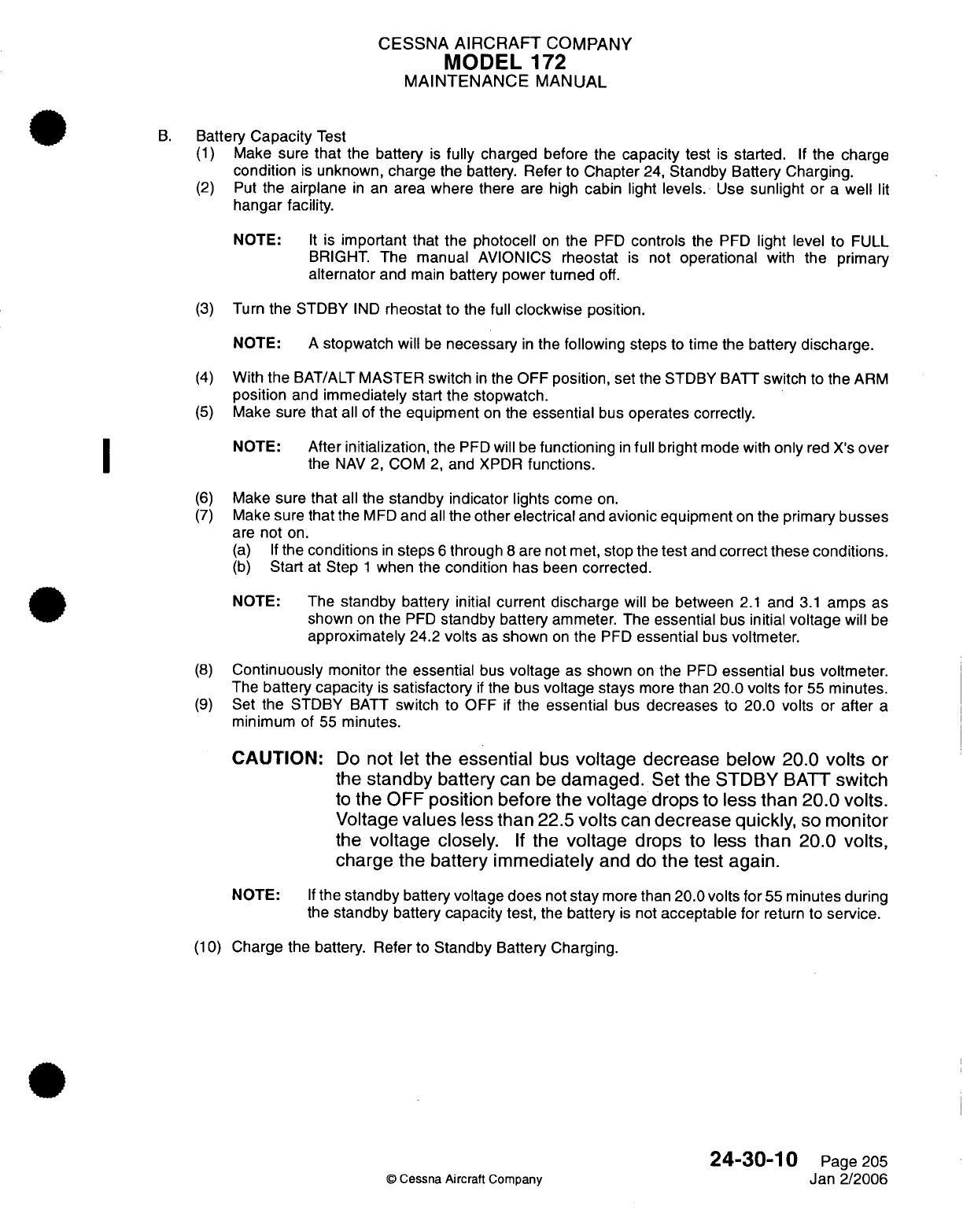
CESSNA
AIRCRAFT
COMPANY
MODEL
172
MAINTENANCE
MANUAL
B.
Battery
Capacity
Test
(1)
Make
sure
that
the
battery
is
fully
charged
before the
capacity
test
is
started.
If
the
charge
condition
is
unknown,
charge
the
battery.
Refer
to
Chapter
24,
Standby
Battery
Charging.
(2)
Put
the
airplane
in
an
area where
there
are high
cabin
light
levels.
Use
sunlight
or
a
well
lit
hangar
facility.
NOTE:
It
is
important
that
the
photocell
on
the
PFD
controls
the PFD
light
level to
FULL
BRIGHT.
The
manual
AVIONICS
rheostat
is
not
operational
with
the primary
alternator
and
main
battery
power turned
off.
(3)
Turn
the
STDBY
IND
rheostat to
the
full
clockwise
position.
NOTE:
A
stopwatch will
be
necessary
in
the
following
steps
to
time the
battery
discharge.
(4)
With
the
BAT/ALT
MASTER
switch
in
the
OFF
position,
set
the
STDBY
BATT
switch
to
the
ARM
position
and
immediately
start
the stopwatch.
(5)
Make
sure
that
all
of
the equipment
on
the
essential
bus
operates
correctly.
NOTE:
After
initialization,
the
PFD
will be
functioning
in
full
bright
mode with
only
red
X's
over
the
NAV
2,
COM
2,
and
XPDR
functions.
(6)
Make
sure that
all
the
standby indicator
lights come
on.
(7)
Make
sure
that
the
MFD
and
all
the
other
electrical
and
avionic
equipment
on
the
primary busses
are
not
on.
(a) If
the
conditions
in
steps
6
through
8
are
not
met,
stop the
test
and
correct
these
conditions.
(b)
Start
at
Step
1
when the
condition
has
been
corrected.
NOTE:
The
standby
battery
initial
current
discharge
will
be
between
2.1
and
3.1
amps
as
shown
on
the
PFD
standby battery
ammeter.
The
essential
bus
initial
voltage
will
be
approximately
24.2
volts
as
shown
on
the
PFD
essential
bus
voltmeter.
(8)
Continuously
monitor
the
essential
bus
voltage
as
shown
on
the
PFD
essential
bus
voltmeter.
The
battery
capacity
is
satisfactory
if
the
bus
voltage stays
more
than
20.0
volts
for
55
minutes.
(9)
Set
the STDBY
BATT
switch
to
OFF
if
the
essential
bus
decreases
to
20.0
volts or
after
a
minimum of
55
minutes.
CAUTION:
Do
not
let
the
essential
bus
voltage
decrease below 20.0
volts
or
the
standby
battery
can
be
damaged.
Set
the
STDBY
BATT
switch
to
the
OFF
position
before the
voltage
drops
to
less
than
20.0
volts.
Voltage
values
less
than
22.5
volts
can
decrease
quickly,
so
monitor
the
voltage
closely.
If
the
voltage
drops
to
less
than 20.0 volts,
charge
the
battery
immediately
and
do
the
test
again.
NOTE:
If
the
standby
battery
voltage
does
not
stay
more
than
20.0
volts
for
55
minutes
during
the
standby
battery
capacity
test,
the
battery
is
not
acceptable
for
return
to
service.
(10)
Charge
the
battery.
Refer
to
Standby
Battery
Charging.
24-30-10
Page
205
©
Cessna
Aircraft
Company
Jan
2/2006
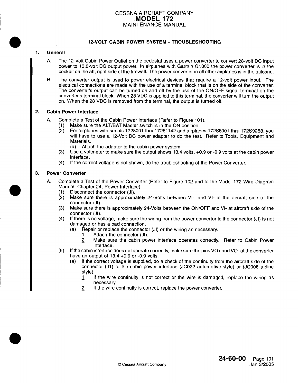
CESSNA
AIRCRAFT
COMPANY
MODEL
172
MAINTENANCE
MANUAL
12-VOLT
CABIN
POWER
SYSTEM
-
TROUBLESHOOTING
1.
General
A.
The
12-Volt Cabin
Power
Outlet
on
the
pedestal
uses
a
power
converter
to
convert
28-volt
DC
input
power
to
13.8-volt
DC
output
power.
In
airplanes
with Garmin
G1000
the
power
converter
is
in
the
cockpit
on the aft,
right
side
of
the
firewall.
The
power
converter
in
all
other
airplanes
is in
the
tailcone.
B.
The
converter output
is
used to
power
electrical devices
that
require
a
12-volt
power
input.
The
electrical
connections
are
made
with
the use
of
a
terminal
block
that
is
on
the
side
of the
converter.
The
converter's
output
can
be
turned
on
and off
by
the use of
the
ON/OFF
signal
terminal
on
the
converter's
terminal
block.
When
28
VDC
is
applied
to
this
terminal,
the converter
will
turn
the
output
on.
When
the
28 VDC
is
removed
from
the terminal,
the
output
is
turned
off.
2.
Cabin Power
Interface
A.
Complete
a
Test
of
the
Cabin
Power
Interface
(Refer
to
Figure
101).
(1)
Make
sure
the
ALT/BAT
Master
switch
is in
the
ON
position.
(2)
For
airplanes
with
serials
1728001 thru
17281142 and
airplanes
172S8001
thru
172S9288, you
will have to use
a
12-Volt
DC
power
adapter
to
do the
test. Refer
to
Tools,
Equipment
and
Materials.
(a)
Attach the
adapter
to
the
cabin
power
system.
(3)
Use
a
voltmeter
to
make sure
the
output
shows
13.4
volts,
+0.9
or
-0.9
volts
at
the
cabin
power
interface.
(4) If
the
correct
voltage
is
not shown,
do the
troubleshooting
of
the
Power
Converter.
3.
Power
Converter
A.
Complete
a
Test
of
the Power
Converter
(Refer
to
Figure
102
and
to
the
Model
172
Wire
Diagram
Manual,
Chapter
24,
Power
Interface).
(1)
Disconnect
the
connector
(JI).
(2)
Make
sure
there
is
approximately
24-Volts between
VI+
and
VI-
at
the
aircraft
side
of
the
connector
(JI).
(3)
Make sure
there
is
approximately
24-Volts
between
the
ON/OFF
and
VI-
at
aircraft
side
of
the
connector
(JI).
(4) If
there
is
no
voltage,
make
sure
the wiring
from
the power
convertor
to
the
connector
(JI)
is
not
damaged
or
has
a
bad
connection.
(a)
Repair
or
replace
the
connector
(JI)
or
the
wiring
as
necessary.
1
Attach
the
connector
(JI).
2
Make sure the
cabin
power interface
operates
correctly. Refer to
Cabin
Power
Interface.
(5) If
the
cabin
interface
does
not
operate
correctly,
make
sure
the
pins
VO+
and
VO-
at
the
converter
have
an
output
of
13.4 +0.9
or
-0.9
volts.
(a) If
the
correct voltage
is
supplied,
do
a
check
of
the
continuity
from
the aircraft
side
of
the
connector
(J1)
to
the
cabin power
interface
(JC022
automotive
style)
or
(JC008
airline
style).
1 If
the
wire
continuity
is
not
correct
or
the
wire
is
damaged,
replace
the
wiring
as
necessary.
2 If
the
wire
continuity
is
correct,
replace
the
power
converter.
24-60-00
©
Cessna Aircraft
Company
Page
101
Jan
3/2005
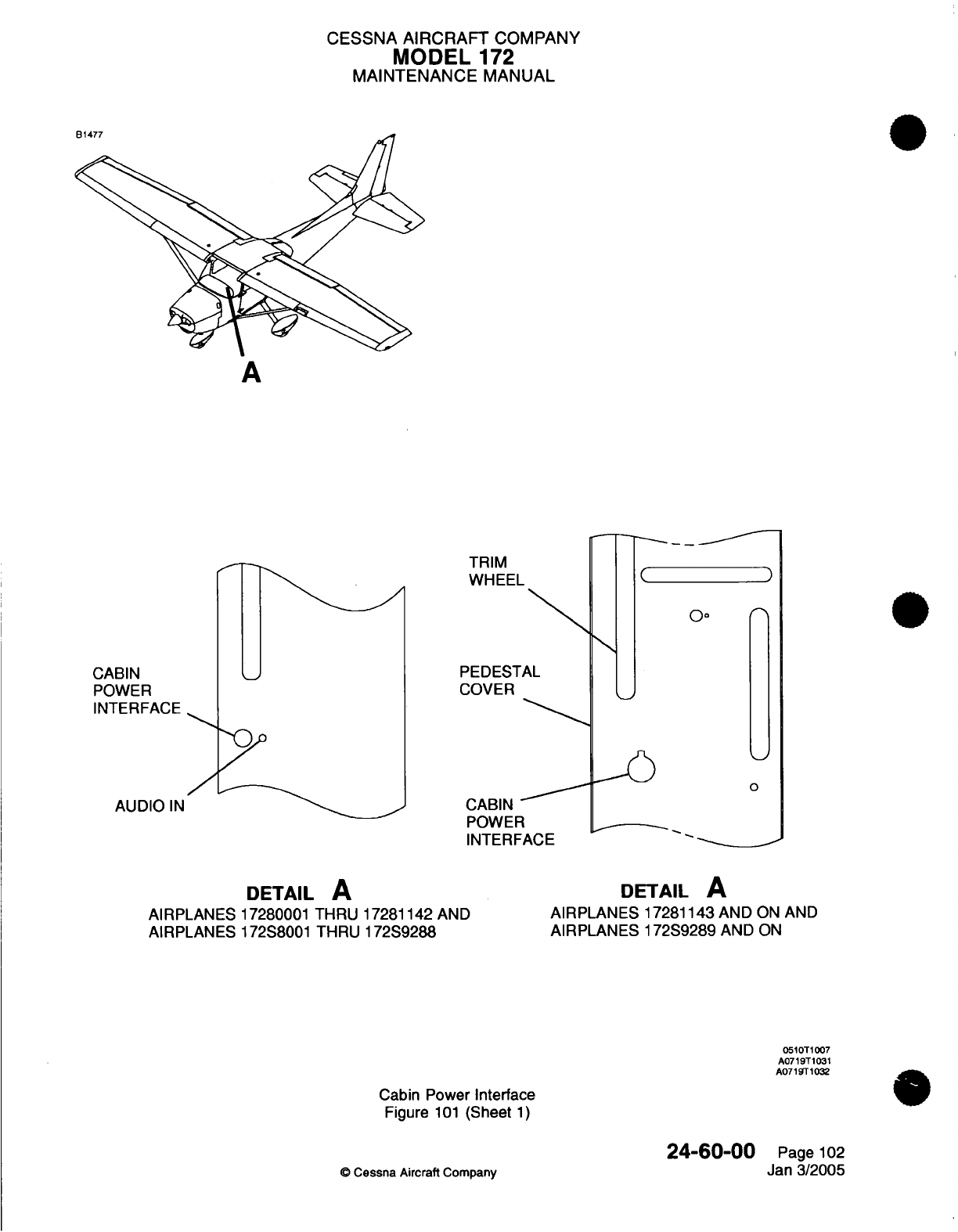
CESSNA
AIRCRAFT
COMPANY
MODEL
172
MAINTENANCE MANUAL
A
TRIM
WHEEL
PEDESTAL
COVER
CABIN
POWER
INTERFACE
AUDIO
IN
(
)
0
I--
CABIN
POWER
INTERFACE
DETAIL
A
AIRPLANES
17280001
THRU
17281142
AND
AIRPLANES
172S8001
THRU
172S9288
DETAIL
A
AIRPLANES
17281143
AND
ON AND
AIRPLANES
172S9289
AND
ON
0510T1007
A0719T1031
A071
T
1032
Cabin
Power
Interface
Figure
101
(Sheet
1)
©
-Cessna Aircraft
Company
24-60-00
Page
102
Jan
3/2005
0o
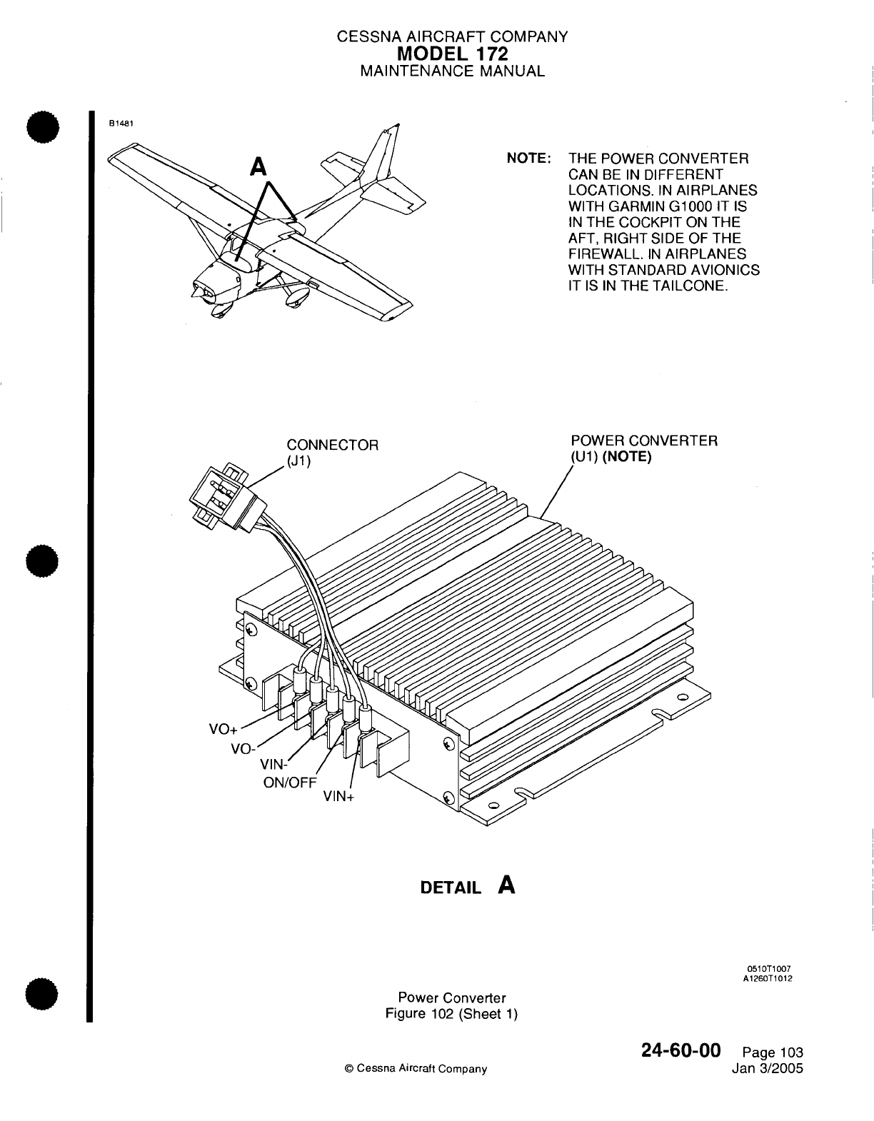
CESSNA
AIRCRAFT
COMPANY
MODEL
172
MAINTENANCE
MANUAL
NOTE:
THE POWER
CONVERTER
CAN
BE
IN
DIFFERENT
LOCATIONS.
IN
AIRPLANES
WITH
GARMIN
G1000
IT
IS
IN
THE
COCKPIT
ON
THE
AFT,
RIGHT
SIDE
OF
THE
FIREWALL.
IN
AIRPLANES
WITH
STANDARD
AVIONICS
IT IS IN
THE
TAILCONE.
CONNECTOR
POWER
CONVERTER
DETAIL
A
0510T1007
A1260T1012
Power
Converter
Figure
102
(Sheet
1)
©
Cessna
Aircraft
Company
24-60-00
Page
103
Jan
3/2005
D4AO4
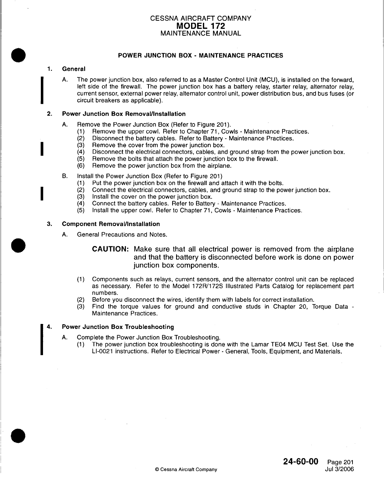
CESSNA
AIRCRAFT
COMPANY
MODEL
172
MAINTENANCE
MANUAL
POWER
JUNCTION
BOX
-
MAINTENANCE
PRACTICES
1.
General
A.
The
power
junction
box, also
referred
to
as
a
Master Control
Unit (MCU),
is
installed
on
the
forward,
left
side
of the
firewall.
The power
junction
box has
a
battery relay,
starter
relay,
alternator
relay,
current
sensor,
external
power
relay,
alternator
control
unit,
power
distribution
bus,
and
bus fuses
(or
circuit
breakers
as
applicable).
2.
Power
Junction
Box
Removal/Installation
A.
Remove
the
Power
Junction
Box
(Refer
to
Figure
201).
(1)
Remove
the upper
cowl. Refer
to
Chapter
71,
Cowls
-
Maintenance Practices.
(2)
Disconnect
the battery
cables.
Refer
to
Battery
-
Maintenance
Practices.
|1 ~
(3)
Remove the
cover
from
the
power
junction
box.
(4)
Disconnect
the
electrical connectors,
cables,
and
ground
strap
from the
power
junction
box.
(5)
Remove
the bolts
that
attach
the
power
junction
box to the
firewall.
(6)
Remove
the
power
junction
box
from the
airplane.
B.
Install
the
Power
Junction
Box
(Refer
to
Figure
201)
(1)
Put
the
power
junction
box
on
the
firewall
and attach
it
with
the
bolts.
(2)
Connect
the
electrical connectors,
cables,
and
ground
strap
to
the
power
junction
box.
(3)
Install
the
cover
on
the power
junction
box.
(4)
Connect
the
battery
cables.
Refer
to
Battery
-
Maintenance Practices.
(5)
Install
the
upper
cowl.
Refer
to
Chapter
71,
Cowls
-
Maintenance Practices.
3.
Component
Removal/Installation
A.
General
Precautions
and
Notes.
CAUTION:
Make
sure
that
all
electrical
power
is
removed from
the
airplane
and
that
the
battery
is
disconnected
before work
is
done
on
power
junction
box
components.
(1)
Components
such
as
relays,
current
sensors,
and
the
alternator
control
unit
can
be
replaced
as
necessary.
Refer to the Model
172R/172S
Illustrated
Parts
Catalog
for
replacement
part
numbers.
(2)
Before
you
disconnect
the
wires,
identify
them
with
labels for
correct installation.
(3)
Find
the
torque
values
for
ground
and
conductive
studs
in
Chapter
20,
Torque
Data
-
Maintenance
Practices.
4.
Power
Junction
Box
Troubleshooting
A.
Complete the Power
Junction
Box
Troubleshooting.
(1)
The
power junction
box
troubleshooting
is
done
with
the
Lamar
TE04
MCU
Test
Set.
Use
the
LI-0021
instructions.
Refer
to Electrical
Power
-
General,
Tools,
Equipment, and
Materials.
24-60-00
Page
201
©
Cessna Aircraft
Company
Jul
3/2006
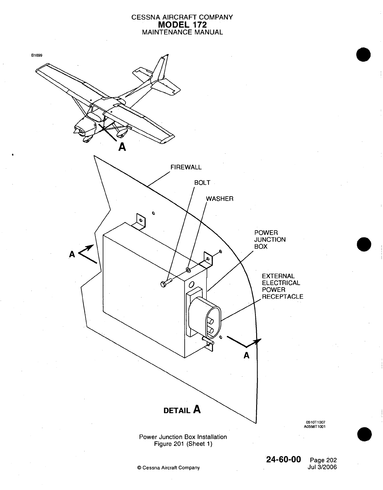
CESSNA
AIRCRAFT
COMPANY
MODEL
172
MAINTENANCE
MANUAL
B1
BOLT
POWER
JUNCTION
BOX
EXTERNAL
ELECTRICAL
POWER
A
DETAIL
A
Power
Junction
Box
Installation
Figure
201
(Sheet
1)
24-60-00
© Cessna
Aircraft
Company
A
051
0T1007
A0558T1001
Page
202
Jul 3/2006
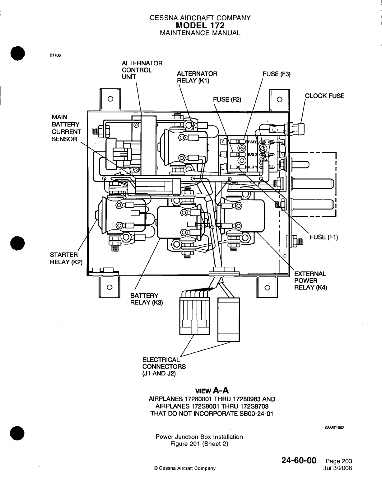
CESSNA
AIRCRAFT
COMPANY
MODEL
172
MAINTENANCE
MANUAL
B1700
MAIN
BATTERY
CURRENT
SENSOR
/
STARTER
RELAY
(K2
BATTERY
RELAY
(K3)
fff
ffI
I I\\
ELECTRICAL
CONNECTORS
(J1
AND
J2)
VIEW
A-A
AIRPLANES
17280001 THRU
17280983
AND
AIRPLANES
172S8001
THRU
172S8703
THAT
DO
NOT INCORPORATE
SB00-24-01
0558T1002
Power
Junction
Box
Installation
Figure
201
(Sheet
2)
24-60-00
©
Cessna
Aircraft Company
Page
203
Jul
3/2006
SE
-----
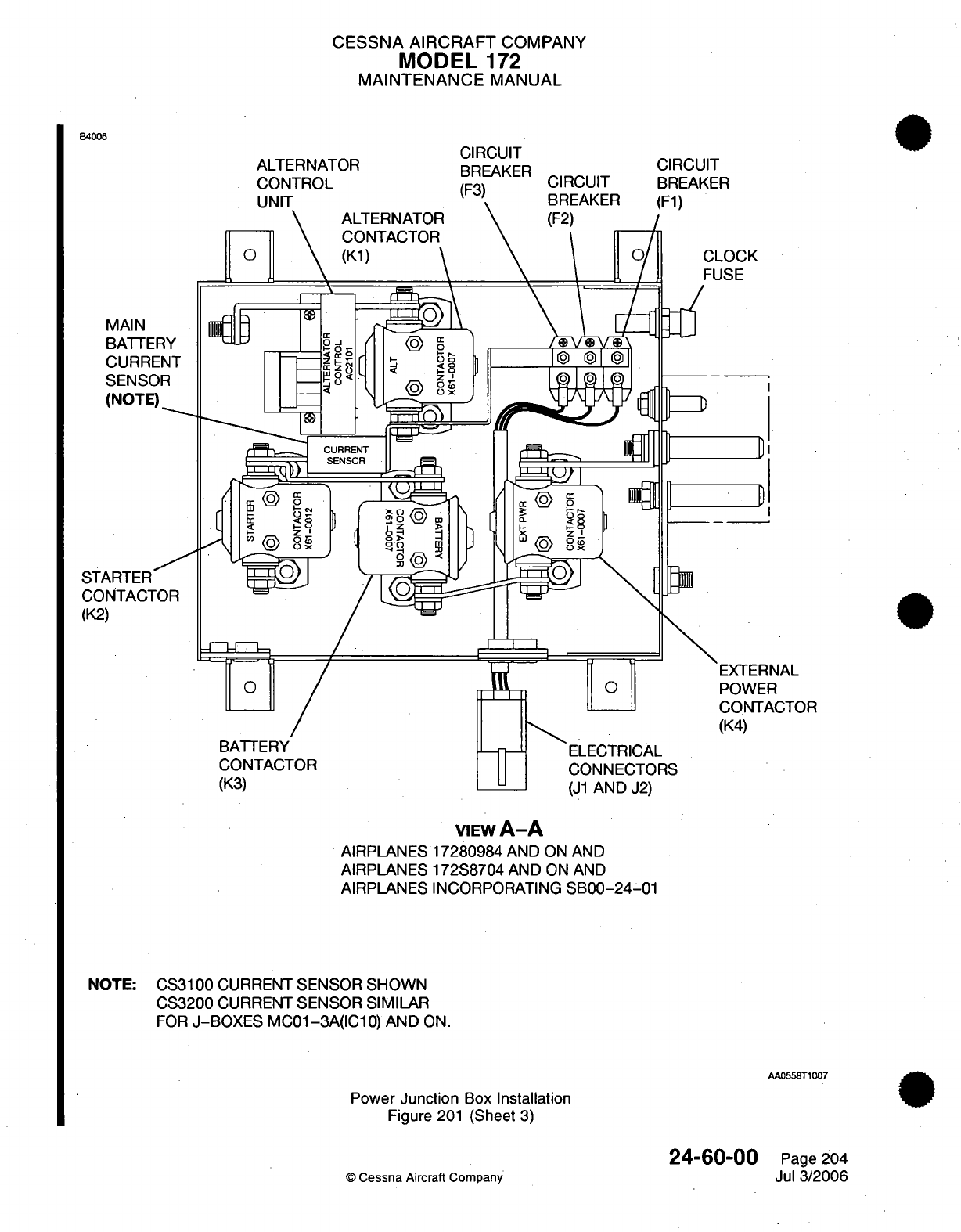
CESSNA
AIRCRAFT
COMPANY
MODEL
172
MAINTENANCE
MANUAL
B4006
ALTERNATOR
-^ tK1-T Ir-
0
CIRCUIT
BREAKER
r'lrli 11T
ALTERNATOR
CONTACTOR
(K)
\
CIRCUIT
DD-
A
ICtD
CLOCK
FUSE
[X
[-l
E0
VIEW
A-A
AIRPLANES
17280984
AND
ON
AND
AIRPLANES
172S8704
AND
ON
AND
AIRPLANES
INCORPORATING
SB00-24-01
NOTE:
CS3100
CURRENT
SENSOR
SHOWN
CS3200
CURRENT
SENSOR
SIMILAR
FOR
J-BOXES
MC01-3A(IC10)
AND
ON.
AA0558T1007
Power
Junction
Box
Installation
Figure
201
(Sheet
3)
24-60-00
©
Cessna
Aircraft Company
ST/
CO
(K2
D
D
)R
Page
204
Jul
3/2006
,
.v/
kj
I /-luv1
Jo.)
CESSNA
AIRCRAFT
COMPANY
MODEL
172
MAINTENANCE
MANUAL
ALTERNATOR
CONTROL
UNIT
-
MAINTENANCE
PRACTICES
1.
General
A.
The
Alternator
Control
Unit
(ACU)
is
found
inside the
power
junction
box,
also referred
to
as
a
Master
Control
Unit
(MCU)
or
J-Box.
The
alternator
system
includes
the
ACU,
Alternator
Contactor,
and
alternator field circuit.
The
ACU
functions
are
as
follows:
(1)
Alternator
Voltage
Regulation
-
The
ACU
controls
the
alternator
field
circuit
to
supply
a
main
bus
voltage
of
approximately
28.5
volts.
(2)
Low
Voltage
Annunciation
-
The
ACU
monitors
the
main
bus
voltage
in
the
power
junction
box
and
supplies
an
output
for
low
voltage
(less
than
24.5
+0.35
or
-0.35
volts)
for
the
annunciation.
(3)
Over-voltage
Protection
-
The
ACU
monitors the
main
bus
voltage
in
the
power
junction
box
and
disengages
the
aircraft
ALT FIELD
circuit
breaker.
This
removes the
power
from
the
alternator
system
if
there
is
an
over-voltage condition
greater
than
31.75
+0.5
or
-0.5
volts.
(4)
Reverse
Alternator
Current
Protection
-
The
ACU
monitors the
alternator
output
current
and
disengages
the
aircraft
ALT
FIELD
circuit
breaker.
This
removes the
power
from the
alternator
system
if
there
is
a
reverse
alternator
current.
(5)
Excess
Field
Current
Protection
-
The
ACU
monitors
the
alternator
field
current
and
disengages
the
aircraft
ALT
FIELD
circuit
breaker.
This
removes
the
power
from
the
alternator
system
if
there
is
an
excessive
field
current.
2.
Alternator Control
Unit
Removal/Installation
A.
Remove
the Alternator
Control
Unit.
Refer
to
Power
Junction
Box
-
Maintenance
Practices,
Component
Removal/Installation.
B.
Install the
Alternator Control
Unit.
Refer
to
Power
Junction
Box
-
Maintenance
Practices,
Component
Removal/Installation.
3.
Over-voltage
Protection
Circuit
Test
A.
General.
(1)
The
ACU
Over-voltage
Protection
Circuit
must
be
tested
in
accordance
with the time limits
in
Chapter
5,
Inspection
Time Limits.
Use
one
of
the
two
procedures that
follow
to
do
the
test
of
the
Over-voltage
Protection
Circuit.
The
recommended
procedure
uses
the
Lamar
TE04
MCU
Test
Set.
The
external
battery procedure
can
be
used
if a
TE04
test
set
is
not
available.
B.
Over-voltage
Protection
Circuit
Test
with
the Lamar
TE04
MCU
Test
Set
(1)
Use
a
Lamar
TE04
MCU
Test
Set and
do
steps
4.2,
4.3.A,
4.3.B,
and
4.3.1
in
the
Lamar's
TE04
MCU
Test Set
instructions
LI-0021(refer
to
Electrical
Power
-
General,
Tools,
Equipment,
and
Materials).
(2) If
the
ACU
TRIP
indicator
on
the
TE04
MCU Test
Set
does
not
illuminate
in
step
4.3.1,
the
Over-
voltage
Protection Circuit
is
not
operational.
(a)
Replace
the
ACU.
(b)
Do
this
test
again.
(3) If
the
ACU
TRIP
indicator
does illuminate
in
step
4.3.1,
the
Over-voltage
Protection
Circuit
is
operational.
(a)
Complete
the
Lamar
procedure
4.3.1.
(b)
Remove
the
TE04
MCU Test
Set.
(c)
Continue with
step
D in
this
section.
24-60-01
Page
201
©
Cessna
Aircraft
Company
Jul
3/2006
CESSNA
AIRCRAFT
COMPANY
MODEL
172
MAINTENANCE
MANUAL
C.
Over-voltage Protection
Circuit
Test
with
External
Batteries
NOTE:
It
is
necessary
to
use
two
general
non-rechargeable
9
volt
batteries
in
new
condition
to
apply
a
temporary over-voltage
condition
on
the
ACU
Sense
wire.
A
locally fabricated
battery test
harness
is
also
necessary.
The
test
harness uses
two
9-volt
snap
connectors
and
two
insulated
alligator
clips.
(Refer to
Figure
201.)
These
components
are
available
at
most
battery supply
stores.
For
ground
safety
reasons,
only
general
household
9
volt
batteries which
have
a
relatively
low
ampere
rating
are
used.
(1)
Make sure
the
BAT
MASTER,
ALT
MASTER,
AVIONICS master,
and
all
electrical
system
switches
are
in
the
OFF
position.
(2)
Remove
the upper
cowl.
Refer
to
Chapter
71,
Cowls
-
Maintenance Practices.
(3)
Disconnect
the
airplane
24
volt
battery
cables
from
the battery.
Refer
to
Battery
-
Maintenance
Practices.
(4)
Remove
the
cover
from
the
power
junction
box.
(5)
Find
the
orange
ACU
sense
wire
attached
to
the
upper
Battery
Contactor
terminal
inside
the
power
junction
box.
Refer
to
Figure
201.
(a)
Remove
the
nut, washer,
and
orange
ACU
sense
wire
ring
terminal
from
the
upper Battery
Contactor terminal.
NOTE:
The
ACU
sense
wire is
connected
to Pin
B in
the
ACU
connector.
(6)
Connect the
battery
test
harness
in
series
with
the
orange
ACU
Sense wire
and the upper
Battery
Contactor terminal
as shown
in
Figure
201.
(a)
Use
tape or
an
equivalent
as
electrical
insulation
on
the
bare
sense
wire
ring
terminal.
NOTE:
This
will
help
prevent accidental electrical
shorts.
(7)
Connect two
new
9-volt
batteries
to
the
harness.
(a)
Put
the
9
volt
batteries
in
position
below the
power
junction
box
as
shown
in
Figure
201.
(8)
Connect the
airplane
24
volt
battery
cables
to
the
battery.
Refer
to
Battery
-
Maintenance
Practices.
(9)
Make
sure
the
ALT FIELD
circuit
breaker
on
the
pilot's
circuit breaker panel
is
engaged.
(10)
Put
the
BAT
and
ALT MASTER
switches
to
the
ON
position
for
5
seconds
and
then
return to
the
OFF
position.
(a)
Make sure
the
ALT
Field
circuit
breaker
opens
or
the
cap
pops
out.
(b) If
the
circuit
breaker
opens, the
Over-voltage
Protection
circuit
is
operational.
Continue
with
step
11.
(c) If
the
circuit
breaker
does
not
open,
do
step
10
a
second time.
1
Use
a
digital voltmeter
and
measure
the
voltage
between
the
orange
ACU
sense
wire
ring
terminal
and
the
power
junction
box ground
stud.
(d) If
the
circuit
breaker does
not
open
the
second
time
and the
ACU
sense
voltage
is
greater
than
34
volts,
the
Over-voltage
Protection
Circuit
is
not
operational.
1
Replace
the
ACU.
(e)
Do
step
10
again
after
a
new
ACU
is
installed.
(11)
Engage
the
ALT
Field
circuit
breaker.
(12)
Disconnect
the
airplane
24
volt
battery
cables
from
the
battery.
Refer to
Battery
-
Maintenance
Practices.
(13)
Disconnect
the
two
9-volt
batteries
from the
harness.
(14)
Disconnect
the battery test
harness.
(15)
Install
the
nut,
washer,
and orange
ACU
sense wire
ring
terminal
to
the
upper Battery
Contactor
terminal.
(a)
Torque
the
terminal
nut
from 35
to
45
inch-pounds.
(16)
Install
the
cover
on
the
power
junction
box.
(17)
Connect the
airplane
24
volt
battery
cables
to
the battery.
Refer to
Battery
-
Maintenance
Practices.
(18)
Install
the
upper
cowl.
Refer
to
Chapter
71,
Cowls
-
Maintenance Practices.
(19)
Continue
with
step
D in
this
section.
24-60-01
Page
202
©
Cessna
Aircraft Company
Jul
3/2006
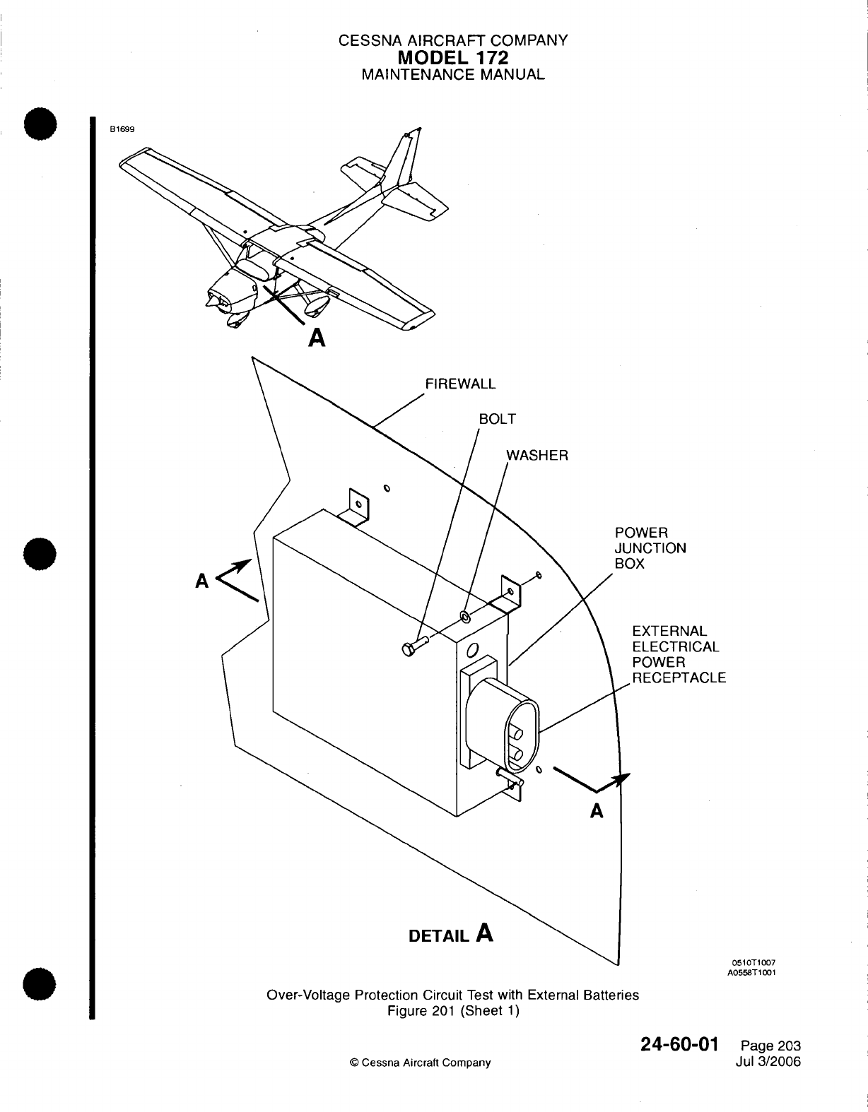
CESSNA
AIRCRAFT
COMPANY
MODEL
172
MAINTENANCE
MANUAL
El
WER
NCTION
X
EXTERNAL
ELECTRICAL
POWER
RECEPTACLE
0510T1007
AO55BT1001
Over-Voltage
Protection
Circuit
Test
with
External
Batteries
Figure
201
(Sheet
1)
24-60-01
©
Cessna
Aircraft
Company
A
Page
203
Jul
3/2006
rower
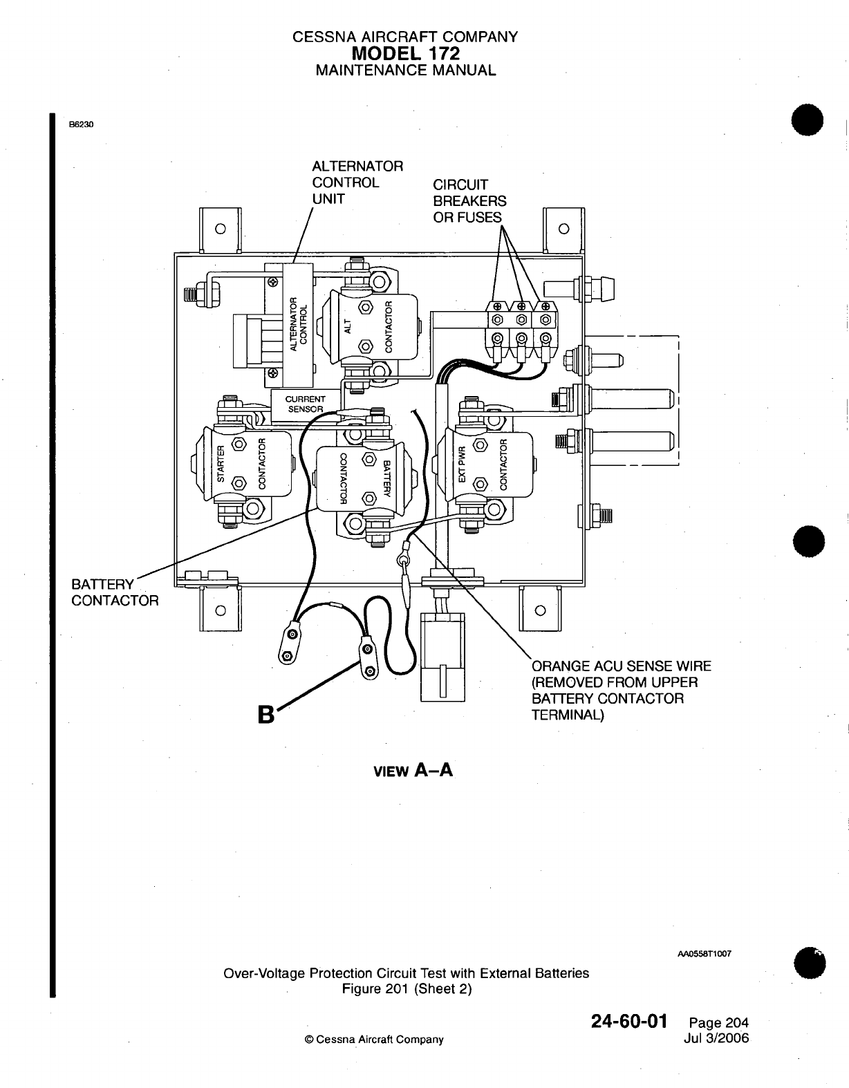
CESSNA
AIRCRAFT
COMPANY
MODEL
172
MAINTENANCE
MANUAL
B6230
ALTERNATOR
CONTROL
UNIT CIRCUIT
BREAKERS
Fl
Fl
ACU
SENSE
WIRE
)
FROM UPPER
CONTACTOR
I
LHMINAL)
VIEW
A-A
AA0558T1007
Over-Voltage Protection
Circuit
Test
with
External Batteries
Figure
201
(Sheet
2)
24-60-01
©
Cessna
Aircraft
Company
0
Page
204
Jul
3/2006
G
yq]
(f]
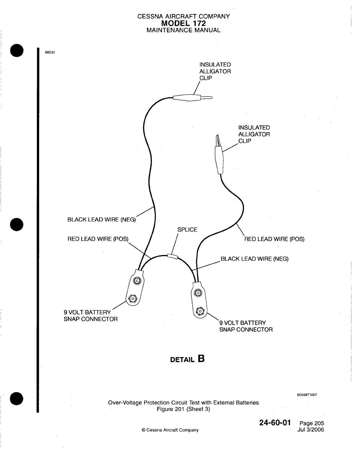
CESSNA
AIRCRAFT
COMPANY
MODEL
172
MAINTENANCE
MANUAL
B6231
INSULATED
ALLIGATOR
CLIP
INSULATED
Al
I I
A-Tl-r,
BLACK
LEAD
WIl
RED LEAD
WIRE
9
VOLT
BATTERY
SNAP
CNNNFCTC
SPLICE
'AI
U
LEAD
WIRE
(POS)
LEAD
WIRE
(NEG)
9
VOLT
BATTERY
SNAP
CONNECTOR
DETAIL
B
B0558T1007
Over-Voltage
Protection
Circuit
Test
with External
Batteries
Figure
201
(Sheet
3)
24-60-01
©
Cessna
Aircraft
Company
Page
205
Jul
3/2006
CESSNA
AIRCRAFT
COMPANY
MODEL
172
MAINTENANCE
MANUAL
D.
Make
sure
of the
correct
ACU
functions
immediately after
the
next engine
start.
(1)
Start
the
engine
in
accordance
with
the
Pilot's
Operating
Handbook, Starting
Engine
(Using
Battery)
procedure but make
sure
the
ALT
MASTER
switch
is in
the OFF
position.
(2)
After
the engine
start
and
oil
pressure
check,
set
the engine
RPM to idle.
(3)
Make
sure
the Low
Voltage
annunciator
is
On.
(4)
While
you
monitor
the
aircraft
voltmeter,
set
the
ALT
MASTER
switch
to
the
ON
position.
(a)
If
the
voltmeter
shows
more than 29
volts, immediately
set
the
ALT
MASTER
switch
to
the
OFF
position
and
stop
the
engine.
NOTE:
The
ACU
regulation
circuit
is
non
operational.
The
ALT
FLD
circuit
breaker
should
open
if
the
voltage
is
more
than
32
volts.
1
Replace
the
ACU
and
do
the
Over-voltage Protection
Test
again.
(b) If
the
voltmeter
shows less
than 29
volts, slowly increase
the
throttle
to
an
engine
speed
of
1300 RPM.
(5) If
the
voltmeter
shows
approximately
28
volts
at
an
engine
speed
of
1300
RPM
the
ACU
regulation
circuit
is
operational.
(6)
Make sure
the
battery charge
is
shown
on
the
aircraft
battery
ammeter.
(7)
Make sure
the LOW VOLTS
annunciator
is
off.
4.
Alternator Control
Unit
Troubleshooting
A.
Complete
the
Alternator Control
Unit
Troubleshooting.
(1)
The
Alternator Control
Unit
troubleshooting
is
done
with
the Lamar
TE04
MCU
Test
Set.
Use
the
LI-0021
instructions.
Refer
to
Electrical
Power
-
General,
Tools,
Equipment,
and
Materials.
24-60-01
Page
206
©
Cessna
Aircraft
Company
Jul 3/2006
CESSNA
AIRCRAFT
COMPANY
MODEL
172
MAINTENANCE
MANUAL
CIRCUIT
BREAKER
-
MAINTENANCE
PRACTICES
1.
General
A.
On
airplanes
without
Garmin G1000,
the
circuit breaker
panel
is
on
the
left
lower
instrument
panel,
below
the
pilot's control
wheel.
The
circuit
breaker
panel
has
electrical
circuit
breakers,
the MAGNETO
switches,
the
ALT BAT
MASTER
switch, the
AVIONICS
MASTER
switch
and
panel
lighting
controls.
B.
On
airplanes
with
Garmin
G1000,
the
circuit
breaker
panel
is
on
the
left
lower
instrument
panel,
below
the
pilot's
control
wheel.
The
circuit breaker
panel
has
electrical circuit
breakers
and
the MAGNETO
switches.
2.
Circuit
Breaker
Removal/Installation (Airplanes
without
Garmin G1000)
A.
Remove
the
Circuit Breaker
(Refer
to
Figure
201).
(1)
Remove
the
top
cowl.
Refer
to
Chapter
71,
Cowls
-
Maintenance
Practices.
(2)
Disconnect
the battery
cables. Refer
to
Battery
-
Maintenance
Practices.
(3)
Remove
the
screws
that
attach the
circuit
breaker
panel
to
the lower
instrument panel.
(4)
Remove
the screws
that
attach
the
circuit
breaker
cover
to
the
panel.
(5)
Put
a
label
on
the
applicable circuit
breaker wires.
(6)
Disconnect
the
applicable circuit
breaker
wires.
(7)
Remove
the
nut and
washer
that
attach the
circuit
breaker
to
the
circuit breaker
panel.
(8)
Remove
the
circuit
breaker.
B.
Install the
Circuit Breaker (Refer
to
Figure
201).
(1)
Remove
the
labels
and
attach
the
wires
to the
applicable
circuit
breakers.
(2)
Put
the
circuit
breaker
in
the
circuit
breaker
panel
and
attach with
the
washer
and
nut.
(3)
Put
the
circuit
breaker
cover
in
position
on
the
back
of
the panel
and
attach
with
the screws.
(4)
Put
the circuit
breaker
panel
in
position
on
the
lower
instrument panel
and
attach
with
the screws.
(5)
Connect
the battery
cables.
Refer
to
Battery
-
Maintenance
Practices.
(6)
Install
the
top
cowl.
Refer
to
Chapter
71,
Cowls
-
Maintenance Practices.
3.
Circuit
Breaker
Removal/Installation (Airplanes
with
Garmin
G1000)
A.
Remove
the
Circuit
Breaker
(Refer
to
Figure
202).
(1)
Remove
the
top
cowl.
Refer
to
Chapter
71,
Cowls
-
Maintenance
Practices.
(2)
Disconnect
the battery
cables. Refer
to
Battery
-
Maintenance
Practices.
(3)
Remove
the screws
that
attach the
circuit
breaker
panel
to
the
lower
instrument
panel.
(4)
Cut
the
tie
straps
from
the
applicable circuit
breaker
cover
and remove the
cover.
(5)
Put
a
label
on
the
applicable circuit
breaker wires.
(6)
Disconnect
the
applicable circuit
breaker
wires.
(7)
Remove
the
screws
and
washers
that
attach the
bus
bar
to
the
circuit
breakers.
(8)
Remove
the
bus
bar.
(9)
Remove
the
nut
and
washer
that
attach the
circuit
breaker
to
the
circuit
breaker
panel.
(10)
Remove
the
circuit
breaker.
B.
Install
the
Circuit
Breaker (Refer
to
Figure
202).
(1)
Attach
the
circuit breaker
to the
circuit
breaker
panel
with
the nut
and
washer.
(2)
Attach
the
bus
bar
to
the
circuit
breakers
with
the
screws
and
washers.
(3)
Remove
the
labels
and
connect the applicable
wires
to
the
circuit
breaker.
(4)
Put
the
tie straps around the
circuit
breaker
panel
cover
and
through
the
0.20
inch
(5.08
mm)
diameter
holes
to
attach
the
cover.
(a)
For
the inboard
cover,
put
one
tie
strap
each
between
circuit
breakers
H1034
and
H1035
and between
circuit
breakers
H1036
and
H1037.
(b)
For
the
outboard
cover,
put
one
tie
strap
each between
circuit
breakers
H1054
and
H1058
and between
circuit
breakers
H1055
and
H1057.
(5)
Attach
the
circuit breaker
panel
to the
lower
instrument
panel
with
the
screws.
(6)
Connect
the battery
cables. Refer
to
Battery
-
Maintenance
Practices.
(7)
Install
the
top
cowl.
Refer
to
Chapter
71,
Cowls
-
Maintenance Practices.
24-61-00
Page
201
©
Cessna Aircraft Company
Jul
1/2005
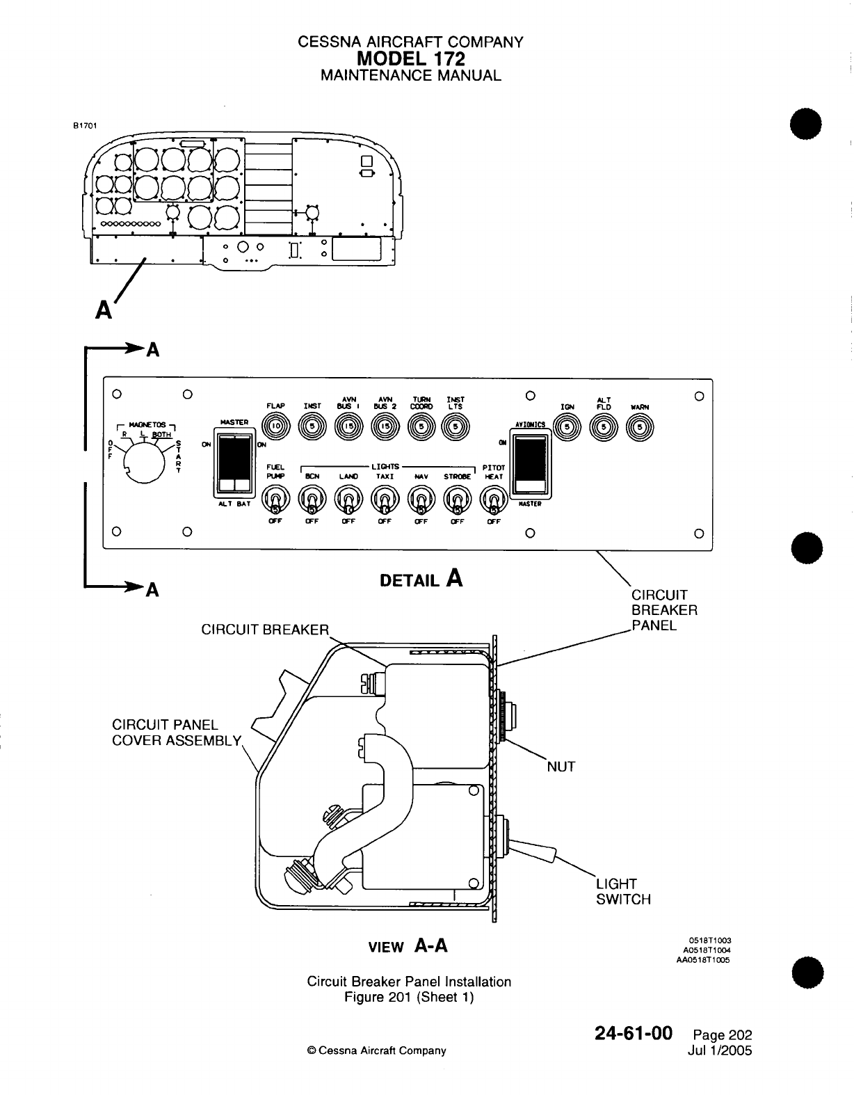
CESSNA
AIRCRAFT
COMPANY
MODEL
172
MAINTENANCE
MANUAL
81701
A
AVN AVN TURN
INST
FLAP
INST
BUS I BUS 2 COOR
LTS
-"^
-
i
-
0
^iMh
-
\ : ~0 ^i\^\(
N^
FLEL
PUP BCN
OFF
LAND
OFF
LIGHTS
TAXI
OFF
ALT BAT
OFF
AV
STROBE
Fv
sOFF
OFF OFF
0 ALT
IGN FLD WARN
Avionic
t~i^
/ /f~
PITOT
HEAT
OFF
0
DETAIL
A
CIRCUIT
BREAKER
,
A
..
rANtL
N,
CIRCUIT
PANEL
COVER
ASSEMBLY,
0
I
VIEW
A-A
LIGHT
*'
SWITCH
0518T1003
A0518T1004
AA0518T
1005
Circuit
Breaker
Panel
Installation
Figure
201
(Sheet
1)
©
Cessna
Aircraft
Company
24-61-00
Page
202
Jul
1/2005
0 0
r-
MAOWTOS
--
R L TH
F
T
R
V'
0 0
0
0
CIRCL
w w
%9
I
^
ON
%F
%v
%F %F
%F
%F
ON
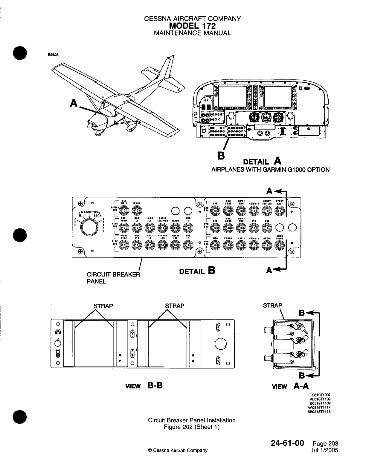
CESSNA
AIRCRAFT
COMPANY
MODEL
172
MAINTENANCE
MANUAL
DETAIL
A
AIRPLANES
WITH
GARMIN
G1000
OPTION
A
,^ ALT ^
...
11 T ",l S"T lBB T
T
lu
0
00 o 0@
0
0.11 nl0
IP111
AI
1 IAW
1*1 1
I
I IN
EL A1 ADTS
i
'
tL ,r1 ....
T IS
L I
SPn
iA CAM
,
I
AUDI PILIT
1,-1 °
''
0 i »> LUTI
1
-.
f® 1"/®~
/
CIRCUIT
BREAKER
PANEL
STRAP
/%
DETAIL
B
STRAP
0
M4
0
0
o
0
9
o
VIEW
B-B
VIEW
A-A
0510T1007
A051Tr1109
B0518T1109
AA051
Tr1114
BB0518T1115
Circuit Breaker
Panel
Installation
Figure
202
(Sheet
1)
©
Cessna Aircraft Company
24-61-00
Page
203
Jul
1/2005
a
r-MAb NETO S-
R L BOTH
T
a
0
6
o
,-^
.
IS
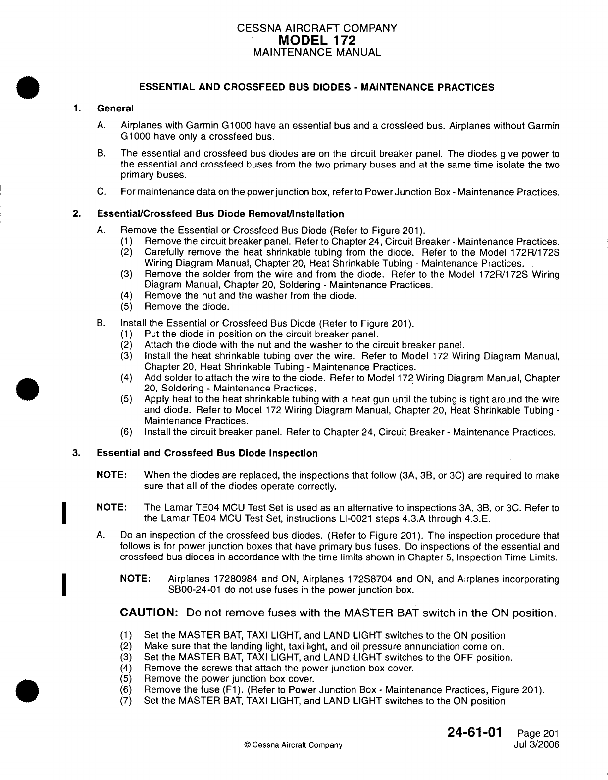
CESSNA
AIRCRAFT
COMPANY
MODEL
172
MAINTENANCE
MANUAL
ESSENTIAL
AND
CROSSFEED
BUS
DIODES
-
MAINTENANCE
PRACTICES
1.
General
A.
Airplanes
with
Garmin
G1000
have
an
essential
bus
and
a
crossfeed
bus.
Airplanes without
Garmin
G1000
have
only
a
crossfeed
bus.
B.
The
essential
and
crossfeed
bus
diodes
are
on
the
circuit
breaker panel.
The
diodes
give
power
to
the
essential
and
crossfeed
buses
from
the
two
primary
buses
and at
the
same
time
isolate
the
two
primary
buses.
C.
For
maintenance data
on
the power
junction
box,
refer
to
Power
Junction
Box
-
Maintenance
Practices.
2.
Essential/Crossfeed
Bus
Diode
Removal/Installation
A.
Remove
the
Essential
or
Crossfeed
Bus Diode
(Refer
to
Figure
201).
(1)
Remove the
circuit
breaker
panel.
Refer to
Chapter
24,
Circuit
Breaker
-
Maintenance Practices.
(2)
Carefully
remove
the
heat
shrinkable
tubing
from
the
diode.
Refer
to
the
Model
172R/172S
Wiring
Diagram
Manual,
Chapter
20,
Heat
Shrinkable
Tubing
-
Maintenance Practices.
(3)
Remove
the
solder
from
the
wire
and from the
diode. Refer
to
the
Model
172R/172S
Wiring
Diagram
Manual, Chapter
20,
Soldering
-
Maintenance
Practices.
(4)
Remove
the nut
and
the
washer
from
the
diode.
(5)
Remove
the
diode.
B.
Install the
Essential
or
Crossfeed
Bus
Diode
(Refer
to Figure
201).
(1)
Put
the
diode
in
position
on the
circuit
breaker
panel.
(2)
Attach
the diode
with
the
nut
and
the
washer
to
the
circuit
breaker
panel.
(3)
Install
the
heat
shrinkable
tubing
over
the wire.
Refer
to
Model
172
Wiring
Diagram
Manual,
Chapter
20,
Heat
Shrinkable
Tubing
-
Maintenance
Practices.
(4)
Add
solder
to
attach
the
wire
to
the
diode.
Refer
to
Model
172
Wiring
Diagram
Manual, Chapter
20,
Soldering
-
Maintenance
Practices.
(5)
Apply
heat
to
the
heat
shrinkable
tubing
with
a
heat
gun
until
the
tubing
is
tight
around
the
wire
and
diode.
Refer
to
Model
172
Wiring
Diagram
Manual,
Chapter
20,
Heat
Shrinkable
Tubing
-
Maintenance
Practices.
(6)
Install the
circuit
breaker
panel. Refer
to
Chapter
24,
Circuit
Breaker
-
Maintenance Practices.
3.
Essential
and
Crossfeed
Bus
Diode
Inspection
NOTE:
When
the
diodes
are
replaced,
the
inspections
that
follow
(3A,
3B,
or
3C)
are
required
to
make
sure
that
all
of
the diodes
operate
correctly.
NOTE:
The
Lamar TE04
MCU
Test
Set
is
used as
an
alternative
to
inspections
3A,
3B,
or
3C.
Refer
to
the
Lamar
TE04
MCU
Test Set,
instructions
LI-0021
steps 4.3.A
through 4.3.E.
A.
Do
an
inspection
of
the
crossfeed
bus
diodes.
(Refer
to
Figure
201). The
inspection
procedure that
follows
is
for
power
junction
boxes that
have
primary
bus
fuses.
Do
inspections
of the
essential
and
crossfeed
bus
diodes
in
accordance
with
the
time limits
shown
in
Chapter
5,
Inspection
Time Limits.
NOTE:
Airplanes
17280984
and
ON,
Airplanes
172S8704
and
ON,
and
Airplanes
incorporating
SB00-24-01
do
not
use
fuses
in
the
power
junction
box.
CAUTION:
Do
not
remove
fuses
with
the
MASTER
BAT
switch
in
the
ON
position.
(1)
Set
the
MASTER
BAT,
TAXI
LIGHT,
and
LAND
LIGHT
switches
to the
ON
position.
(2)
Make
sure
that
the
landing
light,
taxi
light, and
oil
pressure
annunciation
come
on.
(3)
Set
the
MASTER
BAT,
TAXI
LIGHT,
and LAND
LIGHT
switches
to the
OFF
position.
(4)
Remove the
screws
that
attach
the
power
junction
box
cover.
(5)
Remove the
power
junction
box
cover.
(6)
Remove the
fuse
(F1).
(Refer
to
Power
Junction
Box
-
Maintenance
Practices,
Figure
201).
(7)
Set
the
MASTER
BAT,
TAXI
LIGHT,
and LAND
LIGHT
switches
to
the ON
position.
24-61-01
Page
201
©
Cessna
Aircraft
Company
Jul 3/2006
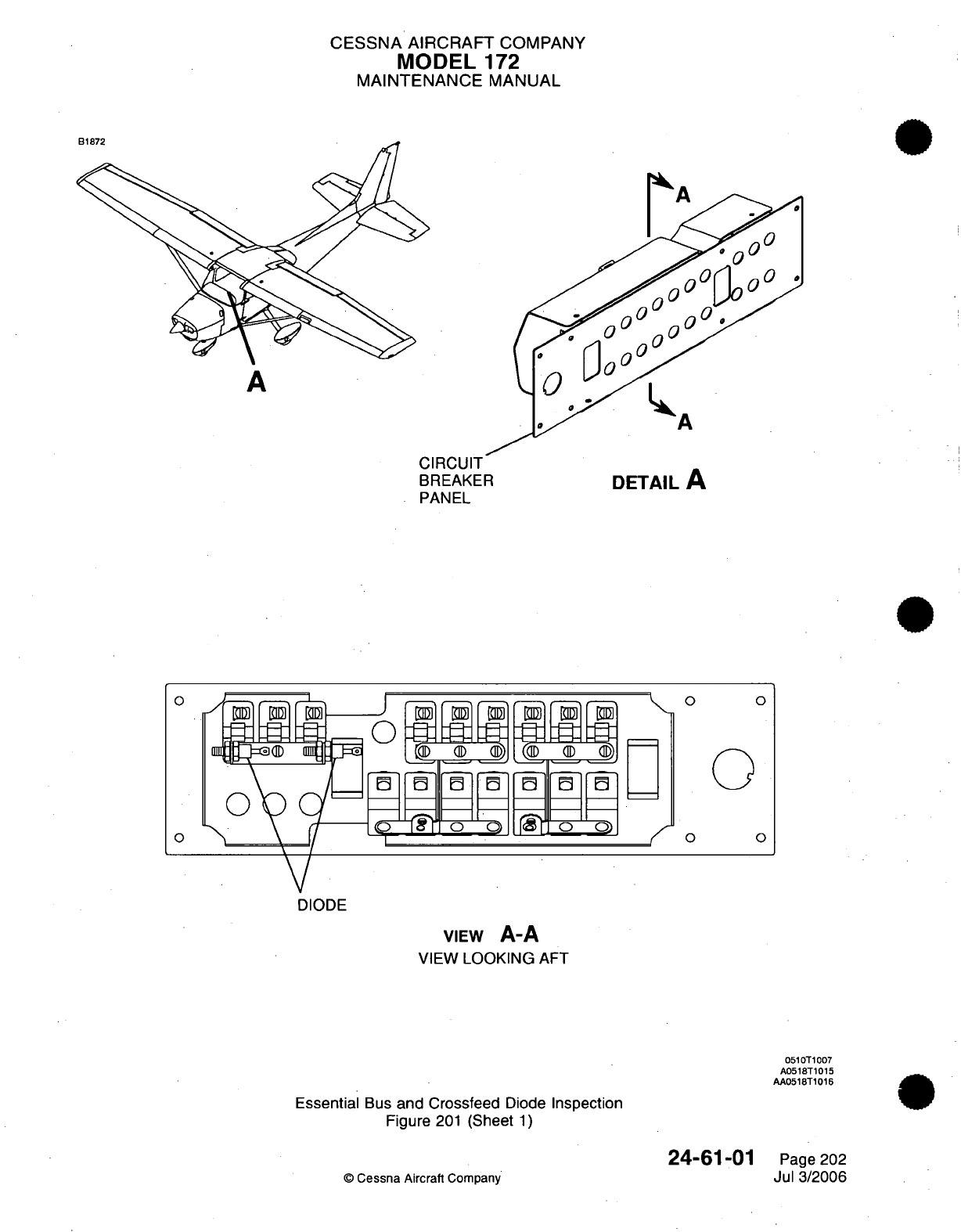
CESSNA
AIRCRAFT
COMPANY
MODEL
172
MAINTENANCE
MANUAL
A
HA
CIRCUIT
BREAKER
PANEL
DETAIL
A
-
O
f
DIODE
VIEW
A-A
VIEW
LOOKING
AFT
0510T1007
A0518T1015
AA0518T1016
Essential
Bus
and Crossfeed
Diode
Inspection
Figure
201
(Sheet
1)
24-61-01
©
Cessna
Aircraft
Company
0
0
0
0
0
0o
o0
Page 202
Jul
3/2006
1\
r
Q"
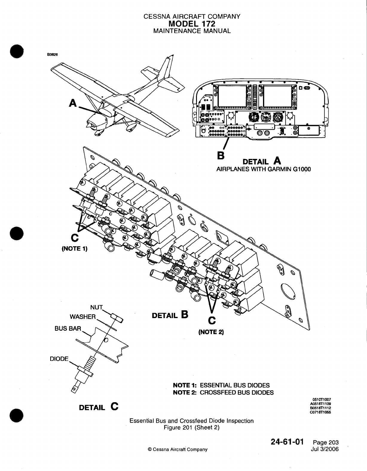
CESSNA
AIRCRAFT
COMPANY
MODEL
172
MAINTENANCE
MANUAL
(Ni
DETAIL
B
BUS
(IN
I
-
Z)
DIODE
NOTE
1: ESSENTIAL
BUS
DIODES
NOTE
2: CROSSFEED
BUS
DIODES
0510T1007
AO51
8T1109
B051
81112
C0718T1055
DETAIL
C
Essential
Bus
and
Crossfeed
Diode
Inspection
Figure
201
(Sheet
2)
©
Cessna Aircraft
Company
24-61-01
Page
203
Jul
3/2006
CESSNA
AIRCRAFT
COMPANY
MODEL
172
MAINTENANCE
MANUAL
(8)
Make
sure
that the
landing
light
and
oil
pressure
annunciation
come
on.
If
the
taxi
light
comes
on or
the
oil
pressure
annunciation
does
not come
on,
do
a
test
of
the
crossfeed
bus diodes
with
the diode
test
function
of
a
digital
multimeter
to
find
which
diodes
you
must
replace.
Refer
to
Essential
and
Crossfeed
Bus
Diode
Multimeter
Test.
(9)
Set
the
MASTER
BAT,
TAXI
LIGHT, and
LAND
LIGHT
switches
to the
OFF
position.
(10)
Install
the fuse
(F1)
in
the
power
junction
box.
If
the
fuse
is
pitted, arced,
or
does
not
fit
tightly
into
the
fuse receptacle, replace
the
fuse
with
one
of
the
same
type.
Do
not
replace
the
fuse
with
thinner
blades.
(11)
Remove
the fuse
(F2).
(Refer
to
Power
Junction
Box
-
Maintenance
Practices,
Figure
201).
(12)
Set
the
MASTER
BAT,
TAXI
LIGHT, and
LAND
LIGHT
switches
to
the
ON
position.
(13)
Make sure that the
taxi light and
oil
pressure
annunciation
come
on.
If
the
landing
light
comes
on or
the
oil
pressure
annunciation
does
not
come
on,
do
a
test
of
the
crossfeed
bus diodes with
the diode
test
function
of
a
digital multimeter
to
find
which
diodes
must
be
replaced.
Refer
to
Essential
and
Crossfeed
Bus
Diode
Multimeter
Test.
(14)
Set
the
MASTER
BAT,
TAXI
LIGHT,
and
LAND
LIGHT
switches
to the
OFF
position.
(15)
Install
the
fuse
(F2)
in
the
power
junction
box.
If
the
fuse
is
pitted,
arced,
or
does
not
fit
tightly
into
the
fuse
receptacle,
replace
the
fuse
with
one
of
the
same
type.
Do
not
replace
the
fuse
with
thinner
blades.
(16)
If
the
diodes
are
replaced,
do
this
test
again
to
make
sure
that
all
diodes
operate
correctly.
(17)
Install
the
junction
box
cover
with
the
screws.
B.
Do
an
inspection
of
the
crossfeed
bus
diodes.
(Refer
to
Figure 201).
The
inspection procedure
that
follows
is
for
power
junction
boxes that
have
primary
bus
circuit
breakers.
NOTE:
The
inspection
procedure that
follows
is
for
airplanes without
Garmin
G1000
avionics.
CAUTION:
Do
not
remove
bus wires
from
the
circuit
breakers
with
MASTER
BAT
switch
in
the
ON
position.
(1)
Set
the
MASTER
BAT,
TAXI
LIGHT,
and
LAND
LIGHT
switches
to
the
ON
position.
(2)
Make sure
that the
landing light,
taxi light, and
oil
pressure
annunciation
come
on.
(3)
Set
the MASTER
BAT,
TAXI
LIGHT,
and
LAND
LIGHT
switches
to
the
OFF
position.
(4)
Remove
the
screws
that
attach
the
power
junction
box
cover.
(5)
Remove
the power
junction
box
cover.
(6)
Remove
the
hex
nut and
lock
washer
that connect
the bus
wire
to
the
circuit
breaker
(F1).
(Refer
to
Power
Junction
Box
-
Maintenance
Practices,
Figure
201).
(7)
Remove
the
wire
terminal
from
the
F1
circuit
breaker stud that
has
a
label
of
AUX
and
isolate
the
end
of
the
bus wire.
(8)
Set
the MASTER
BAT,
TAXI
LIGHT,
and
LAND
LIGHT
switches
to
the
ON
position.
(9)
Make sure
that
the
landing
light
and
oil
pressure
annunciation
come
on.
If
the
taxi
light
comes
on, or
the
oil
pressure
annunciation
does
not
come
on,
do
a
test
of
the
crossfeed
bus
diodes
with
the
diode
test
function
of
a
digital
multimeter
to
find
which
diodes
must
be
replaced.
Refer
to
Essential
and
Crossfeed
Bus Diode
Multimeter
Test.
(10)
Set
the MASTER
BAT,
TAXI
LIGHT,
and
LAND
LIGHT
switches
to the
OFF
position.
(11)
Install
the bus
wire
to
the
circuit
breaker
(F1)
terminal.
Use
the
same
hex
nut
and
washer
that
were removed.
(12)
Torque
the nut
to
20
inch-pounds
to
25
inch-pounds
(2.3
N-m
to 2.8
N-m).
(13)
Remove
the
hex
nut and
lock
washer that connect
the bus
wire
to
the
circuit
breaker
(F2).
(Refer
to
Power
Junction
Box
-
Maintenance
Practices,
Figure
201).
(14)
Remove
the
wire
terminal
from
the
F2
circuit
breaker
stud with
the label
of
AUX
and
isolate
the
end
of
the
bus
wire.
(15)
Set
the MASTER
BAT,
TAXI
LIGHT,
and
LAND
LIGHT
switches
to
the
ON
position.
(16)
Make
sure that
the
taxi
light and
oil
pressure
annunciation
come
on.
If
the
landing
light
comes
on or
the
oil
pressure
annunciation
does
not
come
on, do
a
test
of
the
crossfeed
bus diodes with
the
diode
test
function
of
a
digital multimeter
to
find which
diodes
you
must
replace.
Refer
to
Essential
and
Crossfeed
Bus
Diode
Multimeter
Test.
(17)
Set
the MASTER
BAT,
TAXI
LIGHT,
and
LAND
LIGHT
switches
to the
OFF
position.
24-61-01
Page
204
©
Cessna
Aircraft
Company
Jul
3/2006
CESSNA
AIRCRAFT
COMPANY
MODEL
172
MAINTENANCE
MANUAL
(18)
Install
the
bus
wire
to
the
circuit
breaker
(F2)
terminal.
Use
the
same
hex
nut
and
washer
that
were
removed.
(Refer
to
Power
Junction
Box
-
Maintenance Practices,
Figure
201).
(19)
Torque
the
nut
to 20
inch-pounds
to
25
inch-pounds
(2.3
N-m
to
2.8
N-m).
(20)
If
you
replaced
the
diodes,
do
this test
again
to
make
sure
that
all
diodes
operate
correctly.
(21)
Install
the
junction
box
cover
with
the
screws.
C.
Do
an
inspection
of
the
essential
and
crossfeed
bus
diodes.
(Refer
to
Figure
201). The
inspection
procedure that
follows
is
for
airplanes that
have Garmin
G1000
avionics.
CAUTION:
Do
not
remove
bus
wires
from
the
circuit
breakers
with
the
MASTER
BAT
or
the
STDBY
BATT
switches
in
the
ON
position.
(1)
Set
the
MASTER
BAT,
TAXI
LIGHT,
and LAND
LIGHT
switches to
the
ON
position.
(2)
Make
sure
that
the
STDBY
BATT
and the AVIONICS
master
switches
are
in
the
OFF
position.
(3)
Make
sure
that
the
landing
and
taxi
lights
come
on.
(4)
Make
sure
that
a
minimum
of
20
volts
shows
on
the
primary
flight display
(PFD)
for
the
main
and
essential
bus
voltmeters.
NOTE:
A
minimum
of 20
volts shows
that
there
is
power
to
the
crossfeed
and
essential
buses.
The
GEA-71
must
be
on
to
show
the
voltage
of
the
crossfeed
bus.
If
there
are
no
red
X's on
the
engine
indications,
the
GEA-71
is
on.
(5)
Set
the
MASTER
BAT, TAXI
LIGHT, and
LAND
LIGHT
switches
to
the
OFF
position.
(6)
Remove
the
screws
that
attach
the
power
junction
box
cover
to
the
power
junction
box.
(7)
Remove
the
power
junction
box
cover.
(8)
Remove
the
hex
nut
and
lock
washer that
connect
the
bus
wire
to
the
circuit
breaker
(F1).
Keep
the hex nut and lock
washer. (Refer
to
Power
Junction
Box
-
Maintenance Practices,
Figure
201).
(9)
Remove
the
wire
terminal
from
the
F1
circuit
breaker
stud
that
has
a
label
of
AUX
and
isolate
the
end
of
the
bus
wire.
(10)
Set
the
MASTER
BAT, TAXI
LIGHT,
and LAND
LIGHT
switches to
the
ON
position.
(11)
Make sure
that
the
landing
light
comes
on
and
the
main
and
essential
bus
voltages
show
a
minimum
of 20
volts
on
the
primary
flight
display
(PFD).
If
the taxi
light
comes
on
or
the
main
and
essential
bus
voltages
do
not
show
a
minimum
of
20
volts,
or
the
PFD
does
not come
on,
do
a
test
of
the
essential
and crossfeed
bus
diodes
with
the
diode
test function
of
a
digital
multimeter
to
find
which
diodes
must
be
replaced.
Refer
to
Essential
and
Crossfeed
Bus
Diode
Multimeter
Test.
(12)
Set
the
MASTER
BAT,
TAXI
LIGHT,
and
LAND
LIGHT
switches
to
the
OFF
position.
(13)
Install
the
bus wire
to
the
circuit breaker
(F1)
terminal.
Use
the same
hex
nut
and
washer
that
was removed. (Refer
to
Power
Junction
Box
-
Maintenance Practices,
Figure
201).
(14)
Torque
the
nut
to
20
inch-pounds
to
25
inch-pounds
(2.3
to
2.8
N-m).
(15)
Remove
the
hex
nut
and
lock
washer that
connects
the bus
wire
to
the circuit
breaker
(F2).
(Refer
to
Power
Junction
Box
-
Maintenance
Practices,
Figure
201).
(16)
Remove
the
wire
terminal
from
the
circuit
breaker
(F2)
stud and
isolate
the
end
of
the
bus
wire.
(17)
Set
the
MASTER
BAT, TAXI
LIGHT,
and LAND
LIGHT
switches to
the
ON
position.
(18)
Make
sure
that
the
taxi
light
comes
on
and
the
main
and
essential
bus
voltages
show
a
minimum
of
20
volts
on
the
PFD.
If
the
landing
light
comes
on,
or
the
main
and
essential
bus
voltages
do
not
show
a
minimum
of
20
volts,
or
the
PFD
does
not
come on,
do
a
test
of the
essential
and
crossfeed
bus
diodes
with
the
diode
test function
of
a
digital
multimeter
to
find
which diodes
must
be
replaced.
Refer
to
Essential
and
Crossfeed
Bus
Diode
Multimeter
Test.
(19)
Set
the
MASTER
BAT, TAXI
LIGHT,
and
LAND
LIGHT
switches
to
the
OFF
position.
(20)
With the
hex
nut
and
lock
washer,
install
the bus wire to
the
circuit
breaker
(F2)
terminal.
(Refer
to
Power
Junction
Box
-
Maintenance Practices,
Figure
201).
(a)
Tighten
the
nut
to
a
torque
of
20
inch-pounds
to
25
inch-pounds
(2.3
to
2.8
N-m).
(21)
If
the
diodes
are
replaced,
do
this test again
to
make
sure
that
all
diodes
operate
correctly.
(22)
Install the
junction
box
cover
with
the
screws.
24-61-01
Page
205
©
Cessna Aircraft
Company
Jul
3/2006
CESSNA
AIRCRAFT
COMPANY
MODEL
172
MAINTENANCE
MANUAL
4.
Essential
and
Crossfeed
Bus
Diode Multimeter
Test
NOTE:
Do
the
essential
or
crossfeed
bus
diode
inspection
procedure
applicable
to
your
airplane
before
the
test
that
follows
is
done.
Refer
to
Essential and Crossfeed
Bus
Diode
Inspection.
NOTE: The
test
that
follows
must
be
done only
if
required
by
the
essential
or
crossfeed
bus
diode
inspections.
The
replacement
of
all
the
essential/crossfeed
diodes
is
an
alternative
to
the
test
procedure
that
follows.
A.
Do
a
test
of
the
essential/crossfeed
bus
diodes.
(1)
Remove
the
circuit breaker
panel
to
get
access
to
the essential
and
crossfeed
bus
diodes.
Refer
to
Circuit
Breaker
-
Maintenance
Practices.
(2)
Remove
the
nut and
washer
from
each
diode.
(Refer
to
Figure
201).
(3)
Isolate
the diode
from
the
bus
bar
on
the
circuit
breaker
panel.
Do
not
remove
the
heat
shrink
or
wire
from
the
diode.
(4)
Do
a
test
of
each
diode
with
the
diode test function
of
a
Fluke
75,
77,
or
87
digital
multimeter
(or
equivalent
digital
multimeter
with
a
diode
test
function).
(a)
Connect
the
negative
(-)
or
common
lead
of
the meter
to the
threaded
part
of
the
diode
and
the
positive
(+)
lead
of
the
meter
to
the
opposite
end
of
the
wire
to
which
the
diode
is
soldered.
If
the
diode
operates correctly,
it
will
be
conductive
of an
electric
current
and the
meter
will show
the
forward
voltage
drop
of
the
diode
(approximately
0.2
to 0.8
volts).
(b)
Interchange
the
meter
leads.
Connect
the
positive
(+)
lead
of
the
meter
to
the
threaded
part
of
the
diode
and
the
negative
(-)
or
common
lead
of
the
meter to
the
opposite
end
of the
wire
to
which
the
diode
is
soldered.
If
the
diode
operates correctly,
it
will
not be
conductive
of
an
electric
current
and
the
meter
will give
an
open
circuit indication.
This
indication
on
the
meter
will
be
the
same
as
if
the
leads
are
not
connected.
(c)
Replace
each
diode
that does
not give
a
satisfactory
indication
during
the
multimeter
test.
Refer
to Essential
and Crossfeed
Bus
Diode
Removal/Installation.
(5)
Install
the
diodes that
give
a
satisfactory
indication during
the multimeter
test.
Refer
to
Essential
and
Crossfeed
Bus
Diode
Removal/Installation.
(6)
When you
replace the
diodes,
do
the
applicable essential/crossfeed diode
inspection
(3A,
3B,
or
3C)
again
to
make
sure
that
all
diodes
operate
correctly.
(7)
Install
the
circuit
breaker
panel. Refer
to
Circuit Breaker
-
Maintenance Practices.
24-61-01
Page 206
©
Cessna
Aircraft
Company
Jul
3/2006
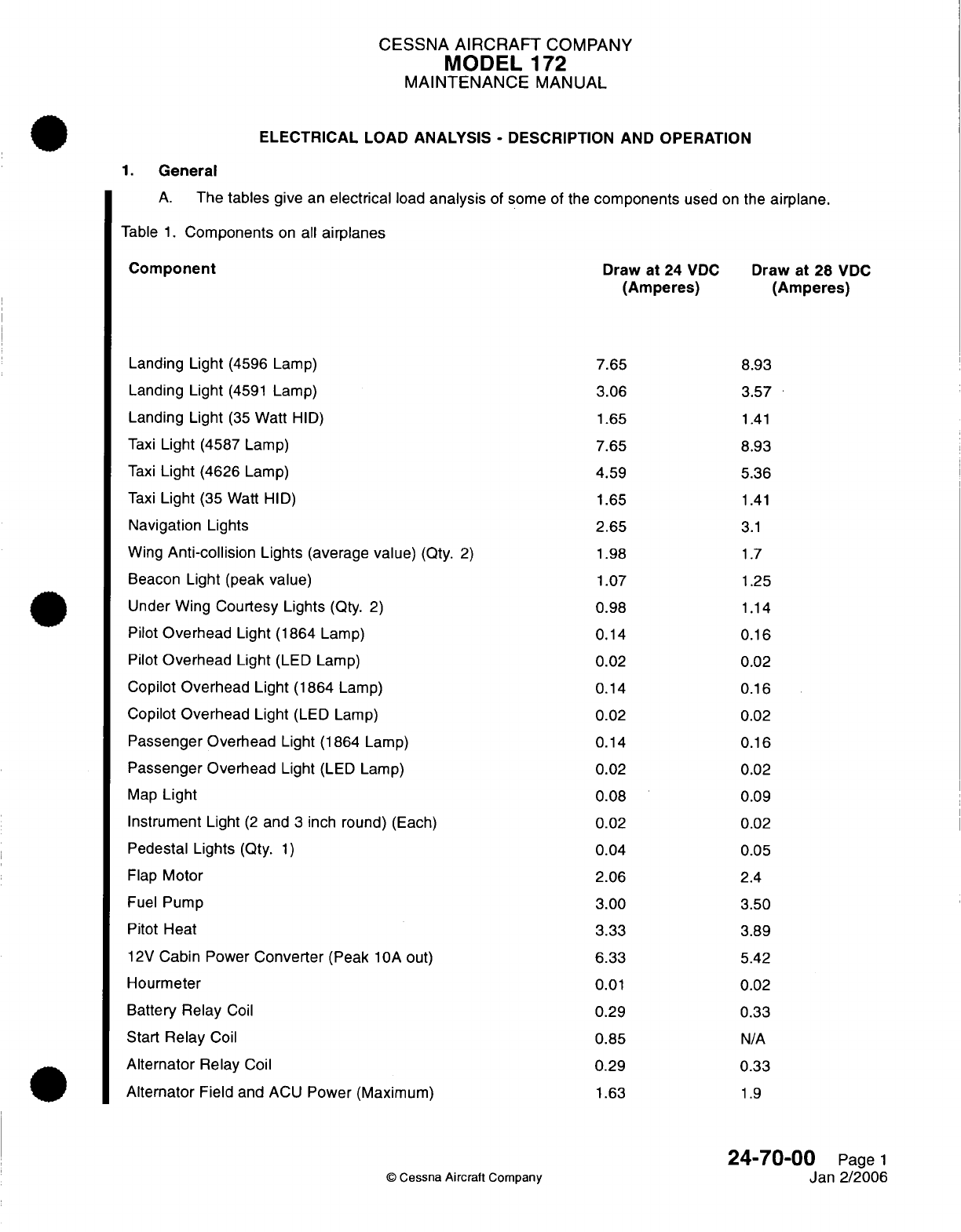
CESSNA
AIRCRAFT
COMPANY
MODEL
172
MAINTENANCE
MANUAL
ELECTRICAL
LOAD ANALYSIS
-
DESCRIPTION
AND OPERATION
1.
General
A.
The
tables
give
an
electrical
load
analysis
of
some
of
the
components
used
on
the
airplane.
Table
1.
Components
on
all
airplanes
Component
Draw
at
24
VDC
Draw
at
28
VDC
(Amperes) (Amperes)
Landing
Light
(4596
Lamp)
7.65
8.93
Landing
Light
(4591
Lamp)
3.06
3.57
Landing
Light
(35
Watt
HID)
1.65
1.41
Taxi
Light
(4587 Lamp)
7.65
8.93
Taxi
Light
(4626
Lamp)
4.59
5.36
Taxi
Light
(35 Watt
HID)
1.65
1.41
Navigation
Lights
2.65
3.1
Wing
Anti-collision
Lights
(average
value)
(Qty.
2)
1.98
1.7
Beacon
Light
(peak
value)
1.07
1.25
Under
Wing
Courtesy
Lights
(Qty.
2)
0.98
1.14
Pilot
Overhead
Light
(1864 Lamp)
0.14
0.16
Pilot
Overhead
Light
(LED
Lamp)
0.02
0.02
Copilot
Overhead Light
(1864
Lamp)
0.14
0.16
Copilot
Overhead
Light
(LED
Lamp)
0.02
0.02
Passenger
Overhead
Light
(1864
Lamp)
0.14
0.16
Passenger
Overhead
Light
(LED
Lamp)
0.02
0.02
Map
Light 0.08
0.09
Instrument
Light
(2
and
3
inch
round)
(Each)
0.02
0.02
Pedestal
Lights
(Qty.
1)
0.04
0.05
Flap
Motor
2.06
2.4
Fuel
Pump 3.00
3.50
Pitot
Heat 3.33
3.89
12V
Cabin
Power
Converter
(Peak
10A
out)
6.33
5.42
Hourmeter
0.01
0.02
Battery Relay
Coil
0.29
0.33
Start
Relay
Coil
0.85
N/A
Alternator
Relay
Coil
0.29
0.33
Alternator
Field
and
ACU
Power
(Maximum)
1.63
1.9
24-70-00
Page
1
©
Cessna
Aircraft
Company
Jan 2/2006
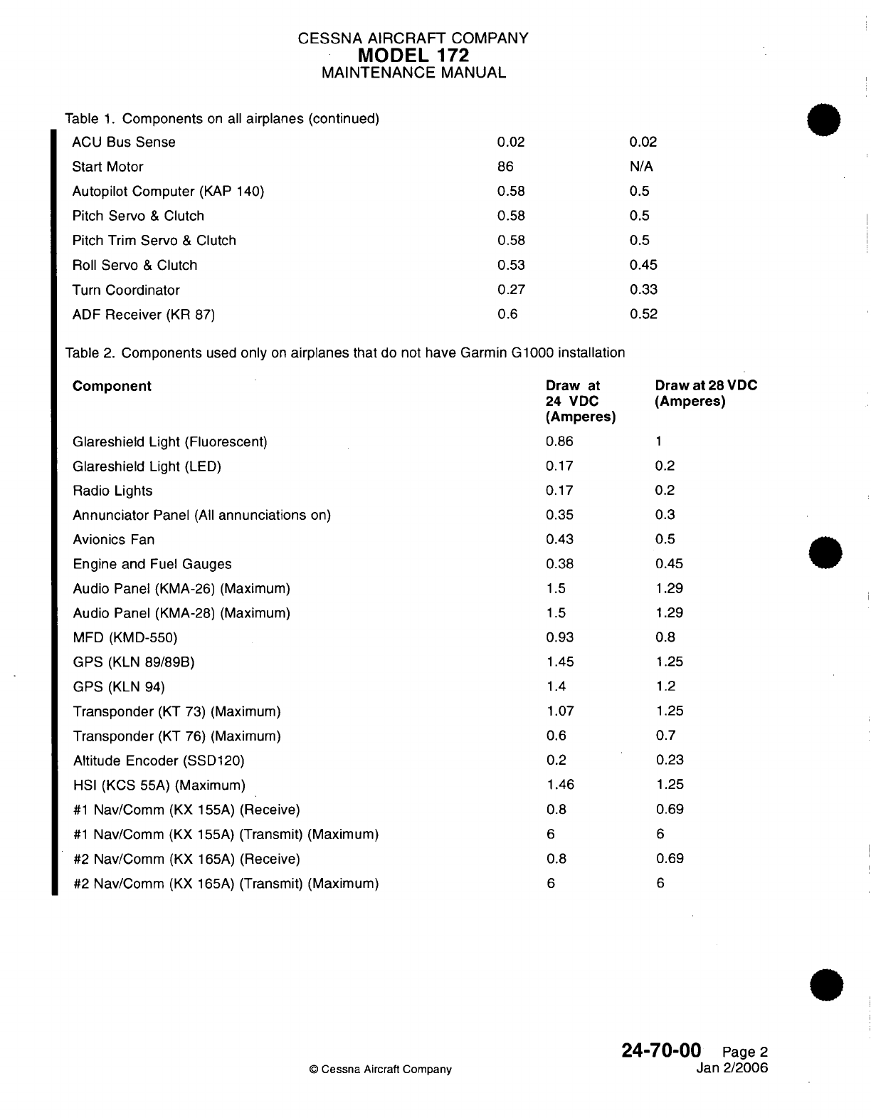
CESSNA AIRCRAFT
COMPANY
MODEL
172
MAINTENANCE
MANUAL
Table
1.
Components
on
all
airplanes
(continued)
ACU
Bus
Sense
0.02
0.02
Start
Motor
86
N/A
Autopilot
Computer
(KAP 140)
0.58
0.5
Pitch
Servo
&
Clutch
0.58
0.5
Pitch Trim
Servo
&
Clutch
0.58
0.5
Roll
Servo
&
Clutch
0.53 0.45
Turn
Coordinator
0.27
0.33
ADF
Receiver
(KR
87)
0.6
0.52
Table
2.
Components
used
only
on
airplanes
that
do not
have
Garmin G1000
installation
Component
Glareshield
Light
(Fluorescent)
Glareshield
Light
(LED)
Radio
Lights
Annunciator
Panel
(All
annunciations
on)
Avionics
Fan
Engine and
Fuel
Gauges
Audio
Panel (KMA-26) (Maximum)
Audio
Panel (KMA-28)
(Maximum)
MFD
(KMD-550)
GPS
(KLN
89/89B)
GPS
(KLN
94)
Transponder
(KT
73) (Maximum)
Transponder
(KT
76)
(Maximum)
Altitude
Encoder (SSD120)
HSI
(KCS
55A)
(Maximum)
#1
Nav/Comm
(KX 155A)
(Receive)
#1
Nav/Comm
(KX
155A)
(Transmit)
(Maximum)
#2 Nav/Comm
(KX
165A)
(Receive)
#2
Nav/Comm
(KX
165A)
(Transmit)
(Maximum)
Draw
at
24
VDC
(Amperes)
0.86
0.17
0.17
0.35
0.43
0.38
1.5
1.5
0.93
1.45
1.4
1.07
0.6
0.2
1.46
0.8
6
0.8
6
Draw
at
28
VDC
(Amperes)
1
0.2
0.2
0.3
0.5
0.45
1.29
1.29
0.8
1.25
1.2
1.25
0.7
0.23
1.25
0.69
6
0.69
6
24-70-00
Page
2
Jan
2/2006
©
Cessna
Aircraft
Company
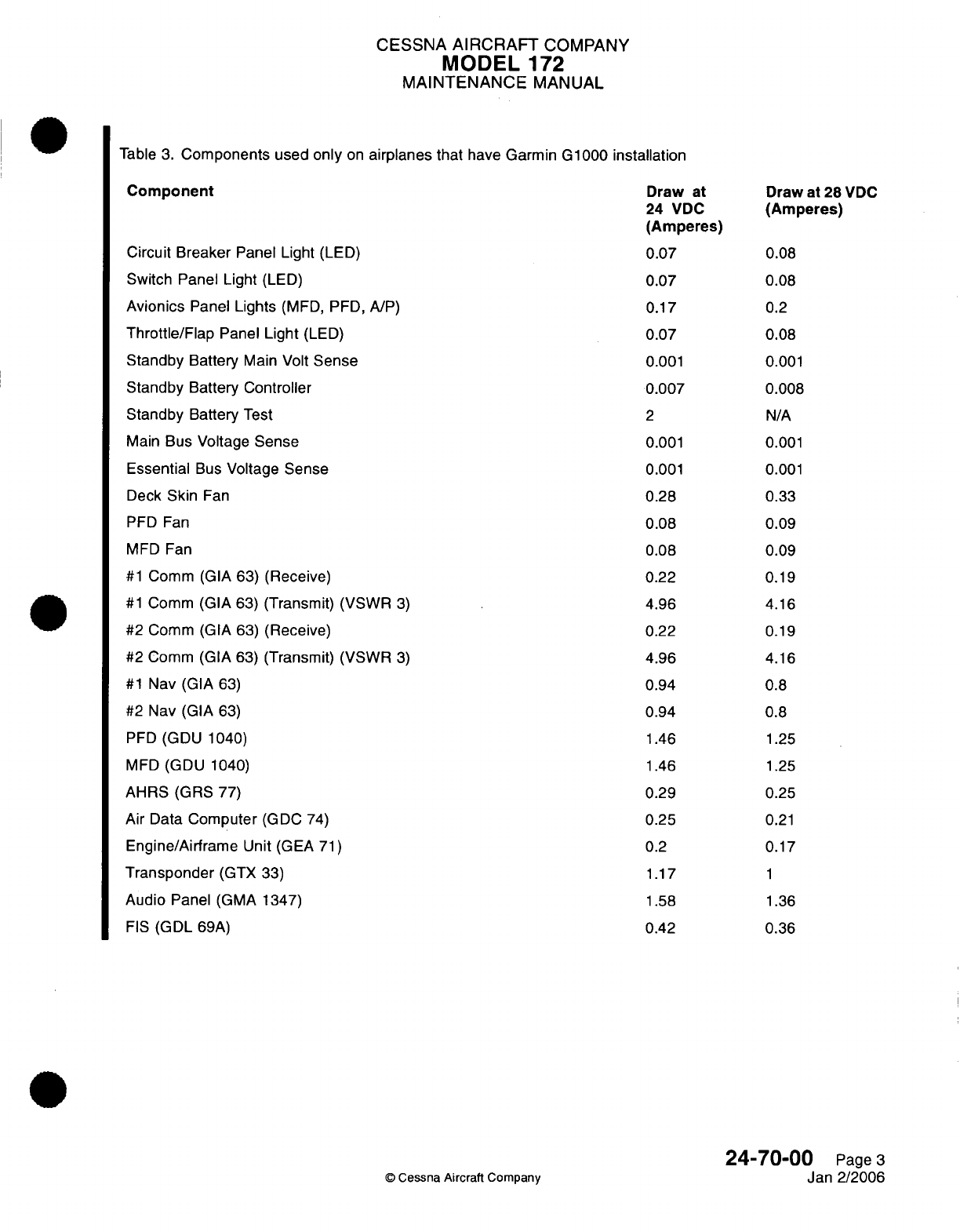
CESSNA
AIRCRAFT
COMPANY
MODEL
172
MAINTENANCE
MANUAL
Table
3.
Components
used
only
on
airplanes that
have
Garmin
G1000
installation
Component
Draw
at
Draw
at
28
VDC
24
VDC
(Amperes)
(Amperes)
Circuit
Breaker
Panel Light
(LED)
0.07
0.08
Switch
Panel
Light
(LED)
0.07
0.08
Avionics
Panel
Lights
(MFD,
PFD,
A/P)
0.17
0.2
Throttle/Flap
Panel
Light
(LED)
0.07
0.08
Standby
Battery
Main
Volt
Sense
0.001 0.001
Standby
Battery Controller 0.007
0.008
Standby
Battery
Test
2 N/A
Main
Bus
Voltage
Sense
0.001
0.001
Essential
Bus
Voltage
Sense
0.001 0.001
Deck
Skin
Fan
0.28
0.33
PFD Fan
0.08
0.09
MFD
Fan
0.08
0.09
#1
Comm
(GIA
63)
(Receive)
0.22
0.19
#1
Comm
(GIA
63)
(Transmit)
(VSWR
3)
4.96
4.16
#2
Comm
(GIA
63)
(Receive)
0.22
0.19
#2
Comm
(GIA
63)
(Transmit)
(VSWR
3)
4.96
4.16
#1
Nav
(GIA
63)
0.94
0.8
#2
Nav
(GIA
63)
0.94
0.8
PFD
(GDU
1040)
1.46
1.25
MFD
(GDU
1040)
1.46
1.25
AHRS
(GRS
77)
0.29
0.25
Air
Data
Computer
(GDC
74)
0.25
0.21
Engine/Airframe
Unit
(GEA
71)
0.2
0.17
Transponder
(GTX
33) 1.17
1
Audio
Panel
(GMA
1347)
1.58
1.36
FIS
(GDL
69A)
0.42 0.36
24-70-00
Page
3
©
Cessna
Aircraft Company
Jan
2/2006
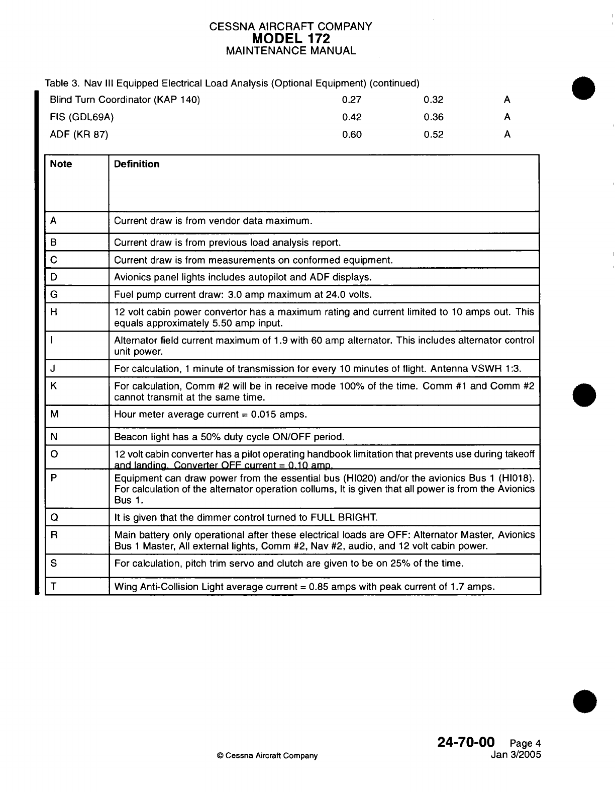
CESSNA AIRCRAFT
COMPANY
MODEL
172
MAINTENANCE
MANUAL
Table
3.
Nav
III
Equipped
Electrical Load
Analysis (Optional
Equipment)
(continued)
Blind Turn
Coordinator
(KAP
140)
0.27 0.32
A
FIS
(GDL69A)
0.42
0.36
A
ADF
(KR
87)
0.60 0.52
A
Note
Definition
A
Current
draw
is
from
vendor
data
maximum.
B
Current draw
is
from
previous
load
analysis
report.
C
Current
draw
is
from
measurements
on
conformed
equipment.
D
Avionics
panel lights
includes autopilot
and
ADF
displays.
G
Fuel
pump
current
draw: 3.0
amp
maximum
at
24.0
volts.
H
12
volt
cabin power
convertor
has
a
maximum rating
and
current
limited
to
10
amps
out.
This
equals
approximately
5.50
amp
input.
I
Alternator
field
current
maximum
of
1.9
with
60
amp
alternator.
This
includes
alternator
control
unit
power.
J
For
calculation,
1
minute
of
transmission
for every
10
minutes
of
flight.
Antenna VSWR
1:3.
K
For
calculation,
Comm
#2
will
be
in
receive
mode
100%
of
the
time.
Comm
#1
and Comm
#2
cannot transmit
at the
same
time.
M
Hour meter
average current
=
0.015
amps.
N
Beacon
light
has
a
50%
duty
cycle
ON/OFF
period.
O
12
volt
cabin
converter
has
a
pilot operating handbook
limitation that
prevents
use
during
takeoff
and
landing.
Converter
OFF
current
=
0.10
amp.
P
Equipment
can
draw
power
from
the
essential
bus
(HI020)
and/or
the
avionics
Bus
1
(HI018).
For
calculation
of the
alternator
operation collums,
It
is
given
that
all
power
is
from
the Avionics
Bus
1.
Q
It
is
given
that
the
dimmer
control
turned
to
FULL BRIGHT.
R
Main
battery
only
operational after
these
electrical
loads
are
OFF:
Alternator
Master,
Avionics
Bus
1
Master,
All
external
lights,
Comm
#2,
Nav
#2,
audio,
and
12
volt
cabin power.
S
For
calculation,
pitch trim
servo
and
clutch
are
given
to
be
on 25%
of
the
time.
T Wing
Anti-Collision
Light
average current
=
0.85
amps
with
peak current of
1.7
amps.
24-70-00
Page
4
©
Cessna
Aircraft
Company
Jan
3/2005

CHAPTER
EQUIPMENT/
FURNISHINGS
CESSNA
AIRCRAFT
COMPANY
MODEL
172
MAINTENANCE
MANUAL
LIST
OF
EFFECTIVE PAGES
CHAPTER-SECTION-SUBJECT
25-Title
25-List
of
Effective
Pages
25-Record
of
Temporary
Revisions
25-Table
of
Contents
25-00-00
25-10-00
25-10-10
25-20-00
25-22-00
25-50-00
25-60-00
25-60-01
25-60-01
25-60-02
25-60-02
25-60-02
25-60-02
25-60-10
25-80-00
©
Cessna
Aircraft Company
PAGE
Page
1
Pages 201-208
Pages
201-208
Pages
201-202
Pages
201-206
Pages
201-202
Pages
201
-209
Pages
201-204
Pages
601
-602
Page
1
Pages
101
-102
Pages
201-204
Pages
601
-606
Pages
201-202
Pages
201
-203
DATE
Janl1/2007
Janl1/2007
Janl1/2007
Jul
3/2006
Apr
7/2003
Apr
7/2003
Janl1/2007
Janl1/2007
Janl1/2007
Janl1/2007
Jan11/2007
Janl1/2007
Jan11/2007
Jan11/2007
Apr
7/2003
25
-
LIST
OF
EFFECTIVE
PAGES
Page
1
of
1
Janl1/2007
Temporary
Revision
Number
RECORD
OF
TEMPORARY
REVISIONS
Page
Number
Issue
Date
By
Date
Removed
By
CESSNA AIRCRAFT
COMPANY
MODEL
172
MAINTENANCE
MANUAL
CONTENTS
EQUIPMENT/FURNISHING
-
GENERAL
......................
Scope....................................
Tools,
Equipment
and
Materials........................
Definition
..................................
FLIGHT
COMPARTMENT
-
MAINTENANCE
PRACTICES
..............
General
...................................
Seat
Removal/installation...........................
Shoulder
Harness
Guide
Removal/Installation
.................
Seat
Rail
Removal/installation
........................
Shoulder
Harness
and
Seat
Belt
Inspection
..................
Crew
Shoulder Harness
and
Seat
Belt
Removal/Installation
...........
Map
Compartment
Removal/installation
....................
INFLATABLE
RESTRAINT
SYSTEM
-
MAINTENANCE
PRACTICES
Airplanes
with
AMSAFE Inflatable
Restraint
System........................
General...................................
Inflatable
Restraint System
Component
Cleaning................
Inflatable Restraint System
Inspection.....................
Storage
of
Spares
..............................
AMSAFE
Inflatable
Restraint
Disarm/Arm
...................
Inflatable Restraint System
Removal/installation
................
Inflatable Restraint System
Adjustment/Test
..................
Inflatable
Restraint
System
Troubleshooting
..................
PASSENGER COMPARTMENT
-
MAINTENANCE
PRACTICES
...........
General...................................
Aft
Seat
Removal/installation
.........................
Seat
Belt
and/or Shoulder
Harness Assembly
Removal/Installation........
Seat
Belt
and
Shoulder
Harness Assembly
Test.................
INTERIOR
UPHOLSTERY
-
MAINTENANCE
PRACTICES..............
General...................................
Cabin Panels
Removal/installation.......................
Door Panels,
Carpet
and
Rubber
Mat
Removal/Installation............
CARGO
TIE-DOWNS
-
MAINTENANCE
PRACTICES
................
General...................................
POINTER
EMERGENCY LOCATOR
TRANSMITTER
-
MAINTENANCE
PRACTICES..
General...................................
Pointer
ELT
Removal/installation
................. II.....I
ELT
Remote
Switch
Removal/Installation....................
ELT
Antenna
Removal/installation
(Integral
Base
with
Coaxial
Cable).......
ELT
Whip
Antenna
Removal/Installation
....................
ELT
Battery Pack
Removal/installation
.....................
Pointer
ELT
Operational
Test
.........................
ARTEX
C406-N
EMERGENCY
LOCATOR
TRANSMITTER
-
MAINTENANCE
PRA
CTIC
ES
...
................ . .......... . ....
General...................................
Artex
C406-N
ELT
Removal/installation.....................
ELT
Remote Switch
Removal/Installation....................
ELT
Rod
Antenna
Removal/Installation.....................
Buzzer
Removal/installation..........................
ARTEX C406-N
EMERGENCY
LOCATOR
TRANSMITTER
-
INSPECTION/CHECK
...
General...................................
Artex
C406-N
ELT
Functional
Test.......................
©
Cessna Aircraft
Company
25-00-00
Page
1
25-00-00
Page
1
25-00-00
Page
1
25-00-00
Page
1
25-10-00
Page
201
25-10-00
Page
201
25-1
0-00
Page
201
25-10-00
Page
201
25-1
0-00
Page
205
25-1
0-00
Page 206
25-10-00
Page
206
25-1
0-00
Page
206
25-1
0-1 0
Page
201
25
-10-1
0 Page
201
25-1
0-1
0 Page
201
25-1
0-1
0
Page 202
25
-10-1
0
Page
202
25-1
0-1
0
Page
203
25-1
0-1
0
Page
203
25-1
0-1
0
Page
207
25-10-10
Page 208
25-20-00
Page
201
25-20-00
Page
201
25-20-00
Page
201
25-20-00
Page
201
25-20-00
Page
201
25-22-00
Page
201
25-22-00
Page
201
25-22-00
Page
201
25-22-00
Page
201
25-50-00
Page
201
25-50-00
Page
201
25-60-00
Page
201
25-60-00
Page
201
25-60-00
Page
201
25-60-00
Page 206
25-60-00
Page 206
25-60-00
Page 207
25-60-00
Page
207
25-60-00
Page
208
25-60-01
25-60-01
25-60-01
25-60-01
25-60-01
25-60-01
25-60-01
25-60-01
25-60-01
Page
201
Page
201
Page
201
Page
201
Page
204
Page
204
Page
601
Page
601
Page
601
25
-
CONTENTS
Page
1
of
2
Janl1/2007
CESSNA
AIRCRAFT
COMPANY
MODEL
172
MAINTENANCE
MANUAL
ARTEX
ME406
EMERGENCY
LOCATOR
TRANSMITTER
SYSTEM
-
DESCRIPTION
AND
OPERATION
................................
General...................................
Description
.................................
Operation..................................
ARTEX
ME406
EMERGENCY
LOCATOR
TRANSMITTER
SYSTEM
-
TROUBLESHOOTING
..............................
General...................................
Tools
and
Equipment.............................
ME406
Emergency
Locator
Transmitter
Self
Test
Preparation
..........
ARTEX
ME406
EMERGENCY
LOCATOR
TRANSMITTER
SYSTEM
-
MAINTENANCE
PRACTICES
...................................
General...................................
Emergency Locator
Transmitter
(ELT)
Removal/Installation
...........
ELT
Buzzer
Removal/Installation
.......................
Remote Switch
Removal/Installation......................
ELT
Antenna
Removal/Installation.......................
ARTEX
ME406
EMERGENCY LOCATOR
TRANSMITTER
(ELT)
SYSTEM
-
INSPECTION/CHECK...............................
General...................................
Tools
and
Equipment.............................
Artex
ME406
Emergency
Locator
Transmitter
(ELT)
Inspection..........
Artex
ME406
Emergency
Locator
Functional
Test................
CARBON MONOXIDE DETECTOR
-
MAINTENANCE PRACTICES
.........
General
...........................
111
..-
Carbon
Monoxide
Detector
Removal/Installation
................
SOUNDPROOFING
AND
INSULATION
-
MAINTENANCE
PRACTICES........
General...................................
25
-
CONTENTS
©
Cessna
Aircraft Company
25-60-02
Page
1
25-60-02
Page
1
25
60
02
Page
1
25-60-02
Page
1
25-60-02
Page
101
25-60-02
Page
101
25-60-02
Page
101
25-60-02
Page
101
25-60-02
Page
201
25-60-02
Page
201
25-60-02
Page
201
25-60-02
Page 201
25-60-02
Page
204
25-60-02
Page
204
25-60-02
Page
601
25-60-02
Page
601
25-60-02
Page 601
25-60-02
Page 601
25-60-02
Page
602
25-60-1
0
Page
201
25-60-1
0
Page
201
25-60-1
0
Page
201
25-80-00
Page
201
25-80-00
Page
201
Page
2
of
2
Janl1/2007
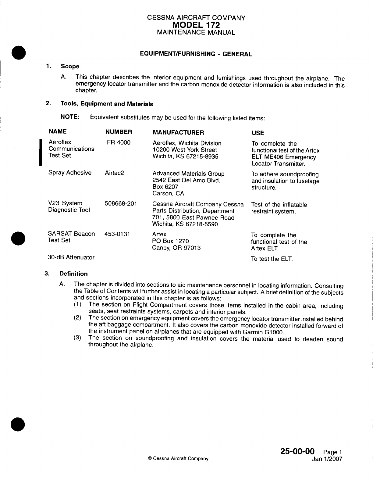
CESSNA
AIRCRAFT
COMPANY
MODEL
172
MAINTENANCE
MANUAL
EQUIPMENT/FURNISHING
-
GENERAL
1.Scope
A.
This
chapter
describes
the
interior
equipment
and
furnishings
used
throughout
the
airpiane.
The
emergency
locator
transmitter
and
the carbon monoxide
detector
information
is
also
included
in
this
chapter.
2.
Tools, Equipment
and
Materials
NOTE:
Equivalent substitutes
may
be
used
for
the
following
listed
items:
NAME
Aeroflex
Communications
Test
Set
Spray
Adhesive
V23
System
Diagnostic
Tool
SARSAT
Beacon
Test
Set
NUMBER
IFR
4000
Airtac2
508668-201
453-0131
MANUFACTURER
Aeroflex, Wichita
Division
10200 West
York
Street
Wichita,
KS
67215-8935
Advanced
Materials
Group
2542
East
Del
Amno
Blvd.
Box 6207
Carson,
CA
Cessna Aircraft Company Cessna
Parts
Distribution,
Department
701,
5800
East
Pawnee
Road
Wichita,
KS
6721
8-5590
Artex
P0
Box
1270
Canby,
OR
97013
30-dB
Attenuator
USE
To
complete
the
functional
test
of
the
Artex
ELT
ME406
Emergency
Locator
Transmitter.
To
adhere
soundproofing
and
insulation
to
fuselage
structure.
Test
of the
inflatable
restraint
system.
To
complete
the
functional
test
of
the
Artex
ELT.
To
test
the
ELT.
3.
Definition
A.
The
chapter
is
divided
into
sections
to
aid
maintenance
personnel
in
locating
information.
Consulting
the
Table
of
Contents
will
further
assist
in
locating
a
particular
subject.
A
brief
definition
of
the
subjects
and
sections
incorporated
in
this
chapter
is
as
follows:
(1)
The
section
on
Flight Compartment covers
those
items
installed
in
the
cabin
area,
including
seats,
seat
restraints
systems,
carpets
and
interior
panels.
(2)
The
section
on
emergency
equipment
covers
the
emergency
locator transmitter
installed
behind
the
aft
baggage compartment.
It
also
covers the
carbon
monoxide detector
installed forward
of
the instrument
panel
on
airplanes
that
are
equipped
with
Garmin
G1000.
(3)
The
section
on
soundproofing
and
insulation
covers
the
material
used
to
deaden
sound
throughout
the
airplane.
25-00-00
Paae
1
I
Jan-1/2007
C
Cessna
Aircraft
Company
CESSNA AIRCRAFT
COMPANY
MODEL
172
MAINTENANCE
MANUAL
FLIGHT
COMPARTMENT
-
MAINTENANCE PRACTICES
1.General
A.
This
maintenance
practices
section
gives
the
removal
and
installation
for
the
crew seats,
seat
rails,
seat
belts, and
shoulder
harnesses.
The
seat
belt
and
shoulder
harness components
are
non-repairable
field
items.
You
must
replace
any component
that
does
not
operate
correctly.
WARNING:
If
the
airplane
has
AMSAFE
inflatable
restraints,
do
not
do
maintenance
on
the
crew
seats,
seat
rails,
seat
belts,
or
shoulder
harnesses
until
you
first
look
at and
obey
all
applicable precautions
and
instructions
supplied
in
AMSAFE
publications
and
this
maintenance
manual.
If
you
do
not obey
these
instructions
and
safety
precautions,
damage
to
equipment
and
harm
to personnel
can
occur.
B. If
your airplane
has
the
AMSAFE
inflatable restraint system,
do
not
do
maintenance
on
the
seats
or
the
seat
restraint
system
unless
you
first
obey
all
applicable
precautions
and
instructions
in
the
E508804
Supplemental
Amsafe
Maintenance
Manual
and
this
Maintenance
Manual.
Refer
to
Inflatable Restraint
System
-
Maintenance
Practices.
2.
Seat
Remova~l/nstallation
A.
Seat Removal
(Refer to
Figure
201).
WARNING:
If
the airplane
has
AMVSAFE
inflatable restraints,
do
not remove
seats
with
the
seat
belts
buckled
or
the
EMA
connected.
Damage
can
occur
to
the
system
and
an
accidental deployment
of the
system
can
cause
injury.
*
~~(1)
Disarm
the
AMSAFE Inflatable
Restraints.
Refer
to
AMSAFE Inflatable
Restraint
Disarm/Arm.
(2)
Remove
the
seat stops
from
the
forward and
aft of
each
seat
track.
(3)
Unlatch
the
seat
from
the seat
track
and
move the
seat
forward
on
the
seat
track
until
the
forward
roller
clears
the
seat
track.
(4)
Move
the
seat
aft
on
the
seat
track
until
the
aft
rollers
clear
the
seat
track.
(5)
Remove the
seat
from
the
airplane.
B.
Seat
Installation
(Refer
to
Figure
201).
(1)
Set
the
aft
roller of
the
seat
in
position
on
the
seat
track.
(2)
Move
the seat
forward
on
the
seat
track
until you can
install
the
front
roller
on
the
seat
track.
(3)
Install
the seat
stops
to
the
front and
the
rear
of
the
seat
track.
WARNING:
Make
sure
the seat
stops
are
set
correctly. Incorrectly
installed
seat
stops
can
let
the
seat move
during
flight,
with
the
result
of
serious
injury
or
death.
(4)
Make
sure
the
seat
stops
are
installed correctly.
(5)
Arm
the
AMVSAFE
Inflatable Restraints.
Refer
to
AMSAFE
Inflatable Restraint
Disarm/Arm.
(6)
Complete
a
test
of
the
seat
through
the
full
range
of
motion
to
make sure
of
the correct operation.
3.
Shoulder
Harness
Guide
Removal/installation
NOTE:
The
removal/installation
procedures
are
typical
for
the
pilot
and
copilot
seats.
A.
Shoulder
Harness
Guide
Removal
(Refer
to
Figure
201).
(1)
Move
the
seat
in
the
full
forward
position.
(2)
Put
the
seat
back
in
the forward
position.
25-1
0-00
Page
201
0
Cessna
Aircraft
Company
Janl1/2007
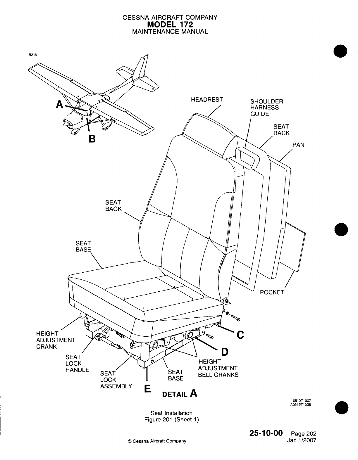
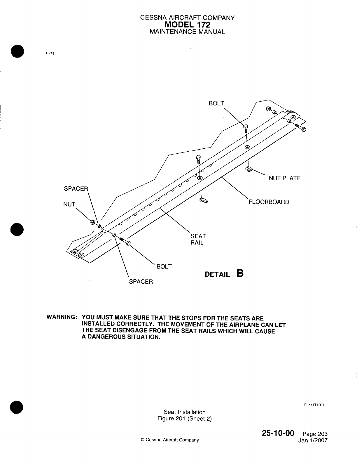
CESSNA AIRCRAFT
COMPANY
MODEL
172
MAINTENANCE
MANUAL
8219
BOLT
NUT
PLATE
C
FLOORBOARD
BOLT
SPACER
SEAT
RAIL
DETAIL
B
WARNING:
YOU
MUST
MAKE SURE
THAT
THE
STOPS
FOR
THE
SEATS
ARE
INSTALLED
CORRECTLY.
THE
MOVEMENT
OF
THE
AIRPLANE
CAN
LET
THE
SEAT
DISENGAGE
FROM
THE
SEAT RAILS
WHICH
WILL
CAUSE
A DANGEROUS
SITUATION.
B051
1T1
01
Seat
Installation
Figure
201
(Sheet
2)
0
Cessna
Aircraft
Company
25-10-00
Page
203
Janl1/2007
N
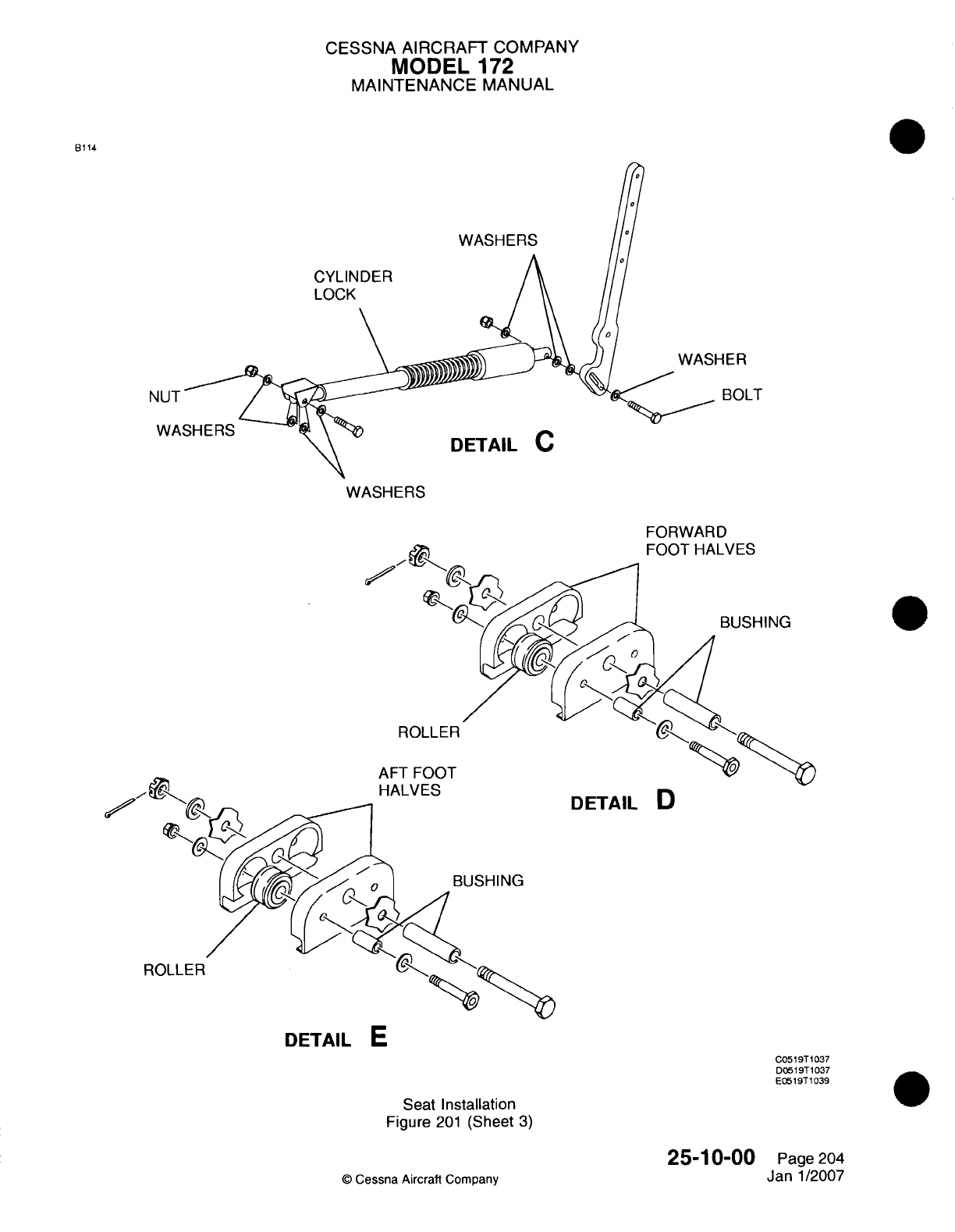
CESSNA
AIRCRAFT
COMPANY
MODEL
172
MAINTENANCE
MANUAL
6114
WASHERS
CYLINDER
LOCK
-IER
BOLT
WASHERS
DETAIL
C
WASHERS
FORWARD
BUSHING
R
AFT
HALVI-b
1
~BUSHING
DETAIL
D
DETAIL
E
C0519T
1037
D0519T1037
E05
19T1
039
Seat
Installation
Figure
201
(Sheet
3)
25-10-00
©
Cessna Aircraft
Company
ROLLER
Page
204
Jan
1/2007
CESSNA AIRCRAFT
COMPANY
MODEL
172
MAINTENANCE
MANUAL
CAUTION:
Make sure you
are
careful
when
you
lift
up
the
upholstery
so you
do
not
cause damage.
(3)
Lift
the
upholstery
above
the
pocket
on
the
seat back
to
get
access
to
the
headrest
frame
and
cotter
pins.
(4)
Remove
the
cotter
pins
from
the
headrest
frame.
(5)
Lift
the
headrest
up
and
out
of
the
seat back.
(6)
Remove
the
shoulder
harness
guide.
(7) If
you
do
not
install
a
new
shoulder
harness
guide,
do
the
procedures that
follow.
(a)
Install the
headrest
into
the
seat
back.
(b)
Install new
cotter
pins
in
the
headrest
frame.
CAUTION:
Make
sure
you
are
careful
when you
pull
down
the
upholstery
so
you
do
not
damage
it.
(c)
Pull
down
the upholstery
over
the
seat
back.
(d)
Move
the
seat
aft
and
set
the
seat
back
in
the
vertical
position.
B.
Shoulder
Harness
Guide
Installation
(Refer
to
Figure
201).
(1) If
the
seat
is
not
in
the
same
position
as
it
was
when
the
shoulder
harness
guide
was
removed,
complete
the
procedures
that follow.
NOTE:
If
the
seat
headrest
is
removed
from the
seat
back,
go
on to
the
next
step.
You
do
not
have
to
complete
this
step.
(a)
Move
the
seat
in
the
full
forward
position.
(b)
Put
the
seat
backs
in
the
forward
position.
CAUTION:
Make
sure
you
are
careful when
you
lift
the
upholstery
so you
do
not
cause
damage.
(c)
Lift the
upholstery
above
the
pocket
on
the
seat
back
to
get access
to
the
headrest
frame
and
cotter pins.
(d)
Remove
the
cotter
pins
from
the
headrest
frame.
(e)
Lift
the
headrest
up
and
out
of
the
seat
back.
(2)
Install
the
shoulder
harness guide
on
the
headrest.
(3)
Install
the
headrest
with
the
shoulder
harness guide
into
the
seat
back
frame.
(4)
Install
new
cotter
pins
in
the
headrest
frame.
(5)
Move
the
seat
aft and
set
the
seat back
in
the
vertical position.
CAUTION:
Make
sure
you
are
careful
when
you
pull
down
the
upholstery
so
you
do
not
cause
damage.
(6)
Pull
down
the
upholstery
over
the
seat
back.
(7)
Move
the
seat
aft
and
set the
seat
back
in
the
vertical
position.
4.
Seat
Rail
Removal/installation
A.
Seat
Rail
Removal
(Refer
to
Figure
201).
(1)
Remove
the
bolts
that
attach
the
seat
rails
to
the
fuselage.
B.
Seat
Rail
Installation (Refer
to
Figure
201).
(1)
Install
the
seat
rails
to
the
fuselage
with
bolts.
25-1
0-00
Page
205
C
Cessna Aircraft
Company
Janl1/2007
CESSNA
AIRCRAFT
COMPANY
MODEL
172
MAINTENANCE
MANUAL
5.
Shoulder
Harness
and
Seat
Belt
Inspection
A.
The shoulder
harness
and
seat
belt
assembly
must
be
inspected
in
accordance
with
the
time
intervals
in
Chapter
5,
Inspection
Time
Limits.
The
shoulder
harness
and
seat
belt
assemblies
have
a
time
life
associated
with
them.
Refer
to
Chapter
5,
Component
Time
Life
for
these limits.
6.
Crew
Shoulder
Harness
and Seat
Belt
Remova~l/nstallation
NOTE:
The
removal
and
installation
of
the
shoulder
harness
and
seat
belt
assembly
are
typical.
A.
Shoulder Harness
and
Seat
Belt
Assembly
Removal (Refer
to
Figure
202).
(1) If
necessary,
disconnect
the AMSAFE
components
as
follows
(refer
to
the
applicable
Warnings
and
steps
inlnflatable
Restraint
System
-
Maintenance Practices,
Inflatable Restraint
System
Removal/Installation):
(a)
Disarm
the
AMVSAFE
inflatable
restraints.
(b)
Disconnect
the
squib
connector
from
the
inflator assembly.
(c)
Disconnect
the
gas
hose
from
the
inflator
assembly.
(2)
Remove the
access covers
(if
installed)
to get
access
to
the
attached
hardware.
(3)
Remove
the
nuts,
bolts, washers,
and
spacers that
attach
the
shoulder
harness
and
seat
belt
assembly
to
the
fuselage
and
to
the seats.
(4)
Remove
the
shoulder
harness
and
seat
belt
assembly
from the
airplane.
B.
Shoulder
Harness
and
Seat
Belt
Assembly
Installation (Refer
to
Figure
202).
(1)
Install
the
shoulder
harness
to
the
fuselage
and/or
the seat
belt
assembly
to
the
seat.
(a)
Make
sure
the
spacers
(if
installed)
are
in
the
correct
position.
(2)
Install the
access covers
(if
equipped).
(3) If
necessary,
connect
the
AMSAFE
components
as
follows
(refer
to
the
applicable
Warnings
and
steps
in
Inflatable
Restraint
System
-
Maintenance Practices,
Inflatable
Restraint
System
Removal/Installation):
(a)
Connect
the
gas
hose
to
the
inflator
assembly.
(b)
Attach
the
squib connector
to
the
inflator
assembly.
(c)
Arm
the
AMSAFE
inflatable
restraints.
(4)
Complete
a
check
of
the
system
for
the
correct
installation
and
operation.
7.
Map
Compartment
Removal/installation
A.
Map
Compartment Removal
(Refer
to
Figure 203).
(1)
Remove
the
interior screws
that
attach
the
map
compartment
to
the
instrument
panel.
(2)
Pull
out the
map
compartment
from
the
instrument
panel.
B.
Map
Compartment
Installation
(Refer
to
Figure 203).
(1)
Put
the
map
compartment
in
the instrument
panel.
(2)
Attach
the
map
compartment
to the
instrument panel
with
the
screws.
25-1
0-00
Page 206
©
Cessna
Aircraft
Company
Janl1/2007
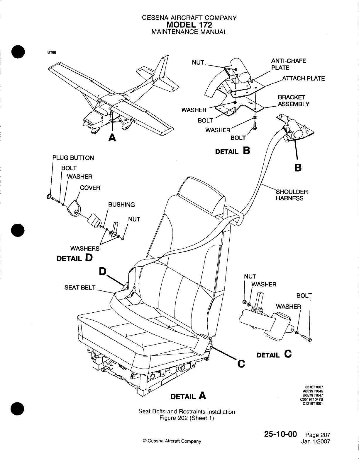
CESSNA AIRCRAFT
COMPANY
MODEL
172
MAINTENANCE
MANUAL
B109
ANTI-CHAFE
PLATE
NTE
BOLT
DETAIL
B
WA
HARNESS
Wi
DETAI
NUT
SEA:
C
DETAIL
C
Seat
Belts and
Restraints Installation
Figure 202
(Sheet
1)
©
Cessna
Aircraft
Company
25-1
0-00
Page
207
Janl1/2007
A
PLUG
BL
L
I
PIa-f-
1007
1046
1047
C051
9T1
047B
01219T1001
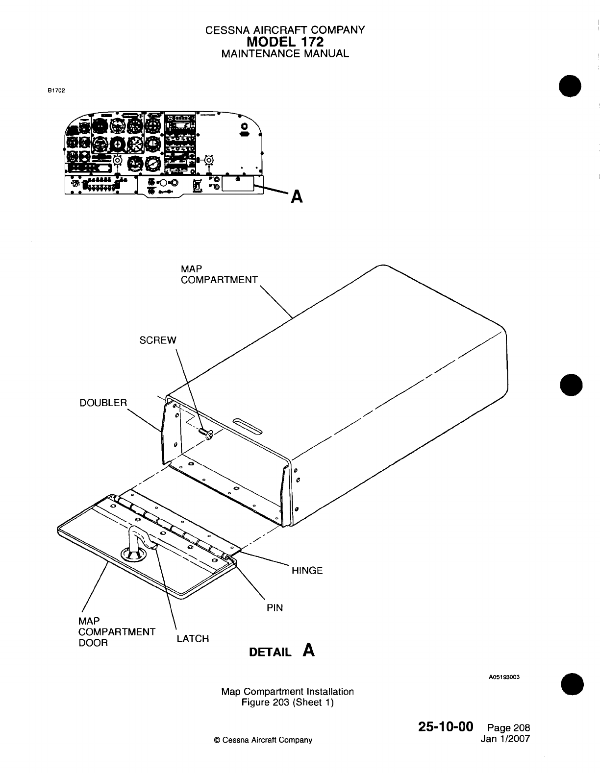
CESSNA AIRCRAFT
COMPANY
MODEL
172
MAINTENANCE
MANUAL
81702
A
H-S
MAP
COMPARTMENT
SCREW
DOUBLER
HINGE
PIN
UUMrPdiI
MLN
I
LAC
DOOR
LATCH
DETAIL
A
A051
93003
Map
Compartment
Installation
Figure
203
(Sheet
1)
25-10-00
©
Cessna Aircraft
Company
Page
208
Janl1/2007
CESSNA AIRCRAFT
COMPANY
MODEL
172
MAINTENANCE
MANUAL
INFLATABLE
RESTRAINT
SYSTEM
-
MAINTENANCE PRACTICES
Airplanes
with
AMVSAFE
Inflatable
Restraint
System
1.General
A.
This
section
has
maintenance
information
for
the
AMVSAFE
Aviation Inflatable
Restraint
(AAIR). The
AAIR
is a
self-contained,
modular,
three-point
restraint
system that
will
help
to
protect
occupants
from
head-impact
injury during
an
accident.
The AAIR
system
has
four
core
components:
the
air
bag
assembly,
the
inflation
assembly,
the
electronics
module
assembly
(EMVA),
and
the cable interface
assembly.
WARNING:
Do
not
try
to
open
the
inflator
assembly.
Do
not
apply
an
electric
current
to
the
electronics
connection.
The
inflator
assembly
is
a
stored, gas/energetic
material
device
and can
cause
injury
if
accidentally
deployed.
2.
Inflatable
Restraint
System
Component
Cleaning
A.
AMVSAFE
recommends
that
the
AAIR
components
be
cleaned
on
a
regular
(annual)
basis.
Buildup
of
dirt
and
unwanted
material can cause
problems
with
system operation,
decrease
the
life
of
the
system,
and
help
cause
corrosion
of
the metal
parts
in
the
system.
Glean the
belt
assembly,
hoses,
cables, inflation
device/cap
assembly,
and the
EMVA.
CAUTION:
Use
care
to keep
contamination
and
cleaning agents away
from
the
hardware
assemblies.
CAUTION:
CAUTION:
Do
not
let
any
part
of the
AAIR
soak
in
any
solution.
This
can
cause
damage
to
the
AAIR
system.
Do
not
use
too
much
water
when
you
clean
the
AAIR
parts.
Too
much
water
can
cause
damage
to
the
internal
components
and
cause
them
to
be
unserviceable.
Only
use
sufficient
cleaning
agent
to
make
minimal
suds.
Excess
soap
must
be
removed before the
part
is
installed
in
the
system.
Do
not
dry the
belt
assembly
in
sunlight
or near any
source
of
heat.
Do
not
dry
clean
the
belt
assembly.
Do
not put
the
belt
assembly
fully
into
water.
CAUTION:
Keep
the
isopropyl alcohol
away
from
the
webbing,
air
bag
cover,
and
the
gas hose
material.
CAUTION:
Do
not
use
soap
or
water
on
metal parts.
(1)
Clean
non-metallic
parts
with
warm
water
and
a
household
soap/laundry
detergent
and
a
moist
cloth.
(2)
Flush
the
parts with
clear
water
on
a
clean
cloth.
(3)
Use
a
soft
brush,
and
cold
soap
solution
to
clean
the
webbing,
air
bag
cover,
and gas
hose
by
hand.
Use
a
household
liquid
soap
or
detergent.
(4)
Let
the belt
assembly
dry
by
air.
(5)
Clean
any
spacers, washers,
nuts,
or
bolts
with
a
lint-free
cloth
and
isopropyl
alcohol.
(6)
Cover
the
cable
opening
into the
EMVA
with
pieces
of
cloth.
Clean the
inflator
and
cables
by
hand
with
a
lint-free
cloth
and
a
cold
water
and
mild
soap solution.
25-1
0-1
0
Page
201
C
Cessna
Aircraft
Company
Janl1/2007
CESSNA
AIRCRAFT COMPANY
MODEL
172
MAINTENANCE
MANUAL
3.
Inflatable
Restraint
System
Inspection
NOTE:
The
AMSAFE
Aviation
Inflatable Restraint
(AAIR)
must
be
examined
in
accordance
with
the
time
intervals
in
Chapter
5,
Inspection
Time
Limits.
The
AMSAFE
Aviation
Inflatable Restraint (AAIR)
assemblies
have
a
time
life
associated
with
them.
Refer
to
Chapter
5,
Component
Time
Life
for
these
limits.
A.
Do
an
inspection
of the AAIR
system
parts.
(1)
Air
bag
assembly.
(a)
Make sure
that
the
attachments
are
tightly connected.
(b)
Do
a
visual inspection
for
dirt,
oil,
grease
or
other
unwanted
material.
(c)
Do
a
check
for
wear
on
the
edges
of
the
belt.
(d)
Do
a
check
for damage
on
stitching
or
fabric threads.
(e)
Do
a
check
for
holes
or
rub
marks
on
the air
bag
cover.
(f)
Do
a
check
of
the
end
fittings,
buckle
and
connector
for
cracks,
dents,
or
corrosion.
(2)
Inflator
hose.
(a)
Do
a
check
for fraying,
wear,
or
tears.
(3)
Cable
interface
assembly.
(a)
Make sure
all
attachments
are
tightly connected.
(4)
Inflator assembly.
(a)
Do
a
check
for
loose
mounting
hardware.
(b)
Do
a
check
of
the
hose
connection.
(c)
Do
a
check
of
the
electrical connection.
(5)
Electronics
module
assembly
(EMA).
(a)
Do
a
check for
loose
connections
and
mounting
hardware.
4.
Storage
of
Spares
A.
Inflator
Assembly.
NOTE:
The
maximum
continuous
storage
time for
the
inflator
assembly
is
seven
years
from
the
date
of
manufacture.
After
seven
years,
send
the
inflator
assembly
to
AMSAFE
Aviation
for
inspection
and
repair.
(1)
Keep
the
inflator
assembly
in a
cool and
dry
area.
The permitted
temperature
range
is
-300
C
(2)
Keep
the
inflator
assembly
away
from
sunlight,
dust, moisture,
and
other
contamination.
(3)
Keep the
inflator
assembly
away
from
high
electromagnetic,
radio
frequency,
and
electrostatic
environments.
(4)
Obey
all
local
storage
regulations.
B.
Electronics Module
Assembly
(EMA).
NOTE:
The maximum
continuous
storage
time for
the
EMA
is
seven
years from
the
date
of
manufacture.
After
seven
years,
send the
EMVA
to
AMSAFE
Aviation
for
inspection
and
repair.
(1)
Keep
the
EMA
assembly
in a
cool and
dry area.
The
permitted
temperature
range
is
-300
C
to
+550
C.
(2)
Make
sure
that
the
EMA
is
kept away
from
sunlight,
dust,
moisture,
and
other
contamination.
(3)
Keep
the
inflator
away
from
EMI/RFI/ESD
environments.
(4)
Obey
all
local
storage
regulations.
C.
Air
Bag
Assembly.
(1)
Keep
the
air
bag
assembly
in a
cool
and
dry
area.
The permitted
temperature
range
is
-300
C
(2)
Make
sure
that the air
bag
assembly
is
kept
away
from
sunlight,
dust,
moisture,
and
other
contamination.
25-1
0-1
0
Page
202
©
Cessna
Aircraft
Company
Janl1/2007
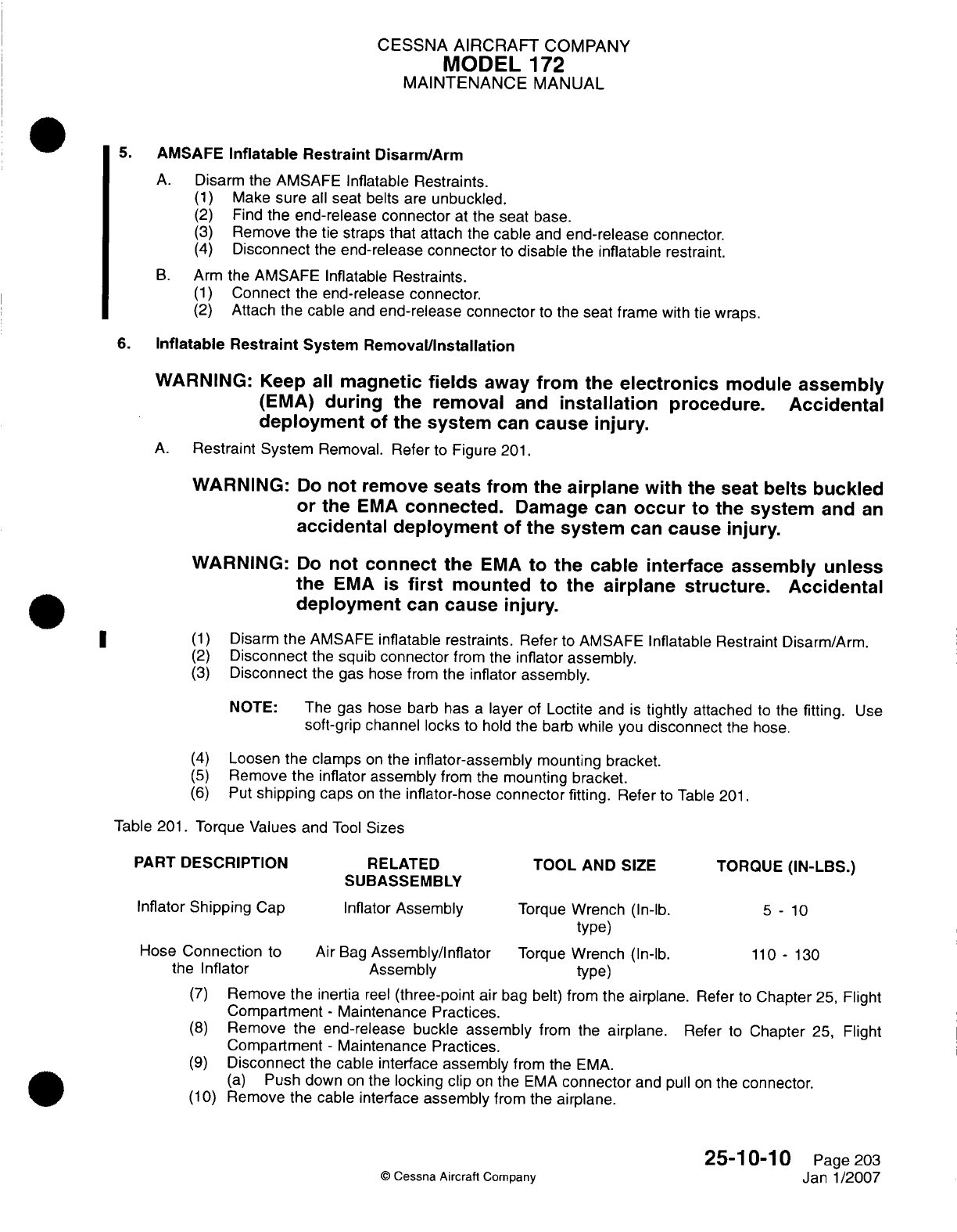
CESSNA
AIRCRAFT
COMPANY
MODEL
172
MAINTENANCE
MANUAL
5.
AMSAFE
Inflatable Restraint
Disarm/Arm
A.
Disarm the AMSAFE
Inflatable
Restraints.
(1)
Make
sure
all
seat belts
are
unbuckled.
(2)
Find
the end-release
connector
at
the
seat base.
(3)
Remove
the
tie
straps
that
attach
the
cable
and
end-release
connector.
(4)
Disconnect
the
end-release
connector
to
disable
the
inflatable
restraint.
B.
Arm
the
AMSAFE
Inflatable
Restraints.
(1)
Connect
the
end-release
connector.
(2)
Attach
the
cable
and
end-release
connector
to
the
seat frame
with
tie
wraps.
6.
Inflatable
Restraint
System
Remnova~l/nstalIlation
WARNING:
Keep
all
magnetic
fields
away
from
the
electronics
module
assembly
(EMA)
during
the
removal
and
installation
procedure.
Accidental
deployment
of
the
system
can
cause
injury.
A.
Restraint System
Removal. Refer
to
Figure
201.
WARNING:
Do
not
remove
seats from
the
airplane with
the
seat
belts
buckled
or
the
EMA
connected.
Damage
can
occur
to
the system
and
an
accidental
deployment
of
the
system
can
cause
injury.
WARNING:
Do
not
connect
the
EMA
to
the cable
interface
assembly
unless
the
EMA is
first
mounted
to
the
airplane
structure.
Accidental
deployment
can
cause
injury.
*
~~(1)
Disarm
the
AMSAFE
inflatable
restraints.
Refer
to
AMSAFE
Inflatable
Restraint
Disarm/Arm.
(2)
Disconnect
the
squib
connector
from the
inflator
assembly.
(3)
Disconnect
the gas
hose
from the
inflator
assembly.
NOTE: The
gas
hose
barb
has
a
layer
of
Loctite and
is
tightly
attached
to
the
fitting.
Use
soft-grip
channel
locks
to
hold the barb
while you
disconnect
the hose.
(4)
Loosen
the
clamps
on
the
inflator-assembly
mounting bracket.
(5)
Remove
the
inflator
assembly
from the
mounting
bracket.
(6)
Put
shipping
caps
on
the
inflator-hose
connector
fitting.
Refer
to
Table
201.
Table
201.
Torque
Values
and
Tool
Sizes
PART
DESCRIPTION
RELATED
TOOL
AND
SIZE
TORQUE
(IN-LBS.)
SUBASSEMBLY
Inflator
Shipping
Cap
Inflator
Assembly
Torque
Wrench
(In-lb.
5
-
10
type)
Hose
Connection
to
Air
Bag
Assembly/Inflator
Torque
Wrench
(In-lb.
110
-
130
the
Inflator Assembly
type)
(7)
Remove
the inertia
reel
(three-point
air
bag
belt)
from
the
airplane.
Refer
to
Chapter
25,
Flight
Compartment
-
Maintenance Practices.
(8)
Remove
the
end-release
buckle
assembly
from
the
airplane.
Refer
to
Chapter
25,
Flight
Compartment
-
Maintenance Practices.
(9)
Disconnect
the
cable
interface
assembly
from the
EMA.
(a)
Push down
on
the
locking
clip
on
the
EMA
connector
and pull
on
the
connector.
(1
0)
Remove
the
cable interface
assembly
from the
airplane.
25-1
0-1
0
Page
203
C
Cessna
Aircraft
Company
Janl1/2007
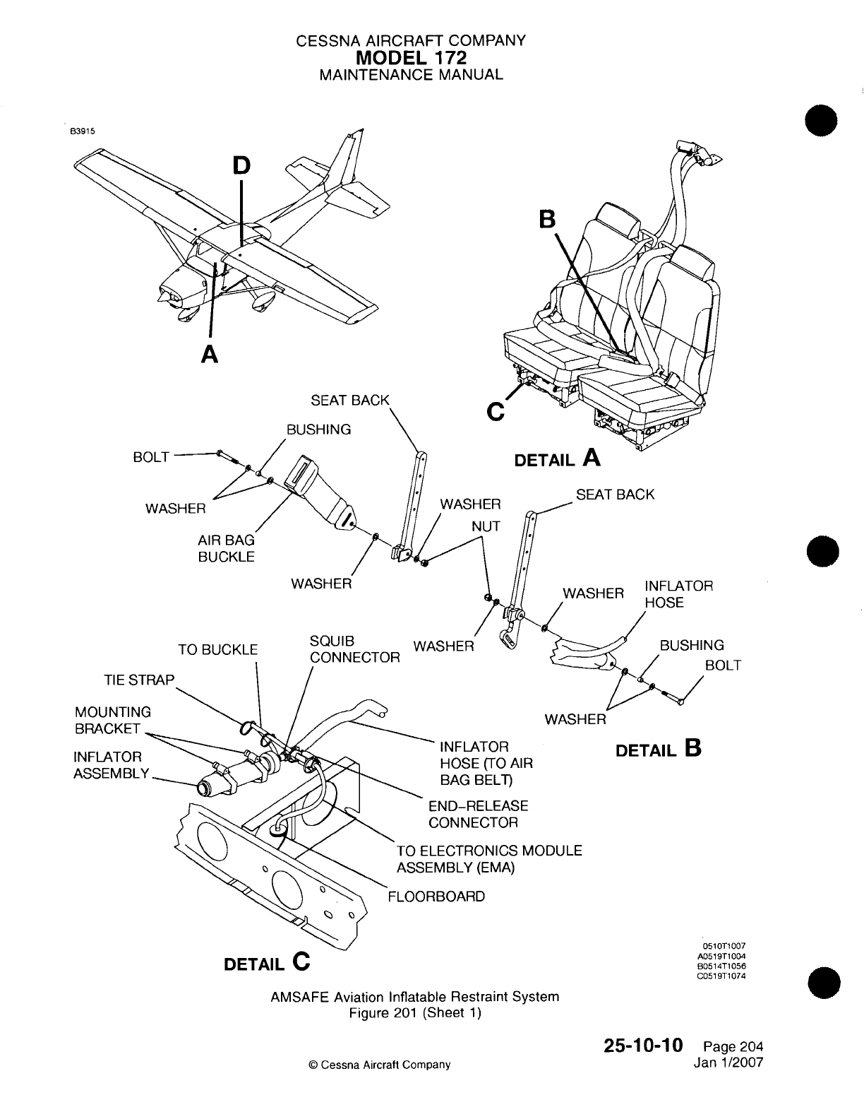
CESSNA AIRCRAFT
COMPANY
MODEL
172
MAINTENANCE
MANUAL
A
SEAT
BACK
BUSHING
BOLT
WA~c
WASHER
___SEAT
BACK
Tr)
Pi
1C(VI
IP
TIE
S5
SQUIBG
IOLT
WASHER
IN
FLATOR
HOSE
(TO
AIR
BAG BELT)
DETAIL
B
ND-RELEASE
,ONNECTOR
ECTRONICS
MODULE
VIBLY
(EMVA)
BOARD
AMVSAFE
Aviation
Inflatable
Restraint
System
Figure
201
(Sheet
1)
25-10-10
©
Cessna
Aircraft
Company
MOUNTIN
BRACKET
INFLATOR
ASSEM
BL
DETAIL
C
051
OT1
007
A0519T1004
B051
4T1
056
CO0i
9T1
074
Page
204
Janl1/2007
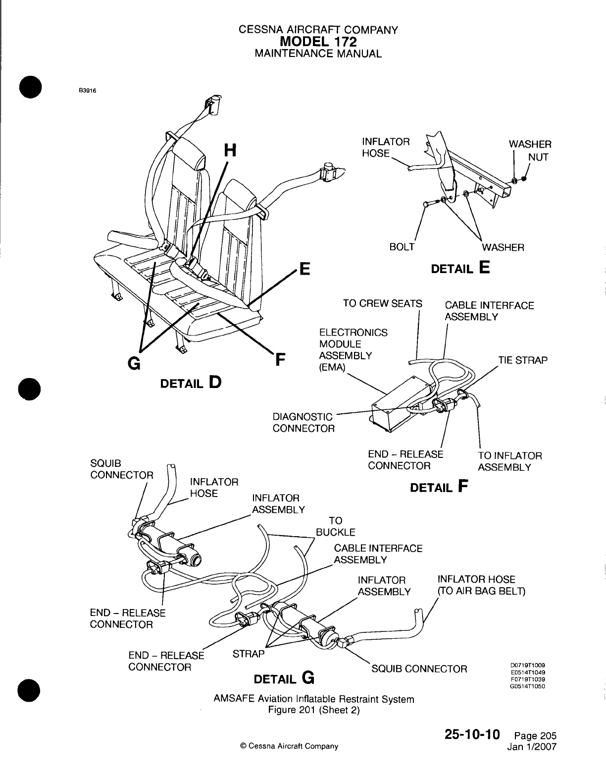
CESSNA AIRCRAFT
COMPANY
MODEL
172
MAINTENANCE
MANUAL
B3916
H
BOLT
WASHER
DETAIL
E
FO
CREW
SEATS
CABLE INTERFACE
FRONICS
JLE
MIBLY
TIE
STRAP
(trv
DETAIL
D
DIAGNOSTIC
CONNECTOR
END
-
RELEASE
DETAIL
F
TO
BUCKLE
CABLE
INTERFACE
ASSEMBLY
INFLATOR
INFLAT
ASSEMBLY
(TO
AI
R
TO INFLATOR
ASSEMBLY
OR
HOSE
BAG
BELT)
DETAIL
U
AMSAFE
Aviation
Inflatable
Restraint
System
Figure
201
(Sheet
2)
©D
Cessna
Aircraft
Company
25-1 0-1
0
Page
205
Janl1/2007
C'l^j
Hun
INFLATOR
HOSE
0'~U
ID
CONNEI
END
-
F
CON
NE(
INFLATOR
ASSEMBLY
D0719T1
009
E0514T1
049
F071
9T1
039
G0514T1
050
I
%A
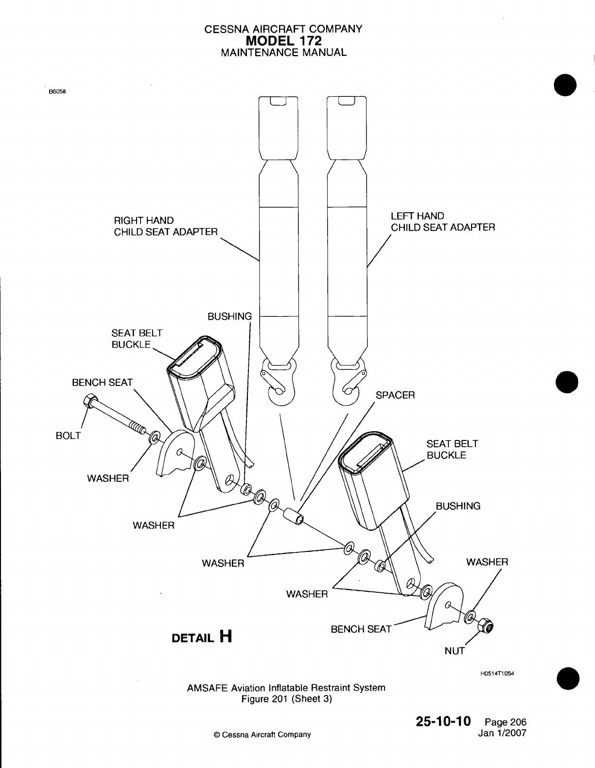
CESSNA
AIRCRAFT
COMPANY
MODEL
172
MAINTENANCE
MANUAL
B6058
RIGHT
HAND
CHILD
SEAT
ADAPTER
BU
SEAT
BELT
a
LEFT
HAND
CHILD
SEAT
ADAPTER
B
SPACER
SEAT
BELT
BUCKLE
WASHER
WASH
ER
WASHER
DETAIL
H
WASHER
BENCH
SEAT
N UT
H051
4T1
054
AMSAFE
Aviation Inflatable
Restraint
System
Figure
201
(Sheet
3)
25-10-10
©
Cessna
Aircraft
Company
BO01-
0
Page 206
Janl1/2007
I
-j L-i
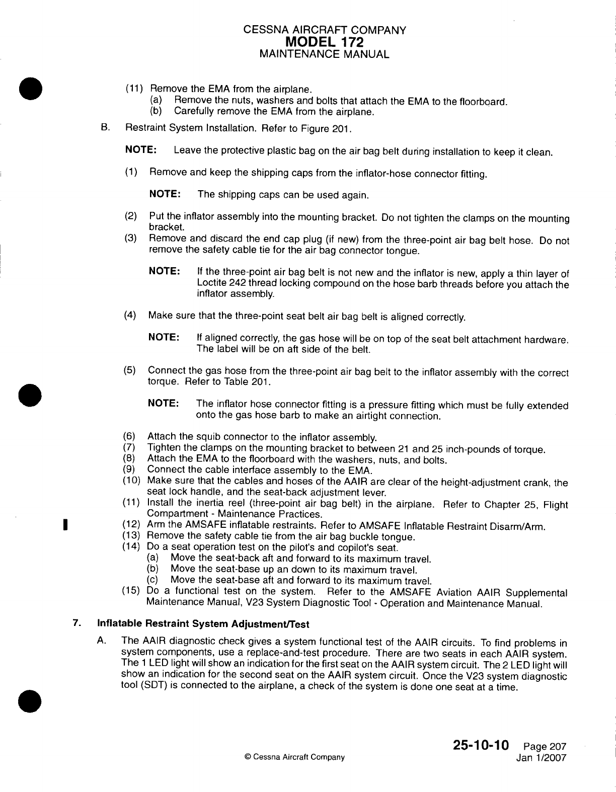
CESSNA AIRCRAFT
COMPANY
MODEL
172
MAINTENANCE
MANUAL
(11)
Remove
the
EMA
from
the
airplane.
(a)
Remove
the nuts,
washers
and bolts
that
attach
the
EMA
to
the
floorboard.
(b)
Carefully
remove
the
EMA
from the
airplane.
B.
Restraint
System
Installation.
Refer
to
Figure
201.
NOTE:
Leave
the
protective plastic
bag
on
the
air
bag
belt
during
installation
to
keep
it
clean.
(1)
Remove
and
keep the
shipping
caps
from
the
inflator-hose
connector
fitting.
NOTE: The
shipping
caps
can
be
used again.
(2)
Put
the
inflator
assembly
into
the
mounting bracket.
Do
not
tighten
the
clamps
on
the
mounting
bracket.
(3)
Remove
and
discard
the
end
cap plug
(if
new)
from
the
three-point
air
bag
belt
hose.
Do
not
remove
the
safety cable
tie
for
the air
bag
connector
tongue.
NOTE:
If
the
three-point
air
bag
belt
is
not
new
and
the
inflator
is
new,
apply
a
thin
layer
of
Loctite
242
thread locking
compound
on
the
hose
barb
threads
before
you
attach
the
inflator
assembly.
(4)
Make
sure that
the
three-point
seat
belt
air
bag
belt
is
aligned
correctly.
NOTE:
If
aligned correctly,
the gas
hose
will
be
on top
of
the
seat
belt
attachment
hardware.
The
label
will
be
on
aft
side
of
the
belt.
(5)
Connect
the gas
hose
from
the
three-point
air
bag
belt
to
the
inflator
assembly
with
the
correct
torque.
Refer
to
Table
201.
NOTE:
The
inflator
hose
connector
fitting
is a
pressure
fitting
which
must
be
fully
extended
onto
the
gas
hose
barb
to
make
an
airtight
connection.
(6)
Attach
the
squib
connector
to
the
inflator assembly.
(7)
Tighten
the
clamps
on
the
mounting bracket
to
between
21
and
25
inch-pounds
of
torque.
(8)
Attach the
EMA
to
the
floorboard
with
the
washers,
nuts,
and
bolts.
(9)
Connect
the
cable
interface
assembly
to
the
EMA.
(1
0)
Make
sure
that
the
cables
and
hoses
of
the AAIR
are
clear
of
the
height-adjustment
crank,
the
seat
lock handle,
and
the
seat-back adjustment
lever.
(11)
Install
the
inertia
reel
(three-point
air
bag belt)
in
the
airplane.
Refer
to
Chapter
25,
Flight
Compartment
-
Maintenance Practices.
(12)
Arm
the AMSAFE
inflatable restraints.
Refer
to
AMSAFE Inflatable
Restraint
Disarm/Arm.
(13)
Remove
the
safety cable
tie
from the
air
bag
buckle
tongue.
(14)
Do
a
seat
operation test
on
the pilot's
and
copilot's
seat.
(a)
Move
the
seat-back
aft
and
forward
to its
maximum
travel.
(b)
Move
the
seat-base
up
an
down
to
its
maximum
travel.
(c)
Move
the
seat-base
aft
and forward
to
its
maximum travel.
(15)
Do
a
functional test
on
the
system.
Refer
to
the
AMSAFE Aviation
AAIR
Supplemental
Maintenance
Manual,
V23
System
Diagnostic
Tool
-
Operation
and
Maintenance
Manual.
7.
Inflatable
Restraint
System
Adjustment/Test
A.
The
AAIR
diagnostic
check
gives
a
system
functional test
of
the
AAIR
circuits.
To
find
problems
in
system
components,
use
a
replace-and-test
procedure. There are
two
seats
in
each
AAIR
system.
The
1
LED
light
will
show
an
indication
for
the
first seat
on
the
AAIR
system
circuit.
The
2
LED
light
will
show
an
indication
for
the
second seat
on
the
AAIR
system
circuit.
Once
the
V23
system
diagnostic
tool
(SDT)
is
connected
to
the
airplane,
a
check
of
the
system
is
done one seat
at
a
time.
25-1
0-1
0
Page 207
©
Cessna
Aircraft
Company
Janl1/2007
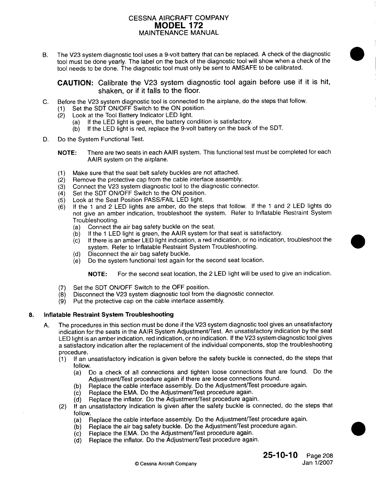
CESSNA AIRCRAFT
COMPANY
MODEL
172
MAINTENANCE
MANUAL
B.
The
V23
system
diagnostic
tool
uses
a
9-volt
battery
that
can
be
replaced.
A
check
of
the
diagnostic
tool
must
be
done
yearly.
The label
on
the
back
of
the
diagnostic
tool
will
show
when
a
check
of
the
tool
needs
to
be
done.
The
diagnostic
tool
must
only
be
sent
to
AMSAFE
to
be
calibrated.
CAUTION:
Calibrate
the V23
system
diagnostic
tool
again
before
use
if it is
hit,
shaken,
or
if it
falls
to
the floor.
C.
Before
the V23
system
diagnostic
tool
is
connected
to
the
airplane,
do
the
steps
that follow.
(1)
Set the
SDT
ON/OFF
Switch
to
the ON
position.
(2)
Look
at the
Tool
Battery
Indicator
LED
light.
(a) If
the LED
light
is
green, the
battery
condition
is
satisfactory.
(b) If
the
LED
light
is
red,
replace
the
9-volt
battery
on
the
back
of
the
SDT.
D.
Do
the
System
Functional
Test.
NOTE:
There
are
two
seats
in
each
AAIR
system.
This
functional
test
must
be
completed
for
each
AAIR
system
on
the
airplane.
(1)
Make sure
that
the
seat
belt
safety
buckles
are
not
attached.
(2)
Remove
the
protective
cap
from
the
cable
interface assembly.
(3)
Connect
the
V23
system
diagnostic
tool
to
the
diagnostic
connector.
(4)
Set
the
SDT
ON/OFF
Switch
to the
ON
position.
(5)
Look
at
the
Seat Position
PASS/FAIL
LED
light.
(6) If
the
1
and
2
LED
lights
are
amber, do the
steps
that
follow.
If
the
1
and
2
LED
lights
do
not
give
an
amber
indication,
troubleshoot
the
system.
Refer
to
Inflatable
Restraint
System
Troubleshooting.
(a)
Connect
the
air
bag
safety
buckle
on
the seat.
(b) If
the
1
LED
light
is
green,
the
AAIR
system
for
that
seat
is
satisfactory.
(c) If
there
is
an
amber
LED
light
indication,
a
red
indication,
or
no
indication,
troubleshoot
the
system.
Refer
to
Inflatable Restraint System Troubleshooting.
(d)
Disconnect
the air
bag
safety buckle.
(e)
Do
the
system functional
test again for
the
second
seat
location.
NOTE:
For
the
second
seat
location,
the
2
LED
light
will
be
used
to
give
an
indication.
(7)
Set
the
SDT
ON/OFF Switch
to the
OFF
position.
(8)
Disconnect
the
V23
system
diagnostic
tool
from
the
diagnostic
connector.
(9)
Put
the protective
cap
on
the
cable
interface assembly.
8..
Inflatable
Restraint
System
Troubleshooting
A.
The procedures
in
this section
must
be
done
if
the
V23
system
diagnostic
tool
gives
an
unsatisfactory
indication
for
the
seats
in
the
AAIR
System
Adjustment/Test.
An
unsatisfactory
indication
by the
seat
LED
light
is
an
amber
indication,
red
indication,
or
no
indication.
If
the
V23
system
diagnostic
tool
gives
a
satisfactory
indication
after
the
replacement
of
the
individual
components,
stop
the
troubleshooting
procedure.
(1) If
an
unsatisfactory
indication
is
given
before
the
safety buckle
is
connected,
do the
steps
that
follow.
(a)
Do
a
check
of
all
connections
and
tighten
loose
connections
that
are
found.
Do
the
Adjustment/Test procedure again
if
there
are
loose
connections
found.
(b)
Replace
the
cable
interface
assembly.
Do
the
Adjustment/Test procedure
again.
(c)
Replace
the
EMVA.
Do
the
Adjustment/Test
procedure again.
(d)
Replace
the
inflator.
Do
the
Adjustment/Test
procedure
again.
(2) If
an
unsatisfactory
indication
is
given
after
the
safety
buckle
is
connected,
do
the
steps
that
follow.
(a)
Replace
the
cable interface
assembly.
Do
the
Adjustment/Test procedure again.
(b)
Replace
the air
bag
safety
buckle.
Do
the
Adjustment/rest
procedure again.
(c)
Replace
the
EMA.
Do
the
Adjustment/Test
procedure again.
(d)
Replace
the
inflator.
Do
the
Adjustment/rest
procedure
again.
25-1
0-1
0
Page
208
©
Cessna Aircraft
Company
Jan
1/2007
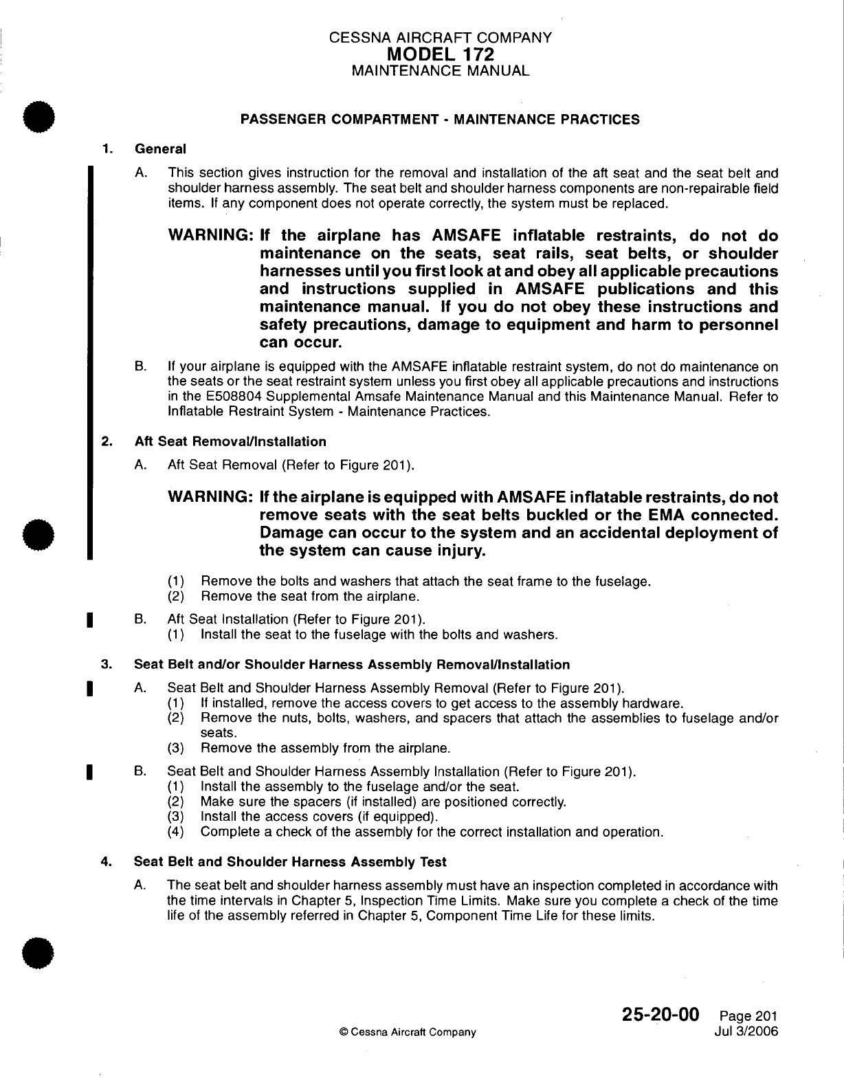
CESSNA
AIRCRAFT
COMPANY
MODEL
172
MAINTENANCE
MANUAL
PASSENGER COMPARTMENT
-
MAINTENANCE
PRACTICES
1.
General
A.
This
section
gives
instruction for
the removal
and installation
of
the aft
seat
and
the
seat
belt
and
shoulder harness
assembly.
The
seat
belt
and
shoulder
harness
components
are
non-repairable
field
items.
If
any
component
does
not
operate
correctly,
the
system
must
be
replaced.
WARNING:
If
the
airplane
has
AMSAFE
inflatable
restraints,
do
not
do
maintenance
on
the
seats,
seat
rails,
seat
belts,
or
shoulder
harnesses
until
you
first
look
at
and
obey
all
applicable precautions
and
instructions
supplied
in
AMSAFE
publications
and
this
maintenance
manual.
If
you
do
not
obey
these
instructions
and
safety
precautions,
damage
to
equipment
and
harm
to
personnel
can
occur.
B. If
your
airplane
is
equipped
with
the AMSAFE
inflatable
restraint
system,
do
not
do
maintenance
on
the
seats
or the
seat restraint
system
unless
you
first obey
all
applicable
precautions
and
instructions
in
the
E508804 Supplemental
Amsafe
Maintenance
Manual
and
this Maintenance
Manual.
Refer
to
Inflatable
Restraint
System
-
Maintenance Practices.
2.
Aft
Seat
Removal/Installation
A.
Aft
Seat
Removal
(Refer
to
Figure
201).
WARNING:
If
the
airplane
is
equipped
with
AMSAFE
inflatable restraints,
do
not
remove
seats
with
the
seat
belts buckled
or
the
EMA
connected.
Damage
can
occur
to
the
system
and
an
accidental deployment
of
the
system
can
cause
injury.
(1)
Remove
the
bolts and
washers
that
attach
the
seat
frame
to
the
fuselage.
(2)
Remove
the
seat
from
the
airplane.
I
B.
Aft
Seat
Installation
(Refer
to Figure
201).
(1)
Install
the
seat
to the
fuselage
with
the
bolts
and
washers.
3.
Seat
Belt
and/or
Shoulder
Harness
Assembly
Removal/Installation
| A.
Seat
Belt
and
Shoulder
Harness Assembly
Removal (Refer
to
Figure
201).
(1) If
installed,
remove
the
access covers
to
get
access
to the
assembly
hardware.
(2)
Remove
the
nuts,
bolts,
washers,
and
spacers
that attach
the
assemblies
to
fuselage
and/or
seats.
(3)
Remove
the assembly
from the
airplane.
B.
Seat
Belt
and
Shoulder
Harness Assembly Installation
(Refer
to
Figure
201).
(1)
Install
the
assembly
to
the
fuselage
and/or the
seat.
(2)
Make
sure
the
spacers
(if
installed)
are
positioned
correctly.
(3)
Install
the
access covers
(if
equipped).
(4)
Complete
a
check
of
the
assembly
for
the
correct installation
and
operation.
4.
Seat
Belt
and
Shoulder
Harness
Assembly
Test
A.
The seat
belt
and
shoulder
harness
assembly
must
have
an
inspection completed
in
accordance
with
the
time
intervals
in
Chapter
5,
Inspection
Time
Limits.
Make
sure you
complete
a
check
of
the
time
life
of
the
assembly
referred
in
Chapter
5,
Component
Time
Life
for
these
limits.
25-20-00
Page
201
©
Cessna Aircraft
Company
Jul 3/2006
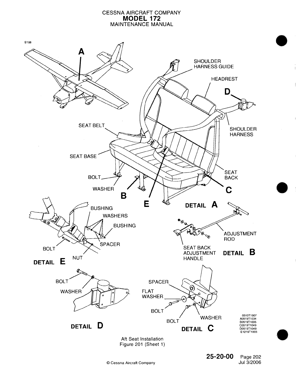
CESSNA
AIRCRAFT
COMPANY
MODEL
172
MAINTENANCE
MANUAL
SEA
ING
SEAT
BACK
ADJUSTMENT
HANDLE
VVl-^lI
1c1
I
DETAIL
C
DETAIL
B
0510T1007
A0519T1034
B0519T1035
C0519T1049
D0519T1049
E1219T1003
Aft
Seat
Installation
Figure
201
(Sheet
1)
©
Cessna
Aircraft Company
DETAIL
E
NUT
DETAIL
E
B(
SPACE
FLAT
WASHER
BOLT
DETAIL
D
BOLT
25-20-00
Page
202
Jul 3/2006
, .A
:Q
CESSNA
AIRCRAFT
COMPANY
MODEL
172
MAINTENANCE
MANUAL
INTERIOR
UPHOLSTERY
-
MAINTENANCE
PRACTICES
1.
General
A.
This
section provides general instructions
for
removal
and
installation
of
the
interior
panels,
carpet
and
rubber
mat.
2.
Cabin Panels
Removal/Installation
A.
Interior panels
are
typically
attached
to
fuselage
structure
using
screws.
Refer
to
Figure
201
for
an
exploded
view
of the
interior
panels,
headliner
and
overhead
console.
3.
Door Panels,
Carpet
and
Rubber
Mat
Removal/Installation
A.
Cabin
door
panels
are
typically
attached
to the
fuselage
and
door structure
using
small
screws.
Carpet
and
rubber
mats
are
attached
to the
floorboard
using
Velcro.
Refer
to
Figure
202
for
a
view
of
the
side
panels,
carpet
and
rubber
mat.
25-22-00
Page
201
©
Cessna Aircraft Company
Apr
7/2003
I
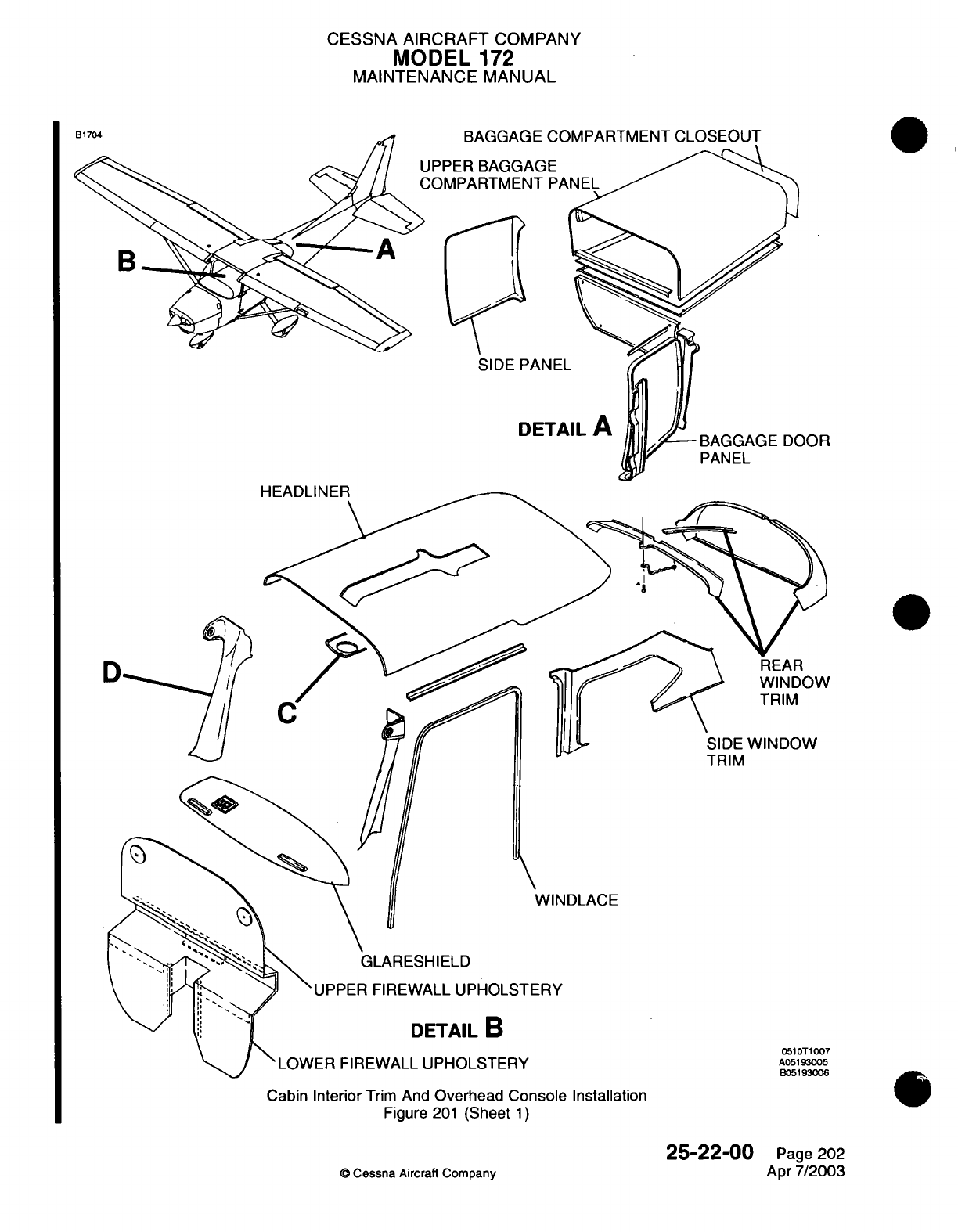
CESSNA
AIRCRAFT
COMPANY
MODEL
172
MAINTENANCE
MANUAL
BAGGAGE
COMPARTMENT
CLOSEOUT
UPPER
BAGGAG
COMPARTMENT
SIDE
PAN
DET
SIDE
WINDOW
TRIM
WINDLACE
GLARESHIELD
'UPPER
FIREWALL UPHOLSTERY
DETAIL
B
LOWER
FIREWALL UPHOLSTERY
Cabin
Interior
Trim
And
Overhead
Console
Installation
Figure
201
(Sheet
1)
25-22-00
©
Cessna
Aircraft Company
Page
202
Apr
7/2003
ILi"A
rnl
IkI-
~lr-
f
I
7s
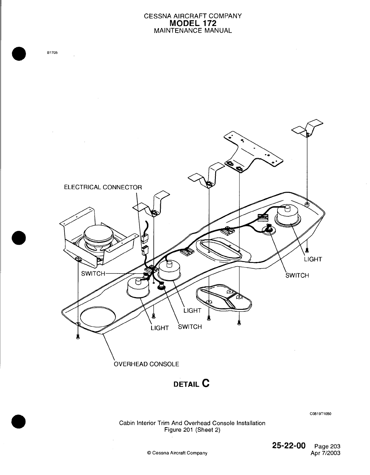
CESSNA
AIRCRAFT
COMPANY
MODEL
172
MAINTENANCE
MANUAL
B1705
0
r=3'~~~~*
ELECTRICAL
CONNECTOR
DETAIL
C
C0519T1050
Cabin
Interior
Trim
And
Overhead
Console
Installation
Figure
201
(Sheet
2)
25-22-00
©
Cessna
Aircraft
Company
Page
203
Apr 7/2003
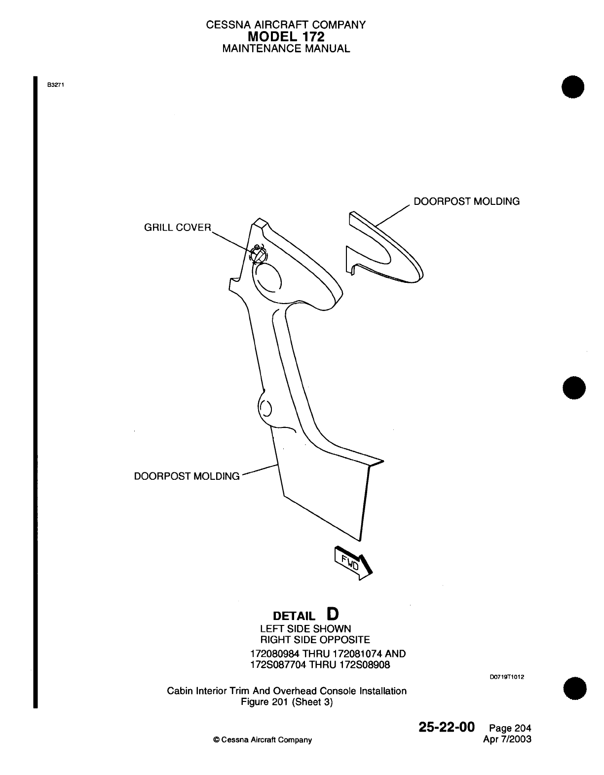
CESSNA AIRCRAFT
COMPANY
MODEL
172
MAINTENANCE
MANUAL
B3271
DOORPOST
MOLDING
/ J
GRILL
CO\
DOORPOST
DETAIL
D
LEFT
SIDE
SHOWN
RIGHT
SIDE
OPPOSITE
172080984
THRU
172081074
AND
172S087704
THRU
172S08908
D0719T1012
Cabin
Interior
Trim
And
Overhead Console Installation
Figure
201
(Sheet
3)
25-22-00
©
Cessna
Aircraft
Company
Page
204
Apr
7/2003
1
O
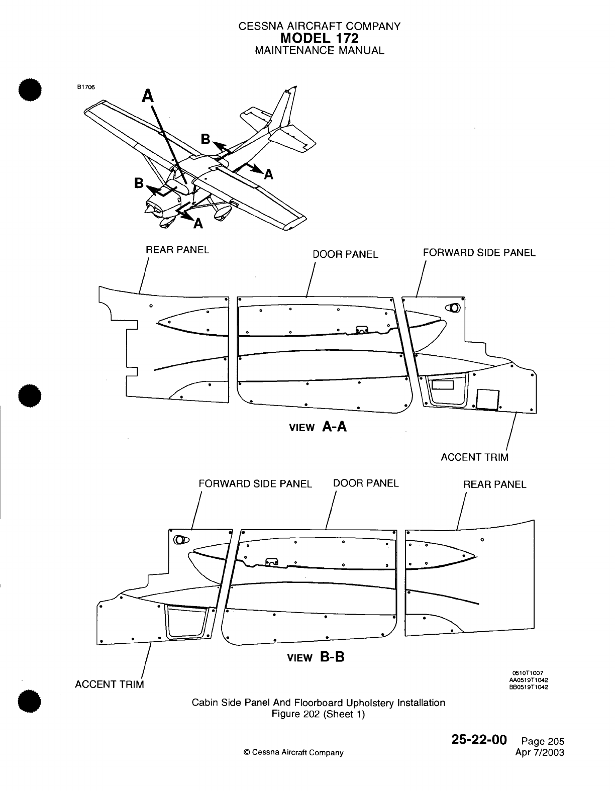
CESSNA
AIRCRAFT
COMPANY
MODEL
172
MAINTENANCE
MANUAL
B1706
REAR PANEL
DOOR
PANEL
/
FORWARD SIDE
PANEL
VIEW
A-A
ACCENT
TRIM
FORWARD
SIDE PANEL
DOOR
PANEL
REAR
PANEL
* o
o
o
.y
ACCENT TRIM
ACCENT
TRIM
VIEW
B-B
0510T1007
AA0519T1042
BB0519T1042
Cabin
Side
Panel And
Floorboard
Upholstery Installation
Figure
202
(Sheet
1)
©
Cessna
Aircraft
Company
25-22-00
Page
205
Apr
7/2003
/
<
:
LL-
0o
/
i '~~~~~~~~~~~~~~~~~~~~~~\
.
I
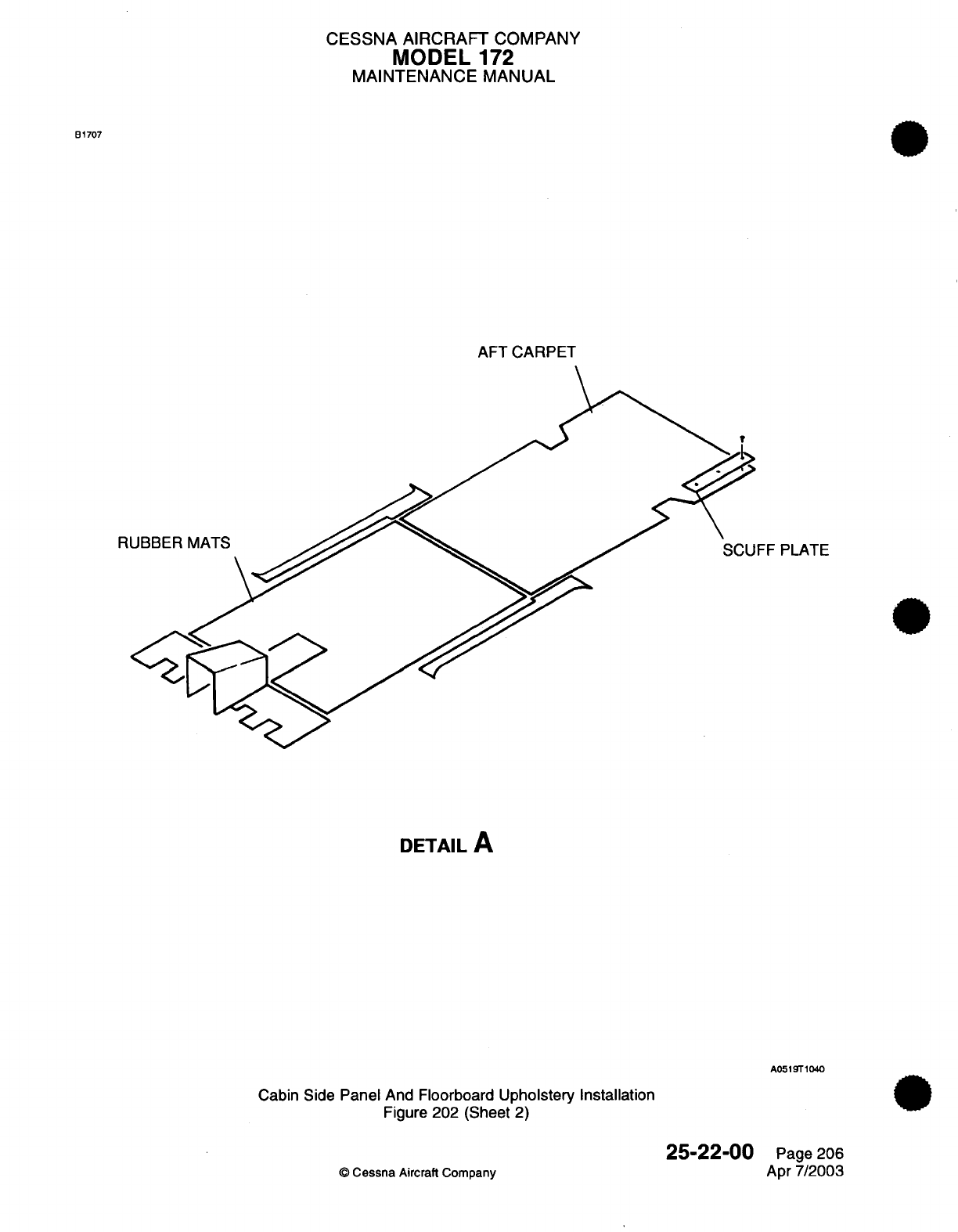
CESSNA
AIRCRAFT
COMPANY
MODEL
172
MAINTENANCE
MANUAL
B1707
AFT
CARPET
R
FF
PLATE
DETAIL
A
A0519T1040
Cabin
Side
Panel
And Floorboard
Upholstery Installation
Figure
202
(Sheet
2)
25-22-00
©
Cessna
Aircraft Company
Page 206
Apr
7/2003
CESSNA
AIRCRAFT
COMPANY
MODEL
172
MAINTENANCE
MANUAL
CARGO
TIE-DOWNS
-
MAINTENANCE
PRACTICES
1.
General
A.
Cargo
tie-downs
are
provided
for
the
airplane to
accommodate
a
variety
of
loading
positions.
These
tie-downs
are
secured directly
to
the
floorboard
through nutplates
or
indirectly
to
the floorboard
through
seat
rails.
Refer
to
Figure
201
for
an
illustration
of
these
tie-
downs.
25-50-00
Page
201
©
Cessna
Aircraft
Company
Apr
7/2003
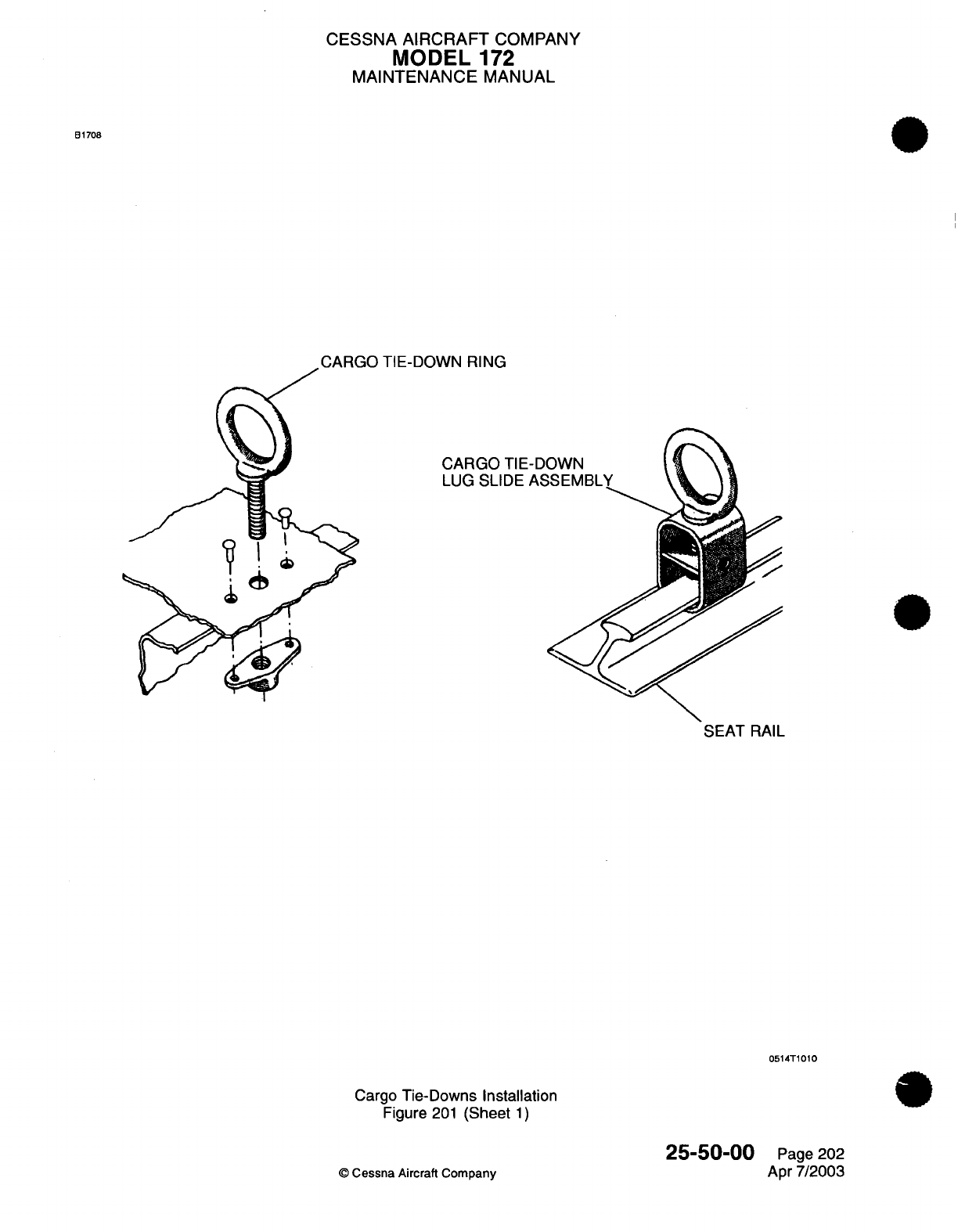
CESSNA
AIRCRAFT
COMPANY
MODEL
172
MAINTENANCE
MANUAL
B1708
CARGO TIE-DOWN
RING
CARGO
TIE-DOWN
LUG SLIDE
ASSEMBLY
SEAT
RAIL
0514T1010
Cargo
Tie-Downs Installation
Figure
201
(Sheet
1)
25-50-00
©
Cessna
Aircraft
Company
Page 202
Apr 7/2003
-- - --
-
^
CESSNA
AIRCRAFT
COMPANY
MODEL
172
MAINTENANCE
MANUAL
POINTER
EMERGENCY
LOCATOR
TRANSMITTER
-
MAINTENANCE PRACTICES
1.General
A.
This
section
gives
maintenance
practices for
the
Emergency Locator
Transmitter
(ELT).
The
ELT
is
activated
by
an
internal G-switch
or
manually
by
a
remote
switch
on
the
instrument
panel,
or
by
the
ELT
master
switch.
The
ELT
transmits
an
emergency distress
signal
on
121.5/243.0
MHz.
*2.
Pointer
ELT
Removal/installation
A.
ELT
Removal
(Refer
to
Figure
201).
(1)
Get
access
to the
ELT
through
the
baggage
compartment
door
on
the
left
side.
(a)
On
airplanes
without
the
G1000
system,
remove
the
bolts,
tiedowns,
and
plastic
closeout
from
the
lower
baggage
area
(Zone 240).
Refer
to
Airplane
Zoning
-
Description
and
I ~ ~~~~Operation.
(b)
On
airplanes
with
the
G1000
system,
remove
the molding
between
the upper
baggage
comnpartment
panel
and
the
rear
window
trim.
(2)
Put
the
ELT
master
switch
in
the
OFF/RESET
(center)
position.
CAUTION:
Do
not
disconnect
the
ELT
remote
connector
before
you
put
the
ELT
master
switch
in
the
OFF/RESET
(center)
position.
ELT
internal
fuse failure
can
occur
if
the
ELT
remote
connector
is
disconnected
before
the
ELT
master
switch
is
put
in
the
OFF/RESET
(center)
position.
(3)
Disconnect
the
ELT
antenna
coaxial
cable
from
the
ELT.
(4)
Disconnect
the
ELT
remote
connector
from
the
ELT.
(5)
Disengage
the attach
strap
from
around
the
ELT
and
remove
the
ELT
from the
airplane.
B.
ELT
Installation
(Refer
to
Figure
201).
(1)
Complete
an
ELT
G-Switch Operation Check. Refer
to
ELT
Operational
Test,
ELT
G-Switch
Operation Check.
CAUTION:
Make sure
that
the
direction-of-flight
arrow
on
the
ELT
points
to
the
nose
of
the
airplane.
CAUTION:
Make
sure
that
the
ELT
master
switch
is
inthe
OFF/RESET position.
ELT
internal
fuse
failure
can
occur
if
the
ELT
remote
connector
is
installed
with the
ELT
master switch
in
the
ON or
AUTO
position.
(2)
Put
the
ELT
into the
ELT
bracket
and
tighten
the
ELT
attach
strap.
(3)
Connect
the
ELT
remote
connector
to
the
ELT.
(4)
Connect
the
ELT
antenna coaxial
cable
to the
ELT.
(5)
Put
the
ELT
master
switch
in
the
AUTO
position.
(6)
Complete
the Control
Tower
Monitored
or
Locally
Monitored
ELT
Operational
Test.
Refer
to
ELT
Operational
Test,
Control
Tower
Monitored
ELT
Operational
Test
or
Locally
Monitored
ELT
Operational
Test.
(7)
Install~the
removed interior pieces.
(a)
On
airplanes
without
the
Gi1
000
system,
install
the
bolts,
tiedowns,
and
plastic
closeout
to
the
lower baggage
area (Zone 240).
Refer
to
Airplane
Zoning
-
Description
and
Operation.
(b)
On
airplanes
with
the
G1000
system,
install
the
molding
between
the upper
baggage
compartment
panel
and
the rear
window
trim.
25-60-00
Page
201
©Cessna
Aircraft
Company
Jan-1/2007
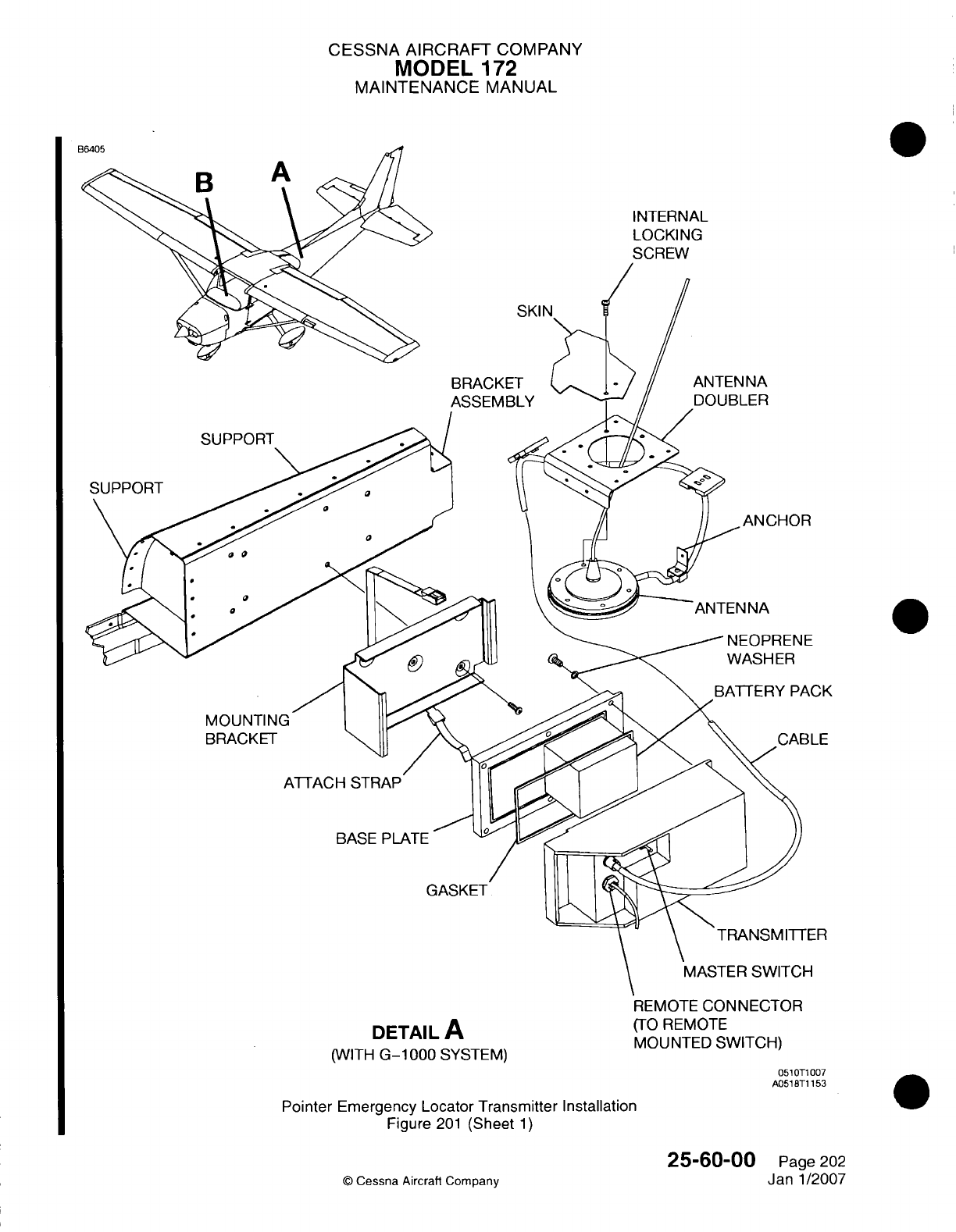
CESSNA
AIRCRAFT
COMPANY
MODEL
172
MAINTENANCE
MANUAL
INTERNAL
LOCKING
SKIN,
BRACKET
ASSEMBLY
ANTENNA
DOUBLER
SUPPORT
NEOPRENE
WASHER
MOUNTING
BRACKET
ATTACH
STRAP
BASE
PLATE
ITRANSMITTER
MASTER
SWITCH
DETAIL
A
(WITH
G-1000
SYSTEM)
REMOTE
CONNECTOR
(TO
REMOTE
MOUNTED
SWITCH)
051
OTi
007
A0518BT1
153
Pointer
Emergency
Locator Transmitter Installation
Figure
201
(Sheet
1)
©
Cessna Aircraft Company
25-60-00
Page
202
Janl1/2007
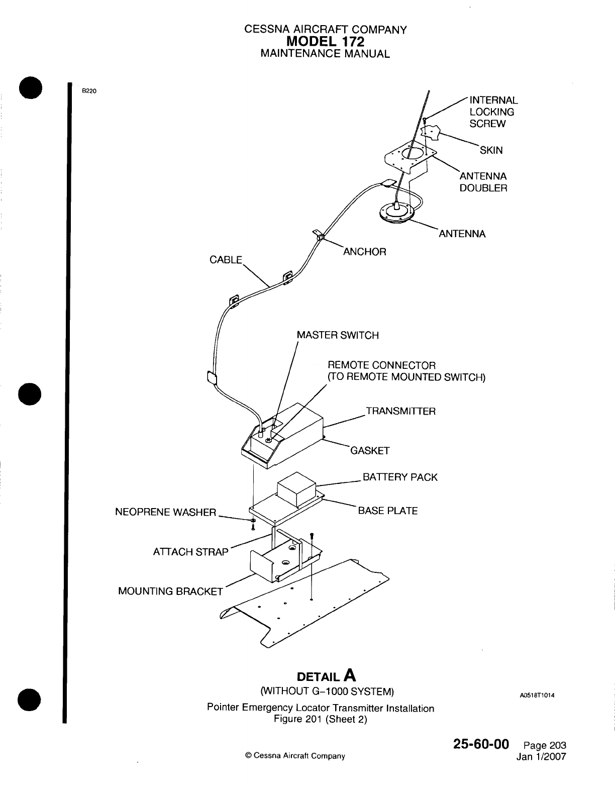
CESSNA
AIRCRAFT
COMPANY
MODEL
172
MAINTENANCE
MANUAL
B220
DOUBLER
ANTENNA
ANCHOR
MASTER SWITCH
REMOTE
CONNECTOR
(TO
REMOTE
MOUNTED
SWITCH)
TRANSMITTER
BATTERY
PACK
NEOPRI
MOUN]
DETAIL
A
(WITHOUT
G-1
000
SYSTEM)
Pointer Emergency
Locator Transmitter Installation
Figure
201
(Sheet
2)
©
Cessna Aircraft
Company
25-6000
Page
203
Janl1/2007
A0518BT1
014
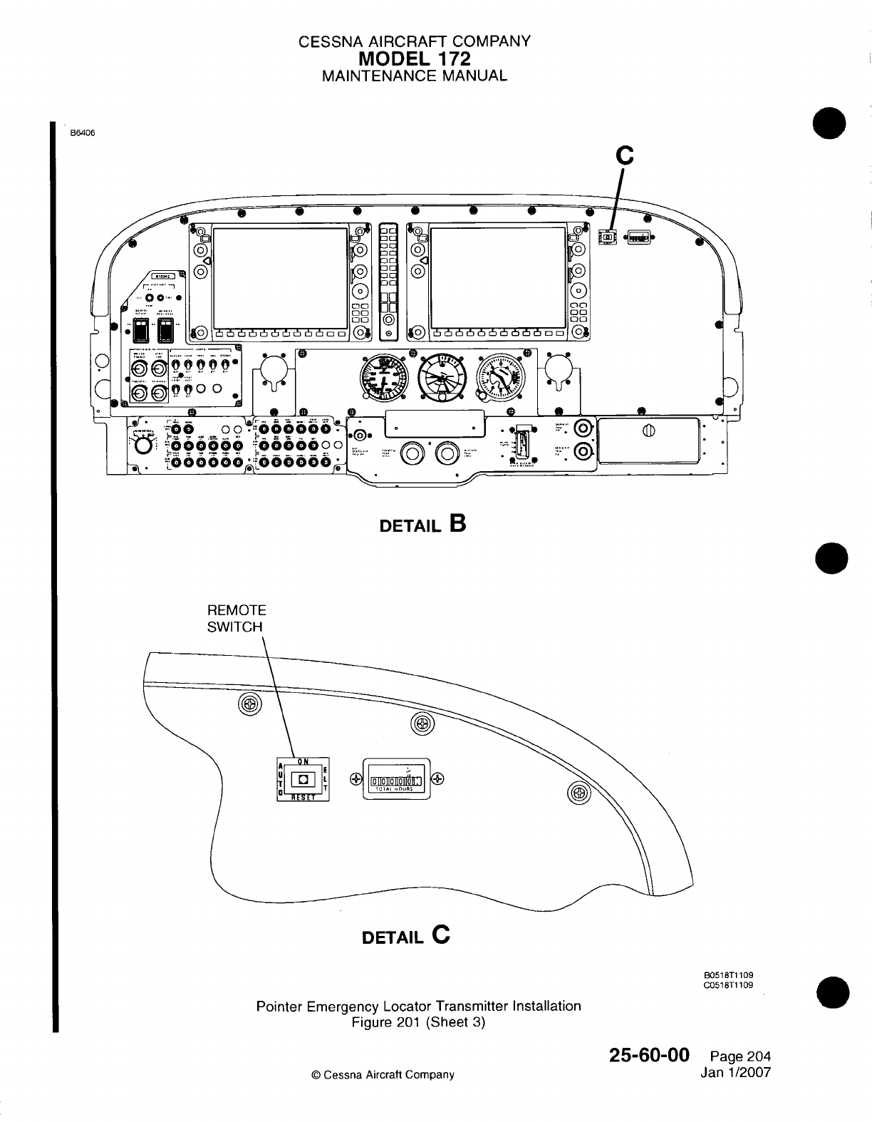
CESSNA
AIRCRAFT
COMPANY
MODEL
172
MAINTENANCE
MANUAL
B6406
DETAIL
B
REMOTE
SWITCH
DETAIL
C
B051
BT1
109
C051
BT1
109
Pointer
Emergency
Locator
Transmitter Installation
Figure
201
(Sheet
3)
25-60-00
©
Cessna Aircraft
Company
0
Page
204
Janl1/2007
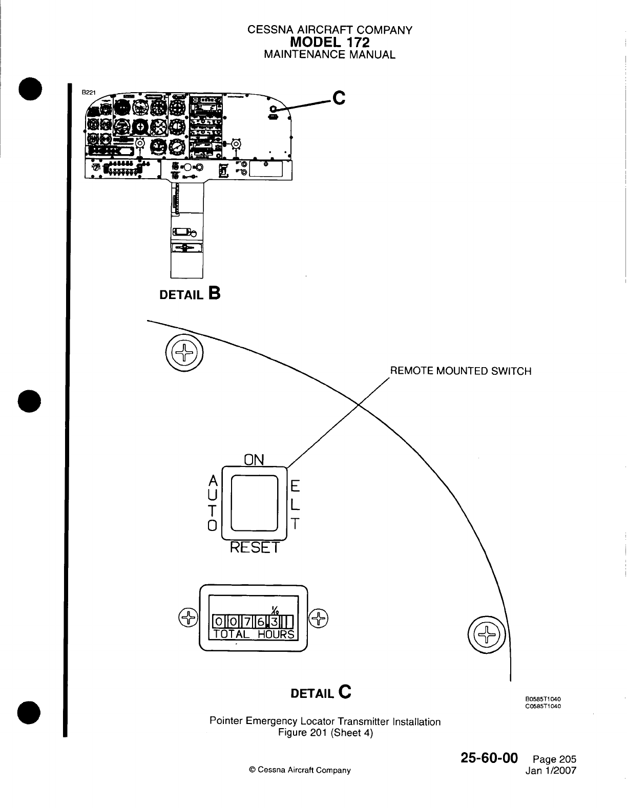
CESSNA
AIRCRAFT
COMPANY
MODEL
172
MAINTENANCE
MANUAL
DETAIL
B
TCH
DETAIL
C
B0585T1
040
C0585T1
040
Pointer
Emergency
Locator
Transmifter
Installation
Figure
201
(Sheet
4)
©
Cessna
Aircraft
Company
25-60-00
Page
205
Jan-1/2007
I
CESSNA
AIRCRAFT
COMPANY
MODEL
172
MAINTENANCE
MANUAL
3.
ELT
Remote
Switch
Removal/installation
CAUTION:
Do
not
disconnect
the
ELT
remote
connector
before you
put
the
ELT
master
switch
in
the
OFF/RESET (center)
position.
ELT
internal
fuse
failure
can
occur
if
the
ELT
remote
connector
is
disconnected
before the
ELT
master
switch
is
put
in
the
OFF/RESET
(center)
position.
CAUTION:
Disconnect
the
ELT
remote
connector
from
the
ELT
before
you
remove
the
ELT
remote
switch
or
disconnect
the
ELT
remote
switch
connector.
ELT
internal fuse failure
can
occur
if
the
ELT
remote
switch
or
disconnect
is
removed
before
the
ELT
remote
connector
is
disconnected.
A.
ELT
Remote Switch
Removal
(Refer
to
Figure
201).
(1)
Put
the
aircraft
master
switch
(ALT/BAT)
to
the
OFF
position.
(2)
Get
access
to
the
ELT
through
the
baggage
compartment
door
on
the
left
side.
(a)
On
airplanes without
the
GlOQO0
system,
remove
the bolts,
tiedowns,
and
plastic closeout
from
the
lower
baggage
area (Zone
240).
Refer
to
Airplane Zoning
-
Description
and
I ~ ~~~~Operation.
(b)
On
airplanes
with
the G1000
system,
remove
the
molding between
the
upper baggage
compartment
panel
and
the
rear
window
trim.
(3)
Put
the
ELT
master switch
in
OFF/RESET
(center)
position.
(4)
Disconnect
the
ELT
remote
connector
from
the
ELT.
(5)
Get
access
to
the
back
of
the
ELT
remote
switch
(Zone
221).
(6)
Disconnect
the
ELT
remote
switch
connector.
(7)
Compress
and hold
the locking tabs
on
the
ELT
remote
switch.
Pull
the
ELT
remote
switch
aft
and
away
from
the
instrument
panel.
B.
ELT
Remote
Switch
Installation
(Refer
to
Figure
201).0
(1)
Hold
the
edges
of
the
ELT
remote switch
and
put
it
into
the
instrument
panel
cutout.
(2)
Make sure
the
locking
tabs engage
and
that
the
switch
is
correctly
installed.
(3)
Connect
the
ELT
remote switch
connector.
(4)
Put
the
ELT
remote
switch
to
the AUTO
position.
CAUTION:
Make sure that
the
ELT
master
switch
is
inthe
OFF/RESET position.
ELT
internal fuse
failure
can
occur
if
the
ELT
remote
connector
is
installed
with
the
ELT
master
switch
in
the
ON or
AUTO
position.
(5)
Connect
the
ELT
remote
connector
to
the
ELT.
(6)
Put the
ELT
master switch
in
the
AUTO
position.
(7)
Complete
the
Control
Tower
Monitored
or
Locally
Monitored
ELT
Operational
Test.
Refer
to
ELT
Operational
Test,
Control
Tower
Monitored
ELT
Operational
Test
or
Locally
Monitored
ELT
Operational
Test.
(8)
Install
the
removed
interior
pieces.
(a)
On
airplanes without
the
G1000
system,
install
the bolts,
tiedlowns,
and
plastic
closeout
to
the
lower
baggage
area
(Zone
240). Refer
to Airplane
Zoning
-
Description
and
Operation.
(b)
On
airplanes
with
the
G1000
system,
install
the molding
between
the
upper
baggage
compartment
panel
and
the
rear
window
trim.
4. ELT
Antenna
Removal/installation
(integral
Base
with
Coaxial
Ca~ble)
A.
ELT
Antenna Removal (Refer
to Figure
201).
(1)
Get
access
to
the
ELT
and
ELT
antenna through
the
baggage compartment door
on
the
left
side.
(a)
On
airplanes
without
the
G
1000
system,
remove
the
bolts,
tiedowns,
and
plastic closeout
from
the
lower
baggage
area (Zone
240).
Refer
to
Airplane
Zoning
-
Description
and
25-60-00
Page
206
CE)
C.--na
Aircraft
Comoanv
Janl1/2007
-I
CESSNA
AIRCRAFT
COMPANY
MODEL
172
MAINTENANCE
MANUAL
(b)
On
airplanes
with the
G1000 system,
remove
the molding
between
the
upper
baggage
compartment
panel
and
the
rear
window
trim.
(2)
Disconnect
the
ELT
antenna coaxial
cable
from
the
ELT.
(3)
Remove
all
of
the
tie
straps
that
attach
the
ELT
antenna
coaxial
cable
to
the
fuselage.
(4)
On
the
external
skin
of
the
airplane,
remove
the
six
internal
locking
screws
that attach
the
ELT
antenna
to
the
fuselage.
NOTE:
The
ELT
antenna
has
an
integral
base and
coaxial
cable.
(5)
Remove
the
ELT
antenna
from
inside
of
the
airplane.
B.
ELT
Antenna Installation
(Refer
to
Figure
201).
(1)
From
inside
the
airplane,
put
the
ELT
antenna
in
position
on
the fuselage
with the
ELT
antenna
pointing
aft.
(2)
On
the
external
skin of the
airplane,
use
the
internal locking
screws
to
attach
the
ELT
antenna
base
to
the
fuselage.
(3)
Connect
the
ELT
antenna coaxial
cable
to the
ELT.
(4)
Use
tie
straps
to
attach
the
ELT
antenna
coaxial
cable
to the
fuselage.
(5)
Complete
the Control
Tower
Monitored
or
Locally
Monitored
ELT
Operational
Test.
Refer
to
ELT
Operational
Test
-
Control
Tower
Monitored
ELT
Operational
Test
or
Locally
Monitored
ELT
Operational
Test.
(6)
Install
the
removed
interior
pieces.
(a)
On
airplanes
without
the
G
1000
system,
install
the
bolts,
tiedowns,
and
plastic
closeout
to
the lower
baggage
area
(Zone 240).
Refer
to
Airplane
Zoning
-
Description
and
Operation.
(b)
On
airplanes
with
the
G1000
system,
install
the
molding
between
the
upper
baggage
compartment
panel
and
the
rear
window
trim.
5.
ELT
Whip
Antenna
Removal/Installation.
A. ELT Whip Antenna Removal (Refer to Figure 201).
*
~~(1)
Get
access
to
the
ELT
and
ELT
antenna through
the
baggage
compartment
door
on
the
left
side.
*
~~~~(a)
On
airplanes without
the
G
1000
system,
remove
the
bolts,
tiedowns,
and
plastic
closeout
*
~~~~~from
the
lower
baggage
area
(Zone 240).
Refer
to
Airplane
Zoning
-
Description
and
*
~~~~~Operation.
()(b)
On
airplanes
with
the
G1000
system, remove
the
molding
between
the upper
baggage
compartment
panel
and
the
rear
window
trim.
2)Disconnect
the
ELT
whip
antenna
coaxial
cable
from the
ELT
whip
antenna.
(3)
From
inside
the
airplane,
remove
the
nut
and
washer that
attach
the
ELT
whip
antenna
to
the
fuselage.
(4)
Remove
the
ELT
whip
antenna
from
the
external
skin
of the
airplane.
B.
ELT
Whip
Antenna Installation
(Refer
to
Figure
201).
(1)
Put
the
ELT
whip
antenna
in
position
on
the
external skin
of
the
fuselage
with
the
ELT
whip
antenna
pointing
aft.
(2)
From
inside
the
airplane,
use
the
nut
and
washer
to
connect
the
ELT
whip
antenna
to
the
fuselage.
(3)
Connect
the
ELT
antenna
coaxial
cable
to
the
ELT
whip
antenna.
(4)
Complete
the
Control
Tower
Monitored
or
Locally
Monitored
ELT
Operational
Test.
Refer
to
ELT
Operational
Test,
Control
Tower
Monitored
ELT
Operational
Test
or
Locally
Monitored
ELT
Operational
Test.
(5)
Install
the
removed
interior
pieces.
(a)
On
airplanes without
the
G
1000
system,
install the
bolts,
tiedowns,
and
plastic
closeout
to
the lower
baggage area
(Zone 240).
Refer
to
Airplane
Zoning
-
Description
and
Operation.
(b)
On
airplanes
with
the
G1000
system,
install the molding
between
the
upper
baggage
compartment
panel and
the
rear
window
trim.
6.
ELT
Battery
Pack
Removal/installation.
W
A.
ELT
Battery
Pack
Removal (Refer
to
Figure
201).
25-60-00
Page
207
0
Cessna
Aircraft
Company
Janl1/2007
..
91
Ank
CESSNA AIRCRAFT
COMPANY
MODEL
172
MAINTENANCE
MANUAL
WARNING:
Obey the
correct procedures
to
discard
the
unserviceable
ELT
battery
pack to
prevent
damage
to the
environment
or
personal
injury.
(1)
Remove
the
ELT
from
the
airplane.
Refer
to
ELT
Removal/installation.
(2)
Remove
the
screws that
attach
the
ELT
base
plate
to
the
ELT.
(3)
Disconnect
the
battery
pack
connector
for
the
ELT.
(4)
Remove
the
ELT
battery
pack
from
the
ELT.
B.
ELT
Battery
Pack
Installation
(Refer
to Figure
201).
CAUTION:
Use
only the
recommended
battery pack
for the
ELT,
or
the
operating
life
and/or
signal
strength
of
the
ELT
will
decrease.
The
incorrect
battery
pack
can
also change
the
mechanical
configuration,
which
will
cause
too
much
vibration
and
corrosion.
(1)
Put
the
ELT
battery pack
in
the
ELT.
(2)
Connect
the
ELT
battery
pack
connector.
CAUTION:
Do
not
tighten
the
ELT
gasket
and
screws
too
much.
(3)
Use
screws
to
attach
the
ELT
base
plate
and
gasket
to
the
ELT.
NOTE:
When
the
new
battery
pack
expiration
date
is
put
in
the
airplane
records,
it is
also
recommended that
you record the
expiration
date
in
the
ELT
owner's
manual
for quick
reference.
(4)
Put the new
replacement
date
on
the
outside
of ELT
transmitter
with
a
stamp.
Put
the
date
on
the
ELT
switch
nameplate,
on
the
side
of
the
ELT
transmitter,
and
in
instruction
nameplate
on
top
of
the
ELT
transmitter.
(5)
Install
the
ELT
in
the
airplane. Refer
to
ELT
Removal/installation.
*7.
Pointer
ELT
Operational
Test
A.
Control Tower
Monitored
ELT
Operational
Test.
CAUTION: Operate
the
Emergency
Locator Transmitter
(ELT)
system
only
during
the
first
five minutes
of
each
hour.
Refer
to the
FAA
Advisory
Circular
AC-91
-44A.
(1)
Request permission
from
the
control
tower
and/or
flight
service station
to
do
a
test
of
the
ELT
system.
CAUTION:
Do
not
operate
the
ELT
system
for
more
than
three
pulses
of
the
audio
signal.
Longer operation
can
decrease
the
ELT
battery
power
supply.
NOTE:
The airplane's
VHF
receiver
or
ADF
will
not
correctly
do
a
check
of
the
power
of
the
ELT
audio
signal.
(2)
Put
the
ELT
remote
switch
to
the
ON
position.
(3)
Contact
the
control
tower and/or flight
service
station
to
make sure the
ELT
system
operates
correctly.
(4)
Momentarily
put
the
ELT
remote
switch
to RESET
position.
(5)
Put
the
ELT
remote
switch
in
the
AUTO
position.
(6)
Contact
the
control tower
and/or flight
service
station
to
make
sure
the
ELT
stopped
transmission.
25-60-00
Page
208
©
Cessna
Aircraft
Company
Janl1/2007
CESSNA
AIRCRAFT
COMPANY
MODEL
172
MAINTENANCE
MANUAL
B.
Locally
Monitored
ELT
Operational
Test.
CAUTION: Operate
the
Emergency Locator Transmitter
(ELT)
system
only
during
the
first five
minutes
of
each
hour. Refer
to the
FAA
Advisory
Circular
AC-91-44A.
(1) (1)
Put
a
small,
hand
held
AM
radio
tuned
to
any
frequency, within
six
inches
of
the
ELT
antenna.
CAUTION:
Do
not
operate
the
ELT
system
for
more
than
three pulses
of
the
audio
signal.
Longer
operation
can
decrease
the
ELT
battery
power
supply.
NOTE:
The
airplane's
VHF
receiver or
ADF
will
not
correctly
do
a
check
of
the
power
of
the
ELT
audio
signal.
(2)
Put
the
ELT
remote
switch
to
the
ON
position.
(3)
Make
sure
that
the
ELT
signal
is
heard
on the
AM
radio.
(4)
Momentarily put
the
ELT
remote
switch
to
RESET
position.
(5)
Put
the
ELT
remote switch
in
the
AUTO
position.
C.
ELT
Master
Switch
Operational
Test.
CAUTION: Operate
the
Emergency
Locator Transmitter
(ELT)
system
only
during the
first
five
minutes
of
each
hour.
Refer
to
the
FAA
Advisory
Circular
AC-91-44A.
CAUTION:
Do not
operate
the
ELT
system
for
more
than
three pulses
of the
audio
signal.
Longer
operation
can
decrease
the
ELT
battery
power
supply.
(1)
Put
the
ELT
master switch
to
the
ON
position.
(2)
Make
sure the
signal
is
heard
by
either
the
Control
Tower,
Flight
Service
Station
or
AM
radio.
(3)
Put
the
ELT
master
switch
in
the
OFF/RESET position.
(4)
Put
the
ELT
master
switch
in
the AUTO
position.
D.
ELT
G-Switch
Operational
Check.
(1)
Remove
the
ELT
from the
airplane.
Refer
to
ELT
Removal/installation.
(2)
Put
the
ELT
master
switch
in
the
AUTO
position.
(3)
Hold
the
ELT
tightly
in
one
hand,
and
move
the
ELT
fast
in
one
direction,
followed
by
a
sudden
reversal
of
direction.
(4)
Make
sure
that
the
ELT
G-switch
has
been
actuated.
(5)
Put
the
ELT
master
switch
in
the
OFF/RESET position
to
reset
the
ELT
G-switch.
(6)
Install the
ELT
in
the
airplane.
Refer
to ELT
Removal/installation.
25-60-00
Page
209
(D
Cessna
Aircraft
Company
Janl1/2007
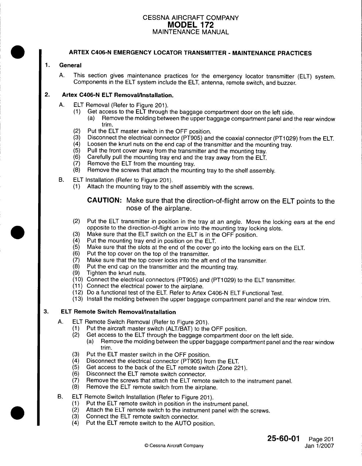
CESSNA
AIRCRAFT
COMPANY
MODEL
172
MAINTENANCE
MANUAL
ARTEX
C406-N EMERGENCY
LOCATOR
TRANSMI1TER
-
MAINTENANCE
PRACTICES
1.General
A.
This
section
gives
maintenance
practices
for
the
emergency locator transmitter
(ELT)
system.
Components
in
the
ELT
system
include
the
ELT,
antenna,
remote
switch,
and
buzzer.
2.
Artex
C406-N
ELT
Removal/installation.
A.
ELT
Removal
(Refer
to
Figure
201).
(1)
Get
access
to
the
ELT
through
the
baggage compartment
door
on
the
left
side.
(a)
Remove
the
molding
between
the
upper
baggage
compartment
panel
and
the
rear
window
trim.
(2)
Put
the
ELT
master
switch
in
the
OFF
position.
(3)
Disconnect
the
electrical
connector
(PT905)
and
the
coaxial connector
(PT1
029)
from
the
ELT.
(4)
Loosen
the
knurl
nuts
on
the
end
cap
of
the
transmitter
and
the
mounting
tray.
(5)
Pull
the
front
cover
away
from
the
transmitter
and
the
mounting
tray.
(6)
Carefully
pull
the
mounting
tray
end and
the tray
away
from
the
ELT.
(7)
Remove
the
ELT
from
the
mounting
tray.
(8)
Remove
the
screws that
attach
the
mounting
tray
to
the
shelf
assembly.
B.
ELT
Installation
(Refer
to
Figure
201).
(1)
Attach
the
mounting
tray
to
the
shelf assembly
with
the
screws.
CAUTION:
Make
sure
that
the
direction-of-flight
arrow
on
the
ELT
points
to
the
nose
of
the
airplane.
(2)
Put
the
ELT
transmitter
in
position
in
the
tray
at
an
angle.
Move
the
locking
ears
at
the
end
opposite
to
the
direction-of-flight
arrow into
the
mounting
tray
locking
slots.
(3)
Make
sure
that
the
ELT
switch
on
the
ELT
is in
the
OFF
position.
(4)
Put the
mounting
tray
end
in
position
on
the
ELT.
(5)
Make sure
that
the
slots
at the
end
of the
cover
go
into
the
locking
ears
on
the
ELT.
(6)
Put
the
top
cover
on
the
top
of
the
transmitter.
(7)
Make sure
that
the
top
cover
locks
into
the aft
end
of the
transmitter.
(8)
Put the
end
cap
on
the
transmitter
and
the
mounting
tray.
(9)
Tighten
the knurl
nuts.
(1 0)
Connect
the
electrical
connectors
(PT905)
and
(PT1
029)
to
the
ELT
transmitter.
(11)
Connect
the
electrical
power
to
the
airplane.
(12)
Do
a
functional
test
of
the
ELT.
Refer
to
Artex
C406-N
ELT
Functional
Test.
(13)
Install
the
molding
between
the
upper baggage compartment
panel
and
the
rear
window
trim.
3.
ELT
Remote
Switch
Removal/installation
A.
ELT
Remote
Switch Removal
(Refer
to
Figure
201).
(1)
Put
the
aircraft master
switch
(ALT/BAT) to
the
OFF
position.
(2)
Get
access
to
the
ELT
through
the
baggage compartment
door
on
the
left
side.
(a)
Remove
the
molding
between
the
upper
baggage
compartment
panel
and
the
rear
window
trim.
(3)
Put
the
ELT
master switch
in
the
OFF
position.
(4)
Disconnect
the
electrical connector
(PT905)
from
the
ELT.
(5)
Get
access
to
the
back
of
the
ELT
remote
switch
(Zone
221).
(6)
Disconnect
the
ELT
remote
switch
connector.
(7)
Remove
the
screws
that attach
the
ELT
remote
switch
to
the instrument panel.
(8)
Remove
the
ELT
remote switch from
the
airplane.
B.
ELT
Remote
Switch
Installation
(Refer
to
Figure
201).
(1)
Put
the
ELT
remote
switch
in
position
in
the
instrument
panel.
(2)
Attach
the
ELT
remote
switch
to
the
instrument
panel
with
the
screws.
(3)
Connect
the
ELT
remote
switch connector.
(4)
Put
the
ELT
remote
switch
to
the
AUTO
position.
25-60-01
Page
201
©D
Cessna
Aircraft
Company
Janl1/2007
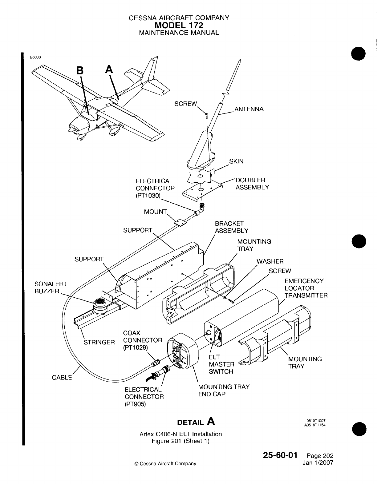
CESSNA AIRCRAFT
COMPANY
MODEL
172
MAINTENANCE
MANUAL
SCREW
SKI
N
ELECTRICAL
CONNECTOR
(PT1
030)_
SUPPORT
ASSEMBLY
BRACKET
ASSEMBLY
MOUNTING
TRAY
SUPPORT
\JCY
TTER
COAX
NG
SWITCH
I--L% I 1I.jF
CONNECTOR
(PT905)
END
CAP
DETAIL
A
TRAY
051 OP1
007
A0518T1
154
Artex
C406-N
ELT
Installation
Figure
201
(Sheet
1)
25-60-01
©
Cessna
Aircraft
Company
ANTENNA
SONA
BUZZI
0
Page
202
Janl1/2007

CESSNA
AIRCRAFT
COMPANY
MODEL
172
MAINTENANCE
MANUAL
B6001
C
DETAIL
B
REMOTE
MOUNTED
SWITCH
Or'
MEMAI
DETAIL
C
B0518T1
109
C0518T1
109
Artex
0406-N
ELT
Installation
Figure
201
(Sheet
2)
25-60-01
0
Cessna
Aircraft Company
Page
203
Janl1/2007
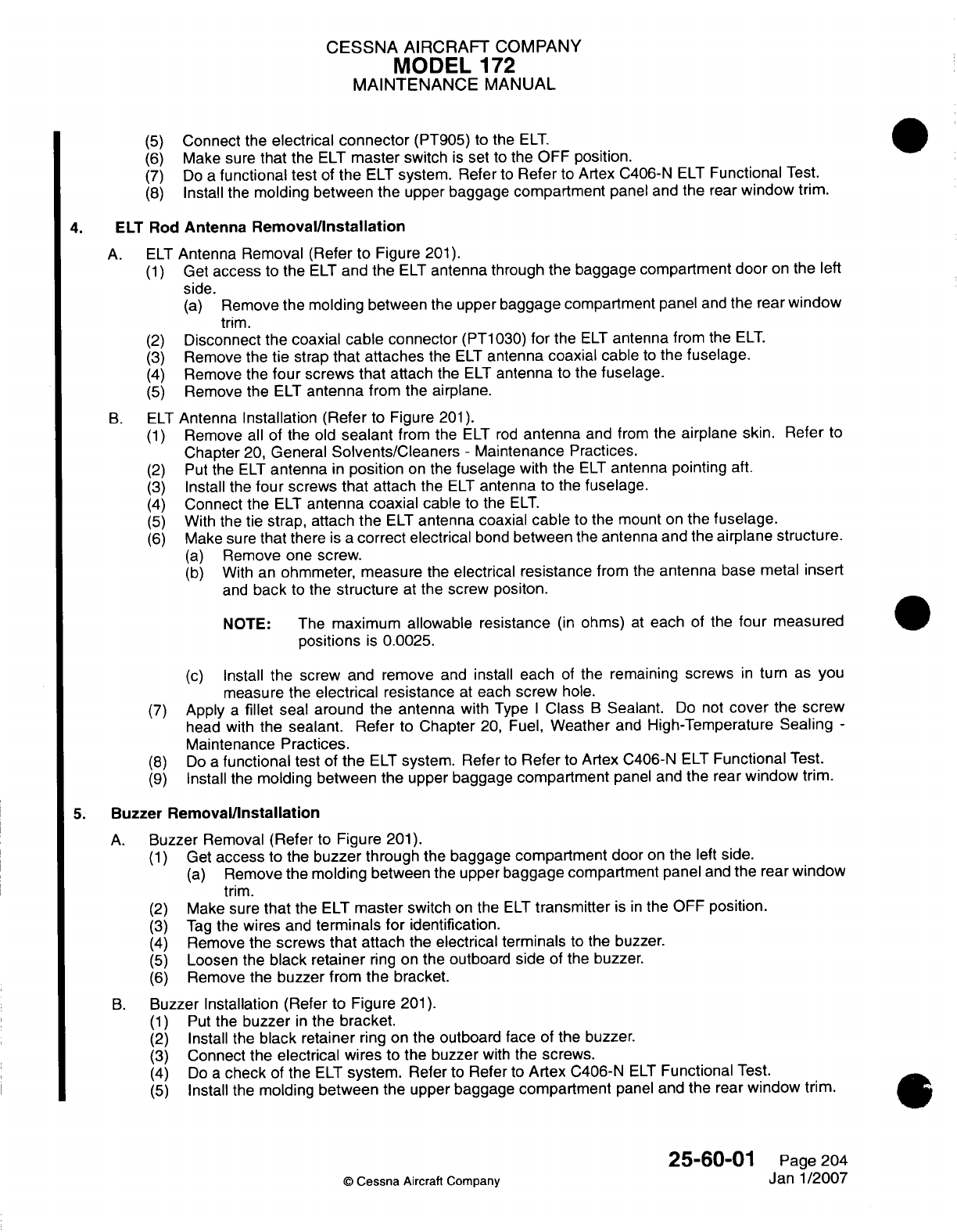
CESSNA
AIRCRAFT
COMPANY
MODEL
172
MAINTENANCE
MANUAL
(5)
Connect
the
electrical
connector
(PT905)
to
the
ELT.
(6)
Make
sure
that
the
ELT
master
switch
is
set
to
the
OFF
position.
(7)
Do
a
functional
test
of
the
ELT
system.
Refer
to
Refer
to
Artex
0406-N
ELT
Functional
Test.
(8)
Install
the
molding between the
upper
baggage compartment
panel
and
the
rear
window
trim.
4.
ELT
Rod
Antenna
Removal/installation
A.
ELT
Antenna
Removal (Refer
to
Figure
201).
(1)
Get
access
to
the
ELT
and
the
ELT
antenna through the
baggage
compartment
door
on
the
left
side.
(a)
Remove
the
molding
between
the
upper
baggage
compartment
panel
and
the
rear
window
trim.
(2)
Disconnect
the
coaxial
cable
connector
(PT1
030)
for
the
ELT
antenna
from
the
ELT.
(3)
Remove
the
tie
strap
that
attaches
the
ELT
antenna
coaxial
cable
to
the
fuselage.
(4)
Remove
the
four
screws that
attach
the
ELT
antenna
to
the
fuselage.
(5)
Remove the
ELT
antenna
from
the
airplane.
B.
ELT
Antenna Installation (Refer
to
Figure
201).
(1)
Remove
all
of
the
old
sealant
from
the
ELT
rod
antenna
and
from the
airplane
skin. Refer
to
Chapter
20,
General
Solvents/Cleaners
-
Maintenance
Practices.
(2)
Put
the
ELT
antenna
in
position
on
the
fuselage
with
the
ELT
antenna
pointing
aft.
(3)
Install
the
four
screws that attach
the
ELT
antenna
to
the
fuselage.
(4)
Connect
the
ELT
antenna
coaxial
cable
to
the
ELT.
(5)
With the
tie
strap,
attach
the
ELT
antenna
coaxial
cable
to
the
mount
on
the
fuselage.
(6)
Make
sure
that there
is a
correct
electrical
bond
between
the
antenna
and the
airplane
structure.
(a)
Remove
one
screw.
(b)
With
an
ohmmeter, measure
the
electrical
resistance
from
the
antenna
base
metal
insert
and
back
to
the
structure
at
the
screw positon.
NOTE:
The
maximum
allowable
resistance
(in
ohms)
at
each
of the
four
measured
positions
is
0.0025.
(c)
Install
the
screw
and
remove
and
install
each
of
the
remaining
screws
in
turn
as
you
measure
the
electrical
resistance
at
each
screw
hole.
(7)
Apply
a
fillet
seal
around
the
antenna
with
Type
I
Class
B
Sealant.
Do
not
cover
the screw
head
with
the
sealant. Refer
to
Chapter
20,
Fuel,
Weather
and
High-Temperature
Sealing
-
Maintenance
Practices.
(8)
Do
a
functional
test
of
the
ELT
system.
Refer
to
Refer
to
Artex
0406-N
ELT
Functional
Test.
(9)
Install
the
molding between
the upper
baggage
compartment
panel
and the
rear
window
trim.
5.
Buzzer
Removal/installation
A.
Buzzer
Removal
(Refer
to
Figure
201).
(1)
Get
access
to the
buzzer
through
the
baggage
compartment
door
on
the
left
side.
(a)
Remove
the molding between
the
upper
baggage
compartment
panel
and
the
rear
window
trim.
(2)
Make sure
that
the
ELT
master
switch
on
the
ELT
transmitter
is
in
the
OFF position.
(3)
Tag
the
wires
and
terminals
for identification.
(4)
Remove
the
screws that
attach
the
electrical terminals
to the
buzzer.
(5)
Loosen
the
black
retainer
ring
on the
outboard
side
of
the
buzzer.
(6)
Remove
the
buzzer
from
the bracket.
B.
Buzzer
Installation
(Refer
to
Figure
201).
(1)
Put
the
buzzer
in
the
bracket.
(2)
Install
the
black
retainer
ring
on
the
outboard
face
of
the
buzzer.
(3)
Connect
the
electrical
wires
to the
buzzer
with
the
screws.
(4)
Do
a
check
of
the
ELT
system.
Refer
to
Refer
to
Artex
0406-N
ELT
Functional
Test.
(5)
Install the
molding
between
the
upper
baggage
compartment
panel
and
the
rear
window
trim.
25-60-01
Page
204
©
Cessna Aircraft
Company
Janl1/2007
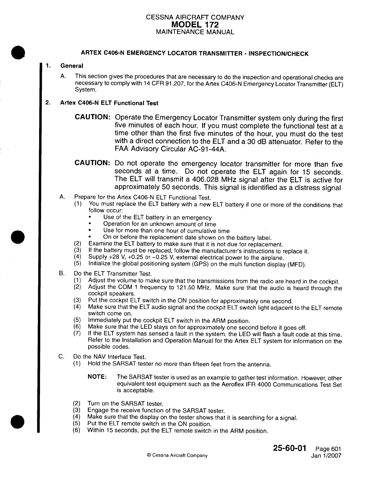
CESSNA
AIRCRAFT
COMPANY
MODEL
172
MAINTENANCE
MANUAL
ARTEX C406-N EMERGENCY
LOCATOR
TRANSMITTER
-
INSPECTION/CHECK
1.General
A.
This
section
gives
the
procedures
that
are
necessary
to
do
the
inspection
and
operational
checks
are
necessary
to
comply
with
14
CFR
91
.207, for
the Artex
0406-N
Emergency Locator
Transmitter
(ELT)
System.
2.
Artex
C406-N
ELT
Functional
Test
CAUTION: Operate
the
Emergency
Locator Transmitter
system only during
the
first
five
minutes
of
each
hour.
If
you
must
complete
the
functional
test
at
a
time other
than
the
first
five minutes
of
the
hour, you must
do
the test
with
a
direct
connection
to
the
ELT
and
a
30
dB
attenuator.
Refer
to the
FAA
Advisory Circular
AC-91-44A.
CAUTION:
Do
not
operate
the
emergency
locator
transmitter
for
more
than
five
seconds
at
a
time.
Do
not
operate
the
ELT
again
for
15
seconds.
The
ELT
will
transmit
a
406.028
MHz
signal
after
the
ELT
is
active
for
approximately
50
seconds.
This
signal
is
identified
as
a
distress
signal
A.
Prepare
for
the
Artex
C406-N
ELT
Functional
Test.
(1)
You
must
replace
the
ELT
battery
with
a
new
ELT
battery
if
one
or
more
of the
conditions
that
follow
occur:
*
Use
of
the
ELT
battery
in
an
emergency
*
Operation
for
an
unknown
amount
of
time
*
Use
for
more
than
one
hour
of
cumulative
time
*
On
or
before
the
replacement
date
shown
on
the
battery
label.
(2)
Examine
the
ELT
battery
to
make sure
that
it is
not
due for
replacement.
(3) If
the
battery
must
be
replaced,
follow
the
manufacturer's
instructions
to
replace
it.
(4)
Supply
+28
V,
+0.25
or
-0.25
V,
external
electrical
power
to
the
airplane.
(5)
Initialize
the
global
positioning
system
(GPS) on the multi
function
display
(MFD).
B.
Do
the
ELT
Transmitter
Test.
(1)
Adjust
the
volume
to
make sure
that
the
transmissions
from
the
radio
are
heard
in
the
cockpit.
(2)
Adjust
the
COM
1
frequency
to
121.50 MHz.
Make sure
that
the
audio
is
heard
through
the
cockpit
speakers.
(3)
Put
the
cockpit
ELT
switch
in
the ON
position for
approximately
one
second.
(4)
Make
sure
that
the
ELT
audio
signal
and
the
cockpit
ELT
switch light
adjacent
to
the
ELT
remote
switch
come on.
(5)
Immediately
put
the
cockpit
ELT
switch
in
the
ARM
position.
(6)
Make sure that
the
LED
stays
on
for
approximately
one
second
before
it
goes
off.
(7) If
the
ELT
system
has
sensed
a
fault
in
the
system,
the
LED
will flash
a
fault
code
at
this
time.
Refer
to the
Installation
and
Operation
Manual
for
the Artex
ELT
system
for
information
on
the
possible
codes.
C.
Do
the
NAV
Interface
Test.
(1)
Hold
the
SARSAT
tester
no
more
than
fifteen
feet from
the
antenna.
NOTE:
The
SARSAT
tester
is
used
as
an
example
to
gather test
information. However,
other
equivalent
test
equipment
such
as
the
Aeroflex
IFIR
4000 Communications
Test Set
is
acceptable.
(2)
Turn
on
the
SARSAT
tester.
(3)
Engage
the
receive function
of
the
SARSAT
tester.
(4)
Make
sure
that the
display
on
the
tester
shows
that
it is
searching
for
a
signal.
(5)
Put
the
ELT
remote
switch
in
the ON
position.
(6)
Within
15
seconds,
put the
ELT
remote
switch
in
the ARM
position.
25-60-01
Page
601
©
Cessna
Aircraft
Company
Janl1/2007
CESSNA
AIRCRAFT
COMPANY
MODEL
172
MAINTENANCE
MANUAL
(7)
Monitor
the SARSAT
tester
to
see
if it
received
a
signal
from
the
ELT
system.
(a) If
no
signal was received,
do
the
test
again
after
the
15-second
off
cycle.
(8)
Make
sure that
the
tail
number
on
the
SARSAT
tester
is
correct.
(9)
Make
sure that the
Mode
S
code
shown
on
the SARSAT
tester
is
the
same
as
the
number
that
is
on
the
back
of
the
transmitter.
(1
0)
Make
sure
that
the
latitude
and
longitude
information
is
the
same
as
that
shown
on
the
MFD
display.
(1 1)
Turn
the SARSAT
tester
off.
(12)
Disconnect
external
electrical
power
from
the aircraft.
D.
Do
the
G-Switch Operational
Test.
CAUTION:
CAUTION:
Operate
the
emergency locator transmitter
(ELT)
system
only
during
the
first
five
minutes
of
each
hour.
If
you
must
complete
the
functional
test
at
a
time
other
than
the
first
five
minutes
of the
hour,
you
must
do
the
test
with
a
direct
connection
to
the
ELT
and
a
30-dB
attenuator. Refer
to the
FAA
Advisory
Circular
AC-91
-44A.
Do
not
operate
the
emergency
locator
transmitter
(ELT)
for
more
than
five
seconds
at
a
time.
Do
not
operate
the
ELT
again
for
15
seconds.
The
ELT
will
transmit
a
406.028
MHz
signal after
the
ELT
is
active
for
approximately
50
seconds.
This
signal
is
identified
as
a
distress
signal.
Remove
the
ELT
from
the
airplane.
Refer
to
Artex
C406-N
ELT
Removal/Installation.
Install
a
jumper
wire
between
pins
12
and
13
on
the
electrical
connector
of
the
ELT.
NOTE:
The
ELT
will
not
activate
with
the
G-switch unless
electrical
pins
12
and
13
have
a
jumper
wire
installed
between them (this happens
automatically
when
the
ELT
is
locked
into
the mount tray
with
the
electrical
connector
in
position).
Because
of
the
potential
physical damage
that
can
occur
if
the
jumper
wire
is
not
installed correctly,
it is
recommended
that
an
experienced technician
do
this
procedure.
Put
the
ELT
switch
in
the OFF
position.
Use
a
receiver,
and
set
it
to
121.5
MHz
to
listen for
the
aural
warning
sweep
tone.
Hold the
ELT
transmitter tightly
in
one hand and
make
a
throwing movement
followed
by
an
opposite
movement
of
the
ELT
transmitter.
Make
sure
that
the G-switch
operates
and
that
the aural
warning
sweep
tone
is
heard
on
the
receiver
set
to
121.5
MHz.
Set
the
ELT
switch
to
the
ON
position
and
then
back
to
the
OFF
position
to
reset
the
G-switch.
Remove
the
jumper
wire
from
electrical
pins
12
and
13
on
the
electrical
connector
of
the
ELT.
Install
the
emergency locator
transmitter
in
the
airplane.
Refer
to
Artex
C406-N
ELT
Removal/
Installation.
25-60-01
©
Cessna
Aircraft
Company
Page
602
Janl1/2007
(1)
(2)
(3)
(4)
(5)
(6)
(7)
(8)
(9)
CESSNA AIRCRAFT
COMPANY
MODEL
172
MAINTENANCE
MANUAL
ARTEX
ME406
EMERGENCY
LOCATOR
TRANSMITTER
SYSTEM
-
DESCRIPTION
AND OPERATION
1.General
A.
An
Artex
ME406
Emergency
Locator
Transmitter
(ELT)
System
is
installed
to
help
rescue
teams
find
the
airplane
in
the event
of
a
crash.
It is
made
to
operate
in a
wide
range
of
environmental
conditions
and
is
resistant
to
the
forces caused
by
many
types
of
accidents.
2.
Description
A.
Artex
ME406
ELT.
(1)
The
Artex
ME406
Emergency
Locator
Transmitter
(ELT)
system includes
an
ELT
unit,
an
integral
battery
pack,
warning buzzer, internal
G-switch, antenna,
remote switch,
cable
assembly,
and
antenna
coaxial
cable.
The
ELT
unit
transmits
on
121
.5
MHz
and
406.028
MHz.
(2)
The
battery pack
has
two
D-size
lithium
cells
mounted
under
a
battery cover.
The
battery
pack
is
replaced
as
necessary
in
the
field.
(3)
The
ELT
activates
a
buzzer
that
is
installed near
the
ELT
assembly.
The
buzzer
makes
a
loud
noise
to
let
people know
that
the
ELT
is
on.
(4)
The
G-switch
is
internally
installed
in
the
ELT
transmitter
and
is
activated
with
a
sudden
reduction
in
forward
speed.
B.
Artex
ELT
Antenna.
(1)
The
ELT
system
uses
an
antenna
to
transmit
the
emergency
locator signal.
The
ELT
antenna
is
installed
on
top
of
the
tailcone
skin, forward
of
the
vertical
stabilizer.
The
ELT
antenna
is
connected
with
a
coaxial
cable
to
the
ELT
unit
inside
the
dorsal.
C.
ELT
Remote
Switch.
(1)
The
ELT
remote
switch
is
installed
on
the
right
panel. The
ELT
remote
switch
is a
two-position
rocker
switch
that
can
be
set
in
the
ARM
or
the
ON
positions.
3.
Operation
CAUTION:
Operate
the
emergency
locator
transmitter
(ELT)
system
only during the
first
five
minutes
of
each
hour.
If
you
must
complete
the
functional
test
at
a
time
other
than
the
first
five minutes
of the
hour,
you
must
do
the test
with
a
direct
connection
to
the
ELT
and
a
30
dB
attenuator.
Refer
to
the
FAA
Advisory
Circular
AC-91
-44A.
CAUTION:
Do
not
operate
the
emergency
locator
transmitter
(ELT)
for
more
than
five
seconds
at
a
time.
Do
not
operate
the
ELT
again
for
15
seconds.
The
ELT
will
transmit
a
406.028
MHz
signal after
the
ELT
is
active
for
approximately
50
seconds.
This
signal
is
identified
as
a
distress
signal.
A.
Artex ME406
ELT.
(1)
During
an
accident,
the
ELT
will
activate
automatically
and
transmit
a
standard
swept
tone
on
121.5 MHz
(emergency
frequency).
The
121.5
MHz
signal
will
continue
until
the
ELT
battery
has
expired.
Every
50
seconds
for
440
milliseconds,
the
406.028
MHz
transmitter
will
activate
and
send
a
message
to
the
satellite.
The
406.028
MHz
transmission
will continue
for
24
hours
and
then
stop.
During
operation,
the
ELT
will
receive
electrical
power from
the
ELT
battery
pack
only.
B.
ELT
Remote
Switch.
(1)
The
ELT
can
also
be
activated manually
in
the
cockpit
with the
ELT
remote
switch.
To
manually
activate
the
ELT,
put
the
ELT
remote
switch
in
the
ON
position.
The
red
LED
will
come
on
when
the
remote
switch
is
set
in
the
ON
position.
The
ELT
remote
switch
can
also
be
used
to
do
a
test
of
the
ELT
system
(refer
to
Artex
ME406
Emergency
Locator
Transmitter
-
Troubleshooting).
During
typical
operation,
the
ELT
remote
switch
will
be
in
the ARM
position.
25-60-02
Page
1
0
Cessna
Aircraft
Company
Janl1/2007
CESSNA AIRCRAFT
COMPANY
MODEL
172
MAINTENANCE
MANUAL
ARTEX
ME406 EMERGENCY LOCATOR
TRANSMITTER
SYSTEM
-
TROUBLESHOOTING
1.General
A.
This
section
contains
the
information
that
is
needed
to
complete
the
self
test
for
the
ARTEX ME406
Emergency Locator
Transmitter
(ELT)
system. The
system transmits
on
two
frequencies
at
the
same
time.
2.
Tools
and
Equipment
A.
For
information
on
tools
and
equipment,
refer
to
Equipment
and
Furnishings
-
General.
3.
ME406 Emergency
Locator
Transmitter Self
Test
Preparation
CAUTION:
Operate
the
emergency
locator transmitter
(ELT)
system
only
during
the
first five
minutes
of
each
hour.
If
you
must
complete
the
functional
test
at
a
time
other
than
the
first
five
minutes
of
the
hour,
you
must
do
the
test
with
a
direct
connection
to
the
ELT
and
a
30
dB
attenuator.
Refer
to
the
FAA
Advisory
Circular AC-91-44A.
CAUTION:
Do
not
operate
the
emergency
locator
transmitter
(ELT)
for
more
than
five
seconds
at
a
time.
Do
not
operate
the
ELT
again for
15
seconds.
The
ELT
will
transmit
a
406.028
MHz
signal
after
the
ELT
is
active
for
approximately
50
seconds.
This
signal
is
identified
as
a
distress
signal.
A.
Prepare
the
Airplane for
the ME406
Emergency Locator
Transmitter Troubleshooting.
(1)
Put
the
BATTERY
switch
in
the
ON
position.
(2)
Examine
the
ELT
battery
to
make
sure
that
it is
serviceable.
(a) If
the
battery
must
be
replaced,
follow
the
manufacturers
instructions
to
replace
it.
B.
ELT
121.5 MHz
Test.
(1)
Tune
the
receiver (usually
the
aircraft
radio)
to
121.5
MHz.
(2)
Set
the
ELT
instrument
panel
remote
switch
to
the
ON
position
and wait
for
3
sweeps
on
the
receiver
which
takes
about
1
second.
(3)
Set
the
remote
switch
back
to the ARM
(OFF)
position immediately
and
the
switch
LED
and
buzzer
will
give
1
pulse.
If
more
pulses
are
displayed,
find
the
problem
from
the
list
below.
(a)
One
flash
-
Shows
that
the
system
is
operational
and
that
no
error
conditions
were
found.
(b)
Three
flashes
-
Shows
an
open
or
short
condition
on
the
antenna
output
or
cable.
Use
the
list
below
to
isolate
and
repair
the
problem:
1
Examine
that
the
coaxial
cable
is
connected
and
in
good
condition.
Do
a
continuity
check
of
the
center conductor
and
shield.
Examine
for
a
shorted
cable.
2
Examine for
a
intermittent
connection
in
the
coaxial
cable.
3
Examine
the
antenna
installation
if
this error
code
persists. This
can
be
examined
with
a
VSWR
meter.
Examine
the
antenna for
opens, shorts,
and
a
resistive
ground
plane connection.
(c)
Four
flashes
-
This shows
a
low
power
condition.
This occurs
if
the
output
power
is
below
approximately
33
dBrn
(2
watts)
for
the
406.028
MHz
signal,
or
17
dBm (50mW)
for
the
121.5 MHz
signal.
Also
this can
show
that
the
406.028
MHz
signal
is
off
frequency.
For
this
error
code
the
ELT
must
be
sent
back
for
repair
or
replacement.
(d)
Five
flashes
-
This shows
that
the
ELT
has
not
been
programmed,
however this
does
not
show erroneous
or
corrupted programmed
data.
(e)
Six
flashes
-
This
shows
that
the
G-switch
loop
between
pins
5
and
12
at
the
D-sub
connector
is
not
installed.
The
ELT
will
not
activate
during
a
crash.
1
Do
a
resistance
test
to
make
sure
the
harness
D-sub
jumper
is
installed.
There
must
be
less
than
1
ohm
of
resistance
between
pins
5
and
12.
(f)
Seven
flashes
-
This
shows
that
the
ELT
battery
has too much
accumulated
operation
time
and
must
be
replaced
to
meet
FAA
specifications.
25-60-02
Page
101
©
Cessna
Aircraft
Company
Jan-1/2007
CESSNA AIRCRAFT
COMPANY
MODEL
172
MAINTENANCE
MANUAL
I C.
Put
the
BATTERY
switch
in
the
OFF
position.
©
Cessna Aircraft
Company
25-60-02
Page
102
Janl1/2007
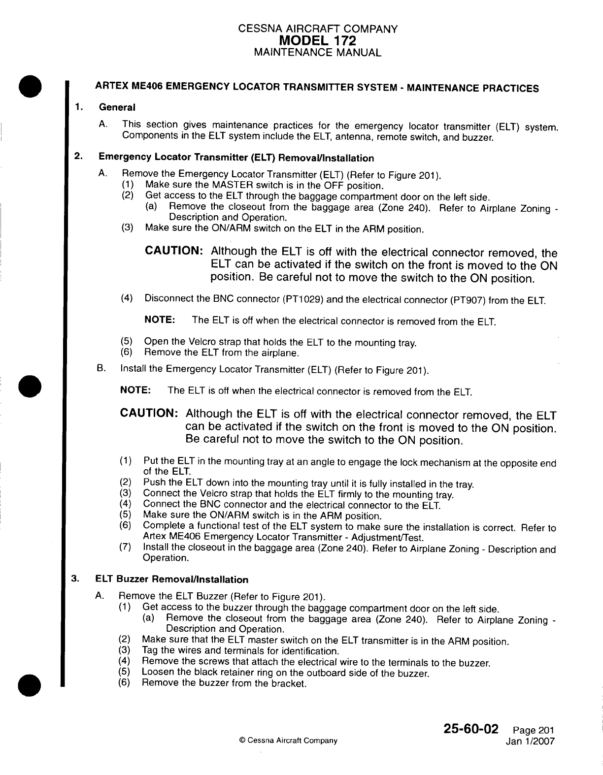
CESSNA
AIRCRAFT
COMPANY
MODEL
172
MAINTENANCE
MANUAL
ARTEX ME406
EMERGENCY
LOCATOR
TRANSMITTER
SYSTEM
-
MAINTENANCE PRACTICES
1.General
A.
This
section gives
maintenance
practices for
the
emergency locator
transmitter
(ELT)
system.
Components
in
the
ELT
system include
the
ELT,
antenna,
remote
switch,
and
buzzer.
2.
Emergency
Locator
Transmitter
(ELT)
Removal/installation
A.
Remove
the
Emergency Locator
Transmitter
(ELT)
(Refer
to
Figure
201).
(1)
Make sure the
MASTER
switch
is in
the
OFF
position.
(2)
Get
access
to
the
ELT
through
the
baggage compartment door
on
the
left
side.
(a)
Remove
the
closeout
from
the
baggage
area (Zone
240).
Refer
to
Airplane
Zoning
-
Description
and
Operation.
(3)
Make
sure
the
ONARM
switch
on
the
ELT
in
the
ARM
position.
CAUTION: Alth
ough the
ELT
is
off
with
the
electrical
connector
removed,
the
ELT
can
be
activated
if
the
switch
on
the
front
is
moved
to
the
ON
position.
Be
careful
not
to
move the
switch
to
the
ON
position.
(4)
Disconnect
the
BNC
connector
(PT1
029)
and
the
electrical
connector
(PT907)
from
the
ELT.
NOTE:
The
ELT
is
off
when
the
electrical
connector
is
removed
from the
ELT.
(5)
Open
the Velcro
strap
that holds the
ELT
to
the
mounting
tray.
(6)
Remove
the
ELT
from
the
airplane.
B.
Install
the
Emergency
Locator
Transmitter
(ELT)
(Refer
to
Figure
201).
NOTE:
The
ELT
is
off
when the
electrical connector
is
removed
from
the
ELT.
CAUTION:
Although
the
ELT
is
off
with
the
electrical
connector
removed,
the
ELT
can
be
activated
if
the
switch
on
the
front
is
moved
to
the
ON
position.
Be
careful
not
to
move
the
switch
to the
ON
position.
(1)
Put
the
ELT
in
the
mounting
tray
at
an
angle
to
engage
the
lock
mechanism
at
the
opposite
end
of
the
ELT.
(2)
Push
the
ELT
down
into
the
mounting tray
until
it
is
fully
installed
in
the tray.
(3)
Connect
the
Velcro strap
that
holds
the
ELT
firmly
to
the
mounting
tray.
(4)
Connect
the
BNC
connector
and
the
electrical
connector
to
the
ELT.
(5)
Make sure the
ONARM
switch
is in
the
ARM
position.
(6)
Complete
a
functional
test
of
the
ELT
system
to
make
sure
the
installation
is
correct.
Refer to
Artex
ME406
Emergency Locator
Transmitter
-
Adjustment/Test.
(7)
Install
the
closeout
in
the
baggage
area
(Zone
240).
Refer
to
Airplane
Zoning
-
Description
and
Operation.
3.
ELT
Buzzer
Removal/installation
A.
Remove
the
ELI
Buzzer
(Refer
to
Figure
201).
(1)
Get
access
to
the
buzzer
through
the
baggage
compartment
door
on
the
left
side.
(a)
Remove
the
closeout
from
the
baggage
area
(Zone
240).
Refer
to
Airplane Zoning
-
Description
and
Operation.
(2)
Make
sure
that
the
ELI
master
switch
on
the
ELT
transmitter
is
in
the
ARM
position.
(3)
Tag
the
wires
and
terminals
for
identification.
(4)
Remove
the
screws
that attach
the
electrical
wire
to
the
terminals
to
the
buzzer.
(5)
Loosen
the
black
retainer
ring on
the
outboard side
of
the
buzzer.
(6)
Remove
the
buzzer
from
the
bracket.
1W
25-60.02
Page
201
©
Cessna
Aircraft Company
Janl1/2007
a
0
in
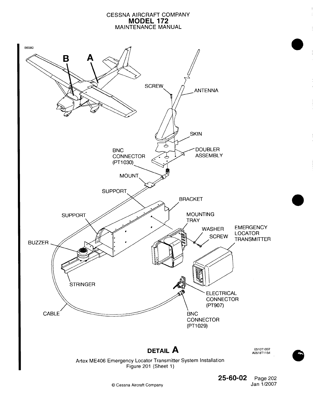
CESSNA
AIRCRAFT
COMPANY
MODEL
172
MAINTENANCE
MANUAL
SCREW
SKIN
BNC
CONNECTOR
(PT1
030)_
ASSEMBLY
SUPPORT
BRACKET
MOUNTING
WASHER
/
SCREW
::MERGENCY
-OCATOR
FRANSM
ITTER
R
CONNECTOR
(PT1
029)
DETAIL
A
Artex
ME406
Emergency
Locator
Transmitter
System
Installation
Figure
201
(Sheet
1)
25-60-02
©
Cessna
Aircraft
Company
SUPPORT
BUZZE
051
0T1007
A0518T1
154
Page
202
Janl1/2007
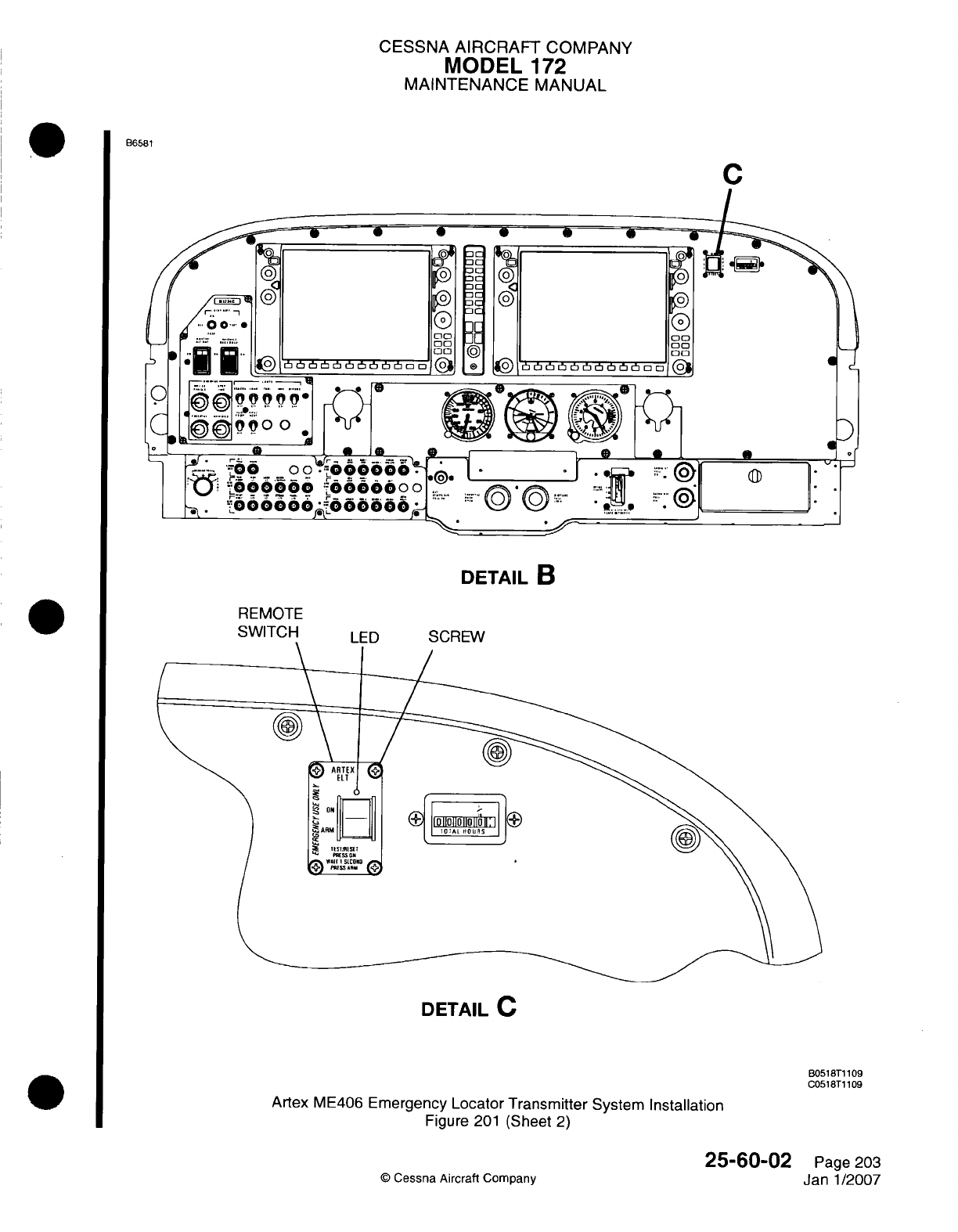
CESSNA
AIRCRAFT
COMPANY
MODEL
172
MAINTENANCE
MANUAL
B6581
C
DETAIL
B
REMOTE
DETAIL
C
B0518T1
1
09
C0518T1
109
Artex
ME406
Emergency
Locator Transmitter
System
Installation
Figure
201
(Sheet
2)
Q
Cessna
Aircraft Company
25-60-02
Page
203
Jan-1/2007
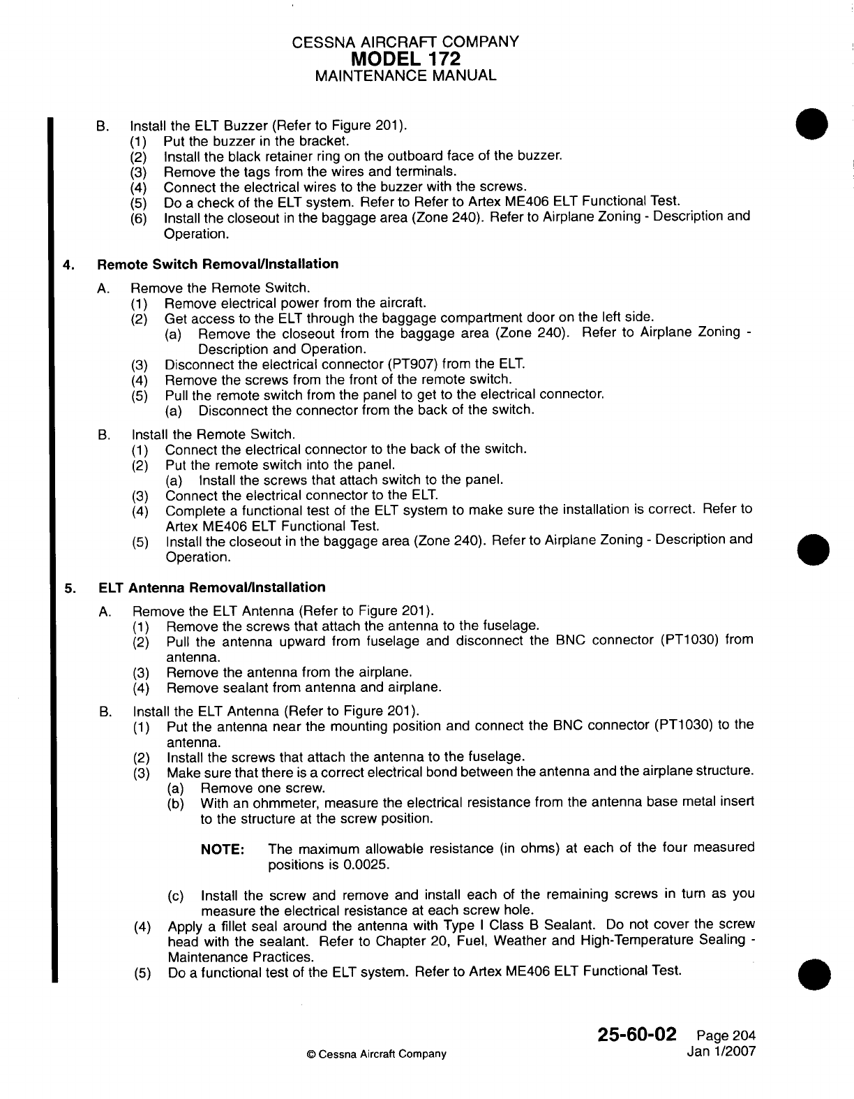
CESSNA
AIRCRAFT
COMPANY
MODEL
172
MAINTENANCE
MANUAL
B.
Install
the
ELT
Buzzer
(Refer
to
Figure
201).
(1)
Put
the
buzzer
in
the bracket.
(2)
Install
the
black retainer
ring
on the
outboard face
of
the
buzzer.
(3)
Remove
the
tags
from
the
wires
and
terminals.
(4)
Connect
the
electrical
wires
to
the
buzzer
with
the screws.
(5)
Do
a
check
of
the
ELT
system.
Refer
to Refer to
Artex
ME406
ELT
Functional
Test.
(6)
Install the
closeout
in
the
baggage area
(Zone
240).
Refer
to
Airplane Zoning
-
Description
and
Operation.
4.
Remote
Switch
Removal/installation
A.
Remove
the
Remote Switch.
(1)
Remove
electrical
power
from the
aircraft.
(2)
Get
access
to
the
ELT
through
the
baggage compartment
door
on
the
left
side.
(a)
Remove
the
closeout
from the
baggage
area (Zone 240).
Refer
to
Airplane
Zoning-
Description
and
Operation.
(3)
Disconnect
the
electrical
connector
(PT907)
from the
ELT.
(4)
Remove
the
screws
from
the
front
of
the
remote
switch.
(5)
Pull
the
remote
switch
from
the
panel
to
get
to
the
electrical
connector.
(a)
Disconnect
the
connector
from
the
back
of
the
switch.
B.
Install the
Remote Switch.
(1)
Connect the
electrical
connector
to
the
back
of
the
switch.
(2)
Put
the remote
switch
into
the
panel.
(a)
Install the
screws
that
attach
switch
to
the
panel.
(3)
Connect
the
electrical
connector
to
the
ELT.
(4)
Complete
a
functional test
of
the
ELT
system
to
make sure
the
installation
is
correct.
Refer
to
Artex ME406
ELT
Functional
Test.
(5)
Install
the
closeout
in
the
baggage
area (Zone 240).
Refer
to
Airplane
Zoning
-
Description
and
Operation.
5.
ELT
Antenna
Removal/installation
A.
Remove
the
ELT
Antenna
(Refer
to
Figure
201).
(1)
Remove
the screws
that
attach
the
antenna
to
the
fuselage.
(2)
Pull
the
antenna
upward from
fuselage
and
disconnect
the
BNC
connector
(PT1030)
from
antenna.
(3)
Remove
the
antenna
from
the
airplane.
(4)
Remove
sealant
from
antenna
and
airplane.
B.
Install
the
ELT
Antenna (Refer
to
Figure
201).
(1)
Put
the
antenna
near
the
mounting
position
and
connect
the
BNC
connector
(PT1
030) to the
antenna.
(2)
Install
the
screws that attach
the
antenna
to
the
fuselage.
(3)
Make sure
that there
is
a
correct
electrical
bond
between
the
antenna
and
the
airplane
structure.
(a)
Remove
one
screw.
(b)
With
an
ohmmeter,
measure
the
electrical
resistance
from the
antenna base
metal
insert
to
the
structure
at
the
screw
position.
NOTE:
The
maximum
allowable
resistance
(in
ohms)
at
each
of
the
four
measured
positions
is
0.0025.
(c)
Install
the
screw
and
remove and
install
each
of
the
remaining screws
in
turn
as
you
measure
the
electrical
resistance
at
each
screw
hole.
(4)
Apply
a
fillet
seal
around
the
antenna
with
Type
I
Class
B
Sealant.
Do
not
cover
the
screw
head
with
the
sealant.
Refer
to
Chapter
20,
Fuel,
Weather
and
High-Temperature
Sealing
-
Maintenance
Practices.
(5)
Do
a
functional
test
of
the
ELT
system.
Refer
to
Artex
ME406
ELT
Functional
Test.
25-60-02
Page
204
©
Cessna
Aircraft
Company
Janl1/2007
CESSNA AIRCRAFT
COMPANY
MODEL
172
MAINTENANCE
MANUAL
ARTEX
ME406
EMERGENCY
LOCATOR
TRANSMITTER
(ELT)
SYSTEM
-
INSPECTION/CHECK
1.General
A.
This
section
gives
the procedures
that
are
necessary
to
do
the
inspection
and
operational
checks
necessary
to
comply
with
14
CFR
91
.207,
for
the
Artex ME406
Emergency
Locator
Transmitter
(ELT)
System.
The
system transmits
on
two
frequencies.
The
121
.5
MHz
frequency
has the
standard
swept
tone
that
rescue personnel
can
follow
to
the
source.
The
other
frequency
is
406.028
MHz
and
is
used
to
activate
a
satellite
tracking
system. The
406.028
MHz
frequency
includes other information
such
as
the
country
code
of
the
airplane,
the
aircraft
identification
beacon serial
number,
the
24-bit address,
the
tail
number,
or
other
identification.
2.
Tools
and
Equipment
A.
For
information
on
tools
and
equipment,
refer
to
Equipment
and
Furnishings
-
General.
3.
Artex
ME406
Emergency
Locator
Transmitter
(ELT)
Inspection
A.
Get
access
to the
ELT.
(1)
Get
access
to
the
ELT
through
the
baggage
compartment door
on the
left
side.
(a)
Remove
the
bolts,
tiedowns,
and
plastic
closeout
from
the
lower baggage
area
(Zone
240).
Refer
to
Airplane
Zoning
-
Description
and
Operation.
B.
Do
an
inspection
of
the
ELT,
mounting
tray,
antenna,
and
the
ELT
battery
for
condition
and
correct
installation.
(1)
Make
sure
that the
ELT
switch,
found
on
the
forward
end
of
the
ELT,
is
set
to
the ARM
position.
(2)
Remove
the
ELT
from
the
mounting
tray.
Refer to Artex
ELT
ME406
Emergency Locator
Transmitter
System
-
Maintenance Practices.
CAUTION:
Do
not
use
solvents
to
clean
the
ELT,
mounting
tray,
or
electrical
contacts.
Solvents
used
in
these
areas
can
cause damage
to
the
ELT
housing.
(3)
Examine
the
ELT
and
the
mounting
tray
for
correct installation,
cleanliness,
cracks,
or
other
damage.
(4)
Examine
the
ELT
battery
for
corrosion.
(5)
Look
at
the battery expiration
date.
(a)
Make
sure
that
the
battery
life limit
is
not
expired.
(b)
Make
sure
that
the
battery
expiration
date
is
shown
correctly
in
the
Maintenance
Records.
NOTE:
The
battery
manufacturer
puts
a
mark
on
the
battery
to
show
the
battery
life
limit.
When
you
install
a
new
battery
in
an
ELT,
make
sure
a
record
of
the
expiration
date
is
put
in
the
space
given
on
the
ELT
name
and data
plate.
(c) If
you
have
to
replace
the
ELT
battery, refer
to
Artex
Maintenance
Manual
570-1600.
(d)
You
must replace
the
ELT
battery
with
a
new
battery
if
one
or
more
of
the
conditions
that
follow
occur:
*
Use
of
the
ELT
battery
in
an
emergency
*
Operation
for
an
unknown
amount
of
time
*
Use
for
more
than one hour
of
cumulative
time
*
Replacement
date
shown
on
the
battery
label
has
expired.
(e)
Record
the
new
battery
expiration
date
in
the
maintenance
log
if
you
replaced
it.
(6)
Examine the
ELT
antenna
for
correct installation
and
cracks
or
other
damage.
(7)
Install the
ELT
into
the
mounting tray.
Refer
to
Artex
ELT
ME406
Emergency
Locator
Transmitter
System
-
Maintenance
Practices.
25-60-02
Page
601
©
Cessna
Aircraft
Company
Janl1/2007
CESSNA
AIRCRAFT
COMPANY
MODEL
172
MAINTENANCE
MANUAL
4.
Artex
ME406
Emergency
Locator
Functional
Test
NOTE:
If
possible,
do
the
test procedure
for
the
emergency
locator
transmitter
inside
a
metal
hangar
with
the
doors
closed
to
decrease
the
signal transmission
from
the
ELT
unit
during
the
test.
A.
Do
a
G-Switch
Operational
Test:
CAUTION:
CAUTION:
Operate
the
Emergency Locator
Transmitter
(ELT)
system
only
during
the
first
five
minutes
of
each
hour.
If
you
must complete the
functional
test
at
a
time
other
than
the first five
minutes
of
the hour, you
must
do
the
test
with
a
direct
connection
to
the
ELT
and
a
30
dB
attenuator.
Refer
to
the
FAA
Advisory
Circular
AC-91-44A.
Do
not
operate
the Emergency
Locator
Transmitter
(ELT)
for
more
than
five
seconds
at
a
time.
Do
not
operate
the
ELT
again
for
15
seconds.
The
ELT
will
transmit
a
406.028
MHz
distress
signal after
it is
activated
for
approximately
50
seconds.
(1)
Remove
the
ELT
from
the
airplane.
Refer
to
Artex
ELT
ME406
Emergency
Locator Transmitter
System
-
Maintenance Practices.
(2)
Install
a
jumper
wire
between
pins
5
and
12
on
the
electrical
connector
of
the
ELT.
CAUTION:
It is
recommended
that
an
experienced
technician
do
this
procedure
because
of
the
potential physical damage
that
can
occur
if
the
jumper
wire
is
not
installed
correctly.
NOTE:
The
ELT
will not
activate
with
the
G-switch unless
electrical
pins
5
and
12
have
a
jumper
wire
installed
between
them
(this
happens
automatically
when
the
ELT
is
locked
into
the
mount
tray
with
the
electrical
connector
in
position).
Make sure
the
ELT
switch
is in
the
ARM
position.
Use
a
receiver
set
to
121
.5
MHz
to
listen
for
the
aural
warning
sweep
tone.
Hold
the
ELT
transmitter
tightly
in
one
hand
and
make
a
throwing
movement
followed
by
an
opposite
movement
of
the
ELT
transmitter.
Make
sure
that the
G-switch operates
and
that
the
aural
warning
sweep tone
is
heard
on
the
receiver
set
to
121
.5
MHz.
Set
the
ELT
switch
to
the
ON
position
and then
back
to
the
ARM
position
to
reset
the
G-switch.
Remove
the
jumper
wire
from
electrical
pins
5
and
12
on
the
electrical connector
of
the
ELT.
Install
the
emergency
locator
transmitter
in
the
airplane.
Refer to Artex
ELT
ME406
Emergency
Locator Transmitter System
-
Maintenance
Practices.
B.
Do
a
Transmitter
Test
of
the
Artex
ME406
Emergency
Locator
Transmitter
(ELT)
System:
25-60-02
Page
602
©
Cessna
Aircraft
Company
Janl1/2007
(3)
(4)
(5)
(6)
(7)
(8)
(9)
CESSNA
AIRCRAFT
COMPANY
MODEL
172
MAINTENANCE
MANUAL
CAUTION: Operate
the
Emergency
Locator
Transmitter
(ELT)
system
only
during the
first
five
minutes
of
each
hour.
If
you
must
complete
the
functional
test
at
a
time
other
than
the
first
five
minutes
of the hour,
you
must
do
the
test
with
a
direct
connection
to
the
ELT
and
a 30
dB
attenuator.
Refer to the
FAA
Advisory
Circular
AC-91
-44A.
CAUTION:
Do
not
operate
the
Emergency Locator Transmitter
(ELT)
for
more
than
five
seconds
at
a
time.
Do
not
operate
the
ELT
again for
15
seconds.
The
ELT
will
transmit
a
406.028
MHz
distress
signal
after
it
is
activated
for
approximately
50
seconds.
(1)
Make
sure the
BATTERY
switch
and the
AVIONICS
switches
are
in
the
OFF
position.
(2)
Connect external
electrical
power
to
the
airplane.
(3)
Make
sure
that
the
COM/NAV
1
and
AUD/MKR
circuit
breakers
on
the
circuit
breaker
panel
are
engaged.
(4)
Set
the
BATTERY
switch
to
the
ON
position.
(5)
Set
the AVIONICS
switches
to
the
ON
position.
(6)
Make
sure
that the
ELT
remote
switch
on
the
right
panel
is in
the
ARM
position.
(7)
Set
one
of
the
communication
units
to
receive
a
frequency
of
121.5
MHz.
(8)
Set the
communication
unit
to
the
airplane speakers
at an
audio
level
loud
enough
to
be
heard.
NOTE:
The
SARSAT
tester
is
used
as
an
example
to
gather test
information. However,
other
equivalent
test
equipment
such
as
the
Aeroflex
IFR
4000
Communications
Test Set
is
acceptable.
(9)
Have
another
person
use
the
SARSAT
tester
set
to
the
RECV
function.
Ref er
to
Figure
601.
NOTE:
The
SARSAT
tester
must
be
less than
15
feet
from
the
ELT
antenna
and
must
have
a
line-of-sight
between
the
ELT
antenna
and SARSAT tester.
NOTE:
The
person
with
the
SARSAT
tester
must
make
sure
that
the
ELT
buzzer
is
heard
during
the test.
NOTE:
If it is
necessary
to
do
the
transmitter
test
after
the first
five minutes
of
the
hour, the
SARSAT
tester
is
connected directly
to
the
ELT
with
a
coaxial cable
and
a
30
dB
attenuator.
You
will
not
hear
the
sweep
tone
from
the
ELT
on
the
airplane
speakers
with
the
attenuator
installed.
(10)
Install
the
30
dB
attenuator
between
the
ELT
and
SARSAT
tester
if
necessary.
(11)
Set
the
ELT
remote
switch
on
the
right
panel
to
the
ON
position.
(12)
Let
the
ELT
make
three sweeps
on
the
airplane speakers.
NOTE:
This
will
take
one
second.
The
ELT
remote
switch
will
start
to
flash.
(13)
Set
the
ELT
remote switch back
to
the
ARM
position
and
monitor
the
LED.
NOTE:
The
ELT
will
do
a
self-test.
The
LED
will
stay
on
for
one
second
and
the
ELT
sweeps
are
not
audible
on
the
airplane
speakers
if
the
ELT
operation
is
normal.
NOTE:
The
ELT
does
not
transmit
a
406.028
MHz
test
signal
to
the
SARSAT
tester
until the
ELT
remote
switch
is
set
back
to
the ARM
position.
(14)
If
the
LED
continues
to
flash,
refer
to
Artex
ME406
Emergency Locator
Transmitter
System
-
Troubleshooting.
(15)
If
the
SARSAT
tester
did
not
receivea
406.028
MHz
signal
and
the
ELT
remote
switch
LED
does
not
show
a
transmitter
problem,
do
the
test
again.
25-60-02
Page
603
©D
Cessna
Aircraft
Company
Jan
1/2007
CESSNA AIRCRAFT
COMPANY
MODEL
172
MAINTENANCE
MANUAL
(16)
When
the
SARSAT
tester
receives
a
406.028
MHz signal, scroll
the
pages
on
the
tester
and
make
sure
of
the
information
that follows:
(a)
Make sure
the information
shown
by
the
SARSAT
tester
agrees with
the
placard
on
the
ELT.
NOTE:
The
information
that
follows
must
match
the
data
on
the
ELT
placard:
*
COUNTRY
code
*
15-digit
Hex
code
ID
*
Aircraft
identification
number.
(b)
Make
sure
that
the SARSAT
tester
shows
the
messages that follow:
*
S
TEST
OK
*
Frequency
-
PASS
*
Homing
frequency
*
Message
format
(short).
NOTE:
When
ownership
of
an
aircraft
is
transferred within
the same
country,
the
ME406
ELT
should
be
reregistered
with
the
applicable
authority.
When
an
aircraft
with
a
ME406
ELT
changes
tail
number
or
country registration,
the
ELT
will
need
to
have
the
new
identification
data
entered. The
ELT
will
also
need
to
be
registered
with
the applicable
authority.
(1 7)
Install
the
bolts,
tiedowns,
and
plastic
closeout
to
the
lower baggage area
(Zone
240).
Refer to
Airplane
Zoning
-
Description
and
Operation.
25-60-02
Page 604
©
Cessna
Aircraft
Company
Janl1/2007
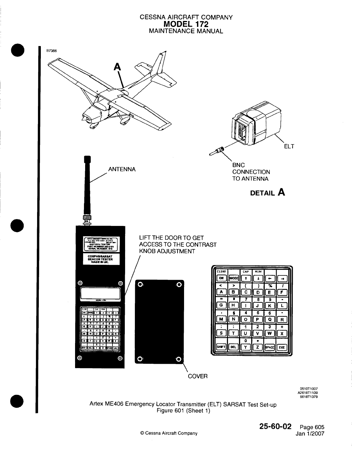
CESSNA
AIRCRAFT
COMPANY
MODEL
172
MAINTENANCE
MANUAL
ELT
BNC
CONNECTION
TO
ANTENNA
DETAIL
A
LIFT
THE
DOOR
TO
GET
ACCESS
TO THE
CONTRA
KNOB ADJUSTMENT
ST
CLEAR CAP
NUME
F-
$
.4
5 6--
F~F~1rn__rjFjFi
rM[-I
C
7P
+
mEI
2
13
4
Fs_
F-15_ I F] il
Isiwi
AEhl
L!
JDJJ
li
l
COVER
0510T1007
A2618T1
109
66
18T1
379
Artex
ME406
Emergency Locator
Transmitter
(ELT)
SARSAT
Test
Set-up
Figure
601
(Sheet
1)
Q
Cessna
Aircraft Company
25-60.02
Page
605
Janl1/2007
L
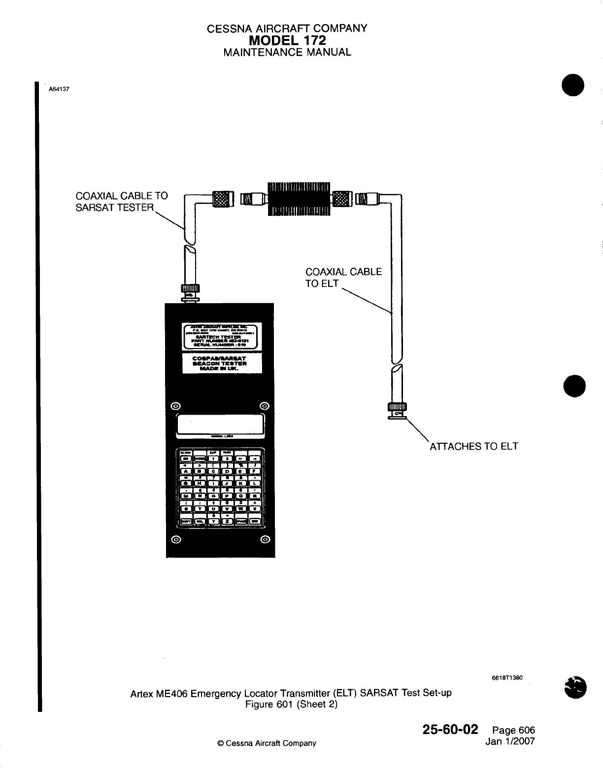
CESSNA
AIRCRAFT
COMPANY
MODEL
172
MAINTENANCE
MANUAL
A64
137
COAXIAL CABLE
SARSAT
TESTER
COAXIAL
CABLE
TO
ELT
ATTACHES
TO
ELT
6618ST1
380
Artex
ME406
Emergency Locator
Transmitter
(ELT)
SARSAT
Test
Set-up
Figure
601
(Sheet
2)
25-60-02
©
Cessna
Aircraft
Company
Page
606
Jan
1/2007
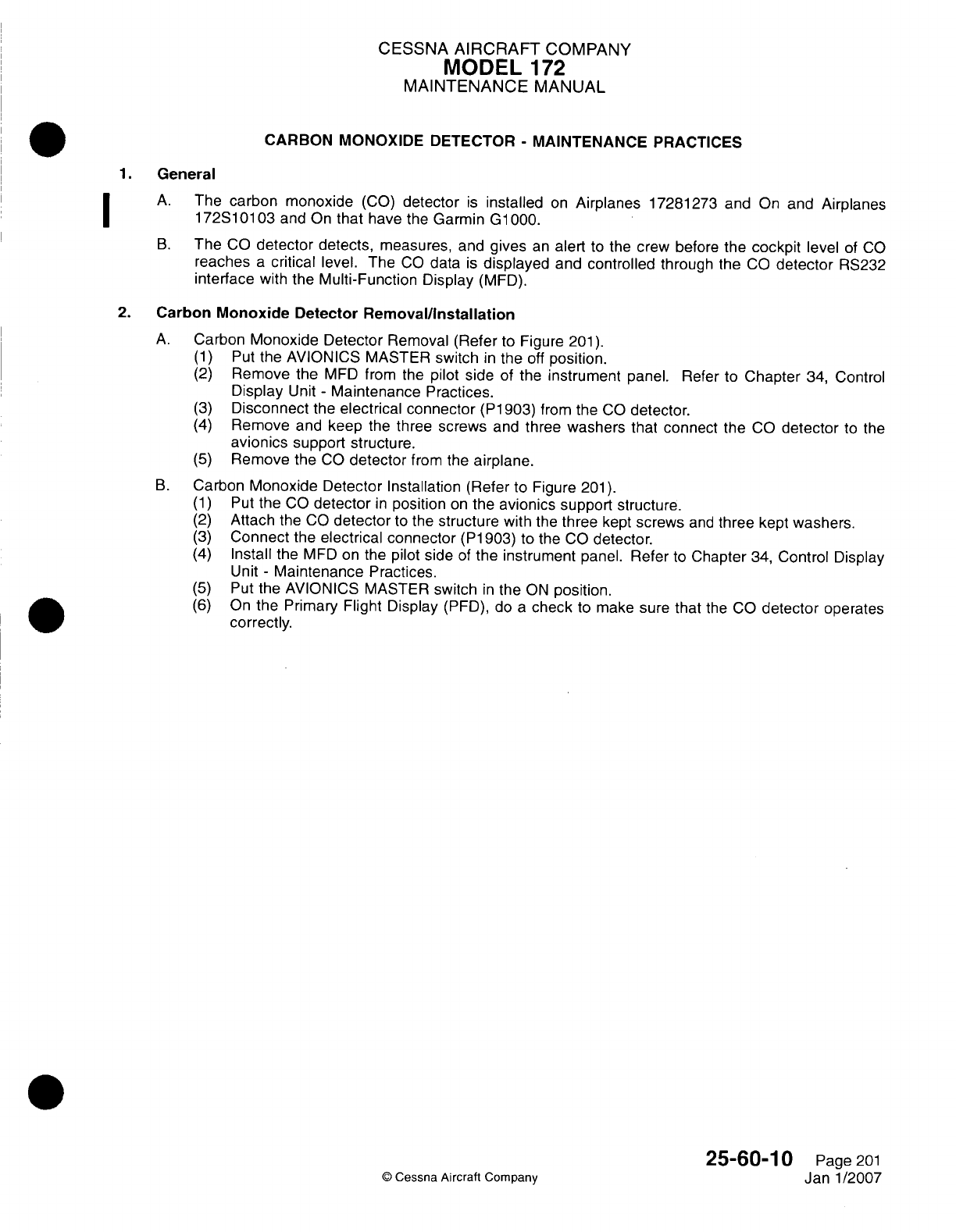
CESSNA
AIRCRAFT
COMPANY
MODEL
172
MAINTENANCE
MANUAL
CARBON
MONOXIDE
DETECTOR
-
MAINTENANCE
PRACTICES
1.General
A.
The
carbon monoxide
(GO)
detector
is
installed
on
Airplanes
17281273
and
On
and
Airplanes
172S1
01
03
and On
that
have
the
Garmin
G1
000.
B.
The
CO
detector
detects,
measures,
and
gives
an
alert
to
the
crew
before
the
cockpit
level
of
CO
reaches
a
critical
level.
The
CO
data
is
displayed
and
controlled
through the
CO
detector
RS232
interface
with
the
Multi-Function
Display
(MFD).
2.
Carbon
Monoxide
Detector
Removal/installation
A.
Carbon
Monoxide Detector
Removal (Refer
to
Figure
201).
(1)
Put
the
AVIONICS
MASTER
switch
in
the
off
position.
(2)
Remove
the
MFD
from the
pilot side
of
the
instrument
panel. Refer
to
Chapter
34, Control
Display
Unit
-
Maintenance
Practices.
(3)
Disconnect
the
electrical connector
(P1903)
from the
CO
detector.
(4)
Remove
and
keep
the
three
screws
and
three
washers
that connect
the
CO
detector
to
the
avionics
support structure.
(5)
Remove
the
CO
detector
from the
airplane.
B.
Carbon
Monoxide
Detector
Installation
(Refer
to
Figure
201).
(1)
Put
the
CO
detector
in
position
on
the
avionics
support
structure.
(2)
Attach
the
CO
detector
to
the
structure
with
the
three
kept
screws
and
three
kept
washers.
(3)
Connect
the
electrical
connector
(P1
903)
to
the CO
detector.
(4)
Install the
MFD on
the
pilot side
of
the
instrument
panel.
Refer
to
Chapter
34,
Control
Display
Unit
-
Maintenance
Practices.
(5)
Put
the
AVIONICS MASTER
switch
in
the
ON
position.
(6)
On
the Primary Flight
Display
(PFD),
do
a
check
to
make
sure that
the
CO
detector
operates
correctly.
25-60-1
0
Page
201
©
Cessna Aircraft Company
Janl1/2007
I
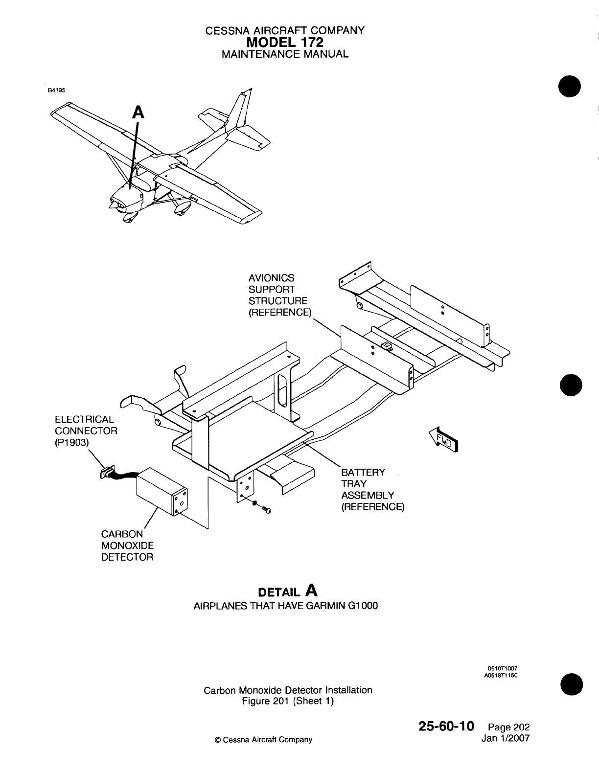
CESSNA
AIRCRAFT
COMPANY
MODEL
172
MAINTENANCE
MANUAL
AVIONICS
SUPPORT
STRUCTURE
(REFERENCE)
TRAY
ASSEMBLY
(REFERENCE)
CARBON
MONOXIDE
DETECTOR
DETAIL
A
AIRPLANES THAT
HAVE
GARMIN
G1
000
051lOTi
007
A0518T1
150
Carbon
Monoxide
Detector
Installation
Figure
201
(Sheet
1)
25-60-10
C
Cessna Aircraft Company
Page
202
Janl1/2007
CESSNA
AIRCRAFT
COMPANY
MODEL
172
MAINTENANCE
MANUAL
SOUNDPROOFING
AND
INSULATION
-
MAINTENANCE
PRACTICES
1.
General
A.
The
airplane utilizes
soundproofing
and
insulation
throughout
the
fuselage
area.
This material
is
glued
into
place
using
spray
adhesive.
Anytime
old
material
is
being replaced,
care
should
be
taken
to
ensure
all
traces
are
removed
from
fuselage
skin before
reapplication.
For
a
list
of
spray
adhesives,
refer
to
Equipment/Furnishing
-
General.
B.
For an
illustration
of
soundproofing
and
insulation
locations,
refer to Figure
201
and
Figure 202.
25-80-00
Page
201
©
Cessna
Aircraft
Company
Apr
7/2003
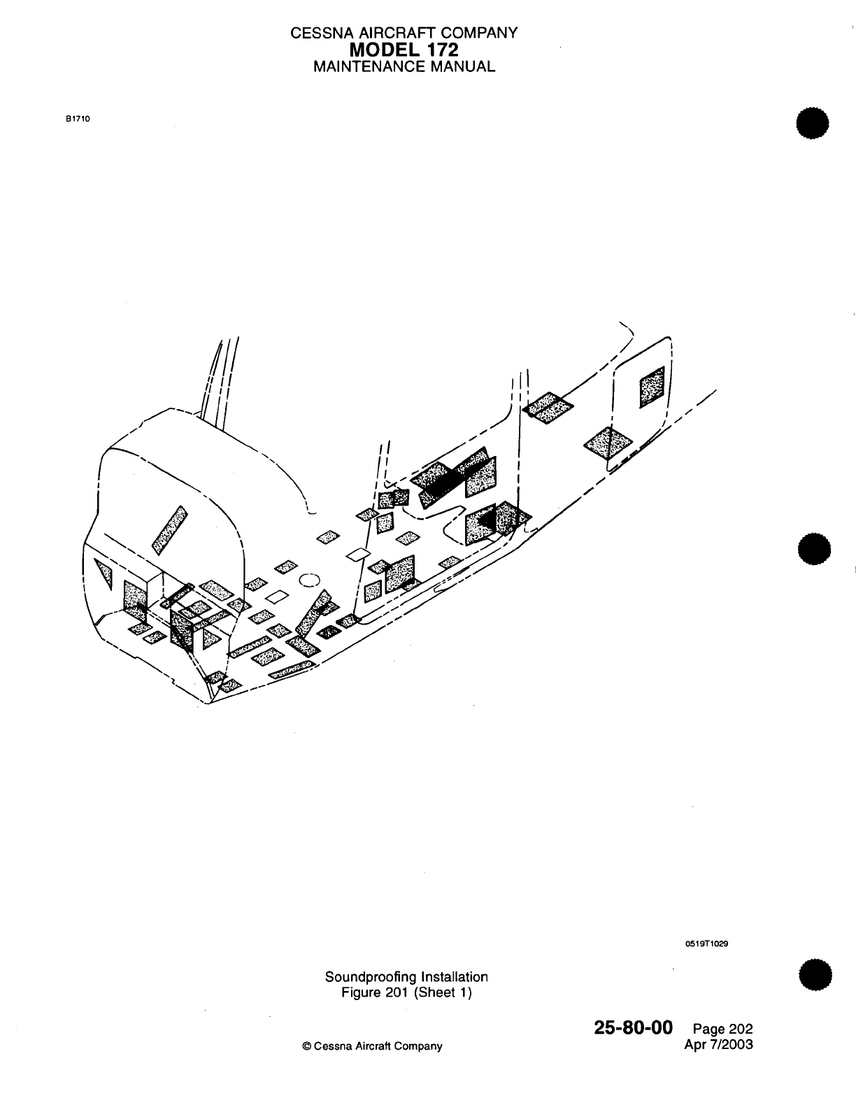
CESSNA AIRCRAFT
COMPANY
MODEL
172
MAINTENANCE
MANUAL
B1710
/
0519T1029
Soundproofing Installation
Figure
201
(Sheet
1)
©
Cessna
Aircraft Company
25-80-00
Page
202
Apr
7/2003
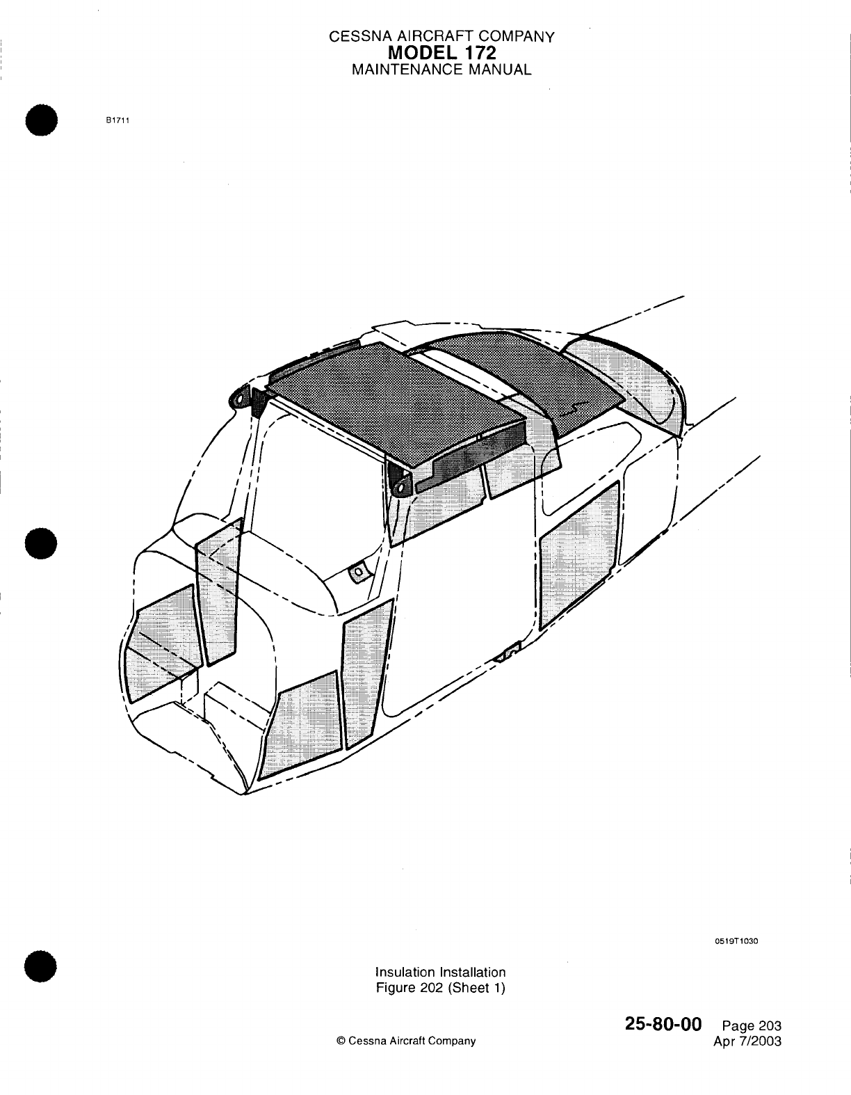
CESSNA
AIRCRAFT
COMPANY
MODEL
172
MAINTENANCE
MANUAL
B1711
0519T1030
Insulation Installation
Figure
202
(Sheet
1)
25-80-00
©
Cessna
Aircraft
Company Page
203
Apr
7/2003
CHAPTER
FIRE
PROTECTION
CESSNA
AIRCRAFT
COMPANY
MODEL
172
MAINTENANCE
MANUAL
LIST
OF
EFFECTIVE PAGES
CHAPTER-SECTION-SUBJECT
26-Title
26-List
of
Effective Pages
26-Record
of
Temporary
Revisions
26-Contents
26-00-00
26-20-00
©
Cessna Aircraft
Company 26
-
LIST
OF
EFFECTIVE
PAGES
Page
1
of
1
Jan
3/2005
PAGE
DATE
Apr
7/2003
Apr
7/2003
Page
1
Pages
1-2
Temporary
Revision
Number
RECORD
OF
TEMPORARY REVISIONS
Page
Number Issue
Date By
Date
Removed
By
CESSNA
AIRCRAFT
COMPANY
MODEL
172
MAINTENANCE
MANUAL
CONTENTS
FIRE
PROTECTION
-
GENERAL..................................................
Scope
and
Definition
........................................................
HAND
FIRE
EXTINGUISHER
-
DESCRIPTION
AND
OPERATION
...................
Description
.................................................................
Operation
..................................................................
26-00-00
Page
1
26-00-00
Page
1
26-20-00
Page
1
26-20-00
Page
1
26-20-00
Page
1
CONTENTS
Page
1
of
1
Jan
3/2005
©
Cessna Aircraft
Company
CESSNA
AIRCRAFT
COMPANY
MODEL
172
MAINTENANCE
MANUAL
FIRE
PROTECTION
-
GENERAL
1.
Scope
and
Definition
A.
This
chapter
contains
a
single
section
which
describes
the
portable
fire
extinguisher
used
in
the
cabin.
26-00-00
Page
1
©
Cessna Aircraft
Company
Apr
7/2003
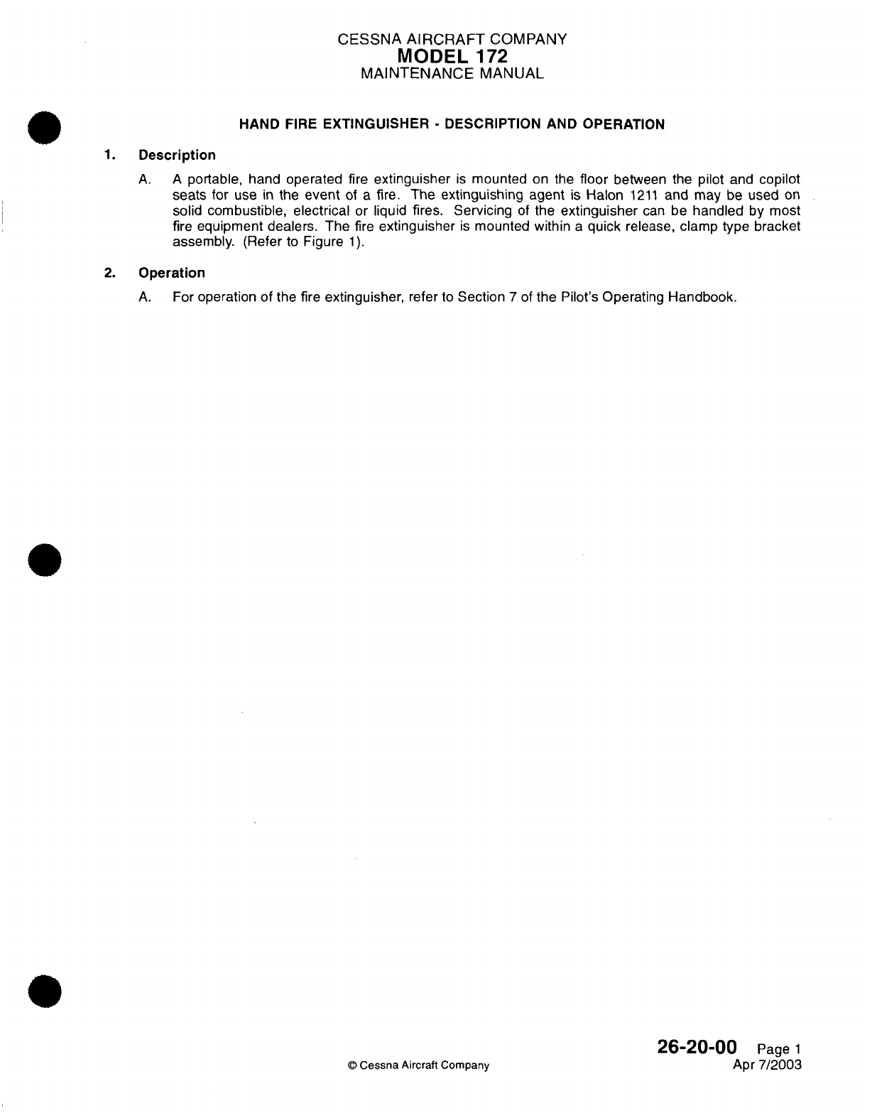
CESSNA
AIRCRAFT
COMPANY
MODEL
1
72
MAINTENANCE
MANUAL
HAND
FIRE
EXTINGUISHER
-
DESCRIPTION
AND
OPERATION
1.
Description
A. A
portable,
hand
operated
fire
extinguisher
is
mounted
on
the
floor
between the
pilot
and
copilot
seats
for
use
in
the
event
of
a
fire.
The
extinguishing
agent
is
Halon
1211
and may
be
used
on
solid
combustible,
electrical
or
liquid
fires. Servicing
of
the
extinguisher
can
be
handled
by
most
fire
equipment
dealers.
The
fire
extinguisher
is
mounted
within
a
quick
release,
clamp type bracket
assembly.
(Refer
to
Figure
1).
2.
Operation
A.
For
operation
of
the fire
extinguisher,
refer
to
Section
7
of
the
Pilot's
Operating
Handbook.
26-20-00
Page
1
©
Cessna Aircraft
Company
Apr
7/2003
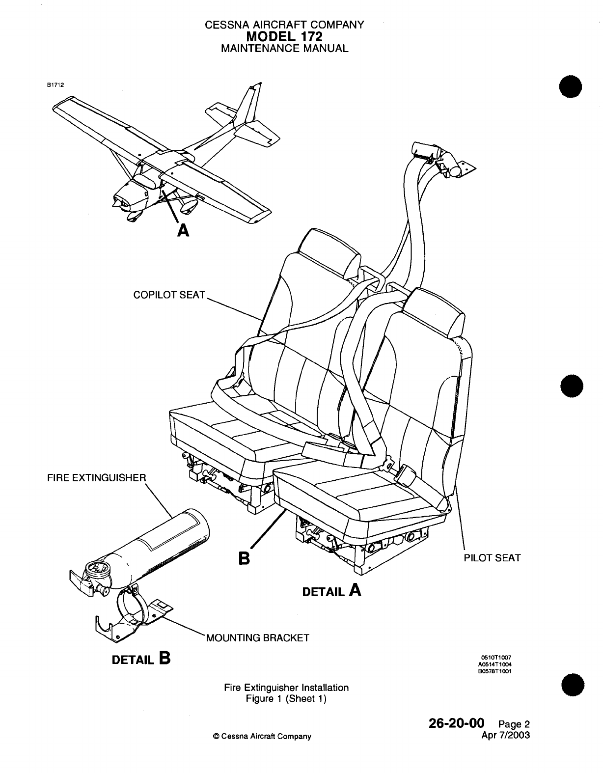
CESSNA
AIRCRAFT
COMPANY
MODEL
172
MAINTENANCE
MANUAL
FIRE
B
_OT
SEAT
DETAIL
A
BRACKET
Fire
Extinguisher Installation
Figure
1
(Sheet
1)
©
Cessna
Aircraft
Company
26-20-00
Page
2
Apr
7/2003
DETAIL
B
0510T1007
A0514T1004
B0578T1001
CHAPTER
FLIGHT
CONTROLS
CESSNA
AIRCRAFT
COMPANY
MODEL
172
MAINTENANCE
MANUAL
LIST
OF EFFECTIVE PAGES
CHAPTER-SECTION-SUBJ
ECT
27-Title
27-List
of
Effective
Pages
27-Record
of
Temporary
Revisions
27-Table of
Contents
27-00-00
27-00-0
1
27-1
0-00
27-1
0-00
27-20-00
27-20-00
27-30-00
27-30-00
27-3
1-00
27-3
1-00
27-32-00
27-50-00
27-50-00
27-5
1-00
©D
Cessna
Aircraft Company
PAGE
Page
1
Pages
201-202
Page
101
Pages
201-208
Page
101
Pages 201-205
Page
1
01
Pages
201
-206
Page
101
Pages
201
-212
Pages
201
-202
Pages
101
-1
02
Pages
201-208
Pages
201-203
DATE
Apr
7/2003
Apr
7/2003
Apr
7/2003
Jul
3/2006
Apr
7/2003
Apr
7/2003
Apr
7/2003
Jul
3/2006
Apr
7/2003
Jul
3/2006
Jul
1/2005
Apr
7/2003
Jul
1/2007
Apr
7/2003
27
-
LIST
OF
EFFECTIVE
PAGES
Page
1
of
1
Jul
1/2007

Temporary
Revision
Number
RECORD
OF
TEMPORARY
REVISIONS
Page
Number
Issue
Date
By
Date
Removed
By
CESSNA AIRCRAFT
COMPANY
MODEL
172
MAINTENANCE
MANUAL
CONTENTS
FLIGHT
CONTROLS
-
GENERAL
.........................
G
eneral.
...
..
........................ ......
Tools,
Equipment
and
Materials........................
Definition
..................................
CONTROL
CABLE
WIRE BREAKAGE
AND
CORROSION
LIMITATIONS-
MAINTENANCE
PRACTICES
...........................
Examination
of
Control Cables
........................
AILERON
CONTROL
SYSTEM
-
TROUBLESHOOTING...............
Troubleshooting
...............................
AILERON
CONTROL
SYSTEM
-
MAINTENANCE
PRACTICES............
General...................................
Control
Yoke
Removal/Installation.......................
Aileron
Removal/installation..........................
Aileron
Bell
Crank
Removal/installation
....................
Adjustment/Test
...............................
Cables
And
Pulleys
Removal/installation....................
RUDDER
CONTROL
SYSTEM
-
TROUBLESHOOTING
...............
Troubleshooting
...............................
RUDDER
CONTROL
SYSTEM
-
MAINTENANCE
PRACTICES............
General...................................
Rudder
Pedal
Assembly
Removal/installation..................
Rudder
Removal/installation
.........................
Rudder
Control
Adjustment/Test........................
ELEVATOR
CONTROL
SYSTEM
-
TROUBLESHOOTING
..............
Troubleshooting
...............................
ELEVATOR
CONTROL
SYSTEM
-
MAINTENANCE
PRACTICES...........
General...................................
Forward
Elevator
Bell
Crank
Removal/installation................
Aft
Elevator
Bell
Crank
Removal/Installation
..................
Elevator
Removal/installation.........................
Elevator
Control
Adjustment/Test
.......................
ELEVATOR
TRIM
CONTROL
-
TROUBLESHOOTING................
Troubleshooting
...............................
ELEVATOR
TRIM
CONTROL
-
MAINTENANCE
PRACTICES.............
General...................................
Trim
Tab
Actuator
Removal/installation.....................
Trim
Tab
Actuator
Disassembly/Assembly
...................
Trim
Tab
Actuator
Cleaning
and
Inspection...................
Trim
Tab
Free
Play
Inspection.........................
Trim
Tab
Control
Wheel
Removal/installation..................
Trim
Tab
Control
Adjustment/Test
.......................
STALL
WARNING SYSTEM
-
MAINTENANCE PRACTICES
.............
General...................................
Scoop
Assembly
Removal/installation.....................
Stall
Warning
Horn
Removal/Installation.....................
FLAP
CONTROL
SYSTEM
-
TROUBLESHOOTING.................
Troubleshooting
...............................
27-00-00
Page
1
27-00-00
Page
1
27-00-00
Page
1
27-00-00
Page
1
27-00-01
Page
201
27-00-01
Page
201
27-10-00
Page
101
27-10-00
Page
101
27-10-00
Page
201
27-10-00
Page
201
27-1
0-00
Page
201
27-1
0-00
Page
201
27-1
0-00
Page 206
27-1
0-00
Page 206
27-10-00
Page 208
27-20-00
Page
101
27-20-00
Page
101
27-20-00
Page
201
27-20-00
Page
201
27-20-00
Page
201
27-20-00
Page
201
27-20-00
Page
201
27-30-00
Page
101
27-30-00
Page
101
27-30-00
Page
201
27-30-00
Page
201
27-30-00
Page
201
27-30-00
Page
201
27-30-00
Page
201
27-30-00
Page 204
27-31 -00
Page
101
27-31
-00
Page
10
1
27-31
-00
Page
201
27-31 -00
Page
201
27-31
-00
Page
201
27-31 -00
Page
201
27-3
1
-00
Page
207
27-3
1
-00
Page
207
27-3
1
-00
Page
208
27-31
-00
Page
208
27-32-00
Page
201
27-32-00
Page
201
27-32-00
Page
201
27-32-00
Page
201
27-50-00
Page
101
27-50-00
Page
101
27
-
CONTENTS
Page
1
of
2
Jul
1/2007
©
Cessna
Aircraft
Company
CESSNA AIRCRAFT
COMPANY
MODEL
172
MAINTENANCE
MANUAL
FLAP
CONTROL
SYSTEM
-
MAINTENANCE
PRACTICES..............
General...................................
Flap Motor
and
Transmission Assembly
Removal/installation
..........
Flap
Removal/Installation...........................
Flap
Drive
Pulley
Removal/installation.....................
Flap Control
System
Adjustment/Test
.....................
Operational
Check..............................
FLAP
FOLLOW
UP
AND
INDICATING
SYSTEM
-
MAINTENANCE PRACTICES.
Description
and
Operation
..........................
Follow
Up
and
Indicating
System
Removal/Installation..............
System Rigging
...............................
27-50-00
Page
201
27-50-00
Page
201
27-50-00
Page
201
27-50-00
Page
201
27-50-00
Page
206
27-50-00
Page
206
27-50-00
Page
208
27-5
1
-00
Page
201
27-51
-00
Page
201
27-51 -00
Page
201
27-51
-00
Page
201
27
-
CONTENTS
Page
2
of
2
Jul
1/2007
©0
Cessna Aircraft
Company
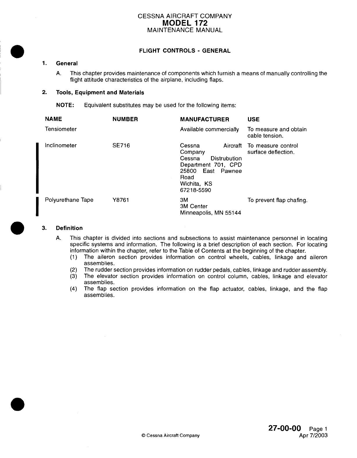
CESSNA
AIRCRAFT
COMPANY
MODEL
172
MAINTENANCE
MANUAL
FLIGHT CONTROLS
-
GENERAL
1.
General
A.
This
chapter
provides maintenance
of
components
which
furnish
a
means
of
manually
controlling
the
flight
attitude
characteristics
of
the
airplane,
including flaps.
2.
Tools,
Equipment
and
Materials
NOTE:
Equivalent
substitutes
may
be
used
for
the
following
items:
NAME
Tensiometer
Inclinometer
Polyurethane
Tape
NUMBER
MANUFACTURER
Available
commercially
SE716
Cessna Aircraft
Company
Cessna
Distrubution
Department
701,
CPD
25800
East
Pawnee
Road
Wichita,
KS
67218-5590
3M
3M
Center
Minneapolis,
MN
55144
Y8761
USE
To
measure
and obtain
cable
tension.
To
measure
control
surface deflection.
To
prevent
flap
chafing.
3.
Definition
A.
This
chapter
is
divided
into
sections
and
subsections
to
assist
maintenance
personnel
in
locating
specific
systems
and
information.
The
following
is
a
brief
description
of
each
section.
For
locating
information
within the
chapter,
refer to
the Table
of
Contents
at
the
beginning
of
the
chapter.
(1)
The
aileron
section
provides
information
on
control wheels,
cables,
linkage
and
aileron
assemblies.
(2)
The
rudder section
provides
information
on
rudder
pedals,
cables,
linkage
and
rudder assembly.
(3)
The
elevator
section
provides
information
on
control column, cables,
linkage and
elevator
assemblies.
(4)
The
flap
section
provides
information
on
the flap
actuator,
cables,
linkage,
and
the
flap
assemblies.
27-00-00
Page
1
©
Cessna
Aircraft
Company
Apr
7/2003
I
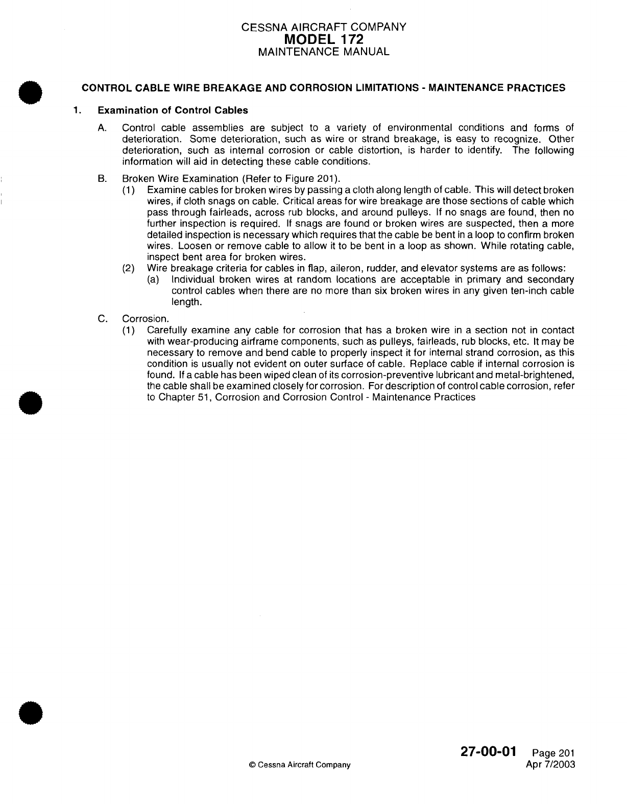
CESSNA
AIRCRAFT
COMPANY
MODEL
172
MAINTENANCE
MANUAL
CONTROL
CABLE
WIRE
BREAKAGE
AND
CORROSION
LIMITATIONS
-
MAINTENANCE
PRACTICES
1.
Examination of
Control
Cables
A.
Control
cable
assemblies
are
subject
to
a
variety
of
environmental conditions
and
forms
of
deterioration.
Some
deterioration,
such as
wire
or
strand
breakage,
is easy
to
recognize.
Other
deterioration,
such
as
internal
corrosion
or
cable
distortion,
is
harder
to
identify.
The
following
information
will aid
in
detecting
these
cable
conditions.
B.
Broken
Wire
Examination (Refer
to
Figure
201).
(1)
Examine
cables for
broken wires
by
passing
a
cloth
along
length
of
cable.
This
will
detect
broken
wires,
if
cloth
snags
on
cable.
Critical areas
for
wire
breakage
are
those
sections
of
cable
which
pass
through
fairleads,
across
rub
blocks,
and
around
pulleys.
If
no
snags
are
found,
then
no
further inspection
is
required.
If
snags
are
found
or
broken
wires
are
suspected,
then
a
more
detailed
inspection
is
necessary
which
requires that the
cable
be
bent
in a
loop
to
confirm
broken
wires.
Loosen
or remove
cable
to
allow
it
to
be
bent
in
a
loop
as
shown.
While
rotating
cable,
inspect
bent
area for
broken
wires.
(2)
Wire
breakage
criteria
for
cables
in
flap, aileron, rudder,
and
elevator
systems
are as
follows:
(a)
Individual broken
wires
at
random
locations
are
acceptable
in
primary
and
secondary
control
cables
when
there
are
no
more
than six
broken
wires
in
any
given
ten-inch
cable
length.
C.
Corrosion.
(1)
Carefully examine
any
cable
for
corrosion
that
has
a
broken
wire
in a
section
not
in
contact
with
wear-producing
airframe components,
such
as
pulleys,
fairleads,
rub
blocks,
etc.
It
may
be
necessary
to
remove
and
bend
cable
to
properly inspect
it
for
internal
strand
corrosion,
as
this
condition
is
usually
not
evident
on
outer surface
of
cable.
Replace
cable
if
internal
corrosion
is
found.
If
a
cable
has
been wiped
clean
of
its
corrosion-preventive
lubricant
and
metal-brightened,
the
cable
shall
be
examined closely
for
corrosion.
For
description
of
control
cable
corrosion,
refer
to
Chapter
51,
Corrosion
and
Corrosion
Control
-
Maintenance Practices
27-00-01
Page
201
©
Cessna
Aircraft
Company
Apr 7/2003
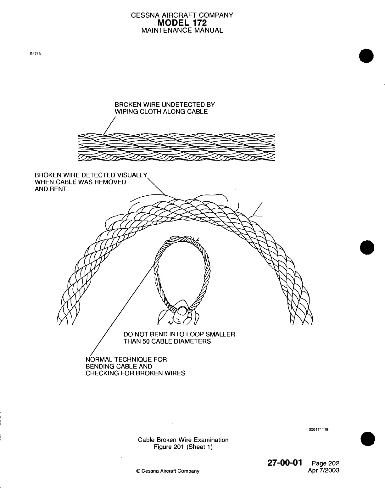
CESSNA AIRCRAFT
COMPANY
MODEL
172
MAINTENANCE
MANUAL
B1713
BROKEN WIRE UNDETECTED
BY
WIPING
CLOTH
ALONG
CABLE
*'yzs
'y^
^^ ,.--c^
ss-^
~
c-^
v-^
y
ss^
BROKEN
WIRE
DETECTED
VISUALLY
WHEN
AND
BE
DO
NOT
BEND
INTO
LOOP SMALLER
THAN
50 CABLE
DIAMETERS
NORMAL
TECHNIQUE
FOR
BENDING CABLE
AND
CHECKING
FOR
BROKEN
WIRES
5561T1
119
Cable
Broken
Wire
Examination
Figure
201
(Sheet
1)
27-00-01
©
Cessna
Aircraft Company
Page 202
Apr
7/2003
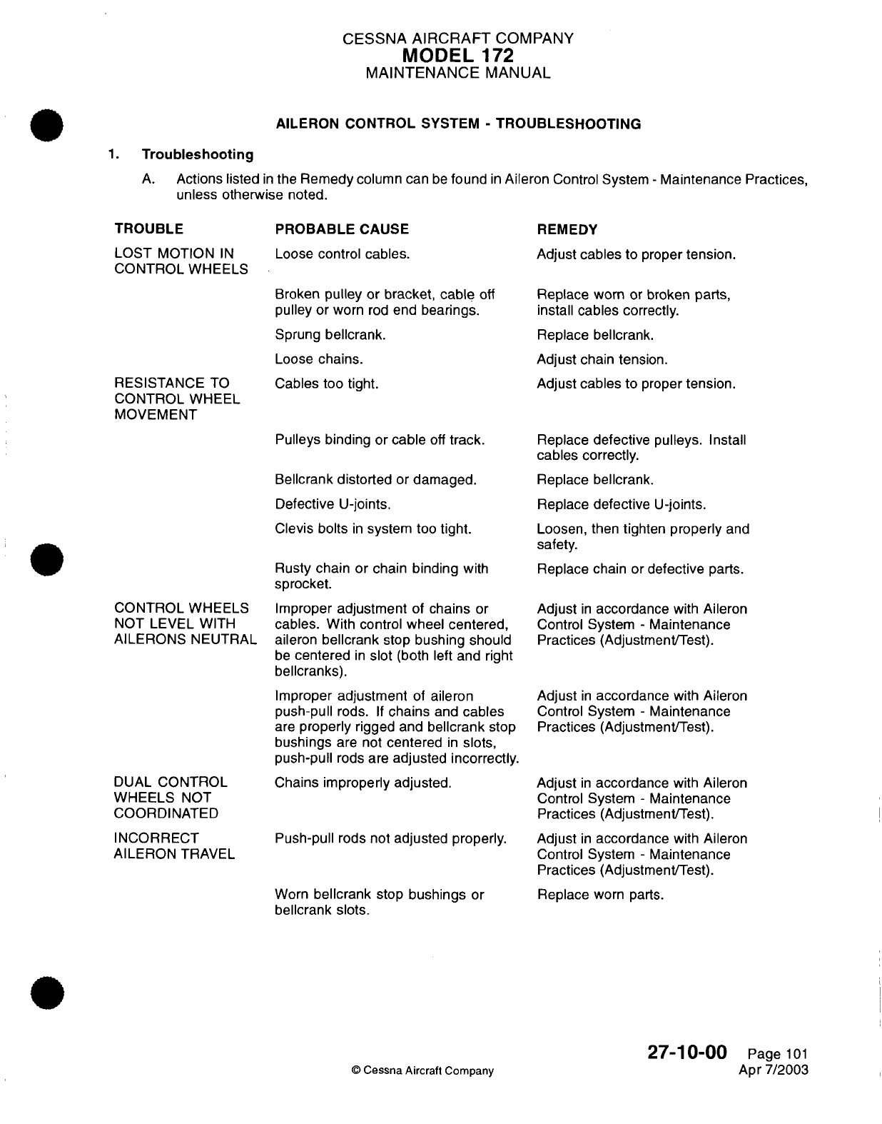
CESSNA
AIRCRAFT
COMPANY
MODEL
172
MAINTENANCE
MANUAL
AILERON
CONTROL
SYSTEM
-
TROUBLESHOOTING
1.
Troubleshooting
A.
Actions listed
in
the
Remedy
column can
be
found
in
Aileron
Control
System
-
Maintenance
Practices,
unless
otherwise
noted.
TROUBLE
LOST
MOTION
IN
CONTROL
WHEELS
RESISTANCE
TO
CONTROL
WHEEL
MOVEMENT
CONTROL WHEELS
NOT LEVEL
WITH
AILERONS
NEUTRAL
DUAL
CONTROL
WHEELS
NOT
COORDINATED
INCORRECT
AILERON
TRAVEL
PROBABLE
CAUSE
Loose
control
cables.
Broken
pulley
or
bracket, cable
off
pulley
or
worn
rod
end
bearings.
Sprung
bellcrank.
Loose
chains.
Cables too tight.
Pulleys
binding
or
cable
off
track.
Bellcrank
distorted
or
damaged.
Defective
U-joints.
Clevis bolts
in
system
too
tight.
Rusty
chain
or
chain
binding
with
sprocket.
Improper
adjustment
of
chains
or
cables.
With control
wheel
centered,
aileron
bellcrank
stop
bushing
should
be
centered
in
slot
(both
left
and
right
bellcranks).
Improper
adjustment
of
aileron
push-pull
rods.
If
chains
and
cables
are
properly
rigged
and
bellcrank
stop
bushings
are
not
centered
in
slots,
push-pull
rods are
adjusted
incorrectly.
Chains
improperly
adjusted.
Push-pull
rods not
adjusted
properly.
Worn
bellcrank
stop
bushings
or
bellcrank slots.
REMEDY
Adjust
cables
to
proper
tension.
Replace
worn or broken parts,
install
cables
correctly.
Replace
bellcrank.
Adjust
chain tension.
Adjust
cables to
proper
tension.
Replace
defective pulleys.
Install
cables
correctly.
Replace
bellcrank.
Replace
defective
U-joints.
Loosen,
then
tighten
properly
and
safety.
Replace chain
or defective
parts.
Adjust
in
accordance
with
Aileron
Control System
-
Maintenance
Practices
(Adjustment/Test).
Adjust
in
accordance
with
Aileron
Control System
-
Maintenance
Practices
(Adjustment/Test).
Adjust
in
accordance
with
Aileron
Control System
-
Maintenance
Practices
(Adjustment/Test).
Adjust
in
accordance
with Aileron
Control System
-
Maintenance
Practices
(Adjustment/Test).
Replace
worn
parts.
27-1
0-00
©
Cessna Aircraft
Company
Page
101
Apr 7/2003
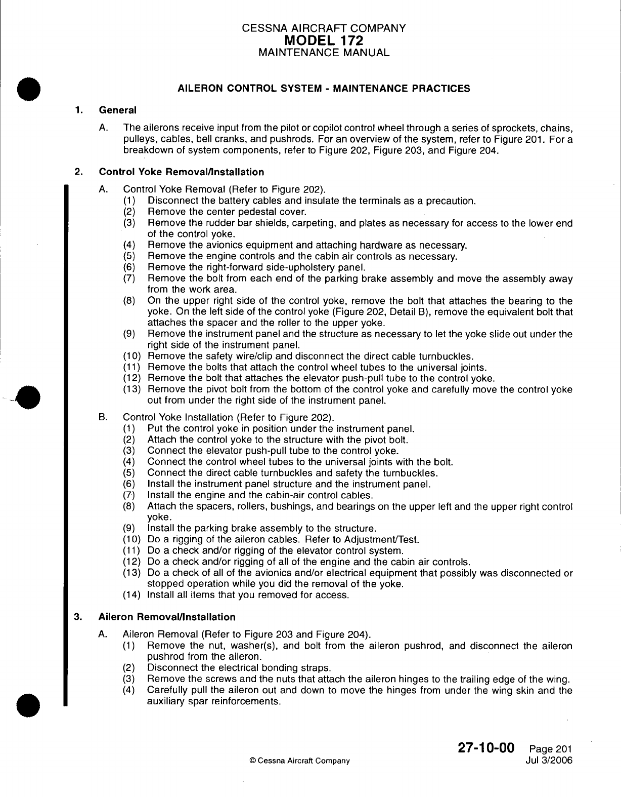
CESSNA
AIRCRAFT
COMPANY
MODEL
172
MAINTENANCE
MANUAL
AILERON CONTROL
SYSTEM
-
MAINTENANCE PRACTICES
1.
General
A.
The
ailerons
receive
input
from
the pilot
or
copilot control
wheel
through
a
series
of
sprockets,
chains,
pulleys,
cables,
bell
cranks,
and
pushrods.
For
an
overview
of
the
system,
refer
to
Figure
201.
For
a
breakdown of
system
components,
refer
to
Figure
202,
Figure
203,
and
Figure
204.
2.
Control
Yoke
Removal/Installation
A.
Control
Yoke
Removal (Refer
to
Figure 202).
(1)
Disconnect
the
battery
cables and insulate
the
terminals
as
a
precaution.
(2)
Remove
the center
pedestal cover.
(3)
Remove
the
rudder
bar
shields,
carpeting,
and
plates
as
necessary
for
access
to
the
lower
end
of
the
control
yoke.
(4)
Remove
the
avionics
equipment
and
attaching hardware
as
necessary.
(5)
Remove
the
engine
controls
and
the
cabin
air
controls
as
necessary.
(6)
Remove
the
right-forward
side-upholstery
panel.
(7)
Remove
the bolt
from
each
end
of
the
parking brake
assembly
and
move
the
assembly
away
from
the
work area.
(8)
On
the
upper
right
side
of
the control yoke, remove
the
bolt
that
attaches
the
bearing
to
the
yoke.
On
the
left
side
of
the
control
yoke (Figure
202,
Detail
B),
remove
the
equivalent
bolt
that
attaches
the
spacer
and
the
roller
to
the
upper
yoke.
(9)
Remove
the
instrument
panel
and
the structure
as necessary
to
let
the
yoke
slide
out
under
the
right side
of
the
instrument
panel.
(10)
Remove
the
safety wire/clip and
disconnect
the
direct
cable
turnbuckles.
(11)
Remove
the
bolts
that attach the control
wheel
tubes
to
the
universal
joints.
(12)
Remove
the
bolt
that
attaches
the
elevator
push-pull tube
to
the
control
yoke.
(13)
Remove
the pivot
bolt
from
the
bottom
of
the
control yoke
and
carefully
move
the
control
yoke
out
from
under the
right
side
of
the instrument panel.
B.
Control Yoke
Installation
(Refer to Figure 202).
(1)
Put
the control yoke
in
position under
the
instrument
panel.
(2)
Attach
the
control
yoke
to
the structure
with
the
pivot bolt.
(3)
Connect
the
elevator
push-pull tube
to
the
control yoke.
(4)
Connect
the control
wheel
tubes
to
the
universal
joints
with
the
bolt.
(5)
Connect
the
direct cable
turnbuckles
and
safety
the
turnbuckles.
(6)
Install
the
instrument
panel
structure
and
the
instrument
panel.
(7)
Install the
engine and
the
cabin-air
control
cables.
(8)
Attach the spacers,
rollers,
bushings, and
bearings
on
the
upper
left
and
the upper
right
control
yoke.
(9)
Install
the
parking brake
assembly
to
the
structure.
(10)
Do
a
rigging
of
the
aileron
cables.
Refer
to
Adjustment/Test.
(11)
Do
a
check and/or
rigging
of
the
elevator
control
system.
(12)
Do
a
check
and/or
rigging
of
all
of the
engine and
the
cabin
air
controls.
(13)
Do
a
check
of
all
of
the
avionics
and/or
electrical equipment that possibly
was
disconnected
or
stopped
operation
while you
did
the removal
of
the
yoke.
(14)
Install
all
items
that
you removed
for
access.
3.
Aileron Removal/Installation
A.
Aileron
Removal
(Refer
to
Figure
203 and
Figure
204).
(1)
Remove
the
nut,
washer(s), and
bolt
from
the
aileron
pushrod,
and
disconnect
the
aileron
pushrod
from
the aileron.
(2)
Disconnect
the
electrical
bonding straps.
(3)
Remove
the screws
and
the
nuts
that
attach
the
aileron hinges
to
the trailing
edge
of
the
wing.
(4)
Carefully
pull
the
aileron
out
and
down to
move
the
hinges
from
under
the
wing skin
and
the
auxiliary
spar
reinforcements.
27-10-00
Page
201
©
Cessna
Aircraft
Company
Jul
3/2006
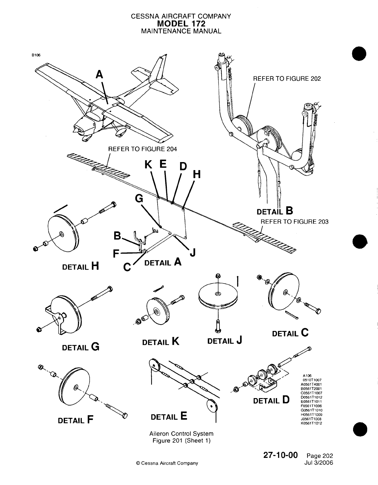
CESSNA AIRCRAFT
COMPANY
MODEL
172
MAINTENANCE
MANUAL
B
REFER
TO FIGURE
204
D
IH
203
U
I
AIL
II
DETAIL
G
DETAIL
K
DETAIL
J
DETAIL
C
DETAIL
D
UtIAIL
r
DETAIL
E
-UJol
I
lUU
D0561T1012
E0561T1011
F0561T1006
G0561T1010
H0561T1009
J0561T1008
K0561T1012
Aileron
Control
System
Figure
201
(Sheet
1)
©
Cessna
Aircraft
Company
t
J
11007
T4001
T2001
IT.n-,
27-10-00
Page
202
Jul 3/2006
)
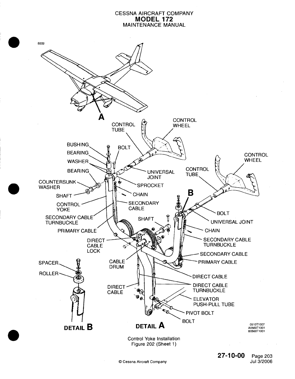
CESSNA
AIRCRAFT
COMPANY
MODEL
172
MAINTENANCE
MANUAL
CONTROL
WHEEL
-UNIVERSAL
JOINT
'SPROCKET
BOLT
UNIVERSAL
JOINT
-CHAIN
-SECONDARY
CABLE
TURNBUCKLE
-
SECONDARY
CABLE
PRIMARY
CABLE
BUL
I
DETAIL
B
DETAILA
Control
Yoke
Installation
Figure 202
(Sheet
1)
©
Cessna
Aircraft Company
27-10-00
Page
203
Jul
3/2006
A
BUSHING
BEARING
WASHER
ROL
L
0510T1007
A0560T1001
B0560T1001
B2
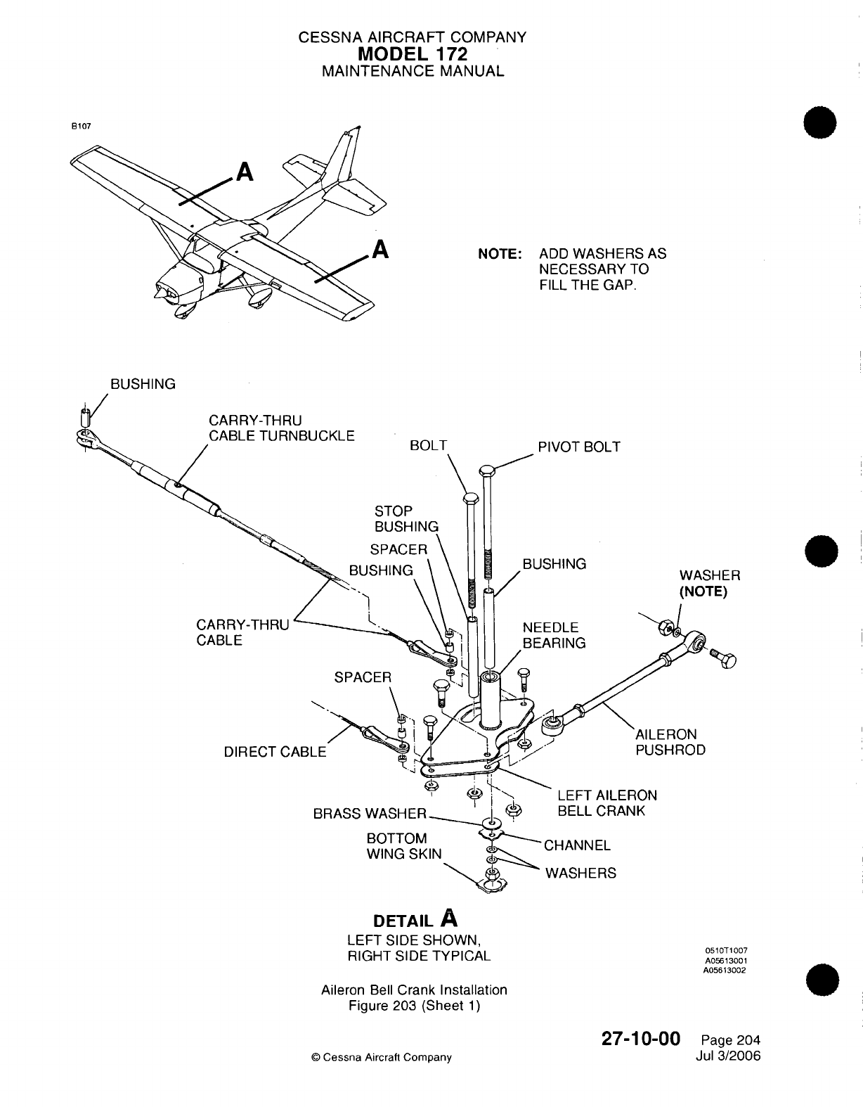
CESSNA AIRCRAFT
COMPANY
MODEL
172
MAINTENANCE
MANUAL
NOTE:
ADD
WASHERS
AS
NECESSARY
TO
FILL
THE
GAP.
BUSHING
CARRY-THRU
CABLE
TURNBUCKLE
SPAC
CARRY-THRU
CABLE
AILERON
PUSHROD
DIRECT CABLE
BRASS WASHER
LEFT
AILERON
BELL
CRANK
BOTTOM
WING
SKIN
WASHERS
DETAIL
A
LEFT
SIDE
SHOWN,
RIGHT SIDE TYPICAL
Aileron
Bell
Crank
Installation
Figure
203 (Sheet
1)
27-10-00
©
Cessna
Aircraft
Company
0510T1007
A05613001
A05613002
Page
204
Jul
3/2006
..A
I
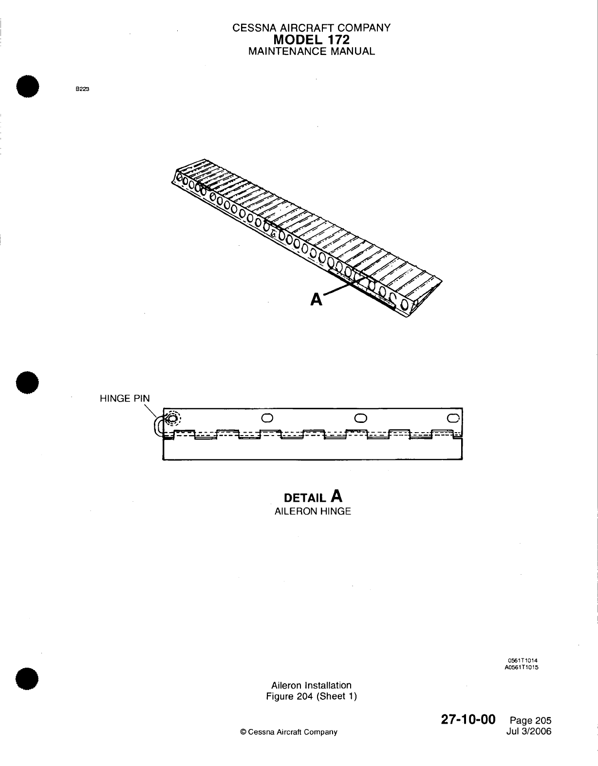
CESSNA
AIRCRAFT
COMPANY
MODEL
172
MAINTENANCE
MANUAL
B223
A
HINGE
PIN
\ :, o o
o
DETAIL
A
AILERON HINGE
0561T1014
A0561T1015
Aileron
Installation
Figure
204
(Sheet
1)
©
Cessna
Aircraft Company
27-10-00
Page
205
Jul
3/2006
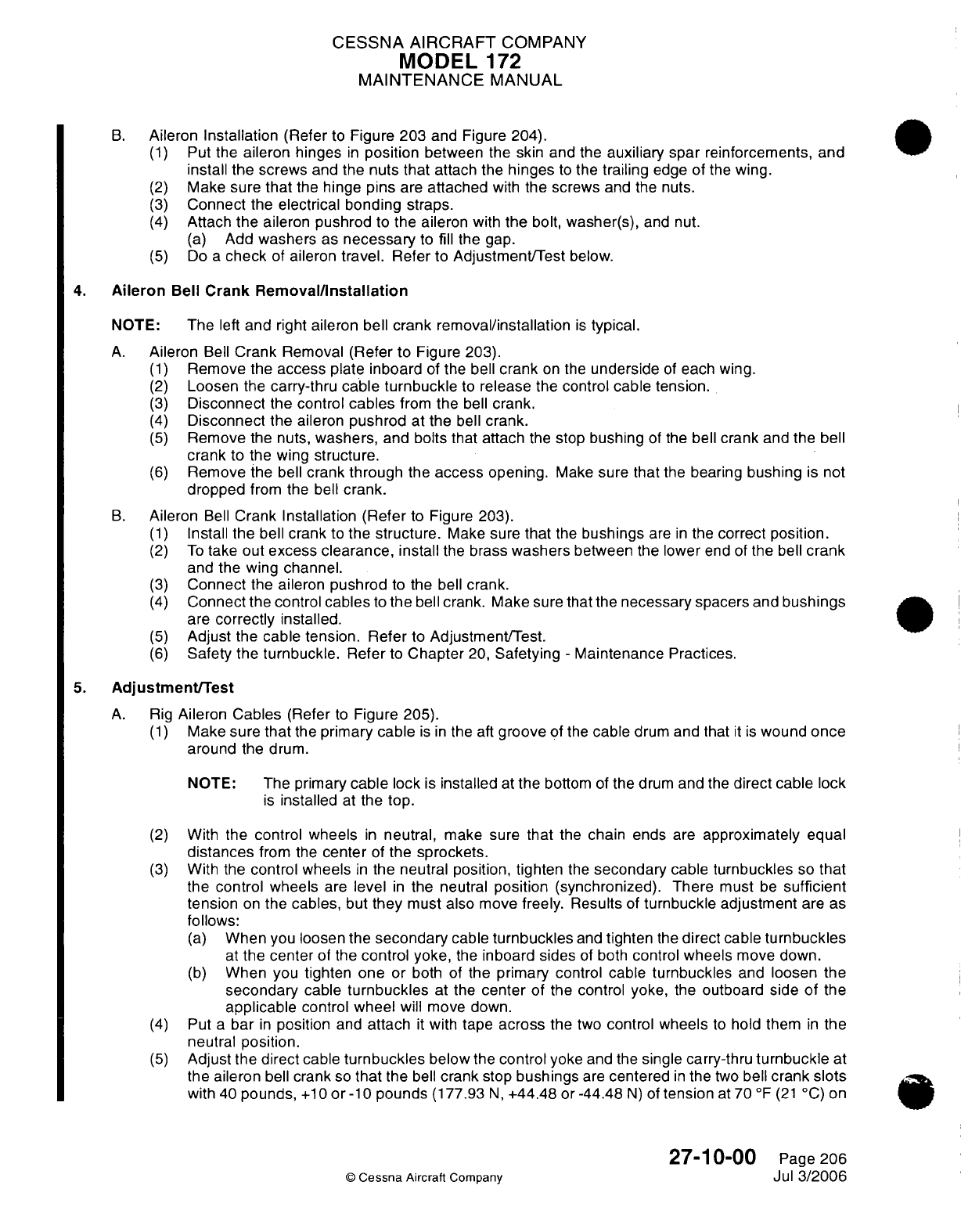
CESSNA AIRCRAFT
COMPANY
MODEL
172
MAINTENANCE
MANUAL
B.
Aileron
Installation
(Refer
to
Figure
203
and
Figure 204).
(1)
Put
the
aileron
hinges
in
position
between
the
skin
and
the
auxiliary spar
reinforcements,
and
install the screws
and the
nuts
that
attach
the
hinges
to
the
trailing
edge
of
the
wing.
(2)
Make
sure
that
the
hinge
pins
are
attached
with
the screws
and
the
nuts.
(3)
Connect
the
electrical bonding
straps.
(4)
Attach
the
aileron
pushrod
to the
aileron
with
the
bolt, washer(s),
and
nut.
(a)
Add
washers
as
necessary
to fill
the
gap.
(5)
Do
a
check
of
aileron
travel.
Refer
to
Adjustment/Test
below.
4.
Aileron
Bell
Crank
Removal/Installation
NOTE:
The
left
and
right
aileron
bell
crank
removal/installation
is
typical.
A.
Aileron
Bell
Crank
Removal
(Refer
to
Figure
203).
(1)
Remove
the
access
plate inboard
of the
bell
crank
on
the
underside
of
each
wing.
(2)
Loosen
the
carry-thru
cable
turnbuckle
to
release the
control
cable tension.
(3)
Disconnect
the
control
cables
from
the
bell
crank.
(4)
Disconnect
the aileron
pushrod
at the
bell
crank.
(5)
Remove
the
nuts,
washers,
and
bolts
that
attach
the
stop
bushing
of
the
bell
crank
and
the
bell
crank
to
the
wing
structure.
(6)
Remove
the
bell
crank through
the
access
opening.
Make
sure
that
the
bearing
bushing
is not
dropped
from
the
bell
crank.
B.
Aileron
Bell
Crank
Installation
(Refer
to
Figure
203).
(1)
Install
the bell
crank
to
the
structure.
Make
sure
that
the
bushings
are
in
the
correct
position.
(2)
To
take
out
excess
clearance,
install
the brass
washers
between
the
lower
end
of
the
bell
crank
and the
wing
channel.
(3)
Connect
the aileron
pushrod
to
the
bell
crank.
(4)
Connect
the
control
cables
to
the
bell
crank.
Make sure
that
the
necessary
spacers
and
bushings
are
correctly installed.
(5)
Adjust
the
cable tension. Refer to Adjustment/Test.
(6)
Safety
the
turnbuckle. Refer
to
Chapter
20,
Safetying
-
Maintenance Practices.
5.
Adjustment/Test
A.
Rig
Aileron
Cables
(Refer
to
Figure 205).
(1)
Make sure
that
the
primary
cable
is in
the aft
groove
of the
cable
drum
and
that
it is
wound
once
around
the
drum.
NOTE:
The primary
cable lock
is
installed
at
the
bottom
of
the
drum
and the
direct cable lock
is
installed
at
the top.
(2)
With
the
control
wheels
in
neutral,
make sure
that
the
chain
ends
are
approximately
equal
distances
from
the
center
of
the
sprockets.
(3)
With
the
control wheels
in
the neutral
position,
tighten
the
secondary
cable
turnbuckles
so
that
the
control
wheels
are
level
in
the
neutral
position
(synchronized).
There
must
be
sufficient
tension
on
the
cables,
but
they
must
also
move
freely.
Results
of
turnbuckle adjustment
are
as
follows:
(a)
When you loosen
the
secondary
cable
turnbuckles
and
tighten
the
direct
cable
turnbuckles
at
the
center
of
the
control
yoke,
the
inboard sides
of
both
control
wheels
move down.
(b)
When you
tighten
one
or
both
of
the
primary
control cable
turnbuckles
and
loosen
the
secondary
cable
turnbuckles
at the
center
of
the
control
yoke,
the
outboard
side
of
the
applicable
control
wheel
will move down.
(4)
Put
a
bar
in
position
and
attach
it
with
tape
across the
two
control
wheels
to
hold
them
in
the
neutral
position.
(5)
Adjust
the
direct
cable
turnbuckles
below
the
control
yoke
and
the single carry-thru
turnbuckle
at
the
aileron
bell
crank
so
that
the
bell
crank
stop
bushings
are
centered
in
the
two
bell
crank
slots
with
40
pounds,
+10
or
-10
pounds
(177.93
N,
+44.48
or
-44.48
N)
of
tension
at 70
°F
(21
°C) on
27-10-00
Page
206
©
Cessna
Aircraft
Company
Jul
3/2006
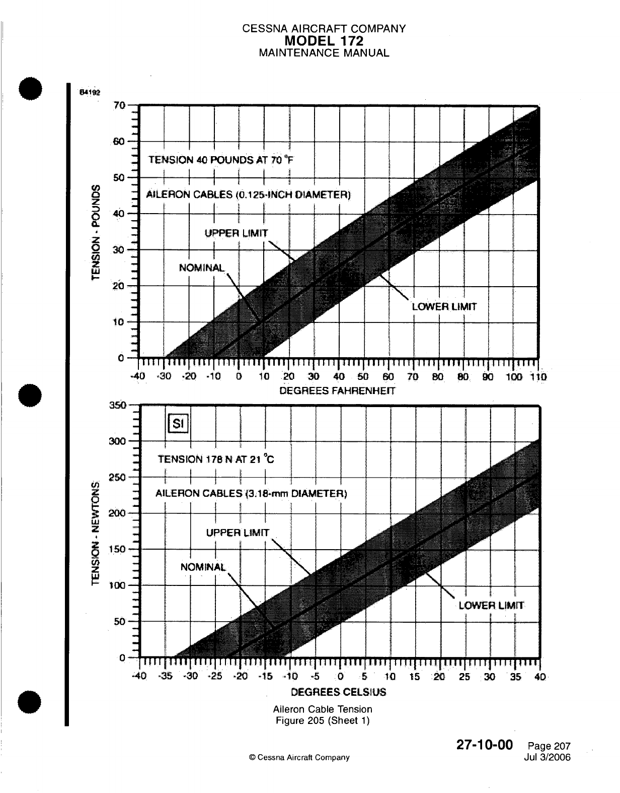
CESSNA
AIRCRAFT
COMPANY
MODEL
172
MAINTENANCE
MANUAL
1
70
EIw
J
60
_ J1
-
TENSION
40
POUNDS
AT
70
"F
s
I I I I I
r
Q
-
AILERON
CABLES
40.125-INCH
DIAMETER)
z
0
U03
UJ
_
U1LPPER
LIMIT
I
--
30
I I
"
!
;
I
1
_
2L
I
2
NOMINAL
A4
---
l
20 f
,
II
I
-
~,
=
10
=
=
0
°
T|WTfTtl TTrTtjT ii
tiT'T[lTiTTTT iii ITlTII Tlil iIliT l .l ITY'T
-40
-30
-20
-10
0
10
20
30
40
50
60
70
0B
80
90
100
1-O
DEGREES FAHRENHEIT
TENSION
178
N
AT
21
0
C
E I
I
AILERON
CABLES
3.18-mm
DIAMETER)
UPPER
IMI
UPPER
LIMIT
|
1
-- [
NOMINAL
*
:iii,4i
1 sis
A
I
-E =
_ _ ]
L,&~LO .WER L
IMIT
ITill
11
rllll
11
r I
Till
T
11
Th1
1 1
iiil""1
Ill
11111IIrtiiT
IrT"
I I .I I A....
.. . . . I
-40
*35
-30
-25
-20 -15
-10
-5
0
5
10
15
20
25
30 35
40
DEGREES
CELSIUS
Aileron
Cable Tension
Figure
205
(Sheet
1)
©
Cessna
Aircraft Company
27-10-00
Page
207
Jul
3/2006
300
250
_
200
-i
150
-1
1tO
Un
z
0
LU
z:
50
-
r
0
IIll
i
J
-1
--
-...
I
;
I
I
fI
i
MI
CESSNA
AIRCRAFT
COMPANY
MODEL
172
MAINTENANCE
MANUAL
the
aileron
carry-thru
cable.
Refer
to
Figure
205
for
the
correct
tensions
at other
temperatures.
Ignore the
tension
on
the
direct
cables.
This
tension
will
be
different than
the
tension
on
the
carry-thru
cable.
(6)
Adjust
the
pushrods
at
the
two
ailerons
until
the
ailerons
are
neutral with
reference
to the
trailing
edge
of
the
wing
flaps.
Be
sure that
the wing
flaps
are
fully
up
when
you make
this
adjustment.
(7)
Remove the bar
from
the
control wheels.
(8)
With
an
inclinometer,
do
a
check
of
the
ailerons
for
correct
travel.
Make
adjustments
if
necessary
and
make sure
that
the
bushing
travel stops
are
correctly
centered
in
the
bell
cranks.
NOTE:
For
aileron
rigging
specifications,
refer
to
Chapter
6,
Airplane
Dimensions
and
Specifications
-
Description
and
Operation.
(9)
Safety
all
turnbuckles.
Refer
to Chapter
20,
Safetying
-
Maintenance
Practices.
(10)
Install
all
items
that
you
removed
for
access.
WARNING:
Make
sure
that
the
ailerons
move
in
the
correct
direction
when
you
move
the
control
wheel.
(11)
Do
a
check
for
the
correct
travel
of
the
aileron.
6.
Cables
And
Pulleys Removal/Installation
A.
Cables
and
Pulleys
Removal.
(1)
Remove
the
access
plates,
wing
root
fairings,
and
upholstery
as
necessary.
(2)
Disconnect
the
cables
from
the aileron bell
cranks
and
remove
the
cable guards
and
the
pulleys
as
necessary
to
move
the
cables
free
of
the aircraft.
NOTE:
To
ease
the
routing
of
cables,
a
length of
wire
can
be
attached
to
the
end
of
the cable
before
it
is
removed
from
the airplane.
Leave
the
wire
in
position, installed
through
me
structure;
ana
men attacn
tne
caDle
tnat
you
install
ana
use
tne
wire
to
pull
me
cable
into
position.
B.
Cables
and
Pulleys
Installation.
(1)
Route
the
cable
and
install
the
pulleys
and
the
cable
guards.
NOTE: Make
sure
that
the cable
is
in
the
correct position
in
the
pulley
groove
before
you
install
the guard.
(2)
Do
a
rigging
of
the
aileron system.
(3)
Safety the
turnbuckles.
(4)
Install
the
access
plates,
fairings,
and
upholstery.
27-10-00
Page 208
©
Cessna
Aircraft
Company
Jul
3/2006
CESSNA
AIRCRAFT
COMPANY
MODEL
172
MAINTENANCE MANUAL
RUDDER
CONTROL
SYSTEM
-
TROUBLESHOOTING
1.
Troubleshooting
A.
Actions
listed
in
the
Remedy
column
can
be
found
in
Rudder Control System
-
Maintenance
Practices,
unless
otherwise
noted.
TROUBLE
RUDDER DOES
NOT
RESPOND
TO
PEDAL
MOVEMENT
BINDING
OR
JUMPY
MOVEMENT
OF
RUDDER
PEDALS
PROBABLE
CAUSE
Broken
or
disconnected
cables.
Cables
too
tight.
REMEDY
Connect
or
replace
cables.
Ensure
distance
from
firewall
to
pivot
shaft
is
6.50 inches.
Cables
not riding
properly
on
pulleys.
Binding,
broken
or
defective pulleys
or
cable
guards.
Pedal
bars
need
lubrication.
Defective
rudder bar bearings.
Defective
rudder hinge
bushings.
Clevis
bolts
too
tight
Steering
rods
not
adjusted
properly.
LOST
MOTION
BETWEEN
RUDDER
PEDALS
AND
RUDDER
INCORRECT
RUDDER TRAVEL
Insufficient
cable
tension.
Incorrect
rigging.
© Cessna Aircraft
Company
Route
cables
correctly
over
pulleys.
Replace
defective pulleys
and
install
guards
properly.
Lubricate
as
required.
If
lubrication
fails
to
eliminate
binding, replace
bearing
blocks.
Replace
defective
bushings.
Readjust
to
eliminate
binding.
Re-rig
system.
Refer to
Rudder
Control
Adjustment/Test.
Ensure
distance
from
firewall
to
pivot
shaft
is
6.50 inches.
Re-rig
system. Refer
to
Rudder
Control
Adjustment/Test.
27-20-00
Page
101
Apr
7/2003
CESSNA
AIRCRAFT
COMPANY
MODEL
172
MAINTENANCE
MANUAL
RUDDER
CONTROL
SYSTEM
-
MAINTENANCE PRACTICES
1.
General
A.
Rudder
control
is
maintained
through
use of
conventional
rudder
pedals
which
also
control nose
wheel
steering.
The
system
is
comprised
of
rudder
pedals, cables
and
pulleys,
all
of
which
link
the
pedals
to
the
rudder
and
nose
wheel
steering.
For
an
illustration
of
the rudder
system,
refer
to
Figure
201.
2.
Rudder
Pedal
Assembly
Removal/Installation
A.
Remove
Rudder
Pedal
Assembly
(Refer
to
Figure
201).
(1)
Remove
upholstery
from
area
below
instrument
panel
as
necessary.
(2)
Disconnect
master
cylinders
at
pilot
rudder
pedals.
(3)
Disconnect
parking brake
cables at
master
cylinders.
(4)
Remove
rudder
pedals
and brake
links.
(5)
Relieve cable
tension
at
clevis
adjustments.
(6)
Disconnect cables,
return
springs,
trim
bungee
and
steering
tubes
from
rudder
bars.
(7)
Remove
bolts
securing
bearing
blocks
and
work
rudder bars
out
of
area
below
instrument
panel.
B.
Install
Rudder
Pedal
Assembly
(Refer
to
Figure
201).
NOTE:
Rudder
bar
assemblies
should
be
checked
for
excessive
wear
before
installation.
The
bearing
blocks
are
nylon
and
require
no
lubrication
unless
binding
occurs.
A
few
drops
of
general
purpose
oil
should eliminate
such
binding.
(1)
Position rudder
bars
in
area
below
instrument
panel and
secure
bearing
blocks
with
bolts.
(2)
Reconnect cables,
return
springs,
trim
bungee
and
steering
tubes
to
rudder
bars.
(3)
Set
distance
from
pivot shaft
to
firewall
at
6.50
inches.
(4)
Install
rudder pedals
and
brake links.
(5)
Connect
parking
brake
cables
at
master cylinders.
(6)
Connect master
cylinders
at
pilot
rudder pedals.
(7)
Install
upholstery
to
tunnel
area as necessary.
3.
Rudder
Removal/Installation
A.
Remove
Rudder
(Refer
to
Figure
201).
(1)
Disconnect
shackles
at
rudder bellcrank.
(2)
Disconnect
tail navigation
light
quick-disconnect
at
bottom
of
rudder.
(3)
With
rudder
supported,
remove
hinge
bolts
(including
electrical
bonding
strap)
and
lift
rudder
free
of
vertical
fin.
B.
Install
Rudder
(Refer
to
Figure
201).
(1)
Install
rudder
(with
electrical
bonding
strap)
to vertical
fin.
Torque
nuts
to
50
to 70
inch
pounds
plus
free running
torque.
(2)
Reconnect tail
navigation light
quick-disconnect
at
bottom
of
rudder.
(3)
Attach
shackles
to
rudder
bellcrank.
NOTE:
Do
not
over
tighten.
Shackle
must pivot
freely.
4.
Rudder
Control Adjustment/Test
A.
Rig
Rudder
Controls.
NOTE:
For
rudder
travel
angles,
refer
to
Chapter
6,
Airplane Dimensions
and
Specifications
-
Description
and
Operation.
(1)
Using
a
digital inclinometer,
adjust
travel
stops
on
rudder
to
obtain
proper
rudder
travel.
27-20-00
Page
201
©
Cessna
Aircraft
Company
Apr
7/2003
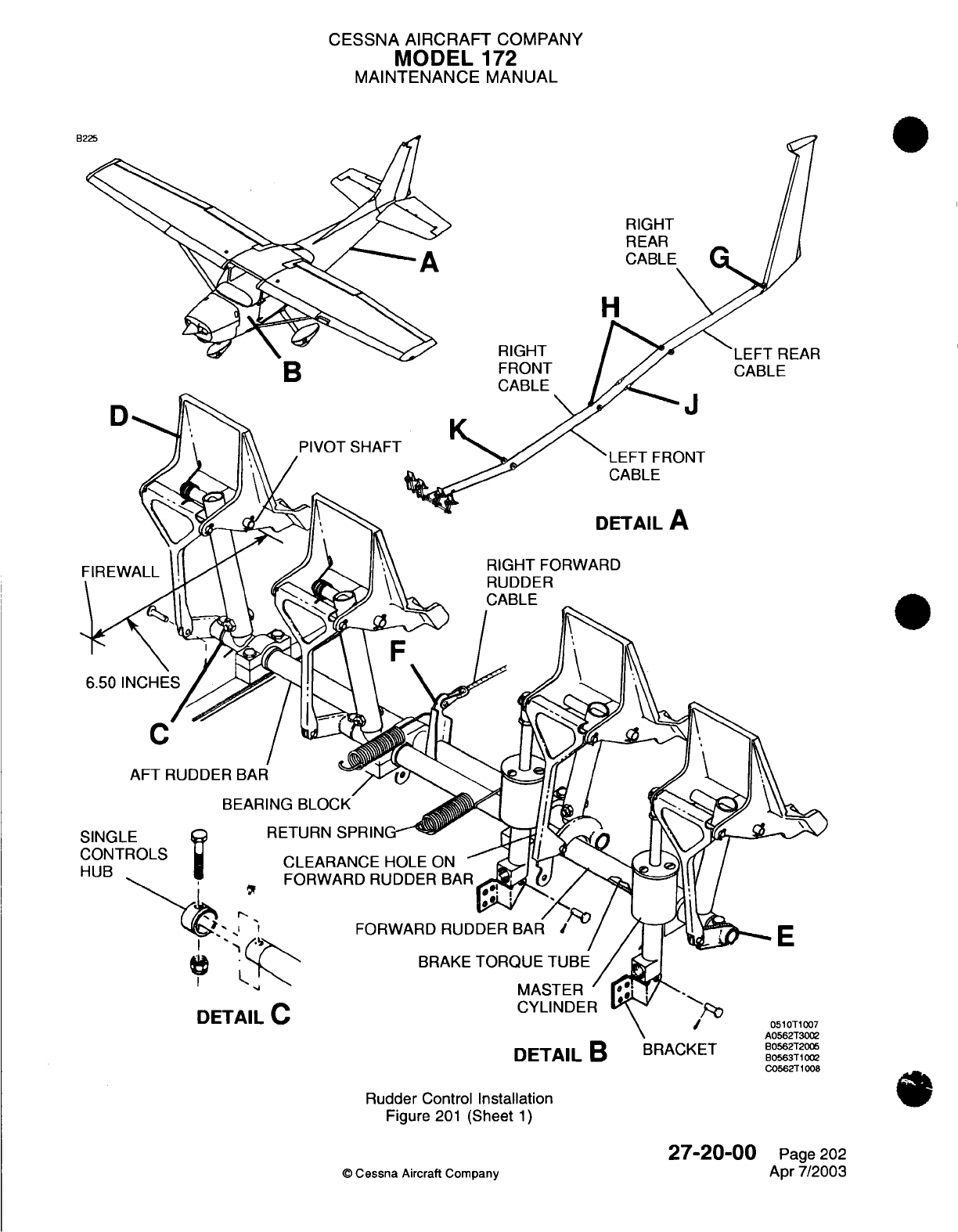
CESSNA
AIRCRAFT
COMPANY
MODEL
172
MAINTENANCE
MANUAL
RIGHT
REAR
H
RIGHT
FRONT
CABLE
LEFT
REAR
CABLE
J
LEFT
FRONT
CABLE
DETAIL
A
RIGHT
FORWARD
RUDDER
6.50
C
AFT
RUDDER
BAR
BEARING
BLOCK
RETURN
SPRIN(
CLEARANCE
HOLE
ON
FORWARD
RUDDER
BAR
FORWARD
RUDDER
BAR
DETAIL
C
BRAKE
TORQUE TUBE
MASTER
'
CYLINDER
Rudder
Control
Installation
Figure
201
(Sheet
1)
27-20-00
©
Cessna
Aircraft
Company
E
DETAIL
B
BRACKET
B0562T2005
B0563T1002
C0562T1008
Page
202
Apr 7/2003
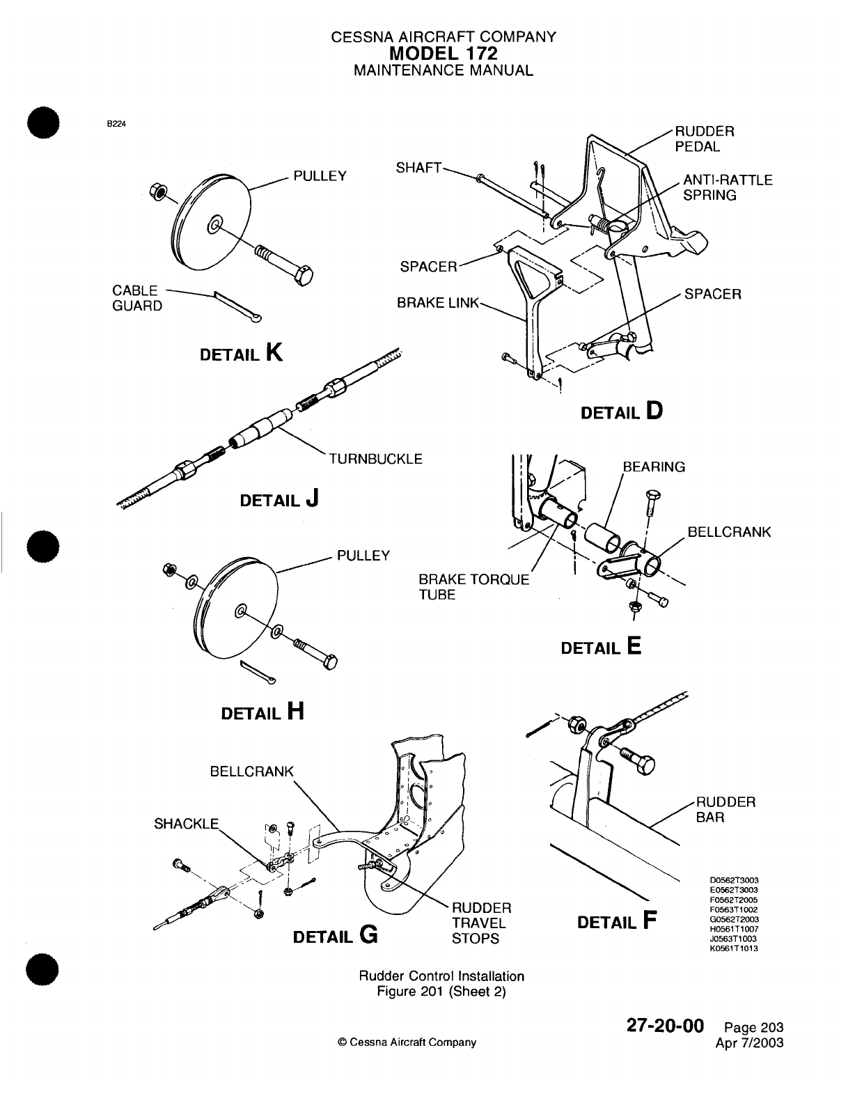
CESSNA
AIRCRAFT
COMPANY
MODEL
172
MAINTENANCE
MANUAL
B224
-LLY
CABLE
GUARD
DETAIL
D
LE
DETAIL
J
BELLCRANK
PULLEY
BRAKE
TORQUE
TUBE
DETAIL
E
DETAIL
H
RUDDER
DETAIL
G
TRAVEL
STOPS
DETAIL
F
Rudder
Control
Installation
Figure
201
(Sheet
2)
©
Cessna
Aircraft Company
27-20-00
Page
203
Apr
7/2003
SPACER
SHACI
RUDDER
BAR
D0562T3003
E0562T3003
F0562T2005
F0563T1002
G0562T2003
H0561T1007
J0563T1003
K0561T1013
.' .,"
II
-l
I.
I
-\
-
A
D1
I
rUI
JLLL
I
'1_0
^
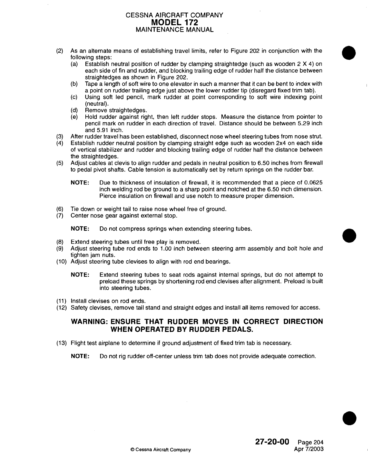
CESSNA AIRCRAFT
COMPANY
MODEL
172
MAINTENANCE
MANUAL
(2)
As
an
alternate
means
of
establishing travel
limits,
refer
to
Figure
202
in
conjunction
with
the
following
steps:
(a)
Establish neutral
position
of
rudder
by
clamping
straightedge
(such
as
wooden
2
X 4) on
each
side
of
fin
and
rudder,
and
blocking
trailing
edge
of
rudder
half
the
distance
between
straightedges
as shown
in
Figure
202.
(b)
Tape
a
length
of
soft
wire
to
one
elevator
in
such
a
manner
that
it
can
be
bent
to
index
with
a
point
on
rudder
trailing
edge
just
above the lower rudder tip (disregard
fixed
trim tab).
(c)
Using
soft
led
pencil,
mark
rudder
at
point
corresponding
to
soft wire
indexing
point
(neutral).
(d)
Remove
straightedges.
(e)
Hold
rudder
against
right,
then left
rudder stops. Measure
the
distance
from
pointer
to
pencil mark
on
rudder
in
each
direction
of
travel.
Distance
should
be
between
5.29
inch
and
5.91
inch.
(3)
After rudder
travel
has
been
established,
disconnect
nose
wheel steering
tubes
from
nose
strut.
(4)
Establish
rudder neutral position
by
clamping
straight
edge such
as
wooden 2x4
on
each
side
of
vertical
stabilizer
and rudder and
blocking
trailing
edge
of
rudder
half
the
distance
between
the
straightedges.
(5)
Adjust
cables
at
clevis
to
align rudder and
pedals
in
neutral
position
to
6.50 inches
from
firewall
to
pedal
pivot shafts. Cable
tension
is
automatically
set
by
return
springs
on the
rudder
bar.
NOTE:
Due to
thickness
of
insulation
of
firewall,
it is
recommended
that
a
piece
of
0.0625
inch
welding
rod
be
ground
to
a
sharp
point
and
notched
at
the
6.50
inch
dimension.
Pierce
insulation
on
firewall
and
use
notch
to
measure proper
dimension.
(6)
Tie
down
or
weight tail
to
raise
nose
wheel
free
of
ground.
(7)
Center
nose
gear
against
external
stop.
NOTE:
Do
not
compress springs
when
extending steering tubes.
(8)
Extend
steering
tubes
until
free play
is
removed.
(9)
Adjust steering tube
rod
ends
to
1.00
inch between
steering
arm
assembly
and
bolt hole
and
tighten
jam
nuts.
(10)
Adjust
steering tube
clevises
to
align with
rod
end
bearings.
NOTE: Extend
steering
tubes
to
seat
rods
against
internal springs,
but
do
not
attempt
to
preload
these springs
by
shortening
rod
end
clevises after
alignment.
Preload
is
built
into
steering
tubes.
(11)
Install
clevises
on
rod
ends.
(12)
Safety
clevises,
remove tail stand
and
straight
edges
and
install
all
items
removed
for
access.
WARNING:
ENSURE
THAT
RUDDER
MOVES
IN
CORRECT
DIRECTION
WHEN
OPERATED
BY
RUDDER
PEDALS.
(13)
Flight
test
airplane
to
determine
if
ground
adjustment
of
fixed
trim
tab
is
necessary.
NOTE:
Do
not
rig
rudder
off-center
unless
trim
tab does not provide
adequate
correction.
27-20-00
Page
204
©
Cessna Aircraft
Company
Apr
7/2003
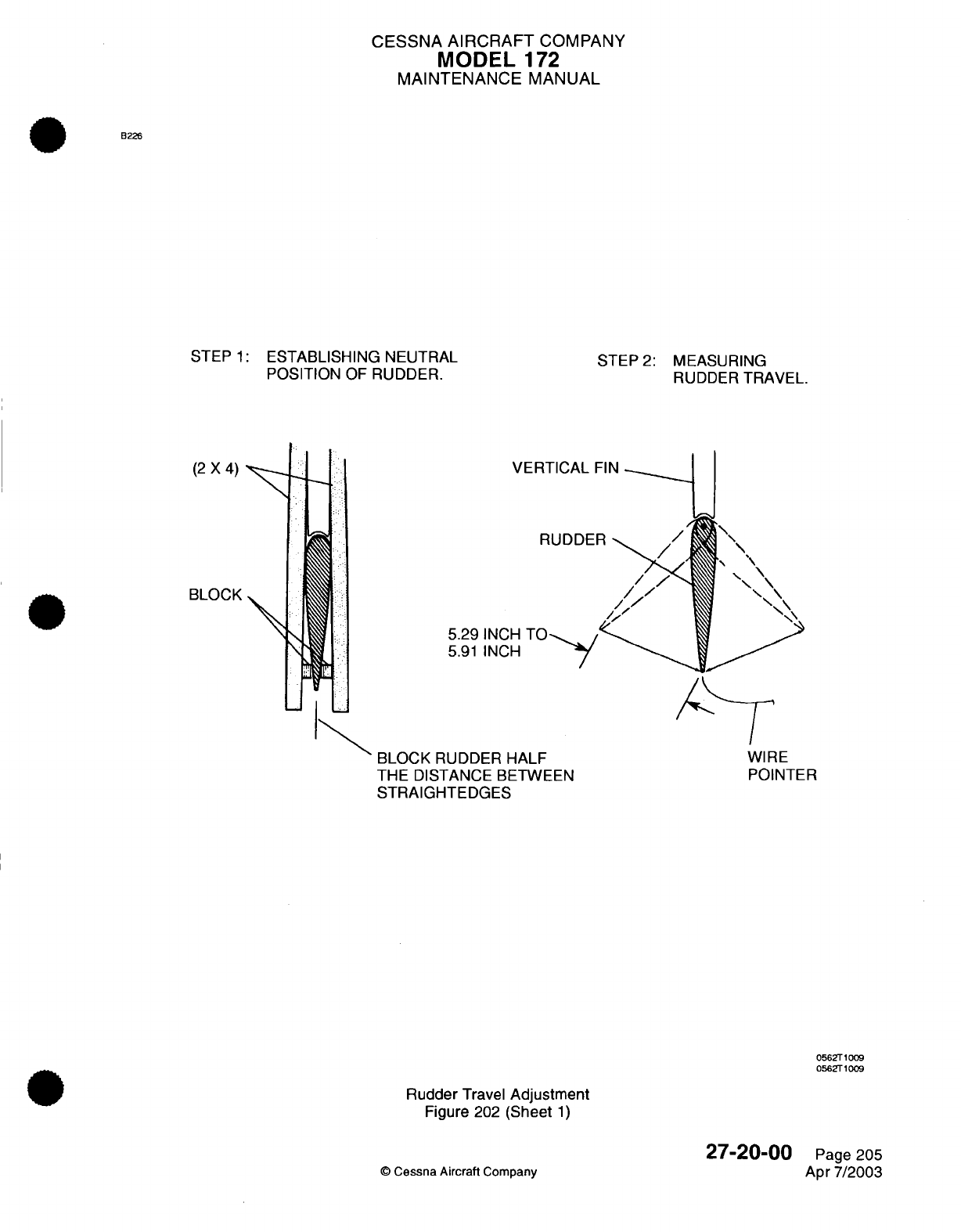
CESSNA
AIRCRAFT
COMPANY
MODEL
172
MAINTENANCE
MANUAL
B226
STEP
1:
ESTABLISHING NEUTRAL
POSITION
OF
RUDDER.
(2 X 4)
BLOCK
STEP
2:
MEASURING
RUDDER
TRAVEL.
VERTICAL
RUDDE
5.29
INCH
TO-,,
5.91
INCH
BLOCK
RUDDER
HALF
THE
DISTANCE
BETWEEN
STRAIGHTEDGES
0562T1009
0562T1009
Rudder
Travel
Adjustment
Figure
202
(Sheet
1)
27-20-00
©
Cessna Aircraft
Company
WIRE
POINTER
Page 205
Apr
7/2003
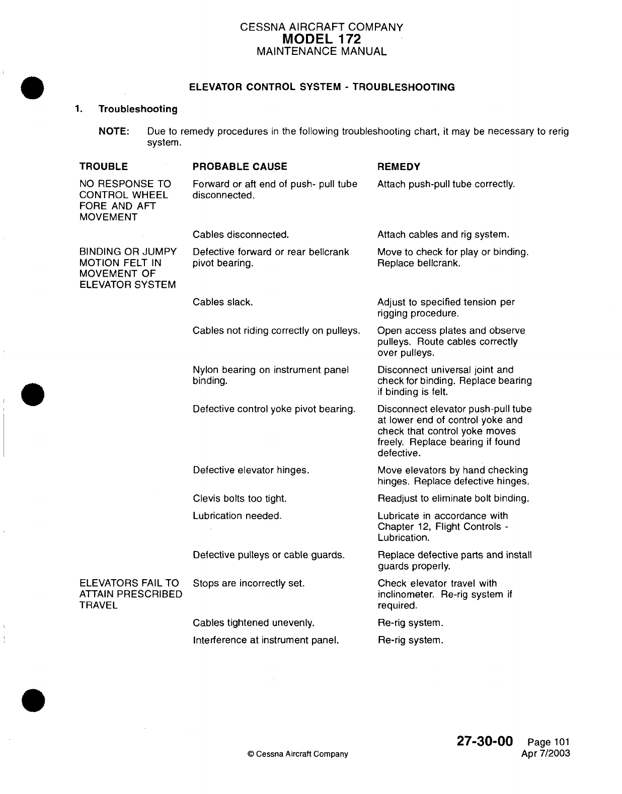
CESSNA
AIRCRAFT
COMPANY
MODEL
1
72
MAINTENANCE
MANUAL
ELEVATOR
CONTROL
SYSTEM
-
TROUBLESHOOTING
1.
Troubleshooting
NOTE:
Due to
remedy
procedures
in
the
following troubleshooting
chart,
it
may
be
necessary
to
rerig
system.
TROUBLE
NO
RESPONSE
TO
CONTROL
WHEEL
FORE AND
AFT
MOVEMENT
BINDING
OR
JUMPY
MOTION
FELT
IN
MOVEMENT
OF
ELEVATOR
SYSTEM
PROBABLE
CAUSE
Forward
or
aft
end
of
push-
pull
tube
disconnected.
Cables
disconnected.
Defective
forward
or
rear
bellcrank
pivot
bearing.
REMEDY
Attach
push-pull
tube
correctly.
Attach
cables
and
rig
system.
Move to
check
for
play
or
binding.
Replace
bellcrank.
Cables
slack.
Cables
not
riding
correctly
on
pulleys.
Nylon
bearing
on
instrument
panel
binding.
Defective
control
yoke
pivot bearing.
Defective
elevator
hinges.
Clevis
bolts
too
tight.
Lubrication
needed.
Defective
pulleys
or
cable
guards.
ELEVATORS FAIL TO
ATTAIN
PRESCRIBED
TRAVEL
Stops
are
incorrectly
set.
Cables
tightened
unevenly.
Interference at
instrument
panel.
Adjust
to
specified
tension
per
rigging
procedure.
Open
access
plates
and
observe
pulleys.
Route
cables correctly
over
pulleys.
Disconnect
universal
joint
and
check
for
binding.
Replace
bearing
if
binding
is
felt.
Disconnect elevator push-pull
tube
at
lower
end
of
control
yoke
and
check
that control yoke
moves
freely.
Replace
bearing
if
found
defective.
Move
elevators
by
hand
checking
hinges.
Replace
defective
hinges.
Readjust
to
eliminate bolt binding.
Lubricate
in
accordance
with
Chapter
12,
Flight
Controls
-
Lubrication.
Replace
defective
parts
and
install
guards
properly.
Check
elevator
travel
with
inclinometer.
Re-rig
system
if
required.
Re-rig
system.
Re-rig
system.
27-30-00
©
Cessna Aircraft
Company
Page
101
Apr
7/2003
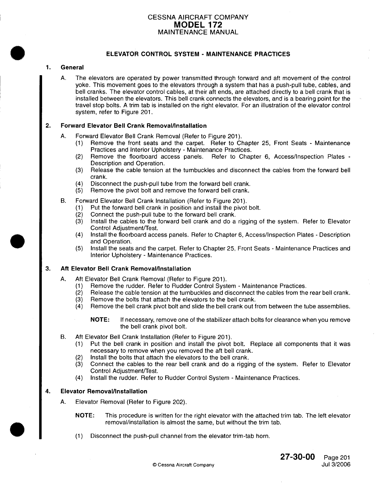
CESSNA
AIRCRAFT
COMPANY
MODEL
172
MAINTENANCE
MANUAL
ELEVATOR
CONTROL
SYSTEM
-
MAINTENANCE
PRACTICES
1.
General
A.
The
elevators
are
operated
by
power
transmitted
through forward
and
aft
movement
of
the
control
yoke.
This
movement
goes
to
the
elevators
through
a
system
that
has
a
push-pull
tube,
cables,
and
bell
cranks.
The
elevator control
cables,
at
their
aft ends,
are
attached
directly
to
a
bell
crank
that
is
installed
between
the
elevators.
This
bell
crank
connects
the
elevators,
and
is
a
bearing
point
for
the
travel
stop bolts.
A
trim
tab
is
installed
on the
right
elevator.
For
an
illustration
of the
elevator
control
system,
refer
to
Figure
201.
2.
Forward
Elevator
Bell Crank
Removal/Installation
A.
Forward
Elevator
Bell
Crank
Removal
(Refer
to
Figure
201).
(1)
Remove the
front seats
and the
carpet. Refer
to
Chapter
25, Front
Seats
-
Maintenance
Practices
and
Interior Upholstery
-
Maintenance
Practices.
(2)
Remove the
floorboard
access
panels. Refer
to
Chapter
6,
Access/Inspection
Plates
-
Description
and
Operation.
(3)
Release
the
cable
tension
at the
turnbuckles
and
disconnect
the
cables
from
the
forward
bell
crank.
(4)
Disconnect
the
push-pull
tube
from
the
forward
bell
crank.
(5)
Remove
the
pivot bolt
and
remove
the
forward
bell
crank.
B.
Forward
Elevator
Bell
Crank
Installation
(Refer
to
Figure
201).
(1)
Put
the
forward
bell
crank
in
position
and
install
the
pivot
bolt.
(2)
Connect
the
push-pull tube
to
the
forward
bell
crank.
(3)
Install
the
cables
to the
forward
bell
crank and do
a
rigging
of the
system. Refer
to
Elevator
Control
Adjustment/Test.
(4)
Install
the
floorboard
access
panels.
Refer
to
Chapter
6,
Access/Inspection
Plates
-
Description
and
Operation.
(5)
Install
the seats and
the
carpet.
Refer
to
Chapter
25,
Front
Seats
-
Maintenance
Practices
and
Interior
Upholstery
-
Maintenance
Practices.
3.
Aft Elevator
Bell
Crank
Removal/Installation
A.
Aft
Elevator
Bell
Crank
Removal
(Refer
to
Figure
201).
(1)
Remove
the
rudder.
Refer
to
Rudder
Control
System
-
Maintenance
Practices.
(2)
Release
the
cable
tension
at
the
turnbuckles
and
disconnect
the
cables
from
the rear
bell
crank.
(3)
Remove
the
bolts
that
attach
the
elevators
to
the
bell
crank.
(4)
Remove
the
bell
crank
pivot
bolt
and
slide
the
bell
crank out
from
between
the
tube
assemblies.
NOTE:
If
necessary,
remove
one
of
the
stabilizer
attach
bolts
for
clearance
when
you remove
the
bell crank
pivot
bolt.
B.
Aft
Elevator
Bell
Crank
Installation
(Refer
to
Figure
201).
(1)
Put
the
bell
crank
in
position
and
install
the
pivot bolt. Replace
all
components that
it
was
necessary
to
remove
when
you removed
the
aft
bell
crank.
(2)
Install
the
bolts
that
attach the
elevators
to the
bell
crank.
(3)
Connect
the
cables
to
the
rear
bell
crank
and
do
a
rigging
of
the
system. Refer
to
Elevator
Control
Adjustment/Test.
(4)
Install
the
rudder.
Refer
to
Rudder
Control
System
-
Maintenance
Practices.
4.
Elevator
Removal/Installation
A.
Elevator
Removal (Refer
to
Figure
202).
NOTE:
This procedure
is
written
for
the right
elevator
with
the
attached
trim
tab.
The
left
elevator
removal/installation
is
almost
the
same,
but
without
the
trim
tab.
(1)
Disconnect
the
push-pull
channel
from
the
elevator
trim-tab
horn.
27-30-00
Page
201
©
Cessna
Aircraft
Company
Jul
3/2006
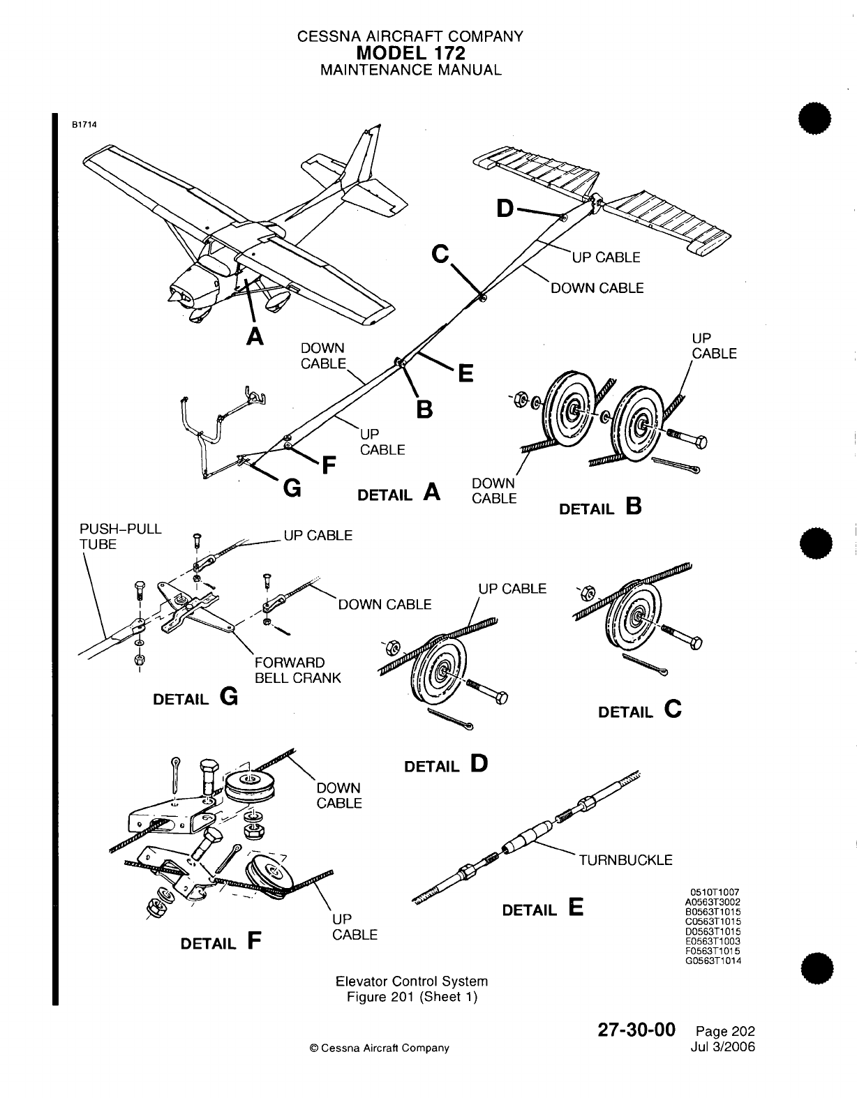
CESSNA AIRCRAFT
COMPANY
MODEL
172
MAINTENANCE
MANUAL
F
UP
CABLE
DETAIL
B
ABLE
DOWr
UP
CABLE
BELL
CRANK
DETAIL
G
DETAIL
C
nFTAII
D
]KLE
DETAIL
C
DETAIL
F
CABLE
Elevator
Control System
Figure
201
(Sheet
1)
©
Cessna
Aircraft Company
0510T1007
A0563T3002
B0563T1015
C0563T1015
D0563T1015
E0563T1003
F0563T1015
G0563T1014
27-30-00
Page
202
Jul 3/2006
D
.
7
4
A
bl
E
VJ/-'DLr
a_
|
AW_
X
X
L
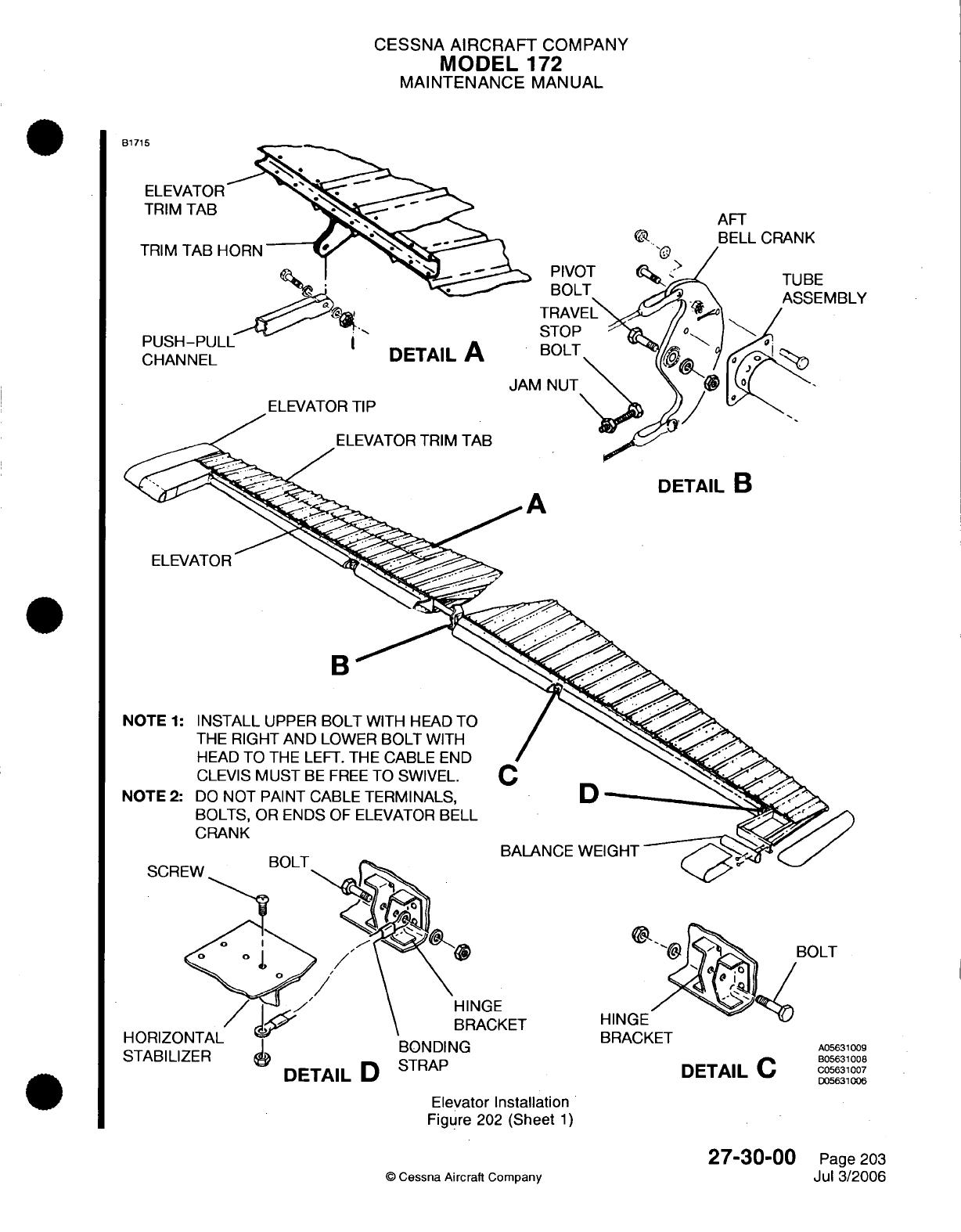
CESSNA
AIRCRAFT
COMPANY
MODEL
172
MAINTENANCE
MANUAL
R171;
AFT
BELL
CRANK
BE
;EMBLY
CHANNEL
DETAIL
A
ELEVATOR
TRIM
TAB
A
DETAIL
B
ELEVATOR
B
C
D
BALANCE
WEIGHT
SCR
NGE
IACKET
HORIZC
STABILI
DETAIL
U ."..)
BRACKET
DETAIL
C
Elevator
Installation
Figure
202
(Sheet
1)
©
Cessna Aircraft
Company
27-30-00
Page 203
Jul 3/2006
A05631009
B05631008
C05631007
D05631006
Y'
I
r»/\l
T
HINm
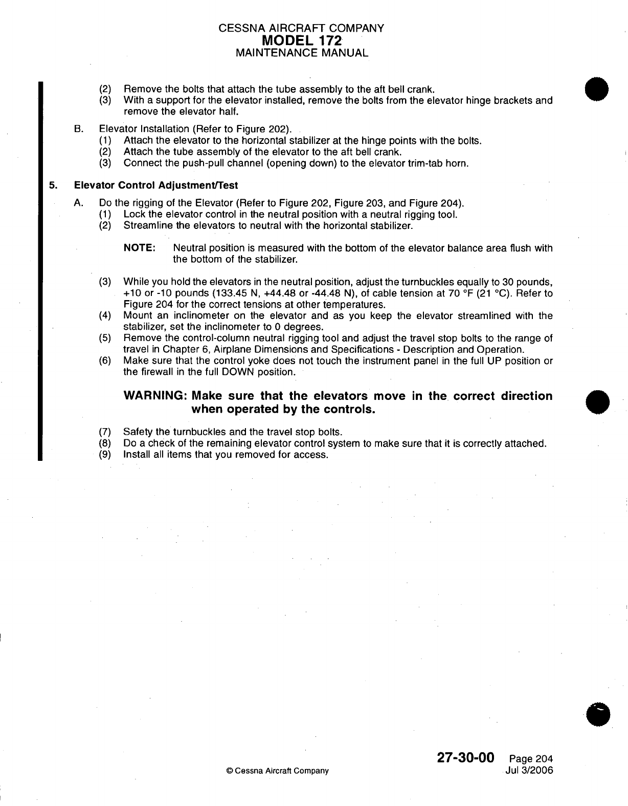
CESSNA
AIRCRAFT
COMPANY
MODEL
172
MAINTENANCE
MANUAL
(2)
(3)
Remove
the
bolts
that
attach the
tube assembly
to the aft
bell
crank.
With
a
support for
the
elevator
installed,
remove
the
bolts from
the
elevator
hinge
brackets
and
remove
the elevator half.
B.
Elevator
Installation (Refer
to
Figure 202).
(1)
Attach
the
elevator
to
the
horizontal
stabilizer
at
the
hinge
points
with
the
bolts.
(2)
Attach
the
tube
assembly
of the
elevator
to
the
aft
bell
crank.
(3)
Connect the
push-pull
channel
(opening
down)
to the
elevator
trim-tab
horn.
5.
Elevator
Control
Adjustment/Test
A.
Do
the
rigging
of
the
Elevator
(Refer
to
Figure
202,
Figure
203,
and
Figure
204).
(1)
Lock
the
elevator
control
in
the
neutral
position
with
a
neutral rigging
tool.
(2)
Streamline
the
elevators
to
neutral
with
the
horizontal
stabilizer.
NOTE:
Neutral
position
is
measured
with
the bottom of the
elevator
balance area
flush
with
the
bottom
of
the
stabilizer.
(3)
While
you hold
the elevators
in
the neutral
position,
adjust the
turnbuckles
equally
to
30
pounds,
+10
or
-10
pounds
(133.45
N,
+44.48
or -44.48
N),
of
cable tension
at
70
°F
(21
°C).
Refer
to
Figure
204
for
the correct
tensions
at
other
temperatures.
(4)
Mount
an
inclinometer
on
the
elevator
and
as
you
keep
the
elevator
streamlined
with
the
stabilizer, set
the
inclinometer
to
0
degrees.
(5)
Remove
the control-column
neutral
rigging tool
and
adjust
the travel stop
bolts to
the
range
of
travel
in
Chapter
6,
Airplane
Dimensions
and
Specifications
-
Description
and
Operation.
(6)
Make
sure
that
the
control yoke
does
not
touch
the instrument
panel
in
the
full
UP
position
or
the
firewall
in
the
full
DOWN
position.
WARNING:
Make
sure
that
the
elevators
move
in
the
correct
direction
when
operated by the
controls.
(7)
(8)
(9)
Safety
the
turnbuckles
and
the
travel
stop
bolts.
Do
a
check
of
the remaining
elevator
control
system
to
make sure
that
it
is
correctly
attached.
Install
all
items
that
you
removed
for
access.
27-30-00
©
Cessna
Aircraft Company
Page
204
Jul
3/2006
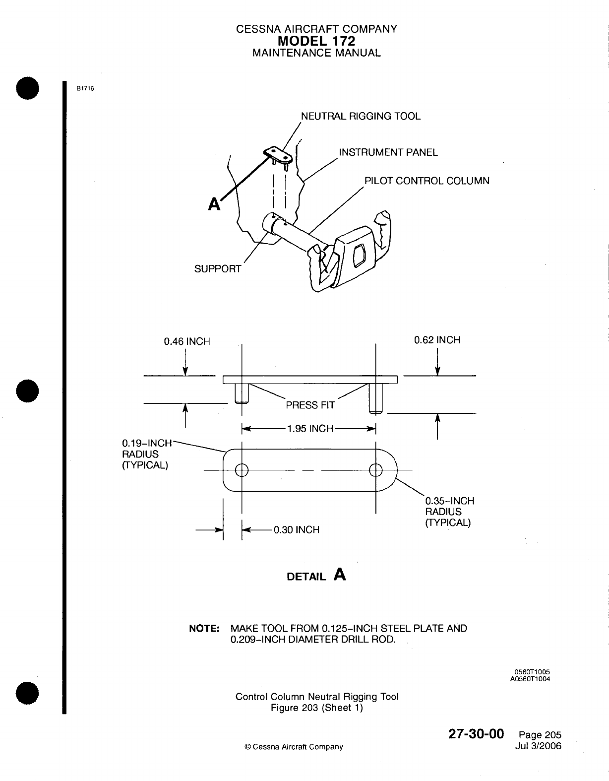
CESSNA
AIRCRAFT
COMPANY
MODEL
172
MAINTENANCE
MANUAL
B1716
NEUTRAL
RIGGING
TOOL
NT
PANEL
CONTROL
COLUMN
A
SUPF
0.46
INCH
0.62
INCH
U\-P
PRESS
FIT
1ju
--
1.95
INCH
-*
0
0.30
INCH
O0
0.35-INCH
RADIUS
(TYPICAL)
DETAIL
A
NOTE:
MAKE
TOOL
FROM
0.125-INCH
STEEL
PLATE
AND
0.209-INCH
DIAMETER
DRILL
ROD.
0560T1005
A0560T1004
Control
Column
Neutral
Rigging
Tool
Figure 203
(Sheet
1)
27-30-00
O
Cessna
Aircraft
Company
Page
205
Jul
3/2006
t
0.19-INCH
RADIUS
(TYPICAL)
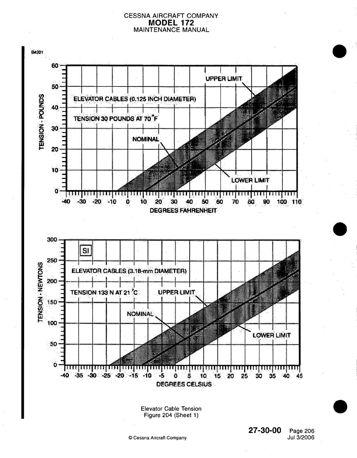
CESSNA
AIRCRAFT
COMPANY
MODEL
172
MAINTENANCE
MANUAL
n,
---- -- -
50-
VC
'
ELEVATOR
CAB
i 4
0
'
1''1
i
'
-, ^
TENSrIO
30
PC
30
1-
20
10-
i
I
0
iI
ni
11i
l
i
-40
-30
-21o
0
0 10
20
30
40
50
70
80.
9
100
110
DEGREES
FAHRENHEIT
300
0
Iri
I I I I I I
I
250-
-4
Z :
ELEVATOR1
CA
t
*30
-i--1
I
(
z
-
TENSt
13
Z
_ 1
ENSION.133
Zo
0
pW] -
50
-
--------
50--
IIII
11 11 1 13
40
-35
-30
-25
-20
-15
-10 -5
0
5
10
15
20
26
30
35
40
45
DEGREES CELSIUS
-
Elevator
Cable Tension
Figure
204
(Sheet
1)
27-30-00
Page 206
©
Cessna
Aircraft
Comoanv
Jul
3/2006
I
.
.~~~~~
-
-
----
-- -- -- -I
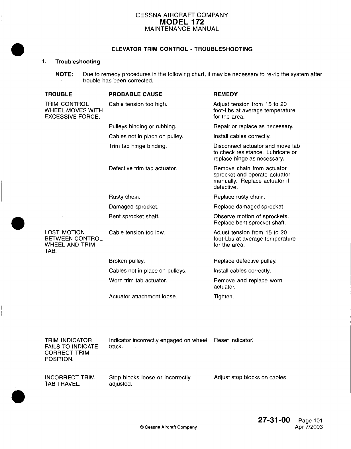
CESSNA
AIRCRAFT
COMPANY
MODEL
172
MAINTENANCE
MANUAL
ELEVATOR TRIM
CONTROL
-
TROUBLESHOOTING
1.
Troubleshooting
NOTE:
Due to
remedy procedures
in
the
following
chart,
it
may
be
necessary
to
re-rig
the
system
after
trouble
has
been
corrected.
TROUBLE
TRIM
CONTROL
WHEEL
MOVES
WITH
EXCESSIVE FORCE.
PROBABLE
CAUSE
Cable
tension
too
high.
Pulleys binding
or
rubbing.
Cables
not
in
place
on
pulley.
Trim
tab hinge
binding.
Defective
trim
tab
actuator.
Rusty chain.
Damaged
sprocket.
Bent
sprocket
shaft.
LOST
MOTION
BETWEEN
CONTROL
WHEEL
AND
TRIM
TAB.
Cable
tension
too
low.
REMEDY
Adjust tension
from
15
to
20
foot-Lbs
at
average
temperature
for
the
area.
Repair or replace
as
necessary.
Install
cables
correctly.
Disconnect actuator
and
move
tab
to
check
resistance. Lubricate
or
replace
hinge
as
necessary.
Remove
chain
from
actuator
sprocket
and operate
actuator
manually. Replace
actuator
if
defective.
Replace
rusty
chain.
Replace
damaged
sprocket
Observe
motion
of
sprockets.
Replace
bent
sprocket
shaft.
Adjust
tension
from
15
to
20
foot-Lbs
at
average
temperature
for
the
area.
Broken pulley.
Cables
not
in
place
on
pulleys.
Worn
trim
tab
actuator.
Actuator
attachment loose.
TRIM
INDICATOR
FAILS
TO
INDICATE
CORRECT
TRIM
POSITION.
Replace
defective pulley.
Install
cables
correctly.
Remove
and replace
worn
actuator.
Tighten.
Indicator incorrectly
engaged
on
wheel
Reset indicator.
track.
INCORRECT
TRIM
TAB
TRAVEL.
Stop
blocks
loose
or
incorrectly
adjusted.
Adjust
stop
blocks
on
cables.
©
Cessna Aircraft Company
27-31-00
Page
101
Apr
7/2003
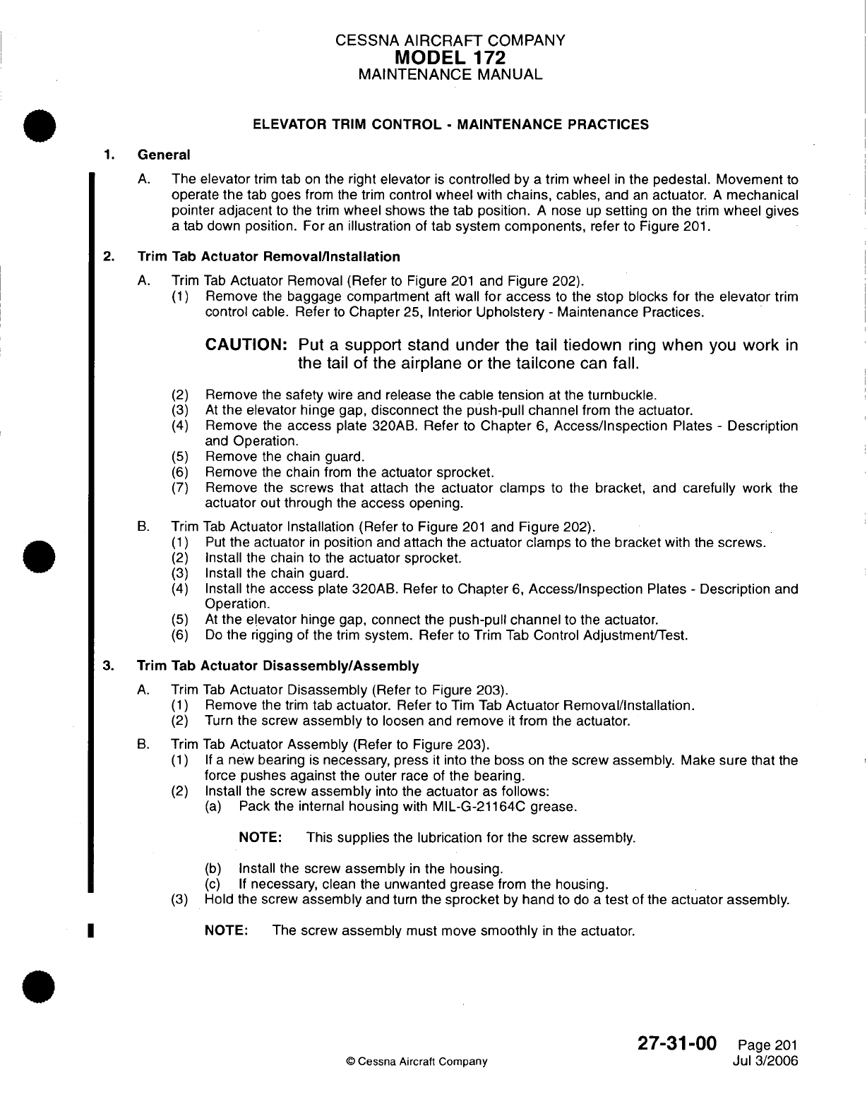
CESSNA
AIRCRAFT
COMPANY
MODEL
172
MAINTENANCE
MANUAL
ELEVATOR
TRIM
CONTROL
-
MAINTENANCE
PRACTICES
1.
General
A.
The
elevator
trim
tab
on the
right
elevator
is
controlled by
a
trim
wheel
in
the
pedestal. Movement
to
operate
the
tab
goes
from
the
trim
control wheel
with
chains,
cables,
and
an
actuator.
A
mechanical
pointer
adjacent
to the
trim
wheel shows
the
tab
position.
A
nose
up
setting
on
the
trim
wheel
gives
a
tab down
position. For
an
illustration
of
tab
system
components,
refer
to Figure
201.
2.
Trim
Tab
Actuator
Removal/nstallation
A.
Trim
Tab
Actuator
Removal
(Refer
to
Figure
201
and
Figure
202).
(1)
Remove
the
baggage
compartment
aft
wall
for
access
to
the
stop
blocks
for
the
elevator
trim
control
cable.
Refer
to
Chapter
25,
Interior
Upholstery
-
Maintenance
Practices.
CAUTION:
Put
a
support
stand
under
the tail
tiedown
ring
when
you
work
in
the
tail
of
the
airplane
or
the
tailcone
can
fall.
(2)
Remove
the
safety
wire
and
release
the
cable
tension
at
the
turnbuckle.
(3)
At
the
elevator
hinge gap,
disconnect
the
push-pull channel
from
the
actuator.
(4)
Remove
the
access
plate
320AB.
Refer
to
Chapter
6,
Access/Inspection
Plates
-
Description
and
Operation.
(5)
Remove the
chain
guard.
(6)
Remove
the
chain
from
the
actuator
sprocket.
(7)
Remove the
screws
that
attach
the
actuator
clamps
to the
bracket,
and
carefully
work
the
actuator
out
through
the
access
opening.
B.
Trim
Tab
Actuator
Installation
(Refer
to
Figure
201
and
Figure
202).
(1)
Put
the
actuator
in
position
and
attach
the
actuator
clamps
to
the
bracket
with
the
screws.
(2)
Install
the
chain
to
the
actuator
sprocket.
(3)
Install
the
chain
guard.
(4)
Install
the
access
plate
320AB. Refer
to
Chapter
6,
Access/Inspection
Plates
-
Description
and
Operation.
(5) At
the elevator
hinge
gap,
connect
the
push-pull
channel
to the
actuator.
(6)
Do
the
rigging
of the
trim
system.
Refer to
Trim
Tab
Control
Adjustment/Test.
3.
Trim
Tab
Actuator
Disassembly/Assembly
A.
Trim
Tab
Actuator Disassembly
(Refer
to
Figure
203).
(1)
Remove
the
trim
tab
actuator.
Refer
to
Tim
Tab
Actuator
Removal/Installation.
(2)
Turn
the screw
assembly
to
loosen
and remove
it
from the
actuator.
B.
Trim
Tab
Actuator
Assembly
(Refer
to
Figure
203).
(1) If
a
new
bearing
is
necessary,
press
it
into
the
boss
on
the
screw assembly.
Make
sure that
the
force
pushes
against
the
outer
race
of
the bearing.
(2)
Install the
screw
assembly
into
the
actuator
as
follows:
(a)
Pack the
internal
housing
with
MIL-G-21164C grease.
NOTE:
This
supplies
the
lubrication
for
the
screw
assembly.
(b)
Install
the
screw
assembly
in
the housing.
(c)
If
necessary,
clean
the
unwanted
grease
from
the
housing.
(3)
Hold the
screw
assembly
and
turn
the
sprocket
by
hand
to
do a
test
of
the
actuator
assembly.
|
NOTE: The
screw
assembly
must move
smoothly
in
the
actuator.
27-31-00
Page
201
©
Cessna Aircraft
ComDanv
Jul 3/2006
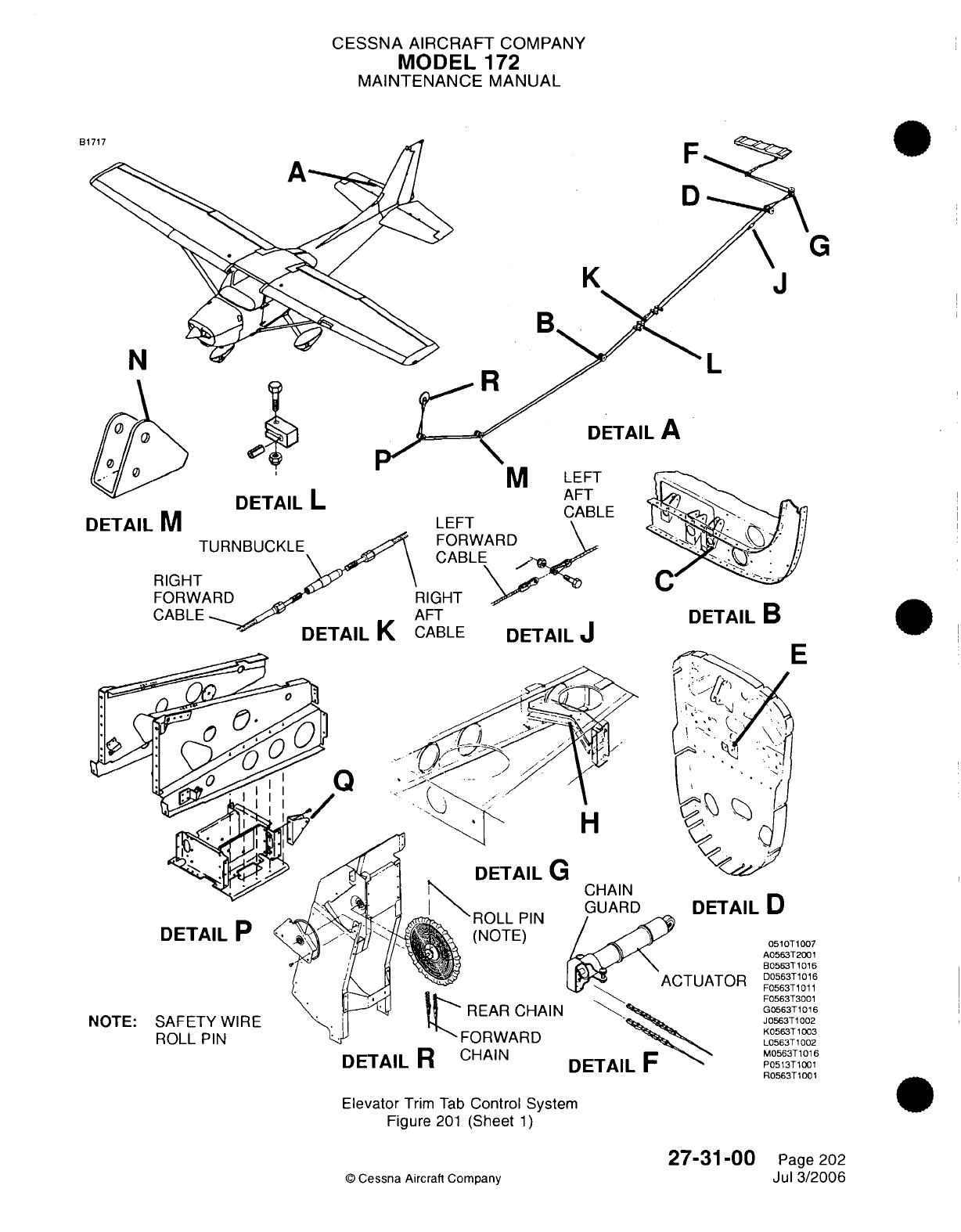
CESSNA AIRCRAFT
COMPANY
MODEL
172
MAINTENANCE
MANUAL
DETAIL
M
RIGHI
FORW
CABLE
DETAIL
R
CHAIN
Elevator
Trim
Tab
Control
System
Figure
201
(Sheet
1)
27-31-00
©
Cessna
Aircraft
Company
B
F
D
G
KJ
k
nFTAII
I
L
DETAIL
A
AFT
DETAIL
B
DETAIL
D
0510T1007
A0563T2001
B0563T1016
D0563T1016
F0563T1011
F0563T3001
G0563T1016
J0563T1002
K0563T1003
L0563T1002
M0563T1016
P0513T1001
H0563
1001
Page
202
Jul
3/2006
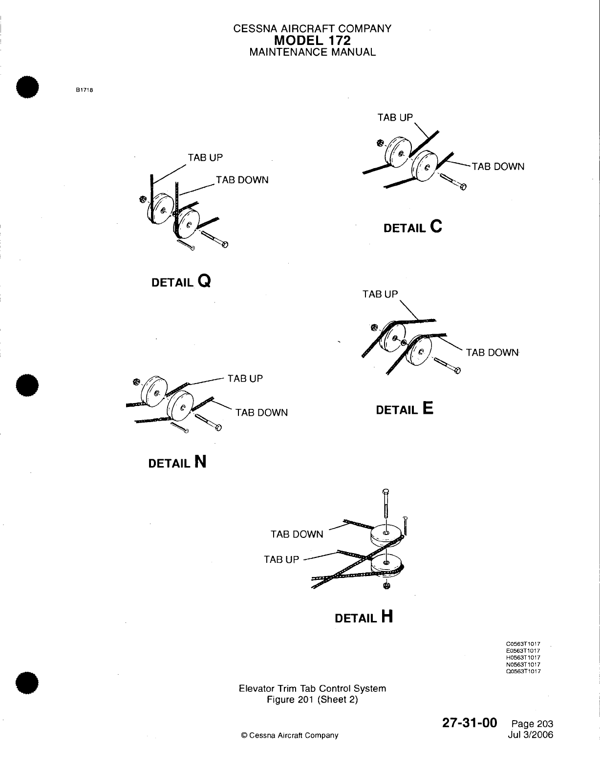
CESSNA
AIRCRAFT
COMPANY
MODEL
172
MAINTENANCE
MANUAL
B1718
TAB
UP
TAB
UP
(/
A
TAB
DOWN
0~.Y:
DETAIL
Q
TAB
DOWN
AB
UP
TAB
DOWN
DETAIL
N
TAB
D(
TAB UP
DETAIL
H
C0563T1017
E0563T1017
H0563T1017
N0563T1017
Q0563T1017
Elevator
Trim
Tab
Control
System
Figure
201
(Sheet
2)
27-31-00
©
Cessna
Aircraft
Company
-TAB
DOWN
DETAIL
C
TAB
UP
DETAIL
E
Page
203
Jul
3/2006
_
.
_
.. _
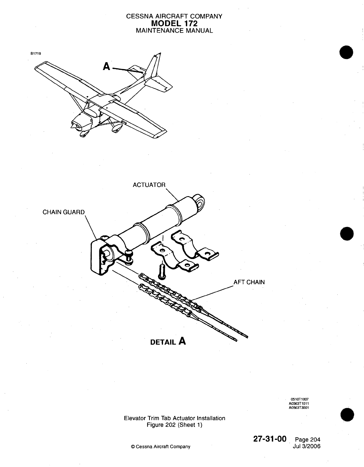
CESSNA
AIRCRAFT
COMPANY
MODEL
172
MAINTENANCE
MANUAL
B1
CHAIN GUARD
CHAIN
UC
I
MIL
r
0510T1007
A0563T1011
A0563T3001
Elevator
Trim
Tab
Actuator Installation
Figure
202
(Sheet
1)
©
Cessna
Aircraft
Company
27-31
-00
Page
204
Jul
3/2006
..
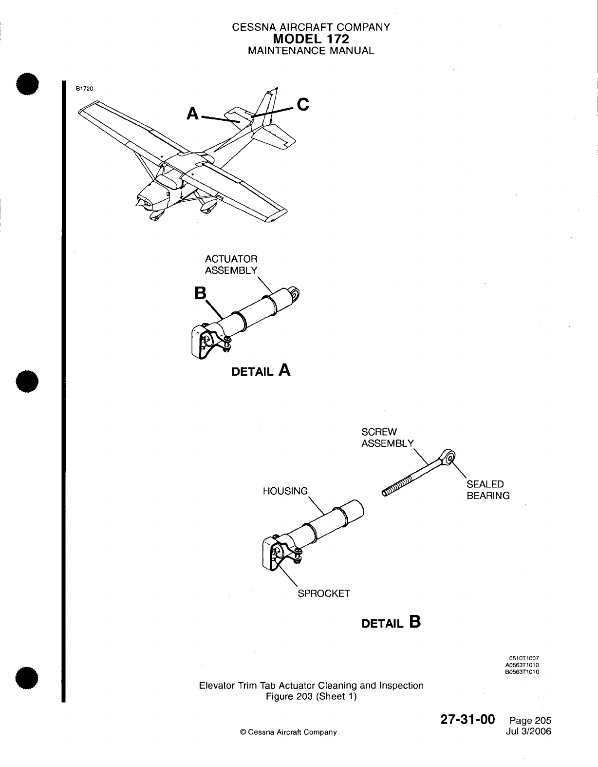
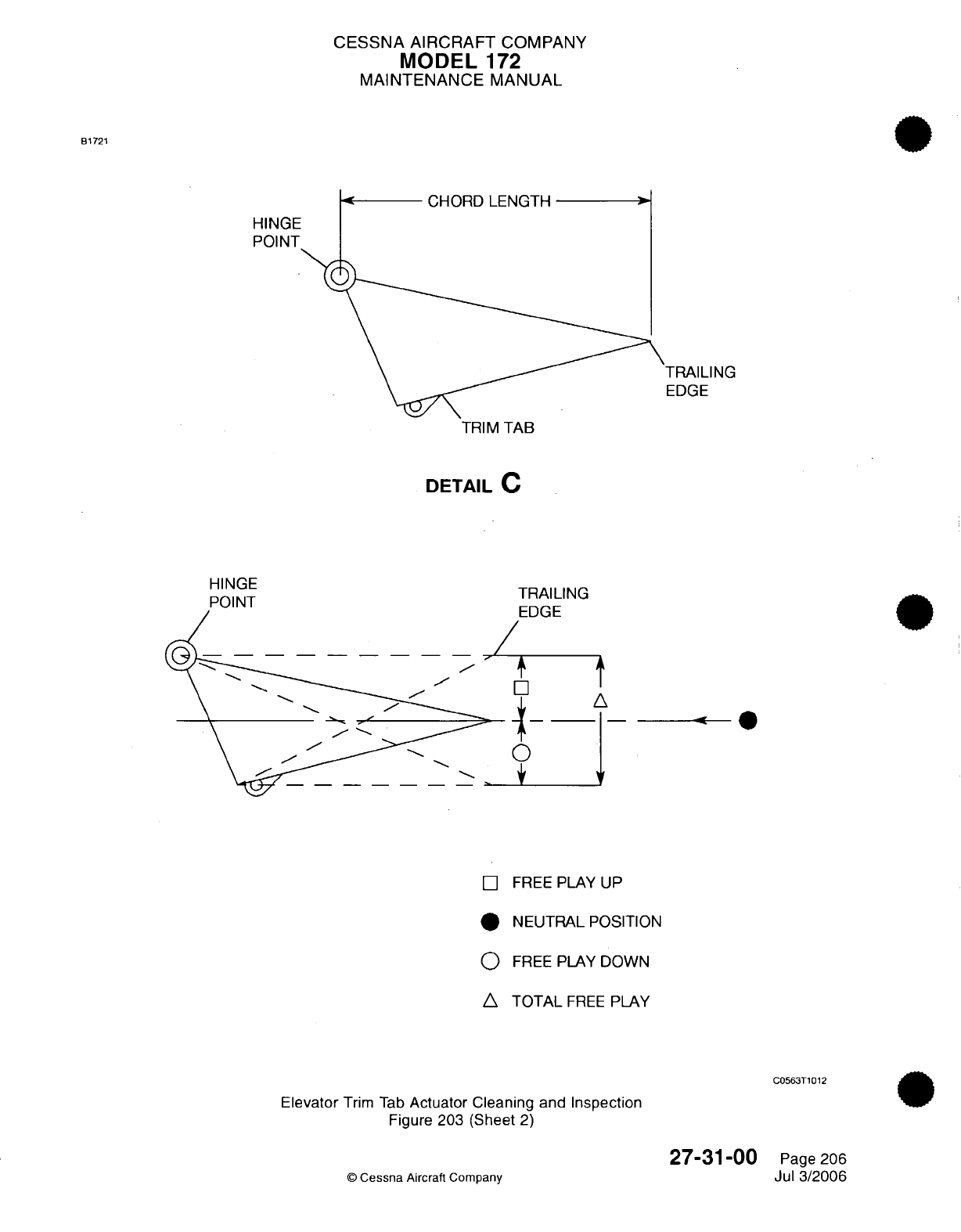
CESSNA AIRCRAFT
COMPANY
MODEL
172
MAINTENANCE MANUAL
B1721
CHORD
LENGTH
HINGE
POINT
TRAILING
EDGE
TRIM
TAB
DETAIL
C
HINGE
EDGE
/ t
__
0
+
V
[]
FREE
PLAY
UP
*
NEUTRAL POSITION
0
FREE
PLAY
DOWN
A
TOTAL
FREE
PLAY
C0563T1012
Elevator
Trim
Tab
Actuator Cleaning and
Inspection
Figure
203
(Sheet
2)
27-31-00
©
Cessna
Aircraft Company
Page
206
Jul 3/2006
TQA11
Mr-'r
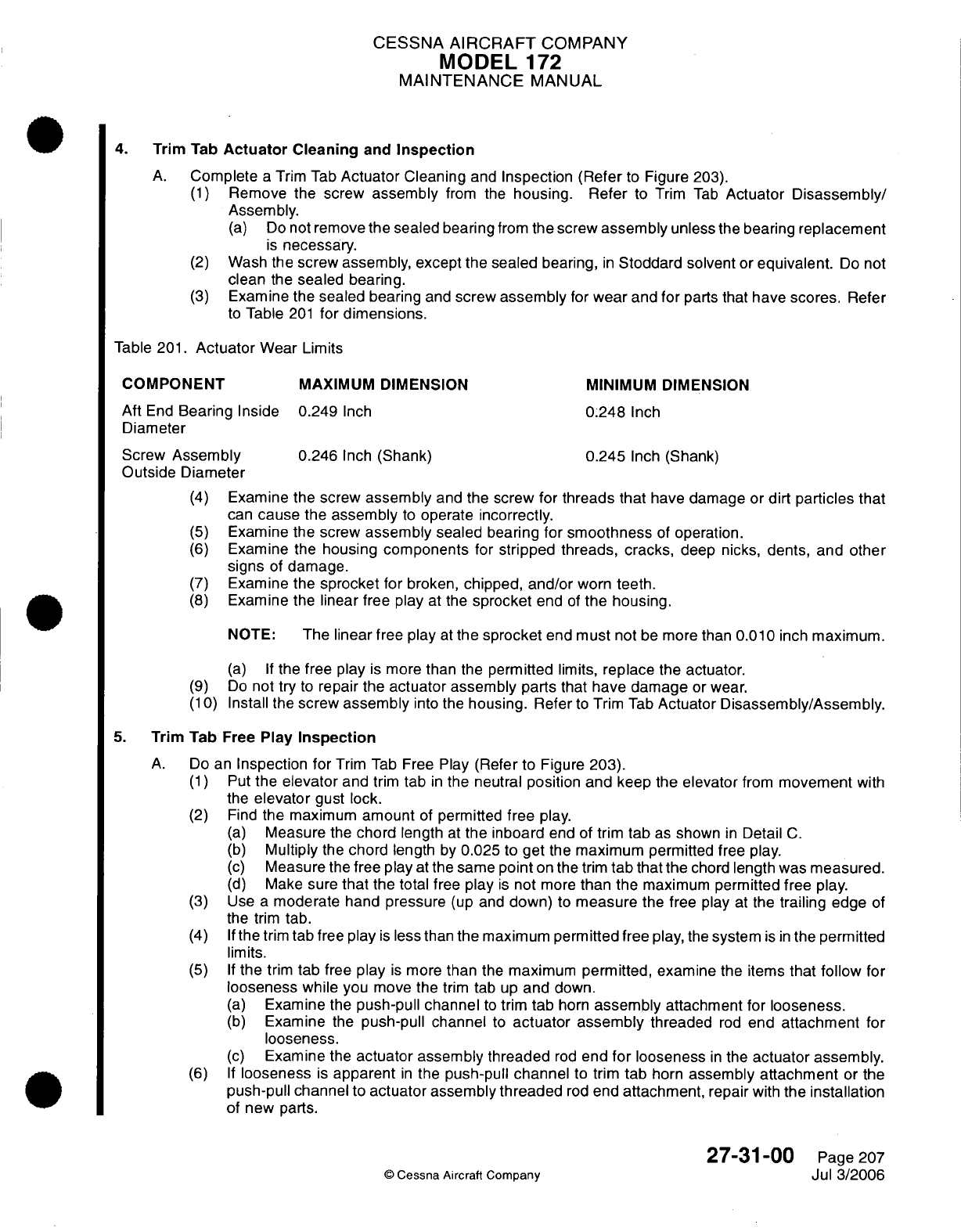
CESSNA
AIRCRAFT
COMPANY
MODEL
172
MAINTENANCE
MANUAL
4.
Trim
Tab
Actuator
Cleaning
and
Inspection
A.
Complete
a
Trim
Tab
Actuator
Cleaning
and
Inspection (Refer
to
Figure 203).
(1)
Remove
the
screw
assembly
from
the
housing. Refer
to
Trim
Tab
Actuator
Disassembly/
Assembly.
(a)
Do
not
remove
the
sealed
bearing
from
the screw
assembly
unless
the
bearing
replacement
is
necessary.
(2)
Wash
the screw
assembly, except
the
sealed
bearing,
in
Stoddard solvent
or
equivalent.
Do
not
clean
the
sealed bearing.
(3)
Examine
the
sealed
bearing
and
screw
assembly
for
wear
and
for
parts
that
have
scores.
Refer
to
Table
201
for
dimensions.
Table
201.
Actuator
Wear
Limits
COMPONENT
MAXIMUM
DIMENSION
MINIMUM DIMENSION
Aft
End
Bearing
Inside
0.249
Inch
0.248
Inch
Diameter
Screw
Assembly
0.246
Inch
(Shank)
0.245
Inch
(Shank)
Outside
Diameter
(4)
Examine
the screw
assembly
and
the screw
for
threads that
have
damage
or
dirt
particles that
can
cause
the
assembly
to
operate
incorrectly.
(5)
Examine
the
screw
assembly sealed
bearing
for
smoothness
of
operation.
(6)
Examine
the
housing
components
for
stripped threads,
cracks,
deep nicks,
dents,
and
other
signs
of
damage.
(7)
Examine
the
sprocket
for
broken,
chipped,
and/or
worn
teeth.
(8)
Examine
the
linear free play
at
the
sprocket
end
of
the
housing.
NOTE:
The
linear
free play
at
the
sprocket
end
must
not
be more
than
0.010
inch
maximum.
(a) If
the
free
play
is
more
than
the
permitted
limits,
replace
the actuator.
(9)
Do
not
try
to
repair the
actuator
assembly
parts that
have damage
or wear.
(10)
Install
the
screw
assembly
into
the
housing.
Refer
to
Trim
Tab
Actuator
Disassembly/Assembly.
5.
Trim Tab
Free
Play
Inspection
A.
Do
an
Inspection for
Trim
Tab
Free
Play
(Refer
to Figure
203).
(1)
Put
the
elevator
and
trim
tab
in
the
neutral
position and
keep the
elevator
from
movement
with
the
elevator
gust lock.
(2)
Find
the
maximum
amount
of
permitted
free
play.
(a)
Measure
the
chord
length
at
the
inboard
end
of trim
tab
as
shown
in
Detail
C.
(b)
Multiply
the
chord length
by
0.025
to
get
the
maximum permitted
free
play.
(c)
Measure
the
free play
at
the
same
point
on the
trim
tab
that
the
chord
length was
measured.
(d)
Make
sure
that
the
total free
play
is
not
more
than
the
maximum
permitted
free
play.
(3)
Use
a
moderate
hand
pressure
(up
and
down)
to
measure
the
free
play
at
the
trailing
edge
of
the
trim
tab.
(4) If
the
trim
tab
free
play
is
less than
the
maximum
permitted
free
play,
the
system
is
in
the
permitted
limits.
(5) If
the
trim
tab
free
play
is
more
than
the
maximum
permitted, examine
the items
that
follow
for
looseness
while
you
move the
trim
tab
up
and
down.
(a)
Examine
the
push-pull
channel
to
trim
tab
horn
assembly
attachment for
looseness.
(b)
Examine
the
push-pull channel
to
actuator assembly
threaded
rod
end
attachment
for
looseness.
(c)
Examine
the
actuator assembly threaded
rod
end
for
looseness
in
the
actuator assembly.
(6) If
looseness
is
apparent
in
the
push-pull
channel
to
trim
tab
horn
assembly
attachment
or
the
push-pull channel to
actuator
assembly
threaded
rod
end
attachment,
repair
with
the
installation
of
new parts.
27-31-00
Page
207
©
Cessna Aircraft
Company
Jul 3/2006
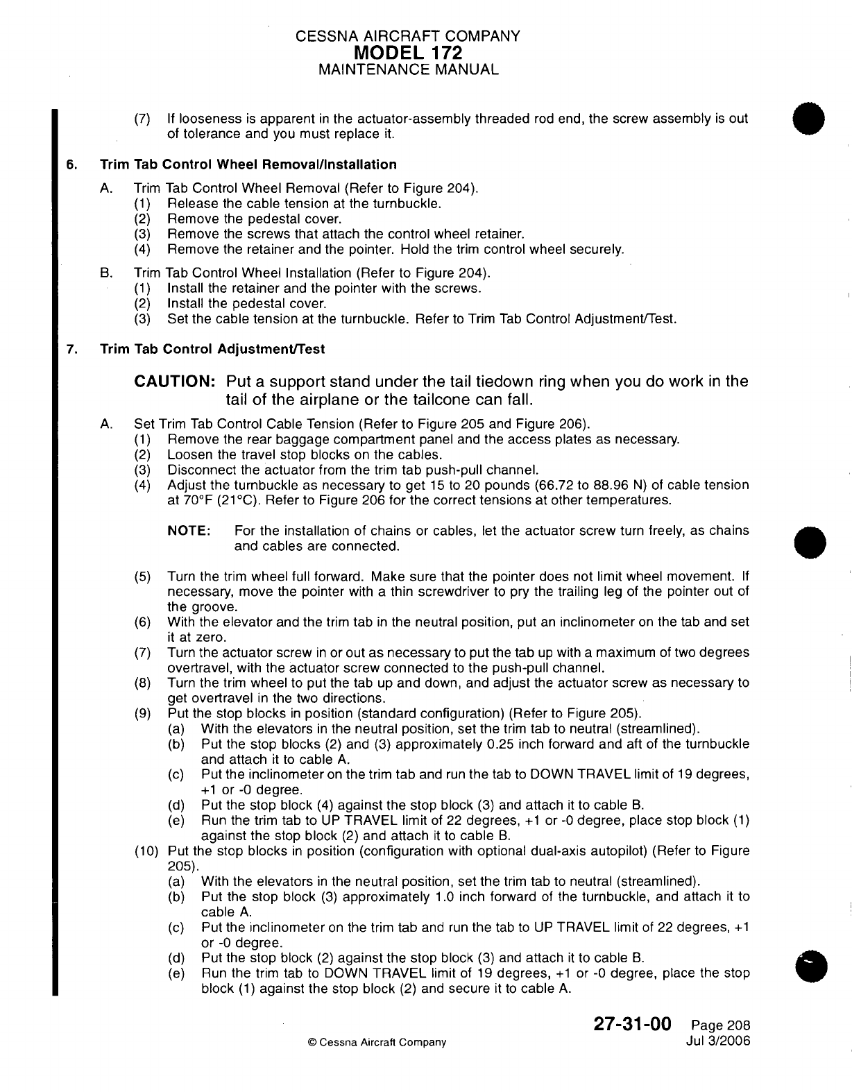
CESSNA
AIRCRAFT
COMPANY
MODEL
172
MAINTENANCE
MANUAL
(7) If
looseness
is
apparent
in
the
actuator-assembly
threaded
rod
end,
the
screw
assembly
is
out
of
tolerance
and you
must
replace
it.
6.
Trim
Tab
Control
Wheel
Removal/Installation
A.
Trim
Tab
Control
Wheel
Removal
(Refer
to
Figure
204).
(1)
Release
the
cable
tension
at the
turnbuckle.
(2)
Remove
the
pedestal
cover.
(3)
Remove
the
screws
that
attach
the
control
wheel retainer.
(4)
Remove
the
retainer
and the
pointer.
Hold the
trim
control wheel
securely.
B.
Trim
Tab
Control
Wheel
Installation
(Refer
to
Figure
204).
(1)
Install
the
retainer
and
the
pointer
with
the screws.
(2)
Install
the
pedestal cover.
(3)
Set
the
cable tension
at
the
turnbuckle.
Refer
to
Trim
Tab
Control
Adjustment/Test.
7.
Trim
Tab
Control
Adjustment/Test
CAUTION:
Put a
support
stand
under
the
tail
tiedown
ring
when
you
do
work
in
the
tail of
the
airplane
or
the
tailcone
can
fall.
A.
Set
Trim
Tab
Control
Cable
Tension
(Refer
to
Figure
205
and
Figure
206).
(1)
Remove
the rear
baggage
compartment
panel
and
the
access
plates
as
necessary.
(2)
Loosen
the
travel
stop
blocks
on
the
cables.
(3)
Disconnect
the
actuator
from
the
trim
tab
push-pull channel.
(4)
Adjust
the
turnbuckle
as
necessary
to get
15
to
20
pounds
(66.72
to
88.96
N)
of
cable
tension
at
70°F
(21
°C).
Refer to
Figure
206
for
the
correct
tensions
at
other
temperatures.
NOTE:
For
the installation
of chains
or
cables,
let
the
actuator
screw
turn
freely,
as
chains
and
cables
are
connected.
(5)
Turn
the
trim
wheel full
forward.
Make sure
that
the
pointer
does not limit wheel
movement.
If
necessary,
move
the
pointer
with
a
thin
screwdriver
to
pry the
trailing
leg
of
the
pointer
out
of
the groove.
(6)
With
the
elevator
and the
trim
tab
in
the
neutral
position,
put
an
inclinometer
on
the
tab
and set
it
at
zero.
(7)
Turn
the
actuator
screw
in
or
out as
necessary
to
put
the
tab
up
with
a
maximum of two
degrees
overtravel,
with
the
actuator
screw
connected
to
the
push-pull channel.
(8)
Turn
the
trim
wheel
to
put
the tab
up
and
down,
and
adjust
the
actuator
screw
as
necessary
to
get
overtravel
in
the two
directions.
(9)
Put
the
stop
blocks
in
position
(standard
configuration)
(Refer
to
Figure
205).
(a)
With
the
elevators
in
the
neutral
position, set
the
trim
tab
to
neutral (streamlined).
(b)
Put
the
stop blocks
(2)
and
(3)
approximately
0.25
inch
forward
and
aft
of
the
turnbuckle
and
attach
it
to
cable
A.
(c) Put
the
inclinometer
on
the
trim
tab
and
run
the
tab to
DOWN
TRAVEL limit
of
19
degrees,
+1
or
-0
degree.
(d)
Put the
stop
block
(4)
against
the
stop
block
(3)
and
attach
it
to
cable
B.
(e)
Run
the
trim
tab
to
UP
TRAVEL
limit
of
22
degrees,
+1
or
-0
degree,
place
stop
block
(1)
against
the
stop
block
(2)
and attach
it
to
cable
B.
(10)
Put
the
stop
blocks
in
position
(configuration
with
optional
dual-axis
autopilot)
(Refer to
Figure
205).
(a)
With
the
elevators
in
the
neutral
position,
set
the
trim
tab
to
neutral (streamlined).
(b)
Put
the
stop
block
(3)
approximately
1.0
inch
forward
of
the
turnbuckle,
and attach
it to
cable
A.
(c)
Put
the
inclinometer
on
the
trim
tab
and
run
the
tab
to
UP
TRAVEL
limit
of
22
degrees,
+1
or
-0
degree.
(d)
Put
the
stop
block
(2)
against
the
stop block
(3)
and
attach
it
to
cable
B.
(e)
Run
the
trim
tab
to
DOWN
TRAVEL
limit of
19
degrees,
+1
or -0
degree,
place the
stop
block
(1)
against
the
stop
block
(2)
and
secure
it
to
cable
A.
27-31-00
Page 208
©
Cessna
Aircraft
Company
Jul
3/2006
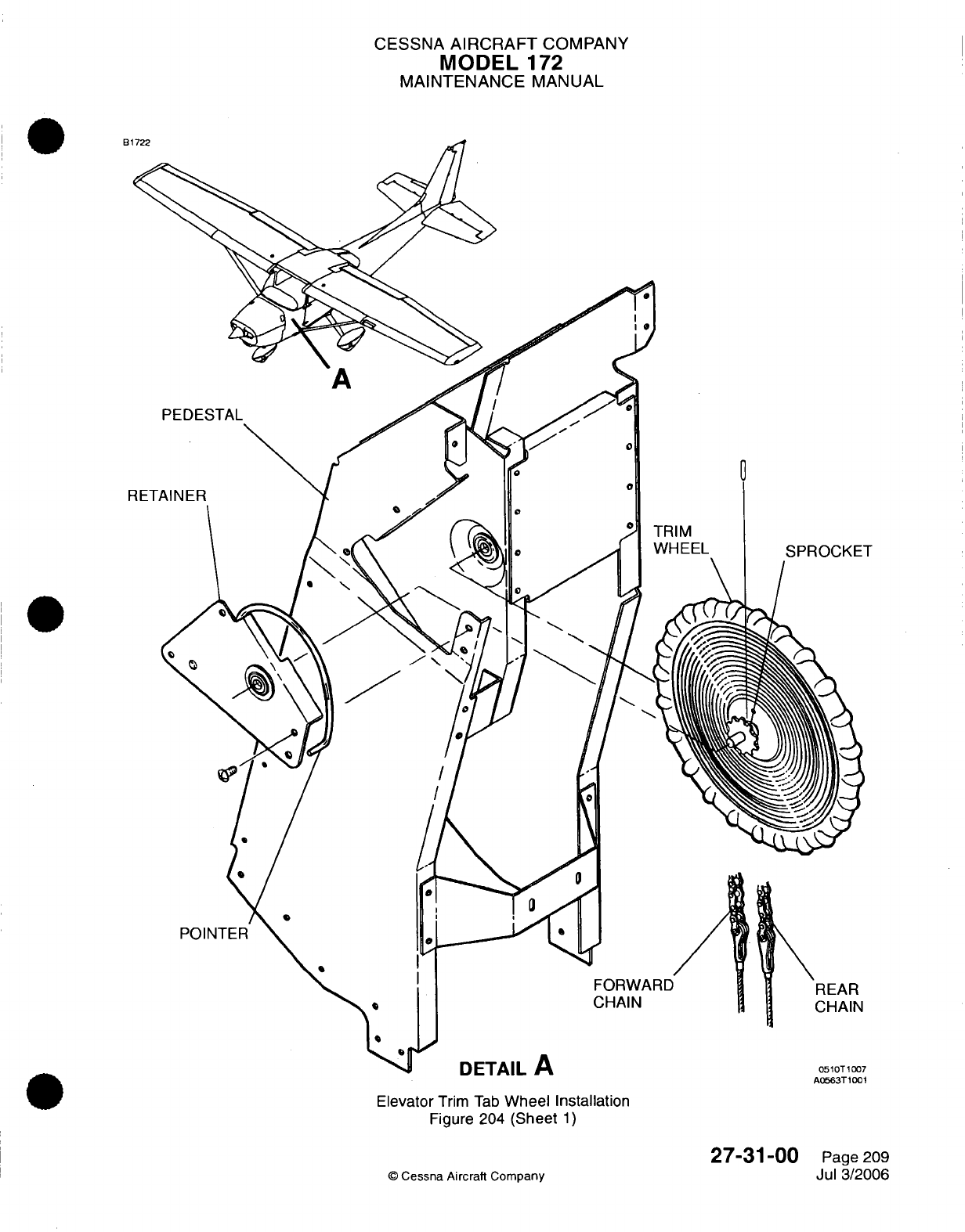
CESSNA
AIRCRAFT
COMPANY
MODEL
172
MAINTENANCE
MANUAL
A0563T1001
Elevator
Trim
Tab
Wheel Installation
Figure 204
(Sheet
1)
27-31-00
©
Cessna
Aircraft
Company
Page
209
Jul
3/2006
I
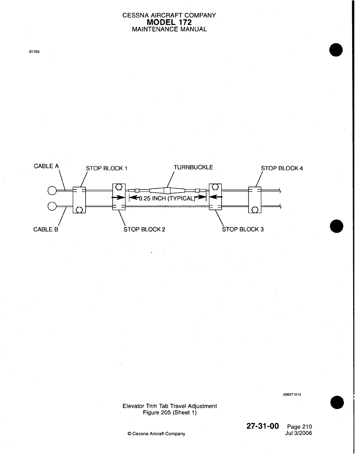
CESSNA
AIRCRAFT
COMPANY
MODEL
172
MAINTENANCE
MANUAL
B1723
.S;TnP
RI
nr.K
1
TURNBUCKLE
STOP
BLOCK
4
STOP
BLOCK
2
BLOCK
3
0563T1013
Elevator
Trim
Tab
Travel Adjustment
Figure
205 (Sheet
1)
27-31-00
©
Cessna
Aircraft
Company
Page
210
Jul
3/2006
CABLE
A
CABI
I
*
a- I
-
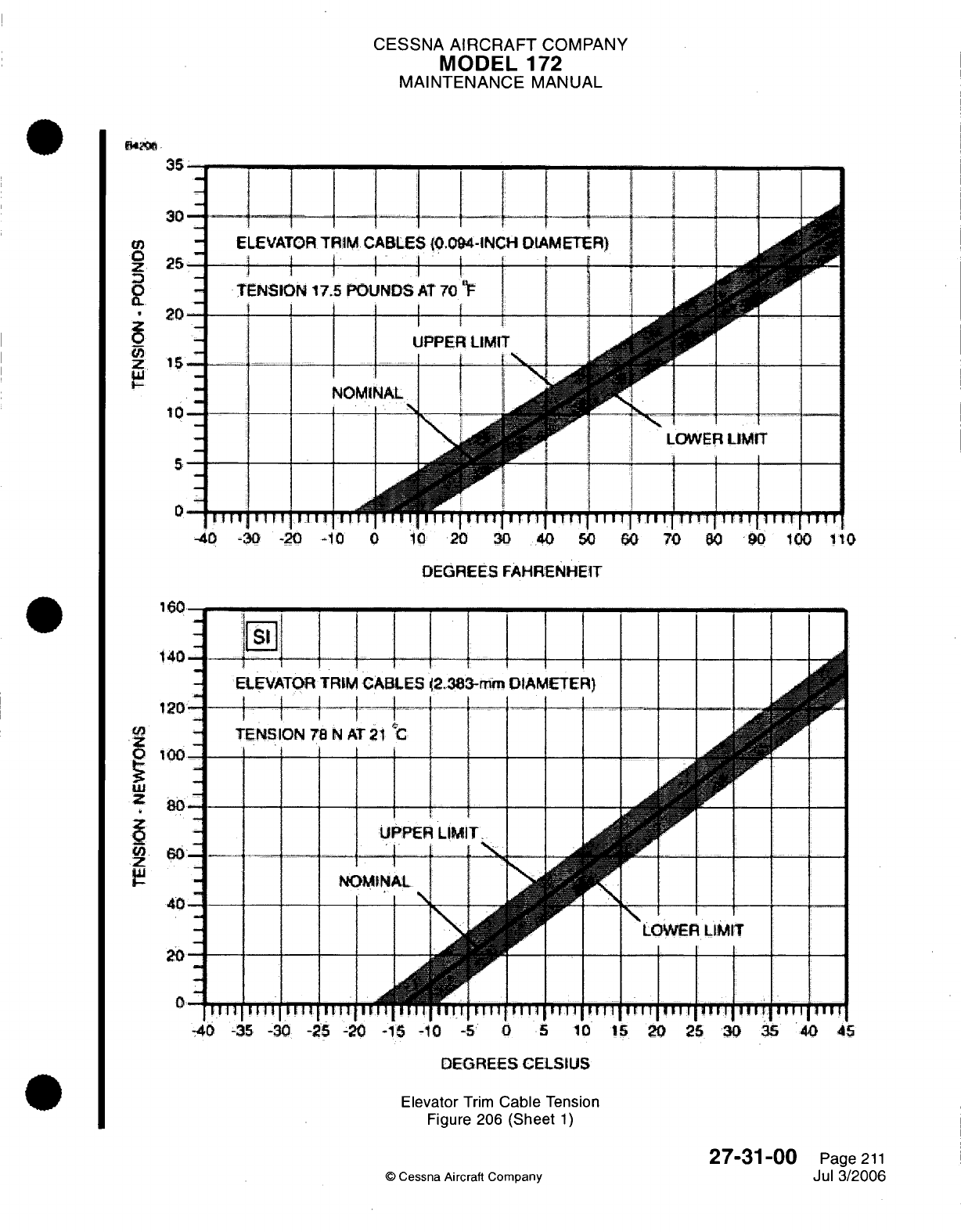
CESSNA
AIRCRAFT
COMPANY
MODEL
172
MAINTENANCE
MANUAL
35i
30---
|
-4_(
__
._i
CO
-
ELEVATOR
TRIM
CABLES
{0.094-INCH
DIAMETER)
z
25
0
-
TENSION
17.5
POUNDS
AT
70
"
20
0
UPPER
LIMIT
Z
5- i,
-
..
w.I
,~..
_r
-
NOMI
10
5
0
... .. .. .. I
LOWER
LIMIT
I--
--------
I
I I I I I I I I I
I
I
I
I
I
I
1
T I
I
I
111
lIT
1
1 1 1
11
1 1
1
I
ll
I
11
I I I
I
-l0
-30
-20
-10
0
10
20
30
40
50
60
70
80
90
100
1t0
DEGREES FAHRENHEIT
160
140^-
ij
4
--
ELEVATOR
TRIM
CAE
120
----
u, -~
TENSION
78
N
AT
21
100
u
-4
80
s~
J
11
i l
U
r
e
fNOMtN
40
20
0
1il
ill
1
ll
1II1
-4
-35
-30
-25 -20
-15
-10
-5
0
5
10
15
20
25
30
35
40
45
DEGREES
CELSIUS
Elevator
Trim
Cable
Tension
Figure 206
(Sheet
1)
27-31-00
Page
211
©
Cessna
Aircraft
Comoanv
Jul
3/2006
CESSNA AIRCRAFT
COMPANY
MODEL
172
MAINTENANCE
MANUAL
(f)
Do
a
check
of
the
pitch
trim
rigging.
1
Streamline
the elevator
and the
trim
tab.
Put
an
inclinometer
to
the
trim
tab
and
set
it
to
0
degrees. Manually
move
the
trim
tab
to
up
and
down
limits
and record the
limits
of
travel.
2
Put
an
observer
at
the bottom aft
access
opening
in
the
tailcone.
Apply power
to
the
aircraft
and
move
the
electric
trim
to
full
nose-up
position
until
the
observer
sees
clutch
slippage.
With the
servo clutch
still
slipping, apply
an
additional quarter
turn
of
the
manual
trim
wheel
nose-up
(test
load
condition).
3 In
this condition,
the
observer
must
make
sure
that
the
stop
blocks
do not
slip
on
the
trim
tab
cables.
4
Release
the
trim
wheel and
disengage
the
autopilot. Manually
move
the
trim
to
full
nose-up
position
and
do
a
check
of
the
trim
tab
deflection
with
an
inclinometer.
Additional
trim
tab
deflection
(compared
with
the
values
that
you
recorded)
shows
slippage
of
the
stop
blocks.
5
Do
a
rigging
of
the
trim
system.
6
Measure the
torque
on
the
stop
block
bolts
and then
do
the
check
of
the
pitch
trim
rigging
7 If
the
swaged
ball
needs
adjustment,
move
the cable
assembly
chain
on
the
gear
teeth
of the
actuator
sprocket
to
make
the adjustments.
One
chain
link
corresponds
to
approximately
17
degrees
of travel
on
the capstan.
Tension
the
cable
and do
the
check
of
the
pitch
trim
rigging
again.
8
Do
this
procedure
again
for
the
full nose-down
trim
condition.
(11)
Make
sure
that
the trim
wheel
pointer
travels
the
same
distance
from
the ends
of
the
slot
in
the
cover.
If
necessary,
move the
trailing
leg
of the
pointer.
WARNING:
Make
sure
that
the trim tab
moves
in
the
correct
direction
when
you
operate
it
with
the
trim
wheel. The nose
down
trim
corresponds
to
the tab
up
position.
(12)
Safety
the
turnbuckle
and
install
all
items removed
to get
access
to
the
components.
27-31-00
©
Cessna
Aircraft
Company
Page
212
Jul
3/2006
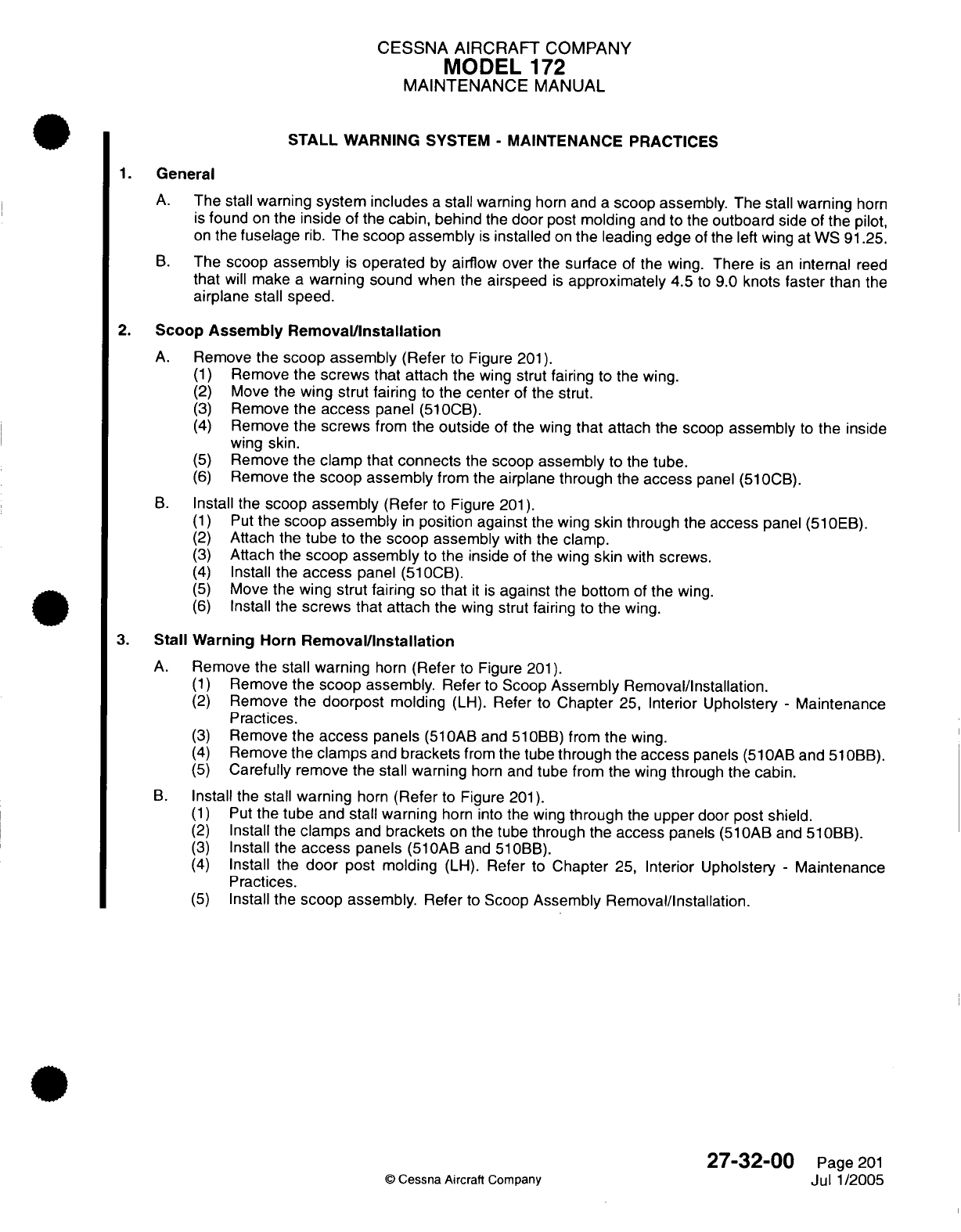
CESSNA AIRCRAFT
COMPANY
MODEL
172
MAINTENANCE
MANUAL
STALL
WARNING
SYSTEM
-
MAINTENANCE PRACTICES
1.
General
A.
The
stall
warning
system includes
a
stall warning
horn
and
a
scoop
assembly. The
stall
warning
horn
is
found
on
the
inside
of
the
cabin,
behind
the
door
post
molding
and to
the
outboard
side of
the pilot,
on
the
fuselage
rib.
The
scoop
assembly
is
installed
on
the
leading
edge
of
the
left
wing
at
WS
91.25.
B.
The
scoop
assembly
is
operated
by
airflow
over
the
surface
of the
wing.
There
is
an
internal
reed
that
will
make
a
warning
sound
when
the
airspeed
is
approximately 4.5
to
9.0
knots
faster
than
the
airplane
stall
speed.
2.
Scoop Assembly Removal/Installation
A.
Remove
the
scoop
assembly
(Refer
to Figure
201).
(1)
Remove
the screws
that attach the
wing strut
fairing
to the
wing.
(2)
Move the
wing
strut fairing
to
the
center
of
the
strut.
(3)
Remove
the
access
panel
(510CB).
(4)
Remove
the screws
from the
outside
of the
wing
that
attach the
scoop
assembly
to
the
inside
wing
skin.
(5)
Remove
the clamp
that
connects
the
scoop assembly
to the
tube.
(6)
Remove
the
scoop assembly
from the
airplane through
the
access
panel (510CB).
B.
Install
the
scoop
assembly
(Refer
to
Figure
201).
(1)
Put
the
scoop
assembly
in
position against
the
wing
skin
through
the
access
panel
(510EB).
(2)
Attach
the
tube
to
the
scoop assembly
with
the
clamp.
(3)
Attach the
scoop
assembly
to
the
inside
of the
wing
skin
with screws.
(4)
Install the
access
panel (510CB).
(5)
Move
the
wing
strut
fairing
so
that
it is
against
the
bottom
of
the
wing.
(6)
Install
the
screws
that attach
the
wing strut
fairing
to
the
wing.
3.
Stall
Warning
Horn
Removal/Installation
A.
Remove
the
stall
warning
horn
(Refer
to Figure
201).
(1)
Remove
the
scoop
assembly. Refer
to
Scoop
Assembly Removal/Installation.
(2)
Remove
the doorpost
molding
(LH).
Refer
to
Chapter
25,
Interior
Upholstery
-
Maintenance
Practices.
(3)
Remove the
access
panels
(510AB
and
510BB)
from
the
wing.
(4)
Remove
the clamps
and
brackets
from
the
tube
through
the
access
panels
(51
OAB
and
51OBB).
(5)
Carefully
remove
the
stall warning
horn
and
tube
from
the
wing through
the cabin.
B.
Install
the stall
warning
horn
(Refer
to Figure
201).
(1)
Put
the
tube
and
stall warning
horn
into the
wing
through
the
upper
door post shield.
(2)
Install
the
clamps
and
brackets
on
the
tube
through the
access
panels
(510AB
and
510BB).
(3)
Install the
access
panels
(510AB
and
510BB).
(4)
Install
the
door
post molding
(LH).
Refer
to
Chapter
25,
Interior Upholstery
-
Maintenance
Practices.
(5)
Install
the
scoop
assembly. Refer
to
Scoop
Assembly
Removal/Installation.
27-32-00
Page
201
©
Cessna
Aircraft
Company
Jul
1/2005
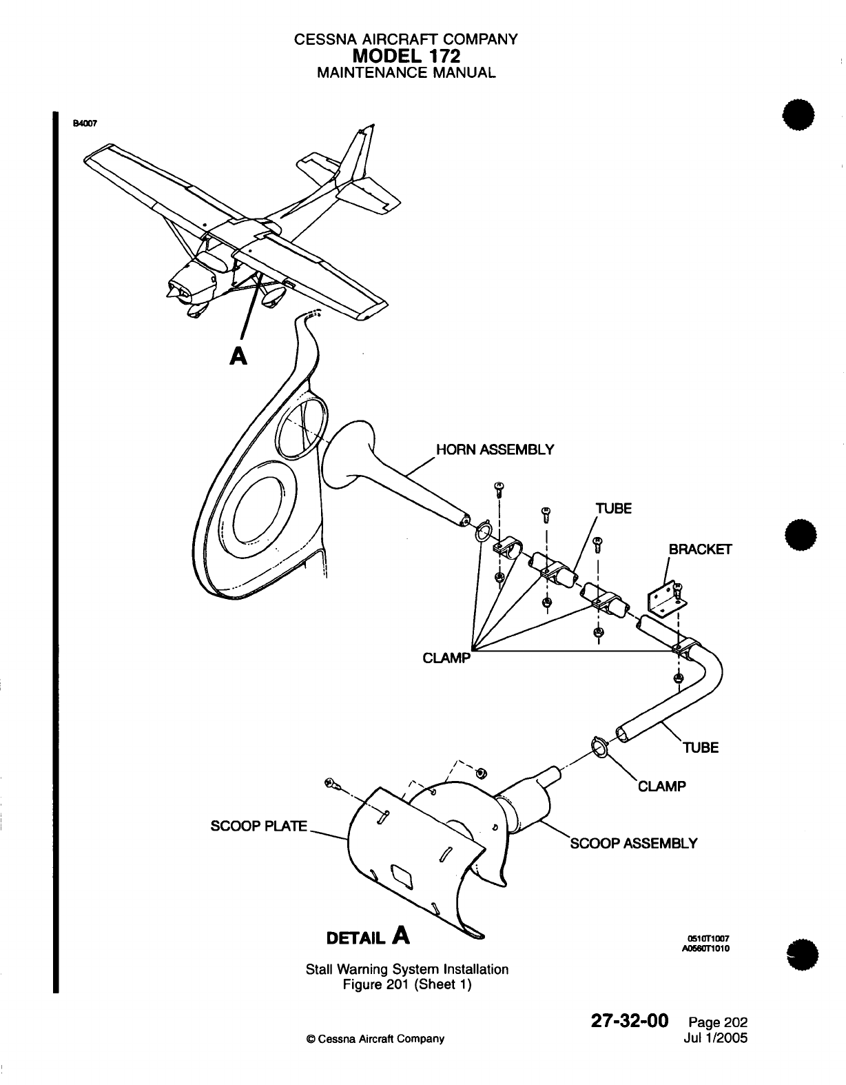
CESSNA
AIRCRAFT
COMPANY
MODEL
172
MAINTENANCE
MANUAL
HORN
ASSEMBLY
TUBE
T
CLAMP
TUBE
SCOOP
PLATE
..
Ade
Is
7
A056rT1010
Stall Warning
System Installation
Figure
201
(Sheet
1)
O
Cessna
Aircraft
Company
27-32-00
Page
202
Jul
1/2005
^,^^
M
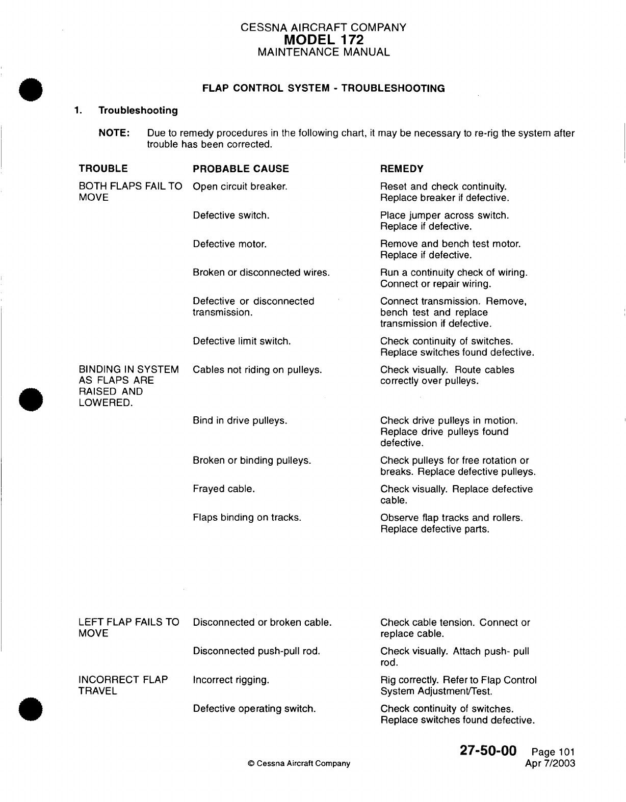
CESSNA AIRCRAFT
COMPANY
MODEL
172
MAINTENANCE
MANUAL
FLAP CONTROL
SYSTEM
-
TROUBLESHOOTING
1.
Troubleshooting
NOTE:
Due
to
remedy
procedures
in
the
following
chart,
trouble
has been
corrected.
TROUBLE
PROBABLE
CAUSE
BOTH
FLAPS
FAIL
TO
Open
circuit
breaker.
MOVE
Defective switch.
Defective
motor.
Broken
or
disconnected
wires.
Defective
or
disconnected
transmission.
Defective limit switch.
BINDING
IN
SYSTEM
Cables
not
riding
on
pulleys.
AS FLAPS
ARE
RAISED
AND
LOWERED.
Bind
in
drive
pulleys.
Broken
or
binding
pulleys.
Frayed
cable.
Flaps
binding
on
tracks.
it
may
be
necessary
to
re-rig the
system
after
REMEDY
Reset
and
check
continuity.
Replace
breaker
if
defective.
Place
jumper
across
switch.
Replace
if
defective.
Remove
and
bench
test
motor.
Replace
if
defective.
Run
a
continuity
check
of
wiring.
Connect
or
repair
wiring.
Connect transmission.
Remove,
bench
test
and
replace
transmission
if
defective.
Check
continuity
of
switches.
Replace
switches
found
defective.
Check
visually.
Route
cables
correctly
over
pulleys.
Check
drive
pulleys
in
motion.
Replace drive
pulleys
found
defective.
Check
pulleys
for
free
rotation
or
breaks.
Replace defective
pulleys.
Check
visually.
Replace
defective
cable.
Observe flap tracks
and
rollers.
Replace
defective
parts.
LEFT
FLAP
FAILS
TO
MOVE
INCORRECT
FLAP
TRAVEL
Disconnected
or
broken
cable.
Disconnected push-pull
rod.
Incorrect rigging.
Defective
operating
switch.
©
Cessna
Aircraft
Company
Check cable tension.
Connect
or
replace
cable.
Check
visually.
Attach
push-
pull
rod.
Rig
correctly.
Refer
to
Flap
Control
System Adjustment/Test.
Check
continuity
of
switches.
Replace
switches
found
defective.
27-50-00
Page
101
Apr 7/2003
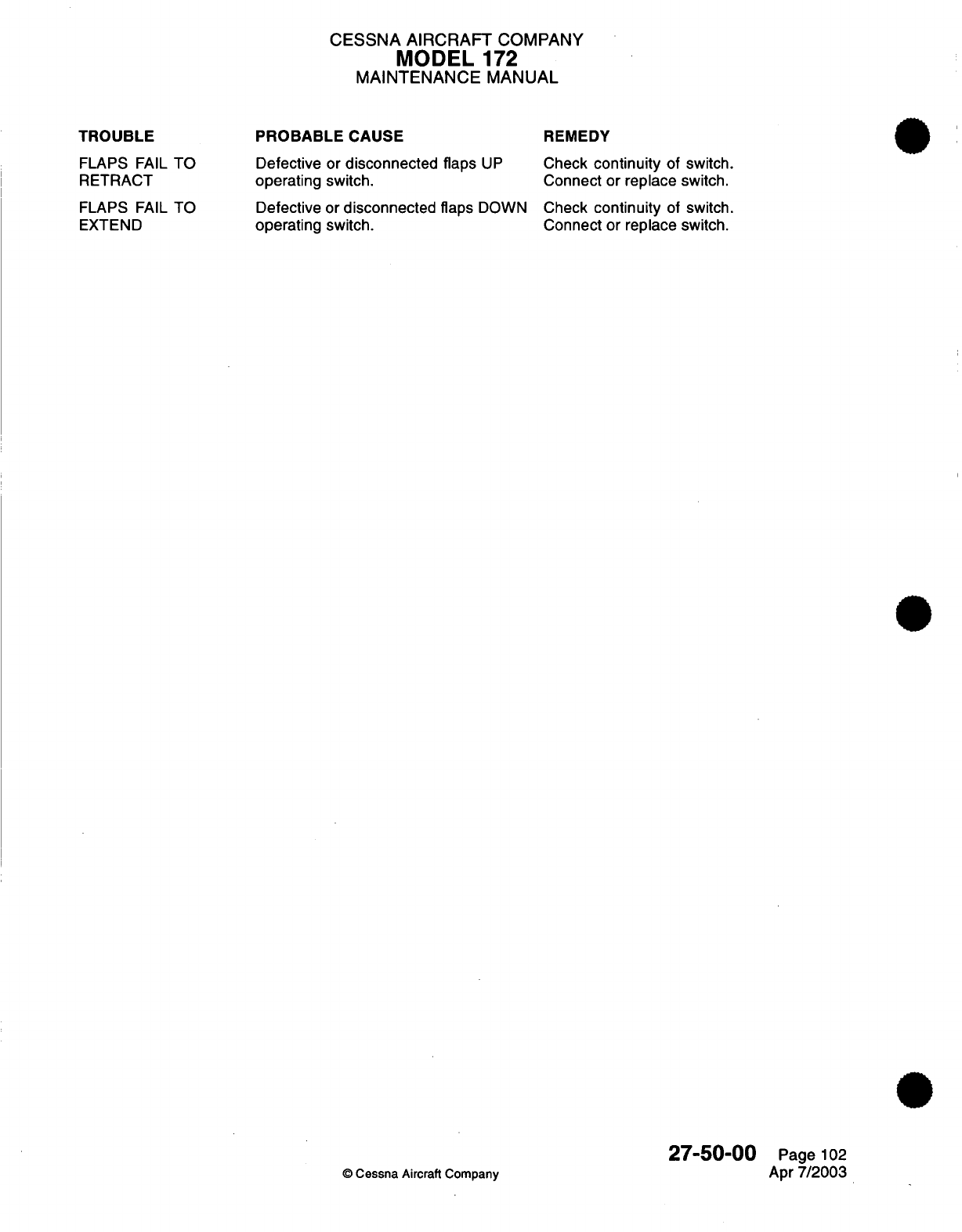
CESSNA AIRCRAFT
COMPANY
MODEL
172
MAINTENANCE
MANUAL
TROUBLE
FLAPS
FAIL
TO
RETRACT
PROBABLE
CAUSE
Defective
or
disconnected
flaps
UP
operating
switch.
REMEDY
Check
continuity
of
switch.
Connect
or
replace
switch.
FLAPS
FAIL
TO
EXTEND
Defective
or
disconnected
flaps
DOWN
Check
continuity
of
switch.
operating
switch.
Connect
or
replace
switch.
27-50-00
Page
102
©
Cessna
Aircraft
Company
Apr
7/2003
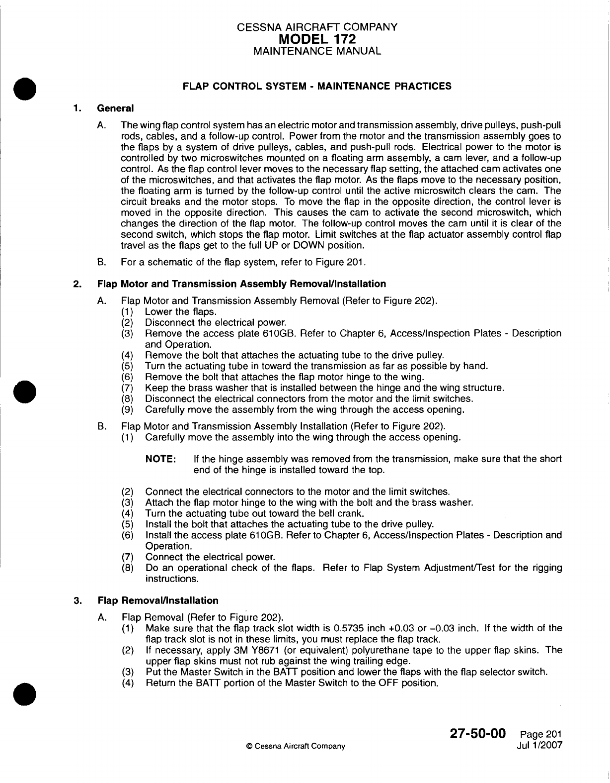
CESSNA
AIRCRAIFT
COMPANY
MODEL
172
MAINTENANCE
MANUAL
FLAP CONTROL
SYSTEM
-
MAINTENANCE PRACTICES
1.General
A.
The
wing
flap
control system
has
an
electric
motor
and
transmission
assembly,
drive pulleys,
push-pull
rods,
cables,
and
a
follow-up
control.
Power
from
the
motor
and
the
transmission
assembly
goes to
the flaps
by
a
system
of
drive
pulleys,
cables,
and
push-pull
rods.
Electrical
power
to
the
motor
is
controlled
by
two
microswitches
mounted
on
a
floating
arm
assembly,
a
cam
lever,
and
a
follow-up
control.
As
the
flap
control lever
moves
to the
necessary
flap
setting,
the
attached cam
activates
one
of
the
microswitches,
and
that
activates
the
flap
motor.
As
the
flaps
move
to
the
necessary
position,
the
floating
arm
is
turned
by
the
follow-up
control
until
the
active
microswitch
clears
the
cam.
The
circuit
breaks
and the
motor
stops.
To
move
the
flap
in
the
opposite
direction,
the
control
lever
is
moved
in
the
opposite direction.
This
causes
the
cam
to
activate
the
second
microswitch,
which
changes
the
direction
of
the
flap
motor.
The
follow-up
control
moves
the
cam
until
it is
clear
of
the
second switch,
which
stops the
flap
motor. Limit
switches
at
the
flap
actuator
assembly
control
flap
travel
as
the
flaps
get
to
the
full
UP
or
DOWN
position.
B.
For
a
schematic
of
the
flap
system,
refer
to
Figure
201.
2.
Flap
Motor
and
Transmission
Assembly Removal/installation
A.
Flap
Motor
and
Transmission
Assembly
Removal
(Refer
to
Figure 202).
(1)
Lower
the
flaps.
(2)
Disconnect
the
electrical
power.
(3)
Remove
the
access
plate
61
0GB. Refer
to
Chapter
6,
Access/Inspection
Plates
-
Description
and
Operation.
(4)
Remove
the bolt
that attaches
the
actuating
tube
to
the
drive pulley.
(5)
Turn
the
actuating tube
in
toward
the
transmission
as
far
as
possible
by
hand.
(6)
Remove
the bolt
that
attaches
the
flap motor
hinge
to
the
wing.
(7)
Keep
the
brass
washer
that
is
installed
between
the
hinge
and
the
wing
structure.
(8)
Disconnect
the
electrical connectors
from
the
motor and
the
limit
switches.
(9)
Carefully
move
the
assembly
from
the
wing
through
the
access
opening.
B.
Flap Motor
and
Transmission Assembly Installation
(Refer to
Figure 202).
(1)
Carefully
move
the
assembly
into the
wing
through
the
access
opening.
NOTE:
If
the
hinge
assembly
was
removed
from
the
transmission,
make
sure
that
the
short
end of
the hinge
is
installed
toward
the
top.
(2)
Connect
the
electrical
connectors
to
the
motor
and
the
limit
switches.
(3)
Attach
the
flap
motor hinge
to
the
wing with
the
bolt
and
the
brass
washer.
(4)
Turn
the
actuating
tube
out toward the
bell
crank.
(5)
Install
the
bolt
that
attaches
the
actuating
tube
to
the
drive pulley.
(6)
Install
the
access
plate
610OGB.
Refer
to
Chapter
6,
Access/inspection
Plates
-
Description
and
Operation.
(7)
Connect
the
electrical
power.
(8)
Do
an
operational
check
of
the
flaps.
Refer
to Flap
System Adjustment/Test
for
the
rigging
instructions.
3.
Flap
Remova~l/nstallation
A.
Flap
Removal
(Refer
to
Figure
202).
(1)
Make
sure
that
the
flap
track
slot width
is
0.5735
inch
+0.03 or -0.03
inch.
If
the
width
of
the
flap
track
slot
is
not
in
these
limits,
you
must
replace
the
flap
track.
(2) If
necessary, apply
3M
Y8671 (or
equivalent)
polyurethane
tape
to
the
upper
flap
skins.
The
upper
flap skins
must
not
rub
against
the
wing
trailing
edge.
(3)
Put the
Master
Switch
in
the
BAIT
position
and
lower
the
flaps
with
the
flap
selector
switch.
(4)
Return
the
BATT
portion
of
the
Master Switch
to
the
OFF
position.
27-50-00
Page
201
©
Cessna
Aircraft
Company
Jul
1/2007
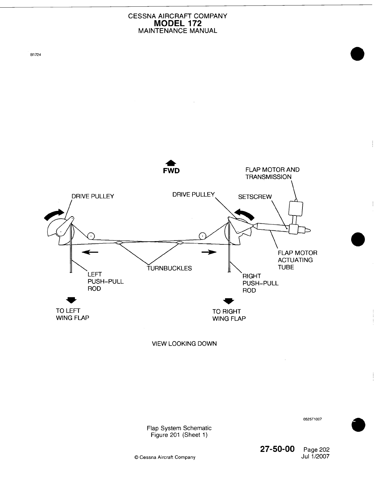
CESSNA AIRCRAFT
COMPANY
MODEL
172
MAINTENANCE
MANUAL
B1724
FWD
DRIVE
PULLEY
DRIVE
FLAP
MOTOR
AND
TRANSMISSION
SETSCREW
Lt1-
I
RIGHT
PUSH-PULL
PUSH-PULL
ROD
ROD
TO
RIGHT
WING
FLAP
VIEW
LOOKING
DOWN
0525T1
007
Flap
System
Schematic
Figure
201
(Sheet
1)
27-50-00
Q
Cessna
Aircraft
Company
TO
LEFT
WING
FLAP
Page 202
Jul 1/2007
)R
3
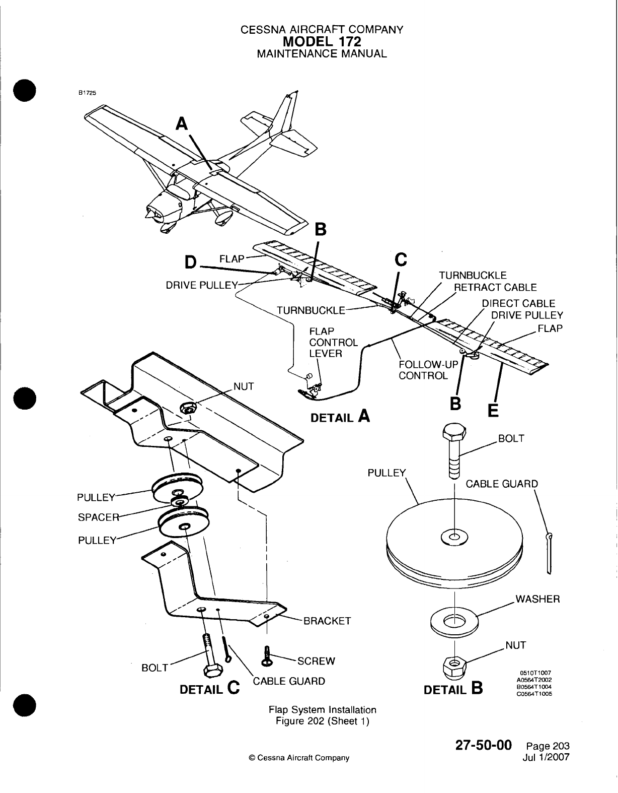
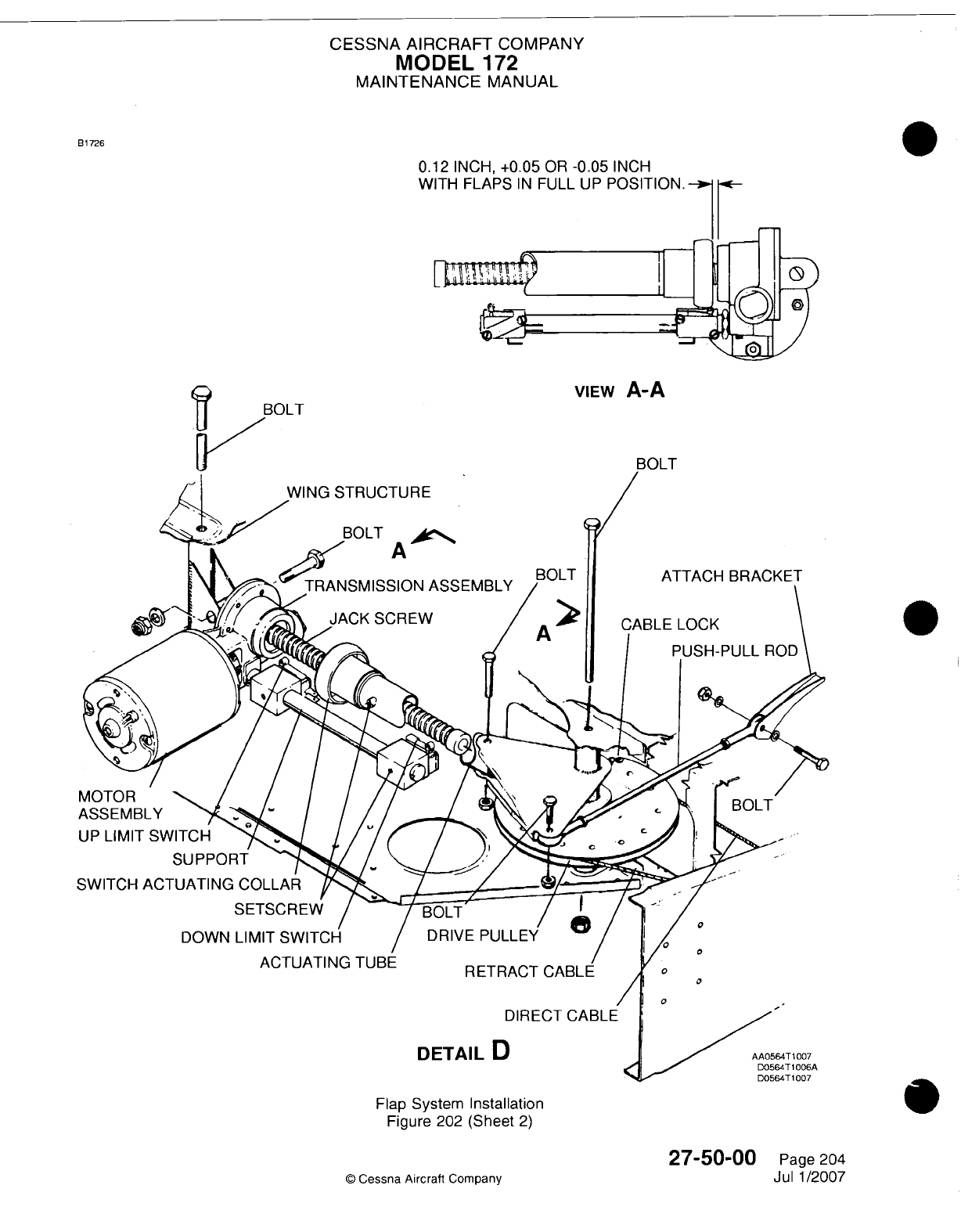
CESSNA AIRCRAFT
COMPANY
MODEL
172
MAINTENANCE
MANUAL
21726
0.12
INCH,
+0.05
OR
-0.05
INCH
w
Flap
System
Installation
Figure
202
(Sheet
2)
Q
Cessna Aircraft
Company
27-50-00
Page
204
Jul
1/2007
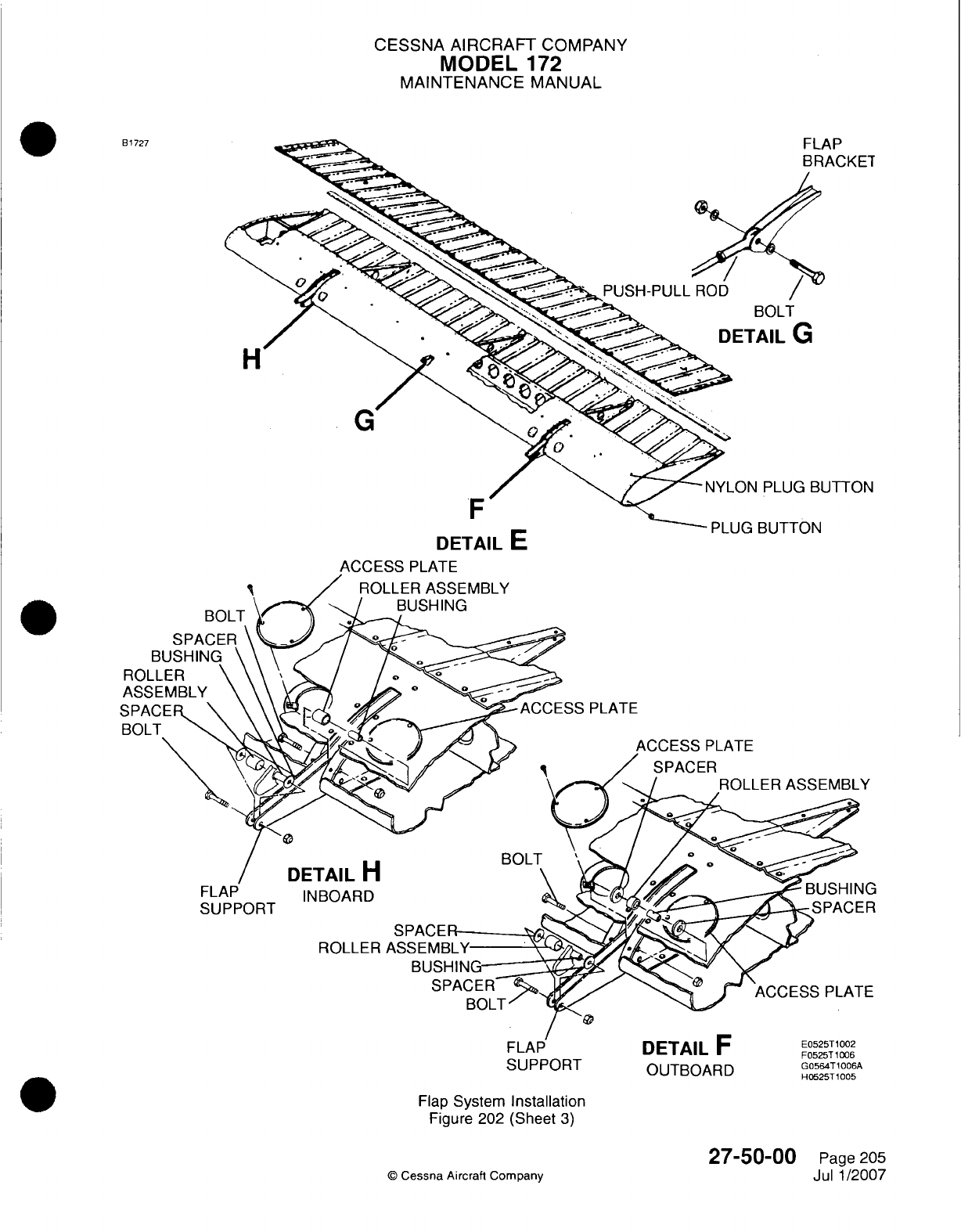
CESSNA
AIRCRAFT
COMPANY
MODEL
172
MAINTENANCE
MANUAL
B 1727
DETAIL
E
,CESS
PLATE
ROLLER
ASSEMBLY
/
BUSHING
PLATE
ACCESS
PLATE
/SPACER
ASSEMBLY
DETAIL
H
IN
BOARD
ROLLER
ASS
EMBLY-
BUSHIN,
ACCESS
PLATE
SUPPORT
OUTBOARD
G0564T1006A
H0525T
1005
Flap
System
Installation
Figure
202
(Sheet
3)
©
Cessna Aircraft Company
27-50-00
Page
205
Jul 1/2007
BOLT
I
L-LJ%.J
LI~J
I I
%i
ROLLER
ASSEMBLY
FLAP
SUPPORT
CESSNA AIRCRAFT
COMPANY
MODEL
172
MAINTENANCE
MANUAL
(5)
Remove
access
panels
51liAT
(61
1AT),
511
BT
(611
BT),
511
CT
(611
CT),
and
511
DT
(611
DT)
from
the
leading
edge
of
the flap.
Refer
to
Chapter
6,
Access/Inspection
Plates
-
Description
I ~ ~~and
Operation.
(6)
Disconnect the push-pull
rod at
the
flap
bracket.
(7)
Remove
the
bolts
at
each
flap
track.
As
you
remove
the
flap
from
the
wing,
all
washers,
rollers,
and
bushings
will
fall
free.
Keep them.
B.
Flaps
Installation
(Refer
to
Figure
202).
(1)
Install
the
flap
to
the
flap
tracks
with
the
kept
hardware.
(2)
Connect
the
push-pull
rod to
the flap
bracket.
(3) If
the
push-pull
rod
adjustment
was
changed
during
this
procedure,
you must
do
the rigging
of
the
flaps
again. Refer
to
Flap Control
Adjustment/Test.
(4)
Install
access
panels
51
1AT
(61
1AT),
511
BT
(611
BT),
51liCT
(611
CT),
and
511
DT
(611
DT)
to
the
leading
edge
of
the
flap.
Refer
to
Chapter
6,
Access/Inspection
Plates
-
Description
and
I ~ ~~~Operation.
(5)
Put
the
Master
Switch
in
the
BATT
position
and
raise
the
flaps
with the
flap
selector
switch.
(6)
Return the
BATT
portion
of
the
Master
Switch
to
the OFF
position.
4.
Flap
Drive
Pulley
Removal/Installation
NOTE:
Left
and
right
flap
drive
pulley
removal
and
installation
are
typical.
A.
Flap
Drive
Pulley
Removal
(Refer
to
Figure
202).
(1) In
the
cockpit/cabin
area,
remove
the
overhead
center
console.
(2)
Remove
the
safety
wire
and
loosen the flap
adjustment turnbuckles.
(3)
Remove
the
access
plate6l
0GB.
Refer
to
Chapter
6,
Access/Inspection
Plates
-
Description
and
Operation.
(4)
Remove
the
bolt
that
attaches
the
flap
push-pull
rod to
the
drive
pulley
and
carefully
lower
the
right
flap.
(5)
Remove
the
bolt
that attaches
the
actuating
tube
to
the
drive pulley
and
carefully
lower
the
left
0
flap.
(6)
Remove
the
cable locks
that
attach the
control
cables
to
the drive
pulley.
Tag
the
cables
for
identification.
(7)
Remove
the
bolt
that
attaches
the
drive
pulley
to
the
wing
structure.
(8)
Remove
the
drive
pulley
through the
access
opening.
Do
not
drop the
bushing.
(9)
Keep
the
brass
washer
that
is
installed
between
the
drive
pulley
and the
wing
structure.
B.
Flap
Drive
Pulley
Installation
(Refer
to
Figure
202).
(1)
Install
the
drive
pulley
and
the bushing through
the
access
opening, install
the
brass
washer,
and
attach
them to the
wing
structure
with
the
bolt.
(2)
Remove
the
tags
and install
the
cable locks
that
attach
the
control
cables
to the
drive
pulley.
(3)
Raise the
left
flap
and install the bolt that
attaches the actuating
tube
to
the
drive pulley.
(4)
Raise
the
right
flap
and
install
the
bolt
that
attaches
the
flap
push-pull
rod
to
the
drive
pulley.
(5)
Do
the
rigging
of
the
system.
Refer
to
Flap
Control
Adjustment/Test.
(6)
Install
the
access
plate
61
0GB.
Refer
to
Chapter
6,
Access/Inspection
Plates
-
Description
and
Operation.
(7)
Install the
overhead
center
console.
5.
Flap
Control
System
Adjustment/Test
A.
Rigging
of
the
Flap
Control
System
(Refer to
Figure 202
and
Figure 203).
(1) In
the
cockpit/cabin
area,
remove
the
overhead
console.
(2)
With the
flaps
in
the
UP
position,
remove
the
clevis
that
attaches
the
follow-up
cable
to the
bell
crank
to
disconnect
the
follow-up
cable.
(3)
Remove
the
safety
wire,
release
the
cable
tension,
disconnect
the
turnbuckles,
and
carefully
lower
the
left
flap.
(4)
Disconnect
the
push-pull
rods
at
the
drive pulleys
in
both
wings
and
carefully
lower the
right
flap.
(5)
Disconnect
the
actuating tube
from
the
drive
pulley.
27-50-00
Page
206
©
Cessna Aircraft Company
Jul
1/2007
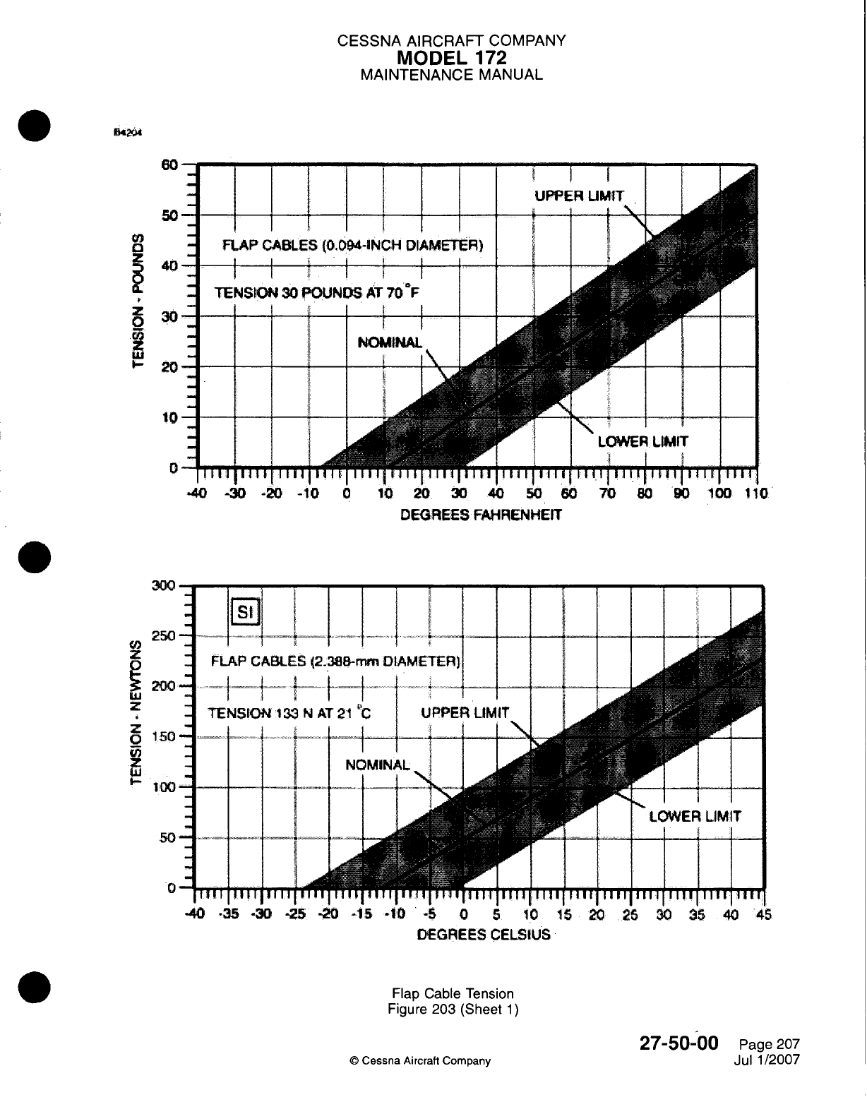
CESSNA AIRCRAFT
COMPANY
MODEL
172
MAINTENANCE
MANUAL
Da2m
I I I I I I
I
FLAP
CABLES
(0.094-INCH
DIAMETER)
TENSKOtN
30
POUNDS
AT
70
IF
I I I I
I
.40
-0
.20 -10
0
10
20
30
DEGREES
FAHRENHEIT
300
250
z
i9200
z
1
i50
I100
0
-40
35-30
-25-20
-5
-10-5
0 5
10
15
20
26
30
3540
45
DfE-GREES
CELSIUS
Flap Cable
Tension
Figure
203
(Sheet
1)
©
Cessna Aircraft
Company
27-50-00
Page
207
Jul
1/2007
.I
I
I
CESSNA
AIRCRAFT
COMPANY
MODEL
172
MAINTENANCE
MANUAL
(6)
Adjust
both
push-pull
rods
to
8.83 inches
+0.12
or
-0.12
inch between
the
centers
of
the
rod
end
bearings,
and
tighten
the
lock
nuts
on
both ends.
Connect
the
push-pull
rods
to
the
flaps
and
the
drive pulleys.
(7) If
the
control
cables
are
not
connected
to
the
left
and
the
right
drive
pulleys,
you
must
disconnect
the
actuating
tube
and
the
push-pull
rods
before you
install
the
cables.
If
the
drive pulleys
are
not
installed,
you
must
attach
the
control
cables
before
you
install
the
drive pulleys
in
the
wings.
(8)
Turn
the
actuating
tube
in
toward
the
transmission
by hand to
0.12
inch +0.05
or
-0.05
inch
between
the
switch
actuating
collar
and the
transmission.
(9)
Temporarily
connect
the
cables
at
the
turnbuckles
and
test
the
flaps
by
hand
to
make
sure
that
the two
flaps
extend
and
retract
together.
If
they
do
not,
the
cables
are
not
correctly
attached
to
the
drive
pulleys.
Make
sure
that
the
right
drive
pulley
turns
clockwise
when
you
monitor
it
from
below,
and
extend
the
flaps.
Put
the
tag
on
the
cables for identification,
and
disconnect
the
turnbuckles
again.
(1 0)
Loosen
the
setscrew
that
attaches
the
actuating
tube
to
the
switch
actuating
collar
and
hold
the
collar
to
keep
0. 12
inch
+0.05 or
-0.05
inch
while
you
hold
the
right
flap
up,
and
adjust
the
actuating
tube
in
or
out as
necessary
to
align
it
with
the
attachment
hole
in
the
drive pulley.
(11
)
Apply Loctite
grade
CV
sealant
to
the
threads
of
the
setscrew
and
torque
to 60
inch-pounds.
(12)
Disconnect
the push-pull
rod
at
the
drive pulley
to
let
the
connecting
actuating
tube drive
the
pulley.
(13)
Manually
hold
the
right
flap
in
the
full
up
position
and
adjust
the
push-pull
rod
to
align
it
with
the
attachment
hole
in
the
drive pulley.
Connect
the
push-pull
rod
and
tighten
the
jam
nuts.
(14)
With
the
flaps
in
the
full
up
position,
loosen
the
setscrew
and
slide
the
up
limit
switch adjustment
block
on
support
to
just
activate
the switch
and
shut
off
the
electrical
power
to
the
motor
at
this
position.
Tighten
the
setscrew.
(1 5)
Manually
hold
the
left
flap
full
up
and
connect
the
control
cables
at
the
turnbuckles.
Remove
the
tags
that
you
installed
for
identification.
(16)
Adjust
the
retract
cable
first.
With the
flaps
up,
adjust
the
turnbuckles
to
30
pounds
+1 0
or
-1
0
pounds
(1
33.45
N,
+44.48
or
-44.48
N)
of
tension
on
the
cables
at
70
OF
(21
00).
Refer
to
Figure
203
for
the
correct tensions
at
other
temperatures.0
(17)
Disconnect
the
push-pull
rod
at
the
left
drive
pulley.
(18)
Run
the
motor
to
extend
the
flaps
approximately
20
degrees
and
check
the
tension
on
each
flap
cable.
(19)
Adjust the
turnbuckles
as
necessary
to
maintain
30
pounds
+1
0 or
-1
0
pounds
(1
33.45
N
+44.48
or
-44.48
N)
of
tension
on
the
cables
at
70
OF
(21
OC).
Refer
to
Figure
203
for
the
correct
tensions
at
other
temperatures.
(20)
Fully retract the
right
flap.
(21)
Manually
hold
the
left
flap
in
the
up
position
and
adjust
the
push-pull
rod to
align
it
with
the
attach
holes
in
the
drive pulley.
(22)
Connect
the
push-pull
rod
and
tighten
the lock
nuts.
(23)
Mount
an
inclinometer
in
the right
flap
and
adjust
to
zero
degrees.
(24)
Run
the
flaps
to
the
full
down
position
and
adjust
the
down limit
switch
to
the
stop
motor
and
flap
at
30
degrees
+0
or
-2
degrees.
Do
the
check
on
the left
flap.
Check
the
limit
switch
through
some
flap
cycles.
(25)
Connect
and
do
a
rigging
of
the
flap follow
up
system.
(26)
Do
an
operational check
of
the
system.
Refer
to
the
Operational
Check.
(27)
Check
all
items
for
correct
safetying
and
install
the
items
that
you
removed
for
access.
6.
Operational
Check
A.
Operational
Check
Procedures
(1)
Operate
the
flaps
through
their
full
range
of
travel, and
look
for
uneven
travel
or
jumpy
motion,
binding,
or
lost
motion.
Make
sure
that
the
flaps
move
together
through
their
full
range
of
travel.
(2)
Check
for
positive
shut
off of
the motor
at
flap
travel extremes
to
prevent
damage
to
the
actuator
assembly.
(3)
With the
flap
full
UP,
mount
an
inclinometer
on
one
flap
and
set
to
0
degrees.
Lower
the
flaps
to
full
DOWN
position
and
check
the
flap angle
as
specified
in
Chapter
6,
Airplane
Dimensions
and
Specifications
-
Description
and
Operation.
Do
this
procedure again
for
the
opposite
flap.
27-50-00
Page
208
©
Cessna
Aircraft
Company
Jul
1/2007
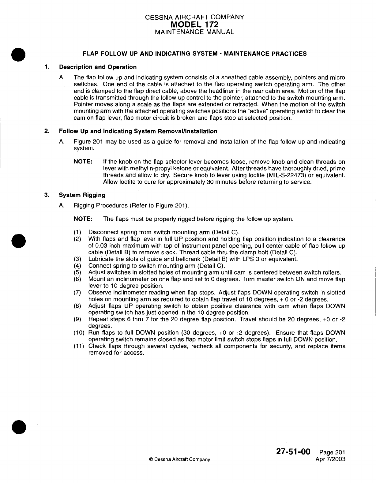
CESSNA
AIRCRAFT
COMPANY
MODEL
172
MAINTENANCE
MANUAL
FLAP
FOLLOW
UP
AND
INDICATING SYSTEM
-
MAINTENANCE
PRACTICES
1.
Description
and
Operation
A.
The
flap
follow
up
and
indicating
system
consists
of
a
sheathed
cable assembly,
pointers
and micro
switches.
One
end
of
the
cable is
attached
to
the
flap operating
switch
operating
arm.
The
other
end
is
clamped
to
the
flap
direct cable, above the
headliner
in
the rear
cabin
area.
Motion of
the
flap
cable
is
transmitted
through
the
follow
up
control
to
the
pointer,
attached
to
the
switch
mounting
arm.
Pointer
moves along
a
scale
as
the
flaps
are
extended
or
retracted. When
the
motion
of
the
switch
mounting
arm
with
the
attached operating
switches
positions
the
"active"
operating switch
to
clear
the
cam
on
flap
lever,
flap
motor
circuit
is
broken
and
flaps
stop
at
selected
position.
2.
Follow
Up
and
Indicating
System
Removal/Installation
A.
Figure
201
may be used
as
a
guide
for
removal
and
installation
of
the
flap
follow
up
and
indicating
system.
NOTE:
If
the
knob
on
the
flap
selector lever
becomes
loose,
remove
knob
and
clean
threads
on
lever
with
methyl
n-propyl ketone
or
equivalent.
After
threads
have
thoroughly
dried,
prime
threads
and
allow
to
dry.
Secure knob
to
lever
using
loctite (MIL-S-22473) or
equivalent.
Allow
loctite
to
cure
for
approximately
30
minutes
before
returning
to
service.
3.
System
Rigging
A.
Rigging
Procedures
(Refer
to
Figure
201).
NOTE:
The
flaps
must
be
properly rigged
before
rigging the
follow
up
system.
(1)
Disconnect
spring
from
switch mounting
arm
(Detail
C).
(2)
With
flaps
and
flap
lever
in
full
UP
position
and
holding
flap
position
Indication
to
a
clearance
of
0.03
inch
maximum
with
top
of
instrument
panel
opening,
pull
center
cable
of
flap
follow
up
cable (Detail
B)
to
remove
slack.
Thread
cable
thru
the
clamp
bolt
(Detail
C).
(3)
Lubricate
the slots
of guide and
bellcrank
(Detail
B)
with
LPS
3
or
equivalent.
(4)
Connect spring
to
switch
mounting
arm
(Detail
C).
(5)
Adjust
switches
in
slotted
holes
of
mounting
arm
until
cam
is
centered
between
switch rollers.
(6)
Mount
an
inclinometer
on
one
flap
and
set
to
0
degrees.
Turn
master
switch
ON
and
move
flap
lever
to
10
degree position.
(7)
Observe
inclinometer
reading
when flap stops.
Adjust
flaps
DOWN
operating switch
in
slotted
holes
on
mounting
arm as
required
to
obtain
flap
travel
of
10
degrees,
+
0
or
-2
degrees.
(8)
Adjust flaps
UP
operating switch
to
obtain
positive
clearance
with
cam
when
flaps
DOWN
operating switch has
just
opened
in
the
10
degree
position.
(9)
Repeat
steps
6
thru
7
for
the
20
degree
flap
position.
Travel
should
be
20
degrees,
+0
or
-2
degrees.
(10)
Run
flaps to full
DOWN
position
(30
degrees,
+0
or
-2
degrees).
Ensure
that
flaps
DOWN
operating
switch
remains
closed
as
flap motor
limit
switch stops
flaps
in
full
DOWN
position.
(11)
Check
flaps
through
several
cycles,
recheck
all
components
for
security,
and
replace
items
removed
for access.
27-51
-00
Page 201
©
Cessna Aircraft Company
Apr 7/2003
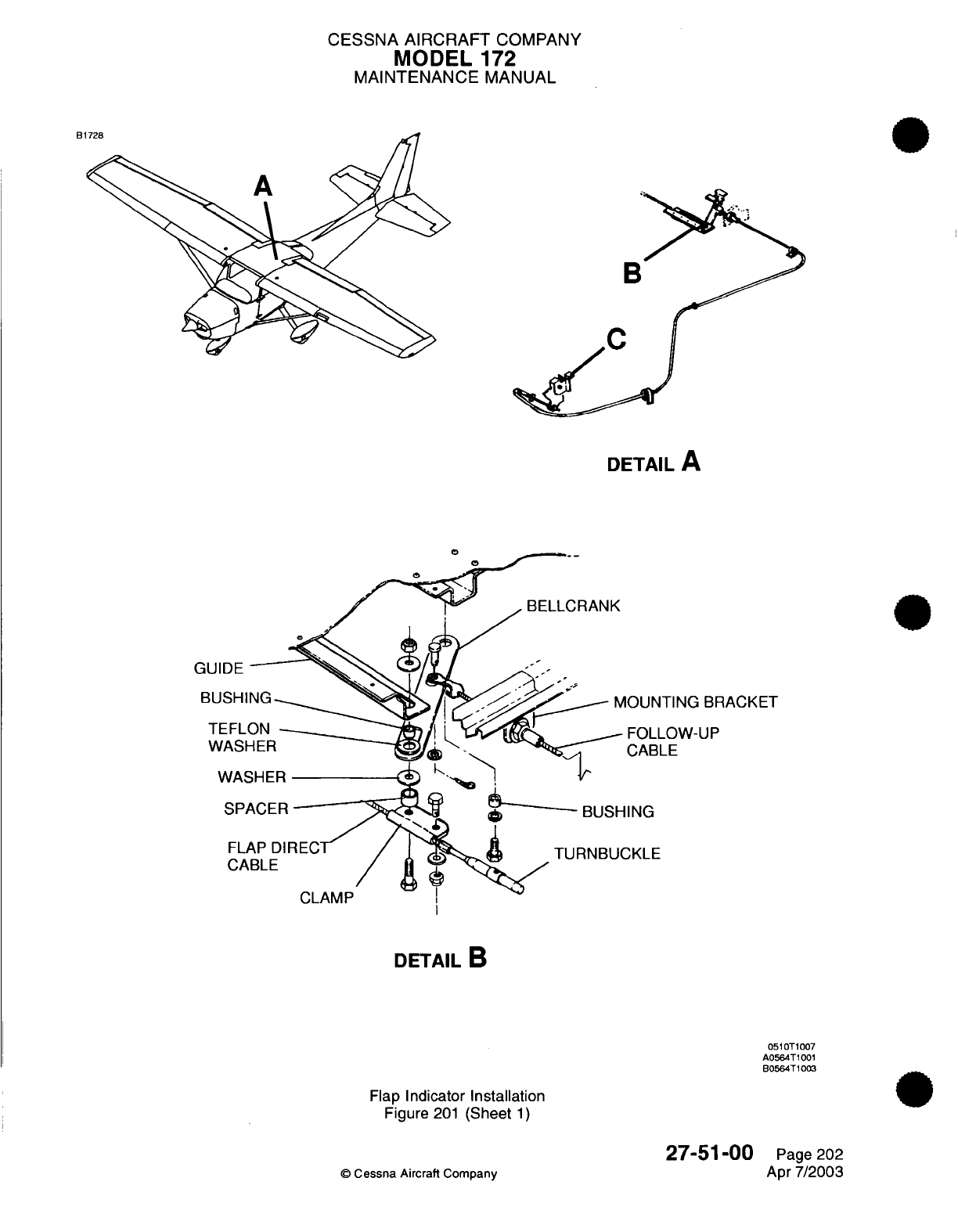
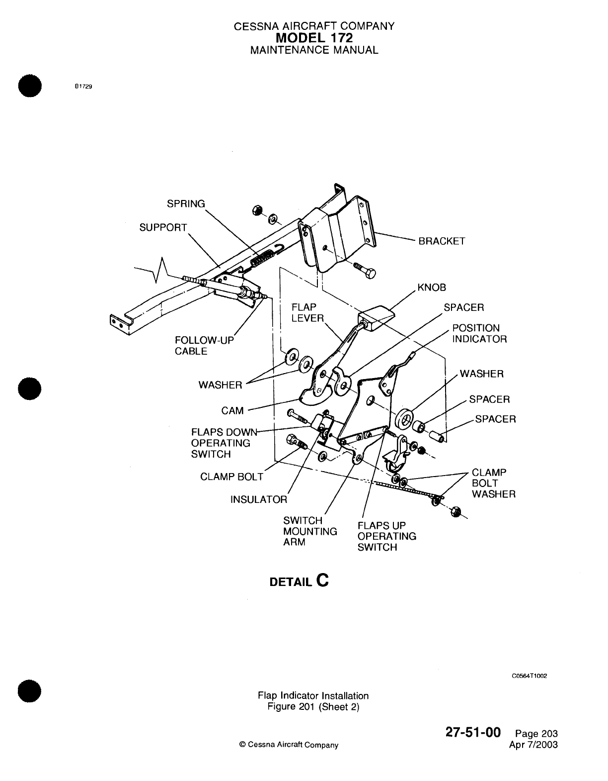
CESSNA
AIRCRAFT
COMPANY
MODEL
172
MAINTENANCE
MANUAL
B1729
;:VYVI
16nM
FLAPS UP
MOUNTING
AMOUNTING
OPERATING
ARM
SWITCH
DETAIL
C
C0564T1002
Flap
Indicator Installation
Figure
201
(Sheet
2)
©
Cessna Aircraft
Company
27-51
-00
Page
203
Apr
7/2003
CHAPTER
FUEL
CESSNA AIRCRAFT
COMPANY
MODEL
172
MAINTENANCE
MANUAL
LIST
OF
EFFECTIVE
PAGES
CHAPTER-SECTION-SUBJECT
28-Title
28-List
of
Effective
Pages
28-Record
of
Temporary
Revisions
28-Table
of
Contents
28-00-00
28-20-00
28-20-00
28-20-00
28-2
1-00
PAGE
Pages
1-2
Pages
1-3
Pages
201-223
Pages
501-506
Pages
201
-218
©
Cessna Aircraft
Company
28
-
LIST
OF
EFFECTIVE
PAGES
Page
1
of
1
Jul
1/2007
DATE
Apr
7/2003
Jan
3/2005
Jul 1/2007
Jul 1/2007
Apr
7/2003
Temporary
Revision
Number
RECORD
OF
TEMPORARY REVISIONS
Page
Number
Issue
Date
By
Date
Removed
By
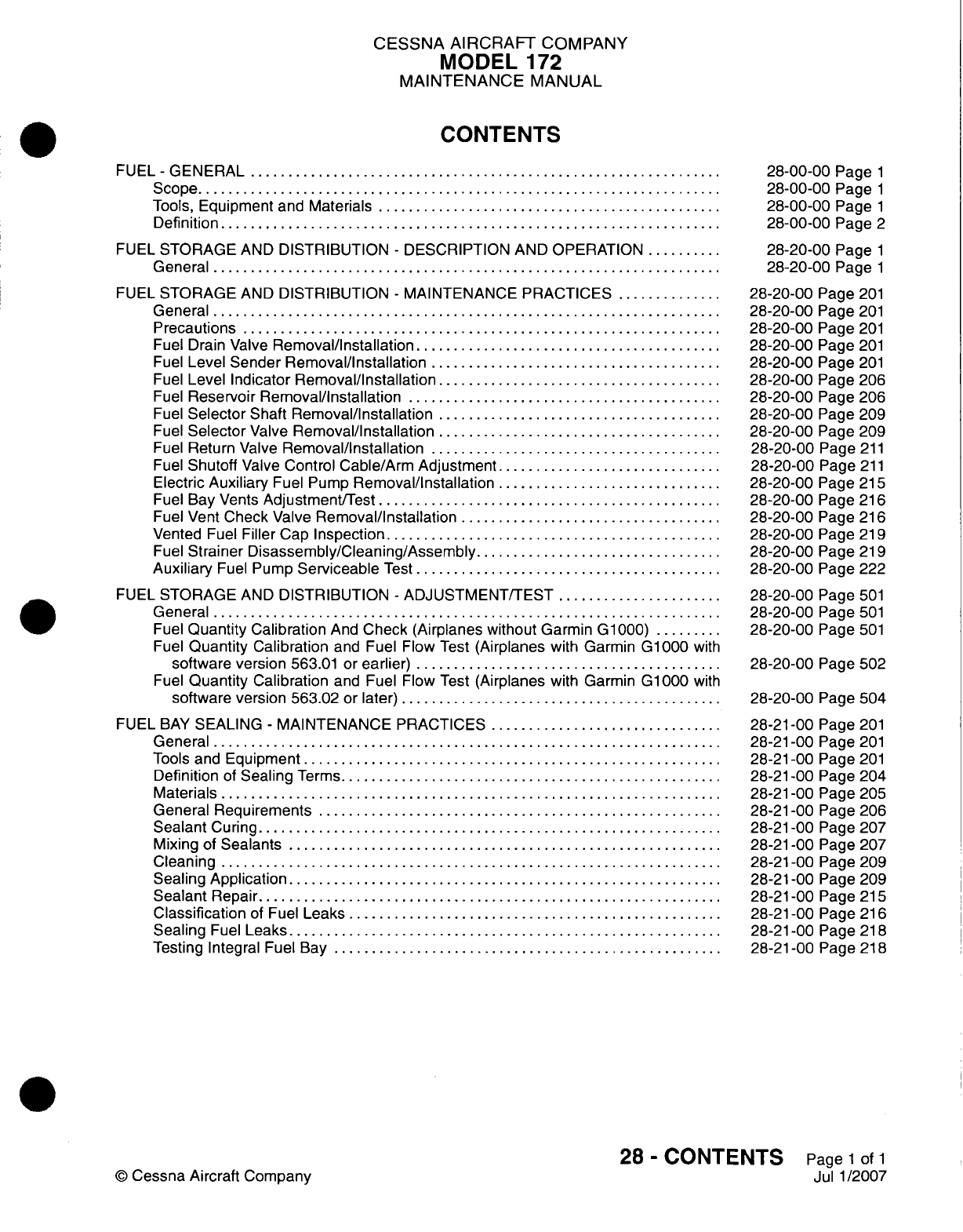
CESSNA
AIRCRAFT
COMPANY
MODEL
172
MAINTENANCE
MANUAL
CONTENTS
FUEL
-GENERAL
................................
Scope....................................
Tools,
Equipment
and
Materials........................
Definition
..................................
FUEL
STORAGE
AND
DISTRIBUTION
-
DESCRIPTION
AND
OPERATION......
General...................................
FUEL
STORAGE
AND
DISTRIBUTION
-
MAINTENANCE
PRACTICES........
General...................................
Precautions.................................
Fuel
Drain
Valve
Removal/Installation
.....................
Fuel
Level
Sender
Removal/Installation
....................
Fuel
Level
Indicator
Removal/Installation....................
Fuel
Reservoir
Removal/installation......................
Fuel
Selector
Shaft
Removal/Installation....................
Fuel
Selector
Valve
Removal/Installation....................
Fuel
Return
Valve
Removal/installation
....................
Fuel
Shutoff
Valve
Control
Cable/Arm
Adjustment................
Electric
Auxiliary
Fuel
Pump
Removal/installation................
Fuel
Bay
Vents
Adjustment/Test........................
Fuel Vent
Check
Valve
Removal/Installation
..................
Vented
Fuel
Filler
Cap
Inspection
.......................
Fuel
Strainer
Disassembly/Cleaning/Assembly
.................
Auxiliary
Fuel
Pump
Serviceable
Test
.....................
FUEL
STORAGE
AND
DISTRIBUTION
-
ADJUSTMENT/TEST............
General...................................
Fuel
Quantity Calibration
And
Check
(Airplanes without
Garmin G1000)
.....
Fuel
Quantity
Calibration
and
Fuel
Flow
Test
(Airplanes
with
Garmin
G1000
with
software
version
563.01
or
earlier)
.....................
Fuel
Quantity
Calibration
and Fuel Flow
Test
(Airplanes
with Garmin
G1000
with
software
version
563.02
or
later)
......................
FUEL
BAY
SEALING
-
MAINTENANCE
PRACTICES
................
General...................................
Tools
and
Equipment.............................
Definition
of
Sealing
Terms
..........................
Materials
..................................
General
Requirements............................
Sealant
Curing................................
Mixing
of
Sealants..............................
Cleaning
..................................
Sealing
Application..............................
Sealant
Repair................................
Classification
of
Fuel
Leaks..........................
Sealing
Fuel
Leaks..............................
Testing Integral
Fuel
Bay...........................
28-00-00
Page
1
28-00-00
Page
1
28-00-00
Page
1
28-00-00
Page
2
28-20-00
Page
1
28-20-00
Page
1
28-20-00
Page
201
28-20-00
Page
201
28-20-00
Page
201
28-20-00
Page
201
28-20-00
Page
201
28-20-00
Page
206
28-20-00
Page
206
28-20-00
Page
209
28-20-00
Page
209
28-20-00
Page
211
28-20-00
Page
211
28-20-00
Page
215
28-20-00
Page
216
28-20-00
Page
216
28-20-00
Page
219
28-20-00
Page
219
28-20-00
Page
222
28-20-00
Page
501
28-20-00
Page
501
28-20-00
Page
501
28-20-00
Page 502
28-20-00
Page 504
28-21
-00
Page
201
28-21
-00
Page
201
28-21
-00
Page
201
28-2
1
-00
Page 204
28-21
-00
Page
205
28-2
1
-00
Page 206
28-2
1
-00 Page 207
28-21
-00
Page
207
28-21
-00 Page 209
28-21
-00
Page
209
28-2
1
-00
Page
215
28-21
-00
Page
216
28-2
1
-00
Page
218
28-21
-00
Page
218
28
-
CONTENTS
Page
1
of
1
Jul
1/2007
©
Cessna
Aircraft
Company
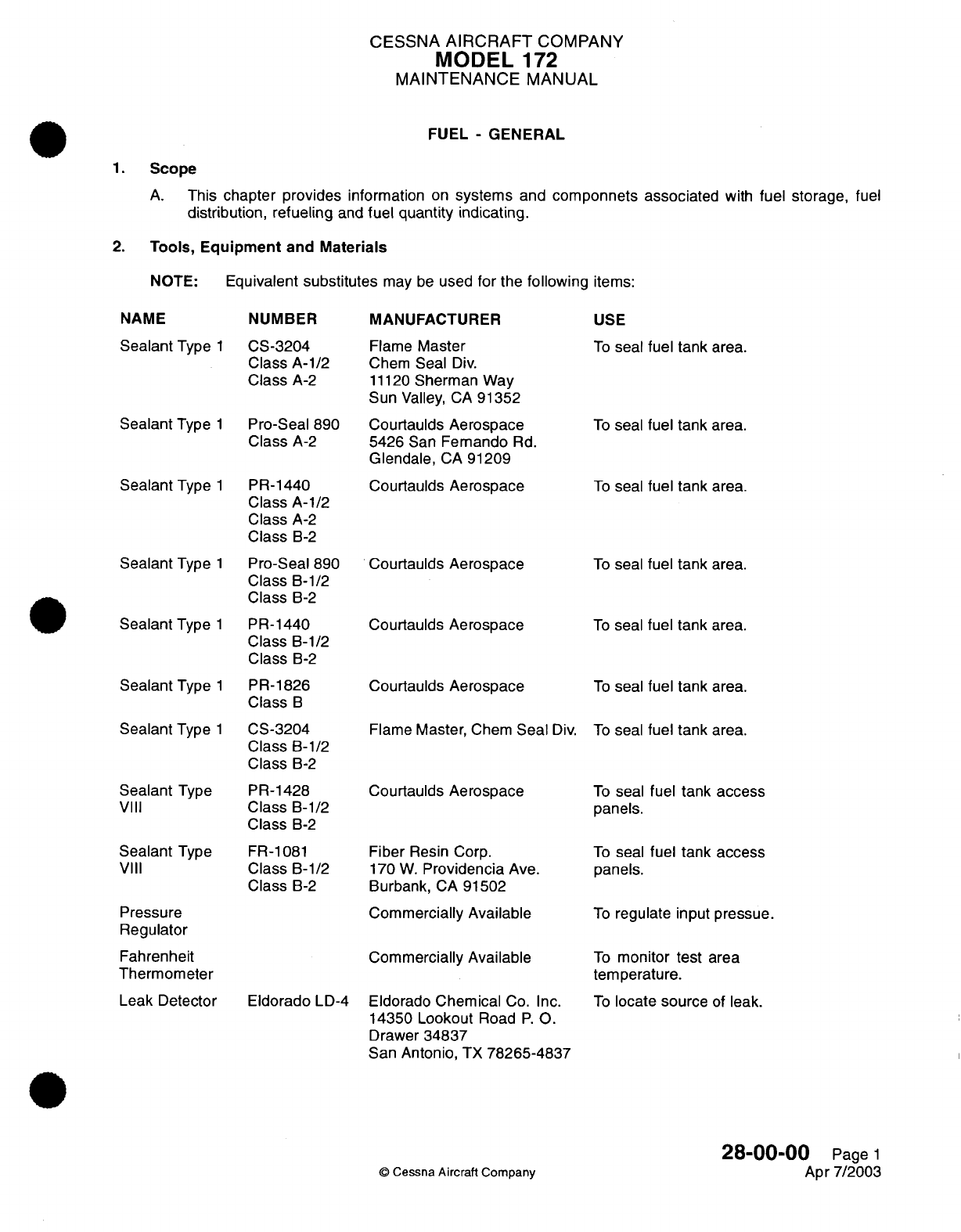
CESSNA
AIRCRAFT
COMPANY
MODEL
172
MAINTENANCE
MANUAL
FUEL
-
GENERAL
1.
Scope
A.
This
chapter
provides
information
on
systems
and
componnets
associated
with
fuel
storage,
fuel
distribution, refueling
and
fuel quantity indicating.
2.
Tools,
Equipment
and
Materials
NOTE:
Equivalent
substitutes
may
be
used
for
the
following
items:
NAME
NUMBER
Sealant
Type
1
Sealant
Type
Sealant
Type
1
1
Sealant
Type
Sealant
Type
Sealant
Type
Sealant Type
Sealant
Type
VIII
Sealant
Type
VIII
Pressure
Regulator
Fahrenheit
Thermometer
Leak
Detector
CS-3204
Class
A-1/2
Class
A-2
Pro-Seal
890
Class
A-2
PR-1440
Class
A-1/2
Class
A-2
Class
B-2
Pro-Seal
890
Class
B-1/2
Class
B-2
PR-1440
Class
B-1/2
Class
B-2
PR-1826
Class
B
CS-3204
Class
B-1/2
Class
B-2
PR-1428
Class
B-1/2
Class
B-2
FR-1081
Class
B-1/2
Class
B-2
Eldorado
LD-4
MANUFACTURER
Flame
Master
Chem
Seal
Div.
11120
Sherman
Way
Sun
Valley,
CA
91352
Courtaulds
Aerospace
5426
San
Femando
Rd.
Glendale,
CA
91209
Courtaulds
Aerospace
Courtaulds
Aerospace
Courtaulds
Aerospace
Courtaulds
Aerospace
Flame
Master,
Chem
Seal
Div.
Courtaulds
Aerospace
Fiber
Resin Corp.
170
W.
Providencia
Ave.
Burbank,
CA
91502
Commercially
Available
Commercially
Available
Eldorado
Chemical
Co.
Inc.
14350
Lookout
Road
P.O.
Drawer
34837
San
Antonio,
TX
78265-4837
USE
To
seal
fuel tank
area.
To
seal
fuel tank
area.
To
seal
fuel
tank
area.
To
seal
fuel tank
area.
To
seal
fuel tank
area.
To
seal
fuel
tank
area.
To
seal
fuel
tank
area.
To
seal
fuel tank
access
panels.
To
seal
fuel tank
access
panels.
To
regulate
input
pressue.
To
monitor
test
area
temperature.
To
locate source
of
leak.
28-00-00
Page
1
Apr
7/2003
©
Cessna Aircraft Company
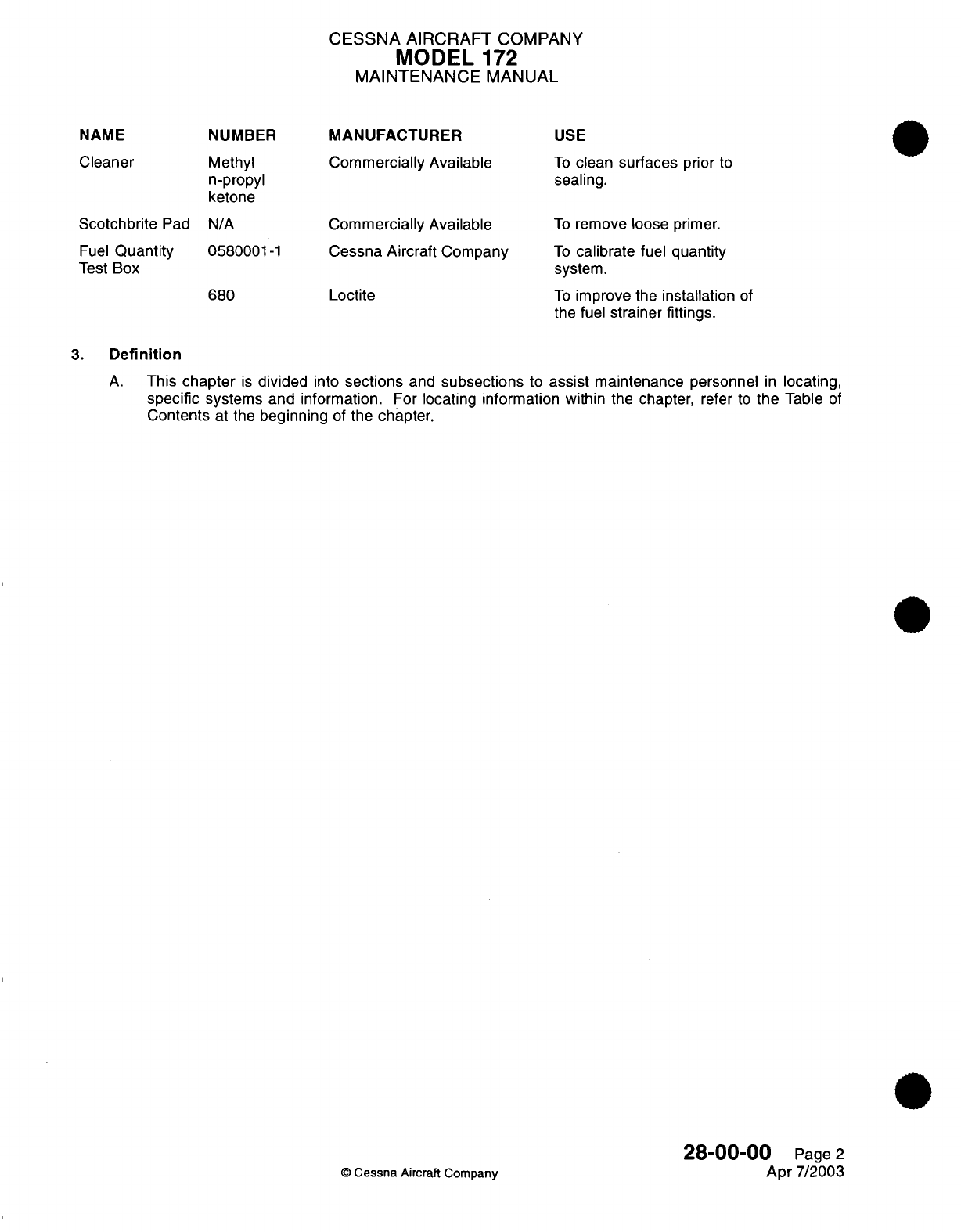
CESSNA
AIRCRAFT
COMPANY
MODEL
172
MAINTENANCE
MANUAL
MANUFACTURER
USE
Cleaner
Methyl
n-propyl
ketone
Scotchbrite
Pad N/A
Fuel
Quantity
Test
Box
0580001-1
680
Commercially
Available
Commercially
Available
Cessna Aircraft
Company
Loctite
To
clean
surfaces
prior
to
sealing.
To
remove loose
primer.
To
calibrate
fuel
quantity
system.
To
improve
the
installation
of
the
fuel
strainer
fittings.
3.
Definition
A.
This
chapter
is
divided
into
sections
and
subsections
to
assist
maintenance personnel
in
locating,
specific
systems and
information.
For
locating information
within
the
chapter, refer
to
the
Table
of
Contents
at the
beginning
of
the
chapter.
©
Cessna
Aircraft
Company
28-00-00
Page
2
Apr
7/2003
NAME
NUMBER
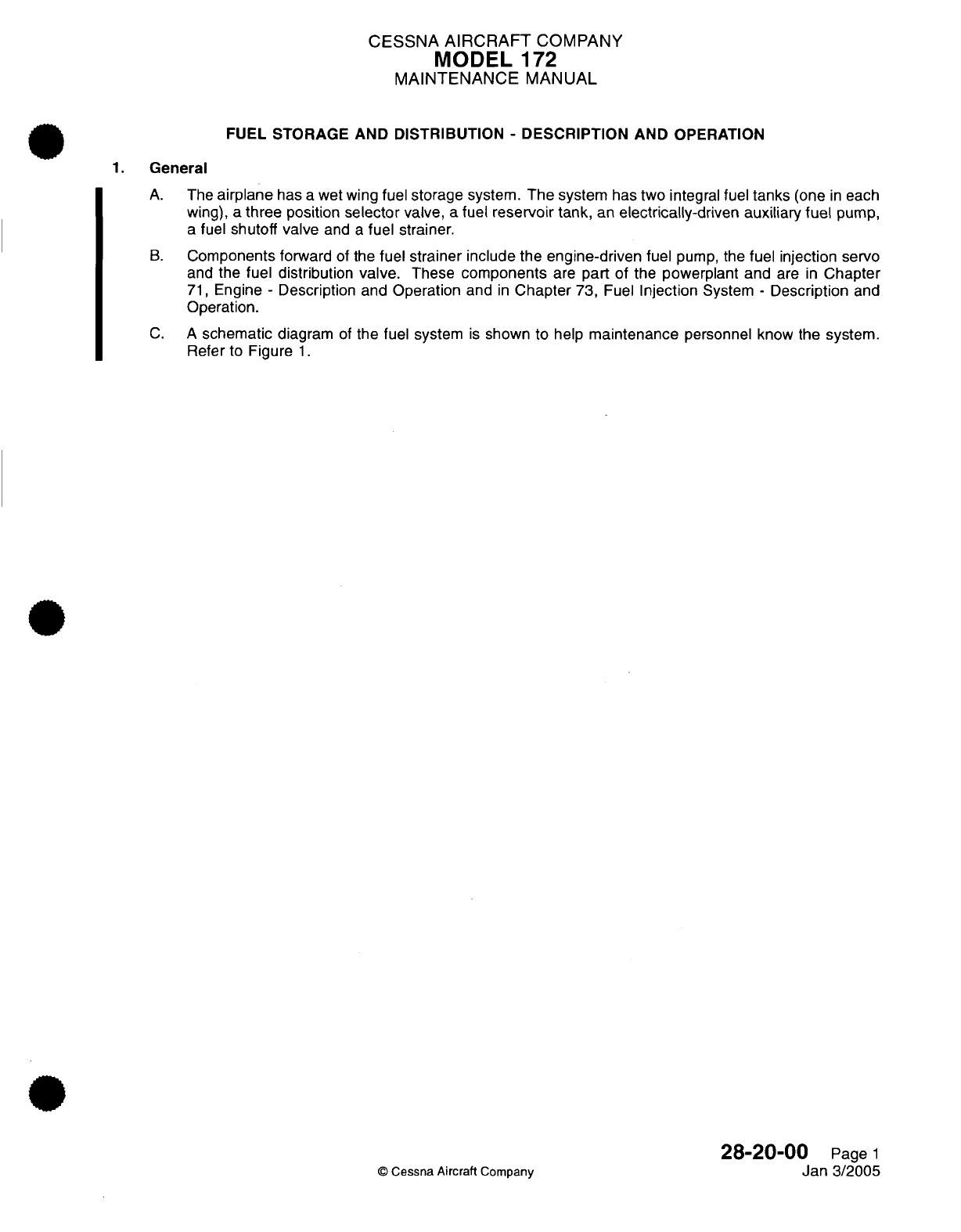
CESSNA
AIRCRAFT
COMPANY
MODEL
172
MAINTENANCE
MANUAL
FUEL
STORAGE AND DISTRIBUTION
-
DESCRIPTION
AND
OPERATION
1.
General
A.
The
airplane
has
a
wet
wing
fuel storage
system.
The
system
has
two integral fuel
tanks
(one
in
each
wing),
a three position selector
valve,
a fuel reservoir
tank,
an
electrically-driven
auxiliary
fuel
pump,
a
fuel
shutoff valve
and
a
fuel
strainer.
B.
Components
forward
of
the
fuel strainer include
the engine-driven
fuel
pump,
the
fuel injection
servo
and
the
fuel distribution
valve.
These
components
are
part
of
the
powerplant
and
are
in
Chapter
71,
Engine
-
Description
and
Operation
and
in
Chapter
73,
Fuel
Injection
System
-
Description
and
Operation.
C. A
schematic
diagram
of
the fuel
system
is
shown
to
help
maintenance
personnel
know
the
system.
Refer
to
Figure
1.
28-20-00
Page
1
©
Cessna
Aircraft Company
Jan
3/2005
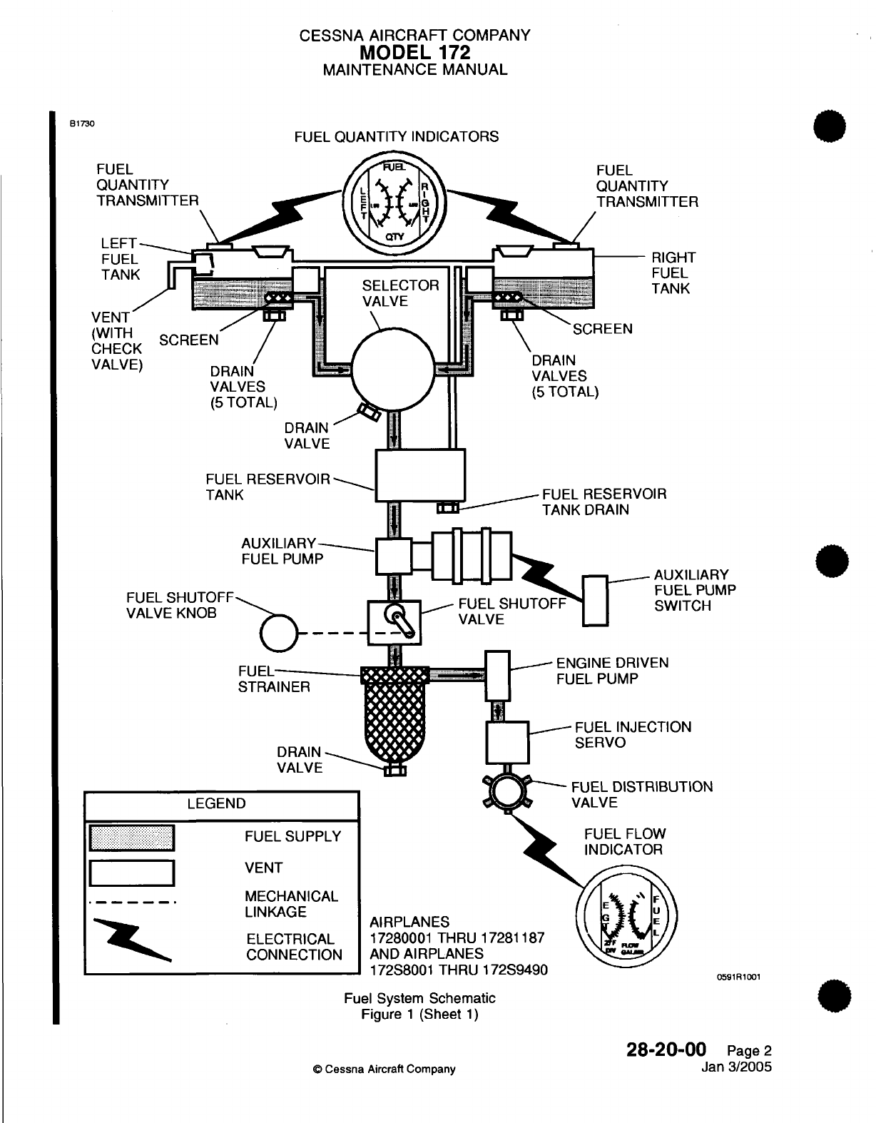
CESSNA
AIRCRAFT
COMPANY
MODEL
172
MAINTENANCE
MANUAL
FUEL
QUANTITY
INDICATORS
TY
MITTER
RIGHT
FUEL
TANK
IR
AUXILIARY
FUEL
PUMP
SWITCH
AUXILIARY-
FUEL
PUMP
FUEL
STRAINER
DRAIN
VALVE
-_
~ENGINE
DRIVEN
FUEL
PUMP
FUEL
INJECTION
SERVO
TION
LEGEND
I
. ... ..
I..
I
I
FUEL SUPPLY
VENT
MECHANICAL
LINKAGE
ELECTRICAL
CONNECTION
AIRPLANES
17280001
THRU
AND
AIRPLANES
dj 7%OOQ n fl4
-rTI
I
Fuel
System
Schematic
Figure
1
(Sheet
1)
28-20-01
©
Cessna
Aircraft Company
B1730
F
C
V
C
V
SELECTOF
VALVE
DRAIN
TANK
I
I/OOUU
I I nnru I I/o7-:Lu
0591R1001
0
Page
2
Jan
3/2005
*I
r;"
.
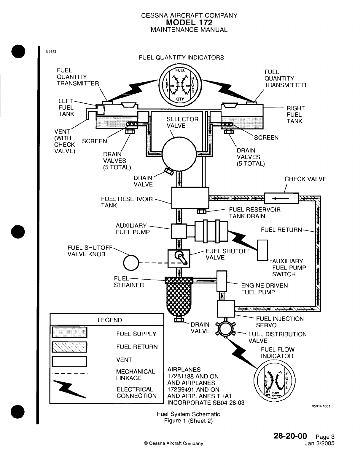
CESSNA
AIRCRAFT
COMPANY
MODEL
172
MAINTENANCE
MANUAL
FUEL
QUANTITY INDICATORS
FUEL
QUANTITY
TRANSMITTER
VALVES
(5
TOTAL)
DRAIN
VALVE
FUEL
RESERVOIR
TANK
AUXILIARY-
FUEL
PUMP
FUEL
SHUTOFF
VALVE KNOB
-> -
FUEL
STRAINER
LEGEND
FUEL
SUPPLY
FUEL
RETURN
VENT
MECHANICAL
LINKAGE
ELECTRICAL
CONNECTION
ii'Ldui Jrlrn/ I
r
ODU'+--O-UO
Fuel
System
Schematic
Figure
1
(Sheet
2)
28-20-00
Page
3
Jan
3/2005
©
Cessna
Aircraft
Company
B3813
VALVE
It
1.
I
P
'
I
I
VALVE
SERVO
0591R1001
I
II
0-T
I
N
.-I
I
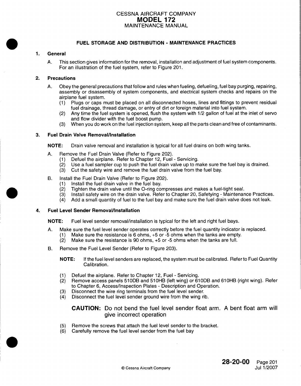
CESSNA AIRCRAFT
COMPANY
MODEL
172
MAINTENANCE
MANUAL
FUEL STORAGE
AND
DISTRIBUTION
-
MAINTENANCE PRACTICES
1.General
A.
This
section
gives
information
for
the removal,
installation
and
adjustment
of
fuel
system components.
For
an
illustration
of
the
fuel
system, refer
to
Figure
201.
2.
Precautions
A.
Obey
the
general
precautions
that
follow
and
rules
when
fueling,
defueling,
fuel
bay
purging, repairing,
assembly
or
disassembly
of
system
components,
and
electrical
system
checks
and
repairs
on
the
airplane
fuel
system.
(1)
Plugs
or
caps
must
be
placed
on all
disconnected
hoses,
lines
and
fittings
to
prevent
residual
fuel
drainage,
thread damage, or
entry
of
dirt or
foreign
material
into
fuel
system.
(2)
Any
time
the
fuel
system
is
opened, flush
the
system
with
1/2
gallon
of
fuel
at
the inlet
of
servo
and
flow
divider
with
the
fuel
boost
pump.
(3)
When
you
do
work
on
the
fuel
injection
system,
keep
all the
parts
clean
and
free
of
contaminants.
3.
Fuel
Drain
Valve
Removal/installation
NOTE:
Drain
valve
removal
and
installation
is
typical
for
all
fuel drains
on
both
wing tanks.
A.
Remove
the
Fuel
Drain Valve
(Refer
to
Figure
202).
(1)
Defuel the
airplane.
Refer
to
Chapter
12,
Fuel
-
Servicing.
(2)
Use
a
fuel
sampler
cup
to
push
the fuel
drain
valve
up
to
make
sure
the fuel
bay
is
drained.
(3)
Cut
the
safety
wire
and
remove
the
fuel drain
valve
from
the
fuel
bay.
B.
Install
the
Fuel
Drain
Valve
(Refer
to
Figure
202).
(1)
Install
the
fuel
drain
valve
in
the
fuel
bay.
(2)
Tighten
the
drain
valve
until the
0-ring
compresses
and
makes
a
fuel-tight
seat.
(3)
Install
safety
wire
on
the
drain
valve. Refer
to
Chapter
20,
Safetying
-
Maintenance
Practices.
(4)
Add
a
small
quantity
of
fuel
to
the fuel
bay
and make
sure the
fuel
drain
valve
does
not leak.
4.
Fuel
Level
Sender
Removal/Installation
NOTE:
Fuel
level
sender
removal/installation
is
typical
for
the
left
and
right
fuel
bays.
A.
Make
sure
the
fuel level
sender operates
correctly
before
the
fuel
quantity indicator
is
replaced.
(1)
Make
sure the
resistance
is 6
ohms,
+5
or
-5
ohms
when
the
tanks
are
empty.
(2)
Make
sure the
resistance
is
90
ohms,
+5
or
-5
ohms
when
the
tanks
are
full.
B.
Remove
the
Fuel
Level
Sender
(Refer
to
Figure 203).
NOTE:
If
the
fuel
level
senders
are
replaced,
the
system
must
be
calibrated.
Refer
to
Fuel
Quantity
Calibration.
(1)
Defuel
the
airplane.
Refer
to
Chapter
12,
Fuel
-
Servicing.
(2)
Remove
access
panels
510ODB
and
51
OHB
(left
wing)
or
61
0DB3
and
61OHB3
(right
wing).
Refer
to
Chapter
6,
Access/Inspection
Plates
-
Description
and
Operation.
(3)
Disconnect
the wire
ring
terminals
from the
fuel
level
sender.
(4)
Disconnect
the
fuel
level
sender
ground
wire
from
the
wing
rib.
CAUTION:
Do
not bend the fuel
level
sender
float
arm.
A
bent
float
arm
will
give
incorrect operation
(5)
Remove
the screws
that
attach
the
fuel
level
sender
to
the
bracket.
(6)
Carefully
remove
the fuel
level
sender
from
the
fuel
bay
28-20-00
Page
201
©
Cessna
Aircraft
Company
Jul
1/2007
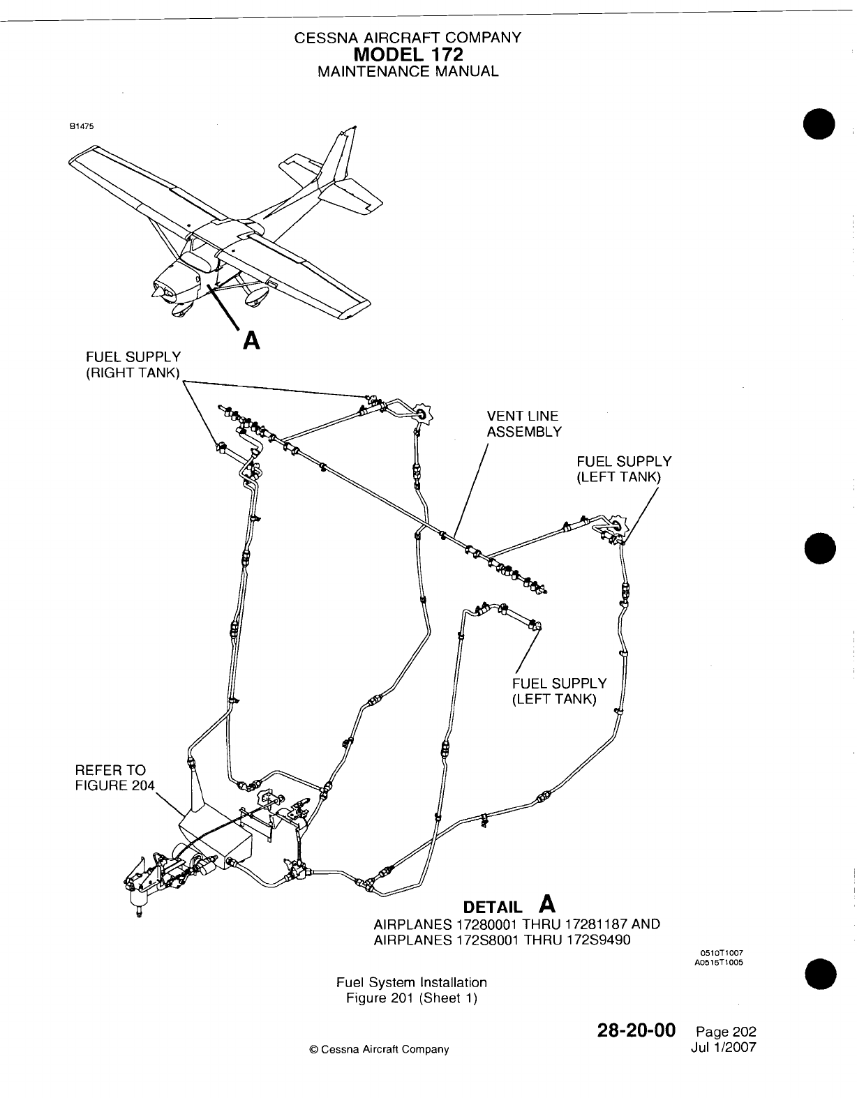
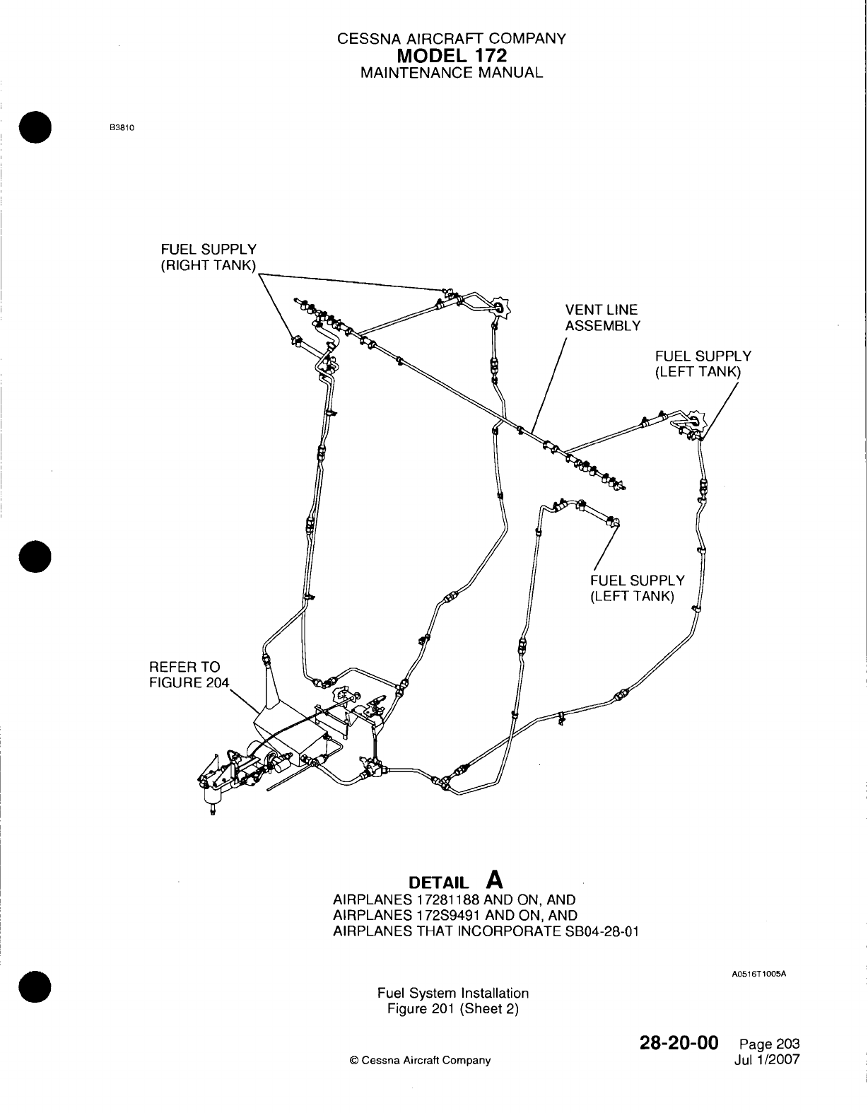
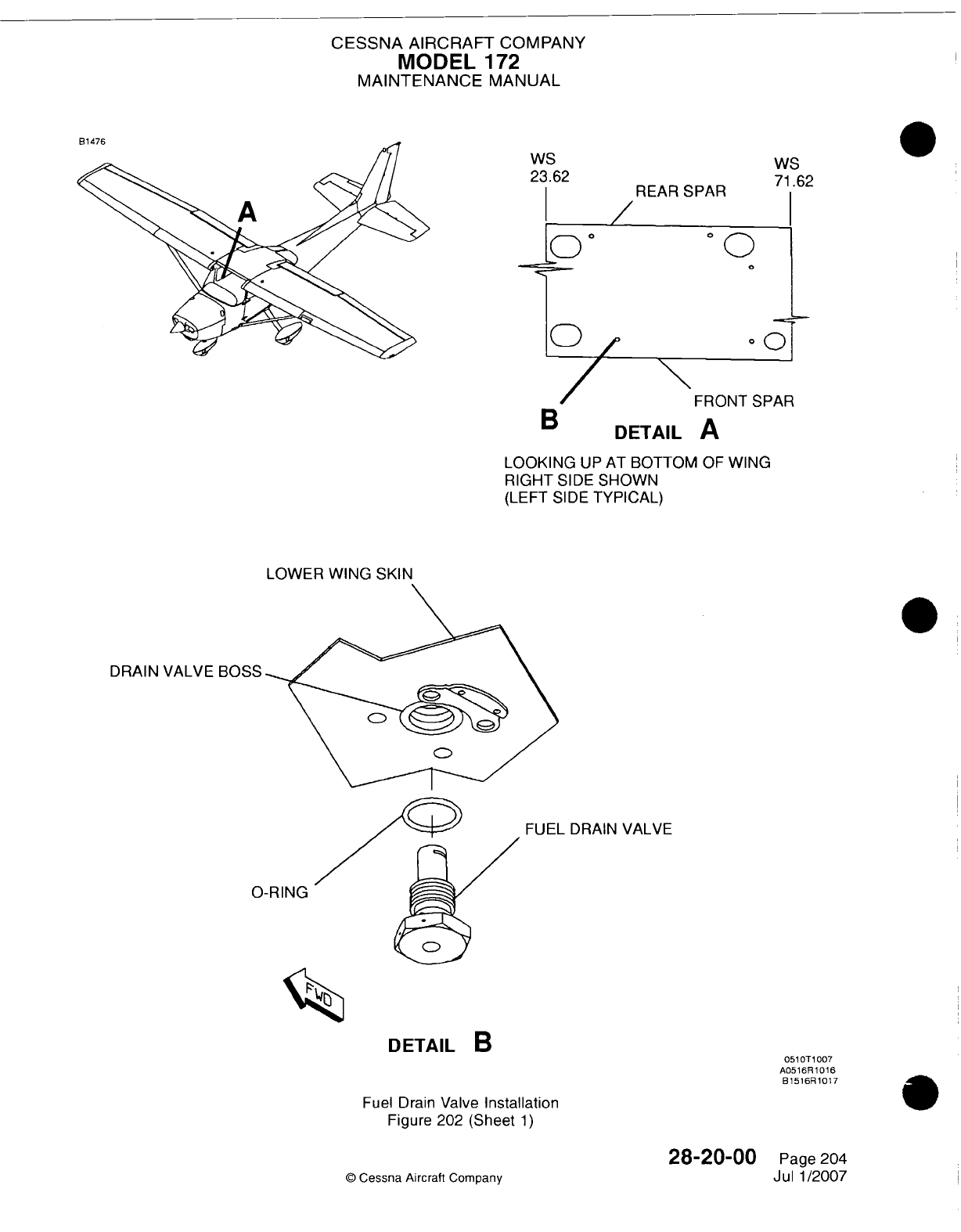
CESSNA
AIRCRAFT
COMPANY
MODEL
172
MAINTENANCE
MANUAL
Ws
23.62
Ws
71
r,9
B
DETAIL
A
LOOKING
UP
AT
BOTTOM
OF
WING
RIGHT
SIDE
SHOWN
(LEFT
SIDE
TYPICAL)
LOWER
WING
SKIN
DRAIN
VALVE
BOSS
FUEL
DRAIN
VALVE
0-RING
DETAIL
B
Fuel
Drain
Valve
Installation
Figure 202
(Sheet
1)
28-20-00
©
Cessna Aircraft
Company
051
OT1
007
A0516R
1016
B1516R
1017
Page
204
Jul
1/2007
1-1-
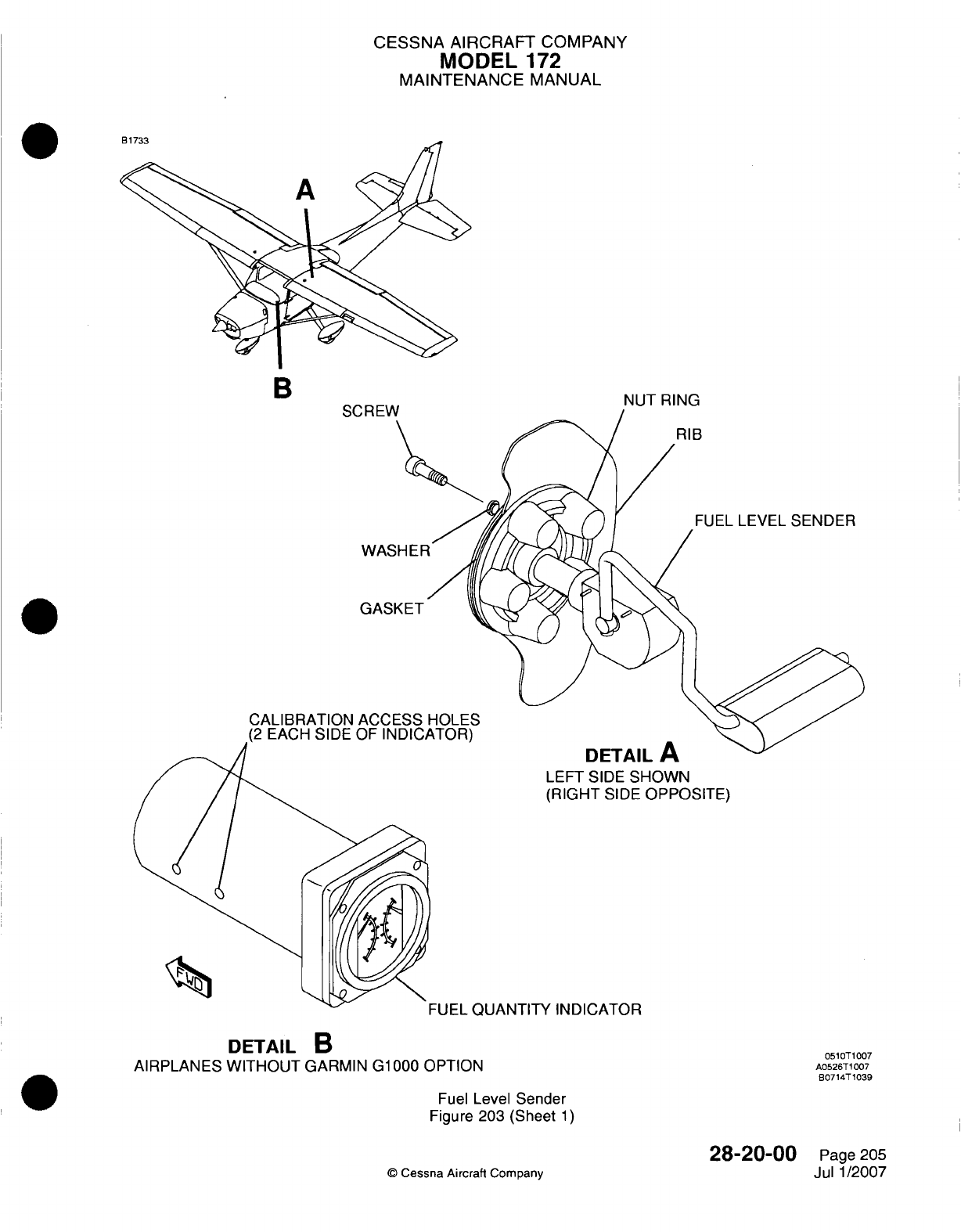
CESSNA
AIRCRAFT
COMPANY
MODEL
172
MAINTENANCE
MANUAL
MII
IT
IK](-,
FUEL
LEVEL SENDER
GASKET
ur-I
AIL-
-
LEFT
SIDE
SHOWN
(RIGHT
SIDE
OPPOSITE)
%I
IAKITriTV
1K~r-ICrA-rn0
DETAIL
B
AIRPLANES
WITHOUT
GARMIN
G1
000
OPTION
Fuel
Level
Sender
Figure
203
(Sheet
1)
©
Cessna
Aircraft Company
28-20-00
Page
205
Jul
1/2007
B
0510T1007
A0526T
1007
B0714T
1039
.11-
I
kjL-L- %aur"11 I I I I
1114Lj1%ar%
I %-II
I
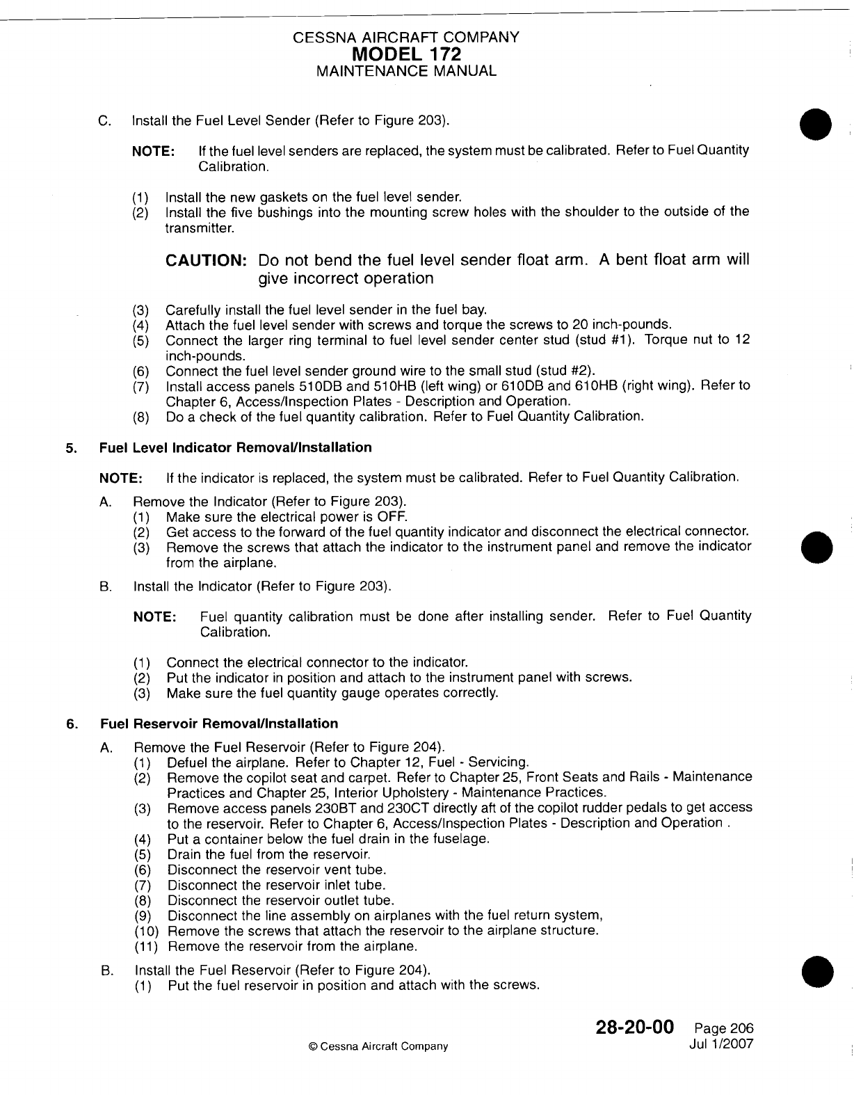
CESSNA
AIRCRAFT
COMPANY
MODEL
172
MAINTENANCE
MANUAL
C.
Install
the
Fuel
Level
Sender
(Refer
to
Figure 203).
NOTE:
If
the fuel
level
senders
are
replaced,
the
system
must
be
calibrated.
Refer
to
Fuel
Quantity
Calibration.
(1)
Install
the
new
gaskets
on
the
fuel level sender.
(2)
Install
the five bushings
into the
mounting screw
holes
with the
shoulder
to
the
outside
of
the
transmitter.
CAUTION:
Do
not
bend
the
fuel
level
sender float
arm.
A
bent
float
arm
will
give
incorrect
operation
(3)
Carefully
install
the fuel
level
sender
in
the fuel bay.
(4)
Attach the fuel
level
sender
with
screws
and
torque
the
screws
to
20
inch-pounds.
(5)
Connect
the
larger
ring
terminal
to
fuel
level
sender
center
stud
(stud
#1).
Torque
nut
to
12
inch-pounds.
(6)
Connect
the
fuel
level
sender
ground
wire
to
the
small
stud
(stud
#2).
(7)
Install
access
panels
510ODB
and
51
OHB
(left
wing)
or
610ODB
and
61
0HB
(right
wing).
Refer
to
Chapter
6,
Access/Inspection
Plates
-
Description
and
Operation.
(8)
Do
a
check
of
the
fuel
quantity calibration.
Refer
to
Fuel
Quantity
Calibration.
5.
Fuel
Level
Indicator Removal/installation
NOTE:
If
the
indicator
is
replaced,
the
system
must
be
calibrated.
Refer
to
Fuel
Quantity
Calibration.
A.
Remove
the
Indicator
(Refer
to
Figure 203).
(1)
Make
sure
the
electrical
power
is
OFF.
(2)
Get
access
to
the
forward
of
the
fuel
quantity indicator
and
disconnect
the
electrical
connector.
(3)
Remove
the
screws
that
attach the
indicator
to
the
instrument panel
and
remove
the
indicator
from
the
airplane.
B.
Install
the
Indicator
(Refer to
Figure
203).
NOTE:
Fuel
quantity
calibration
must
be
done
after
installing
sender.
Refer
to
Fuel
Quantity
Cal
ib
ration.
(1)
Connect
the
electrical
connector
to
the
indicator.
(2)
Put
the
indicator
in
position
and
attach
to
the
instrument
panel
with
screws.
(3)
Make
sure
the fuel
quantity
gauge
operates
correctly.
6.
Fuel
Reservoir
Removal/installation
A.
Remove
the
Fuel
Reservoir
(Refer
to
Figure 204).
(1)
Defuel
the
airplane.
Refer
to
Chapter
12,
Fuel
-
Servicing.
(2)
Remove
the
copilot
seat
and
carpet. Refer
to
Chapter
25,
Front
Seats
and
Rails
-
Maintenance
Practices
and
Chapter
25,
Interior
Upholstery
-
Maintenance Practices.
(3)
Remove
access
panels
230BT
and
230CT
directly
aft
of
the
copilot
rudder pedals
to
get
access
to
the
reservoir.
Refer
to
Chapter
6,
Access/inspection
Plates
-
Description
and
Operation .
(4)
Put
a
container
below
the
fuel drain
in
the
fuselage.
(5)
Drain
the
fuel from
the reservoir.
(6)
Disconnect
the
reservoir
vent
tube.
(7)
Disconnect
the
reservoir inlet
tube.
(8)
Disconnect
the
reservoir
outlet
tube.
(9)
Disconnect
the
line
assembly
on
airplanes
with
the
fuel
return
system,
(1 0)
Remove
the
screws
that attach
the
reservoir
to
the
airplane
structure.
(1 1)
Remove
the
reservoir
from
the
airplane.
B.
Install
the
Fuel
Reservoir
(Refer
to
Figure
204).
(1)
Put
the
fuel reservoir
in
position
and
attach
with
the screws.
28-20-00
Page 206
©
Cessna
Aircraft
Company
Jul 1/2007
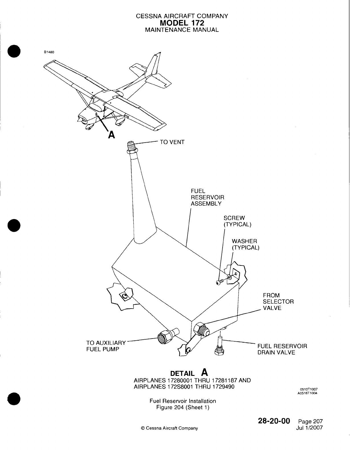
CESSNA
AIRCRAFT
COMPANY
MODEL
172
MAINTENANCE
MANUAL
FROM
SELECTOR
VALVE
JEL
RESERVOIR
RAIN
VALVE
DETAIL
A
AIRPLANES
17280001
THRU
17281187
AND
AIRPLANES
172S8001
THRU
1729490
01T10
A0516T
1004
Fuel
Reservoir Installation
Figure
204
(Sheet
1)
©
Cessna
Aircraft
Company
28-20-00
Page
207
Jul
1/2007
TO
AU)
FUEL
P
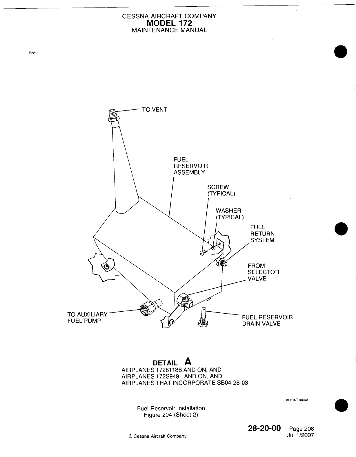
CESSNA
AIRCRAFT
COMPANY
MODEL
172
MAINTENANCE
MANUAL
0
FUEL
RETURN
SYSTEM
-ROM
3ELECTOR
/ALVE
EL
RESERVOIR
1AIN
VALVE
DETAIL
A
AIRPLANES 17281188
AND
ON,
AND
AIRPLANES
172S9491 AND
ON,
AND
AIRPLANES
THAT INCORPORATE
SB04-28-03
A0516T1004A
Fuel
Reservoir
Installation
Figure 204
(Sheet
2)
28-20-00
©
Cessna
Aircraft
Company
83811
TO
FUE
Page
208
Jul
1/2007
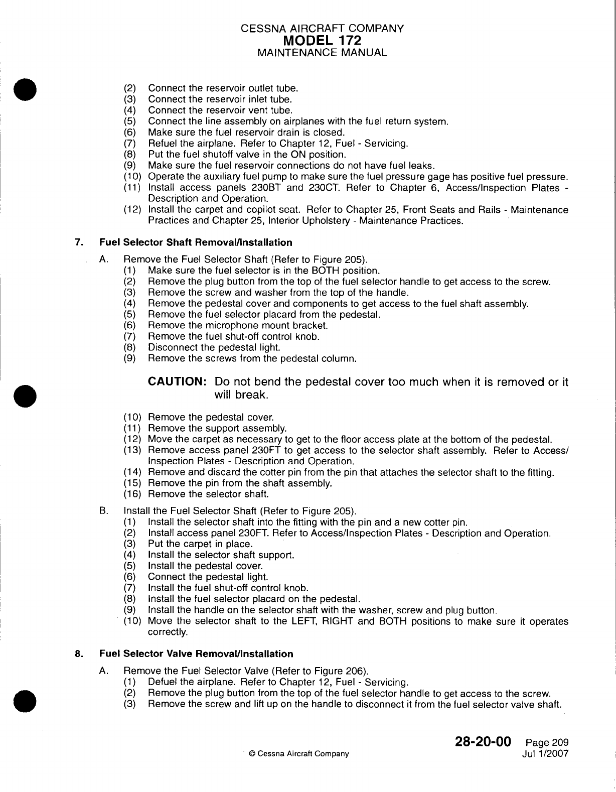
CESSNA AIRCRAFT
COMPANY
MODEL
172
MAINTENANCE
MANUAL
(2)
Connect
the
reservoir
outlet
tube.
(3)
Connect
the
reservoir
inlet tube.
(4)
Connect
the
reservoir
vent
tube.
(5)
Connect
the
line
assembly
on
airplanes
with the
fuel
return
system.
(6)
Make sure
the
fuel
reservoir
drain
is
closed.
(7)
Refuel
the
airplane.
Refer
to
Chapter
12,
Fuel
-
Servicing.
(8)
Put
the
fuel
shutoff valve
in
the ON
position.
(9)
Make
sure the
fuel
reservoir
connections
do
not
have
fuel
leaks.
(1 0)
Operate
the
auxiliary
fuel pump
to
make
sure the
fuel pressure
gage
has
positive
fuel
pressure.
(11)
Install
access
panels
230BT
and
230CT.
Refer
to
Chapter
6,
Access/Inspection
Plates
-
Description
and
Operation.
(12)
Install
the
carpet
and
copilot
seat. Refer
to
Chapter
25,
Front
Seats
and
Rails
-
Maintenance
Practices
and
Chapter
25,
Interior
Upholstery
-
Maintenance
Practices.
7.
Fuel
Selector
Shaft
Removal/installation
A.
Remove
the
Fuel
Selector
Shaft (Refer
to
Figure
205).
(1)
Make sure
the
fuel
selector
is in
the
BOTH
position.
(2)
Remove
the
plug
button
from
the
top
of
the
fuel
selector
handle
to
get
access
to
the
screw.
(3)
Remove
the
screw
and
washer
from
the
top
of
the handle.
(4)
Remove
the
pedestal
cover
and
components
to
get
access
to
the
fuel
shaft
assembly.
(5)
Remove
the fuel
selector
placard
from
the
pedestal.
(6)
Remove
the
microphone
mount
bracket.
(7)
Remove
the fuel
shut-off
control
knob.
(8)
Disconnect the pedestal
light.
(9)
Remove
the
screws
from the
pedestal
column.
CAUTION:
Do
not
bend
the
pedestal
cover
too
much
when
it is
removed
or
it
will break.
(1
0)
Remove
the
pedestal
cover.
(11)
Remove the
support assembly.
(12)
Move the
carpet
as
necessary
to
get
to
the
floor access
plate
at
the
bottom
of
the
pedestal.
(13)
Remove
access
panel
230FT
to
get
access
to
the
selector
shaft
assembly. Refer
to
Access!
Inspection
Plates
-
Description
and
Operation.
(14)
Remove
and
discard
the
cotter
pin
from the
pin
that attaches
the
selector shaft
to
the
fitting.
(15)
Remove
the
pin
from
the shaft
assembly.
(16)
Remove
the
selector
shaft.
B.
Install the
Fuel
Selector
Shaft
(Refer
to
Figure 205).
(1)
Install
the
selector
shaft
into
the
fitting
with the pin
and
a
new
cotter
pin.
(2)
Install
access
panel
230FT. Refer
to
Access/Inspection
Plates
-
Description
and
Operation.
(3)
Put
the
carpet
in
place.
(4)
Install
the
selector
shaft support.
(5)
Install
the
pedestal
cover.
(6)
Connect
the
pedestal
light.
(7)
Install the
fuel
shut-off
control
knob.
(8)
Install
the fuel
selector
placard
on
the
pedestal.
(9)
Install
the
handle
on
the
selector
shaft
with
the
washer,
screw
and
plug
button.
(1
0)
Move
the
selector
shaft
to
the
LEFT,
RIGHT
and
BOTH
positions
to
make
sure
it
operates
correctly.
8.
Fuel
Selector
Valve
Removal/installation
A.
Remove
the
Fuel
Selector
Valve
(Refer
to
Figure
206).
(1)
Defuel the
airplane.
Refer
to
Chapter
12,
Fuel
-
Servicing.
(2)
Remove
the
plug
button
from
the
top
of
the
fuel
selector
handle
to
get
access
to
the
screw.
(3)
Remove
the
screw
and
lift
up on
the
handle
to
disconnect
it
from
the
fuel
selector valve
shaft.
28-20-00
Page
209
©
Cessna Aircraft
Company
Jul
1
/2007
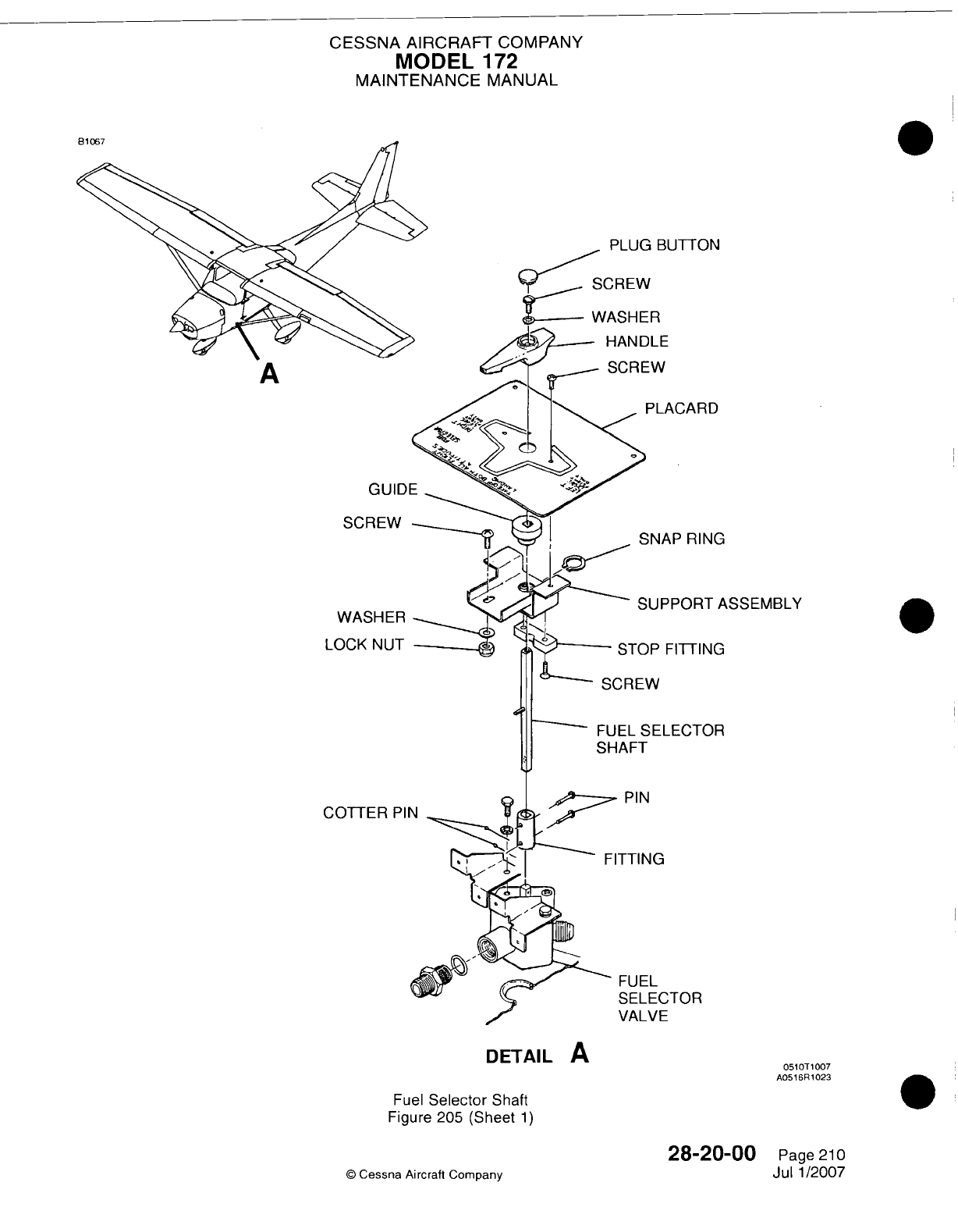
CESSNA
AIRCRAFT
COMPANY
MODEL
172
MAINTENANCE
MANUAL
PLUG BUTTON
)LE
PLACARD
;NAP
RING
UPPORT
ASSEMBLY
iP
FITTING
'ELECTOR
JiG
ECTOR
VE
Fuel
Selector
Shaft
Figure
205 (Sheet
1)
28-20-00
(D
Cessna
Aircraft
Company
A
SCI`
WAII
LOCK
COTT
I
DETAIL
A
0510T
1007
A0516R
1023
Page
21
0
Jul
1/2007
r
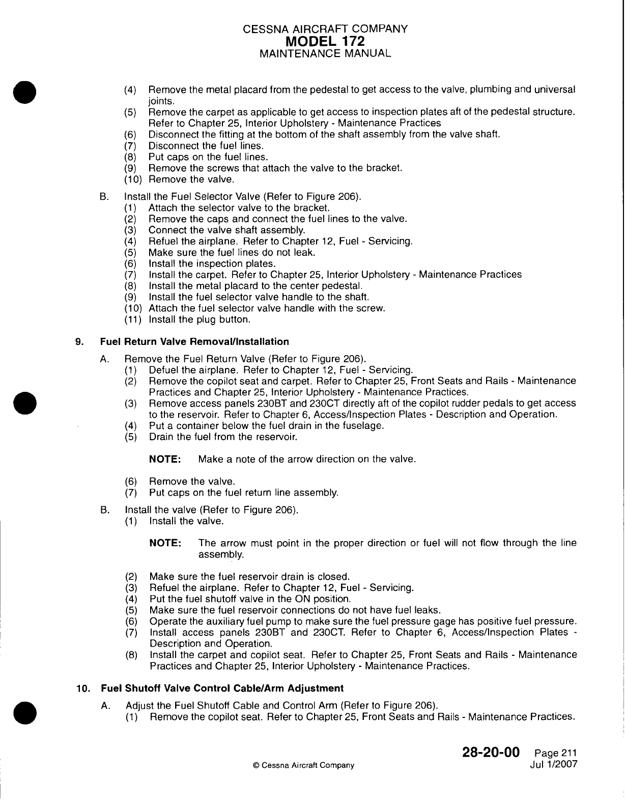
CESSNA
AIRCRAFT
COMPANY
MODEL
172
MAINTENANCE
MANUAL
(4)
Remove
the
metal
placard
from
the
pedestal
to
get
access
to
the
valve,
plumbing
and
universal
joints.
(5)
Remove
the
carpet
as
applicable
to
get
access
to
inspection plates
aft
of
the
pedestal structure.
Refer
to
Chapter
25,
Interior
Upholstery
-
Maintenance
Practices
(6)
Disconnect
the
fitting
at
the
bottom
of
the
shaft
assembly
from the
valve
shaft.
(7)
Disconnect
the
fuel
lines.
(8)
Put
caps
on
the
fuel
lines.
(9)
Remove
the
screws
that
attach the
valve
to the
bracket.
(110)
Remove
the
valve.
B.
Install
the
Fuel
Selector
Valve
(Refer
to
Figure
206).
(1)
Attach
the
selector
valve
to
the
bracket.
(2)
Remove
the
caps
and
connect
the fuel
lines
to
the valve.
(3)
Connect
the
valve
shaft
assembly.
(4)
Refuel
the
airplane.
Refer
to
Chapter
12,
Fuel
-
Servicing.
(5)
Make
sure
the
fuel lines
do
not
leak.
(6)
Install
the
inspection
plates.
(7)
Install the
carpet.
Refer
to
Chapter
25,
Interior
Upholstery
-
Maintenance
Practices
(8)
Install
the
metal
placard
to
the
center
pedestal.
(9)
Install
the fuel
selector
valve
handle
to
the
shaft.
(1 0)
Attach
the
fuel
selector
valve handle
with
the screw.
(11)
Install the
plug
button.
9.
Fuel
Return
Valve
Removal/installation
A.
Remove the
Fuel
Return
Valve
(Refer
to
Figure
206).
(1)
Defuel
the
airplane.
Refer
to
Chapter
12,
Fuel
-
Servicing.
(2)
Remove
the
copilot
seat
and
carpet.
Refer
to
Chapter
25,
Front
Seats
and
Rails
-
Maintenance
Practices
and
Chapter
25,
Interior
Upholstery
-
Maintenance
Practices.
(3)
Remove
access
panels
230BT
and
230CT
directly
aft of
the
copilot
rudder
pedals
to
get
access
to
the
reservoir.
Refer
to
Chapter
6,
Access/Inspection
Plates
-
Description and
Operation.
(4)
Put
a
container
below
the
fuel
drain
in
the
fuselage.
(5)
Drain
the
fuel
from
the
reservoir.
NOTE:
Make
a note
of
the
arrow
direction
on
the
valve.
(6)
Remove
the
valve.
(7)
Put
caps
on
the
fuel
return line
assembly.
B.
Install the
valve
(Refer
to
Figure
206).
(1)
Install
the
valve.
NOTE:
The arrow
must
point
in
the
proper
direction
or
fuel
will
not
flow through
the
line
assembly.
(2)
Make
sure
the
fuel reservoir
drain
is
closed.
(3)
Refuel
the
airplane.
Refer
to
Chapter
12,
Fuel
-
Servicing.
(4)
Put
the
fuel
shutoff
valve
in
the
ON
position.
(5)
Make sure
the
fuel
reservoir
connections
do
not
have
fuel
leaks.
(6)
Operate
the
auxiliary
fuel
pump
to
make
sure the
fuel
pressure
gage
has
positive
fuel
pressure.
(7)
Install access panels
230BT
and
230CT.
Refer
to
Chapter
6,
Access/inspection
Plates
-
Description
and Operation.
(8)
Install
the
carpet
and
copilot
seat. Refer
to
Chapter
25,
Front
Seats
and
Rails
-
Maintenance
Practices
and
Chapter
25,
Interior Upholstery
-
Maintenance
Practices.
10. Fuel
Shutoff
Valve
Control
Cable/Arm
Adjustment
A.
Adjust
the
Fuel
Shutoff
Cable
and
Control
Arm
(Refer
to
Figure 206).
(1)
Remove
the
copilot
seat.
Refer
to
Chapter
25,
Front
Seats
and
Rails
-
Maintenance Practices.
28-20-00
Page
211
0
Cessna Aircraft
Company
Jul
1/2007
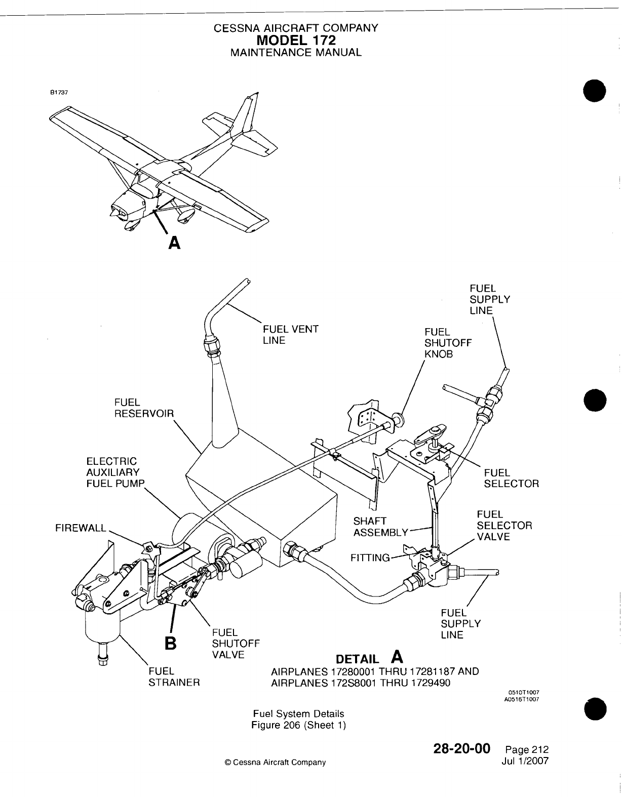
CESSNA AIRCRAFT
COMPANY
MODEL
172
MAINTENANCE
MANUAL
LINE
FUEL
RESERVOIR
N
ELECTRIC
AUXILIARY
FUEL
PUMP
I
FUEL
B
SHUITOFF
VALVE
AIRPLANES
17280001
THRU
17281187
ANE
AIRPLANES
172S8001
THRU
1729490
)
5O10
A051
0T1007
Fuel
System Details
Figure
206
(Sheet
1)
28-20-00
©
Cessna Aircraft
Company
.CTOR
TOR
FUEL
STRAINER
FUEL
SUIPPL
LINE
0
Page
212
Jul 1/2007
----
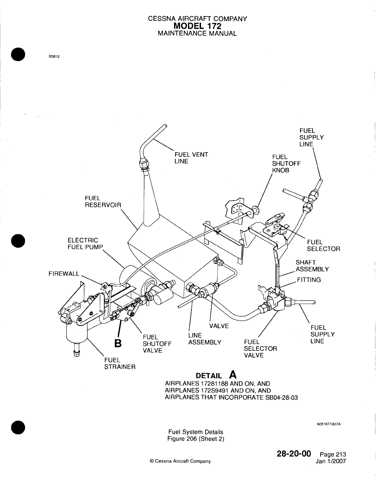
CESSNA AIRCRAFT
COMPANY
MODEL
172
MAINTENANCE
MANUAL
B3812
FUEL
SUPPLY
FUEL VENT
LINE
FUEL
FUEL
ELECTRIC
FUEL PUMP
FIR
FIT
VALVE
I
FUEL
B
SHUTOFF
VALVE
LINE
ASSEMBLY
FUEL
STRAINER
FUEL
SELECTOR
VALVE
DETAIL
A
AIRPLANES
17281188
AND
ON,
AND
AIRPLANES
172S9491
AND ON,
AND
AIRPLANES
THAT
INCORPORATE SB04-28-03
A0516T1007A
Fuel
System
Details
Figure
206
(Sheet
2)
28-20-00
©
Cessna
Aircraft
Company
FOR
-Y
Page
213
Janl1/2007
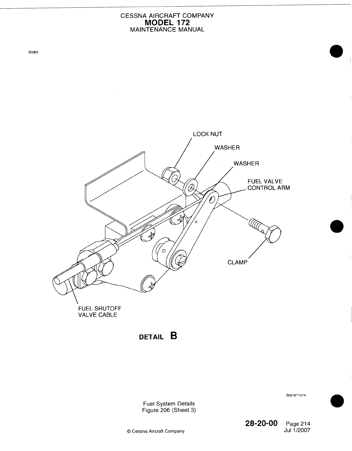
CESSNA
AIRCRAFT
COMPANY
MODEL
172
MAINTENANCE
MANUAL
B3263
LOCK
NUT
RM
CLAMP
FUEL
SHUTOFF
VALVE
CABLE
DETAIL
B
B016T
10
14
Fuel
System Details
Figure
206
(Sheet
3)
28-20-00
©
Cessna
Aircraft
Company
Page
214
Jul
1/2007
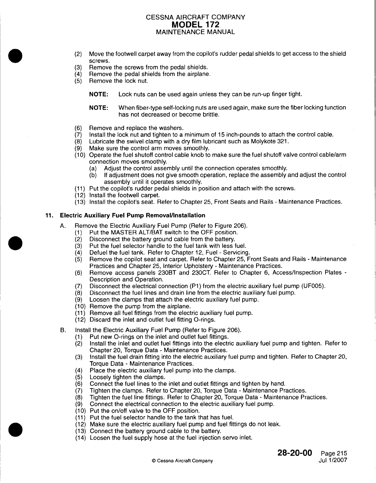
CESSNA
AIRCRAFT
COMPANY
MODEL
172
MAINTENANCE
MANUAL
(2)
Move
the
footwell
carpet away
from
the
copilot's
rudder
pedal
shields
to
get
access
to
the
shield
screws.
(3)
Remove
the
screws
from
the
pedal
shields.
(4)
Remove
the pedal
shields
from the
airplane.
(5)
Remove
the
lock
nut.
NOTE:
Lock
nuts
can
be
used again unless
they
can
be
run-up
finger
tight.
NOTE:
When
fiber-type self-locking
nuts are
used
again, make
sure
the
fiber
locking function
has
not
decreased
or
become
brittle.
(6)
Remove
and
replace
the
washers.
(7)
Install
the
lock
nut
and
tighten
to
a
minimum
of
15
inch-pounds
to
attach
the
control
cable.
(8)
Lubricate the swivel
clamp
with
a
dry
film
lubricant such
as
Molykote
321.
(9)
Make sure
the
control
arm
moves
smoothly.
(1 0)
Operate
the fuel
shutoff
control
cable
knob
to
make
sure
the
fuel shutoff
valve
control
cable/arm
connection
moves
smoothly.
(a)
Adjust
the
control
assembly
until
the
connection
operates
smoothly.
(b) If
adjustment
does
not
give smooth
operation, replace
the
assembly
and adjust
the
control
assembly
until
it
operates smoothly.
(1 1)
Put
the
copilot's
rudder
pedal
shields
in
position
and
attach
with
the
screws.
(12)
Install the
footwell
carpet.
(13)
Install
the
copilot's
seat.
Refer
to
Chapter
25,
Front
Seats
and
Rails
-
Maintenance
Practices.
11.
Electric
Auxiliary
Fuel
Pump
Removal/installation
A.
Remove
the
Electric
Auxiliary
Fuel
Pump
(Refer
to
Figure
206).
(1)
Put
the
MASTER
ALT/BAT
switch
to
the
OFF
position.
(2)
Disconnect
the
battery
ground
cable
from
the battery.
(3)
Put
the
fuel
selector
handle
to
the fuel
tank
with
less fuel.
(4)
Defuel the
fuel
tank.
Refer
to
Chapter
12,
Fuel
-
Servicing.
(5)
Remove
the
copilot
seat
and
carpet.
Refer
to
Chapter
25,
Front
Seats
and
Rails
-
Maintenance
Practices
and
Chapter
25,
Interior
Upholstery
-
Maintenance
Practices.
(6)
Remove
access
panels 230BT
and
230CT.
Refer to
Chapter
6,
Access/Inspection
Plates
-
Description
and Operation.
(7)
Disconnect
the
electrical
connection
(P1)
from
the
electric
auxiliary
fuel
pump
(UIFOO5).
(8)
Disconnect
the
fuel
lines
and drain
line
from
the
electric
auxiliary
fuel
pump.
(9)
Loosen
the
clamps
that
attach
the
electric
auxiliary
fuel
pump.
(1
0)
Remove
the pump from
the
airplane.
(1 1)
Remove
all
fuel
fittings
from the
electric auxiliary
fuel
pump.
(12)
Discard
the inlet and
outlet
fuel
fitting
0-rings.
B.
Install
the Electric
Auxiliary
Fuel
Pump
(Refer
to
Figure
206).
(1)
Put
new
0-rings
on
the
inlet
and
outlet
fuel
fittings.
(2)
Install
the
inlet
and
outlet
fuel
fittings
into
the
electric
auxiliary
fuel
pump
and
tighten.
Refer to
Chapter
20,
Torque
Data
-
Maintenance
Practices.
(3)
Install
the
fuel
drain
fitting
into the
electric
auxiliary
fuel pump and tighten.
Refer
to
Chapter
20,
Torque Data
-
Maintenance
Practices.
(4)
Place the
electric auxiliary
fuel
pump
into
the
clamps.
(5)
Loosely
tighten
the
clamps.
(6)
Connect
the
fuel lines
to
the
inlet
and
outlet
fittings
and
tighten
by
hand.
(7)
Tighten the
clamps.
Refer
to
Chapter
20,
Torque Data
-
Maintenance Practices.
(8)
Tighten
the
fuel
line
fittings.
Refer
to
Chapter
20,
Torque
Data
-
Maintenance
Practices.
(9)
Connect
the
electrical
connection
to
the
electric
auxiliary
fuel
pump.
(1
0) Put
the
on/off
valve
to
the
OFF
position.
(1 1)
Put the
fuel
selector
handle
to
the
tank
that
has
fuel.
(12)
Make
sure
the
electric auxiliary
fuel
pump
and
fuel
fittings
do
not
leak.
(13)
Connect
the
battery
ground
cable
to
the
battery.
(14)
Loosen
the
fuel
supply
hose
at
the
fuel
injection
servo
inlet.
28-20-00
Page
215
Q
Cessna
Aircraft
Company
Jul
1/2007
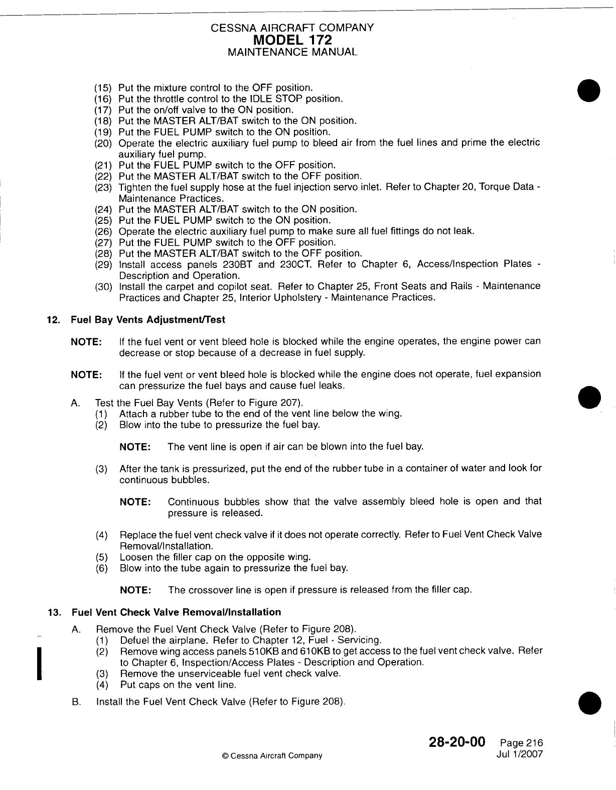
CESSNA
AIRCRAFT
COMPANY
MODEL
172
MAINTENANCE
MANUAL
(15)
Put the
mixture control
to
the
OFF position.
(16)
Put
the
throttle
control
to the
IDLE
STOP
position.
(17)
Put
the
on/off
valve
to
the
ON
position.
(18)
Put
the MASTER
ALT/BAT
switch
to
the
ON
position.
(19)
Put
the FUEL
PUMP
switch
to
the
ON
position.
(20)
Operate
the
electric
auxiliary
fuel pump
to
bleed
air
from
the fuel
lines
and
prime
the
electric
auxiliary
fuel
pump.
(21)
Put the FUEL
PUMP
switch
to
the
OFF
position.
(22)
Put the
MASTER
ALT/BAT
switch
to
the
OFF
position.
(23)
Tighten
the
fuel
supply
hose
at
the fuel
injection
servo
inlet.
Refer
to
Chapter
20,
Torque
Data
-
Maintenance
Practices.
(24)
Put
the
MASTER
ALT/BAT
switch
to the
ON
position.
(25)
Put the FUEL
PUMP
switch
to
the
ON
position.
(26)
Operate
the
electric
auxiliary
fuel
pump
to
make
sure
all
fuel
fittings
do
not
leak.
(27) Put
the
FUEL
PUMP
switch
to
the
OFF
position.
(28)
Put the
MASTER
ALT/BAT
switch
to
the
OFF
position.
(29)
Install
access
panels 230BT
and
230CT.
Refer
to
Chapter
6,
Access/Inspection
Plates
-
Description
and
Operation.
(30)
Install
the
carpet
and
copilot
seat. Refer
to
Chapter
25,
Front Seats
and
Rails
-
Maintenance
Practices
and
Chapter
25,
Interior
Upholstery
-
Maintenance Practices.
12.
Fuel
Bay Vents
Adjustment/Test
NOTE:
If
the fuel
vent
or
vent
bleed
hole
is
blocked
while
the
engine operates,
the
engine
power
can
decrease
or
stop
because
of
a
decrease
in
fuel
supply.
NOTE:
If
the fuel
vent
or
vent bleed
hole
is
blocked while
the
engine does
not
operate,
fuel
expansion
can
pressurize
the
fuel
bays
and
cause
fuel
leaks.
A. Test
the Fuel
Bay
Vents
(Refer
to
Figure 207).
(1)
Attach
a
rubber
tube
to
the
end
of
the
vent
line
below
the
wing.
(2)
Blow
into
the
tube
to
pressurize
the fuel
bay.
NOTE:
The
vent
line
is
open
if
air
can
be
blown
into
the
fuel
bay.
(3)
After
the
tank
is
pressurized,
put the
end
of
the
rubber tube
in a
container
of
water
and
look
for
continuous
bubbles.
NOTE:
Continuous
bubbles show
that
the
valve assembly
bleed hole
is
open
and
that
pressure
is
released.
(4)
Replace
the
fuel vent
check
valve
if it
does
not
operate
correctly.
Refer
to
Fuel
Vent
Check
Valve
Removal/Installation.
(5)
Loosen
the
filler
cap
on
the
opposite
wing.
(6)
Blow
into the
tube
again
to
pressurize
the
fuel
bay.
NOTE:
The
crossover
line
is
open
if
pressure
is
released
from
the
filler
cap.
13.
Fuel
Vent
Check
Valve
Removal/installation
A.
Remove
the
Fuel
Vent
Check
Valve
(Refer
to
Figure 208).
(1)
Defuel the
airplane.
Refer
to
Chapter
12,
Fuel
-
Servicing.
(2)
Remove
wing
access
panels
5l0KB
and
6l0KBto
get
access
to
the fuel
vent
check
valve.
Refer
to
Chapter
6,
Inspection/Access
Plates
-
Description
and
Operation.
(3)
Remove
the
unserviceable
fuel
vent
check
valve.
(4)
Put
caps
on
the
vent
line.
B.
Install
the
Fuel
Vent
Check
Valve
(Refer
to
Figure
208).
28-20-00
Page
216
©
Cessna
Aircraft
Company
Jul
1/2007
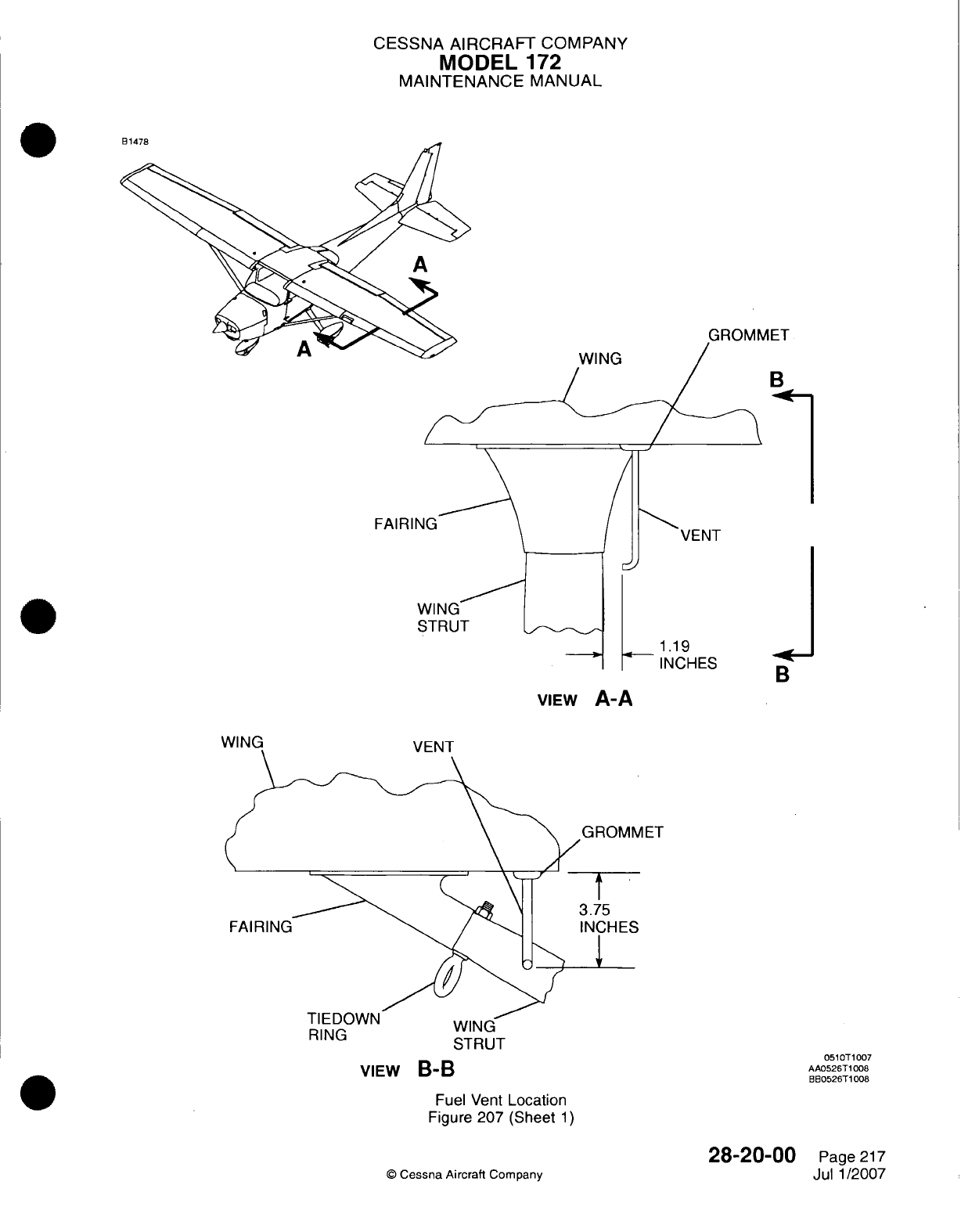
CESSNA
AIRCRAIFT
COMPANY
MODEL
172
MAINTENANCE
MANUAL
GROMMET
FAIR
I
VIEw
A-A
I ET
RING ~~~~~~~vviI,,mu
RING
~STRUT
Fuel Vent
Location
Figure
207
(Sheet
1)
©
Cessna
Aircraft
Company
-*I
B
VIEw
B-B
051
0T1007
AA0526TI1008
H830526T1
008
28-20-00
Page
217
Jul 1/2007
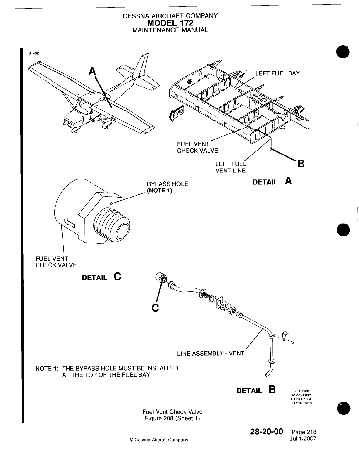
CESSNA AIRCRAFT
COMPANY
MODEL
172
MAINTENANCE
MANUAL
LEFT
FUEL
VENT
LINE
BYPASS
HOLE
(NOTE
1)
DETAIL
A
0
FUEL
VENT
CHECK
VALVE
DETAIL
C
(
LINE
ASSEMBLY
-
VENT
NOTE
1:
THE
BYPASS
HOLE
MUST
BE
11\N':
AT THE
TOP
OF
THE FUEL
BAY.
Fuel
Vent
Check
Valve
Figure
208
(Sheet
1)
28-20-00
C
Cessna
Aircraft
Company
DETAIL
B
05lOT
1007
A1226R
1001
B1226R11004
C0516T1015
Page
218
Jul 1/2007
CESSNA
AIRCRAFT
COMPANY
MODEL
172
MAINTENANCE
MANUAL
WARNING:
You
must
correctly
align
the fuel
vent line
below
the
wing
near the
wing
strut
to
prevent
icing of
the
vent
tube.
WARNING:
You
must
correct
any
fuel
vent
component
that
is
blocked
or
restricted
before
the
airplane returns
to
service.
(1)
Remove
the
caps
from
the vent
line.
NOTE:
The
fuel
vent
check
valve
bypass
hole
on
the
valve
flap
must
be
at
the top
of
the
fuel
bay.
(2)
Install
the
new fuel
vent
check
valve
with
the bypass
hole
on
the
valve flap
at
the top
of
the
fuel
bay.
(3)
Install the
wing
access
panels.
(4)
Do
a
test
to make
sure
the fuel
vent
check
valve operates correctly.
Refer
to
Fuel
Bay
Vents
Adjustment/Test.
(5)
Refuel
the
airplane
and
make
sure
there are
no
leaks.
(6)
Make
sure
the
fuel
vent
line
below the
wing
is
correctly
aligned.
Refer
to
Figure 207.
114.
Vented
Fuel
Filler
Cap
Inspection
A.
Do
an
Inspection
of
the
Vented
Fuel
Filler
Cap
(Refer
to
Figure 209).
(1)
Remove
the
vented
fuel
filler
cap
from the
adapter
assembly.
(2)
Disconnect the
safety
chain
(if
installed).
(3)
Put
a
cover
on the
tank
opening.
(4)
Do
a
check
of
the
gasket
and
frictionless
washer.
(5)
Replace
the
gasket
and
frictionless washer
as
required.
B.
Clean
the
rubber
umbrella.
(1)
Use
cotton swabs
and
solvent
to
gently
lift
the
edges
of
the rubber
umbrella
and
to
clean
the
seat
and
the umbrella.
(2)
Use
a
second
swab
to
wipe
the
seat
and
umbrella
thoroughly
to
remove
cotton
particles.
(3)
Clean
the
rubber umbrella
and
seat
until
the
swabs show
no
discoloration.
C.
Replace
the umbrella
if it
leaks
fuel
or
has
deterioration.
(1)
To
remove
the umbrella,
lubricate
the
umbrella
stem
with
hydraulic
fluid (MIL-PRF-5606)
to
prevent damage
to
the
stem.
(2)
To
install
the
new
umbrella, lubricate the
stem
with
hydraulic fluid (MIL-PRF-5606)
and
use
a
small
blunt
tool
to
insert
the
retaining knob
on
the
umbrella
into
the
check valve
body.
D.
Connect
the fuel
cap
to
safety
chain
(if
installed)
and
install
the
cap
in
the
adapter
assembly.
15.
Fuel
Strainer
Disassembly/Cleaning/Assembly
A.
Disassemble
and
Clean
the
Fuel
Strainer
(Refer
to
Figure 210).
(1)
Put
the
fuel
selector
valve
in
the
off
position.
(2)
Disconnect
and
remove
the
safety
wire,
nut,
and
washer
at
the
bottom
of
the
filter
bowl.
(3)
Remove
the
bowl.
(4)
Carefully
remove
the standpipe.
(5)
Remove
the
filter
screen
and
gasket.
(6)
Wash
the
filter
screen
and
bowl
in
solvent.
(7)
Dry
the
filter
screen
with
compressed
air.
B.
Assemble
the
Fuel
Strainer
(Refer
to
Figure
21
0).
(1)
Install
a
new
gasket
between
the
filter
screen
and
top
assembly.
(2)
Install
the
screen.
28-20-00
Page
219
©
Cessna Aircraft Company
Jul
1/2007
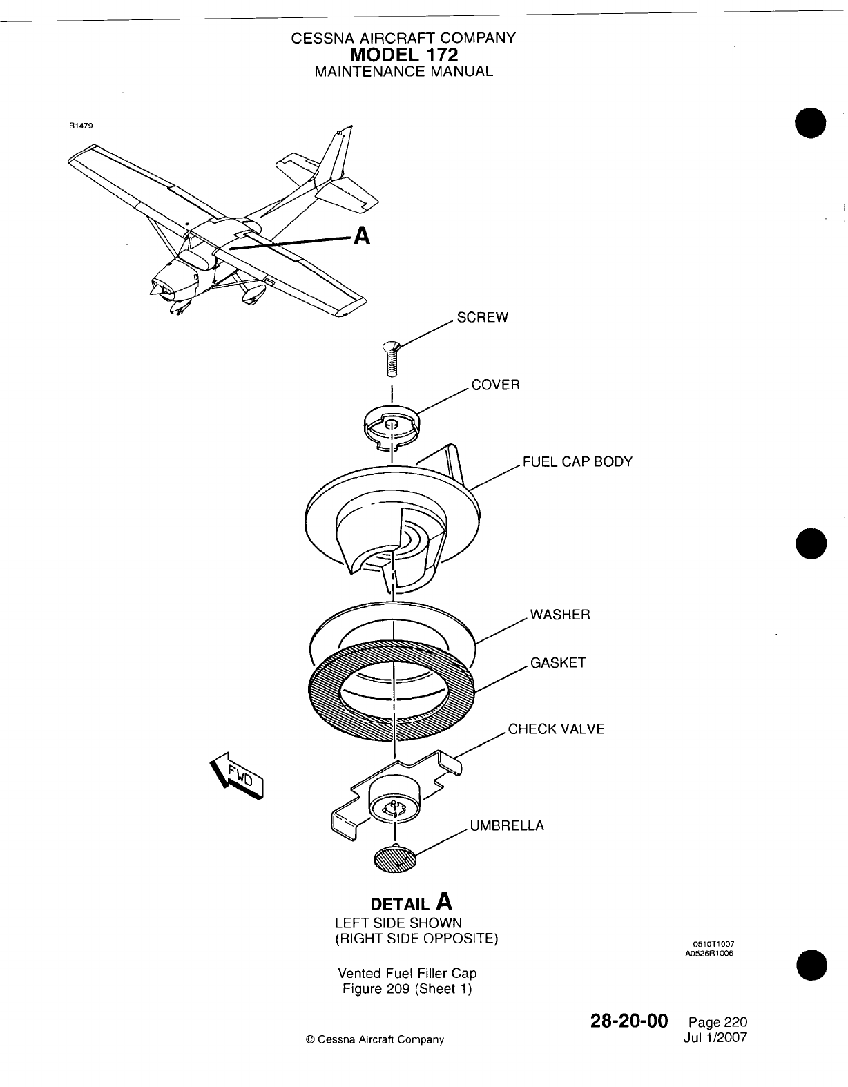
CESSNA
AIRCRAFT
COMPANY
MODEL
172
MAINTENANCE
MANUAL
SCREW
=-L
CAP
BODY
ASHER
fkSKET
'K
VALVE
DETAIL
A
LEFT
SIDE SHOWN
(RIGHT
SIDE
OPPOSITE)
Vented
Fuel
Filler
Cap
Figure 209
(Sheet
1)
28-20-00
©
Cessna Aircraft
Company
051 OT1
007
A0526R
1006
Page
220
Jul
1/2007
lIfINVICM
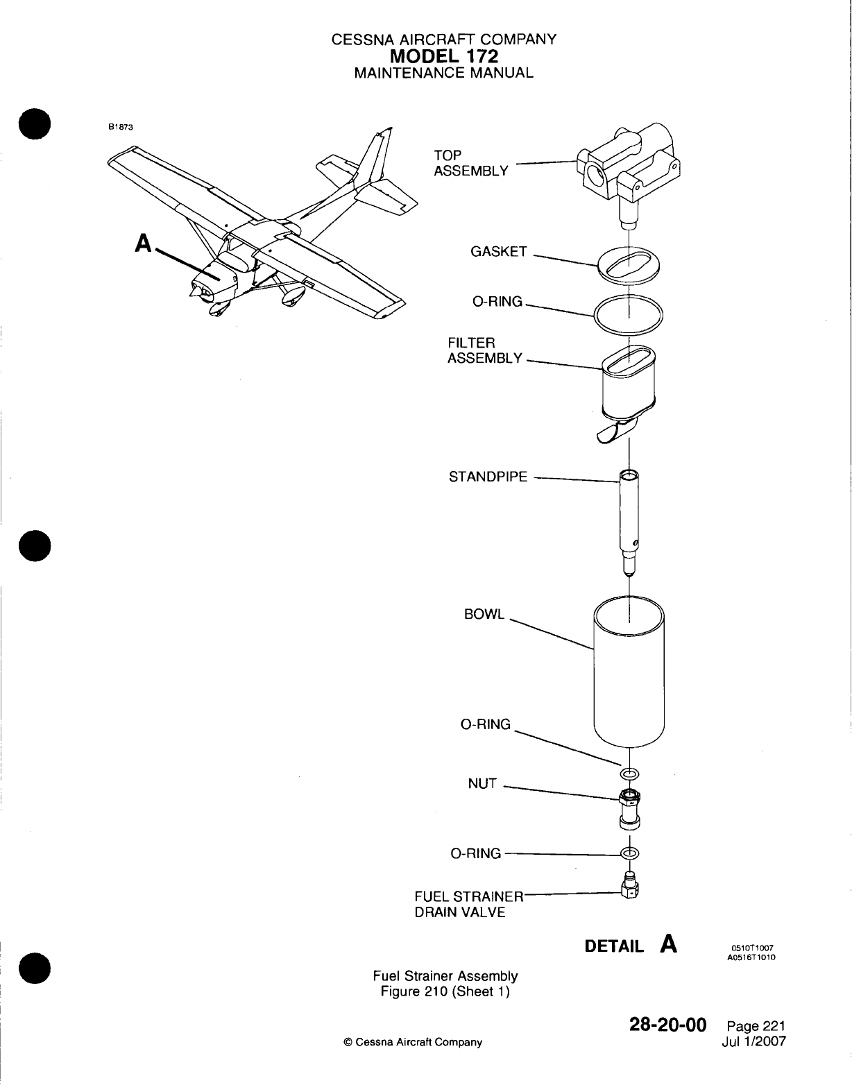
CESSNA
AIRCRAFT
COMPANY
MODEL
172
MAINTENANCE
MANUAL
TOP
ASSEMBL'
GAS
0-RI
FILTER
ASSEME
STANDF
BOWI.
0-RIN'
NUT
0-RING
FUEL
STRAINER
DRAIN
VALVE
DETAIL
A
051071
1007
A0516T
10
1
Fuel
Strainer
Assembly
Figure
210
(Sheet
1)
C
Cessna Aircraft
Company
28-20-00
Page
221
Jul
1/2007
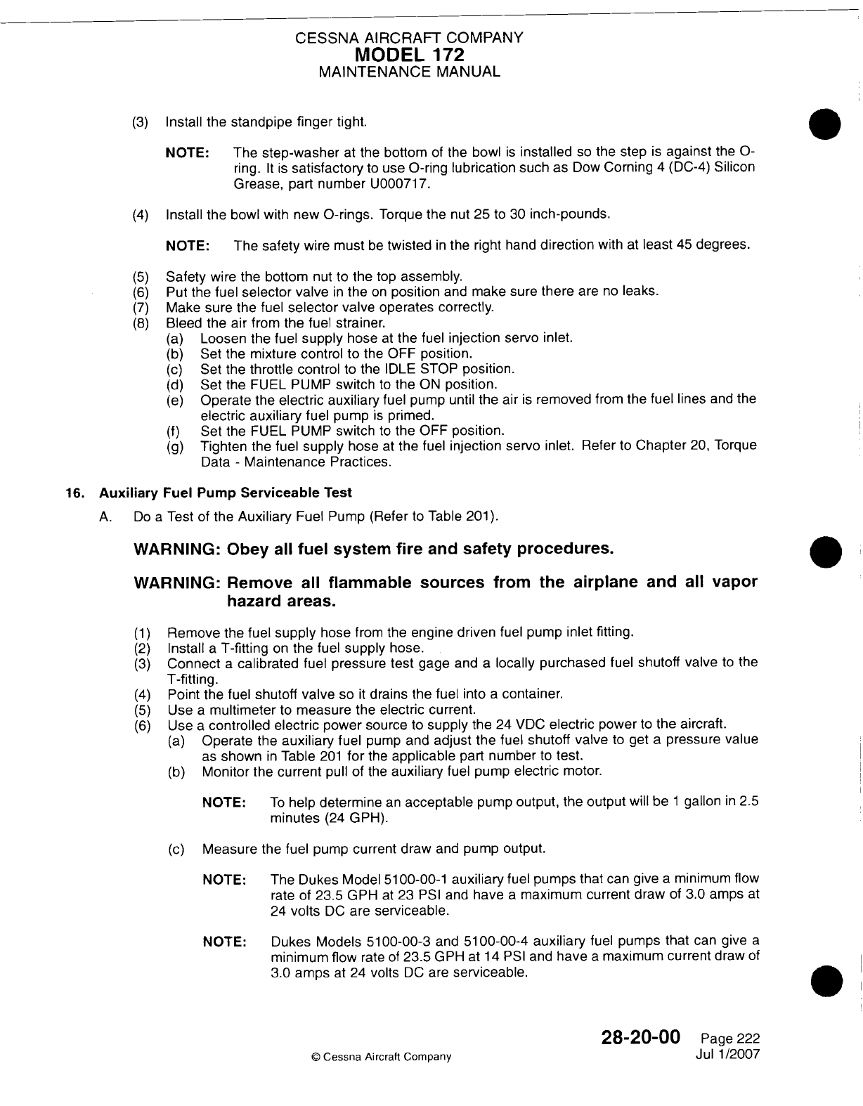
CESSNA
AIRCRAFT
COMPANY
MODEL
172
MAINTENANCE
MANUAL
(3)
Install the
standpipe
finger
tight.
NOTE:
The
step-washer
at
the
bottom
of
the bowl
is
installed
so
the step
is
against
the
0-
ring.
It is
satisfactory
to
use
0-ring
lubrication
such
as
Dow
Corning
4
(DC-4)
Silicon
Grease,
part
number
U000717.
(4)
Install
the
bowl with
new
0-rings.
Torque
the
nut
25
to 30
inch-pounds.
NOTE:
The
safety
wire
must
be
twisted
in
the
right
hand
direction
with
at
least
45
degrees.
(5)
Safety
wire
the
bottom
nut
to
the
top
assembly.
(6)
Put the
fuel
selector
valve
in
the
on
position
and
make sure
there
are
no
leaks.
(7)
Make
sure
the
fuel
selector
valve
operates correctly.
(8)
Bleed
the
air
from
the fuel
strainer.
(a)
Loosen
the fuel
supply
hose
at
the fuel
injection
servo
inlet.
(b)
Set
the
mixture
control
to
the
OFF
position.
(c)
Set
the
throttle control
to the
IDLE
STOP
position.
(d)
Set
the
FUEL PUMP
switch
to
the
ON
position.
(e)
Operate
the
electric
auxiliary
fuel
pump
until
the air
is
removed
from
the fuel
lines
and
the
electric
auxiliary
fuel
pump
is
primed.
(f)
Set
the
FUEL PUMP
switch
to
the
OFF
position.
(g)
Tighten
the fuel
supply
hose
at
the fuel
injection
servo
inlet. Refer
to
Chapter
20,
Torque
Data
-
Maintenance
Practices.
16.
Auxiliary
Fuel
Pump
Serviceable
Test
A.
Do
a
Test
of
the
Auxiliary
Fuel
Pump (Refer
to
Table
201).
WARNING:
Obey
all
fuel
system
fire
and
safety procedures.
WARNING:
Remove
all
flammable
sources
from
the airplane
and
all
vapor
hazard
areas.
(1)
Remove
the
fuel
supply
hose
from
the
engine driven
fuel
pump
inlet fitting.
(2)
Install
a
T-fitting
on
the
fuel
supply
hose.
(3)
Connect
a
calibrated
fuel
pressure
test
gage
and
a
locally purchased
fuel
shutoff valve
to the
T-fitting.
(4)
Point
the fuel
shutoff
valve
so
it
drains
the
fuel
into
a
container.
(5)
Use
a
multimeter
to
measure
the
electric
current.
(6)
Use
a
controlled electric
power source
to
supply
the
24
VDC
electric
power
to
the
aircraft.
(a)
Operate
the
auxiliary
fuel
pump
and
adjust
the fuel
shutoff
valve
to
get
a
pressure
value
as
shown
in
Table
201
for
the
applicable
part
number
to
test.
(b)
Monitor the current
pull of the
auxiliary
fuel
pump
electric
motor.
NOTE:
To
help
determine
an
acceptable
pump
output,
the
output
will
be
1
gallon
in 2.5
minutes
(24
GPH).
(c)
Measure
the fuel
pump
current
draw
and
pump
output.
NOTE: The
Dukes
Model
51
00-00-1
auxiliary
fuel
pumps
that
can
give
a
minimum flow
rate
of
23.5
GPH
at
23
PSI
and
have
a
maximum current
draw
of
3.0
amps
at
24
volts
DC
are
serviceable.
NOTE: Dukes
Models
51
00-00-3
and
51
00-00-4
auxiliary
fuel pumps
that
can
give
a
minimum flow
rate
of
23.5
GPH
at 14
PSI
and
have
a
maximum current
draw
of
3.0
amps
at
24
volts
DC
are
serviceable.
28-2000
Page
222
©
Cessna
Aircraft
Company
Jul
1/2007
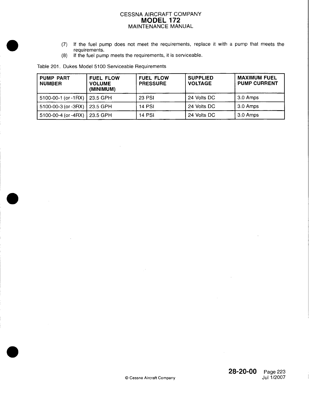
CESSNA
AIRCRAFT
COMPANY
MODEL
172
MAINTENANCE
MANUAL
(7) If
the
fuel
pump does
not meet the
requirements,
replace
it
with
a
pump that
meets
the
requirements.
(8) If
the
fuel
pump
meets
the
requirements,
it is
serviceable.
Table
201.
Dukes
Model
5100
Serviceable
Requirements
PUMP PART
FUEL FLOW
FUEL
FLOW
SUPPLIED
MAXIMUM
FUEL
NUMBER
VOLUME
PRESSURE VOLTAGE
PUMP
CURRENT
____ ____ ____
(M
INIM
UM
) _ _ _ _ _ _
_
5100-00-1
(or -1RX)
23.5
GPH
23
PSI
24 Volts
DC
3.0
Amps
5100-00-3
(or
-3RX)
23.5
GPH
14
PSI
24
Volts
DC
3.0
Amps
51
00-00-4
(or
-4RX)
23.5 GPH
14
PSI
24 Volts
DC
3.0
Amps
©
Cessna Aircraft
Company
28-20-00
Page
223
Jul
1/2007
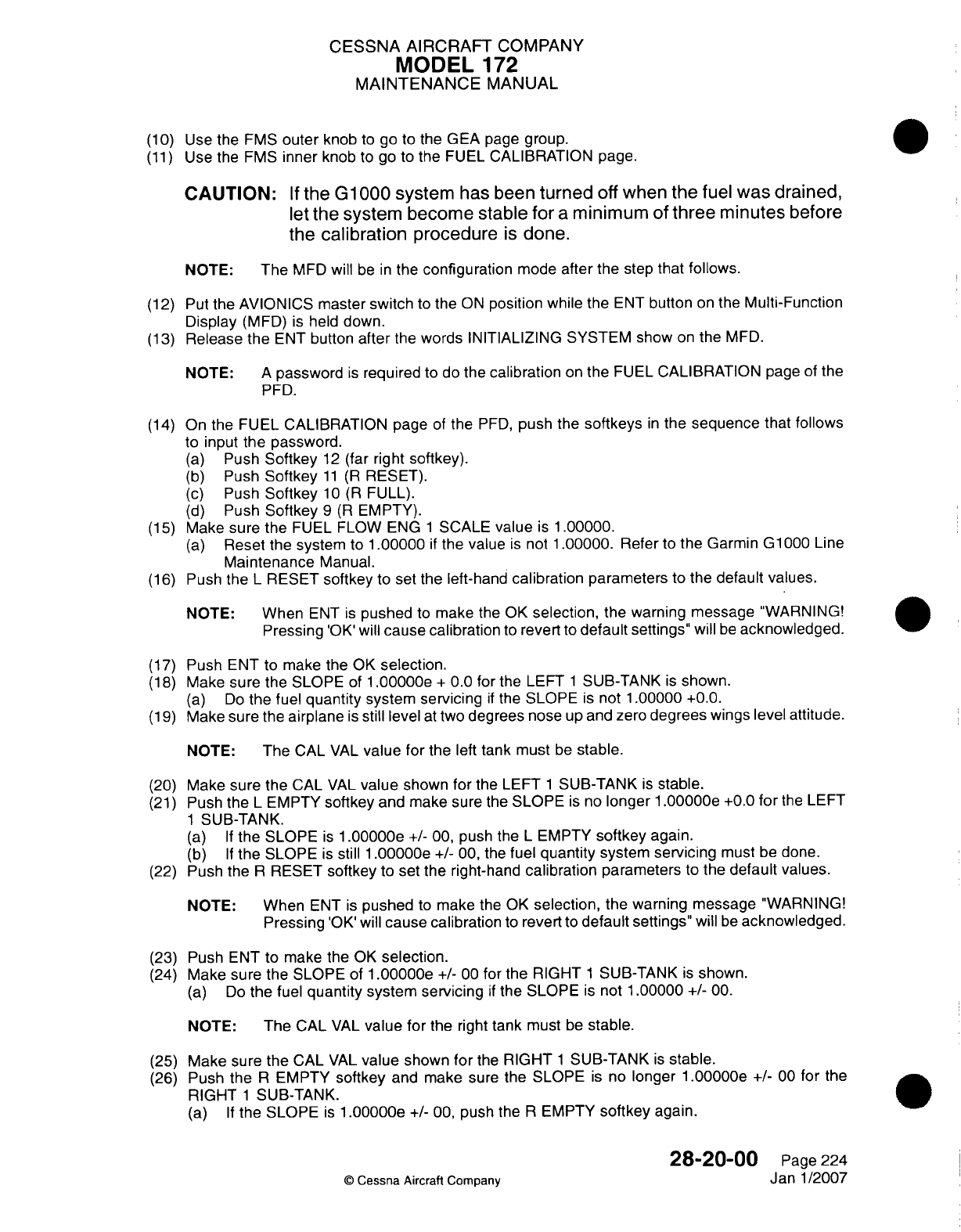
CESSNA AIRCRAFT
COMPANY
MODEL
172
MAINTENANCE
MANUAL
(10)
Use
the
EMS
outer
knob
to
go
to
the GEA
page
group.
(11)
Use the
EMS
inner
knob
to
go
to
the
FUEL
CALIBRATION
page.
CAUTION:
If
the
Gl
000system
has been
turned
off
when
the
fuel
was
drained,
let
the
system become
stable
for
a
minimum
of
three
minutes
before
the
calibration
procedure
is
done.
NOTE:
The
MFD will
be
in
the
configuration
mode
after
the step
that
follows.
(12)
Put
the AVIONICS master
switch
to
the
ON
position
while
the
ENT
button
on
the
Multi-Function
Display
(MFD)
is
held
down.
(13)
Release the
ENT
button
after
the
words
INITIALIZING
SYSTEM
show
on
the
MED.
NOTE:
A
password
is
required
to
do
the
calibration
on
the
FUEL
CALIBRATION
page
of
the
FED.
(14)
On
the
FUEL
CALIBRATION
page
of
the
FED,
push
the
softkeys
in
the
sequence
that
follows
to input
the
password.
(a)
Push
Softkey
12
(far
right
softkey).
(b)
Push
Softkey
11
(R
RESET).
(c)
Push
Softkey
10
(R
FULL).
(d)
Push
Softkey
9 (R
EMPTY).
(15)
Make
sure
the
FUEL
FLOW
ENG
1
SCALE
value
is 1
.00000.
(a)
Reset
the
system
to
1
.00000
if
the value
is
not
1
.00000. Refer
to
the
Garmin
G1
000
Line
Maintenance
Manual.
(16)
Push the
L
RESET
softkey
to
set
the left-hand
calibration
parameters
to
the
default
values.
NOTE:
When
ENT
is
pushed
to
make
the OK
selection,
the
warning message
"WARNING!
Pressing'OK'will
cause
calibration
to
revert
to
default
settings"
will
be
acknowledged.
(17)
Push ENT
to
make
the OK
selection.
(18)
Make
sure
the
SLOPE
of
1
.00000e
+
0.0
for
the LEFT
1
SUB-TANK
is
shown.
(a)
Do
the
fuel
quantity
system
servicing
if
the
SLOPE
is
not
1
.00000
+0.0.
(19)
Make
sure
the
airplane
is
still level
at
two
degrees nose
up
and zero
degrees
wings
level
attitude.
NOTE:
The
CAL
VAL
value
for
the
left
tank
must
be
stable.
(20)
Make
sure
the
CAL
VAL
value
shown
for
the
LEFT
1
SUB-TANK
is
stable.
(21)
Push
the
L
EMPTY
softkey
and
make
sure
the
SLOPE
is
no
longer
1
.00000e
+0.0
for
the LEFT
1
SUB-TANK.
(a) If
the
SLOPE
is 1
.00000e
+/-
00,
push
the
L
EMPTY
softkey
again.
(b) If
the
SLOPE
is
still
1
.00000e
+/-
00,
the
fuel
quantity system
servicing
must
be
done.
(22)
Push
the
R
RESET
softkey
to
set
the
right-hand
calibration
parameters
to the
default
values.
NOTE:
When
ENT
is
pushed
to
make
the
OK
selection,
the warning message
"WARNING!
Pressing
'OK'will
cause
calibration
to
revert
to
default
settings"
will
be
acknowledged.
(23)
Push
ENT
to
make
the
OK
selection.
(24)
Make sure
the
SLOPE
of
1
.00000e
+/-
00
for
the
RIGHT
1
SUB-TANK
is
shown.
(a)
Do
the
fuel
quantity system servicing
if
the
SLOPE
is
not
1.00000
+/-
00.
NOTE:
The
CAL
VAL
value for
the
right
tank
must
be
stable.
(25)
Make sure the
CAL
VAL
value shown
for
the
RIGHT
1
SUB-TANK
is
stable.
(26)
Push
the
R
EMPTY
softkey
and
make
sure
the SLOPE
is
no
longer
1
.00000e
+/-
00
for
the
RIGHT
1
SUB-TANK.0
(a) If
the
SLOPE
is 1
.00000e
+1-
00,
push
the
R
EMPTY
softkey
again.
28-20-00
Page
224
©
Cessna
Aircraft
Company
Janl1/2007
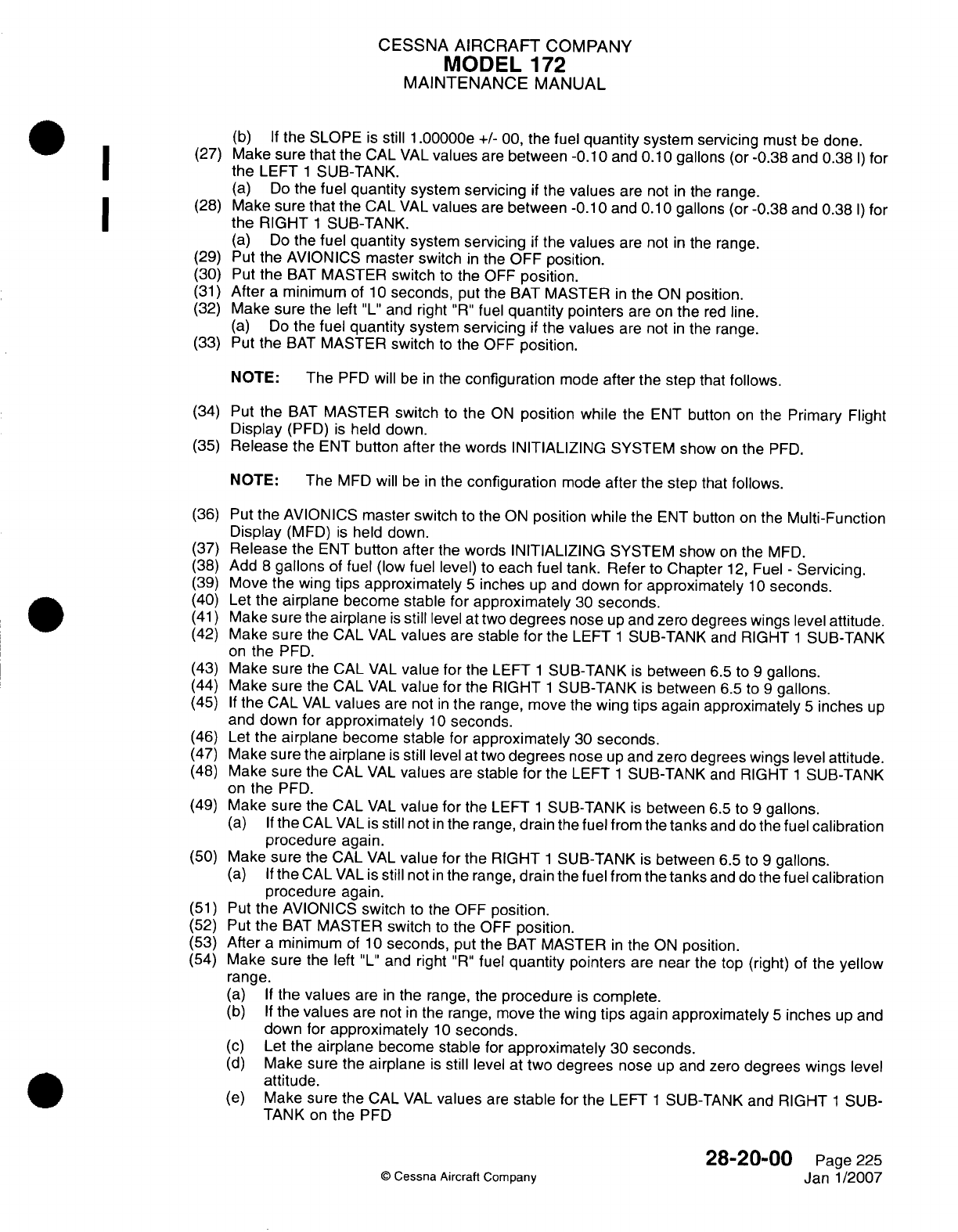
CESSNA
AIRCRAFT
COMPANY
MODEL
172
MAINTENANCE
MANUAL
(b) If
the
SLOPE
is
still
1
.00000e
+/-
00, the
fuel
quantity system
servicing
must
be
done.
@
1
~ ~~~~(27)
Make sure
that
the
CAL
VAL
values
are
between
-0.1
0
and
0.1
0
gallons
(or
-0.38
and
0.38
I)
for
(a)
Do
the
fuel
quantity
system
servicing
if
the
values
are not
in
the
range.
(28)
Make sure
that
the
CAL
VAL
values
are
between
-0.1
0
and
0.1
0
gallons
(or
-0.38 and 0.38
I)
for
I ~ ~~the
RIGHT
1
SUB-TANK.
(a)
Do
the
fuel
quantity
system
servicing
if
the
values
are not
in
the
range.
(29)
Put the
AVIONICS
master switch
in
the
OFF
position.
(30)
Put
the
BAT
MASTER
switch
to
the
OFF
position.
(31)
After
a
minimum
of
1
0
seconds,
put
the
BAT
MASTER
in
the
ON
position.
(32)
Make
sure
the left
"L"
and
right
"R"
fuel
quantity pointers
are
on
the
red
line.
(a)
Do
the
fuel
quantity
system
servicing
if
the
values
are
not
in
the
range.
(33)
Put
the
BAT
MASTER
switch
to
the OFF
position.
NOTE:
The
PFD
will
be
in
the
configuration
mode
after the
step
that
follows.
(34) Put
the
BAT
MASTER
switch
to
the
ON
position
while
the
ENT
button
on
the
Primary
Flight
Display
(PFD)
is
held
down.
(35)
Release
the
ENT
button
after
the
words
INITIALIZING
SYSTEM
show
on
the
PFD.
NOTE:
The
MFD
will
be
in
the
configuration
mode
after
the step that
follows.
(36)
Put the
AVIONICS
master
switch
to
the
ON
position while
the ENT
button
on
the
Multi-Function
Display
(MFD)
is
held
down.
(37)
Release
the
ENT
button
after
the
words
INITIALIZING
SYSTEM
show
on
the
MFD.
(38)
Add
8
gallons
of
fuel
(low
fuel
level)
to
each
fuel
tank.
Refer
to
Chapter
12,
Fuel
-
Servicing.
(39)
Move
the
wing
tips
approximately
5
inches
up
and
down
for
approximately
1
0
seconds.
(40)
Let
the
airplane
become stable
for
approximately
30
seconds.
(41)
Make sure the
airplane
is
still
level
at
two
degrees
nose
up
and
zero degrees
wings
level
attitude.
(42)
Make
sure
the
CAL
VAL
values
are
stable
for
the
LEFT
1
SUB-TANK
and
RIGHT
1
SUB-TANK
on
the
PFD.
(43)
Make sure
the CAL
VAL
value
for
the
LEFT
1
SUB-TANK
is
between
6.5
to
9
gallons.
(44)
Make
sure
the
CAL
VAL
value
for
the
RIGHT
1
SUB-TANK
is
between
6.5
to
9
gallons.
(45)
If
the
CAL
VAL
values
are
not
in
the
range,
move
the
wing tips
again
approximately
5
inches
up
and
down
for
approximately
1 0
seconds.
(46) Let the
airplane
become stable
for
approximately
30
seconds.
(47)
Make sure
the
airplane
is
still
level
at
two
degrees
nose
up
and
zero
degrees wings
level
attitude.
(48)
Make sure the
CAL
VAL
values
are
stable for
the LEFT
1
SUB-TANK
and
RIGHT
1
SUB-TANK
on
the
PFD.
(49)
Make
sure
the
CAL
VAL
value
for
the
LEFT
1
SUB-TANK
is
between
6.5
to
9
gallons.
(a) If
the
CAL
VAL
is
still
not
in
the
range,
drain
the
fuel
from
the
tanks
and
do
the
fuel
calibration
procedure
again.
(50)
Make sure the
CAL
VAL
value
for
the
RIGHT
1
SUB-TANK
is
between
6.5
to
9
gallons.
(a) If
the
CAL
VAL
is
still
not
in
the
range,
drain
the
fuel
from
the
tanks
and
do
the
fuel
calibration
procedure again.
(51)
Put
the
AVIONICS
switch
to the OFF
position.
(52) Put
the
BAT
MASTER
switch
to
the OFF
position.
(53)
After
a
minimum
of
10
seconds,
put
the
BAT
MASTER
in
the
ON
position.
(54)
Make
sure
the
left
"L"
and right
"R"
fuel
quantity
pointers
are
near
the
top
(right)
of
the
yellow
range.
(a) If
the
values
are
in
the
range, the
procedure
is
complete.
(b) If
the
values
are
not
in
the
range, move the
wing
tips
again
approximately
5
inches
up
and
down
for
approximately
10
seconds.
(c)
Let
the
airplane
become stable
for
approximately
30
seconds.
(d)
Make
sure
the
airplane
is
still
level
at
two
degrees
nose
up
and
zero
degrees
wings
level
attitude.
(e)
Make sure
the CAL
VAL
values
are
stable
for
the
LEFT
1
SUB-TANK and
RIGHT
1
SUB-
28-20-00
Page
225
Janl/2007
Q
Cessna
Aircraft
Company
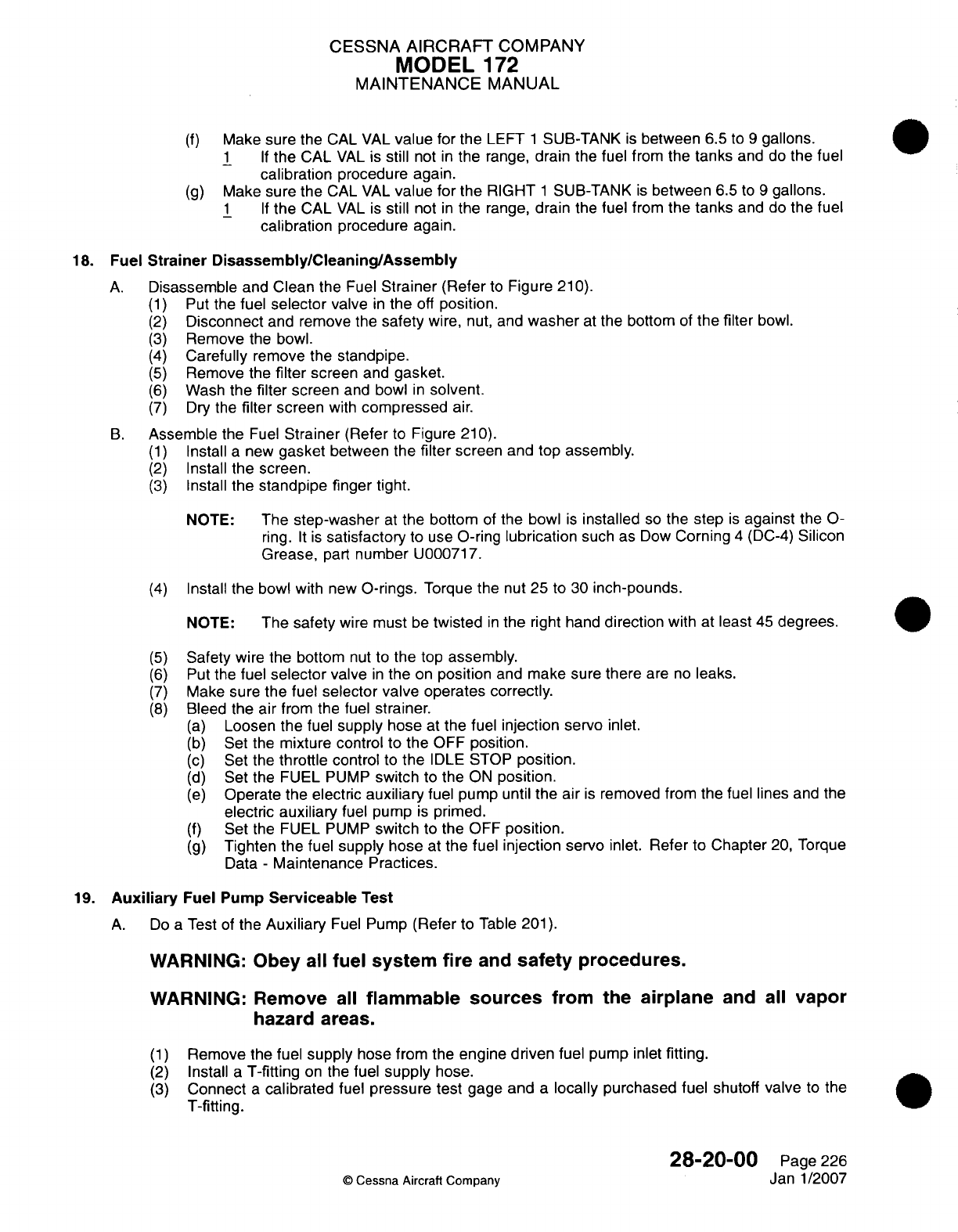
CESSNA
AIRCRAFT
COMPANY
MODEL
172
MAINTENANCE
MANUAL
(f)
Make
sure
the
CAL VAL
value
for
the
LEFT
1
SUB-TANK
is
between
6.5
to
9
gallons.
1 If
the
CAL
VAL
is
still
not
in
the
range,
drain
the fuel from
the
tanks
and
do
the
fuel
calibration
procedure
again.
(g)
Make sure
the
CAL
VAL
value
for
the
RIGHT
1
SUB-TANK
is
between
6.5
to
9
gallons.
1 If
the
CAL
VAL
is
still
not
in
the
range,
drain
the
fuel
from
the
tanks
and
do the
fuel
calibration
procedure
again.
18.
Fuel
Strainer
Disassembly/CleaninglAssembly
A.
Disassemble
and
Clean
the
Fuel
Strainer
(Refer
to
Figure
21
0).
(1)
Put
the
fuel
selector
valve
in
the
off
position.
(2)
Disconnect
and
remove the
safety
wire,
nut,
and
washer
at
the
bottom
of
the
filter
bowl.
(3)
Remove
the bowl.
(4)
Carefully
remove
the
standpipe.
(5)
Remove
the
filter
screen
and
gasket.
(6)
Wash
the
filter screen
and bowl
in
solvent.
(7)
Dry
the
filter screen
with
compressed
air.
B.
Assemble
the
Fuel
Strainer
(Refer
to
Figure
210).
(1)
Install
a
new
gasket
between
the
filter
screen
and top
assembly.
(2)
Install
the screen.
(3)
Install
the
standpipe finger
tight.
NOTE:
The
step-washer
at
the
bottom
of
the
bowl
is
installed
so
the
step
is
against
the
0-
ring.
It is
satisfactory
to
use
0-ring
lubrication
such
as Dow
Corning
4
(DC-4)
Silicon
Grease,
part
number
U000717.
(4)
Install
the
bowl with
new
0-rings.
Torque the
nut
25
to
30
inch-pounds.
NOTE:
The safety
wire
must
be
twisted
in
the
right hand
direction
with
at
least
45
degrees.
(5)
Safety
wire
the bottom
nut
to
the
top
assembly.
(6)
Put
the
fuel
selector
valve
in
the
on
position
and
make
sure
there
are
no
leaks.
(7)
Make
sure
the fuel
selector
valve
operates correctly.
(8)
Bleed the
air
from the
fuel
strainer.
(a)
Loosen
the
fuel
supply
hose
at
the
fuel
injection
servo
inlet.
(b)
Set the
mixture control
to the OFF
position.
(c)
Set
the
throttle
control
to
the
IDLE
STOP
position.
(d)
Set
the
FUEL
PUMP
switch
to
the
ON
position.
(e)
Operate
the
electric
auxiliary
fuel pump
until
the air
is
removed
from
the fuel
lines
and the
electric
auxiliary
fuel
pump
is
primed.
(f)
Set
the
FUEL
PUMP
switch
to
the
OFF
position.
(g)
Tighten the
fuel
supply
hose
at
the
fuel
injection
servo
inlet.
Refer
to
Chapter
20,
Torque
Data
-
Maintenance Practices.
19.
Auxiliary
Fuel Pump
Serviceable
Test
A.
Do
a
Test
of
the
Auxiliary
Fuel
Pump
(Refer
to Table
201).
WARNING: Obey
all
fuel
system
fire
and
safety
procedures.
WARNING:
Remove
all
flammable
sources
from
the
airplane
and
all
vapor
hazard
areas.
(1)
Remove
the
fuel
supply
hose
from
the
engine driven
fuel pump
inlet
fitting.
(2)
Install
a
T-fitting
on
the fuel
supply
hose.
(3)
Connect
a
calibrated
fuel
pressure
test
gage
and
a
locally purchased fuel
shutoff
valve
to
the
T-fitting.
28-20-00
Page
226
©
Cessna
Aircraft
Company
Janl1/2007
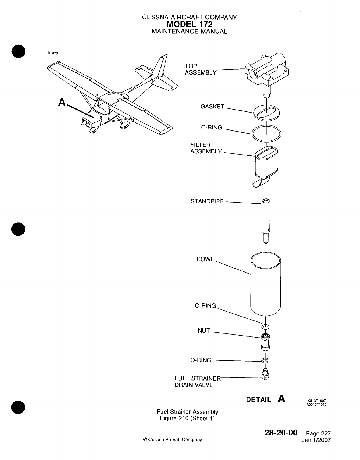
CESSNA AIRCRAFT
COMPANY
MODEL
172
MAINTENANCE
MANUAL
IRI%7q
TO'
A
S,
F
A
S
NUT
0-RING
FUEL
STRAINER
DRAIN VALVE
DETAIL
A
Fuel
Strainer
Assembly
Figure
210
(Sheet
1)
28-20-00
©
Cessna Aircraft
Company
051
0T1007
A0516T
10 10
Page
227
Janl1/2007
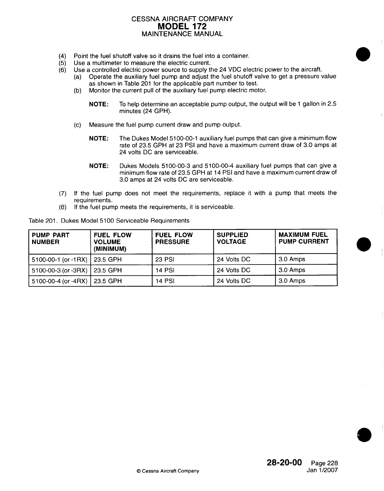
CESSNA
AIRCRAFT
COMPANY
MODEL
172
MAINTENANCE
MANUAL
(4)
Point
the
fuel
shutoff
valve
so
it
drains
the
fuel into
a
container.
(5)
Use
a
multimeter
to
measure
the
electric
current.
(6)
Use
a
controlled
electric power source
to
supply
the
24
VDC
electric
power
to
the
aircraft.
(a)
Operate the
auxiliary
fuel pump
and
adjust the
fuel
shutoff
valve
to
get
a
pressure
value
as
shown
in
Table
201
for
the
applicable
part
number to
test.
(b)
Monitor
the current
pull
of
the
auxiliary
fuel pump
electric
motor.
NOTE:
To
help
determine
an
acceptable
pump
output,
the
output
will
be
1
gallon
in
2.5
minutes
(24
GPH).
(c)
Measure
the
fuel pump
current
draw
and
pump output.
NOTE:
The
Dukes
Model
51
00-00-1
auxiliary
fuel
pumps
that
can
give
a
minimum
flow
rate
of
23.5
GPH
at
23
PSI
and
have
a
maximum
current
draw
of
3.0 amps
at
24
volts
DC
are
serviceable.
NOTE: Dukes
Models
5100-00-3
and
5100-00-4
auxiliary
fuel
pumps
that
can
give
a
minimum
flow
rate
of
23.5
GPH at
14
PSI
and
have
a
maximum
current
draw
of
3.0
amps
at
24
volts
DC
are
serviceable.
(7) If
the
fuel
pump
does
not
meet
the
requirements,
replace
it
with
a
pump
that
meets
the
requirements.
(8) If
the
fuel
pump
meets
the
requirements,
it is
serviceable.
Table
201.
Dukes
Model
5100 Serviceable Requirements
PUMP
PART
FUEL
FLOW
FUEL FLOW
SUPPLIED
MAXIMUM
FUEL
NUMBER
VOLUME
PRESSURE VOLTAGE
PUMP
CURRENT
(MINIMUM)
_ _ _ _ _ _
_
5100-00-1
(or
-lAX)
23.5
GPH
23
PSI
24
Volts
DC
3.0
Amps
5100-00-3
(or
-3RX)
23.5
GPH
14
PSI
24
Volts
DC
3.0
Amps
510000-4(or
-4RX)
23.5
GPH
14
PSI
24
Volts
DC
3.0
Amps
28-20-00
©
Cessna
Aircraft
Company
Page
228
Janl1/2007
CESSNA AIRCRAFT
COMPANY
MODEL
172
MAINTENANCE
MANUAL
FUEL STORAGE AND
DISTRIBUTION
-
ADJUSTMVENT/TEST
1.General
A.
This section
gives
the
adjustment/test procedures
for
the
fuel
storage and
distribution
system.
2.
Fuel
Quantity Calibration
And Check
(Airplanes
without
Garmin
G1000)
A.
Fuel
Indicator
Calibration
(1)
Put the
fuel
selector valve
in
the
BOTH
position.
(2)
Defuel
the
airplane.
Refer
to
Chapter
12,
Fuel
-
Servicing.
(a)
Open
all
the
wing
drain
valves
and
drain
the fuel
bays
until
both
are
empty.
(b)
Drain
the fuel
selector
valve
until
empty.
(3)
Put
the
fuel
selector
valve
in
the
RIGHT
position.
(4)
Remove
the
fuel
quantity
indicator
from
the
instrument
panel.
(5)
Install
a
0580001
-1
test
box
between
the
wire
harness
connector
and
the
fuel
quantity
indicator
connector.
NOTE:
The internal
light
for
the
fuel
quantity
indicator
will
not
work
when
the
test
box
is
connected.
(6)
Make
the
airplane
level.
(a)
Make
the
wings
level
to
0.00 degree,
+0.25 degree
or
-0.25 degree.
Use
blocks
under
the
wheels
or
adjust
the tire
pressure
to
make
the
wings
level. Refer
to
Chapter
8,
Leveling
-
Maintenance
Practices.
(b)
Make
the
airplane
level
to
2.00
degrees,
+0.25
or
-0.25
degrees
nose
up
position.
Refer
to
Chapter
8,
Leveling
-
Maintenance
Practices.
(7)
Use
an
external
power source
to
apply
28
VDC,
+0.5
or
-0.5 VDC,
to
the
airplane,
and
put
the
master
switch
in
the
ON
position.
Put both
switches
on
the
test
box
to
the
NORM
position.
(8)
Add
unusable
fuel
to
each fuel
bay.
Refer
to
Pilots'Operating
Handbook for
the
amount
of
usable
fuel
unusable
fuel.
(9)
Move
the
wing
tips
approximately
5
inches
up
and
down
for
approximately
1 0
seconds.
(1 0)
Let
the
airplane
become stable for
approximately
30
seconds.
(1 1)
Make sure
that
the
airplane
is
still
at
2
degrees
nose
up
and
the
wings
are
still
level.
(12)
Adjust
the
"EMPTY"
potentiometer,
on
the fuel
quantity
indicator,
for
the
left
and
right
gages
until
the
indicator
pointer
is in
the
middle
of
the
red
radial
line.
NOTE:
A
nonmagnetic
screwdriver
must
be
used when
you
adjust
the
potentiometers
on
the
fuel
quantity
indicator.
(13)
Make
sure that the
low-fuel
warning-lamps
come
on.
(14)
Fill
both
fuel
bays.
(15)
Adjust
the "FULL"
potentiometer
for
the
left
and
right
gages
until
the
pointer
is in
the middle
of
the
white
radial
line at
the
full
indication.
(16)
Make
sure
the
low-fuel
warning-lamps
go
off.
(17)
Proceed
to
the
Fuel
Warning
System Check.
B.
Fuel
Warning System Check.
(1)
Configure
the
airplane
for
the
Fuel
Warning
System Check.
(a)
Apply
28
VDC
to
the
airplane.
(b)
Set
the
master
switch
to
ON.
(c)
Move
the
test box switches
to
NORM.
(d)
Make
sure
the
fuel
gages
read
FULL.
(e)
Make sure
the
low-fuel
annunciator
is
OFF.
28-20-00
Page
501
0
Cessna
Aircraft Company
Jul
1/2007
CESSNA AIRCRAFT
COMPANY
MODEL
172
MAINTENANCE
MANUAL
(2)
Turn
the
NORM/OPEN
switch
on
the
text
box
to
the OPEN
position
and
start
the
timer.
NOTE:
The
airplane's
digital
clock
can
be
used
in
the
timer
mode
to
measure
the
time
of
the
annunciators.
The
interval
for
this
test
is
from
switch operation
until
the
annunciator
begins
to
flash.
The
annunciators
will
flash
for
approximately
1 0
seconds
before
they
come
continuously
on
without
a
flash.
(3)
Monitor
the
fuel
quantity
indicator.
(a)
Make
sure
the
pointer
goes
to
the
power
off
position
below
the
first graduation.
(b)
The
annunciators
must come
on
within
75
seconds.
(4)
Put
the
NORM/OPEN
switch
to
the
NORM
position.
(a)
The
indicators
must
read
full and
the
annunciators
must
go off.
(b)
Set
the
timer
again.
(5)
Turn
the
SHORT/NORM/i100+
OHM
switch
to
the
100+
OHM
position.
Start
the
timer.
(6)
Monitor
the
fuel
quantity
indicator.
(a)
Make
sure
the
pointer
goes
to
the
power
off
position
below
the
first
graduation.
(b)
The
annunciators
must come
on
within
75
seconds.
(7)
Turn
the
SHORT/NORM/i100+
OHM
switch
to
the
NORM
position.
(a)
The
indicators
must
read
full and
the
annunciators
must
go
off.
(b)
Set
the
timer
again.
(8)
Turn
the
SHORT/NORM/i100+
OHM
switch
to
the
SHORT position. Start
the
timer.
(9)
Monitor
the
fuel
quantity
indicator.
(a)
Make
sure the
pointer
goes
to
the
power
off
position
below
the
first graduation.
(b)
The
annunciators
must
come
on
within
75
seconds.
(1 0)
Turn
the
SHORT/NORM/i
00+
OHM
switch
to
the
NORM
position.
(a)
The
indicators
must
read
full and
the
annunciators
must
go off.
(ii1)
Set
the
airplane
digital
clock
back
to
the
clock
mode.
(12)
Set
the
master
switch
to
OFF.
(13)
Remove
the
test
box.
(14)
Install
the
fuel
quantity indicator
in
the instrument
panel.
(15)
Set
the
master
switch
to
ON.
(16)
Make
sure
the
fuel
quantity indicators
show
FULL and
the
annunciators
are
off.
(17)
Set
the
master
switch
to
OFF.
3.
Fuel
Quantity
Calibration
and
Fuel
Flow
Test
(Airplanes
with
Garmin
G1000
with
software
version
563.01
or
earlier)
NOTE:
The software
version
is
shown
on
the upper right
corner
of
the
MED on
the
first page
displayed
after
power
is
applied
the
MVFD
in
normal
operation.
NOTE:
If
the fuel
quantity indicator
on
the
Garmin
G1000
system
has
a
red
X
on
it
during
normal
operation,
examine
the
sender
and
wiring and
refer
to
the
Garmin
G1000
Line
Maintenance
Manual
for
more
Garmin
system
troubleshooting.
If
the
values
given
on
the
Primary
Flight
Display
(PFD) are
not
the
same
as
the
values
given
in
the
calibration
procedure,
refer
to
the
Garmin
G1000
Line
Maintenance
Manual for
troubleshooting.
A.
Do
a
Fuel
Quantity Calibration
and
Fuel
Flow
Test.
(1)
Put
the
selector
valve
in
the BOTH
position.
(2)
Defuel
the
airplane.
Refer
to
Chapter
12,
Fuel
-
Servicing.
(a)
Drain
the
fuel
tanks
with
all
wing
drain
valves
until the two
tanks
are
empty.
(b)
Drain
the
fuel-selector
drain
valve
until
it is
empty.
(3)
Put
the
fuel
selector
valve
in
the
RIGHT position.
(4)
Make
the
airplane
level.
(a)
Make
the wings
level
to
0.0
degrees,
+0.25
or
-0.25
degree.
Use
blocks
under
the
wheels
or
adjust
the tire
pressure
to
make
the
wings
level.
Refer
to
Chapter
8,
Leveling
-
Maintenance
Practices.
(b)
Make
the
airplane
level
to
2.00
degrees, +0.25
or
-0.25
degree,
in
the nose
up
position.
Refer
to
Chapter
8,
Leveling
-
Maintenance Practices.
28-20-00
Page 502
@
Cessna
Aircraft Company
Jul
1/2007
CESSNA
AIRCRAFT
COMPANY
MODEL
172
MAINTENANCE
MANUAL
(5)
Add
unusable
fuel
to
each
fuel
tank.
Refer to
the
Pilot's
Operating
Handbook for
the
amount
of
usable
fuel.
(6)
Move
the
wing
tips
approximately
5
inches
up
and
down for
approximately
10
seconds.
(7)
Let
the
airplane
become
stable
for
approximately
30
seconds.
(8)
Put
the
BAT
MASTER
switch
to
the
ON
position
while
you
push
the
ENT
button
on
the
PFD.
(9)
Release
the
ENT
button
after
the
words
INITIALIZING
SYSTEM show
on
the
PFD.
NOTE:
The
PFD
is
now
in
the
configuration
mode.
(1 0)
Use
the
Flight
Management System
(EMS)
outer
knob
to
go to
the
CAL
page
group.
(11
)
Use
the
EMS
inner
knob
to
go
to
the
FUEL
CALIBRATION
page.
(12)
Put
the
AVIONICS
master
switch
in
the
ON
position while
you
hold
down
the
ENT
button
on
the
MFD.
(13)
Release
the
ENT
button
after
the
words
INITIALIZING
SYSTEM
show
on
the
MED.
CAUTION:
Before you
do
the
calibration
procedure,
you
must
turn
on
the
G1000
system
and
let
it
become
stable
for
a
minimum
of
three
minutes.
NOTE:
The
MED
is
now
in
the
configuration
mode.
(14)
Push
the
softkeys
on
the
FUEL
CALIBRATION page
of
the
PED,
in
the
sequence
that
follows,
to
enter
the
password.
(a)
Push
Softkey
12
(far right
softkey).
(b)
Push
Softkey
11.
(c)
Push
Softkey
10.
(d)
Push
Softkey
9.
(15)
Make
sure
that
the FUEL FLOW
ENG
1
SCALE
value
is
1
.00000.
(a) If
the
FUEL
FLOW
ENG
1
SCALE
value
is
not
1.00000,
use the
EMS
knobs
to
make
it
1.00000.
Push
in
the
inner
EMS
knob to
activate
the
cursor.
Use
the
outer
EMS
knob to
select
FUEL
FLOW
ENG
1
SCALE.
Use
the
inner
EMS
knob
to
change
the
value.
(16)
Push
the
L
RESET
softkey
to
set
the
left
calibration parameters
to
the
default
values.
NOTE: When
L
RESET
is
pushed,
the
system
shows
the
warning
message
"WARNING!
Pressing
'OK'
will
cause
the
calibration
to
revert
to
the
default
settings."
(17)
Push
ENT
to
make
the
OK
selection.
(18)
Make sure
that
the
airplane
is
level
at
2.0
degrees
nose
up
position
and
0.0
degrees
wings
level
attitude.
(19)
Make
sure
that
the CAL
VAL
value
shown
for
the
LEFT
1
SUB-TANK
is
stable.
(20) Push
the
L
EMPTY
softkey.
(21)
Push the
R
RESET
softkey
to
set
the
right
calibration parameters
to
the
default
values.
NOTE: When
R
RESET
is
pushed, the
system
shows
the
warning
message
"WARNING!
Pressing
'OK' will
cause calibration
to
revert to
default
settings."
(22)
Push
ENT
to
make
the
OK
selection.
(23)
Make
sure that
the CAL
VAL
value
shown
for
the
RIGHT
1
SUB-TANK
is
stable.
(24)
Push
the
R
EMPTY
softkey.
(25)
Make
sure
that
the CAL
VAL
values
are
between
-0.
10
and
+0. 10
gallon
(
-0.38
and
+0.381)
for
the
LEFT
1
SUB-TANK.
(26)
Make sure
that
the
CAL
VAL
values
are
between
-0.1
0
and
+0.1
0
gallon
(
-0.38
and
+0.381)
for
the
RIGHT
1
SUB-TANK.
(27) Put
the AVIONICS
master
switch
in
the
OFF
position.
(28)
Put
the
BAT
MASTER
switch
in
the OFF
position.
(29)
After
a
minimum
of
1 0
seconds,
put the
BAT
MASTER
switch
in
the
ON
position.
(30)
Make
sure
that
the
left,
L,
and
right,
R,
fuel
quantity
pointers
are
on
the
red
line.
28-20-00
Page
503
©
Cessna Aircraft Company
Jul 1/2007
CESSNA
AIRCRAFT
COMPANY
MODEL
172
MAINTENANCE
MANUAL
(31)
Put the
BAT
MASTER
switch
in
the OFF
position.
(32)
Put the
BAT
MASTER
switch
to
the
ON
position
while
the
ENT
button
on
the
PFD
is
held
down.
(33)
Release
the
ENT
button
after
the
words INITIALIZING
SYSTEM
show
on
the
PFD.
(34)
Use
the
EMS
outer
knob
to
go
to
the
CAL page group.
(35)
Use
the
EMS
inner
knob
to
go
to
the
FUEL
CALIBRATION
page.
(36) Put
the
AVIONICS
master
switch
to
the
ON
position while the
ENT
button
on
the
MED
is
held
down.
(37)
Release
the
ENT
button
after the
words
INITIALIZING
SYSTEM
show
on
the
MED.
CAUTION:
Before
you
do
the
calibration
procedure,
you must
turn
on
the
G1000
system
and
let
it
become
stable
for
a
minimum
of
three
minutes.
(38)
Add
5
gallons
of
fuel
(low
fuel
level)
to
the left
fuel
tank. Refer
to
Chapter
12,
Fuel
-
Servicing.
(39)
Make
sure
the
fuel
is
sensed
in
the LEFT
1
SUB-TANK.
(40)
Add
5
gallons
of
fuel
(low
fuel
level)
to
the
right
fuel tank. Refer
to
Chapter
12,
Fuel
-
Servicing.
(41)
Make sure
the
fuel
is
sensed
in
the
RIGHT
1
SUB-TANK.
(42)
Move
the
wing tips
approximately
5
inches
up
and down
for
approximately
1 0
seconds.
(43)
Let
the
airplane
become stable
for
approximately
30
seconds.
(44)
Make
sure
that
the
airplane
is
level
at
2.0
degrees
nose
up
position
and
0.0
degrees wings
level
attitude.
(45)
Make
sure
the
CAL
VAL
values
are
stable
for
the
LEFT
1
SUB-TANK
and
RIGHT
1
SUB-TANK
on
the
PFD.
(46)
Make sure the
CAL
VAL
value
for
the LEFT
1
SUB-TANK
is
between
2.5
to
5
gallons.
(47)
Make
sure
the
CAL
VAL
value
for
the
RIGHT
1
SUB-TANK
is
between
2.5
to
5
gallons.
(48)
If
the
values
are
in
the
tolerance
range,
the
procedure
is
complete.
(49)
If
the
CAL
VAL
values
are
not
in
tolerance:
(a)
Move
the wing
tips
approximately
5
inches
up
and
down
for
approximately
10
seconds.
(b)
Let
the
airplane
become
stable
for
approximately
30
seconds.0
(c)
Make
sure
that
the
airplane
is
level
at
2.0
degrees
nose
up
position
and
0.0
degrees wings
level
attitude.
(d)
Make
sure
the CAL
VAL
values
are
stable
for
the
LEFT
1
SUB-TANK
and
RIGHT
1
SUB-
TANK
on
the
PFD.
(e)
Make
sure
the
CAL
VAL
value
for
the
LEFT
1
SUB-TANK
is
between
2.5
to
5
gallons.
1 If
the
CAL
VAL
is
still
not
in
the
tolerance
range,
drain the
fuel
from
the
tanks
and
do
the
fuel
calibration procedure again.
(f)
Make
sure the
CAL
VAL
value for
the
RIGHT
1
SUB-TANK
is
between
2.5
to
5
gallons.
1 If
the
CAL
VAL
is
still
not
in
the
tolerance
range, drain the fuel
from
the
tanks
and
do
the
fuel
calibration
procedure
again.
(50)
Inflate
the
tire to the
correct
pressure.
(51)
Put
the
AVIONICS
switch
to the
OFF
position.
(52)
Put
the
BAT
MASTER
switch
to
the
OFF
position.
4.
Fuel
Quantity
Calibration
and
Fuel
Flow
Test
(Airplanes
with
Garmin
G1000 with software
version
563.02
or
later)
NOTE:
The
software
version
is
shown
on
the
upper
right
corner
of
the
MED
on
the
first
page
displayed
after
the
MED
is
powered
on
in
normal
operation.
NOTE:
If
the
fuel
quantity
indicator
on the
Garmin
G1000
system
has
a
red
X
on
it
during
normal
operation, examine
the
fuel
quantity
sender
and
wiring
and
refer
to
the Garmin
G1000
Line
Maintenance
Manual
for
more
Garmin
system troubleshooting.
If
the
values
given
on
the
PFD
are
not
the
same
as
the
values
given
in
the
calibration
procedure,
refer
to
the
Garmin
G1lOQO
Line
Maintenance
Manual
for
troubleshooting.
A.
Do
a
Fuel
Quantity Calibration
and
Fuel
Flow Test.
(1)
Put
the
selector
valve
in
the
BOTH
position
28-20-00
Page
504
©
Cessna
Aircraft
Company
Jul
1/2007
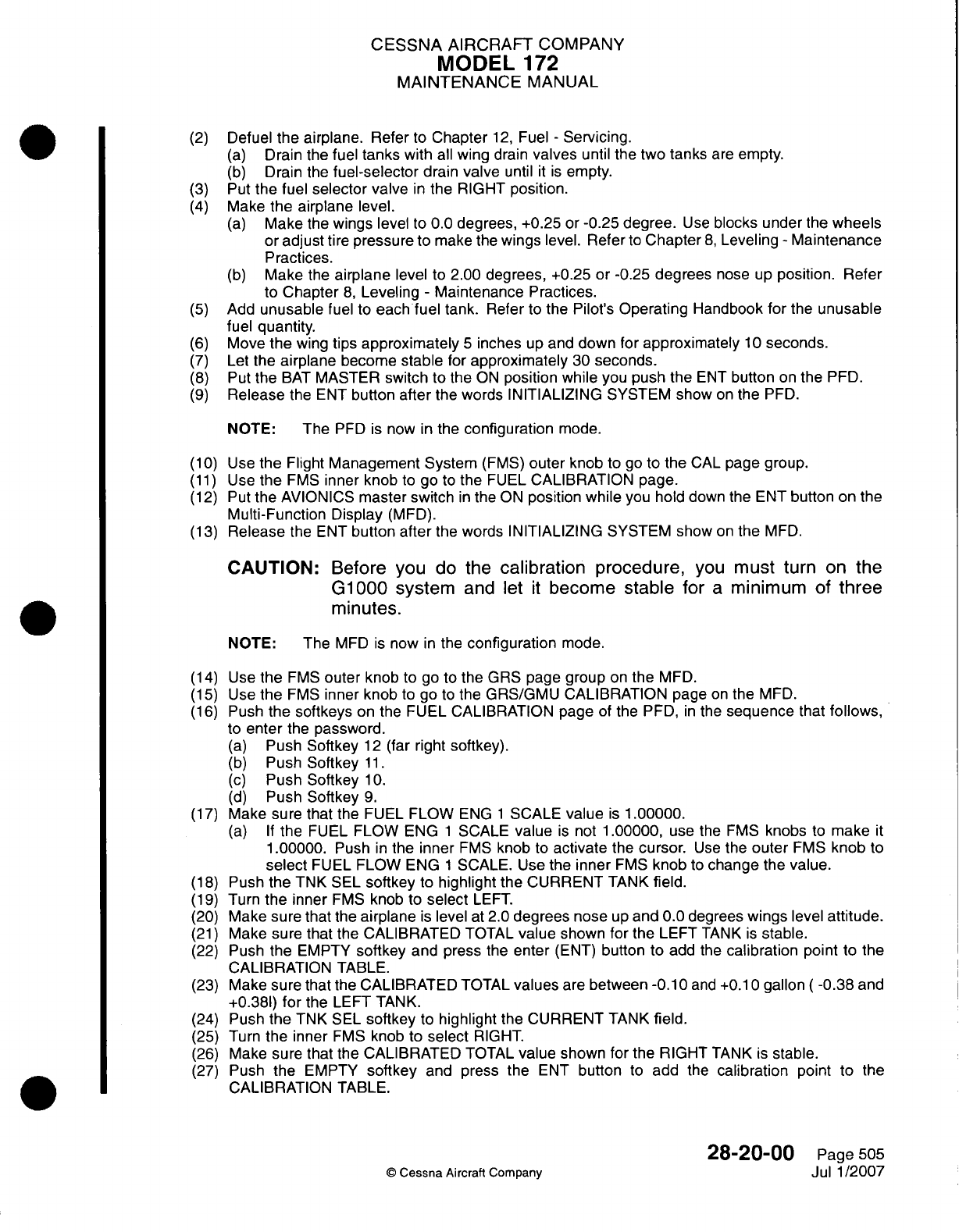
CESSNA
AIRCRAFT
COMPANY
MODEL
172
MAINTENANCE
MANUAL
(2)
Defuel
the airplane.
Refer
to
Chapter
12,
Fuel
-
Servicing.
(a)
Drain the
fuel
tanks
with
all
wing
drain
valves
until
the two
tanks
are
empty.
(b)
Drain
the
fuel-selector
drain
valve
until
it is
empty.
(3)
Put
the
fuel
selector
valve
in
the
RIGHT position.
(4)
Make
the airplane
level.
(a)
Make
the
wings
level
to
0.0
degrees, +0.25
or
-0.25
degree.
Use
blocks under
the
wheels
or
adjust
tire
pressure
to
make the
wings
level.
Refer
to
Chapter
8,
Leveling
-
Maintenance
Practices.
(b)
Make
the
airplane
level
to
2.00
degrees,
+0.25
or -0.25
degrees
nose
up
position.
Refer
to
Chapter
8,
Leveling
-
Maintenance Practices.
(5)
Add
unusable
fuel
to
each
fuel tank.
Refer
to
the
Pilot's
Operating Handbook
for
the
unusable
fuel
quantity.
(6)
Move
the
wing
tips
approximately
5
inches
up
and
down
for
approximately
1 0
seconds.
(7)
Let
the
airplane
become
stable
for
approximately
30
seconds.
(8)
Put the
BAT
MASTER
switch
to
the
ON
position
while
you
push
the
ENT
button
on
the
PFD.
(9)
Release
the
ENT
button
after
the
words
INITIALIZING SYSTEM show
on
the
PED.
NOTE:
The
PED
is
now
in
the
configuration
mode.
(1
0) Use
the Flight
Management System
(FMS)
outer
knob
to go
to
the
CAL
page
group.
(1 1)
Use
the
FMS
inner
knob
to
go
to
the
FUEL
CALIBRATION
page.
(12)
Put
the
AVIONICS
master
switch
in
the
ON
position
while
you
hold
down the ENT
button
on
the
Multi-Function
Display
(MFD).
(13)
Release
the
ENT
button
after
the
words
INITIALIZING
SYSTEM
show
on
the
MFD.
CAUTION:
Before
you
do
the
calibration
procedure,
you
must
turn
on
the
G1000
system
and
let
it
become
stable
for
a
minimum
of
three
minutes.
NOTE: The
MFD
is
now
in
the
configuration
mode.
(14)
Use
the
FMS
outer
knob
to
go
to
the GRS
page group
on
the
MFD.
(15)
Use
the
FMS
inner
knob
to
go
to
the GRS/GMU CALIBRATION page
on
the
MFD.
(16)
Push
the softkeys
on
the
FUEL CALIBRATION
page
of
the PFD,
in
the
sequence
that
follows,
to
enter
the
password.
(a)
Push
Softkey
12
(far right
softkey).
(b)
Push
Softkey
11.
(c)
Push
Softkey
10.
(d)
Push
Softkey
9.
(17)
Make
sure
that the
FUEL
FLOW
ENG
1
SCALE
value
is
1.00000.
(a) If
the
FUEL
FLOW
ENG
1
SCALE
value
is
not
1
.00000,
use the
EMS
knobs
to
make
it
1.00000.
Push
in
the
inner
FMS
knob
to
activate
the
cursor.
Use
the
outer
EMS
knob
to
select
FUEL FLOW ENG
1
SCALE.
Use
the
inner
FMS
knob
to
change
the
value.
(1 8)
Push
the
TNK
SEL
softkey
to
highlight
the
CURRENT
TANK
field.
(19)
Turn
the
inner
FMS
knob
to
select
LEFT.
(20)
Make sure that
the
airplane
is
level
at
2.0
degrees
nose
up
and 0.0
degrees
wings
level
attitude.
(21)
Make
sure that
the
CALIBRATED
TOTAL
value
shown
for
the
LEFT
TANK
is
stable.
(22)
Push
the
EMPTY
softkey
and
press
the
enter
(ENT)
button
to
add
the
calibration
point
to the
CALIBRATION
TABLE.
(23)
Make
sure that the
CALIBRATED TOTAL
values
are
between
-0.10
and
+0.10
gallon
(
-0.38
and
+0.381)
for
the
LEFT
TANK.
(24)
Push
the
TNK
SEL
softkey
to
highlight
the
CURRENT
TANK
field.
(25) Turn
the
inner
FMS
knob
to
select
RIGHT.
(26)
Make
sure
that the CALIBRATED
TOTAL
value
shown
for
the RIGHT
TANK
is
stable.
(27)
Push
the
EMPTY
softkey
and
press
the
ENT
button
to
add
the
calibration
point
to the
CALIBRATION
TABLE.
28-20-00
Page
505
C
Cessna
Aircraft Company
Jul
1
/2007
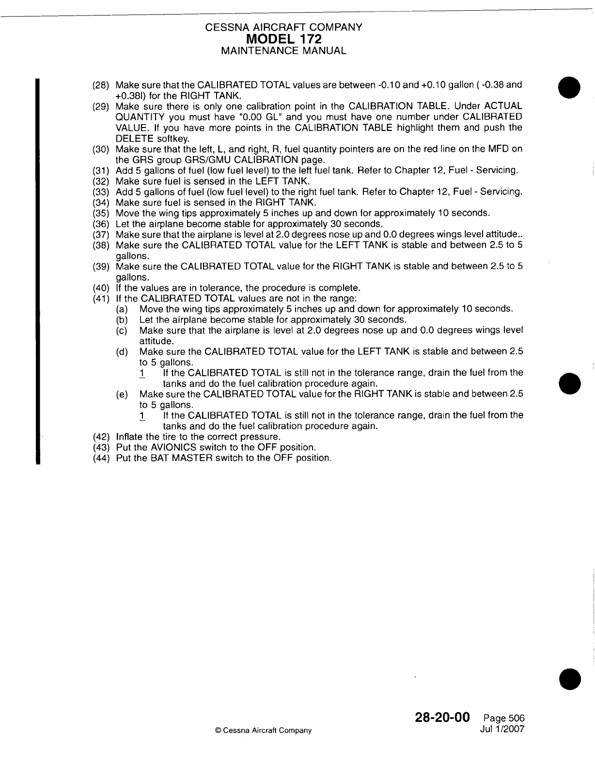
CESSNA
AIRCRAFT
COMPANY
MODEL
172
MAINTENANCE
MANUAL
(28)
Make
sure
that
the
CALIBRATED
TOTAL
values
are
between -0.10
and +0.10
gallon
(-0.38
and
+0.381)
for
the
RIGHT
TANK.
(29)
Make
sure
there
is
only
one
calibration
point
in
the
CALIBRATION
TABLE.
Under ACTUAL
QUANTITY
you
must have
"0.00
GL"
and
you
must
have one
number
under
CALIBRATED
VALUE.
If
you
have
more
points
in
the
CALIBRATION
TABLE
highlight
them
and
push
the
DELETE
softkey.
(30)
Make sure
that
the left,
L,
and
right,
R,
fuel
quantity pointers
are on
the
red
line
on
the
MED
on
the
GRS group GRS/GMU
CALIBRATION
page.
(31)
Add
5
gallons
of
fuel
(low
fuel
level)
to
the left
fuel
tank.
Refer
to
Chapter
12,
Fuel
-
Servicing.
(32)
Make
sure fuel
is
sensed
in
the
LEFT TANK.
(33)
Add
5
gallons
of
fuel
(low
fuel
level)
to
the
right fuel
tank. Refer
to
Chapter
12,
Fuel
-
Servicing.
(34)
Make sure
fuel
is
sensed
in
the RIGHT
TANK.
(35)
Move
the
wing
tips
approximately
5
inches
up
and
down
for
approximately
1
0
seconds.
(36)
Let
the
airplane
become
stable for approximately
30
seconds.
(37)
Make
sure
that
the
airplane
is
level
at
2.0
degrees nose
up
and
0.0
degrees wings
level
attitude..
(38)
Make
sure
the CALIBRATED
TOTAL
value
for
the
LEFT
TANK
is
stable
and
between
2.5
to
5
gallons.
(39)
Make sure the CALIBRATED
TOTAL
value
for
the
RIGHT
TANK
is
stable
and
between
2.5
to
5
gallons.
(40)
If
the
values
are
in
tolerance,
the
procedure
is
complete.
(41)
If
the CALIBRATED
TOTAL
values
are
not
in
the
range:
(a)
Move the
wing
tips
approximately
5
inches
up
and
down
for
approximately
10
seconds.
(b)
Let the
airplane
become
stable
for
approximately
30
seconds.
(c)
Make
sure
that
the
airplane
is
level
at
2.0
degrees
nose
up
and
0.0
degrees
wings
level
attitude.
(d)
Make
sure
the CALIBRATED
TOTAL
value for
the
LEFT
TANK
is
stable
and
between
2.5
to
5
gallons.
1 If
the
CALIBRATED
TOTAL
is
still
not
in
the
tolerance
range, drain
the
fuel
from
the
tanks
and
do
the
fuel
calibration
procedure
again.
(e)
Make
sure
the
CALIBRATED
TOTAL
value
for
the
RIGHT TANK
is
stable and
between
2.5
to
5
gallons.
1 If
the CALIBRATED
TOTAL
is
still
not
in
the
tolerance
range,
drain
the
fuel
from
the
tanks
and
do the
fuel
calibration
procedure
again.
(42)
Inflate
the
tire
to
the
correct
pressure.
(43)
Put the
AVIONICS
switch
to
the
OFF
position.
(44)
Put
the
BAT
MASTER
switch
to
the
OFF
position.
28-20-00
Page
506
©
Cessna
Aircraft Company
Jul
1/2007
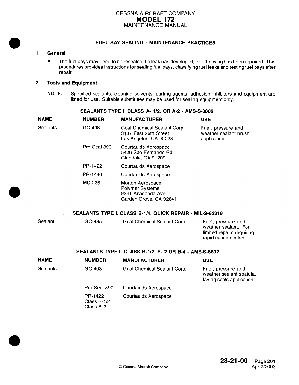
CESSNA
AIRCRAFT
COMPANY
MODEL
1
72
MAINTENANCE
MANUAL
FUEL
BAY
SEALING
-
MAINTENANCE PRACTICES
1.
General
A.
The
fuel
bays
may
need
to
be
resealed
if
a
leak
has
developed,
or
if
the
wing has
been
repaired.
This
procedures
provides instructions
for sealing
fuel
bays,
classifying
fuel
leaks
and
testing
fuel
bays
after
repair.
2.
Tools
and
Equipment
NOTE:
Specified
sealants,
cleaning
solvents,
parting
agents, adhesion inhibitors
and
equipment
are
listed
for
use.
Suitable
substitutes
may
be
used
for
sealing
equipment
only.
SEALANTS
TYPE
I,
CLASS
A-
1/2,
OR
A-2
-
AMS-S-8802
NUMBER
GC-408
Pro-Seal
890
PR-1422
PR-1440
MC-236
MANUFACTURER
Goal
Chemical
Sealant
Corp.
3137
East
26th Street
Los
Angeles,
CA
90023
Courtaulds
Aerospace
5426
San
Fernando
Rd.
Glendale,
CA
91209
Courtaulds
Aerospace
Courtaulds
Aerospace
Morton
Aerospace
Polymer
Systems
9341
Anaconda
Ave.
Garden
Grove,
CA
92641
USE
Fuel,
pressure
and
weather sealant
brush
application.
SEALANTS
TYPE
I,
CLASS
B-1/4, QUICK
REPAIR
-
MIL-S-83318
Goal
Chemical
Sealant
Corp.
Fuel,
pressure
and
weather
sealant.
For
limited
repairs requiring
rapid
curing
sealant.
SEALANTS
TYPE
I,
CLASS
B-1/2,
B-
2
OR
B-4
-
AMS-S-8802
MANUFACTURER
Goal
Chemical
Sealant
Corp.
USE
Fuel,
pressure
and
weather sealant
spatula,
faying
seals
application.
Pro-Seal 890
PR-1422
Class
B-1/2
Class
B-2
Courtaulds
Aerospace
Courtaulds Aerospace
28-21-00
©
Cessna
Aircraft
Company
NAME
Sealants
Sealant
GC-435
NAME
Sealants
NUMBER
GC-408
Page
201
Apr
7/2003
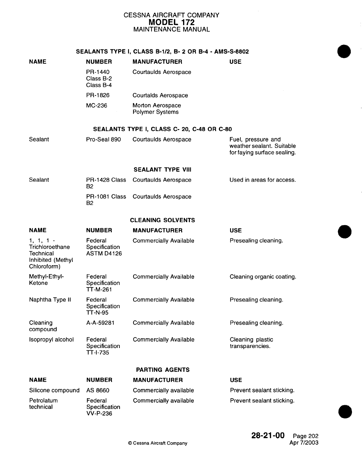
CESSNA AIRCRAFT
COMPANY
MODEL
172
MAINTENANCE
MANUAL
SEALANTS
TYPE
I,
CLASS
B-1/2,
B-
2
OR
B-4
-
AMS-S-8802
NUMBER
MANUFACTURER
USE
PR-1440 Courtaulds
Aerospace
Class
B-2
Class
B-4
PR-1826
Courtalds Aerospace
MC-236
Morton
Aerospace
Polymer
Systems
SEALANTS
TYPE
I,
CLASS
C-
20, C-48
OR
C-80
Sealant
Pro-Seal
890
Courtaulds Aerospace
Fuel,
pressure
and
weather
sealant. Suitable
for
faying
surface
sealing.
PR-1428 Class
B2
PR-1081
Class
B2
SEALANT
TYPE
VIII
Courtaulds
Aerospace
Courtaulds
Aerospace
Used
in
areas
for
access.
NAME
1,
1,
1-
Trichloroethane
Technical
Inhibited
(Methyl
Chloroform)
Methyl-Ethyl-
Ketone
Naphtha
Type
II
Cleaning
compound
Isopropyl
alcohol
NAME
Silicone
compound
Petrolatum
technical
NUMBER
Federal
Specification
ASTM
D4126
Federal
Specification
TT-M-261
Federal
Specification
TT-N-95
A-A-59281
Federal
Specification
TT-I-735
NUMBER
AS
8660
Federal
Specification
VV-P-236
CLEANING
SOLVENTS
MANUFACTURER
Commercially
Available
Commercially
Available
Commercially
Available
Commercially
Available
Commercially
Available
PARTING
AGENTS
MANUFACTURER
Commercially
available
Commercially
available
USE
Presealing cleaning.
Cleaning
organic
coating.
Presealing
cleaning.
Presealing cleaning.
Cleaning plastic
transparencies.
USE
Prevent
sealant sticking.
Prevent
sealant sticking.
©
Cessna
Aircraft
Company
28-21
-00
Page 202
Apr
7/2003
NAME
Sealant
CESSNA
AIRCRAFT
COMPANY
MODEL
172
MAINTENANCE
MANUAL
EQUIPMENT
Pneumatic
sealing
gun.
Hand-operated
sealing
gun
Nozzles,
Round
1/16
orifice
Semco
Number
250
with
accessories
(or
equivalent)
Semco
Number
850
Semco Packaging
and
Applications
Systems,
Division
of
Courtaulds
Aerospace
5454 San
Fernanco
Rd.
Glendale,
CA
91209
Semco Packaging
and
Applications
Systems,
Division
of
Courtaulds
Aerospace
Semco
Packaging
and
Applications
Systems,
Division
of
Courtaulds Aerospace
Injection
sealing.
Injection sealing.
Application
of
sealant.
Semco
No.
420
Round
1/8
orifice
Duckbill
Duckbill
Comb
Polyethylene
cartridges
with
plungers
and
caps
for
sealant
gun.
Metal
spatulas
with
either
stainless
steel
or
glass
plates.
Plastic
lined
cups,
wax-free
with
caps
Sealant
fairing
tools
Cheesecloth,
lint-free
Plastic
scraper,
45-degree
cutting
edge.
Durometer
Commercially
available
Commercially
available
Commercially
available
Commercially
available
Commercially
available
Commercially
available
Rex
Model
1500
(or
equivalent)
Gloves, lightweight
lint-free
white
cotton
Rex
Gauge
Company,
Inc.
3230
West
Lake
Avenue
P.O.
Box
46
Glenview,
IL
60025
Commercially
available
Application
of
sealant.
Mixing
sealant.
Mixing
sealant.
To
fair-in
sealant.
Cleaning.
Removing
old
sealant.
Testing
cure of
sealant.
Removing
old
sealant.
©
Cessna Aircraft
Company
28-21-00
Page 203
Apr
7/2003
Semco
No.
440
Semco
No.
8615
Semco
No.
8648
Semco
No.
8646
CESSNA AIRCRAFT
COMPANY
MODEL
172
MAINTENANCE
MANUAL
EQUIPMENT
Nylon
bristle
Commercially
available
Removing old
sealant.
brushes
Pipe
cleaners
Commercially
available
Cleaning.
Funnel
brushes Commercially
available
Cleaning.
3.
Definition
of
Sealing
Terms
A.
The
following definitions
are
included
to
provide
a
basic
concept
of
the special
terms
used
in
sealing.
This
list
is
not
all
inclusive
but the
more
common terms
are
listed.
(1)
Absolute
Sealing
-
There
can
be
no
leakage allowed.
All
openings
of
any
nature
through
the
seal
plane
are
positively
sealed.
This
is
the
first
level
of
sealing.
(All
holes,
slots,
joggles,
fasteners
and
seams
must
be
sealed.)
(2)
Accelerator (Activator)
-
Curing
agent for
sealants.
(3)
Application
Time
-
The
length
of
time
sealant
remains
workable
or
suitable for
application
to
structure
by
brush,
extrusion
gun,
spatula or
roller.
(4)
Base
Compound
-
The
major
component
of
a
two-part
sealing
compound
which
is
mixed
with
the
accelerator prior
to
application
to
produce
a
fuel,
temperature,
pressure,
weather
and/or
firewall
sealing
material.
(5)
Brush
Coat
-
Apply
an
overcoating
or
continuous
film
of
appropriate
sealing compound
by use
of
a
brush.
(6)
Fay
Seal
or Faying
Surface
Seal
-
A
seal
barrier
created
by
the
sandwiching
of
sealant
between
mating
surfaces
of
structure. Special
attention
must
be
taken
to
avoid metal
chips or dirt
at
the
faying
surface.
(7)
Fillet
Seal
-
Sealant material
applied
at
the
seam,
joint
or
fastener
after
the
assembly
has
all
permanent
fasteners installed
and
shall
conform
to
the
dimension
in
applicable
figure.
(8)
Hole
-
An
opening
that
has
no
appreciable
depth,
such
as
a
tool
hole.
Holes
that
penetrate
the
seal
plane must
be
metal
filled
with
a
fastener, gusset
or
patch.
(9)
Injection
Seal
-
Filling
of
channels
by
forcing
sealant into
a
void
or
cavity
after
assembly.
(10)
Integral
Tank
-
Composition
of
structure
and
sealant
material
which
forms
a
tank that
is
capable
of
containing
fuel
without
a
bladder.
(11)
Intermediate
Seal
-
The
second
level
of
sealing.
All
holes,
slots,
joggles
and
seams
in
the
seal
plane
must
be
sealed.
A
minor
amount
of
leakage
is
tolerable
and
permanent
fasteners
are
not
required
to
be
sealed.
(12)
Post-Assembly
Seal
-
A
seal
that
is
applied
after
the
structure
is
assembled.
(Fillet
and
injection
seals.)
(13)
Preassembly
Seal
-
Sealant
material
that must
be
applied
during
or
prior
to
the
assembly
of the
structure.
(Faying
surface
and
pre-pack
seals.)
(14)
Pre-Pack
Seal
-
A
preassembly
seal
used
to fill
voids
and
cavities;
can be
a
primary
seal
used
to
provide seal
continuity
when used
in
conjunction
with
a
fillet
seal.
It
can
be
used
as
a
backup
seal
to
support
a
fillet across
a
void.
Fill
the
entire
cavity
to
be
pre-
packed.
Usage
as
a
primary
seal
should
be
kept
to a
minimum.
(15)
Primary
Seal
-
Sealant
material
that
prevents
leakage
and
forms
a
continuous
seal
plane.
This
seal
is
in
direct contact
with
the
fuel,
vapor,
air,
acid,
etc.
With
few
exceptions,
it
is
in
the
form
of
a
fillet
seal.
(16)
Sealant
-
A
compound
applied to
form
a
seal
barrier.
(17)
Seal Plane
-
A
surface
composed
of
structure,
sealant
and
fasteners
on
which
the
continuity
of
seal
is
established.
(18)
Shank
Sealing
-
Sealant
compound
shall
be
applied to
the
hole
or
to
both the
shank
and the
underhead area
of
the fastener
in
sufficient
quantity
that
the
entire shank
is
coated and
a
small
continuous
bead
of
sealant
is
extruded
out
around
the complete
periphery
of
each end
of
the
fastener
when
installed.
The
fastener
shall
be
installed
within
the application
time
of
the
sealing
compound used.
(19)
Squeeze-Out
Life
-
Length
of
time
sealant
remains
suitable
for
structure
assembly
in
faying
surface
seal
application.
28-21-00
Page
204
©
Cessna Aircraft Company
Apr
7/2003
CESSNA AIRCRAFT
COMPANY
MODEL
172
MAINTENANCE
MANUAL
(20)
Tack-Free Time
-
Tack-free
time
is a
stage,
during
the
cure
of
the
sealant compound,
after
which
the
sealant compound
is
no
longer
tacky.
When
the
sealant
compound
is
pressed
firmly
with
the
knuckles,
but
no
longer
adheres
to the
knuckles,
the
sealant
compound
is
tack-free.
4.
Materials
A.
Type
of
Sealants
-
Sealants
are
categorized
by
type
of
usage. Type
I
sealants
are
separated
into
classes
to
differentiate
the
materials
according
to
method
of
application.
Dash
numbers
following
the
class
designation
indicate
the
minimum
application
time
(in
hours)
for
Class
A
and
Class
B,
and
minimum
work
life (in
hours)
for
Class
C.
Refer
to
Table
201
for
application
time,
curing
rate, etc.,
for
Type
I
sealants.
(1)
Type
I
-
Fuel,
pressure,
and
weather
sealant.
(a)
Class
A
-
Sealant which
is
suitable
for
brush
application.
(b)
Class
B
-
Sealant
which
is
suitable
for
application
by
extrusion
gun,
spatula, etc.
(c)
Class
C
-
Sealant which
is
suitable
in
faying
surface
applications.
(d)
Quick
Repair
Sealant
-
This
material
is
for
use
only
in
making
repairs
when
an
extremely
rapid
curing
sealant
is
required.
A
possible application includes
sealing
a
leaking
fuel
tank
on
an
airplane
which must
be
dispatched
within
a
few
hours.
CAUTION:
QUICK
REPAIR
SEALANT
MUST
BE
APPLIED
WITHIN
ITS
WORKING
LIFE
OF
15
MINUTES.
ATTEMPTS
TO
WORK
QUICK
REPAIR
SEALANT
BEYOND
WORKING
LIFE
WILL
RESULT
IN
INCOMPLETE WETTING
OF
SURFACE
AND
WILL
RESULT
II\I
A
FAILED
SEAL.
(2)
Type
VIII
-
Low
Adhesion
Access
Door
Sealant.
This
Class
B
sealant
is
designed
for
sealing
faying
surfaces
where
easy
separation
of
the
joined surfaces
is
required.
The
sealant
has
low
adhesion
and
forms
a
gasket that
molds
itself
to
fill
all
irregularities
between two
surfaces.
The
sealant
is
exceptionally
resistant
to
fuels, greases,
water, most
solvents
and
oils
including
hydraulic
oil.
NOTE:
Time
periods presented
below
are
based
on
a
temperature
of
77°F
and
50
percent
relative humidity.
Any increase
in
either
temperature
or
relative
humidity
may shorten
these
time
periods
and
accelerate
the
sealant
cure.
Table
201.
Curing
Properties
of Type
I
Sealant
CLASS
APPLICATION WORK
LIFE
TACK-FREE
CURING
RATE
TIME
(HOURS,
(HOURS,
TIME
(HOURS,
(HOURS,
MINIMUM) MINIMUM) MAXIMUM) MAXIMUM)
A-1/2
1/2
10
40
A-2
2
40
72
B-1/2
1/2
4
6
B-2
2
40
72
B-4
4
48
90
C-24
8
24 96
168
(7
days)
C-48
12
48
120
336
(14
days)
C-80
8
80
120
504
(21
days)
28-21-00
Page
205
©
Cessna
Aircraft
Company
Apr
7/2003
CESSNA AIRCRAFT
COMPANY
MODEL
172
MAINTENANCE
MANUAL
5.
General
Requirements
A.
When
working
with
sealants observe
the
following
requirements.
(1)
Unmixed
sealants
shall
not
be
more
than
two
months
old
when
received.
These sealants
shall
not
be
more than
six
months old
when
used.
(2)
Unmixed
sealants
stored at
temperatures
exceeding
80°F
shall
be
used
within
five
weeks.
(3)
Sealants
which
have been
premixed,
degassed
and flash
frozen
shall
be
maintained
at -40°F
or
lower
and
shall
not
be
received
more
than
two
weeks
beyond the
date
of
mixing. These
sealants
shall
not
be
used
more
than
six
weeks
after the
date
of
mixing.
(4)
Frozen
sealant
shall
be
thawed
before
being
used.
If
sealant
were
applied at
a
temperature
below
60°F,
it
would
not
be
sufficiently
pliable
for
proper
application
and
adhesion could
be
critically
reduced
by
condensation
of
moisture.
On
the
other
hand,
although
sealant
must
extrude
freely
for
proper
application,
it
would
be
subject
to
excessive
slumping
if
applied
at
a
temperature above
80°F.
Frozen
sealant
may
be
thawed
by
any
s
uitable means
which does
not
cause contamination
or
overheating
of
the
sealant
and
does not
shorten
the
application
time
of
the
sealant
to
an
impractical
period.
Examples:
Thawing
by
exposure
to
ambient
air
temperature, accelerated
thawing
by
exposure
in
a
constant temperature
bath
(using
clean,
hot
water),
accelerated
thawing
in
a
microwave oven.
In
any
case,
thawing
temperature
and time
shall
be
adjusted
to
give
a
thawed
sealant
temperature
between
60°F,
and
80°F
at
the
time
the
sealant
is
applied.
(5)
Mixed,
frozen sealants
which
have
thawed
shall
not
be
refrozen.
(6)
Complete
preassembly operations
such
as
fitting,
filing,
drilling,
countersinking,
dimpling
and
deburring
prior
to
cleaning
and
sealant
application.
(7)
Surfaces must
be
clean
and
dry, free
from
dust,
lint,
grease,
chips,
oil
condensation
or
other
moisture
and
all
other
contaminating
substances
prior
to
the
application
of
sealant.
(a)
All
exposed bonding
primer
or
bonded
assemblies
which
are
to
be
sealed
shall
be
cleaned
using
Scotch
Brite
followed
by
solvent cleaning
using
Trichloroethane.
NOTE:
Bond
primer
shall
not
be
removed;
just
lightly scuffed
with
Scotch
Brite.
(8)
Sealant materials
may
be
applied
to
unprimed
or
primed
surfaces.
Nonchromated
or
epoxy
primers
shall
have good
adhesion
to
the
substrate
material and
shall
have
aged
at
least
48
hours
prior
to
sealant
application.
Adhesive
bonding
primer shall
be
scotchbrited
and
cleaned
before
applying
sealant.
(9)
Sealants
shall
not
be
applied
when the
temperature
of
either the sealant or
the
structure
is
below
60°F.
(10)
Sealant
applied
by
the
fillet
or
brush
coat
methods
shall
always
be
applied
to
the
pressure
side
of
a
Joint
if
possible.
(11)
After
application, sealants
shall
be
free
of
entrapped
air
bubbles
and
shall not
exhibit
poor
adhesion.
All
fillets
shall
be
smoothed
down
and
pressed
into
the
seam or
joint
with
a
filleting
tool before
the
sealant
application
time
has
expired.
(12)
Where
fasteners
have been
shank or
underhead
sealed,
extruded
sealant shall
be
evident
around
the
complete
periphery
of
the
fastener
to
indicate
adequate sealing.
Sealant
extruded
through
a
hole
by
a
rivet
shall
be
wiped
from
the
end
of the
rivet
before
bucking. Threaded
fasteners
which
have
been
shank
or
underhead
sealed
shall not
be
retorqued
after
the
expiration
of
the
application
time
of
the
sealant.
Prior to
torqueing, sealant
shall
be
removed
from
the
threads.
In
torqueing,
turn
the
nut
rather
than
the
bolt,
if
possible.
(13)
Pressure
testing
shall not
be
accomplished
until
the
sealant
is
cured.
(14)
Sealant
shall not
be
applied
over
ink,
pencil or
wax
pencil
marks.
If
these materials extend
into
the sealing
area,
they
must
be
removed.
(15)
If
sealing
is
to
be
accomplished
over
primer
and the
primer
is
removed during
the
cleaning
process,
it
is
permissible
to
seal
directly
over the
cleaned
area
and
then
touch
up
the
exposed
areas
after
the
sealant
has
been
applied
and
is
tack
free.
(16)
Sealed structure
shall
not
be
handled
or
moved
until
sealant
is
tack
free
(sealant
may
be
dislodged
or
have
the adhesion
damaged).
Excessive
vibration
of
structure, such
as
riveting,
engine
run
up,
etc.
is
not
permitted.
28-21-00
Page
206
©
Cessna
Aircraft
Company
Apr
7/2003
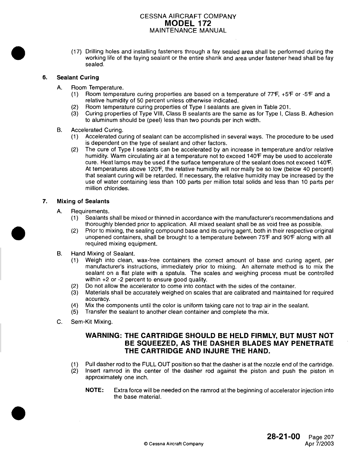
CESSNA
AIRCRAFT
COMPANY
MODEL
1
72
MAINTENANCE
MANUAL
(17)
Drilling holes
and
installing
fasteners
through
a
fay
sealed
area
shall
be
performed
during
the
working
life of
the
faying
sealant
or
the
entire
shank
and
area under
fastener
head
shall
be
fay
sealed.
6.
Sealant Curing
A.
Room
Temperature.
(1)
Room
temperature
curing
properties
are
based
on
a
temperature
of
77°F,
+5°F
or
-5°F
and
a
relative humidity of
50
percent
unless otherwise
indicated.
(2)
Room
temperature
curing
properties
of
Type
I
sealants
are
given
in
Table
201.
(3)
Curing
properties
of
Type
VIII,
Class
B sealants
are
the same
as
for
Type
I,
Class
B.
Adhesion
to
aluminum should
be
(peel)
less
than two pounds
per
inch
width.
B.
Accelerated
Curing.
(1)
Accelerated curing
of
sealant
can be
accomplished
in
several ways.
The
procedure
to
be
used
is
dependent
on
the
type
of
sealant
and
other
factors.
(2)
The
cure
of
Type
I
sealants
can
be
accelerated
by
an
increase
in
temperature
and/or
relative
humidity.
Warm
circulating air
at
a
temperature
not
to
exceed
140°F
may
be
used
to
accelerate
cure.
Heat
lamps
may be
used
if
the
surface
temperature
of
the
sealant
does
not
exceed
140°F.
At
temperatures
above
120°F,
the
relative
humidity
will
normally
be
so
low
(below 40
percent)
that
sealant
curing
will
be
retarded.
If
necessary,
the relative
humidity
may
be
increased
by
the
use
of
water
containing
less
than
100
parts per
million
total
solids
and
less
than
10
parts
per
million
chlorides.
7.
Mixing
of
Sealants
A.
Requirements.
(1)
Sealants
shall
be
mixed or
thinned
in
accordance
with
the
manufacturer's
recommendations
and
thoroughly
blended
prior
to
application.
All
mixed
sealant
shall
be
as
void
free
as
possible.
(2)
Prior
to
mixing,
the
sealing
compound
base
and
its
curing agent,
both
in
their respective original
unopened
containers,
shall
be
brought
to
a
temperature
between
75°F
and
90°F
along
with
all
required
mixing
equipment.
B.
Hand
Mixing
of
Sealant.
(1)
Weigh
into
clean,
wax-free
containers the
correct
amount
of
base
and
curing
agent,
per
manufacturer's instructions, immediately prior
to
mixing.
An
alternate
method
is
to
mix
the
sealant
on
a
flat
plate
with
a
spatula.
The
scales
and
weighing
process
must
be
controlled
within
+2
or
-2
percent
to
ensure good
quality.
(2)
Do
not
allow
the
accelerator
to
come
into
contact
with
the sides
of
the
container.
(3)
Materials
shall
be
accurately weighed
on
scales
that
are
calibrated
and
maintained
for
required
accuracy.
(4)
Mix
the components
until
the color
is
uniform
taking
care
not
to
trap
air
in
the
sealant.
(5)
Transfer
the
sealant
to
another clean
container
and
complete
the
mix.
C.
Sem-Kit
Mixing.
WARNING:
T-IE
CARTRIDGE
SHOULD
BE
HELD
FIRMLY,
BUT
MUST
NOT
BE
SQUEEZED, AS
THE
DASHER
BLADES
MAY
PENETRATE
THE
CARTRIDGE
AND
INJURE
THE
HAND.
(1)
Pull
dasher
rod
to
the
FULL OUT
position so that the dasher
is
at
the
nozzle end
of
the
cartridge.
(2)
Insert ramrod
in
the
center
of
the
dasher
rod
against
the
piston
and
push the
piston
in
approximately
one
inch.
NOTE:
Extra
force will
be
needed
on
the
ramrod at
the beginning
of
accelerator
injection
into
the
base
material.
28-21-00
Page
207
©
Cessna
Aircraft
Company
Apr
7/2003
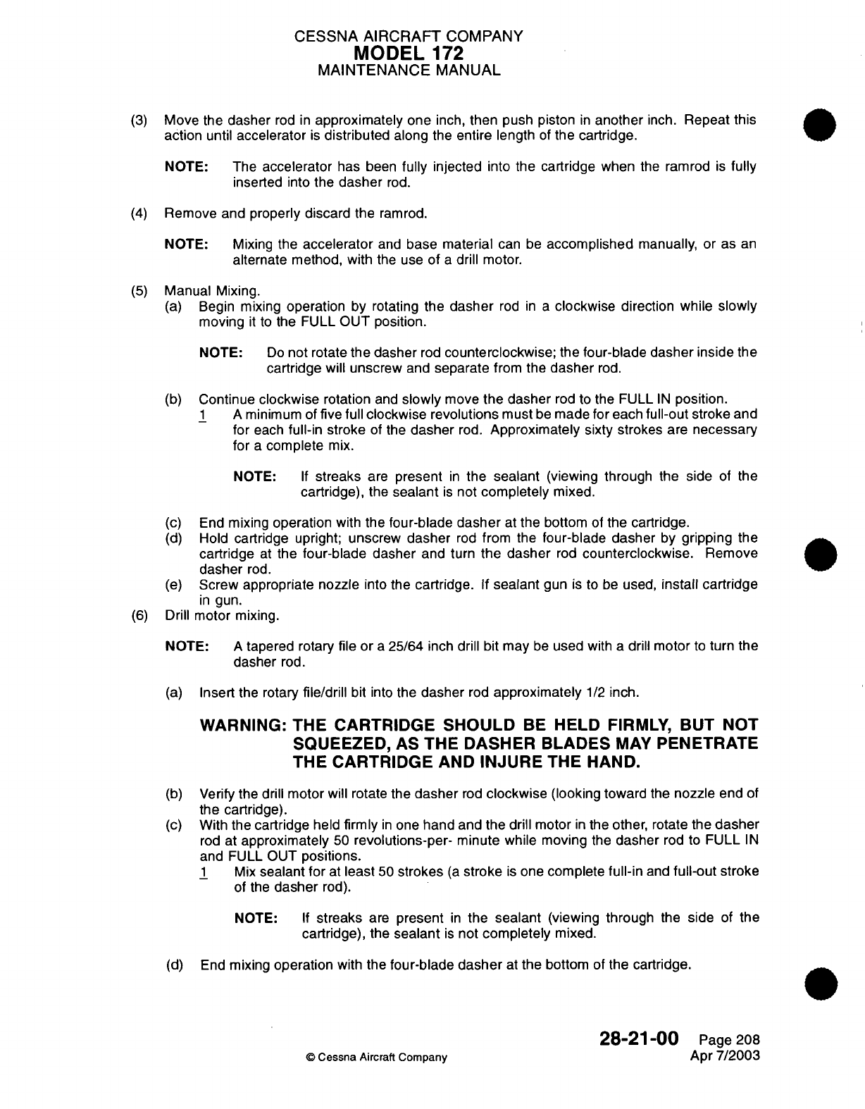
CESSNA AIRCRAFT
COMPANY
MODEL
172
MAINTENANCE
MANUAL
(3)
Move
the
dasher
rod
in
approximately
one
inch,
then
push
piston
in
another
inch.
Repeat
this
action
until
accelerator
is
distributed
along
the
entire
length
of
the
cartridge.
NOTE:
The
accelerator
has
been
fully
injected
into
the
cartridge
when
the
ramrod
is
fully
inserted into
the
dasher
rod.
(4)
Remove and
properly discard
the
ramrod.
NOTE:
Mixing
the
accelerator
and
base material
can
be
accomplished
manually,
or
as
an
alternate
method,
with
the use
of
a
drill
motor.
(5)
Manual Mixing.
(a)
Begin
mixing
operation
by
rotating
the
dasher
rod
in a
clockwise
direction
while
slowly
moving
it
to
the
FULL
OUT position.
NOTE:
Do
not
rotate
the
dasher
rod
counterclockwise;
the
four-blade dasher inside
the
cartridge will unscrew
and
separate
from
the
dasher
rod.
(b)
Continue
clockwise
rotation
and
slowly
move
the
dasher
rod
to the FULL
IN
position.
1
A
minimum of
five
full
clockwise revolutions
must
be
made for each
full-out
stroke
and
for
each
full-in
stroke
of
the
dasher
rod.
Approximately sixty
strokes
are
necessary
for
a
complete
mix.
NOTE:
If
streaks
are
present
in
the
sealant
(viewing
through
the
side
of
the
cartridge),
the
sealant
is
not
completely
mixed.
(c) End
mixing
operation
with
the
four-blade
dasher
at
the bottom
of
the
cartridge.
(d)
Hold
cartridge
upright;
unscrew
dasher
rod
from
the
four-blade
dasher
by
gripping
the
cartridge
at
the
four-blade dasher
and
turn
the dasher
rod
counterclockwise.
Remove
dasher
rod.
(e)
Screw appropriate
nozzle
into
the
cartridge.
If
sealant
gun
is
to
be
used,
install
cartridge
in
gun.
(6)
Drill
motor
mixing.
NOTE:
A
tapered
rotary file
or
a
25/64
inch
drill
bit
may
be
used
with
a
drill
motor
to
turn
the
dasher
rod.
(a)
Insert
the
rotary
file/drill
bit
into
the
dasher
rod
approximately
1/2
inch.
WARNING: THE
CARTRIDGE SHOULD
BE
HELD
FIRMLY, BUT
NOT
SQUEEZED, AS
THE
DASHER
BLADES
MAY
PENETRATE
THE CARTRIDGE
AND
INJURE
THE
HAND.
(b)
Verify
the drill
motor
will
rotate
the
dasher
rod
clockwise
(looking toward
the
nozzle
end
of
the
cartridge).
(c)
With
the
cartridge
held
firmly
in
one
hand
and the drill
motor
in
the other,
rotate
the
dasher
rod
at
approximately
50
revolutions-per-
minute
while moving
the
dasher
rod to
FULL
IN
and FULL
OUT
positions.
1
Mix
sealant
for
at
least
50
strokes
(a
stroke
is
one
complete
full-in
and
full-out
stroke
of
the
dasher
rod).
NOTE:
If
streaks
are
present
in
the
sealant
(viewing through
the
side
of the
cartridge),
the
sealant
is
not
completely
mixed.
(d)
End
mixing
operation
with
the
four-blade
dasher
at
the
bottom
of
the
cartridge.
28-21-00
Page 208
©
Cessna
Aircraft
Company
Apr
7/2003
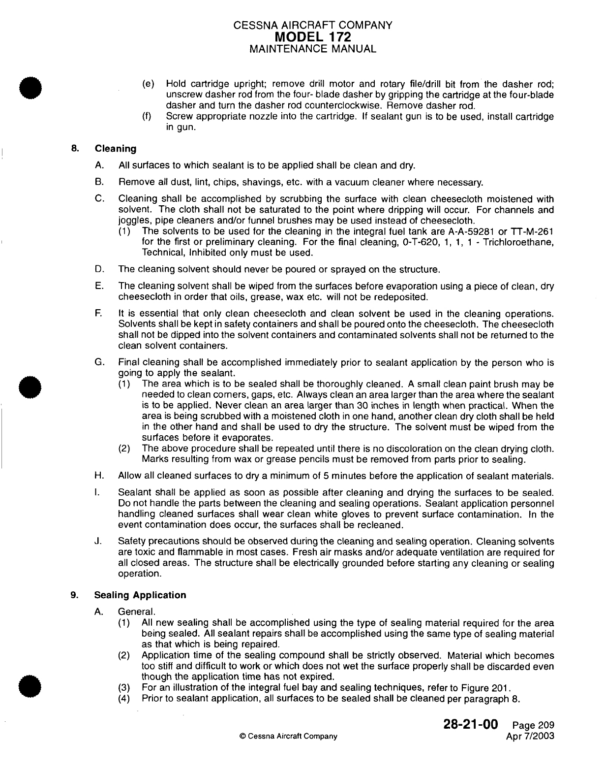
CESSNA
AIRCRAFT
COMPANY
MODEL
172
MAINTENANCE
MANUAL
(e)
Hold
cartridge
upright; remove
drill
motor
and
rotary
file/drill
bit
from the
dasher
rod;
unscrew
dasher
rod
from
the
four-
blade
dasher
by
gripping
the
cartridge
at
the
four-blade
dasher
and
turn
the
dasher
rod
counterclockwise.
Remove
dasher
rod.
(f)
Screw
appropriate
nozzle
into
the
cartridge.
If
sealant
gun
is to
be
used,
install cartridge
in
gun.
8.
Cleaning
A.
All
surfaces
to
which
sealant
is
to
be
applied
shall
be
clean
and
dry.
B.
Remove
all
dust, lint, chips,
shavings,
etc.
with
a
vacuum
cleaner
where necessary.
C.
Cleaning
shall
be
accomplished
by
scrubbing
the
surface
with
clean
cheesecloth moistened with
solvent. The cloth shall
not
be
saturated
to
the
point where
dripping will
occur.
For
channels
and
joggles,
pipe
cleaners and/or
funnel
brushes
may
be
used
instead
of
cheesecloth.
(1)
The
solvents
to
be
used
for
the
cleaning
in
the
integral fuel tank
are
A-A-59281
or
TT-M-261
for
the
first
or preliminary
cleaning.
For
the final
cleaning,
O-T-620,
1, 1, 1
-
Trichloroethane,
Technical,
Inhibited
only
must
be
used.
D.
The
cleaning
solvent
should
never
be
poured
or
sprayed
on
the structure.
E.
The
cleaning
solvent
shall
be
wiped
from
the
surfaces before
evaporation
using
a
piece
of
clean, dry
cheesecloth
in
order
that oils,
grease,
wax
etc.
will
not be
redeposited.
F. It
is
essential that only
clean
cheesecloth
and
clean
solvent
be
used
in
the
cleaning
operations.
Solvents
shall
be
kept
in
safety containers
and
shall
be
poured
onto
the
cheesecloth.
The
cheesecloth
shall
not
be
dipped
into
the
solvent containers
and
contaminated
solvents
shall
not
be
returned
to
the
clean
solvent
containers.
G.
Final
cleaning
shall
be
accomplished
immediately
prior
to
sealant
application
by
the
person
who
is
going to
apply
the
sealant.
(1)
The area
which
is
to
be
sealed
shall
be
thoroughly
cleaned.
A
small
clean
paint
brush
may
be
needed
to
clean
corners,
gaps,
etc.
Always
clean
an
area larger
than
the
area
where
the
sealant
is
to
be
applied.
Never
clean
an
area larger
than
30
inches
in
length
when
practical.
When
the
area
is
being
scrubbed
with
a
moistened
cloth
in
one
hand,
another
clean
dry
cloth
shall
be held
in
the
other
hand
and
shall
be
used
to
dry
the
structure.
The
solvent
must
be
wiped
from
the
surfaces before
it
evaporates.
(2)
The
above
procedure shall
be
repeated
until there
is
no
discoloration
on
the
clean
drying cloth.
Marks
resulting
from
wax
or
grease
pencils
must
be
removed
from
parts
prior
to
sealing.
H.
Allow
all
cleaned
surfaces
to dry
a
minimum of
5
minutes
before
the
application
of
sealant
materials.
I.
Sealant
shall
be
applied
as
soon
as
possible
after
cleaning
and drying
the
surfaces
to
be
sealed.
Do
not handle
the
parts between the
cleaning
and
sealing operations.
Sealant
application
personnel
handling cleaned
surfaces
shall wear clean
white
gloves
to
prevent
surface
contamination.
In
the
event
contamination
does
occur, the
surfaces
shall
be
recleaned.
J.
Safety
precautions
should
be
observed
during
the cleaning
and
sealing
operation.
Cleaning solvents
are
toxic
and
flammable
in
most
cases.
Fresh
air
masks
and/or
adequate ventilation
are
required
for
all
closed
areas.
The structure
shall
be
electrically
grounded
before
starting
any
cleaning
or
sealing
operation.
9.
Sealing
Application
A.
General.
(1)
All
new
sealing
shall
be
accomplished
using
the
type
of
sealing
material
required
for
the
area
being
sealed.
All
sealant
repairs
shall
be
accomplished
using
the same
type
of
sealing
material
as
that
which
is
being
repaired.
(2)
Application
time
of
the
sealing
compound shall
be
strictly
observed.
Material
which becomes
too
stiff
and
difficult
to
work or
which
does
not
wet
the
surface properly
shall
be
discarded
even
though
the
application
time
has not
expired.
(3)
For
an
illustration
of
the
integral fuel
bay
and
sealing
techniques,
refer
to
Figure
201.
(4)
Prior
to
sealant
application,
all
surfaces
to
be
sealed shall
be
cleaned
per
paragraph
8.
28-21
-00
Page
209
©
Cessna
Aircraft Company
Apr 7/2003
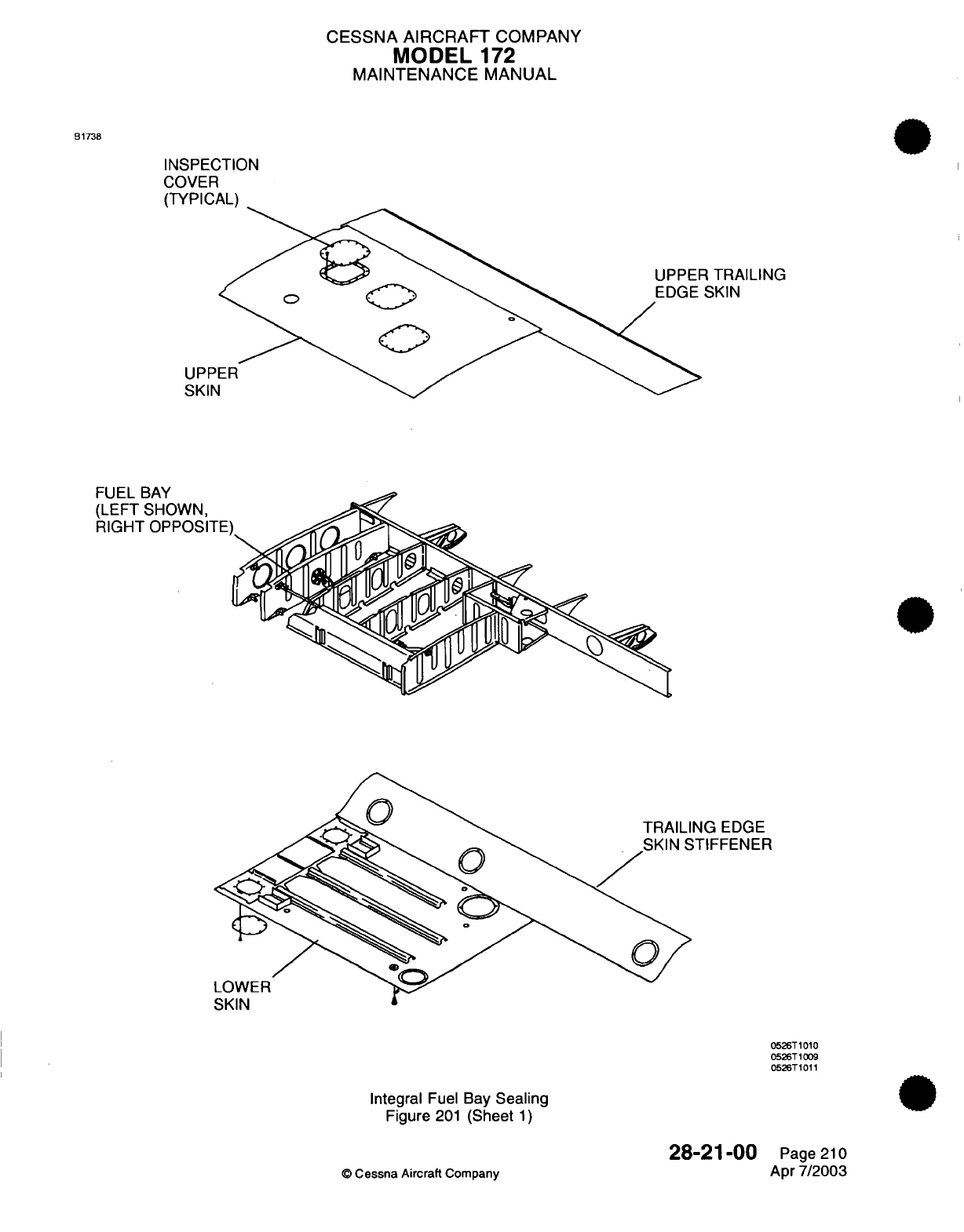
CESSNA AIRCRAFT
COMPANY
MODEL
172
MAINTENANCE
MANUAL
B1738
INSPECTION
COVER
(TYPICAL)
R
TRAILING
SKIN
UPP
SKIN
Ir
Ii
D
AU/
NG
EDGE
;TIFFENER
0526T
1010
0526T1009
0526T1011
Integral
Fuel Bay
Sealing
Figure
201
(Sheet
1)
©
Cessna
Aircraft
Company
28-2'1-00
Page
210
Apr
7/2003
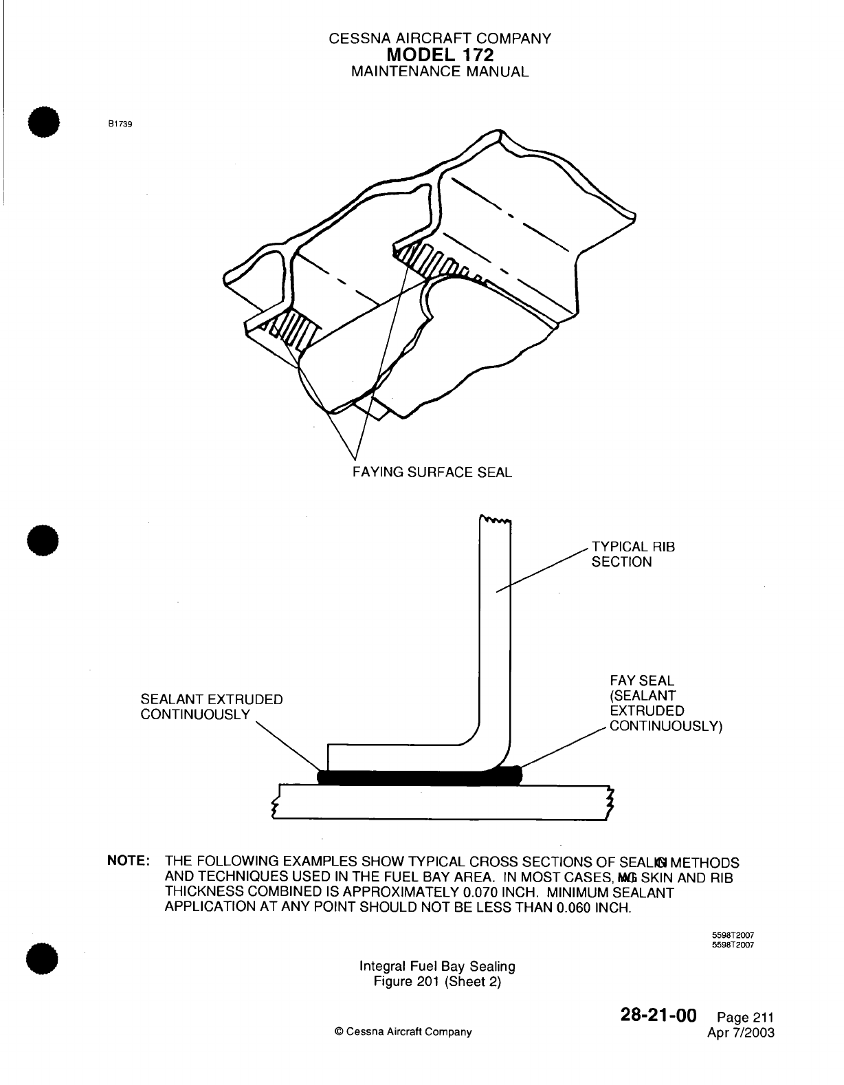
CESSNA
AIRCRAFT
COMPANY
MODEL
1
72
MAINTENANCE
MANUAL
B1739
FAYING
SURFACE
SEAL
TYPICAL
RIB
SECTION
SEALANT
EXTRUDED
CONTINUOUSLY
"' I
,/
FAY
SEAL
(SEALANT
EXTRUDED
CONTINUOUSLY)
NOTE: THE
FOLLOWING
EXAMPLES
SHOW
TYPICAL
CROSS SECTIONS
OF
SEALING
METHODS
AND
TECHNIQUES
USED
IN
THE
FUEL
BAY
AREA.
IN
MOST
CASES,
MGX
SKIN
AND
RIB
THICKNESS
COMBINED
IS
APPROXIMATELY 0.070
INCH.
MINIMUM
SEALANT
APPLICATION
AT
ANY
POINT
SHOULD
NOT
BE
LESS
THAN
0.060
INCH.
5598T2007
5598T2007
Integral
Fuel
Bay
Sealing
Figure
201
(Sheet
2)
©
Cessna
Aircraft Company
28-21-00
Page
211
Apr
7/2003
_·M
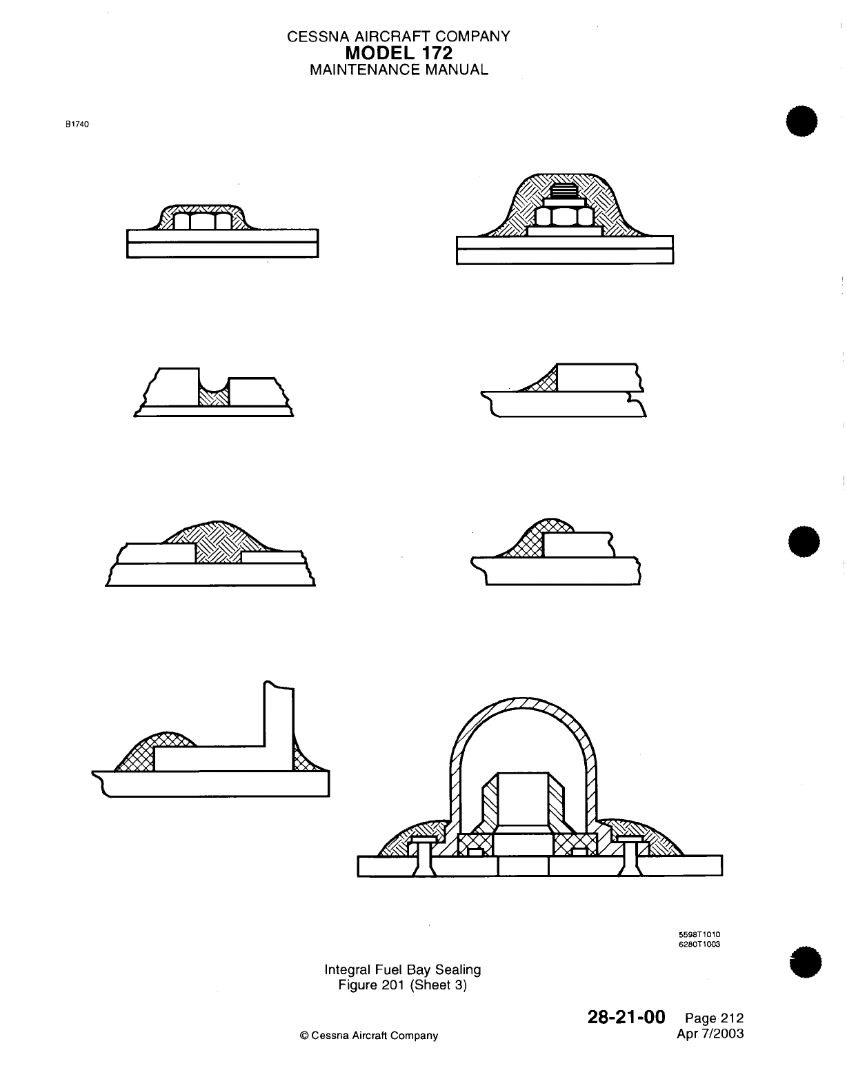
CESSNA
AIRCRAFT
COMPANY
MODEL
172
MAINTENANCE
MANUAL
B1740
.^^'-
*
T'.
IJ
J/
",
/
S
?S^
\'N
I&
Integral
Fuel
Bay
Sealing
Figure
201
(Sheet
3)
28-21-00
©
Cessna Aircraft Company
\
.3
'A1
5598T1010
6280T1003
Page
212
Apr
7/2003
II
,"d
II
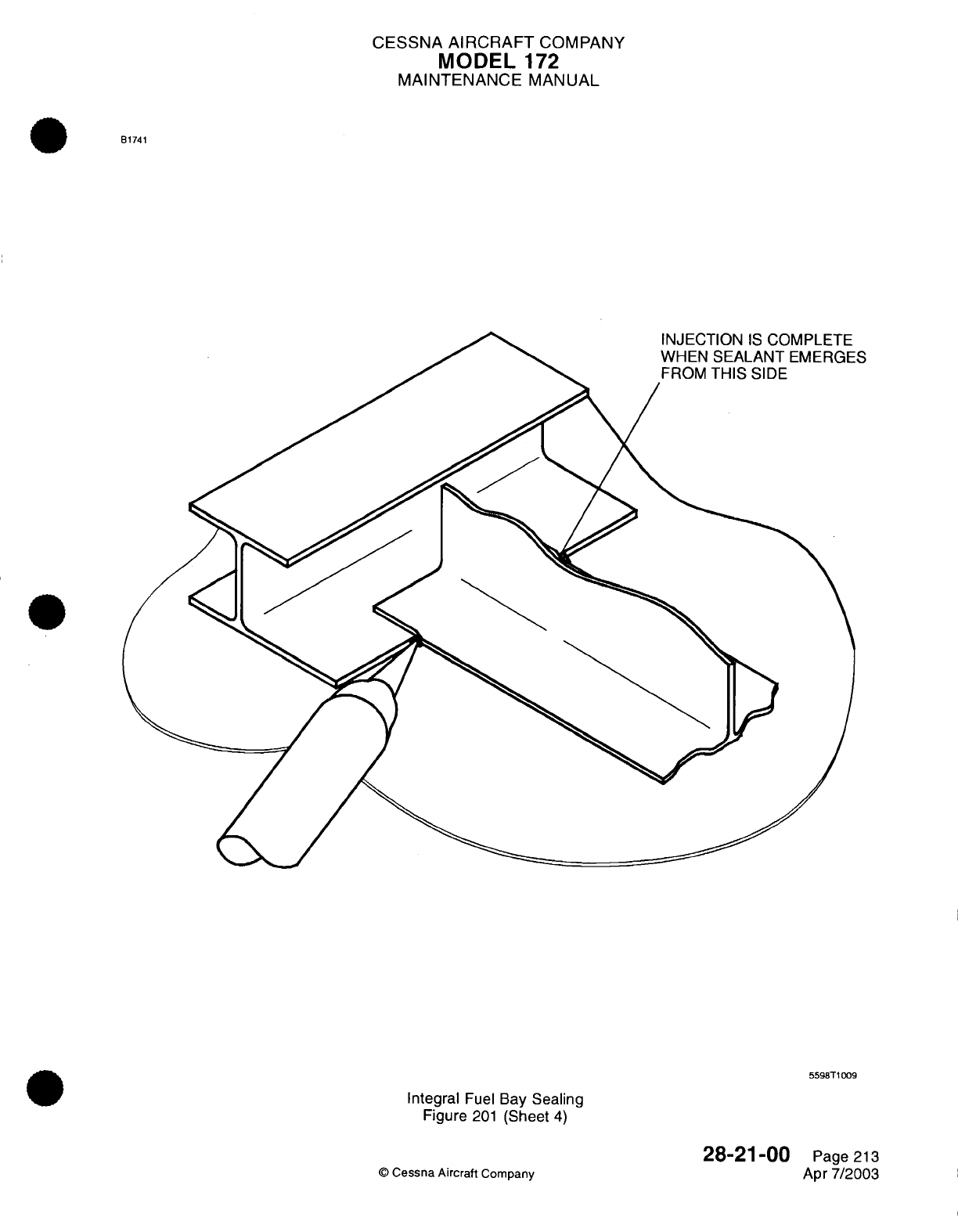
CESSNA
AIRCRAFT
COMPANY
MODEL
172
MAINTENANCE
MANUAL
B1741
5598T1009
Integral
Fuel
Bay
Sealing
Figure
201
(Sheet
4)
28-21-00
©
Cessna
Aircraft
Company
Page
213
Apr
7/2003
S
CESSNA
AIRCRAFT
COMPANY
MODEL
172
MAINTENANCE
MANUAL
B.
Faying
Surface
Sealing
-
The
application
of
a
faying
surface
seal
shall
be
made
only
when
new
structure
is
being
added
to
the
airplane
and
requires
a
faying surface
seal
or when
the
structure
and/or
parts
have been
disassembled
for
reasons
other
than
a
faulty
seal.
Fay
sealed
joints
must
be
closed
and
fastened
before
expiration
of
the
work
life given
in
Table
201.
Excess
sealant
must
squeeze
out
of
a
fay
sealed
joint
when
attachment
is
made.
Countersinking and
reaming
of
holes
through
a
fay
sealed
joint
is
permissible
when
every
other
hole
is
held
firm
by
temporary
or
permanent
holding
fasteners.
Spring
loaded
plunger
type
clecos
are
inadequate
to
create
sufficient
pressure
for
sealant
squeeze-out.
Fabrication and
changes
done after
sealing
are
not
recommended
and
shall
be
held to
a
minimum.
Fasteners
installed
after the
sealant
has
cured
to
replace
temporary
fasteners
shall
be
installed
wet with
sealing
compound.
NOTE: Pre-
assembly
operations such
as
fitting, filing,
drilling, dimpling
and
deburring shall
be
completed
prior
to
cleaning
and
sealing
application.
(1)
Immediately prior
to
final closure
of
the
joint,
sealant
shall
be
applied
to
one
mating
surface
of the
joint
with
a
sealant
gun,
spatula, roller
or
other
suitable tool.
Sufficient sealant
shall
be
applied
so
that
the
space
between the
assembled
faying
surfaces
is
completely
filled
with
sealant
and
a
small
excess
is
squeezed
out
in
a
continuous
bead
around
the
periphery
of the
joint
when
the
joint
is
secured
(refer
to
Figure 201,
Sheet
2
).
(2)
Place
parts
in
assembly
position and
install
the
fasteners within
the
application
time
of
the
faying
surface
sealant.
When
assembly
with
permanent
type
fasteners
is
not
feasible,
temporary
fasteners
(clecos
or
bolts)
may
be
used,
but when
the
temporary
fasteners
are
used,
they
must
be
replaced
by
permanent type
fasteners
prior
to
the
expiration
of the
work
life
of
the
faying
surface
sealant. Removal
of
each
individual
temporary
fastener
shall
be
followed
immediately
by
the
installation
of
the
permanent
fastener.
(3)
When
a
fillet
seal
is
required around
the
periphery
of
a
fay sealed
joint,
it
is
not
necessary
to
remove
the
sealant
squeeze
out
where
the
fillet
is
to
be
applied,
provided that
the
material
which
was
squeezed out
has
been
shaped
into
a
small
fillet configuration
prior
to
the
expiration
of
the application
time. When
the
squeeze-out
has
been
shaped,
a
final
or full bodied
seal
can
be
applied over
the
shaped
squeeze-out
without waiting
for
the
squeeze-out
to
cure.
If
the
squeezed
out
material
was
not
shaped
before
the
expiration of
its
application
time,
it
shall
be
cured
to
a
tack-free
condition
and
then removed,
by
use
of
a
plastic
tool,
from
locations
where
a
fillet
is
to
be
applied.
(4)
Immediately
after
the
assembly
is
completed
and
all
permanent
type
fasteners
have
been
installed,
remove
uncured
sealant
which
extrudes
onto
the
exterior
of the
airplane
using
clean
rags
moistened
with
A-A-59107,
Toluene
or
TT-M-261,
Methyl-
Ethyl-Ketone.
C.
Injection Sealing.
(1)
Sealant
shall
be
injected
into
the
channel,
joggle,
void
or
cavity
from
one
point
only,
using
a
sealant
gun,
in
such
a
manner
that
no
air
is
entrapped
and the
channel,
joggle,
void
or
cavity
is
completely
filled
and
sealant
is
observed
emerging
from
the
prescribed opening
(refer
to
Figure
201,
Sheet
4).
If
multiple
exits
or
channels
exist,
block each
channel
exit
after
it is
filled, without
stopping
the
injection,
so
that
sealant
extrudes
into
all
necessary
channels.
(2)
Remove
excess
sealant
before
the
expiration
of
its
application
time
and
smooth flush
with
the
surface
using
a
suitable
tool.
D.
Fillet
Sealing.
(1)
Fastener
considerations:
(a)
Do
not
fillet
seal
any
parts
until
they
are
held
completely
together
by
permanent fasteners.
(b)
Prior
to
filleting the periphery
of
bolted
structure
and
fittings,
it
is
necessary
that
all
bolts,
accomplishing
the
attachment,
be
properly torqued.
(2)
The
sealant shall
be
applied
using
a
sealant
gun
or
spatula.
(3)
When using
a
sealant
gun
for
fillet
sealing,
the nozzle tip shall
be
pointed
into
the
seam or
joint
and shall
be
maintained
nearly
perpendicular
to the
line
of
travel.
A
continuous
bead
of
sealant
shall
precede
the tip and
the
tip
size,
shape and
rate
of
travel
shall
be such
that
sufficient
sealant
shall
be
applied
to
produce
the
required
fillet.
(4)
Fillets shall
be
shaped or
formed
to
meet the
size
and
shape requirements
as
shown
in
applicable
figures
using
the
nozzle
tip
and/or
fairing
tools
to
press
against
the
sealant
while
moving
parallel
to
the
bead.
Exercise
caution
to
prevent folds
and
entrapment
of
air
during
application
and
28-21-00
Page
214
©
Cessna
Aircraft
Company
Apr
7/2003
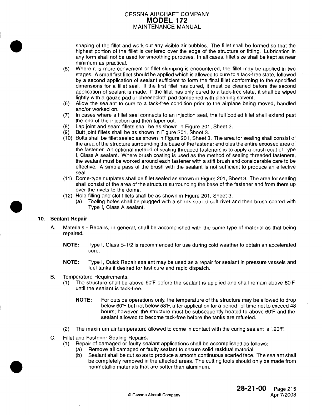
CESSNA AIRCRAFT
COMPANY
MODEL
172
MAINTENANCE
MANUAL
shaping
of
the
fillet
and
work
out
any
visible
air bubbles.
The
fillet
shall
be
formed
so
that
the
highest
portion
of
the
fillet
is
centered
over
the
edge
of
the
structure
or
fitting.
Lubrication
in
any
form
shall
not
be
used
for
smoothing purposes.
In
all
cases,
fillet
size
shall
be
kept
as
near
minimum
as
practical.
(5)
Where
it
is
more
convenient
or
fillet
slumping
is
encountered,
the
fillet may
be
applied
in
two
stages.
A
small
first fillet
should
be
applied which
is
allowed
to
cure
to
a
tack-free
state,
followed
by
a
second
application
of
sealant sufficient
to
form
the final
fillet
conforming
to
the
specified
dimensions
for
a
fillet
seal.
If
the
first
fillet
has
cured,
it
must
be
cleaned
before the
second
application
of sealant
is
made.
If
the
fillet
has
only cured
to
a
tack-free state,
it
shall
be
wiped
lightly
with
a
gauze pad
or
cheesecloth
pad
dampened
with
cleaning
solvent.
(6)
Allow
the
sealant
to
cure
to
a
tack-free
condition
prior
to
the
airplane being
moved,
handled
and/or
worked
on.
(7) In
cases
where
a
fillet
seal
connects
to
an
injection seal, the
full bodied
fillet
shall
extend
past
the
end
of
the injection
and
then
taper
out.
(8)
Lap
joint
and
seam
fillets
shall
be
as
shown
in
Figure
201,
Sheet
3.
(9)
Butt
joint
fillets
shall
be
as
shown
in
Figure
201,
Sheet
3.
(10)
Bolts
shall
be
fillet
sealed
as
shown
in
Figure
201,
Sheet
3.
The
area
for
sealing
shall
consist
of
the
area
of
the
structure
surrounding
the base
of
the
fastener
end plus
the
entire exposed area
of
the
fastener.
An
optional
method
of
sealing threaded
fasteners
is
to
apply
a
brush
coat
of
Type
I,
Class
A
sealant.
Where brush
coating
is
used
as
the
method of
sealing
threaded fasteners,
the
sealant
must
be
worked
around
each
fastener
with
a
stiff
brush
and
considerable
care
to
be
effective.
A
simple
pass
of
the
brush
with
the
sealant
is
not
sufficient
to
produce
an
effective
seal.
(11)
Dome-type
nutplates shall
be
fillet
sealed
as shown
in
Figure
201,
Sheet
3.
The
area
for
sealing
shall
consist
of
the area
of
the structure surrounding
the
base
of
the
fastener
and
from
there
up
over
the
rivets
to
the
dome.
(12)
Hole
filling
and slot
fillets
shall
be
as
shown
in
Figure
201,
Sheet
3.
(a)
Tooling
holes
shall
be
plugged
with
a
shank sealed soft
rivet
and
then
brush
coated with
Type
I,
Class
A
sealant.
10.
Sealant
Repair
A.
Materials
-
Repairs,
in
general,
shall
be
accomplished
with
the same
type
of
material
as
that
being
repaired.
NOTE:
Type
I,
Class
B-1/2
is
recommended
for
use
during
cold
weather
to
obtain
an
accelerated
cure.
NOTE:
Type
I,
Quick
Repair
sealant
may
be
used
as
a
repair
for
sealant
in
pressure
vessels
and
fuel
tanks
if
desired
for
fast
cure
and
rapid
dispatch.
B.
Temperature
Requirements.
(1)
The
structure shall
be
above
60°F
before
the
sealant
is
ap
plied and
shall
remain
above
60°F
until
the
sealant
is
tack-free.
NOTE:
For
outside
operations
only,
the
temperature
of
the
structure
may
be
allowed
to
drop
below
60°F
but
not
below
58°F,
after
application
for
a
period
of
time
not
to
exceed
48
hours;
however,
the
structure
must
be
subsequently
heated
to
above
60°F
and
the
sealant
allowed
to
become
tack-free
before the
tanks
are refueled.
(2)
The
maximum
air temperature
allowed
to
come
in
contact
with
the
curing
sealant
is
120°F.
C.
Fillet and
Fastener
Sealing Repairs.
(1)
Repair
of
damaged
or
faulty
sealant
applications
shall
be
accomplished
as
follows:
(a)
Remove
all
damaged
or
faulty sealant
to
ensure solid
residual
material.
(b)
Sealant shall
be
cut
so
as
to
produce
a
smooth
continuous
scarfed
face. The
sealant
shall
be
completely
removed
in
the
affected areas.
The
cutting
tools
should
only
be
made from
nonmetallic
materials
that
are
softer
than
aluminum.
28-21-00
Page
215
©
Cessna
Aircraft
Company
Apr
7/2003
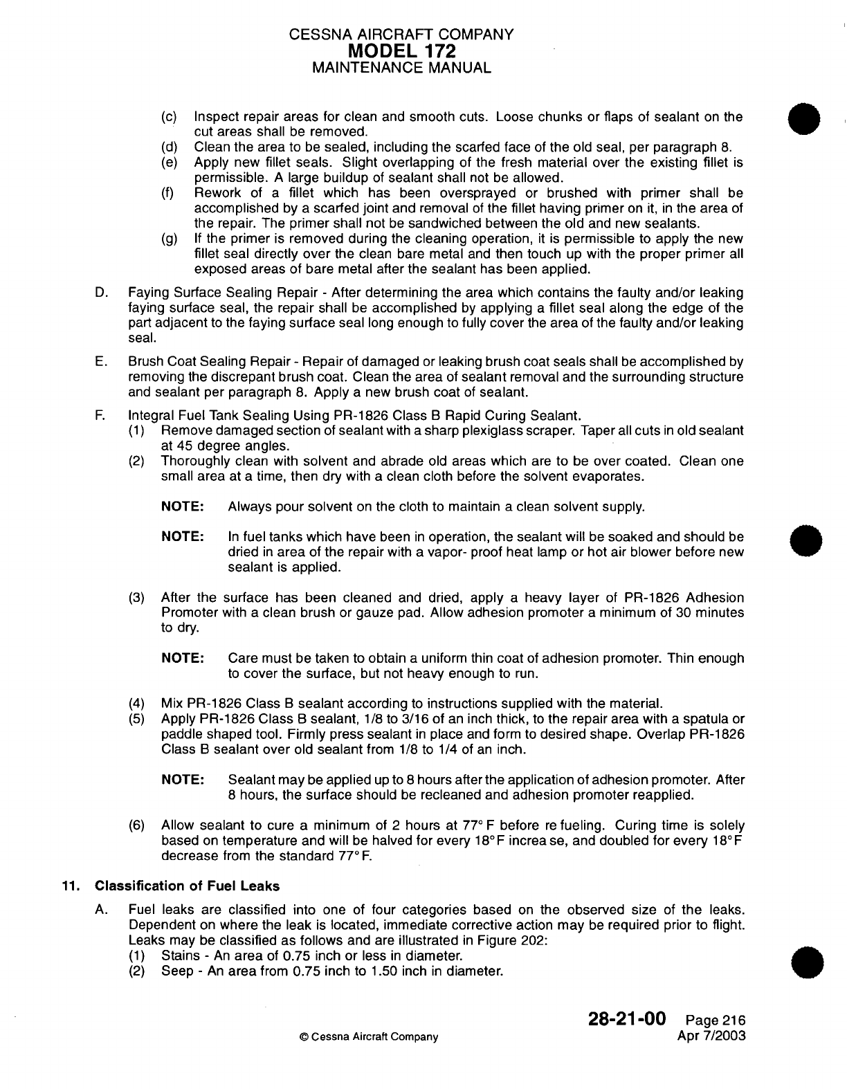
CESSNA
AIRCRAFT
COMPANY
MODEL
172
MAINTENANCE
MANUAL
(c)
Inspect
repair
areas
for
clean
and
smooth cuts. Loose
chunks
or
flaps
of
sealant
on
the
cut areas
shall
be
removed.
(d)
Clean
the
area
to
be
sealed,
including
the
scarfed
face
of
the
old
seal,
per
paragraph
8.
(e)
Apply
new
fillet
seals.
Slight
overlapping
of
the fresh
material over
the
existing
fillet
is
permissible.
A
large
buildup
of
sealant
shall
not be
allowed.
(f)
Rework
of
a
fillet
which
has been
oversprayed
or
brushed
with
primer
shall
be
accomplished
by
a
scarfed
joint
and removal
of
the
fillet
having
primer
on
it, in
the
area
of
the
repair.
The
primer shall
not
be
sandwiched
between
the
old
and
new
sealants.
(g) If
the primer
is
removed
during
the
cleaning
operation,
it
is
permissible
to
apply
the
new
fillet
seal
directly over
the
clean
bare
metal
and
then touch
up
with
the
proper primer
all
exposed
areas
of
bare metal after the
sealant
has
been
applied.
D.
Faying
Surface
Sealing
Repair
-
After
determining
the
area
which
contains
the
faulty and/or
leaking
faying
surface
seal,
the
repair
shall
be
accomplished
by
applying
a
fillet
seal along
the
edge
of
the
part
adjacent
to
the
faying
surface
seal
long
enough
to
fully
cover
the
area
of
the
faulty
and/or
leaking
seal.
E.
Brush
Coat
Sealing
Repair
-
Repair
of
damaged
or
leaking brush coat
seals shall
be
accomplished
by
removing
the
discrepant
brush coat.
Clean
the area
of
sealant
removal
and
the
surrounding
structure
and
sealant
per
paragraph
8.
Apply
a
new
brush
coat
of
sealant.
F.
Integral
Fuel Tank
Sealing
Using PR-1826
Class
B
Rapid
Curing
Sealant.
(1)
Remove damaged
section
of
sealant
with
a
sharp
plexiglass
scraper.
Taper
all
cuts
in
old
sealant
at
45 degree
angles.
(2)
Thoroughly
clean
with
solvent
and
abrade
old
areas
which
are
to
be
over coated. Clean
one
small
area
at
a
time,
then
dry
with
a
clean
cloth
before the
solvent
evaporates.
NOTE:
Always
pour
solvent
on
the
cloth
to
maintain
a
clean
solvent
supply.
NOTE:
In
fuel
tanks which
have
been
in
operation,
the
sealant
will
be
soaked
and
should
be
dried
in
area
of
the
repair
with
a
vapor-
proof
heat lamp
or
hot air
blower before
new
sealant
is
applied.
(3)
After
the
surface
has
been
cleaned
and
dried,
apply
a
heavy
layer
of
PR-1826
Adhesion
Promoter with
a
clean brush
or
gauze
pad.
Allow adhesion promoter
a
minimum
of
30
minutes
to dry.
NOTE:
Care
must
be
taken
to
obtain
a
uniform thin
coat
of
adhesion
promoter. Thin
enough
to
cover the
surface,
but
not
heavy
enough
to
run.
(4)
Mix
PR-1826 Class
B
sealant
according
to
instructions
supplied
with
the
material.
(5)
Apply
PR-1826 Class
B
sealant,
1/8
to
3/16
of
an
inch
thick,
to
the
repair area
with
a
spatula
or
paddle
shaped tool. Firmly press sealant
in
place
and
form
to
desired shape.
Overlap
PR-1826
Class
B
sealant
over
old
sealant
from
1/8
to 1/4 of
an
inch.
NOTE:
Sealant
may
be
applied
up
to
8
hours
after
the
application
of
adhesion
promoter.
After
8
hours,
the
surface
should
be
recleaned and
adhesion promoter reapplied.
(6)
Allow
sealant
to
cure
a
minimum
of
2
hours
at
77°
F
before
re
fueling.
Curing time
is
solely
based
on
temperature
and
will
be
halved
for
every
18°F increa
se,
and
doubled
for every
18°F
decrease
from
the
standard
77°
F.
11.
Classification
of
Fuel
Leaks
A.
Fuel
leaks
are
classified
into
one
of
four
categories
based
on
the observed size
of
the
leaks.
Dependent
on
where
the leak
is
located, immediate
corrective
action
may
be
required
prior
to
flight.
Leaks
may be
classified
as
follows
and
are
illustrated
in
Figure
202:
(1)
Stains
-
An
area
of
0.75
inch
or
less
in
diameter.
(2)
Seep
-
An
area
from
0.75
inch
to
1.50
inch
in
diameter.
28-21-00
Page
216
©
Cessna
Aircraft
Company
Apr
7/2003
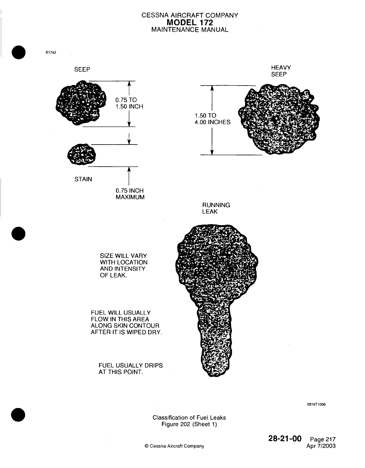
CESSNA
AIRCRAFT
COMPANY
MODEL
172
MAINTENANCE
MANUAL
B1742
HEAVY
SEEP
0.75
TO
1.50
INCH
I
1.50
TO
4.00 INCHES
I
STAIN
0.75
INCH
MAXIMUM
RUNNING
LEAK
SIZE
WILL
VARY
WITH LOCATION
AND INTENSITY
OF LEAK.
FUEL
WILL USUALLY
FLOW
IN
THIS
AREA
ALONG
SKIN
CONTOUR
AFTER
IT
IS
WIPED
DRY.
FUEL
USUALLY DRIPS
AT
THIS
POINT.
Classification
of
Fuel
Leaks
Figure
202
(Sheet
1)
©
Cessna
Aircraft
Company
SEEP
0516T1006
28-21-00
Page
217
Apr
7/2003
4
0
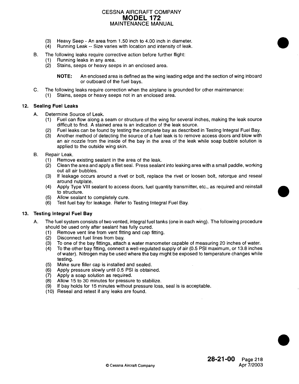
CESSNA AIRCRAFT
COMPANY
MODEL
172
MAINTENANCE
MANUAL
(3)
Heavy
Seep
-
An
area
from 1.50 inch
to
4.00
inch
in
diameter.
(4)
Running
Leak
--
Size
varies
with
location
and
intensity
of
leak.
B.
The
following
leaks
require
corrective
action
before
further
flight:
(1)
Running leaks
in
any
area.
(2)
Stains,
seeps
or
heavy
seeps
in
an
enclosed
area.
NOTE:
An
enclosed
area
is
defined
as
the wing leading
edge
and
the
section
of
wing
inboard
or
outboard of
the
fuel
bays.
C.
The
following leaks
require
correction
when
the
airplane
is
grounded
for
other
maintenance:
(1)
Stains,
seeps
or
heavy
seeps
not
in
an
enclosed
area.
12.
Sealing
Fuel
Leaks
A.
Determine
Source
of
Leak.
(1)
Fuel
can
flow
along
a
seam
or structure
of
the
wing
for several
inches,
making the
leak source
difficult
to
find.
A
stained
area
is
an
indication
of
the
leak
source.
(2)
Fuel
leaks
can
be
found
by
testing the complete
bay
as
described
in
Testing
Integral
Fuel Bay.
(3)
Another
method
of
detecting
the
source
of
a
fuel
leak
is
to
remove
access
doors
and
blow
with
an
air
nozzle
from
the
inside
of the
bay
in
the
area
of
the leak
while
soap bubble
solution
is
applied
to
the
outside
wing
skin.
B.
Repair
Leak.
(1)
Remove
existing
sealant
in
the area
of the leak.
(2)
Clean the
area
and
apply
a
filet
seal.
Press
sealant
into
leaking
area
with
a
small paddle, working
out
all
air
bubbles.
(3) If
leakage
occurs
around
a
rivet
or
bolt, replace
the
rivet
or
loosen
bolt,
retorque
and
reseal
around
nutplate.
(4)
Apply
Type
VIII
sealant
to
access
doors,
fuel
quantity
transmitter,
etc.,
as
required
and
reinstall
to
structure.
(5)
Allow
sealant
to
completely
cure.
(6)
Test
fuel bay for
leakage.
Refer
to
Testing
Integral
Fuel
Bay.
13.
Testing
Integral
Fuel
Bay
A.
The
fuel
system
consists
of
two
vented,
integral
fuel
tanks
(one
in
each wing).
The
following
procedure
should
be
used
only
after
sealant
has
fully
cured.
(1)
Remove
vent
line from
vent
fitting
and
cap
fitting.
(2)
Disconnect fuel
lines
from
bay.
(3)
To
one
of
the
bay
fittings, attach
a
water
manometer
capable
of
measuring
20
inches
of water.
(4)
To
the other bay
fitting,
connect
a
well-regulated supply
of
air
(0.5
PSI
maximum,
or
13.8
inches
of
water).
Nitrogen
may
be
used
where the
bay might
be
exposed
to
temperature changes
while
testing.
(5)
Make sure
filler
cap
is
installed
and
sealed.
(6)
Apply
pressure
slowly
until
0.5
PSI
is
obtained.
(7)
Apply
a
soap solution
as
required.
(8)
Allow
15
to 30
minutes
for
pressure
to
stabilize.
(9) If
bay holds for
15
minutes
without
pressure
loss,
seal
is
is
acceptable.
(10)
Reseal
and
retest
if
any
leaks
are
found.
28-21-00
Page
218
©
Cessna
Aircraft
Company
Apr 7/2003

CHAPTER
INDICATING/
RECORDING
SYSTEMS

CESSNA
AIRCRAFT
COMPANY
MODEL
172
MAINTENANCE
MANUAL
LIST
OF
EFFECTIVE PAGES
CHAPTER-SECTION-SUBJECT
31-Title
31-List
of
Effective
Pages
31-Record
of
Temporary
Revisions
31-Table
of
Contents
31-00-00
31-10-00
31-10-10
31-20-00
31-30-00
31-50-00
©
Cessna Aircraft
Company
PAGE
Page
1
Pages
201-202
Pages
201-203
Page
201
Pages
201-202
Pages
201-203
DATE
Apr
7/2003
Apr
7/2003
Jan
2/2006
Apr
7/2003
Apr
7/2003
Apr
7/2003
31
-
LIST
OF
EFFECTIVE
PAGES
Page
1
of
1
Jan
2/2006
Temporary
Revision
Number
RECORD OF
TEMPORARY
REVISIONS
Page
Number
Issue
Date
By
Date
Removed
By
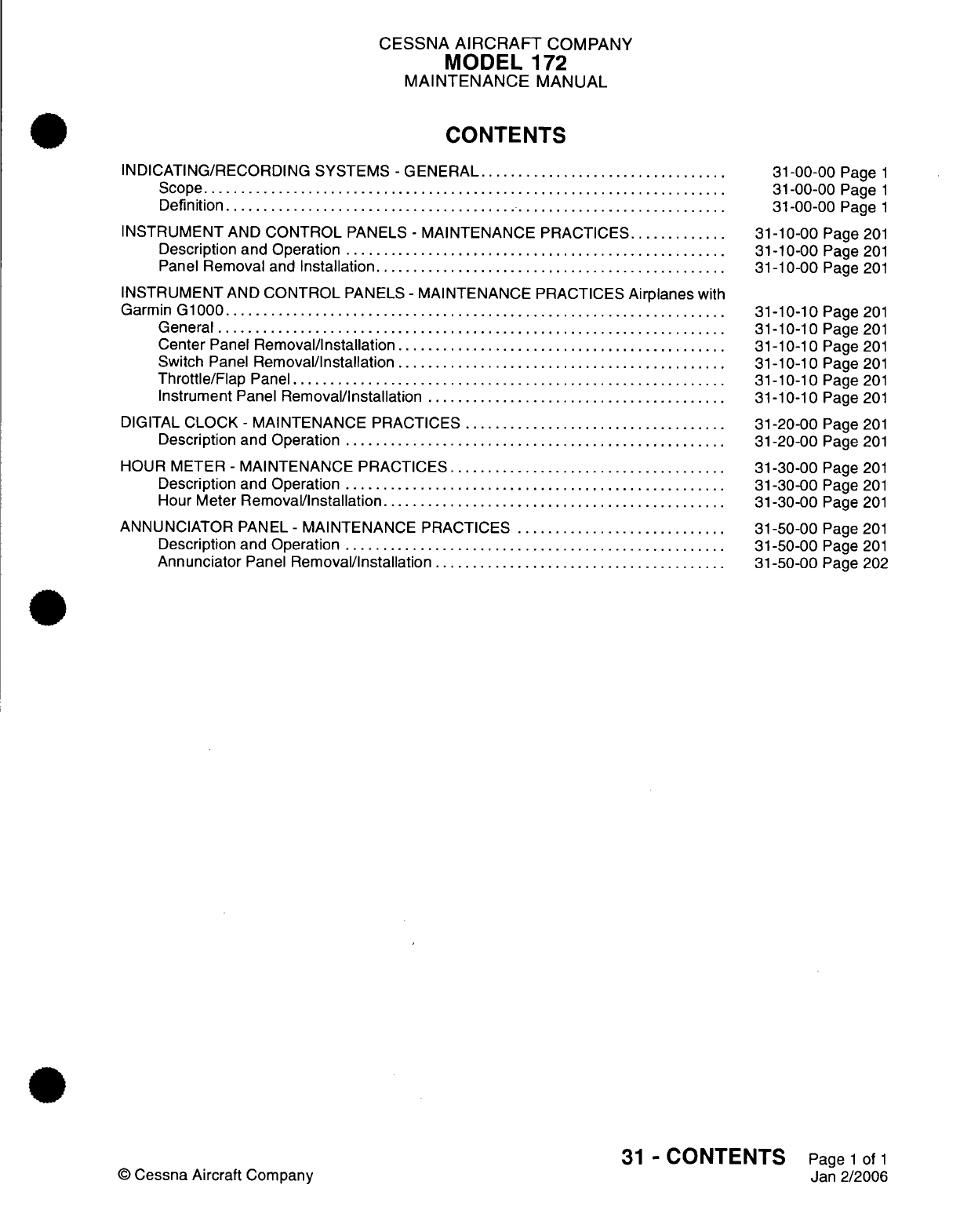
CESSNA
AIRCRAFT
COMPANY
MODEL
172
MAINTENANCE
MANUAL
CONTENTS
INDICATING/RECORDING SYSTEMS
-
GENERAL
.................................
Scope......................................................................
Definition...................................................................
INSTRUMENT
AND
CONTROL
PANELS
-
MAINTENANCE
PRACTICES.............
Description and Operation
...................................................
Panel
Removal
and
Installation...............................................
INSTRUMENT
AND
CONTROL
PANELS
-
MAINTENANCE PRACTICES
Airplanes
with
Garmin
G1000...................................................................
General
....................................................................
Center
Panel
Removal/Installation............................................
Switch
Panel
Removal/Installation
......... ...........
....................
Throttle/Flap
Panel..........................
................................
Instrument
Panel
Removal/Installation
........................................
DIGITAL
CLOCK
-
MAINTENANCE
PRACTICES
...................................
Description
and
Operation
...................................................
HOUR
METER
-
MAINTENANCE
PRACTICES.....................................
Description and Operation
...................................................
Hour
Meter
Removal/Installation
..............................
........
ANNUNCIATOR
PANEL
-
MAINTENANCE
PRACTICES
............................
Description and Operation
...................................................
Annunciator
Panel
Removal/Installation
.......................................
31-00-00
Page
1
31-00-00
Page
1
31-00-00
Page
1
31-10-00
Page 201
31-10-00
Page
201
31-10-00
Page
201
31-10-10
Page 201
31-10-10
Page 201
31-10-10
Page 201
31-10-10
Page 201
31-10-10
Page 201
31-10-10
Page 201
31-20-00
Page 201
31-20-00
Page
201
31-30-00
Page
201
31-30-00
Page
201
31-30-00
Page
201
31-50-00
Page 201
31-50-00
Page
201
31-50-00
Page
202
31
-
CONTENTS
Page
1
of
1
Jan
2/2006
©
Cessna Aircraft
Company
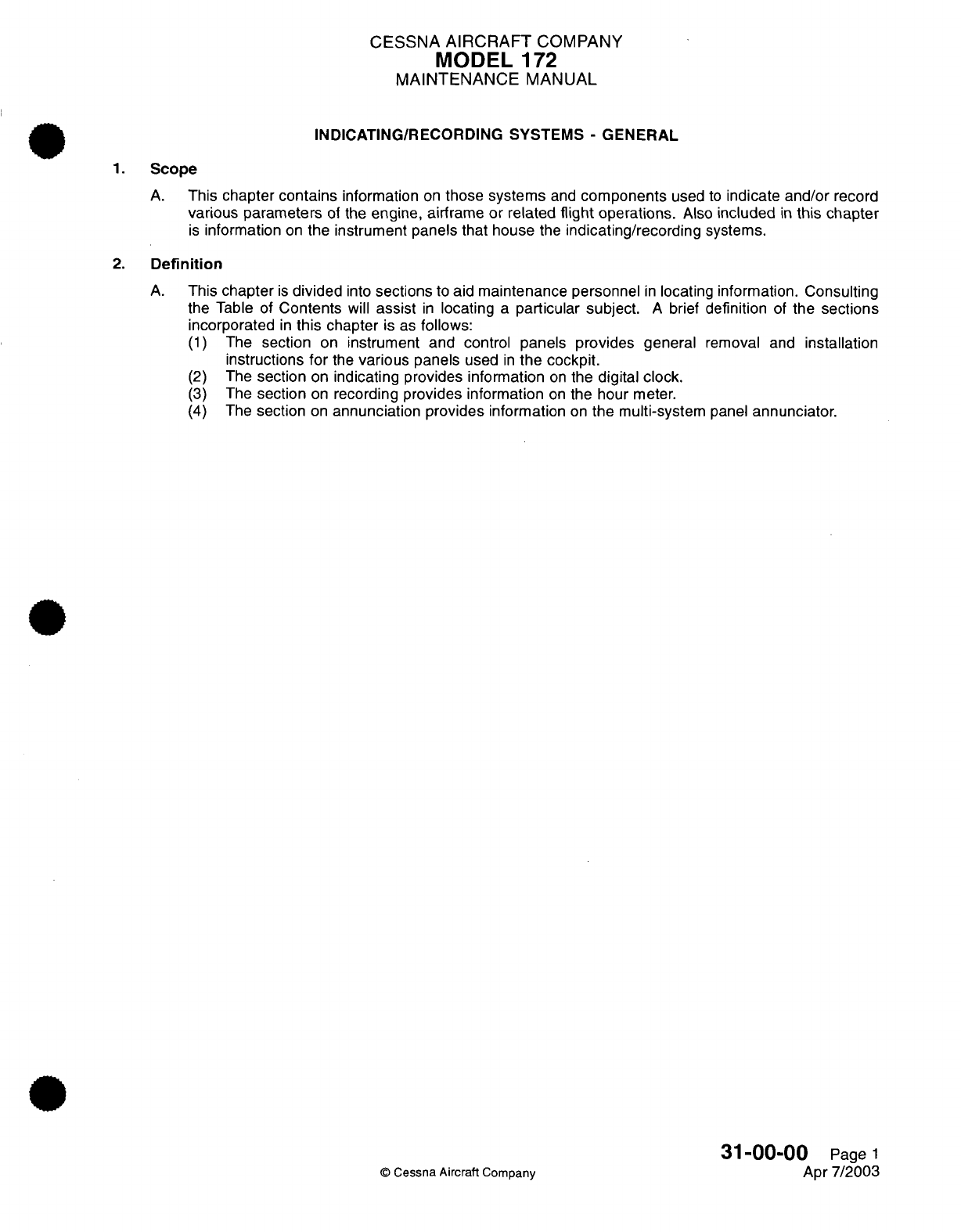
CESSNA
AIRCRAFT
COMPANY
MODEL
172
MAINTENANCE
MANUAL
INDICATING/RECORDING SYSTEMS
-
GENERAL
1.
Scope
A.
This
chapter
contains
information
on
those
systems
and
components
used
to
indicate
and/or record
various
parameters
of
the
engine,
airframe
or
related
flight
operations.
Also
included
in
this
chapter
is
information
on
the instrument
panels
that house
the
indicating/recording
systems.
2.
Definition
A.
This
chapter
is
divided
into
sections
to
aid
maintenance personnel
in
locating information.
Consulting
the
Table
of
Contents
will
assist
in
locating
a
particular
subject.
A
brief
definition
of
the
sections
incorporated
in
this
chapter
is
as
follows:
(1)
The
section
on
instrument and
control
panels
provides
general
removal
and
installation
instructions
for
the
various
panels
used
in
the cockpit.
(2)
The
section
on
indicating provides information
on
the
digital
clock.
(3)
The
section
on
recording
provides
information
on
the
hour
meter.
(4)
The
section
on
annunciation provides
information
on
the
multi-system
panel
annunciator.
31-00-00
Page
1
©
Cessna
Aircraft
Company
Apr
7/2003
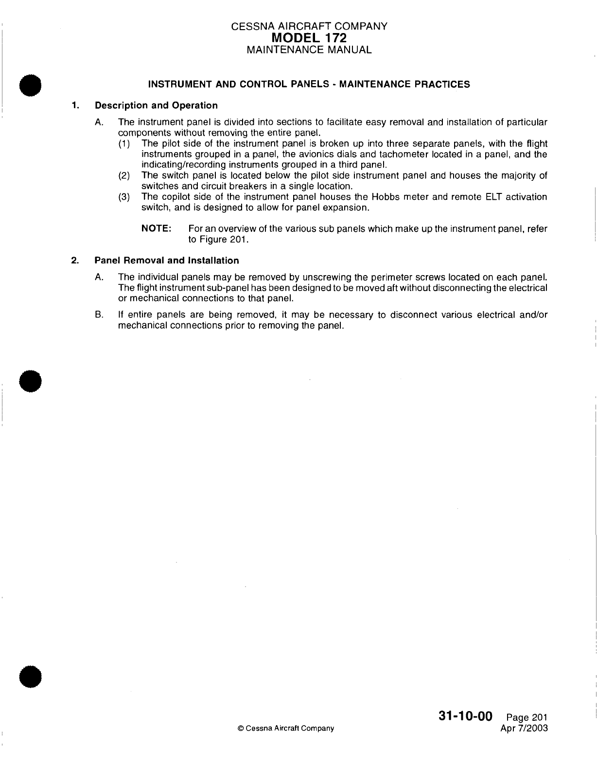
CESSNA
AIRCRAFT
COMPANY
MODEL
172
MAINTENANCE
MANUAL
INSTRUMENT
AND
CONTROL
PANELS
-
MAINTENANCE
PRACTICES
1.
Description
and
Operation
A.
The
instrument
panel
is
divided
into
sections
to
facilitate
easy
removal
and
installation
of
particular
components
without
removing
the
entire
panel.
(1)
The
pilot side
of
the
instrument
panel
is
broken
up
into
three
separate
panels,
with
the
flight
instruments
grouped
in a
panel, the
avionics dials
and
tachometer
located
in a
panel,
and
the
indicating/recording
instruments grouped
in a
third
panel.
(2)
The
switch
panel
is
located below
the
pilot
side
instrument
panel
and
houses
the
majority
of
switches
and
circuit
breakers
in
a
single
location.
(3)
The
copilot
side
of
the
instrument
panel
houses the Hobbs meter
and
remote
ELT
activation
switch,
and
is
designed
to
allow
for
panel
expansion.
NOTE:
For
an
overview
of
the
various
sub
panels which
make
up
the
instrument
panel,
refer
to
Figure
201.
2.
Panel
Removal
and
Installation
A.
The
individual
panels
may
be
removed
by
unscrewing
the
perimeter
screws
located
on
each
panel.
The
flight
instrument
sub-panel
has
been
designed
to
be
moved
aft
without
disconnecting
the
electrical
or
mechanical
connections
to
that panel.
B. If
entire
panels
are
being
removed,
it
may be
necessary
to
disconnect
various
electrical and/or
mechanical
connections
prior
to
removing
the panel.
31-10-00
Page
201
©
Cessna
Aircraft
Company
Apr
7/2003
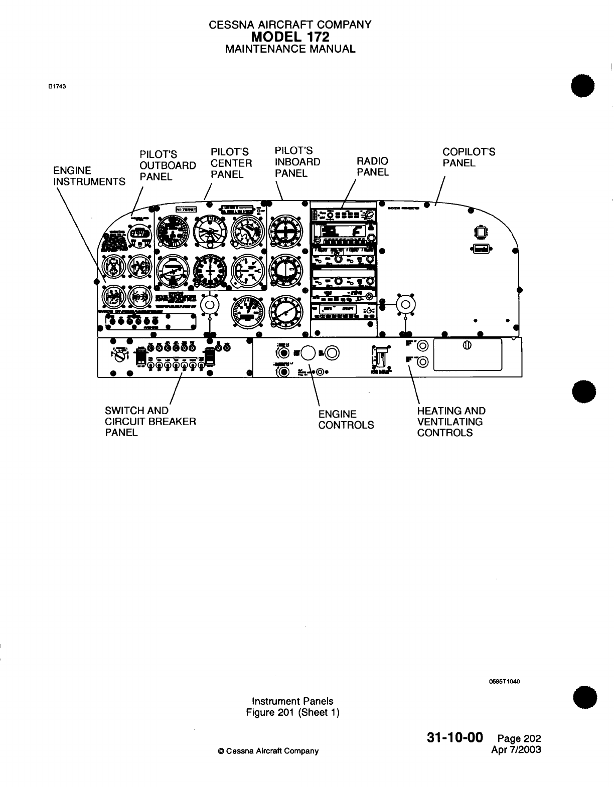
CESSNA AIRCRAFT
COMPANY
MODEL
172
MAINTENANCE
MANUAL
B1743
PILOT'S
OUTBOARD
PANEL
COPILOT'S
PANEL
.6
of
/
0
«*
JC
.
>.o
I
R@.
a
SWITCH
AND
CIRCUIT
BREAKER
PANEL
ENGINE
CONTROLS
HEATING
AND
VENTILATING
CONTROLS
Instrument
Panels
Figure
201
(Sheet
1)
O
Cessna
Aircraft
Company
31-'10-00
Page
202
Apr
7/2003
ENGINE
PILOT'S
CENTER
PANEL
PILOT'S
INBOARD
PANEL RADIO
PANEL
/
0
a
a
.
I
0585T1040
0
r-~L
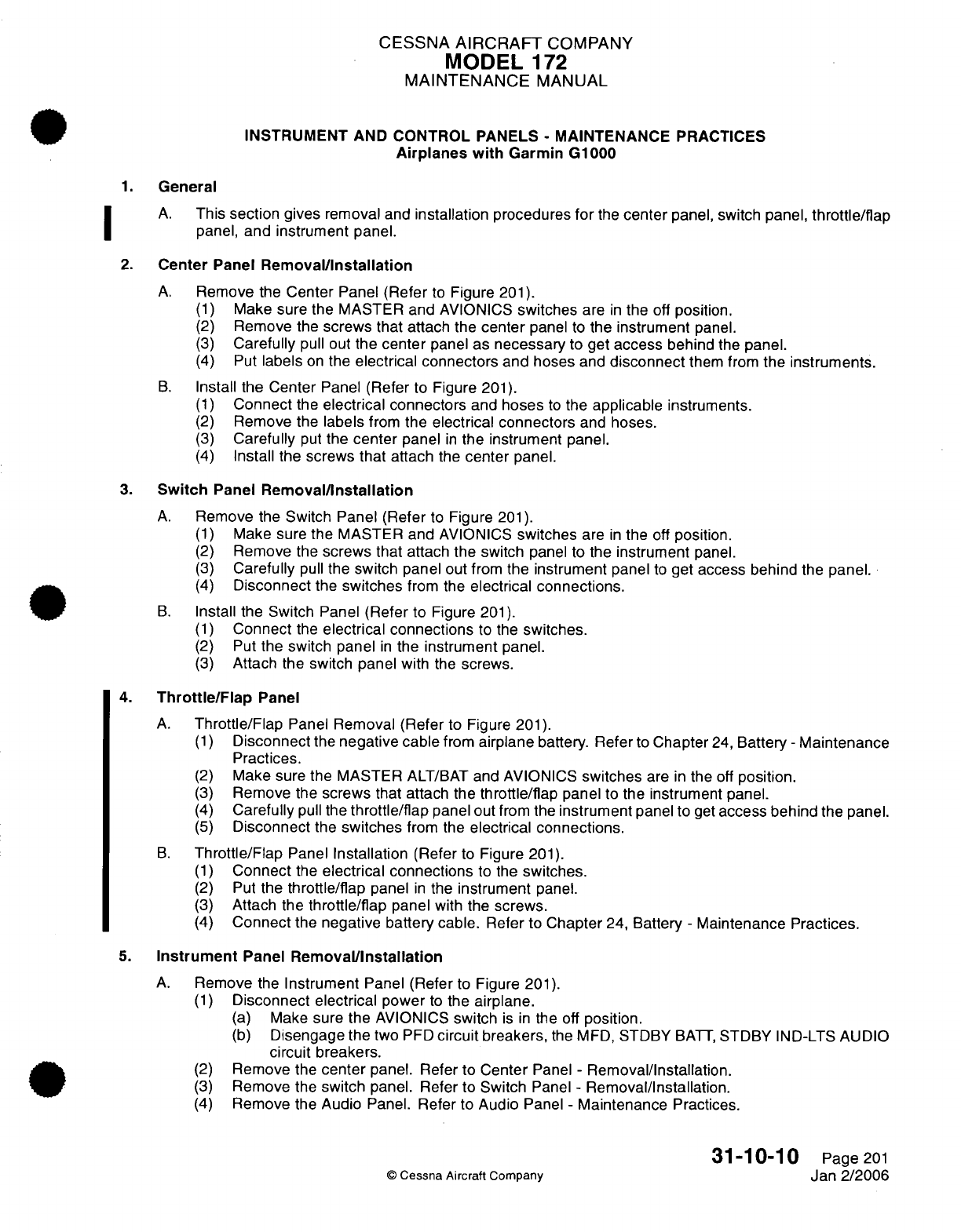
CESSNA
AIRCRAFT
COMPANY
MODEL
172
MAINTENANCE
MANUAL
INSTRUMENT
AND
CONTROL
PANELS
-
MAINTENANCE
PRACTICES
Airplanes
with
Garmin
G1000
1.
General
A.
This
section
gives
removal
and
installation
procedures
for
the
center
panel, switch panel,
throttle/flap
panel,
and
instrument
panel.
2.
Center
Panel
Removal/Installation
A.
Remove
the
Center
Panel
(Refer
to
Figure
201).
(1)
Make
sure the MASTER and
AVIONICS
switches
are
in
the
off
position.
(2)
Remove
the
screws
that attach
the
center
panel
to
the
instrument
panel.
(3)
Carefully
pull
out
the
center
panel
as
necessary
to
get
access
behind
the
panel.
(4)
Put
labels
on
the
electrical connectors
and
hoses
and
disconnect
them
from
the
instruments.
B.
Install the
Center
Panel
(Refer
to Figure
201).
(1)
Connect
the
electrical connectors
and
hoses
to
the
applicable
instruments.
(2)
Remove
the
labels
from
the
electrical connectors
and
hoses.
(3)
Carefully
put
the
center
panel
in
the instrument panel.
(4)
Install the screws
that
attach
the
center
panel.
3.
Switch
Panel
Removal/Installation
A.
Remove
the
Switch
Panel (Refer
to
Figure
201).
(1)
Make sure
the
MASTER and
AVIONICS
switches
are
in
the
off
position.
(2)
Remove
the
screws that
attach the switch
panel
to
the
instrument
panel.
(3)
Carefully
pull
the
switch panel
out
from
the instrument
panel
to
get
access behind
the
panel.
(4)
Disconnect
the
switches
from the
electrical
connections.
B.
Install
the
Switch Panel
(Refer
to Figure
201).
(1)
Connect
the
electrical connections
to
the
switches.
(2)
Put
the switch panel
in
the
instrument
panel.
(3)
Attach
the
switch panel
with
the
screws.
4.
Throttle/Flap
Panel
A.
Throttle/Flap
Panel
Removal
(Refer
to
Figure
201).
(1)
Disconnect
the
negative cable
from
airplane
battery. Refer
to
Chapter
24,
Battery
-
Maintenance
Practices.
(2)
Make
sure
the
MASTER
ALT/BAT
and
AVIONICS
switches
are
in
the
off
position.
(3)
Remove
the
screws that attach
the
throttle/flap
panel
to
the
instrument
panel.
(4)
Carefully
pull
the
throttle/flap
panel
out
from
the
instrument
panel
to
get
access behind
the
panel.
(5)
Disconnect
the
switches
from
the
electrical
connections.
B.
Throttle/Flap
Panel
Installation
(Refer
to
Figure
201).
(1)
Connect
the
electrical
connections
to the
switches.
(2)
Put
the
throttle/flap
panel
in
the
instrument
panel.
(3)
Attach
the
throttle/flap
panel
with
the
screws.
(4)
Connect
the
negative battery
cable.
Refer
to
Chapter
24,
Battery
-
Maintenance
Practices.
5.
Instrument
Panel
Removal/Installation
A.
Remove
the
Instrument
Panel (Refer
to
Figure
201).
(1)
Disconnect
electrical
power
to
the
airplane.
(a)
Make
sure
the
AVIONICS
switch
is
in
the
off
position.
(b)
Disengage the
two
PFD
circuit
breakers,
the
MFD,
STDBY
BATT,
STDBY
IND-LTS AUDIO
circuit
breakers.
(2)
Remove
the
center
panel.
Refer
to
Center
Panel
-
Removal/Installation.
(3)
Remove
the
switch
panel. Refer
to
Switch
Panel
-
Removal/Installation.
(4)
Remove
the
Audio
Panel.
Refer
to
Audio
Panel
-
Maintenance
Practices.
31-10-10
Page
201
C
Cessna
Aircraft
Company
Jan
2/2006
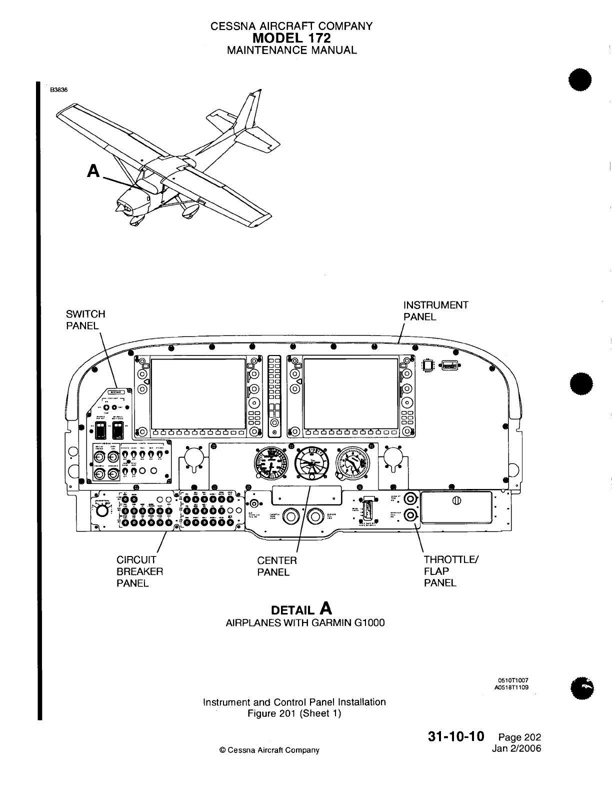
CESSNA
AIRCRAFT
COMPANY
MODEL
172
MAINTENANCE
MANUAL
INSTRUMENT
PANEL
/
00
CIRCUIT
CENTER
BREAKER PANEL
PANEL
THROTTLE/
FLAP
PANEL
DETAIL
A
AIRPLANES
WITH
GARMIN
G1000
0510T1007
A051T1
109
Instrument and
Control
Panel
Installation
Figure
201
(Sheet
1)
©
Cessna
Aircraft Company
31-10-10
Page
202
Jan
2/2006
SWITCH
PANEL
CESSNA
AIRCRAFT
COMPANY
MODEL
172
MAINTENANCE
MANUAL
(5)
Remove
the
screws that
attach
the
control
column
collars
to
the
instrument
panel.
(6)
Remove
the
hourmeter.
(a)
Remove
the
screws for
the
hourmeter.
(b)
Pull
the
hourmeter
out
and
disconnect
the
connector.
(7)
Remove
the
Control Display
Units
(CDU).
Refer
to
Control
Display
Unit
(CDU)
-
Maintenance
Practices.
(8)
Remove
the
screws
from the
instrument panel.
(9)
Disconnect
and
remove
the
ELT
switch
from
the
instrument
panel.
NOTE:
The
ELT
switch
can
only
be
removed
from
the
back
of the
instrument
panel.
(10)
Remove
the instrument
panel.
B.
Install
the
Instrument
Panel (Refer
to
Figure
201).
(1)
Put
the
instrument
panel
in
position.
(2)
Install the
ELT
switch
and
connect
the
electrical
connector.
(3)
Install
the
instrument
panel
screws.
(a)
Make sure to put the
electrical
connector
for
the
hourmeter
through
the
panel
hole
for
the
hourmeter
installation.
(4)
Connect
the
electrical connector
to
the hourmeter.
(5)
Install the
hourmeter.
(6)
Attach
the
collar
for
the
control column
to
the instrument
panel.
(7)
Put
the
switch
panel
in
position
and
connect
the
electrical connections
to
the
switches.
(8)
Install the switch
panel
to
the instrument
panel
with
the screws.
(9)
Put
the
center
panel
in
position
and
connect
the
electrical
connectors
and
vacuum
hoses
to the
instruments.
(10)
Install
the
center
panel
to
the instrument panel
with
the
screws.
(11)
Install
the
Control Display
Units
(CDU).
Refer
to
Control
Display
Unit
(CDU)
-
Maintenance
Practices.
31-10-10
Page
203
©
Cessna Aircraft
Company
Jan
2/2006
CESSNA
AIRCRAFT
COMPANY
MODEL
172
MAINTENANCE
MANUAL
DIGITAL
CLOCK
-
MAINTENANCE
PRACTICES
1.
Description
and
Operation
A.
The
digital
clock
is
located
in
upper
left
side
of
the instrument panel
and
incorporates
clock,
temperature
and
voltage
readings
in
a
single
unit.
For
removal/installation
of
the
OAT/Clock,
refer
to
Chapter
34,
Outside
Air
Temperature Gauge
-
Maintenance
Practices.
31-20-00
Page
201
©
Cessna
Aircraft
Company
Apr
7/2003
CESSNA AIRCRAFT
COMPANY
MODEL
172
MAINTENANCE
MANUAL
HOUR METER
-
MAINTENANCE PRACTICES
1.
Description
and
Operation
A.
The
hour
(Hobbs)
meter
is
located
in
the
upper
right
corner
of
the
instrument
panel and
provides
indication
of
flight
hours based
on
engine
operation.
B.
The
hour meter
receives
power
through
the
WARN
circuit breaker
located
on
the lower
instrument
panel.
The hour meter
is
grounded
through
the
Oil
Pressure
Switch,
and
anytime
oil
pressure
exceeds
20
PSI
a
ground
is
sent
from
the
switch
to
the
hour
meter,
completing
a
circuit and
activating the
hour
meter.
2.
Hour
Meter
Removal/Installation
A.
Remove
Hour Meter
(Refer
to
Figure
201).
(1)
Gain
access
to
backside
of
instrument
panel
and
hold nuts
while
loosening
screws.
(2)
Disconnect electrical
connectors
leading
into
hour
meter.
B.
Install
Hour Meter (Refer
to
Figure
201).
(1)
Connect
electrical connectors
to
hour
meter.
(2)
Install
hour
meter
to
panel
and
secure
using
screws
and
nuts.
©
Cessna
Aircraft Company
31-30-00
Page
201
Apr
7/2003
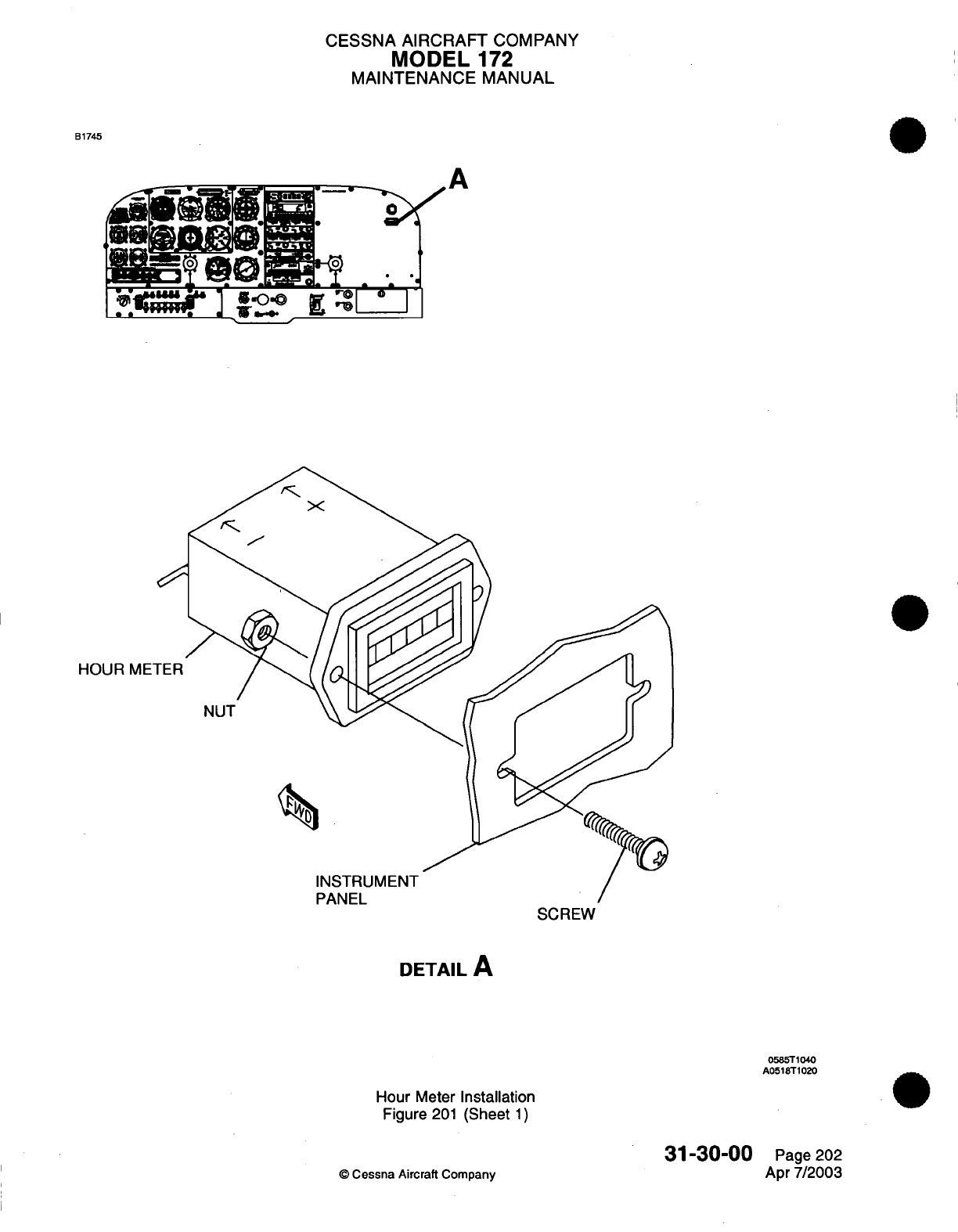
CESSNA
AIRCRAFT
COMPANY
MODEL
172
MAINTENANCE
MANUAL
B1745
II
HOUR
METER
NUT
INSTRUMENT
PANEL
SCREW
DETAIL
A
0585T1040
A0518T1020
Hour
Meter
Installation
Figure
201
(Sheet
1)
31-30-00
©
Cessna
Aircraft Company
Page
202
Apr 7/2003
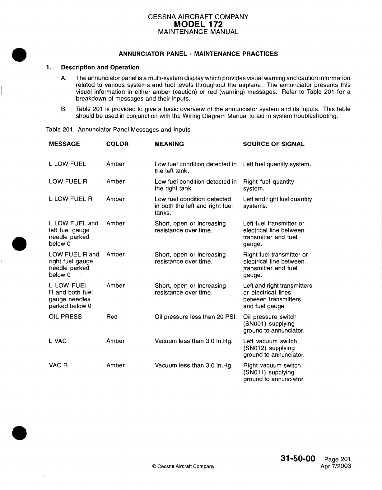
CESSNA
AIRCRAFT
COMPANY
MODEL
-172
MAINTENANCE
MANUAL
ANNUNCIATOR PANEL
-
MAINTENANCE
PRACTICES
1.
Description
and
Operation
A.
The
annunciator
panel
is
a
multi-system
display
which
provides visual
warning
and
caution
information
related
to
various systems
and
fuel
levels throughout
the
airplane.
The
annunciator
presents this
visual
information
in
either
amber (caution)
or
red
(warning)
messages.
Refer
to
Table
201
for
a
breakdown
of
messages
and
their
inputs.
B.
Table
201
is
provided
to
give
a
basic
overview
of the
annunciator
system
and its
inputs.
This
table
should
be
used
in
conjunction
with
the
Wiring
Diagram Manual to
aid
in
system
troubleshooting.
Table 201.
Annunciator
Panel
Messages
and
Inputs
MESSAGE
L
LOW
FUEL
LOW
FUEL
R
L
LOW
FUEL
R
L
LOW FUEL
and
left
fuel
gauge
needle
parked
below
0
LOW
FUEL
R
and
right
fuel
gauge
needle
parked
below
0
L
LOW
FUEL
R
and
both
fuel
gauge
needles
parked
below
0
OIL
PRESS
L
VAC
VAC
R
COLOR
Amber
Amber
Amber
Amber
Amber
Amber
Red
Amber
Amber
MEANING
Low
fuel
condition
detected
in
the
left
tank.
Low
fuel
condition
detected
in
the
right
tank.
Low
fuel
condition
detected
in
both
the
left and
right
fuel
tanks.
Short,
open
or
increasing
resistance
over
time.
Short,
open
or
increasing
resistance
over
time.
Short, open
or
increasing
resistance
over
time.
Oil
pressure
less
than
20
PSI.
Vacuum
less
than
3.0
In.Hg.
Vacuum
less
than
3.0
In.Hg.
©
Cessna
Aircraft
Company
SOURCE
OF
SIGNAL
Left
fuel
quantity
system.
Right fuel quantity
system.
Left
and right
fuel
quantity
systems.
Left
fuel
transmitter
or
electrical
line
between
transmitter
and
fuel
gauge.
Right
fuel
transmitter
or
electrical
line
between
transmitter
and
fuel
gauge.
Left
and
right
transmitters
or
electrical
lines
between
transmitters
and
fuel
gauge.
Oil
pressure
switch
(SN001)
supplying
ground
to
annunciator.
Left
vacuum
switch
(SN012)
supplying
ground
to
annunciator.
Right
vacuum
switch
(SN011)
supplying
ground
to
annunciator.
31-50-00
Page
201
Apr
7/2003
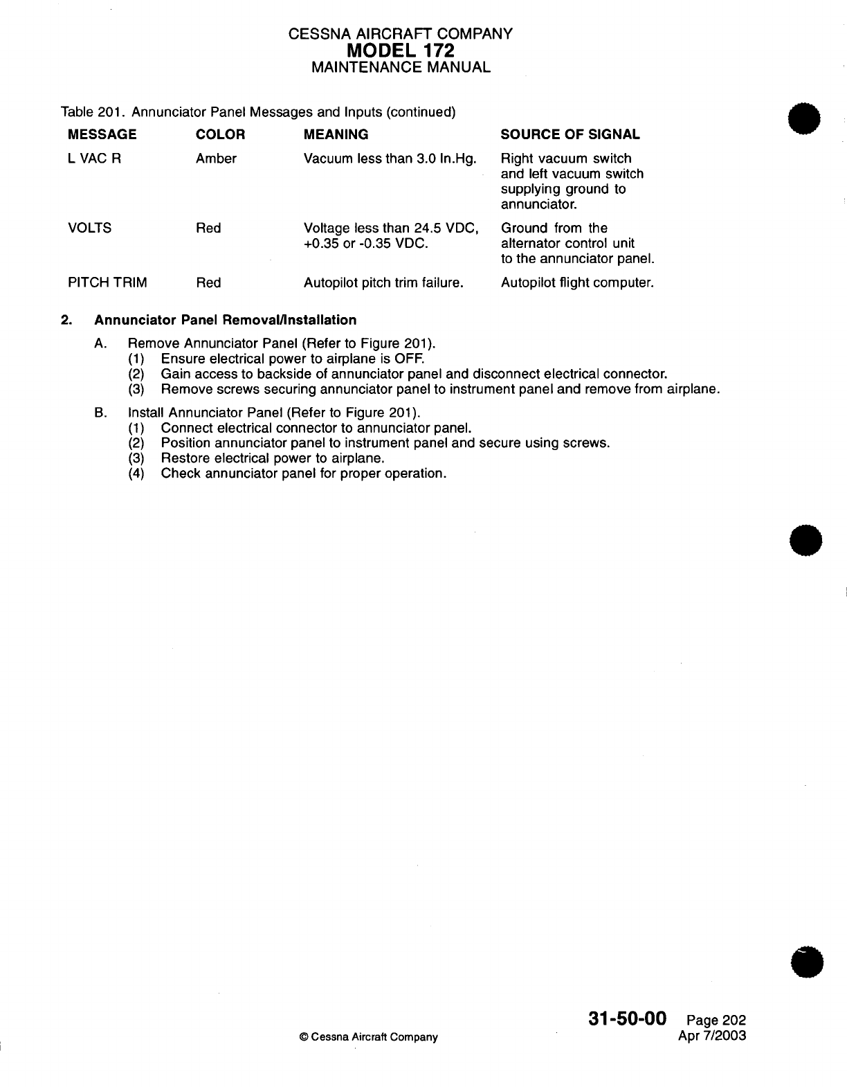
CESSNA AIRCRAFT
COMPANY
MODEL
172
MAINTENANCE
MANUAL
Table
201.
Annunciator
Panel
Messages
and
Inputs
(continued)
MESSAGE
LVAC R
VOLTS
COLOR
Amber
Red
PITCH
TRIM
Red
MEANING
Vacuum
less
than
3.0
In.Hg.
Voltage
less
than 24.5
VDC,
+0.35
or
-0.35
VDC.
Autopilot
pitch trim
failure.
SOURCE
OF
SIGNAL
Right
vacuum switch
and
left
vacuum
switch
supplying
ground
to
annunciator.
Ground
from
the
alternator
control
unit
to
the
annunciator
panel.
Autopilot
flight
computer.
2.
Annunciator
Panel
Removal/Installation
A.
Remove
Annunciator
Panel
(Refer
to
Figure
201).
(1)
Ensure
electrical
power
to
airplane
is
OFF.
(2)
Gain access
to
backside
of
annunciator
panel
and
disconnect electrical
connector.
(3)
Remove
screws
securing
annunciator
panel
to
instrument panel
and
remove
from
airplane.
B.
Install
Annunciator
Panel
(Refer
to Figure
201).
(1)
Connect electrical
connector
to
annunciator
panel.
(2)
Position
annunciator
panel
to
instrument
panel
and
secure
using
screws.
(3)
Restore
electrical
power
to
airplane.
(4)
Check
annunciator
panel
for
proper operation.
31-50-00
Page 202
©
Cessna Aircraft Company
Apr
7/2003
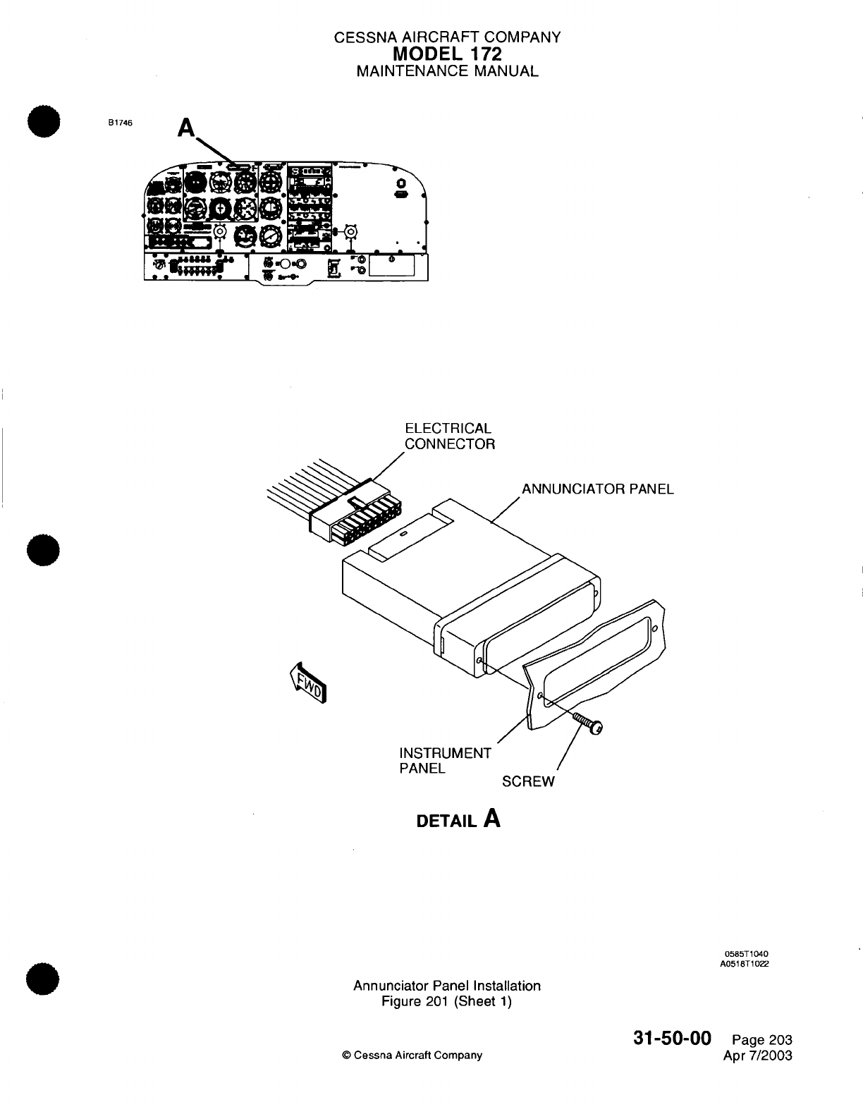
CESSNA
AIRCRAFT
COMPANY
MODEL
172
MAINTENANCE
MANUAL
A
.OR
d]'^.
0m
ELECTRI
ELECTRICAL
CONNECTOR
L
SCREW
DETAIL
A
0585T1040
A051BT1022
Annunciator
Panel
Installation
Figure
201
(Sheet
1)
©
Cessna
Aircraft Company
B1746
31-50-00
Page
203
Apr
7/2003
....
,
__
CHAPTER
LANDING
GEAR
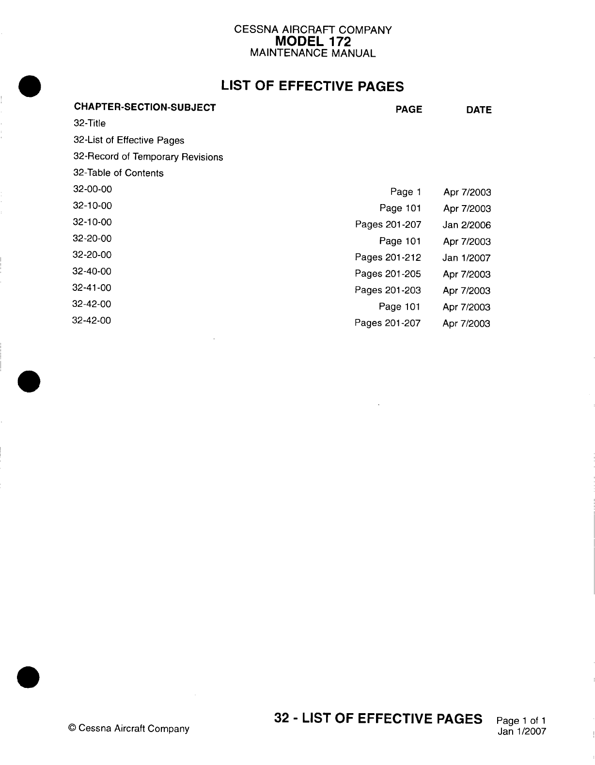
CESSNA AIRCRAFT
COMPANY
MODEL
172
MAINTENANCE
MANUAL
LIST
OF
EFFECTIVE
PAGES
CHAPTER-SECTION-SUBJECT
32-Title
32-List
of
Effective
Pages
32-Record
of
Temporary
Revisions
32-Table
of
Contents
32-00-00
32-10-00
32-10-00
32-20-00
32-20-00
32-40-00
32-4
1-00
32-42-00
32-42-00
©
Cessna Aircraft
Company
PAGE
Page
1
Page
101
Pages
201-207
Page
101
Pages
201
-212
Pages
201
-205
Pages
201
-203
Page
101
Pages
201
-207
DATE
Apr 7/2003
Apr 7/2003
Jan
2/2006
Apr 7/2003
Janl1/2007
Apr
7/2003
Apr
7/2003
Apr
7/2003
Apr
7/2003
32
-
LIST
OF
EFFECTIVE
PAGES
Page
1
of
1
Janl1/2007
Temporary
Revision
Number
RECORD
OF
TEMPORARY
REVISIONS
Page
Number
Issue
Date
By
Date
Removed
By
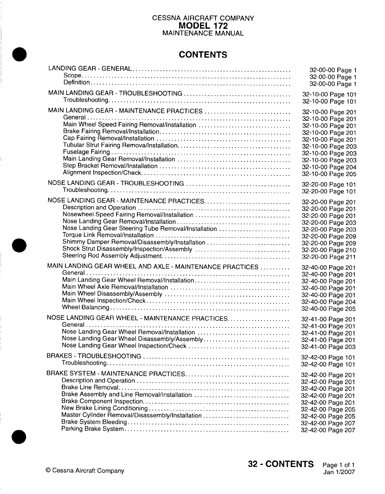
CESSNA
AIRCRAFT
COMPANY
MODEL
172
MAINTENANCE
MANUAL
CONTENTS
LANDING GEAR
-
GENERAL
...........................
Scope....................................
Definition
..................................
MAIN
LANDING GEAR
-
TROUBLESHOOTING...................
Troubleshooting
...............................
MAIN
LANDING GEAR
-
MAINTENANCE PRACTICES
...............
General...................................
Main
Wheel Speed
Fairing
Removal/Installation
................
Brake
Fairing
Removal/installation.......................
Cap
Fairing
Removal/installation
.......................
Tubular
Strut
Fairing
Remova/Installation....................
Fuselage
Fairing...............................
Main
Landing
Gear
Removal/Installation....................
Step
Bracket
Removal/installation.......................
Alignment
Inspection/Check
..........................
NOSE
LANDING
GEAR
-
TROUBLESHOOTING
..................
Troubleshooting
...............................
NOSE
LANDING
GEAR
-
MAINTENANCE PRACTICES
...............
Description
and
Operation
..........................
Nosewheel
Speed Fairing
Removal/Installation.................
Nose
Landing
Gear
Removal/installation....................
Nose
Landing
Gear
Steering
Tube
Removal/installation.............
Torque
Link
Removal/Installation
.......................
Shimmy
Damper
Removal/Disassembly/Installation...............
Shock
Strut
Disassembly/Inspection/Assembly.................
Steering
Rod
Assembly Adjustment
......................
MAIN
LANDING
GEAR
WHEEL
AND
AXLE
-
MAINTENANCE
PRACTICES......
General...................................
Main
Landing
Gear
Wheel
Removal/Installation.................
Main
Wheel Axle
Removal/installation.....................
Main
Wheel
Disassembly/Assembly......................
Main
Wheel
Inspection/Check.........................
Wheel
Balancing...............................
NOSE
LANDING GEAR
WHEEL
-
MAINTENANCE PRACTICES
...........
General...................................
Nose
Landing
Gear
Wheel
Removal/Installation
................
Nose
Landing
Gear
Wheel
Disassembly/Assembly
...............
Nose
Landing
Gear
Wheel
Inspection/Check..................
BRAKES
-
TROUBLESHOOTING
.........................
Troubleshooting
...............................
BRAKE
SYSTEM
-
MAINTENANCE
PRACTICES
..................
Description
and
Operation
..........................
Brake
Line
Removal
.............................
Brake
Assembly
and
Line
Removal/installation.................
Brake
Component Inspection
.........................
New
Brake
Lining
Conditioning
........................
Master
Cylinder
Removal/Disassembly/Installation
...............
Brake
System
Bleeding............................
Parking
Brake
System
............................
32-00-00
Page
1
32-00-00
Page
1
32-00-00
Page
1
32-10-00
Page
101
32-10-00
Page
101
32-1
0-00
Page
201
32-10-00
Page
201
32-10-00
Page
201
32-1
0-00
Page
201
32-1
0-00
Page
201
32-10-00
Page
203
32-10-00
Page
203
32-1
0-00
Page
203
32-1
0-00
Page 204
32-10-00
Page 205
32-20-00
Page
101
32-20-00
Page
101
32-20-00
Page
201
32-20-00
Page
201
32-20-00
Page
201
32-20-00
Page 203
32-20-00
Page 203
32-20-00
Page 209
32-20-00
Page
209
32-20-00
Page
21
0
32-20-00
Page
211
32-40-00
Page
201
32-40-00
Page
201
32-40-00
Page
201
32-40-00
Page
201
32-40-00
Page
201
32-40-00
Page
204
32-40-00
Page
205
32-41
-00
Page
201
32-41
-00
Page
201
32-41
-00
Page
201
32-4
1
-00
Page
201
32-41 -00
Page
203
32-42-00
Page
101
32-42-00
Page
101
32-42-00
Page
201
32-42-00
Page
201
32-42-00
Page
201
32-42-00
Page
201
32-42-00
Page
201
32-42-00
Page
205
32-42-00
Page
205
32-42-00
Page 207
32-42-00
Page 207
32
-
CONTENTS
Page
1
of
1
Janl1/2007
©
Cessna
Aircraft
Company
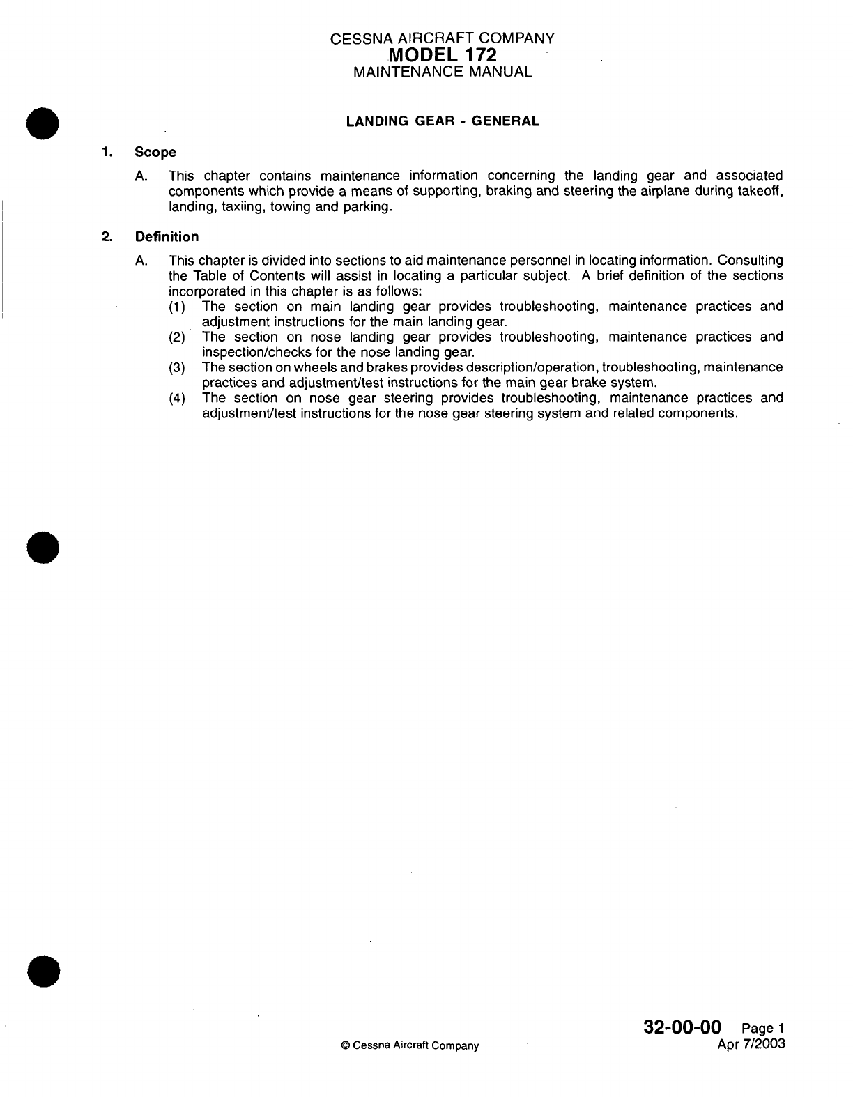
CESSNA
AIRCRAFT
COMPANY
MODEL
172
MAINTENANCE
MANUAL
LANDING GEAR
-
GENERAL
1.
Scope
A.
This
chapter contains maintenance
information
concerning
the
landing
gear
and
associated
components
which
provide
a
means
of
supporting, braking
and
steering
the
airplane
during
takeoff,
landing,
taxiing,
towing and
parking.
2.
Definition
A.
This
chapter
is
divided
into
sections
to
aid
maintenance
personnel
in
locating
information.
Consulting
the
Table
of
Contents
will
assist
in
locating
a
particular subject.
A
brief
definition
of
the sections
incorporated
in
this chapter
is
as
follows:
(1)
The
section
on
main landing
gear
provides
troubleshooting,
maintenance
practices
and
adjustment
instructions
for
the
main landing
gear.
(2)
The
section
on
nose
landing
gear
provides
troubleshooting,
maintenance
practices
and
inspection/checks for
the
nose
landing
gear.
(3)
The
section
on
wheels
and
brakes
provides
description/operation, troubleshooting,
maintenance
practices
and
adjustment/test instructions
for
the
main
gear
brake
system.
(4)
The
section
on
nose gear
steering provides
troubleshooting,
maintenance
practices
and
adjustment/test instructions
for
the
nose
gear
steering system
and
related
components.
32-00-00
Page
1
©
Cessna Aircraft Company
Apr
7/2003
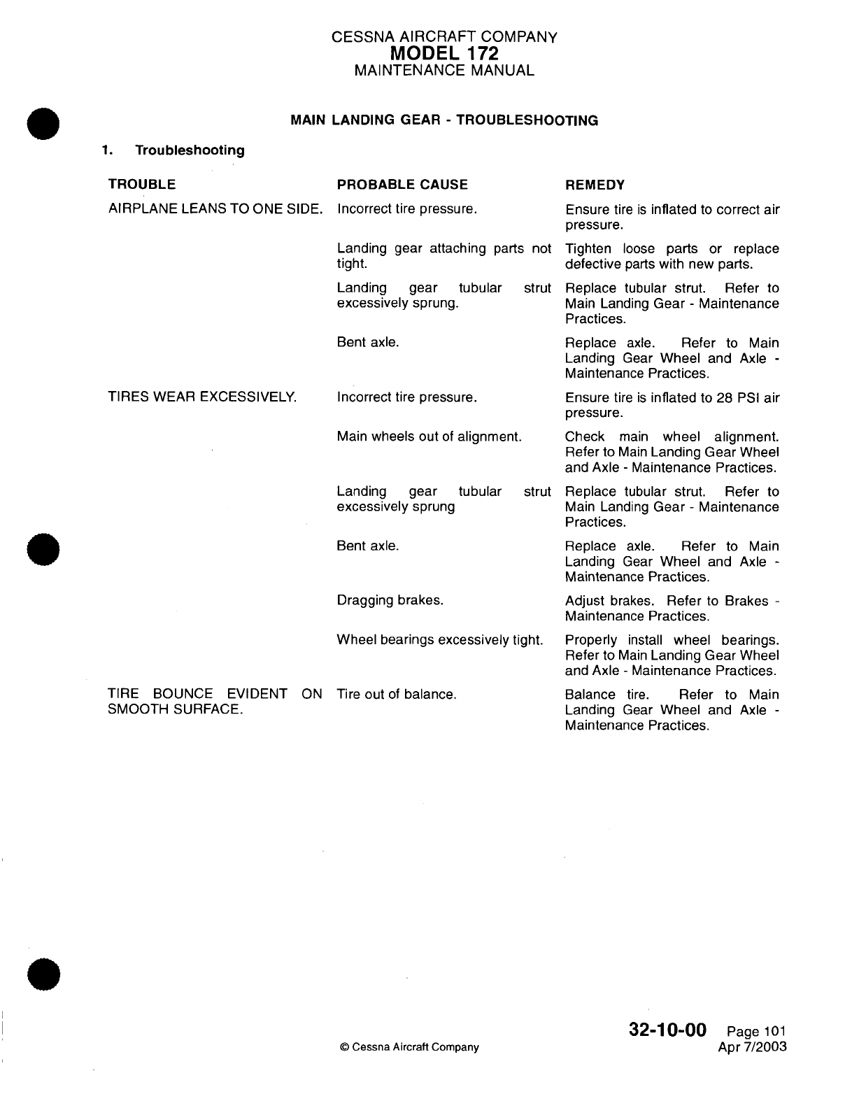
CESSNA
AIRCRAFT
COMPANY
MODEL
172
MAINTENANCE
MANUAL
MAIN
LANDING GEAR
-
TROUBLESHOOTING
1.
Troubleshooting
TROUBLE
AIRPLANE
LEANS
TO
ONE
SIDE.
TIRES
WEAR
EXCESSIVELY.
TIRE
BOUNCE
EVIDENT
ON
SMOOTH
SURFACE.
PROBABLE
CAUSE
Incorrect tire
pressure.
Landing gear
attaching
parts not
tight.
Landing
gear
tubular
strut
excessively
sprung.
Bent
axle.
Incorrect tire
pressure.
Main
wheels
out
of
alignment.
Landing
gear
tubular
strut
excessively
sprung
Bent
axle.
Dragging
brakes.
Wheel bearings
excessively
tight.
Tire
out
of
balance.
REMEDY
Ensure
tire
is
inflated
to
correct
air
pressure.
Tighten
loose
parts
or
replace
defective
parts
with
new
parts.
Replace
tubular
strut.
Refer
to
Main
Landing
Gear
-
Maintenance
Practices.
Replace
axle.
Refer
to
Main
Landing
Gear
Wheel
and
Axle
-
Maintenance
Practices.
Ensure
tire
is
inflated
to
28
PSI
air
pressure.
Check
main
wheel
alignment.
Refer
to
Main
Landing
Gear
Wheel
and
Axle
-
Maintenance
Practices.
Replace
tubular
strut.
Refer
to
Main
Landing
Gear
-
Maintenance
Practices.
Replace
axle.
Refer
to
Main
Landing
Gear
Wheel
and
Axle
-
Maintenance
Practices.
Adjust
brakes.
Refer
to
Brakes
-
Maintenance
Practices.
Properly
install
wheel
bearings.
Refer
to
Main
Landing
Gear
Wheel
and
Axle
-
Maintenance
Practices.
Balance
tire.
Refer
to
Main
Landing
Gear
Wheel
and
Axle
-
Maintenance
Practices.
©
Cessna Aircraft
Company
32-10-00
Page
101
Apr 7/2003
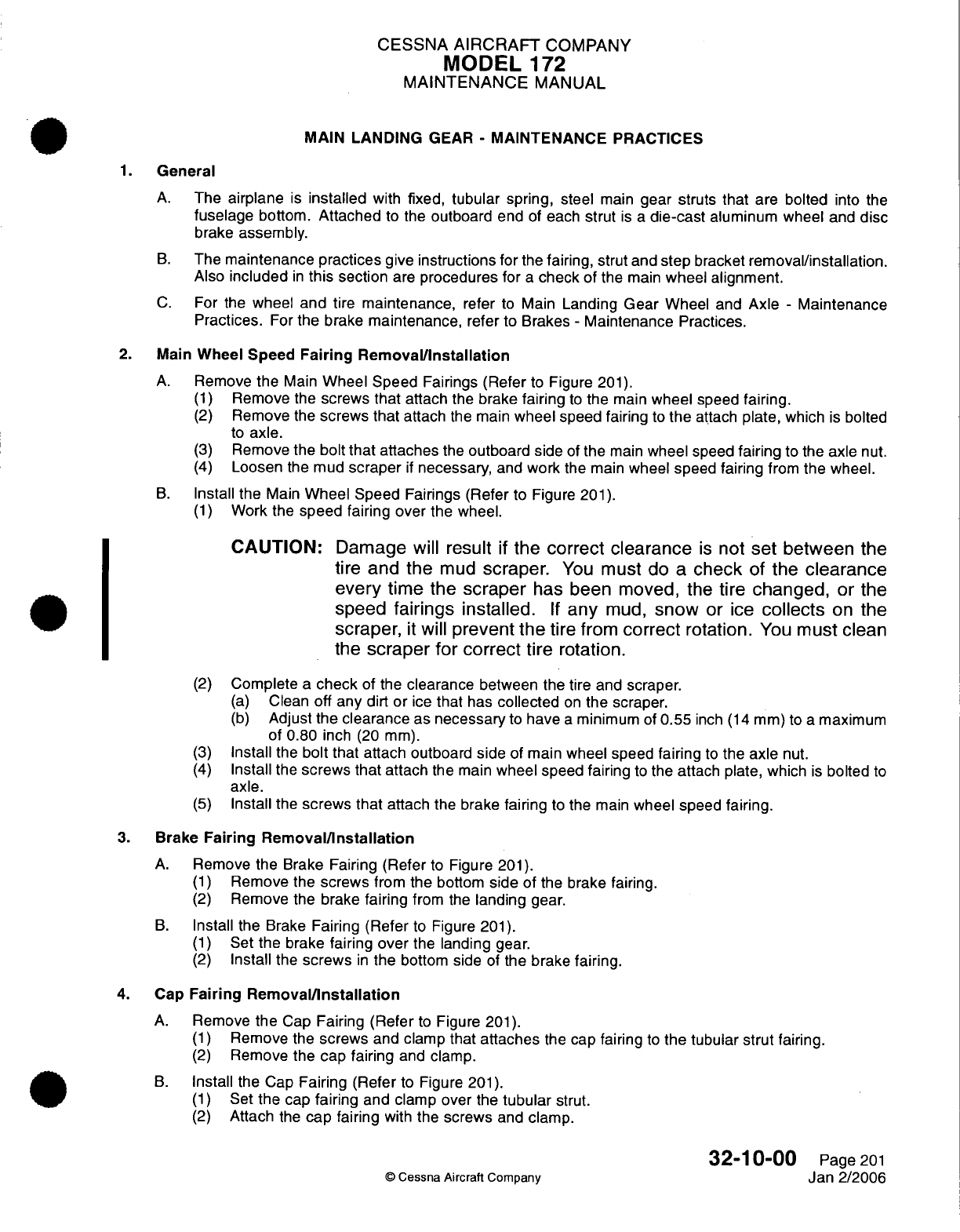
CESSNA
AIRCRAFT
COMPANY
MODEL
172
MAINTENANCE
MANUAL
MAIN
LANDING
GEAR
-
MAINTENANCE
PRACTICES
1.
General
A.
The
airplane
is
installed
with
fixed,
tubular
spring, steel
main
gear struts
that
are
bolted
into
the
fuselage
bottom.
Attached
to
the
outboard
end
of
each
strut
is
a
die-cast
aluminum
wheel
and
disc
brake
assembly.
B.
The
maintenance
practices
give
instructions
for
the
fairing,
strut
and
step
bracket
removal/installation.
Also
included
in
this
section
are
procedures
for
a
check
of
the
main
wheel
alignment.
C.
For the
wheel
and
tire
maintenance,
refer
to
Main
Landing Gear
Wheel
and
Axle
-
Maintenance
Practices.
For
the
brake
maintenance,
refer
to
Brakes
-
Maintenance
Practices.
2.
Main
Wheel Speed
Fairing Removal/Installation
A.
Remove
the
Main
Wheel
Speed
Fairings
(Refer
to
Figure
201).
(1)
Remove
the
screws
that
attach
the
brake
fairing
to
the
main
wheel
speed
fairing.
(2)
Remove
the
screws
that
attach
the
main
wheel
speed fairing
to
the
attach
plate,
which
is
bolted
to
axle.
(3)
Remove
the
bolt
that
attaches
the
outboard
side
of
the
main
wheel speed
fairing
to the
axle
nut.
(4)
Loosen
the mud
scraper
if
necessary,
and
work
the main
wheel
speed fairing
from
the
wheel.
B.
Install
the
Main
Wheel
Speed
Fairings (Refer
to
Figure
201).
(1)
Work
the
speed fairing over
the
wheel.
CAUTION:
Damage
will
result
if
the
correct clearance
is
not
set
between
the
tire
and
the
mud
scraper.
You
must
do a
check
of
the
clearance
every
time the
scraper
has
been moved,
the
tire
changed,
or
the
speed
fairings
installed.
If
any
mud,
snow
or
ice
collects
on
the
scraper,
it
will
prevent the
tire
from
correct
rotation.
You
must
clean
the
scraper
for correct
tire
rotation.
(2)
Complete
a
check
of the
clearance
between
the tire
and scraper.
(a)
Clean
off
any
dirt
or
ice
that
has
collected
on
the scraper.
(b)
Adjust the
clearance
as
necessary
to
have
a
minimum
of
0.55
inch
(14
mm)
to
a
maximum
of
0.80
inch
(20 mm).
(3)
Install
the
bolt that
attach outboard
side
of
main wheel
speed
fairing
to
the
axle
nut.
(4)
Install
the
screws that
attach
the
main
wheel
speed
fairing
to
the
attach
plate, which
is
bolted
to
axle.
(5)
Install
the
screws
that
attach
the
brake
fairing
to
the
main
wheel
speed
fairing.
3.
Brake
Fairing
Removal/Installation
A.
Remove
the Brake
Fairing
(Refer
to
Figure
201).
(1)
Remove
the
screws
from
the
bottom
side
of the
brake
fairing.
(2)
Remove
the
brake
fairing
from
the
landing
gear.
B.
Install
the
Brake
Fairing (Refer
to
Figure
201).
(1)
Set
the
brake
fairing
over
the
landing
gear.
(2)
Install
the
screws
in
the
bottom side
of
the
brake
fairing.
4.
Cap
Fairing
Removal/Installation
A.
Remove
the
Cap
Fairing
(Refer
to
Figure
201).
(1)
Remove
the
screws
and
clamp
that attaches
the
cap
fairing
to
the tubular
strut
fairing.
(2)
Remove
the
cap
fairing
and clamp.
B.
Install
the
Cap
Fairing (Refer
to
Figure
201).
(1)
Set
the
cap
fairing
and
clamp
over
the
tubular
strut.
(2)
Attach
the
cap
fairing
with
the screws
and
clamp.
32-10-00
Page
201
©
Cessna
Aircraft
Company
Jan
2/2006
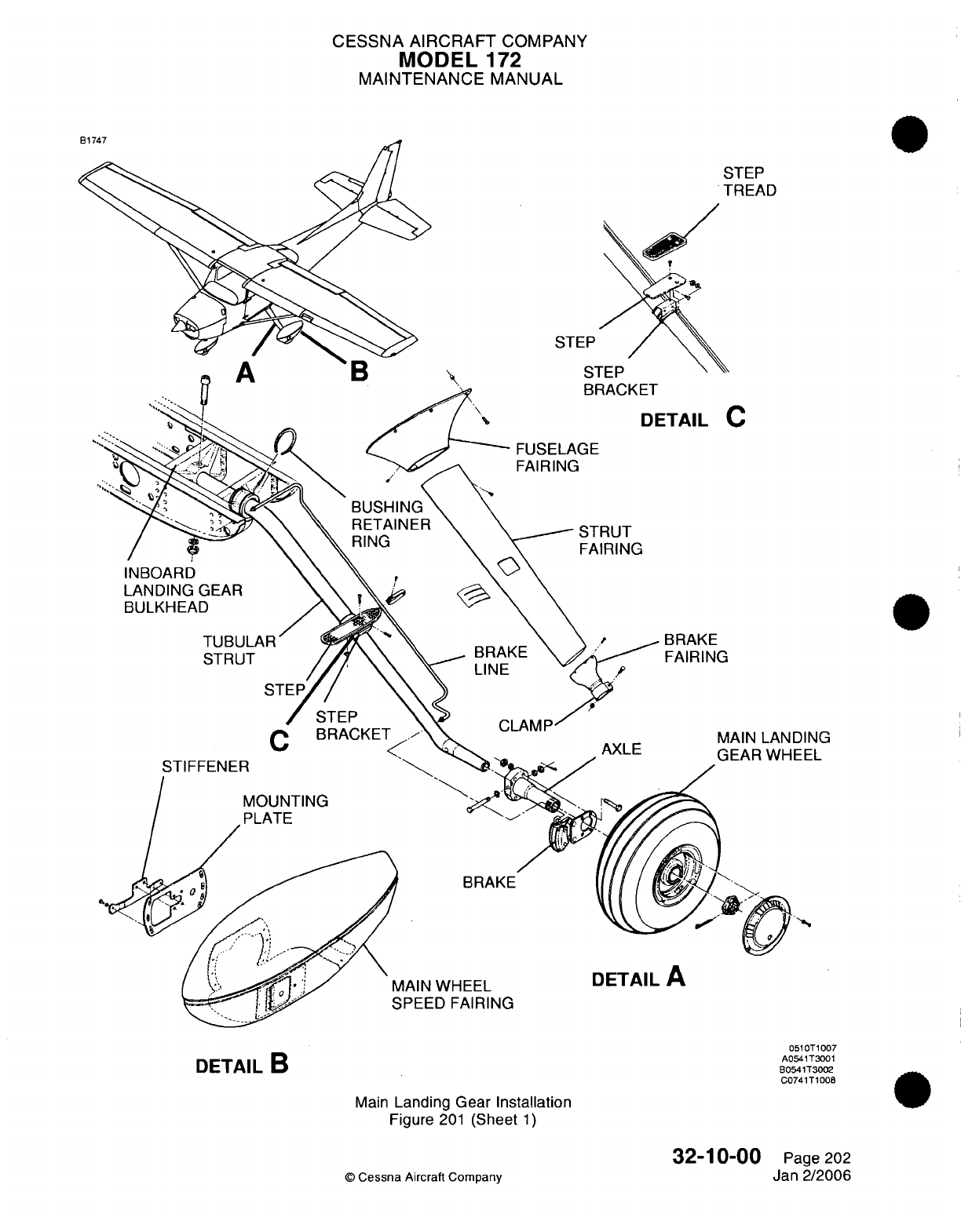
CESSNA AIRCRAFT
COMPANY
MODEL
172
MAINTENANCE
MANUAL
STEP
TREAD
STEP
/
STEP
BRACKET
DETAIL
C
FUSELAGE
FAIRING
STRUT
FAIRING
INBOARD
LANDING
GEAR
BULKHEAD
TUBULAR'
STRUT
STIFFENER
BRAKE
FAIRING
C
BRAKE
AIN
WHEEL
PEED
FAIRING
DETAIL
A
DETAIL
B
Main
Landing
Gear
Installation
Figure
201
(Sheet
1)
32-10-00
©
Cessna
Aircraft Company
DING
EEL
0510T1007
A0541T3001
B0541T3002
C0741T1008
Page 202
Jan
2/2006
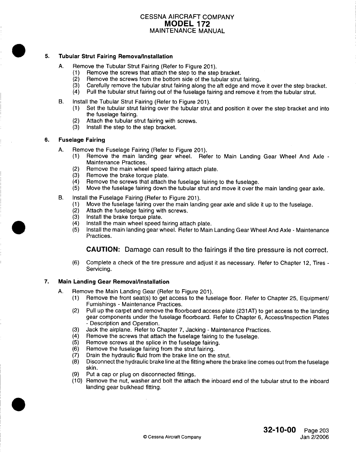
CESSNA
AIRCRAFT
COMPANY
MODEL
172
MAINTENANCE
MANUAL
5.
Tubular
Strut
Fairing
Remova/Installation
A.
Remove
the
Tubular
Strut Fairing (Refer
to
Figure
201).
(1)
Remove
the
screws that
attach the step
to
the
step bracket.
(2)
Remove
the
screws
from
the
bottom
side
of
the
tubular strut
fairing.
(3)
Carefully
remove
the
tubular
strut
fairing
along
the aft
edge
and move
it
over
the
step
bracket.
(4)
Pull
the
tubular
strut
fairing out
of
the
fuselage
fairing
and
remove
it
from
the
tubular
strut.
B.
Install the
Tubular
Strut
Fairing
(Refer
to
Figure
201).
(1)
Set
the
tubular
strut
fairing
over
the
tubular
strut
and
position
it
over
the step
bracket
and
into
the
fuselage
fairing.
(2)
Attach
the
tubular
strut fairing
with
screws.
(3)
Install
the step
to
the
step
bracket.
6.
Fuselage
Fairing
A.
Remove
the Fuselage
Fairing
(Refer
to
Figure
201).
(1)
Remove
the
main
landing
gear
wheel. Refer
to
Main
Landing
Gear
Wheel
And
Axle
-
Maintenance
Practices.
(2)
Remove
the
main
wheel
speed
fairing
attach
plate.
(3)
Remove
the brake
torque
plate.
(4)
Remove
the
screws that attach the
fuselage
fairing
to
the
fuselage.
(5)
Move
the
fuselage
fairing
down the
tubular
strut and
move
it
over
the
main
landing gear
axle.
B.
Install
the
Fuselage
Fairing
(Refer
to
Figure
201).
(1)
Move
the
fuselage
fairing
over
the
main
landing gear
axle
and
slide
it
up
to
the
fuselage.
(2)
Attach
the
fuselage
fairing
with
screws.
(3)
Install the
brake torque
plate.
(4)
Install the
main
wheel
speed
fairing
attach
plate.
(5)
Install
the
main
landing
gear
wheel.
Refer
to
Main
Landing
Gear
Wheel
And
Axle
-
Maintenance
Practices.
CAUTION:
Damage
can
result
to
the
fairings
if
the
tire
pressure
is
not
correct.
(6)
Complete
a
check
of
the
tire pressure
and
adjust
it
as
necessary.
Refer to
Chapter
12,
Tires
-
Servicing.
7.
Main
Landing
Gear
Removal/Installation
A.
Remove
the
Main
Landing
Gear
(Refer
to
Figure
201).
(1)
Remove
the
front
seat(s)
to get
access
to
the
fuselage
floor.
Refer
to
Chapter
25,
Equipment/
Furnishings
-
Maintenance
Practices.
(2)
Pull
up
the
carpet
and remove the
floorboard access
plate
(231AT) to get
access
to
the landing
gear
components
under
the fuselage
floorboard.
Refer
to
Chapter
6,
Access/Inspection
Plates
-
Description
and
Operation.
(3)
Jack the
airplane.
Refer
to
Chapter
7,
Jacking
-
Maintenance Practices.
(4)
Remove
the
screws
that attach
the fuselage
fairing
to
the
fuselage.
(5)
Remove
screws
at
the
splice
in
the fuselage
fairing.
(6)
Remove
the
fuselage
fairing
from
the
strut
fairing.
(7) Drain
the
hydraulic
fluid
from
the
brake
line
on
the
strut.
(8)
Disconnect
the
hydraulic
brake line
at
the
fitting
where the
brake line comes
out
from
the
fuselage
skin.
(9)
Put a
cap or plug
on
disconnected fittings.
(10)
Remove
the
nut,
washer
and
bolt
the
attach
the
inboard
end
of
the
tubular
strut
to
the inboard
landing gear bulkhead fitting.
32-10-00
Page
203
©
Cessna Aircraft
Company
Jan
2/2006
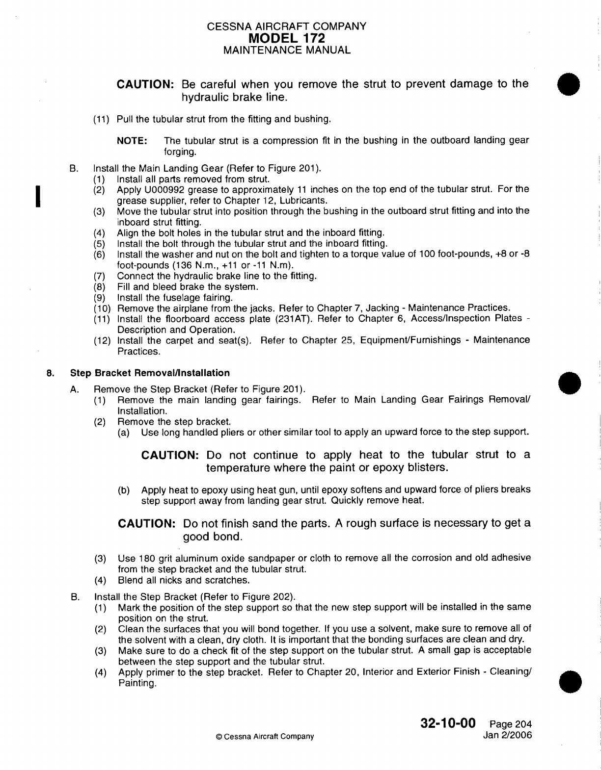
CESSNA AIRCRAFT
COMPANY
MODEL
172
MAINTENANCE
MANUAL
CAUTION:
Be
careful
when you
remove
the
strut to
prevent damage
to
the
hydraulic
brake
line.
(11)
Pull
the
tubular
strut
from
the fitting and bushing.
NOTE:
The
tubular
strut
is
a
compression
fit
in
the
bushing
in
the
outboard
landing
gear
forging.
B.
Install
the Main
Landing
Gear
(Refer
to Figure
201).
(1)
Install
all
parts removed
from
strut.
(2)
Apply
U000992 grease
to
approximately
11
inches
on
the
top
end
of
the
tubular
strut.
For
the
grease supplier,
refer
to
Chapter
12,
Lubricants.
(3)
Move
the
tubular
strut
into
position
through the
bushing
in
the
outboard
strut
fitting
and into the
inboard
strut
fitting.
(4)
Align
the
bolt
holes
in
the
tubular
strut
and
the inboard fitting.
(5)
Install
the
bolt
through
the
tubular
strut
and
the
inboard
fitting.
(6)
Install
the washer
and
nut
on
the
bolt
and
tighten
to
a
torque
value
of
100
foot-pounds,
+8
or
-8
foot-pounds
(136
N.m.,
+11
or
-11
N.m).
(7)
Connect
the
hydraulic
brake line
to
the
fitting.
(8)
Fill
and
bleed brake
the
system.
(9)
Install
the fuselage
fairing.
(10)
Remove
the
airplane
from
the
jacks.
Refer
to
Chapter
7,
Jacking
-
Maintenance
Practices.
(11)
Install
the
floorboard
access
plate
(231AT).
Refer
to
Chapter
6,
Access/Inspection
Plates
-
Description
and
Operation.
(12)
Install
the
carpet
and seat(s). Refer
to
Chapter
25,
Equipment/Furnishings
-
Maintenance
Practices.
8.
Step
Bracket Removal/Installation
A.
Remove
the
Step
Bracket
(Refer
to
Figure
201).
(1)
Remove
the
main
landing gear
fairings.
Refer
to Main
Landing
Gear Fairings Removal/
Installation.
(2)
Remove
the
step
bracket.
(a)
Use
long
handled
pliers
or
other
similar
tool
to
apply
an
upward force
to
the
step
support.
CAUTION:
Do
not
continue
to
apply
heat
to
the
tubular
strut
to
a
temperature where
the
paint
or
epoxy
blisters.
(b)
Apply
heat
to
epoxy
using
heat
gun,
until
epoxy
softens
and
upward
force
of
pliers breaks
step
support
away
from
landing gear strut.
Quickly
remove
heat.
CAUTION:
Do
not
finish
sand
the
parts.
A
rough
surface
is
necessary
to
get
a
good
bond.
(3)
Use
180
grit
aluminum oxide
sandpaper
or
cloth
to
remove
all
the
corrosion
and
old
adhesive
from
the
step
bracket
and
the
tubular
strut.
(4)
Blend
all
nicks
and
scratches.
B.
Install the Step
Bracket
(Refer
to Figure 202).
(1)
Mark
the
position
of
the
step
support
so
that
the new
step
support will
be
installed
in
the
same
position
on
the
strut.
(2)
Clean
the
surfaces
that
you will bond
together.
If
you
use
a
solvent,
make sure
to
remove
all of
the
solvent
with
a
clean,
dry
cloth.
It
is
important
that
the bonding
surfaces
are
clean
and
dry.
(3)
Make
sure
to
do
a
check
fit
of
the
step support
on
the
tubular
strut.
A
small
gap
is
acceptable
between the step
support
and
the
tubular
strut.
(4)
Apply primer
to
the
step
bracket.
Refer
to
Chapter
20,
Interior and
Exterior
Finish
-
Cleaning/
Painting.
32-10-00
Page 204
©
Cessna
Aircraft Company
Jan
2/2006
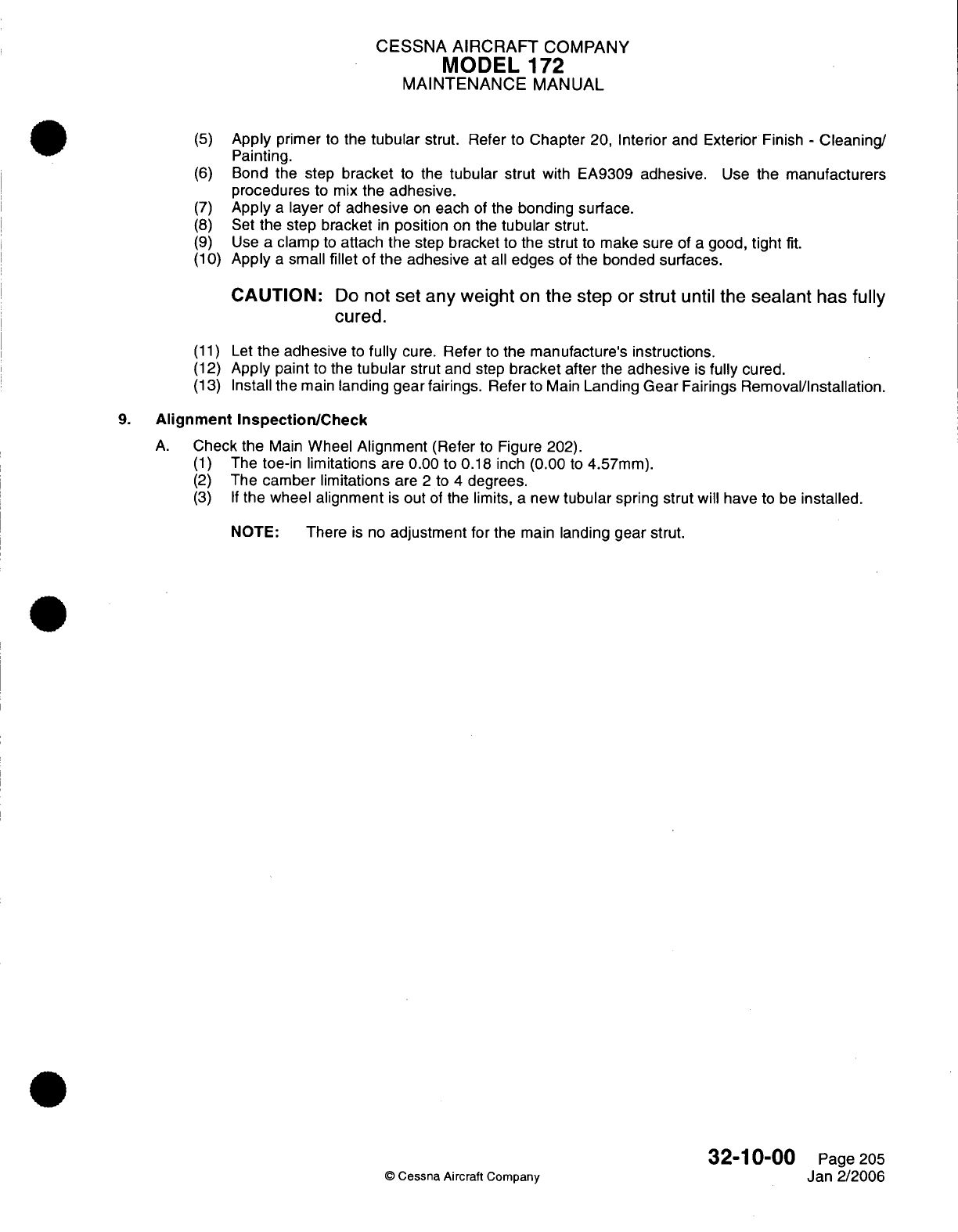
CESSNA
AIRCRAFT
COMPANY
MODEL
172
MAINTENANCE
MANUAL
(5)
(6)
(7)
(8)
(9)
(10)
Apply
primer
to
the
tubular
strut.
Refer
to
Chapter
20,
Interior
and
Exterior
Finish
-
Cleaning/
Painting.
Bond
the step
bracket
to
the
tubular
strut
with EA9309
adhesive.
Use
the
manufacturers
procedures
to
mix
the
adhesive.
Apply
a
layer
of
adhesive
on
each
of
the
bonding surface.
Set
the
step bracket
in
position
on
the
tubular
strut.
Use
a
clamp
to
attach the
step
bracket
to the
strut
to
make sure
of
a
good,
tight
fit.
Apply
a
small
fillet
of
the adhesive
at
all
edges
of the
bonded surfaces.
CAUTION:
Do
not
set
any
weight
on
the
step
or
strut
until
the
sealant
has
fully
cured.
(11)
Let
the adhesive
to
fully
cure.
Refer
to
the
manufacture's
instructions.
(12)
Apply paint
to
the
tubular
strut
and step
bracket
after
the
adhesive
is
fully
cured.
(13)
Install
the
main
landing
gear fairings.
Refer
to
Main
Landing
Gear
Fairings
Removal/Installation.
9.
Alignment Inspection/Check
A.
Check the
Main
Wheel
Alignment
(Refer
to
Figure
202).
(1)
The
toe-in
limitations
are 0.00
to
0.18
inch
(0.00
to
4.57mm).
(2)
The
camber
limitations
are
2
to
4
degrees.
(3) If
the
wheel
alignment
is
out
of
the limits,
a
new
tubular
spring
strut
will have
to
be
installed.
NOTE:
There
is
no
adjustment
for
the
main
landing
gear
strut.
©
Cessna
Aircraft
Company
32-10-00
Page
205
Jan
2/2006
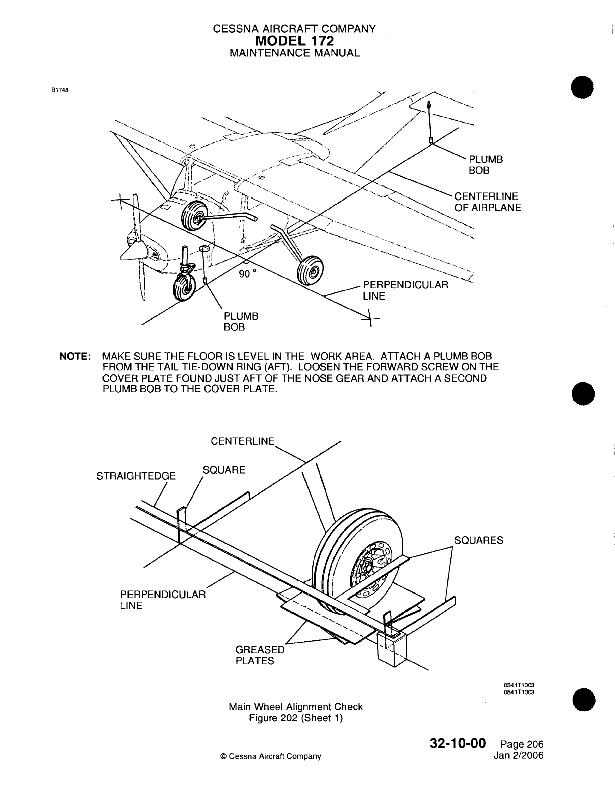
CESSNA AIRCRAFT
COMPANY
MODEL
172
MAINTENANCE
MANUAL
B1748
NOTE:
MAKE
SURE
THE
FLOOR
IS
LEVEL
IN
THE
WORK
AREA. ATTACH
A
PLUMB
BOB
FROM THE
TAIL
TIE-DOWN
RING
(AFT).
LOOSEN
THE
FORWARD
SCREW
ON
THE
COVER
PLATE FOUND
JUST
AFT
OF
THE
NOSE
GEAR
AND ATTACH
A
SECOND
PLUMB BOB
TO
THE
COVER
PLATE.
SQUARES
0541T1003
0541T1003
Main
Wheel
Alignment
Check
Figure
202 (Sheet
1)
32-10-00
©
Cessna
Aircraft Company
Page
206
Jan
2/2006
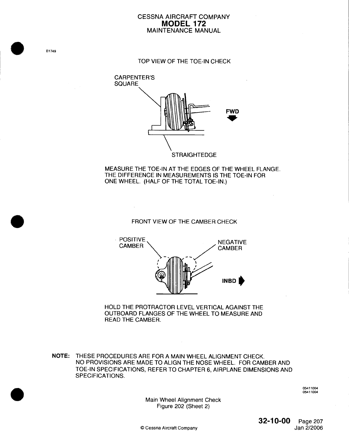
CESSNA
AIRCRAFT
COMPANY
MODEL
172
MAINTENANCE
MANUAL
B1749
TOP
VIEW
OF
THE
TOE-IN
CHECK
CARPENTER'S
SQUARE
FWD
STRAIGHTEDGE
MEASURE
THE
TOE-IN
AT
THE
EDGES
OF THE
WHEEL
FLANGE.
THE
DIFFERENCE
IN
MEASUREMENTS
IS
THE
TOE-IN
FOR
ONE WHEEL. (HALF
OF
THE
TOTAL
TOE-IN.)
FRONT
VIEW
OF
THE
CAMBER
CHECK
POSITIVE
CAMBER
NEGATIVE
CAMBER
INBD
HOLD
THE
PROTRACTOR
LEVEL
VERTICAL
AGAINST
THE
OUTBOARD
FLANGES
OF
THE
WHEEL
TO
MEASURE
AND
READ
THE CAMBER.
NOTE:
THESE PROCEDURES
ARE
FOR
A
MAIN
WHEEL
ALIGNMENT
CHECK.
NO
PROVISIONS
ARE MADE TO
ALIGN
THE
NOSE
WHEEL.
FOR
CAMBER
AND
TOE-IN SPECIFICATIONS,
REFER
TO
CHAPTER
6,
AIRPLANE
DIMENSIONS
AND
SPECIFICATIONS.
05411004
05411004
Main
Wheel
Alignment
Check
Figure
202
(Sheet
2)
©
Cessna Aircraft
Company
32-10-00
Page
207
Jan
2/2006
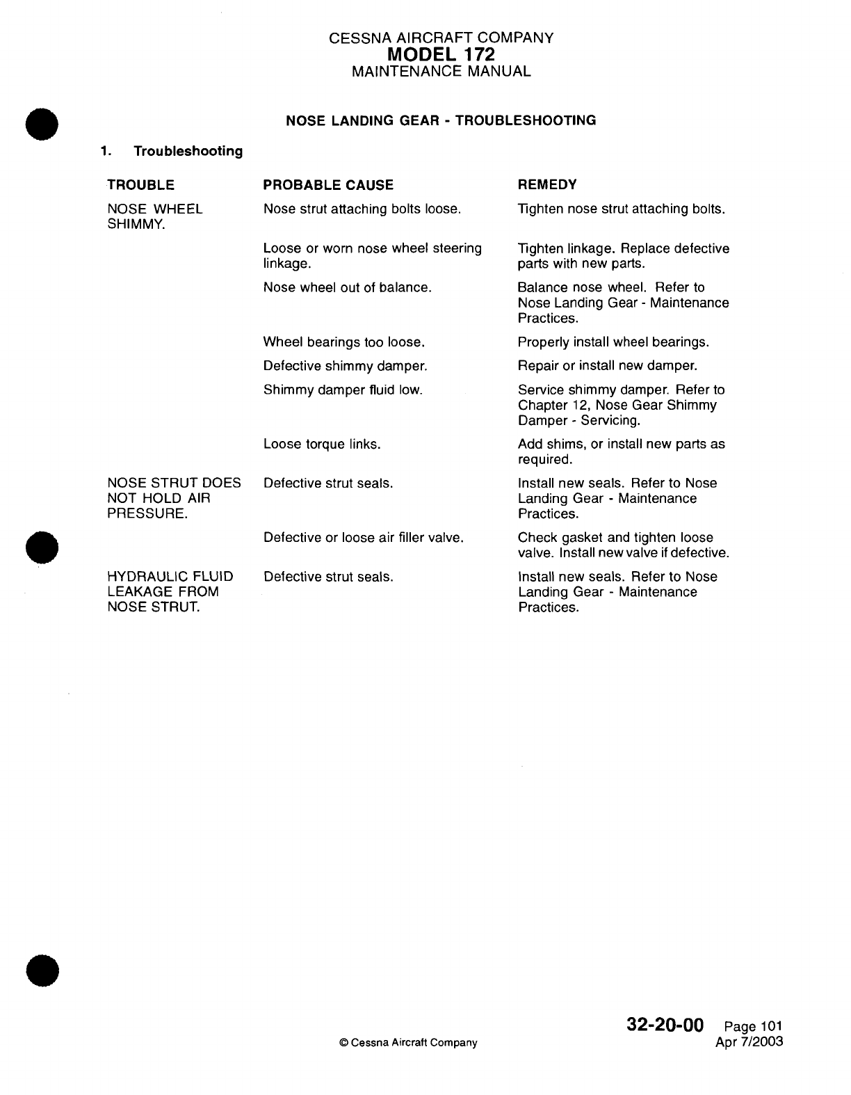
CESSNA
AIRCRAFT
COMPANY
MODEL
172
MAINTENANCE
MANUAL
NOSE
LANDING
GEAR
-
TROUBLESHOOTING
1.
Troubleshooting
TROUBLE
NOSE WHEEL
SHIMMY.
NOSE
STRUT
DOES
NOT HOLD
AIR
PRESSURE.
HYDRAULIC
FLUID
LEAKAGE
FROM
NOSE
STRUT.
PROBABLE
CAUSE
Nose
strut attaching
bolts
loose.
Loose
or
worn
nose
wheel
steering
linkage.
Nose
wheel
out
of
balance.
Wheel bearings
too
loose.
Defective shimmy damper.
Shimmy
damper fluid
low.
Loose torque links.
Defective strut
seals.
Defective
or
loose air
filler
valve.
Defective
strut
seals.
REMEDY
Tighten
nose
strut
attaching
bolts.
Tighten linkage.
Replace
defective
parts
with
new
parts.
Balance
nose wheel.
Refer
to
Nose Landing
Gear
-
Maintenance
Practices.
Properly
install
wheel
bearings.
Repair
or
install
new
damper.
Service shimmy
damper.
Refer
to
Chapter
12,
Nose
Gear
Shimmy
Damper
-
Servicing.
Add
shims,
or
install new parts
as
required.
Install new
seals.
Refer
to
Nose
Landing
Gear
-
Maintenance
Practices.
Check
gasket
and
tighten
loose
valve.
Install new
valve
if
defective.
Install
new
seals.
Refer
to
Nose
Landing
Gear
-
Maintenance
Practices.
©
Cessna
Aircraft
Company
32-20-00
Page
101
Apr
7/2003
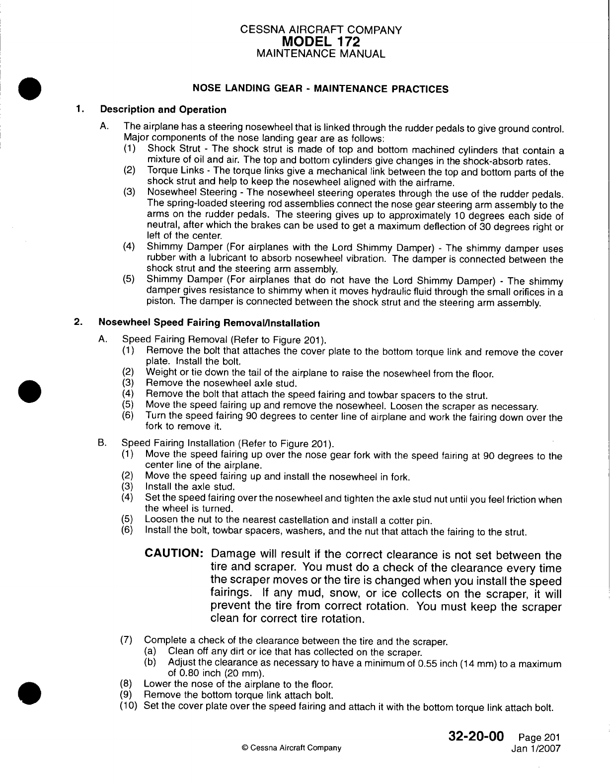
CESSNA
AIRCRAFT
COMPANY
MODEL
172
MAINTENANCE
MANUAL
NOSE
LANDING
GEAR
-
MAINTENANCE
PRACTICES
Description
and
Operation
A.
The
airplane
has
a
steering nosewheel that
is
linked
through the
rudder
pedals
to
give
ground
control.
Major
components
of the nose
landing gear
are
as
follows:
(1)
Shock
Strut
-
The
shock
strut
is
made
of
top
and
bottom
machined
cylinders
that
contain
a
mixture
of
oil
and
air.
The
top
and
bottom
cylinders
give
changes
in
the
shock-absorb
rates.
(2)
Torque
Links
-
The
torque links
give
a
mechanical
link
between
the
top and
bottom
parts
of
the
shock
strut
and
help
to
keep
the
nosewheel
aligned
with the
airframe.
(3)
Nosewheel Steering
-
The nosewheel
steering operates
through
the
use of
the
rudder
pedals.
The
spring-loaded
steering
rod
assemblies connect
the
nose
gear steering
arm
assembly
to the
arms
on
the
rudder
pedals.
The
steering
gives
up
to
approximately
10
degrees
each
side
of
neutral,
after
which
the
brakes
can
be
used
to
get
a
maximum
deflection
of
30
degrees
right
or
left
of
the
center.
(4)
Shimmy Damper
(For
airplanes
with
the
Lord
Shimmy
Damper)
-
The
shimmy
damper
uses
rubber
with
a
lubricant
to
absorb
nosewheel
vibration.
The
damper
is
connected
between
the
shock
strut
and
the
steering
arm
assembly.
(5)
Shimmy
Damper
(For
airplanes
that
do
not
have the
Lord
Shimmy
Damper)
-
The
shimmy
damper
gives resistance
to
shimmy
when
it
moves
hydraulic
fluid
through
the
small
orifices
in
a
piston. The
damper
is
connected
between
the shock
strut
and the
steering
arm
assembly.
2.
Nosewheel
Speed
Fairing
Removal/Installation
A.
Speed
Fairing Removal (Refer
to
Figure
201).
(1)
Remove
the
bolt
that
attaches
the
cover
plate
to
the
bottom
torque
link
and
remove
the
cover
plate.
Install
the
bolt.
(2)
Weight
or
tie
down
the
tail
of
the
airplane
to
raise
the
nosewheel
from
the
floor.
(3)
Remove
the
nosewheel
axle
stud.
(4)
Remove
the
bolt
that
attach
the
speed fairing
and
towbar
spacers
to
the
strut.
(5)
Move
the
speed fairing
up
and
remove
the
nosewheel.
Loosen
the
scraper
as
necessary.
(6)
Turn
the
speed
fairing
90
degrees
to
center
line of
airplane
and
work
the
fairing
down
over
the
fork
to
remove
it.
B.
Speed
Fairing
Installation
(Refer
to
Figure
201).
(1)
Move
the
speed
fairing
up
over
the
nose
gear
fork with
the
speed
fairing
at
90
degrees
to the
center
line
of
the
airplane.
(2)
Move
the
speed fairing
up
and
install
the
nosewheel
in
fork.
(3)
Install
the
axle
stud.
(4)
Set
the
speed fairing
over
the nosewheel
and
tighten
the axle stud
nut
until
you
feel
friction
when
the
wheel
is
turned.
(5)
Loosen
the nut
to
the
nearest
castellation
and install
a
cotter
pin.
(6)
Install
the bolt,
towbar
spacers, washers,
and
the
nut
that
attach the
fairing
to
the strut.
CAUTION:
Damage
will result
if
the
correct
clearance
is
not
set
between
the
tire and
scraper.
You
must
do
a
check
of
the
clearance
every
time
the
scraper
moves
or
the
tire
is
changed
when
you
install
the
speed
fairings.
If
any mud,
snow,
or
ice
collects
on
the scraper,
it
will
prevent
the
tire
from
correct
rotation.
You
must
keep
the
scraper
clean for
correct
tire
rotation.
(7)
Complete
a
check
of
the
clearance
between
the
tire
and
the
scraper.
(a)
Clean
off
any
dirt or
ice
that
has
collected
on
the
scraper.
(b)
Adjust
the
clearance
as
necessary
to
have
aminimum
of
0.55
inch
(14
mm)
to
amaximum
of
0.80 inch
(20
mm).
(8)
Lower
the
nose
of the
airplane
to
the
floor.
(9)
Remove
the bottom
torque
link
attach
bolt.
(1 0)
Set
the
cover
plate
over
the
speed
fairing
and
attach
it
with
the
bottom
torque
link attach
bolt.
32-20-00
Page
201
©
Cessna
Aircraft Company
Janl1/2007
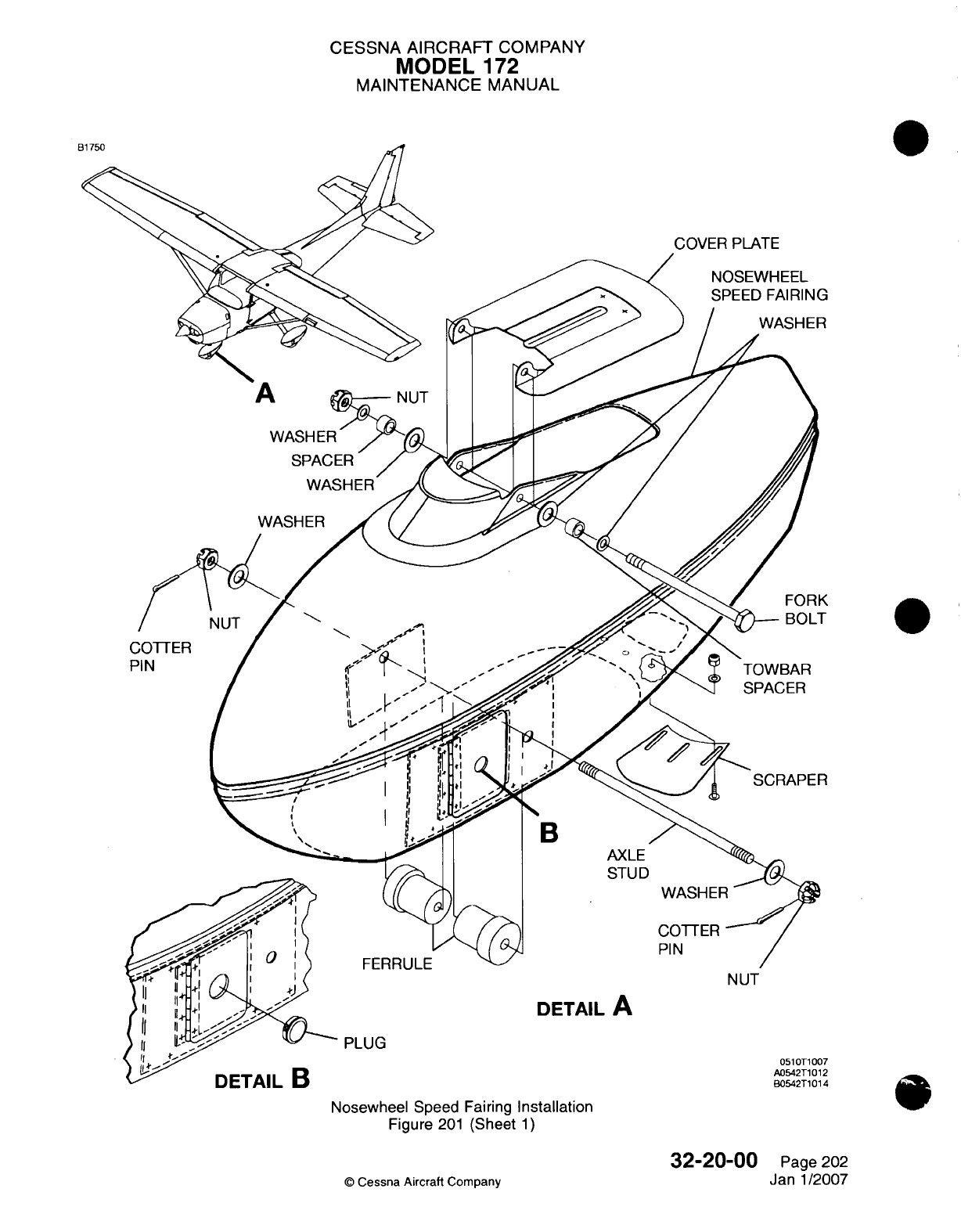
CESSNA AIRCRAFT
COMPANY
MODEL
172
MAINTENANCE
MANUAL
N UT
DETAIL
A
PLUG
051
0T1 007
A05-42T1012
B05-42T1014
Nosewheel
Speed
Fairing
Installation
Figure
201
(Sheet
1)
32-20-00
©
Cessna
Aircraft
Company
Page 202
Janl1/2007
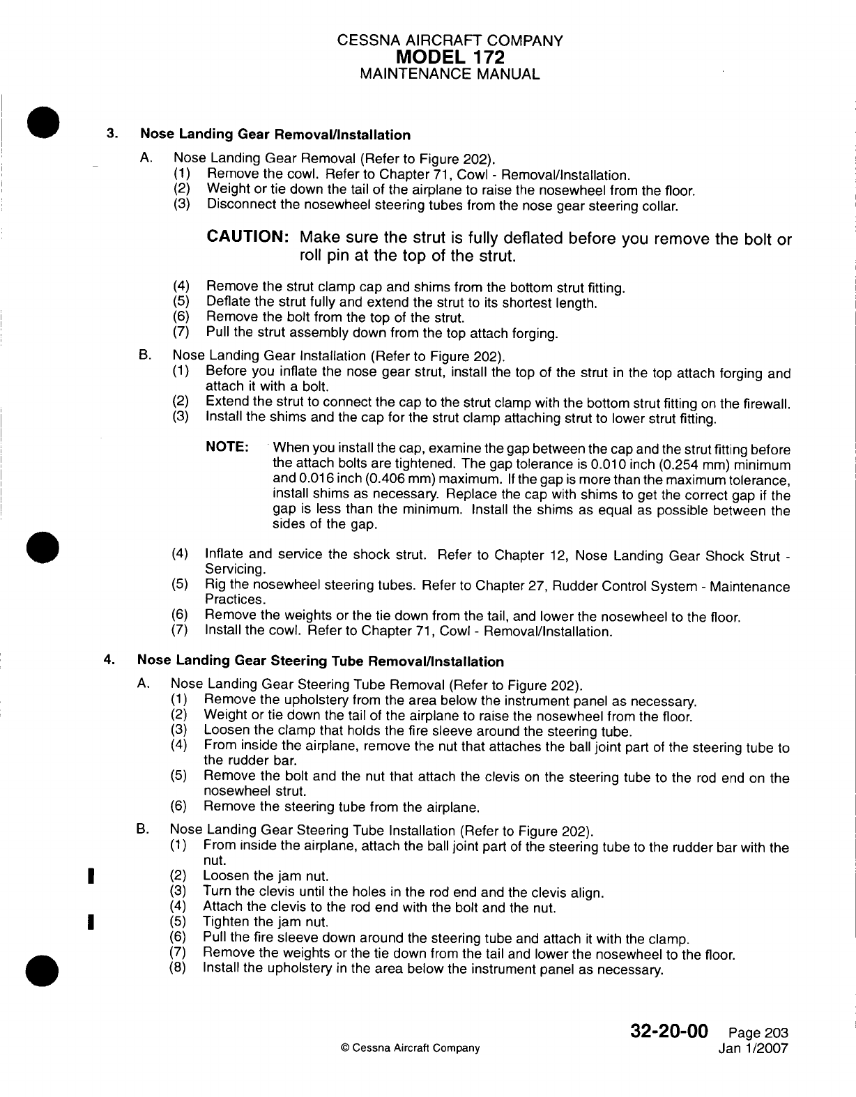
CESSNA AIRCRAFT
COMPANY
MODEL
172
MAINTENANCE
MANUAL
3.
Nose
Landing
Gear
Removal/installation
A.
Nose Landing
Gear
Removal
(Refer
to
Figure
202).
(1)
Remove
the
cowl.
Refer
to
Chapter
71,
Cowl
-
Removal/installation.
(2)
Weight
or
tie
down
the tail of
the
airplane
to
raise
the
nosewheel
from
the
floor.
(3)
Disconnect
the
nosewheel
steering
tubes
from
the
nose
gear steering
collar.
CAUTION:
Make
sure the
strut
is
fully
deflated
before
you
remove the
bolt
or
roll
pin
at
the top
of
the
strut.
(4)
Remove
the strut
clamp
cap and
shims
from
the
bottom
strut
fitting.
(5)
Deflate
the
strut
fully
and
extend
the
strut
to
its
shortest
length.
(6)
Remove
the
bolt
from
the
top
of
the
strut.
(7)
Pull
the
strut
assembly
down
from the
top
attach
forging.
B.
Nose
Landing
Gear
Installation (Refer
to
Figure 202).
(1)
Before
you
inflate
the
nose
gear
strut,
install
the
top
of
the
strut
in
the top
attach forging
and
attach
it
with
a
bolt.
(2)
Extend
the strut
to
connect
the cap
to
the
strut
clamp
with the
bottom
strut
fitting
on
the
firewall.
(3)
Install
the
shims
and
the
cap
for
the
strut
clamp
attaching
strut
to
lower
strut
fitting.
NOTE:
When
you
install
the
cap,
examine
the
gap
between
the cap
and the
strut fitting
before
the
attach
bolts
are
tightened.
The
gap
tolerance
is
0.01
0
inch
(0.254
mm)
minimum
and
0.01
6
inch
(0.406
mm)
maximum.
If
the
gap
is
more
than the
maximum
tolerance,
install
shims
as
necessary. Replace
the
cap
with
shims
to
get
the
correct
gap
if
the
gap
is
less
than
the
minimum.
Install
the
shims
as
equal
as
possible
between
the
sides
of
the
gap.
(4)
Inflate and
service
the
shock
strut.
Refer
to
Chapter
12,
Nose
Landing Gear
Shock Strut
-
Servicing.
(5)
Rig the
nosewheel
steering
tubes.
Refer
to
Chapter
27,
Rudder
Control
System
-
Maintenance
Practices.
(6)
Remove the
weights
or
the
tie
down
from
the
tail,
and
lower
the
nosewheel
to
the
floor.
(7)
Install
the
cowl.
Refer
to
Chapter
71,
Cowl
-
Removal/installation.
4.
Nose
Landing
Gear
Steering
Tube
Removal/installation
A.
Nose
Landing
Gear
Steering
Tube Removal (Refer
to
Figure
202).
(1)
Remove
the
upholstery
from
the
area
below
the
instrument panel
as
necessary.
(2)
Weight
or
tie
down
the
tail of
the
airplane
to
raise
the
nosewheel
from
the
floor.
(3)
Loosen
the clamp that
holds
the fire
sleeve
around the
steering
tube.
(4)
From
inside
the
airplane,
remove the
nut
that attaches
the
ball
joint
part
of
the
steering
tube
to
the
rudder
bar.
(5)
Remove
the
bolt and
the nut
that
attach
the
clevis
on
the
steering
tube
to
the
rod
end on
the
nosewheel
strut.
(6)
Remove
the
steering
tube
from the
airplane.
B.
Nose
Landing
Gear
Steering
Tube
Installation
(Refer
to
Figure
202).
(1)
From
inside
the
airplane, attach
the
ball
joint
part
of
the
steering
tube
to
the
rudder
bar
with
the
nut.
*
~~(2)
Loosen
the
jam
nut.
(3)
Turn
the
clevis
until
the
holes
in
the
rod
end and
the
clevis
align.
(4)
Attach
the
clevis
to
the
rod
end
with
the bolt
and the
nut.
*
~~(5)
Tighten
the
jam
nut.
(6)
Pull
the fire
sleeve
down
around
the
steering
tube
and
attach
it
with
the
clamp.
(7)
Remove
the
weights
or
the
tie down
from
the
tail
and
lower
the
nosewheel
to
the
floor.
(8)
Install
the
upholstery
in
the
area
below
the
instrument
panel
as
necessary.
32-20-00
Page
203
©
Cessna
Aircraft
Company
Janl1/2007
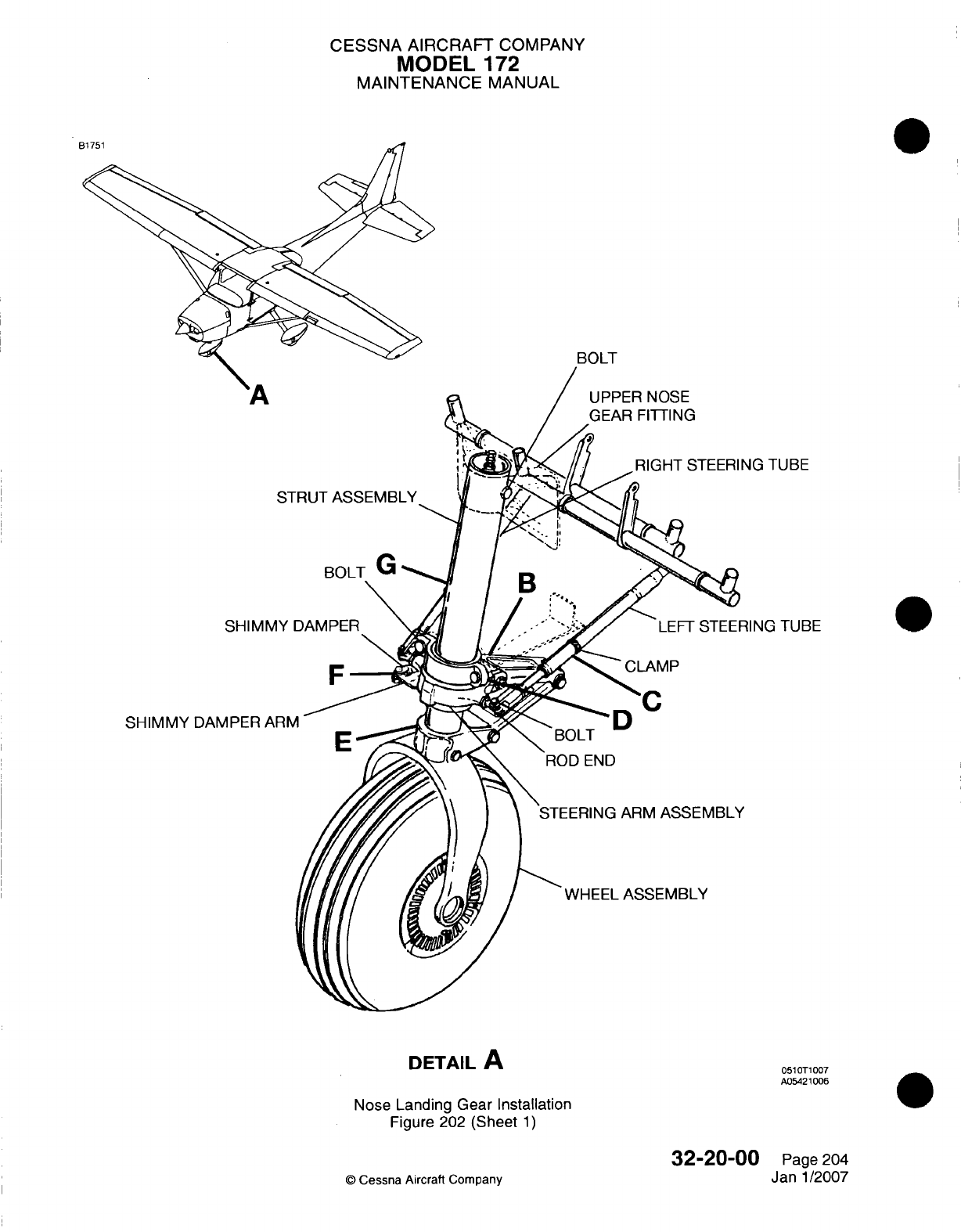
CESSNA
AIRCRAFT
COMPANY
MODEL
172
MAINTENANCE
MANUAL
BOLT
SHIMMY
DAMPER
A
DETAIL
A
Nose Landing
Gear
Installation
Figure
202
(Sheet
1)
32-20-00
Q
Cessna
Aircraft Company
"'A
SHIMNv
TUBE
G
TUBE
051
OTi
007
A05421006
Page 204
Janl1/2007
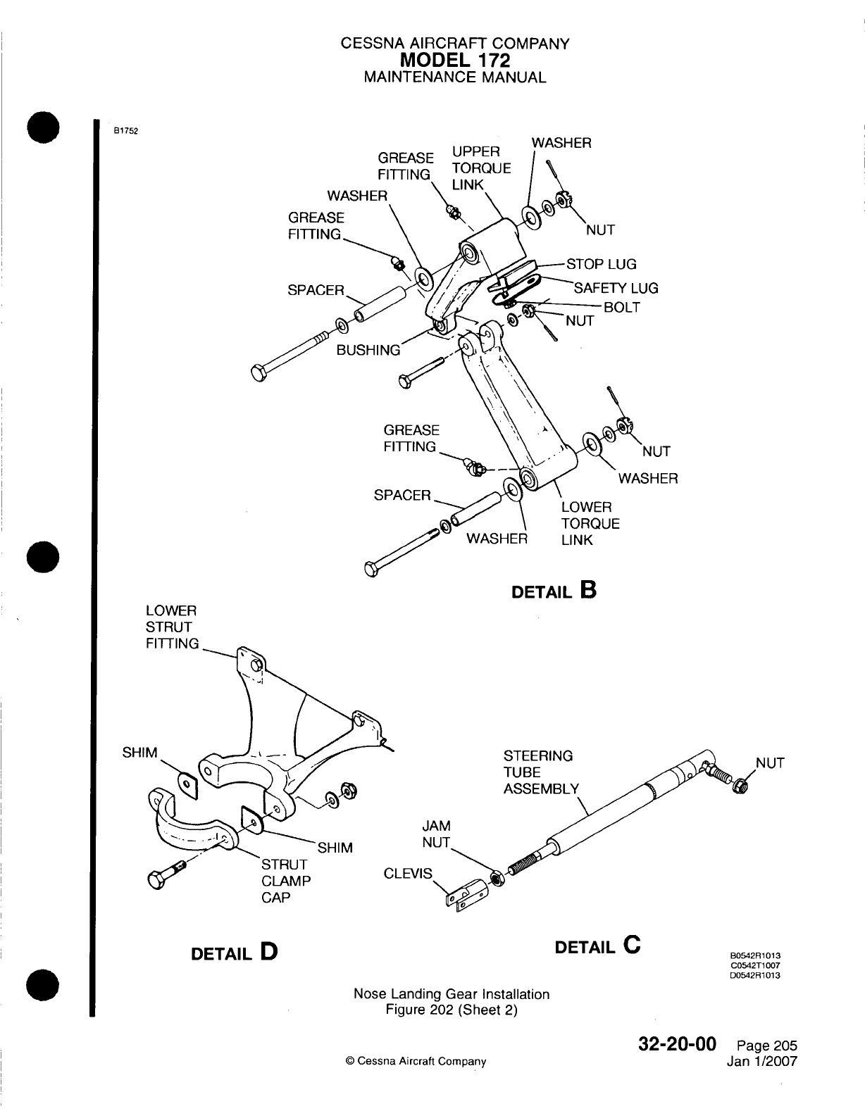
CESSNA
AIRCRAFT
COMPANY
MODEL
172
MAINTENANCE
MANUAL
B1752
DETAIL
B
LOWER
STRUT
FITTrI
N
SHI
STEERING
TUBE
ASSEMBLY
LEVI
DETAIL
D
DETAIL
C
B0542R1013
C0542T1
007
D0542R81013
Nose
Landing
Gear Installation
Figure 202
(Sheet
2)
©
Cessna
Aircraft
Company
N UT
32-20-00
Page 205
Janl1/2007
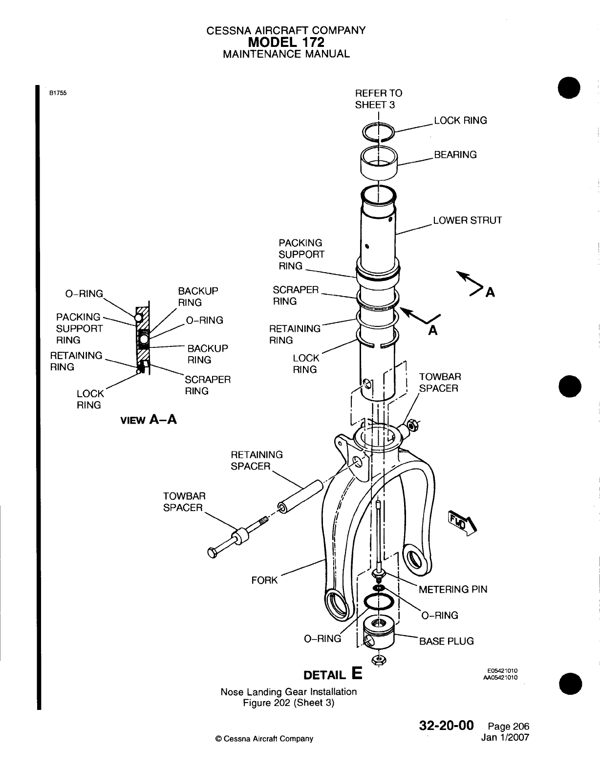
CESSNA
AIRCRAFT
COMPANY
MODEL
172
MAINTENANCE
MANUAL
REFER
TO
SHEET
3
PACKING
SUPPORT
RING
-
0-RING
PACKING
SUPPORT
RING
RETAINING
RING
LOCK
RING
BACI
RING
/0-F
-~
BA(
RIN
SCF
RINI
viEw
A-A
TOWBAF
SPACER
FORK
DETAIL
E=
Nose Landing
Gear Installation
Figure
202
(Sheet
3)
32-20-00
©
Cessna
Aircraft
Company
81755
lUT
SCRAPER
RING
RING
LOCK
RING
O-RIN(
E0542
101
0
AA0S.42
1010
0
Page
206
Janl1/2007
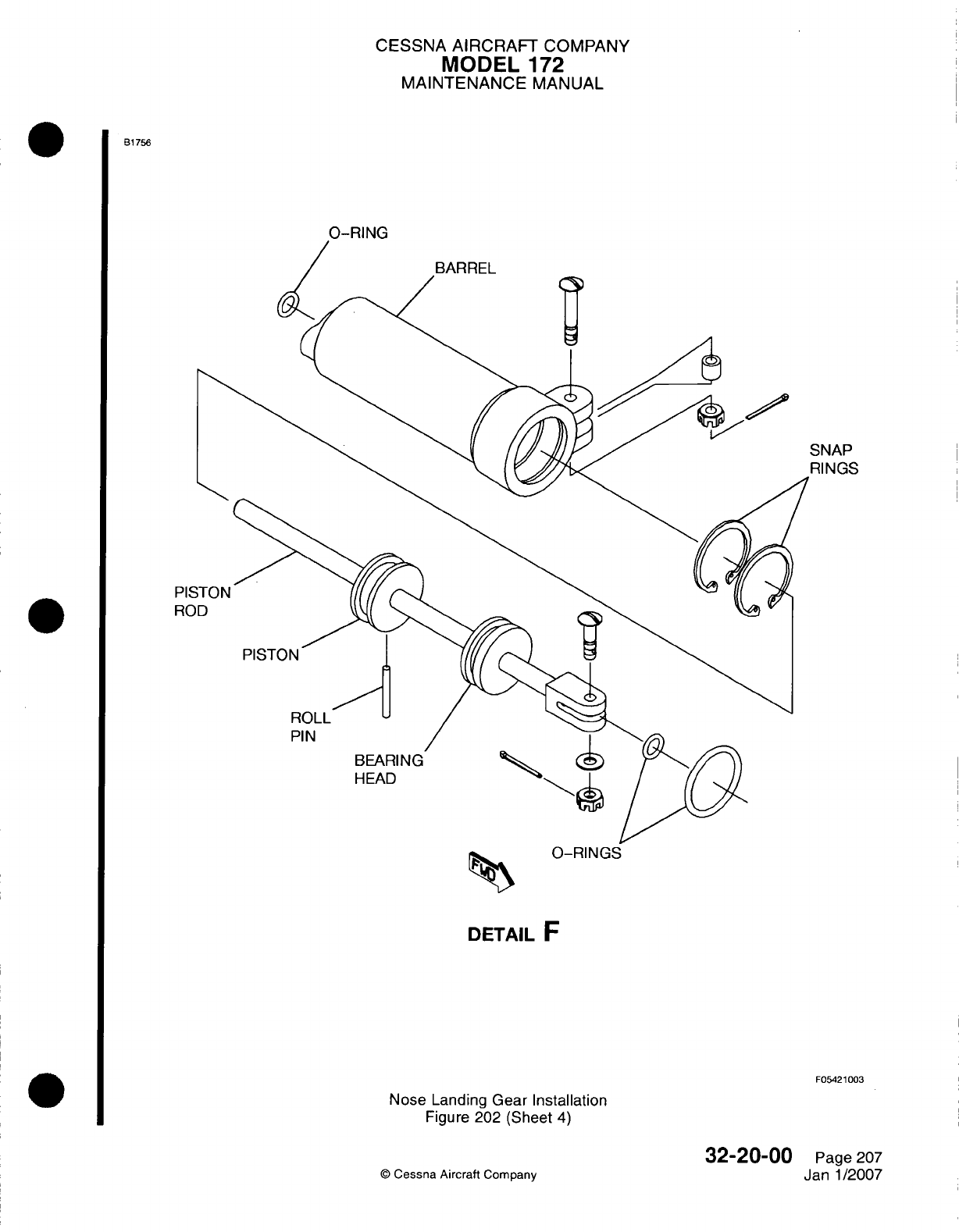
CESSNA AIRCRAFT
COMPANY
MODEL
172
MAINTENANCE
MANUAL
B1756
0-RING
SNAP
RINGS
0-RINGS
DETAIL
F
F05421
003
Nose
Landing
Gear
Installation
Figure
202
(Sheet
4)
'0
Cessna
Aircraft
Company
32-20-00
Page
207
Janl1/2007
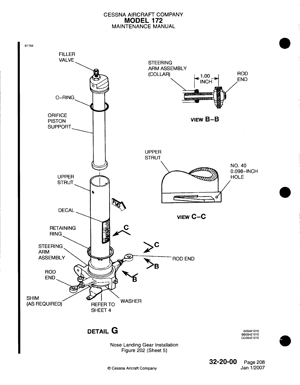
CESSNA AIRCRAFT
COMPANY
MODEL
172
MAINTENANCE
MANUAL
81754
FILLER
VALVE
E-MBLY
0-RING
ORIFICE
PISTON
SUPPORT.-
UPPER
STRUT
DECAL
RING
viEw
B-B
UPPER
STRUT
NO.
40
0.098-INCH
HOLE
C
>
C
VIEW
C-C
ROD
END
ROD
END~
(AS
REQUIRED)
REFER
TO
SHEET
4
DETAIL
G
Nose
Landing
Gear
Installation
Figure
202
(Sheet
5)
32-20-00
©
Cessna
Aircraft
Company
ioD
:ND
SHIM
G05421010
BB05421
01
0
CC05421
101
0
0s
Page 208
Janl1/2007
.. , --I
CESSNA
AIRCRAFT
COMPANY
MODEL
172
MAINTENANCE
MANUAL
(9)
Do
the rigging
of
the
nosewheel steering tubes.
Refer
to
Chapter
27,
Rudder
Control
System
-
Maintenance
Practices.
5.
Torque
Link
Removall/Installation
A.
Torque
Link Removal
(Refer
to
Figure
202).
WARNING: Completely deflate
the
shock strut
before
you
remove
the
torque
links.
(1)
Disconnect
the top
and
bottom
attach
bolts,
spacers,
shims,
and
nuts.
(2)
Remove
the
torque
links.
B.
Torque
Link
Installation
(Refer
to
Figure
202).
NOTE:
If
the
safety
lug
and
stop
lug
are
removed
from
the top
torque
link
during
disassembly,
they
must
be
installed
and
the
retaining
bolts
tightened
20
to
25
In-lbs
(2.26
to
2.82
N.m).
After
you
tighten
the bolts, bend
the
tips
of
the
safety
lug
to
safety
them
into
position.
(1)
Install
the
top
and
bottom
torque
link
assemblies
with
the
shock
strut
fully
deflated.
(2)
Install the bolt
that
attaches
the
top
and
bottom assemblies.
(3)
Tighten
the
nuts
at
each
end
of
the
torque
links
until
they
are
almost
tight. Then
tighten
the
nuts
to
align the
next
castellation
with
a
cotter
pin
hole
in
the
bolt.
(4)
Examine
the top
and
bottom
torque
link
for
looseness.
If
looseness
is
apparent, shims
can
be
installed
to
remove
any
slack.
This
will help
to
prevent
nosewheel
shimmy.
(5)
Fill
and inflate
the
shock strut
to
the
correct
pressure.
Refer
to
Chapter
12,
Nose
Landing
Gear
Shock
Strut
-
Servicing.
6.
Shimmy
Damper
Removal/Disassembly/Installation
A.
Shimmy
Damper
Removal
(Refer
to
Figure
202).
NOTE:
There
are
no
inspection
or
overhaul requirements
for
the
Lord
Shimmy
Damper.
The
Lord
I ~ ~~~Shimmy
Dampener
is
discarded.
(1)
Remove
the
cotter
pin,
nut,
washer,
and
bolt
that attach
the
piston
shaft
clevis
to
the
bracket
that
is
welded
on
the
bottom
of
the
top
strut
tube.
(2)
Remove
the
cotter
pin,
nut,
spacer,
and
bolt
that
attach
the
housing
to the
steering
arm
assembly.
(3)
Remove
the
shimmy
damper.
(4)
For
airplanes
with
the
Lord
shimmy
damper,
discard
the
Lord
Shimmy
Damper.
B.
Disassemble
and
Assemble
the
Hydraulic Shimmy
Damper
(Refer
to
Figure
202).
NOTE:
There
are
no
inspection
or
overhaul
requirements
for
the
Lord
Shimmy
Damper.
The
Lord
Shimmy
Dampener
is
discarded.
(1)
Use
Detail
F
as
a
guide
to
disassemble
the
shimmy
damper.
When
you
assemble
the
damper,
all
of
the
new
0-rings
must
be
used.
All
parts must
be
lubricated before
you
assemble
with
clean
hydraulic
fluid.
(2)
When
the
damper
is
fully
assembled,
it
must
be
serviced
using
procedures
in
Chapter
12,
Nose
Landing
Gear Shimmy
Damper
-
Servicing.
C.
Shimmy
Damper
Installation (Refer
to
Figure
202).
(1)
Before
you
install
the
shimmy
damper,
do
the
maintenance
that
follows:
(a) If a
Lord
Shimmy
Damper
has
been
in
storage
for
a
long
period,
make
sure
that
the
shaft
moves freely
before you
install
it.
Refer
to
Chapter
12,
Nose
Landing
Gear
Shimmy
Damper
-
Servicing.
(b)
Make
sure
that
the
tire
is
in
good
condition,
is
balanced,
and
has
no
tears
or
foreign
objects
in
it.
32-20-00
Page
209
Janl/2007
Cessna
Aircrah
Company
CESSNA
AIRCRAFT
COMPANY
MODEL
172
MAINTENANCE
MANUAL
(c)
Examine
the
interface
between
the
bottom
of
the
steering collar
and
the
top
of
the
nose
gear
fork.
If
there
is
looseness
here,
replace
or
add
more
shims
under
the
collar.
(d)
Examine
the
assembly
hardware
such
as
bolts
and
nuts
for
wear, and
replace
as
necessary.
(e)
Examine
the
shimmy
damper
arm
attach
points
on
the landing
gear
and
structure
for
wear
and
replace
as
necessary.
(2)
Attach
the
shimmy
damper housing
to
the
steering
arm
assembly
with
the
bolt,
spacer,
nut,
and
cotter
pin.
(3)
Attach
the
shimmy
damper
piston
rod
clevis
to
the
bracket
that
is
welded
on
the
bottom
of the
top
strut
tube
with
the
bolt,
washers
(as
necessary),
and
nut.
(4)
For
cleaning
and
servicing
of
the
shimmy
damper,
refer to
Chapter
12,
Nose
Landing
Gear
Shimmy
Damper
-
Servicing.
7.
Shock
Strut
Disassembly/InspectionlAssembly
A.
Dissemble
the
Shock
Strut
(Refer
to
Figure 202).
NOTE:
The
procedures that follow
apply
to
the
nose
gear
shock
strut
after
it
has
been
removed
from the
airplane
and
the
speed
fairings
and
nosewheel
have
been
removed.
If
you
separate
the
top
and
the
bottom
strut,
you
do
not
have
to
remove
or
completely
disassemble
the
strut
to
do
an
inspection
and
parts
installation.
WARNING:
Make
sure
that
you
completely
deflate
the
shock
strut
before
you remove
the
lock
ring
in
the
bottom
end
of
the
top
strut
and
before
you
disconnect
the
torque
links.
(1)
Remove
the
shimmy damper. Refer
to
Shimmy
Damper
Removal/Disassembly/Installation.
(2)
Remove
the
torque
links.
Refer
to
Torque
Link
Removal/Installation.
(a)
To
help
in
assembly,
record
the
position
of
the
washers,
shim, and
spacers.
(3)
Remove
the
lock
ring
from
the groove
inside the
bottom
end
of
the
top
strut.
NOTE:
There
is a
small
hole
at
the
lock
ring
groove
to
help you
remove
the
lock
ring.
NOTE:
Hydraulic
fluid
will drain from the
strut
halves
as
the bottom
strut
is
pulled
from the
top strut.
(4)
Use
a
straight,
hard pull
to
separate
the
top and
bottom
struts.
(a)
Turn
the
bottom
strut
upside
down and
drain
the
hydraulic
fluid.
(5)
Remove
the lock
ring
and
the
bearing
at
the
top
end
of
the
bottom strut
assembly.
(a)
Make
a
mark
on
the top side
of
the bearing
for
assembly.
(6)
Slide
the
packing support
ring,
scraper
ring,
retaining
ring, and
lock
ring
from the
bottom
strut.
(a)
Make
a
mark
at the
relative
position
and
the
top
side
of
each
ring.
Wire
or
tape
the
rings
together
to
be
sure
that
you
install
them
in
the
correct
position.
(7)
Remove
the
0-ring
and
the
backup
rings
from the
packing
support
ring.
(8)
Remove
the
bolt
that
attaches
the
towbar spacers.
NOTE:
The
bolt
that attaches
the
towbar spacers also
holds
the
bushing
and
the
base
plug
in
position.
(9)
Remove
the
bolt
that
attaches
the
fork
to
the
strut
barrel.
(1
0)
Remove
the
base plug
and
the
metering
pin
from
the
bottom
strut.
(1 1)
Remove
the
0-rings
and
the
metering
pin
from
the
base plug.
NOTE:
The
bottom strut
barrel
and
fork
are
a
press
fit
and
are
drilled
on
the
assembly.
Separation
of
these
parts
is
not
recommended unless
you
install
a
new part.
(1 2)
Remove the
retaining
ring
that attaches
the
steering
arm
assembly
on
the
top
strut.
32-20-00
Page
210
©
Cessna Aircraft Company
Janl1/2007
CESSNA
AIRCRAFT
COMPANY
MODEL
172
MAINTENANCE
MANUAL
(13)
Remove the
steering
arm
assembly, shims
(if
installed),
and
washer.
(a) If
shims
are
installed,
record the
quantity
and
position
of
each
shim.
(1 4)
Push
the
orifice support
from the top
strut
and
remove
the
0-ring.
(15)
Remove
the
filler
valve
from
the
orifice support.
B.
Inspect/Repair
the
Strut.
(1)
Clean
all
the
parts
in
cleaning solvent.
(2)
Examine
all
the
parts
for damage
and
wear.
(3)
Replace
all
parts
that show wear
or
damage
and all
0-rings
and
backup
rings
with
new
parts.
(4)
Sharp
metal
edges
must
be
smoothed
with
Number
400
emery
paper
and
cleaned
with
solvent.
C.
Assemble
the
Shock
Strut
(Refer
to Figure
202).
NOTE:
All
parts
must
be
cleaned
and
lubricated
with
hydraulic
fluid
before
assembly.
All
0-rings
must
be
new.
(1)
Install
the
washer
and
the
shims.
(2)
Lubricate the needle bearings
in
the
steering
collar.
(3)
Install
collar
and
retaining
ring.
(4)
Make
sure
the
steering collar
has
a
tight
fit
against
washer.
(a)
Shims
of
variable
thicknesses
are
available
from
Cessna
Aircraft
Company
to
give
a
tight
fit
for
the
collar against
the
washer. Refer
to
the
Model
172
Illustrated
Parts
Catalog
for
the
shim numbers.
(5)
Install
the
rod
ends
in
the
steering
collar.
(6)
Adjust
the
rod
ends
to
the
dimensions specified
in
View
A-A.
(7)
Install
the
0-rings
and
filler
valve
in
the
orifice piston
support.
(8)
Install
the
orifice
piston
support
in
the top strut.
(9)
Install
the
0-ring
and
metering
pin
with
the
0-ring
in
the base plug.
Attach with
a
nut.
NOTE:
If
the
base
plug
is
to
be
replaced,
the
new
part
will
need
to
be
line-drilled
to
accept
the
NAS75-5
bushing.
(1
0)
Install
the
bushing
(if
removed)
in
the
base
plug.
(11)
Install the
base
plug
assembly
in
the
bottom
strut.
(a)
Align
the holes
of
the
bushing,
hole
in
the
bottom
strut, and
the hole
in
the
fork.
(b)
Install
the
towbar
spacer
under
the
head
of
the bolt.
(c)
Install
the
bolt
through
the fork,
bottom
strut and
bushing,
which
is
installed
in
base
plug.
(d)
Install the
towbar spacer
on
the
threaded
end
of
the
bolt.
(e)
Install
and
tighten
the
nut.
(12)
Install
the
lock
ring,
retaining
ring,
and
scraper
ring on
the
bottom
strut.
Make sure
they
are
installed
in
the
same
positions
before
they
were
removed.
(13)
Install
the
0-rings
and
backup
rings
in
the
packing
support
ring.
(14)
Move
the
packing
support
ring
over
the
bottom
strut.
(15)
Install
the
bearing
and
the
lock
ring at
the
top
end
of
the
bottom
strut
assembly.
Note top
side
of
bearing.
(16)
Install
the
top
strut
assembly
over
the
bottom
strut
assembly.
(17)
Install
the
lock
ring
in
the
groove
of
the
bottom
end of
the
top
strut.
(a)
Set
the
lock
ring
in
position
so
that
one
of
its
ends covers
the
small
access
hole
in
the
lock
ring
groove
(View
C-C).
(18)
Install
the
torque
links.
(a)
Set the
washers,
shims,
and
spacers
in
the
same
positions
as
before
they
were
removed.
(19)
Install
the
shimmy
damper.
(20)
After the
shock
strut
assembly
is
complete, install
the
strut
on
the
airplane.
(21)
Fill
and
inflate
the
strut.
Refer
to
Chapter
12,
Nose
Landing
Gear
Shock
Strut
-
Servicing.
8.
Steering
Rod
Assembly Adjustment
A.
Adjustment
Criteria
(Refer
to
Figure
202).
(1)
Adjust
the
rod
ends
to
the
dimension
specified
in
Detail
E,
View
A-A.
32-20-00
Page
211
©
Cessna Aircraft
Company
Janl1/2007
CESSNA
AIRCRAFT
COMPANY
MODEL
172
MAINTENANCE
MANUAL
(2)
Attach
the
nosewheel steering
rods
to
the
rod
ends
protruding
from
the
steering
arm
assembly.
NOTE:
The
nosewheel
steering
and rudder
systems
are
connected.
An
adjustment
to
one
system
can have
an
effect
on
the
other
system
and
must
be
taken
into
consideration.
32-20-00
Page
212
©
Cessna
Aircraft
Company
Jan
1
/2007
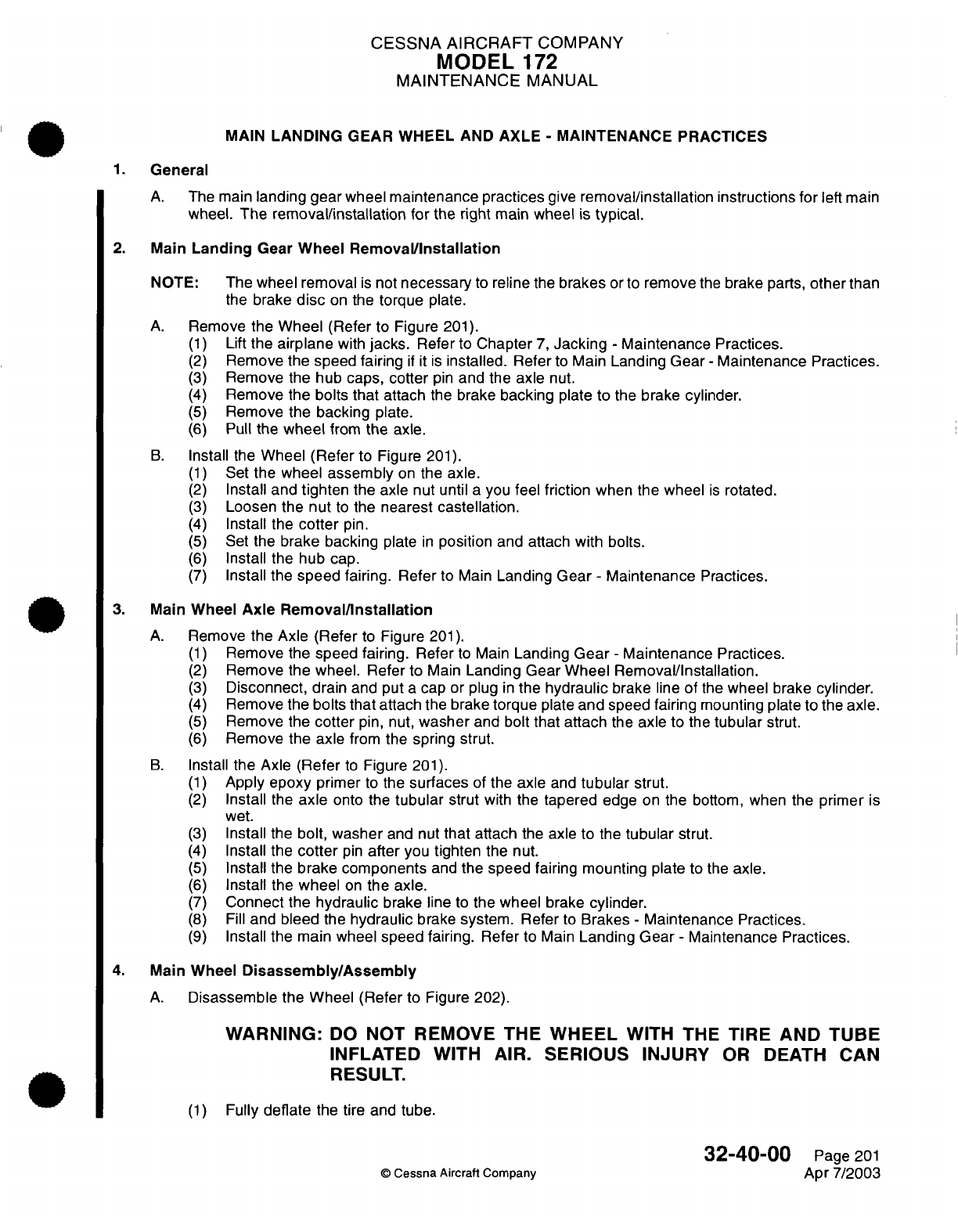
CESSNA
AIRCRAFT
COMPANY
MODEL
172
MAINTENANCE
MANUAL
MAIN
LANDING
GEAR
WHEEL
AND
AXLE
-
MAINTENANCE
PRACTICES
1.
General
A.
The
main
landing gear
wheel
maintenance practices
give
removal/installation
instructions for
left
main
wheel.
The
removal/installation
for
the
right
main
wheel
is
typical.
2.
Main
Landing
Gear
Wheel
Removal/Installation
NOTE:
The
wheel removal
is
not
necessary
to
reline
the
brakes
or
to
remove
the
brake
parts,
other
than
the
brake
disc
on
the
torque
plate.
A.
Remove
the
Wheel
(Refer
to Figure
201).
(1)
Lift
the
airplane
with
jacks.
Refer
to
Chapter
7,
Jacking
-
Maintenance
Practices.
(2)
Remove
the speed fairing
if it is
installed.
Refer
to
Main
Landing
Gear
-
Maintenance Practices.
(3)
Remove
the
hub
caps,
cotter
pin
and the
axle
nut.
(4)
Remove
the
bolts that
attach
the
brake
backing
plate
to
the
brake cylinder.
(5)
Remove
the
backing
plate.
(6)
Pull
the
wheel
from
the
axle.
B.
Install the
Wheel (Refer
to
Figure
201).
(1)
Set
the wheel
assembly
on
the axle.
(2)
Install
and
tighten
the axle
nut until
a
you
feel
friction
when
the
wheel
is
rotated.
(3)
Loosen
the
nut
to
the
nearest
castellation.
(4)
Install
the
cotter
pin.
(5)
Set
the
brake backing
plate
in
position
and attach
with
bolts.
(6)
Install
the
hub
cap.
(7)
Install
the
speed
fairing. Refer
to
Main
Landing
Gear
-
Maintenance
Practices.
3.
Main
Wheel
Axle
Removal/Installation
A.
Remove
the
Axle
(Refer
to
Figure
201).
(1)
Remove
the speed
fairing.
Refer
to
Main
Landing
Gear
-
Maintenance
Practices.
(2)
Remove
the wheel. Refer
to
Main
Landing Gear
Wheel Removal/Installation.
(3)
Disconnect,
drain
and put
a
cap or
plug
in
the
hydraulic
brake
line
of
the
wheel
brake
cylinder.
(4)
Remove
the
bolts that
attach
the
brake
torque
plate
and
speed fairing
mounting
plate
to
the
axle.
(5)
Remove
the
cotter
pin,
nut,
washer
and
bolt
that attach
the
axle
to the
tubular
strut.
(6)
Remove
the axle
from
the
spring
strut.
B.
Install
the
Axle
(Refer
to
Figure
201).
(1)
Apply
epoxy
primer
to
the
surfaces
of the
axle
and
tubular
strut.
(2)
Install
the
axle
onto
the
tubular
strut
with
the
tapered
edge
on
the
bottom,
when the
primer
is
wet.
(3)
Install
the
bolt, washer
and
nut
that
attach
the
axle to the
tubular
strut.
(4)
Install
the
cotter
pin
after
you
tighten
the
nut.
(5)
Install the
brake
components
and
the speed fairing mounting
plate
to
the
axle.
(6)
Install the
wheel
on
the
axle.
(7)
Connect
the
hydraulic
brake line
to
the
wheel
brake
cylinder.
(8)
Fill
and
bleed
the
hydraulic
brake
system. Refer
to
Brakes
-
Maintenance
Practices.
(9)
Install
the
main wheel
speed fairing.
Refer
to
Main
Landing Gear
-
Maintenance
Practices.
4.
Main
Wheel
Disassembly/Assembly
A.
Disassemble
the Wheel (Refer
to
Figure
202).
WARNING:
DO
NOT
REMOVE
THE
WHEEL
WITH THE
TIRE
AND
TUBE
INFLATED
WITH
AIR.
SERIOUS
INJURY
OR
DEATH
CAN
RESULT.
(1)
Fully
deflate
the
tire and
tube.
32-40-00
Page
201
©
Cessna
Aircraft Company
Apr
7/2003
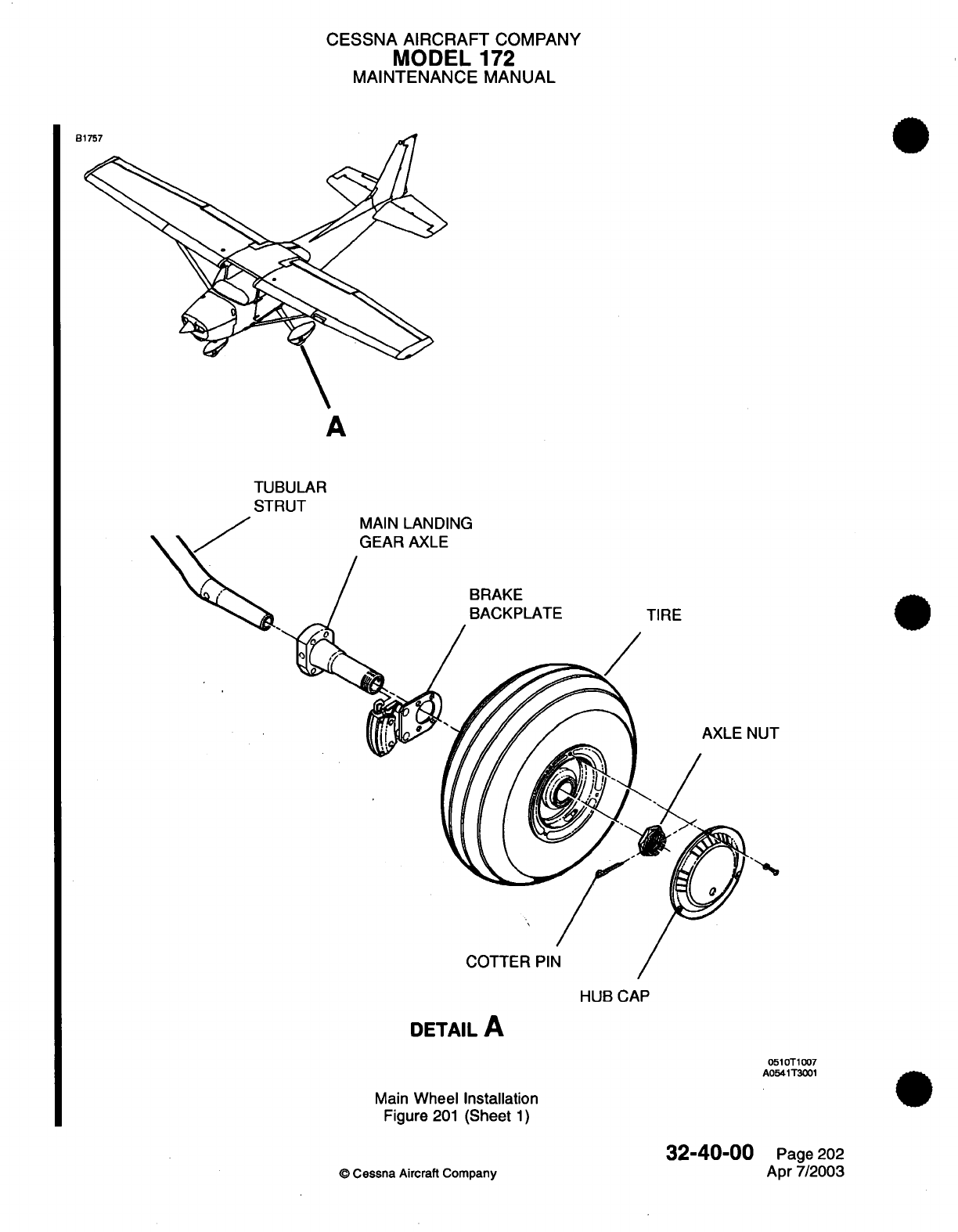
CESSNA
AIRCRAFT
COMPANY
MODEL
172
MAINTENANCE
MANUAL
B
A
TUBULAR
STRUT
MAIN
LANDING
GEAR AXLE
BRAKE
BACKPLATE
TIRE
COTTER
PIN
HUB
CAP
DETAIL
A
0510T1007
A0541T3001
Main
Wheel
Installation
Figure
201
(Sheet
1)
32-40-00
©
Cessna
Aircraft
Company
Page
202
Apr
7/2003
-
CESSNA
AIRCRAFT
COMPANY
MODEL
172
MAINTENANCE
MANUAL
B
RETAINING
RING
GREASE
SEAL
GREASE
SEAL
FELT
BEARING
CONE
WHEEL HALF
NUT
/
WASHER
7
BEARING
CUP
BEARING CUP GREASE
SEAL
FELT
GREASE
SEAL
RETAINER
DETAIL
A
RETAINING
RING
0510T1007
A0541T1001
Main
Wheel Assembly
Figure 202
(Sheet
1)
32-40-00
©
Cessna Aircraft
Company
Page
203
Apr
7/2003
TIRE
TUBE
BEARING
CONE
AL
A,
CESSNA
AIRCRAFT
COMPANY
MODEL
172
MAINTENANCE MANUAL
CAUTION:
BE
CAREFUL
TO
PREVENT
TOOL
DAMAGE TO
THE
TIRE
WHEN
YOU
REMOVE
THE TIRE
FROM THE
WHEEL
HALVES.
(2)
Break loose
the
tire
bead.
(3)
Remove
the
bolts
that
attach
the
wheel
halves
together.
(4)
Separate
and
remove
the
tire
and
tube
from
the
wheel halves.
(5)
Remove
the
retaining
rings,
grease
seal
retainers, grease
seal
felts, grease
seal
retainers
and
bearing
cones.
(6)
The
bearing
cups
(races)
are
a
press fit
in
the wheel
halves
and
must
not
be
removed
unless
a
new
part
is
to
be
installed.
(a)
To
remove
the
bearing
cups,
heat
the
wheel half
in
boiling water for
30
minutes
or
in
an
oven, not
to
exceed
250°F
(121°C).
(b)
Use
an
arbor press
if
available,
to
press
out
bearing cup
and
press
in a
new
bearing
cup
while
the wheel
half
is
still
hot.
B.
Assemble
the
Wheel (Refer
to Figure
202).
(1)
Apply
a
small
quantity
of SAE
10
oil
for
lubrication
on
the
felt
grease
seal.
(2)
Install
the
bearing cone,
grease
seal
retainer,
grease
seal
felt,
grease seal
retainer
and retaining
ring
into
each
wheel
half.
(3)
Install
the
tube
in
the tire.
Make
sure
to
align
the
index marks
on
the
tire
and tube.
(4)
Set
the wheel
half
into the tire
and
tube
(side
opposite valve
stem).
(5)
Install
the
bolt
through the wheel
half with
a
washer
under
the
head
of
the
bolt.
(6)
Set
the
other
wheel half
into the
other
side
of
the
tire
and
tube.
Make
sure
to
align
the
valve
stem
in
the
valve
slot.
(7)
Make
sure
the
tube
is
not
pinched
between
the
wheel halves
before
you
torque
the
nuts.
CAUTION:
MAKE
SURE
THE
NUTS
HAVE
THE
CORRECT
TORQUE.
THE
BOLTS CAN
CAUSE
DAMAGE OF THE
WHEEL
IF
THE
NUTS
DO
NOT
HAVE
THE
CORRECT
TORQUE.
CAUTION:
DO
NOT
USE
IMPACT
WRENCHES
ON
THE BOLTS
OR
NUTS.
(8)
Install
the
washers
and
nuts
on
the
bolts.
(9)
Tighten the
nuts
to
a
dry
torque
of
90
inch-pounds,
+2
or
-2
inch-pounds
(10.17
N.m,
+0.23
or
-0.23
N.m).
(10)
Inflate
the
tire
to
seat the tire beads.
(11)
Adjust
the
air
in
the tire
to
the
correct
pressure.
5.
Main
Wheel
Inspection/Check
A.
Remove the
Wheel.
Refer
to Main
Wheel
Removal/Installation.
B.
Disassemble
the
Wheel.
Refer
to
Main
Wheel
Disassembly/Assembly.
C.
Inspect the
Main
Wheel (Refer
to
Figure
202).
(1)
Clean
all
metal
parts
and
grease
seal
felts
in
solvent,
and dry
thoroughly.
NOTE:
A
soft
bristle
brush can
be
used
to
remove hardened
grease,
dust
or
dirt.
(2)
Examine
the wheel
halves for
cracks
or
damage.
(3)
Examine
the bearing
cones,
cups,
retaining
rings,
grease
seal
retainers, grease
seal
felts
and
grease seal
retainers
for
wear
or
damage.
(4)
Examine the bolts
for
cracks
in
the
bolt head.
(5)
Replace
the
wheel half
if it
is
cracked
or
damaged.
(6)
Replace
damaged retainer
rings
and
seals.
(7)
Replace
worn or
damaged
bearing
cups
and
cones.
(8)
Replace any
worn
or
damaged bolts.
(9)
Remove
any
corrosion
or
small
nicks
with
a
minimum
of
320 grit
sandpaper.
32-40-00
Page
204
©
Cessna
Aircraft
Company
Apr
7/2003
CESSNA
AIRCRAFT
COMPANY
MODEL
172
MAINTENANCE
MANUAL
(10)
Clean
and paint
repaired
areas
with
a
layer
of
clear
lacquer
paint.
Refer
to
Chapter
20,
Interior
and
Exterior
Finish
-
Cleaning/Painting.
(11)
Pack
the
bearings
with
MIL-PRF-81322
wheel bearing
grease.
D.
Assemble
the
Wheel.
Refer
to Main
Wheel
Disassembly/Assembly.
E.
Install
the
Wheel.
Refer
to
Main Landing
Gear
Wheel
Removal/Installation.
6.
Wheel
Balancing
A.
Tire
wear
that
is
not
equal
is
usually
the
result
of the
wheel not
correctly
balanced.
Replacement
of
the
tire
will
usually
correct
the
condition.
(1)
The
light
weight
point
of
the
tire
is
marked with
a red
dot
on
the
tire
sidewall.
The heavy
weight
point
of the
tube
is
marked
with
a
contrasting
color
line
(usually
near
the
inflation
valve
stem).
When you
install
a
new tire,
set
the
marks
adjacent
to
each
other. The
wheel
can
be
statically
balanced but
not
dynamically
balanced
if
a
wheel
shows indication
of
unbalance
when
you
service
it.
NOTE:
Static balance
is
the
balance
of the
control
surface,
which
is
balanced
from
its
hinge
point.
A
tire
that
is
not
dynamically
balanced
will
cause
vibration
and
can
be
examined
when
the
tire
rotates.
32-40-00
Page 205
©
Cessna Aircraft
Company
Apr
7/2003
CESSNA
AIRCRAFT
COMPANY
MODEL
172
MAINTENANCE
MANUAL
NOSE
LANDING
GEAR
WHEEL
-
MAINTENANCE
PRACTICES
1.
General
A.
The
maintenance
practices
for
the wheel of the
nose
landing
gear gives instructions for
the nose
wheel
removal/installation,
nose wheel
disassembly/assembly
and
the
nose
landing
gear wheel
inspection/
check.
2.
Nose
Landing
Gear
Wheel
Removal/nstallation
A.
Remove
the
Wheel
(Refer
to
Figure
201).
(1)
Weight
or
tie
down
the
tail
of
the
airplane
to
lift
the
nose
wheel
from
the
floor.
(2)
Remove the
nose
wheel
axle
stud.
(3)
Pull
the
nose
wheel
assembly
from
the
fork.
(4)
Remove
the axle
tube
from
the
nose wheel.
Loosen
the
wheel
scraper
as
necessary
on
airplanes
that
are
installed
with
a
speed fairing.
B.
Install the Wheel
(Refer
to
Figure
201).
(1)
Install
the
axle
tube
in
the
nose
wheel.
(2)
Install
the
nose
wheel
assembly
in
the
fork.
(3)
Install
the
nose
wheel axle
stud.
(4)
Tighten
the
axle stud
until
you
feel
friction
when
the
wheel
is
rotated.
(5)
Loosen
the nut
to
the nearest
castellation
and
install the
cotter
pins.
(6)
Airplanes
that
are
installed
with
speed
fairings
will
require
a
check
of
the
scraper clearance.
Refer
to
Nose
Landing Gear
-
Maintenance Practices.
3.
Nose
Landing
Gear Wheel
Disassembly/Assembly
A.
Disassemble
the
Wheel
(Refer
to Figure
201).
WARNING:
DO
NOT REMOVE
THE
WHEEL
WITH THE
TIRE AND TUBE
INFLATED WITH
AIR.
SERIOUS INJURY
OR
DEATH
CAN
RESULT.
(1)
Fully
deflate
the
tire
and
tube.
(2)
Loosen
the
tire
beads.
(3)
Remove
the
bolts
and
washers.
CAUTION:
BE
CAREFUL
TO
PREVENT
TOOL
DAMAGE
TO
THE
TIRE
WHEN YOU REMOVE
THE
TIRE
FROM
THE
WHEEL
HALVES.
(4)
Separate and
remove
each
wheel
half
from
the tire
and
tube.
(5)
Remove the
retaining
rings, grease seal
retainer, felt grease
seal,
grease
retainer
and
bearing
cone
from
each
wheel
half.
(6)
Bearing
cups
(races) are
a
press fit
in
each
wheel
half
and
must
not
be
removed
unless
a
new
part
is
to
be
installed.
(a)
To
remove
the
bearing
cups, heat
the wheel
half
in
boiling
water
for
30
minutes
or
in an
oven,
no
more
than
250°F
(121°C).
(b)
Use an
arbor press
if
available,
to
press out the bearing
cup.
(c)
Press
in a
new
bearing
cup with
the wheel
half
is
still
hot.
B.
Assemble
the
Wheel (Refer
to Figure
201).
(1)
Apply
a
small
quantity
of
SAE
10
oil
for
lubrication
on
the
felt
grease
seal.
(2)
Install
the
bearing cone, grease seal
retainer,
felt
grease
seal, grease
seal
retainer
and
retaining
ring
into each of
the wheel
halves.
(3)
Install
the
tube
in
the
tire.
Make
sure
to
align the
index
marks
on
the
tire
and
tube.
(4)
Set
the wheel
half
into
the
tire and
tube.
(5)
Install
the
bolt
through
the
wheel half with
the
washer
under
the
head
of
the
bolt.
32-41-00
Page
201
©
Cessna Aircraft Company
Apr
7/2003
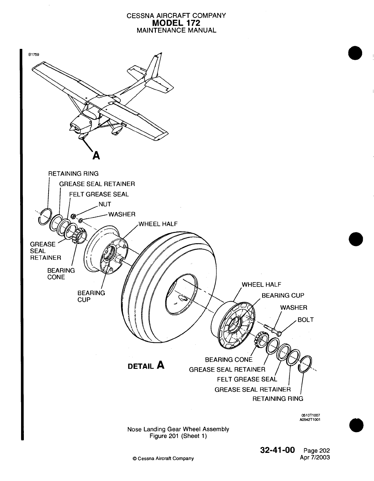
CESSNA
AIRCRAFT
COMPANY
MODEL
172
MAINTENANCE
MANUAL
B1759
A
RETAINING RING
GREASE
SEAL
RETAINER
.WHEEL
HALF
G
SEAL
RETAINER
WHEEL
HALF
BEARING
CUP
BEARING CUP
WASHER
F
DETAIL
A
RETAINING
RING
0510T1007
A0542T1001
Nose
Landing Gear
Wheel
Assembly
Figure
201
(Sheet
1)
©
Cessna Aircraft Company
32-41-00
Page
202
Apr
7/2003
BEARING
CONE
BEARING
CUP
CESSNA
AIRCRAFT
COMPANY
MODEL
172
MAINTENANCE
MANUAL
(6)
Set
the
other
wheel half
into the
other
side
of
the
tire
and
tube.
(a)
Make
sure
to
align the
valve
stem
in
the
valve
slot.
(7)
Make
sure the
tube
is
not
pinched
between
the
wheel
halves
before
you
tighten
the nuts.
CAUTION:
MAKE SURE
THE
NUTS
HAVE
THE
CORRECT
TORQUE.
THE
BOLTS
CAN
CAUSE
DAMAGE
TO THE
WHEEL
IF
THE NUTS
DO
NOT
HAVE
THE
CORRECT TORQUE.
CAUTION:
DO
NOT
USE
IMPACT
WRENCHES
ON
THE
BOLTS
OR
NUTS.
(8)
Install the
washers
and nuts
on
the
bolts.
(9)
Tighten
the
nuts
to
a
dry
torque
of
90
inch-pounds,
+2
or
-2
inch-pounds
(10.17
N.m,
+0.23
or
-0.23
N.m).
(10)
Inflate
the
tire
to
seat
the
tire
beads.
(11)
Adjust
the
air
in
the
tire
to
the
correct
pressure.
4.
Nose
Landing
Gear
Wheel
Inspection/Check
A.
Remove
the Wheel. Refer
to Nose
Landing
Gear
Removal/Installation.
B.
Disassemble
the
Wheel.
Refer
to
Nose
Landing Gear Wheel
Disassembly/Assembly.
C.
Inspect
the
Wheel
(Refer
to
Figure
201).
(1)
Clean
all
of
the
metal
parts
and
felt
grease
seals
in
Stoddard
solvent
or
equivalent,
and dry
fully.
(2)
Examine
the
wheel halves for
cracks
or
damage.
(3)
Examine
the
bearing
cones,
cups,
retaining
rings,
and
seals
for
wear
or
damage.
(4)
Examine
the
bolts
and nuts
for
cracks
in
the
threads
or
radius
of
the
bolt
heads.
(5)
Replace
cracked
or
damaged
wheel
half.
(6)
Replace
damaged
retaining
rings
and
seals.
(7)
Replace
any
worn
or
cracked
bolts
or
nuts.
(8)
Replace
worn
or
damaged bearing cups
or
cones.
(9)
Remove
any corrosion
or
small
nicks
with
a
minimum
of
320
grit
sandpaper.
(10)
Clean
and
paint repaired
areas
with
a
layer of
clear
lacquer
paint.
Refer
to
Chapter
20, Interior
and
Exterior
Finish
-
Cleaning/Painting.
D.
Assemble
the
wheel.
Refer
to
Nose
Landing
Gear
Wheel
Disassembly/Assembly.
E.
Install
the
wheel.
Refer
to Nose
Landing
Gear
Removal/Installation.
32-41
-00
Page 203
©
Cessna Aircraft
Company
Apr
7/2003
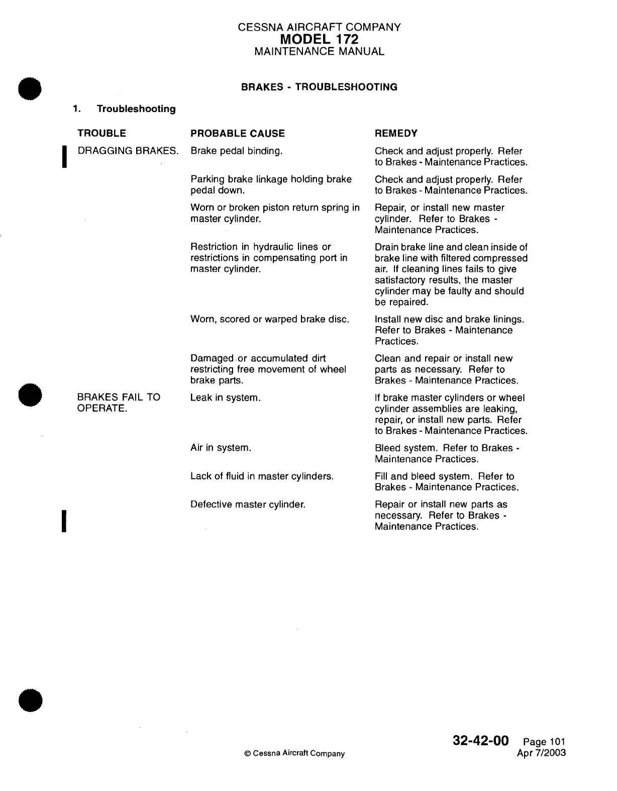
CESSNA
AIRCRAFT
COMPANY
MODEL
172
MAINTENANCE
MANUAL
BRAKES
-
TROUBLESHOOTING
1.
Troubleshooting
PROBABLE
CAUSE
Brake pedal
binding.
Parking brake
linkage
holding brake
pedal down.
Worn
or broken piston
return
spring
in
master
cylinder.
Restriction
in
hydraulic
lines
or
restrictions
in
compensating
port
in
master cylinder.
Worn,
scored
or
warped
brake
disc.
Damaged
or
accumulated
dirt
restricting
free
movement
of
wheel
brake
parts.
Leak
in
system.
Air
in
system.
Lack of
fluid
in
master
cylinders.
Defective master cylinder.
I
©
Cessna
Aircraft
Company
REMEDY
Check
and
adjust
properly.
Refer
to
Brakes
-
Maintenance
Practices.
Check
and
adjust
properly.
Refer
to
Brakes
-
Maintenance
Practices.
Repair,
or
install
new
master
cylinder.
Refer
to
Brakes
-
Maintenance
Practices.
Drain
brake
line
and
clean
inside
of
brake
line with
filtered
compressed
air.
If
cleaning
lines
fails
to
give
satisfactory
results, the
master
cylinder
may
be
faulty
and
should
be
repaired.
Install
new
disc
and
brake
linings.
Refer
to
Brakes
-
Maintenance
Practices.
Clean and
repair
or
install
new
parts
as
necessary.
Refer
to
Brakes
-
Maintenance
Practices.
If
brake
master
cylinders
or wheel
cylinder
assemblies
are
leaking,
repair,
or
install
new
parts.
Refer
to
Brakes
-
Maintenance
Practices.
Bleed
system.
Refer
to
Brakes
-
Maintenance Practices.
Fill
and
bleed system.
Refer
to
Brakes
-
Maintenance
Practices.
Repair
or
install
new
parts
as
necessary.
Refer
to
Brakes
-
Maintenance Practices.
32-42-00
Page
101
Apr
7/2003
TROUBLE
DRAGGING
BRAKES.
I
BRAKES
FAIL TO
OPERATE.
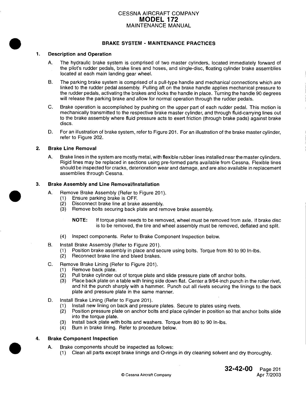
CESSNA
AIRCRAFT
COMPANY
MODEL
172
MAINTENANCE
MANUAL
BRAKE
SYSTEM
-
MAINTENANCE
PRACTICES
1.
Description
and
Operation
A.
The
hydraulic
brake
system
is
comprised
of
two
master
cylinders,
located immediately forward
of
the
pilot's
rudder
pedals, brake
lines
and
hoses,
and
single-disc,
floating
cylinder
brake
assemblies
located
at
each
main
landing gear
wheel.
B.
The
parking
brake system
is
comprised
of
a
pull-type
handle
and
mechanical
connections
which
are
linked
to
the
rudder
pedal
assembly. Pulling
aft
on
the
brake
handle
applies mechanical pressure
to
the
rudder
pedals,
activating
the brakes
and
locks
the
handle
in
place. Turning
the handle
90
degrees
will
release the parking
brake
and allow
for
normal
operation through
the
rudder
pedals.
C.
Brake
operation
is
accomplished
by
pushing
on
the upper
part
of
each
rudder
pedal.
This
motion
is
mechanically
transmitted
to
the
respective
brake
master
cylinder,
and through
fluid-carrying
lines
out
to
the
brake
assembly
where
fluid
pressure acts
to
exert
friction
(through
brake
pads)
against
brake
discs.
D.
For
an
illustration
of
brake
system, refer
to
Figure
201.
For an
illustration of
the
brake
master
cylinder,
refer
to
Figure
202.
2.
Brake
Line
Removal
A.
Brake
lines
in
the
system
are
mostly
metal,
with
flexible
rubber
lines
installed
near
the
master
cylinders.
Rigid
lines
may
be
replaced
in
sections
using
pre-formed parts
available
from
Cessna.
Flexible lines
should
be
inspected
for
cracks, deterioration wear
and
damage,
and
are
also
available
in
replacement
assemblies
through
Cessna.
3.
Brake
Assembly
and
Line
Removal/Installation
A.
Remove
Brake
Assembly
(Refer
to Figure
201).
(1)
Ensure
parking
brake
is
OFF.
(2)
Disconnect
brake
line
at brake
assembly.
(3)
Remove
bolts
securing
back
plate
and
remove
brake
assembly.
NOTE:
If
torque plate
needs
to
be
removed,
wheel
must
be
removed from axle.
If
brake
disc
is
to
be
removed,
the
tire
and
wheel
assembly
must
be
removed,
deflated
and
split.
(4)
Inspect
components.
Refer
to
Brake
Component Inspection
below.
B.
Install
Brake
Assembly
(Refer
to Figure
201).
(1)
Position
brake
assembly
in
place
and secure
using
bolts.
Torque from
80
to
90
In-lbs.
(2)
Reconnect
brake
line
and
bleed brakes.
C.
Remove
Brake
Lining (Refer
to Figure
201).
(1)
Remove
back
plate.
(2)
Pull
brake
cylinder
out
of
torque plate
and
slide pressure
plate
off
anchor
bolts.
(3)
Place
back
plate
on
a
table
with
lining side
down
flat.
Center
a
9/64-inch
punch
in
the
roller
rivet,
and
hit
the
punch
sharply
with
a
hammer.
Punch out
all rivets
securing
the
linings
to
the
back
plate
and
pressure
plate
in
the
same manner.
D.
Install
Brake
Lining
(Refer
to Figure
201).
(1)
Install new
lining
on
back
and
pressure
plates. Secure
to
plates
using
rivets.
(2)
Position
pressure
plate
on
anchor
bolts and
place
cylinder
in
position
so
that
anchor
bolts
slide
into
the
torque
plate.
(3)
Install
back
plate
with
bolts
and
washers.
Torque
from
80
to
90
In-lbs.
(4)
Burn
in
brake
lining.
Refer
to
procedure
below.
4.
Brake
Component
Inspection
A.
Brake
components
should
be
inspected
as
follows:
(1)
Clean
all
parts except
brake
linings
and
O-rings
in
dry
cleaning
solvent
and dry
thoroughly.
32-42-00
Page
201
©
Cessna
Aircraft Company
Apr
7/2003
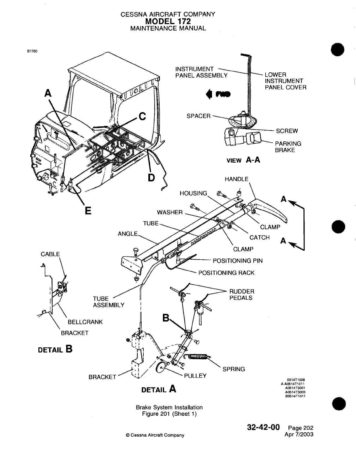
CESSNA AIRCRAFT
COMPANY
MODEL
172
MAINTENANCE
MANUAL
INSTRUMENT
PANEL
ASSEMBLY
LOWER
INSTRUMENT
PANEL
COVER
SPACER
SCREW
PARKING
BRAKE
VIEW
A-A
E
TUBE
CABLE
TUBE
ASSEMBLY
\BELLCRANK
BRACKET
j
N
N
CLAMP
*^
\
CATCH
CLAMP
POSITIONING
PIN
POSITIONING
RACK
RUDDER
PEDALS
;EMB
DETAIL
B
PRING
DETAIL
A
Brake
System
Installation
Figure
201
(Sheet
1)
32-42-00
©
Cessna
Aircraft Company
BRACKET
0514T1008
A-A0514T1011
A0514T3001
A0514T3003
B0514T1011
Page
202
Apr
7/2003
D
.7:n
O
N;-11
IF
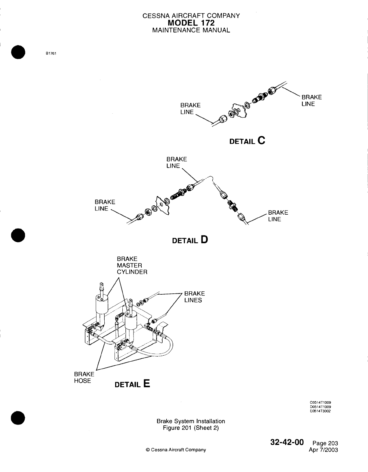
CESSNA
AIRCRAFT
COMPANY
MODEL
172
MAINTENANCE
MANUAL
B1761
BRAK
LINE
DETAIL
C
BRAKE
LINE
BRAKE
LINE
BRAKE
LINE
DETAIL
D
BRAKE
MASTER
CYLINDER
BRAKE
LINES
DETAIL
E
Brake
System
Installation
Figure
201
(Sheet
2)
©
Cessna
Aircraft Company
32-42-00
Page
203
Apr 7/2003
BRAKE
LINE
BRAKE
HOSE
C0514T1009
D0514T1009
E0514T3002
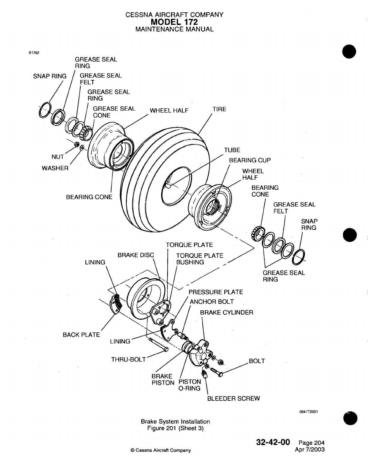
CESSNA
AIRCRAFT
COMPANY
MODEL
172
MAINTENANCE MANUAL
B1762
GREASE
SEAL
RING
GREASE
SEAL
FELT
GREASE
SEAL
RING
GREASE
SEAL
CONE
NUT
WASHER
BEARING CONE
WHEEL
HALF
TIRE
TUBE
RING
CUP
WHEEL
HALF
BEARING
CONE
TORQUE
PLATE
TORQUE
PLATE
BUSHING
GREASE
SEAL
RING
BOLT
PISTON
PISTON
O-RING
BLEEDER
SCREW
0541T2001
Brake System
Installation
Figure
201
(Sheet
3)
32-42-00
©
Cessna Aircraft Company
SNAP
RING
LINING
BACK
LINING
Page
204
Apr
7/2003
CESSNA
AIRCRAFT
COMPANY
MODEL
172
MAINTENANCE
MANUAL
(2)
Install
all
new
O-rings.
Ensure
all
components
are
clean
and
lubricated
with
brake fluid
before
reinstallation.
(3)
Check brake
linings
for
deterioration
and
wear.
Minimum
allowable thickness
is
3/32-inch.
(4)
Inspect
brake
cylinder
bore for
scoring.
A
scored
cylinder
will
leak
or
cause
rapid
O-ring
wear.
Install
a
new brake
cylinder
if
the
bore
is
scored.
(5) If
the
anchor
bolts
on
the
brake
assembly
are
nicked
or gouged,
they
must
be
sanded
smooth
to
prevent
binding
with
the pressure
plate
or
torque
plate.
When new anchor
bolts
are
installed,
press
out
old
bolts
and
install
new
bolts
with
a
soft
mallet.
(6)
Inspect wheel brake
disc
for
thickness.
Minimum
thickness
is
0.205
inch.
5.
New
Brake
Lining
Conditioning
A.
Non-asbestos
organic
lining:
(1)
Taxi
airplane for
1500
feet
with
engine
at
1700
RPM,
applying
brake
pedal
force
as
needed
to
develop
a
5
to
9
knot
taxi speed.
(2)
Allow
brakes
to
cool
for
10
to
15
minutes.
(3)
Apply
brakes
and
check
to
see
if
a
high
throttle static
run
up
may
be
held
with
normal pedal
force.
If
so,
burn-in
is
completed.
(4) If
static
run
up
cannot
be
held,
allow brakes
to
completely
cool then repeat
steps
1
through
3 as
needed
to
successfully
hold.
B.
Iron-based metallic
lining:
(1)
Perform
two
consecutive
full
stop
braking
applications
from
30
to
35 knots.
Do
not
allow
the
brake
discs
to
cool
substantially
between stops.
NOTE:
Light
brake usage can
cause
the
glaze
to
wear
off,
resulting
in
reduced brake
performance.
In
such cases,
the lining
may
be
conditioned
again
following
the
instructions
set forth
in
this
conditioning
procedure.
6.
Master
Cylinder
Removal/Disassembly/Installation
A.
Remove
Master
Cylinder
(Refer
to Figure
201).
(1)
Remove
front seats
and
rudder
bar
shield
to
access the
brake
master cylinders.
(2)
Remove
bleeder
screw
at wheel
brake
assembly
and
drain
hydraulic
fluid
from
brake
cylinders.
(3)
Disconnect
parking brake
and
disconnect
brake
master
cylinders
from
rudder pedals.
Disconnect hydraulic
hose
from
brake
master
cylinders
and
remove
cylinders.
(4)
Plug
or
cap
hydraulic
fittings,
hose
and
lines
to
prevent
entry
of
foreign material.
B.
Disassemble
Master
Cylinder
(Refer
to
Figure
202).
(1)
Unscrew
clevis
and
nut
from
piston.
(2)
Remove
filler
plug.
(3)
Unscrew
cover
and
remove
from
piston.
(4)
Remove
piston
and
spring.
(5)
Remove
packing
and
back-up
ring
from
piston.
C.
Inspect
and
Repair
Master
Cylinder.
(1)
Repair
is
limited
to
installation
of
new
parts
and
cleaning.
Use
clean
hydraulic
fluid
as
a
lubricant
during
reassembly
of
the
cylinders.
Replace
packing
and
back-up
ring.
Filler
plug
must
be
vented
so
pressure
cannot
build
up
during brake
operation.
If
plug
is
not
vented,
drill
a
1/16-inch
hole,
30
degrees
from
vertical.
Refer
to
Figure 202,
View
A-A
for
vent
location.
D.
Reassemble
Master
Cylinder
(Refer
to
Figure
202).
(1)
Install
spring
in
cylinder
body.
(2)
Install
back-up
ring
and
packing
in
groove
of piston.
(3)
Install
piston
in
cylinder
body. Install
cover
over
piston
and
screw cover
into
cylinder
body.
(4)
Install
nut and
clevis
on
piston.
(5)
Install
filler
plug. Ensure
vent
hole
is
open.
E.
Install Master
Cylinder
(Refer
to
Figure
201).
(1)
Connect
hydraulic
hoses
to
brake master
cylinders
and
install cylinders.
(2)
Connect
brake
master
cylinders
to
rudder pedals
and
connect
parking
brake
linkage.
32-42-00
Page
205
©
Cessna
Aircraft
Company
Apr
7/2003
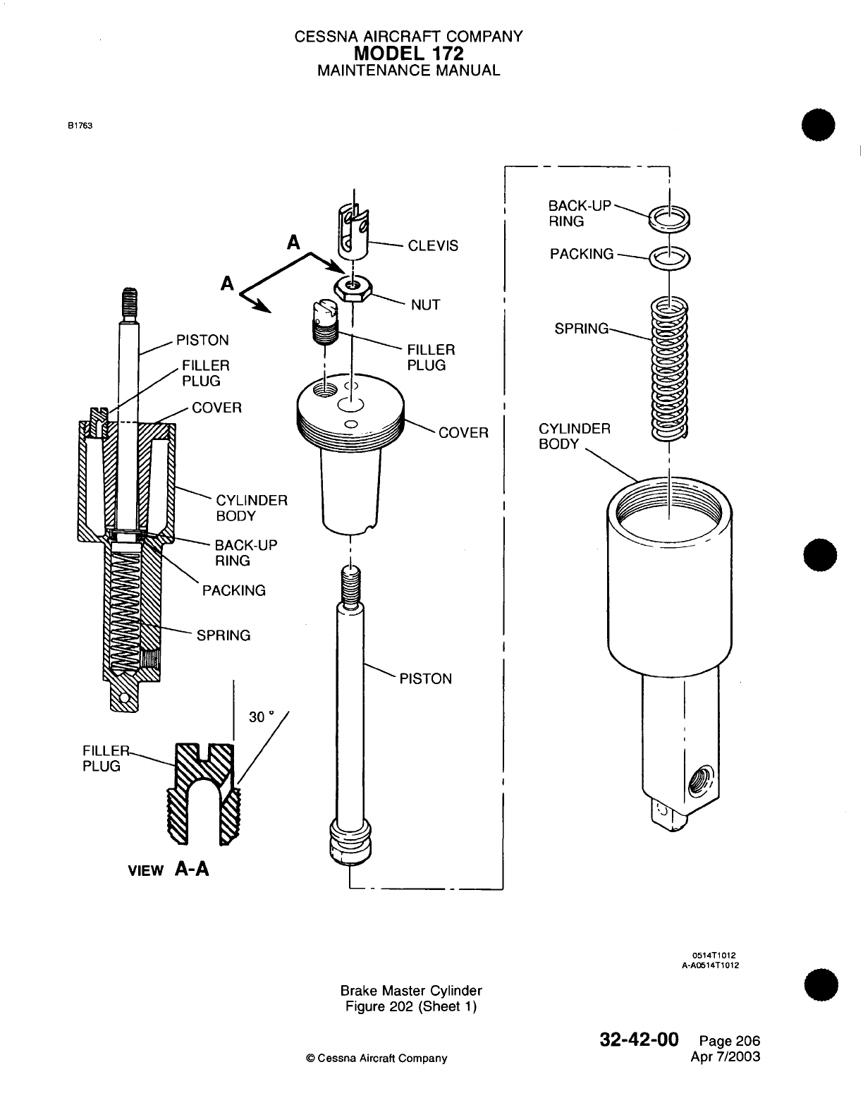
CESSNA
AIRCRAFT
COMPANY
MODEL
172
MAINTENANCE
MANUAL
B1763
-7
PISTO
<KA I
CLEVIS
S) Nf^T
NUT
IN ~
FILLER
U
COVER
PISTON
PISTON
VIEW
A-A
0514T1012
A-A0514T1012
Brake
Master Cylinder
Figure 202
(Sheet
1)
©
Cessna
Aircraft
Company
32-42-00
Page
206
Apr 7/2003
E
0
rrl I
D
2i
011
CESSNA
AIRCRAFT
COMPANY
MODEL
172
MAINTENANCE
MANUAL
(3)
(4)
Install
bleeder
screw
at
wheel
brake
assembly.
Fill
and
bleed
brake
system.
Refer
to
Brake
System
Bleeding
below.
WARNING:
ENSURE
SEAT
IS
POSITIONED
CORRECTLY
ON
SEAT
RAILS
AND
THAT
SEAT
STOPS
ARE
PROPERLY INSTALLED.
(5)
Install
seat
and
rudder
bar
shield.
7.
Brake
System
Bleeding
A.
Bleeding
Procedures.
(1)
Remove
brake
master
cylinder
filler
plug.
(2)
Screw
flexible
hose with
appropriate
fitting
into
the
filler
hole.
(3)
Immerse
opposite
end
of
flexible
hose
in
a
container
with
enough hydraulic
fluid to
cover
the
end
of
the
hose.
(4)
Connect
a
clean
hydraulic
pressure source
to
the
bleeder
valve
in
the
wheel
cylinder.
(5)
Pump
clean
hydraulic
fluid
into
the
system.
Observe
the
immersed
end
of
the
hose
at
the
master
brake
cylinder
for
evidence
of
air
bubbles
being
forced
from
the
brake system.
When
bubbling
has
ceased,
all
air
has
been
removed
from
system.
(6)
Close
bleeder
valve
at
wheel
cylinder
and
tighten.
Remove
pressure
source
from
wheel
cylinder
bleeder
valve.
Remove
flexible
hose
from
master
cylinder
filler
hose.
(7)
Reinstall
filler
plug
on
master
cylinder.
(8)
Test
system
and
ensure brakes
are
operating
properly.
8.
Parking
Brake
System
A.
Figure 201,
Detail
A
may
be
used
as
a
guide
in
removal
and
installation
of
parking
brake
components.
32-42-00
Page
207
©
Cessna
Aircraft
Company
Apr
7/2003

CHAPTER
LIGHTS

CESSNA
AIRCRAFT
COMPANY
MODEL
172
MAINTENANCE
MANUAL
LIST
OF
EFFECTIVE PAGES
CHAPTER-SECTION-SUBJECT
33-Title
33-List
of
Effective
Pages
33-Record
of
Temporary
Revisions
33-Table
of
Contents
33-00-00
33-10-00
33-11-00
33-12-00
33-13-00
33-14-00
33-15-00
33-40-00
33-41-00
33-43-00
33-43-00
33-44-00
©
Cessna Aircraft
Company
PAGE
Page
1
Pages 201-204
Pages
201-202
Pages
201-202
Pages
201-203
Pages
201-202
Pages
201-202
Pages
201-203
Pages
201-202
Pages 101-102
Pages
201-205
Pages 201-202
DATE
Apr
7/2003
Jan
2/2006
Apr
7/2003
Apr
7/2003
Jun
7/2004
Apr
7/2003
Apr
7/2003
Apr
7/2003
Jan
2/2006
Jul
1/2005
Jul
1/2005
Apr
7/2003
33
-
LIST
OF
EFFECTIVE PAGES
Page
1
of
1
Jan
2/2006
Temporary
Revision
Number
RECORD
OF
TEMPORARY REVISIONS
Page
Number
Issue
Date
By
Date
Removed
By
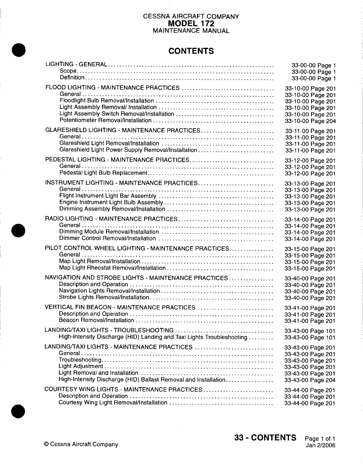
CESSNA
AIRCRAFT
COMPANY
MODEL
172
MAINTENANCE
MANUAL
CONTENTS
LIGHTING
-
GENERAL
.........
...............................................
S
cope......................................................................
Definition...................................................................
FLOOD
LIGHTING
-
MAINTENANCE PRACTICES
.................................
General
...................................................................
Floodlight
Bulb
Removal/Installation
..........................................
Light
Assembly
Removal/ Installation
.........................................
Light
Assembly
Switch
Removal/Installation
...................................
Potentiometer
Removal/Installation
...........................................
GLARESHIELD LIGHTING
-
MAINTENANCE
PRACTICES..........................
General
....................................................................
Glareshield
Light
Removal/Installation
.......................................
Glareshield
Light Power
Supply
Removal/Installation
...........................
PEDESTAL
LIGHTING
-
MAINTENANCE
PRACTICES..............................
General
....................................................................
Pedestal
Light
Bulb
Replacement.............................................
INSTRUMENT LIGHTING
-
MAINTENANCE
PRACTICES...........................
G
eneral
....................................................................
Flight
Instrument
Light
Bar
Assembly
.........................................
Engine
Instrument Light
Bulb
Assembly
.......................................
Dimming
Assembly Removal/Installation
......................................
RADIO
LIGHTING
-
MAINTENANCE
PRACTICES..................................
General
....................................................................
Dimming
Module
Removal/Installation
........................................
Dimmer
Control
Removal/Installation
.........................................
PILOT
CONTROL
WHEEL LIGHTING
-
MAINTENANCE
PRACTICES................
General
....................................................................
Map
Light
Removal/nstallation
...............................................
Map
Light
Rheostat
Removal/Installation
......................................
NAVIGATION AND
STROBE LIGHTS
-
MAINTENANCE
PRACTICES
................
Description and Operation
...................................................
Navigation Lights
Removal/Installation
........................................
Strobe Lights
Removal/nstallation
............................................
VERTICAL
FIN
BEACON
-
MAINTENANCE
PRACTICES
...........................
Description and Operation
...................................................
Beacon
Removal/Installation.................................................
LANDING/TAXI
LIGHTS
-
TROUBLESHOOTING
...................................
High-Intensity
Discharge
(HID)
Landing
and
Taxi
Lights
Troubleshooting
.........
LANDING/TAXI LIGHTS
-
MAINTENANCE
PRACTICES
............................
General
....................................................................
Troubleshooting.............................................................
Light
Adjustment
...........................................................
Light Removal and
Installation
...............................................
High-Intensity
Discharge
(HID)
Ballast
Removal
and
Installation.................
COURTESY
WING
LIGHTS
-
MAINTENANCE PRACTICES
.........................
Description
and Operation
...................................................
Courtesy
Wing
Light
Removal/Installation
.....................................
33-00-00
Page
1
33-00-00
Page
1
33-00-00
Page
1
33-10-00
Page
201
33-10-00
Page
201
33-10-00
Page
201
33-10-00
Page
201
33-10-00
Page
201
33-10-00
Page
204
33-11-00
Page
201
33-11-00
Page
201
33-11-00
Page
201
33-11-00
Page
201
33-12-00
Page
201
33-12-00
Page
201
33-12-00
Page
201
33-13-00
Page
201
33-13-00
Page
201
33-13-00
Page
201
33-13-00
Page
201
33-13-00
Page
201
33-14-00
Page
201
33-14-00
Page
201
33-14-00
Page
201
33-14-00
Page
201
33-15-00
Page
201
33-15-00
Page
201
33-15-00
Page
201
33-15-00
Page
201
33-40-00
Page
201
33-40-00
Page
201
33-40-00
Page
201
33-40-00
Page
201
33-41-00
Page
201
33-41-00
Page
201
33-41-00
Page
201
33-43-00
Page
101
33-43-00
Page
101
33-43-00
Page
201
33-43-00
Page 201
33-43-00
Page
201
33-43-00
Page 201
33-43-00
Page 201
33-43-00
Page
204
33-44-00
Page 201
33-44-00
Page 201
33-44-00
Page
201
33
-
CONTENTS
Page
1
of
1
Jan 2/2006
©
Cessna Aircraft
Company
CESSNA
AIRCRAFT
COMPANY
MODEL
172
MAINTENANCE
MANUAL
LIGHTING
-
GENERAL
1.
Scope
A.
This
chapter
provides
information
on
internal
and
external lighting.
2.
Definition
A.
This
chapter
is
divided
into
section
and
subsections
to
assist
maintenance
personnel
in
locating
specific
components
and
information.
Consulting
the
Table
of
Contents
will
further
assist
in
locating
a
particular
subject.
33-00-00
Page
1
©
Cessna
Aircraft
Company
Apr 7/2003
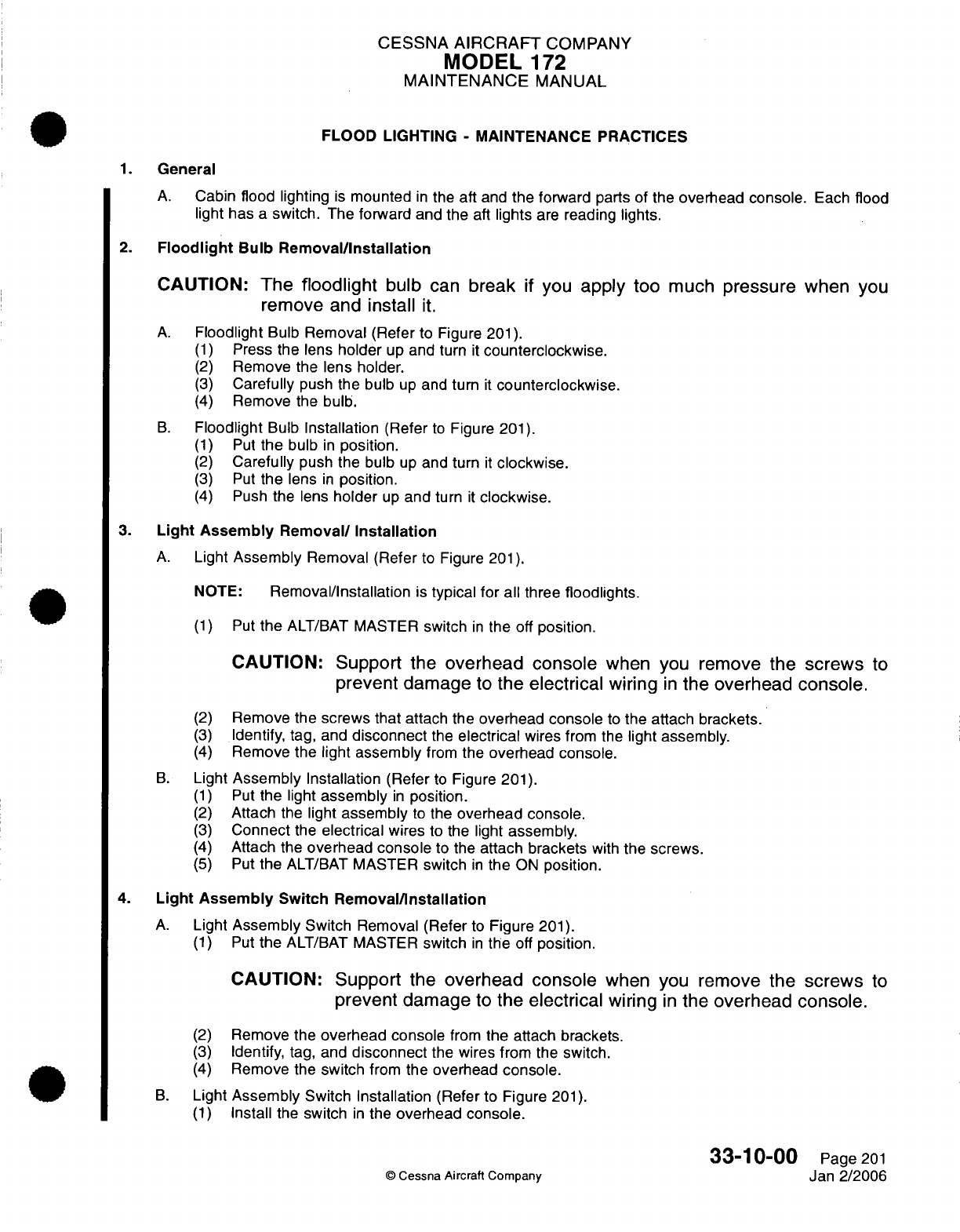
CESSNA
AIRCRAFT
COMPANY
MODEL
172
MAINTENANCE
MANUAL
FLOOD
LIGHTING
-
MAINTENANCE
PRACTICES
1.
General
A.
Cabin
flood lighting
is
mounted
in
the
aft
and
the
forward
parts of the
overhead
console.
Each
flood
light
has
a
switch.
The
forward and the
aft
lights
are
reading lights.
2.
Floodlight
Bulb Removal/Installation
CAUTION:
The
floodlight
bulb
can
break
if
you
apply
too
much
pressure
when
you
remove
and
install
it.
A.
Floodlight
Bulb
Removal
(Refer
to Figure
201).
(1)
Press
the
lens
holder
up
and
turn
it
counterclockwise.
(2)
Remove
the
lens holder.
(3)
Carefully
push
the
bulb
up
and
turn
it
counterclockwise.
(4)
Remove
the
bulb.
B.
Floodlight
Bulb
Installation
(Refer
to
Figure
201).
(1)
Put
the
bulb
in
position.
(2)
Carefully
push
the
bulb
up
and
turn
it
clockwise.
(3)
Put
the
lens
in
position.
(4)
Push
the
lens
holder
up
and
turn
it
clockwise.
3.
Light
Assembly
Removal/
Installation
A.
Light
Assembly
Removal (Refer
to
Figure
201).
NOTE:
Removal/Installation
is
typical
for all three
floodlights.
(1)
Put
the
ALT/BAT
MASTER
switch
in
the
off
position.
CAUTION:
Support
the
overhead
console
when
you
remove
the
screws
to
prevent damage
to
the
electrical
wiring
in
the overhead
console.
(2)
Remove
the
screws
that
attach the
overhead
console
to
the attach
brackets.
(3)
Identify,
tag, and
disconnect
the
electrical
wires
from
the
light assembly.
(4)
Remove
the
light
assembly
from
the
overhead
console.
B.
Light
Assembly
Installation
(Refer
to
Figure
201).
(1)
Put
the light
assembly
in
position.
(2)
Attach
the
light
assembly
to
the
overhead console.
(3)
Connect
the
electrical
wires
to
the light
assembly.
(4)
Attach
the
overhead console
to the
attach brackets
with
the
screws.
(5)
Put
the
ALT/BAT
MASTER
switch
in
the
ON
position.
4.
Light Assembly
Switch
Removal/Installation
A.
Light
Assembly
Switch
Removal
(Refer
to
Figure
201).
(1)
Put
the
ALT/BAT
MASTER
switch
in
the
off
position.
CAUTION:
Support
the
overhead
console
when you
remove
the
screws
to
prevent damage
to
the
electrical
wiring
in
the
overhead
console.
(2)
Remove
the
overhead console
from
the attach brackets.
(3)
Identify,
tag, and
disconnect
the
wires
from the
switch.
(4)
Remove
the
switch
from
the overhead
console.
B.
Light
Assembly
Switch Installation
(Refer
to
Figure
201).
(1)
Install
the
switch
in
the
overhead
console.
33-10-00
Page
201
©
Cessna
Aircraft
Company
Jan
2/2006
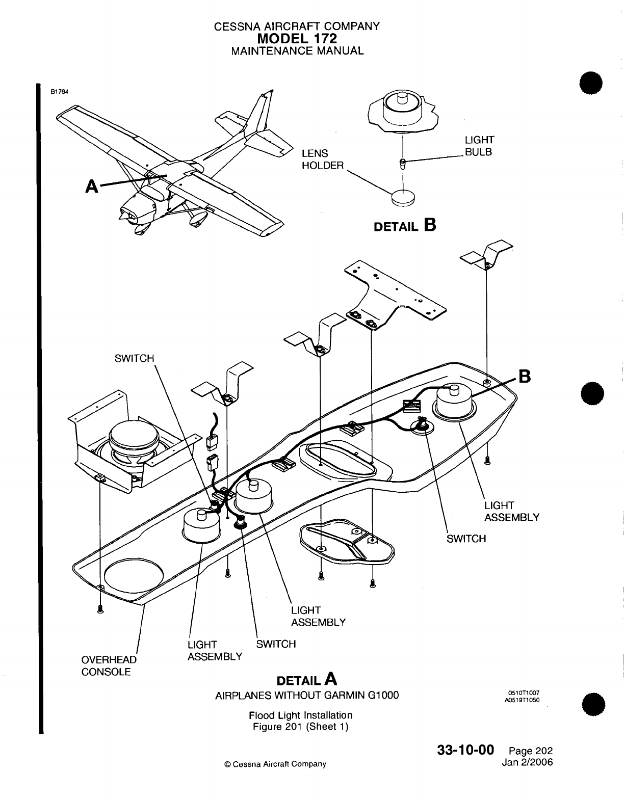
CESSNA AIRCRAFT
COMPANY
MODEL
172
MAINTENANCE
MANUAL
LENS
HOLDER
DETAIL
B
T
B
IBLY
OVERHEAD
CONSOLE
AIRPLANES
WITHOUT
GARMIN
G1000
051
T1
007
A0519T1050
Flood Light
Installation
Figure
201
(Sheet
1)
©
Cessna
Aircraft Company
33-10-00
Page 202
Jan
2/2006
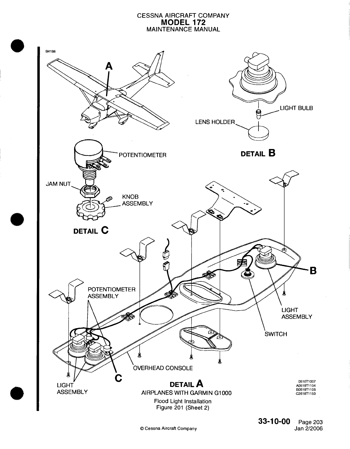
CESSNA
AIRCRAFT
COMPANY
MODEL
172
MAINTENANCE
MANUAL
BULB
LENS HOLDER
POTENTIOMETER
DETAIL
B
JAM
NUT
KNOB
ASSEMBLY
DETAIL
C
3
LIGHT
DETAIL
A
A0519T1104
ASSEMBLY
AIRPLANES
WITH
GARMIN
G1000
C2618Tl153
Flood
Light
Installation
Figure
201
(Sheet
2)
©
Cessna
Aircraft
Company
33-10-00
Page
203
Jan
2/2006
7
CESSNA
AIRCRAFT
COMPANY
MODEL
172
MAINTENANCE
MANUAL
(2)
(3)
(4)
Connect
the
electrical
wires
to the
switch.
Attach the
overhead console
to the
attach
brackets
with
the screws.
Put
the
ALT/BAT
MASTER
switch
in
the
ON
position.
5.
Potentiometer
Removal/Installation
A.
Potentiometer
Removal (Refer
to
Figure
201).
(1)
Put
the
ALT/BAT
MASTER
switch
in
the
off
position.
CAUTION:
Support
the overhead
console
when
you
remove the
screws
to
prevent
damage
to
the
electrical wiring
in
the
overhead console.
(2)
(3)
(4)
(5)
Remove
the
overhead
console
from
the
attach
brackets.
Identify,
tag,
and
disconnect
the
wires
from
the
switch.
Remove
the
knob
assembly
and
the
jam
nut
from
the
potentiometer.
Remove
the
potentiometer
from
the
overhead
console.
B.
Potentiometer Installation
(Refer
to
Figure
201).
(1)
Install
the
jam
nut
and
the
knob assembly.
(2)
Connect
the
electrical wires
to the
potentiometer.
(3)
Attach the
overhead console
to
the
attach brackets
with
the screws.
(4)
Put
the
ALT/BAT
MASTER
switch
in
the
ON
position.
©
Cessna
Aircraft
Company
33-10-00
Page 204
Jan
2/2006
CESSNA
AIRCRAFT
COMPANY
MODEL
172
MAINTENANCE
MANUAL
GLARESHIELD
LIGHTING
-
MAINTENANCE
PRACTICES
1.
General
A. A
single
white
neon
tube
installed
under
the
glareshield provides overall
lighting
for
the
instrument
panel.
A
glareshield
dimming
control
is
mounted below
and
to
the
left
of
the
throttle.
2.
Glareshield
Light
Removal/Installation
A.
Remove
Glareshield
Light
(Refer
to
Figure
201).
(1)
Remove
glareshield.
(2)
Disconnect
glareshield electrical
connector.
(3)
Remove
glareshield
light lens.
(4)
Remove
light
tube
from
individual
retainers.
B.
Install
Glareshield
Light
(Refer
to
Figure
201).
(1)
Secure
light
tube with
individual
retainers.
(2)
Install
glareshield
light
lens.
(3)
Connect
glareshield electrical
connector.
(4)
Install
glareshield.
3.
Glareshield
Light
Power
Supply
Removal/Installation
A.
Remove
Glareshield
Light
Power
Supply
(Refer
to
Figure
201).
(1)
Remove
electrical
connector
from
power
supply.
(2)
Remove
screws
securing
power
supply
to
back
of
instrument
panel.
B.
Install
Glareshield
Light Power
Supply
(Refer
to
Figure 201).
(1)
Secure
power
supply
to
back
of
instrument panel with
screws.
(2)
Connect
electrical
connector
to
power supply.
©
Cessna
Aircraft
Company
33-11-00
Page
201
Apr
7/2003
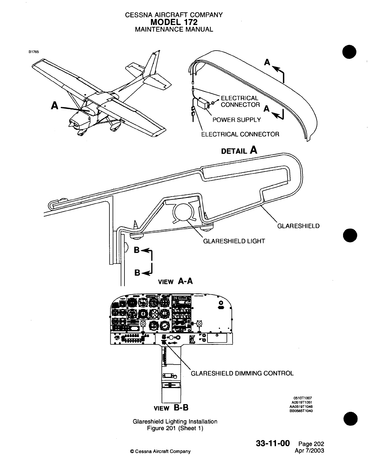
CESSNA
AIRCRAFT
COMPANY
MODEL
172
MAINTENANCE
MANUAL
B
ELECTRICAL
CONNECTOR
POWER
SUPPLY
ELECTRICAL
CONNECTOR
DETAIL
A
GLARESHIELD
)
Bi
ULfA~H
tOL1 ;3ILU
LIUn
I
)
Bn
VIEW
A-A
o
4
.0
.
GLARESHIELD
DIMMING
CONTROL
VIEW
B-B
VIEW
B-B
Glareshield
Lighting Installation
Figure
201
(Sheet
1)
©
Cessna
Aircraft
Company
33-11-00
Page 202
Apr
7/2003
0510T1007
A0519T1051
AA0519T1046
BB0585T1040
B
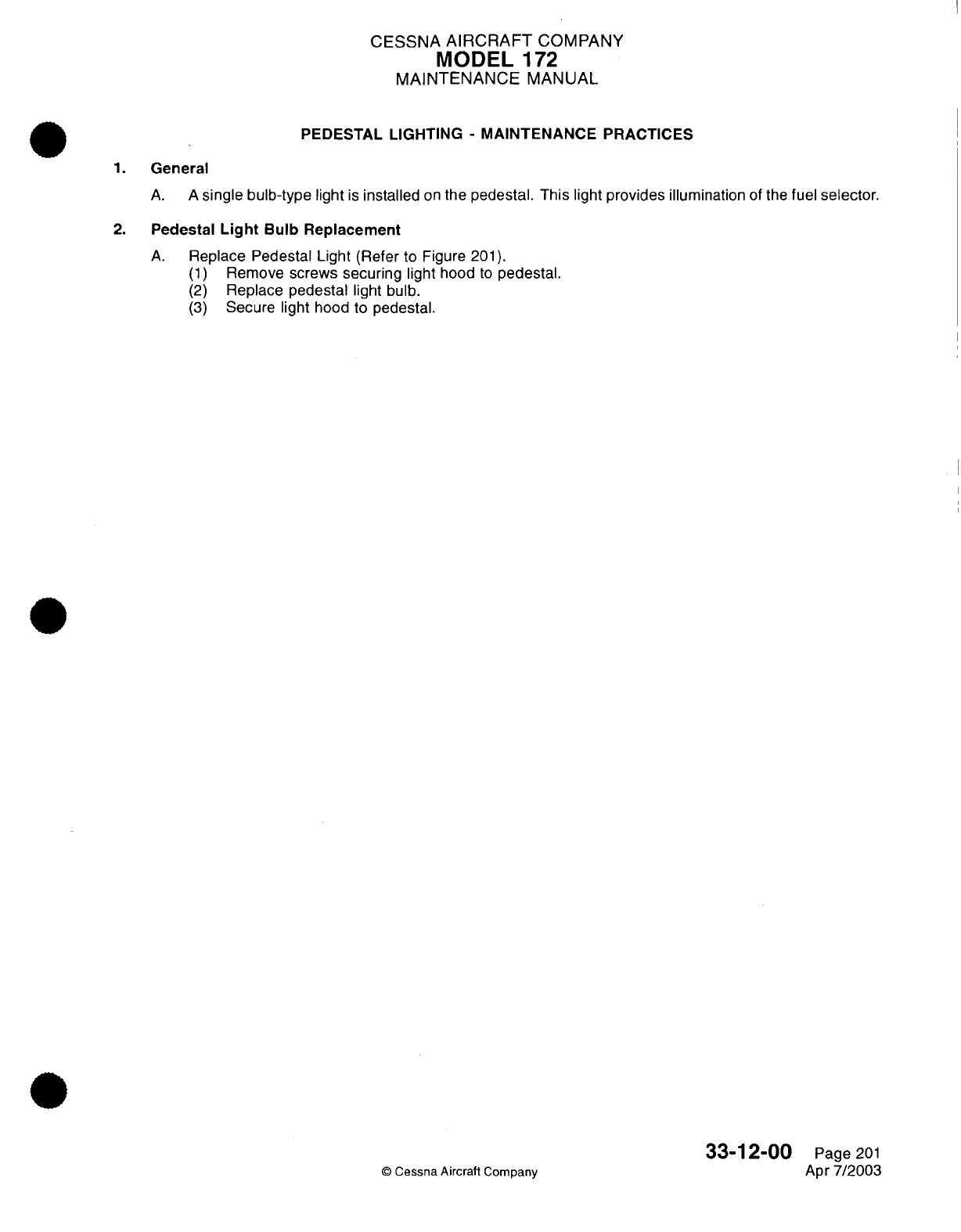
CESSNA
AIRCRAFT
COMPANY
MODEL
172
MAINTENANCE
MANUAL
PEDESTAL
LIGHTING
-
MAINTENANCE
PRACTICES
1.
General
A. A
single bulb-type
light
is
installed
on
the
pedestal.
This
light
provides
illumination
of
the
fuel
selector.
2.
Pedestal
Light
Bulb
Replacement
A.
Replace Pedestal Light
(Refer
to
Figure
201).
(1)
Remove
screws
securing
light
hood
to
pedestal.
(2)
Replace
pedestal
light
bulb.
(3)
Secure
light
hood to
pedestal.
©
Cessna Aircraft
Company
33-12-00
Page
201
Apr
7/2003
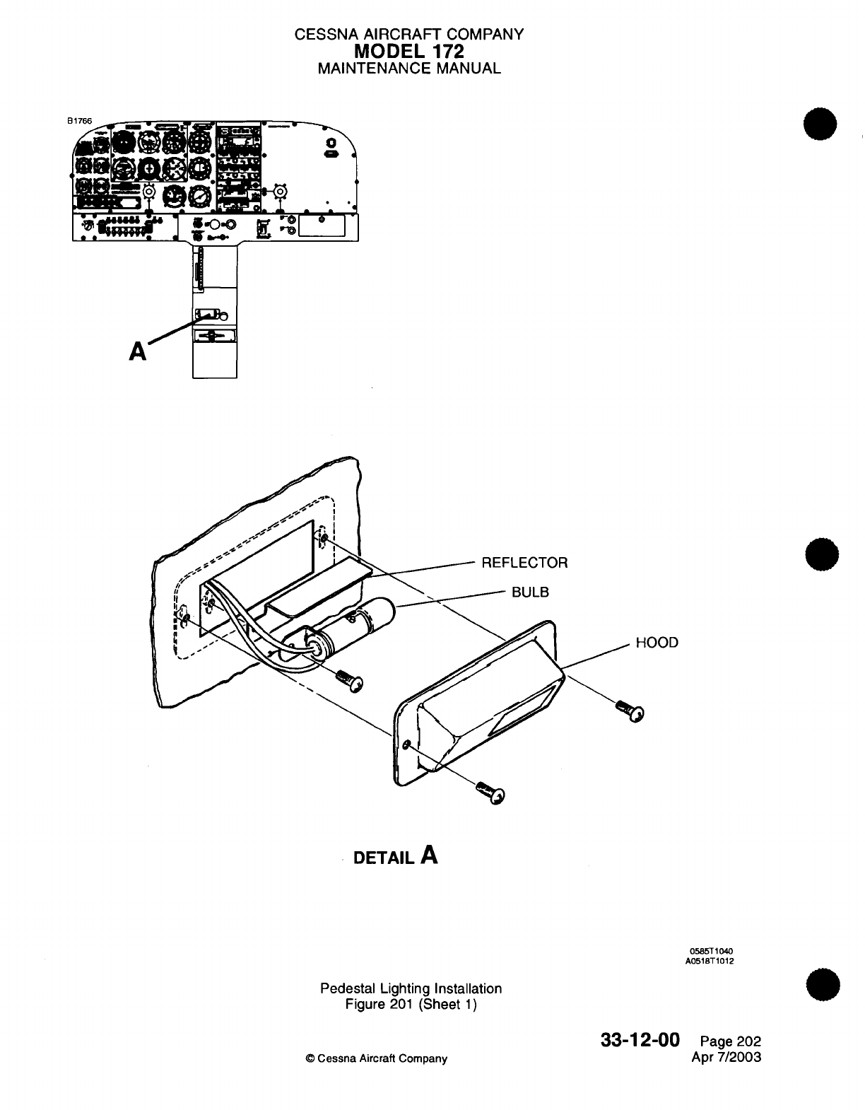
CESSNA AIRCRAFT
COMPANY
MODEL
172
MAINTENANCE
MANUAL
P1
7Fc
I
A I 1--.
REFLECTOR
--
BULB
OOD
DETAIL
A
0585T1040
A0518T1012
Pedestal
Lighting Installation
Figure
201
(Sheet
1)
©
Cessna
Aircraft Company
33-12-00
Page
202
Apr
7/2003
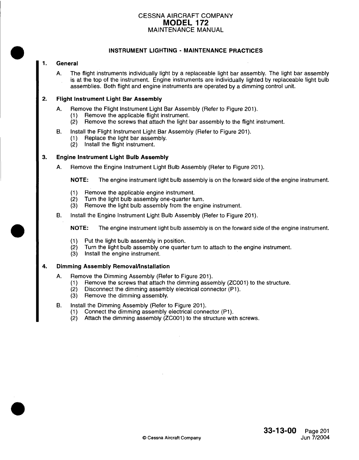
CESSNA
AIRCRAFT
COMPANY
MODEL
172
MAINTENANCE
MANUAL
INSTRUMENT LIGHTING
-
MAINTENANCE PRACTICES
1.
General
A.
The
flight instruments
individually
light
by
a
replaceable
light
bar
assembly. The
light
bar
assembly
is
at
the
top
of the
instrument.
Engine
instruments
are
individually
lighted
by
replaceable light
bulb
assemblies.
Both
flight
and
engine
instruments
are
operated
by
a
dimming
control
unit.
2.
Flight
Instrument
Light
Bar
Assembly
A.
Remove
the Flight
Instrument Light
Bar
Assembly
(Refer
to
Figure
201).
(1)
Remove the
applicable flight
instrument.
(2)
Remove
the
screws that
attach
the
light
bar
assembly
to
the
flight
instrument.
B.
Install
the
Flight
Instrument
Light
Bar
Assembly
(Refer
to
Figure
201).
(1)
Replace
the light
bar
assembly.
(2)
Install
the
flight
instrument.
3.
Engine
Instrument
Light
Bulb
Assembly
A.
Remove
the Engine
Instrument
Light
Bulb
Assembly
(Refer
to
Figure
201).
NOTE:
The
engine
instrument
light
bulb
assembly
is
on
the
forward
side
of
the engine instrument.
(1)
Remove the
applicable
engine
instrument.
(2)
Turn
the
light
bulb
assembly one-quarter
turn.
(3)
Remove
the light
bulb
assembly
from
the
engine
instrument.
B.
Install
the Engine Instrument
Light
Bulb
Assembly
(Refer
to Figure
201).
NOTE:
The engine
instrument
light
bulb
assembly
is
on
the forward
side
of
the
engine
instrument.
(1)
Put
the
light
bulb
assembly
in
position.
(2)
Turn
the
light
bulb
assembly
one
quarter
turn
to
attach
to
the
engine
instrument.
(3)
Install
the engine
instrument.
4. Dimming
Assembly
Removal/Installation
A.
Remove
the
Dimming
Assembly
(Refer
to
Figure
201).
(1)
Remove
the
screws
that
attach the
dimming
assembly
(ZC001)
to the
structure.
(2)
Disconnect
the
dimming
assembly electrical connector
(P1).
(3)
Remove the
dimming
assembly.
B.
Install
the
Dimming
Assembly
(Refer
to
Figure
201).
(1)
Connect the
dimming
assembly electrical connector
(P1).
(2)
Attach
the dimming
assembly
(ZC001)
to the
structure
with
screws.
33-13-00
Page
201
©
Cessna
Aircraft Company
Jun
7/2004
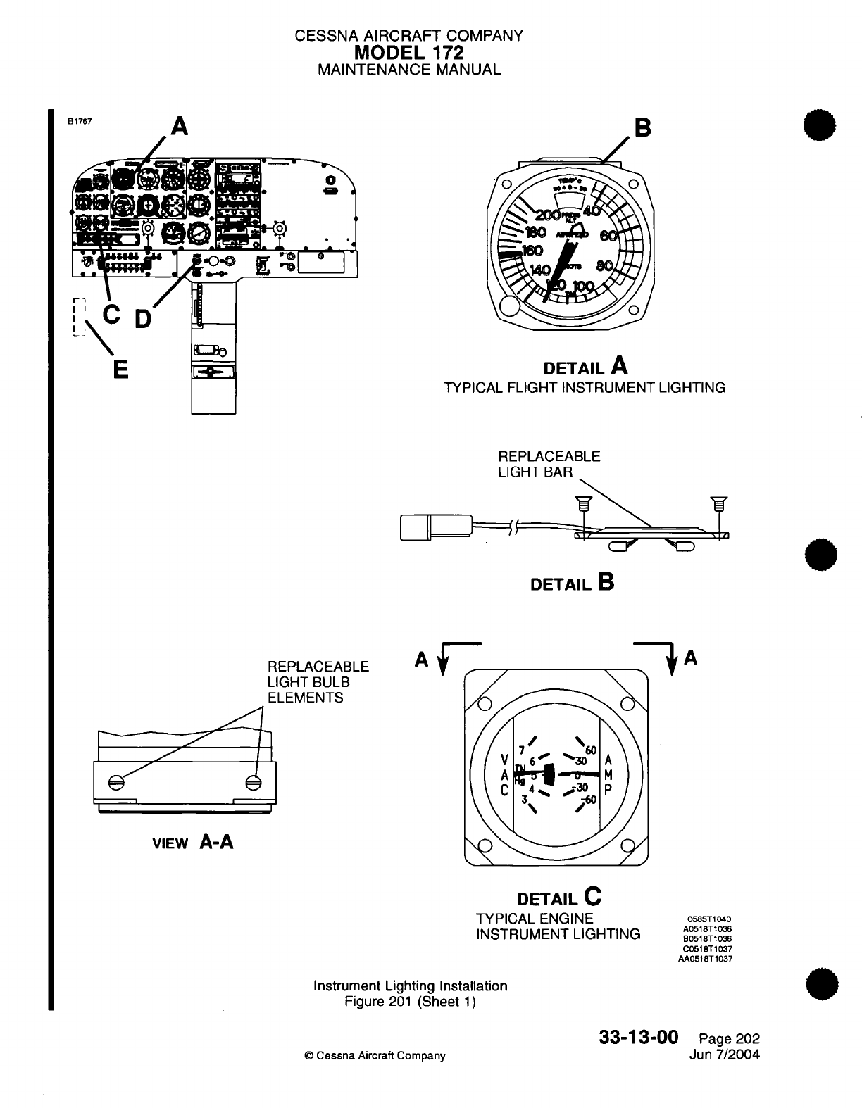
CESSNA
AIRCRAFT
COMPANY
MODEL
172
MAINTENANCE
MANUAL
B
I
DETAIL
A
TYPICAL
FLIGHT
INSTRUMENT
LIGHTING
REPLACEABLE
LIGHT
BAR
\
1%
ta-,
-,(:Y
-1i
DETAIL
B
REPLACEABLE
LIGHT
BULB
ELEMENTS
J
1
VIEW
A-A
DETAIL
C
TYPICAL
ENGINE
INSTRUMENT
LIGHTING
Instrument
Lighting Installation
Figure
201
(Sheet
1)
©
Cessna
Aircraft
Company
33-13-00
Page 202
Jun
7/2004
:
ls.
D
E
.- I
A
t
-/
A
0585T1040
A0518T1036
B0518T1036
C0518T1037
AA0518T1037
1
"--
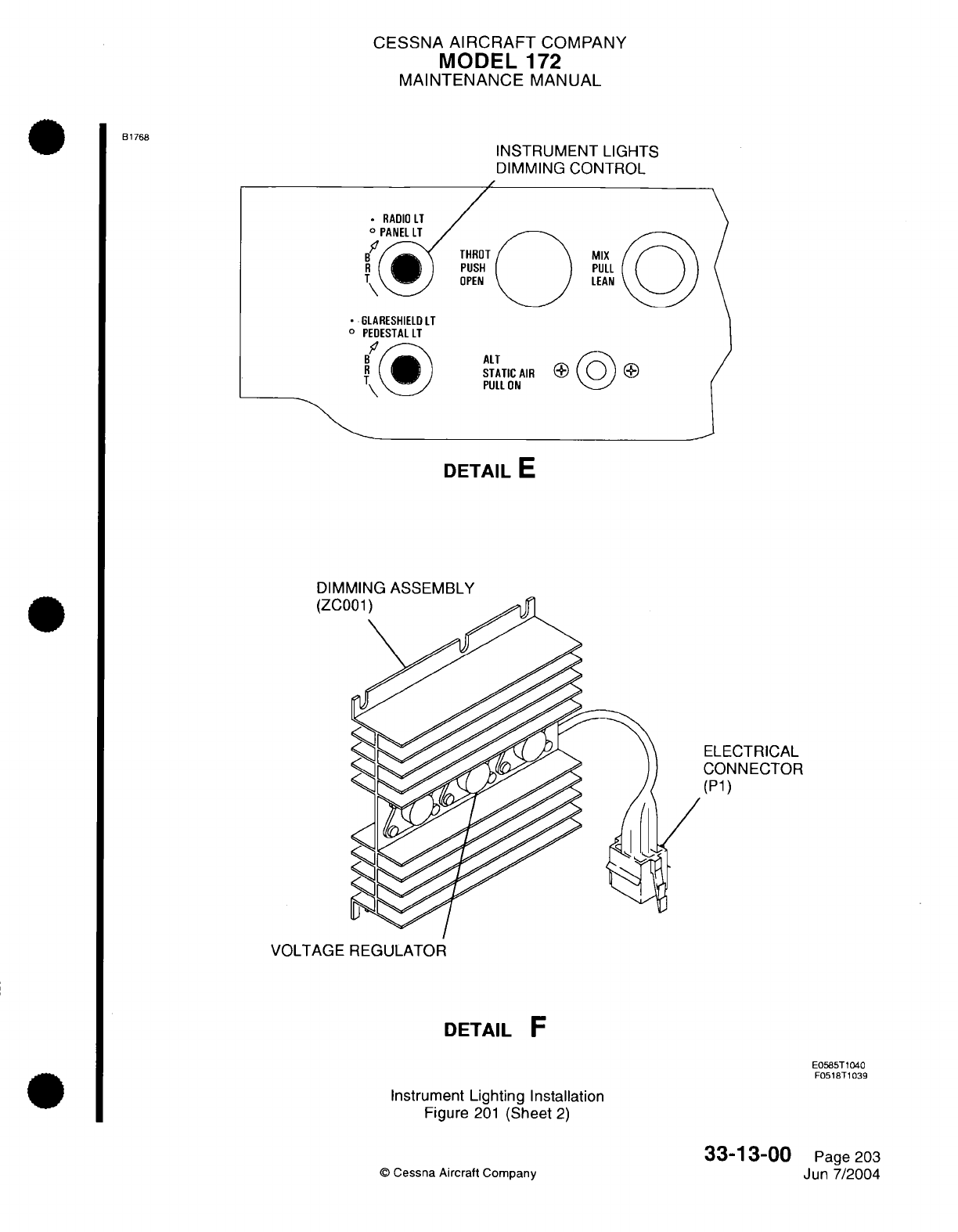
CESSNA
AIRCRAFT
COMPANY
MODEL
172
MAINTENANCE
MANUAL
NSTRUMENT LIGHTS
DIMMING
CONTROL
*
RADIO
LT
O ~II
-
-
mnitL~I
MIX
PULL
LEAN
*
GLARESHIELD
LT
O
PEDESTAL
LT
^
(3
n
ALT
STU
PUL
DETAI
DIMMING
ASSEMBLY
(ZCC
ATIC
AIR
() )
)
L ON
LE
ELECTRICAL
CONNECTOR
(P1)
VOLTAGE REGULATOR
DETAIL
F
E0585T1040
F0518T1039
Instrument
Lighting Installation
Figure
201
(Sheet
2)
33-1
3-00
©
Cessna
Aircraft
Company
B1768
Page
203
Jun
7/2004
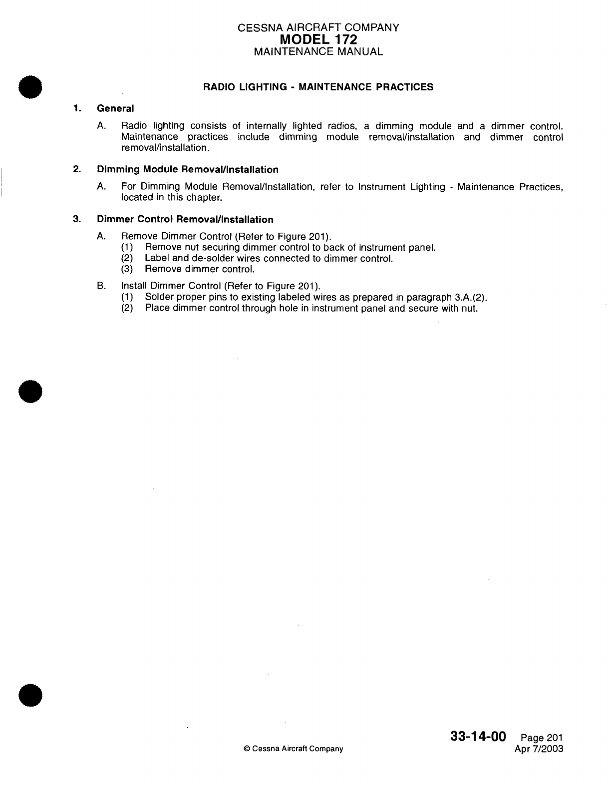
CESSNA
AIRCRAFT
COMPANY
MODEL
1
72
MAINTENANCE
MANUAL
RADIO
LIGHTING
-
MAINTENANCE PRACTICES
1.
General
A.
Radio
lighting
consists
of
internally
lighted radios,
a
dimming
module
and
a
dimmer
control.
Maintenance
practices
include dimming
module
removal/installation
and
dimmer
control
removal/installation.
2.
Dimming Module
Removal/Installation
A.
For
Dimming
Module
Removal/Installation,
refer to
Instrument
Lighting
-
Maintenance
Practices,
located
in
this chapter.
3.
Dimmer
Control Removal/Installation
A.
Remove
Dimmer
Control
(Refer
to
Figure
201).
(1)
Remove nut
securing dimmer control
to
back
of
instrument
panel.
(2)
Label
and
de-solder
wires connected
to
dimmer
control.
(3)
Remove
dimmer
control.
B.
Install Dimmer
Control
(Refer
to
Figure
201).
(1)
Solder
proper
pins to
existing
labeled wires
as
prepared
in
paragraph
3.A.(2).
(2)
Place
dimmer control through
hole
in
instrument
panel
and
secure
with
nut.
33-14-00
Page
201
©
Cessna
Aircraft Company
Apr
7/2003
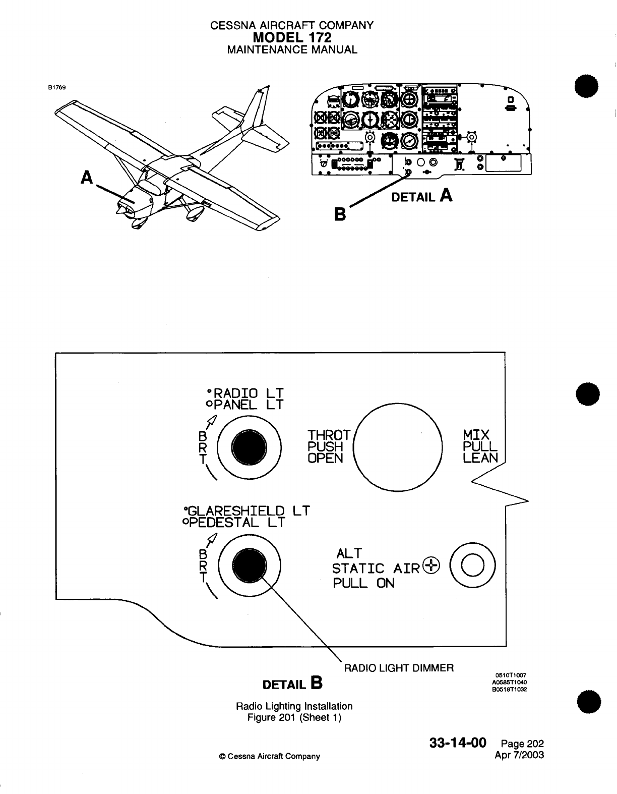
CESSNA AIRCRAFT
COMPANY
MODEL
172
MAINTENANCE
MANUAL
B1
B
°RAPIO
LI
OPAIIEL
L
B
R
T
F1
F-IROT
PUSH
3PEI\I
*GLARESI-IIELD
LT
OPEDESTAL
LT
ALT
STATIC
AIR+
PULL
ON
0510T1007
A0585T1040
B0518T1032
RADIO
LIGHT
DIMMER
DETAIL
B
Radio
Lighting Installation
Figure
201
(Sheet
1)
33-14-00
®
Cessna
Aircraft
Company
Page
202
Apr
7/2003
PUIX
LEAN
B
R
I
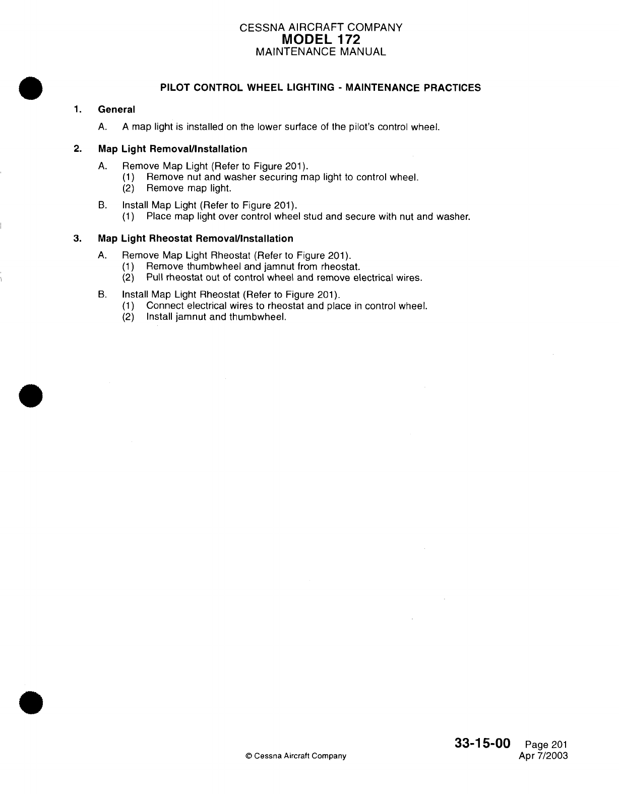
CESSNA
AIRCRAFT
COMPANY
MODEL
172
MAINTENANCE
MANUAL
PILOT
CONTROL
WHEEL LIGHTING
-
MAINTENANCE
PRACTICES
1.
General
A. A
map
light
is
installed
on
the
lower surface
of
the
pilot's
control
wheel.
2.
Map
Light
Removal/Installation
A.
Remove Map
Light
(Refer
to
Figure
201).
(1)
Remove
nut
and
washer
securing
map
light
to
control
wheel.
(2)
Remove
map
light.
B.
Install Map
Light
(Refer
to
Figure
201).
(1)
Place
map
light
over
control
wheel
stud and
secure with
nut
and
washer.
3.
Map
Light
Rheostat
Removal/Installation
A.
Remove
Map
Light
Rheostat
(Refer
to
Figure
201).
(1)
Remove
thumbwheel
and
jamnut
from
rheostat.
(2)
Pull
rheostat
out
of
control
wheel
and
remove
electrical
wires.
B.
Install
Map
Light
Rheostat
(Refer
to
Figure
201).
(1)
Connect
electrical
wires
to
rheostat
and
place
in
control
wheel.
(2)
Install
jamnut
and
thumbwheel.
©
Cessna
Aircraft
Company
33-15-00
Page
201
Apr 7/2003
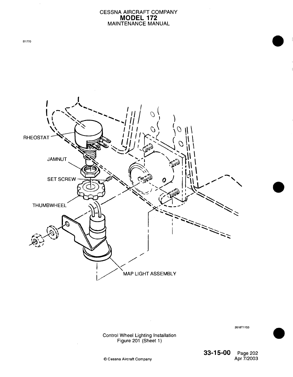
CESSNA AIRCRAFT
COMPANY
MODEL
172
MAINTENANCE
MANUAL
B1770
I
I
{
x,
\
I
JAMNUT
I
\1
I
II
I
I
MAP
LIGHT
ASSEMBLY
2618T1153
Control
Wheel
Lighting
Installation
Figure
201
(Sheet
1)
33-15-00
©
Cessna
Aircraft
Company
/
\N
Page 202
Apr
7/2003
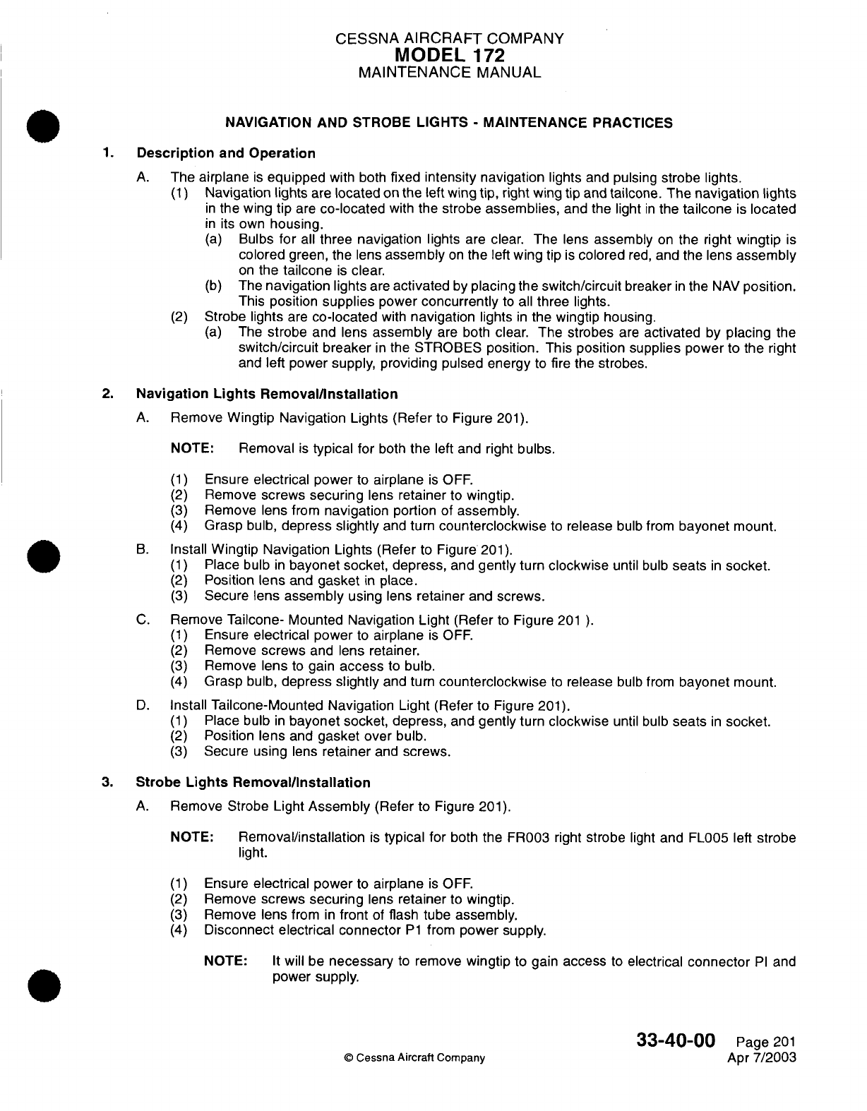
CESSNA
AIRCRAFT
COMPANY
MODEL
172
MAINTENANCE
MANUAL
NAVIGATION AND STROBE
LIGHTS
-
MAINTENANCE
PRACTICES
1.
Description
and
Operation
A.
The
airplane
is
equipped
with
both
fixed
intensity
navigation
lights
and
pulsing
strobe
lights.
(1)
Navigation
lights
are
located
on
the
left
wing
tip,
right
wing
tip
and
tailcone.
The navigation
lights
in
the wing
tip
are
co-located
with
the
strobe
assemblies,
and the light
in
the
tailcone
is
located
in
its
own
housing.
(a)
Bulbs
for
all
three navigation
lights
are
clear.
The
lens
assembly
on
the right
wingtip
is
colored
green, the lens
assembly
on
the
left
wing
tip
is
colored
red,
and the lens
assembly
on
the
tailcone
is
clear.
(b)
The
navigation
lights
are
activated
by
placing the
switch/circuit
breaker
in
the
NAV
position.
This position
supplies
power
concurrently
to
all
three
lights.
(2)
Strobe lights
are
co-located
with
navigation
lights
in
the wingtip housing.
(a)
The
strobe
and lens
assembly
are
both
clear.
The
strobes
are
activated
by
placing
the
switch/circuit
breaker
in
the
STROBES position. This
position supplies
power to
the
right
and
left
power supply,
providing
pulsed energy
to fire the
strobes.
2.
Navigation
Lights
Removal/nstallation
A.
Remove
Wingtip
Navigation
Lights (Refer
to
Figure
201).
NOTE:
Removal
is
typical
for
both
the
left
and
right
bulbs.
(1)
Ensure
electrical
power
to
airplane
is
OFF.
(2)
Remove
screws
securing
lens
retainer
to
wingtip.
(3)
Remove
lens
from
navigation
portion
of
assembly.
(4)
Grasp
bulb,
depress
slightly
and
turn
counterclockwise
to
release
bulb
from
bayonet
mount.
B.
Install
Wingtip Navigation
Lights
(Refer
to
Figure
201).
(1)
Place
bulb
in
bayonet
socket, depress,
and
gently
turn
clockwise
until
bulb
seats
in
socket.
(2)
Position
lens
and
gasket
in
place.
(3)
Secure
lens
assembly
using
lens
retainer
and
screws.
C.
Remove
Tailcone-
Mounted
Navigation
Light (Refer
to
Figure
201
).
(1)
Ensure
electrical
power
to
airplane
is
OFF.
(2)
Remove
screws
and
lens
retainer.
(3)
Remove
lens
to
gain
access
to
bulb.
(4)
Grasp
bulb,
depress
slightly
and
turn
counterclockwise
to
release
bulb
from
bayonet
mount.
D.
Install
Tailcone-Mounted Navigation Light
(Refer
to
Figure
201).
(1)
Place bulb
in
bayonet
socket, depress,
and
gently
turn
clockwise
until bulb
seats
in
socket.
(2)
Position
lens
and
gasket over
bulb.
(3)
Secure
using
lens
retainer
and
screws.
3.
Strobe
Lights
Removal/Installation
A.
Remove
Strobe Light
Assembly
(Refer
to Figure
201).
NOTE:
Removal/installation
is
typical
for
both
the
FR003
right
strobe
light
and
FL005 left
strobe
light.
(1)
Ensure
electrical
power
to
airplane
is
OFF.
(2)
Remove
screws
securing
lens
retainer
to
wingtip.
(3)
Remove
lens
from
in
front
of
flash
tube
assembly.
(4)
Disconnect
electrical connector
P1
from
power
supply.
NOTE:
It
will be
necessary
to
remove
wingtip
to gain
access
to
electrical
connector
PI
and
power
supply.
33-40-00
Page
201
©
Cessna
Aircraft
Company
Apr
7/2003
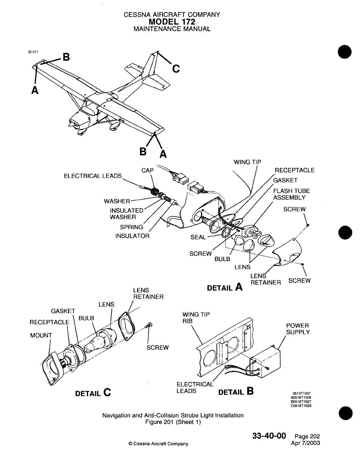
CESSNA AIRCRAFT
COMPANY
MODEL
172
MAINTENANCE
MANUAL
C
WING
ELECTRICAL
WASHER
~^
/ j
WASHER
/
SPRING
/ v
INSULATOR
SEAL-
SCREW
/
BULB
DETAIL
A
RETAINER
SCREW
LENS
WING
TIP
POWER
SUPPLY
ELECTRICAL
LEADS
DETAIL
C
DETAIL
B
0510T1007
A0518T1028
B0518T1027
C0518T1029
Navigation and
Anti-Collision Strobe
Light
Installation
Figure
201
(Sheet
1)
33-40-00
©
Cessna
Aircraft
Company
CLE
BE
Y
V
GASKET
LENS
LENS
RETAINER
Page
202
Apr
7/2003
E
I
W
_
.
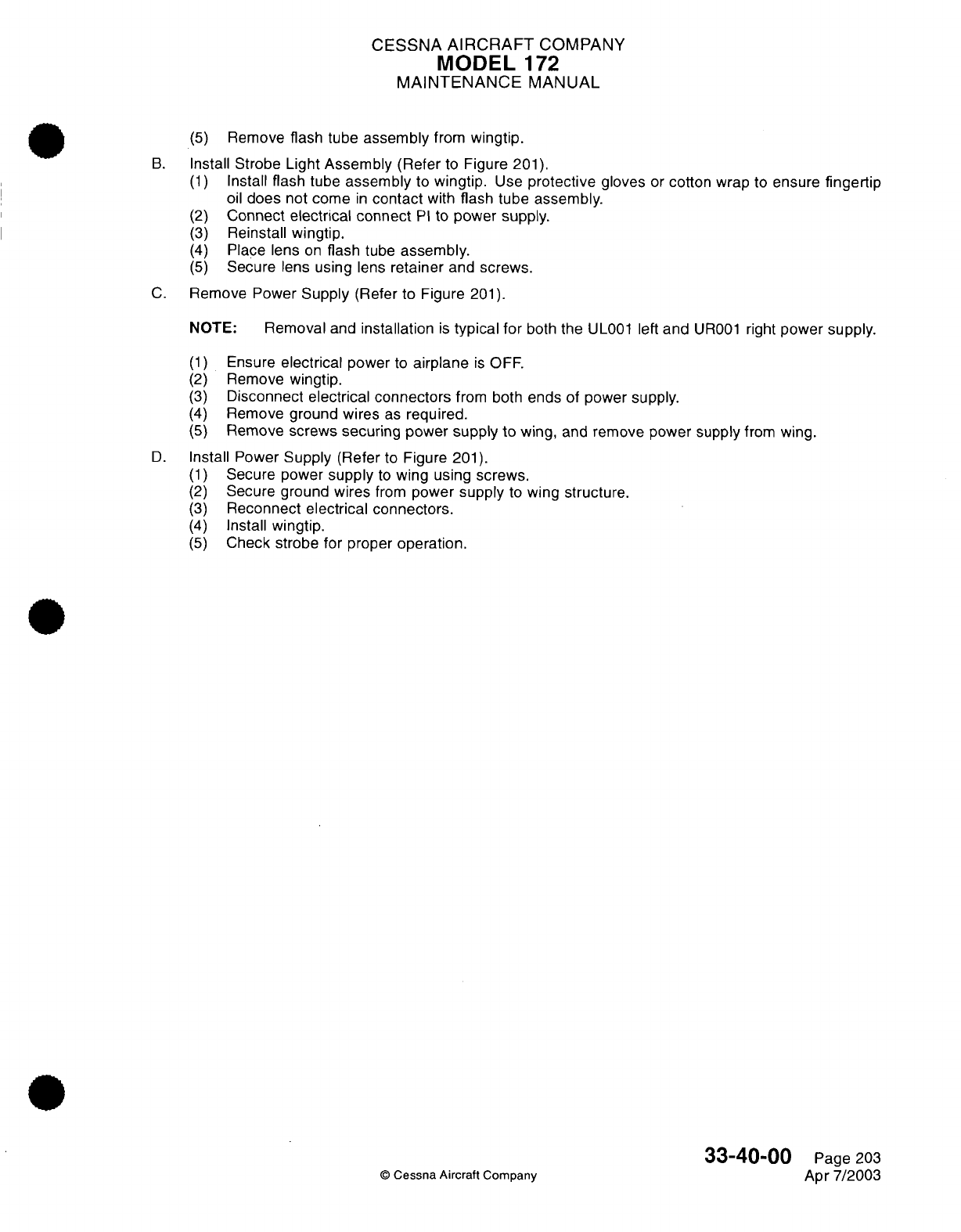
CESSNA
AIRCRAFT
COMPANY
MODEL
1
72
MAINTENANCE
MANUAL
(5)
Remove
flash
tube
assembly
from
wingtip.
B.
Install
Strobe
Light
Assembly
(Refer
to
Figure
201).
(1)
Install
flash
tube
assembly
to
wingtip.
Use
protective
gloves
or
cotton
wrap
to
ensure
fingertip
oil
does
not
come
in
contact
with
flash tube assembly.
(2)
Connect
electrical
connect
PI
to
power
supply.
(3)
Reinstall
wingtip.
(4)
Place lens
on
flash
tube
assembly.
(5)
Secure
lens
using
lens
retainer
and
screws.
C.
Remove Power
Supply
(Refer to Figure
201).
NOTE:
Removal
and
installation
is
typical
for
both
the
UL001
left
and
UR001
right
power
supply.
(1)
(2)
(3)
(4)
(5)
Ensure
electrical
power
to
airplane
is
OFF.
Remove
wingtip.
Disconnect
electrical connectors
from both
ends
of
power
supply.
Remove
ground
wires
as
required.
Remove
screws securing power supply
to
wing,
and
remove power
supply
from
wing.
D.
Install
Power
Supply
(Refer
to Figure
201).
(1)
Secure power
supply
to
wing
using
screws.
(2)
Secure ground
wires
from
power
supply
to
wing
structure.
(3)
Reconnect
electrical connectors.
(4)
Install
wingtip.
(5)
Check
strobe
for
proper
operation.
©
Cessna
Aircraft Company
33-40-00
Page
203
Apr
7/2003
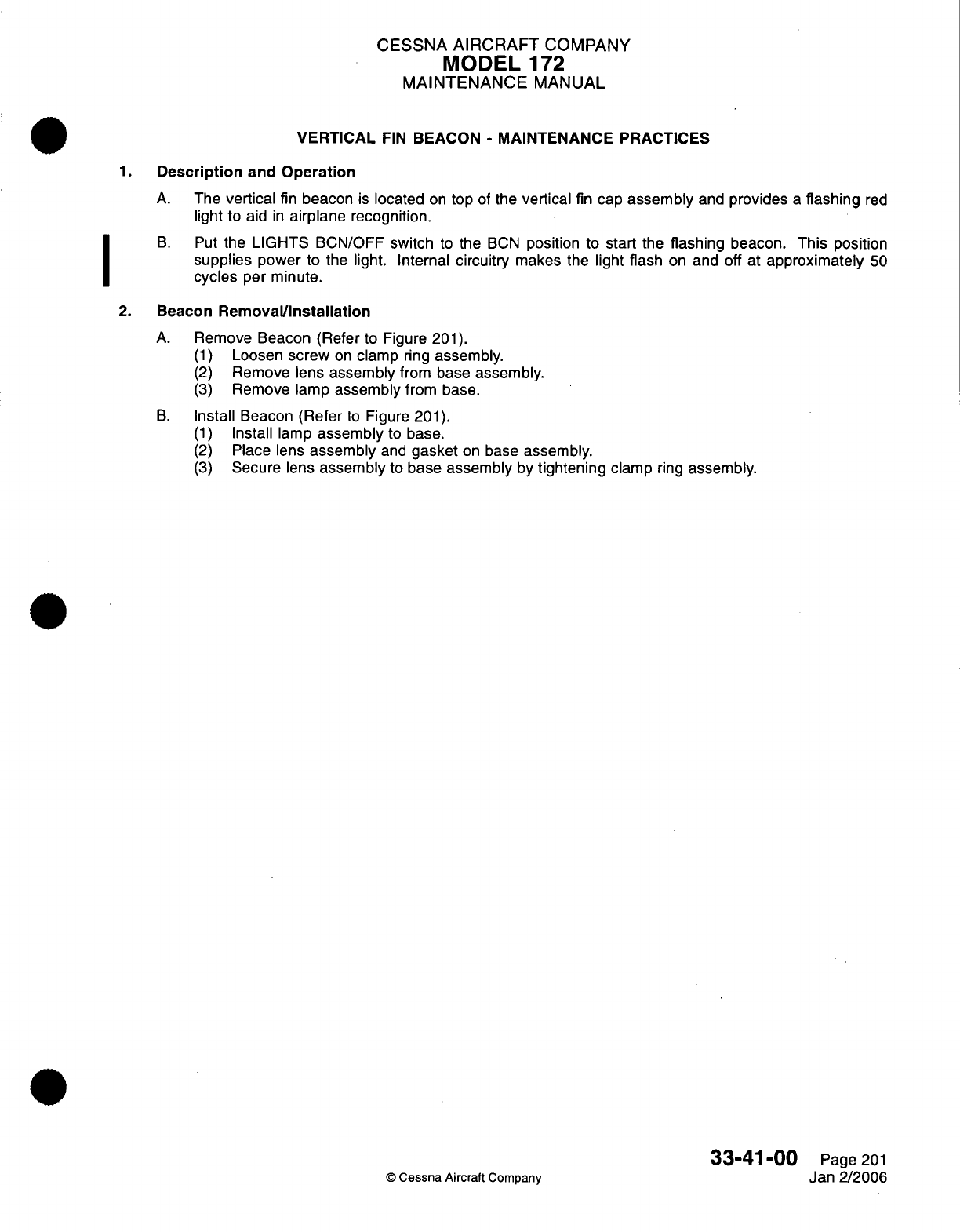
CESSNA
AIRCRAFT
COMPANY
MODEL
172
MAINTENANCE
MANUAL
VERTICAL
FIN
BEACON
-
MAINTENANCE
PRACTICES
1.
Description
and
Operation
A.
The
vertical
fin
beacon
is
located
on
top
of
the
vertical
fin
cap
assembly
and
provides
a
flashing
red
light
to
aid
in
airplane
recognition.
B.
Put
the
LIGHTS
BCN/OFF
switch
to
the
BCN
position
to
start
the
flashing
beacon. This position
supplies
power
to the
light.
Internal
circuitry
makes
the
light
flash
on
and off at
approximately
50
cycles
per minute.
2.
Beacon
Removal/Installation
A.
Remove
Beacon
(Refer
to Figure
201).
(1)
Loosen
screw
on
clamp
ring
assembly.
(2)
Remove
lens
assembly
from
base
assembly.
(3)
Remove lamp
assembly
from
base.
B.
Install
Beacon
(Refer
to
Figure
201).
(1)
Install
lamp
assembly
to
base.
(2)
Place
lens
assembly
and
gasket
on
base
assembly.
(3)
Secure
lens
assembly
to
base
assembly
by
tightening
clamp
ring
assembly.
33-41-00
Page
201
©
Cessna
Aircraft Company
Jan 2/2006
I
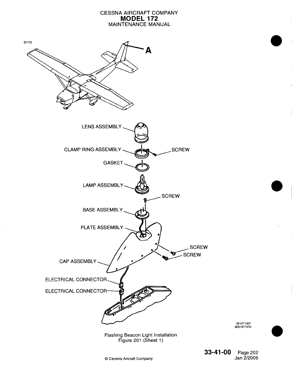
CESSNA
AIRCRAFT
COMPANY
MODEL
172
MAINTENANCE
MANUAL
B1
A
LENS
CLAMP
RING
GASKET
LAMP
ASSEMBLY
SCREW
CREW
CAP AS
ELECTRICAL
ELECTRICAL
0510T1007
A0518T1010
Flashing
Beacon Light
Installation
Figure
201
(Sheet
1)
33-41-00
©
Cessna
Aircraft
Company
Page
202
Jan
2/2006
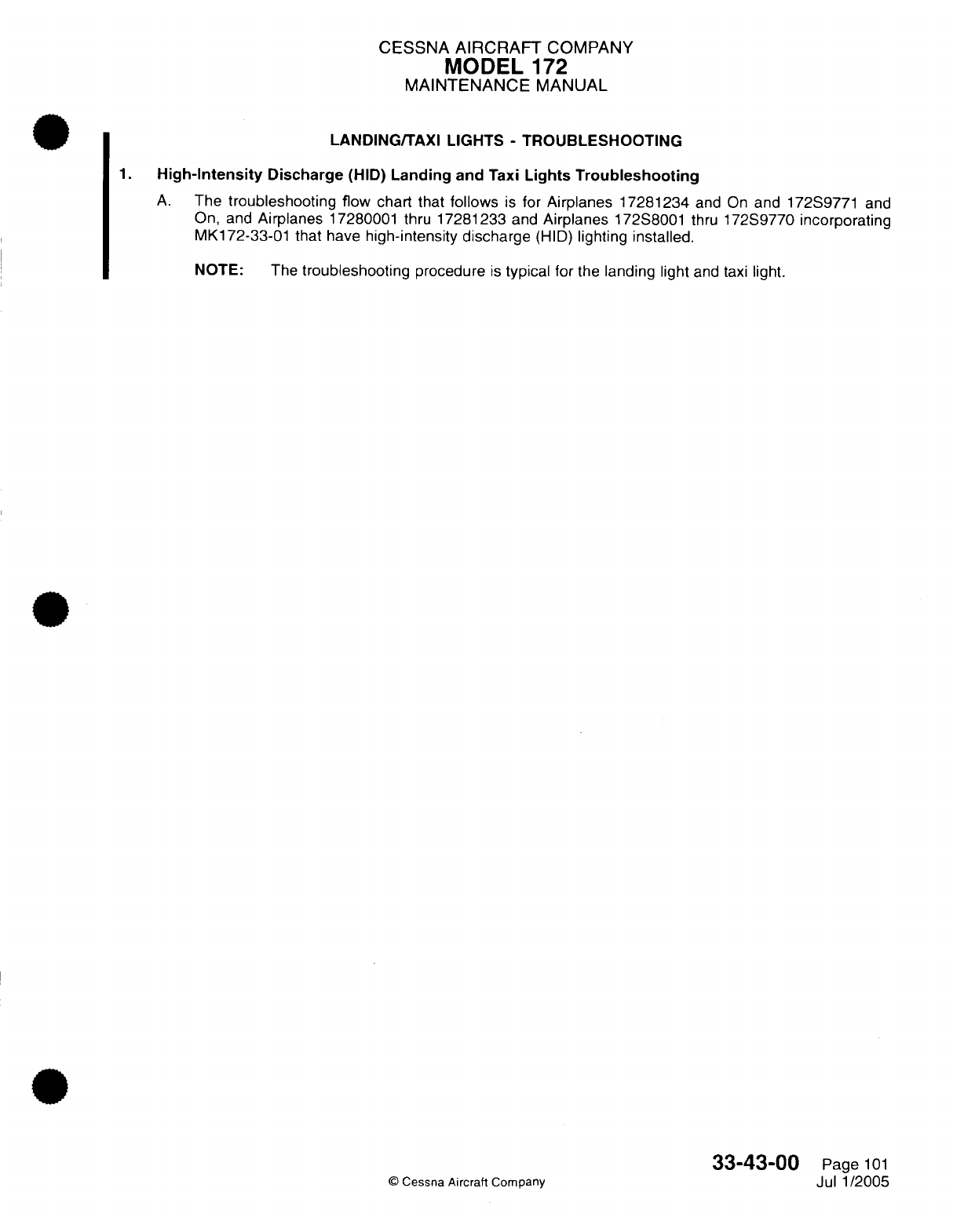
CESSNA
AIRCRAFT
COMPANY
MODEL
172
MAINTENANCE
MANUAL
LANDING/TAXI
LIGHTS
-
TROUBLESHOOTING
1.
High-Intensity
Discharge
(HID)
Landing
and
Taxi
Lights Troubleshooting
A.
The
troubleshooting
flow
chart that
follows
is
for
Airplanes 17281234
and
On
and 172S9771
and
On, and
Airplanes
17280001
thru
17281233
and
Airplanes
172S8001
thru
172S9770
incorporating
MK172-33-01
that have
high-intensity discharge
(HID)
lighting
installed.
NOTE: The
troubleshooting
procedure
is
typical
for
the
landing
light
and
taxi
light.
33-43-00
Page
101
©
Cessna
Aircraft Company
Jul
1/2005
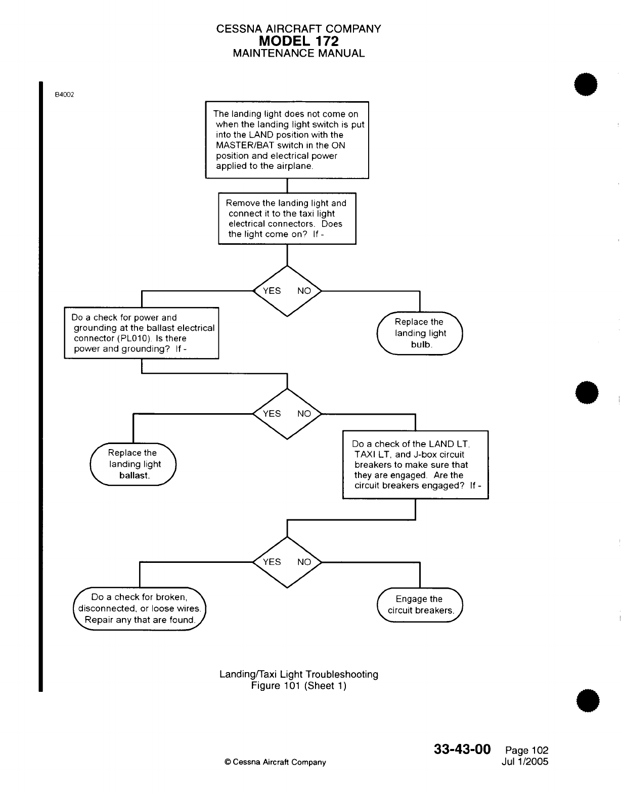
CESSNA
AIRCRAFT
COMPANY
MODEL
172
MAINTENANCE
MANUAL
B4002
The
landing
light
does
not
come
on
when
the landing light
switch
is
put
into
the
LAND
position
with
the
MASTER/BAT
switch
in
the
ON
position
and
electrical
power
applied
to
the
airplane.
I
Remove
the
landing
light
and
connect
it
to
the
taxi light
electrical connectors.
Does
the
light
come
on?
If-
Do
a
check for
power
and
grounding
at
the
ballast
electrical
connector
(PL010).
Is
there
power
and
grounding?
If
-
I
Replace
the>
landing
light
ballast.
/Do
a
check
for
broken,
(disconnected,
or
loose
wires
\Repair
any
that
are
found/
I
Replace
thea
landing
light
bulb.
J
Do
a
check
of
the
LAND
LT,
TAXI LT,
and
J-box
circuit
breakers
to make
sure
that
they
are
engaged.
Are
the
circuit
breakers
engaged?
If-
I
Engage
the
circuit
breakers.
Landing/Taxi
Light Troubleshooting
Figure
101
(Sheet
1)
©
Cessna Aircraft
Company
33-43-00
Page
102
Jul
1/2005
CESSNA
AIRCRAFT
COMPANY
MODEL
172
MAINTENANCE
MANUAL
LANDING/TAXI
LIGHTS
-
MAINTENANCE
PRACTICES
1.
General
A.
Airplanes
17280001
thru 17281233 and
Airplanes
172S8001
thru
172S9770
not
incorporating
MK172-
33-01
have
an
incandescent
landing
and
taxi
light installed.
The
landing
and
taxi
lights
are
installed
on
the
left wing
leading
edge between
WS
100.00
and
WS
118.00.
The landing and
taxi
lights
are
controlled
by
two
switches
on
the
circuit
panel
assembly.
The landing
light
is
operated
by
the
landing
light
switch
and
the
taxi
light
is
operated
by
the taxi light switch.
B.
Airplanes
17281234
and
On and
Airplanes
172S9771
and On,
and
Airplanes
17280001
thru
17281233
and
Airplanes
172S8001
thru 172S9770
incorporating
MK172-33-01
have
a
high-intensity
discharge
(HID)
landing
and
taxi
light
installed.
The
landing
and
taxi
lights
have an igniter
installed
on the
back
side
of
each
light.
A
ballast
is
necessary
for
the operation
of
the
HID
bulbs.
The
ballast
for
the
landing
light
HID
bulb (inboard
bulb)
is
installed
on
a
bracket that
is
attached
to a
wing
leading-edge
rib
inboard
of
the
bulb.
The
ballast
for
the taxi
light
HID
bulb
(outboard
bulb)
is
installed
on
a
bracket
that
is
attached
to
a
wing
leading-edge
rib
outboard
of
the
bulb.
The
wiring
is
almost
the same
as
the
incandescent
bulb
installation,
but
there
is
one
more
cable
necessary
to
connect
the
ballast
to
the
HID
bulbs.
The
landing
and
taxi
light
switches, and the
landing
and
taxi
light
circuit
breakers
for
the
HID
lighting
system
are the
same
as
those
for
the
incandescent
lighting
system.
2.
Troubleshooting
A.
For
troubleshooting
of
the
HID
landing
and
taxi light
installation,
refer
to
Chapter
33,
Landing/Taxi
Lights
-
Troubleshooting.
3.
Light
Adjustment
A.
The
landing
and
taxi
lights
are
set
to specified positions,
but
you
can
adjust
them
as
necessary. The
procedures
that
follow
give
information
on
the correct
landing
and
taxi
light
adjustment
procedure.
The
procedures that
follow
are
typical for
incandescent
and
HID
lights.
(1)
Park
the
airplane
on
a
flat,
level
surface
with
the
landing
and
taxi
lights
in
front
of
a
light-reflecting
object.
Make
sure
that
the
waterline
of
the
airplane
is
level
and that
the
wings
are
level.
Refer
to
Chapter
8,
Leveling
-
Maintenance Practices.
(2)
Park
the
airplane
so
that
the distance
from
the
light-reflecting
object
to
the
rivet line
on
the
bottom
of
the front
spar
is
approximately
3
feet.
(3)
Set
the
landing
light
switch
to
the
LAND
position.
(4)
Measure
the
distance
from
the
floor
to
the
center
of
the
beam
that
shines
on
the
light-reflecting
object.
The
correct
distance
is
74.41
inches.
(5)
Set
the
landing
light
switch
to
the OFF
position
(6)
Set
the
taxi light
switch
to the
TAXI
position.
(7)
Measure the
distance
from the
floor
to
the center
of
the
beam
that
shines
on
the
light-reflecting
object. The
correct
distance
is
73.29 inches.
(8)
Set
the
taxi
light switch
to
the
OFF
position.
(9)
To
adjust
the
beam
to
the
correct
position,
add
or remove
washers
between
the spacers
and the
plate.
4.
Light
Removal and
Installation
NOTE:
Removal
and
installation
is
typical
for
incandescent
and
HID
landing
and
taxi
lights.
A.
Remove
the
Light
(Refer
to
Figure
201).
(1)
Disconnect
the
main
battery
from the
airplane. Refer
to
Chapter
24,
Battery
-
Maintenance
Practices.
(2)
Set
the
landing
light
and
the
taxi
light
switches to
OFF.
(3)
Remove
the
screws
that
attach the
lens
assembly
to
the
leading
edge
of
the
wing.
(4)
Remove
the
screws,
brackets,
and
nuts
that
hold
the light
in
position against
the
plate.
NOTE:
Some
airplanes
that
have
the
HID
landing
and
taxi lights have
an
aluminum
ring
installed
between
the
HID
landing
and
taxi
lights and
the
bracket.
33-43-00
Page
201
©
Cessna Aircraft Company
Jul
1/2005
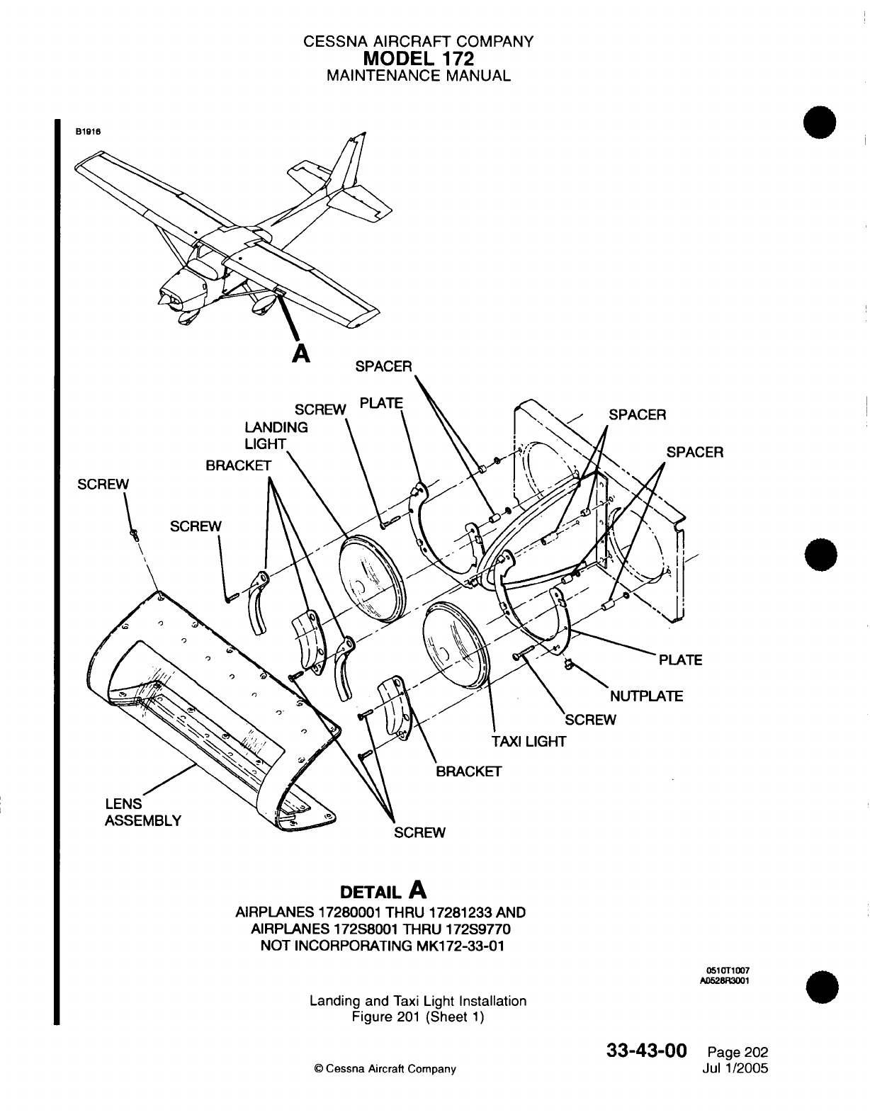
CESSNA AIRCRAFT
COMPANY
MODEL
172
MAINTENANCE
MANUAL
S
DETAIL
A
AIRPLANES
17280001 THRU
17281233
AND
AIRPLANES
172S8001 THRU
172S9770
NOT
INCORPORATING
MK172-33-01
051
T1007
A052BR3001
Landing
and
Taxi
Light
Installation
Figure
201
(Sheet
1)
33-43-00
©
Cessna
Aircraft
Company
Page
202
Jul
1/2005
nanny
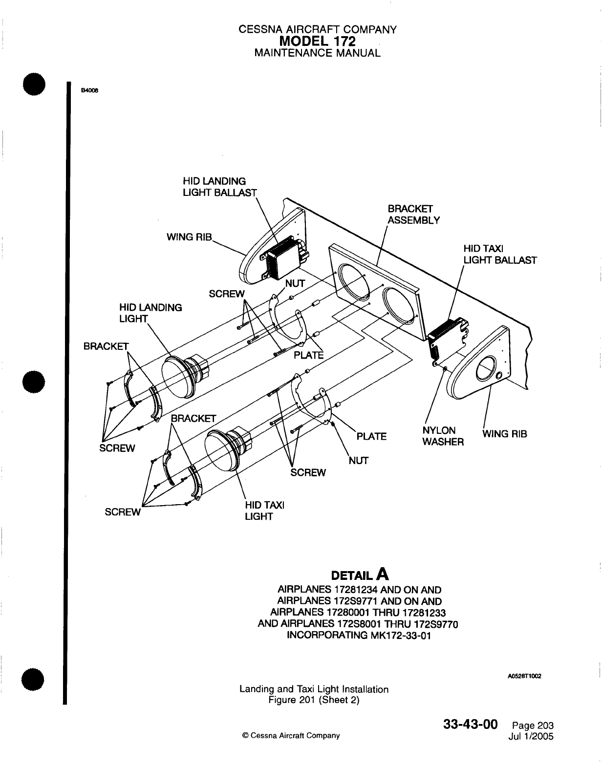
CESSNA
AIRCRAFT
COMPANY
MODEL
172
MAINTENANCE
MANUAL
B4006
HID
LANDING
LIGHT
BALLAST
SCREW
LIGHT
DETAIL
A
AIRPLANES
17281234 AND
ON
AND
AIRPLANES
172S9771
AND
ON
AND
AIRPLANES 17280001
THRU
17281233
AND AIRPLANES
172S8001
THRU
172S9770
INCORPORATING
MK172-33-01
A0528T1002
Landing and
Taxi
Light Installation
Figure
201
(Sheet
2)
33-43-00
©
Cessna
Aircraft
Company
Page
203
Jul
1/2005
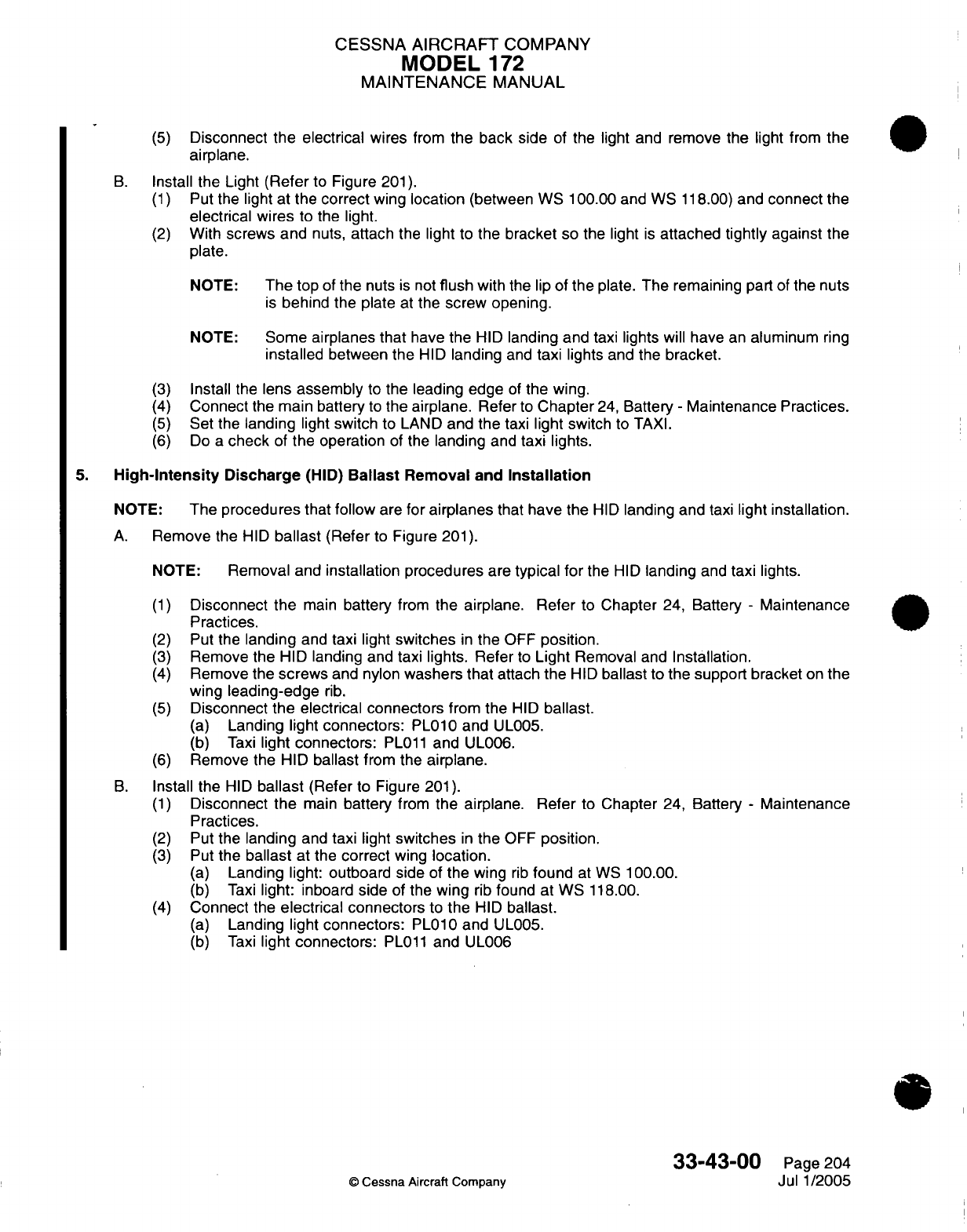
CESSNA
AIRCRAFT
COMPANY
MODEL
172
MAINTENANCE
MANUAL
(5)
Disconnect
the
electrical
wires
from
the back
side
of
the
light
and
remove
the
light from the
airplane.
B.
Install
the Light
(Refer
to
Figure
201).
(1)
Put
the
light
at
the
correct
wing
location
(between WS
100.00
and WS
118.00)
and
connect
the
electrical
wires
to
the
light.
(2)
With
screws and
nuts,
attach
the
light
to
the
bracket
so the light
is
attached
tightly
against
the
plate.
NOTE:
The
top
of
the
nuts
is
not
flush
with
the
lip
of
the
plate.
The remaining
part
of
the nuts
is
behind
the plate
at
the
screw
opening.
NOTE:
Some
airplanes that
have
the
HID
landing
and taxi lights
will
have
an
aluminum
ring
installed
between
the
HID
landing
and
taxi
lights
and
the
bracket.
(3)
Install
the
lens
assembly
to
the
leading
edge
of
the
wing.
(4)
Connect
the
main battery
to
the
airplane.
Refer
to
Chapter
24,
Battery
-
Maintenance Practices.
(5)
Set
the
landing
light
switch
to
LAND
and
the
taxi
light
switch
to
TAXI.
(6)
Do
a
check
of
the
operation
of
the
landing
and
taxi
lights.
5.
High-Intensity
Discharge
(HID)
Ballast
Removal
and
Installation
NOTE:
The
procedures
that
follow
are for
airplanes
that
have
the
HID
landing and
taxi
light installation.
A.
Remove
the
HID
ballast
(Refer
to
Figure
201).
NOTE:
Removal and
installation procedures
are
typical for
the
HID
landing
and
taxi lights.
(1)
Disconnect
the
main
battery
from
the airplane. Refer
to
Chapter
24,
Battery
-
Maintenance
Practices.
(2)
Put
the
landing
and
taxi
light
switches
in
the
OFF
position.
(3)
Remove
the
HID
landing
and
taxi
lights. Refer
to
Light
Removal
and
Installation.
(4)
Remove the
screws
and
nylon
washers that
attach
the
HID
ballast
to
the support
bracket
on
the
wing
leading-edge
rib.
(5)
Disconnect
the
electrical
connectors
from the
HID
ballast.
(a)
Landing light
connectors:
PL010 and
UL005.
(b)
Taxi
light
connectors:
PL011
and
UL006.
(6)
Remove the
HID
ballast
from the
airplane.
B.
Install
the
HID
ballast
(Refer
to Figure
201).
(1)
Disconnect
the
main
battery
from
the airplane. Refer
to
Chapter
24, Battery
-
Maintenance
Practices.
(2)
Put
the
landing
and
taxi light
switches
in
the
OFF
position.
(3)
Put
the
ballast
at
the
correct
wing
location.
(a)
Landing
light:
outboard side
of
the wing
rib
found
at
WS
100.00.
(b)
Taxi
light: inboard
side
of
the
wing
rib
found
at
WS
118.00.
(4)
Connect
the
electrical connectors
to
the
HID
ballast.
(a)
Landing light
connectors:
PL010 and
UL005.
(b)
Taxi
light
connectors:
PL011
and
UL006
33-43-00
Page
204
©
Cessna
Aircraft
Company
Jul 1/2005
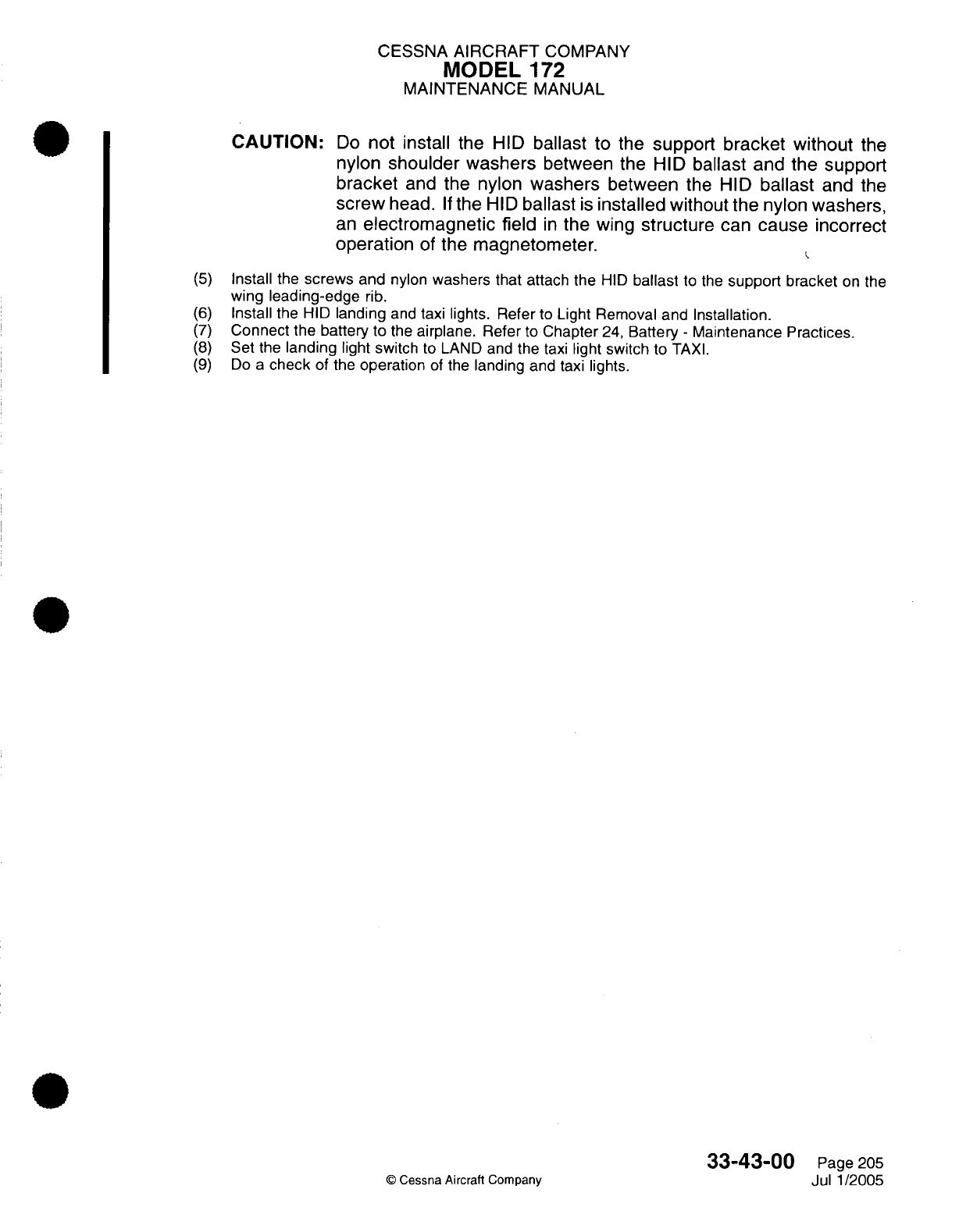
CESSNA
AIRCRAFT
COMPANY
MODEL
172
MAINTENANCE
MANUAL
CAUTION:
Do
not install
the
HID
ballast
to
the
support
bracket without
the
nylon
shoulder washers
between
the HID
ballast
and
the support
bracket
and
the
nylon
washers
between
the
HID
ballast
and
the
screw
head.
If
the
HID
ballast
is
installed
without the
nylon
washers,
an
electromagnetic
field
in
the
wing
structure
can
cause
incorrect
operation
of
the
magnetometer.
(5)
Install
the
screws
and
nylon
washers that
attach the
HID
ballast
to
the
support
bracket
on
the
wing
leading-edge
rib.
(6)
Install
the HID
landing
and
taxi
lights.
Refer
to Light Removal and
Installation.
(7)
Connect
the battery
to
the
airplane.
Refer
to
Chapter
24,
Battery
-
Maintenance
Practices.
(8)
Set
the
landing
light switch
to
LAND and
the
taxi
light switch
to
TAXI.
(9)
Do
a
check
of the
operation
of
the
landing
and
taxi lights.
33-43-00
Page
205
©
Cessna Aircraft
Company
Jul 1/2005
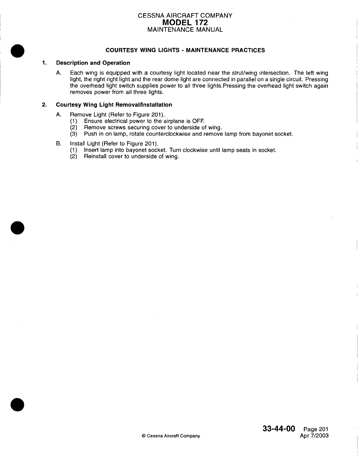
CESSNA
AIRCRAFT
COMPANY
MODEL
172
MAINTENANCE
MANUAL
COURTESY WING
LIGHTS
-
MAINTENANCE
PRACTICES
1.
Description
and
Operation
A.
Each
wing
is
equipped
with
a
courtesy light
located
near
the
strut/wing
intersection. The left
wing
light, the
right
right
light
and
the
rear
dome
light
are
connected
in
parallel
on
a
single circuit. Pressing
the
overhead
light
switch
supplies
power
to
all
three
lights.Pressing
the
overhead
light switch
again
removes
power
from
all
three lights.
2.
Courtesy
Wing
Light
Removal/Installation
A.
Remove
Light
(Refer
to
Figure
201).
(1)
Ensure
electrical
power
to
the
airplane
is
OFF.
(2)
Remove screws
securing
cover
to
underside
of
wing.
(3)
Push
in
on
lamp,
rotate
counterclockwise
and
remove
lamp
from
bayonet
socket.
B.
Install
Light
(Refer
to
Figure
201).
(1)
Insert lamp
into
bayonet
socket.
Turn
clockwise
until
lamp
seats
in
socket.
(2)
Reinstall cover
to
underside
of
wing.
33-44-00
Page
201
©
Cessna Aircraft
Company
Apr
7/2003
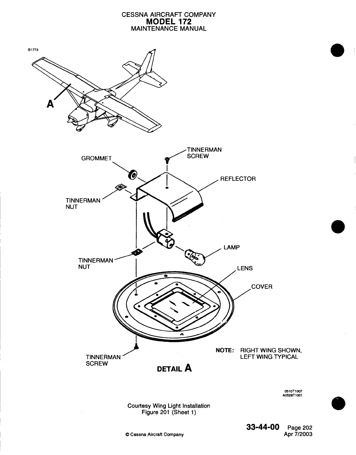
CESSNA AIRCRAFT
COMPANY
MODEL
172
MAINTENANCE
MANUAL
B1
TINNERMAN
C,'
D C\
r
AI
TINNE
NUT
T
N
I
INNth-MMAN
SCREW
DETAIL
A
3
SHOWN,
"'/ l
"'
A
I
Lt-
I
VVIINU
ITr
IIAL
0510T1007
A0528T1001
Courtesy
Wing
Light Installation
Figure
201
(Sheet
1)
33-44-00
©
Cessna
Aircraft
Company
Page
202
Apr
7/2003
A
.
_s
CHAPTER
NAVIGATION
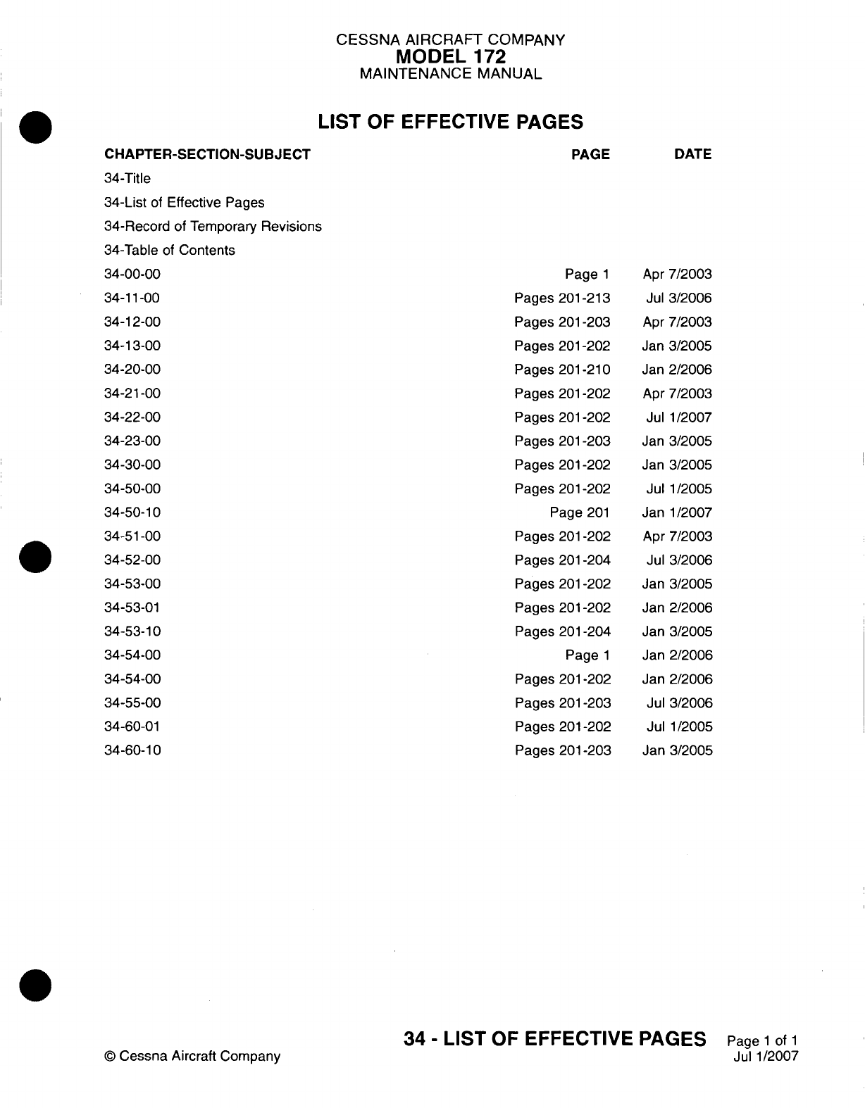
CESSNA AIRCRAFT
COMPANY
MODEL
172
MAINTENANCE
MANUAL
LIST
OF
EFFECTIVE
PAGES
CHAPTER-SECTION-SUBJECT
34-Title
34-List
of
Effective
Pages
34-Record
of
Temporary
Revisions
34-Table
of
Contents
34-00-00
34-11-00
34-1
2-00
34-13-00
34-20-00
34-21-00
34-22-00
34-23-00
34
-30-00
34-50-00
34-50-10
34-5
1-00
34-52-00
34-53-00
34-53-01
34-53-10
34-54-00
34-54-00
34-55-00
34-60-01
34-60-10
©
Cessna
Aircraft
Company
PAGE
Page
1
Pages
201
-213
Pages
201-203
Pages
201
-202
Pages
201
-21
0
Pages
201-202
Pages 201-202
Pages
201-203
Pages
201
-202
Pages
201
-202
Page
201
Pages
201-202
Pages
201-204
Pages
201-202
Pages
201
-202
Pages
201
-204
Page
1
Pages
201-202
Pages
201-203
Pages
201
-202
Pages
201
-203
DATE
Apr
7/2003
Jul
3/2006
Apr
7/2003
Jan
3/2005
Jan
2/2006
Apr
7/2003
Jul
1/2007
Jan
3/2005
Jan
3/2005
Jul
1/2005
Janl1/2007
Apr
7/2003
Jul
3/2006
Jan
3/2005
Jan
2/2006
Jan
3/2005
Jan
2/2006
Jan
2/2006
Jul
3/2006
Jul
1/2005
Jan
3/2005
34
-
LIST
OF
EFFECTIVE PAGES
Page
1
of
1
Jul
1/2007
Temporary
Revision
Number
RECORD
OF
TEMPORARY
REVISIONS
Page
Number Issue
Date By
Date
Removed
By
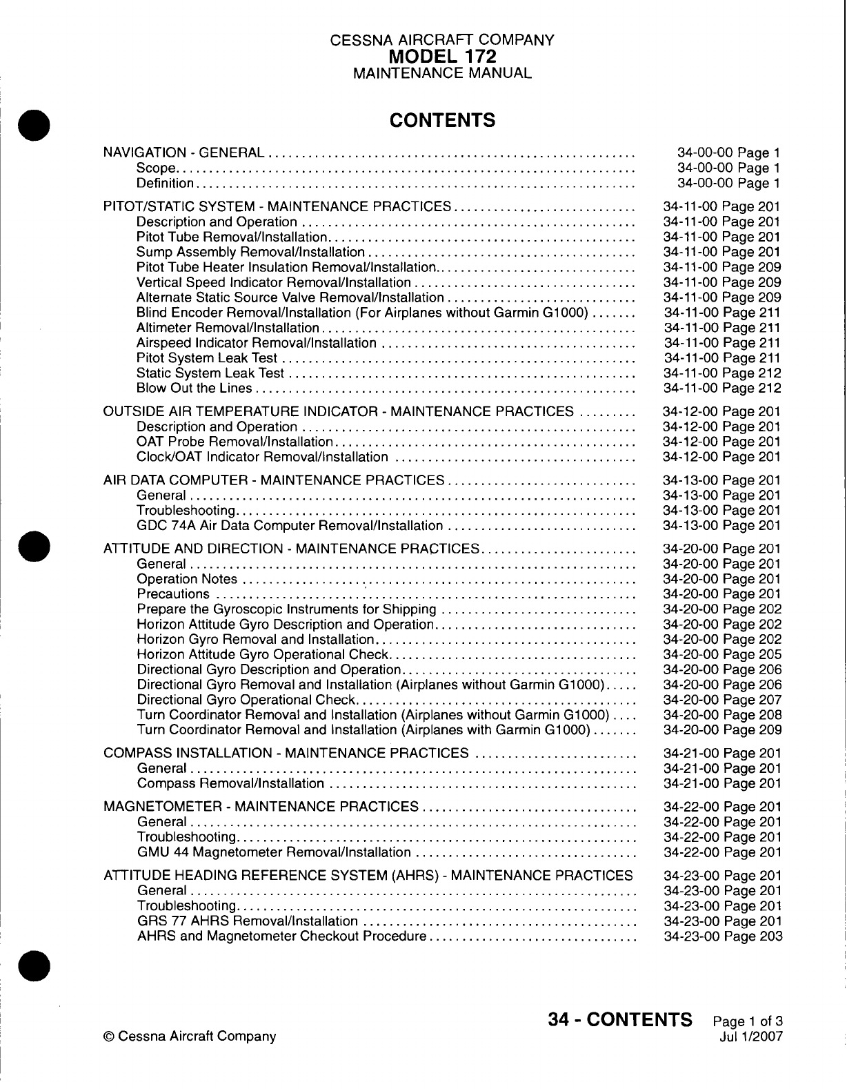
CESSNA AIRCRAFT
COMPANY
MODEL
172
MAINTENANCE
MANUAL
CONTENTS
NAVIGATION
-
GENERAL.............................
Scope....................................
Definition
..................................
PITOT/STATIC
SYSTEM
-
MAINTENANCE
PRACTICES...............
Description
and
Operation
..........................
Pitot
Tube
Removal/Installation
........................
Sump
Assembly
Removal/installation
.....................
Pitot
Tube
Heater
Insulation
Removal/installation
................
Vertical
Speed
Indicator
Removal/Installation..................
Alternate
Static
Source
Valve
Removal/Installation
...............
Blind
Encoder
Removal/Installation
(For
Airplanes
without
Garmin
G1
000)
....
Altimeter
Removal/Installation.........................
Airspeed
Indicator
Removal/Installation
....................
Pitot
System Leak
Test............................
Static
System
Leak
Test
...........................
Blow
Out
the
Lines..............................
OUTSIDE
AIR
TEMPERATURE
INDICATOR
-
MAINTENANCE
PRACTICES
.....
Description
and
Operation
..........................
OAT
Probe
Removal/Installation........................
Clock/OAT Indicator
Removal/installation
...................
AIR
DATA
COMPUTER
-
MAINTENANCE PRACTICES
...............
General...................................
Troubleshooting
...............................
GDC
74A Air
Data
Computer
Removal/Installation
...............
ATTITUDE
AND
DIRECTION
-
MAINTENANCE
PRACTICES.............
General...................................
Operation
Notes...............................
Precautions.................................
Prepare
the
Gyroscopic
Instruments
for
Shipping................
Horizon Attitude
Gyro
Description
and
Operation
................
Horizon
Gyro
Removal
and
Installation.....................
Horizon Attitude
Gyro
Operational
Check....................
Directional
Gyro
Description
and
Operation...................
Directional
Gyro
Removal
and
Installation
(Airplanes
without
Garmin
G-1000)...
Directional
Gyro
Operational Check
......................
Turn
Coordinator
Removal
and
Installation (Airplanes
without
Garmin
G1
000)
....
Turn
Coordinator
Removal
and
Installation (Airplanes
with
Garmin
G1OQO)
....
COMPASS
INSTALLATION
-
MAINTENANCE
PRACTICES
.............
General...................................
Compass
Removal/Installation
........................
MAGNETOMETER
-
MAINTENANCE PRACTICES
.................
General...................................
Troubleshooting
...............................
GMU
44
Magnetometer
Removal/Installation..................
ATTITUDE
HEADING
REFERENCE
SYSTEM
(AHRS)
-
MAINTENANCE PRACTICES
General...................................
Troubleshooting
...............................
GRS
77
AHRS
Removal/installation......................
AHRS
and
Magnetometer Checkout
Procedure.................
34-00-00
Page
1
34-00-00
Page
1
34-00-00
Page
1
34-11
-00
Page
201
34-1
1-00
Page
201
34-11
-00
Page
201
34-1
1-00
Page
201
34-1
1-00
Page
209
34-1
1-00
Page
209
34-1
1-00
Page
209
34-11
-00 Page
211
34-11
-00
Page
211
34-11
-00
Page
211
34-11
-00
Page
211
34-11
-00
Page
212
34-11
-00
Page
212
34-12-00
Page
201
34-12-00
Page
201
34-12-00
Page
201
34-12-00
Page
201
34-13-00
Page
201
34-13-00
Page
201
34-13-00
Page
201
34-13-00
Page
201
34-20-00
Page
201
34-20-00
Page
201
34-20-00
Page
201
34-20-00
Page
201
34-20-00
Page
202
34-20-00
Page
202
34-20-00
Page 202
34-20-00
Page 205
34-20-00
Page 206
34-20-00
Page
206
34-20-00
Page
207
34-20-00
Page 208
34-20-00
Page
209
34-2
1
-00
Page
201
34-21
-00
Page
201
34-21
-00
Page
201
34-22-00
Page
201
34-22-00
Page
201
34-22-00
Page
201
34-22-00
Page
201
34-23-00
Page
201
34-23-00
Page
201
34-23-00
Page
201
34-23-00
Page
201
34-23-00
Page
203
34
-
CONTENTS
Page
1
of
3
Jul
1/2007
©
Cessna
Aircraft
Company
CESSNA AIRCRAFT
COMPANY
MODEL
172
MAINTENANCE
MANUAL
MARKER
BEACON
-
MAINTENANCE
PRACTICES.................
General...................................
Audio
Panel
Removal/installation
.......................
Marker Beacon
Antenna
Removal/installation..................
NAV/COM
-
MAINTENANCE PRACTICES
.....................
General
..................................
Nay
Antenna
Removal/installation.......................
Nay
Antenna
Coupler
Removal/Installation...................
Nay
Indicator
Removal/Installation.......................
GIA 63
INTEGRATED AVIONICS INSTALLATION
-
MAINTENANCE PRACTICES
...
General...................................
Troubleshooting
...............................
GIA
63
Integrated
Avionics
Unit
Removal/Installation
..............
GPS
-
MAINTENANCE
PRACTICES........................
General...................................
GPS
Removal/installation...........................
G
PS
Antenna
Removal/Installation
......................
KR-87
ADF
SYSTEM
-
MAINTENANCE PRACTICES
................
General...................................
KR-87
ADF
Receiver
Removal/installation
(Airplanes
without
Garmin
G1
000)
..
KR-87
ADF
Receiver
Removal/Installation
(Airplanes
with
Garmin
G1000)
....
KA-44B
ADF
Antenna
Removal/Installation
(For
Airplanes
With
or
Without
Garmin
G100)
..................................
KI-227
ADF
Indicator
Removal/Installation
...................
KT76C
TRANSPONDER
-
MAINTENANCE
PRACTICES...............
General...................................
Transponder
Removal/installation.......................
Transponder
Antenna
Removal/Installation...................
KT-73
MODE
S
TRANSPONDER
-
MAINTENANCE
PRACTICES...........
General...................................
KT-73
Mode
S
Transponder
Removal
and
Installation..............
GTX 33
TRANSPONDER
-
MAINTENANCE
PRACTICES
..............
General...................................
Troubleshooting
...............................
GTX
33
Transponder
Removal/Installation...................
Transponder
Antenna
Removal/Installation...................
GDL-69A
FIS
-
DESCRIPTION
AND
OPERATION..................
General...................................
GDL-69A
FIS
-
MAINTENANCE
PRACTICES....................
General...................................
GDL-69A
XM
Weather
Data
Link
Removal/Installation..............
DME
-
MAINTENANCE
PRACTICES........................
General...................................
KN-63
DME
Receiver
Removal/Installation...................
DME
Antenna
Removal/installation
......................
KMD-540 MULTI-FUNCTION
DISPLAY
-
MAINTENANCE
PRACTICES
........
General...................................
KMD-540
Multi-Function
Display
(MFD)
Removal
and
Installation
........
Operational
Check
of
the
MD-540
Multi-Function
Display
............
34-30-00
Page
201
34-30-00
Page
201
34-30-00
Page
201
34-30-00
Page
201
34-50-00
Page
201
34-50-00
Page
201
34-50-00
Page
201
34-50-00
Page
201
34-50-00
Page
201
34-50-10
Page
201
34-50-10
Page
201
34-50-1
0
Page
201
34-50-1
0
Page
201
34-51
-00
Page
201
34-51
-00 Page
201
34-51
-00
Page
201
34-51
-00
Page
201
34-52-00
Page
201
34-52-00
Page
201
34-52-00
Page
201
34-52-00
Page
201
34-52-00
Page
201
34-52-00
Page
204
34-53-00
Page
201
34-53-00
Page
201
34-53-00
Page
201
34-53-00
Page
201
34-53-01
Page
201
34-53-01
Page
201
34-53-01
Page
201
34-53-1
0
Page
201
34-53-10
Page
201
34-53-1
0
Page
201
34-53-1
0
Page
201
34-53-1
0
Page
203
34-54-00
Page
1
34-54-00
Page
1
34-54-00
Page
201
34-54-00
Page
201
34-54-00
Page
201
34-55-00
Page
201
34-55-00
Page
201
34-55-00
Page
201
34-55-00
Page
201
34-60-01
Page
201
34-60-01
Page
201
34-60-01
Page
201
34-60-01
Page
201
34
-
CONTENTS
Page
2
of
3
Jul
1/2007
©
Cessna
Aircraft Company
CESSNA
AIRCRAFT
COMPANY
MODEL
172
MAINTENANCE
MANUAL
GARMIN
DISPLAY
UNIT (GDU)
-
MAINTENANCE PRACTICES
...........
General...................................
Troubleshooting
...............................
Control
Display
Unit
Removal/Installation
...
.................
34-60-10
Page
201
34-60-10
Page
201
34-60-10
Page
201
34-60-1
0 Page
201
34
-
CONTENTS
Page
3
of
3
Jul
1/2007
©D
Cessna
Aircraft
Company
CESSNA
AIRCRAFT
COMPANY
MODEL
172
MAINTENANCE
MANUAL
NAVIGATION
-
GENERAL
1.
Scope
A.
This
chapter
describes
the
navigation
systems,
units,
and components
which
provide airplane
navigational
information.
Included
are
pitot/static temperature,
gyros, compass, VOR and
indicators.
For
King
KAP140
Autopilot
information refer
to
Chapter
22.
2.
Definition
A.
This
chapter
is
divided
into
sections
to
aid
maintenance
personnel
in
locating
information. Consulting
the
table
of
Contents
will
further assist
in
locating
a
particular
subject.
A
brief
definition
of
the
sections
incorporated
in
this chapter
is
as
follows:
(1)
The
Flight
Environmental
Data
Section
describes
systems
that
sense
environment
conditions,
and
use
data
to
influence navigation
of
the
airplane.
This
includes systems
that depend
on
pitot
and
static information.
(2)
The
Attitude
and
Direction Section
describes
systems
that
use
magnetic
gyroscopic
and inertia
forces. This
includes
items
like
gyros,
compass, magnetic
heading,
and
turn
and
bank.
(3)
The
Dependent Position
Determining
Section
describes
systems
that
provide
information
to
determine position,
and
are
mainly
dependent
on
ground
installation.
This
includes
systems
like
VOR,
ADF,
GPS,
and
transponders.
34-00-00
Page
1
Apr 7/2003
©
Cessna
Aircraft
Company
CESSNA
AIRCRAFT
COMPANY
MODEL
172
MAINTENANCE
MANUAL
PITOT/STATIC
SYSTEM
-
MAINTENANCE
PRACTICES
1.
Description
and
Operation
A.
The
pitot
system
supplies
ram
air
pressure
to
the
airspeed
indicator.
The
static
system
connects
the
vertical
speed indicator,
altimeter,
and
airspeed
indicator
to
atmospheric
pressure through
plastic
tubing
connected
to
a
static
port.
A
static
line
sump
is
installed
at
the source
button
to
collect condensation
in
the
static
system.
A
heated
pitot
tube
is
standard,
with
the
heating element
controlled
by
a
switch
on the
instrument
panel
and
powered
by
the
electrical
system.
An
alternate
static
source
valve
is
installed
on the
instrument
panel
to
use
when
the
external
static source
is not
in
operation.
Refer
to Figure
201
for
the
pitot/static
system
schematic.
B.
On
airplanes
with
an
autopilot,
there
is
a
tube that connects
the
autopilot
to
a
static
port
on
the
left
side
of
the
airplane
at
FS
117.25.
This
part
of
the
pitot/static
system
is
not
connected
to
the
other
parts
of
the
pitot/static
system.
C.
Correct
maintenance
of
pitot and
static
system
is
essential for correct
operation
of
altimeter, vertical
speed
and
airspeed
indicators,
and,
if
installed,
the autopilot.
Leaks,
moisture, and
blockage
can
have
an
effect
on
the
readings of
the
instruments. Under instrument
flight
conditions,
you
must
use
the
instrument readings
for
the
safe
operation
of
the
airplane.
Keep
the
system
clean
and
all
instruments
and
all
parts of
the
system
correctly
attached
to
the
airplane.
Keep
the
pitot
tube
and
static ports clean
with
no
blockage.
(1)
Test
the
pitot/static
system
in
accordance
with
the
time
limits
set forth
in
Chapter
5,
Inspection
Time
Limits, or
anytime
components
or
lines
within the
system are
opened.
Refer
to
14
CFR
91.411.
2.
Pitot
Tube
Removal/Installation
A.
Pitot
Tube
Removal (Refer
to Figure
202).
(1)
Remove
the
screws that attach
the
pitot
tube
to
the
wing
and
remove
the
pitot tube.
(2)
Disconnect
the
ram
air
tube
from
the
pitot.
(3)
Disconnect
the
electrical
connectors
from
the
pitot heater
and the
pitot
heat
ground.
B.
Pitot Tube
Installation
(Refer
to
Figure
202).
CAUTION:
Do
not
blow
through
the pitot
lines
toward
the
instrument,
as
damage
will
occur
to
the
instruments.
CAUTION:
You
must
keep the
pitot tube
assembly
clean
and
all
system
components
free
of
blockage
and
leaks
for
correct
operation.
(1)
Connect
the
ram
air
tube
to
the
pitot.
(2)
Connect
the
electrical connectors
to
the
pitot
heater
and the
pitot heat
ground.
(3)
Do
a
check
of
the system
for
leaks.
Refer
to
Pitot
System Leak
Test.
3.
Sump
Assembly
Removal/Installation
NOTE:
The
removal/installation
is
typical for
the
two
sump
assemblies.
A.
Sump
Assembly
Removal (Refer
to
Figure
202).
(1)
Get
access
to
the
sump
assembly.
(2)
Loosen
the nut
that
connects
the
static
tube
to the
sump
assembly
nipple.
(3)
Turn
the
sump
assembly
and
remove
the sump
assembly
from
the
elbow.
B.
Sump
Assembly Installation
(Refer
to
Figure
202).
(1)
Attach
the
sump
assembly
to
the
elbow.
Apply
Teflon®
tape (U000912)
as
necessary
where
plastic
and
metal
connections
interface.
(2)
Connect
static
tube
to
the
sump
assembly
nipple
with
nut.
(3)
Do
a
leak
check.
Refer
to
the
Static
Pressure
System
Inspection
and
Leakage
Test.
34-11-00
Page
201
©
Cessna Aircraft
Company Jul
3/2006
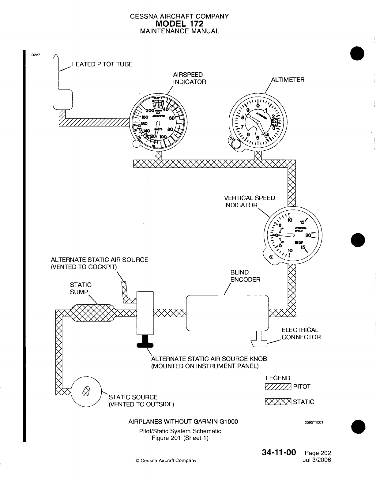
CESSNA
AIRCRAFT
COMPANY
MODEL
172
MAINTENANCE
MANUAL
B227
n
HEATED PITOT
TUBE
Al RSPEED
I
InrI'ATf-
BLIND
ENCODER
ALTIMETER
-N
I
I
ELECTRICAL
CONNECTOR
ALTERNATE
STATIC
AIR
SOURCE
KNOB
(MOUNTED
ON
INSTRUMENT
PANEL)
LEGEND
V/////A
PITOT
)URCE
-0
OUTSIDE)
AIRPLANES WITHOUT
GARMIN
G1000
Pitot/Static
System Schematic
Figure
201
(Sheet
1)
34-11-00
©
Cessna
Aircraft
Company
STATIC
0595T1001
Page 202
Jul
3/2006
/
C
rx\
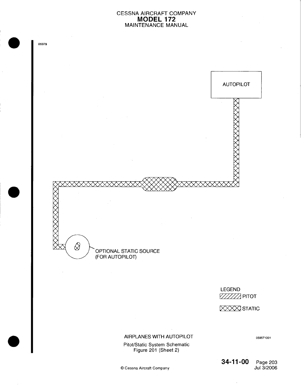
CESSNA
AIRCRAFT
COMPANY
MODEL
172
MAINTENANCE
MANUAL
B5979
AUTOPILOT
SOURCE
LEGEND
/
PITOT
XO
STATIC
AIRPLANES
WITH
AUTOPILOT
059
Pitot/Static
System
Schematic
Figure
201
(Sheet
2)
I5T1001
©
Cessna Aircraft
Company
34-11-00
Page
203
Jul 3/2006
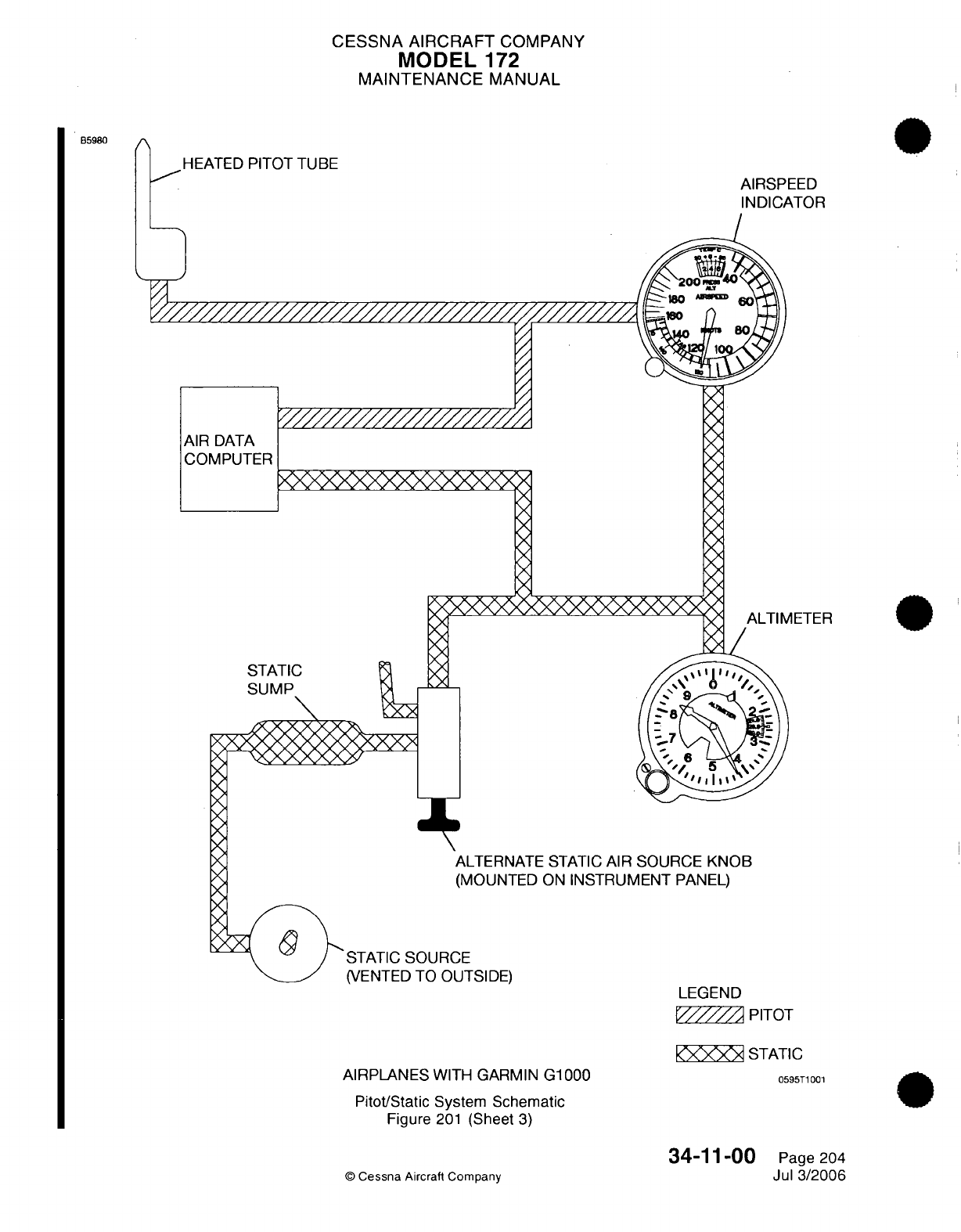
CESSNA
AIRCRAFT
COMPANY
MODEL
172
MAINTENANCE
MANUAL
B5980
HEATED
PITOT
TUBE
AIRSPEED
INDICATOR
I///////////
AIR
DATA
COMPUTER
IETER
STA
R1
h1
ALTERNATE
STATIC
AIR
SOURCE
KNOB
(MOUNTED
ON
INSTRUMENT PANEL)
OURCE
ro
OUTSIDE)
AIRPLANES
WITH GARMIN
G1000
Pitot/Static
System
Schematic
Figure
201
(Sheet
3)
LEGEND
PITOT
STATIC
0595T1001
34-11-00
©
Cessna
Aircraft Company
Page
204
Jul
3/2006
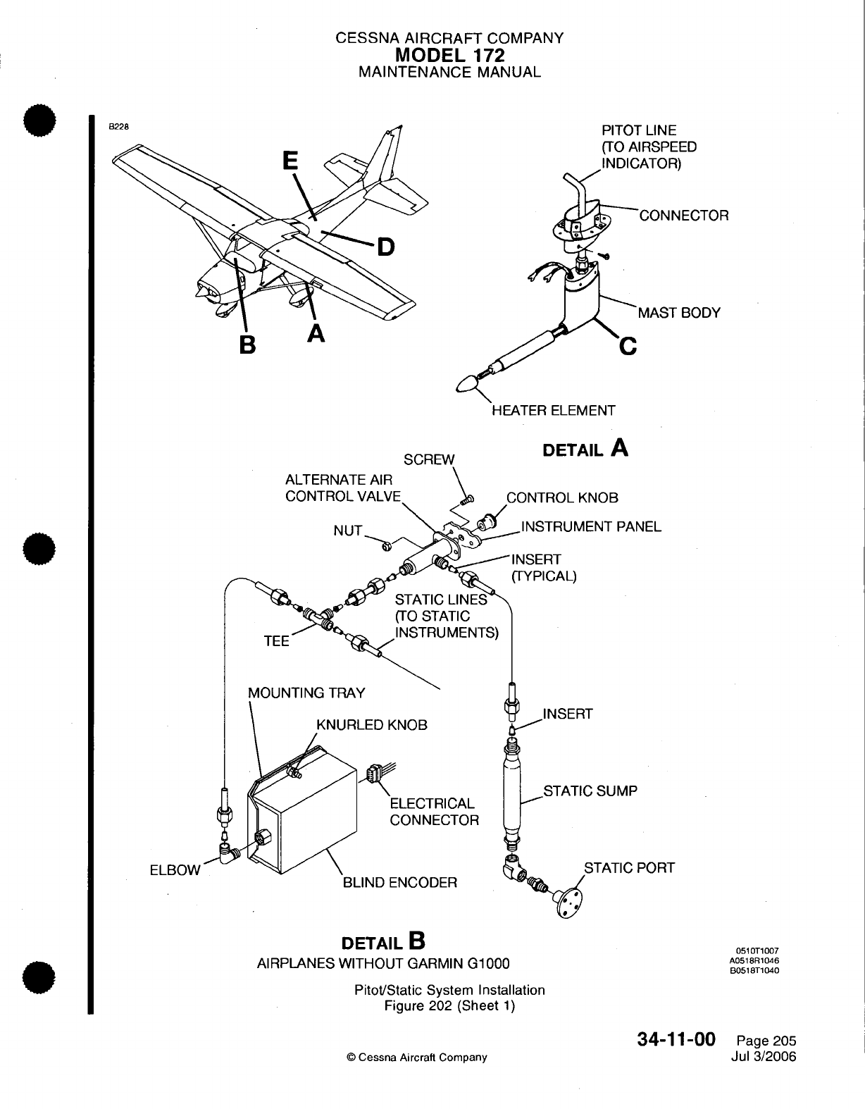
CESSNA AIRCRAFT
COMPANY
MODEL
172
MAINTENANCE
MANUAL
PITOT
LINE
(TO
AIRSPEED
INDICATOR)
'CONNECTOR
MAST
BODY
D
HEATER
ELEMENT
ALTERNATE
AIR
CONTROL
VALVE
NUT
DETAIL
A
SCREW
3
PANEL
BLIND
ENCODER
DETAIL
B
AIRPLANES WITHOUT
GARMIN
G1000
Pitot/Static
System
Installation
Figure 202
(Sheet
1)
©
Cessna Aircraft
Company
ELBOW
PORT
0510T1007
A0518R1046
B0518T1040
34-11-00
Page
205
Jul
3/2006
BAA
-
I
....
/
-,
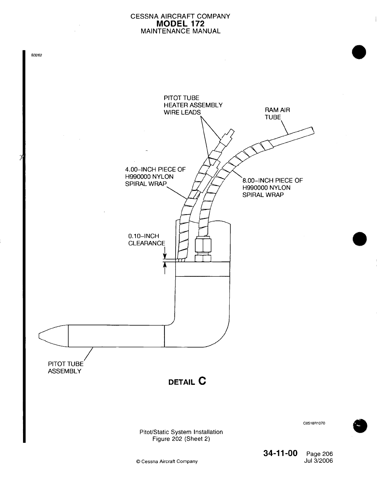
CESSNA AIRCRAFT
COMPANY
MODEL
172
MAINTENANCE
MANUAL
B3262
PITOT
TUBE
HEATER
ASSEMBLY
WIRE
LEADS
RAM
AIR
4
S
8.00-INCH
PIECE
OF
H990000
NYLON
SPIRAL WRAP
/
PITOT
TUBE
ASSEMBLY
DETAIL
C
C0518R1070
Pitot/Static
System
Installation
Figure 202
(Sheet
2)
34-11-00
©
Cessna Aircraft Company
Page 206
Jul
3/2006
C--::
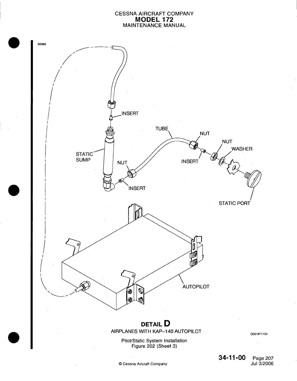
CESSNA
AIRCRAFT
COMPANY
MODEL
172
MAINTENANCE
MANUAL
B5985
/
/
/
I
STATIC
SUMP
INSERT
STATIC
PORT
I
(
DETAIL
D
AIRPLANES
WITH
KAP-140
AUTOPILOT
Pitot/Static
System
Installation
Figure
202
(Sheet
3)
©
Cessna
Aircraft
Company
NUT
WASHER
D0518T1153
Page
207
Jul
3/2006
34-11-00
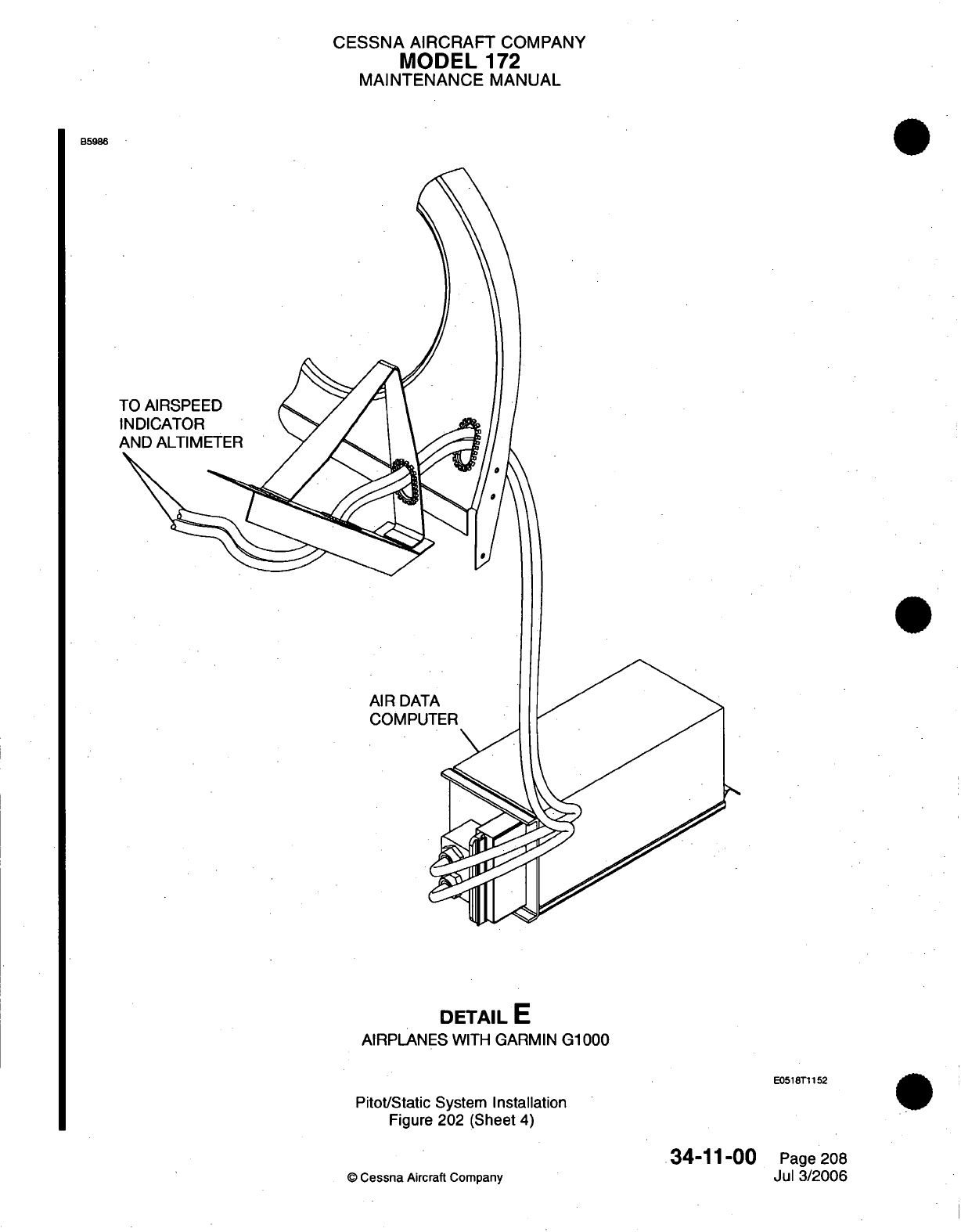
CESSNA
AIRCRAFT
COMPANY
MODEL
172
MAINTENANCE
MANUAL
B59ss
AIR
DAT
COMPU
DETAIL
E
AIRPLANES
WITH
GARMIN
G1000
E0518T1152
Pitot/Static
System
Installation
Figure
202
(Sheet
4)
34-11-00
©
Cessna
Aircraft
Company
Page
208
Jul
3/2006
I
CESSNA
AIRCRAFT
COMPANY
MODEL
172
MAINTENANCE
MANUAL
4.
Pitot
Tube
Heater
Insulation
Removal/lnstallation.
A.
Pitot
Tube
Heater
Insulation
Removal (Refer
to
Figure
202).
(1)
Set
the
ALT/BATT
Master
Switch
to OFF.
(2)
Make sure
that the
PITOT
HEAT/OFF
switch
is
put
in
the
OFF
position.
(3)
Remove
the
510BB
access
plate.
Refer
to
Chapter
6,
Access/Inspection
Plates
-
Description
And
Operation.
CAUTION:
Do
not
disconnect
the
pitot
ram
air
tube
from
the
pitot
tube.
(4)
Remove
the
screws
that
attach the pitot
tube
to
the wing.
(5)
Remove
and
discard
all
nylon
spiral
wrap
insulation.
B.
Pitot Tube
Heater
Insulation
Installation
(Refer
to
Figure
202).
(1)
Cut
new
nylon
spiral
wrap
into
two
pieces.
Make
one
piece
that
is
4.0
inches
in
length and
make
one
piece that
is
8.0
inches
in
length.
(2)
Start
0.10
inch from
the
pitot
tube
and
install
the
4.0-inch
piece
of
spiral
wrap
around
the
pitot
tube
heater
assembly.
(a)
Trim
as
necessary.
CAUTION:
Do
not
let
the
pitot
heater
assembly
wire leads touch
the pitot
ram
air
tubing,
wire
bundles,
or
heat-sensitive
components.
The
pitot
tube
heater
assembly
wire
leads
operate
at
high
temperatures.
(3)
Install the
8.0-inch
piece
of
spiral
wrap
around
the
pitot
ram
air tube.
(a)
Trim
as
necessary.
(4)
Attach
the
pitot
tube
to
the
wing
with
the
screws.
CAUTION:
Do
not
blow
through
the
pitot
lines
toward the instrument,
as
damage
will
occur
to
the instruments
if
you
do.
CAUTION:
Keep the
pitot tube
assembly
clean
and make
sure
that
all
system
components
are
free of
blockage
and
leaks
for
correct
operation.
(5)
Install
the
510BB
access
plate. Refer
to
Chapter
6,
Access/Inspection
Plates
-
Description
And
Operation.
(6)
Connect
electrical
power to the
airplane as
necessary.
5.
Vertical
Speed
Indicator
Removal/Installation
A.
Vertical
Speed
Indicator
(VSI)
Removal
(Refer
to
Figure
203).
(1)
Remove
the
screws that attach the flight
instrument
panel
to the
instrument
panel.
(2)
Disconnect
the
static
tube
and the
electrical connector
from
the
VSI.
(3)
Remove
the screws that attach
the
VSI
to
the
flight
instrument
panel.
(4)
Remove
the
VSI
from the
airplane.
B.
Vertical
Speed
Indicator
(VSI)
Installation
(Refer
to Figure
203).
(1)
Put
the
VSI
on
the
flight
instrument
panel
and
attach
it
with
screws.
(2)
Connect the
static
tube
and
the electrical
connector
to
the
VSI.
(3)
Attach
the
flight
instrument
panel
to
the
instrument
panel with
the
screws.
(4)
Do
a
check of
the
system
for leaks.
Refer
to
the
Static
System Leak
Test.
6.
Alternate
Static
Source
Valve
Removal/Installation
A.
Alternate
Static
Source
Valve
Removal
(Refer to
Figure
202).
(1)
Behind
the
stationary
control
panel,
loosen
the
nuts that
attach
the
two
static
tubes
to
the
alternate
static source
valve.
Disconnect
the static
tubes
from
the
alternate static
source
valve.
(2)
Remove
the
screws that
attach
the
alternate
static source
valve
to
the
stationary
control
panel.
34-11-00
Page
209
©
Cessna
Aircraft
Company
Jul
3/2006
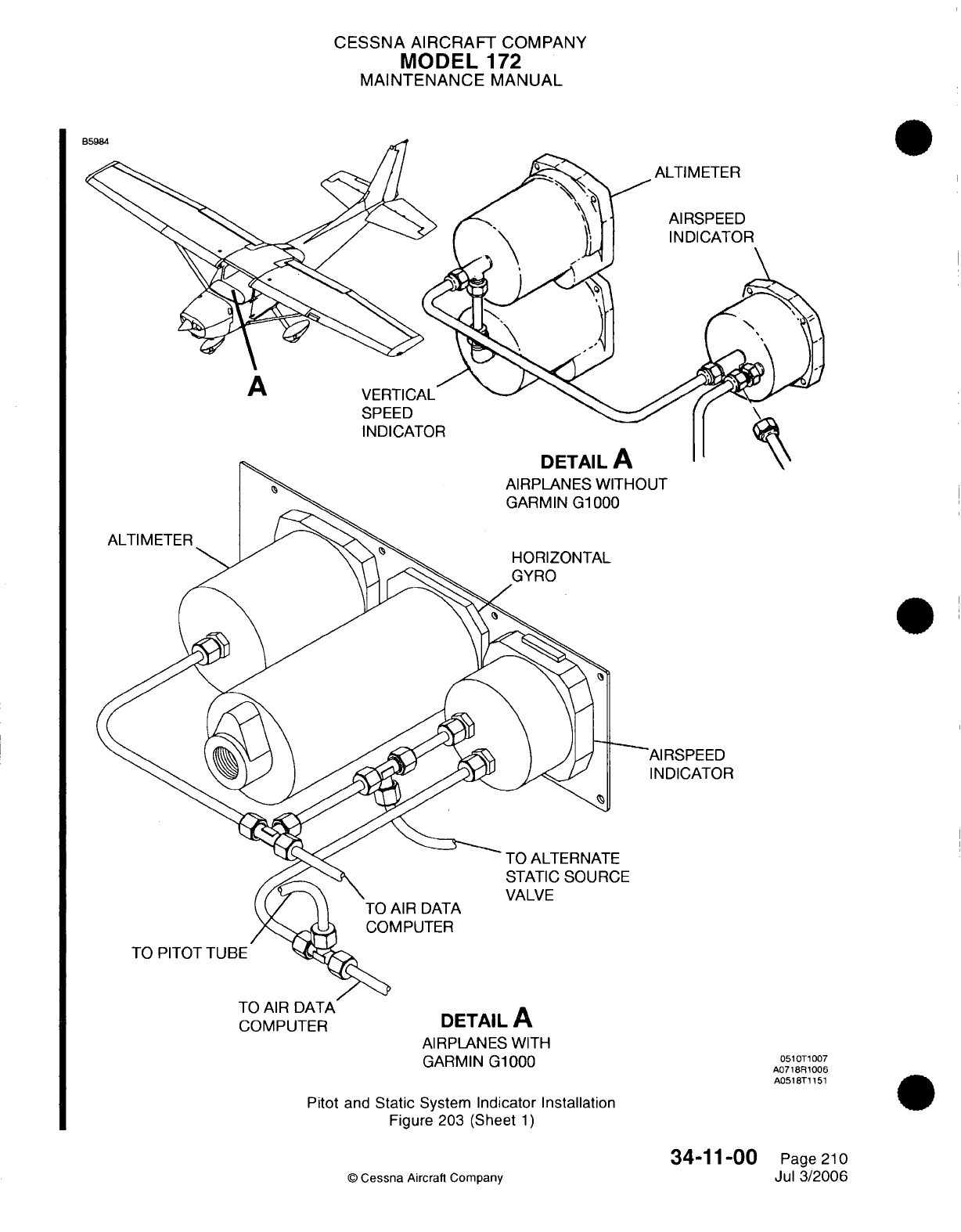
CESSNA
AIRCRAFT
COMPANY
MODEL
172
MAINTENANCE
MANUAL
ISPEED
DICATOR
COMPUTER
DETAIL
A
AIRPLANES WITH
GARMIN
G1000
Pitot
and
Static
System
Indicator
Installation
Figure
203
(Sheet
1)
34-11-00
©
Cessna
Aircraft
Company
0510T1007
A0718R1006
A0518T1151
Page 210
Jul
3/2006
CESSNA
AIRCRAFT
COMPANY
MODEL
172
MAINTENANCE
MANUAL
(3)
Remove
the
alternate
static
source valve
from
the
airplane.
B.
Alternate
Static Source
Valve
Installation
(Refer
to
Figure 202).
(1)
Put
the alternate
static
source
valve
behind
the
stationary
control
panel
and attach
the
static
tubes
with
the nuts.
(2)
Attach
the
alternate
static
source valve
to
the
stationary
control
panel
with
the
screws.
7.
Blind
Encoder
Removal/Installation
(For
Airplanes
without
Garmin
G1000)
A.
Blind
Encoder
Removal
(Refer to
Figure
202).
NOTE:
The blind
encoder
is
under
the
dash
on
the
copilot
side.
(1)
Disconnect
the
static
tube
and the
electrical connector
and
remove
the
encoder
from
the
airplane.
(2)
Loosen
the
knurled
knob
and
remove
the
encoder
from
the
mount.
B.
Blind
Encoder
Installation
(Refer
to
Figure
202).
(1)
Put
the
encoder
on
the
mount
and
attach
with
the
knurled knob.
(2)
Connect
the
static
tube
and
the
electrical
connector
to
the
encoder.
(3)
Do
a
check
of
the
system for
leaks.
Refer
to
the Static System Leak
Test.
8.
Altimeter
Removal/nstallation
A.
Altimeter Removal
(Refer
to Figure
203).
(1)
To
get access
to
the
back
of
the
altimeter, remove
the
screws
that
attach
the
flight
instrument
panel
to the
instrument
panel.
(2)
Disconnect
the static
tube
and
the
electrical connector
from
the
altimeter.
(3)
Remove
the
screws that
attach the
altimeter
to
the
flight
instrument
panel.
(4)
Remove
the
altimeter
from
the
airplane.
B.
Altimeter Installation
(Refer
to
Figure
203).
(1)
Put
the altimeter
on
the
flight
instrument panel
and
attach
it
with
screws.
(2)
Connect
the
static
tube and the
electrical connector
to
the altimeter.
(3)
Attach
the
flight
instrument
panel
to the
instrument panel
with
the
screws.
(4)
Do
a
check
of
the
system
for
leaks.
Refer
to
the Static System
Leak
Test.
9.
Airspeed
Indicator
Removal/Installation
A.
Airspeed
Indicator
Removal (Refer
to
Figure
203).
(1)
Remove
the
screws that
attach the
flight
instrument panel
to
the
instrument
panel
to
get
access
to
the
back
of
the
airspeed
indicator.
(2)
Disconnect
the
static
tube
and
the
electrical
connector
from
the
airspeed
indicator.
(3)
Remove
the
screws that
attach the airspeed
indicator
to
the
flight
instrument
panel.
(4)
Remove
the
airspeed
indicator
from
the
airplane.
B.
Airspeed
Indicator
Installation
(Refer
to
Figure
203).
(1)
Put
the airspeed
indicator
on
the
flight
instrument
panel
and
attach
with
the
screws.
(2)
Connect
the
static
tube
and
the
electrical connector
to
the
airspeed
indicator.
(3)
Attach
the
flight
instrument
panel
to
the
instrument panel
with
the
screws.
(4)
Do
a
check
of
the
system for
leaks.
Refer
to
the
Static System
Leak
Test.
10.
Pitot
System
Leak
Test
A.
Test
Procedures.
(1)
Put a
piece
of
tape
over
the
small
hole
in
the
lower aft
end
of the
pitot
tube.
(2)
Attach
a
piece
of
rubber
or
plastic
tubing
over
the
pitot
tube
and
close
the
opposite
end
of
the
tube.
(3)
Slowly
roll
up
the
tube
until
the
airspeed indicator
shows
in
cruise
range.
34-11-00
Page
211
©
Cessna Aircraft Company
Jul
3/2006
CESSNA AIRCRAFT
COMPANY
MODEL
172
MAINTENANCE
MANUAL
(4)
Attach
the
tube
to
prevent air
pressure change,
and
look
at
the
airspeed after
one
minute.
If
there
is
a
leak, the
pressure
in
the
system
is
reduced,
and
you
will see
a
lower
airspeed
on
the
airspeed
indicator.
(5) If
there
is
a
leak
in
the
system,
you must examine
and
tighten
all
connections,
hoses,
and
fittings
before
you
do
another check.
(6) If
there
are
no
leaks,
slowly
unroll
the
tubing
to
let
the
pressure
in
the
instrument
slowly
return
to
ambient
pressure.
11.
Static
System Leak
Test
A.
Test
Procedures.
(1)
Make
sure
that
the
static
system
is
free
from
moisture
that
is
caught
in
the system, and
that
there
are
no
restrictions
in
the system.
(2)
Make
sure that
there
are
no
changes
in
or
deformations
to the
airframe surface
that
can
affect
the
relation between
the air pressure
in
the
static pressure system
and
true
ambient
static
air
pressure
for
any
flight
configuration.
(3)
Close
the
static pressure alternate
source
control.
(4)
Attach
a
vacuum
source
to
the
static
pressure source opening.
(5)
Slowly
apply
the
vacuum source
until
the
altimeter indication
is
a
1,000-foot
increase
in
altitude.
(6)
Cut
off
the
vacuum
source
to
make sure
that
there
is
a
closed system
for
one
minute.
(7)
If
the
altimeter
loss
is
not
more
than
100
feet
after
one
minute,
the
system
is
good
and you
can
slowly
release
the
vacuum
until the
system
goes
back
to
ambient.
If
the
altimeter
loss
is
more
than
100
feet,
tighten
all
connections
and
do
the
leak
test
again.
If
the
rate
continues
to
be
more
than
the
maximum
allowable,
do
as
follows.
(a)
Disconnect
the
static
pressure
lines
from
the
airspeed
indicator
and
the
vertical
speed
indicator.
Use
suitable fittings
to
connect
the
lines
together
so
that
the
altimeter
is
the
only
instrument
connected
into
the
static
pressure system.
(b)
Do
the
leakage
test
again
to
see
if
the static pressure system
or
the
instruments that
you
bypassed
are
the cause
of
the
leakage.
If
the
instruments
are
the
cause
of
the
leak,
you
must
have
the instruments
repaired
by
an
approved
repair
station,
or
replaced.
If
the
static
pressure system
is
the
problem,
do
as
follows.
CAUTION:
Do
not
apply positive
pressure
with
the
airspeed
indicator
or
the
vertical
speed indicator
connected
to
the
static
pressure
system.
1
Attach
a
source
of
positive pressure
to
the
static
source opening.
2
Slowly
apply positive
pressure
until the
altimeter indication decreases
500-feet,
and
stops
on
this
value.
3
Put
a
solution
of mild
soap
and
water
on
the
line
connections
and the
static source
flange,
and
look
for
bubbles
to
find leaks.
4
Tighten
all leaking
connections.
Repair or
replace
all
damaged
parts.
5
Connect
the
airspeed
and
the
vertical
speed indicators into
the
static
pressure
system
and
do
the
static
system
leak
test
again.
12.
Blow
Out
the
Lines
CAUTION:
Do
not
blow
through
the
pitot
or
static
lines toward
the
instrument
as
damage
will
occur
to
the
instrument.
A.
Pitot
Lines.
(1)
Although
the
pitot
system
drains
down
to
the
pitot
tube
opening,
condensation
can
collect
at
other
areas
in
the
system
and
cause
some
blockage
of
the
line.
To
remove the
blockage,
disconnect
the
line
at
the
airspeed
indicator.
With
low-pressure
air,
blow
from
the
indicator
end
of the
line
toward
the
pitot
tube.
34-11-00
Page 212
©
Cessna
Aircraft
Company
Jul
3/2006
CESSNA
AIRCRAFT
COMPANY
MODEL
172
MAINTENANCE
MANUAL
B.
Static
Lines.
(1)
Keep
static
lines
clear
and keep
connections
tight.
All
models have
a
static
source
sump
which
collects
moisture
and
keeps
the
system
clear.
If
necessary,
disconnect
the
static
line
at
the
first
instrument
to
which
it is
connected,
and
then
blow
line
clear
with
low-pressure
air.
34-11-00
Page
213
©
Cessna
Aircraft
Company
Jul
3/2006
I
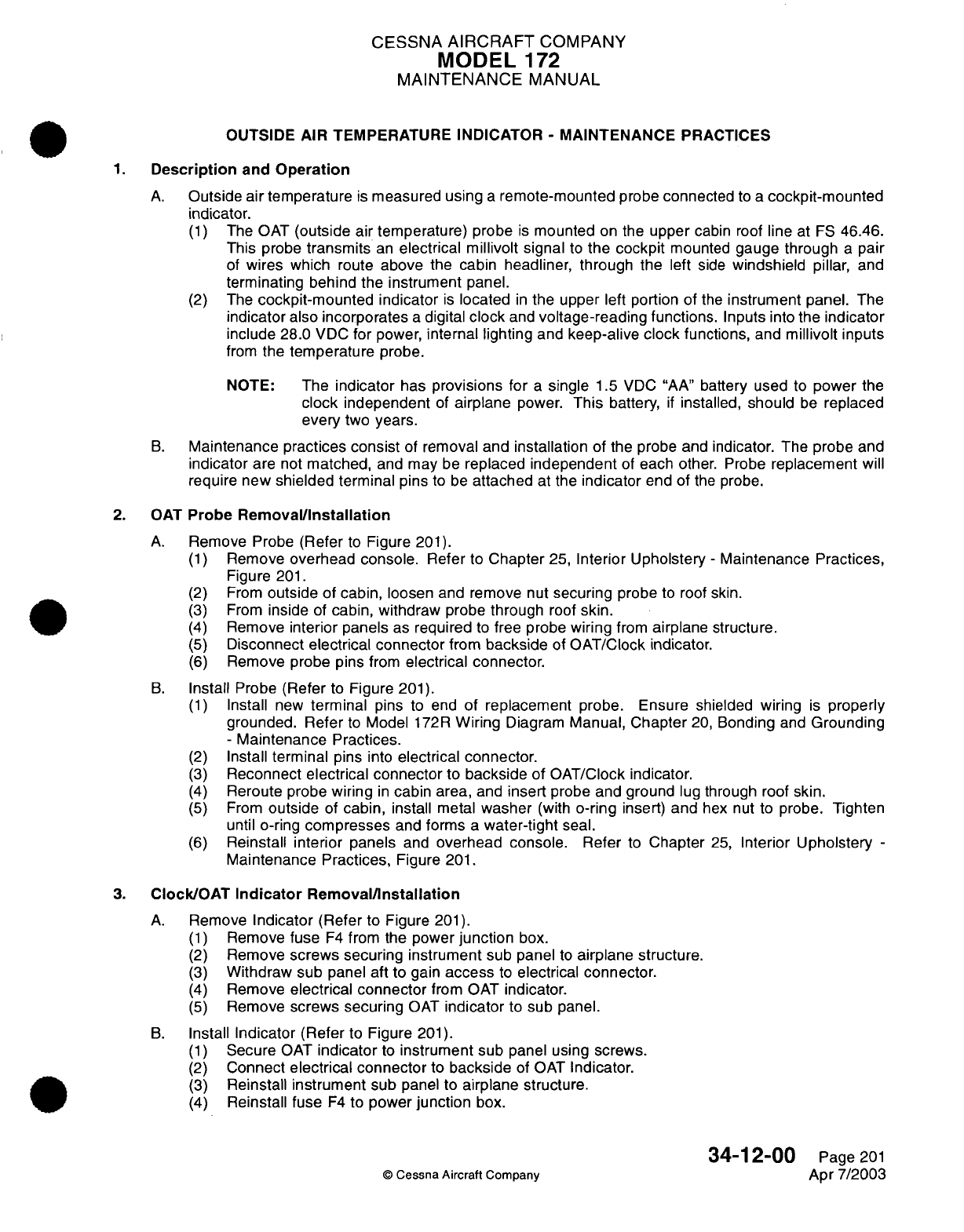
CESSNA
AIRCRAFT
COMPANY
MODEL
172
MAINTENANCE
MANUAL
OUTSIDE
AIR
TEMPERATURE
INDICATOR
-
MAINTENANCE
PRACTICES
1.
Description
and
Operation
A.
Outside air
temperature
is
measured using
a
remote-mounted
probe
connected
to
a
cockpit-mounted
indicator.
(1)
The
OAT
(outside
air
temperature)
probe
is
mounted
on
the
upper
cabin
roof
line
at
FS
46.46.
This probe
transmits
an
electrical millivolt signal
to
the
cockpit
mounted
gauge through
a
pair
of
wires
which
route
above
the
cabin headliner,
through the
left
side
windshield
pillar,
and
terminating
behind the instrument
panel.
(2)
The
cockpit-mounted
indicator
is
located
in
the
upper left portion
of
the
instrument
panel.
The
indicator
also
incorporates
a
digital
clock
and
voltage-reading functions.
Inputs
into
the
indicator
include
28.0
VDC
for
power,
internal lighting
and
keep-alive
clock
functions,
and
millivolt
inputs
from
the
temperature
probe.
NOTE:
The
indicator
has
provisions
for
a
single
1.5
VDC "AA"
battery
used
to
power
the
clock
independent
of
airplane
power.
This
battery,
if
installed,
should
be
replaced
every
two
years.
B.
Maintenance
practices
consist
of
removal
and
installation of
the probe and
indicator.
The
probe
and
indicator
are
not
matched,
and
may
be
replaced
independent
of
each
other.
Probe
replacement
will
require
new
shielded
terminal
pins
to
be
attached
at the
indicator
end of
the
probe.
2.
OAT
Probe
Removal/Installation
A.
Remove
Probe
(Refer
to
Figure
201).
(1)
Remove
overhead
console.
Refer
to
Chapter
25,
Interior Upholstery
-
Maintenance Practices,
Figure
201.
(2)
From
outside of
cabin, loosen
and
remove
nut
securing
probe
to
roof skin.
(3)
From
inside
of
cabin,
withdraw
probe
through
roof
skin.
(4)
Remove
interior panels
as
required
to
free probe
wiring
from
airplane
structure.
(5)
Disconnect
electrical
connector
from
backside
of
OAT/Clock indicator.
(6)
Remove probe
pins
from
electrical
connector.
B.
Install
Probe
(Refer
to
Figure
201).
(1)
Install
new
terminal
pins
to
end
of replacement
probe.
Ensure
shielded
wiring
is
properly
grounded.
Refer
to
Model
172R
Wiring
Diagram
Manual,
Chapter
20,
Bonding
and
Grounding
-
Maintenance Practices.
(2)
Install
terminal
pins
into
electrical
connector.
(3)
Reconnect
electrical
connector
to
backside
of
OAT/Clock
indicator.
(4)
Reroute probe
wiring
in
cabin area,
and
insert
probe
and ground
lug
through
roof skin.
(5)
From
outside
of
cabin,
install
metal
washer
(with
o-ring
insert) and
hex nut
to
probe.
Tighten
until
o-ring
compresses
and
forms
a
water-tight
seal.
(6)
Reinstall
interior
panels
and
overhead console.
Refer
to
Chapter
25,
Interior
Upholstery
-
Maintenance
Practices,
Figure
201.
3.
Clock/OAT
Indicator
Removal/nstallation
A.
Remove
Indicator
(Refer to
Figure
201).
(1)
Remove
fuse
F4
from the
power
junction
box.
(2)
Remove
screws
securing instrument
sub
panel
to
airplane
structure.
(3)
Withdraw sub
panel
aft
to
gain
access
to
electrical
connector.
(4)
Remove
electrical connector
from
OAT
indicator.
(5)
Remove
screws securing
OAT
indicator
to
sub
panel.
B.
Install
Indicator
(Refer
to
Figure
201).
(1)
Secure
OAT
indicator
to
instrument sub
panel using
screws.
(2)
Connect
electrical connector
to
backside
of
OAT
Indicator.
(3)
Reinstall
instrument
sub
panel to
airplane
structure.
(4)
Reinstall fuse
F4
to
power
junction
box.
34-12-00
Page
201
©
Cessna Aircraft Company
Apr 7/2003
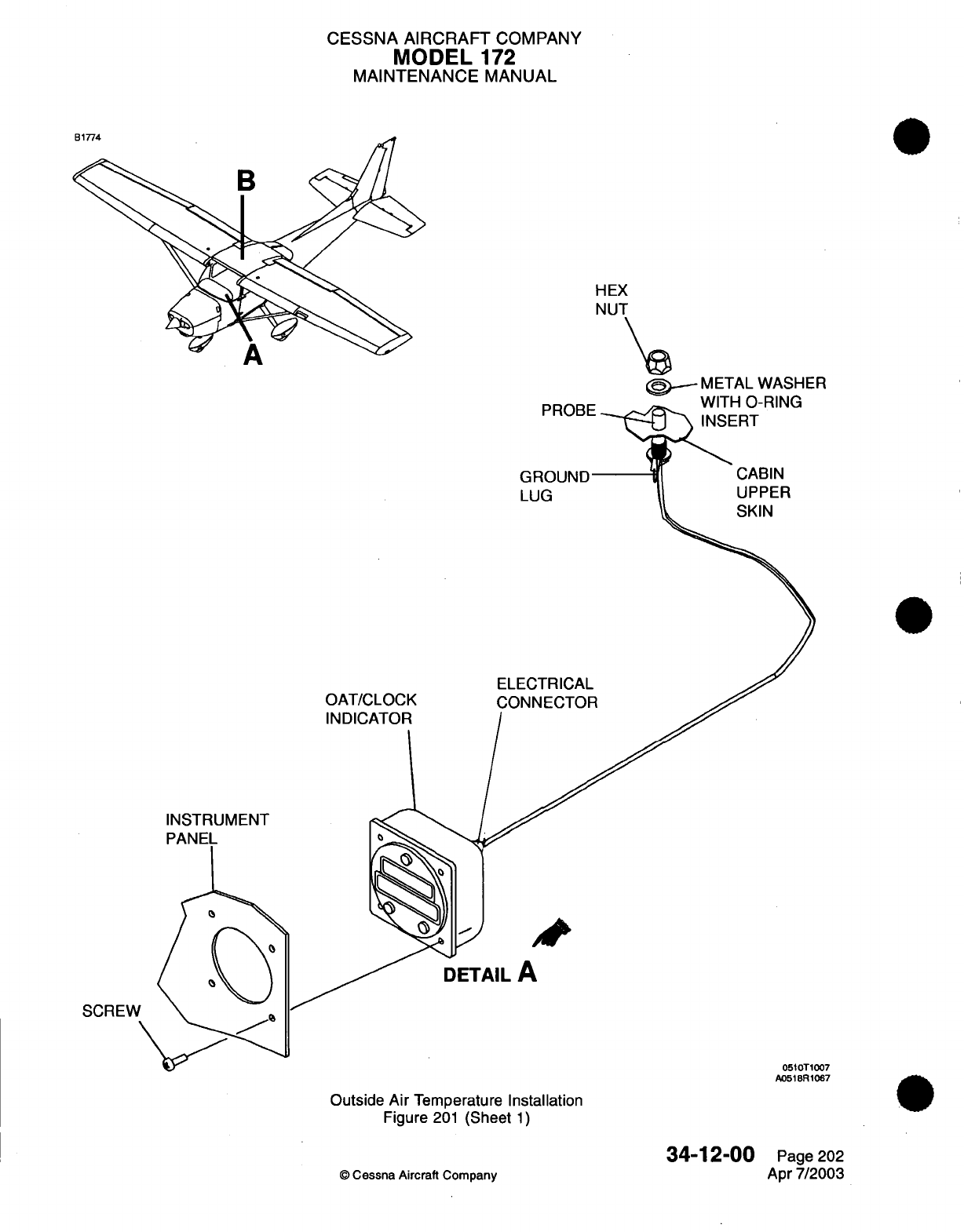
CESSNA AIRCRAFT
COMPANY
MODEL
172
MAINTENANCE
MANUAL
HEX
NUT
\
>,
METAL WASHER
WAITI-I
Cn-DIM(
OAT/CLOCK
INDICATOR
CABIN
UPPER
SKIN
GROUND
LUG
ELECTRICAL
CONNECTOR
INSTRUMENT
PANEL
DETAIL
A
SCREW
0510T1007
A0518R1067
Outside
Air
Temperature
Installation
Figure
201
(Sheet
1)
34-12-00
©
Cessna Aircraft Company
Page
202
Apr
7/2003
,..
U-1
CESSNA
AIRCRAFT
COMPANY
MODEL
172
MAINTENANCE
MANUAL
(5)
Test
for
proper operation.
Refer
to
Pilot's
Operating
Handbook and
FAA
Approved Airplane
Flight
Manual,
Supplements,
for
operation/test
instructions.
34-12-00
Page
203
©
Cessna
Aircraft
Company
Apr
7/2003
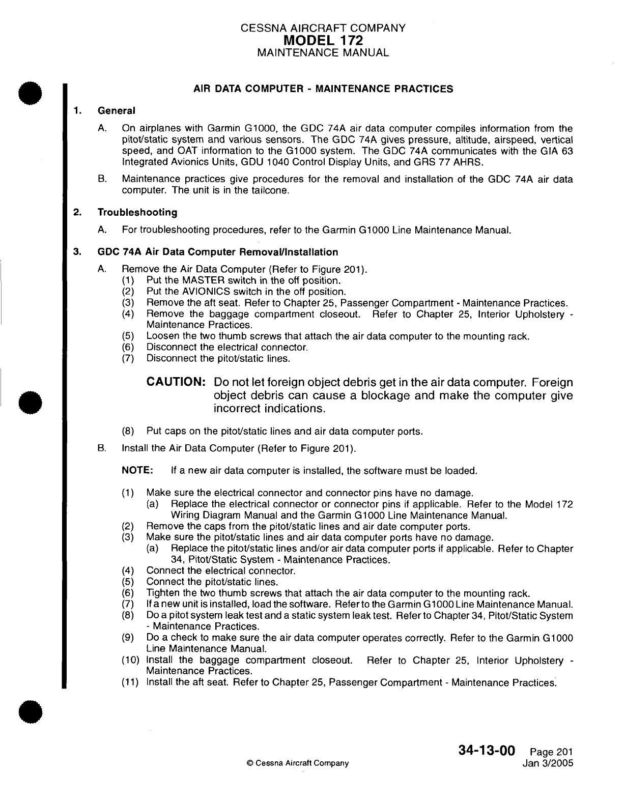
CESSNA
AIRCRAFT
COMPANY
MODEL
172
MAINTENANCE
MANUAL
AIR
DATA
COMPUTER
-
MAINTENANCE PRACTICES
1.
General
A.
On
airplanes
with
Garmin
G1000,
the
GDC
74A
air
data
computer compiles
information
from
the
pitot/static
system
and
various
sensors.
The
GDC
74A
gives pressure,
altitude,
airspeed, vertical
speed,
and
OAT
information
to
the
G1000
system. The
GDC
74A
communicates
with
the
GIA
63
Integrated
Avionics
Units,
GDU
1040
Control Display
Units,
and
GRS
77
AHRS.
B.
Maintenance practices
give
procedures
for
the
removal
and
installation
of
the
GDC 74A
air data
computer.
The
unit
is in
the
tailcone.
2.
Troubleshooting
A.
For
troubleshooting
procedures,
refer
to
the
Garmin
G1000
Line
Maintenance
Manual.
3. GDC
74A
Air
Data
Computer
Removal/Installation
A.
Remove
the
Air Data
Computer
(Refer
to
Figure
201).
(1)
Put
the
MASTER
switch
in
the
off
position.
(2)
Put
the
AVIONICS
switch
in
the
off
position.
(3)
Remove
the aft
seat.
Refer
to
Chapter
25,
Passenger Compartment
-
Maintenance
Practices.
(4)
Remove
the
baggage
compartment
closeout.
Refer
to
Chapter
25,
Interior
Upholstery
-
Maintenance
Practices.
(5)
Loosen
the
two
thumb
screws that
attach the
air
data
computer
to
the
mounting
rack.
(6)
Disconnect
the
electrical
connector.
(7)
Disconnect
the
pitot/static
lines.
CAUTION:
Do
not
let
foreign object debris
get
In
the
air
data computer.
Foreign
object
debris
can
cause
a
blockage
and
make
the
computer
give
Incorrect Indications.
(8)
Put
caps
on
the
pitot/static
lines and air
data
computer
ports.
B.
Install
the
Air
Data
Computer
(Refer
to
Figure
201).
NOTE:
If a
new
air
data computer
is
installed,
the
software must
be
loaded.
(1)
Make
sure
the
electrical
connector
and
connector
pins
have
no
damage.
(a)
Replace
the
electrical
connector
or
connector
pins
if
applicable.
Refer
to
the Model
172
Wiring
Diagram
Manual
and
the
Garmin G1000
Line
Maintenance
Manual.
(2)
Remove
the
caps
from
the
pitot/static
lines
and air
date
computer
ports.
(3)
Make sure the
pitot/static
lines and air
data
computer
ports have
no damage.
(a)
Replace the
pitot/static
lines
and/or
air
data
computer
ports
if
applicable.
Refer
to
Chapter
34,
Pitot/Static
System
-
Maintenance
Practices.
(4)
Connect
the
electrical
connector.
(5)
Connect
the
pitot/static
lines.
(6)
Tighten
the two
thumb
screws that attach
the
air
data
computer
to
the
mounting
rack.
(7) If
a
new
unit
is
installed,
load the
software.
Referto
the
Garmin G1000
Line
Maintenance
Manual.
(8)
Do
a
pitot
system
leak
test
and
a
static
system
leak
test.
Refer
to
Chapter
34,
Pitot/Static
System
-
Maintenance
Practices.
(9)
Do
a
check
to
make sure the
air
data
computer operates
correctly.
Refer
to
the
Garmin
G1000
Line
Maintenance
Manual.
(10)
Install
the
baggage compartment
closeout.
Refer
to
Chapter
25,
Interior
Upholstery
-
Maintenance
Practices.
(11)
Install
the aft
seat. Refer
to
Chapter
25,
Passenger
Compartment
-
Maintenance
Practices.
34-13-00
Page
201
©
Cessna
Aircraft
Company
Jan
3/2005

CESSNA
AIRCRAFT
COMPANY
MODEL
172
MAINTENANCE
MANUAL
AIR
DATA
TRANSPONDER
DETAIL
A
AIRPLANES
THAT
HAVE
THE
GARMIN G1000
Forward
Avionics
Equipment
Installation
Figure
201
(Sheet
1)
34-1
3-00
©
Cessna Aircraft
Company
0510T1007
A0518T1103
Page
202
Jan
3/2005
DOO<O
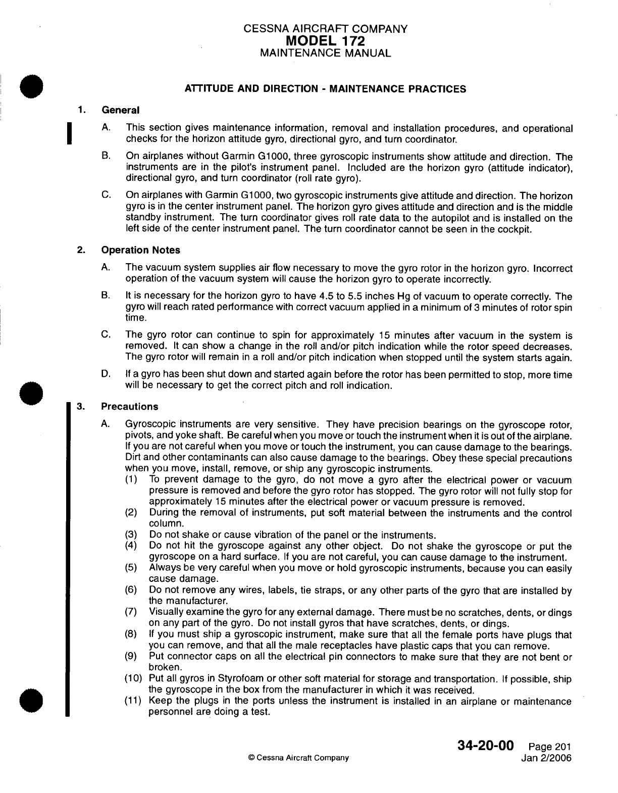
CESSNA
AIRCRAFT
COMPANY
MODEL
172
MAINTENANCE
MANUAL
ATTITUDE
AND
DIRECTION
-
MAINTENANCE
PRACTICES
1.
General
A.
This
section gives maintenance
information,
removal
and
installation
procedures, and operational
checks
for
the
horizon
attitude
gyro,
directional
gyro,
and turn
coordinator.
B.
On
airplanes without
Garmin
G1000,
three
gyroscopic
instruments
show
attitude
and
direction.
The
instruments
are
in
the
pilot's instrument
panel.
Included
are
the
horizon gyro
(attitude
indicator),
directional
gyro,
and
turn
coordinator
(roll
rate
gyro).
C.
On
airplanes
with
Garmin
G1000,
two
gyroscopic
instruments
give
attitude and
direction. The
horizon
gyro
is
in
the
center
instrument
panel.
The
horizon
gyro
gives
attitude
and
direction
and
is
the
middle
standby
instrument.
The
turn
coordinator gives
roll
rate
data
to
the
autopilot
and
is
installed
on
the
left
side of
the
center
instrument
panel.
The turn
coordinator
cannot
be
seen
in
the
cockpit.
2.
Operation
Notes
A.
The
vacuum
system
supplies
air
flow
necessary
to move
the
gyro rotor
in
the
horizon
gyro.
Incorrect
operation of
the
vacuum
system will
cause
the
horizon
gyro
to
operate
incorrectly.
B. It
is
necessary
for
the
horizon
gyro
to
have 4.5
to 5.5
inches
Hg of
vacuum
to
operate
correctly.
The
gyro
will
reach
rated
performance
with
correct
vacuum applied
in
a
minimum
of
3
minutes
of
rotor spin
time.
C.
The gyro rotor can
continue
to
spin
for
approximately
15
minutes
after
vacuum
in
the
system
is
removed.
It
can
show
a
change
in
the
roll
and/or
pitch
indication
while
the
rotor speed
decreases.
The
gyro
rotor will
remain
in a
roll
and/or
pitch
indication
when stopped
until
the
system
starts
again.
D. If a
gyro
has
been
shut
down
and started again before
the
rotor
has
been
permitted
to
stop,
more time
will
be
necessary
to
get
the correct pitch and
roll
indication.
3.
Precautions
A.
Gyroscopic
instruments
are
very
sensitive.
They
have
precision
bearings
on
the
gyroscope
rotor,
pivots,
and
yoke
shaft.
Be
careful
when you
move
or
touch
the
instrument
when
it
is
out of
the
airplane.
If
you
are
not
careful
when
you
move
or
touch
the
instrument,
you can
cause
damage
to
the bearings.
Dirt
and
other contaminants
can also
cause damage
to
the
bearings. Obey these special
precautions
when you move,
install, remove,
or
ship
any
gyroscopic
instruments.
(1)
To
prevent
damage
to
the
gyro,
do
not
move
a
gyro
after the
electrical
power
or
vacuum
pressure
is
removed and
before
the
gyro
rotor
has
stopped.
The
gyro rotor will
not
fully
stop
for
approximately
15
minutes
after
the electrical
power
or
vacuum
pressure
is
removed.
(2)
During
the
removal
of
instruments,
put
soft
material between
the
instruments
and the
control
column.
(3)
Do
not
shake
or
cause
vibration
of the
panel
or
the
instruments.
(4)
Do
not
hit
the
gyroscope
against any
other
object.
Do
not shake
the
gyroscope
or
put
the
gyroscope
on
a
hard
surface.
If
you
are
not
careful,
you
can
cause
damage
to
the
instrument.
(5)
Always
be
very careful
when
you
move
or
hold
gyroscopic
instruments,
because
you
can
easily
cause
damage.
(6)
Do
not
remove any
wires,
labels,
tie
straps,
or
any
other
parts
of the gyro
that
are
installed
by
the
manufacturer.
(7)
Visually examine
the
gyro
for
any
external
damage.
There must
be
no
scratches,
dents,
or
dings
on
any
part
of
the
gyro.
Do
not
install
gyros that
have
scratches,
dents,
or
dings.
(8)
If
you must
ship
a
gyroscopic instrument,
make
sure that
all
the
female ports have
plugs
that
you
can
remove,
and
that
all
the male
receptacles
have plastic caps
that
you
can
remove.
(9)
Put
connector
caps
on
all
the
electrical
pin
connectors
to
make
sure
that
they
are
not
bent
or
broken.
(10) Put
all
gyros
in
Styrofoam or
other
soft
material for storage
and
transportation.
If
possible,
ship
the
gyroscope
in
the
box
from
the
manufacturer
in
which
it
was received.
(11)
Keep the
plugs
in
the ports
unless
the
instrument
is
installed
in
an
airplane
or
maintenance
personnel
are
doing
a
test.
34-20-00
Page
201
©
Cessna
Aircraft
Company
Jan
2/2006
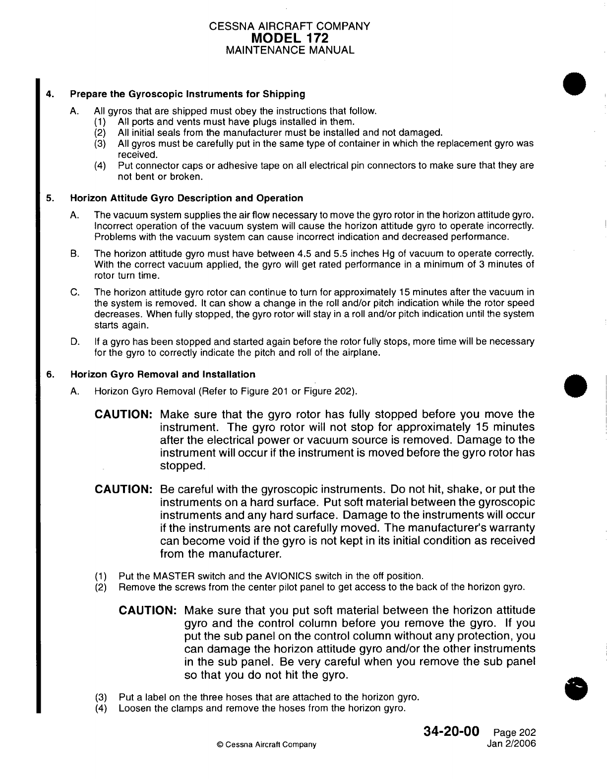
CESSNA AIRCRAFT
COMPANY
MODEL
172
MAINTENANCE
MANUAL
4.
Prepare
the
Gyroscopic
Instruments
for
Shipping
A.
All
gyros
that
are
shipped
must
obey
the
instructions that
follow.
(1)
All ports and
vents
must
have
plugs
installed
in
them.
(2)
All
initial
seals
from the
manufacturer
must
be
installed
and
not
damaged.
(3)
All
gyros must
be
carefully
put
in
the
same
type
of
container
in
which
the
replacement
gyro
was
received.
(4)
Put
connector
caps or
adhesive
tape
on
all
electrical
pin
connectors
to make
sure that
they
are
not
bent
or broken.
5.
Horizon
Attitude
Gyro
Description
and
Operation
A.
The
vacuum
system
supplies
the air flow
necessary
to
move
the
gyro rotor
in
the
horizon
attitude
gyro.
Incorrect
operation
of the
vacuum system
will
cause
the
horizon
attitude
gyro
to
operate incorrectly.
Problems
with
the vacuum system
can
cause
incorrect
indication
and
decreased
performance.
B.
The
horizon
attitude
gyro
must
have between
4.5
and
5.5
inches
Hg
of
vacuum
to
operate
correctly.
With
the
correct vacuum applied,
the
gyro will
get
rated
performance
in a
minimum
of
3
minutes
of
rotor
turn time.
C.
The horizon
attitude
gyro
rotor
can
continue
to
turn
for
approximately
15
minutes after
the
vacuum
in
the
system
is
removed.
It
can
show
a
change
in
the
roll
and/or
pitch
indication
while
the
rotor
speed
decreases.
When
fully
stopped,
the
gyro rotor will
stay
in
a
roll
and/or
pitch
indication
until the
system
starts again.
D. If a
gyro
has
been
stopped
and
started
again before
the
rotor
fully
stops,
more
time
will
be
necessary
for
the
gyro
to
correctly indicate
the
pitch and
roll
of the
airplane.
6.
Horizon
Gyro
Removal
and
Installation
A.
Horizon
Gyro
Removal (Refer
to
Figure
201
or
Figure 202).
CAUTION:
CAUTION:
(1)
(2)
Make
sure
that
the gyro
rotor
has
fully
stopped
before
you
move
the
instrument.
The
gyro
rotor
will not
stop
for
approximately
15
minutes
after
the
electrical
power
or
vacuum
source
is
removed. Damage to the
instrument
will
occur
if
the
instrument
is
moved before
the
gyro
rotor
has
stopped.
Be
careful
with
the
gyroscopic
instruments.
Do
not
hit,
shake,
or
put
the
instruments
on
a
hard
surface.
Put
soft
material between
the gyroscopic
instruments
and
any
hard
surface.
Damage to
the
instruments
will
occur
if
the
instruments
are not
carefully
moved.
The manufacturer's
warranty
can
become
void
if
the
gyro
is
not
kept
in
its
initial
condition
as
received
from
the manufacturer.
Put
the
MASTER
switch
and
the
AVIONICS
switch
in
the
off
position.
Remove
the
screws
from
the
center
pilot
panel
to
get
access
to
the
back
of
the
horizon
gyro.
CAUTION:
Make
sure
that
you
put
soft material
between the horizon
attitude
gyro and
the control
column
before
you
remove
the
gyro.
If
you
put
the
sub
panel
on
the
control column
without
any protection,
you
can
damage
the
horizon attitude
gyro
and/or
the other
instruments
in
the
sub
panel.
Be
very careful
when
you
remove
the
sub
panel
so
that
you do
not
hit
the
gyro.
Put
a
label
on
the
three hoses
that
are
attached
to the
horizon gyro.
Loosen the
clamps
and
remove
the
hoses
from
the
horizon gyro.
©
Cessna
Aircraft Company
34-20-00
Page
202
Jan
2/2006
(3)
(4)
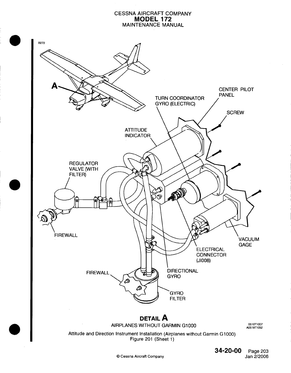
CESSNA
AIRCRAFT
COMPANY
MODEL
172
MAINTENANCE
MANUAL
CENTER
PILOT
PANEL
SCREW
ATTITUDE
REGULATOR
VALVE
(WITH
FIREWALL
VACUUM
GAGE
CONNECTOR
(J1008)
FIREWALL
GYRO
FILTER
DETAIL
A
AIRPLANES WITHOUT
GARMIN
G1000
Attitude
and
Direction
Instrument Installation (Airplanes
without
Garmin
G1000)
Figure
201
(Sheet
1)
34-20-00
©
Cessna
Aircraft
Company
0510T1007
A0518T1052
Page
203
Jan
2/2006
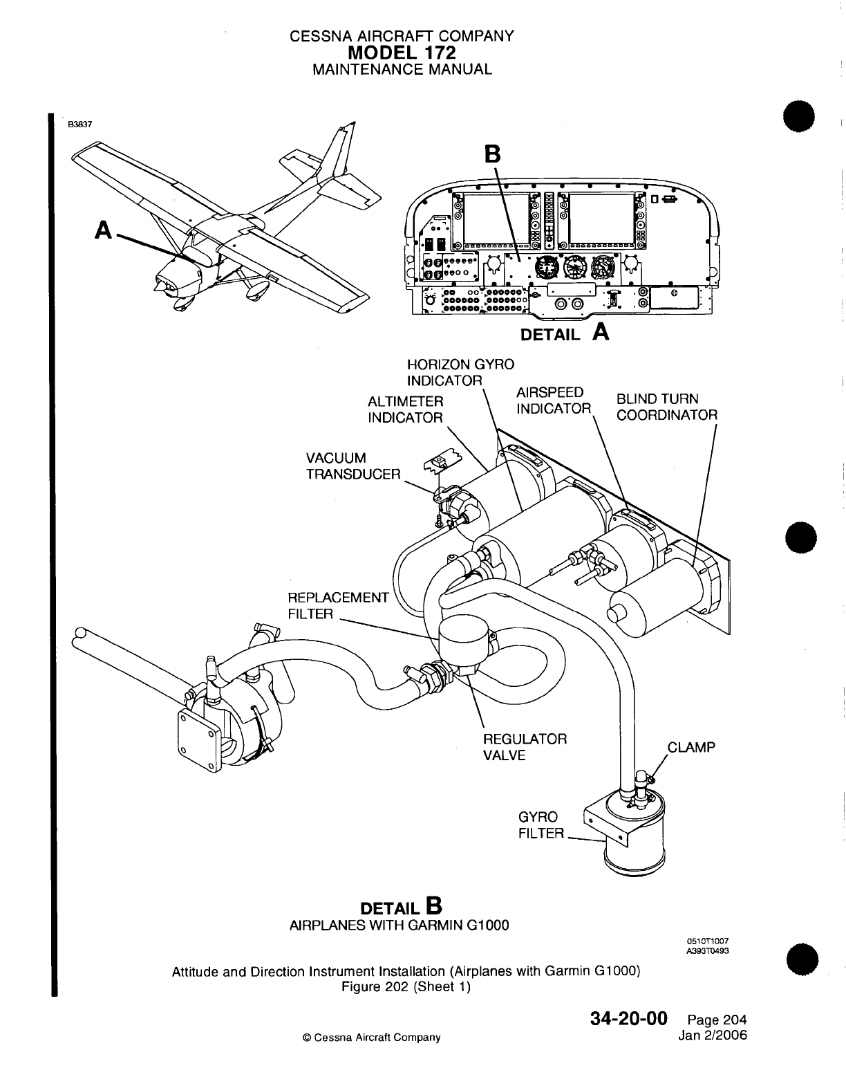
CESSNA
AIRCRAFT
COMPANY
MODEL
172
MAINTENANCE
MANUAL
B
DETAIL
A
HORIZON
GYRO
ALTIMETER
INDICATOR
AIRSPEED
INDICATOR BLIND
TURN
COORDINATOR
VACUUM
TRANSDUCER
FILTER
DETAIL
B
AIRPLANES
WITH
GARMIN
G1000
051OT1007
A393TD493
Attitude and
Direction
Instrument
Installation
(Airplanes
with
Garmin
G1000)
Figure
202
(Sheet
1)
34-20-00
©
Cessna
Aircraft
Company
Page
204
Jan
2/2006
CESSNA
AIRCRAFT
COMPANY
MODEL
172
MAINTENANCE
MANUAL
(5)
Disconnect
the
electrical connector
from
the
horizon
gyro.
(6)
Put
female
plugs
over
the
ports
and
put
a
connector
cap
on
the
electrical
connector.
(7)
Remove
the
screws that
attach the
horizon attitude
gyro
to the
center
pilot
panel.
CAUTION: Put
a
cover
on
the
applicable
hose
or
port
or
on
the
applicable
electrical
connector
when
the
gyroscopic
instrument
is
out
of
the
airplane
or
is
to
be
shipped.
Damage
to
the
instrument
will
occur
from
foreign
object
debris
if
a
cover
is
not
used.
(8)
Remove
the
horizon
gyro from
the airplane.
B.
Horizon
Gyro
Installation
(Refer
to
Figure
201
or
Figure 202).
CAUTION:
Do
not
remove
the
horizon
attitude
gyro from
the box
in
which
it
was
shipped
until
it
is
ready
to
be
installed
into
the
airplane.
This
will
minimize
the
possibility
of
accidentally
causing damage
to
the
gyro.
CAUTION:
Remove
all
plugs
from
the
horizon
attitude
gyro
before
you
install
it
in
the
airplane.
CAUTION:
Be
careful
with
the
gyroscopic
instruments.
Do
not
drop, shake,
bump
or
put
on a
hard
surface.
Use
soft
material
between the gyroscopic
instruments
and
any
hard
surface.
Damage
to
the
instruments
will occur
if
the instruments
are
not
carefully
moved.
The
manufacturer's warranty
can
become
void
if
the
gyro
is
not
kept
in
it's
initial
condition
as
received
from
the
manufacturer.
(1)
Attach
the
horizon
gyro to
the
center
pilot
panel
with
the screws.
(2)
Make sure
that
the horizon
altitude
gyro
is
installed
level
in
the
panel.
(3)
Remove
the
female
plugs
from
the
ports
and
remove
the
connector
cap
from
the
electrical
connector.
(4)
Make sure
that
the vacuum
lines
and the
static
lines
have
no
kinks
in
them.
(5)
Attach
the
applicable
hoses
to the
horizon
gyro and
tighten
the
clamps.
(6)
Attach the
horizon
gyro
connector
to
the
horizon
gyro.
(7)
Attach
the
center
pilot
panel with
the
screws.
(8)
Tighten the
screws
in
an
opposite
sequence.
(9)
Put
the
MASTER
switch
and
the
AVIONICS
switch
in
the
ON
position.
(10)
Do
an
operational
check
of
the horizon
attitude
gyro
to
make
sure
that
it
operates
correctly.
7.
Horizon
Attitude
Gyro
Operational
Check
A.
Horizon
Attitude
Gyro Operational
Check.
(1)
Start
the
airplane
engine.
(2)
Let
the
engine
run
for
no
less than
3
minutes.
(3)
Make
sure
that
the
vacuum
gage
shows
between 4.5 and
5.5
inches
Hg.
(4)
Make sure
that
the
horizon bar
becomes
stable
at
the
correct position
for
the
attitude
of
the
airplane,
or
becomes
stable
at
the
correct
position,
begins
to
vibrate,
and
then
slowly
stops
vibration
altogether.
(5)
Taxi
in a
straight
line.
Make sure
that the
horizon
bar
stays
in
the
horizontal position while
you
taxi.
(6)
Do
a
360-degree
turn.
Do
not
turn
sharply
as
you make
the
turn.
Make
sure
that
the
horizon
bar
does
not
tip
more than
4
degrees
from
the horizontal
during
the
turn.
(7)
If
the horizontal
gyro
precession
is
more
than
4
degrees
from
a
heading
in
either
direction
during
a
10-minute
period,
or
does
not
operate
within
one
or
more
of the
limits
given
in
steps
4
through
6
of
this operational
check,
you
must repair the
system
and/or replace
the
gyro.
34-20-00
Page
205
©
Cessna Aircraft
Company
Jan 2/2006
CESSNA AIRCRAFT
COMPANY
MODEL
172
MAINTENANCE
MANUAL
8.
Directional Gyro Description
and
Operation
A.
The
vacuum
system
supplies
the air flow
necessary
to
move
the
gyro
rotor
in
the
directional
gyro.
Incorrect operation
of
the
vacuum
system will
cause
the
horizon
attitude
gyro
to
operate
incorrectly.
Problems
with
the
vacuum
system
can
cause
incorrect indication
and
decreased
performance.
B.
The
directional
gyro
must
have
between
4.5
and
5.5
inches
Hg
of
vacuum
to
operate correctly.
With
the
correct
vacuum
applied,
the
gyro
will
get
rated
performance
in a
minimum
of
3
minutes
of
rotor
turn
time.
C.
The
directional
gyro
rotor
can
continue
to
turn
for
approximately
15
minutes after
the
vacuum
in
the
system
is
removed.
It
can
show
a
change
in
the
directional indication
while
the rotor
speed
decreases,
or
the
directional
gyro
dial
can
start
to
turn.
When
fully
stopped,
the
gyro
rotor will
not
correctly
indicate
changes
in
the
airplane's
direction
until
the system
starts
again.
D. If
a
gyro has
been
stopped
and
started again
before
the rotor
fully
stops,
more
time
will
be
necessary
for
the
gyro
to
correctly indicate
the
directional
changes
of the
airplane.
E.
The
permitted
limit
for
directional
gyro
drift
on
the
ground
or
in
flight
is
4
degrees
from
a
fixed heading,
during
a
10-minute
period.
F.
Continuous
turns
around
a
point
and/or
banks
of
more
than
55
degrees
can
cause
the
directional gyro
to
turn.
This
is
a
limit
of
the
gyro and
not
a
cause for
removal.
9.
Directional
Gyro
Removal
and
Installation (Airplanes
without
Garmin
G1000)
A.
Directional
Gyro
Removal
(Refer
to
Figure
201).
CAUTION:
CAUTION:
(1)
(2)
Make
sure
that
the
gyro
rotor
has
fully stopped
before you
move
the
instrument.
The
gyro
rotor
will
not
stop
for
approximately
15
minutes
after the
vacuum
source
is
removed.
Damage
to
the
instrument
will
occur
if
the instrument
is
moved
before
the
gyro
rotor
has
stopped.
Be
careful
with
the
gyroscopic
instruments.
Do
not
hit,
shake,
or
put
the
instruments
on
a
hard
surface.
Put
soft material
between
the
gyroscopic
instruments
and
any
hard
surface.
Damage
to
the
instruments
will
occur
if
the
instruments
are
not
carefully
moved. The
manufacturer's
warranty
can
become
void
if
the gyro
is
not
kept
in
its
initial
condition
as
received
from
the
manufacturer.
Put
the
MASTER
switch
and
the
AVIONICS
switch
in
the
off
position.
Remove
the
screws
of
the
center
pilot panel
to get
access
to
the back
of
the
directional
gyro.
CAUTION: Make
sure
that
you
put
soft
material between
the
directional
gyro
and
the control
column before
you
remove the
gyro.
If
you
put
the
sub
panel
on
the
control
column
without
any
protection,
you
can
damage
the
directional
gyro
and/or the other instruments
in
the
sub
panel.
Be
very
careful
when you
remove
the
sub
panel
so
that
you
do
not
to
hit
the
gyro.
Put
a
label
on
the
two
hoses
that
are
attached
to
the
directional
gyro.
Loosen the
clamps
and
remove
the
hoses
from
the
directional
gyro.
Disconnect
the
gyro
connector
and
electrical connector
from
the
directional
gyro.
Put
female plugs
over
the ports
and
put
a
connector
cap
on
the
electrical connector.
Remove
the
directional
gyro
screws
from
the
center
pilot
panel.
34-20-00
Page
206
©
Cessna
Aircraft Company
Jan
2/2006
(3)
(4)
(5)
(6)
(7)
CESSNA
AIRCRAFT
COMPANY
MODEL
172
MAINTENANCE
MANUAL
CAUTION:
Put
a
cover
on
the
applicable
hose
or port
or
on
the
applicable
electrical
connector
when
the
gyroscopic
instrument
is
out
of
the
airplane
or
is
to be
shipped.
Damage
to
the
instrument
will
occur
from
foreign
object
debris
if
a
cover
is
not
used.
(8)
Remove
the
directional
gyro
from
the
airplane.
B.
Directional
Gyro
Installation
(Refer
to
Figure
201).
CAUTION:
Do
not
remove the directional gyro
from
the
box
in
which
it
was
shipped
until
it
is
ready
to
be
installed
into
the
airplane.
This
will
minimize
the
possibility
of
accidentally
causing
damage
to
the
gyro.
CAUTION: Remove all
plugs
from
the
directional
gyro before
you
install
it
in
the
airplane.
CAUTION:
Be
careful
with the
gyroscopic
instruments.
Do
not
drop,
shake,
bump
or put
on
a
hard
surface.
Use
soft
material
between the
gyroscopic
instruments
and
any
hard
surface.
Damage to
the
instruments will
occur
if
the instruments
are
not
carefully
moved.
The manufacturer's
warranty
can
become
void
if
the
gyro
is
not
kept
in
it's
initial condition
as
received
from
the
manufacturer.
(1)
Attach
the
directional
gyro
to the
center
pilot
panel with
the
screws.
(2)
Remove
the
female
plugs
from the
ports
and
remove
the
connector
cap
from
the
electrical
connector.
(3)
Attach
the
applicable
hoses
to the
directional
gyro
and tighten
the
clamps.
(4)
Attach
the
electrical
and
gyro
connectors
to
the
directional
gyro.
(5)
Attach
the
center
pilot panel
with
the screws.
(6)
Put
the
MASTER
switch
and
the
AVIONICS
switch
in
the
ON
position.
(7)
Do
a
test
of the
directional
gyro
to
make
sure
it
operates
correctly.
Refer to
Directional Gyro
Operational
Check.
10.
Directional
Gyro
Operational
Check
A.
Directional
Gyro Check
(Refer
to
Figure
201).
NOTE:
The
permitted
limit for
gyro
drift
on
the ground
or
in
flight
is
4
degrees
from
a
fixed
heading,
during
a
10-minute
period.
(1)
Start
the
airplane
engine.
(2)
Make sure
that
the
vacuum
system
operates correctly.
(a)
The
vacuum gage must show
between
4.5 and 5.5
inches
Hg.
(3)
Let
the
directional gyro
become
stable
for
at
least
3
minutes.
(4)
If
the
directional
gyro
dial
starts
to
turn,
let
the
gyro
become
stable
and then push the
gyro-caging
knob.
If
the gyro
dial
continues
to
turn,
repair
the system
and/or
replace the
gyro.
NOTE:
It is
usual
for
the
directional
gyro
dial
to
turn
when
the
gyro
becomes stable. This
is
not
a
cause
for
removal.
(5)
Point
the
airplane's heading
to
the
north.
(6)
Set
the
directional gyro
to
the
north.
(7)
Make
sure
that
the
directional
gyro dial
drift
is
not more than
4
degrees
in
a
10-minute period.
(8)
Do
steps
5
through
7
again for
each
cardinal
heading
(North,
West,
South,
and
East).
34-20-00
Page
207
©
Cessna
Aircraft
Company
Jan
2/2006
CESSNA AIRCRAFT
COMPANY
MODEL
172
MAINTENANCE
MANUAL
(9) If
the
directional
gyro
dial
drift
is
not
satisfactory
at
any
heading,
repair
the
system
and/or
replace
the
gyro.
NOTE:
After
you
stop
operation
of
the
airplane,
it is
usual
for
the
directional
gyro dial
to
continue
to
turn.
This
is
not
a
cause
to
remove
the
gyro.
11.
Turn
Coordinator
Removal
and
Installation
(Airplanes
without
Garmin G1000)
A.
Turn
Coordinator
Removal
(Refer
to
Figure
201).
CAUTION:
CAUTION:
(1)
(2)
Make
sure
that
the
gyro
rotor
has
fully stopped
before
you
move
the
instrument.
The
gyro
rotor
will
not
stop
for
approximately
15
minutes
after
the
vacuum
source
is
removed.
Damage
to
the
instrument
will
occur
if
the instrument
is
moved
before
the gyro
rotor
has
stopped.
Be
careful
with
the
gyroscopic
instruments.
Do
not
hit,
shake,
or
put
the
instruments
on
a
hard
surface.
Put
soft material
between the
gyroscopic
instruments
and
any
hard
surface.
Damage
to
the
instruments
will occur
if
the
instruments
are
not
carefully
moved.
The manufacturer's
warranty
can become
void
if
the gyro
is
not
kept
in
its
initial
condition
as
received
from the
manufacturer.
Put
the
MASTER
switch
and
the
AVIONICS
switch
in
the
off
position.
Remove the screws from the
center
pilot
panel
to
get
access
to
the
turn
coordinator.
CAUTION:
Make
sure
that
you put
soft material
between the
turn
coordinator
and
the
control
column
before
you
remove
the
turn
coordinator.
If
you
put
the
sub-panel
on
the control
column
without
any
protection,
you
can
damage the
turn
coordinator
and/or the other
instruments
in
the
sub-panel.
Be
very
careful
when
you
remove
the
sub-panel
so
that
you do not
to
hit
the
turn
coordinator.
(3)
Disconnect
the
turn
coordinator connector
and
electrical connector
from
the
turn
coordinator.
CAUTION:
Put
a
cover
on
the
applicable
electrical connector
when
the
gyroscopic
instrument
is
out
of
the
airplane
or
is
to
be
shipped.
Damage
to
the
instrument
will
occur
from
contamination
if a
cover
is
not
used.
(4)
Put
connector
caps
on
the
turn
coordinator
avionics
connector
and
electrical connector.
(5)
Remove the
screws
that
attach the
turn
coordinator
to
the
center
pilot
panel.
(6)
Remove
the
turn
coordinator
from
the
airplane.
B.
Turn
Coordinator
Installation
(Refer
to Figure
201).
©
Cessna
Aircraft Company
34-20-00
Page 208
Jan 2/2006
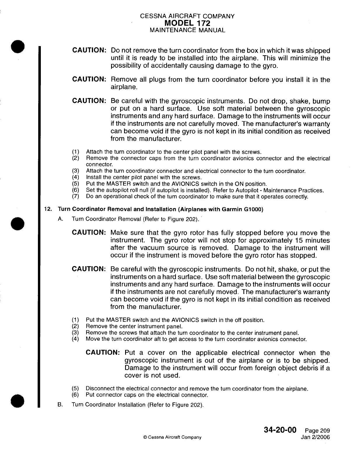
CESSNA
AIRCRAFT
COMPANY
MODEL
172
MAINTENANCE
MANUAL
CAUTION:
Do
not
remove
the
turn
coordinator
from
the
box
in
which
it
was
shipped
until
it
is
ready
to
be
installed
into
the
airplane.
This
will
minimize
the
possibility
of
accidentally
causing
damage
to
the
gyro.
CAUTION:
Remove
all
plugs
from
the
turn
coordinator
before
you
install
it in
the
airplane.
CAUTION:
(1)
(2)
(3)
(4)
(5)
(6)
(7)
Be
careful
with
the
gyroscopic
instruments.
Do
not
drop, shake,
bump
or
put
on
a
hard
surface.
Use
soft
material
between the
gyroscopic
instruments
and any
hard
surface.
Damage
to
the
instruments
will
occur
if
the instruments
are
not
carefully
moved.
The
manufacturer's
warranty
can
become
void
if
the
gyro
is
not
kept
in
its
initial
condition
as
received
from the
manufacturer.
Attach
the
turn
coordinator
to
the
center
pilot
panel with
the
screws.
Remove
the
connector
caps
from
the
turn
coordinator
avionics
connector
and
the electrical
connector.
Attach
the
turn
coordinator
connector
and
electrical connector
to
the
turn
coordinator.
Install
the
center
pilot panel
with
the
screws.
Put
the
MASTER switch
and
the
AVIONICS
switch
in
the
ON
position.
Set
the
autopilot
roll
null
(if autopilot
is
installed).
Refer
to
Autopilot
-
Maintenance Practices.
Do
an
operational
check
of the
turn
coordinator
to
make sure
that
it
operates
correctly.
12.
Turn
Coordinator
Removal
and
Installation
(Airplanes with
Garmin
G1000)
A.
Turn
Coordinator
Removal (Refer
to
Figure 202).
CAUTION:
CAUTION:
(1)
(2)
(3)
(4)
Make
sure
that
the
gyro
rotor has
fully stopped
before
you
move the
instrument.
The
gyro
rotor will
not
stop
for
approximately
15
minutes
after
the vacuum
source
is
removed.
Damage
to
the
instrument
will
occur
if
the
instrument
is
moved
before
the
gyro rotor
has
stopped.
Be
careful
with
the
gyroscopic
instruments.
Do
not
hit,
shake,
or
put
the
instruments
on
a
hard
surface.
Use
soft
material between
the
gyroscopic
instruments
and any
hard
surface.
Damage
to the
instruments
will
occur
if
the instruments
are
not
carefully
moved.
The
manufacturer's
warranty
can
become void
if
the
gyro
is
not
kept
in
its
initial
condition
as
received
from the
manufacturer.
Put
the MASTER
switch
and
the
AVIONICS
switch
in
the off
position.
Remove the
center
instrument
panel.
Remove
the
screws
that attach the
turn
coordinator
to
the
center
instrument
panel.
Move the
turn
coordinator
aft
to get
access
to the
turn
coordinator avionics
connector.
CAUTION:
Put
a
cover
on the
applicable
electrical
connector
when the
gyroscopic
instrument
is
out
of the
airplane
or
is
to
be
shipped.
Damage
to the
instrument
will
occur
from
foreign
object
debris
if
a
cover
is
not
used.
(5)
(6)
Disconnect
the
electrical
connector
and
remove
the
turn
coordinator
from
the
airplane.
Put
connector
caps
on
the
electrical connector.
B.
Turn
Coordinator
Installation
(Refer
to
Figure
202).
©
Cessna
Aircraft
Company
34-20-00
Page 209
Jan
2/2006
CESSNA AIRCRAFT
COMPANY
MODEL
172
MAINTENANCE
MANUAL
CAUTION:
Do
not
remove the
turn
coordinator
from
the
box
in
which
it
was
shipped
until
it
is
ready
to
be
installed
into the
airplane.
This
will
minimize
the
possibility
of
accidentally
causing damage
to
the gyro.
CAUTION:
Remove
all
plugs
from
the
turn
coordinator
before
you
install
it
in
the
airplane.
CAUTION:
(1)
(2)
(3)
(4)
(5)
(6)
(7)
(8)
Be
careful
with
the
gyroscopic
instruments.
Do
not
drop,
shake,
bump
or
put
on
a hard
surface.
Use
soft
material
between the
gyroscopic
instruments
and
any
hard
surface.
Damage
to
the
instruments
will
occur
if
the
instruments
are not
carefully
moved.
The
manufacturer's
warranty
can
become
void
if
the
gyro
is
not
kept
in
its
initial
condition
as received
from
the
manufacturer.
Remove
the
connector
caps
from
the
electrical connector.
Connect
the
electrical
connector.
Put
the
turn
coordinator
in
position
on
the
center
instrument
panel.
Attach
the
turn
coordinator
with screws.
Install
the center instrument
panel.
Put
the MASTER
switch
and
the
AVIONICS
switch
in
the
ON
position.
Set
the
autopilot
roll
null
(if
autopilot
is
installed). Refer
to
Autopilot
-
Maintenance
Practices.
Do
an
operational
check
of the
turn
coordinator
to
make sure
that
it
operates
correctly.
34-20-00
Page
210
©
Cessna
Aircraft
Company
Jan
2/2006
CESSNA
AIRCRAFT
COMPANY
MODEL
172
MAINTENANCE
MANUAL
COMPASS
INSTALLATION
-
MAINTENANCE
PRACTICES
1.
General
A. A
lighted,
magnetic
compass
is
installed
on top
of
the
glareshield
at
the
airplane
centerline.
2.
Compass
Removal/Installation
A.
Remove
Compass
(Refer
to Figure
201).
(1)
Remove
screws
securing
compass
to
compass
base.
(2)
Disconnect electrical
connector.
B.
Install
Compass
(Refer
to
Figure
201).
(1)
Connect
electrical
connector.
(2)
Secure
compass
to
compass
base
with
screws.
(3)
Check
compass
accuracy
on
compass
rose.
©
Cessna
Aircraft
Company
34-21-00
Page
201
Apr
7/2003
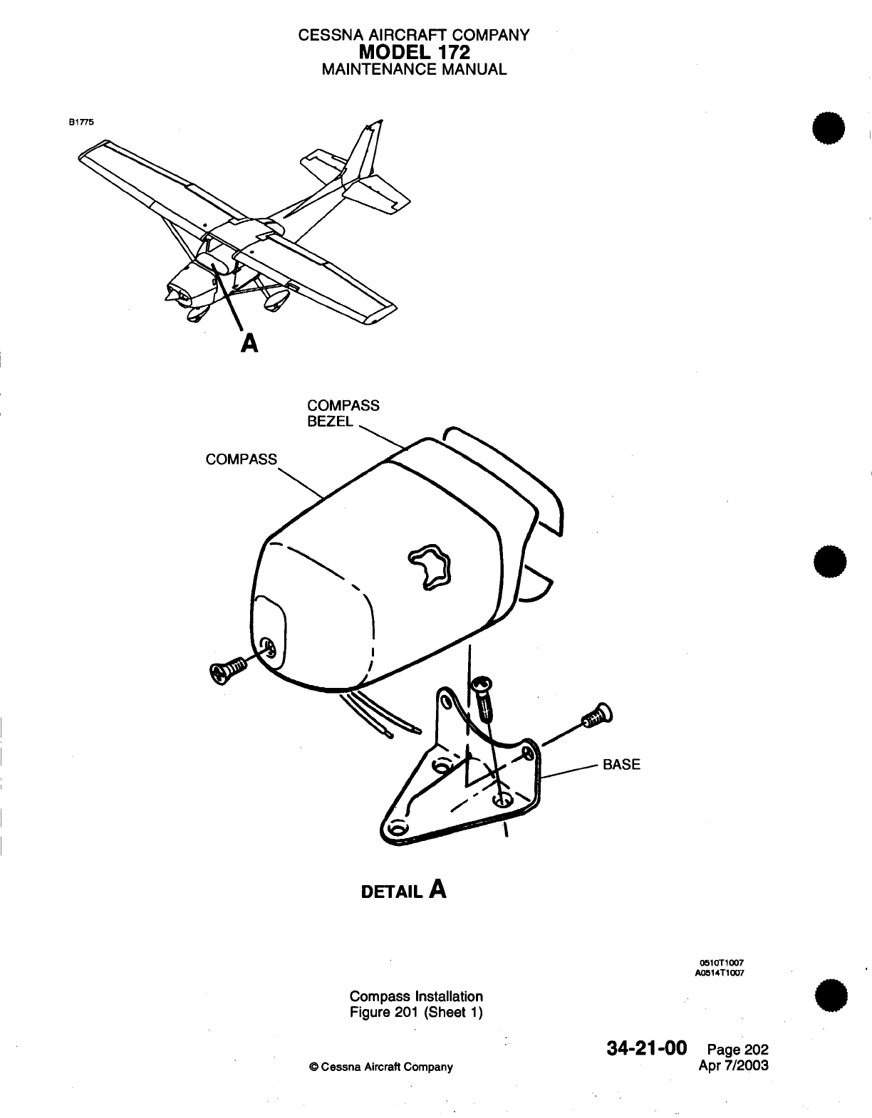
CESSNA
AIRCRAFT
COMPANY
MODEL
172
MAINTENANCE
MANUAL
B1
A
COMPASS
BEZEL
ASE
DETAIL
A
0510T1007
A0514T1007
Compass Installation
Figure
201
(Sheet
1)
©
Cessna
Aircraft
Company
34-21-00
Page
202
Apr
7/2003
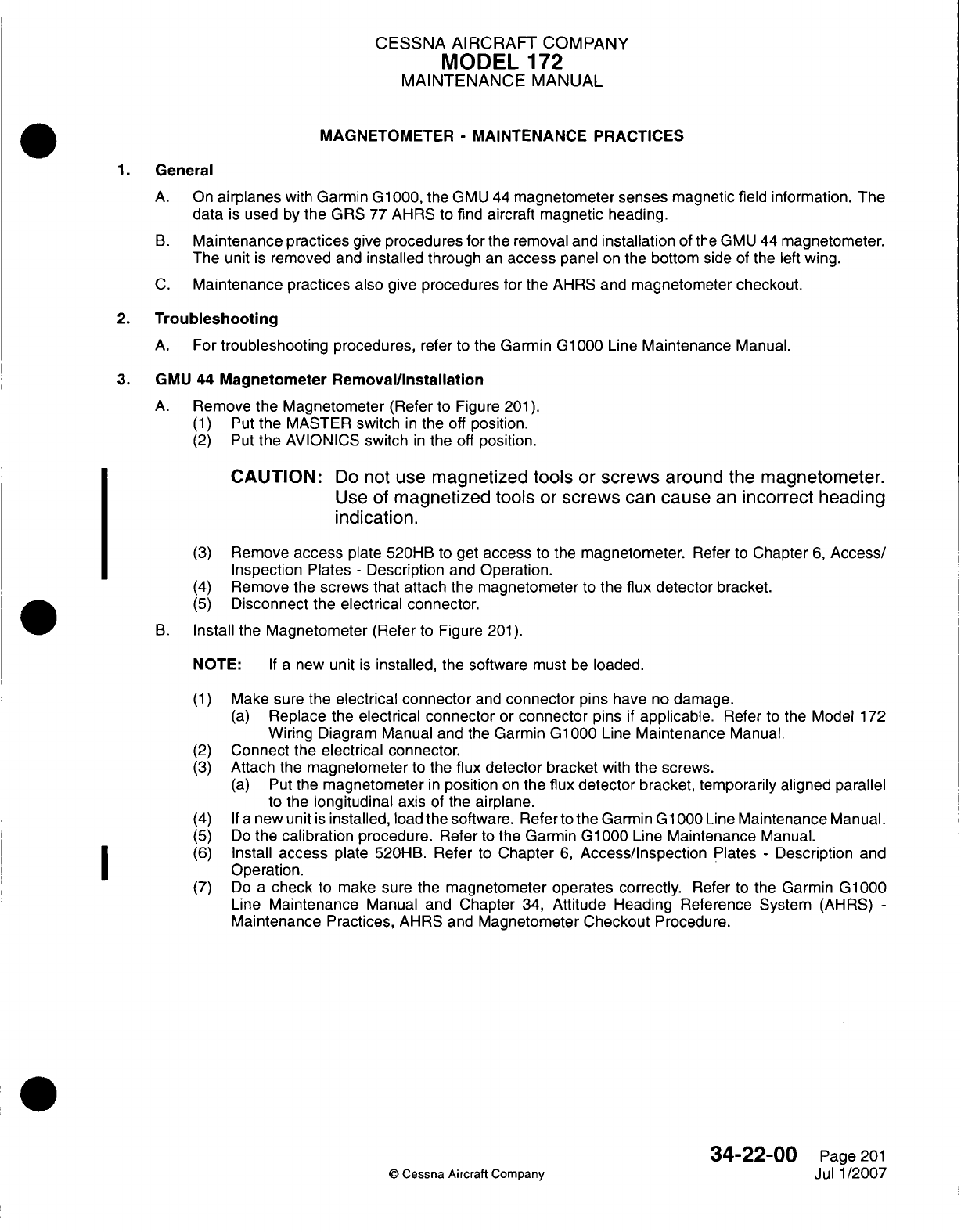
CESSNA
AIRCRAFT
COMPANY
MODEL
172
MAINTENANCE
MANUAL
MAGNETOMETER
-
MAINTENANCE PRACTICES
1.General
A.
On
airplanes
with
Garmin G1000,
the GMU
44
magnetometer
senses
magnetic
field
information. The
data
is
used
by
the GRS
77
AHRS
to
find
aircraft
magnetic
heading.
B.
Maintenance
practices
give
procedures
for
the
removal
and
installation
of
the
GMU
44
magnetometer.
The
unit
is
removed and
installed through
an
access
panel
on
the
bottom
side
of
the
left
wing.
C.
Maintenance practices
also
give
procedures
for
the
AHRS
and
magnetometer checkout.
2.
Troubleshooting
A.
For
troubleshooting
procedures,
refer
to
the
Garmin
G1
000
Line
Maintenance
Manual.
3. G
MU
44
Magnetometer
Removal/installation
A.
Remove
the
Magnetometer
(Refer
to
Figure
201).
(1)
Put
the
MASTER
switch
in
the
off
position.
(2)
Put
the
AVIONICS
switch
in
the
off
position.
CAUTION:
Do
not
use
magnetized tools
or
screws
around the
magnetometer.
Use
of
magnetized tools
or
screws
can
cause
an
incorrect heading
indication.
(3)
Remove
access
plate 520HB
to
get
access
to
the
magnetometer.
Refer
to
Chapter
6,
Access/
Inspection Plates
-
Description
and
Operation.
(4)
Remove
the
screws
that
attach
the
magnetometer
to
the
flux
detector
bracket.
(5)
Disconnect
the
electrical
connector.
B.
Install
the
Magnetometer
(Refer
to
Figure
201).
NOTE:
If a
new unit
is
installed,
the
software
must
be
loaded.
(1)
Make sure
the
electrical connector
and
connector
pins
have
no
damage.
(a)
Replace
the
electrical
connector
or
connector
pins
if
applicable.
Refer
to
the
Model
172
Wiring Diagram
Manual and
the
Garmin
G1000
Line
Maintenance
Manual.
(2)
Connect
the
electrical connector.
(3)
Attach
the
magnetometer
to
the
flux
detector
bracket
with
the
screws.
(a)
Put
the
magnetometer
in
position
on
the
flux
detector
bracket, temporarily
aligned
parallel
to
the
longitudinal
axis
of
the
airplane.
(4)
If
anew
unit
is
installed,
load
the
software.
Refer
to
the
Garmin
Gl1000Line Maintenance
Manual.
(5)
Do
the
calibration
procedure.
Refer
to
the Garmin
GlOQO0
Line
Maintenance
Manual.
(6)
Install
access
plate
520HB.
Refer
to
Chapter
6,
Access/Inspection
Plates
-
Description
and
I ~
~~~Operation.
(7)
Do
a
check
to
make
sure
the
magnetometer
operates correctly.
Refer
to
the
Garmin
G1000
Line
Maintenance
Manual
and
Chapter
34,
Attitude Heading
Reference System
(AHRS)
-
Maintenance
Practices,
AHRS
and
Magnetometer Checkout
Procedure.
34-22-00
Page
201
C
Cessna Aircraft Company
Jul
1/2007
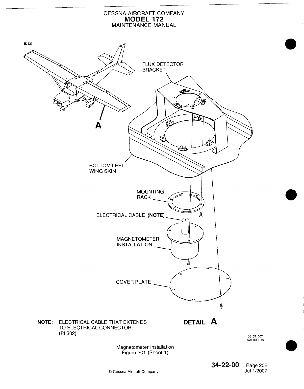
CESSNA AIRCRAFT
COMPANY
MODEL
172
MAINTENANCE
MANUAL
FLUX
DETECTOR
BRACKET
A
BOTTOM
LEFT
WING
SKIN
RACK
ELECTRICAL
CABLE
(NOTE)
MAGNETOMETER
INSTALLATION-
COVER
PLATE
NOTE:
ELECTRICAL
CABLE
THAT
EXTENDS
TO
ELECTRICAL
CONNECTOR.
(PL302)
DETAIL
A
0510T
1007
A0518T1
1 10
Magnetomneter
Installation
Figure
201
(Sheet
1)
34-22-00
C
Cessna
Aircraft
Company
Page
202
Jul
1/2007
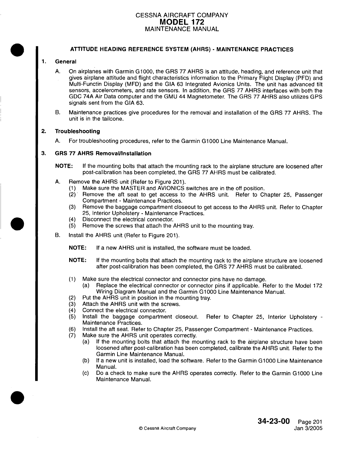
CESSNA
AIRCRAFT
COMPANY
MODEL
172
MAINTENANCE
MANUAL
ATTITUDE
HEADING
REFERENCE
SYSTEM
(AHRS)
-
MAINTENANCE
PRACTICES
1.
General
A.
On
airplanes
with Garmin G1000,
the
GRS
77
AHRS
is
an
attitude, heading,
and
reference
unit
that
gives
airplane attitude
and
flight
characteristics
information
to
the
Primary
Flight
Display
(PFD) and
Multi-Functin
Display
(MFD)
and
the
GIA
63
Integrated
Avionics
Units.
The
unit
has
advanced
tilt
sensors,
accelerometers,
and
rate
sensors.
In
addition,
the
GRS
77
AHRS
interfaces
with
both
the
GDC
74A
Air
Data
computer
and the
GMU
44
Magnetometer. The
GRS
77
AHRS
also utilizes
GPS
signals sent
from
the
GIA
63.
B.
Maintenance
practices
give
procedures
for
the removal and
installation
of
the
GRS
77
AHRS.
The
unit
is
in
the
tailcone.
2.
Troubleshooting
A.
For
troubleshooting
procedures,
refer
to
the Garmin
G1000
Line
Maintenance
Manual.
3.
GRS
77
AHRS
Removal/Installation
NOTE:
If
the
mounting
bolts
that
attach
the
mounting
rack
to the
airplane
structure
are
loosened
after
post-calibration
has
been
completed,
the
GRS
77
AHRS
must
be
calibrated.
A.
Remove
the
AHRS
unit
(Refer
to
Figure
201).
(1)
Make
sure
the
MASTER
and
AVIONICS
switches
are
in
the
off
position.
(2)
Remove
the
aft
seat
to
get
access
to
the
AHRS
unit.
Refer
to
Chapter
25,
Passenger
Compartment
-
Maintenance Practices.
(3)
Remove
the
baggage
compartment
closeout
to
get
access
to
the
AHRS
unit. Refer
to
Chapter
25,
Interior Upholstery
-
Maintenance
Practices.
(4)
Disconnect
the
electrical
connector.
(5)
Remove
the
screws
that
attach the
AHRS
unit to
the mounting
tray.
B.
Install
the
AHRS
unit
(Refer
to
Figure
201).
NOTE:
If
a
new AHRS unit
is
installed,
the
software must
be
loaded.
NOTE:
If
the
mounting
bolts
that attach
the
mounting
rack
to
the
airplane structure
are
loosened
after
post-calibration
has
been
completed, the
GRS
77
AHRS
must
be
calibrated.
(1)
Make
sure
the
electrical
connector
and
connector
pins
have
no
damage.
(a)
Replace
the
electrical
connector
or
connector
pins
if
applicable.
Refer
to
the
Model
172
Wiring
Diagram
Manual
and the
Garmin G1000
Line
Maintenance Manual.
(2)
Put
the
AHRS
unit
in
position
in
the mounting
tray.
(3)
Attach
the AHRS
unit with
the
screws.
(4)
Connect
the electrical
connector.
(5)
Install
the
baggage
compartment
closeout.
Refer
to
Chapter
25,
Interior Upholstery
-
Maintenance
Practices.
(6)
Install
the
aft
seat.
Refer
to
Chapter
25,
Passenger
Compartment
-
Maintenance Practices.
(7)
Make
sure
the
AHRS
unit
operates
correctly.
(a) If
the
mounting bolts
that
attach
the
mounting
rack
to the
airplane structure have
been
loosened after
post-calibration
has
been
completed,
calibrate
the
AHRS
unit.
Refer
to
the
Garmin
Line
Maintenance
Manual.
(b) If
a
new
unit
is
installed,
load
the
software. Refer
to
the Garmin
G1000
Line
Maintenance
Manual.
(c)
Do
a
check
to
make
sure
the
AHRS
operates
correctly.
Refer
to
the
Garmin G1000 Line
Maintenance
Manual.
34-23-00
Page
201
©
Cessna Aircraft
Company
Jan
3/2005
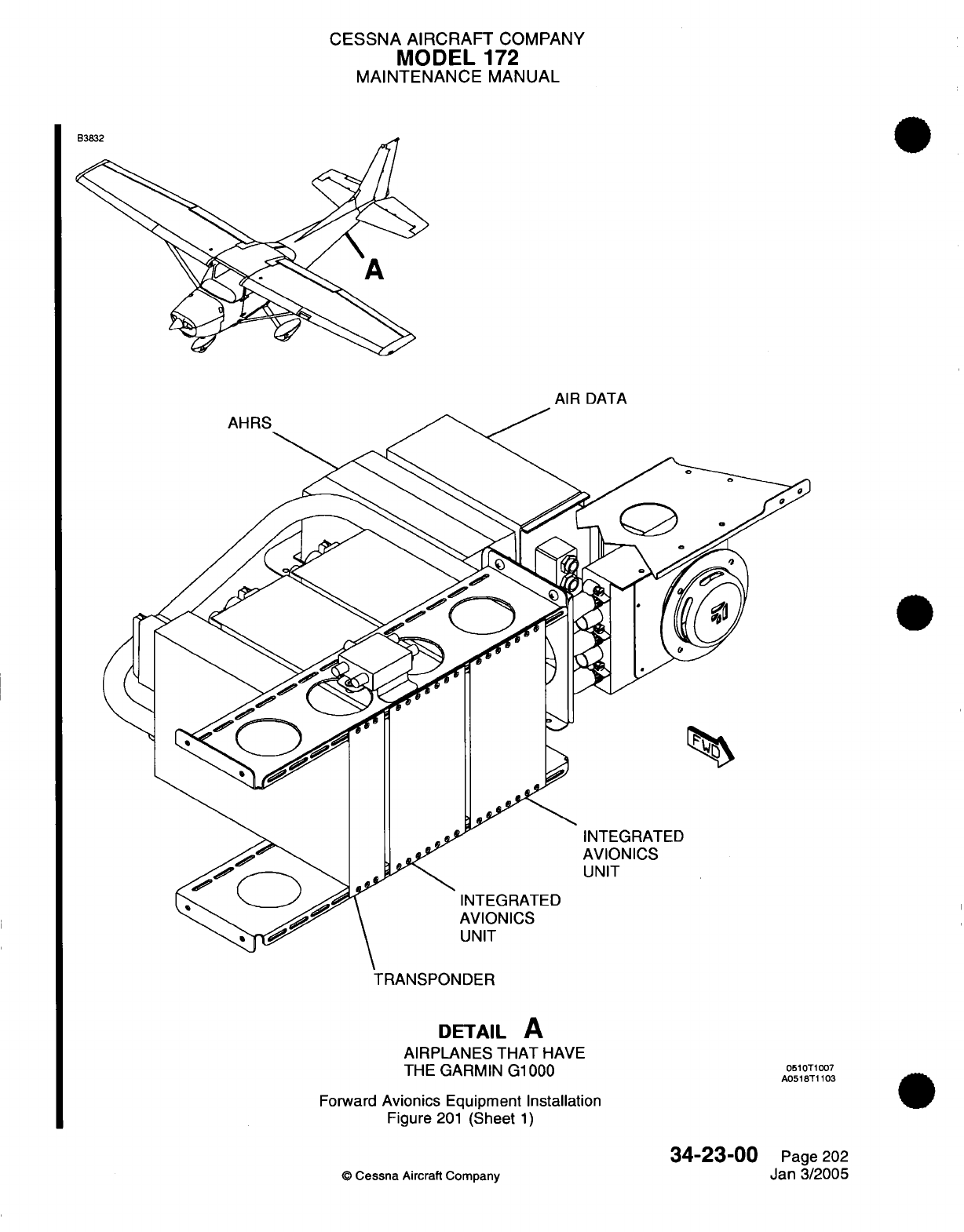
CESSNA
AIRCRAFT
COMPANY
MODEL
172
MAINTENANCE
MANUAL
AIR
DATA
TRANSPONDER
DETAIL
A
AIRPLANES
THAT
HAVE
THE
GARMIN G1000
Forward
Avionics
Equipment Installation
Figure
201
(Sheet
1)
34-23-00
©
Cessna
Aircraft
Company
0510T1007
A0518T1103
Page
202
Jan
3/2005
CESSNA
AIRCRAFT
COMPANY
MODEL
1
72
MAINTENANCE
MANUAL
4.
AHRS
and
Magnetometer
Checkout
Procedure
A.
Checkout
Instructions
NOTE:
The
installation
and
verification
of the
system
software must
be
completed before
the
AHRS
and
magnetometer
checks
can
be
done.
(1)
Use
the
Garmin
GRS 77/GMU
44
Installation
Manual
(P/N
190-00303-10)
to
do
the
check.
B.
Post
Installation Calibration Procedures
(1)
Read
Section
5.2
in
the
Garmin GRS 77/GMU
44
Installation
Manual
(P/N
190-00303-10).
NOTE:
The Garmin
Calibration Procedures
A-1,
B,
and
D
must
be
fully
completed.
(2)
Do
the Calibration Procedure
A-1
in
Section
5.3
of the
Garmin
GRS 77/GMU
44
Installation
Manual.
(a)
Make
the
wings
level
to
0
degrees, +0.25
or -0.25
degrees.
Refer
to
Chapter
8,
Leveling
-
Maintenance
Practices.
(b)
Make
the
airplane
nose
up
2
degrees,
+0.25
or
-0.25
degrees.
Refer
to
Chapter
8,
Leveling
-
Maintenance
Practices.
(c)
Do
the
calibration
procedure.
(3)
Do
the
Calibration
Procedure
B in
Section
5.5
of
the
Garmin GRS
77/GMU
44
Installation
Manual.
(4)
Do
the
Calibration Procedure
D in
Section
5.7
of
the
Garmin
GRS
77/GMU 44
Installation
Manual.
34-23-00
Page
203
©
Cessna
Aircraft
Company
Jan
3/2005
CESSNA
AIRCRAFT
COMPANY
MODEL
172
MAINTENANCE
MANUAL
MARKER
BEACON
-
MAINTENANCE
PRACTICES
1.
General
A.
Maintenance
practices
have
procedures
for
the
removal
and
installation
of
the
audio
panel and
marker
beacon
antenna.
2.
Audio
Panel
Removal/Installation
A.
For
removal
and
installation
of the
audio
panel, refer
to
Chapter
23,
Audio Panel
-
Maintenance
Practices.
3.
Marker Beacon
Antenna
Removal/Installation
A.
Remove
the
Marker
Beacon
Antenna
(Refer
to
Figure
201).
(1)
Make
sure
the
AVIONICS
and
MASTER
switches
are
in
the off
position.
(2)
Remove
the
baggage compartment
lower
access
panel.
Refer
to
Chapter
25,
Interior Upholstery
-
Maintenance
Practices.
(3)
Remove
the aft
floorboard
access/inspection
plate
to
get access
to
the
marker
beacon
antenna.
(4)
Disconnect
the
coaxial
cable
from
the antenna.
CAUTION:
Be
careful when
you
remove
the
screws
from
the
antenna.
It
can
fall
to
the ground
and
as
a
result,
be
damaged.
(5)
Remove
the
screws
that
attach
the
antenna
to
the
bottom
of the
fuselage.
B.
Install the
Marker
Beacon
Antenna
(Refer
to
Figure
201).
(1)
Put
the
marker beacon antenna
in
position
on the
bottom
of
the
fuselage.
(2)
Attach
the
antenna
with
the
screws.
(3)
Attach
the
coaxial
cable
to
the
antenna.
(4)
Install
the
access/inspection
plate
to
the
floor
of
airplane.
(5)
Install
the
baggage
compartment
lower
access
panel.
Refer
to
Chapter 25,
Interior Upholstery
-
Maintenance
Practices.
34-30-00
©
Cessna
Aircraft
Company
Page
201
Jan
3/2005
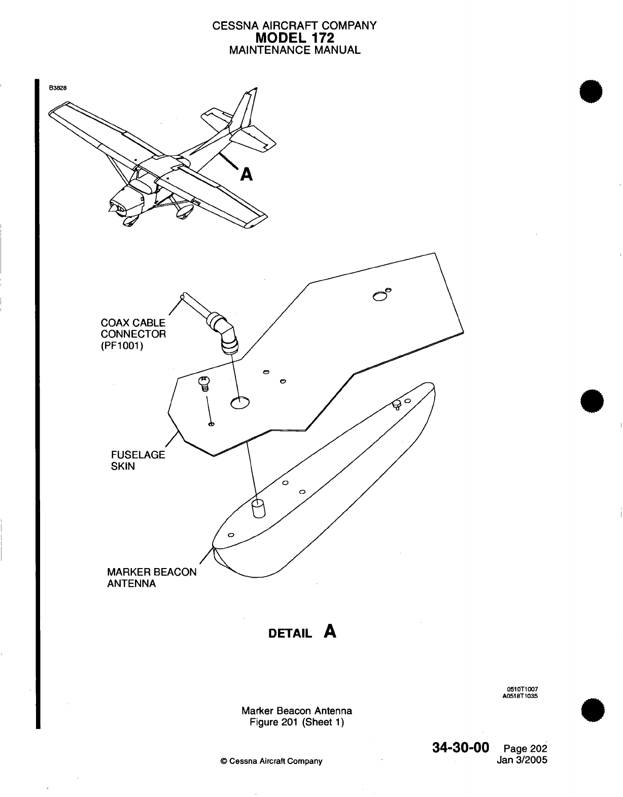
CESSNA AIRCRAFT
COMPANY
MODEL
172
MAINTENANCE
MANUAL
COAX CABLE
CONNECTOF
(PF1001)
FUSELAGE
SKIN
MARKER
BE
ANTENNA
DETAIL
A
0510T1007
A0518T1035
Marker
Beacon
Antenna
Figure
201
(Sheet
1)
34-30-00
©
Cessna
Aircraft Company
Page
202
Jan
3/2005
- ---
CESSNA
AIRCRAFT
COMPANY
MODEL
172
MAINTENANCE
MANUAL
NAV/COM
-
MAINTENANCE
PRACTICES
1.
General
A.
Nav/Com
maintenance
practices
is
primarily
concerned
with
navigation
hardware
removal/installation.
For
removal/installation
of
the
KX155A
radio,
refer
to
Chapter
23,
Communications
-
Maintenance
Practices.
CAUTION:
Do
not
interchange
the
KX-155A
and
KX-165A
NAV/COM
Radios.
You
can
cause
damage
to
the NAV/COM
Radio.
2.
Nav
Antenna
Removal/Installation
A.
Remove
Nav
Antenna (Refer
to
Figure
201).
(1)
Remove
boots
over
antenna
rods.
(2)
Remove
antenna
rods
by
threading
from
base.
(3)
Remove
fin
cap
assembly.
(4)
Remove
screws securing
antenna
base
to
vertical
fin.
(5)
Remove
antenna
base
and
disconnect
coax
connector.
B.
Install Nav
Antenna
(Refer
to
Figure
201).
(1)
Connect
coax
connector
to
antenna
base.
(2)
Secure
antenna
base
to
vertical
fin
with
screws.
(3)
Install
fin
cap
assembly.
(4)
Thread
antenna
rods
into base.
(5)
Install
boots
over
antenna
rods.
3.
Nav
Antenna
Coupler
Removal/Installation
A.
Remove
Nav
Antenna
Coupler
(Refer
to
Figure
201).
(1)
Label
and
disconnect
antenna
coax connectors
from nav
antenna coupler.
(2)
Remove
screws
securing
nav
antenna
coupler
to
fuselage.
(3)
Remove
nav
antenna coupler.
B.
Install
Nav
Antenna
Coupler
(Refer
to Figure
201).
(1)
Place
nav
antenna
coupler
on
fuselage
and
secure
with
screws.
(2)
Connect
antenna
coax
connectors
to nav
antenna
coupler.
4.
Nav
Indicator Removal/Installation
A.
Remove
Nav
Indicator.
(1)
Remove
screws
securing
right
instrument
sub-panel
to
instrument
panel.
(2)
Disconnect
electrical connector
from
nav
indicator.
(3)
Remove
screws
securing
nav
indicator
to
right
instrument
sup-panel.
(4)
Remove
nav
indicator.
B.
Install
Nav
Indicator.
(1)
Place
nav
indicator
on
right
instrument
sub-panel
and
secure
with
screws.
(2)
Install
electrical
connector
to nav
indicator.
(3)
Secure
right
instrument sub-panel to instrument
panel
with
screws.
34-50-00
Page
201
©
Cessna
Aircraft
Company
Jul
1/2005
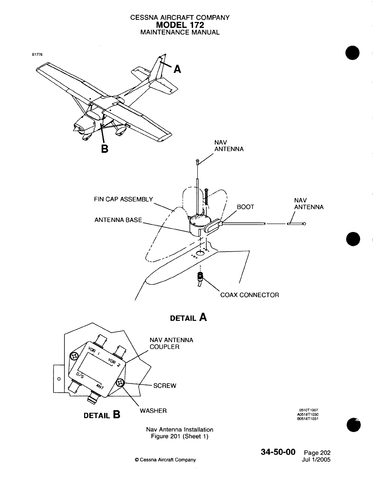
CESSNA AIRCRAFT
COMPANY
MODEL
172
MAINTENANCE
MANUAL
ut
NAV
ANTENNA
I
FIN
CAP
ASSE
ANTENNA
BA?
DETAIL
A
4AV
ANTENNA
JOUPLER
SCREW
WASHER
Nav
Antenna Installation
Figure
201
(Sheet
1)
©
Cessna
Aircraft
Company
051
OT1007
A0518T1030
B0518T1031
34-50-00
Page
202
Jul
1/2005
(
NAV
ANTENNA
,__L
NECTOR
DETAIL
B
rl ware
L
CESSNA AIRCRAFT
COMPANY
MODEL
172
MAINTENANCE
MANUAL
GIA
63
INTEGRATED
AVIONICS
INSTALLATION
-
MAINTENANCE
PRACTICES
1.General
A.
Two
GIA
63
Integrated Avionics
Units (IAU's) are
on
the
avionics shelf
in
the
tailcone.
B.
The
units
have
the
communication
and
navigation
receiver/transmitter
components
to
operate
the
GPS,
NAy, COM,
and
Glideslope
functions.
The
GIA
63W
has
the
Wide
Area
Augmentation
System
(WAAS)
installed. The
units
are
integrated
components
of
the
Garmin
G
1000
avionics
system.
2.
Troubleshooting
A.
For
troubleshooting
procedures,
refer
to
the Garmin
Gi
000
Line
Maintenance
Manual.
3.
GIA 63
Integrated
Avionics
Unit
Removal/installation
A.
Remove
the
Integrated Avionics
Unit.
(1)
Refer
to
Chapter
23,
Communications
-
Maintenance
Practices
(D
Cessna
Aircraft
Company
34-50-1
0
Page
201
Janl1/2007
I
CESSNA
AIRCRAFT
COMPANY
MODEL
172
MAINTENANCE
MANUAL
GPS
-
MAINTENANCE
PRACTICES
1.
General
A.
The
KLN89B
or
the
optional
KLN94GPS
is
installed
in
the
avionics
panel
radio
rack.
The
GPS antenna
is
mounted above
the
cabin,
in
the general
proximity
of
the
comm
antennas.
2.
GPS
Removal/Installation
A.
Remove
GPS
(Refer
to
Figure 201).
(1)
Loosen
single locking
screw
located
in
recessed
hole
on
face
of
receiver.
(2)
Pull
GPS from
radio
rack.
B.
Install
GPS
(Refer
to
Figure
201).
(1)
Place GPS
in
radio
rack
and
slide forward,
engaging
fixed electrical
plug.
(2)
Tighten
single locking
screw
located
in
recessed
hole
on
face
of
receiver.
3.
GPS
Antenna
Removal/Installation
A.
Remove
GPS
Antenna (Refer to
Figure
201
).
(1)
Remove
screws
securing
GPS
antenna
to
fuselage
skin.
(2)
Disconnect
coax
connector
from
GPS
antenna.
(3)
Remove
antenna
and
gasket.
B.
Install
GPS
Antenna (Refer
to Figure
201).
(1)
Place GPS
antenna gasket
in
position
on
fuselage skin.
(2)
Connect
coax
connector
to
GPS
antenna.
(3)
Secure
GPS
antenna
to
fuselage
skin with
screws.
©
Cessna
Aircraft
Company
34-51-00
Page
201
Apr 7/2003
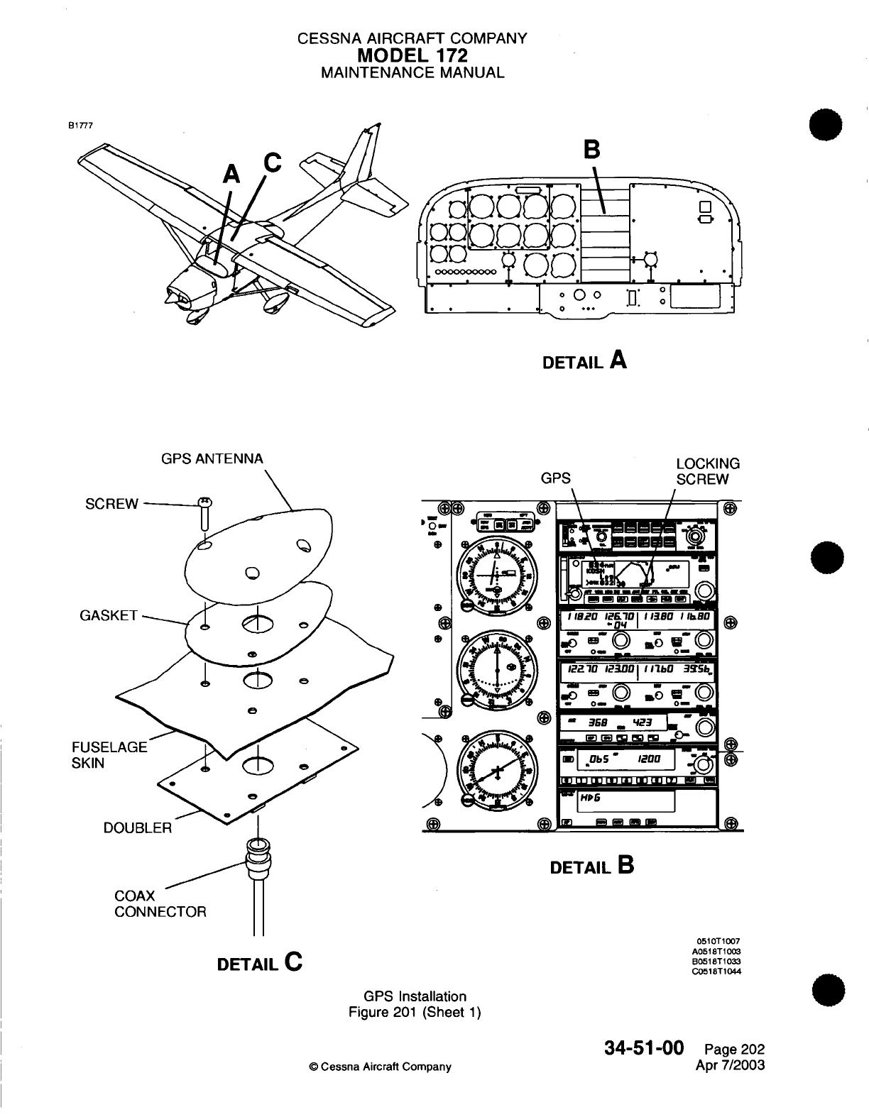
CESSNA
AIRCRAFT
COMPANY
MODEL
172
MAINTENANCE
MANUAL
B1777
B
\
-
QO.QO
o
..--
:'
.
].
O
:.n:
:
f
.
*
*H
. .
0
...
DETAIL
A
GPS
ANTENNA
\
/
0-
0i
rI.
70
i
l
lIbO
34Ibj
'1 0 "°
0
365 _
23
L
2
IU
UHLuIa JMUULZ J I
-
m |HP6 MO
3e
M O
M
GPS
Installation
Figure
201
(Sheet
1)
34-51-00
©
Cessna
Aircraft Company
SC
GA'
GPS LOCKING
SCREW
0
FUSE
SKIN
S
00)
DETAIL
B
DETAIL
C
0510T1007
A0518T1003
B0518T1033
C0518T1044
Page 202
Apr
7/2003
._
(9
r
II clr
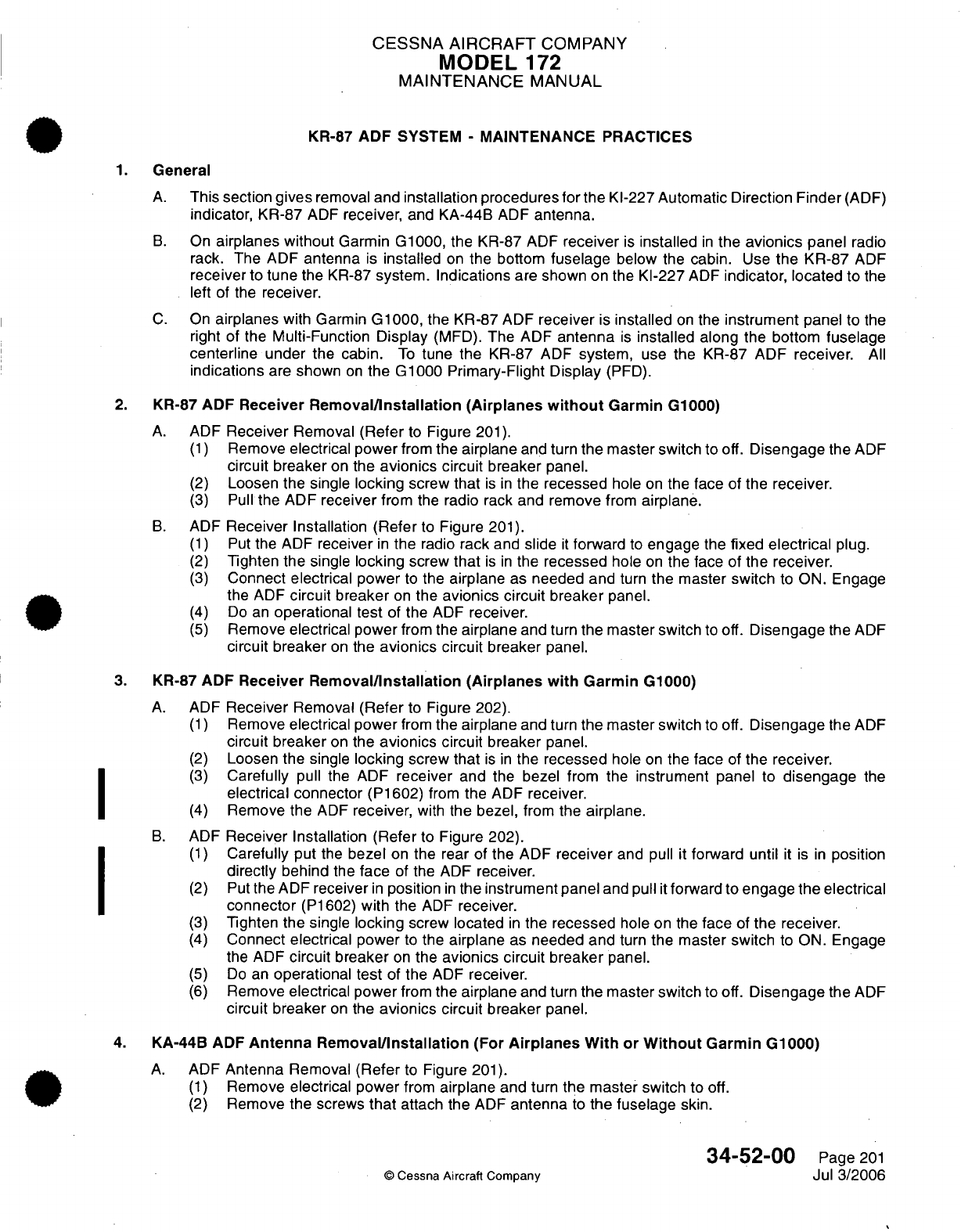
CESSNA
AIRCRAFT
COMPANY
MODEL
172
MAINTENANCE
MANUAL
KR-87
ADF
SYSTEM
-
MAINTENANCE
PRACTICES
1.
General
A.
This
section
gives
removal
and
installation procedures
for
the
Kl-227 Automatic
Direction
Finder
(ADF)
indicator,
KR-87
ADF
receiver,
and KA-44B
ADF
antenna.
B.
On
airplanes without
Garmin
G1000,
the KR-87 ADF
receiver
is
installed
in
the
avionics
panel
radio
rack. The
ADF
antenna
is
installed
on
the
bottom
fuselage
below the
cabin.
Use
the
KR-87
ADF
receiver
to
tune
the
KR-87
system.
Indications
are shown
on the
Kl-227
ADF
indicator,
located
to
the
left
of the
receiver.
C.
On
airplanes
with
Garmin
G1000,
the
KR-87
ADF
receiver
is
installed
on
the
instrument
panel
to
the
right of the
Multi-Function Display
(MFD).
The
ADF
antenna
is
installed
along
the bottom
fuselage
centerline
under
the cabin.
To
tune
the
KR-87
ADF
system,
use
the
KR-87
ADF
receiver.
All
indications
are
shown
on
the
G1000 Primary-Flight Display
(PFD).
2.
KR-87
ADF Receiver
Removal/Installation
(Airplanes
without
Garmin G1000)
A.
ADF
Receiver
Removal
(Refer
to
Figure
201).
(1)
Remove
electrical
power
from
the
airplane
and
turn
the
master switch
to off.
Disengage
the
ADF
circuit
breaker
on
the
avionics
circuit
breaker
panel.
(2)
Loosen
the single
locking
screw
that
is in
the
recessed
hole on
the face
of
the
receiver.
(3)
Pull
the
ADF
receiver
from
the
radio rack and
remove
from
airplane.
B.
ADF
Receiver
Installation
(Refer
to
Figure
201).
(1)
Put
the
ADF
receiver
in
the
radio
rack
and
slide
it
forward
to
engage
the
fixed
electrical
plug.
(2)
Tighten the
single
locking
screw
that
is in
the
recessed
hole
on
the
face
of
the
receiver.
(3)
Connect
electrical
power
to
the
airplane
as
needed and
turn
the master
switch
to
ON.
Engage
the
ADF
circuit breaker
on
the
avionics
circuit
breaker
panel.
(4)
Do
an
operational test
of the
ADF
receiver.
(5)
Remove
electrical power
from
the
airplane
and
turn
the master switch
to
off.
Disengage
the
ADF
circuit
breaker
on
the
avionics
circuit
breaker
panel.
3.
KR-87
ADF Receiver
Removal/Installation
(Airplanes
with
Garmin G1000)
A.
ADF
Receiver
Removal
(Refer
to
Figure
202).
(1)
Remove
electrical
power
from
the
airplane
and
turn
the
master
switch
to
off.
Disengage
the
ADF
circuit
breaker
on
the
avionics
circuit
breaker
panel.
(2)
Loosen
the single
locking
screw
that
is in
the
recessed
hole
on
the face
of
the
receiver.
(3)
Carefully
pull
the
ADF
receiver
and the bezel from the
instrument
panel
to
disengage
the
electrical connector
(P1602)
from
the
ADF
receiver.
(4)
Remove
the
ADF
receiver,
with
the
bezel,
from
the
airplane.
B.
ADF
Receiver
Installation (Refer
to
Figure
202).
(1)
Carefully put
the
bezel
on
the rear
of
the
ADF
receiver
and
pull
it
forward
until
it
is
in
position
directly
behind
the
face
of the
ADF
receiver.
(2)
Put
the ADF
receiver
in
position
in
the
instrument
panel
and
pull
it
forward
to
engage the
electrical
connector
(P1602)
with the
ADF
receiver.
(3)
Tighten
the single
locking
screw
located
in
the
recessed
hole on the
face
of
the
receiver.
(4)
Connect
electrical
power
to
the
airplane
as
needed and
turn
the master
switch
to
ON.
Engage
the
ADF
circuit breaker
on
the
avionics
circuit
breaker
panel.
(5)
Do
an
operational
test
of
the
ADF
receiver.
(6)
Remove
electrical power
from
the
airplane
and
turn
the
master
switch
to off.
Disengage the
ADF
circuit
breaker
on
the
avionics
circuit breaker
panel.
4.
KA-44B
ADF
Antenna
Removal/Installation
(For
Airplanes With
or
Without
Garmin G1000)
A.
ADF
Antenna
Removal
(Refer
to
Figure
201).
(1)
Remove
electrical
power
from
airplane
and
turn
the
master
switch
to off.
(2)
Remove
the
screws
that
attach
the
ADF
antenna
to
the
fuselage
skin.
34-52-00
Page
201
©
Cessna
Aircraft
Company
Jul
3/2006

CESSNA AIRCRAFT
COMPANY
MODEL
172
MAINTENANCE
MANUAL
B-AM 0
--
|
-w
_0- _ 0-
_
K1-227
ADF
INDICATOR
SKIN
KR-87
ADF
RECEIVER
LUUI;INU
INBOARD
SCREW
PANEL
ASSEMBLY
SPACER
DETAIL
A
AIRPLANES
WITHOUT
GARMIN
G1000
KA-44B
ADF
ANTENNA
RICAL
ECTOR
\\
§TI
G.
SCREW
|
DETAIL
B
ASKET
0510T1007
A0518T1033
B0518T1043
KR-87
ADF
Installation
Figure
201
(Sheet
1)
34-52-00
©
Cessna
Aircraft
Company
B
Page
202
Jul
3/2006
E
I
._ _)
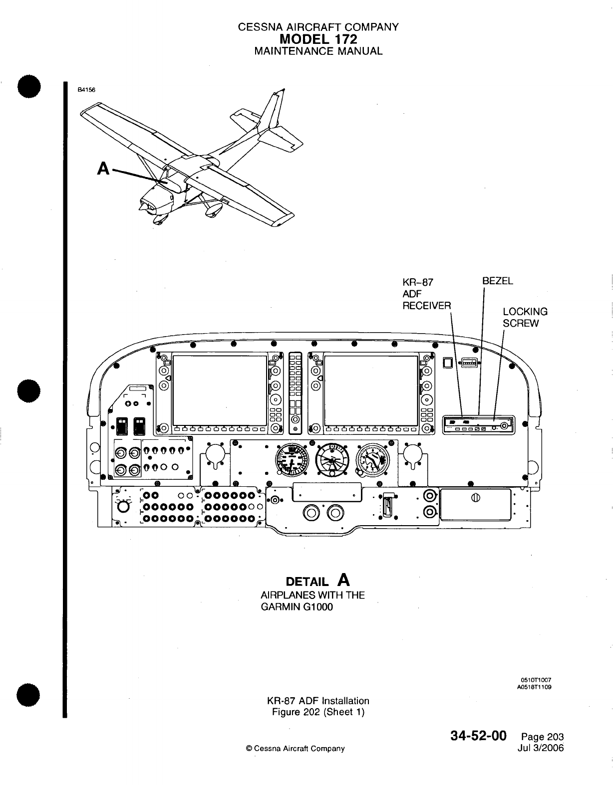
CESSNA
AIRCRAFT
COMPANY
MODEL
172
MAINTENANCE
MANUAL
c
o
O0
bobbboo00
oaooaoooa~ooa
(g
00
Do
00
00
00
1:3
00
00
-©
* P
00
00
r!c 6 !t t
no
o
0
®D
1
DETAIL
A
AIRPLANES
WITH
THE
GARMIN
G1000
0510T1007
A0518T1109
KR-87
ADF
Installation
Figure
202 (Sheet
1)
34-52-00
©
Cessna
Aircraft
Company
Page 203
Jul
3/2006
KR-87
ADF
RECEIVER
BEZEL
I
r1VI
K'I
r
C' ^ooo
o
.
/~
,ooooo
,00
oo0
^a.
.000000
A
..
_
A
I
wl
l
.3
CESSNA
AIRCRAFT
COMPANY
MODEL
172
MAINTENANCE
MANUAL
(3)
(4)
Disconnect the
antenna
connector
(PC600)
from
the
ADF
antenna.
Remove
the
antenna
and the
gasket.
B.
ADF
Antenna Installation
(Refer
to
Figure
201).
(1)
Connect
the
electrical
connector
(PC600)
to
the
ADF
antenna.
(2)
Attach
the
ADF
antenna
to the
fuselage
skin
with
the
screws.
5.
Kl-227
ADF
Indicator Removal/Installation
A.
ADF
Indicator
Removal (Refer
to
Figure
201).
(1)
Remove
electrical power
from
airplane and
set
the
MASTER
switch
to
the
off
position.
(2)
Remove
the
inboard
pilot panel
assembly
to
gain
access
to the
ADF
indicator. Refer
to
Chapter
31,
Instrument
and
Control
Panels
-
Maintenance Practices.
(3)
Disconnect
the
electrical
connector
(P1603)
from
the
ADF
indicator.
(4)
Remove
the screws
that
attach
the
ADF
indicator
to the
inboard
pilot
panel
assembly.
(5)
Remove
the
ADF
indicator
from
the
airplane.
ADF
Indicator Installation
(Refer
to
Figure
201).
(1)
Put the
ADF
indicator
on
the inboard
pilot
panel
assembly
and
attach
with
the
screws.
(2)
Connect
the
electrical
connector
(P1603)
to
the
ADF
indicator.
(3)
Attach the
inboard pilot
panel
assembly
to
the
structure
with
the
screws. Refer
to
Chapter
31,
Instrument and
Control
Panels
-
Maintenance Practices.
(4)
Connect
power
and
set
the
MASTER
switch
to
the
ON
position.
34-52-00
Page
204
©
Cessna
Aircraft
Company
Jul 3/2006
B.
CESSNA
AIRCRAFT
COMPANY
MODEL
1
72
MAINTENANCE
MANUAL
KT76C
TRANSPONDER
-
MAINTENANCE
PRACTICES
1.
General
A.
The
KT76C
transponder
is
in
the
avionics
panel radio rack.
The
transponder
antenna
is
on
the bottom
of
the
cabin forward
of
the
baggage area.
2.
Transponder
Removal/nstallation
A.
Remove
the
Transponder
(Refer
to
Figure
201).
(1)
Loosen
the locking screw
found
in
the
recessed
hole
on
the
face
of the
receiver.
(2)
Pull
the
transponder
from
the
radio
rack.
B.
Install
the
Transponder
(Refer
to Figure
201).
(1)
Put
the
transponder
in
the radio rack
and
move
it
forward
to
engage
the
electrical
plug.
(2)
Tighten
the
locking
screw
found
in
the
recessed
hole
on
the
face
of
the
receiver.
3.
Transponder
Antenna
Removal/Installation
A.
Remove
the
Transponder Antenna
(Refer
to
Figure
201).
(1)
Remove
the
aft
cabin
panel
to
get
access
to the
tailcone
and
transponder
antenna.
(2)
Remove
the
nuts
and
washers that
attach
the
transponder
antenna
to
the
tailcone.
(3)
From
outside
the
airplane,
disconnect
the
coax
connector.
B.
Install the
Transponder
Antenna
(Refer
to
Figure
201).
(1)
From
outside
the
airplane,
connect
the
coax
connector
to the
transponder antenna.
(2)
From
the
tailcone,
put the
antenna
studs through the
mounting
holes
and
attach
with
the
nuts
and
washers.
34-53-00
Page
201
©
Cessna Aircraft Company
Jan
3/2005
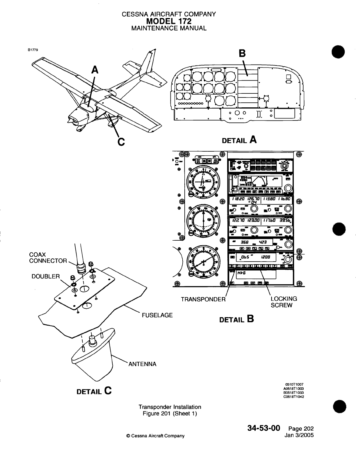
CESSNA AIRCRAFT
COMPANY
MODEL
172
MAINTENANCE
MANUAL
B
1o'
y0o
* ..
*. * -
DETAIL
A
I
wea ier,,
I.
a\
usu,
,,.a I
a
I
- - --
0-
m
|122
70
I1230
I
I
IllbO
Ii3a
I
-
G
o3
L 0-
CO
CO
DC
)
TRANSPOND
-LAGE
I
.-
N
'-
.,,,- 2,, '.--'--
1l1
vi I
11
11111.
1
&I11 1 [G I 1
M
7'H""
\
I
-~~~^^
7F^rF
\
ER
LOCKING
SCREW
DETAIL
B
0510T1007
A0518T1003
B0518T1033
C0518T1042
Transponder
Installation
Figure
201
(Sheet
1)
34-53-00
©
Cessna
Aircraft Company
Page
202
Jan
3/2005
B1779
DETAIL
C
I
----- I
--- .
'n'
i4
'
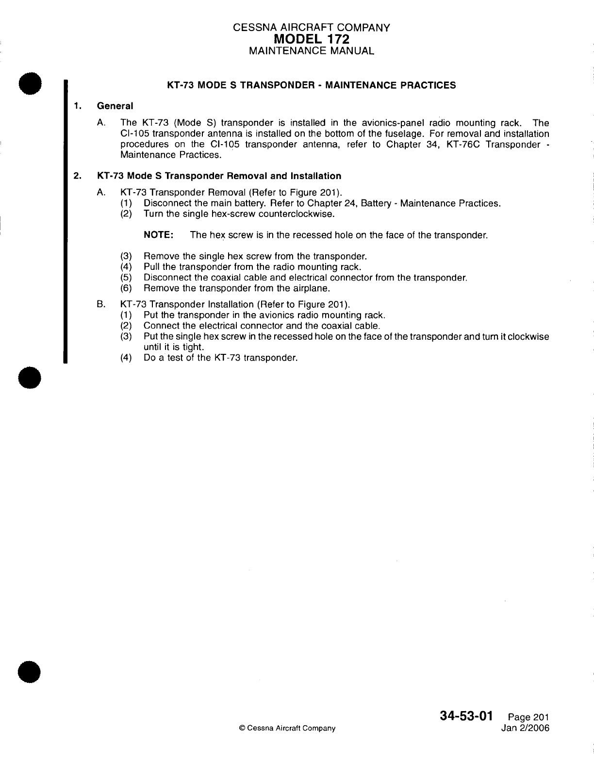
CESSNA
AIRCRAFT
COMPANY
MODEL
172
MAINTENANCE
MANUAL
KT-73
MODE
S
TRANSPONDER
-
MAINTENANCE
PRACTICES
1.
General
A.
The
KT-73 (Mode
S)
transponder
is
installed
in
the
avionics-panel
radio
mounting
rack.
The
Cl-105
transponder
antenna
is
installed
on the
bottom
of
the
fuselage.
For
removal
and
installation
procedures
on
the
CI-105
transponder
antenna,
refer
to
Chapter
34,
KT-76C
Transponder
-
Maintenance Practices.
2.
KT-73
Mode
S
Transponder
Removal
and
Installation
A.
KT-73
Transponder
Removal
(Refer
to
Figure
201).
(1)
Disconnect
the
main
battery.
Refer
to
Chapter
24,
Battery
-
Maintenance
Practices.
(2)
Turn
the
single
hex-screw
counterclockwise.
NOTE:
The
hex screw
is
in
the
recessed
hole
on
the
face
of
the
transponder.
(3)
(4)
(5)
(6)
Remove
the
single
hex
screw
from
the
transponder.
Pull
the
transponder
from
the
radio
mounting
rack.
Disconnect
the coaxial cable
and
electrical connector
from
the
transponder.
Remove
the
transponder
from
the
airplane.
B.
KT-73
Transponder
Installation
(Refer
to
Figure
201).
(1)
Put
the
transponder
in
the
avionics
radio
mounting
rack.
(2)
Connect
the
electrical connector
and the
coaxial
cable.
(3)
Put
the
single
hex
screw
in
the recessed
hole
on
the
face
of
the
transponder
and
turn
it
clockwise
until
it
is
tight.
(4)
Do
a
test
of
the
KT-73
transponder.
34-53-01
Page
201
©
Cessna Aircraft
Company
Jan
2/2006
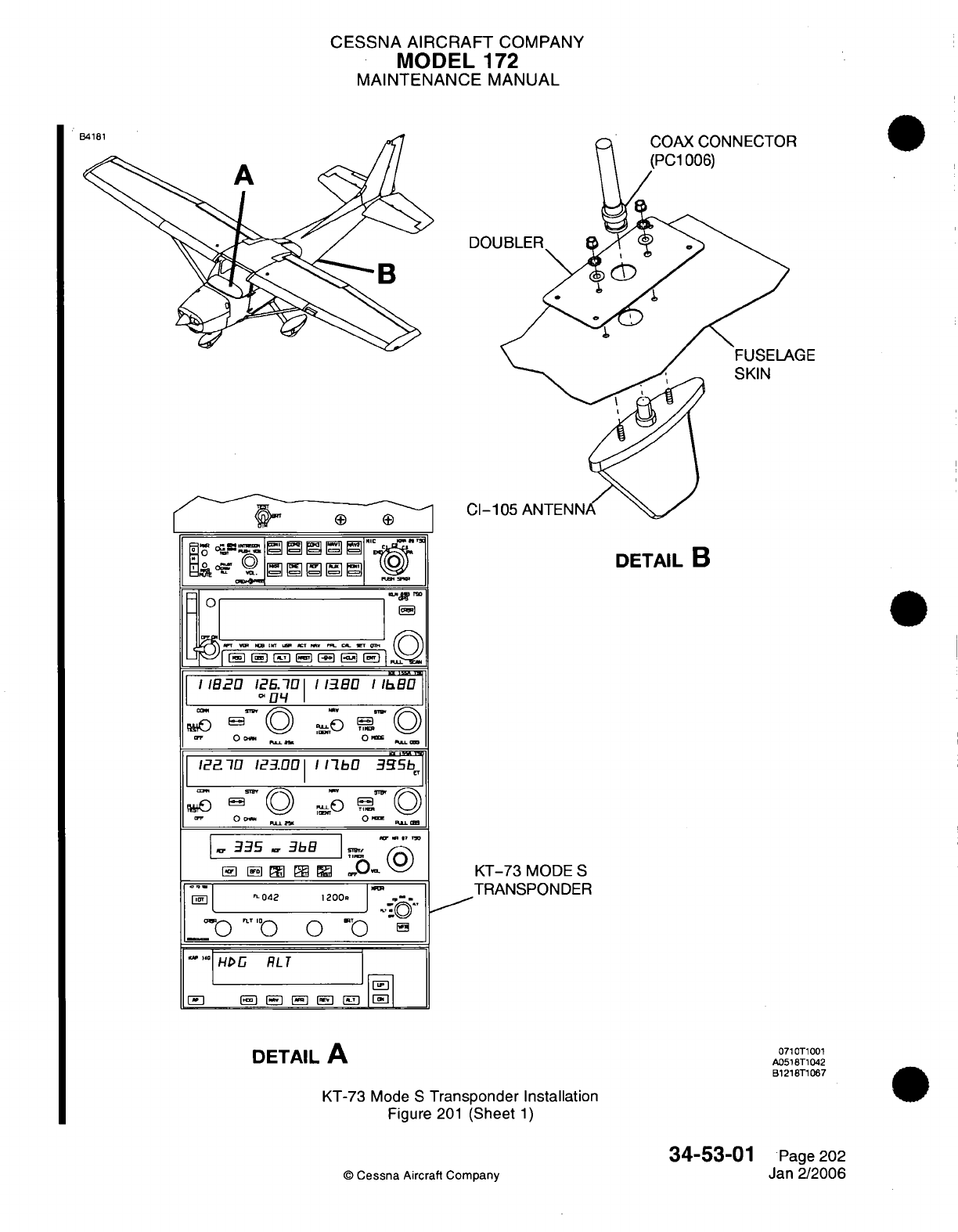
CESSNA
AIRCRAFT
COMPANY
MODEL
172
MAINTENANCE
MANUAL
DETAIL
B
KT-73
MODE
S
1
TRANSPONDER
H
RL
0710T1001
DETAIL
A
B121BT1
067
KT-73
Mode S
Transponder
Installation
Figure
201
(Sheet
1)
34-53-01
Page
202
n
Aircraft
Companv
Jan
2/2006
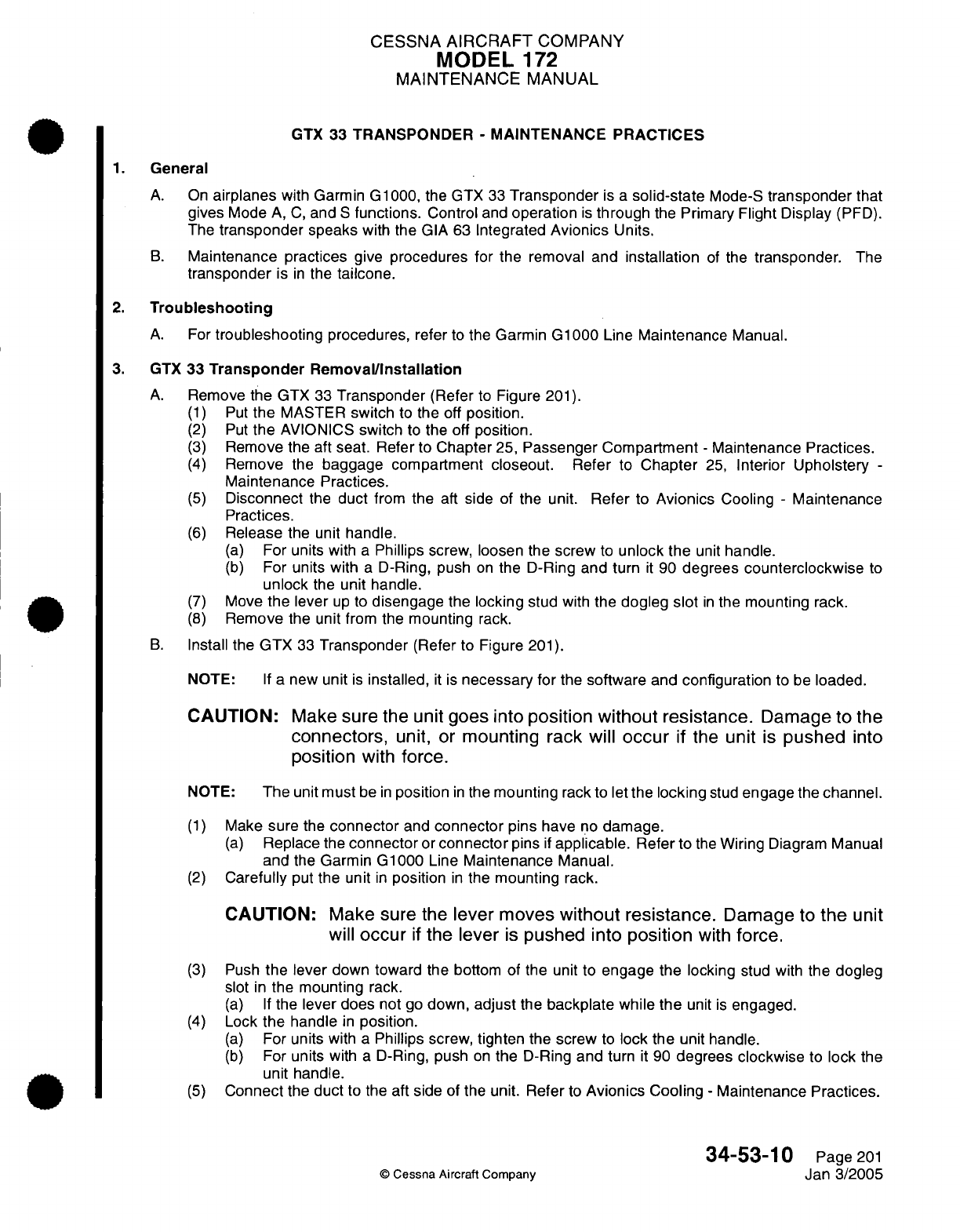
CESSNA
AIRCRAFT
COMPANY
MODEL
172
MAINTENANCE
MANUAL
GTX
33
TRANSPONDER
-
MAINTENANCE PRACTICES
1.
General
A.
On
airplanes
with
Garmin
G1000, the
GTX
33
Transponder
is
a
solid-state
Mode-S
transponder
that
gives
Mode
A,
C,
and
S
functions.
Control
and
operation
is
through
the
Primary
Flight
Display
(PFD).
The
transponder
speaks
with
the GIA
63
Integrated
Avionics
Units.
B.
Maintenance practices
give
procedures for
the
removal
and
installation
of
the
transponder.
The
transponder
is
in
the
tailcone.
2.
Troubleshooting
A.
For
troubleshooting
procedures,
refer
to
the
Garmin
G1000
Line
Maintenance
Manual.
3. GTX
33
Transponder Removal/Installation
A.
Remove
the
GTX
33
Transponder
(Refer
to
Figure
201).
(1)
Put
the
MASTER
switch
to
the
off
position.
(2)
Put
the
AVIONICS
switch
to
the off
position.
(3)
Remove
the
aft
seat.
Refer
to
Chapter
25,
Passenger Compartment
-
Maintenance
Practices.
(4)
Remove
the
baggage compartment
closeout.
Refer
to
Chapter
25,
Interior
Upholstery
-
Maintenance
Practices.
(5)
Disconnect
the
duct
from
the
aft side of the
unit.
Refer
to
Avionics
Cooling
-
Maintenance
Practices.
(6)
Release
the unit
handle.
(a)
For
units with
a
Phillips
screw,
loosen
the
screw
to
unlock the
unit
handle.
(b)
For
units
with
a
D-Ring,
push
on
the D-Ring and
turn
it
90
degrees
counterclockwise
to
unlock
the
unit handle.
(7)
Move
the
lever
up
to
disengage
the
locking
stud
with
the
dogleg
slot
in
the
mounting rack.
(8)
Remove
the
unit
from
the
mounting
rack.
B.
Install
the
GTX
33
Transponder
(Refer
to
Figure
201).
NOTE:
If
a
new
unit
is
installed,
it
is
necessary
for
the
software
and
configuration
to
be
loaded.
CAUTION:
Make
sure
the
unit
goes
Into
position without resistance.
Damage to
the
connectors,
unit, or
mounting rack
will
occur
If
the
unit
Is
pushed
Into
position
with
force.
NOTE:
The
unit
must
be
in
position
in
the
mounting
rack
to
let
the
locking
stud
engage
the
channel.
(1)
Make
sure
the
connector
and
connector
pins have
no
damage.
(a)
Replace
the
connector
or
connector
pins
if
applicable.
Refer
to
the
Wiring
Diagram
Manual
and
the
Garmin
G1000
Line
Maintenance
Manual.
(2)
Carefully
put
the
unit
in
position
in
the
mounting
rack.
CAUTION:
Make
sure
the
lever
moves
without resistance.
Damage
to
the
unit
will
occur
If
the lever
Is
pushed
Into
position
with
force.
(3)
Push
the
lever
down
toward
the bottom of
the
unit to
engage
the
locking
stud
with
the
dogleg
slot
in
the mounting
rack.
(a) If
the
lever
does
not go
down,
adjust
the
backplate
while
the
unit
is
engaged.
(4)
Lock
the
handle
in
position.
(a)
For
units
with
a
Phillips
screw,
tighten
the screw
to
lock
the
unit
handle.
(b)
For
units
with
a
D-Ring, push
on
the
D-Ring
and
turn
it
90
degrees
clockwise
to
lock
the
unit
handle.
(5)
Connect
the duct
to the
aft side
of the
unit.
Refer
to
Avionics
Cooling
-
Maintenance
Practices.
34-53-10
Page
201
©
Cessna
Aircraft
Company
Jan
3/2005
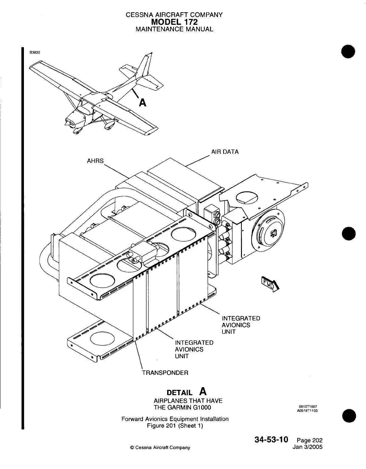
CESSNA
AIRCRAFT
COMPANY
MODEL
172
MAINTENANCE
MANUAL
AIR DATA
TRANSPONDER
DETAIL
A
AIRPLANES
THAT
HAVE
THE
GARMIN G1000
Forward
Avionics
Equipment
Installation
Figure
201
(Sheet
1)
34-53-10
©
Cessna
Aircraft Company
0510T1007
A051BT1103
Page
202
Jan
3/2005
-^^^-
CESSNA
AIRCRAFT
COMPANY
MODEL
1
72
MAINTENANCE
MANUAL
(6)
Install the
baggage compartment
closeout.
Refer
to
Chapter
25,
Interior
Upholstery
-
Maintenance Practices.
(7)
Install the
aft
seat. Refer
to
Chapter
25,
Passenger
Compartment
-
Maintenance
Practices.
(8) If a
new unit
is
installed,
load
the
software
and
configuration.
Refer
to
the
Garmin
G1000
Line
Maintenance
Manual.
(9)
Do
a
check
to
make
sure
the
transponder
operates
correctly.
Refer
to
the
Garmin
G1000
Line
Maintenance
Manual.
4.
Transponder
Antenna
Removal/Installation
A.
Remove
the Transponder Antenna
(Refer
to
Figure
202).
(1)
Set
the MASTER
switch and
AVIONICS
switch
to
the
off
position.
(2)
Remove
the screws
that
attach the
antenna
to the
bottom
of
the
fuselage.
(3)
Disconnect
the
coaxial cable
from
the
antenna
(PC1006).
B.
Install
the
Transponder Antenna
(Refer
to Figure
202).
(1)
Attach
the
coaxial
cable
to
the
antenna
(PC1006).
(2)
Put
the
transponder antenna
in
position
on
the
bottom
of
the
fuselage.
(3)
Attach
the
antenna
with
screws.
34-53-10
Page
203
©
Cessna
Aircraft
Company
Jan
3/2005
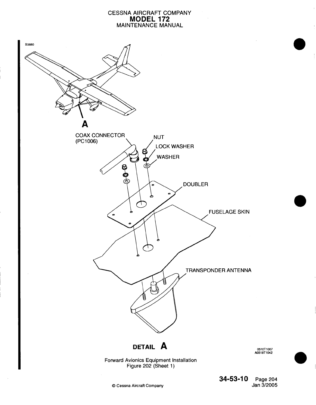
CESSNA AIRCRAFT
COMPANY
MODEL
172
MAINTENANCE
MANUAL
A
COAX
CONNECTOR
(PC100
SKIN
TENNA
DETAIL
A
Forward
Avionics Equipment Installation
Figure
202
(Sheet
1)
34-53-10
©
Cessna
Aircraft
Company
0510T1007
A0518T1042
Page 204
Jan 3/2005
-AAv
l=1
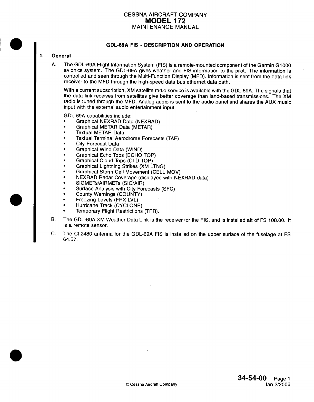
CESSNA
AIRCRAFT
COMPANY
MODEL
172
MAINTENANCE
MANUAL
GDL-69A
FIS
-
DESCRIPTION
AND OPERATION
1.
General
A.
The
GDL-69A
Flight
Information System
(FIS)
is
a
remote-mounted component
of
the Garmin
G
1000
avionics
system.
The GDL-69A
gives
weather
and
FIS
information
to
the
pilot.
The
information
is
controlled
and seen through the
Multi-Function
Display
(MFD).
Information
is
sent
from
the
data
link
receiver
to
the
MFD
through
the
high-speed
data
bus
ethernet
data
path.
With
a
current
subscription,
XM
satellite
radio
service
is
available
with
the
GDL-69A.
The
signals
that
the
data
link
receives
from
satellites
give
better
coverage
than
land-based
transmissions.
The
XM
radio
is
tuned
through the
MFD.
Analog
audio
is
sent
to
the
audio
panel
and
shares
the
AUX
music
input
with
the
external
audio entertainment
input.
GDL-69A
capabilities
include:
·
Graphical
NEXRAD
Data
(NEXRAD)
Graphical
METAR Data (METAR)
Textual
METAR
Data
Textual
Terminal
Aerodrome
Forecasts
(TAF)
·
City
Forecast
Data
Graphical
Wind
Data (WIND)
·
Graphical
Echo
Tops
(ECHO
TOP)
Graphical
Cloud
Tops
(CLD
TOP)
Graphical Lightning Strikes
(XM
LTNG)
Graphical
Storm
Cell
Movement
(CELL
MOV)
·
NEXRAD
Radar
Coverage
(displayed
with
NEXRAD
data)
SIGMETs/AIRMETs
(SIG/AIR)
Surface
Analysis
with
City
Forecasts
(SFC)
County
Warnings
(COUNTY)
Freezing
Levels
(FRX
LVL)
Hurricane Track
(CYCLONE)
Temporary Flight
Restrictions
(TFR).
B.
The
GDL-69A
XM
Weather
Data
Link
is
the
receiver
for
the
FIS,
and
is
installed
aft
of
FS
108.00.
It
is
a remote
sensor.
C.
The Cl-2480
antenna for
the GDL-69A
FIS
is
installed
on
the
upper
surface
of
the
fuselage
at
FS
64.57.
34-54-00
Page
1
Jan
2/2006
©
Cessna
Aircraft
Company
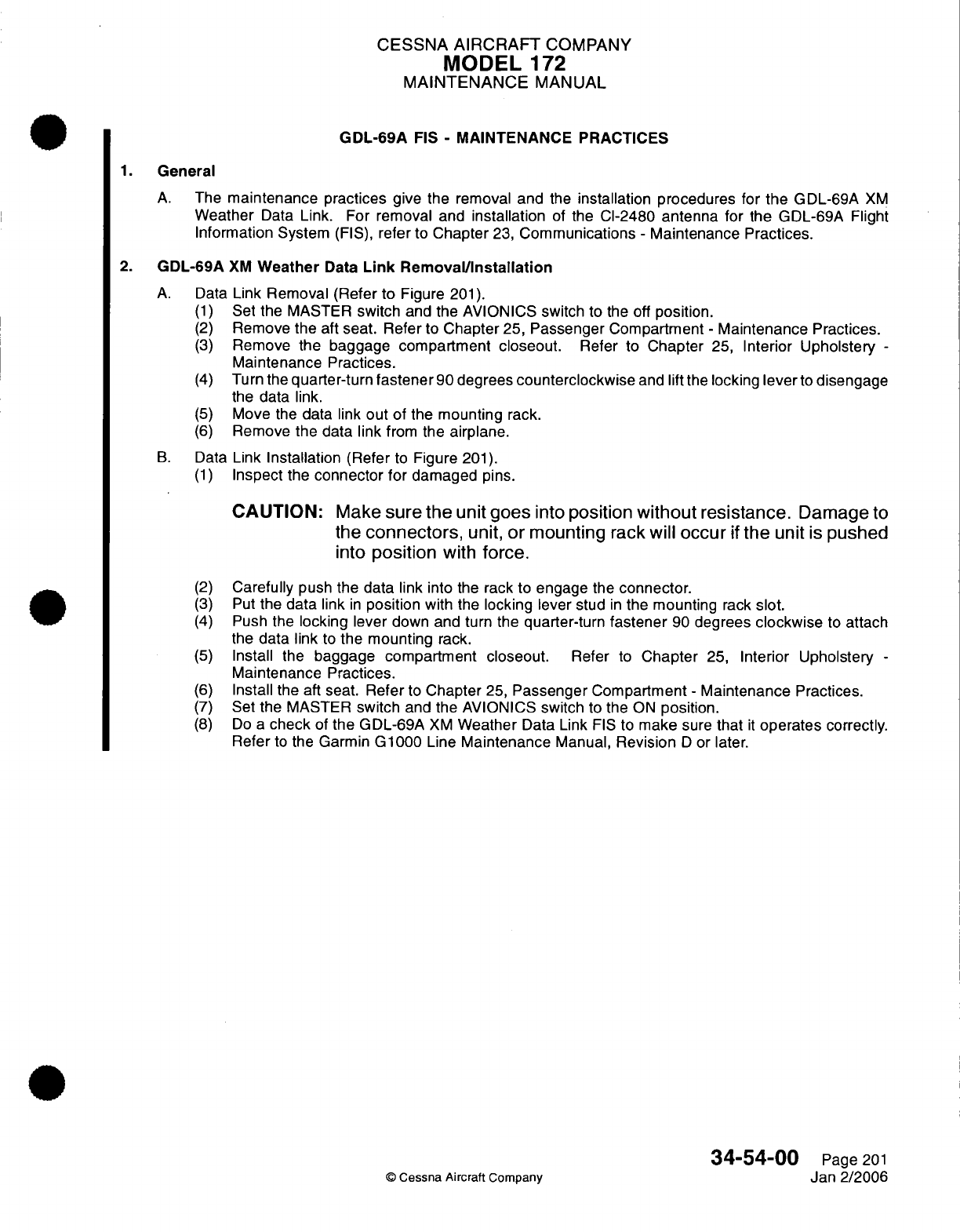
CESSNA
AIRCRAFT
COMPANY
MODEL
172
MAINTENANCE
MANUAL
GDL-69A
FIS
-
MAINTENANCE
PRACTICES
1.
General
A.
The
maintenance practices
give the
removal
and
the
installation procedures for
the
GDL-69A
XM
Weather
Data
Link.
For
removal
and
installation
of
the
Cl-2480 antenna
for
the
GDL-69A
Flight
Information System
(FIS),
refer
to
Chapter
23,
Communications
-
Maintenance
Practices.
2.
GDL-69A
XM
Weather
Data
Link
Removal/Installation
A.
Data
Link
Removal
(Refer to
Figure
201).
(1)
Set
the
MASTER
switch
and the AVIONICS
switch
to
the
off
position.
(2)
Remove
the
aft
seat.
Refer
to
Chapter
25,
Passenger
Compartment
-
Maintenance
Practices.
(3)
Remove
the
baggage
compartment
closeout.
Refer
to
Chapter
25,
Interior Upholstery
-
Maintenance Practices.
(4)
Turn the
quarter-turn
fastener
90
degrees
counterclockwise
and
lift
the
locking
lever
to
disengage
the data link.
(5)
Move
the
data link
out
of
the
mounting
rack.
(6)
Remove
the
data
link
from
the
airplane.
B.
Data
Link
Installation
(Refer
to
Figure
201).
(1)
Inspect
the
connector
for
damaged
pins.
CAUTION:
Make
sure the
unit
goes
into
position
without
resistance.
Damage
to
the
connectors,
unit,
or
mounting rack will
occur
if
the
unit
is
pushed
into
position
with
force.
(2)
Carefully
push
the
data
link
into the
rack
to
engage
the
connector.
(3)
Put
the
data
link
in
position
with
the
locking
lever stud
in
the mounting
rack
slot.
(4)
Push
the
locking
lever
down and
turn
the
quarter-turn
fastener
90
degrees
clockwise
to
attach
the
data link
to
the
mounting
rack.
(5)
Install
the
baggage
compartment
closeout.
Refer
to
Chapter
25,
Interior Upholstery
-
Maintenance
Practices.
(6)
Install
the aft
seat.
Refer
to
Chapter
25,
Passenger
Compartment
-
Maintenance
Practices.
(7)
Set
the
MASTER
switch
and the AVIONICS
switch
to the
ON
position.
(8)
Do
a
check
of
the
GDL-69A
XM
Weather
Data Link
FIS
to
make
sure
that
it
operates
correctly.
Refer
to
the
Garmin
G1000
Line
Maintenance
Manual,
Revision
D
or later.
34-54-00
Page
201
©
Cessna
Aircraft
Company
Jan
2/2006
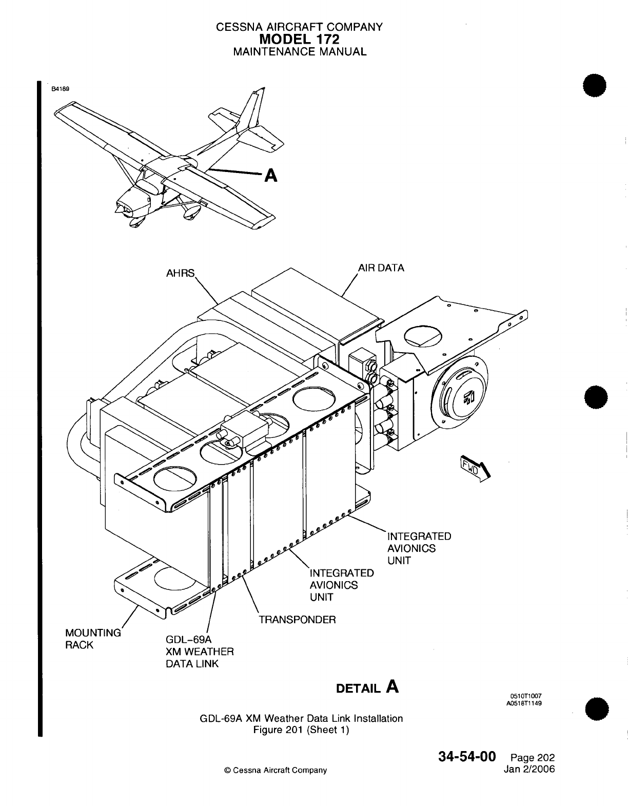
CESSNA
AIRCRAFT
COMPANY
MODEL
172
MAINTENANCE
MANUAL
INTEGRATED
AVIONICS
UNIT
RACK
GLUUL-69A
XM
WEATHER
DATA
LINK
AVIONICS
UNIT
TRANSPONDER
DETAIL
A
GDL-69A
XM
Weather
Data
Link
Installation
Figure
201
(Sheet
1)
©
Cessna
Aircraft
Company
0510T1007
A0518T1149
34-54-00
Page
202
Jan
2/2006
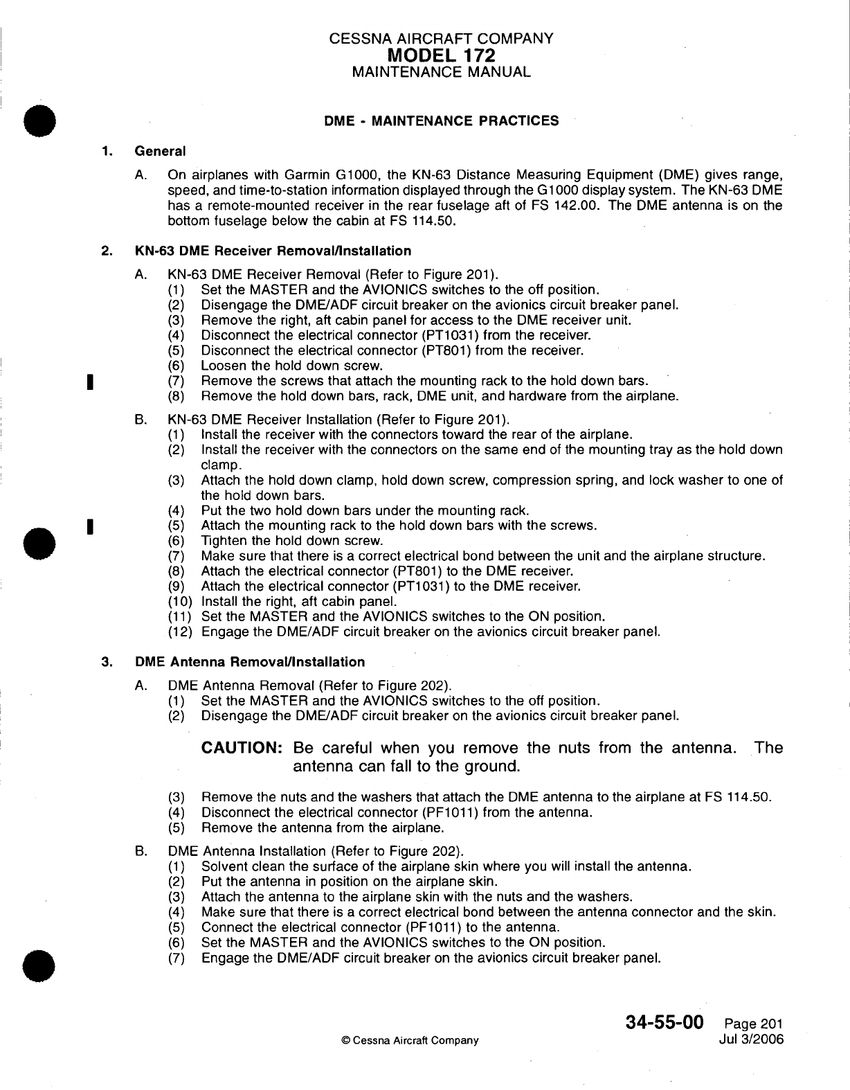
CESSNA AIRCRAFT
COMPANY
MODEL
172
MAINTENANCE
MANUAL
DME
-
MAINTENANCE
PRACTICES
1.
General
A.
On
airplanes
with Garmin
G1000,
the
KN-63
Distance
Measuring
Equipment
(DME)
gives
range,
speed,
and
time-to-station
information
displayed
through the
G1000
display
system.
The
KN-63
DME
has
a
remote-mounted receiver
in
the rear
fuselage
aft
of
FS
142.00. The
DME
antenna
is
on
the
bottom
fuselage
below
the
cabin
at
FS
114.50.
2.
KN-63
DME
Receiver
Removal/Installation
A.
KN-63
DME
Receiver
Removal
(Refer
to
Figure
201).
(1)
Set
the
MASTER and
the
AVIONICS
switches
to
the
off
position.
(2)
Disengage
the
DME/ADF
circuit
breaker
on
the
avionics
circuit breaker panel.
(3)
Remove
the
right,
aft
cabin
panel
for
access
to
the
DME
receiver
unit.
(4)
Disconnect
the
electrical connector
(PT1031)
from
the
receiver.
(5)
Disconnect
the
electrical connector
(PT801)
from the
receiver.
(6)
Loosen
the
hold down
screw.
|* ~ (7)
Remove
the
screws that
attach the mounting
rack
to
the
hold
down
bars.
(8)
Remove
the
hold
down
bars,
rack,
DME
unit,
and hardware
from
the
airplane.
B.
KN-63
DME
Receiver
Installation
(Refer
to
Figure
201).
(1)
Install
the
receiver
with
the
connectors
toward
the
rear
of
the
airplane.
(2)
Install
the
receiver
with
the
connectors
on
the
same
end
of
the mounting
tray as
the hold down
clamp.
(3)
Attach
the
hold
down clamp,
hold
down
screw,
compression
spring,
and
lock washer
to
one
of
the
hold down
bars.
(4)
Put
the
two
hold down bars under
the
mounting
rack.
|* ~ (5)
Attach
the
mounting
rack
to
the hold down
bars
with
the
screws.
(6)
Tighten
the
hold down
screw.
(7)
Make
sure
that
there
is a
correct electrical
bond between
the
unit
and
the
airplane
structure.
(8)
Attach
the
electrical connector
(PT801)
to
the
DME
receiver.
(9)
Attach
the
electrical connector
(PT1031)
to
the
DME
receiver.
(10)
Install
the
right,
aft cabin
panel.
(11)
Set
the MASTER
and the
AVIONICS
switches
to
the
ON
position.
(12)
Engage
the
DME/ADF
circuit
breaker
on
the
avionics
circuit breaker
panel.
3.
DME
Antenna
Removal/Installation
A.
DME
Antenna
Removal (Refer
to
Figure
202).
(1)
Set
the
MASTER
and
the
AVIONICS
switches
to the
off
position.
(2)
Disengage
the
DME/ADF
circuit
breaker
on
the
avionics
circuit
breaker
panel.
CAUTION:
Be
careful
when you
remove
the
nuts
from
the
antenna.
The
antenna
can
fall
to
the
ground.
(3)
Remove
the
nuts
and the washers that
attach
the
DME
antenna
to the
airplane
at
FS
114.50.
(4)
Disconnect
the
electrical connector
(PF1011)
from
the
antenna.
(5)
Remove
the
antenna
from
the
airplane.
B.
DME
Antenna
Installation
(Refer
to
Figure 202).
(1)
Solvent
clean
the
surface
of
the
airplane skin
where you
will
install
the
antenna.
(2)
Put
the antenna
in
position
on
the
airplane
skin.
(3)
Attach
the
antenna
to
the
airplane
skin
with
the
nuts
and the
washers.
(4)
Make
sure
that there
is
a
correct
electrical
bond
between the
antenna
connector
and
the
skin.
(5)
Connect
the electrical connector
(PF1011)
to
the
antenna.
(6)
Set
the MASTER and the AVIONICS
switches
to
the
ON
position.
(7)
Engage
the
DME/ADF
circuit
breaker
on
the
avionics
circuit
breaker
panel.
34-55-00
Page
201
©
Cessna Aircraft
Company
Jul 3/2006
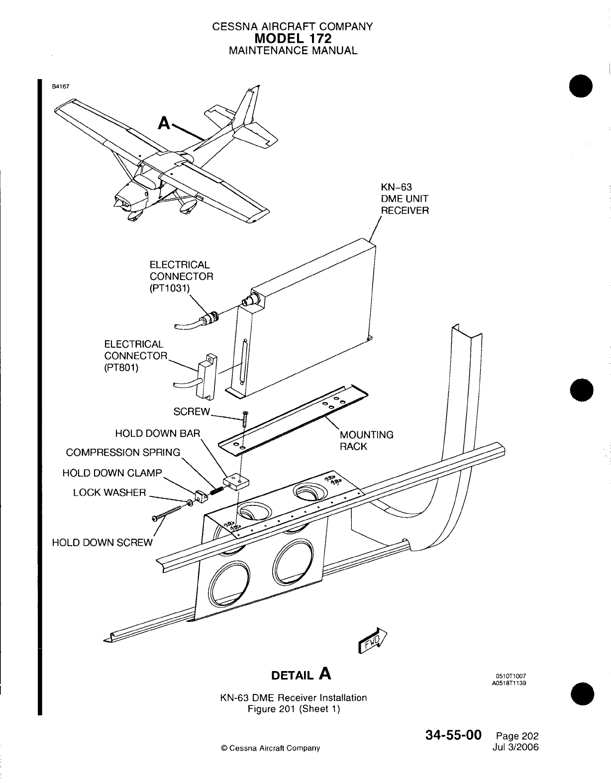
CESSNA
AIRCRAFT
COMPANY
MODEL
172
MAINTENANCE
MANUAL
KN-63
DME
UNIT
RECEIVER
COMPR
HOLD
DC
LOCK
HOLD
DOV\
DETAIL
A
0510T1007
A0518T1139
KN-63
DME
Receiver
Installation
Figure
201
(Sheet
1)
©
Cessna
Aircraft Company
34-55-00
Page
202
Jul
3/2006
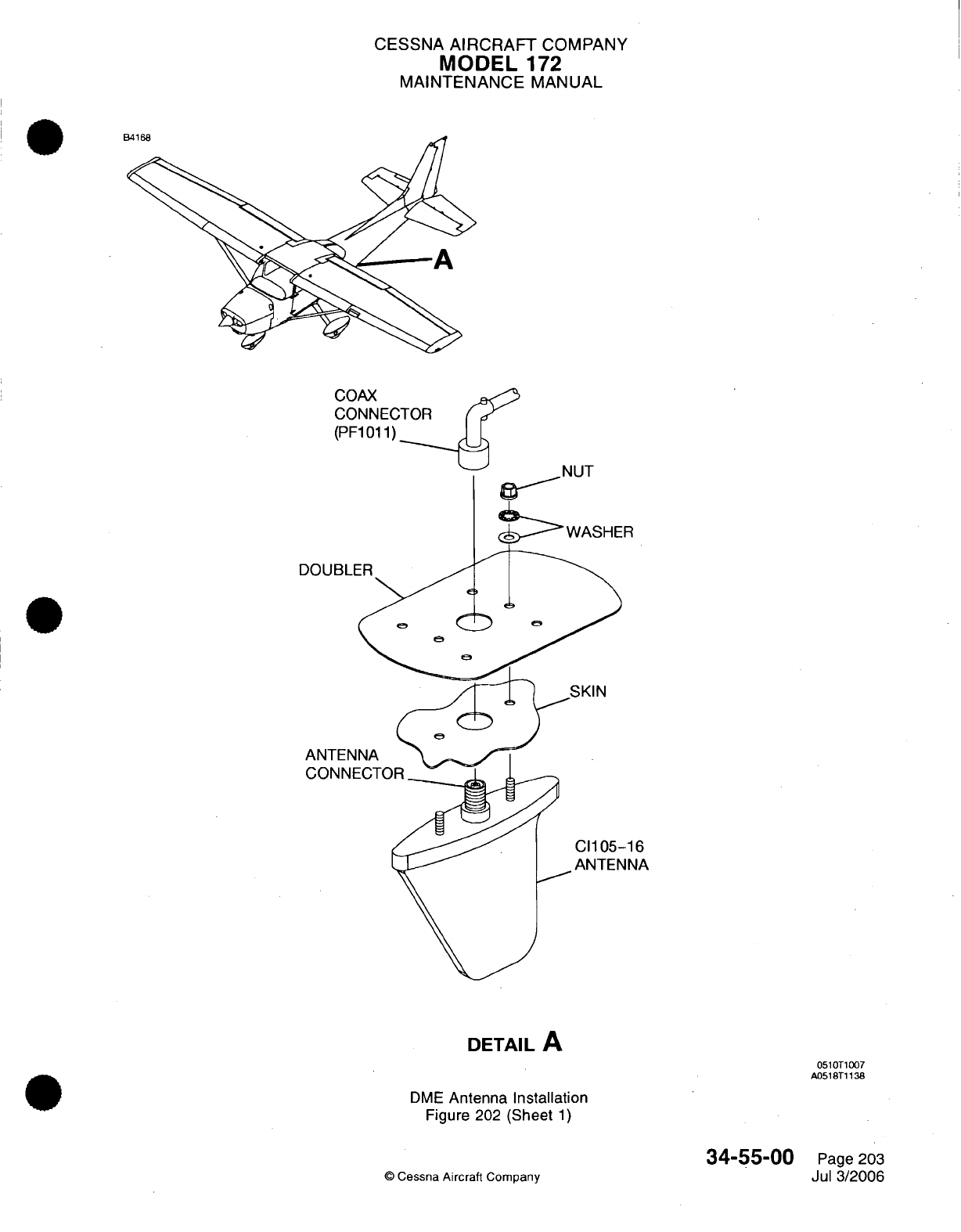
CESSNA
AIRCRAFT
COMPANY
MODEL
172
MAINTENANCE
MANUAL
COAX
CONNECTOR
(PF1011)
R
[
-16
JNA
DETAIL
A
051OT1007
A0518T1138
DME
Antenna Installation
Figure
202
(Sheet
1)
©
Cessna
Aircraft
Company
34-55-00
Page
203
Jul
3/2006
A
.
In
E
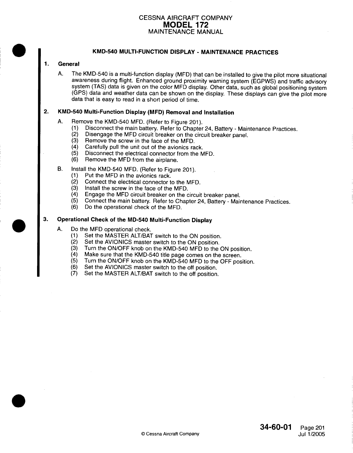
CESSNA
AIRCRAFT
COMPANY
MODEL
172
MAINTENANCE
MANUAL
KMD-540
MULTI-FUNCTION
DISPLAY
-
MAINTENANCE PRACTICES
1.
General
A.
The KMD-540
is
a
multi-function
display
(MFD)
that
can be
installed
to
give
the
pilot
more
situational
awareness
during
flight.
Enhanced
ground
proximity
warning
system
(EGPWS) and
traffic
advisory
system
(TAS)
data
is
given
on
the color
MFD
display.
Other
data,
such
as
global
positioning
system
(GPS)
data
and
weather
data
can
be
shown
on
the
display.
These
displays
can
give
the
pilot
more
data
that
is
easy
to
read
in
a
short
period
of
time.
2.
KMD-540
Multi-Function
Display
(MFD)
Removal
and
Installation
A.
Remove
the
KMD-540
MFD.
(Refer
to
Figure
201).
(1)
Disconnect
the
main
battery. Refer
to
Chapter
24,
Battery
-
Maintenance Practices.
(2)
Disengage
the
MFD
circuit breaker
on
the
circuit
breaker
panel.
(3)
Remove
the
screw
in
the
face
of
the
MFD.
(4)
Carefully
pull
the
unit
out of the
avionics
rack.
(5)
Disconnect the electrical
connector
from
the
MFD.
(6)
Remove
the
MFD
from
the
airplane.
B.
Install
the
KMD-540
MFD.
(Refer
to
Figure
201).
(1)
Put
the
MFD
in
the
avionics
rack.
(2)
Connect
the
electrical
connector
to
the
MFD.
(3)
Install the
screw
in
the
face
of
the
MFD.
(4)
Engage the
MFD
circuit
breaker
on
the
circuit
breaker
panel.
(5)
Connect
the
main
battery.
Refer
to
Chapter
24,
Battery
-
Maintenance
Practices.
(6)
Do
the
operational
check
of
the
MFD.
3.
Operational Check
of
the
MD-540
Multi-Function
Display
A.
Do
the MFD
operational
check.
(1)
Set
the
MASTER
ALT/BAT
switch
to
the
ON
position.
(2)
Set
the
AVIONICS
master switch
to
the
ON
position.
(3)
Turn
the
ON/OFF
knob
on
the
KMD-540
MFD
to
the
ON
position.
(4)
Make
sure
that
the
KMD-540
title
page
comes
on
the
screen.
(5)
Turn
the
ON/OFF
knob
on
the
KMD-540
MFD
to
the
OFF
position.
(6)
Set
the
AVIONICS
master switch
to
the
off
position.
(7)
Set
the
MASTER
ALT/BAT
switch
to
the
off
position.
34-60-01
Page
201
©
Cessna
Aircraft
Company
Jul
1/2005
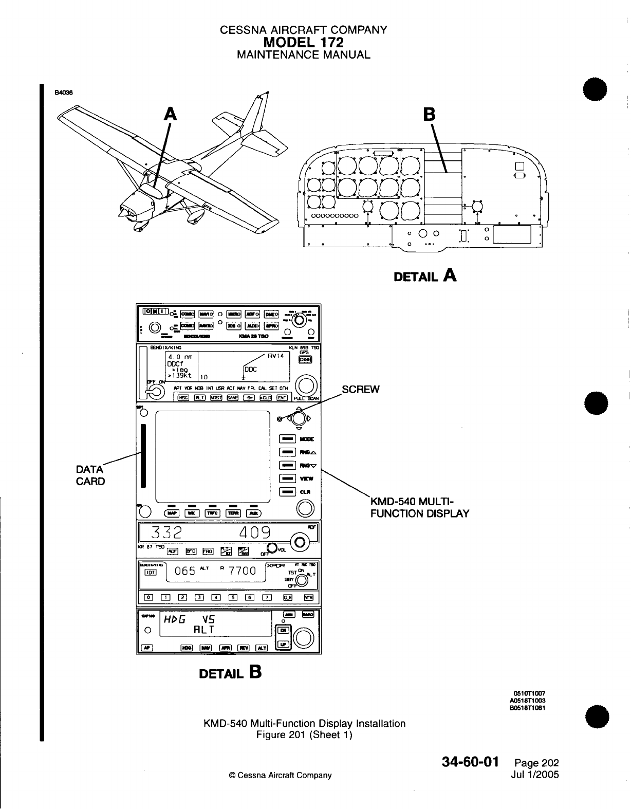
CESSNA
AIRCRAFT
COMPANY
MODEL
172
MAINTENANCE
MANUAL
E
B
oooooooooo
.
o_
e2
o
DETAIL
A
I
lloEE^I^
FIq
o
Fs3°
EF-
EF -=-
·
O©
_. e_
°
EE3
E
E'
-'-\
I
-
XXK
,
AMT8,O
._
_ BEW IX/KING KLN 89B TS,
d.0
nm
RV14
6
i
DDCf
oJ
39t
I
1
0
P T
VR
NDB INT
UR
ACT IAV FPL CAL SET OTH
SCREW
_
[-|16
|T t S arg |-) 9c
'
| -_ E
I
N
SRW
*
°7
DATA
CARD
-
i--0
-
1i~
[-]
mm
[-VI
[E
A
0
KMD-540
MULTI-
FUNCTION
DISPLAY
332
409
KR 87 TSO
Fn31
w
F5
@
O
i<
065
"7700
7
J
TST
rnRm
L
Tr
n n n 3
f-
"HD
VS\15
0
RLT
[rq<
DETAIL
B
0510T1007
A0518T1D03
80518T1081
KMD-540
Multi-Function
Display
Installation
Figure
201
(Sheet
1)
34-60-01
©
Cessna
Aircraft Company
Page
202
Jul
1/2005
B
CESSNA
AIRCRAFT
COMPANY
MODEL
172
MAINTENANCE
MANUAL
GARMIN DISPLAY
UNIT
(GDU)
-
MAINTENANCE
PRACTICES
1.
General
A.
The
GDU 1040
has
a
10.4
inch
LCD
display
with 1024x768 resolution.
The
cockpit
has
two
GDU
1040s.
One
is
configured
as
a
Primary
Flight Display
(PFD)
and
the
other
is
configured
as
the
Multi-
Function
Display
(MFD).
The
MFD
shows
navigation,
engine,
and
airframe information.
The
PFD
shows primary
flight
information,
in
place
of
gyro
systems.
Both
GDU 1040s
connect
and
show
all
functions
of
the
G1000 system during
flight.
The
displays
communicate
with
each
other
and the
GIA
63
Integrated
Avionics
Units
(IAU)
through
a
High-Speed
Data
Bus
(HSDB)
Ethernet
connection.
The
PFD
and
MFD
have
a
reversionary
switch
in
which one
display
can
show all
information
usually
shown
by
both
displays
in
the
event
that
one
does
not
operate
correctly.
B.
Two
GDUs are
in
the
instrument
panel of
airplanes
with
Garmin
G1000. Maintenance
practices give
removal and
installation procedures.
2.
Troubleshooting
A.
For
troubleshooting
procedures,
refer
to
the Garmin
G1000
Line
Maintenance
Manual.
3.
Control
Display Unit
Removal/Installation
CAUTION:
If
possible,
do not
touch
the
lens.
The
GDU 1040
lens
has
a
layer
of anti-
reflective
material which
Is
very
sensitive
to
skin
oils,
waxes
and
abrasive
cleaners.
CAUTION:
Do
not
use
cleaners
that
contain
ammonia.
Ammonia
will
cause
damage
to
the
anti-reflective
material.
It
Is
very
Important
to clean
the
lens
with
a
clean,
lint-free
cloth
and an
eyeglass
lens
cleaner
that
Is
specified
as
safe
for
anti-reflective
material.
A.
Remove
the
Garmin
Display
Unit
(GDU)
(Refer
to
Figure
201).
(1)
Disengage
the applicable
Primary
Function
Display
(PFD)
or
Multi-Function
Display
(MFD)
circuit
breaker
for
the
GDU.
(2)
Turn
the
quick
release
fasteners
1/4
turn
counterclockwise
with
a
3/32"
hex
drive
tool.
(3)
Carefully
pull
the
GDU
from
the
instrument
panel.
(4)
Disconnect
the
electrical connector
from
the
GDU.
B.
Install
the
Garmin
Display
Unit
(GDU)
(Refer
to Figure
201).
CAUTION:
CAUTION:
If
possible,
do
not
touch
the
lens.
The
GDU
1040
lens
has
a
layer
of
anti-reflective
material
which
Is
very sensitive
to
skin
oils,
waxes
and
abrasive
cleaners.
Do
not use
cleaners
that
contain
ammonia.
Ammonia
will
cause
damage
to
the
anti-reflective
material.
It
Is
very
Important
to
clean
the
lens
with
a
clean, lint-free cloth
and
an
eyeglass
lens
cleaner
that
Is
specified
as
safe
for
anti-reflective
material.
NOTE:
If a
new
unit
is
installed,
it
is
necessary
to
load
the
software
and
configuration.
NOTE:
If
the
initial
unit
is
installed
in
the
initial location
or
in
the
opposite
location,
it
is
not
necessary
to
load
the software and
configuration.
(1)
Make
sure
the
connector
and
connector pins
have
no
damage.
(a)
Replace
the
connector
or
connector
pins
if
applicable.
Refer
to
The
Wiring
Diagram
Manual
and
the
Garmin
G1000
Line
Maintenance
Manual.
34-60-10
Page
201
©
Cessna Aircraft
Company
Jan
3/2005
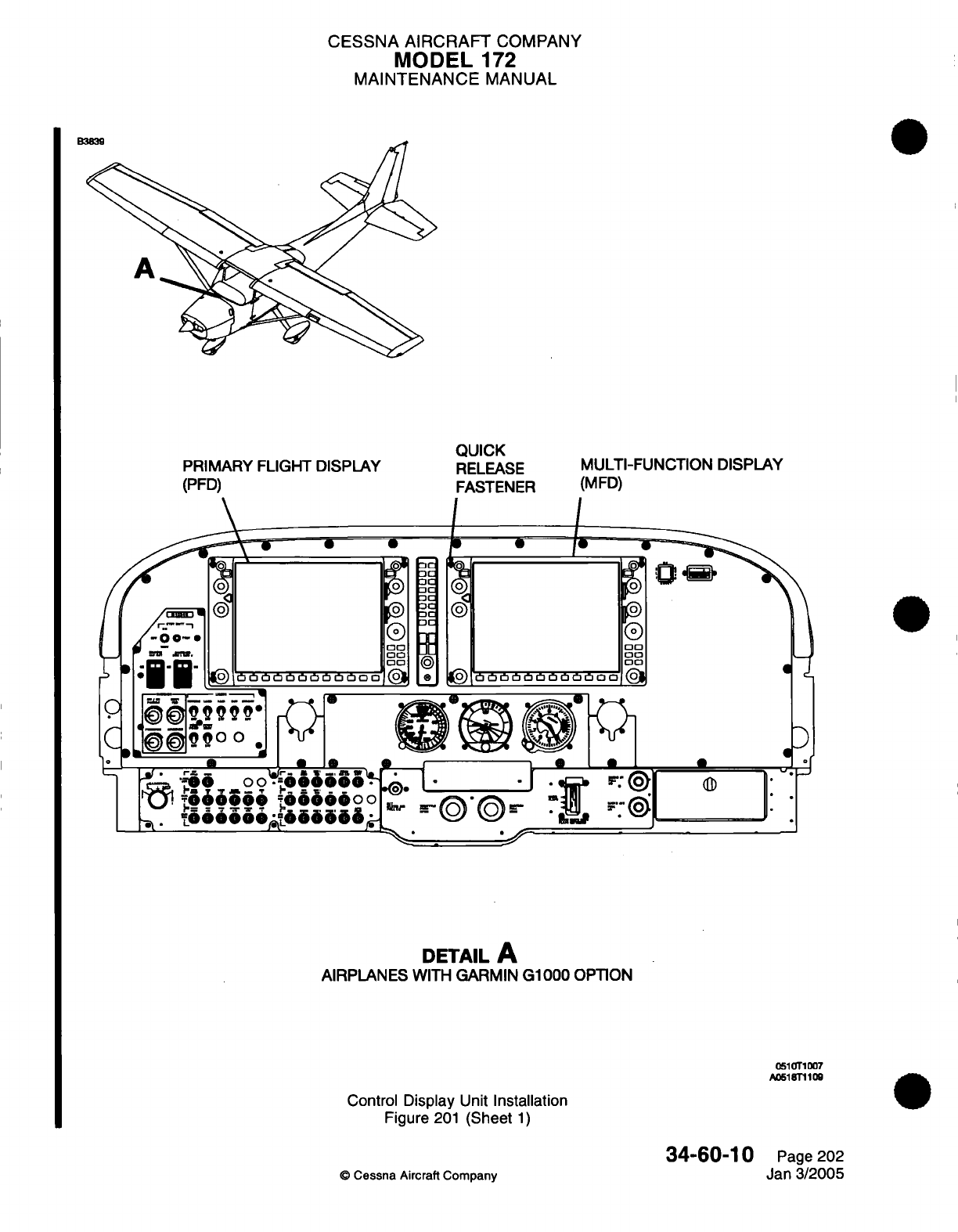
CESSNA AIRCRAFT
COMPANY
MODEL
172
MAINTENANCE
MANUAL
PRIMARY
FLIGHT
DISPLAY
(PFD)
QUICK
RELEASE
FASTENER
I
L
ma
7a
oo
30
03
a
MULTI-FUNCTION
DISPLAY
(MFD)
/
0
0
00
go
<)
bobbObObboaoo
(
1©
*O
.
.:'
I
'[
,~
a
1b
of
DETAIL
A
AIRPLANES
WITH
GARMIN
G1000
OPTION
0510T1
07
A0518T1109
Control
Display
Unit
Installation
Figure
201
(Sheet
1)
34-60-10
©
Cessna
Aircraft
Company
Page
202
Jan
3/2005
new
M
I
CESSNA
AIRCRAFT
COMPANY
MODEL
172
MAINTENANCE
MANUAL
Connect
the
electrical connector
to
the
GDU.
Put
the
GDU
in
position
flush
with
the
instrument panel.
Make
sure
the
locking-stud alignment
marks
are
in
the
vertical
position.
NOTE:
Light forward
pressure
can
be
required
to
engage
the
quick
release
fasteners.
Turn
the
quick
release fasteners
1/4
turn
clockwise
with
a
3/32"
hex
drive
tool.
Make
sure
the
GDU
operates
correctly.
(a)
If
a
new
unit
is
installed,
load
the
software
and
configuration.
Refer
to
the
Garmin
G1000
Line
Maintenance
Manual.
(b)
Do
a
check
to
make sure
the
GDU
operates
correctly. Refer
to
the
Garmin
G1000
Line
Maintenance
Manual.
34-60-10
Page
203
©
Cessna
Aircraft
Company
Jan
3/2005
(2)
(3)
(4)
(5)
(6)
CHAPTER
VACUUM
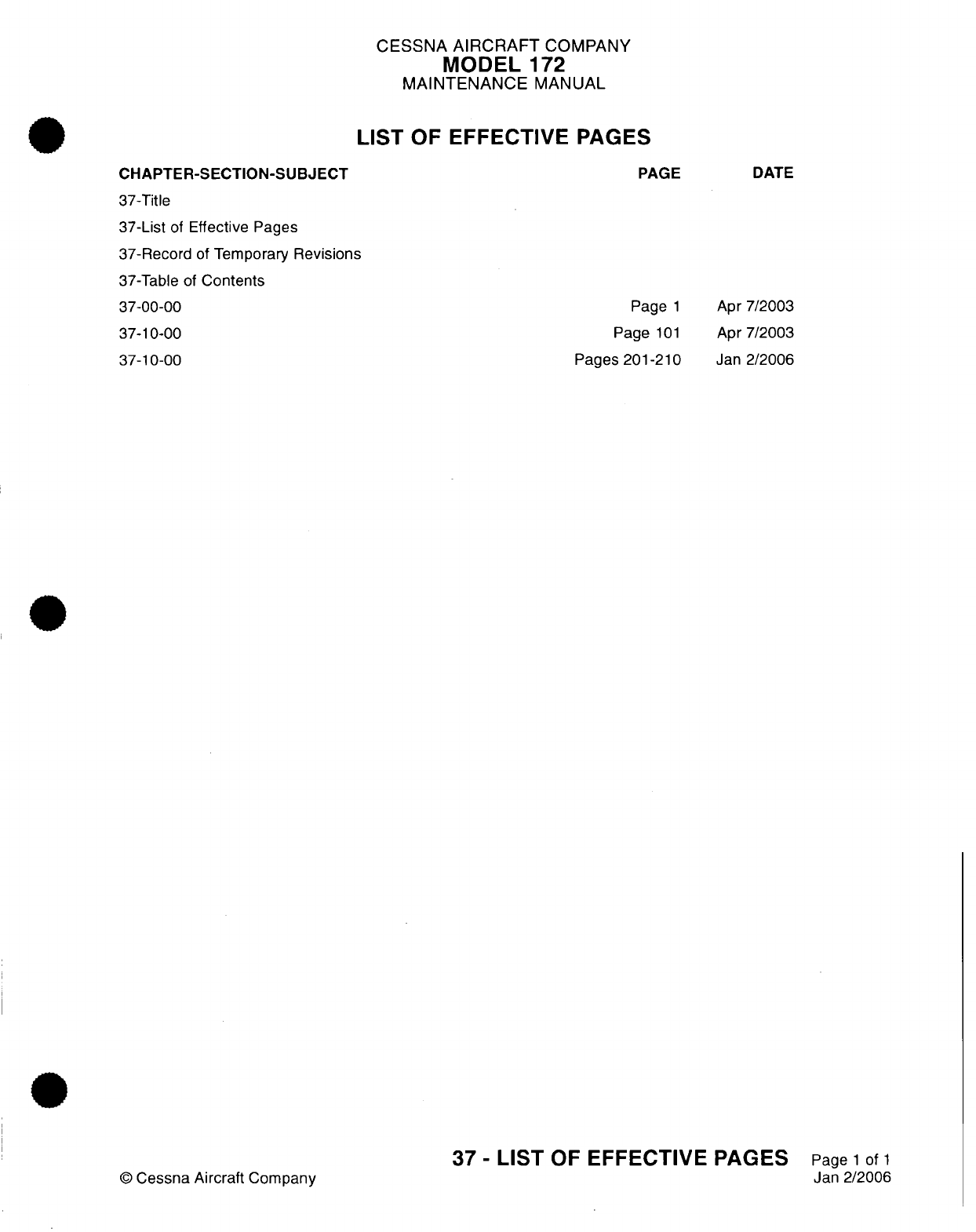
CESSNA
AIRCRAFT
COMPANY
MODEL
172
MAINTENANCE
MANUAL
LIST
OF
EFFECTIVE PAGES
PAGE
CHAPTER-SECTION-SUBJECT
37-Title
37-List
of
Effective
Pages
37-Record
of
Temporary
Revisions
37-Table
of
Contents
37-00-00
37-10-00
37-10-00
Page
1
Page
101
Pages
201-210
©
Cessna Aircraft
Company
37
-
LIST
OF
EFFECTIVE
PAGES
Page
1
of
1
Jan
2/2006
DATE
Apr
7/2003
Apr
7/2003
Jan
2/2006
Temporary
Revision
Number
RECORD OF
TEMPORARY
REVISIONS
Page
Number
Issue
Date
By
Date
Removed
By
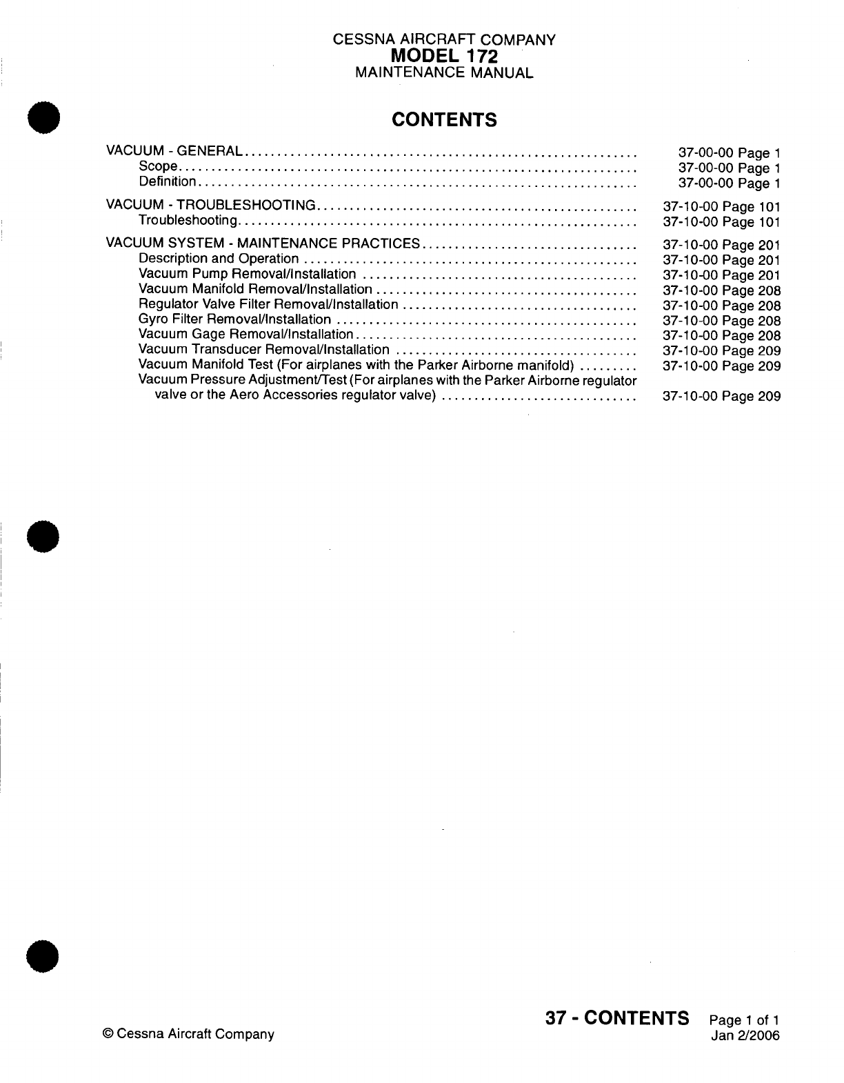
CESSNA
AIRCRAFT
COMPANY
MODEL
172
MAINTENANCE
MANUAL
CONTENTS
VACUUM
-
GENERAL
...........
..............................................
S
cope......................................................................
Definition
...........
..
....................................................
VACUUM
-
TROUBLESHOOTING
..........................
...........
Troubleshooting
.........
..
..................................................
VACUUM
SYSTEM
-
MAINTENANCE
PRACTICES.................................
Description
and
Operation
...................................................
Vacuum Pump
Removal/Installation
..........................................
Vacuum
Manifold
Removal/Installation
........................................
Regulator
Valve
Filter
Removal/Installation
....................................
Gyro
Filter
Removal/Installation
..............................................
Vacuum
Gage
Removal/Installation...........................................
Vacuum
Transducer
Removal/Installation
.....................................
Vacuum
Manifold
Test
(For
airplanes
with
the Parker
Airborne
manifold)
.........
Vacuum
Pressure
Adjustment/Test
(For
airplanes
with
the
Parker Airborne regulator
valve
or
the
Aero
Accessories
regulator
valve)
.........
.....................
37-00-00
Page
1
37-00-00
Page
1
37-00-00
Page
1
37-10-00
Page
101
37-10-00
Page
101
37-10-00
Page
201
37-10-00
Page
201
37-10-00
Page
201
37-10-00
Page
208
37-10-00
Page
208
37-10-00
Page
208
37-10-00
Page
208
37-10-00
Page 209
37-10-00
Page
209
37-10-00
Page
209
37
-
CONTENTS
Page
1
of
1
Jan 2/2006
©
Cessna
Aircraft
Company
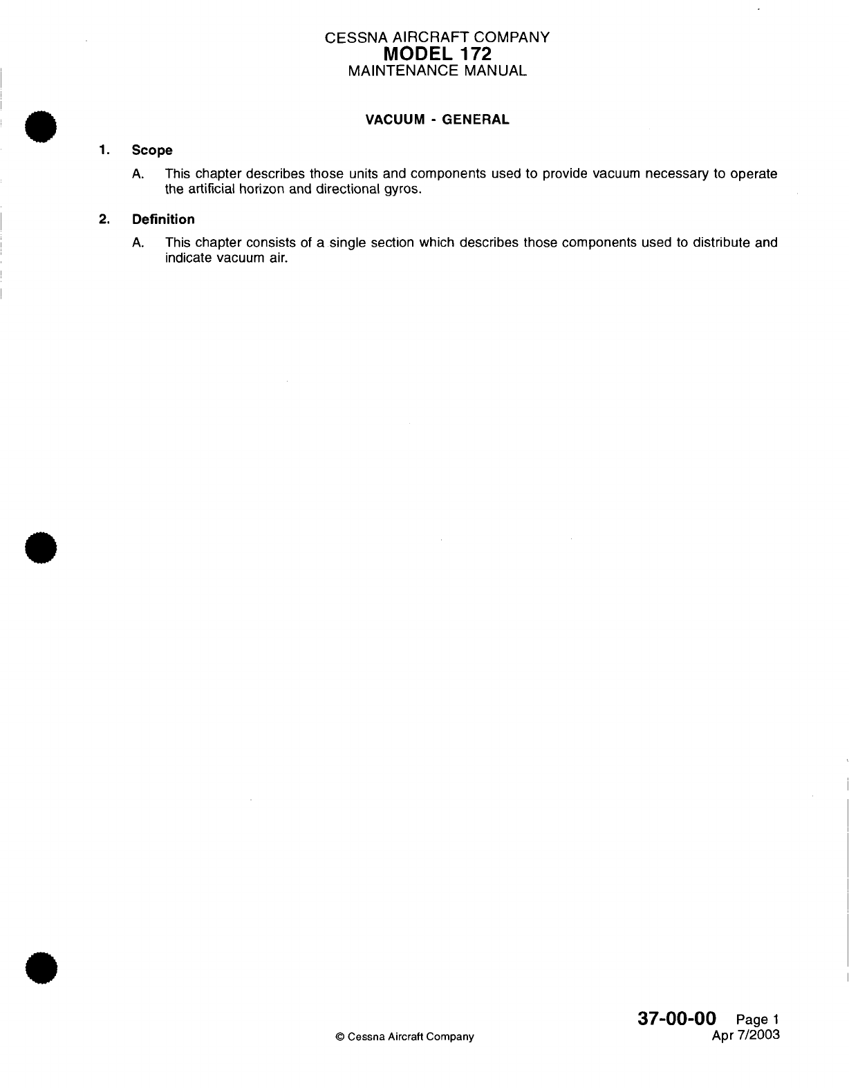
CESSNA
AIRCRAFT
COMPANY
MODEL
172
MAINTENANCE
MANUAL
VACUUM
-
GENERAL
1.
Scope
A.
This
chapter describes those
units and
components
used
to
provide
vacuum
necessary
to
operate
the
artificial
horizon
and
directional
gyros.
2.
Definition
A.
This
chapter consists
of
a
single
section which
describes
those components
used
to
distribute
and
indicate
vacuum air.
37-00-00
Page
1
©
Cessna Aircraft Company
Apr 7/2003
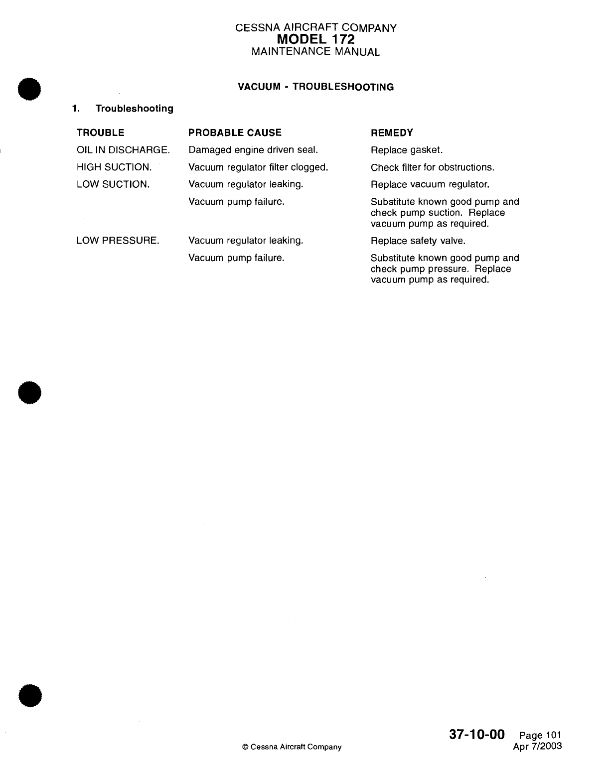
CESSNA
AIRCRAFT
COMPANY
MODEL
172
MAINTENANCE
MANUAL
VACUUM
-
TROUBLESHOOTING
1.
Troubleshooting
TROUBLE
OIL
IN
DISCHARGE.
HIGH
SUCTION.
LOW
SUCTION.
LOW
PRESSURE.
PROBABLE
CAUSE
Damaged
engine driven
seal.
Vacuum
regulator
filter
clogged.
Vacuum
regulator
leaking.
Vacuum
pump
failure.
Vacuum
regulator leaking.
Vacuum
pump
failure.
REMEDY
Replace
gasket.
Check
filter
for
obstructions.
Replace
vacuum
regulator.
Substitute
known
good
pump
and
check
pump
suction.
Replace
vacuum
pump
as
required.
Replace
safety
valve.
Substitute
known
good
pump
and
check
pump
pressure.
Replace
vacuum
pump
as
required.
©
Cessna Aircraft
Company
37-1
0-00
Page
101
Apr 7/2003
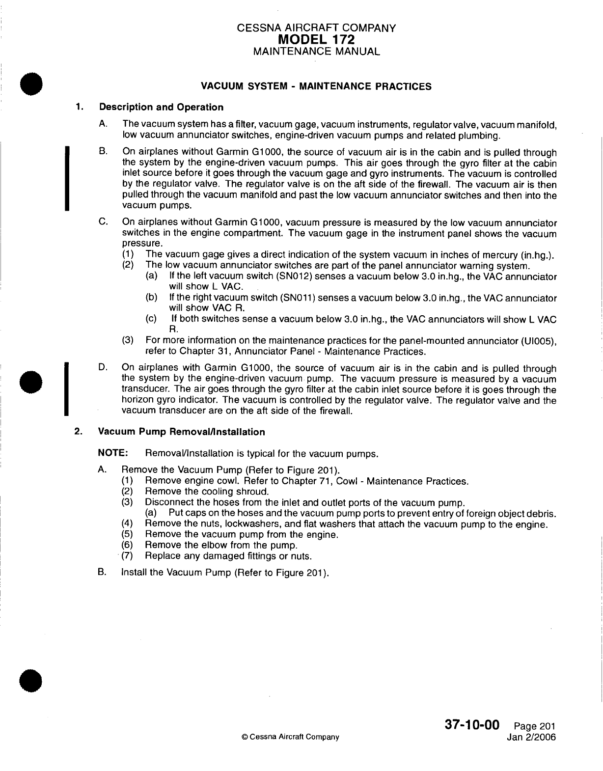
CESSNA
AIRCRAFT
COMPANY
MODEL
172
MAINTENANCE
MANUAL
*
VACUUM
SYSTEM
-
MAINTENANCE
PRACTICES
1.
Description
and
Operation
A.
The
vacuum system
has
a
filter, vacuum
gage,
vacuum
instruments, regulator
valve,
vacuum
manifold,
low
vacuum
annunciator switches,
engine-driven
vacuum
pumps
and
related
plumbing.
B.
On
airplanes without
Garmin
G1000,
the source
of
vacuum air
is
in
the
cabin and
is
pulled
through
the
system
by
the engine-driven
vacuum
pumps.
This
air
goes
through
the
gyro
filter
at
the cabin
inlet
source before
it
goes
through
the
vacuum gage and
gyro
instruments.
The
vacuum
is
controlled
by
the
regulator valve.
The regulator valve
is
on the aft
side
of
the firewall. The vacuum air
is
then
pulled through the vacuum manifold and
past
the
low
vacuum
annunciator
switches
and
then
into
the
vacuum
pumps.
C.
On
airplanes without
Garmin G1000, vacuum
pressure
is
measured
by
the
low
vacuum
annunciator
switches
in
the
engine
compartment. The vacuum
gage
in
the
instrument
panel
shows the
vacuum
pressure.
(1)
The
vacuum gage
gives
a
direct
indication of
the
system
vacuum
in
inches
of
mercury
(in.hg.).
(2)
The
low
vacuum
annunciator
switches
are
part
of
the
panel
annunciator
warning system.
(a) If
the
left
vacuum
switch
(SN012)
senses
a
vacuum
below
3.0 in.hg., the
VAC
annunciator
will
show
L
VAC.
(b) If
the
right
vacuum
switch
(SN011)
senses
a
vacuum
below
3.0
in.hg.,
the
VAC
annunciator
will
show
VAC
R.
(c) If
both
switches sense
a
vacuum below
3.0
in.hg.,
the
VAC
annunciators
will
show
L
VAC
R.
(3)
For more
information
on
the
maintenance
practices
for
the
panel-mounted
annunciator
(UI005),
refer
to
Chapter
31,
Annunciator
Panel
-
Maintenance
Practices.
D.
On
airplanes
with Garmin
G1000,
the
source
of
vacuum
air
is
in
the
cabin and
is
pulled
through
_*O~ ~the
system
by
the
engine-driven
vacuum
pump.
The
vacuum
pressure
is
measured
by
a
vacuum
transducer. The
air
goes
through
the gyro
filter
at
the
cabin
inlet
source
before
it
is
goes
through
the
horizon
gyro
indicator. The
vacuum
is
controlled
by
the
regulator valve.
The
regulator valve
and
the
vacuum
transducer
are
on
the aft
side
of
the
firewall.
2.
Vacuum
Pump
Removal/nstallation
NOTE:
Removal/Installation
is
typical
for
the
vacuum
pumps.
A.
Remove
the
Vacuum
Pump
(Refer
to
Figure
201).
(1)
Remove
engine cowl.
Refer
to
Chapter
71,
Cowl
-
Maintenance Practices.
(2)
Remove
the
cooling
shroud.
(3)
Disconnect
the
hoses
from
the
inlet
and
outlet
ports
of the
vacuum
pump.
(a) Put
caps
on
the hoses
and
the
vacuum pump
ports
to
prevent
entry
of
foreign
object
debris.
(4)
Remove
the
nuts,
lockwashers,
and
flat
washers
that
attach
the
vacuum
pump
to
the
engine.
(5)
Remove
the
vacuum
pump
from
the
engine.
(6)
Remove
the
elbow
from
the
pump.
(7)
Replace
any damaged
fittings
or
nuts.
B.
Install
the Vacuum
Pump
(Refer
to
Figure
201).
37-10-00
Page
201
©
Cessna
Aircraft Company
Jan
2/2006
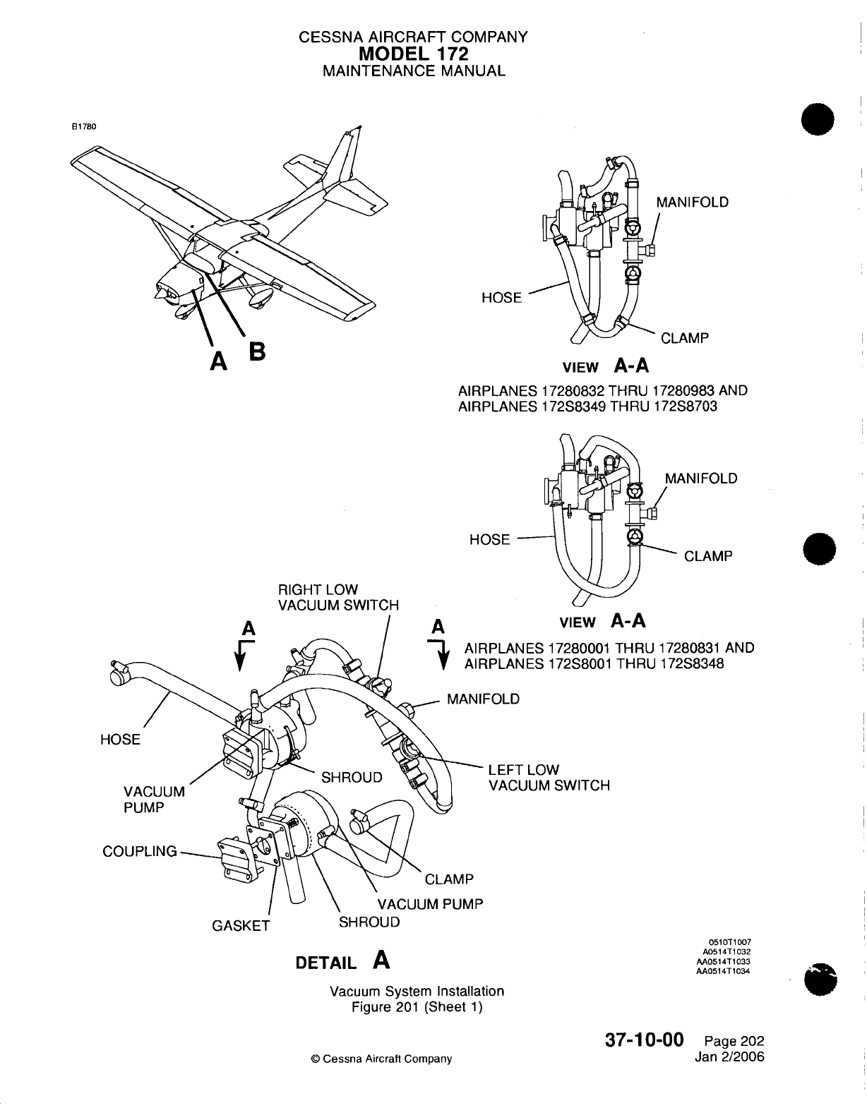
CESSNA AIRCRAFT
COMPANY
MODEL
172
MAINTENANCE
MANUAL
AANIFOLD
CLAMP
HOSE
VIEW
A-A
AIRPLANES 17280832
THRU 17280983
AND
AIRPLANES 172S8349 THRU
172S8703
HOSE
RIGHT
LOW
VACUUM SWITCH
..
A
A
CLAMP
VIEW
A-A
IPLANES 17280001
THRU
17280831
AND
IPLANES
172S8001
THRU 172S8348
=OLD
LEFT
LOW
VACUUM
SWITCH
SHROUD
DETAIL
A
Vacuum
System
Installation
Figure
201
(Sheet
1)
37-10-00
©
Cessna
Aircraft
Company
GASKET
0510T1007
A0514T1032
AA0514T1033
AA0514T1034
Page 202
Jan
2/2006
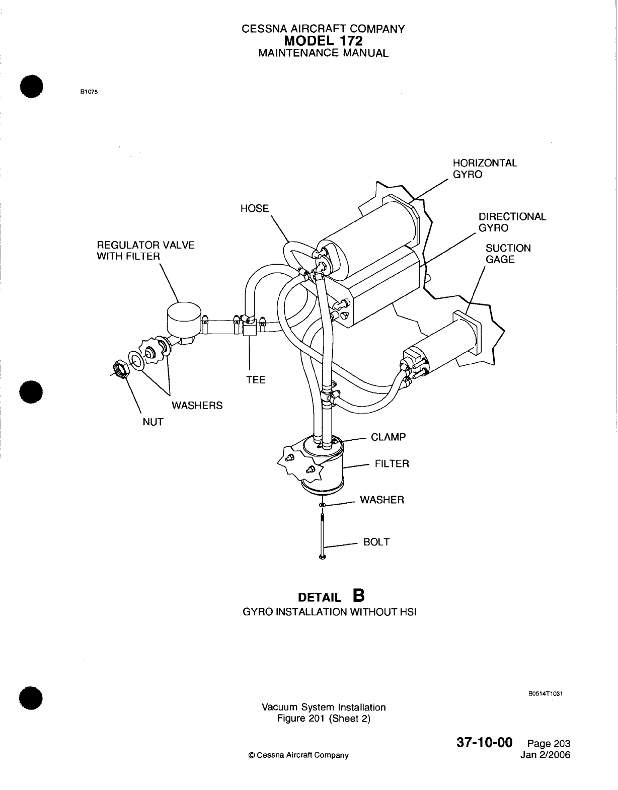
CESSNA
AIRCRAFT
COMPANY
MODEL
172
MAINTENANCE
MANUAL
B1075
HORIZONTAL
GYRO
HOSE TIONAL
TION
RE
W
TEE
WASHERS
NUT
CLAMP
FILTER
WASHER
BOLT
DETAIL
B
GYRO
INSTALLATION
WITHOUT
HSI
B0514T1031
Vacuum
System
Installation
Figure
201
(Sheet
2)
37-10-00
©
Cessna
Aircraft
Company
Page
203
Jan 2/2006
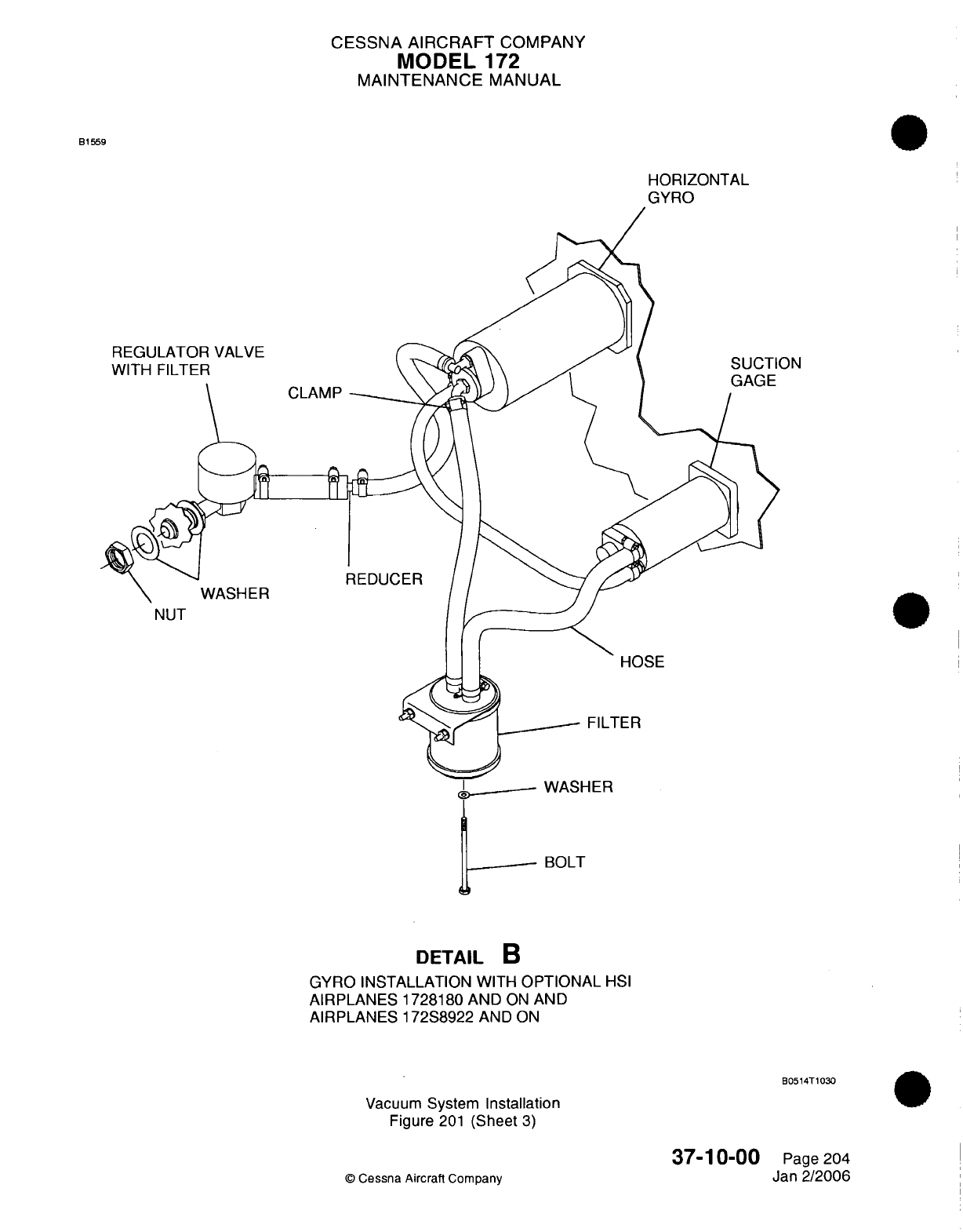
CESSNA
AIRCRAFT
COMPANY
MODEL
172
MAINTENANCE
MANUAL
B1559
HORIZONTAL
GYRO
REGULATOR
VALVE
WITH FILTER
CLAMP
WASHER
ON
REDUCER
NUT
HOSE
FILTER
WASHER
BOLT
DETAIL
B
GYRO
INSTALLATION
WITH
OPTIONAL
HSI
AIRPLANES
1728180
AND
ON
AND
AIRPLANES 172S8922
AND
ON
80514T1030
Vacuum
System
Installation
Figure
201
(Sheet
3)
37-10-00
©
Cessna
Aircraft
Company
Page 204
Jan
2/2006
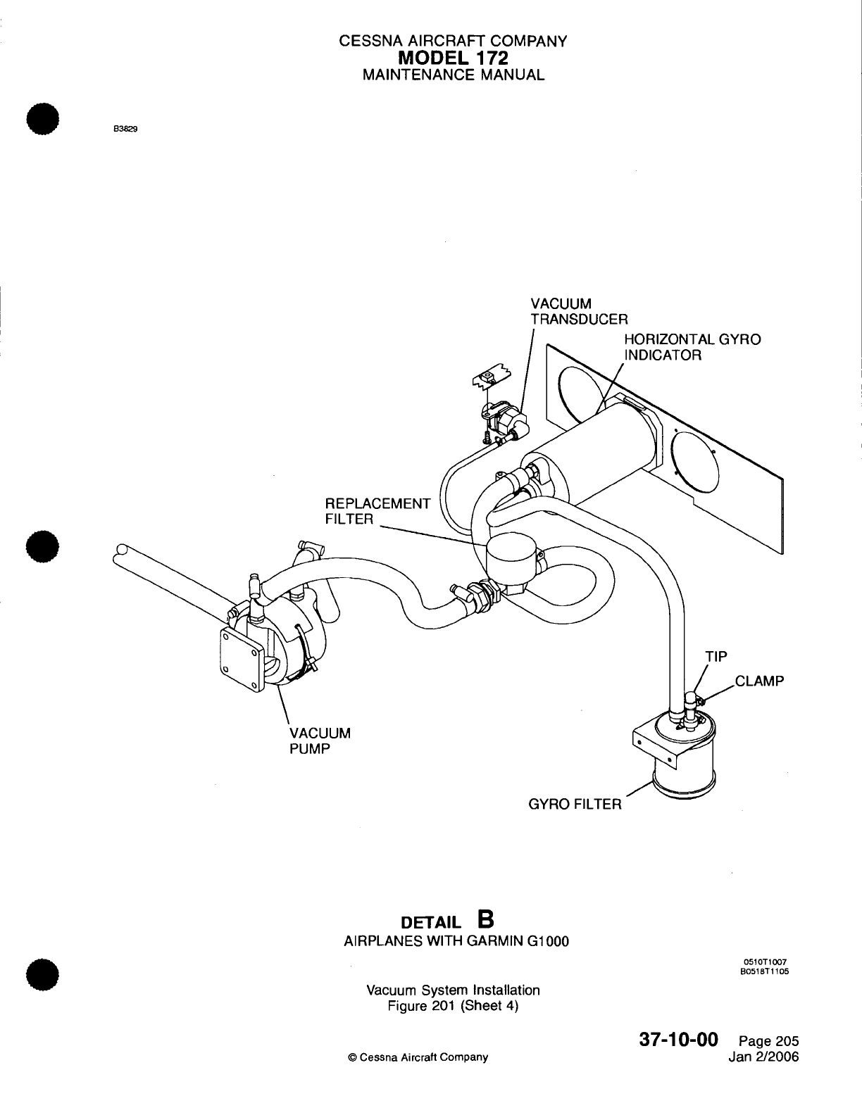
CESSNA
AIRCRAFT
COMPANY
MODEL
172
MAINTENANCE
MANUAL
B3829
VACUUM
TRANSDUCER
HORIZONTAL GYRO
INDICATOR
REPLACEMENT
FILTER
TIP
VACUUM
PUMP
GYRO
FILTER
DETAIL
B
AIRPLANES
WITH
GARMIN G1000
0510T1007
B051BT1105
Vacuum
System
Installation
Figure
201
(Sheet
4)
37-10-00
©
Cessna
Aircraft
Company
Page
205
Jan 2/2006
CESSNA
AIRCRAFT
COMPANY
MODEL
172
MAINTENANCE
MANUAL
CAUTION:
Do
not
install
a
vacuum
pump
that
has
been
dropped or
shows that
it
was
incorrectly
held
in
a
vise.
CAUTION:
Do
not
use
any
cork-type gaskets
when
the vacuum
pump
is
installed.
CAUTION: Make
sure
all
unwanted
material
is
removed
from
the
system.
Foreign
object
debris
will
cause
damage
to
the
vacuum system
components.
CAUTION:
CAUTION:
If
a
vise
is
used,
hold
the
pump
housing
by
the
flange
and
protect
the
flange
with
soft
material such
as
aluminum,
copper
or
wood.
The
pump
housing
must
never
be
set
in
a
vise
with
pressure applied across
the
center
of
the
housing. The
pressure
will
cause
damage
to
the
carbon
rotor.
Do
not use
Teflon
tape,
pipe
dope,
or
thread
lubricants
of
any type.
Foreign
object
debris
will
cause
damage
to
the vacuum
system
components.
Put
the
vacuum
pump
in
a
jaw
protected
vise,
with
the
drive
coupling
downward.
Install
the
elbow
in
the
pump
hand
tight.
Use
only
a
box
end
wrench
to
tighten
the
fittings
to
the
necessary position.
Do
not
make
more
than
1.5
turns
beyond
the
hand
tight
position
Make
sure
the
pump
and
engine surfaces
are
clean and
free
of
any
old
gasket
material.
Set
the
new
pad
gasket
on the
studs
of the
engine.
Put
the
vacuum
pump
on
the
studs.
Attach
the
pump
to
the
engine
with
the
flat
washers,
new
lockwashers,
and
nuts.
Torque
and
tighten
the nuts
in
a
cross
pattern
to
70
inch-pounds,
+10
or
-10
inch-pounds
(7.9
N-m,
+1.1
or-
1.1
N-m).
(a)
To
torque
the
nuts,
fabricate
a
torque
wrench
adapter
(Refer
to
Figure
202).
1
Weld
a
3/8 inch drive
to
a
7/16
inch
wrench
with
a
12
point
cut
out
in
the
box
end
of
the
wrench.
2
The
wrench
length
must
be
2.25
inches
(57.15
mm)
from
the
center
of
box
end
to the
center
of
the
drive.
CAUTION:
For
airplanes
that
are
equipped
with
an
HSI
gyro
system,
make
sure
that
the
two
hoses
connected together
between the horizon
gyro
and
the
regulator
valve
are
connected
with
a
metal
reducer.
If
there
is
no
metal
reducer,
you
must
install
one.
If
a
plastic
reducer
is
installed,
it
can
crack
or
break
from
maintenance.
Refer to
Service
Bulletin
SB02-37-03.
(9)
Connect
the
hose
to
the
inlet and
the
outlet
ports
of
the
vacuum
pump.
(10)
Put
the hose
in
position
so
that
the
exhaust
from
the
vacuum
pump
is
not
pointed
at
the magnetos
or
the
electrical
wiring.
(11)
Install
the
cooling
shroud.
(12)
Operate
the
engine
and
examine
the
indication
on
the
vacuum
gage. Refer
to
the
Pilot's
Operating
Handbook
and
FAA
Approved Airplane
Flight
Manual.
(13)
Adjust
the
indication
on
the vacuum gage,
if
necessary.
Refer
to
the vacuum
pressure
adjustment/test.
(14)
Install
the
upper
engine
cowl. Refer
to
Chapter
71,
Cowl
-
Removal/Installation.
37-10-00
Page
206
©
Cessna
Aircraft Company
Jan
2/2006
(1)
(2)
(3)
(4)
(5)
(6)
(7)
(8)
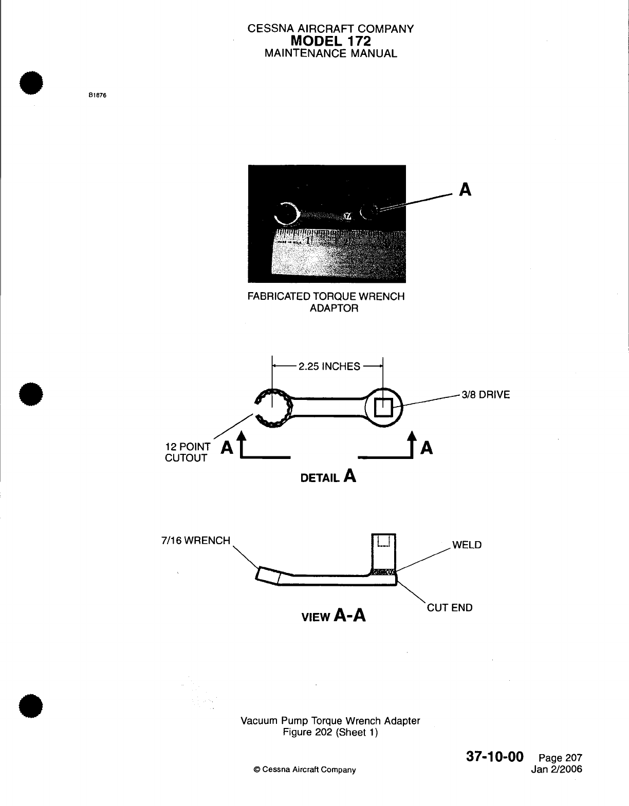
CESSNA
AIRCRAFT
COMPANY
MODEL
172
MAINTENANCE
MANUAL
81876
FABRICATED
TORQUE WRENCH
ADAPTOR
2.25
INCHES
/
12
POINT
CUTOUT
3/8
DRIVE
tA
DETAIL
A
7/16
WRENCH
VIEW
A-A
Vacuum
Pump
Torque
Wrench
Adapter
Figure
202
(Sheet
1)
Cessna
Aircraft
Company
37-10-00
Page
207
Jan 2/2006
CUT
END
A
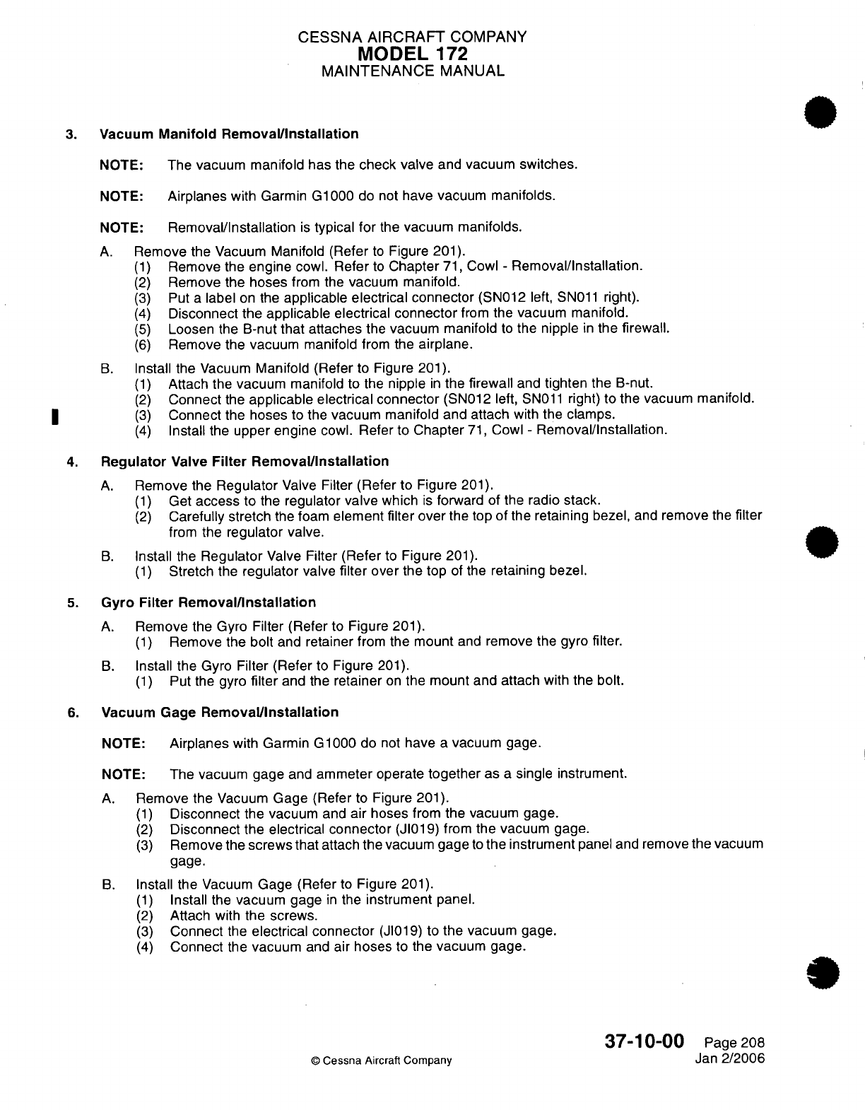
CESSNA AIRCRAFT
COMPANY
MODEL
172
MAINTENANCE
MANUAL
3.
Vacuum
Manifold
Removal/Installation
NOTE: The
vacuum
manifold
has
the
check valve
and
vacuum switches.
NOTE:
Airplanes
with
Garmin
G1000
do not
have
vacuum
manifolds.
NOTE:
Removal/Installation
is
typical
for
the
vacuum
manifolds.
A.
Remove the
Vacuum
Manifold (Refer
to
Figure
201).
(1)
Remove
the
engine
cowl.
Refer
to
Chapter
71,
Cowl
-
Removal/Installation.
(2)
Remove the
hoses
from
the
vacuum
manifold.
(3)
Put
a
label
on the
applicable
electrical
connector
(SN012
left,
SN011
right).
(4)
Disconnect
the
applicable
electrical
connector
from
the
vacuum manifold.
(5)
Loosen
the
B-nut
that attaches
the
vacuum manifold
to
the
nipple
in
the
firewall.
(6)
Remove the vacuum manifold
from
the
airplane.
B.
Install
the Vacuum
Manifold (Refer
to
Figure
201).
(1)
Attach
the
vacuum
manifold
to the
nipple
in
the
firewall
and
tighten
the
B-nut.
(2)
Connect
the
applicable
electrical
connector
(SN012
left,
SN011
right) to
the vacuum
manifold.
(3)
Connect the hoses
to the
vacuum manifold and attach
with
the
clamps.
(4)
Install
the
upper
engine
cowl.
Refer
to Chapter
71,
Cowl
-
Removal/Installation.
4.
Regulator
Valve
Filter Removal/Installation
A.
Remove
the
Regulator
Valve
Filter
(Refer
to
Figure
201).
(1)
Get
access
to
the
regulator
valve
which
is
forward of the
radio
stack.
(2)
Carefully stretch
the foam
element filter
over
the top
of
the
retaining
bezel,
and
remove
the
filter
from
the
regulator valve.
B.
Install
the
Regulator
Valve
Filter
(Refer
to
Figure
201).
(1)
Stretch
the
regulator
valve
filter
over
the top
of
the
retaining
bezel.
5.
Gyro Filter
Removal/Installation
A.
Remove the
Gyro Filter
(Refer
to
Figure
201).
(1)
Remove
the
bolt
and
retainer
from
the
mount
and
remove
the
gyro
filter.
B.
Install
the
Gyro
Filter (Refer
to
Figure
201).
(1)
Put
the
gyro
filter
and the
retainer
on
the
mount
and
attach
with
the
bolt.
6.
Vacuum Gage
Removal/Installation
NOTE:
Airplanes
with Garmin
G1000
do
not
have
a
vacuum
gage.
NOTE: The
vacuum gage
and
ammeter
operate
together
as
a
single
instrument.
A.
Remove
the
Vacuum
Gage
(Refer to
Figure
201).
(1)
Disconnect
the vacuum
and
air
hoses
from
the vacuum gage.
(2)
Disconnect the electrical
connector
(JI019)
from
the vacuum gage.
(3)
Remove the
screws
that
attach
the
vacuum
gage
to
the
instrument
panel and
remove
the vacuum
gage.
B.
Install
the
Vacuum
Gage (Refer
to
Figure
201).
(1)
Install
the
vacuum
gage
in
the
instrument
panel.
(2)
Attach
with
the
screws.
(3)
Connect
the
electrical connector
(JI019)
to
the
vacuum gage.
(4)
Connect
the
vacuum
and air
hoses
to
the
vacuum
gage.
37-10-00
Page
208
©
Cessna
Aircraft
Company
Jan
2/2006
CESSNA
AIRCRAFT
COMPANY
MODEL
172
MAINTENANCE
MANUAL
7.
Vacuum
Transducer
Removal/Installation
NOTE:
Only
airplanes
with
the
Garmin
G1000
have
a
vacuum
transducer.
A.
Remove
the Vacuum
Transducer
(Refer
to
Figure
201).
(1)
Remove
the
center
panel.
Refer
to
Chapter
31,
Instrument
and
Control
Panels
-
Maintenance
Practices.
(2)
Remove
the
screw
and
clamp
that
hold
the
vacuum
transducer
in
position.
(3)
Remove
the vacuum transducer.
B.
Install
the
Vacuum
Transducer
(Refer
to
Figure
201).
(1)
Install the
vacuum
transducer.
(2)
Install
the screw
and
clamp
that
hold the
vacuum
transducer
in
position.
(3)
Install
the
center
panel. Refer
to
Chapter
31,
Instrument
and
Control
Panels
-
Maintenance
Practices.
I
8.
Vacuum
Manifold
Test
(For
airplanes
with
the
Parker
Airborne
manifold)
A.
The
vacuum manifold
must
be
tested
periodically
to
determine
its
condition
and
serviceability.
Refer
to
Chapter
5,
Inspection
Time
Limits
for
inspection intervals.
Refer
to
Parker
Hannifin Corporation/
Airborne
Division's Product
Reference
Memo
#39
(or
latest revision)
for
the
procedures.
9.
Vacuum
Pressure Adjustment/Test
(For
airplanes
with
the
Parker
Airborne
regulator
valve or
the
Aero
Accessories
regulator
valve)
NOTE: Before
the
adjustment
procedure,
the
entire
pneumatic
system
must
be
inspected
and tested
for
leaks,
restrictions,
and
unserviceable
components.
Failure
to
correct
all
system
anomalies
will
lead
to
reduced
dry
air
pump
service
life.
A.
Prepare
the
System
for
the
Test
(Refer
to
Figure
201).
(1)
Remove
the
gyro (central
air)
filter.
B.
Do
a
Check
of
the
Regulator
Valve.
CAUTION: Make
sure that the temperature
of
the
engine does
not
go
above the
maximum engine
temperature
during the
adjustment/test
of
the
regulator
valve.
NOTE:
At
engine
speeds
between
1200
RPM
and
full
throttle, suction
must
fall
between 4.5
in.hg.
and
5.5
in.hg.
(green
range
on
gage).
(1)
Start
the
engine,
warm
up
to
the
normal
operating
temperature,
and
run
at
static
RPM.
Refer
to
Pilot's
Operating
Handbook
and
FAA
Approved Airplane
Flight
Manual.
(2)
Make sure
the
suction
gage
indication does
not
go
above
5.5
in.hg.
(3)
Run
the
engine
at
1200
RPM
and make
sure
the
gage
indication does
not
go
below 4.5
in.hg.
(4) If
the
suction
indication falls
outside
of
the
range,
shut
down
the engine
and
adjust
the
regulator
valve
in
the
steps that
follow.
(a)
Bend
the locking
tab
upward
on
the
lower
surface
of
the
regulator valve.
CAUTION:
Be
careful
when you
turn
the
adjustment
screw.
Do
not
turn
it
too much
in
either direction.
When
you
turn
it
too
much
in
either direction, damage
can
occur
to
the
equipment.
(b)
Turn
the adjustment
screw
on
the lower
surface
of
the
regulator
valve
in
the direction
to
increase
or
decrease
the
pressure
as
necessary.
NOTE:
As
you
face
the
adjustment
screw,
when
you
turn
it
clockwise
the
pressure
increases.
When
you
turn
it
counterclockwise,
the
pressure
decreases.
37-10-00
Page
209
©
Cessna
Aircraft Company
Jan 2/2006
CESSNA AIRCRAFT
COMPANY
MODEL
172
MAINTENANCE
MANUAL
(c)
Tap
the
regulator
after
you
adjust
it
to help
reset
the
components.
(d)
Bend
the locking
tab downward
to
keep
the
adjustment
screw
in
place
when
the
correct
pressure
has
been
set.
(5)
Run
the engine
at
static
RPM
and
make
sure
the
gage
indication does
not
go
above
5.5
in.hg.
(6)
Run
the engine
at
1200
RPM
and
make sure
the
gage
indication does
not
go
below
4.5
in.hg.
(7)
Shut
down
the
engine.
(a)
For
airplanes
without
the
Garmin
G1000,
make
sure
that
the
L
VAC
R
lights
come
on.
(b)
For
airplanes
with the
Garmin
G1000,
make sure
that
the
low
vacuum
annunciator
visual
and aural
warnings
come
on.
(8)
Attach
the
filter
element
to the
gyro
(central
air)
filter.
(9)
Before
you
start
the
engine,
make sure
that
the low
vacuum
annunciations
are
on.
(a)
For
airplanes
without
the
Garmin
G1000, make sure
that
the
L
VAC
R
lights are
on.
(b)
For
airplanes
with the
Garmin
G1000,
make sure
that
the
low
vacuum
annunciator
visual
warning
is on.
(10)
Run
the engine
for
a
final
time
at
static
RPM and
observe
the
indication
on
the
suction
gage.
(a) If
the
indication falls noticeably
after
the
filter
is
installed,
replace
the
filter.
(11)
Reduce the
engine speed to
1200
RPM
and
make
sure
that
the
suction stays
in
the
green
range
(does
not
fall
below
4.5
in.hg.).
and
that
the
low
vacuum
annunciations
are
off.
(a)
For
airplanes without
the
Garmin
G1000,
make
sure
that
the
L
VAC
R
lights
go off.
(b)
For
airplanes
with
the Garmin
G1000,
make sure
that the
low
vacuum
annunciator
visual
and aural
warnings
go off.
(12)
Shut
down
the
engine.
37-10-00
Page
210
©
Cessna
Aircraft
Company
Jan
2/2006

CHAPTER
STANDARD
PRACTICES
-
STRUCTURES
CESSNA
AIRCRAFT
COMPANY
MODEL
172
MAINTENANCE
MANUAL
LIST
OF
EFFECTIVE PAGES
CHAPTER-SECTION-SUBJECT
51-Title
51-List
of
Effective
Pages
51-Record
of
Temporary
Revisions
51-Contents
51-00-00
51-10-00
51-11-00
©
Cessna
Aircraft Company
51
-
LIST OF EFFECTIVE
PAGES
Page
1
of
1
Jan
3/2005
PAGE
DATE
Apr
7/2003
Apr
7/2003
Apr
7/2003
Page
1
Page
1
Pages
1-4
Temporary
Revision
Number
RECORD
OF
TEMPORARY
REVISIONS
Page
Number
Issue
Date By
Date
Removed
By
CESSNA
AIRCRAFT
COMPANY
MODEL
172
MAINTENANCE
MANUAL
CONTENTS
STRUCTURES
-
GENERAL
.........
.........
....................................
S
cope......................................................................
Definition
...................................................................
STRUCTURES
-
DESCRIPTION
AND
OPERATION
................................
Description
.................................................................
CORROSION
-
DESCRIPTION
AND
OPERATION
.........
......................
G
eneral...................................................................
Characteristics
of
Corrosion..................................................
Types
of
Corrosion
..........................................................
Typical
Corrosion Areas
.....................................................
Corrosion Detection
............................
.........................
Corrosion
Damage
Limits
.........
..........................................
51-00-00
Page
1
51-00-00
Page
1
51-00-00
Page
1
51-10-00
Page
1
51-10-00
Page
1
51-11-00
Page
1
51-11-00
Page
1
51-11-00
Page
1
51-11-00
Page
1
51-11-00
Page
3
51-11-00
Page
4
51-11-00
Page
4
CONTENTS
Page
1
of
1
Jan
3/2005
©
Cessna Aircraft
Company
CESSNA
AIRCRAFT
COMPANY
MODEL
172
MAINTENANCE
MANUAL
STRUCTURES
-
GENERAL
1.
Scope
A.
This
chapter
provides
a
description
of
general
airplane
structures
and
corrosion
characteristics.
For
repair
of
structural
members and
repair
techniques
used
throughout
the
airplane,
refer
to
the Single
Engine
Structural Repair
Manual
1996
and
On.
2.
Definition
A.
This
chapter
is
divided
into
two
sections
briefly described
below.
(1)
The
section
on
structures provides
an
overall
description
of
the
airplane structure
and
methods
of
construction
used
on
the
airplane.
(2)
The
section
on
corrosion
provides
a
general
description
of
corrosion
characteristics,
types
of
corrosion
and
typical
corrosion
areas.
51-00-00
Page
1
©
Cessna
Aircraft Company
Apr
7/2003
CESSNA
AIRCRAFT
COMPANY
MODEL
1
72
MAINTENANCE
MANUAL
STRUCTURES
-
DESCRIPTION
AND
OPERATION
1.
Description
A.
The
fuselage
is
of
semimonocoque construction
and
consists
of
three
major
sections: forward
section,
center section,
and
tailcone
section.
Construction
consists
of
formed
bulkheads, longitudinal
stringers,
reinforcing
channels
and skin. Frame
members
of
the cabin
section
are
constructed
of
formed
bulkhead
channels.
Bulkheads
are
formed
"U"
channel
sections.
Principal
material
is
2024-
0
alclad
aluminum
alloy
which,
after
forming,
is
heat
treated
to
a
2024-T42
condition
and
painted
with
epoxy
primer.
All
bulkheads
in
the
fuselage
are
constructed
of
formed sheet
metal
or reinforced
sheet
metal.
B.
The
wings
are of
all-metal, strut-braced,
semi
monocoque
construction,
utilizing
two spars.
Each
wing
consists
of
an
outer
wing panel
with
an
integral
fuel
bay,
an
aileron and
a
flap.
Flanged
upper
and
lower
edges
of
all
ribs
serve
as
cap-
strips,
in
addition
to
providing rigidity
to
the
rib.
The
skin,
riveted
directly
to
each
rib
flange,
provides
the
cellular
strength
for each
successive
rib
bay.
The nose,
center,
and
trailing
edge
rib
segments
are
riveted
together
through
the
front
and
rear
spars
to form
the
basic
airfoil sections. Alclad stringers
stiffen
the
skin
between
ribs.
Spars
are
comprised
of machine
milled,
tapered
extrusions
riveted
to
sheet
metal
webs.
C.
The
full-cantilever,
all-
metal tail
group
consists
of
a
vertical
stabilizer
and
rudder,
and
a
horizontal
stabilizer
and
elevators.
The
horizontal
stabilizer
is
of
one-piece
construction,
consisting
of
spars,
ribs
and
skins. Elevators
are
constructed
of
aluminum
spars,
ribs
and
skin panels.
The
skin panels
are
riveted
to
ribs
and
spars.
A
balance
weight
is
located
in
the
outboard
end
of
each
elevator,
forward
of
the
hinge line.
An
elevator
trim
tab,
attached
to each
elevator,
is
constructed
of
a
spar,
ribs,
and
skin;
all
riveted
together.
The
vertical
stabilizer
is
constructed
of
a
forward
spar
and
aft
spar,
ribs
and
skin.
The
rudder
is
constructed
of
spars,
ribs
and
skin panels.
The rudder
trim
tab
is
constructed
of
a
spar,
ribs,
and
skin;
all
riveted
together.
D.
The
main
landing gear
is
constructed
of
6150
alloy spring-steel
tubing
with
attaching
parts
of
high
strength
7075-T73
aluminum
alloy
forgings.
Nose
gear
components
are
4130,
6150
alloy
steel
and
7075-T73
aluminum
alloy
forgings.
E.
The engine
mount
is
constructed
of
welded 4130
steel
tubing.
F.
The
engine
cowling
consists
of
upper
and
lower formed
aluminum
sections.
The
upper
section
includes
and
oil
inspection
door,
and
the
lower
section includes
an
air
induction
scoop
with
an
engine
oil
filter.
Both
sections
are
removable.
51-10-00
Page
1
©
Cessna
Aircraft
Company
Apr 7/2003
CESSNA AIRCRAFT
COMPANY
MODEL
172
MAINTENANCE
MANUAL
CORROSION
-
DESCRIPTION
AND OPERATION
1.
General
A.
This section
describes
corrosion
so
the
maintenance
technician
can
identify the
various types
of
corrosion
and
apply
preventative measures
to
minimize
corrosion
activity.
For
corrosion
control
and
corrosion
damage, refer
to
the
Single Engine
Structural
Repair
Manual
1996
and
On.
2.
Characteristics
of
Corrosion
A.
Corrosion
is
a
natural phenomenon which
destroys
metal
by
chemical
or
electrochemical action
and
converts
it
to
a
metallic
compound,
such
as
an
oxide,
hydroxide,
or sulfate.
All
metals
used
in
airplane
construction
are
subject
to corrosion. Attack
may
take
place
over
an
entire metal
surface,
if
exposed,
or
it
may
be
penetrating
in
nature,
forming
deep
pits.
It
may
follow
grain
boundaries
or
it
may
penetrate
a
surface
at
random.
Corrosion
may
be
accentuated
by
stresses
from
external
loads
or
from
lack
of
homogeneity
in
the
metallic
structure
or
from
improper heat
treatment.
It is
promoted
by contact
between
dissimilar
metals
or
with
materials
which
absorb
moisture,
such
as wood,
rubber,
felt,
dirt,
etc.
(1)
The
following
conditions
must
exist
for
electrochemical
corrosion
to
occur.
Refer
to
Figure
1
for
an
illustration
of
electrochemical
corrosion.
(a)
There must
be
a
metal
that corrodes
and
acts
as
the
anode.
(b)
There
must
be
a
less
corrodible
metal
that acts
as
the
cathode.
(c)
There must
be
a
continuous
liquid path
between
the two
metals which
acts
as
the
electrolyte,
usually
condensation
and
salt
or
other
contaminations.
(d)
There
must
be
a
conductor
to
carry
the flow
of
electrons
from the
cathode
to
the anode.
This
conductor
is
usually
in
the
form
of
a
metal-to-metal contact
(rivets,
bolts,
welds,
etc.)
(2)
The
elimination
of
any
one
of
the
four conditions described
above
will
stop
the
corrosion reaction
process.
(3)
One
of
the best ways
to
eliminate
one
of
the
four
described conditions
is
to
apply
an
organic
film
(such
as paint,
grease, plastic,
etc.)
to
the
surface
of
the
metal
affected.
This
will
prevent
the
electrolyte
from
connecting
the
cathode
to
the anode, and
current
cannot
flow,
therefore,
preventing corrosion
reaction.
Refer
to
Figure
1
for
a
typical
organic
film
application.
(4)
At
normal
atmospheric
temperatures,
metals
do
not corrode
appreciably without moisture,
but
the
moisture
in
the
air
is
usually
enough
to
start
corrosive
action.
(5)
The initial rate
of
corrosion
is
usually
much
greater
than
the
rate
after
a
short
period
of time.
This
slowing
down
occurs
because
of
the
oxide
film
that
forms
on the
metal's
surface.
This
film
tends
to
protect
the metal
underneath.
(6)
When
components
and systems
constructed
of
many
different types
of
metals
must
perform
under
various
climatic
conditions,
corrosion
becomes
a
complex
problem.
Salt
on
metal
surfaces
(from
sea
coast
operation) greatly increases
the
electrical conductivity
of
any
moisture
present
and
accelerates
corrosion.
(7)
Other
environmental
conditions
which
contribute
to
corrosion
are:
(a)
Moisture
collecting
on
dirt
particles.
(b)
Moisture
collecting
in
crevices
between
lap
joints,
around rivets,
bolts
and
screws.
3.
Types
of
Corrosion
A.
Corrosion Types.
(1)
Direct
Surface
Attack
-
The
most common
type
of
general surface corrosion results
from
direct
reaction
of
a
metal
surface
with
oxygen
in
the
atmosphere.
Unless
properly protected,
steel
will
rust
and
aluminum
and
magnesium
will
form
oxides.
The
attack
may
be
accelerated
by
salt
spray
or
salt-bearing
air,
by
industrial
gases
or
by
engine exhaust
gases.
(2)
Pitting
-
While
pitting can
occur
in
any
metal,
it
is
particularly characteristic
of
passive
materials,
such
as
the
alloys
of
aluminum,
nickel
and
chromium.
It is
first
noticeable
as
a
white
or
gray
powdery
deposit similar
to
dust,
which
blotches
the
surface.
When the
deposits
are
cleaned
away,
tiny
pits
can
be
seen
in
the
surface.
(3)
Dissimilar
Metal
Corrosion
-
When
two
dissimilar
metals
are
in
contact
and
are
connected
by
an
electrolyte
(continuous
liquid
or
gas
path),
accelerated
corrosion
of
one
of
the
metals
occurs.
The
most
easily
oxidized
surface
becomes the
anode
and
corrodes.
The less
active
member
51-11-00
Page
1
©
Cessna
Aircraft
Company
Apr
7/2003
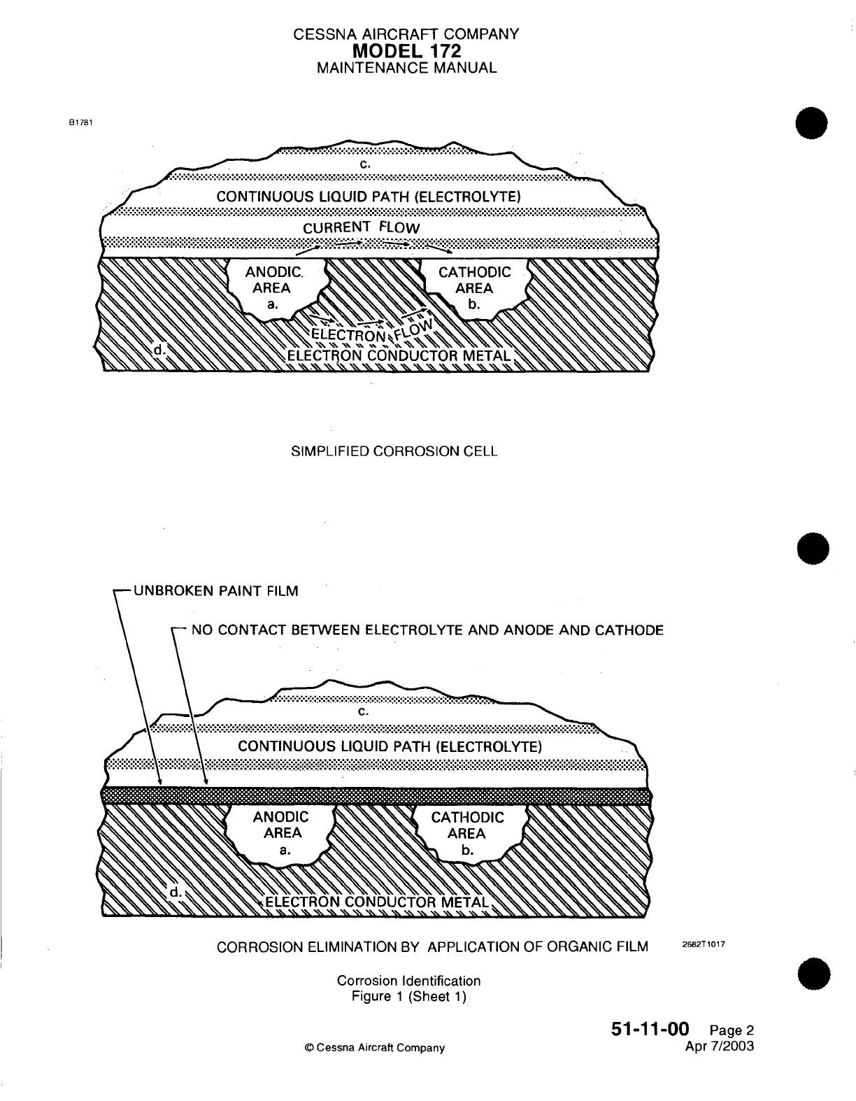
CESSNA
AIRCRAFT
COMPANY
MODEL
172
MAINTENANCE
MANUAL
B1781
..
CURRENT
FLOW
............................................
CURRENT
FLOW
SIMPLIFIED CORROSION
CELL
UNBROKEN
PAINT
FILM
\
NO
CONTACT
BETWEEN ELECTROLYTE
AND
ANODE
AND
CATHODE
\ \ y i..>~~:.:.:.··: >:.: x-·····~~::::ss.-ss s:..: : s;:: :::.
\ \ CONTINUOUS
LIQUID
PATH
(ELECTROLYTE)
: > :::ANODIC AA ::TA >IC
AREA
~
AE
a.
h.
CORROSION
ELIMINATION
BY
APPLICATION
OF
ORGANIC
FILM
2682T1017
Corrosion
Identification
Figure
1
(Sheet
1)
51-11-00
Page
2
Apr 7/2003
©
Cessna
Aircraft
Company
Ot ......... m 6 ~...........
CESSNA
AIRCRAFT
COMPANY
MODEL
1
72
MAINTENANCE
MANUAL
of
the
couple
becomes
the
cathode of
the
galvanic cell.
The
degree
of
attack
depends
on
the
relative
activity
of the
two
surfaces;
the
greater
the
difference
in
activity
the
more
severe
the
corrosion. Relative
activity
in
descending
order
is
as
follows:
(a)
Magnesium
and
its
alloys.
(b)
Aluminum
alloys
1100,
3003,
5052,
6061,
220,
355,
356,
cadmium
and
zinc.
(c)
Aluminum
alloys
2014,
2017,
2024,
7075
and
195.
(d)
Iron,
lead
and
their
alloys
(except
stainless
steel).
(e)
Stainless
steels,
titanium,
chromium,
nickel, copper,
and
their
alloys.
(f)
Graphite
(including
dry
film
lubricants
containing graphite).
(4)
Intergranular Corrosion
-
Selective
attack along
the
grain
boundaries
in
metal
alloys
is
referred
to
as
intergranular
corrosion.
It
results
from
lack
of
uniformity
in
the
alloy
structure.
It is
particularly
characteristic
of
precipitation hardened
alloys
of
aluminum
and
some stainless steels. Aluminum
extrusions
and
forgings
in
general
may
contain
nonuniform
areas,
which
in
turn
may
result
in
galvanic
attack
along
the grain
boundaries.
When
attack
is
well
advanced,
the
metal
may blister
or
delaminate,
which
is
referred to
as
'exfoliation".
(5)
Stress Corrosion
-
This results
from
the
combined
effect
of
static
tensile
stresses applied
to
a
surface
over
a
period of
time.
In
general,
cracking
susceptibility
increases
with stress,
particularly
at
stresses approaching
the
yield
point,
and
with
increasing
temperature,
exposure
time
and
concentration
of
corrosive
ingredients
in
the
surrounding
environment.
Examples
of
parts
which
are
susceptible
to
stress corrosion
cracking
are aluminum
alloy
bellcranks
employing pressed-in
taper
pins,
landing gear
shock
struts
with pipe
thread-type
grease
fittings,
clevis
joints
and
shrink
fits.
(6)
Corrosion Fatigue
-
This
is
a
type
of
stress corrosion
resulting
from
the
cyclic
stresses
on a metal
in
corrosive
surroundings.
Corrosion
may
start
at
the
bottom
of
a
shallow
pit
in
the
stressed
area.
Once
attack begins,
the
continuous
flexing
prevents repair
of
protective
surface coating
or
oxide
films
and
additional corrosion takes
place
in
the
area
of
stress.
4.
Typical
Corrosion
Areas
A.
This
section
lists
typical
areas
of
the
airplane
which
are
susceptible
to
corrosion.
These areas
should
be
carefully inspected
at
periodic intervals
to
detect
corrosion
as
early
as
possible.
(1)
Engine
Exhaust
Trail
Areas.
(a)
Gaps,
seams
and
fairings
on
the
lower
right
side
of
the
fuselage,
aft
of the
engine
exhaust
stack,
are
typical
areas where
deposits
may
be
trapped
and
not
reached
by
normal
cleaning
methods.
(b)
Around rivet
heads,
skin
laps
and
inspection
covers
on
the
airplane
lower
fuselage,
aft
of
the
engine
secondary exhaust
stack,
should
be
carefully
cleaned
and
inspected.
(2)
Battery
Box
and Battery
Vent
Opening.
(a)
The
battery,
battery
cover,
battery
box
and
adjacent
areas,
especially
areas
below
the
battery
box where
battery
electrolyte
may
have
seeped,
are
particularly subject
to
corrosive
action.
If
spilled
battery
electrolyte
is
neutralized
and
cleaned
up
at
the
same
time
of
spillage,
corrosion
can
be
held
to
a
minimum
by using
a
weak
boric
acid
solution
to
neutralize
the battery
electrolyte
(ni-cad
battery)
or
baking
soda
solution
to
neutralize
the
lead acid-type
battery
electrolyte.
If
boric
acid
or
baking
soda
is
not
available,
flood
the
area
with
water.
(3)
Steel
Control
Cables
(including
Stainless
Steel).
(a)
Checking
for
corrosion
on
control
cables
is
normally
accomplished
during the
preventative
maintenance
check.
During
preventative
maintenance,
broken wires
and
wear
of
the
control
cables
are
also
checked.
(b) If
the
surface
of the
cable
is
corroded,
carefully
force
the
cable
open
by
reverse twisting
and
visually
inspect
the
interior.
Corrosion
on
the
interior
strands
of the
cable
constitutes
failure and
the
cable
must
be
replaced.
If
no
internal
corrosion
is
detected,
remove
loose
external
rust
and
corrosion
with
a
clean,
dry,
coarse-weave
rag
or
fiber
brush.
NOTE:
Do
not
use
metallic
wools
or
solvents
to
clean
installed
cables.
Use
of
metallic
wool
will
embed
dissimilar
metal
particles
in
the
cables
and
create
further
corrosion.
Solvents
will remove
internal
cable lubricant, allowing cable
strands
to
abrade
and
further
corrode.
51-11-00
Page
3
©
Cessna
Aircraft
Company
Apr 7/2003
CESSNA
AIRCRAFT
COMPANY
MODEL
172
MAINTENANCE
MANUAL
(c)
After thorough
cleaning
of
the
exterior
cable
surface,
apply
a
light
coat
of
lubricant
(VV-L-
800)
to
the
external
cable
surface.
(4)
Internal
Fuel
Tanks.
(a)
The
presence
of
soil
contamination
(a
brown
slimy
substance)
and
pitting-type
corrosion
may
occur
in
the lower areas
of
the
integral fuel
tanks
of
certain
airplanes.
This
condition
can
cause
a
general
degradation
of
some top
coating
and
some
depolymerization
and
loosening
of
sealant
materials
in
lower
areas.
(b)
The
contaminants
resemble normal aluminum
corrosion
products,
including
a
considerable
quantity
of
iron.
The
brown,
slimy deposits
are
microbial
in
nature.
Examination
of the
corrosion
pits
by
metallurgical
techniques
indicate
the
presence
of
intergranular attacks.
5.
Corrosion
Detection
A.
Corrosion
Defoliation.
The
primary means
of
corrosion detection
is
visual,
but
in
situations
where
visual inspection
is
not
feasible, other
techniques
must
be
used.
The
use
of
liquid
dye
penetrant,
magnetic
particle,
X-ray
and
ultra-sonic
devices
can be
used,
but
most
of
these sophisticated
techniques
are
intended
for
the
detection
of
physical
flaws within
metal
objects,
rather
than the
detection
of
corrosion.
(1)
Visual
Inspection.
A
visual
check
of
the
metal
surface
can
reveal
the
signs
of
corrosive
attack,
the
most
obvious
of
which
is
a
corrosive
deposit.
Corrosion
deposits
of
aluminum
or
magnesium
are
generally
a
white
or
grayish-white
powder,
while the
color
of
ferrous compounds
varies
from
red
to
dark
reddish-brown.
(a)
The
indications
of
corrosive
attack
are
small,
localized
discolorations of
the metal
surface.
Surfaces
protected
by
paint
or
plating
may
only
exhibit indications
of
more
advanced
corrosive
attack
by
the
presence
of
blisters
or
bulges
in
the protective
film.
Bulges
in
lap
joints
are
indications
of
corrosive build-up
which
is
well
advanced.
(b) In
many
cases
the
inspection
area
is
obscured
by
structural
members,
equipment
installations
or,
for
other
reasons,
are
awkward
to
check visually.
In
such
cases,
mirrors,
borescope
or
similar devices
can
be
used
to
inspect
the
obscured
areas.
Any
means
which
allows
a
thorough
inspection
can
be
used.
Magnifying
glasses
are
valuable
aids
for
determining
whether or
not
all
corrosive
products
have been
removed during
clean
up
operations.
(2)
Liquid
Dye
Penetrant
Inspection.
Inspection
for
large
stress-corrosion
or
corrosion
fatigue
cracks
on
nonporous
or
nonferrous
metals
may
be
accomplished
using
dye penetrant
processes.
The
dye
applied
to
a
clean
metallic surface
will
enter
small
openings
or
cracks
by
capillary
action.
After
the
dye
has
an
opportunity
to
be
absorbed
by
any surface
discontinuity,
the
excess
dye
is
removed
and
a
developer
is
applied
to
the
surface.
The
developer
acts
like a
blotter
and
draws
the
dye
from
cracks
or fissures
back
to
the
surface, giving
visible
indication
of any
fault
that
is
present
on
the surface.
The
magnitude
of
the
fault
is
indicated
by
the
quantity
of
dye
brought
back
to
the
surface
by
the
developer.
6.
Corrosion
Damage
Limits
A.
Following
cleaning
and
inspection
of
the
corroded
area,
the
actual
extent
of
the
damage
may
be
evaluated
using
the
following
general
guidelines
and
good,
sound
maintenance
judgement.
Determine
the
degree
of
corrosion
damage
(light,
moderate,
or
severe)
with
a
dial-type
depth
gage,
if
accessibility
permits.
If
the
area
is
inaccessible,
clay impressions,
or
any
other
means
which
will
give
accurate
results,
should
be
used.
In
the
event
the
corrosion
damage
is
severe,
contact
Cessna
Propeller Aircraft Product
Support
for
assistance.
(1)
Light
Corrosion
-
Characterized
by
discoloration
or
pitting
to
a
depth
of
approximately
0.001
inch
maximum.
This
type
of
damage
is
normally
removed
by
light
hand-sanding
or
a
minimum
of
chemical
treatment.
(2)
Moderate
Corrosion
-
Appears similar
to
light
corrosion
except
there
may
be
blistering
or
some
evidence
of
scaling
or
faking.
Pitting
depths
may
be
as
deep
as
0.010
inch.
This
type
of
damage
is
normally
removed
by
extensive hand-sanding
or
mechanical
sanding.
(3)
Severe
Corrosion
-
General appearance
may
be
similar
to
moderate
corrosion
with
severe
blistering
exfoliation
and
scaling
or
flaking.
Pitting
depths
may
be
as deep as
0.10
inch.
This
type
of
damage
is
normally
removed
by
extensive
mechanical
sanding
or
grinding
(if
not
complete
part
replacement).
51-11-00
Page
4
©
Cessna
Aircraft
Company
Apr
7/2003
CHAPTER
DOORS

CESSNA AIRCRAFT
COMPANY
MODEL
172
MAINTENANCE
MANUAL
LIST
OF
EFFECTIVE
PAGES
CHAPTER-SECTION-SUBJECT
52-Title
52-List
of
Effective
Pages
52-Record
of
Temporary
Revisions
52-Table
of
Contents
52-00-00
52-10-00
52-10-00
52-30-00
PAGE
Page
1
Page
1
Pages
201-209
Pages
201-204
©
Cessna Aircraft
Company
52
-
LIST
OF
EFFECTIVE
PAGES
Page
1
of
1
Jul 3/2006
DATE
Apr
7/2003
Jun
7/2004
Jul
3/2006
Jul
3/2006
Temporary
Revision
Number
RECORD
OF
TEMPORARY
REVISIONS
Page
Number Issue
Date
By
Date
Removed
By
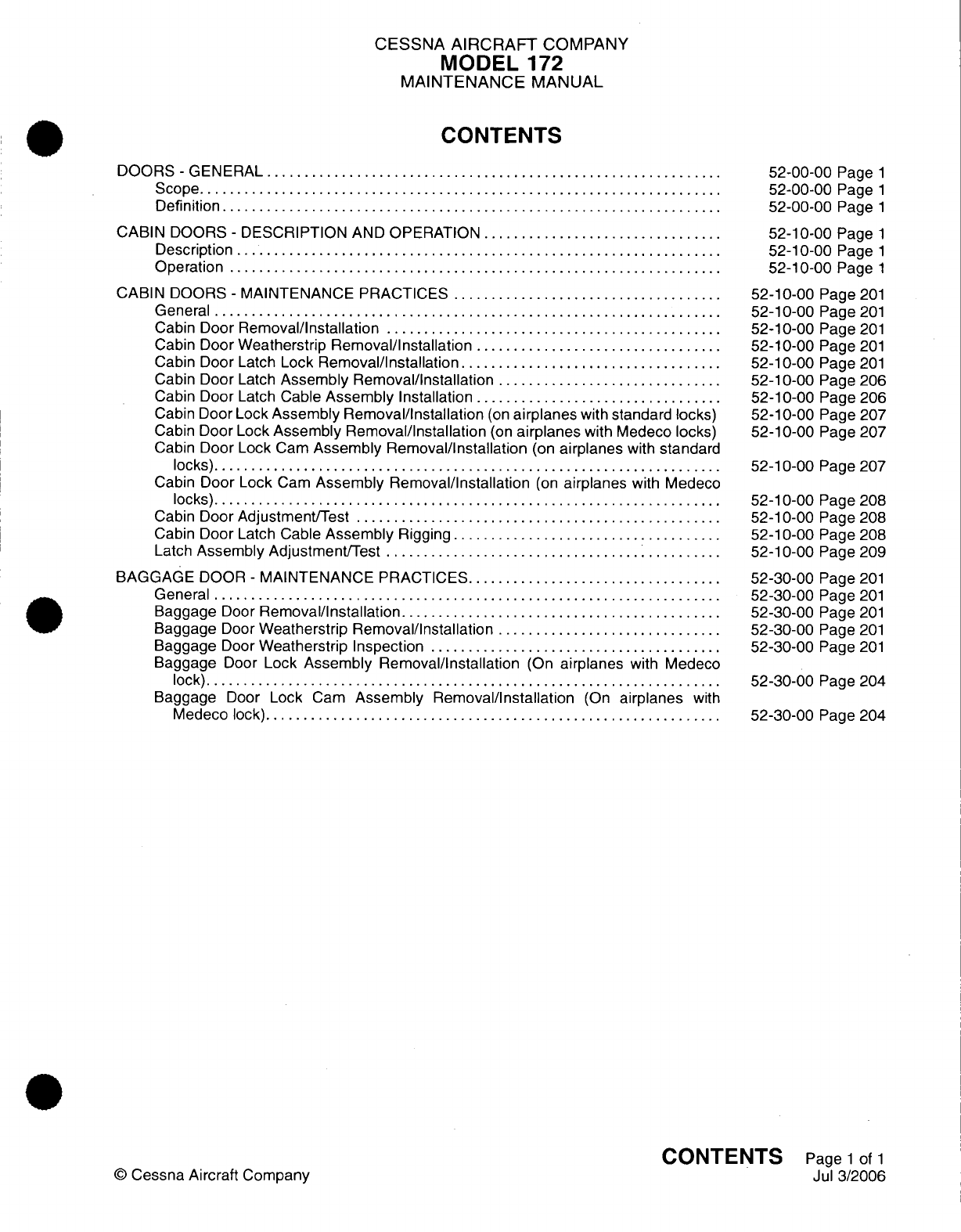
CESSNA
AIRCRAFT
COMPANY
MODEL
172
MAINTENANCE
MANUAL
CONTENTS
DOORS
-
GENERAL
.........
............................
........................
S
cope......................................................................
Definition
...................................................................
CABIN
DOORS
-
DESCRIPTION
AND
OPERATION
................................
Description
.................................................................
Operation
............................
...........
...........................
CABIN
DOORS
-
MAINTENANCE PRACTICES
....................................
G
en
eral
....................................................................
Cabin
Door
Removal/Installation
....................
.........................
Cabin
Door
Weatherstrip
Removal/Installation
.........
........................
Cabin Door Latch
Lock
Removal/Installation
..............................
Cabin Door
Latch
Assembly Removal/Installation
..............................
Cabin Door
Latch
Cable
Assembly
Installation
.................................
Cabin
Door
Lock
Assembly Removal/Installation
(on
airplanes
with
standard
locks)
Cabin Door
Lock
Assembly Removal/Installation
(on
airplanes
with Medeco
locks)
Cabin Door
Lock
Cam
Assembly Removal/Installation
(on
airplanes
with
standard
locks)................
...
.................................................
Cabin
Door
Lock
Cam
Assembly Removal/Installation
(on
airplanes
with
Medeco
locks)...............
.........
.........
...................................
Cabin
Door
Adjustment/Test
.........
.........
...............................
Cabin
Door
Latch
Cable
Assembly
Rigging
....................................
Latch
Assembly
Adjustment/Test
.............................................
BAGGAGE
DOOR
-
MAINTENANCE
PRACTICES.................................
G eneral
....................................................................
Baggage
Door
Removal/Installation.
..........................................
Baggage
Door
Weatherstrip
Removal/Installation
..........
....................
Baggage
Door
Weatherstrip Inspection
.......................................
Baggage
Door
Lock
Assembly Removal/Installation
(On
airplanes
with Medeco
lock)....................................
.................................
Baggage
Door
Lock
Cam
Assembly Removal/Installation
(On
airplanes
with
M
edeco
lock).............................................................
52-00-00
Page
1
52-00-00
Page
1
52-00-00
Page
1
52-10-00
Page
1
52-10-00
Page
1
52-10-00
Page
1
52-10-00
Page
201
52-10-00
Page
201
52-10-00
Page
201
52-10-00
Page
201
52-10-00
Page
201
52-10-00
Page 206
52-10-00
Page 206
52-10-00
Page 207
52-10-00
Page 207
52-10-00
Page 207
52-10-00
Page 208
52-10-00
Page 208
52-10-00
Page 208
52-10-00
Page 209
52-30-00
Page
201
52-30-00
Page
201
52-30-00
Page
201
52-30-00
Page
201
52-30-00
Page
201
52-30-00
Page
204
52-30-00
Page
204
CONTENTS
Page
1
of
1
Jul
3/2006
©
Cessna Aircraft
Company

CESSNA
AIRCRAFT
COMPANY
MODEL
172
MAINTENANCE
MANUAL
DOORS
-
GENERAL
1.
Scope
A.
This
chapter
provides
maintenance
information
on
doors. Provided
are
removal/installation
instructions
and
rigging
procedures.
2.
Definition
A.
This
chapter
is
divided
into
sections
and
subsections
to
assist
maintenance
personnel
in
locating
specific
systems
and
information. The
following
is
a
brief
description
of
each
section.
For
locating
information
within
the
chapter, refer
to
the Table
of
Contents
at
the
beginning
of the
chapter.
(1)
The
cabin
door
section
provides
information
on
removal/installation
and
rigging
of
the doors.
(2)
The
baggage
door
section
provides
information
on
removal/installation
of
baggage
door,
seal
replacement
and
inspection.
52-00-00
Page
1
©
Cessna
Aircraft
Company
Apr
7/2003
CESSNA
AIRCRAFT
COMPANY
MODEL
172
MAINTENANCE
MANUAL
CABIN
DOORS
-
DESCRIPTION
AND
OPERATION
1.
Description
A. A
cabin
door
is
installed
on
each
side
of
the
airplane.
Each
door
has
an
outer
sheet
skin
that
is
chemically
bonded
to
an
inner
pan assembly.
Each door
has
a
latch
assembly,
an
inside
handle, a
pair
of
external
hinges,
and
a
doorstop assembly.
2.
Operation
A.
The
cabin
doors
open by
the
inside
or
outside
handle,
that
is
connected
to
internal
components.
(1)
The
cabin door
latch
is
a
two-part
assembly
latch
base,
external handle,
spring-loaded
latch
bolt
and
pull-bar
assembly,
and
a
spring-loaded
catch
pin
assembly.
The interior
handle
base
plate
assembly
is
directly
connected
to
the
cabin
door
latch
by
an
adjustable
push
rod
assembly. This
push
rod
assembly
has
two
clamps
attached
180
degrees
apart
on
the
main rod.
These clamps
operate
a
cable
assembly that moves
a
cable
pin from
the
top
aft end
of
the
cabin
door
into
the
aft top
door
sill.
(2)
The
door
latch
exterior
handle
is
extended
when
the
cabin
door
is
open.
The
handle
is
held
in
position
by
the
spring-loaded
latch
catch
engaged with
the
latch bolt
through
the
hole
in
the
bolt.
The push
rod
assembly
will move forward. The
attached
cable
assembly
will
be
retracted
from
the
top
door
sill
with
the
cable
pin
in
a
recess
in
the
pin
guide. The
interior
handle will
move
approximately
15
degrees
aft
of
the
vertical
position.
B.
The
cabin
doors
close
and
latch
by
the
internal
or
external
handle
connected
with
internal
components.
(1)
The
cabin
door
moves the
catch
pin
over
the
actuator
attached
to
the
cover
plate.
The cover
plate
is
on
the
rear door
post.
The
catch
pin
disengages
the
latch
catch
from
the
latch
bolt
as
the
catch
pin
is
moved forward.
The
latch
handle
extends
and
the
pull-bar assembly
compresses.
The
latch
handle
is
pulled
in
and
the
latch
bolt
is
moved
on
the latch striker. The
latch
striker
is
on
the
rear
door
post.
(2)
The
push
rod
assembly
moves
aft
and
moves
the
cable
pin
from
the
pin
guide
in
the
door
into
the
top
aft door
sill
receptacle
when
the
exterior
handle
is
pushed
flush
with
the
fuselage
skin.
The interior
door handle
has moved
from
approximately
15
degrees
aft
of
the vertical
position
to
approximately
45
degrees forward
of
the
vertical
position.
The
interior
handle pushed to
the
horizontal
position,
flush
with
the armrest,
will
overcenter
the
door
latch.
C.
The
cabin
doors
have
a
key
lock.
(1)
The
key
lock
turns
and
moves the
pin
into
the
exterior
latch
handle
when
the
cabin
door
is
closed
and the
exterior
latch
handle
is
flush.
NOTE:
It
is
possible
to
lock
the
cabin door
when
the
exterior
handle
is
used
and
the push
rod
assembly
is
not
adjusted
correctly.
The
rigging
and
adjustment procedures
must
be
used
to
correctly
adjust
the
push
rod.
52-1
0-00
Page
1
©
Cessna Aircraft
Company
Jun
7/2004
,
CESSNA
AIRCRAFT
COMPANY
MODEL
172
MAINTENANCE
MANUAL
CABIN
DOORS
-
MAINTENANCE PRACTICES
1.
General
A.
The
cabin
door maintenance practices
give
procedures for
the
removal
and
installation
of
the cabin
doors,
weatherstrip, locks, latches,
handles,
and
cable
assemblies.
B.
The
cabin
door
maintenance
practices also
give
procedures
for
the
adjustment
and
test
of
the
cabin
door,
latch
cable,
and
inside
handle.
I
C.
An
optional Medeco
lock
is
installed
on
the
cabin
doors
on
some
airplanes.
2.
Cabin
Door
Removal/Installation
NOTE: The
removal and
installation procedures
given
are
for
the
pilot's
door.
The
procedures for
the
copilot's door
are
typical.
A.
Cabin
Door Removal (Refer
to
Figure
201).
(1)
Open
the
cabin
door.
(2)
Remove
the nut,
screw,
and
spacers
from
the stop
fitting.
(3)
Remove
the
nuts
and
screws that
attach the
hinges
to
the
fuselage
structure.
(4)
Remove
the
cabin door
from
the
airplane.
B.
Cabin
Door
Installation
(Refer
to Figure
201).
(1)
Put
the
cabin
door
in
position
and
attach the
door
with
the screws
and
nuts.
(2)
Install the
screw, spacers,
and
nut
on
the
stop fitting.
(3)
Close
and
latch
the
cabin
door.
(4)
Make sure
the
cabin
door
is
correctly
adjusted.
Refer
to Cabin
Door
Adjustment/Test.
3.
Cabin
Door
Weatherstrip
Removal/Installation
A.
Cabin
Door
Weatherstrip
Removal
(Refer
to
Figure
201).
(1)
Use
a
nonmetallic scraper
to
remove
the
weatherstrip
and
adhesive
from
the
door
assembly.
(2)
Use
solvent
to
remove
all
remaining
adhesive
from
the
door surface.
B.
Cabin
Door
Weatherstrip Installation
(Refer
to
Figure
201).
(1)
Cut
the
new
weatherstrip
to
the
correct
length
with
the
used
weatherstrip
as
a
template.
(2)
Cut
a
small
notch
in
the
butt ends
of the new
weatherstrip
to
let
water
drain.
(3)
Put
the
weatherstrip
in
position
with
the
notches
at
the
door
low
point.
(4)
Apply
a
thin,
smooth layer
of
EC-1300L, or
equivalent
adhesive
to the two
surfaces.
(5)
Let
the
adhesive
dry until
it is
tacky.
(6)
Push
the
weatherstrip
in
position.
(7)
Do
not
stretch the
weatherstrip around
the
door
corners.
4.
Cabin
Door
Latch
Lock
Removal/Installation
A.
Cabin
Door
Latch
Lock
Removal (Refer
to Figure
201).
(1)
Remove
the cam
from
the latching side
of
the
locking
arm.
(2)
Remove
the
washers
between
the cam
and
the
locking
arm.
(3)
Remove
the
locking
arm
pin from
the locking
arm
and the
catch
base
assembly.
B.
Cabin
Door
Latch
Lock Installation
(Refer
to
Figure
201).
(1)
Assemble
the
locking
arm
with the
locking
arm
pin.
(a)
Put
one
washer
on
each
side
of
the
locking
arm.
(b)
Swage
the
locking
arm
pin
so
there
is
minimum
movement
between
the
parts.
(c)
Cut
the
unwanted material
from
the
pin.
(2)
Put
the
locking
arm pin
into the
0.125
inch
(3.2
mm)
diameter
hole
at
the
catch
base
assembly.
(3)
Align
the
hole
in
the
locking
arm
with
the hole
in
the
latch base
assembly
and
install
the
pin.
(4)
Put
three
washers
between
the
cam
and
the
locking
arm.
(5)
Attach
the cam to the latch
side
of
the
locking
arm.
52-10-00
Page
201
©
Cessna Aircraft
Company
Jul
3/2006
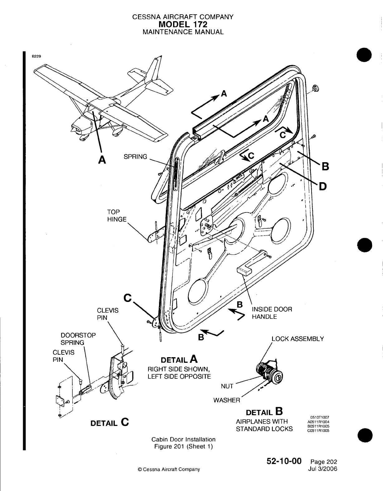
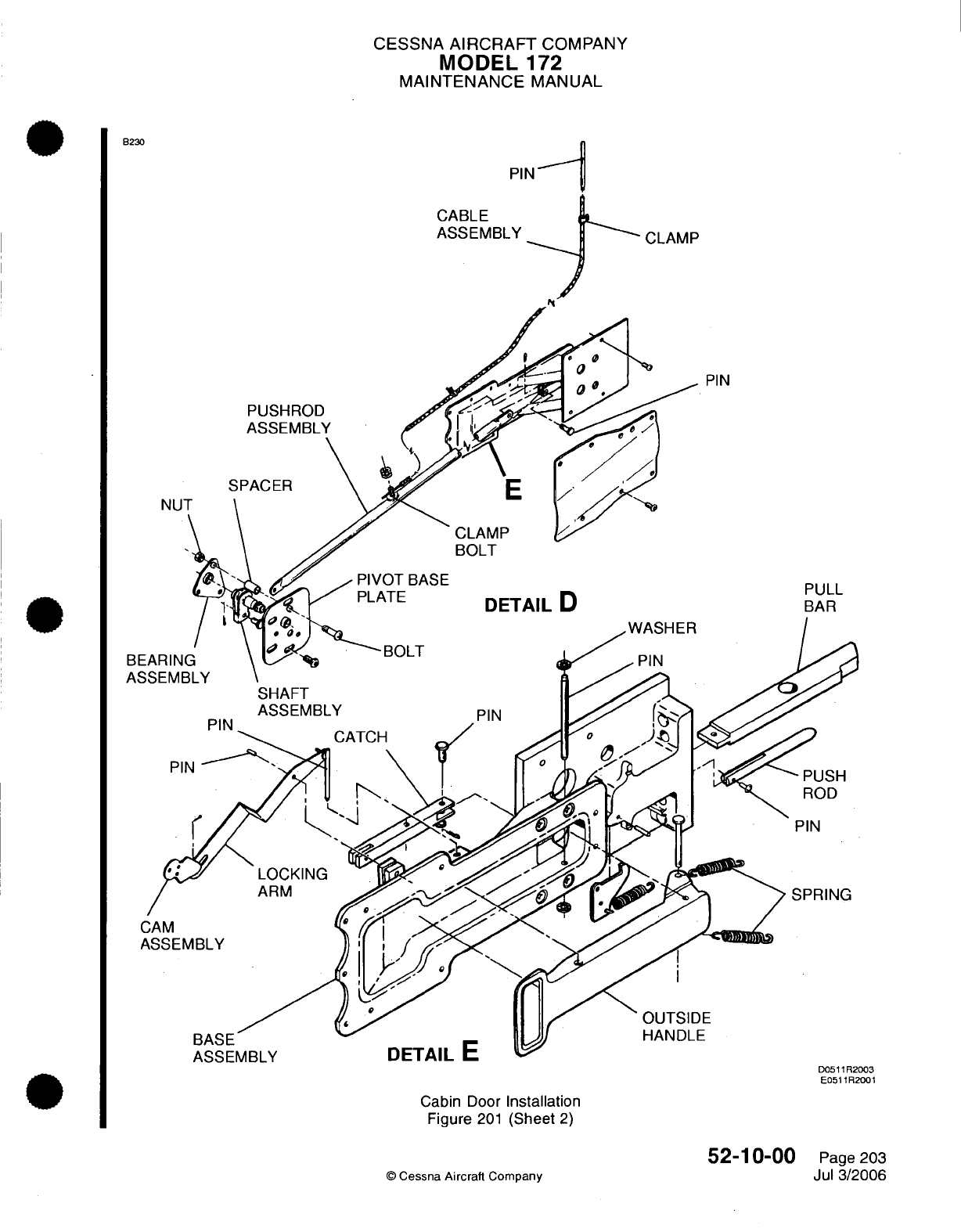
CESSNA
AIRCRAFT
COMPANY
MODEL
172
MAINTENANCE
MANUAL
B230
PIN-
1
CABLE
ASSEMBLY
PIN
PUSHROD
NU
SPACER
CLAMP
BOLT
DETAIL
D
Cabin Door
Installation
Figure
201
(Sheet
2)
©
Cessna
Aircraft
Company
PULL
BAR
D0511R2003
E0511R2001
52-10-00
Page
203
Jul 3/2006
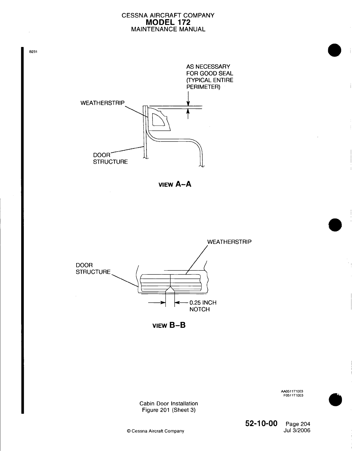
CESSNA
AIRCRAFT
COMPANY
MODEL
172
MAINTENANCE
MANUAL
8231
WEATHERSTRIP
AS
NECESSARY
FOR
GOOD
SEAL
(TYPICAL
ENTIRE
PERIMETER)
4.
DOOR
STRUCTURE
VIEW
A-A
WEATHERSTRIP
rnnn
0.25
INCH
NOTCH
VIEW
B-B
AA0511T1003
F0511T1003
Cabin Door
Installation
Figure
201
(Sheet
3)
52-10-00
©
Cessna
Aircraft
Company
Page
204
Jul
3/2006
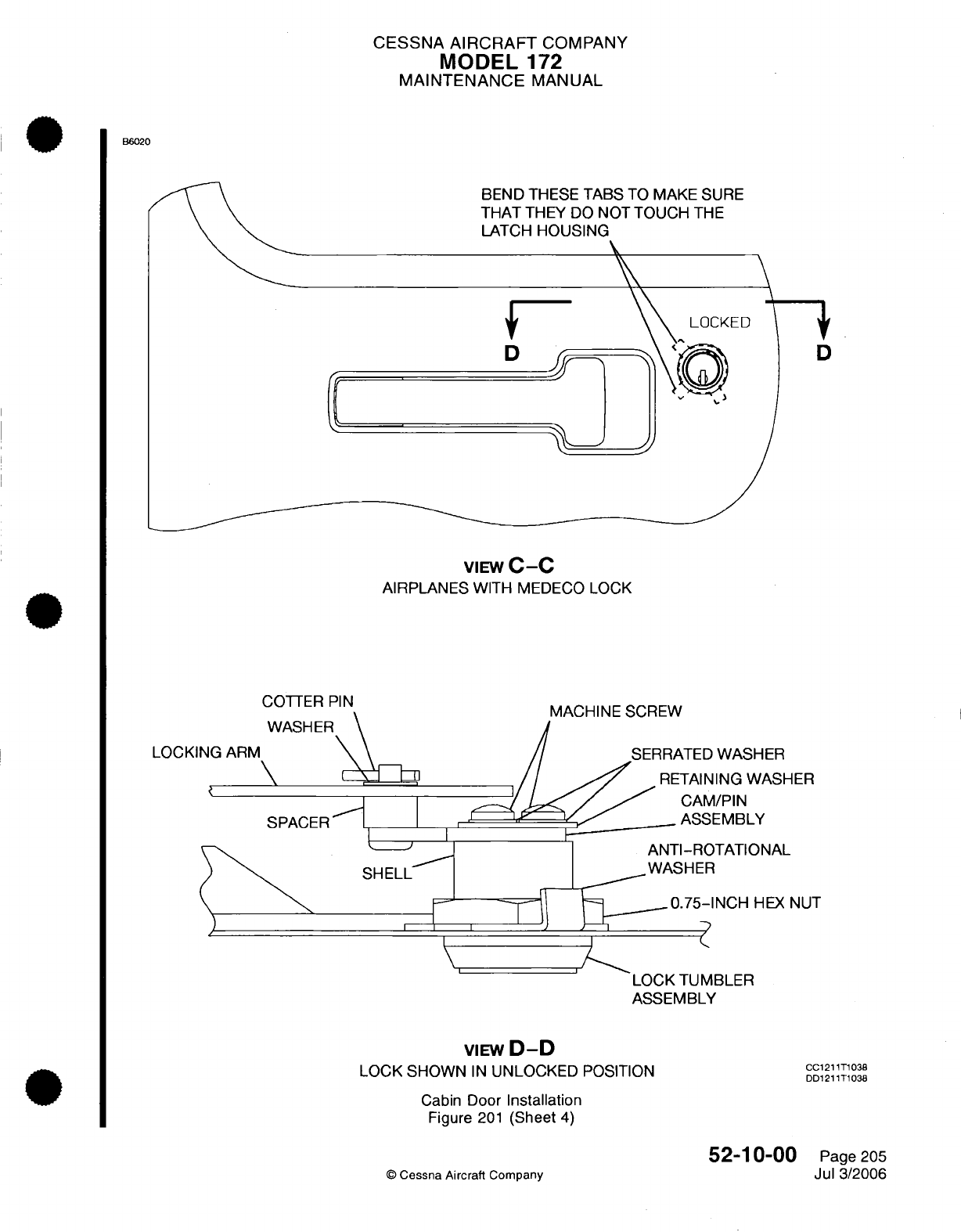
CESSNA AIRCRAFT
COMPANY
MODEL
172
MAINTENANCE
MANUAL
B6020
BEND THESE
TABS
TO MAKE
SURE
THAT
THEY
DO
NOT TOUCH
THE
LATCH
HOUSING
D
D
VIEW
C-C
AIRPLANES
WITH
MEDECO
LOCK
COTTER
PIN
WASHEF
LOCKING
ARM
\
SPACER
MACHINE
SCREW
SERRATED
WASHE
~//
.'
RETAINING
WA
I_. A/~
/
CAM/PIN
, .'
Xv
? l< '_/,/ _
.ASSEMBLY
ER
\SHER
ANTI-ROTATIONAL
WASHER
'
I
0.5-0.75-INCH
HEX NUT
LOCK TUMBLER
ASSEMBLY
VIEW
D-D
LOCK SHOWN
IN
UNLOCKED
POSITION
Cabin
Door
Installation
Figure
201
(Sheet
4)
52-10-00
©
Cessna Aircraft Company
CC1211T1038
DD1211T1038
Page
205
Jul 3/2006
SHELL
I
\
j
CESSNA AIRCRAFT
COMPANY
MODEL
172
MAINTENANCE
MANUAL
5.
Cabin
Door
Latch
Assembly
Removal/Installation
A.
Cabin
Door
Latch
Assembly
Removal
(Refer
to
Figure
201).
(1)
Remove
the
cabin
door
lock
assembly. Refer
to
Cabin
Door
Lock
Assembly Removal/
Installation.
(2)
Remove the rivets
that
attach the
latch
base
to
the
door
skin.
(3)
Remove the
screws that
attach
the
latch
to
the
door
pan.
(4)
Remove the pushrod
and
bolt.
(5)
Pull
the
latch
handle
through the
cutout
in
the
door
skin.
(6)
Remove
the
latch
assembly
from
the
airplane.
B.
Cabin
Door
Latch
Assembly
Installation
(Refer
to
Figure
201).
(1)
Put
the
latch
assembly
in
the
closed
position between the door
pan
and
the door
skin.
(2)
Make
sure
the
cable
assembly
is
forward
of
the latch
base attach
plate,
and
inboard
of
latch
base
cup.
(3)
Extend
the
latch
handle
through
the
cutout
in
the
door
skin.
(4)
Push the
latch
assembly
aft
so
the bolt
and
pushrod extend through
their
related holes.
(5)
Release
the
pushrod
so
the
bolt
is
fully
extended
and
the
handle
is
flush.
(6)
Attach
the
latch
to
the
door
pan
with the
screws
through
the
base
assembly
and
through the
aft
flange
of
the door
pan.
(7)
Make
sure
the
door
skin
dimension
around the latch
assembly
is
correct.
CAUTION:
Do
not
make
the
holes
oversize
in
the
latch
base.
(8)
Drill
eleven
0.128
inch
(3.25
mm)
diameter
holes
that
align
with
the latch base.
(9)
Make
sure
the
cabin
door
latch
cable
assembly
rigging
and the
cabin
door
inside
handle rigging
is
done
before
the latch
base
is
attached
to
the
skin.
Refer
to
Cabin
Door Latch
Cable
Assembly
Adjustment/Test
and
Cabin Door Inside
Handle
Rigging.
(10)
Attach
the
latch base
to
the
door
skin
with
rivets.
(11)
Install
the
cabin
door
lock
assembly.
Refer
to
Cabin
Door Lock
Assembly Removal/Installation.
6.
Cabin
Door
Latch Cable
Assembly
Installation
A.
Cabin
Door
Latch
Cable
Assembly
Removal (Refer
to
Figure
201).
(1)
Remove
the
screw
and
clamp
that
attach
the
cable
assembly
to
the
door.
(2)
Remove the
plug button.
(3)
Remove
the
pin
from
the
pin
guide.
(4)
Pull
the
pin
end
of
the
cable from
the
top
of
the
door.
(5)
Remove
the
nut
and
clamp
from the
opposite
end of
the cable
casing.
(6)
Remove
the
cable
assembly
from
the door.
B.
Cabin
Door
Latch
Cable
Assembly Installation
(Refer
to
Figure
201).
(1)
Attach
the
clamp
and
nut
one
inch
(25
mm)
from
the
end of the
cable
casing
on
the
pin
end
of
the cable
assembly.
(2)
Put
the
pin
end
of
the
cable
between
the
door
pan
and
the
door
skin at
the
aft
end
of
the
door.
(3)
Push
the
pin end
of
the
cable
to the
top
of
the
door.
(4)
Remove
the
plug
button
and
align
the
pin
of
the
cable
with
the
pin
guide.
(5)
Put
the
pin
through
the
pin
guide.
(6)
Align
the
clamp
on
the
cable
casing
through
the
hole
that
is
below
the
0.875
inch
(22.22
mm)
access
hole.
(7)
Install
the
screw.
(8)
Make sure
the cable
operates
freely.
(a)
Add
washers
as
required
if
the
cable
does
not
operate
freely.
(9)
Do
the
cabin
door
latch cable
assembly
rigging. Refer
to
Cabin
Door
Latch
Cable
Assembly
Rigging.
52-10-00
Page
206
©
Cessna
Aircraft
Company
Jul
3/2006
CESSNA
AIRCRAFT
COMPANY
MODEL
172
MAINTENANCE
MANUAL
7.
Cabin
Door
Lock
Assembly
Removal/Installation
(on
airplanes
with standard
locks)
A.
Cabin
Door
Lock
Assembly
Removal (Refer
to
Figure
201).
(1)
Remove
the
lower
door accent
panel
and main
door panel
to get
access
to
the
cabin
door
lock
assembly. Refer
to
Chapter
25,
Interior
Upholstery
-
Maintenance Practices.
(2)
Remove
the armrest
door
plugs,
door
panel
insert,
armrest, door
handle,
and
cover
plate
from
the
door
to
get access
to the
cabin door
lock
assembly.
(3)
Remove
the nut and washer.
(4)
Remove
the
cabin
door
lock
assembly.
| B.
Cabin
Door
Lock
Assembly
Installation
(Refer
to Figure
201).
(1)
Put
the
cabin door
lock
assembly
in
position.
(2)
Install the
washer
and nut.
(3)
Install the
armrest door
plugs,
door
panel
insert,
armrest,
door
handle and
cover
plate.
(4)
Install
the
lower
door
accent
panel and
main
door
panel. Refer
to
Chapter
25, Interior
Upholstery
-
Maintenance
Practices.
8.
Cabin
Door
Lock
Assembly
Removal/Installation
(on
airplanes
with
Medeco
locks)
A.
Cabin
Door
Lock
Assembly
Removal
(Refer
to
Figure
201).
(1)
Remove
the
lower
door accent
panel
and main
door
panel
to get
access
to the
cabin
door
lock
assembly.
Refer
to
Chapter
25,
Interior
Upholstery
-
Maintenance
Practices.
(2)
Remove
the armrest
door
plugs,
door
panel insert,
armrest,
door
handle,
and
cover
plate
from
the
door
to
get access
to the
cabin door
lock
assembly.
(3)
Remove
the
cotter
pin,
washer,
locking
arm,
and
spacer
from
the
lock
assembly.
(4)
Remove
the
hex
nut
and
the anti-rotational
washer that
attach the
lock
tumbler
assembly
to the
door
structure
and the cam
assembly.
(5)
Remove
the
lock
assembly
from
the
door.
B.
Cabin Door
Lock
Assembly
Installation
(Refer to
Figure
201).
(1)
Put
the
cabin door
lock
assembly
in
position
on the
cabin
door.
(2)
Install
the
hex
nut
and
the
anti-rotational washer
that
attach
the
lock
tumbler assembly
to the
door
structure
and
the cam
assembly.
Make
sure
that
the
anti-rotational washer
is
installed
under
the
hex
nut.
(3)
Torque
the
nut.
(4)
Bend the
applicable
tab
on
the
anti-rotational washer against
the
flat
part
of
the
nut.
(5)
Install
the
spacer, locking
arm,
washer,
and
cotter
pin
that
connect
the
lock
assembly
to
the
door
handle.
(6)
Bend
the
applicable
tabs
on
the
cam-pin
assembly
to
make
sure
that they
do
not
touch
the
latch
housing.
(7)
Install
the
armrest
door plugs,
door
panel
insert,
armrest,
door
handle,
and
cover
plate.
(8)
Install
the lower door
accent
panel
and
the
main
door
panel. Refer
to
Chapter
25,
Interior
Upholstery
-
Maintenance Practices.
9.
Cabin
Door
Lock
Cam
Assembly Removal/Installation
(on
airplanes
with
standard
locks)
A.
Cabin
Door
Lock
Cam
Assembly
Removal (Refer
to
Figure
201).
(1)
Remove
the
lower
door accent
panel and
the
main
door
panel
to get
access
to
the
cabin
door
lock
cam
assembly.
Refer
to
Chapter
25,
Interior Upholstery
-
Maintenance
Practices.
(2)
Remove
the
armrest
door
plugs,
door
panel
insert, armrest,
door
handle,
and
cover
plate
from
the
door
to
get access
to the
cabin
door
lock
cam
assembly.
(3)
Remove
the
cam
stop
screw
from
the cabin
door lock
cam
assembly.
(4)
Remove
the
cam
assembly.
B.
Cabin
Door
Lock
Cam
Assembly
Installation
(Refer
to
Figure
201).
(1)
Put the
cam
assembly
in
position.
(2)
Install
the
cam
stop screw
with
Loctite
242.
(3)
Install
the
armrest door
plugs,
door
panel
insert, armrest,
door
handle
and
cover
plate.
(4)
Install
the
lower
door
accent
panel
and
main
door
panel.
Refer
to
Chapter
25,
Interior
Upholstery
-
Maintenance Practices.
52-10-00
Page
207
©
Cessna
Aircraft
Company
Jul 3/2006
CESSNA
AIRCRAFT
COMPANY
MODEL
172
MAINTENANCE
MANUAL
10.
Cabin
Door
Lock
Cam
Assembly
Removal/Installation
(on
airplanes
with
Medeco
locks)
A.
Cabin Door
Lock
Cam
Assembly
Removal
(Refer
to
Figure
201).
(1)
Remove the lower
door
accent
panel
and
main door
panel to
get
access
to
the
cabin
door
lock
cam
assembly.
Refer
to
Chapter
25,
Interior
Upholstery
-
Maintenance Practices.
(2)
Remove
the
armrest
door
plugs,
door
panel
insert,
armrest,
door
handle,
and
cover
plate
from
the
door
to get
access
to the cabin
door
lock
cam
assembly.
(3)
Remove
the
machine
screws,
serrated
washers,
and
retaining
washer
from
the
cabin door
lock
cam
assembly.
(4)
Remove the
cam
assembly.
B.
Cabin Door
Lock
Cam
Assembly
Installation
(Refer
to
Figure
201).
(1)
Put
the
cam
assembly
in
position.
(2)
Install
the
machine
screws,
serrated
washers,
and
retaining
washer
that
attach
the
cam
assembly
to the
cabin
door
lock. Install the
machine screws with
Loctite
242.
(3)
Install
the armrest
door
plugs,
door
panel
insert, armrest,
door
handle,
and
cover
plate.
(4)
Install
the
lower
door
accent
panel and
main
door
panel.
Refer
to
Chapter
25,
Interior Upholstery
-
Maintenance
Practices.
11.
Cabin
Door
Adjustment/Test
A.
Adjust
the
new
cabin
doors.
CAUTION:
Do
not
adjust
the
bonded door flange
or
the
airplane
structure
with
force.
Damage
to
the
bonded areas
and
the
structural
components
can
occur.
(1)
Trim
the
door
flange
as
required
to
get
a
gap
between the
door
skin and
fuselage
skin
of
0.09
inch
(2.3
mm)
or
less.
B.
Adjust
the
cabin
doors.
NOTE:
The
cabin
doors
must
be
smooth
with
the
fuselage
skin.
(1)
Use
the
slots
at
the
door
latch
plate to
adjust
the latch
assembly
and
the
bolt engagement
with
the rotary
clutch
on
the
door
post.
12.
Cabin
Door
Latch
Cable
Assembly
Rigging
A.
Do
the
Cabin
Door
Latch
Cable
Assembly
Rigging (Refer
to
Figure 201).
(1)
Pull
the
cable
tight.
(2)
Attach the clamp
and
the
nut
to the
cable
so
it
aligns
with
the
0.193
inch
(4.9
mm)
diameter
hole
in
the
door
pan.
(3)
Make
sure
the
door latch
is
open.
(4)
Cut
the
casing
of
the
cable
assembly
approximately
two
inches
(50
mm)
from
the
clamp
bolt
on
the
push
rod
assembly.
(5)
Put
the
core
of
the
cable
through
the
clamp.
(6)
Pull
the
core
of
the
cable
through
the
clamp
bolt
so
the
pin
extends approximately
0.125
inch
(3.2
mm)
from
the
door
pan
contour.
(7)
Cut
the
core
of
the
cable
approximately
one
inch (25
mm)
forward
of
the
push
rod
clamp.
(8)
Attach
the
two
nuts
to
the
push
rod
clamp
bolt.
(9)
Make
sure
the
latch
operates
freely.
(a)
Remove
the
cable
core
from
the
clamp
and
operate
the
latch
if
the
latch binds
and
will
not
operate
freely.
(b)
Do
a
check
of
the
cable
for
possible
adjustments
that
will make
the
operation easier.
(10)
Install
the
cover
assembly
and
do
another
check
of
the
cable
operation.
52-10-00
Page
208
©
Cessna
Aircraft Company
Jul 3/2006
CESSNA
AIRCRAFT
COMPANY
MODEL
172
MAINTENANCE
MANUAL
13.
Latch
Assembly
Adjustment/Test
A.
Do
the
adjustment
of
the
latch
assembly. (Refer
to
Figure
201).
(1)
Make
sure
the
cabin door
is
installed
and
fitted
to
the
fuselage
before
the
adjustment/test
can
be
done.
(2)
Make
sure
the
cabin door
latch
is
in
the
OPEN
position
before
the
adjustment/test
can
be
done.
(3)
Make
sure
the
door
latch
operates smoothly
and
freely.
(4)
Make
sure
the
bolt
or
pull
bar
are
not
filed,
ground
or
sanded
in
any
way.
NOTE:
A
noise
can be heard
when the
inside handle
is
pushed
down.
It
is
recommended
that the outside door handle
be
flush
with
the
door
skin,
although the
noise
is
heard.
(5)
Install shims
to
adjust
the
striker
plate forward
to
give
a
minimal
clearance
between
the
bolt
and
the
striker
plate.
NOTE:
This
adjustment
will make
sure the
pushrod
will
engage
the
latch catch.
It
will also
make
sure
the
exterior
handle
will
stay open
until the
door
is
closed
again when
the
door
is
opened
from
the
outside.
(6)
Install
shims
as
required,
beneath
the
actuator
on
the
cover
assembly.
NOTE:
If
the cabin
door
is
too
far
forward
for
correct
operation
of
the
door
latch,
the
latch
assembly
pushrod
will
not
let
the bolt move.
(7)
Close
the
cabin
door.
(8)
Make
sure
the
exterior
handle
is
flush
with
the
door
skin
when
the door
is
closed.
(a)
Adjust the
push-pull
rod
out,
if
the
exterior
handle
is
not
flush
with
the
door
skin when
the
door
is
closed.
1
Remove
the
screws
and
nuts
that
attach the
base
plate
to
the
door.
2
Remove
the
smaller
end
of
the
push-pull
rod
and
turn
it
180
degrees.
3
Install
the
screws
and
nuts
that
attach the
base
plate.
(9) Do
a
check
for
slippage
between
the
cable
casing
and
clamps
that
attach
the
cable.
(10)
Install
the
cotter
pin
in
the
clevis
pin.
52-10-00
©
Cessna
Aircraft
Company
Page 209
Jul
3/2006
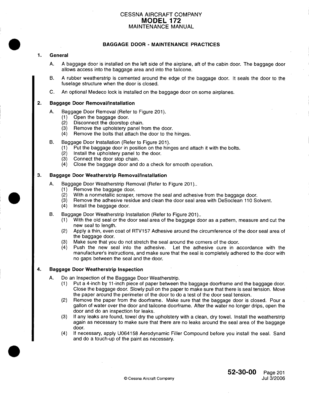
CESSNA
AIRCRAFT
COMPANY
MODEL
172
MAINTENANCE
MANUAL
BAGGAGE
DOOR
-
MAINTENANCE PRACTICES
1.
General
A. A
baggage
door
is
installed
on the
left
side
of
the
airplane,
aft
of
the
cabin
door.
The
baggage
door
allows
access
into
the
baggage
area
and
into
the
tailcone.
B. A
rubber
weatherstrip
is
cemented
around
the
edge
of
the
baggage
door.
It
seals
the
door
to
the
fuselage
structure
when
the
door
is
closed.
C.
An
optional
Medeco
lock
is
installed
on
the
baggage
door
on
some
airplanes.
2.
Baggage
Door
Removal/Installation
A.
Baggage
Door
Removal
(Refer
to
Figure
201).
(1)
Open the
baggage
door.
(2)
Disconnect
the
doorstop
chain.
(3)
Remove
the
upholstery
panel
from
the
door.
(4)
Remove
the bolts
that
attach the
door
to the
hinges.
B.
Baggage
Door
Installation
(Refer
to
Figure
201).
(1)
Put
the
baggage
door
in
position
on
the
hinges
and
attach
it
with
the
bolts.
(2)
Install
the
upholstery
panel
to
the
door.
(3)
Connect
the
door
stop chain.
(4)
Close
the
baggage
door
and
do
a
check
for
smooth
operation.
3.
Baggage
Door
Weatherstrip Removal/Installation
A.
Baggage
Door
Weatherstrip
Removal (Refer
to
Figure
201)..
(1)
Remove
the baggage
door.
(2)
With
a
nonmetallic scraper,
remove the
seal
and
adhesive
from
the
baggage door.
(3)
Remove
the adhesive
residue
and
clean
the
door
seal
area with
DeSoclean
110
Solvent.
(4)
Install the
baggage
door.
B.
Baggage
Door
Weatherstrip
Installation (Refer
to Figure
201)..
(1)
With
the
old
seal
or
the
door
seal
area of
the
baggage door
as
a
pattern,
measure and
cut
the
new
seal to
length.
(2)
Apply
a
thin,
even
coat
of
RTV157
Adhesive
around
the
circumference
of
the door
seal
area
of
the
baggage
door.
(3)
Make sure
that
you
do
not
stretch
the
seal
around
the
corners
of the
door.
(4)
Push
the
new seal
into
the
adhesive.
Let
the
adhesive
cure
in
accordance
with
the
manufacturer's
instructions,
and
make
sure
that
the
seal
is
completely
adhered
to
the
door
with
no
gaps
between
the
seal
and the
door.
4.
Baggage
Door
Weatherstrip Inspection
A.
Do
an
Inspection
of
the
Baggage
Door
Weatherstrip.
(1)
Put
a
4-inch
by 11-inch
piece
of
paper between the
baggage doorframe
and
the baggage
door.
Close the
baggage
door.
Slowly
pull
on
the paper
to
make sure
that
there
is
seal
tension.
Move
the
paper
around the perimeter
of
the
door
to
do
a
test
of
the
door
seal
tension.
(2)
Remove
the
paper
from
the
doorframe.
Make
sure
that
the
baggage door
is
closed.
Pour
a
gallon
of
water
over
the
door
and
tailcone
doorframe.
After
the water
no
longer
drips,
open
the
door
and
do
an
inspection
for leaks.
(3) If
any leaks
are
found,
towel
dry
the
upholstery
with
a
clean,
dry
towel. Install the
weatherstrip
again
as
necessary
to
make
sure
that
there
are
no
leaks
around
the
seal
area
of
the
baggage
door.
(4) If
necessary,
apply
U064158
Aerodynamic
Filler
Compound
before
you
install
the
seal.
Sand
and
do
a
touch-up
of
the
paint
as necessary.
52-30-00
Page
201
©
Cessna
Aircraft
Company
Jul
3/2006
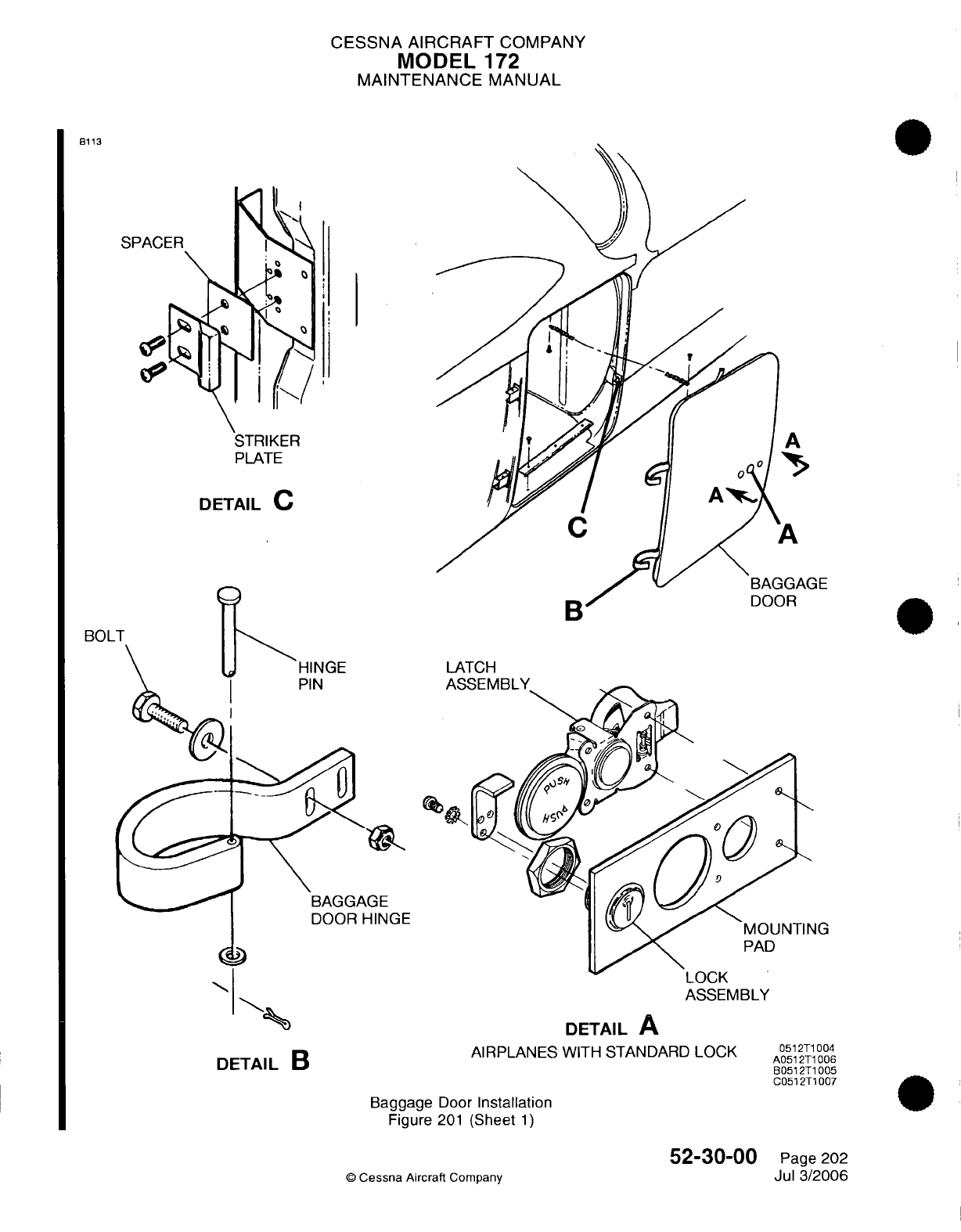
CESSNA AIRCRAFT
COMPANY
MODEL
172
MAINTENANCE
MANUAL
8113
STRIKER
PLATE
DETAIL
C
b
BOLT
LATCH
AQCCQfMPI
V
DOOR
HINGE
LUJ'-r\
ASSEMBLY
DETAIL
B
DETAIL
A
AIRPLANES
WITH STANDARD
LOCK
Baggage
Door
Installation
Figure
201
(Sheet
1)
©
Cessna
Aircraft
Company
52-30-00
Page 202
Jul 3/2006
A
A
iGAGE
)R
0512T1004
A0512T1006
B0512T1005
C0512T1007
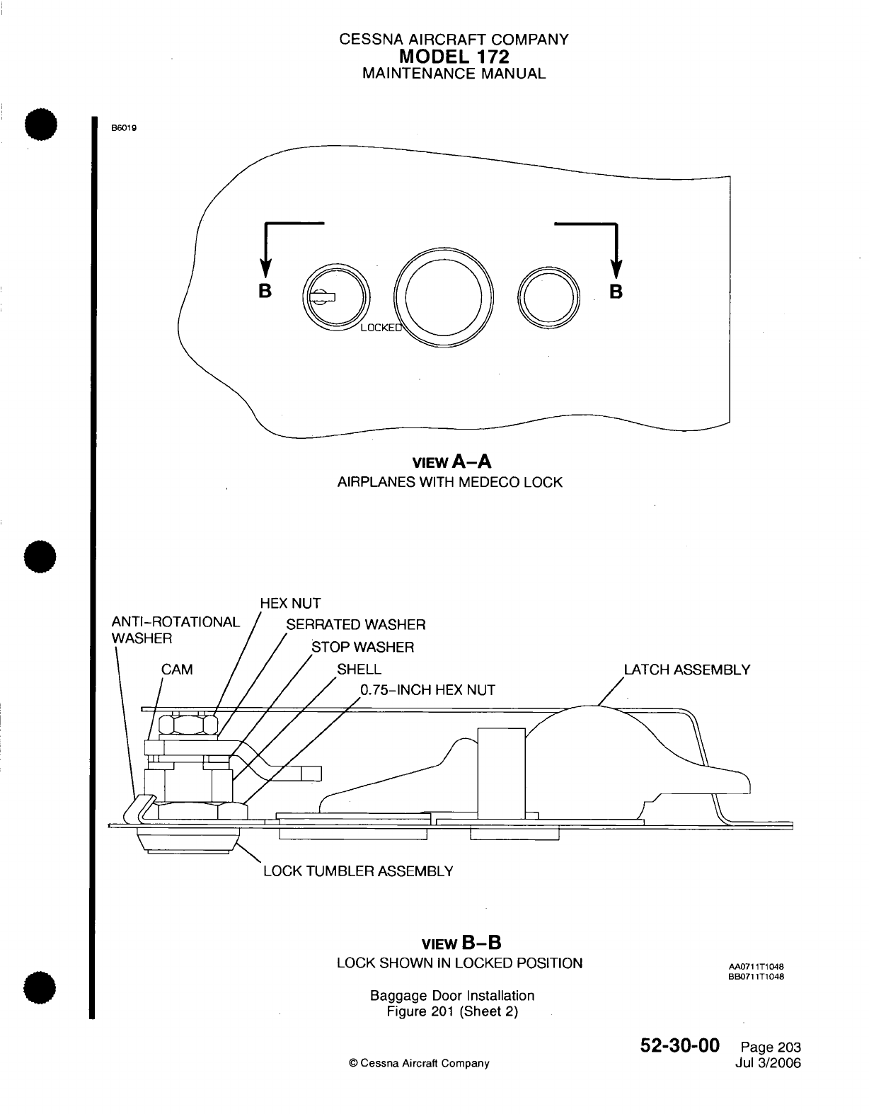
CESSNA
AIRCRAFT
COMPANY
MODEL
172
MAINTENANCE
MANUAL
B6019
B
DCKE
K
VIEW
A-A
AIRPLANES
WITH
MEDECO LOCK
HEX
NUT
LATCH
ASSEMBLY
-1
LOCK
TUMBLER
ASSEMBLY
VIEW
B-B
LOCK SHOWN
IN
LOCKED POSITION
Baggage
Door
Installation
Figure
201
(Sheet
2)
AA0711T1048
BB071
1T1048
52-30-00
O
Cessna
Aircraft
Company Page
203
Jul
3/2006
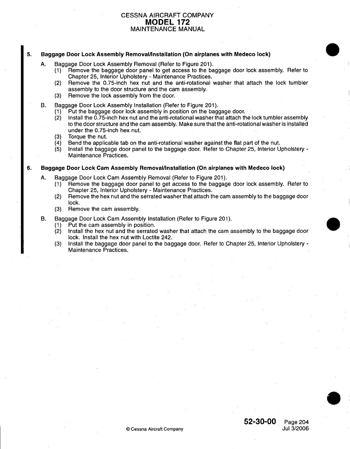
CESSNA
AIRCRAFT
COMPANY
MODEL
172
MAINTENANCE
MANUAL
5.
Baggage
Door
Lock
Assembly
Removal/Installation
(On
airplanes
with
Medeco
lock)
A.
Baggage Door
Lock
Assembly
Removal
(Refer
to
Figure
201).
(1)
Remove
the
baggage
door
panel
to
get
access
to
the
baggage
door lock
assembly.
Refer
to
Chapter
25,
Interior
Upholstery
-
Maintenance
Practices.
(2)
Remove
the
0.75-inch
hex
nut
and
the
anti-rotational washer
that
attach
the
lock
tumbler
assembly
to
the door
structure
and
the
cam
assembly.
(3)
Remove the
lock
assembly
from
the
door.
B.
Baggage Door Lock
Assembly
Installation
(Refer
to Figure
201).
(1)
Put
the
baggage
door
lock
assembly
in
position
on
the baggage
door.
(2)
Install
the
0.75-inch
hex
nut
and
the
anti-rotational washer
that attach
the
lock
tumbler
assembly
to
the
door
structure
and the
cam
assembly.
Make sure
that
the
anti-rotational washer
is
installed
under
the
0.75-inch
hex
nut.
(3)
Torque
the
nut.
(4)
Bend
the
applicable
tab
on
the anti-rotational washer against
the
flat
part
of the
nut.
(5)
Install
the baggage
door
panel
to
the
baggage
door.
Refer
to
Chapter
25,
Interior Upholstery
-
Maintenance Practices.
6.
Baggage
Door
Lock
Cam
Assembly
Removal/Installation
(On
airplanes with
Medeco
lock)
A.
Baggage
Door
Lock
Cam
Assembly
Removal (Refer
to
Figure
201).
(1)
Remove the
baggage door
panel
to
get
access
to
the
baggage
door
lock
assembly.
Refer
to
Chapter
25,
Interior
Upholstery
-
Maintenance Practices.
(2)
Remove the
hex
nut
and
the
serrated washer that
attach the
cam
assembly
to
the
baggage door
lock.
(3)
Remove
the cam
assembly.
B.
Baggage
Door
Lock
Cam
Assembly
Installation
(Refer
to
Figure
201).
(1)
Put
the
cam
assembly
in
position.
(2)
Install
the
hex nut
and
the
serrated washer
that
attach the
cam
assembly
to
the
baggage door
lock. Install
the
hex
nut
with
Loctite
242.
(3)
Install
the
baggage
door
panel
to
the
baggage
door.
Refer
to
Chapter
25,
Interior Upholstery
-
Maintenance
Practices.
52-30-00
Page 204
©
Cessna
Aircraft
Company
Jul
3/2006

CHAPTER
STABILIZERS
CESSNA
AIRCRAFT
COMPANY
MODEL
172
MAINTENANCE
MANUAL
LIST
OF
EFFECTIVE
PAGES
CHAPTER-SECTION-SUBJECT
55-Title
55-List
of
Effective
Pages
55-Record
of
Temporary
Revisions
55-Contents
55-00-00
55-10-00
55-30-00
PAGE
Page
1
Pages
201-202
Pages
201-202
©
Cessna Aircraft
Company
55
-
LIST
OF
EFFECTIVE
PAGES
Page
1
of
1
Apr
7/2003
DATE
Apr
7/2003
Apr
7/2003
Apr
7/2003
Temporary
Revision
Number
RECORD
OF
TEMPORARY
REVISIONS
Page
Number
Issue
Date
By
Date
Removed
By
CESSNA
AIRCRAFT
COMPANY
MODEL
172
MAINTENANCE
MANUAL
CONTENTS
STABILIZERS
-
GENERAL
.......................................................
Scope
.....................................................................
Definition
..................................................................
HORIZONTAL
STABILIZER- MAINTENANCE
PRACTICES..........................
General
....................................................................
Horizontal
Stabilizer
Removal/Installation
.....................................
VERTICAL STABILIZER
FIN
-
MAINTENANCE
PRACTICES
........................
G
e n
eral
....................................................................
Vertical
Stabilizer
Fin
Removal/Installation..................................
55-00-00
Page
1
55-00-00
Page
1
55-00-00
Page
1
55-10-00
Page
201
55-10-00
Page
201
55-10-00
Page
201
55-30-00
Page
201
55-30-00
Page
201
55-30-00
Page
201
CONTENTS
Page
1
of
1
Apr 7/2003
©
Cessna
Aircraft
Company
CESSNA
AIRCRAFT
COMPANY
MODEL
172
MAINTENANCE
MANUAL
STABILIZERS
-
GENERAL
1.
Scope
A.
This
chapter
provides maintenance
information
on the
horizontal
and
vertical
stabilizer.
2.
Definition
A.
The
section
on
horizontal
stabilizer
provides instructions for
removal
and
installation
of
the
horizontal
stabilizer.
B.
The section
on
vertical
stabilizer
fin provides
instructions for
removal and
installation
on
the
vertical
stabilizer
fin.
55-00-00
Page
1
©
Cessna Aircraft Company
Apr 7/2003
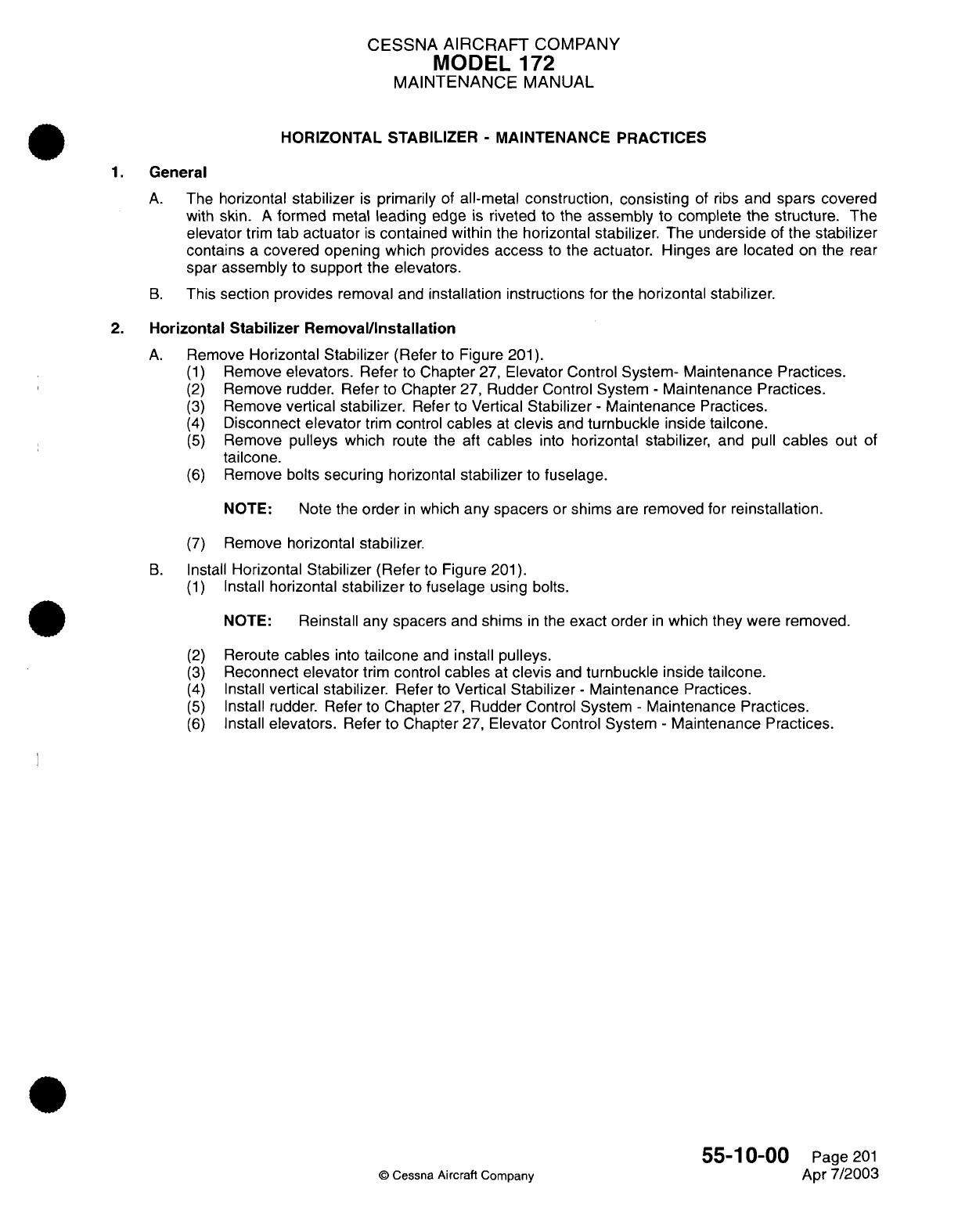
CESSNA AIRCRAFT
COMPANY
MODEL
172
MAINTENANCE
MANUAL
HORIZONTAL
STABILIZER
-
MAINTENANCE PRACTICES
1.
General
A.
The
horizontal
stabilizer
is
primarily
of
all-metal
construction, consisting
of
ribs
and
spars covered
with skin.
A
formed
metal
leading
edge
is
riveted
to
the
assembly
to
complete
the
structure.
The
elevator
trim
tab
actuator
is
contained within
the
horizontal stabilizer.
The
underside
of
the
stabilizer
contains
a
covered opening which
provides
access
to
the
actuator.
Hinges
are
located
on
the
rear
spar
assembly
to
support
the
elevators.
B.
This section
provides
removal
and
installation
instructions
for
the
horizontal
stabilizer.
2.
Horizontal
Stabilizer
Removal/Installation
A.
Remove
Horizontal
Stabilizer
(Refer to Figure
201).
(1)
Remove
elevators.
Refer
to
Chapter
27,
Elevator
Control
System-
Maintenance Practices.
(2)
Remove
rudder.
Refer
to
Chapter
27,
Rudder
Control
System
-
Maintenance Practices.
(3)
Remove
vertical
stabilizer.
Refer
to
Vertical
Stabilizer
-
Maintenance
Practices.
(4)
Disconnect
elevator
trim
control
cables
at
clevis
and
turnbuckle
inside
tailcone.
(5)
Remove
pulleys
which
route
the
aft
cables
into
horizontal
stabilizer,
and
pull
cables
out
of
tailcone.
(6)
Remove
bolts
securing
horizontal
stabilizer
to
fuselage.
NOTE:
Note
the
order
in
which
any
spacers
or
shims
are
removed for
reinstallation.
(7)
Remove
horizontal stabilizer.
B.
Install
Horizontal
Stabilizer
(Refer
to
Figure
201).
(1)
Install
horizontal
stabilizer
to
fuselage
using
bolts.
NOTE:
Reinstall any
spacers
and
shims
in
the
exact
order
in
which
they
were
removed.
(2)
(3)
(4)
(5)
(6)
Reroute
cables
into
tailcone
and
install
pulleys.
Reconnect
elevator
trim control
cables
at
clevis
and
turnbuckle
inside
tailcone.
Install
vertical
stabilizer.
Refer
to
Vertical
Stabilizer
-
Maintenance
Practices.
Install
rudder.
Refer to
Chapter
27,
Rudder
Control
System
-
Maintenance
Practices.
Install
elevators.
Refer
to
Chapter
27,
Elevator
Control
System
-
Maintenance
Practices.
55-10-00
©
Cessna
Aircraft
Company
Page
201
Apr
7/2003
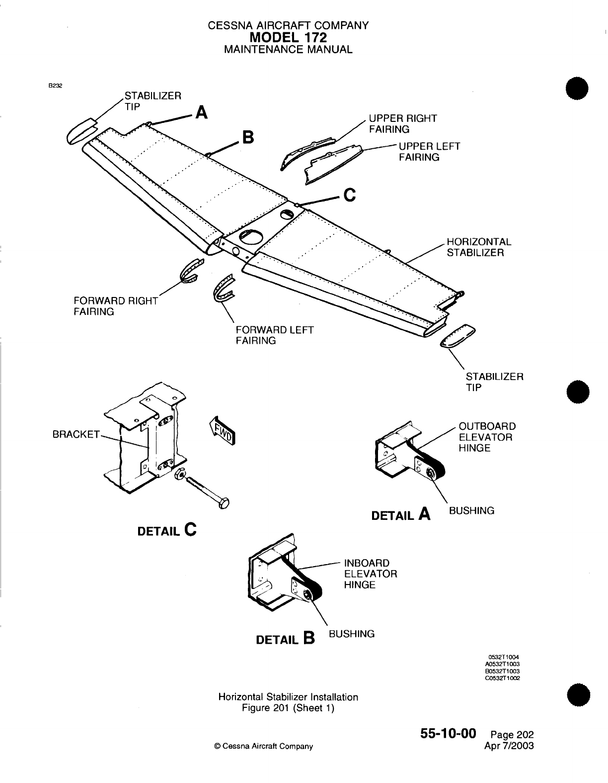
CESSNA
AIRCRAFT
COMPANY
MODEL
172
MAINTENANCE
MANUAL
B232
A
B
UPPER
RIGHT
FAIRING
UPPER
LEFT
FAIRING
HORIZONTAL
LIZER
,
FORWARD
RIGHT
FAIRING
FORWARD
LEFT
FAIRING
STABILIZER
TIP
OUTBOARD
ELEVATOR
HINGE
DETAIL
A
BUSHING
DETAIL
C
INBOARD
ELEVATOR
HINGE
DETAIL
B
BUSHING
0532T1004
A0532T1003
B0532T1003
C0532T1002
Horizontal
Stabilizer
Installation
Figure
201
(Sheet
1)
55-1
0-00
©
Cessna
Aircraft
Company
BRACKET
Page
202
Apr
7/2003
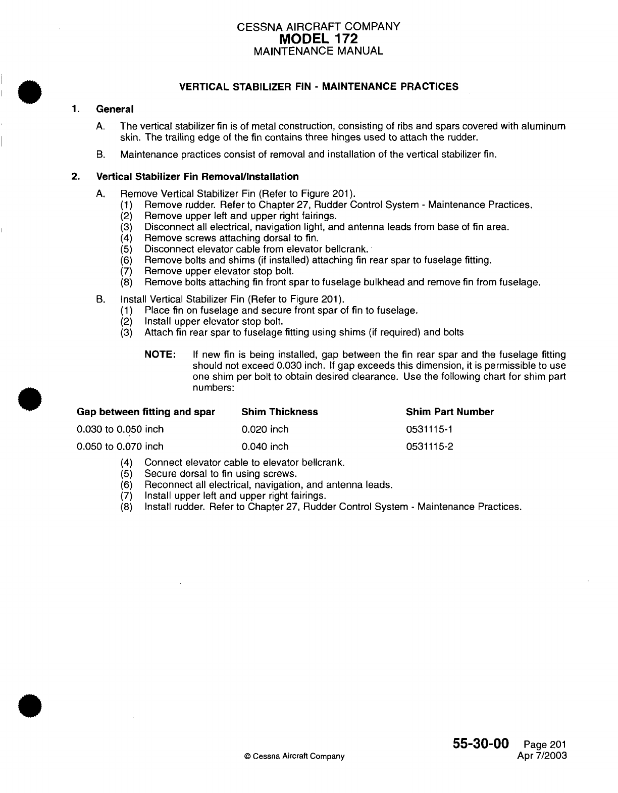
CESSNA
AIRCRAFT COMPANY
MODEL
172
MAINTENANCE MANUAL
VERTICAL STABILIZER
FIN
-
MAINTENANCE
PRACTICES
1.
General
A.
The
vertical
stabilizer
fin
is
of metal
construction,
consisting
of
ribs
and
spars
covered
with
aluminum
skin.
The
trailing
edge
of
the fin
contains
three
hinges
used to
attach
the
rudder.
B.
Maintenance
practices
consist
of removal
and
installation
of
the
vertical stabilizer
fin.
2.
Vertical
Stabilizer
Fin
Removal/Installation
A.
Remove Vertical
Stabilizer
Fin
(Refer
to Figure
201).
(1)
Remove
rudder.
Refer
to
Chapter
27,
Rudder
Control System
-
Maintenance
Practices.
(2)
Remove
upper
left
and
upper
right
fairings.
(3)
Disconnect
all
electrical,
navigation
light,
and
antenna
leads
from
base
of
fin
area.
(4)
Remove screws
attaching
dorsal
to
fin.
(5)
Disconnect
elevator
cable
from
elevator bellcrank.
(6)
Remove
bolts
and
shims
(if
installed)
attaching
fin
rear
spar
to
fuselage
fitting.
(7)
Remove upper
elevator
stop
bolt.
(8)
Remove
bolts
attaching
fin
front
spar
to
fuselage
bulkhead
and remove
fin
from
fuselage.
B.
Install Vertical
Stabilizer
Fin
(Refer
to
Figure
201).
(1)
Place
fin
on
fuselage
and
secure
front
spar
of
fin
to
fuselage.
(2)
Install
upper
elevator
stop
bolt.
(3)
Attach
fin
rear
spar
to
fuselage
fitting
using
shims
(if
required)
and
bolts
NOTE:
If
new
fin
is
being
installed,
gap
between the
fin
rear
spar
and
the
fuselage
fitting
should
not
exceed
0.030
inch.
If
gap
exceeds this
dimension,
it
is
permissible
to
use
one shim
per bolt
to
obtain
desired
clearance.
Use
the
following
chart
for
shim
part
numbers:
Gap
between
fitting
and
spar
0.030
to
0.050
inch
0.050
to
0.070
inch
Shim
Thickness
0.020
inch
0.040
inch
Shim
Part
Number
0531115-1
0531115-2
Connect elevator cable
to
elevator bellcrank.
Secure
dorsal
to
fin
using
screws.
Reconnect
all
electrical,
navigation,
and
antenna leads.
Install
upper
left
and upper
right
fairings.
Install
rudder.
Refer to
Chapter
27,
Rudder
Control System
-
Maintenance
Practices.
55-30-00
©
Cessna
Aircraft
Company
Page
201
Apr 7/2003
(4)
(5)
(6)
(7)
(8)
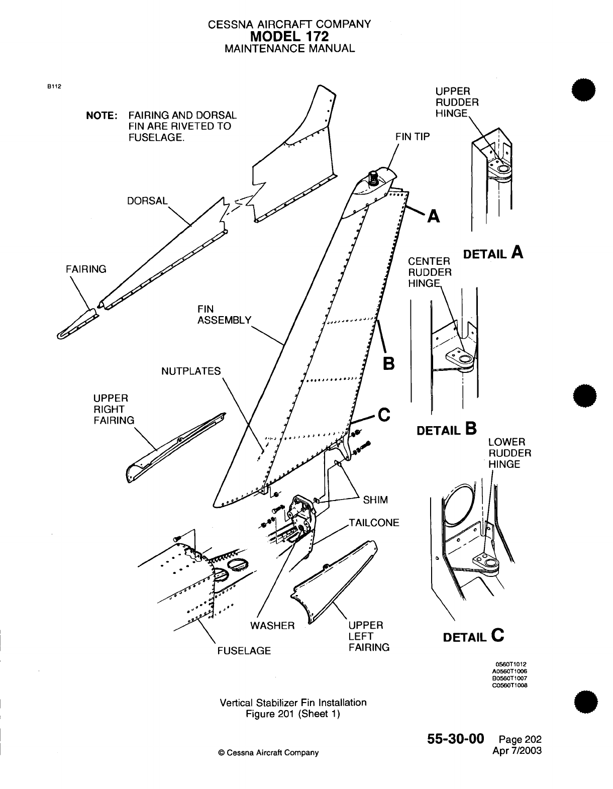
CESSNA AIRCRAFT
COMPANY
MODEL
172
MAINTENANCE
MANUAL
B112
NOTE: FAIRING
AND
DORSAL
FIN
ARE
RIVETED
TO
FUSELAGE.
UPPER
RUDDER
IINGE
FIN
TIP
DORSAL
DETAIL
A
FAIRING
FIN
ASSEMBLY
NUTPLATES
FUSELAGE
DETAIL
C
Vertical
Stabilizer
Fin
Installation
Figure
201
(Sheet
1)
55-30-00
©
Cessna
Aircraft
Company
UPPER
RIGHT
FAIRING
AILB
LOWER
RUDDER
HINGE
SHIM
WASHER
FAIRING
0560T1012
A0560T1006
B0560T1007
C0560T1008
Page
202
Apr
7/2003
..
CENTER

CHAPTER
WINDOWS
CESSNA
AIRCRAFT
COMPANY
MODEL
172
MAINTENANCE
MANUAL
LIST
OF
EFFECTIVE
PAGES
CHAPTER-SECTION-SUBJECT
56-Title
56-List
of
Effective
Pages
56-Record
of
Temporary
Revisions
56-Table
of
Contents
56-00-00
56-00-01
56-10-00
56-20-00
56-30-00
PAGE
Pages
1-2
Pages
1-2
Pages
201-202
Pages 201-202
Pages 201-202
©
Cessna
Aircraft
Company
56
-
LIST
OF
EFFECTIVE
PAGES
Page
1
of
1
Jan
2/2006
DATE
Jan
2/2006
Apr
7/2003
Apr
7/2003
Apr
7/2003
Apr
7/2003
Temporary
Revision
Number
RECORD
OF
TEMPORARY REVISIONS
Page
Number
Issue
Date
By
Date
Removed
By
CESSNA
AIRCRAFT
COMPANY
MODEL
172
MAINTENANCE
MANUAL
CONTENTS
WINDOWS
-
GENERAL
..........................................................
S
cope......................................................................
Tools,
Equipment
and
Materials
..............................................
Definition
...................................................................
WINDSHIELDS
AND
WINDOWS
-
DESCRIPTION
AND
OPERATION
................
General
....................................................................
Tools,
Equipment
and
Materials
..............................................
Cleaning
Instructions........................................................
Windshield
and
Window
Preventive Maintenance
..............................
Windshield
and
Window
Installation Techniques
...............................
Windshield
Rain
Repellent...................................................
WINDSHIELD
-
MAINTENANCE
PRACTICES......................................
General
....................................................................
Windshield
Removal/Installation..............................................
Temporary
Repairs
..........................................................
CABIN
WINDOWS
-
MAINTENANCE
PRACTICES
.................................
G
en
e
ra l
....................................................................
Rear
Window
Removal/Installation............................................
Side
Window
Removal/Installation
............................................
CABIN
DOOR
WINDOWS
-
MAINTENANCE
PRACTICES
..........................
General
....................................................................
Cabin
Door
Window Removal/Installation
.....................................
56-00-00
Page
1
56-00-00
Page
1
56-00-00
Page
1
56-00-00
Page
2
56-00-01
Page
1
56-00-01
Page
1
56-00-01
Page
1
56-00-01
Page
1
56-00-01
Page
1
56-00-01
Page
2
56-00-01
Page
2
56-10-00
Page
201
56-10-00
Page
201
56-10-00
Page
201
56-10-00
Page
201
56-20-00
Page
201
56-20-00
Page
201
56-20-00
Page
201
56-20-00
Page
201
56-30-00
Page
201
56-30-00
Page
201
56-30-00
Page
201
56
-
CONTENTS
Page
1
of
1
Jan
2/2006
©
Cessna Aircraft
Company
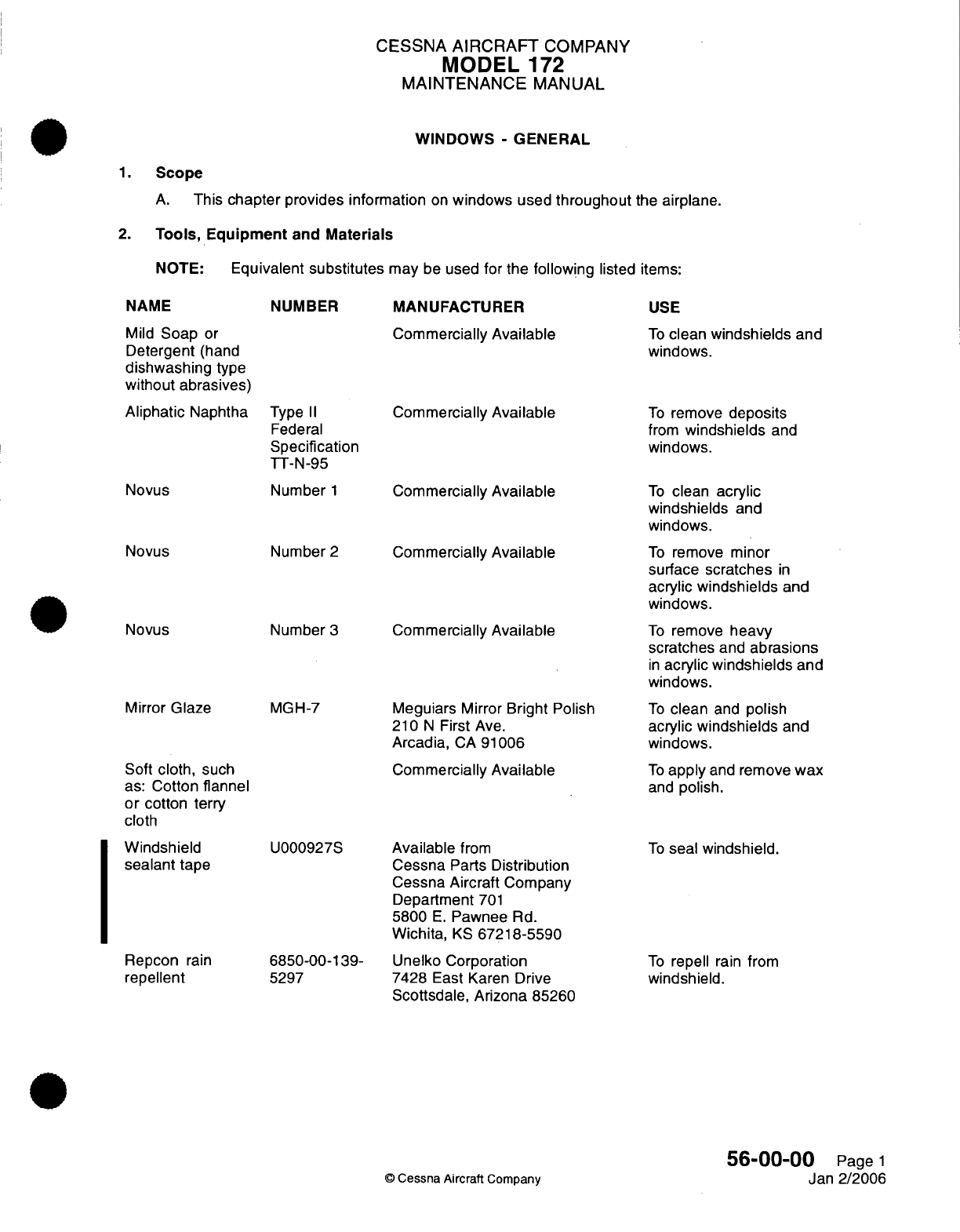
CESSNA
AIRCRAFT
COMPANY
MODEL
172
MAINTENANCE
MANUAL
WINDOWS
-
GENERAL
1.
Scope
A.
This
chapter
provides
information
on
windows
used
throughout
the
airplane.
2.
Tools, Equipment
and
Materials
NOTE:
Equivalent
substitutes
may
be
used
for
the
following
listed
items:
NAME
Mild
Soap
or
Detergent
(hand
dishwashing
type
without
abrasives)
Aliphatic
Naphtha
Novus
Novus
Novus
Mirror
Glaze
NUMBER
Type
II
Federal
Specification
TT-N-95
Number
1
Number
2
Number
3
MGH-7
Soft
cloth,
such
as:
Cotton flannel
or
cotton
terry
cloth
MANUFACTURER
Commercially
Available
Commercially Available
Commercially
Available
Commercially
Available
Commercially
Available
Meguiars
Mirror
Bright
Polish
210
N
First
Ave.
Arcadia,
CA
91006
Commercially
Available
USE
To
clean
windshields
and
windows.
To
remove
deposits
from
windshields
and
windows.
To
clean
acrylic
windshields
and
windows.
To
remove
minor
surface
scratches
in
acrylic
windshields
and
windows.
To
remove
heavy
scratches
and
abrasions
in
acrylic windshields
and
windows.
To
clean
and
polish
acrylic
windshields
and
windows.
To
apply
and
remove
wax
and
polish.
Windshield
sealant
tape
Repcon
rain
repellent
U000927S
6850-00-139-
5297
Available
from
Cessna
Parts
Distribution
Cessna Aircraft
Company
Department
701
5800
E.
Pawnee
Rd.
Wichita,
KS
67218-5590
Unelko
Corporation
7428
East
Karen
Drive
Scottsdale, Arizona
85260
To
seal
windshield.
To
repell
rain
from
windshield.
56-00-00
Page
1
Jan
2/2006
©
Cessna Aircraft
Company
CESSNA
AIRCRAFT
COMPANY
MODEL
172
MAINTENANCE
MANUAL
3.
Definition
A.
This
chapter
is
divided
into
sections
and
subsections
to
assist
maintenance personnel
in
locating
specific
systems
and
information.
The
following
is
a
brief
description
of
each section.
For
locating
information
within
the
chapter,
refer to the
Table
of
Contents
at
the
beginning of
the
chapter.
(1)
The
section
on
windshields
and
windows provides
installation
notes
and
precautions applicable
to
the
entire chapter.
(2)
The
section
on
flight
compartment windows
provides
maintenance instructions
for
repair
and
replacement
of
the windshield.
(3)
The
section
on
cabin windows provides
maintenance instructions
for
the
cabin
side
and
cabin
rear
windows.
(4)
The
section
on
door
windows provides
maintenance instructions
for openable
windows
located
in
the
cabin
doors.
56-00-00
Page
2
©
Cessna
Aircraft
Company
Jan
2/2006
CESSNA
AIRCRAFT
COMPANY
MODEL
172
MAINTENANCE
MANUAL
WINDSHIELDS
AND
WINDOWS
-
DESCRIPTION
AND
OPERATION
1.
General
A.
This section provides
instructions
and
tips
for
cleaning
and
installing
windshields
and
windows
used
in
the airplane.
2.
Tools,
Equipment
and
Materials
A.
For a
list
of
required
tools,
equipment
and
materials,
refer
to
Windows
-
General.
3.
Cleaning
Instructions
CAUTION:
WINDSHIELDS
AND
WINDOWS
(ACRYLIC-FACED)
ARE
EASILY
DAMAGED
BY
IMPROPER
HANDLING AND
CLEANING
TECHNIQUES.
CAUTION:
DO
NOT
USE
METHANOL,
DENATURED
ALCOHOL, GASOLINE,
BENZENE,
XYLENE,
METHYL
N-PROPYL
KETONE,
ACETONE,
CARBON
TETRACHLORIDE,
LACQUER
THINNERS,
COMMERCIAL
OR
HOUSEHOLD
WINDOW CLEANING
SPRAYS
ON
WINDSHIELDS
OR
WINDOWS.
A.
Instructions
For
Cleaning.
(1)
Place
airplane
inside
hangar
or
in
shaded
area
and
allow
to
cool
from
heat
of
suns
direct
rays.
(2)
Using clean
(preferably
running)
water,
flood
the
surface.
Use
bare
hands
with
no
jewelry
to
feel
and
dislodge any
dirt or
abrasive
materials.
(3)
Using
a
mild
soap
or
detergent
(such as
a
dishwashing
liquid)
in
water,
wash
the
surface.
Again
use
only
the
bare
hand
to
provide rubbing
force.
(A
clean cloth
may
be
used
to
transfer
the
soap
solution
to
the surface,
but
extreme care must
be
exercised
to
prevent
scratching
the
surface.)
(4)
When
contaminants
on
acrylic
windshields
and
windows
cannot
be
removed
by
a
mild
detergent,
Type
II
aliphatic
naphtha,
applied
with
a
soft clean cloth,
may
be
used
as
a
cleaning
solvent.
Be
sure to
frequently
refold
cloth
to
avoid
redepositing
contaminants
and/or
scratching
windshield
with
any abrasive particles.
(5)
Rinse
surface
thoroughly
with
clean
fresh
water
and
dry
with
a
clean
cloth.
(6)
Hard
polishing
wax
should
be
applied
to
acrylic
surfaces.
(The
wax
has
an
index
of
refraction
nearly
the
same
as
transparent
acrylic
and
will
tend
to
mask
any
shallow
scratches
on
the
windshield
surface).
(7)
Acrylic surfaces
may
be
polished
using
a
polish
meeting
Federal
Specification
P-P-560
applied
per
the
manufacturers instructions.
NOTE:
When
applying
and
removing wax
and
polish,
use
a
clean,
soft
cloth, such
as
cotton
or
cotton
flannel.
4.
Windshield
and
Window Preventive
Maintenance
NOTE:
Utilization
of
the
following techniques
will
help
minimize
windshield
and
window
crazing.
A.
General
Notes
and
Techniques
For
Acrylic
Windshields.
(1)
Keep
all
surfaces
of
windshields
and
windows
clean.
(2) If
desired, wax acrylic
surfaces.
(3)
Carefully
cover
all
surfaces
during any
painting,
powerplant
cleaning
or
other procedure
that
calls for
use
of
any
type
of
solvents
or
chemicals.
(4)
Do
not
park or
store
airplane
where
it
might
be
subjected
to
direct
contact
with
or
vapors
from:
methanol,
denatured alcohol, gasoline,
benzene, xylene,
methyl
n-propyl
ketone, acetone,
carbon tetrachloride, lacquer thinners,
commercial
or
household
window
cleaning
sprays,
paint
strippers,
or
other types
of
solvents.
56-00-01
Page
1
©
Cessna
Aircraft
Company
Apr 7/2003
CESSNA
AIRCRAFT
COMPANY
MODEL
172
MAINTENANCE
MANUAL
(5)
Do
not
leave
sun
visors
up
against windshield
when
not
in
use.
The
reflected
heat
from
these
items
causes
elevated
temperatures
on
the windshield.
If
solar
screens
are
installed
on
the
inside
of
the
airplane,
make
sure
they
are
the
silver
appearing, reflective
type.
(6)
Do
not use
a
power
drill
motor
or
other
powered
device
to
clean,
polish,
or
wax
surfaces.
5.
Windshield
and
Window
Installation
Techniques
A.
Installation Techniques.
(1)
Special drills
must
be
used
when
drilling
holes
in
acrylic.
Standard
drills
will
cause
the hole
to
be
oversized, distorted,
or
excessively
chipped.
(2)
Whenever
possible,
a
coolant
such
as
a
plastic drilling
wax
should
be
used
to
lubricate
the
drill
bit.
(3)
Drilled
holes
should
be
smooth
with
a
finish
of
125 rms
(root
mean
square).
(4)
The feed
and
speed
of
the
drill
is
critical.
Refer
to
Table
1
for
thickness
verses
drill
speed
information.
Table
1.
Material
Thickness
vs.
Drill
Speed
Thickness
(in inches)
Drill
Speed
(RPM)
0.062
to
0.1875
1500 to
4500
0.250
to
0.375
1500 to
2000
0.4375
1000
to
1500
0.500
500 to
1000
0.750
500
to
800
1.00
500
(5) In
addition
to
feed
and
speed
of the
drill
bit,
the
tip
configuration
is
of
special
importance
when
drilling through acrylic windows and
windshields.
Tip
configuration
varies
with
hole
depth,
and
the
following information
applies
when
drilling
through
acrylic:
(a)
Shallow
Holes
-
When
hole depth
to
hole
diameter
ratio
is
less
than
1.5 to
1,
the
drill
shall
have
an
included
tip
angle
of 55
degrees
to 60
degrees
and
a
lip
clearance
angle
of
15
degrees
to
20
degrees.
(b)
Medium
Deep
Holes
-
When
hole
depth
to
hole
diameter
ratio
is
from
1.5
to
1
up
to
3
to
1,
the
drill
shall
have
an
included
tip
angle
of 60
degrees
to
140
degrees
and
a lip
clearance
angle
of
15
degrees
to
20
degrees.
(c)
Deep
Holes
-
when
hole
depth
of
hole
diameter
ratio
is
greater than
3.0
to
1,
the
drill
shall
have
an
included
tip angle
of
140
degrees
and
a lip
clearance
of
12
degrees
to
15
degrees.
(6)
Parts which
must have
holes
drilled
shall
be
backed
up
with
a
drill
fixture.
Holes
may
be
drilled
through
the
part
from
one
side.
However,
less
chipping
around
holes
will
occur
if
holes
are
drilled
by
drilling the holes
from
both
sides. This
is
accomplished
by
using
a
drill
with
an
acrylic
backup
piece
on
the
opposite
side.
Remove
the
drill
from
the
hole
and
switch
the
backup
plate
and
finish
drilling
from
the
opposite
side.
6.
Windshield
Rain
Repellent
A.
Repcon
is
a
rain
repellent
and
surface
conditioner
that
may
be
used
to
increase
the
natural
cleaning
of
the
windshield
during
rain.
Apply
in
accordance
with
manufacturers
instructions.
56-00-01
Page
2
©
Cessna
Aircraft Company
Apr
7/2003
CESSNA
AIRCRAFT
COMPANY
MODEL
172
MAINTENANCE
MANUAL
WINDSHIELD
-
MAINTENANCE
PRACTICES
1.
General
A.
This
section provides instructions
for
removal and
installation
of
the
window
as well
as
repair
techniques
applicable
to
acrylic windshields
and
windows.
2.
Windshield
Removal/Installation
A.
Remove
Windshield
(Refer
to
Figure
201).
(1)
Remove
wing
fairings.
(2)
Remove
air
vent
tubes.
(3)
Drill
out
rivets
securing front
retainer
strip.
CAUTION:
IF
WINDSHIELD
IS
TO
BE
REINSTALLED,
BE
SURE
TO
PROTECT
WINDSHIELD
DURING
REMOVAL.
(4)
Pull
windshield
straight
forward, out
of
side
and
top
retainers.
Remove
top
retainer
if
necessary.
(5)
Clean
sealer
from
inner
sidewalls
and
bottom
of
retainers.
B.
Install
Windshield
(Refer
to
Figure
201).
(1) If
windshield
is
to
be
reinstalled,
clean
off
old
sealer
and
felt,
then install new
felt
around
edges
of
windshield.
(2) If
new
windshield
is
to
be
installed,
remove
protective
cover
and clean.
(3)
Apply
new
felt
to
edges
of
windshield.
(4)
Apply
windshield
sealant
tape
along
the
sides
and bottom of
felt.
Refer
to
Windows
-
General
for
a
list of
sealant
tape.
(5)
Position the
bottom
edge
of
windshield against
deck
skin.
(6)
Using
a
piece
of bent
sheet
metal
(8
inches
wide
x
length
of
top
edge
of
windshield)
placed
under
top edge
of
upper
retainer,
bow
windshield
and
guide
top
edge
of
windshield
into upper
retainer
using
bent
sheet
metal
in a
shoe
horn
effect.
(7)
Secure
front
retainer
strip
using
rivets.
(8)
Install
air
vent
tube.
(9)
Install
wing
fairings.
3.
Temporary
Repairs
A.
Temporary
repairs to
windshields
and
windows
can
be
accomplished
using
techniques illustrated
and
described
in
the
Single
Engine
Structural
Repair
Manual,
Chapter
56,
Plastic
Window Surface
Repair.
56-1
0-00
Page
201
©
Cessna
Aircraft Company
Apr
7/2003
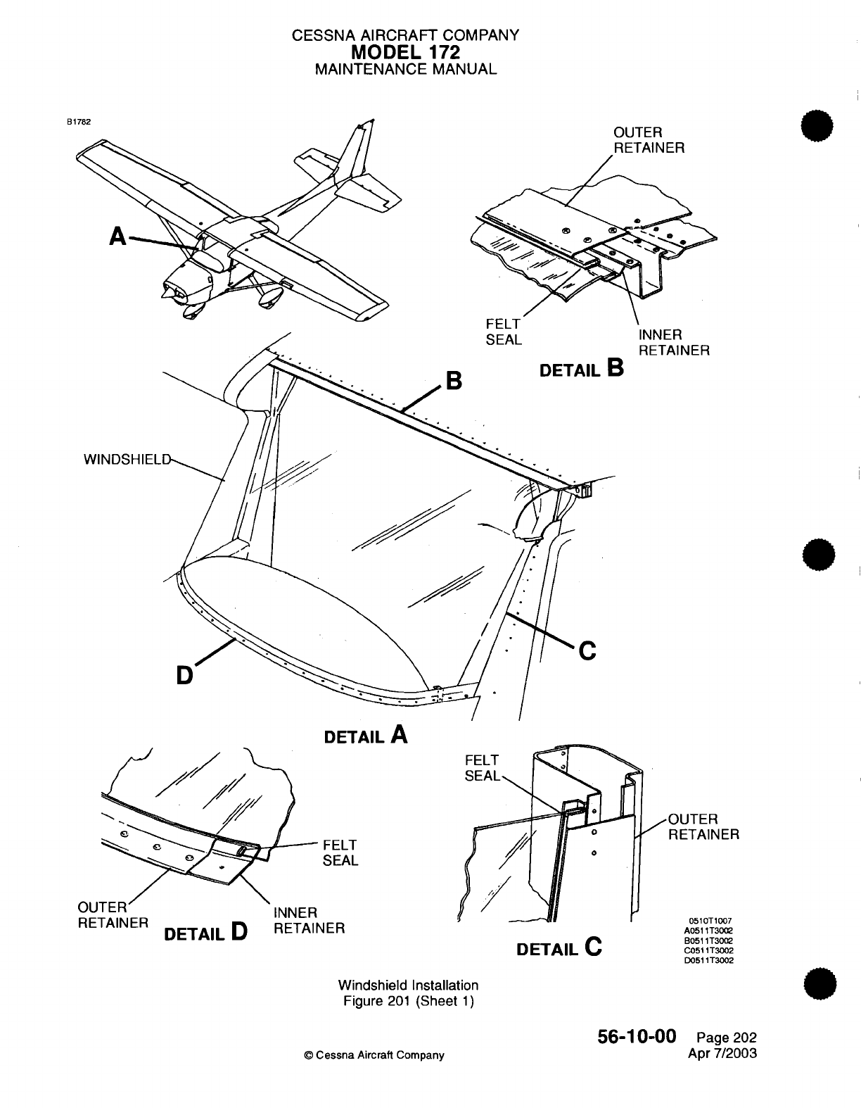
CESSNA
AIRCRAFT
COMPANY
MODEL
172
MAINTENANCE
MANUAL
DETAIL
A
FELT
SEAL
RETAINER
DETAILD
DETAIL
D
RETAINER
DETAIL
C
jOUTER
RETAINER
0510T1007
A0511T3002
B0511T3002
C0511T3002
D0511T3002
Windshield
Installation
Figure
201
(Sheet
1)
©
Cessna
Aircraft
Company
56-10-00
Page
202
Apr
7/2003
B1
OUTER
INNER
RETAINER
FELT
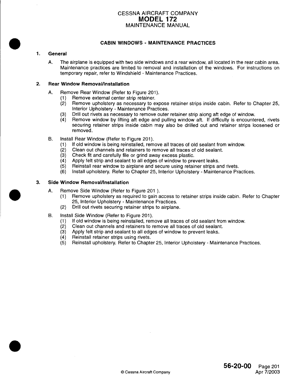
CESSNA
AIRCRAFT
COMPANY
MODEL
172
MAINTENANCE MANUAL
CABIN WINDOWS
-
MAINTENANCE PRACTICES
1.
General
A.
The
airplane
is
equipped
with
two
side windows and
a
rear
window,
all
located
in
the rear
cabin
area.
Maintenance
practices
are
limited
to
removal
and
installation
of
the
windows.
For
instructions
on
temporary
repair,
refer
to
Windshield
-
Maintenance
Practices.
2.
Rear
Window Removal/Installation
A.
Remove
Rear
Window
(Refer
to
Figure
201).
(1)
Remove
external center
strip retainer.
(2)
Remove
upholstery
as
necessary
to
expose
retainer strips
inside
cabin.
Refer
to
Chapter
25,
Interior
Upholstery
-
Maintenance Practices.
(3)
Drill
out
rivets
as
necessary
to
remove
outer
retainer strip along aft
edge
of
window.
(4)
Remove
window by
lifting
aft edge and
pulling
window
aft.
If
difficulty
is
encountered,
rivets
securing
retainer strips
inside
cabin
may
also
be
drilled
out
and retainer
strips loosened
or
removed.
B.
Install Rear
Window
(Refer
to
Figure
201).
(1) If
old
window
is
being
reinstalled,
remove
all traces
of
old
sealant
from
window.
(2)
Clean
out
channels
and
retainers
to
remove
all
traces
of
old
sealant.
(3)
Check
fit
and
carefully file
or
grind
away
excess
plastic.
(4)
Apply
felt
strip
and
sealant
to
all
edges
of
window
to
prevent
leaks.
(5)
Reinstall
rear window
to
airplane
and
secure
using
retainer
strips
and
rivets.
(6)
Install
upholstery.
Refer to
Chapter
25,
Interior
Upholstery
-
Maintenance
Practices.
3.
Side
Window
Removal/nstallation
A.
Remove
Side
Window
(Refer
to
Figure
201
).
(1)
Remove
upholstery
as
required
to gain
access
to
retainer strips
inside
cabin. Refer
to
Chapter
25,
Interior
Upholstery
-
Maintenance Practices.
(2)
Drill
out
rivets
securing retainer strips
to
airplane.
B.
Install Side
Window
(Refer
to
Figure
201).
(1) If
old
window
is
being
reinstalled,
remove
all
traces
of
old
sealant
from
window.
(2)
Clean
out
channels
and
retainers
to
remove
all
traces
of
old
sealant.
(3)
Apply
felt
strip
and
sealant
to
all
edges
of
window
to
prevent leaks.
(4)
Reinstall
retainer strips
using rivets.
(5)
Reinstall
upholstery.
Refer
to
Chapter
25,
Interior
Upholstery
-
Maintenance Practices.
56-20-00
Page
201
©
Cessna
Aircraft
Company
Apr
7/2003
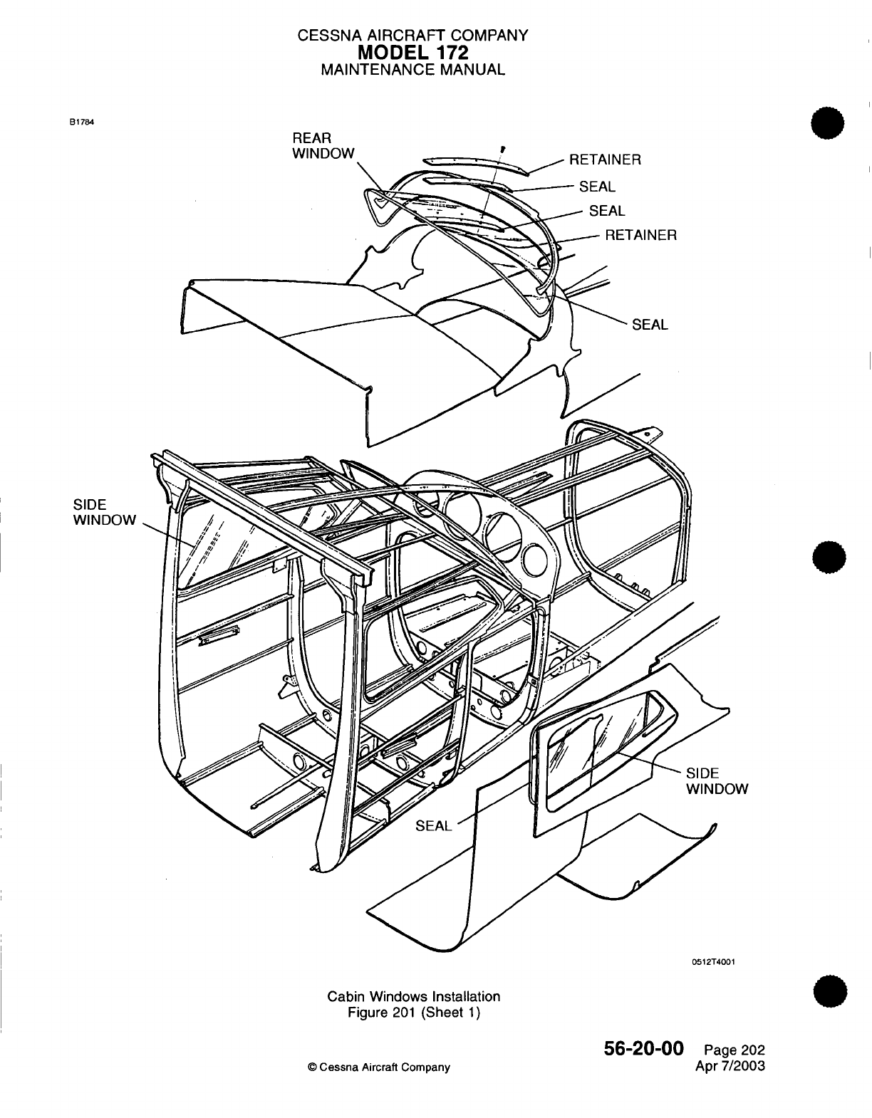
CESSNA
AIRCRAFT
COMPANY
MODEL
172
MAINTENANCE
MANUAL
B1784
REAR
IA
1
KI
r%/r'%AI
SIDE
WINDOW
0512T4001
Cabin
Windows
Installation
Figure
201
(Sheet
1)
©
Cessna
Aircraft
Company
56-20-00
Page
202
Apr
7/2003
CESSNA
AIRCRAFT
COMPANY
MODEL
172
MAINTENANCE
MANUAL
CABIN
DOOR
WINDOWS
-
MAINTENANCE
PRACTICES
1.
General
A.
This
maintenance
practices section
consists
of
removal
and
installation
of
the
hinged
windows
located
in
each
door.
For
instructions
on
temporary repair
to the
cabin door
windows,
refer
to
Windshield -
Maintenance
Practices.
2.
Cabin Door
Window Removal/Installation
A.
Remove
Cabin
Door
Window
(Refer
to
Figure
201).
(1)
Disconnect
arm
from
window assembly.
(2)
Remove
hinge
pins
from
hinge.
B.
Install
Cabin
Door
Window
(Refer
to
Figure
201).
(1)
Position
window
assembly
to
door.
(2)
Secure
window
assembly
to
hinge
using
hinge
pin.
©
Cessna
Aircraft Company
56-30-00
Page
201
Apr
7/2003
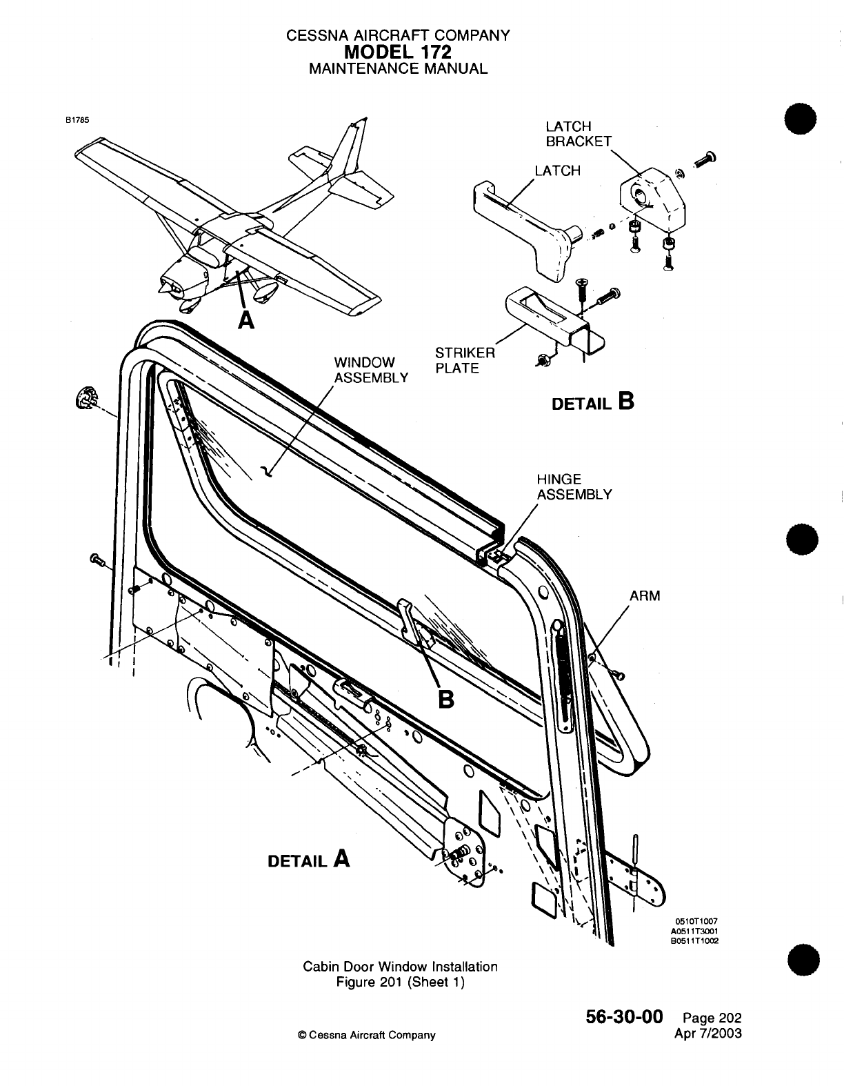
CESSNA
AIRCRAFT
COMPANY
MODEL
172
MAINTENANCE
MANUAL
WINDOW
ASSEMBLY
DETAIL
B
HINGE
ASSEMBLY
ARM
DETAIL
A
0510T1007
A0511T3001
B0511T1002
Cabin Door
Window Installation
Figure
201
(Sheet
1)
56-30-00
©
Cessna
Aircraft
Company
B1
LATCH
BRACKET
Page
202
Apr
7/2003
CHAPTER
WINGS

CESSNA
AIRCRAFT
COMPANY
MODEL
172
MAINTENANCE
MANUAL
LIST
OF
EFFECTIVE
PAGES
CHAPTER-SECTION-SUBJECT
57-Title
57-List
of
Effective
Pages
57-Record
of
Temporary
Revisions
57-Contents
57-00-00
57-10-00
PAGE
Page
1
Pages
201-206
©
Cessna
Aircraft
Company
57
-
LIST
OF
EFFECTIVE
PAGES
Page
1
of
1
Jan 3/2005
DATE
Apr
7/2003
Apr
7/2003
Temporary
Revision
Number
RECORD OF
TEMPORARY
REVISIONS
Page
Number Issue
Date
By
Date
Removed
By
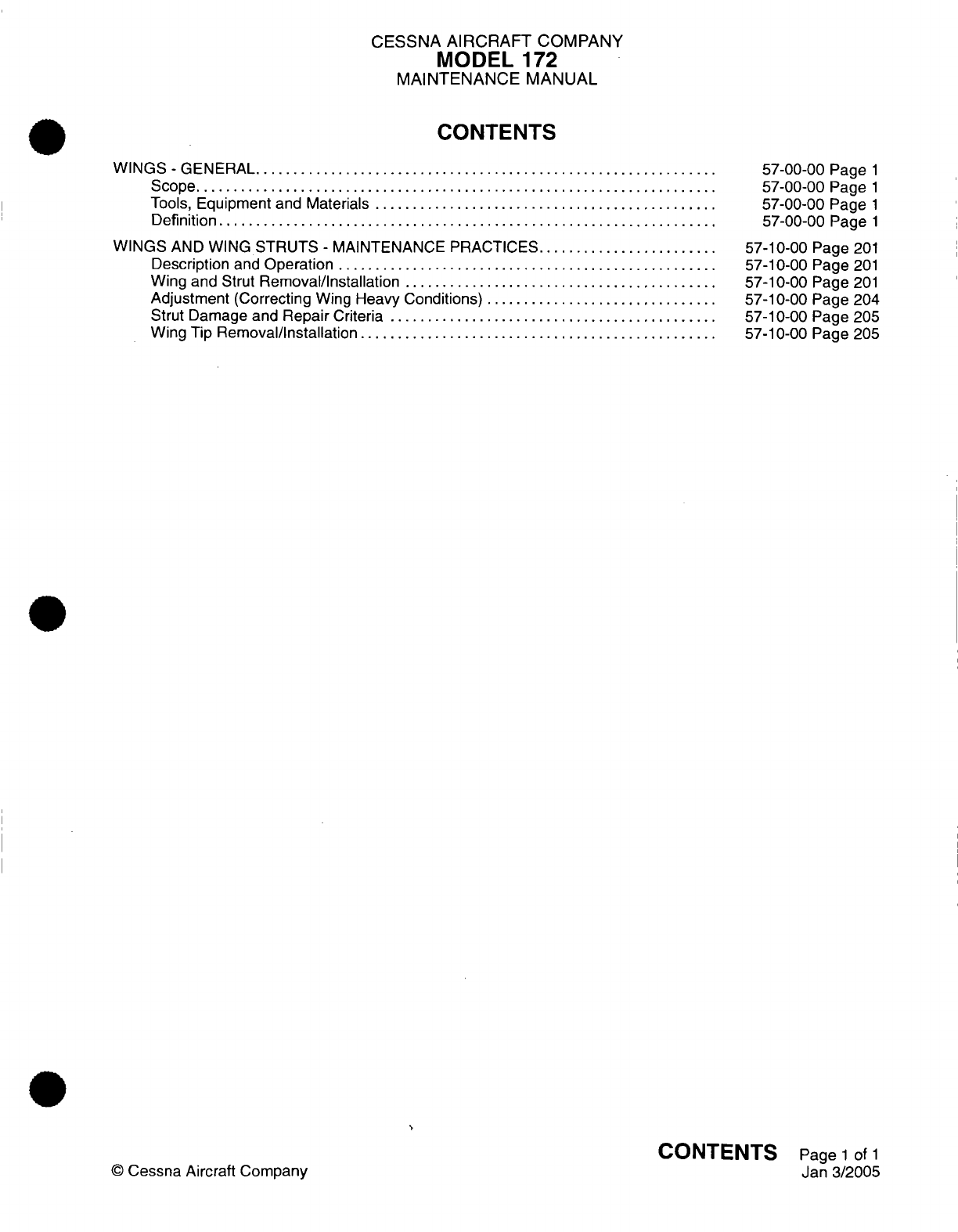
CESSNA
AIRCRAFT
COMPANY
MODEL
172
MAINTENANCE MANUAL
CONTENTS
W
INGS
-
GENERAL..........
..................................................
S
cope......................................................................
Tools,
Equipment
and
Materials
..............................................
Definition
...................................................................
WINGS
AND
WING
STRUTS
-
MAINTENANCE
PRACTICES........................
Description
and
Operation
...................................................
Wing
and
Strut
Removal/Installation
..........................................
Adjustment
(Correcting
Wing
Heavy Conditions)
...............................
Strut Damage
and
Repair
Criteria
............................................
Wing
Tip
Removal/Installation
................................................
57-00-00 Page
1
57-00-00
Page
1
57-00-00
Page
1
57-00-00
Page
1
57-10-00 Page
201
57-10-00 Page
201
57-10-00
Page
201
57-10-00 Page
204
57-10-00 Page
205
57-10-00 Page
205
CONTENTS
Page
1
of
1
Jan
3/2005
©
Cessna
Aircraft
Company
CESSNA
AIRCRAFT
COMPANY
MODEL
172
MAINTENANCE
MANUAL
WINGS
-
GENERAL
1.
Scope
A.
This
chapter
provides
instructions
on
wing
removal
and
installation.
Information
and repair procedures
beyond
the
scope
of
this
chapter
can
be
found
in
the
Single
Engine 1996
and On
Structural
Repair
Manual.
2.
Tools,
Equipment
and
Materials
NOTE:
Equivalent
substitutes
may
be
used for
the
following
listed
items:
NUMBER
MIL-G-21164
MANUFACTURER
E/M
Corporation
Box
2200
Highway
52
N.W.
West
Lafayette,
IN
47906
USE
To
lubricate wing
attach
fittings
and
bolts
upon
reinstallation.
3.
Definition
A.
This
chapter contains
a
single
section
on
wing
removal,
installation
and
adjustment.
57-00-00
Page
1
©
Cessna
Aircraft
Company
Apr
7/2003
NAME
Grease
CESSNA
AIRCRAFT
COMPANY
MODEL
172
MAINTENANCE
MANUAL
WINGS AND
WING
STRUTS
-
MAINTENANCE
PRACTICES
1.
Description
and
Operation
A.
Each
metal
wing
is
a
strut braced
type,
with
two main
spars
and
suitable
ribs
for
the
attachment
of
the
skin. Skin
panels
are
riveted to
ribs,
spars
and
stringers
to
complete
the
structure.
An
all
metal,
piano
hinged aileron,
flap
and
detachable
wing
tip are
mounted
on
each
wing
assembly. Each
wing
also
incorporates
an
integral
fuel
bay
located between
the
two
spars
at
the
inboard
portion
of
the wing.
Each
wing
is
supported
in
position
by
a
single
lift
strut
which
consists
of
a
streamlined
tube
riveted
to
two
end
fittings
for
attachment
at the
wing
and
at the
fuselage.
B.
For
a
skeletal
view
of
the
wing
assembly, refer
to
Chapter
6,
Airplane
Stations
-
Description
and
Operation,
Figure
2.
2.
Wing
and
Strut
Removal/Installation
A.
Remove
Wing
and
Strut
(Refer
to
Figure
201).
NOTE:
Wings
are
most
easily
removed
if
four
people
are
available
to
handle
the
wing. Otherwise,
the
wing
should
be
supported
with
a
sling
or
maintenance
stand when the
fasteners
are
loosened.
(1)
Remove
fasteners
from
fairings
at
wing/fuselage
intersections.
(2)
Remove
inspection
plates
as
required
to
allow for
disconnection
of
all
electrical,
mechanical
and
fuel
connections.
(3)
Drain
fuel
from
wing.
(4)
Disconnect
electrical
wires
at
wing
root
disconnects.
(5)
Disconnect
fuel
lines
at
wing
root.
(6)
On
left
wing,
disconnect
pitot line.
(7)
Disconnect
fresh
air
distribution duct
at
wing
root.
(8)
Loosen
and
disconnect
aileron
cables
at
aileron
bellcrank.
(9)
Disconnect flap
cables
at
turnbuckle
above cabin
headliner, and
pull
cables
into
wing
root
area.
NOTE:
To
ease rerouting
of
cables,
a
guide
wire may
be
attached
to
each
cable
before
it
is
pulled
free
from
the
wing.
Cable
may
then
be
disconnected
from
the
guide
wire.
Leave
the
guide
wire
routed
through
the
wing;
it
will
be
reattached
to
the
cable
during
installation
and used
to
pull
the
cable
into
place.
(10)
Remove
screws
from
strut
fairings
and
slide
fairings
toward
center
of
strut.
(11)
Support
wing
at
outboard
end.
Remove
strut-to-wing
attach
bolt
and
strut-to-fuselage
attach
bolt.
(12)
Remove
strut
from
between
wing
and
fuselage.
NOTE:
Tape
flaps
in
the
streamlined
position
during wing
removal.
This
will
prevent
flap
movement
during
handling.
(13)
Mark
position
of
wing
attachment eccentric bushings
in
relationship
to
fittings. These
bushings
are used
to
rig
out
wing
heaviness,
and
if
bushings
are
not
marked,
wings
may require
readjustment
at
installation.
(14)
Remove nuts,
washers,
bushings
and
bolts
attaching
wing
spars
to
fuselage.
NOTE:
It
may
be
necessary
to
rock
the
wings
slightly
and/or
to
use
a
long
drift
punch
to
remove
attaching
bolts.
(15)
Remove
wing and lay
on
padded stand.
57-10-00
Page
201
©
Cessna
Aircraft Company
Apr
7/2003
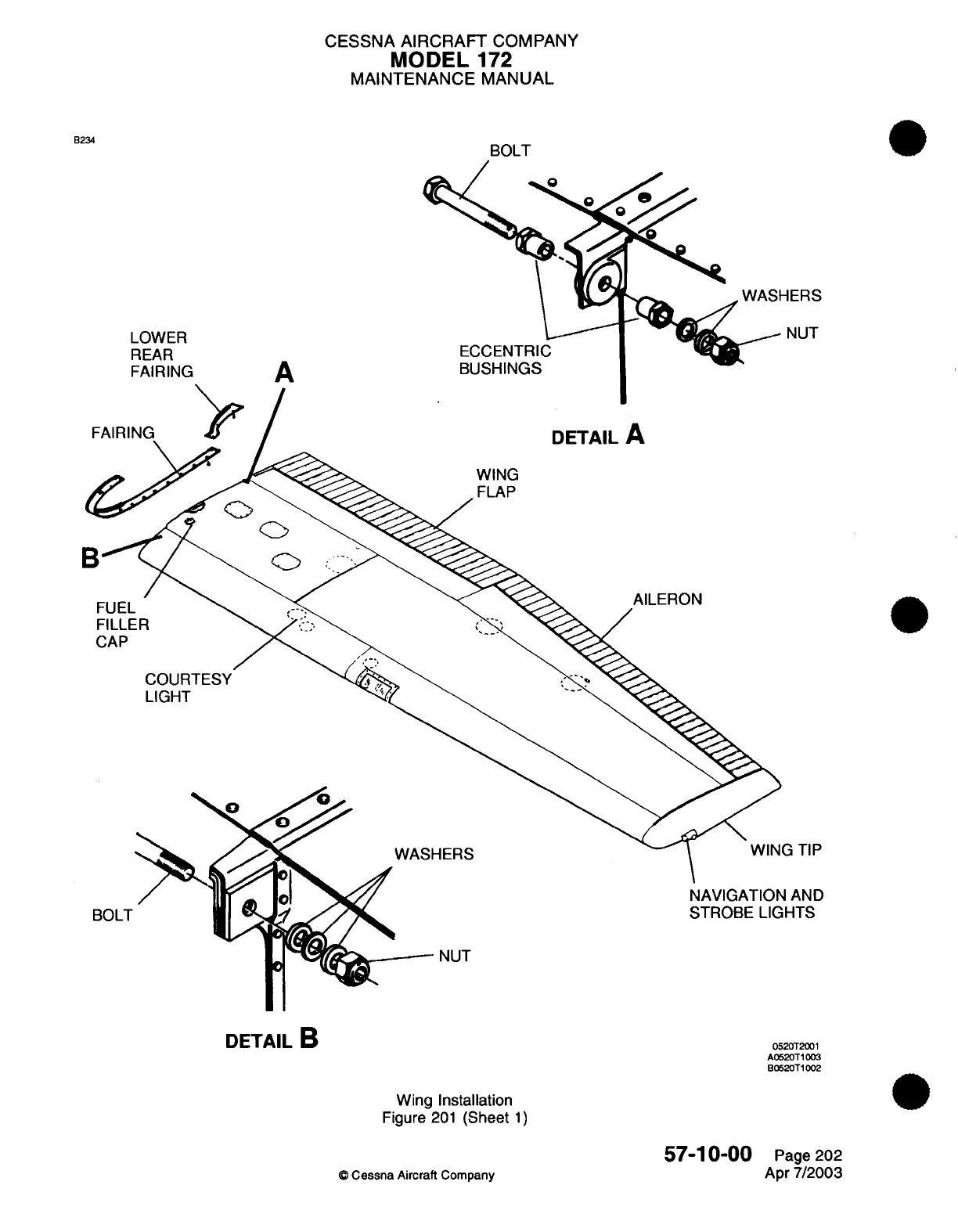
CESSNA
AIRCRAFT
COMPANY
MODE
172
MAINTENANCE MANUAL
B234
LOWER
REAR
FAIRING
ECCENTRIC
BUSHINGS
A
DETAIL
A
WING
FLAP
AILERC
COURTESY
LIGHT
WASHERS
NAVIGATION
AND
STROBE
LIGHTS
NUT
Wing
Installation
Figure
201
(Sheet
1)
57-10-00
©
Cessna Aircraft
Company
FAIRING
WASHERS
NUT
FUEL
FILLER
CAP
BOLT
G
TIP
DETAIL
B
0520T2001
A0520T1003
B0520T1002
Page
202
Apr
7/2003
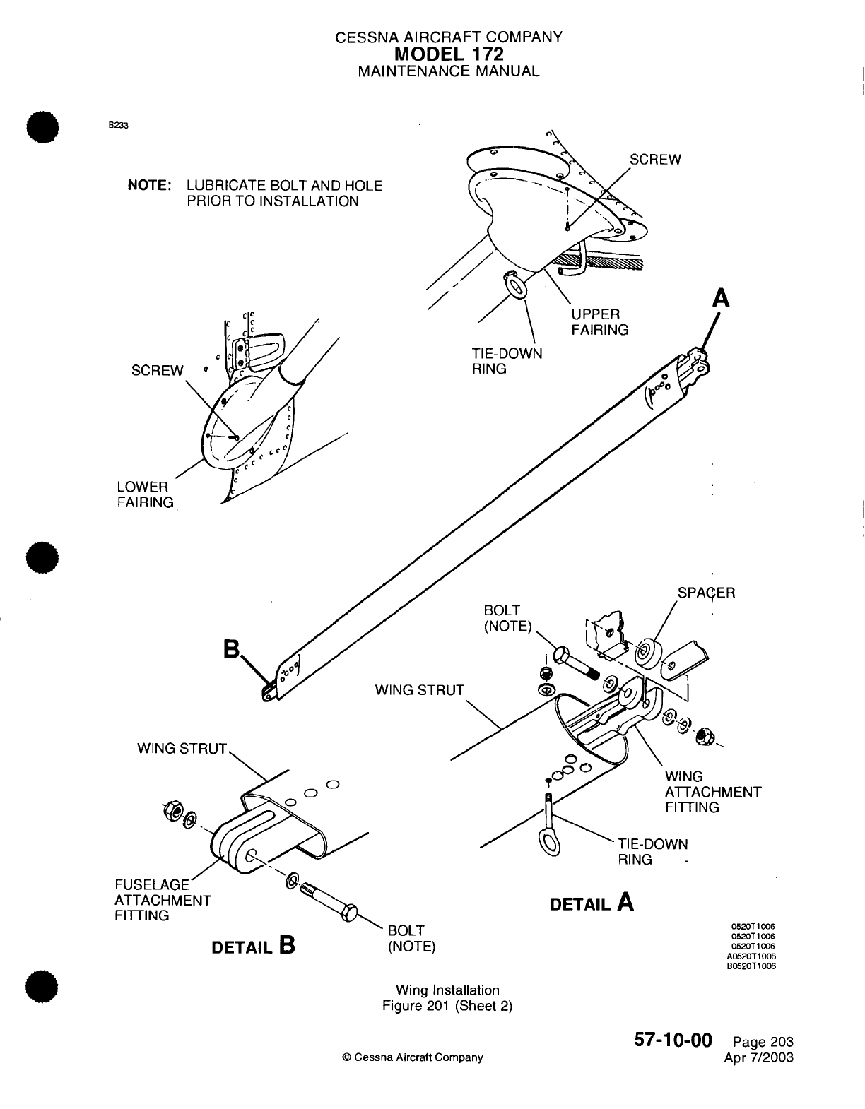
CESSNA
AIRCRAFT
COMPANY
MODEL
172
MAINTENANCE
MANUAL
B233
NOTE: LUBRICATE
BOLT
AND
HOLE
PRIOR TO
INSTALLATION
A
TIE-DOWN
RING
SCREW
LOWER
FAIRING
WING
STRUT
WING
STRUT
ATTACHMENT
FUSEL
ATTAC
FITTING
DETAIL
B
RING
DETAIL
A
0520T1006
0520T
1006
0520T1006
A0520T1006
B0520T1006
BOLT
(NOTE)
Wing
Installation
Figure
201
(Sheet
2)
©
Cessna
Aircraft
Company
57-10-00
Page
203
Apr
7/2003
FAIRING
SPACER
WING
STRUT
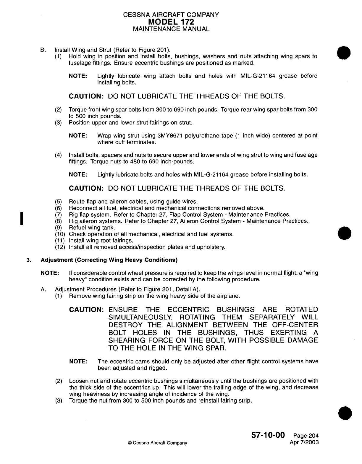
CESSNA
AIRCRAFT
COMPANY
MODEL
172
MAINTENANCE
MANUAL
B.
Install
Wing
and Strut
(Refer
to
Figure
201).
(1)
Hold
wing
in
position and install
bolts,
bushings,
washers
and
nuts
attaching
wing
spars
to
fuselage
fittings.
Ensure
eccentric
bushings
are
positioned
as
marked.
NOTE:
Lightly
lubricate
wing
attach bolts
and
holes
with
MIL-G-21164 grease
before
installing
bolts.
CAUTION:
DO
NOT LUBRICATE THE
THREADS
OF
THE
BOLTS.
(2)
Torque
front
wing
spar
bolts
from
300 to 690
inch
pounds.
Torque
rear
wing
spar
bolts
from
300
to
500
inch
pounds.
(3)
Position upper
and
lower
strut
fairings
on
strut.
NOTE: Wrap
wing
strut
using
3MY8671
polyurethane
tape
(1
inch
wide)
centered
at
point
where
cuff
terminates.
(4)
Install
bolts, spacers
and
nuts
to
secure
upper
and
lower
ends
of
wing
strut
to
wing
and
fuselage
fittings.
Torque
nuts
to
480
to 690
inch-pounds.
NOTE:
Lightly lubricate
bolts
and
holes
with
MIL-G-21164
grease
before
installing
bolts.
CAUTION:
DO
NOT
LUBRICATE THE
THREADS
OF
THE
BOLTS.
(5)
Route
flap
and
aileron
cables,
using guide
wires.
(6)
Reconnect
all
fuel,
electrical
and
mechanical
connections
removed
above.
(7)
Rig
flap
system.
Refer
to
Chapter
27,
Flap
Control System
-
Maintenance
Practices.
(8)
Rig
aileron
systems.
Refer
to
Chapter
27,
Aileron Control
System
-
Maintenance
Practices.
(9)
Refuel
wing tank.
(10)
Check
operation
of
all
mechanical, electrical
and
fuel systems.
(11)
Install
wing
root
fairings.
(12)
Install all removed
access/inspection
plates
and
upholstery.
3.
Adjustment
(Correcting
Wing
Heavy
Conditions)
NOTE:
If
considerable
control
wheel
pressure
is
required
to
keep
the wings
level
in
normal
flight,
a
"wing
heavy"
condition
exists
and
can
be
corrected
by
the
following
procedure.
A.
Adjustment
Procedures
(Refer
to Figure
201,
Detail
A).
(1)
Remove
wing fairing
strip
on
the
wing
heavy
side
of the
airplane.
CAUTION:
ENSURE
THE
ECCENTRIC
BUSHINGS
ARE
ROTATED
SIMULTANEOUSLY. ROTATING
THEM
SEPARATELY
WILL
DESTROY
THE
ALIGNMENT
BETWEEN THE
OFF-CENTER
BOLT
HOLES
IN
THE
BUSHINGS, THUS
EXERTING
A
SHEARING
FORCE
ON
THE
BOLT,
WITH
POSSIBLE
DAMAGE
TO
THE
HOLE
IN
THE
WING
SPAR.
NOTE: The
eccentric cams should only
be
adjusted after
other
flight
control systems have
been
adjusted
and
rigged.
(2)
Loosen nut
and
rotate
eccentric bushings
simultaneously
until the
bushings
are
positioned
with
the
thick
side
of
the
eccentrics
up.
This
will
lower
the trailing
edge
of
the
wing,
and
decrease
wing
heaviness
by
increasing
angle
of
incidence
of
the wing.
(3)
Torque
the
nut
from 300
to
500 inch
pounds
and
reinstall
fairing
strip.
57-10-00
Page 204
©
Cessna
Aircraft
Company
Apr
7/2003
CESSNA
AIRCRAFT
COMPANY
MODEL
172
MAINTENANCE
MANUAL
(4)
Test
fly
the
airplane.
If
the
wing
heavy
condition
still
exists,
remove
fairing strip
on
the
lighter
wing, loosen
nut and
rotate
bushing
simultaneously
until
the
bushings
are
positioned with
the
thick
side of the
eccentrics
down.
This will
raise
the
trailing
edge
of
the
wing, thus
increasing
wing
heaviness
to
balance
heaviness
in
the
opposite
wing.
(5)
Torque
nut
from
300
to
500
inch
pounds,
install
fairing
strip
and
repeat
flight
test.
4.
Strut
Damage
and
Repair
Criteria
A.
For
wing
strut damage
and
repair
criteria,
refer
to the
Single
Engine
Structural Repair Manual
Chapter
57,
Wing Damage
Classification.
5.
Wing Tip
Removal/Installation
A.
Remove
Wing
Tip
(Refer
to
Figure 202).
(1)
Remove
screws securing
wing
tip
to
wing.
(2)
Remove
screw securing strobe light
and
navigation
light
ground
straps
to
power
supply.
(3)
Disconnect
navigation
light
electrical
connector.
(4)
Disconnect
strobe
light
electrical
connector.
(5)
Remove
wing
tip
from
wing.
B.
Install Wing
Tip
(Refer
to
Figure
202).
(1)
Connect strobe
light
electrical
connector,
and
connect
navigation
light
electrical
connector.
(2)
Slide
the
wing
tip
into
position
over
the
wing
tip
rib
ensuring
the
existing
holes
in
the
wing
tip
align with
the
attach
holes
in
the
wing skin/rib
nutplates.
(3)
Fabricate
a
curved
spacer
from
phenolic
or
aluminum
which
is 0.01 to
0.03
inch
thick
X
1.0
inch
X
2.0
inches
which
matches
the
contour
of the
leading
edge.
(4)
Insert
the
spacer
at
the
leading
edge
of
the wing between
the
skin
and the
inside
contour
of
the
wing
tip.
(5)
Secure
wing
tip
to
wing
using
screws
starting
at
the
aft
of
the
tip
and working
forward.
(6)
When
all
screws
are
secure,
remove
the
spacer
to
leave
a
gap
of
0.01
inch to
0.03
inch
between
the
skin
and
the
inside
contour
of
the
wing tip.
57-10-00
Page
205
©
Cessna
Aircraft Company
Apr
7/2003
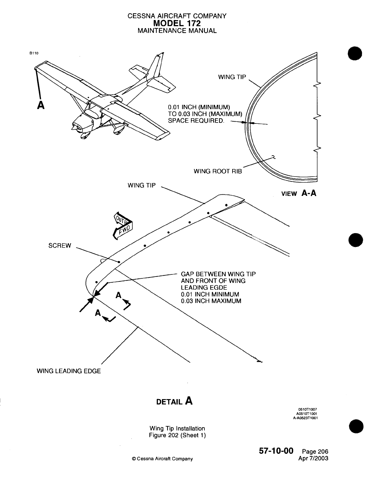
CESSNA AIRCRAFT
COMPANY
MODEL
172
MAINTENANCE
MANUAL
B110
P
A
INCH
WING
ROOT
WING
TIP
-w
A-A
SCREW
GAP BETWEEN
WING
TIP
AND
FRONT
OF
WING
LEADING
EGDE
0.01
INCH
MINIMUM
0.03
INCH
MAXIMUM
WING
LEADING
EDGE
DETAIL
A
0510T1007
A0510T1001
A-A0523T1001
Wing
Tip
Installation
Figure 202
(Sheet
1)
©
Cessna
Aircraft
Company
57-10-00
Page
206
Apr
7/2003
r

CHAPTER
PROPELLERS
CESSNA AIRCRAFT
COMPANY
MODEL
172
MAINTENANCE
MANUAL
LIST
OF
EFFECTIVE
PAGES
CHAPTER-SECTION-SUBJECT
61
-Title
61
-List
of
Effective
Pages
61
-Record
of
Temporary
Revisions
61
-Table
of
Contents
61-00-00
61
-10-00
PAGE
Page
1
Pages
201-203
©
Cessna
Aircraft
Company
61
-
LIST
OF
EFFECTIVE PAGES
Page
1
of
1
Jul
1/2007
DATE
Apr
7/2003
Jul
1/2007

Temporary
Revision
Number
RECORD
OF
TEMPORARY
REVISIONS
Page
Number
Issue
Date
By
Date
Removed
By
CESSNA AIRCRAFT
COMPANY
MODEL
172
MAINTENANCE
MANUAL
CONTENTS
PROPELLERS
-
GENERAL
............................
Scope....................................
Definition
..................................
PROPELLER
-
MAINTENANCE
PRACTICES....................
Description
and
Operation
..........................
Propeller
and
Spinner
Removal/installation...................
61
-00-00
Page
1
61
-00-00
Page
1
61
-00-00
Page
1
61
-10-00
Page
201
61
-10-00
Page
201
61
-10-00
Page
201
61
-CONTENTS
Pagel1ofi1
Jul
1/2007
©
Cessna
Aircraft
Company
CESSNA
AIRCRAFT
COMPANY
MODEL
172
MAINTENANCE
MANUAL
PROPELLERS
-
GENERAL
Scope
A.
This
chapter
provides
instructions
on
propeller and
spinner.
Definition
A.
This
chapter contains
a
single
section
on
removal
and
installation
of
the
propeller
and
spinner.
61-00-00
Page
1
©
Cessna Aircraft Company
Apr 7/2003
1.
2.
CESSNA
AIRCRAFT
COMPANY
MODEL
172
MAINTENANCE
MANUAL
PROPELLER
-
MAINTENANCE PRACTICES
1.Description
and
Operation
A.
The
airplane
is
equipped
with
a
two
bladed,
fixed
pitch
metal
propeller.
Maintenance
practices
consist
of
propeller/spinner
removal
and
installation.
For
information
beyond
the
scope
of
this
section,
refer
to
the
applicable
McCauley
Service
Manual.
2.
Propeller
and
Spinner
Remnoval/Installation
A.
Remove
the
Propeller
and
Spinner
(Refer
to
Figure
201).
WARNING:
Exercise
care
when
working
with
the
propeller.
Ensure
magneto
switch
is
in
the
off
position
before
turning
propeller.
(1)
Remove
the
cowling
and
nosecap.
Refer
to
Chapter
71,
Cowling
-
Maintenance Practices.
(2)
Remove screws
securing
the
spinner
to
the
forward
and
aft
bulkheads.
Remove
the
spinner.
(3)
Cut
and
discard
safety
wire from the
propeller
mounting bolts.
(4)
Remove
the
mounting
bolts, forward
bulkhead,
propeller,
aft
bulkhead
and
spacer
from
crankshaft.
NOTE:
A
dowel
pin
holds
the
propeller,
aft
bulkhead
and
spacer
together when
removed.
(5)
The
propeller
mounting
bolts
must
be
magnetic
particle inspected,
refer
to
ASTM E-1414
or
liquid
penetrant inspected,
refer
to
ASTM
E-1
417,
or
replaced
at
every
overhaul. The
propeller
mounting bolts must
be
replaced
when
the
propeller
is
involved
in a
blade
strike.
(6)
Remove
the
spacer
and the
aft
bulkhead
from
the
propeller.
(a)
Support
the
propeller
by
setting
it
between
two
sand filled bags placed
as
close
to
the
hub
as
possible
with
the
spacer
down.
Allow
two
(2)
inches
of
clearance
for
the
spacer
and
aft
S ~ ~~~~~~bulkhead
to
separate
from
the
hub.
(b)
Select
a
rod
of
proper diameter
and
is
six
(6)
inches
long. Insert
rod
into
propeller
hub
dowel
pin
holes.
Using
a
hammer,
lightly
tap dowels
in a
alternating
pattern
to
free
the
spacer
and
bulkhead
from
propeller
hub.
The
dowels
will
remain
in
the
spacer.
(c) If
the
tapered
end
of
dowels
were
installed
in
the
propeller
hub, remove
dowels
from spacer
by
inserting
the
rod
into
dowel
pin
holes
in
spacer.
Using
a
hammer,
lightly
tap dowels
in
a
alternating
pattern
to
remove
dowels
from
spacer.
B.
Aft
bulkhead
and
spacer
assembly.
CAUTION: The
spacer
and
propeller
are
balanced
as
a
pair and
must
be
installed
together.
Do
not
exchange
spacers
or
propellers
from
other airplanes.
(1)
Position
spacer
on
a
arbor
press
table
with
hub mating
surface
facing
up.
(2) If
dowels
were
removed
from
spacer,
install dowels
with
tapered
end
into
spacer.
(a)
Lightly
oil
each
dowel
and
press
into
spacer.
(b)
Engage
dowel
into
spacer
enough
to
hold
dowel
firmly. Extension
of
both
dowels
above
face
of
spacer
must
be
the
same
after
pressing.
NOTE:
Final
dowel
location
will
be
made
when
spacer
is
installed
in
propeller
hub.
(c)
Position
propeller
hub
on
arbor press
table
with
spacer
mating
surface
facing
up.
(d)
Place
bulkhead
over
hub
aligned
with
dowel
holes.
(e)
Align
serial number
on
spacer
with
serial number
on
propeller
hub.
(f)
Press
spacer
down
against
hub
and
allow
the
bulkhead
to
rotate
against
the
dowels
for
adjustment.
C.
Install the
Propeller
and
Spinner
(Refer
to
Figure
201).
61
-1
000
Page
201
©
Cessna Aircraft Company
Jul
1/2007
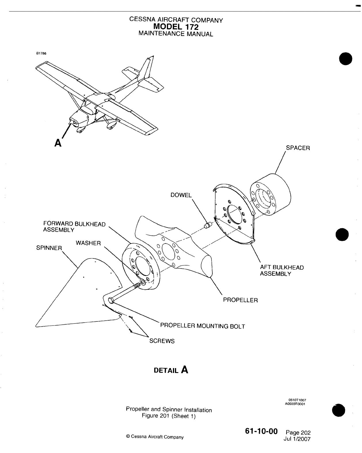
CESSNA
AIRCRAFT
COMPANY
MODEL
172
MAINTENANCE
MANUAL
B1
786
A
SPACER
DOWEL
FORWARD
BULKHEAD
ASSEMBLY
WASHER
FAD
PROPELLER
PROPELLER
MOUNTING
BOLT
SCREWS
DETAIL
A
Propeller
and
Spinner
Installation
Figure
201
(Sheet
1)
©
Cessna
Aircraft Company
051OT 1007
A0555R3001
0
61
-10-00
Page
202
Jul
1/2007
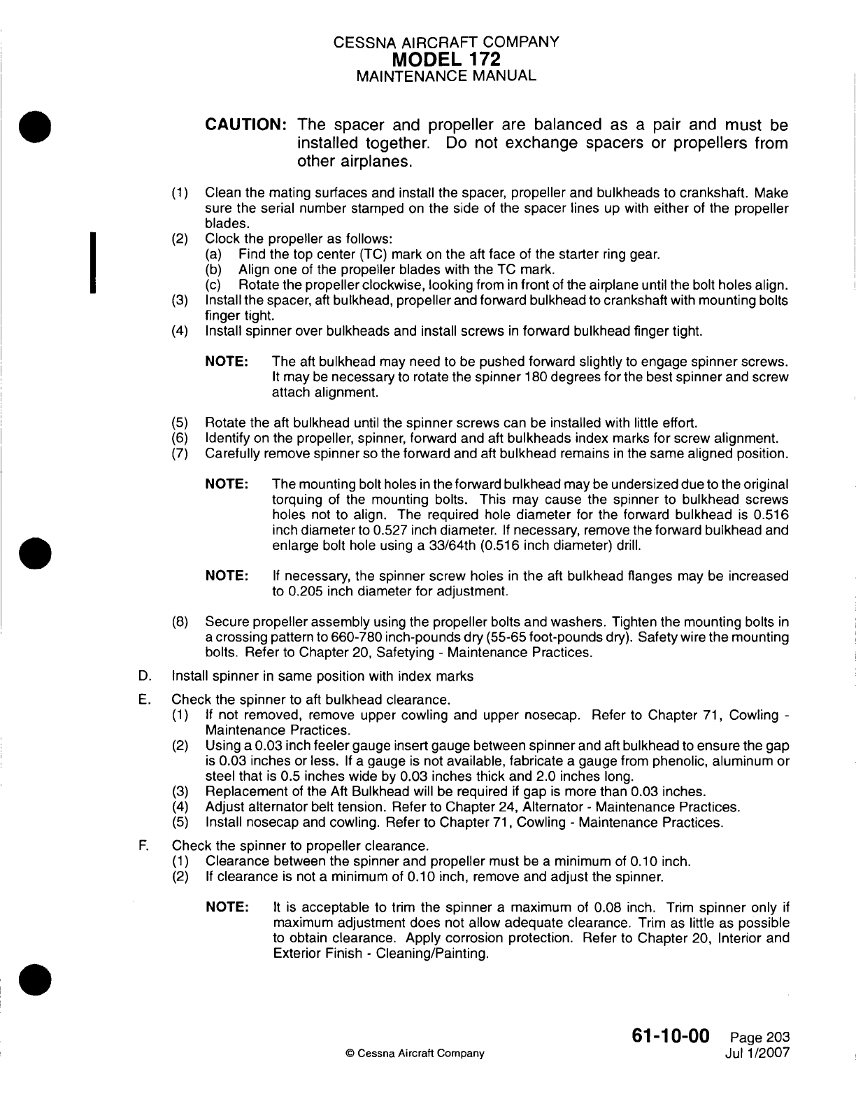
CESSNA
AIRCRAFT
COMPANY
MODEL
172
MAINTENANCE
MANUAL
CAUTION:
The
spacer
and
propeller
are
balanced
as
a
pair
and
must
be
installed
together.
Do
not
exchange
spacers
or
propellers
from
other
airplanes.
(1)
Clean the
mating
surfaces
and
install
the
spacer,
propeller
and
bulkheads
to
crankshaft.
Make
sure
the
serial
number stamped
on
the side
of
the
spacer
lines
up
with
either
of
the
propeller
blades.
(2)
Clock
the
propeller
as
follows:
(a)
Find
the
top
center
(TC)
mark
on
the
aft
face
of
the
starter
ring
gear.
I ~ ~~~(b)
Align one
of
the
propeller
blades
with the
TC
mark.
(c)
Rotate
the
propeller clockwise,
looking
from
in
front
of
the
airplane
until the bolt
holes
align.
(3)
Install
the spacer,
aft
bulkhead,
propeller
and
forward
bulkhead
to
crankshaft
with
mounting bolts
finger
tight.
(4)
Install
spinner
over
bulkheads
and
install
screws
in
forward
bulkhead finger
tight.
NOTE:
The
aft
bulkhead
may
need
to be
pushed
forward
slightly
to
engage
spinner
screws.
It
may
be
necessary
to
rotate
the
spinner
1
80
degrees
for
the
best
spinner
and
screw
attach
alignment.
(5)
Rotate
the
aft
bulkhead
until the
spinner
screws
can
be
installed
with
little
effort.
(6)
Identify
on
the
propeller, spinner,
forward
and
aft
bulkheads
index
marks
for
screw
alignment.
(7)
Carefully
remove
spinner
so
the
forward
and
aft
bulkhead
remains
in
the
same
aligned
position.
NOTE:
The
mounting
bolt
holes
in
the
forward
bulkhead
may
be
undersized
due
to
the
original
torquing
of
the
mounting
bolts.
This
may
cause
the
spinner
to
bulkhead screws
holes
not
to align.
The
required
hole
diameter
for
the
forward
bulkhead
is
0.516
inch
diameter
to
0.527
inch
diameter.
If
necessary,
remove
the
forward
bulkhead
and
enlarge
bolt
hole using
a
33/64th
(0.516
inch
diameter)
drill.
NOTE:
If
necessary,
the
spinner
screw
holes
in
the
aft
bulkhead flanges
may
be
increased
to
0.205
inch
diameter
for
adjustment.
(8)
Secure
propeller
assembly
using
the
propeller
bolts
and
washers.
Tighten
the
mounting
bolts
in
a
crossing
pattern
to
660-780 inch-pounds
dry
(55-65
foot-pounds
dry).
Safety
wire
the
mounting
bolts. Refer
to
Chapter
20,
Safetying
-
Maintenance
Practices.
D.
Install
spinner
in
same
position
with
index
marks
E.
Check
the
spinner
to
aft
bulkhead clearance.
(1) If
not
removed,
remove
upper
cowling
and
upper
nosecap.
Refer
to
Chapter
71,
Cowling
-
Maintenance
Practices.
(2)
Using
a
0.03
inch
feeler
gauge insert gauge
between
spinner
and
aft
bulkhead
to
ensure
the
gap
is
0.03
inches
or
less.
If a
gauge
is
not
available, fabricate
a
gauge
from
phenolic,
aluminum
or
steel that
is
0.5
inches wide
by
0.03
inches thick
and
2.0
inches
long.
(3)
Replacement
of
the
Aft
Bulkhead
will
be
required
if
gap
is
more
than 0.03
inches.
(4)
Adjust
alternator
belt
tension. Refer
to
Chapter
24,
Alternator
-
Maintenance Practices.
(5)
Install
nosecap
and
cowling.
Refer
to
Chapter
71,
Cowling
-
Maintenance
Practices.
F.
Check
the
spinner
to
propeller clearance.
(1)
Clearance
between
the
spinner
and
propeller
must
be
a
minimum
of
0.10
inch.
(2) If
clearance
is
not
a
minimum
of
0. 10
inch, remove
and
adjust
the
spinner.
NOTE:
It is
acceptable
to
trim
the
spinner
a
maximum
of
0.08
inch.
Trim
spinner
only
if
maximum
adjustment does
not
allow
adequate
clearance.
Trim
as
little
as
possible
to
obtain
clearance.
Apply
corrosion
protection.
Refer
to
Chapter
20,
Interior and
Exterior
Finish
-
Cleaning/Painting.
61
-1
0-00
Page
203
c
Cessna
Aircraft
Company
Jul
1/2007

CHAPTER
POWER
PLANT
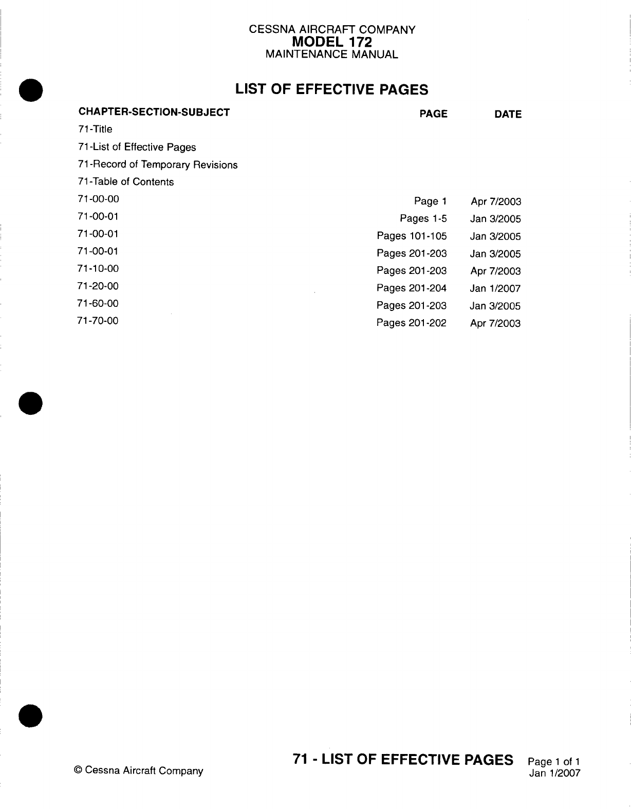
CESSNA AIRCRAFT
COMPANY
MODEL
172
MAINTENANCE
MANUAL
LIST
OF
EFFECTIVE
PAGES
CHAPTER-SECTION-SUBJECT
71
-Title
71
-List
of
Effective Pages
71
-Record
of
Temporary
Revisions
71
-Table of
Contents
71-00-00
71
-00-01
71-00-01
71
-00-01
71
-10-00
71-20-00
71-60-00
71-70-00
©
Cessna Aircraft
Company
PAGE
Page
1
Pages
1-5
Pages
101
-1
05
Pages
201
-203
Pages 201-203
Pages
201
-204
Pages
201-203
Pages 201-202
DATE
Apr
7/2003
Jan
3/2005
Jan
3/2005
Jan
3/2005
Apr
7/2003
Janl1/2007
Jan
3/2005
Apr
7/2003
71
-
LIST
OF
EFFECTIVE PAGES
Page
1
of
1
Janl1/2007
Temporary
Revision
Number
RECORD
OF
TEMPORARY
REVISIONS
Page
Number
Issue
Date
By
Date
Removed
By
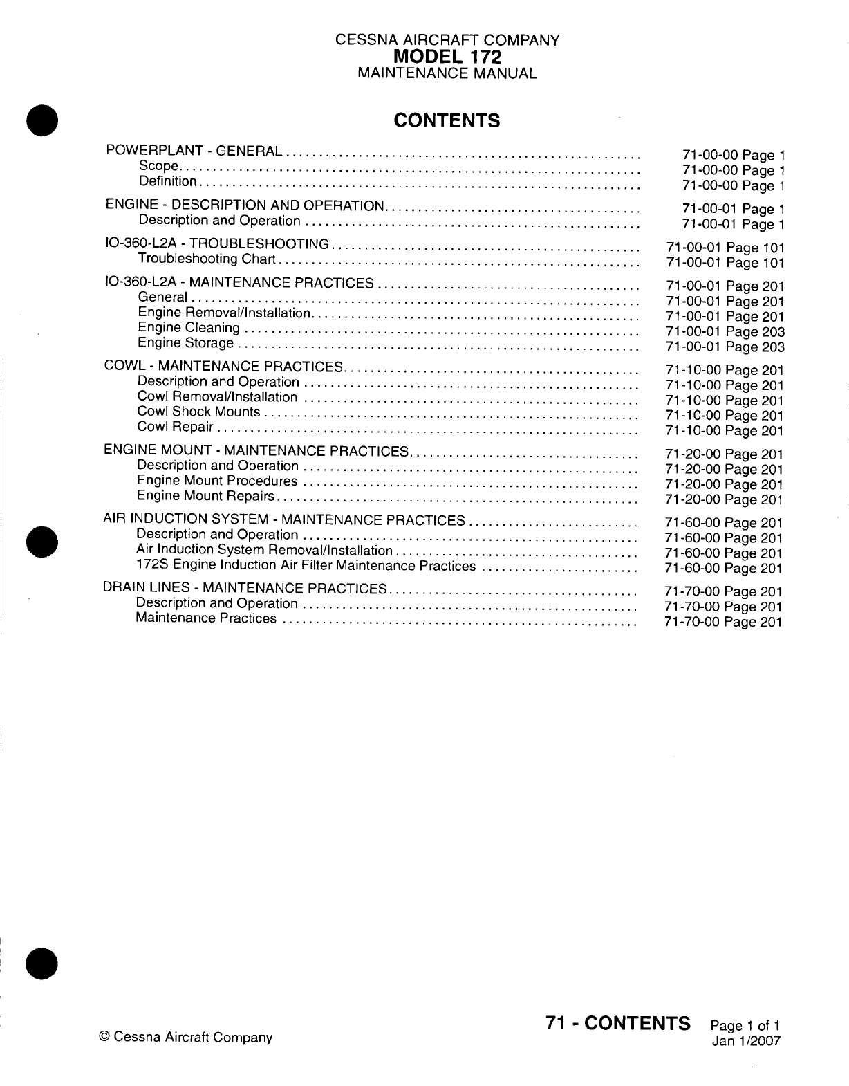
CESSNA
AIRCRAFT
COMPANY
MODEL
172
MAINTENANCE
MANUAL
CONTENTS
POWERPLANT
-
GENERAL............................
S
cope
.. . . . ... . .... . . . . . . . ... . . . . . .... . . .
Definition
..................................
ENGINE
-
DESCRIPTION
AND
OPERATION
....................
Description
and
Operation
..........................
10-360-1-2A
-
TROUBLESHOOTING
........................
Troubieshooting
Chart
............................
10-360-1-2A
-
MAINTENANCE
PRACTICES.....................
General...................................
Engine
Removal/Installation..........................
Engine
Cleaning...............................
Engine
Storage
...............................
COWL
-
MAINTENANCE
PRACTICES
.......................
Description
and
Operation
..........................
Cowl
Removal/installation
..........................
Cowl
Shock
Mounts
.............................
Cowl
Repair.................................
ENGINE MOUNT
-
MAINTENANCE
PRACTICES
..................
Description
and
Operation
..........................
Engine
Mount
Procedures
..........................
Engine
Mount
Repairs
............................
AIR
INDUCTION
SYSTEM
-
MAINTENANCE
PRACTICES..............
Description
and
Operation
..........................
Air
Induction
System
Removal/Installation
...................
172S Engine Induction
Air
Filter
Maintenance
Practices.............
DRAIN
LINES
-
MAINTENANCE
PRACTICES....................
Description
and
Operation
..........................
Maintenance
Practices............................
©
Cessna
Aircraft
Company
71
-00-00
Page
1
71
-00-00
Page
1
71
-00-00
Page
1
71
-00-01
Page
1
71
-00-01
Pagel1
71-00-01
Page
101
71
-00-01
Page
101
71-00-01
Page
201
71-00-01
Page
201
71-00-01
Page
201
71-00-01 Page
203
71-00-01
Page 203
71
-10-00 Page
201
71
-1
0-00
Page
201
71
-10-00
Page
201
71
-1
0-00
Page
201
71
-1
0-00 Page
201
71-20-00
Page
201
71-20-00
Page
201
71-20-00
Page
201
71-20-00
Page
201
71
-60-00 Page
201
71-60-00
Page
201
71-60-00
Page
201
71-60-00
Page
201
71-70-00
Page
201
71-70-00
Page
201
71
-70-00 Page
201
71
-
CONTENTS
Page
1
of
1
Janl1/2007
CESSNA
AIRCRAFT
COMPANY
MODEL
172
MAINTENANCE
MANUAL
POWERPLANT
-
GENERAL
1.
Scope
A.
This
chapter contains
maintenance
information
on
the
powerplant
and
associated
components.
For
engine
related
information
not
found
in
this
chapter,
refer
to
applicable
Textron
Lycoming
maintenance
manuals, listed
in
Introduction
-
List
of
Supplier Publications.
2.
Definition
A.
This
chapter
is
divided
into
sections
to
aid
maintenance personnel
in
locating information.
Consulting
the Table
of
Contents
will
further
assist
in
locating
a
particular
subject.
A
brief
definition
of
the
sections
incorporated
in
this chapter
is
as
follows:
(1)
The
section
on
powerplant provides
description, operation, troubleshooting
and
removal/
installation
information
for
the engine.
(2)
The
section
on
engine
cowlings provides
removal
and
installation
instructions
for
the
engine
cowlings.
(3)
The
section
on
mounts
provides
removal
and
installation
procedures
for
the
engine mount.
(4)
The
section
on air
induction provides
removal
and
installation
procedures for
the
air
induction
part
of
the
fuel
system.
(5)
The
section
on
drain lines
provides
removal
and
installation
instructions
on
the
various
drain
lines used
in
the
engine compartment.
71-00-00
Page
1
©
Cessna
Aircraft
Company
Apr
7/2003
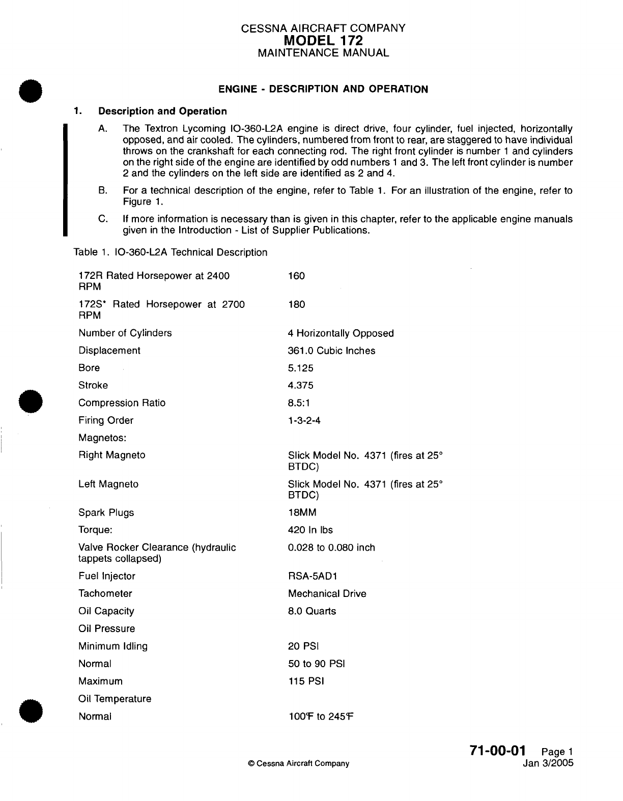
CESSNA
AIRCRAFT
COMPANY
MODEL
172
MAINTENANCE
MANUAL
ENGINE
-
DESCRIPTION AND OPERATION
1.
Description
and
Operation
A.
The Textron
Lycoming
IO-360-L2A
engine
is
direct
drive,
four
cylinder,
fuel
injected,
horizontally
opposed, and
air
cooled.
The
cylinders,
numbered from
front
to
rear,
are
staggered
to
have
individual
throws
on
the
crankshaft
for
each
connecting
rod.
The
right
front cylinder
is
number
1
and
cylinders
on
the
right
side
of
the engine
are
identified
by
odd
numbers
1
and
3.
The
left
front
cylinder
is
number
2
and
the
cylinders
on
the
left
side
are
identified
as
2
and
4.
B.
For a
technical description
of
the
engine,
refer to
Table
1.
For an
illustration
of
the
engine,
refer
to
Figure
1.
C.
If
more
information
is
necessary
than is
given
in
this
chapter,
refer
to
the
applicable
engine
manuals
given
in
the
Introduction
-
List
of
Supplier
Publications.
Table
1.
IO-360-L2A Technical
Description
172R
Rated
Horsepower
at
2400
RPM
172S*
Rated
Horsepower
at
2700
RPM
Number
of
Cylinders
Displacement
Bore
Stroke
Compression
Ratio
Firing
Order
Magnetos:
Right
Magneto
Left
Magneto
Spark
Plugs
Torque:
Valve
Rocker
Clearance
(hydraulic
tappets collapsed)
Fuel
Injector
Tachometer
Oil
Capacity
Oil
Pressure
Minimum
Idling
Normal
Maximum
Oil
Temperature
Normal
160
180
4
Horizontally Opposed
361.0
Cubic
Inches
5.125
4.375
8.5:1
1-3-2-4
Slick
Model
No.
4371
(fires
at
25°
BTDC)
Slick
Model
No.
4371
(fires at
25°
BTDC)
18MM
420
In
lbs
0.028
to
0.080
inch
RSA-5AD1
Mechanical
Drive
8.0
Quarts
20
PSI
50 to
90
PSI
115 PSI
100°F
to
245°F
©
Cessna Aircraft
Company
71-00-01
Page
1
Jan
3/2005
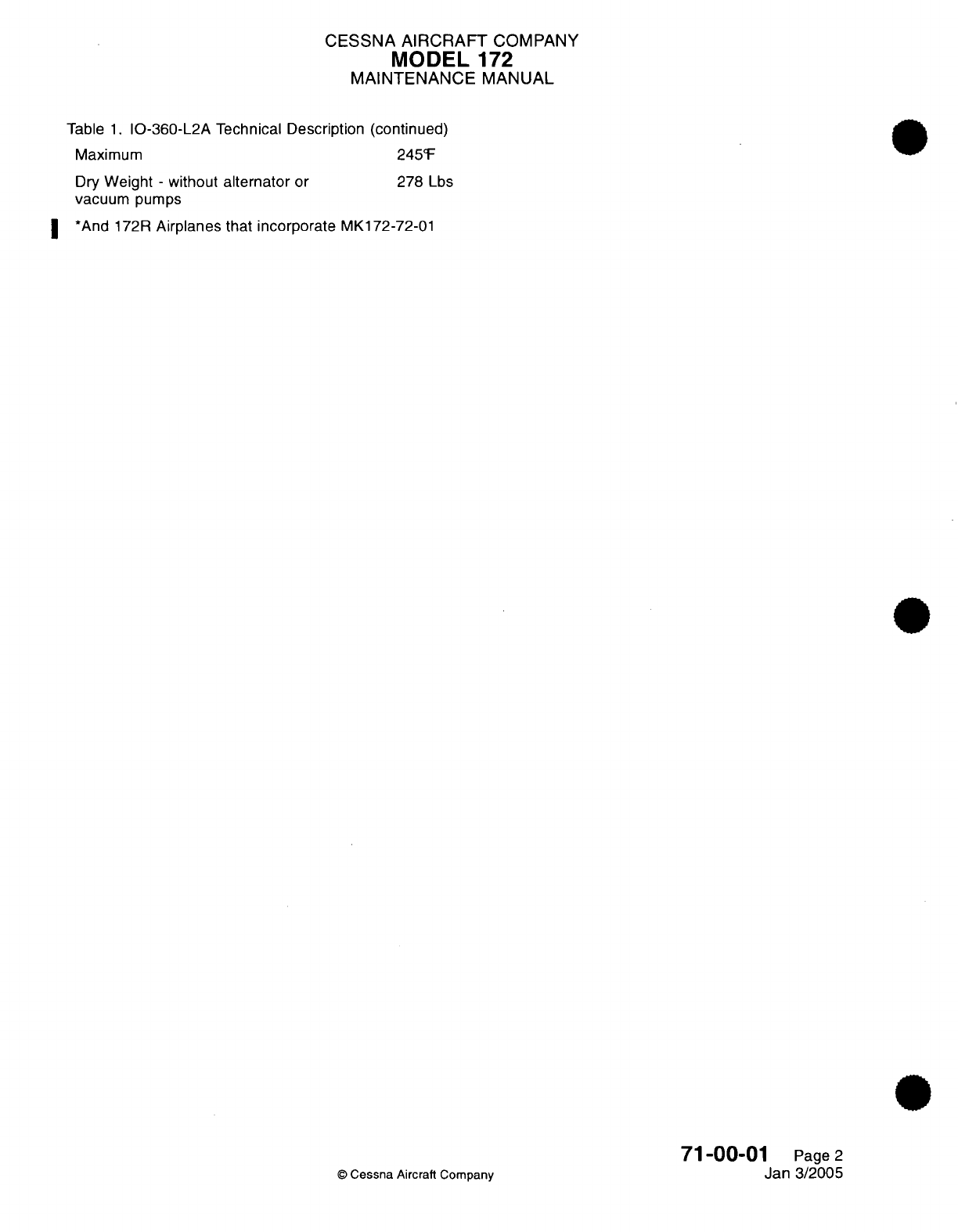
CESSNA
AIRCRAFT
COMPANY
MODEL
172
MAINTENANCE
MANUAL
Table
1.
IO-360-L2A Technical Description (continued)
Maximum
245°F
Dry
Weight
-
without
alternator
or
278
Lbs
vacuum
pumps
*
And 172R
Airplanes that incorporate
MK172-72-01
©
Cessna
Aircraft Company
71-00-01
Page
2
Jan
3/2005
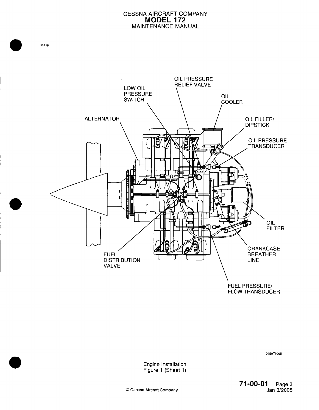
CESSNA
AIRCRAFT
COMPANY
MODEL
172
MAINTENANCE
MANUAL
B1419
ER/
;K
ESSURE
;DUCER
OIL
FILTER
:CASE
HER
FUEL
PRESSURE/
FLOW
TRANSDUCER
0550T1005
Engine
Installation
Figure
1
(Sheet
1)
©
Cessna Aircraft
Company
71-00-01
Page
3
Jan
3/2005
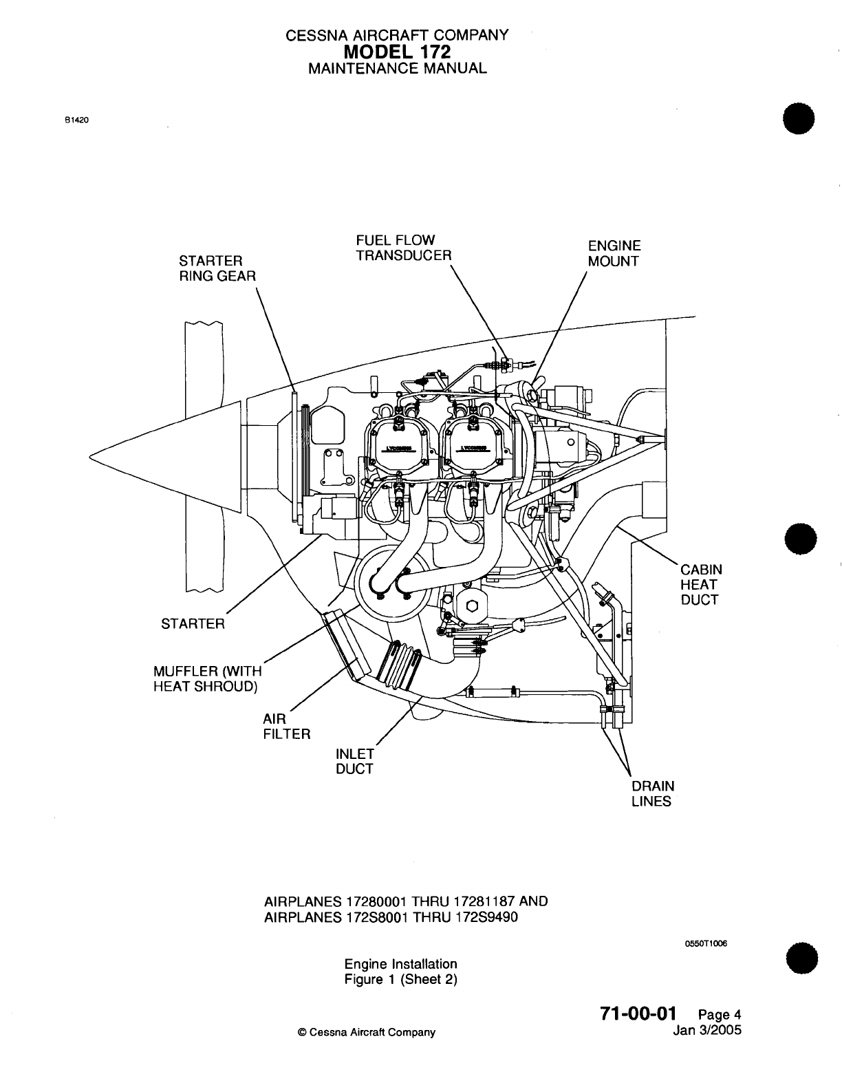
CESSNA
AIRCRAFT
COMPANY
MODEL
172
MAINTENANCE
MANUAL
81420
STARTFR
FUEL FLOW
TRANSDUCER
AIRPLANES
17280001
THRU
17281187
AND
AIRPLANES
172S8001
THRU
172S9490
0550T1006
Engine
Installation
Figure
1
(Sheet
2)
71
-00-01
Page
4
Jan
3/2005
©
Cessna
Aircraft Company
ENGINE
MOUNT
CABIN
HEAT
DUCT
DRAIN
LINES
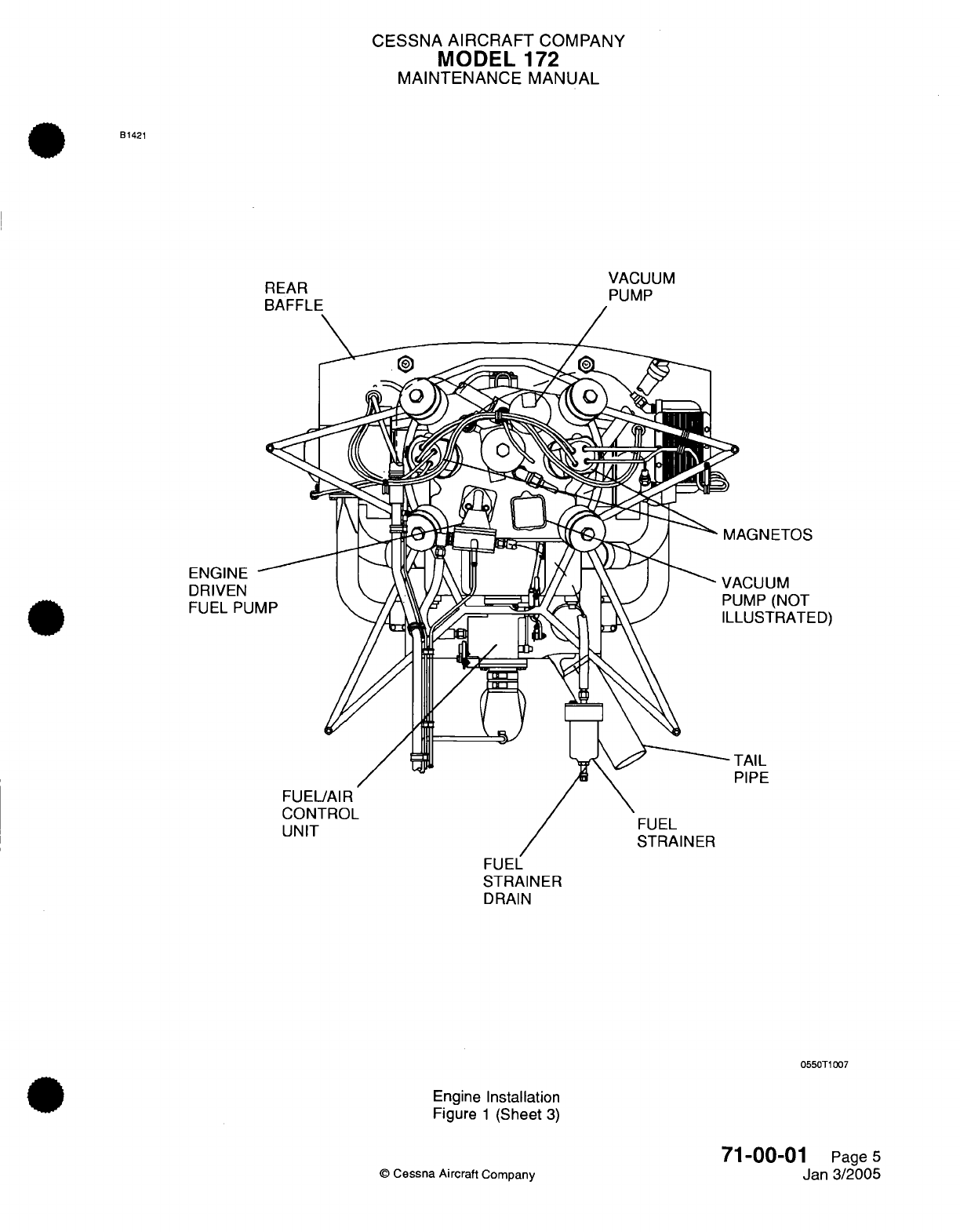
CESSNA
AIRCRAFT
COMPANY
MODEL
172
MAINTENANCE
MANUAL
B1421
VACUUM
PUMP
ETOS
M
(NOT
RATED)
FUEL
STRAINER
DRAIN
0550T1007
Engine
Installation
Figure
1
(Sheet
3)
71-00-0
©
Cessna
Aircraft
Company
REAR
REAR
ENGINE
DRIVEN
FUEL
PUMP
Page
5
Jan
3/2005
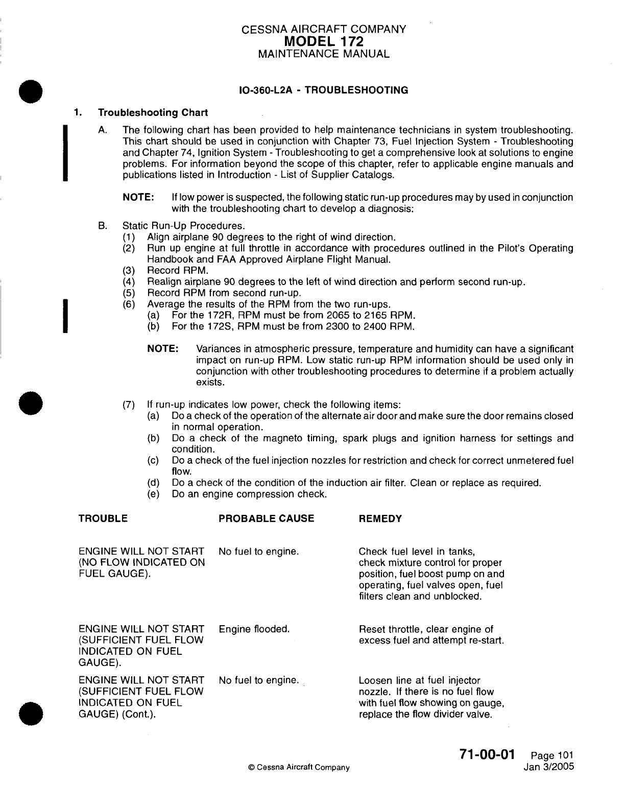
CESSNA
AIRCRAFT
COMPANY
MODEL
172
MAINTENANCE
MANUAL
IO-360-L2A
-
TROUBLESHOOTING
1.
Troubleshooting
Chart
A.
The
following
chart
has been
provided
to help
maintenance
technicians
in
system
troubleshooting.
This
chart
should
be
used
in
conjunction
with
Chapter
73,
Fuel
Injection
System
-
Troubleshooting
and
Chapter
74,
Ignition
System
-
Troubleshooting
to
get
a
comprehensive
look
at
solutions
to
engine
problems.
For
information beyond
the
scope
of
this
chapter,
refer
to
applicable engine manuals
and
publications
listed
in
Introduction
-
List
of
Supplier
Catalogs.
NOTE:
If
low
power
is
suspected,
the
following
static
run-up
procedures
may
by
used
in
conjunction
with
the
troubleshooting
chart
to
develop
a
diagnosis:
B.
Static
Run-Up
Procedures.
(1)
Align
airplane
90
degrees
to
the
right
of
wind
direction.
(2)
Run
up
engine
at
full
throttle
in
accordance
with
procedures
outlined
in
the
Pilot's
Operating
Handbook
and
FAA
Approved
Airplane
Flight
Manual.
(3)
Record
RPM.
(4)
Realign
airplane
90
degrees
to
the left
of
wind
direction
and
perform
second
run-up.
(5)
Record
RPM
from
second
run-up.
(6)
Average
the
results
of
the
RPM
from
the
two
run-ups.
(a)
For
the
172R,
RPM
must
be
from
2065
to
2165
RPM.
(b)
For
the
172S, RPM
must
be
from
2300
to
2400
RPM.
NOTE:
Variances
in
atmospheric pressure, temperature
and
humidity
can
have
a
significant
impact
on
run-up
RPM.
Low
static
run-up
RPM
information
should
be
used
only
in
conjunction
with
other
troubleshooting
procedures
to
determine
if
a
problem
actually
exists.
(7) If
run-up
indicates
low
power,
check
the
following
items:
(a)
Do
a
check
of
the
operation
of
the
alternate
air
door
and
make
sure
the
door
remains closed
in
normal
operation.
(b)
Do
a
check
of
the
magneto
timing,
spark
plugs
and
ignition
harness
for
settings
and
condition.
(c)
Do
a
check
of
the
fuel
injection
nozzles
for
restriction
and
check
for
correct
unmetered
fuel
flow.
(d)
Do
a
check
of
the condition
of the
induction
air
filter.
Clean
or
replace
as
required.
(e)
Do
an
engine compression
check.
TROUBLE PROBABLE
CAUSE
REMEDY
ENGINE
WILL
NOT START
No
fuel
to
engine.
Check fuel
level
in
tanks,
(NO
FLOW
INDICATED
ON
check
mixture
control
for
proper
FUEL
GAUGE).
position,
fuel
boost
pump
on
and
operating,
fuel
valves
open,
fuel
filters
clean
and
unblocked.
ENGINE
WILL
NOT
START
Engine flooded.
Reset
throttle,
clear
engine
of
(SUFFICIENT
FUEL
FLOW
excess
fuel
and
attempt
re-start.
INDICATED
ON
FUEL
GAUGE).
ENGINE
WILL
NOT
START
No
fuel
to
engine. Loosen
line
at
fuel
injector
(SUFFICIENT
FUEL
FLOW
nozzle.
If
there
is
no fuel
flow
INDICATED
ON
FUEL
with
fuel
flow
showing
on
gauge,
GAUGE) (Cont.).
replace the
flow
divider
valve.
71-00-01
Page
101
©
Cessna
Aircraft
Company
Jan
3/2005
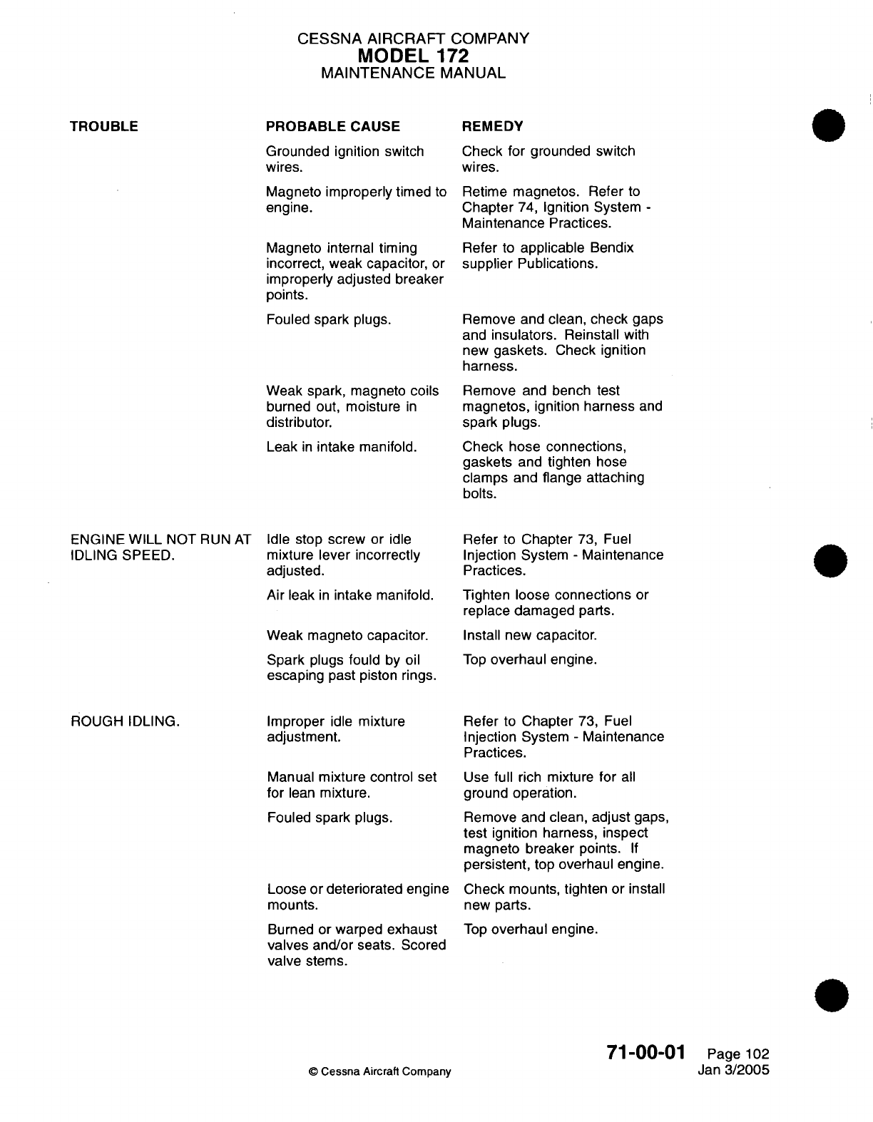
CESSNA
AIRCRAFT
COMPANY
MODEL
172
MAINTENANCE
MANUAL
PROBABLE
CAUSE
REMEDY
TROUBLE
Grounded
ignition
switch
wires.
Magneto
improperly timed
to
engine.
Magneto
internal
timing
incorrect, weak capacitor,
or
improperly adjusted
breaker
points.
Fouled
spark
plugs.
Weak spark,
magneto
coils
burned
out,
moisture
in
distributor.
Leak
in
intake manifold.
Check
for
grounded
switch
wires.
Retime
magnetos.
Refer
to
Chapter
74,
Ignition
System
-
Maintenance
Practices.
Refer
to
applicable
Bendix
supplier
Publications.
Remove and
clean,
check
gaps
and
insulators. Reinstall with
new
gaskets.
Check
ignition
harness.
Remove and bench
test
magnetos,
ignition
harness
and
spark plugs.
Check
hose connections,
gaskets
and tighten
hose
clamps and
flange
attaching
bolts.
ENGINE
WILL
NOT
RUN
AT
IDLING
SPEED.
ROUGH IDLING.
Idle
stop
screw
or idle
mixture
lever
incorrectly
adjusted.
Air
leak
in
intake manifold.
Weak magneto
capacitor.
Spark
plugs
fould
by
oil
escaping
past piston rings.
Improper
idle
mixture
adjustment.
Manual
mixture control
set
for
lean
mixture.
Fouled
spark
plugs.
Loose
or deteriorated
engine
mounts.
Burned
or
warped
exhaust
valves
and/or
seats. Scored
valve
stems.
Refer
to Chapter
73,
Fuel
Injection System
-
Maintenance
Practices.
Tighten loose
connections
or
replace
damaged
parts.
Install new
capacitor.
Top
overhaul
engine.
Refer
to
Chapter
73,
Fuel
Injection
System
-
Maintenance
Practices.
Use
full
rich mixture
for
all
ground
operation.
Remove
and clean,
adjust
gaps,
test
ignition harness,
inspect
magneto
breaker
points.
If
persistent,
top
overhaul engine.
Check mounts,
tighten
or
install
new
parts.
Top
overhaul
engine.
71-00-01
©
Cessna
Aircraft
Company
Page
102
Jan
3/2005
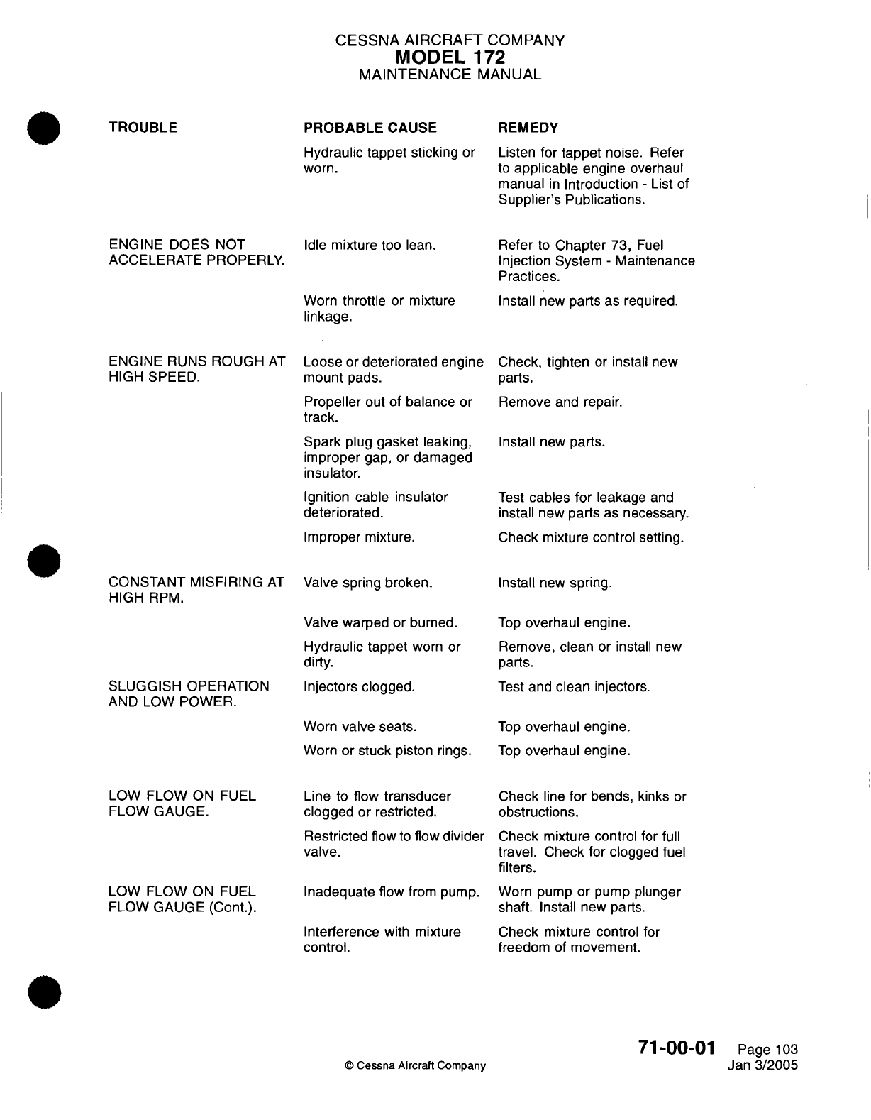
CESSNA
AIRCRAFT
COMPANY
MODEL
172
MAINTENANCE
MANUAL
PROBABLE
CAUSE
Hydraulic tappet sticking
or
worn.
REMEDY
Listen
for
tappet
noise.
Refer
to
applicable
engine
overhaul
manual
in
Introduction
-
List
of
Supplier's Publications.
ENGINE
DOES
NOT
ACCELERATE PROPERLY.
Idle
mixture
too
lean.
Worn
throttle
or
mixture
linkage.
Refer
to
Chapter
73,
Fuel
Injection System
-
Maintenance
Practices.
Install
new
parts
as
required.
ENGINE
RUNS
ROUGH
AT
HIGH
SPEED.
CONSTANT MISFIRING
AT
HIGH
RPM.
SLUGGISH
OPERATION
AND LOW
POWER.
LOW FLOW
ON
FUEL
FLOW
GAUGE.
LOW
FLOW
ON
FUEL
FLOW
GAUGE
(Cont.).
Loose
or
deteriorated
engine
mount
pads.
Propeller
out of
balance
or
track.
Spark
plug
gasket
leaking,
improper
gap,
or
damaged
insulator.
Ignition cable insulator
deteriorated.
Improper mixture.
Valve
spring
broken.
Valve
warped
or burned.
Hydraulic tappet
worn
or
dirty.
Injectors
clogged.
Worn
valve seats.
Worn or
stuck
piston rings.
Line
to
flow
transducer
clogged or
restricted.
Restricted
flow
to
flow
divider
valve.
Inadequate
flow
from pump.
Interference
with
mixture
control.
Check,
tighten
or
install
new
parts.
Remove
and
repair.
Install
new
parts.
Test
cables for
leakage
and
install new parts
as
necessary.
Check mixture
control
setting.
Install
new
spring.
Top
overhaul
engine.
Remove,
clean
or
install
new
parts.
Test
and
clean injectors.
Top
overhaul engine.
Top
overhaul engine.
Check
line
for
bends,
kinks
or
obstructions.
Check
mixture control
for full
travel.
Check
for
clogged
fuel
filters.
Worn pump
or
pump
plunger
shaft.
Install
new
parts.
Check mixture
control
for
freedom
of
movement.
©
Cessna Aircraft
Company
71-00-01
Page
103
Jan
3/2005
TROUBLE
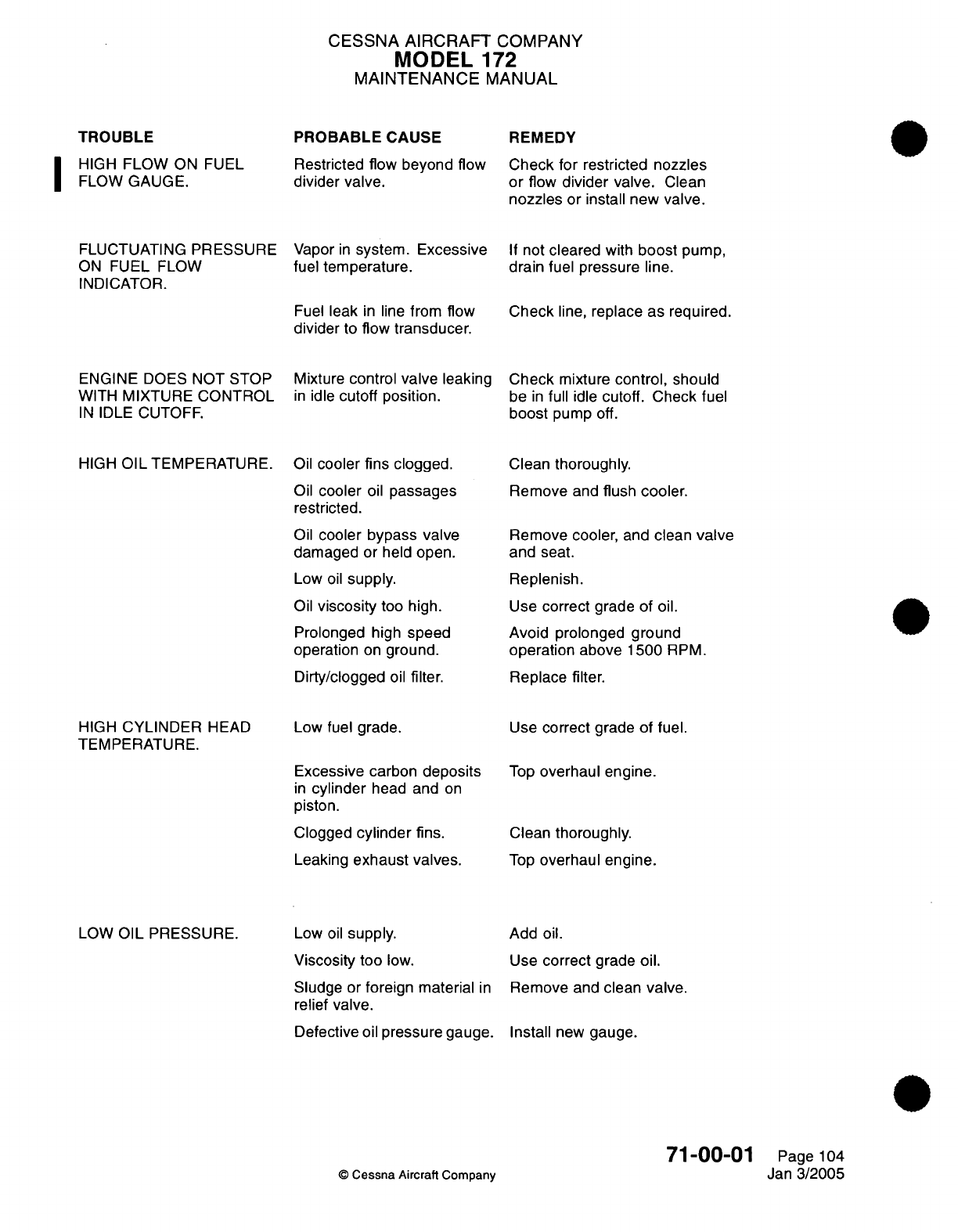
CESSNA
AIRCRAFT
COMPANY
MODEL
172
MAINTENANCE
MANUAL
TROUBLE
I
HIGH
FLOW
ON
FUEL
FLOW
GAUGE.
FLUCTUATING
PRESSURE
ON
FUEL
FLOW
INDICATOR.
PROBABLE
CAUSE
Restricted flow beyond
flow
divider valve.
Vapor
in
system.
Excessive
fuel
temperature.
REMEDY
Check
for
restricted nozzles
or
flow
divider valve.
Clean
nozzles
or
install new
valve.
If
not
cleared
with
boost
pump,
drain
fuel
pressure
line.
Fuel
leak
in
line
from
flow
divider
to
flow
transducer.
Check
line,
replace
as
required.
ENGINE
DOES
NOT
STOP
WITH
MIXTURE
CONTROL
IN
IDLE
CUTOFF.
HIGH
OIL
TEMPERATURE.
HIGH
CYLINDER
HEAD
TEMPERATURE.
Mixture
control
valve
leaking
in
idle
cutoff
position.
Oil
cooler
fins
clogged.
Oil
cooler
oil
passages
restricted.
Oil
cooler bypass
valve
damaged
or held open.
Low
oil
supply.
Oil
viscosity
too
high.
Prolonged
high
speed
operation
on
ground.
Dirty/clogged
oil
filter.
Low
fuel grade.
Check
mixture
control,
should
be
in
full
idle
cutoff. Check
fuel
boost
pump
off.
Clean
thoroughly.
Remove
and
flush cooler.
Remove
cooler, and
clean
valve
and
seat.
Replenish.
Use
correct
grade
of
oil.
Avoid prolonged ground
operation
above
1500
RPM.
Replace
filter.
Use
correct
grade
of fuel.
Excessive
carbon
deposits
in
cylinder
head and
on
piston.
Clogged
cylinder
fins.
Leaking
exhaust
valves.
Top
overhaul engine.
Clean
thoroughly.
Top
overhaul engine.
LOW
OIL
PRESSURE.
Low
oil
supply.
Viscosity
too
low.
Sludge
or
foreign
material
in
relief
valve.
Defective
oil
pressure gauge.
Add
oil.
Use
correct
grade
oil.
Remove
and
clean
valve.
Install
new
gauge.
©
Cessna Aircraft
Company
71-00-01
Page
104
Jan
3/2005
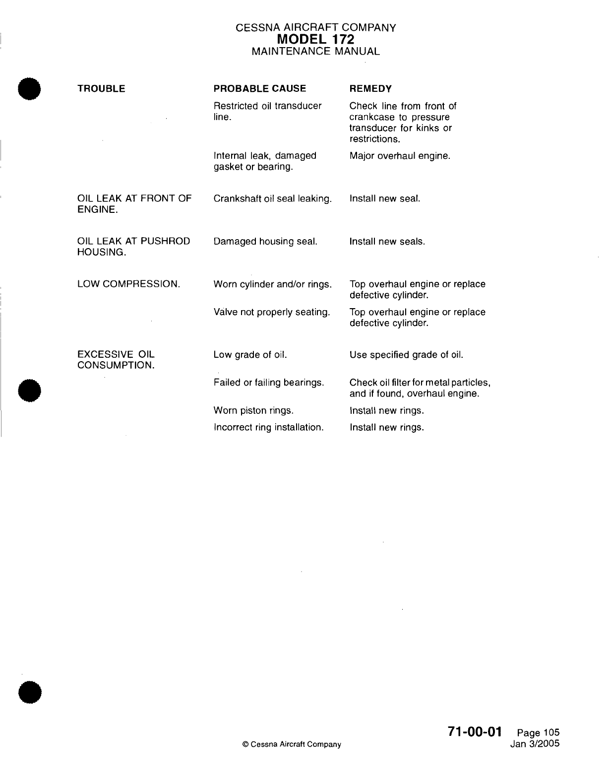
CESSNA
AIRCRAFT
COMPANY
MODEL
172
MAINTENANCE
MANUAL
PROBABLE
CAUSE
Restricted
oil
transducer
line.
Internal
leak,
damaged
gasket
or bearing.
REMEDY
Check
line
from
front
of
crankcase
to
pressure
transducer
for
kinks
or
restrictions.
Major
overhaul engine.
OIL
LEAK
AT
FRONT
OF
ENGINE.
OIL
LEAK
AT
PUSHROD
HOUSING.
LOW
COMPRESSION.
Crankshaft
oil
seal
leaking.
Damaged
housing seal.
Worn
cylinder
and/or
rings.
Valve
not
properly
seating.
Install
new
seal.
Install
new
seals.
Top
overhaul engine
or
replace
defective
cylinder.
Top
overhaul engine
or
replace
defective
cylinder.
EXCESSIVE
OIL
CONSUMPTION.
Low grade of
oil.
Use
specified
grade
of oil.
Failed
or
failing
bearings.
Worn
piston rings.
Incorrect
ring
installation.
©
Cessna Aircraft
Company
Check
oil
filter
for
metal
particles,
and
if
found,
overhaul
engine.
Install
new
rings.
Install
new
rings.
71-00-01
Page
105
Jan
3/2005
TROUBLE
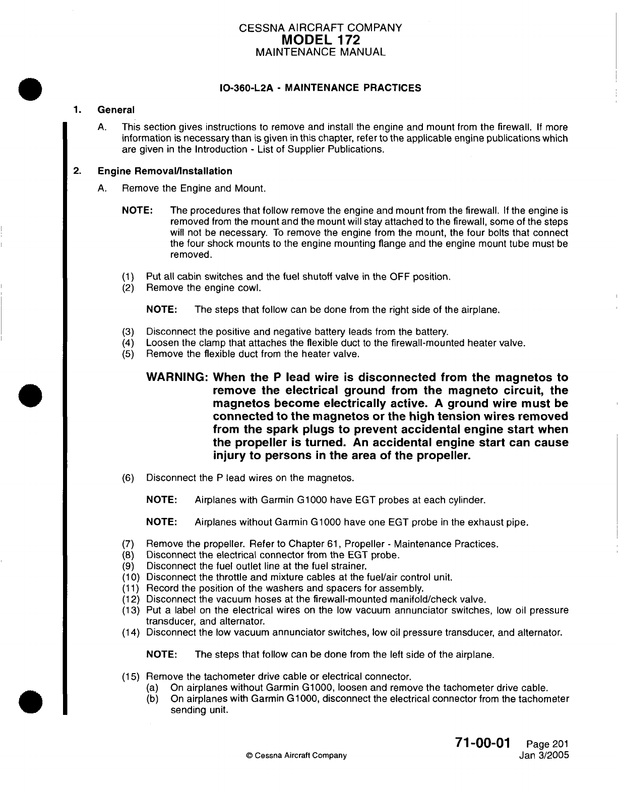
CESSNA
AIRCRAFT
COMPANY
MODEL
172
MAINTENANCE
MANUAL
IO-360-L2A
-
MAINTENANCE
PRACTICES
1.
General
A.
This
section gives instructions
to
remove
and
install
the
engine
and
mount
from
the
firewall.
If
more
information
is
necessary than
is
given
in
this
chapter, refer
to
the
applicable
engine
publications
which
are
given
in
the
Introduction
-
List
of
Supplier
Publications.
2.
Engine
Removal/Installation
A.
Remove
the
Engine
and
Mount.
NOTE:
The
procedures that follow
remove
the
engine
and mount
from the
firewall.
If
the
engine
is
removed
from
the
mount
and
the
mount
will
stay
attached
to
the
firewall,
some
of
the
steps
will
not
be
necessary.
To
remove
the
engine
from the mount,
the
four
bolts
that
connect
the
four shock mounts
to
the
engine
mounting
flange
and
the
engine
mount
tube
must
be
removed.
(1)
Put
all
cabin switches
and
the
fuel
shutoff
valve
in
the
OFF
position.
(2)
Remove
the engine
cowl.
NOTE:
The
steps
that
follow
can
be
done
from
the
right
side
of the
airplane.
(3)
Disconnect
the
positive
and
negative
battery
leads
from
the
battery.
(4)
Loosen
the clamp
that attaches
the
flexible
duct
to
the
firewall-mounted heater
valve.
(5)
Remove
the
flexible
duct
from
the
heater
valve.
WARNING:
When
the
P
lead
wire
Is
disconnected
from
the
magnetos
to
remove the
electrical
ground
from
the
magneto
circuit,
the
magnetos
become
electrically
active.
A
ground
wire must
be
connected
to
the
magnetos
or
the
high
tension
wires
removed
from
the
spark
plugs to
prevent
accidental
engine
start
when
the
propeller
Is
turned.
An
accidental
engine
start
can
cause
Injury
to
persons
In
the
area
of
the
propeller.
(6)
Disconnect
the
P
lead
wires
on
the
magnetos.
NOTE:
Airplanes with
Garmin
G1000
have
EGT
probes
at
each
cylinder.
NOTE:
Airplanes
without
Garmin
G1000
have
one
EGT
probe
in
the
exhaust
pipe.
(7)
Remove
the
propeller.
Refer
to
Chapter
61,
Propeller
-
Maintenance
Practices.
(8)
Disconnect the
electrical
connector
from
the
EGT
probe.
(9)
Disconnect
the
fuel
outlet
line
at
the
fuel
strainer.
(10)
Disconnect
the
throttle
and mixture
cables
at
the
fuel/air
control
unit.
(11)
Record
the position
of
the washers
and
spacers
for
assembly.
(12)
Disconnect
the vacuum hoses
at
the firewall-mounted manifold/check valve.
(13)
Put a
label
on
the
electrical
wires
on
the
low
vacuum
annunciator
switches,
low
oil
pressure
transducer,
and
alternator.
(14)
Disconnect
the
low
vacuum
annunciator
switches,
low
oil
pressure
transducer,
and
alternator.
NOTE:
The
steps
that
follow
can
be
done
from
the
left
side
of
the
airplane.
(15)
Remove
the
tachometer
drive cable
or
electrical
connector.
(a)
On
airplanes
without
Garmin
G1000,
loosen
and
remove
the tachometer
drive
cable.
(b)
On
airplanes
with
Garmin
G1000,
disconnect
the
electrical connector
from
the
tachometer
sending
unit.
71-00-01
Page
201
©
Cessna Aircraft
Company
Jan 3/2005
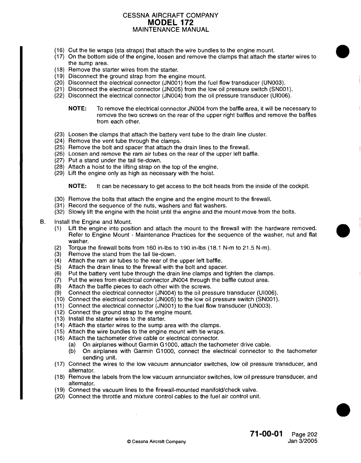
CESSNA
AIRCRAFT
COMPANY
MODEL
172
MAINTENANCE
MANUAL
(16)
Cut
the
tie
wraps
(sta
straps)
that
attach the
wire
bundles
to
the
engine mount.
(17)
On
the
bottom
side of
the
engine, loosen
and
remove
the
clamps
that
attach
the
starter
wires
to
the
sump
area.
(18)
Remove
the
starter
wires
from
the
starter.
(19)
Disconnect
the
ground
strap
from
the
engine mount.
(20)
Disconnect
the electrical
connector
(JN001)
from
the
fuel
flow
transducer
(UN003).
(21)
Disconnect
the electrical
connector
(JN005)
from
the
low
oil
pressure switch
(SN001).
(22)
Disconnect
the electrical
connector
(JN004)
from
the
oil
pressure
transducer
(UI006).
NOTE:
To
remove
the
electrical connector
JN004
from
the baffle
area,
it
will
be
necessary
to
remove
the
two
screws
on
the
rear
of
the
upper
right
baffles
and
remove
the
baffles
from each
other.
(23)
Loosen the
clamps that
attach
the
battery vent
tube
to
the
drain
line
cluster.
(24)
Remove
the
vent
tube
through
the clamps.
(25)
Remove
the
bolt
and
spacer
that
attach
the
drain
lines
to
the
firewall.
(26)
Loosen
and
remove
the
ram
air
tubes
on
the rear
of
the
upper
left
baffle.
(27)
Put
a
stand
under
the
tail
tie-down.
(28)
Attach
a
hoist
to
the
lifting
strap
on
the top
of
the
engine.
(29)
Lift
the
engine only
as
high
as
necessary
with
the
hoist.
NOTE:
It
can
be
necessary
to
get
access
to
the
bolt
heads
from
the
inside
of
the cockpit.
(30)
Remove
the bolts
that
attach the
engine
and
the
engine
mount
to
the
firewall.
(31)
Record
the
sequence
of
the
nuts,
washers and flat washers.
(32)
Slowly
lift
the
engine
with
the
hoist
until
the
engine
and
the
mount
move
from
the bolts.
B.
Install
the
Engine
and
Mount.
(1)
Lift
the
engine
into
position
and
attach the
mount
to
the
firewall
with the
hardware removed.
Refer
to
Engine
Mount
-
Maintenance
Practices
for
the
sequence
of
the washer,
nut
and
flat
washer.
(2)
Torque
the
firewall
bolts
from
160
in-lbs
to
190
in-lbs
(18.1
N-m
to
21.5
N-m).
(3)
Remove
the
stand
from
the
tail
tie-down.
(4)
Attach
the
ram
air
tubes to
the
rear
of
the upper
left
baffle.
(5)
Attach
the
drain
lines
to
the
firewall
with
the
bolt
and
spacer.
(6)
Put
the
battery
vent
tube
through the drain line
clamps
and
tighten
the
clamps.
(7)
Put
the
wires
from
electrical
connector
JN004 through
the baffle
cutout
area.
(8)
Attach
the
baffle
pieces
to
each
other
with
the
screws.
(9)
Connect
the
electrical
connector
(JN004)
to
the
oil
pressure
transducer
(UI006).
(10)
Connect
the electrical
connector
(JN005)
to
the
low
oil
pressure
switch
(SN001).
(11)
Connect the
electrical
connector
(JN001)
to
the
fuel
flow
transducer
(UN003).
(12)
Connect
the
ground
strap
to
the
engine
mount.
(13)
Install
the
starter
wires
to
the starter.
(14)
Attach
the
starter
wires
to
the
sump area
with
the
clamps.
(15)
Attach
the
wire
bundles
to
the
engine
mount
with
tie
wraps.
(16)
Attach the
tachometer
drive
cable
or electrical connector.
(a)
On
airplanes
without
Garmin
G1000,
attach the
tachometer
drive
cable.
(b)
On
airplanes
with
Garmin
G1000,
connect
the electrical
connector
to
the
tachometer
sending unit.
(17)
Connect
the wires
to
the
low
vacuum
annunciator
switches,
low
oil
pressure
transducer,
and
alternator.
(18)
Remove
the
labels
from
the
low
vacuum
annunciator switches,
low
oil
pressure
transducer,
and
alternator.
(19)
Connect
the vacuum
lines
to the
firewall-mounted
manifold/check
valve.
(20)
Connect
the
throttle
and
mixture control
cables
to
the fuel air
control
unit.
71-00-01
Page
202
© Cessna
Aircraft Company
Jan
3/2005
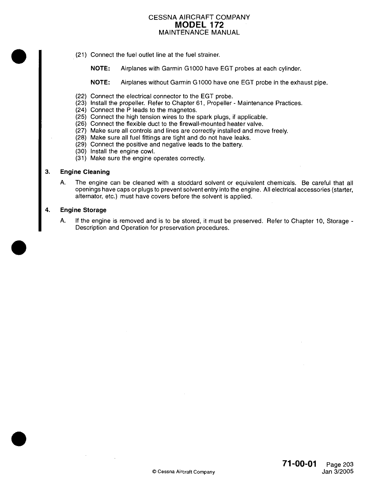
CESSNA
AIRCRAFT
COMPANY
MODEL
172
MAINTENANCE
MANUAL
(21)
Connect
the
fuel
outlet
line
at
the
fuel
strainer.
NOTE:
Airplanes
with
Garmin G1000
have
EGT
probes
at
each
cylinder.
NOTE:
Airplanes
without
Garmin G1000 have
one
EGT
probe
in
the
exhaust
pipe.
(22)
(23)
(24)
(25)
(26)
(27)
(28)
(29)
(30)
(31)
Connect
the
electrical
connector
to
the
EGT probe.
Install
the propeller.
Refer
to
Chapter
61,
Propeller
-
Maintenance
Practices.
Connect
the
P
leads
to the
magnetos.
Connect
the
high
tension wires
to
the spark
plugs,
if
applicable.
Connect
the
flexible
duct
to
the
firewall-mounted
heater
valve.
Make
sure
all
controls
and
lines
are
correctly
installed
and
move
freely.
Make
sure
all
fuel
fittings
are
tight
and
do not
have
leaks.
Connect
the
positive
and
negative
leads to the
battery.
Install
the
engine
cowl.
Make
sure
the
engine
operates
correctly.
3.
Engine
Cleaning
A.
The
engine
can
be
cleaned
with
a
stoddard
solvent
or
equivalent
chemicals.
Be
careful
that
all
openings
have caps
or
plugs
to
prevent
solvent
entry
into
the
engine.
All
electrical
accessories
(starter,
alternator,
etc.)
must
have
covers
before the
solvent
is
applied.
4.
Engine
Storage
A.
If
the
engine
is
removed
and
is
to
be
stored,
it
must
be
preserved.
Refer
to
Chapter
10,
Storage
-
Description
and
Operation for
preservation
procedures.
71-00-01
Page
203
©
Cessna
Aircraft Company
Jan
3/2005
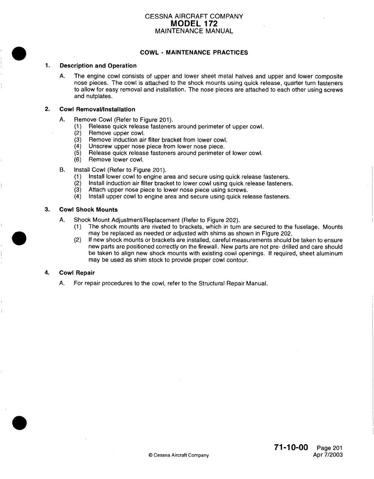
CESSNA AIRCRAFT
COMPANY
MODEL
1
72
MAINTENANCE
MANUAL
COWL
-
MAINTENANCE
PRACTICES
1.
Description
and
Operation
A.
The
engine
cowl
consists
of
upper
and
lower
sheet
metal
halves
and
upper
and
lower
composite
nose
pieces. The
cowl
is
attached
to
the
shock
mounts
using
quick
release,
quarter
turn
fasteners
to
allow
for easy
removal
and installation.
The
nose
pieces
are
attached
to
each
other
using
screws
and
nutplates.
2.
Cowl
Removal/Installation
A.
Remove
Cowl
(Refer
to
Figure
201).
(1)
Release
quick
release
fasteners
around
perimeter
of
upper cowl.
(2)
Remove
upper
cowl.
(3)
Remove
induction air
filter
bracket
from
lower
cowl.
(4)
Unscrew upper nose
piece
from
lower
nose
piece.
(5)
Release
quick
release fasteners
around
perimeter
of
lower
cowl.
(6)
Remove
lower
cowl.
B.
Install
Cowl
(Refer
to
Figure
201).
(1)
Install
lower
cowl
to
engine
area
and
secure using
quick
release fasteners.
(2)
Install
induction
air
filter
bracket
to
lower cowl
using
quick
release
fasteners.
(3)
Attach
upper
nose piece
to
lower
nose
piece
using
screws.
(4)
Install
upper
cowl
to
engine
area
and
secure
using
quick
release
fasteners.
3.
Cowl
Shock
Mounts
A.
Shock
Mount
Adjustment/Replacement
(Refer
to
Figure
202).
(1)
The
shock
mounts are
riveted
to
brackets,
which
in
turn are
secured
to
the
fuselage.
Mounts
may
be
replaced
as
needed
or
adjusted
with
shims as shown
in
Figure 202.
(2) If
new
shock
mounts or
brackets
are
installed,
careful
measurements
should
be
taken
to
ensure
new
parts
are
positioned
correctly
on
the
firewall.
New
parts
are
not
pre-
drilled
and
care
should
be
taken
to
align
new
shock
mounts
with
existing
cowl
openings.
If
required,
sheet
aluminum
may
be
used
as shim
stock
to
provide
proper
cowl
contour.
4.
Cowl
Repair
A.
For
repair
procedures
to
the
cowl,
refer
to the
Structural Repair
Manual.
71-10-00
Page
201
©
Cessna
Aircraft Company
Apr
7/2003
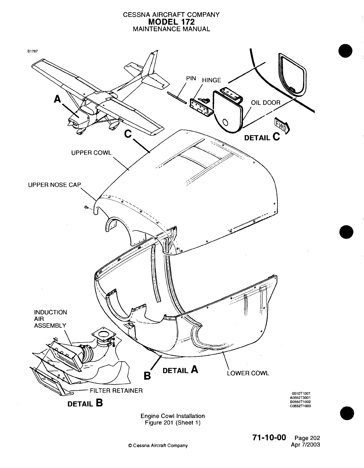
CESSNA AIRCRAFT
COMPANY
MODEL
172
MAINTENANCE
MANUAL
Engine
Cowl
Installation
Figure
201
(Sheet
1)
71-10-00
©
Cessna
Aircraft
Company
DETAIL
B
A0552T3001
B0550T1002
C0552T1003
Page
202
Apr
7/2003
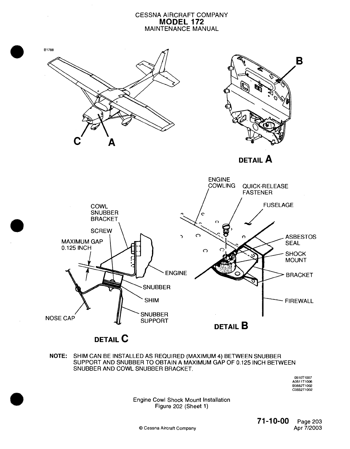
CESSNA
AIRCRAFT
COMPANY
MODEL
172
MAINTENANCE
MANUAL
B1788
DETAIL
A
ENGINE
COWL
SNUBBER
BRACKET
ASBESTOS
SEAL
SHOCK
MOUNT
ACKET
-SNUBBER
SHIM
SNUBBER
SUPPORT
NOSE(
FIREWALL
DETAIL
B
DETAIL
C
NOTE:
SHIM
CAN
BE
INSTALLED
AS
REQUIRED (MAXIMUM 4)
BETWEEN SNUBBER
SUPPORT
AND
SNUBBER
TO
OBTAIN
A
MAXIMUM GAP
OF
0.125
INCH
BETWEEN
SNUBBER
AND
COWL SNUBBER
BRACKET.
0510T1007
A0511T1006
B0552T1002
C0552T1002
Engine
Cowl
Shock Mount Installation
Figure
202
(Sheet
1)
©
Cessna
Aircraft Company
71-10-00
Page
203
Apr 7/2003
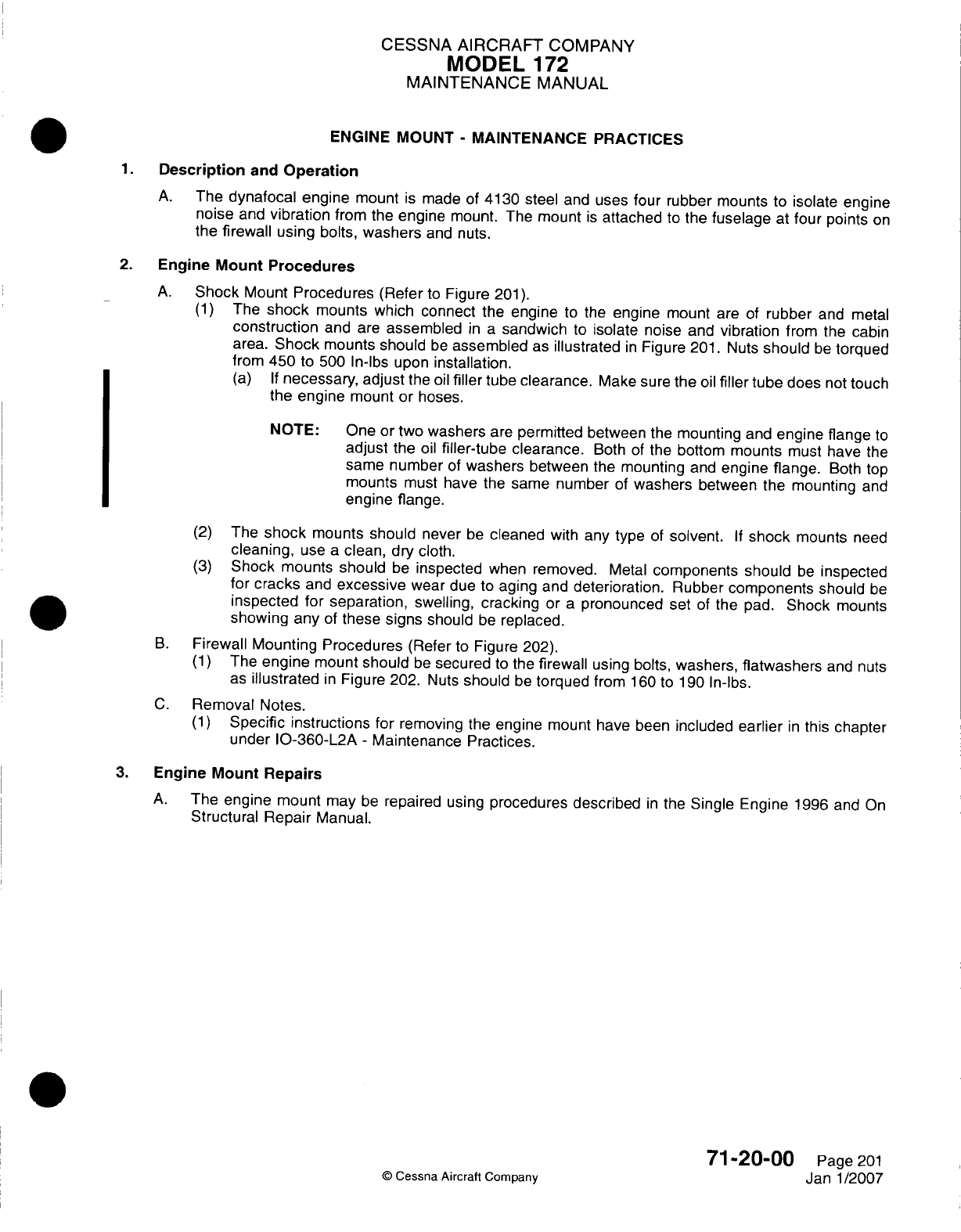
CESSNA
AIRCRAFT
COMPANY
MODEL
172
MAINTENANCE
MANUAL
ENGINE MOUNT
-
MAINTENANCE PRACTICES
1.Description
and
Operation
A.
The
dynafocal
engine
mount
is
made of
4130 steel
and
uses
four rubber
mounts
to
isolate
engine
noise
and
vibration
from
the
engine
mount.
The
mount
is
attached
to
the
fuselage
at
four
points
on
the
firewall
using
bolts,
washers
and
nuts.
2.
Engine
Mount Procedures
A.
Shock
Mount
Procedures
(Refer
to
Figure
201).
(1)
The
shock
mounts
which
connect
the
engine
to the
engine
mount
are
of
rubber
and
metal
construction
and are
assembled
in a
sandwich
to
isolate
noise and
vibration
from
the
cabin
area.
Shock
mounts should
be
assembled
as
illustrated
in
Figure
201.
Nuts
should
be
torqued
from
450
to
500
In-lbs
upon
installation.
(a) If
necessary,
adjust
the
oil
filler
tube
clearance.
Make
sure
the
oil
filler
tube
does
not
touch
the engine
mount
or
hoses.
NOTE:
One
or
two
washers
are
permitted
between
the
mounting
and
engine
flange
to
adjust
the
oil
filler-tube
clearance.
Both
of
the bottom
mounts
must
have
the
same
number
of
washers
between
the mounting
and
engine
flange.
Both top
mounts
must
have
the
same number
of
washers
between
the mounting
and
engine flange.
(2)
The
shock
mounts should
never
be
cleaned
with
any
type
of
solvent.
If
shock
mounts
need
cleaning,
use
a
clean,
dry
cloth.
(3)
Shock
mounts should
be
inspected
when
removed.
Metal
components
should
be
inspected
for cracks
and
excessive
wear
due
to
aging
and
deterioration.
Rubber
components
should
be
inspected
for
separation,
swelling, cracking
or
a
pronounced set
of
the
pad.
Shock
mounts
showing any
of
these
signs
should
be
replaced.
B.
Firewall Mounting
Procedures
(Refer
to
Figure 202).
(1)
The
engine
mount
should
be
secured
to
the
firewall
using
bolts,
washers,
flatwashers
and
nuts
as
illustrated
in
Figure
202.
Nuts
should
be
torqued
from
160
to
190
In-lbs.
C.
Removal Notes.
(1)
Specific instructions
for
removing
the
engine
mount
have
been
included
earlier
in
this chapter
under
10-360-L2A
-
Maintenance Practices.
3.
Engine
Mount
Repairs
A.
The engine
mount
may
be
repaired
using
procedures described
in
the
Single
Engine
1996
and
On
Structural Repair
Manual.
71-20-00
Page
201
©
Cessna
Aircraft Company
Janl1/2007
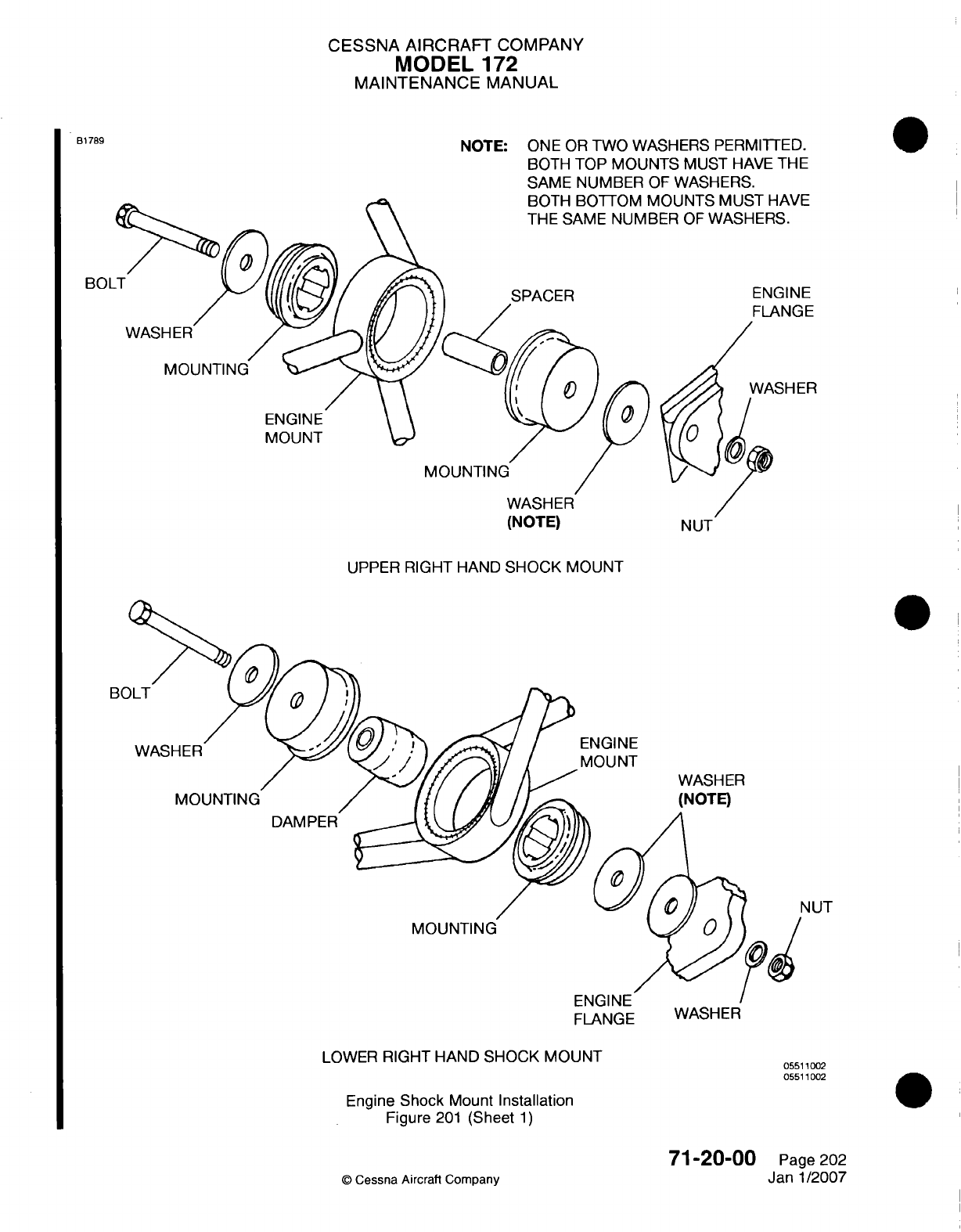
CESSNA
AIRCRAFT
COMPANY
MODEL
172
MAINTENANCE
MANUAL
NOTE:
ONE
OR
TWO
WASHERS
PERMITTED.
BOTH
TOP
MOUNTS
MUST
HAVE
THE
SAME
NUMBER
OF
WASHERS.
O1UUN1
I
0
MUZ-
I
I1MVLz
3ER
OF
WASHERS.
BOL
SPACER
WASH
ER
ENGINE
MOUNT
(NOTE)
UPPER
RIGHT
HAND
SHOCK
MOUNT
BC
ENGINE
MOUNT
MOUNTING
DAMPER
4UT
MOUNTING
FLANGE WASHER
LOWER
RIGHT
HAND
SHOCK
MOUNT
Engine
Shock
Mount
Installation
Figure
201
(Sheet
1)
©
Cessna
Aircrati
Company
71-20-00
Page
202
Janl1/2007
B1789
ENGINE
FLANGE
WASHER
(NOTE)
05511002
05511002
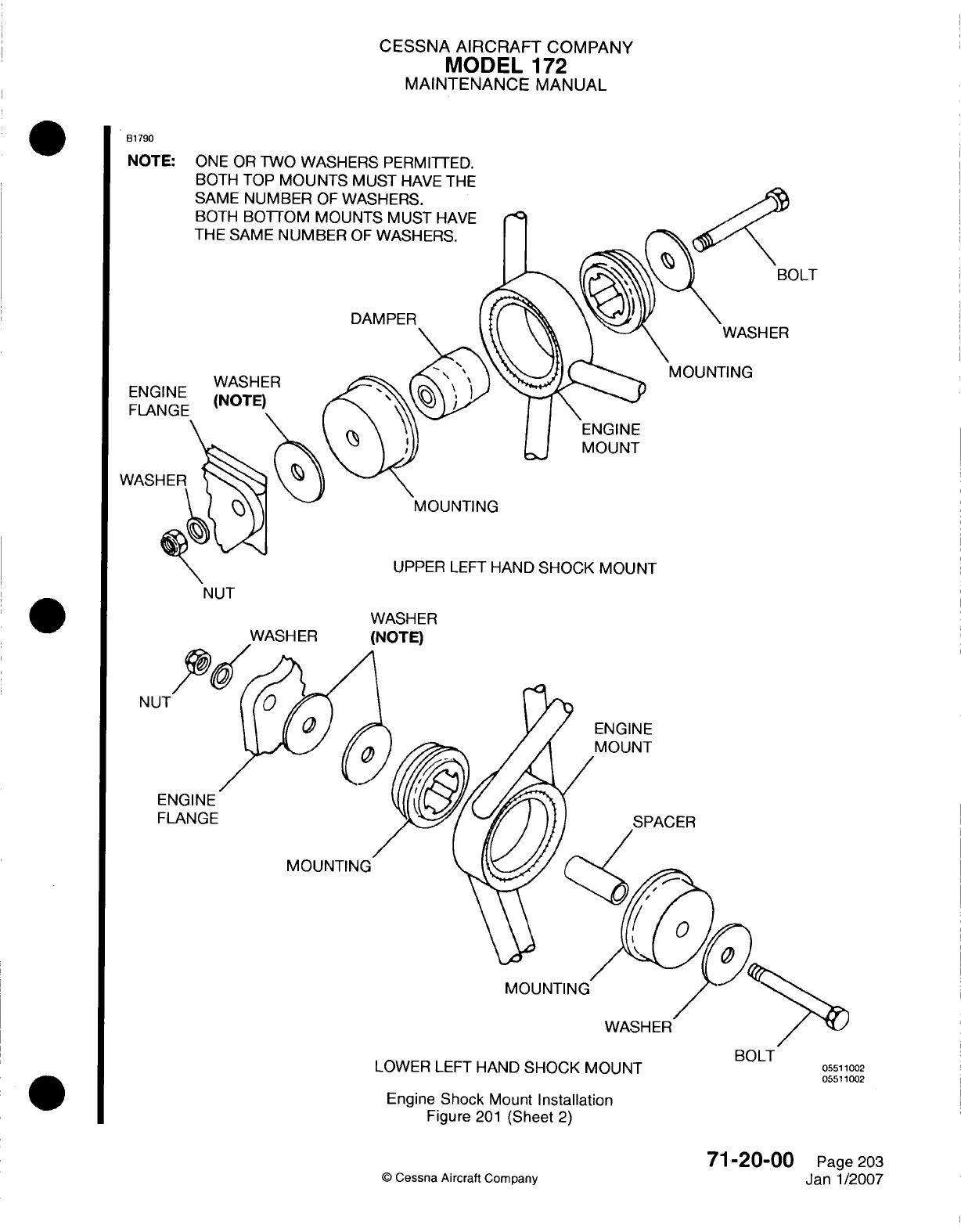
CESSNA
AIRCRAFT
COMPANY
MODEL
172
MAINTENANCE
MANUAL
Bi1790
NOTE:
ONE OR
TWO
WASHERS
PERMITTED.
BOTH
TOP
MOUNTS
MUST
HAVEF
THE
WASH
ER
Li
MOUNT
MOUNTING
UPPER
LEFT
HAND
SHOCK MOUNT
WASHER
ENGINE
MOUNT
FL
MOUNTING
MOUNTING
BOLT
LOWER
LEFT
HAND
SHOCK MOUNT
05511002
05511002
Engine
Shock
Mount
Installation
Figure
201
(Sheet
2)
©
Cessna
Aircraft
Company
71-20-00
Page
203
Jan-1/2007
v
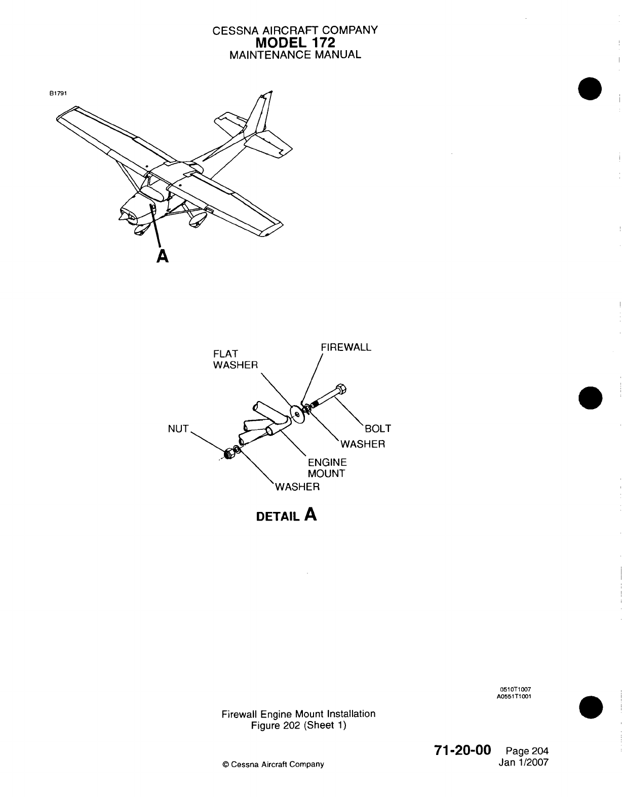
CESSNA
AIRCRAFT
COMPANY
MODEL
172
MAINTENANCE
MANUAL
B
A
0
NUT
DETAIL
A
051
OT 1
007
A0551TIO01
Firewall
Engine
Mount
Installation
Figure
202
(Sheet
1)
©
Cessna
Aircraft Company
71-20-00
Page 204
Jan
1/2007
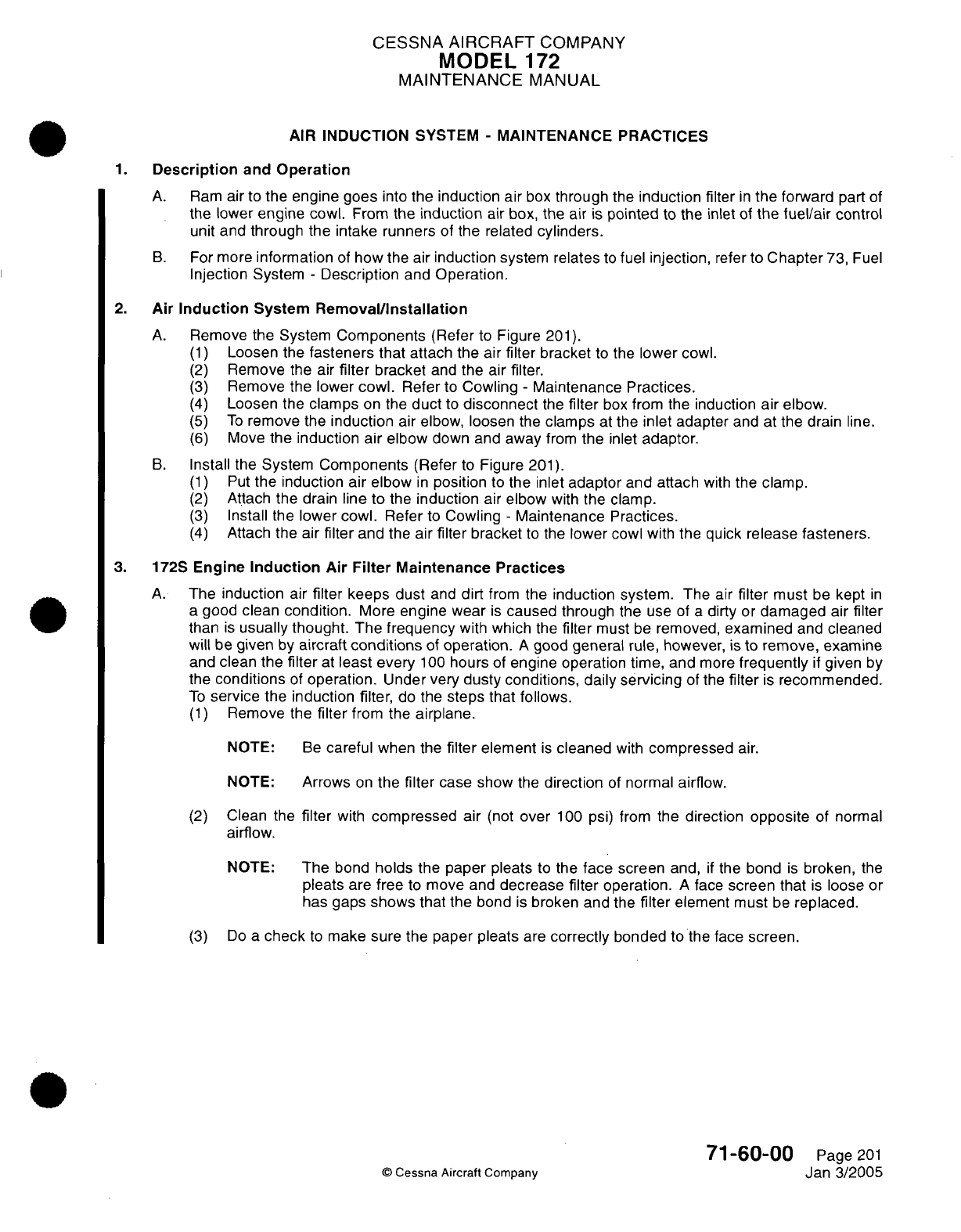
CESSNA
AIRCRAFT
COMPANY
MODEL
172
MAINTENANCE
MANUAL
AIR INDUCTION
SYSTEM
-
MAINTENANCE
PRACTICES
1.
Description
and
Operation
A.
Ram
air to
the engine
goes
into
the induction air
box
through
the
induction
filter
in
the
forward
part
of
the
lower
engine cowl.
From
the
induction
air
box,
the
air is
pointed
to the inlet of
the
fuel/air
control
unit
and
through the intake runners
of the related
cylinders.
B.
For
more
information
of
how
the air
induction system relates
to
fuel
injection,
refer
to
Chapter
73,
Fuel
Injection System
-
Description
and
Operation.
2.
Air
Induction
System
Removal/Installation
A.
Remove
the
System
Components
(Refer
to
Figure
201).
(1)
Loosen
the
fasteners
that
attach the air
filter
bracket
to
the
lower
cowl.
(2)
Remove the air
filter
bracket
and
the air filter.
(3)
Remove
the lower
cowl.
Refer
to
Cowling
-
Maintenance
Practices.
(4)
Loosen
the
clamps
on
the
duct
to
disconnect
the
filter
box
from
the
induction
air
elbow.
(5)
To
remove
the
induction
air elbow,
loosen
the
clamps
at
the
inlet
adapter
and
at the drain
line.
(6)
Move
the
induction
air
elbow
down and
away
from
the
inlet
adaptor.
B.
Install
the
System
Components
(Refer
to
Figure
201).
(1)
Put
the
induction air
elbow
in
position
to
the inlet
adaptor
and attach
with
the
clamp.
(2)
Attach
the drain
line
to
the
induction
air
elbow
with
the clamp.
(3)
Install the
lower
cowl. Refer
to
Cowling
-
Maintenance Practices.
(4)
Attach
the air
filter
and the air
filter bracket
to
the
lower
cowl
with
the
quick
release
fasteners.
3.
172S
Engine
Induction
Air
Filter
Maintenance
Practices
A.
The
induction
air
filter keeps
dust
and
dirt
from
the
induction system. The
air
filter
must
be
kept
in
a
good clean
condition.
More
engine wear
is
caused
through the
use
of
a
dirty
or
damaged
air
filter
than
is
usually thought.
The
frequency
with
which
the
filter
must
be
removed,
examined
and
cleaned
will
be
given
by
aircraft
conditions
of
operation.
A
good
general
rule,
however, is
to remove,
examine
and
clean the
filter
at
least every
100
hours
of
engine operation time, and
more
frequently
if
given
by
the
conditions
of
operation.
Under very
dusty
conditions, daily servicing
of
the
filter
is
recommended.
To
service
the
induction filter,
do
the
steps that follows.
(1)
Remove the
filter
from
the
airplane.
NOTE:
Be
careful
when
the
filter
element
is
cleaned
with
compressed
air.
NOTE:
Arrows
on
the
filter
case
show
the
direction
of
normal
airflow.
(2)
Clean
the
filter
with
compressed
air
(not
over
100
psi) from
the
direction
opposite
of
normal
airflow.
NOTE:
The
bond
holds
the
paper
pleats
to
the
face
screen
and,
if
the
bond
is
broken,
the
pleats
are
free
to
move
and
decrease filter
operation.
A
face
screen
that
is
loose
or
has
gaps
shows that
the
bond
is
broken
and the
filter
element
must
be
replaced.
(3)
Do
a
check
to
make sure
the paper pleats
are
correctly
bonded
to the
face
screen.
71-60-00
Page
201
©
Cessna Aircraft Company
Jan 3/2005
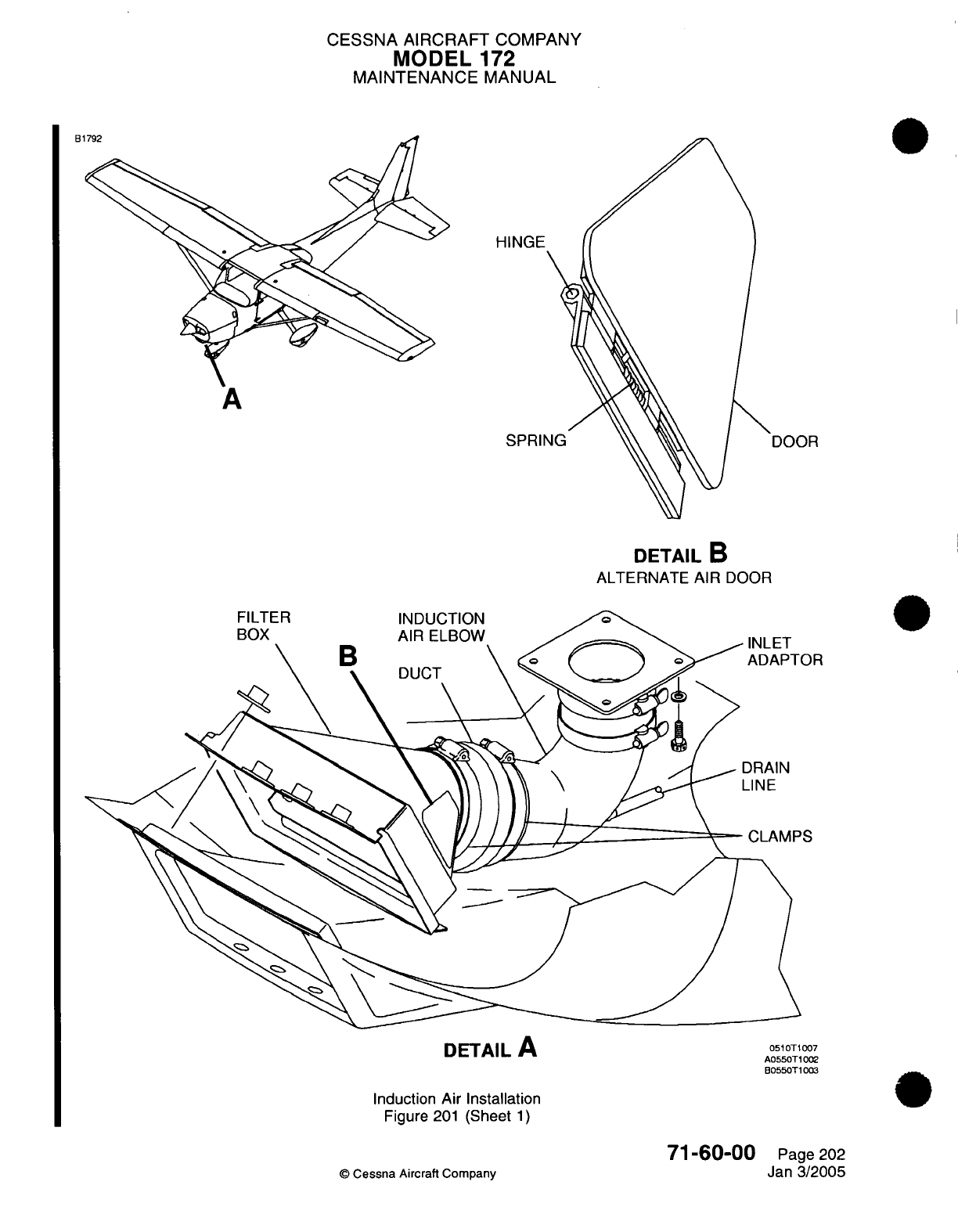
CESSNA AIRCRAFT
COMPANY
MODEL
172
MAINTENANCE
MANUAL
B1
A
SPRING
DETAIL
B
ALTERNATE
AIR
DOOR
INLET
ADAPTOR
DRAIN
LINE
CLAMPS
DETAIL
A
Induction
Air
Installation
Figure
201
(Sheet
1)
71-60-00
©
Cessna Aircraft
Company
0510T1007
A0550T1002
B0550T1003
Page
202
Jan
3/2005
CESSNA AIRCRAFT
COMPANY
MODEL
172
MAINTENANCE
MANUAL
CAUTION:
Do
not use
solvent
or
cleaning
fluids
to
wash
the
filter.
Use
only
a
water
and
household
detergent
solution
when
washing
the
filter.
(4)
After
compressed
air
has
been blown
through the
filter,
the
filter
can
be
washed,
if
necessary,
in
a
solution
of
warm
water
and
a
mild
household
detergent.
A
cold
water
solution
can
be
used.
NOTE:
The
filter
assembly
can
be
cleaned
with
compressed
air
a
maximum
of
30
times
or
it
can
be
washed
a
maximum
of
20
times.
NOTE:
A
new
filter
must
be
installed
at
500
hours of
engine
operation or
one
year,
whichever
occurs
first.
A
new
filter
must
be
installed
if
the
filter
is
damaged.
(5)
Flush
the
filter
with
clear
water
until
the
water
from
the
filter
is
clear.
Let
the
water
drain
from
the
filter
and
dry
with
compressed
air
(not
over
100
psi).
NOTE: The
panels
of
the
filter
can have
distortion
when wet,
but
they will
go
back
to
their
normal
shape
when
dry.
(6)
Make
sure the
airbox
is
clean.
(7)
Examine
the
filter
and
replace
if
applicable.
(8)
Install
the
filter
in
the
airbox
with
the
gasket
on
the aft
face
of
the
filter frame
and
with the flow
arrows
on
the
filter
frame pointed
in
the
correct
direction.
71-60-00
Page
203
©
Cessna
Aircraft
Company
Jan 3/2005
CESSNA
AIRCRAFT
COMPANY
MODEL
172
MAINTENANCE
MANUAL
DRAIN
LINES
-
MAINTENANCE PRACTICES
1.
Description
and
Operation
A.
Various
components
within
the
engine
compartment
are
equipped
with drain
lines
to
allow
fluid and/or
vapor
to
escape
and
vent
to
the
atmosphere.
These
lines
are
typically
secured
using
hose
clamps,
and
are
routed
together
in
a
cluster
on the
left
side of
the
forward firewall.
2.
Maintenance
Practices
A.
Maintenance
practices
for
all
drain
lines
are
typical.
Line
removal and installation
consists
of
removing
clamps
and
other
devices
used
to secure
the
lines
to
various structure.
Lines
should
be
checked
for
condition
and
security
when
removed,
and
installed
in
reverse
order.
B.
For an
illustration
of
various
drain
lines,
refer
to
Figure
201.
© Cessna
Aircraft
Company
71-70-00
Page
201
Apr
7/2003
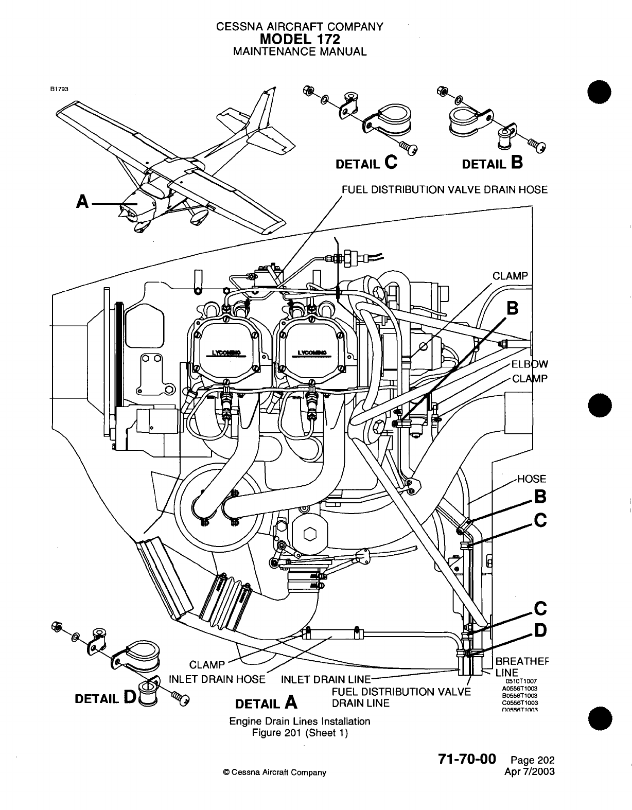
CESSNA AIRCRAFT
COMPANY
MODEL
172
MAINTENANCE
MANUAL
FUEL
DISTRIBUTION
VALVE
DRAIN
HOSE
CLAMP
INLET DRAIN
HOSE
INLET
DRAIN
LINE
DETAIL
FUEL
DISTRIBUTION
VALVE
DETAIL
A
DRAIN
LINE
Engine
Drain
Lines
Installation
Figure
201
(Sheet
1)
©
Cessna
Aircraft Company
71-70-00
Page 202
Apr
7/2003

CHAPTER
ENGI
FUEL
CONT
INE
AN
RO
D
L
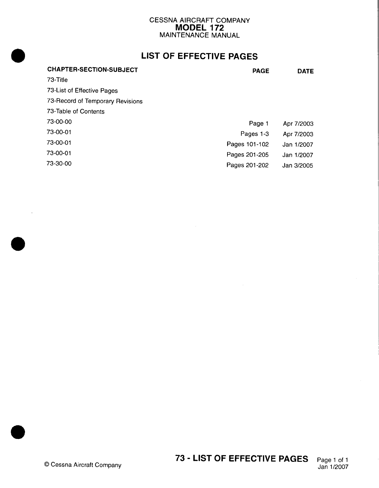
CESSNA
AIRCRAFT
COMPANY
MODEL
172
MAINTENANCE
MANUAL
LIST
OF
EFFECTIVE PAGES
CHAPTER-SECTION-SUBJECT
73-Title
73-List
of
Effective Pages
73-Record
of
Temporary
Revisions
73-Table
of
Contents
73-00-00
73-00-0
1
73-00-01
73-00-01
73-30-00
PAGE
Page
1
Pages
1-3
Pages
101
-102
Pages 201-205
Pages
201
-202
©
Cessna
Aircraft Company
73
-
LIST
OF
EFFECTIVE PAGES
Page
1
of
1
Janl1/2007
DATE
Apr
7/2003
Apr
7/2003
Janl1/2007
Janl1/2007
Jan
3/2005
Temporary
Revision
Number
RECORD
OF
TEMPORARY
REVISIONS
Page
Number Issue
Date
By
Date
Removed
By
CESSNA AIRCRAFT
COMPANY
MODEL
172
MAINTENANCE
MANUAL
CONTENTS
ENGINE
FUEL
AND
CONTROL
-
GENERAL
....................
S
cope
............ . ................ . .... .
Definition
..................................
FUEL
INJECTION SYSTEM
-
DESCRIPTION
AND
OPERATION...........
General...................................
Description
.................................
Operation..................................
Fuel
Injection
System
-
TROUBLESHOOTING....................
General...................................
Fuel
Injection System
Troubleshooting.....................
FUEL
INJECTION SYSTEM
-
MAINTENANCE
PRACTICES
.............
General...................................
Precautions.................................
Fuel/Air
Control
Unit
Removal/installation
...................
Fuel
Distribution
Valve
Removal/installation
..................
Injection
Nozzles
Removal/Installation.....................
Injection Nozzle
Flow
Test
..........................
Idle and
Mixture
Adjustment..........................
Injector
Nozzle
Cleaning
...........................
Fuel
Strainer
Cleaning
............................
Air Throttle
Shaft
Lubrication
.........................
FUEL
FLOW
INDICATOR
-
MAINTENANCE
PRACTICES
..............
General...................................
EGT/Fuel
Flow Gage
Removal/Installation...................
Transducer
and
Line
Removal/installation
...................
©
Cessna
Aircraft
Company
73-00-00
Page
1
73-00-00
Page
1
73-00-00
Page
1
73-00-0
1
Page
1
73-00-0
1
Page
1
73-00-0
1
Page
1
73-00-0
1
Page
1
73-00-01
Page
101
73-00-01
Page
101
73-00-01
Page
101
73-00-01
Page
201
73-00-01
Page
201
73-00-0
1
Page
201
73-00-01 Page
201
73-00-01
Page 202
73-00-01
Page
202
73-00-0
1
Page
202
73-00-0
1
Page 203
73-00-01
Page
205
73-00-01
Page 205
73-00-01
Page 205
73-30-00
Page
201
73-30-00
Page
201
73-30-00
Page
201
73-30-00
Page
201
73-
CONTENTS
Page
1
of
1
Janl1/2007
CESSNA
AIRCRAFT
COMPANY
MODEL
172
MAINTENANCE
MANUAL
ENGINE FUEL
AND
CONTROL
-
GENERAL
1.
Scope
A.
This
chapter
provides information
on
the
fuel
injection system
used
for
the
10-360-
L2A
engine.
Information
beyond
the
scope
of
this chapter
can
be
found
in
Chapter
28,
Fuel
-
General
and
in
various
publications
which
are
listed
in
Introduction
-
General.
2.
Definition
A.
This
chapter
is
divided
into
sections
and
subsections
to
assist
maintenance
personnel
in
locating
specific
systems
and
information.
The
following
is
a
brief
description
of
each
section.
For
locating
information
within
the
chapter,
refer to the
Table
of
Contents
at
the
beginning
of
the chapter.
(1)
The
section
on
fuel injection
covers
procedures
used
to
troubleshoot
and
maintain
the
fuel
injection system.
(2)
The
section
on
fuel
flow
indicator covers
procedures
used
to
maintain
the
indicating
portion
of
the
system.
73-00-00
Page
1
©
Cessna
Aircraft
Company
Apr
7/2003
CESSNA
AIRCRAFT
COMPANY
MODEL
1
72
MAINTENANCE
MANUAL
FUEL
INJECTION
SYSTEM
-
DESCRIPTION
AND OPERATION
1.
General
A.
This
section
covers
the
RSA
Fuel
Injection
system
used
on
the
IO-360-L2A
engine.
For a
schematic
of
the
fuel injection
system,
refer
to Figure
1.
2.
Description
A.
The
fuel
injection
system
is
a
low
pressure,
multi
nozzle, continuous
flow
system
which
injects
raw
fuel
into
the
engine
cylinder
heads.
The
injection
system
is
based
on
the
principle
of
measuring
engine
air
consumption
to
control
fuel flow.
More air
flow through
the
venturi
will
result
in
more
fuel
being
delivered
to
the
engine,
and
less
air
flow
through
the
venturi
results
in
a
decreased
flow
of
fuel
to
engine.
B.
System
components
consist
of
the
fuel/air
control unit,
the
fuel distribution
valve
(flow divider),
injection
nozzles
(4
total)
and
lines
used
to
connect
the
components.
A
description
of
the
components
is
as
follows:
(1)
Fuel/Air Control
Unit
-
The
fuel/air
control
unit,
also
known
as
the
'servo
regulator,'
is
located
on
the
underside
of
the
engine
and
integrates
the
functions
of
measuring
airflow
and
controlling
fuel
flow.
The
control
unit
consists
of
an
airflow sensing
system,
a
regulator section
and
a
fuel
metering
section.
(2)
Fuel
Distribution
Valve
-
The
fuel
distribution
valve, also
known
as
a
'spider'
or
a
flow
divider,
is
located
on
top
of
the
engine
and
serves
to
distribute
fuel
evenly
to
the
four
cylinders
once
it
has been
regulated
by
the
fuel/air
control
unit.
Also
attached
to
the
fuel
distribution valve
is
a
rigid
line
which
feeds
into
a
pressure
transducer.
This
transducer
measures
fuel
pressure
and
translates that
reading into fuel
flow
at
the
cockpit
indicator.
(3)
Injection
Nozzles
-
Each
cylinder
contains
an
injection nozzle,
also
known
as
an
air
bleed nozzle
or
a
fuel
injector.
This
nozzle
incorporates
a
calibrated
jet
that determines,
in
conjunction with
fuel
pressure,
the
fuel
flow
entering
each
cylinder.
Fuel
entering the
nozzle
is
discharged
through
the
jet
into an
ambient
air
pressure
chamber
within the
nozzle
assembly.
This nozzle assembly
also
contains
a
calibrated opening
which
is
vented
to
the
atmosphere, and
allows
fuel
to
be
dispersed
into
the
intake portion
of
the
cylinder
in
an
atomized,
cone-shaped
pattern.
3.
Operation
A.
Fuel
is
stored
in
the
wing
tanks
and
is
delivered
to
the
fuel injection
system
via
a
series
of
lines,
valves
and
pumps.
From
the
engine-driven
fuel
pump,
fuel
enters
the
fuel/air
control
unit,
passes
through
the
fuel
distribution
valve,
and
is
routed to
individual injection
nozzles
at
each
cylinder.
NOTE:
For
a
schematic
of
the entire
fuel
system,
refer
to
Chapter
28,
Fuel
Storage
and
Distribution
-
Description and
Operation,
Figure
1.
B.
The
heart
of
the injection
system
is
the
fuel/air
control
unit,
which occupies
the
position
ordinarily
used
by
the
carburetor
at
the
engine intake manifold inlet.
The
fuel/air
control
unit
is
comprised
of
an
integrated
airflow
sensing
system,
a
regulator section
and
a
fuel metering
section.
Operation
of
the
fuel
injection
system
is
based
on
the principle
of
measuring
airflow
and
using
the
airflow
signal
to
operate
a
servo
valve.
The
accurately
regulated
fuel
pressure established
by
the
servo
valve,
when
applied
across the
fuel
control
system,
makes
fuel
flow
proportional
to
airflow.
(1)
THE
AIRFLOW
SENSING SYSTEM
consists
of
a
throttle
body
which
houses
the air
throttle
valve,
the
venturi,
servo
valve
and
fuel control
unit.
The differential
pressure
between
impact
air
and
the
venturi
throat
pressure
is
a
measurement
of
the
velocity
of
the
air entering the
engine.
These
pressures
are
vented through
drilled
channels
in
the
throttle
body
to
both
sides
of
an
air
diaphragm
and
create
a
force
across the
diaphragm.
A
change
in
air throttle position
or
a
change
in
engine
speed
will
change
the
air
velocity,
which
in
turn
changes
the
force
across
the
air
diaphragm.
73-00-01
Page
1
©
Cessna
Aircraft
Company
Apr
7/2003
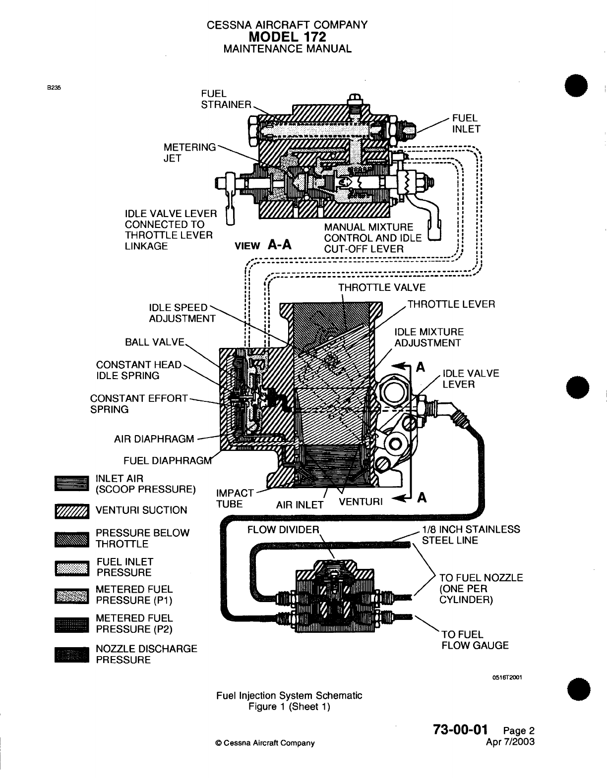
CESSNA
AIRCRAFT
COMPANY
MODEL
172
MAINTENANCE
MANUAL
B235
IDLE
CON
THROTTLE
LEVER
LINK
BALL
VA
T...L.IVR
MANUAL
MIXTURE
U
!I
1
JTTLE
LEVER
CONTROL
AND
IDLE
"
AGE
VIEW
A-A
CUT-OFF LEVER
I
,;--
................
…-------
jI
THROTTLE
VALVE
I IE
I
IDLE SPEED
ADJUSTMEN1
VAI
VF
CONSTANT
HEAD
N
IDLE
SPRING
CONSTANT
EFFORT-
SPRING
AIR
DIAPHRAGM
FUEL
DIAPHRAGM'
ees
INLET
AIR
*
I
(SCOOP PRESSURE)
1///////\ /vclTI
IDI
1I
IrTInTl
r'/"///
... .
v*
.
PRESSURE
BELOW
THROTTLE
iii.....i
..
FUEL
INLET
B:r::
PRESSURE
METERED
FUEL
PRESSURE
(P1)
METERED
FUEL
PRESSURE
(P2)
__
NOZZLE
DISCHARGE
__B
PRESSURE
,1/8
INCH
STAINLESS
STEEL
LINE
TO
FUEL
NOZZLE
(ONE
PER
CYLINDER)
Tfr
CIl ICI
FLOW
GAUGE
FLOW
GAUGE
05e16T2001
Fuel
Injection
System Schematic
Figure
1
(Sheet
1)
73-00-01
Page
2
Apr
7/2003
©
Cessna Aircraft
Company
I
l///// /,l
V
LI I
U_
I
I
II,
CESSNA
AIRCRAFT
COMPANY
MODEL
-172
MAINTENANCE
MANUAL
(2)
THE
REGULATOR
SECTION
contains
the
air
diaphragm
mentioned
in
the
preceding
paragraph
and
a
fuel
diaphragm.
Fuel inlet
pressure
is
applied
to
one
side
of
the
fuel
diaphragm.
The
other
side
of
the
fuel
diaphragm
is
exposed
to
fuel
that
has
passed
through
the
metering
jet
(metered
fuel pressure). The
differential
pressure
across
the fuel
diaphragm
is
referred
to
as
the
fuel
metering force.
(a)
The
air
metering force
applied
to
the
air diaphragm
is
transmitted through
the
regulator
stem
and
tends
to move
the
ball
valve
in
the
opening
direction.
The fuel
metering force
across
the
fuel
diaphragm acts
to
oppose
the air
metering
force
and
tends
to
close
the
ball
valve.
Because
the air
forces
are
very
low
in
the idle
range, a
constant
head
idle
spring
is
provided
to
maintain
an
adequate fuel
metering
force
at
low
rpm.
(b)
As
the
air metering
force
increases,
the spring
compresses
until
the
spring
retainer
touches
the
air
diaphragm
and
acts
as
a
solid
member.
The
constant
effort
spring
produces
a
force
which
provides
a
smooth
transfer
from
idle to
low
power
cruise
operation.
Whenever
the
air
metering, fuel
metering
and
spring forces
are
balanced,
the
ball
valve
maintains
a
fixed
position.
(3)
THE
FUEL
METERING
SECTION
is
contained
within
the
throttle body
casting
and
consists
of
an
inlet
fuel
screen,
a
rotary
idle
valve
and
a
rotary mixture
valve.
Both
idle
speed
(closed throttle
position)
and
idle mixture
(relationship
between
throttle
position
and
idle
valve position)
may
be
adjusted
externally
to
meet
individual engine requirements.
(a)
The idle
valve
is
connected
to
the
throttle valve
by
means
of
an
external
adjustable
link.
The
idle
valve controls
fuel
flow through the
low
speed range
of
operation
and
is
adjustable
to
obtain good
idling
characteristics
without
affecting
fuel
metering
in
the
high
power
range.
(b)
The
mixture control
valve
gives
full
rich
mixture
on
one
stop
and
a
progressively
leaner
mixture
as
it is
moved
toward idle
cutoff. The
full
rich
stop
defines
sea level
requirements
and the
mixture
control provides
for
altitude
leaning.
73-00-01
Page
3
©
Cessna Aircraft
Company
Apr
7/2003
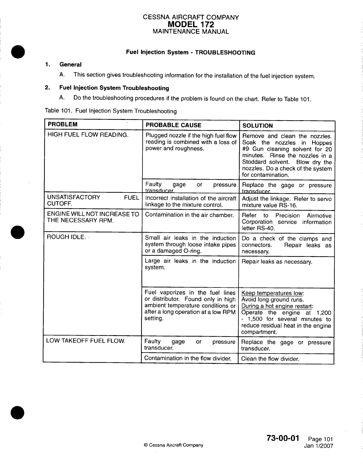
CESSNA
AIRCRAFT
COMPANY
MODEL
172
MAINTENANCE
MANUAL
Fuel
Injection
System
-
TROUBLESHOOTING
1.
General
A.
This
section
gives troubleshooting
information
for
the
installation
of
the
fuel
injection
system.
2.
Fuel
Injection
System
Troubleshooting
A.
Do
the
troubleshooting
procedures
if
the
problem
is
found
on
the
chart. Refer
to
Table
1
01.
Table
101.
Fuel
Injection
System
Troubleshooting
PROBLEM
PROBABLE
CAUSE
SOLUTION
HIGH
FUEL FLOW
READING.
Plugged nozzle
if
the high
fuel
flow
Remove
and
clean
the
nozzles.
reading
is
combined
with
a
loss
of Soak the
nozzles
in
Hoppes
power
and
roughness.
#9
Gun
cleaning solvent
for
20
minutes.
Rinse
the
nozzles
in
a
Stoddard
solvent.
Blow
dry the
nozzles.
Do
a
check
of
the
system
for
contamination.
Faulty
gage
or
pressure
Replace
the
gage
or
pressure
transdiir-pr
tranndijcpr
UNSATISFACTORY
FUEL
Incorrect
installation
of
the
aircraft
Adjust
the
linkage.
Refer
to
servo
CUTOFF.
linkage
to
the
mixture
control.
mixture
value RS-16.
ENGINE
WILL
NOT
INCREASE
TO
Contamination
in
the
air
chamber. Refer
to
Precision
Airmotive
THE
NECESSARY
RPM.
Corporation
service
information
_____ _____ _____ _____ ____
letter
RS-40.
ROUGH
IDLE.
Small
air
leaks
in
the
induction
Do
a
check
of
the
clamps
and
system
through
loose
intake pipes
connectors.
Repair
leaks
as
or
a
damaged
0-ring,
necessary.
Large air
leaks
in
the
induction
Repair
leaks
as
necessary.
system.
Fuel
vaporizes
in
the
fuel lines
Keep
temperatures
low:
or
distributor.
Found
only
in
high
Avoid
long
ground
runs.
ambient temperature
conditions
or During
a
hot
engine
restart:
after
a
long
operation
at
a
low
RPM
Operate
the
engine
at
1,200
setting.
-
1,500 for
several minutes
to
reduce residual
heat
in
the
engine
____ ___
____ ___ ____ ___ ___
compartment.
LOW
TAKEOFF
FUEL FLOW.
Faulty
gage
or pressure Replace
the
gage
or
pressure
transducer.
transducer.
___________________________Contamination
in
the
flow
divider.
Clean
the
flow
divider.
73-00-01
©
Cessna Aircraft
Company
Page
101
Jan-1/2007

CESSNA AIRCRAFT
COMPANY
MODEL
172
MAINTENANCE
MANUAL
Table
101.
Fuel
Injection System
Troubleshooting (continued)
ENGINE
IS
DIFFICULT
TO
START.
ENGINE
OPERATES
ROUGH.
Incorrect starting
procedure.
Flooded engine.
Throttle
valve
is
opened
too
far.
A
prime
that
is
not
sufficient
(usually
combined
with
a
backfire).
Too
rich
or
too lean
mixture.
Plugged
nozzle(s)
(usually
combined
with
high
takeoff
fuel
flow).
Air
leak
in
the
induction system.
Air
leak
in
the fuel
line
from the fuel
tank
to
the
servo.
Flow
divider
sticks.
Refer
to the
Pilot's
Operating
Handbook.
Crank
the
engine
to
clear
it
with
the
throttle open
and
the
mixture
in
the
IDLE/CUTOFF position.
Open
the
throttle
to
approximately
800
RPM.
Increase the
quantity
of
priming.
Adjust
the
mixture control.
If
the
mixture
is
too
rich,
the
engine
will
run
smoothly
when
leaned.
If
the
mixture
is
too
lean,
the
engine
will
run
smoothly
when the
mixture
is
enriched.
Adjust
idle
mixture
to
give
a
10
-
50
PRMV
rise
at
idle.
Remove
and
cla
tIIe
nozzles
Soak
the
nozzles
in a
Hoppes
#9
Gun
cleaning solvent for
20
minutes. Rinse
the
nozzles
with
a
Stoddard solvent.
Blow
dry
the
nozzles.
Do
a
check
of
the
system
for contamination.
Do
a
check
for
leaks.
Do
a
check
for
the
leak.
Connect
clear
tubing
between
the
servo
and the
flow
divider
and
look
for
air
bubbles.
Find
and
correct
the
source
of
the
leak.
This
can
include
the
boost
pump
or
the
engine-driven
pump.
Do
an
inspection
of
the
flow
divider.
Clean
the
flow
divider.
73-00-01
©
Cessna
Aircraft Company
Page
102
Janl1/2007
CESSNA AIRCRAFT
COMPANY
MODEL
172
MAINTENANCE
MANUAL
FUEL
INJECTION
SYSTEM
-
MAINTENANCE PRACTICES
1.
General
A.
This
section
provides
instructions
for
removal/installation, adjustment
and
cleaning
of
various
components
used
in
the
fuel
injection
system.
For
maintenance
information
beyond
the scope
of
this section,
refer
to
applicable
fuel
injection component
maintenance
manuals
which are listed
in
Introduction
-
List
of
Supplier
Publications.
2.
Precautions
A.
Observe
the
following
general
precautions
and
rules
during
fueling,
defueling,
fuel bay
purging,
repairing,
assembly
or
disassembly
of
system components,
and
electrical
system
checks
and
repairs
on
the
airplane fuel
system.
(1)
Plugs or
caps should
be
placed
on
all
disconnected
hoses,
lines
and
fittings
to
prevent
residual
fuel drainage,
thread damage,
or
entry
of
dirt
or
foreign
material into
fuel
system.
(2)
Any
time
fuel
system
is
opened,
flush
system
with
1/2
gallon
of
fuel
at
the
inlet
of
servo
and
flow
divider
using
the
fuel boost
pump.
(3)
When
working
on
fuel
injection
system,
keep
all
parts clean
and
free
of
contaminants.
3.
Fuel/Air
Control Unit RemovaVlnstallation
A.
Remove
Fuel/Air Control
Unit.
(1)
Place
cockpit-mounted
FUEL
SHUTOFF valve
in
the
OFF
position.
(2)
Remove
lower cowling. Refer
to
Chapter
71,
Cowling
-
Maintenance Practices.
(3)
Remove
clamp
securing induction
air
elbow
to
inlet
adaptor.
(4)
Disconnect
fuel
inlet
and
outlet
lines
from
control
unit.
(5)
Remove
mixture
and
throttle
control
linkages
from
control
unit.
Note
number
and
position
of
washers
for reinstallation.
(6)
Cut
safety
wire
at
base of
control
unit.
Remove
bolts securing
inlet
adaptor
and
throttle cable
bracket
to
base
of
control
unit
and
mixture
cable bracket.
(7)
Remove
nuts,
lock
washers
and
flat
washers securing
control
unit
to
oil
sump/intake
manifold.
Cover engine
intake
opening
and
place control
unit
in a
sealed,
dust-free
environment
to
prevent
accumulation
of
foreign particles
into
unit.
B.
Install
Fuel/Air
Control Unit.
(1)
Remove engine intake
cover
from
sump
area.
(2)
Install
control
unit,
spacer
and
gaskets
to
sump
using
washers,
new
lock
washers
and
nuts.
Finger
tighten
nuts
to
control
unit.
(3)
First
torque
nuts
in a
crisscross
(opposite)
pattern
to
90
inch-pounds
and
then
retorque
nuts
in
the
same
manner
to
a
final
torque value
of
180-200 inch
pounds.
(4)
Install
inlet
adaptor
and
throttle
cable
bracket
to
base
of
control
unit
using
hardware
removed
above. Safety
wire bolts.
(5)
Install
mixture
cable bracket.
(6)
Install mixture
and
throttle
control
linkages
to
control
unit.
Ensure
all
washers
are
in
proper
position.
Refer
to
Chapter
76,
Throttle
Control
-
Maintenance
Practices,
Figure
201
and
Chapter
76,
Fuel
Mixture Control
-
Maintenance Practices,
Figure
201
for
an
illustration
of
washer
and
linkage
sequence.
CAUTION:
Do
not
back the
nuts
off
to
line
the
cotter
pin
hole
up
with
the
castellations
in
the
nut.
(7)
Torque
each
nut
to
30
inch-pounds
and
then
proceed
tightening
the nut
until
the
cotter
pin
hole
lines
up with the
castellation
in
each
nut.
Do
not
exceed
50
inch-pounds.
(a) If
the
cotter
pin hole
and
the
nut
castellations
will
not
line
up,
install
a
different
thickness
NAS1
149F0363P
washer
or
use
a
thin,
NAS1
149F0332P
washer
at
the
location
between
the
throttle cable
rod
end
and
S1450-3-14-032
washer
to
obtain
the
specified
torque
on
the
nut.
It
may
also
be
necessary
to
use
a
different
AN310-3
nut.
(8)
Install
cotter
pins.
73-00-01
Page
201
©
Cessna Aircraft
Company
Janl1/2007
CESSNA AIRCRAFT
COMPANY
MODEL
172
MAINTENANCE
MANUAL
(9)
Move
the
mixture
and
throttle control through
each
controls
entire
range
of
movement
and
ensure
that
there
is
no
binding.
(1
0)
Connect
fuel
inlet and
outlet
lines
to
control
unit.
(1 1)
Secure induction air
elbow
to
inlet
adaptor
using clamp.
(12)
Install
lower cowling.
Refer
to
Chapter
71,
Cowling
-
Maintenance
Practices.
(13)
Place
cockpit-mounted
FUEL
SHUTOFF
valve
in
the
ON
position.
(14)
Check
for
leaks during engine
run.
4. Fuel
Distribution
Valve
RemovaVinstallation
A.
Remove
Fuel
Distribution
Valve.
(1)
Remove upper
cowling.
Refer
to
Chapter
71,
Cowling
-
Maintenance
Practices.
(2)
Disconnect
all
lines
leading
in
to and
out
of
fuel
distribution
valve.
(3)
Remove
nuts, bolts,
washers
and
spacers securing
fuel
distribution
valve
to
engine
case.
B.
Install
Fuel
Distribution
Valve.
(1)
Secure
fuel
distribution
valve
to
engine
case using
nuts,
bolts,
washers
and
spacers.
Torque
to
75
In-lbs.
(2)
Reinstall
all
lines
leading
in
to
and
out
of
fuel
distribution valve.
(3)
Check for
leaks during
engine
run.
(4)
Install
upper
cowling. Refer
to
Chapter
71,
Cowling
-
Maintenance
Practices.
5.
Injection
Nozzles
Removal/installation
A.
Remove
Injection
Nozzles.
(1)
Remove
upper cowling.
Refer
to
(Thapter
71,
Cowling
-
Maintenance
Practices.
(2)
Remove-
rigid
fuel
lines
leading
into
individual
nozzles.
(3)
Remove
nozzles
from
cylinders.
B.
Install
Injection Nozzles.
CAUTION:
Use
only
fuel-soluble
lubricants
(such as
engine
oil)
on
the nozzle
threads
during installation.
(1)
Install
nozzles
to
intake
cylinders.
Torque from
55
to
60
In-lbs.
(2)
Install rigid
fuel lines
to
nozzles.
Torque
25
to
50
In-lbs.
(3)
Install
upper cowling.
Refer
to
Chapter
71,
Cowling
-
Maintenance
Practices.
6.
Injection
Nozzle
Flow
Test
A.
Check Injection
Nozzles
For
Plugging.
(1) If
nozzle plugging
is
suspected,
disconnect
injector
lines
at
the
nozzles.
(2)
Cap
nozzles
with
clean
valve
stem
caps
to
protect
nozzles
from
contamination
during
removal.
(3)
Remove
nozzles.
Refer
to
Injection
Nozzles
Removal/Installation.
(4) Pull
up
injector
lines
taking care
that
lines
are
not
kinked.
(5)
Install
nozzles back
into
lines
and
torque
from
25
to
50
in-lbs.
(6)
Using
clear
containers
(bottles
with
graduations
are
preferred)
flow
fuel
into
containers
using
aircraft
boost
pump
and
observe
nozzle
discharge
pattern.
(7)
When the
mixture
control
is
placed
in
the
full
rich
position
the
nozzles
should
display
a
pencil
stream
pattern.
The
nozzles
should
also
flow
the
same
amount
of
fuel
from
cylinder
to
cylinder.
If
an
unusual flow
pattern or
an
unequal amount
of fuel
is
noted
in
any
of
the
containers
the
nozzles
should
be
thoroughly
cleaned. Refer
to
Injector
Nozzle
Cleaning.
(8)
After
cleaning
install clean
protective valve
stem
caps.
It is
recommended
that after cleaning
the
nozzles,
they
be
reinstalled
in
the
injector
lines
and
a
nozzle
flow check
is
conducted
to
verify
that
the
nozzles
are
clean.
(9)
Following
a
successful
flow
check
reinstall
the
protective
flow
caps
and
reinstall
the nozzles
in
the
cylinders
and
torque
from
55
to
60
in-lbs..
(10)
Remove
protective
caps
and
reinstall
injector
lines
to
the
nozzles
and
torque
from
25
to
50
in-lbs.
(11)
Perform
leak
check.
73-00-01
Page 202
©
Cessna
Aircraft
Company
Janl1/2007
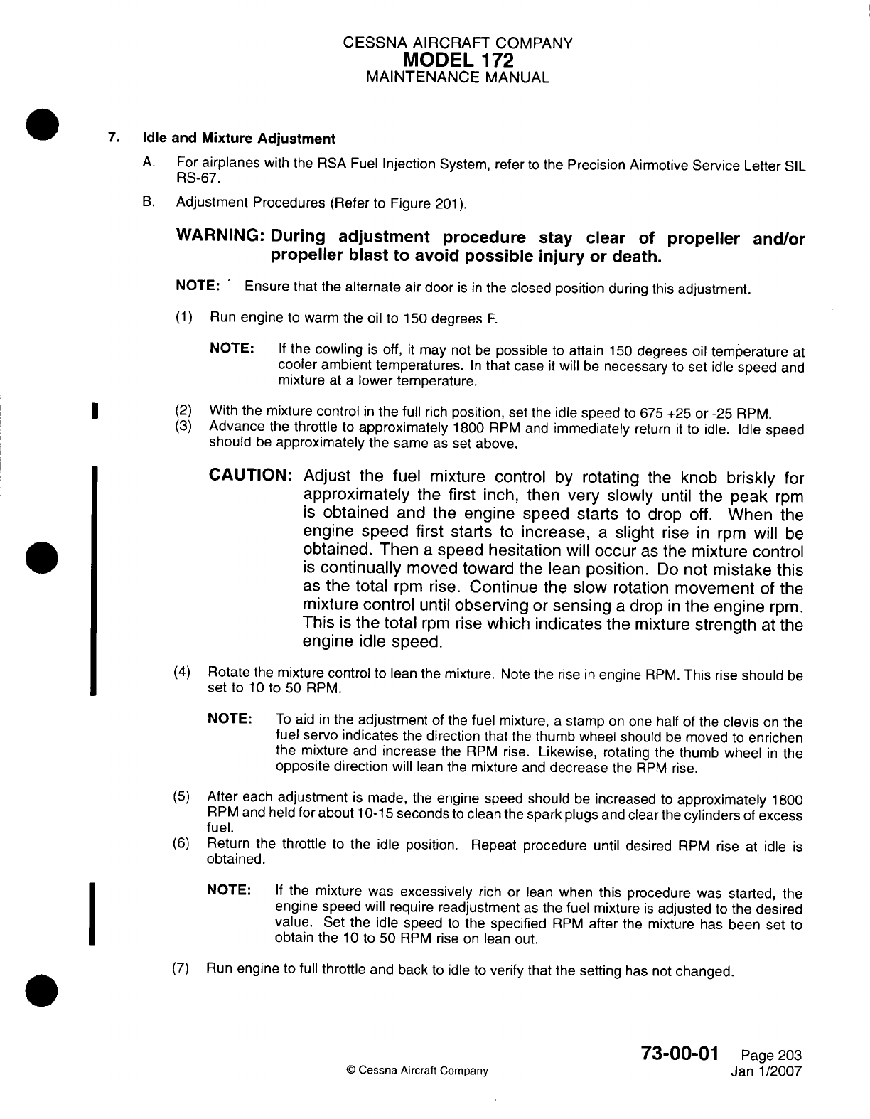
CESSNA AIRCRAFT
COMPANY
MODEL
172
MAINTENANCE
MANUAL
7.
Idle and
Mixture Adjustment
A.
For
airplanes
with
the
RSA
Fuel
Injection
System,
refer
to
the
Precision
Airmotive
Service
Letter
SIL
RS-67.
B.
Adjustment
Procedures
(Refer
to
Figure
201).
WARNING:
During
adjustment
procedure
stay clear
of
propeller
and/or
propeller blast
to
avoid
possible
injury
or
death.
NOTE:
-
Ensure that
the
alternate
air
door
is in
the closed
position
during
this
adjustment.
(1)
Run
engine
to warm
the oil
to
150
degrees
F.
NOTE:
If
the cowling
is
off,
it
may
not
be
possible
to attain
150
degrees
oil
temperature
at
cooler
ambient
temperatures.
In
that
case
it
will
be
necessary
to
set
idle
speed
and
mixture
at
a
lower temperature.
*
~~(2)
With
the
mixture
control
in
the
full
rich
position,
set
the
idle
speed
to
675
+25
or
-25
RPM.
(3)
Advance
the
throttle
to
approximately
1800
RPM
and
immediately
return
it
to
idle.
Idle
speed
should
be
approximately
the
same
as
set
above.
CAUTION:
Adjust
the
fuel
mixture
control
by
rotating
the
knob
briskly
for
approximately
the
first
inch,
then
very
slowly
until
the
peak
rpm
is
obtained
and the
engine speed starts
to
drop
off.
When
the
engine
speed
first
starts
to
increase,
a
slight
rise
in
rpm
will
be
obtained.
Then
a
speed
hesitation
will
occur
as
the
mixture
control
is
continually
moved
toward
the
lean
position.
Do
not
mistake
this
as
the
total
rpm
rise.
Continue
the
slow
rotation
movement
of the
mixture
control
until
observing
or
sensing
a
drop
in
the engine
rpm.
This
is
the
total
rpm
rise
which
indicates
the
mixture
strength
at
the
engine
idle
speed.
(4)
Rotate
the
mixture
control
to
lean the
mixture.
Note
the
rise
in
engine
RPM.
This
rise
should
be
set
to
10
to
50
RPM.
NOTE:
To
aid
in
the
adjustment
of
the
fuel mixture,
a
stamp
on
one
half
of the
clevis
on
the
fuel
servo indicates
the
direction
that
the
thumb
wheel should
be
moved
to
enrichen
the
mixture
and
increase
the
RPM
rise.
Likewise,
rotating
the
thumb
wheel
in
the
opposite
direction
will
lean
the
mixture
and
decrease
the
RPM
rise.
(5)
After
each
adjustment
is
made,
the
engine
speed
should
be
increased
to
approximately
1800
RPM
and
held
for
about
10-1
5
seconds
to
clean
the
spark
plugs
and
clear
the
cylinders
of
excess
fuel.
(6)
Return
the
throttle
to
the
idle
position.
Repeat
procedure
until
desired
RPM
rise
at
idle
is
obtained.
NOTE:
If
the
mixture
was
excessively
rich
or
lean
when
this procedure
was
started,
the
engine speed
will require
readjustment
as
the fuel
mixture
is
adjusted
to
the
desired
value.
Set
the
idle
speed
to
the
specified
RPM
after
the
mixture
has
been
set
to
obtain
the
10
to
50
RPM
rise
on
lean
out.
(7)
Run
engine
to
full
throttle
and
back
to
idle
to
verify
that
the
setting
has not
changed.
73-00-0
1
Page
203
(D
Cessna
Aircraft
Company
Janl1/2007
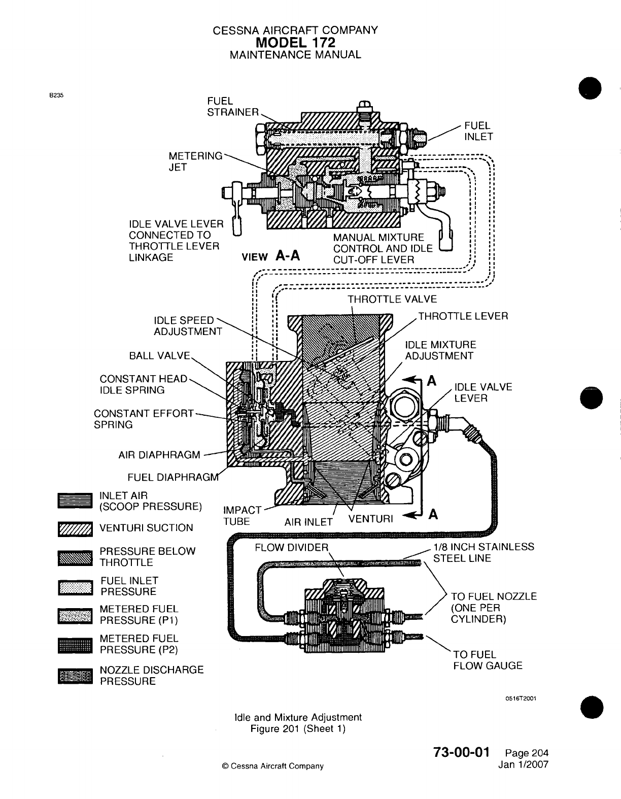
CESSNA
AIRCRAFT
COMPANY
MODEL
172
MAINTENANCE
MANUAL
B235
U EL
JLET
IDLE
CON
TH
R(
LINK
MtE
I
EMIl
JET
VALVE
LE\
NFC.TFn
T(
I.
*
I,
I #5I
.I
*
~~~~~~~~~~IVIMI-WJL-L
IVII/\
I LJFL
DTTLE LEVER
CONTROL
AND
IDLEL
AGE
VIEW
A-A
CUT-OFF
LEVER
I.
…~~~TRTL
AV
IDLE
SPEED
-
ADJUSTMENI
WALL
V/ALVr-
CONSTANT
HEAD
IDLE
SPRING
CONSTANT
EFFORT--_
SPRING
AIR
DIAPHRAGM
-
FUEL
DIAPHRAGMv<
INLET
AIR
(SCOOP
PRESSURE)
VENTURI
SUCTION
PRESSURE
BELOW
LM
TH
ROTTLE
...
FUEL
INLET
PRESSURE
___METERED
FUEL
PRESSURE
(Pl)
METERED
FUEL
PRESSURE
(P2)
I
%.
I
%J"L.
FLOW
GAUGE
NOZZLE
DISCHARGE
'M
PRESSURE
0516T2001
Idle
and
Mixture
Adjustment
Figure
201
(Sheet
1)
0
Cessna
Aircraft
Company
73-00-01
Page
204
Jan
1/2007
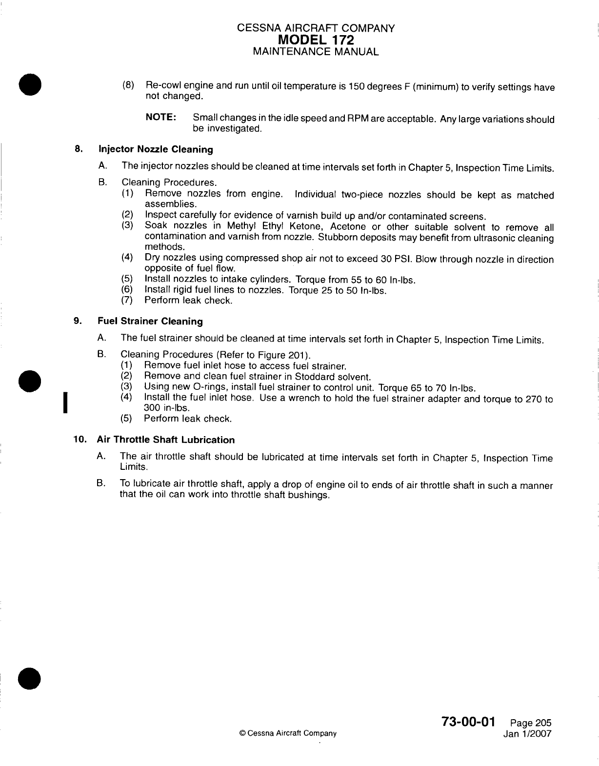
CESSNA
AIRCRAFT
COMPANY
MODEL
172
MAINTENANCE
MANUAL
(8)
Re-cowl
engine
and
run
until
oil
temperature
is
150
degrees
F
(minimum)
to
verify
settings
have
not
changed.
NOTE:
Small
changes
in
the
idle
speed
and
RPM
are
acceptable.
Any
large
variations
should
be
investigated.
8.
Injector
Nozzle
Cleaning
A.
The
injector nozzles
should
be
cleaned
at
time
intervals
set
forth
in
Chapter
5,
Inspection
Time
Limits.
B.
Cleaning
Procedures.
(1)
Remove
nozzles
from
engine.
Individual two-piece
nozzles
should
be
kept
as
matched
assemblies.
(2)
Inspect
carefully
for
evidence
of
varnish
build
up
and/or
contaminated screens.
(3)
Soak
nozzles
in
Methyl
Ethyl
Ketone,
Acetone
or
other
suitable
solvent
to
remove
all
contamination
and
varnish
from
nozzle. Stubborn
deposits
may
benefit
from
ultrasonic
cleaning
methods.
(4)
Dry
nozzles
using
compressed
shop
air
not
to
exceed
30
PSI.
Blow
through nozzle
in
direction
opposite
of
fuel flow.
(5)
Install
nozzles
to
intake
cylinders.
Torque
from
55
to
60
In-lbs.
(6)
Install
rigid
fuel
lines
to
nozzles.
Torque
25
to
50
In-lbs.
(7)
Perform
leak check.
9.
Fuel
Strainer
Cleaning
A.
The
fuel
strainer
should
be
cleaned
at
time
intervals
set
forth
in
Chapter
5,
Inspection
Time
Limits.
B.
Cleaning
Procedures
(Refer
to
Figure
201).
(1)
Remove
fuel
inlet
hose
to
access
fuel
strainer.
(2)
Remove
and
clean
fuel
strainer
in
Stoddard solvent.
(3)
Using
new
0-rings,
install
fuel
strainer
to
control
unit.
Torque
65 to 70
In-lbs.
(4)
Install the
fuel
inlet
hose.
Use
a
wrench
to
hold
the
fuel
strainer
adapter
and
torque
to
270
to
300
in-lbs.
(5)
Perform
leak
check.
10.
Air
Throttle Shaft
Lubrication
A.
The
air
throttle
shaft
should
be
lubricated
at
time
intervals
set
forth
in
Chapter
5,
Inspection
Time
Limits.
B.
To
lubricate
air
throttle
shaft,
apply
a
drop
of
engine
oil to
ends
of
air
throttle shaft
in
such
a
manner
that
the oil
can
work
into
throttle
shaft
bushings.
73-00-01
Pagie
205
Janl/2007
(D
Cessna
Aircraft
Company
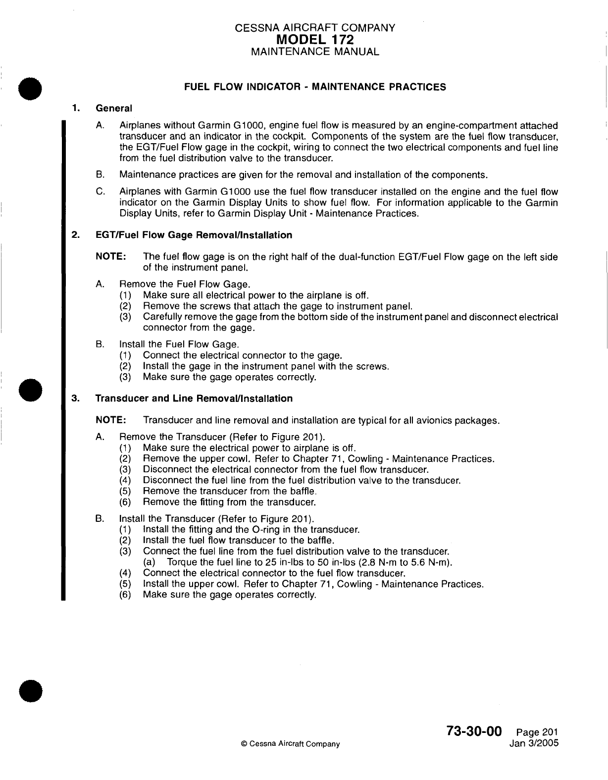
CESSNA
AIRCRAFT
COMPANY
MODEL
172
MAINTENANCE
MANUAL
FUEL
FLOW
INDICATOR
-
MAINTENANCE PRACTICES
1.
General
A.
Airplanes without
Garmin G1000,
engine
fuel
flow
is
measured
by
an
engine-compartment
attached
transducer
and an
indicator
in
the
cockpit.
Components
of
the
system
are
the
fuel
flow
transducer,
the
EGT/Fuel Flow
gage
in
the
cockpit, wiring
to
connect
the
two
electrical
components
and
fuel
line
from
the
fuel
distribution valve
to
the
transducer.
B.
Maintenance
practices
are given
for
the removal
and
installation
of the
components.
C.
Airplanes
with
Garmin
G1000
use
the
fuel
flow
transducer
installed
on
the
engine
and
the
fuel
flow
indicator
on
the
Garmin
Display
Units to
show
fuel
flow. For
information
applicable
to
the Garmin
Display
Units,
refer
to
Garmin Display
Unit
-
Maintenance
Practices.
2.
EGT/Fuel
Flow
Gage
Removal/Installation
NOTE:
The
fuel
flow
gage
is
on
the
right
half
of
the
dual-function
EGT/Fuel
Flow
gage
on
the
left side
of
the
instrument panel.
A.
Remove
the
Fuel
Flow
Gage.
(1)
Make sure
all
electrical
power
to
the
airplane
is
off.
(2)
Remove
the
screws that
attach
the
gage to
instrument
panel.
(3)
Carefully
remove
the
gage
from
the
bottom side of
the
instrument
panel
and
disconnect
electrical
connector
from
the
gage.
B.
Install
the
Fuel
Flow
Gage.
(1)
Connect
the
electrical
connector
to the
gage.
(2)
Install
the
gage
in
the
instrument
panel
with the screws.
(3)
Make
sure
the gage
operates
correctly.
3.
Transducer
and
Line
Removal/Installation
NOTE:
Transducer
and
line
removal
and
installation
are
typical
for
all
avionics
packages.
A.
Remove
the
Transducer
(Refer
to
Figure
201).
(1)
Make
sure
the
electrical
power
to
airplane
is
off.
(2)
Remove
the
upper cowl.
Refer
to
Chapter
71,
Cowling
-
Maintenance Practices.
(3)
Disconnect
the
electrical
connector
from
the
fuel
flow
transducer.
(4)
Disconnect
the
fuel
line
from
the
fuel
distribution valve
to
the transducer.
(5)
Remove
the
transducer
from
the
baffle.
(6)
Remove
the
fitting
from
the
transducer.
B.
Install
the
Transducer
(Refer
to Figure
201).
(1)
Install
the
fitting
and
the
O-ring
in
the
transducer.
(2)
Install
the
fuel
flow
transducer
to
the
baffle.
(3)
Connect
the
fuel
line from
the
fuel
distribution
valve
to
the
transducer.
(a)
Torque
the
fuel
line
to 25
in-lbs
to
50
in-lbs
(2.8
N-m
to 5.6
N-m).
(4)
Connect
the
electrical
connector
to
the
fuel
flow
transducer.
(5)
Install
the upper
cowl.
Refer
to
Chapter
71,
Cowling
-
Maintenance
Practices.
(6)
Make
sure
the gage
operates correctly.
73-30-00
Page
201
©
Cessna
Aircraft
Company
Jan
3/2005
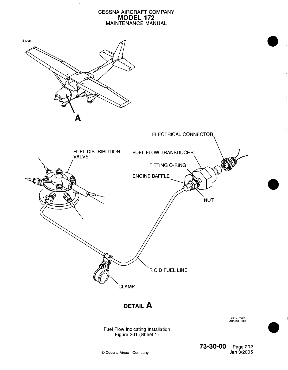
CESSNA
AIRCRAFT
COMPANY
MODEL
172
MAINTENANCE
MANUAL
B1795
A
ELECTRICAL
CONNE(
FUEL
DISTRIBUTION
VALVE
FUEL FLOW
TRA
FITTING
(
ENGINE
BAFFLE
RIGID FUEL
LINE
CLAMP
DETAIL
A
0510T1007
A0516T1009
Fuel Flow
Indicating Installation
Figure
201
(Sheet
1)
73-30-00
©
Cessna
Aircraft
Company
O-RING
NUT
Page
202
Jan
3/2005
CHAPTER
IGNITION
CESSNA
AIRCRAFT
COMPANY
MODEL
172
MAINTENANCE
MANUAL
LIST
OF
EFFECTIVE
PAGES
CHAPTER-SECTION-SUBJECT
74-Title
74-List
of
Effective Pages
74-Record
of
Temporary
Revisions
74-Contents
74-00-00
74-10-00
74-10-00
74-30-00
PAGE
Page
1
Pages
101-102
Pages 201-205
Pages
601-602
©
Cessna
Aircraft
Company
74
-
LIST
OF
EFFECTIVE
PAGES
Page
1
of
1
Jan
3/2005
DATE
Apr
7/2003
Apr
7/2003
Apr
7/2003
Apr
7/2003

Temporary
Revision
Number
RECORD
OF
TEMPORARY
REVISIONS
Page
Number
Issue
Date
By
Date
Removed
By
CESSNA
AIRCRAFT
COMPANY
MODEL
172
MAINTENANCE
MANUAL
CONTENTS
IGNITION
SYSTEM
-
GENERAL
............................
......................
S
cope......................................................................
Tools,
Equipment and
Materials
..............................................
Definition
...................................................................
IGNITION
SYSTEM
-
TROUBLESHOOTING
.......................................
General
....................................................................
IGNITION SYSTEM
-
MAINTENANCE
PRACTICES
................................
Description
and
Operation
...................................................
M
agneto
Removal/Installation................................................
Magneto-to-Engine
External
Timing
Adjustment................................
Magneto-to-EngineTiming
Check.............................................
IGNITION
SWITCH
-
INSPECTION/CHECK........................................
Description
.................................................................
Tools,
Equipment and
Materials
..............................................
ACS
Ignition
Switch
Inspection
and
Lubrication
................................
74-00-00
Page
1
74-00-00
Page
1
74-00-00
Page
1
74-00-00
Page
1
74-10-00
Page
101
74-10-00
Page
101
74-10-00
Page
201
74-10-00
Page
201
74-10-00
Page
201
74-10-00
Page
204
74-10-00
Page
204
74-30-00
Page
601
74-30-00
Page
601
74-30-00
Page
601
74-30-00
Page
601
CONTENTS
Page
1
of
1
Jan
3/2005
©
Cessna Aircraft
Company
CESSNA AIRCRAFT
COMPANY
MODEL
172
MAINTENANCE
MANUAL
IGNITION
SYSTEM
-
GENERAL
1.
Scope
A.
This
chapter covers
the
ignition
system
used
on the
10-360
L2A
engine.
2.
Tools,
Equipment
and
Materials
NOTE:
Refer
to
the
following
table
for
tools,
equipment
and
material
used
throughout
the
chapter.
NAME NUMBER
Luberex
Grease
Ignition
Switch
Parts
Kit
10-1206
A3770
MANUFACTURER
Cessna Aircraft
Company
Cessna
Parts
Distribution
Department
701,
CPD
25800
East
Pawnee
Wichita,
KS
67218-5590
Cessna
Aircraft
USE
To
lubricate
ignition
switch components.
To
rebuild
ignition switch.
3.
Definition
A.
This
chapter
contains
two
sections
on
the
ignition
system.
The
first
section
provides
a
troubleshooting
chart
to
aid
in
identifying
common problems which
may
occur
in
the
ignition system. The
second
section
contains
maintenance practices
for
the
ignition system.
74-00-00
Page
1
Apr
7/2003
©
Cessna
Aircraft
Company
CESSNA
AIRCRAFT
COMPANY
MODEL
172
MAINTENANCE
MANUAL
IGNITION
SYSTEM
-
TROUBLESHOOTING
1.
General
A.
The
following
chart
has been
provided
to
aid
maintenance
technicians
in
system
troubleshooting.
This
chart
should
be
used
in
conjunction
with
Chapter
71,
IO-360-L2A
-
Troubleshooting
to
provide
a
comprehensive
look
at
solutions
to
engine problems.
For
information
beyond
the
scope
of
this
chapter,
refer
to
applicable
engine
and
ignition
system
manuals
and
publications
listed
in
Introduction
-
List
of
Supplier
Catalogs.
TROUBLE PROBABLE
CAUSE
REMEDY
ENGINE
WILL
NOT
START
Defective ignition
switch.
Spark
plugs
defective,
improperly
gapped
or
fouled
by
moisture
or
deposits.
Defective
ignition
harness.
Magneto
"P"
lead
grounded.
Failure of
impulse
coupling.
Defective
magneto.
Broken
drive gear.
Check
switch continuity.
Replace
if
defective.
Clean, regap and
test
plugs.
Replace
if
defective.
If
no
defects
are
found
by
a
visual inspection, check with
a
harness
tester. Replace
defective
parts.
Check
continuity.
"P"
lead
should
not
be
grounded
in
the
ON
position,
but
should
be
grounded
on
OFF
position.
Repair
or
replace
"P"
lead.
Impulse
coupling
pawls
should
engage
at
cranking
speeds.
Listen
for
loud
clicks
as
impulse
couplings
operate.
Remove
magnetos
and
determine
cause.
Replace
defective
magnetos.
Refer
to
Ignition
System
-
Maintenance
Practices.
Remove
magneto
and
check
magneto
and
engine
gears.
Replace
defective
parts.
Make
sure
no
pieces
of
damaged
parts remain
in
engine,
or
engine
disassembly
will be
required.
ENGINE
WILL
NOT
IDLE
OR
RUN
PROPERLY.
Spark plugs
defective,
improperly
gapped
or
fouled
by
moisture
or
deposits.
Defective
ignition
harness.
©
Cessna Aircraft
Company
Clean,
regap
and
test
plugs.
Replace
if
defective.
If
no
defects
are
found
by
a
visual inspection,
check
with
a
harness
tester.
Replace
defective
parts.
74-10-00
Page
101
Apr 7/2003
CESSNA
AIRCRAFT
COMPANY
MODEL
172
MAINTENANCE
MANUAL
PROBABLE
CAUSE
REMEDY
TROUBLE
Defective
magneto.
Impulse
coupling
pawls
remain
engaged.
Spark
plugs
loose.
Refer
to
Ignition
System
-
Maintenance
Practices.
Listen
for
loud
clicks
as
impulse
coupling operates.
Remove
magneto
and
determine
cause.
Replace
defective
magneto.
Check
and
install properly.
©
Cessna
Aircraft Company
74-10-00
Page
102
Apr
7/2003
CESSNA
AIRCRAFT
COMPANY
MODEL
172
MAINTENANCE
MANUAL
IGNITION
SYSTEM
-
MAINTENANCE PRACTICES
1.
Description
and
Operation
A.
The engine
uses
two
Unison/Slick
4371
series,
impulse-coupled
magnetos
to
fire
two
spark
plugs
in
each
cylinder.
B.
For
complete
description,
operation,
troubleshooting,
maintenance,
overhaul and
lubrication
requirements
of
the
magnetos, refer
to
the Lycoming
Direct
Drive
Engine
Overhaul Manual, Lycoming
Operators
Manual,
Lycoming
Service
Instruction
1437
and
the
Unison
4300/6300
Series
Magneto
Maintenance
and
Overhaul
Manual.
C.
For
the
inspection
time
requirements of
the
magnetos,
refer
to
Chapter
5,
Inspection
Time
Limits.
For
the
inspection
procedures,
refer
to the
Unison
4300/6300 Series
Magneto Maintenance and
Overhaul
Manual.
2.
Magneto
Removal/Installation
NOTE:
The
removal
and
installation
for
each
magneto
is
typical.
A.
Remove
the Magneto (Refer
to
Figure
201).
(1)
Remove
the
engine
cowl.
Refer
to
Chapter
71,
Engine Cowl
-
Maintenance Practices.
WARNING:
MAKE
SURE
THAT
EACH
MAGNETO
P
LEAD
IS
GROUNDED.
WARNING:
BEFORE
YOU ROTATE
THE
PROPELLER
REMOVE
A
MINIMUM
OF
ONE
SPARK
PLUG
FROM
EACH
CYLINDER
TO
PREVENT
THE
START
OF THE
ENGINE.
(2)
Remove
the
screws
that attach
the
high
tension
outlet
cover
to
the
magneto.
(3)
Disengage
the high
tension
cover
from
the
magneto.
(4)
For
a
reference point
when
you install
the
magneto,
turn
the propeller
in
the
normal
direction
until
each
impulse
coupling
releases
near
Top
Dead
Center
(TDC)
on
the
number
one
cylinder
compression
stroke.
NOTE:
You
will
hear
a
click
sound
from
the
impulse
couplings
when
they
release.
(5)
The
crankshaft
position
can
be
found
by
the
marks
on
the
front
or
aft
face
of
the
starter
ring
gear
support.
Refer
to
the
Lycoming
Service
Instruction
1437
or
latest
revision
for
more
instructions.
(a)
When
you
use
the
marks
on
the
front
face
of
the
ring
gear,
they
must
be
aligned
with
the
small
hole
that
is
found
at
the
two
o'clock position
on
the
front
face of
the starter
housing.
(b)
When
you
use
the
marks
on
the aft
face
of
the
ring
gear,
they
must
be
aligned
with
the
engine
case
parting
line.
(6)
Turn
the
propeller
in
the
opposite direction
of
the
normal
propeller
operation
to
approximately
30
degrees
BTDC
(Before
Top
Dead
Center)
on
the
number
one
cylinder compression stroke.
(7)
Turn
the
propeller
in
the
normal
direction
to
25
degrees
BTDC
on
the
number
one
cylinder
compression stroke.
(8)
Disconnect the
P
lead
and
ground
wire
from
the
magneto.
(9)
Examine
the
magneto
angle
to
help
make
sure you put
it in
the
same position for
installation.
(10)
Remove the nuts,
washers
and clamps
that
attach
the
magneto
to
the
engine
housing.
(11)
Remove
the magneto
from
the
housing.
B.
Install
the
Magneto (Refer
to Figure
201).
(1)
Apply
a
small
quantity
of
silicone
grease
such
as
DC4
to
each
side
of
the
new
magneto
base
gasket,
which
will
help
future timing
adjustments.
(2)
Make
sure
the
magneto drive
gear
is
installed
correctly,
the
nut
torqued
correctly
and
the
cotter
pin is
installed. Refer
to
the
Lycoming
Service Instructions
1437
or
latest
revision
and
the Unison
4300/6300 Magneto
Maintenance
and
Overhaul
Manual
Instructions.
74-10-00
Page
201
©
Cessna
Aircraft
Company
Apr 7/2003
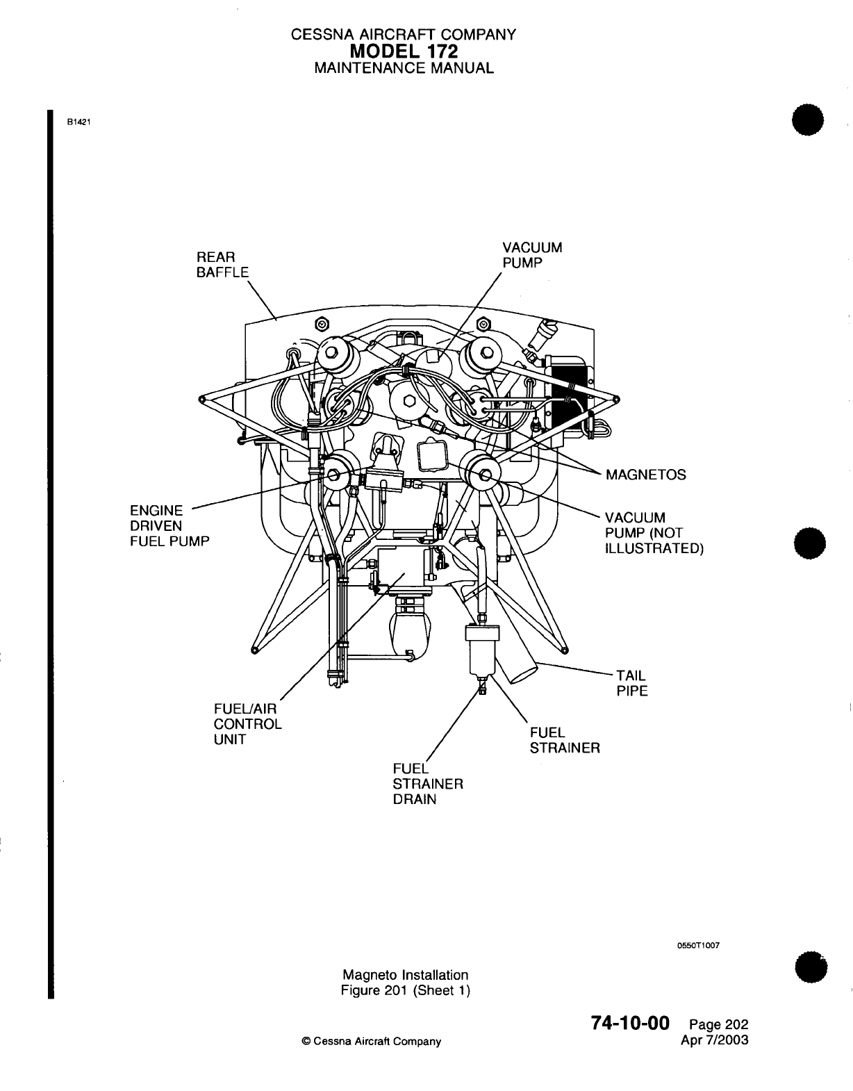
CESSNA
AIRCRAFT
COMPANY
MODEL
172
MAINTENANCE
MANUAL
B1421
VACUUM
PUMP
MAGNETOS
VACUUM
PUMP
(NOT
-USTRATED)
TAIL
PIPE
FUEL
STRAINER
DRAIN
0550T1007
Magneto
Installation
Figure
201
(Sheet
1)
74-10-00
©
Cessna
Aircraft Company
REAR
RAFFLE
ENGINE
DRIVEN
FUEL
PU
Page 202
Apr
7/2003
CESSNA
AIRCRAFT
COMPANY
MODEL
172
MAINTENANCE
MANUAL
CAUTION:
MAKE
SURE
YOU
REMOVE
THE
T-118
TIMING
PIN
IMMEDIATELY
AFTER
YOU
ATTACH
THE
MAGNETO
TO
THE
ACCESSORY
CASE
AND
BEFORE
THE
MAGNETO
OR
PROPELLER
IS
TURNED.
(3)
Insert
the
T-118
timing
pin
into
the
L
timing
hole
in
the
magneto
distributor
block.
(4)
Turn
the
magneto
rotor
in
the
opposite
of normal
direction
until
the
timing
pin
is
engaged
fully
into
the
distributor
gear.
(a) If
the
magneto rotor
does
not
move
freely
and
the
pin
will
not
go
into
the
hole
in
the
gear,
the pin
has
hit
the pointer
on
the
gear.
(b)
Pull
the
pin
out
far
enough
to
continue
to
turn
the
magneto
freely
in
the opposite direction
of
normal
movement
until
the
pointer
has
passed
the
pin,
then
insert
the
pin.
1
Turn
the
magneto
rotor until
the
pin
engages
the gear.
(5)
Do
a
check
of
the
crankshaft
to
make
sure
the
propeller
has
not
moved
and
is
still
set
in
position
with
the
number
one
cylinder
at
25
degrees
BTDC
(Before
Top
Dead
Center)
on
the
compression
stroke.
(6) If
the
propeller
as
been
turned
and
only one magneto
was
removed,
it
will
be
necessary
to
engage
the
impulse
coupling
on
the magneto
that
is
installed,
and
establish
the
crankshaft
position. Refer
to step 2.A.(4)
thru
2.A.(7)
before
you
continue.
(7)
With
the
number
one
cylinder
at
25
degrees
BTDC
on
the
compression stroke,
do
the
steps that
follow.
CAUTION:
MAKE
SURE
YOU
REMOVE
THE
T-118
TIIVIING
PIN
IMMEDIATELY
AFTER
YOU
ATTACH
THE
MAGNETO
TO
THE
ACCESSORY
CASE
AND
BEFORE
THE
MAGNETO
OR
PROPELLER
IS
TURNED.
(a)
Install
the magneto
with
the
new
base
gasket
and
the
T-118 timing
pin
in
position.
(b)
Engage
the magneto drive
gear
with
the engine
gear,
in a
position
that
will give
a
range
of
magneto
timing
adjustments
in
each
direction.
(c)
Hold
the magneto
in
position
against
the
accessory
case
and
install
the nuts,
flat
washers,
clamps
and new
lock
washers.
(d)
Finger
tighten
each
nut
by
hand.
(e)
Remove
the
timing
pin.
(8)
Before you
continue,
you must
adjust
the
magneto timing.
Refer
to
Magneto-to Engine External
Timing
Adjustment.
(9)
With
the
magneto
set
in
position,
first
tighten
each
nut
to
8
foot-pounds
(10
N.m).
(10)
Tighten
each
nut
from
one
side
to
another,
to
a
torque
of
17
foot-pounds
(23
N.m).
(11)
Connect
the
P
lead
to
the
magneto.
(12)
Attach
a
ground
wire
to
the
magneto.
(13)
Attach
the
high
tension
outlet
cover
to
the
magneto.
(14)
Tighten the
P
lead
nut
to
a
torque
of
13
to
15
inch-pounds
(17
to
20
N.m).
CAUTION:
MAKE
SURE
YOU REMOVE THE T-118
TIMING
PIN
BEFORE
THE
MAGNETO
OR
PROPELLER
IS
TURNED.
(15)
Install
the
spark
plugs.
(16)
Install
the
cowl.
Refer
to
Chapter
71,
Engine
Cowl
-
Maintenance
Practices.
(17)
Complete
a
engine
preflight
operational
check
of
the ignition
system.
Refer to
the
Pilot's
Operating
Handbook.
74-10-00
Page
203
©
Cessna Aircraft Company
Apr
7/2003
CESSNA AIRCRAFT
COMPANY
MODEL
172
MAINTENANCE
MANUAL
3.
Magneto-to-Engine
External
Timing Adjustment
A.
Adjust
the
Magneto-to-Engine
Timing
(Refer
to
Figure
201).
NOTE: The
Magneto-to-Engine
timing
can
be
adjusted
a
maximum
total
of
0.125
inch
(3.17
mm)
movement
from
the
original
factory
position,
or
between each
internal
timing
adjustment.
The
external
timing
movement
of
0.125
inch
(3.17
mm)
approximately
equals
5
degrees
of
internal
timing
change.
(1)
Before the
first
field
adjustment
of
external
timing,
the
magneto
and
accessory
case
must
be
indexed
as necessary
to monitor external
timing
adjustments.
(a)
The
magneto
must
be
removed
and
internal
timing
adjusted
in
accordance
with Unison
4300/6300 Series
Aircraft Magnetos
Maintenance
and
Overhaul Instructions
Form
L-1363B
or
latest
revision, when the
external timing
adjustments
collect
up
to
0.125
inch
(3.17
mm)
movement
change.
(2)
Make
sure
the
ignition
is
in
the
OFF
position.
(3)
Remove
the
engine cowl.
Refer
to
Chapter
71,
Engine
Cowl
-
Maintenance
Practices.
(4)
Remove
a
minimum
of
one
spark
plug
from
each
cylinder.
(5)
Make
sure
that cylinder
number
one
is
at
25
degrees
BTDC
(Before
Top
Dead
Center)
on
the
compression
stroke.
(6)
Connect
a
standard
aircraft
magneto timing light between
a
acceptable
engine
ground
and
the
P
lead
terminal
of
the
magneto.
NOTE:
Most
standard
aircraft
magneto
timing lights
show
open
points
with
a
Light
On
condition
and/or
a
signal
that
you can
hear.
(7)
Loosen
the mount
clamps
that
attach
the
magneto
to
the
accessory
case
so
that
the
magneto
will
turn
on
the
accessory
case.
(8)
Turn
the
ignition
switch
to the
BOTH
position.
(a)
Look
at
the
magneto
from
the
aft side of the
engine.
1
If
the timing light
is
luminated,
turn
the
magneto frame
clockwise
until the
timing
light
shuts
off.
2
Turn
the
magneto
frame
counter-clockwise
until
the
timing
light
comes
on,
which
shows that
the
contact
breaker points are
open.
CAUTION
:
DO
NOT
TORQUE
THE
NUTS
MORE
THAN
17
FOOT-POUNDS
(23 N.m.)
OR
THE
MOUNTING
FLANGE
CAN
CRACK.
(9)
With
the
magneto set
in
position,
first
tighten
each
nut
to
8
foot-pounds
(10
N.m).
(10)
Tighten
each
nut from
one side
to
another,
to
a
torque
of
17
foot-pounds
(23
N.m).
(11)
Complete
a
check
of
the
magneto
timing
to
make
sure
it
has
not
changed.
Refer
to
Magneto-
to-Engine Timing
Check.
4.
Magneto-to-EngineTiming
Check
A.
Complete
a
Check
of
the
Magneto-to-Engine
Timing
(Refer to
Figure
201).
(1)
Make
sure
the
ignition
is
in
the
OFF
position.
(2)
Remove
the
engine cowl.
Refer
to
Chapter
71,
Engine
Cowl
-
Maintenance
Practices.
(3)
Remove
a
minimum
of one
spark
plug
from
each
cylinder.
(4)
Connect
a
standard
aircraft
magneto timing light between
an
acceptable
engine
ground
and
the
P
lead
terminal
of
the magneto.
NOTE:
Most
standard aircraft
magneto timing
light
indicate
open
points
with
a
Light
On
condition
and/or
an
signal that
you can
hear.
(5)
Turn
the
ignition
switch
to the
BOTH
position.
74-10-00
Page
204
©
Cessna
Aircraft
Company
Apr
7/2003
CESSNA
AIRCRAFT
COMPANY
MODEL
172
MAINTENANCE
MANUAL
(6)
Turn the
propeller
in
the
normal
direction
of
movement
until
each
impulse
coupling
releases
as
the
number
one
cylinder
moves
near
TDC
(Top
Dead
Center)
on
the
compression stroke.
NOTE:
You
will
hear
a
click
sound
from
the
impulse
couplings
when
they
release.
(7)
Turn
the
propeller
in
the
opposite direction
of
normal
movement
to
approximately
30
degrees
BTDC
(Before
Top
Dead
Center)
on
the
number
one
cylinder
compression
stroke.
(8)
Slowly
turn
the
propeller
in
the
normal
direction
of
movement
until the
timing
light
comes
on.
(9)
Examine
the
crankshaft
to make sure
it is in
the
correct position.
NOTE:
The
timing
light
must come
on
at
25
degrees
BTDC
with
the
number
one
cylinder
on
the
compression
stroke.
(10)
If
the
crankshaft
is
not
in
the
correct
position
you
will have
to
make
an
adjustment.
Refer
to
Magneto-to-Engine
External Timing
Adjustment.
(11)
Turn
the ignition
switch
to
the
OFF
position.
(12)
Install
the
spark
plugs.
(13)
Install
the
ignition
leads
on the
spark
plugs.
(14)
Install
the
cowl. Refer
to
Chapter
71,
Engine
cowl
-
Maintenance
Practices.
(15)
Complete
a
engine
preflight
operational
check
of
the ignition
system.
Refer
to the
pilot's
operating
handbook.
74-10-00
Page
205
©
Cessna
Aircraft
Company
Apr
7/2003
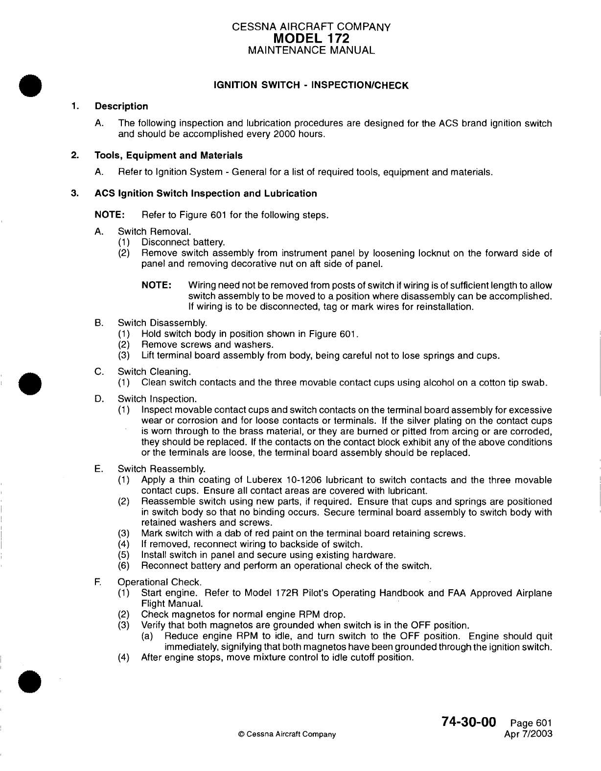
CESSNA
AIRCRAFT
COMPANY
MODEL
172
MAINTENANCE
MANUAL
IGNITION
SWITCH
-
INSPECTION/CHECK
1.
Description
A.
The
following
inspection
and
lubrication procedures
are
designed
for
the
ACS
brand
ignition
switch
and
should
be
accomplished
every
2000
hours.
2.
Tools,
Equipment
and
Materials
A.
Refer
to
Ignition
System
-
General
for
a
list
of
required
tools,
equipment
and
materials.
3.
ACS
Ignition
Switch
Inspection
and
Lubrication
NOTE:
Refer
to
Figure
601
for
the
following
steps.
A.
Switch Removal.
(1)
Disconnect
battery.
(2)
Remove
switch
assembly
from
instrument
panel
by
loosening
locknut
on
the
forward
side
of
panel
and removing
decorative
nut on
aft
side
of
panel.
NOTE:
Wiring
need
not
be
removed
from
posts
of
switch
if
wiring
is of
sufficient
length
to
allow
switch
assembly
to
be
moved
to
a
position
where
disassembly
can
be
accomplished.
If
wiring
is
to
be
disconnected,
tag
or
mark wires
for
reinstallation.
B.
Switch
Disassembly.
(1)
Hold
switch
body
in
position
shown
in
Figure
601.
(2)
Remove
screws
and
washers.
(3)
Lift
terminal
board
assembly
from
body,
being careful
not
to
lose
springs
and
cups.
C.
Switch
Cleaning.
(1)
Clean
switch
contacts
and
the three
movable
contact
cups
using
alcohol
on
a
cotton
tip
swab.
D.
Switch
Inspection.
(1)
Inspect
movable
contact
cups
and
switch
contacts
on
the terminal
board
assembly
for
excessive
wear
or corrosion
and
for
loose
contacts
or
terminals.
If
the
silver
plating
on
the
contact cups
is
worn
through
to
the brass material,
or
they
are
burned
or
pitted
from
arcing
or
are
corroded,
they
should
be
replaced.
If
the
contacts
on
the
contact
block
exhibit
any
of
the above
conditions
or the
terminals
are
loose,
the
terminal
board
assembly
should
be
replaced.
E.
Switch
Reassembly.
(1)
Apply
a
thin
coating
of
Luberex
10-1206
lubricant
to
switch
contacts
and
the
three
movable
contact
cups.
Ensure
all
contact
areas
are
covered
with
lubricant.
(2)
Reassemble
switch
using new
parts,
if
required.
Ensure
that
cups
and
springs
are
positioned
in
switch
body
so
that
no
binding
occurs.
Secure
terminal
board
assembly
to
switch
body
with
retained
washers
and
screws.
(3)
Mark
switch
with
a
dab
of red
paint
on the
terminal
board
retaining
screws.
(4) If
removed,
reconnect
wiring to backside
of
switch.
(5)
Install
switch
in
panel
and
secure
using
existing
hardware.
(6)
Reconnect battery
and
perform
an
operational
check
of
the
switch.
F.
Operational
Check.
(1)
Start
engine.
Refer
to
Model
172R
Pilot's
Operating
Handbook
and
FAA
Approved Airplane
Flight
Manual.
(2)
Check
magnetos
for
normal engine
RPM
drop.
(3)
Verify
that
both
magnetos
are
grounded
when
switch
is
in
the
OFF position.
(a)
Reduce
engine
RPM
to
idle,
and
turn
switch
to
the
OFF position.
Engine
should quit
immediately,
signifying that
both
magnetos
have
been
grounded
through
the ignition
switch.
(4)
After
engine stops,
move
mixture control
to
idle
cutoff
position.
74-30-00
Page
601
©
Cessna
Aircraft Company
Apr
7/2003
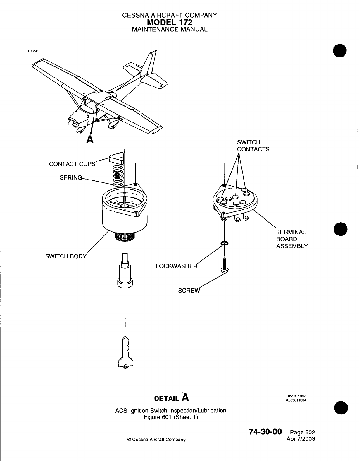
CESSNA
AIRCRAFT
COMPANY
MODEL
172
MAINTENANCE
MANUAL
B1796
SWITCH
CONTACTS
TERMINAL
BOARD
ASSEMBLY
SWITCH
LOCKWASHE
SCREW
DETAIL
A
ACS
Ignition
Switch
Inspection/Lubrication
Figure
601
(Sheet
1)
74-30-00
©
Cessna
Aircraft
Company
0510T1007
A0558T1004
Page
602
Apr
7/2003
CHAPTER
ENGINE
CONTROLS
CESSNA
AIRCRAFT
COMPANY
MODEL
172
MAINTENANCE
MANUAL
LIST
OF
EFFECTIVE PAGES
CHAPTER-SECTION-SUBJECT
76-Title
76-List
of Effective
Pages
76-Record
of
Temporary
Revisions
76-Table
of
Contents
76-00-00
76-10-00
76-11-00
PAGE
Page
1
Pages
201-203
Pages
201-203
©
Cessna
Aircraft
Company 76
-
LIST
OF
EFFECTIVE
PAGES
Page
1
of
1
Jan 2/2006
DATE
Apr
7/2003
Jan
2/2006
Jan
2/2006

Temporary
Revision
Number
RECORD
OF
TEMPORARY
REVISIONS
Page
Number Issue
Date
By
Date
Removed
By
CESSNA
AIRCRAFT
COMPANY
MODEL
172
MAINTENANCE
MANUAL
CONTENTS
ENGINE
CONTROLS
-
GENERAL
................................................
Scope.
.....................................................................
Definition
...................................................................
THROTTLE CONTROL
-
MAINTENANCE
PRACTICES
.............................
General
...................................................................
Throttle
Control
Removal/Installation.........................................
Throttle
Control
Adjustment/Test..............................................
Throttle
Control
Inspection/Check
............................................
FUEL
MIXTURE
CONTROL
-
MAINTENANCE
PRACTICES.........................
General
....................................................................
Fuel
Mixture
Control
Removal/Installation
.....................................
Fuel
Mixture
Control Adjustment/Test
.........................................
Fuel
Mixture
Control
Inspection/Check
........................................
76-00-00
Page
1
76-00-00
Page
1
76-00-00
Page
1
76-10-00
Page
201
76-10-00
Page
201
76-10-00
Page
201
76-10-00
Page
201
76-10-00
Page
203
76-11-00
Page
201
76-11-00
Page
201
76-11-00
Page
201
76-11-00
Page
201
76-11-00
Page
203
76
-
CONTENTS
Page
1
of
1
Jan
2/2006
©
Cessna
Aircraft
Company
CESSNA
AIRCRAFT
COMPANY
MODEL
172
MAINTENANCE
MANUAL
ENGINE
CONTROLS
-
GENERAL
1.
Scope
A.
This
chapter
describes those
controls
used to
regulate
engine
power.
2.
Definition
A.
This
Chapter
is
divided
into
sections
to
aid
maintenance
technicians
in
locating
information.
Consulting
the
Table
of
Contents
will
further
assist
in
locating
a
particular
subject.
A
brief
description
of
the
sections follows:
(1)
The
section
on
throttle control
describes
the throttle
handle,
cable
and
linkage.
(2)
The
section
on
fuel
mixture
control
describes
the
mixture
handle,
cable
and
linkage.
(3)
Both
sections
include
removal/installation,
rigging
and
inspection
requirements.
76-00-00
©
Cessna
Aircraft Company
Page
1
Apr
7/2003
CESSNA
AIRCRAFT
COMPANY
MODEL
172
MAINTENANCE
MANUAL
THROTTLE CONTROL
-
MAINTENANCE
PRACTICES
1.
General
A.
The
throttle control
is
the
push-pull
type
that
incorporates
a
knurled
friction
knob, which prevents
vibration induced "creeping" of
the
control.
The
ball
bearing-type
rod
end
on
the
throttle
is
secured
to
the
engine
with
a
predrilled
AN
bolt,
a
castellated
nut
and
a
cotter
pin.
NOTE:
Steel
AN
bolts
with
an
undrilled
shank
are
identified
with an
"A"
suffix
(AN3-6A).
A
steel
bolt
of the same
size,
with
the
shank drilled
for
castellated
nut
and
cotter
pin
is
identified
as AN3-6.
Aluminum
AN
bolts
shall not
be
used
in
this
application.
B.
When
adjusting
the
throttle
control,
it is
important
to
check
that throttle
control slides
smoothly
throughout
its
full
range
of
travel, that
it
locks
securely
with
the
friction
lock
and
the
throttle
arm
operates
through
its
full
arc
of
travel.
Do
not
lubricate
throttle control.
If
excessive
binding
is
noticed,
replace
throttle control.
C.
Whenever
engine
controls
are
being
disconnected,
pay
particular
attention
to
the
exact position,
size
and
number
of
attaching parts
for
re-connecting
controls.
2.
Throttle Control
Removal/Installation
A.
Remove
Throttle
Control
(Refer
to
Figure
201).
(1)
Remove
engine cowling.
Refer
to
Chapter
71,
Cowling
-
Maintenance
Practices.
(2)
Remove
cotter
pin,
castellated
nut,
bolt
and
washers
securing throttle
control
rod
end to
throttle
body
arm.
(3)
Remove
clamp
securing
throttle control
to
engine
mount.
(4)
Remove
throttle
cable retaining
nut
and
washer
from
forward
side
of
firewall.
(5)
Inside
the
cockpit/cabin
area,
remove
throttle
cable
retaining
nut
and
washer
from
forward
side
of
instrument
panel.
(6)
Carefully
pull
throttle control
through firewall
and
instrument
panel,
and
remove
from
airplane.
B.
Install
Throttle
Control
(Refer
to
Figure
201).
NOTE:
When
installing throttle
control,
ensure
that
control
is
routed
exactly
as
previously
installed.
Ensure
that
no
binding
or
preloading occurs
from
a
too
small
bend
radius.
(1)
Inside
the
cockpit/cabin
area,
carefully
route throttle
control
rod
end
through
instrument
panel
and
then
place
washer
and retaining
nut
over
rod
end.
(2)
Route
throttle control
rod end
through
firewall
and
position
throttle
control
in
instrument
panel.
(3)
Secure
throttle
control
in
instrument panel
by
tightening
retaining
nut
against
washer
and
instrument
panel.
NOTE:
To
prevent damage
to
the
instrument
panel finish
and
markings, ensure
the
control
housing does
not
rotate
against
the instrument
panel
during
installation.
(4) In
the
engine compartment,
place
washer
and
retaining
nut
over
throttle
control
rod
end
and
secure
against
firewall.
(5)
Attach
throttle
control
rod end
to
throttle body
with
bolt,
washers,
castellated
nut
and
cotter
pin.
(6)
Secure
throttle
control
to
engine
mount
with
clamp.
(7)
Adjust throttle
control as
required.
Refer
to
Throttle
Control Adjustment/Test.
(8)
Install engine
cowling.
Refer
to
Chapter
71,
Cowling
-
Maintenance Practices.
3.
Throttle Control
Adjustment/Test
A.
Check
Throttle
Control
(Refer
to
Figure
201).
(1)
Pull
throttle control
knob
full
out and
check
that
idle
stop
on
throttle
body
is
contacted.
(2)
Push
throttle control
knob
full
in
and
check
that
full power
stop on
throttle
body
is
contacted.
(3)
Do
a
check
to make sure
that
the
throttle
has
no
less than
0.12-inch
(3.18
mm)
and
no
more
than
0.25-inch
(6.35
mm)
cushion
at
each
stop.
76-10-00
Page
201
©
Cessna
Aircraft
Company
Jan
2/2006
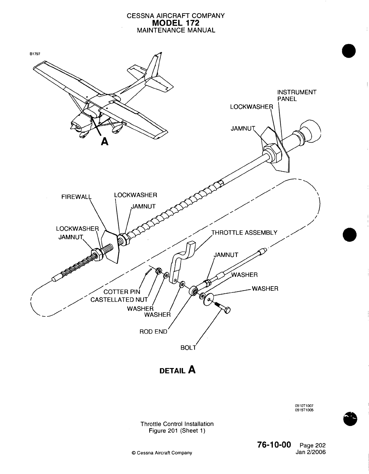
CESSNA
AIRCRAFT
COMPANY
MODEL
172
MAINTENANCE
MANUAL
INSTRUMENT
PANEL
LOCKWASHEI
JAMNUT
LOCKWASHER
THROTTLE
ASSEMBLY
CASTELLATED
WA
DETAIL
A
0510T1007
0515T1005
Throttle
Control
Installation
Figure
201
(Sheet
1)
©
Cessna
Aircraft
Company
76-10-00
Page
202
Jan
2/2006
FIREWAL
/
CESSNA
AIRCRAFT
COMPANY
MODEL
172
MAINTENANCE
MANUAL
(4)
Work
throttle
control
in
and out
several times
to
check
for
binding.
B.
Adjust
Throttle
Control
(Refer
to
Figure
201).
(1)
Disconnect throttle
control
rod
end
from
the throttle
body.
(2)
Loosen
jam
nut
and
adjust
throttle
control
rod
end to
obtain
desired
setting.
(3)
Tighten
jam
nut.
(4)
Connect
throttle
control
rod
end
to
throttle
body.
4.
Throttle
Control Inspection/Check
A.
Inspection
of
Throttle
Control.
(1)
The
throttle control
attachment
to
throttle
body should
be
inspected
in
accordance
with time
limits
established
in
Chapter
5,
Inspection
Time
Limits.
Do
a
check
of
the
bolt,
castellated
nut,
cotter
pin,
rod
end,
and
rod
end jam
nut
for
security
and
condition.
(2)
Do
a
check
of
the
rod
end
witness
hole
for
proper
rod
end
engagement
with
the
throttle
control.
(3)
Do
a
check to
make
sure
that
the
throttle control
slides
smoothly
throughout
its
full
range
of
travel,
that
it
locks
securely
with
the
friction lock,
and that
the
throttle
arm
operates
through
its
full
arc
of
travel.
76-10-00
Page
203
©
Cessna Aircraft
Company
Jan
2/2006
CESSNA
AIRCRAFT
COMPANY
MODEL
172
MAINTENANCE
MANUAL
FUEL
MIXTURE
CONTROL
-
MAINTENANCE
PRACTICES
1.
General
A.
The mixture
control
is
the
push-pull type
that
incorporates
a
threaded
vernier mechanism
for
fine
adjustment.
The
ball
bearing
rod
end
on
the
mixture
control
is
secured
to the
engine
with
a
predrilled
AN
bolt,
a
castellated
nut
and
a
cotter
pin.
NOTE:
Steel
AN
bolts with
an
undrilled
shank
are
identified
with
an
'A'
suffix
(AN3-6A).
A
steel
bolt
of
the same
size,
with
the
shank
drilled
for
castellated
nut and
cotter
pin
is
identified
as
AN3-6.
Aluminum
bolts
and
undrilled
bolts
must
not be used
in
this
application.
B.
When
adjusting
the
fuel
mixture
control,
it
is
important
to
check
that
fuel mixture
control
slides
smoothly
throughout
its
full
range of
travel, that
it
adjusts
through
its
full
vernier
range
and the
mixture
arm
operates
through
its
full
arc
of
travel.
Do
not
lubricate
fuel
mixture control.
If
excessive
binding
is
noticed, replace
fuel
mixture control.
C.
Whenever
engine
controls
are
being
disconnected,
pay
particular
attention
to
the
exact
position,
size
and number
of attaching
parts
as
noted
when
connecting
controls.
2.
Fuel
Mixture
Control Removal/Installation
A.
Remove
Fuel
Mixture
Control
(Refer
to
Figure
201).
(1)
Remove
engine
cowling.
Refer
to
Chapter
71,
Cowling
-
Removal/Installation.
(2)
Remove
cotter
pin, nut,
bolt
and
washers securing mixture control
rod
end
to
throttle
body
mixture
arm.
(3)
Remove
clamp
securing
fuel
mixture
control
to
mixture
control
bracket.
(4)
Remove
fuel
mixture
control
retaining
nut
and
washer
from
forward
side
of
firewall.
(5) In
the
cockpit/cabin
area,
remove
mixture
control
retaining
nut and
washer
from
forward
side
of
instrument
panel.
(6)
Carefully
pull
mixture
control
through firewall
and
instrument
panel,
and
remove
from
airplane.
B.
Install
Fuel
Mixture Control
(Refer
to
Figure
201).
NOTE:
When
installing
mixture control
ensure
that
control
is
routed
exactly
as
previously
installed.
Ensure
that
no
binding
or
preloading
occurs
from
a
too small
bend
radius.
(1) In
the
cabin/cockpit
area,
carefully
route
fuel
mixture
control
through
instrument
panel,
and
then
place
washer
and retaining
nut
over
fuel
mixture control
rod
end.
(2)
Route
fuel
mixture
control through firewall.
(3)
Secure
fuel
mixture control
in
instrument
panel
by
tightening
retaining
nut
against washer
and
instrument panel.
NOTE:
To
prevent
damage
to
the
instrument panel finish
and
markings, ensure the control
housing
does
not rotate
against
the
instrument
panel during
installation.
(4) In
the
engine
compartment,
place
washer
and retaining nut
over
fuel
mixture
control
rod
end
and
secure
against
firewall.
(5)
Attach
mixture
control
rod
end
to
throttle
body
mixture
arm
with
bolt,
washers,
nut
and
cotter
pin.
(6)
Secure fuel
mixture
control
to
mixture
control bracket
with
clamp.
(7)
Install
Engine
Cowling.
Refer
to
Chapter
71,
Cowling
-
Removal/Installation.
3.
Fuel
Mixture Control Adjustment/Test
A.
Check
Fuel
Mixture
Control.
(1)
Push
fuel
mixture
control
full
in
and verify
that
mixture
arm on
throttle
body
is
fully
open
(rich).
(2)
Pull
fuel
mixture control full
out
and
verify
that
mixture
arm on
throttle
body
is
fully closed
(lean).
(3)
Do
a
check
to
make
sure
that
the
fuel mixture
control
has
no
less than
0.12-inch
(3.18
mm) and
no more
than
0.25-inch
(6.35
mm)
cushion
at
each
stop.
(4)
Work
fuel
mixture
control
in
and
out
several
times to
check for
binding.
76-11-00
Page
201
©
Cessna
Aircraft
Company
Jan 2/2006
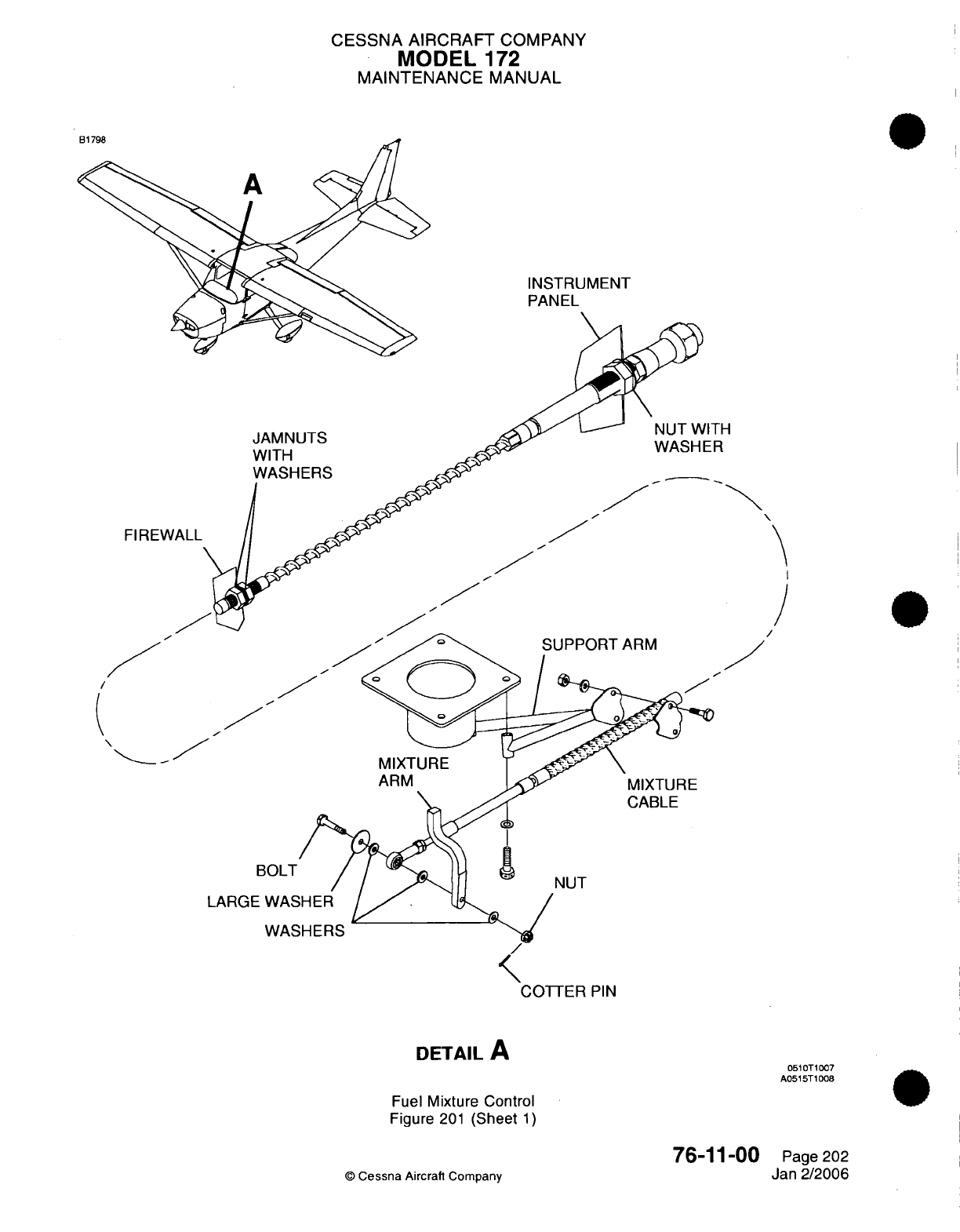
CESSNA AIRCRAFT
COMPANY
MODEL
172
MAINTENANCE
MANUAL
INSTRUMENT
PANEL
SUPPORT
ARM
/
MIXTURE
CABLE
BOLT
LARGE
WA
WA
DETAIL
A
Fuel
Mixture
Control
Figure
201
(Sheet
1)
76-11-00
©
Cessna
Aircraft Company
JAMNUTS
WITH
WASHERS
FIREW
ITH
ER
NUT
PIN
0510T1007
A0515T1008
Page
202
Jan
2/2006
CESSNA
AIRCRAFT
COMPANY
MODEL
172
MAINTENANCE
MANUAL
B.
Adjust
Fuel
Mixture
Control.
(1)
Disconnect fuel
mixture
control
rod end
from
throttle
body.
(2)
Loosen
jam
nut
and
adjust
rod
end
to
obtain desired setting.
The
witness
hole
in
the
rod
end
must
be
covered
with
the mixture
cable
threads.
(3)
Tighten
jam
nut.
(4)
Connect
rod
end
to
throttle
body.
If
necessary,
you
can
reposition
the
mixture
control
housing
in
the
mixture
control
bracket
clamp.
4.
Fuel
Mixture
Control
Inspection/Check
A.
Inspect
Fuel
Mixture Control.
(1)
The mixture control
attachment
to
the
throttle
body
should
be
inspected
in
accordance
with
time
limits
established
in
Chapter
5,
Inspection
Time
Limits. Check
bolt,
castellated
nut,
cotter
pin
and
rod
end
for
security
and
condition. The
witness
hole
in
the
rod
end
must
be
covered
with
the
mixture
cable threads.
Check
that
fuel
mixture
control
slides smoothly
throughout
its
full
range
of
travel,
that
it
adjusts
through
its full
vernier
range
and
the
mixture
arm
operates
through
its
full
arc of
travel.
76-11-00
Page
203
©
Cessna
Aircraft Company
Jan
2/2006
I
I
CHAPTER
ENGINE
INDICATING
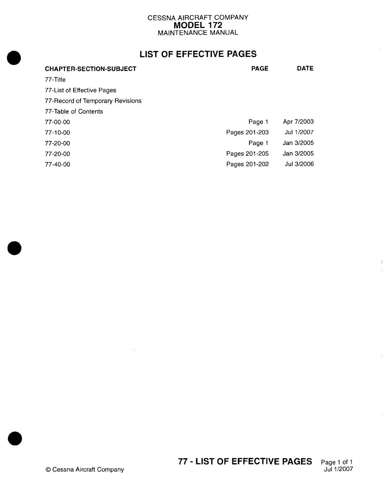
CESSNA
AIRCRAFT
COMPANY
MODEL
172
MAINTENANCE
MANUAL
LIST
OF
EFFECTIVE
PAGES
PAGE
CHAPTER-SECTION-SUBJ
ECT
77-Title
77-List
of
Effective Pages
77-Record
of
Temporary
Revisions
77-Table
of
Contents
77-00-00
77-1
0-00
77-20-00
77-20-00
77-40-00
Page
1
Pages
201-203
Page
1
Pages
201
-205
Pages
201
-202
©
Cessna
Aircraft Company
77
-
LIST
OF
EFFECTIVE
PAGES
Page
1
of
1
Jul
1/2007
DATE
Apr
7/2003
Jul
1/2007
Jan
3/2005
Jan 3/2005
Jul
3/2006

Temporary
Revision
Number
RECORD OF
TEMPORARY
REVISIONS
Page
Number
Issue
Date
By
Date
Removed
By
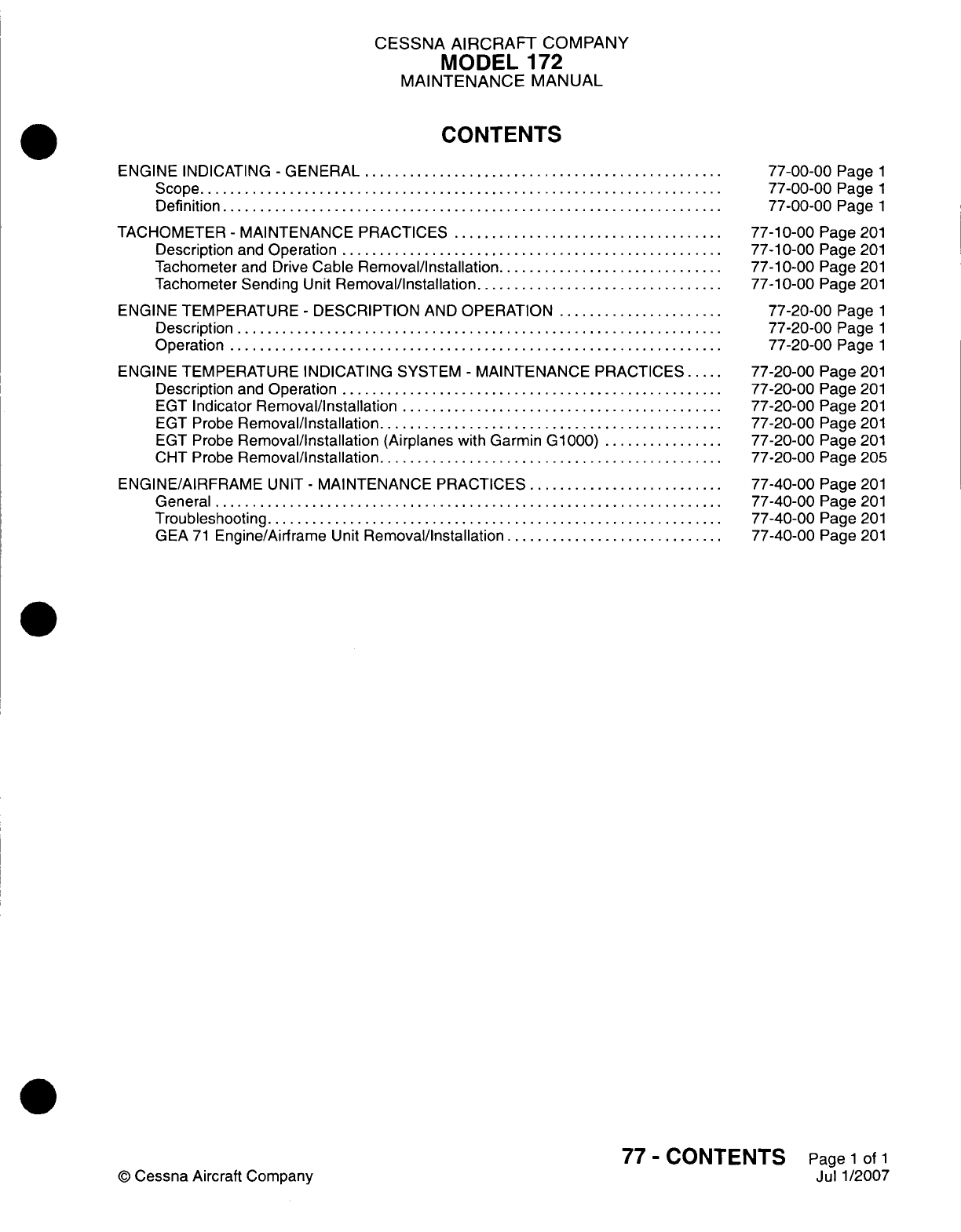
CESSNA
AIRCRAFT
COMPANY
MODEL
172
MAINTENANCE
MANUAL
CONTENTS
ENGINE
INDICATING
-
GENERAL.........................
Scope....................................
Definition
..................................
TACHOMETER
-
MAINTENANCE
PRACTICES...................
Description
and
Operation
..........................
Tachometer
and
Drive
Cable
Removal/Installation................
Tachometer
Sending
Unit
Removal/Installation
.................
ENGINE TEMPERATURE
-
DESCRIPTION
AND
OPERATION............
Description
.................................
Operation..................................
ENGINE TEMPERATURE
INDICATING SYSTEM
-
MAINTENANCE PRACTICES.
Description
and
Operation
..........................
EGT
Indicator
Removal/Installation
......................
EGT Probe
Removal/Installation........................
EGT Probe
Removal/installation
(Airplanes with
Garmin
G1000).........
CHT
Probe
Removal/Installation........................
ENGINE/AIRFRAME
UNIT
-
MAINTENANCE
PRACTICES..............
General...................................
Troubleshooting
...............................
GEA
71
Engine/Airframe
Unit
Removal/installation
...............
77-00-00
Page
1
77-00-00
Page
1
77-00-00
Page
1
77-1
0-00
Page
201
77-1
0-00
Page
201
77-1
0-00
Page
201
77-1
0-00
Page
201
77-20-00
Page
1
77-20-00
Page
1
77-20-00
Page
1
77-20-00
Page
201
77-20-00
Page
201
77-20-00
Page
201
77-20-00
Page
201
77-20-00
Page
201
77-20-00
Page
205
77-40-00
Page
201
77-40-00
Page
201
77-40-00
Page
201
77-40-00
Page
201
77
-
CONTENTS
Page
1
of
1
Jul 1/2007
©
Cessna
Aircraft
Company
CESSNA
AIRCRAFT
COMPANY
MODEL
172
MAINTENANCE
MANUAL
ENGINE INDICATING
-
GENERAL
1.
Scope
A.
This
chapter
describes
those
components
used
to
measure
and
indicate
engine
output.
2.
Definition
A.
This
chapter
is
divided
into
sections
to
aid
maintenance
technicians
in
locating
information.
Consulting
the
Table
of
Contents
will
further
assist
in
locating
a
particular subject.
A
brief
description
of
the
sections
follows:
(1)
The
section
on
tachometer describes
the
instrument
used
to
measure
engine
RPM.
(2)
The
section
on
exhaust gas temperature
describes
the
system
used
to
monitor
and
measure
engine
temperature.
77-00-00
Page
1
©
Cessna
Aircraft Company
Apr
7/2003
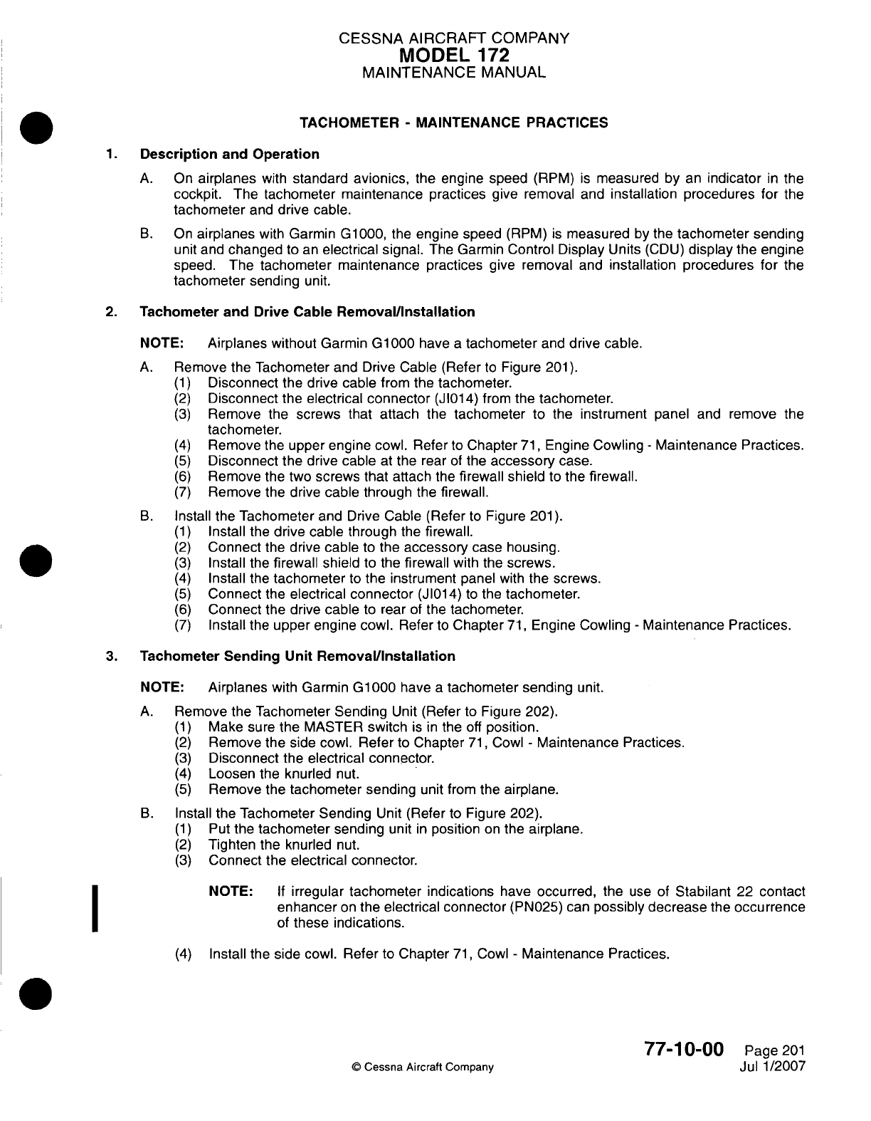
CESSNA
AIRCRAFT
COMPANY
MODEL
172
MAINTENANCE
MANUAL
TACHOMETER
-
MAINTENANCE PRACTICES
1.Description
and
Operation
A.
On
airplanes
with
standard
avionics,
the
engine
speed
(RPM)
is
measured
by
an
indicator
in
the
cockpit.
The
tachometer maintenance
practices
give removal
and
installation
procedures
for
the
tachometer
and
drive
cable.
B.
On
airplanes
with
Garmin
G1000,
the
engine
speed
(RPM)
is
measured
by
the
tachometer
sending
unit
and
changed
to
an
electrical
signal.
The
Garmin
Control Display
Units
(CDU)
display
the
engine
speed.
The
tachometer maintenance
practices
give removal
and
installation procedures for the
tachometer
sending
unit.
2.
Tachometer and
Drive Cable
Removal/installation
NOTE:
Airplanes without
Garmin
G1000
have
a
tachometer
and
drive cable.
A.
Remove
the
Tachometer
and
Drive
Cable
(Refer
to
Figure
201).
(1)
Disconnect
the drive
cable
from
the
tachometer.
(2)
Disconnect
the
electrical
connector
(J1014)
from
the
tachometer.
(3)
Remove
the
screws
that
attach
the
tachometer
to the
instrument
panel
and
remove
the
tachometer.
(4)
Remove
the upper
engine cowl.
Refer
to
Chapter
71,
Engine
Cowling
-
Maintenance Practices.
(5)
Disconnect the
drive cable
at
the
rear
of
the
accessory
case.
(6)
Remove
the
two
screws
that attach
the
firewall shield
to
the
firewall.
(7)
Remove
the
drive
cable
through
the
firewall.
B.
Install
the
Tachometer
and
Drive
Cable
(Refer
to
Figure
201).
(1)
Install
the
drive
cable
through
the
firewall.
(2)
Connect
the
drive
cable
to
the
accessory
case
housing.
(3)
Install
the
firewall
shield
to
the
firewall
with
the
screws.
(4)
Install
the
tachometer
to
the
instrument
panel
with
the
screws.
(5)
Connect
the
electrical
connector
(JI014)
to
the
tachometer.
(6)
Connect
the
drive
cable
to rear
of
the
tachometer.
(7)
Install
the
upper engine cowl.
Refer
to
Chapter
71,
Engine
Cowling
-
Maintenance
Practices.
3.
Tachometer
Sending
Unit
Remova~l/nstallation
NOTE:
Airplanes
with
Garmin
G1000
have
a
tachometer
sending
unit.
A.
Remove the
Tachometer
Sending
Unit
(Refer
to
Figure
202).
(1)
Make sure
the MASTER
switch
is in
the
off
position.
(2)
Remove the
side
cowl.
Refer
to
Chapter
71,
Cowl
-
Maintenance
Practices.
(3)
Disconnect
the
electrical connector.
(4)
Loosen
the
knurled
nut.
(5)
Remove
the
tachometer
sending
unit from
the
airplane.
B.
Install
the
Tachometer
Sending
Unit
(Refer
to
Figure 202).
(1)
Put the
tachometer
sending
unit
in
position
on the
airplane.
(2)
Tighten
the knurled
nut.
(3)
Connect the
electrical connector.
NOTE:
If
irregular
tachometer
indications
have
occurred,
the
use
of
Stabilant
22
contact
enhancer
on
the
electrical
connector
(PN025)
can
possibly
decrease
the
occurrence
of
these
indications.
(4)
Install
the
side
cowl.
Refer
to
Chapter
71,
Cowl
-
Maintenance
Practices.
77-1
0-00
Page
201
©
Cessna
Aircraft
Company
Jul
1/2007
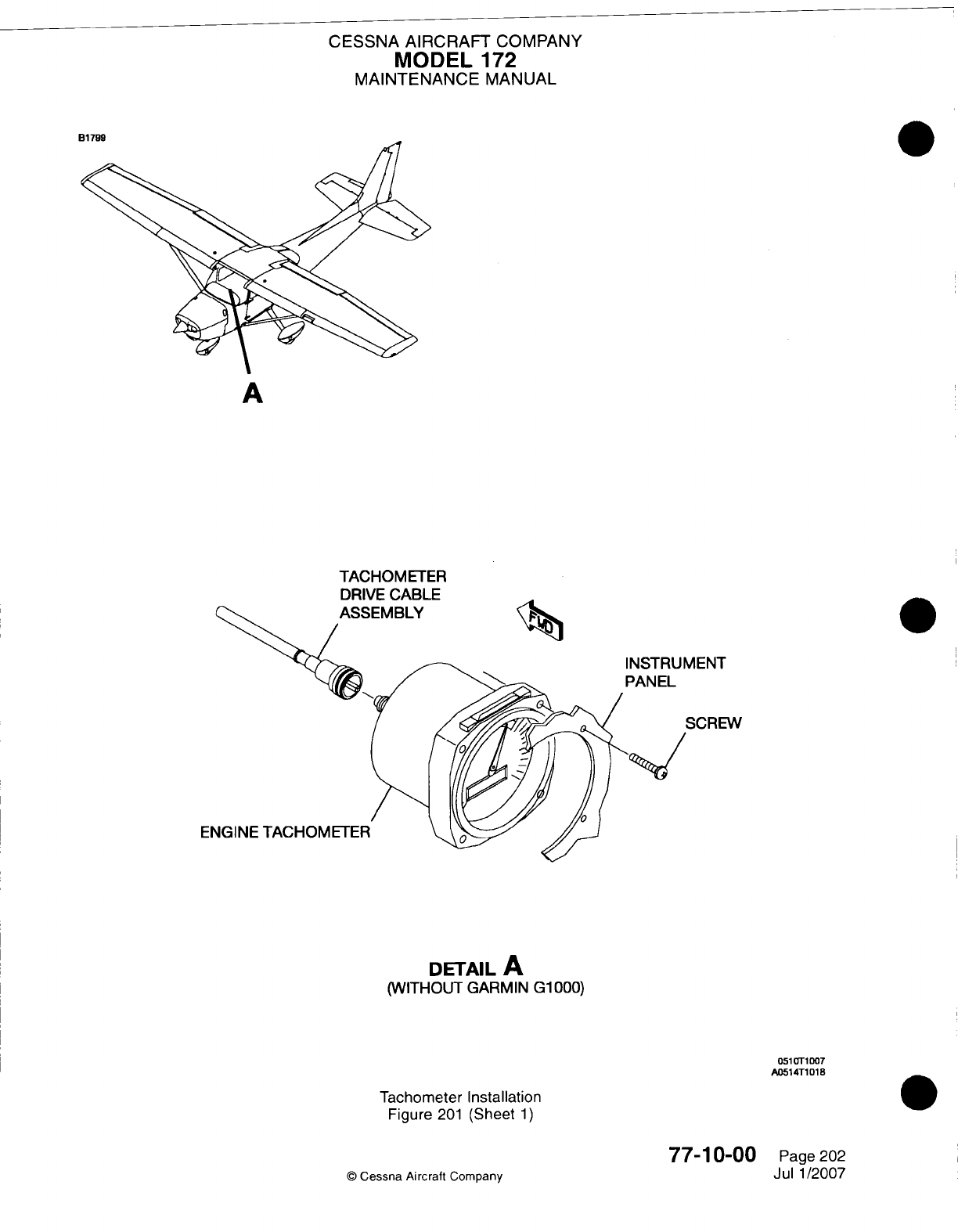
CESSNA
AIRCRAFT
COMPANY
MODEL
172
MAINTENANCE
MANUAL
91799
A
TACHOM
ETER
DRIVE
CABLE
INSTRUMENT
PANEL
El
DETAIL
A
(WITHOUT
GARMIN
G1000)
Tachometer Installation
Figure
201
(Sheet
1)
77-1
0-00
©
Cessna Aircraft
Company
as51rOT1D0
A0514T1
018
0
Page
202
Jul
1/2007
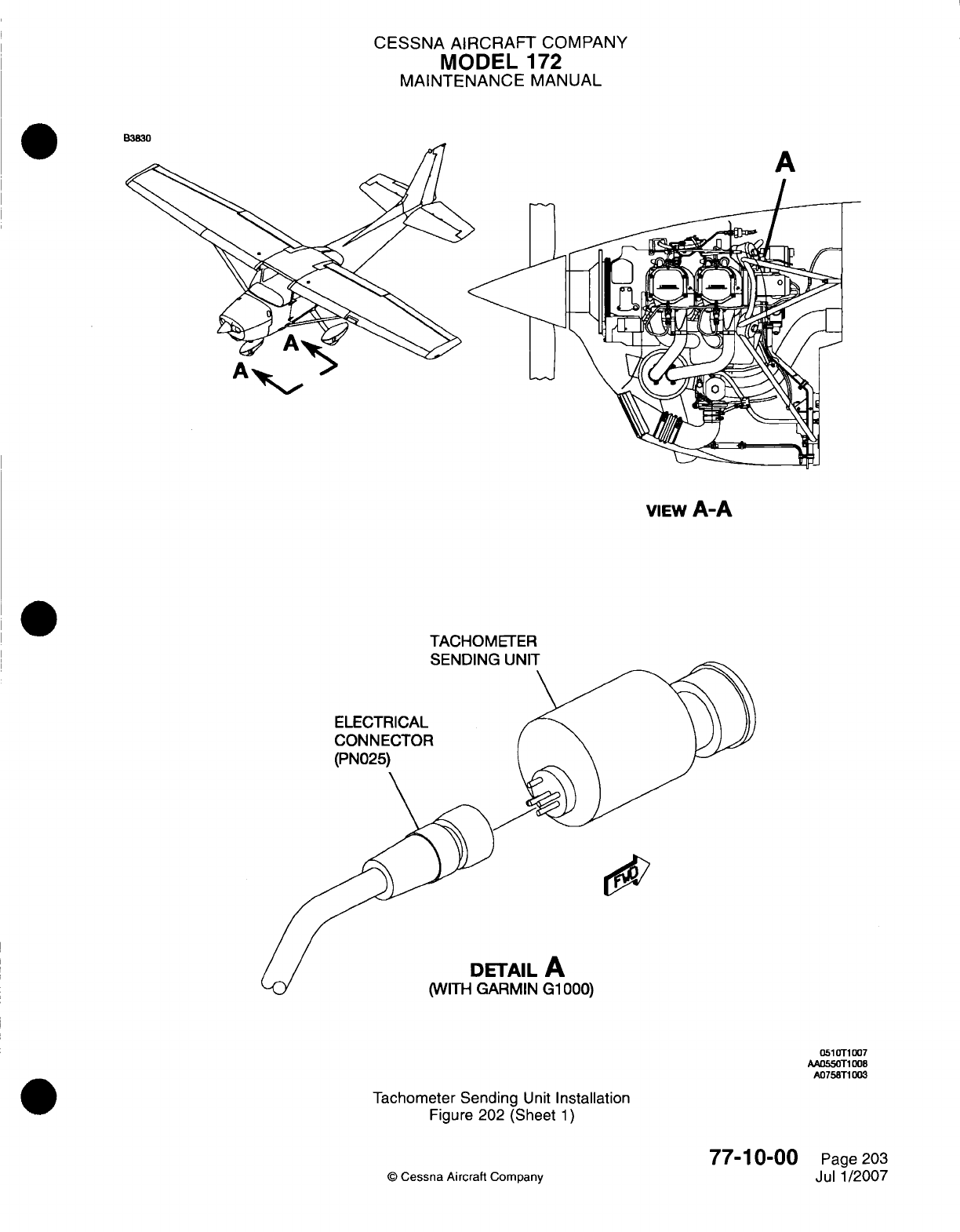
CESSNA AIRCRAFT
COMPANY
MODEL
172
MAINTENANCE
MANUAL
W3M30
A
VIEw
A-A
TACHOMETER
0CK1F`%hI~rf1
1
WMI
ELECTRICAL
CON NECTOR
(PN025)
DETAIL
A
(WITH
GARMIN
G1
000)
051
OTI
007
AAO55OTl
008
A0l758T1
003
Tachometer Sending
Unit
Installation
Figure 202 (Sheet
1)
77-1
0-00
©
Cessna
Aircraft
Company
Page
203
Jul
1/2007
.-
CESSNA
AIRCRAFT
COMPANY
MODEL
172
MAINTENANCE
MANUAL
ENGINE
TEMPERATURE
-
DESCRIPTION AND OPERATION
1.
Description
A.
The
section
that follows
has
removal
and
installation procedures
for
the
system
which
will
show
different
temperatures
in
the
engine. The
system
that
shows
the
temperature
for
the engine
includes
the
indicators
and
probes for
the
Cylinder
Head
Temperature
(CHT)
and
Exhaust
Gas
Temperature
(EGT).
2.
Operation
A.
The
EGT
system
is
used
to
measure
the
temperature
of
the
exhaust
gas.
The
measurement
gives
an
indication
of
the
fuel/air
mixture for
the
pilot.
The system has
one
indicator
installed
in
the
instrument
panel,
which
gives
the
two
functions
that
show
the
EGT
and
CHT
information.
A
probe
installed
in
the
exhaust
and
a
probe
installed
in
a
cylinder,
send the
temperature
information
to
the
EGT/CHT
indicator.
On
airplanes
with
Garmin G1000, each
cylinder
has
EGT
and
CHT
probes.
77-20-00
Page
1
©
Cessna Aircraft
Company
Jan
3/2005
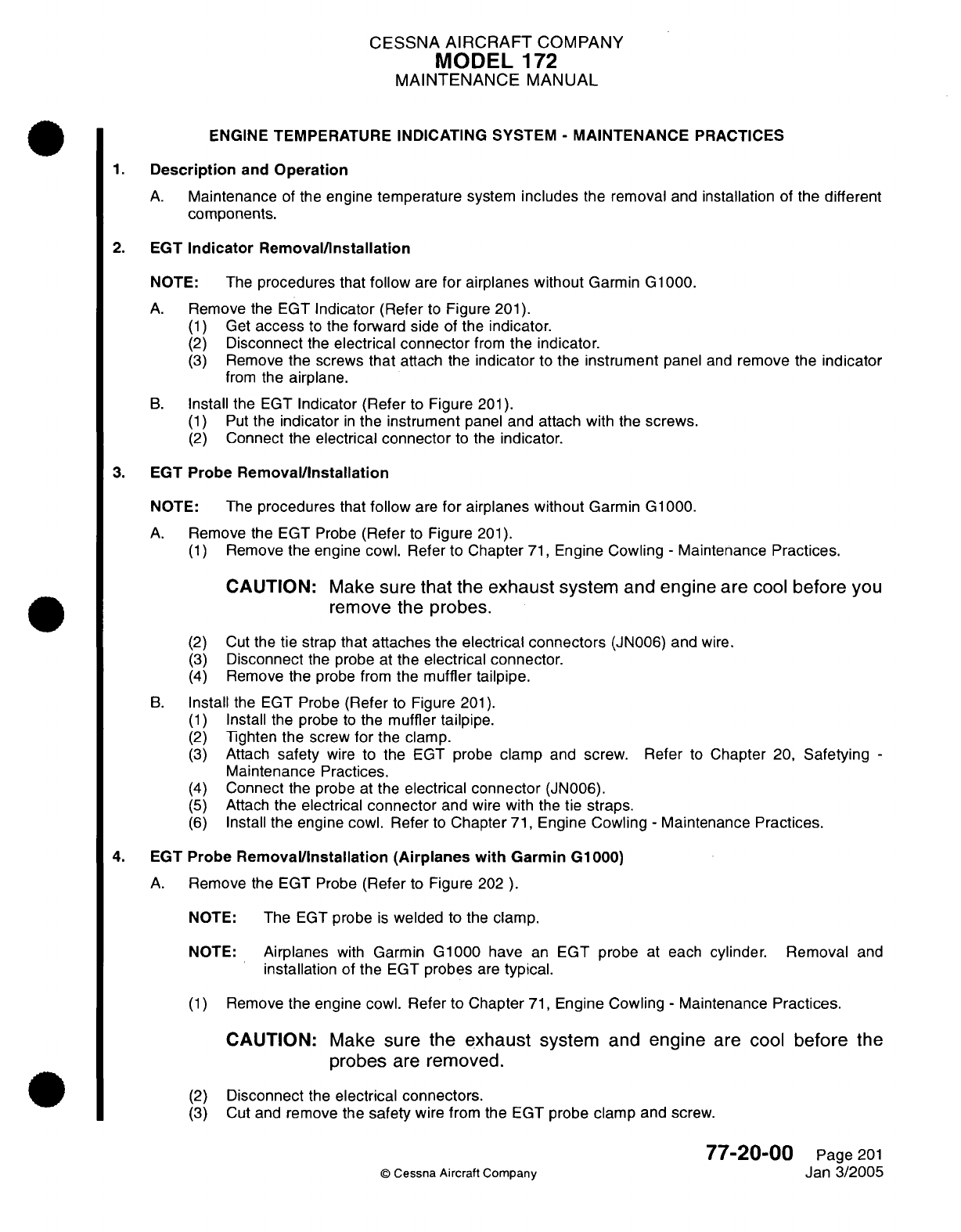
CESSNA
AIRCRAFT
COMPANY
MODEL
172
MAINTENANCE
MANUAL
ENGINE
TEMPERATURE INDICATING SYSTEM
-
MAINTENANCE
PRACTICES
1.
Description
and
Operation
A.
Maintenance
of
the
engine
temperature
system
includes
the
removal
and
installation
of the
different
components.
2.
EGT
Indicator Removal/Installation
NOTE: The
procedures
that
follow
are
for
airplanes without
Garmin
G1000.
A.
Remove the
EGT
Indicator
(Refer
to
Figure
201).
(1)
Get
access
to
the
forward
side of
the
indicator.
(2)
Disconnect
the
electrical
connector
from
the
indicator.
(3)
Remove
the
screws
that
attach
the
indicator
to
the
instrument
panel
and
remove
the
indicator
from
the
airplane.
B.
Install
the
EGT
Indicator
(Refer
to
Figure
201).
(1)
Put
the
indicator
in
the
instrument
panel and
attach
with
the
screws.
(2)
Connect
the
electrical
connector
to
the
indicator.
3.
EGT
Probe
Removal/Installation
NOTE:
The
procedures
that
follow
are
for
airplanes without
Garmin
G1000.
A.
Remove the
EGT
Probe
(Refer
to
Figure
201).
(1)
Remove
the
engine cowl. Refer
to Chapter
71,
Engine
Cowling
-
Maintenance
Practices.
CAUTION:
Make
sure
that
the
exhaust
system
and
engine
are cool
before
you
remove
the
probes.
(2)
Cut
the
tie
strap
that attaches
the
electrical
connectors
(JN006)
and
wire.
(3)
Disconnect
the
probe
at
the
electrical
connector.
(4)
Remove
the
probe
from
the
muffler
tailpipe.
B.
Install
the
EGT
Probe
(Refer
to
Figure
201).
(1)
Install
the probe
to
the
muffler
tailpipe.
(2)
Tighten
the
screw
for
the
clamp.
(3)
Attach
safety
wire
to
the
EGT
probe
clamp
and
screw.
Refer
to
Chapter
20,
Safetying
-
Maintenance
Practices.
(4)
Connect
the probe
at
the
electrical
connector
(JN006).
(5)
Attach
the electrical
connector
and wire
with
the
tie
straps.
(6)
Install
the
engine cowl. Refer
to
Chapter
71,
Engine Cowling
-
Maintenance
Practices.
4.
EGT
Probe
Removal/Installation
(Airplanes
with
Garmin
G1000)
A.
Remove
the
EGT Probe
(Refer
to
Figure
202
).
NOTE:
The
EGT
probe
is
welded
to the
clamp.
NOTE:
Airplanes
with
Garmin
G1000
have
an
EGT
probe
at
each
cylinder.
Removal
and
installation
of
the
EGT
probes
are
typical.
(1)
Remove
the engine
cowl.
Refer
to Chapter
71,
Engine Cowling
-
Maintenance
Practices.
CAUTION:
Make
sure
the
exhaust
system
and
engine
are
cool
before
the
probes
are
removed.
(2)
Disconnect
the
electrical
connectors.
(3)
Cut
and
remove
the
safety
wire
from the
EGT
probe
clamp
and
screw.
77-20-00
Page
201
©
Cessna
Aircraft Company
Jan
3/2005
. .
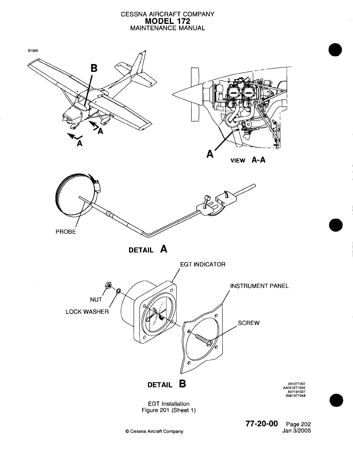
CESSNA
AIRCRAFT
COMPANY
MODEL
172
MAINTENANCE
MANUAL
A,
A
A
A
VIEW
A-A
PROBE
DETAIL
A
EGT
INDICATOR
INSTRUMENT
PANEL
NUT
LOCK
WASHI
SCREW
DETAIL
B
EGT
Installation
Figure
201
(Sheet
1)
0510T1007
AA0518T1049
A07181037
B0518T1048
77-20-00
©
Cessna
Aircraft Company
Page 202
Jan
3/2005
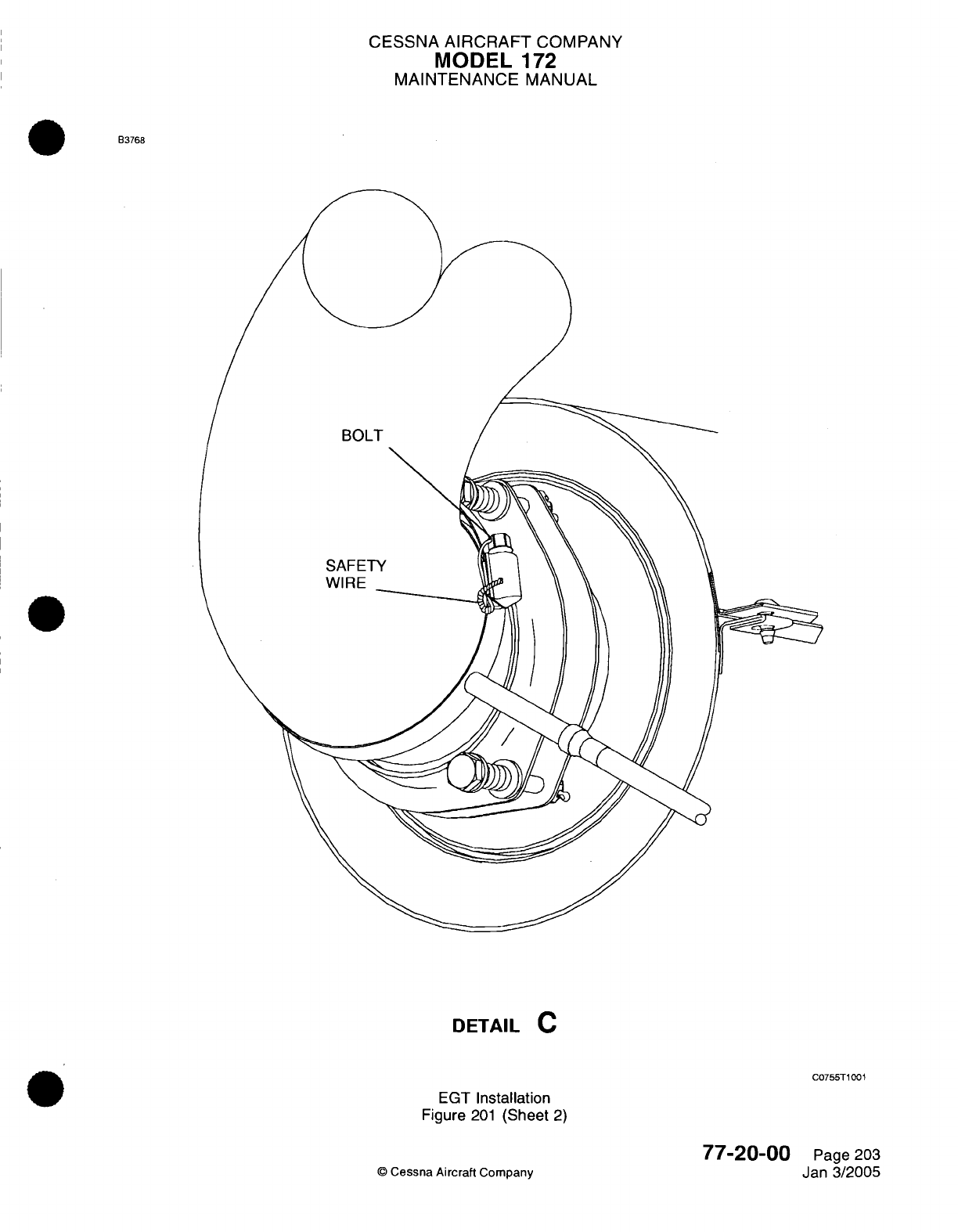
CESSNA
AIRCRAFT
COMPANY
MODEL
172
MAINTENANCE
MANUAL
B3768
BOLT
SAFETY
WIRE
DETAIL
C
C0755T1001
EGT
Installation
Figure
201
(Sheet
2)
© Cessna
Aircraft
Company
77-20-00
Page
203
Jan
3/2005
I
I
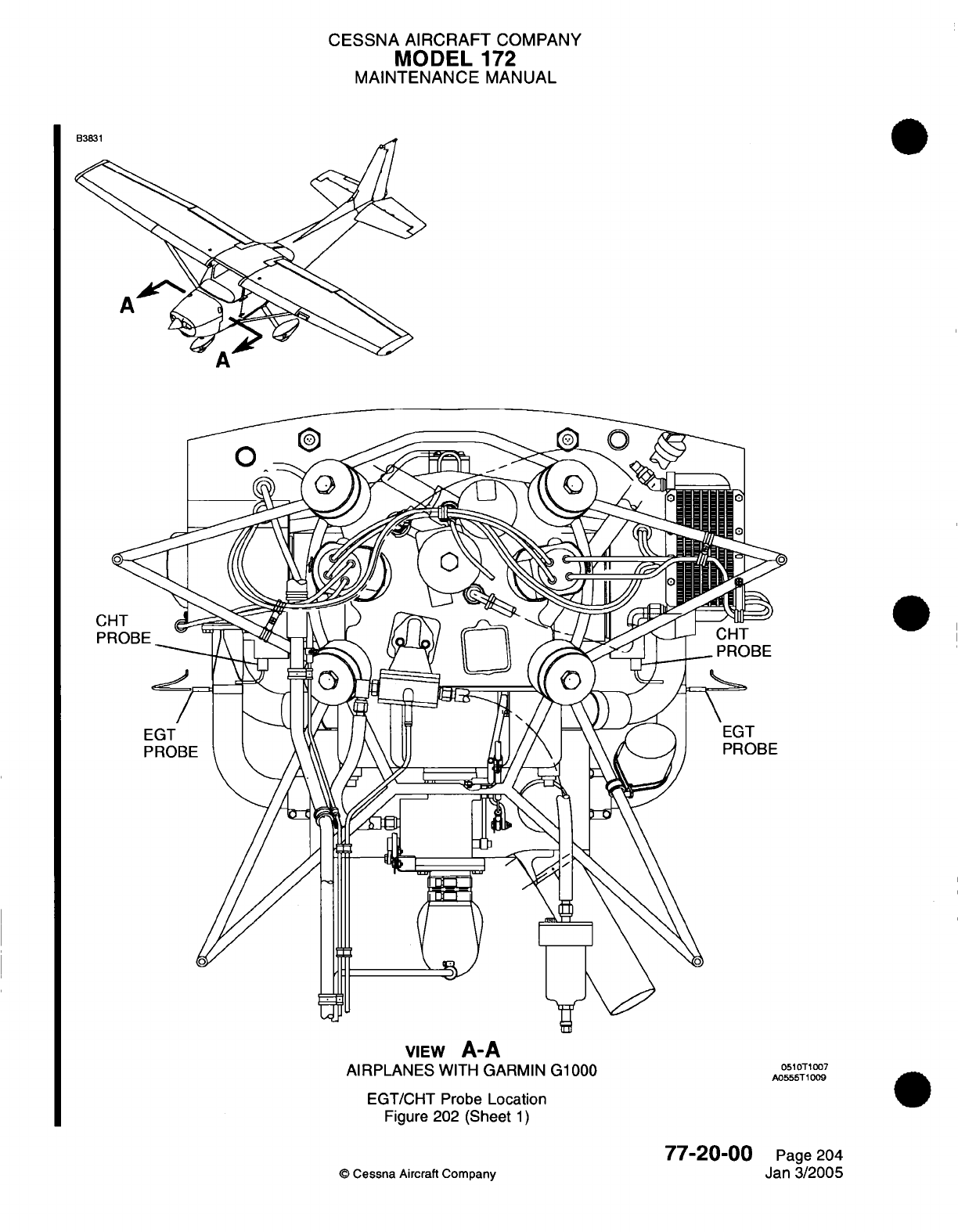
CESSNA AIRCRAFT
COMPANY
MODEL
172
MAINTENANCE
MANUAL
VIEW
A-A
AIRPLANES
WITH
GARMIN
G1000
EGT/CHT Probe
Location
Figure 202
(Sheet
1)
77-20-00
©
Cessna
Aircraft
Company
0510T1007
A0555T1009
Page 204
Jan 3/2005
B3831
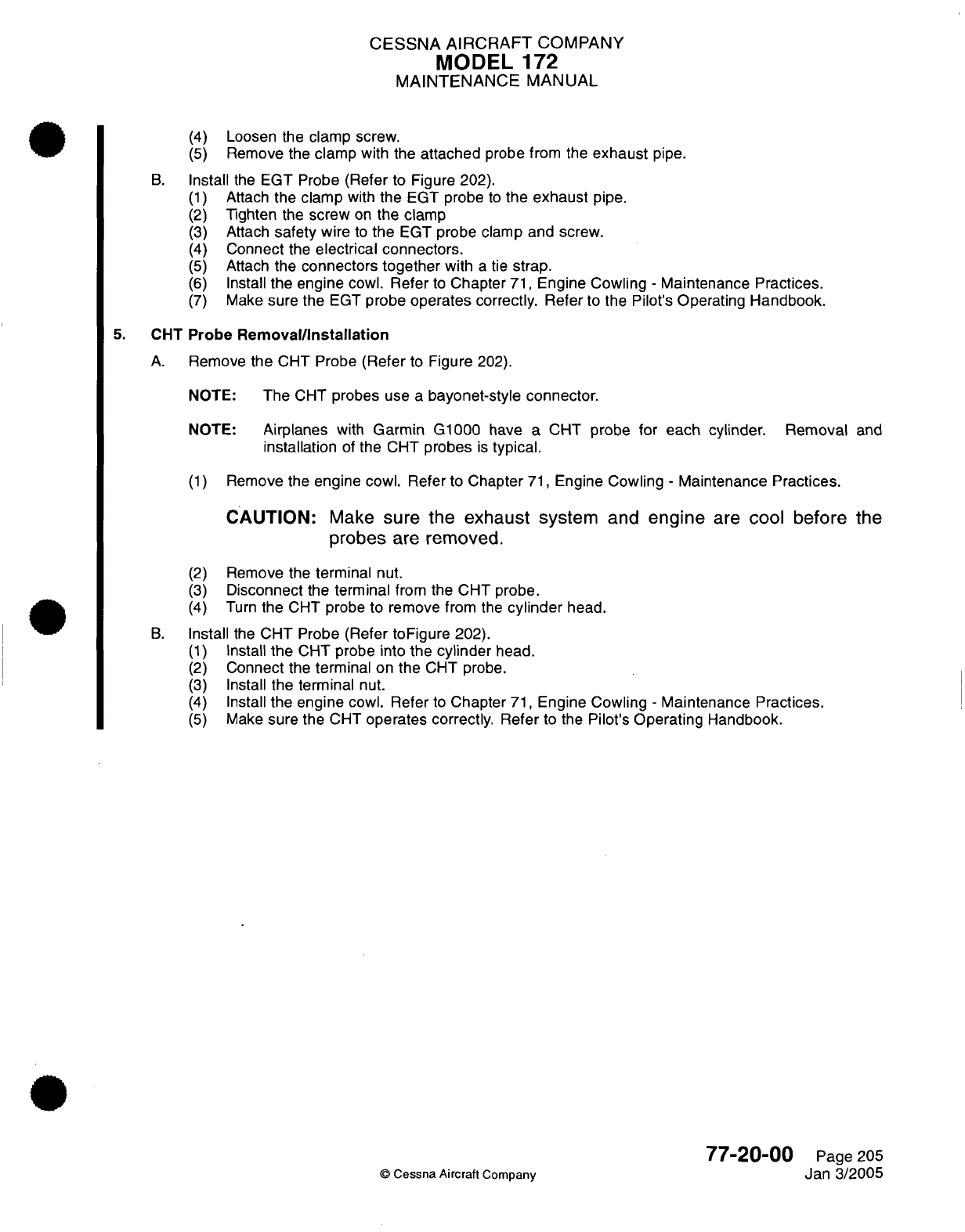
CESSNA AIRCRAFT
COMPANY
MODEL
172
MAINTENANCE
MANUAL
(4)
(5)
Loosen the
clamp screw.
Remove the
clamp
with
the
attached
probe from the
exhaust
pipe.
B.
Install
the
EGT
Probe
(Refer
to
Figure 202).
(1)
Attach
the
clamp
with
the
EGT
probe
to
the exhaust
pipe.
(2)
Tighten
the
screw
on
the
clamp
(3)
Attach
safety
wire
to
the
EGT
probe clamp and
screw.
(4)
Connect
the
electrical
connectors.
(5)
Attach
the
connectors
together
with
a
tie
strap.
(6)
Install
the
engine
cowl.
Refer
to
Chapter
71,
Engine
Cowling
-
Maintenance Practices.
(7)
Make
sure
the
EGT
probe
operates
correctly.
Refer
to
the
Pilot's
Operating
Handbook.
5.
CHT
Probe
Removal/Installation
A.
Remove
the
CHT Probe
(Refer
to
Figure
202).
NOTE:
The
CHT
probes
use
a
bayonet-style
connector.
NOTE:
Airplanes
with
Garmin
G1000
have a CHT
probe
for each
cylinder.
Removal
and
installation
of
the CHT
probes
is
typical.
(1)
Remove
the
engine
cowl. Refer
to
Chapter
71,
Engine
Cowling
-
Maintenance
Practices.
CAUTION:
Make
sure
the
exhaust system
and
engine
are
cool before
the
probes
are
removed.
(2)
(3)
(4)
Remove the
terminal
nut.
Disconnect
the
terminal
from
the
CHT
probe.
Turn
the
CHT
probe to remove
from
the
cylinder
head.
B.
Install
the
CHT Probe
(Refer
toFigure
202).
(1)
Install
the
CHT
probe
into
the
cylinder
head.
(2)
Connect
the terminal
on
the
CHT
probe.
(3)
Install
the terminal
nut.
(4)
Install
the
engine
cowl.
Refer
to
Chapter
71,
Engine
Cowling
-
Maintenance Practices.
(5)
Make
sure
the
CHT
operates correctly.
Refer
to
the
Pilot's
Operating
Handbook.
77-20-00
©
Cessna Aircraft
Company
Page
205
Jan
3/2005
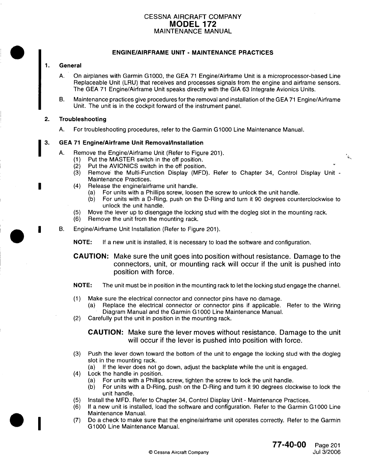
CESSNA
AIRCRAFT
COMPANY
MODEL
172
MAINTENANCE
MANUAL
ENGINE/AIRFRAME
UNIT
-
MAINTENANCE PRACTICES
1.
General
A.
On
airplanes
with
Garmin
G1000,
the
GEA
71
Engine/Airframe
Unit
is
a
microprocessor-based
Line
Replaceable
Unit
(LRU)
that
receives
and
processes signals
from
the
engine
and
airframe sensors.
The
GEA
71
Engine/Airframe
Unit
speaks
directly
with
the
GIA
63
Integrate
Avionics
Units.
B.
Maintenance
practices
give procedures
for
the removal
and
installation
of
the
GEA
71
Engine/Airframe
Unit.
The unit
is
in
the
cockpit
forward
of
the
instrument
panel.
2.
Troubleshooting
A.
For
troubleshooting
procedures,
refer
to
the Garmin G1000
Line
Maintenance
Manual.
3.
GEA
71
Engine/Airframe Unit Removal/Installation
A.
Remove
the
Engine/Airframe
Unit
(Refer
to
Figure
201).
(1)
Put
the
MASTER
switch
in
the
off
position.
''
(2)
Put
the
AVIONICS switch
in
the off
position.
(3)
Remove the
Multi-Function
Display
(MFD).
Refer
to
Chapter
34,
Control
Display
Unit
-
Maintenance
Practices.
|
(4)
Release
the
engine/airframe
unit
handle.
(a)
For
units with
a
Phillips
screw,
loosen
the screw
to
unlock
the
unit
handle.
(b)
For
units
with
a
D-Ring,
push
on
the
D-Ring
and
turn
it
90
degrees
counterclockwise
to
unlock
the
unit handle.
(5)
Move
the lever
up
to
disengage
the
locking
stud
with
the
dogleg
slot
in
the mounting
rack.
(6)
Remove
the
unit
from
the mounting
rack.
I
B.
Engine/Airframe
Unit
Installation
(Refer
to
Figure
201).
NOTE:
If
a
new
unit
is
installed,
it
is
necessary
to load
the
software
and
configuration.
CAUTION:
Make
sure
the
unit
goes
into
position
without
resistance.
Damage
to
the
connectors,
unit,
or
mounting
rack
will
occur
if
the
unit
is
pushed
into
position
with
force.
NOTE:
The
unit
must
be
in
position
in
the
mounting
rack
to
let
the
locking
stud
engage
the
channel.
(1)
Make
sure
the
electrical
connector
and
connector
pins have
no
damage.
(a)
Replace
the
electrical connector
or
connector
pins
if
applicable.
Refer
to
the
Wiring
Diagram
Manual
and the
Garmin
G1000
Line
Maintenance
Manual.
(2)
Carefully
put
the
unit
in
position
in
the
mounting
rack.
CAUTION:
Make
sure
the
lever
moves
without
resistance.
Damage to
the
unit
will
occur
if
the
lever
is
pushed
into
position
with
force.
(3)
Push
the
lever
down
toward
the
bottom
of
the
unit
to
engage
the locking
stud with
the
dogleg
slot
in
the
mounting
rack.
(a)
If
the
lever does not
go
down,
adjust
the
backplate while
the
unit
is
engaged.
(4)
Lock
the
handle
in
position.
(a)
For
units
with
a
Phillips
screw,
tighten
the
screw
to
lock
the
unit
handle.
(b)
For
units
with
a
D-Ring,
push
on
the
D-Ring
and turn
it
90
degrees
clockwise
to
lock
the
unit handle.
(5)
Install
the
MFD.
Refer
to
Chapter
34,
Control Display
Unit
-
Maintenance Practices.
(6)
If
a
new
unit
is
installed,
load
the
software
and
configuration.
Refer
to
the
Garmin
G1000
Line
Maintenance
Manual.
(7)
Do
a
check
to
make
sure
that the
engine/airframe
unit
operates correctly.
Refer
to
the
Garmin
G1000
Line
Maintenance
Manual.
77-40-00
Page
201
©
Cessna
Aircraft
Company
Jul
3/2006
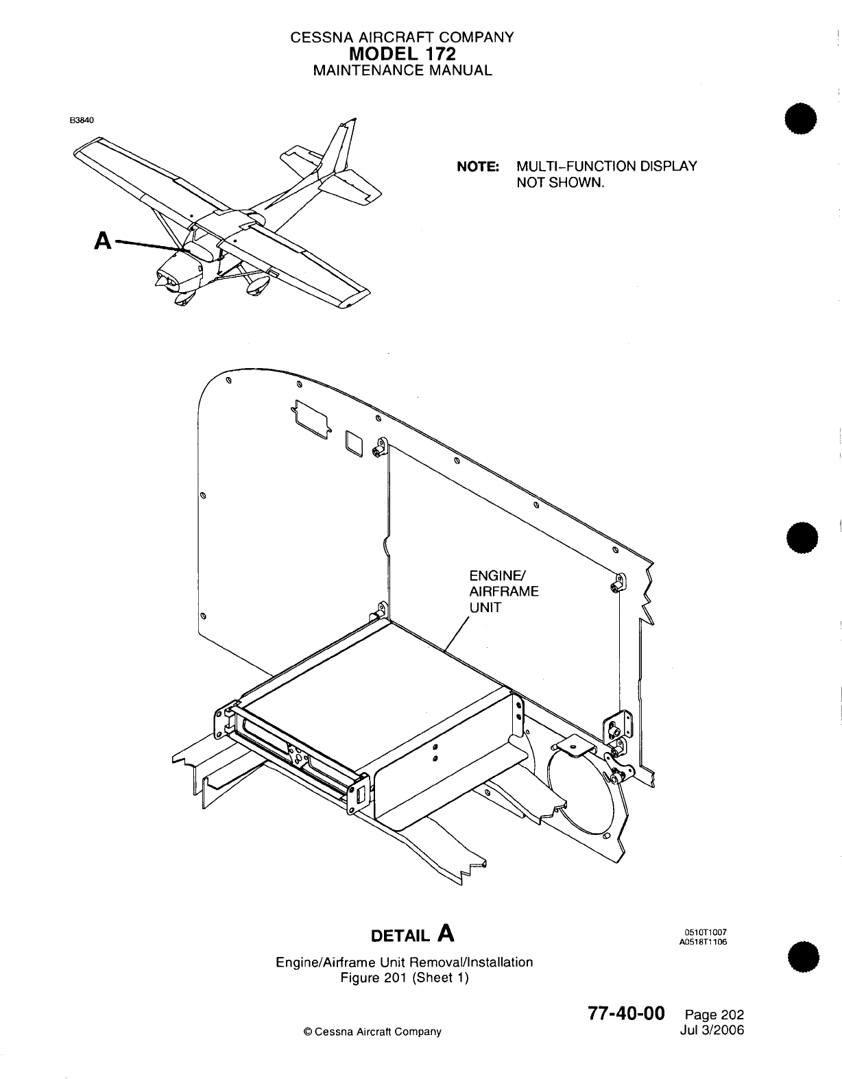
CESSNA
AIRCRAFT
COMPANY
MODEL
172
MAINTENANCE
MANUAL
NOTE:
MULTI-FUNCTION
DISPLAY
NOT
SHOWN.
(
ENGINE/
AIRFRAME
DETAIL
A
Engine/Airframe
Unit
Removal/Installation
Figure
201
(Sheet
1)
0510T1007
A0518T1106
77-40-00
© Cessna
Aircraft Company
Page
202
Jul
3/2006
i
CESSNA
AIRCRAFT
COMPANY
MODEL
172
MAINTENANCE
MANUAL
(7)
Do
a
check
to
make sure
the engine interface
unit operates
correctly.
Refer
to
the
Garmin
G
1000
Line
Maintenance
Manual.
77-40-00
Page
203
©
Cessna Aircraft
Company
Jan 2/2006
CHAPTER
EXHAUST
CESSNA
AIRCRAFT
COMPANY
MODEL
172
MAINTENANCE
MANUAL
LIST
OF
EFFECTIVE PAGES
CHAPTER-SECTION-SUBJECT
78-Title
78-List
of
Effective
Pages
78-Record
of
Temporary
Revisions
78-Contents
78-00-00
78-10-00
PAGE
Page
1
Pages
201-203
©
Cessna
Aircraft
Company
78
-
LIST
OF
EFFECTIVE
PAGES
Page
1
of
1
Jan
3/2005
DATE
Apr
7/2003
Apr
7/2003
Temporary
Revision
Number
RECORD
OF
TEMPORARY
REVISIONS
Page
Number
Issue
Date
By
Date
Removed
By
CESSNA
AIRCRAFT
COMPANY
MODEL
172
MAINTENANCE
MANUAL
CONTENTS
EXHAUST
-
GENERAL
......... .........
...........
...........................
Scope
and
Definition
........................................................
EXHAUST
SYSTEM
-
MAINTENANCE PRACTICES
.........
.....................
Description
.................................................................
Exhaust
System
Removal/Installation
.........................................
Muffler
Inspection
...........................................................
78-00-00
Page
1
78-00-00
Page
1
78-10-00
Page
201
78-10-00
Page
201
78-10-00
Page
201
78-10-00
Page
201
CONTENTS
Page
1
of
1
Jan
3/2005
©
Cessna
Aircraft Company
CESSNA
AIRCRAFT
COMPANY
MODEL
172
MAINTENANCE
MANUAL
EXHAUST
-
GENERAL
1.
Scope
and
Definition
A.
This
chapter
is
comprised
of
a
single
section
on
the
exhaust
system. The
section
details
removal,
installation
and
testing
procedures for
the
exhaust
system.
78-00-00
Page
1
©
Cessna Aircraft Company
Apr
7/2003
CESSNA
AIRCRAFT
COMPANY
MODEL
172
MAINTENANCE
MANUAL
EXHAUST
SYSTEM
-
MAINTENANCE PRACTICES
1.
Description
A.
The
exhaust
system
consists
of
an
exhaust
pipe
(riser)
from
each
cylinder
to
the
muffler
with
a
single
tailpipe
which
routes
exhaust
gases
out
through
the
lower
cowling
area. The
muffler
is
located beneath
the
engine,
and
is
enclosed
by
a
shroud which
captures
radiated
exhaust
heat.
This
heated air
is
then
ducted
to
the
airplane cabin
through
flexible
hoses.
B.
Maintenance
practices
for
the
exhaust
system
consist
of
removal,
installation
and
testing
of
the
exhaust
system
for
leaks.
2.
Exhaust
System
Removal/Installation
A.
Remove
Exhaust System
(Refer
to
Figure
201).
(1)
Remove
engine
cowling.
Refer
to
Chapter
71,
Engine
Cowling
-
Maintenance
Practices.
(2)
Loosen
left
front
baffle
to
allow
heat
shroud inlet
to
clear
baffle.
(3)
Remove
EGT
probe.
(4)
Disconnect
flexible
heat
duct
from
heat
shroud.
(5)
Remove
clamps
securing
risers
to
muffler.
(6)
Remove
nuts
and
washers
securing
risers
to
engine
and
remove
risers/muffler
as
an
assembly
from
engine.
(7)
Remove
screws securing
heat
shroud
to
itself,
and
unwrap
heat shroud
from
around
muffler.
(8)
Inspect muffler
for
leaks.
Refer
to
Muffler
Inspection
below.
B.
Install
Exhaust
System
(Refer
to
Figure
201).
(1)
Wrap
heat
shroud around muffler and secure
to
itself
using
screws.
(2)
Loosely install
risers
(4
total)
to
muffler
using
clamps.
(3)
Install
riser/muffler assembly
to
engine
using
new
gaskets.
(4)
Tighten
risers
200-210 inch-pounds
at
engine,
then
tighten clamps
connecting
risers
to
muffler.
(5)
Reconnect
EGT
probe.
(6)
Reinstall
engine
cowling.
Refer
to
Chapter
71,
Engine Cowling
-
Maintenance
Practices.
3.
Muffler
Inspection
NOTE:
The
exhaust
system must
be
thoroughly
inspected
at
time
intervals
set forth
in
Chapter
5,
Inspection
Time
Limits,
or
anytime
exhaust
fumes
are
detected
in
the cabin.
WARNING:
FAILURE
TO
INSPECT MUFFLER
FOR
LEAKS
COULD RESULT
IN
CARBON
MONOXIDE ENTERING THE
CABIN,
LEADING
TO
SERIOUS
INJURY
OR DEATH.
A.
Inspection Procedures.
NOTE:
If
muffler
shows
signs
of
leaks
or
damage
as
indicated
in
steps
3.A.(1)
thru 3.A.(3),
it
must
be
replaced.
(1)
Using
a
flashlight
and
mirror,
examine the
interior
of the
muffler,
looking
for
cracks or
general
deterioration.
(2)
Using
visual
inspection,
examine
the
exterior
of
muffler,
looking
for
holes,
cracks
and
burned
spots.
Pay
special
attention
to
areas
adjacent
to
welds
and
to
exhaust
gas
deposits
(which
indicate
an
exhaust
leak).
(3)
After
visual
inspection
an
air
leak
check
should
be
made
on
the
system
as
follows:
(a)
Attach
the
pressure side
of an
industrial
vacuum
cleaner
to
the
tail
pipe
opening,
using
a
rubber
plug
to
effect
a
seal
as
required.
NOTE:
The
inside of
vacuum
cleaner
hose
should
be
free
of
any
contamination
that
might
be
blown
into
the
engine
exhaust
system.
78-10-00
Page
201
©
Cessna
Aircraft
Company
Apr
7/2003
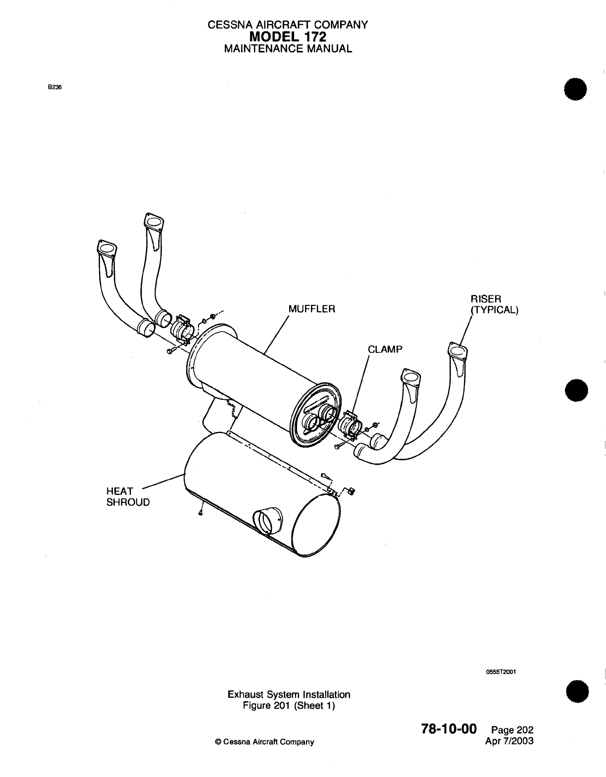
CESSNA
AIRCRAFT
COMPANY
MODEL
172
MAINTENANCE
MANUAL
B236
MUFFLER
RISER
PICAL)
CLAMP
HEAT
SHROUD
0555T2001
Exhaust
System
Installation
Figure
201
(Sheet
1)
78-10-00
©
Cessna
Aircraft
Company
Page 202
Apr
7/2003
CESSNA
AIRCRAFT
COMPANY
MODEL
172
MAINTENANCE
MANUAL
(b)
With
vacuum
cleaner
operating,
all
joints
in
the
exhaust system
may
be
checked
by
using
a
soap and water solution
and
watching
for
bubbles. Forming
of
bubbles
is
considered
acceptable;
if
bubbles
are
blown
away,
system
is
not
considered
acceptable.
(4)
Use a
water test
to
determine
muffler integrity:
(a)
Seal
openings
in
muffler
using
rubber
expansion
plugs.
NOTE: One
expansion
plug
should
be
adapted
to
allow
for
introduction
of
low-pressure
air into
muffler.
(b)
Using
a
pressure gauge
or
manometer,
apply
approximately
3.0
PSI,
+0.5
or
-0.5
PSI
(6
inches
mercury),
to
interior
of
muffler and
submerge
muffler
into
water.
Any
leaks
will
appear
as
bubbles
and
can
be
readily
detected.
(c) If
any
leaks
are
detected,
the
muffler
must
be
removed
from service
and
repaired
or
replaced.
(d) If
no
defects
are
found,
remove
muffler
from
water,
remove
plugs
and
dry
muffler
with
compressed
air.
78-10-00
Page
203
©
Cessna
Aircraft
Company
Apr 7/2003

CHAPTER
OIL
CESSNA
AIRCRAFT
COMPANY
MODEL
172
MAINTENANCE
MANUAL
LIST
OF EFFECTIVE
PAGES
CHAPTER-SECTION-SUBJECT
79-Title
79-List
of
Effective Pages
79-Record
of Temporary
Revisions
79-Table
of
Contents
79-00-00
79-20-00
79-30-00
79-30-00
79-31-00
79-31-00
©
Cessna
Aircraft
Company
PAGE
Page
1
Pages 201-202
Pages
101-102
Pages
201-203
Pages
101-102
Pages 201-202
DATE
Apr 7/2003
Apr
7/2003
Jan
2/2006
Jan
3/2005
Jan
2/2006
Jan 3/2005
79
-
LIST
OF
EFFECTIVE PAGES
Page
1
of
1
Jan
2/2006
Temporary
Revision
Number
RECORD OF
TEMPORARY
REVISIONS
Page
Number Issue
Date By
Date
Removed
By
CESSNA
AIRCRAFT
COMPANY
MODEL
172
MAINTENANCE
MANUAL
CONTENTS
OIL
-
GENERAL
......................
...........................................
S
cope......................................................................
Definition
...................................................................
OIL
COOLER
-
MAINTENANCE PRACTICES
....................................
General
....................................................................
Oil
Cooler
Removal/Installation...............................................
OIL
PRESSURE
INDICATOR
-
TROUBLESHOOTING
..............................
General
....................................................................
OIL
PRESSURE
INDICATOR
-
MAINTENANCE PRACTICES
.......................
Description
and
Operation
.................................................
Oil
Pressure
Indicator
and
Transducer
Removal/Installation
.....................
Low
Oil
Pressure
Switch
Removal/Installation
.................................
OIL
TEMPERATURE
INDICATOR
-
TROUBLESHOOTING
..........................
General
....................................................................
OIL
TEMPERATURE
INDICATOR
-
MAINTENANCE PRACTICES
...................
Description
and
Operation
...................................................
Oil
Temperature Sending
Unit
Removal/Installation.............................
Oil
Temperature/Oil Pressure
Indicator Removal/Installation
....................
79-00-00
Page
1
79-00-00
Page
1
79-00-00
Page
1
79-20-00
Page
201
79-20-00
Page
201
79-20-00
Page
201
79-30-00
Page
101
79-30-00
Page
101
79-30-00
Page
201
79-30-00
Page
201
79-30-00
Page 201
79-30-00
Page
201
79-31-00
Page
101
79-31-00
Page
101
79-31-00
Page
201
79-31-00
Page
201
79-31-00
Page
201
79-31-00
Page
201
79
-
CONTENTS
Page
1
of
1
Jan
2/2006
©
Cessna Aircraft
Company
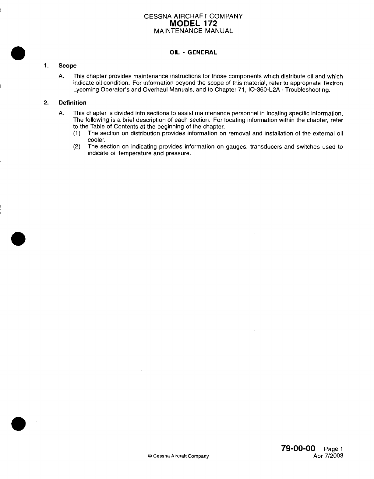
CESSNA
AIRCRAFT
COMPANY
MODEL
1
72
MAINTENANCE
MANUAL
OIL
-
GENERAL
1.
Scope
A.
This
chapter
provides
maintenance instructions
for
those components
which distribute
oil
and
which
indicate
oil condition.
For
information
beyond
the
scope
of
this
material,
refer to
appropriate Textron
Lycoming
Operator's
and
Overhaul
Manuals,
and
to
Chapter
71,
IO-360-L2A
-
Troubleshooting.
2.
Definition
A.
This
chapter
is
divided
into
sections
to
assist
maintenance
personnel
in
locating
specific
information.
The
following
is
a
brief
description
of
each
section.
For
locating
information
within
the
chapter,
refer
to
the
Table
of
Contents
at the
beginning
of the
chapter.
(1)
The
section
on
distribution provides
information
on
removal
and
installation
of
the
external
oil
cooler.
(2)
The
section
on
indicating
provides
information
on
gauges,
transducers
and
switches
used
to
indicate
oil
temperature
and
pressure.
79-00-00
Page
1
©
Cessna
Aircraft
Company
Apr
7/2003
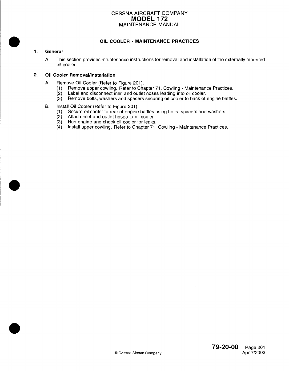
CESSNA
AIRCRAFT
COMPANY
MODEL
1
72
MAINTENANCE
MANUAL
OIL
COOLER
-
MAINTENANCE
PRACTICES
1.
General
A.
This
section
provides maintenance instructions for
removal
and
installation
of
the
externally
mounted
oil
cooler.
2.
Oil
Cooler
Removal/Installation
A.
Remove
Oil
Cooler
(Refer
to Figure
201).
(1)
Remove
upper
cowling.
Refer
to
Chapter
71,
Cowling
-
Maintenance
Practices.
(2)
Label
and
disconnect
inlet and
outlet
hoses leading
into
oil
cooler.
(3)
Remove
bolts,
washers
and
spacers securing
oil
cooler
to
back
of
engine
baffles.
B.
Install
Oil
Cooler
(Refer
to Figure
201).
(1)
Secure
oil
cooler
to
rear
of
engine
baffles
using
bolts,
spacers
and
washers.
(2)
Attach
inlet
and
outlet
hoses
to
oil
cooler.
(3)
Run
engine
and
check
oil
cooler
for
leaks.
(4)
Install
upper cowling.
Refer
to
Chapter
71,
Cowling
-
Maintenance
Practices.
79-20-00
Page
201
©
Cessna
Aircraft
Company
Apr
7/2003
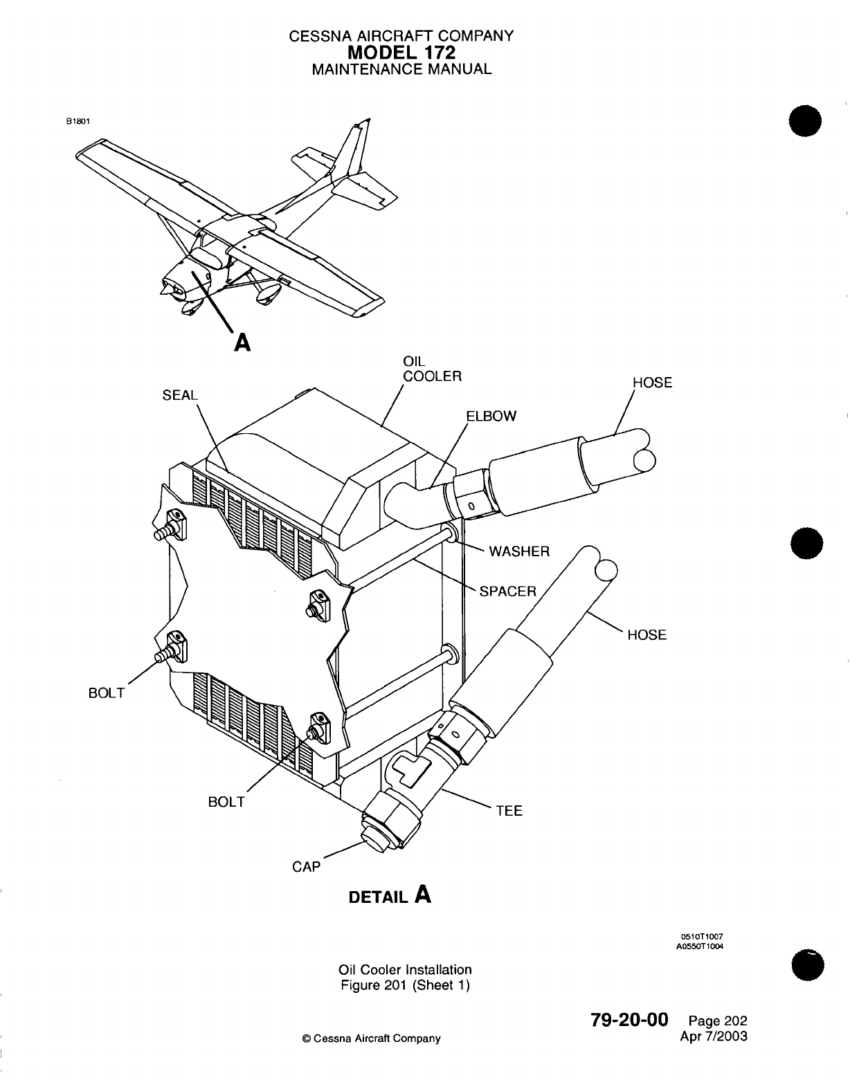
CESSNA AIRCRAFT
COMPANY
MODEL
172
MAINTENANCE
MANUAL
B1801
OIL
COOLER
HOSE
BOLT
CAP
DETAIL
A
0510T1007
A0550T1004
Oil
Cooler
Installation
Figure
201
(Sheet
1)
79-20-00
©
Cessna
Aircraft
Company
Page
202
Apr
7/2003
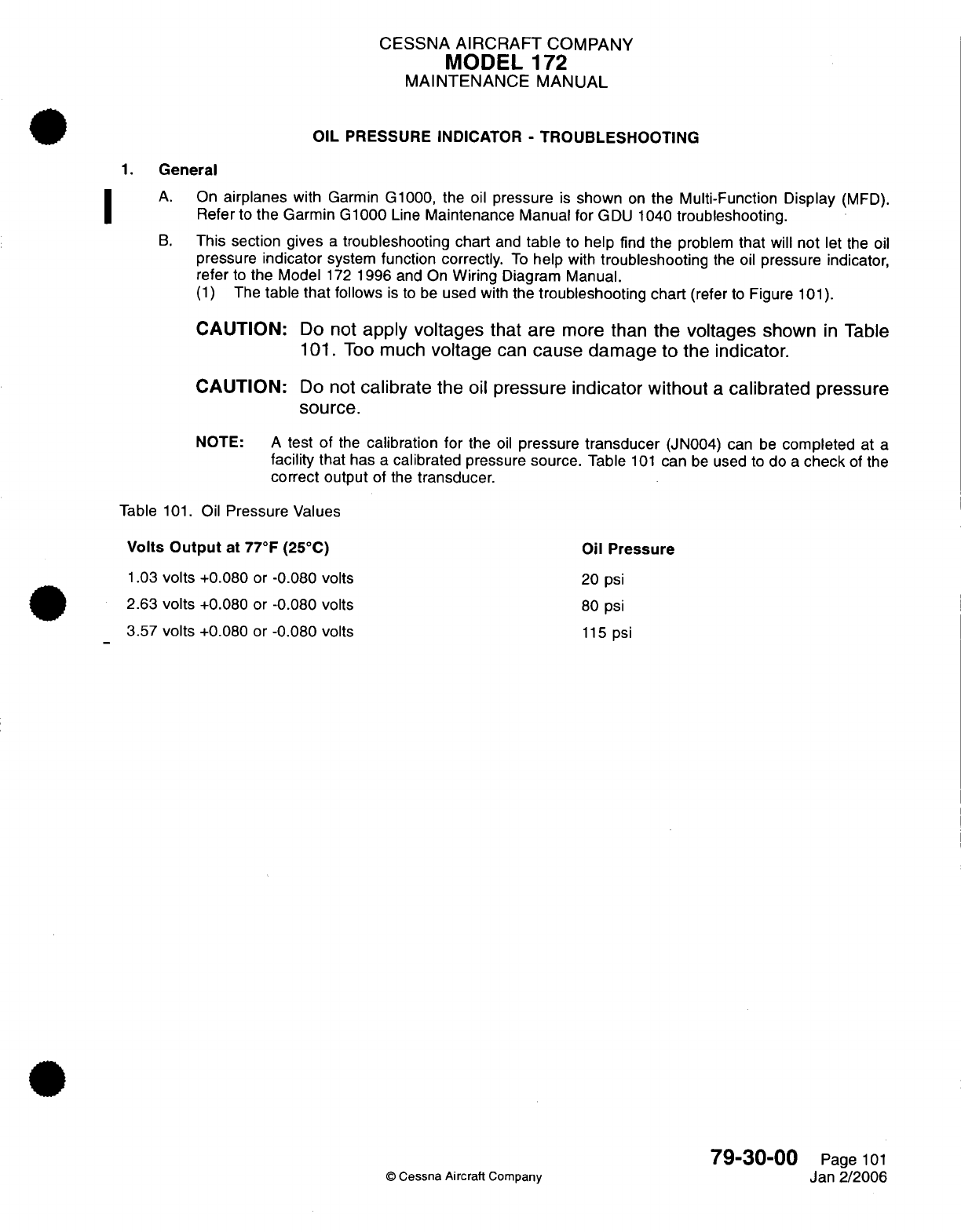
CESSNA
AIRCRAFT
COMPANY
MODEL
172
MAINTENANCE
MANUAL
OIL
PRESSURE
INDICATOR
-
TROUBLESHOOTING
1.
General
A.
On
airplanes
with
Garmin
G1000,
the
oil
pressure
is
shown
on
the
Multi-Function Display
(MFD).
Refer
to
the Garmin
G1000
Line
Maintenance
Manual
for GDU
1040
troubleshooting.
B.
This
section gives
a
troubleshooting
chart
and
table
to
help
find the
problem
that
will
not
let the
oil
pressure
indicator
system
function
correctly.
To
help
with
troubleshooting
the
oil
pressure
indicator,
refer
to
the
Model
172
1996
and
On
Wiring
Diagram
Manual.
(1)
The
table
that
follows
is to
be
used
with
the
troubleshooting
chart
(refer
to
Figure
101).
CAUTION:
Do
not
apply
voltages
that
are
more
than
the
voltages
shown
in
Table
101.
Too
much
voltage
can
cause damage
to
the
indicator.
CAUTION:
Do
not
calibrate
the
oil
pressure
indicator
without
a
calibrated pressure
source.
NOTE:
A
test of
the
calibration
for
the
oil
pressure
transducer
(JN004)
can
be
completed
at
a
facility
that
has
a
calibrated
pressure
source.
Table
101
can
be
used
to
do
a
check
of the
correct output
of
the
transducer.
Table
101.
Oil
Pressure
Values
Volts
Output
at
77°F
(25°C)
1.03
volts
+0.080
or
-0.080
volts
2.63
volts
+0.080
or
-0.080
volts
3.57
volts
+0.080 or
-0.080
volts
Oil
Pressure
20
psi
80
psi
115
psi
©
Cessna
Aircraft
Company
79-30-00
Page
101
Jan
2/2006
I
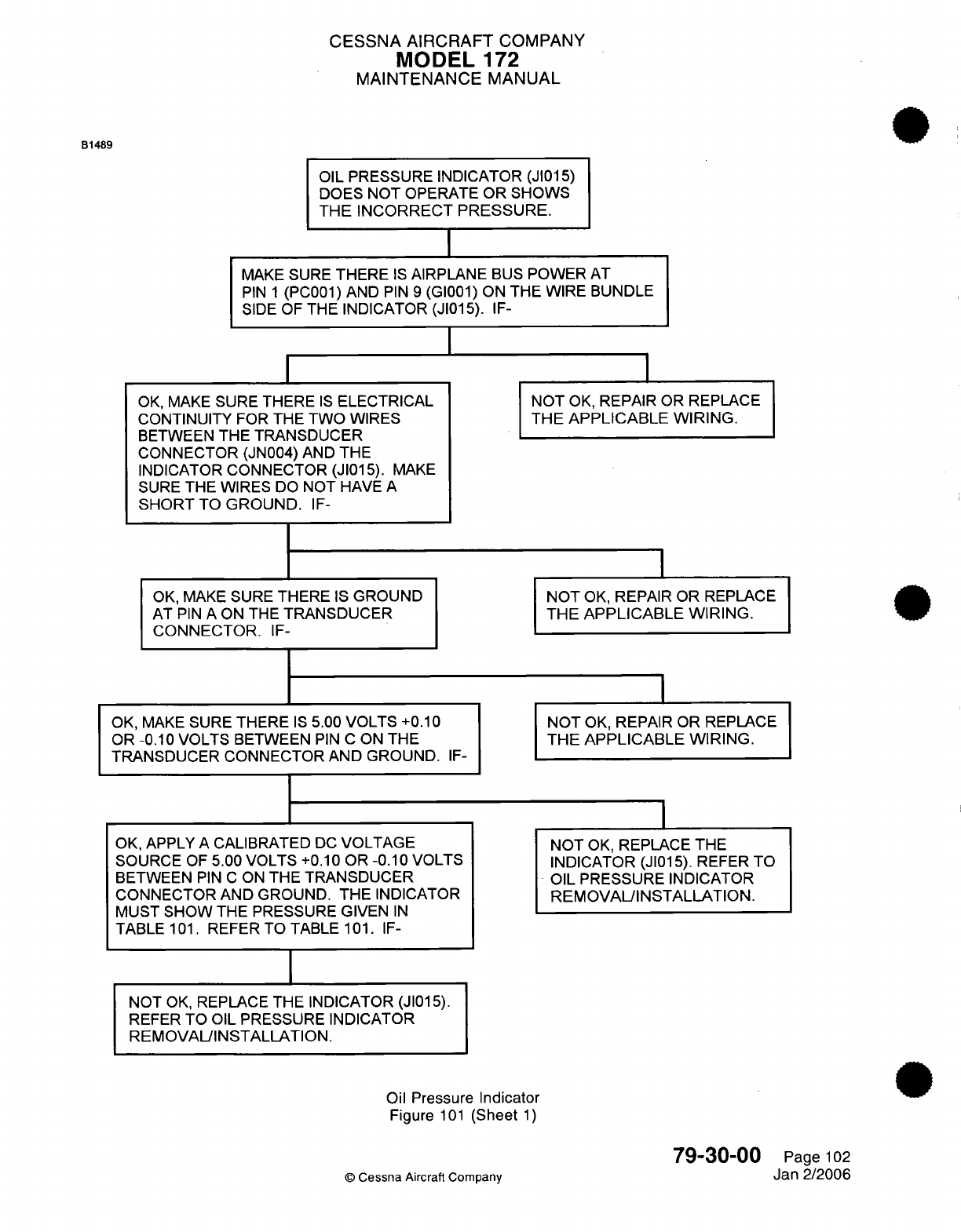
CESSNA
AIRCRAFT
COMPANY
MODEL
172
MAINTENANCE
MANUAL
B1489
OIL PRESSURE INDICATOR (JI015)
DOES
NOT
OPERATE OR
SHOWS
THE INCORRECT
PRESSURE.
MAKE
SURE
THERE
IS
AIRPLANE
BUS
POWER
AT
PIN
1
(PC001)
AND
PIN
9
(GI001)
ON
THE WIRE BUNDLE
SIDE
OF
THE
INDICATOR (JI015).
IF-
OK,
MAKE
SURE
THERE
IS
ELECTRICAL
CONTINUITY
FOR
THE TWO
WIRES
BETWEEN
THE
TRANSDUCER
CONNECTOR (JN004)
AND
THE
INDICATOR
CONNECTOR
(JI015).
MAKE
SURE
THE
WIRES
DO
NOT
HAVE
A
SHORT
TO
GROUND.
IF-
OK, MAKE
SURE
THERE
IS
GROUND
AT
PIN
A
ON THE
TRANSDUCER
CONNECTOR.
IF-
OK,
MAKE
SURE
THERE
IS
5.00
VOLTS
+0.10
OR -0.10
VOLTS
BETWEEN
PIN
C
ON
THE
TRANSDUCER
CONNECTOR
AND GROUND.
IF-
OK,
APPLY
A
CALIBRATED
DC
VOLTAGE
SOURCE
OF
5.00
VOLTS
+0.10 OR
-0.10
VOLTS
BETWEEN
PIN
C
ON
THE
TRANSDUCER
CONNECTOR
AND
GROUND.
THE
INDICATOR
MUST
SHOW
THE PRESSURE
GIVEN
IN
TABLE
101.
REFER TO TABLE
101. IF-
I
NOT
OK,
REPAIR
OR
REPLACE
THE
APPLICABLE WIRING.
NOT
OK,
REPAIR
OR
REPLACE
THE
APPLICABLE WIRING.
NOT
OK,
REPAIR
OR
REPLACE
THE
APPLICABLE WIRING.
NOT
OK,
REPLACE
THE
INDICATOR
(JI015).
REFER
TO
OIL
PRESSURE
INDICATOR
REMOVAL/INSTALLATION.
NOT
OK,
REPLACE
THE INDICATOR (JI015).
REFER
TO
OIL
PRESSURE
INDICATOR
REMOVALINSTALLATION.
Oil
Pressure
Indicator
Figure
101
(Sheet
1)
79-30-00
©
Cessna
Aircraft Company
Page
102
Jan 2/2006
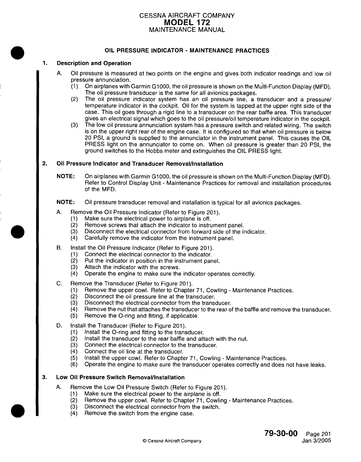
CESSNA
AIRCRAFT
COMPANY
MODEL
172
MAINTENANCE
MANUAL
OIL
PRESSURE
INDICATOR
-
MAINTENANCE
PRACTICES
1.
Description
and
Operation
A.
Oil
pressure
is
measured
at
two
points
on the
engine
and
gives
both
indicator readings
and
low
oil
pressure
annunciation.
(1)
On
airplanes
with
Garmin
G1000,
the
oil
pressure
is
shown
on
the Multi-Function
Display
(MFD).
The
oil
pressure
transducer
is
the
same for
all
avionics
packages.
(2)
The
oil
pressure
indicator
system
has
an
oil pressure
line,
a
transducer
and
a
pressure/
temperature indicator
in
the
cockpit.
Oil
for
the
system is
tapped
at
the
upper
right
side
of
the
case.
This
oil
goes
through
a
rigid
line
to
a
transducer
on
the rear
baffle
area.
This
transducer
gives
an
electrical signal
which
goes
to
the
oil
pressure/oil temperature
indicator
in
the
cockpit.
(3)
The
low
oil
pressure
annunciation
system
has
a
pressure
switch
and
related
wiring. The
switch
is
on
the
upper right
rear
of
the
engine case.
It
is
configured
so
that
when
oil
pressure
is
below
20
PSI,
a
ground
is
supplied
to
the annunciator
in
the
instrument
panel.
This
causes
the
OIL
PRESS
light
on the
annunciator
to
come
on.
When
oil
pressure
is
greater
than
20
PSI, the
ground
switches
to the
Hobbs
meter
and
extinguishes
the
OIL
PRESS
light.
2.
Oil
Pressure
Indicator
and
Transducer Removal/Installation
NOTE: On
airplanes
with
Garmin
G1000, the
oil
pressure
is
shown
on
the Multi-Function
Display
(MFD).
Refer
to
Control
Display
Unit
-
Maintenance
Practices
for
removal
and
installation
procedures
of
the
MFD.
NOTE:
Oil
pressure
transducer
removal
and
installation
is
typical
for
all
avionics
packages.
A.
Remove
the
Oil
Pressure
Indicator
(Refer
to
Figure
201).
(1)
Make sure
the
electrical
power to
airplane
is off.
(2)
Remove
screws
that
attach
the
indicator
to
instrument
panel.
(3)
Disconnect
the
electrical
connector
from
forward
side
of
the
indicator.
(4)
Carefully
remove the
indicator
from the
instrument
panel.
B.
Install
the
Oil
Pressure
Indicator
(Refer
to
Figure
201).
(1)
Connect
the
electrical connector
to the
indicator.
(2)
Put
the
indicator
in
position
in
the
instrument
panel.
(3)
Attach
the
indicator
with
the
screws.
(4)
Operate
the
engine
to make
sure
the
indicator
operates correctly.
C.
Remove
the
Transducer
(Refer
to Figure
201).
(1)
Remove
the upper
cowl.
Refer to
Chapter
71,
Cowling
-
Maintenance Practices.
(2)
Disconnect
the
oil
pressure
line
at
the
transducer.
(3)
Disconnect
the
electrical connector
from
the
transducer.
(4)
Remove
the nut
that attaches
the
transducer
to
the
rear
of
the
baffle
and
remove
the
transducer.
(5)
Remove the
O-ring
and
fitting,
if
applicable.
D.
Install
the
Transducer
(Refer
to
Figure
201).
(1)
Install
the
O-ring
and
fitting
to
the
transducer.
(2)
Install
the
transducer
to
the
rear
baffle
and attach
with
the nut.
(3)
Connect
the
electrical connector
to
the
transducer.
(4)
Connect
the
oil line
at
the
transducer.
(5)
Install the
upper
cowl.
Refer
to
Chapter
71,
Cowling
-
Maintenance
Practices.
(6)
Operate
the
engine
to
make
sure
the
transducer
operates
correctly
and
does
not
have leaks.
3.
Low
Oil
Pressure
Switch
Removal/Installation
A.
Remove
the
Low
Oil
Pressure
Switch
(Refer
to
Figure
201).
(1)
Make sure
the
electrical
power
to
the
airplane
is
off.
(2)
Remove
the
upper cowl.
Refer
to
Chapter
71,
Cowling
-
Maintenance Practices.
(3)
Disconnect
the
electrical connector
from
the
switch.
(4)
Remove
the
switch from
the
engine
case.
79-30-00
Page
201
©
Cessna
Aircraft Company
Jan
3/2005
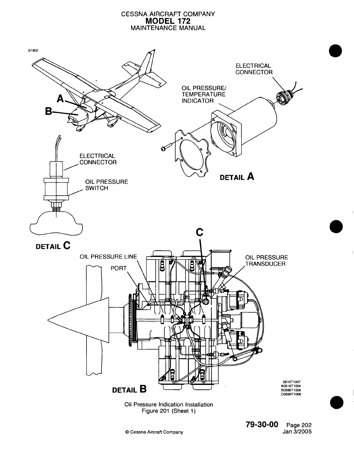
CESSNA
AIRCRAFT
COMPANY
MODEL
172
MAINTENANCE MANUAL
B
ELECTRICAL
CONNECTOR
OIL
PRESSURE/
TEMPERATURE
INDICATOR
ELECTRICAL
-
I/
CONNECTOR
mi
DETAIL
A
OIL PRESSURE
SWITCH
C
DETAIL
C
OIL
PRESSURE
''
s
-'
rf
onrn
run
ESSURE
DUCER
0510T1007
DETAIL
B
L
A0518T1034
B0556T1008
C0556T1006
Oil
Pressure Indication
Installation
Figure
201
(Sheet
1)
©
Cessna Aircraft
Company
79-30-00
Page
202
Jan
3/2005
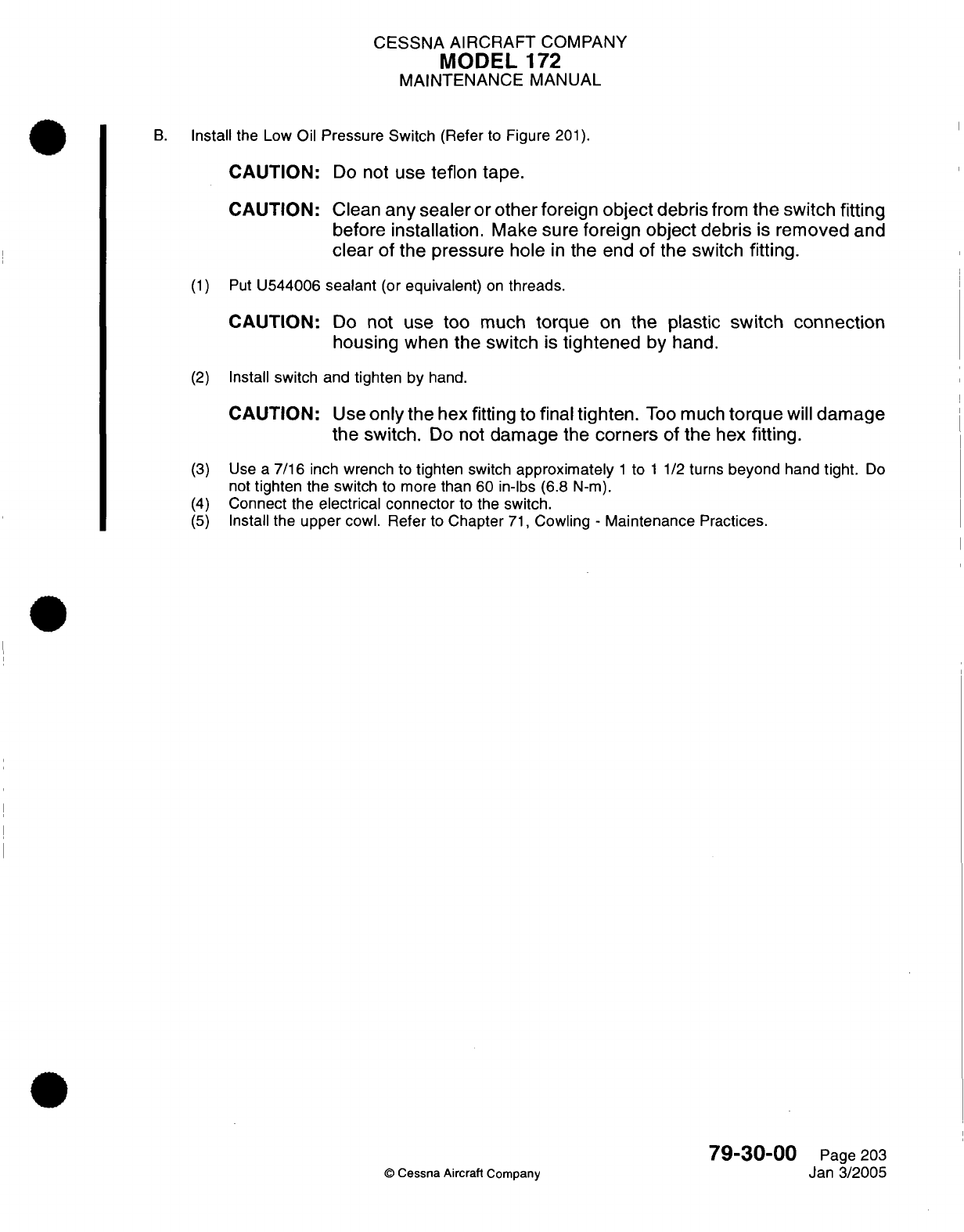
CESSNA
AIRCRAFT
COMPANY
MODEL
172
MAINTENANCE MANUAL
B.
Install
the Low
Oil
Pressure Switch
(Refer
to
Figure
201).
CAUTION:
Do
not
use
teflon tape.
CAUTION:
Clean
any sealer
or
other foreign
object
debris
from
the
switch
fitting
before Installation.
Make
sure foreign
object
debris
Is
removed
and
clear
of
the pressure
hole
In
the
end
of
the
switch
fitting.
(1)
Put
U544006
sealant
(or
equivalent)
on
threads.
CAUTION:
Do
not use
too
much
torque
on
the
plastic
switch connection
housing
when
the
switch
Is
tightened
by
hand.
(2)
Install
switch and
tighten
by
hand.
CAUTION:
Use
only
the
hex
fitting
to
final
tighten.
Too
much
torque
will
damage
the
switch.
Do
not
damage
the
corners
of
the
hex
fitting.
(3)
Use
a
7/16
inch
wrench
to
tighten switch
approximately
1
to
1
1/2
turns
beyond
hand
tight.
Do
not
tighten the
switch
to
more
than
60
in-lbs
(6.8
N-m).
(4)
Connect
the
electrical connector
to
the switch.
(5)
Install
the
upper
cowl.
Refer
to
Chapter
71,
Cowling
-
Maintenance
Practices.
79-30-00
Page
203
©
Cessna Aircraft
Company
Jan
3/2005
CESSNA
AIRCRAFT
COMPANY
MODEL
172
MAINTENANCE
MANUAL
OIL
TEMPERATURE
INDICATOR
-
TROUBLESHOOTING
1.
General
A.
On
airplanes
with
Garmin
G1000
the
oil
temperature
is
shown
on
the
Multi-Function
Display
(MFD).
Refer
to
the Garmin
G1000
Line
Maintenance
Manual
for
GDU
1040
troubleshooting.
B.
This
section
gives
a
troubleshooting
chart
and table
to help find
the
problem
that
will not
let
the
oil
temperature indicator
system
function
correctly.
To
help
with
troubleshooting
the
oil
temperature
indicator, refer
to
the
Model
172
1996
and
On
Wiring
Diagram
Manual.
(1)
The
table
that follows
is
to
be
used
with
the
troubleshooting
chart
(refer
to
Figure
101).
Table
101.
Oil
Temperature
Values
OHMS
497
+65
or
-65
36
+2
or
-2
Temperature
100°F
(38°C)
245°F
(118°C)
O
Cessna
Aircraft
Company
79-31-00
Page
101
Jan
2/2006
I
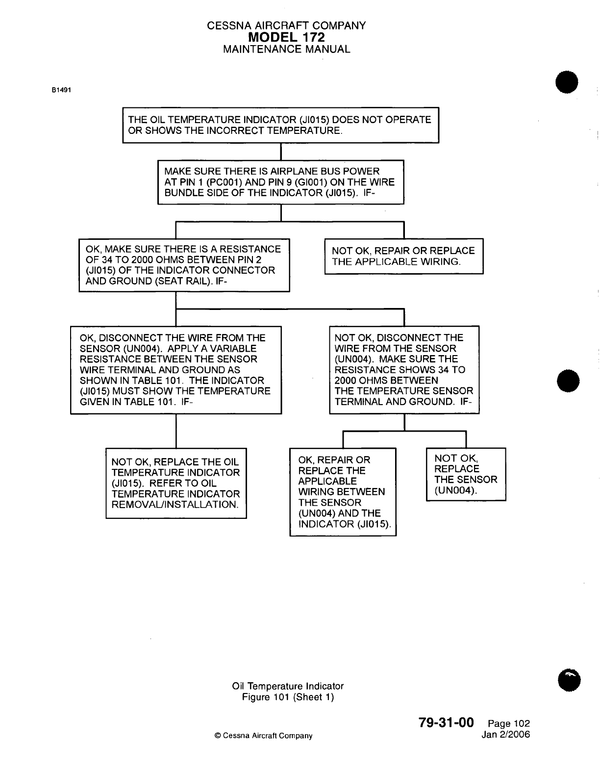
CESSNA
AIRCRAFT
COMPANY
MODEL
172
MAINTENANCE
MANUAL
B1491
THE
OIL
TEMPERATURE
INDICATOR
(JI015)
DOES
NOT OPERATE
OR
SHOWS
THE
INCORRECT TEMPERATURE.
MAKE
SURE THERE
IS
AIRPLANE
BUS
POWER
AT
PIN
1
(PC001)
AND
PIN
9
(GI001)
ON
THE
WIRE
BUNDLE
SIDE
OF
THE
INDICATOR (JI015).
IF-
I
OK,
MAKE
SURE
THERE
IS
A
RESISTANCE
OF
34
TO 2000
OHMS
BETWEEN
PIN
2
(JI015)
OF
THE
INDICATOR
CONNECTOR
AND
GROUND
(SEAT
RAIL).
IF-
OK,
DISCONNECT
THE WIRE
FROM
THE
SENSOR
(UN004).
APPLY
A
VARIABLE
RESISTANCE
BETWEEN
THE
SENSOR
WIRE TERMINAL
AND
GROUND AS
SHOWN
IN
TABLE
101.
THE
INDICATOR
(JI015)
MUST
SHOW
THE
TEMPERATURE
GIVEN
IN
TABLE
101.
IF-
NOT
OK, REPAIR
OR REPLACE
THE
APPLICABLE WIRING.
NOT
OK,
DISCONNECT THE
WIRE
FROM
THE
SENSOR
(UN004).
MAKE
SURE
THE
RESISTANCE SHOWS
34
TO
2000
OHMS
BETWEEN
THE
TEMPERATURE
SENSOR
TERMINAL
AND
GROUND.
IF-
I
NOT
OK,
REPLACE
THE
OIL
TEMPERATURE
INDICATOR
(JI015). REFER TO
OIL
TEMPERATURE
INDICATOR
REMOVAL/INSTALLATION.
OK,
REPAIR
OR
REPLACE
THE
APPLICABLE
WIRING
BETWEEN
THE SENSOR
(UN004)
AND THE
INDICATOR (JI015).
I
NOT
OK,
REPLACE
THE
SENSOR
(UN004).
Oil
Temperature
Indicator
Figure
101
(Sheet
1)
79-31-00
©
Cessna Aircraft
Company
Page
102
Jan
2/2006
CESSNA
AIRCRAFT
COMPANY
MODEL
172
MAINTENANCE MANUAL
OIL
TEMPERATURE
INDICATOR
-
MAINTENANCE
PRACTICES
1.
Description
and
Operation
A.
On
airplanes
with
Garmin
G1000,
the
oil
temperature
is
shown
on
the
Multi-Function
Display
(MFD).
The
oil
temperature sending
unit
is
the
same for
all
avionics packages.
B.
The
oil
temperature
system
has
a
sending
unit,
an oil
temperature/oil
pressure
indicator
and
wire
between the
two
components.
Oil
temperature
is
measured
in
the accessory case
area
and
gives
cockpit
readings
in
°F.
2.
Oil
Temperature
Sending
Unit
RemovaL/Installation
NOTE:
Oil
temperature
sending
unit removal
and
installation
is
typical
for
all avionics packages.
A.
Remove
the
Oil
Temperature
Sending
Unit
(Refer
to
Figure
201).
(1)
Remove
the upper
engine
cowl.
Refer
to
Chapter
71,
Cowling
-
Maintenance
Practices.
(2)
Disconnect the
ring
terminal
wiring
at
the
sending
unit.
(3)
Loosen
and
remove
the
sending
unit
from
the
accessory
case.
B.
Install
the
Oil
Temperature Sending
Unit
(Refer
to Figure
201).
(1)
Install
the
sending unit
to
the
accessory
case.
(2)
Attach
the
ring
terminal
wire
to
the
sending
unit.
(3)
Torque
the
jamnut
to
a
maximum of 20
in-lbs
(2.3
N-m).
(4)
Operate
the
engine
to
make
sure
the
indicator operates
correctly
and
there
are
no
leaks.
(5)
Install
the
upper
engine
cowl.
Refer
to
Chapter
71,
Cowling
-
Maintenance
Practices.
3.
Oil
Temperature/Oil Pressure
Indicator
Removal/Installation
A.
On
airplanes
with
Garmin
G1000,
the
oil
temperature
is
shown
on
the
Mult-Function Display
(MFD).
Refer
to
Control Display
Unit
-
Maintenance
Practices for
removal
and
installation procedures
of
the
MFD.
B.
For
removal
and
installation
of
the
Oil
Temperature/Oil
Pressure
Indicator,
refer
to
Oil
Pressure
Indicators
-
Maintenance Practices.
79-31-00
©
Cessna
Aircraft
Company
Page
201
Jan
3/2005
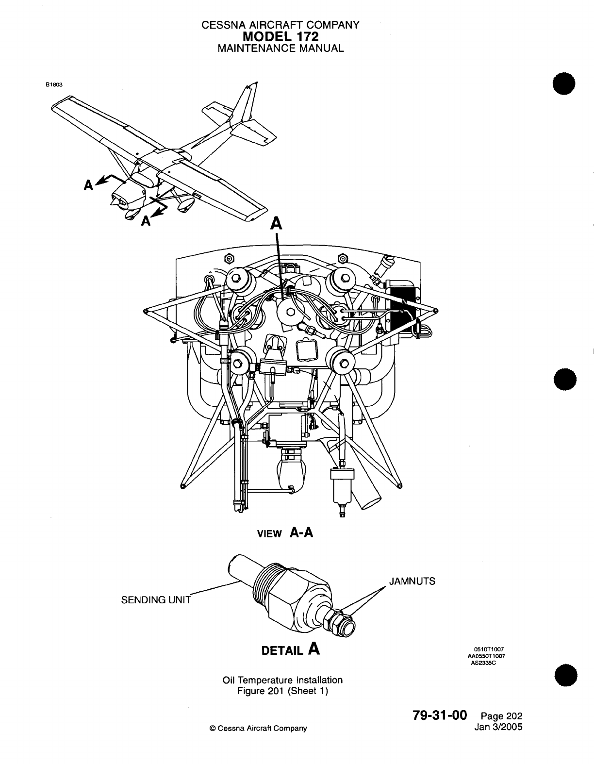
CESSNA
AIRCRAFT
COMPANY
MODEL
172
MAINTENANCE
MANUAL
B
A
VIEW
A-A
JAMNUTS
SENDING
DETAIL
A
Oil Temperature
Installation
Figure
201
(Sheet
1)
©
Cessna
Aircraft
Company
79-31-00
Page
202
Jan
3/2005
0510T1007
AA0550T1007
AS2335C
A

CHAPTER
STARTING
CESSNA
AIRCRAFT COMPANY
MODEL
172
MAINTENANCE
MANUAL
LIST
OF
EFFECTIVE
PAGES
CHAPTER-SECTION-SUBJECT
80-Title
80-List
of
Effective Pages
80-Record
of
Temporary
Revisions
80-Table
of
Contents
80-00-00
80-1
0-00
PAGE
Page
1
Pages
201
-204
©
Cessna
Aircraft
Company
80
-
LIST
OF
EFFECTIVE
PAGES
Page
1
of
1
Jul
1/2007
DATE
Apr
7/2003
Jul
1/2007
Temporary
Revision
Number
RECORD
OF
TEMPORARY
REVISIONS
Page
Number Issue
Date
By
Date
Removed
By
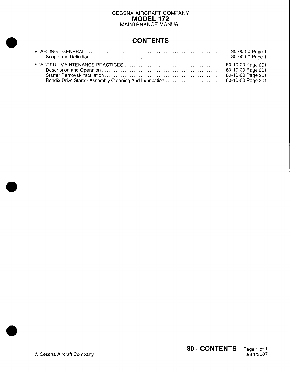
CESSNA
AIRCRAFT
COMPANY
MODEL
172
MAINTENANCE
MANUAL
CONTENTS
STARTING
-
GENERAL..............................
Scope
and
Definition.............................
STARTER
-
MAINTENANCE
PRACTICES
.....................
Description
and
Operation
..........................
Starter
Removal/installation..........................
Bendix
Drive
Starter Assembly Cleaning
And
Lubrication
............
80-00-00
Page
1
80-00-00
Page
1
80-1
0-00
Page
201
80-1
0-00
Page
201
80-1
0-00
Page
201
80-1
0-00
Page
201
80
-
CONTENTS
Page
1
of
1
Jul
1
/2007
©0
Cessna
Aircraft Company
CESSNA
AIRCRAFT
COMPANY
MODEL
172
MAINTENANCE
MANUAL
STARTING
-
GENERAL
1.
Scope
and
Definition
A.
This
chapter
is
comprised
of
a
single
section
on
the starting system.
The
section
details
removal
and
installation
instructions
for
the
engine
starter.
80-00-00
Page
1
©
Cessna
Aircraft
Company
Apr
7/2003
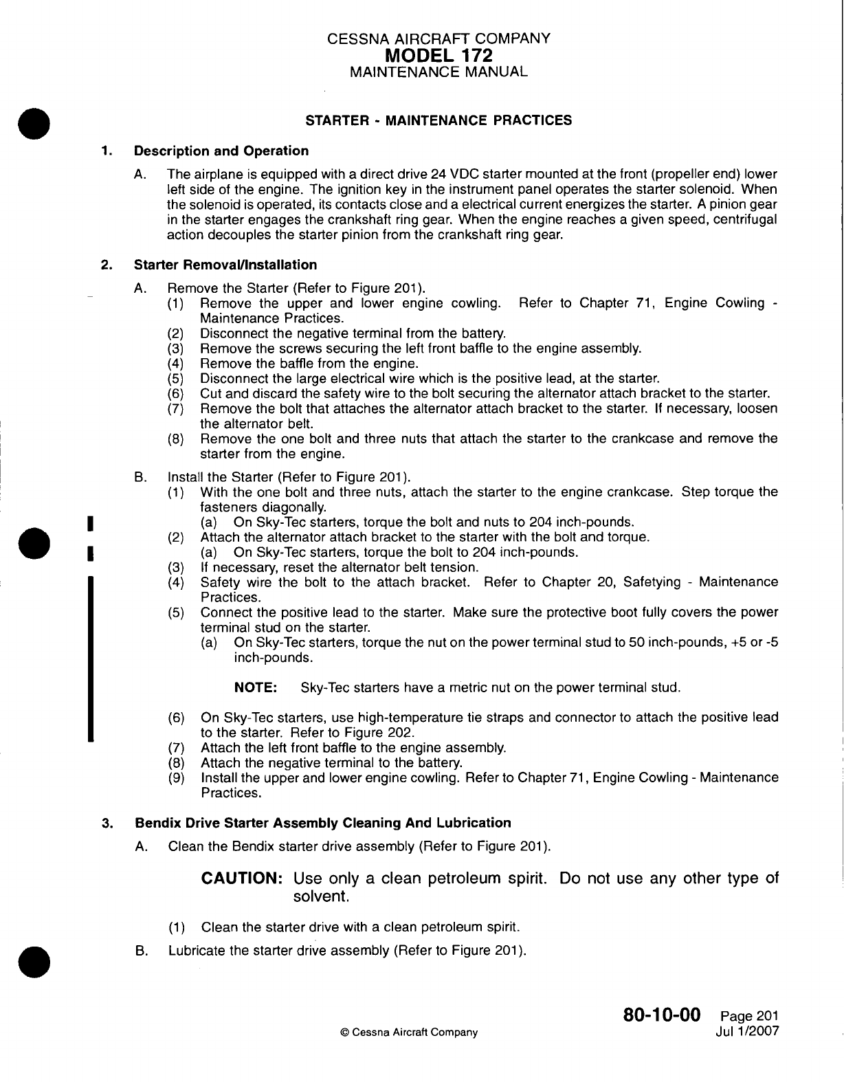
CESSNA AIRCRAFT
COMPANY
MODEL
172
MAINTENANCE
MANUAL
STARTER
-
MAINTENANCE PRACTICES
1.Description
and
Operation
A.
The
airplane
is
equipped
with
a
direct
drive
24
VDC
starter
mounted
at
the
front
(propeller
end)
lower
left
side
of
the
engine.
The ignition
key
in
the
instrument
panel
operates
the
starter solenoid.
When
the
solenoid
is
operated,
its
contacts
close
and
a
electrical
current energizes
the
starter.
A
pinion
gear
in
the
starter engages
the
crankshaft
ring
gear.
When
the
engine
reaches
a
given
speed,
centrifugal
action
decouples
the
starter pinion
from
the
crankshaft
ring
gear.
2.
Starter
RemovaVlnstallation
A.
Remove
the Starter
(Refer
to
Figure
201).
(1)
Remove
the
upper
and
lower
engine
cowling.
Refer
to
Chapter
71,
Engine Cowling
-
Maintenance
Practices.
(2)
Disconnect
the negative terminal
from the
battery.
(3)
Remove
the
screws
securing
the
left
front
baffle
to
the
engine
assembly.
(4)
Remove
the
baffle
from
the
engine.
(5)
Disconnect
the
large
electrical
wire
which
is
the
positive
lead,
at
the
starter.
(6)
Cut
and
discard
the
safety
wire
to
the
bolt
securing
the
alternator
attach
bracket
to the
starter.
(7)
Remove
the bolt that
attaches
the
alternator
attach
bracket
to
the starter.
If
necessary,
loosen
the
alternator
belt.
(8)
Remove
the
one
bolt
and
three
nuts
that attach the starter
to
the
crankcase
and
remove
the
starter
from
the
engine.
B.
Install
the Starter
(Refer
to
Figure
201)
(1)
With
the
one
bolt
and
three
nuts, attach
the
starter
to
the
engine crankcase.
Step
torque
the
fasteners
diagonally.
(a)
On
Sky-Tec
starters, torque
the
bolt
and nuts to
204
inch-pounds.
(2)
Attach
the
alternator
attach
bracket
to the
starter
with
the
bolt and torque.
*
~~~~(a)
On
Sky-Tec
starters, torque
the
bolt
to
204
inch-pounds.
(3) If
necessary,
reset the
alternator
belt
tension.
(4)
Safety
wire
the
bolt
to
the
attach bracket.
Refer
to
Chapter
20,
Safetying
-
Maintenance
Practices.
(5)
Connect
the
positive
lead to
the
starter. Make
sure
the
protective
boot
fully covers
the
power
terminal
stud
on the
starter.
(a)
On
Sky-Tec
starters,
torque
the
nut
on
the
power
terminal
stud
to
50
inch-pounds,
+5
or
-5
inch-pounds.
NOTE:
Sky-Tec
starters
have
a
metric
nut
on
the
power
terminal stud.
(6)
On
Sky-Tec
starters,
use
high-temperature
tie
straps
and
connector
to
attach
the
positive
lead
to
the
starter. Refer
to
Figure
202.
(7)
Attach
the
left
front baffle
to
the
engine
assembly.
(8)
Attach
the
negative
terminal
to
the
battery.
(9)
Install
the
upper
and
lower
engine
cowling.
Refer
to
Chapter
71,
Engine
Cowling
-
Maintenance
Practices.
3.
Bendix
Drive
Starter
Assembly
Cleaning
And
Lubrication
A.
Clean
the
Bendix
starter
drive
assembly
(Refer
to
Figure
201).
CAUTION:
Use
only
a
clean
petroleum spirit.
Do
not
use
any
other
type
of
solvent.
(1)
Clean
the
starter
drive
with
a
clean
petroleum
spirit.
B.
Lubricate the
starter
drive
assembly
(Refer
to
Figure
201).
80-1
0-00
Page
201
©
Cessna Aircraft
Company
Jul
1
/2007
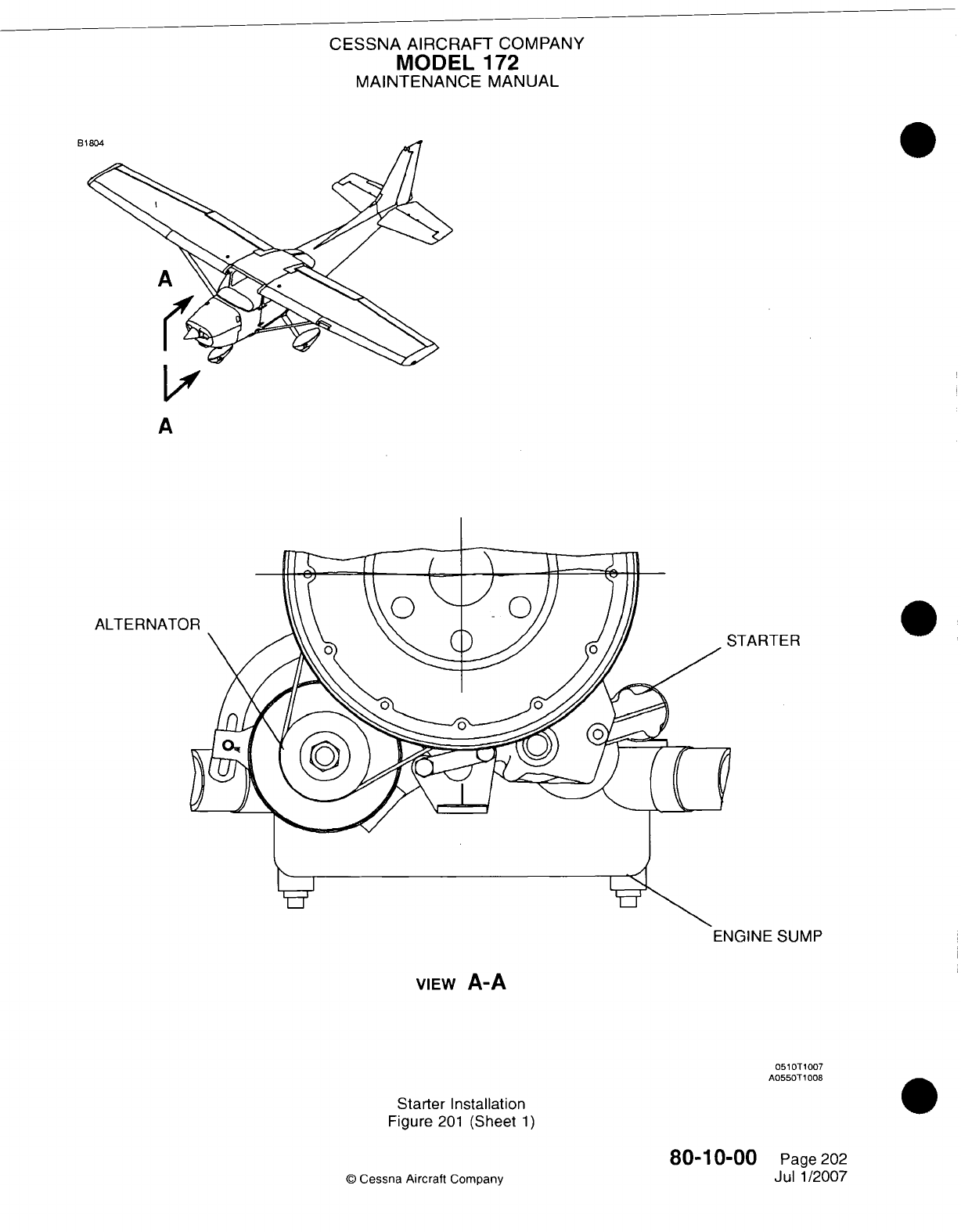
CESSNA
AIRCRAFT
COMPANY
MODEL
172
MAINTENANCE
MANUAL
Bi
LI
A
ALTERNATO
VIEw
A-A
0510T
1007
A055OT
1008
Starter
Installation
Figure
201
(Sheet
1)
80-10-00
©D
Cessna
Aircraft
Company
FER
SUMP
Page
202
Jul
1/2007
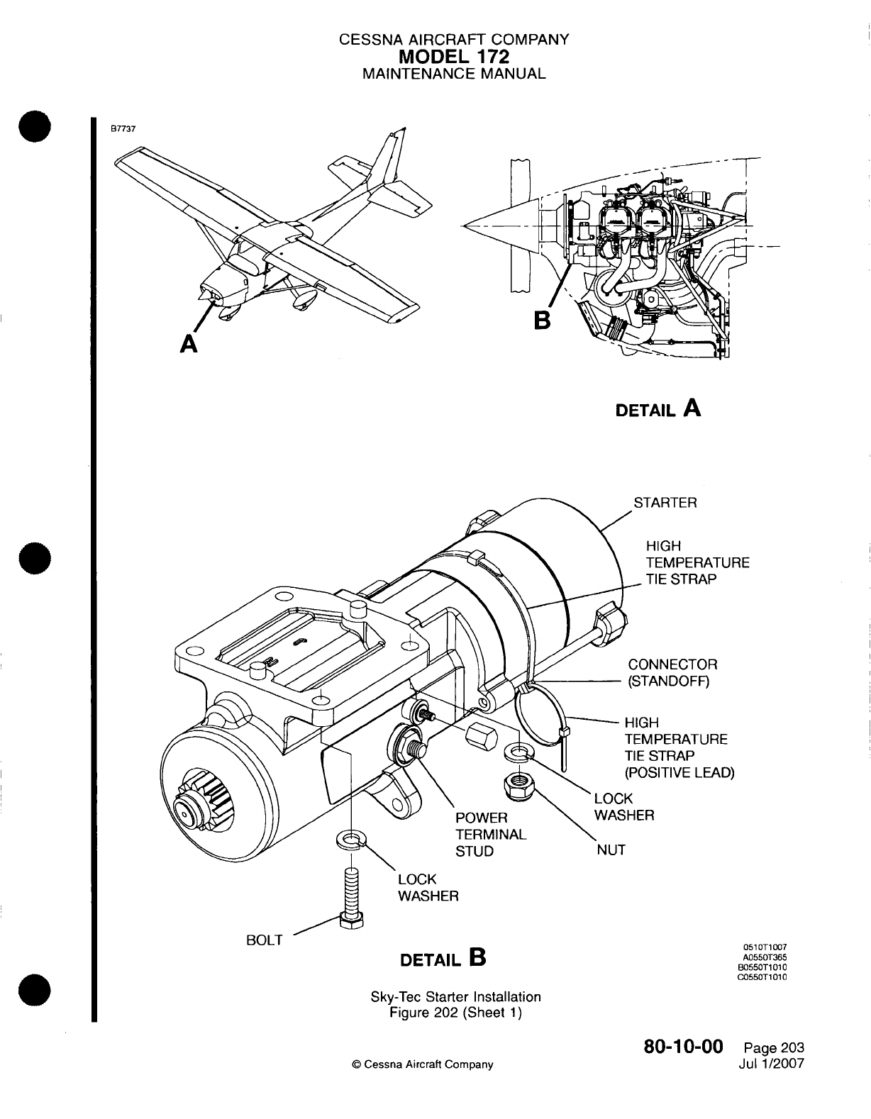
CESSNA AIRCRAFT
COMPANY
MODEL
172
MAINTENANCE
MANUAL
DETAIL
A
TARTER
HIGH
TEMPERATURE
TIE
STRAP
)NNECTOR
TAN
DOFF)
MPERATURE
:STRAP
)SITIVE
LEAD)
DETAIL
B
051 OTi
007
A0550T365
6055OT1
010
C055OT1010
Sky-Tec
Starter Installation
Figure
202 (Sheet
1)
80-1
0-00
©
Cessna
Aircraft
Company
Page
203
Jul
1/2007
bULlI
CESSNA
AIRCRAFT
COMPANY
MODEL
172
MAINTENANCE
MANUAL
CAUTION:
Do
not
use
grease,
oil
or
graphite lubricants.
Use
only
silicone
spray
lubricants
which
are
recommended
for correct
operation.
(1)
Lubricate
the
Bendix starter
drive
assembly
with
a
silicone
spray
such
as
Crown
Industrial
Products
silicone
spray
8034.
80-1
0-00
Page 204
©Cessna
Aircraft
Company
Jul
1/2007
