D2027 1 13 R172 SERIES (1977 THRU 1981) Cessna_172XP_R172_1977 1981_MM_D2027 Cessna 172XP 1977 1981 MM
User Manual: Cessna_172XP_R172_1977-1981_MM_D2027-1-13
Open the PDF directly: View PDF ![]() .
.
Page Count: 464 [warning: Documents this large are best viewed by clicking the View PDF Link!]
- D2027-1-13 - MODEL R172 SERIES (1977 THRU 1981)
- TEMPORARY REVISION NUMBER 5
- TEMPORARY REVISION NUMBER 4
- TEMPORARY REVISION NUMBER 3
- TEMPORARY REVISION NUMBER 2
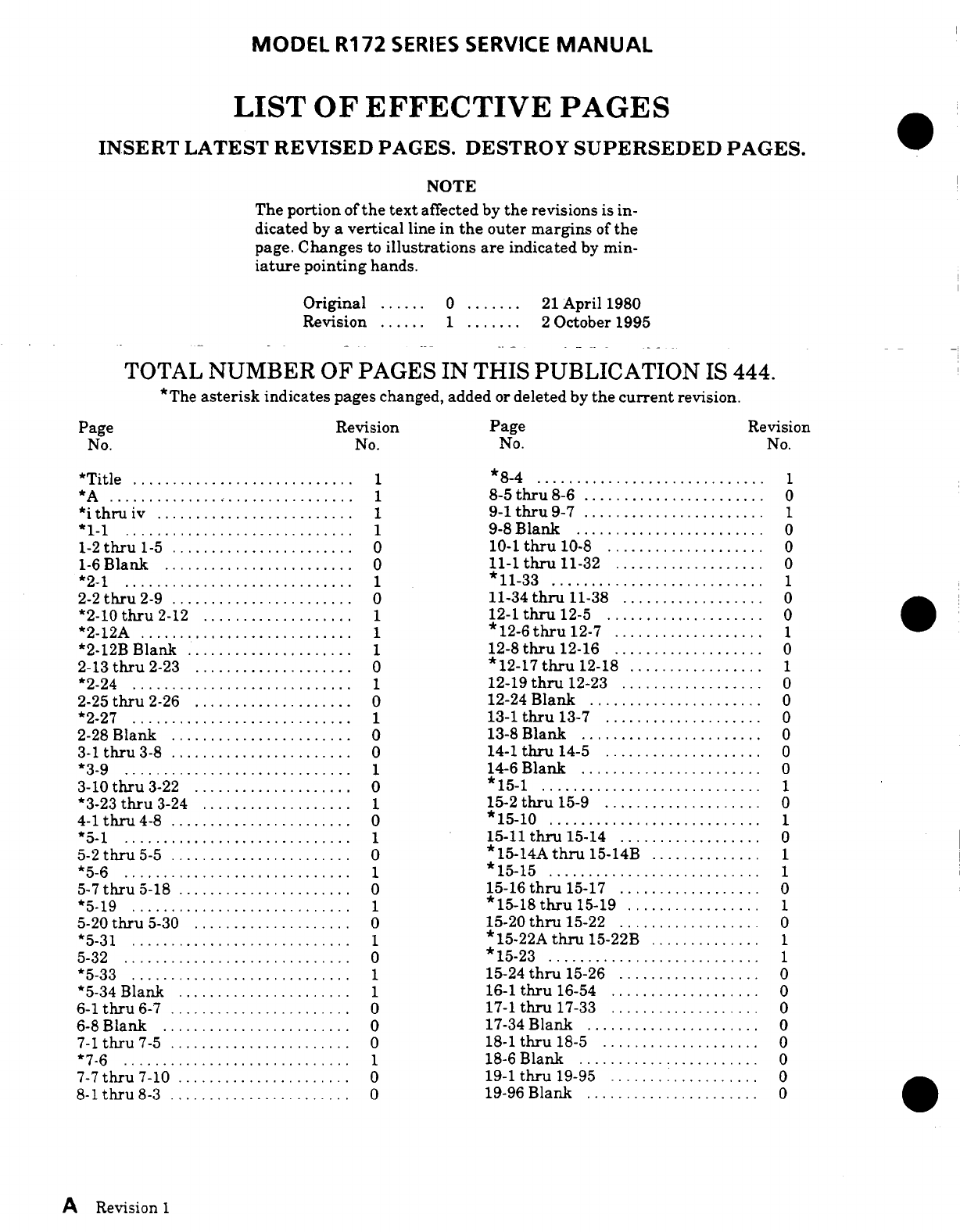
- LIST OF EFFECTIVE PAGES
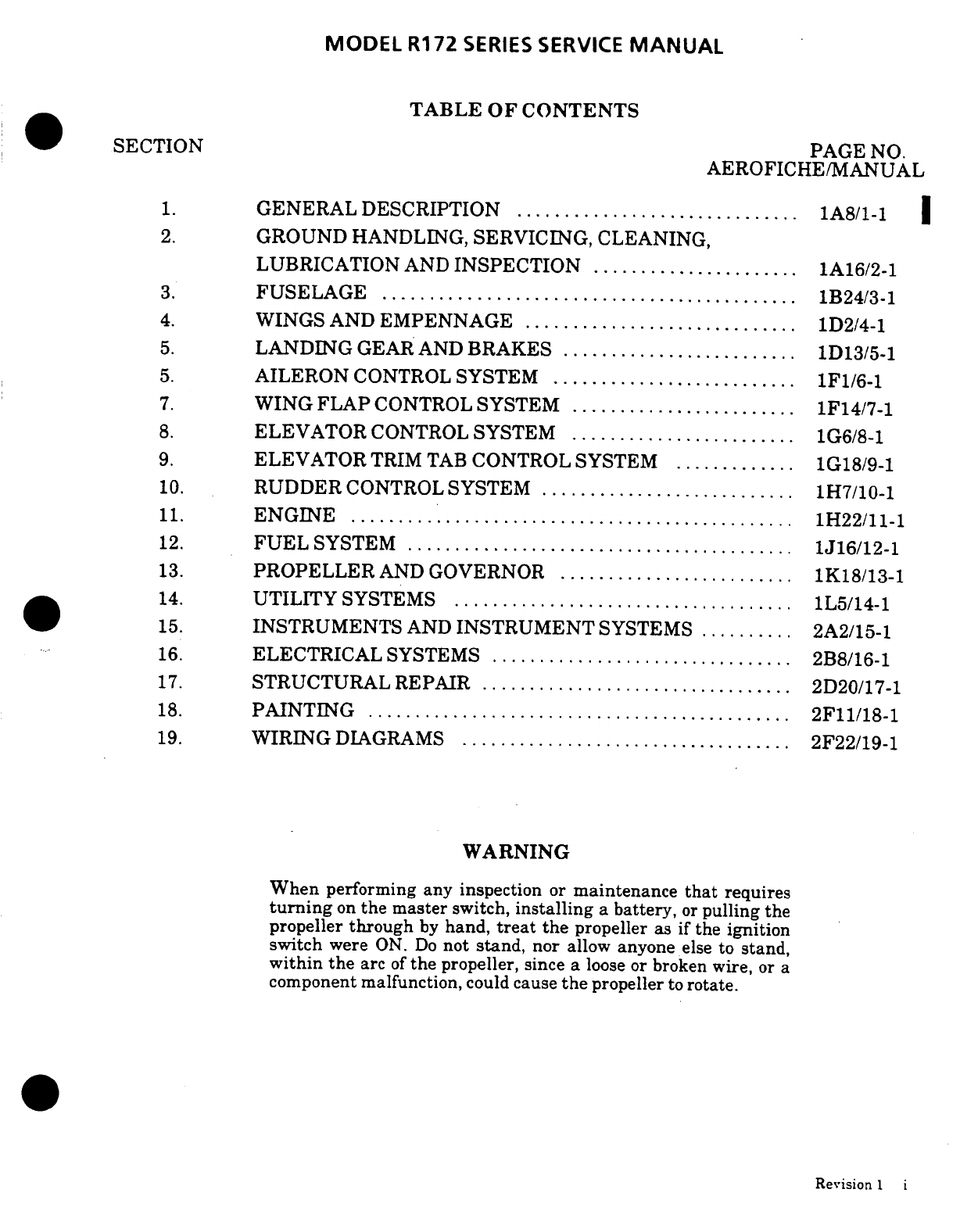
- TABLE OF CONTENTS
- CROSS REFERENCE LISTING OF POPULAR NAME VS. MODEL NUMBERS AND SERIALS
- INTRODUCTION
- KEEPING CESSNA PUBLICATIONS CURRENT
- SUPPLEMENTAL TYPE CERTIFICATE INSTALLATIONS
- CUSTOMER CARE SUPPLIES AND PUBLICATIONS CATALOG
- CUSTOMER COMMENTS ON MANUAL
- SECTION 1 - GENERAL DESCRIPTION
- SECTION 2 - GROUND HANDLING, SERVICING, CLEANING, LUBRICATION AND INSPECTION
- SECTION 3 - FUSELAGE
- SECTION 4 - WINGS AND EMPENNAGE
- SECTION 5 - LANDING GEAR AND BRAKES
- TABLE OF CONTENTS
- LANDING GEAR
- DESCRIPTION
- TROUBLE SHOOTING
- MAIN LANDING GEAR
- STEP BRACKET INSTALLATION
- FAIRINGS
- WHEEL REMOVAL
- WHEEL (MCCAULEY 2-PIECE)
- WHEEL (CLEVELAND)
- WHEEL (MCCAULEY WITH HUB AND CAPSCREWS)
- WHEEL INSTALLATION
- WHEEL AXLE REMOVAL
- WHEEL AXLE INSTALLATION
- BONDED AXLE REMOVAL
- BONDED AXLE INSTALLATION
- WHEEL ALIGNMENT CHECK
- WHEEL BALANCING
- NOSE GEAR
- DESCRIPTION
- TROUBLE SHOOTING
- REMOVAL
- INSTALLATION
- FAIRING REMOVAL
- FAIRING INSTALLATION
- WHEEL REMOVAL
- WHEEL DISASSEMBLY (THRU FR1720610)
- WHEEL INSPECTION AND REPAIR (THRU FR1720610)
- WHEEL REASSEMBLY (THRU FR1720610)
- WHEEL DISASSEMBLY (BEGINNING WITH FR1720611 AND R172-02000)
- WHEEL INSPECTION AND REPAIR (BEGINNING WITH FR1720611 AND R172000)
- WHEEL REASSEMBLY (BEGINNING WITH FR1720611 AND R172-02000)
- WHEEL DISASSEMBLY (CLEVELAND)
- WHEEL INSPECTION AND REPAIR (CLEVELAND)
- WHEEL REASSEMBLY (CLEVELAND)
- WHEEL INSTALLATION
- WHEEL BALANCING
- STRUT DISASSEMBLY
- STRUT INSPECTION AND REPAIR
- STRUT REASSEMBLY
- TORQUE LINKS
- SHIMMY DAMPENER
- DISASSEMBLY AND REASSEMBLY
- INSTALLATION
- STEERING SYSTEM
- BRAKE SYSTEM
- SECTION 6 - AILERON CONTROL SYSTEM
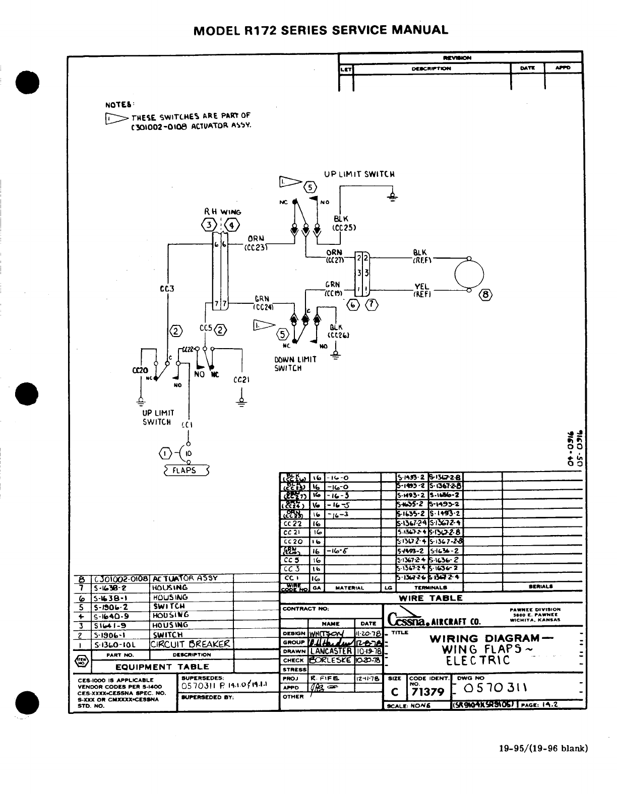
- SECTION 7 - WING FLAP CONTROL SYSTEM
- SECTION 8 - ELEVATOR CONTROL SYSTEM
- SECTION 9 - ELEVATOR TRIM TAB CONTROL SYSTEM
- SECTION 10 - RUDDER CONTROL SYSTEM
- SECTION 11 - ENGINE
- TABLE OF CONTENTS
- ENGINE COWLING
- ENGINE
- ENGINE BAFFLES
- ENGINE MOUNTS
- ENGINE OIL SYSTEM
- ENGINE FUEL SYSTEM
- INDUCTION AIR SYSTEM
- IGNITION SYSTEM
- MAGNETOS (BENDIX)
- MAGNETOS (SLICK)
- ENGINE CONTROLS
- EXHAUST SYSTEM
- STARTING SYSTEM
- EXTREME WEATHER MAINTENANCE
- SECTION 12 - FUEL SYSTEM
- SECTION 13 - PROPELLER AND GOVERNOR
- SECTION 14 - UTILITY SYSTEMS
- SECTION 15 - INSTRUMENTS AND INSTRUMENT SYSTEMS
- TABLE OF CONTENTS
- INSTRUMENTS AND INSTRUMENT SYSTEMS
- GENERAL
- INSTRUMENT PANEL
- PITOT AND STATIC SYSTEMS
- DESCRIPTION
- MAINTENANCE
- STATIC SYSTEM INSPECTION AND LEAKAGE TEST
- PITOT SYSTEM INSPECTION AND LEAKAGE TEST
- BLOWING OUT LINES
- REMOVAL AND INSTALLATION OF COMPONENTS
- ENCODING ALTIMETER
- DESCRIPTION
- REMOVAL AND INSTALLATION
- TROUBLE SHOOTING
- TRUE AIRSPEED INDICATOR
- DESCRIPTION
- REMOVAL AND INSTALLATION
- TROUBLE SHOOTING
- TROUBLE SHOOTING-ALTIMETER
- TROUBLE SHOOTING-VERTICAL SPEED INDICATOR
- TROUBLE SHOOTING-PITOT TUBE HEATER
- VACUUM SYSTEM
- ENGINE INDICATORS
- TACHOMETER
- MANIFOLD PRESSURE/FUEL FLOW INDICATOR
- CYLINDER HEAD TEMPERATURE GAGE
- OIL PRESSURE
- OIL TEMPERATURE GAGE
- ECONOMY MIXTURE INDICATOR
- FUEL QUANTITY INDICATING SYSTEM
- HOURMETER
- MAGNETIC COMPASS
- STALL WARNING SYSTEM
- TURN COORDINATOR
- TURN-AND-SLIP INDICATOR
- OUTSIDE AIR TEMPERATURE GAGE
- SECTION 16 - ELECTRICAL SYSTEMS
- TABLE OF CONTENTS
- ELECTRICAL SYSTEMS
- GENERAL
- ELECTRICAL POWER SUPPLY SYSTEM
- BATTERY POWER SYSTEM
- GROUND SERVICE RECEPTACLE
- ALTERNATOR POWER SYSTEM
- DESCRIPTION
- ALTERNATOR
- OVER-VOLTAGE WARNING SYSTEM
- ALTERNATOR VOLTAGE REGULATOR
- ALTERNATOR CONTROL UNIT
- RIGGING THROTTLE-OPERATED MICROSWITCH
- AUXILIARY ELECTRICAL FUEL PUMP FLOW RATE ADJUSTMENT
- AIRCRAFT LIGHTING SYSTEM
- LANDING AND TAXI LIGHTS (DUAL)
- NAVIGATION LIGHTS
- ANTI-COLLISION STROBE LIGHT
- FLASHING BEACON
- INSTRUMENT, AND DOME LIGHTS
- COURTESY LIGHTS
- COMPASS AND RADIO DIAL LIGHTING
- INSTRUMENT POST LIGHTING
- TRANSISTORIZED LIGHT DIMMING
- MAP LIGHTING
- CONTROL WHEEL MAP LIGHT
- PITOT HEATER
- CIGAR LIGHTER
- CLOCK
- EMERGENCY LOCATOR TRANSMITTER (THRU R1722287)
- EMERGENCY LOCATOR TRANSMITTER (BEGINNING WITH R1722288
- ELECTRICAL LOAD ANALYSIS CHART
- SECTION 17 - STRUCTURAL REPAIR
- TABLE OF CONTENTS
- STRUCTURAL REPAIR
- REPAIR CRITERIA
- EQUIPMENT AND TOOLS
- WING TWIST AND STABILIZER INCIDENCE
- REPAIR MATERIALS
- WING
- ELEVATORS AND RUDDER
- FIN AND STABILIZER
- FUSELAGE
- BONDED DOORS
- BULKHEADS
- REPLACEMENT OF HI-SHEAR RIVETS
- FIREWALL DAMAGE
- ENGINE MOUNT
- BAFFLES
- ENGINE COWLING
- REPAIR OF GLASS-FIBER CONSTRUCTED COMPONENTS
- SECTION 18 - PAINTING
- SECTION 19 - WIRING DIAGRAMS
- TABLE OF CONTENTS
- CIRCUIT FUNCTION AND SPECIFIC CIRCUIT CODE LETTERS
- D.C. POWER
- IGNITION
- FUEL AND OIL
- ENGINE INSTRUMENTS
- FLIGHT INSTRUMENTS
- OTHER INSTRUMENTS
- LIGHTING
- MAP AND AUXILIARY INSTRUMENT LIGHT
- COMPASS AND INSTRUMENT LIGHT
- COMPASS AND INSTRUMENT LIGHT
- INSTRUMENT PANEL POST LIGHTING
- INSTRUMENT PANEL POST LIGHTING
- DOME AND COURTESY LIGHTS
- LANDING AND TAXI LIGHT
- LANDING AND TAXI LIGHT
- LANDING AND TAXI LIGHT
- NAVIGATION LIGHTS
- FLASHING BEACON LIGHT
- MAP LIGHT - CONTROL WHEEL
- WING TIP STROBE LIGHT
- HEATING, VENTING AND DE-ICING
- CONTROL SURFACE SECTION
- D. C. POWER
- IGNITION
- FUEL AND OIL
- ENGINE INSTRUMENTS
- FLIGHT INSTRUMENTS
- OTHER INSTRUMENTS
- LIGHTING
- MAP AND AUXILIARY INSTRUMENT LIGHT
- COMPASS AND INSTRUMENT LIGHT
- COMPASS AND INSTRUMENT LIGHT
- INSTRUMENT PANEL POST LIGHTING
- INSTRUMENT PANEL POST LIGHTING
- DOME AND COURTESY LIGHTS
- LANDING AND TAXI LIGHT
- LANDING AND TAXI LIGHT
- NAVIGATION LIGHTS
- FLASHING BEACON LIGHT
- MAP LIGHT - CONTROL WHEEL
- WING TIP STROBE LIGHT
- HEATING, VENTING AND DE-ICING
- CONTROL SURFACE SECTION
Cessna
ATextron
Comoanv
Service
Manual
1977
Thru
1981
MODEL
R172
SERIES
i)
Member
of
GAMA
FAA
APPROVAL
HAS
BEEN
OBTAINED
ON
TECHNICAL
DATA
IN
THIS
PUBLICATION
THAT
AFFECTS
AIRPLANE
TYPE DESIGN.
REVISION
1
TO
THE
BASIC
MANUAL
INCORPORATES
TEMPORARY
REVISION
I,
DATED
3
OCTOBER,
1994.
COPYRIGHT
C
1995
CESSNA
AIRCRAFT
COMPANY
21
APRIL
1980
WICHITA,
KANSAS.
USA
D2027-1-13
REVISION
1
2
OCTOBER
1995
(RGI-50-8/00)
Cessna
A
Textron
Company
TEMPORARY
REVISION
NUMBER
5
DATE
5
April
2004
MANUAL
TITLE
Model
R172
Series
1977
Thru
1981
Service
Manual
MANUAL
NUMBER
-
PAPER
COPY
MANUAL
NUMBER
-
AEROFICHE
TEMPORARY
REVISION
NUMBER
D2027-1-13
D2027-1-13AF
D2027-1TR5
MANUAL
DATE
21
April
1980
REVISION NUMBER
1
DATE
2
October
1995
This
Temporary
Revision
consists
of
the
following
pages,
which
affect
and
replace
existing
pages
in
the
paper
copy
manual
and
supersede
aerofiche
information.
AEROFICHE
FICHE/FRAME
1/B17
1/B20
SECTION
AEROFICHE
PAGE
FICHE/FRAME
REASON
FOR
TEMPORARY
REVISION
1.
To
add
the
cleaning
interval
of
the
engine
fuel
injection nozzles.
FILING
INSTRUCTIONS
FOR
THIS
TEMPORARY
REVISION
1.
For
Paper
Publications, file this
cover
sheet behind
the
publication's
title
page
to
identify
the
inclusion
of
the
Temporary Revision
into
the
manual.
Insert
the
new
pages into the
publication
at
the
appropriate
locations
and
remove
and
discard
the
superseded
pages.
2.
For
Aerofiche
Publications,
draw
a
line
with
permanent
red
ink
marker,
through
any aerofiche
frame
(page)
affected
by
the Temporary
Revision.
This will
be
a
visual
identifier that
the
information
on
the
frame
(page)
is
no
longer valid
and
the
Temporary
Revision
should
be
referenced.
For
"added"
pages
in
a
Temporary
Revision,
draw
a
vertical
line
between
the
applicable
frames.
Line
should
be
wide
enough
to
show
on
the
edges
of
the
pages.
Temporary
Revisions should
be
collected
and
maintained
in
a
notebook
or
binder
near
the
aerofiche
library
for quick
reference.
©
Cessna Aircraft
Company
SECTION
2
2
PAGE
24
27
TEMPORARY
REVISION
NUMBER
4
DATE
7
October
2002
MANUAL
TITLE
Model
R172
Series
1977
Thru
1981
Service
Manual
MANUAL NUMBER
-
PAPER
COPY
MANUAL
NUMBER
-
AEROFICHE
TEMPORARY REVISION
NUMBER
D2027-1-13
D2027-1-13AF
D2027-1TR4
MANUAL
DATE
21
April
1980
REVISION
NUMBER
1
DATE
2
October
1995
This
Temporary Revision
consists
of
the following
pages, which
affect
and
replace existing
pages
in
the
paper
copy
manual
and supersede
aerofiche information.
PAGE
24
24A/Deleted
27
28
29
30
24A
24B
24C
AEROFICHE
FICHE/FRAME
1/B17
NA
1/B20
Added
Added
Added
2/B02
2/B03
Added
AEROFICHE
SECTION
PAGE
FICHE/FRAME
REASON
FOR
TEMPORARY
REVISION
1.
To
add
a
Component
Time
Limits
section
and
a
fuel
quantity
indicating
system operational
test.
FILING INSTRUCTIONS
FOR THIS TEMPORARY
REVISION
1.
For
Paper
Publications,
file
this
cover
sheet
behind
the
publication's title
page
to
identify
the
inclusion
of
the
Temporary
Revision
into
the
manual.
Insert
the
new
pages
into
the
publication
at
the
appropriate
locations
and
remove
and
discard
the
superseded
pages.
2.
For
Aerofiche
Publications,
draw
a
line with
permanent
red
ink marker,
through
any
aerofiche
frame
(page)
affected
by
the
Temporary
Revision. This
will
be
a visual
identifier
that
the
information
on
the
frame
(page)
is no
longer
valid
and
the
Temporary
Revision
should
be
referenced.
For
"added"
pages
in
a
Temporary
Revision, draw
a
vertical
line
between the applicable
frames.
Line
should
be
wide
enough
to show
on
the
edges
of the
pages.
Temporary
Revisions
should
be
collected
and
maintained
in
a
notebook
or
binder
near
the
aerofiche
library
for
quick
reference.
COPYRIGHT
©
2002
CESSNA
AIRCRAFT
COMPANY
WICHITA,
KANSAS,
USA
A
SECTION
2
2
2
2
2
2
15
15
15
TEMPORARY
REVISION
NUMBER
3
DATED
7
January
2000
MANUAL
TITLE MODEL R172
SERIES
1977 THRU
1981
SERVICE
MANUAL
MANUAL
NUMBER
-
PAPER
COPY
D2027-1-13
AEROFICHE
D2027-1-13AF
TEMPORARY
REVISION
NUMBER
PAPER
COPY
D2027-1TR3
AEROFICHE
N/A
MANUAL
DATE
21
APRIL
1980
REVISION
NUMBER
1
DATE
2
OCTOBER
1995
This
Temporary
Revision
consists
of the
following
pages,
which
affect
existing
pages
in
the
paper
copy
manual
and
supersede aerofiche
information.
AEROFICHE
AEROFICHE
SECTION
PAGE
FICHE/FRAME
SECTION PAGE FICHE/FRAME
2
24A
Added
2
28A
Added
17
4A
Added
17
4B
Added
REASON
FOR
TEMPORARY
REVISION
To
include
the
inspection
requirements of
Cessna
Service Bulletin
SEB99-18.
To
provide
additional
information
for
the stop
drilling
of
cracks that originate
at the
trailing
edge
of
control
surfaces
with
corrugated
skins.
FILING
INSTRUCTIONS
FOR
THIS TEMPORARY
REVISION
For
Paper
Publications:
File
this
cover sheet behind
the
publication's
title
page
to
identify
the
inclusion
of the
Temporary
Revision
into
the
manual.
Insert the
new
pages
into
the
publication
at
the
appropriate
locations.
Draw
a
line, with
a
permanent
red
ink
marker,
through
any
superceded
information.
For
Aerofiche
Publications:
Draw
a
line
through
any
aerofiche
frame
(page)
affected
by
the
Temporary
Revision
with
a
permanent
red
ink
marker.
This
will
be
a
visual
identifier that
the information
on
the
frame
(page)
is
no
longer
valid
and
the Temporary
Revision
should
be
referenced.
For
"added"
pages
in
a
Temporary
Revision,
draw
a
vertical
line
between
the
applicable
frames
which
is
wide
enough
to
show
on
the
edges
of the
pages.
Temporary
Revisions
should
be
collected
and
maintained
in
a
notebook or
binder
near
the
aerofiche
library
for
quick
reference.
COPYRIGHT
©2000
CESSNA
AIRCRAFT
COMPANY
WICHITA,
KANSAS,
USA
TEMPORARY
REVISION
NUMBER
2
DATED April
3,
1998
MANUAL
TITLE
Model
R172 Series
Service
Manual
(1977
Thru
1981)
MANUAL
NUMBER -
PAPER
COPY
D2027-1-13
AEROFICHE
D2027-1-13AF
TEMPORARY
REVISION
NUMBER -
PAPER
COPY
D2027-1TR2-13
AEROFICHE
N/A
MANUAL
DATE
21
April 1980
REVISION
NUMBER
1
DATE
2
October
1995
This
Temporary
Revision
consists
of
the
following
pages,
which
affect
and
replace existing pages
in
the
paper
copy
manual
and
supersede
aerofiche
information.
CHAPTER/
CHAPTER/
SECTION/ AEROFICHE
SECTION/
AEROFICHE
SUBJECT
PAGE FICHE/FRAME
SUBJECT
PAGE
FICHE/FRAME
1 1
1A08
1
17
Added
1
2
1A09
1
18
Added
1
3
1A10
1
19
Added
1
4
1A11
1
20
Added
1
5
1A12
1
21
Added
1
6
Added
1
22
Added
1
7
Added
1
23
Added
1
8
Added
13
1
K18
1
9
Added
13
2
1K19
1
10
Added
13 3
1K20
1
11
Added
13
4
1K21
1
12
Added
13
5
1K22
1
13
Added
13
6
1K23
1
14
Added
13
7
1K24
1
15
Added
13
8
Added
1
16
Added
REASON
FOR
TEMPORARY
REVISION
1.
To
add
wet
torque
values
for
McCauley
propeller
hub
bolts
and
add
standard
torque
value
tables.
FILING
INSTRUCTIONS
FOR
THIS
TEMPORARY
REVISION
For
Paper
Publications:
File
this
cover
sheet
behind
the
publication's
title
page to
identify
inclusion
of
the
temporary
revision
in
the
manual.
Insert
the
new
pages
in
the
publication
at
the
appropriate
locations
and
remove
and
discard
the
superseded pages.
For
Aerofiche Publications:
Draw
a
line,
with
a
permanent
red
ink
marker,
through
any
aerofiche
frame
(page)
affected
by
the
temporary
revision.
This
will
be
a
visual
identifier
that
the information
on
the
frame
(page)
is
no
longer
valid
and
the
temporary
revision should
be
referenced.
For
"added"
pages
in a
temporary
revision,
draw
a
vertical
line
between
the
applicable
frames.
Line
should
be
wide
enough
to
show
on
the
edges of
the
pages.
Temporary
revisions should
be
collected
and
maintained
in
a
notebook
or
binder
near
the
aerofiche
library
for
quick
reference.
COPYRIGHT
©
1998
CESSNA
AIRCRAFT
COMPANY
WICHITA,
KANSAS,
USA
MODEL
R172
SERIES
SERVICE
MANUAL
LIST
OF
EFFECTIVE
PAGES
INSERT
LATEST
REVISED
PAGES.
DESTROY
SUPERSEDED
PAGES.
NOTE
The
portion
of
the
text
affected
by
the
revisions
is
in-
dicated
by
a
vertical
line
in
the
outer
margins
of
the
page.
Changes
to
illustrations
are
indicated
by
min-
iature
pointing
hands.
Original
......
0
.......
21
April
1980
Revision
......
1
.......
2
October
1995
TOTAL
NUMBER
OF PAGES IN
THIS
PUBLICATION
IS
444.
*The
asterisk
indicates
pages
changed,
added
or
deleted
by
the
current
revision.
Page
Revision
Page
Revision
No.
No.
No.
No.
*Title
............................ 1
*8-4
.............................
1
*A
.............................. 1
8-5
thru
8-6
.......................
0
*i
thru
iv
......................... 1
9-1
thru
9-7
.......................
1
*1-1
............................. 1
9-8
Blank
........................
0
1-2
thru
1-5
.......................
0 10-1
thru
10-8
............
..
......
0
1-6
Blank
........................
0
11-1
thru
11-32
...................
0
*2-1
............................. 1
*11-33
...........................
1
2-2
thru
2-9
.......................
0
11-34
thru
11-38
..................
0
*2-10
thru
2-12
................... 1
12-1
thru
12-5
....................
0
*2-12A
........................... 1
*12-6
thru
12-7
...................
1
*2-12B
Blank
..................... 1
12-8
thru
12-16
...................
0
2-13
thru
2-23
..................
.
0
*12-17
thru
12-18
.................
1
*2-24
............................ 1
12-19
thru
12-23
..................
0
2-25
thru
2-26
....................
0
12-24
Blank
......................
0
*2-27
............................ 1
13-1
thru
13-7
....................
0
2-28
Blank
.......................
0
13-8
Blank
.......................
0
3-1
thru
3-8
.......................
0
14-1
thru
14-5
....................
0
*3-9
............................. 1
14-6
Blank
.......................
0
3-10
thru
3-22
....................
0
*15-1
............................
1
*3-23
thru
3-24
................... 1
15-2
thru
15-9
....................
0
4-1
thru
4-8
.......................
0
*15-10
...........................
1
*5-1
............................ 1
15-11
thru
15-14
..................
0
5-2
thru
5-5
.......................
0
*15-14A
thru
15-14B
..............
1
*5-6
............................. 1
*15-15
...........................
1
5-7
thru
5-18
......................
0
15-16
thru
15-17
..................
0
*5-19
............................ 1
*15-18
thru
15-19
.
................
1
5-20
thru
5-30
....................
0
15-20
thru
15-22
..................
0
*5-31
............................ 1
*15-22A
thru
15-22B
..............
1
5-32
.............................
0
*15-23
...........................
1
*5-33
............................ 1
15-24
thru
15-26
..................
0
*5-34
Blank
...................... 1
16-1
thru
16-54
...................
0
6-1
thru
6-7
.......................
0
17-1
thru
17-33
...................
0
6-8
Blank
........................
0
17-34
Blank
......................
0
7-1
thru
7-5
.......................
0
18-1
thru
18-5 ..
.........
.........
0
*7-6
............................. 1
18-6
Blank
.......................
0
7-7
thru
7-10
......................
0
19-1
thru
19-95
...................
0
8-1
thru
8-3
.......................
0
19-96
Blank
.....................
0
A
Revision
1
MODEL
R172
SERIES
SERVICE
MANUAL
TABLE
OF
CONTENTS
SECTION
PAGE
NO.
AEROFICHE/MANUAL
1.
GENERAL
DESCRIPTION
..............................
1A8/1-1
2.
GROUND
HANDLING,
SERVICING,
CLEANING,
LUBRICATION
AND
INSPECTION
......................
1A16/2-1
3.
FUSELAGE
............................................
1B24/3-1
4.
WINGS
AND
EMPENNAGE
.............................
1D2/4-1
5.
LANDING
GEAR
AND
BRAKES
.........................
1D13/5-1
5.
AILERON
CONTROL
SYSTEM
..........................
1F1/6-1
7.
WING
FLAP
CONTROL
SYSTEM ........................
1F14/7-1
8.
ELEVATOR
CONTROL
SYSTEM
........................
1G6/8-1
9.
ELEVATOR
TRIM
TAB
CONTROL
SYSTEM
.............
1G18/9-1
10.
RUDDER
CONTROL
SYSTEM
...........................
1H7/10-1
11.
ENGINE
...............................................
1H22/11-1
12.
FUEL
SYSTEM
......................................... 1J16/12-1
13.
PROPELLER
AND
GOVERNOR
.........................
1K18/13-1
14.
UTILITY
SYSTEMS
....................................
1L5/14-1
15.
INSTRUMENTS
AND
INSTRUMENT
SYSTEMS
..........
2A2/15-1
16.
ELECTRICAL
SYSTEMS
................................
2B8/16-1
17.
STRUCTURAL
REPAIR
................................. 2D20/17-1
18.
PAINTIN
G
.............................................
2F11/18-1
19.
WIRING
DIAGRAMS
...................................
2F22/19-1
WARNING
When
performing
any
inspection
or
maintenance
that
requires
turning
on
the
master
switch,
installing
a
battery,
or
pulling
the
propeller
through
by
hand,
treat
the
propeller
as
if the
ignition
switch
were
ON.
Do
not
stand,
nor
allow
anyone
else
to
stand,
within
the
arc
of
the
propeller,
since a
loose
or
broken
wire,
or
a
component
malfunction,
could
cause
the
propeller
to
rotate.
Revision
1
i
MODEL
R172
SERIES
SERVICE
MANUAL
CROSS
REFERENCE
LISTING
OF
POPULAR
NAME
VS.
MODEL
NUMBERS
AND
SERIALS
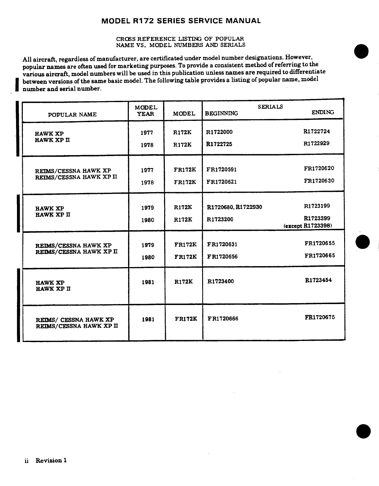
All
aircraft,
regardless
of
manufacturer, are
certificated
under
model
number
designations.
However,
popular
names
are
often
used
for
marketing
purposes.
To
provide
a
consistent
method
of
referring
to
the
various
aircraft,
model
numbers
will
be
used
in
this
publication
unless
names
are
required
to
differentiate
between versions
of
the
same
basic
model.
The
following
table
provides
a
listing
of
popular
name,
model
number
and
serial
number.
MODEL
SERIALS
POPULAR
NAME
YEAR
MODEL
BEGINNING
ENDING
HAWK
XP
1977
R172K
R1722000 R1722724
HAWK
XP
II
1978
R172K R1722725
R1722929
REIMS/CESSNA
HAWK
XP
1977
FR172K
FR1720591 FR1720620
REIMS/CESSNA
HAWK
XP
II
1978
FR172K
FR1720621 FR1720630
HAWK
XP
1979
R172K
R1720680,R1722930
R1723199
HAWK
XP
H
1980
R172K
R1723200
R1723399
(except
R1723398)
REIMS/CESSNA
HAWK
XP
1979
FR172K
FR1720631
FR1720655
REIMS/CESSNA
HAWK
XP
II
1980
FR172K
FR1720656
FR1720665
HAWK
XP
1981
R172K R1723400 R1723454
HAWK
XP
II
REIMS/
CESSNA
HAWK
XP
1981
FR172K FR1720666
FR1720675
REIMS/CESSNA
HAWK
XP
II
ii
Revision
1
MODEL
R172
SERIES
SERVICE
MANUAL
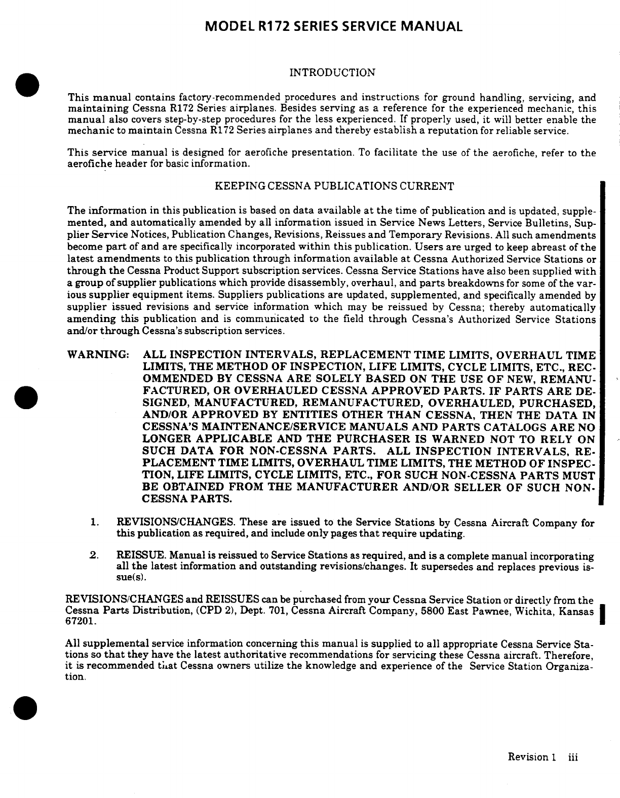
INTRODUCTION
This
manual
contains
factory-recommended
procedures
and
instructions
for
ground
handling,
servicing,
and
maintaining
Cessna
R172
Series
airplanes.
Besides
serving
as
a
reference
for
the
experienced
mechanic,
this
manual
also covers
step-by-step
procedures
for
the
less
experienced.
If
properly
used,
it
will
better
enable
the
mechanic
to
maintain
Cessna
R172
Series
airplanes
and
thereby
establish
a
reputation
for
reliable
service.
This
service
manual
is
designed
for
aerofiche
presentation.
To
facilitate
the
use of
the
aerofiche,
refer
to
the
aerofiche
header
for
basic
information.
KEEPING
CESSNA
PUBLICATIONS
CURRENT
The
information
in
this
publication
is
based
on
data
available
at
the
time
of
publication
and
is
updated,
supple-
mented,
and
automatically
amended
by
all
information
issued
in
Service
News
Letters,
Service
Bulletins,
Sup-
plier
Service
Notices,
Publication
Changes,
Revisions,
Reissues
and
Temporary
Revisions.
All
such
amendments
become
part
of
and
are
specifically
incorporated
within
this
publication.
Users
are
urged
to
keep
abreast
of
the
latest
amendments
to
this
publication through information
available
at
Cessna
Authorized
Service
Stations
or
through the
Cessna
Product
Support subscription
services.
Cessna
Service
Stations
have
also
been
supplied
with
a
group
of
supplier
publications
which
provide
disassembly,
overhaul,
and
parts
breakdowns
for
some
of
the
var-
ious
supplier
equipment
items.
Suppliers
publications
are
updated,
supplemented,
and
specifically
amended
by
supplier
issued
revisions
and
service
information
which
may
be
reissued
by
Cessna;
thereby
automatically
amending
this
publication
and
is
communicated
to
the
field
through
Cessna's
Authorized
Service
Stations
and/or
through
Cessna's
subscription
services.
WARNING:
ALL
INSPECTION
INTERVALS,
REPLACEMENT
TIME
LIMITS, OVERHAUL
TIME
LIMITS,
THE METHOD
OF
INSPECTION,
LIFE
LIMITS,
CYCLE
LIMITS,
ETC., REC-
OMMENDED
BY
CESSNA
ARE
SOLELY
BASED
ON
THE
USE
OF
NEW,
REMANU-
FACTURED,
OR
OVERHAULED
CESSNA
APPROVED
PARTS.
IF
PARTS
ARE
DE-
SIGNED, MANUFACTURED,
REMANUFACTURED,
OVERHAULED,
PURCHASED,
AND/OR
APPROVED
BY
ENTITIES
OTHER
THAN CESSNA,
THEN
THE
DATA
IN
CESSNA'S
MAINTENANCE/SERVICE
MANUALS
AND
PARTS
CATALOGS
ARE
NO
LONGER
APPLICABLE
AND
THE
PURCHASER IS
WARNED
NOT
TO
RELY
ON
SUCH
DATA
FOR
NON-CESSNA
PARTS.
ALL
INSPECTION
INTERVALS,
RE-
PLACEMENT TIME
LIMITS,
OVERHAUL
TIME LIMITS,
THE
METHOD OF
INSPEC-
TION,
LIFE
LIMITS,
CYCLE
LIMITS,
ETC.,
FOR
SUCH
NON-CESSNA
PARTS
MUST
BE
OBTAINED
FROM
THE
MANUFACTURER
AND/OR
SELLER
OF
SUCH
NON-
CESSNA
PARTS.
1. REVISIONS/CHANGES.
These are
issued
to
the
Service
Stations
by
Cessna
Aircraft
Company
for
this
publication as
required,
and
include
only
pages
that
require
updating.
2.
REISSUE. Manual
is
reissued
to
Service
Stations
as
required,
and
is
a
complete
manual
incorporating
all
the
latest
information
and
outstanding
revisions/changes.
It
supersedes and
replaces
previous
is-
sue(s).
REVISIONS/CHANGES
and
REISSUES
can
be
purchased
from
your
Cessna
Service
Station
or
directly
from
the
Cessna
Parts
Distribution,
(CPD
2),
Dept.
701,
Cessna
Aircraft
Company,
5800
East
Pawnee,
Wichita,
Kansas
67201.
All
supplemental
service
information
concerning
this
manual
is
supplied
to
all
appropriate
Cessna
Service
Sta-
tions
so
that
they
have
the
latest authoritative
recommendations
for
servicing
these
Cessna
aircraft.
Therefore,
it
is
recommended
tuat
Cessna owners
utilize
the
knowledge
and experience
of
the
Service
Station
Organiza-
tion.
Revision
1
iii
MODEL
R172
SERIES
SERVICE
MANUAL
SUPPLEMENTAL
TYPE
CERTIFICATE
INSTALLATIONS
Inspection,
maintenance
and
parts requirements
for
supplemental
type
certificate
(STC)
installations
are
not
in-
cluded
in
this
manual.
When
an
STC
installation
is
incorporated
on
the
airplane,
those
portions
of
the
airplane
affected
by
the
installation
must
be
inspected
in
accordance
with
the
inspection
program
published
by
the
owner
of
the
STC.
Since STC
installations
may
change
systems
interface,
operating
characteristics
and
component
loads
or
stresses
on
adjacent
structures,
Cessna
provided
inspection
criteria
may not
be
valid
for
airplanes
with
STC
installations.
CUSTOMER
CARE
SUPPLIES
AND
PUBLICATIONS
CATALOG
A
Customer
Care
Supplies
and
Publications
Catalog
is
available
from
your
Cessna
Service
Station
or
directly
from
the
Cessna
Parts
Distribution,
(CPD
2)
Dept.
701,
Cessna
Aircraft
Company,
5800
East
Pawnee, Wichita,
Kansas
67201.
The-Supplies
and
Publications
catalog
lists
all
publications
and
Customer
Care
Supplies
avail-
able
from Cessna
for
prior
year
models
as
well
as new
products.
CUSTOMER
COMMENTS ON
MANUAL
Cessna
Aircraft
Company
has
endeavored
to
furnish
you
with
an accurate,
useful,
up-to-date
manual.
This man-
ual
can
be
improved
with
your
help.
Please
use the
return
card,
provided
with your
manual,
to
report
any
errors,
discrepancies,
and
omissions
in
this
manual
as
well
as
any
comments
you
wish
to
make.
iv
Revision
1
MODEL
R172
SERIES
SERVICE
MANUAL
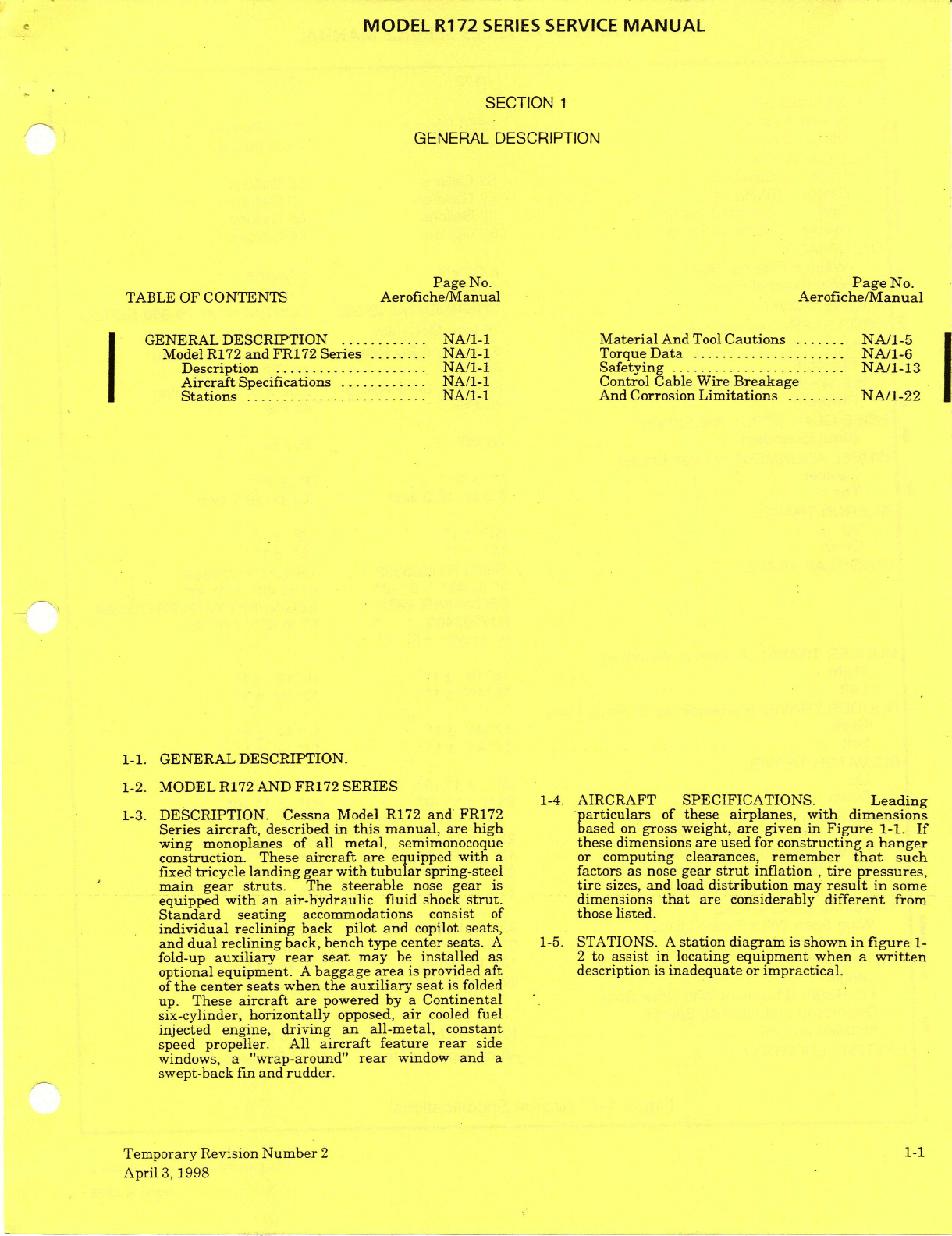
SECTION
1
GENERAL
DESCRIPTION
Page
No.
Page
No.
TABLE
OF
CONTENTS
Aerofiche/Manual
Aerofiche/Manual
GENERAL
DESCRIPTION
............
NA/1-1
Material
And
Tool
Cautions
.......
NA/1-5
Model R172
and
FR172
Series
........
NA/1-1
Torque
Data
.....................
NA/1-6
Description
.....................
NA/1-1
Safetying
........................
NA/1-13
Aircraft
Specifications ............
NA/1-1
Control
Cable Wire
Breakage
Stations
.........................
NA/1-1
And
Corrosion
Limitations
........
NA/1-22
1-1.
GENERAL
DESCRIPTION.
1-2.
MODEL
R172
AND
FR172
SERIES
1-4.
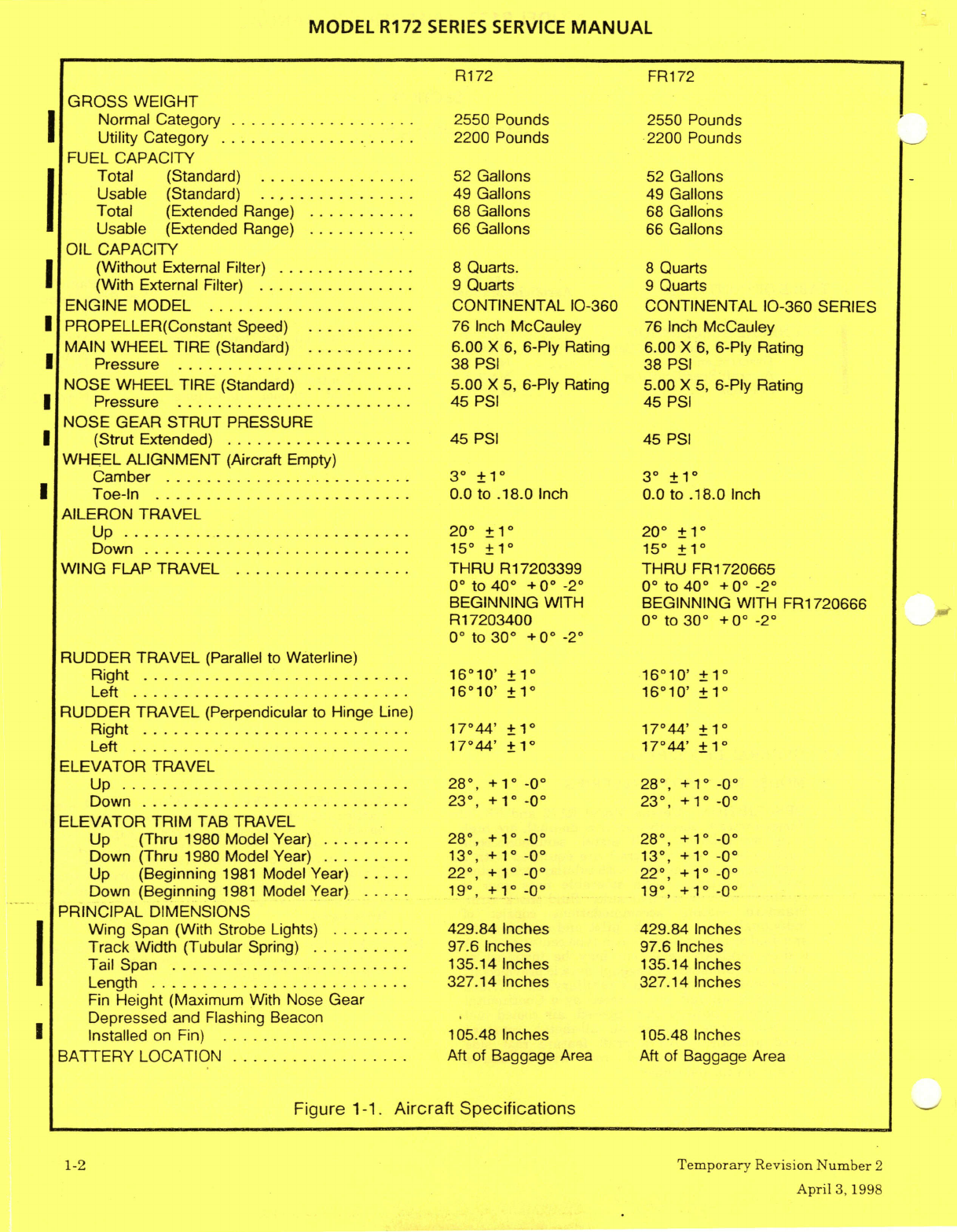
AIRCRAFT
SPECIFICATIONS.
Leading
1-3.
DESCRIPTION.
Cessna
Model
R172
and
FR172
particulars
of
these
airplanes,
with
dimensions
Series
aircraft,
described
in
this
manual,
are high
based
on
gross
weight,
are
given
in
Figure
1-1.
If
wing
monoplanes
of
all metal,
semimonocoque
these
dimensions
are
used
for
constructing
a
hanger
construction.
These
aircraft
are
equipped
with
a or
computing clearances,
remember
that
such
fixed
tricycle
landing
gear
with
tubular
spring-steel
factors as
nose
gear
strut
inflation
,
tire
pressures,
main
gear
struts.
The
steerable
nose
gear
is
tire
sizes,
and
load
distribution
may
result
in
some
equipped
with
an
air-hydraulic
fluid
shock
strut.
dimensions
that
are
considerably
different
from
Standard
seating
accommodations consist
of
those
listed.
individual
reclining
back
pilot
and
copilot
seats,
and
dual
reclining
back,
bench
type
center
seats.
A
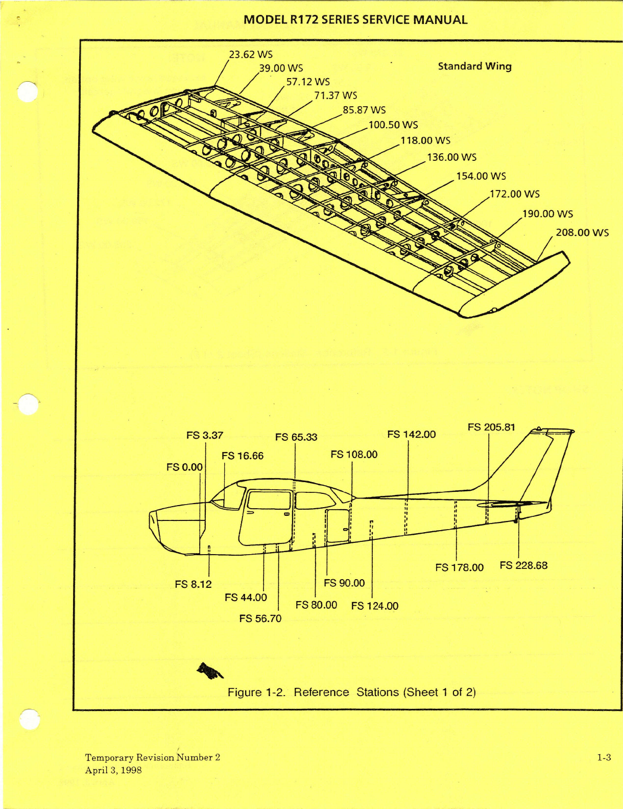
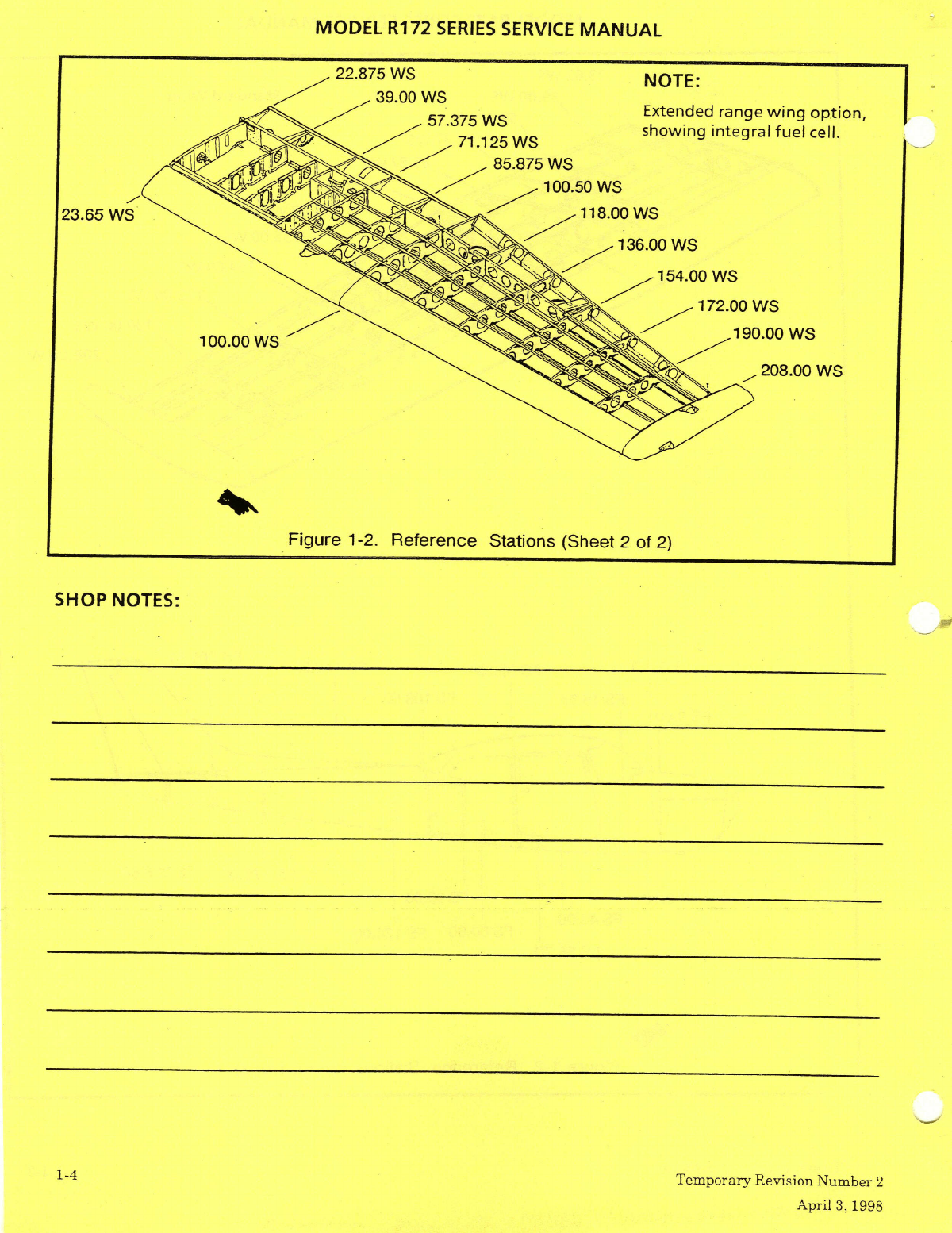
1-5.
STATIONS.
A
station
diagram
is
shown
in
figure
1-
fold-up
auxiliary
rear
seat
may
be
installed
as
2
to
assist
in
locating
equipment when
a
written
optional
equipment.
A
baggage
area
is
provided
aft
description
is
inadequate
or
impractical.
of
the
center
seats when
the
auxiliary
seat
is
folded
up.
These
aircraft are
powered
by
a
Continental
six-cylinder,
horizontally
opposed,
air
cooled
fuel
injected
engine,
driving an
all-metal,
constant
speed
propeller.
All
aircraft
feature
rear
side
windows,
a
"wrap-around"
rear
window
and
a
swept-back
fin
and rudder.
Temporary
Revision
Number
2
1-1
April
3,
1998
MODEL
R172
SERIES
SERVICE
MANUAL
R172
FR172
GROSS
WEIGHT
Normal Category
...................
2550 Pounds
2550 Pounds
Utility
Category
....................
2200
Pounds
2200 Pounds
FUEL
CAPACITY
Total
(Standard)
................
52
Gallons
52
Gallons
Usable
(Standard)
................
49
Gallons
49
Gallons
Total
(Extended
Range)
...........
68
Gallons
68
Gallons
Usable
(Extended
Range)
...........
66
Gallons
66
Gallons
OIL
CAPACITY
(Without
External
Filter)
..............
8
Quarts.
8
Quarts
(With
External
Filter)
................
9
Quarts
9
Quarts
ENGINE
MODEL
....................
CONTINENTAL
10-360
CONTINENTAL
10-360 SERIES
PROPELLER(Constant
Speed)
...........
76
Inch
McCauley
76
Inch
McCauley
MAIN
WHEEL
TIRE
(Standard)
...........
6.00
X
6,
6-Ply
Rating
6.00
X
6,
6-Ply
Rating
Pressure
........................
38
PSI
38
PSI
NOSE
WHEEL
TIRE
(Standard)
........... 5.00
X
5,
6-Ply
Rating
5.00
X
5,
6-Ply
Rating
Pressure ........................
45
PSI
45
PSI
NOSE
GEAR
STRUT
PRESSURE
(Strut
Extended)
...................
45
PSI
45
PSI
WHEEL
ALIGNMENT
(Aircraft
Empty)
Camber
.........................
3
±1
3
±
1
Toe-In
..........................
0.0
to
.18.0
Inch
0.0
to
.18.0
Inch
AILERON
TRAVEL
Up
.............................
20
±1°
20
±1°
Down
...........................
15
±1°
15
±1
WING
FLAP
TRAVEL
..................
THRU
R17203399
THRU
FR1720665
0°
to
40
+0°
-2
0°
to
40°
+0°
-2
BEGINNING
WITH
BEGINNING
WITH
FR1720666
R17203400
0"
to
30
+0°
-2°
0°
to
30
+00 -20
RUDDER TRAVEL
(Parallel
to
Waterline)
Right
...........................
16°10'
±1°
16°10'
±10
Left
............................
16°10'
±1
16°10'
±1
RUDDER
TRAVEL
(Perpendicular
to
Hinge
Line)
Right
...........................
17°44'
+1°
17°44'
+1°
Left ............................
17°44'
±10
17°44'
±1°
ELEVATOR TRAVEL
Up
............................
28°,
+1
-0°
28,
+1°
-0°
Down
...........................
23,
+1°
-0°
23,
+10°
-0
ELEVATOR TRIM
TAB
TRAVEL
Up
(Thru
1980
Model
Year) .........
28°,
+ 1
-0
28°,
+1°
-0°
Down
(Thru
1980
Model Year)
.........
13°,
+1
-0°
13,
+1
-0°
Up
(Beginning
1981
Model
Year)
.....
22,
+1° -0° 22°,
+1°
-0°
Down
(Beginning
1981
Model
Year)
.....
19,
+1°
-0 19,
+1°
-0°
PRINCIPAL DIMENSIONS
Wing
Span
(With
Strobe
Lights)
........
429.84
Inches
429.84 Inches
Track
Width
(Tubular
Spring)
..........
97.6
Inches
97.6
Inches
Tail
Span
........................
135.14
Inches
135.14 Inches
Length ..........................
327.14
Inches
327.14 Inches
Fin
Height
(Maximum
With Nose
Gear
Depressed and
Flashing Beacon
Installed
on Fin)
...................
105.48
Inches
105.48
Inches
BATTERY
LOCATION
..................
Aft
of
Baggage
Area Aft
of Baggage
Area
Figure
1-1.
Aircraft
Specifications
1-2
Temporary
Revision
Number
2
April
3,1998
MODEL
R172
SERIES
SERVICE
MANUAL
23.62
WS
FS
3.37
FS
65.33
Figure
1-2.
Reference
Stations
(Sheet
1
of
2)
cooo
Figure
1-2.
Reference
Stations
(Sheet
1
of
2)
Temporary
Revision
Number
2 1-3
April
3,
1998
MODEL
R172
SERIES
SERVICE
MANUAL
22.875
WS
NOTE:
showing
integral
fuel
cell.
71.125
WS
85.875
WS
23.65
WS
136.00 WS
208.00 WS
Figure
1-2.
Reference
Stations
(Sheet
2
of
2)
SHOP
NOTES:
1-4
Temporary
Revision
Number
2
April
3,
1998
MODEL
R172
SERIES
SERVICE
MANUAL
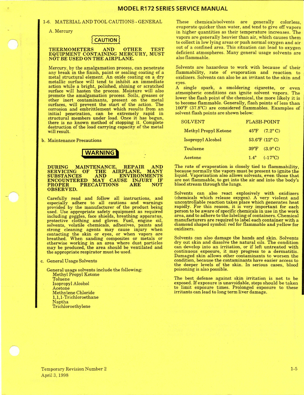
1-6.
MATERIAL
AND TOOL CAUTIONS
-GENERAL
These
chemicals/solvents
are generally
colorless,
evaporate
quicker
than
water,
and
tend
to
give
off
vapors
A.
Mercury in
higher
quantities
as
their
temperature
increases.
The
vapors
are
generally
heavier
than
air,
which
causes
them
to
collect
in
low
lying
areas
or
push
normal
oxygen
and
air
THERMOMETERS
AND
OTHER
TEST
out
of
a confined
area.
This
situation
can
lead
to
oxygen
EQUIPMENT
CONTAINING MERCURY,
MUST
deficient
atmospheres.
Many
general
usage
solvents
are
NOT
BE
USED
ON
THE
AIRPLANE.
also
flammable.
Mercury,
by
the
amalgamation
process,
can
penetrate
Solvents
are hazardous
to
work
with because
of
their
any
break
in
the
finish,
paint
or
sealing
coating
of
a
flammability,
rate
of
evaporation and
reaction
to
metal
structural
element.
An
oxide
coating
on
a
dry
oxidizers.
Solvents can
also
be
an
irritant
to
the skin
and
metallic
surface
will
tend
to
inhibit
an
immediate
eyes.
action
while
a
bright,
polished,
shining
or
scratched
A
single
spark,
a
smoldering
cigarette,
or even
surface
will
hasten
the
process.
Moisture
will
also atmospheric
conditions
can
ignite
solvent
vapors. The
promote
the
amalgamation
process.
Soils,
greases
or lower
the
flash
point
of
the
chemical,
the
more
likely
it
is
other
inert
contaminants,
present
on
the
metal
surfaces,
will
prevent
the
start
of
the
action.
The to
become
flammable.
Generally,
flashpoints
of
less
than
corrosion
and
embrittlement
which
results
from
an
100°F
(37.8°C)
are
considered
flammables.
Examples
of
initial penetration,
can
be
extremely
rapid in
solvent
flash points
are
shown below:
structural
members
under
load.
Once
it
has
begun,
there
is
no
known
method
of
stopping
it.
Complete SOLVENT
FLASH-POINT
destruction
of
the
load
carrying
capacity
of
the
metal
will
result.
Methyl
Propyl
Ketone
45°F
(7.2
°
C)
b.
Maintenance
Precautions
Isopropyl
Alcohol
53.6°F
(12
°
C)
Touluene
39°F
(3.9
°
C)
WARNING
Acetone
1.4
°
(-17°C)
DURING
MAINTENANCE,
REPAIR
AND
The
rate
of
evaporation
is
closely
tied
to
flammability,
SERVICING OF
THE AIRPLANE,
MANY
because
normally
the
vapors
must
be
present to
ignite
the
SUBSTANCES
AND
ENVIRONMENTS
liquid.
Vaporization
also
allows
solvents,
even
those
that
ENCOUNTERED
MAY
CAUSE
INJURY
IF
are
not
flammable,
to
get
into
the
air
and
into
the
body's
PROPER
PRECAUTIONS
ARE
NOT
blood
stream
through
the
lungs.
OBSERVED.
Solvents can
also
react
explosively
with
oxidizers
Carefully
read
and
follow
all
instructions,
and
(chemicals
which
release
oxygen).
A
very
violent
and
especially
adhere to
all
cautions
and
warnings
uncontrollable
reaction
takes
place
which
generates
heat
provided
by
the
manufacturer
of
the
product being rapidly. For
this
reason,
it
is very
important
for
each
used.
Use
appropriate
safety equipment
as
required
person
to
be
aware
of
specific
chemicals
in
use
in
the
work
including
goggles, face
shields,
breathing
apparatus,
area,
and
to
adhere
to
the
labeling
of
containers.
Chemical
protective clothing
and
gloves.
Fuel,
engine
oil,
manufacturers
are
required
to label
each
container
with
a
solvents,
volatile
chemicals, adhesives,
paints
and
diamond
shaped
symbol:
red
for
flammable
and
yellow
for
strong
cleaning
agents
may
cause
injury
when
oxidizers.
contacting
the skin
or eyes, or
when
vapors
are
breathed.
When
sanding
composites
or
metals
or
Solvents
can
also damage
the
hands and
skin.
Solvents
otherwise
working
in
an
area
where
dust
particles
dry
out
skin
and
dissolve
the
natural
oils.
The condition
may
be
produced,
the
area
should
be
ventilated and
can
develop
into
an
irritation,
or
if
left
untreated
with
the
appropriate
respirator
must
be
used.
continuous
exposure,
it
may
progress
to
a
dermatitis.
Damaged
skin
allows
other contaminants
to
worsen
the
c.
General
Usage
Solvents condition,
because
the
contaminants
have
easier
access to
the
deeper levels
of
the
skin.
In
serious
cases,
blood
General
usage
solvents
include
the
following:
poisoning
is
also possible.
Methyl Propyl Ketone
Toluene
The
best
defense
against
skin
irritation
is
not
to
be
Isopropyl
Alcohol
exposed.
If
exposure
is
unavoidable, steps
should
be
taken
Acetone to
limit
exposure
times.
Prolonged
exposure
to
these
Methylene
Chloride
irritants
can
lead
to
long
term liver
damage.
1,1,1-Trichloroethane
Naptha
Trichloroethylene
Temporary
Revision
Number
2
1-5
April
3,
1998
MODEL
R172
SERIES
SERVICE
MANUAL
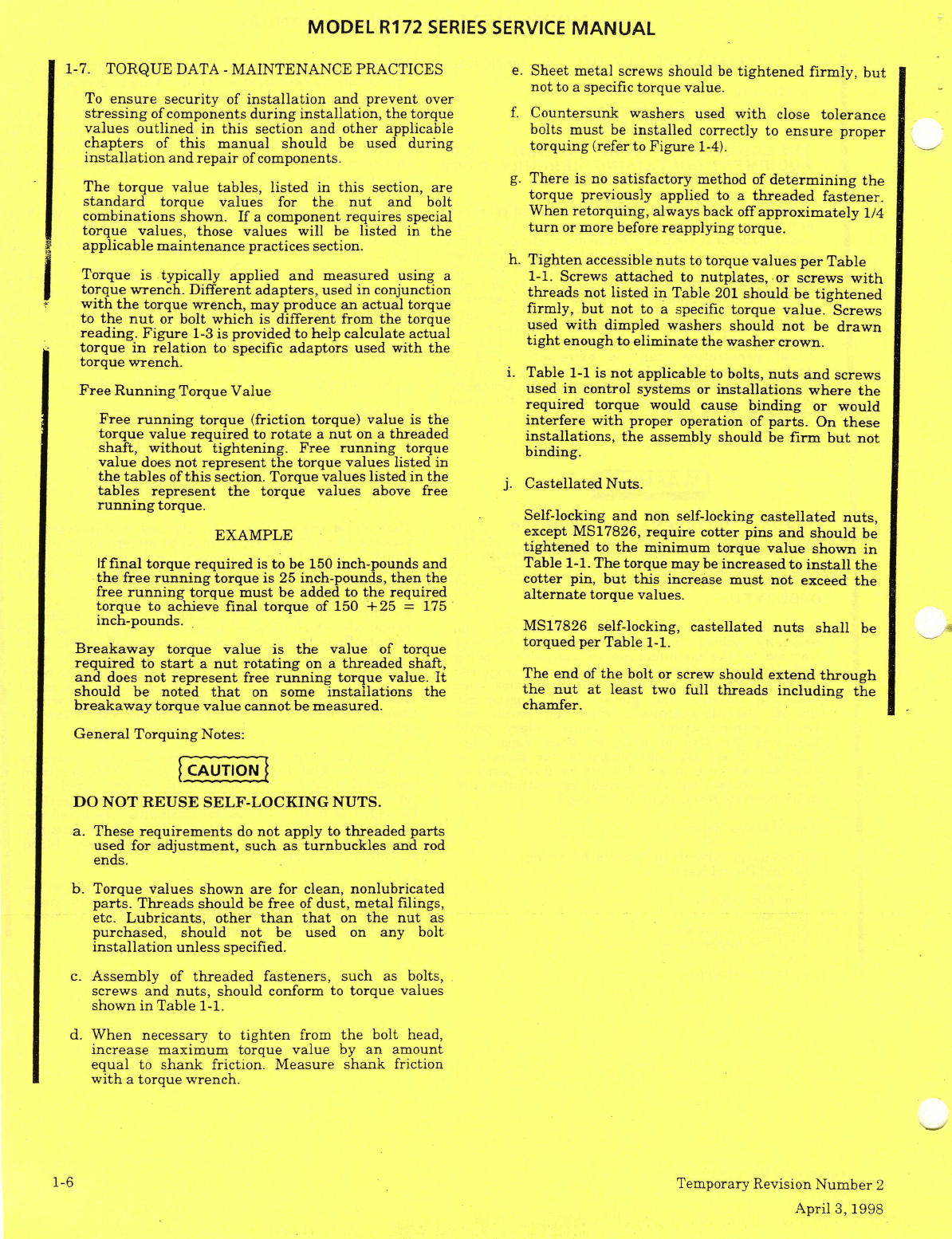
1-7.
TORQUE
DATA
- MAINTENANCE
PRACTICES
e.
Sheet
metal
screws
should
be
tightened
firmly,
but
not
to
a
specific
torque
value.
To
ensure
security
of
installation
and
prevent
over
stressing
of
components
during installation,
the
torque
f. Countersunk
washers
used
with
close
tolerance
values
outlined
in
this
section
and
other
applicable bolts
must
be
installed
correctly to
ensure
proper
chapters
of
this
manual
should
be
used
during
torquing
(refer
to
Figure
1-4).
installation
and
repair
of
components.
The
torque
value
tables,
listed
in
this
section,
are
g.
There
is
no
satisfactory
method
of
determining
the
standard
torque values
for
the
nut
and
bolt
torque
previously
applied
to
a
threaded
fastener.
combinations
shown.
If
a
component
requires
special
When
retorquing,
always
back
off
approximately
1/4
torque values,
those
values
will
be
listed
in
the
turn
or
more
before
reapplying
torque.
applicable
maintenance
practices
section.
h.
Tighten
accessible
nuts
to
torque
values
per
Table
Torque
is
typically
applied
and
measured
using
a
1-1.
Screws
attached
to
nutplates,
or
screws
with
torque
wrench.
Different
adapters,
used
in
conjunction
threads
not
listed
in
Table
201
should
be
tightened
with
the
torque
wrench,
may
produce
an
actual
torque firmly,
but not
to
a
specific
torque value.
Screws
to
the
nut
or
bolt which
is
different
from
the
torque
used
with
dimpled
washers
should
not
be
drawn
reading.
Figure
1-3
is
provided to
help
calculate
actual
tight
enough
to
eliminate the
washer
crown.
torque
in
relation
to
specific
adaptors
used
with
the
torque
wrench.
i.
Table
1-1
is
not
applicable
to
bolts,
nuts
and
screws
Free Running
Torque Value
used
in
control
systems
or
installations
where
the
required torque
would cause
binding
or would
Free
running
torque
(friction
torque)
value
is
the interfere
with
proper
operation
of
parts.
On
these
torque
value
required
to
rotate
a
nut
on
a threaded
installations,
the
assembly should
be
firm but
not
shaft,
without tightening.
Free
running
torque
binding.
value
does
not
represent
the
torque values
listed
in
the
tables
of
this
section.
Torque
values listed
in
the
j.
Castellated
Nuts.
tables represent
the
torque
values
above
free
running
torque.
Self-locking
and
non
self-locking
castellated
nuts,
EXAMPLE except
MS17826,
require
cotter pins
and
should
be
tightened
to
the
minimum torque
value
shown in
If
final
torque required
is
to
be
150
inch-pounds and Table
1-1.
The
torque
may
be
increased
to
install
the
the
free
running
torque
is
25
inch-pounds,
then
the
cotter pin,
but
this
increase
must not
exceed
the
free
running
torque must
be
added
to
the
required
alternate
torque
values.
torque
to
achieve
final torque
of 150
+25
=
175
inch-pounds.
MS17826
self-locking,
castellated
nuts
shall
be
Breakaway
torque
value
is
the
value
of
torque
torqued
per
Table
1-1.
required
to
start
a
nut
rotating
on
a
threaded
shaft,
and
does
not
represent
free
running
torque
value.
It
The
end
of
the
bolt
or
screw
should
extend
through
should
be
noted
that
on
some
installations
the
the
nut
at
least
two
full
threads
including
the
breakaway
torque value
cannot
be
measured.
chamfer.
General
Torquing
Notes:
DO
NOT
REUSE
SELF-LOCKING
NUTS.
a.
These
requirements
do
not
apply
to
threaded
parts
used
for
adjustment,
such
as
turnbuckles
and
rod
ends.
b.
Torque
values
shown
are
for
clean,
nonlubricated
parts.
Threads
should
be
free
of
dust, metal
filings,
etc.
Lubricants,
other
than
that
on
the
nut
as
purchased,
should
not
be
used
on
any
bolt
installation
unless
specified.
c.
Assembly
of
threaded
fasteners,
such
as
bolts,
screws
and
nuts,
should
conform
to
torque
values
shown
in
Table
1-1.
d.
When
necessary
to
tighten
from
the
bolt
head,
increase
maximum
torque
value
by
an
amount
equal
to
shank
friction. Measure
shank
friction
with
a
torque wrench.
1-6
Temporary Revision
Number
2
April
3,
1998
MODEL
R172
SERIES
SERVICE
MANUAL
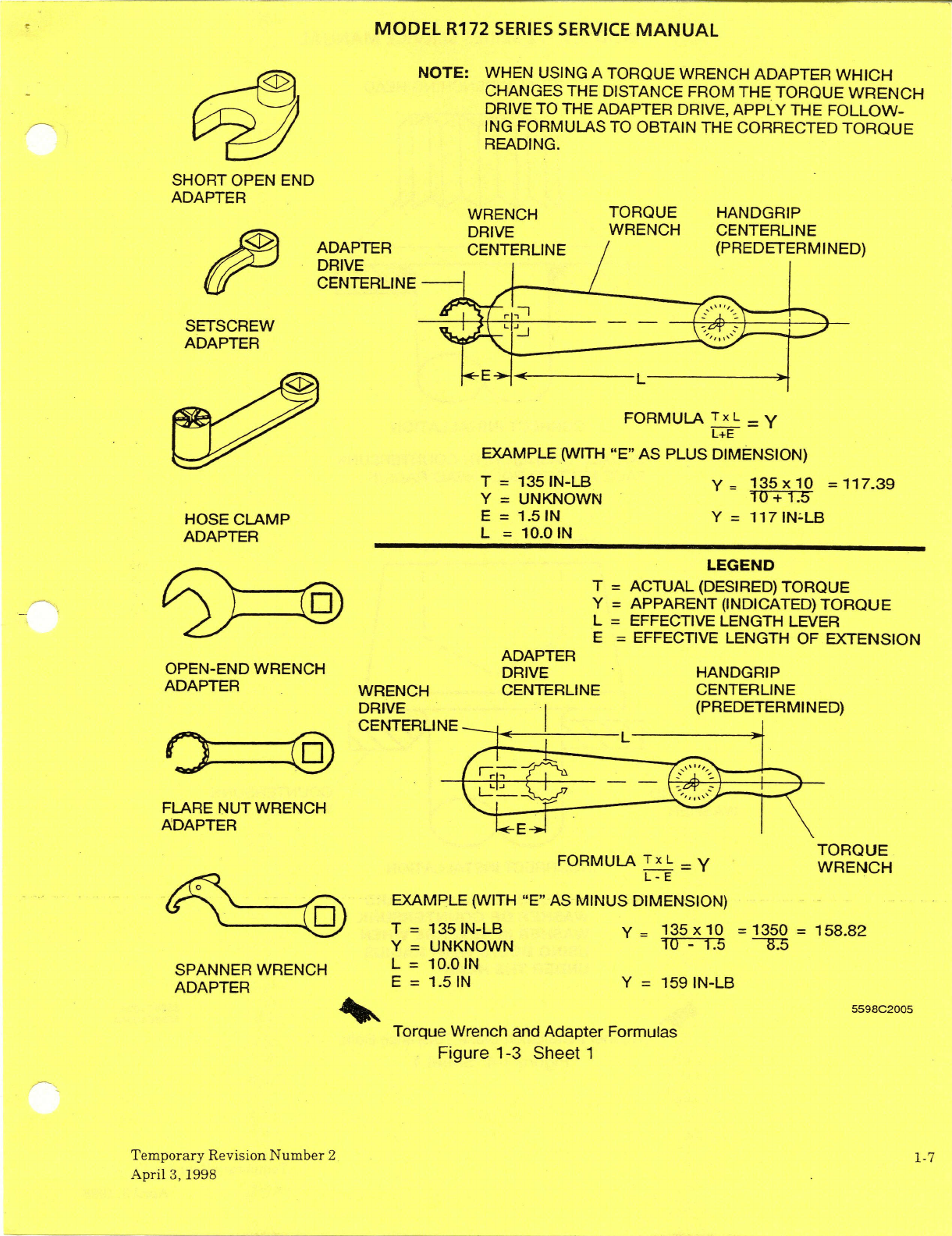
NOTE:
WHEN
USING
A
TORQUE
WRENCH
ADAPTER
WHICH
CHANGES
THE
DISTANCE
FROM
THE
TORQUE
WRENCH
DRIVE
TO
THE
ADAPTER
DRIVE,
APPLY
THE
FOLLOW-
ING
FORMULAS
TO
OBTAIN
THE
CORRECTED
TORQUE
READING.
SHORT
OPEN
END
ADAPTER
WRENCH
TORQUE HANDGRIP
DRIVE
WRENCH
CENTERLINE
ADAPTER
CENTERLINE
/(PREDETERMINED)
DRIVE
CENTERLINE
SETSCREW
ADAPTER
FORMULA
TxL
EXAMPLE
(WITH
"E"
AS
PLUS
DIMENSION)
T
=
135IN-LB
y=
135x10
=117.39
Y
=
UNKNOWN
HOSE
CLAMP
E
=
1.5
N
Y
=
117
IN-LB
ADAPTER L
=
10.0
IN
LEGEND
T
=
ACTUAL
(DESIRED)
TORQUE
ADAPTER
OPEN-END WRENCH
DRIVE
HANDGRIP
ADAPTER
WRENCH
CENTERLINE
CENTERLINE
DRIVE
(PREDETERMINED)
CENTERLINE
FLARE
NUT
WRENCH
ADAPTER
TORQUE
FORMULA
Tx
L=
Y
WRENCH
L-E
EXAMPLE (WITH
"E"
AS
MINUS
DIMENSION)
T
=
135
IN-LB
y =
135x10
=1350
=
158.82
Y
=
UNKNOWN
10
-1.5
85
L=
10.0
IN
SPANNERWRENCH
L
=
10.0IN
SPANNER
WRENCH
=
1.5
IN
Y
=
159
IN-LB
ADAPTER
5598C2005
Torque
Wrench and
Adapter
Formulas
Figure
1-3
Sheet
1
Temporary
Revision
Number
2
1-7
April
3,
1998
MODEL
R172
SERIES
SERVICE
MANUAL
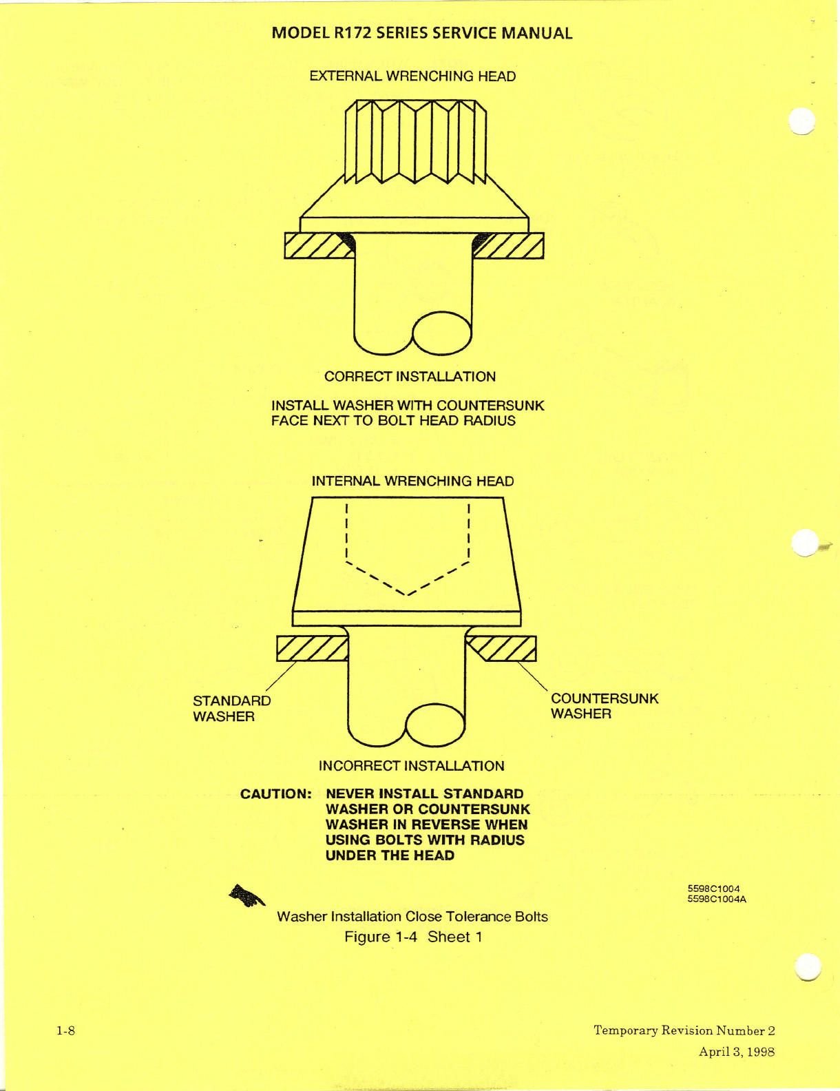
EXTERNAL
WRENCHING
HEAD
CORRECT
INSTALLATION
INSTALL
WASHER WITH
COUNTERSUNK
FACE
NEXT
TO
BOLT
HEAD
RADIUS
INTERNAL
WRENCHING
HEAD
I
.
STANDARD
COUNTERSUNK
INCORRECT
INSTALLATION
CAUTION:
NEVER
INSTALL
STANDARD
WASHER
OR
COUNTERSUNK
WASHER
IN
REVERSE
WHEN
USING
BOLTS
WITH
RADIUS
UNDER
THE
HEAD
5598C1004
5598C1004A
Washer
Installation
Close
Tolerance
Bolts
Figure
1-4
Sheet
1
1-8
Temporary Revision
Number
2
April
3,
1998
MODEL
R172
SERIES
SERVICE
MANUAL
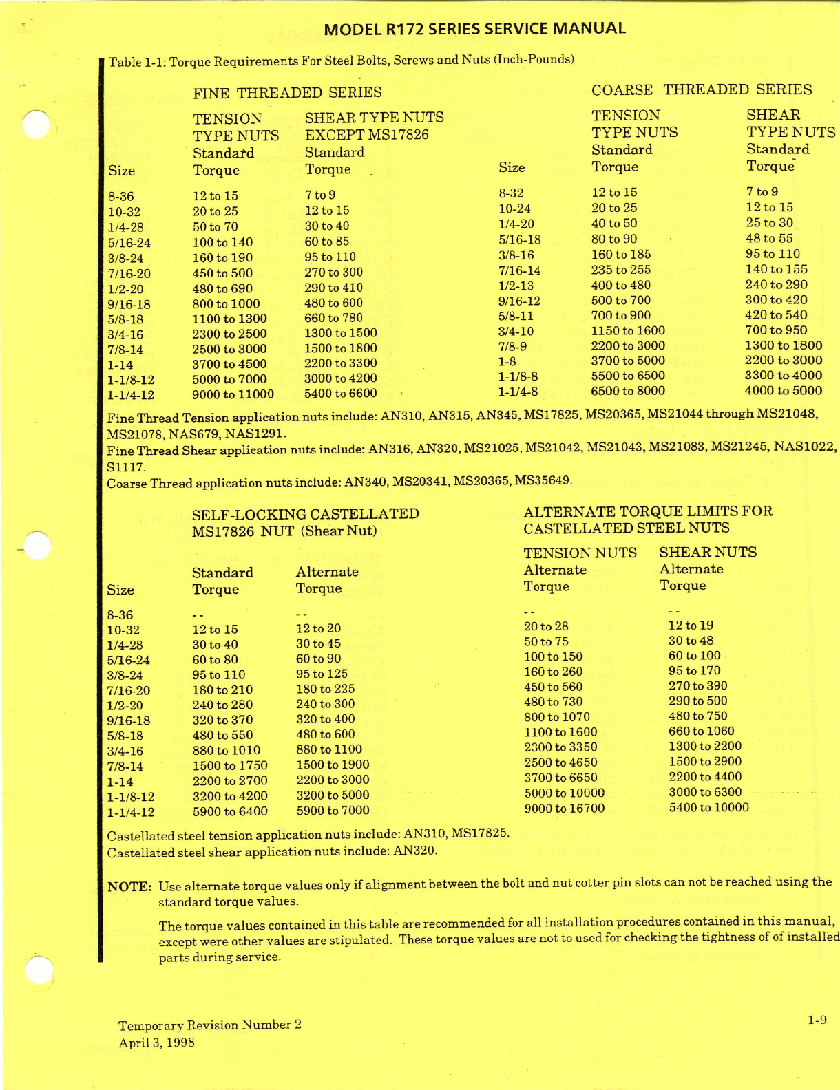
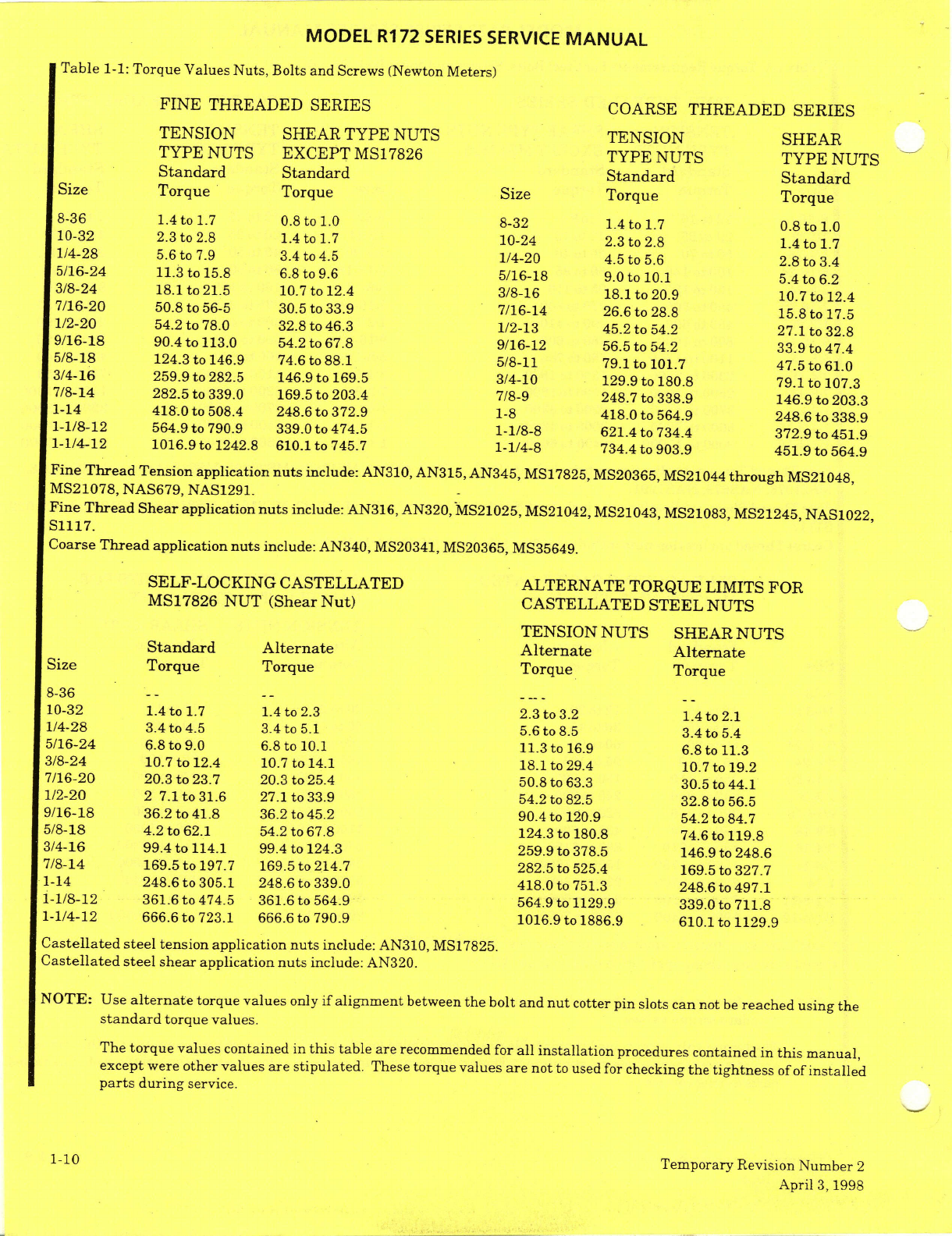
Table
1-1:
Torque
Requirements
For Steel
Bolts,
Screws
and
Nuts
(Inch-Pounds)
FINE
THREADED
SERIES
COARSE
THREADED
SERIES
TENSION
SHEAR
TYPE NUTS
TENSION
SHEAR
TYPE
NUTS
EXCEPT
MS17826
TYPE
NUTS
TYPE
NUTS
Standard
Standard
Standard
Standard
Size
Torque
Torque
Size
Torque
Torque
8-36
12
to
15
7
to
9
8-32
12
to
15
7
to
9
10-32
20
to
25
12
to
15
10-24
20
to
25
12
to
15
1/4-28
50
to
70
30
to
40
1/4-20
40
to
50
25
to
30
5/16-24
100
to
140
60
to
85
5/16-18
80
to
90
48
to
55
3/8-24
160
to
190
95
to
110
3/8-16
160
to
185
95
to
110
7/16-20 450
to
500
270
to
300
7/16-14
235
to
255
140
to
155
1/2-20
480
to
690
290
to
410
1/2-13
400
to
480
240
to
290
9/16-18
800
to
1000
480
to
600 9/16-12
500
to
700
300
to
420
5/8-18
1100
to
1300
660
to
780 5/8-11
700
to
900
420
to
540
3/4-16
2300
to
2500
1300
to
1500
3/4-10
1150
to
1600
700
to
950
7/8-14
2500
to
3000
1500
to
1800
7/8-9
2200 to
3000
1300
to
1800
1-14
3700
to
4500
2200
to
3300
1-8
3700
to
5000
2200
to
3000
1-1/8-12
5000
to
7000
3000
to
4200
1-1/8-8
5500
to
6500
3300
to
4000
1-1/4-12
9000
to
11000
5400
to
6600
1-1/4-8
6500
to
8000
4000
to
5000
Fine
Thread
Tension
application
nuts
include:
AN310,
AN315,
AN345, MS17825,
MS20365,
MS21044
through
MS21048,
MS21078,
NAS679,
NAS1291.
Fine
Thread
Shear application
nuts
include:
AN316, AN320,
MS21025, MS21042,
MS21043, MS21083, MS21245,
NAS1022,
S1117.
Coarse
Thread
application
nuts
include: AN340,
MS20341,
MS20365,
MS35649.
SELF-LOCKING
CASTELLATED
ALTERNATE
TORQUE
LIMITS
FOR
MS17826
NUT (Shear
Nut)
CASTELLATED
STEEL
NUTS
TENSION
NUTS
SHEAR
NUTS
Standard
Alternate Alternate
Alternate
Size
Torque
Torque Torque
Torque
8-36
-
-
10-32
12
to
15
12
to
20
20
to
28
12
to
19
1/4-28 30
to
40
30
to
45
50
to
75 30
to
48
5/16-24
60
to
80
60
to
90
100
to
150
60
to
100
3/8-24 95
to
110
95
to
125
160
to
260
95
to
170
7/16-20
180
to
210
180
to
225
450
to
560
270
to
390
1/2-20
240
to
280
240
to
300 480
to
730
290
to
500
9/16-18
320
to
370
320
to
400
800
to
1070
480
to
750
5/8-18
480
to
550
480
to
600
1100
to
1600
660
to
1060
3/4-16
880
to
1010
880
to
1100 2300
to
3350
1300
to
2200
7/8-14 1500
to
1750
1500
to
1900
2500
to
4650
1500
to
2900
1-14 2200
to
2700
2200
to
3000 3700
to
6650 2200
to
4400
1-1/8-12
3200
to
4200
3200
to
5000 5000
to
10000 3000
to
6300
1-1/4-12
5900
to
6400
5900
to
7000 9000
to
16700 5400
to
10000
Castellated
steel
tension
application
nuts
include:
AN310,
MS17825.
Castellated
steel
shear
application
nuts
include:
AN320.
NOTE:
Use
alternate
torque
values
only
if
alignment
between
the
bolt
and
nut
cotter pin
slots
can
not
be
reached
using
the
standard
torque
values.
The
torque values
contained
in
this
table
are
recommended
for
all
installation
procedures
contained
in
this
manual,
except
were
other
values
are
stipulated.
These
torque
values
are
not
to
used
for
checking
the
tightness
of
of
installed
parts
during
service.
Temporary
Revision
Number
2 1-9
April
3,
1998
MODEL
R172
SERIES
SERVICE
MANUAL
Table
1-1:
Torque Values Nuts,
Bolts
and
Screws
(Newton
Meters)
FINE
THREADED
SERIES
COARSE
THREADED SERIES
TENSION
SHEAR TYPE NUTS
TENSION
SHEAR
TYPE NUTS
EXCEPT
MS17826
TYPE
NUTS
TYPE
NUTS
Standard
Standard
Standard
Standard
Size
Torque
Torque
Size
Torque
Torque
8-36 1.4
to
1.7
0.8
to
1.0
8-32
1.4
to
1.7
0.8
to
1.0
10-32
2.3
to
2.8
1.4
to
1.7
10-24
2.3
to
2.8
1.4
to
1.7
1/4-28
5.6
to
7.9
3.4
to
4.5
1/4-20 4.5
to
5.6
2.8
to
3.4
5/16-24
11.3
to
15.8 6.8
to
9.6
5/16-18
9.0
to
10.1
5.4
to
6.2
3/8-24
18.1
to
21.5
10.7
to 12.4
3/8-16
18.1
to
20.9 10.7
to
12.4
7/16-20
50.8
to
56-5
30.5 to
33.9
7/16-14
26.6
to
28.8
15.8
to
17.5
1/2-20
54.2
to
78.0 32.8
to
46.3
1/2-13
45.2
to
54.2
27.1
to
32.8
9/16-18
90.4
to
113.0 54.2
to
67.8 9/16-12
56.5
to
54.2
33.9
to
47.4
5/8-18
124.3
to
146.9 74.6
to
88.1
5/8-11
79.1
to
101.7
47.5
to
61.0
3/4-16
259.9
to
282.5 146.9
to
169.5
3/4-10
129.9
to
180.8
79.1
to
107.3
7/8-14
282.5 to
339.0 169.5
to
203.4
7/8-9
248.7
to
338.9
146.9
to
203.3
1-14
418.0 to
508.4
248.6
to
372.9
1-8
418.0
to
564.9
248.6
to
338.9
1-1/8-12 564.9
to
790.9
339.0
to
474.5
1-1/8-8
621.4
to
734.4
372.9
to
451.9
1-1/4-12
1016.9
to
1242.8 610.1
to
745.7
1-1/4-8
734.4
to
903.9
451.9
to
564.9
Fine
Thread
Tension
application
nuts
include:
AN310,
AN315,
AN345,
MS17825,
MS20365,
MS21044
through
MS21048,
MS21078,
NAS679,
NAS1291.
Fine
Thread
Shear
application
nuts
include:
AN316,
AN320, MS21025,
MS21042,
MS21043, MS21083,
MS21245,
NAS1022,
S1117.
Coarse
Thread
application
nuts
include:
AN340,
MS20341,
MS20365,
MS35649.
SELF-LOCKING
CASTELLATED ALTERNATE TORQUE
LIMITS
FOR
MS17826
NUT
(Shear
Nut)
CASTELLATED
STEEL
NUTS
TENSION
NUTS
SHEAR
NUTS
Standard Alternate Alternate
Alternate
Size
Torque Torque
Torque
Torque
8-36
10-32
1.4
to
1.7 1.4
to
2.3
2.3 to
3.2 1.4
to
2.1
1/4-28 3.4
to
4.5 3.4
to
5.1
5.6
to
8.5
3.4
to
5.4
5/16-24
6.8
to
9.0
6.8
to
10.1
11.3
to
16.9
6.8
to
11.3
3/8-24
10.7
to
12.4
10.7
to
14.1
18.1
to
29.4
10.7
to
19.2
7/16-20
20.3
to
23.7 20.3
to
25.4 50.8
to
63.3
30.5
to
44.1
1/2-20
2
7.1
to
31.6
27.1
to
33.9 54.2 to
82.5
32.8
to
56.5
9/16-18
36.2
to
41.8
36.2
to
45.2
90.4
to
120.9
54.2 to
84.7
5/8-18
4.2
to
62.1
54.2
to
67.8
124.3
to
180.8
74.6
to
119.8
3/4-16 99.4
to
114.1 99.4
to 124.3
259.9
to
378.5
146.9
to
248.6
7/8-14
169.5
to
197.7
169.5
to
214.7 282.5
to
525.4
169.5
to
327.7
1-14
248.6
to
305.1
248.6
to
339.0
418.0
to
751.3
248.6
to 497.1
1-1/8-12
361.6
to
474.5 361.6
to
564.9
564.9 to
1129.9
339.0
to
711.8
1-1/4-12
666.6 to
723.1
666.6
to
790.9
1016.9
to
1886.9 610.1
to
1129.9
Castellated
steel
tension
application
nuts
include:
AN310,
MS17825.
Castellated
steel
shear
application
nuts
include:
AN320.
NOTE:
Use
alternate
torque
values
only
if
alignment
between
the
bolt and
nut
cotter pin
slots
can
not
be
reached
using
the
standard
torque
values.
The
torque
values
contained
in
this
table
are
recommended
for
all installation
procedures
contained
in
this
manual,
except
were
other values
are
stipulated.
These
torque
values
are
not
to
used
for
checking
the
tightness
of of
installed
parts
during
service.
1-10
Temporary
Revision
Number
2
April
3,
1998
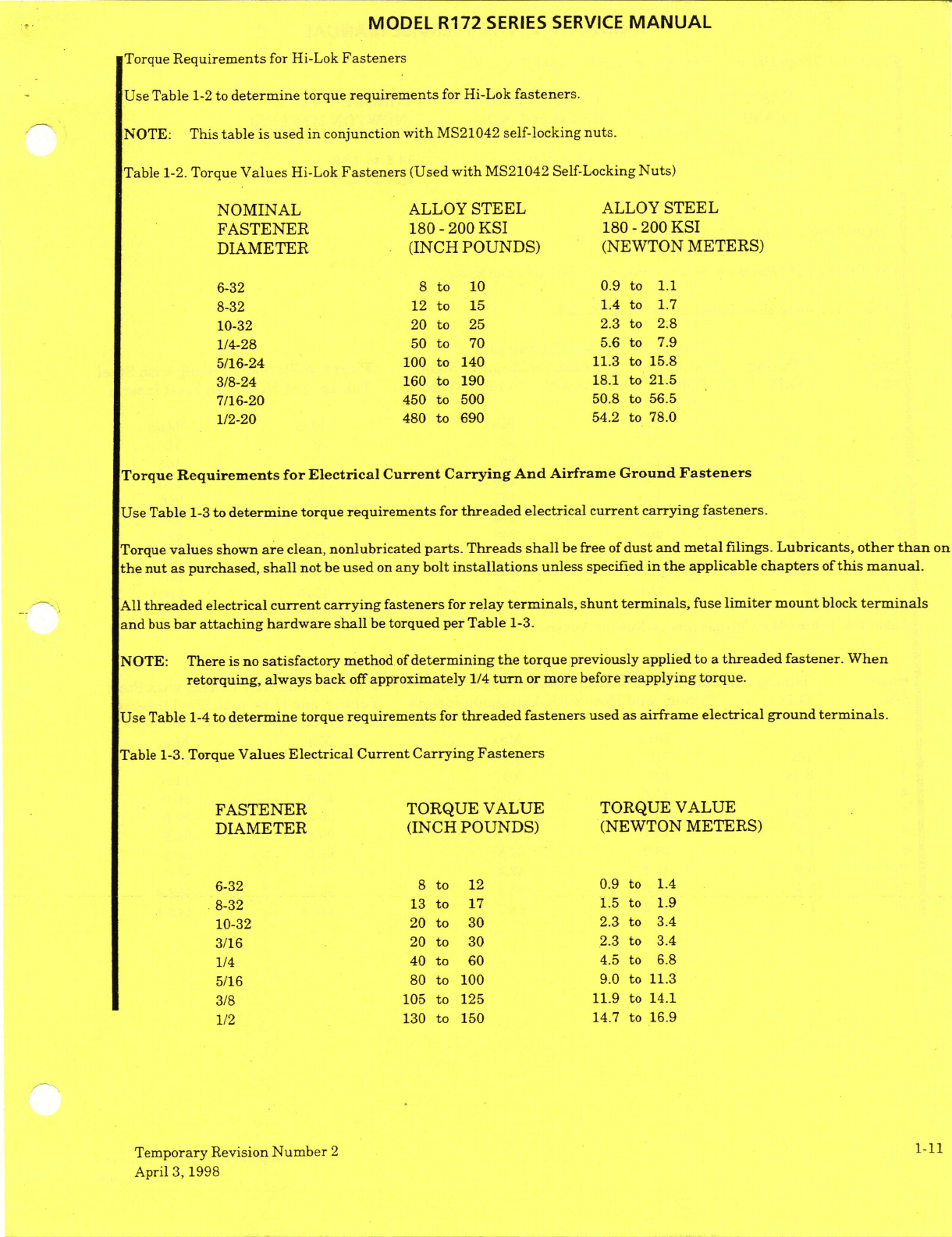
MODEL R172
SERIES
SERVICE
MANUAL
Torque
Requirements
for
Hi-Lok
Fasteners
Use
Table
1-2
to
determine
torque
requirements
for Hi-Lok
fasteners.
NOTE:
This
table
is
used
in conjunction
with
MS21042
self-locking
nuts.
Table
1-2.
Torque
Values
Hi-Lok
Fasteners
(Used
with
MS21042
Self-Locking
Nuts)
NOMINAL
ALLOY
STEEL
ALLOY
STEEL
FASTENER
180
-
200
KSI
180
-
200
KSI
DIAMETER
(INCH
POUNDS)
(NEWTON
METERS)
6-32
8
to
10
0.9
to
1.1
8-32
12
to
15
1.4
to
1.7
10-32
20
to
25 2.3
to
2.8
1/4-28
50
to
70
5.6
to
7.9
5/16-24
100
to
140
11.3
to
15.8
3/8-24
160
to
190
18.1
to
21.5
7/16-20
450
to
500
50.8
to
56.5
1/2-20
480
to
690
54.2
to
78.0
Torque
Requirements
for
Electrical
Current Carrying
And
Airframe
Ground
Fasteners
Use Table
1-3
to
determine
torque
requirements
for
threaded
electrical
current
carrying
fasteners.
Torque
values
shown
are
clean, nonlubricated
parts.
Threads
shall
be
free
of
dust
and
metal
filings.
Lubricants,
other
than
on
the nut
as
purchased,
shall
not
be
used
on
any
bolt
installations
unless
specified
in
the
applicable
chapters
of
this manual.
All
threaded
electrical
current
carrying
fasteners
for
relay
terminals,
shunt terminals,
fuse
limiter
mount
block
terminals
and
bus
bar
attaching
hardware shall
be
torqued
per Table
1-3.
NOTE: There
is
no
satisfactory
method
of
determining
the
torque
previously
applied
to
a
threaded
fastener.
When
retorquing,
always
back
off
approximately
1/4
turn
or more
before
reapplying
torque.
Use
Table
1-4
to
determine
torque requirements
for
threaded
fasteners
used as
airframe
electrical
ground
terminals.
Table
1-3.
Torque
Values Electrical
Current
Carrying
Fasteners
FASTENER
TORQUE
VALUE
TORQUE
VALUE
DIAMETER
(INCH
POUNDS)
(NEWTON
METERS)
6-32
8
to
12
0.9
to
1.4
8-32
13
to
17 1.5
to
1.9
10-32 20
to
30
2.3
to
3.4
3/16 20
to
30
2.3
to
3.4
1/4
40
to
60
4.5
to
6.8
5/16
80
to
100
9.0
to
11.3
3/8
105
to
125
11.9
to
14.1
1/2
130
to
150
14.7
to
16.9
Temporary
Revision
Number
2
1-11
April
3,
1998
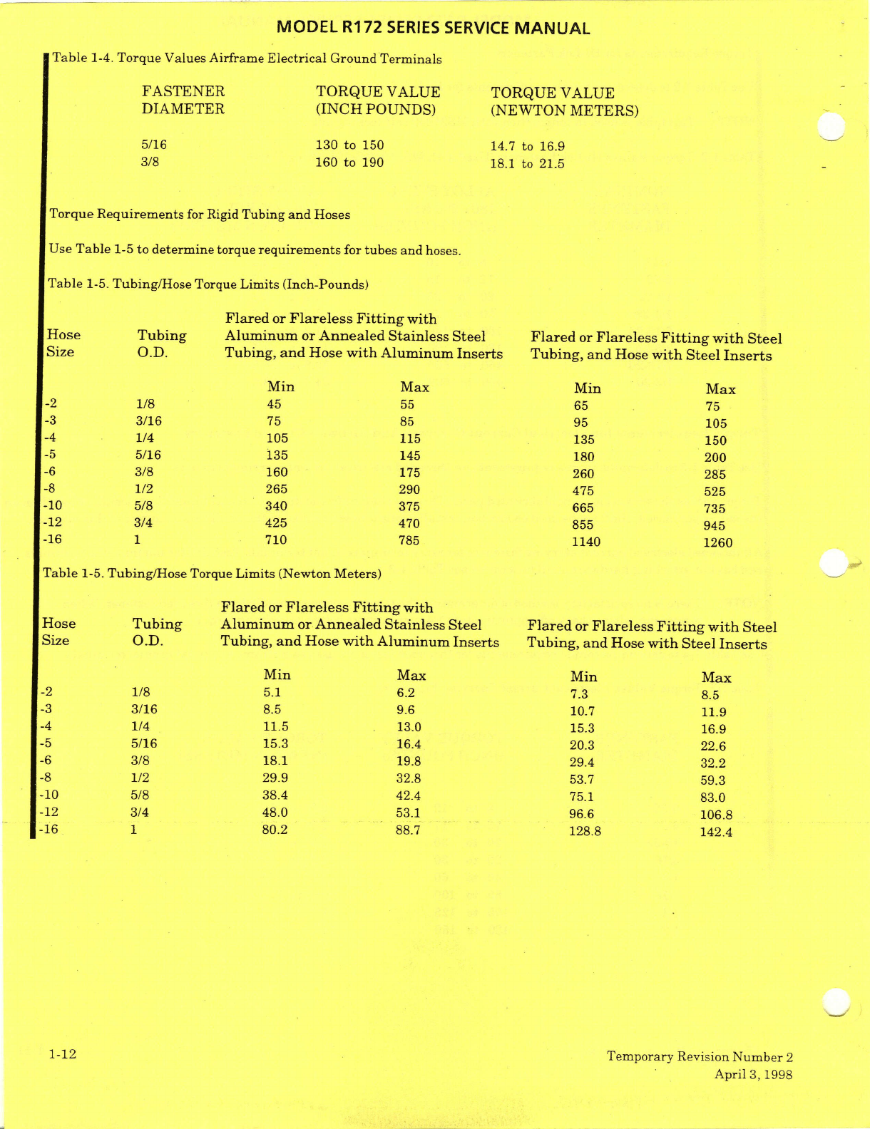
MODEL
R172
SERIES
SERVICE
MANUAL
Table
1-4.
Torque
Values
Airframe
Electrical
Ground
Terminals
FASTENER
TORQUE
VALUE
TORQUE VALUE
DIAMETER
(INCH
POUNDS)
(NEWTON METERS)
5/16
130
to
150
14.7
to
16.9
3/8
160
to
190
18.1
to
21.5
Torque
Requirements
for
Rigid
Tubing
and
Hoses
Use
Table
1-5
to determine
torque
requirements
for
tubes
and
hoses.
Table
1-5.
Tubing/Hose
Torque
Limits
(Inch-Pounds)
Flared
or
Flareless
Fitting
with
Hose
Tubing
Aluminum
or
Annealed
Stainless
Steel
Flared
or
Flareless
Fitting
with
Steel
Size
O.D.
Tubing,
and
Hose
with
Aluminum
Inserts
Tubing,
and
Hose
with
Steel
Inserts
Min
Max
Min Max
-2
1/8
45
55 65
75
-3
3/16
75 85
95
105
-4
1/4
105
115
135
150
-5
5/16
135
145
180
200
-6
3/8 160
175
260
285
-8
1/2
265 290 475
525
-10
5/8
340
375
665
735
-12
3/4
425
470
855
945
-16
1
710
785
1140
1260
Table
1-5.
Tubing/Hose
Torque
Limits
(Newton
Meters)
Flared
or
Flareless
Fitting
with
Hose
Tubing
Aluminum
or
Annealed
Stainless
Steel
Flared
or
Flareless
Fitting
with
Steel
Size
O.D.
Tubing,
and
Hose
with
Aluminum
Inserts
Tubing,
and
Hose
with
Steel
Inserts
Min
Max
Min
Max
-2
1/8
5.1
6.2
7.3
8.5
-3
3/16
8.5
9.6
10.7
11.9
-4
1/4 11.5
13.0 15.3
16.9
-5
5/16
15.3
16.4 20.3
22.6
-6
3/8
18.1
19.8
29.4
32.2
-8
1/2
29.9
32.8
53.7
59.3
-10
5/8
38.4 42.4
75.1
83.0
-12
3/4
48.0
53.1
96.6
106.8
-16
1
80.2
88.7
128.8
142.4
1-12
Temporary
Revision
Number
2
April
3,
1998
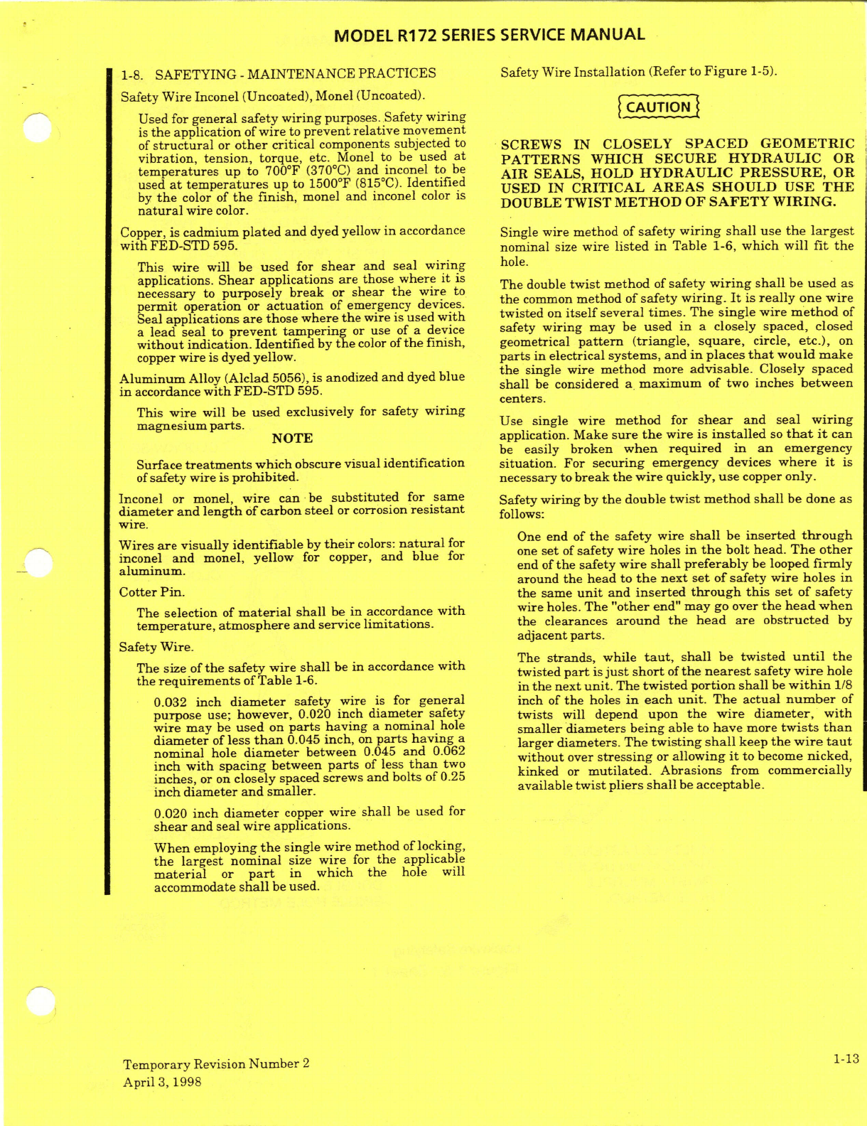
MODEL R172
SERIES SERVICE
MANUAL
1-8.
SAFETYING -
MAINTENANCE
PRACTICES
Safety
Wire
Installation
(Refer
to
Figure
1-5).
Safety Wire
Inconel
(Uncoated),
Monel (Uncoated).
Used
for
general
safety
wiring
purposes. Safety
wiring
is
the
application
of
wire
to
prevent relative
movement
of
structural
or
other
critical
components
subjected
to
SCREWS
IN
CLOSELY
SPACED
GEOMETRIC
vibration,
tension,
torque,
etc. Monel
to be
used
at
PATTERNS
WHICH
SECURE
HYDRAULIC
OR
temperatures
up
to
700°F
(370°C)
and
inconel
to
be
AIR SEALS,
HOLD
HYDRAULIC
PRESSURE,
OR
used
at
temperatures
up
to
1500
F
(815
C).
Identified
USED
IN
CRITICAL AREAS
SHOULD USE
THE
by
the
color
of
the
finish,
monel and
inconel
color
is
DOUBLE
TWIST
METHOD
OF
SAFETY
WIRING.
DOUBLE
TWIST
METHOD
OF
SAFETY WIRING.
natural
wire
color.
Copper,
is
cadmium
plated
and
dyed
yellow
in
accordance
Single wire
method
of
safety
wiring shall
use
the
largest
with
FED-STD
595.
nominal
size
wire
listed
in
Table
1-6,
which
will
fit
the
This
wire
will
be
used
for
shear
and
seal
wiring
hole.
applications.
Shear
applications
are
those
where
it
is The
double
twist
method
of
safety
wiring
shall
be
used
as
necessary
to
purposely break
or
shear
the
wire
to
permit
operation
or
actuation
of
emergency
devices.
the
common
method
of
safety
wiring.
It
is
really
one wire
Seal
applications
are
those
where
the
wire
is used
with
twisted
on
itself
several
times. The
single
wire
method
of
a
lead
seal to
prevent
tampering
or use of
a
device
safety
wiring
may
be
used
in
a
closely
spaced,
closed
without
indication.
Identified
by
the
color
of
the
finish,
geometrical
pattern
(triangle,
square,
circle,
etc.),
on
copper
wire
is dyed
yellow,
parts in
electrical
systems,
and
in
places
that
would
make
the
single
wire
method
more
advisable.
Closely
spaced
Aluminum
Alloy
(Alclad
5056),
is
anodized
and
dyed
blue
the
single
wire
method more
advisable.
Closely
spaced
in
accordance
with
FED-STD
595.
in
accordance
with
FED-STD
595.
shall
be
considered
a maximum
of
two
inches
between
centers.
This
wire
will
be
used
exclusively
for
safety
wiring
magnesium
parts.
Use single
wire method
for
shear
and
seal
wiring
NOTE
application.
Make
sure
the
wire
is
installed
so
that
it
can
be
easily
broken
when
required
in an
emergency
Surface
treatments
which
obscure
visual
identification situation. For
securing
emergency
devices
where
it
is
of
safety
wire is
prohibited.
necessary
to
break
the
wire quickly,
use
copper
only.
Inconel
or
monel,
wire
can
be
substituted
for
same
Safety
wiring
by
the
double
twist
method shall
be
done
as
diameter and
length
of
carbon
steel
or
corrosion
resistant
follows:
wire.
Wires
are
visually
identifiable
by
their
colors:
natural
for
One
end of
the
safety
wire
shall
be
inserted
through
inconel
and
monel,
yellow
for
copper,
and
blue
for
one
set
of
safety wire
holes
in
the
bolt
head.
The
other
aluminum.
end
of
the
safety
wire
shall preferably
be
looped
firmly
around
the
head
to
the
next
set
of safety wire
holes
in
Cotter
Pin.
the
same
unit
and
inserted
through
this
set
of
safety
The
selection
of
material
shall
be
in
accordance
with
wire
holes.
The
"other
end"
may
go
over
the
head
when
temperature,
atmosphere and
service
limitations.
the
clearances
around the head
are
obstructed
by
adjacent
parts.
Safety
Wire.
The
strands,
while
taut,
shall be
twisted
until
the
The size
of
the
safety
wire
shall
be in
accordance
with
twisted
part
is
just
short
of
the
nearest
safety
wire
hole
the
requirements
of
Table
1-6.
in
the
next
unit.
The
twisted
portion
shall
be
within
1/8
0.032
inch
diameter
safety
wire
is
for
general
inch
of
the
holes
in
each
unit.
The
actual
number
of
purpose
use;
however,
0.020
inch
diameter
safety
twists
will
depend upon
the
wire
diameter,
with
wire
may
be
used
on
parts
having
a
nominal
hole
smaller
diameters
being
able to
have
more
twists
than
diameter
of
less
than
0.045
inch,
on
parts
having
a larger diameters.
The
twisting
shall
keep
the
wire
taut
nominal
hole
diameter
between
0.045
and
0.062
without
over
stressing
or
allowing
it
to
become
nicked,
inch
with
spacing
between
parts
of
less
than
two.
inches,
or
on
closely
spaced screws
and
bolts
of
0.25
kinked
or
mutilated.
Abrasions
from
commercially
inch
diameter
and smaller.
available
twist
pliers
shall
be
acceptable.
0.020
inch
diameter
copper
wire
shall
be
used
for
shear
and
seal
wire
applications.
When
employing
the
single
wire
method
of
locking,
the
largest
nominal
size
wire
for
the
applicable
material
or
part
in
which
the
hole
will
accommodate
shall
be
used.
Temporary
Revision
Number
2
1-13
April
3,
1998
MODEL
R172
SERIES
SERVICE
MANUAL
STEP
1.
INSERT
WIRE
THROUGH
BOLT
A
AND
BEND
AROUND
BOLT
(IF
NECESSARY,
BEND WIRE
ACROSS
BOLT
HEAD).
TWIST WIRES
CLOCKWISE
UNTIL
THEY
REACH
BOLT
B.
STEP
2.
INSERT
ONE
END
OF
WIRE
THROUGH
BOLT
B.
BEND
OTHER
END
AROUND
BOLT
(IF
NECESSARY,
BEND
WIRE
ACROSS
HEAD
OF
BOLT).
TWIST
WIRES
COUNTERCLOCKWISE
1/2
INCH
OR
SIX
TWISTS.
CLIP
ENDS.
BEND
PIGTAIL
BACK
AGAINST
PART.
NOTE:
RIGHT THREADED
PARTS
SHOWN:
REVERSE
DIRECTIONS
FOR
LEFT
PARTS.
BOLT
B
CLOCKWISE
DOUBLE-WIRE
SAFETYING
COUNTER-
CLOCKWISE
CLOCKWISE
COUNTER-
CLOCKWISE
CLOCKWISE
MULTIPLE
FASTENER
APPLICATION
DOUBLE
TWIST
-
MULTIPLE
DOUBLE-TWIST
SAFETYING
HOLE
METHOD.
SINGLE
HOLE
METHOD
5598C2001
5599C2001
6598C1029
Lockwire
Safetying
Figure
1-5,
Sheet
1
1-14
Temporary
Revision
Number
2
April
3,
1998
MODEL
R172
SERIES SERVICE
MANUAL
EXTERNAL
SNAP RING
SINGLE-WIRE
METHOD
BOLTS
IN
CLOSELY
SPACED,
CLOSED
GEOMETRICAL
PATTERN.
SINGLE
WIRE
METHOD
SINGLE
FASTENER
APPLICATION
SMALL
SCREWS
IN
CLOSELY
SPACED, CLOSED
GEOMETRICAL
PATTERN,
SINGLE
WIRE
METHOD
NOTE:
RIGHT
THREADED
PARTS
SHOWN.
REVERSE
DIRECTION
FOR
LEFT
THREADS
5598C1003
5598C1024
5598C1024
5598C1024
Lockwire
Safetying
Figure
1-5,
Sheet
2
Temporary
Revision
Number
2
1-15
April
3,
1998
MODEL
R172
SERIES
SERVICE
MANUAL
AN500A
SCREW
5598C1001
5598C1001
Lockwire
Safetying
Figure
1-5,
Sheet
3
1-16
Temporary Revision
Number
2
April
3,
1998
MODEL
R172
SERIES SERVICE
MANUAL
Table
1-6.
Safety
Wire
MATERIAL
SIZE
AND
NUMBER
(MS20995-XXX)
0.015 0.020
0.032 0.040
0.041
0.047 0.051
0.091
Ni-Cu
Alloy NC20
NC32
NC40
_ _
NC51
NC91
(Monel)
Ni-Cr-Fe
Alloy
_
N20
N32
N40
_
N51
N91
(Inconel)
Carbon
Steel
F20
F32
F41
F47
F91
Corrosion
Resistant
C15
C20
C32
C41
C47
C91
Steel
Aluminum
Alloy
_
AB20
AB32
_
AB41
AB47
_
AB91
(Blue)
Copper
(Yellow)
CY15
CY20
Usage
The
wire shall
be
twisted
to form
a
pigtail
of
3
to
5
twists
after
wiring
the
last
unit.
The
excess
wire
shall
A
pigtail
of
0.25
to
0.50
inch
(3
to
5
twists)
shall
be
be
cut
off.
The
pigtail
shall
be
bent
toward
the
part
to
made
at
the
end
of
the wiring.
This pigtail
shall
be
bent
prevent
it
from
becoming
a
snag.
Safety
wiring
back
or
under to
prevent
it
from
becoming
a
snag.
multiple
groups
by
the
double
twist
double
hole
method
shall
be
the
same
as
the
previous double
twist
Safety
wre
shall
be
new
upon
each
application.
single
hole
method
except
the twist
direction
between
When
castellated
nuts
are
to
be
secured
with
safety
subsequent fasteners
may
be
clockwise
or
wire,
tighten
the
nut
to
the
low side of
the
selected
counterclockwise.
torque
range,
unless
otherwise
specified,
and
if
Spacing necessary,
continue
tightening
until
a
slot
aligns
with
the
hole.
When
safety
wiring
widely spaced
multiple
groups
by
the double
twist
method,
three
units
shall
be
the
In
blind
tapped
hole
applications
of bolts
or
castellated
maximum
number
in a
series.
nuts
on
studs,
the
safety
wiring
shall
be
as
described
in
these
instructions.
When
safety
wiring
closely
spaced
multiple
groups,
the
number
of
units
that
can
be
safety
wired
by
a
Hollow
head
bolts
are
safetied
in
the
manner
twenty four
inch
length
of
wire
shall
be
the
maximum
prescribed
for
regular
bolts.
number
in a
series.
Drain plugs
and
pet
cocks
may
be
safetied
to
a
bolt,
nut
Widely
spaced
multiple
groups
shall
mean those
in
or
other
part
having
a
free
lock
hole
in accordance
with
which
the
fastenings
are
from
four
to
six
inches
apart.
the
instructions
described
in
this
text.
Safety
wiring
shall
not
be
used to
secure
fasteners
or
External
snap
rings
may
be
locked,
if
necessary,
in
fittings
which
are
spaced
more
than
six
inches
apart,
accordance
with
the
general
locking
principles
as
unless
tie
points
are
provided
on
adjacent
parts
to
described
and
illustrated.
Internal
snap
rings
shall
not
shorten
the
span
of
the
safety wire
to
less
than
six
be
safety
wired.
inches.
When
safety
wiring
is
required
on
electrical
connectors
Tension
which
use
threaded
coupling
rings,
or
on
plugs
which
Parts
shall
be
safety
wired
in
such
a
manner
that
the
employ
screws or
rings
to
fasten
the
individual
parts
of
safety
wire
shall
be
put
in
tension
when
the
part
tends
the
plug
together,
they
shall
be
safety
wired
with
0.020
to
loosen.
The
safety
wire
should always
be
installed
inch
diameter
wire
in
accordance
with
the
safety
and
twisted
so
that
the
loop
around
the
head
stays
wiring
principles as described
and
illustrated.
It
is
down
and
does
not
tend
to
come
up
over
the
bolt
head
preferable
to
safety
wire all electrical
connectors
and
leave a
slack
loop.
individually.
Do
not
safety
wire
one
connector
to
another
unless
it
is
necessary
to
do
so.
NOTE
Drilled
head
bolts
and
screws
need
not
be
safety
wired
This
does
not
necessarily
apply
to
castellated
nuts
if
installed
into
self-locking
nuts
or
installed
with
lock
when
the
slot
is
close
to
the
top
of
the
nut,
the
wire
washers.
Castellated
nuts
with
cotter
pins
or
safety
will
be
more
secure
if
it
is
made
to
pass
along
the
wire
are
preferred
on
bolts
or
studs
with
drilled
shanks
side
of
the
stud.
but
self-locking
nuts
are
permissible
within
the
limitations
ofMS33588.
Care
shall
be
exercised when
installing
safety wire
to
ensure
that
it
is
tight
but
not
over
stressed.
Temporary
Revision
Number
2
1-17
April
3,
1998
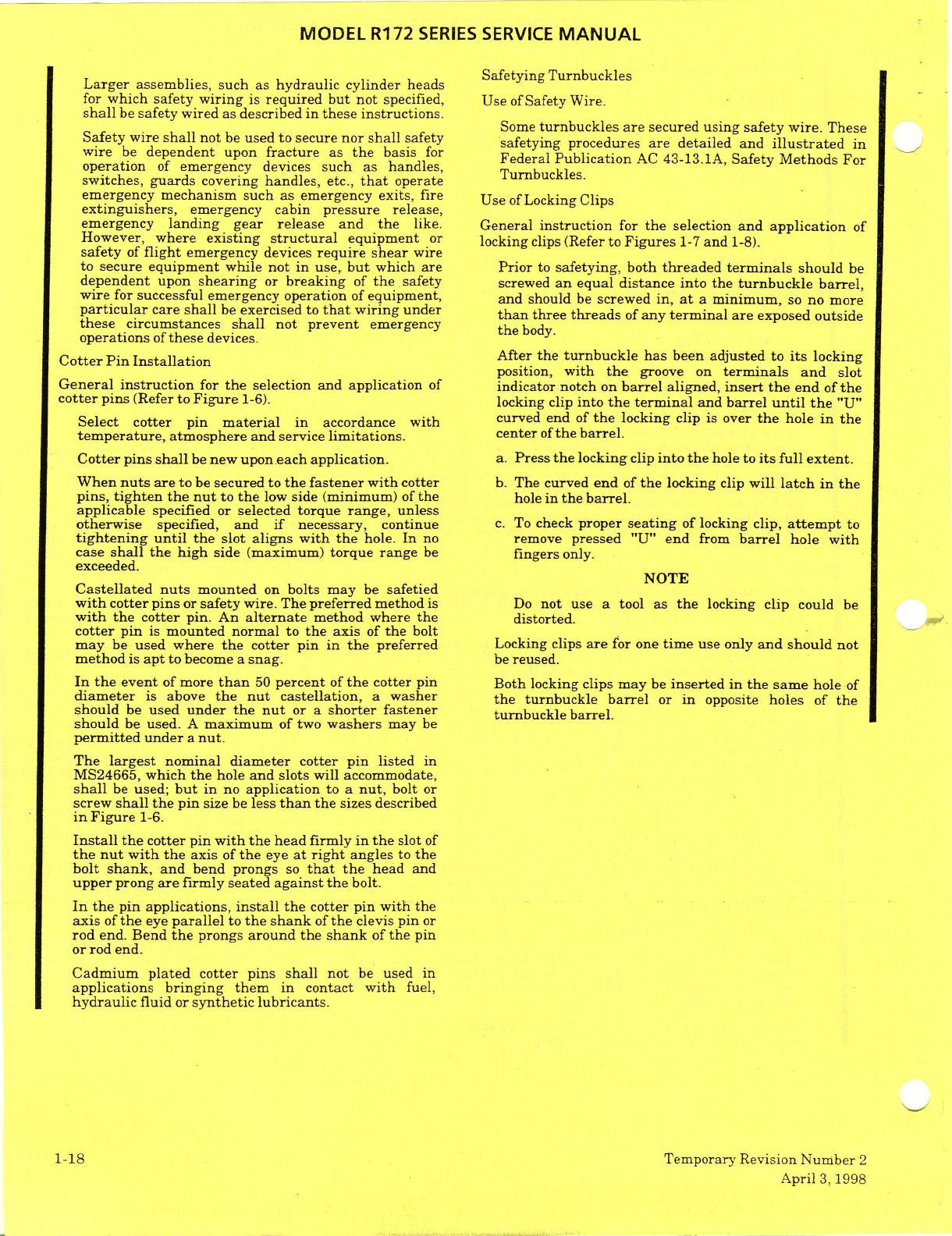
MODEL
R172
SERIES
SERVICE
MANUAL
Safetying
Turnbuckles
Larger
assemblies,
such as
hydraulic cylinder
heads
for
which
safety
wiring
is
required but
not
specified,
Use
of
Safety
Wire.
shall
be
safety
wired
as
described
in
these
instructions.
Some
turnbuckles
are
secured
using safety wire.
These
Safety wire
shall
not
be
used
to
secure
nor
shall
safety
safetying
procedures
are
detailed
and
illustrated
in
wire
be
dependent
upon
fracture
as
the
basis
for
Federal
Publication
AC
43-13.1A,
Safety
Methods
For
operation
of
emergency
devices
such
as
handles,
Turnbuckles.
switches,
guards
covering
handles,
etc.,
that
operateurnbuckles.
emergency
mechanism
such
as
emergency
exits,
fire
Use
of
Locking
Clips
extinguishers,
emergency
cabin
pressure
release,
emergency
landing
gear
release
and
the
like.
General
instruction
for
the
selection
and
application
of
However,
where
existing
structural
equipment
or
locking
clips
(Refer
to
Figures
1-7
and
1-8).
safety
of
flight
emergency
devices
require shear
wire
to
secure
equipment
while not in
use,
but
which
are
Prior
to
safetying,
both
threaded
terminals
should
be
dependent
upon
shearing
or
breaking
of
the
safety
screwed
an
equal distance into
the
turnbuckle
barrel,
wire
for
successful
emergency
operation
of
equipment, and
should
be
screwed
in,
at
a minimum,
so
no
more
particular
care
shall
be
exercised
to
that
wiring
under
than
three
threads
of
any
terminal
are
exposed
outside
these
circumstances
shall
not
prevent
emergency
the
body.
operations
of
these
devices.
Cotter
Pin
Installation
After
the
turnbuckle
has
been
adjusted
to
its
locking
position,
with
the
groove
on
terminals
and
slot
General
instruction
for
the
selection
and
application
of
indicator
notch
on
barrel
aligned,
insert
the
end
of
the
cotter
pins
(Refer
to
Figure
1-6).
locking
clip
into
the
terminal
and
barrel
until
the
"U"
Select
cotter
pin
material
in accordance
with
curved end
of
the
locking
clip
is
over
the
hole
in
the
temperature,
atmosphere and
service
limitations,
center
of
the
barrel.
Cotter
pins
shall
be
new
upon
each
application,
a.
Press
the
locking
clip
into the
hole to
its
full extent.
When
nuts
are
to
be
secured
to
the fastener
with
cotter
b.
The
curved
end
of
the
locking
clip
will
latch
in
the
pins,
tighten
the
nut
to
the
low
side
(minimum)
of
the
hole
in
the barrel.
applicable
specified or
selected
torque
range,
unless
otherwise
specified,
and
if
necessary,
continue
c.
To
check
proper
seating
of
locking
clip,
attempt
to
tightening until
the
slot
aligns
with
the
hole.
In
no
remove
pressed
"U"
end
from
barrel
hole
with
case
shall
the
high
side
(maximum)
torque range
be
fingers
only.
exceeded.
NOTE
Castellated
nuts
mounted
on
bolts
may
be
safetied
with
cotter
pins
or
safety
wire.
The
preferred
method
is
Do
not
use a
tool
as
the
locking clip
could
be
with the
cotter
pin.
An
alternate
method
where
the
distorted.
cotter
pin
is
mounted normal
to
the axis
of
the
bolt
may
be
used
where
the
cotter
pin
in
the
preferred
Locking clips
are
for
one
time
use
only
and should
not
method
is
apt
to
become
a
snag.
be
reused.
In
the
event
of
more
than
50
percent
of
the
cotter
pin
Both
locking clips
may
be
inserted
in
the
same
hole
of
diameter
is
above
the
nut
castellation,
a
washer
the
turnbuckle
barrel
or
in
opposite
holes
of
the
should
be
used
under the
nut
or a
shorter
fastener turnbuckle barrel.
should
be
used.
A
maximum
of two
washers
may
be
permitted
under
a
nut.
The
largest
nominal
diameter
cotter
pin
listed
in
MS24665,
which
the
hole
and
slots will
accommodate,
shall
be
used;
but
in
no
application
to
a
nut,
bolt
or
screw
shall
the
pin
size
be
less
than
the
sizes
described
in
Figure
1-6.
Install
the
cotter pin
with the
head
firmly
in the
slot
of
the nut
with the
axis
of
the
eye
at
right
angles
to
the
bolt
shank,
and
bend prongs
so
that
the
head
and
upper
prong
are
firmly
seated
against the
bolt.
In
the
pin
applications,
install
the
cotter
pin
with
the
axis
of
the
eye
parallel
to
the shank
of
the
clevis
pin
or
rod
end.
Bend
the
prongs
around
the
shank
of
the
pin
or
rod
end.
Cadmium
plated
cotter
pins shall
not
be
used
in
applications
bringing
them
in
contact
with
fuel,
hydraulic
fluid
or
synthetic
lubricants.
1-18
Temporary Revision
Number
2
April
3,
1998
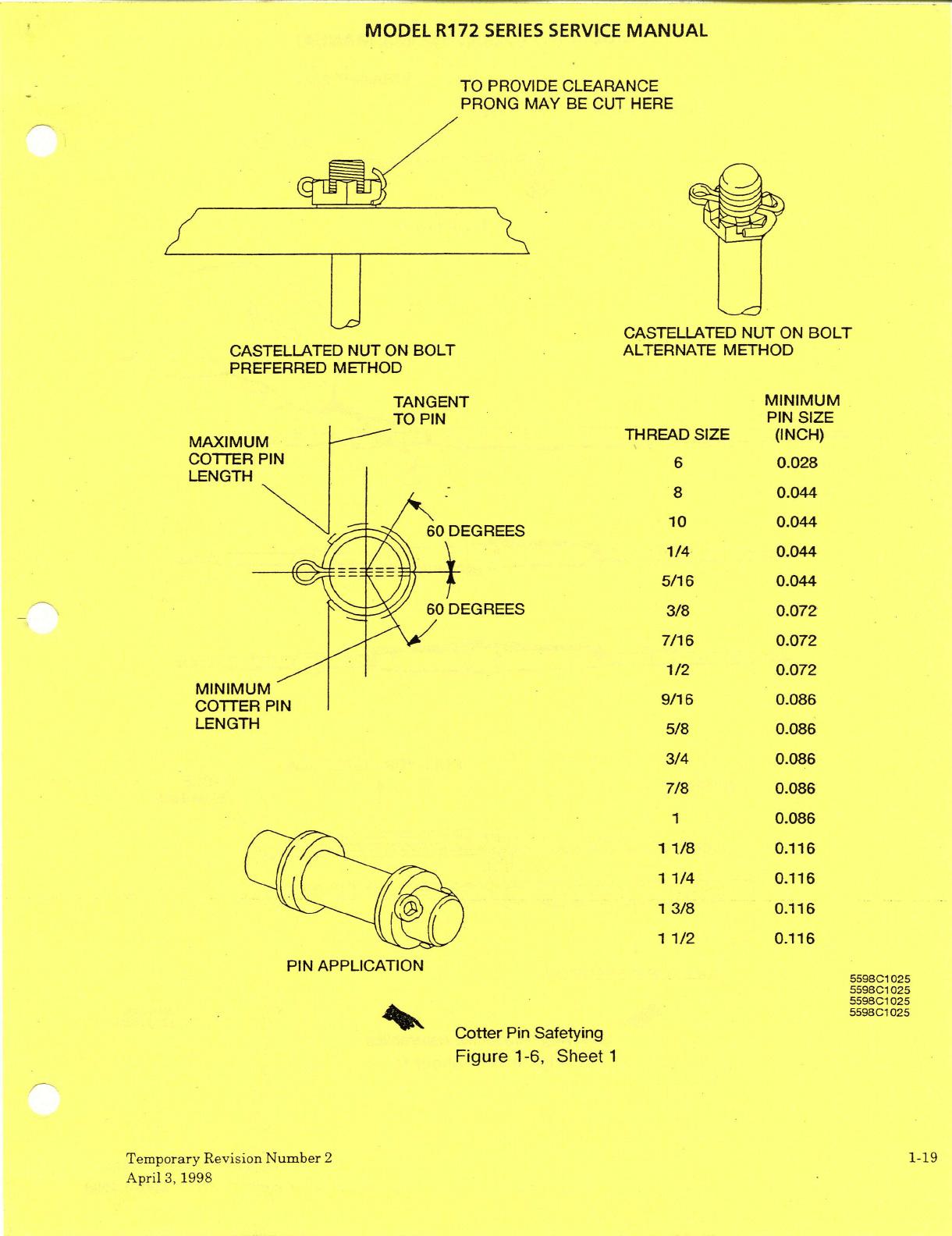
MODEL
R172
SERIES
SERVICE
MANUAL
TO
PROVIDE
CLEARANCE
PRONG MAY
BE
CUT
HERE
v
'
CASTELLATED
NUT
ON
BOLT
CASTELLATED NUT
ON
BOLT
ALTERNATE
METHOD
PREFERRED METHOD
TANGENT
MINIMUM
TO
PIN
PIN
SIZE
MAXIMUM
THREAD
SIZE
(INCH)
COTTER
PIN
6
0.028
LENGTH
8 0.044
10
0.044
60
DEGREES
1/4
0.044
5/16
0.044
MINIMUM
9/16
0.086
5/8
0.086
3/4
0.086
7/8
0.086
13/8
0.116
1
1/2
0.116
PIN
APPLICATION
Cotter
Pin
Safetying
Figure
1-6,
Sheet
1
Temporary Revision
Number
2
1-19
April
3,
1998
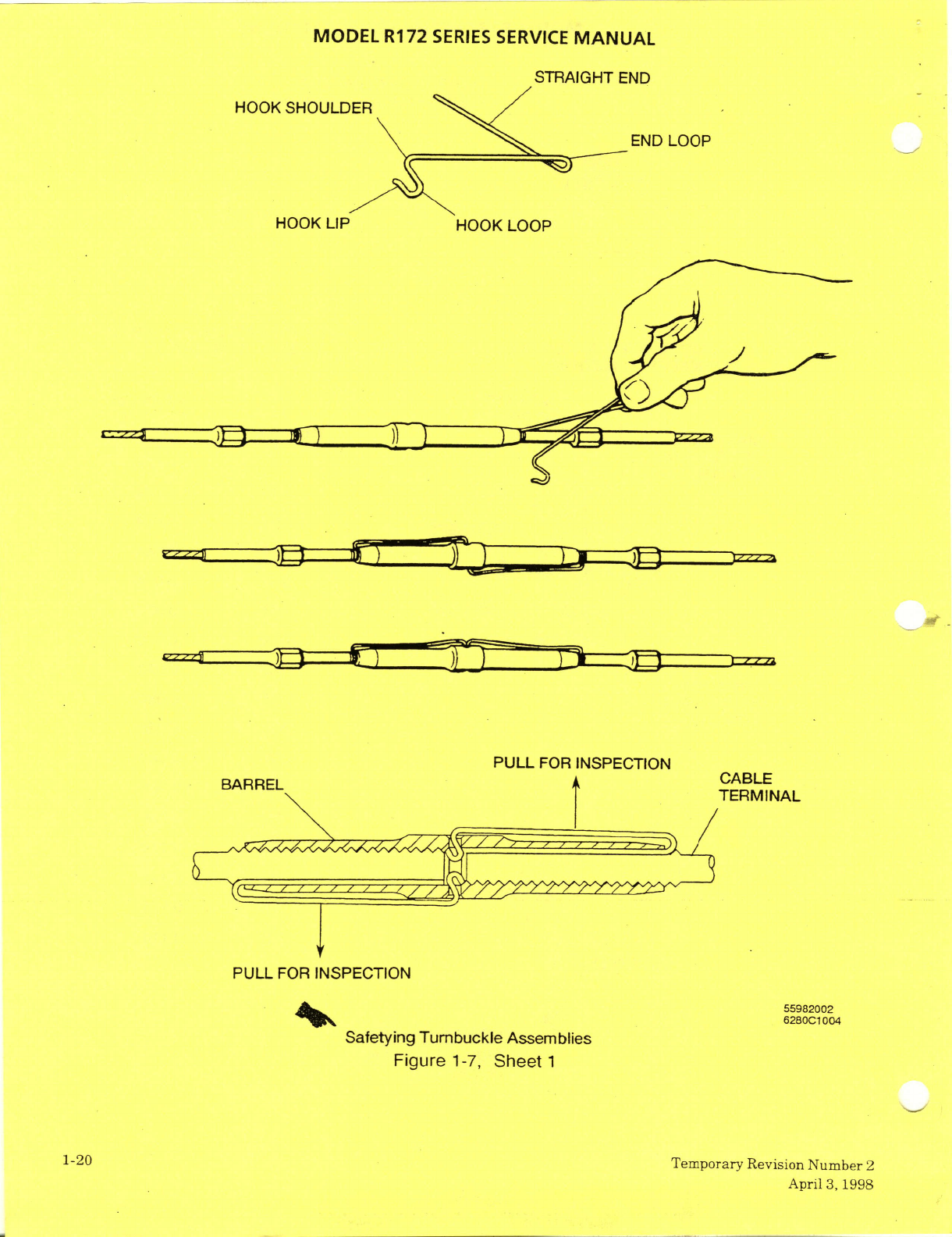
661
'g
IldV
;g
iqmnN
uoISIAa.i
ziiBodzmaL
OZ-I
L
laaeS
'L-L
ajn6!j
sa!lqLwessV
ealonquJnl
6u!ialeS
1OO
Lo829z
ZOOZ86SS
N01103dSNI
HOd
Tllnd
T
-1VNIV3BJ.v
N01133dSNI
UOd
ilnd
-
=
I
dOOl
)OOH
dln
)OOH
dOO1
tIN3
/3ailnoHS
0OOH
aN3
IHDEIVHIS
vlnNVIA
3D31A3S
S313S
ZL
L
13CIaOI
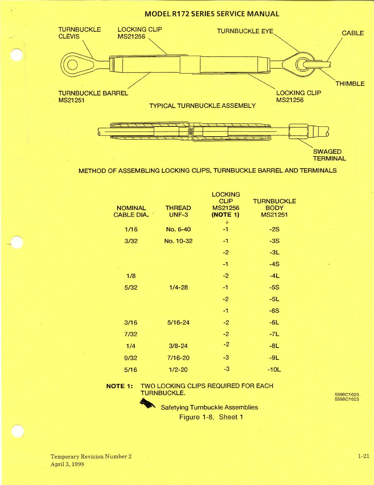
MODEL
R172
SERIES
SERVICE
MANUAL
TURNBUCKLE
LOCKING
CLIP
TURNBUCKLE
EYE
CLEVIS
MS21256
THIMBLE
TURNBUCKLE
BARREL
LOCKING
CLIP
MS21251
MS21256
TYPICAL TURNBUCKLE ASSEMBLY
SWAGED
TERMINAL
METHOD
OF ASSEMBLING
LOCKING
CLIPS,
TURNBUCKLE BARREL
AND
TERMINALS
LOCKING
CUP
TURNBUCKLE
NOMINAL
THREAD
MS21256
BODY
CABLE
DIA.
UNF-3
(NOTE
1)
MS21251
1/16
No.
6-40
-1
-2S
3/32
No.
10-32
-1
-3S
-2
-3L
-1
-4S
1/8
-2
-4L
5/32
1/4-28
-1
-5S
-2 -5L
-1
-6S
3/16 5/16-24
-2
7/32
-2
1/4 3/8-24
-2 -8L
9/32
7/16-20
-3 -9L
5/16 1/2-20
-3
-10L
NOTE
1:
TWO LOCKING
CLIPS
REQUIRED
FOR
EACH
TURNBUCKLE.
5598C1023
5598C1
023
Safetying
Tumbuckle
Assemblies
Figure
1-8,
Sheet
1
Temporary
Revision
Number
2
1-21
April
3,
1998
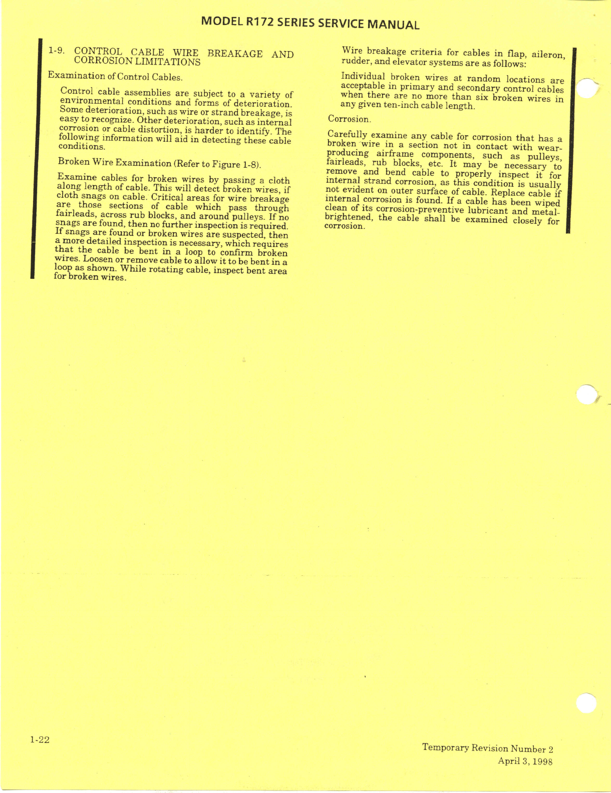
MODEL
R172
SERIES
SERVICE
MANUAL
WIRE
BREAKAGE AND
Wire
breakage
criteria
for
cables
in
flap,
aileron,
1-9.
CORROLCABLEWIRNE
BREAKAGE AND
rudder, and
elevator
systems
are
as
follows:
CORROSION
LIMITATIONS
Individual
broken
wires
at
random
locations
are
Examination
of
Control
Cables.
acceptable
in primary
and
secondary
control
cables
Control
cable
assemblies are
subject
to a
variety
of
when
there
are
no
more
than
six
broken
wires
in
environmental
conditions
and
forms
of
deterioration.
any
given
ten-inch
cable
length.
Some
deterioration,
such
as wire
or
strand
breakage,
is
Corrosion.
easy
to
recognize.
Other deterioration,
such
as
internal
corrosion
or
cable
distortion,
is
harder
to
identify.
The
Carefully
examine
any
cable
for
corrosion
that
has
a
following
information
will
aid in
detecting
these
cable
broken-wire
in
a
section
not
in
contact
with
wear-
conditions.
producing
airframe
components,
such
as
pulleys,
fairleads,
rub
blocks,
etc.
It
may
be
necessary
to
Broken
Wire
Examination
(Refer
to
Figure
1-8).
remove
and
bend
cabe
properly
inspect
it
for
Examine
cables for
broken
wires
by
passing
a
cloth
internal strand
corrosion,
as
this
condition
is
usually
along
length
of
cable. This will
detect
broken wires,
if
not
evident
on
outer
surface
of
cable. Replace cable
if
cloth
snags
on
cable.
Critical
areas
for
wire
breakage
internal
corrosion
is
found.
If
a
cable
has
been
wiped
are
those
sections
of
cable
which
pass
through
clean
of
its
corrosion-preventive
lubricant
and
metal-
fairleads,
across
rub
blocks,
and
around
pulleys.
If
no
brightened,
the
cable
shall
be
examined
closely
for
snags
are
found,
then
no
further
inspection
is
required.
corrosion.
If
snags
are
found
or
broken wires
are
suspected,
then
a
more
detailed
inspection
is
necessary,
which
requires
that
the
cable
be
bent
in
a
loop
to
confirm
broken
wires.
Loosen
or
remove
cable
to allow
it
to
be
bent
in
a
loop
as shown.
While
rotating
cable,
inspect
bent
area
for
broken
wires.
1-22
Temporary
Revision
Number
2
April
3,
1998
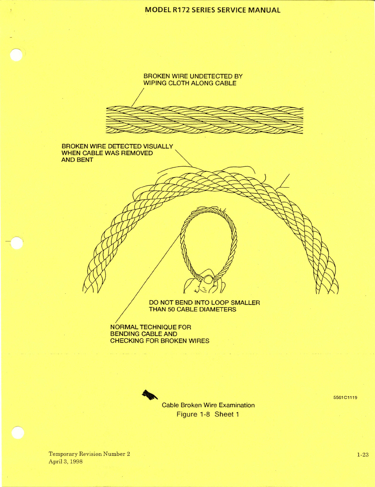
MODEL
R172
SERIES SERVICE
MANUAL
BROKEN
WIRE UNDETECTED
BY
WIPING
CLOTH
ALONG
CABLE
BROKEN
WIRE DETECTED
VISUALLY
WHEN CABLE
WAS
REMOVED
AND
BENT
DO
NOT
BEND
INTO
LOOP SMALLER
THAN
50
CABLE
DIAMETERS
NORMAL
TECHNIQUE
FOR
BENDING
CABLE AND
CHECKING
FOR BROKEN
WIRES
5561C1119
Cable
Broken
Wire
Examination
Figure
1-8
Sheet
1
Temporary
Revision
Number
2
1-23
April
3,
1998
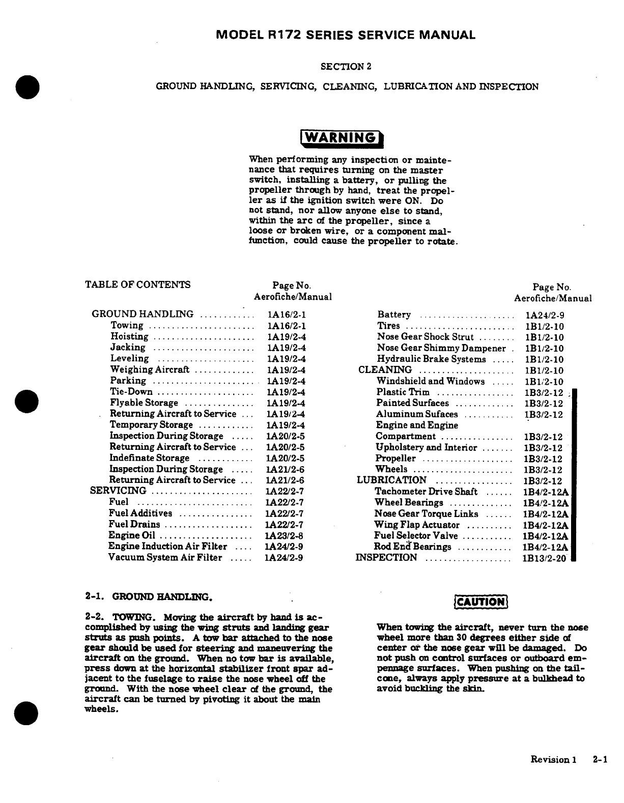
MODEL
R172
SERIES SERVICE
MANUAL
SECTION
2
GROUND
HANDLING,
SERVICING, CLEANING, LUBRICATION
AND
INSPECTION
WARNING
When
performing
any
inspection
or
mainte-
nance
that
requires
turning
on
the
master
switch,
installing
a
battery,
or
pulling the
propeller
through
by hand,
treat
the
propel-
ler
as
if
the ignition switch
were
ON.
Do
not
stand,
nor
allow
anyone
else
to
stand,
within
the
arc
of
the
propeller,
since
a
loose
or
broken
wire,
or
a
component
mal-
function,
could
cause
the
propeller
to
rotate.
TABLE
OF
CONTENTS
Page
No. Page
No.
Aerofiche/Manual
Aerofiche/Manual
GROUND
HANDLING
............
1A16/2-1
Battery
.
..............
1A24/2-9
Towing .......................
1A
16/2-1
Tires
..................
.....
1B1/2-10
Hoisting
......................
1A19/2-4
Nose
Gear
Shock
Strut
........
1B1/2-10
Jacking
......................
1A19/2-4
Nose
Gear
Shimmy
Dampener
.
1B1/2-10
Leveling
.....................
1A19/2-4
Hydraulic
Brake
Systems
.....
1B1/2-10
Weighing Aircraft
............
1A19/2-4
CLEANING
.....................
1B1/2-10
Parking
......................
1A19/2-4
Windshield
and
Windows
.....
1B12-10
Tie-Down
.................. ..
1A19/2-4
Plastic
Trim
.................
1B3/2-12
Flyable
Storage
...............
1A19/2-4
Painted
Surfaces
.............
1B3/2-12
Returning
Aircraft
to
Service
...
1A19/2-4
AluminumSufaces
..........
1B3/2-12
Temporary
Storage
............
1A19/2-4
Engine
and
Engine
Inspection
During
Storage
.....
1A20/2-5
Compartment
................
1B3/2-12
Returning
Aircraft
to
Service
...
1A20/2-5
Upholstery
and
Interior
.......
1B3/2-12
Indefinate
Storage
............
1A20/2-5
Propeller
....................
1B3/2-12
Inspection
DuringStorage
.....
1A21/2-6
Wheels
. . ...... ...
1B3/2-12
Returning
Aircraft
to
Service
...
1A21/2-6
LUBRICATION
.................
1B3/2-12
SERVICING ......................
1A22/2-7
Tachometer
Drive
Shaft
......
1B4/2-12A
Fuel
........................
1A22/2-7
W
heel
Bearings
..............
1B4/2-12A
Fuel
Additives
................
1A22/2-7
Nose
Gear
Torque
Links
......
1B4/2-12A
Fuel
Drains
...................
A22/2-7
Wing
Flap
Actuator
.........
1B4/2-12A
Engine
Oil
....................
1A23/2-8
Fuel
Selector
Valve
..........
1B4/2-12A
Engine
Induction
Air
Filter
....
1A24/2-9
Rod
End
Bearings
............
1B4/2-12A
Vacuum System
Air
Filter
.....
1A24/2-9
INSPECTION
...................
1B13/2-20
2-1.
GROUND
HANDLING. CAUTION
2-2.
TOWING.
Moving
the
aircraft
by
hand
is
ac-
complished
by
using
the
wing
struts
and
landing
gear
When
towing
the
aircraft,
never
turn
the
nose
struts
as
push points.
A
tow
bar
attached
to
the nose
wheel
more
than
30
degrees
either
side
of
gear
should
be
used
for
steering
and
maneuvering
the
center
or
the
nose
gear
will
be
damaged.
Do
aircraft
on the
ground.
When
no
tow
bar
is
available,
not
push
on
control
surfaces
or
outboard
em-
press
down
at
the
horizontal
stabilizer
front
spar
ad-
pennage
surfaces.
When
pushing
on
the
tail-
jacent
to the fuselage to
raise
the
nose wheel
off
the
cone,
always
apply
pressure at
a
bulkhead
to
ground.
With
the
nose
wheel
clear
of
the
ground,
the
avoid
buckling
the
skin
aircraft
can
be
turned
by
pivoting
it
about
the
main
wheels.
Revision
1
2-1
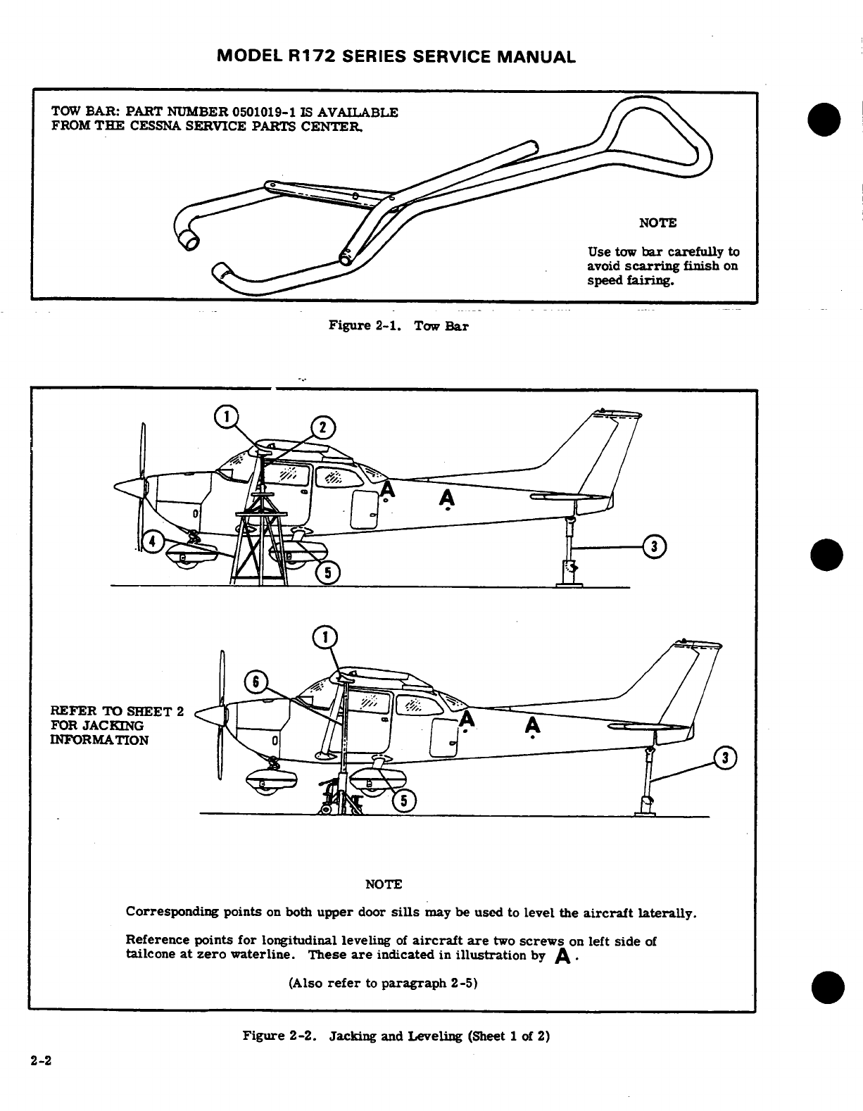
MODEL
R172
SERIES
SERVICE
MANUAL
TOW
BAR: PART
NUMBER
0501019-1
IS
AVAILABLE
FROM
THE
CESSNA
SERVICE
PARTS
CENTER.
NOTE
Use
tow
bar
carefully
to
avoid
scarring
finish
on
speed
fairing.
Figure
2-1.
Tow
Bar
REFER
TO
SHEET 2
FOR
JACKING
INFORMATION
NOTE
Corresponding
points
on
both
upper
door
sills
may be
used
to
level
the
aircraft
laterally.
Reference
points
for
longitudinal
leveling
of
aircraft
are
two
screws
on
left
side
of
tailcone
at
zero
waterline. These
are
indicated
in
illustration
by
A
(Also
refer
to
paragraph
2-5)
Figure
2-2.
Jacking
and
Leveling
(Sheet
1
of
2)
2-2
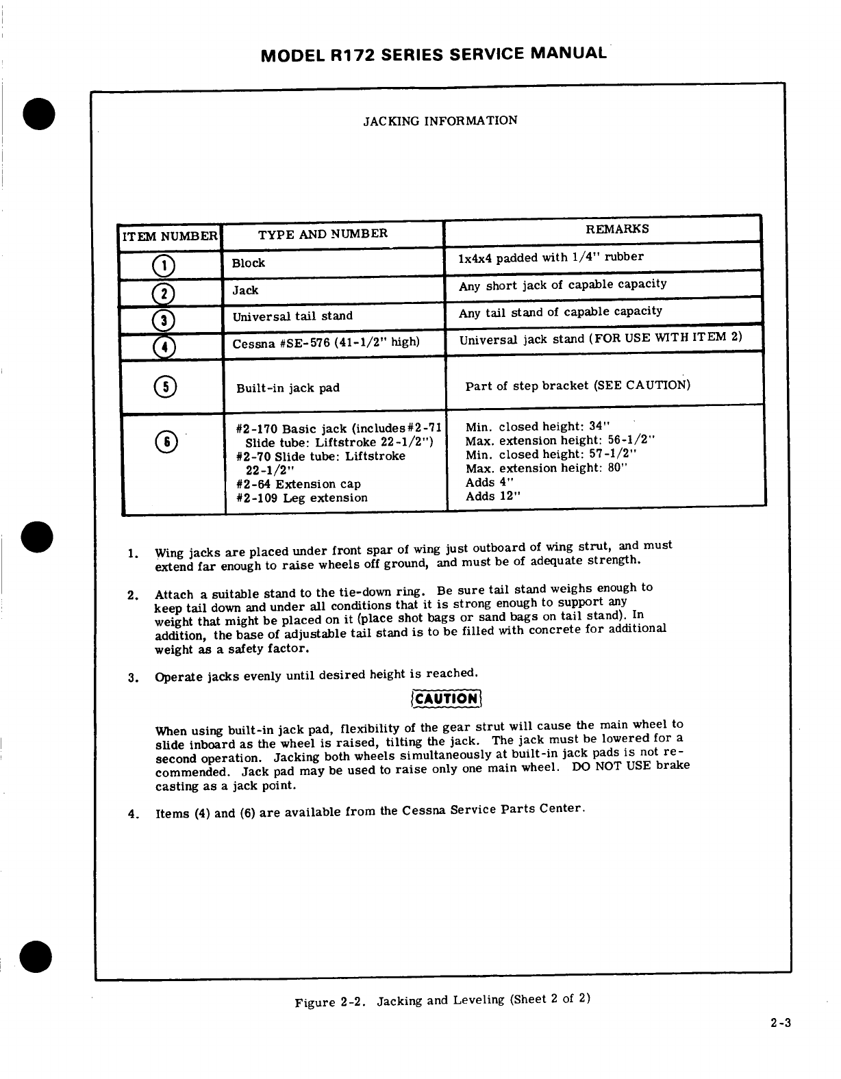
MODEL
R172
SERIES
SERVICE
MANUAL
JACKING
INFORMATION
ITEM
NUMBER
TYPE
AND
NUMBER
REMARKS
1
Block
1x4x4
padded with
1/4"
rubber
2
Jack
Any
short
jack
of
capable
capacity
3
Universal
tail
stand
Any
tail
stand
of
capable capacity
4
Cessna
#SE-576
(41-1/2"
high)
Universal
jack
stand
(FOR
USE
WITH
ITEM
2)
5
Built-in
jack
pad
Part
of
step
bracket
(SEE
CAUTION)
#2-170
Basic
jack
(includes#2-71
Min.
closed
height:
34"
Slide
tube:
Liftstroke
22-1/2")
Max.
extension
height:
56-1/2"
#2-70
Slide
tube:
Liftstroke
Min.
closed
height:
57-1/2"
22-1/2"
Max.
extension
height:
80"
#2-64
Extension
cap
Adds
4"
#2-109
Leg
extension
Adds
12"
1.
Wing
jacks
are
placed
under
front
spar
of
wing
just
outboard
of
wing
strut,
and
must
extend
far
enough
to
raise
wheels
off
ground,
and
must
be
of
adequate
strength.
2.
Attach
a
suitable
stand
to
the
tie-down
ring.
Be
sure
tail
stand
weighs
enough
to
keep
tail
down
and
under
all
conditions
that
it
is
strong
enough
to
support
any
weight
that
might
be
placed
on
it
(place
shot
bags
or
sand
bags
on
tail
stand).
In
addition,
the
base
of
adjustable
tail
stand
is
to
be
filled
with
concrete
for
additional
weight
as
a
safety
factor.
3.
Operate
jacks
evenly
until
desired
height
is
reached.
CAUTION
When
using
built-in
jack
pad,
flexibility
of
the
gear
strut
will
cause
the
main
wheel
to
slide
inboard
as
the wheel
is
raised,
tilting
the
jack.
The
jack must
be
lowered
for
a
second
operation. Jacking
both
wheels
simultaneously at
built-in
jack
pads
is
not
re-
commended.
Jack
pad
may
be
used
to
raise
only
one
main
wheel.
DO
NOT
USE
brake
casting
as
a
jack point.
4.
Items
(4)
and
(6)
are
available
from
the
Cessna
Service
Parts
Center.
Figure
2-2.
Jacking
and
Leveling (Sheet
2
of
2)
2-3
MODEL
R172
SERIES SERVICE
MANUAL
2-3.
HOISTING.
The
aircraft
may
be
lifted
with
a
age
and/or
the
first
25
hours
of
intermittent
engine
hoist
of
two-ton
capacity
by
using
hoisting
rings,
operation.
which
are
optional
equipment,
or
by
means
of
suit-
NOTE
able
slings.
The
front
sling should
be
hooked
to The
aircraft
is
delivered
from
Cessna
with
each
upper
engine mount
at
the
firewall,
and
the aft
a
corrosion
preventative
aircraft
engine
oil
sling
should
be
positioned
around
the
fuselage
at
the
(MIL-C-6529, Type
II).
This
engine
oil
is
first
bulkhead
forward
of
the
leading
edge
of
the
a
blend
of
aviation grade
straight
mineral
stabilizer.
If
the
optional
hoisting
rings
are
used,
oil
and
a
corrosion
preventative
compound.
a
minimum
cable
length
of
60
inches
for
each cable
This
engine
oil
should
be
used
for
the
first
is
required
to
prevent
bending
of
the
eyebolt-type
25
hours
of
engine
operation.
In
the
event
hoisting
rings.
If
desired,
a
spreader
jig
may
be
it
is
necessary
to
add
oil
during
the
first
25
fabricated
to
apply
vertical
force
to
the
eyebolts.
hours
of
operation,
use
only
aviation
grade
straight
mineral
oil
of
the
correct
viscosity.
2-4.
JACKING.
Refer
to
figure
2-2
for
jacking
procedures.
During
the
30
day
non-operational
storage
or
the
first
25
hours
of
intermittent
engine
operation, every
sev-
2-5.
LEVELING.
Corresponding
points
on
both
enth
day
the
propeller
shall
be
rotated
by
hand
without
upper
door
sills
may
be
used
to
level
the
aircraft
running
the
engine.
After
rotating the
engine
five
revo-
laterally.
The
reference
points
for
longitudinally
lutions,
stop
the
propeller
45
°
to
90
°
from
the
position
leveling
the
aircraft
are
the
two
screws
located
on
it
was
in.
If
the
aircraft
is
stored
outside,
tie-down
the
left
side
of
the
tailcone.
Refer
to
figure
2-2
for
in
accordance
with
paragraph
2-8.
In
addition,
the
screw
locations. pitot
tube,
static
air
vents,
air
vents,
openings
in
the
engine
cowling,
and
other
similar
openings
shall
have
2-6.
WEIGHING
AIRCRAFT.
Refer
to
Pilot's
protective covers installed
to
prevent
entry
of
foreign
Operating
Handbook.
material.
If
at
the
end
of
thirty
(30)
days
aircraft
will
not
be
removed
from storage,
the
engine
shall
2-7.
PARKING.
Parking
precautions
depend
prin-
be
started
and
run.
The
preferred
method
would
be
cipally
on
local
conditions.
As
a
general
precaution,
to
fly the
aircraft
for
thirty
(30)
minutes,
and
up
to,
set
parking
brake
or
chock the
wheels
and
install
the but not
exceeding
normal
oil
and
cylinder
tempera-
controls
lock.
In
severe
weather
and
high
wind
con-
tures.
ditions,
tie
down
the
aircraft
as
outlined
in
paragraph
2-8
if
a
hangar
is
not
available.
CAUTION
2-8.
TIE-DOWN.
When
mooring
the
aircraft
in
the
Excessive
ground
operation
shall
be
avoided.
open,
head
into
the
wind
if
possible.
Secure
control
surfaces
with
the
internal
control
lock
and
set
brakes.
2-10.
RETURNING
AIRCRAFT
TO
SERVICE.
After
flyable
storage,
returning
the
aircraft
to
service
is
CAUTION
accomplished
by
performing
a
thorough
pre-flight
in-
spection.
At
the
end
of
the
first
25
hours
of
engine
Do
not
set
parking
brakes
during
cold
weather
operation, drain
engine
oil
and
clean
oil
screens
(or
when
accumulated
moisture
may
freeze
the
change spin
on
filter).
Service
engine
with
correct
brakes or
when
the
brakes
are
overheated.
grade
and
quantity
of
engine
oil.
Refer
to
figure
2-5
and
paragraph
2-22
for
correct
grade
of
engine
oil.
After
completing
the
preceding,
proceed
to
moor
the
aircraft
as
follows: 2-11.
TEMPORARY
STORAGE.
Temporary
storage
a.
Tie
ropes,
cables,
or
chains
to
the
wing
tie-
is
defined
as
aircraft
in
a
non-operational
status
for
down
fittings
located
at
the
upper
end
of
each
wing
a
maximum
of
90
days.
The
aircraft
is
constructed
strut.
Secure
the
opposite
ends
of
ropes, cables,
of
corrosion
resistant
alclad
aluminum,
which
will
or
chains
to
ground
anchors.
last
indefinitely
under
normal
conditions
if
kept
clean,
b.
Secure
rope
(no
chains
or cables)
to
forward
however,
these
alloys
are
subject
to
oxidation.
The
mooring
ring
and
secure
opposite
end
to
ground an-
first
indication
of
corrosion
on
unpainted
surfaces
is
chor.
in
the
form
of
white
deposits
or
spots.
On
painted
c.
Secure
the
middle
of
a
rope
to the
tail
tie-down
surfaces,
the
paint
is
discolored
or
blistered.
Stor-
ring.
Pull
each
end
of
rope
away
at
a
45
degree
angle
age
in
a
dry
hangar
is
essential
to
good
preservation
and
secure
to ground
anchors
at
each
side
of
tail.
and
should
be
procured
if
possible.
Varying
condi-
d.
Secure
control
lock
on
pilot control
column.
If
tions
will
alter
the
measures
of
preservation,
but
control
lock
is
not
available, tie
pilot
control
wheel
under
normal conditions
in
a
dry
hangar,
and
for
back
with
front seat
belt.
storage
periods
not
to
exceed
90
days,
the
following
e.
These
aircraft
are
equipped
with
a
spring-loaded
methods
of
treatment
are
suggested:
steering
system
which
affords
protection
against
nor-
a.
Fill
fuel
tanks
with
correct
grade
of
gasoline.
mal
wind
gusts.
However,
if
extremely
high
wind
b.
Clean
and wax
aircraft
thoroughly.
gusts
are
anticipated,
additional
external
locks
may
c.
Clean
any
oil
or
grease
from
tires
and
coat
be
installed.
tires
with
a
tire
preservative.
Cover
tires
to
pro-
tect
against
grease
and
oil.
2-9.
FLYABLE
STORAGE.
Flyable
storage
is
de- d.
Either
block
up
fuselage
to
relieve
pressure
on
fined
as
a
maximum
of
30
days
non-operational
stor-
tires
or rotate
wheels
every
30
days
to
change
sup-
porting
points
and
prevent
flat
spotting
the
tires.
2-4
MODEL
R172
SERIES
SERVICE
MANUAL
e.
Lubricate
all
airframe
items
and
seal
or
cover
o.
Attach
a
warning
placard
to
the
propeller
to
the
all
openings which
could
allow
moisture
and/or
dust
effect
that
the
propeller
shall
not
be
moved
while the
to
enter.
engine
is
in
storage.
NOTE
2-12.
INSPECTION
DURING
STORAGE.
The
aircraft
battery
serial
number
is
recorded
a.
Inspect
airframe
for
corrosion
at
least
once
a
in
the
aircraft
equipment
list.
To
assure
ac-
month
and
remove
dust
collections
as
frequently
as
curate
warranty records,
the
battery
should
be
possible.
Clean
and
wax
as
required.
reinstalled
in
the
same
aircraft
from
which
it
b.
Inspect
the
interior
of
at
least
one
cylinder
was
removed.
If
the
battery
is
returned
to
through
the
spark
plug
hole
for
corrosion
at
least
service
in
a
different
aircraft,
appropriate
once
a
month.
record
changes
must
be
made and
notification
sent
to
the
Cessna
Claims
Department.
NOTE
f.
Remove
battery
and
store
in a
cool
dry place;
Do
not
move
crankshaft
when
inspecting
in-
service
the
battery
periodically
and
charge
as
re-
terior
of
cylinder
for
corrosion.
quired.
NOTE
c.
If
at
the
end
of
the
90
day
period,
the
aircraft
is
to
be
continued
in
non-operational
storage,
again
per-
An
engine
treated
in
accordance
with
the
fol-
form
the
procedural
steps
"g"
thru
"o"
of
paragraph
lowing
may
be
considered
protected
against
2-11.
normal
atmospheric
corrosion
for
a
period
not
to exceed
90
days.
2-13.
RETURNING
AIRCRAFT
TO SERVICE.
After
temporary
storage,
use
the
following
procedures
to
g.
Disconnect
spark
plug
leads
and
remove
upper
return
the
aircraft
to
service.
and
lower
spark
plugs from
each
cylinder.
a.
Remove
aircraft
from
blocks
and
check
tires
for
proper
inflation.
Check
for
proper
nose
gear
strut
inflation.
(Refer to
Section
1.)
NOTE
b.
Check
and
install
battery.
c.
Check
oil
sump
for
proper
grade
and
quantity
of
The
preservative
oil
must
be
Lubricating
Oil
-
engine
oil.
Contact
and
Volatile,
Corrosion
Inhibited,
d.
Service
induction
air
filter
and
remove
warning
MIL-L-46002, Grade
1
or
equivalent.
placard
from
propeller.
e.
Remove
materials
used
to
cover
openings.
f.
Remove,
clean
and
gap
spark
plugs.
h.
Using
a
portable
pressure
sprayer,
spray pre-
g.
While
spark
plugs
are
removed,
rotate
propeller
servative
oil
through
the
upper
spark
plug
hole
of
each
several
revolutions
to
clear
excess
rust
preventive
cylinder
with
the
piston
in
a
down
position.
Rotate
oil
from cylinders.
crankshaft
as
each
pair
of
cylinders
is
sprayed.
h.
Install
spark
plugs. Torque
spark
plugs
to
value
i.
After
completing step
"h,
"
rotate
crankshaft
so
specified
in
Section
11
and
connect
spark
plug
leads.
that
no
piston
is
at
a
top
position.
If
the
aircraft
is
i.
Check
fuel
strainer.
Remove
and
clean
filter
to
be
stored
outside,
stop
propeller
so
that
blades
as
screen
if
necessary.
Check
fuel
tanks
and
fuel
lines
near
horizontal
as
possible
to
provide
maximum
clear-
for
moisture
and
sediment.
Drain
enough
fuel
to
ance
with
passing
aircraft.
eliminate
moisture
and
sediment.
Torque
bottom
nut
j.
Again
spray
each cylinder
without
moving the
of
strainer
to
25-30
lb-in
and
safety
wire
to
top
as-
crankshaft
to
thoroughly cover
all
interior
surfaces
sembly
of
strainer.
Wire
must
have
right-hand
wrap,
of
the
cylinder
above the
piston. at
least
45
degrees.
k.
Install
spark
plugs
and
connect
spark
plug
leads.
j.
Perform
a
thorough
pre-flight
inspection,
then
l.
Apply
preservative
oil
to
the
engine
interior
by
start
and
warm-up
engine.
spraying approximately
two
ounces
of
the
preserva-
tive
oil
through the
oil
filler
tube.
2-14.
INDEFINITE
STORAGE.
Indefinite
storage
is
m.
Seal
all
engine
openings
exposed
to
the
atmos-
defined
as
aircraft
in
a
non-operational
status
for
an
phere
using
suitable
plugs
or
non-hygroscopic
tape.
indefinite
period
of
time.
Engines
treated
in
accor-
Attach a
red
streamer
at
each
point
that
a
plug
or
dance
with
the
following
may
be
considered
protected
tape
is
installed.
against
normal
atmosphere
corrosion,
provided
the
n.
If
the
aircraft
is
to
be
stored
outside,
perform
procedures
outlined
in
paragraph
2-15
are performed
the
procedures
outlined
in
paragraph
2-8.
In
addi-
at the
intervals
specified.
tion,
the
pitot
tube,
static
source
vents,
air
vents,
a.
Operate
engine
until
oil
temperature reaches
openings
in the
engine
cowling
and
other
similar
normal
operating
range.
Drain
engine
oil
sump
then
openings
should
have
protective
covers
installed
to
reinstall
and
safety drain
plug.
prevent entry
of
foreign
material.
b.
Fill
oil
sump
to
normal
operating
capacity
with
corrosion
preventative
mixture
which
has
been
thor-
oughly
mixed
and
pre-heated
(221°F
to
250°
F)
at
the
time
it
is
added to
the
engine.
2-5
MODEL
R172
SERIES
SERVICE
MANUAL
NOTE
inside
of
the
sealed
area
with
safety
wire
to
prevent
wicking
of
moisture into
the
sealed
Corrosion
preventative
mixture
consists
of
one
area.
part
compound
MIL-C-6529,
Type
I,
mixed
with
three
parts
new
lubricating
oil
of
the
n.
Drain
corrosion-preventive mixture
from
engine
grade
recommended
for
service.
During
all
sump
and
reinstall
drain
plug.
spraying operation
corrosion
mixture
is
pre-
heated
to
221
°
to
250°F.
NOTE
c.
Immediately
after
filling
the
oil sump
with
cor-
The
corrosion-preventive
mixture
is
harmful
rosion
preventative
mixture,
fly the
aircraft
for
a
to
paint
and
should
be wiped
from
painted
sur-
period
of
time
not
to
exceed
a
maximum
of
30
min-
faces
immediately.
utes.
d.
With
engine
operating
at
1200
to
1500
RPM
and
o.
Attach
a
warning
placard
on
the
throttle
control
induction
air
filter
removed,
spray
corrosion
pre-
knob,
to
the
effect
that
the
engine
contains
no
lubri-
ventative
mixture
into
induction
airbox,
at
the
rate
cating
oil.
Placard
the
propeller
to
the
effect
that
it
of
one-half
gallon
per
minute,
until
heavy
smoke
should
not
be moved while
the-engineis
in
storage.
comes
from exhaust
stack,
then
increase
the
spray
p.
Prepare airframe
for
storage
as
outlined
in
until
the engine
is
stopped.
paragraph
2-11
thru
step
"f."
ICAUTION
NOTE
Injecting
corrosion-preventative
mixture
As
an
alternate
method
of
indefinite storage,
too
fast
can
cause a
hydrostatic
lock.
the
aircraft
may
be
serviced
in
accordance
with
paragraph
2-11
providing
the
aircraft
is
e.
Do
not
rotate
propeller
after
completing
step run
up
at
maximum
intervals
of
90
days
and
"d.
"
then
reserviced
per
paragraph
2-11.
f.
Remove
all
spark
plugs
and
spray
corrosion-
preventative
mixture,
which
has
been
pre-heated
2-15.
INSPECTION
DURING
STORAGE.
Aircraft
(221
°
to
250°F,)
into
all
spark
plug
holes
to
thor-
in
indefinite
storage
shall
be
inspected
as
follows:
oughly
cover
interior
surfaces
of
cylinders.
a.
Inspect
cylinder
protex
plugs
each
7
days.
b.
Change
protex
plugs
if
their
color
indicates
an
NOTE
unsafe
condition.
c.
If
the
dehydrator
plugs
have
changed
color
in
one
To
thoroughly
cover
all
surfaces
of
the
half
of
the
cylinders,
all desiccant
material
in
the
cylinder
interior,
move
the
nozzle
of
the
engine
shall
be
replaced
with
new
material.
spray
gun
from
the
top
to
the
bottom
of
d.
Every
6
months
respray
the
cylinder
interiors
the
cylinder.
If
by
accident
the
propeller
with
corrosion-preventative
mixture
and
replace
all
is
rotated
following
this
spraying,
respray desiccant
and
protex
plugs.
the
cylinders
to
insure
an
unbroken
coverage
on
all
surfaces.
NOTE
g.
Install
lower
spark
plugs
or
install
solid
plugs,
Before
spraying,
inspect
the
interior
of
one
and
install
dehydrator
plugs
in
upper
spark
plug
cylinder
for
corrosion
through
the
spark
holes.
Be
sure
that
dehydrator
plugs
are
blue
in plug
hole
and
remove
at
least
one
rocker
box
color
when
installed.
cover
and
inspect
the
valve
mechanism.
h.
Cover
spark
plug
lead
terminals
with shipping
plugs
(AN4060-1)
or
other
suitable
covers.
2-16.
RETURNING
AIRCRAFT
TO SERVICE.
i.
With
throttle
in
full
open
position,
place
a bag
After
indefinite
storage,
use
the
following
procedure
of
desiccant
in
the
carburetor
intake
and
seal
open-
to
return
the
aircraft
to
service.
ing
with
moisture
resistant
paper
and
tape.
a.
Remove
aircraft
from
blocks
and
check
tires
for
j.
Place
a
bag
of
desiccant
in
the
exhaust
tail-
correct
inflation.
Check
for
correct
nose
gear
strut
pipe(s)
and
seal
openings
with
moisture
resistant
inflation.
tape.
b.
Check
battery
and
install.
k.
Seal
cold
air
inlet
to
the
heater
muff
with
mois-
c.
Remove
all
materials
used
to
seal
and
cover
ture
resistant
tape.
openings.
1.
Seal engine
breather
by
inserting
a
protex
plug d.
Remove
warning
placards
posted
at
throttle
and
in
the
breather
hose and
clamping
in place.
propeller.
m.
Seal
all
other
engine
openings
exposed
to
atmos-
e.
Remove
and
clean
engine
oil
screen,
then
re-
phere
using
suitable plugs or
non-hygroscopic
tape.
install
and
safety.
On
aircraft
that
are
equipped
with
an
external
oil
filter, install
new
filter
element.
NOTE
f.
Remove
oil
sump
drain
plug
(or
open
quick-drain
valve)
and
drain
oil sump.
Install
and
safety
drain
Attach
a
red
streamer
to
each
place
plugs
or plug (or
close
quick-drain
valve) and
service
engine
tape
is
installed.
Either
attach
red
streamers
with
oil
per
figure
2-5.
outside
of
the
sealed
area
with
tape
or
to
the
2-6
MODEL
R172
SERIES
SERVICE
MANUAL
NOTE
The
manner
in
which
the
alcohol
is
added
to
the
fuel
is
significant
because
alcohol
is most effective
when
The
corrosion-preventative
mixture
will
mix
it is
completely
dissolved
in
the
fuel.
To
insure
with
the
engine
lubricating
oil,
so
flushing
proper
mixing
the following
is
recommended.
the
oil
system
is
not
necessary.
Draining
the
oil
sump
is
sufficient.
1.
For
best
results
the
alcohol
should
be
added
during
the
fueling
operation
by
pouring
the
alcohol
g.
Service
and
install
the
induction
air
filter.
directly
on
the
fuel
stream
issuing
from
the
fuel
h.
Remove
dehydrator
plugs
and
spark
plugs
or
nozzle.
plugs
installed
in
spark
plug
holes
and
rotate
pro-
2.
An
alternate
method
that
may be
used
is
to
peller
by
hand
several
revolutions
to
clear
corrosion-
premix
the
complete alco
ol
dosage
with
some
fuel
preventative mixture
from
cylinders.
in
a
separate
clean
container (approximately
2-3
i.
Clean,
gap,
and
install
spark
plugs.
Torque
gallon
capacity)
and
then
transfer
this
mixture
to the
plugs
to
the
value
listed
in
Section
11.
tank
prior
to
the
fuel
operation.
j.
Check
fuel
strainer.
Remove
and
clean
filter
Any
high
quality
isopropyl
alcohol
may
be
used,
such
screen.
Check
fuel
tanks and
fuel
lines for moisture
as:
Anti-icing
fluid
(MIL-F-5566)
or
Isopropyl
alco-
and
sediment,
and
drain
enough
fuel
to
eliminate.
hol
(Federal
Specification
TT-I-735a).
k.
Perform
a
thorough
pre-flight
inspection,
then
start
and
warm-up
engine.
Ethylene
glycol monomethyl
ether
(EGME)
compound
l.
Thoroughly
clean
aircraft
and
flight
test
air-
in
compliance
with
MIL-I-27686
or
Phillips
PFA-
craft.
55MB,
if
used,
must
be
carefully
mixed
with
the
fuel
in
concentrations
not to
exceed
0.15%
by
volume.
2-17.
SERVICING.
2-18.
Requirements
are
shown
in
figure
2-5.
The
CAUTION
following
supplements
this
figure
by
adding
details.
Mixing
of
the
EGME
compound
with
the
fuel
is
extremely important
because
concentra-
2-19.
FUEL.
Fill
tanks
immediately
after
flight
to
tion
in
excess
of
that
recommended
(0.15
lessen
condensation.
Fuel
capacities
are
listed
in
percent
by
volume
maximum)
will
result
in
Section
1
and
fuel
grades
are
shown
in
figure
2-5.
detrimental
affects
to
the
fuel
tanks, such
2-20.
USE
OF
FUEL
ADDITIVES
FOR
COLD
as
deterioration
of
protective
primer
and
WEATHER
OPERATION.
Strict
adherence
to
recom-
sealants
and
damage
to
O-rings
and
seals
in the
fuel
system
and
engine
components.
mended
preflight draining
instructions
will
eliminate
any
free
water accumulations
from
the
tank
sumps.
While
small
amounts
of
water
may
still
remain
in
solution
in
the
gasoline,
it
will
normally
be
consumed
proportioning.
and
go
unnoticed
in
the
operation
of
the
engine.
Do
not
allow
the
concentrated
EGME
com-
pound
to
come
in
contact
with
the
airplane
One
exception
to
this can
be
encountered
when
oper-
finish or
fuel
cell
as
damage
can
result.
ating under
the
combined
effect
of:
1)
use
of
certain
fuels,
with
2)
high
humidity
conditions
on
the ground
Prolonged
storage
of
the
airplane
will
result
in a
3)
followed
by
flight
at
high
altitude
and
low
tempera-
water
buildup
in
the
fuel
which
"leeches
out"
the
ture.
Under
these
unusual
conditions
small
amounts
additive.
An
indication
of
this
is
when
an
excessive
of
water
in
solution can
precipitate
from
the fuel
amount
of
water
accumulates
in
the
fuel
tank
sumps.
stream
and
freeze
in
sufficient
quantities
to
induce
The
concentration
can
be
checked
using
a
differential
partial
icing
of
the
engine
fuel
system,
refractometer.
It
is imperative
that
the
technical
manual
for
the
differential
refractometer
be
followed
While
these
conditions
are
quite
rare
and
will
not
explicitly
when
checking
the
additive
concentration.
normally
pose
a
problem
to
owners
and
operators,
they
do
exist
in
certain
areas
of
the
world
and con-
sequently
must
be
dealt
with
when
encountered. 2-21.
FUEL
DRAINS.
Fuel
drains are
located
at
various
places
throughout
the
fuel
system. Refer
to
Therefore,
to
alleviate
the
possibility
of
fuel
icing
Section
12
for location
of
the
various
drains
in
the
occurring
under
these
unusual
conditions
it
is
per-
system.
The
fuel
tanks
and
fuel
strainer
have
drain
missible
to
add
isopropyl
alcohol
or
ethyelene
glycol
valves.
To
activate
the
tank
drain
valve
for
fuel
monomethyl
ether
(EGME)
compound
to
the
fuel
sup-
sampling,
place
cup
up
to
valve
and
depress
valve
ply.
See
Figure
2-3
for
fuel additive
mixing
ratio.
with rod
protruding from
cup.
See
Section
12
for
illustration
of
fuel
tank
drain
valve.
The
strainer
The
introduction
of
alcohol
or
EGME
compound
into
drain
valve
is
an
integral
part
of
the
fuel
strainer
the
fuel
provides
two
distinct
effects:
1) it
absorbs
assembly.
The
strainer
drain
is
equipped
with
a
the
dissolved
water
from
the
gasoline
and
2)
alcohol
control
which
is
located
adjacent
to
the
oil
dipstick.
has
a
freezing
temperature depressant
effect.
Access
to
the
control
is
through
the
oil
dipstick
access
door.
Open
drains
and
remove
drain
plugs
at
the
Alcohol,
if
used,
is
to be
blended
with
the
fuel
in
a
intervals
specified
in
figure
2-5.
Also,
during
daily
concentration
of
1%
by
volume.
Concentrations
inspection
of
the
fuel
strainer
or fuel
tanks,
if
water
greater
than
1%
are
not
recommended
since
they
can
is
found in
the
fuel
system,
all
fuel
drain
plugs
should
be
detrimental
to
fuel tank
materials,
be
removed
and
all
water
drained
from
the
system.
2-7
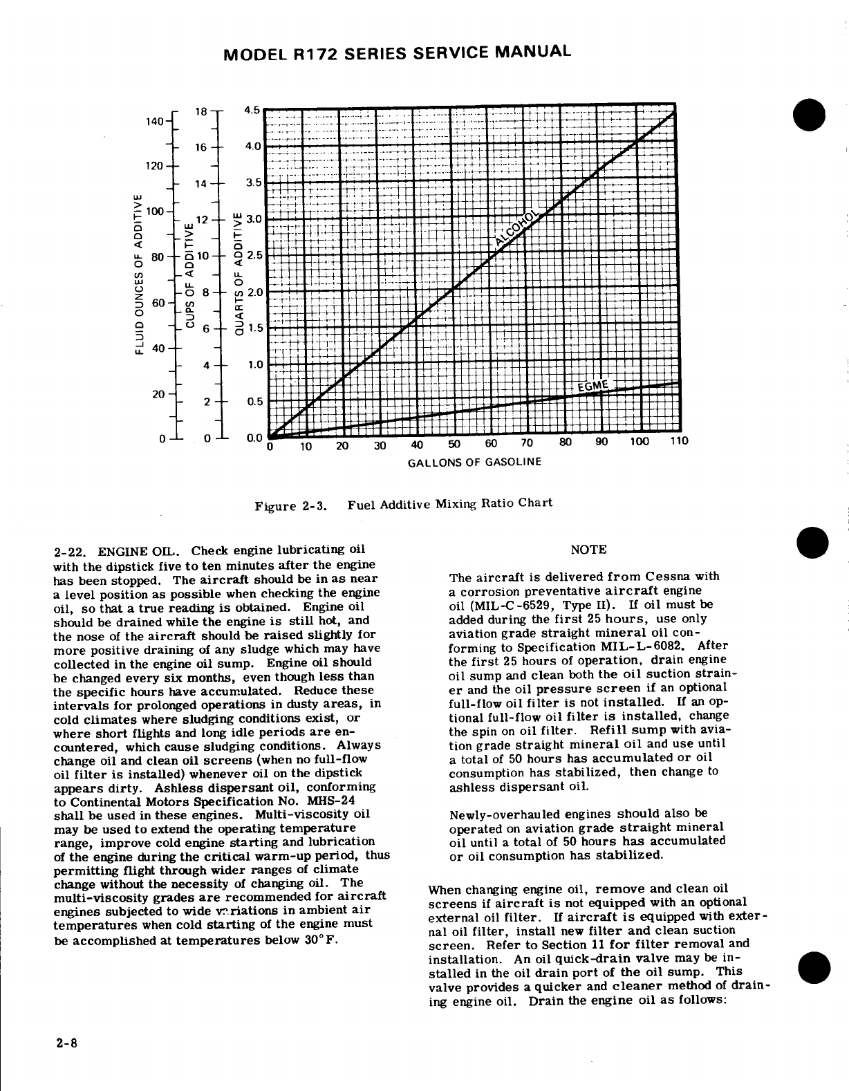
MODEL
R172
SERIES SERVICE
MANUAL
-
140
has
been
stopped.
The
aircraft
should
be
in
as
near
The
aircraft
is
delivered
from
Cessna
with
a
level
position
as
possible
when
checking the
engine
a
corrosion
preventative
aircraft
engine
oil,
so
that
a
true
reading
is
obtained.
Engine
oil
oil (MIL-C-6529,
Type
II).
If
oil must
be
should
be
drained
while
the
engine
is
still
hot,
and added
during
the
first
25
hours,
use
only
the
nose
of
the
aircraft
should be
raised
slightly
for
aviation
grade
straight
mineral
oil
con-
more
positive
draining
of
any
sludge
which
may
have
forming
to
Specification
MIL-L-6082.
After
collected
in
the
engine
oil
sump.
Engine
oil should
the
first
25
hours
of
operation,
drain
engine
be changed
every
six
months,
even
though
less
than oil
sump
and
clean
both
the
oil
suction
strain-
the
specific
hours
have
accumulated.
Reduce
these
er
and
the
oil
pressure
screen
if
an
optional
intervals
for
prolonged
operations
in
dusty
areas,
in
full-flow oil
filter
is
not
installed.
If
an
op-
cold
climates
where
sludging conditions
exist,
or
tional full-flow
oil
filter
is
installed,
change
where
short
flights
and
long
idle
periods
are
en-
the spin
on
oil
filter.
Refill sump
with
avia-
countered,
which
cause
sludging conditions.
Always
tion
grade
straight mineral
oil
and
use
until
change
oil and
clean
oil
screens
(when
no
full-flow
a
total
of
50
hours
has
accumulated
or
oil
oil
filter
is
installed)
whenever
oil
on
the dipstick
consumption
has
stabilized,
then
change
to
appears
dirty.
Ashless
dispersant
oil,
conforming
ashless
dispersant
oil.
to
Continental
Motors
Specification
No.
MHS-24
shall
be
used
in
these
engines.
Multi-viscosity
oil
Newly-overhauled
engines
should
also
be
may
be
used
to
extend
the
operating
temperature
operated
on
aviation
grade
straight
mineral
range, improve
cold
engine
starting
and
lubrication oil
until
a
total
of
50
hours
has
accumulated
of
the
engine
during
the
critical
warm-up
period,
thus
or
oil
consumption
has
stabilized.
permitting
flight
through wider
ranges
of
climate
change
without
the
necessity
of
changing oil.
The
multi-viscosity
grades
are
recommended
for
aircraft
When
changing
engine
oil,
remove
and
clean
oil
engines subjected to
wide
variations
in
ambient
air
screens
if
aircraft
is
not
equipped
with
an
optional
temperatures
when
cold
starting
of
the
engine
must
external
oil
filter.
If
aircraft
is
equipped
with
exter-
be
accomplished
at
temperatures
below
30°F.
nal
oil
filter,
install
new
filter
and clean
suction
screen.
Refer
to
Section
11
for filter
removal
and
installation.
An
oil
quick-drain
valve
may
be in-
stalled
in the
oil
drain
port
of
the
oil
sump.
This
valve
provides
a
quicker
and
cleaner
method
of
drain-
ing
engine
oil.
Drain
the
engine oil
as
follows:
2-8
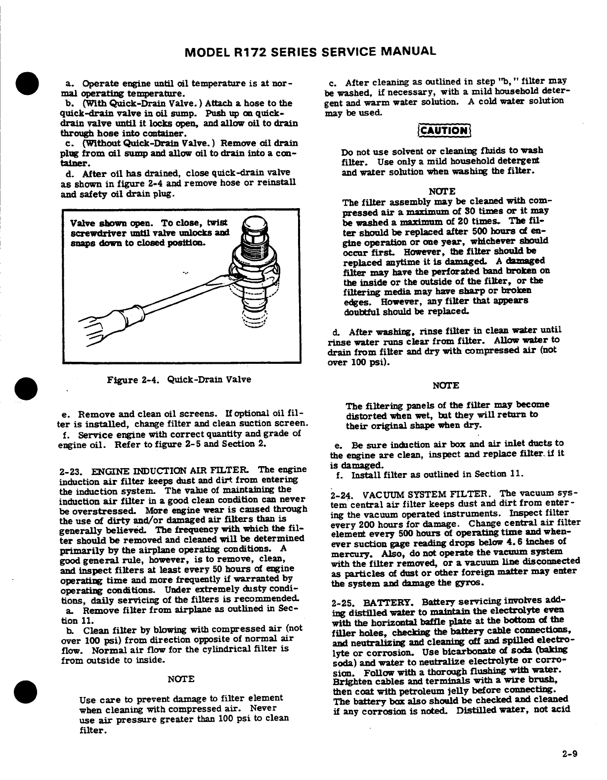
MODEL
R172
SERIES SERVICE
MANUAL
a.
Operate
engine
until
oil
temperature
is
at
nor-
c.
After
cleaning
as
outlined
in
step
"b,"
filter
may
mal
!operating
temperature.
be
washed,
if
necessary,
with
a
mild
household
deter-
b.
(With
Quick-Drain
Valve.)
Attach
a
hose
to
the
gent
and
warm
water
solution.
A
cold
water
solution
quick-drain
valve
in
oil
sump.
Push
up on
quick-
may
be
used.
drain
valve
until
it
locks
open,
and
allow
oil
to
drain
through
hose
into
container.
CAUTION
c. (Without
Quick-Drain
Valve.)
Remove
oil
drain
plug
from
oil
sump
and
allow
oil
to
drain
into
a
con-
Do
not
use
solvent
or
cleaning
fluids
to
wash
taner.
filter.
Use
only
a
mild
household
detergent
d.
After
oil
has
drained, close
quick-drain
valve
and
water
solution
when
washing
the
filter.
as
shown
in figure
2-4
and
remove
hose
or
reinstall
and
safety
oil
drain
plug.
NOTE
The
filter
assembly
may
be cleaned
with
com-
pressed
air
a
maximum
of
30
times
or
it
may
Valve
shown
open.
To
close,
twist
be
washed
a
maximum
of
20
times.
The
fil-
screwdriver
until
valve unlocks
and
ter
should
be
replaced
after
500
hours
of
en-
snaps
down
to
closed
position.
gine
operation
or
one
year,
whichever
should
occur
first.
However,
the
filter
should
be
replaced
anytime
it
is
damaged.
A
damaged
filter
may
have
the
perforated
band
broken
on
the
inside
or
the
outside
of
the
filter, or
the
filtering
media
may
have
sharp
or
broken
edges.
However,
any
filter
that
appears
doubtful should
be
replaced.
d.
After
washing,
rinse
filter
in
clean
water
until
rinse
water runs
clear
from
filter.
Allow
water
to
drain
from
filter
and
dry
with
compressed
air
(not
over
100
psi).
Figure
2-4.
Quick-Drain
Valve
NOTE
e.
Remove and clean
oil
screens.
If
optional
oil
fil-
The
filtering
panels
of
the
filter
may
become
ter
is
installed,
change
filter
and
clean
suction
screen.
distorted
when
wet,
but
they
will
return
to
f.
Service
engine
with
correct
quantity
and
grade
of
engine
oil.
Refer
to
figure
2-5
and
Section
2.
e.
Be
sure
induction
air
box
and
air
inlet
ducts
to
the
engine
are
clean,
inspect
and
replace
filter,
if
it
2-23.
ENGINE
INDUCTION
AIR
FILTER.
The
engine
is
damaged.
induction
air
filter
keeps
dust
and
dirt
from
entering
f.
Install
filter
as
outlined
in
Section
11.
the
induction
system.
The
value
of
maintaining
the
induction
air
filter
in
a
good
clean condition
can
never
2-24.
VACUM
SYSTEM
FILTER.
The
vacuum
sys-
be
overstressed.
More
engine
wear
is
caused
through tem
central
air
filter
keeps
dust
and
dirt
from
enter-
the
use
of
dirty
and/or
damaged
air
filters
than
is
ing
the vacuum
operated
instruments.
Inspect
filter
generally
believed.
The
frequency
with
which
the
fil-
every
200
hours
for
damage.
Change
central
air
filter
ter
should be removed
and
cleaned
will
be
determined
element
every
500
hours
of
operating
time
and when-
primarily
by
the
airplane
operating
conditions.
A
ever
suction
gage
reading
drops
below
4.6
inches
of
good
general
rule,
however,
is
to
remove,
clean,
mercury.
Also,
do
not
operate
the
vacuum
system
and
inspect
filters
at
least
every
50
hours
of
engine
with
the
filter
removed,
or
a
vacuum
line
disconnected
operating
time
and
more
frequently
if
warranted
by
as
particles
of
dust
or
other
foreign
matter
may
enter
operating
conditions.
Under
extremely
dusty
condi-
the
system
and damage
the
gyros.
tions,
daily
servicing
of
the
filters
is
recommended.
2-25.
BATERY.
Battery
sericingvoes
add-
a.
Remove
filter
from airplane
as
outlined
in
Sec-
2-2
BATTERY
tion
11.
ing
distilled
water
to
maintain
the
electrolyte
even
b.
Clean
filter
by blowing
with
compressed
air
(not
with
the
horizontal
baffle
plate
a
the
bottom
of
the
over
100
psi)
from
direction
opposite
of
normal
air
filler
holes,
checking
the
battery
cable connections,
flow.
Normal
air
flow
for
the
cylindrical
filter is
and
neutralizing
and
cleaning
off
and
spilled
electro-
from
outside
to
inside. lyte
or corrosion.
Use
bicarbonate
of
sod
(baking
soda)
and
water
to
neutralize
electrolyte
or
corro-
NOTE
sion.
Follow
with
a
thorough
flushing
with
water.
Brighten
cables
and
terminals
with
a
wire
brush,
Use
care
to
prevent
d:%amage
to
filter
element
then
coat
with
petroleum
jelly
before
connecting.
when
cleaning
with
compressed
air.
Never
The
battery
box
also
should
be
checked
and
cleaned
use
air
pressure greater
than
100
psi
to
clean
if
any
corrosion
is
noted.
Distilled water,
not
acid
filter.
2-9
MODEL
R172
SERIES
SERVICE
MANUAL
or
"rejuvenators",
should
be
used
to
maintain
electro-
2-28.
NOSE
GEAR
SHIMMY
DAMPENER.
The
lyte level.
Check
the
battery
every
50
hours
(or
at
least
shimmy
dampener
should
be
serviced
at
least
every
50
every
30
days)
oftener
in
hot
weather.
See
Section
16
hours.
The
shimmy dampener
must
be
filled
com-
for
detailed
battery
removal,
installation
and
testing.
pletely
with
fluid,
free
of
entrapped
air,
to serve
it's
purpose.
To
service
the
shimmy
dampener,
proceed as
2-26.
TIRES.
Maintain
tire
pressure
at
the
air
pres-
follows:
sures
specified
in
Section
1.
When
checking
tire
pres-
a.
Remove
shimmy
dampener
from
aircraft.
sure,
examine
tires
for
wear,
cuts,
bruises
and
slip-
b.
While
holding
the
dampener
in
a
vertical
position
page.
Remove
oil,
grease
and
mud
from
tires
with
soap
with fitting
end
pointed
downward,
pull
fitting
end
of
and
water.
the
dampener
shaft
to
its
limit
of
travel.
c. While
holding
dampener
in
this
position,
fill
NOTE
dampener
through
open
end
of
cylinder
with
hydraulic
fluid.
Recomended
tire
pressures
should
be
main-
d.
Push
the
shaft
upward
slowly
to
seal
off
the
filler
tained.
Especially-in-cold
weather.-remember
-hole.
-
that
any
drop
in
temperature
of
the
air
inside
a
e.
Clean
dampener
with
solvent.
Be
sure
to
keep
the
tire
causes
a
corresponding
drop
in
air
pressure.
shaft
protruding
through
the
filler
hole
until
dampener
is
installed
on
the
aircraft.
2-27.
NOSE
GEAR
SHOCK
STRUT.
The
nose
gear
shock
strut
requires
periodic
checking
to
ensure
that
NOTE
the
strut
is
filled
with
hydraulic
fluid
and
is
inflated to
the correct
air
pressure.
To
service
the
nose
gear
shock Keep
the
shimmy dampener,
especially
the
strut,
proceed
as
follows:
exposed
portions
of
the
dampener
piston
a.
Remove
valve
cap
and
release
all
air.
shaft,
clean
to
prevent
collection
of
dust
and
b.
Remove
valve
housing
assembly.
grit
which
could
cut
the
seals
in
the
c.
Compress
strut
completely
(stops
in
contact
with
dampener
barrel.
Keep
machined surfaces
outer
barrel
hub).
wiped
free
of
dirt
and
dust,
using
a
clean,
d.
Oil
level.
lint-free
cloth
saturated
with
MIL-H-5606
1.
Fluid
used
should
comply
with
specification
hydraulic
fluid
or
kerosene.
All
surfaces
MIL-H-5606.
should
be
wiped
free
of
excess
hydraulic
2.
Fill
strut
to
bottom
of
valve
installation
hole. fluid.
3.
Maintain
oil
level
at
bottom
of
valve
instal-
lation
hole.
2-29.
HYDRAULIC
BRAKE
SYSTEMS. Check
brake
e.
Fully
extend
strut.
master
cylinders
and
refill
with
MIL-H-5606
hydraulic
f.
Replace
valve
housing
assembly.
fluid
as
specified
in the
inspection
charts.
Bleed
the
g.
With
strut
fully
extended
and
nose
wheel
clear
of
brake
system of
entrapped
air
whenever
there
is
a
ground,
inflate
strut
to
45
PSI.
spongy response
to
the
brake
pedals.
Refer
to
Section 5
for
filling
and
bleeding
of
the
brakes.
NOTE
2-30.
CLEANING.
The
nose
landing
gear
shock
strut
will
nor-
mally
require
only
a
minimum
amount
of
ser-
2-31.
Keeping
the
aircraft
clean is
important.
Besides
vice.
Maintain
the
strut
extension
pressure
as
maintaining the
trim
appearance
of
the
aircraft,
shown
in
Section
1.
Lubricate
landing
gear
as
cleaning
lessens
the
possibility
of
corrosion
and
makes
shown
in
figure
2-6.
Check
the
landing
gear
inspection
and
maintenance
easier.
daily
for
general
cleanliness,
security
of
mounting
and for
hydraulic
fluid
leakage.
2-32.
CLEANING
WINDSHIELD
AND
WINDOWS
Keep
machined
surfaces
wiped
free
of
dirt
and
dust,
using
a
clean,
lint-free
cloth
saturated
with
MIL-H-5606
hydraulic
fluid
or
kerosene.
All
surfaces
should
be
wiped
free
of
excess
hy-
draulic
fluid.
2-32A. MATERIALS
REQUIRED.
NAME MANUFACTURER
USE
Mild
soap
or
detergent
Commercially
available.
Cleaning
windshields
and
hand
dishwashing
type
windows.
without
abrasives).
Aliphatic
naphtha
Type
II
Commercially
available.
Removing
deposits which
cannot
conforming
to
Federal
be
removed
with
mild
soap
Specification
TT-N-95.
solution
on
acrylic
windshields
and
windows.
2-10
Revision 1
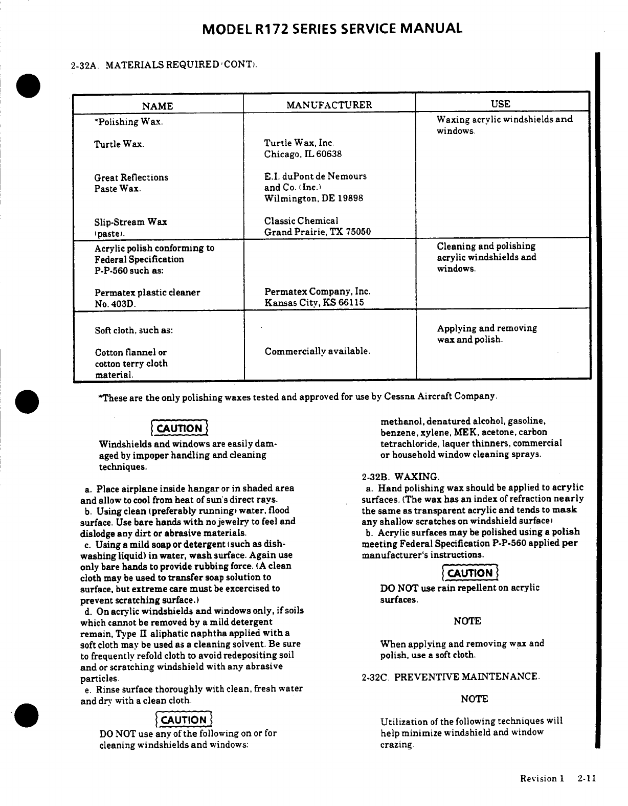
MODEL
R172
SERIES
SERVICE
MANUAL
2-32A.
MATERIALS
REQUIRED
CONT).
NAME
MANUFACTURER
USE
Polishing
Wax. Waxing
acrylic
windshields
and
windows.
Turtle
Wax.
Turtle
Wax,
Inc.
Chicago.
IL 60638
Great
Reflections
E.I.
duPont
de
Nemours
Paste
Wax.
and
Co.
(Inc.)
Wilmington,
DE 19898
Slip-Stream
Wax
Classic
Chemical
paste).
Grand
Prairie,
TX
75050
Acrylic
polish conforming
to
Cleaning and
polishing
Federal
Specification
acrylic
windshields
and
P-P-560
such
as: windows.
Permatex
plastic
cleaner
Permatex
Company,
Inc.
No.
403D.
Kansas
City,
KS
66115
Soft
cloth,
such
as:
Applying
and
removing
wax
and
polish.
Cotton
flannel
or
Commercially
available.
cotton
terry
cloth
material.
*These
are
the
only
polishing
waxes
tested
and
approved
for use
by
Cessna Aircraft
Company.
CAUTION
methanol,
denatured
alcohol,
gasoline,
benzene,
xylene,
MEK,
acetone,
carbon
Windshields
and
windows
are
easily
dam-
tetrachloride,
laquer
thinners,
commercial
aged
by
impoper
handling
and
cleaning
or
household
window
cleaning
sprays.
techniques.
2-32B.
WAXING.
a.
Place
airplane
inside
hangar
or
in
shaded
area
a.
Hand
polishing
wax
should
be
applied
to
acrylic
and
allow
to cool
from
heat
of
sun's
direct
rays.
surfaces.
(The wax
has
an
index
of
refraction
nearly
b.
Using clean (preferably
running,
water,
flood
the same
as
transparent
acrylic
and
tends
to
mask
surface.
Use
bare
hands
with
no
jewelry
to
feel
and any
shallow
scratches
on
windshield surface
dislodge
any
dirt
or
abrasive
materials.
b.
Acrylic
surfaces
may
be
polished
using
a
polish
c.
Using
a
mild
soap or
detergent
such as
dish- meeting
Federal
Specification
P-P-560
applied
per
washing
liquid)
in
water,
wash
surface.
Again
use
manufacturer's
instructions.
only
bare
hands
to
provide
rubbing
force.
(A
clean
-----
cloth
may
be
used
to
transfer
soap
solution
to
CAUTION
surface,
but
extreme
care
must
be
excercised
to
DO
NOT
use
rain
repellent
on
acrylic
prevent scratching
surface.)
surfaces.
d.
On
acrylic
windshields
and
windows
only,
if
soils
which
cannot
be
removed
by
a
mild
detergent
NOTE
remain,
Type
II
aliphatic
naphtha
applied
with
a
soft
cloth
may
be
used
as a
cleaning solvent.
Be
sure
When
applying
and
removing
wax
and
to
frequently
refold cloth
to
avoid
redepositing
soil
polish, use
a soft
cloth.
and
or
scratching
windshield with any
abrasive
particles.
2-32C.
PREVENTIVE
MAINTENANCE.
e.
Rinse
surface
thoroughly
with
clean,
fresh water
and
dry
with
a
clean
cloth.
NOTE
CAUTION
Utilization
of
the
following
techniques
will
DO
NOT
use any
of
the
following
on
or for
help
minimize windshield
and
window
cleaning
windshields
and
windows:
crazing.
Revision
1
2-11
MODEL
R172
SERIES
SERVICE
MANUAL
a.
Keep
all
surfaces
of
windshields
and
windows
removed
to
acilitate
engine
and
interior
cowl
clean.
cleaning.
Wash
down
the
engine
and
components
with
b.
If
desired,
wax
acrylic
surfaces.
a
suitable
solvent,
such
as
Stoddard
solvent
or
c.
DO
NOT
park
or
store
airplane
where
it
might
be
equvalent,
then
dry
thoroughly
with
compressed
air.
subjected
to
direct
contact
with
or
vapors
from:
methanol.
denatured
alcohol,
gasoline, benzene,
CAUTION
xylene, MEK,
acetone,
carbon
tetrachloride.
laquer
thinners,
commercial
or
household
window
cleaning
Particular
care
should
be
given
to
electrical
sprays,
paint
strippers,
or
other
types
of
solvents.
equipment
before
cleaning.
Solvent
should
d.
DO
NOT
use solar screens
or
shields
installed
on
not
be
allowed
to
enter
magnetos,
starters.
inside
of
airplane orleave sun
visors
up
against
alternators,
voltage
regulators
and
the
like.
windshield.
The
reflected
heat
from
these
items
causes Hence, these
components
should
be
protected
elevated
temperatures
which accelerate
crazing
and
before
saturating
the engine
with
solvent.
may cause
formation
of
bubbles
in
inner
ply
of
Any
fuel,
oil
and
air
openings should
be
multiple
ply
windshields.
covered-before
washing-the-engine
with
solvent.
Caustic cleaning solutions should
2-33.
PLASTIC
TRIM.
The
instrument
panel,
plastic
not
be
used.
After
cleaning the
engine,
re-
trim,
and
control
knobs
need only
be
wiped
with
a
lubricate
all
control
arms
and
moving
parts.
damp
cloth.
Oil
and
grease
on
the
control
wheel
and
control
knobs
can
be
removed
with
a
cloth
moistened
2-37.
UPHOLSTERY
AND
INTERIOR.
Keeping
the
with
Stoddard
solvent.
Volatile
solvents, such as
upholstery
and
interior
trim
clean
prolongs
upholstery
mentioned
in
paragraph
2-32,
must
never
be
used
fabric
and interior
trim
life.
To
clean
the
interior,
since
they soften
and
craze
the
plastic.
proceed
as
follows:
a.
Empty
all
ash
trays
and
refuse
containers.
2-34.
PAINTED
SURFACES.
The
painted
exterior
b.
Brush
or
vacuum
clean
the
upholstery and
carpet
surfaces
of
the
aircraft,
under
normal conditions,
to
remove
dust
and
dirt.
require
a
minimum
of
polishing
and
buffing. c.
Wipe
leather
and
plastic
trim
with
a
damp
cloth.
Approximately
15
days
are
required
for
acrylic
or
d.
Soiled upholstery
fabrics
and
carpet
may
be
laquer
paint
to
cure
completely:
in
most
cases,
the
cleaned
with
a
foam-type
detergent
used
according
to
curing
period
will
have
been completed
prior
to
the
manufacturer's
instructions.
delivery
of
the
aircraft.
In
the
event
that
polishing
or
e.
Oil
spots
and
stains
may
be
cleaned
with
household
buffing
is
required
within
the
curing
period,
it
is
spot
removers,
used
sparingly.
Before
using
any
recommended
that
the
work
be
done
by
an
experienced
solvent, read
the
instructions
on
the
container and
test
painter.
Generally.
the
painted
surfaces
can
be
kept
it
on
an
obscure
place
in
the
fabric
to
be
cleaned.
Never
bright
by
washing
with
water
and
mild
soap, followed
saturate
the
fabric
with
volatile
solvent;
it
may
by
a
rinse with
water
and
drying
with
cloths
or
damage
the
padding
and
backing
material.
chamois.
Harsh
or
abrasive
soaps
or
detergents
which
f.
Scrape
sticky
material
from
fabric
with
a
dull
could
cause
corrosion
or
make
scratches
should
never
knife,
then
spot
clean
the
area.
be
used.
Remove
stubborn
oil
and grease
with
a
cloth
moistened
with
Stoddard
solvent. After
the
curing
2-38.
PROPELLER. Wash
hub
and
blade
with
a
soft
period,
the
aircraft
may
be
waxed
with
a
good
cloth
and
Stoddard
cleaning
solvent
or
equivalent,
automotive
wax.
A
heavier
coating
of
wax
on
the then
dry thoroughly
with
compressed
air.
The
leading
edges
of
the
wing
and
tail
and
on
the engine
propeller
should
be
wiped
occasionally
with
an
oily
nose cap
will
help
reduce
the
abrasion
encountered
in
cloth,
then
wiped
with
a
dry cloth.
In
salt
water
areas
these
areas.
this
will
assist
in corrosion
proofing
the
propeller.
2-35.
ALUMINUM
SURFACES.
The
aluminum
2-39.
WHEELS.
The wheels
should
be
washed
surfaces
require
a
minimum
of
care,
but
should
never
periodically
and
examined
for
corrosion,
chipped
paint,
be
neglected.
The
aircraft
may
be
washed
with
clean
and
cracks
or
dents
in
the
wheel
halves
or
in
the
water
to
remove
dirt
and
may
be
washed
with
non- flanges
or
hubs.
If
defects
are
found
remove
and repair
alkaline
grease
solvents
to
remove
oil
and'or
grease.
in
accordance
with
Section
5.
Discard
cracked wheel
Household
type
detergent
soap
powders
are
effective
halves, flanges
or
hubs and
install
new
parts.
cleaners,
but
should
be
used
cautiously
since some
of
them
are
strongly
alkaline.
Many
good
aluminum
2-40.
LUBRICATION.
cleaners, polishes
and
waxes
are
available
from
commercial
suppliers
of
aircraft
products.
2-41.
Lubrication
requirements
are
shown
in
figure
2-
6.
Before
adding
grease
to
grease
fittings,
wipe
dirt
2-36.
ENGINE
AND
ENGINE
COMPARTMENT.
from
fitting.
Lubricate
until
grease
appears
around
The engine
should
be
kept clean
and
dry
since
dirty
parts
being
lubricated,
and
wipe
excess
grease
from
cooling
fins
and
baffle
plates can
cause
overheating
of
parts.
The
following
paragraphs
supplement figure
2-6
the engine.
Also,
cleaning
is
essential
to
minimize
any
by
adding
details.
danger
of
fire
and
provide
for
easier
inspection
of
components.
The
entire
engine
cowling
may
be
2-12
Revision
1
MODEL
R172
SERIES
SERVICE
MANUAL
2-42.
TACHOMETER
DRIVE
SHAFT.
Refer
to
c.
With
oil
can,
apply
light
coat
of
No.
10-weight,
non-
Sections
11
and
15.
detergent
oil
to
threads
of
jack
screw.
2-43.
WHEEL BEARINGS.
Clean
and
repack
the
2-46.
FUEL
SELECTOR
VALVE.
At
each
100
hour
wheel
bearings
at
the
first
100
hour inspection
and
at
inspection,
check
the
fuel
selector
valve
and
drive
each
500
hour inspection
thereafter.
If
more
than
the
shaft
for
the
following:
usual
number
of
take-offs
and
landings
are
made,
a.
Valve
control
detent
plate
for
cleanliness
and
extensive
taxiing
is
required,
or
the aircraft
is
excessive
wear.
Dirt accumulation
on
this
plate
can
operated
in
dusty
areas
or
under
seacoast conditions
cause
binding,
poor
detent
feel
and
rapid
wear
of
the
cleaning
and
lubrication
of
the
wheel
bearings
shall
be
plate.
accomplished
at
each
100
hour
inspection.
b.
All
drive
shaft
attach
points
for
security,
binding,
excessive
wear
and
lubrication,
if
required.
2-44.
NOSE
GEAR
TORQUE
LINKS.
Lubricate
nose
c.
Operate
valve handle
through
all
positions
and
gear
torque
links
every
50
hours.
When
operating
in
check
for
proper operation,
detent
feel
and
freedom
of
dusty
conditions, more
frequent lubrication
is
movement.
required.
2-47.
ROD
END
BEARINGS.
Periodic
inspection
and
2-45.
WING
FLAP
ACTUATOR.
Clean
and
lubricate
lubrication
is
required
to
prevent
corrosion
of
the
wing
flap
actuator jack
screw
each
100
hours
as
bearing
in
the
rod
end.
At each
100
hour
inspection,
follows:
disconnect
the
control
rods
at
the
aileron, flap and
nose
a.
Expose
jack
screw
by
operating
flaps
to
full-down
gear
steering
bungee,
and
inspect
each
rod
end
for
position.
corrosion.
If
no
corrosion
is
found,
wipe
the surface
of
b.
Clean
jack
screw
threads
with
solvent
rag and
dry
the
rod
end
balls
with
general
purpose
oil
and
rotate
with
compressed
air.
ball
freely
to
distribute the
oil
over
its entire surface
and
connect
the
control
rods
to
their
respective
units.
NOTE
If
corrosion
is
detected
during the
inspection,
install
new
rod
ends.
It
is
not
necessary
to
remove
actuator
from
aircraft
to
clean
or
lubricate
threads.
SHOP
NOTES:
Revision
1
2-12A,
2-12B
Blank)
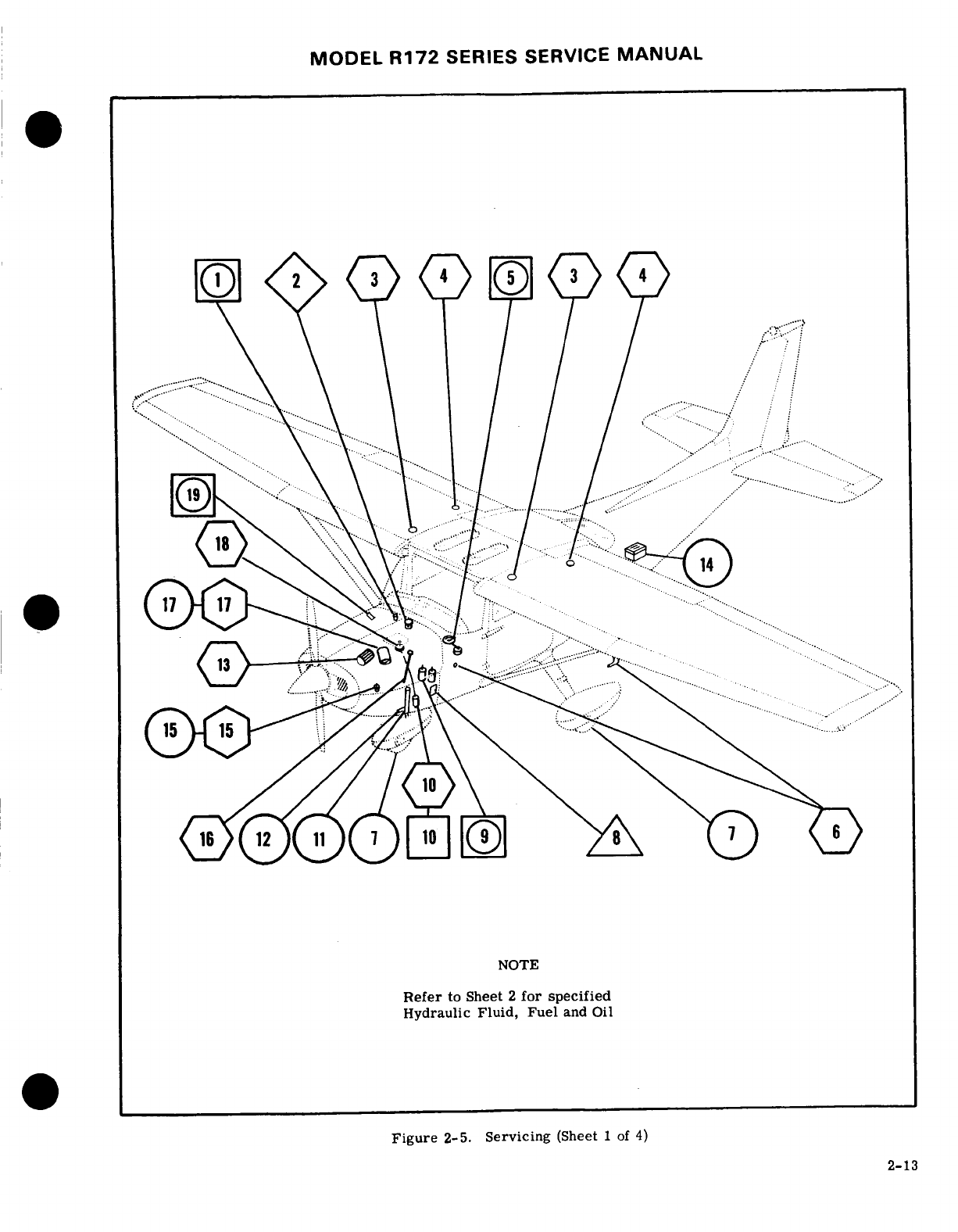
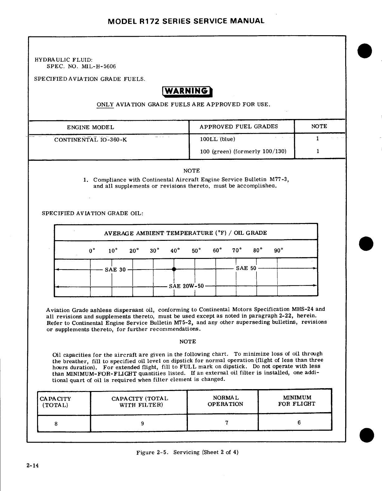
MODEL
R172
SERIES
SERVICE
MANUAL
HYDRAULIC
FLUID:
SPEC.
NO.
MIL-H-5606
SPECIFIED
AVIATION GRADE
FUELS.
WARNING
ONLY AVIATION
GRADE
FUELS
ARE
APPROVED
FOR
USE.
ENGINE
MODEL
APPROVED
FUEL
GRADES
NOTE
CONTINENTAL
IO-360-K
100LL(blue)
1
100
(green)
(formerly
100/130)
1
NOTE
1.
Compliance
with
Continental
Aircraft
Engine
Service
Bulletin
M77-3,
and
all
supplements or
revisions
thereto,
must
be
accomplished.
SPECIFIED
AVIATION
GRADE
OIL:
AVERAGE AMBIENT
TEMPERATURE
(°F)
/
OIL GRADE
0
°
10
°
20
°
30
°
40
°
50
°
60°
70°
80 °
90°
----
-SAE
30 AE
50-
SAE
20W-50
Aviation
Grade
ashless
dispersant
oil,
conforming
to
Continental
Motors Specification
MHS-24
and
all
revisions
and
supplements
thereto,
must
be
used
except
as
noted
in
paragraph
2-22,
herein.
Refer
to
Continental
Engine
Service
Bulletin
M75-2,
and
any
other
superseding
bulletins,
revisions
or
supplements
thereto,
for
further
recommendations.
NOTE
Oil
capacities
for
the
aircraft
are
given
in
the
following
chart.
To
minimize
loss
of
oil
through
the
breather,
fill
to
specified
oil
level
on
dipstick
for
normal
operation
(flight
of
less
than
three
hours
duration).
For
extended
flight,
fill
to
FULL
mark
on
dipstick.
Do
not
operate
with
less
than
MINIMUM-FOR-FLIGHT
quantities
listed.
If
an
external
oil
filter
is
installed,
one
addi-
tional
quart
of
oil
is
required
when
filter
element
is
changed.
CAPACITY
CAPACITY (TOTAL
NORMAL
MINIMUM
(TOTAL)
WITH
FILTER)
OPERATION
FOR
FLIGHT
8
9 7
6
Figure 2-5. Servicing
(Sheet
2
of
4)
2-14
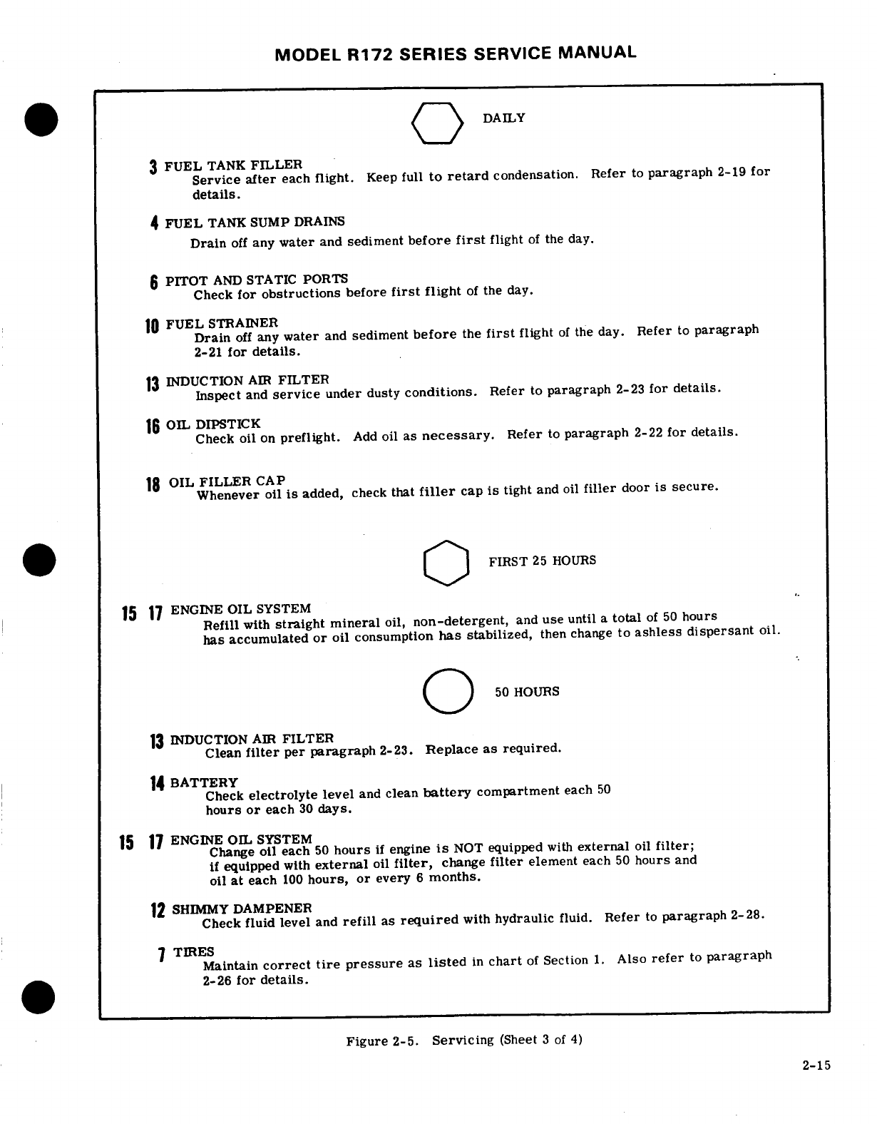
MODEL
R172
SERIES
SERVICE
MANUAL
DAILY
3
FUEL
TANK
FILLER
Service
after
each
flight.
Keep
full
to
retard
condensation.
Refer
to
paragraph
2-19 for
details.
4
FUEL
TANK
SUMP
DRAINS
Drain
off
any
water
and
sediment
before
first
flight
of
the
day.
6
PITOT
AND
STATIC
PORTS
Check
for
obstructions
before
first
flight
of
the
day.
10
FUEL
STRAINER
Drain
off
any
water
and
sediment
before
the
first
flight
of
the
day.
Refer
to
paragraph
2-21
for
details.
13
INDUCTION
AIR
FILTER
Inspect
and
service
under
dusty
conditions.
Refer
to
paragraph
2-23
for
details.
16
OIL
DIPSTICK
Check
oil
on
preflight.
Add
oil
as
necessary.
Refer
to
paragraph
2-22
for
details.
18
OIL
FILLER
CAP
Whenever
oil
is
added,
check
that
filler
cap
is
tight
and
oil
filler
door
is
secure.
FIRST
25
HOURS
15
17
ENGINE
OIL
SYSTEM
Refill
with
straight
mineral
oil,
non-detergent,
and
use
until
a
total
of
50
hours
has
accumulated
or
oil
consumption
has
stabilized,
then
change
to
ashless
dispersant
oil.
"50
HOURS
13
INDUCTION
AIR
FILTER
Clean
filter
per
paragraph
2-23.
Replace as
required.
14
BATTERY
Check
electrolyte level
and
clean
battery
compartment
each
50
hours
or
each
30
days.
15 17
ENGINE
OIL
SYSTEM
Change
oil
each
50
hours
if
engine
is
NOT
equipped
with
external
oil
filter;
if
equipped
with
external
oil
filter,
change
filter
element
each
50
hours
and
oil
at
each
100
hours, or
every
6
months.
12
SHIMMY
DAMPENER
Check
fluid
level
and
refill
as
required
with
hydraulic
fluid.
Refer
to
paragraph
2-28.
7
TIRES
Maintain
correct
tire
pressure
as
listed
in
chart
of
Section
1.
Also
refer
to
paragraph
2-26
for
details.
Figure
2-5.
Servicing
(Sheet
3
of
4)
2-15
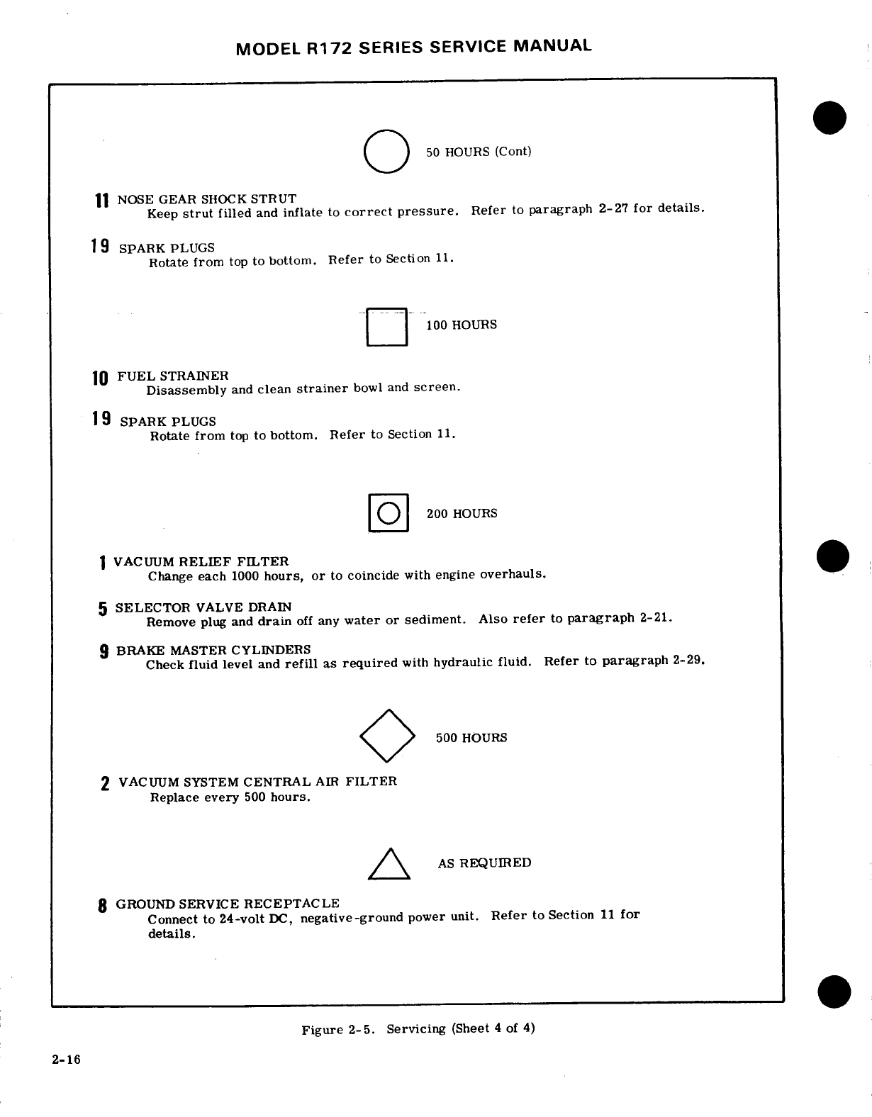
MODEL
R172
SERIES
SERVICE
MANUAL
50
HOURS
(Cont)
NOSE
GEAR
SHOCK
STRUT
Keep
strut
filled
and
inflate
to
correct pressure.
Refer
to
paragraph
2-27
for details.
19
SPARK PLUGS
Rotate
from
top
to
bottom.
Refer
to
Section
11.
100 HOURS
10
FUEL
STRAINER
Disassembly
and
clean
strainer
bowl
and
screen.
19
SPARK
PLUGS
Rotate
from
top
to bottom.
Refer
to
Section
11.
--
200
HOURS
1
VACUUM
RELIEF
FILTER
Change
each
1000
hours,
or
to
coincide
with
engine
overhauls.
5
SELECTOR
VALVE DRAIN
Remove
plug
and
drain
off
any
water
or sediment.
Also
refer
to
paragraph
2-21.
9
BRAKE
MASTER
CYLINDERS
Check
fluid
level
and
refill
as
required
with
hydraulic
fluid.
Refer
to
paragraph
2-29.
500
HOURS
2
VACUUM
SYSTEM
CENTRAL
AIR
FILTER
Replace
every
500
hours.
/\
AS
REQUIRED
8
GROUND
SERVICE
RECEPTACLE
Connect
to
24-volt
DC,
negative-ground
power unit.
Refer
to
Section
11
for
details.
Figure 2-5.
Servicing
(Sheet
4
of
4)
2-16
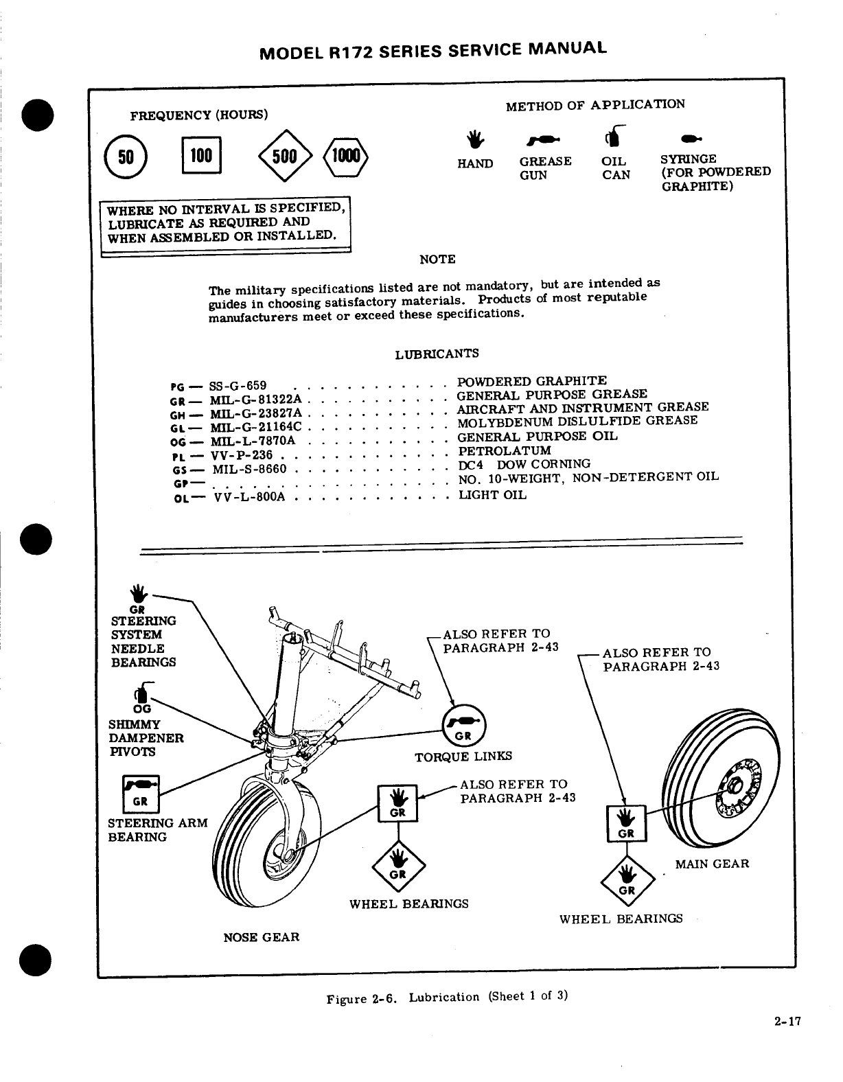
MODEL
R172
SERIES
SERVICE
MANUAL
FREQUENCY
(HOURS)
METHOD
OF
APPLICATION
HAND
GREASE
OIL
SYRINGE
GUN
CAN
(FOR
POWDERED
GRAPHITE)
WHERE
NO
INTERVAL
IS
SPECIFIED,
LUBRICATE
AS
REQUIRED
AND
WHEN
ASSEMBLED
OR
INSTALLED.
NOTE
The
military
specifications
listed
are
not
mandatory,
but
are
intended
as
guides
in choosing
satisfactory
materials.
Products
of
most
reputable
manufacturers
meet
or
exceed
these
specifications.
LUBRICANTS
PG
-
SS-G-659
............
POWDERED
GRAPHITE
GR-
MIL-G-81322A
..........
GENERAL
PURPOSE
GREASE
GH-
MIL-G-23827A
..........
AIRCRAFT
AND
INSTRUMENT
GREASE
GL-
MIL-G-21164C
..........
MOLYBDENUM
DISLULFIDE
GREASE
OG-
MIL-L-7870A
..........
GENERAL
PURPOSE
OIL
PL
-
VV-P-236
.............
PETROLATUM
GS-
MIL-S-8660
............
DC4
DOW
CORNING
GP--
.................
NO.
10-WEIGHT,
NON-DETERGENT
OIL
OL-
VV-L-800A
...........
.
LIGHT
OIL
GR
STEERING
NEEDLE
PARAGRAPH
2-43
BEARINGS
ALSO
REFER
TO
PARAGRAPH
2-43
SHIMy
DAMPENER
---
PIVOTS
TORQUE
LINKS
ALSO
REFER
TO
PARAGRAPH
2-43
STEERING
ARM
MAIN
GEAR
WHEEL
BEARINGS
WHEEL
BEARINGS
NOSE
GEAR
Figure
2-6.
Lubrication
(Sheet
1
of
3)
2-17
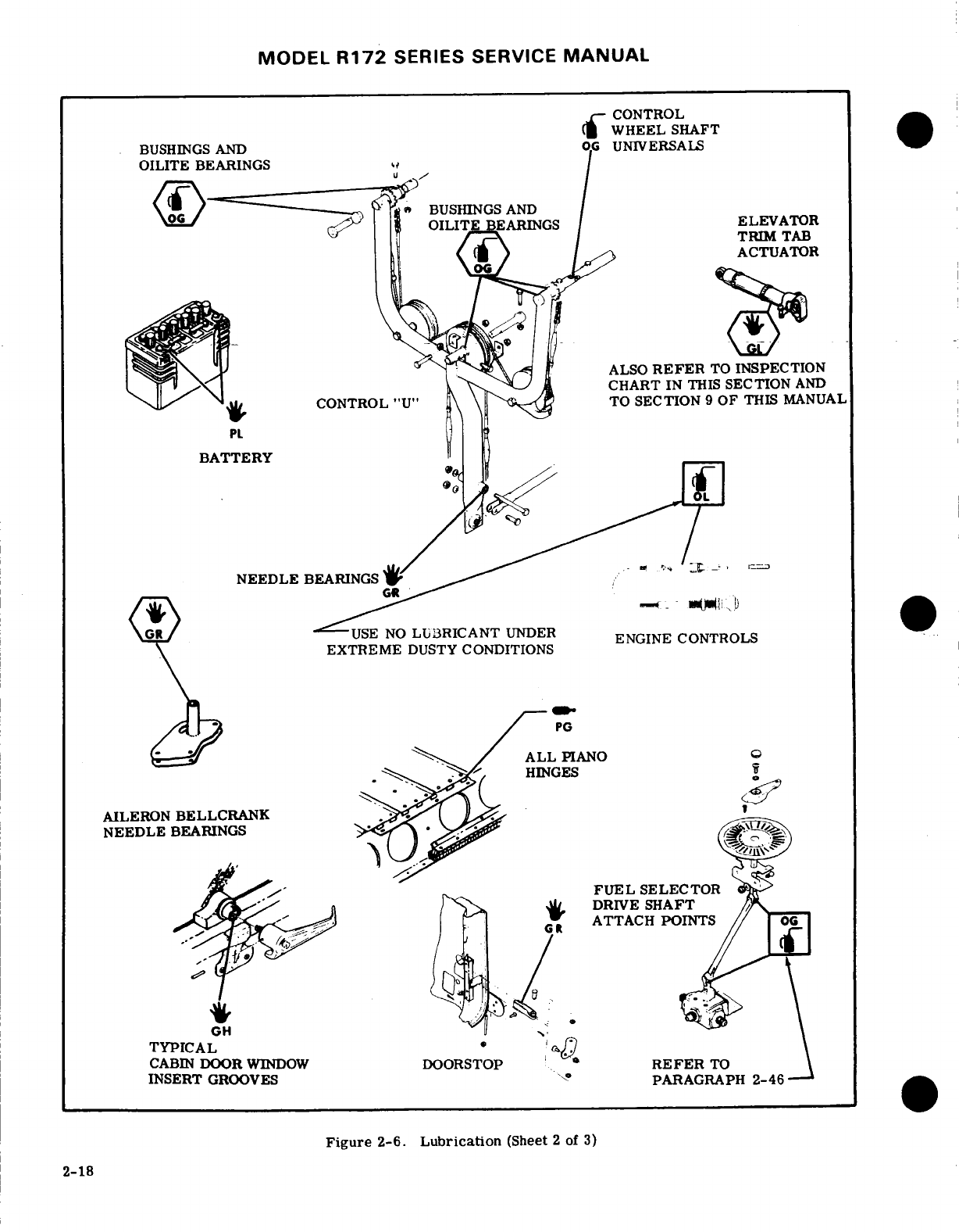
MODEL
R172
SERIES SERVICE
MANUAL
CONTROL
WHEEL
SHAFT
BUSHINGS AND
BEARINGS
----
-
BUSHINGS
AND
ELEVATOR
TRIM
TAB
ACTUATOR
ALSO
REFER
TO
INSPECTION
CHART
IN
THIS
SECTION
AND
CONTROL
"U"
TO
SECTION
9
OF
THIS
MANUAL
PL
BATTERY
-
USE
NO
LUBRICANT
UNDER
ENGINE
CONTROLS
EXTREME
DUSTY
CONDITIONS
PG
ALL
PIANO
AILERON
BELLCRANK
.
NEEDLE
BEARINGS
SELECTOR
"/ .
DRIVE SHAFT
.-
ATTACH
POINTS
OG
TYPICAL
I
CABIN
DOOR
WINDOW
DOORSTOP
REFER
TO
INSERT
GROOVES
PARAGRAPH
2-46
Figure
2-6.
Lubrication
(Sheet
2
of 3)
2-18
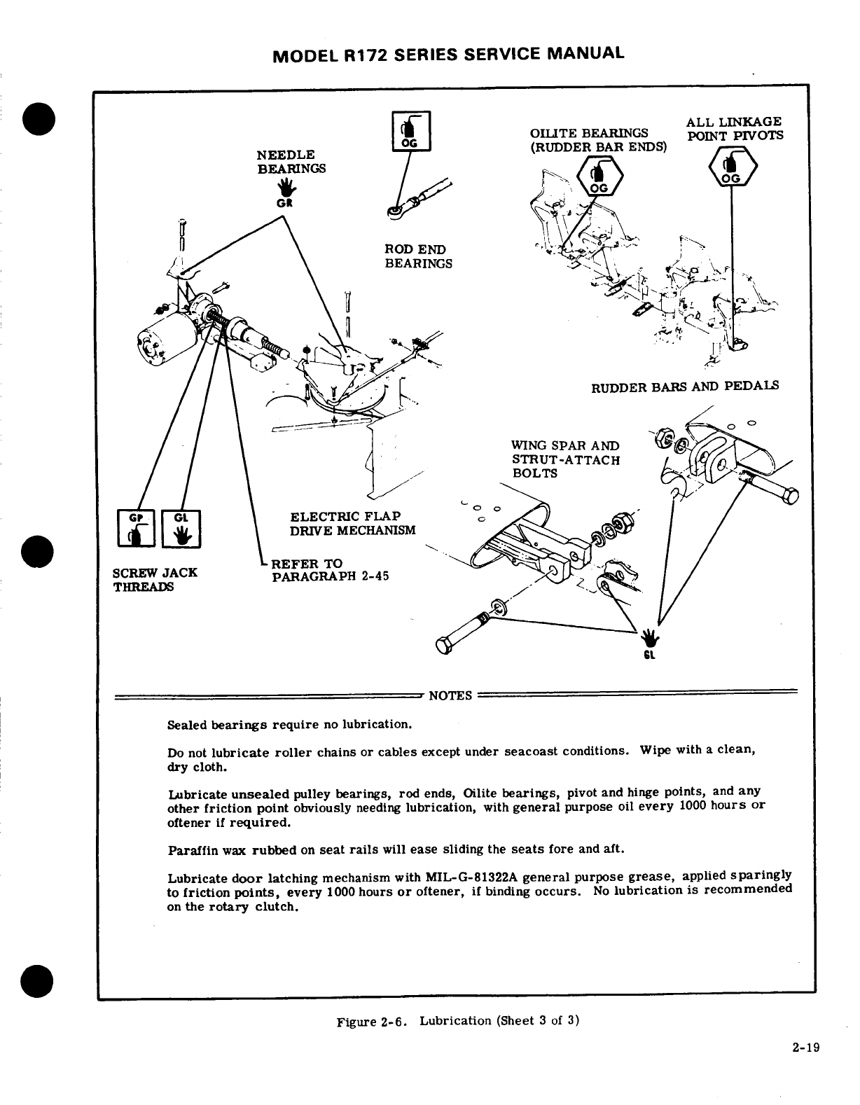
MODEL R172
SERIES
SERVICE
MANUAL
ALL
LINKAGE
OILITE
BEARINGS
POINT
PIVOTS
NEEDLE
(RUDDER
BAR
ENDS)
BEARINGS
ROD
END
BEARINGS
\
G
THREADS
PARAGRAPH
2-45
THREADS
NOTES
Sealed
bearings
require
no
lubrication.
Do
not
lubricate
roller
chains
or
cables
except
under
seacoast
conditions.
Wipe
with
a
clean,
dry
cloth.
Lubricate
unsealed
pulley
bearings, rod
ends,
Oilite
bearings,
pivot
and
hinge
points,
and
any
other
friction
point
obviously
needing
lubrication,
with
general
purpose
oil
every
1000
hours
or
oftener
if
required.
Paraffin
wax
rubbed
on
seat
rails
will
ease
sliding
the
seats
fore
and
aft.
Lubricate
door
latching
mechanism
with
MIL-G-81322A
general
purpose
grease,
applied
sparingly
to
friction
points,
every
1000
hours
or
oftener,
if
binding
occurs.
No
lubrication
is recommended
on
the
rotary
clutch.
Figure
2-6.
Lubrication
(Sheet
3
of
3)
2-19
MODEL
R172
SERIES
SERVICE MANUAL
I
INSPECTION
REQUIREMENTS.
As
required
by
Federal
Aviation
Regulations,
all
civil
aircraft
of
U.S.
registry
must
undergo a
COMPLETE
INSPECTION
(ANNUAL)
each twelve
calendar
months.
In
addition
to
the
required
ANNUAL
inspection,
aircraft
operated commercially
(for
hire)
must
also
have
a
COMPLETE
AIRCRAFT
INSPECTION
every
100
hours
of
operation.
In
lieu
of
the
above
requirements,
an
aircraft
may
be
inspected
in
accordance
with
a
progressive
inspection
schedule,
which
allows
the
work
load
to
be
divided
into
smaller
operations
that
can
be
accomplished
in
shorter
time
periods.
Therefore,
the
Cessna
Aircraft
Company
recommends
PROGRESSIVE
CARE
for
aircraft
that
are
being
flown
200
hours
or more
per
year,
and
the
100
HOUR
inspection for
all other
aircraft.
II
INSPECTION
CHARTS.
The
following
charts
show
the
recommended
intervals
at
which
items
are
to be
inspected.
As
shown
in
the
charts,
there
are
items
to
be
checked
each
50
hours,
each
100
hours,
each
200
hours,
and
also
Special
Inspection
items
which
require
servicing
or inspection
at
intervals
other
than
50,
100
or
200
hours.
a.
When
conducting
an
inspection
at
50
hours,
all
items
marked
under
EACH
50 HOURS
would
be
inspected,
serviced
or
otherwise
accomplished
as
necessary
to
insure
continuous
airworthiness.
b. At
each
100
hours,
the
50
hour
items
would
be
accomplished
in
addition
to
the
items
marked
under
EACH
100
HOURS
as
necessary
to
insure
continuous
airworthiness.
c.
An
inspection
conducted
at
200
hour
intervals
would
likewise
include
the
50
hour
items
and
100
hour
items
in
addition
to
those
at
EACH
200
HOURS.
d.
The
numbers appearing
in
the
SPECIAL
INSPECTION
ITEMS
column
refer
to
data
listed
at
the
end
of
the
inspection
charts.
These
items should
be
checked
at
each
inspection
interval
to
insure
that
applicable
servicing
and
inspection
requirements
are
accomplished
at
the
specified
intervals.
e.
A
COMPLETE
AIRCRAFT
INSPECTION
includes
all
50,
100
and
200
hour
items
plus
those
Special
Inspection
Items
which
are
due
at
the
time
of
the
inspection.
m
INSPECTION
PROGRAM
SELECTION.
AS A
GUIDE
FOR
SELECTING
THE
INSPECTION
PROGRAM
THAT
BEST
SUITS THE
OPERATION
OF
THE
AIRCRAFT,
THE
FOLLOWING
IS
PROVIDED.
1.
IF
THE
AIRCRAFT
IS
FLOWN
LESS
THAN
200
HOURS
ANNUALLY.
a.
IF
FLOWN
FOR
HIRE
An
aircraft
operating
in
this
category
must
have
a
COMPLETE
AIRCRAFT
INSPECTION
each
100
hours
and
each
12
calendar
months
of
operation.
A
COMPLETE
AIRCRAFT
INSPECTION
consists
of
all
50, 100,
200 and
Special
Inspection
Items
shown
in
the
in-
spection
charts
as
defined
in
paragraph
II
above.
b.
IF
NOT
FLOWN
FOR
HIRE
An
aircraft
operating
in
this
category
must
have
a COMPLETE
AIRCRAFT
INSPECTION
each
12
calendar
months
(ANNUAL).
A
COMPLETE
AIRCRAFT INSPECTION
consists
of
all
50,
100,
200
and
Special
Inspection
Items shown
in
the
inspection
charts
as
defined
in
paragraph
II
above.
In
addition,
it
is
recommended
that
between
annual
inspections, all
items
be
inspected
at
the
intervals
specified
in
the
inspection
charts.
2-20
MODEL
R172
SERIES
SERVICE
MANUAL
2.
IF
THE
AIRCRAFT
IS
FLOWN
MORE
THAN
200
HOURS
ANNUALLY.
Whether
flown
for
hire or
not,
it is
recommended
that
aircraft
operating
in
this
category
be
placed
on
the
CESSNA
PROGRESSIVE
CARE
PROGRAM.
However,
if
not
placed
on
Progressive
Care,
the
inspection
requirements
for
aircraft
in
this
category
are
the
same
as
those
defined under
paragraph
III
1.
(a)
and
(b).
Cessna Progressive
Care
may
be
utilized
as
a
total
concept
program
which
insures
that
the
inspection
intervals
in
the
inspection
charts
are
not
exceeded.
Manuals
and
forms
which
are
required
for
conducting
Progressive
Care
in-
spections
are
available
from
the
Cessna
Service
Parts
Center.
IV
INSPECTION
GUIDE
LINES.
(a)
MOVABLE
PARTS
for:
lubrication,
servicing,
security
of
attachment,
binding,
excessive
wear,
safetying,
proper
operation, proper
adjustment,
correct travel,
cracked
fittings,
security
of
hinges,
defective
bearings,
cleanliness,
corrosion,
deformation, sealing
and
tension.
(b)
FLUID
LINES
AND
HOSES
for: leaks,
cracks,
dents,
kinks,
chafing,
proper
radius,
security,
corrosion,
deterioration,
obstruction
and
foreign
matter.
(c)
METAL
PARTS
for: security
of
attachment,
cracks,
metal
distortion,
broken
spotwelds,
corrosion,
condition
of
paint
and
any
other
apparent
damage.
(d)
WIRING
for:
security,
chafing,
burning,
defective
insulation, loose
or
broken
terminals,
heat
deterioration
and
corroded
terminals.
(e)
BOLTS
IN
CRITICAL
AREAS
for:
correct
torque
in
accordance
with
torque
values
given
in
the
chart
in Section
1,
when
installed
or
when
visual inspection
indicates
the
need
for
a
torque
check.
NOTE
Torque
values
listed
in
Section
1
are
derived from
oil-free
cadmium-plated
threads,
and
are
recommended
for
all
installation procedures
contained
in
this
book
except
where
other
values
are
stipulated.
They
are
not
to
be
used for
checking
tightness
of
installed
parts
during
service.
(f)
FILTERS,
SCREENS
&
FLUIDS
for:
cleanliness,
contamination
and/or
replacement
at
specified
intervals.
(g)
AIRCRAFT
FILE.
Miscellaneous
data,
information
and
licenses
are
a
part
of
the
aircraft
file. Check
that
the
following
documents
are
up-to-date
and
in
accordance
with
current
Federal
Aviation
Regulations.
Most
of
the
items listed
are
required
by
the
United
States
Federal
Aviation
Regulations.
Since
the
regulations
of
other
nations
may
require
other
documents
and data,
owners
of
exported
aircraft
should check
with
their
own
aviation
officials
to
determine
their
individual
requirements.
To
be
displayed
in
the
aircraft
at
all
times:
1.
Aircraft
Airworthiness
Certificate
(FAA
Form
8100-2).
2.
Aircraft
Registration Certificate
(FAA
Form
8050-3).
3.
Aircraft
Radio
Station
License,
if
transmitter
is
installed
(FCC
Form
556).
To
be
carried
in
the
aircraft
at
all
times:
1.
Weight
and
Balance,
and
associated
papers
(Latest
copy
of the
Repair
and
Alteration
Form,
FAA
Form
337,
if
applicable).
2.
Aircraft
Equipment
List.
3.
Pilot's
Operating
Handbook.
To
be
made
available
upon
request:
1.
Aircraft
Log Book
and
Engine
Log Book.
2-21
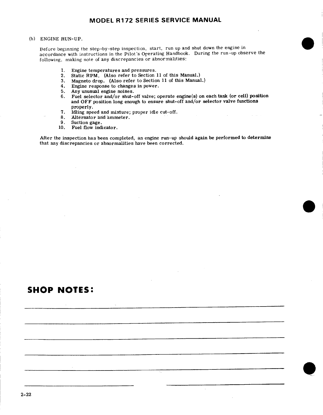
MODEL
R172
SERIES
SERVICE
MANUAL
(h)
ENGINE
RUN-UP.
Before
beginning
the
step-by-step
inspection,
start,
run
up
and
shut
down
the
engine
in
accordance
with
instructions
in
the
Pilot's
Operating
Handbook.
During
the
run-up
observe
the
following.
making
note
of
any
discrepancies
or
abnormalities:
1.
Engine
temperatures
and
pressures.
2.
Static
RPM.
(Also
refer
to
Section
11
of
this
Manual.)
3.
Magneto
drop.
(Also
refer
to
Section
11
of
this
Manual.)
4.
Engine
response
to
changes
in
power.
5.
Any
unusual
engine
noises.
6.
Fuel
selector and/or
shut-off
valve;
operate
engine(s)
on
each
tank
(or
cell)
position
and
OFF
position
long
enough
to
ensure
shut-off
and/or
selector
valve
functions
properly.
7.
Idling
speed
and
mixture;
proper
idle
cut-off.
8.
Alternator
and
ammeter.
9.
Suction gage.
10.
Fuel
flow
indicator.
After
the
inspection
has
been
completed,
an
engine
run-up
should
again
be
performed
to
determine
that
any
discrepancies
or abnormalities
have
been
corrected.
SHOP
NOTES:
2-22
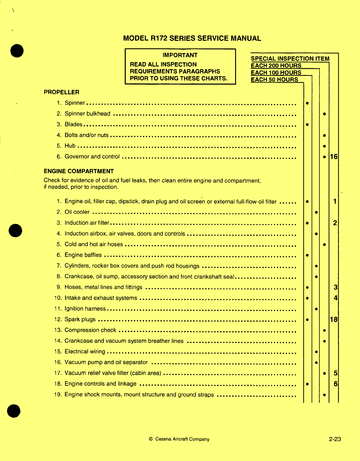
MODEL
R172
SERIES SERVICE
MANUAL
IMPORTANT
READ
ALL
INSPECTION
REQUIREMENTS
PARAGRAPHS
PRIOR
TO
USING
THESE
CHARTS.
SPECIAL INSPECTION
ITEM
EACH
200
HOURS
EACH
100
HOURS
EACH
50
HOURS
PROPELLER
1.
Spinner
......................................................................
2.
Spinner
bulkhead
..............................................................
3.
B
lades
.......................................................................
4. Bolts
and/or
nuts
...............................................................
5.
Hub ..........................................................................
6.
Governor and
control
...........................................................
ENGINE
COMPARTMENT
Check
for
evidence
of
oil
and
fuel
leaks, then clean entire
engine
and
compartment,
if
needed,
prior
to
inspection.
1.
Engine
oil,
filler
cap,
dipstick,
drain
plug
and
oil
screen or
external
full-flow
oil
filter
......
2.
Oil
cooler
...................................................
................
3.
Induction
air
filter...............................................................
4.
Induction
airbox, air
valves,
doors
and
controls
.....................................
5.
Cold
and
hot
air
hoses
.........................................................
6.
Engine
baffles
...................................................
............
7.
Cylinders,
rocker
box
covers
and
push
rod
housings
................................
8.
Crankcase,
oil
sump,
accessory
section
and
front
crankshaft
seal.....................
9.
Hoses,
metal lines and
fittings
...................................................
10.
Intake
and
exhaust
systems
.....................................................
11.
Ignition
harness
...................................................
...........
12.
Spark plugs
...................................................................
13.
Compression
check
..........................................................
14.
Crankcase
and
vacuum
system breather lines
.....................................
15.
Electrical
wiring
................................................................
16.
Vacuum pump
and
oil
separator
.................................................
17.
Vacuum relief
valve
filter
(cabin
area)
............................................
18.
Engine
controls
and
linkage
.....................................................
19.
Engine
shock
mounts, mount
structure
and
ground
straps
...........................
©
Cessna
Aircraft
Company
0
.
0
*
16
*
*
1
a
2
.
.
.
*
*
·3
* 4
·
18
*
S
a
·5
6
0
2-23
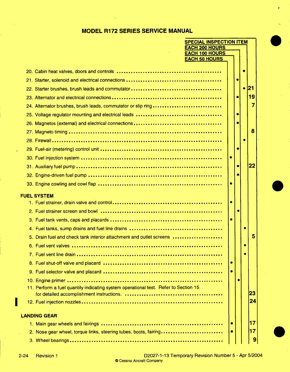
MODEL
R172
SERIES
SERVICE
MANUAL
SPECIAL
INSPECTION
ITEIV
EACH
200
HOURS
EACH
100 HOURS
EACH
50
HOURS
20.
Cabin
heat
valves,
doors
and
controls
............................................
21.
Starter,
solenoid
and
electrical connections
........................................
22.
Starter brushes,
brush
leads
and
commutator......................................
21
23.
Alternator
and
electrical
connections
...................
.......................
*
19
24.
Alternator
brushes,
brush
leads,
commutator
or
slip
ring.............................
7
25.
Voltage
regulator
mounting and
electrical
leads
....................................
26.
Magnetos
(external)
and
electrical
connections
.....................................
27.
Magneto
timing
...................................................
8
28. Firewall
.......................................................................
29.
Fuel-air
(metering)
control
unit
...................................................
30.
Fuel
injection system
...........................................................
*
31.
Auxiliary fuel pump
.............................................................
*
22
32.
Engine-driven fuel
pump
........................................................
33.
Engine
cowling
and cowl
flap
....................................................
*
FUEL
SYSTEM
1.
Fuel
strainer,
drain
valve
and
control
..............................................
*
2.
Fuel
strainer
screen
and bowl
...................................................
3.
Fuel
tank
vents, caps
and
placards
...............................................
4.
Fuel
tanks,
sump drains
and
fuel
line
drains
.......................................
5.
Drain
fuel
and
check
tank interior
attachment
and
outlet screens
.....................
5
6.
Fuel
vent
valves
...............................................................
7.
Fuel
vent
line
drain
................................
.........
8.
Fuel
shut-off valve
and
placard
..................................................
9.
Fuel
selector
valve
and
placard
....................
.............................
*
10.
Engine
primer
.........
........................................................
11.
Perform
a
fuel
quantity indicating
system
operational
test.
Refer to
Section
15
for
detailed
accomplishment
instructions
........................................
23
12.
Fuel
injection
nozzles...........................................................
24
LANDING
GEAR
1.
Main
gear wheels
and
fairings
............................................
... ·
17
2.
Nose
gear
wheel,
torque
links,
steering tubes,
boots,
fairing
..........................
17
3.
W heel
bearings................................................................
9
2-24 Revision
1
D2027-1-13
Temporary
Revision Number
5
-
Apr
5/2004
©
Cessna Aircraft
Company
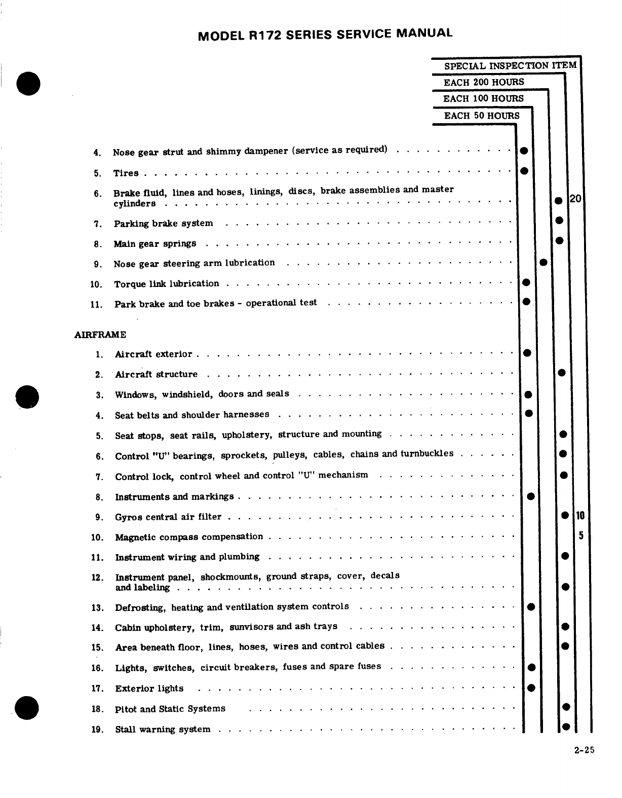
MODEL
R172
SERIES
SERVICE
MANUAL
SPECIAL INSPECTION ITEM
EACH
200
HOURS
EACH
100
HOURS
EACH
50
HOURS
4.
Nose
gear
strut
and
shimmy
dampener
(service
as
required)
............ .
5.
T
ires
.....................................
6.
Brake
fluid,
lines
and
hoses,
linings,
discs,
brake
assemblies
and
master
cylinders
.................................. .
20
7.
Parking
brake system
.... ... .. ... . .. .. . ... . ... . . ..
8.
Main
gear
springs
........ . . . . . . . . ........
9.
Nose
gear
steering
arm
lubrication
.......................
10.
Torque
link
lubrication
.. . .... . ... ... ... .. .. . ... . . ..
11.
Park
brake
and
toe
brakes
-
operational
test
............... .. .
AIRFRAME
1.
Aircraft exterior
............................... .
2.
Aircraft
structure
................... .
3.
Windows,
windshield,
doors
and
seals
.............. .
4.
Seat
belts
and
shoulder
harnesses
........ ....... ..... ..
5.
Seat
stops, seat
rails,
upholstery,
structure
and
mounting ...
..........
6.
Control
"U"
bearings, sprockets,
pulleys,
cables,
chains
and
turnbuckles
......
7.
Control
lock,
control
wheel
and
control
"U"
mechanism
..............
8.
Instruments
and
markings
.. ... .. . .. .. ... . .. .. . ... . . ..
9.
Gyros
central
air
filter
....................... ....... 10
10.
Magnetic
compass
compensation
....................... ..5
11.
Instrument
wiring
and
plumbing
.........................
12.
Instrument
panel,
shockmounts,
ground
straps,
cover, decals
and
labeling
............... ..... ... .....
. ..
13.
Defrosting,
heating
and
ventilation
system controls
................ .
14.
Cabin
upholstery,
trim,
sunvisors
and
ash
trays
.. . . . . .... .
15.
Area
beneath
floor,
lines, hoses,
wires
and
control
cables
.. ...... .
.
16.
Lights,
switches,
circuit
breakers,
fuses
and
spare
fuses
. . ... .....
17.
Exterior
lights
. . . . .... ....
.. . .... . ..... . . . . .
18.
Pitot
and
Static
Systems
........................... .
19.
Stall
warning
system
.................... .
2-25
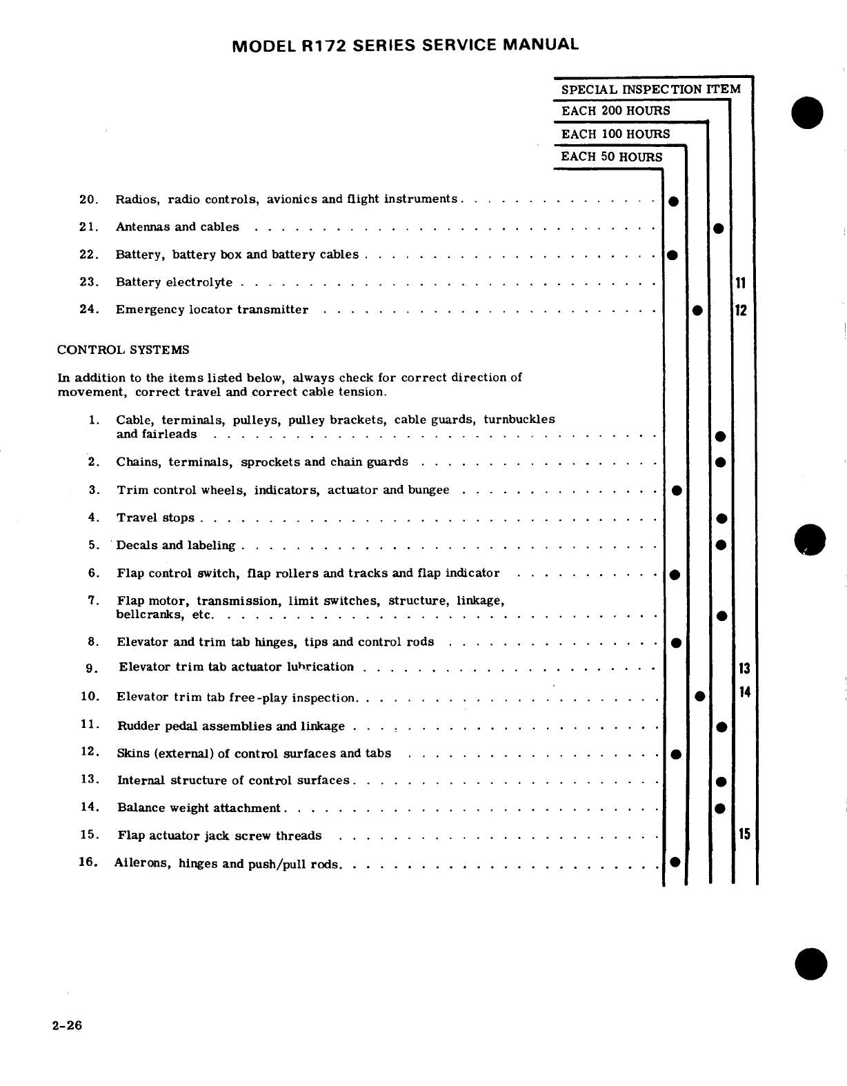
MODEL
R172
SERIES
SERVICE
MANUAL
SPECIAL INSPECTION
ITEM
EACH
200
HOURS
EACH 100 HOURS
EACH 50
HOURS
20.
Radios,
radio
controls,
avionics
and
flight
instruments
...............
21.
Antennas
and
cables
...............
22.
Battery,
battery
box
and
battery
cables
...
..................
.
23.
Battery
electrolyte
.. . . . ..........................
24.
Emergency
locator
transmitter
......................... 12
CONTROL
SYSTEMS
In
addition
to
the
items
listed
below,
always
check
for
correct
direction
of
movement,
correct
travel
and
correct
cable
tension.
1.
Cable,
terminals,
pulleys,
pulley
brackets,
cable
guards,
turnbuckles
and
fairleads
.... . . . ......... .
2.
Chains,
terminals,
sprockets
and
chain
guards
..
.......
......
.
3.
Trim
control wheels,
indicators, actuator
and
bungee
..........
..
4.
Travel stops
.................
5.
Decals
and
labeling
. ... .. . .. . .. . . ...
6.
Flap control
switch,
flap
rollers
and
tracks
and flap
indicator
... ... ..
7.
Flap motor,
transmission,
limit
switches,
structure,
linkage,
bellcranks,
etc
................................
8.
Elevator
and
trim
tab
hinges,
tips
and
control
rods
.. .
.... ......
9.
Elevator
trim
tab
actuator lubrication
............................
13
10.
Elevator
trim
tab
free-play
inspection.
.....................
14
11.
Rudder
pedal
assemblies
and
linkage
.. .
...................
12.
Skins
(external)
of
control
surfaces
and
tabs
...............
13.
Internal
structure
of
control
surfaces.......................
14.
Balance
weight
attachment............................
15.
Flap
actuator
jack
screw
threads
.......... ........ ......
..
15
16.
Ailerons,
hinges
and
push/pull rods
........................
2-26
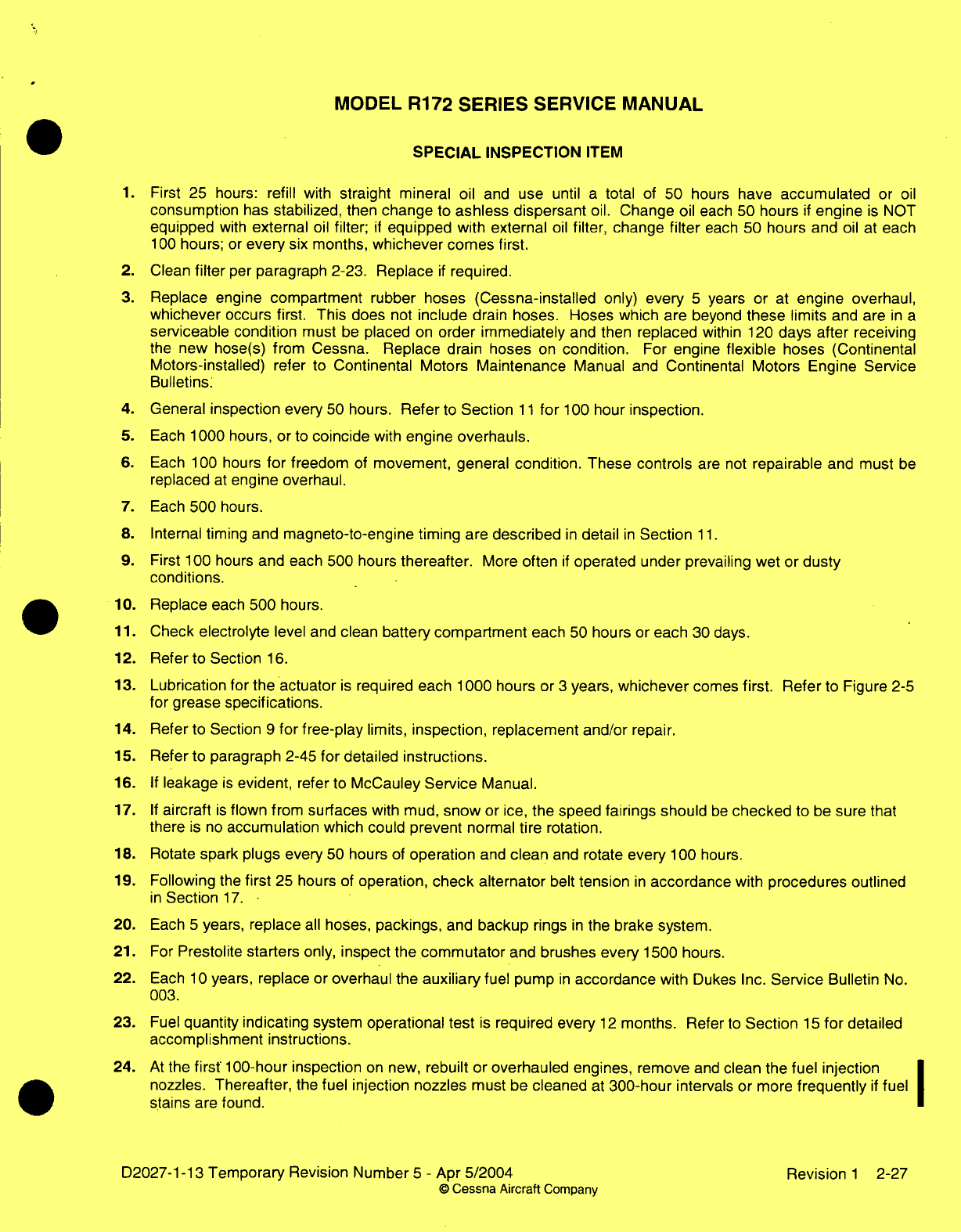
MODEL
R172 SERIES
SERVICE
MANUAL
SPECIAL
INSPECTION
ITEM
1.
First
25 hours:
refill
with
straight
mineral oil
and
use
until
a
total
of
50
hours
have
accumulated
or
oil
consumption
has
stabilized,
then
change
to
ashless dispersant
oil.
Change
oil each
50 hours
if
engine
is
NOT
equipped
with
external
oil
filter;
if
equipped
with
external
oil
filter,
change
filter
each
50 hours and
oil
at
each
100
hours;
or
every
six
months,
whichever comes first.
2. Clean
filter
per
paragraph 2-23.
Replace
if
required.
3.
Replace
engine
compartment
rubber hoses
(Cessna-installed
only)
every
5
years
or
at
engine overhaul,
whichever
occurs
first.
This
does
not
include
drain
hoses.
Hoses which
are
beyond
these
limits
and
are
in
a
serviceable condition
must
be
placed
on
order immediately
and
then
replaced
within
120
days after receiving
the
new hose(s)
from
Cessna. Replace
drain
hoses
on
condition.
For
engine
flexible
hoses
(Continental
Motors-installed)
refer
to
Continental
Motors
Maintenance
Manual
and
Continental
Motors Engine Service
Bulletins:
4.
General
inspection every
50
hours.
Refer
to
Section
11
for
100
hour
inspection.
5.
Each
1000 hours,
or
to
coincide
with
engine
overhauls.
6.
Each 100
hours
for
freedom
of
movement, general
condition. These controls
are not
repairable
and
must
be
replaced
at
engine overhaul.
7.
Each
500
hours.
8.
Internal
timing
and
magneto-to-engine
timing
are
described
in
detail
in
Section
11.
9.
First 100
hours
and
each
500 hours
thereafter.
More
often
if
operated
under
prevailing
wet or
dusty
conditions.
10.
Replace
each
500
hours.
11.
Check
electrolyte
level and
clean battery
compartment
each
50
hours or
each
30 days.
12.
Refer
to
Section
16.
13.
Lubrication
for
the actuator
is
required each 1000
hours
or
3
years,
whichever
comes
first.
Refer
to Figure
2-5
for
grease
specifications.
14.
Refer
to Section
9
for
free-play
limits,
inspection, replacement and/or
repair.
15.
Refer
to
paragraph
2-45
for
detailed
instructions.
16.
If
leakage
is
evident,
refer
to
McCauley
Service
Manual.
17.
If
aircraft
is
flown
from
surfaces
with
mud,
snow
or
ice,
the speed
fairings should
be
checked
to
be
sure
that
there
is
no
accumulation
which
could
prevent normal
tire
rotation.
18.
Rotate
spark
plugs every
50
hours
of
operation
and
clean
and
rotate
every
100
hours.
19.
Following
the
first
25 hours
of
operation,
check
alternator
belt
tension
in
accordance
with
procedures outlined
in
Section
17.
20.
Each
5
years,
replace
all
hoses,
packings,
and
backup
rings
in
the
brake
system.
21. For
Prestolite
starters
only,
inspect
the
commutator
and
brushes every
1500
hours.
22.
Each
10
years,
replace
or
overhaul the
auxiliary
fuel
pump
in
accordance
with
Dukes Inc.
Service
Bulletin
No.
003.
23.
Fuel
quantity indicating
system
operational
test
is
required
every
12
months.
Refer
to
Section
15
for
detailed
accomplishment instructions.
24.
At
the
first
100-hour
inspection
on
new,
rebuilt
or
overhauled engines,
remove
and
clean
the
fuel
injection
nozzles.
Thereafter,
the
fuel
injection nozzles
must
be
cleaned
at
300-hour
intervals
or
more
frequently
if
fuel
stains
are found.
D2027-1-13
Temporary
Revision
Number
5
-
Apr
5/2004 Revision
1
2-27
©
Cessna
Aircraft
Company
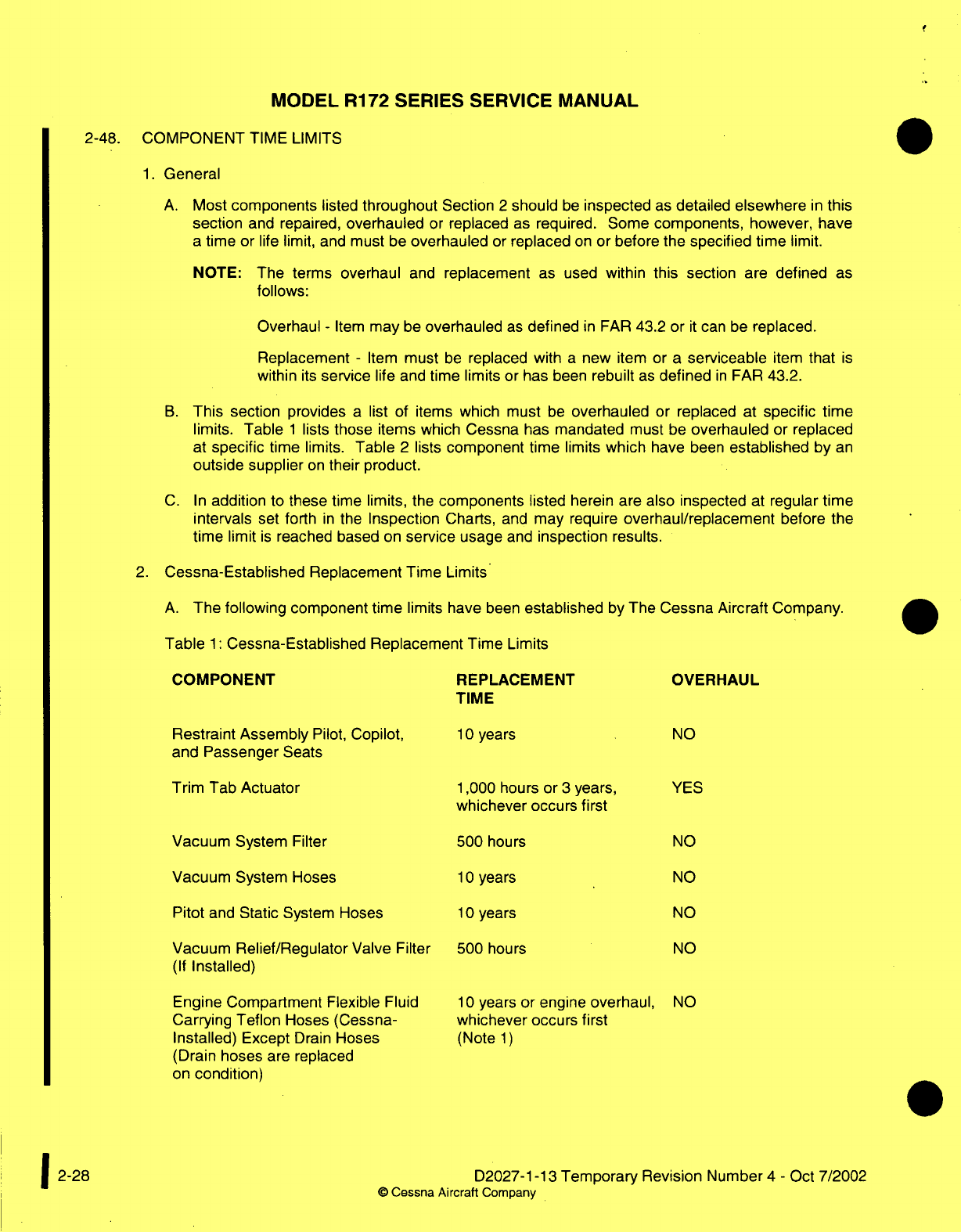
MODEL R172
SERIES
SERVICE
MANUAL
2-48.
COMPONENT
TIME
LIMITS
1.
General
A.
Most
components
listed
throughout
Section
2
should
be
inspected
as
detailed
elsewhere
in
this
section
and repaired,
overhauled
or
replaced
as
required.
Some
components,
however,
have
a
time
or
life
limit,
and
must
be
overhauled
or
replaced
on
or
before
the
specified time
limit.
NOTE:
The terms
overhaul
and
replacement
as
used
within
this
section
are
defined
as
follows:
Overhaul
-
Item
may
be
overhauled
as
defined
in
FAR
43.2
or
it
can be
replaced.
Replacement
-
Item
must
be
replaced with
a
new item
or
a
serviceable
item
that
is
within
its
service
life
and
time
limits
or
has
been
rebuilt
as
defined
in
FAR
43.2.
B.
This
section
provides
a
list
of items
which
must
be
overhauled
or
replaced
at
specific
time
limits.
Table
1
lists
those
items
which
Cessna
has
mandated
must
be
overhauled
or
replaced
at
specific
time
limits.
Table
2
lists
component time
limits
which
have
been
established
by
an
outside supplier
on
their
product.
C.
In
addition
to
these
time
limits,
the
components
listed
herein
are
also
inspected
at
regular
time
intervals
set
forth
in
the
Inspection
Charts,
and
may
require
overhaul/replacement
before
the
time limit
is
reached
based
on
service
usage
and
inspection
results.
2.
Cessna-Established
Replacement
Time
Limits
A.
The
following
component time
limits have
been
established
by
The
Cessna Aircraft
Company.
Table
1:
Cessna-Established Replacement
Time Limits
COMPONENT
REPLACEMENT
TIME OVERHAUL
Restraint Assembly
Pilot,
Copilot,
and
Passenger
Seats
Trim
Tab
Actuator
Vacuum
System
Filter
Vacuum
System Hoses
Pitot
and
Static
System Hoses
Vacuum
Relief/Regulator
Valve
Filter
(If
Installed)
Engine Compartment
Flexible
Fluid
Carrying
Teflon
Hoses (Cessna-
Installed)
Except
Drain
Hoses
(Drain
hoses
are replaced
on
condition)
1,000
hours
or
3
years,
whichever occurs
first
500
hours
10
years
10
years
500
hours
10
years or engine
overhaul,
whichever occurs
first
(Note
1)
D2027-1-13
Temporary
Revision Number
4
-
Oct
7/2002
0
Cessna Aircraft
Company
10
years
NO
YES
NO
NO
NO
NO
NO
1
2-28
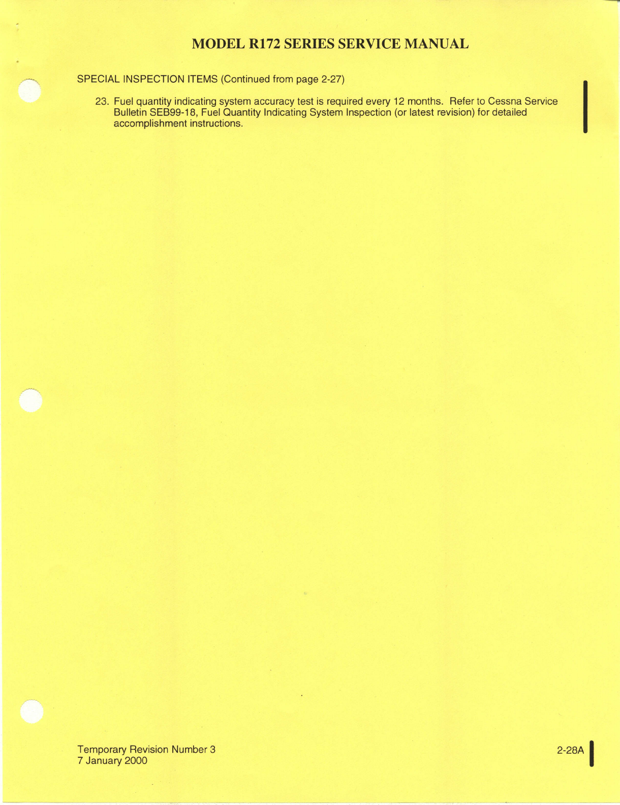
MODEL
R172
SERIES
SERVICE
MANUAL
SPECIAL INSPECTION
ITEMS
(Continued
from
page 2-27)
23.
Fuel
quantity
indicating system
accuracy
test
is
required
every
12
months.
Refer to
Cessna
Service
Bulletin
SEB99-18,
Fuel
Quantity
Indicating
System
Inspection
(or
latest
revision)
for
detailed
accomplishment
instructions.
Temporary Revision
Number
3
2-28A
7
January
2000
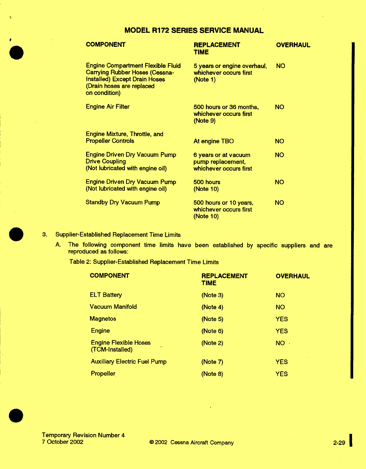
MODEL
R172
SERIES
SERVICE
MANUAL
COMPONENT
REPLACEMENT
TIME
OVERHAUL
Engine
Compartment
Flexible
Fluid
Carrying Rubber
Hoses (Cessna-
Installed)
Except
Drain
Hoses
(Drain
hoses are
replaced
on
condition)
Engine
Air
Filter
Engine
Mixture,
Throttle,
and
Propeller
Controls
Engine Driven
Dry
Vacuum
Pump
Drive
Coupling
(Not
lubricated
with engine
oil)
Engine
Driven
Dry
Vacuum
Pump
(Not
lubricated
with engine
oil)
Standby
Dry
Vacuum
Pump
5
years
or
engine
overhaul,
whichever
occurs
first
(Note
1)
500
hours
or
36
months,
whichever
occurs
first
(Note
9)
At
engine
TBO
6
years
or
at
vacuum
pump
replacement,
whichever
occurs
first
500
hours
(Note
10)
500
hours
or
10
years,
whichever
occurs
first
(Note
10)
3.
Supplier-Established
Replacement
Time
Limits
A.
The
following
component
time
limits
have
been
established
by
reproduced
as
follows:
Table
2:
Supplier-Established Replacement
Time
Limits
specific
suppliers
and
are
COMPONENT
REPLACEMENT
TIME
OVERHAUL
ELT
Battery
Vacuum
Manifold
Magnetos
Engine
Engine
Flexible
Hoses
(TCM-Installed)
Auxiliary
Electric
Fuel
Pump
Propeller
Temporary
Revision Number
4
7
October
2002
©
2002
(Note
3)
(Note
4)
(Note
5)
(Note
6)
(Note
2)
(Note
7)
(Note
8)
NO
NO
YES
YES
NO
YES
YES
Cessna
Aircraft
Company
NO
NO
NO
NO
NO
NO
2-29
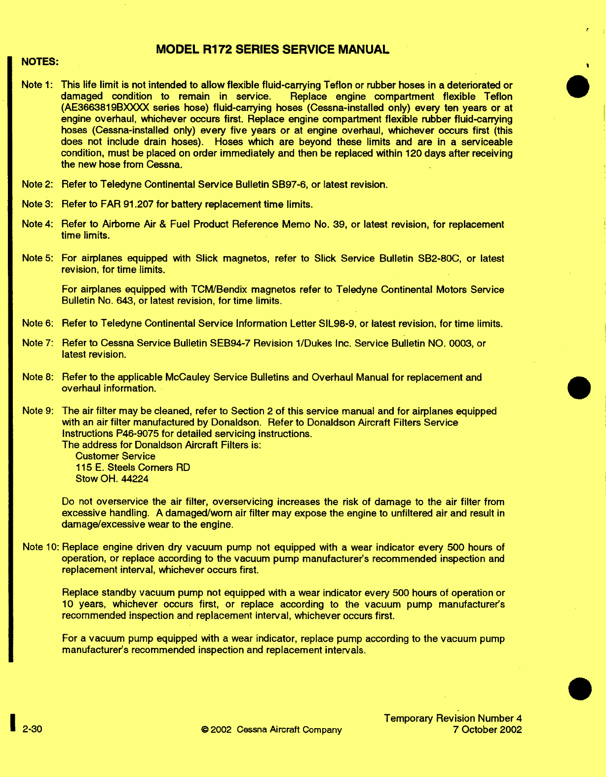
MODEL
R172
SERIES SERVICE
MANUAL
NOTES:
Note
1:
This
life limit
is
not
intended
to
allow
flexible
fluid-carrying
Teflon
or
rubber
hoses
in
a
deteriorated
or
damaged
condition
to
remain in
service.
Replace
engine
compartment
flexible
Teflon
(AE3663819BXXXX
series
hose)
fluid-carrying
hoses
(Cessna-installed
only)
every
ten
years
or
at
engine
overhaul,
whichever
occurs
first.
Replace engine
compartment
flexible
rubber
fluid-carrying
hoses
(Cessna-installed
only)
every
five
years
or
at
engine overhaul,
whichever
occurs first
(this
does not
include
drain
hoses).
Hoses
which
are
beyond
these
limits
and are
in
a
serviceable
condition,
must be
placed
on
order
immediately
and
then
be
replaced
within
120
days
after
receiving
the
new hose
from
Cessna.
Note
2:
Refer
to
Teledyne
Continental
Service
Bulletin SB97-6,
or
latest revision.
Note
3:
Refer
to
FAR
91.207
for
battery
replacement
time
limits.
Note
4:
Refer
to
Airborne
Air
&
Fuel
Product
Reference
Memo
No.
39, or
latest revision,
for
replacement
time
limits.
Note
5:
For
airplanes
equipped
with
Slick
magnetos,
refer
to
Slick
Service
Bulletin
SB2-80C,
or
latest
revision,
for
time
limits.
For
airplanes
equipped
with
TCM/Bendix
magnetos
refer
to
Teledyne Continental
Motors
Service
Bulletin
No.
643,
or
latest
revision,
for
time
limits.
Note
6:
Refer to
Teledyne
Continental
Service
Information
Letter
SIL98-9,
or
latest revision,
for
time
limits.
Note
7:
Refer
to
Cessna
Service Bulletin
SEB94-7
Revision
1/Dukes Inc.
Service
Bulletin
NO.
0003,
or
latest
revision.
Note
8:
Refer
to
the applicable
McCauley
Service
Bulletins
and
Overhaul
Manual
for
replacement
and
overhaul information.
Note
9:
The
air
filter
may
be
cleaned,
refer
to
Section
2
of
this
service
manual and
for
airplanes
equipped
with
an
air
filter
manufactured by Donaldson.
Refer
to
Donaldson
Aircraft
Filters
Service
Instructions
P46-9075
for
detailed
servicing
instructions.
The
address
for
Donaldson
Aircraft
Filters
is:
Customer
Service
115
E.
Steels
Corners
RD
Stow
OH.
44224
Do
not
overservice
the air
filter,
overservicing
increases
the risk
of
damage
to
the
air
filter
from
excessive
handling.
A
damaged/worn
air
filter
may
expose
the
engine
to
unfiltered
air
and
result
in
damage/excessive
wear
to
the
engine.
Note
10:
Replace
engine driven dry
vacuum
pump
not
equipped with
a
wear
indicator every
500
hours
of
operation,
or
replace
according
to
the
vacuum pump manufacturer's
recommended
inspection
and
replacement interval,
whichever
occurs first.
Replace
standby
vacuum pump
not
equipped
with
a
wear
indicator
every
500
hours
of
operation
or
10
years,
whichever occurs
first,
or
replace
according
to
the
vacuum
pump
manufacturer's
recommended inspection
and
replacement
interval,
whichever
occurs
first.
For
a
vacuum
pump
equipped
with
a
wear
indicator,
replace pump
according to
the
vacuum
pump
manufacturer's
recommended
inspection
and
replacement
intervals.
Temporary
Revision
Number
4
2-30 ©
2002
Cessna
Aircraft
Company
7
October
2002
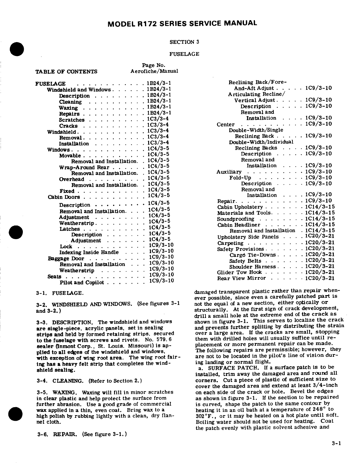
MODEL
R172
SERIES
SERVICE
MANUAL
SECTION
3
FUSELAGE
Page
No.
TABLE
OF
CONTENTS
Aerofiche/Manual
FUSELAGE
............
1B24/3-1 Reclining
Back/Fore-
Windshield
and
Windows
. ... .
1B24/3-1 And-Aft Adjust
.. .
C9/3-10
Description
.......
.
1B24/3-1
Articulating
Recline/
Cleaning
.....
.. ...
1B24/3-1
Vertical
Adjust
. ...
C9/3-10
Waxing
..
....
1B24/3-1
Description
...
C9/3-10
Repairs
...........
Removal
and
Scratches
.
.......
1C3/3-4
Installation
.
C9/3-10
Cracks
... . ...
1C3/3-4
Center
...........
1C9/3-10
Windshield.
.......
1C3/3-4
Double-Width/Single
Removal.
..
....
1C3/3-4
Reclining
Back
..
C9/3-10
Installation
.......
.
1C3/3-4
Double-Width/Individual
Windows.
............
1C4/3-5
Reclining
Backs
....
1C9/3-10
Movable
....
1C4/3-5
Description
...
1C9/3-10
Removal and
Installation.
.
1C4/3-5
Removal
and
Wrap-Around
Rear
......
1C4/3-5
Installation
....
1C9/3-10
Removal and
Installation.
.
1C4/3-5 Auxiliary
.........
1C9/3-10
Overhead
......
1C4/3-5
Fold-Up
.......
C9/3-10
Removal and
Installation.
.
1C4/3-5
Description.
..
C9/3-10
Fixed
.....
1C4/3-5
Removal
and
Cabin
Doors
...........
1C4/3-5
Installation
.. .
1C9/3-10
Description
.........
1C4/3-5
Repair.
...........
1C9/3-10
Removal
and
Installation.
..
1C4/3-5
Cabin
Upholstery
. . .
.C14/3-15
Adjustment.
1C4/3-5
Materials
and
Tools
.. .
.1C14/3-15
Weatherstrip
...
1C4/3-5
Soundproofing
...
....
1C14/3-15
Latches
.....
1C4/3-5
Cabin
Headliner
... ...
1C14/3-15
Description
1C4/3-5
Removal
and
Installation
.1C14/3-15
Adjustment.
1C4/3-5
Upholstery
Side
Panels
....
1C20/3-21
Lock
.........
...
1C9/3-10
Carpeting
.1......
1C20/3-21
Indexing
Inside
Handle
....
1C9/3-10
Safety
Provisions
.
.....
1C20/3-21
Baggage
Door
..........
1C9/3-10
Carg6
Tie-Downs
.....
1C20/3-21
Removal
and
Installation
. . .
1C9/3-10
Safety
Belts
....
1C20/3-21
Weatherstrip
.. . .
1C9/3-10
Shoulder
Harness
....
1C20/3-21
Seats
........
1C9/3-10
Glider
Tow
Hook
.....
.
1C20/3-21
Pilot
and
Copilot.
.. . . .
1C9/3-10
Rear
View
Mirror
......
1C20/3-21
3-1.
FUSELAGE.
damaged
transparent
plastic
rather
than
repair
when-
ever
possible,
since
even
a
carefully
patched
part
is
3-2.
WINDSHIELD
AND
WINDOWS.
(See
figures
3-1
not
the
equal
of
a
new
section,
either
optically
or
and
3-2.)
structurally.
At
the
first
sign
of
crack
development,
drill
a
small
hole
at
the
extreme
end
of
the
crack
as
3-3.
DESCRIPTION.
The
windshield
and
windows
shown
in
figure
3-1.
This
serves
to
localize
the
crack
are
single-piece.
acrylic panels,
set
in
sealing
and
prevents
further
splitting
by
distributing
the
strain
strips
and
held
by
formed
retaining
strips,
secured
over
a
large
area.
If
the
cracks
are
small,
stopping
to
the
fuselage
with
screws
and
rivets.
No.
579.
6
them with
drilled
holes
will
usually
suffice
until
re-
sealer
(Inmont
Corp.,
St.
Louis.
Missouri)
is
ap-
placement
or
more
permanent
repair
can
be
made.
plied
to
all
edges
of
the
windshield
and
windows.
The
following
repairs
are
permissible;
however,
they
with
exception
of
wing
root
area.
The
wing
root
fair-
are
not
to
be
located
in
the
pilot's
line
of
vision
dur-
ing
has
a
heavy
felt
strip
that
completes
the
wind-
ing
landing
or
normal
flight.
shield
sealing.
a.
SURFACE
PATCH.
If
a
surface
patch
is
to
be
installed,
trim
away
the
damaged
area
and
round all
3-4.
CLEANING.
(Refer
to
Section
2.)
corners.
Cut
a
piece
of
plastic
of
sufficient
size
to
cover
the
damaged
area
and
extend
at
least
3/4-inch
3-5.
WAXING.
Waxing
will
fill
in
minor
scratches
on
each
side
of
the
crack
or
hole.
Bevel
the
edges
in
clear
plastic
and help
protect
the
surface
from
as
shown
in
figure
3-1.
If
the
section
to
be
repaired
further
abrasion.
Use
a
good
grade
of
commercial
is
curved, shape the
patch
to
the
same
contour
by
wax
applied
in
a
thin,
even
coat.
Bring
wax
to
a
heating
it
in
an oil
bath
at
a
temperature
of
248
°
to
high polish
by
rubbing
lightly
with
a
clean,
dry
flan-
302°F.,
or
it
may
be
heated
on a
hot
plate
until soft.
nel
cloth.
Boiling
water
should
not
be
used
for
heating.
Coat
the
patch
evenly
with
plastic solvent
adhesive
and
3-6.
REPAIR.
(See
figure 3-1.)
3-1
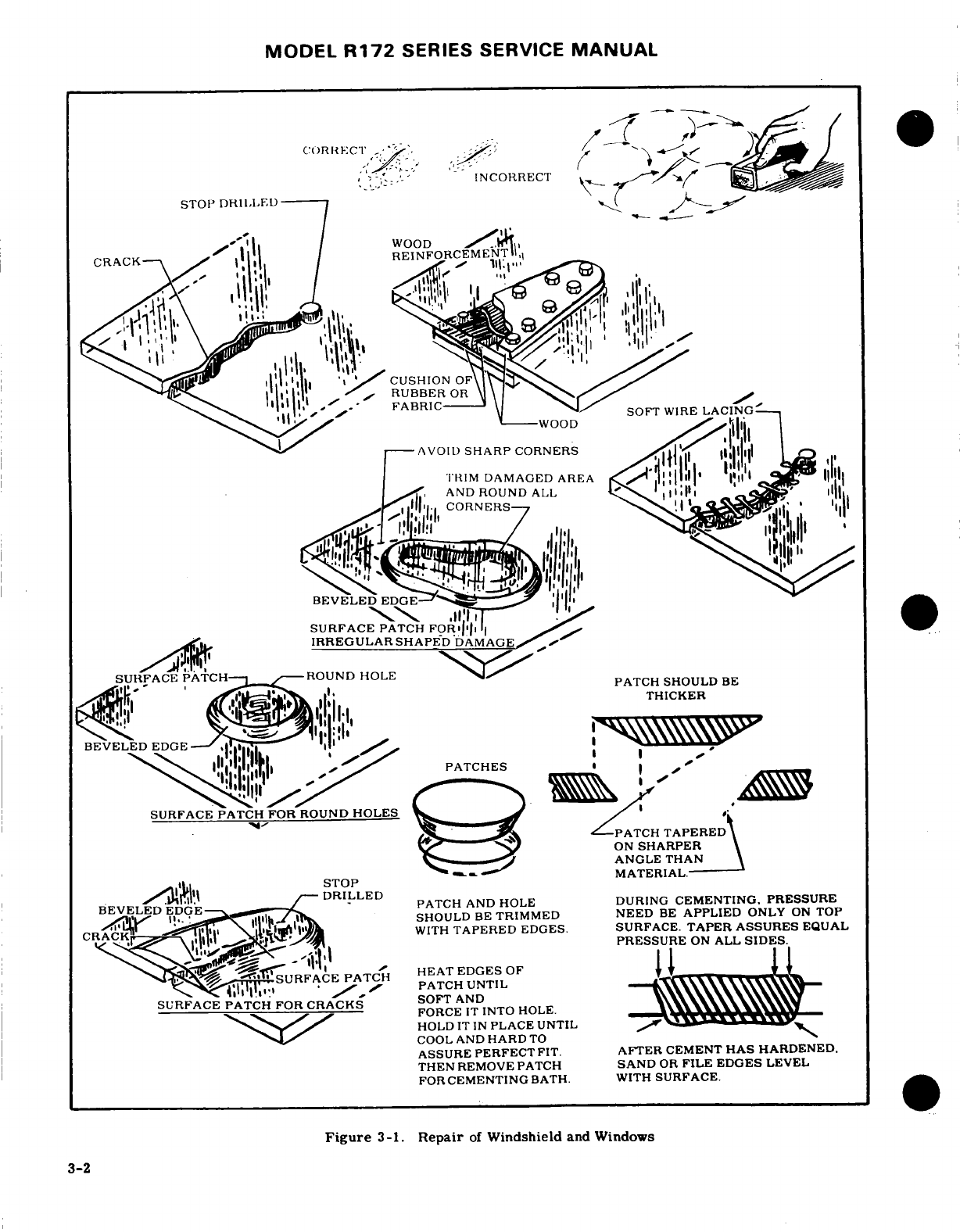
MODEL
R172
SERIES
SERVICE
MANUAL
CORRECT
INCORRECT
STOP
DRILLED
WOOD
CRACK---
REINFORCEMENT
CUSHION
OF
RUBBER
OR
FABRIC
SOFT
WIRE
LACING
AVOID
SHARP
CORNERS
CORNERS
BEVELED
EDGE
SURFACE
PATCH
FOR
IRREGULAR SHAPED
DAMAGE
SURFACE
PATCH-
-
ROUND HOLE
PATCH
SHOULD
BE
PATCH SHOULD
BE
THICKER
BEVELED
EDGE
--
PATCHES
SURFACE PATCH
FOR
ROUND
HOLES
PATCH
TAPERED
ON
SHARPER
ANGLE
THAN
STOP
MATERIAL.
PATCH
AND
HOLE
DURING
CEMENTING.
PRESSURE
SHOULD
BE
TRIMMED
NEED
BE
APPLIED
ONLY
ON
TOP
CRACK
WITH
TAPERED
EDGES.
SURFACE.
TAPER
ASSURES
EQUAL
PRESSURE
ON
ALL
SIDES.
HEAT
EDGES
OF
PATCH
UNTIL
SURFACE PATCH FOR
CRACKS
SOFT
AND
FORCE
IT
INTO
HOLE.
HOLD
IT
IN
PLACE
UNTIL
COOL AND
HARD
TO
ASSURE
PERFECT
FIT.
AFTER
CEMENT
HAS
HARDENED.
THEN
REMOVE
PATCH
SAND
OR
FILE
EDGES
LEVEL
FOR
CEMENTING
BATH.
WITH
SURFACE.
Figure
3-1.
Repair
of
Windshield
and
Windows
3-2
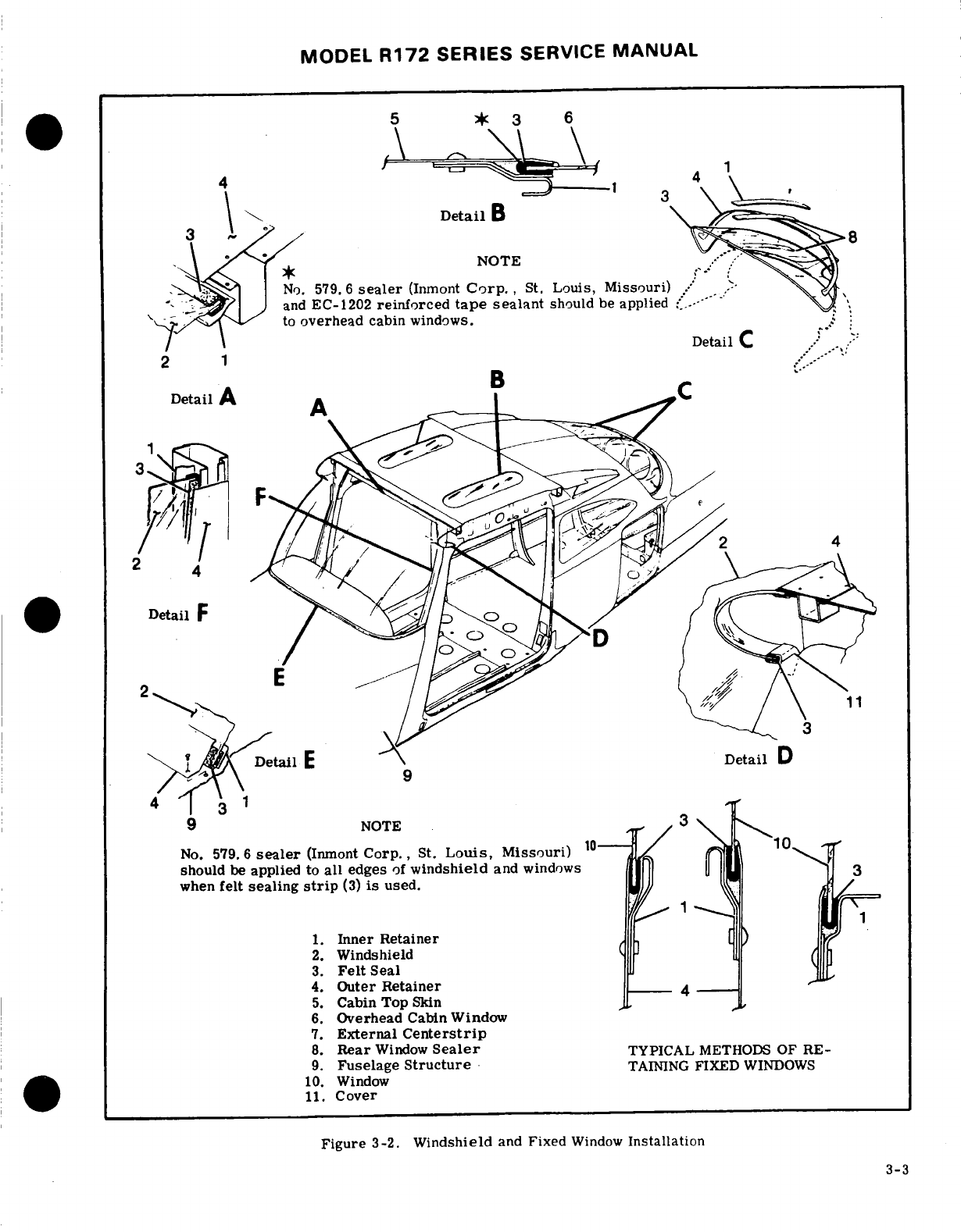
MODEL
R172
SERIES
SERVICE
MANUAL
Detail
B
NOTE
No.
579.6
sealer
(Inmont
Corp.,
St.
Louis,
Missouri)
and
EC-1202
reinforced
tape
sealant
should
be
applied
to
overhead
cabin
windows.
.
Detail
C
.--
Detail
A
Detail
F
DetailE
Detail
D
NOTE
No.
579.6
sealer
(Inmont
Corp.,
St.
Louis,
Missouri)
should
be
applied
to
all
edges
of
windshield
and
windows
when
felt
sealing
strip
(3)
is
used.
1.
Inner
Retainer
2.
Windshield
3.
Felt
Seal
4.
Outer
Retainer
4
5.
Cabin Top
Skin
6.
Overhead
Cabin
Window
7.
External
Centerstrip
8.
Rear
Window
Sealer
TYPICAL
METHODS
OF
RE-
9.
Fuselage
Structure
TAINING
FIXED
WINDOWS
10.
Window
11.
Cover
Figure
3-2.
Windshield
and
Fixed
Window
Installation
3-3
MODEL
R172
SERIES
SERVICE
MANUAL
place immediately
over
the hole.
Maintain
a
uniform
NOTE
pressure
of
from
5
to
10
psi
on
the
patch
for
a
mini-
mum
of
three
hours.
Allow the
patch
to
dry
24
to
36
Rubbing
plastic
surface
with
a
dry cloth
hours
before
sanding
or
polishing
is
attempted.
will
build
up
an
electrostatic
charge
which
b.
PLUG
PATCH. In
using
inserted
patches
to
attracts
dirt
particles
and
may
eventually
repair
holes
in
plastic
structures,
trim
the
holes
to
cause
scratching
of
surface.
After
wax
a
perfect
circle
or
oval
and
bevel
the
edges
slightly.
has
hardened,
dissipate
this
charge
by
rub-
Make
the
patch
slightly
thicker
than
the
material
bing
surface
with
a
slightly
damp
chamois.
being
repaired,
and
similarly
bevel
the
edges.
In-
This
will
also
remove
dust
particles
which
stall
patches
in
accordance
with
procedure
illustrated
have
collected
while
wax
is
hardening.
in
figure 3-1.
Heat
the plug
until
soft
and
press
into
the
hole
without
cement
and
allow to cool to
make
a
f.
Minute
hairline
scratches
can
often
be
removed
perfect
fit.
Remove
the
plug,
coat
the
edges
with
by
rubbing
with
commercial
automobile
body
clean-
adhesive,
and
then
reinsert
in
the
hole.
Maintain
a
er
or
fine-grade rubbing
compound.
Apply
with
a
firm
light
pressure
until
the
cement
has
set,
then
soft,
clean,
dry
cloth
or
imitation
chamois.
sand
or
file
the
edges
level
with
the
surface;
buff
and
polish.
3-8.
CRACKS.
(See
figure
3-1.)
a.
When
a
crack
appears,
drill
a
hole
at
end
of
3-7.
SCRATCHES.
Scratches
on
clear
plastic
sur-
crack
to
prevent
further
spreading.
Hole
should
be
faces
can
be
removed
by
hand-sanding
operations
approximately
1/8
inch
in
diameter,
depending
on
followed
by
buffing
and
polishing,
if
steps
below
are
length
of
crack
and
thickness
of
material.
followed
carefully.
b.
Temporary
repairs
to
flat
surfaces
can
be
ac-
a.
Wrap
a
piece
of
No.
320
(or
finer)
sandpaper
or
complished
by
placing
a
thin
strip
of
wood
over
each
abrasive
cloth around
a
rubber
pad
or
wood
block.
side
of
surface
and
inserting
small
bolts
through
Rub
surface
around
scratch
with
a
circular
motion,
wood
and
plastic.
A
cushion
of
sheet
rubber
or
air-
keeping
abrasive
constantly
wet
with
clean
water
to
craft
fabric
should
be
placed
between
wood
and
plas-
prevent
scratching
surface
further.
Use
minimum
tic
on
both
sides.
pressure
and
cover an
area
large
enough
to
prevent
c.
A
temporary
repair
can
be
made
by
drilling
formation
of
"bull's-eyes"
or
other
optical
distor-
small
holes
along
both
sides
of
crack
1/4
to
1/8
inch
tions.
apart
and lacing
edges
together
with
soft
wire.
Small-stranded
antenna wire
makes
a
good
temporary
CAUTION
lacing
material.
This
type
of
repair
is
used
as
a
temporary
measure
ONLY,
and
as
soon
as
facilities
Do
not
use
a
coarse
grade
of
abrasive.
No.
are
available,
panel
should
be
replaced.
320
is of
maximum
coarseness.
3-9.
WINDSHIELD.
(See
figure
3-2.)
b.
Continue
sanding
operation,
using
progressively
finer
grade
abrasives
until
scratches
disappear.
3-10.
REMOVAL.
(See
figure
3-2.)
c.
When
scratches
have
been
removed,
wash
area
a.
Drill
out
rivets
securing
front
retainer
strip.
thoroughly
with
clean
water
to
remove
all
gritty
par-
b.
Remove
wing
fairings
over
windshield edges.
tides.
The
entire
sanded
area
will
be
clouded with
c.
Pull
windshield
straight
forward,
out
of
side
minute
scratches
which
must
be
removed
to
restore
and
top
retainers.
Remove
top
retainer
if
necessary.
transparency.
d.
Apply
fresh
tallow
or
buffing
compound
to
a 3-11.
INSTALLATION.
(See
figure
3-2.)
motor-driven
buffing
wheel.
Hold
wheel
against plas-
a.
Apply
felt
strip
and
sealing
compound
or
sealing
tic
surface,
moving
it
constantly over
damaged
area
tape
to
all
edges
of
windshield
to
prevent
leaks.
until
cloudy
appearance
disappears.
A
2000-foot-per-
b.
Reverse steps
in
preceding
paragraph
for
instal-
minute
surface
speed
is
recommended
to
prevent
lation.
overheating
and
distortion.
(Example:
750
rpm
c.
When
installing
a
new
windshield,
check
fit
and
polishing
machine
with
a
10
inch
buffing
bonnet.)
carefully
file
or
grind
away
excess
plastic.
d.
Use
care
not
to
crack
windshield
when
installing.
NOTE
If
not
previously
removed,
top
retainer
may
be
re-
moved
if
necessary. Starting
at
upper
corner
and
Polishing
can
be
accomplished
by
hand
but
gradually
working
windshield
into
position
is
recom-
will
require
a
considerably
longer
period
mended.
of
time
to
attain
the
same
result
as
pro-
duced
by
a
buffing
wheel.
NOTE
e.
When buffing
is
finished,
wash
area
thoroughly
Screws
and
self-locking
nuts
may
be
used
and
dry with
a
soft
flannel
cloth.
Allow
surface
to
instead
of
rivets
which
fasten
front
retaining
cool
and
inspect
area
to
determine
if
full
transpar-
strip
to
cowl
deck.
If
at
least
No.
6
screws
ency
has
been
restored.
Apply
a
thin
coat
of
hard
are
used,
no
loss
of
strength
will
result.
wax
and
polish
surface
lightly
with
a
clean
flannel
cloth.
3-4
MODEL
R172
SERIES SERVICE
MANUAL
3-12.
WINDOWS.
(See
figure
3-2.)
3-20.
CABIN
DOORS. (See
figure
3-3.)
3-13.
MOVABLE.
(See
figure
3-3.)
A
standard
3-21.
DESCRIPTION.
A
cabin
door
is
installed
on
movable
window,
hinged
at the
top,
is
installed
in each
side
of
the
aircraft
consisting
of
a
sheet
outer
the
left
cabin
door.
An
optional
movable
window
is
skin
chemically
bonded
to
a
formed
inner
pan
assem-
available
for
installation
in
the
right
cabin
door. bly.
To
this
rigid
structure
are
attached
the
door
latch assembly,
a
remote
inside
handle,
a
pair
of
3-14.
REMOVAL
AND
INSTALLATION.
(See
figure
external
hinges
and
an
integral
doorstop
assembly.
3-3.)
A
openable
window
is
installed
on
the
LH
door
and
a.
Disconnect
window
stop
(5).
may
also
be
optionally
installed
on
the
RH
door.
b.
Remove
pins
from
window
hinges
(6).
c.
Reverse
preceding
steps
for
installation.
To
3-22.
REMOVAL
AND
INSTALLATION.
(See
figure
remove frame from
plastic
panel,
drill
out
blind
3-3.)
Removal
of
cabin
doors
is
accomplished
either
rivets
at
frame
splice.
When
replacing
plastic
by
removing
screws
attaching
door hinges or
by
re-
panel
in
frame,
ensure
sealing
strip
and an adequate
moving
hinge pins.
coating
of
Presstite
No.
579.6
sealing
compound
is
used
around
all
edges
of
panel.
NOTE
3-15.
WRAP-AROUND REAR.
(See
figure 3-2.)
Ensure clevis
pin
(index
21,
figure
3-3)
The
rear
window
is
a one-piece
acrylic
plastic
panel
is
removed before
removing
door.
set
in
sealing
strips
and held
in
place
by
retaining
strips.
During
reinstallation
permanent-type
hinge
pins
may
be
replaced
with
clevis
pins
secured
with
cotter
pins.
3-16.
REMOVAL
AND
INSTALLATION. (See
figure
3-2.)
3-23.
ADJUSTMENT.
Cabin
doors
should
be
adjust-
a.
Remove
external
centerstrip
(7).
ed
so
that
door
skin
fairs
smoothly
with
fuselage
skin.
b.
Remove
upholstery
as
necessary
to
expose
re-
Slots
at
door
latch plate
permit
re-positioning
of
latch
tainer
strips
inside
cabin.
assembly
and
hence
bolt
engagement
with
rotary
clutch
c.
Drill
out
rivets as
necessary
to
remove
outer
on
door
post.
If
fitting
a
new
door
assembly,
some
retainer
strip
along
aft
edge
of
window.
trimming
of
door
flange
may
be
necessary
but gap
be-
d.
Remove
window
by
lifting
aft
edge
and pulling
tween
door skin
and
fuselage
skin should
be
.
09
inch
i
window
aft.
If
difficulty
is
encountered,
rivets
se- or
less.
curing
retainer
strips
inside
cabin
may
also
be
drilled
out
and
retainer
strips
loosened or
removed.
CAUTION
e.
Reverse
preceding
steps
for
installation.
Apply
felt
strip
and
sealing
compound
to
all
edges
of
win-
Reforming
of
bonded
door
flange
by
striking
dow
to
prevent
leaks.
Check
fit
and
carefully
file
with
soft
mallet etc.
is
NOT
permissible
or
grind
away
excess
plastic.
Use
care
not
to
crack
due
to
possible
damage
to
bonded
areas.
plastic
when
installing.
3-24.
CABIN
DOOR
WEATHERSTRIP.
A
hollow
3-17.
OVERHEAD.
(See
figure
3-2.)
Overhead
fluted-type,
rubber
weatherstrip
is
cemented
around
cabin
windows,
located
in
the
cabin
top,
may
be
in-
all
edges
of
the
cabin
door.
When
replacing weather-
stalled.
These
windows
are
one-piece
acrylic
plastic
strip,
ensure
that
contact
surfaces
are
clean
and
dry.
panels
set
in
sealing
strips
and
held
in
place
by
re-
Cut
new
weatherstrip
to
length
using
old
weatherstrip
taining
strips. as
a
guide.
Cut
small
notch
in
butt
ends
of
new
weath-
erstrip
to allow
for
drainage.
Position
splice
with
3-18.
REMOVAL
AND
INSTALLATION. (See
figure
notch
at
door
low
point
and
apply
a thin,
even
coat
of
3-2.)
EC-880
adhesive
(3-M
Company)
or
equivalent to
both
a.
Remove
headliner
and
trim
panels.
surfaces.
Allow
to
dry
until tacky
before
pressing
b.
Drill
out
rivets
as
necessary
to
remove
retainer
into
place
on
door.
Do
not
stretch
weatherstrip
strips.
around door
corners.
c.
Reverse
preceding
steps
for
installation.
Apply
felt
strip
and
sealing
compound
to
all
edges
of
window
3-25.
DOOR
LATCHES.
(See
figure
3-4.)
to
prevent
leaks.
Check
fit
and
carefully
file
or
grind
away
excess
plastic.
Use
care
not
to
crack plastic
3-26.
DESCRIPTION.
The
cabin
door
latch
is
a
when
installing,
push-pull
bolt
type,
utilizing
a
rotary
clutch
for
posi-
tive
bolt
engagement.
As
door
is
closed,
teeth
on
3-19.
FIXED.
(See
figure
3-2.) Fixed
windows,
underside
of
bolt
engage
gear
teeth
on
clutch.
The
mounted
in
sealing
strips
and
sealing
compound,
are
clutch
gear rotates
in
one
direction
only
and
holds
held
in
place
by
various
retainer
strips.
To
replace
door
until
handle
is
moved
to LOCK
position,
driving
side
windows,
remove
upholstery
and
trim
panels as
bolt into
slot.
necessary
and
drill
out
rivets
securing
retainers.
Apply
felt
strip
and
sealing
compound
to
all
edges
of
3-27.
ADJUSTMENT.
Adjustment
of
latch
or
clutch
window
to
prevent
leaks.
Check
fit
and
file
or
grind
cover
is
afforded
by
oversize
and/or
slotted
holes.
away
excess
plastic.
Use
care
not
to
crack
plastic
This
adjustment
ensures
sufficient
gear-to-bolt
en-
when
installing.
gagement
and
proper
alignment.
3-5
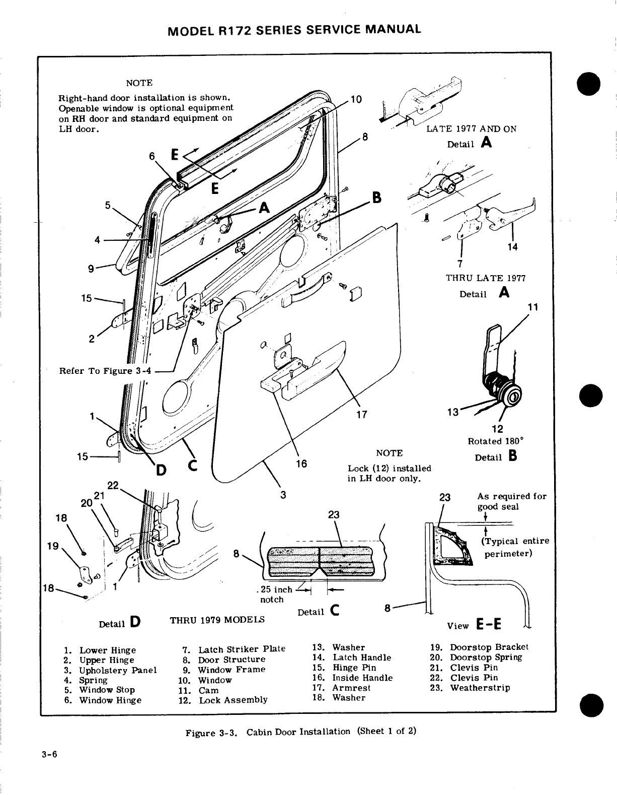
MODEL
R172
SERIES
SERVICE
MANUAL
NOTE
Right-hand
door
installation
is
shown.
Openable
window
is
optional equipment
.
on
RH
door
and
standard
equipment
on
LATE
1977 AND
ON
Detail
A
5
THRU
Detail B
23
.
9. p
Window
Frame
5.
inge
in21f...rimetern
DetailD
THRU
1979
MODEL-S
Detaie
4.
Spring
10.
Window
16.
Inside
Handle
22.
Clevis
Pin
5.
Window
Stop
11.
Cam
17.
Armrest
23.
Weatherstrip
Figure
3-3. Cabin
LH
door
Installationly.
(Sheet
of
2)
23
As
required
for
19
(Typical
entire
perimeter)
DetailC
8
Detail
D
THRU
1979
MODELS
1.
Lower
Hinge
7.
Latch
Striker
Plate
13.
Washer
19.
Doorstop
Bracket
2.
Upper
Hinge
8.
Door
Structure
14.
Latch
Handle
20.
Doorstop
Spring
3.
Upholstery
Panel
9.
Window
Frame
15.
Hinge
Pin
21.
Clevis
Pin
4.
Spring
10.
Window
16.
Inside
Handle
22.
Clevis
Pin
5.
Window
Stop
11.
Cam
17.
Armrest
23.
Weatherstrip
6.
Window
Hinge
12.
Lock
Assembly
18.
Washer
Figure
3-3.
Cabin
Door
Installation
(Sheet
1
of
2)
3-6
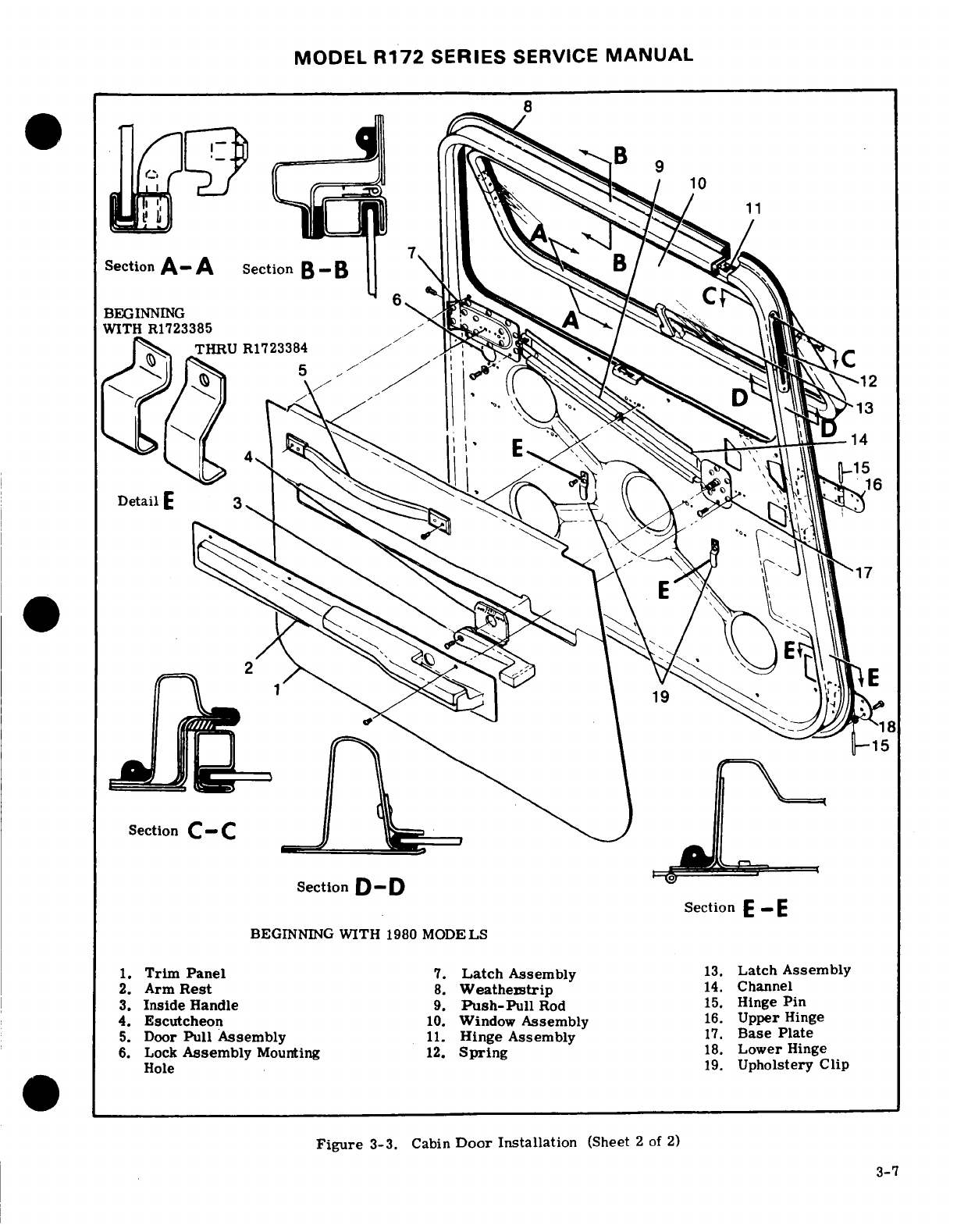
MODEL
R172
SERIES
SERVICE
MANUAL
Section
A- A
Section
B-B
BEGINNING
WITH
R1723385
Section
C
C
Section
D
-
D
BEGINNING
WITH
1980
MODELS
1.
Trim
Panel
7.
Latch
Assembly
13.
Latch Assembly
2.
Arm
Rest
8.
Weatherstrip
14.
Channel
3.
Inside
Handle
9.
Push-Pull
Rod
15.
Hinge
Pin
4.
Escutcheon
10.
Window
Assembly
16.
Upper
Hinge
5.
Door
Pull
Assembly
11.
Hinge
Assembly
17.
Base
Plate
6.
Lock
Assembly
Mounting
12.
Spring
18.
Lower
Hinge
Hole
19.
Upholstery
Clip
Figure
3-3.
Cabin
Door
Installation
(Sheet
2
of
2)
3-7
Section
E
BEGINNING
WITH
1980
MODELS
1.
Trim
Panel
7.
Latch
Assembly
13.
Latch
Assembly
2.
Arm
Rest
8.
Weatherstrip
14.
Channel
3.
Inside
Handle
9.
Push-Pull
Rod
15.
Hinge
Pin
4.
Escutcheon
10.
Window
Assembly
16.
Upper
Hinge
5.
Door
Pull
Assembly
11.
Hinge
Assembly
17.
Base
Plate
6.
Lock
Assembly
Mounting
12.
Spring
18.
Lower
Hinge
Hole
19.
Upholstery
Clip
Figure
3-3.
Cabin
Door
Installation
(Sheet
2
of
2)
3-7
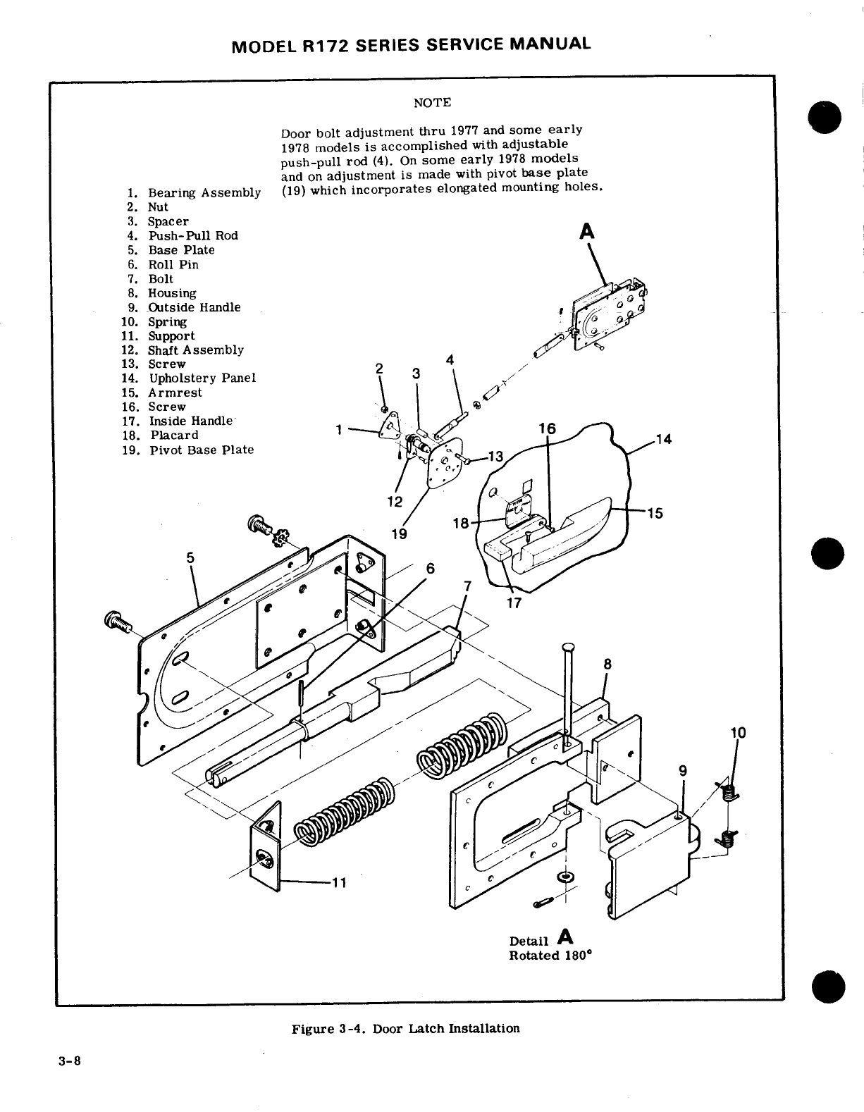
MODEL
R172
SERIES
SERVICE
MANUAL
NOTE
Door
bolt
adjustment
thru
1977
and
some
early
1978
models
is
accomplished
with
adjustable
push-pull
rod
(4).
On
some
early
1978
models
and
on
adjustment is
made
with pivot
base
plate
1.
Bearing
Assembly
(19)
which
incorporates
elongated
mounting
holes.
2.
Nut
3.
Spacer
4.
Push-Pull
Rod
A
5.
Base
Plate
6.
Roll
Pin
7.
Bolt
8.
Housing
9.
Outside
Handle
10.
Spring
11.
Support
12.
Shaft
Assembly
13.
Screw
4
14.
Upholstery Panel
15.
Armrest
16.
Screw
,
17.
Inside
Handle
18.
Placard
19.
Pivot
Base
Plate
19
18 15
10
Detail
A
Rotated
180
°
Figure
3-4.
Door
Latch
Installation
3-8
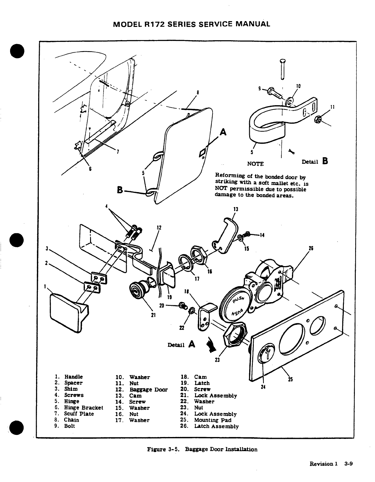
MODEL
R172
SERIES
SERVICE
MANUAL
~
NOTE
Detail
B
.
Reforming
of
the
bonded
door
by
striking
with
a
soft
mallet
etc.
is
NOT
permissible
due
to
possible
damage
to
the
bonded
areas.
2.
Spacer
11.
Nut
19.
Latch
3.
Shim
12.
Baggage
Door
20.
Screw
4.
Screws
13.
Cam
21. Lock
Assembly
5.
Hinge
14.
Screw
22.
Washer
6.
Hinge
Bracket
15.
Washer
23.
Nut
7.
Scuff
Plate
16.
Nut
24.
Lock
Assembly
.
Chain
1.
Washer
2.
Mounting
Padssembly
8.
Chain
17.
Washer
25.
MountingPad
9.
Bolt
26.
Latch
Assembly
Figure
3-5.
Baggage
Door
Installation
Revision
1
3-9
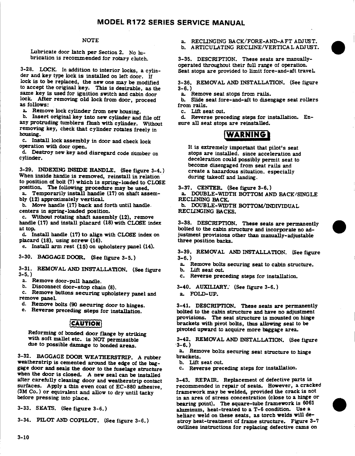
MODEL
R172
SERIES
SERVICE
MANUAL
NOTE
a.
RECLINGING
BACK/FORE-AND-AFT
ADJUST.
b.
ARTICULATING
RECLINE/VERTICAL
ADJUST.
Lubricate
door
latch
per
Section
2.
No
lu-
b
brication
is
recommended
for
rotary
clutch.
3-35.
DESCRIPTION.
These
seats
are
manually-
operated
throughout
their
full
range
of
operation.
3-28.
LOCK.
In
addition
to
interior
locks,
a
cylin-
Seat stops
are
provided
to
limit
fore-and-aft
traveL
der
and
key
type
lock
is
installed
on
left
door.
If
lock
is
to
be
replaced,
the
new
one
may be
modified
3-36.
REMOVAL
AND
INSTALLATION.
(See
figure
to
accept
the
original
key.
This
is
desirable,
as
the
3-6.)
same key
is
used
for
ignition
switch
and
cabin
door
a
Remove
seat
stops
from
rails.
lock.
After
removing
old
lock
from
door,
proceed
b.
Slide
seat
fore-and-aft
to
disengage
seat
rollers
as
follows:
from
rails.
a.
Remove
lock
cylinder
from
new
housing.
c.
Lift
seat
out.
b.
Insert
original
key
into
new
cylinder
and
file
off
d.
Reverse
preceding
steps for
installation.
En-
any
protruding
tumblers
flush
with
cylinder.
Without
sure
all
seat
stops
are
reinstalled.
removing
key,
check
that
cylinder
rotates freely
in
WARNI
housing.
c.
Install
lock
assembly
in
door
and
check
lock
operation
with
door
open.
It
is
extremely important
that
pilot's
seat
d.
Destroy
new
key
and disregard
code
number
on
stops
are
installed.
since
acceleration
and
cylinder,
deceleration
could
possibly
permit
seat
to
become disengaged
from
seat
rails
and
3-29.
INDEXING
INSIDE
HANDLE.
(See
figure
3-4.)
create
a
hazardous situation.
especially
When
inside
handle
is removed,
reinstall
in
relation
during
takeoff
and landing.
to
position
of
bolt
(7)
which
is
spring-loaded
to
CLOSE
position.
The following
procedure
may
be
used.
3-37.
CENTER.
(See
figure
3-6.)
a.
Temporarily
install
handle
(17)
on
shaft
assem-
a.
DOUBLE-WIDTH
BOTTOM
AND
BACK/SINGLE
bly
(12)
approximately
vertical
RECLINING
BACK.
b.
Move
handle
(17)
back
and
forth
until
handle.
b. DOUBLE-WIDTH
BOTTOM/INDIVIDUAL
centers
in
spring-loaded
position.
RECLIKNING
BACKS.
c.
Without
rotating
shaft
assembly
(12),
remove
handle
(17) and
install
placard
(18)
with
CLOSE
index
3-38.
DESCRIPTION.
These
seats
are
permanently
at
top.
bolted
to
the cabin
structure
and
incorporate
no
ad-
d.
Install
handle
(17)
to
align
with
CLOSE
index
on
justment
provisions
other
than
manually-adjustable
placard
(18),
using
screw
(16).
three
position
backs.
e.
Install
arm
rest
(15)
on
upholstery
panel
(14).
3-39.
REMOVAL
AND
INSTALLATION.
(See
figure
3-30.
BAGGAGE
DOOR.
(See
figure 3-5.)
3-6.)
a.
Remove
bolts
securing
seat
to
cabin
structure.
3-31.
REMOVAL
AND
INSTALLATION.
(See
figure
b.
Lift
seat
out.
3-5.)
c.
Reverse
preceding
steps for
installation.
a.
Remove
door-pull
handle.
b.
Disconnect
door-stop
chain
(8).
3-40.
AUXILIARY.'
(See
figure
3-6.)
c.
Remove
buttons
securing
upholstery
panel
and
a.
FOLD-UP.
remove
paneL
d.
Remove
bolts
(90
securing
door to
hinges. 3-41.
DESCRIPTION.
These
seats
are
permanently
e.
Reverse
preceding
steps
for
installation.
bolted
to
the
cabin
structure
and
have
no
adjustment
provisions.
The
seat
structure
is
mounted
on
hinge
CAUTION
brackets
with
pivot
bolts,
thus
allowing
seat
to
be
ReforminTofbonde
pivoted
upward
to
acquire more
baggage
area.
Reforming
of
bonded
door
flange
by
striking
with
soft
mallet
etc.
is
NOT
permissible
3-42.
REMOVAL
AND
INSTALLATION.
(See
figure
due
to
possible
damage
to bonded
areas.
3-6.)
a.
Remove
bolts
securing
seat
structure
to
hinge
3-32.
BAGGAGE
DOOR
WEATHERSTRIP.
A
rubber
brackets.
weatherstrip
is
cemented
around
the
edge
of
the
bag-
b.
Lift
seat
out.
gage
door
and
seals
the
door
to
the
fuselage
structure
c.
Reverse
preceding
steps
for
installation.
when
the
door
is
closed.
A
new
seal
can
be
installed
after
carefully
cleaning
door
and
weatherstrip
contact
3-43.
REPAIR.
Replacement
of
defective
parts
is
surfaces.
Apply
a
thin
even
coat
of
EC-880 adhesive,
recommended
in
repair
of
seats.
However,
a
cracked
(3M
Co.)
or
equivalent
and
allow
to
dry
until
tacky
framework
may
be
welded,
provided
the
crack
is
not
before
pressing
into
place.
in
an
area
of
stress
concentration
(close
to
a
hinge
or
bearing
point).
The
square-tube
framework is
6061
3-33. SEATS.
(See
figure
3-6.)
aluminum,
heat-treated
to
a
T-6
condition.
Use a
heliarc
weld
on
these
seats,
as
torch
welds
will
de-
3-34.
PILOT
AND
COPILOT.
(See
figure
3-6.)
stroy
heat-treatment
of
frame
structure.
Figure
3-7
outlines
instructions
for
replacing
defective
cams
on
3-10
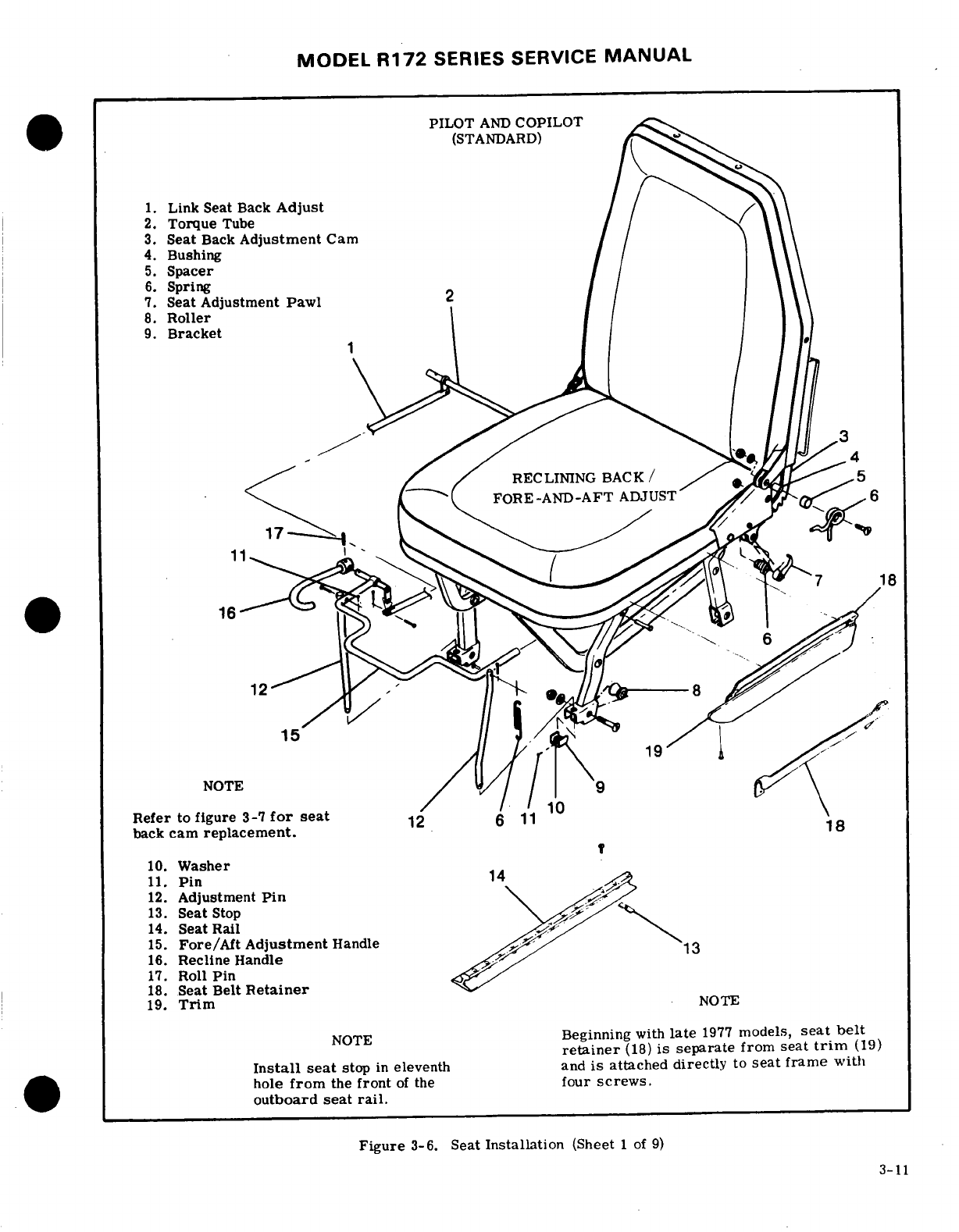
MODEL
R172
SERIES
SERVICE
MANUAL
PILOT
AND
COPILOT
(STANDARD)
1.
Link
Seat
Back
Adjust
2.
Torque
Tube
3.
Seat
Back
Adjustment
Cam
4.
Bushing
5.
Spacer
6.
Spring
7.
Seat
Adjustment Pawl
8.
Roller
9.
Bracket
RECLINING
BACK/
FORE-AND-AFT
ADJUST
17.w'
NOTE
Refer
to
figure
3-7
for
seat
back
cam
replacement.
10.
Washer
11.
Pin
12.
Adjustment
Pin
13.
Seat
Stop
14.
Seat
Rail
15.
Fore/Aft
Adjustment
Handle
,
16.
Recline
Handle
17.
Roll
Pin
18.
Seat
Belt
Retainer
19.
Trim
NOTE
Beginning
with
late
1977
models,
seat
belt
retainer
(18)
is
separate
from
seat
trim
(19)
Install
seat
stop
in
eleventh and
is
attached
directly
to
seat
frame
with
hole
from
the
front
of
the
four
screws.
outboard
seat
rail.
Figure
3-6.
Seat
Installation
(Sheet
1 of
9)
3-11
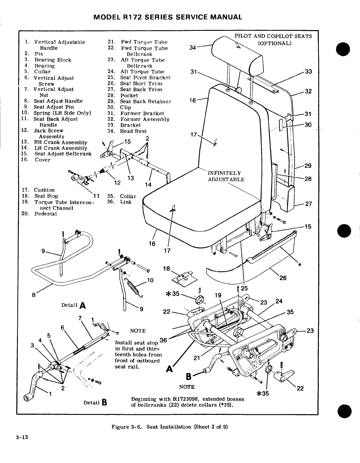
MODEL
R172
SERIES
SERVICE
MANUAL
PILOT
AND
COPILOT
SEATS
1.
Vertical
Adjustable
21.
Fwd
Torque
Tube
(OPTIONAL)
Handle
22.
Fwd
Torque
Tube
34
2.
Pin
Bellcrank
3.
Bearing
Block
23.
Aft
Torque Tube
4.
Bearing
Bellcrank
5.
Collar
24.
Aft
Torque
Tube
31
.
33
6.
Vertical
Adjust
25.
Seat
Pivot
Bracket
Screw
26.
Seat
Skirt
Trim
7.
Vertical
Adjust
27.
Seat
Back
Trim
32
Nut
28.
Pocket
8.
Seat
Adjust
Handle
29.
Seat
Back
Retainer
16
9.
Seat
Adjust
Pin
30.
Clip
10.
Spring
(LH
Side
Only)
31.
Former
Bracket
11.
Seat Back
Adjust
32.
Former
Assembly
Handle
33.
Bracket
12.
Jack
Screw
34.
Head
Rest
Assembly
2
13. RH
Crank Assembly
15
14.
LH
Crank
Assembly
15.
Seat
Adjust
Bellcrank
16.
Cover
29
INFINITELY
ADJUSTABLE
28
12
14
17.
Cushion
18.
Seat
Stop
11 35.
Collar
19.
Torque
Tube
Intercon-
36.
Link
27
nect
Channel
20.
Pedestal
35
19
25
Detail
A
24
Install
seat
stop
36
in
first
and
thir-
teenth
holes
from
front
of
outboard
seat
rail.
NOTE
22
*35
Beginning
with
R1723098,
extended
bosses
of
bellcranks
(22)
delete
collars
(*35).
Figure
3-6.
Seat
Installation
(Sheet
2
of
9)
3-12
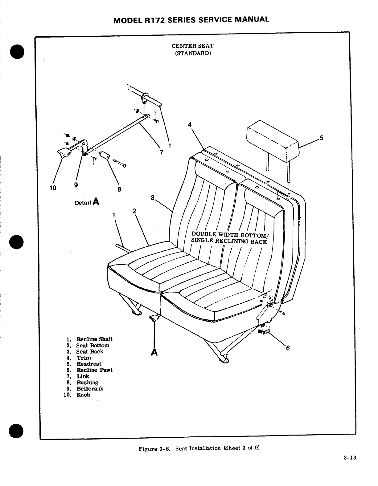
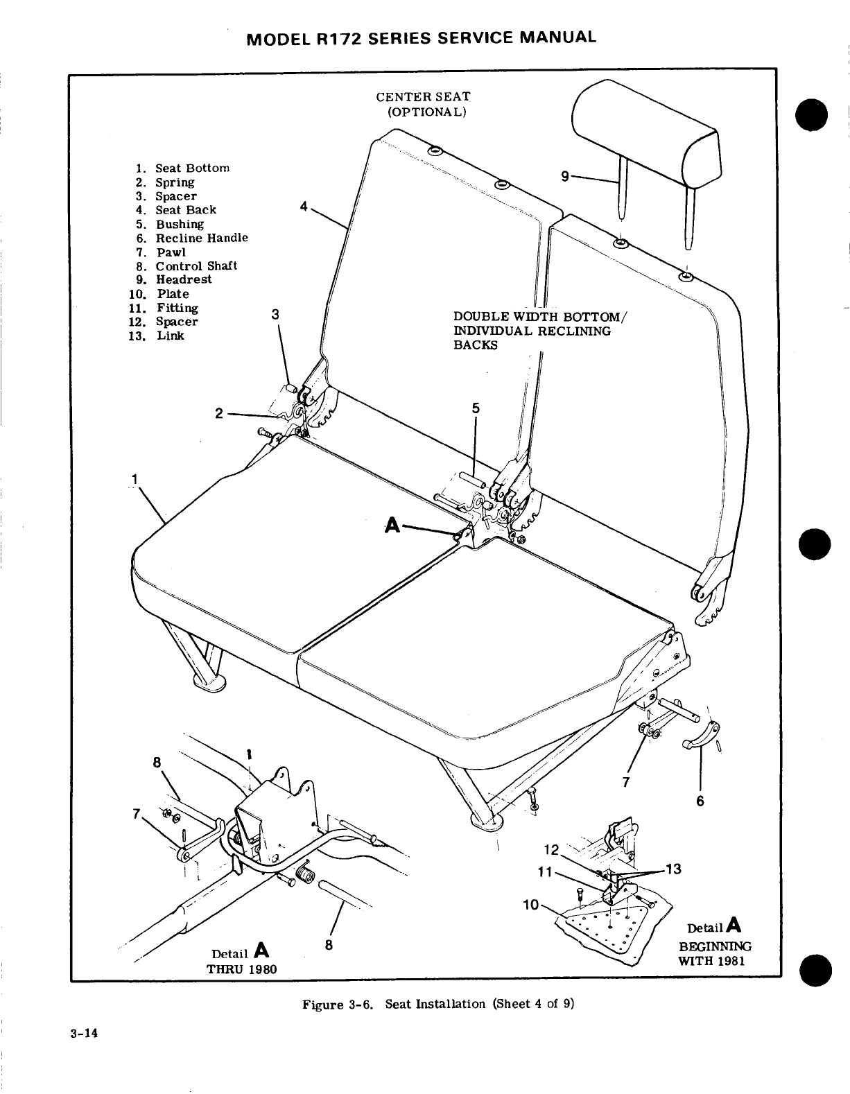
MODEL
R172
SERIES SERVICE
MANUAL
CENTER
SEAT
(OPTIONAL)
1.
Seat
Bottom
2.
Spring
9
3.
Spacer
4.
Seat
Back
5.
Bushing
6.
Recline
Handle
7.
Pawl
8.
Control
Shaft
9.
Headrest
10.
Plate
13.
Link
INDiVIDUAL
RECLINING
THRU
1980
WITH
1981
Figure
3-6. Seat
Installation
(Sheet
4
of
9)
BEGINNING
THRU 1980
WITH
1981
Figure
3-6.
Seat
Installation
(Sheet
4
of
9)
3-14
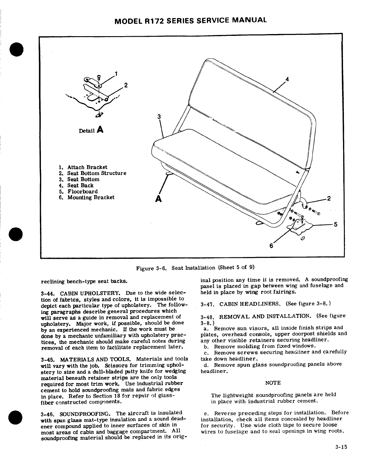
MODEL
R172
SERIES SERVICE
MANUAL
Detail
A
1.
Attach
Bracket
2.
Seat
Bottom
Structure
,,
3.
Seat
Bottom
4.
Seat
Back
5.
Floorboard
6.
Mounting
Bracket
Figure
3-6.
Seat
Installation
(Sheet
5
of
9)
reclining
bench-type
seat
backs.
inal position
any
time
it is
removed.
A
soundproofing
panel
is
placed
in
gap
between
wing
and
fuselage
and
3-44.
CABIN
UPHOLSTERY.
Due
to
the
wide
selec-
held
in
place
by
wing
root
fairings.
tion
of
fabrics, styles
and
colors,
it
is
impossible
to
depict
each
particular
type
of
upholstery.
The
follow-
3-47.
CABIN
HEADLINERS.
(See
figure
3-8.)
ing
paragraphs describe
general
procedures
which
will
serve
as
a
guide
in
removal
and
replacement
of
3-48.
REMOVAL
AND
INSTALLATION.
(See
figure
upholstery.
Major work,
if
possible,
should
be
done
3-8.)
by
an
experienced
mechanic.
If
the
work
must
be
a.
Remove
sun
visors,
all
inside
finish
strips
and
done
by
a
mechanic
unfamiliary
with
upholstery
prac-
plates,
overhead console,
upper
doorpost
shields
and
tices,
the
mechanic
should make
careful
notes
during
any
other
visible
retainers
securing
headliner.
removal
of
each
item
to
facilitate
replacement
later.
b.
Remove
molding
from
fixed
windows.
c.
Remove
screws
securing
headliner
and
carefully
3-45.
MATERIALS
AND
TOOLS.
Materials
and
tools
take
down
headliner.
will
vary
with
the
job.
Scissors
for
trimming
uphol-
d.
Remove
spun
glass
soundproofing
panels
above
stery
to
size
and a
dull-bladed
putty
knife
for
wedging
headliner.
material
beneath
retainer
strips
are
the
only
tools
required
for
most
trim
work.
Use
industrial rubber
NOTE
cement
to
hold
soundproofing
mats
and
fabric
edges
in
place.
Refer
to
Section
18
for
repair
of
glass-
The
lightweight
soundproofing panels
are
held
fiber constructed
components.
in
place
with
industrial
rubber
cement.
3-46.
SOUNDPROOFING.
The
aircraft
is
insulated
e.
Reverse
preceding
steps
for
installation.
Before
with
spun
glass
mat-type
insulation
and
a
sound
dead-
installation,
check
all
items
concealed
by
headliner
ener
compound
applied
to
inner
surfaces
of
skin
in
for security.
Use
wide
cloth
tape
to
secure
loose
most
areas
of
cabin
and
baggage
compartment.
All wires
to
fuselage
and
to
seal
openings in wing
roots.
soundproofing
material
should
be
replaced
in
its orig-
3-15
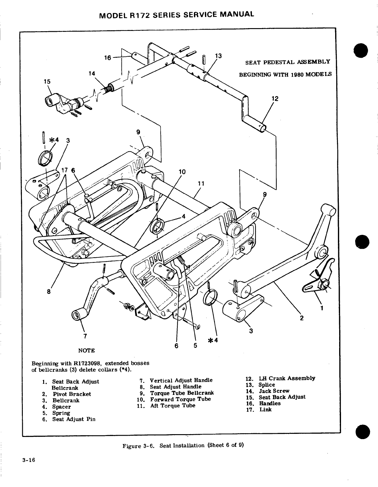
MODEL
R172
SERIES
SERVICE
MANUAL
SEAT
PEDESTAL
ASSEMBLY
^BEGINNING
WITH
1980
MODELS
3
NOTE
Beginning
with
R1723098,
extended
bosses
of
bellcranks
(3)
delete
collars
(*4).
1.
Seat Back
Adjust
7.
Vertical
Adjust
Handle
12.
LH
Crank
Assembly
Bellcrank
8.
Seat
Adjust
Handle
13.
Splice
2.
Pivot
Bracket
9.
Torque
Tube
Bellcrank
14.
Jack
Screw
3.
Bellcrank
10.
Forward
Torque
Tube
15.
Seat
Back
Adjust
4.
Spacer
11.
Aft
Torque
Tube
16.
Handles
5.
Spring
17.
Link
6.
Seat
Adjust
Pin
Figure
3-6.
Seat
Installation
(Sheet
6
of
9)
3-16
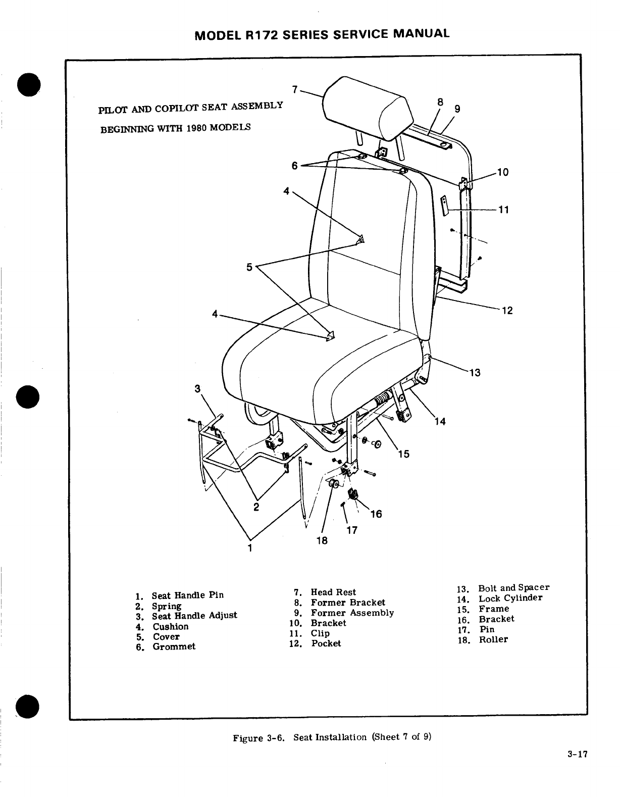
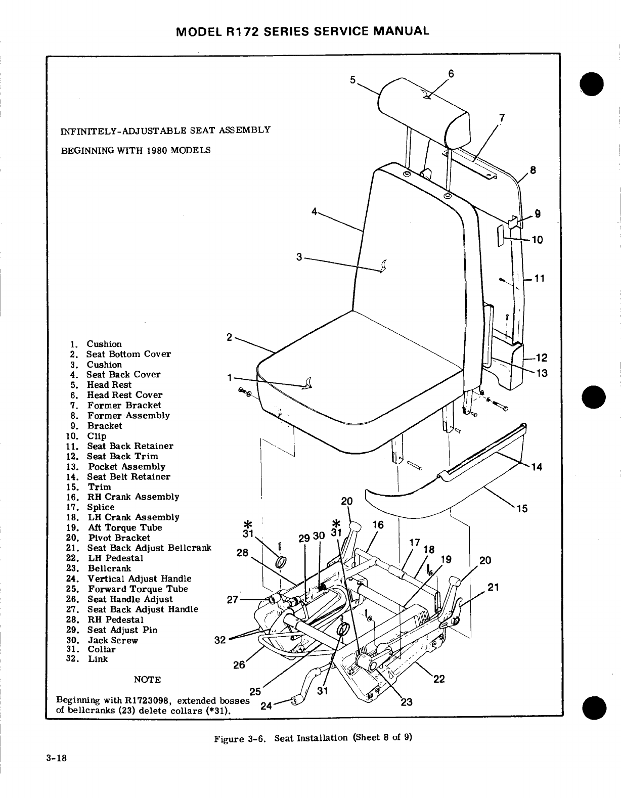
MODEL
R172
SERIES
SERVICE
MANUAL
INFINITELY-ADJUSTABLE
SEAT
ASSEMBLY
BEGINNING
WITH
1980
MODELS
10
1.
Cushion
2.
Seat
Bottom
Cover
3.
Cushion
12
4.
Seat
Back
Cover
13
5.
Head
Rest
6.
Head
Rest
Cover
7.
Former
Bracket
8.
Former
Assembly
9.
Bracket
10.
Clip
11.
Seat
Back
Retainer
12.
Seat
Back
Trim
13.
Pocket
Assembly
14
14.
Seat
Belt
Retainer
15.
Trim
16.
RH
Crank
Assembly
17.
Splice
18.
LH
Crank
Assembly
19.
Aft
Torque Tube
20.
Pivot
Bracket
31
3
31
21.
Seat
Back
Adjust
Bellcrank
17
22.
LH
Pedestal
19
23.
Bellcrank
24.
Vertical
Adjust
Handle
25.
Forward
Torque
Tube
21
26.
Seat
Handle
Adjust
27
27.
Seat
Back
Adjust
Handle
28. RH
Pedestal
29.
Seat
Adjust
Pin
30.
Jack
Screw
32
31.
Collar
32.
Link
NOTE
22
Beginning
with
R1723098,
extended
bosses
23
of
bellcranks
(23)
delete
collars
(*31).
24
Figure
3-6.
Seat
Installation
(Sheet
8
of
9)
3-18
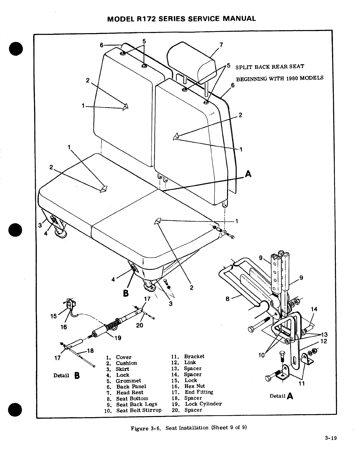
MODEL
R172
SERIES
SERVICE
MANUAL
SPLIT
BACK
REAR
SEAT
BEGINNING
WITH
1980
MODELS
3
8
1.
Cover
11.
Bracket
2.
Cushion
12.
Link
3.
Skirt
13.
Spacer
Detail
B
4.
Lock
14.
Spacer
5.
Grommet
15.
Lock
6.
Back
Panel
16.
Hex
Nut
11
7.
Head
Rest
17.
End
Fitting
8.
Seat
Bottom
18.
Spacer
DetailA
9.
Seat
Back Legs
19.
Lock
Cylinder
10.
Seat
Belt
Stirrup
20.
Spacer
Figure
3-6.
Seat
Installation
(Sheet
9 of
9)
3-19
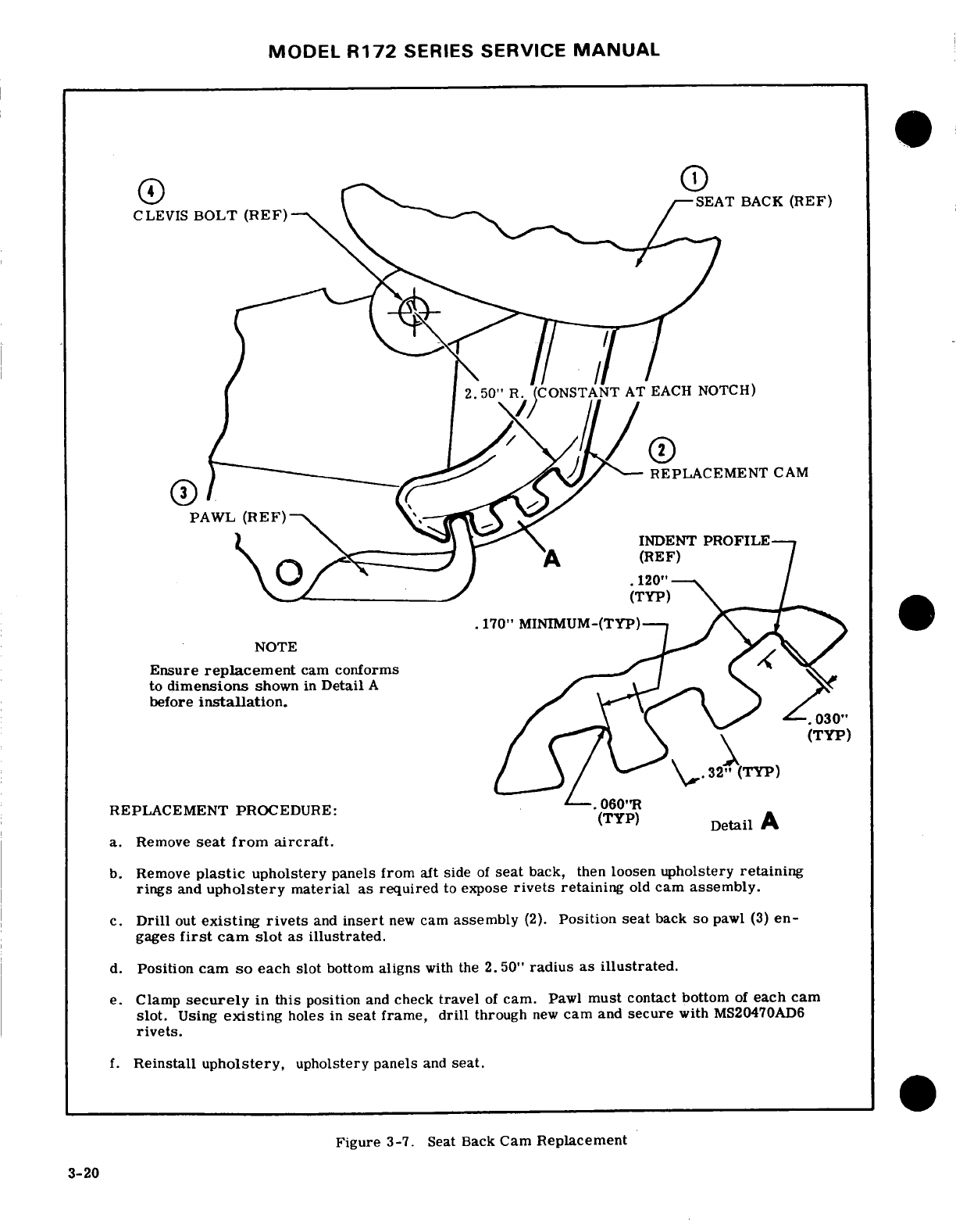
MODEL
R172
SERIES
SERVICE
MANUAL
SEAT
BACK
(REF)
CLEVIS
BOLT
(REF)-
50"
R.
(CONSTANT
AT EACH NOTCH)
(E) Z
-REPLACEMENT
CAM
PAWL
(REF)
INDENT
PROFILE
(TYP)
.170"
MINIMUM-(TYP)
NOTE
Ensure
replacement
cam
conforms
to
dimensions
shown
in
Detail
A
before
installation.
REPLACEMENT
PROCEDURE:
-. 060"R
(TYP)
Detail
A
a.
Remove
seat from
aircraft.
b.
Remove
plastic
upholstery
panels from
aft
side
of
seat
back,
then
loosen
upholstery
retaining
rings
and
upholstery
material
as
required
to
expose
rivets
retaining
old
cam
assembly.
c.
Drill
out
existing
rivets
and
insert
new
cam
assembly
(2).
Position seat
back
so
pawl (3)
en-
gages
first
cam slot
as
illustrated.
d.
Position
cam
so
each
slot
bottom
aligns
with
the
2.
50"
radius
as
illustrated.
e.
Clamp
securely
in
this
position
and
check
travel
of
cam.
Pawl
must
contact
bottom
of
each
cam
slot.
Using
existing
holes
in
seat
frame,
drill
through
new
cam
and
secure
with
MS20470AD6
rivets.
f.
Reinstall
upholstery,
upholstery
panels
and
seat.
Figure
3-7.
Seat
Back
Cam
Replacement
3-20
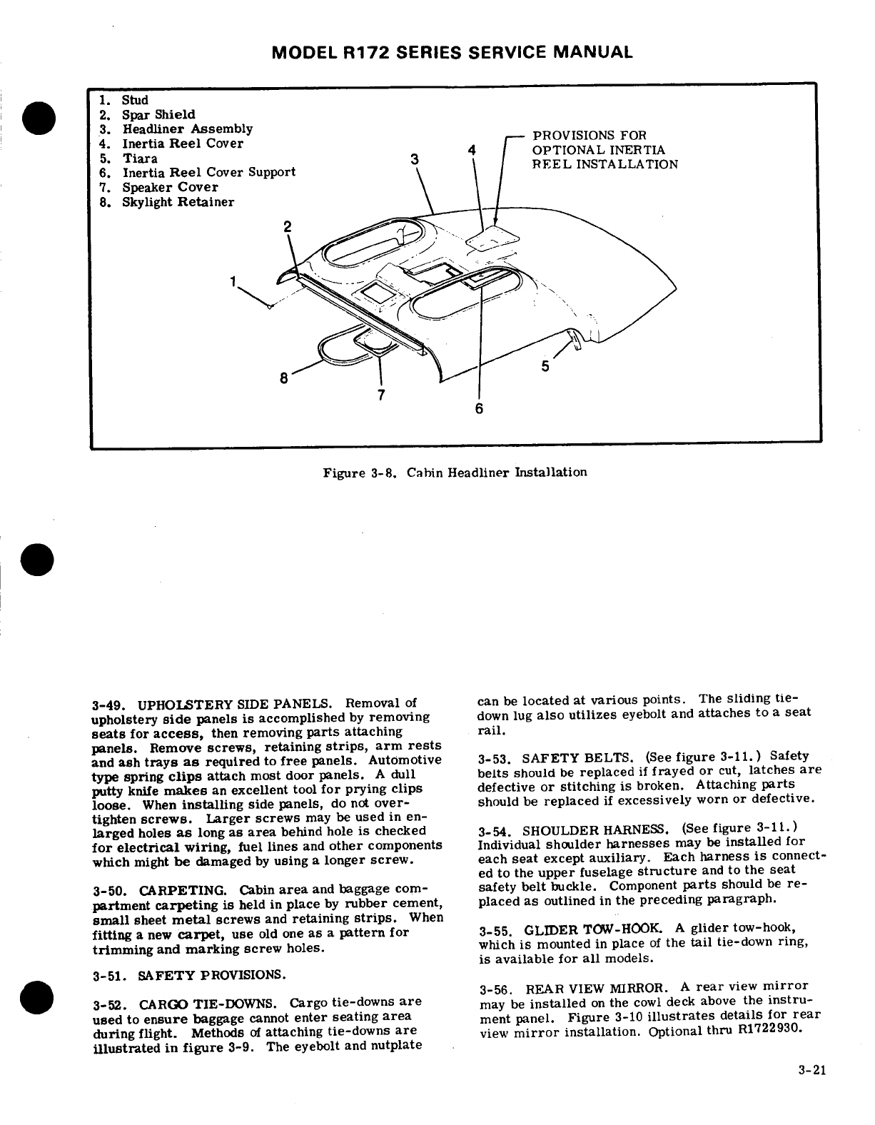
MODEL
R172
SERIES
SERVICE
MANUAL
1.
Stud
2.
Spar
Shield
3.
Headliner
Assembly
4.
Inertia
Reel
Cover
PROVISIONS FOR
5.
Tiara
OPTIONAL
INERTIA
6.
Inertia
Reel
Cover
Support
REEL
INSTALLATION
7.
Speaker
Cover
8.
Skylight
Retainer
Figure
3-8.
Cabin
Headliner
Installation
3-49.
UPHOLSTERY
SIDE
PANELS.
Removal
of
can
be
located
at
various
points.
The
sliding
tie-
upholstery
side
panels
is
accomplished
by
removing
down
lug
also
utilizes
eyebolt
and
attaches to
a
seat
seats
for
access,
then
removing
parts
attaching
rail.
panels.
Remove
screws,
retaining
strips,
arm
rests
and
ash
trays
as
required
to
free
panels.
Automotive
3-53.
SAFETY
BELTS.
(See
figure
3-11.)
Safety
type
spring
clips
attach
most
door
panels.
A
dull
belts
should
be
replaced
if
frayed
or
cut,
latches
are
putty
knife
makes
an
excellent
tool
for
prying
clips
defective
or
stitching
is
broken. Attaching
parts
loose.
When
installing
side
panels,
do not
over-
should
be
replaced
if
excessively
worn
or defective.
tighten
screws.
Larger
screws
may
be
used
in
en-
larged
holes
as
long
as
area
behind
hole
is
checked
3-54.
SHOULDER
HARNESS.
(See
figure
3-11.)
for
electrical
wiring,
fuel
lines
and
other
components
Individual
shoulder
harnesses
may
be
installed
for
which
might
be
damaged
by
using
a
longer
screw.
each
seat
except
auxiliary.
Each
harness
is
connect-
ed
to
the
upper
fuselage
structure
and
to
the seat
3-50.
CARPETING.
Cabin
area
and
baggage
com-
safety
belt
buckle.
Component
parts
should
be
re-
partment
carpeting
is
held
in
place
by
rubber
cement,
placed
as
outlined
in
the
preceding
paragraph.
small
sheet
metal
screws
and
retaining
strips.
When
fitting
a
new
carpet,
use
old one
as
a
pattern
for
3-55.
GLIDER
TOW-HOOK.
A
glider
tow-hook,
trimming
and
marking
screw
holes.
which
is
mounted
in
place
of
the
tail
tie-down
ring,
is
available
for
all
models.
3-51.
SAFETY
PROVISIONS.
i
REAR
VIEW
MIRROR.
A
rear
view
mirror
3-52.
CARGO
TIE-DOWNS.
Cargo
tie-downs
are
may
be
installed
on
the
cowl
deck
above
the
instru-
used
to
ensure
baggage
cannot
enter
seating
area
ment
panel.
Figure
3-10
illustrates
details
for
rear
during
flight.
Methods
of
attaching
tie-downs
are
view
mirror
installation.
Optional
thru
R1722930.
illustrated
in
figure
3-9.
The
eyebolt
and
nutplate
3-21
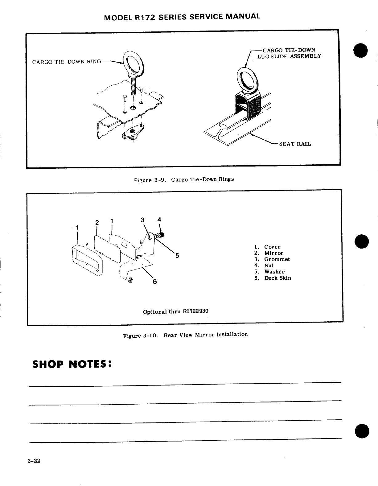
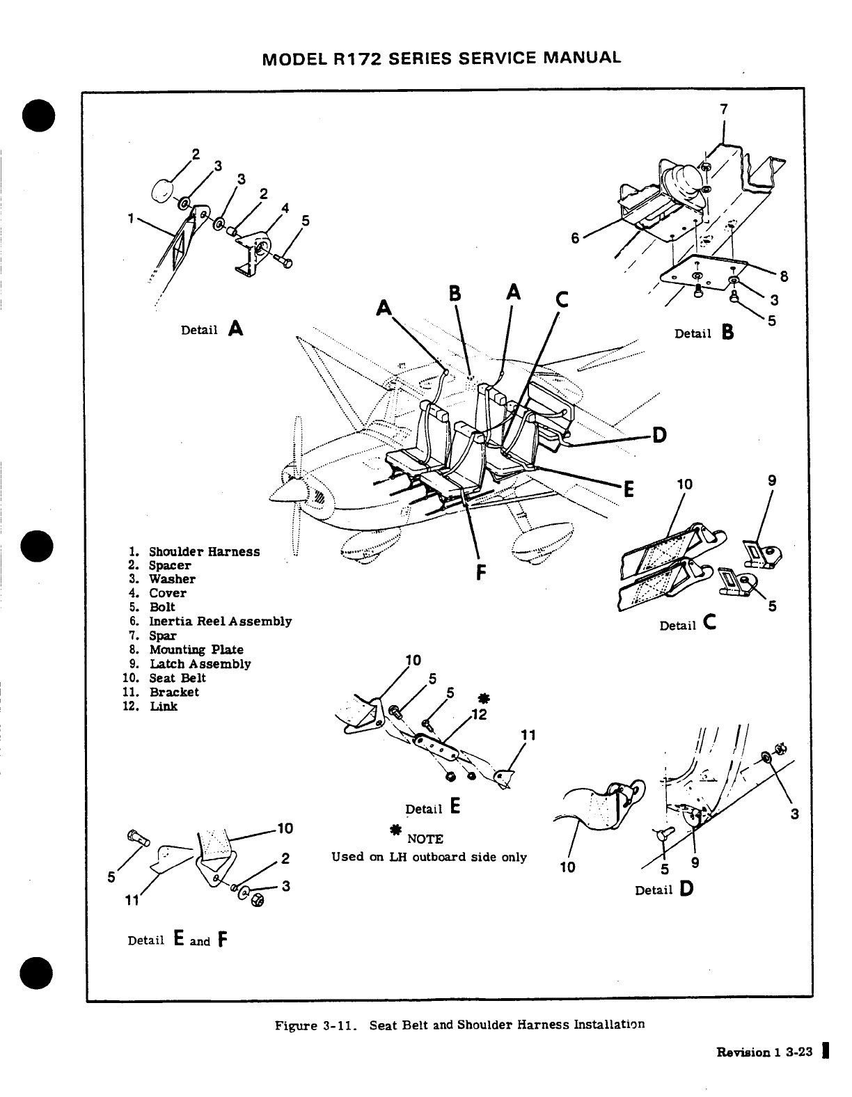
MODEL
R172
SERIES
SERVICE
MANUAL
/
Detail
B
1.
Shoulder
Harness
..-
1
2.
Spacer
3.
Washer
4.
Cover
5.
Bolt
6.
Inertia
Reel
Assembly
7.
Spar
8.
Mounting
Plate
9.
Latch
Assembly
10
10.
Seat Belt
11.
Bracket
12.
Link
Detail
E
*
NOTE
Used
on
LH
outboard
side
only
Detail
D
Detail
E
and
F
Figure
3-11.
Seat
Belt
and
Shoulder
Harness
Installation
Revision
1 3-23
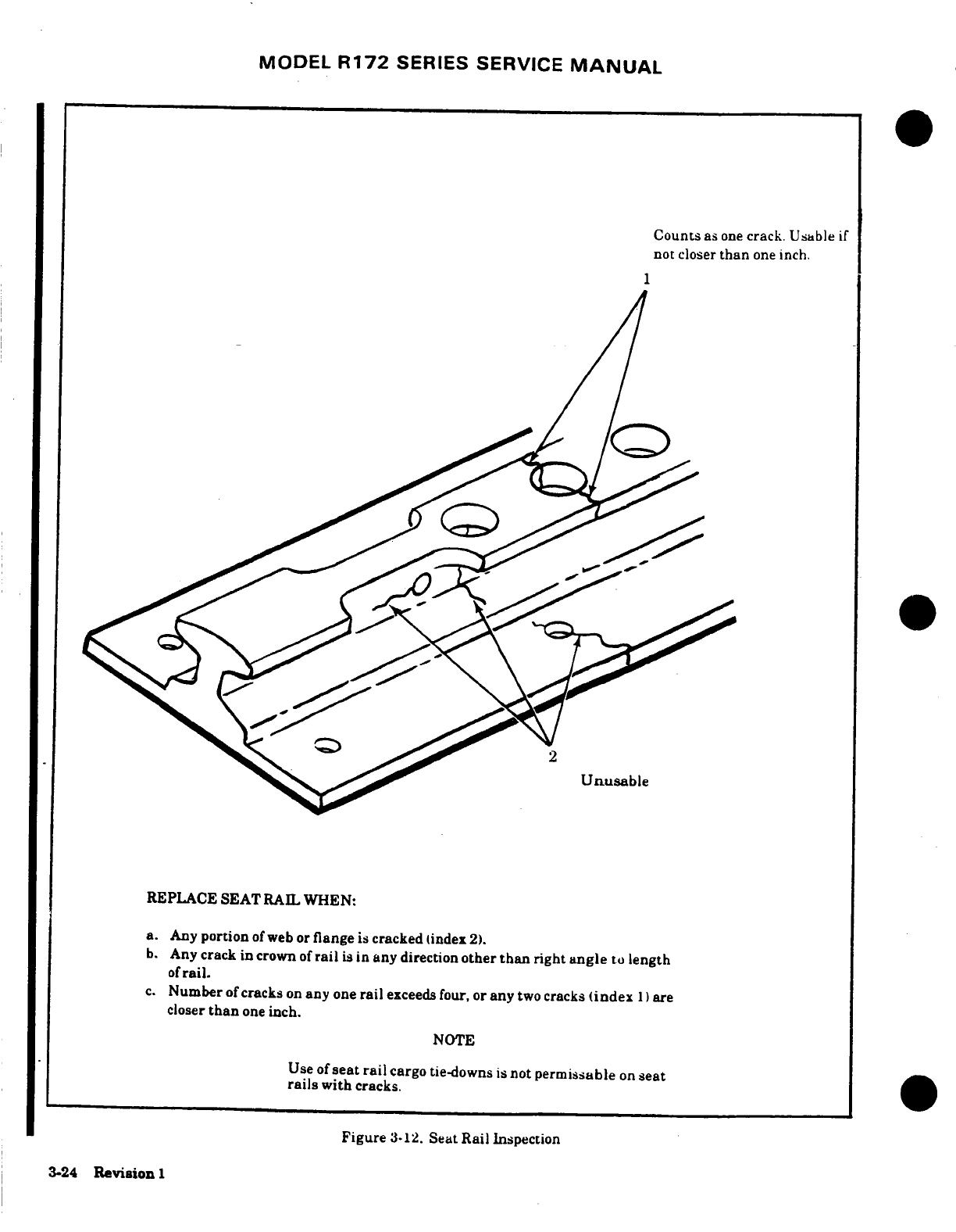
MODEL
R172
SERIES
SERVICE
MANUAL
Counts
as
one
crack. Usable
if
not
closer
than
one
inch.
1
Unusable
REPLACE
SEAT
RAIL
WHEN:
a.
Any
portion
of
web
or
flange
is
cracked
tindex
2).
b.
Any
crack in
crown
of
rail
is
in
any
direction
other
than
right
angle
to
length
of
rail.
c.
Number
of
cracks
on
any
one
rail
exceeds
four, or
any
two
cracks
(index
1)
are
closer
than
one
inch.
NOTE
Use
of
seat
rail
cargo
tie-downs
is
not
permissable
on
seat
rails
with
cracks.
Figure
3-12.
Seat
Rail
Inspection
3-24
Revision
1
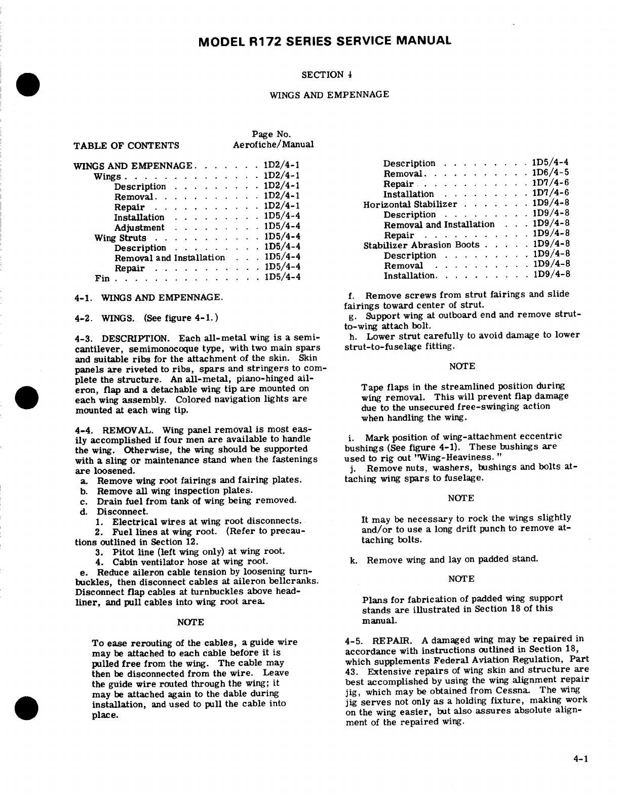
MODEL
R172
SERIES SERVICE
MANUAL
SECTION
4
WINGS
AND
EMPENNAGE
Page
No.
TABLE
OF
CONTENTS
Aerofiche/Manual
WINGS
AND
EMPENNAGE
.
......
D2/4-1
Description
.........
1D5/4-4
Wings
............
.
1D2/4-1
Removal
.........
. 1D6/4-5
Description
.........
1D2/4-1
Repair
...........
1D7/4-6
Removal
...........
1D2/4-1
Installation
.........
1D7/4-6
Repair
...........
D2/4-1
Horizontal Stabilizer
.......
D9/4-8
Installation
.........
1D5/4-4
Description........
1D9/4-8
Adjustment
.........
1D5/4-4
Removal
and
Installation
. . .1D9/4-8
Wing
Struts
.......
...
1D5/4-4
Repair
...........
1D9/4-8
Description
.........
1D5/4-4
Stabilizer
Abrasion
Boots
.....
1D9/4-8
Removal
and
Installation
..
1D5/4-4
Description
.......
1.D9/4-8
Repair
...........
1D5/4-4
Removal
..........
1D9/4-8
Fin
...............
.
1D5/4-4
Installation
....
.1D9/4-8
4-1.
WINGS
AND
EMPENNAGE.
f.
Remove
screws
from
strut
fairings
and
slide
fairings
toward
center
of
strut.
4-2.
WINGS.
(See
figure 4-1.)
g.
Support
wing
at
outboard
end
and
remove
strut-
to-wing
attach
bolt.
4-3.
DESCRIPTION.
Each
all-metal
wing
is
a
semi-
h.
Lower
strut
carefully
to
avoid
damage
to
lower
cantilever,
semimonocoque
type, with
two
main
spars strut-to-fuselage
fitting.
and
suitable
ribs
for
the
attachment
of
the
skin.
Skin
panels
are
riveted
to
ribs,
spars
and
stringers
to
cor-
NOTE
plete
the
structure.
An
all-metal,
piano-hinged
ail-
eron,
flap
and
a
detachable
wing
tip
are
mounted
on
Tape
flaps
in
the
streamlined
position
during
each
wing
assembly.
Colored
navigation lights
are
wing
removal.
This
will
prevent
flap
damage
mounted
at
each
wing
tip.
due
to
the
unsecured free-swinging
action
when
handling
the
wing.
4-4.
REMOVAL.
Wing
panel
removal
is
most
eas-
ily
accomplished
if
four
men
are
available
to handle
i.
Mark
position
of
wing-attachment
eccentric
the
wing.
Otherwise,
the
wing
should
be
supported
bushings
(See
figure
4-1).
These
bushings
are
with
a sling
or
maintenance
stand
when the
fastenings
used
to
rig
out
"Wing-Heaviness.
"
are
loosened.
j.
Remove
nuts,
washers,
bushings
and
bolts
at-
a.
Remove
wing
root
fairings
and
fairing
plates.
taching
wing
spars
to
fuselage.
b.
Remove
all
wing
inspection
plates.
c.
Drain
fuel
from
tank
of
wing
being
removed.
NOTE
d.
Disconnect.
1.
Electrical
wires
at
wing
root
disconnects.
It
may
be
necessary
to
rock
the
wings
slightly
2.
Fuel
lines
at
wing
root.
(Refer
to
precau-
and/or
to
use
a
long
drift
punch
to
remove
at-
tions
outlined
in
Section
12.
taching
bolts.
3.
Pitot
line
(left
wing
only)
at
wing
root.
4.
Cabin
ventilator
hose
at
wing
root.
k.
Remove
wing
and
lay
on
padded
stand.
e.
Reduce
aileron
cable
tension
by
loosening
turn-
buckles,
then
disconnect
cables
at
aileron
bellcranks.
NOTE
Disconnect flap cables at
turnbuckles
above
head-
liner,
and
pull cables
into
wing
root
area.
Plans
for fabrication
of
padded
wing
support
stands
are
illustrated
in
Section
18
of
this
NOTE
manual.
To
ease rerouting
of
the
cables,
a
guide
wire
4-5.
REPAIR.
A
damaged
wing
may
be
repaired
in
may
be
attached
to
each
cable
before
it
is
accordance
with
instructions
outlined
in
Section
18,
pulled
free
from
the
wing.
The
cable
may which
supplements
Federal
Aviation
Regulation,
Part
then
be
disconnected
from
the
wire.
Leave
43.
Extensive
repairs
of
wing
skin
and
structure
are
the guide
wire
routed through
the
wing;
it
best
accomplished
by
using
the
wing
alignment
repair
may
be
attached
again
to
the
dable
during jig,
which
may
be
obtained
from
Cessna.
The
wing
installation,
and
used
to
pull
the
cable
into
jig
serves
not
only
as
a
holding
fixture,
making
work
place.
on
the
wing
easier,
but
also
assures
absolute
align-
ment
of
the
repaired
wing.
4-1
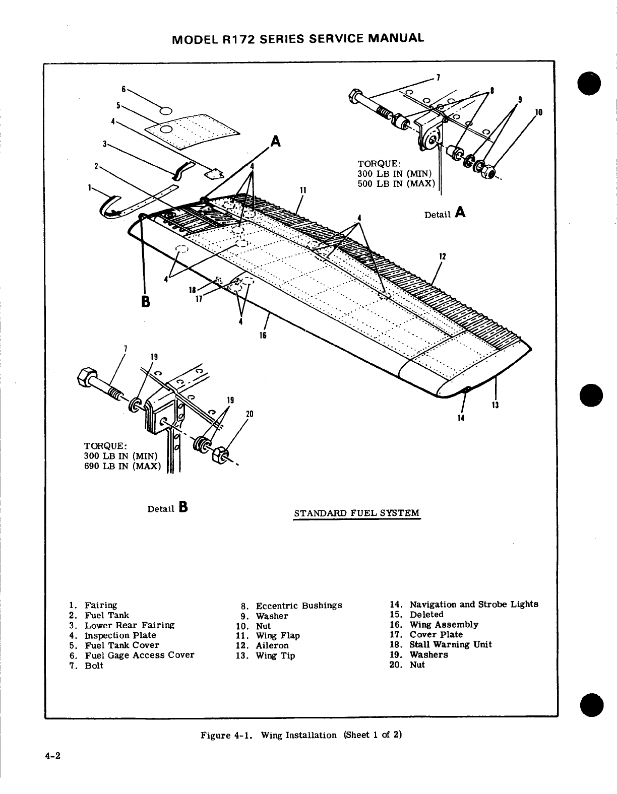
MODEL
R172
SERIES
SERVICE
MANUAL
B
-- --
2.
5.
Fuel
Tank
Cover
12.
Aileron
18.
Stall
Warning
Unit
6.
Fuel
Gage
Access
Cover
13.
Wing
Tip
19.
Washers
7.
STANDARD
FUEL
SYSTEM
1.
Fairing
8.
Eccentric
Bushings
14.
Navigation
and
Strobe Lights
2.
Fuel
Tank
9.
Washer
15.
Deleted
3.
Lower
Rear
Fairing
10.
Nut
16.
Wing
Assembly
4.
Inspection
Plate
11.
Wing
Flap
17.
Cover
Plate
5.
Fuel
Tank
Cover
12.
Aileron
18.
Stall
Warning
Unit
6.
Fuel
Gage
Access
Cover
13.
Wing
Tip
19.
Washers
7.
Bolt
20. Nut
Figure
4-1.
Wing
Installation
(Sheet
1
of
2)
4-2
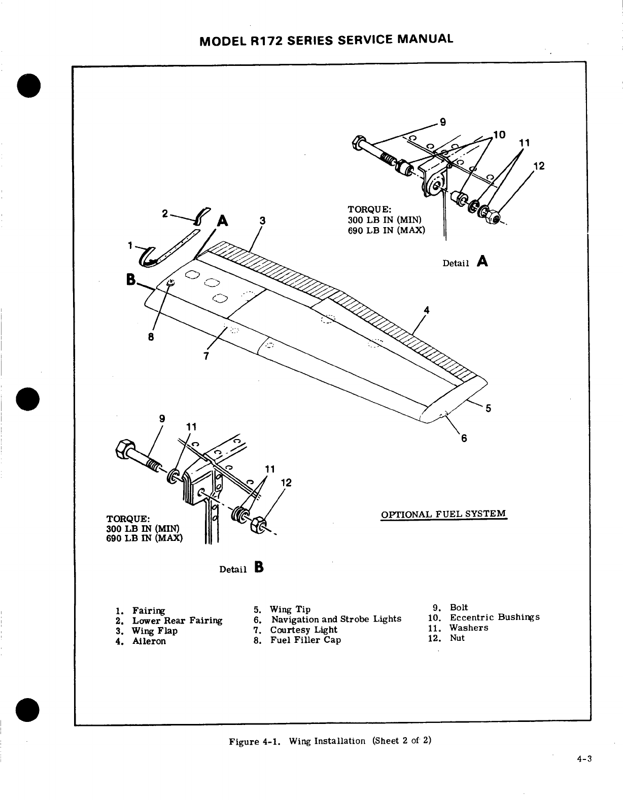
MODEL
R172
SERIES SERVICE
MANUAL
300
LB
IN
(MIN)
690
LB
IN
(MAX)
TORQUE:
OPTIONAL
FUEL
SYSTEM
300
LB
IN
(MIN)
690
LB
IN
(MAX)
Detail
B
1.
Fairing
5.
Wing
Tip
9.
Bolt
2.
Lower
Rear
Fairing
6.
Navigation
and
Strobe Lights
10.
Eccentric
Bushings
3.
Wing
Flap
7.
Courtesy
Light
11.
Washers
4.
Aileron
8.
Fuel
Filler
Cap
12.
Nut
Figure
4-1.
Wing
Installation
(Sheet
2
of
2)
4-3
MODEL
R172
SERIES
SERVICE
MANUAL
4-6.
INSTALLATION.
(See
figure
4-1.)
control
wheel
pressure
is
required
to
keep
the
wings
level
in
normal
flight,
a
wing-heavy condition
exists.
NOTE
a. Remove
wing
fairing
strip
on
the
wing-heavy
side
of
the
aircraft.
The
forward
wing
spar
fittings
are
attached
to
b.
Loosen
nut
(10)
and
rotate
bushings
(8)
simul-
the
fuselage
fittings
with
AN8-23
bolts,
and the
taneously until
the
bushings
are
positioned
with
the
aft
wing
spar
fittings
are
attached
to
the
fuse-
thick
side
of the
eccentrics
up.
This
will
lower
the
lage
fittings
with AN7-24
bolts.
Minimum
trailing
edge
of
the
wing,
and
decrease
wing-heavi-
torque
on
the AN8-23
bolts
is
300
lb-in
and
ness
by
increasing
angle-of-incidence
of
the
wing.
the
maximum
torque
is
690
lb-in.
Minimum
torque
on the
AN7-24
bolts
is
300
lb-in,
and
CAUTION
the
maximum
torque
is
500
lb-in.
Be
sure
to
rotate
the
eccentric
bushings
simul-
NOTE
taneously.
Rotating
them
separately
will
de-
stroy
the
alignment
between
the
off-center
bolt
Upon
installation-of bolts,
-coat
holes
and
holes
in
the
bushings,
thus
exerting
a
shearing
bolts
lightly
with
Electro-Moly
No.
11
force
on
the
bolt,
with
possible
damage
to the
(MIL-G-121164)
grease.
hole
in
the
wing
spar.
a.
Hold
wing
in
position
and
install
bolts,
bushings,
c.
Torque
nut
(10)
and
reinstall
fairing
strip.
washers
and
nuts
attaching
wing
spars
to
fuselage
d.
Test-fly
the
aircraft.
If
the
wing-heavy
condi-
fittings.
Ensure
eccentric
bushings
are
positioned
tion
still
exists,
remove
fairing
strip
on
the
"lighter"
as
marked.
Torque
nuts
to
values stipulated
in
note
wing,
loosen
nut,
and
rotate
bushings
simultaneously
preceding
this
step.
until
the
bushings
are
positioned
with
the
thick
side
b.
Install
bolts,
spacers,
and
nuts
to
secure
upper
of
the
eccentrics
down.
This
will
raise
the
trailing
and
lower
ends
of
wing
strut
to
wing
and
fuselage
edge
of
the
wing,
thus
increasing wing-heaviness
to
fittings.
balance
heaviness
in
the
opposite
wing.
e.
Torque
nut
(10),
install
fairing
strip,
and
repeat
NOTE
flight
test.
Upon
installation
of
bolts,
coat
holes
and
4-8.
WING
STRUTS.
(See
figure 4-2.)
bolts
lightly
with
Electro-Moly
No.
11
(MIL-G-121164)
grease.
4-9.
DESCRIPTION.
Each
wing
has
a
single
lift
strut
which
transmits
a
part
of
the
wing
load
to
the
NOTE
lower
portion
of
the
fuselage.
The
strut
consists
of
a
streamlined
tube
riveted
to
two
end
fittings
for
at-
Seal
opening
in
fuselage
skin
around
lower
tachment
at
the
fuselage
and wing.
wing
strutfitting
with
579.
6
Sealer
(Inmont
Corp.,
St.
Louis,
Missouri)
or
equivalent.
4-10.
REMOVAL
AND
INSTALLATION.
a.
Remove
screws
from
strut
fairings
and
slide
a.
Route
flap
and
aileron cables,
using
guide
wires.
fairings
along
strut.
(See
note
in
paragraph
4-4.)
b.
Remove
fuselage
and
wing
inspection plates
at
d.
Connect:
strut
junction
points.
1.
Electrical wires
at
wing
root
disconnects.
c.
Support
wing
securely,
then
remove
nut
and
bolt
2.
Fuel
lines
at
wing
root.
(Refer
to
precau-
securing
strut
to
fuselage.
tions
outlined
in
Section
12).
d.
Remove nut,
bolt,
and
spacer
used
to
attach
3.
Pitot
line
(if
left
wing
is
being
installed).
strut
to
wing,
then
remove
strut
from
aircraft.
e.
Rig
aileron
system.
(Section
6.)
e.
Reverse
preceding
steps
to
install
strut.
f.
Rig
flap
system
(Section
7.)
g.
Refuel
wing
tank
and
check
for
leaks.
(Refer to
NOTE
precautions
outlined
in
Section
12.)
h.
Check
operation
of
wing
tip
lights.
Seal
opening
in
fuselage
skin
around
lower
i.
Check
operation
of
fuel
gage.
wing
strut
fitting
with
579.
6
Sealant
(Inmont
j.
Install
wing
root
fairings. Corp.,
St.
Louis, Missouri)
or
equivalent.
NOTE
4-11.
REPAIR.
Wing
strut
repair
is
limited
to
re-
placement
of
tie-downs
and
attaching
parts.
A
badly
Be
sure
to
insert
soundproofing
panel
in
wing
dented,
cracked,
or
deformed
wing
strut
should
be
gap,
if
such
a
panel
was
installed
originally,
replaced.
before replacing
wing
root
fairings.
4-12.
FIN.
(See
figure
4-3.)
k.
Install
all
wing
inspection
plates,
interior
panels
and
upholstery.
4-13.
DESCRIPTION.
The
fin
is
primarily
of
metal
construction,
consisting
of
ribs
and
spars
covered
4-7.
ADJUSTMENT (CORRECTING
"WING-HEAVY"
with
skin. Fin
tips
are
of
ABS
construction.
Hinge
CONDITION.)
(See
figure
4-1.)
If
considerable
brackets
at
the
fin
rear
spar
attach
the
rudder.
4-4
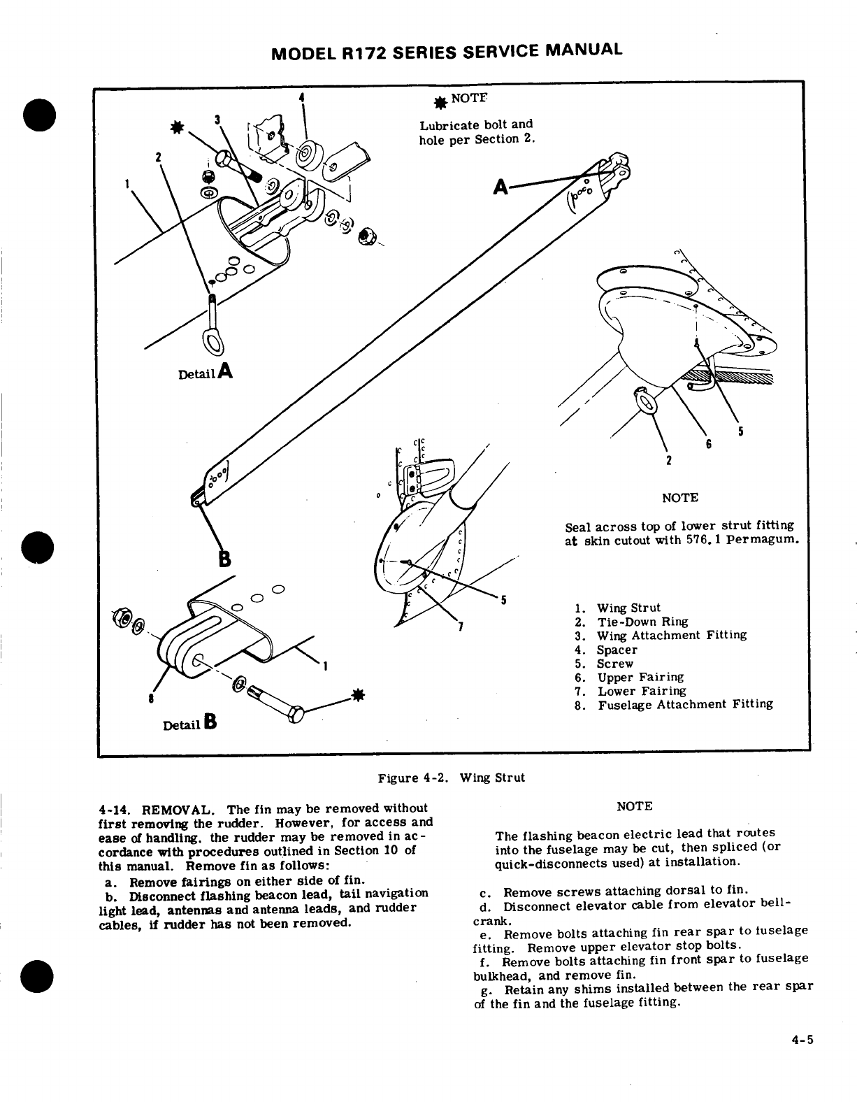
MODEL
R172
SERIES
SERVICE
MANUAL
Lubricate
bolt
and
,
hole
per
Section
2.
Seal
across
top
of
lower
strut
fitting
at
skin
cutout
with
576.1
Permagum.
o.
^g) 1.
Wing
Strut
2.
Tie-Down
Ring
3.
Wing
Attachment
Fitting
0
S
5.
Screw
6.
Upper
Fairing
7.
Lower
Fairing
-8.
Fuselage
Attachment
Fitting
Figure
4-2.
Wing
Strut
4-14.
REMOVAL.
The
fin
may
be
removed
without
NOTE
first
removing the
rudder.
However,
for
access
and
ease
of
handling.
the
rudder
may
be
removed
in
ac-
The
flashing
beacon
electric
lead
that
routes
cordance with
procedures outlined
in
Section
10
of
into
the
fuselage
may
be
cut,
then
spliced
(or
this
manual.
Remove
fin
as
follows:
quick-disconnects
used)
at
installation.
a.
Remove
fairings
on
either
side
of
fin.
b.
Disconnect
flashing
beacon
lead,
tail
navigation
c.
Remove
screws
attaching
dorsal
to fin.
light lead,
antennas
and antenna
leads,
and
rudder
d.
Disconnect
elevator
cable
from
elevator
bell-
cables,
if
rudder
has
not
been
removed,
crank.
e.
Remove
bolts
attaching
fin
rear
spar
to
fuselage
fitting.
Remove
upper
elevator
stop
bolts.
f.
Remove
bolts
attaching
fin
front
spar
to
fuselage
bulkhead,
and
remove
fin.
g.
Retain
any
shims
installed
between
the
rear
spar
of
the
fin
and
the
fuselage
fitting.
4-5
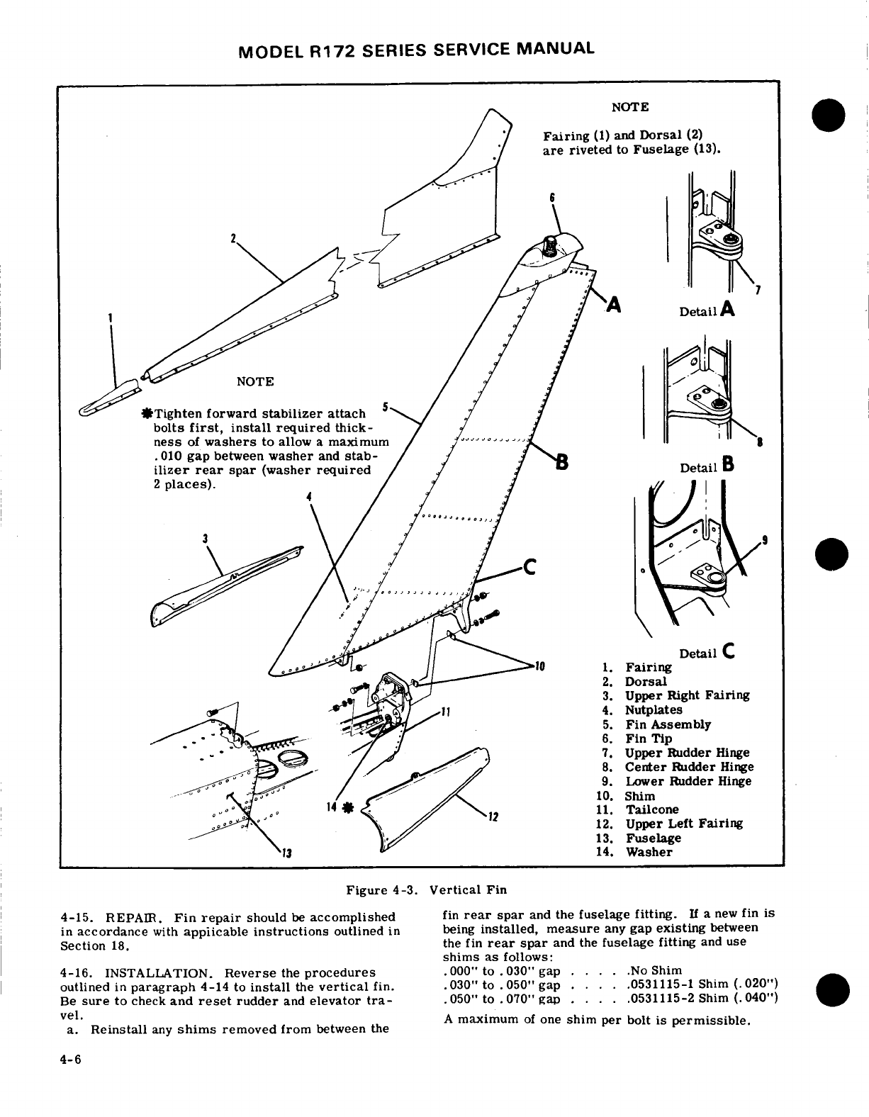
MODEL
R172
SERIES
SERVICE
MANUAL
Fairing
(1)
and
Dorsal
(2)
are
riveted
to
Fuselage
(13).
*Tighten
forward
stabilizer
attach
5
bolts
first,
install
required
thick-
ness
of
washers
to
allow
a
maximum
.010
gap
between
washer
and
stab-
Detail
C
4.
Nutplates
2.
Dorsal
3.
Upper
Right
Fairing
6.
Fin
Tip
.
7.
Upper
Rudder
Hinge
8.
Center
Rudder
Hinge
9.
Lower
Rudder
Hinge
10.
Shim
11.
Tailcone
12.
Upper
Left
Fairing
13.
Fuselage
13
14.
Washer
Figure
4-3.
Vertical
Fin
4-15.
Fin
repair
should
be
accomplished
fin
rear
spar
and
the
fuselage
fitting.
a
new
fin
is
in
accordance
with
applicable
instructions
outlined
in
being
installed, measure
any
gap
existing
between
Section
18.
the fin
rear
spar
and
the
fuselage
fitting
and
use
shims
as
follows:
4-16.
INSTALLATION.
Reverse
the
procedures
.000"
to .
030"
gap
.... .No
Shim
outlined
in
paragraph
4-14
to
install
the
vertical
fin.
.030"
to
.050"
gap
....
.0531115-1
Shim
(.020")
Be
sure
to
check
and
reset
rudder
and
elevator
tra-
.050"
to
.070"
gap
....
.0531115-2
Shim
(.040")
vel
install.
an
shm
reoe
fo
bewe
th
,
„A
maximum
of
one
shim
per
bolt
is
permissible.
a.
Reinstall
any
shims
removed
from
between
the
4-6
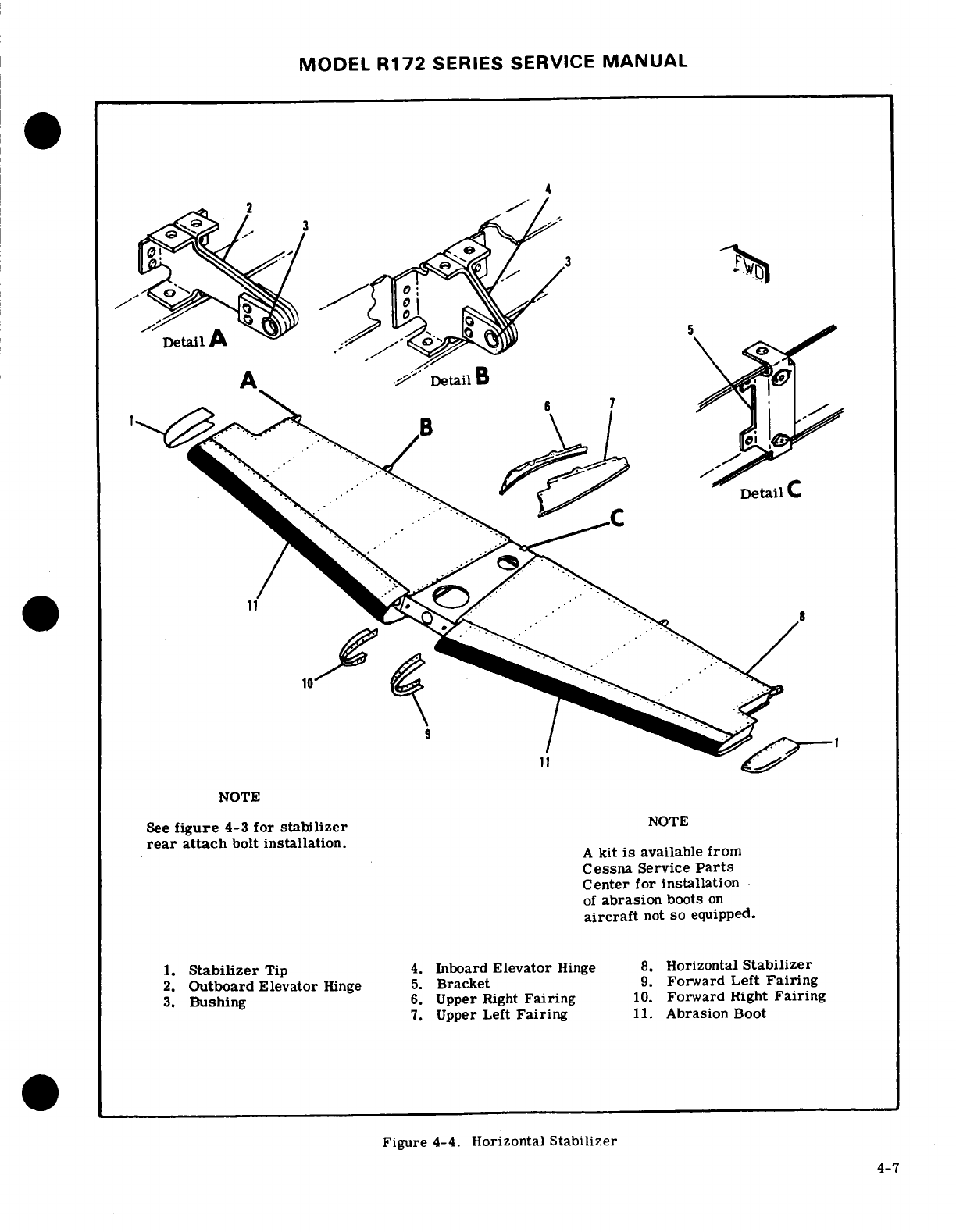
MODEL
R172
SERIES
SERVICE
MANUAL
NOTE
See
figure
4-3
for
stabilizer
NOTE
rear
attach
bolt
installation.
A
kit
is
available
from
Cessna
Service
Parts
Center
for
installation
of
abrasion
boots
on
aircraft
not
so
equipped.
1.
Stabilizer
Tip
4.
Inboard
Elevator
Hinge
8.
Horizontal
Stabilizer
2.
Outboard
Elevator
Hinge
5.
Bracket
9.
Forward
Left
Fairing
3.
Bushing
6.
Upper
Right
Fairing
10.
Forward
Right
Fairing
7.
Upper
Left
Fairing
11.
Abrasion
Boot
Figure
4-4.
Horizontal
Stabilizer
4-7
MODEL
R172
SERIES SERVICE
MANUAL
4-17.
HORIZONTAL
STABILIZER.
(See
figure
4-4.) 4-23.
REMOVAL.
The
abrasion
boots
can
be
re-
moved
by
loosening
one
end
of
the boot
and
pulling
it
4-18.
DESCRIPTION.
The
horizontal
stabilizer
is
off
the
stabilizer
with an
even
pressure.
Excess
ad-
primarily
of
all-metal
construction,
consisting
of
hesive
or rubber
can
be
removed
with
Methyl-Ethyl-
ribs
and
spars
covered
with
skin.
Stabilizer
tips
are
Ketone.
of
ABS
construction.
A
formed metal
leading
edge
is
riveted
to
the
assembly
to
complete
the
structure.
4-24.
INSTALLATION.
Install abrasion
boots as
The
elevator trim
tab
actuator
is
contained within
the
outlined
in
the
following
procedures.
horizontal
stabilizer.
The
underside
of
the
stabilizer
a.
Trim
boots
to
desired
length.
contains
a covered
opening
which
provides
access
to
b.
Mask
off
boot
area
on
leading
edge
of
stabilizer
the
actuator.
Hinges
are
located
on
the
rear
spar
with
1-inch
masking
tape,
allowing
1/4-inch
margin.
assembly
to
support
the
elevators.
c.
Clean
metal
surfaces
of
stabilizer,
where
boot
is
to
be
installed
with
Methyl-Ethyl-Ketone.
4-19.
REMOVAL
AND
INSTALLATION.
d.
Clean
inside
of
abrasion
boot
with
Methyl-Ethyl-
a.
Remove
elevators
and
rudder
in
accordance
with
Ketone
and
a
Scotch
brite
pad
to
ensure
complete
re-
procedures
outlined
in
Sections
8
and
10.
moval
of
paraffin/talc.
Then
a
normal
wipedown
b.
Remove
vertical
fin
in
accordance
with
proce-
with
MEK
on
a
cloth
will
leave
surface
suitable
for
dures
outlined
in
paragraph
4-14.
bonding
to
the
aluminum.
c.
Disconnect
elevator
trim
control
cables
at
clevis
and
turnbuckle
inside
tailcone,
remove
pulleys
which
NOTE
route
the
aft
cables
into
horizontal
stabilizer,
and
pull
cables
out
of
tailcone.
Boots
may
be
applied
over
epoxy
primer,
but
d.
Remove
bolts
securing horizontal
stabilizer
to
if
the
surface
has
been
painted,
the
paint
shall
fuselage.
be
removed
from
the
bond
area. This
shall
be
e.
Remove
horizontal
stabilizer.
done
by
wiping the
surfaces
with
a
clean,
lint-
f.
Reverse
preceding
steps
to
install
horizontal
free
rag,
soaked with
solvent,
and
then
wiping
stabilizer.
the
surfaces
dry,
before
the
solvent
has
time
to
evaporate,
with a
clean,
dry
lint-free
rag.
NOTE
e.
Stir
cement
(EC-1300
Minnesota
Mining
and
Tighten forward
stabilizer-attach
bolts
first.
Manufacturing
Co.)
thoroughly.
Install
required
thickness
of
washers
to
allow
f.
Apply
one
even
brush
coat
to
the
metal
and
the
a
maximum
.
010-inch
gap between
washer
inner
surface
of
the boot. Allow
cement
to
air-dry
and
stabilizer
rear
spar.
Washers
are
re-
for
a
minimum
of
30
minutes,
and
then
apply a
sec-
quired
in
2
places.
The
following
washers
ond
coat
to
each
surface.
Allow
at
least
30
minutes
are
available
from
the
Cessna
Service
Parts
(preferably
one-hour)
for
drying.
Center.
g.
After
the
cement
has
thoroughly
dried,
reacti-
S1450-5A20-100
vate
the
surface
of
the
cement
on
the
stabilizer
and
S1450-5A20-080
boot,
using
a
clean,
lint-free
cloth,
heavily
moisten-
S1450-5A20-063
ed
with toluol.
Avoid
excess
rubbing which
would
remove
the
cement
from
the
surfaces.
g.
Check
operation
of
tail
navigation
light
and
flash-
h.
Position
boot
against
leading
edge,
exercising
ing
beacon.
care
not
to
trap
air
between
boot and
stabilizer.
h.
Rig
control
systems
as
necessary.
NOTE
4-20.
REPAIR.
Horizontal
stabilizer
repair
should
be
accomplished
in
accordance
with
applicable
in-
Should
boot
be
attached
"off-course",
pull
it
structions
in
Section
18.
up
immediately
with
a
quick motion,
and
re-
position
properly.
4-21.
STABILIZER
ABRASION
BOOTS.
i.
Press
or
roll
entire
surface
of
boot
to
assure
NOTE
positive
contact
between the
two
surfaces.
j.
Apply
a
coat
of
GACO
N700A
sealer,
or
equiva-
An
Accessory
Kit
(AK182-217)
is
available
lent,
conforming
to
MIL-C-21067,
along
the
trailing
from
the
Cessna
Service
Parts
Center
for
edges
of
the boots
to
the
surface
of
the
skin
to
form
installation
of
abrasion
boots
on
aircraft
a
neat,
straight
fillet.
not
so
equipped.
k.
Remove
masking
tape
and
clean
stabilizer
of
excess
material.
4-22.
DESCRIPTION.
The
aircraft
may
be
equipped
1.
Mask
to
the
edge
of
boot
for
painting
stabilizer.
with
two
extruded
rubber abrasion
boots,
one
on
the
leading
edge
of
each
horizontal
stabilizer.
These
boots
are
installed
to
protect
the
stabilizer
leading
edge
from
damage
caused
by
rocks
thrown
back
by
the
propeller.
4-8
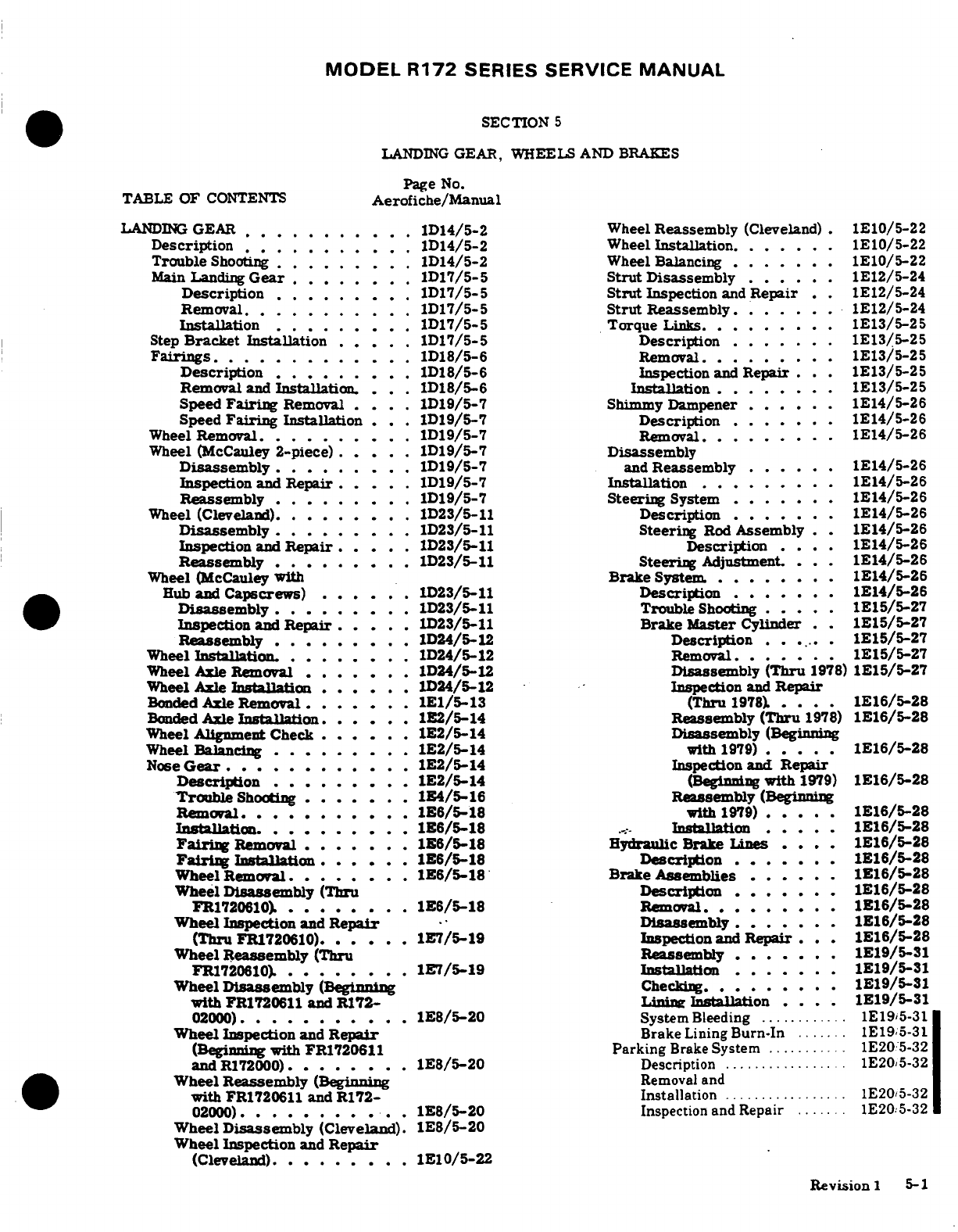
MODEL R172
SERIES
SERVICE
MANUAL
SECTION
5
LANDING
GEAR,
WHEELS
AND
BRAKES
Page
No.
TABLE
OF
CONTENTS
Aerofiche/Manual
LANDING
GEAR
...........
1D14/5-2
Wheel
Reassembly
(Cleveland)
.
1E10/5-22
Description
...........
1D14/5-2
Wheel
Installation
.
.....
1E10/5-22
Trouble
Shooting ...
1D14/5-2
Wheel
Balancing
.......
1E10/5-22
Main
Landing
Gear
........
1D17/5-5
Strut
Disassembly
... ..
.1E12/5-24
Description
.........
1D17/5-5
Strut
Inspection
and
Repair
.
1E12/5-24
Removal...........
1D17/5-5
Strut
Reassembly
.......
1E12/5-24
Installation
.........
1D17/5-5 Torque
Links
.........
1E13/5-25
Step
Bracket
Installation
.....
1D17/5-5
Description
......
1E13/5-25
Fairings
.............
1D18/5-6
Removal
..........
1E13/5-25
Description
.
........
1D18/5-6
Inspection
and
Repair
...
1E13/5-25
Removal
and
Insallation...
1D18/5-6 Installation
..
..
1E13/5-25
Speed
Fairing
Removal
...
.
1D19/5-7
Shimmy
Dampener
....
1E14/5-26
Speed
Fairing
Installation
...
1D19/5-7
Description
.
.....
1E14/5-26
Wheel Removal.D19/5-7
Removal.
........
1E14/5-26
Wheel
(McCauley
2-piece)
.....
1D19/5-7
Disassembly
Disassembly
.........
1D19/5-7
and
Reassembly
......
1E14/5-26
Inspection
and
Repair
....
1D19/5-7
Installation
.........
1E14/5-26
Reassembly
.........
1D19/5-7 Steering
System
.......
1E14/5-26
Wheel
(Cleveland)
........
1D23/5-11
Description
.......
1E14/5-26
Disassembly
.........
1D23/5-11 Steering
Rod
Assembly
. .
1E14/5-26
Inspection
and
Repair
...
1D23/5-11
Description
.
.
1E14/5-26
Reassembly.
........
1D23/5-11
Steering
Adjustment.
...
1E14/5-26
Wheel (McCauley
with
Brake
System.
........
1E14/5-26
Hub
and
Capscrews)
..... .
1D23/5-11
Description
.......
1E14/5-26
Disassembly
..
.......
1D23/5-11
Trouble
Shooting
.....
1E15/5-27
Inspection
and
Repair
.....
1)D23/5-11
Brake
Master
Cylinder
1E15/5-27
Reassembly
.........
1D24/5-12
Description
......
1E15/5-27
Wheel
Installation.
........
1D24/5-12
Removal.
......
1E15/5-27
Wheel Axle
Removal
....
...
1D24/5-12
Disassembly
(Thru
1978)
1E15/5-27
Wheel Axle
Installation
......
1D24/5-12
Inspection
and
Repair
Bonded Axle
Removal.
......
1E1/5-13
(Thru
1978)....
1E16/5-28
Bonded Axle
Installation.
....
.
1E2/5-14
Reassembly
(Thru
1978)
1E16/5-28
Wheel
Alignment Check
......
1E2/5-14
Disassembly
(Beginning
Wheel
Balancing
.........
1E2/5-14
with
1979)
.....
1E16/5-28
Nose
Gear
... .........
1E2/5-14
Inspection
and
Repair
Description
.........
1E2/5-14
(Beginning
with
1979)
1E16/5-28
Trouble
Shooting
.......
1B4/5-16
Reassembly
(Beginning
Removal.
......... .
1E6/5-18
with
1979)
.....
1E16/5-28
Installation
......... 1lation
.6/51
....
.
1E16/5-28
Fairing
Removal
.......
1E6/5-18
Hydraulic
Brake
Lines
. . .
1E16/5-28
Fairing
Installation
.... .
1E6/5-18
Description
......
1E16/5-28
Wheel
Removal
.......
1E6/5-18
Brake
Assemblies
.....
1E16/5-28
Wheel
Disassembly
(Thru
Description
.......
116/5-28
FR1720610).
........
1E6/5-18
Removal.........
1E16/5-28
Wheel
Inspection
and
Repair
Disassembly
.......
1E16/5-28
(Thru
FR1720610).
.....
1E7/5-19
Inspection
and
Repair
...
1E16/5-28
Wheel
Reassembly (Thru
Reassembly
......
1E19/5-31
FR1720610)........
1E7/5-19
Installation
.......
1E19/5-31
Wheel
Disassembly
(Beginning
Chec
........
1E19/5-31
with
FR1720611
and
R172-
Linie
Installation
....
1E19/5-31
02000)...........
1E8/5-20
System
Bleeding
............
1E195-31
Wheel
Inspection
and
Repair
Brake
Lining
Burn-In
.......
1E19,5-31
(Beginning
with
FR1720611
Parking
Brake
System
...........
1E20
5-32
and
R172000) ........
1E8/5-20
Description ................
1E20,5-32
Wheel
Reassembly
(Beginning
Removal and
with
FR1720611
and
R172-
Installation
.................
1E20,5-32
02000)........ ..
1E8/5-20
Inspection
and
Repair
.......
1E20:5-32
Wheel
Disassembly
(Cleveland).
1E8/5-20
Wheel
Inspection
and
Repair
(Cleveland),
..
......
1E10/5-22
Revision
1
5-1
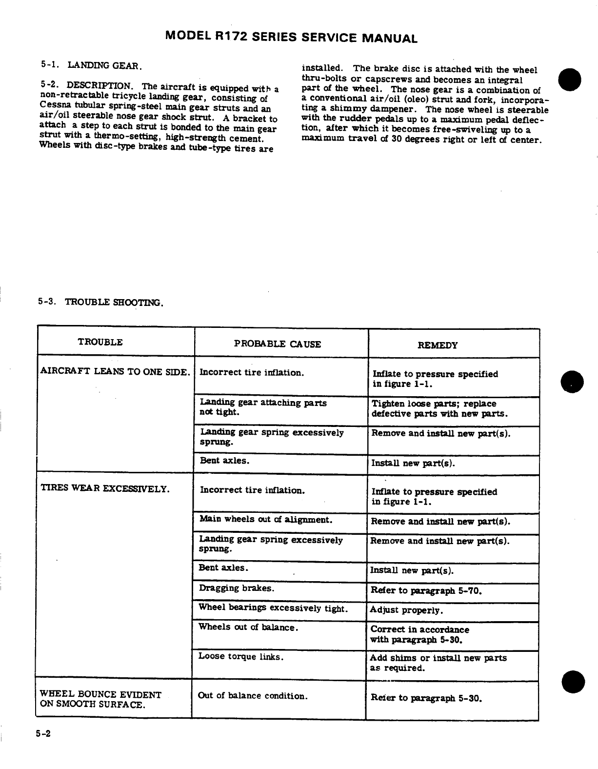
MODEL
R172
SERIES
SERVICE
MANUAL
5-1.
LANDING
GEAR.
installed.
The
brake disc
is
attached
with
the wheel
thru-bolts
or
capscrews
and
becomes an
integral
5-2.
DESCRIPTION. The
aircraft is
equipped
with
a
part
of
the
wheel.
The
nose
gear
is
a
combination
of
non-retractable
tricycle
landing
gear,
consisting
of
a
conventional
air/oil
(oleo)
strut
and
fork,
incorpora-
Cessna
tubular
spring-steel
main
gear
struts
and
an
ting
a
shimmy
dampener.
The
nose
wheel
is
steerable
air/oil
steerable
nose
gear
shock
strut.
A
bracket
to
with
the
rudder
pedals
up
to
a
maximum
pedal deflec-
attach a
step
to
each
strut
is
bonded to
the
main
gear
tion,
after
which
it
becomes
free-swiveling
up
to
a
strut
with
a thermo-setting,
high-strength
cement.
maximum
travel
of
30
degrees right
or left
of
center.
Wheels
with
disc-type brakes
and
tube-type
tires
are
5-3.
TROUBLE
SHOOTING.
TROUBLE
PROBABLE
CAUSE
REMEDY
AIRCRAFT
LEANS
TO
ONE
SIDE.
Incorrect
tire
inflation.
Inflate
to
pressure
specified
in
figure
1-1.
Landing
gear
attaching
parts
Tighten
loose
parts;
replace
not
tight.
defective
parts
with
new
parts.
Landing
gear
spring
excessively
Remove
and
install
new
part(s).
sprung.
Bent
axles. Install
new
part(s).
TIRES
WEAR EXCESSIVELY.
Incorrect
tire
inflation.
Inflate
to
pressure
specified
in
figure
1-1.
Main
wheels
out
of
alignment.
Remove
and
install
new
part(s).
Landing
gear
spring
excessively
Remove
and
install
new
part(s).
sprung.
Bent
axles.
Install
new
part(s).
Dragging
brakes.
Refer
to
paragraph
5-70.
Wheel
bearings
excessively
tight. Adjust
properly.
Wheels
out
of
balance.
Correct
in
accordance
with
paragraph
5-30.
Loose
torque
links.
Add
shims
or
install
new
parts
as
required.
WHEEL
BOUNCE
EVIDENT
Out
of
balance
condition.
Reier
to
paragraph
5-30.
ON
SMOOTH
SURFACE.
5-2
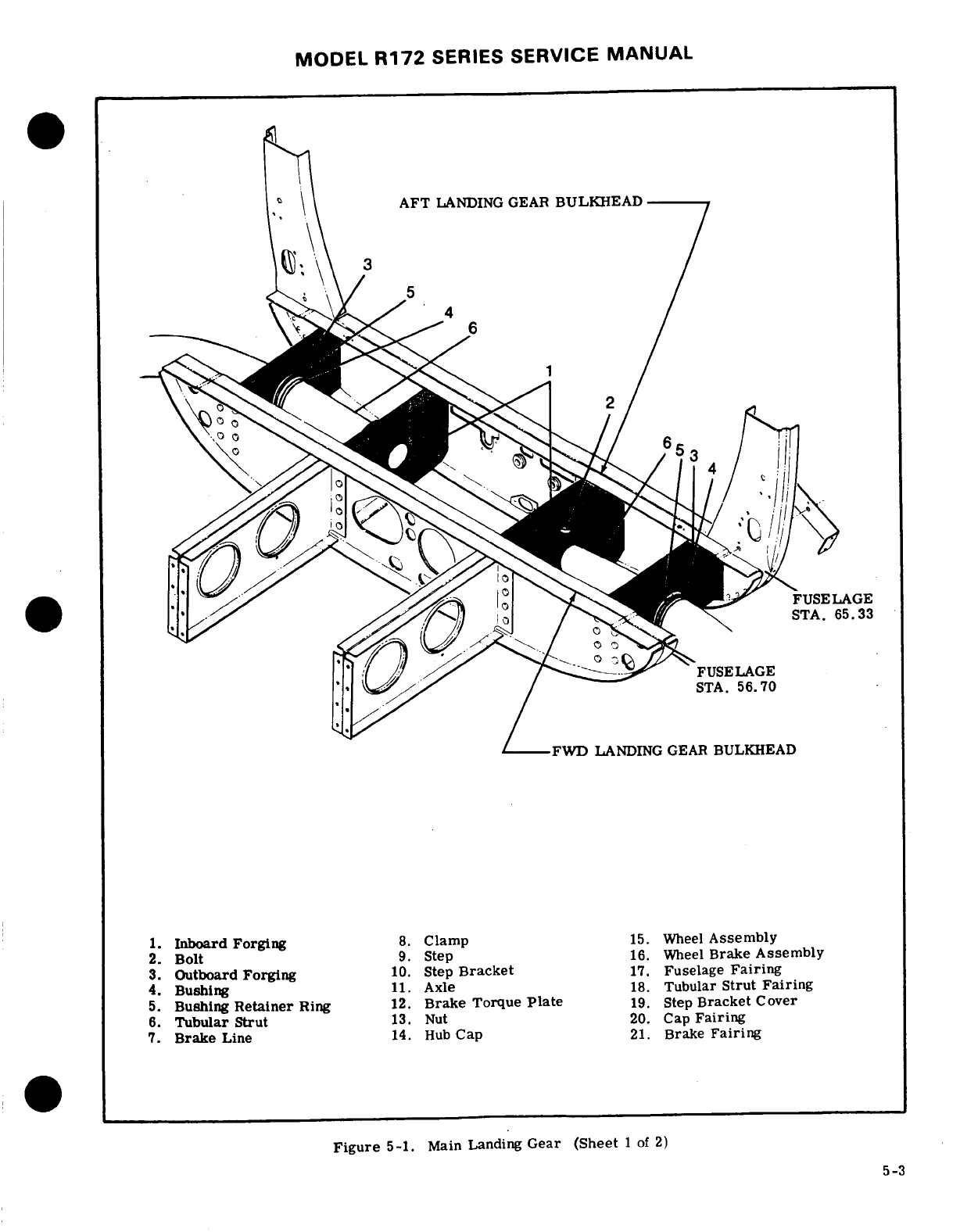
MODEL
R172
SERIES
SERVICE
MANUAL
AFT
LANDING GEAR
BULKHEAD
FUSELAGE
FUSELAGE
STA.
56.70
FWD
LANDING
GEAR
BULKHEAD
1.
Inboard Forging
8.
Clamp
15.
Wheel
Assembly
2.
Bolt
9.
Step
16.
Wheel
Brake
Assembly
3.
Outboard
Forging
10.
Step
Bracket
17.
Fuselage
Fairing
4.
Bushing
11.
Axle
18.
Tubular
Strut
Fairing
5.
Bushing
Retainer
Ring
12.
Brake
Torque
Plate
19.
Step
Bracket
Cover
6.
Tubular Strut
13.
Nut
20.
Cap
Fairing
7.
Brake
Line
14.
Hub
Cap
21.
Brake
Fairing
Figure
5-1.
Main
Landing
Gear
(Sheet
1
of
2)
5-3
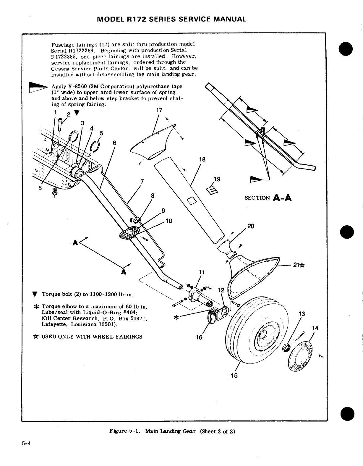
MODEL
R172
SERIES
SERVICE
MANUAL
Fuselage
fairings
(17)
are
split
thru production
model
Serial
R1722284.
Beginning
with
production
Serial
R1722885.
one-piece
fairings
are
installed.
However.
service
replacement
fairings.
ordered
through
the
Cessna Service
Parts
Center.
will
be
split,
and
can
be
installed
without
disassembling
the
main landing
gear.
Apply
Y-8560
(3M
Corporation)
polyurethane tape
(1"
wide)
to
upper
amd
lower
surface
of
spring
and
above
and
below
step
bracket
to
prevent
chaf-
ing
of
spring fairing.
1 2
17
7
19
8
SECTION
A-A
20
21*
<
A
11
12
Torque bolt
(2)
to
1100-1300
lb-in.
*
Torque
elbow
to
a
maximum
of
60
lb
in.
Lube/seal
with
Liquid-O-Ring
#404:
13
(Oil
Center
Research,
P.O.
Box
51971,
Lafayette,
Louisiana
70501).
14
*
USED ONLY
WITH
WHEEL
FAIRINGS
16
15
Figure
5-1.
Main
Landing
Gear
(Sheet
2
of
2)
5-4
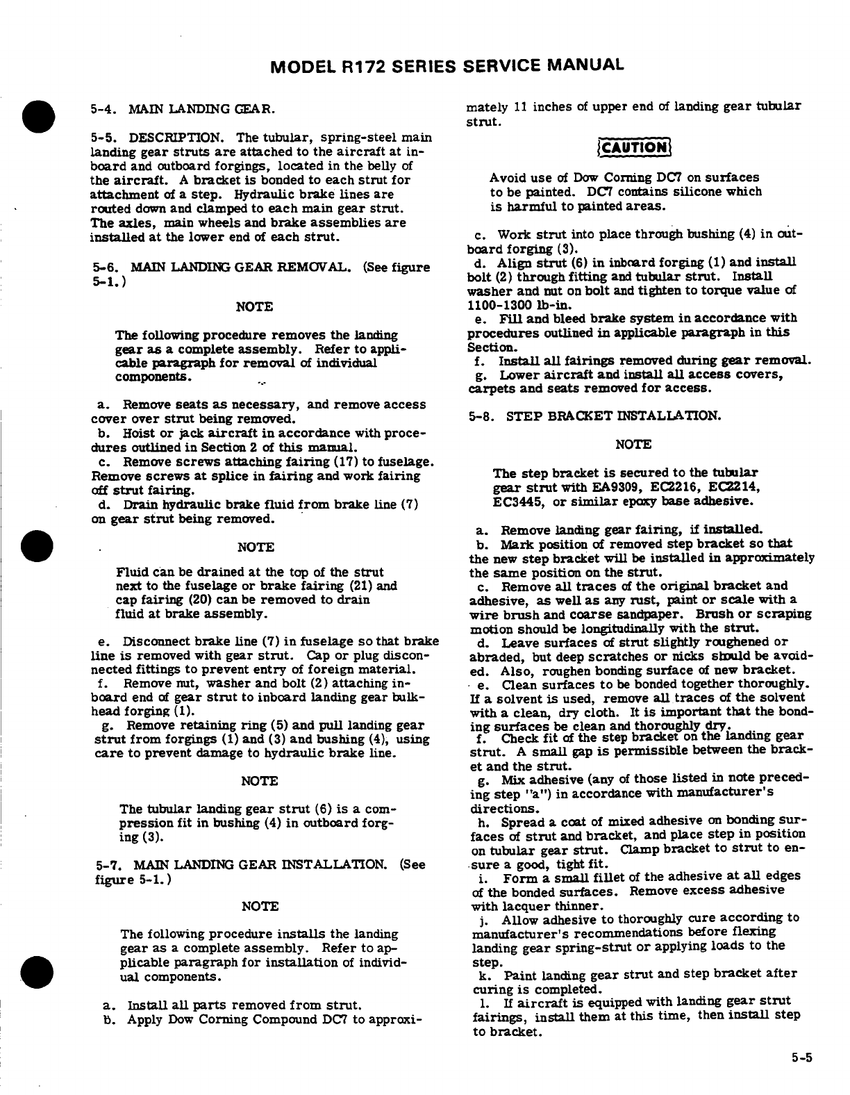
MODEL
R172
SERIES
SERVICE
MANUAL
5-4.
MAIN
LANDING
GEAR.
mately
11
inches
of
upper
end
of
landing
gear
tubular
strut.
5-5.
DESCRIPTION.
The
tubular,
spring-steel
main
landing
gear
struts are
attached
to
the
aircraft
at
in-
board
and outboard
forgings,
located
in
the
belly
of
the
aircraft.
A
bracket
is
bonded
to
each
strut
for
Avoid
use
of
Dow
Corning
DC7 on
surfaces
attachment
of
a
step.
Hydraulic
brake lines
are
to
be
painted.
DC7
contains
silicone
which
routed
down
and
clamped
to
each
main
gear
strut.
is
harmful
to
painted
areas.
The
axles,
main
wheels
and
brake
assemblies
are
installed
at
the
lower
end
of
each
strut.
c.
Work
strut
into
place
through
bushing
(4)
in
out-
board forging
(3).
5-6.
MAIN
LANDING
GEAR
REMOVAL.
(See
figure
d.
Align
strut
(6)
in
inboard
forging
(1)
and
install
5-1.)
-bolt
(2)
through
fitting
and
tubular
strut.
Install
washer
and
nut
on
bolt
and
tighten
to
torque
value
of
NOTE
1100-1300
lb-in.
e.
Fill
and
bleed
brake
system
in
accordance
with
The following
procedure
removes
the
landing
procedures
outlined
in
applicable
paragraph
in
this
gear
as
a
complete
assembly.
Refer
to
appli-
Section.
cable
paragraph
for
removal
of
individual
f.
Install
all
fairings
removed
during
gear
removal.
components.
g.
Lower
aircraft
and
install
all
access
covers,
carpets
and
seats
removed
for
access.
a.
Remove
seats
as
necessary,
and
remove
access
cover
over
strut
being
removed.
5-8.
STEP
BRACKET
INSTALLATION.
b.
Hoist
or
jack
aircraft
in
accordance
with
proce-
dures
outlined
in
Section
2
of
this
manual.
NOTE
c.
Remove
screws
attaching
fairing
(17)
to
fuselage.
Remove
screws
at
splice
in
fairing
and
work
fairing
The
step
bracket
is
secured
to
the
tubular
off
strut
fairing.
gear
strut
with
EA9309,
EC2216,
EC2214,
d.
Drain
hydraulic
brake
fluid
from
brake
line
(7)
EC3445,
or
similar
epaxy
base
adhesive.
on
gear
strut
being
removed.
a.
Remove
landing
gear
fairing,
if
installed.
NOTE
b.
Mark position
of
removed
step
bracket
so
that
the
new
step
bracket
will
be
installed
in
approximately
Fluid
can
be
drained
at
the
top
of
the
strut
the
same
position
on
the
strut.
next
to
the
fuselage
or
brake fairing
(21)
and c.
Remove
all
traces
of
the original
bracket
and
cap
fairing
(20)
can
be
removed
to
drain
adhesive,
as
well
as
any
rust,
paint
or
scale
with
a
fluid
at
brake
assembly.
wire
brush
and
coarse
sandpaper.
Brush
or
scraping
motion
should
be
longitudinally with
the
strut.
e.
Disconnect
brake
line
(7)
in
fuselage
so
that
brake
d.
Leave
surfaces
of
strut
slightly
roughened
or
line
is
removed
with
gear
strut.
Cap
or
plug
discon-
abraded,
but
deep
scratches or
nicks
should be
avoid-
nected fittings
to
prevent
entry
of
foreign
material.
ed.
Also,
roughen
bonding
surface
of
new
bracket.
f.
Remove nut,
washer
and
bolt
(2)
attaching
in-
e.
Clean
surfaces to
be
bonded
together
thoroughly.
board
end
of
gear
strut
to
inboard
landing
gear
bulk-
If
a
solvent
is
used,
remove
all
traces
of
the
solvent
head
forging
(1).
with
a
clean,
dry
cloth.
It
is
important
that
the
bond-
g.
Remove
retaining
ring
(5)
and
pull
landing
gear
ing
surfaces
be
clean
and
thoroughly
dry.
strut
from
forgings
(1)
and
(3)
and
bushing
(4),
using
f.
Check
fit
of
the
step
bracket
on
the
landing
gear
care
to prevent
damage
to
hydraulic
brake
line.
strut.
A
small
gap
is
permissible
between
the
brack-
et
and
the
strut.
NOTE
g.
Mix
adhesive
(any
of
those
listed
in
note
preced-
ing
step
"a")
in
accordance
with
manufacturer's
The
tubular
landing
gear
strut
(6)
is a
cor-
directions.
pression
fit
in bushing
(4)
in
outboard forg-
h.
Spread
a
coat
of
mixed
adhesive
on
bonding
sur-
ing
(3).
faces
of
strut
and
bracket,
and
place
step
in
position
on
tubular
gear
strut.
Clamp
bracket
to
strut
to
en-
5-7.
MAIN
LANDING
GEAR
INSTALLATION.
(See
sure
a
good,
tight
fit.
figure
5-1.)
i.
Form
a
small
fillet
of
the
adhesive
at
all
edges
of
the
bonded
surfaces.
Remove
excess
adhesive
NOTE
with
lacquer
thinner.
j.
Allow
adhesive
to
thoroughly
cure
according
to
The
following
procedure
installs
the
landing
manufacturer's
recommendations before flexing
gear
as
a
complete
assembly.
Refer
to
ap-
landing
gear
spring-strut or
applying
loads
to the
plicable
paragraph
for
installation
of
individ-
step.
ual
components.
k.
Paint
landing
gear
strut
and
step
bracket
after
curing
is
completed.
a.
Install
all
parts
removed
from
strut.
1.
If
aircraft
is
equipped
with
landing
gear
strut
b.
Apply
Dow
Corning
Compound
DC7
to
approxi-
fairings,
install
them
at this
time,
then
install step
to bracket.
5-5
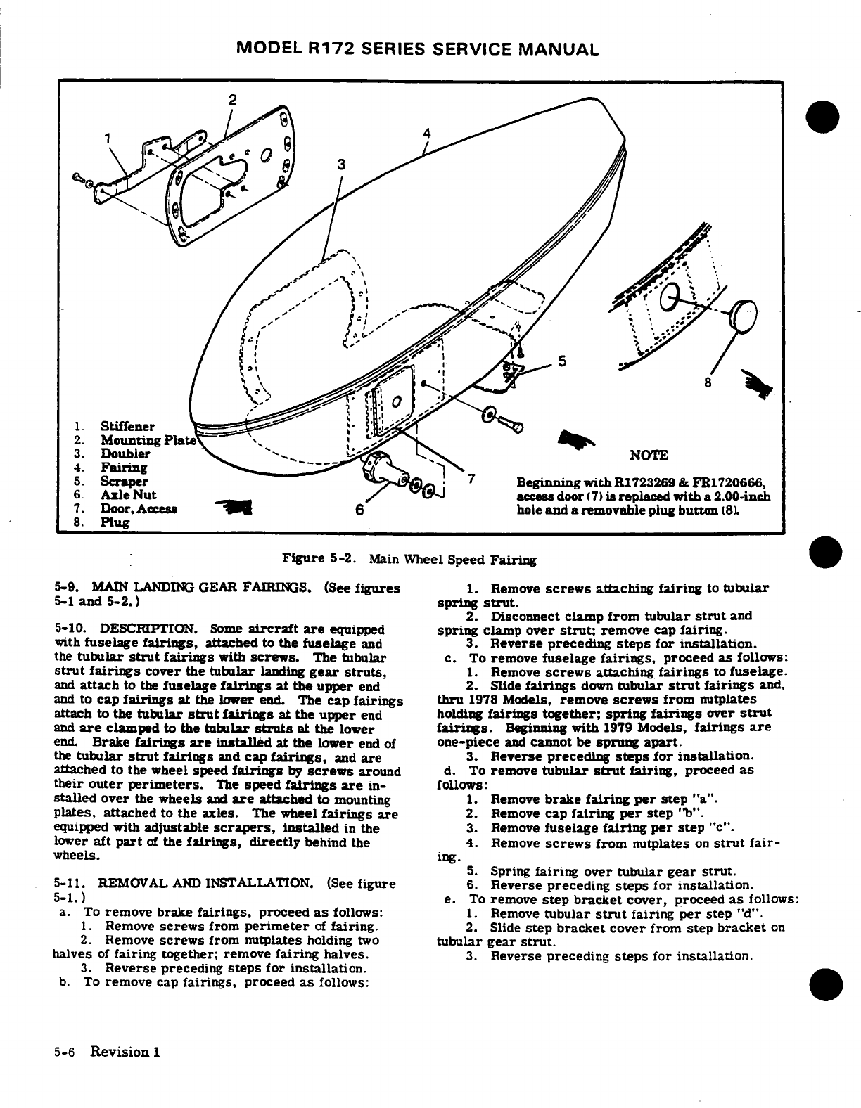
MODEL
R172
SERIES
SERVICE
MANUAL
:
1.
Stiffener
2.
Mounting
Plate
4.
Fairing
NOTE
5.
Scraper
Begnninng
with
R1723269
&
FR1720666,
6.
Axle
Nut
access
door
(7)
is
replaced
with
a
2.00-inch
7.
Door.
6
hole
and
a
removable
plug
button
(8)
8.
Plug
Figure
5-2.
Main
Wheel
Speed
Fairing
5-9.
MAIN
LANDIIG
GEAR FAIRINGS.
(See
figures
1.
Remove
screws
attaching
fairing
to
tubular
5-1
and
5-2.)
spring
strut.
2.
Disconnect
clamp
from
tubular
strut
and
5-10.
DESCRIPTION.
Some
aircraft
are
equipped
spring
clamp
over
strut;
remove
cap
fairing.
with
fuselage
fairings,
attached
to
the
fuselage
and
3.
Reverse preceding
steps
for
installation.
the
tubular
strut
fairings
with
screws.
The
tubular
c.
To
remove
fuselage
fairings,
proceed
as
follows:
strut
fairings
cover
the
tubular
landing
gear struts,
1.
Remove
screws
attaching
fairings
to
fuselage.
and
attach
to
the
fuselage
fairings
at
the upper
end
2.
Slide
fairings
down
tubular
strut
fairings
and,
and
to
cap
fairings
at
the
lower
end.
The
cap
fairings
thru
1978
Models,
remove
screws
from
nutplates
attach
to
the
tubular
strut
fairings
at
the
upper
end
holding
fairings
together;
spring fairings
over
strut
and
are
clamped
to
the
tubular
struts
at
the
lower
fairings.
Beginning
with
1979
Models,
fairings
are
end.
Brake
fairings
are
installed
at
the
lower
end
of
one-piece
and
cannot
be
sprung
apart.
the
tubular
strut
fairings
and
cap
fairings,
and
are
3.
Reverse preceding
steps for
installation.
attached
to the
wheel speed
fairings
by
screws
around
d.
To
remove
tubular
strut
fairing,
proceed
as
their
outer perimeters.
The
speed
fairings
are
in-
follows:
stalled
over
the
wheels
and
are
attached
to
mounting
1. Remove
brake
fairing
per
step
"a".
plates,
attached
to
the
axles.
The
wheel
fairings
are
2.
Remove
cap
fairing
per
step
"b".
equipped with
adjustable
scrapers,
installed
in
the
3.
Remove
fuselage
fairing
per
step
"c".
lower
aft
part
of
the
fairings,
directly
behind
the
4.
Remove
screws
from
nutplates
on
strut
fair-
wheels.
ing. 5.
Spring
fairing
over
tubular
gear
strut.
5-11. REMOVAL
AND
INSTALLATION.
(See
figure
6.
Reverse preceding
steps
for installation.
5-1.)
e.
To
remove
step bracket
cover,
proceed
as
follows:
a.
To
remove
brake
fairings,
proceed
as
follows:
1.
Remove
tubular
strut
fairing
per
step
"d".
1.
Remove
screws
from
perimeter
of
fairing.
2.
Slide
step
bracket
cover
from
step
bracket
on
2.
Remove
screws
from
nutplates
holding
two
tubular
gear
strut.
halves
of
fairing
together;
remove
fairing
halves.
3.
Reverse
preceding
steps
for installation.
3.
Reverse preceding
steps
for
installation.
b.
To
remove
cap
fairings,
proceed
as
follows:
5-6
Revision
1
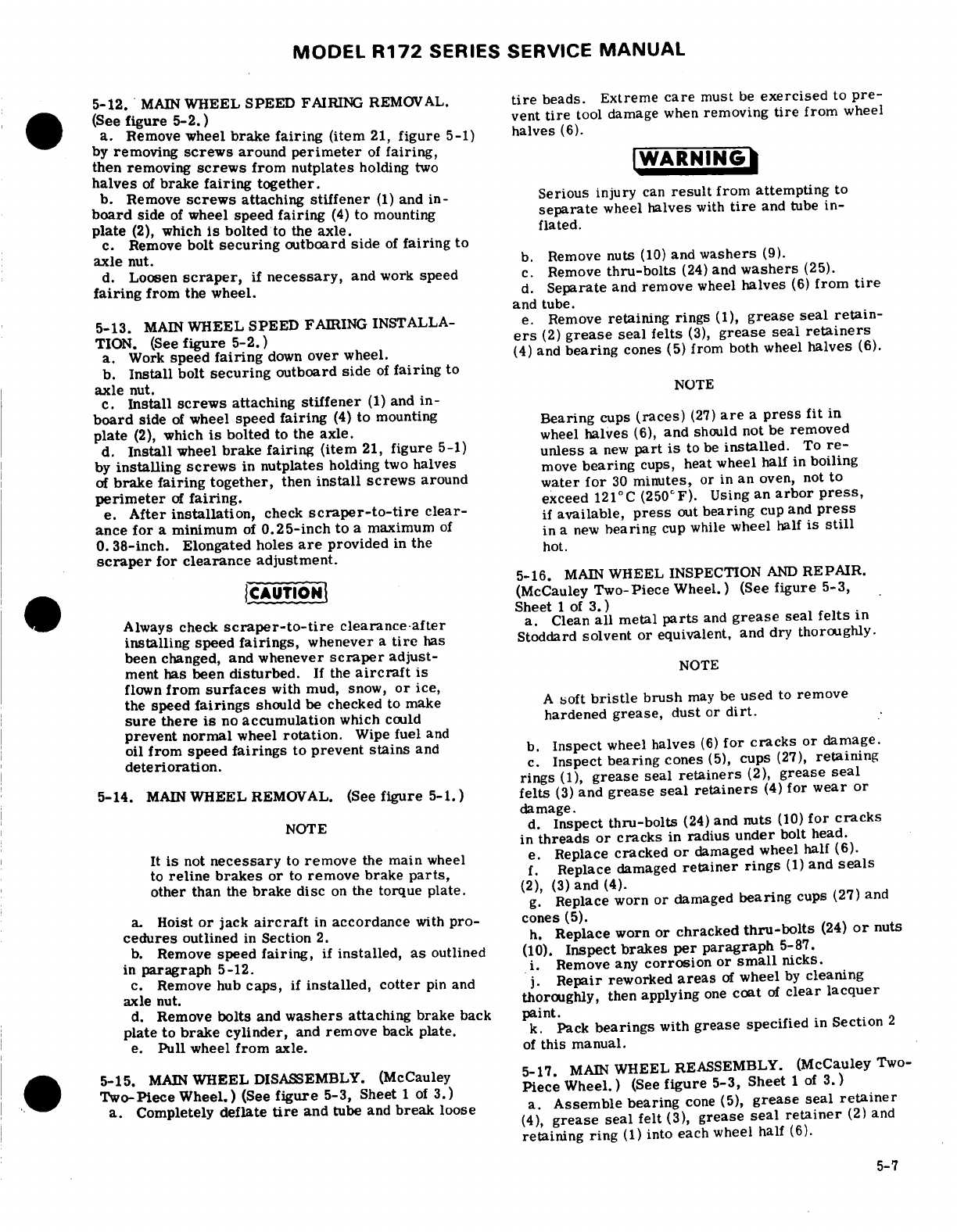
MODEL
R172
SERIES
SERVICE
MANUAL
5-12.
MAIN
WHEEL
SPEED
FAIRING
REMOVAL.
tire
beads.
Extreme
care
must
be
exercised
to
pre-
(See
figure
5-2.)
vent
tire
tool
damage
when
removing
tire
from
wheel
a.
Remove
wheel
brake
fairing
(item
21,
figure
5-1)
halves
(6).
by
removing
screws
around
perimeter
of
fairing,
WARNING
then removing
screws
from nutplates
holding
two
halves
of
brake
fairing
together.
b.
Remove
screws
attaching
stiffener
(1)
and
in-
Serious
injury
can
result
from
attempting
to
board
side
of
wheel
speed
fairing
(4)
to
mounting
separate
wheel
halves
with
tire
and
tube
in-
plate
(2),
which
is
bolted
to
the
axle. flated.
c.
Remove
bolt
securing
outboard
side
of
fairing
to
axle
nut.
b.
Remove
nuts
(10)
and
washers
(9).
d.
Loosen
scraper,
if
necessary,
and
work
speed
c.
Remove
thru-bolts
(24)
and
washers
(25).
fairing
from
the
wheel.
d.
Separate
and
remove
wheel
halves
(6)
from
tire
and
tube.
5-13.
MAIN
WHEEL
SPEED
FAIRING
INSTALLA-
e.
Remove
retaining
rings
(1),
grease
seal
retain-
TION.
(See
figure 5-2.)
ers
(2)
grease
seal
felts
(3),
grease
seal
retainers
a.
Work
speed
fairing
down
over
wheel.
(4)
and
bearing
cones
(5)
from
both
wheel
halves
(6).
b.
Install
bolt
securing
outboard
side
of
fairing
to
axle
nut.
NOTE
c.
Install
screws
attaching
stiffener
(1)
and
in-
board
side
of
wheel
speed
fairing
(4)
to
mounting
Bearing
cups
(races)
(27)
are
a
press
fit
in
plate
(2),
which
is
bolted
to
the axle.
wheel
halves
(6),
and
should not
be
removed
d.
Install
wheel
brake
fairing
(item
21,
figure
5-1)
unless
a
new
part
is
to
be
installed.
To
re-
by
installing
screws
in
nutplates
holding
two
halves
move
bearing
cups,
heat
wheel
half
in
boiling
of
brake
fairing together,
then
install
screws
around
water
for
30
minutes,
or
in
an
oven, not
to
perimeter
of
fairing.
exceed
121°C
(250°F).
Using
an
arbor
press,
e.
After
installation,
check
scraper-to-tire
clear-
if
available,
press
out
bearing
cup
and
press
ance
for
a
minimum
of
0.25-inch
to
a
maximum
of
in
a
new
bearing
cup
while
wheel
half
is
still
0.
38-inch. Elongated
holes
are
provided
in
the
hot.
scraper
for
clearance
adjustment.
5-16.
MAIN
WHEEL
INSPECTION
AND
REPAIR.
CAUTION
(McCauley
Two-Piece
Wheel.)
(See
figure
5-3,
Sheet
1 of
3.)
Always
check
scraper-to-tire
clearance
after
a.
Clean
all
metal
parts
and
grease
seal
felts
in
installing
speed
fairings,
whenever
a
tire
has
Stoddard
solvent
or
equivalent,
and dry thoroughly.
been
changed,
and
whenever
scraper
adjust-
ment has
been
disturbed.
If
the
aircraft
is
NOTE
flown
from
surfaces
with
mud,
snow,
or
ice,
the
speed
fairings
should
be
checked
to make
A
soft
bristle
brush
may
be
used
to
remove
sure
there
is
no
accumulation
which
could
hardened
grease,
dust
or
dirt.
prevent normal
wheel
rotation.
Wipe
fuel
and
oil
from
speed
fairings
to
prevent
stains
and
b.
Inspect
wheel
halves
(6)
for
cracks
or
damage.
deterioration.
c.
Inspect
bearing
cones
(5),
cups
(27),
retaining
rings
(1),
grease
seal
retainers
(2),
grease
seal
5-14.
MAIN
WHEEL
REMOVAL.
(See
figure
5-1.)
felts
(3)
and
grease
seal
retainers
(4)
for
wear
or
damage.
NOTE
d.
Inspect
thru-bolts
(24)
and
nuts
(10)
for
cracks
in
threads or
cracks
in
radius
under
bolt
head.
It
is
not
necessary
to
remove
the
main
wheel
e.
Replace
cracked
or
damaged
wheel half
(6).
to
reline brakes
or
to
remove
brake
parts,
f.
Replace
damaged
retainer
rings
(1)
and
seals
other
than
the
brake disc
on
the
torque
plate.
(2),
(3)
and
(4).
g.
Replace
worn
or
damaged
bearing
cups
(27)
and
a.
Hoist
or
jack
aircraft
in
accordance
with
pro-
cones
(5).
cedures
outlined
in
Section
2.
h.
Replace worn or
chracked
thru-bolts
(24)
or
nuts
b.
Remove
speed
fairing,
if
installed,
as
outlined
(10).
Inspect
brakes
per
paragraph
5-87.
in
paragraph
5-12.
i.
Remove
any
corrosion
or
small
nicks.
c.
Remove
hub
caps,
if
installed, cotter
pin
and
j.
Repair reworked
areas
of
wheel
by
cleaning
axle
nut.
thoroughly,
then
applying
one
coat
of
clear
lacquer
d.
Remove
bolts
and
washers
attaching
brake
back
paint.
plate
to
brake
cylinder,
and
remove
back
plate.
k.
Pack
bearings
with
grease
specified
in
Section
2
e.
Pull
wheel
from
axle.
of
this
manual.
5-15.
MAIN
WHEEL
DISASSEMBLY.
(McCauley
5-17.
MAIN
WHEEL
REASSEMBLY.
(McCauley
Two-
Two-Piece
Wheel.)
(See
figure
5-3,
Sheet
1 of
3.)
Piece
Wheel.)
(See
figure
5-3,
Sheet
1
of
3.)
a.
Completely
deflate
tire
and
tube
and
break
loose
a.
Assemble
bearing
cone
(5),
grease
seal
retainer
(4),
grease
seal
felt
(3),
grease
seal
retainer
(2)
and
retaining
ring
(1)
into each
wheel half
(6).
5-7
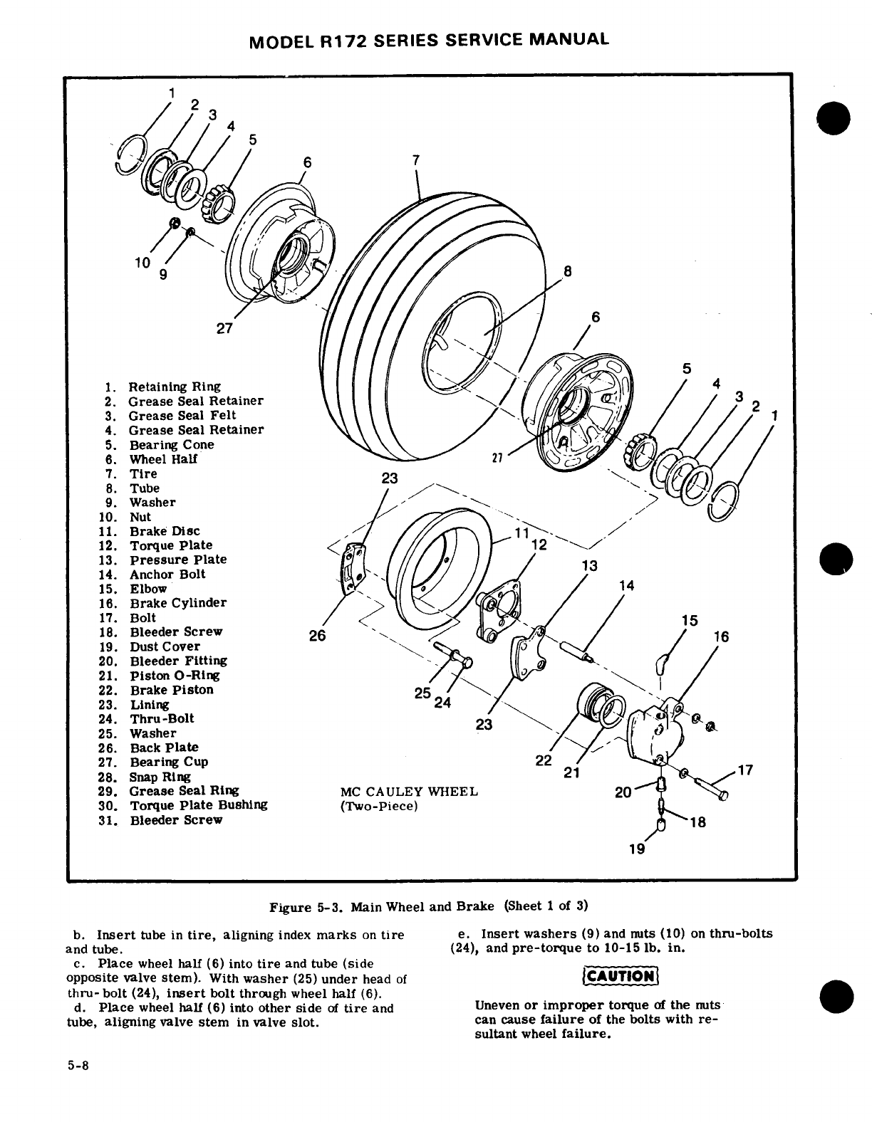
MODEL
R172
SERIES SERVICE
MANUAL
1
1.
Retaining
Ring
4
2.
Grease
Seal
Retainer
3.
Grease
Seal
Felt
4.
Grease
Seal
Retainer
5.
Bearing
Cone
6.
Wheel
Half
7.
Tire
23
8.
Tube
9.
Washer
10.
Nut
11.
Brake Disc
12.
Torque
Plate
13.
Pressure
Plate
14.
Ancho
r
Bolt
15.
Elbow
16.
Brake
Cylinder
17.
Bolt
15
18.
Bleeder
Screw
19.
Dust
Cover
20.
Bleeder
Fitting
21.
Piston
O-Ring
22.
Brake
Piston
23.
Lining
24
24.
Thru-Bolt
25.
Washer
26.
Back
Plate
27.
Bearing
Cup
22
28.
Snap
Ring
21
17
29.
Grease
Seal
Ring
MC
CAULEY
WHEEL
20
30.
Torque
Plate
Bushing
(Two-Piece)
31.
Bleeder
Screw
18
19
Figure
5-3.
Main
Wheel
and
Brake
(Sheet 1
of
3)
b.
Insert
tube in
tire,
aligning
index
marks
on
tire
e.
Insert washers
(9)
and nuts
(10)
on
thru-bolts
and
tube.
(24),
and
pre-torque
to
10-15
lb.
in.
c.
Place
wheel
half
(6)
into
tire
and
tube
(side
opposite
valve
stem).
With
washer
(25)
under
head
of
CAUTION
thru-
bolt
(24),
insert
bolt
through
wheel
half
(6).
d.
Place
wheel
half
(6)
into
other
side
of
tire
and
Uneven
or
improper
torque
of
the
nuts
tube,
aligning
valve
stem
in
valve
slot.
can
cause
failure
of
the
bolts
with
re-
sultant
wheel
failure.
5-8
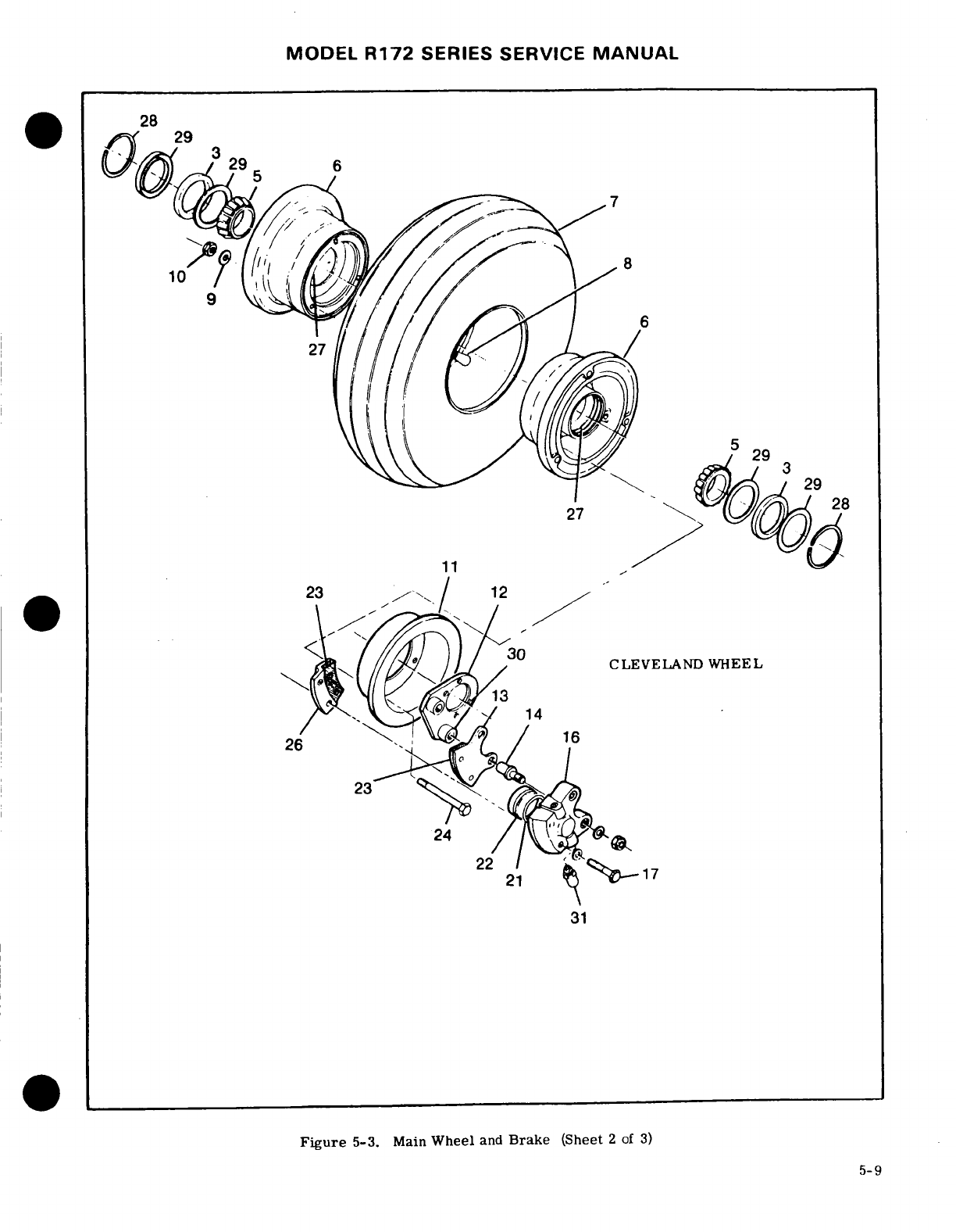
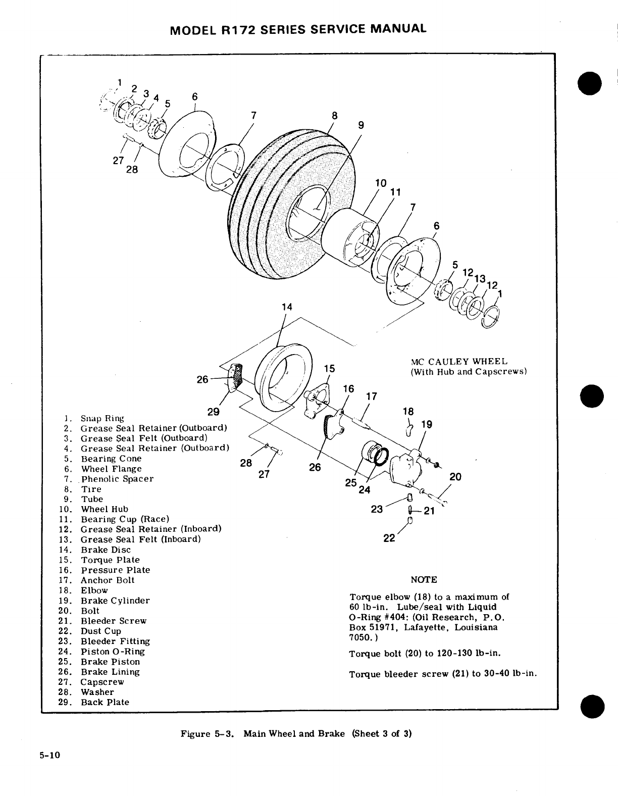
MODEL
R172
SERIES
SERVICE
MANUAL
-
.
2
Grease
Seal
Retainer
(Inboard)
3.
Grease
Seal
Felt
(Inboard)
4.
Brake
Disca
etier(utord
14
(With Hub
and
Capscrews)
7.
Pnchor Bolt
NOTES17
18.
ElIbow
12.
Grease
Seal
Retainerr
Torque
elbow
29.
TorquBack
Plate
16.
Pressure
Plate
17.
Anchor Bolt
NOTE
18.
Elbow
19. Brake
Cylinder
Torque
(She
lbow
(18)
to
a
maximum
of
5-10b-in.
21.
Bleeder
Screw
O-Ring
#404:
(Oil
Research,
P.O.
22.
Dust
Cup
Box
51971,
Lafayette,
Louisiana
23.
Bleeder
Fitting
7050.
)
bolt
(20)
to
120-130
Torque
bleeder
screw
(21)
to
30-40
28.
Washer
29.
Back Plate
Figure
5-3.
Main Wheel
and
Brake
(Sheet
3
of
3)
5-10
MODEL
R172
SERIES
SERVICE
MANUAL
f.
Prior
to
torquing
nuts
(10),
inflate
tube
with
wheel
half.
approximately
10-15
psi
air
pressure
to
seat
tire.
b.
Position
tire
and
tube
on
outboard
wheel
half
with
tube
inflation
valve
through
hole in
wheel
half.
CAUTION·
c.
Place
inner
wheel
half in
position
on
outboard
wheel
half.
Apply a
light force to
bring
wheel
halves
Do
not
use
impact
wrenches
on
thru-bolts
together.
While
maintaining
the light
force,
assemble
or
nuts.
a
washer
and
nut
on
thru-bolt
and
tighten
to
maintain
force.
Assemble
remaining
washers
and
nuts
to
thru-
g.
Dry
torque
all
nuts
(10)
evenly
to
a
torque
value
bolts.
Tighten nuts
evenly
to
the
torque
value
of
90
lbin.
of
140-150
lb
in.
h.
Inflate
tire
to
correct
pressure
specified
in
CAUTI
figure
1-1
of
this
manual.
Uneven
or
improper
torque
of
thru-bolt
nuts
5-18.
MAIN
WHEEL
DISASSEMBLY.
(Cleveland
can
cause
failure
of
bolts,
resulting
in
wheel
Wheel.)
(See
figure
5-3,
sheet
2
of
3.)
failure.
a.
Remove
valve
core
and
deflate
tire
and
tube.
Break
tire
beads
loose
from
wheel
rims.
d.
Clean
and
pack
bearing
cones
with
clean
aircraft
wheel
bearing
grease,
as
outlined
in
Section
2
of
this
WARNING
manual.
e.
Assemble
bearing
cones,
grease
seal
felts
and
Injury
can
result
from
attempting
to
separate
rings
into
wheel
halves.
wheel
halves
with
tire
inflated.
Avoid
dam-
f.
Inflate
tire
to
seat
tire
beads,
then
adjust
to
aging
wheel
flanges
when
breaking
tire
beads
correct
tire
pressure.
Refer
to
chart
in
Section
1
loose.
A
scratch,
gouge
or nick
in
the
wheel
of
this
manual
for
correct
tire pressure.
may
cause
wheel
failure.
5-21.
MAIN
WHEEL
DISASSEMBLY.
(McCauley
b. Remove
thru-bolts
and
separate
wheel
halves,
Wheel with
Hub
and
Capscrews.)
(See
figure
5-3,
removing
tire,
tube
and
brake
disc.
sheet
3
of
3.)
c.
Remove
grease
seal rings,
felts
and
bearing
cones
from
wheel
halves.
NOTE
Injury can
result
from
attempting
to
remove
wheel
flanges
with
tize
and
tube
inflated.
Bearing
cups
(races)
are
a
press-fit
in
the
Avoid
damaging wheel
flanges
when
breaking
wheel
halves
and
should
not
be
removed
tire
beads
loose.
A
scratch,
gouge
or
nick
unless
a
new
part
is
to
be
installed.
To
in
wheel flange
could
cause
wheel
failure,
remove
bearing
cups,
heat wheel
halves
in
boiling
water for
30
minutes
or
in
an
a.
Remove
valve
core
and
deflate
tire
and
tube.
oven
not
to
exceed
149°C
(300°F.)
Using
Break
tire
beads
loose
from
wheel
flanges.
an
arbor
press,
if
available,
press
out
b.
Remove
capscrews
and
washers
from
outboard
bearing
cup
and
press
in
new
bearing
cup
wheel
flange.
while
wheel
half
is
still
hot.
c.
Remove
capscrews
and
washers
from
inboard
wheel
flange.
5-19.
MAIN
WHEEL
INSPECTION
AND
REPAIR.
d.
Remove
brake
disc.
(Cleveland
Wheel.)
(See
figure
5-3,
sheet
2
of
3.)
e.
Separate
wheel
flanges
from
wheel
hub.
Retain
a.
Clean
all
metal
parts
and
grease
seal
felts
in
spacers
on
each side
of
wheel
hub.
solvent
and
dry
thoroughly.
f.
Remove
wheel
hub
from
tire.
b.
Inspect
wheel
halves
for
cracks.
Cracked
wheel
g.
Remove
retainer
rings,
grease
seal
retainers.
halves
should
be
discarded
and
new
parts
used.
Sand
grease
seal
felts
and
bearing
cones.
out
nicks,
gouges
and
corroded
areas.
When
protec-
tive
coating
has
been
removed,
the
area should
be
NOTE
cleaned
thoroughly,
primed
with
zinc
chromate
and
painted
with
aluminum
lacquer.
Bearing
cups
(races)
are
a
press-fit
in
the
c.
Inspect
brakes per
paragraph
5-87.
wheel
hub
and
should
not
be
removed
unless
d.
Carefully
inspect
bearing
cones
and
cups
for
a
new
part
is
to be
installed.
To
remove
the
damage
and
discoloration.
After
cleaning,
pack
bearing
cup,
heat
wheel
hub
in
boiling
water
bearing
cones
with
clean
aircraft
wheel
bearing
for
30
minutes,
or
in an
oven
not
to
exceed
grease,
as
outlined
in
Section
2
of
this
manual,
be-
121°C
(250°F.)
Using
an
arbor
press,
if
fore
installing
in
wheel
half.
available,
press
out the
bearing
cup
and
press
in
the
new
bearing
cup
while
the
wheel
5-20.
MAIN
WHEEL REASSEMBLY.
(Cleveland
hub
is
still
hot.
Wheel.)
(See
figure
5-3,
sheet
2
of
3.)
a.
Insert
thru-bolts
through
brake
disc
and
position
5-22.
MAIN
WHEEL INSPECTION
AND
REPAIR.
disc
in
the
inner
wheel
half,
using
thru-bolts
to
guide
(McCauley
Wheel
with
Hub
and
Capscrews.)
(See
the
disc.
Ascertain
that
the
disc
is bottomed
in
the
figure
5-3,
Sheet
3
of
3
)
a.
Clean
all
metal
parts,
grease
seal
felts
and
5-11
MODEL
R172
SERIES
SERVICE
MANUAL
and
.
Inspect
wheel
flanges
and
wheel
hub
for
cracks.
C
racked
wheel
flanges
or
hub
shall
be
discarded
and
Always
check
scraper-to-tire
clearance
after
new
parts
installed.
Sand out
smooth
nicks,
gouges
installing
speed
fairings,
whenever
a
tire
has
and
corroded
areas.
When
the
protective
coating
has
been
changed,
and
whenever
scraper
adjust-
been
removed,
the
area
should
be
cleaned
thoroughly,
ment
has
been
disturbed.
If
the
aircraft
is
pi
.:ned
with
zinc
chromate
and
painted
with
aluminum
flown
from surfaces
with mud,
snow,
or
ice,
lacquer.
the
fairing
should
be
checked
to
make
sure
c.
Carefully
inspect
bearing
cones
and
cups
for
there
is
no
accumulation
which
could
prevent
tdamage
and
discoloration.
After
cleaning,
pack
bear-
normal
wheel
rotation.
Refer
to
paragraph
ing
cones
with
clean
aircraft
wheel
bearing
grease.
5-12A
for
correct
scraper-to-tire
clearance.
Refer
to
Section
2
of
this
manual
for
grease
type.
5-25.
MAIN
WHEEL
AXLE
REMOVAL.
5-23.
MAIN
WHEEL
REASSEMBLY.
(McCauley
Wheel
with
Hub
anc
Capscrews.)
(See
figure
5-3,
NOTE
Sheet
3 of
3.)
a.
Place
wheel
hub
in
tire
and
tube
with
tube
infla-
This
procedure
should-be
used
if
the
axle
is
tiun
stem
in
hole
of
wheel
hub.
not
bonded
to
the
tubular
strut.
If
the
axle
b.
Place
spacer
and
wheel
flange
on
inboard
side
is
bonded
to
the
strut,
refer
to
paragraph
i,)
wheel
hub
(opposite
of
tube
inflation
stem).
5-27.
c.
Place
washer
under
head
of
each
capscrew,
in-
sert
capscrew
through
brake disc,
wheel flange
and
a.
Remove
speed
fairing,
if
installed,
in
accor-
spacer,
and
start
capscrews
into wheel
hub
threads,
dance
with
paragraph
5-12.
b.
Remove
wheel
in
accordance
with
paragraph
5-14.
CAUTION
c.
Disconnect,
drain
and
cap
or
plug
hydraulic
brake
line
at
the
wheel
brake
cylinder.
Be
sure
that
spacers,
wheel
flanges
and
d.
Remove
bolts
attaching
brake
torque
plate
and
brake
disc
are seated
on
flange
of
wheel
hub.
speed
fairing
mounting
plate
to
axle.
Uneven
or improper
torque
of
capscrews
can
e.
Remove
cotter
pin,
nut,
washer
and
bolt
attach-
cause
failure
of
capscrews
or
hub
threads
ing
axle
to
tubular
strut.
with
resultant
wheel
failure.
f.
Remove
axle
from
spring-strut.
d.
Tighten
capscrews
evenly
and
torque
to
the
value
5-26.
MAIN
WHEEL
AXLE
INSTALLATION.
specified.
e.
Place
spacer
and
wheel
flange
on
outboard side
NOTE
of
wheel
hub
and
align
valve
stem
hole in wheel
flange.
This
procedure
should
be
used
if
the
axle
is
f.
Place
washer
under
head
of
each
capscrew,
in-
not
to
be
bonded
to
the
tubular
strut.
If the
sert
capscrew
through
wheel
flange
and
spacer.
axle
is
to
be
bonded
to
the
strut, refer
to
Start
capscrews
into
wheel
hub
threads.
paragraph
5-27.
g.
Tighten
capscrews
(27)
evenly
and
torque
to
190
to
200
Ib-in.
a.
Install
axle
on
spring-strut,
using
wet
primer
on
h.
Clean
and
pack
bearing cones
with
clean
aircraft
faying
surfaces
of
axle
and
spring-strut.
Axle is
in-
wheel
bearing
grease.
Refer
to
Section
2
of
this
man-
stalled
with
tapered
edges
to
bottom.
ual
for
grease
type.
b.
Install
bolt,
washer
and
nut
attaching
axle
to
i.
Assemble
bearing cones,
grease
seal
felts
and
spring-strut.
After
tightening
nut,
install
cotter
pin.
retainer
into
wheel
hub. c.
Install
brake
components
and
speed
fairing
j.
Inflate
tire
to
seat
tire
beads,
then
adjust
to
cor-
mounting
plate
to
axle.
rect
pressure.
Refer
to
chart
in
Section
1
of
this
d.
nstall
wheel
on
axle
in
accordance
with
para-
manual
for
correct
tire
pressure.
graph
5-24
e.
Connect hydraulic
brake
line
to
wheel
brake
cyl-
5-24.
MAIN
WHEEL
INSTALLATION.
inder.
a.
Place
wheel
assembly
on
axle.
f.
Fill
and
bleed
hydraulic
brake
system
in
accord-
b.
Install
axle
nut
and
tighten axle
nut
until
a
slight
ance
with
applicable
paragraph
in
this
section.
bearing
drag
is
obvious
when
the
wheel
is
rotated.
g.
Install
speed
fairing,
if
used,
in
accordance
with
Back
off
axle
nut
to
the
nearest
castellation
and
in-
paragraph
5-13.
stall
cotter
pin.
c.
Place
brake
back
plate
in
position
and
secure
with
bolts
and
washers.
d.
Install
valve
extension
and
hub
cap.
Install
speed
fairing
(if
used)
as
outlined
in
paragraph
5-13.
5-12
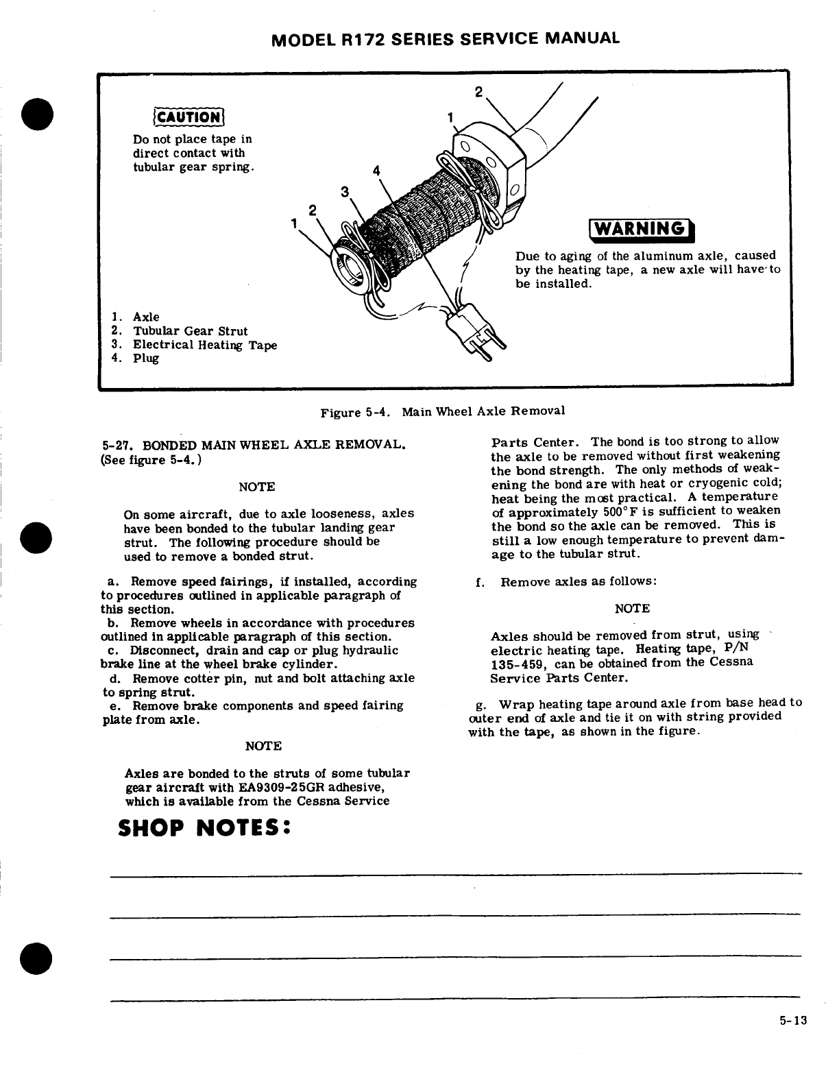
MODEL
R172
SERIES
SERVICE
MANUAL
CAUTION
Do
not
place
tape
in
direct
contact
with
tubular
gear
spring.
IWARNING
^
.
Due
to
aging
of
the
aluminum
axle,
caused
by
the
heating
tape,
a
new
axle will
have
to
be
installed.
1.
Axle
2.
Tubular
Gear
Strut
3.
Electrical
Heating
Tape
4.
Plug
Figure
5-4.
Main
Wheel
Axle
Removal
5-27.
BONDED
MAIN
WHEEL
AXLE
REMOVAL.
Parts
Center.
The
bond
is
too
strong
to
allow
(See
figure
5-4.)
the
axle
to
be
removed
without
first
weakening
the
bond
strength.
The
only
methods
of
weak-
NOTE
ening
the
bond
are
with
heat
or
cryogenic
cold;
heat
being
the
most
practical.
A
temperature
On
some
aircraft,
due
to
axle
looseness,
axles
of
approximately
500°F
is
sufficient
to
weaken
have
been
bonded
to
the
tubular
landing
gear
the
bond
so
the
axle
can
be
removed. This
is
strut.
The
following
procedure
should
be
still
a
low
enough
temperature
to
prevent
dam-
used
to
remove
a
bonded
strut.
age
to
the
tubular
strut.
a.
Remove
speed
fairings,
if
installed,
according
f.
Remove
axles
as
follows:
to
procedures
outlined
in
applicable
paragraph
of
this
section.
NOTE
b.
Remove
wheels
in
accordance
with
procedures
outlined in
applicable
paragraph
of
this
section.
Axles
should
be
removed
from
strut,
using
c.
Disconnect,
drain
and
cap
or
plug
hydraulic
electric
heating
tape. Heating
tape,
P/N
brake
line
at
the
wheel
brake
cylinder.
135-459,
can
be
obtained
from the
Cessna
d.
Remove
cotter
pin,
nut
and
bolt
attaching
axle
Service
Parts
Center.
to
spring
strut.
e.
Remove
brake
components
and
speed
fairing
g.
Wrap
heating tape around axle
from
base
head
to
plate
from
axle.
outer
end
of
axle
and tie
it
on
with
string
provided
with
the
tape,
as
shown
in
the
figure.
NOTE
Axles
are
bonded
to
the
struts
of
some
tubular
gear
aircraft
with
EA9309-25GR
adhesive,
which
is
available
from
the
Cessna
Service
SHOP
NOTES:
5-13
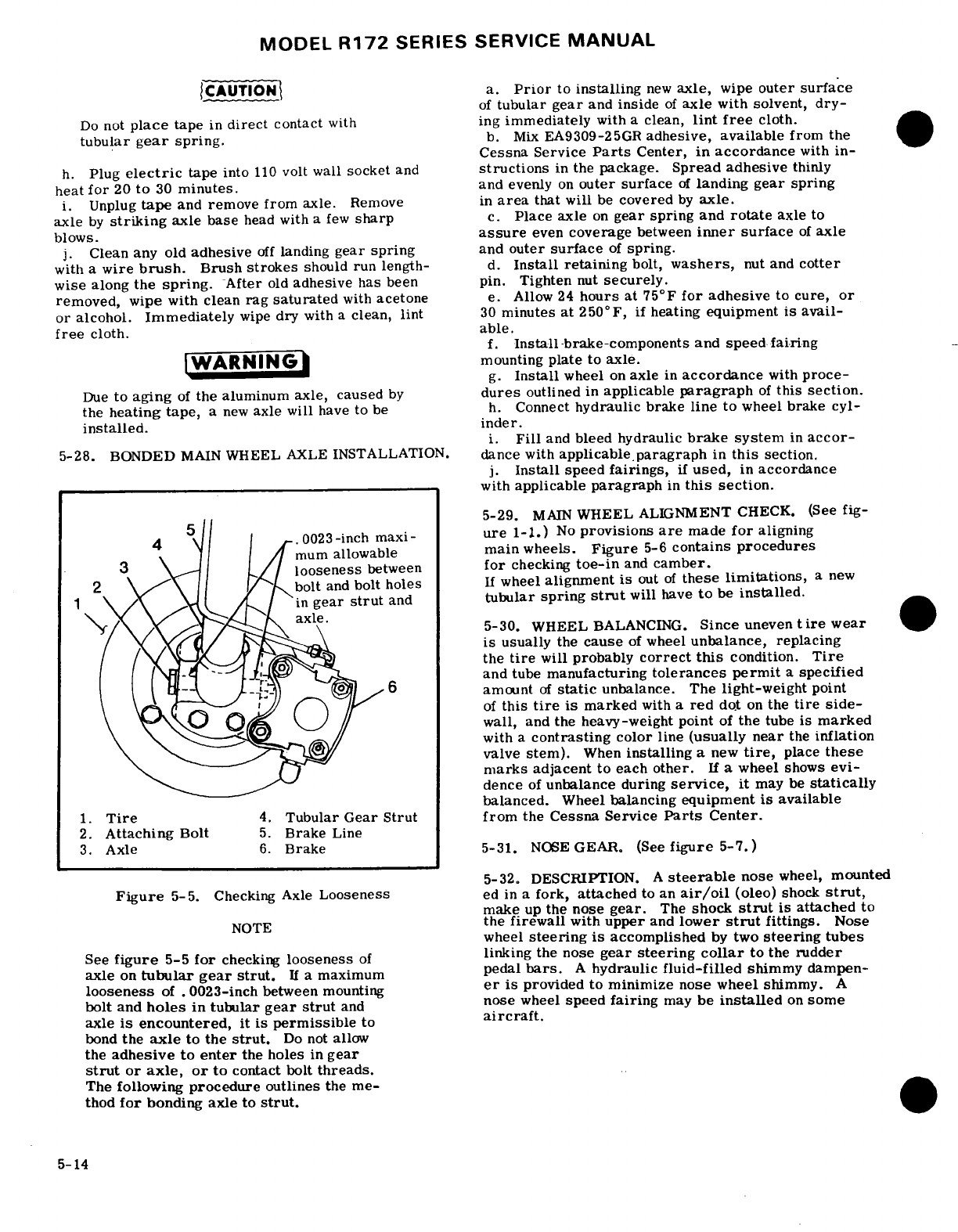
MODEL
R172
SERIES
SERVICE
MANUAL
CAUTION
a.
Prior
to
installing
new
axle,
wipe
outer
surface
of
tubular
gear
and
inside
of
axle
with
solvent,
dry-
Do
not
place
tape
in
direct
contact
with
ing
immediately
with
a
clean,
lint
free
cloth.
tubular
gear
spring.
b.
Mix
EA9309-25GR
adhesive,
available
from
the
Cessna Service
Parts
Center,
in
accordance
with
in-
h.
Plug
electric
tape
into
110
volt
wall
socket
and
structions
in the
package.
Spread adhesive
thinly
heat
for
20
to
30
minutes.
and
evenly
on
outer
surface
of
landing
gear
spring
i.
Unplug
tape
and
remove
from
axle.
Remove
in
area
that
will
be
covered
by
axle.
axle
by
striking
axle
base
head
with
a
few
sharp
c.
Place
axle
on
gear spring
and
rotate
axle
to
blows.
assure
even
coverage
between
inner
surface
of
axle
j.
Clean
any
old
adhesive
off
landing
gear
spring
and
outer
surface
of
spring.
with
a
wire
brush.
Brush
strokes
should
run
length-
d.
Install
retaining
bolt,
washers,
nut
and
cotter
wise
along
the
spring.
After
old
adhesive
has
been pin.
Tighten
nut
securely.
removed,
wipe
with
clean
rag
saturated
with
acetone
e.
Allow
24
hours
at
75°F
for
adhesive
to
cure,
or
or
alcohol.
Immediately
wipe
dry
with
a
clean,
lint
30
minutes
at 250°F,
if
heating
equipment
is
avail-
free
cloth.
able.
f.
Install
-brake-components
and
speed
fairing
WARNING
mounting
plate
to
axle.
g.
Install
wheel
on
axle
in
accordance
with
proce-
Due
to
aging
of
the
aluminum axle, caused
by
dures
outlined
in
applicable
paragraph
of
this
section.
the
heating tape,
a
new
axle
will
have
to
be
h.
Connect
hydraulic
brake
line
to
wheel
brake
cyl-
installed.
inder.
i.
Fill
and
bleed hydraulic
brake
system
in
accor-
5-28.
BONDED
MAIN
WHEEL
AXLE
INSTALLATION.
dance with
applicable
paragraph
in
this
section.
j.
Install
speed
fairings,
if
used,
in
accordance
with
applicable
paragraph
in
this
section.
5-29.
MAIN
WHEEL
ALIGNMENT
CHECK.
(See
fig-
,
ure
1-1.)
No
provisions
are
made
for
aligning
mum
allowable
main
wheels.
Figure
5-6
contains
procedures
A
looseness
between
for
checking
toe-in
and
camber.
t
bolt
and
bolt
holes
If
wheel
alignment
is
out
of
these
limitations,
a
new
.
in
gear
strut
and
tubular
spring
strut
will
have
to
be
installed.
axle.
5-30.
WHEEL
BALANCING.
Sinceuneventirewear
is
usually
the
cause
of
wheel
unbalance, replacing
the
tire
will
probably
correct
this
condition.
Tire
and
tube
manufacturing
tolerances
permit
a
specified
amount
of
static
unbalance.
The
light-weight
point
of
this
tire
is
marked
with a
red
dot
on
the
tire
side-
wall,
and
the
heavy-weight
point
of
the
tube is
marked
with
a
contrasting
color
line
(usually
near
the
inflation
valve
stem).
When
installing
a
new
tire,
place
these
marks
adjacent
to
each
other.
If
a
wheel
shows
evi-
dence
of
unbalance
during
service,
it
may
be
statically
balanced.
Wheel
balancing
equipment
is
available
1.
Tire
4.
Tubular
Gear
Strut
from
the
Cessna Service
Parts
Center.
2.
Attaching
Bolt
5.
Brake
Line
3.
Axle
6.
Brake
5-31.
NOSE
GEAR.
(See
figure
5-7.)
5-32.
DESCRIPTION.
A
steerable
nose
wheel,
mounted
Figure
5-5.
Checking
Axle
Looseness
ed
in
a
fork,
attached
to
an
air/oil
(oleo)
shock
strut,
make
up
the
nose
gear.
The
shock
strut
is
attached
to
NOTE
the
firewall
with
upper
and
lower
strut
fittings.
Nose
wheel
steering
is
accomplished
by
two
steering
tubes
See
figure
5-5
for
checking
looseness
of
linking
the
nose
gear
steering
collar
to
the
rudder
axle
on
tubular gear
strut.
If
a
maximum
pedal
bars.
A
hydraulic
fluid-filled
shimmy
dampen-
looseness
of
.
0023-inch
between
mounting
er
is
provided to
minimize
nose wheel
shimmy.
A
bolt
and
holes
in
tubular
gear
strut
and
nose
wheel
speed
fairing
may
be
installed
on
some
axle
is
encountered,
it
is
permissible
to
aircraft.
bond
the
axle
to the
strut.
Do
not
allow
the
adhesive
to
enter
the
holes
in
gear
strut
or
axle,
or
to
contact
bolt
threads.
The
following
procedure
outlines
the
me-
thod
for
bonding axle
to
strut.
5-14
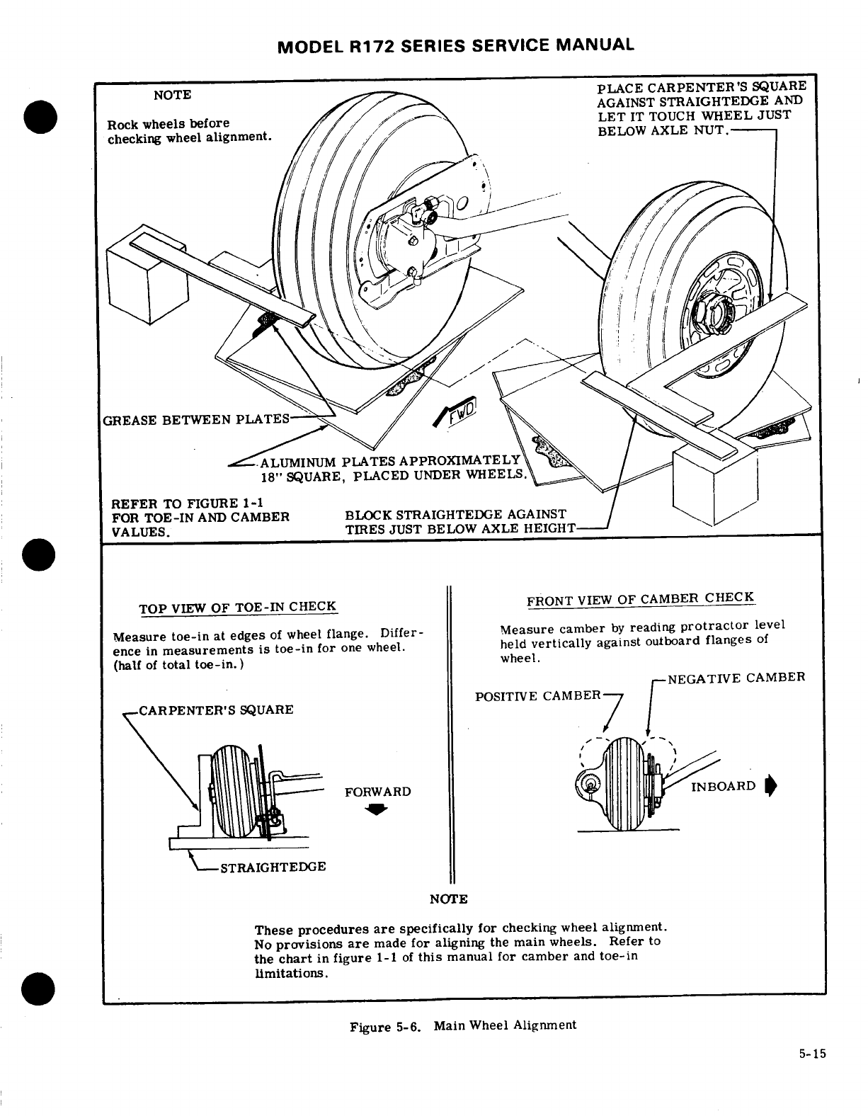
MODEL
R172
SERIES SERVICE
MANUAL
NOTE
A
PLACE
CARPENTER'S
SQUARE
AGAINST
STRAIGHTEDGE
AND
Rock
wheels
before
LET
IT
TOUCH
WHEEL
JUST
checking
wheel
alignment.
BELOW AXLE
NUT.
GREASE
BETWEEN
PLATES
-ALUMINUM
PLATES
APPROXIMATELY
18"
SQUARE,
PLACED
UNDER
WHEELS.
REFER
TO
FIGURE
1-1
FOR
TOE-IN
AND
CAMBER
BLOCK
STRAIGHTEDGE
AGAINST
VALUES.
TIRES
JUST
BELOW
AXLE
HEIGHT-
TOP
VIEW
OF
TOE-IN
CHECK
FRONT
VIEW
OF
CAMBER
CHECK
Measure
toe-in
at
edges
of
wheel
flange.
Differ-
Measure
camber
by
reading
protractor
level
ence
in
measurements
is
toe-in
for
one wheel.
held
vertically
against
outboard
flanges
of
(half
of
total
toe-in.)
wheel.
CNEGATIVE
CAMBER
POSITIVE
CAMBER
CARPENTER'S
SQUARE
P
FORWARD
STRAIGHTEDGE
NOTE
These
procedures
are
specifically
for
checking
wheel alignment.
No
provisions
are
made
for
aligning
the
main
wheels.
Refer
to
the
chart
in
figure
1-1
of
this
manual for
camber
and
toe-in
limitations.
Figure
5-6. Main Wheel
Alignment
5-15
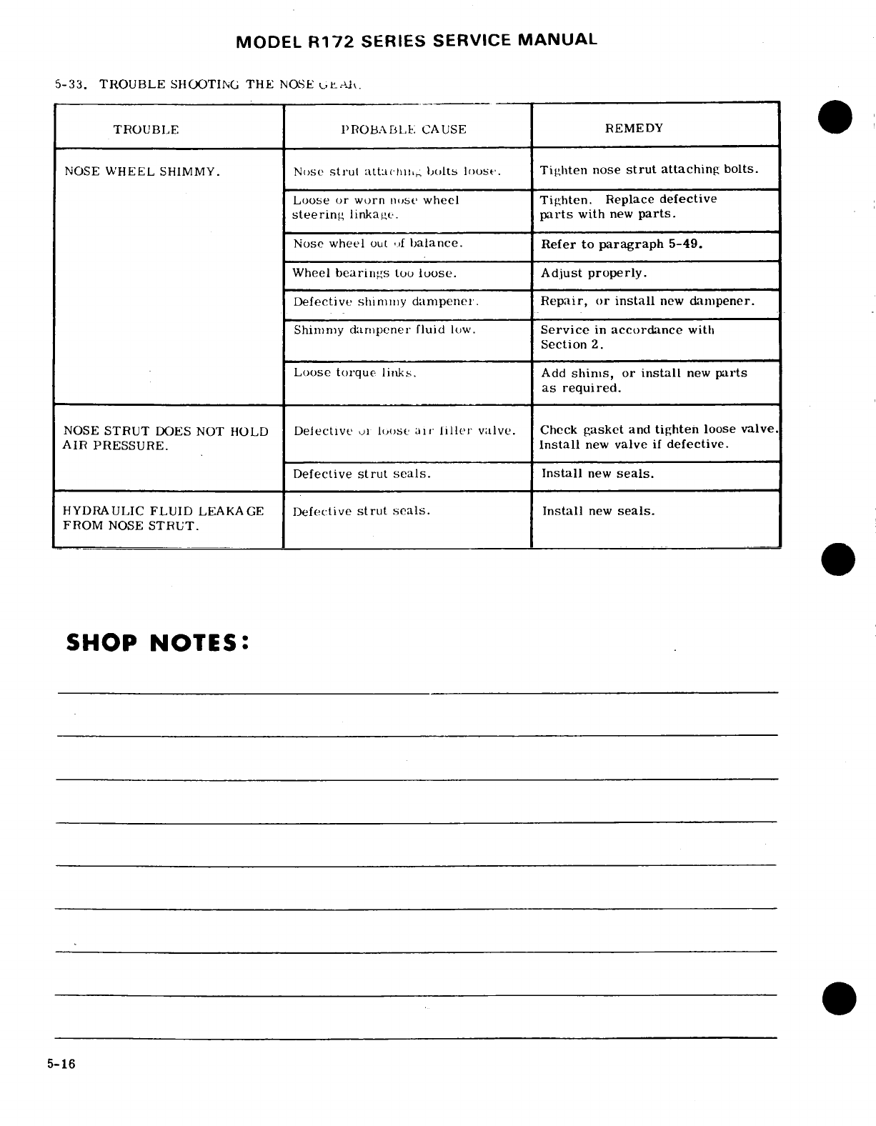
MODEL
R172
SERIES SERVICE
MANUAL
5-33. TROUBLE
SHOOTING
THE
NOSE
urAR.
TROUBLE
PROBA BLE
CAUSE
REMEDY
NOSE
WHEEL
SHIMMY.
Nose
strut
loose.
Tighten
nose
strut
attaching
bolts.
Loose
or
worn
nose
wheel
Tighten.
Replace
defective
steering
linkage.
parts
with
new
parts.
Nose
wheel
out
lf
balance.
Refer
to
paragraph
5-49.
Wheel
bearings
too
loose.
Adjust
properly.
Defective
shimmy
dampener.
Repair, or
install
new
dampener.
Shimmy
dampener
fluid
low.
Service
in
accordance
with
Section
2.
Loose
torque
links.
Add
shims,
or
install
new
parts
as
required.
NOSE
STRUT
DOES NOT HOLD
Defective
oi
lIoose
air
lillet
valve.
Check
gasket
and
tighten
loose
valve.
AIR
PRESSURE.
Install
new
valve
if
defective.
Defective
strut
seals.
Install
new
seals.
HYDRAULIC
FLUID
LEAKAGE
Defective
strut
seals.
Install
new
seals.
FROM
NOSE
STRUT.
SHOP
NOTES:
5-16
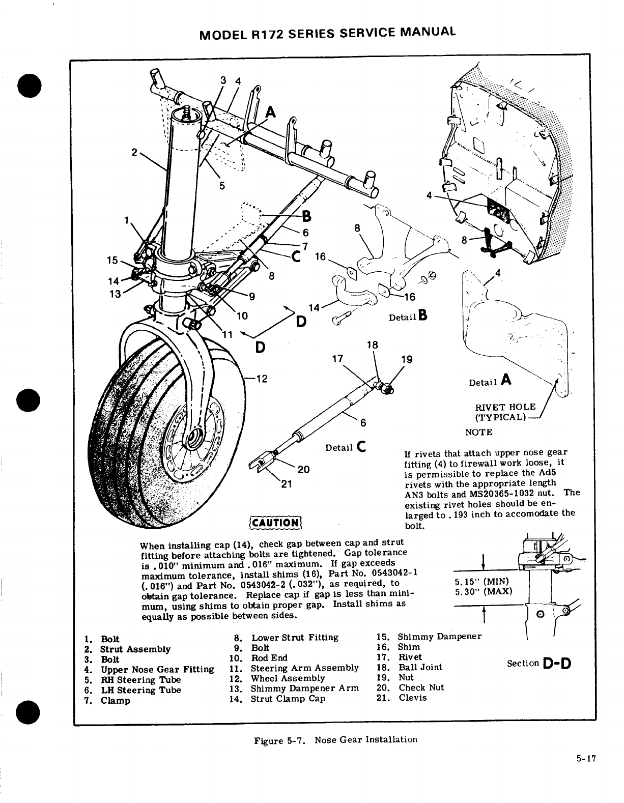
MODEL
R172
SERIES SERVICE
MANUAL
....
"Detail
i\-j
,
fitting
(4)
to
firewall
work
loose,
it
-
rivets
with
the
appropriate
length
bolts
and
MS20365-1032
nut.
The
existing
rivet holes
should
be
en-
Detail
A
--
RIVET
HOLEt
When
fitting
before attaching
bolts
are
tightened.
Gap
toleranceit
If
greplace
the
Ad5
rivets
with
the
appropriate
length
maximum
tolerance, install
shims
(16),
Part
No.
0543042-1 ' -
MS20365-002
obtain
gap
tolerance.
Replace
cap
if
gap
is
less
than
mini- 5.30"
(MAX)
Installe should
be
larged
to
.
13
inch
to
accomodate
the
When
install
ing
ca
p
(14),
check
gap
between
sidescap
and
strut
1.
Bolt
8.
Lower
Strut
Fitting
15.
Shimmy
Dampener
before
maximum
tolerance,
install
shims
(16),
Part
No.
0543042-1
(.
016")
and
Part
No.
0543042-2
(.
032"),
as
required,
to
5.15"
(MIN)
obtain
gap
tolerance.
Replace
cap
if
gap
is
less
than mini-
5.30"
(MAX)
2.
Strut
Assembly
9.
Bolt
16.
Shim
3.
Bolt
10.
Rod
End
17.
Rivet
4.
Upper
Nose
Gear
Fitting
11.
Steering Arm
Assembly
18.
Ball
Joint
SectionD-D
5.
RH
Steering
Tube
12.
Wheel
Assembly
19.
Nut
6.
LH
Steering
Tube
13.
Shimmy
Dampener
Arm
20.
Check
Nut
7.
Clamp
14.
Strut
Clamp
Cap
21.
Clevis
Figure
5-7.
Nose
Gear
Installation
5-17
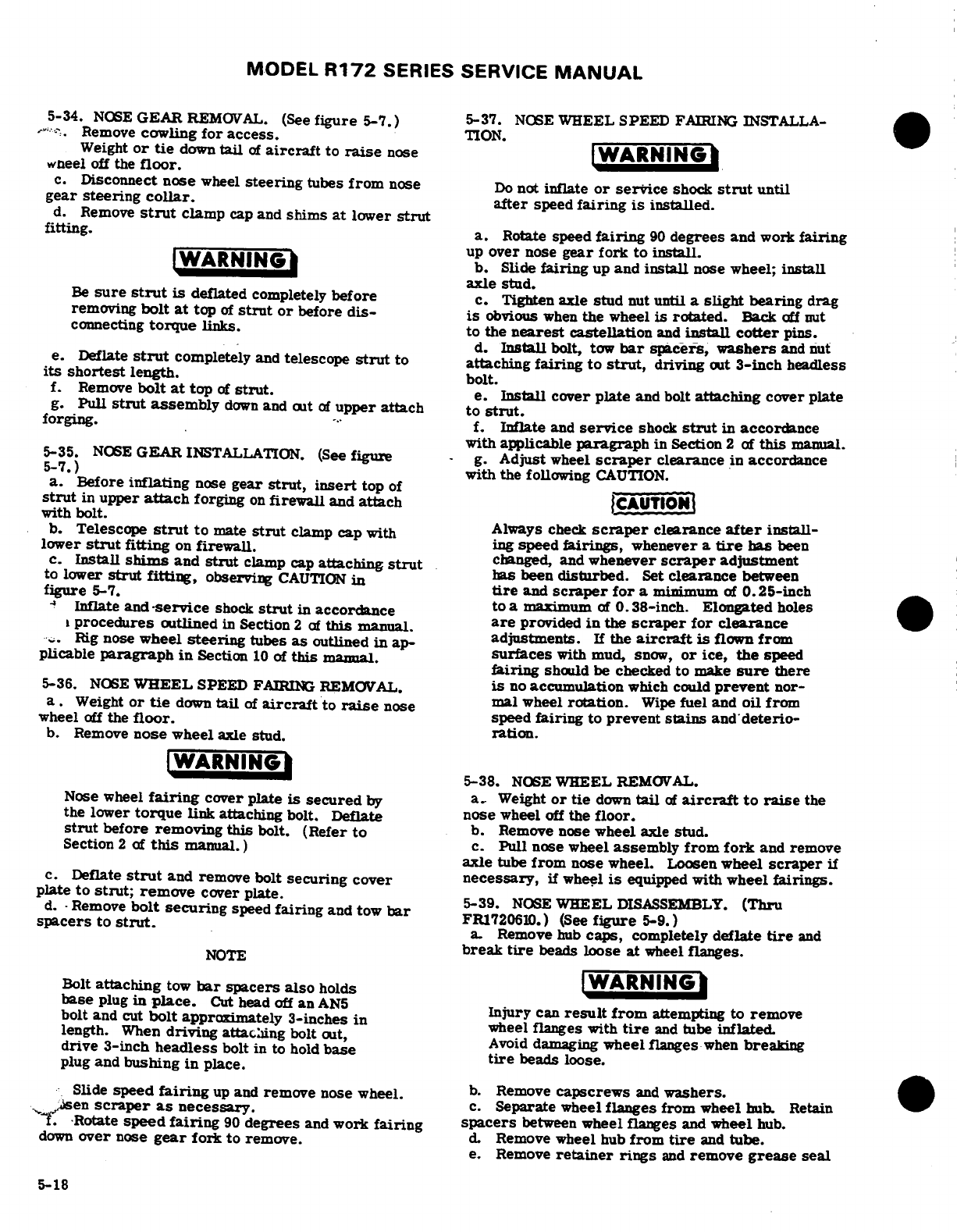
MODEL
R172
SERIES
SERVICE
MANUAL
5-34.
NOSE
GEAR
REMOVAL.
(See
figure
5-7.)
5-37.
NOSE
WHEEL
SPEED
FAIRING
INSTALLA-
.Remove
cowling
for access.
TION.
Weight
or
tie
down
tail
of
aircraft
to
raise
nose
WARNING
wheel
off
the
floor.
c.
Disconnect
nose
wheel
steering
tubes
from
nose
Do
not
inflate
or service
shock
strut
until
gear steering
collar.
after
speed
fairing
is
installed.
d.
Remove
strut
clamp
cap
and
shims
at
lower
strut
fitting.
a.
Rotate
speed
fairing
90
degrees
and
work
fairing
up
over
nose
gear
fork
to
install.
WARNING
b.
Slide
fairing
up
and
install
nose wheel;
install
axle
stud.
Be
sure
strut
is
deflated
completely
before
c.
Tighten
axle
stud
nut
until
a
slight
bearing
drag
removing
bolt
at
top
of
strut
or
before
dis-
is
obvious
when
the
wheel
is
rotated.
Back
off
nut
connecting
torque
links.
to
the
nearest
castellation
and
install
cotter
pins.
d.
Install
bolt,
tow
bar
spacers,
washers
and
nut
e.
Deflate
strut
completely
and
telescope
strut
to attaching
fairing
to
strut,
driving
out
3-inch
headless
its
shortest
length.
bolt.
f.
Remove
bolt
at
top
of
strut.
e.
Install
cover
plate
and bolt
attaching
cover
plate
g.
Pull
strut
assembly
down
and
out
of
upper
attach
to
strut.
forging.
f.
Inflate
and
service
shock
strut
in
accordance
with
applicable
paragraph
in
Section
2
of
this
manual.
5-35.
NOSE
GEAR
INSTALLATION.
(See
figure
-
g.
Adjust
wheel
scraper
clearance
in
accordance
5-7.)
with the
following
CAUTION.
a.
Before
inflating
nose
gear
strut, insert
top
of
strut
in
upper
attach
forging
on
firewall
and
attach
CAUTION
with
bolt.
b.
Telescope
strut
to
mate
strut
clamp
cap
with
Always
check
scraper
clearance
after
install-
lower
strut
fitting
on
firewall.
ing
speed
fairings,
whenever
a
tire
has
been
c.
Install
shims
and
strut
clamp
cap
attaching
strut
changed
and
whenever
scraper
adjustment
to
lower
strut
fitting,
observing
CAUTION
in
s
ben
disturbed.
Set
clearance
between
figure
5-7.
tire
and
scraper
for
a
minimum
of
0.25-inch
Inflate
and
-service
shock
strut
in
accordance
to
a
maximum
of
0.38-inch.
Elongated
holes
procedures
outlined
in
Section
2
of
this
manual.
are
provided
in
the
scraper
for clearance
.
Rig
nose
wheel
steering
tubes
as
outlined
in
ap-
adjustments.
If
the
aircraft
is
flown
from
plicable
paragraph
in
Section
10
of
this
manual.
surfaces
with
mud,
snow,
or
ice,
the
speed
fairing
should be checked
to
make
sure
there
5-36.
NOSE
WHEEL
SPEED
FAIRING
REMOVAL.
is
no
accumulation
which
could
prevent
nor-
a.
Weight
or
tie
down
tail
of
aircraft
to
raise
nose
mal
wheel
rotation.
Wipe
fuel
and
oil
from
wheel
off
the
floor.
speed
fairing
to
prevent stains
and
deterio-
b.
Remove
nose
wheel
axle
stud.
ration.
WARNING
5-38.
NOSE
WHEEL
REMOVAL.
Nose
wheel
fairing
cover
plate
is
secured
by
a.
Weight
or
tie
down
tail
of
aircraft
to
raise
the
the
lower
torque
link
attaching
bolt.
Deflate
nose
wheel
off
the
floor.
strut
before
removing this
bolt.
(Refer
to
b.
Remove
nose
wheel
axle
stud.
Section
2
of
this
manual.)
c.
Pull
nose
wheel
assembly
from
fork
and
remove
axle
tube
from
nose
wheel.
Loosen
wheel
scraper
if
c. Deflate
strut
and
remove
bolt
securing cover
necessary,
if
wheel
is
equipped
with
wheel
fairings.
plate
to
strut;
remove
cover
plate.
5-39
NOSE
WHEEL
DISASSEMBLY.
(Thru
d.
-
Remove
bolt securing
speed
fairing
and
tow
bar
FR1720610.)
(See
figure
5-9.)
spacers
to
strut.
a.
Remove
hub
caps,
completely
deflate
tire
and
NOTE
break
tire
beads
loose
at
wheel
flanges.
Bolt
attaching
tow
bar
spacers also
holds
WARNING
base
plug
in
place.
Cut
head
off
an
AN5
Injury
can
result
from
attempting to
remove
bolt
and
cut
bolt
approximately
3-inches
in
wheel
anges
with
tire
and
tube
inflated.
length.
When
driving
attaching
bolt
out,
Avoid
damaging
wheel
flanges
when
breaking
drive
3-inch
headless
bolt
in to
hold
base
tire
beads loose.
plug
and
bushing
in
place.
Slide
speed
fairing
up
and
remove
nose
wheel.
b.
Remove
capscrews
and
washers.
sen
scraper
as
necessary.
c.
Separate
wheel
flanges
from
wheel
hub.
Retain
f.
Rotate
speed
fairing
90
degrees
and
work
fairing
spacers
between
wheel
flanges
and
wheel
hub.
down
over
nose
gear
fork
to
remove.
d.
Remove
wheel
hub
from
tire
and
tube.
e.
Remove
retainer
rings
and
remove
grease
seal
5-18
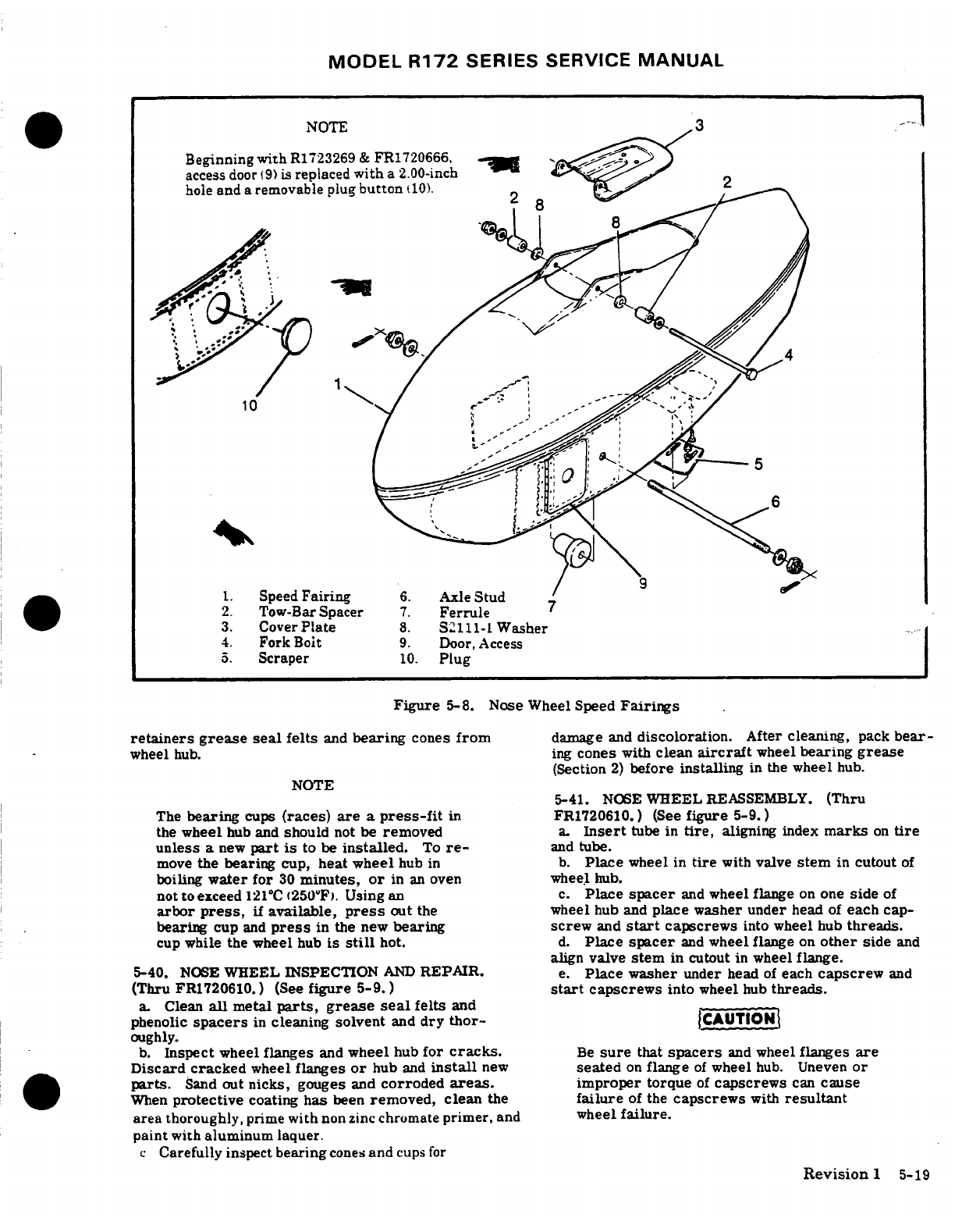
MODEL
R172
SERIES
SERVICE
MANUAL
NOTE
-
Beginning
with
R1723269
&
FR1720666,
-
access
door
(9)
is
replaced
with
a
2.00-inch
hole
and
a
removable
plug
button
Speed
Fairing
6.
Axle
Stud
2.
Tow-Bar
Spacer
7.
Ferrule
3.
Cover
Plate
8.
S2111-1
Washer
4.
Fork
Bolt
9.
Door,
Access
Figure
5-8.
Nose
Wheel
Speed
Fairings
retainers grease
seal
felts
and
bearing
cones
from
damage
and
discoloration.
After
cleaning,
pack
bear-
wheel
hub. ing
cones
with
clean
aircraft
wheel
bearing
grease
(Section
2)
before
installing
in
the
wheel
hub.
NOTE 5-41.
NOSE
WHEEL
REASSEMBLY.
(Thru
The
bearing
cups
(races)
are
a
press-fit
in
FR1720610.)
(See
figure
5-9.)
the
wheel
hub
and
should
not
be
removed
a.
Insert
tube
in
tire,
aligning
index
marks
on
tire
unless
a
new
part
is
to
be
installed.
To
re-
and
tube.
move
the
bearing
cup,
heat
wheel
hub
in
b.
Place
wheel
in
tire
with
valve
stem
in
cutout
of
boiling
water
for
30
minutes,
or
in
an
oven
wheel
hub.
not
to
exceed
121
0
C
(250'F). Using an
c.
Place
spacer
and
wheel
flange
on
one
side
of
arbor
press,
if
available,
press
out
the
wheel
hub
and
place washer under
head
of
each
cap-
bearing
cup
and
press
in
the
new
bearing screw
and
start
capscrews
into
wheel
hub
threads.
cup
while
the
wheel
hub
is
still
hot.
d.
Place
spacer
and
wheel
flange
on
other
side
and
align
valve
stem
in
cutout
in
wheel
flange.
5-40.
NOSE
WHEEL
INSPECTION
AND
REPAIR.
e.
Place washer
under
head
of
each
capscrew
and
(Thru
FR1720610.) (See
figure 5-9.)
start
capscrews
into
wheel
hub
threads.
a.
Clean
all
metal
parts,
grease
seal
felts
and
phenolic
spacers
in
cleaning
solvent
and
dry
thor-
(CAUTIONi
oughly.
b.
Inspect
wheel
flanges
and
wheel
hub
for
cracks.
Be
sure
that
spacers
and
wheel
flanges
are
Discard
cracked
wheel
flanges
or
hub
and
install
new
seated
on
flange
of
wheel
hub.
Uneven
or
parts.
Sand
out
nicks,
gouges
and
corroded
areas.
improper
torque
of
capscrews
can
cause
When
protective
coating
has
been
removed,
clean
the
failure
of
the
capscrews
with
resultant
area
thoroughly,
prime
with
non
zinc
chromate
primer,
and
wheel
failure.
paint
with
aluminum
laquer.
c
Carefully
inspect
bearing
cones
and
cups
for
Revision
1
5-19
MODEL
R172
SERIES
SERVICE
MANUAL
f.
Tighten
capscrews
(15)
evenly
and
torque
to
190
oughly,
then
applying
one
coat
of
clear
lacquer
paint.
to
200
lb-in.
k.
Pack
bearings
with
grease
specified
in
Section
2
g.
Clean
and
pack
bearing cones
with
clean
aircraft
of
this
manual.
wheel
bearing
grease.
(Refer
to
Section
2
for
grease
type.
)
5-44.
NOSE
WHEEL
REASSEMBLY.
(Beginning
with
h.
Assemble
bearing
cones,
grease
seal
felts
and
FR1720611
and
R17202001.)
(See
figure
5-9.)
retainers
into
wheel
hub. a.
Assemble
bearing
cone
(9).
grease
seal
retainer
i.
Inflate
tire
to
seat
tire
beads,
then
adjust
to
cor-
(2),
felt
grease
seal
(3),
grease
seal
retainer
(2)
and
rect
tire
pressure.
(Refer
to
Section
1.
)
retaining ring
(1)
into
both
wheel
halves
(6).
b.
Insert
tube
in
tire.
aligning
index
marks
on
tire
5-42.
NOSE
WHEEL
DISASSEMBLY.
(Beginning
with
and
tube.
FR1720611
and
R17202000.)
(See
figure
5-9.)
c.
Place
wheel
half
(6)
into
tire
and
tube (side
oppo-
site
valve
stem).
With
washer
(5)
under
head
of
thru-
WARNING
bolt
(8),
insert
bolt
through
wheel
half
(6).
d.
Place
wheel
half
(6)
into
other side
of
tire
and
Serious
injury
can
result
from
attempting
to
tube.
aligning
valve
stem
in
valve
slot.
separate
wheel
halves
with
tire
and
tube
in-
e.
Install
washers
(5)
and
nuts
(4)
on
thru-bolts
(8)
flated.
and
pre-torque
to
10-50 lb.
in.
a.
Completely deflate
tire
and
tube
and
break
loose
tire
beads.
Extreme
care
must
be
exercised
to
pre-
vent
tire
tool
damage
when
removing
tire
from
wheel
CAUTION
halves
(6).
b.
Remove
nuts
(4)
and
washers
(5).
Uneven
or
improper
torque
of
the
nuts
can
c.
Remove
thru-bolts
(8)
and
washers
(5).
cause
failure
of
the
bolts
with
resultant
d.
Separate
and
remove
wheel
halves
(6)
from
tire
wheel
failure.
and
tube.
e.
Remove
retaining
ring
(1),
grease
seal retainer
f.
Prior
to
torquing
nuts
(4),
inflate
tube
with
ap-
(2),
felt
grease
seal
(3),
grease
retainer
(2)
and
bear- proximately
10-15
psi
air
pressure
to
seat
tire.
ing
cone
(9)
from each
wheel
half
(6).
CAUTION
NOTE
Do
not
use impact wrenches
on
thru-bolts
Bearing cups
(races)
(7)
are
a
press
fit
in
or
nuts.
wheel half
(6)
and
should
not
be
removed
unless
a
new
part
is
to
be
installed.
To
g.
Dry
torque
all
nuts
(4)
evenly
to
a
torque
value
of
remove bearing
cups,
heat
wheel
half
in
of
140
to
150
lb-in.
boiling
water
for
30
minutes,
or
in
an
oven,
h.
Inflate
tire
to
correct
pressure
specified
in
fig-
not
to
exceed
121°C
(250°F).
Using
an
ure
1-1
of
this
manual.
arbor
press,
if
available,
press
out
bearing
cup
and
press
in
a
new
bearing
cup
while 5-45.
DISASSEMBLY.
(Cleveland)
(See
figure
5-9,
wheel
half
is
still
hot.
Sheet
2
of
2.)
5-43.
NOSE
WHEEL
INSPECTION
AND
REPAIR.
IWARNING
(Beginning
with
FR1720611
and
R17202001.)
(See
figure
5-9.)
Injury
can
result
from
attempting
to
separate
a.
Clean
all
metal
parts
and
felt
grease seals
in
Stoddard
solvent
or
equivalent,
and
dry
thoroughly.
wheel
halves
with
tire
inflated.
Avoid
dam-
aging wheel
flanges
when
breaking
tire
beads
loose.
NOTE
A
soft
bristle
brush
may
be
used
to
remove
a
Deflate
tire
and
break
tire
beads
loose.
a.
Deflate
tire
and
break
tire
beads
loose.
hardened
grease,
dust
or
dirt.
hardened
grease,
dust
or
dirt.
b.
Remove
thru-bolts
and
separate
wheel
halves.
c.
Remove
tire
and
tube.
b.
Inspect
wheel
halves
(6)
for
cracks
or
damage.
d.
Remove
snap
ring,
grease
seal
felt,
grease
seal
c.
Inspect bearing
cones
(9),
cups
(7),
retaining
rings
and
bearing cones from
both
wheel halves.
rings
(1)
and
seals
(2)
and
(3),
for
wear
or
damage.
d.
Inspect
thru-bolts
(8)
and
nuts
(4)
for
cracks
in
threads
or
cracks
in
radius
of
bolt
heads.
Bearing
cups
are
a
press-fit
in
the
wheel
e.
Replace
cracked
or
damaged
wheel
half
(6).
halves
and
should
not
be
removed
unless
halves
and
should
not
be
removed
unless
f.
Replace
damaged
retaining
rings
(1)
and
seals
(2)
replacement
is
necessary.
To
remove
and
(3).
replacement
is
necessary.
To
remove
bearing
cups,
heat
wheel
half
in
boiling
g.
Replace
any
worn
or
cracked
thru-bolts
(8)
or water for
15
minutes.
Using
an
arbor
press,
if
available,
press
out
bearing
cup
h.
Replace
worn
or
damaged
bearing cups
(7)
or
cones
(9).
and
press
in
new
cup
while
wheel
is
still
i.
Remove
any
corrosion
or
small
nicks.
hot.
j.
Repair
reworked
areas
of wheel
by
cleaning
thor-
5-20
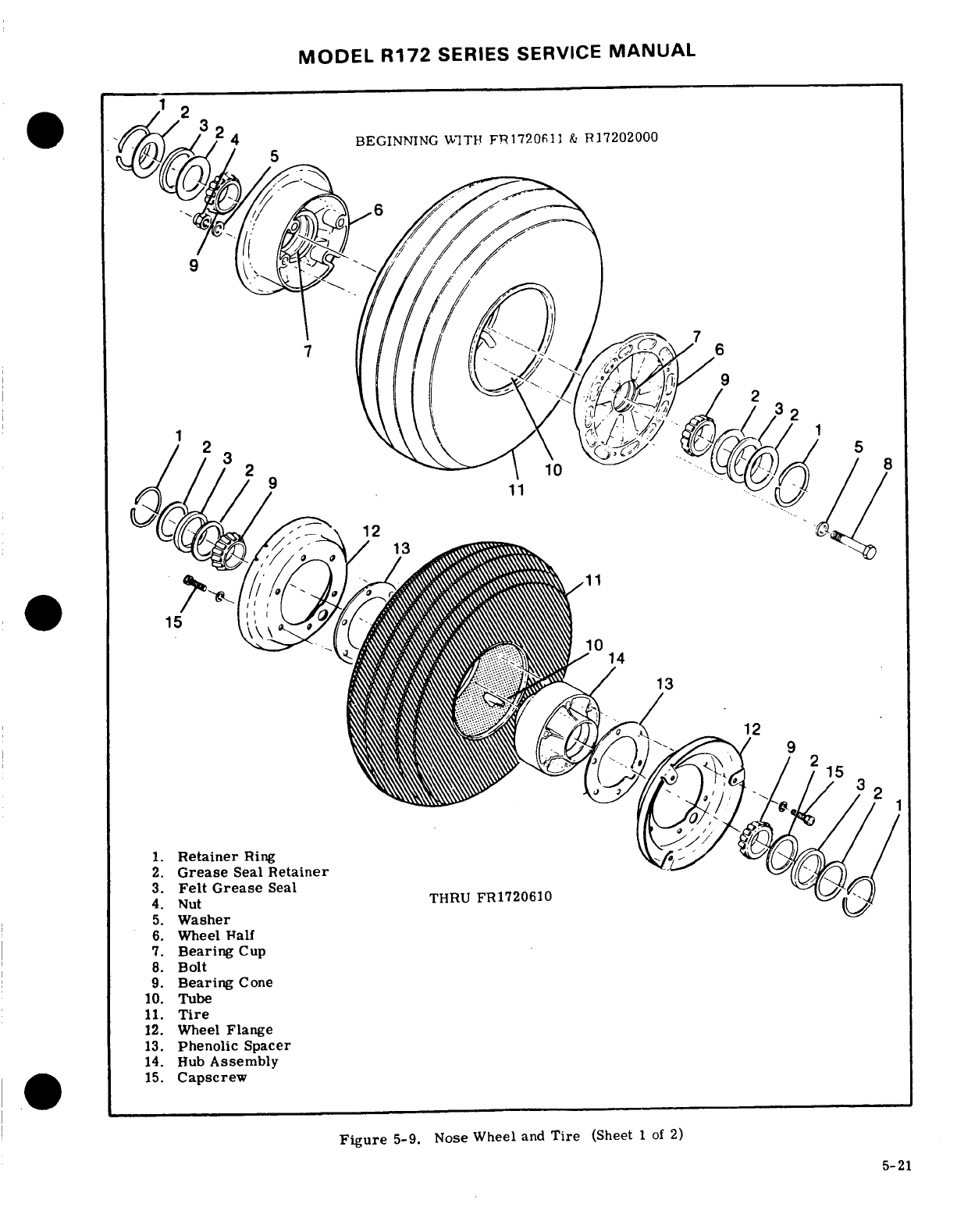
MODEL
R172
SERIES
SERVICE
MANUAL
BEGINNING
WITH
FR1720611
&
R17202000
1.
Retainer
Ring
2.
Grease
Seal
Retainer
3.
Felt
Grease
Seal
4.
Nut
THRU
FR1720610
5.
Washer
6.
Wheel
Half
7.
Bearing
Cup
8.
Bolt
9.
Bearing
Cone
10.
Tube
11.
Tire
12.
Wheel
Flange
13.
Phenolic
Spacer
15.
Capscrew
Figure
5-9.
Nose Wheel
and
Tire
(Sheet
1
of
2)
5-21
5-21
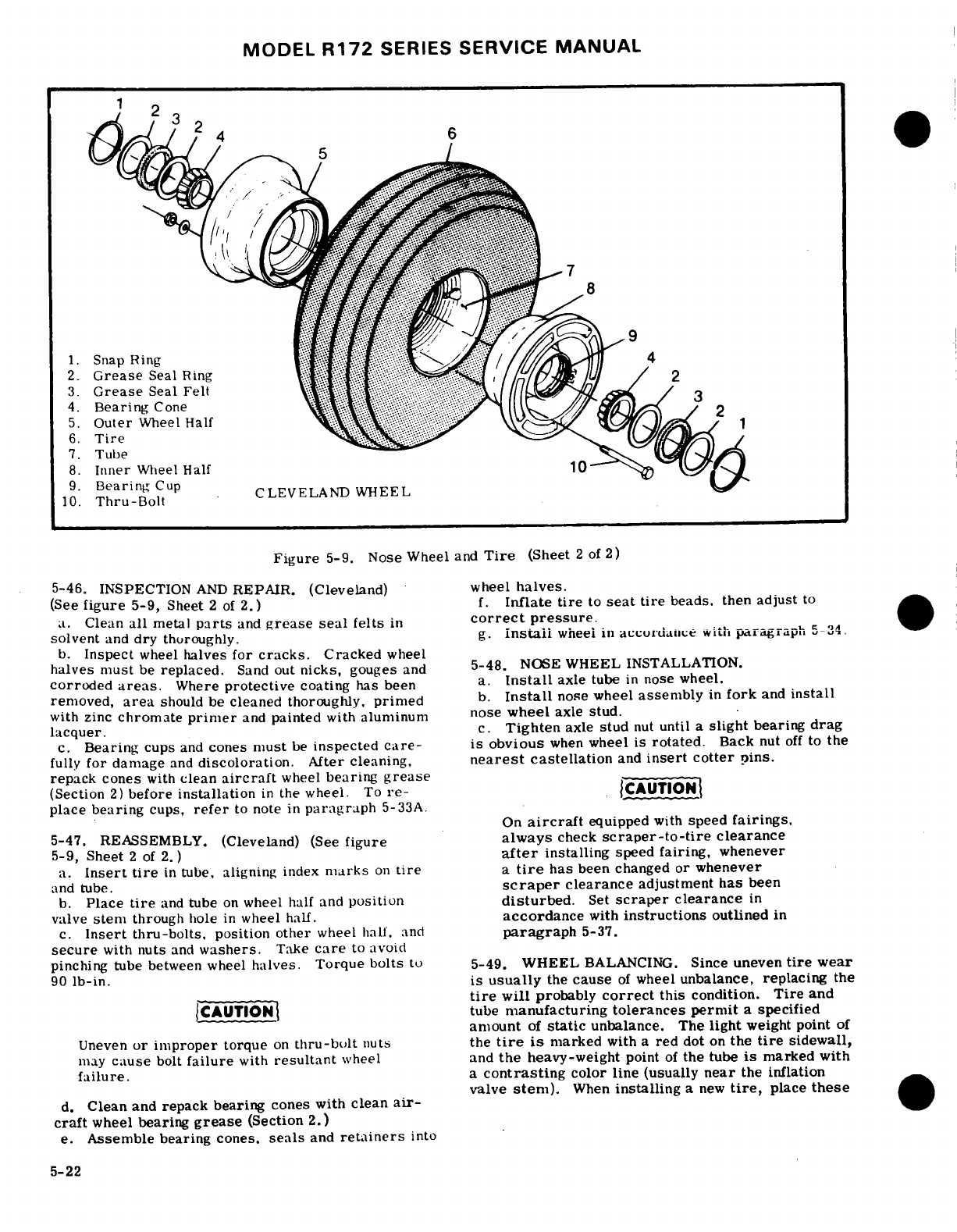
MODEL
R172
SERIES
SERVICE
MANUAL
1.
Snap
Ring
2.
Grease
Seal
Ring
3.
Grease
Seal
Felt
4.
Bearing
Cone
5. Outer
Wheel
Half
6.
Tire
.
7.
Tube
8.
Inner
Wheel
Half
10
9.
Bearing
Cup
CLEVELAND
WHEEL
10.
Thru-Bolt
Figure
5-9.
Nose
Wheel
and
Tire
(Sheet
2
of
2)
5-46.
INSPECTION
AND
REPAIR.
(Cleveland)
wheel
halves.
(See
figure
5-9,
Sheet
2
of
2.)
f.
Inflate
tire
to
seat
tire
beads, then
adjust
to
a.
Clean
all
metal
parts
and
grease
seal
felts
in
correct
pressure.
solvent
and
dry
thoroughly.
g.
install
wheel
in
accordance
with
paragraph
5-34.
b.
Inspect
wheel
halves
for
cracks.
Cracked
wheel
halves
must
be
replaced.
Sand
out
nicks,
gouges
and
5-48.
NOSE
WHEEL
INSTALLATION.
corroded
areas.
Where
protective
coating
has
been
a.
Install
axle
tube
in
nose
wheel.
removed,
area
should
be
cleaned
thoroughly,
primed
b.
Install
nose
wheel
assembly
in
fork
and
install
with zinc
chromate
primer
and
painted
with
aluminum
nose
wheel
axle
stud.
lacquer.
c.
Tighten
axle
stud
nut
until
a
slight
bearing
drag
c.
Bearing
cups
and
cones
must
be
inspected
care-
is
obvious
when
wheel
is
rotated.
Back
nut
off
to
the
fully
for
damage
and
discoloration.
After
cleaning,
nearest
castellation
and
insert cotter
pins.
repack cones
with
clean
aircraft
wheel
bearing
grease
(Section
2)
before
installation
in
the
wheel.
To
re-
CAUTION
place
bearing
cups,
refer
to
note
in
paragraph
5-33A.
On
aircraft
equipped
with
speed
fairings.
5-47.
REASSEMBLY.
(Cleveland)
(See
figure
always
check
scraper-to-tire
clearance
5-9,
Sheet
2
of
2.)
after
installing
speed
fairing,
whenever
a.
Insert
tire
in
tube,
aligning
index
marks
on
tire
a
tire
has
been changed
or
whenever
and
tube.
scraper
clearance
adjustment
has
been
b.
Place
tire
and
tube
on
wheel half
and
position
disturbed.
Set
scraper
clearance
in
valve
stem
through
hole
in
wheel
half.
accordance
with
instructions
outlined
in
c.
Insert
thru-bolts,
position other
wheel hall,
and
paragraph
5-37.
secure
with
nuts
and
washers.
Take
care
to
avoid
pinching
tube
between
wheel
halves.
Torque
bolts
to
5-49.
WHEEL
BALANCING.
Since
uneven
tire
wear
90
lb-in.
is
usually
the
cause
of
wheel
unbalance,
replacing
the
tire
will
probably
correct
this
condition.
Tire
and
CAUTION
tube
manufacturing
tolerances
permit
a
specified
amount
of
static
unbalance.
The
light
weight
point
of
Uneven
or improper
torque
on
thru-bolt
nuts
the
tire
is
marked
with a
red
dot
on
the
tire
sidewall,
may
cause
bolt
failure
with
resultant
wheel
and
the
heavy-weight
point
of
the
tube
is
marked
with
failure.
a
contrasting
color
line
(usually
near
the
inflation
valve
stem).
When
installing
a
new
tire,
place
these
d.
Clean
and
repack
bearing
cones with
clean
air-
craft
wheel
bearing
grease
(Section
2.)
e.
Assemble bearing
cones,
seals
and
retainers
into
5-22
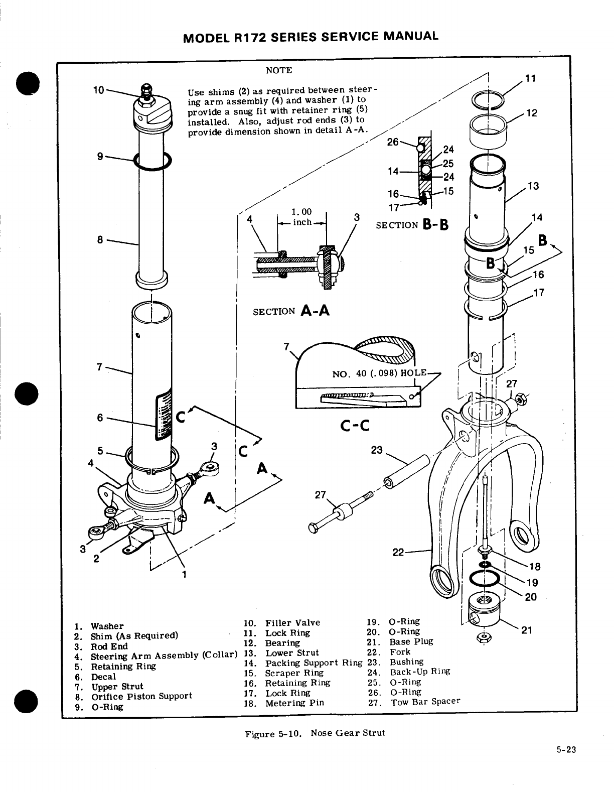
MODEL
R172
SERIES
SERVICE
MANUAL
NOTE
11
Use
shims
(2)
as
required
between
steer-
ing
arm
assembly
(4)
and
washer
(1)
to
.
provide
a
snug
fit
with
retainer
ring
(5)
1
installed.
Also,
adjust
rod
ends
(3)
to
provide dimension
shown
in
detail
A-A.
9
24
14
24
16
13
SECTION
B-B
15
16
17
SECTION
A-A
27
1.
Washer
10.
Filler
Valve
19.
O-Ring
2.
Shim
(As
Required)
11.
Lock Ring
20.
O-Ring
21
3.
Rod
End
12.
Bearing
21.
Base
Plug
4.
Steering
Arm
Assembly
(Collar)
13.
Lower
Strut
22.
Fork
5.
Retaining
Ring
14.
Packing Support
Ring
23.
Bushing
6.
Decal
15.
Scraper
Ring
24.
Back-Up
Ring
7.
Upper
Strut
16.
Retaining
Ring
25.
O-Ring
8.
Orifice
Piston
Support
17.
Lock Ring
26.
O-Ring
9.
O-Ring
18.
Metering
Pin
27.
Tow
Bar
Spacer
Figure
5-10.
Nose
Gear
Strut
5-23
MODEL
R172
SERIES
SERVICE
MANUAL
marks
adjacent
to
each
other.
If
a
wheel
shows
evi-
j.
Remove
retaining
ring
securing
steering
arm
dence
of
unbalance
during
service,
it
may
be
statically
assembly
on
upper
strut,
and
remove
steering
arm
balanced.
Wheel
balancing
equipment
is
available
assembly,
shims
(if
installed)
and
washer.
If
shims
from the
Cessna
Service
Parts
Center.
are
installed,
note
number
and
position
of
each
shim.
k.
Push
orifice
support
from
upper
strut
and
re-
5-
50.
NOSE
GEAR
SHOCK
STRUT
DISASSEMBLY.
move
O-ring.
(See
figure
5-10.
)
l.
Remove
filler
valve
from
orifice
support.
NOTE
5-51.
NOSE
GEAR
SHOCK
STRUT
INSPECTION
AND
REPAIR.
(See
figure
5-10.)
The
following
procedures
apply
to
the
nose
a.
Thoroughly
clean
all
parts
in
cleaning
solvent
gear
shock
strut after
it
has
been
removed
and
inspect
them
carefully.
from
the
aircraft
and
the
speed
fairing
and
b.
All
worn
or
defective
parts
and
all
O-rings
and
the
nose
wheel have
been
removed.
In
many
back-up
rings
must
be
replaced
with
new
parts.
cases,
separation
of
the
upper
and
lower
c.
Sharp
metal
edges
should
be
smoothed
with
No.
strut
will
permit inspection
and
parts
in-
400
emery
paper,
then cleaned
with
solvent.
stallation
without
removal or
complete
dis-
assembly
of
the
strut.
5-52.
NOSE
GEAR
SHOCK
STRUT
REASSEMBLY.
WARNING
(See
figure
5-10.)
NOTE
Be
sure
shock
strut
is
completely deflated
before
removing
lock
ring
in
lower
end
of
Used
sparingly,
Dow
Corning
Compound
DC4
upper
strut,
or
disconnecting torque
links.
is
recommended
for
O-ring
lubrication.
All
other
internal
parts
should
be
liberally
coated
a.
Remove
shimmy
dampener.
with
hydraulic
fluid during
reassembly.
b.
Remove
torque
links.
Note
position
of
washers,
shims
and
spacers.
a.
Install
washer
(1)
and
shim(s)
(2),
if
installed.
c.
Remove
lock
ring
from
groove
inside
lower
end
b.
Lubricate
needle
bearings
in
steering
collar
(4),
of
upper
strut.
A
small
hole
is
provided
at
the
lock
as
shown
in
Section
2
of
this
manual,
and
install
ring
groove
to
facilitate
removal
of
the
lock
ring.
steering
collar
and
retaining ring
(5).
c.
Check
steering
collar
for
snug
fit
against
washer.
NOTE
Shims
of
variable
thicknesses
and
available
from
the
Cessna
Service
Parts
Center
to
provide
a
snug
fit
for
Hydraulic
fluid
will
drain
from
strut
halves
collar
against
washer.
as
lower
strut
is
pulled
from
upper
strut.
NOTE
d.
Using
a
straight, sharp
pull,
separate
upper
and
lower
struts.
Invert
lower
strut
and
drain
hydraulic
If
shims
are
required,
remove
retaining
ring
fluid. and
steering
collar
and
add
shims
as
neces-
e.
Remove
lock
ring
and
bearing
at
upper
end
of
sary
to
provide
a
snug
fit
with
steering
collar
lower
strut
assembly.
Note
top
side
of
bearing. retaining
ring
in
place.
f.
Slide
packing
support
ring,
scraper
ring,
re-
taining
ring
and
lock
ring
from
lower
strut,
noting
Part
numbers
of
available
shims
and
their
thicknesses
relative
position
and
top
side
of
each
ring;
wire
or
are
listed
as
follows:
tape
together,
if
desired.
g.
Remove
O-rings
and
back-up rings
from
packing
1243030-5
... .
0.006
support
ring.
1243030-6
.......
0.012
h.
Remove
bolt
securing
tow
bar
spacers.
1243030-7
........
... .
.0.020
NOTE
d.
Install
rod
ends
(3)
in
steering
collar
(4)
and
adjust
rod
ends
to
dimension
specified
in
Section
Bolt
attaching
tow
bar
spacers
also
holds
view
A-A
in
figure
5-10.
bushing
and
base
plug
in
place.
e.
Install
O-ring
(9)
and
filler
valve
(10)
in
orifice
piston
support
(8)
and
install
orifice
piston
support
i.
Remove bolt
attaching
fork
to
strut
barrel
and
in
upper
strut
(7).
remove
bushing,
base
plug
and
metering
pin
from
f.
Install
O-ring
(20) and
metering
pin
(18)
with
lower
strut.
Remove
O-rings
and
metering
pin
from
O-ring
(19)
in
base
plug
(21);
secure
with
nut.
base
plug.
NOTE
NOTE
If
base
plug
(21)
is
to
be
replaced,
new
part
Lower
strut barrel
and nose
gear
fork
are
a
will
need
to
be
line-drilled
to
accept
NAS75-5
press
fit,
drilled
on
assembly.
Separation
bushing.
of
these
parts
is
not
recommended
except
for
installation
of
a
new
part.
g.
Install
bushing
(23), if
removed,
in
base
plug
5-24
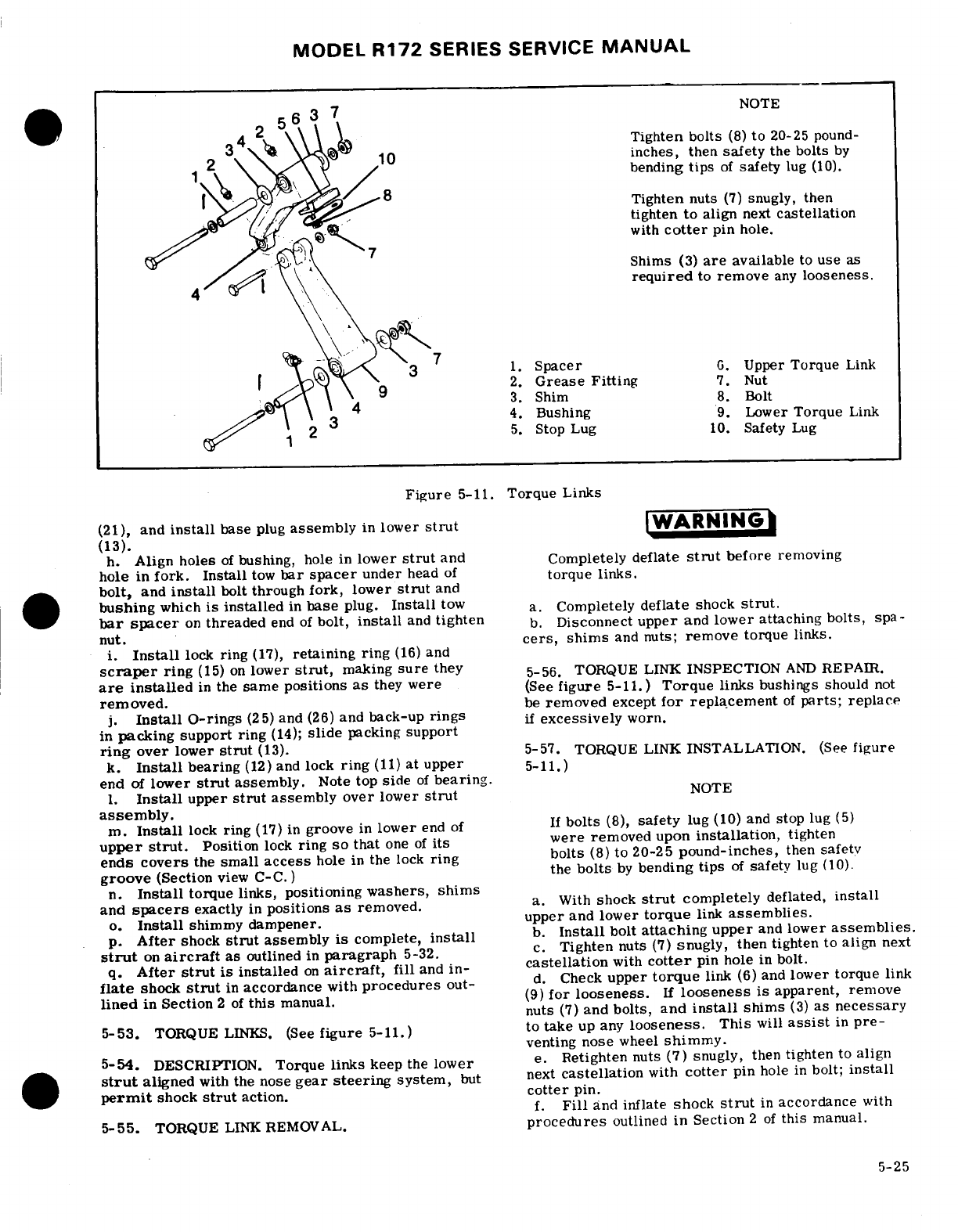
MODEL
R172
SERIES
SERVICE
MANUAL
NOTE
inches,
then
safety
the
bolts
by
bending
tips
of
safety
lug
(10).
Tighten
nuts
(7)
snugly,
then
tighten
to
align
next
castellation
with
cotter
pin
hole.
Shims
(3)
are
available
to
use
as
required
to
remove
any
looseness.
3
1.
Spacer
G.
Upper
Torque
Link
[ j
2.
Grease Fitting
7.
Nut
3.
Shim
8.
Bolt
4.
Bushing
9.
Lower
Torque
Link
1
5.
Stop
Lug
10.
Safety
Lug
5-11.
Torque
Links
(21),
and
install
base
plug
assembly
in
lower
strut
WARNING
(13).
h.
Align
holes
of
bushing,
hole
in
lower
strut
and Completely
deflate
strut
before
removing
hole
in
fork. Install
tow
bar
spacer
under
head
of
torque
links.
bolt,
and
install
bolt
through
fork, lower
strut
and
bushing
which
is
installed
in
base
plug.
Install
tow
a.
Completely
deflate
shock
strut.
bar spacer
on
threaded
end
of
bolt,
install
and
tighten
b.
Disconnect
upper
and
lower
attaching
bolts,
spa-
nut.
cers,
shims
and
nuts;
remove
torque
links.
i.
Install
lock
ring
(17),
retaining
ring
(16)
and
scraper
ring
(15)
on
lower
strut,
making
sure
they
5-56.
TORQUE
LINK
INSPECTION
AND
REPAIR.
are
installed
in
the
same
positions
as
they
were
(See
figure
5-11.)
Torque
links
bushings
should
not
removed.
be
removed
except
for
replacement
of
parts; replace
j.
Install
O-rings
(25) and
(26)
and
back-up
rings
if
excessively
worn.
in
packing
support
ring
(14);
slide
packing
support
ring
over
lower
strut
(13).
5-57.
TORQUE LINK
INSTALLATION.
(See
figure
k.
Install
bearing
(12)
and
lock
ring
(11)
at upper
5-11.)
end
of
lower
strut
assembly.
Note
top
side
of
bearing.
1.
Install
upper
strut
assembly
over
lower
strut
NOTE
assembly.
m.
Install
lock
ring
(17)
in
groove
in
lower
end
of
If
bolts
(8),
safety
lug
(10)
and
stop
lug
(5)
upper
strut.
Position
lock
ring
so
that
one
of
its
were
removed
upon
installation,
tighten
ends
covers
the
small
access
hole
in
the
lock
ring
bolts
(8)
to
20-25
pound-inches,
then
safety
groove
(Section
view
C-C.)
the
bolts
by
bending
tips
of
safety
lug
(10).
n.
Install
torque links, positioning
washers,
shims
and
spacers
exactly
in
positions
as
removed.
a. With
shock
strut
completely
deflated,
install
o.
Install
shimmy
dampener. upper
and
lower
torque
link
assemblies.
p.
After
shock
strut
assembly
is
complete,
install
b.
Install
bolt
attaching
upper
and
lower
assemblies.
strut
on
aircraft
as
outlined
in
paragraph
5-32.
c.
Tighten
nuts
(7)
snugly, then
tighten
to
align
next
q.
After
strut
is
installed
on
aircraft,
fill
and
in-
castellation
with
cotter
pin
hole
in
bolt.
flate
shock
strut
in
accordance
with
procedures
out-
d.
Check
upper
torque
link
(6)
and
lower
torque
link
lined
in
Section
2
of
this
manual.
(9)
for
looseness.
If
looseness
is
apparent,
remove
nuts
(7)
and
bolts,
and
install
shims
(3)
as
necessary
5-53.
TORQUE
LINKS.
(See
figure
5-11.)
to
take
up
any
looseness.
This
will
assist
in
pre-
venting
nose
wheel
shimmy.
5-54.
DESCRIPTION.
Torque
links
keep
the
lower
e.
Retighten
nuts
(7)
snugly,
then
tighten
to
align
strut
aligned
with
the
nose
gear steering
system,
but
next
castellation
with
cotter
pin
hole
in
bolt;
install
permit
shock
strut
action,
cotter
pin.
f.
Fill
and
inflate
shock
strut
in
accordance
with
5-55.
TORQUE
LINK
REMOVAL.
procedures
outlined
in
Section
2
of
this
manual.
5-25
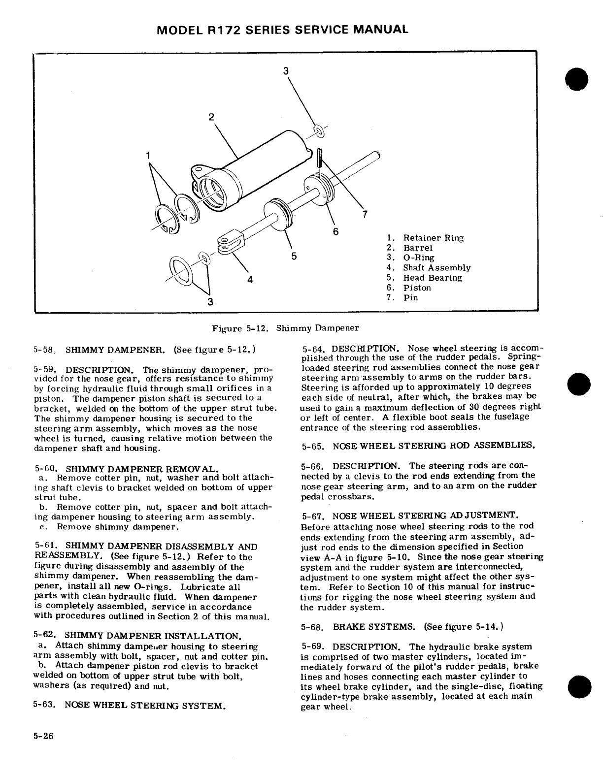
MODEL
R172
SERIES SERVICE
MANUAL
3
2
1.
Retainer
Ring
2.
Barrel
5
3.
O-Ring
.4.
Shaft
Assembly
5.
Head
Bearing
6.
Piston
3
7.
Pin
Figure
5-12.
Shimmy Dampener
5-58,
SHIMMY
DAMPENER.
(See
figure
5-12.)
5-64.
DESCRIPTION. Nose
wheel
steering
is
accom-
plished
through
the
use
of
the
rudder pedals.
Spring-
5-59.
DESCRIPTION. The
shimmy
dampener,
pro-
loaded
steering
rod
assemblies
connect
the
nose
gear
vided
for
the
nose
gear,
offers
resistance
to
shimmy
steering
arm
assembly
to
arms
on
the
rudder
bars.
by
forcing
hydraulic fluid through
small
orifices
in a
Steering
is
afforded
up
to
approximately
10
degrees
piston.
The
dampener piston
shaft
is
secured
to
a
each
side
of
neutral,
after
which,
the
brakes
may
be
bracket,
welded
on
the
bottom
of
the
upper
strut
tube.
used
to
gain
a
maximum
deflection
of
30
degrees
right
The
shimmy
dampener
housing
is
secured
to
the
or
left
of
center.
A
flexible
boot
seals
the fuselage
steering
arm
assembly,
which
moves
as
the
nose
entrance
of
the
steering
rod
assemblies.
wheel
is
turned,
causing
relative
motion
between
the
dampener
shaft
and
housing.
5-65.
NOSE
WHEEL
STEERING
ROD
ASSEMBLIES.
5-60.
SHIMMY
DAMPENER
REMOVAL.
5-66.
DESCRIPTION.
The
steering rods
are
con-
a.
Remove
cotter
pin,
nut,
washer
and
bolt
attach-
nected
by a
clevis
to
the
rod
ends
extending
from
the
ing
shaft
clevis
to
bracket
welded
on
bottom
of
upper
nose
gear steering
arm,
and
to
an
arm
on
the
rudder
strut
tube.
pedal
crossbars.
b.
Remove
cotter
pin,
nut,
spacer
and
bolt
attach-
ing
dampener
housing
to
steering
arm
assembly.
5-67.
NOSE
WHEEL
STEERING ADJUSTMENT.
c.
Remove
shimmy
dampener.
Before
attaching nose
wheel
steering
rods
to
the
rod
ends
extending
from
the
steering
arm
assembly,
ad-
5-61.
SHIMMY
DAMPENER
DISASSEMBLY
AND
just
rod
ends
to
the
dimension
specified
in
Section
REASSEMBLY.
(See
figure
5-12.)
Refer
to
the
view
A-A
in
figure
5-10.
Since
the
nose
gear
steering
figure
during
disassembly
and
assembly
of
the
system
and
the
rudder
system
are
interconnected,
shimmy
dampener.
When
reassembling
the
dam-
adjustment
to
one
system
might
affect
the
other
sys-
pener,
install
all
new
O-rings.
Lubricate
all
tem.
Refer
to
Section
10
of
this
manual
for
instruc-
parts
with
clean
hydraulic
fluid.
When
dampener
tions
for
rigging
the
nose
wheel
steering
system
and
is completely
assembled,
service
in
accordance
the
rudder
system.
with
procedures
outlined
in
Section
2
of
this
manual.
5-68.
BRAKE
SYSTEMS.
(See
figure
5-14.)
5-62.
SHIMMY
DAMPENER
INSTALLATION.
a.
Attach shimmy
dampener
housing
to
steering
5-69.
DESCRIPTION.
The
hydraulic
brake
system
arm assembly
with
bolt,
spacer,
nut
and
cotter
pin.
is
comprised
of
two
master
cylinders,
located
im-
b.
Attach
dampener
piston rod
clevis
to
bracket
mediately
forward
of
the
pilot's
rudder
pedals,
brake
welded
on
bottom
of
upper
strut
tube
with
bolt,
lines
and
hoses connecting
each
master
cylinder
to
washers
(as
required)
and
nut.
its
wheel
brake
cylinder,
and
the
single-disc,
floating
cylinder-type brake
assembly,
located
at
each
main
5-63.
NOSE
WHEEL
STEERING
SYSTEM.
gear
wheel.
5-26
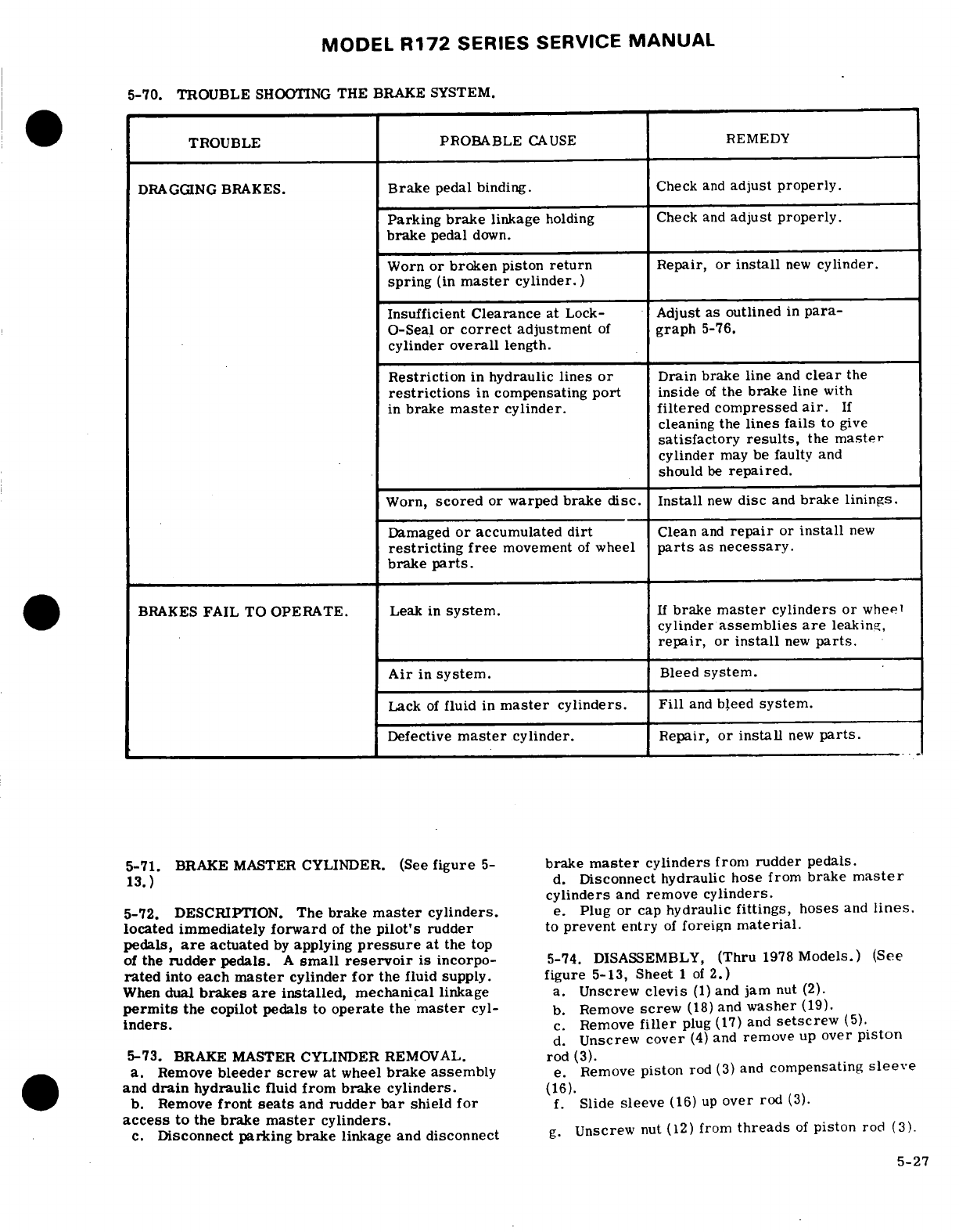
MODEL
R172
SERIES
SERVICE
MANUAL
5-70.
TROUBLE
SHOOTING
THE
BRAKE SYSTEM.
TROUBLE
PROBABLE
CAUSE
REMEDY
DRAGGING
BRAKES.
Brake
pedal
binding.
Check
and
adjust properly.
Parking
brake
linkage
holding
Check
and
adjust
properly.
brake
pedal
down.
Worn
or
broken
piston
return
Repair,
or
install
new
cylinder.
spring
(in
master
cylinder.)
Insufficient
Clearance
at
Lock-
Adjust
as
outlined
in
para-
O-Seal
or
correct
adjustment
of
graph
5-76.
cylinder
overall
length.
Restriction
in
hydraulic
lines
or
Drain brake line
and
clear
the
restrictions
in
compensating
port
inside
of
the
brake
line
with
in
brake
master
cylinder,
filtered
compressed
air.
If
cleaning the
lines
fails
to
give
satisfactory
results,
the
master
cylinder
may be
faulty
and
should
be
repaired.
Worn,
scored
or
warped
brake
disc.
Install
new
disc
and
brake
linings.
Damaged
or
accumulated
dirt
Clean
and
repair
or
install
new
restricting
free
movement
of
wheel
parts
as
necessary.
brake
parts.
BRAKES
FAIL
TO
OPERATE. Leak
in
system.
If
brake
master
cylinders
or
wheel
cylinder
assemblies
are
leaking,
repair,
or
install
new
parts.
Air
in
system.
Bleed
system.
Lack
of
fluid
in
master
cylinders. Fill
and
bleed
system.
Defective
master
cylinder.
Repair,
or
install
new
parts.
5-71.
BRAKE
MASTER
CYLINDER. (See
figure
5-
brake
master
cylinders
from
rudder
pedals.
13.)
d.
Disconnect
hydraulic
hose
from
brake
master
cylinders
and
remove
cylinders.
5-72. DESCRIPTION.
The
brake
master
cylinders.
e.
Plug or
cap
hydraulic
fittings,
hoses
and
lines.
located immediately
forward
of
the
pilot's
rudder
to
prevent entry
of
foreign
material.
pedals,
are
actuated
by
applying
pressure
at
the
top
of
the
rudder
pedals.
A
small
reservoir
is incorpo-
5-74.
DISASSEMBLY,
(Thru
1978
Models.)
(See
rated
into
each
master
cylinder
for
the fluid
supply.
figure
5-13,
Sheet
1
of
2.)
When
dual
brakes
are
installed,
mechanical
linkage
a.
Unscrew
clevis
(1)
and
jam
nut
(2).
permits
the
copilot
pedals
to
operate
the
master
cyl-
b.
Remove
screw
(18)
and
washer
(19).
inders.
c.
Remove
filler
plug
(17)
and
setscrew
(5).
d.
Unscrew
cover
(4)
and
remove
up
over
piston
5-73.
BRAKE MASTER
CYLINDER
REMOVAL.
rod
(3).
a.
Remove
bleeder
screw
at
wheel
brake assembly
e.
Remove
piston
rod
(3)
and
compensating
sleeve
and
drain
hydraulic
fluid
from brake cylinders.
(16).
b.
Remove
front
seats
and
rudder
bar
shield
for
f.
Slide
sleeve
(16)
up
over
rod
(3).
access
to
the
brake
master
cylinders.
c.
Disconnect
parking brake
linkage
and
disconnect
g.
Unscrew
nut
(12)
from
threads
of
piston
rod
(3)
5-27
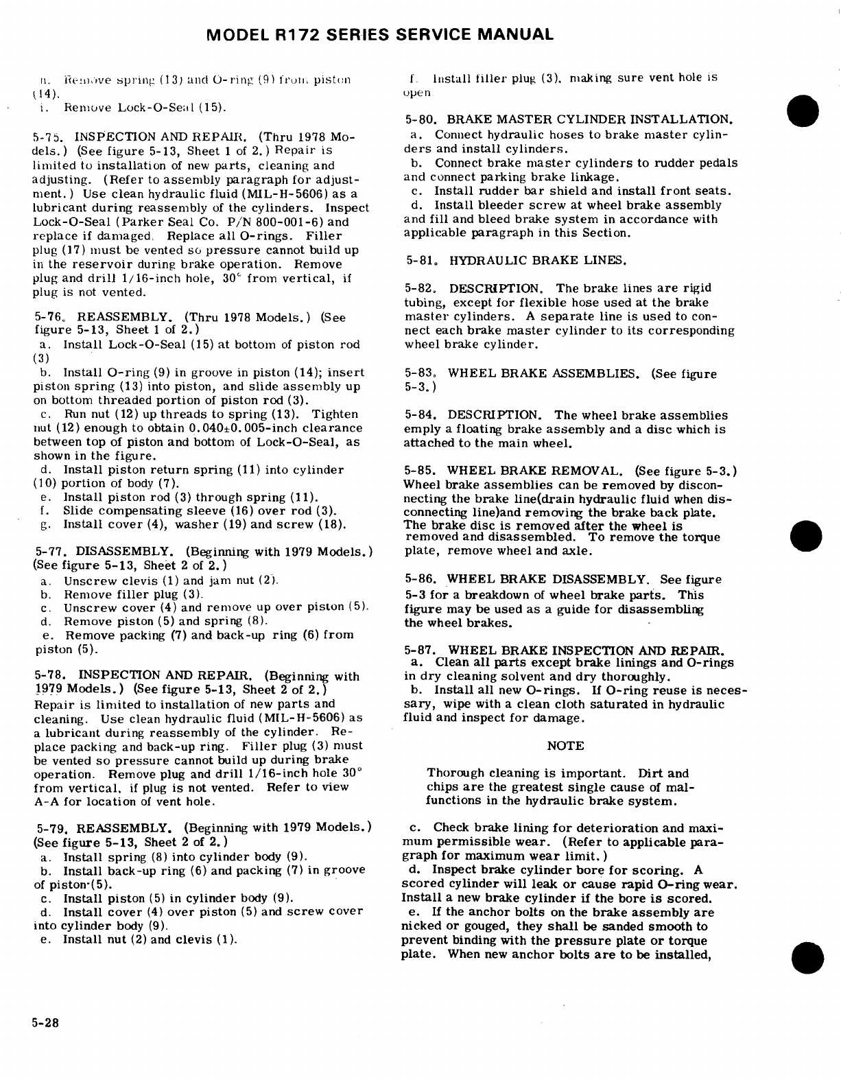
MODEL
R172
SERIES SERVICE
MANUAL
plug
(3).
sure
vent
hole
is
i.
Remove
Lock-O-Seal
(15).
5-80.
BRAKE
MASTER CYLINDER
INSTALLATION.
5-75.
INSPECTION
AND
REPAIR.
(Thru
1978
Mo-
a.
Connect
hydraulic
hoses
to
brake
master
cylin-
dels.)
(See
figure
5-13,
Sheet
1
of
2.)
Repair
is
ders
and
install
cylinders.
limited
to
installation
of
new
parts,
cleaning
and
b.
Connect
brake
master
cylinders
to
rudder
pedals
adjusting. (Refer
to
assembly paragraph
for
adjust-
and connect
parking
brake
linkage.
ment.
)
Use
clean
hydraulic
fluid (MIL-H-5606)
as
a
c.
Install
rudder
bar
shield
and
install
front
seats.
lubricant
during
reassembly
of
the
cylinders.
Inspect
d.
Install bleeder
screw
at
wheel
brake
assembly
Lock-O-Seal
(Parker
Seal
Co.
P/N
800-001-6)
and and
fill
and
bleed
brake
system
in
accordance
with
replace
if
damaged.
Replace
all
0-rings.
Filler
applicable
paragraph
in
this
Section.
plug
(17)
must
be
vented
so
pressure
cannot
build
up
in
the
reservoir
during
brake
operation.
Remove 5-81.
HYDRAULIC
BRAKE LINES.
plug
and
drill
1/16-inch
hole,
30
°
from
vertical,
if
plug
is
not
vented.
5-82.
DESCRIPTION.
The
brake lines
are
rigid
tubing, except
for
flexible
hose
used
at
the
brake
5-76. REASSEMBLY.
(Thru
1978
Models.)
(See
master
cylinders.
A
separate
line
is
used
to
con-
figure
5-13,
Sheet
1
of
2.)
nect
each
brake
master
cylinder
to
its
corresponding
a.
Install
Lock-O-Seal
(15)
at
bottom
of
piston
rod wheel
brake
cylinder.
(3)
b.
Install
O-ring
(9)
in
groove
in
piston
(14);
insert
5-83.
WHEEL
BRAKE
ASSEMBLIES.
(See
figure
piston
spring
(13)
into
piston,
and
slide assembly
up 5-3.)
on
bottom
threaded
portion
of
piston
rod
(3).
c.
Run
nut
(12)
up
threads
to
spring
(13).
Tighten
5-84.
DESCRIPTION.
The wheel
brake
assemblies
nut
(12)
enough
to
obtain
0.040±0.005-inch
clearance
emply
a
floating
brake
assembly
and
a
disc
which
is
between
top
of
piston
and
bottom
of
Lock-O-Seal,
as
attached
to the
main
wheel.
shown
in
the
figure.
d.
Install
piston
return
spring
(11)
into
cylinder
5-85.
WHEEL
BRAKE
REMOVAL.
(See
figure
5-3.)
(10)
portion
of
body
(7).
Wheel
brake
assemblies
can
be
removed
by
discon-
e.
Install
piston
rod
(3)
through
spring
(11).
necting the
brake
line(drain
hydraulic
fluid
when
dis-
f.
Slide
compensating
sleeve
(16)
over rod
(3).
connecting
line)and
removing
the
brake
back
plate.
g.
Install
cover
(4),
washer
(19)
and
screw
(18).
The
brake disc
is
removed
after
the
wheel
is
removed
and
disassembled.
To
remove
the
torque
5-77.
DISASSEMBLY.
(Beginning
with
1979
Models.)
plate,
remove
wheel and
axle.
(See
figure
5-13,
Sheet
2
of
2.)
a.
Unscrew
clevis
(1)
and
jam
nut
(2).
5-86.
WHEEL
BRAKE DISASSEMBLY.
See
figure
b.
Remove
filler
plug
(3).
5-3
for
a
breakdown
of
wheel
brake
parts.
This
c.
Unscrew
cover
(4)
and
remove
up
over
piston
(5).
figure
may
be
used
as
a
guide
for
disassembling
d.
Remove
piston
(5)
and
spring
(8).
the
wheel
brakes.
e.
Remove
packing
(7)
and
back-up
ring
(6)
from
piston
(5).
5-87.
WHEEL
BRAKE
INSPECTION
AND
REPAIR.
a.
Clean
all
parts
except
brake
linings
and
O-rings
5-78.
INSPECTION
AND
REPAIR.
(Beginning
with
in
dry
cleaning
solvent
and
dry
thoroughly.
1979
Models.)
(See
figure
5-13,
Sheet
2
of
2.)
b.
Install
all
new
O-rings.
If
O-ring reuse
is
neces-
Repair
is
limited
to
installation
of
new
parts
and
sary,
wipe
with
a
clean
cloth
saturated
in
hydraulic
cleaning.
Use
clean
hydraulic
fluid
(MIL-H-5606)
as
fluid
and
inspect
for
damage.
a
lubricant
during
reassembly
of
the
cylinder.
Re-
place
packing
and
back-up
ring.
Filler
plug
(3)
must
NOTE
be
vented
so
pressure
cannot
build
up
during
brake
operation.
Remove
plug
and
drill
1/16-inch
hole
30
°
Thorough
cleaning
is
important.
Dirt
and
from
vertical,
if
plug
is
not
vented.
Refer
to
view
chips
are
the
greatest
single
cause
of
mal-
A-A
for
location
of
vent
hole.
functions
in
the
hydraulic brake
system.
5-79.
REASSEMBLY.
(Beginning
with
1979
Models.)
c.
Check
brake
lining
for
deterioration
and
maxi-
(See
figure
5-13,
Sheet
2
of
2.)
mum
permissible
wear.
(Refer
to
applicable
para-
a.
Install
spring
(8)
into
cylinder
body
(9).
graph
for
maximum
wear
limit.)
b.
Install
back-up ring
(6)
and
packing
(7)
in
groove
d.
Inspect brake
cylinder
bore
for scoring.
A
of
piston-(5).
scored
cylinder
will
leak
or
cause
rapid
O-ring
wear.
c.
Install
piston
(5)
in
cylinder
body (9).
Install
a
new
brake
cylinder
if the
bore
is
scored.
d.
Install cover
(4)
over piston
(5)
and
screw
cover
e.
If
the
anchor bolts
on
the
brake
assembly
are
into
cylinder
body (9).
nicked
or
gouged,
they
shall
be
sanded
smooth
to
e.
Install
nut
(2)
and
clevis
(1).
prevent
binding with
the
pressure
plate
or
torque
plate.
When
new
anchor
bolts
are
to
be
installed,
5-28
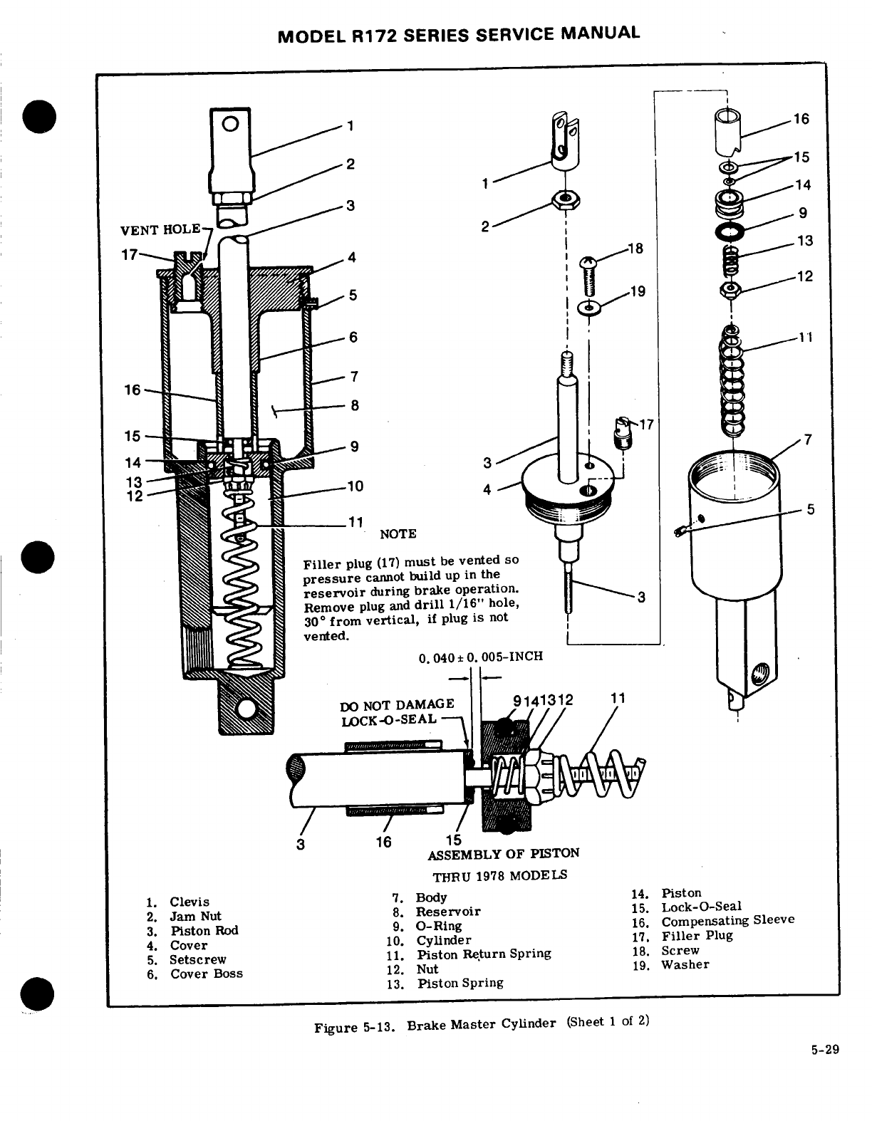
MODEL
R172
SERIES
SERVICE
MANUAL
VENT
HOLE---
Filler
plug
(17)
must
be
vented
so
pressure
cannot
build
up
in
the
reservoir
during
brake
operation.
Remove
plug
and
drill
1/16"
hole,
3
ASSEMBLY
OF PISTON
THRU
1978
MODELS
1.
Clevis
7.
Body
14.
Piston
2.
Jam
Nut
8.
Reservoir
15.
Lock-O-Seal
3.
Piston
Rod
9.
0-Ring
16.
Compensating
Sleeve
4.
Cover
10.
Cylinder
17.
Filler
Plug
5.
Setscrew
11.
Piston
Return
Spring
18.
Screw
6.
Cover
Boss
12.
Nut
19.
Washer
*& l13.
Piston
Spring
Figure
5-13.
Brake
Master
Cylinder
(Sheet
1
of
2)
5-29
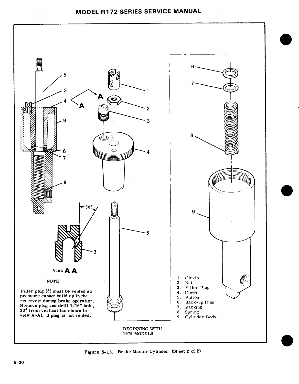
MODEL
R172
SERIES SERVICE
MANUAL
--
Clevis
2.
Nut
3.
Filler
Plug
Filler
plug
(3)
must
be
vented
so
4.
Cover
pressure
cannot
build
up in
the
5.
Piston
reservoir
during
brake
operation.
6
Back-up
Ring
Remove
plug
and
drill
1/16"
hole,
7.
Packing
30'
from
vertical (as
shown in
8
Spring
view
A-A),
if
plug
is
not
vented.
.
Clindr
9.
Cylinder
Body
BEGILNING
WITH
1979 MODELS
Figure
5-13.
Brake
Master
Cylinder
(Sheet
2
of
2)
5-30
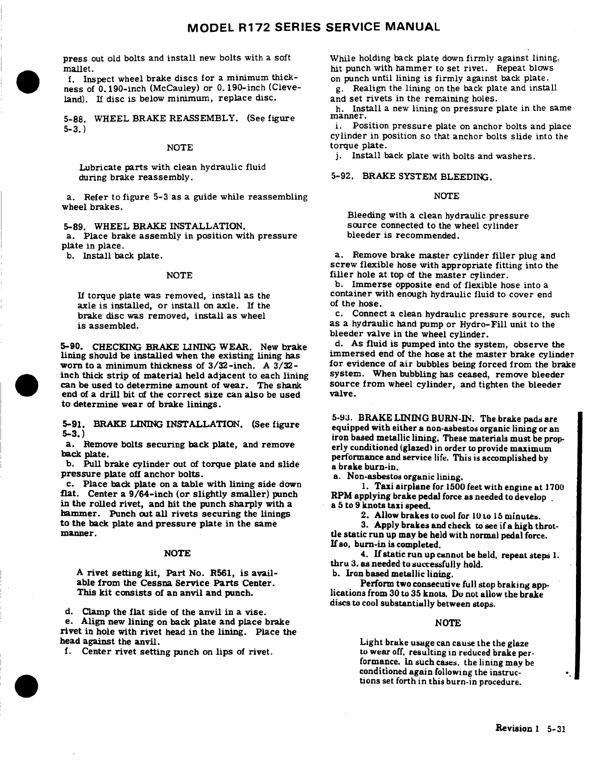
MODEL
R172
SERIES
SERVICE
MANUAL
press
out
old
bolts
and
install
new
bolts
with
a
soft
While
holding
back
plate
down
firmly against
lining,
mallet.
hit
punch
with
hammer
to
set
rivet.
Repeat
blows
f.
Inspect
wheel
brake
discs
for
a
minimum thick-
on
punch
until
lining
is
firmly against
back
plate.
ness
of
0.190-inch
(McCauley)
or
0.
190-inch
(Cleve-
g.
Realign
the
lining
on
the
back
plate
and
install
land).
If
disc
is
below
minimum,
replace
disc.
and
set
rivets
in
the
remaining
holes.
h.
Install
a
new
lining
on
pressure
plate
in
the same
5-88.
WHEEL
BRAKE
REASSEMBLY. (See
figure
manner.
B5-3.) in
i.
Position
pressure
plate
on
anchor
bolts
and place
~cylinder
in
position
so
that
anchor
bolts
slide
into
the
NOTE
torque
plate.
j.
Install
back
plate
with
bolts
and
washers.
Lubricate
parts
with
clean
hydraulic
fluid
during
brake
reassembly.
5-92.
BRAKE
SYSTEM
BLEEDING.
a.
Refer to
figure
5-3
as
a
guide
while
reassembling
NOTE
wheel
brakes.
Bleeding
with
a
clean
hydraulic
pressure
5-89. WHEEL
BRAKE
INSTALLATION.
source
connected
to
the
wheel
cylinder
a.
Place
brake
assembly
in
position
with
pressure
bleeder
is
recommended.
plate
in
place.
b.
Install
back
plate.
a.
Remove
brake
master
cylinder
filler
plug
and
screw
flexible
hose
with
appropriate
fitting into
the
NOTE
filler
hole
at
top
of
the
master
cylinder.
b.
Immerse
opposite
end
of
flexible
hose
into
a
If
torque plate
was
removed,
install
as
the
container
with
enough
hydraulic
fluid
to
cover
end
axle
is
installed,
or
install
on
axle.
If
the
of
the
hose.
brake
disc
was
removed,
install
as
wheel
c.
Connect
a
clean
hydraulic
pressure
source,
such
is
assembled.
as
a
hydraulic
hand
pump
or
Hydro-Fill
unit
to
the
bleeder
valve
in
the
wheel
cylinder.
5-90.
CHECKING
BRAKE
LINING
WEAR.
New
brake
d.
As
fluid
is
pumped
into
the system,
observe
the
lining
should
be
installed
when
the
existing
lining
has
immersed
end
of
the
hose
at
the
master
brake
cylinder
worn to
a
minimum
thickness
of
3/32-inch.
A
3/32-
for
evidence
of
air
bubbles
being
forced
from
the
brake
inch
thick
strip
of
material
held
adjacent
to each
lining
system.
When
bubbling
has
ceased,
remove
bleeder
can
be
used
to
determine
amount
of
wear.
The
shank
source
from
wheel
cylinder,
and
tighten
the
bleeder
end
of a
drill
bit
of
the
correct
size
can
also
be
used
valve.
to
determine
wear
of
brake linings.
5-93.
BRAKE
LINING
BURN-IN.
The
brake
pads
are
5-91.
BRAKE
LINING
INSTALLATION.
(See
figure
equipped
with
either a
non-asbestos organic
lining
or an
5-3.)
iron
based
metallic lining.
These
materials
must
be
prop-
a.
Remove
bolts
securing
back
plate,
and
remove
erly conditioned
(glazed)
in
order
to
provide
maximum
back
plate.
performance
and service
life.
This
is
accomplished
by
b.
Pull
brake
cylinder
out
of
torque
plate
and
slide
a
brake burn-in.
pressure
plate
off
anchor bolts.
a.
Non-asbestos
organic
lining.
c.
Place
back
plate
on
a
table
with
lining
side
down
1.
Taxi
airplane
for
1500
feet
with
engine
at
1700
flat.
Center
a
9/64-inch
(or
slightly
smaller)
punch
RPM
applying
brake
pedal
force
as
needed
to
develop
in
the
rolled
rivet,
and
hit the
punch
sharply
with
a
a
5
to
9
knots
taxi
speed.
hammer.
Punch
out
all
rivets
securing
the
linings
2.
Allow
brakes
to
cool
for
10
to
15
minutes.
to
the
back
plate
and
pressure
plate
in
the
same
3.
Apply
brakes
and
check
to
see
if
a
high
throt-
manner.
tie
static
run
up
may
be
held
with
normal
pedal
force.
If
so,
burn-in
is
completed.
NOTE
4.
If
static
run
up cannot
be
held,
repeat steps
1.
thru
3.
as
needed
to
successfully
hold.
A
rivet
setting
kit,
Part
No.
R561,
is
avail-
b.
Iron based
metallic
lining.
able
from
the
Cessna
Service
Parts
Center.
Perform
two
consecutive
full
stop
braking
app-
This
kit
consists
of
an
anvil
and
punch.
lications
from
30 to 35
knots.
Do
not
allow
the
brake
discs
to
cool
substantially
between
stops.
d.
Clamp
the
flat
side
of
the
anvil
in
a
vise.
e.
Align
new
lining
on
back
plate
and
place
brake
NOTE
rivet
in
hole
with
rivet
head
in
the
lining.
Place
the
head
against
the
anvil.
Light
brake
usage
can
cause
the the
glaze
f.
Center
rivet
setting
punch
on
lips
of
rivet.
to
wear
off,
resulting
in
reduced
brake
per-
formance.
In
such
cases,
the
lining
may
be
conditioned
again
following
the
instruc-
tions
set forth in
this
burn-in
procedure.
Revision
1
5-31
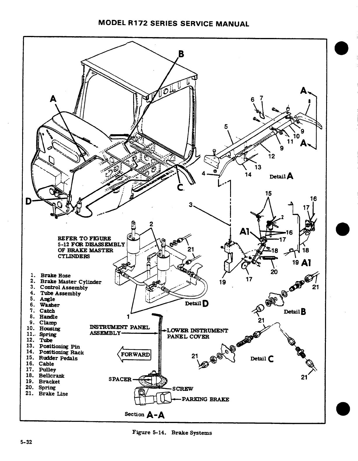
MODEL
R172
SERIES SERVICE
MANUAL
1
--
6
OF
BRAKE
MASTER
.-
1.
Brake
Hose
,
2.
Brake
Master
, .19
3.
Control
Assembly
.
4.
Tube
, .. --
5.
Angle
.
6.
Washer
7.
Catch
DetailB
8.
Handle
10.
Clamp
INSTRUMENT
PANEL
·
10.
Housing
11.-
Spring
12.
Tube
13.
Positioning
Pin
14.
Positioning Rack
15.
Rudder
Pedals
-
16.
Cable
17.
Pulley
18.
Bellcrank
19.
Bracket
20.
Spring
21.
Brake
Line
Figure
5-14.
Brake
Systems
5-32
MODEL
R172
SERIES
SERVICE
MANUAL
5-94. PARKING
BRAKE
SYSTEM.
(See
figure
5-14.)
illustration
may
be
used
as
a
guide
during
removal
and
installation
of
components.
5-95.
DESCRIPTION.
The
parking
brake
system
consists
of
a
handle
and
ratchet
mechanism,
connec-
5-97.
INSPECTION
AND
REPAIR
OF SYSTEM
COM-
ted
by
a
cable to
linkage
at
the
brake
master
cylinders.
PONENTS.
Inspect lines
for
leaks,
cracks,
dents,
Pulling
out
on
the
handle
depresses
both
brake
mas-
chafing,
proper radius,
security,
corrosion,
deteri-
ter
cylinder
piston
rods
and
the
handle
ratchet
locks
oration,
obstructions
and
foreign
matter.
Check
the
handle
in
this
position
until
the
handle
is
turned brake
master
cylinders
and
repair
as
outlined
in
and
released.
applicable
paragraph
in
this
Section.
Check
parking
brake
handle
and
ratchet
for
proper operation
and
5-96.
REMOVAL
AND
INSTALLATION.
See
figure
release.
Replace
worn
or
damaged
parts.
5-14
for
relative
location
of
system
components.
The
SHOP
NOTES:
Revision
1
5-33/(5-34
blank)
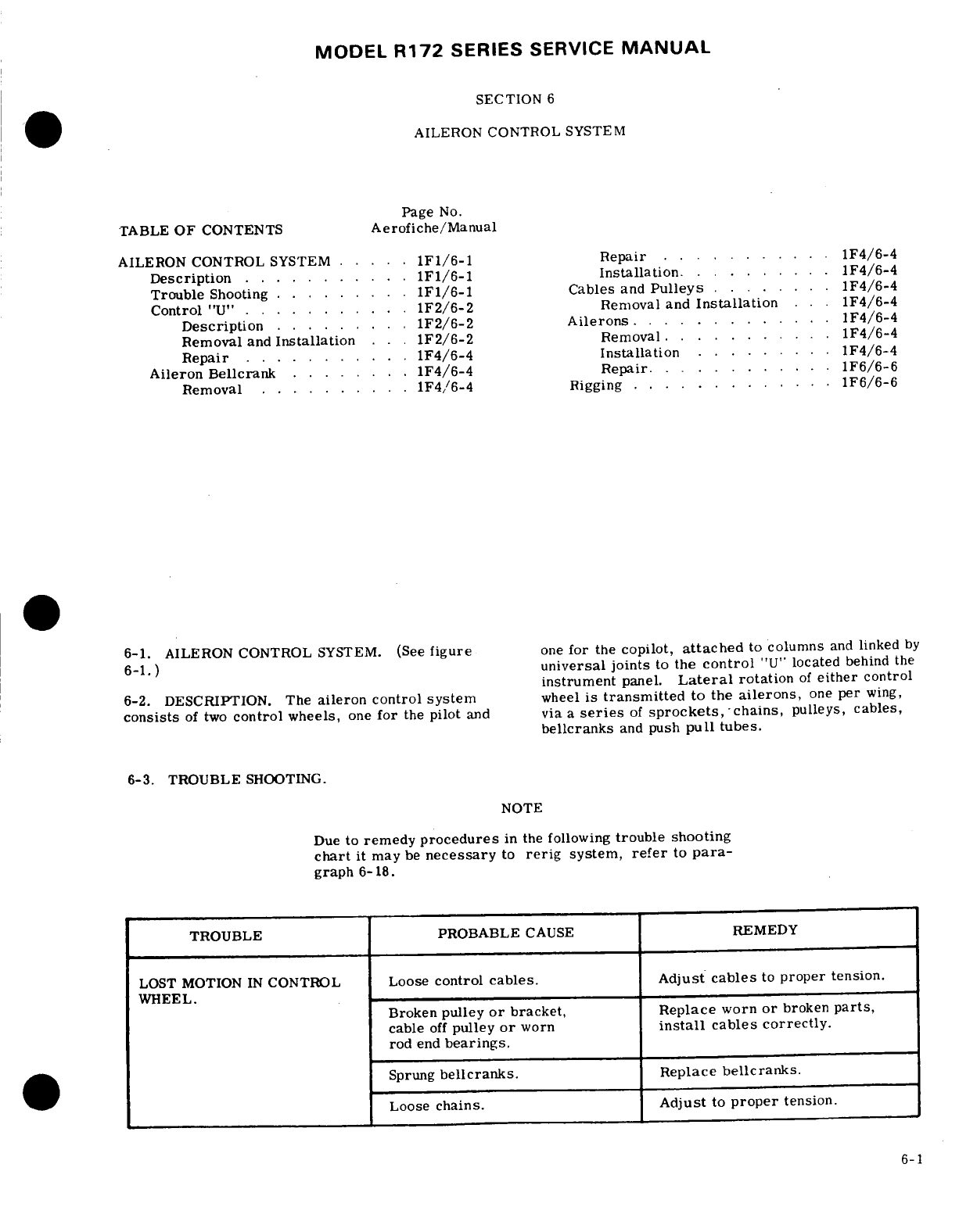
MODEL
R172
SERIES
SERVICE
MANUAL
SECTION
6
AILERON CONTROL
SYSTEM
Page
No.
TABLE
OF
CONTENTS
Aerofiche/Manual
AILERON
CONTROL
SYSTEM
.....
1F1/6-1
Repair
..........
1F4/6-4
Description
........
.
1F1/6-1
Installation.
1F4/6-4
Trouble
Shooting
.........
1F1/6-1 Cables
and
Pulleys
.......
1F4/6-4
Control
"U"
.
.......
1F2/6-2
Removal
and
Installation
..
1F4/6-4
Description
.......
.
1F2/6-2
Ailerons
........
1F4/6-4
Removal
and
Installation
..
1F2/6-2
Removal
.
1F4/6-4
Repair
....
.
.....
1F4/6-4
Installation
.....
....
F4/6-4
Aileron
Bellcrank
........
1F4/6-4 Repair
........
.
1F6/6-6
Removal
..........
1F4,/6-4
Rigging
.............
1F6/6-6
6-1.
AILERON CONTROL
SYSTEM.
(See
figure
one
for
the
copilot,
attached
to
columns
and
linked
by
6-1.)
universal
joints
to
the
control
"U"
located
behind
the
instrument
panel.
Lateral
rotation
of
either
control
6-2.
DESCRIPTION.
The
aileron control
system
wheel
is
transmitted
to the
ailerons,
one
per
wing,
consists
of two
control
wheels,
one
for
the
pilot
and
via
a
series
of
sprockets,
-chains,
pulleys,
cables,
bellcranks
and
push
pull
tubes.
6-3.
TROUBLE
SHOOTING.
NOTE
Due
to
remedy
procedures
in
the
following
trouble
shooting
chart
it
may
be
necessary
to
rerig
system,
refer
to
para-
graph
6-18.
TROUBLE PROBABLE
CAUSE
REMEDY
LOST
MOTION
IN
CONTROL
Loose
control
cables.
Adjust
cables
to
proper
tension.
WHEEL.
Broken
pulley
or
bracket,
Replace
worn
or
broken
parts,
cable
off
pulley
or
worn
install
cables
correctly.
rod
end
bearings.
Sprung
bellcranks.
Replace
bellcranks.
Loose
chains.
Adjust
to
proper
tension.
6-1
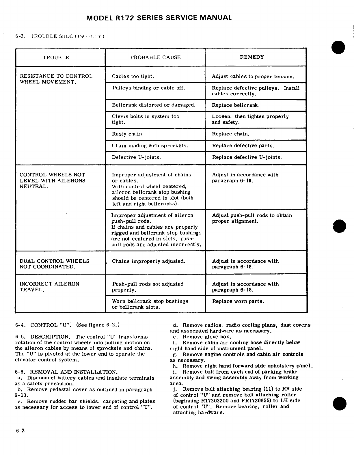
MODEL
R172
SERIES SERVICE
MANUAL
6-3.
TROUBLE
SHOOTING
(CONT)
TROUBLE
PROBABLE
CAUSE
REMEDY
RESISTANCE
TO
CONTROL
Cables
too
tight. Adjust
cables
to
proper
tension.
WHEEL
MOVEMENT.
Pulleys
binding
or
cable
off.
Replace
defective
pulleys.
Install
cables
correctly.
Bellcrank
distorted
or
damaged.
Replace
bellcrank.
Clevis
bolts
in
system
too
Loosen, then
tighten
properly
tight.
and
safety.
Rusty
chain.
Replace
chain.
Chain
binding
with
sprockets.
Replace
defective
parts.
Defective
U-joints.
Replace
defective
U-joints.
CONTROL
WHEELS
NOT
Improper
adjustment
of
chains
Adjust
in
accordance
with
LEVEL
WITH
AILERONS
or
cables. paragraph
6-18.
NEUTRAL.
With
control
wheel
centered,
aileron
bellcrank
stop
bushing
should
be
centered
in
slot
(both
left
and
right bellcranks).
Improper
adjustment
of
aileron
Adjust
push-pull
rods
to
obtain
push-pull
rods.
proper
alignment.
If
chains
and
cables
are
properly
rigged
and
bellcrank stop
bushings
are
not
centered
in
slots,
push-
pull
rods
are
adjusted
incorrectly.
DUAL
CONTROL WHEELS
Chains
improperly
adjusted.
Adjust
in
accordance
with
NOT
COORDINATED.
paragraph
6-18.
INCORRECT
AILERON
Push-pull
rods
not
adjusted
Adjust in
accordance
with
TRAVEL.
properly.
paragraph
6-18.
Worn
bellcrank
stop
bushings
Replace
worn
parts.
or
bellcrank
slots.
6-4.
CONTROL
"U".
(See
figure
6-2.)
d.
Remove
radios,
radio
cooling
plans,
dust
covers
and
associated
hardware
as
necessary.
6-5.
DESCRIPTION.
The
control
"U"
transforms
e.
Remove glove
box.
rotation
of
the
control
wheels
into
pulling motion
on
f.
Remove
cabin
air
cooling
hose
directly
below
the
aileron
cables
by
means
of
sprockets
and
chains.
right
hand
side
of
instrument
panel.
The
"U"
is
pivoted
at
the
lower
end
to
operate
the
g.
Remove
engine
controls
and
cabin
air
controls
elevator
control
system.
as
necessary.
h.
Remove
right
hand
forward
side upholstery
panel.
6-6.
REMOVAL
AND
INSTALLATION.
i.
Remove
bolt
from
each
end of
parking
brake
a.
Disconnect
battery
cables
and
insulate
terminals
assembly
and
swing
assembly
away
from
working
as
a
safety
precaution,
area.
b.
Remove
pedestal
cover
as
outlined
in
paragraph
j.
Remove
bolt
attaching bearing
(11)
to
RH
side
9-13.
of
control
"U"
and
remove
bolt
attaching
roller
c.
Remove
rudder
bar
shields,
carpeting
and
plates
(beginning
R17203200
and
FR1720655)
to
LH
side
as
necessary
for
access
to
lower
end
of
control
"U".
of
control
"U".
Remove
bearing,
roller
and
attaching
hardware.
6-2
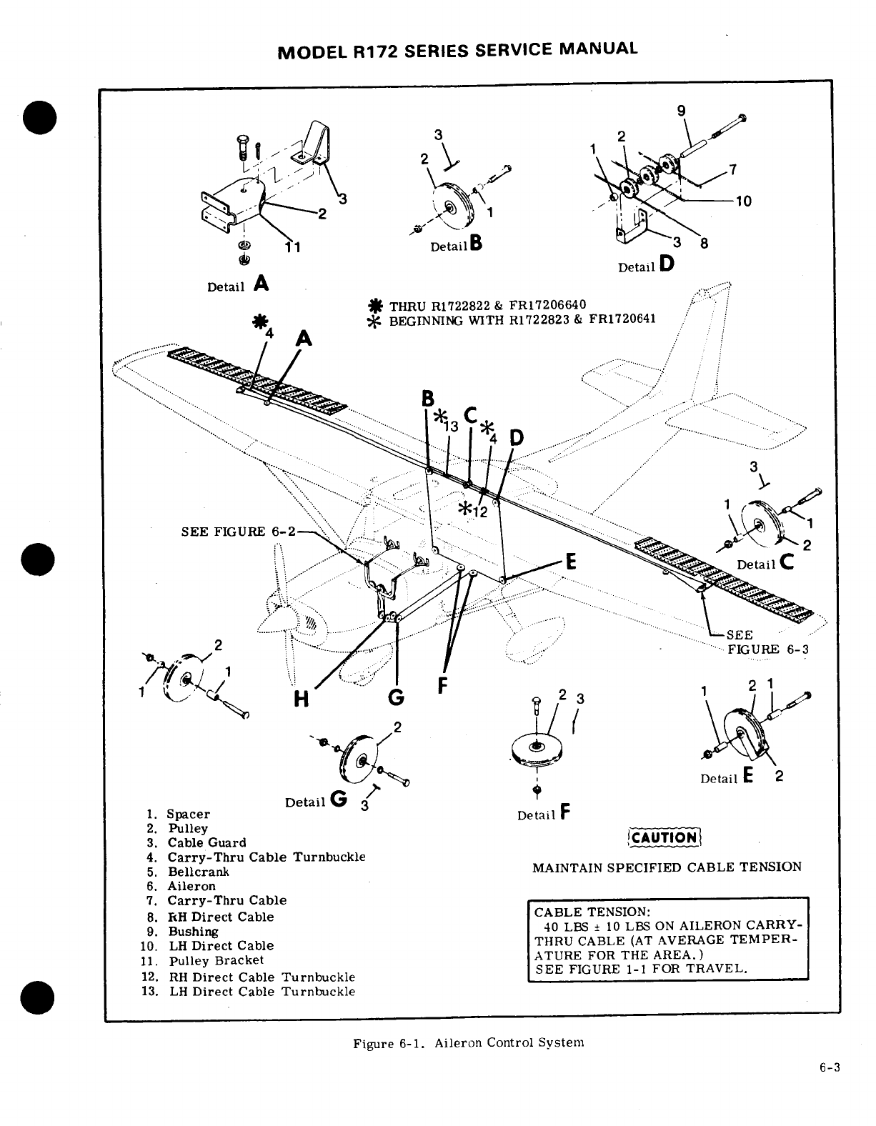
MODEL
R172
SERIES
SERVICE
MANUAL
11
Detail
B
3
8
Detail
D
Detail
A
THRU
R1722822
&
FR17206640
.
BEGINNING
WITH
R1722823
&
FR1720641
4
A
Detail
G
1.
Spacer
DetailF
2.
Pulley
3.
Cable
Guard
CAUTION
4.
Carry-Thru
Cable
Turnbuckle
5.
Bellcrank
MAINTAIN
SPECIFIED
CABLE
TENSION
6.
Aileron
7.
Carry-Thru
Cable
8.
RH
Direct
Cable
CABLE
TENSION:
9.
Bushing
40
LBS
±
10
LBS
ON
AILERON
CARRY-
10.
LH
Direct
Cable
THRU
CABLE
(AT
AVERAGE
TEMPER-
11.
Pulley
Bracket
ATURE
FOR
THE
AREA.)
12.
RH
Direct
Cable
Turnbuckle
SEE
FIGURE
1-1
FOR
TRAVEL.
13.
LH
Direct
Cable
Turnbuckle
Figure
6-1.
Aileron
Control
System
6-3
MODEL
R172
SERIES
SERVICE
MANUAL
k.
Drill
out
rivets
attaching
instrument
panel
sup-
6-10.
REPAIR.
Repair
of
bellcranks
consists
of
re-
port
(after
completion
of
step
"j")
and
remove
sup-
placement
of
defective
parts.
If
needle
bearings
are
port.
dirty
or
in
need
of
lubrication,
clean
thoroughly
and
l.
Drill
out
rivets
attaching
right
hand
side
panel
to
lubricate
as
outlined
in
Section
2.
pedestal
structure
and
remove
panel.
m.
Remove
safety
wire
and
disconnect
turnbuckles
6-11.
INSTALLATION.
(17).
a.
Place
bushing
(5)
and
stop-bushing
(15)
in
bell-
n.
Remove
bolts
(12)
attaching
control
wheel
tubes
crank
(7)
and
position
bellcrank
in
wing.
to
universal
joints
(13).
b.
Install brass
washers
(11)
between
lower
end
of
o.
Remove
bolt
(19)
attaching
push-pull
tube
(18)
bellcrank
and
wing
channel
(9)
to
shim
out
excess
to
control
"U."
clearance.
p.
Remove
pivot
bolt
(20)
and
carefully
work
con-
c.
Install
bellcrank
pivot bolt
(4),
washers
and
nut.
trol
"U"
out
from
under
right
hand
side
of
instrument
d.
Position
bellcrank
stop-bushing
and
install
at-
panel.
taching
bolt
(16).
washers
and
nut.
q.
Reverse
preceding
steps
for
reinstallation.
e.
Connect
aileron
cables
and
push-pull rod
to
bell-
crank.
f.
Rig
aileron
system
in
accordance
with
applicable
paragraph
in
this
section,
safety
turnbuckle
(17)
and
NOTE
reinstall
all
items
removed
for
access.
To
prevent
loss
of
strength
and
to
ease
re-
6-12.
CABLES
AND
PULLEYS.
(See
figure
6-1.)
installation
of
right
hand
pedestal
structure
side
panel,
machine
screws
and
nuts
may
6-13.
REMOVAL
AND
INSTALLATION.
be
installed
in
the
two
upper
rivet
holes,
a.
Remove
access
plates,
wing
root
fairings
and
provided
at
least
No.
6
screws
are
installed.
upholstery
as
required.
b.
Disconnect
cables
from
aileron
bellcranks
and
r.
Rig
aileron
control
system
in
accordance
with
remove
cable
guards
and
pulleys
as necessary
to
paragraph
6-18
and
safety
turnbuckles
(17).
work
cables
free
of
aircraft.
s.
Check
and/or
rig elevator
control
system
in
accordance
with
paragraph
8-14.
NOTE
t.
Check
and/or
rig
all
engine
and
cabin
air
con-
trols.
To
ease
routing
of
cables,
a
length
of
wire
u.
Check
all
radios
and
electrical
components
may
be
attached
to end
of
cable
before
being
which may
have been
disconnected
or
become
in-
withdrawn
from
aircraft.
Leave
wire
in
operative
while
performing
the
preceding
steps,
place,
routed
through
structure;
then
attach
v.
Reinstall
all items
removed
for
access.
cable
being
installed
and
use
to
pull cable
into
position.
6-7. REPAIR.
Repair
consists
of
replacing
worn,
damaged
or
defective
shafts, bearings,
bushings,
c.
After
cable
is
routed,
install
pulleys
and
cable
sprockets,
roller
chains,
universal
joints
or
other
guards.
Ensure
cable
is
positioned
in
pulley
groove
components.
Refer
to
Section
2
for
lubrication
re-
before
installing
guard.
quirements.
d.
Rig
aileron
system
in
accordance
with
appli-
cable
paragraph
in
this
section, safety turnbuckles
6-8.
AILERON BELLCRANK.
(See
figure
6-3.)
and
install
access
plates,
fairings
and
upholstery
removed
in
step
"a."
6-9.
REMOVAL.
a.
Remove
access
plate
inboard
of
each
bellcrank
6-14.
AILERONS.
(See
figure
6-3.)
on
underside
of
wing.
b.
Relieve
control
cable
tension
by
loosening
turn-
6-15.
REMOVAL.
buckle
barrel
(17).
a.
Disconnect
push-pull
rod
(8)
at
aileron.
c.
Disconnect
control
cables
from
bellcrank.
Re-
b.
Remove
screws
and
nuts
attaching
aileron
hinges
tain
all
spacers
(12).
(2)
to
trailing
edge
of
wing.
d.
Disconnect
aileron
push-pull
rod
(8)
at
bellcrank.
c.
Using
care,
pull
aileron
out
and
down
to
slide
e.
Remove
nuts,
washers
and
bolts
securing
bell-
hinges
from
under
wing
skin
and
auxiliary
spar
rein-
crank stop
bushing
(15)
and
bellcrank
(7)
to
wing
forcements.
structure.
f.
Remove
bellcrank
through
access
opening,
using
6-16.
INSTALLATION.
care
that
bushing
(5)
is
not
dropped
from bellcrank.
a.
Position
aileron
hinges between
skin
and
auxil-
iary
spar
reinforcements
and
install
screws
and
nuts
NOTE
attaching
hinges
to
trailing
edge
of
wing.
b.
Attach
push-pull
rod
(8)
to
aileron.
Brass
washers
(11)
may
be
used
as
shims
between
lower
end
of
bellcrank
and
wing
NOTE
channel
(9).
Retain
these
shims.
Tape
open
ends
of
bellcrank
to
prevent
dust
and
If
rigging
was
correct
and
push
pull
rod
dirt
from
entering
bellcrank
needle
bear-
adjustment
was
not
disturbed,
it
should
ings
(6).
not
be
necessary
to
rig
system.
6-4
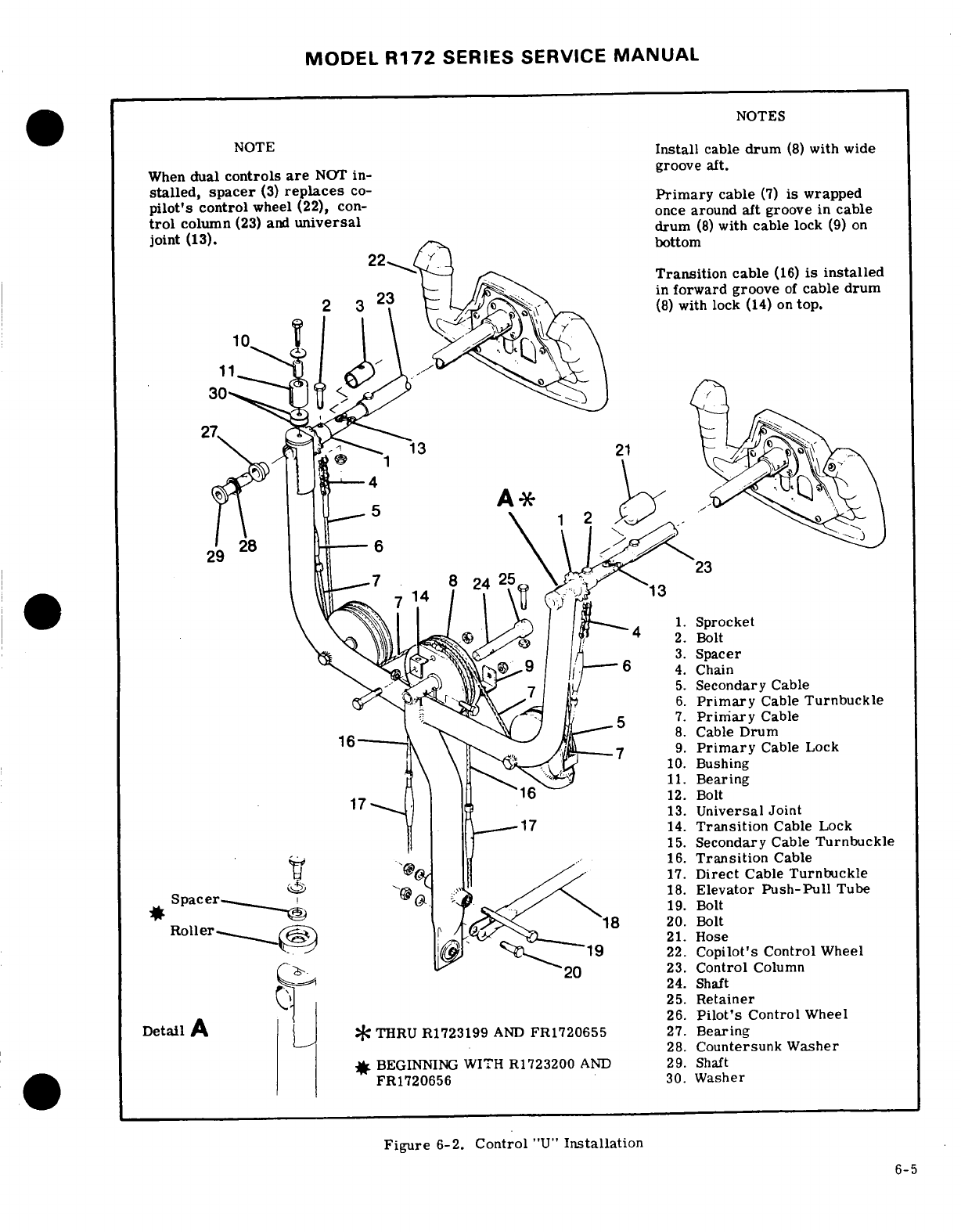
MODEL
R172
SERIES SERVICE
MANUAL
NOTES
NOTE
Install
cable
drum
(8)
with
wide
When
dual
controls
are
NOT
in-
groove
aft.
stalled,
spacer
(3)
replaces
co-
Primary
cable
(7)
is
wrapped
piot's
column
(23)
and
universl
once
around
aft
groove
in
cable
joint
(13).
drum
(8)
with
cable
lock
(9)
on
joint
(13)-.
Transition
cable
(16)
is
installed
in
forward
groove
of
cable
drum
2
(8)
with lock
(14)
on
top.
\ ^\
1.procket
5.
Secondary
Cable
..
-..-
6.
Primary
Cable
Turnbuckle
5
7.
Primary
Cable
J
Drum
9.
Primary
Cable
Lock
--
10.
Bushing
11.
Bearing
12.
Bolt
13.
Universal
Joint
14.
Transition
Cable
Lock
15.
Secondary
Cable
Turnbuckle
16.
Transition
Cable
17.
Direct
Cable
Turnbuckle
18.
Elevator
Push-Pull
Tube
.
9.
Bolt
Roller-
-
20.
Bolt
.
22.
Copilot's
Control
Wheel
23.
Control
Column
24.
Shaft
25.
Retainer
.
26.
Pilot's
Control
Wheel
*
THRU
R1723199
AND
FR1720655
27.
Bearing
28.
Countersunk
Washer
#
BEGINNING
WITH
R1723200
AND
29.
Shaft
FR1720656
30.
Washer
Figure
6-2.
Control
"U"
Installation
6-5
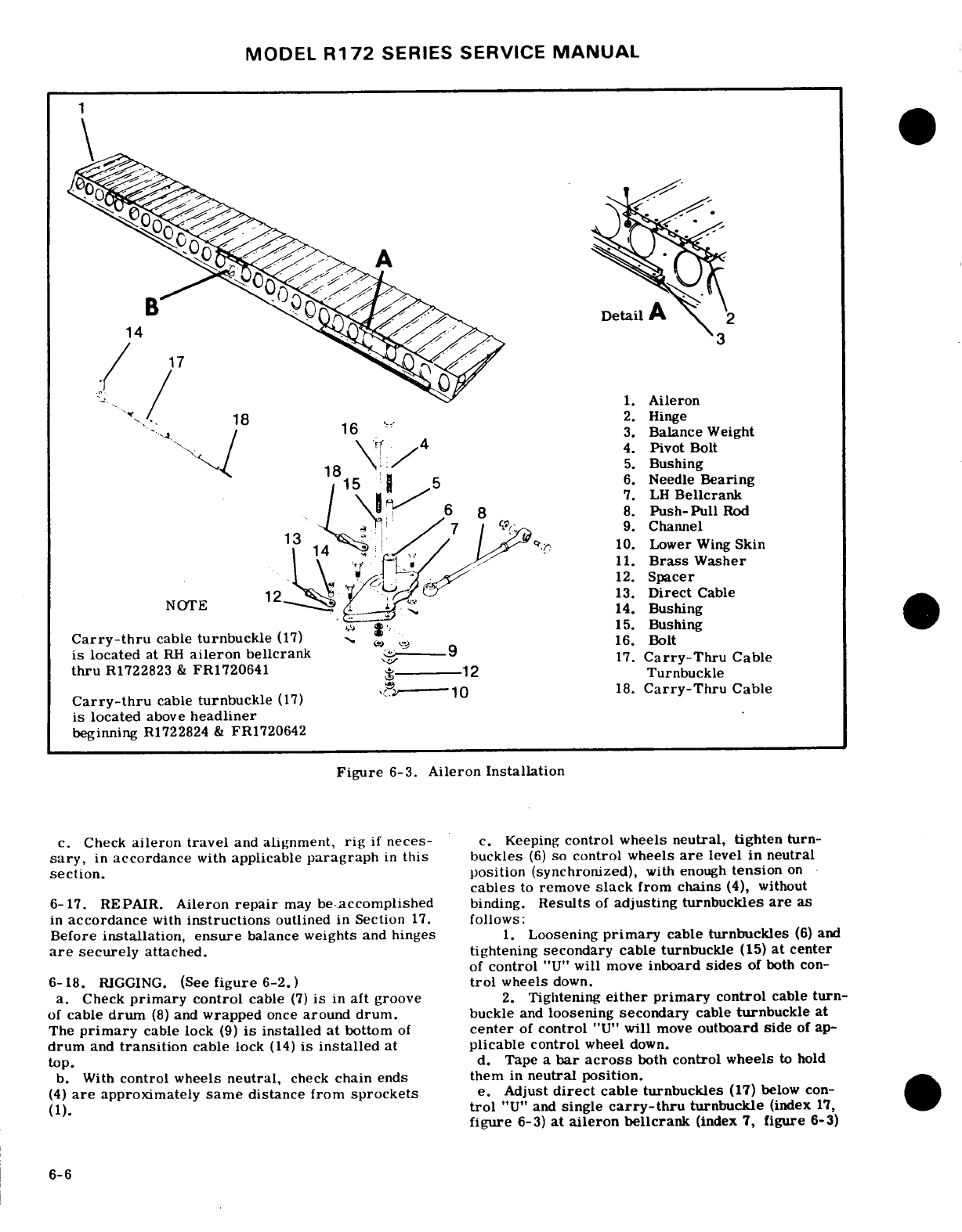
MODEL
R172
SERIES SERVICE
MANUAL
Detail
A
1.
Aileron
2.
Hinge
3.
Balance
Weight
4.
Pivot
Bolt
5.
Bushing
6.
Needle
Bearing
7.
LH
Bellcrank
8.
Push-Pull
Rod
9.
Channel
10.
Lower
Wing
Skin
/
11.
Brass
Washer
12.
Spacer
13.
Direct
Cable
14.
Bushing
,,,
15.
Bushing
Carry-thru
cable
turnbuckle
(17)16.
Bolt
is
located
at
RH
aileron
bellcrank
17.
,
17.
Carry-Thru
Cable
thru
R1722823
&
FR1720641
,
-----
18.
Carry-Thru
Cable
Carry-thru
cable
turnbuckle
(17)
is
located
above
headliner
beginning
R1722824
&
FR1720642
Figure
6-3.
Aileron
Installation
c.
Check
aileron
travel
and
alignment,
rig
if
neces-
c.
Keeping
control
wheels
neutral, tighten
turn-
sary,
in
accordance
with
applicable
paragraph
in
this
buckles
(6)
so
control
wheels
are
level
in
neutral
section.
position
(synchronized),
with
enough
tension
on
cables
to
remove
slack
from
chains
(4),
without
6-17.
REPAIR.
Aileron
repair
may
be-accomplished
binding.
Results
of
adjusting
turnbuckles
are
as
in
accordance
with
instructions
outlined
in
Section
17.
follows:
Before
installation, ensure
balance
weights
and
hinges
1.
Loosening
primary
cable
turnbuckles
(6)
and
are
securely
attached.
tightening
secondary
cable turnbuckle
(15)
at
center
of
control
"U"
will
move
inboard
sides
of
both
con-
6-18.
RIGGING.
(See
figure
6-2.)
trol
wheels
down.
a.
Check
primary
control
cable
(7)
is
in
aft
groove
2.
Tightening
either
primary
control
cable
turn-
of
cable
drum
(8)
and
wrapped
once
around drum.
buckle
and
loosening
secondary
cable
turnbuckle
at
The
primary
cable
lock
(9)
is
installed
at
bottom
of
center
of
control
"U"
will
move
outboard
side
of
ap-
drum
and
transition
cable
lock
(14)
is
installed
at
plicable
control
wheel
down.
top.
d.
Tape
a
bar
across
both
control wheels
to
hold
b.
With
control
wheels
neutral,
check
chain
ends
them
in
neutral
position.
(4)
are
approximately
same
distance from
sprockets
e.
Adjust
direct
cable turnbuckles
(17)
below con-
(1).
trol
"U"
and
single
carry-thru
turnbuckle
(index
17,
figure
6-3)
at
aileron
bellcrank
(index
7,
figure
6-3)
6-6
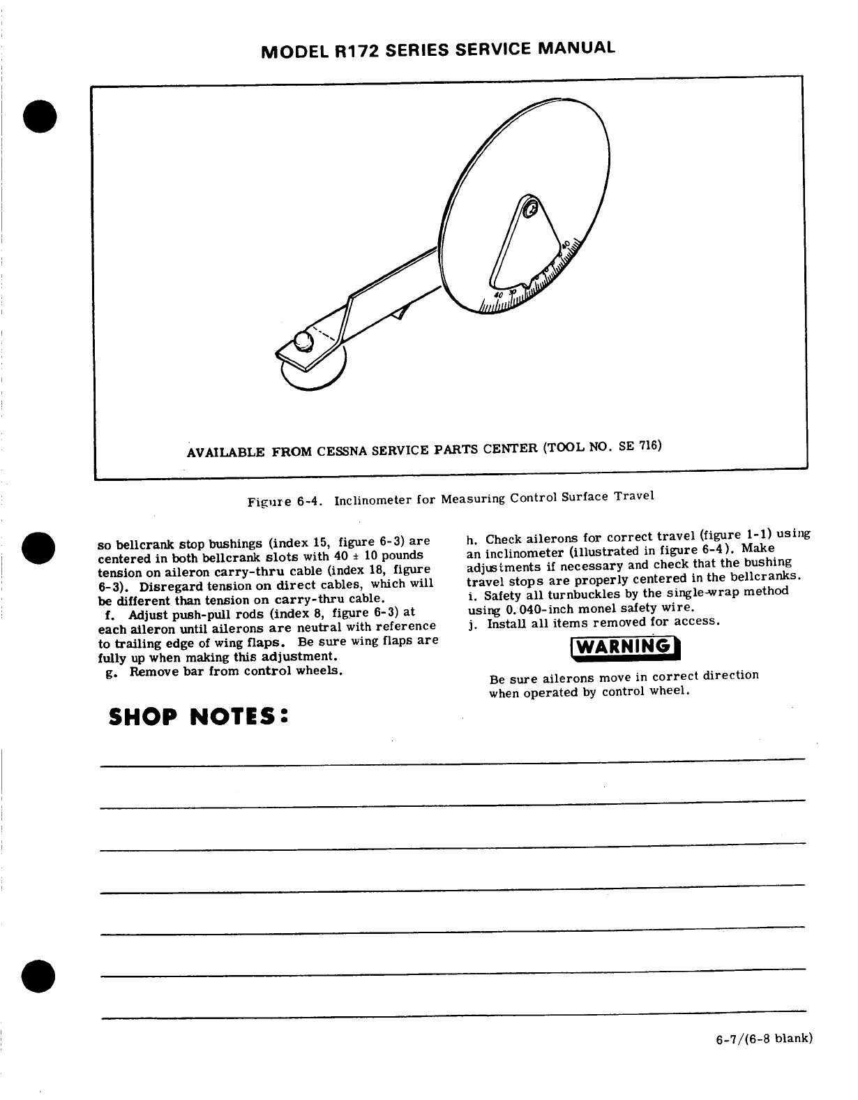
MODEL
R172
SERIES
SERVICE
MANUAL
AVAILABLE
FROM
CESSNA
SERVICE
PARTS CENTER
(TOOL
NO.
SE
716)
Figure
6-4.
Inclinometer
for
Measuring
Control
Surface
Travel
.
so
bellcrank
stop bushings
(index
15,
figure
6-3)
are
h.
Check
ailerons
for
correct
travel
(figure
1-1)
using
centered
in
both
bellcrank
slots
with
40
±
10
pounds
an
inclinometer
(illustrated
in
figure
6-4).
Make
tension
on
aileron
carry-thru
cable
(index
18,
figure
adjustments
if
necessary
and
check that
the
bushing
6-3).
Disregard
tension
on
direct
cables,
which
will
travel
stops
are
properly
centered
in
the
bellcranks.
be
different
than
tension
on
carry-thru
cable.
i.
Safety
all
turnbuckles
by
the
single-wrap
method
f.
Adjust
push-pull
rods
(index
8,
figure
6-3)
at
using
0.040-inch
monel safety
wire.
each
aileron
until
ailerons
are
neutral
with
reference
j.
Install
all
items
removed
for
access.
to
trailing
edge
of
wing
flaps.
Be
sure
wing
flaps
are
fully
up
when
making
this
adjustment.
WARNING
g.
Remove
bar
from
control
wheels.
Be
sure
ailerons
move
in
correct
direction
when
operated
by
control
wheel.
SHOP
NOTES:
6-7/(6-8
blank)
MODEL
R172
SERIES
SERVICE
MANUAL
SECTION
7
WING
FLAP
CONTROL
SYSTEM
Page
No.
TABLE
OF
CONTENTS
Aerofiche/Manual
WING
FLAP
CONTROL SYSTEM
.
..
.
1F14/7-1
Flaps
......
.. . .. .. .
1F17/7-4
Description
.
....... ....
1F14/7-1
Removal and
Installation.
. . .
1F17/7-4
Operation
Check
.
.......
1F14/7-1 Repair..
.
..........
F17/7-4
Trouble
Shooting
..........
1F15/7-2
Cables
and
Pulleys
....
.. .
1F17/7-4
Motor
and
Transmission
Removal and
Installation
. .
1F17/7-4
Assembly
...........
1F17/7-4
Rigging
......... ....
1F20/7-7
Removal and
Installation.
.. .
1F17/7-4
Follow-Up
and
Indicating
System
. .
1F21/7-8
Repair
...........
1F17/7-4 Description
.
........
F21/7-8
Drive
Pulleys
...........
1F17/7-4
Removal and
Installation
...
F21/7-8
Removal
and
Installation
. .
1F17/7-4
Rigging
.
.........
lF21/7-8
Repair
..........
1F17/7-4
7-1.
WING
FLAP
CONTROL
SYSTEM.
(See
7-3.
OPERATIONAL
CHECK.
figure
7-1.)
a-
Operate
flaps
through
their
full
range
of
travel
observing
for
uneven
travel
or
jumpy
motion,
binding
7-2.
DESCRIPTION.
The
wing
flap
control system
or
lost
motion.
Ensure
flaps
are
moving
together
is
comprised
of
an
electric
motor
and
transmission
through
their
full
range
of
travel.
assembly,
drive
pulleys,
push-pull
rods,
cables
and
b.
Check
for
positive
shut-off
of
motor
at
flap
a
follow-up
control.
Power
from
the
motor
and
trans-
travel
extremes
to
prevent
damage
to
actuator assem-
mission
assembly
is
transmitted
to
the
flaps
by
a
sys-
bly.
ter
of
drive
pulleys,
cables
and
push-pull
rods.
c.
With
flaps
full
UP,
mount
an
inclinometer
on
one
Electrical
power
to the
motor is
controlled
by
two
flap
and
set
to
Oc.
Lower
flaps
to
full
DOWN
position
microswitches
mounted
on
a
floating
arm
assembly,
and
check flap
angle
as
specified
in
figure
1-1.
Check
by
a
camming
lever
and
a
follow-up
control.
As
the
approximate
mid-range
percentage
setting
against
flap
control
lever
is
moved
to
thedesired
flap
setting, degrees
as indicated
on
inclinometer.
Repeat
the
the
attached
cam
trips
one of
the
microswitches,
act-
same
procedure
for
the
opposite
flap.
ivating
the flap
motor.
As
the
flaps
move
to
the
po-
sition
selected,
the floating
arm
is
rotated
by
the
NOTE
follow-up
control
until
the
active
microswitch
clears
the
cam
breaking
the
circuit
and
stopping
the
motor.
An
inclinometer for measuring
control
sur-
To
reverse
flap
direction,
the
control
lever is
moved
face
travel
is
available
from
the
Cessna
in
the
opposite
direction
causing
the
cam
to
trip
the
Service
Parts
Center.
See
figure
6-4.
second
microswitch
which
reverses
the
flap
motor.
The follow-up
control
moves
the
cam
until
it is
clear
d.
Remove
access
plates
adjacent
to
flap
drive
pul-
of
the second
switch,
shutting
off
the
flap
motor.
leys
and
attempt
to
rock
pulleys
to
check
for
bearing
Limit
switches
on
flap
actuator assembly
prevent
wear.
over-travel
of
the
flaps
in
the
full
UP
or
DOWN
posi-
e.
Inspect
flap
rollers
and
tracks
for
evidence
of
tions.
binding
or
defective
parts.
7-1
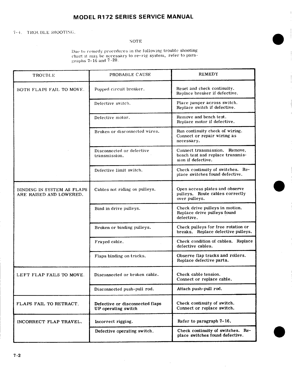
MODEL
R172
SERIES
SERVICE
MANUAL
7-4.
TROUBLE
SHOOTING;.
NOTE
Due
to
remnedy
procedures
in
the
following
trouble
shooting
ch.rt
it
may
be
necessary
to
re-rig
system,
refer
to
para-
graphs
7-16
and
7-20.
TROUBLE
PROBABLE
CAUSE
REMEDY
BOTH
FLAPS
FAIL
TO
MOVE.
Popped
circuit
breaker.
Reset
and
check
continuity.
Replace
breaker
if
defective.
Defective
switch.
Place
jumper
across
switch.
Replace
switch
if
defective.
Defective
motor.
Remove and bench
test.
Replace
motor
if
defective.
Broken
or
disconnected
wires.
Run
continuity
check
of
wiring.
Connect
or repair
wiring
as
necessary.
Disconnected
or
defective
Connect
transmission.
Remove,
transmission.
bench
test
and
replace
transmis-
sion
if
defective.
Defective
limit
switch.
Check
continuity
of
switches.
Re-
place
switches
found
defective.
BINDING
IN
SYSTEM
AS
FLAPS
Cables
not
riding
on
pulleys.
Open
access
plates
and
observe
ARE
RAISED
AND
LOWERED.
pulleys.
Route
cables
correctly
over
pulleys.
Bind
in
drive
pulleys.
Check
drive pulleys
in
motion.
Replace
drive pulleys
found
defective.
Broken
or
binding
pulleys.
Check
pulleys for
free
rotation
or
breaks.
Replace
defective
pulleys.
Frayed
cable.
Check
condition
of
cables.
Replace
defective
cables.
Flaps
binding
on
tracks.
Observe
flap
tracks
and
rollers.
Replace
defective
parts.
LEFT
FLAP
FAILS
TO
MOVE.
Disconnected
or
broken cable.
Check
cable
tension.
Connect
or
replace
cable.
Disconnected
push-pull
rod.
Attach
push-pull
rod.
FLAPS
FAIL
TO
RETRACT.
Defective
or disconnected
flaps
Check
continuity
of
switch.
UP
operating
switch
Connect
or
replace
switch.
INCORRECT FLAP
TRAVEL.
Incorrect
rigging.
Refer
to
paragraph
7-16.
Defective
operating
switch.
Check
continuity
of
switches.
Re-
place
switches
found
defective.
7-2
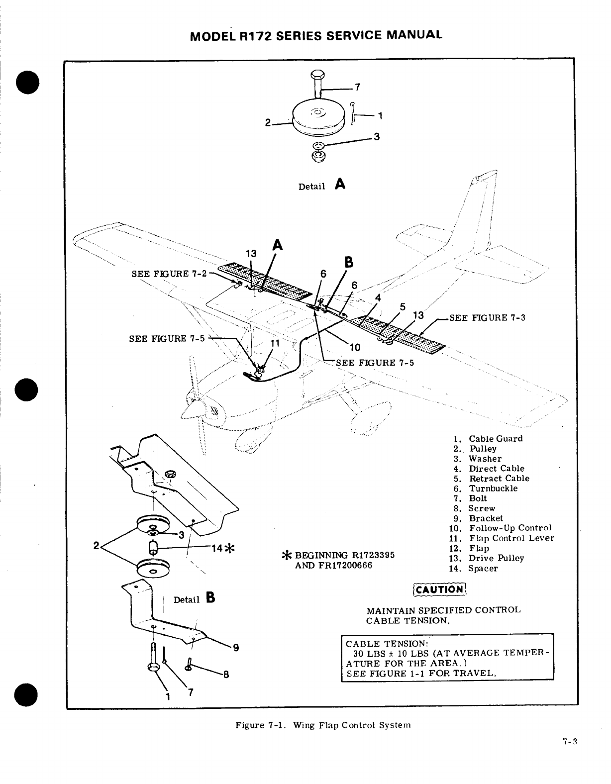
MODEL
R172
SERIES
SERVICE
MANUAL
Detail A
SEE
FIGURE
7-3
..
... .
- -
....
,
...
.... 1.
Cable
Guard
2.
Pulley
3.
Washer
4.
Direct
Cable
5.
Retract
Cable
6.
Turnbuckle
7.
Bolt
8.
Screw
9.
Bracket
10.
Follow-Up
Control
11.
Flap
Control
Lever
BEGINNING
R1723395
12.
FLap
AND
FR17200666
14.2Spacer
Detail
B
CAUTION
MAINTAIN
SPECIFIED
CONTROL
CABLE
TENSION.
9
CABLE
TENSION:
30
LBS
±
10
LBS
(AT
AVERAGE
TEMPER-
.... 2ATURE
FOR THE
AREA.)
SEE
FIGURE
1-1
FOR
TRAVEL,
Figure
7-1.
Wing
Flap
Control
System
7-3
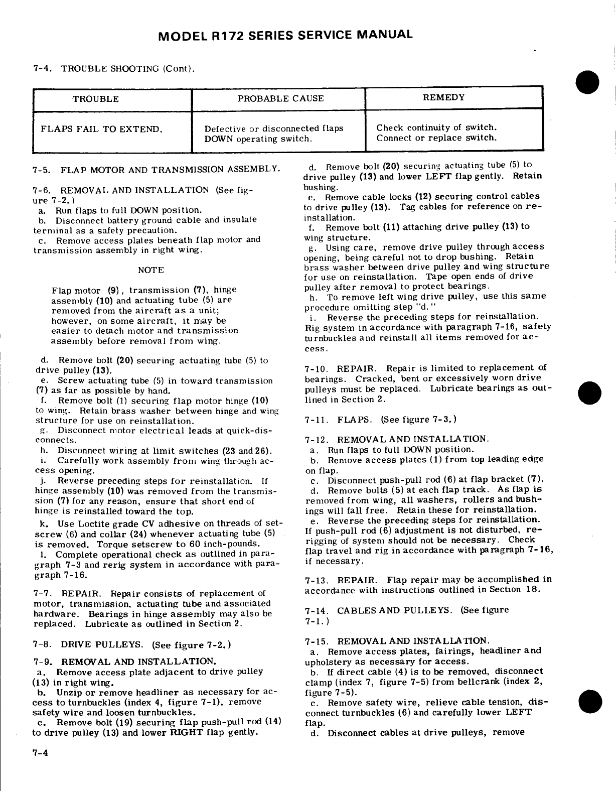
MODEL
R172
SERIES SERVICE
MANUAL
7-4.
TROUBLE
SHOOTING
(Cont).
TROUBLE
PROBABLE
CAUSE
REMEDY
FLAPS
FAIL
TO
EXTEND.
Defective
or
disconnected
flaps
Check
continuity
of
switch.
DOWN
operating
switch.
Connect
or
replace
switch.
7-5.
FLAP
MOTOR
AND
TRANSMISSION
ASSEMBLY.
d.
Remove
bolt
(20)
securing
actuating
tube
(5)
to
drive
pulley
(13)
and
lower
LEFT
flap gently.
Retain
7-6.
REMOVAL
AND
INSTALLATION
(See
fig-
bushing.
ure
7-2.
)
e.
Remove
cable
locks
(12)
securing
control
cables
a.
Run
flaps
to
full
DOWN
position.
to
drive
pulley
(13).
Tag
cables
for
reference
on
re-
b.
Disconnect
battery
ground
cable
and
insulate
installation.
terminal
as
a
safety
precaution.
f.
Remove
bolt
(11)
attaching
drive
pulley
(13)
to
c.
Remove
access
plates
beneath
flap
motor
and wing
structure.
transmission
assembly
in
right
wing.
g.
Using
care,
remove
drive
pulley through
access
opening,
being
careful
not
to
drop
bushing.
Retain
NOTE
brass
washer
between
drive
pulley
and
wing
structure
for
use
on
reinstallation.
Tape
open
ends
of
drive
Flap
motor
(9),
transmission
(7),
hinge
pulley
after
removal
to
protect bearings.
assembly
(10)
and
actuating
tube
(5)
are
h.
To
remove left
wing
drive
pulley,
use
this
same
removed from
the
aircraft
as
a
unit;
procedure
omitting
step
"d."
however,
on
some
aircraft,
it
nay
be
i.
Reverse
the
preceding
steps
for
reinstallation.
easier
to
detach
motor
and
transmission
Rig
system
in
accordance
with
paragraph
7-16,
safety
assembly
before
removal
from
wing.
turnbuckles
and
reinstall
all
items
removed
for
ac-
cess.
d.
Remove
bolt (20)
securing actuating
tube
(5)
to
drive
pulley
(13).
7-10.
REPAIR.
Repair
is
limited
to
replacement
of
e.
Screw
actuating
tube
(5)
in
toward
transmission
bearings.
Cracked,
bent
or
excessively
worn
drive
(7)
as far
as
possible
by
hand.
pulleys
must
be
replaced. Lubricate
bearings
as
out-
f.
Remove
bolt
(1)
securing
flap
motor
hinge
(10)
lined
in
Section
2.
to
wing.
Retain
brass
washer
between
hinge
and
wing
structure
for
use
on
reinstallation.
7-11. FLAPS.
(See
figure
7-3.)
g.
Disconnect
motor
electrical
leads
at
quick-dis-
connects.
7-12.
REMOVAL AND
INSTALLATION.
h.
Disconnect wiring
at
limit switches
(23
and
26).
a.
Run
flaps
to
full
DOWN
position.
i.
Carefully
work
assembly
from
wing
through
ac-
b.
Remove
access
plates
(1)
from
top
leading
edge
cess
opening.
on
flap.
j.
Reverse
preceding
steps
for
reinstallation.
If c.
Disconnect
push-pull
rod
(6)
at
flap
bracket
(7).
hinge
assembly
(10)
was
removed
from
the
transmis-
d.
Remove
bolts
(5)
at
each
flap
track.
As
flap
is
sion
(7)
for
any
reason,
ensure
that
short
end
of
removed
from
wing,
all
washers,
rollers
and
bush-
hinge
is
reinstalled
toward the
top.
ings
will
fall
free.
Retain
these for reinstallation.
k.
Use
Loctite
grade
CV
adhesive
on
threads
of
set-
e.
Reverse
the
preceding
steps
for
reinstallation.
screw
(6)
and
collar
(24)
whenever
actuating
tube
(5)
If
push-pull rod
(6)
adjustment
is
not
disturbed,
re-
is
removed.
Torque
setscrew
to
60
inch-pounds.
rigging
of
system
should
not
be
necessary.
Check
1.
Complete
operational
check
as
outlined
in
para-
flap
travel
and
rig
in
accordance
with
paragraph
7-16,
graph
7-3
and
rerig
system
in
accordance
with
para-
if
necessary.
graph
7-16.
7-13.
REPAIR.
Flap
repair
may
be
accomplished
in
7-7.
REPAIR.
Repair
consists
of
replacement
of
accordance
with
instructions
outlined
in
Section
18.
motor,
transmission,
actuating
tube
and
associated
hardware.
Bearings
in
hinge
assembly
may
also
be
7-14.
CABLES
AND
PULLEYS. (See
figure
replaced.
Lubricate
as
outlined
in
Section
2.
7-1.)
7-8.
DRIVE
PULLEYS.
(See
figure
7-2.)
7-15.
REMOVAL
AND
INSTALLATION.
a.
Remove
access
plates,
fairings,
headliner
and
7-9.
REMOVAL
AND
INSTALLATION.
upholstery
as
necessary
for
access.
a.
Remove
access
plate
adjacent
to
drive
pulley
b.
If
direct
cable
(4)
is
to
be
removed,
disconnect
(13)
in
right
wing.
clamp
(index
7,
figure
7-5)
from
bellcrank
(index
2,
b.
Unzip
or
remove
headliner
as
necessary
for
ac-
figure
7-5).
cess
to
turnbuckles
(index
4,
figure
7-1),
remove
c.
Remove
safety
wire,
relieve
cable
tension,
dis-
safety wire
and
loosen
turnbuckles.
connect
turnbuckles
(6)
and
carefully
lower
LEFT
c.
Remove
bolt
(19)
securing
flap
push-pull
rod
(14)
flap.
to
drive
pulley
(13)
and
lower RIGHT flap
gently.
d.
Disconnect
cables at
drive
pulleys,
remove
7-4
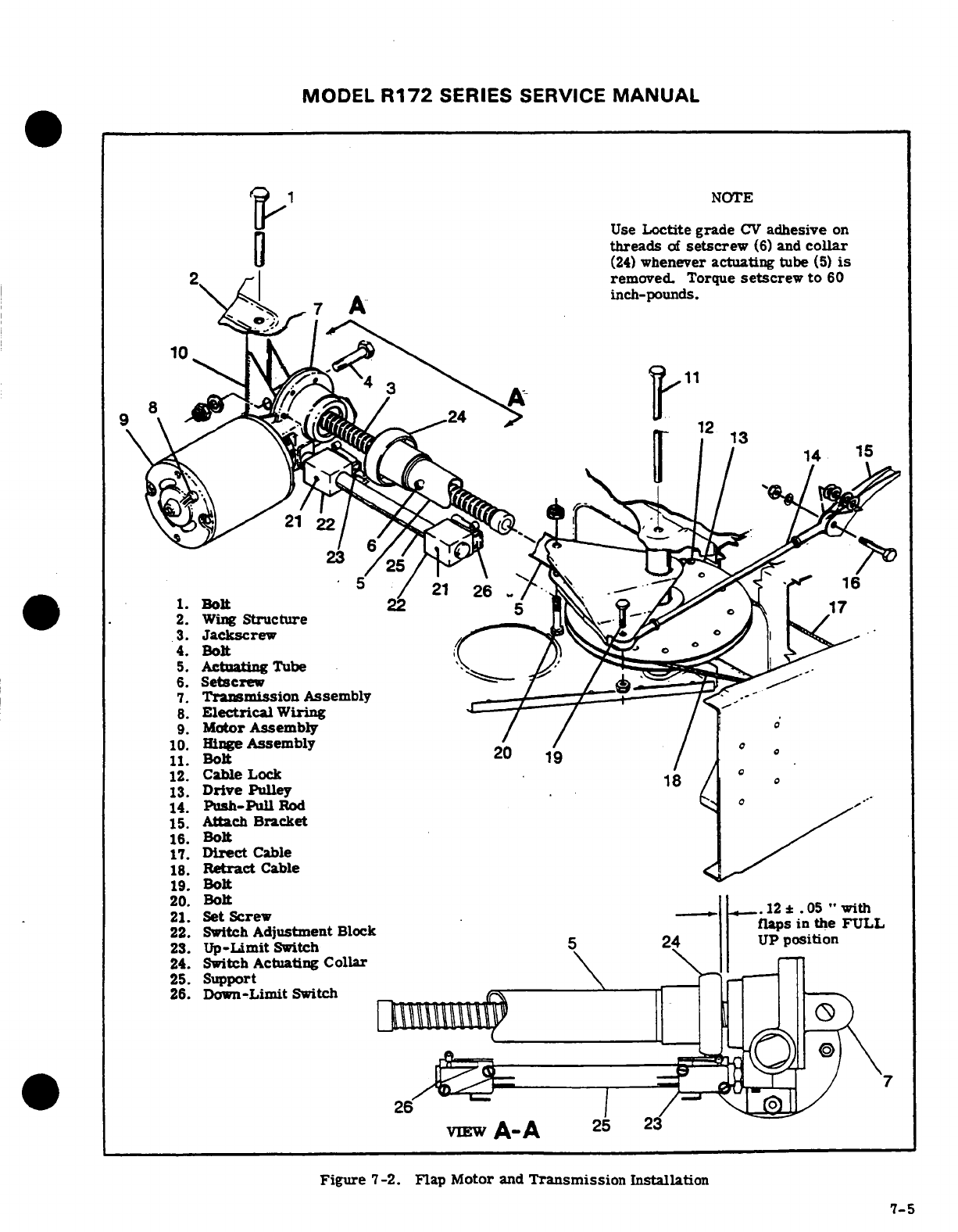
MODEL
R172
SERIES
SERVICE
MANUAL
NOTE
Use
Loctite grade
CV
adhesive
on
threads
of
setscrew
(6)
and
collar
(24)
whenever
actuating
tube
(5)
is
removed.
Torque
setscrew
to
60
inch-pounds.
. Bolt2
1.
Bolt
2.
Wing
Structure
3.
Jackscrew
4.
Bolt
5.
Actuating
Tube
6.
Setscrew
7.
Transmission
Assembly
8.
Electrical
Wiring
-
9.
Motor
Assembly
10.
Hinge
Assembly
11.
Bolt
12.
Cable
Lock
13.
Drive
Pulley
14.
Push-Pull
Rod
-
15.
Attach
Bracket
16.
Bolt
17.
Direct
Cable
18.
Retract
Cable
19.
Bolt
20.
Bolt
21.
Set
Screw
, .
22.
Switch
Adjustment
Block flaps
in
the
FLL
23.
Up-Limit
Switch
UP
position
24.
Switch
Actuating
Collar
25.
Support
26.
Down-Limit
Switch
-- -
VIEW
A-A
Figure
7-2.
Flap Motor
and
Transmission
Installation
7-5
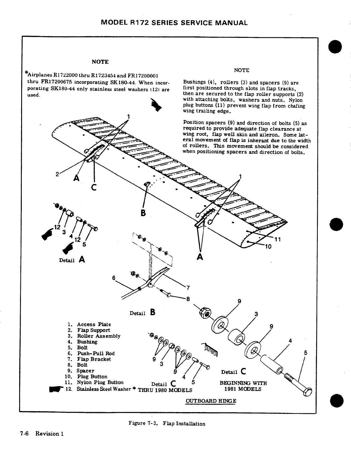
MODEL
R172
SERIES SERVICE
MANUAL
NOTE
NOTE
*Airplanes
R1722000
thru
R1723454
and
FR17200001
thru
FR17200675
incorporating
SK180-44.
When
incor-
Bushings
(4),
rollers
(3)
and
spacers
(9)
are
porating
SK180-44
only
stainless
steel washers
(12)
are
first
positioned
through
slots
in
flap
tracks,
used.
then
are
secured
to
the
flap
roller
supports
(2)
with
attaching
bolts,
washers
and
nuts.
Nylon
plug
buttons
(11)
prevent
wing
flap
from
chafing
wing
trailing
edge.
Position
spacers
(9)
and
direction
of
bolts
(5)
as
required
to
provide
adequate
flap
clearance
at
wing
root,
flap
well skin
and
aileron.
Some
lat-
eral
movement
of
flap
is
inherant
due
to
the
width
of
rollers.
This movement
should
be
considered
when
positioning
spacers
and
direction
of
bolts.
8
9
Detail
B
1.
Access
Plate
9
2.
Flap
Support
3.
Roller
Assembly
4.
Bushing
5.
Bolt
6.
Push-Pull
Rod
7.
Flap Bracket
9
8.
Bolt
9.
Spacer
9
Detail
C
10.
Plug Button
11.
Nylon
Plug
Button
Detail
C
BEGINNING
WITH
12.
Stainless
Steel
Washer
THRU
1980
MODELS
1981
MODELS
OUTBOARD
HINGE
Figure
7-3.
Flap
Installation
7-6
Revision
1
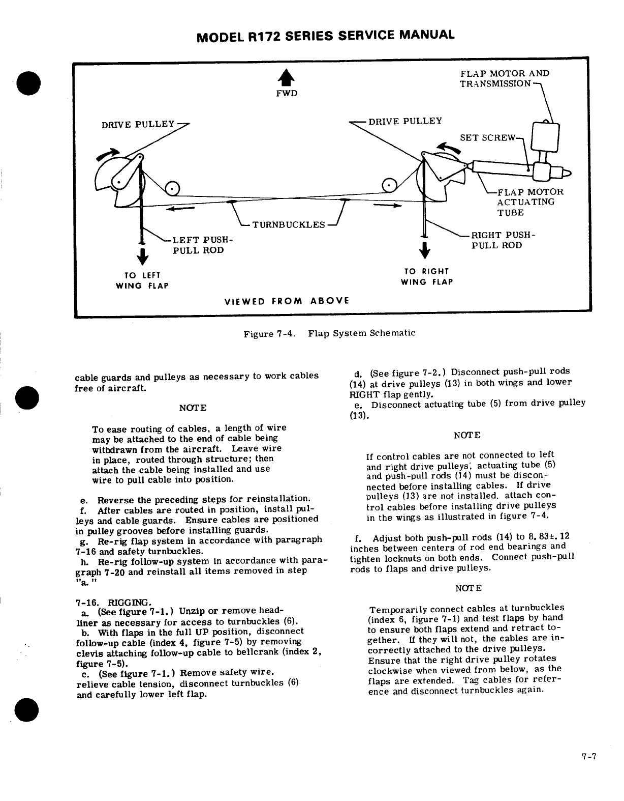
MODEL
R172
SERIES
SERVICE
MANUAL
FLAP
MOTOR
AND
FWD TRANSMISSION
DRIVE
PULLEY-
DRIVE
PULLEY
SET
SCREW
FLAP
MOTOR
ACTUATING
TUBE
TURNBUCKLES
--
LEFT
PUSH-
-RIGHT
PUSH-
PULL
ROD
PULL
ROD
TO
LEFT
TO
RIGHT
WING
FLAP
WING
FLAP
VIEWED
FROM
ABOVE
Figure
7-4.
Flap
System
Schematic
cable
guards
and
pulleys
as
necessary
to
work
cables
d.
(See
figure 7-2.)
Disconnect
push-pull
rods
free
of
aircraft.
(14)
at
drive
pulleys
(13)
in
both
wings
and
lower
RIGHT
flap
gently.
NOTE
e.
Disconnect
actuating
tube
(5)
from
drive
pulley
(13).
To
ease
routing
of
cables,
a
length
of
wire
may
be
attached
to
the
end
of
cable
being
NOTE
withdrawn
from
the
aircraft.
Leave wire
in
place,
routed
through
structure;
then
If
control
cables
are
not
connected
to
left
attach
the
cable
being
installed
and
use
and
right
drive
pulleys;
actuating
tube
(5)
wire
to
pull
cable
into
position.
and
push-pull
rods
(14)
must
be
discon-
nected
before
installing cables.
If
drive
e.
Reverse
the
preceding
steps
for
reinstallation.
pulleys
(13)
are
not
installed.
attach
con-
f.
After
cables
are
routed
in
position,
install
pul-
trol
cables
before
installing
drive
pulleys
leys
and
cable
guards.
Ensure
cables
are
positioned
in
the
wings
as
illustrated
in
figure
7-4.
in
pulley
grooves
before
installing guards.
g.
Re-rig
flap
system
in
accordance
with
paragraph
f.
Adjust
both
push-pull
rods
(14)
to
8.
83±.
12
7-16
and
safety turnbuckles.
inches
between
centers
of
rod
end
bearings
and
h.
Re-rig
follow-up
system
in
accordance
with
para-
tighten
locknuts
on
both
ends. Connect
push-pull
graph
7-20
and
reinstall
all
items
removed
in
step
rods
to
flaps
and
drive
pulleys.
"a."
NOT
E
7-16.
RIGGING.
a.
(See
figure 7-1.)
Unzip
or
remove
head-
Temporarily
connect
cables
at
turnbuckles
liner
as
necessary
for
access
to
turnbuckles
(6).
(index
6,
figure
7-1)
and
test
flaps
by
hand
b. With
flaps
in
the
full
UP
position,
disconnect
to
ensure
both
flaps
extend
and
retract
to-
follow-up cable
(index
4,
figure
7-5)
by
removing
gether.
If
they
will
not,
the
cables
are
in-
clevis
attaching
follow-up
cable
to
bellcrank
(index
2,
correctly
attached
to
the
drive
pulleys.
figure
7-5).
Ensure
that
the
right
drive
pulley
rotates
c.
(See
figure
7-1.)
Remove
safety
wire,
clockwise
when
viewed
from
below,
as
the
relieve
cable
tension,
disconnect
turnbuckles
(6)
flaps
are
extended.
Tag
cables
for
refer-
and
carefully
lower
left
flap.
ence
and
disconnect
turnbuckles
again.
7-7
MODEL
R172
SERIES
SERVICE
MANUAL
IN
toward
transmission
(7)
by
hand
to .
12±. 05
inches
to
0°.
between
switch actuating
collar
(24)
and
transmission
r. Run
flaps
to
full
DOWN
postion
and
adjust
as
illustrated
in
View
A-A.
DOWN
limit
switch
(26)
to
stop
motor
and
flap
at
the
h.
Loosen
setscrew
(6)
securing
actuating
tube
(5)
degree
of
travel
specified
in
figure
1-1.
Repeat
check
to
switch
actuating
collar
(24)
and
hold
collar
to
main-
on
LEFT
flap.
Recheck
limit
switch
through
several
tain
.
12
±.
05
inch
while holding
RIGHT
flap
in
the
full
flap
cycles.
UP
position
and
adjust
actuating
tube
(5)
IN
or
OUT,
as
necessary
to
align
with
attachment
hole
in
drive
NOTE
pully
(13).
i.
Apply
Loctite
grade
CV
sealant
(or
equivalent)
All
flap
rollers
may
not
bottom
in
the
flap
to
threads
of
setscrew
(6)
and
torque
to
60
inch-
tracks
at
the
travel
extremes.
pounds.
s.
Reconnect
and
rerig
the flap
follow-up
system
in
NOTE
accordance
with
paragraph
7-20.
Perform
an
opera-
tional
check
in
accordance
with paragraph
7-3,
re-
If
actuating
tube
(5)
is
too
long
to
allow
check
all
items
for
proper
safetying
and
replace
attachment
to
drive
pully
after
completion
items
removed
for
access.
of
step
"h",
proceed
to
step
"j".
7-17. FLAP FOLLOW-UP
AND
INDICATING
SYSTEM.
j.
Disconnect
push-pull
rod
(14)
at
drive
pully
(13)
(See
figure 7-5.)
to
allow connecting
actuating
tube
(5)
to
drive
pully.
k.
Manually
hold RIGHT
flap
in
full
UP
postion
and
7-18.
DESCRIPTION.
The
flap
follow-up
and
indi-
readjust
push-pull
rod
(14)
to
align
with
attachment cating
system
consists
of
a
sheathed
cable
assembly
hole
in
drive
pully.
Connect
push-pull
rod
and
tight-
one
end
of
which
is
attached
to the
flap
operating
en
locknuts. switch
mounting
arm
and
the
other
end
is
clamped
to
the
flap
direct
cable
above
the
headliner
in
the
rear
NOTE
cabin
area.
Motion
of
the
flap
cable
is
transmitted
through
the follow-up
control
to
the
pointer
attached
The
right
flap
and
actuator
must
be
correctly
to
the
switch
mounting
arm,
moving
the
pointer
along
rigged,
before
cables
and
left
flap
can
be
a
scale
as
the
flaps
are
extended
or
retracted.
When
rigged.
this
motion
of
the
switch
mounting
arm,
to
which
the
flap
operating switches
are
attached,
positions
the
1.
With
flaps
in
full
UP
position,
loosen
setscrew
"active"
operating switch
to
clear
a
cam
on
the
flap
(21)
and
slide
up
limit
switch
adjustment
block
(22)
lever,
the
circuit
to
the
flap
motor
is
broken
and
the
on
support
(25)
to
just activate
switch
and
shut
off
flaps
stop
at
the
selected
position.
electrical
power
to
motor
at
this
position.
Tighten
setscrew.
7-19.
REMOVAL
AND
INSTALLATION.
Figure
7-5
m.
Manually
hold
LEFT
flap, full
UP
and
connect
can be
used
as
a
guide
to
removal
and
installation
of
control cables
at
turnbuckles
(index
4,
figure
7-1).
the
flap
follow-up
and
indicating
system.
Remove
reference
tags
previously installed.
n.
With
flaps
full
UP,
adjust
turnbuckles
to obtain 7-20.
RIGGING.
(See
figure
7-5.)
30±10
pounds
tension
on
cables.
Adjust
retract
cable
a.
Flap
control
system
must
be
rigged
in
accord-
(18)
first.
ance
with
paragraph
7-16
before
flap
follow-up sys-
tem
can
be
rigged.
NOTE
b.
Disconnect
spring
(21)
from
switch
mounting
arm
(16).
Ensure
cables
are
positioned
in
pully
grooves
c.
With
flaps
and
flap
lever
(13)
in
full
UP
position
and
cable
ends
are
postioned
correctly
at
and
holding
flap
position
indicator
(14)
to
a
clearance
drive
pullys
before
tightening
turnbuckles.
of
.03
inch
maximum
with
top
of
instrument
panel
opening,
pull
center
cable
of
flap
follow-up
(index
4,
o.
Disconnect
push-pull
rod
at
left
drive
pully.
detail
b)
to
remove
slack.
Connect
cable through
Run
motor
to
extend
flaps
approximately
20
°
and
clamp
bolt
(17)
observing
note
of
figure 7-5.
check
tension
on
each
flap
cable.
If
necessary,
re-
d.
Connect
spring
(21)
to
switch
mounting
arm
(16).
adjust
turnbuckles
to
maintain
30±10
pounds
tension
e.
Adjust
switches
(18)
and
(20)
in
slotted
holes
in
on
each cable
and
safety
turnbuckles.
mounting
arm
(16)
until
cam
(19)
is
centered
between
p.
Fully
retract
right
flap.
Manually
hold
left
flap switch
rollers.
in
full
UP
position
and
readjust
push-pull
rod
to
align
f.
Mount
an
inclinometer
on
one
flap
and
set
to
0
°
with
attaching
hole
in
drive
pulley.
Connect
push-pull
(flaps
full
UP).
Turn
master
switch
ON
and
move
rod
and
tighten
locknuts.
flap
lever
(13)
to
10°
position.
NOTE
NOTE
An
inclinometer
for measuring
control
sur-
An
inclinometer
for
measuring
control
sur-
face
travel
is
available
from
the
Cessna
face
travel
is
available
from
the
Cessna
vice
Parts
Center.
See
figure
6-4.
Service
Parts
Center.
See
figure 6-4.
7-8
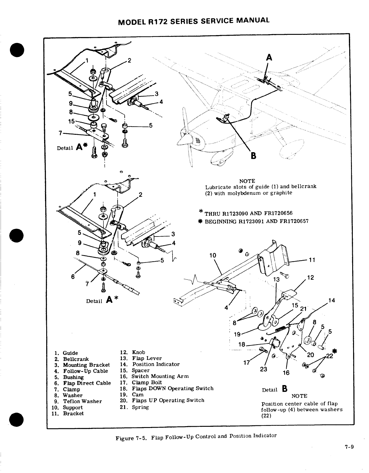
MODEL
R172
SERIES
SERVICE
MANUAL
DetailDa
l
Lubricate
slots
of
guide
(1)
and
bellcrank
(2)
with
molybdenum or
graphite
THRU
R1723090
AND
FR1720656
*
BEGINNING
R1723091
AND
FR1720657
8.
Washer
19.
Cam
9.
Teflon
Washer
20.
Flaps
UP
Operating
Switch
10.
Support
21.
Spring
Position
center
cable
of
flap
11.
Bracket
follow-up
(4)
between
washers
(22)
Figure
7-5.
Flap
Follow-Up
Control
and
Position
Indicator
7-9
MODEL
R172
SERIES SERVICE
MANUAL
g.
Observe inclinometer
reading
when
flaps
stop.
(travel
20
°
+0
°
-2°).
Adjust
flaps
DOWN
operating
switch
(18)
in
slotted
j.
Run
flaps
to
full
DOWN
position
at
the
degree
holes
on
mounting
arm
(16)
as
required
to
obtain flap
of
travel
specified
in
figure
1-1.
Check
that
flaps
travel
of
10°
+0'
-2
°
.
DOWN
operating
switch
(18)
remains
closed
as
h.
Adjust
flaps
UP
operating
switch
(20)
to
obtain
flap motor
limit
switch
(index
26,
figure
7-2)
stops
positive
clearance
with
cam
(19)
when
flaps
DOWN
flaps
at
full
DOWN
position.
operating
switch
has
just
opened
in
the
10
position.
k.
Check
flaps
through
several
cycles.
recheck
all
i.
Repeat
steps
g.
and
h.
for
20'
flap
position
components
for
security
and
replace
items
removed
for
access.
SHOP
NOTES:
7-10
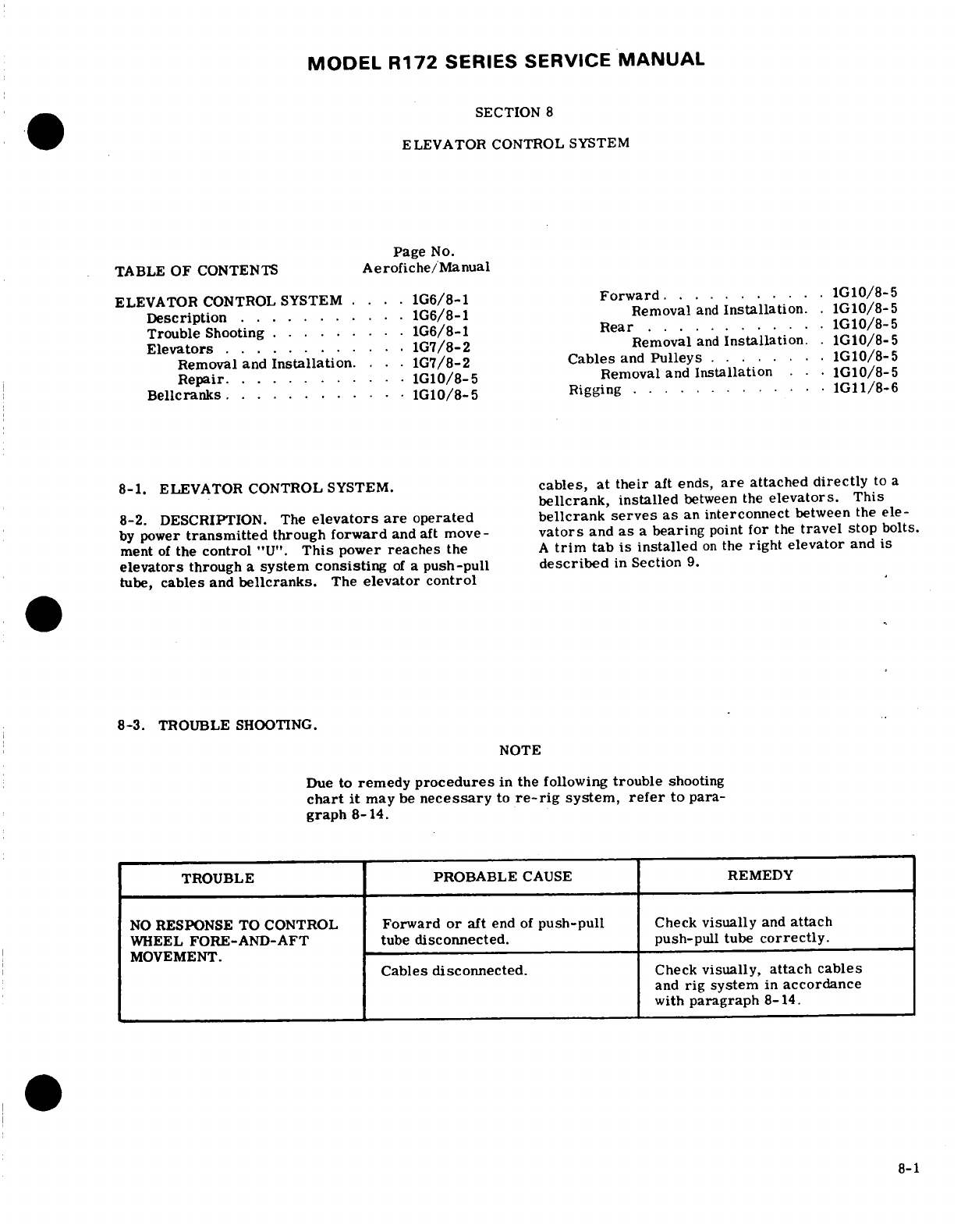
MODEL
R172
SERIES
SERVICE
MANUAL
SECTION
8
ELEVATOR
CONTROL
SYSTEM
Page
No.
TABLE
OF
CONTENTS
Aerofiche/Manual
ELEVATOR
CONTROL SYSTEM
....
1G6/8-1
Forward.
. . .. .. .
1G10/8-5
Description
..
........
1G6/8-1
Removal
and
Installation.
.
1G10/8-5
Trouble
Shooting
..... ....
1G6/8-1
Rear
............
1G10/8-5
Elevators
.. . .
.....
1G7/8-2
Removal
and
Installation.
1G10/8-5
Removal
and
Installation.
. .
1G7/8-2
Cables
and
Pulleys
....
1G10/8-5
Repair.
.........
.
1G10/8-5
Removal and
Installation
. . .
1G10/8-5
Bellcranks...
.
........ 1.G1
/8-5
Rigging
.
.........
1G11/8-6
8-1.
ELEVATOR CONTROL
SYSTEM.
cables,
at
their
aft
ends,
are
attached
directly
to
a
bellcrank,
installed
between the
elevators.
This
8-2.
DESCRIPTION. The
elevators
are
operated
bellcrank
serves
as
an
interconnect
between
the
ele-
by
power
transmitted
through
forward
and
aft
move-
vators
and
as
a
bearing
point
for
the
travel
stop bolts.
ment
of
the
control
"U".
This
power
reaches
the
A
trim
tab
is
installed
on
the
right elevator
and
is
elevators
through a
system
consisting
of
a
push-pull
described
in
Section
9.
tube,
cables
and
bellcranks.
The
elevator control
8-3.
TROUBLE
SHOOTING.
NOTE
Due
to
remedy
procedures
in
the
following
trouble
shooting
chart
it
may
be
necessary
to
re-rig
system,
refer
to
para-
graph 8-14.
TROUBLE
PROBABLE
CAUSE
REMEDY
NO
RESPONSE
TO
CONTROL
Forward
or
aft
end
of
push-pull
Check
visually
and
attach
WHEEL
FORE-AND-AFT
tube
disconnected.
push-pull
tube
correctly.
MOVEMENT.
Cables
disconnected.
Check
visually,
attach
cables
and
rig
system
in
accordance
with
paragraph
8-14.
8-1
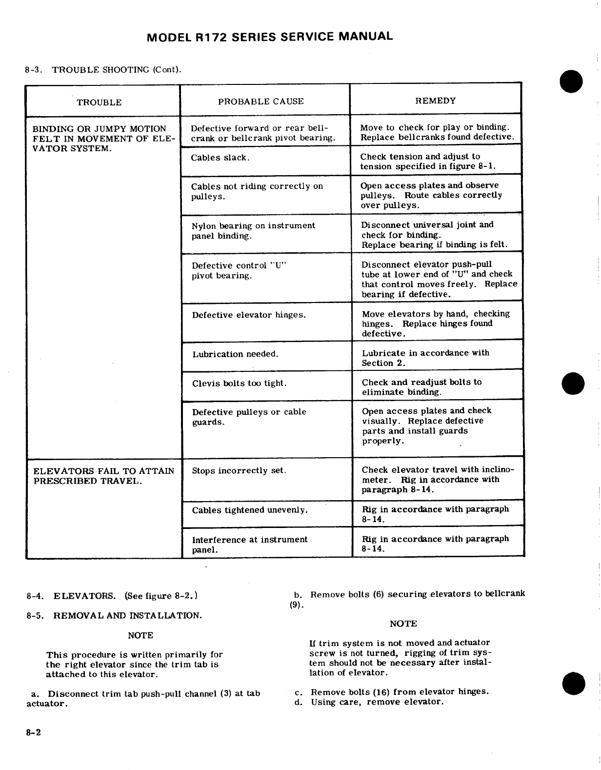
MODEL
R172
SERIES
SERVICE
MANUAL
8-3.
TROUBLE
SHOOTING
(Cont).
TROUBLE
PROBABLE
CAUSE
REMEDY
BINDING
OR JUMPY
MOTION
Defective
forward
or
rear
bell-
Move
to
check
for
play
or
binding.
FELT
IN
MOVEMENT
OF
ELE-
crank
or
bellcrank
pivot
bearing.
Replace
bellcranks
found
defective.
VATOR
SYSTEM.
Cables
slack.
Check
tension
and
adjust
to
tension
specified
in
figure
8-1.
Cables
not
riding
correctly
on
Open
access
plates
and
observe
pulleys.
pulleys.
Route
cables
correctly
over
pulleys.
Nylon
bearing
on
instrument
Disconnect
universal
joint
and
panel
binding.
check
for
binding.
Replace
bearing
if
binding
is
felt.
Defective
control
"U"
Disconnect
elevator
push-pull
pivot
bearing,
tube
at
lower
end
of
"U"
and check
that
control
moves
freely.
Replace
bearing
if
defective.
Defective
elevator
hinges.
Move
elevators
by
hand,
checking
hinges.
Replace
hinges
found
defective.
Lubrication
needed.
Lubricate
in
accordance
with
Section
2.
Clevis
bolts
too
tight.
Check
and
readjust
bolts
to
eliminate
binding.
Defective
pulleys
or
cable
Open
access
plates
and
check
guards.
visually.
Replace
defective
parts
and
install
guards
properly.
ELEVATORS
FAIL
TO
ATTAIN
Stops
incorrectly
set.
Check
elevator
travel
with
inclino-
PRESCRIBED
TRAVEL.
meter.
Rig
in
accordance
with
paragraph
8-14.
Cables tightened
unevenly.
Rig
in
accordance
with
paragraph
8-14.
Interference at
instrument
Rig
in
accordance
with
paragraph
panel.
8-14.
8-4.
ELEVATORS.
(See
figure
8-2.)
b.
Remove
bolts
(6)
securing
elevators
to
bellcrank
(9).
8-5.
REMOVAL
AND
INSTALLATION.
NOTE
NOTE
If
trim
system
is
not
moved
and
actuator
This
procedure
is
written
primarily
for
screw
is
not
turned,
rigging
of
trim
sys-
the
right
elevator
since
the
trim
tab
is
tem should
not
be
necessary
after
instal-
attached
to
this
elevator.
lation
of
elevator.
a.
Disconnect
trim
tab
push-pull
channel
(3)
at
tab
c.
Remove
bolts
(16)
from
elevator
hinges.
actuator.
d.
Using
care, remove
elevator.
8-2
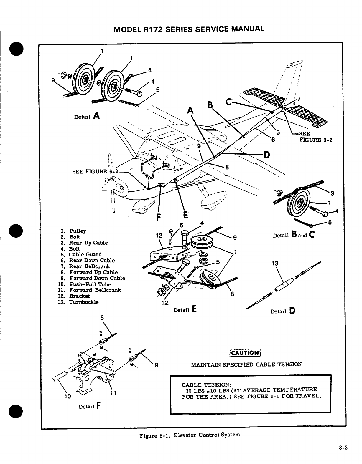
MODEL
R172
SERIES
SERVICE
MANUAL
FIGURE
8-2
SEE
FIGURE
6-2
-
1.
Pulley
2.
Bolt
3.
Rear
Up
Cable
4.
Bolt
5.
Cable
Guard
1
6.
Rear
Down
Cable
7.
Rear
Bellerank
8.
Forward
Up
Cable
9.
Forward
Down
Cable
10.
Push-Pull
Tube
11.
Forward
Bellcrank
12.
Bracket
13.
Turnbuckle
Detail
E
Detail
D
9
..
MAINTAIN
SPECIFIED
CABLE
TENSION
CABLE
TENSION:
30
LBS
=10
LBS
(AT AVERAGE
TEMPERATURE
FOR
THE
AREA.)
SEE FIGURE
1-1
FOR
TRAVEL.
Detail
F
Figure
8-1.
Elevator
Control
System
8-3
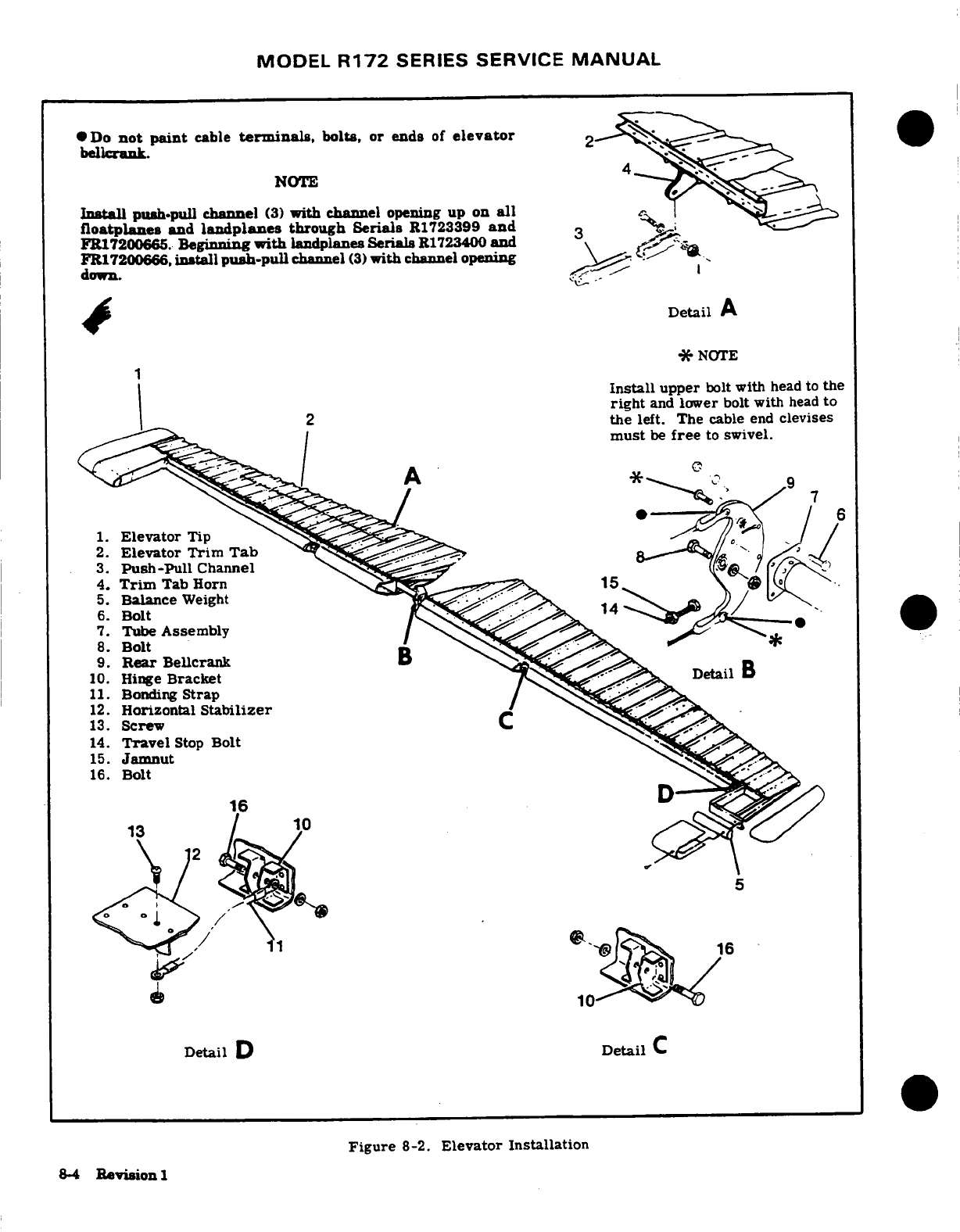
MODEL
R172
SERIES
SERVICE
MANUAL
Do
not
paint
cable
terminals,
bolts,
or
ends
of
elevator
bellcrank.
NOTE
Install
push-pull
channel
(3)
with
channel
opening
up
on
all
floatplanes
and
landplanes
through
Serials
R1723399
and
3
FR17200665.
Beginning
with
landplanes
Serials
R1723400
and
FR17200666,
install
push-pull
channel
(3)
with
channel
opening
down.
Detail
A
*
NOTE
Install
upper
bolt
with
head
to
the
right
and
lower
bolt with
head
to
the
left.
The
cable
end
clevises
must
be
free
to
swivel.
6
1.
Elevator
Tip
2.
Elevator Trim
Tab
3.
Push-Pull
Channel
4.
Trim
Tab Horn
5.
Balance
Weight
6.
Bolt
7.
Tube
Assembly
8.
Bolt
9.
Rear
Bellcrank
10.
Hinge
Bracket
11.
Bonding
Strap
12.
Horizontal
Stabilizer
13.
Screw
14.
Travel
Stop
Bolt
,
15.
Jamnut
8-4
Revision
1
MODEL
R172
SERIES
SERVICE
MANUAL
e.
To
remove
left
elevator
use same procedure,
NOTE
omitting
step
"a".
f.
Reverse
preceding
steps
for
installation.
Rig
It
may
be
necessary
to
remove
one
of
the
system
in
accordance
with
applicable
paragraph
in
stabilizer
attaching
bolts
for
clearance
this
section
if
necessary.
when
removing
the
bellcrank
pivot
bolt.
8-6.
REPAIR.
Repair
may
be
accomplished
as
out-
e.
Reverse
preceding
steps
for
installation.
Rig
lined
in
Section
18.
If
repair
has affected
static
system
in
accordance
with
applicable
paragraph
in
balance,
check
and
rebalance
as
required. this
section,
safety
turnbuckles
and
reinstall
all
items
removed
for
access.
8-7.
BELLCRANKS.
8-12.
CABLES
AND
PULLEYS. (See
figure
8-8.
FORWARD.
(See
figure
8-1.)
8-1.)
8-9.
REMOVAL
AND
INSTALLATION.
8-13.
REMOVAL
AND
INSTALLATION.
a.
Remove
seats, upholstery
and
access
plates
as
a.
Remove
seats,
upholstery
and
access
plates
as
necessary.
necessary.
b.
Relieve
cable
tension
at
turnbuckles
(13)
and
dis-
b.
Relieve
cable
tension
at
turnbuckles
(13).
connect
cables
from
bellcrank
(11).
c.
Disconnect
cables
at
forward
bellcrank
(11).
c.
Disconnect
push-pull
tube
(10)
from bellcrank
d.
Disconnect
cables
at
rear
bellcrank
(7).
(11).
e.
Remove
cable
guards
and
pulleys
as necessary
d.
Remove
pivot
bolt
and
remove bellcrank.
to
work
cables free
of
aircraft.
e.
Reverse
preceding
steps
for
installation.
Rig
system
in
accordance
with
applicable paragraph
in
NOTE
this
section,
safety
turnbuckles
and
reinstall
all
items
removed
in
step
"a".
To
ease
routing
of
cables,
a
length
of
wire
may
be
attached
to
end
of
cable
before
being
8-10.
REAR.
(See
figure
8-2.)
withdrawn
from
aircraft.
Leave
wire
in
place,
routed
through
structure,
attach
cable
8-11.
REMOVAL
AND INSTALLATION.
being
installed
and
pull
cable
into
position.
a.
Remove
rudder.
(Refer
to Section
10.)
b.
Relieve
cable
tension
at
turnbuckles
(index
13,
f.
After
cable
is
routed
in
position,
install
pulleys
figure
8-1)
and
disconnect
cables
from
rear
bellcrank
and
cable
guards.
Ensure
cable
is
positioned
in
(9).
pulley
groove before
installing guards.
c.
Remove
bolts
(6)
securing
elevators
to
bellcrank.
g.
Rig
system
in
accordance
with
applicable
para-
d.
Remove
bellcrank
pivot
bolt
(8)
and
slide bell-
graph
in
this
section,
safety
turnbuckles
and
re-
crank
from
between
tube
assemblies
(7).
install all
items
removed
in
step
"a".
SHOP
NOTES:
8-5
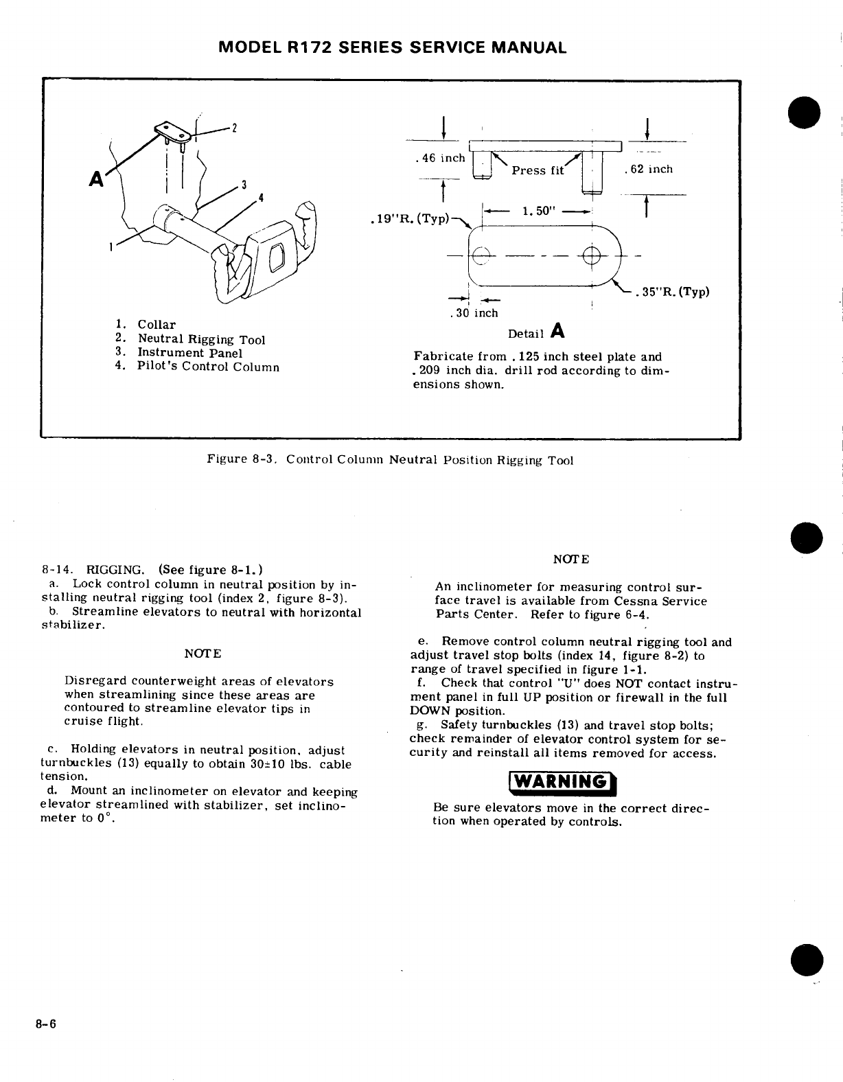
MODEL
R172
SERIES
SERVICE
MANUAL
2
..
.
2.
Neutral
Rigging
Tool
3.
Instrument
Panel
Fabricate
from
.125
inch
steel
plate
and
4.
Pilot's
Control
Column
.209
inch
dia.
drill
rod
according
to dim-
ensions
shown.
Figure
8-3.
Control
Column
Neutral
Position
Rigging
Tool
NOTE
8-14.
RIGGING.
(See
figure
8-1.)
a.
Lock
control
column
in
neutral
position
by
in-
An
inclinometer
for
measuring
control
sur-
stalling
neutral
rigging
tool
(index
2,
figure
8-3).
face
travel
is
available
from
Cessna
Service
b.
Streamline
elevators
to
neutral
with
horizontal
Parts
Center.
Refer
to
figure
6-4.
stabilizer.
e.
Remove
control
column
neutral
rigging
tool
and
NOTE
adjust
travel
stop
bolts
(index
14,
figure
8-2)
to
range
of
travel
specified
in
figure
1-1.
Disregard
counterweight
areas
of
elevators
f.
Check that
control
"U"
does
NOT
contact
instru-
when
streamlining since
these
areas
are
ment
panel
in
full
UP
position
or
firewall
in
the
full
contoured
to
streamline
elevator
tips
in
DOWN
position.
cruise
flight.
g.
Safety
turnbuckles
(13)
and
travel
stop
bolts;
check
remainder
of
elevator
control
system
for
se-
c.
Holding
elevators
in
neutral
position,
adjust
curity
and
reinstall
all
items
removed
for
access.
turnbuckles
(13)
equally
to
obtain
30±10
lbs.
cable
tension.
WARNING
d.
Mount
an
inclinometer
on
elevator
and
keeping W
elevator
streamlined
with
stabilizer,
set
inclino-
Be
sure
elevators
move
in
the
correct
direc-
meter
to
0
°
.tion
when
operated
by
controls.
8-6
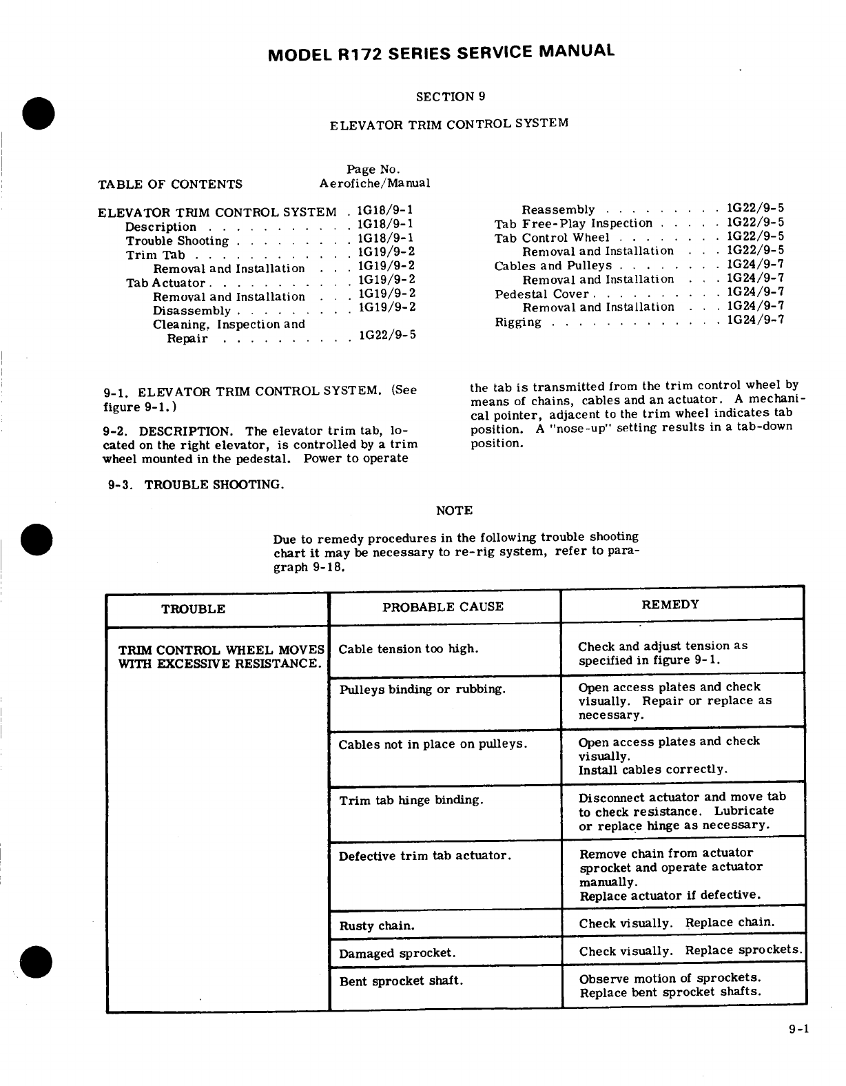
MODEL
R172
SERIES
SERVICE
MANUAL
SECTION
9
ELEVATOR
TRIM
CONTROL
SYSTEM
Page
No.
TABLE
OF CONTENTS
Aerofiche/Manual
ELEVATOR
TRIM
CONTROL
SYSTEM
.
1G18/9-1
Reassembly
... .. ... 1G22/9-5
Description
.1.....G18/9-1
Tab
Free-Play
Inspection
.....
1G22/9-5
Trouble
Shooting
.........
1G18/9-1
Tab
Control
Wheel
... ..
G22/9-5
Trim
Tab
............
1G19/9-2 Removal
and
Installation
..1G22/9-5
Removal and
Installation
.
1G19/9-2
Cables
and
Pulleys
........
1G24/9-7
Tab
Actuator
...
1G19/9-2 Removal and
Installation
.. .
1G24/9-7
Removal and
Installation
.
1G19/9-2
Pedestal
Cover
..........
G24/9-7
Disassembly
.....
1G19/9-2
Removal
and
Installation
... 1G24/9-7
Cleaning,
Inspection
and Rigging
..
........
. 1G24/9-7
Repair
..........
1G22/9-5
9-1.
ELEVATOR
TRIM
CONTROL
SYSTEM.
(See
the tab
is
transmitted
from
the
trim
control
wheel
by
figure
9-1.)
means
of
chains, cables
and
an
actuator.
A
mechani-
cal pointer,
adjacent
to the
trim
wheel
indicates
tab
9-2.
DESCRIPTION.
The
elevator
trim
tab,
lo-
position.
A
"nose-up"
setting
results
in a
tab-down
cated
on
the
right elevator,
is
controlled
by
a
trim
position.
wheel
mounted
in
the
pedestal.
Power
to
operate
9-3.
TROUBLE
SHOOTING.
NOTE
Due
to
remedy
procedures
in
the
following
trouble
shooting
chart
it
may
be
necessary
to
re-rig
system,
refer
to
para-
graph 9-18.
TROUBLE PROBABLE
CAUSE
REMEDY
TRIM
CONTROL WHEEL
MOVES
Cable
tension
too
high.
Check
and
adjust
tension
as
WITH
EXCESSIVE
RESISTANCE.
specified in
figure
9-1.
Pulleys
binding
or
rubbing.
Open
access
plates
and
check
visually.
Repair
or
replace
as
necessary.
Cables
not
in
place
on
pulleys.
Open
access
plates
and
check
visually.
Install cables
correctly.
Trim
tab
hinge
binding.
Disconnect
actuator
and
move
tab
to
check
resistance.
Lubricate
or
replace
hinge
as necessary.
Defective
trim
tab
actuator.
Remove
chain from
actuator
sprocket
and
operate
actuator
manually.
Replace
actuator
if
defective.
Rusty chain.
Check
visually.
Replace
chain.
Damaged
sprocket.
Check
visually.
Replace
sprockets.
Bent
sprocket
shaft.
Observe
motion
of
sprockets.
Replace
bent
sprocket
shafts.
9-1
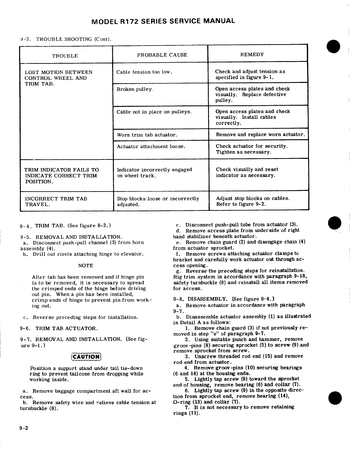
MODEL
R172
SERIES SERVICE
MANUAL
9-3.
TROUBLE
SHOOTING
(Cont).
TROUBLE
PROBABLE
CAUSE
REMEDY
LOST
MOTION
BETWEEN
Cable
tension
too
low.
Check
and
adjust tension
as
CONTROL
WHEEL
AND
specified
in
figure
9-1.
TRIM
TAB.
Broken
pulley.
Open
access
plates
and
check
visually.
Replace
defective
pulley.
Cable
not
in
place
on
pulleys.
Open
access
plates
and
check
visually.
Install
cables
correctly.
Worn
trim
tab actuator.
Remove
and
replace
worn
actuator.
Actuator
attachment
loose.
Check
actuator
for
security.
Tighten
as
necessary.
TRIM
INDICATOR
FAILS
TO
Indicator
incorrectly
engaged
Check
visually
and
reset
INDICATE
CORRECT
TRIM
on
wheel
track.
indicator
as necessary.
POSITION.
INCORRECT
TRIM
TAB
Stop
blocks
loose
or
incorrectly
Adjust
stop
blocks
on
cables.
TRAVEL.
adjusted. Refer
to
figure
9-2.
9-4.
TRIM
TAB,
(See
figure
8-2.)
c.
Disconnect
push-pull
tube
from
actuator
(3).
d.
Remove
access
plate
from
underside
of
right
9-5.
REMOVAL
AND
INSTALLATION.
hand
stabilizer
beneath
actuator.
a.
Disconnect push-pull
channel
(3)
from
horn
e.
Remove
chain
guard
(2)
and
disengage
chain
(4)
assembly
(4).
from
actuator
sprocket.
b.
Drill
out
rivets
attaching
hinge
to
elevator.
f.
Remove
screws
attaching
actuator clamps
to
bracket
and
carefully
work
actuator
out
through
ac-
NOTE
cess
opening.
g.
Reverse
the
preceding
steps
for
reinstallation.
After
tab
has
been
removed
and
if
hinge
pin
Rig
trim
system
in
accordance
with
paragraph
9-18,
is
to
be
removed,
it
is
necessary
to
spread
safety
turnbuckle
(8)
and
reinstall
all
items
removed
the
crimped
ends
of
the
hinge
before
driving
for
access.
out
pin.
When
a
pin
has
been
installed,
crimp
ends
of
hinge
to
prevent
pin
from
work-
9-8.
DISASSEMBLY.
(See
figure
9-4.)
ing
out.
a.
Remove
actuator
in
accordance
with
paragraph
9-7.
c.
Reverse
preceding
steps
for
installation.
b.
Disassemble actuator
assembly
(1)
as
illustrated
in
Detail
A
as
follows:
9-6.
TRIM
TAB
ACTUATOR.
1.
Remove
chain guard
(3)
if
not
previously
re-
moved
in
step
"e"
of
paragraph
9-7.
9-7.
REMOVAL
AND
INSTALLATION.
(See
fig-
2.
Using
suitable
punch
and
hammer,
remove
ure
9-1.)
groov-pins
(8)
securing
sprocket
(5)
to
screw
(9)
and
remove
sprocket
from
screw.
CAUTION
3.
Unscrew
threaded rod
end
(15)
and
remove
rod
end
from
actuator.
Position
a
support stand
under
tail
tie-down
4.
Remove
groov-pins
(10)
securing
bearings
ring
to
prevent tailcone
from
dropping
while
(6
and
14)
at
the
housing
ends.
working
inside.
5.
Lightly
tap
screw
(9)
toward
the
sprocket
end
of
housing,
remove
bearing
(6)
and
collar
(7).
a.
Remove
baggage
compartment
aft
wall
for
ac-
6.
Lightly
tap
screw
(9)
in the
opposite
direc-
cess.
tion
from
sprocket
end,
remove
bearing
(14),
b.
Remove
safety
wire
and
relieve
cable
tension
at
O-ring
(13)
and
collar
(7).
turnbuckle
(8).
7.
It
is
not
necessary
to
remove
retaining
rings
(11).
9-2
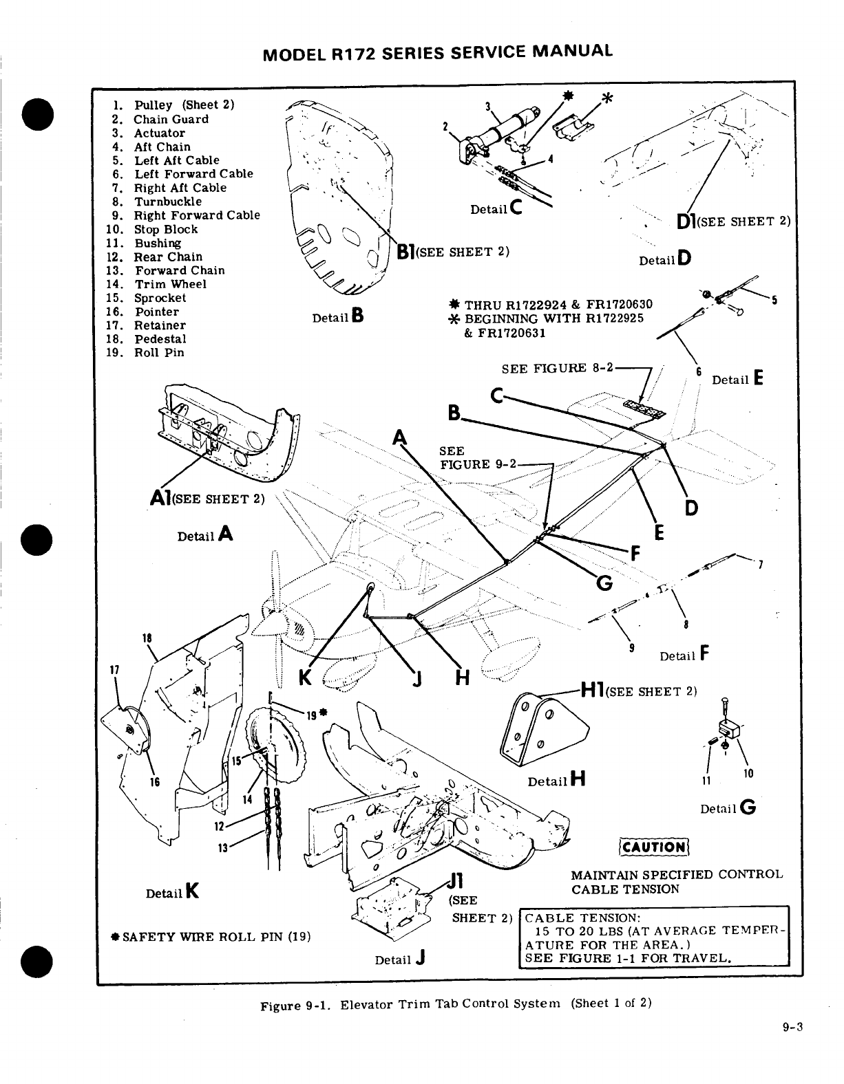
MODEL
R172
SERIES SERVICE
MANUAL
1.
Pulley
(Sheet
2)
2.
Chain
Guard
3.
Actuator
4.
Aft
Chain
-
5.
Left
Aft
Cable
6.
Left
Forward
Cable- -
7.
Right
Aft
Cable
8.
Turnbuckle
9.
Right
Forward
Cable
10.
Stop
Block
SHEET
2)
11.
Bushing
12.
Chain
13.
Forward
Chain
14.
Trim
Wheel
15.
Sprocket
16.
Pointer
*
THRU
R1722924
&
FR1720630
-.
17.
Retainer
*
-BEGINNING
WITH
R1722925
18.
Pedestal
& FR1720631
19.
Roll
Pin
SEE
FIGURE
8-2
.........
-
Detail
E
FIGURE
9-2
-- ..
Detail
A
.
.
..
.
(SEE
SHEET
2)
Detail
Detail
G
...
-..-
CAUTION
MAINTAIN
SPECIFIED
CONTROL
CABLE
TENSION
........
.
,
SHEET
2)
CABLE
TENSION:
*
SAFETY
WIRE
ROLL
PIN
(19)
15
TO
20
LBS
(AT
AVERAGE
TEMPER-
ATURE
FOR
THE
AREA.)
Detail
J
SEE
FIGURE
1-1
FOR
TRAVEL.
Figure
9-1.
Elevator
Trim
Tab
Control
System
(Sheet
1
of
2)
9-3
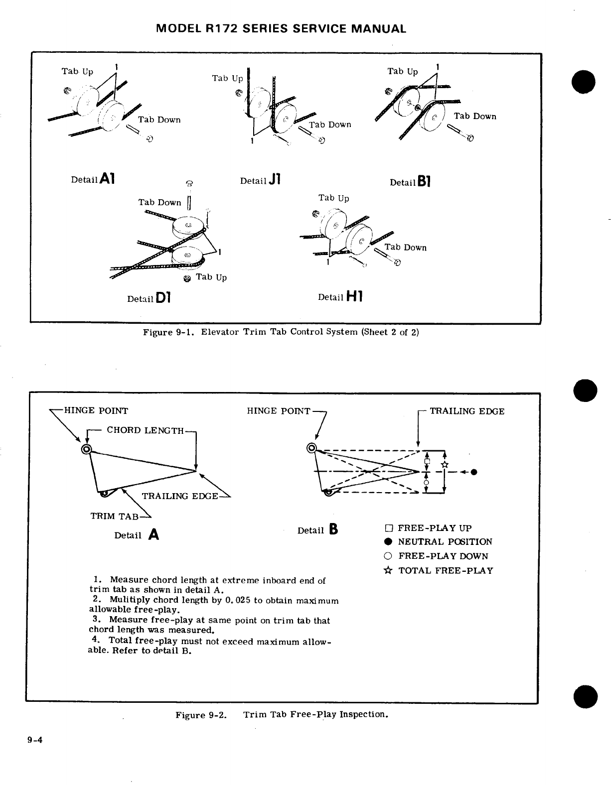
MODEL
R172
SERIES
SERVICE
MANUAL
Tab
Up
Tab
Up
Tab
Up
Down
Tab
Down
Tab
Down
DetailAl
Detail
J1
Detail
B1
Tab
Down
Tab
Up
Down
Tab
Up
Detail
Dl
Detail
HI
Figure
9-1.
Elevator
Trim
Tab
Control
System
(Sheet
2
of
2)
-HINGE
POINT
HINGE
POINT
TRAILING
EDGE
CHORD
LENGTH
TRSAILING
G
-
-----
.
TRAILING
EDGE
TRIM
TAB
Detail
A
Detail
B
0
FREE-PLAY
UP
*
NEUTRAL
POSITION
O
FREE-PLAY
DOWN
*
TOTAL
FREE-PLAY
1.
Measure chord
length
at
extreme
inboard
end
of
trim
tab
as
shown
in
detail
A.
2.
Mulitiply
chord
length
by
0.
025
to
obtain
maximum
allowable
free-play.
3.
Measure
free-play
at
same
point
on
trim
tab that
chord
length
was
measured.
4.
Total
free-play
must
not
exceed
maximum
allow-
able.
Refer
to
detail
B.
Figure
9-2.
Trim
Tab
Free-Play
Inspection.
9-4
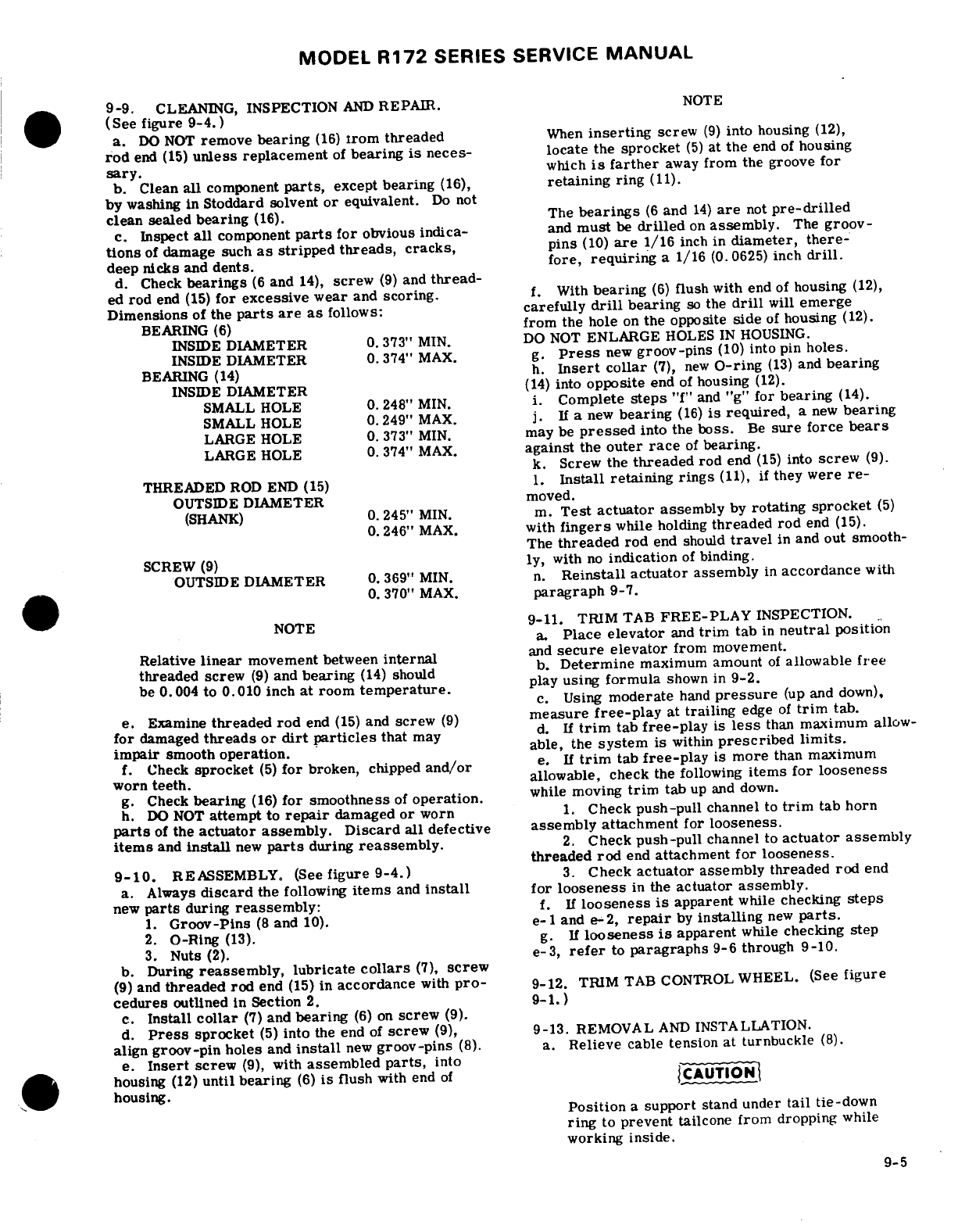
MODEL
R172
SERIES SERVICE
MANUAL
9-9.
CLEANING,
INSPECTION
AND
REPAIR.
NOTE
(See
figure
9-4.
)
a.
DO
NOT
remove
bearing
(16)
Irom
threaded
When
inserting
screw
(9)
into
housing
(12),
rod
end
(15)
unless
replacement
of
bearing
is
neces-
locate
the
sprocket
(5)
at
the
end
of
housing
sary.
which
is
farther
away
from
the groove
for
b.
Clean
all
component
parts,
except
bearing
(16),
retaining
ring
(11).
by
washing
in
Stoddard solvent
or
equivalent.
Do
not
clean sealed
bearing
(16).
The
bearings
(6
and
14)
are
not
pre-drilled
c.
Inspect
all
component
parts
for
obvious
indica-
and
must
be
drilled
on
assembly.
The
groov-
tions
of
damage
such
as
stripped
threads,
cracks,
pins
(10)
are
1/16
inch
in
diameter,
there-
deep
nicks
and
dents.
fore,
requiring
a
1/16
(0.0625)
inch
drill.
d. Check
bearings
(6
and
14),
screw
(9)
and
thread-
ed
rod
end
(15)
for excessive
wear
and
scoring.
f.
With
bearing
(6)
flush
with
end
of
housing
(12),
Dimensions
of
the
parts
are
as
follows:
carefully
drill
bearing
so
the
drill
will
emerge
BEARING
(6)
from
the
hole
on
the
opposite
side
of
housing
(12).
INSIDE
DIAMETER
0.373"
MIN.
DO
NOT
ENLARGE
HOLES
IN
HOUSING.
INSIDE
DIAMETER
0.
374"
MAX.
g.
Press
new
groov-pins
(10)
into
pin
holes.
BEARING
(14)
h.
Insert
collar
(7),
new
O-ring
(13)
and
bearing
INSIDE
DIAMETER
(14)
into
opposite
end
of
housing
(12).
SMALL HOLE
0.
248"
MIN. i.
Complete
steps
"f"
and
"g"
for
bearing
(14).
SMALL HOLE
0.249"
MAX.
j.
If
a
new
bearing
(16)
is
required,
a
new
bearing
LARGE
HOLE
0.
373"
MIN.
may
be
pressed
into
the
boss.
Be
sure
force
bears
LARGE
HOLE
0.
374"
MAX.
against
the
outer
race
of
bearing.
k.
Screw
the
threaded
rod
end
(15)
into
screw
(9).
THREADED
ROD
END (15)
1.
Install
retaining
rings
(11),
if
they
were
re-
OUTSIDE
DIAMETER
moved.
(SHANK)
0.
245"
MIN.
m.
Test
actuator
assembly
by
rotating
sprocket
(5)
0.246"
MAX.
with
fingers
while
holding
threaded rod
end
(15).
The
threaded
rod
end should
travel
in
and
out smooth-
SCREW
(9)
ly,
with
no
indication
of
binding.
OUTSIDE
DIAMETER
0.
369"
MIN.
n.
Reinstall
actuator
assembly
in
accordance
with
0.
370"
MAX.
paragraph
9-7.
NOTE
9-11. TRIM
TAB
FREE-PLAY
INSPECTION.
a.
Place
elevator
and
trim
tab
in
neutral
position
Relative
linear
movement between
internal
and
secure
elevator
from
movement.
threaded
screw
(9)
and
bearing
(14)
should
b.
Determine
maximum
amount
of
allowable
free
be
0.004
to
0.010
inch
at
room
temperature,
play
using
formula
shown in
9-2.
c.
Using
moderate
hand
pressure
(up
and
down),
e.
Examine
threaded
rod
end
(15)
and
screw
(9)
measure
free-play
at
trailing
edge
of
trim
tab.
for
damaged
threads
or
dirt
particles
that
may
d.
If
trim
tab
free-play
is
less
than
maximum
allow-
impair
smooth
operation.
able,
the
system
is
within
prescribed
limits.
f.
Check
sprocket
(5)
for
broken,
chipped
and/or
e.
If
trim
tab
free-play
is more
than
maximum
worn
teeth,
allowable, check
the
following
items
for
looseness
g.
Check
bearing
(16)
for smoothness
of
operation.
while
moving
trim
tab
up and
down.
h.
DO
NOT
attempt
to
repair
damaged
or
worn
1.
Check
push-pull
channel
to
trim
tab
horn
parts
of
the
actuator assembly.
Discard
all
defective
assembly
attachment
for
looseness.
items
and
install
new
parts
during
reassembly.
2.
Check
push-pull
channel
to
actuator
assembly
threaded
rod
end
attachment
for
looseness.
9-10.
REASSEMBLY.
(See
figure 9-4.)
3.
Check
actuator
assembly
threaded
rod
end
a.
Always
discard
the
following
items
and
install
for
looseness
in
the
actuator
assembly.
new
parts
during
reassembly:
f. If
looseness
is
apparent
while
checking
steps
1.
Groov-Pins
(8
and
10).
e-1
and
e-2,
repair
by
installing
new
parts.
2.
O-Ring
(13).
g.
If
looseness
is
apparent
while
checking
step
3.
Nuts
(2).
e-3,
refer
to
paragraphs
9-6
through
9-10.
b.
During
reassembly,
lubricate
collars
(7),
screw
(9)
and
threaded rod
end
(15)
in
accordance
with
pro-
9-12.
TRIM
TAB CONTROL
WHEEL.
(See
figure
cedures
outlined in
Section
2.
9-1.)
c.
Install
collar
(7)
and
bearing
(6)
on
screw
(9).
d.
Press
sprocket
(5)
into
the
end
of
screw
(9),
9-13.
REMOVAL
AND
INSTALLATION.
align
groov-pin
holes
and
install
new
groov-pins
(8).
a.
Relieve
cable
tension
at
turnbuckle
(8).
e.
Insert
screw
(9),
with
assembled
parts,
into
housing
(12)
until
bearing
(6)
is
flush
with end
of
CAUTION
housing.
Position
a
support
stand
under
tail
tie-down
ring
to
prevent
tailcone
from
dropping
while
working
inside.
9-5
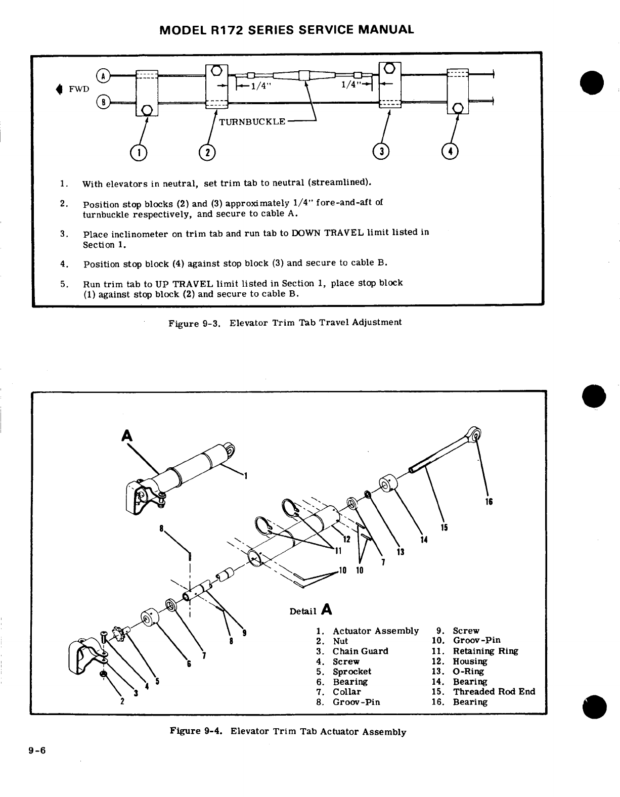
MODEL
R172
SERIES
SERVICE
MANUAL
TURNBUCKLE
With
elevators
in
neutral, set
trim
tab
to
neutral
(streamlined).
2.
Position stop
blocks
(2)
and
(3)
approximately
1/4"
fore-and-aft
of
turnbuckle
respectively,
and
secure
to
cable
A.
3.
Place
inclinometer
on
trim
tab
and
run
tab
to
DOWN
TRAVEL
limit
listed
in
Section
1.
4.
Position
stop
block
(4)
against
stop block
(3)
and
secure
to
cable
B.
5.
Run
trim
tab
to
UP TRAVEL
limit
listed
in
Section
1,
place
stop
block
(1)
against
stop
block
(2)
and
secure
to
cable
B.
Figure
9-3.
Elevator
Trim
Tab
Travel
Adjustment
A
10
10
Detail
1.
Actuator
Assembly
9.
Screw
2.
Nut
10.
Groov-Pin
3.
Chain
Guard
11.
Retaining
Ring
4.
Screw
12.
Housing
5.
Sprocket
13.
O-Ring
6.
Bearing
14.
Bearing
7.
Collar
15.
Threaded
Rod
End
2
8.
Groov-Pin
16.
Bearing
Figure
9-4.
Elevator
Trim
Tab
Actuator Assembly
9-6
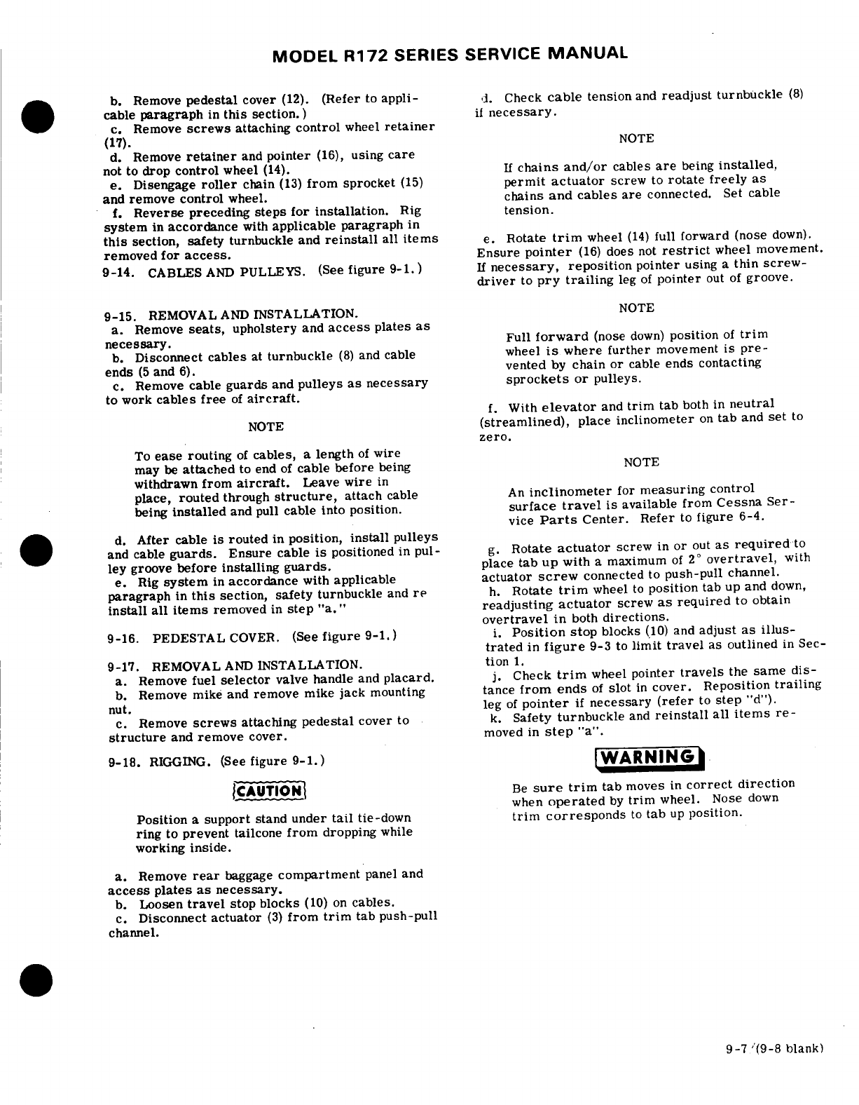
MODEL
R172
SERIES
SERVICE
MANUAL
b.
Remove
pedestal
cover
(12).
(Refer
to
appli-
d.
Check
cable
tension
and
readjust
turnbuckle
(8)
cable
paragraph
in
this
section.)
if
necessary.
c.
Remove
screws
attaching
control
wheel
retainer
(17).
NOTE
d.
Remove
retainer
and
pointer
(16),
using
care
not to
drop
control
wheel
(14).
If
chains
and/or
cables
are
being
installed,
e.
Disengage
roller
chain
(13)
from
sprocket
(15)
permit
actuator
screw
to
rotate freely
as
and
remove
control
wheel.
chains
and cables
are
connected.
Set
cable
f.
Reverse preceding
steps for
installation.
Rig
tension.
system
in
accordance
with
applicable paragraph
in
this
section,
safety
turnbuckle
and
reinstall
all
items
e.
Rotate
trim
wheel
(14)
full
forward
(nose
down).
removed
for
access.
Ensure
pointer
(16)
does
not
restrict
wheel movement.
9-14.
CABLES
AND
PULLEYS.
(See
figure 9-1.)
If
necessary,
reposition
pointer
using
a
thin
screw-
driver
to
pry
trailing
leg
of
pointer
out
of
groove.
9-15.
REMOVAL
AND
INSTALLATION.
NOTE
a. Remove
seats,
upholstery and
access
plates
as
necessary.
Full
forward
(nose
down)
position
of
trim
b.
Disconnect
cables
at
turnbuckle
(8)
and
cable
wheel
is
where
further
movement
is
pre-
ends
(5
and
6).
vented
by
chain or
cable
ends
contacting
c.
Remove
cable
guards
and
pulleys
as necessary
sprockets
or
pulleys.
to
work
cables free
of
aircraft.
f.
With
elevator
and
trim
tab
both
in
neutral
NOTE
(streamlined),
place
inclinometer
on
tab
and
set
to
zero.
To
ease
routing
of
cables,
a
length
of
wire
may
be
attached
to end
of
cable
before
being
NOTE
withdrawn
from
aircraft.
Leave
wire
in
place,
routed
through
structure,
attach
cable
An
inclinometer
for
measuring control
being
installed
and
pull
cable into position.
surface
travel
is
available
from
Cessna
Ser-
vice
Parts
Center.
Refer
to
figure 6-4.
d.
After
cable
is
routed
in
position,
install
pulleys
and
cable
guards.
Ensure
cable
is
positioned
in
pul-
g.
Rotate
actuator
screw
in
or
out
as
required
to
ley
groove
before
installing
guards.
place
tab
up
with
a
maximum
of
2
°
overtravel,
with
e.
Rig
system
in
accordance
with
applicable
actuator
screw
connected
to
push-pull
channel.
paragraph
in
this
section,
safety
turnbuckle
and
re
h.
Rotate
trim
wheel
to
position
tab
up
and
down,
install
all
items
removed
in
step
"a."
readjusting
actuator
screw
as
required
to
obtain
overtravel
in
both
directions.
9-16.
PEDESTAL
COVER.
(See
figure
9-1.)
i.
Position
stop
blocks
(10)
and
adjust
as illus-
trated
in
figure
9-3
to
limit
travel
as
outlined
in
Sec-
9-17.
REMOVAL
AND
INSTALLATION.
tion
1.
a.
Remove
fuel
selector
valve
handle
and
placard.
j.
Check
trim
wheel
pointer
travels
the
same
dis-
b.
Remove
mike
and
remove
mike
jack
mounting
tance
from
ends
of
slot
in
cover.
Reposition
trailing
nut.
leg
of
pointer
if
necessary
(refer
to
step
"d").
c.
Remove
screws
attaching
pedestal
cover
to
k.
Safety
turnbuckle
and
reinstall
all
items
re-
structure
and
remove
cover.
moved
in
step
"a".
9-18.
RIGGING.
(See
figure
9-1.)
WARNING
.CAUTION
Be
sure
trim
tab
moves
in
correct
direction
when
operated
by
trim
wheel.
Nose
down
Position
a
support
stand
under
tail
tie-down
trim
corresponds
to
tab
up
position.
ring
to
prevent
tailcone
from
dropping
while
working
inside.
a.
Remove
rear
baggage
compartment
panel
and
access
plates
as
necessary.
b.
Loosen
travel
stop blocks
(10)
on
cables.
c.
Disconnect
actuator
(3)
from
trim
tab
push-pull
channel.
9-7
/(9-8
blank)
MODEL
R172
SERIES SERVICE
MANUAL
SECTION
10
RUDDER
AND
RUDDER TRIM
CONTROL
SYSTEM
Page
No.
TABLE OF
CONTENTS
Aerofiche/Manual
RUDDER
CONTROL
SYSTEM
. . . .. 1H7/10-1
Repair
.
..........
1H12/10-6
Description
..........
1H7/10-1
Cables
and
Pulleys
.. .1H12/10-6
Trouble
Shooting
.. ... 1H7/10-1
Removal
and
Installation
.. . 1H12/10-6
Pedal
Assembly
.........
H8/10-2
Rigging
...... ......
1H13/10-7
Removal
and
Installation.
. .
1H8/10-2
RUDDER
TRIM CONTROL
SYSTEM.
..
1H13/10-7
Rudder
..
......
.
.1H12/10-6
Description
............
H13/10-7
Removal
and Installation.
. .
1H12/10-6 Rigging
.........
..
1H13/10-7
10-1.
RUDDER
CONTROL
SYSTEM.
(See
figure
prised
of
rudder
pedals,
cables
and
pulleys,
all
of
10-1.)
which
link
the
pedals
to
the
rudder
and
nose
wheel
steering.
Cable
tension
is
automatically
determined
10-2.
DESCRIPTION.
Rudder
control
is
maintained
when
the
rudder
pedals
are
rigged
against
return
through
use
of
conventional
rudder
pedals
which
also
springs
6.50
inches
from
firewall.
control
nose
wheel
steering.
The
system
is
com-
10-3.
TROUBLE
SHOOTING.
NOTE
Due
to
remedy
procedures
in
the following
trouble
shooting
chart
it
may
be
necessary
to
re-rig
system,
refer
to
para-
graph
10-11.
TROUBLE
PROBABLE
CAUSE
REMEDY
RUDDER
DOES
NOT RESPOND
Broken
or
disconnected
cables.
Open
access
plates
and
check
TO
PEDAL
MOVEMENT.
visually.
Connect
or
replace
cables.
10-1
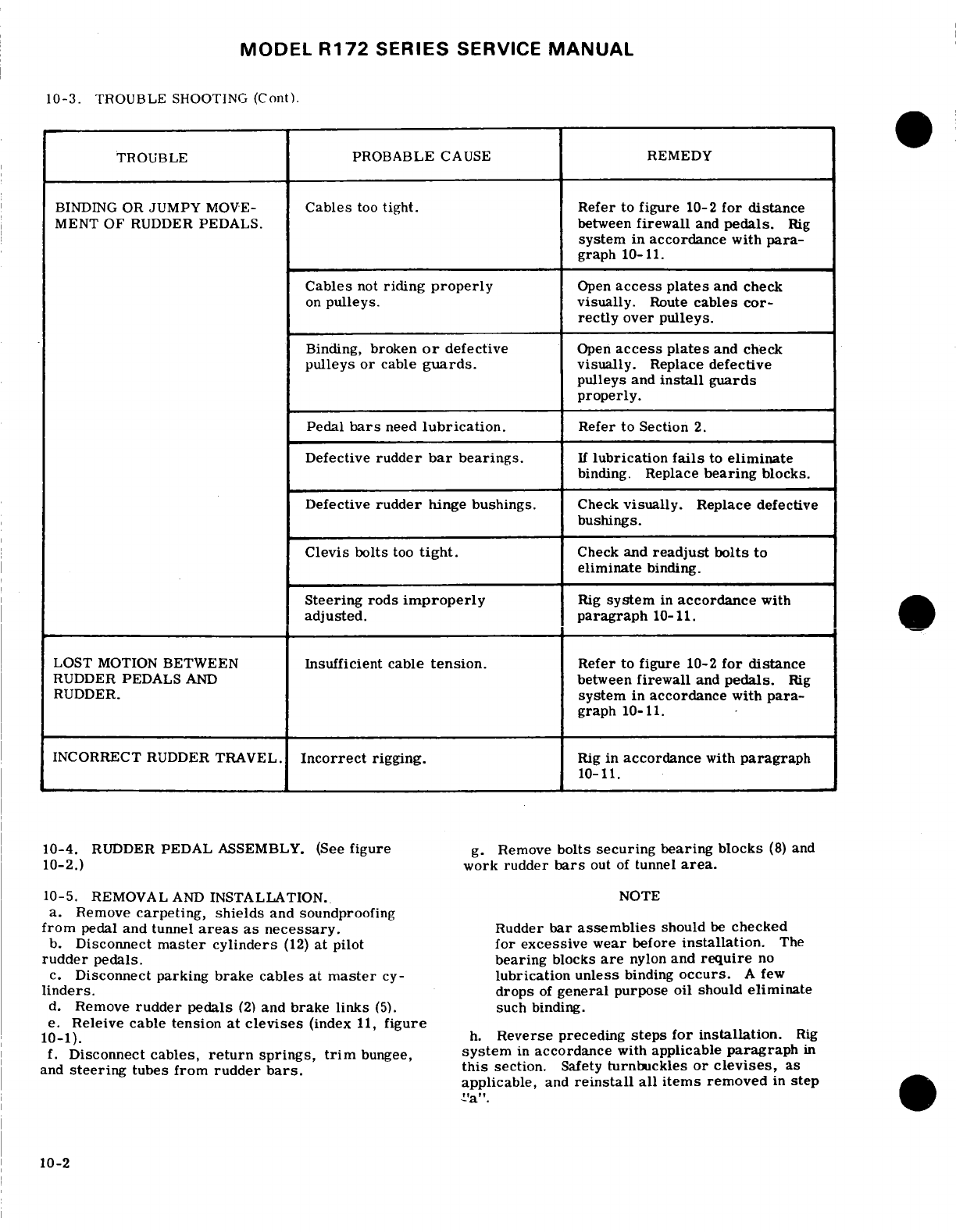
MODEL
R172
SERIES
SERVICE
MANUAL
10-3.
TROUBLE
SHOOTING
(Cont).
TROUBLE
PROBABLE
CAUSE REMEDY
BINDING
OR
JUMPY
MOVE-
Cables
too
tight. Refer
to
figure
10-2
for distance
MENT
OF
RUDDER
PEDALS.
between
firewall
and
pedals.
Rig
system
in
accordance
with
para-
graph
10-11.
Cables
not
riding
properly
Open
access plates
and
check
on
pulleys. visually.
Route
cables
cor-
rectly
over
pulleys.
Binding,
broken
or
defective
Open
access plates
and
check
pulleys
or
cable
guards.
visually.
Replace
defective
pulleys
and
install
guards
properly.
Pedal
bars
need
lubrication.
Refer to
Section
2.
Defective
rudder
bar
bearings.
If
lubrication
fails
to
eliminate
binding.
Replace
bearing
blocks.
Defective
rudder
hinge
bushings.
Check
visually.
Replace
defective
bushings.
Clevis
bolts
too
tight.
Check
and
readjust
bolts
to
eliminate
binding.
Steering
rods
improperly
Rig
system
in
accordance
with
adjusted.
paragraph
10-11.
LOST
MOTION
BETWEEN
Insufficient
cable
tension.
Refer
to
figure
10-2
for
distance
RUDDER
PEDALS
AND
between
firewall
and
pedals.
Rig
RUDDER.
system
in
accordance
with
para-
graph
10-11.
INCORRECT
RUDDER
TRAVEL.
Incorrect
rigging.
Rig
in
accordance
with
paragraph
10-11.
10-4.
RUDDER
PEDAL
ASSEMBLY.
(See
figure
g.
Remove
bolts
securing
bearing
blocks
(8)
and
10-2.)
work
rudder
bars
out
of
tunnel
area.
10-5.
REMOVAL
AND
INSTALLATION.
NOTE
a.
Remove
carpeting,
shields
and
soundproofing
from
pedal
and tunnel
areas
as
necessary.
Rudder
bar
assemblies
should
be
checked
b.
Disconnect
master
cylinders
(12)
at
pilot
for
excessive
wear
before
installation.
The
rudder
pedals.
bearing
blocks
are
nylon
and
require
no
c.
Disconnect parking
brake
cables
at
master
cy-
lubrication
unless
binding
occurs.
A
few
linders.
drops
of
general
purpose
oil
should
eliminate
d.
Remove
rudder
pedals
(2)
and
brake
links
(5).
such
binding.
e.
Releive cable tension
at
cevises
(index
11,
figure
10-1).
h.
Reverse
preceding
steps
for
installation.
Rig
f.
Disconnect
cables,
return
springs,
trim
bungee,
system
in
accordance
with
applicable
paragraph
in
and
steering
tubes
from
rudder
bars.
this
section.
Safety
turnbuckles
or
clevises,
as
applicable,
and
reinstall
all
items
removed
in
step
10-2
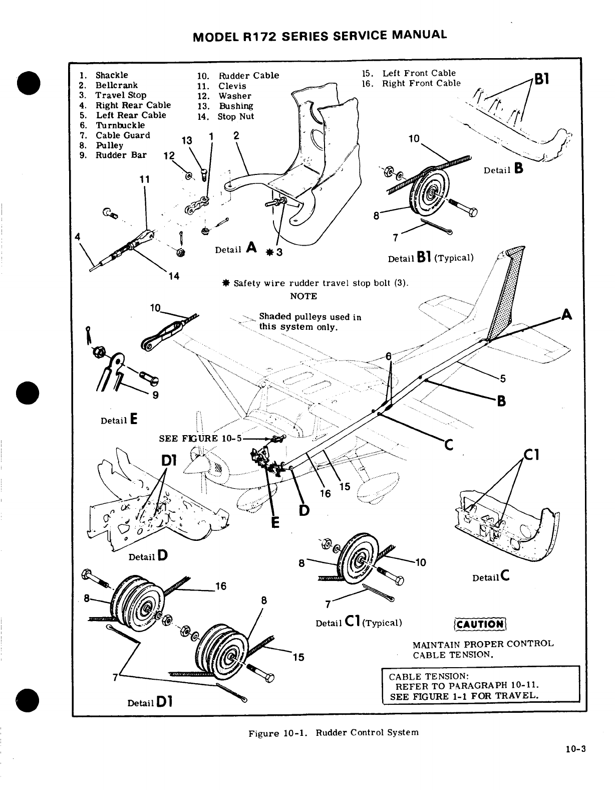
MODEL
R172
SERIES
SERVICE
MANUAL
1.
Shackle
10.
Rudder
Cable
15.
Left
Front
Cable
2.
Bellcrank
11.
Clevis
16.
Right
Front
Cable
B1
3.
Travel
Stop
12.
Washer
C
4.
Right
Rear
Cable
13.
Bushing
.
5.
Left
Rear
Cable
14.
Stop
Nut
6.
Turnbuckle
1.
7.
Cable
Guard
1 2
(
8.
Pulley
9.
Rudder
Bar
12
Detail
B
8
Detail
A
Detail
B
(Typical)
14
*
Safety
wire
rudder
travel
stop
bolt
(3).
NOTE-
-.
Shaded
pulleys
used
in
.
this
system
only.-
*
Detail
E
... .
.
.
....
SEE
FIGURE
10-5
CABLE
TENSION:
REFER
TO
PARAGRAPH
10-11.
Detail
D1
SEE
FIGURE
1-1
FOR TRAVEL.
Figure
10-1.
Rudder
Control
System
10-3
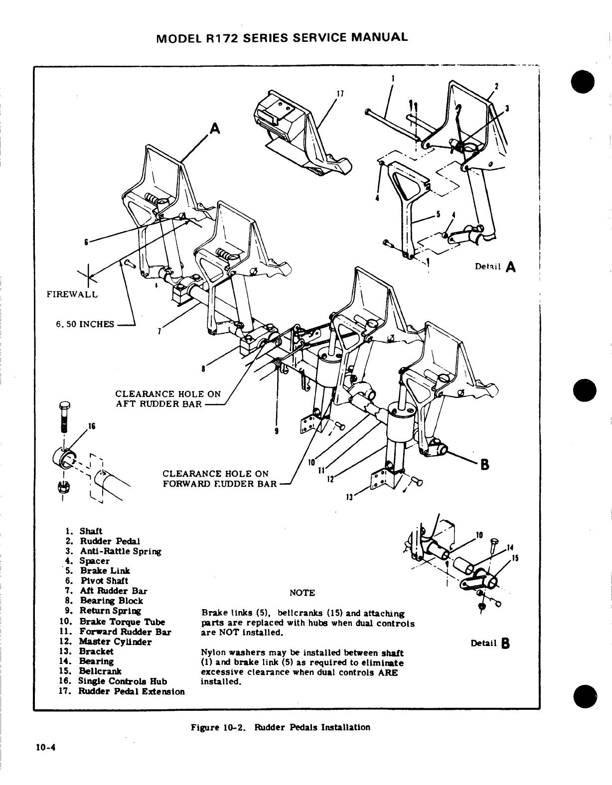
MODEL
R172
SERIES SERVICE
MANUAL
FIREWALL
6.
50
INCHES
CLEARANCE
HOLE
AFT
RUDDER
BAR
16
CLEARANCE
HOLE
ON
FORWARD
RUDDER
BAR
1.
Shaft
2.
Rudder
Pedal
6.
Pivot
Shaft
7.
Aft
Rudder
Bar
NOTE
8.
Bearing
Block
9.
Return
Spring
Brake
links
(5),
bellcranks
(15)
and
attaching
10.
Brake Torque
Tube
parts
are
replaced
with
hubs
when
dual
controls
11.
Forward
Rudder
Bar
are
NOT
installed.
12.
Master
Cylinder
Detail
B
13.
Bracket
Nylon
washers
may
be
installed
between
shaft
14.
Bearing
(1)
and
brake
link
(5)
as
required
to
eliminate
15.
Bellcrank
excessive
clearance
when
dual
controls
ARE
16.
Single
Controls
Hub
installed.
17.
Rudder
Pedal
Extension
Figure
10-2.
Rudder
Pedals
Installation
10-4
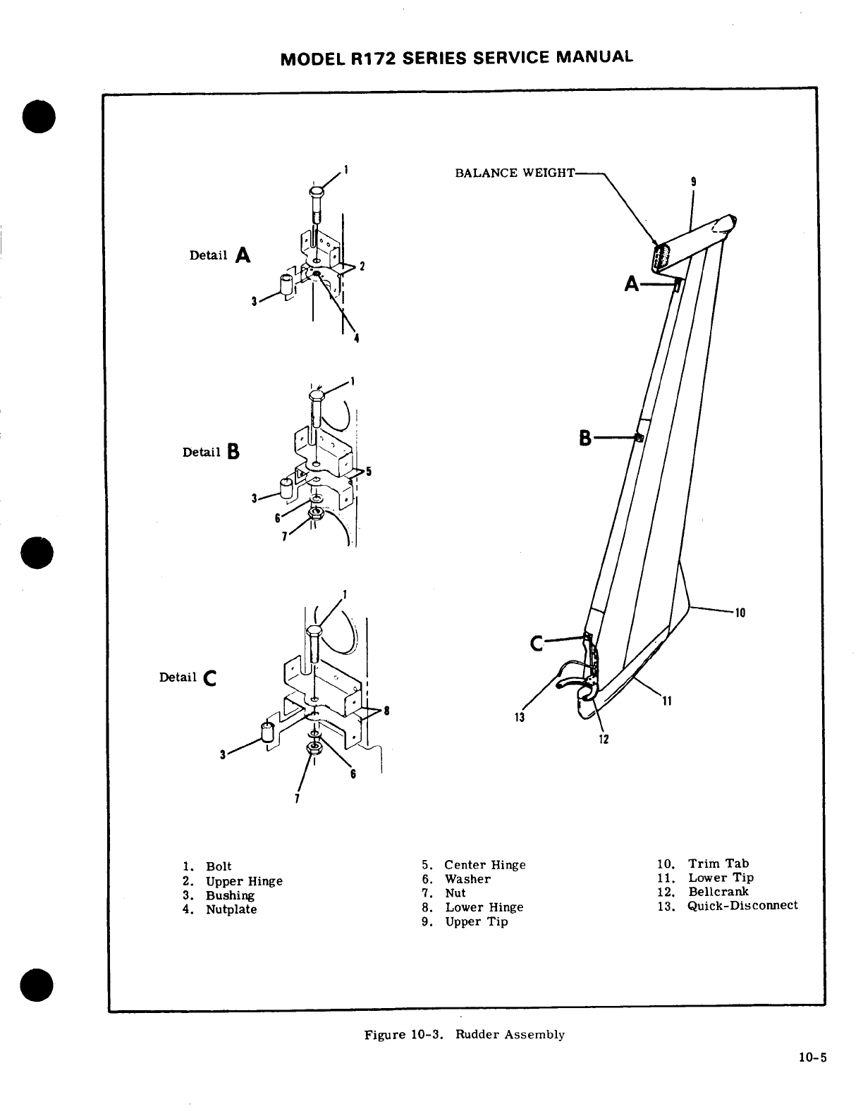
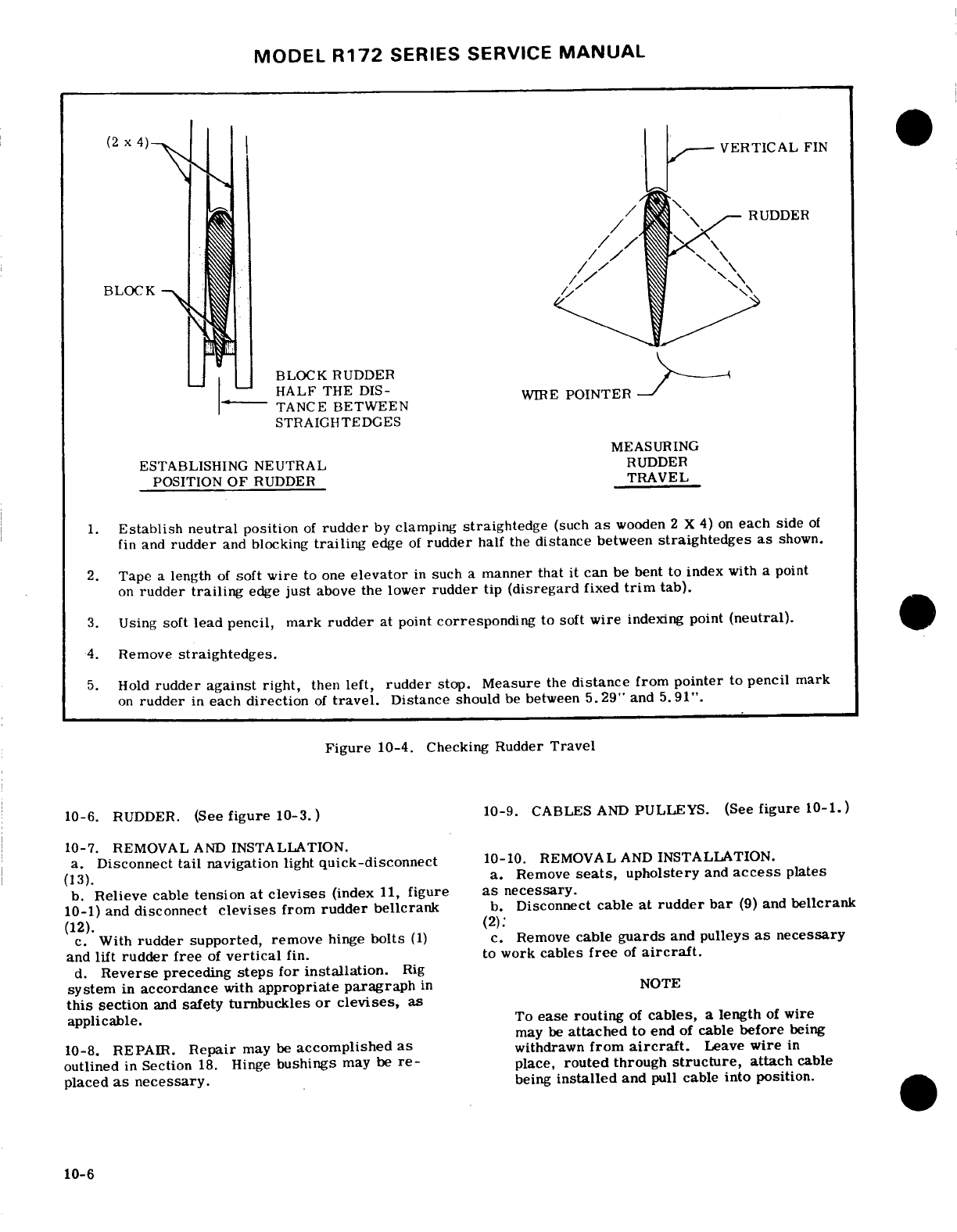
MODEL
R172
SERIES
SERVICE
MANUAL
BLOCK RUDDER
TANCE
BETWEEN
STRAIGHTEDGES
MEASURING
ESTABLISHING
NEUTRAL
RUDDER
POSITION
OF
RUDDER
TRAVEL
1.
Establish neutral
position
of
rudder
by
clamping
straightedge
(such
as
wooden
2
X
4)
on
each
side
of
fin
and
rudder
and
blocking
trailing
edge
of
rudder
half
the
distance
between
straightedges
as
shown.
2.
Tape
a
length
of
soft
wire
to one
elevator
in
such
a
manner
that
it can
be
bent
to
index
with
a
point
on
rudder
trailing
edge
just
above
the
lower
rudder
tip
(disregard
fixed
trim
tab).
3.
Using
soft
lead
pencil,
mark
rudder
at
point
corresponding
to
soft
wire
indexing
point
(neutral).
4.
Remove
straightedges.
5.
Hold
rudder
against
right,
then
left,
rudder
stop.
Measure
the
distance
from
pointer
to
pencil
mark
on
rudder
in
each
direction
of
travel.
Distance
should
be
between
5.29"
and
5.91".
Figure
10-4.
Checking Rudder
Travel
10-6.
RUDDER.
(See
figure
10-3.)
10-9.
CABLES
AND
PULLEYS. (See
figure
10-1.)
10-7.
REMOVAL
AND
INSTALLATION.
a.
Disconnect
tail
navigation
light
quick-disconnect
10-10.
REMOVAL
AND
INSTALLATION.
(13).
a.
Remove
seats,
upholstery
and
access
plates
b.
Relieve
cable
tension
at
clevises
(index
11,
figure
as
necessary.
10-1)
and
disconnect
devises
from
rudder
bellcrank
b.
Disconnect
cable
at
rudder
bar
(9)
and
bellcrank
(12).
(2)
c.
With
rudder
supported, remove
hinge
bolts
(1)
c.
Remove
cable
guards
and
pulleys
as
necessary
and
lift
rudder free
of
vertical
fin.
to
work
cables
free
of
aircraft.
d.
Reverse
preceding
steps
for
installation.
Rig
system
in
accordance
with
appropriate
paragraph
in
NOTE
this
section
and
safety
turnbuckles
or clevises,
as
applicable.
To
ease
routing
of
cables,
a length
of
wire
may
be
attached
to
end
of
cable
before
being
10-8.
REPAIR.
Repair
may
be
accomplished
as
withdrawn
from
aircraft.
Leave
wire
in
outlined
in
Section
18.
Hinge
bushings
may
be
re-
place,
routed
through
structure,
attach
cable
placed
as
necessary.
being
installed
and
pull
cable into position.
10-6
MODEL
R172
SERIES SERVICE
MANUAL
d.
After cable
is
routed
in
position,
install
pulleys
NOTE
and
cable
guards.
Ensure
cable
is
positioned
in
pulley
groove
before
installing
guard.
Flight
test
aircraft
to
determine
if
ground
e. Rig
system
in
accordance
with
appropriate
adjustment
of
fixed
trim
tab
is
necessary.
paragraph
in
this
section.
Safety
turnbuckles
or
DO
NOT
rig
rudder
"off-center"
unless
clevises,
as
applicable,and
reinstall
all
items
re-
trim
tab
does
not
provide
adequate
correc-
moved
in
step
"a".
tion.
10-11.
RIGGING.
(See
figure
10-1.)
a.
Adjust
travel
stops
(3)
to
attain
travel
specified
in
Section
1.
Figure
10-4
illustrates
correct
travel
WARNING
and
one
method
of
checking.
b.
Disconnect
nose
wheel
steering
tubes (refer
to
Be
sure
rudder
moves
in
correct
direction
section
5)
from
nose
strut.
when
operated
by
pedals.
c.
Adjust
cables
at
clevises
(11)
to
align rudder
and
pedals
in
neutral
position,
6. 50
inches
from
firewall
to
pedal
pivot
shafts
(index
6,
figure
10-2).
This
step
automatically
determines
cable
tension
because
of
the
return
springs
(index
9,
figure
10-2)
attached
to
the
rudder
bar.
10-12.
RUDDER
TRIM
CONTROL
SYSTEM.
(See
NOTE
figure
10-5.)
Due
to
thickness
of
insulation
on
firewall,
it
10-13.
DESCRIPTION.
A
lever
assembly,
actuated
is
recommended
that
a
piece
of
1/16
inch
by
the
pilot,
is
linked
via
a
bellcrank
to
a
rudder
welding
rod
be
ground to
a
sharp
point
and
trim
bungee
which
is,
in
turn
connected
directly
to
notched
at
the
6.50
inch
dimension.
Pierce
the
rudder bar assembly
and
hence
to
the
rudder
it-
insulation
on
firewall
and use
notch
to
mea-
self.
The
lever
assembly
is
mounted on
the
center
sure
proper
dimension.
console
structure
and
utilizes
a
pin
to
positively
lock
the
trim
system
in
any
of 3
positions
left
or
right
of
d.
Tie
down
or
weight
tail
to
raise
nose
wheel
the
center
or
"neutral"
trim
position.
The
lever
also
free
of
ground.
serves
as
the
trim
position
indicator.
e.
Center
nose
gear
against
external
stop.
f
Extend
steering
tubes
until
free
play
is
re-
10-14.
RIGGING.
(See
figure 10-5.)
moved.
DO
NOT
COMPRESS
SPRINGS.
g.
Adjust
steering
tube
rod
ends
to
1.00
inch
di-
NOTE
mension
between
steering
arm
assembly
and
bolt
hole
as
illustrated
in
section
5
and
tighten
jam
nuts.
The
rudder
control
system
MUST
be
rigged
h.
Adjust
steering
tube
devises
to
align
with
rod
according
to
paragraph
10-11
prior
to rigging
end
bearings.
the
rudder
trim
control
system.
NOTE
a.
Tie
down
or
weight
tail
of
the
aircraft
to
raise
nose
wheel
clear
of ground.
Extend
steering
tubes
to
seat
rods
against
b.
Ensure
nose
wheel
rudder
and
rudder
pedals
are
internal
springs
but do
not
attempt
to
pre-
all
in
"neutral"
position.
load
these
springs
by
shortening
rod
end
c.
Ensure
top nut
on
bungee
assembly
is
adjusted
devises
after
alignment.
Preload
is
built
to
eliminate
end
play
between
shaft
and
housing.
into
steering
tubes.
d.
Install
bungee
(5)
between
rudder
bar
(6)
and
bellcrank
(7)
as
shown
in
fig
10-5,
detail
A.
i.
Install
devises
on
rod
ends.
e.
Make
sure
lever assembly
(3)
is
in
neutral
posi-
tion
or
center
hole
of
bracket
(4).
NOTE
f.
Adjust
ball
ends
of
push
rod
(8)
so
that
ball
end
studs
align
with
holes
in
bellcrank
(7)
and
lever
assem-
DO
NOT
adjust rudder
trim
with
steering
bly
(3)
and
install
push
rod.
tubes. Degree
of
steering travel
cannot
g.
Check
for security
and
safetying
of
all
components
be
adjusted.
and
reinstall
all
items
removed
for
access.
j.
Rig
rudder
trim
control
system
In
accordance
WARNING
with
paragraph
10-14.
k.
Safety
clevises
(11)
and
install
all
items
removed
Be
sure
rudder
trim
lever
moves
rudder
in
for
access.
correct
direction.
10-7
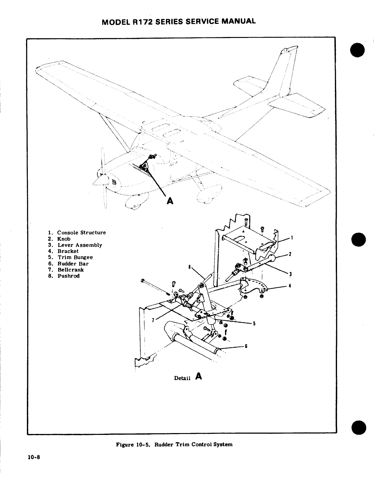
MODEL
R172
SERIES
SERVICE
MANUAL
SECTION
11
ENGINE
WARNING
When
performing
any
inspection
or
mainte-
nance
that
requires
turning
on
the
master
switch,
installing
a
battery,
or
pulling
the
propeller
through
by
hand,
treat
the
propel-
ler
as
if
the
ignition
switch
were
ON. Do
not
stand,
nor
allow anyone
else
to
stand,
within
the
arc
of
the
propeller,
since
a
loose
or
broken
wire,
or
a
component
mal-
function,
could
cause
the
propeller
to
rotate.
Page
No.
Engine
Baffles
.........
1111/11-14
TABLE OF
CONTENTS
Aerofiche/Manual
Description
........
1111/11-14
Cleaning
and
Inspection
..
1111/11-14
ENGINE
COWLING
.........
1H24/11-3
Removal
and
Installation
1111/11-14
Description
..........
1H24/11-3
Repair
..........
1113/11-16
Removal
and
Installation
....
1H24/11-3 Engine
Mount
.........
1113/11-16
Cleaning
and
Inspection
.....
.
1H24/11-3
Description
...
......
1113/11-16
Repair.
............
111/11-4
Removal
and
Installation
. .
1113/11-16
Cowl
Flap
...........
11/-4
Repair
..........
1113/11-16
Description
..
......
111/11-4
Painting
..........
1113/11-16
Removal
and
Installation
. 111/11-4
Shock
Mount
Pass
.....
1113/11-16
Rigging
.
.........
111/11-4
ENGINE
OIL
SYSTEM.
.....
1113/11-16
ENGINE
............
.. 111/11-4
Description........
1113/11-16
Description
..........
111/11-4
Capacity..........
1114/11-17
Engine
Data
..........
113/11-6
Trouble
Shooting
...
1114/11-17
Time
Between
Overhaul
(TBO)
.113/11-6
Oil
Cooler
......
...
1116/11-19
Overspeed
Limitations
.....
113/11-6
Description
......
1116/11-19
Trouble
Shooting
........
114/11-7
Full-Flow
Oil
Filter
....
1116/11-19
Static
Run-Up
Procedures
....
117/11-10
Description
... ..
1116/11-19
Engine
Removal
........
118/11-11
Removal
and
Installation
Cleaning.
.
............
118/11-11
(Filter)
.......
1116/11-19
Accessories
Removal
......
118/11-11
(Adapter)
....
.
1116/11-19
Inspection
..............
119/11-12
ENGINE
FUEL
SYSTEM.
....
1117/11-20
Build-Up
...........
119/11-12
Description
........
1117/11-20
Installation
..........
119/11-12
Trouble
Shooting
......
1119/11-22
Flexible
Fluid
Hoses
......
1110/11-13
Fuel-Air
Control
Unit.
. .
1120/11-23
Pressure
fest
.
......
1110/11-13
Description
......
1120/11-23
Replacement
.... ...
1110/11-13
Removal
and
Installation.
1120/11-23
Tachometer Drive
Adapter
Seal
.1110/11-13
Adjustment
(Idle
Speed
Removal
and
Installation..
.
1110/11-13
and
Idle
Mixture)
. .
1120/11-23
11-1
MODEL
R172
SERIES
SERVICE
MANUAL
TABLE
OF
CONTENTS
(Cont.)
Fuel
Manifold
Valve
....
1I22/11-25
Installation
and
Timing
Description
....
.
1I22/11-25
to
Engine
........
1J6/11-33
Removal
and
Installation. 1I22/11-25
Disassembly,
Inspection
and
Cleaning
..
......
1I22/11-25
Reassembly
.......
1J6/11-33
Fuel
Discharge
Nozzles
...
1I22/11-25
Magneto
Check
.......
1J6/11-33
Description
.
....
1I22/11-25
Spark
Plugs
......
.
1J6/11-33
Removal.
........
1I22/11-25
ENGINE CONTROLS
......
1J6/11-33
Cleaning
and
Inspection
.
1I22/11-25
Description
.
.......
1J6/11-33
Installation
.
....
1I22/11-25
Rigging
.
.........
1J7/11-34
Fuel
Injection
Pump
. ...
1I23/11-26
Throttle
Control
..
..
1J7/11-34
Description
.
....
1I23/11-26
Mixture
Control
..
..
1J7/11-34
Removal
and
Installation.
1I23/11-26
Propeller
Governor
Adjustment
......
1I23/11-26
Control
.......
1J8/11-35
Auxiliary
Electric
Fuel
Pump
Rigging
Throttle
Operated
Flow
Rate
Adjustment
..
1I23/11-26
Microswitch
.......
1J8/11-35
INDUCTION
AIR
SYSTEM
. . .
1I23/11-26
EXHAUST
SYSTEM
.......
1J8/11-35
Description
..
......
1I23/11-26
Description
........
1J9/11-36
Removal
and Installation
.
1I24/11-27
Economy
Mixture
Indicator
IGNITION
SYSTEM.
.. ... .
1I24/11-27
(EGT)
..........
1J9/11-36
Description
..
....
1I24/11-27
Removal
...........
.
1J9/11-36
Trouble
Shooting
...
1J1/11-28
Inspection
.
.......
.
1J9/11-36
MAGNETOS
(Bendix)
...
1J2/11-29
Installation
........
1J9/11-36
Description
..
.....
1J2/11-29
STARTING
SYSTEM
......
1J9/11-36
Removal
.
.........
1J2/11-29
Description
........
1J9/11-36
Internal Timing
...
1J2/11-29
Trouble
Shooting
... .
1J10/11-37
Installation
and
Timing
Primary
Maintenance
....
1J10/11-37
to
Engine
..
.....
1J2/11-29
Starter
Motor
.......
1J11/11-38
Maintenance
.
.......
1J3/11-30
Removal
and
Installation.
1J11/11-38
Magneto
Check
.......
1J5/11-32
EXTREME
WEATHER
MAINTENANCE
1J11/11-38
MAGNETOS
(Slick)
.......
1J5/11-32
Cold
Weather
......
.
1J11/11-38
Description
..
.....
1J5/11-32
Dusty Conditions
........
1J11/11-38
Removal
.
........
1J5/11-32
Sea
Coast
and
Humid
Areas
. .
1J11/11-38
Internal
Timing.
.......
1J5/11-32
SHOP
NOTES:
11-2
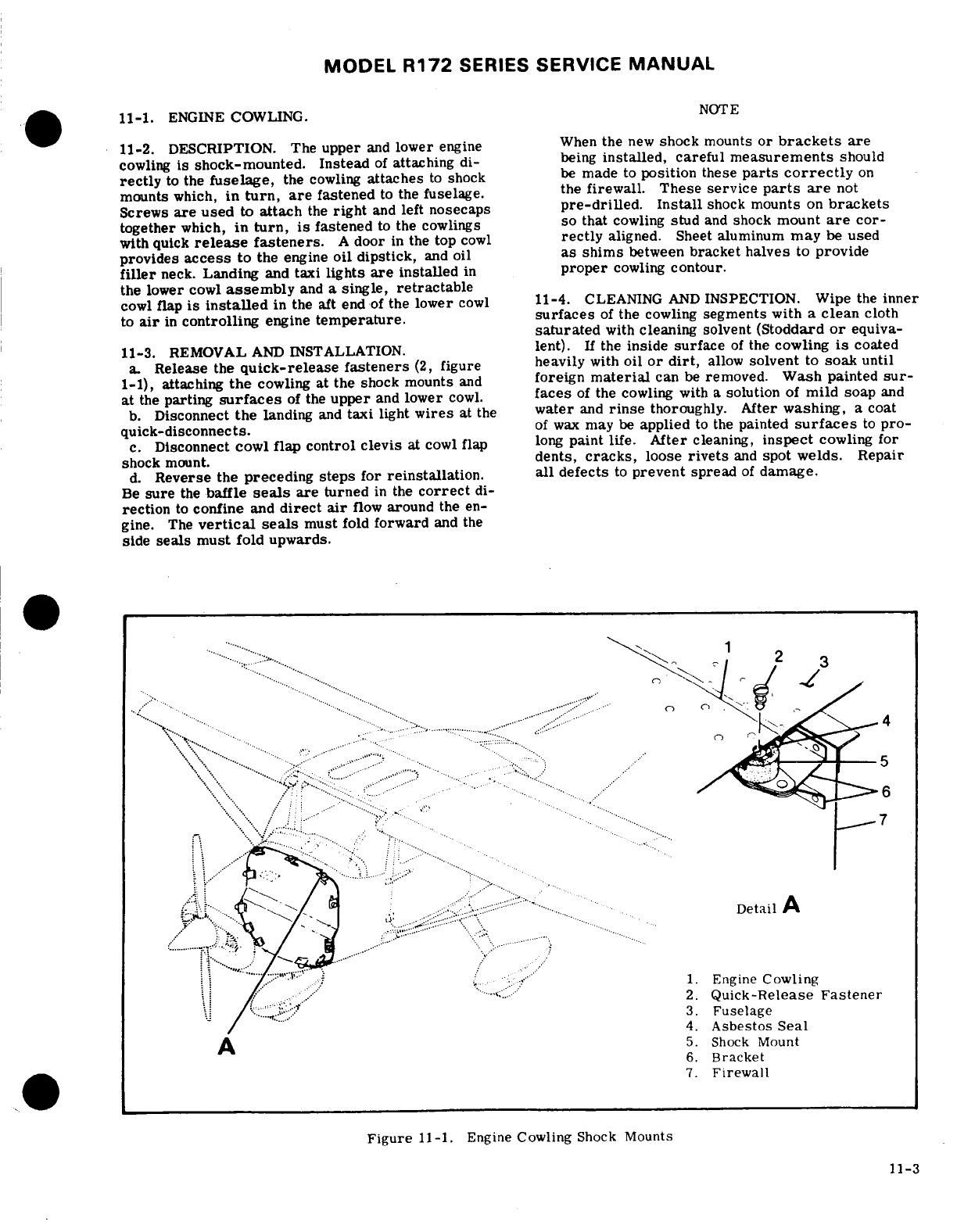
MODEL
R172
SERIES
SERVICE
MANUAL
11-1.
ENGINE
COWLING.
NOTE
11-2.
DESCRIPTION. The
upper
and
lower
engine
When
the
new
shock
mounts
or
brackets are
cowling
is
shock-mounted.
Instead
of
attaching
di-
being
installed, careful
measurements
should
rectly
to
the
fuselage,
the
cowling
attaches
to
shock
be
made
to
position
these
parts
correctly
on
mounts
which,
in
turn, are
fastened
to
the
fuselage.
the
firewall.
These
service
parts
are
not
Screws
are
used
to
attach
the
right
and
left
nosecaps
pre-drilled.
Install
shock
mounts
on
brackets
together
which,
in
turn,
is
fastened
to
the cowlings
so that
cowling
stud
and
shock
mount
are
cor-
with
quick
release
fasteners.
A
door
in
the
top
cowl
rectly
aligned.
Sheet
aluminum
may
be
used
provides
access
to
the
engine
oil dipstick,
and
oil
as shims
between
bracket
halves
to
provide
filler
neck.
Landing
and
taxi
lights
are
installed
in
proper
cowling
contour.
the
lower
cowl
assembly
and
a
single,
retractable
cowl
flap
is
installed
in the aft
end
of
the
lower
cowl
11-4.
CLEANING
AND
INSPECTION.
Wipe
the
inner
to
air
in
controlling
engine
temperature. surfaces
of
the
cowling
segments
with
a
clean
cloth
saturated
with
cleaning
solvent
(Stoddard
or
equiva-
11-3.
REMOVAL
AND
INSTALLATION.
lent).
If
the
inside
surface
of
the
cowling
is
coated
a.
Release
the
quick-release
fasteners
(2,
figure heavily
with
oil
or
dirt,
allow
solvent
to
soak
until
1-1),
attaching
the
cowling
at the
shock
mounts
and
foreign
material
can
be
removed.
Wash
painted
sur-
at
the
parting
surfaces
of
the
upper
and
lower
cowl.
faces
of
the
cowling with
a
solution
of
mild
soap
and
b.
Disconnect
the
landing
and
taxi
light
wires
at
the
water
and
rinse
thoroughly.
After
washing,
a
coat
quick-disconnects.
of
wax
may
be
applied
to
the
painted
surfaces
to
pro-
c.
Disconnect
cowl
flap
control clevis
at
cowl
flap
long
paint
life.
After
cleaning,
inspect
cowling
for
shock
mount.
dents,
cracks,
loose
rivets
and
spot
welds.
Repair
d.
Reverse
the
preceding
steps
for
reinstallation.
all defects
to
prevent
spread
of
damage.
Be
sure
the
baffle
seals
are
turned
in
the
correct
di-
rection
to
confine
and
direct
air
flow
around
the
en-
gine.
The
vertical
seals
must
fold
forward
and the
side
seals must
fold upwards.
.......
..
.....
...
Detail
A
.... ........... .....................
.
........
..
1.
Engine
Cowling
..
2..
Quick-Release
Fastener
4.
Asbestos
Seal
A
5.
Shock
Mount
6.
Bracket
7.
Firewall
Figure
11-1.
Engine
Cowling
Shock
Mounts
11-3
MODEL
R172
SERIES
SERVICE
MANUAL
11-5.
REPAIR.
If
cowling
skins are
extensively
flap
shock-mount
(8).
damaged.
new
complete
sections
of
the
cowling
b.
Check
to
make
sure
that
the
flexible
control
should
be
installed.
Standard
insert-type patches
reaches
its internal
stops
in
each
direction.
Mark
may
be
used
for
repair
if
repair parts
are
formed
control
so
that
full
travel
can
be
readily
checked
and
to
fit
contour
of
cowling.
Small
cracks
may
be
stop-
maintained
during
the
remaining
rigging
procedures.
drilled
and
small
dents
straightened
if
they
are
rein-
c.
Place
cowl
flap
lever
(3)
in
the
closed
position.
forced
on the
inner
surface
with a
doubler
of
the
If
the
control
lever
cannot
be
placed
in
the
closed
same
material
as
the cowling
skin.
Damaged
rein-
position,
adjust
control
at
upper
clevis
(1)
to
posi-
forcement
angles
should
be
replaced
with
new
parts.
tion
control
lever
in
bottom
hole
of
position
bracket
Due
to
their
small
size,
new
reinforcement
angles
(2).
are
easier
to
install
than to
repair
the
damaged
part.
d.
With
the
control
lever
in
closed position,
hold
cowl
flap closed,
streamlined
with
trailing
edge
of
11-6.
COWL
FLAP.
(See
figure
11-2.)
lower
cowl.
Loosen
jam
nut
and
adjust
clevis
(1)
on
the
control
to
hold
cowl
flap
in
this
position
and
in-
11-7.
DESCRIPTION.
A
single,
retractable
cowl
stall
bolt.
Tighten
jam
nut.
flap
is
installed
in
the
aft
end
of
the
lower
cowl
to
aid
in
controlling
engine
temperature.
11-10.
ENGINE.
11-8.
REMOVAL
AND
INSTALLATION.
(See
figure
11-11. DESCRIPTION.
An
air-cooled,
wet-sump,
11-2.)
six-cylinder,
horizontally-opposed,
Continental
a.
Place
cowl
flap
lever
(3)
in
the
open
position.
IO-360-K
engine,
equipped
with
fuel
injection,
is
b.
Disconnect
cowl
flap
control
clevis
(1)
from
used
to
power
the
aircraft.
The
engine
features
cowl
flap
shock
mount
(8).
inclined
valves,
with
individual
rocker
box
covers
c.
Remove
safety
wire securing
hinge
pin
(11)
to for
each
valve.
The intake
ports
are
located
on
the
cowl
flap,
pull
pin
from
hinge
and
remove
flap. opposite
side
of
the
cylinders
from
the
exhaust
ports.
d.
Reverse
the
preceding
steps
for
reinstallation.
An
oil
cooler
is
located
at
the
rear
(accessory
case)
Rig
cowl
flap,
if
necessary,
in
accordance
with
para-
end
of
the
engine
on
the
2-4-6
side.
Refer
to
para-
graph
11-9.
graph
11-12
for
engine
data.
For
repairs
and
over-
haul
of
the
engine,
accessories
and
propeller,
refer
11-9.
RIGGING.
(See
figure
11-2.)
to
the
applicable
publications
issued
by
their
manu-
a.
Disconnect
cowl
flap
control
clevis
(1)
from
cowl
facturers.
SHOP
NOTES:
11-4
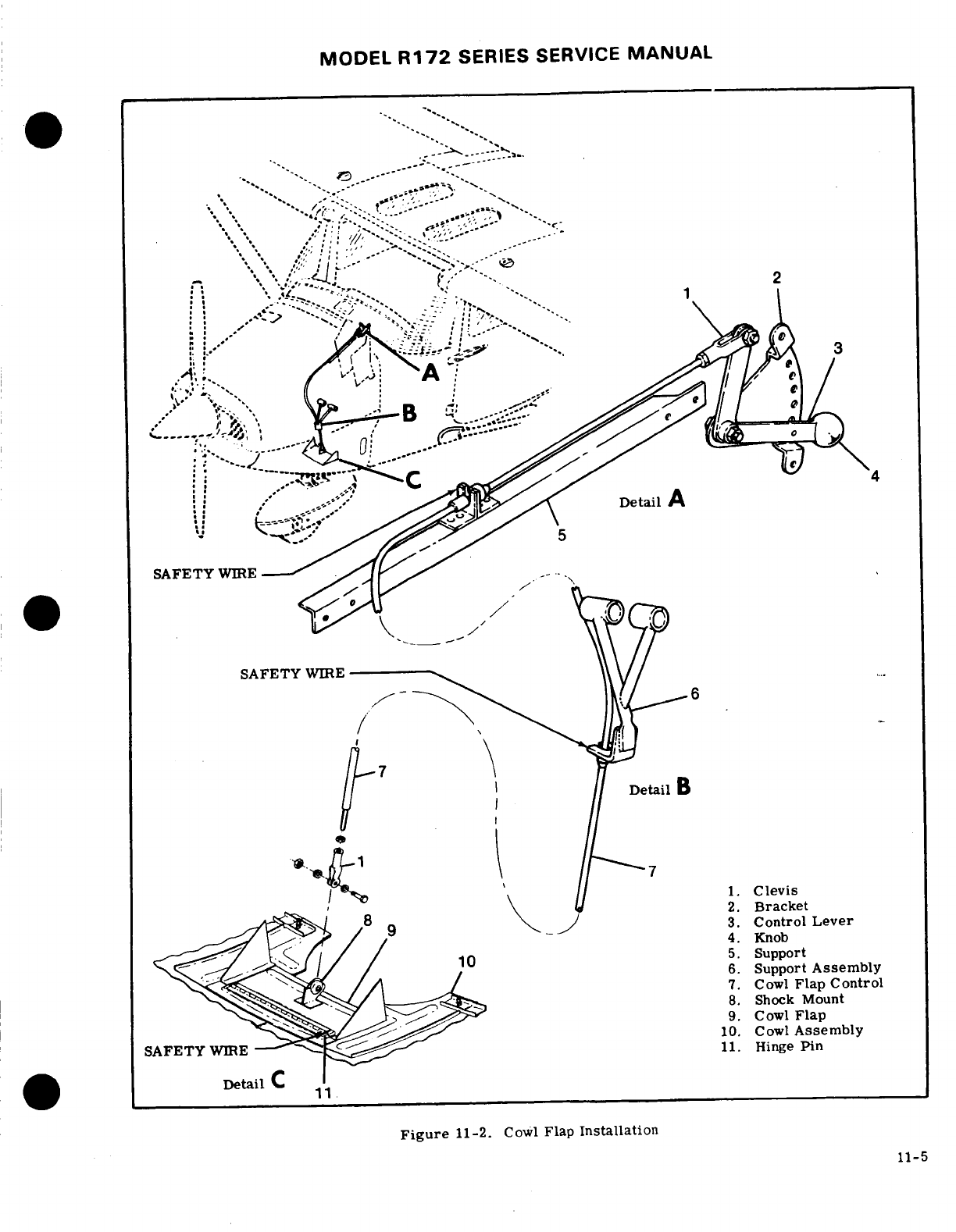
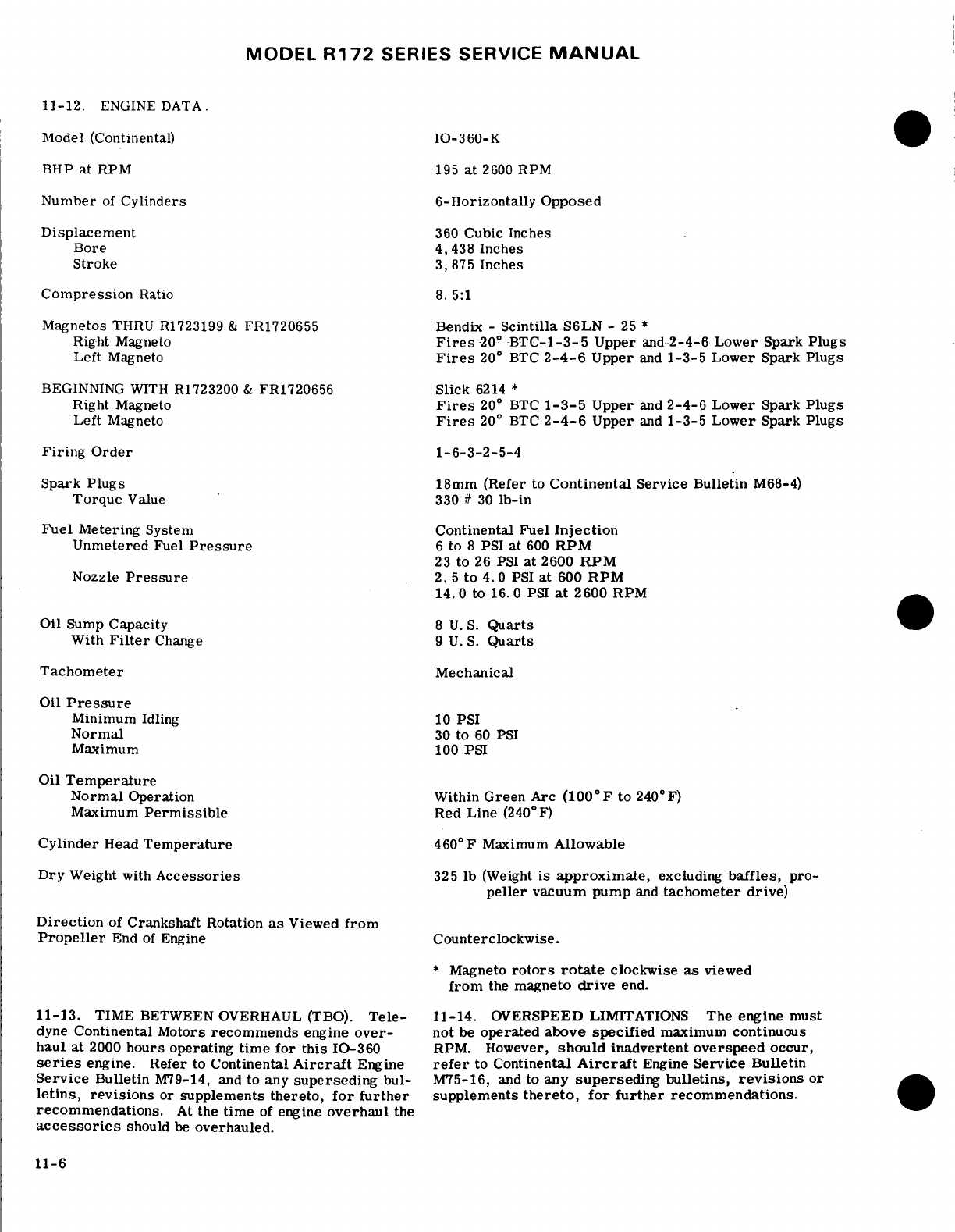
MODEL
R172
SERIES
SERVICE
MANUAL
11-12.
ENGINE
DATA.
Model
(Continental)
IO-360-K
BHP
at
RPM
195
at
2600
RPM
Number
of
Cylinders
6-Horizontally
Opposed
Displacement
360
Cubic
Inches
Bore
4,438
Inches
Stroke
3,875
Inches
Compression
Ratio
8.
5:1
Magnetos
THRU R1723199
&
FR1720655
Bendix -
Scintilla
S6LN
-
25
*
Right
Magneto
Fires
20°
-BTC-1-3-5
Upper
and
2-4-6
Lower Spark
Plugs
Left
Magneto
Fires
20
°
BTC
2-4-6
Upper
and
1-3-5
Lower Spark
Plugs
BEGINNING
WITH
R1723200
&
FR1720656
Slick
6214
*
Right
Magneto
Fires
20
°
BTC
1-3-5
Upper
and
2-4-6
Lower Spark
Plugs
Left
Magneto
Fires
20
°
BTC
2-4-6
Upper
and
1-3-5
Lower Spark
Plugs
Firing
Order
1-6-3-2-5-4
Spark
Plugs
18mm
(Refer
to
Continental
Service
Bulletin
M68-4)
Torque
Value
330
#
30
lb-in
Fuel
Metering
System
Continental
Fuel
Injection
Unmetered
Fuel
Pressure
6
to
8
PSI
at
600
RPM
23
to
26 PSI
at
2600
RPM
Nozzle
Pressure
2.
5
to
4.0
PSI
at
600
RPM
14.
0
to
16.0
PSI
at
2600
RPM
Oil
Sump
Capacity
8
U.
S.
Quarts
With
Filter
Change
9
U.S.
Quarts
Tachometer
Mechanical
Oil
Pressure
Minimum
Idling
10
PSI
Normal
30
to
60
PSI
Maximum
100
PSI
Oil
Temperature
Normal
Operation
Within
Green
Arc
(100°F
to
240°F)
Maximum
Permissible
Red
Line
(240
°
F)
Cylinder
Head
Temperature
460°
F
Maximum
Allowable
Dry
Weight
with
Accessories
325
lb
(Weight
is
approximate,
excluding
baffles,
pro-
peller
vacuum pump
and
tachometer
drive)
Direction
of
Crankshaft
Rotation
as
Viewed
from
Propeller
End
of
Engine
Counterclockwise.
*
Magneto
rotors
rotate
clockwise
as
viewed
from
the
magneto
drive
end.
11-13.
TIME
BETWEEN
OVERHAUL
(TBO).
Tele-
11-14.
OVERSPEED
LIMITATIONS
The
engine
must
dyne
Continental
Motors
recommends
engine
over-
not
be
operated
above
specified
maximum continuous
haul at
2000
hours
operating
time
for
this
10-360
RPM.
However,
should
inadvertent
overspeed
occur,
series
engine.
Refer
to
Continental
Aircraft
Engine
refer
to
Continental
Aircraft
Engine
Service
Bulletin
Service
Bulletin
M79-14,
and
to
any
superseding
bul- M75-16,
and
to
any
superseding
bulletins,
revisions
or
letins,
revisions
or
supplements
thereto,
for
further
supplements
thereto, for
further
recommendations.
recommendations.
At
the
time
of
engine
overhaul
the
accessories
should
be
overhauled.
11-6
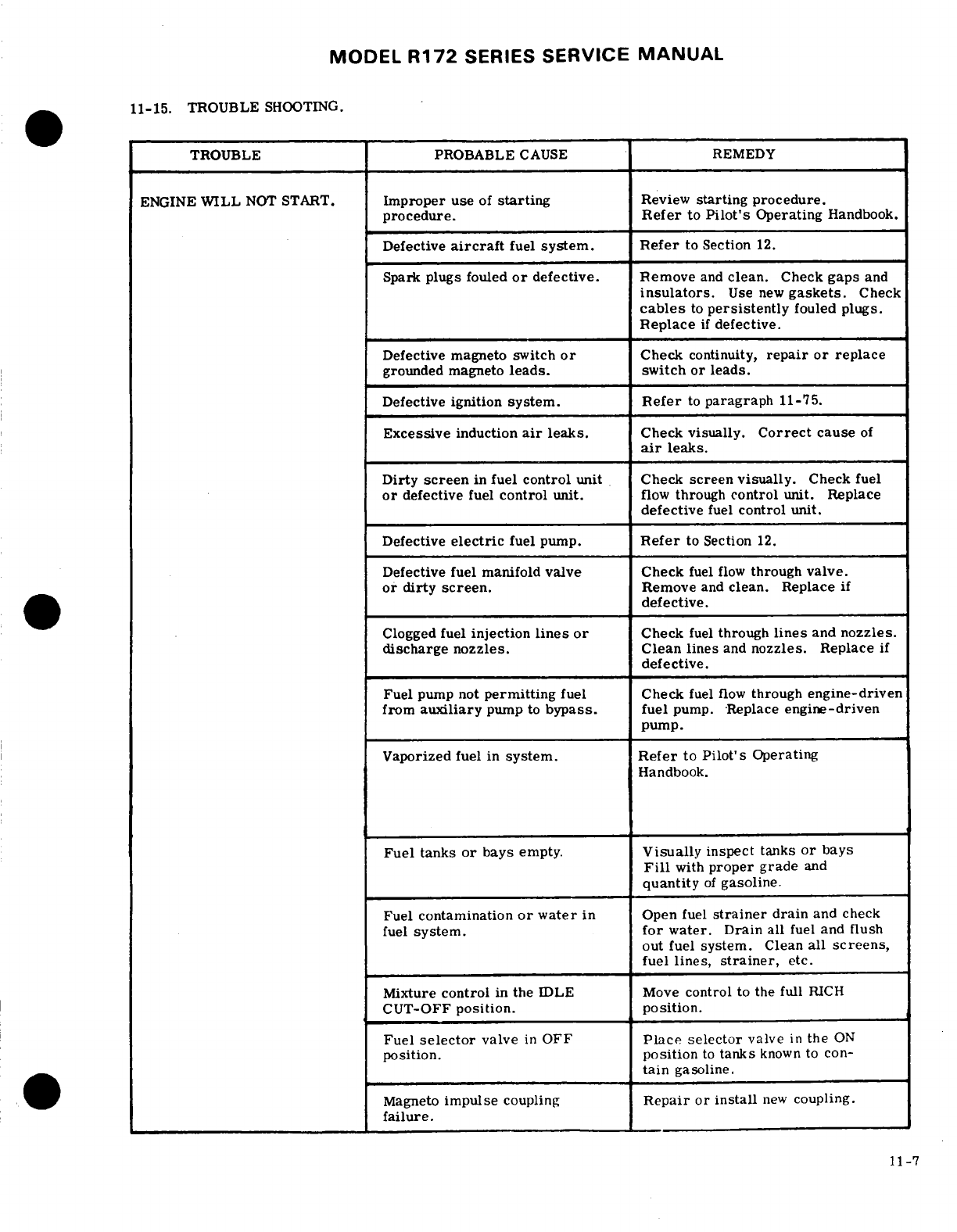
MODEL
R172
SERIES
SERVICE
MANUAL
11-15.
TROUBLE
SHOOTING.
TROUBLE PROBABLE
CAUSE
REMEDY
ENGINE
WILL
NOT
START.
Improper
use
of
starting
Review
starting
procedure.
procedure.
Refer
to
Pilot's
Operating
Handbook.
Defective
aircraft
fuel
system.
Refer
to
Section
12.
Spark
plugs
fouled
or
defective. Remove
and
clean.
Check
gaps
and
insulators.
Use
new
gaskets.
Check
cables
to
persistently
fouled
plugs.
Replace
if
defective.
Defective magneto
switch
or
Check
continuity,
repair
or replace
grounded
magneto
leads.
switch or
leads.
Defective
ignition
system.
Refer
to
paragraph
11-75.
Excessive
induction
air
leaks.
Check
visually.
Correct
cause
of
air
leaks.
Dirty
screen
in
fuel
control
unit
Check
screen
visually.
Check
fuel
or
defective
fuel
control
unit.
flow
through
control
unit. Replace
defective
fuel
control
unit.
Defective
electric
fuel
pump.
Refer
to Section
12.
Defective fuel manifold
valve Check
fuel
flow
through
valve.
or
dirty
screen.
Remove
and
clean.
Replace
if
defective.
Clogged
fuel
injection
lines or
Check
fuel
through
lines
and
nozzles.
discharge
nozzles. Clean
lines
and
nozzles.
Replace
if
defective.
Fuel
pump
not
permitting
fuel
Check
fuel
flow
through
engine-driven
from
auxiliary
pump
to
bypass.
fuel
pump.
Replace
engine-driven
pump.
Vaporized
fuel in
system.
Refer
to
Pilot's
Operating
Handbook.
Fuel
tanks
or
bays
empty.
Visually
inspect
tanks
or
bays
Fill
with
proper
grade
and
quantity
of
gasoline.
Fuel
contamination
or
water
in
Open
fuel
strainer
drain
and
check
fuel
system.
for
water.
Drain
all
fuel
and
flush
out fuel
system.
Clean
all
screens,
fuel
lines,
strainer,
etc.
Mixture
control
in
the
IDLE
Move
control
to
the
full
RICH
CUT-OFF
position. position.
Fuel
selector
valve
in
OFF
Place selector
valve
in
the
ON
position.
position
to
tanks
known
to
con-
tain
gasoline.
Magneto
impulse
coupling
Repair
or
install
new
coupling.
failure.
11-7
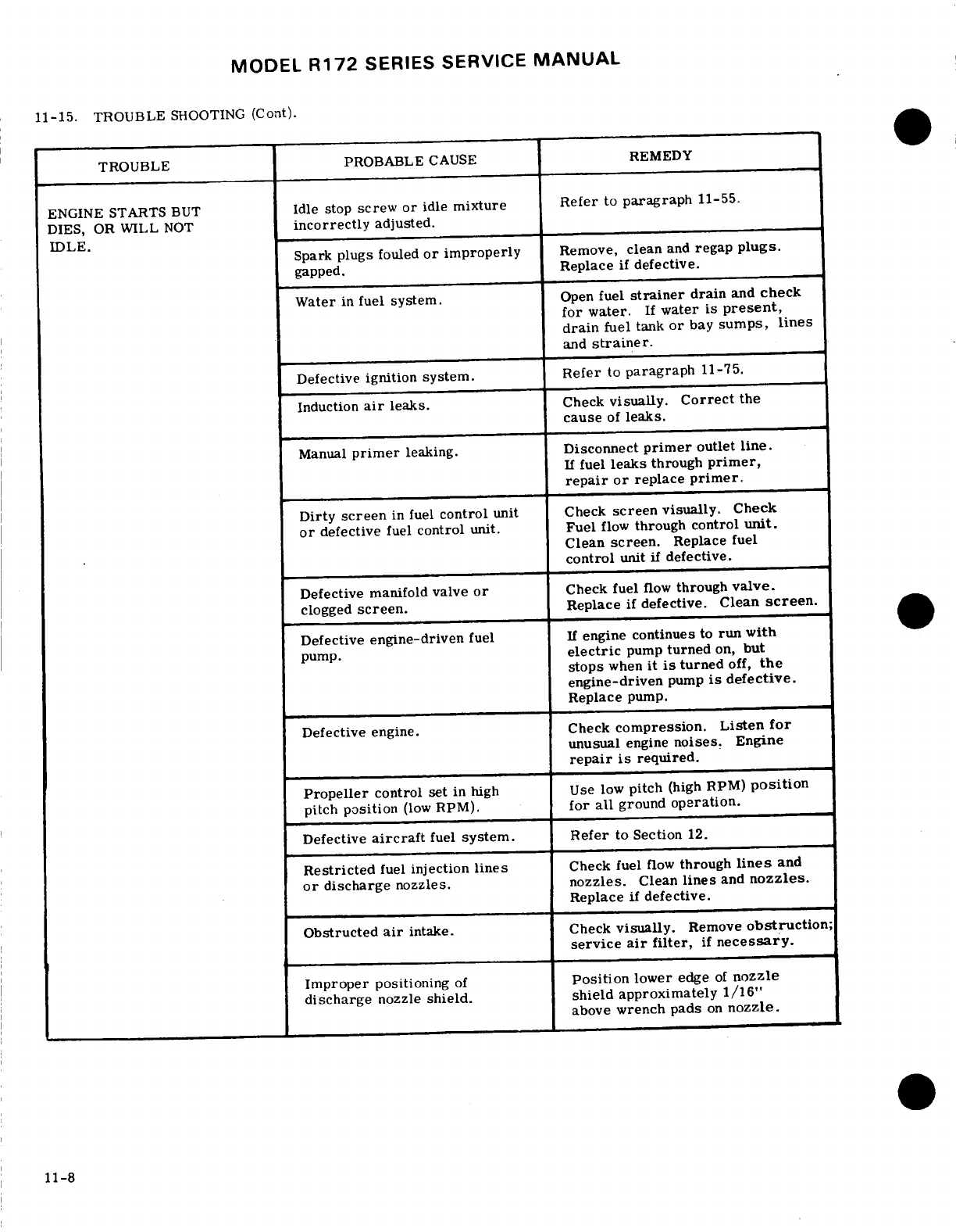
MODEL
R172
SERIES
SERVICE
MANUAL
11-15.
TROUBLE
SHOOTING
(Cont).
TROUBLE
PROBABLE
CAUSE
REMEDY
ENGINE
STARTS
BUT
Idle
stop
screw
or
idle
mixture Refer
to
paragraph
11-55.
DIES,
OR
WILL
NOT
incorrectly
adjusted.
IDLE.
Spark
plugs
fouled
or
improperly
Remove,
clean
and
regap
plugs.
gapped.
Replace
if
defective.
Water
in
fuel
system.
Open
fuel
strainer
drain
and
check
for
water.
If
water
is
present,
drain
fuel
tank
or
bay
sumps,
lines
and
strainer.
Defective
ignition
system.
Refer
to
paragraph
11-75.
Induction
air
leaks.
Check
visually.
Correct
the
cause
of
leaks.
Manual
primer
leaking.
Disconnect
primer
outlet
line.
If
fuel
leaks
through
primer,
repair
or
replace
primer.
Dirty
screen
in fuel
control
unit Check
screen
visually.
Check
or
defective
fuel
control
unit.
Fuel
flow
through
control
unit.
Clean
screen.
Replace
fuel
control
unit
if
defective.
Defective
manifold
valve
or
Check
fuel
flow
through
valve.
clogged
screen.
Replace
if
defective.
Clean
screen.
Defective
engine-driven
fuel
If
engine
continues
to
run
with
pump.
electric
pump
turned
on,
but
stops
when
it
is
turned
off,
the
engine-driven
pump
is
defective.
Replace
pump.
Defective
engine.
Check
compression.
Listen
for
unusual
engine
noises.
Engine
repair
is
required.
Propeller
control
set
in high Use
low
pitch
(high
RPM)
position
pitch
position
(low
RPM).
for
all
ground
operation.
Defective
aircraft
fuel
system. Refer
to Section
12.
Restricted
fuel
injection
lines
Check
fuel
flow
through
lines
and
or
discharge
nozzles.
nozzles.
Clean
lines
and
nozzles.
Replace
if
defective.
Obstructed
air
intake.
Check
visually.
Remove
obstruction;
service
air
filter,
if
necessary.
Improper
positioning
of
Position
lower
edge
of
nozzle
discharge
nozzle
shield.
shield
approximately 1/16"
above
wrench
pads
on
nozzle.
11-8
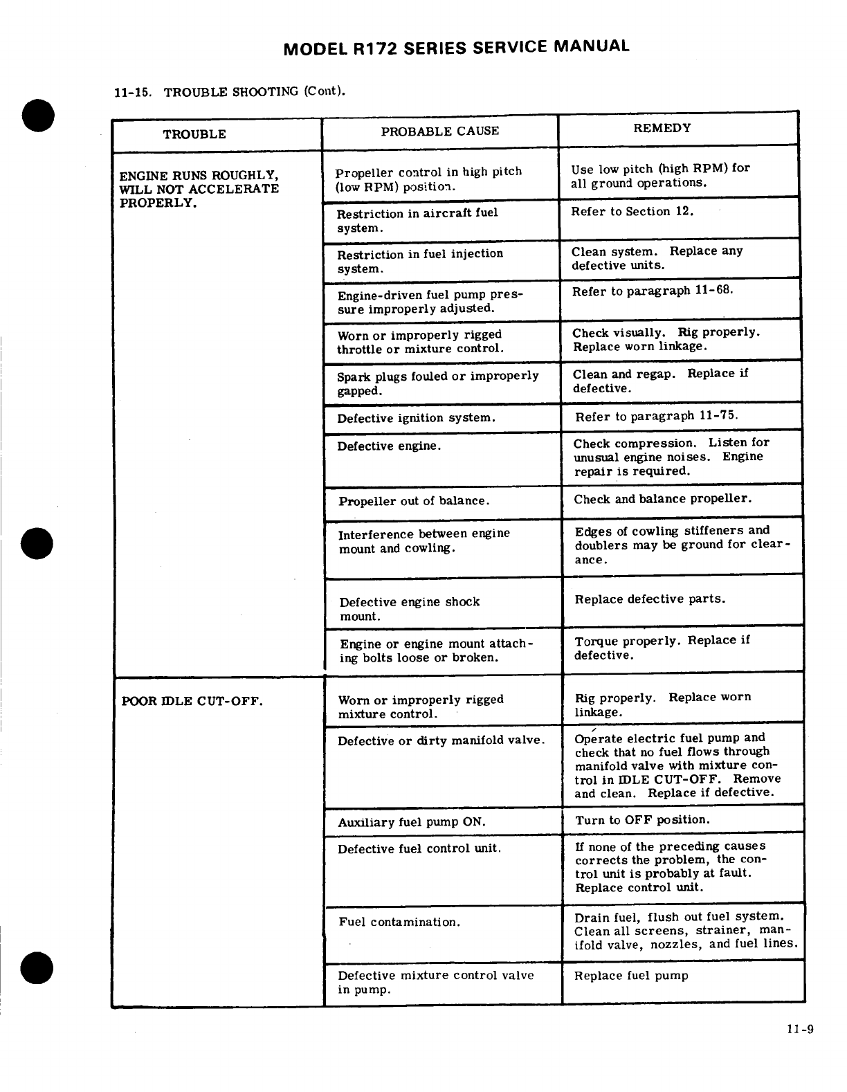
MODEL
R172
SERIES
SERVICE
MANUAL
11-15.
TROUBLE
SHOOTING
(Cont).
TROUBLE
PROBABLE
CAUSE
REMEDY
ENGINE RUNS ROUGHLY,
Propeller
control
in
high
pitch
Use
low
pitch
(high
RPM)
for
WILL NOT
ACCELERATE
(low
RPM)
position.
all
ground
operations.
PROPERLY.
Restriction
in
aircraft
fuel
Refer
to
Section
12.
system.
Restriction
in
fuel
injection
Clean
system.
Replace
any
system.
defective
units.
Engine-driven
fuel
pump
pres-
Refer
to
paragraph
11-68.
sure improperly
adjusted.
Worn
or
improperly
rigged
Check
visually.
Rig
properly.
throttle
or
mixture
control.
Replace worn
linkage.
Spark
plugs
fouled
or
improperly
Clean
and
regap.
Replace
if
gapped.
defective.
Defective
ignition
system.
Refer
to
paragraph
11-75.
Defective
engine.
Check
compression. Listen
for
unusual
engine
noises.
Engine
repair
is
required.
Propeller
out
of
balance.
Check
and
balance
propeller.
Interference
between
engine
Edges
of
cowling
stiffeners
and
mount
and
cowling.
doublers
may
be
ground
for
clear-
ance.
Defective
engine
shock
Replace
defective
parts.
mount.
Engine
or
engine
mount
attach-
Torque
properly.
Replace
if
ing
bolts loose
or
broken.
defective.
POOR
IDLE
CUT-OFF.
Worn
or
improperly
rigged
Rig
properly.
Replace
worn
mixture
control.
linkage.
Defective
or
dirty
manifold
valve.
Operate
electric
fuel
pump
and
check
that
no
fuel
flows
through
manifold
valve
with
mixture
con-
trol
in
IDLE
CUT-OFF.
Remove
and
clean.
Replace
if
defective.
Auxiliary
fuel
pump
ON.
Turn
to
OFF
position.
Defective
fuel
control
unit.
If
none
of
the
preceding
causes
corrects
the
problem,
the
con-
trol
unit
is
probably
at
fault.
Replace
control
unit.
Fuel
contamination.
Drain
fuel,
flush
out
fuel
system.
Clean all
screens, strainer,
man-
ifold
valve,
nozzles,
and
fuel
lines.
Defective
mixture control
valve
Replace
fuel
pump
in
pump.
11-9
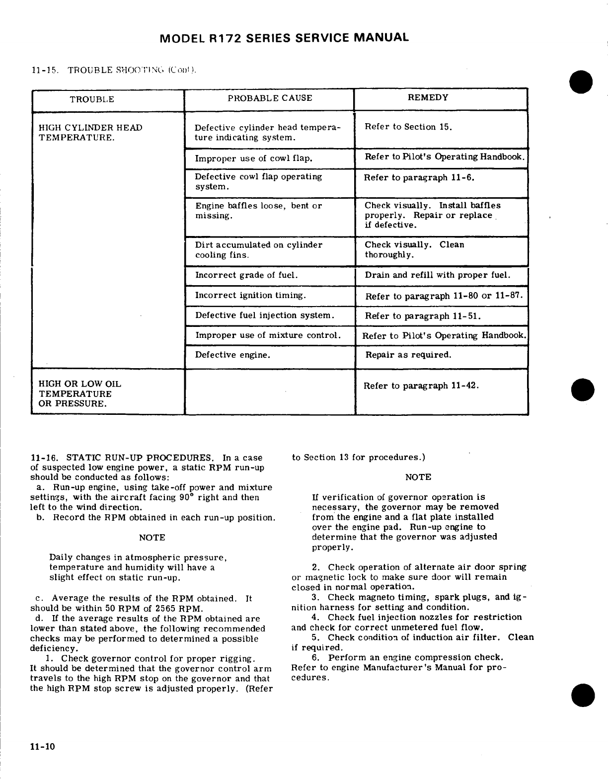
MODEL
R172
SERIES
SERVICE
MANUAL
11-15.
TROUBLE
SHOOTING
(Cont)
TROUBLE
PROBABLE
CAUSE
REMEDY
HIGH
CYLINDER
HEAD
Defective
cylinder
head
tempera-
Refer
to
Section
15.
TEMPERATURE.
ture
indicating system.
Improper
use
of
cowl
flap. Refer
to
Pilot's
Operating
Handbook.
Defective
cowl
flap
operating
Refer
to
paragraph
11-6.
system.
Engine
baffles
loose,
bent
or
Check
visually.
Install
baffles
missing.
properly.
Repair
or
replace
if
defective.
Dirt
accumulated
on
cylinder
Check
visually.
Clean
cooling
fins.
thoroughly.
Incorrect
grade
of
fuel.
Drain
and
refill
with
proper
fuel.
Incorrect
ignition timing.
Refer
to
paragraph
11-80
or
11-87.
Defective
fuel
injection system. Refer
to
paragraph
11-51.
Improper
use
of
mixture control. Refer
to
Pilot's
Operating
Handbook.
Defective
engine.
Repair
as
required.
HIGH
OR
LOW OIL
Refer
to
paragraph
11-42.
TEMPERATURE
OR
PRESSURE.
11-16.
STATIC
RUN-UP
PROCEDURES.
In
a
case
to
Section
13
for
procedures.)
of
suspected
low
engine
power,
a
static
RPM
run-up
should
be
conducted
as
follows:
NOTE
a.
Run-up
engine,
using
take-off
power and
mixture
settings,
with
the
aircraft
facing
90
°
right
and
then
If
verification
of
governor
operation
is
left
to the
wind
direction.
necessary,
the
governor
may be
removed
b.
Record
the
RPM
obtained
in
each
run-up
position. from
the
engine
and a
flat
plate
installed
over
the engine
pad.
Run-up
engine
to
NOTE
determine
that
the
governor
was
adjusted
properly.
Daily
changes
in
atmospheric
pressure,
temperature
and
humidity
will
have
a
2.
Check
operation
of
alternate
air
door spring
slight
effect
on
static
run-up.
or
magnetic
lock
to
make
sure
door will
remain
closed
in
normal
operation.
c.
Average
the
results
of
the
RPM
obtained.
It
3.
Check magneto
timing,
spark
plugs,
and
ig-
should
be
within
50
RPM
of 2565
RPM.
nition
harness
for
setting
and
condition.
d.
If
the
average
results
of
the
RPM
obtained
are
4.
Check fuel
injection nozzles
for
restriction
lower
than
stated
above,
the
following
recommended
and
check
for
correct
unmetered
fuel
flow.
checks
may
be
performed
to
determined
a
possible
5.
Check
condition
of
induction
air
filter.
Clean
deficiency,
if
required.
1.
Check
governor
control
for
proper
rigging.
6.
Perform
an
engine
compression
check.
It
should
be
determined that
the
governor
control
arm
Refer
to
engine
Manufacturer's
Manual
for
pro-
travels
to
the
high
RPM
stop
on
the
governor
and
that
cedures.
the
high
RPM
stop
screw
is
adjusted
properly.
(Refer
11-10
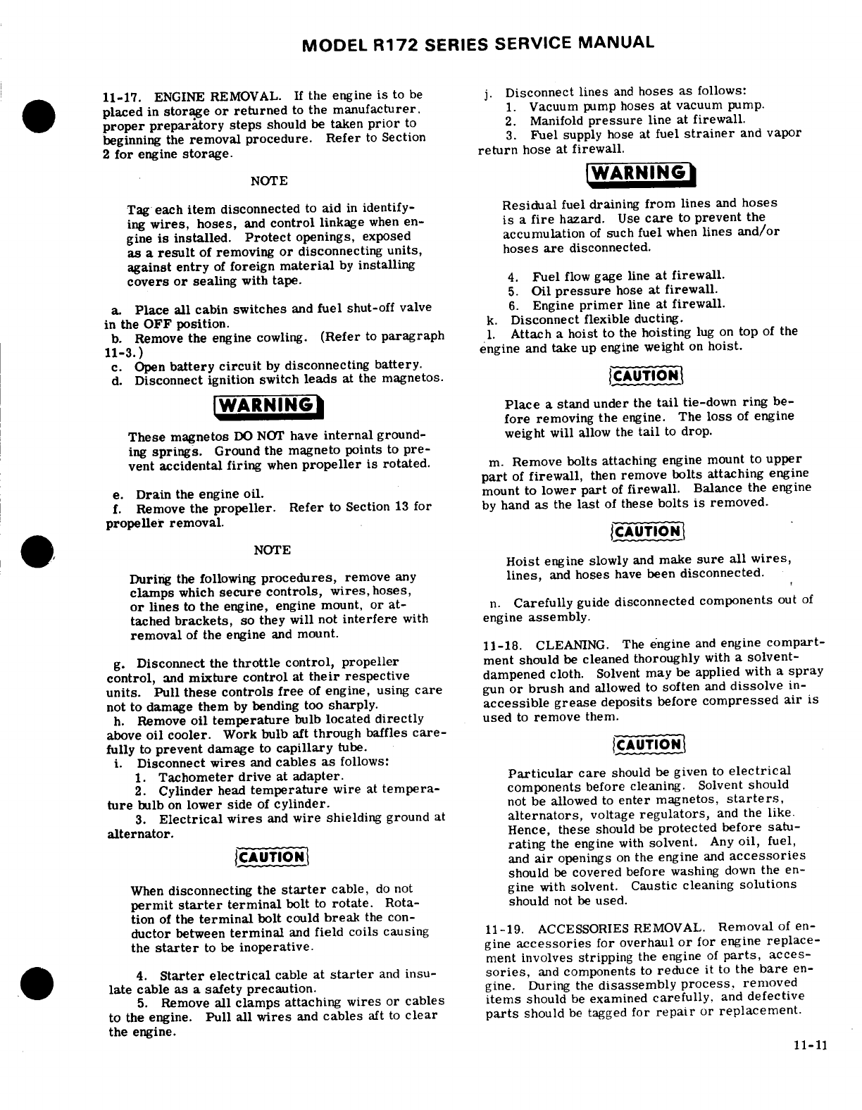
MODEL
R172
SERIES SERVICE
MANUAL
11-17.
ENGINE
REMOVAL.
If
the
engine
is
to
be
j.
Disconnect
lines
and
hoses as
follows:
placed
in
storage
or
returned
to
the
manufacturer.
1.
Vacuum
pump
hoses
at
vacuum
pump.
proper preparatory steps
should
be
taken
prior
to
2.
Manifold
pressure
line at
firewall.
beginning
the
removal procedure.
Refer
to
Section
3.
Fuel
supply
hose
at
fuel
strainer
and
vapor
2
for
engine
storage.
return
hose
at
firewall.
NOTE
WARNING
Tag
each
item
disconnected
to
aid
in
identify-
Residual
fuel
draining
from
lines
and
hoses
ing
wires,
hoses,
and
control
linkage
when
en-
is
a
fire
hazard.
Use
care
to
prevent
the
gine
is
installed.
Protect
openings,
exposed
accumulation
of
such
fuel
when
lines
and/or
as
a
result
of
removing
or
disconnecting
units, hoses
are
disconnected.
against
entry
of
foreign
material
by
installing
covers
or
sealing
with
tape.
4.
Fuel
flow
gage line
at
firewall.
5.
Oil
pressure
hose
at
firewall.
a.
Place
all
cabin
switches
and
fuel
shut-off
valve
6.
Engine
primer
line
at
firewall.
in
the
OFF
position.
k.
Disconnect
flexible ducting.
b.
Remove
the
engine
cowling.
(Refer
to
paragraph
1.
Attach
a
hoist
to
the
hoisting
lug
on
top
of
the
11-3.
engine
and
take up
engine
weight
on
hoist.
c.
Open
battery
circuit
by
disconnecting
battery.
d.
Disconnect
ignition switch
leads
at
the
magnetos.
CAUTION
WARNING
Place
a
stand
under
the
tail
tie-down
ring
be-
fore
removing
the
engine.
The
loss
of
engine
These
magnetos
DO
NOT
have
internal
ground-
weight
will
allow
the
tail
to
drop.
ing
springs.
Ground
the
magneto
points
to
pre-
vent
accidental firing
when
propeller
is
rotated.
m.
Remove
bolts
attaching
engine
mount to
upper
part
of
firewall,
then
remove
bolts
attaching
engine
e.
Drain
the
engine
oil.
mount
to
lower
part
of
firewall.
Balance
the
engine
f.
Remove
the
propeller.
Refer
to Section
13
for
by
hand
as
the
last
of
these
bolts
is
removed.
propeller
removal.
CAUTION
NOTE
Hoist
engine slowly
and
make
sure
all
wires,
During
the
following
procedures,
remove
any
lines,
and
hoses
have
been
disconnected.
clamps
which
secure
controls,
wires,
hoses,
or
lines
to
the
engine, engine mount,
or at-
n.
Carefully
guide
disconnected
components
out
of
tached
brackets,
so
they
will
not
interfere
with
engine
assembly.
removal
of
the engine
and
mount.
11-18.
CLEANING.
The
engine
and
engine
compart-
g.
Disconnect
the
throttle
control,
propeller
ment
should
be
cleaned thoroughly
with
a
solvent-
control,
and
mixture
control
at
their
respective
dampened
cloth.
Solvent
may
be
applied
with
a
spray
units.
Pull these controls
free
of
engine, using
care
gun
or
brush
and
allowed
to
soften
and
dissolve
in-
not
to
damage them
by
bending too
sharply.
accessible grease
deposits
before
compressed
air
is
h.
Remove
oil
temperature
bulb
located
directly
used
to
remove
them.
above
oil
cooler.
Work bulb aft
through
baffles
care-
fully
to
prevent
damage
to
capillary
tube.
CAUTION
i.
Disconnect
wires
and
cables as
follows:
1.
Tachometer
drive
at
adapter.
Particular
care
should
be
given
to
electrical
2.
Cylinder
head
temperature
wire
at
tempera-
components
before
cleaning.
Solvent
should
ture
bulb
on
lower
side
of
cylinder,
not
be allowed
to
enter
magnetos,
starters,
3.
Electrical
wires
and
wire
shielding
ground
at
alternators,
voltage
regulators,
and
the
like.
alternator.
Hence,
these
should
be
protected
before
satu-
rating
the
engine
with
solvent.
Any
oil,
fuel,
CAUTION
and
air
openings
on
the
engine
and
accessories
should
be
covered
before
washing
down
the
en-
When
disconnecting
the
starter
cable,
do
not
gine
with
solvent.
Caustic
cleaning
solutions
permit
starter
terminal
bolt
to
rotate.
Rota-
should
not
be
used.
tion
of
the
terminal
bolt
could
break
the
con-
ductor
between
terminal
and
field coils
causing
11-19.
ACCESSORIES REMOVAL.
Removal
of
en-
the
starter
to
be
inoperative.
gine
accessories
for
overhaul
or
for
engine
replace-
ment
involves
stripping
the engine
of
parts,
acces-
4.
Starter electrical
cable
at
starter
and
insu-
sories,
and
components
to
reduce
it
to
the
bare
en-
late
cable
as
a
safety
precaution.
gine.
During
the
disassembly
process,
removed
5.
Remove
all
clamps
attaching
wires
or
cables
items
should
be
examined
carefully.
and
defective
to
the engine.
Pull
all
wires
and
cables
aft
to
clear
parts
should
be
tagged
for
repair
or
replacement.
the
engine.
11-11
MODEL
R172
SERIES
SERVICE
MANUAL
NOTE
f.
Connect
lines
and
hoses
as
follows:
1.
Engine
primer
line
at
firewall.
Items
easily
confused
with
similar
items
2.
Oil
pressure
hose
at
firewall.
should
be
tagged
to
provide
a
means
of
iden-
3.
Fuel
flow
gage line
at
firewall.
tification
when
being
installed
on
a
new
en-
4.
Fuel
supply
hose
at
fuel
strainer
and
vapor
gine.
All
openings
exposed
by
the
removal
return
hose
at
firewall
of
an
item
should
be
closed
by
installing
a
suitable
cover
or
cap over
the
hole.
This
NOTE
will
prevent
entry
of
foreign
particles.
If
suitable
covers
are
not
available,
tape
may
Throughout
the
aircraft
fuel
system,
from
the
be
used
to
cover
the
openings.
fuel
tanks
to
the
engine-driven
fuel
pump,
use
NS-40
(RAS-4)
(Snap-On-Tools
Corp.,
Kenosha,
11-20.
INSPECTION.
For
specific
items
to
be
in-
Wisconsin), MIL-T-5544
(Thread
Compound,
spected
refer
to
engine
manufacturer's
manual.
Antiseize,
Graphite
Petrolatum),
USP
Petro-
a.
Visually inspect
the
engine
for
loose
nuts,
bolts, latum
or
engine
oil
as
a
thread
lubricant
or
to
cracks
and
fin
damage.
seal
a
leaking
connection.
Apply
sparingly
to
b.
Inspect
baffles, baffle
seals
and
brackets
for
male
threads
only,
omitting
the
first
two
cracks,
deterioration
and
breakage.
threads,
exercising extreme
caution
to
avoid
c.
Inspect
all
hoses
for internal
swelling,
chafing
"stringing"
sealer
across
the
end
of
the
fitting.
through
protective
plys,
cuts,
breaks,
stiffness,
Always
ensure
that
a compound,
the
residue
damaged
threads
and
loose
connections.
Excessive
from
a
previously
used
compound,
or
any
other
heat
on
hoses
will
cause
them
to
become
brittle
and
foreign
material
cannot
enter
the
system.
easily
broken.
Hoses
and
lines
are
most
likely
to
Throughout
the
fuel
injection
system,
from
the
crack
or
break
near
the
end
fittings
and
support engine-driven
fuel
pump
through
the
discharge
points.
nozzles,
use
only
a
fuel-soluble lubricant,
d.
Inspect
for
color
bleaching
of
the
end
fittings
or
such
as
engine
oil,
on
fitting
threads.
Do
not
severe
discoloration
of
the
hoses. use
any
other
form
of
thread
compound
on
the
injection
system.
NOTE
5.
Manifold
pressure
line
at
firewall.
Avoid
excessive
flexing
and
sharp
bends
6.
Vacuum
pump
hoses
at
firewall
and
separator.
when
examining
hoses
for
stiffness.
g.
Connect
wires
and
cables
as
follows:
1.
Tachometer drive
shaft
at
adapter
on
engine.
e.
Refer
to
Section
2
for
replacement
intervals
for
Tighten drive
shaft attaching
nut
to
100
lb-in.
flexible
fluid
carrying
hoses
in
the
engine
compart-
2.
Cylinder
head
temperature
wire
at
tempera-
ment.
ture
bulb.
Do
not
exceed
4
lb-in
torque.
f.
For
major
engine
repairs,
refer
to
the
manu-
3.
Electrical
wire
and
wire shielding
ground
at
facturer's
overhaul
and
repair
manual.
alternator.
11-21.
BUILD-UP. Engine
build-up
consists
of
the
CAUTION
installation
of
parts,
accessories
and
components
to
the
basic
engine
to
build
up a
powerplant
unit
ready
When
connecting
the
starter
cable,
do not
for installation
in
the
aircraft.
All
safety
wire,
lock-
permit
starter
terminal
bolt
to
rotate.
Ro-
washers.
Palnuts,
elastic
stop
nuts,
gaskets
and
tation
of
the
terminal
bolt
could
break
the
rubber
connections
should
be
new
parts.
conductor
between
terminal
and
field coils
causing
the
starter
to
be
inoperative.
11-22.
INSTALLATION.
Before
installing
the
engine,
reinstall
any
items
which
were
removed
from
the
en-
4.
Starter
electrical
cable
at
starter.
gine
after
it
was
removed
from
the
aircraft.
5.
Install
all
clamps
attaching
wires
or
cables
to
the
engine.
NOTE
h.
Install oil
temperature
bulb.
i.
Install
propeller.
(See
Section
13.)
Remove
all
protective
covers,
plugs,
caps,
j.
Make
a
magneto switch
ground-out
and
continuity
and
identification
tags
as
each
item
is
con-
check.
Connect
magneto
primary wires
to
the
mag-
nected
or
installed.
netos.
Remove
temporary
ground.
a.
Hoist
engine
and
mount
assembly
to
a
point
near
WARNING
the
firewall.
b.
Route
controls,
lines,
and
hoses
in
place
as
the
Be
sure
magneto
switch
is
in
OFF
position
engine
is
positioned
near
the
firewall.
when
connecting
primary
leads
to
magnetos.
c.
Install
engine
mount
bolts.
Install
the
upper
engine
mount
bolts
at
firewall,
then
install
lower
k.
Clean induction
air
filter
and
install.
bolts.
When
tightening, torque
to
160
to
190
lb-in.
l.
Service
engine
with
proper
grade
and
quantity
of
d.
Remove
hoist
and
stand
placed
under
tail.
engine oil.
Refer
to
Section
2
if
engine
has
been
in
e.
Route
throttle,
mixture,
and
propeller
controls
storage.
to
their
respective
units
and
connect.
Secure
controls
m. Make
sure
all
switches
are
in
the
OFF
position,
in
position
with
clamps.
and
connect
battery
ground cable.
11-12
MODEL
R172
SERIES SERVICE
MANUAL
n.
Rig
engine
controls
in
accordance
with
para-
hose
is
not
bent
excessively,
and
during
reinstalla-
graphs
11-93
and
11-97.
tion to
assure
hose
is
returned
to
its
original
position.
o.
Check
engine
installation
for
security,
correct
e.
Refer
to
AC
43.13,
Chapter
10,
for
additional
routing
of
controls,
lines,
hoses
and
electrical
installation procedures
for flexible
fluid
hose
assem-
wiring,
proper
safetying,
and
tightness
of
all
corn-
blies.
ponents.
p.
Install
engine
cowling. 11-26.
TACHOMETER DRIVE
ADAPTER SEAL.
q.
Perform
engine
run-up
and
make
final
adjust-
ments
on
engine
controls.
11-27.
REMOVAL
AND
INSTALLATION.
To
install
a
new
tachometer
drive
seal,
special tools
are
re-
11-23.
FLEXIBLE
FLUID
HOSES.
quired.
(See
figures
11-3
and
11-4.)
11-24. PRESSURE
TEST.
NOTE
a.
After
each
50
hours
of
engine
operation,
all
flexible
fluid
hoses
in
the engine
compartment
should
Tool
Kit
MK6-1 and
tool
SE909
are
available
be
pressure
tested
as
follows:
from
the
Cessna
Service
Parts
Center.
Tools
1.
Place
mixture
control
in
the
idle
cut-off
posi-
in
the
MK6-1
kit
are
used
for
installing
the
tionf.
seal
in
the
adapter
and
installation
of
the
2.
Operate
the
auxiliary
fuel
pump in
the
high
adapter
on
the
engine.
The
E0
tool
is
used
position. o
to
apply
the
correct
torque
value
on
the
tacho-
3.
Examine
the
exterior
of
hoses
for evidence
meter
drive
connector.
of
leakage
or
wetness.
4.
Hoses
found
leaking
should
be
replaced.
a.
Remove
engine
cowling
as
required
for
access.
5.
After
pressure
testing
fuel hoses,
allow suf-
b.
Drain
oil
until
a
maximum
of
eight
quarts
are
ficient
time
for
excess
fuel
to
drain
overboard
from
left
in
the
enine
the
engine
manifold
before attempting
an
engine
start.
c.
Remove
alternator.
(Refer
to
Section
16.)
6.
Refer
to
paragraph
11-20for
detailed
inspec-
d.
Disconnect
tachometer
drive
shaft from
tacho-
tion
procedures
for
flexible
hoses.
meter
drive reduction
adapter.
e.
Remove
drive reduction
adapter
from
tacho-
11-25.
REPLACEMENT.
meter
drive
housing.
a.
Hoses
should
not
be
twisted
on
installation.
f.
Remove
three
sets
of
nuts
and
washers
and
re-
Pressure
applied
to
a
twisted
hose
may
cause
fail-
move
tachometer
drive
housing.
ure
or
loosening
of
the nut.
g.
Engage
lock tool
(10)
and
driver
tool
(9)
through
b.
Provide
as
large
a
bend
radius
as possible.
the
housing
(4)
as
shown
in
figure
11-4.
Tap
the
c.
Hoses
should
have
a
minimum
of
one-half
inch
driver
tool
(9)
with
a
hammer
until
the
seal
(4)
is
clearance
from
other
lines,
ducts,
hoses
or
sur-
removed
from
the
drive
housing.
rounding
objects
or
be
butterfly
clamped
to
same
or
h
Engage
bolt
(5)
through
sleeve
(6),
washer
(7),
tied
with
sta-straps
to
prevent
chafing,
drive
housing
(4),
seal
(3),
and
into
driver
tool
(8)
d.
Rubber
hoses
will
take
a
permanent
set
during
as
shown in
figure
11-4.
Tighten
bolt
(5)
until
driver
extended
use
in
service.
Straightening
a
hose
with
a
bend having
a
permanent
set
will
result
in
hose
crack-
tool
(8)
comes
in
conta2t
with
the
face
o,
drive
hous-
ing.
Care
should
be
taken
during
removal
so
that
ing
(4).
SHOP
NOTES:
11-13
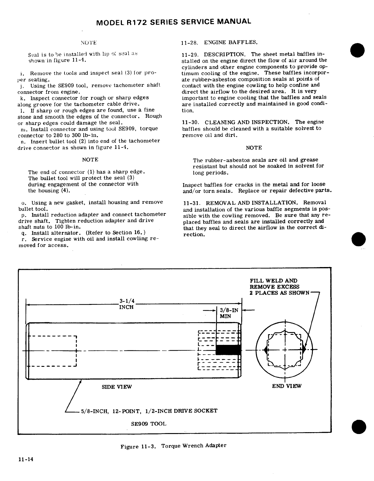
MODEL
R172
SERIES
SERVICE
MANUAL
NOTE
11-28.
ENGINE
BAFFLES.
Seal
is
to
be
installedl
with
lip
o'
seal
as
11-29.
DESCRIPTION. The
sheet
metal
baffles
in-
shownin
figure
11-4.
stalled
on
the
engine
direct
the
flow
of
air
around
the
cylinders
and
other
engine
components
to
provide
op-
i.
Remove
the
tools
and
inspect
seal
(3)
for
pro-
timum
cooling
of
the
engine.
These
baffles
incorpor-
per
seating.
ate
rubber-asbestos
composition
seals
at
points
of
j.
Using
the
SE909
tool,
remove
tachometer
shaft
contact
with
the engine
cowling
to
help
confine
and
connector
from
engine.
direct
the
airflow
to
the
desired
area.
It
is
very
k.
Inspect
connector for
rough
or
sharp
edges
important
to
engine
cooling
that
the
baffles
and
seals
along
groove
for
the
tachometer
cable
drive,
are
installed
correctly
and
maintained
in
good condi-
1.
If
sharp
or
rough
edges
are
found,
use
a
fine
tion.
stone
and
smooth
the
edges
of
the
connector.
Rough
or
sharp
edges
could
damage the
seal.
11-30.
CLEANING
AND
INSPECTION.
The
engine
m.
Install
connector
and
using
tool
SE909,
torque
baffles
should
be
cleaned
with
a
suitable
solvent
to
connector to
280
to
300
lb-in.
remove
oil
and
dirt.
n.
Insert
bullet
tool
(2)
into
end
of
the
tachometer
drive
connector
as
shown
in
figure
11-4.
NOTE
NOTE
The
rubber-asbestos
seals
are
oil
and
grease
resistant
but
should
not
be
soaked
in
solvent
for
The
end
of
connector
(1)
has
a
sharp
edge.
long
periods.
The
bullet
tool
will
protect
the
seal
(3)
during
engagement
of
the
connector
with
Inspect
baffles
for
cracks
in
the
metal
and for loose
the
housing
(4).
and/or
torn
seals.
Replace
or
repair
defective
parts.
o.
Using
a
new
gasket,
install
housing
and
remove
11-31.
REMOVAL
AND
INSTALLATION.
Removal
bullet
tool.
and
installation
of
the
various
baffle
segments
is
pos-
p.
Install
reduction adapter
and
connect
tachometer
sible
with
the
cowling
removed.
Be
sure
that
any
re-
drive
shaft.
Tighten
reduction
adapter
and
drive
placed
baffles
and
seals
are
installed
correctly
and
shaft
nuts
to
100
lb-in.
,
that
they
seal
to
direct
the
airflow
in
the
correct
di-
q.
Install
alternator.
(Refer
to Section
16.)
rection.
r.
Service
engine
with
oil
and
install
cowling
re-
moved
for
access.
FILL
WELD
AND
REMOVE
EXCESS
3-1/4
SIDE VIEW END
VIEW
5/8-INCH,
12-POINT,
1/2-INCH
DRIVE SOCKET
SE909
TOOL
Figure
11-3.
Torque
Wrench Adapter
11-14
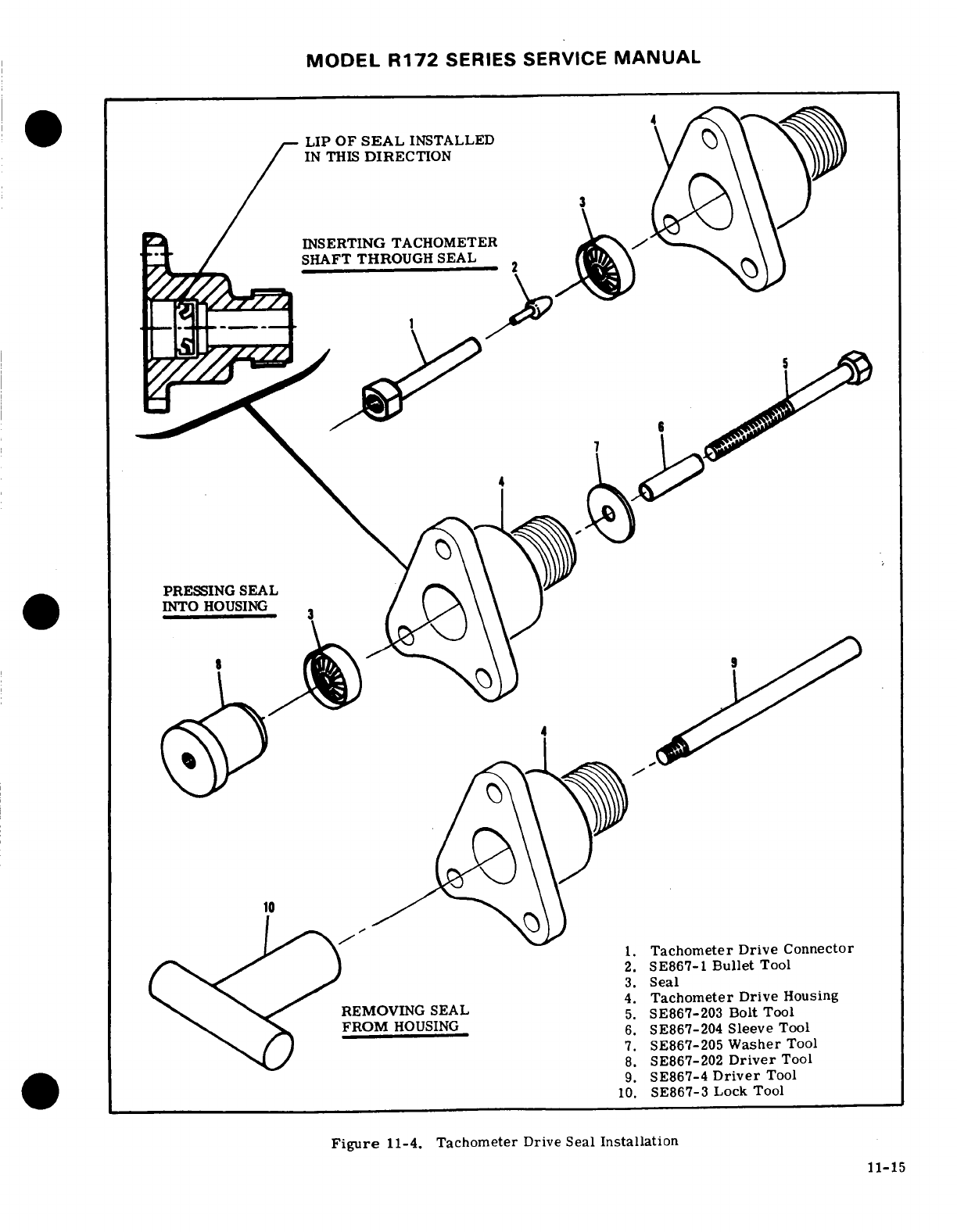
MODEL
R172
SERIES
SERVICE
MANUAL
LIP
OF
SEAL
INSTALLED
IN
THIS
DIRECTION
INSERTING
TACHOMETER
SHAFT
THROUGH
SEAL
PRESSING
SEAL
INTO
HOUSING
1.
Tachometer Drive
Connector
2.
SE867-1
Bullet
Tool
3.
Seal
.4.
Tachometer
Drive
Housing
REMOVING SEAL
5
SE867-203
Bolt
Tool
FROM
HOUSING
6.
SE867-204
Sleeve
Tool
7.
SE867-205
Washer
Tool
8.
SE867-202
Driver
Tool
9.
SE867-4
Driver
Tool
10.
SE867-3
Lock
Tool
Figure
11-4.
Tachometer
Drive Seal
Installation
11-15
MODEL
R172
SERIES
SERVICE
MANUAL
11-32. REPAIR.
Baffles
ordinarily
should
be
re-
h.
Remove
bolts
attaching
engine
mount
to
fuselage
placed
if
damaged
or cracked.
However,
small
plate
and
work
mount
from
aircraft.
reinforcements
riveted
to the
baffle
will
often prove
i.
To
install
the
engine
mount,
reverse
the
pre-
satisfactory
both
to
the
strength
and
cooling
require-
ceding
steps.
Be
sure
that
spacer
washers
are
in-
ments
of
the
unit.
stalled
between
engine
mount
and
firewall.
11-33.
ENGINE
MOUNT.
NOTE
11-34.
DESCRIPTION.
The
engine
mount
is
com-
When
tightening
mount-to-firewall
bolts,
tight-
posed
of
sections
of
tubing
welded
together
and
rein-
en
to
a
torque
value
of
160
to
190
lb-in.
When
forced
with welded
gussets.
The
purpose
of
the tightening
engine-to-mount
bolts,
tighten
to
a
mount
is
to
support
the engine
and
attach
it
to
the
air-
torque
value
of
450
to
500
lb-in.
11-36.
REPAIR.
Refer
to
section
18
of
this
manual
11-35.
REMOVAL
AND
INSTALLATION.
Removal
for
repair
procedures.
and
installation
of
the
engine
mount
may
be
accom-
plished
without
completely
removing
the
engine
from
11-37.
PAINTING.
Refer
to
section
19
of
this
man-
the
aircraft.
ual
for
painting
procedures.
a.
Remove
cowling
for
acess.
b.
Remove
engine
exhaust
system
as outlined
in
11-38.
SHOCK
MOUNT
PADS.
The
bonded rubber
paragraph
11-101.
and
metal
shock
mounts
are
designed
to
reduce
c.
Remove
clamps
attaching
lines,
hoses,
and
transmission
of
engine
vibrations
to the
airframe.
wiring
to
engine mount.
The
rubber
pads
should
be
wiped
clean
with
a
dry
d.
Remove heat
shields
from
right
hand
rear
and
cloth.
left
hand
forward
engine shock
mounts
(if
installed).
e.
Attach
a
suitable
hoist
to
the
hoisting
lug
on top
NOTE
of
the
engine
and
take
up
engine
weight
with
the
hoist.
Do
not
clean
the
rubber
parts
with
any
type
of
cleaning
solvent.
Place
a
stand under
the
tail
tie-down
ring
be-
Inspect
metal
parts
for
cracks
and
excessive
wear
due
to
aging
and
deterioration.
Inspect
the
rubber
fore lifting
the
engine.
The
loss
of
engine
weight
will
allow
the
tail
to
drops.
eparts
for
swelling,
cracking,
or
a
pronounced
set
weight
of
the
part.
Replace
with
new
parts
all
of
the
parts
f.
Remove
nuts,
washers,
and
bolts
attaching
en-
gine to
mount.
11-39.
ENGINE OIL
SYSTEM.
g.
Raise
hoist
slightly
so
that
no
engine
weight
is
on
the
mount
and
remove
engine
shock
mount pads
and
spacers.
11-40.
DESCRIPTION.
A
wet-sump,
pressure-
Use
care
when
lifting
engine
to
prevent
damage
to
lines,
hoses,
wiring,
and
controls.
SHOP
NOTES:
11-16
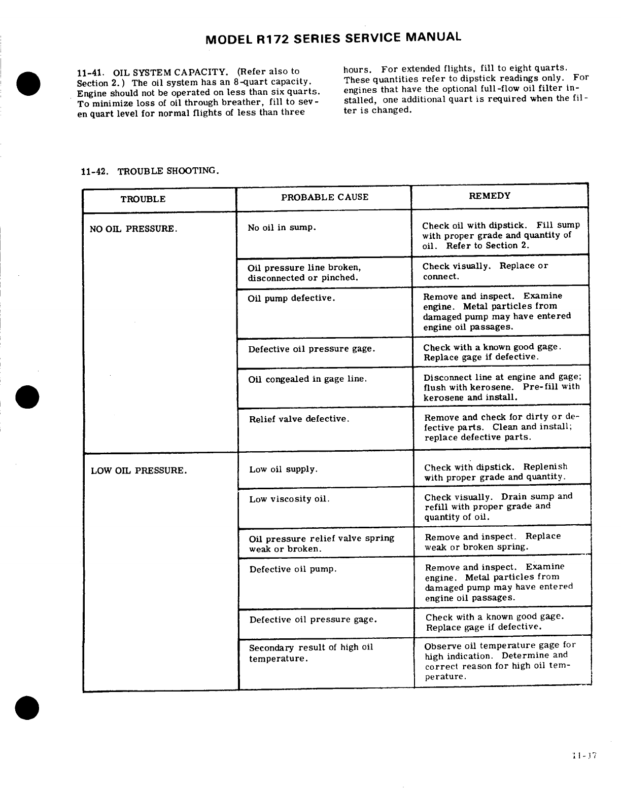
MODEL
R172
SERIES
SERVICE
MANUAL
11-41.
OIL
SYSTEM
CAPACITY.
(Refer
also
to
hours.
For
extended
flights,
fill
to
eight
quarts.
Section
2.
)
The
oil
system
has
an
8-quart
capacity.
These
quantities
refer
to
dipstick
readings
only.
For
Engine
should
not
be
operated
on
less
than
six
quarts.
engines
that
have
the
optional
full-flow oil
filter
in-
To
minimize
loss
of
oil
through
breather,
fill to
sev-
stalled,
one
additional
quart
is
required
when the
fil-
en
quart
level
for
normal
flights
of
less
than
three
ter
is
changed.
11-42.
TROUBLE
SHOOTING.
TROUBLE
PROBABLE
CAUSE
REMEDY
NO
OIL
PRESSURE.
No
oil
in
sump. Check
oil
with
dipstick.
Fill
sump
with
proper
grade
and
quantity
of
oil.
Refer
to
Section
2.
Oil
pressure
line
broken,
Check
visually.
Replace
or
disconnected
or
pinched.
connect.
Oil
pump
defective.
Remove
and
inspect.
Examine
engine. Metal
particles
from
damaged
pump
may
have
entered
engine
oil
passages.
Defective
oil
pressure
gage.
Check
with
a
known good
gage.
Replace
gage
if
defective.
Oil
congealed
in
gage
line.
Disconnect
line
at
engine
and
gage;
flush
with
kerosene.
Pre-fill
with
kerosene
and
install.
Relief
valve
defective.
Remove
and
check
for
dirty
or
de-
fective
parts.
Clean
and
install;
replace
defective
parts.
LOW
OIL
PRESSURE.
Low
oil
supply.
Check
with
dipstick. Replenish
with
proper
grade
and
quantity.
Low
viscosity
oil.
Check
visually. Drain
sump
and
refill
with
proper
grade
and
quantity
of
oil.
Oil
pressure
relief
valve
spring
Remove
and
inspect.
Replace
weak
or
broken.
weak
or
broken
spring.
Defective
oil
pump.
Remove
and
inspect.
Examine
engine.
Metal
particles
from
damaged
pump
may
have
entered
engine
oil
passages.
Defective
oil
pressure
gage.
Check
with
a
known
good
gage.
Replace
gage
if
defective.
Secondary
result
of
high
oil
Observe
oil
temperature
gage
for
temperature.
high
indication.
Determine
and
correct
reason
for
high
oil
tem-
perature.
11-17
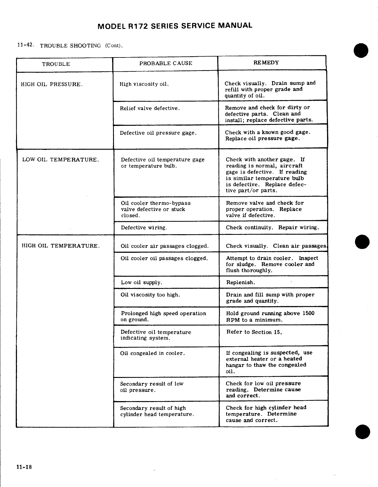
MODEL
R172
SERIES
SERVICE
MANUAL
11-42.
TROUBLE
SHOOTING
(Cont).
TROUBLE PROBABLE
CAUSE
REMEDY
HIGH
OIL
PRESSURE.
High
viscosity
oil.
Check
visually. Drain
sump
and
refill
with
proper
grade
and
quantity
of
oil.
Relief
valve
defective.
Remove
and
check
for
dirty
or
defective
parts.
Clean
and
install; replace
defective
parts.
Defective
oil
pressure
gage. Check
with
a
known
good
gage.
Replace
oil
pressure
gage.
LOW
OIL
TEMPERATURE.
Defective
oil
temperature
gage Check
with
another
gage.
If
or
temperature
bulb.
reading
is
normal,
aircraft
gage
is
defective.
If
reading
is
similar
temperature
bulb
is
defective.
Replace
defec-
tive
part/or
parts.
Oil
cooler
thermo-bypass
Remove
valve
and
check
for
valve
defective
or
stuck
proper
operation.
Replace
closed, valve
if
defective.
Defective
wiring.
Check
continuity.
Repair
wiring.
HIGH
OIL
TEMPERATURE.
Oil
cooler
air
passages
clogged.
Check
visually.
Clean
air
passages
Oil
cooler
oil
passages
clogged.
Attempt
to
drain cooler.
Inspect
for
sludge.
Remove
cooler
and
flush
thoroughly.
Low
oil
supply.
Replenish.
Oil
viscosity
too high.
Drain
and
fill
sump
with
proper
grade
and
quantity.
Prolonged
high
speed
operation
Hold
ground
running
above
1500
on
ground.
RPM
to
a
minimum.
Defective oil
temperature
Refer
to
Section
15.
indicating
system.
Oil
congealed
in
cooler.
If
congealing
is
suspected,
use
external
heater or
a
heated
hangar
to thaw
the
congealed
oil.
Secondary
result
of
low
Check
for
low
oil
pressure
oil
pressure.
reading.
Determine
cause
and
correct.
Secondary
result
of
high
Check
for
high
cylinder
head
cylinder
head
temperature.
temperature.
Determine
cause
and
correct.
11-18
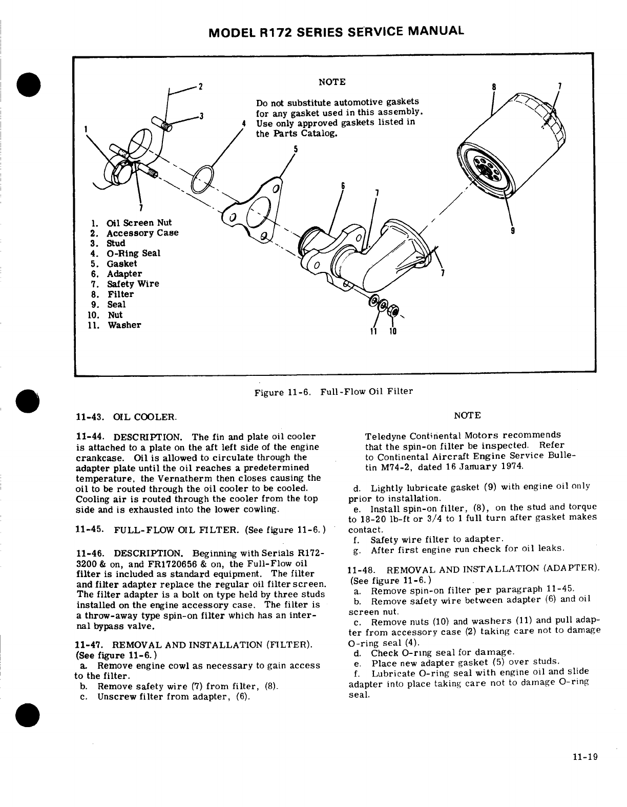
MODEL
R172
SERIES
SERVICE
MANUAL
NOTE
8
7
Do
not
substitute
automotive gaskets
for
any
gasket
used
in
this
assembly.
Use
only
approved
gaskets
listed
in
the
Parts
Catalog.
1.
Oil
Screen
Nut
2.
Accessory
Case
3.
Stud
4.
O-Ring
Seal
5.
Gasket
6.
Adapter
7.
Safety
Wire
8.
Filter
9.
Seal
10.
Nut
11.
Washer
,Figure
11-6.
Full-Flow
Oil
Filter
11-43.
OIL
COOLER.
NOTE
11-44.
DESCRIPTION.
The
fin
and
plate
oil
cooler
Teledyne
Continental
Motors
recommends
is
attached
to
a
plate
on
the
aft
left
side
of
the
engine
that
the
spin-on
filter
be
inspected.
Refer
crankcase.
Oil
is
allowed
to
circulate
through
the
to
Continental
Aircraft
Engine
Service
Bulle-
adapter
plate
until
the
oil
reaches
a
predetermined
tin
M74-2,
dated
16
January
1974.
temperature,
the
Vernatherm
then
closes
causing
the
oil
to be
routed
through
the
oil
cooler
to
be
cooled.
d.
Lightly
lubricate
gasket
(9)
with
engine
oil
only
Cooling
air
is
routed
through
the
cooler
from
the
top
prior
to
installation.
side
and
is
exhausted
into
the
lower
cowling.
e.
Install
spin-on
filter,
(8),
on
the
stud
and
torque
to
18-20
Ib-ft
or
3/4
to
1
full
turn
after
gasket
makes
11-45.
FULL-FLOW
OIL
FILTER.
(See
figure
11-6.)
contact.
f.
Safety
wire
filter
to
adapter.
11-46.
DESCRIPTION.
Beginning
with
Serials
R172-
g.
After
first
engine
run
check
for
oil
leaks.
3200
&
on,
and
FR1720656
&
on,
the
Full-Flow
oil
filter
is
included as
standard
equipment.
The
filter
11-48.
REMOVAL
AND
INSTALLATION
(ADAPTER).
and
filter
adapter replace
the
regular
oil
filter
screen.
(See
figure
11-6. )
The
filter
adapter
is
a
bolt
on
type
held
by
three
studs
a.
Remove
spin-on
filter
per
paragraph
11-45.
installed
on
the
engine
accessory
case.
The
filter
is
b.
Remove
safety wire
between
adapter
(6)
and
oil
a
throw-away
type
spin-on
filter
which
has
an
inter-
screen
nut.
nal
bypass
valve.
c.
Remove
nuts
(10)
and
washers
(11)
and
pull
adap-
ter
from
accessory
case
(2)
taking
care
not
to
damage
11-47.
REMOVAL
AND
INSTALLATION
(FILTER).
O-ring
seal
(4).
(See
figure
11-6.)
d.
Check
O-ring
seal
for
damage.
a Remove
engine
cowl
as
necessary
to
gain
access
e.
Place
new
adapter
gasket
(5)
over
studs.
to
the
filter.
f.
Lubricate
O-ring
seal
with
engine
oil
and
slide
b.
Remove
safety wire
(7)
from
filter,
(8).
adapter
into
place taking
care
not
to
damage
O-ring
c.
Unscrew
filter
from
adapter,
(6).
seal.
11-19
MODEL
R172
SERIES
SERVICE
MANUAL
-
Install
washers
and
nuts in
throttle
position,
engine
speed,
or
a
combination
h.
Safety
wire
oil
screen
nut
to
adapter,
of
both.
changes
fuel
flow
in
the
correct
relation
to
I. Install
oil
filter
per
paragraph
11-47.
engine airflow.
A
manual
mixture
control
and
a
fuel
flow
indicator
are
provided
for
leaning
at
any
combi-
11-49. ENGINE
FUEL
SYSTEM.
(See
figure
11-7.)
nation
of
altitude
and
power
setting.
The continuous-
flow
system
uses
a
typical
rotary-vane
fuel
pump,
11-50.
DESCRIPTION. The
fuel
injection
system
is
which
is
the
only
running
part
in
the
system.
Since
a
simple.
low-pressure
system
of
injecting
metered
the
fuel
injection nozzles
and the
intake
manifolds
fuel
into
the
intake
valve
ports
in
the
cylinders.
It
is
are
installed
on
the
top
side
of
the
cylinders,
drain
a
multi-nozzle.
continuous-flow
system
which con-
lines
are
installed
in
the
bottom
side
of
the
intake
trols
fuel
flow
to
match engine
airflow.
Any
change
ports
to
drain
any
fuel
which
might
accumulate
in
the
intake
ports
during
engine
shut-down.
SHOP
NOTES:
11-20
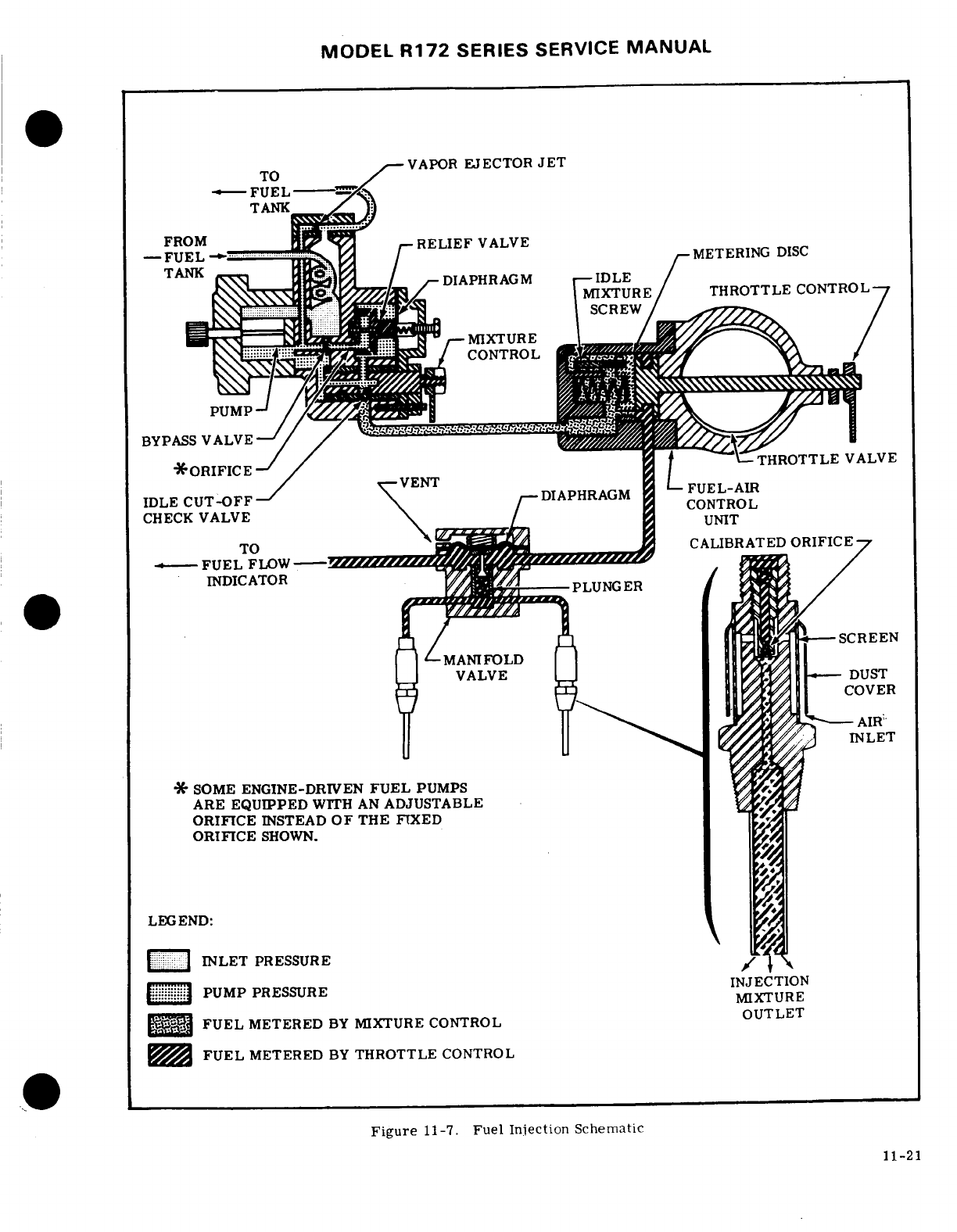
MODEL
R172
SERIES
SERVICE
MANUAL
TO
VAPOR
EJECTOR
JET
FUEL
-
TANK
FROM
RELIEF
VALVE
FUEL ,
METERING
DISC
MIXTURE
PUMP
BYPASS
VALVE
ORIFICE THROTTLE
VALVE
IDLE
CUT-OFF
DIAPHRAGM
CHECK
VALVE
UNIT
INDICATOR
PLUNGER
SCREEN
VALVE
DUST
COVER
AIR
INLET
PRESSURE
11-21
LEGEND:
INLET
PRESSURE
PUMP
PRESSURE
MIXTURE
FUEL
METERED
BY
MIXTURE
CONTROL
FUEL
METERED
BY
THROTTLE
CONTROL
Figure
11-7.
Fuel
Injection Schematic
11-21
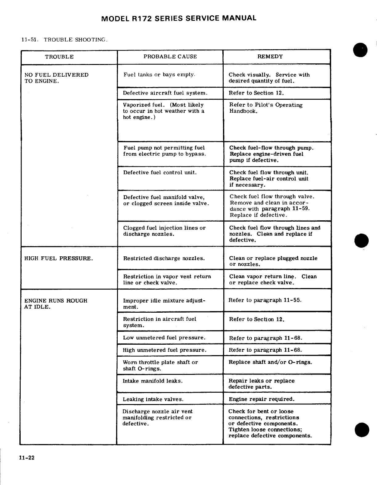
MODEL
R172
SERIES
SERVICE
MANUAL
11-51.
TROUBLE
SHOOTING.
TROUBLE
PROBABLE
CAUSE
REMEDY
NO
FUEL
DELIVERED
Fuel
tanks
or
bays
empty.
Check
visually.
Service
with
TO
ENGINE.
desired
quantity
of
fuel.
Defective
aircraft
fuel
system.
Refer
to
Section
12.
Vaporized
fuel.
(Most
likely
Refer
to
Pilot's
Operating
to
occur
in
hot
weather
with a
Handbook.
hot
engine.)
Fuel
pump
not
permitting
fuel
Check
fuel-flow
through
pump.
from
electric
pump
to
bypass.
Replace
engine-driven
fuel
pump
if
defective.
Defective
fuel
control
unit. Check
fuel
flow
through
unit.
Replace
fuel-air
control
unit
if
necessary.
Defective
fuel manifold
valve,
Check
fuel
flow
through
valve.
or
clogged
screen
inside
valve. Remove
and
clean
in
accor-
dance
with
paragraph
11-59.
Replace
if
defective.
Clogged
fuel
injection
lines
or
Check
fuel
flow
through
lines
and
discharge
nozzles.
nozzles.
Clean
and
replace
if
defective.
HIGH
FUEL
PRESSURE.
Restricted
discharge
nozzles.
Clean
or
replace
plugged
nozzle
or
nozzles.
Restriction
in
vapor
vent
return
Clean
vapor
return
line.
Clean
line
or
check
valve.
or
replace
check
valve.
ENGINE
RUNS
ROUGH
Improper
idle
mixture
adjust-
Refer
to
paragraph
11-55.
AT
IDLE.
ment.
Restriction
in
aircraft
fuel
Refer
to
Section
12.
system.
Low
unmetered
fuel
pressure.
Refer
to
paragraph
11-68.
High
unmetered
fuel
pressure.
Refer
to
paragraph
11-68.
Worn
throttle
plate
shaft
or
Replace
shaft
and/or
O-rings.
shaft
O-rings.
Intake
manifold
leaks. Repair leaks
or
replace
defective
parts.
Leaking
intake
valves.
Engine
repair
required.
Discharge
nozzle
air
vent
Check
for
bent
or
loose
manifolding
restricted
or
connections,
restrictions
defective.
or
defective components.
Tighten
loose connections;
replace
defective
components.
11-22
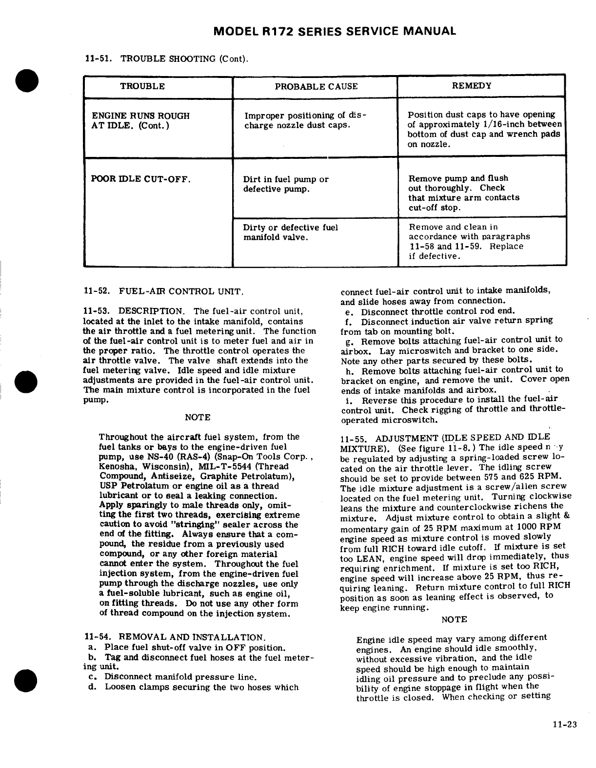
MODEL
R172
SERIES SERVICE
MANUAL
11-51.
TROUBLE
SHOOTING
(Cont).
TROUBLE PROBABLE
CAUSE
REMEDY
ENGINE
RUNS
ROUGH
Improper
positioning
of
dis-
Position
dust caps
to
have
opening
AT
IDLE.
(Cont.)
charge
nozzle
dust
caps.
of
approximately 1/16-inch
between
bottom
of
dust
cap
and
wrench
pads
on
nozzle.
POOR
IDLE
CUT-OFF.
Dirt
in
fuel
pump
or
Remove pump
and
fush
defective
pump.
out
thoroughly.
Check
that
mixture
arm
contacts
cut-off
stop.
Dirty
or
defective
fuel Remove
and
clean
in
manifold
valve.
accordance
with
paragraphs
11-58
and
11-59. Replace
if
defective.
11-52.
FUEL-AIR
CONTROL
UNIT.
connect
fuel-air
control
unit
to
intake
manifolds,
and
slide
hoses
away
from
connection.
11-53. DESCRIPTION.
The
fuel-air
control
unit,
e.
Disconnect
throttle
control
rod
end.
located
at
the
inlet
to the
intake
manifold,
contains
f.
Disconnect
induction
air
valve
return
spring
the
air
throttle
and
a
fuel
metering
unit.
The
function
from tab
on
mounting
bolt.
of
the
fuel-air
control
unit
is
to
meter
fuel
and
air
in
g.
Remove
bolts
attaching
fuel-air
control
unit to
the
proper
ratio.
The
throttle
control operates
the
airbox.
Lay
microswitch
and
bracket
to
one
side.
air
throttle
valve.
The
valve
shaft
extends into
the
Note
any
other
parts
secured
by
these
bolts.
fuel
metering
valve.
Idle
speed
and
idle mixture
h.
Remove
bolts
attaching
fuel-air
control
unit
to
adjustments
are
provided
in
the
fuel-air
control
unit.
bracket
on
engine,
and
remove
the
unit.
Cover
open
The
main
mixture control
is
incorporated
in the fuel ends
of
intake
manifolds
and
airbox.
pump.
i.
Reverse
this
procedure
to
install
the
fuel-air
NOTE
control
unit.
Check
rigging
of
throttle
and
throttle-
operated
microswitch.
Throughout
the
aircraft
fuel
system,
from
the 11-55.
ADJUSTMENT
(IDLE
SPEED
AND
IDLE
fuel
tanks
or
bays
to
the
engine-driven
fuel
MIXTURE).
(See
figure
11-8.)
The
idle
speed
n
y
pump,
use
NS-40
(RAS-4)
(Snap-On
Tools
Corp.,
be
regulated
by
adjusting
a
spring-loaded screw
lo-
Kenosha,
Wisconsin), MIL-T-5544
(Thread
cated
on
the
air
throttle
lever.
The
idling
screw
Compound,
Antiseize,
Graphite
Petrolatum),
should
be
set
to
provide
between
575
and
625
RPM.
USP
Petrolatum
or
engine
oil
as
a
thread
The
idle
mixture
adjustment
is
a
screw/alien
screw
lubricant
or
to
seal
a
leaking
connection,
located
on
the
fuel
metering
unit.
Turning
clockwise
Apply
sparingly
to
male
threads
only,
omit- leans
the
mixture
and
counterclockwise
richens
the
ting
the
first
two
threads,
exercising
extreme
mixture.
Adjust
mixture
control
to
obtain
a
slight
&
end
of
the
fitting
Always
ensure
tat
across
t
momentary
gain
of
25
RPM
maximum
at
1000
RPM
pound,
the
residue
from
a
previously
used
engine
speed
as
mixture
control is
moved
slowly
compound,
or
any
other
foreign
material
from
full
RICH
toward
idle cutoff.
If
mixture is
set
cannot
enter
the
system.
Throughout
the
fuel
too
LEAN,
engine
speed
will
drop
immediately,
thus
injection
system,
from
the
engine-driven
fuel
requiring enrichment.
If
mixture
is
set
too
RICH,
pump
through
the
discharge
nozzles,
use
only
engine
speed
will
increase
above
25
RPM,
thus
re-
a
fuel-soluble
lubricant,
such
as
engine
oil,
quiring
leaning.
Return
mixture control to
full
RICH
on
fitting
threads.
Do
not
use
any
other
form position
as
soon
as
leaning
effect is
observed,
to
of
thread
compound
on
the injection
system.
keep
engine
running.
NOTE
11-54.
REMOVAL
AND
INSTALLATION.
11-54.REMOVALAD
INSTALLATION.
Engine
idle
speed
may
vary
among
different
ing
unit,
without
excessive
vibration,
and
the
idle
c.
Disconnect
manifold
pressure
line.
idling oil
pressure
and
to
preclude
any
possi-
d.
Loosen
clamps
securing
the
two
hoses
which
bility
of
engine
stoppage in
flight
when
the
throttle
is
closed.
When
checking
or
setting
11-23
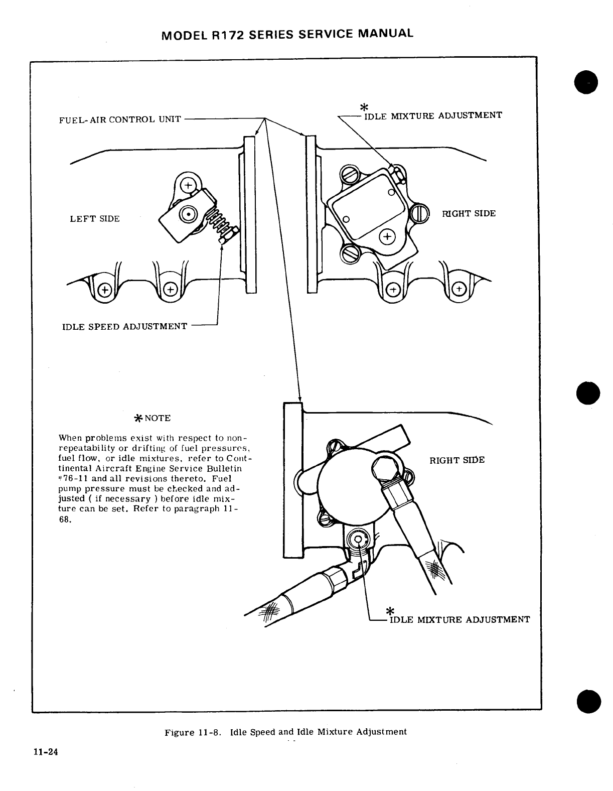
MODEL
R172
SERIES
SERVICE
MANUAL
FUEL-AIR
CONTROL
UNIT
IDLE
MIXTURE
ADJUSTMENT
LEFT
SIDE
RIGHT SIDE
IDLE
SPEED
ADJUSTMENT
-
NOTE
-
When
problems
exist
with
respect
to
non-
repeatability
or drifting
of
fuel
pressures,
fuel
flow,
or
idle
mixtures,
refer
to
Cont-
RIGHT
SIDE
tinental
Aircraft
Engine
Service
Bulletin
#76-11
and
all
revisions
thereto.
Fuel
pump
pressure
must
be
checked
and
ad-
justed
(
if
necessary
)
before
idle
mix-
ture
can
be
set.
Refer
to
paragraph
11-
68.
IDLE
MIXTURE
ADJUSTMENT
Figure
11-8.
Idle
Speed
and
Idle
Mixture
Adjustment
11-24
MODEL
R172
SERIES
SERVICE
MANUAL
idle speed
or
idle
mixture,
"clear"
the
en-
is
open and
clean.
gine
between
checks
to
prevent
false
indica-
g.
Carefully
replace
diaphragm
and
valve.
Check
tions.
that
valve
works
freely
in body
bore.
h.
Position
diaphragm
so
that
horizontal
hole
in
11-56.
FUEL
MANIFOLD
VALVE.
plunger
valve
is
90
degrees
from
the
fuel
inlet
port
in
the
valve
body.
11-57. DESCRIPTION.
Metered
fuel
flows
to
the
i.
Place
upper
spring
in
position
on
diaphragm.
fuel
manifold
valve,
which
provides
a
central
point
j.
Place
cover in
position
so
that
vent
hole
in
for
distributing
fuel
to
individual
cylinders.
An
in-
cover
is
90
degrees
from
inlet
port
in
valve
body.
ternal
diaphragm,
operated
by
fuel
pressure,
raises
Install
cover
attaching
screws
and
tighten
to
20±1
or
lowers
a
plunger
to
open
and
close
the
individual
lb-in.
Install
safety
wire
on
cover
screws.
cylinder
supply
ports
simultaneously.
A
needle
valve
k.
Install
fuel
manifold
valve
assembly
on
engine
in
the
plunger
ensures
that
the
plunger
fully
opens the
and
reconnect all
lines
and
hoses
to
valve.
outlet
ports
before
fuel
flow
starts,
and
closes
the
1.
Inspect
installation
and
install
cowling.
ports
simultaneously
for positive
engine
shut-down.
A
fine-mesh
screen
is
included in
the
fuel
manifold
11-60.
FUEL
DISCHARGE
NOZZLES.
valve.
11-61. DESCRIPTION.
From
the
fuel
manifold
valve,
11-58.
REMOVAL
AND
INSTALLATION.
individual,
identical
size
and
length
fuel
lines
carry
a. Disconnect
all
lines
and
hoses
from
the
fuel
metered
fuel
to
the
fuel
discharge
nozzles
located
in
manifold
valve,
the
cylinder
heads.
The
outlet
of
each
nozzle
is
di-
b.
Remove
the
two
crankcase
bolts
which
secure
rected
into
the
intake
port
of
each
cylinder.
An
air
mounting
bracket.
After
removal,
bracket
may
be
bleed,
incorporated
into
each
nozzle,
aids
in
vapor-
disassembled
from
manifold
valve
if
desired.
izing
the
fuel
by
breaking
the
high
vacuum
in
the
in-
c.
Reverse
this
procedure
to
install
the
fuel
mani-
take
manifold
at
idle
RPM and
keeps
the
fuel
lines
fold
valve.
filled.
The
nozzles
are
calibrated
in
several
ranges
All
nozzles
furnished for
one
engine
are
the
same
11-59.
CLEANING.
range
and
are
identified
by
a
number
and
a
suffix
a.
Remove
fuel
manifold
valve
from
engine
and
re-
letter
stamped
on
the
flat
portion
of
the
nozzle
body.
move
safety
wire from
cover
attaching
screws.
When
replacing
a
fuel
discharge
nozzle
be
sure
that
b.
Hold
the
top
cover
down
against
internal
spring
it is
of
the
same
calibrated
range
as
the
rest
of
the
until
all
four
cover
attaching
screws
have
been
re-
nozzles
in
the
engine.
When
a
complete
set
of
nozzles
moved, then
gently
lift
off
the
cover.
Use
care
not
is
being
replaced,
the
number
must
be
the
same
as
to
damage the
spring-loaded
diaphragm
below
cover.
the
one
removed,
but
the
suffix
letters
may
be
differ-
c.
Remove
the upper
spring
and
lift
the
diaphragm
ent,
as
long
as
they
are
the
same
for
all
nozzles
assembly
straight
up.
being
installed
on
a
particular
engine.
NOTE
11-62.
REMOVAL.
If
the
valve
attached
to
the
diaphragm
is
NOTE
stuck
in
the
bore
of
the
body,
grasp
the
center
nut
and
rotate
and
lift
at
the
same
Plug
or
cap
all
disconnected lines
and
fittings.
time
to
work
gently
out
of
the
body.
a.
Disconnect
the
fuel
injection
lines
at
the
fuel
jCAUTION
discharge
nozzles.
Remove
the
nozzles
with
a
1/2-
inch
deep
socket.
Do
not
attempt
to
remove
needle
or
spring
from
inside
plunger
valve.
Removal
of
11-63.
CLEANING
AND
INSPECTION.
To
clean
these
items
from
the
valve
will
disturb
the
nozzles,
immerse
in
clean
solvent
and
use
compressed
calibration
of
the
valve.
air
to
dry
them.
When
cleaning
the
nozzle with
com-
pressed
air,
direct
air
through
the nozzle
in
the
direc-
d. Using
clean
gasoline,
flush
out
the
chamber
tion
opposite
of
normal
fuel
flow.
Do
not
remove
the
below the
screen,
nozzle
shield
or
distort
it
in
any
way.
Do
not
use
a
e.
Flush
above
the
screen
and
inside
the
center
wire
or
other
metal
object
to
clean
the
orifice
or
bore
making
sure
that
outlet
passages
are
open.
metering jet.
After
cleaning,
check
the
shield
height
Use
only
a
gentle
stream
of
compressed air
to
re-
from
the
hex
portion
of the
nozzle.
The
bottom
of
the
move
dust
and
dirt
and
to
dry.
shield
should
be
approximately
1/16
inch
above
the
hex
portion
of
the
nozzle.
CAUTION
-
11-64.
INSTALLATION.
The
filter
screen
is
a
tight
fit
in
the
body
a.
Install
the fuel
discharge
nozzles
in
the
cylinders
and
may
be
damaged
if
removal
is
attempted.
using
a
1/2-inch
deep
socket,
and
tighten
nozzle
to
a
It
should
be
removed
only
if
a
new
screen
is
torque
value
of
60
to 80
lb-in.
to be
installed.
b.
Connect
the
fuel
injection
lines
at
the
fuel
dis-
charge
nozzles.
f.
Clean
diaphragm
and
valve
and
top
cover
in the
c.
Check
installation
for
crimped
lines, loose fit-
same
manner.
Be
sure
the
vent
hole
in
the
top
cover tings,
etc,
11-25
MODEL
R172
SERIES
SERVICE
MANUAL
11-65.
FUEL
INJECTION
PUMP.
NOTE
11-66.
DESCRIPTION. The
fuel
pump
is
a
positive-
Cessna Service
Kit
No.
SK320-2J
provides
displacement,
rotating
vane
type,
located
just
forward
a
special
indicator,
lines,
and
instructions
of
number
five
cylinder
at
the
propeller
end
of
the
en-
for
connecting
the
indicator
into
the
system
gine.
Fuel
enters
the
pump
at
the
swirl
well
of
the
to
perform
accurate
calibration
of
the
en-
pump
vapor
separator.
Here,
vapor
is
separated
by
gine-driven
fuel
pump.
a
swirling
motion so
that
only
liquid
fuel
is
fed to
the
pump.
The
vapor
is
drawn
from
the
top
center
of
the
c.
Allow
engine
to
warm-up.
Set
mixture
control
swirl
well
by
small
pressure
jet
of
fuel
and
is
fed
into
full
rich
and
propeller
control
full
forward
(low
pitch
the
vapor
return
line,
where
it
is
returned
to
the
air-
high
RPM).
craft
fuel
tank
or
bay. Since
the
pump
is
engine-
d.
Idle
engine
at
600
RPM and
check
fuel
pressure
driven,
changes
in
engine
speed
affect
total
pump
on
special indicator
per
paragraph
11-12.
flow
proportionally.
The
pump
supplies more
fuel
than
is
required
by
the
engine:
therefore,
a
spring-
loaded,
diaphragm
type
relief
valve
is
provided,
with
WARNING
an
adjustable
orifice
installed
in
the fuel
passage
to
this
relief
valve
to
maintain
the
desired
pressure
at
DO
NOT
make
fuel
pump
pressure
adjust-
the full
throttle
position.
The
fuel
pump
is
equipped
ments
while
engine
is
operating.
with
a
manual
mixture
control
to
provide
positive
mixture
control
throughout
the
range
required
by
the
e.
If
pressure
is
not
within
prescribed tolerances,
injection
system.
This control
limits
output
of
the
stop
engine
and
adjust
pressure
by
turning
the
screw
pump
from
full
rich
to
idle cutoff.
Non-adjustable
on
the
fuel
pump
relief
valve
(turn
IN
to
increase
mechanical stops
are
located
at
these positions.
A
pressure
and
OUT
to
decrease
pressure)
to
attain
check
valve
allows
the
auxiliary
fuel
pump
pressure
correct
pressure
and
repeat
steps
"c"
and
"d".
to
bypass
the
engine-driven
fuel
pump
for
starting,
or
in
the
event
of
an
engine-driven
fuel
pump
failure.
NOTE
11-67.
REMOVAL
AND
INSTALLATION.
After
adjusting
fuel
pressure,
idle
speed
a.
Place
fuel
shut-off
valve
in
OFF
position
and
re-
and
idle
mixture
must
be
readjusted
(refer
move
cowling,
baffles,
and
covers
as
necessary
for
to
paragraph
11-55).
access.
b.
Disconnect
mixture
control from
lever
on
pump.
f.
Advance
throttle
to
obtain
maximum
RPM
and
c.
Tag
and
disconnect
fuel
hoses
attached
to
pump.
check
fuel
pressure
on
special
indicator
per para-
d.
Remove
mounting
nuts,
and
pull pump
and
gasket
graph
11-12.
from
mounting
pad.
e.
The
drive
shaft
coupling
may
come
off with
the
WARNING
fuel
pump,
or
if
may
remain
in
the engine.
If
it
comes
off with
the
pump,
reinstall
it
in
the
engine
to
DO
NOT
make
fuel
pump
pressure
adjust-
prevent
dropping
or
losing
it.
ments
while
engine
is
operating.
f.
If
a
pump
is
not
to be
installed
for some
time,
install
a
cover
on
the engine
pad.
g.
If
pressure
is
not
within
prescribed
tolerances,
g.
Using a
new
gasket,
reverse
this
procedure
to
(paragraph
11-12)
on
the
adjustable
orifice
pump;
stop
install
the
fuel
pump.
Do
not
force
engagement
of
engine
and
adjust
pressure
by
loosening
locknut
and
drive.
Rotate
engine
crankshaft
and
drive
will
en-
turning
the slotheaded
needle
valve
located
just
below
gage
smoothly
when
aligned
properly.
Check
mix-
the
fuel
pump
inlet
fitting
(turn
clockwise
to
increase
ture
control
rigging.
pressure
and
counterclockwise
to
decrease pressure)
11-68.
ADJUSTMENT.
to
attain
the
correct
pressure
and
repeat
steps
"c
and
d".
h.
After
correctpressure
isobtained,
safetyadjust-
NOTE able
orifice
locknut
and
remove
test
equipment.
i.
Install
cowling.
On
fuel
pumps
requiring
full
throttle
fuel
pressure
calibration
and
the
adjustable
NOTE
orifice
is
sealed, Continental
Aircraft
Engine
Service
Bulletin
No.
M70-10
must
When
a
problem
exists
with
respect
to
non-
be
complied
with
before
calibration
can
be
repeatability
or
drifting
of
fuel
pressures,
performed.
fuel
flows,
or
idle
mixtures,
refer
to
Con-
tinental
Aircraft
Engine
Service
Bulletin
a.
Remove
engine
cowling
as
required for
access.
#76-11
and
all
revisions
thereto.
b.
Disconnect
engine-driven
fuel
pump
hose
at
the
11-69.
AUXILIARY
ELECTRI FUEL
PUMP
FLOW
fuel
metering
unit.
Using
test
hose
and
fittings,
con-
RATE
ADJUSTMENT
(Refer
to
Section
12
nect
test
gage
pressure
port
into
fuel
injection
sys-
tem
in
accordance
with
figure
11-9. 11-70.
INDUCTION
AIR SYSTEM.
11-71.
DESCRIPTION.
Induction
air
enters
the
11-26
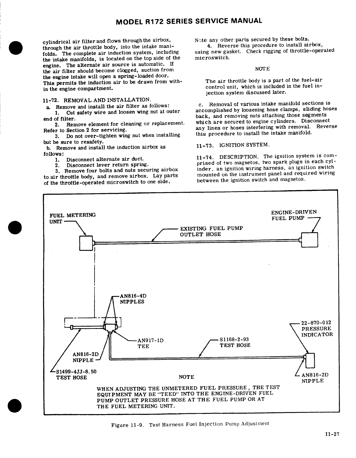
MODEL
R172
SERIES
SERVICE MANUAL
cylindrical
air
filter
and
flows
through
the
airbox,
N.,te any
other
parts
secured
by
these
bolts.
through
the
air throttle
body,
into
the
intake
mani-
4.
Reverse
this
procedure
to
install
airbox,
folds.
The
complete
air
induction
system,
including
using
new
gasket.
Check
rigging
of
throttle-operated
the intake
manifolds,
is
located
on
the
top
side
of
the
microswitch.
engine.
The
alternate
air
source
is
automatic.
If
the
air
filter
should
become
clogged,
suction
from
NOTE
the engine intake
will
open
a
spring-loaded
door.
This
permits
the
induction
air
to be
drawn
from
with-
The
air
throttle
body
is
a
part
of
the
fuel-air
in
the
engine
compartment.
control
unit,
which
is
included
in
the
fuel
in-
jection
system discussed
later.
11-72.
REMOVAL
AND
INSTALLATION.
a.
Remove
and
install
the
air
filter
as
follows:
c.
Removal
of
various
intake
manifold
sections
is
1.
Cut
safety
wire
and
loosen
wing
nut
at
outer
accomplished
by
loosening
hose
clamps,
sliding
hoses
end
of
filter.
back,
and
removing
nuts
attaching.those
segments
2.
Remove
element
for
cleaning
or
replacement. which
are
secured
to
engine
cylinders.
Disconnect
Refer
to
Section
2
for servicing.
any
lines
or
hoses
interfering
with
removal.
Reverse
3.
Do
not
over-tighten
wing
nut
when
installing
this
procedure
to
install
the
intake manifold.
but
be
sure
to
resafety.
b.
Remove
and
install
the
induction airbox
as
11-73.
IGNITION
SYSTEM.
follows:
1.
Disconnect
alternate
air
duct.
11-74.
DESCRIPTION.
The
ignition
system
is
corn-
2.
Disconnect
lever
return
spring.
prised
of
two
magnetos,
two
spark
plugs
in
each
cyl-
3.
Remove
four
bolts
and
nuts
securing
airbox
inder,
an
ignition
wiring
harness,
an
ignition
switch
to
air
throttle
body,
and
remove
airbox.
Lay
parts
mounted
on
the
instrument
panel
and
required
wiring
of
the
throttle-operated
microswitch
to
one
side.
between
the
ignition
switch
and
magnetos.
FUEL
METERING
ENGINE-DRIVEN
UNIT-
FUEL
PUMP
EXISTING
FUEL
PUMP
OUTLET
HOSE
1I/
AN816-4D
--
PRESSURE
S1168-2-93
TEE
HOSE
AN816-2D
NIPPLE
-
S1499-4JJ-8.50
TEST
HOSE
NOTE
AN816-2D
NIPPLE
WHEN
ADJUSTING THE
UNMETERED
FUEL
PRESSURE,
THE
TEST
EQUIPMENT
MAY
BE
"TEED"
INTO
THE
ENGINE-DRIVEN
FUEL
PUMP OUTLET
PRESSURE
HOSE
AT
THE
FUEL
PUMP
OR
AT
THE FUEL
METERING
UNIT.
Figure
11-9.
Test
Harness
Fuel
Injection
Pump
Adjustment
11-27
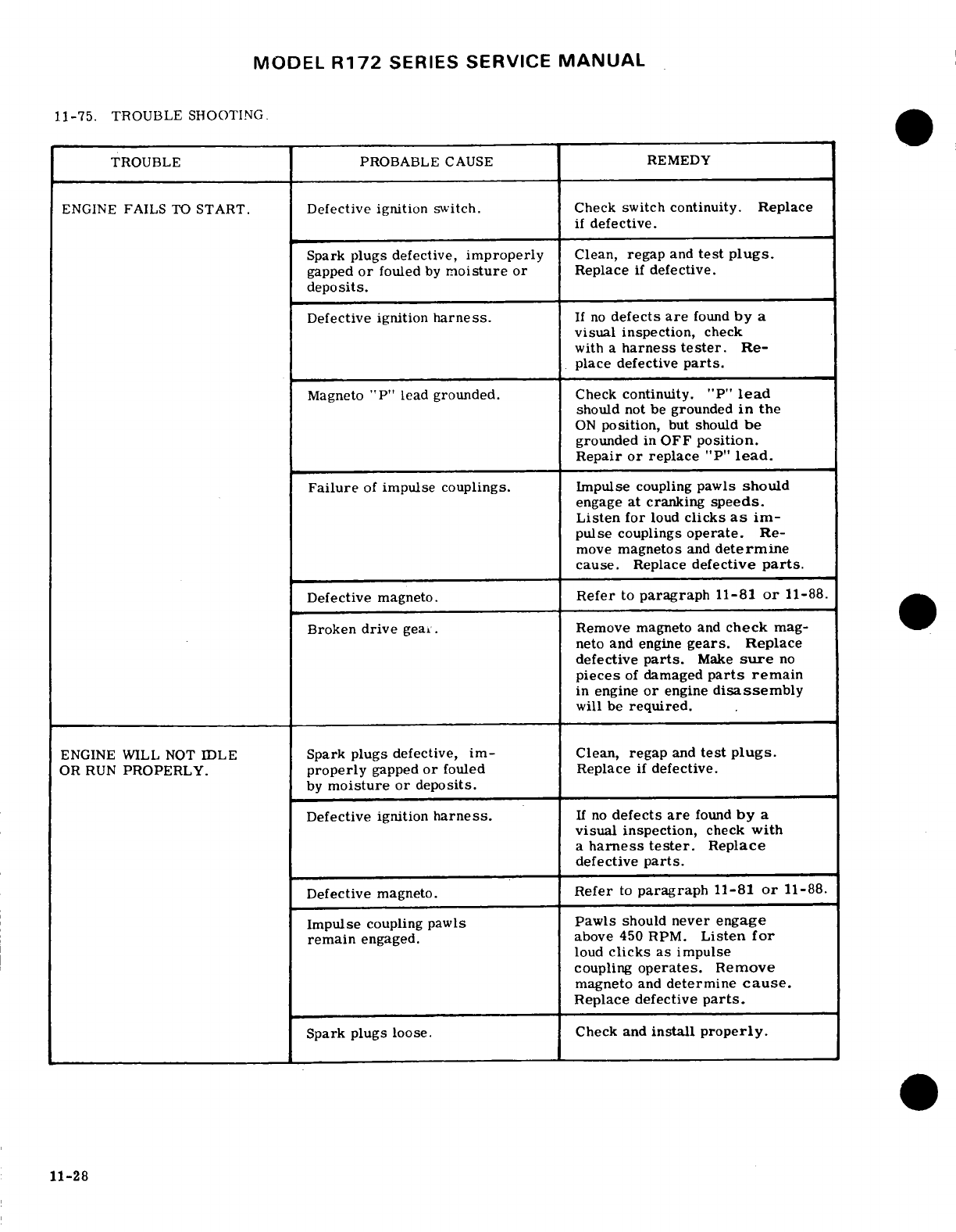
MODEL
R172
SERIES
SERVICE
MANUAL
11-75.
TROUBLE
SHOOTING.
TROUBLE
PROBABLE
CAUSE
REMEDY
ENGINE
FAILS
TO
START.
Defective
ignition
switch.
Check
switch
continuity.
Replace
if
defective.
Spark
plugs
defective,
improperly
Clean,
regap
and
test
plugs.
gapped
or
fouled
by
moisture
or
Replace
if
defective.
deposits.
Defective ignition
harness.
If
no
defects
are
found
by
a
visual
inspection,
check
with
a
harness
tester.
Re-
place
defective
parts.
Magneto
"P"
lead
grounded.
Check
continuity.
"P"
lead
should
not
be
grounded
in
the
ON
position,
but
should
be
grounded
in
OFF
position.
Repair
or
replace
"P"
lead.
Failure
of
impulse couplings. Impulse
coupling
pawls
should
engage
at
cranking
speeds.
Listen
for
loud
clicks
as
im-
pulse
couplings
operate.
Re-
move
magnetos
and
determine
cause.
Replace
defective
parts.
Defective
magneto.
Refer
to
paragraph
11-81
or
11-88.
Broken
drive
gear.
Remove magneto
and
check
mag-
neto
and engine
gears.
Replace
defective
parts.
Make
sure
no
pieces
of
damaged
parts
remain
in
engine
or
engine
disassembly
will
be
required.
ENGINE WILL
NOT
IDLE
Spark
plugs
defective,
im-
Clean,
regap
and
test
plugs.
OR
RUN
PROPERLY.
properly
gapped
or
fouled
Replace
if
defective.
by
moisture
or
deposits.
Defective ignition
harness.
If
no
defects
are
found
by
a
visual
inspection,
check
with
a
harness
tester.
Replace
defective
parts.
Defective
magneto.
Refer
to
paragraph
11-81
or
11-88.
Impulse
coupling
pawls
Pawls
should
never
engage
remain
engaged.
above
450 RPM.
Listen for
loud
clicks
as
impulse
coupling
operates.
Remove
magneto
and
determine
cause.
Replace defective
parts.
Spark
plugs
loose. Check
and
install
properly.
11-28
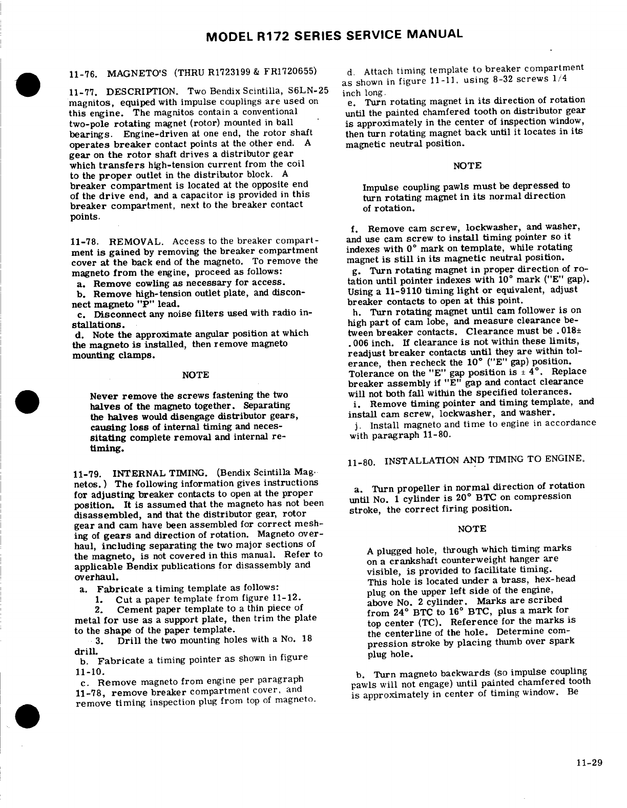
MODEL
R172
SERIES
SERVICE
MANUAL
11-76.
MAGNETO'S
(THRU
R1723199
&
FR1720655)
d.
Attach
timing template
to
breaker
compartment
as
shown
in
figure
11-11.
using
8-32
screws
1/4
11-77.
DESCRIPTION.
Two
Bendix
Scintilla,
S6LN-25
inch
long.
magnitos,
equiped
with
impulse
couplings
are
used
on e.
Turn
rotating
magnet
in
its
direction
of
rotation
this
engine.
The magnitos
contain
a
conventional
until
the
painted
chamfered
tooth
on
distributor
gear
two-pole
rotating
magnet
(rotor)
mounted
in
ball
is
approximately
in
the
center
of
inspection
window,
bearings.
Engine-driven
at
one
end,
the
rotor
shaft
then
turn
rotating
magnet
back
until
it
locates
in
its
operates
breaker
contact
points
at
the
other
end.
A
magnetic
neutral
position.
gear
on
the
rotor
shaft
drives
a
distributor
gear
which
transfers
high-tension
current
from
the
coil
NOTE
to
the
proper
outlet
in
the
distributor
block.
A
breaker
compartment
is
located
at
the
opposite
end
Impulse
coupling
pawls
must
be
depressed
to
of
the
drive
end,
and
a
capacitor
is
provided
in
this
un
oaing
mae
in
normal
direction
breaker
compartment,
next
to
the
breaker
contact
o
rotation.
points.
points.
of
rotation.
f.
Remove
cam
screw,
lockwasher,
and
washer,
11-78.
REMOVAL.
Access
to
the
breaker
compart-
and
use
cam
screw
to
install
timing pointer
so
it
ment
is
gained
by
removing
the
breaker
compartment
indexes with
0
°
mark
on
template,
while
rotating
cover
at
the
back
end
of
the
magneto.
To
remove
the
magnet
is
still
in
its
magnetic neutral
position.
magneto
from
the
engine,
proceed
as
follows:
g.
Turn
rotating
magnet
in
proper
direction
of
ro-
a.
Remove
cowling
as
necessary
for
access.
tation
until
pointer
indexes with
10°
mark
("E"
gap).
b.
Remove high-tension
outlet
plate,
and
discon-
Using
a
11-9110
timing
light
or
equivalent, adjust
nect
magneto
"P"
lead.
breaker
contacts
to
open
at
this
point.
c.
Disconnect
any
noise
filters
used
with
radio
in-
h.
Turn
rotating
magnet
until
cam
follower
is
on
stallations.
high
part
of
cam
lobe,
and
measure
clearance
be-
d.
Note
the
approximate angular
position
at
which
tween
breaker
contacts.
Clearance
must
be
.018±
the
magneto
is
installed,
then
remove
magneto .006
inch.
If
clearance
is
not
within
these
limits,
mounting
clamps,
readjust
breaker
contacts
until
they
are
within
tol-
erance,
then
recheck
the
10
°
("E"
gap)
position.
NOTE
Tolerance
on
the "E"
gap
position
is
±
4
°.
Replace
breaker assembly
if
"E"
gap
and
contact
clearance
Never remove
the
screws
fastening
the
two
will
not
both
fall
within
the
specified
tolerances.
halves
of
the magneto
together.
Separating
i.
Remove
timing
pointer
and
timing
template,
and
the
halves
would
disengage
distributor gears, install
cam
screw, lockwasher,
and
washer.
causing
loss
of
internal
timing
and
neces-
j.
Install
magneto
and
time
to
engine
in
accordance
sitating
complete
removal
and
internal
re-
with
paragraph
11-80.
timing.
11-80.
INSTALLATION
AND
TIMING
TO
ENGINE.
11-79.
INTERNAL
TIMING.
(Bendix
Scintilla
Mag.
netos.
)
The
following
information
gives
instructions
for
adjusting
breaker
contacts
to
open at
the
proper
a.
Turn
propeller
in
normal
direction
of
rotation
position.
It is
assumed
that
the
magneto has
not
been
until
No.
1
cylinder
is
20
°
BTC
on
compression
disassembled,
and
that
the
distributor
gear,
rotor
stroke,
the
correct
firing
position.
gear
and
cam
have
been
assembled
for
correct
mesh-
ing
of
gears
and
direction
of
rotation.
Magneto
over-
NOTE
haul,
including
separating
the
two
major
sections
of
the
magneto,
is
not
covered in
this
manual.
Refer
to
A
plugged
hole,
through
which
timing
marks
applicable
Bendix
publications
for disassembly
and
on
a
crankshaft
counterweight
hanger
are
overhaul. visible,
is
provided
to
facilitate
timing.
a.
Fabricate
a
timing
template
as
follows:
T
This
hole
is
located
under
a
brass,
hex-head
1.
Cut
a paper
template
from
figure
11-12.
plug
on
the
upper
left
side
of
the
engine,
2.
Cement
paper
template
to
a
thin
piece
of
above
No.
2
cylinder. Marks
are
scribed
metal
for
use
as
a
support
plate,
then
trim
the
plate
from
24°
BTC
to
16
BTC,
plus
a
mark
for
to
the
shape
of
the
paper
template.
top
center
(TC).
Reference
for
the
marks
is
3.
Drill
the
two
mounting
holes
with
a
No.
18
the
centerlneofthe
hole. Determine
com-
dril.
pression
stroke
by
placing
thumb
over
spark
b.
Fabricate
a
timing
pointer
as
shown in
figure
plug
hole.
11-10.
c.
Remove
magneto
from
engine
per
paragraph
b.
Turn
magneto
backwards
(so
impulse
coupling
11-78,
remove
breaker
compartment
cover,
and
pawls
will
not
engage)
until
painted chamfered
tooth
remove timing
inspection
plug
from
top
of
magneto.
is
approximately
in
center
of
timing
window.
Be
11-29
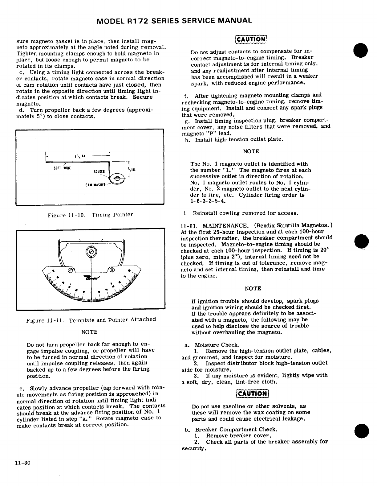
MODEL
R172
SERIES
SERVICE
MANUAL
sure
magneto
gasket
is
in
place,
then
install
mag-
CAUTION
neto
approximately
at
the
angle
noted
during
removal.
Tighten mounting
clamps
enough
to
hold
magneto
in
Do
not
adjust
contacts
to
compensate
for
in-
place,
but
loose
enough to
permit
magneto
to
be
correct
magneto-to-engine timing. Breaker
rotated
in
its
clamps.
contact
adjustment
is
for
internal
timing
only,
c.
Using
a
timing
light
connected
across
the break-
and
any
readjustment
after
internal
timing
er
contacts,
rotate
magneto
case
in
normal
direction
has
been
accomplished
will
result
in
a
weaker
of
cam
rotation
until
contacts
have
just
closed,
then
spark,
with
reduced
engine
performance.
rotate
in the
opposite
direction
until
timing
light
in-
dicates
position
at
which
contacts
break.
Secure
f.
After
tightening
magneto mounting
clamps
and
magneto.
rechecking
magneto-to-engine
timing,
remove
tim-
d.
Turn
propeller
back
a
few
degrees (approxi-
ing
equipment.
Install
and
connect
any
spark
plugs
mately
5
°
) to
close
contacts.
that
were
removed.
g.
Install
timing
inspection
plug,
breaker
compart-
ment
cover,
any
noise
filters
that
were
removed,
and
magneto
"P"
lead.
h.
Install high-tension
outlet
plate.
NOTE
The
No.
1
magneto
outlet
is
identified
with
the
number
"1."
The
magneto
fires
at
each
successive
outlet
in
direction
of
rotation.
CAN
No.
1
magneto
outlet
routes
to
No.
1
cylin-
der,
No.
2
magneto
outlet
to
the next cylin-
der
to
fire,
etc.
Cylinder
firing order
is
11-10. Timing
Pointer
.
Reinstall
cowling
removed
for
access.
11-81.
MAINTENANCE.
(Bendix
Scintilla
Magnetos.)
At
the
first
25-hour
inspection
and
at
each
100-hour
inspection
thereafter,
the
breaker
compartment
should
be
inspected.
Magneto-to-engine
timing
should
be
checked
at
each
100-hour
inspection.
If
timing
is
20
°
(plus
zero,
minus
2°),
internal
timing
need
not
be
checked.
If
timing
is
out
of
tolerance,
remove
mag-
-<.
neto
and
set
internal
timing, then
reinstall
and
time
,
the
engine.
NOTE
If
ignition trouble
should develop,
spark
plugs
and
ignition
wiring
should
be
checked
first.
If
the
trouble
appears
definitely
to
be
associ-
Figure
11-11.
Template
and
Pointer Attached
ated
with
a
magneto,
the
following
may
be
used
to help
disclose
the
source
of
trouble
NOTE
without
overhauling
the
magneto.
Do
not
turn
propeller
back
far
enough
to
en-
a.
Moisture
Check.
gage
impulse
coupling,
or
propeller
will
have
1.
Remove
the
high-tension
outlet plate,
cables,
to be
turned
in
normal
direction
of
rotation
and
grommet,
and
inspect
for
moisture.
until
impulse
coupling
releases,
then
again
2.
Inspect
distributor
block
high-tension
outlet
backed
up
to
a
few
degrees
before
the
firing
side for
moisture.
position.
3.
If
any
moisture
is
evident, lightly
wipe
with
a
soft,
dry,
clean,
lint-free
cloth.
e.
Slowly
advance
propeller
(tap
forward
with
min-
ute
movements
as
firing
position
is
approached)
in
CAT
normal
direction
of
rotation
until
timing
light
indi-
cates
position
at
which
contacts
break.
The
contacts
Do
not
use
gasoline
or other solvents,
as
should
break
at
the
advance
firing
position
of
No.
1
these
will
remove
the
wax
coating
on
some
cylinder
listed
in
step
"a."
Rotate
magneto
case
to
parts
and
could
cause
electrical
leakage.
make
contacts
break
at correct
position.
b.
Breaker
Compartment
Check.
1.
Remove
breaker
cover.
2.
Check
all
parts
of
the
breaker
assembly
for
security.
11-30
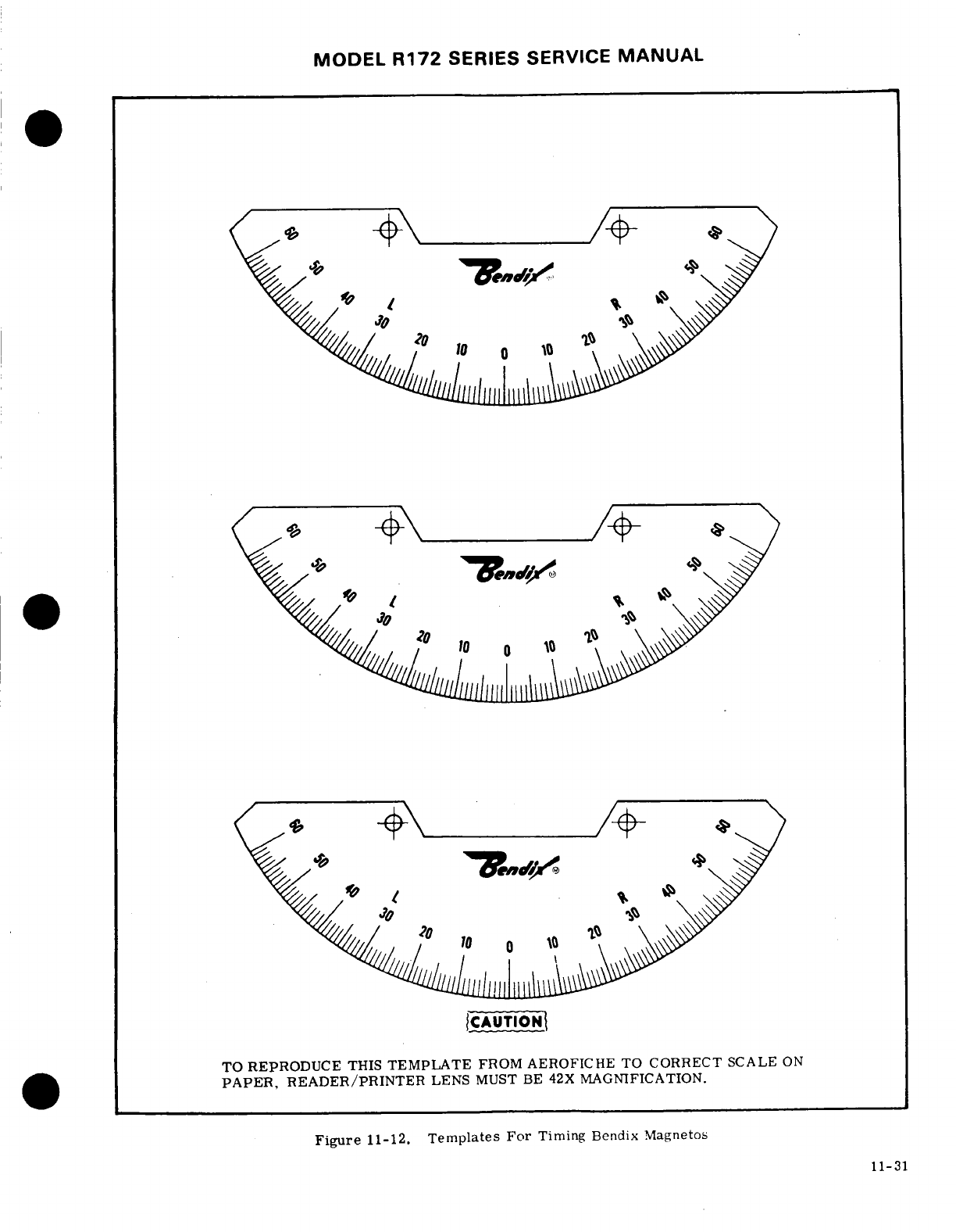
MODEL
R172
SERIES
SERVICE
MANUAL
CAUTION
TO REPRODUCE
THIS
TEMPLATE
FROM
AEROFICHE
TO
CORRECT
SCALE
ON
PAPER,
READER/PRINTER
LENS
MUST BE
42X
MAGNIFICATION.
Figure
11-12.
Templates
For
Timing
Bendix
Magnetos
11-31
11-31
MODEL
R172
SERIES SERVICE
MANUAL
3.
Check
breaker
contacts
for
excessive
wear,
or
a
magneto
out
of
time.
If
there
is
doubt
concerning
burning,
deep
pits,
and
carbon
deposits. Contacts
operation
of
the
ignition
system.
RPM
checks
at
a
may
be
cleaned
with
a
hard-finish
paper. Replace
leaner
mixture
setting
or
a
higher
engine
speeds
will
defective
breaker
assemblies.
Make
no
attempt
to
usually
confirm
whether
a
deficiency
exists.
stone
or
dress
contacts.
Clean
new
contacts
with
clear,
unleaded
gasoline
and
hard-finish
paper
before
NOTE
installing.
4.
Check
cam
follower
oiling
felt.
If
it
appears
An
absence
of
RPM
drop
may
be an
indication
dry,
re-oil
with
2
or
3
drops
of
lubricant
(Scintilla
of
faulty
grounding
of
one
side
of
the ignition
10
86527,
or
equivalent).
Allow
about
30
minutes
system,
a
disconnected
ground
lead
at
mag-
for
the
felt
to
absorb
the
oil,
then
blot
off
excess
neto
or
possibly
the magneto timing
is
set
too
with
a
clean
cloth.
Too
much
oil
may
result
in
foul-
far
in
advance.
icr
and
excessive
burning
of
contacts.
5.
Check
that
the
condenser
mounting
bracket
11-83.
MAGNETO'S
(BEGINNING
WITH
R1723200
is not
cracked or
loose.
If
equipment
is
available,
&
FR1720656)
check
condenser
for
a
minimum
capacitance
of
.30
microfarads.
If
equipment
for
testing
is
not
avail-
11-84.
DESCRIPTION.
Two
Slick
6214
Magnitos,
.able
and
a
defective
condenser
is
suspected, replace
equiped
with
impulse
couplings
are
used
on
this
engine.
with
a
new
one.
The
magnitos
incorporate
an
integral feed-thru
c.
If
the
trouble
has
not
been
corrected after
ac-
capacitor
and
require
no
external
noise
filter
in
the
complishing
steps
"a"
and "b,
"
check
magneto-to-
ground
lead.
The
direction
of
rotation
of
the
magnito
engine
timing.
If
timing
is
not
within
prescribed
shafts,
viewed
from
the
anti-propeller
end
of
engine,
is
tolerance,
remove
magneto
and
set
internal
timing, clockwise.
Refer
to
Slick 4200/6200
Series
Aircraft
tien reinstall
and
time
to
the
engine.
Magnetos Maintenance
and
Overhaul
Instructions
d.
If
the
trouble
has
still
not
been
corrected,
mag-
Bulletin.
and
all
revisions
and
supplements
thereto,
Ireto
overhaul
or
replacement
is
indicated.
for
a
detailed
description, disassembly
and
reassem-
bly
of
the
magneto.
11-82
MAGNETO
CHECK.
Advanced
timing
set-
fings
in
some
cases,
is
the
result
of
the
erroneous-.
MVAL.
practice
of
bumping
magnetos
up
in
timing
in
order
WARNING
tn
reduce
RPM
drop
on
single ignition.
NEVER
AD-
VANCE TIMING BEYOND
SPECIFICATIONS
IN
OR-
DER
TO
REDUCE
RPM
DROP.
Too
much
importance
The
mgneto
is in
a
SWITCH
ON
condition
is
being
attached
to
RPM
drop
on
single
ignition.
whe
the
swtch
wre
s
disconnected.
RPM
drop
on
single
ignition
is
a
natural
character-
Therefore,
ground
the
breaker
contact
,stic
of
dual
ignition design.
The
purpose
of
the
fol-
poits
or
disconnect
the
high-tension wires
lowing
magneto
check
is
to
determine
that
all
cyl-
from
the
magneto
or
the
spark
plugs.
inders
are
firing.
If
all
cylinders
are
not
firing,
the
engine
will
run
extremely
rough
and
cause
for
investi-
a
Remove engine
cowling
in
accordance
with
para-
gation
will
be
quite
apparent.
The
amount
of
RPM
graph
11-3.
drop
is
not
necessarily
significant
and
will
be
influ-
b.
Remove
screws
securing
the
high-tension
outlet
cniced
by
ambient
air
temperature,
humidity,
airport
cover
to
the
magneto.
The
"P"
leads
may
be
discon-
;ltitude,
etc.
In
fact,
absence
of
RPM
drop
should
nected
for
additional
clearance
if
necessary.
hb
cause
for
suspicion
that the
magneto
timing
has
b'oen
bumped
up
and
is
set
in
advance
of
the
setting
NOTE
specified.
Magneto
checks
should
be
performed
on
a
c'onparative
basis
between
individual
right
and
left
It
is
a
good
practice
to
position
No.
1
m.ligneto
performance. cylinder
at
its
approximate
advance
i.
Start
and
run
engine
until
the
oil
and
cylinder
firing
position
before
removing
the
head
temperature
is
in
the
normal operating
range.
magneto.
b.
Place
the
propeller
control
in
the
full
low
pitch
(high
RPM)
position.
c.
Remove
nuts,
washers
and
clamps
attaching the
c.
Advance
engine
speed
to
1800 RPM.
magneto
to
the
engine
accessory
housing.
Note
the
d.
Turn
the
ignition
switch
to
the
"R"
position
and
approximate angular
position
at
which
the
magneto
note the
RPM
drop,
then
return
the
switch
to
the
is
installed,
then
remove
the
magneto.
"BOTH"
position
to
clear
the
opposite
set
of
plugs.
e.
Turn
the
switch
to
the
"L"
position
and
note
the
11-86.
INTERNAL
TIMING.
(MAGNETO
REMOVED
RPM
drop,
then
return
the
switch
to
the
"BOTH"
FROM
ENGINE.)
Refer
to
Slick
4200/6200
Series
position.
Aircraft
Magnetos Maintenance
and
Overhaul
Instruc-
f.
The
RPM
drop
should
not
exceed
150
RPM
on
tions
Bulletin,
and
all
revisions
and
supplements
either
magneto
or
show
greater
than
50
RPM
differ-
thereto,
for
internal
timing
instructions.
ential
between
magnetos.
A
smooth
RPM
drop-off
past
normal
is
usually
a
sign
of
a
too
lean
or
too
rich
mixture.
A
sharp
RPM
drop-off
past
normal
is
usu-
ally
a
sign
of
a
fouled
plug,
a
defective
harness
lead
11-32
MODEL
R172
SERIES
SERVICE
MANUAL
11-87.
INSTALLATION
AND
TIMING
TO
ENGINE.
11-90.
SPARK
PLUGS.
Two
spark
plugs
are
in-
After
100
hours
of
operation
and
every
100
hours
stalled
in
each
cylinder
and
screw
into
helicoil
type
thereafter.
or
at
annual inspection,
whichever
comes
thread
inserts.
The
spark
plugs
are
shielded
to
pre-
first,
the
magneto-to-engine
timing
should
be
checked.
vent
spark
plug
noise
in the
radios
and
have
an
inter-
This
is
accomplished
in
the
following
manner:
nal
resistor
to
provide
longer
terminal
life.
Spark
a.
Reverse
the
removal
steps
for
reinstallation.
plug
service
life
will
vary
with
operating
conditions.
A
spark
plug
that
is
kept
clean
and
properly
gapped
will
give
better
and
longer
service
than
one
that
is
Magneto
(primary
lead
nut
torque
range
is
allowed
to collect
lead
deposits
and
is
improperly
13-15
inch-pounds.
Exceeding
this
torque
gapped.
range
could
result
in
possible
condenser
damage.
NOTE
WARNING
Refer
to Section
2
for
inspection
interval.
Be sure switch is
in
"OFF"
position
and the
ch
inspection, remove,
clean,
inspect
"P"
lead
is
grounded.
and
regap
all
plugs,
Install
lower
spark
lead is grounded.
plugs
in
upper portion
of
cylinders
and
in-
stall
upper
spark
plugs
in
lower
portion
of
b.
Turn
the
engine
crankshaft
in
the
normal
direc-
stall
upper
spark
plugs
in
lower
portion
of
tion
of
rotation
until
the
No.
1
cylinder
is
in
the
full-
cylinders.
Since
dey
meoration
of
lower
advance
firing
position,
following
the
engine
manu-
of
the
upper
spark
plugs,
rotating
helps
facturer's
procedure
for
timing
of
magnetos.
of
the
spark
plugng
helps
c.
Loosen
the
magneto
mounting
bolts,
and
connect
prolong
spark
plug
fe
a
standard
timing
light
between engine
ground
and
the
magneto
condenser terminal.
11-91.
ENGINE
CONTROLS.
NOTE
11-92.
DESCRIPTION.
The
throttle, mixture
and
propeller
controls
are
of
the
push-pull
type.
The
Switch
must
be
"ON".
propeller
and
mixture
controls
are
equipped
to
lock
in
any
position
desired.
To
move the
control,
the
c.
Rotate
the
complete
magneto
opposite
normal
spring-loaded
button, located
in
the
end of
the
control
rotation
of
the magneto
on
the
engine
mounting,
until
knob,
must
be
depressed.
When
the
button
is
released,
the
timing
light indicates
the
contact
breaker
points
the
control
is
locked.
The
propeller
and
mixture
con-
are
just
opening.
Secure
the
magneto
in
this
position.
trols
also
have a
vernier
adjustment.
Turning
the
control
knob
in
either
direction
will change
the
con-
WARNING
trol
setting.
The
vernier
is
primarily
for
precision
control
setting.
The
throttle control
has
neither
a
During
all
magneto
maintenance,
always
locking
button nor
a
vernier
adjustment,
but
contains
take
proper
precautions
to
make
sure
the
a
knurled
friction
knob
which
is
rotated
for
more
or
engine
can
not
fire
or
start
when
the
pro-
less
friction
as
desired.
The
friction
knob
prevents
peler
is
moved.
TURN SWITCH
"OFF".
vibration
induced
"creeping"
of
the
control.
An
addi-
tional
"Palnut"
type lockout
is
installed
in
back
of
the
locknut
at
the
engine
end
of
the
throttle,
mixture
and
11-88.
DISASSEMBLY,
INSPECTION,
AND
RE-
ASSEMBLY.
Refer to
Slick 4200/6200
Series
Aircraft
Magnitos
Maintenance
and
Overhaul
Instructions.
11-89.
MAGNETO
CHECK.
Refer
to
paragraph
11-82.
SHOP
NOTES:
Revision
1
11-33
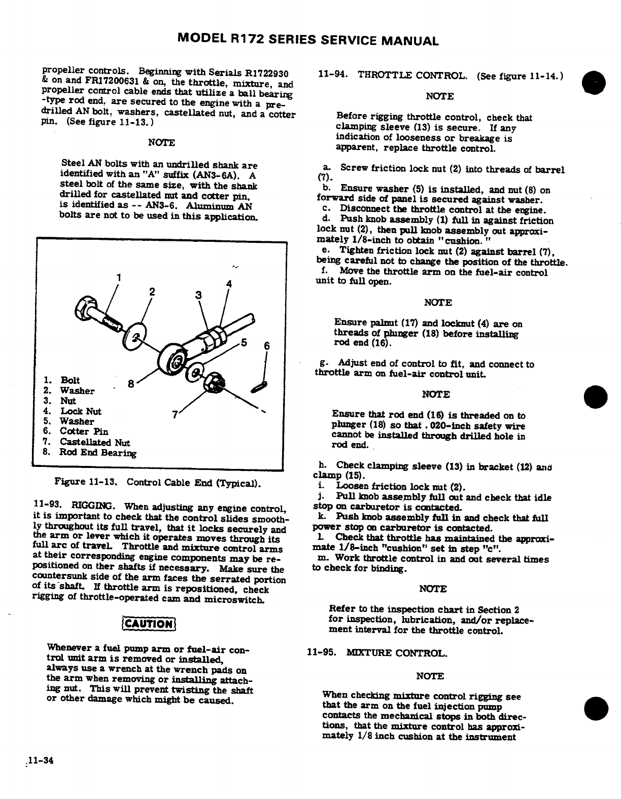
MODEL
R172
SERIES
SERVICE
MANUAL
propeller
controls.
Beginning
with
Serials
R1722930
11-94.
THROTTLE
CONTROL. (See
figure
11-14.)
&
on
and
FR17200631
&
on,
the
throttle,
mixture,
and
propeller
control
cable
ends
that
utilize
a
ball
bearing
NOTE
-type
rod
end,
are
secured
to
the
engine with
a
pre-
drilled
AN
bolt,
washers,
castellated
nut,
and
a
cotter
Before
rigging
throttle
control,
check
that
pin.
(See
figure
11-13.)
clamping
sleeve
(13)
is
secure.
If any
indication
of
looseness
or
breakage
is
NOTE
apparent,
replace
throttle
control.
Steel
AN
bolts
with an
undrilled
shank
are
a.
Screw
friction
lock
nut
(2)
into
threads
of
barrel
identified with
an
"A"
suffix
(AN3-6A).
A
(7).
steel
bolt
of
the
same
size, with
the
shank
b.
Ensure
washer
(5)
is
installed,
and nut
(8)
on
drilled
for
castellated
nut
and
cotter
pin,
forward
side
of
panel
is
secured
against
washer.
is
identified
as
--
AN3-6.
Aluminum
AN
c.
Disconnect
the
throttle
control
at
the
engine.
bolts
are
not
to
be
used
in
this
application.
d.
Push
knob
assembly
(1)
full
in
against
friction
lock
nut
(2),
then
pull
knob
assembly
out
approxi-
mately
1/8-inch
to
obtain
"cushion."
e.
Tighten
friction
lock
nut
(2)
against
barrel
(7),
being
careful
not
to
change
the
position
of
the
throttle.
I
f.
Move
the
throttle
arm
on
the
fuel-air
control
unit
to
full
open.
NOTE
Ensure
palnut
(17)
and
locknut
(4)
are
on
threads
of
plunger
(18)
before
installing
rod
end
(16).
g.
Adjust
end
of
control
to
fit,
and
connect
to
throttle
arm
on
fuel-air
control
unit.
1.
Bolt
8
2.
Washer
NOTE
3.
Nut
4.
LockNut
Ensure
that
rod
end
(16)
is
threaded
on
to
5.
Washer
plunger
(18)
so
that.
020-inch
safety
wire
6.
Cotter
Pin cannot
be
installed
through
drilled
hole
in
7.
Castellated
Nut
rod
end.
8.
Rod
End
Bearing
h.
Check
clamping
sleeve
(13)
in
bracket
(12)
and
clamp
(15).
Figure
11-13.
Control
Cable
End
(Typical).
i.
Loosen
friction
lock
nut
(2).
j.
Pull
knob
assembly
full
out
and
check
that
idle
11-93.
RIGGING.
When
adjusting
any engine
control,
stop
on
carburetor
is
contacted.
it
is
important
to
check that
the
control
slides
smooth-
k.
Push
knob
assembly
full
i
and
check
that
full
ly
throughout
its
full
travel,
that
it
locks
securely
and
power
stop
on
carburetor
is
contacted.
the
arm
or
lever
which
it
operates
moves
through
its
L
Check
that
throttle
has
maintained
the
approxi-
full
arc
of
traveL
Throttle
and
mixture
control
arms
mate
1/8-inch
"cushion"
set
in
step
"c".
at
their
corresponding
engine
components may
be
re-
m.
Work
throttle control
in
and
out
several
times
positioned
on
ther
shafts
if
necessary.
Make
sure
the
to
check
for
binding.
countersunk
side
of
the
arm
faces
the
serrated
portion
of
its
shaft.
If
throttle
arm
is repositioned,
check
NOTE
rigging
of
throttle-operated
cam
and
microswitch.
Refer
to
the
inspection
chart
in
Section
2
for
inspection,
lubrication,
and/or
replace-
CAUTION
ment
interval
for
the
throttle
control.
Whenever
a
fuel
pump
arm or
fuel-air
con-
11-95.
MIXTURE
CONTROL.
trol
unit
arm
is
removed
or
installed,
always
use
a
wrench
at
the
wrench
pads
on
NOTE
the
arm
when
removing
or
installing
attach-
ing nut.
This
will
prevent
twisting
the
shaft
When
checking
mixture
control rigging
see
or other
damage
which
might
be
caused.
that
the
arm
on
the
fuel
injection
pump
contacts
the
mechanical
stops
in
both
direc-
tions,
that
the
mixture
control
has approxi-
mately
1/8
inch
cushion
at
the
instrument
.11-34
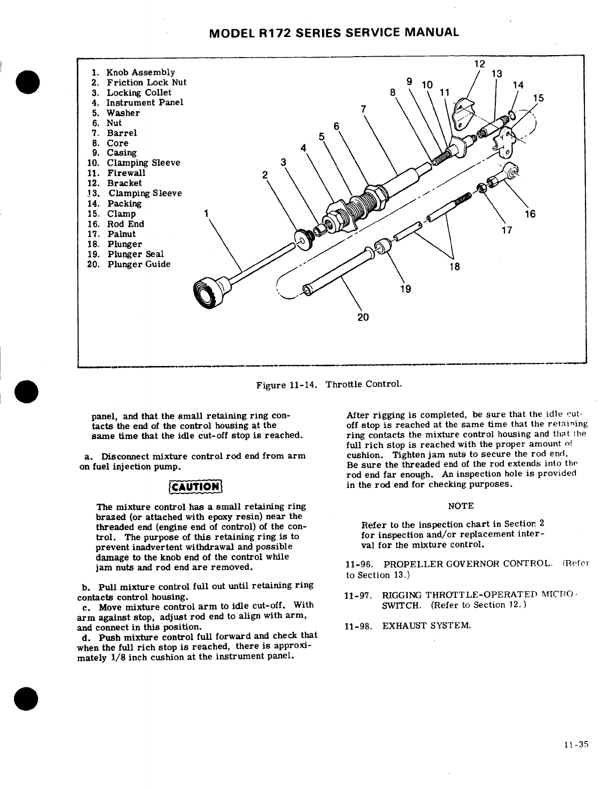
MODEL
R172
SERIES SERVICE
MANUAL
12
1.
Knob
Assembly
13
2.
Friction
Lock
Nut
9
10
14
3.
Locking
Collet
8
4.
Instrument Panel
15
5.
Washer
7
6.
Nut
7.
Barrel
8.
Core
9.
Casing
4
10.
Clamping
Sleeve
3
11.
Firewall
2
12.
Bracket
13.
Clamping
Sleeve
14.
Packing
15.
Clamp
1 16
16.
Rod
End
17.
Palnut
.--
17
18.
Plunger
19.
Plunger
Seal
20.
Plunger
Guide
18
19
20
Figure
11-14.
Throttle
Control.
panel,
and
that
the
small
retaining
ring
con-
After
rigging
is
completed,
be
sure
that
the
idle
cut-
tacts
the
end
of
the
control
housing
at
the
off
stop
is
reached at
the
same
time
that
the
retaining
same
time that
the
idle
cut-off
stop
is
reached.
ring
contacts
the
mixture control
housing
and
that
the
full
rich
stop
is
reached
with
the
proper
amount
of
a.
Disconnect
mixture
control
rod
end
from
arm
cushion.
Tighten
jam
nuts
to
secure
the
rod
end.
on
fuel
injection
pump.
Be
sure
the
threaded
end
of
the
rod
extends
into
the
rod
end
far
enough.
An
inspection
hole
is
provided
CAUTION
in
the
rod
end
for
checking
purposes.
The
mixture
control
has
a
small
retaining
ring
NOTE
brazed
(or
attached
with
epoxy
resin)
near
the
threaded
end
(engine
end
of
control)
of
the
con-
Refer
to
the
inspection
chart
in
Section
2
trol.
The
purpose
of
this
retaining
ring
is
to
for
inspection
and/or
replacement
inter-
prevent
inadvertent
withdrawal
and
possible
val
for
the
mixture
control.
damage
to
the knob
end
of
the
control
while
jam nuts
and
rod
end
are
removed.
11-96.
PROPELLER
GOVERNOR
CONTROL.
(Refer
to
Section
13.)
b.
Pull
mixture
control
full
out
until
retaining
ring
contacts
control
housing.
11-97.
RIGGING
THROTTLE-OPERATED
MICRO-
c.
Move
mixture control
arm
to
idle
cut-off.
With
SWITCH.
(Refer
to
Section
12.)
arm
against
stop,
adjust
rod
end
to
align
with
arm,
and
connect
in
this
position.
11-98.
EXHAUST SYSTEM.
d.
Push
mixture control full
forward
and check
that
when
the full
rich
stop
is
reached,
there
is
approxi-
mately
1/8
inch
cushion
at
the
instrument
panel.
11-35
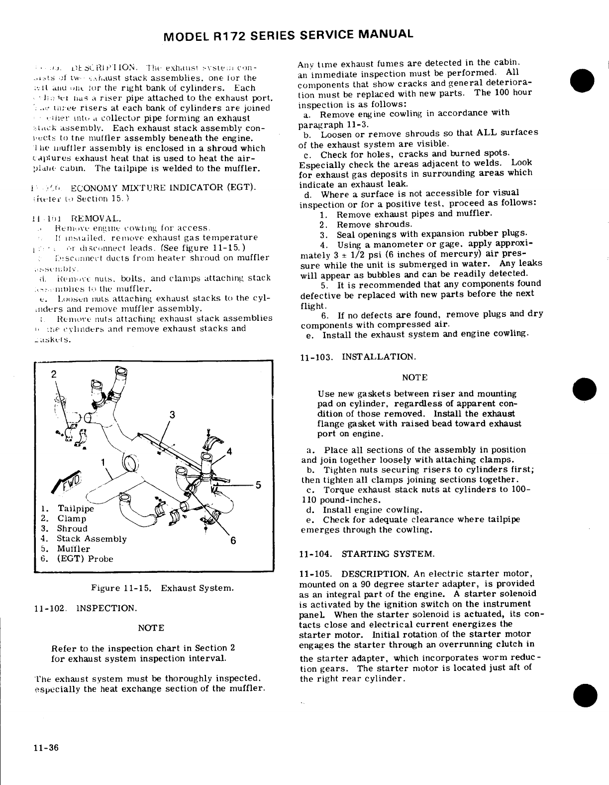
MODEL
R172
SERIES SERVICE
MANUAL
11-109.
DESCRIPTION.
The
exhaust
system
con-
Any
time exhaust
fumes
are
detected
in
the cabin.
trols
of
two
exhaust
stack
assemblies.
one
for
the
an
immediate inspection
must
be
performed.
All
and
the
for
the
right
bank
of
cylinders.
Each
components
that
show
cracks
and
general
deteriora-
heater
has
a
riser
pipe
attached
to
the
exhaust
port.
tion
must
be
replaced
with
new
parts.
The
100
hour
three
risers
at
each
bank
of
cylinders
are
joined
inspection
is
as
follows:
other
into
a
collector
pipe
forming
an
exhaust
a. Remove engine
cowling
in
accordance
with
stack
assembly.
Each
exhaust
stack
assembly
con-
paragraph
11-3.
tacts
to
the
mufler
assembly
beneath
the engine.
b.
Loosen
or
remove
shrouds
so
that
ALL
surfaces
The
muffler
assembly
is
enclosed
in a
shroud
which
of
the
exhaust
system
are
visible.
captures
exhaust
heat
that
is
used
to
heat
the
air-
c.
Check
for
holes,
cracks
and
burned
spots.
plane
cabin.
The
tailpipe
is
welded
to
the
muffler.
Especially
check
the
areas
adjacent
to
welds.
Look
for
exhaust
gas
deposits
in
surrounding
areas
which
11-100.
ECONOMY
MIXTURE
INDICATOR
(EGT).
indicate
an
exhaust
leak.
(Refere
to
Section
15.
)
d.
Where
a
surface
is
not
accessible
for
visual
inspection
or for
a
positive
test,
proceed
as
follows:
11-101
REMOVAL.
1.
Remove
exhaust pipes
and
muffler.
Remove
engine
cowling
for
access.
2.
Remove
shrouds.
Is
installed.
remove
exhaust
gas
temperature
3.
Seal
openings
with
expansion
rubber
plugs.
or
disconnect
leads.
(See
figure
11-15.)
4.
Using
a
manometer
or
gage,
apply
approxi-
disconnect
ducts
from
heater
shroud
on
muffler
mately
3 ±
1/2
psi
(6
inches
of
mercury)
air
pres-
assembly.
sure
while the
unit
is
submerged
in
water.
Any
leaks
d.
Revome
nuts,
bolts,
and
clamps
attaching
stack
will
appear
as
bubbles
and
can
be
readily
detected.
reassemblies
to
the
muffler.
5.
It
is
recommended
that
any
components
found
e.
Loosen
nuts
attaching exhaust
stacks
to
the
cyl-
defective
be
replaced
with
new
parts
before
the
next
inders
and
remove
muffler
assembly.
flight.
f.
Remove
nuts
attaching
exhaust
stack
assemblies
6.
If
no
defects
are
found,
remove
plugs
and
dry
in the
cylinders
and
remove
exhaust
stacks
and
components
with
compressed
air.
gaskets.
e.
Install
the
exhaust system
and
engine
cowling.
11-103.
INSTALLATION.
NOTE
Use
new
gaskets
between
riser
and
mounting
on
cylinder,
regardless
of
apparent
con-
dition
of
those
removed.
Install
the
exhaust
flange
gasket
with
raised
bead
toward
exhaust
..
port
on
engine.
,
a.
Place
all
sections
of
the
assembly
in
position
and
join
together
loosely
with
attaching
clamps.
b.
Tighten nuts
securing
risers
to
cylinders
first;
then
tighten
all
clamps
joining
sections
together.
c.
Torque
exhaust
stack
nuts
at
cylinders
to
100-
110
pound-inches.
1.
Tailpipe
d.
Install
engine cowling.
2.
Clamp
e.
Check
for
adequate
clearance
where tailpipe
3.
Shroud
emerges
through
the cowling.
4.
Stack
Assembly
5.
Muffler
6.
(EGT)
Probe
11-104.
STARTING
SYSTEM.
11-105.
DESCRIPTION.
An
electric
starter
motor,
Figure
11-15.
Exhaust System.
mounted
on
a
90
degree
starter
adapter,
is
provided
as
an
integral
part
of
the
engine.
A
starter
solenoid
11-102.
INSPECTION.
is
activated
by
the
ignition
switch
on
the
instrument
panel.
When
the
starter
solenoid
is actuated,
its
con-
NOTE
tacts
close
and
electrical
current
energizes
the
starter
motor.
Initial
rotation
of
the
starter
motor
Refer
to
the
inspection
chart
in
Section
2
engages
the
starter
through
an
overrunning
clutch
in
for
exhaust
system
inspection
interval.
the
starter
adapter,
which
incorporates
worm
reduc-
tion
gears.
The
starter
motor
is
located
just
aft
of
The
exhaust
system
must
be
thoroughly
inspected.
the
right
rear
cylinder.
especially
the
heat
exchange
section
of
the
muffler.
11-36
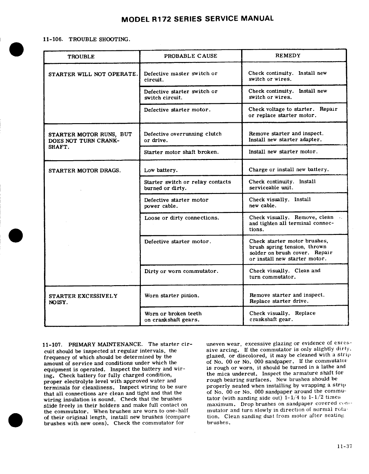
MODEL
R172
SERIES SERVICE
MANUAL
11-106.
TROUBLE
SHOOTING.
TROUBLE
PROBABLE
CAUSE
REMEDY
STARTER
WILL
NOT
OPERATE.
Defective
master
switch
or
Check
continuity.
Install
new
circuit.
switch
or
wires.
Defective
starter
switch
or
Check
continuity.
Install
new
switch
circuit.
switch
or
wires.
Defective
starter
motor.
Check
voltage
to
starter.
Repair
or
replace
starter
motor.
STARTER
MOTOR
RUNS,
BUT
Defective
overrunning
clutch
Remove
starter
and
inspect.
DOES
NOT
TURN CRANK-
or
drive.
Install
new
starter
adapter.
SHAFT.
Starter
motor
shaft
broken.
Install
new
starter
motor.
STARTER
MOTOR
DRAGS.
Low
battery.
Charge
or
install
new
battery.
Starter
switch
or
relay
contacts
Check
continuity.
Install
burned
or
dirty.
serviceable
unit.
Defective
starter
motor
Check
visually.
Install
power
cable.
new
cable.
Loose
or
dirty
connections.
Check
visually.
Remove,
clean
and
tighten
all
terminal
connec-
tions.
Defective
starter
motor.
Check
starter
motor
brushes,
brush
spring
tension,
thrown
solder
on
brush
cover. Repair
or
install
new
starter
motor.
Dirty
or
worn
commutator.
Check
visually.
Clean
and
turn
commutator.
STARTER
EXCESSIVELY
Worn
starter
pinion.
Remove
starter
and
inspect.
NOISY.
Replace
starter
drive.
Worn
or
broken
teeth
Check
visually.
Replace
on
crankshaft
gears.
crankshaft
gear.
11-107.
PRIMARY
MAINTENANCE.
The
starter cir-
uneven
wear,
excessive
glazing
or
evidence
of
exccs-
cult
should
be
inspected
at
regular
intervals,
the
sive
arcing.
If
the
commutator
is
only
slightly
dirty,
frequency
of
which
should
be
determined
by
the
glazed,
or
discolored,
it
may
be
cleaned
with
a
strip
amount
of
service
and
conditions
under
which
the
of
No.
00
or
No.
000
sandpaper.
If
the
commutator
equipment
is operated.
Inspect
the
battery
and
wir-
is
rough
or
worn,
it
should
be
turned
in
a
lathe
and
ing.
Check
battery for
fully
charged
condition,
the mica
undercut.
Inspect
the
armature
shaft
for
proper
electrolyte
level
with
approved
water
and
rough
bearing
surfaces.
New
brushes
should
be
terminals
for
cleanliness.
Inspect
wiring
to be
sure
properly
seated
when
installing
by
wrapping
a
strip
that
all
connections
are
clean
and
tight
and
that
the
of
No.
00
or
No.
000
sandpaper
around
the
commu-
wiring
insulation is
sound. Check
that
the
brushes
tator
(with
sanding
side
out)
1-1/4
to
1-1/2
timne
slide
freely
in
their
holders
and
make
full
contact
on
maximum.
Drop
brushes
on
sandpaper
covered
c(tr:!-
the
commutator.
When
brushes are
worn
to
one-half
inutator
and
turn
slowly
in
direction
of
normal
rota-
of
their
original
length,
install
new
brushes
(compare tion.
Clean
sanding
dust
from
motor
after
seating
brushes
with
new
ones). Check the
commutator
for
brushes.
11-37
MODEL
R172
SERIES
SERVICE
MANUAL
11-108.
STARTER
MOTOR
11-109.
REMOVAL
AND
INSTALLATION.
WARNING
CAUTION
Do
not
heat
the
oil
above
121
0
C
(2500F).
A
flash
fire
may
result.
Before
pulling
the
When
disconnecting
on
connecting
the
starter
propeller
through,
ascertain
that
the
mag-
cable
do
not
permit
starter
terminal
bolt
to
neto
switch
is
in
the
OFF
position
to
pre-
rotate.
Rotation
of
the
terminal
bolt
could
vent
accidental
firing
of
the
engine.
break
the
conductor
between
terminal
bolt
and
field
coils
causing
the
starter
to be in-
CAUTION
operative.
Due
to
the
desludging
effect
of
the
diluted
oil.
a.
Disconnect
electrical
cable
from
starter
motor.
engine
operation
should
be
observed
closely
Insulate cable terminal
as
a
safety
precaution.
during
the
initial
warm-up
of
the
engine.
En-
b.
Remove
two
sets
of
nuts
and
washers
securing
gines
that
have
considerable
amount
of
opera-
motor
to
the
starter
adapter
and
pull motor
from
tional
hours
accumulated
since
their
last
dilu-
mounting
pad.
tion
period
may
be
seriously
affected
by
the
c.
To
install
the
starter
motor,
reverse
the
pre-
dilution
process.
This will
be
caused
by the
ceding
steps.
Install
a
new
O-ring
on
the
starter,
diluted
oil
dislodging
sludge
and
carbon
de-
then
install
to
starter
motor,
be
sure
that
starter
posits
within
the
engine.
This residue
will
motor
drive
engages
drive
in
the
starter
adapter.
collect
in
the
oil
sump
and
possibly
clog
the
screened
inlet
to
the
oil
pump.
Small
deposits
11-110.
EXTREME
WEATHER
MAINTENANCE.
may
actually
enter
the
oil
pump
and
be
trapped
by
the
main
oil
filter
screen.
Partial
or
com-
NOTE
plete
loss
of
engine
lubrication
may
result
from
either
condition.
If
these
conditions
are
Refer
to
the
appropriate
Pilot's
Operating
anticipated
after
oil
dilution,
the
engine should
Handbook
for
approved
starting
procedures.
be
run
for
several
minutes
at
normal
operating
temperatures
and
then
stopped
and
inspected
for
evidence
of
sludge
and
carbon
deposits
in
11-111.
COLD
WEATHER.
Cold
weather
starting
the
oil
sump
and
oil
filter
screen.
Future
is
made
easier
by
the
installation
of
the
manually-
occurrence
of
this
condition
can
be
prevented
operated
engine
primer
system.
Fuel
is
supplied
by
diluting
the
oil
prior
to
each
oil
change.
by
a
line from
the
fuel
strainer
to
the
plunger
type
This
will
prevent
the
accumulation
of
the
primer.
Operating
the
primer
forces
fuel
to
the
sludge
and
carbon
deposits.
forward
end
of
each
engine
intake
manifold.
This
11-112.
DUSTY
CONDITIONS
Dust
inducted
into
primes
the
entire
length
of
each intake
manifold
the
intake
system
of the
engine
is
probably
the
for
each
bank
of
cylinders.
Primer
lines
should
be
greatest
single
cause
of
early
engine
wear.
When
replaced
when
crushed
or
broken,
and
should
be
operating
under
high
dust
conditions,
service
the
properly
clamped
to
prevent
vibration
and
chafing.
induction
air
filter
daily
as
outlined
in
Section
2.
The
following
may
also
be
used
to
assist
engine
Also, change
engine
oil
and
lubricate
the
airframe
starting
in
extreme
cold
weather.
After
the
last
more
often than
specified.
flight
of
the
day,
drain
the
engine
oil
into
a
clean
container
so
the
oil
can be
pre-heated.
Cover
the 11-113.
SEACOAST
AND
HUMID
AREAS. In
salt
engine
to prevent
ice
or
snow
from collecting
inside
water
areas,
special
care
should
be
taken
to
keep
the
cowling.
When
preparing
the
aircraft
for flight
the
engine
and
accessories
clean
to
prevent
oxidation.
or
engine
run-up
after
these
conditions
have
been
In
humid
areas,
fuel
and
oil
should
be
checked
fre-
followed,
preheat
the
drained
oil.
After
pre-heating
quently
and
drained
of
condensed
moisture.
the
oil,
gasoline
may
be
mixed
with the
oil
in
a
ratio
of
1
part
gasoline
to
12
parts
oil
before
pouring
into
the
engine
oil
sump.
If
the
free
air
temperature
is
below
-29
°C
(-20
°
F),
the
engine
compartment
should
be
preheated
by
a
ground
heater.
After
the
engine
compartment
has
been
preheated, inspect
all
engine
compartment
drain
and
vent
lines
for
presence
of
ice.
After
this
procedure
has
been followed,
pull
the
propeller
through
several
revolutions
by
hand
before
starting
the
engine.
11-38
MODEL
R172
SERIES
SERVICE
MANUAL
SECTION
12
FUEL
SYSTEM
Page
No.
TABLE
OF
CONTENTS
Aerofiche/Manual
FUEL
SYSTEM
........
1J16/12-1
Auxiliary Fuel
Pump
....
11K2/12-11
Description
........
1J16/12-1 Description
....
.1K2/12-11
Precautions
.
.......
1J16/12-1
Removal
and
Installation.
1K2/12-11
Trouble
Shooting
......
1J18/12-3
Electric
Circuit
....
1K3/12-12
Fuel
Tanks
........
1J22/12-7
Rigging
Microswitch
. .
K4/12-13
Description
......
1J22/12-7
Flow
Rate
Adjustment
.
1K5/12-14
Removal
and
Installation.
1J22/12-7
Maximum
High
Boost
Fuel
Quantity
Transmitters
.
1J22/12-7
Check.
....
...
1K6/12-15
Fuel
Vents
.........
1J23/12-8
Fuel
Strainer.......
1K6/12-15
Description
......
1J23/12-8
Description
.. ...
1K6/12-15
Checking
.......
1J23/12-8
Removal
and
Installation.
1K6/12-15
Fuel
Reservoir
Tank
....
1J23/12-8
Disassembly
and
Description
......
1J23/12-8
Assembly......
1K6/12-15
Removal
and
Installation.
1J23/12-8
Priming
System
......
1K6/12-15
Fuel
Selector
Valve.
.....
J23/12-8
Description
......
1K6/12-15
Description
......
1J23/12-8
Removal
and
Installation.
1K6/12-15
Removal
and
Installation. 1J23/12-8
EXTENDED
RANGE
OPTION
..
1K9/12-18
Disassembly
......
1J23/12-8
Classification
of
Fuel
Leaks
.
1K9/12-18
Cleaning,
Inspection
Fuel
Bay
Purging.
......
1K9/12-18
and
Repair
.....
1J24/12-9
Integral
Fuel
Bay
Sealant
..
1K9/12-18
Reassembly
......
1J24/12-9
Mixing
Sealant
.....
1K9/12-18
Fuel
Shutoff
Valve
.....
1J24/12-9
Sealing
Bays
......
1K10/12-19
Description
......
1J24/12-9
Sealing
Leaks
.....
1K13/12-22
Removal
and
Installation.
1J24/12-9
Curing
Time
......
1K13/12-22
Disassembly
......
1J24/12-9
Testing..........
1K14/12-23
Cleaning,
Inspection Fuel
Quantity
Transmitter.
.1K14/12-23
and
Repair
.....
1J24/12-9
VENTED
FUEL
FILLER
CAP
..
1K14/12-23
Reassembly
......
1J24/12-9
Description
......
1K14/12-23
Inspection,
Cleaning
and
Repair
.....
1K14/12-23
12-1.
FUEL
SYSTEM.
The
fuel
system
as
covered
which
directs
the
flow
to
the
engine
fuel
manifold
and
in
this
manual
includes
all
components
up
to
and
in-
fuel
flow
indicator.
Depending
upon
selector
valve
cluding
the
line
(inlet)
to
the
engine
driven
fuel
pump.
handle
position,
fuel
is
directed
from
either
or
both
The fuel
pump
and
the
fuel
injection
system
are
not
tanks
or
bays
to
the
engine
through
other
components
covered,
because
they
are
considered
engine
acces-
of the
system.
Positive
ventilation
for
all
three
sories,
therefore,
are
covered
in
the
Engine
Section.
systems
is
provided
by a
vent
line
and
check valve
assembly
located
in
the
left
wing
tank/bay,
a
cross-
12-2.
DESCRIPTION.
These
aircraft
are
equipped
over vent
line
connecting
the
two
tanks/bays
together,
with
either
a
standard
fuel
system,
an
optional
long-
and
a
vented
cap
on
the
right
hand
tank/bay.
The vent
range
fuel
system,
or
beginning
with
Serials
R1722930
line
from
the
check
valve
assembly
extends
overboard
and
FR1720631, an
optional
extended
range
"Wet
thru
the
lower
wing
skin
adjacent
to
the
left
wing
strut.
Wing"
system.
The
standard
and
long
range
systems
The
reservoir
tank
has
a
vapor
return
line
from
the
are
essentially
the
same,
differing
mainly
in
fuel
engine
and
a
vent
line
connected
to
the
tank
crossover
tank
capacity.
The
extended
range
system
consists
line.
of
an
integral
fuel
bay
in
the
inboard
end
of
each
wing.
Fuel
flows
by
gravity
from
two
aluminum tanks
(one
per
wing)
in
the
standard
and
long-range
systems,
general
precautions
should
be
observed
when
per-
and
from
an
integral
fuel
bay
area
in
each
wing
in
the
forming
maintenance
on
the
fuel
and
associated
extended
range
system,
through
a
three-position
fuel
systems.
Some
of
these
are
as
follows:
selector
valve, fuel
reservoir
tank,
fuel
shutoff
valve,
a.
Always
GROUND
aircraft
to
a
suitable
ground
auxiliary
fuel
pump,
fuel
strainer,
engine-driven
fuel
stAke
to
prevent
electrostatic
build-up.
pump
and
mixture
unit,
to
a
fuel/air
control
unit,
b.
Eliminate accumulation
of
residual
fuel
spills
and
drainage
by
using
proper
drip
pans
and
good
housekeeping
practices.
12-1
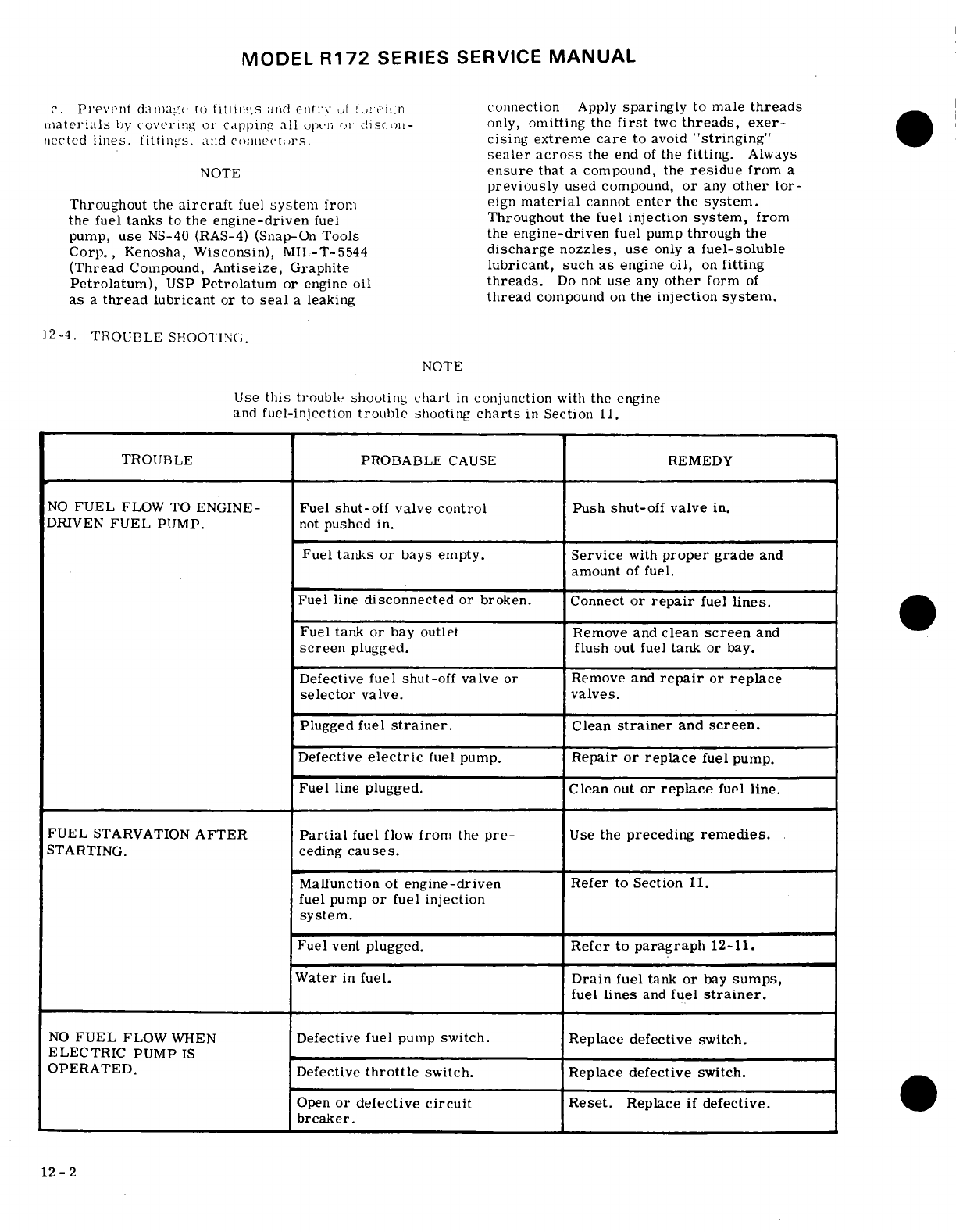
MODEL
R172
SERIES
SERVICE
MANUAL
c.
Prevent
damage
to
fittings
and
entry
of
forgin
connection
Apply
sparingly
to
male
threads
materials
bV
covrl
ing,
or
cappinL
all
crpc;i
o;
disclo- only,
omitting
the
first
two
threads,
exer-
nected
lines.
littinis.
and
corlnectrs.
cising
extreme
care
to
avoid
"stringing"
sealer
across
the
end
of
the
fitting.
Always
NOTE
ensure
that
a
compound,
the
residue
from
a
previously
used
compound,
or
any
other
for-
Throughout
the
aircraft
fuel
system
from eign
material
cannot
enter
the
system.
the
fuel
tanks
to
the
engine-driven
fuel
Throughout
the
fuel
injection
system,
from
pump,
use
NS-40 (RAS-4)
(Snap-On
Tools
the
engine-driven
fuel
pump
through
the
Corp.,
Kenosha,
Wisconsin),
MIL-T-5544
discharge
nozzles,
use
only a
fuel-soluble
(Thread
Compound,
Antiseize,
Graphite
lubricant,
such
as
engine
oil,
on
fitting
Petrolatum),
USP
Petrolatum
or
engine
oil
threads.
Do
not
use
any
other
form
of
as
a
thread
lubricant
or
to
seal
a
leaking
thread
compound
on
the
injection
system.
12-4.
TROUBLE
SHOOTING.
NOTE
Use
this
trouble
shooting
chart
in
conjunction
with
the engine
and
fuel-injection
trouble
shooting
charts
in
Section
11.
TROUBLE
PROBABLE
CAUSE
REMEDY
NO
FUEL
FLOW
TO
ENGINE-
Fuel
shut-off
valve
control
Push
shut-off
valve
in.
DRIVEN
FUEL
PUMP.
not
pushed
in.
Fuel
tanks
or
bays
empty.
Service
with
proper
grade
and
amount
of
fuel.
Fuel
line
disconnected
or
broken.
Connect
or
repair
fuel
lines.
Fuel
tank
or
bay
outlet
Remove
and
clean
screen
and
screen
plugged.
flush
out
fuel
tank
or
bay.
Defective
fuel
shut-off
valve
or
Remove
and
repair
or
replace
selector
valve.
valves.
Plugged
fuel
strainer.
Clean
strainer
and
screen.
Defective
electric
fuel
pump.
Repair
or replace
fuel
pump.
Fuel
line
plugged.
Clean
out
or
replace
fuel
line.
FUEL
STARVATION
AFTER
Partial
fuel
flow
from
the
pre-
Use
the
preceding
remedies.
STARTING.
ceding
causes.
Malfunction
of
engine-driven
Refer
to
Section
11.
fuel
pump
or
fuel
injection
system.
Fuel
vent
plugged.
Refer
to
paragraph
12-11.
Water
in
fuel.
Drain
fuel
tank
or
bay
sumps,
fuel
lines
and
fuel
strainer.
NO
FUEL
FLOW
WHEN
Defective fuel
pump
switch.
Replace
defective
switch.
ELECTRIC
PUMP
IS
OPERATED. Defective
throttle
switch. Replace
defective
switch.
Open
or
defective
circuit
Reset.
Replace
if
defective.
breaker.
12-2
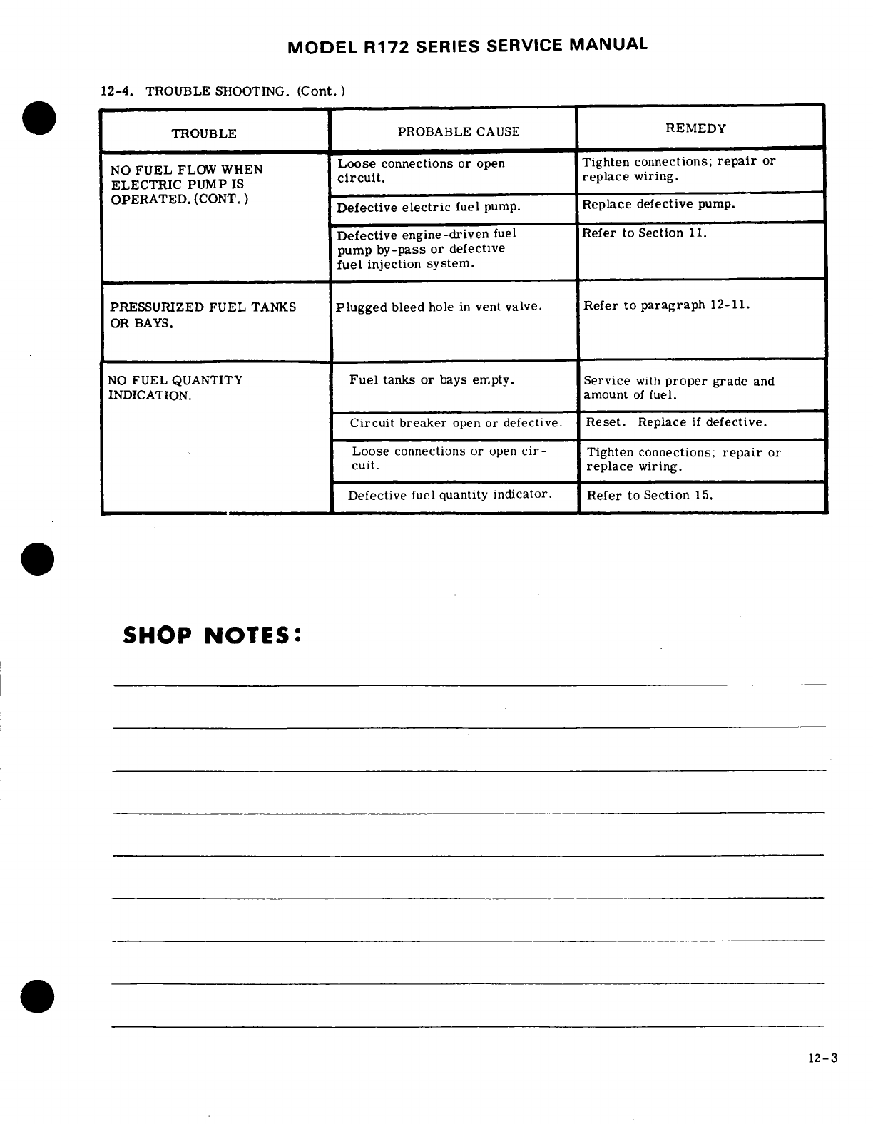
MODEL
R172
SERIES
SERVICE
MANUAL
12-4.
TROUBLE
SHOOTING.
(Cont.)
TROUBLE PROBABLE
CAUSE
REMEDY
NO
FUEL
FLOW
WHEN
Loose
connections
or
open
Tighten connections;
repair
or
circuit.
replace
wiring.
ELECTRIC
PUMP
IS
OPERATED.
(CONT.)
Defective
electric
fuel
pump
Replace
defective
pump.
Defective
engine-driven
fuel
Refer
to Section
11.
pump
by-pass
or
defective
fuel
injection system.
PRESSURIZED
FUEL
TANKS
Plugged
bleed
hole
in
vent valve.
Refer
to paragraph
12-11.
OR
BAYS.
NO
FUEL
QUANTITY
Fuel
tanks
or
bays empty.
Service
with
proper
grade
and
INDICATION.
amount
of
fuel.
Circuit
breaker
open
or defective.
Reset.
Replace
if
defective.
Loose
connections
or
open
cir-
Tighten
connections;
repair
or
cuit.
replace
wiring.
Defective
fuel
quantity
indicator.
Refer
to Section
15.
SHOP
NOTES:
12-3
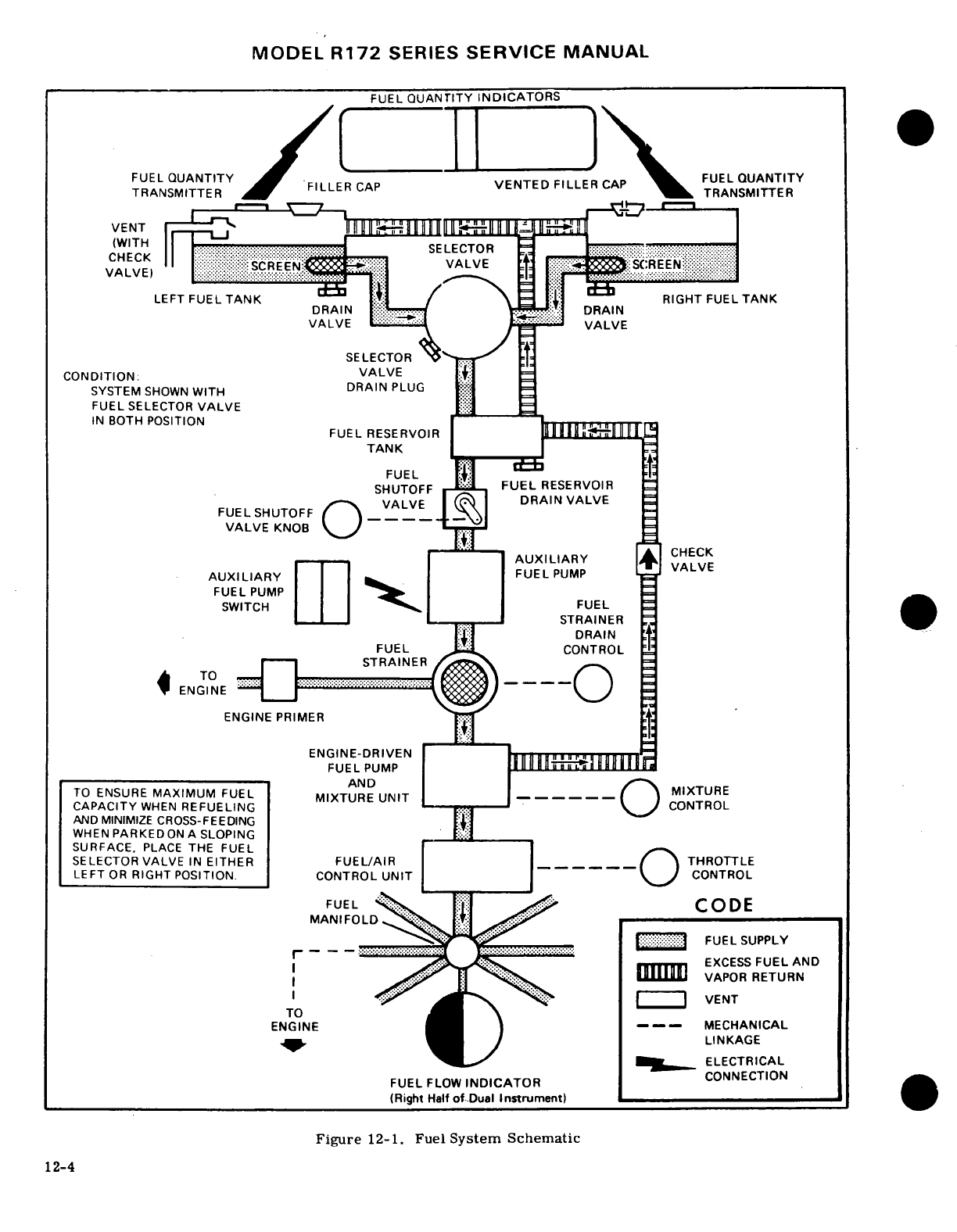
MODEL
R172
SERIES
SERVICE
MANUAL
FUEL
QUANTITY
INDICATORS
FUEL
QUANTITY FILLER
CAP
VENTED
FILLER
CAP
FUEL
QUANTITY
VENTED
FILLER
CAP
TRANSMITTER FILLER
CAP
TRANSMITTER
RIGHT FUEL
TANK
DRAIN
SELECTOR
CONDITION:
VALVE
SYSTEM
SHOWN
WITH
DRAIN
PLUG
FUEL
SELECTOR
VALVE
IN
BOTH
POSITION
FUEL RESERVOIR
TANK
FUEL
SHUTOFF
FUEL
RESERVOIR
DRAIN
VALVE
VALVE
KNOB
AUXILIARY
FUEL
PUMP
FUEL
PUMP
SWITCH
FUEL
STRAINER
FUEL
CONTROL
STRAINER
VENT
ENGINE
ENGINE
PRIMER
ENGINE-DRIVEN
FUEL
PUMP
AND
TO
ENSURE
MAXIMUM
FUEL
MIXTURE
CAPACITY
WHEN
REFUELING MIXTURE
UNIT
CONTROL
AND
MINIMIZE
CROSS-FEEDING
WHEN
PARKEDON
A
SLOPING
SURFACE,
PLACE
THE
FUEL
SELECTOR
VALVE
IN
EITHER
FUEL/AIR
THROTTLE
LEFT
OR
RIGHT
POSITION.
CONTROL UNIT
CONTROL
FUEL
CODE
MANIFOLD
,
FUEL
SUPPLY
EXCESS
FUEL
AND
VAPOR
RETURN
VENT
ENGINE
----
MECHANICAL
LINKAGE
ELECTRICAL
FUEL
FLOW
INDICATOR
CONNECTION
(Right
Half
of
Dual
Instrument)
Figure
12-1.
Fuel
System Schematic
12-4
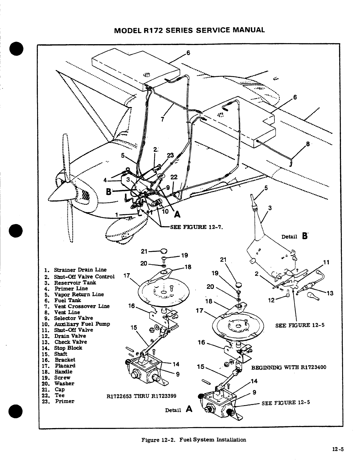
MODEL
R172
SERIES
SERVICE MANUAL
-.
-SEE
FIGURE
12-7.
,
Detail
B
1.
Strainer
Drain
Line
2.
Shut-Off
Valve
Control
3.
Reservoir
Tank.
4.
Primer
Line
5.
Vapor
Return
Line
-,,
6.
Fuel
Tank
7.
Vent
Crossover
Line
8.
Vent
Line
9.
Selector
Valve
11.
Shut-Off
Valve 15
SEE
FIGURE
12-5
12.
Drain
Valve
13.
Check
Valve
14.
Stop
Block
15.
Shaft
16.
Bracket
17.
Placard
-,
18.
Hacade
BEGINNING
WITH
R1723400
19.
Screw
20.
Washer
21.
Cap
22.
Tee
R1722653
THRU
R1723399
23.
Primer
SEE
FIGURE
12-5
Detail
A
Figure
12-2.
Fuel
System
Installation
12-5
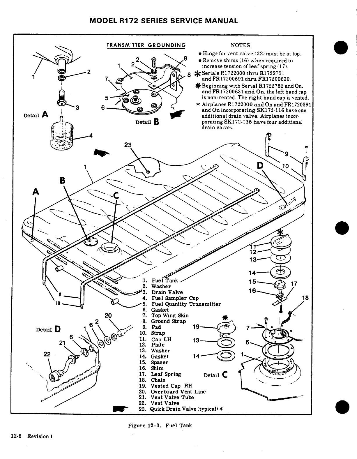
MODEL
R172
SERIES SERVICE
MANUAL
TRANSMITTER
GROUNDING
NOTES
*
Hinge
for
vent
valve
(22)
must
be
at
top.
*
Remove
shims
(16)
when
required
to
increase tension
of
leaf
spring
(17).
8
*
Serials
R1722000
thru
R1722751
and FR17200591
thru
FR17200630.
a
Beginning with
Serial
R1
722752
and
On.
and
FR17200631
and
On,
the
left hand
cap
*
Airplanes
R1722000
and
On
and
FR1720591
and
On
incorporating
SK172-116
have
one
Detail
A '
additional drain
valve.
Airplanes
incor-
Detail
B
porating
SK172-135
have
four
additional
drain
valves.
Fuel
Tank
5---
2.
Washer
3.
Drain
Valve
4.
Fuel
Sampler
Cup
Fuel Quantity
Transmitter
6.
Gasket
7.
Top
Wing Skin
*
Ground
Strap
DetailD
9.
Pad
10.
Strap
Plate
14.
Gasket
15.
Spacer
Shim
17.
Leaf Spring
DetailC
18.
Chain
19.
Vented
Cap
RH
20.
Overboard
Vent
Line
21.
Vent
Valve Tube
22.
Vent
Valve
23.
Quick
Drain
Valve
(typical)
*
Figure
12-3.
Fuel
Tank
12-6
Revision
1
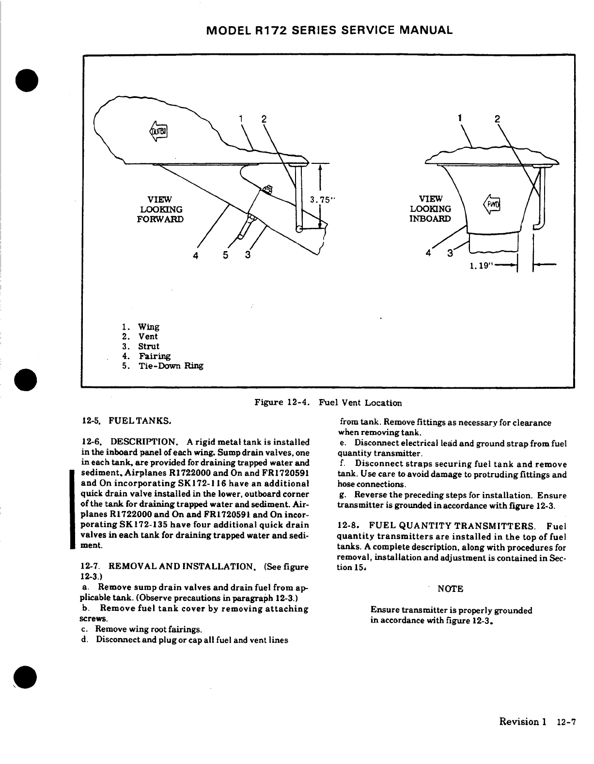
MODEL
R172
SERIES
SERVICE
MANUAL
1.
Wing
2.
Vent
3.
Strut
4.
Fairing
5.
Tie-Down
Ring
Figure
12-4.
Fuel
Vent
Location
12-5.
FUEL
TANKS.
from
tank.
Remove
fittings
as
necessary
for
clearance
when
removing
tank.
12-6.
DESCRIPTION.
A
rigid metal
tank
is
installed
e.
Disconnect
electrical
lead
and
ground
strap
from fuel
in
the
inboard
panel
of
each
wing. Sump
drain
valves,
one
quantity
transmitter.
in
each
tank,
are
provided
for
draining
trapped
water
and
f.
Disconnect
straps
securing
fuel
tank
and
remove
sediment.
Airplanes
R
1722000
and
On
and
FR1720591
tank.
Use
care
to
avoid
damage
to
protruding fittings
and
and
On
incorporating
SK172-116
have an
additional
hose
connections.
quick
drain
valve
installed
in
the
lower,
outboard
corner
g.
Reverse
the
preceding
steps
for
installation.
Ensure
of
the
tank
for
draining
trapped
water
and
sediment.
Air-
transmitter
is
grounded
in
accordance
with
figure
12-3.
planes
R1722000
and
On
and
FR1720591
and
On
incor-
porating
SK172-135
have
four
additional
quick
drain
12-8.
FUEL
QUANTITY
TRANSMITTERS.
Fuel
valves
in
each
tank
for
draining
trapped
water
and
sedi-
quantity
transmitters
are
installed
in
the
top
of
fuel
ment.
tanks.
A
complete
description,
along
with
procedures
for
removal,
installation
and
adjustment
is
contained in
Sec-
12-7.
REMOVAL
AND
INSTALLATION.
(See
figure
tion
15.
12-3.)
a.
Remove
sump
drain
valves
and
drain
fuel from
ap-
NOTE
plicable
tank.
(Observe
precautions
in
paragraph
12-3.)
b.
Remove
fuel
tank
cover
by
removing
attaching
Ensure
transmitter
is properly grounded
screws.
in
accordance
with
figure
12-3.
c.
Remove
wing
root
fairings.
d.
Disconnect
and
plug
or cap
all
fuel
and
vent
lines
Revision
1
12-7
MODEL
R172
SERIES
SERVICE
MANUAL
12-9.
FUEL
VENTS.
a.
Completely
drain
all
fuel
from
wing
tanks,
fuel
strainer,
lines,
reservoir
tanks
and
selector
valve.
12-10.
DESCRIPTION.
A
vent
line
is
installed
in
the
b. Remove
copilot's
seat
and
carpeting
as
neces-
outboard
end
of
the
left
fuel tank
and
extends
over-
sary
to
gain
access
to
tank
cover
plate.
board
down
through
the
lower
wing
skin.
The
inboard
c.
Remove
access
plate
from
floorboard.
end
of
the
vent
line
extends into the
fuel
tank,
then
d.
Disconnect
and
cap
or
plug
all
fuel
lines
at
tank.
forward and slightly
downward.
A
vent
valve
is
in-
e. Remove
tank
mounting
bolt
and
screws
and
lift
stalled
on
the
inboard
end
of
the vent
line
inside
the
out
tank.
fuel
tank,
and
a
crossover
vent line
connects
the
two
f.
Reverse
the
preceding
steps
for
installation.
tanks
for
positive
ventilation.
In
addition,
the
right
Prior
to
reinstalling
access
plate,
service
fuel tanks
hand
fuel
tank
cap
incorporates
a
small
vent
safety
and
check
for
leaks.
valve
to
ensure
positive
fuel
tank
ventilation.
12-15.
FUEL
SELECTOR
VALVE.
12-11.
CHECKING.
Field
experience
has demon-
strated
that
the fuel
vent
can
become
plugged,
with
12-16.
DESCRIPTION.
A
three
position
fuel
selector
possible
fuel
flow
interruption.
Also,
the
bleed
hole
valve
is
located
between
the
pilot
and
copilot
positions
in
the
vent
valve
assembly
could
possibly
become
on
the
pedestal.
The
positions
on
the
valve
are
label-
phlugged,
allowing
pressure
from
expanding
fuel
to
ed
"LEFT,
BOTH
ON
and
RIGHT."
Valve
repair
con-
pressurize
the
tanks/bays.
The following
procedure
sists
of
replacement
of
seals,
springs,
balls
and
other
may
be
used
to
check
the
vent
and
bleed
hQle
in
the
detail
parts.
Figure
12-5
illustrates
the
proper
re-
valve
assembly.
lationship
of
parts
and
may be
used
as
a
guide
during
a.
Attach
a rubber
tube
to
the end
of
vent
line
be-
disassembly
and
assembly.
neath
the
wing.
b.
Blow
into
tube
to
slightly
pressurize
tank.
If
12-17.
REMOVAL
AND
INSTALLATION. (See
figure
air
can
be
blown
into
tank,
vent
line
is open.
12-2.)
c.
After
tank
is
slightly
pressurized,
insert
end
of
a.
Completely
drain
all
fuel
from
wing
tanks,
fuel
rubber
tube
into
a container
of
water
and watch
for
strainer,
lines,
reservoir
tank
and
selector
valve.
a
continuous
stream
of
bubbles,
which
indicates
the (Observe
precautions
in paragraph
12-3.)
bleed
hole
in
valve
assembly
is
open
and
relieving
b.
Remove
fuel
selector
valve
handle.
pressure.
c.
Remove
pedestal
cover.
d.
After
completion
of
step
"c",
blow
into
tube
d.
Remove
carpeting
as
necessary
to
gain
access
to
again
to
slightly
pressurize
the
tank,
and loosen,
plates
aft
of
pedestal
and
inboard
of
right
front
door-
but
do
not
remove
filler
cap
on
opposite
wing
to
post.
check
tank
crossover
line.
If
pressure
escapes
from
e.
Disconnect
handle
drive
shaft
from
valve.
filler
cap,
crossover
line
is open.
f.
Disconnect
and
cap
or
plug
all
fuel
lines
at
valve.
g.
Remove
screws
attaching
valve
to
bracket
and
NOTE
remove
valve.
h.
Reverse
the
preceding
steps
for
installation.
Remember
that
a
plugged
vent
line
or
bleed
Prior
to
installing
access
plates,
service
fuel
tanks
hole
can cause
either
fuel
flow
interruption
and
check
for
leaks.
or
the
pressurizing
of
the
tanks/bays
by
fuel
expansion.
12-18.
DISASSEMBLY.
(See
figure
12-5.)
a.
Remove
fuel
selector
valve
in
accordance
e.
Any
fuel
vent
found
plugged
or
restricted
must
with
paragraph
12-17.
be
corrected
prior
to
returning
aircraft
to
service.
b.
Remove
nipples
(10)
from
the two
fuel
inlet
ports.
NOTE
NOTE
The
fuel
vent
line
protruding
beneath
the
wing
near
the
wing
strut
must
be
correctly
aligned
Removal
of
inlet
nipples
will
allow
toavoid
possible
icing
of
the
vent
tube.
Di-
spring
(9).
ball
(4).
O-ring
(8).
re-
mensions
are
shown
in
figure
12-4.
tainer
(7)
and
ball
(4)
to
pop
free
of
valve
body.
Use
care
to
avoid
loss
12-12.
FUEL
RESERVOIR
TANK.
of
these
parts
during
disassembly.
12-13.
DESCRIPTION.
A
reservoir
tank
is
installed
c.
Remove
nipple
(10)
from
fuel
outlet
port.
in
the
lower
fuselage
area
beneath
the
floor
immedi-
d.
Remove
roll
pin
(3)
and
lift
housing
(1)
ately
forward
of
the
copilot
position.
The
tank
has
from
cam.
Retain
ball
(4)
and
detent
spring'
four
fuel
line
connections;
a
fuel
supply line
from
the
(18)
for
reinstallation.
selector
valve,
a
supply
line
to
the
shut-off
valve,
a
e.
Remove
two
screws
holding
stop
(2)
to
cover.
vapor
return
line
from
the engine
and
a
vent
line
teed
Remove
four
screws
attaching
cover
(15)
to
valve
into the
tank
crossover
vent
line.
A
drain
plug
or
body
(6)
and
carefully
remove
cover.
valve
is
installed
in
the
bottom
of
the
tank
for
drain-
f.
Remove
gasket
(12)
and
withdraw
cam
(13)
ing
trapped
water
and
sediment
from
the
fuel
system.
with
washer
(14)
and
O-ring
(8).
g.
Remove
bushing
(5).
12-14.
REMOVAL
AND
INSTALLATION.
(See
figure
12-8

MODEL
R172
SERIES
SERVICE
MANUAL
12-2.)
NOTE
a.
Completely
drain
all
fuel
from
wing
tanks,
fuel
strainer,
lines,
reservoir
tank
and
selector
valve.
Repair
of
damaged
or
worn
parts
of
the
selec-
b.
Remove
copilot's
seat
and
carpeting
as
neces-
tor
valve
is
NOT
authorized,
and
therefore
is
sary
to
gain
access
to
reservoir
tank
access
plate.
limited
to
replacement
of
component
parts
only.
c.
Remove
access
plate
from
floorboard.
d.
Disconnect
shutoff valve
control.
a.
Clean
disassembled
parts
by
washing
in
Stoddard
e.
Disconnect
and
cap
or
plug
all
fuel
lines
at
valve.
solvent
or
equivalent.
Blow
parts
dry
using
clean
f.
Remove
valve
mounting
bolts.
compressed
air.
g.
Reverse
the
preceding
steps
for
installation.
b.
Inspect
all
parts
for
obvious
wear
or
damage
as
Prior
to
reinstalling
access
plate,
rig
valve
control,
follows:
service
fuel
tanks
and
check
for
leaks.
1.
Check
detent
holes
in
cover
(15)
for
exces-
sive
wear.
12-24.
DISASSEMBLY.
(See
figure
12-6.)
2.
Inspect
shaft
and
bearing
surfaces
of
cam
a.
Remove
fuel shutoff valve
in
accordance
with
(13)
for
removal
of
black
anodized
surface
indicating
paragraph
12-23.
wear.
b.
Remove
two
screws
securing
cover
(2)
to
valve
3.
Examine
valve
body
(6)
for
wear,
cracks,
body
(1)
and
carefully
remove
cover.
Discard O-ring
distortion
and
internal
corrosion.
Any
damage
to
(8)
but
retain
ball
(5)
and
detent
spring
(4)
for
rein-
thread
surfaces
at
inlet
and
outlet
ports or
cover
stallation.
attach
holes
is
cause
for rejection.
c.
Slowly
withdraw
rotor
(3)
from
valve
body.
12-20.
REASSEMBLY.
(See
figure
12-5.)
NOTE
a.
Ensure that
all
component
parts
are
clean,
then
coat
sparingly
with
lightweight
engine
oil.
Removal
of
rotor
(3)
will allow
seal
(9),
b.
Insert
bushing
(5)
into
place
in
valve
body.
O-ring
(10),
washer
(11)
and
spring
(12)
c.
Fit
washer
and
a
new
O-ring
in
place
on
cam
to
pop
free.
(13)
and
insert
cam
into
valve
body.
d.
Install
new
gasket
(12)
and
cover
(15).
12-25.
CLEANING,
INSPECTION
AND
REPAIR.
e.
Install ball
(4),
retainer
(7),
O-ring
(8),
ball
O'
(4),
spring
(9),
O-ring
(8)
and
nipple
(10)
in
each
NOTE
inlet
port.
f.
Install
nipple
(10)
and
O-ring
(8)
in
outlet
port.
Repair
of
damaged
or
worn
parts
of
the
g.
Lubricate
detent
spring
(16)
and
ball
(4)
with fuel
shutoff valve
is
NOT
authorized,
and
lubricant
conforming
to
Military
Specification
therefore
is
limited
to
the
replacement
of
VV-P-236
(USP
Petrolatum
or
equivalent).
component
parts
only.
h.
Insert
spring
(16)
in
hole
in
housing
(1).
i.
Rotate
cam
as
necessary
so
that
ball
(4)
will
a.
Clean
disassembled
parts
by
washing
in
Stoddard
align
with
one
of
the
detent
holes
on
cover
when
in
solvent
or
equivalent.
Blow
parts
dry
using
clean
position
on
cam.
compressed
air.
j.
With
ball
(4)
on
spring
(16),
slide
housing
(1)
b.
Inspect
all
parts
for
obvious
wear
or
damage
as
onto
cam
and
install
roll
pin.
follows:
k.
Install
stop
(2)
and
check
rotation
of
cam
for
1.
Check
detent
holes
in
cover
(2)
for
excessive
ease
of
operation
and
positive
detent
engagement. wear
and
examine
bearing
surfaces
on
rotor
(3).
1.
Reinstall
selector
valve
in
accordance
with
2.
Inspect
shaft
and
bearing
surfaces
of
rotor
paragraph
12-17
(3)
for
removal
of
black
anodized
finish
indicating
wear.
Check
for
internal corrosion
of
drilled
pas-
12-21.
FUEL
SHUTOFF
VALVE.
sages.
3.
Examine
valve
body
(1)
for
wear,
cracks,
12-22.
DESCRIPTION.
The
fuel
shutoff
valve
is a
distortion
and
internal
corrosion.
Any
damage
to
two
position
ON-OFF
valve
mounted
directly
on
the
thread
surfaces
at
inlet
and
outlet
ports
or
cover
reservoir
tank
using
an
adapter.
The
valve
control
attach
screw
holes
is
cause
for rejection.
knob
is
located
on
the
left
lower
instrument
panel.
Valve
repair
consists
of
replacement
of
seals,
12-26.
REASSEMBLY.
(See
figure
12-6.)
springs, balls
and
other detail
parts.
Figure
12-6
illustrates
the
proper
relationship
of
parts
and
may
be
used
as
a
guide during
disassembly
and
reassem-
bly.
12-9
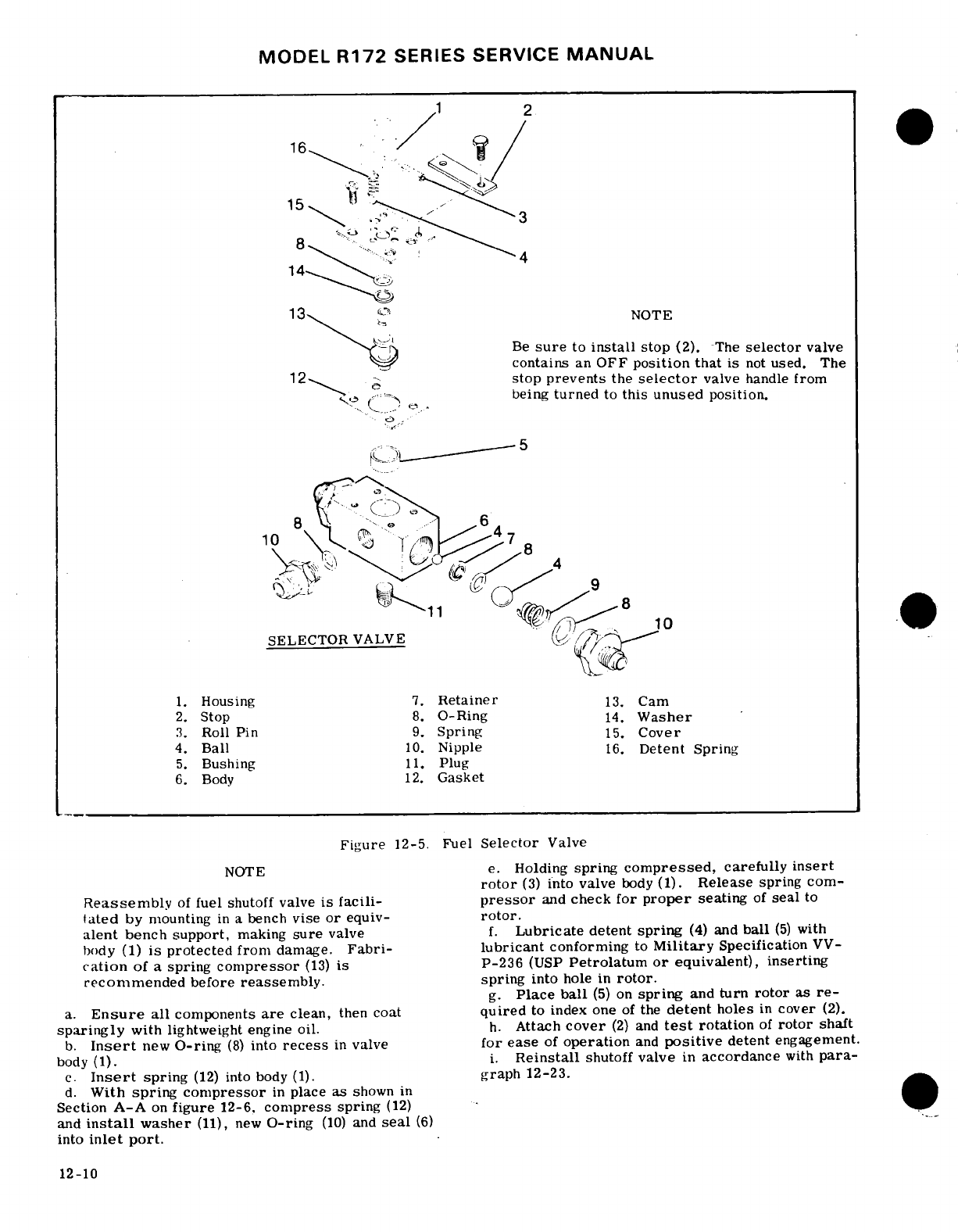
MODEL
R172
SERIES
SERVICE
MANUAL
NOTE
Be
sure
to
install
stop
(2).
The
selector
valve
contains
an
OFF
position
that
is
not
used.
The
stop prevents
the
selector
valve
handle
from
being
turned
to
this
unused
position.
.
SELECTOR
VALVE
1.
Housing
7.
Retainer
13.
Cam
2.
Stop
8.
0-Ring
14.
Washer
3.
Roll
Pin
9.
Spring
15.
Cover
4.
Ball
10.
Nipple
16.
Detent
Spring
5.
Bushing
11.
Plug
6.
Body
12.
Gasket
Figure
12-5.
Fuel
Selector
Valve
NOTE
e.
Holding
spring
compressed,
carefully
insert
rotor
(3)
into
valve
body
(1).
Release
spring
com-
Reassembly
of
fuel shutoff valve
is
facili-
pressor
and
check
for
proper
seating
of
seal
to
tated
by mounting
in
a
bench
vise
or
equiv-
rotor.
alent
bench
support,
making
sure
valve
f.
Lubricate
detent
spring
(4)
and
ball
(5)
with
body
(1)
is
protected
from
damage.
Fabri- lubricant
conforming
to
Military
Specification
VV-
cation
of
a
spring
compressor
(13)
is P-236
(USP
Petrolatum
or
equivalent),
inserting
recommended
before
reassembly.
spring
into
hole
in
rotor.
g.
Place
ball
(5)
on
spring
and
turn
rotor
as
re-
a.
Ensure
all
components
are
clean,
then
coat
quired
to
index
one
of
the
detent
holes
in
cover
(2).
sparingly
with
lightweight
engine
oil.
h.
Attach
cover
(2)
and
test
rotation
of
rotor
shaft
b.
Insert
new
O-ring
(8)
into
recess
in
valve
for
ease
of
operation
and
positive
detent
engagement.
body
(1).
i.
Reinstall
shutoff
valve
in
accordance
with
para-
c.
Insert
spring
(12)
into
body
(1).
graph
12-23.
d.
With
spring
compressor
in
place
as
shown
in
Section
A-A
on
figure
12-6,
compress
spring
(12)
and
install
washer
(11),
new
O-ring
(10)
and
seal
(6)
into
inlet port.
12-10
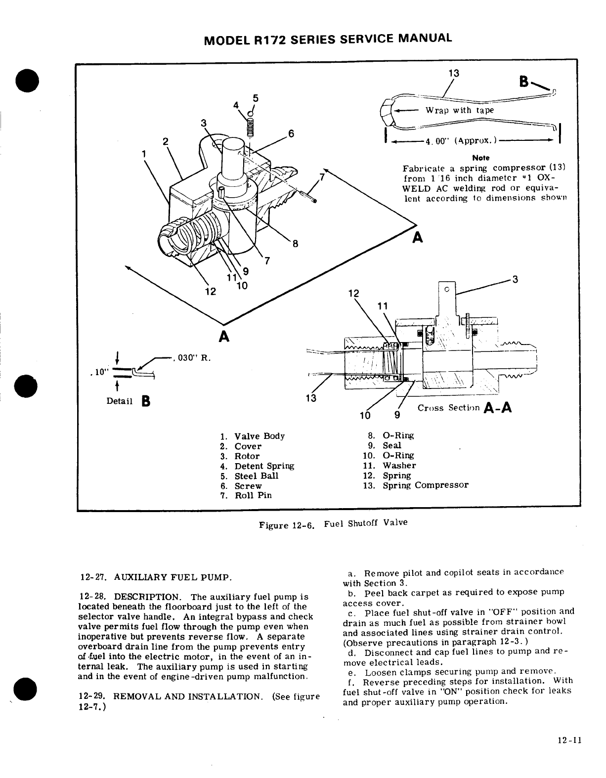
MODEL
R172
SERIES
SERVICE
MANUAL
Detail
B
Cross
Section
A-A
1.
Valve
Body
8.
O-Ring
2.
Cover
9.
Seal
3.
Rotor
10.
O-Ring
4.
Detent
Spring
11.
Washer
5.
Steel
Ball
12.
Spring
6.
Screw
13.
Spring
Compressor
7.
Roll
Pin
Figure
12-6.
Fuel
Shutoff
Valve
12-27.
AUXILIARY
FUEL
PUMP.
a.
Remove pilot
and
copilot
seats
in
accordance
with
Section
3.
12-28,
DESCRIPTION.
The
auxiliary
fuel
pump
is
b.
Peel
back
carpet
as
required
to
expose
pump
located
beneath
the
floorboard
just
to
the
left
of
the
access
cover.
selector
valve handle.
An
integral
bypass
and
check
c.
Place
fuel
shut-off
valve
in
"OFF"
position
and
valve
permits
fuel
flow
through
the
pump even
when
drain as
much
fuel
as
possible
from
strainer
bowl
inoperative
but
prevents
reverse
flow.
A
separate
and
associated
lines
using
strainer
drain
control.
overboard
drain
line
from
the
pump
prevents
entry
(Observe
precautions
in
paragraph
12-3. )
offuel
into the
electric
motor,
in
the
event
of
an
in-
d.
Disconnect
and
cap fuel
lines
to
pump
and
re-
ternal
leak.
The
auxiliary
pump
is
used
in
starting
move
electrical
leads.
and
in
the
event
of
engine-driven
pump
malfunction.
e.
Loosen
clamps
securing
pump and
remove.
f.
Reverse
preceding
steps
for
installation.
With
12-29.
REMOVAL
AND
INSTALLATION.
(See
figure
fuel
shut-off
valve
in
"ON"
position check
for
leaks
12-7.)
and
proper auxiliary
pump
operation.
12-11
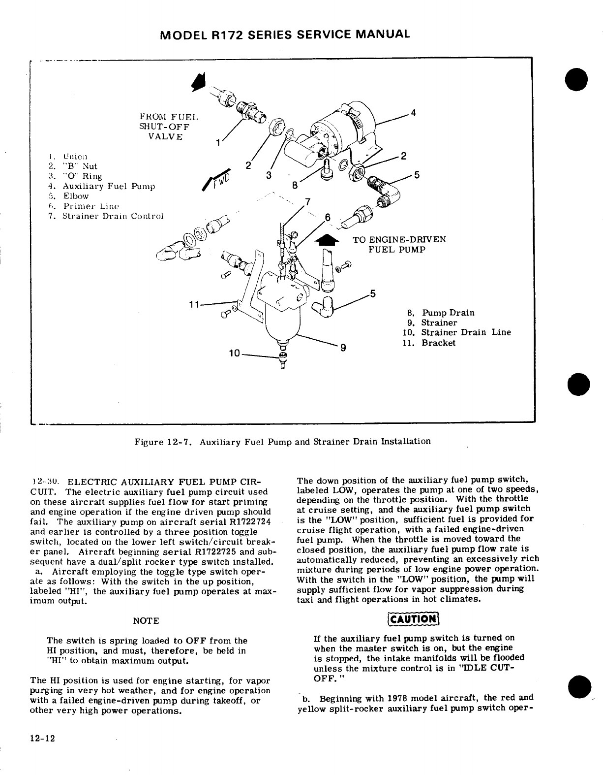
MODEL R172
SERIES
SERVICE
MANUAL
.
FROM
FUEL
SHUT-OFF
VALVE
2.
"B"
Nut
2
3.
"O"
Ring
4.
Auxiliary
Fuel
Pump
5.
Elbow
6.
Primer
Line
7.
Strainer
Drain Control
TO
ENGINE-DRIVEN
FUEL
PUMP
11
Figure
12-7. Auxiliary
Fuel
Pump
and
Strainer
Drain
Installation
12-30.
ELECTRIC
AUXILIARY
FUEL
PUMP
CIR-
The
down
position
of
the
auxiliary
fuel
pump
switch,
CUIT.
The
electric
auxiliary
fuel
pump
circuit
used
labeled
LOW,
operates
the
pump at
one
of
two
speeds,
on
these
aircraft
supplies
fuel
flow
for
start
priming
depending
on
the
throttle
position.
With the
throttle
and
engine
operation
if
the
engine
driven
pump
should
at
cruise
setting,
and
the
auxiliary
fuel
pump switch
fail.
The
auxiliary
pump
on
aircraft
serial
R1722724
is
the
"LOW"
position,
sufficient
fuel
is
provided
for
and
earlier
is
controlled
by
a
three
position
toggle
cruise
flight
operation,
with
a
failed
engine-driven
switch, located
on
the
lower
left
switch/circuit
break-
fuel
pump.
When
the
throttle
is
moved
toward
the
er
panel.
Aircraft
beginning
serial
R1722725 and
sub-
closed
position,
the
auxiliary
fuel
pump
flow
rate
is
sequent
have a
dual/split rocker
type switch
installed. automatically
reduced,
preventing
an
excessively
rich
a.
Aircraft
employing
the
toggle
type
switch
oper-
mixture
during
periods
of
low
engine
power
operation.
ate
as
follows:
With
the
switch
in
the
up
position,
With
the
switch
in
the
"LOW"
position,
the
pump
will
labeled
"HI",
the
auxiliary
fuel
pump
operates
at
max-
supply
sufficient
flow
for
vapor
suppression
during
imum
output.
taxi
and
flight
operations
in
hot
climates.
NOTE
CAUTION
The
switch
is
spring
loaded
to
OFF
from
the
If
the
auxiliary
fuel
pump
switch
is
turned
on
HI
position,
and
must,
therefore,
be
held
in
when
the
master
switch
is
on,
but
the
engine
"HI"
to
obtain
maximum
output.
is
stopped,
the
intake manifolds
will
be
flooded
unless
the
mixture
control
is
in
"IDLE
CUT-
The
HI
position
is
used
for
engine
starting,
for
vapor
OFF."
purging
in
very
hot
weather,
and
for
engine
operation
with
a
failed
engine-driven
pump
during
takeoff,
or
b.
Beginning
with
1978
model
aircraft,
the
red
and
other
very
high
power
operations.
yellow
split-rocker
auxiliary
fuel
pump
switch
oper-
12-12

MODEL
R172
SERIES
SERVICE
MANUAL
MICROSWITCH
ADJUSTING
SLOTS
*
BETWEEN
CENTERLINE
OF
IDLE
STOP
AND
CAM
PEAK
SWITCH
ROLLER
1/16
INCH
With
switch
actuated
IDLE
STOP-
*,
on
high
cam,
clearance
must
exist
between
arm
and
switch
body.
CAM
/--IDLE
SCREW
(Against
Stop)
THROTTLE
ARM
(Full
Retard)
DETAIL
A
DETAIL
B
Figure
12-8.
Rigging
Throttle Operated
Microswitch
ates as
follows:
The
YELLOW
right
half
of
the
switch
CAUTION
is
labeled
LOW,
and
is
used
to
prime
the
engine for
normal
starting
and
minor
vapor
purging
during
taxi.
The
RED
left
half
of
the
switch
is
labeled
HIGH,
and
tally
selected
with
the
master
switch
ON
and
is
used
in
the
event
an
engine-driven
pump
failure
tally
selected
wth
the
mster
switch
ON
and
during
takeoff
or
high
power
operation.
The
HIGH
the
engine
stopped,
the
intake
anifolds
will
position
may
also
be
used
for
extreme
vapor
purging.
befloodedunless
the
mixture
contr
is in
With
the
YELLOW
half of
the
switch
in
the
LOW posi-DLE
tion, the pump
operates
at
one
of
two
speeds,
that
are
dependent
upon
the
throttle
setting.
If
the
throt-
12-31.
RIGGING
THROTTLE OPERATED
MICRO
tie
is
open
to
cruise
settings
the
pump
operates
at
SWITCH. (See
figure
12-8.)
The
aircraft
electirn
high
flow
capacity,
to
supply
sufficient
fuel
flow to
auxiliary
fuel
pump
circuit
is
equipped
with a
nicr,
-
maintain
flight.
When
the throttle
is
moved
toward
switch
which
operates
on
a
cam attached
to
the
the
closed
position,
as
during
letdown,
landing
or
tle
arm
of
the
fuel-air
control
unit.
The
cam
on
thei
taxiing,
the
fuel
pump
flow
is
automatically
reduced
throttle
arm
actuates
the
microswitch
as the
thrutile
to
prevent
an
excessively
rich
mixture
during
these
is
retarded
to
a
manifold
pressure
of
approximatelv
low
engine
speed
conditions.
Maximum
fuel
flow
is
16"
Hg,
thus
reduces
the
speed
of
the
auxiliary
fui1l
produced
when
the RED
portion
of the
split
rocker
is
pump
by
introducing
a
resistance
into
the
circuil
held
in
the
spring
loaded
HIGH
position.
In
the
HIGH
Rig
the
microswitch
as
follows:
position,
an
interlock
in
the switch
also
moves
the
a.
Perform
an
initial adjustment
of
cant
and
YELLOW
portion
of
the
switch
to
the
LOW
position.
switch
as
follows:
When
the
spring-loaded
HIGH
portion
is
released,
1.
Close
throttle
and
adjust
cam
as
shown
i.
the
LOW
will
remain
ON
until
manually
turned
OFF.
detail
"A"
of
figure
12-8.
When
the
engine
driven
fuel
pump
is
operating,
a
2.
Refer
to
detail
"B"
of
figure
12-8
to
set
fuel
air
ratio
considerably
richer
than
best-power microswitch
to
actuate
on
the
peak
of
the
cam.
and
is
produced
unless
the
mixture
is
leaned.
A
throttle
to
de-actuate
on
the
flat
portion
of
the
cam.
Be
sure
operated
microswitch
adds
resistance
to
the
circuit
that
roller
arm
of
switch
actuator
clears
switch
l^,dv
to
lower
pump
output
as
the
throttle
is
retarded.
in
actuated
position.
b.
Start
engine,
and
set throttle
to
obtain
approxi-
mately
15
-
17"
Hg
manifold
pressure.
Mark
this
position
on
throttle
control
rod,
and
stop
engine.
12-1.
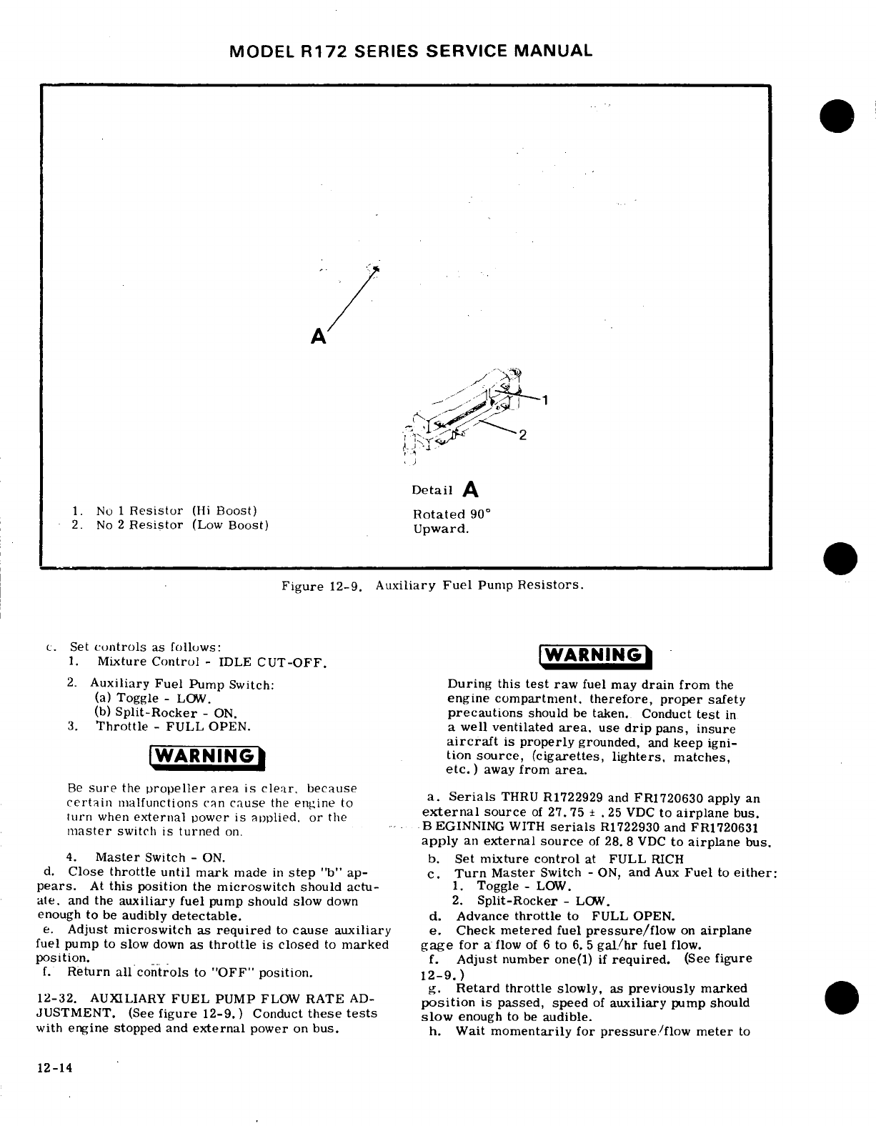
MODEL
R172
SERIES
SERVICE
MANUAL
,
Detail
A
1.
No
1
Resistor
(Hi
Boost)
Rotated
90
°
2.
No
2
Resistor
(Low
Boost)
Upward.
Figure
12-9.
Auxiliary
Fuel
Pump
Resistors.
c.
Set
controls
as
follows:A
1.
Mixture
Control
-
IDLE
CUT-OFF.
WARNING
2.
Auxiliary Fuel
Pump
Switch:
During
this
test
raw
fuel may
drain
from
the
(a)
Toggle -
LOW.
engine compartment,
therefore,
proper
safety
(b)
Split-Rocker
-
ON.
precautions
should
be
taken.
Conduct
test
in
3.
Throttle
-
FULL
OPEN.
a
well
ventilated
area,
use
drip
pans,
insure
aircraft
is
properly
grounded,
and
keep
igni-
WARNING
tion
source,
(cigarettes,
lighters,
matches,
)
away
from
area.
Be
sure
the
propeller
area
is
clear,
because
R1722929
and
FR1720630
apply
an
a.
Serials
THRU R1722929
and
FR1720630
apply
an
certain
malfunctions
can
cause
the
engine
to
certain
malfunctions
aen
cause
the
engine
to
external
source
of
27.
75
±
.25
VDC
to
airplane
bus.
turn
when
external
0ower
is
aoolied.
or
the
mast
urn
when
external
power
.s
applied,
or
BEGINNING
WITH
serials
R1722930
and
FR1720631
master
switch
is
turned
on.
apply
an
external
source
of
28.
8
VDC
to
airplane
bus.
4.
Master
Switch
-
ON.
b.
Set
mixture
control
at
FULL
RICH
d.
Close
throttle
until
mark
made
in
step
"b"
ap-
c.
Turn
Master
Switch
-
ON,
and
Aux
Fuel
to
either:
pears.
At
this
position
the
microswitch
should
actu-
1.
Toggle -
LOW.
ate.
and
the
auxiliary
fuel
pump
should slow
down
2.
Split-Rocker
-
LOW.
enough
to
be
audibly
detectable.
d.
Advance
throttle
to
FULL OPEN.
e.
Adjust
microswitch
as
required
to
cause
auxiliary
e.
Check
metered
fuel
pressure/flow
on
airplane
fuel
pump
to
slow
down
as
throttle
is
closed
to
marked
gage
for
a
flow
of
6
to
6.5
gal/hr
fuel
flow.
position.
f.
Adjust number
one(l)
if
required.
(See
figure
f.
Return
all
controls
to
"OFF"
position.
12-9.)
g.
Retard
throttle
slowly,
as
previously
marked
12-32.
AUXILIARY
FUEL
PUMP
FLOW
RATE
AD-
position
is passed,
speed
of
auxiliary
pump
should
JUSTMENT.
(See
figure
12-9.)
Conduct
these
tests
slow
enough
to be
audible.
with
engine stopped
and
external
power
on
bus.
h.
Wait
momentarily for
pressure/flow
meter
to
12-14
MODEL
R172
SERIES
SERVICE
MANUAL
stabilize.
The
pressure/flow
gage
should
read
2
c.
Carefully
unscrew
standpipe
and
removt.
galihr.
d.
Remove
filter
screen
and
gasket.
Wash
filter
i.
Adjust
number
(2)
two
resistor
if
required.
screen
and
bowl
with
solvent
(Federal
Specification
P-S-661, or
equivalent)
and
dry
with
compressed
12-33.
MAXIMUM
HIGH
BOOST
CHECK.
To
verify
air.
high
position
function
momentarily
depress
spring-
e.
Using a
new
gasket
between
filter
screen
and
loaded
rocker,
with
master
switch
"ON."
and
verify
top
assembly,
install
screen
and
standpipe.
Tig;l.ici
noticeable
increase
in
fuel
flow
on
the
fuel
flow
gage. standpipe
only
finger
tight.
f.
Using
all
new
O-rings, install
bowl.
Note
that
12-34.
9
FUEL
STRAINER,.
step-washer at
bottom
of
bowl
is
installed
so
that
step
seats
against
O-ring.
Connect
drain
tube.
g.
With
shut-off
valve
in
"ON"
position,
check
f.,r
12-35.
DESCRIPTION. The
fuel
stainer
is
mounted
leaks
and
proper
operation
of
quick-drain
valve.
on
the
firewall
in
the
engine
compartment.
The
h.
Safety
wire
bottom
nut
to
top
assembly.
Wir
strainer
is
equipped
with a
quick-drain
valve which
must
have
right
hand
wrap,
at
least
45
degrees.
provides a means
of
draining
trapped
water
and
sedi-
ment
from
the
fuel
system.
The
quick-drain
control
12-38.
PRIMING
SYSTEM
is
located
adjacent
to
the
oil
dipstick. Access
to the
drain
control
is
made
through
the
oil
dipstick
cowling
12-39.
DESCRIPTION.
The
priming
system
is
.
prised
of
a
plunger-type
manually-operated
prilit
NOTE
which
draws
fuel
from
the
strainer
and
forces
it
through
a
tee
fitting
to
the
front
end
of
each
intake-
manifold.
Injecting
the
fuel
into
each manifold
The
fuel
strainer
can
be
disassembled,
cleaned
manifold
Injecting
the
fuel
into
each
manifold
and
reassembled
without
removing
the
assembly prlmes
both
banks
of
cylinders.
from
the
aircraft.
(Refer
to
paragraph
12-37.)
12-40.
REMOVAL
AND
INSTALLATION.
12-36.
REMOVAL
AND
INSTALLATION.
(See
figure
a.
With
shut-off
valve
in
"OFF"
position,
drain
fuel
from
strainer
and
lines
with
quick-drain
cunti.J!.
b.
Disconnect
and cap
or
plug
all
fuel
lines
at
a.
Remove cowling
as
necessary
to
gain
access
to
pimer.
(bsere
pcap
or
plug
all
ful
lines
at
strainer.~
*primer.
(Observe
precautions
in
paragraph
12-3.'
b.
With
shut-off
valve
in
"OFF"
position,
drain
fuel
screw
d
ut
and
remove
plunger
fro
from
strainer
and
lines
with
strainer
quick-drain
pump
bod
~~~~~~~~control.
d.
Remove
pump
body
from
instrument
panel.
control.
c.
Disconnect
and
cap
or
plug
all
fuel
lines
and
con-
NOTE
trols
from
strainer.
(Observe
precautions
in
para-
graph
12-3.
)
Visually
inspect
primer
lines
for
crushed,
d.
Remove
bolts
attaching
assembly
to
firewall
and
Visually inspect
primer
lines
for
crushed,
remove
strainer
kinked,
or
broken
condition.
Ensure
proper
e.
Reverse
the
preceding
steps
for installation.
clamping
to
prevent
fatigue
due
to
vibration
With
shut-off
valve
in
"ON"
position
check
for
leaks
and
chafing.
and
proper
operation
of
quick-drain
valve.
e.
Prior
to
installing
a
primer,
check
for
proper
12-37.
DISASSEMBLY
AND
ASSEMBLY
pumping
action
and
positive
fuel
shut-off
in
the
a.
With
shut-off
valve
in
"OFF"
position,
drain
locked
position.
fuel
from
bowl
and
lines
with
quick-drain
control.
f.
Reverse
the
preceding
steps
for
installation.
b.
Remove
drain
tube,
safety
wire,
nut
and
With
shut-off
valve
in"ON"
position,
check
for
washer
at
bottom
of
filter
bowl
and
remove
bowl.
leaks
and
proper
pumping
action.
SHOP
NOTES:
12-15
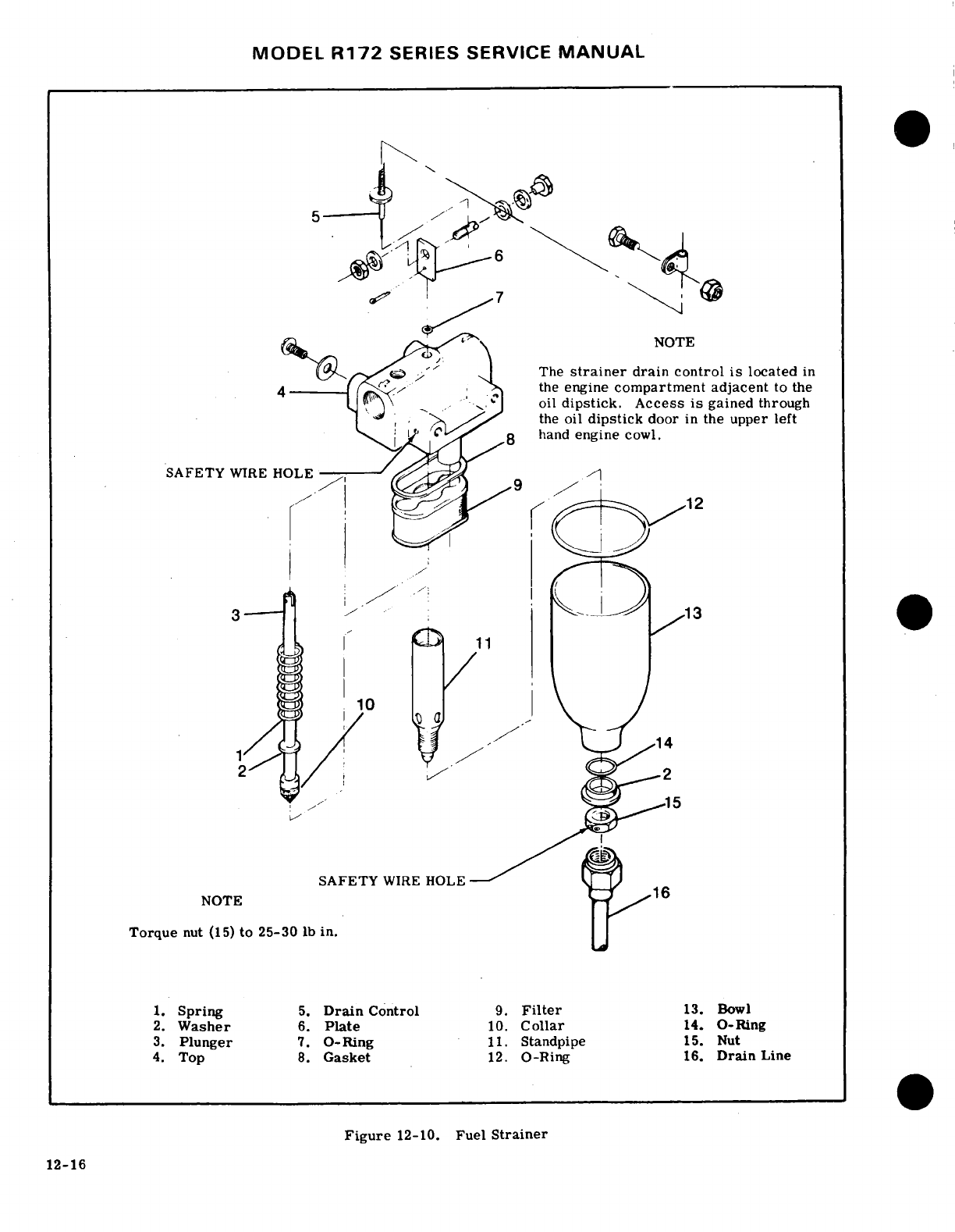
MODEL
R172
SERIES
SERVICE
MANUAL
NOTE
The
strainer
drain
control
is
located
in
,
the
engine
compartment
adjacent
to the
.- -
oil
dipstick.
Access
is
gained
through
,
the
oil
dipstick
door
in
the upper
left
.
hand
engine
cowl.
·
SAFETY
WIRE
HOLE
,
-
SAFETY
WIRE HOLE
NOTE
Torque
nut
(15)
to
25-30
lb
in.
1.
Spring
5.
Drain
Control
9.
Filter
13.
Bowl
2.
Washer
6.
Plate
10.
Collar
14.
O-Ring
3.
Plunger
7.
O-Ring
11.
Standpipe
15.
Nut
4.
Top
8.
Gasket
12.
O-Ring
16.
Drain
Line
Figure
12-10.
Fuel
Strainer
12-16
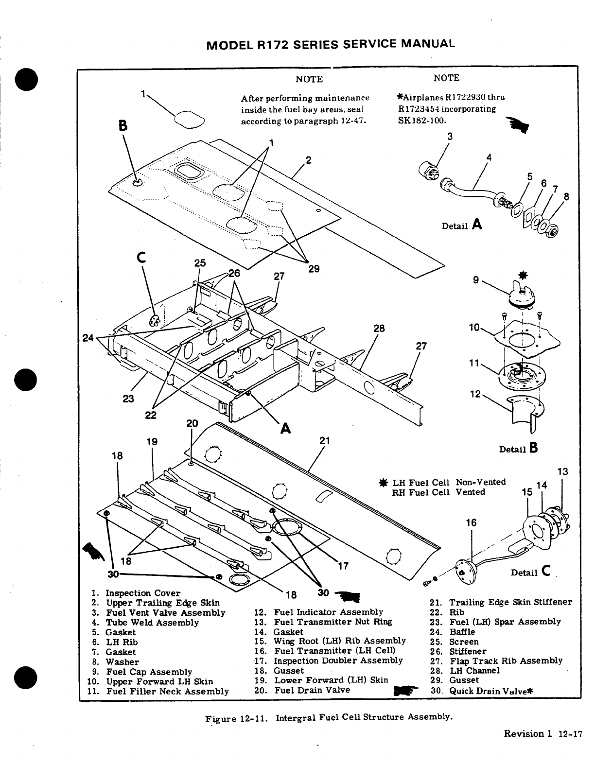
MODEL
R172
SERIES
SERVICE
MANUAL
NOTE
NOTE
After
performing
maintenance
*Airplanes
R
722930
thru
inside the
fuel
bay
areas.
seal
R1723454
incorporating
B
according
to
paragraph
12-47.
SK182-100.
2
4
*
LH
Fuel
Cell
Non-Vented
Detail
C
1.
Inspection
Cover
2.
Upper
Trailing
Edge
Skin
21.
Trailing
Edge
Skin
Stiffener
3.
Fuel
Vent Valve
Assembly
12.
Fuel
Indicator
Assembly
22.
Rib
4.
Tube
Weld
Assembly
13.
Fuel
Transmitter
Nut
Ring
23.
Fuel
(LH)
Spar
Assembly
5.
Gasket
14.
Gasket
24
Baffle
6.
LH
Rib
15.
Wing
Root
(LH)
Rib
Assembly
25.
Screen
7.
Gasket
16.
Fuel
Transmitter
(LH
Cell)
26.
Stiffener
8.
Washer
17.
Inspection
Doubler
Assembly
27.
Flap
Track
Rib
Assembly
9.
Fuel
Cap
Assembly
18.
Gusset
28.
LH
Channel
10.
Upper
Forward
LH
Skin
19.
Lower
Forward
(LH)
Skin
29.
Gusset
11.
Fuel
Filler
Neck
Assembly
20.
Fuel
Drain
Valve
30.
Quick
Drain
Valve*
Figure
12-11.
Intergral
Fuel
Cell
Structure
Assembly.
Revision
1
12-17
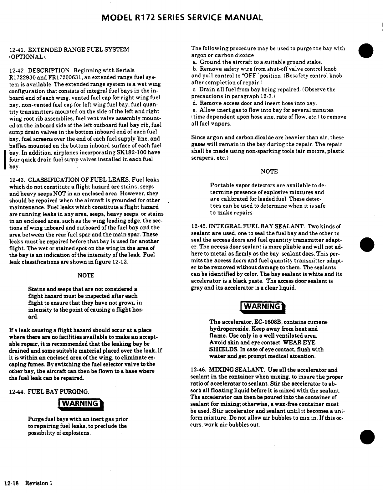
MODEL
R172
SERIES
SERVICE
MANUAL
12-41.
EXTENDED
RANGE
FUEL
SYSTEM
The
following
procedure
may
be
used
to
purge
the
bay
with
(OPTIONALi.
argon
or
carbon
dioxide.
a.
Ground
the
aircraft
to
a
suitable
ground
stake.
12-42.
DESCRIPTION.
Beginning
with
Serials
b.
Remove
safety
wire
from
shut-off
valve
control knob
R1722930
and
FR17200631,
an extended
range
fuel
sys-
and
pull
control
to
"OFF"
position.
(Resafety
control
knob
tern
is
available.
The
extended
range
system
is
a wet
wing
after completion
of
repair.)
configuration
that
consists
of
integral
fuel
bays
in
the
in- c.
Drain
all
fuel
from
bay
being
repaired.
(Observe
the
board
end
of
each
wing,
vented
fuel
cap
for
right
wing
fuel
precautions
in
paragraph
12-3.)
bav,
non-vented
fuel cap
for
left
wing fuel
bay,
fuel
quan-
d.
Remove
access
door
and
insert
hose
into
bay.
titv
transmitters
mounted
on
the
side
of
the
left
and
right
e.
Allow
inert
gas
to
flow
into bay
for
several minutes
wing
root rib
assemblies,
fuel
vent
valve
assembly mount-
(time
dependent
upon
hose
size,
rate
of
flow,
etc.)
to remove
ed
on
the
inboard
side
of
the
left
outboard
fuel
bay
rib,
fuel
all
fuel
vapors.
sump
drain
valves
in
the
bottom
inboard
end
of
each
fuel
bay,
fuel
screens
over
the
end
of
each
fuel
supply
line, and
Since
argon
and
carbon
dioxide
are
heavier
than
air,
these
baffles
mounted
on
the
bottom inboard
surface
of each
fuel
gases
will
remain
in
the
bay
during
the
repair.
The
repair
bay.
In
addition, airplanes incorporating
SK182-100
have shall
be
made
using
non-sparking
tools
(air
motors,
plastic
four
quick
drain
fuel
sump
valves
installed
in
each
fuel
scrapers, etc.)
bay.
NOTE
12-43.
CLASSIFICATION
OF
FUEL
LEAKS.
Fuel
leaks
which
do
not
constitute
a
flight
hazard
are
stains,
seeps
Portable
vapor
detectors are
available
to
de-
and
heavy seeps
NOT
in
an
enclosed
area.
However,
they
termine
presence
of
explosive
mixtures
and
should
be
repaired
when
the
aircraft
is
grounded
for
other
are
calibrated
for
leaded
fuel.
These
detec-
maintenance.
Fuel leaks
which
constitute
a
flight
hazard
tors
can
be
used
to
determine
when
it
is
safe
are
running
leaks
in
any
area,
seeps,
heavy
seeps,
or
stains
to make
repairs.
in
an enclosed
area,
such
as
the wing
leading
edge,
the
sec-
tions
of
wing
inboard and
outboard
of
the
fuel
bay
and
the
12-45.
INTEGRAL
FUEL
BAY
SEALANT.
Two
kinds
of
area
between the
rear
fuel
spar
and
the
main
spar.
These
sealant
are
used,
one to
seal
the
fuel
bay
and
the
other
to
leaks
must
be
repaired
before
that
bay
is
used
for
another
seal
the
access
doors
and
fuel
quantity
transmitter
adapt-
flight.
The
wet
or
stained
spot
on
the
wing
in
the
area
of
er.
The
access
door
sealant
is
more
pliable
and
will
not
ad-
the bay
is
an
indication
of
the
intensity
of
the
leak.
Fuel
here
to
metal
as
firmly as
the
bay
sealant
does.
This
per-
leak
classifications
are
shown
in
figure
12-12.
mits
the
access
doors
and
fuel
quantity
transmitter
adapt-
er
to
be
removed
without
damage
to
them.
The
sealants
NOTE
can
be
identified
by
color.
The
bay
sealant
is
white
and
its
accelerator
is
a
black
paste.
The
access
door
sealant
is
Stains
and
seeps
that
are
not
considered
a
gray
and
its
accelerator
is
a
clear
liquid.
flight
hazard
must
be
inspected
after
each
flight
to
ensure
that
they
have
not
growL
in
WARNING
intensity
to
the point
of
causing
a
flight haz-
ard.
The
accelerator,
EC-1608B,
contains
cumene
If
a
leak
causing
a
flight
hazard
should
occur
at a
place
hydroperoxide.
Keep
away
from
heat
and
where
there
are
no
facilities
available
to
make
an
accept-
flame.
Use only
in
a
well
ventilated
area.
able
repair,
it
is
recommended
that
the
leaking
bay
be
Avoid skin
and
eye
contact.
WEAR
EYE
drained and
some
suitable
material
placed
over
the
leak,
if
SHIELDS.
In
case
of
eye
contact,
flush
with
it
is
within
an
enclosed
area
of
the
wing,
to
eliminate
es-
water
and
get
prompt
medical
attention.
caping fumes.
By
switching the
fuel
selector
valve
to
the
other
bay,
the
aircraft
can
then
be
flown
to
a
base
where
12-46.
MIXING
SEALANT. Use
all
the
accelerator
and
the
fuel
leak
can
be
repaired.
sealant
in
the
container
when
mixing,
to
insure
the
proper
ratio
of
accelerator
to
sealant.
Stir
the
accelerator
to ab-
12-44.
FUEL
BAY
PURGING.
sorb
all
floating
liquid
before
it
is
mixed
with
the
sealant.
The
accelerator
can
then
be
poured
into
the
container
of
WARNING
sealant
for
mixing,
otherwise,
a wax-free
container
must
be
used.
Stir
accelerator
and
sealant
until
it
becomes
a
uni-
Purge
fuel
bavs
with
an
inert
gas
prior
form
mixture.
Do
not
allow
air
bubbles
to
mix
in.
If
this
oc-
to
repairing
fuel
leaks,
to
preclude the
curs,
work
air
bubbles
out.
possibility
of
explosions.
12-18
Revision 1
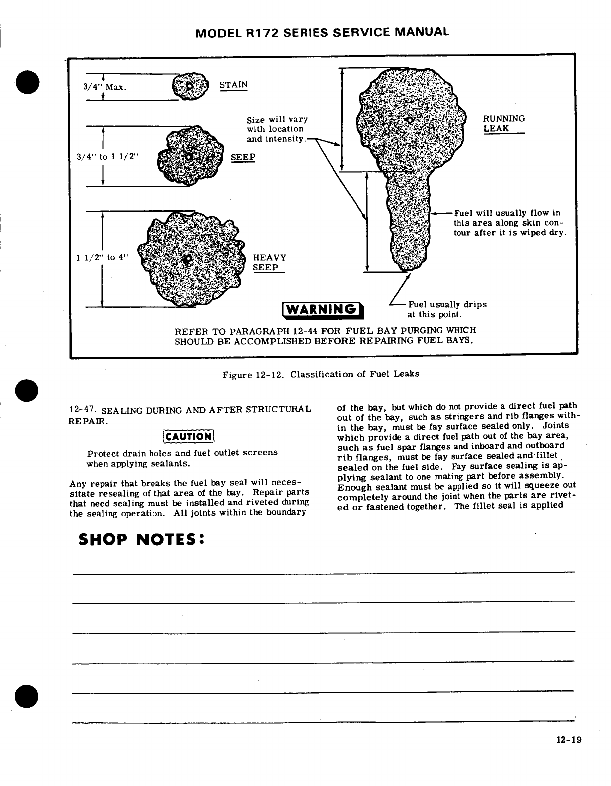
MODEL
R172
SERIES
SERVICE
MANUAL
3/4"
Max.
STAIN
Size
will
vary
-
RUNNING
with
location
LEAK
and
intensity.
3/4"
to
11/2"
Fuel
will
usually
flow
in
this
area
along
skin
con-
tour
after
it
is
wiped
dry.
1
1/2'
to
4"
HEAVY
WARNINGS
at
this
point.
REFER
TO PARAGRAPH
12-44
FOR
FUEL
BAY
PURGING
WHICH
SHOULD
BE
ACCOMPLISHED
BEFORE
REPAIRING
FUEL
BAYS.
Figure
12-12.
Classification
of
Fuel
Leaks
12-47.
SEALING
DURING AND
AFTER
STRUCTURAL
of
the bay,
but
which
do
not
provide
a
direct
fuel
path
REPAIR.
out
of
the
bay, such
as stringers
and
rib
flanges
with-
in
the
bay,
must
be
fay
surface
sealed
only.
Joints
CAUTION
which
provide
a
direct
fuel
path
out
of
the
bay
area,
Protect drain
holes
and
fuel
outlet
screens
such
as
fuel
spar
flanges
and
inboard
and
outboard
when
applying
sealants.
rib
flanges,
must
be
fay
surface sealed
and
fillet
sealed
on
the fuel
side.
Fay
surface
sealing
is
ap-
Any
repair
that
breaks
the fuel
bay
seal
will
neces-
plying
sealant
to
one
mating
part
before
assembly.
sitate
resealing
of
that
area
of
the
bay.
Repair
parts
Enough
sealant
must
be
applied
so
it
will
squeeze
out
that
need
sealing
must
be
installed
and
riveted
during
completely
around
the
joint
when
the
parts
are
rivet-
the
sealing
operation.
All
joints
within
the
boundary
ed
or
fastened
together.
The
fillet
seal
is
applied
SHOP
NOTES:
12-19
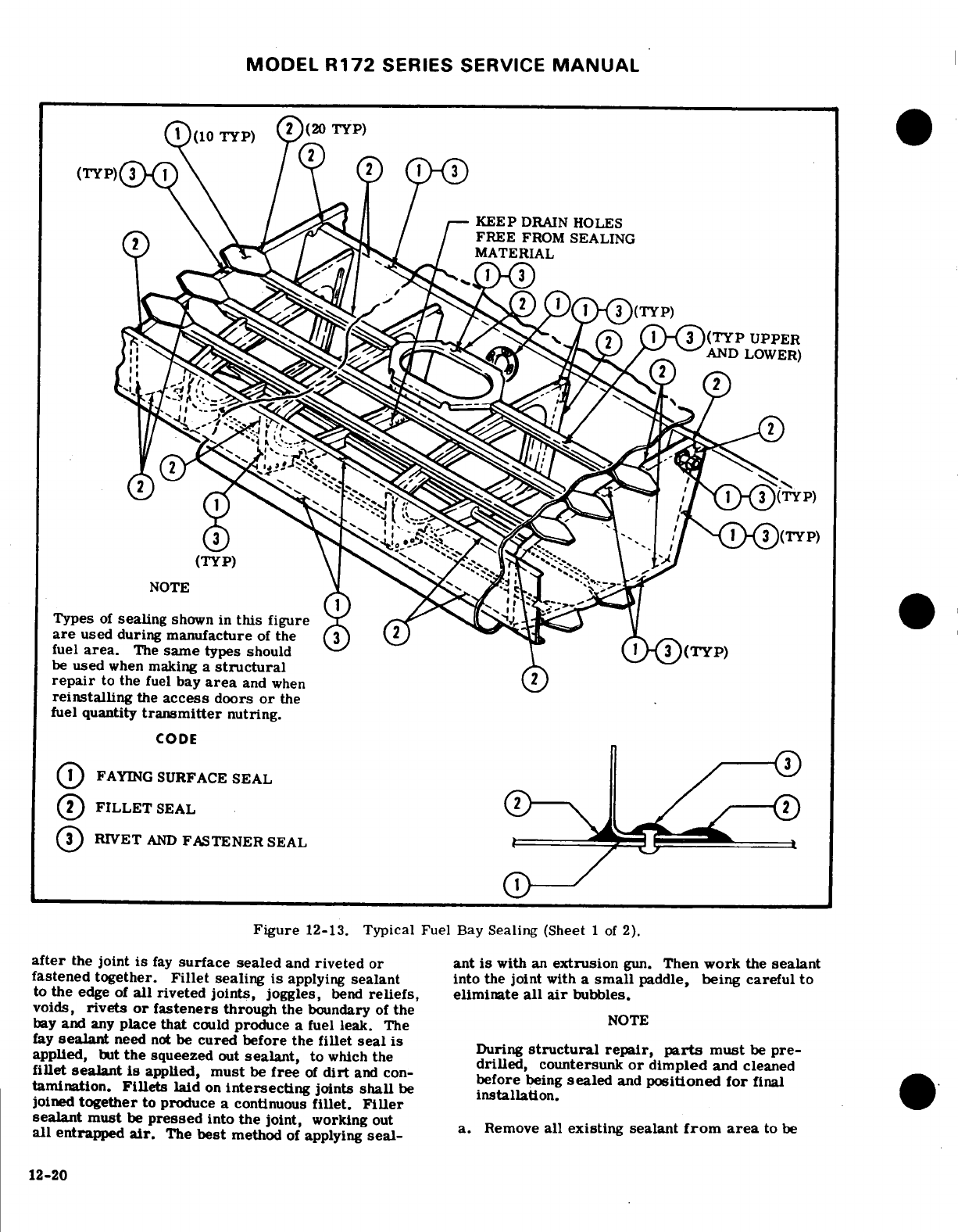
MODEL
R172
SERIES
SERVICE
MANUAL
KEEP
DRAIN
HOLES
FREE
FROM
SEALING
AND
LOWER)
Types
of
sealing
shown
in
this
figure
are
used
during
manufacture
of
the
fuel
area.
The
same
types should
FAYING
SURFACE
SEAL
be
used
when
making
a
structural
Figure
12-1.
Tp
fuel
after
the
joint
is
fay
surface
sealed
and
riveted
or
ant
is
with
an
extrusion
gun.
Then
work
the
sealant
fastened
together.
Fillet
sealing
is
applying
sealant
into
the
joint
with
a
small
paddle,
being careful
to
to
the
edge
of
all
riveted
joints,
joggles,
bend
reliefs,
eliminate
all
air
bubbles.
voids,
rivets
or
faes
rs
the
the
fay
sealant
need
not
be
cured
before
the
fillet
seal
is
During
structural
repair,
parts
must
be
pre-
applied,
but
the
squeezed
out
sealant,
to
which the
drilled,
countersunk
or dimpled
and
cleaned
CODE
fillet
sealant
is
applied,
must
be
free
of
dirt
and
con-
before
being
sealed
and
positioned
for
final
tamination.
Fillets
laid
on
intersecting
joints
shall
be
installation.
FILLET
SEAL
RIVET
AND
FASTENER
SEAL
Figure
12-13.
Typical
Fuel
Bay
Sealing
(Sheet
1
of
2).
after
the
joint
is
fay
surface sealed
and
riveted
or
ant
is
with
an
extrusion
gun.
Then
work
the
sealant
fastened together.
Fillet
sealing
is
applying
sealant
into the
joint
with
a
small
paddle,
being careful
to
to
the
edge
of
all
riveted
joints,
joggles,
bend
reliefs,
all
air
bubbles.
voids,
rivets
or
fasteners
through
the
boundary
of
the
NOTE
bay
and
any
place that
could
produce
a
fuel
leak.
The
fay
sealant
need
not
be
cured
before
the
fillet
seal
is
structural
repair,
parts
must
be
pre-
applied,
but
the
squeezed
out
sealant,
to
which
the
drilled,
countersunk
or
dimpled
and
cleaned
fillet
sealant
is
applied,
must
be
free
of
dirt
and
con-
^^
positioned
for
final
tamination.
Fillets
laid
on
intersecting
joints
shall
be
installation.
joined
together
to
produce a
continuous
fillet.
Filler
sealant
must
be
pressed
into
the
joint,
working
out Remove
all
existing sealant
from
area
to
be
all
entrapped
air.
The
best
method
of
applying
seal-
12-20
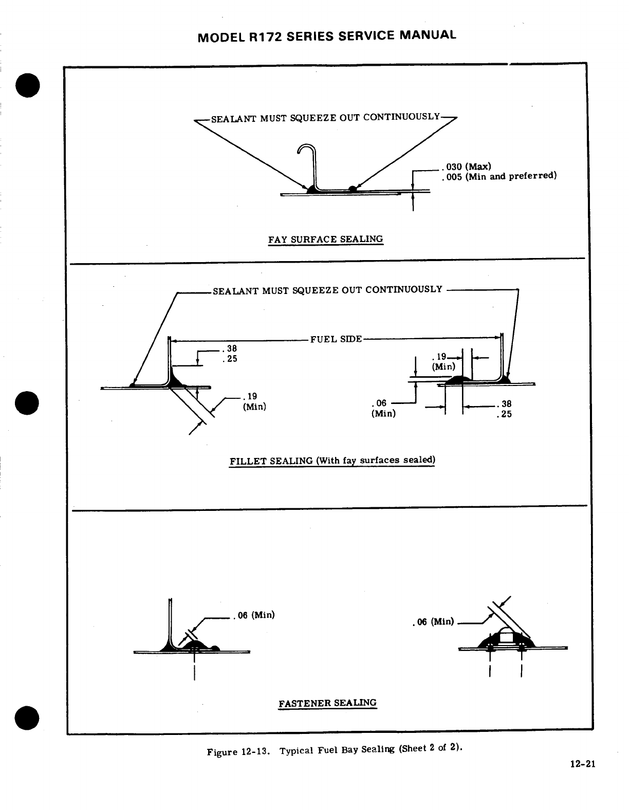
MODEL
R172
SERIES
SERVICE
MANUAL
SEALANT
MUST
SQUEEZE
OUT
CONTINUOUSLY
.030
(Max)
.005
(Min
and
preferred)
FAY
SURFACE
SEALING
SEALANT
MUST
SQUEEZE
OUT
CONTINUOUSLY
/
------
FUEL
SIDE
(Min)
FILLET
SEALING
(With
fay
surfaces
sealed)
.
(Min)
FASTENER
SEALING
Figure
12-13.
Typical
Fuel
Bay
Sealing
(Sheet
2
of
2).
12-21
MODEL
R172
SERIES
SERVICE
MANUAL
sealed,
leaving
a
taper
on
the
remaining
sealant.
be
found
by
testing
the
complete
bay
as
described
in
The
taper
will
allow
a
scarf
bond
and
a
continuous
paragraph
12-50.
Another
method
of
detecting
the
seal
when
the
new
sealant
is
applied.
source
of
a
fuel
leak
is
to
remove
access
doors
and
blow with
an
air
nozzle
from
the
inside
of
the
bay
in
NOTE
the
area
of
the
leak
while
a
soap
bubble
solution
is
applied
to
the
outside
of
the
bay.
After
the
leak
The
best
method
of
removing
sealant
is
with
source
has
been
found,
proceed
as
follows:
a
chisel-like
tool
made
of
hard
fiber.
Re-
a.
Remove
existing
sealant
in
the
area
of
the
leak
maining
sealant
may
then
be
removed
with
as
described
in
paragraph
12-47,
step
"a."
aluminum
wool.
Steel
wool
or
sandpaper
b.
Clean
the
area
and apply
a
fillet
seal.
Press
must
not
be
used.
sealant
into
leaking
area
with
a
small
paddle,
being
sure
to
work
out
all entrapped
air.
b.
Vacuum
thoroughly
to
remove
all
chips, filings,
c.
If
a
leak
occurs
around
a
rivet
or
bolt,
restrike
dirt,
etc.,
from
the bay
area.
the
rivet
or
torque
the
bolt
to
the
maximum
allowable
c.
All
surfaces
and
areas
to
be
sealed
shall
be
torque,
and
repair
any
damaged
sealant.
thoroughly cleaned
by
wiping
with
a
clean
cloth
damp-
d.
Apply fay
surface
door
sealant
to
access
doors
ened
with Methyl
Ethyl
Ketone
(MEK),
acetone
or or
fuel
quantity
transmitter
adapter,
if
removed,
and
similar
solvent
and
dried
with
a
clean
cloth
before
install
the
doors
and
adapter.
the
solvent
evaporates.
Always pour
the
solvent
on e.
Test
fuel
bay
for
leaks
as described
in
para-
the
cloth.
Never
use
contaminated solvent.
The
graph
12-50.
cloth
shall
not
be
so
saturated
that
dripping
occurs.
12-49.
CURING
TIME.
Service
Kit
SK210-56
con-
NOTE
tains
SP654890B2
Fuel
Tank
Area
Sealant
Kit
and
SP654706B2
Access
Door
Sealant
Kit.
Normal
cur-
Allowable
work
life
of
EC-1675B/A
sealant
ing
time
for
SP654890B2
Sealant
Kit
is
72
hours.
is
four
hours
from
the
starting
time
of
mix-
Normal
curing
time
for
SP654706B2
Sealant
Kit
is
ing.
Allowable
work
life
of
EC-1608B/A
24
hours.
These
values
are
based
on
a
Standard
sealant
is
one
hour.
These
apply
to
stand-
condition
of
77
°
Fahrenheit
and
50%
humidity.
Cur-
ard
conditions
of
77
°
Fahrenheit
and
50%
rel-
ing
time
may
be
accelerated
as
shown
in
the
follow-
ative
humidity.
An
increase
in
temperature
ing
chart.
or
a
decrease
in
humidity will
shorten
the
work
life
of
the
sealant.
Temperature
of
Sealant
°F.
Time
in
Hours
d.
Apply fay
surface
sealant
to
one
mating
part
and
install rivets
or
fasteners
while
sealant
is
still
with-
in
its
allowable
work
life.
160
3
140
NOTE
120
During
the
sealing operation,
sealant
must
be
checked
at
various
times
to
determine
that
it
NOTE
has
not
exceeded
its
allowable
work lifo.
Use
a
small
wood
paddle,
such
as
a
tongue
depres-
Temperature
shall
not
exceed
160°F.
Bay
must
sor,
to
gather
some
sealant.
Touch
the
seal-
be
vented
to
relieve
pressure
during
accelerated
ant
to
a
piece
of
clean
sheet
metal.
If
the
curing.
sealant adheres
to the
sheet
metal,
it
is
still
within
its
allowable
work
life.
If
the
sealant
WARNING
does
not
adhere
to
the
sheet
metal,
it
is
be-
yond
its
allowable
work
life
and
must
not
be
Access
door
sealant
must
not
be
heated
above
used.
90
°
until
sealant
is
cured
for
24
hours
based
on
a
standard
condition
of
77
°
Fahrenheit
and
e.
Apply
a
fillet
seal
to
the
repaired
area
on
the
50%
relative
humidity. Harmful
vapors
are
inside
of
the
bay.
released
if
sealant
is
heated
above
90°F.
f.
Apply
fay
surface
door
sealant
to
access
doors
and
fuel
quantity
transmitter
adapter,
if
removed,
12-50.
TESTING
INTEGRAL
FUEL
BAY.
and
install
the
doors
and
adapter.
a.
Remove
vent
line
from
vent
fitting
and
cap
the
g.
Allow
the
sealant
to
cure.
Refer
to
paragraph
fitting.
12-49
for
curing
time.
b.
Remove
forward
and aft
fuel
lines
from
bay.
h.
Clean
stains
from
outside
of
bay
area.
c.
To
one
of
the
bay
fittings, attach
a
water
ma-
i.
Test
fuel
bay
for
leaks
as
described
in
paragraph
nometer
capable
of
measuring
20
inches
of
water.
12-50.
d.
To
the
other
bay
fitting,
connect
a
well
regula-
ted
supply
of
air
(1/2
PSI
MAXIMUM
or
13.
8
12-48.
SEALING
FUEL
LEAKS.
First
determine
the
INCHES
OF
WATER).
Nitrogen
may be
used
where
source
of
the
fuel
leaks.
Fuel can
flow
along
a
seam
the
bay
might
be
exposed
to
temperature
changes
or
the
structure
of
the
wing
for
several
inches,
mak-
while
testing.
ing
the
leak
source
difficult
to
find.
A
stained
area
e. Make
sure
filler
cap
is
installed
and
sealed.
is
an
indication
of
the
leak
source.
Fuel
leaks
can
12-22
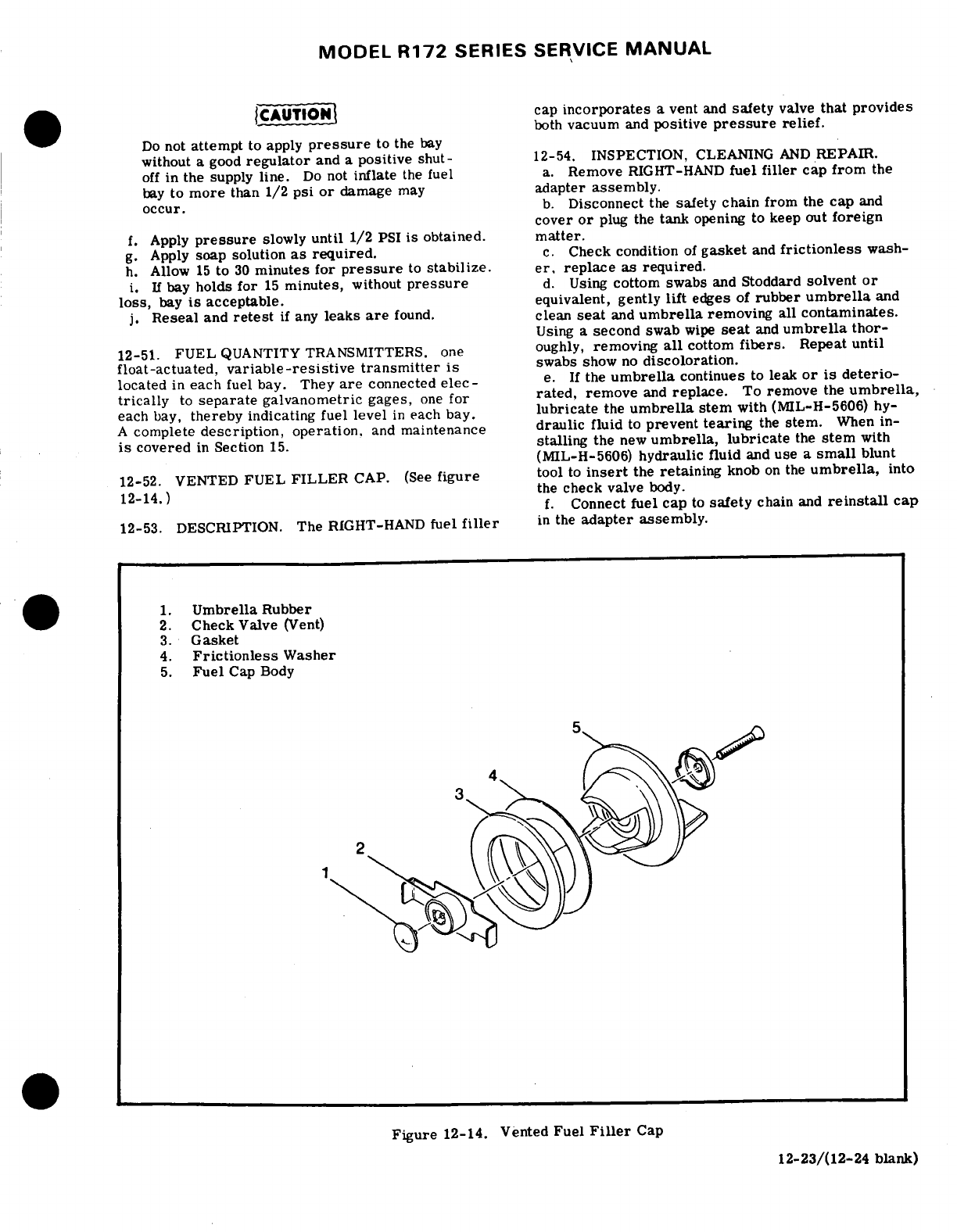
MODEL
R172
SERIES
SERVICE
MANUAL
CAUTION
cap
incorporates
a
vent
and
safety
valve
that
provides
both
vacuum
and
positive
pressure
relief.
Do
not
attempt
to
apply
pressure
to
the
bay
without
a
good
regulator
and
a positive
shut-
12-54.
INSPECTION,
CLEANING
AND
REPAIR.
off
in
the
supply
line.
Do
not
inflate
the
fuel
a.
Remove
RIGHT-HAND
fuel
filler
cap
from
the
bay
to
more
than
1/2
psi
or
damage
may
adapter
assembly.
occur.
b.
Disconnect
the
safety
chain
from
the
cap
and
cover
or
plug
the
tank
opening
to
keep
out
foreign
f.
Apply
pressure
slowly
until
1/2
PSI
is
obtained.
matter.
g.
Apply
soap
solution
as
required.
c.
Check
condition
of
gasket
and
frictionless
wash-
h.
Allow
15
to
30
minutes
for
pressure
to
stabilize.
er,
replace
as
required.
i.
If
bay
holds
for
15
minutes,
without
pressure
d.
Using
cottom swabs
and
Stoddard
solvent
or
loss,
bay
is
acceptable.
equivalent,
gently
lift
edges
of
rubber
umbrella
and
j.
Reseal
and
retest
if
any
leaks
are
found,
clean
seat
and
umbrella
removing
all
contaminates.
Using
a
second
swab
wipe
seat
and
umbrella
thor-
12-51.
FUEL
QUANTITY
TRANSMITTERS. one
oughly,
removing
all
cottom
fibers.
Repeat
until
float-actuated,
variable-resistive
transmitter
is
swabs
show
no
discoloration.
located
in
each
fuel
bay.
They
are
connected
elec-
e.
If
the
umbrella
continues
to
leak
or
is
deterio-
trically
to
separate
galvanometric
gages,
one
for
rated,
remove
and
replace.
To
remove
the
umbrella,
each
bay,
thereby
indicating
fuel
level
in
each
bay.
lubricate
the
umbrella
stem
with (MIL-H-5606)
hy-
A
complete
description,
operation,
and
maintenance
draulic
fluid
to
prevent
tearing
the
stem.
When
in-
is
covered
in
Section
15.
stalling
the
new
umbrella,
lubricate
the
stem
with
(MIL-H-5606)
hydraulic
fluid
and
use
a
small
blunt
12-52.
VENTED
FUEL
FILLER
CAP.
(See
figure
tool
to
insert
the
retaining
knob
on
the
umbrella,
into
12-14.)
the
check valve
body.
f.
Connect
fuel
cap
to
safety
chain
and
reinstall
cap
12-53. DESCRIPTION.
The
RIGHT-HAND
fuel
filler
in
the
adapter
assembly.
1.
Umbrella
Rubber
2.
Check
Valve
(Vent)
3.
Gasket
4.
Frictionless
Washer
5.
Fuel
Cap
Body
Figure
12-14.
Vented
Fuel
Filler
Cap
12-23/(12-24
blank)
MODEL
R172
SERIES
SERVICE
MANUAL
SECTION
13
PROPELLER
AND
GOVERNOR
WHEN PERFORMING
ANY
INSPECTION
OR
MAINTENANCE
THAT
REQUIRE
TURNING
ON
THE
MASTER
SWITCH,
INSTALLING
A
BATTERY,
OR
TURNING
THE PROPELLER
THROUGH
BY
HAND,
TREAT
THE
PROPELLER
AS
IF
THE IGNITION
SWITCH WERE
ON.
DO
NOT
STAND, NOR
ALLOW
ANYONE
ELSE
TO STAND,
WITHIN
THE
ARC
OF
THE PROPELLER,
SINCE
A
LOOSE
OR
BROKEN
WIRE,
OR
A
COMPONENT
MALFUNCTION
COULD
CAUSE
THE
PROPELLER
TO
ROTATE.
Page
No.
Page
No.
TABLE
OF
CONTENTS
Aerofiche/Manual
Aerofiche/Manual
PROPELLER
.....................
NA/13-1
GOVERNOR
........................
NA/13-7
Description
.....................
NA/13-1
Description
.....................
NA/13-7
Repair
..........
..............
NA/13-1
Trouble
Shooting
...............
NA/13-7
Trouble
Shooting
............
NA/13-2
Removal..
NA/13-7
Removal
.......................
NA/13-3
Installation
....................
NA/13-7
Installation
....................
NA/13-3
High
RPM
Stop
Adjustment
......
NA/13-8
Time
Between
Overhaul
(TBO)
...
NA/13-7
Rigging
Governor
Control
.......
NA/13-8
Time
Between
Overhaul
(TBO)
...
NA/13-8
13-1.
PROPELLER.
(See
figure
13-1.)
NOTE:
13-2.
DESCRIPTION. The
airplane
is
equipped
with
an
For
information
not
covered
in
this
section,
refer
all
metal,
constant-speed,
governor-regulated
to
the
applicable McCauley
Service
Manual
and
propeller.
The
constant-speed
propeller
is
single
applicable
supplements.
acting,
in
which
engine
oil
pressure,
boosted
and
regulated
by
the
governor
is
used
to
obtain
the
13-3.
REPAIR.
Metal
propeller repair
first
involves
correct
blade
pitch
for
the
engine
load.
Engine
evaluating
the
damage
and
determining
whether
lubrication
oil
is
supplied
to
the
power
piston
in
the
the
repair
will
be
a
major
or
minor
one.
Federal
propeller
hub
through the
crankshaft.
The
amount
Aviation Regulations,
Part
43
(FAR
43),
and
and
pressure
of
the
oil
supplied
is
controlled
by
the
Federal Aviation
Agency,
Advisory
Circular
No
engine
driven
governor.
An increase
or
decrease
in
throttle
setting
or
a
change
in
aircraft attitude
will
43.13
(FAA
AC
No.
43.13),
define
major
and
minor
affect
the
balance
which
maintains
a
given
RPM.
If repairs,
alterations
and
who may
accomplish
them.
the
throttle
is
opened
further
or
if
the
aircraft
speed
When
making
repairs
or
alterations
to
a
propeller
is
increased,
engine
RPM
will
try
to
increase.
The
FAR
43,
FAA
AC
No.
43.13
and
the
propeller
governor
senses
this
and
directs
oil
pressure
to
the
manufacturer's
instructions
must
be
observed.
forward
side
of
the
piston in
the
propeller
hub.
The
blades
will
be moved
to
a higher pitch
and
engine
speed
will
remain
constant.
Conversely,
if
the
throttle
opening
or
the
aircraft
speed
is
decreased,
the
engine
RPM
will
try
to
decrease.
The
governor
senses
this
and
allows
oil
to
drain
from
the
forward
side
of
the
piston.
Spring
tension and centrifugal
twisting
moment
will
move
the
blades
to
a
lower
pitch
to
maintain
the
selected
engine
speed.
Temporary
Revision
Number
2
13-1
April
3,1998
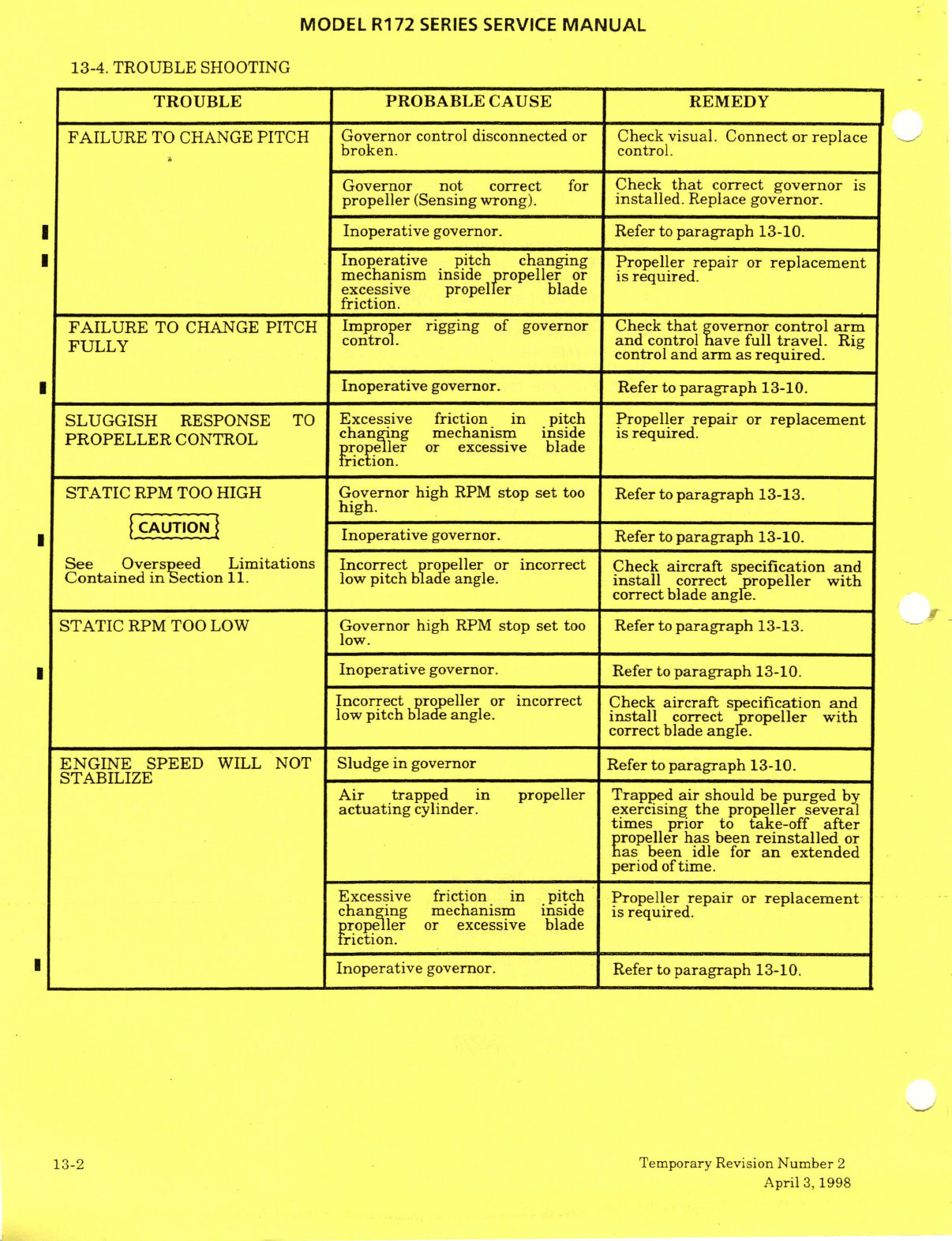
MODEL
R172
SERIES
SERVICE
MANUAL
13-4.
TROUBLE
SHOOTING
TROUBLE
PROBABLE
CAUSE
REMEDY
FAILURE
TO
CHANGE
PITCH
Governor
control
disconnected
or
Check
visual.
Connect
or
replace
broken.
control.
Governor
not correct
for
Check
that
correct
governor
is
propeller
(Sensing
wrong).
installed.
Replace
governor.
Inoperative
governor.
Refer
to
paragraph
13-10.
Inoperative
pitch
changing
Propeller
repair
or
replacement
mechanism
inside
propeller
or
is
required.
excessive
propeller
blade
friction.
FAILURE
TO CHANGE
PITCH
Improper
rigging
of
governor
Check
that
governor
control
arm
FULLY
and
control
have
full
travel.
Rig
control
and
arm
as
required.
Inoperative
governor.
Refer
to
paragraph
13-10.
SLUGGISH
RESPONSE
TO
Excessive friction
in
pitch
Propeller
repair
or
replacement
PROPELLER
CONTROL
changing
mechanism
inside
is
required.
propeller
or
excessive
blade
friction.
STATIC
RPM
TOO
HIGH
Governor
high
RPM
stop
set
too
Refer
to
paragraph
13-13.
high.
Inoperative
governor.
Refer
to
paragraph
13-10.
See
Overspeed
Limitations Incorrect
propeller
or
incorrect
Check
aircraft
specification
and
Contained in
Section
11.
low
pitch
blade angle.
install
correct
propeller
with
correct
blade
angle.
STATIC
RPM
TOO LOW
Governor
high
RPM
stop
set
too
Refer
to
paragraph
13-13.
low.
Inoperative
governor.
Refer
to
paragraph
13-10.
Incorrect
propeller
or
incorrect
Check
aircraft
specification
and
low
pitch
blade
angle.
install
correct
propeller
with
correct
blade
angle.
ENGINE
SPEED
WILL
NOT
Sludge
in
governor
Refer
to
paragraph
13-10.
STABILIZE
Air
trapped
in
propeller
Trapped
air
should
be
purged
by
actuating
cylinder.
exercising
the
propeller
several
times
prior
to
take-off
after
propeller
has
been
reinstalled
or
has
been
idle
for
an
extended
period
of
time.
Excessive friction
in
pitch Propeller
repair
or
replacement
changing
mechanism
inside
is
required.
propeller
or
excessive
blade
friction.
Inoperative
governor.
Refer
to
paragraph
13-10.
13-2
Temporary Revision
Number
2
April
3,
1998
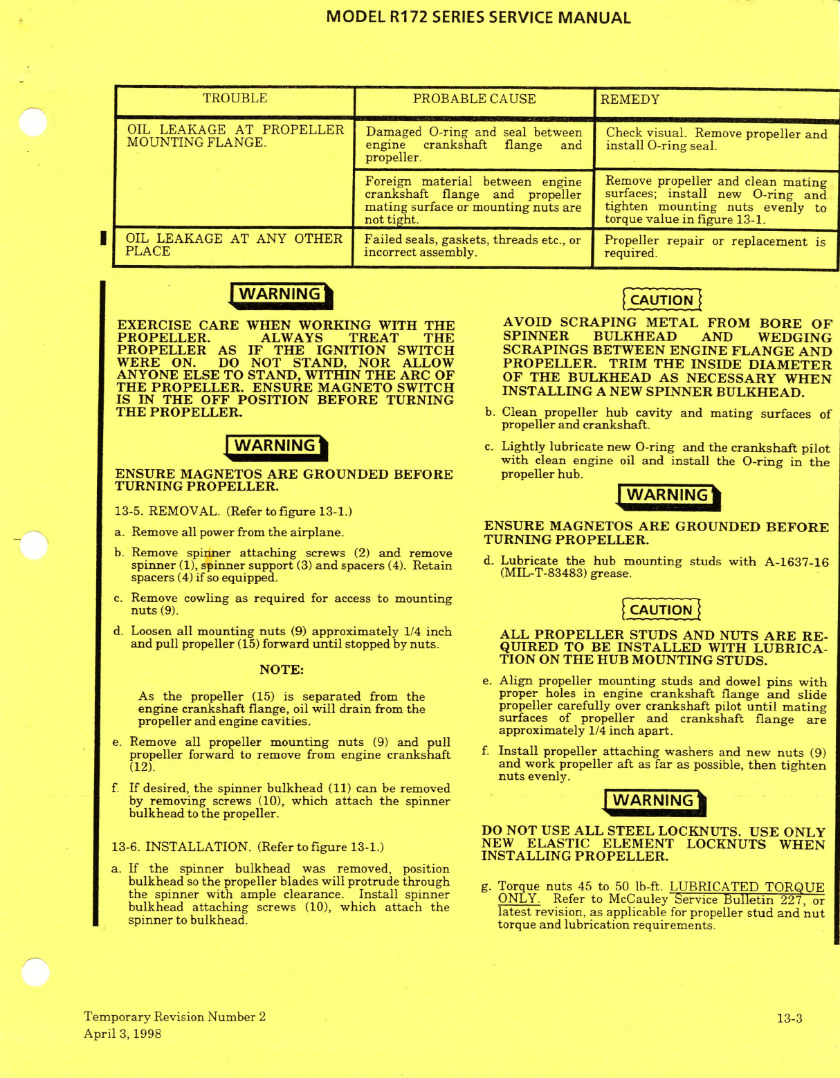
MODEL
R172
SERIES
SERVICE
MANUAL
TROUBLE PROBABLE
CAUSE
REMEDY
OIL
LEAKAGE
AT
PROPELLER Damaged
O-ring and
seal
between
Check
visual.
Remove
propeller
and
MOUNTING
FLANGE.
engine
crankshaft
flange
and
install
O-ring
seal.
propeller.
Foreign
material
between
engine
Remove
propeller
and
clean
mating
crankshaft
flange
and
propeller
surfaces;
install
new
O-ring
and
mating
surface
or
mounting
nuts
are
tighten mounting nuts
evenly
to
not
tight.
torque
value in
figure
13-1.
OIL
LEAKAGE
AT
ANY
OTHER
Failed
seals,
gaskets,
threads
etc.,
or
Propeller
repair
or
replacement
is
PLACE
incorrect
assembly.
required.
WARNING
EXERCISE
CARE WHEN
WORKING
WITH
THE
AVOID
SCRAPING
METAL
FROM
BORE
OF
PROPELLER.
ALWAYS
TREAT THE
SPINNER
BULKHEAD
AND
WEDGING
PROPELLER
AS
IF
THE
IGNITION
SWITCH
SCRAPINGS
BETWEEN
ENGINE
FLANGE
AND
WERE
ON.
DO
NOT
STAND, NOR
ALLOW
PROPELLER.
TRIM
THE
INSIDE
DIAMETER
ANYONE
ELSE
TO
STAND,
WITHIN
THE
ARC
OF OF THE
BULKHEAD
AS
NECESSARY
WHEN
THE
PROPELLER.
ENSURE
MAGNETO
SWITCH
INSTALLING
A
NEW
SPINNER
BULKHEAD.
IS
IN
THE
OFF POSITION
BEFORE
TURNING
THE
PROPELLER.
b.
Clean
propeller
hub
cavity
and
mating
surfaces
of
propeller
and
crankshaft.
c.
Lightly
lubricate
new O-ring
and
the
crankshaft
pilot
with
clean
engine
oil
and
install
the
O-ring
in
the
ENSURE
MAGNETOS
ARE
GROUNDED
BEFORE
propeller
hub.
TURNING
PROPELLER. WARNING
13-5.
REMOVAL. (Refer
to
figure
13-1.)
a.
Remove
all
power
from
the airplane.
ENSURE
MAGNETOS
ARE
GROUNDED
BEFORE
ENSURE
MAGNETOS
ARE
GROUNDED
BEFORE
Remove all power from
the
airplane.
TURNING
PROPELLER.
b.
Remove
spinner
attaching
screws
(2)
and
remove
spinner
(1),
spinner
support
(3)
and
spacers
(4).
Retain
d.
Lubricate
the
hub
mounting
studs
with
A-163716
spacers
(4)
if
so
equipped.
MIL-T-83483)
grease.
c.
Remove
cowling
as required
for
access
to
mounting
nuts
(9).
d.
Loosen
all
mounting
nuts
(9)
approximately
1/4
inch
ALL
PROPELLER
STUDS
AND
NUTS
ARE
RE-
and
pull propeller
(15)
forward
until
stopped
by
nuts.
QUIRED
TO
BE
INSTALLED
WITH
LUBRICA-
TION
ON
THE
HUB MOUNTING STUDS.
NOTE:
e.
Align
propeller
mounting
studs
and
dowel
pins
with
As
the
propeller
(15)
is
separated
from
the
proper
holes
in
engine
crankshaft
flange
and
slide
engine
crankshaft
flange,
oil
will
drain
from
the
propeller
carefully
over
crankshaft
pilot
until mating
propeller
and engine
cavities.
surfaces
of
propeller and
crankshaft flange
are
approximately
1/4
inch
apart.
e.
Remove
all
propeller
mounting
nuts
(9)
and
pull
propeller
forward
to
remove
from
engine
crankshaft
f.
Install
propeller
attaching
washers
and
new
nuts
(9)
(12).
and
work
propeller
aft
as
far
as
possible,
then
tighten
nuts
evenly.
f.
If
desired,
the spinner
bulkhead
(11)
can
be
removed
by
removing
screws
(10),
which
attach
the
spinner
WARNING
bulkhead
to
the
propeller.
DO
NOT
USE
ALL
STEEL
LOCKNUTS.
USE
ONLY
13-6.
INSTALLATION.
(Refer
to figure
13-1.)
NEW
ELASTIC
ELEMENT
LOCKNUTS
WHEN
INSTALLING
PROPELLER.
a.
If
the
spinner
bulkhead
was
removed,
position
bulkhead
so
the
propeller
blades
will
protrude through
g.
Torque
nuts
45
to
50
lb-ft.
LUBRICATED
TORQUE
the
spinner with
ample
clearance.
Install
spinner
ONLY.
Refer to McCauley Service
Bulletin
227,
or
bulkhead
attaching
screws
(10),
which
attach
the
latest
revision,
as
applicable
for
propeller
stud and
nut
spinner
to bulkhead.
torque
and
lubrication
requirements.
Temporary
Revision
Number
2
13-3
April
3,
1998
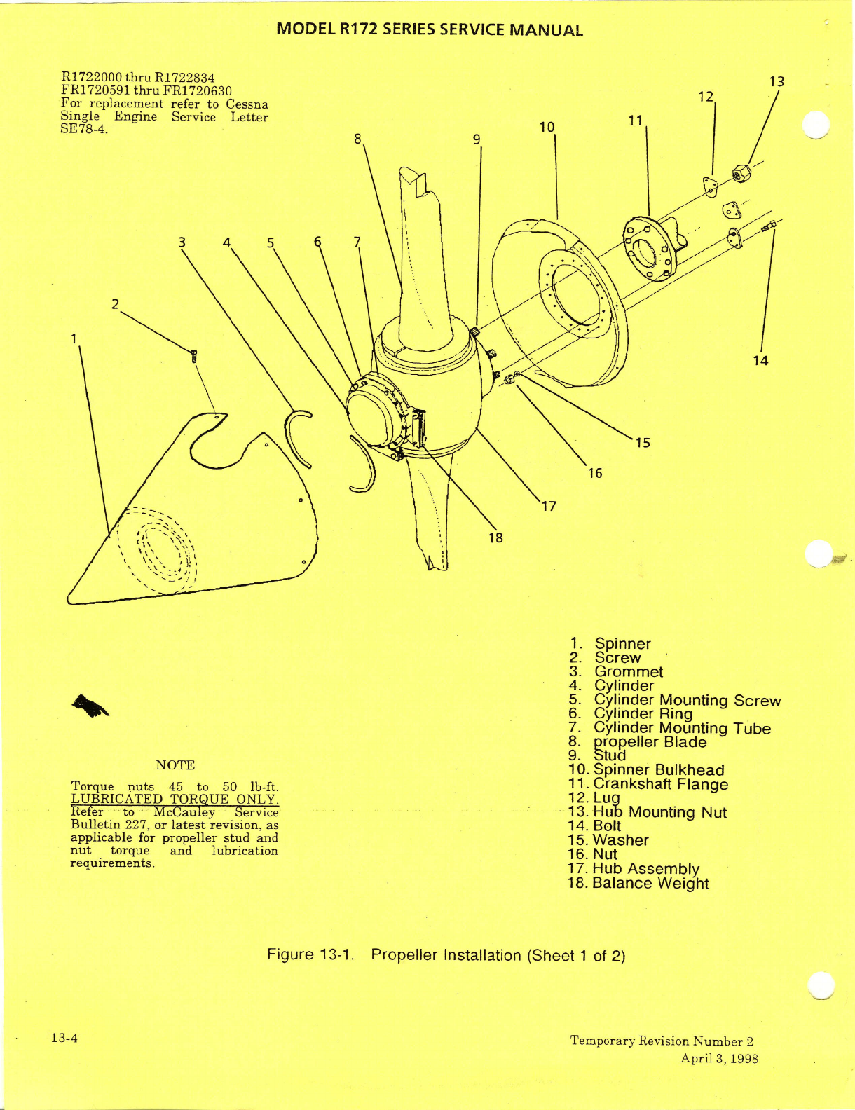
MODEL
R172
SERIES
SERVICE
MANUAL
R1722000
thru
R1722834
13
FR1720591
thru
FR1720630
1 2
For
replacement
refer
to
Cessna
Single
Engine
Service
Letter
SE78-4.
2
1.
Spinner
2.
Screw
3.
Grommet
4.
Cylinder
5.
Cylinder
Mounting
Screw
6. Cylinder
Ring
7.
Cylinder
Mounting
Tube
8.
ropeller Blade
9.
Stud
NOTE
10.
Spinner
Bulkhead
Torque
nuts
45
to
50 lb-ft.
11.Crankshaft
Flange
LUBRICATED
TORQUE
ONLY.
12.
Lug
Refer
to
McCauley
Service
13.
Hub
Mounting
Nut
Bulletin
227,
or
latest
revision,
as
14.
Bolt
applicable
for
propeller
stud
and
15.
Washer
nut
torque and
lubrication
16.
Nut
requirements.
17.
Hub
Assembly
18.
Balance
Weight
Figure
13-1.
Propeller
Installation
(Sheet
1
of
2)
13-4
Temporary
Revision
Number
2
April
3,
1998
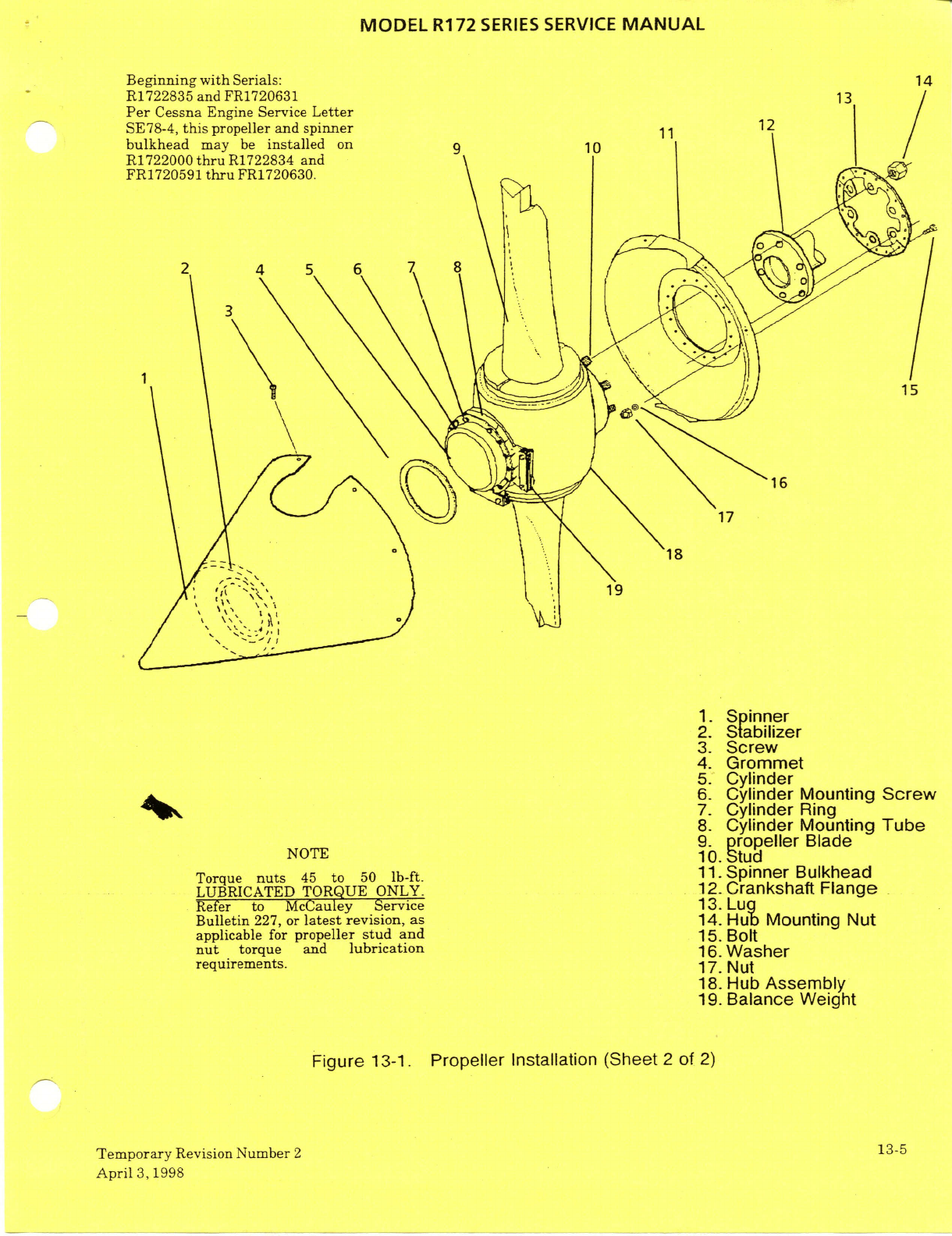
MODEL
R172
SERIES
SERVICE
MANUAL
Beginning
with
Serials:
14
R1722835
and
FR1720631
13
Per
Cessna
Engine
Service
Letter
SE78-4,
this
propeller
and spinner
1112
bulkhead
may
be
installed
on
9
10
R1722000
thru
R1722834
and
FR1720591
thru
FR1720630.
15
17
18
19
1.
Spinner
2.
Stabilizer
3.
Screw
4.
Grommet
5.
Cylinder
6.
Cylinder
Mounting
Screw
7.
Cylinder
Ring
8.
Cylinder
Mounting
Tube
9.
propeller
Blade
NOTE
10.
Stud
Torque
nuts
45
to
50
lb-ft.
11.Spinner
Bulkhead
LUBRICATED
TORQUE
ONLY.
12.
Crankshaft
Flange
Refer
to McCauley
Service
13.
Lug
Bulletin
227, or
latest
revision,
as
14.
Hub
Mounting
Nut
applicable
for
propeller
stud
and
15.
Bolt
nut
torque
and
lubrication
16.
Washer
requirements.
17.
Nut
18.
Hub
Assembly
19.
Balance
Weight
Figure
13-1.
Propeller
Installation (Sheet
2
of
2)
Temporary
Revision
Number
2
13-5
April
3,1998
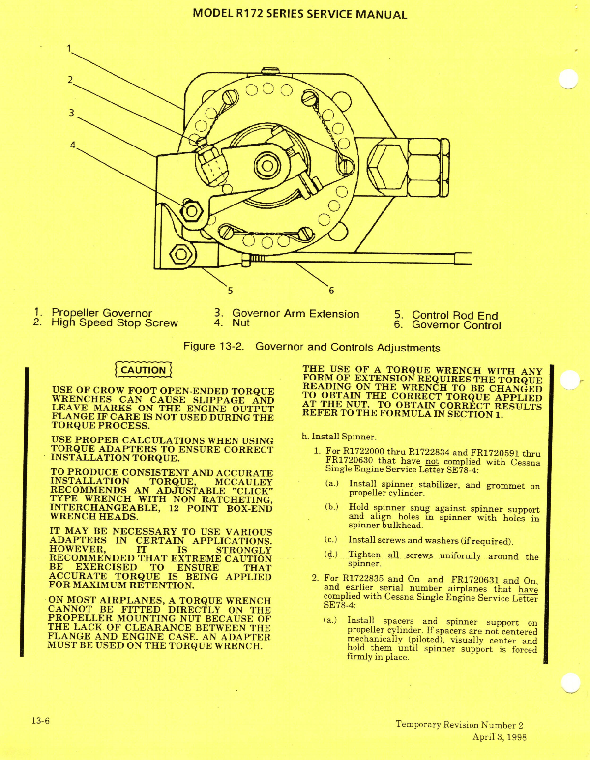
MODEL
R172
SERIES
SERVICE
MANUAL
5
6
1.
Propeller
Governor
3.
Governor
Arm
Extension
5.
Control
Rod
End
2.
High Speed
Stop
Screw
4. Nut
6.
Governor
Control
Figure
13-2.
Governor
and Controls
Adjustments
THE
USE
OF
A
TORQUE
WRENCH
WITH
ANY
FORM
OF
EXTENSION
REQUIRES
THE
TORQUE
READING
ON
THE
WRENCH
TO
BE
CHANGED
USE OF
CROW
FOOT
OPEN-ENDED
TORQUE TO
OBTAIN
THE
CORRECT
TORQUE
APPLIED
WRENCHES
CAN
CAUSE
SLIPPAGE
AND
AT
THE
NUT.
TO
OBTAIN
CORRECT
RESULTS
LEAVE MARKS
ON
THE
ENGINE
OUTPUT
REFER
TO
THE
FORMULA
IN
SECTION
1.
FLANGE
IF
CARE
IS
NOT
USED
DURING
THE
TORQUE
PROCESS.
h.
Install
Spinner.
USE
PROPER
CALCULATIONS
WHEN
USING
Install
Spinner.
TORQUE
ADAPTERS
TO
ENSURE
CORRECT
1.
For
R1722000
thru
R1722834
and
FR1720591
thru
INSTALLATION TORQUE.
FR1720630
that
have
not
complied
with
Cessna
TO PRODUCE
CONSISTENT
AND
ACCURATE
Single
Engine
Service
Letter
SE78-4:
TO
PRODUCE
CONSISTENT
AND
ACCURATE
INSTALLATION
TORQUE,
MCCAULEY
(a.)
Install spinner
stabilizer,
and
grommet
on
RECOMMENDS
AN
ADJUSTABLE
"CLICK"
propeller cylinder.
TYPE
WRENCH WITH
NON
RATCHETING,
INTERCHANGEABLE,
12
POINT
BOX-END
(b.)
Hold
spinner
snug
against
spinner
support
WRENCH
HEADS.
and
align
holes
in
spinner
with
holes
in
spinner
bulkhead.
IT
MAY
BE
NECESSARY
TO
USE
VARIOUS
ADAPTERS
IN
CERTAIN
APPLICATIONS.
(c.)
Install
screws
and
washers
(if
required).
HOWEVER, IT
IS
STRONGLY
(d.)
Tighten
all
screws
uniformly
around
the
RECOMMENDED
THAT
EXTREME
CAUTION
spinner.
BE
EXERCISED
TO
ENSURE
THAT
ACCURATE
TORQUE
IS
BEING
APPLIED
2.
For
R1722835
and
On
and
FR1720631
and
On,
FOR
MAXIMUM
RETENTION.
and
earlier
serial
number
airplanes
that
have
ON MOST
AIRPLANES,
A
TORQUE
WRENCH
complied
with
Cessna
Single Engine
Service
Letter
ON
MOST
AIRPLANES,
A
TORQUE WRENCH
SE78-4:
CANNOT
BE
FITTED
DIRECTLY
ON
THE
PROPELLER
MOUNTING
NUT
BECAUSE
OF
(a.)
Install
spacers
and
spinner
support
on
THE
LACK
OF
CLEARANCE
BETWEEN
THE
propeller
cylinder.
If
spacers
are
not
centered
FLANGE
AND
ENGINE
CASE.
AN
ADAPTER
mechanically
(piloted),
visually
center
and
MUST
BE
USED
ON
THE
TORQUE
WRENCH.
hold
them
until
spinner support
is
forced
firmly
in
place.
13-6
Temporary
Revision
Number
2
April
3,
1998
MODEL
R172
SERIES
SERVICE
MANUAL
(b.)
Hold
spinner
snug
against
spinner
support
and
13-10.
TROUBLESHOOTING.
When
troubleshooting
the
check
alignment
of
holes
in
spinner
with
holes
in
propeller/governor
combination,
it
is
spinner
bulkhead.
Add
or
remove
spacers
from
recommended
that
a
governor
known
to
be
in
good
propeller
cylinder
until
holes
are within
.050
inch condition
be
installed
to check
whether the
forward
of
the
true
center
of
holes
in
spinner propeller
or
the
governor
has
failed.
Removal
and
bulkhead
assembly.
bulkhead assembly.
replacement,
rigging
high-speed
stop
adjustment,
(c.)
Push
on
spinner
to
align
holes
and
install
screws
de-sludging
and
replacement
of
the
governor
and
washers
(if
required)
in
three
(3)
or more
mounting
gasket are
not
major
repairs
and
may
be
equal
spacers
around the
spinner
bulkhead
(11).
accomplished
in
the
field.
Repairs
to
propeller
Relax
pressure
on
spinner
and
install
remaining
governors
are
classed
as
propeller
major
repairs
in
screws
and
washers
(if
required)
in
spinner.
the
Federal
Aviation
Regulations,
which
also
(d.)
Tighten
all
screws
uniformly
around the
spinner.
define
who may accomplish
such
repairs.
13-7.
TIME
BETWEEN
OVERHAUL
(TBO).
Propeller
13-11.
REMOVAL.
(See
Figure
13-2.)
overhaul shall
coincide
with
engine
overhaul,
but
shall
not
exceed
limits
specified
in
McCauley
a.
Remove
all
electrical power from
the
Service
Bulletin
137
and
all
revisions
and
airplane.
supplements
thereto.
b.
Remove
cowling
and
engine
baffles
as
required
for
access
to
the
governor.
13-8.
GOVERNOR.
(See
Figurer
13-2.)
for
access
to
the
governor
c.
Disconnect
governor
control
from
WARNING
governor
extension
arm.
EXERCISE
CARE
WHEN
WORKING
WITH
NOTE:
THE
PROPELLER.
ALWAYS
TREAT
THE
Note
the
position
of
all
washers
so
that
washers
PROPELLER
AS
IF
THE
IGNITION
SWITCH
may
be
installed in
the
same
position
on
WERE
ON. DO
NOT
STAND
,
NOR
ALLOW
reinstallation.
ANYONE
ELSE
TO
STAND,
WITHIN
THE
ARC
OF
THE
PROPELLER.
ENSURE
d
Remove
four
nuts
and washers
securing
MAGNETO SWITCH
IS
IN
THE
OFF
governor
from
mounting
studs.
POSITION BEFORE
TURNING
THE
e.
Remove
gasket
from
between
governor
and
PROPELLER.
engine mounting
pad.
WARNING
WARNING
13-12.
INSTALLATION.
(See
Figurer
13-2.)
a.
Clean
mating
surfaces
of
propeller
governor
ENSURE
MAGNETOS
ARE
GROUNDED
BEFORE
and engine mounting
surface.
TURNING
THE
PROPELLER.
b.
Install
new
gasket
on
the
mounting
studs.
13-9.
DESCRIPTION.
The
propeller
governor is
a
single-
Install
gasket
with
the
raised surface
of
the
acting,
centrifugal
type,
which
boosts oil
pressure
gasket
screen
toward
the
governor.
from
the
engine
and
directs
it
to
the
propeller where
the
oil
is
used
to
increase
blade pitch.
A
single-
acting
governor
uses
oil
pressure
to
effect
a
pitch
change
in
one
direction
only;
a
pitch
change
in
the
DO
NOT
FORCE GOVERNOR
SPLINE
opposite
direction
results
from
a
combination
of
ENGAGEMENT.
ROTATE
THE
ENGINE
centrifugal
twisting
moment
of
rotating
blades
and
CRANKSHAFT
SLIGHTLY AND
SPLINES
compressed
springs.
Oil
pressure
is
boosted
in
the
WILL
MESH
SMOOTHLY
WHEN
PROPERLY
governor
by
a
gear type
oil
pump.
A
pilot
valve,
ALIGNED.
flyweight
and
speeder
spring
act
together
to
open
c.
Position
governor
on
the mounting
studs
and
close
governor
oil
passages as
required
to
aligning
governor
drive
splines
in
the
engine
and
maintain
a
constant
engine
speed.
install
mounting
nuts
and
washers.
Do
not
force
spline
engagement.
Rotate
engine
crankshaft
as
NOTE:
required
to
properly
align
the propeller
drive
Outward
physical
appearance
of
specific
splines.
governors
is
the
same,
but
internal
parts
d.
Connect
governor
control
to
governor
arm
determine
whether
it
uses
oil
pressure
to
extension
and
rig
control
as
outlined
in
increase
or
decrease
blade
pitch.
The
paragraph
13-14.
propellers
used
on
these
aircraft
require
e.
Reinstall all
items removed for
access.
governors
which
"sense"
in
a
certain
manner.
"Sensing"
is
determined
by
the
type
pilot
valve
installed
inside
the
governor.
Since
the
basic
governor
may
be
sent
to"sense"
oppositely,
it
is
important
to
ascertain
that
the
governor
is
correct
for
the
propeller
being
used.
Temporary
Revision
Number
2
13-7
April
3,
1998
MODEL
R172
SERIES
SERVICE
MANUAL
13-13.
HIGH
RPM
STOP ADJUSTMENT.
THE
PROPELLER
CONTROL
HAS
A
SMALL
RETAINING
RING
BRAZED (OR
ATTACHED
EXERCISE
CARE
WHEN
WORKING
WITH
EPOXY
RESIGN) NEAR
THE THREADED
WITH
THE
PROPELLER.
ALWAYS
END
(ENGINE
END)
OF
THE
CONTROL.
THE
TREAT
THE
PROPELLER
AS
IF
THE
PURPOSE
OF
THIS RETAINING
RING
IS
TO
IGNITION
SWITCH
WERE
ON. DO
NOT
PREVENT
INADVERTENT
WITHDRAWAL
AND
STAND,
NOR
ALLOW
ANYONE
ELSE
TO
POSSIBLE
DAMAGE TO
THE
KNOB END
OF
THE
STAND,
WITHIN
THE
ARC
OF
THE
TCONTROL
WHILE
JAM
NUTS
AND ROD
END
IS
STAND, WITHIN
THE
ARC OF
THE
PROPELLER.
ENSURE
MAGNETO
REMOVED.
SWITCH
IS
IN
THE
OFF POSITION
a.
Disconnect
governor
control
from
governor
BEFORE
TURNING
THE
PROPELLER.
extension
arm.
b.
Place
propeller
governor
control,
in
cabin,
full
forward,
then
pull
back
approximately
1/8
inch.
This will
allow
"cushion" to
assure
full
contact
of
the
ENSURE
MAGNETOS ARE
GROUNDED
BEFORE
TURNING
THE
PROPELLER.
c.
Place
governor
arm
against
the
high
RPM
stop
screw.
a.
Remove
engine
cowling
and
baffles
as
required
for
d.
Loosen
jam
nut
and
adjust
control
rod
end
until
access.
attaching
holes
align
while governor
arm
is
against
b.
Remove
safety
wire
and
loosen
the
high
speed
screw
the
high
RPM
stop
screw. Be
sure
to
maintain
locknut.
sufficient
thread
engagement
of
the
control
and
rod
end.
If
necessary,
shift
control
in
the
clamps
to
c.
Turn
the
stop
screw
IN
(clockwise)
to
decrease
achieve
this.
maximum
RPM
and
OUT
(counterclockwise)
to
increase
maximum
RPM. One
full
turn
of
the
stop
e.
Attach
rod
end
to
the
governor
arm
extension.
Be
screw
causes
a
change
of
approximately
25
RPM.
sure
all
washers
are
installed
correctly.
d.
Tighten
stop
screw
locknut,
safety
wire
stop
screw
and
f.
Operate
the
control
to
see
that
the
governor
arm
make
propeller
control
linkage
adjustment
as
bottoms
out
against
the
high pitch
stop
on
the
necessary
to
maintain
full
travel,
governor
before
reaching the
end
of
control
cable
travel.
e.
Install
baffles
and
cowling.
NOTE:
f.
Functionally
test
the
propeller and
governor.
The
governor
is
equipped
with
an
offset
extension
to
NOTE:
the
governor
arm.
The
offset
extension
has
an
It
is
possible
for
either
the
propeller
low
pitch
(high
elongated
slot
to
permit
further
adjustment.
The
RPM)
stop
or
the
governor high
RPM
stop
to
be
the
proceeding
steps
may
still
be
used
as
an
outline
in
high
RPM
limiting
factor.
It
is
desirable
for
the
the
rigging
procedure.
The
result
of
rigging,
in
all
governor stop
to
limit
the
high
RPM
at
the
against
both
high
and
low
pitch
stops)
with
some
governor stop to
limit
the
high
RPM
at
the
cases,
is
full
travel
of
the
governor
arm
(bottom
out
maximum
rated
RPM for a
particular
aircraft.
Due
against
both high
nd
low
pitch
stops)
with
some
to
climatic
conditions,
field
elevation,
low
pitch
blade
angle
and
other
considerations,
an
engine
may
not
reach rated
RPM
on
the
ground.
It
may
be 13-15.
TIME
BETWEEN OVERHAUL
(TBO).
necessary
to
adjust the
governor
stop
after
test
flying
to
obtain
maximum
rated
RPM
when
Propeller governing
overhaul
should,
as
much
as
flying
to
obtain
maximum
rated
RPM
when
practicable,
coincide
with
engine overhaul,
but
shall
airborne.
not
exceed
1800
hours
of
service.
Refer
to Section
11
for
engine time
between
overhaul
(TBO)
periods.
13-14.
RIGGING
PROPELLER
CONTROL. The
governor
overhaul
manual
is
available
from
Cessna
Parts Distribution.
WARNING
EXERCISE
CARE
WHEN WORKING
WITH
THE
PROPELLER.
ALWAYS
TREAT THE
PROPELLER
AS
IF
THE
IGNITION
SWITCH
WERE
ON. DO
NOT
STAND,
NOR
ALLOW
ANYONE
ELSE
TO
STAND,
WITHIN
THE
ARC OF
THE
PROPELLER.
ENSURE
MAGNETO
SWITCH
IS
IN
THE
OFF
POSITION
BEFORE
TURNING
THE
PROPELLER.
13-8
Temporary
Revision
Number
2
April
3,
1998
MODEL R172
SERIES SERVICE
MANUAL
SECTION
14
UTILITY
SYSTEMS
Page
No.
TABLE
OF
CONTENTS
Aerofiche/Manual
UTILITY
SYSTEMS
.........
1L5/14-1
Ventilating
Systems
.......
.
L8/14-4
Heating
System
....
1L5/14-1
Description
....
.
.L8/14-4
Description
.........
1L5/14-1
Operation
..........
1L8/14-4
Operation
..........
1L5/14-1
Trouble
Shooting
..
L8/14-4
Trouble
Shooting
1L5/14-1 Removal,
Repair
and
Removal,
Repair
and
Operation
........
.1L8/14-4
Installation
......
.
1L5/14-1
Air
Circulating
Fan
System
..
.1L8/14-4
Defroster
System
..
L5/14-1
Description
.
.1L8/14-4
Description
... ..
1L5/14-1 Removal
.. .
1L8/14-4
Operation
..........
1L8/14-4
Inspection
and
Repair
.. .
L8/14-4
Trouble
Shooting.
.... .
1L8/14-4
Installation.
.........
L8/14-4
Removal,
Repair
and
Installation
.....
.
1L8/14-4
14-1.
UTILITY
SYSTEMS.
in
the
correct
direction,
and
that
they
move
through
their
complete range
of
travel
and
seal
properly.
14-2.
HEATING
SYSTEM.
Check
that
hoses
are
properly
secured,
and
replace
hoses
that
are
burned,
frayed
or
crushed.
If
fumes
14-3.
DESCRIPTION. The
heating
system
is
com-
are
detected
in
the
cabin,
a
thorough
inspection
of
prised
of
the
heat
exchange
section
of
the
exhaust
the
exhaust
system
should
be
accomplished.
Refer
muffler,
a
shut-off
valve,
mounted
on
the
right
for-
to
applicable
paragraph
in
Section
11
for
this
inspec-
ward
side
of
the
firewall,
a
push-pull
control
on
the
tion. Since
any
holes or
cracks
may
permit
exhaust
instrument
panel,
outlets
and
flexible
ducting
con-
fumes
to
enter
the
cabin,
replacement
of
defective
necting the
system.
parts
is
imperative
because
fumes
constitute
an ex-
treme
danger.
Seal
any gaps
in
shut-off
valves
or
14-4.
SYSTEM
OPERATION.
Ram
air
is
ducted
openings
at
the
firewall
with
Pro-Seal
//700
(Coast
through an
engine baffle
inlet
and
heat
exchange
sec-
Pro-Seal
Co.,
Los
Angeles,
California)
compound,
tion
of
the
exhaust
muffler,
to
the
shut-off
valve
at
or
equivalent.
the
firewall.
The
heated
air
flows
from
the
shut-off
valve
into
a
duct
across
the
aft
side
of
the
firewall,
14-6.
REMOVAL,
REPAIR
AND
INSTALLATION.
where it
is
distributed
into the
cabin.
The
shut-off
The
heating
and
defrosting
systems
are
illustrated
valve,
operated
by
a
push-pull
control
marked
in
figure
14-1.
The
figure
may
be
used
as
a
guide
"CABIN HT,
"
located
on
the
instrument
panel,
regu-
for
removal,
repair
or
installation
of
system
com-
lates
the
volume
of
heated
air
entering
the
system.
ponents.
Burned,
frayed
or
crushed
hose must
be
Pulling
the
control full
out
supplies
maximum
flow,
replaced
with
new
hose,
cut
to
correct
length
and
and
pushing
control
in
gradually
decreases
flow,
installed
in
the
original
routing.
Trim
hose
windings
shutting
off
flow
completely
when
the
control is
shorter
than
complete
hose
length
to
allow clamps
to
pushed
full
in.
be
installed.
Defective
air
valves
should
be
repaired
or
replaced.
Check
for
correct
operation
of
valves
14-5.
TROUBLE
SHOOTING.
Most
of
the
operation-
and
their
controls
after
repair and/or
installation.
al
troubles
in
the
heating,
defrosting
and
ventilating
systems
are
caused
by
sticking
or
binding
air
valves
14-7.
DEFROSTER
SYSTEM.
and/or
their
controls,
damaged
air
ducting,
or
de-
fects
in
the
exhaust
muffler.
In
most
cases,
valves
14-8.
DESCRIPTION.
The
defrosting
system
is
or
controls
can
be
freed
by
proper
lubrication.
comprised
of
a
duct
across
the
aft
side
of
the
fire-
Damaged
or
broken
parts
must
be
repaired
or
re-
wall,
defroster
outlets,
mounted
on
the
cowl deck,
placed.
When
checking
controls,
ensure
that
valves
immediately aft
of
the
windshield,
and
flexible
duct-
respond
freely
to
control
movement,
that
they
move
ing
connecting
the
system.
14-1
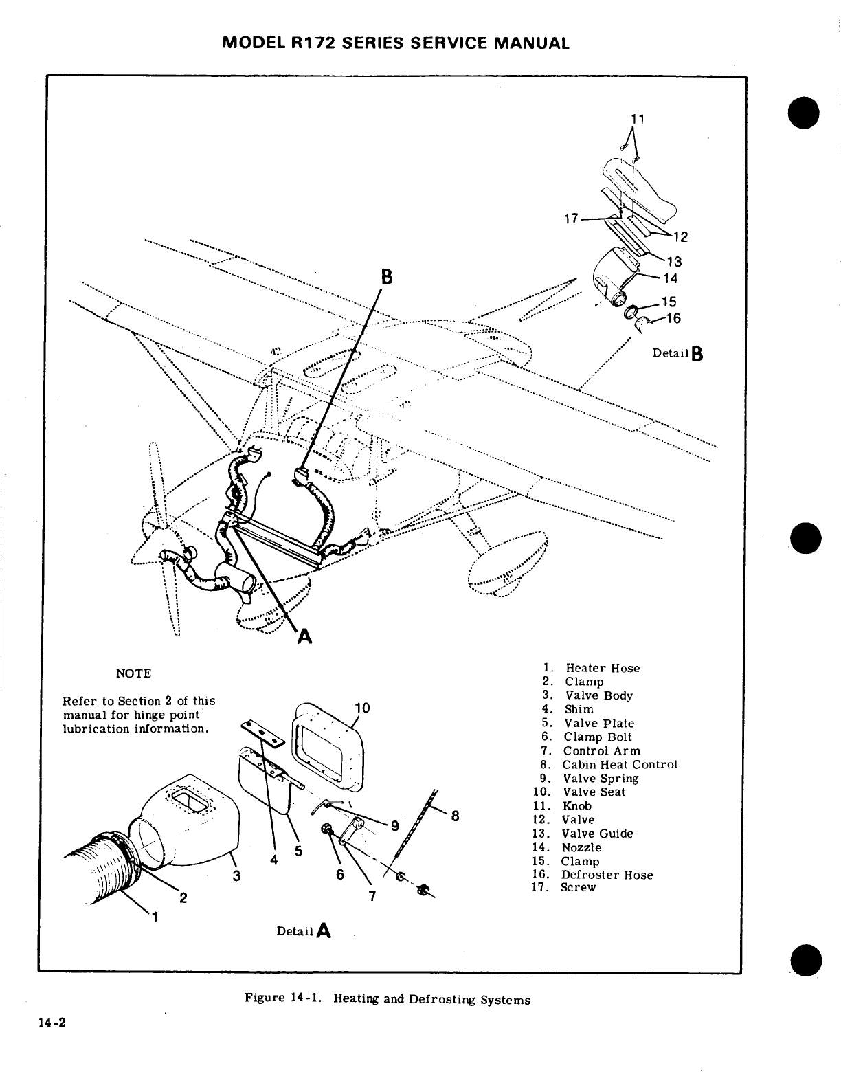
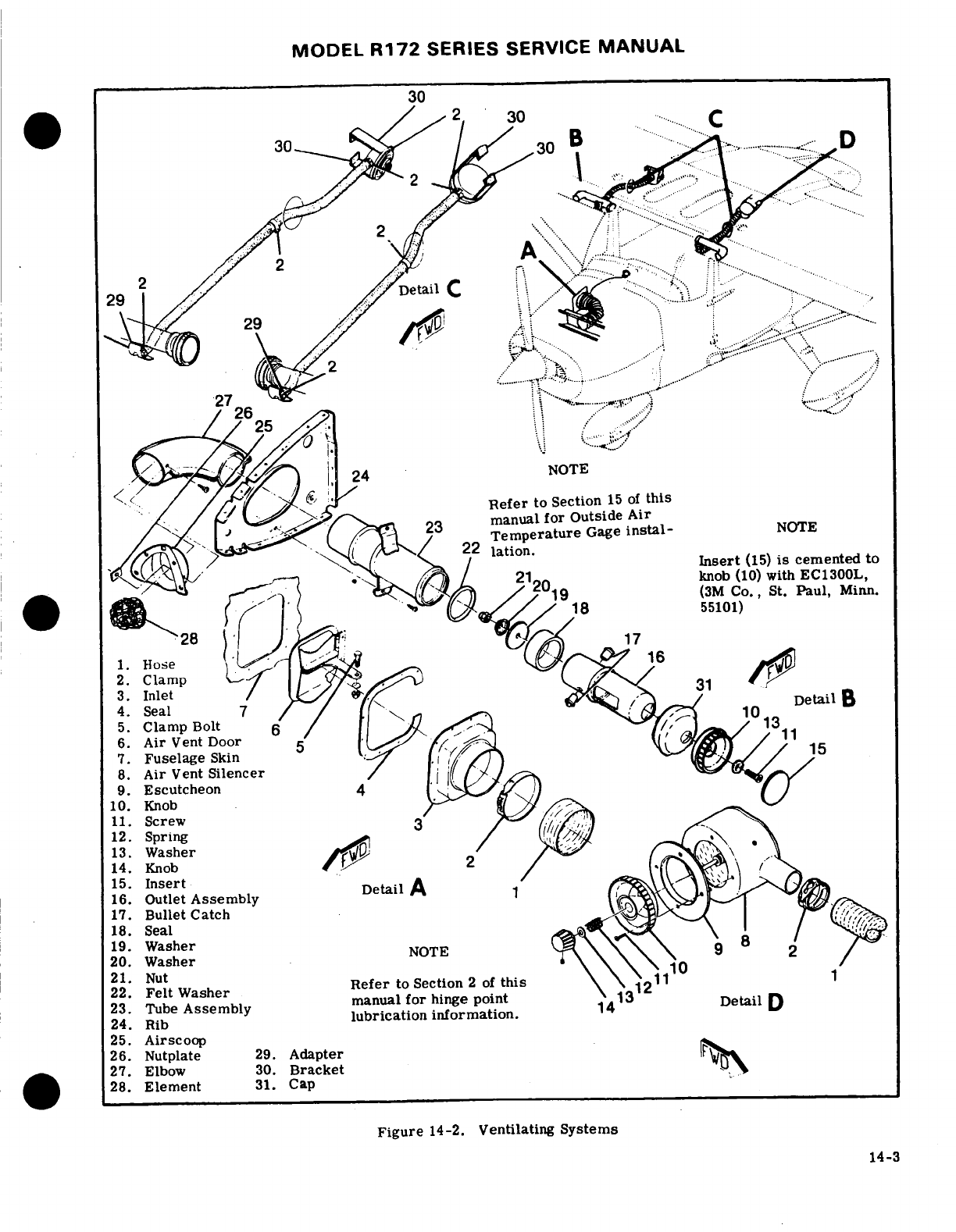
MODEL
R172
SERIES
SERVICE
MANUAL
......
...
...........
.
.... ....
.....
.-.....
.
NOTE
Refer
to
Section
15 of
this
Temperature
Gage
instal-
NOTE
.
Insert
(15)
is
emented
to
Refer
to
Section
15
of
this
5.
Clamp
Bolt
1 ,
7.
Fuselage
Skin
Air
Vent
Silencer
9.
Escutcheon
10.
Knob
(10)
EC1300L,
11.
Screw
.
13.
Washer
14.
Knob
.
1.
16.
Outlet
Assembly Detail
A
17.
Bullet
Catch31
18.
Seal
19.
Washer
20.
Washer
ut
Refer
to
Section
2
of
this
23. Tube
Assembly
manual
for
hin10nt
13
Detail
D
lubrcaton
25.
Airscoop
26.
Nutplate
29.
Adapter
O^
27.
Elbow
30.
Bracket
1
28.
Element
31.
Cap
Figure
14-2.
Ventilating
Systems
14
-3
MODEL
R172
SERIES SERVICE
MANUAL
14-9.
SYSTEM
OPERATION.
Air
from
the
duct
coming cabin
ventilating
air,
which
greatly
reduces
across
the
aft
side
of
the
firewall
flows
through
the
inlet
air
noise.
The
outlet
assemblies,
installed
near
flexible
ducting
to
the
defroster
outlet.
Temperature
the
upper
corners
of
the windshield
are
manually-
and volume
of
this
air
is controlled
by
settings
of
the
operated,
increasing
or decreasing
flow
of
ram
air
heater
system
control,
into
the
cabin.
14-10.
TROUBLE
SHOOTING.
Since
the
defrosting
14-15.
TROUBLE
SHOOTING.
Most
of
the
operation-
system
depends
on
proper
operation
of
the
heating
al
troubles
in
the
ventilating
systems
are
caused
by
system,
trouble
shooting
procedures
outlined
in
sticking
or
binding
of
the
inlet scoop
door or
its
con-
paragraph
14-5
should
be
followed
for
checking
the
trol.
Check
airscoop
filter
elements
in
the
wing
defroster
system.
leading
edges
for obstructions.
The
elements
may
be
removed
and
cleaned
or
replaced.
Since
air
14-11.
REMOVAL,
REPAIR
AND
INSTALLATION.
passing
through
the
filters
is
emitted
into
the
cabin,
The
defroster
system
is
illustrated
in
figure
14-1
in
do
not
use
a
cleaning
solution
which could
contami-
conjunction
with
the
heating
system.
The
figure
may
nate
the
air.
The
filters
may
be
removed
to
increase
be
used
as
a guide
for
removal,
repair
or
installation
air
flow.
However,
their
removal
will cause
a
slight
of
system
components. Burned,
frayed
or
crushed
increase
in
noise
level.
hose
must
be
replaced
with
new
hose,
cut
to
correct
length
and
installed
inthe
original
routing.
Trim
14-16.
REMOVAL,
REPAIR
AND
INSTALLATION.
hose
windings
shorter
than
complete
hose length to
The
ventilating
system
is
illustrated
in
figure
14-2.
allow
clamps
to
be
installed.
A
defective
defroster
The
figure
may
be
used
as
a
guide
for
removal,
re-
outlet
should
be
repaired
or
replaced.
Check
for
pair
or
installation
of
system
components.
A
defec-
correct
operation
of
control
after
repair and/or
in-
tive
ventilator
or
scoop
must
be
repaired
or
replaced.
stallation.
Check
for
proper
operation
of
controls
after
repair
and/or
installation.
4-12.
VENTILATING
SYSTEMS.
14-17.
AIR
CIRCULATING
FAN
SYSTEM.
(See
fig-
14-13.
DESCRIPTION.
Three
separate
systems
are
ure
14-3.)
installed
for
cabin
ventilation.
One
system
is
com-
prised
of
an
airscoop,
located
in
each
wing
root
14-18.
DESCRIPTION.
An
optional cabin
ventilating
fillet,
with
flexible
ducting
connecting
each
airscoop
fan
may
be
located
above
the
extended
baggage
com-
to
an
adjustable
air
vent
silencer
unit,
located
on
partment.
This
system consists
of
a
high-speed
each
side
of
the
rear
cabin
area.
Another
system
is
blower
and
overhead
ductwork,
similar
to
that
offered
comprised
of
an
airscoop,
located
in
the
leading
edge
with
the
air
conditioning
option.
This
fan
only
circu-
of
each
wing,
just
outboard
of
the
airscoop
in
the
lates
air
and
no
cooling
components
are
attached.
The
wing
root
fillets.
These
airscoops
are
connected
to
blower
is controlled
by a
four-position
switch,
located
cabin
outlets,
installed
on
each
side
of
the
cabin,
on
the
pilot's
console.
The
four
switch
positions
are
near
the
upper
corners
of
the
windshield. These
out-
labeled
HI,
MED,
LOW
and
OFF.
lets
are
manually-adjustable
with knobs
on
the
outlet
assemblies.
A
third
system
is
comprised
of
a
fresh
14-19.
REMOVAL.
(See
figure
14-3.) Access
to
airscoop
door
on
the
right
side
of
the
fuselage,
just
the
blower
assembly
and
ducting
is
gained
through
forward
of
the
copilot
seat.
Flexible
ducting
connects
the
baggage
door.
this
airscoop
to
the duct
across
the
aft side
of
the
a.
Remove baggage
compartment
panel.
firewall.
This
system
is
controlled
by
a
push-pull
b.
Disconnect
forward
and
aft
ends
of
hoses
(8)
by
control
on
the
instrument
panel. removing
hose
clamps.
c.
Remove
8
screws
attaching
blower
assembly
(5)
14-14.
SYSTEMS
OPERATION.
Heating,
defrosting
and
duct
assembly
(9)
to
supports
(3)
and
(6).
and
ventilating
systems
work
together
to provide
the
d.
Remove
lower
support
(6).
conditions
desired
by
the
pilot.
The
heating
system,
e.
Disconnect
electrical
connections.
defrosting system
and
one
ventilating
system receive
f.
Remove
blower
assembly.
air
from
the duct
across
the
aft
side
of
the
firewall.
As
long
as
the
"CABIN
HT"
control
is
pushed in,
no
14-20.
INSPECTION
AND
REPAIR.
Hoses
should
heated
air
can
enter
the
firewall
duct;
therefore,
if
be
checked
for
security,
and
replaced
if
frayed
or
the
"CABIN
AIR"
control
(to
the
scoop door
on
the
crushed.
Check
that
hose
clamps
are
properly
right
forward
fuselage)
is
pulled
out,
only
fresh
air
tightened.
Check
electrical
connections,
and
check
from
the
scoop
will
flow
through
the
duct
into
the
that
blower
fans
rotate
freely.
cabin.
As
the
"CABIN
HT"
control
is
gradually
pulled
out,
more
and
more
heated
air
will
blend
with
14-21.
INSTALLATION. (See
figure
14-3.)
the
fresh air
from the
scoop, and
be
distributed
into
a.
Install
blower
unit
(5)
and
duct
assembly
(9)
to
the
cabin.
Either
one,
or
both
of
the
controls
may
upper
support
(3).
be
set
at
any
position from
full
open
to
full
closed.
b.
Connect
electrical
connections.
Rear
seat
ventilation
is
provided
by
air
vent
silencer
c.
Install
lower
support
(6),
and
attach
blower
as-
assemblies,
mounted
in
the
left
and
right
rear
cabin
sembly
and duct
(9).
wing
root
areas.
These units
receive
ram
air
from
d.
Install
hoses
and hose
clamps.
the
airscoops
in
the
wing
root
fillets.
Each
silencer
e.
Install
baggage
compartment
panel.
assembly
is
equipped
with
a
valve
which
meters
in-
14-4
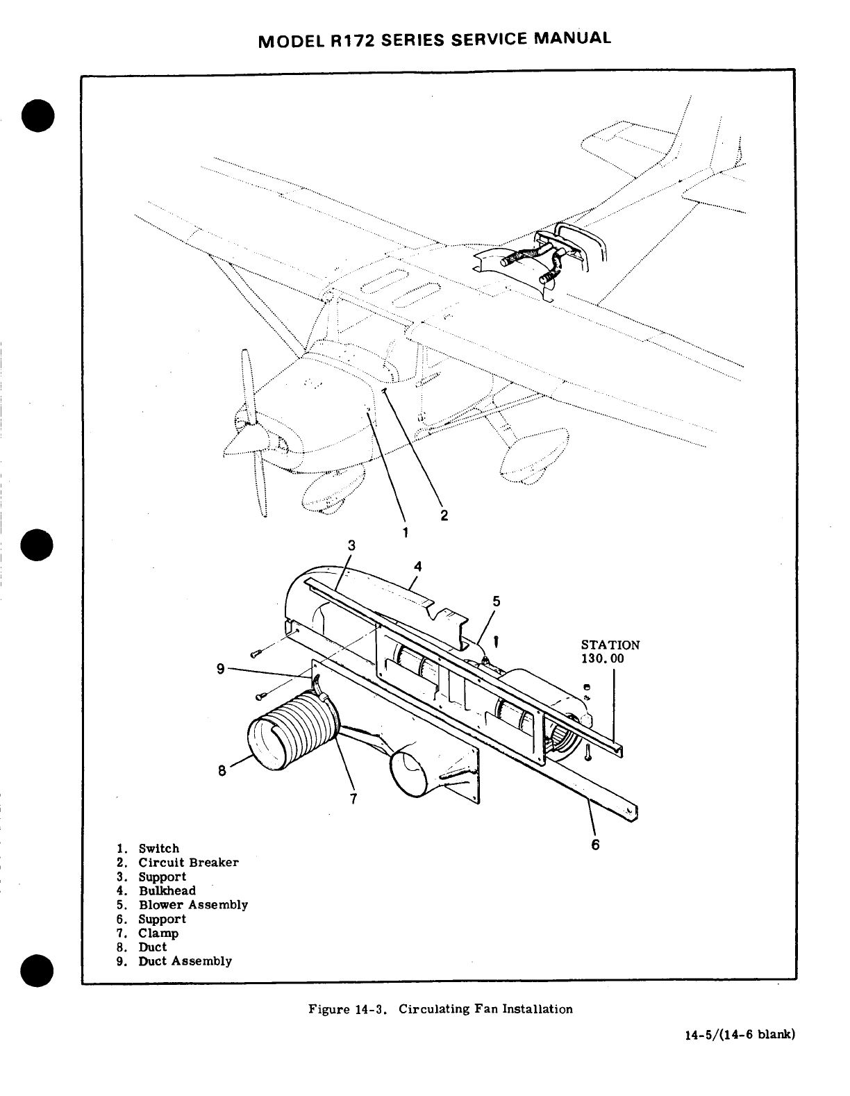
MODEL
R172
SERIES
SERVICE
MANUAL
SECTION
15
INSTRUMENTS
AND
INSTRUMENT
SYSTEMS
Page
No.
Page
No.
TABLE OF
CONTENTS
Aerofiche/Manual Aerofiche/Manual
INSTRUMENTS
AND
INSTRUMENT
SYSTEMS
...............
2A3/15-2
Tachometer
...................
2A18/15-15
General
................
2A3/15-2
Description
................
2A18/15-15
Instrument
Panel
...........
2A4/15-3
Manifold
Pressure/Fuel
Description
.............
2A4/15-3
Flow
Indicator
.............
2A19/15-16
Removal and
Installation
.....
2A4/15-3
Description
................
2A19/15-16
Shock Mounts
.
..........
2A4/15-3
Trouble
Shooting-Manifold
Instruments
.................
2A4/15-3
Pressure
Gage
..............
2A19/15-16
Removal
. ..............
2A4/15-3
Trouble
Shooting-Fuel
Flow
Installation
.............
2A4/15-3
Indicator
..................
2A20/15-17
Pitot
and
Static
Systems
.........
2A4/15-3
Cylinder
Head
Temperature
Description
.................
2A4/15-3
Gage
......................
2A21/15-18
Maintenance
. .............
2A4/15-3
Description
................
2A21/15-18
Static
System
Inspection
Trouble
Shooting
...........
2A21/15-18
and
Leakage
Test
...........
2A4/15-3
Oil
Pressure
Gage
.............
2A21/15-18
Pitot
System
Inspection
Description
................
2A21/15-18
and
Leakage
Test
...........
2A5/15-4
Trouble
Shooting
...........
2A22/15-19
Blowing
Out
Lines
..........
2A5/15-4 Oil
Temperature
Gage
.........
2A22/15-19
Removal
and
Installation
Description
................
2A22/15-19
of
Components
. ............
2A5/15-4 Economy
Mixture
Indicator
....
2A23/15-20
Encoding
Altimeter
..........
2A5/15-4
Description
................
2A23/15-20
Description
.................
2A5/15-4
Calibration
................
2A23/15-20
Removal
and
Installation
.....
2A5/15-4
Removal
and
Installation
...
2A23/15-20
Trouble Shooting
.............
2A8/15-7
Trouble
Shooting
...........
2A23/15-20
True
Airspeed
Indicator
.......
2A8/15-7
Fuel
Quantity
Indicating
Description
. ................
2A8/15-7
System
....................
2B1/15-22
Removal and
Installation
.....
2A8/15-7
Description
................
2B1/15-22
Trouble Shooting
.............
2A8/15-7
Removal
and
Installation
...
2B1/15-22
Trouble
Shooting-Altimeter
..
2A10/15-9
Trouble
Shooting
...........
2B1/15-22
Trouble
Shooting-Vertical
Transmitter
Calibration
....
2B2/15-22A
Speed
Indicator
.............
2A10/15-9
Hourmeter
...................
2B4/15-23
Trouble
Shooting-Pitot
Description
................
2B4/15-23
Tube
Heater
. ................
2A11/15-10
Magnetic
Compass
............
2B4/15-23
Vacuum
System
.................
2A11/15-10
Description
................
2B4/15-23
Description
..................
2A1115-10
Removal
and
Installation
...
2B4/15-23
Trouble
Shooting
...........
2A12/15-11
Stall Warning
System
.........
2B4/15-23
Trouble
Shooting-Gyros
.......
2A12/15-11
Description
................
2B4/15-23
Trouble
Shooting-Pump
.......
2A18/15-15
Removal
and
Installation
...
2B4/15-23
Removal
and
Installation
.....
2A18/15-15
Turn
Coordinator
.............
2B6/15-25
Cleaning
....................
2A18/15-15
Description
................
2B6/15-25
Vacuum
Relief
Trouble
Shooting
...........
2B6/15-25
Valve
Adjustment
............
2A18/15-15
Turn-and-Slip
Indicator
........
2B7/15-26
Standby
Vacuum
System
......
2A18/15-15
Description
................
2B7/15-26
Description ..................
2A18/15-15
Outside
Air
Temperature
Removal
and
Installation
.....
2A18/15-15
Gage
......................
2B7/15-26
Engine
Indicators ...........
2A18/15-15
Revision 1
15-1
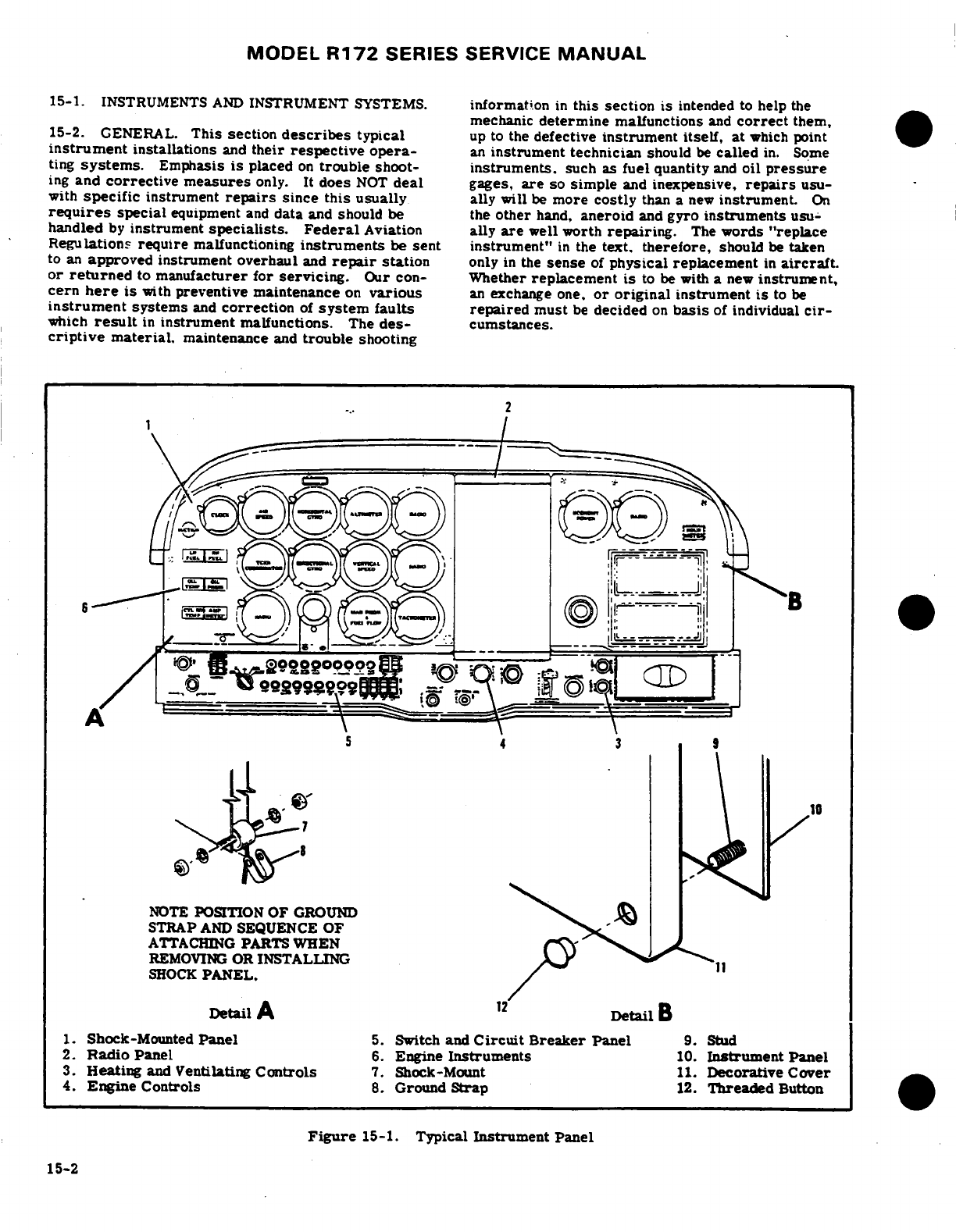
MODEL
R172
SERIES
SERVICE
MANUAL
15-1.
INSTRUMENTS
AND
INSTRUMENT
SYSTEMS.
information
in
this
section
is
intended
to
help
the
mechanic
determine
malfunctions
and
correct
them,
15-2.
GENERAL.
This section
describes
typical
up
to
the
defective
instrument
itself,
at
which point
instrument
installations
and
their
respective
opera-
an
instrument
technician
should
be
called
in.
Some
ting
systems.
Emphasis
is
placed
on
trouble
shoot-
instruments,
such
as
fuel
quantity
and
oil
pressure
ing
and
corrective measures
only.
It
does
NOT
deal
gages,
are
so
simple
and
inexpensive,
repairs
usu-
with
specific
instrument
repairs
since
this
usually
ally
will
be
more
costly
than
a
new
instrument.
On
requires
special
equipment
and
data
and
should
be
the
other
hand,
aneroid
and
gyro
instruments
usu-
handled
by
instrument
specialists. Federal
Aviation
ally
are
well
worth
repairing.
The
words
"replace
Regulations
require
malfunctioning
instruments
be
sent
instrument"
in
the
text.
therefore,
should
be
taken
to
an
approved instrument overhaul
and
repair
station
only
in
the
sense
of
physical
replacement
in
aircraft.
or
returned
to
manufacturer for
servicing.
Our
con-
Whether
replacement
is
to
be
with
a
new
instrument,
cern
here
is
with
preventive maintenance
on
various
an
exchange
one,
or
original
instrument
is
to
be
instrument
systems
and
correction
of
system
faults
repaired
must
be
decided
on
basis
of
individual
cir-
which
result
in
instrument
malfunctions.
The
des-
cumstances.
criptive
material,
maintenance
and
trouble
shooting
-
NOTE
POSITION
OF
GROUND
STRAP
AND
SEQUENCE
OF
ATTACHING
PARTS
WHEN
REMOVING
OR
INSTALLING
SHOCK
PANEL.
Detail
A
l
1.
Shock-Mounted
Panel
5.
Switch
and
Circuit
Breaker
Panel
9.
Stud
2.
Radio
Panel
6.
Engine
Instruments
10.
Instrument Panel
3.
Heating
and
Ventilating
Controls
7.
Shock-Mount
11.
Decorative
Cover
4.
Engine Controls
8.
Ground
Strap
12.
Threaded
Button
Figure
15-1.
Typical
Instrument
Panel
15-2
15-2
MODEL
R172
SERIES
SERVICE
MANUAL
15-3.
INSTRUMENT
PANEL.
NOTE
15-4.
DESCRIPTION.
The
instrument
panel
assem-
All
instruments (gages
and
indicators),
re-
bly
consist
of
a
stationary
and
shock-mounted
panel.
quiring a
thread
seal
or
lubricant,
shall
be
The
stationary
panel
contains
instruments
which
are
installed
using
teflon
tape
on
male
fittings
NOT
sensitive
to
vibration.
The
shock-mounted
pan-
only.
This
tape
is
available
through
Cessna
el
contains
major
flight
instruments
such
as
horizontal
Service
Parts
Center.
and
directional
gyros
which
are
affected
by
vibration.
Most
of
the
instruments
are
screw-mounted
on
the
When
replacing
an
electrical
gage
in
an
instrument
panel
backs,
cluster
assembly,
avoid
bending
pointer
or
dial
plate.
Distortion
of
dial
or
back
plate could
change
calibra-
15-5.
REMOVAL
AND
INSTALLATION.
(Refer
to
tion
of
gages.
figure
15-1.)
The
stationary
panel
is
secured
to en-
gine
mount
stringers
and
a
forward
fuselage
bulkhead
15-10.
PITOT
AND
STATIC
SYSTEMS.
(Refer
to
and
ordinarily
is
not
considered
removable.
The
figure
15-2.)
shock-mounted
panel
is
secured
to
the
stationary
panel
with
rubber
shock-mounted
assemblies.
To
re-
15-11.
DESCRIPTION.
The pitot
system
conveys
move
shock-mounted panel
proceed
as follows:
ram air
pressure
to
the
airspeed
indicator.
The
a.
Unscrew threaded
buttons
securing
decorative
static
system
vents
vertical
speed
indicator,
alti-
cover
and
remove
cover.
meter
and
airspeed
indicator
to
atmospheric
pres-
b.
Remove
nuts
and
washers
from
shock-mounts.
sure
through
plastic
tubing
connected
to
static
ports.
c.
Tag
and
disconnect
instrument
wiring.
A
static
line
sump
is
installed
at
source
buttons
to
d.
Disconnect
plumbing
and
cap
all
open
fittings collect
condensation
in
static
system.
A
pitot
tube
and
lines.
heater
may
be
installed.
The
heating
element
is
con-
e.
Pull
panel
straight
back
to
remove.
trolled
by
a
switch
at
instrument
panel
and
powered
f.
For
installation
reverse
the
preceding
procedure.
by
the
electrical
system.
An
alternate static
source
Ensure
ground
strap
is
properly
installed.
valve
may
be
installed
in
the
static
system
for
use
when the
external
static
source
is
malfunctioning.
15-6.
SHOCK
MOUNTS.
Service
life
of
instruments
Refer
to
the
Owner's
Manual
for flight
operation
is
directly
related
to
adequate
shock-mounting
of
using
the
alternate
static
source.
panel.
If
removal
of
panel
is necessary,
check
mounts
for deterioration.
15-12.
MAINTENANCE.
Proper
maintenance
of
pitot
and
static system
is
essential
for proper
opera-
15-7.
INSTRUMENTS.
tion
of
altimeter,
vertical
speed
and
airspeed
indica-
tors.
Leaks,
moisture
and
obstructions
in
pitot
sys-
15-8.
REMOVAL.
(Refer
to
figure
15-1.)
Most
in-
tem
will
result
in
false
airspeed
indications,
while
struments
are
secured
to
panel
with
screws inserted
static
system
malfunctions
will
affect
readings
of
all
through
panel
face.
To
remove
an
instrument,
re-
three
instruments.
Under instrument
flight
conditions,
move decorative
cover,
disconnect
wiring
or
plumb-
these
instrument
errors
could
be
hazardous.
Cleanli-
ing
to
instrument,
remove
mounting
screws
and
take
ness
and
security
are
the
prinicpal
rules
for
system
instrument
out
from
behind,
or
in
some
cases,
from maintenance.
The
pitot
tube
and
static
ports
MUST
front
of
panel.
Instrument
clusters
are installed
as
be
kept
clean
and
unobstructed.
units
and
are
secured
by
a
screw
at
each
end.
A
cluster
must
be
removed
from
panel
to
replace
an
15-13.
STATIC
PRESSURE
SYSTEM
INSPECTION
individual
gage.
In
all
cases
when
an
instrument
is
AND
LEAKAGE
TEST.
The
following
procedure
out-
removed,
disconnect
lines
or
wires
should
be
pro-
lines
inspection
and
testing
of
static
pressure
system,
tected.
Cap
open
lines
and
cover
pressure
connec-
assuming
altimeter
has
been
tested
and
inspected
in
tions
on
instrument
to
prevent
thread
damage
and
en-
accordance
with
current
Federal
Aviation
Regulations.
trance
of
foreign
matter.
Wire
terminals
should
be
a.
Ensure
static
system
is
free from
entrapped
insulated
or
tied
up
to
prevent
accidental
grounding
moisture
and
restrictions.
or short-circuiting.
b.
Ensure
no
alternations
or
deformations
of
air-
frame
surface
have
been
made
which
would
affect
the
15-9.
INSTALLATION.
Generally,
installation
pro-
relationship
between
air
pressure
in
static
pressure
cedure
is
the
reverse
of
removal
procedure.
Ensure
system
and
true
ambient
static
air
pressure
for
any
mounting
screw
nuts
are
tightened
firmly,
but
do
not
flight
configuration.
over-tighten,
particularly
on
instruments
having
c.
Close
static
pressure
alternate
source control,
plastic
cases.
The
same
rule
applies
to
connecting
if
installed.
plumbing
and
wiring.
d.
Attach
a
source
of
suction
to
static
pressure
15-3
MODEL
R172
SERIES
SERVICE
MANUAL
source
opening,
place
a
piece
of
tape
over
other
open-
sure
in
system,
resulting
in
a
lower
airspeed
indica-
i"g.
Figure
15-3
shows method
of
obtaining
suction
tion.
Slowly
unroll
tubing
before
removing
it,
so
e.
Slowly
apply
suction
until
altimeter
indicates
a
pressure
is reduced
gradually.
Otherwise
instrument
1'.
O-foot
increase
in
altitude.
may
be
damaged.
If
test
reveals
leak
in
system,
check
all
connections
for tightness.
CAUTION
When
applying
or releasing
suction,
do
not
15-15.
BLOWING
OUT
LINES.
Although
pitot
sys-
exceed
range
of
vertical
speed
indicator
or
ter
is designed
to
drain
down
to
pitot
tube
opening,
airpseed
indicator.
condensation
may
collect
at
other
points
in
system
and
produce
a
partial
obstruction.
To
clear
line,
f.
Cut
off
suction
source
to
maintain
a
"closed"
disconnect
at
airspeed
indicator.
Using
low
pressure
:;stem
for
one
minute. Leakage
shall
not exceed
air,
blow
from
indicator
end
of
line
toward pitot
tube.
feat
of
altitude
loss
as
indicated
on
altimeter.
.
If
leakage
rate
is
within
tolerance,
slowly
re-
SAUTIO
source.
Never
blow
through
pitot
or
static
lines
toward
NOTE
instruments.
If
leakage
rate
exceeds
maximum
allowable,
Like
pitot
lines,
static
pressure
lines
must
be
kept
first
tighten
all
connections,
then
repeat
clear
and
connections
tight.
All
models
have
a
static
leakage
test.
If
leakage
rate
still
exceeds
source
sump
which
collects
moisture
and
keeps
sys-
maximum
allowable,
use following
procedure.
tern
clear.
However,
when
necessary,
disconnect
static
line
at
first
instrument
to which
it
is
connected,
h.
Disconnect
static
pressure
lines
from
airspeed
then
blow
line
clear
with
low-pressure
air.
Check
indicator
and
vertical
speed
indicator.
Use
suitable all
static
pressure
line
connections
for
tightness.
If
fillines
to
connect
lines together
so
altimeter
is
the
hose
or
hose
connections
are used,
check
for
general
i,
instrument
still
connected
into
static
pressure
condition
and
clamps for
security.
Replace
hoses
-.
f,:omn.
which
have
cracked,
hardened
or
show
other
signs
of
Repeat leakage
test
to
check
whether
static
prs-
deterioration.
,iire
system
or
the
bypassed
instruments
are
cause
of
If
instruments
are
at
fault,
they must
be
re-
15-16.
REMOVAL
AND
INSTALLATION
OF
COM-
lpaired
by an
appropriately
rated
repair
station"
or
PONENTS.
(Refer
to
figure
15-2.)
To
remove
pitot
replaced.
If
static
pressure
system
is
at
fault,
use
mast
remove
four
mounting
screws
on
side
of
connec-
'-llowing procedure
to
locate
leakage.
tor
(13)
and
pull
mast
out
of
connector
far
enough
to
Attach
a
source
of
positive
pressure
to
static
disconnect
pitot
line
(5).
Electrical
connections
to
:murce
opening.
Figure
15-3
shows
one
method
of
heater
assembly
(if
installed)
may
be
disconnected
:
taining
positive
pressure.
through
wing
access
opening
just
inboard
of
mast.
Pitot
and
static
lines
are
removed
in
the
usual
man-
CAUTION
ner, after
removing
wing
access
plates,
lower
wing
fairing
strip
and
upholstery
as
required.
Installation
Do
not
apply
positive
pressure
with
airspeed
of
tubing
will
be
simpler
if
a
guide
wire
is
drawn
in
indicator
or
vertical
speed
indicator
connect-
as
tubing
is
removed from
wing.
The
tubing
may
be
ed to
static
pressure
system.
removed
from
wing.
The
tubing
may
be
removed
in-
tact
by
drawing
it
out
through
cabin
and
right
door.
k.
Slowly
apply
positive
pressure
until altimeter
Tighten
connections
firmly
but
avoid
overtightening
indicates
a
500-foot
decrease
in
altitude
and
maintain
and
distorting
fittings.
If
twisting
of
plastic
tubing
is
t-.is
altimeter
indication
while
checking
for
leaks.
encountered
when
tightening
fittings,
W-P-236
(USP
'
line
connections
and
static
source
flange
with
Petrolatum),
may
be
applied
sparingly
between tubing
solution
of
mild
soap
and
water,
watching
for
bubbles
and
fittings.
to
locate
leaks.
1.
Tighten
leaking
connections.
Repair
or
replace
15-17.
ENCODING
ALTIMETER.
parts
found
defective.
m.
Reconnect
airspeed
and
vertical
speed
indicators
15-18. DESCRIPTION.
An
encoding
altimeter
may
into
static
pressure
system
and
repeat
leakage
test
be
installed
which
is
also
connected
to
static
system
per
steps
"c"
thru
"g".
pressure.
The
encoding
altimeter
supplies
coded
altitude
signals
to
the
aircraft's
transponder
for
15-14.
PITOT
SYSTEM
INSPECTION
AND
LEAKAGE
transmission
to
ground
based
interrogating
radar.
TEST.
To
check
pitot
system
for
leaks,
place
a
piece
The
encoding
altimeter
installation
requires
the
use
of
taps
over
small
hole
in
lower
aft
end
of
pitot
tube,
of
a
fully
operational
secondary
altimeter
as
backup.
fasten
a
piece
of
rubber
or
plastic
tubing
over
pitot
tube,
close
opposite
end
of
tubing
and
slowly
roll
up
15-19.
REMOVAL
AND
INSTALLATION.
Figure
tube
until
airspeed
indicator
registers
in
cruise
range.
15-2,
sheet
2
may
be
used
as
a
guide
for
removal
Secure
tube
and
after
a
few
minutes
recheck
airspeed
and
installation
of
the
encoding
altimeter.
indicator.
Any
leakage will
have
reduced
the
pres-
15-4
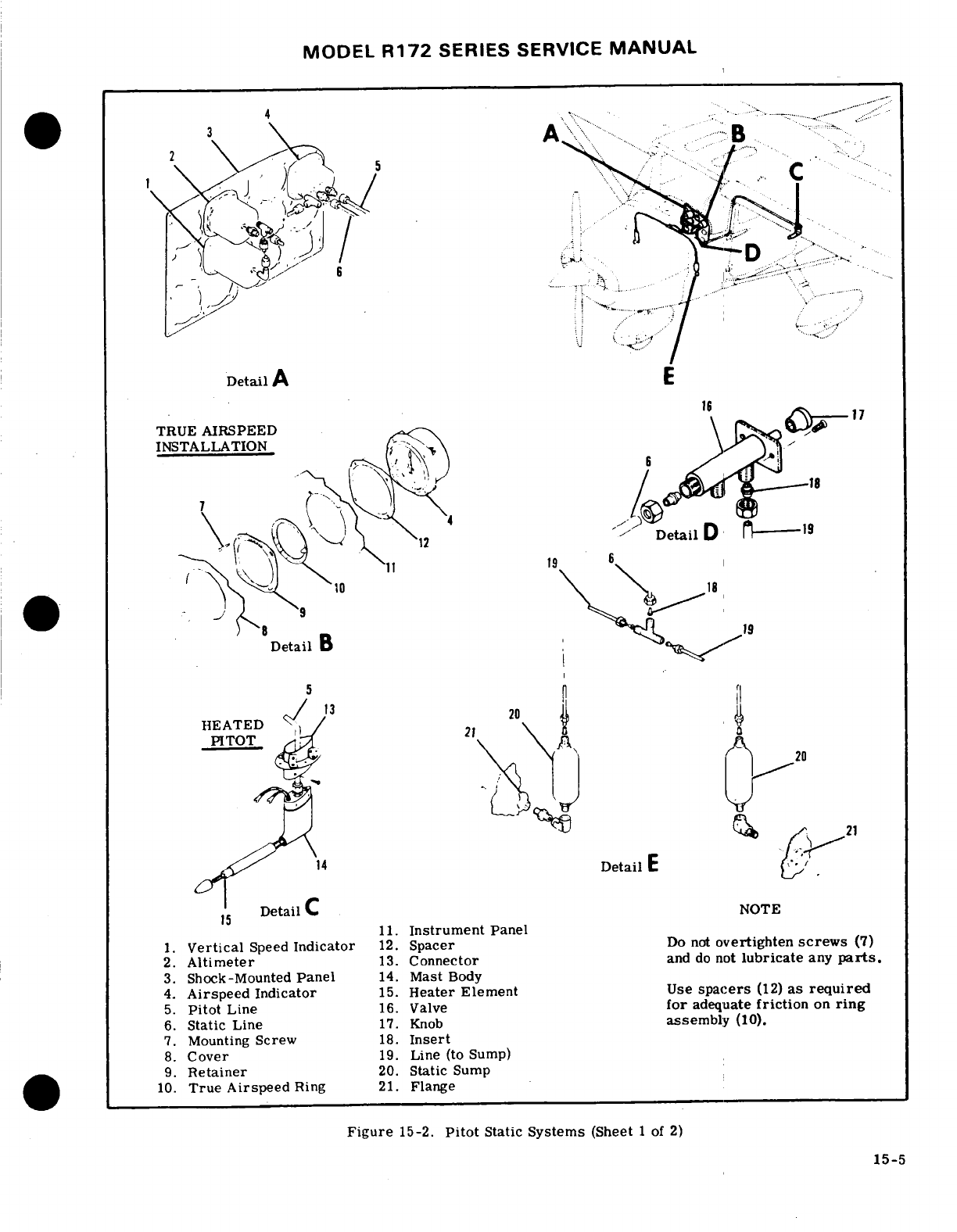
MODEL
R172
SERIES
SERVICE
MANUAL
4
.-
. .
Detail
TRUE
AIRSPEED
INSTALLATION
-
-
Detail
B
HEATED
Detail
DetailC
NOTE
11.
Instrument
Panel
1.
Vertical
Speed
Indicator
12.
Spacer
Do
not
overtighten
screws
(7)
2.
Altimeter
13.
Connector
and
do
not
lubricate
any
parts.
3.
Shock-Mounted
Panel
14.
Mast
Body
4.
Airspeed
Indicator
15.
Heater
Element
Use
spacers
(12)
as
required
5.
Pitot
Line
16.
Valve
for
adequate
friction
on
ring
6.
Static
Line
17.
Knob
assembly
(10).
7.
Mounting
Screw
18.
Insert
8.
Cover
19.
Line
(to
Sump)
9.
Retainer
20.
Static
Sump
10.
True Airspeed
Ring
21.
Flange
Figure
15-2.
Pitot
Static
Systems
(Sheet
1 of
2)
15-5
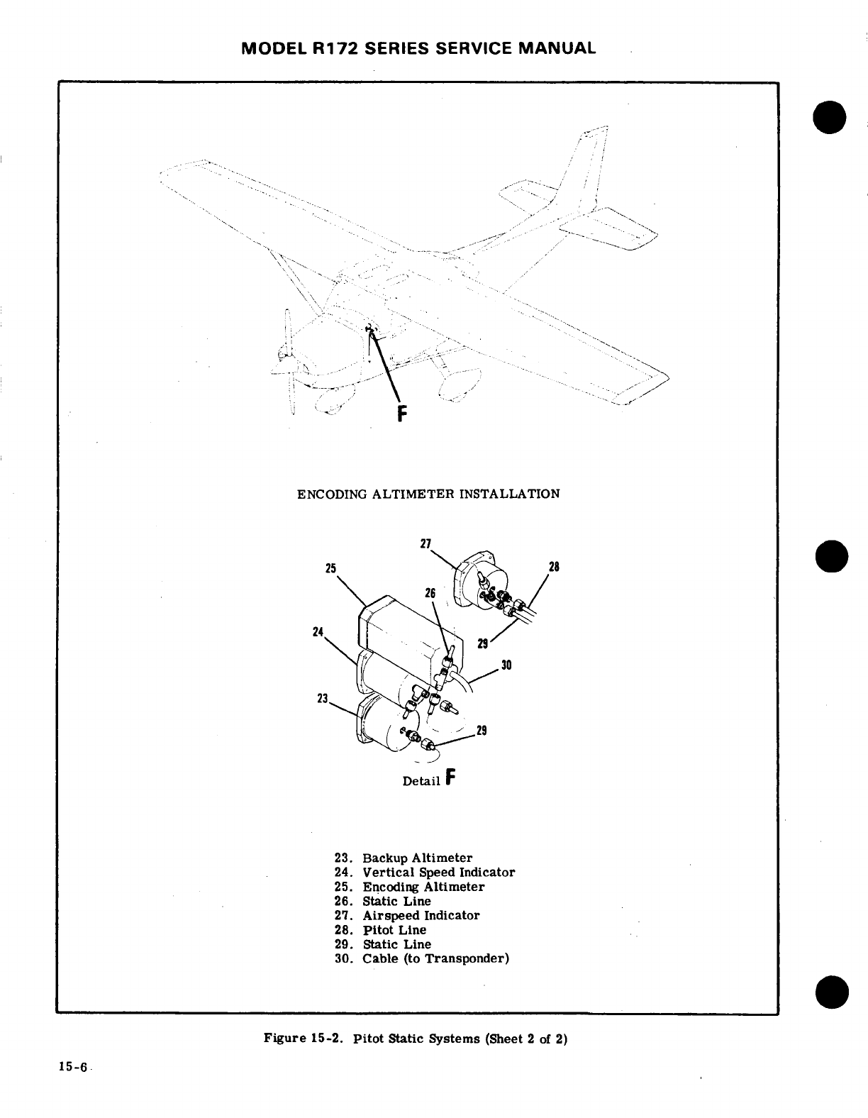
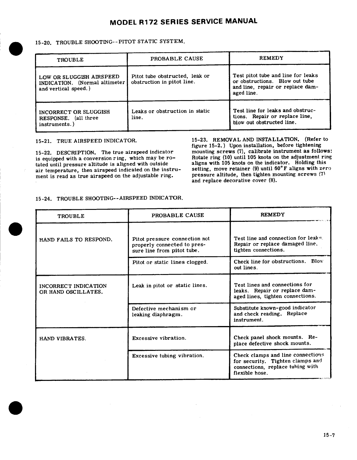
MODEL
R172
SERIES
SERVICE
MANUAL
15-20.
TROUBLE
SHOOTING--PITOT
STATIC
SYSTEM.
TROUBLE
PROBABLE
CAUSE REMEDY
LOW OR SLUGGISH
AIRSPEED
Pitot
tube
obstructed,
leak
or
Test
pitot
tube
and
line
for leaks
INDICATION.
(Normal
altimeter
obstruction
in
pitot
line.
or
obstructions.
Blow
out
tube
and
vertical
speed.
)
and
line,
repair
or
replace
dam-
aged
line.
INCORRECT
OR
SLUGGISH
Leaks
or
obstruction
in
static
Test
line
for
leaks
and
obstruc-
RESPONSE.
(all
three
line.
tions.
Repair
or
replace
line,
instruments.
)
blow
out
obstructed
line.
15-21.
TRUE
AIRSPEED
INDICATOR.
15-23.
REMOVAL
AND
INSTALLATION.
(Refer
to
figure
15-2.)
Upon
installation,
before
tightening
15-22.
DESCRIPTION.
The
true
airspeed
indicator
mounting
screws
(7),
calibrate
instrument
as
follows:
is
equipped
with a
conversion
ring,
which
may
be
ro-
Rotate
ring
(10)
until
105
knots
on
the
adjustment ring
tated
until
pressure
altitude is
aligned
with
outside
aligns
with
105
knots
on
the
indicator.
Holding
this
air
temperature,
then
airspeed
indicated
on
the
instru-
setting,
move
retainer
(9)
until
60°F aligns
with
zero
ment
is
read
as
true
airspeed
on
the
adjustable
ring.
pressure
altitude,
then
tighten mounting
screws
(7)
and
replace
decorative
cover
(8).
15-24.
TROUBLE
SHOOTING--AIRSPEED
INDICATOR.
TROUBLE
PROBABLE
CAUSE
REMEDY
HAND
FAILS
TO RESPOND.
Pitot
pressure
connection
not
Test
line
and
connection
for
leak;.
properly
connected
to
pres-
Repair
or
replace
damaged
line.
sure
line
from
pitot
tube.
tighten connections.
Pitot
or static
lines
clogged.
Check
line
for
obstructions.
Blow
out
lines.
INCORRECT
INDICATION
Leak in
pitot
or
static
lines.
Test
lines
and
connections
for
OR
HAND
OSCILLATES.
leaks.
Repair
or
replace
dam-
aged
lines,
tighten connections.
Defective
mechanism
or
Substitute
known-good
indicator
leaking
diaphragm.
and
check
reading.
Replace
instrument.
HAND
VIBRATES.
Excessive
vibration.
Check
panel shock
mounts.
Re-
place
defective shock
mounts.
Excessive
tubing
vibration.
Check
clamps
and
line connections
for
security.
Tighten
clamps
and
connections,
replace
tubing with
flexible
hose.
15-7
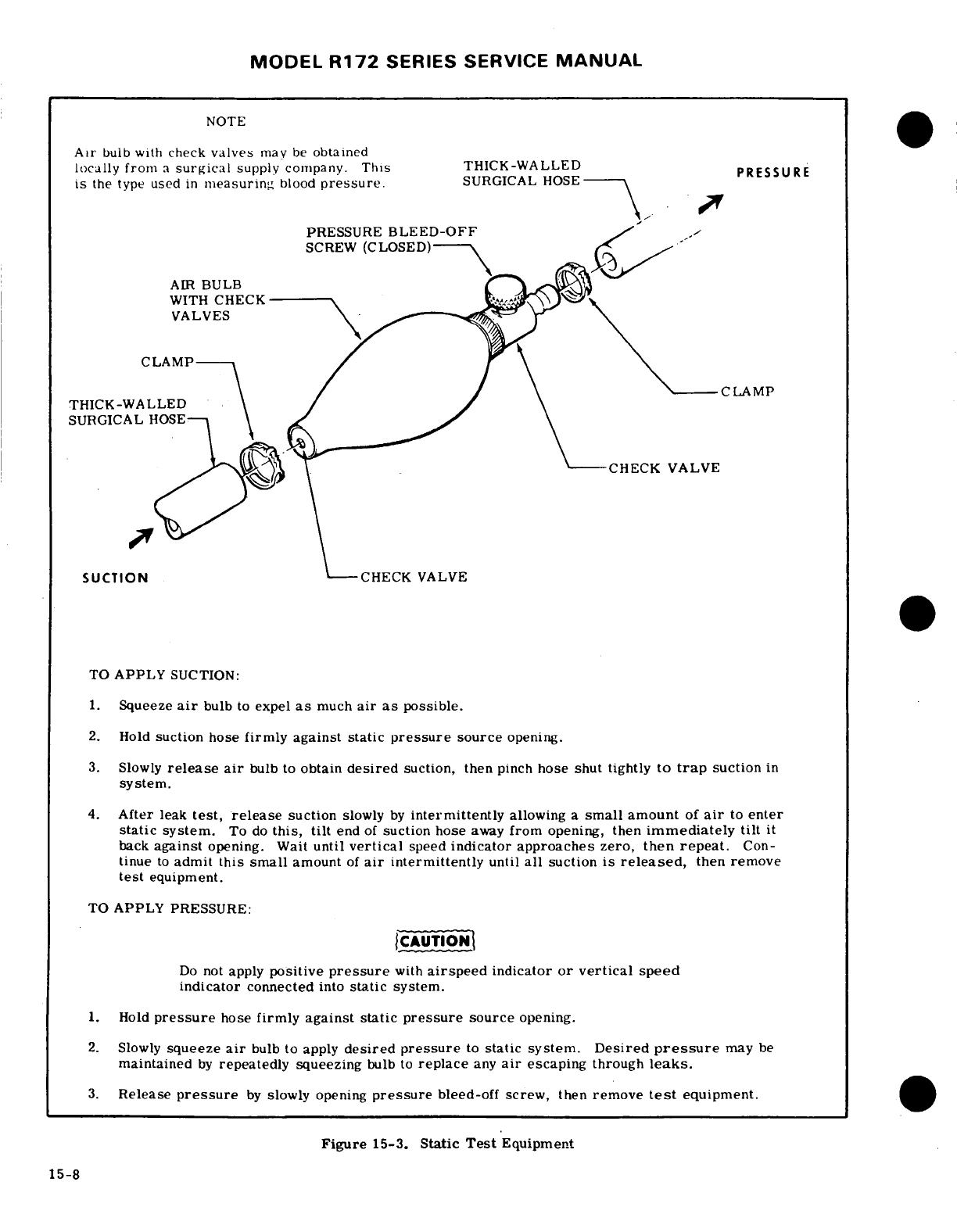
MODEL
R172
SERIES
SERVICE
MANUAL
NOTE
Air
bulb with
check
valves
may
be
obtained
locally from
a
surgical
supply
company.
This
THICK-WALLED
PRESSURE
is
the
type
used
in
measuring
blood
pressure.
SURGICAL
HOSE
PRESSURE
BLEED-OFF
SCREW
(CLOSED)
AIR
BULB
WITH
CHECK
VALVES
CLAMP
CLAMP
THICK-WALLED
SURGICAL
HOSE-
CHECK
VALVE
SUCTION
CHECK
VALVE
TO
APPLY
SUCTION:
1.
Squeeze
air
bulb
to
expel
as
much
air
as
possible.
2.
Hold
suction
hose
firmly
against
static
pressure
source
opening.
3.
Slowly
release air
bulb
to
obtain
desired
suction, then
pinch
hose
shut
tightly
to
trap
suction
in
system.
4.
After
leak
test,
release
suction
slowly
by
intermittently
allowing
a
small
amount
of
air
to
enter
static system.
To
do
this,
tilt
end
of
suction
hose
away
from
opening,
then
immediately
tilt
it
back
against
opening. Wait
until
vertical
speed
indicator
approaches
zero,
then
repeat.
Con-
tinue
to
admit
this
small
amount
of
air
intermittently
until
all
suction
is
released,
then remove
test
equipment.
TO
APPLY
PRESSURE:
CAUTION
Do
not
apply
positive
pressure
with
airspeed
indicator
or vertical
speed
indicator
connected
into
static
system.
1.
Hold
pressure
hose
firmly against
static
pressure
source
opening.
2.
Slowly
squeeze
air
bulb
to apply
desired
pressure
to
static
system.
Desired
pressure
may
be
maintained
by
repeatedly
squeezing
bulb
to
replace
any
air
escaping
through
leaks.
3.
Release
pressure
by
slowly opening
pressure
bleed-off
screw,
then
remove
test
equipment.
Figure
15-3.
Static
Test
Equipment
15-8
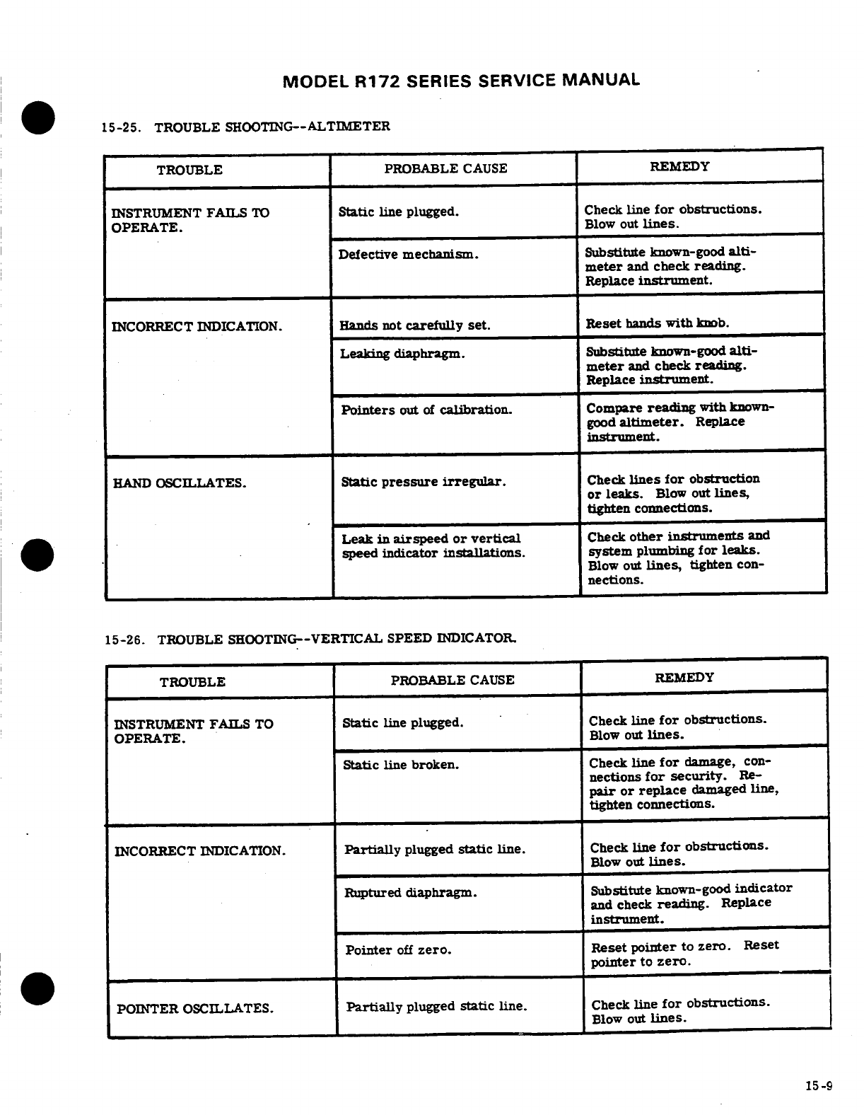
MODEL
R172
SERIES SERVICE
MANUAL
15-25.
TROUBLE
SHOOTING--ALTIMETER
TROUBLE
PROBABLE
CAUSE
REMEDY
INSTRUMENT
FAILS
TO
Static
line
plugged. Check
line
for
obstructions.
OPERATE.
Blow
out
lines.
Defective
mechanism.
Substitute
known-good
alti-
meter
and
check
reading.
Replace
instrument.
INCORRECT
INDICATION.
Hands not
carefully
set.
Reset
hands
with
knob.
Leaking
diaphragm.
Substitute
known-good
alti-
meter
and
check
reading.
Replace
instrument.
Pointers
out
of
calibration.
Compare
reading
with
known-
good
altimeter.
Replace
instrument.
HAND
OSCILLATES.
Static
pressure
irregular.
Check
lines
for
obstruction
or
leaks.
Blow
out
lines,
tighten
connections.
Leak
in
airspeed
or
vertical
Check
other
instruments
and
speed indicator
installations,
system
plumbing
for leaks.
Blow
out
lines,
tighten
con-
nections.
15-26.
TROUBLE
SHOOTING--VERTICAL
SPEED
INDICATOR.
TROUBLE PROBABLE
CAUSE
REMEDY
INSTRUMENT
FAILS
TO
Static
line
plugged. Check
line
for
obstructions.
OPERATE.
Blow
out
lines.
Static
line
broken.
Check
line
for
damage,
con-
nections
for
security.
Re-
pair
or
replace
damaged
line,
tighten
connections.
INCORRECT
INDICATION.
Partially
plugged
static
line.
Check
line
for
obstructions.
Blow
out
lines.
Ruptured
diaphragm.
Substitute
known-good
indicator
and
check
reading.
Replace
instrument.
Pointer
off
zero.
Reset
pointer
to
zero.
Reset
pointer
to
zero.
POINTER
OSCILLATES.
Partially
plugged
static
line.
Check
line
for
obstructions.
Blow
out
lines.
15-9
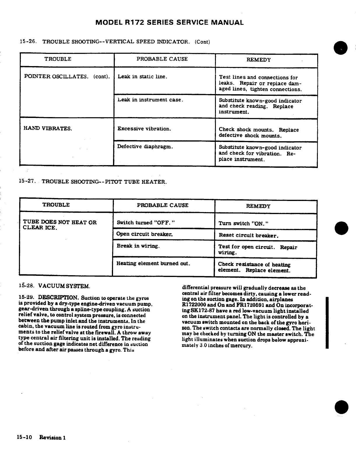
MODEL
R172
SERIES
SERVICE
MANUAL
15-26.
TROUBLE
SHOOTING--VERTICAL
SPEED
INDICATOR.
(Cont)
TROUBLE PROBABLE
CAUSE
REMEDY
POINTER
OSCILLATES.
(cont).
Leak
in
static
line.
Test
lines
and
connections
for
leaks.
Repair
or
replace
dam-
aged
lines,
tighten
connections.
Leak
in
instrument case.
Substitute
known-good
indicator
and
check
reading.
Replace
instrument.
HAND
VIBRATES.
Excessive
vibration.
Check shock
mounts.
Replace
defective
shock
mounts.
Defective diaphragm.
Substitute
known-good
indicator
and
check
for vibration.
Re-
place
instrument.
15-27.
TROUBLE
SHOOTING--PITOT
TUBE HEATER.
TROUBLE PROBABLE
CAUSE
REMEDY
TUBE
DOES
NOT
HEAT
OR
Switch
turned
"OFF."
Turn
switch
"ON."
CLEAR
ICE.
Open
circuit
breaker.
Reset
circuit
breaker.
Break
in
wiring.
Test
for
open
circuit.
Repair
wiring.
Heating
element
burned
out.
Check
resistance
of
heating
element.
Replace
element.
15-28.
VACUUM
SYSTEM.
differential
pressure
will
gradually
decrease
as
the
central
air
filter
becomes
dirty,
causing
a lower
read-
15-29.
DESCRIPTION.
Suction
to
operate
the
gyros
ing
on
the
suction
gage.
In
addition,
airplanes
is
provided
by
a
dry-type engine-driven
vacuum
pump.
R1722000
and
On
and
FR1720591
and On
incorporat-
gear-driven
through
a
spline-type
coupling.
A
suction
ing
SK
72-87
have
a
red
low-vacuum
light
installed
relief
valve,
to control
system
pressure,
is
connected
on
the
instrument
panel.
The
light
is
controlled
by
a
between
the
pump
inlet
and
the instruments.
In
the
vacuum switch
mounted
on
the
back
of
the
gyro
hori-
cabin,
the
vacuum
line
is
routed
from gyro
instru-
zon.
The
switch
contacts
are
normally
closed.
The
light
ments
to
the
relief
valve
at
the
firewall.
A
throw
away may
be
checked
by
turning
ON
the
master
switch.
The
type
central
air
filtering
unit
is
installed.
The reading
light
illuminates
when
suction
drops
below
approxi-
of
the
suction
gage
indicates
net
difference
in suction
mately
3.0
inches
of
mercury.
before
and
after air
passes
through
a gyro.
This
15-10
Revision
1
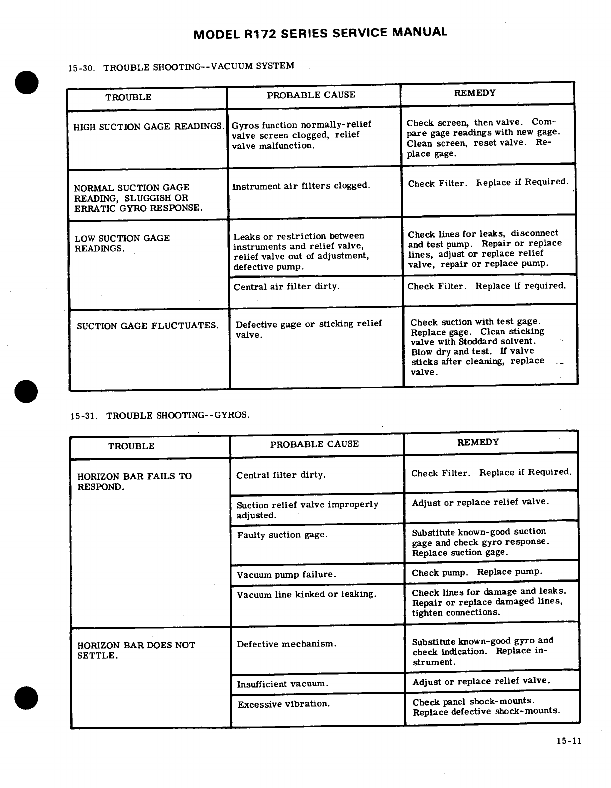
MODEL
R172
SERIES
SERVICE
MANUAL
15-30. TROUBLE
SHOOTING--VACUUM
SYSTEM
TROUBLE
PROBABLE
CAUSE
REMEDY
HIGH
SUCTION
GAGE
READINGS.
Gyros
function
normally-relief
Check
screen,
then valve.
Com-
valve
screen
clogged,
relief pare
gage
readings
with
new
gage.
valve
malfunction. Clean
screen,
reset
valve.
Re-
place
gage.
NORMAL
SUCTION
GAGE
Instrument
air
filters
clogged.
Check
Filter.
Replace
if
Required.
READING,
SLUGGISH OR
ERRATIC
GYRO
RESPONSE.
LOW
SUCTION
GAGE
Leaks
or
restriction
between
Check
lines
for
leaks, disconnect
READINGS.
instruments
and
relief
valve,
and
test
pump.
Repair
or replace
relief
valve
out
of
adjustment,
lines,
adjust
or
replace
relief
defective
pump.
valve,
repair
or
replace
pump.
Central
air
filter
dirty.
Check
Filter.
Replace
if
required.
SUCTION
GAGE
FLUCTUATES.
Defective
gage
or
sticking
relief
Check
suction
with
test
gage.
valve. Replace
gage.
Clean
sticking
valve
with
Stoddard
solvent.
Blow
dry
and
test.
If
valve
sticks
after
cleaning,
replace
valve.
15-31. TROUBLE
SHOOTING--GYROS.
TROUBLE
PROBABLE
CAUSE
REMEDY
HORIZON
BAR
FAILS
TO
Central
filter
dirty.
Check
Filter.
Replace
if
Required.
RESPOND.
Suction
relief
valve
improperly
Adjust
or
replace
relief
valve.
adjusted.
Faulty
suction
gage.
Substitute
known-good
suction
gage
and
check
gyro
response.
Replace suction
gage.
Vacuum
pump
failure.
Check
pump.
Replace
pump.
Vacuum
line
kinked
or
leaking.
Check
lines
for
damage and
leaks.
Repair
or
replace
damaged
lines,
tighten
connections.
HORIZON
BAR
DOES
NOT
Defective
mechanism.
Substitute
known-good
gyro
and
SETTLE.
check
indication. Replace
in-
strument.
Insufficient
vacuum. Adjust
or
replace
relief
valve.
Excessive
vibration.
Check
panel
shock-mounts.
Replace
defective
shock-mounts.
15-11
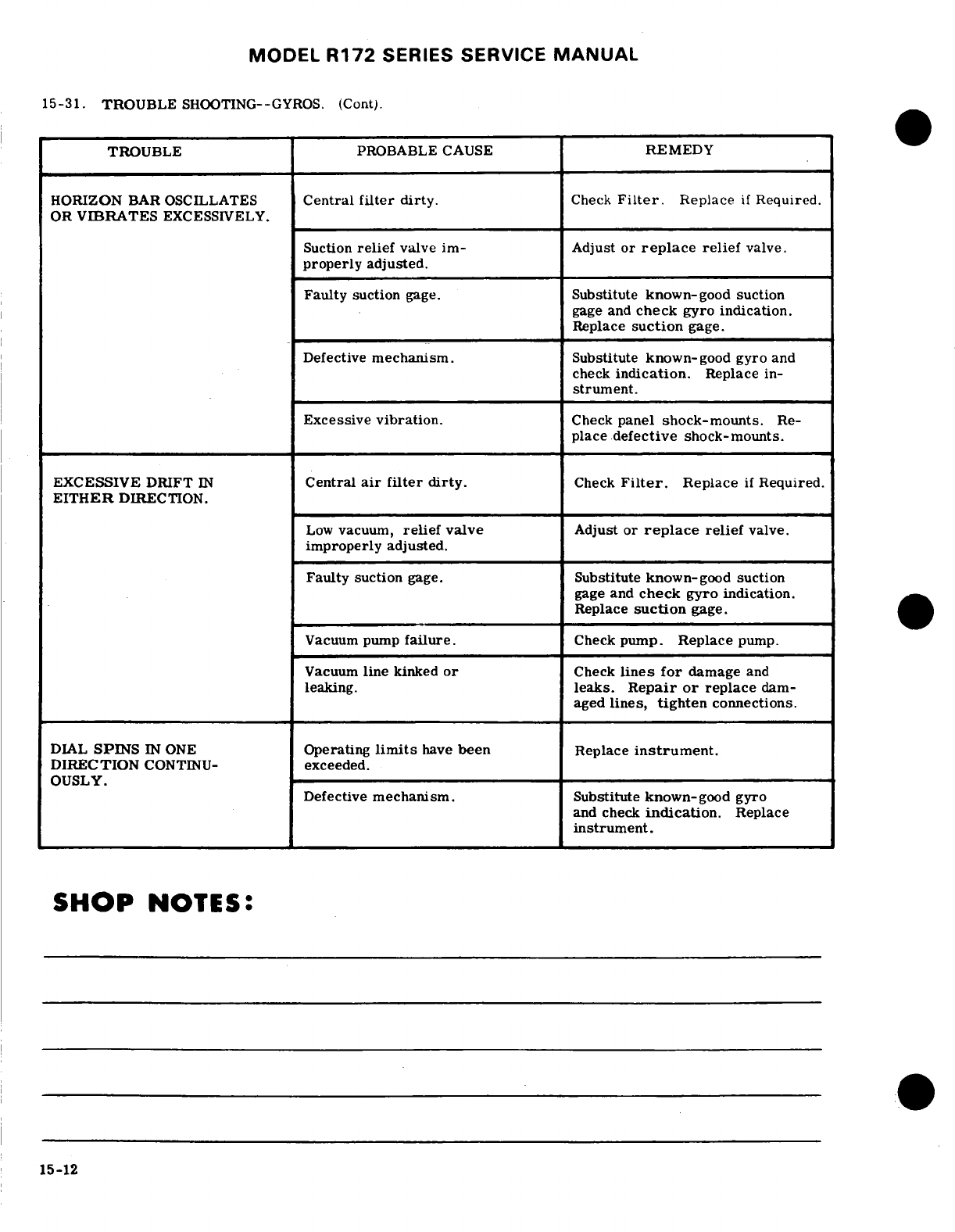
MODEL
R172
SERIES SERVICE
MANUAL
15-31.
TROUBLE
SHOOTING--GYROS.
(Cont).
TROUBLE
PROBABLE
CAUSE
REMEDY
HORIZON
BAR OSCILLATES
Central
filter
dirty.
Check
Filter.
Replace
if
Required.
OR
VIBRATES
EXCESSIVELY.
Suction
relief
valve
im-
Adjust
or
replace
relief
valve.
properly
adjusted.
Faulty
suction
gage.
Substitute
known-good
suction
gage and
check
gyro indication.
Replace
suction
gage.
Defective
mechanism.
Substitute
known-good
gyro
and
check
indication.
Replace
in-
strument.
Excessive
vibration.
Check
panel
shock-mounts.
Re-
place
defective
shock-mounts.
EXCESSIVE
DRIFT
IN
Central
air
filter
dirty.
Check
Filter.
Replace
if
Required.
EITHER
DIRECTION.
Low
vacuum,
relief
valve
Adjust or
replace
relief
valve.
improperly adjusted.
Faulty
suction
gage.
Substitute
known-good
suction
gage
and
check
gyro indication.
Replace
suction
gage.
Vacuum
pump
failure.
Check
pump.
Replace
pump.
Vacuum
line
kinked
or
Check
lines
for
damage
and
leaking.
leaks.
Repair
or
replace
dam-
aged
lines,
tighten
connections.
DIAL
SPINS
IN
ONE
Operating
limits
have
been
Replace
instrument.
DIRECTION
CONTINU-
exceeded.
OUSLY.
Defective
mechanism.
Substitute
known-good
gyro
and check
indication.
Replace
instrument.
SHOP
NOTES:
15-12
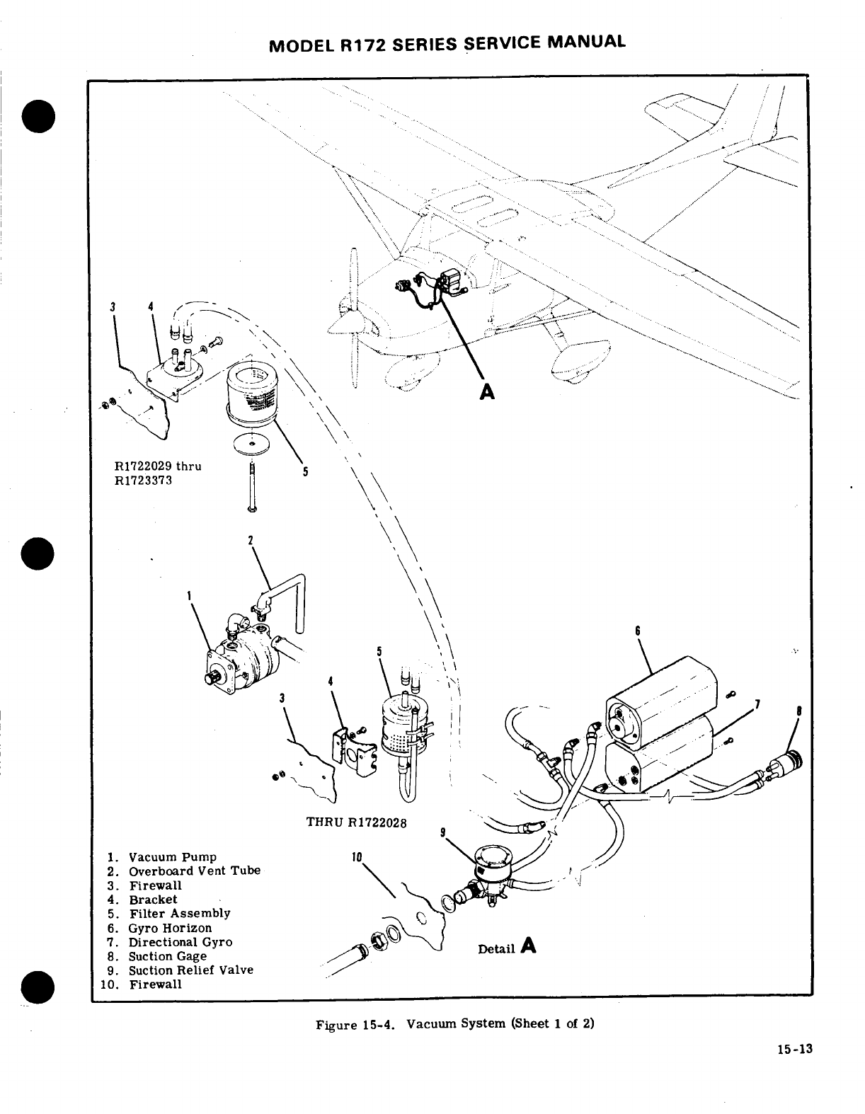
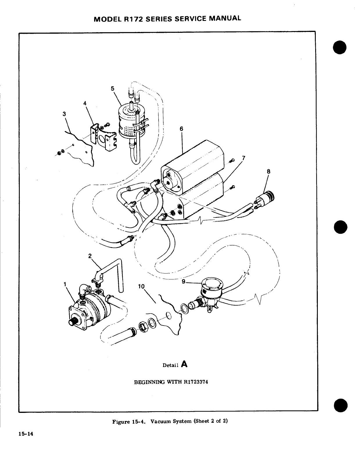
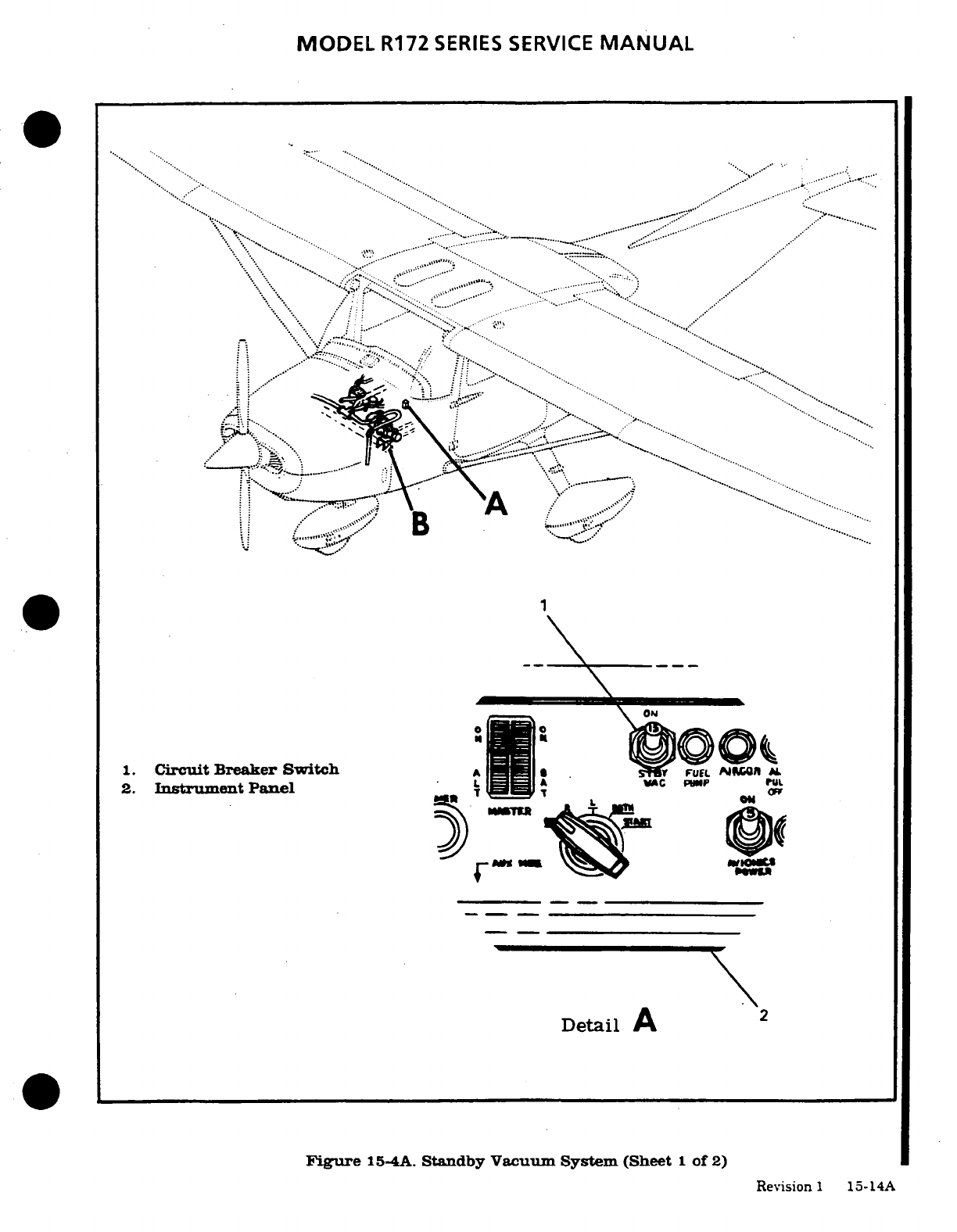
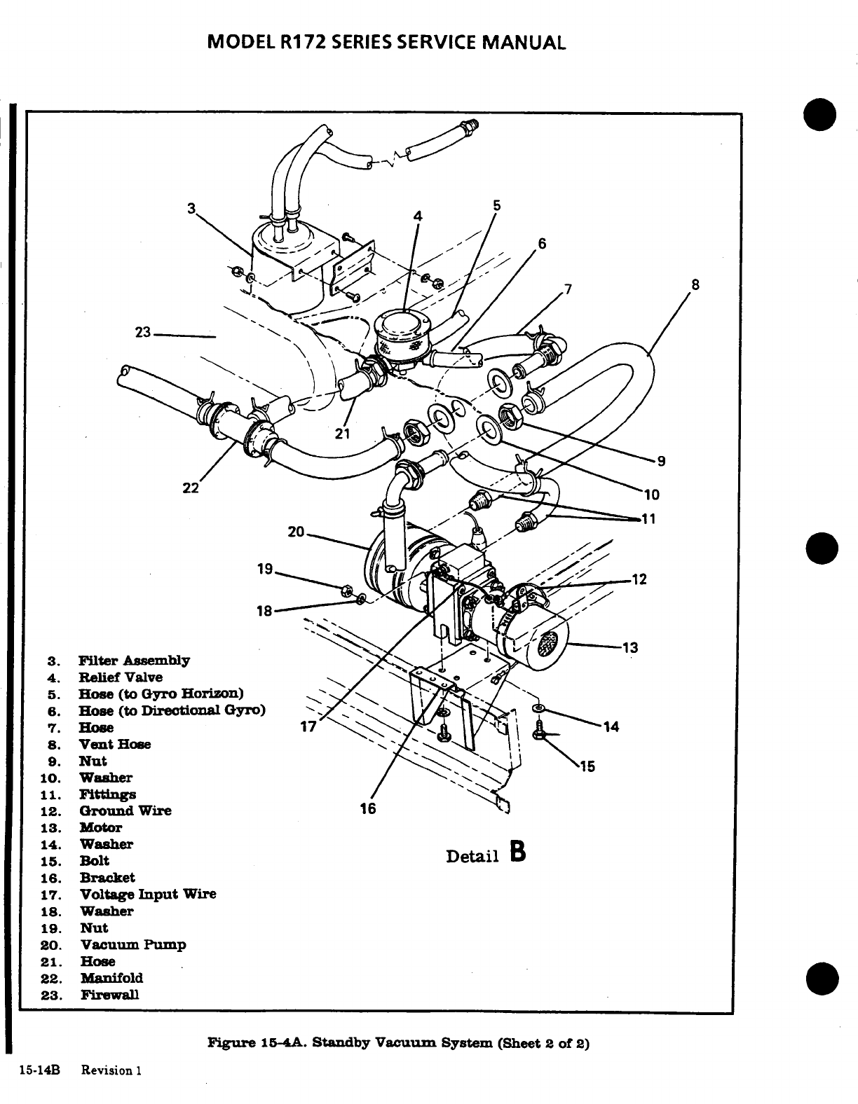
MODEL
R172
SERIES
SERVICE
MANUAL
~3
3.
Filter
Assembly
, -
4.
Relief
Valve
5.
Hose
(to
Gyro
Horizon)
6.
Hose
(to
Directional
Gyro)
.
7.
8.
Vent
Hose
'
9.
Nut
10.
Washer
11.
Fittings
12.
Ground
Wire
16
13.
Motor
15.
WaerBolt
Detail
B
16.
Bracket
17.
Voltage
Input
Wire
18.
Washer
19.
Nut
20.
Vacuum
Pump
21.
Hose
22.
Manifold
23.
Firewall
Figure
15-4A.
Standby
Vacuum
System
(Sheet
2
of
2)
15-14B
Revision 1
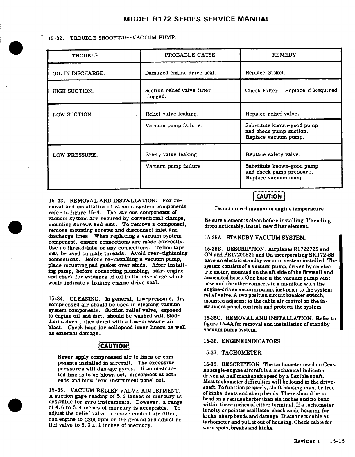
MODEL
R172
SERIES
SERVICE
MANUAL
15-32.
TROUBLE
SHOOTING--VACUUM
PUMP.
TROUBLE
PROBABLE
CAUSE
REMEDY
OIL
IN
DISCHARGE.
Damaged engine
drive
seal.
Replace
gasket.
HIGH
SUCTION.
Suction
relief
valve
filter
Check
Filter.
Replace
if
Required.
clogged.
LOW
SUCTION.
Relief
valve
leaking.
Replace
relief
valve.
Vacuum
pump
failure.
Substitute
known-good
pump
and
check pump
suction.
Replace vacuum
pump.
LOW
PRESSURE.
Safety
valve
leaking.
Replace
safety
valve.
Vacuum
pump
failure.
Substitute
known-good
pump
and
check
pump
pressure.
Replace vacuum
pump.
15-33.
REMOVAL AND
INSTALLATION.
For
re-
moval
and
installation
of
vacuum
system
components
Do
not
exceed
maximum
engine
temperature.
refer
to
figure
15-4.
The
various
components
of
vacuum
system
are
secured
by
conventional
clamps,
Be
sure
element
is
clean
before
installing.
If
reading
mounting
screws
and nuts.
To
remove
a
component,
drops
noticeably,
install
new
filter
element.
remove
mounting
screws
and
disconnect
inlet
and
discharge
lines.
When
replacing
a
vacuum
system
15-35A.
STANDBY
VACUUM
SYSTEM.
component,
ensure
connections
are
made
correctly.
Use
no
thread-lube
on
any
connections.
Teflon
tape
15-35B.
DESCRIPTION.
Airplanes
R1722725
and
may
be
used
on
male
threads.
Avoid
over-tightening
ON
and
FR17200621
and
On
incorporating
SK172-88
connections.
Before
re-installing
a
vacuum
pump,
have
an
electric
standby
vacuum
system
installed.
The
place
mounting
pad
gasket
over studs.
After
install-
system
consists
of
a vacuum
pump, driven
by
an
elec-
ing pump,
before
connecting
plumbing,
start
engine
tric
motor, mounted
on
the
aft side
of
the
firewall
and
and
check
for
evidence
of
oil
in
the
discharge
which associated
hoses.
One
hose
is
the
vacuum
pump
vent
would
indicate
a
leaking
engine
drive
seal.
hose
and the
other
connects
to
a
manifold
with
the
engine-driven vacuum
pump,
just
prior
to
the system
relief
valve.
A
two
position
circuit
breaker switch,
15-34.
CLEANING.
In
general,
low-pressure,
dry
mounted
adjacent
to
the cabin
air
control
on
the
in-
compressed
air
should
be
used
in
cleaning
vacuum
strument
panel, controls
and
protects
the
system.
system
components.
Suction
relief
valve, exposed
to
engine
oil
and
dirt,
should
be
washed
with
Stod-
15-35C.
REMOVAL
AND
INSTALLATION.
Refer to
datd
solvent,
then
dried
with
a
low-pressure
air
figure
15-4A
for
removal
and
installation
of
standby
blast.
Check
hose
for
collapsed
inner
liners
as
well
vacuum pump
system.
as
external
damage.
15.36.
ENGINE
INDICATORS.
iCAUTION
15-37.
TACHOMETER.
Never
apply
compressed
air
to
lines
or
com-
ponents
installed
in
aircraft.
The
excessive
15-38.
DESCRIPTION. The
tachometer
used
on
Cess-
pressures
will
damage
gyros.
If
an
obstruc-
na
single-engine
aircraft
is
a
mechanical
indicator
ted
line
is
to
be
blown
out,
disconnect
at
both
driven
at
half
crankshaft
speed
by
a
flexible
shaft.
ends
and
blow
from
instrument
panel
out.
Most
tachometer
difficulties
will
be
found
in
the
drive-
15-35.
VACUUM
RELIEF
VALVE
ADJUSTMENT.
shaft.
To
function
properly,
shaft
housing
must
be
free
ofkinks,
dents
and
sharp
bends.
There
should
be
no
A
suction
gage
reading
of
5. 3
inches
of
mercury
is
kinks
pbends.There
should
beno
A
suction
gage
reading
of
5.
3
inches
of
mercury
is bend
on
a
radius
shorter
than
six
inches
and
no bend
desirable
for
gyro
instruments.
However
a rnge
of
4.d esirable
for
gyro
instru
of
mentrcury
is
acceptver,
a
range
within
three
inches
of
either
terminal.
If
a
tachometer
i mercury
s acceptab. To
is
noisy or
pointer oscillates,
check
cable
housing
for
adjust
the
relief
valve,
remove
control
air
filter,
kinks,
sharp
bends
and
damage.
Disconnect
cable
at
run
engine
to
2200
rpm
on
the ground
and
adjust
re-
tachometer
and
pull
it
out
of
housing.
Check
cable
for
lief
valve
to
5.3
±.
1
inches
of
mercury.
worn
spots,
breaks
and kinks.
Revision
1
15-15
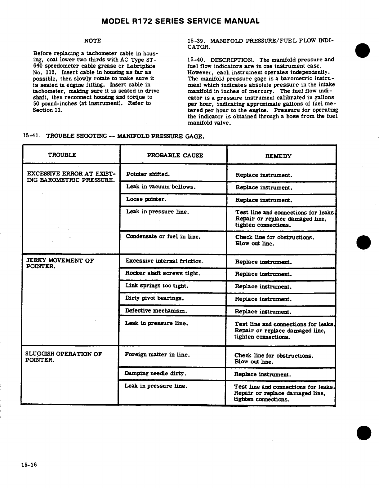
MODEL
R172
SERIES
SERVICE
MANUAL
NOTE
15-39.
MANIFOLD
PRESSURE/FUEL
FLOW
INDI-
CATOR.
Before
replacing
a
tachometer
cable
in
hous-
ing,
coat
lower
two
thirds
with
AC
Type ST-
15-40.
DESCRIPTION.
The
manifold
pressure
and
640
speedometer
cable
grease
or
Lubriplate
fuel
flow
indicators
are
in
one
instrument
case.
No.
110.
Insert
cable
in
housing
as
far as
However,
each
instrument
operates
independently.
possible,
then
slowly
rotate
to make
sure
it
The
manifold
pressure
gage
is
a
barometric
instru-
is
seated
in
engine
fitting.
Insert
cable
in
ment
which
indicates
absolute
pressure
in the
intake
tachometer,
making
sure
it
is
seated
in
drive manifold
in
inches
of
mercury.
The
fuel
flow
indi-
shaft,
then
reconnect
housing and
torque
to
cator
is a
pressure
instrument
calibrated
in
gallons
50
pound-inches
(at
instrument).
Refer
to
per
hour,
indicating
approximate
gallons
of
fuel
me-
Section
11.
tered
per
hour
to
the
engine.
Pressure
for
operating
the
indicator
is
obtained
through
a
hose
from
the
fuel
manifold
valve.
15-41.
TROUBLE
SHOOTING
--
MANIFOLD
PRESSURE
GAGE.
TROUBLE
PROBABLE
CAUSE
REMEDY
EXCESSIVE
ERROR
AT
EXIST-
Pointer
shifted.
Replace
instrument.
ING
BAROMETRIC
PRESSURE.
Leak
in
vacuum
bellows. Replace
instrument.
Loose
pointer. Replace
instrument.
Leak
in
pressure
line.
Test
line
and
connections
for
leaks
Repair or
replace
damaged
line,
tighten
connections.
Condensate
or
fuel
in
line.
Check
line
for
obstructions.
Blow
out
line.
JERKY
MOVEMENT
OF
Excessive
internal
friction.
Replace
instrument.
POINTER.
Rocker
shaft
screws
tight.
Replace
instrument.
Link
springs
too
tight.
Replace
instrument.
Dirty
pivot
bearings.
Replace
instrument.
Defective
mechanism.
Replace
instrument.
Leak
in
pressure
line.
Test
line
and
connections
for
leaks
Repair
or
replace
damaged
line,
tighten
connections.
SLUGGISH
OPERATION
OF
Foreign
matter
in
line.
Check
line
for obstructions.
POINTER. Blow
out
line.
Damping
needle
dirty.
Replace
instrument.
Leak
in
pressure
line.
Test
line
and
connections
for
leaks
Repair
or
replace
damaged
line,
tighten
connections.
15-16
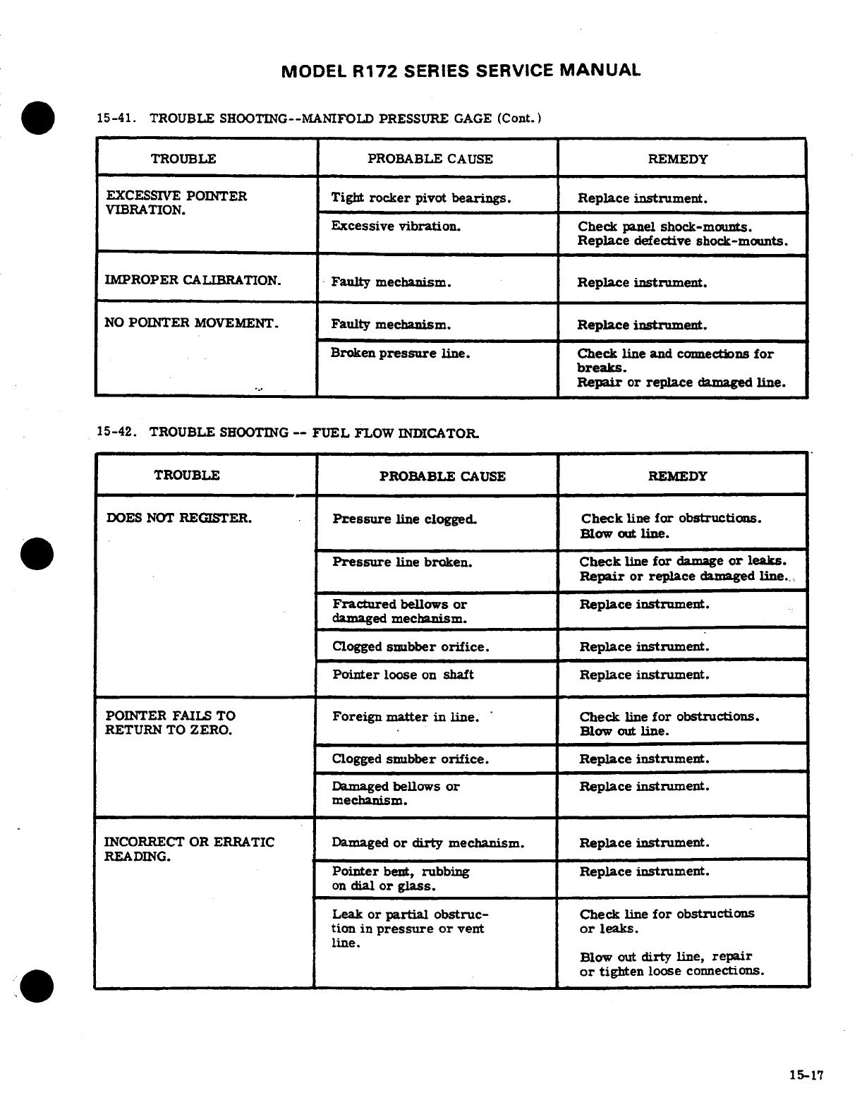
MODEL
R172
SERIES
SERVICE
MANUAL
15-41.
TROUBLE SHOOTING--MANIFOLD
PRESSURE
GAGE
(Cont.)
TROUBLE
PROBABLE
CAUSE
REMEDY
EXCESSIVE
POINTER
Tight
rocker
pivot
bearings.
Replace
instrument.
VIBRATION.
Excessive
vibration.
Check
panel
shock-mounts.
Replace
defective
shock-mounts.
IMPROPER
CALIBRATION.
Faulty
mechanism.
Replace
instrument.
NO
POINTER
MOVEMENT.
Faulty
mechanism.
Replace
instrument.
Broken
pressure
line. Check
line
and
connections
for
breaks.
Repair
or replace
damaged
line.
15-42.
TROUBLE
SHOOTING
--
FUEL
FLOW
INDICATOR.
TROUBLE
PROBABLE
CAUSE
REMEDY
DOES
NOT
REGISTER.
Pressure
line
clogged.
Check
line
for
obstructions.
Blow
out
line.
Pressure
line
broken.
Check
line
for
damage
or
leaks.
Repair
or
replace
damaged
line.
Fractured
bellows
or
Replace instrument.
damaged
mechanism.
Clogged
snubber
orifice.
Replace
instrument.
Pointer
loose
on
shaft
Replace
instrument.
POINTER
FAILS
TO
Foreign
matter
in
line.
Check
line
for
obstructions.
RETURN
TO
ZERO.
Blow
out
line.
Clogged
snubber
orifice.
Replace instrument.
Damaged
bellows
or
Replace instrument.
mechanism.
INCORRECT
OR
ERRATIC
Damaged
or
dirty
mechanism.
Replace
instrument.
READING.
Pointer
bent,
rubbing
Replace instrument.
on
dial
or glass.
Leak
or
partial
obstruc-
Check
line
for
obstructions
tion
in
pressure
or
vent
or
leaks.
line.
Blow
out
dirty line,
repair
or
tighten
loose
connections.
15-17
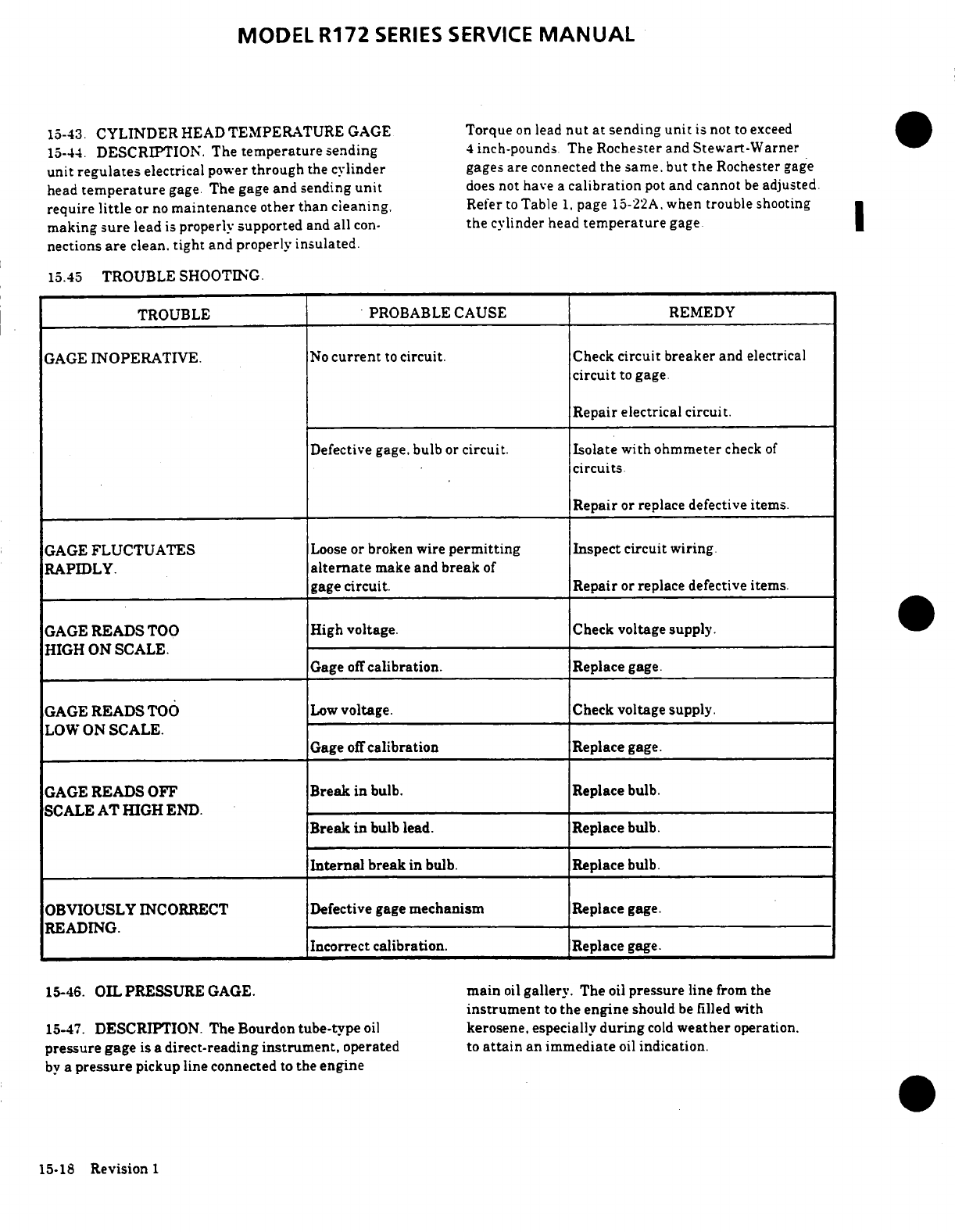
MODEL
R172
SERIES
SERVICE
MANUAL
15-43.
CYLINDER
HEAD
TEMPERATURE
GAGE
Torque
on
lead
nut
at
sending
unit
is not
to
exceed
15-44.
DESCRIPTION. The
temperature
sending
4
inch-pounds. The Rochester
and
Stewart-Warner
unit
regulates
electrical
power
through
the
cylinder
gages
are
connected
the
same.
but
the
Rochester
gage
head
temperature
gage.
The
gage
and
sending
unit
does
not
have
a
calibration
pot
and
cannot
be
adjusted.
require
little
or
no
maintenance
other
than
cleaning,
Refer
to
Table
1,
page
15-22A,
when
trouble
shooting
making
sure
lead
is
properly
supported
and
all
con-
the
cylinder
head
temperature
gage
nections
are
clean,
tight
and
properly
insulated.
15.45
TROUBLE
SHOOTING.
TROUBLE
PROBABLE
CAUSE REMEDY
GAGE
INOPERATIVE.
No
current
to
circuit. Check
circuit breaker
and
electrical
circuit
to
gage.
Repair
electrical circuit.
Defective
gage.
bulb
or
circuit. Isolate
with
ohmmeter
check
of
circuits.
Repair
or
replace defective
items.
GAGE
FLUCTUATES
Loose
or
broken
wire
permitting
Inspect
circuit
wiring.
RAPIDLY.
alternate
make
and
break
of
gage
circuit. Repair
or
replace
defective
items.
GAGE
READS
TOO
High
voltage.
Check
voltage supply.
HIGH
ON
SCALE.
Gage
off
calibration.
Replace
gage.
GAGE
READS
TOO
Low
voltage.
Check
voltage supply.
LOW
ON
SCALE.
Gage
off
calibration
Replace
gage.
GAGE
READS
OFF
Break
in
bulb.
Replace
bulb.
SCALE
AT HIGH
END.
Break
in
bulb
lead.
Replace
bulb.
Internal
break
in
bulb.
Replace
bulb.
OBVIOUSLY
INCORRECT
Defective
gage
mechanism
Replace
gage.
READING.
Incorrect
calibration.
Replace
gage.
15-46.
OIL PRESSURE
GAGE.
main
oil
gallery.
The
oil
pressure
line
from
the
instrument
to
the
engine
should
be
filled
with
15-47.
DESCRIPTION. The
Bourdon
tube-type
oil
kerosene,
especially
during
cold
weather
operation.
pressure
gage
is
a
direct-reading
instrument,
operated
to
attain
an immediate
oil
indication.
by
a
pressure
pickup line connected
to
the
engine
15-18
Revision 1
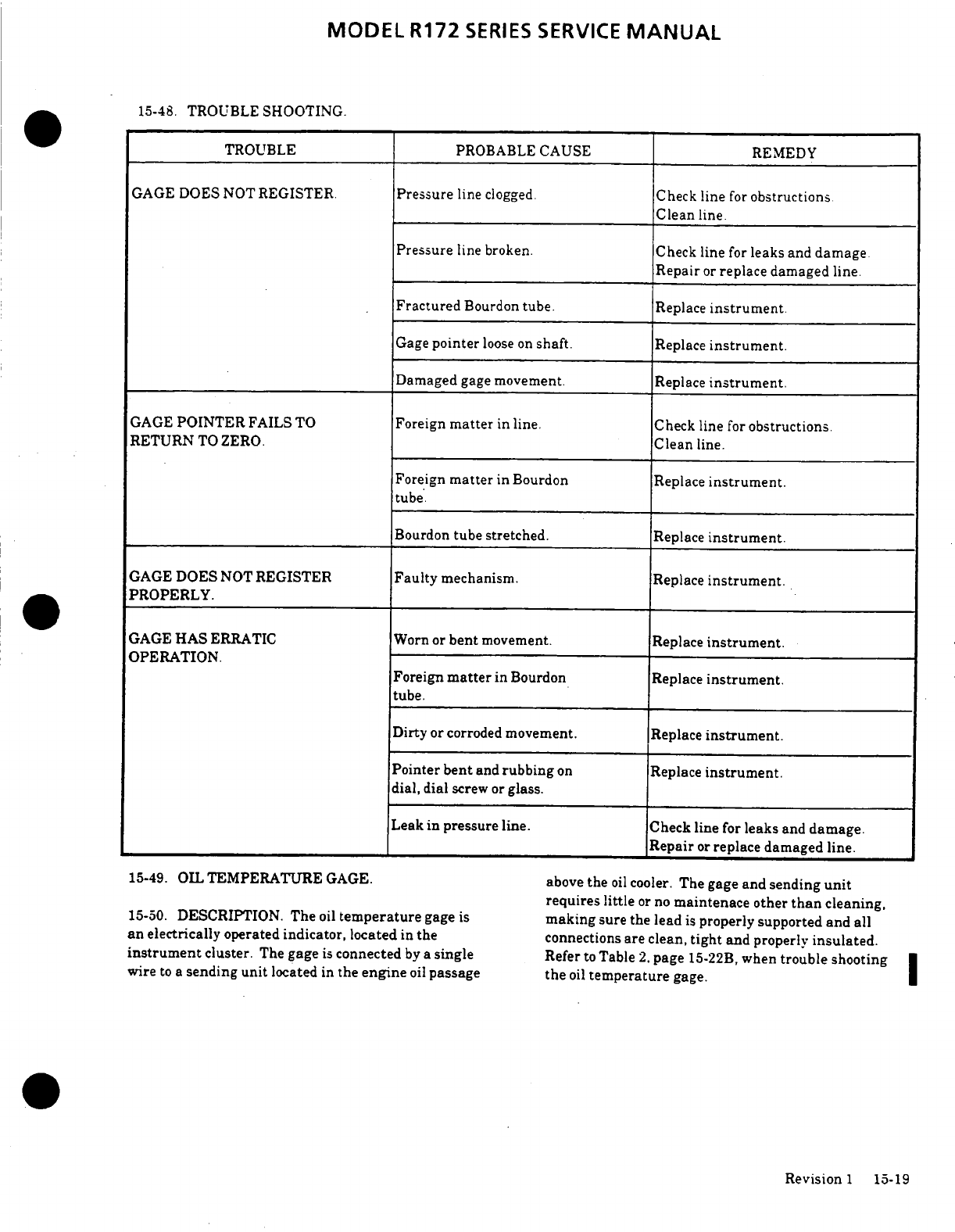
MODEL
R172
SERIES
SERVICE
MANUAL
15-48.
TROUBLE
SHOOTING.
TROUBLE
PROBABLE
CAUSE
REMEDY
GAGE
DOES NOT
REGISTER.
Pressure
line
clogged.
Check
line
for
obstructions.
Clean
line.
Pressure
line
broken. Check
line
for
leaks
and
damage
Repair
or
replace
damaged
line.
Fractured
Bourdon
tube.
Replace
instrument.
Gage
pointer
loose on
shaft.
Replace
instrument.
Damaged
gage
movement.
Replace
instrument.
GAGE
POINTER
FAILS
TO
Foreign
matter
in
line.
Check
line
for
obstructions.
RETURN
TO
ZERO.
Clean
line.
Foreign
matter
in
Bourdon
Replace
instrument.
tube.
Bourdon
tube stretched.
Replace
instrument.
GAGE
DOES
NOT
REGISTER
Faulty
mechanism.
Replace
instrument.
PROPERLY.
GAGE
HAS
ERRATIC
Worn or
bent
movement.
Replace
instrument.
OPERATION.
Foreign
matter
in
Bourdon
Replace
instrument.
tube.
Dirty
or
corroded
movement.
Replace
instrument.
Pointer bent
and
rubbing
on
Replace
instrument.
dial,
dial
screw
or
glass.
Leak in
pressure
line.
Check
line
for
leaks
and
damage.
Repair
or
replace
damaged
line.
15-49.
OIL
TEMPERATURE
GAGE.
above
the
oil
cooler.
The
gage
and
sending
unit
requires little
or
no
maintenace other
than
cleaning,
15-50.
DESCRIPTION.
The
oil
temperature
gage
is
making
sure the
lead
is
properly
supported and
all
an
electrically
operated
indicator,
located
in
the
connections
are clean,
tight
and
properly
insulated.
instrument
cluster.
The
gage
is
connected
by
a
single
Refer
to
Table
2.
page
15-22B,
when
trouble
shooting
|
wire
to
a
sending
unit
located
in
the
engine
oil
passage
the
oil
temperature
gage.
Revision
1
15-19
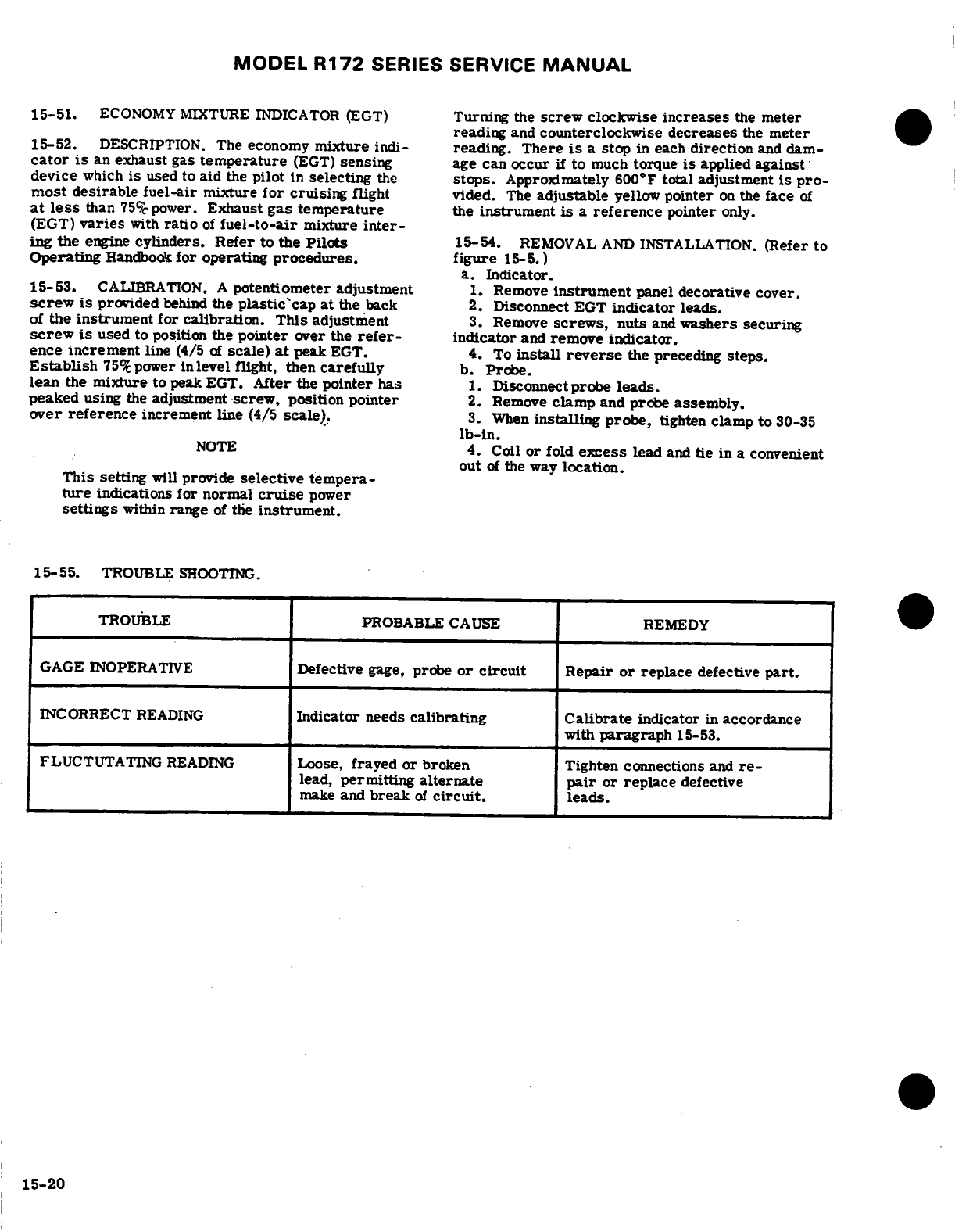
MODEL
R172
SERIES SERVICE
MANUAL
15-51.
ECONOMY MIXTURE
INDICATOR
(EGT)
Turning
the
screw
clockwise
increases
the
meter
reading
and
counterclockwise
decreases
the
meter
15-52.
DESCRIPTION.
The
economy
mixture
indi-
reading.
There
is
a
stop
in
each
direction
and
dam-
cator
is
an
exhaust
gas
temperature
(EGT)
sensing
age can occur
if
to
much
torque
is
applied
against
device
which
is
used
to
aid
the
pilot
in
selecting
the
stops.
Approximately 600°F
total adjustment
is
pro-
most desirable
fuel-air
mixture
for
cruising
flight
vided.
The
adjustable
yellow
pointer
on
the
face
of
at
less
than
75%
power.
Exhaust
gas
temperature
the
instrument
is
a
reference
pointer
only.
(EGT)
varies
with
ratio
of
fuel-to-air
mixture
inter-
ing
the
engine
cylinders.
Refer
to the
Pilots
15-54.
REMOVAL
AND
INSTALLATION.
(Refer
to
Operating
Handbook
for
operating
procedures. figure
15-5.)
a.
Indicator.
15-53.
CALIBRATION.
A
potentiometer adjustment
1.
Remove
instrument
panel
decorative
cover.
screw
is
provided
behind
the
plastic'cap at
the
back
2.
Disconnect
EGT
indicator
leads.
of
the instrument
for
calibration.
This
adjustment
3.
Remove
screws,
nuts
and
washers
securing
screw
is
used
to
position
the
pointer
over
the
refer-
indicator
and
remove
indicator.
ence
increment
line
(4/5
of
scale)
at
peak
EGT.
4.
To
install
reverse
the preceding
steps.
Establish
75%
power
inlevel
flight,
then
carefully
b.
Probe.
lean
the
mixture
to
peak EGT.
After
the
pointer
has
1.
Disconnect
probe
leads.
peaked
using
the
adjustment
screw,
position
pointer
2.
Remove
clamp
and
probe
assembly.
over reference
increment
line
(4/5 scale).
3.
When
installing
probe,
tighten
clamp
to
30-35
lb-in.
NOTE
4.
Coil
or
fold
excess
lead
and
tie
in
a
convenient
out
of
the
way
location.
This
setting
will
provide
selective tempera-
ture
indications for
normal
cruise
power
settings
within
range
of
the
instrument.
15-55.
TROUBLE
SHOOTING.
TROUBLE
PROBABLE
CAUSE REMEDY
GAGE INOPERATIVE
Defective
gage,
probe
or
circuit
Repair
or
replace
defective
part.
INCORRECT
READING
Indicator
needs
calibrating
Calibrate
indicator
in
accordance
with
paragraph
15-53.
FLUCTUTATING
READING
Loose,
frayed
or
broken
Tighten
connections
and
re-
lead,
permitting
alternate
pair
or
replace
defective
make
and
break
of
circuit,
leads.
15-20
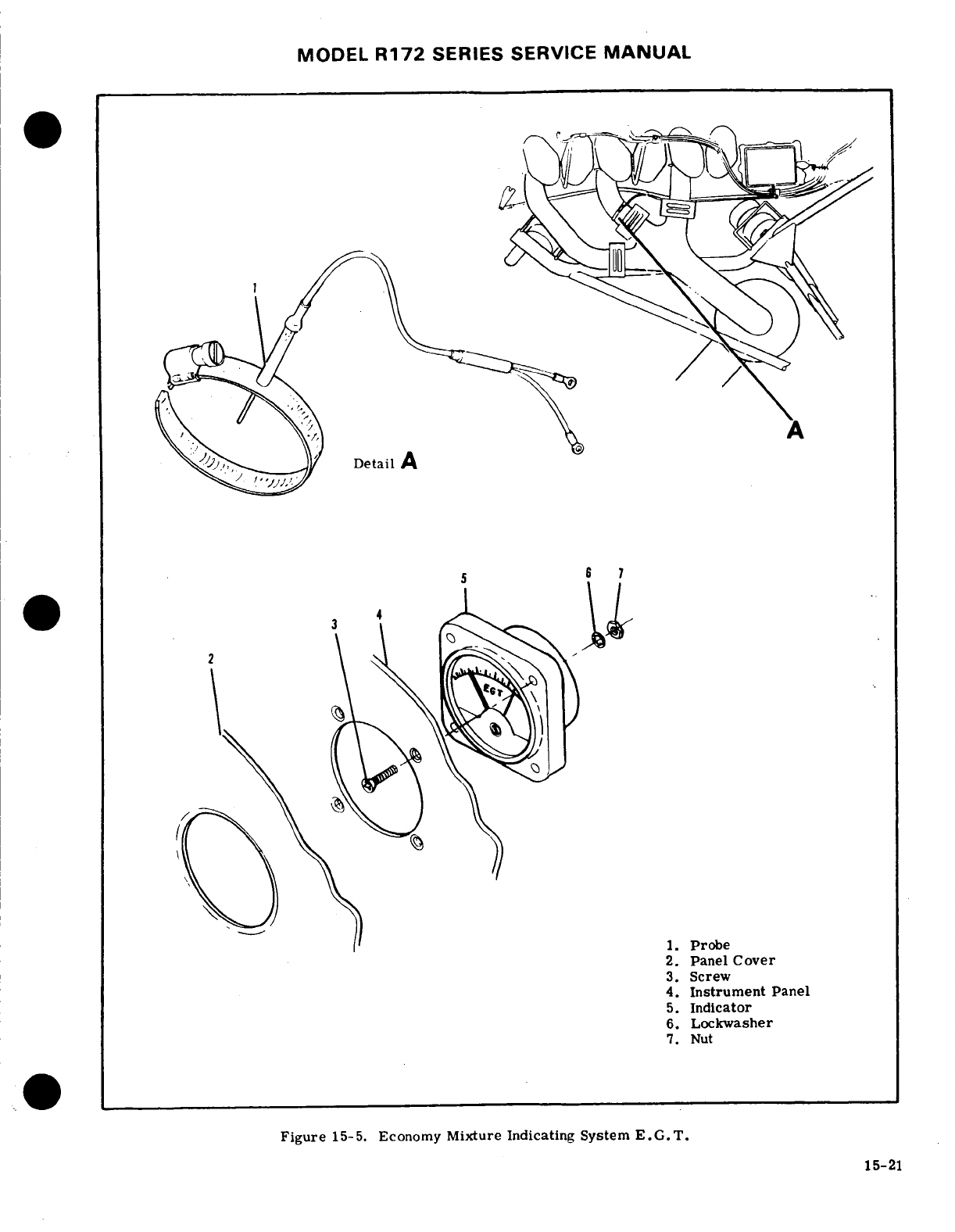
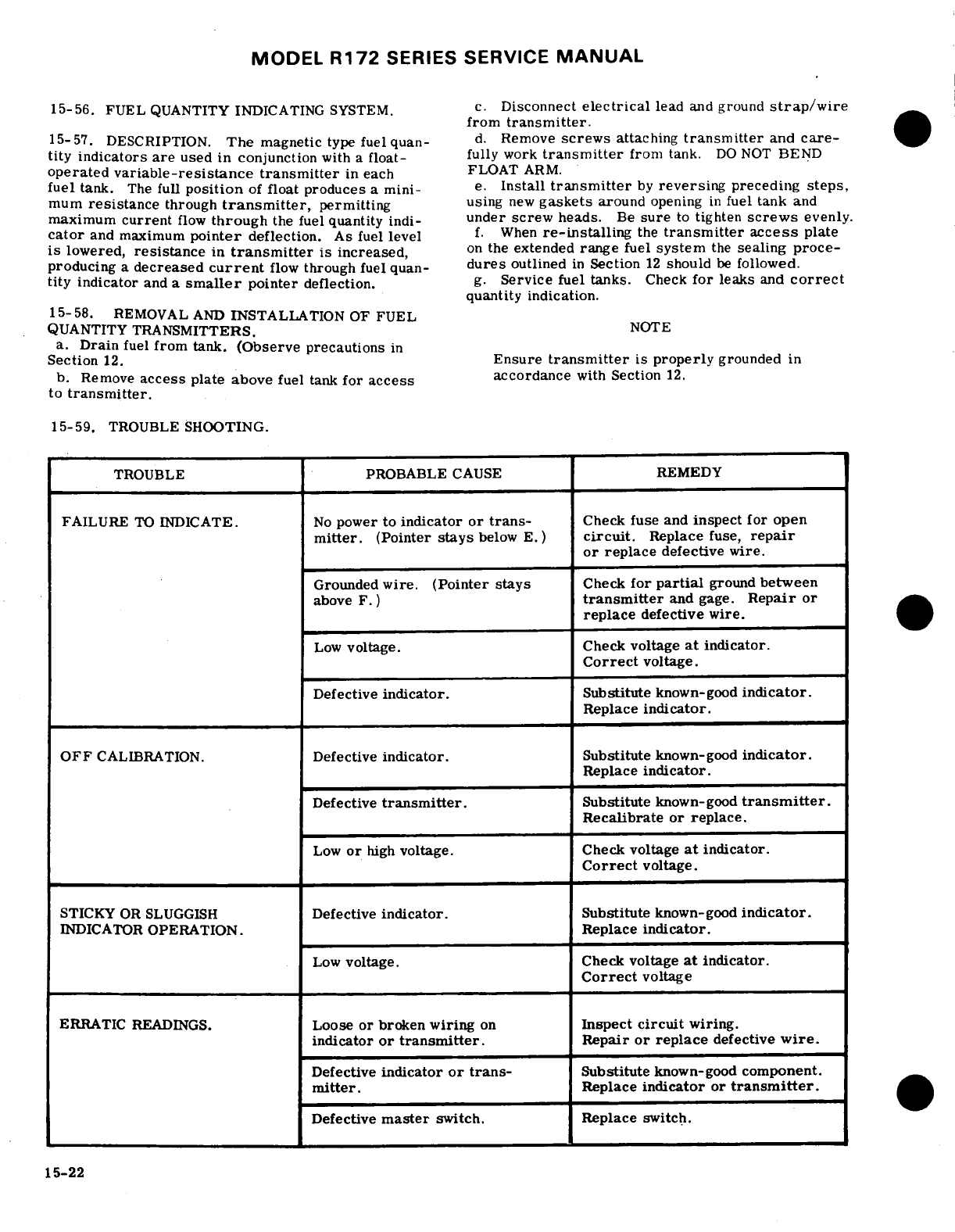
MODEL
R172
SERIES
SERVICE
MANUAL
15-56.
FUEL
QUANTITY INDICATING
SYSTEM.
c.
Disconnect
electrical
lead
and
ground
strap/wire
from
transmitter.
15-57.
DESCRIPTION.
The
magnetic
type
fuelquan-
d.
Remove
screws
attaching
transmitter
and
care-
tity
indicators
are
used
in
conjunction
with
a
float-
fully
work
transmitter
from
tank.
DO
NOT
BEND
operated
variable-resistance
transmitter
in each
FLOAT
ARM.
fuel
tank.
The
full
position
of
float produces
a
mini-
e.
Install
transmitter
by
reversing
preceding
steps,
mum
resistance
through
transmitter,
permitting
using
new
gaskets
around
opening
in
fuel
tank
and
maximum
current
flow
through
the fuel
quantity
indi-
under screw
heads.
Be
sure
to
tighten
screws
evenly.
cator
and
maximum
pointer
deflection.
As fuel
level
f.
When
re-installing
the
transmitter access
plate
is
lowered,
resistance
in
transmitter
is
increased,
on
the
extended
range
fuel
system
the
sealing
proce-
producing
a
decreased
current
flow
through
fuel quan-
dures
outlined
in
Section
12
should
be
followed.
tity
indicator
and
a
smaller
pointer
deflection.
g.
Service
fuel tanks.
Check
for
leaks
and
correct
quantity indication.
15-58.
REMOVAL
AND
INSTALLATION
OF FUEL
QUANTITY
TRANSMITTERS.
NOTE
a.
Drain
fuel
from
tank.
(Observe
precautions
in
Section
12.
Ensure
transmitter
is
properly
grounded
in
b.
Remove
access
plate above
fuel
tank
for
access
accordance
with
Section
12.
to
transmitter.
15-59.
TROUBLE
SHOOTING.
TROUBLE
PROBABLE
CAUSE
REMEDY
FAILURE
TO
INDICATE.
No
power
to
indicator
or
trans-
Check
fuse
and
inspect
for
open
mitter.
(Pointer
stays
below
E.)
circuit.
Replace
fuse,
repair
or
replace
defective wire.
Grounded
wire.
(Pointer stays
Check
for
partial
ground
between
above
F.)
transmitter
and
gage.
Repair
or
replace
defective
wire.
Low
voltage.
Check voltage
at
indicator.
Correct
voltage.
Defective
indicator.
Substitute
known-good
indicator.
Replace
indicator.
OFF
CALIBRATION.
Defective
indicator.
Substitute
known-good
indicator.
Replace
indicator.
Defective
transmitter.
Substitute
known-good
transmitter.
Recalibrate
or
replace.
Low
or
high
voltage. Check
voltage
at
indicator.
Correct
voltage.
STICKY
OR
SLUGGISH
Defective
indicator.
Substitute
known-good
indicator.
INDICATOR
OPERATION.
Replace
indicator.
Low
voltage. Check
voltage
at
indicator.
Correct
voltage
ERRATIC
READINGS.
Loose
or
broken
wiring
on
Inspect
circuit
wiring.
indicator
or
transmitter.
Repair
or
replace
defective
wire.
Defective
indicator
or trans-
Substitute
known-good
component.
mitter.
Replace
indicator
or
transmitter.
Defective
master
switch.
Replace
switch.
15-22
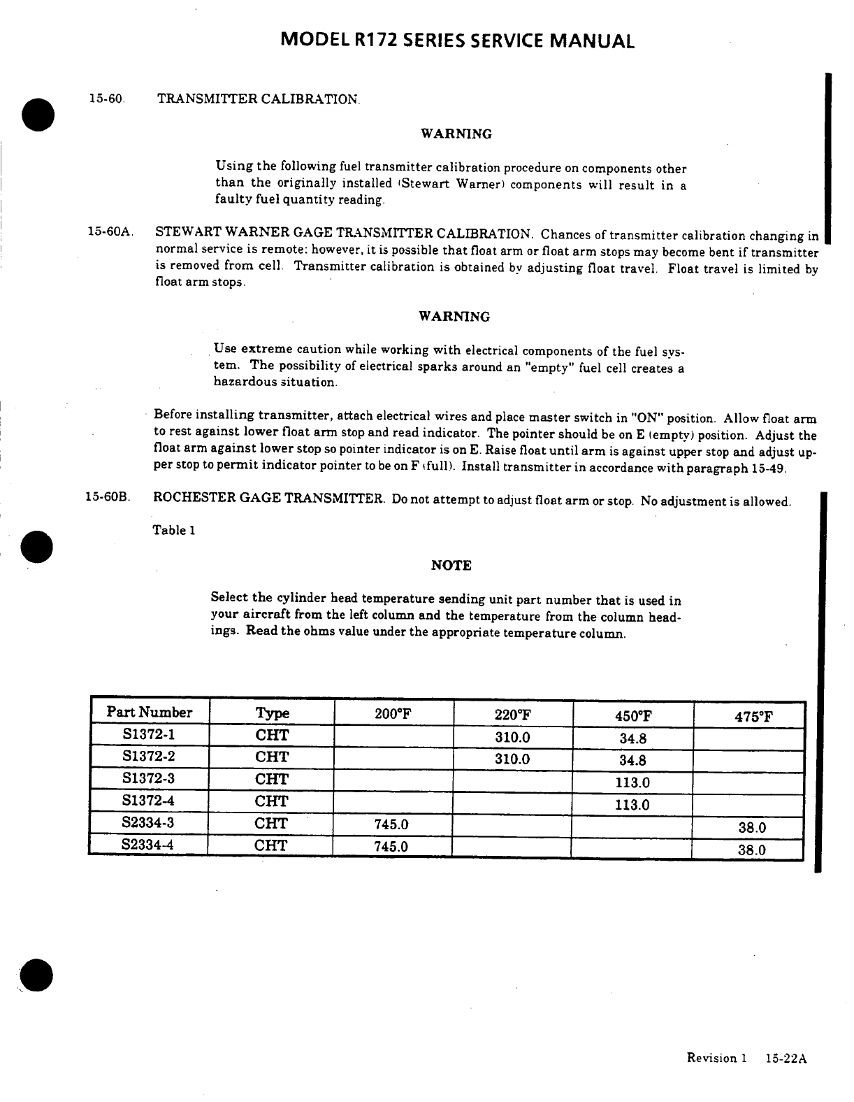
MODEL
R172
SERIES
SERVICE
MANUAL
.
15-60.
TRANSMITTER
CALIBRATION.
WARNING
Using
the
following
fuel
transmitter
calibration
procedure
on
components
other
than
the
originally
installed
(Stewart
Warner)
components will
result
in a
faulty
fuel
quantity
reading.
15-60A.
STEWART
WARNER
GAGE TRANSMITTER
CALIBRATION.
Chances
of
transmitter
calibration changing
in
normal
service
is remote:
however,
it
is
possible
that
float
arm
or
float
arm
stops
may
become
bent
if
transmitter
is removed
from
cell.
Transmitter
calibration
is obtained
by
adjusting
float
travel.
Float
travel
is
limited
by
float
arm
stops.
WARNING
Use
extreme
caution
while
working
with
electrical
components
of
the
fuel
sys-
tem.
The
possibility
of
electrical
sparks
around
an
"empty"
fuel
cell
creates
a
hazardous
situation.
Before
installing
transmitter,
attach
electrical
wires
and
place
master
switch
in
"ON"
position.
Allow
float
arm
to
rest
against
lower
float
arm
stop
and
read
indicator.
The
pointer
should
be
on E
(empty)
position.
Adjust
the
float
arm
against
lower
stop
so
pointer
indicator
is
on
E.
Raise
float
until
arm
is
against
upper
stop
and
adjust
up-
per
stop
to
permit
indicator
pointer
to
be
on
F
(full).
Install
transmitter
in
accordance
with
paragraph
15-49.
15-60B.
ROCHESTER
GAGE
TRANSMITTER.
Do
not
attempt
to
adjust float
arm
or
stop.
No
adjustment
is
allowed.
Table
1
NOTE
Select
the
cylinder
head
temperature
sending
unit
part
number
that
is
used
in
your
aircraft
from
the
left
column
and
the
temperature
from
the
column
head-
ings.
Read
the
ohms
value
under
the
appropriate
temperature
column.
Part
Number
Type
200°F
22
0
F
450°F
475°F
S1372-1
CHT
310.0
34.8
S1372-2
CHT
310.0
34.8
S1372-3
CHT
113.0
S1372-4
CHT
113.0
S2334-3
CHT
745.0
38.0
S2334-4
CHT
745.0
38.0
Revision
1
15-22A
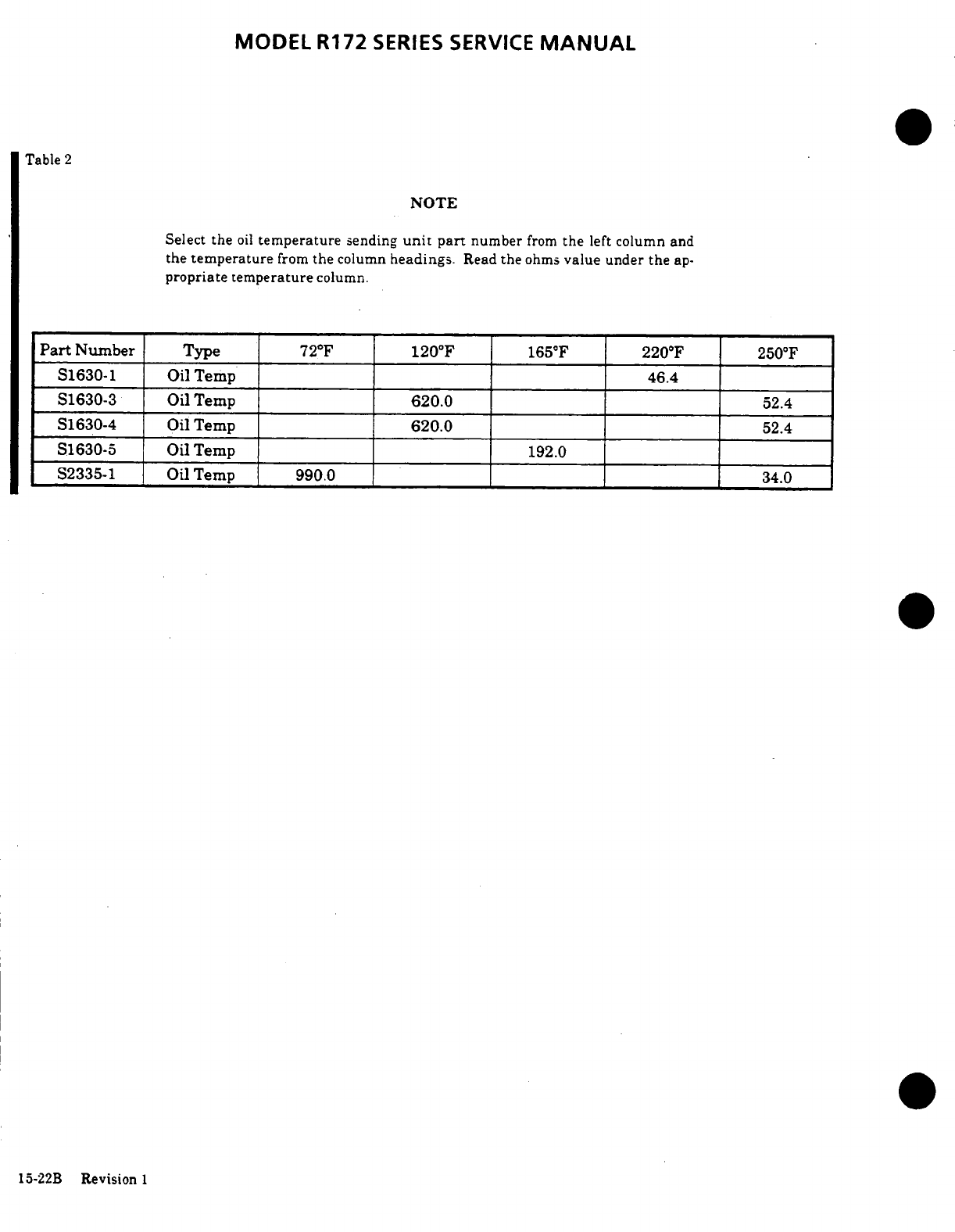
MODEL
R172
SERIES
SERVICE
MANUAL
Table
2
NOTE
Select
the
oil
temperature
sending
unit
part
number
from
the
left
column
and
the
temperature
from
the
column
headings.
Read
the
ohms
value under
the
ap-
propriate
temperature
column.
Part
Number
Type
72°F
120°F
165°F
220°F
250°F
S1630-1
Oil
Temp
46.4
S1630-3 Oil
Temp
620.0
52.4
S1630-4
Oil
Temp
620.0
52.4
S1630-5
Oil
Temp
192.0
S2335-1
Oil
Temp 990.0
34.0
15-22B
Revision
1
MODEL
R172
SERIES
SERVICE
MANUAL
15-60
TRANSMITTER
ADJUSTMENT.
15-63.
MAGNETIC COMPASS.
(Refer
to
page
15-24A.)
15-64.
DESCRIPTION.
The
magnetic
compass
is
liquid-filled,
with
expansion
provisions
to
compensate
for
temperature
changes.
It
is
equipped
with
compen-
sating
magnets
adjustable
from
front
of
case.
The
com-
pass
is
internally
lighted,
controlled
by
the
panel
lights
rheostat.
No
maintenance
is
required
on
com-
pass
except
an
occasional check
on
a
compass
rose
for
adjustment
of
compensation
and
replacement
of
lamp.
15-61.
HOURMETER.
(Refer
to
figure
15-6.)
15-65.
REMOVAL
AND
INSTALLATION. Refer
to
figure
15-6
for
removal
and
installation.
15-62.
DESCRIPTION.
The
hourmeter
is
electrically
operated
and
is
actuated
by
a
pressure
switch
in
the
oil
15-66.
STALL
WARNING
SYSTEM.
system.
Electrical
power
is
supplied
through
a
one-
amp
fuse
from
the
electrical
clock
circuit
and
there-
15-67.
DESCRIPTION. The
system
is
composed
of
an
fore,
will
not
operate
independent
of
the
master
adjustable
plate
on
left
wing
leading
edge,
connected
switch.
If
no
clock
is
installed,
a
line direct
from
the
to
a
reed
type
horn
by
means
of
plastic
tubing.
The
battery
contactor
provides
power independent
of
the
horn
is
actuated approximately
5
to
10
knots
above
master
switch
through
a
one-amp
fuse located
adjacent stalling
speed
as
a
negative
air
pressure
area
at
wing
to
the
battery
box.
An
indicator
on
the
dial
face
rotates
leading
edge
causes
a reverse
flow
of
air
through
the
when
the
meter
is
actuated.
If
the
meter
is
inoperative
horn.
By
moving
adjustable
plate
(6)
up,
actuation
of
and
clock
is
operating,
the
meter
or
its
wiring is
faulty
horn
will occur
at
a
higher
speed
and
moving
plate
and
must
be
replaced.
down
causes
actuation
to
occur
at
a
slower
speed. Cen-
ter
adjustable
plate
opening
in
wing
leading
edge upon
NOTE
installation,
then
flight
test
aircraft,
observing
horn
actuation
during
stall.
Readjust plate
to
obtain
desired
Hourmeters
installed
in
some
later
aircraft
results
if
necessary.
Approximately
3/32
inch
adjust-
and
later
spares
incorporate
adiode.
These
ment
of
plate
will
change
speed
at
which
horn
actu-
are
identified
only
by
awhite
"+ "
above
the
ation
occurs
by
5
miles
per
hour.
To
test
horn
opera-
positive
terminal.
When
installing
this
tion,
cover
opening
in
plate
(6)
with
a
clean
cloth,
such
type
hourmeter,
the
positive
wire
(red on
as
a
handkerchief
and
apply
a
slight
suction
by
mouth
factory
equipped
aircraft)
must
be
con-
to
draw air
through
horn.
nected
to
the
white
" + "
terminal.
Connect-
ing
wires
incorrectly
will
damage
the
me-
15-68.
REMOVAL
AND
INSTALLATION.
Refer
to
ter.
figure
15-6
for
removal
and
installation.
SHOP
NOTES:
Revisiun
i
15-23
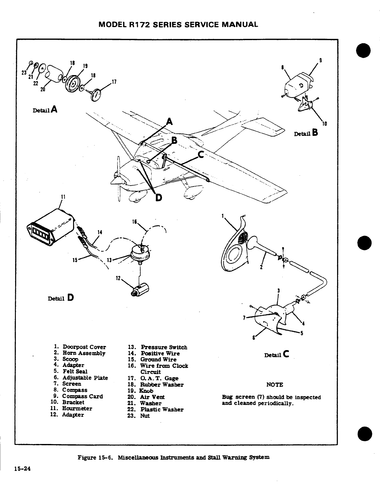
MODEL
R172
SERIES
SERVICE
MANUAL
Detail
A
16
Detail
D
1.
Doorpost
Cover
13.
Pressure
Switch
2.
Horn
Assembly
14.
Positive
Wire
Detail
C
3.
Scoop
15.
Ground
Wire
4.
Adapter
16.
Wire
from
Clock
5.
Felt
Seal
Circuit
6.
Adjustable
Plate
17.
O.A.T.
Gage
7.
Screen
18.
Rubber
Washer
NOTE
8.
Compass
19.
Knob
9.
Compass
Card
20.
Air
Vent
Bug
screen
(7)
should
be
inspected
10.
Bracket
21.
Washer
and
cleaned
periodically.
11.
Hourmeter
22.
Plastic
Washer
12.
Adapter
23.
Nut
Figure
15-6.
Miscellaneous
Instruments
and
Stall
Warning
System
15-24
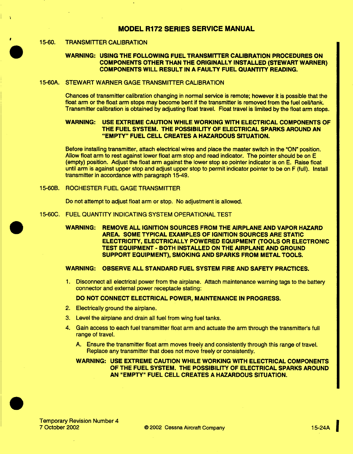
MODEL
R172
SERIES
SERVICE MANUAL
15-60.
WARNING:
USING
THE
FOLLOWING
FUEL
TRANSMITTER
CALIBRATION
PROCEDURES
ON
COMPONENTS
OTHER
THAN
THE
ORIGINALLY INSTALLED
(STEWART
WARNER)
COMPONENTS
WILL
RESULT
IN
A
FAULTY
FUEL
QUANTITY
READING.
15-60A.
STEWART WARNER
GAGE
TRANSMITTER
CALIBRATION
Chances
of
transmitter
calibration
changing
in
normal
service
is
remote;
however
it
is
possible
that
the
float
arm
or
the
float
arm
stops
may
become
bent
if
the transmitter
is removed
from the
fuel
cell/tank.
Transmitter calibration
is
obtained by
adjusting
float
travel.
Float
travel
is
limited
by
the
float
arm
stops.
WARNING:
USE
EXTREME
CAUTION
WHILE
WORKING
WITH
ELECTRICAL
COMPONENTS
OF
THE
FUEL SYSTEM.
THE
POSSIBILITY
OF
ELECTRICAL SPARKS
AROUND
AN
"EMPTY"
FUEL
CELL
CREATES
A
HAZARDOUS
SITUATION.
Before
installing
transmitter,
attach
electrical
wires
and
place
the
master
switch
in
the
"ON"
position.
Allow
float
arm
to rest
against
lower
float
arm
stop
and
read
indicator.
The
pointer
should
be
on
E
(empty)
position.
Adjust
the
float
arm
against
the
lower
stop
so
pointer
indicator
is on
E.
Raise
float
until
arm
is
against upper
stop and
adjust
upper
stop
to
permit
indicator
pointer
to
be
on
F
(full). Install
transmitter
in
accordance
with
paragraph
15-49.
15-60B.
ROCHESTER
FUEL
GAGE
TRANSMITTER
Do
not
attempt to
adjust
float
arm
or
stop.
No
adjustment
is
allowed.
15-60C.
FUEL
QUANTITY
INDICATING SYSTEM
OPERATIONAL
TEST
WARNING:
REMOVE
ALL
IGNITION
SOURCES
FROM THE
AIRPLANE
AND
VAPOR HAZARD
AREA.
SOME
TYPICAL
EXAMPLES
OF
IGNITION SOURCES ARE
STATIC
ELECTRICITY,
ELECTRICALLY
POWERED
EQUIPMENT
(TOOLS
OR
ELECTRONIC
TEST
EQUIPMENT
-
BOTH
INSTALLED
ON
THE
AIRPLANE
AND
GROUND
SUPPORT
EQUIPMENT),
SMOKING
AND SPARKS
FROM
METAL
TOOLS.
WARNING:
OBSERVE
ALL
STANDARD
FUEL
SYSTEM
FIRE
AND
SAFETY
PRACTICES.
1.
Disconnect
all
electrical
power
from the
airplane. Attach
maintenance warning
tags to
the
battery
connector
and
external
power
receptacle stating:
DO
NOT
CONNECT ELECTRICAL
POWER,
MAINTENANCE
IN
PROGRESS.
2.
Electrically ground
the
airplane.
3.
Level
the
airplane
and
drain
all
fuel
from
wing
fuel tanks.
4.
Gain
access
to
each fuel
transmitter
float
arm
and
actuate
the
arm
through
the
transmitter's
full
range
of
travel.
A.
Ensure
the
transmitter float
arm
moves
freely
and
consistently
through
this
range
of
travel.
Replace
any
transmitter
that does
not
move
freely
or
consistently.
WARNING:
USE
EXTREME
CAUTION
WHILE
WORKING
WITH
ELECTRICAL
COMPONENTS
OF
THE
FUEL
SYSTEM. THE
POSSIBILITY
OF
ELECTRICAL
SPARKS
AROUND
AN
"EMPTY" FUEL
CELL
CREATES
A
HAZARDOUS
SITUATION.
Temporary Revision Number
4
7
October
2002
©2002
Cessna
Aircraft
Company
15-24A
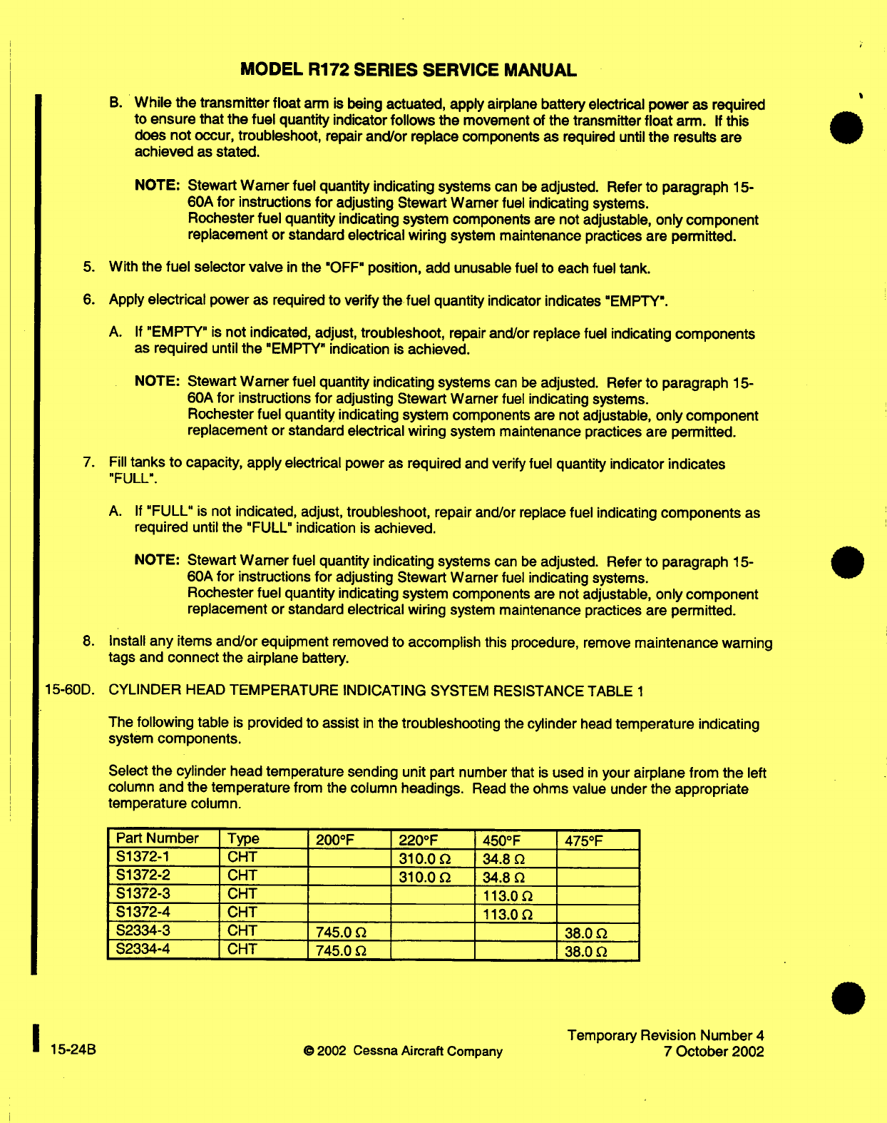
MODEL
R172 SERIES SERVICE
MANUAL
B.
While
the
transmitter float
arm
is
being
actuated,
apply
airplane
battery
electrical
power
as
required
to ensure
that
the
fuel
quantity indicator
follows the
movement
of
the transmitter
float
arm.
If
this
does
not occur, troubleshoot,
repair
and/or
replace
components
as
required
until
the
results are
achieved
as
stated.
NOTE:
Stewart
Warner
fuel
quantity indicating
systems
can
be
adjusted.
Refer
to
paragraph
15-
60A
for
instructions
for
adjusting
Stewart
Warner
fuel
indicating
systems.
Rochester
fuel
quantity
indicating
system
components
are not
adjustable,
only component
replacement
or
standard
electrical
wiring
system
maintenance
practices
are
permitted.
5.
With
the
fuel
selector valve
in
the
"OFF"
position,
add
unusable fuel
to
each
fuel
tank.
6.
Apply
electrical
power
as
required
to
verify
the
fuel
quantity
indicator
indicates
"EMPTY".
A.
If
"EMPTY"
is
not
indicated,
adjust,
troubleshoot,
repair
and/or
replace
fuel
indicating
components
as required
until
the
"EMPTY"
indication
is
achieved.
NOTE:
Stewart
Warner
fuel
quantity
indicating
systems
can
be
adjusted.
Refer
to
paragraph
15-
60A
for
instructions
for
adjusting
Stewart
Warner
fuel
indicating systems.
Rochester
fuel
quantity
indicating
system components
are
not adjustable,
only
component
replacement
or standard
electrical
wiring
system
maintenance practices are
permitted.
7.
Fill
tanks
to
capacity,
apply
electrical
power
as
required
and
verify
fuel
quantity
indicator
indicates
"FULL".
A.
If
"FULL"
is
not
indicated,
adjust,
troubleshoot,
repair and/or
replace
fuel indicating
components
as
required
until
the
"FULL"
indication
is
achieved.
NOTE:
Stewart
Warner
fuel
quantity indicating systems
can
be
adjusted.
Refer
to
paragraph
15-
60A
for
instructions
for
adjusting
Stewart
Warner
fuel
indicating systems.
Rochester
fuel
quantity
indicating
system components are
not
adjustable,
only
component
replacement
or
standard
electrical
wiring
system
maintenance practices are
permitted.
8. Install
any
items
and/or
equipment removed
to
accomplish
this
procedure, remove
maintenance
warning
tags and
connect
the airplane
battery.
15-60D.
CYLINDER
HEAD
TEMPERATURE INDICATING
SYSTEM
RESISTANCE
TABLE
1
The
following
table
is
provided
to
assist
in
the
troubleshooting
the
cylinder
head
temperature indicating
system
components.
Select
the
cylinder
head
temperature sending unit
part
number that
is
used
in
your
airplane from the
left
column
and
the temperature
from
the
column headings.
Read the
ohms
value
under
the
appropriate
temperature
column.
Part
Number
Type
200°F
220°F
450°F
475°F
S1372-1
CHT
310.0
34.8
S1372-2
CHT
310.0
34.8
S1372-3 CHT
113.0
S1372-4 CHT
113.0
S2334-3 CHT 745.0 38.0
S2334-4 CHT 745.0
38.0
Temporary
Revision Number
4
15-24B
©
2002
Cessna
Aircraft
Companv
7
October
2002
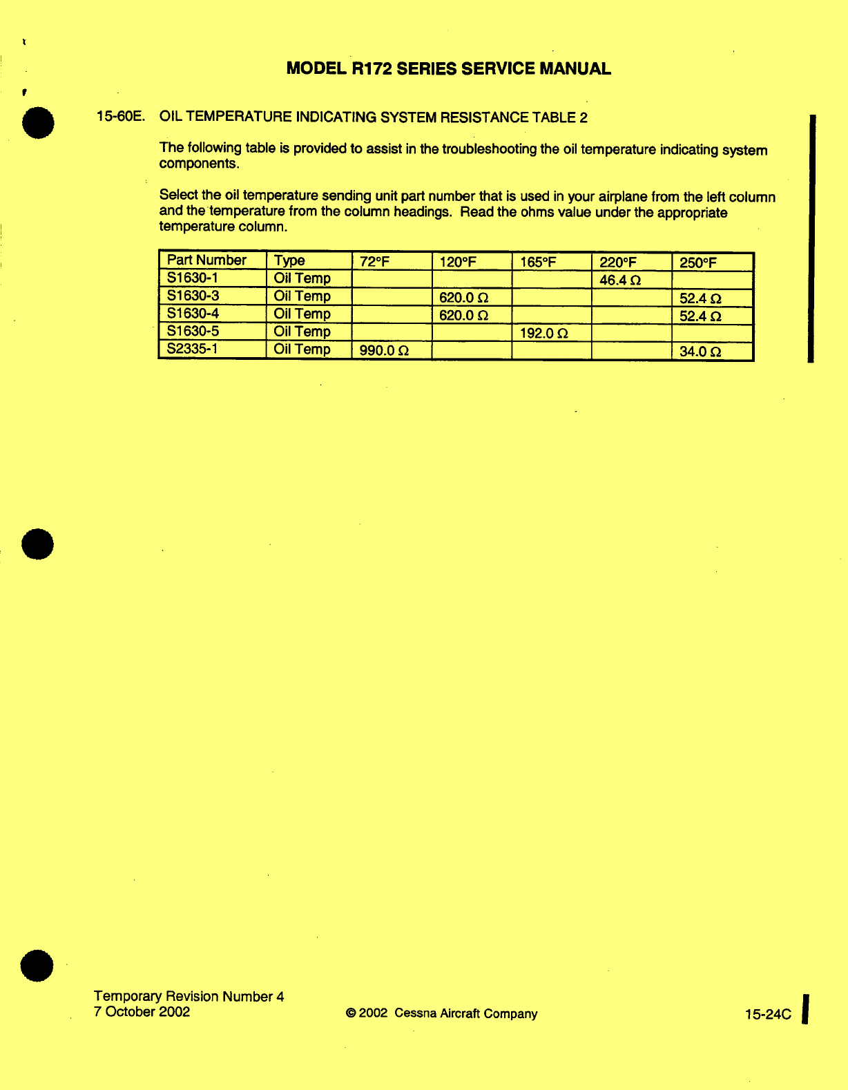
MODEL
R172
SERIES
SERVICE
MANUAL
15-60E.
OIL
TEMPERATURE
INDICATING
SYSTEM
RESISTANCE
TABLE
2
The
following table
is
provided
to
assist
in
the
troubleshooting
the
oil
temperature
indicating
system
components.
Select
the
oil
temperature
sending
unit part
number
that
is
used
in
your
airplane
from
the
left
column
and
the
temperature
from the column
headings.
Read
the
ohms
value
under
the appropriate
temperature
column.
Part
Number
S1630-1
S1630-3
S1630-4
S1630-5
S2335-1
Type
Oil
Temp
Oil
Temp
Oil
Temp
Oil
Temp
Oil
Temp
72°F
120°F
620.0
620.0
990.0
165°F
220°F
46.4
250°F
52.4
52.4
192.0
34.0
Temporary
Revision
Number
4
7
October
2002
©
2002
Cessna
Aircraft
Company
15-24C
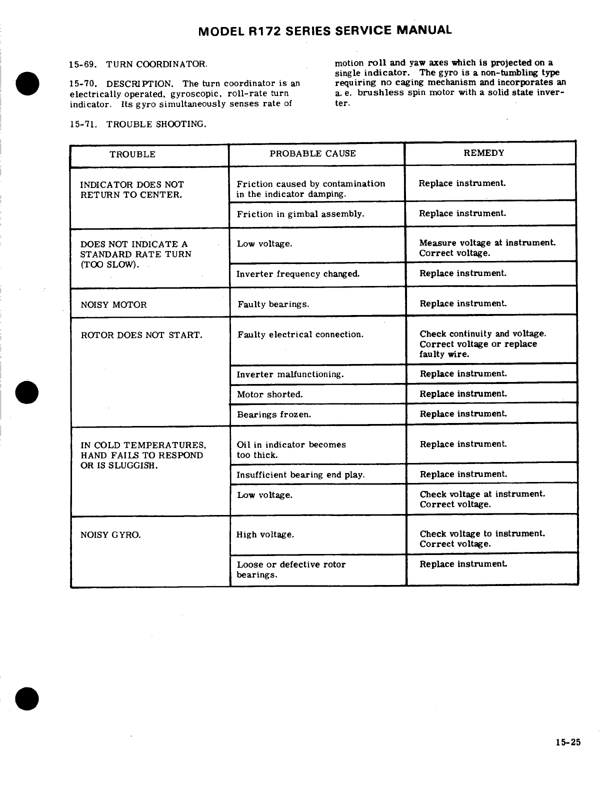
MODEL
R172
SERIES
SERVICE
MANUAL
15-69.
TURN
COORDINATOR.
motion
roll
and
yaw
axes
which
is
projected
on
a
single
indicator.
The
gyro
is
a
non-tumbling
type
15-70.
DESCRIPTION.
The
turn
coordinator
is
an
requiring
no caging
mechanism
and
incorporates
an
electrically
operated, gyroscopic,
roll-rate
turn
a.
e.
brushless
spin motor
with
a
solid
state
inver-
indicator. Its
gyro
simultaneously
senses
rate
of
ter.
15-71. TROUBLE
SHOOTING.
TROUBLE
PROBABLE
CAUSE
REMEDY
INDICATOR
DOES
NOT
Friction
caused
by
contamination
Replace
instrument.
RETURN
TO
CENTER.
in
the
indicator
damping.
Friction
in
gimbal
assembly.
Replace
instrument.
DOES
NOT
INDICATE
A
Low
voltage.
Measure
voltage
at
instrument.
STANDARD
RATE TURN
Correct
voltage.
(TOO
SLOW).
Inverter
frequency
changed.
Replace
instrument.
NOISY
MOTOR
Faulty
bearings.
Replace
instrument.
ROTOR DOES
NOT
START.
Faulty
electrical
connection. Check
continuity
and
voltage.
Correct
voltage
or
replace
faulty
wire.
Inverter
malfunctioning.
Replace
instrument.
Motor
shorted.
Replace
instrument.
Bearings frozen.
Replace
instrument.
IN
COLD
TEMPERATURES,
Oil
in
indicator
becomes
Replace
instrument.
HAND
FAILS
TO
RESPOND
too
thick.
OR
IS
SLUGGISH.
Insufficient
bearing
end
play.
Replace
instrument.
Low
voltage.
Check
voltage
at
instrument.
Correct
voltage.
NOISY
GYRO.
High
voltage.
Check
voltage
to
instrument.
Correct
voltage.
Loose
or
defective
rotor
Replace
instrument.
bearings.
15-25
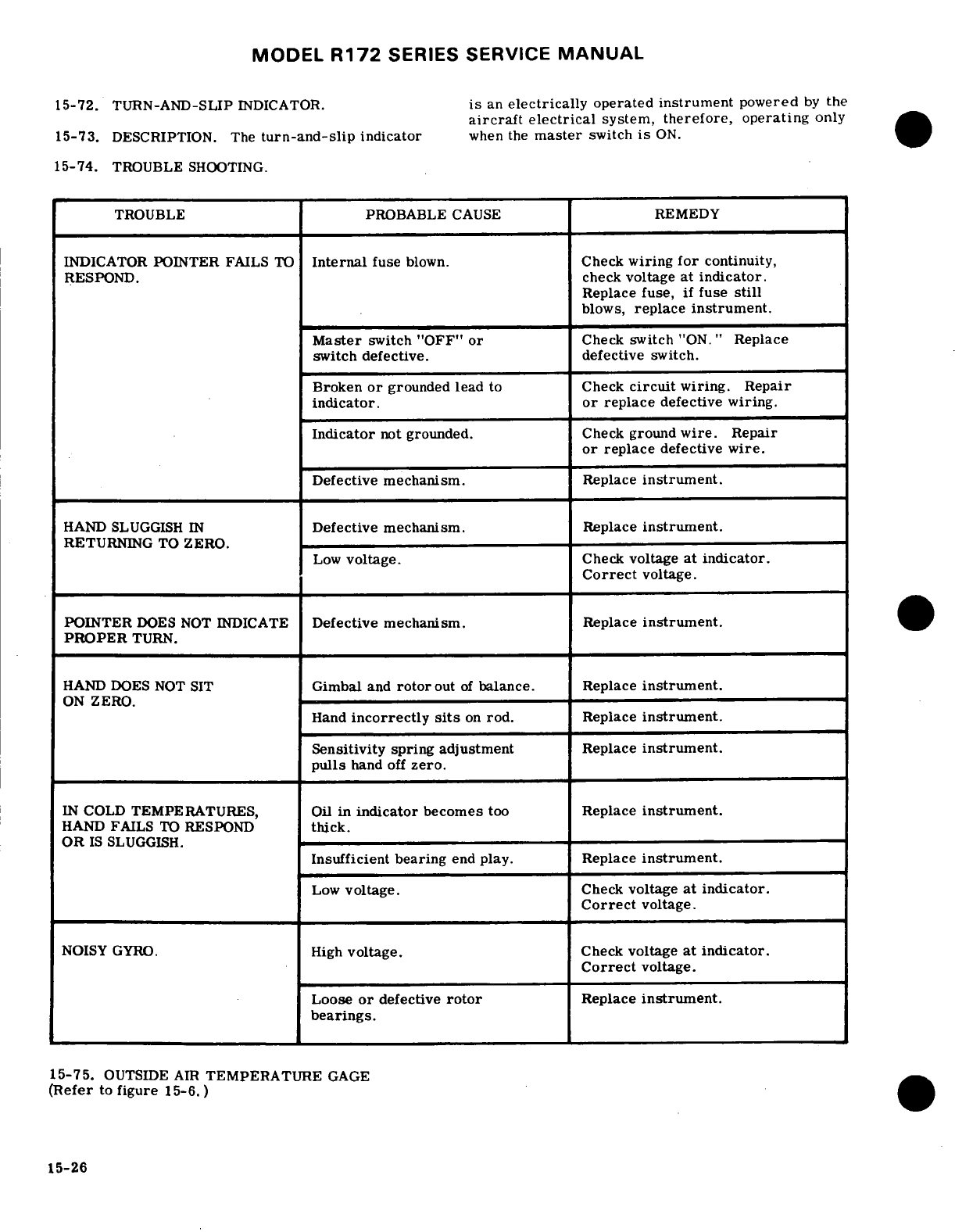
MODEL
R172
SERIES
SERVICE
MANUAL
15-72.
TURN-AND-SLIP
INDICATOR.
is
an
electrically
operated
instrument
powered
by
the
aircraft
electrical
system,
therefore,
operating
only
15-73.
DESCRIPTION.
The
turn-and-slip
indicator
when
the
master
switch
is
ON.
15-74.
TROUBLE
SHOOTING.
TROUBLE
PROBABLE
CAUSE
REMEDY
INDICATOR
POINTER
FAILS
TO
Internal
fuse
blown.
Check
wiring
for
continuity,
RESPOND.
check
voltage
at
indicator.
Replace
fuse,
if
fuse
still
blows,
replace
instrument.
Master
switch
"OFF"
or
Check
switch
"ON."
Replace
switch
defective.
defective
switch.
Broken
or
grounded lead
to
Check
circuit
wiring.
Repair
indicator.
or
replace
defective
wiring.
Indicator
not
grounded.
Check
ground
wire.
Repair
or
replace
defective
wire.
Defective
mechanism.
Replace
instrument.
HAND
SLUGGISH
IN
Defective
mechanism.
Replace
instrument.
RETURNING
TO
ZERO.
Low
voltage.
Check
voltage
at
indicator.
Correct
voltage.
POINTER
DOES
NOT
INDICATE
Defective
mechanism.
Replace
instrument.
PROPER
TURN.
HAND
DOES
NOT
SIT
Gimbal
and
rotor
out
of
balance. Replace
instrument.
ON
ZERO.
Hand
incorrectly
sits
on
rod.
Replace
instrument.
Sensitivity
spring
adjustment
Replace
instrument.
pulls
hand
off
zero.
IN
COLD
TEMPERATURES, Oil
in
indicator
becomes
too
Replace
instrument.
HAND
FAILS
TO
RESPOND
thick.
OR
IS
SLUGGISH.
Insufficient
bearing
end
play. Replace
instrument.
Low
voltage.
Check
voltage
at
indicator.
Correct
voltage.
NOISY
GYRO.
High
voltage.
Check
voltage
at indicator.
Correct
voltage.
Loose
or
defective
rotor
Replace
instrument.
bearings.
15-75.
OUTSIDE
AIR
TEMPERATURE
GAGE
(Refer
to
figure
15-6. )
15-26
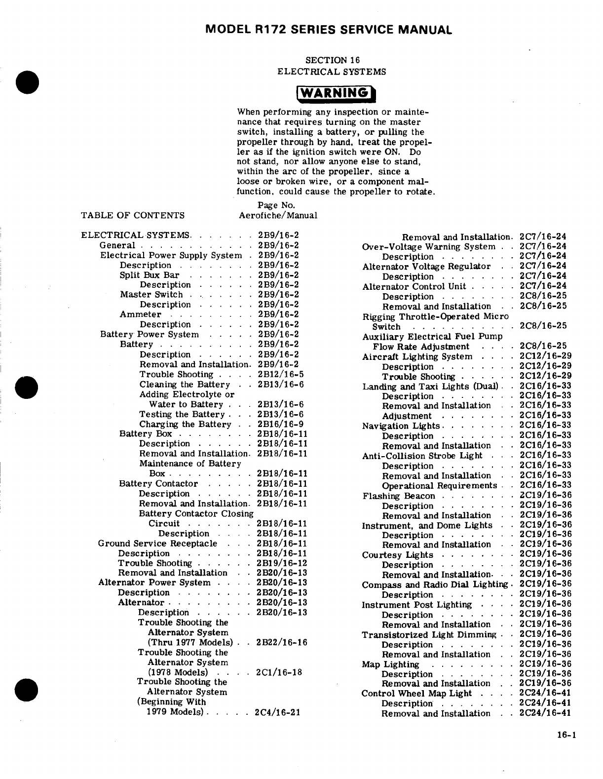
MODEL
R172
SERIES
SERVICE
MANUAL
SECTION
16
ELECTRICAL
SYSTEMS
WARNING
When
performing
any
inspection
or
mainte-
nance that
requires
turning
on
the
master
switch,
installing
a
battery,
or
pulling
the
propeller
through
by
hand,
treat
the
propel-
ler
as
if
the
ignition
switch
were
ON.
Do
not
stand,
nor
allow
anyone
else
to
stand,
within
the
arc
of
the
propeller,
since
a
loose
or
broken
wire,
or
a
component
mal-
function,
could
cause
the
propeller
to
rotate.
Page
No.
TABLE
OF
CONTENTS
Aerofiche/Manual
ELECTRICAL
SYSTEMS.
.
....
2B9/16-2
Removal
and
Installation.
2C7/16-24
General
........
2B9/16-2
Over-Voltage
Warning
System.
.
2C7/16-24
Electrical
Power
Supply
System
.
2B9/16-2
Description
...
2C7/16-24
Description
..
....
.
2B9/16-2
Alternator
Voltage
Regulator
. .
2C7/16-24
Split
Bux
Bar
. . .
2B9/16-2
Description
...
2C7/16-24
Description
......
2B9/16-2
Alternator
Control
Unit
....
2C7/16-24
Master
Switch
.......
2B9/16-2
Description
........
2C8/16-25
Description
......
2B9/16-2 Removal
and
Installation
2C8/16-25
Ammeter
.......
2B9/16-2
Rigging
Throttle-Operated
Micro
Description
......
2B9/16-2
Switch
...........
2C8/16-25
Battery
Power
System
.....
2B9/16-2
Auxiliary
Electrical
Fuel
Pump
Battery
..........
2B9/16-2
Flow
Rate
Adjustment
....
2C8/16-25
Description
..
2B9/16-2
Aircraft
Lighting
System
....
2C12/16-29
Removal
and
Installation.
2B9/16-2
Description
........
2C12/16-29
Trouble
Shooting
.
2B12/16-5
Trouble
Shooting
.. .
2C12/16-29
Cleaning
the
Battery
..
2B13/16-6
Landing
and
Taxi
Lights
(Dual).
.
2C16/16-33
Adding
Electrolyte
or
Description
... .
2C16/16-33
Water
to
Battery
..
2B13/16-6
Removal
and
Installation
. .
2C16/16-33
Testing
the
Battery
..
2B13/16-6 Adjustment
...
2C16/16-33
Charging
the
Battery
2B16/16-9
Navigation
Lights.
L
....
... .
2C16/16-33
Battery
Box
...
2B18/16-11
Description
... .
2C16/16-33
Description
......
2B18/16-11
Removal
and
Installation
.
.2C16/16-33
Removal
and
Installation.
2B18/16-11
Anti-Collision
Strobe
Light
...
2C16/16-33
Maintenance
of
Battery
Description
... .
2C16/16-33
Box
..
.....
.
2B18/16-11
Removal
and
Installation
.
.2C16/16-33
Battery
Contactor
... .
2B18/16-11
Operational
Requirements
.
2C16/16-33
Description
..
2B18/16-11
Flashing
Beacon
....
2C19/16-36
Removal
and
Installation.
2B18/16-11
Description
........
2C19/16-36
Battery
Contactor
Closing Removal
and
Installation
.
.2C19/16-36
Circuit
.. .
2B18/16-11
Instrument,
and
Dome
Lights
.2C19/16-36
Description
....
2B18/16-11
Description
...
2C19/16-36
Ground
Service
Receptacle
. .
2B18/16-11
Removal
and
Installation
. .
2C19/16-36
Description
.......
2B18/16-11
Courtesy
Lights
... .
2C19/16-36
Trouble
Shooting
. . .
2B19/16-12
Description
... .
2C19/16-36
Removal
and
Installation
. .
2B20/16-13
Removal
and
Installation..
.
2C19/16-36
Alternator
Power
System
.. ..
2B20/16-13
Compass
and
Radio
Dial Lighting.
2C19/16-36
Description
...
2B20/16-13
Description
... .
2C19/16-36
Alternator
.....
2B20/16-13
Instrument Post
Lighting
....
2C19/16-36
Description
. .
2B20/16-13
Description
...
2C19/16-36
Trouble
Shooting
the
Removal
and
Installation
.
2C19/16-36
Alternator
System
Transistorized
Light
Dimming
.
2C19/16-36
(Thru
1977
Models)
.
2B22/16-16
Description
... .
2C19/16-36
Trouble
Shooting
the
Removal
and
Installation
..
2C19/16-36
Alternator
System
Map
Lighting
... .
2C19/16-36
(1978
Models)
....
2C1/16-18
Description
... .
2C19/16-36
Trouble
Shooting
the
Removal
and
Installation
.
2C19/16-36
Alternator
System
Control
Wheel
Map
Light
....
2C24/16-41
(Beginning
With
Description
........
2C24/16-41
1979
Models)
... .
2C4/16-21
Removal
and
Installation
.
2C24/16-41
16-1
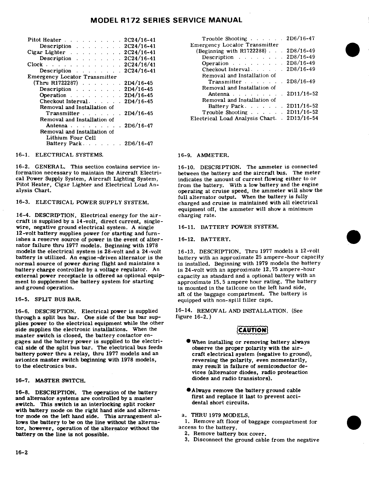
MODEL
R172
SERIES
SERVICE
MANUAL
Pitot
Heater
...
.......
2C24/16-41
Trouble
Shooting
.. . .
2D6/16-47
Description
... .
2C24/16-41
Emergency
Locator
Transmitter
Cigar
Lighter
.........
2C24/16-41
(Beginning
with
R1722288)
...
2D8/16-49
Description
... .
2C24/16-41
Description
...
2D8/16-49
Clock
.......
2C24/16/41
Operation
.. ..
2D8/16-49
Description
... .
2C24/16-41
Checkout
Interval
. . .
2D8/16-49
Emergency
Locator
Transmitter
Removal
and
Installation
of
(Thru
R1722287)
.......
2D4/16-45
Transmitter
2D8/16-49
Description
. .
2D4/16-45
Removal
and
Installation
of
Operation
.........
2D4/16-45
Antenna ... .
2D11/16-52
Checkout
Interval
.
2D4/16-45
Removal
and
Installation
of
Removal
and
Installation
of
Battery
Pack
.
2D11/16-52
Transmitter
....
.
2D4/16-45 Trouble
Shooting
......
2D11/16-52
Removal
and
Installation
of
Electrical
Load
Analysis
Chart.
2D13/16-54
Antenna
........
2D6/16-47
Removal
and
Installation
of
Lithium
Four
Cell
Battery
Pack
......
2D6/16-47
16-1. ELECTRICAL
SYSTEMS.
16-9.
AMMETER.
16-2.
GENERAL.
This
section
contains
service
in-
16-10.
DESCRIPTION. The
ammeter
is
connected
formation
necessary
to
maintain
the
Aircraft
Electri-
between the
battery
and
the
aircraft
bus.
The
meter
cal
Power
Supply
System,
Aircraft
Lighting
System,
indicates
the
amount
of
current
flowing
either
to or
Pitot
Heater,
Cigar Lighter
and
Electrical
Load
An-
from
the
battery.
With
a
low
battery
and
the
engine
alysis
Chart.
operating
at
cruise
speed,
the
ammeter
will
show the
full
alternator
output.
When
the
battery
is
fully
16-3. ELECTRICAL
POWER
SUPPLY
SYSTEM.
charged
and
cruise
is
maintained
with
all
electrical
equipment
off,
the
ammeter
will
show
a
minimum
16-4.
DESCRIPTION.
Electrical
energy
for
the
air-
charging
rate.
craft
is
supplied
by
a
14-volt,
direct
current,
single-
wire,
negative
ground
electrical
system.
A
single
16-11.
BATTERY
POWER
SYSTEM.
12-volt
battery
supplies
power
for
starting
and
furn-
ishes
a
reserve
source
of
power
in
the
event
of
alter-
16-12.
BATTERY.
nator
failure thru
1977
models.
Beginning
with
1978
models
the
electrical
system
is
28-volt
and
a
24-volt
16-13.
DESCRIPTION.
Thru
1977
models
a
12-volt
battery
is
utilized.
An
engine-driven
alternator
is
the
battery
with an
approximate
25
ampere-hour
capacity
normal
source
of
power
during
flight
and
maintains
a
is
installed.
Beginning
with
1979
models
the
battery
battery
charge
controlled
by
a
voltage
regulator.
An
is
24-volt
with
an
approximate
12.75
ampere-hour
external
power
receptacle
is offered
as optional
equip-
capacity
as standard
and
a
optional
battery
with
an
ment
to
supplement
the
battery
system
for
starting
approximate
15.5
ampere
hour
rating.
The
battery
and
ground
operation.
is
mounted
in
the tailcone
on
the
left
hand
side,
aft
of
the
baggage
compartment.
The
battery
is
16-5. SPLIT
BUS
BAR.
equipped
with
non-spill
filler
caps.
16-6.
DESCRIPTION.
Electrical
power
is
supplied
16-14.
REMOVAL
AND
INSTALLATION.
(See
through
a
split
bus
bar.
One
side
of
the
bus
bar
sup-
figure
16-2.)
plies
power
to
the
electrical
equipment
while
the
other
side
supplies
the
electronic
installations.
When
the
CAUTION
master
switch
is closed,
the
battery
contactor
en-
gages
and
the
battery
power
is
supplied
to
the
electri-
When
installing
or
removing
battery
always
cal
side
of
the
split
bus
bar.
The
electrical
bus feeds
observe
the
proper
polarity
with
the
air-
battery
power
thru
a
relay,
thru
1977
models
and
an
craft
electrical
system
(negative
to
ground),
avionics
master
switch
beginning with
1978
models,
reversing
the
polarity,
even
momentarily,
to
the
electronics
bus.
may
result
in
failure
of
semiconductor
de-
vices
(alternator
diodes,
radio proteaction
16-7.
MASTER
SWITCH.
diodes
and
radio
transistors).
16-8.
DESCRIPTION. The
operation
of
the
battery
Always
remove
the
battery
ground
cable
and
alternator
systems are
controlled
by
a
master
first
and
replace
it
last
to
prevent acci-
switch.
This
switch
is
an
interlocking
split
rocker
dental
short
circuits.
with
battery
mode
on
the
right
hand
side
and
alterna-
tor
mode
on
the
left
hand
side.
This
arrangement
al-
a.
THRU 1979
MODELS.
lows the
battery
to
be
on
the
line
without the
alterna-
1.
Remove
aft
floor
of
baggage
compartment
for
tor,
however,
operation
of
the
alternator
without
the
access
to
the
battery.
battery
on
the
line
is
not
possible.
2.
Remove
battery
box
cover.
3.
Disconnect
the
ground
cable
from
the
negative
16-2
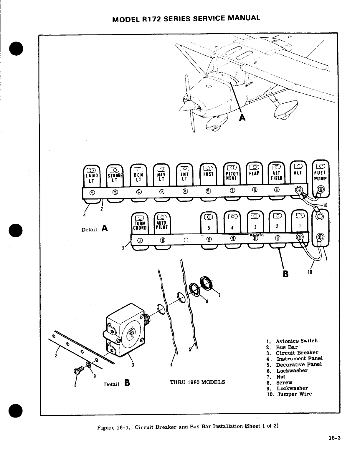
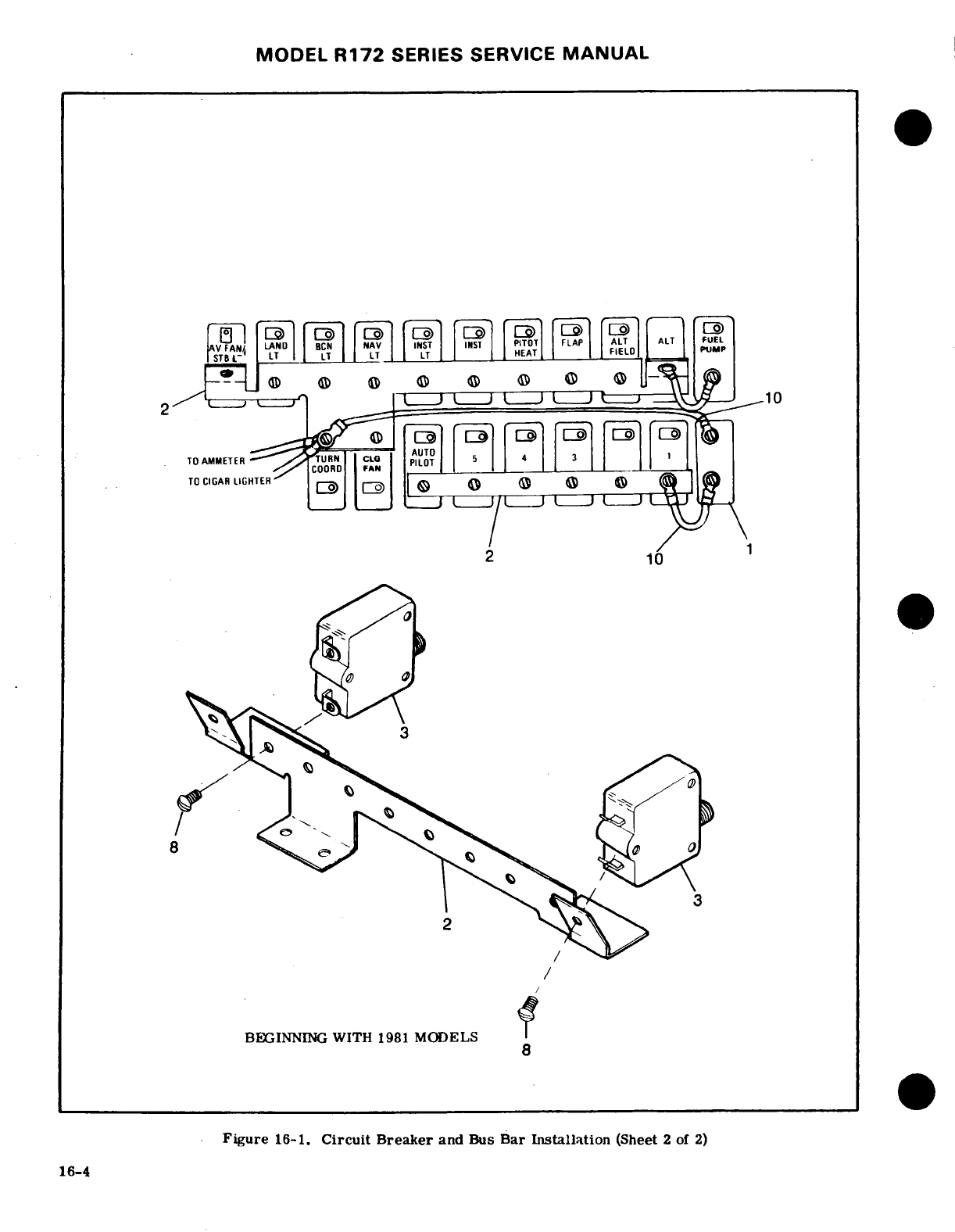
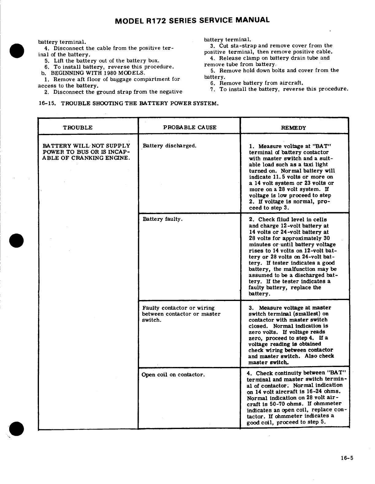
MODEL
R172
SERIES
SERVICE
MANUAL
battery
terminal.
4.
Disconnect the
cable
from
the
positive
ter-
3.
Cut
sta-strap
and
remove cover
from
the
inal
of
the
battery.
positive
terminal,
then
remove positive
cable.
5.
Lift
the
battery
out
of
the
battery
box.
4.
Release
clamp
on
battery
drain
tube
and
6.
To
install
battery,
reverse
this
procedure.
remove
tube from
battery,
b.
BEGINNING
WITH
1980
MODELS,
5.
Remove
hold
down
bolts
and
cover
from
the
1.
Remove
aft
floor
of
baggage
compartment
for
battery.
access
to
the
battery.
6.
Remove
battery
from
aircraft.
2.
Disconnect
the
ground
strap
from
the
negative
7.
To
install
the
battery,
reverse
this
procedure.
16-15. TROUBLE
SHOOTING
THE
BATTERY
POWER
SYSTEM.
TROUBLE
PROBABLE
CAUSE
REMEDY
BATTERY
WILL
NOT
SUPPLY
Battery
discharged.
1.
Measure voltage
at
"BAT"
POWER
TO BUS
OR
IS
INCAP-
terminal
of
battery
contactor
ABLE OF
CRANKING
ENGINE.
with
master
switch
and
a
suit-
able
load
such
as
a
taxi
light
turned
on.
Normal
battery
will
indicate
11.5
volts
or
more
on
a
14
volt
system
or
23
volts
or
more
on
a
28
volt
system.
If
voltage
is
low
proceed
to
step
2.
If
voltage
is
normal,
pro-
ceed to
step
3.
Battery
faulty.
2.
Check fliud
level
in
cells
and
charge
12-volt
battery
at
14
volts
or
24-volt
battery
at
28
volts
for
approximately
30
minutes
or
until
battery
voltage
rises
to
14
volts
on
12-volt
bat-
tery or
28
volts
on
24-volt
bat-
tery.
If
tester
indicates
a
good
battery,
the
malfunction
may
be
assumed
to
be
a
discharged
bat-
tery.
If
the
tester
indicates
a
faulty
battery, replace
the
battery.
Faulty
contactor
or
wiring
3.
Measure voltage
at
master
between
contactor or
master
switch
terminal
(smallest)
on
switch.
contactor
with
master
switch
closed.
Normal
indication
is
zero
volts.
If
voltage
reads
zero,
proceed
to
step
4.
If
a
voltage
reading
is
obtained
check
wiring
between
contactor
and
master
switch. Also
check
master
switch.
Open
coil
on
contactor.
4.
Check
continuity
between
"BAT"
terminal
and
master
switch
termin-
al
of
contactor.
Normal
indication
on
14
volt
aircraft
is
16-24
ohms.
Normal indication
on
28
volt
air-
craft
is
50-70
ohms.
If
ohmmeter
indicates
an
open
coil,
replace
con-
tactor.
If
ohmmeter
indicates
a
good
coil,
proceed
to
step
5.
16-5
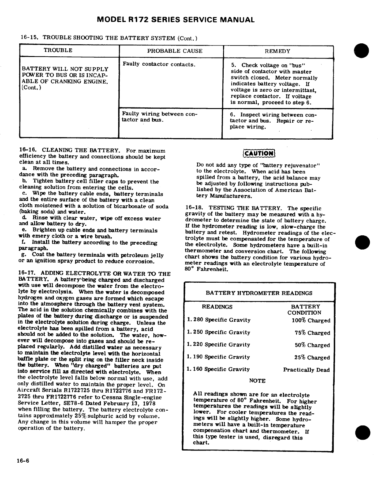
MODEL
R172
SERIES
SERVICE
MANUAL
16-15.
TROUBLE
SHOOTING
THE BATTERY
SYSTEM
(Cont.)
TROUBLE
PROBABLE
CAUSE
REMEDY
Faulty
contactor
contacts.
5.
Check
voltage
on
"bus"
BATTERY
WILL
NOT
SUPPLY
side
of
contactor
with
master
POWER
TO
BUS
OR
IS
INCAP-
switch
closed.
Meter
normally
ABLE
OF
CRANKING
ENGINE.
indicates
battery
voltage.
If
(Cont.)
voltage
is
zero
or
intermittant,
replace
contactor.
If
voltage
is
normal,
proceed
to
step
6.
Faulty
wiring
between
con-
6.
Inspect
wiring
between
con-
tactor
and
bus.
tactor
and bus.
Repair
or
re-
place
wiring.
16-16.
CLEANING
THE BATTERY.
For
maximum
CAUTION
efficiency
the
battery
and
connections
should
be
kept
clean
at
all
times.
Do
not
add any
type
of
"battery rejuvenator"
a.
Remove the
battery
and
connections
in
accor-
to
the
electrolyte.
When
acid
has
been
dance
with
the preceding
paragraph,
spilled
from a
battery,
the
acid
balance
may
b.
Tighten
battery
cell
filler
caps
to
prevent
the
be
adjusted
by
following
instructions
pub-
cleaning
solution
from
entering
the
cells.
lished
by
the
Association
of
American
Bat-
c.
Wipe
the
battery
cable
ends,
battery
terminals
tery
Manufacturers.
and
the
entire
surface
of
the
battery
with
a
clean
cloth
moistened
with
a solution
of
bicarbonate
of
soda
16-18.
TESTING
THE
BATTERY.
The
specific
(baking
soda)
and
water.
gravity
of the
battery
may
be
measured
with a
hy-
d.
Rinse
with
clear
water,
wipe
off
excess
water
drometer
to
determine
the
state
of
battery
charge.
and
allow
battery
to
dry.
If
the
hydrometer
reading is
low,
slow-charge
the
e.
Brighten
up
cable
ends
and
battery
terminals
battery
and
retest.
Hydrometer
readings
of
the
elec-
with
emery
cloth
or
a
wire
brush.
trolyte
must
be
compensated
for
the
temperature
of
f.
Install
the
battery
according
to the
preceding
the
electrolyte.
Some
hydrometers
have
a
built-in
paragraph.
thermometer
and
conversion
chart.
The
following
g.
Coat
the
battery
terminals
with
petroleum
jelly
chart
shows
the
battery
condition
for
various
hydro-
or
an
ignition
spray
product
to
reduce
corrosion.
meter
readings
with an
electrolyte
temperature
of
80
°
Fahrenheit.
16-17.
ADDING
ELECTROLYTE
OR
WATER TO
THE
BATTERY.
A
battery'being charged
and
discharged
with
use
will
decompose
the
water from
the
electro-
lyte
by
electrolysis.
When
the
water
is
decomposed
BATTERY
HYDROMETER
READINGS
hydrogen
and
oxygen
gases
are
formed
which
escape
into the
atmosphere
through
the
battery
vent
system.
READINGS
BATTERY
The
acid
in
the
solution
chemically
combines
with
the
CONDITION
plates
of
the
battery
during
discharge
or
is
suspended
1.
280
Specific
Gravity
100%
Charged
in
the
electrolyte
solution
during
charge.
Unless
the
electrolyte
has
been
spilled
from
a
battery,
acid
1.
250
Specific
Gravity
75%
Charged
should
not
be
added
to
the
solution.
The
water,
how-
ever
will
decompose
into
gases
and
should
be
re-
1.
220
Specific
Gravity
50%
Charged
placed
regularly.
Add
distilled water
as
necessary
to
maintain
the
electrolyte
level
with
the
horizontal
190
Specific
Gravity
25%
Charged
baffle
plate
or
the
split
ring
on
the
filler
neck
inside
the
battery.
When
"dry
charged"
batteries
are
put
1
160
Specific
Gravity
Practically
Dead
into
service
fill
as
directed
with
electrolyte.
When
the
electrolyte
level
falls
below
normal
with
use,
add
NOTE
only
distilled
water
to
maintain
the
proper
level.
On
Aircraft
Serials
R1722725
thru
R1722776
and
FR172-
All
readings
shown
are
for
an
electrolyte
2725
thru
FR1722776
refer
to
Cessna
Single-engine
temperature
of
80
°
Fahrenheit.
For
higher
Service
Letter,
SE78-6 Dated
February
13,
1978
temperatures
the
readings
will
be
slightly
when
filling
the
battery.
The
battery
electrolyte
con-
lower.
For
cooler temperatures
the
read-
tains
approximately
25%
sulphuric
acid
by
volume.
ings will
be
slightly
higher.
Some
hydro-
Any
change
in
this
volume
will
hamper
the
proper
meters
will
have
a
built-in
temperature
operation
of
the
battery,
compensation
chart
and
thermometer.
If
this
type
tester
is
used,
disregard
this
chart.
16-6
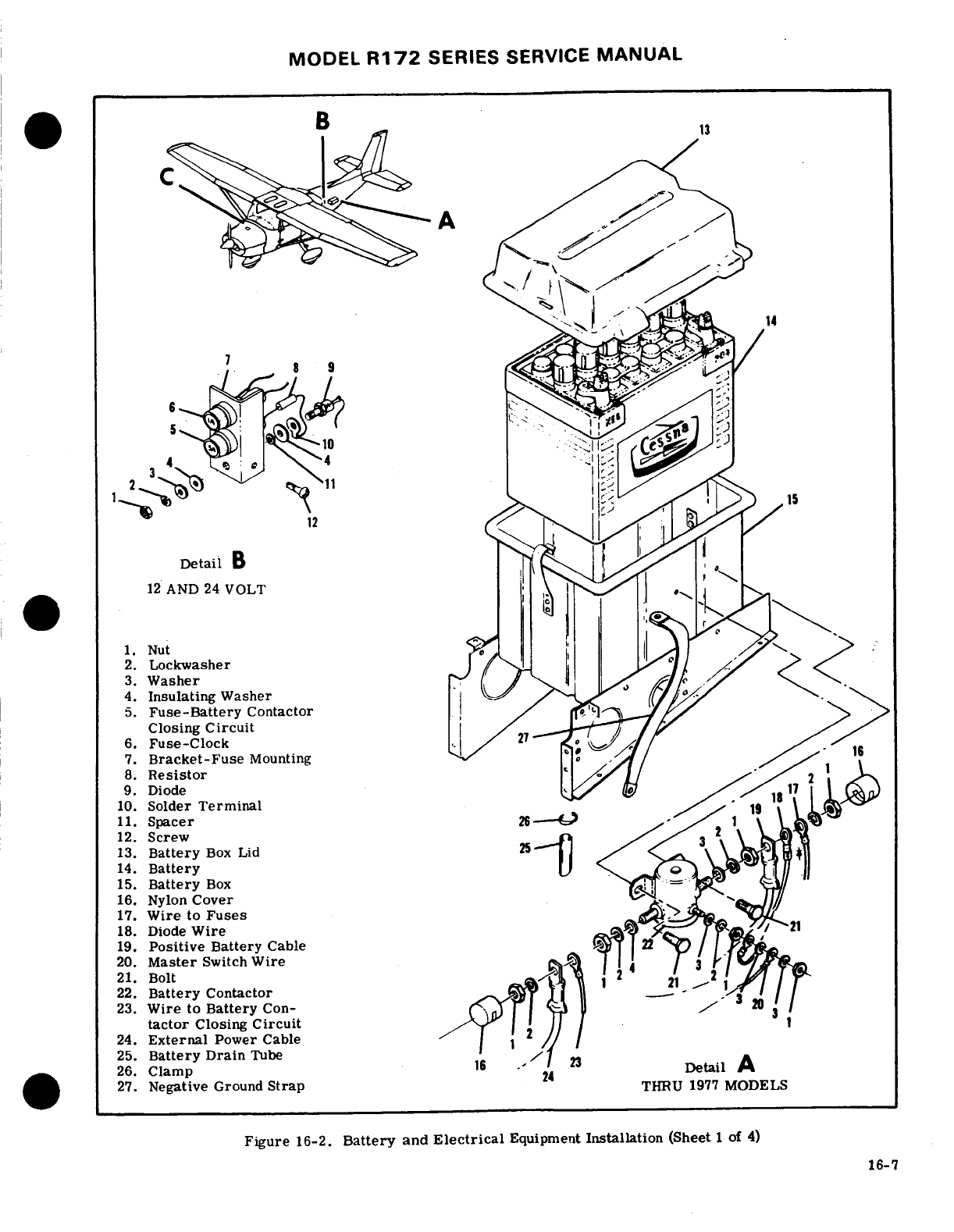
MODEL
R172
SERIES
SERVICE
MANUAL
Detail
B
12
AND
24
VOLT
1.
Nut
2.
Lockwasher
3.
Washer
4.
Insulating
Washer
5.
Fuse-Battery
Contactor
Closing
Circuit
6.
Fuse-Clock
7.
Bracket-Fuse
Mounting
8.
Resistor
9.
Diode
10.
Solder
Terminal
11.
Spacer1
12.
Screw
13.
Battery
Box
Lid
14.
Battery
15.
Battery
Box
16.
Nylon
Cover
17.
Wire
to
Fuses
18.
Diode
Wire
19.
Positive
Battery
Cable
20.
Master
Switch
Wire
21.
Bolt
22.
Battery
tactor
Closing
Circuit
24.
External
Power
Cable
25.
Battery
Drain
Tube
26.
Clamp16
Detail
A
27.
Negative
Ground
Strap
24
THRU
1977
MODELS
Figure
16-2.
Battery
and
Electrical
Equipment
Installation
(Sheet
1
of
4)
16-7
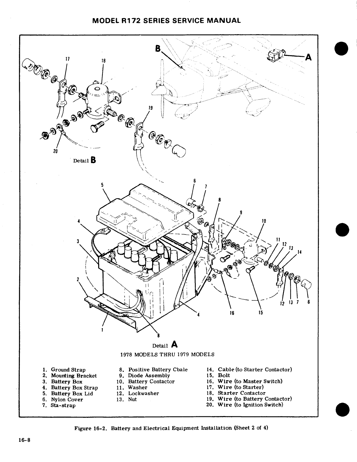
MODEL
R172
SERIES
SERVICE
MANUAL
..........
Detail
2.
Mounting
Bracket
9.
Diode
Assembly
15.
Bolt
-
.- -
.
,
6.
Nylon
Cover
13.
Nut
Battery
Detail
A
3.
Battery
Box
10.
Battery
Contactor
16.
Wire
(to
Master
Switch)
4.
Battery
Box
Strap
11.
Washer
17.
Wire
(to
Starter)
5.
Battery
Box
Lid
12.
Lockwasher
18.
Starter
Contactor
6.
Nylon
Cover
13.
Nut
19.
Wire
(to
Battery
Contactor)
7.
Sta-strap
20.
Wire
(to Ignition
Switch)
Figure
16-2.
Battery
and
Electrical
Equipment
Installation
(Sheet
2
of
4)
16-8
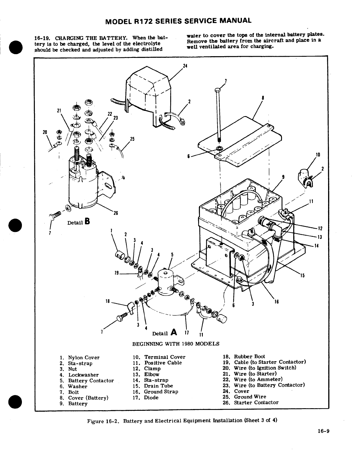
MODEL
R172
SERIES
SERVICE
MANUAL
16-19.
CHARGING
THE
BATTERY.
When
the
bat-
water
to
cover
the
tops
of
the
internal
battery
plates.
tery
is
to be
charged,
the
level
of
the
electrolyte
Remove
the battery
from
the
aircraft
and
place
in
a
should
be
checked
and
adjusted
by
adding
distilled
well
ventilated
area
for
charging.
,
Detail
B
-
Detail
A
BEGINNING
WITH
1980
MODELS
1.
Nylon
Cover
10.
Terminal
Cover
18.
Rubber
Boot
2.
Sta-strap
11.
Positive
Cable
19.
Cable
(to
Starter
Contactor)
3.
Nut
12.
Clamp
20.
Wire
(to
Ignition
Switch)
4.
Lockwasher
13.
Elbow
21.
Wire
(to
Starter)
5.
Battery
Contactor
14.
Sta-strap
22.
Wire
(to
Ammeter)
6.
Washer
15.
Drain
Tube
23.
Wire
(to
Battery
Contactor)
7.
Bolt
16.
Ground
Strap
24.
Cover
8.
Cover
(Battery)
17.
Diode
25.
Ground
Wire
9.
Battery
26.
Starter
Contactor
Figure
16-2.
Battery
and
Electrical
Equipment
Installation
(Sheet
3
of
4)
16-9
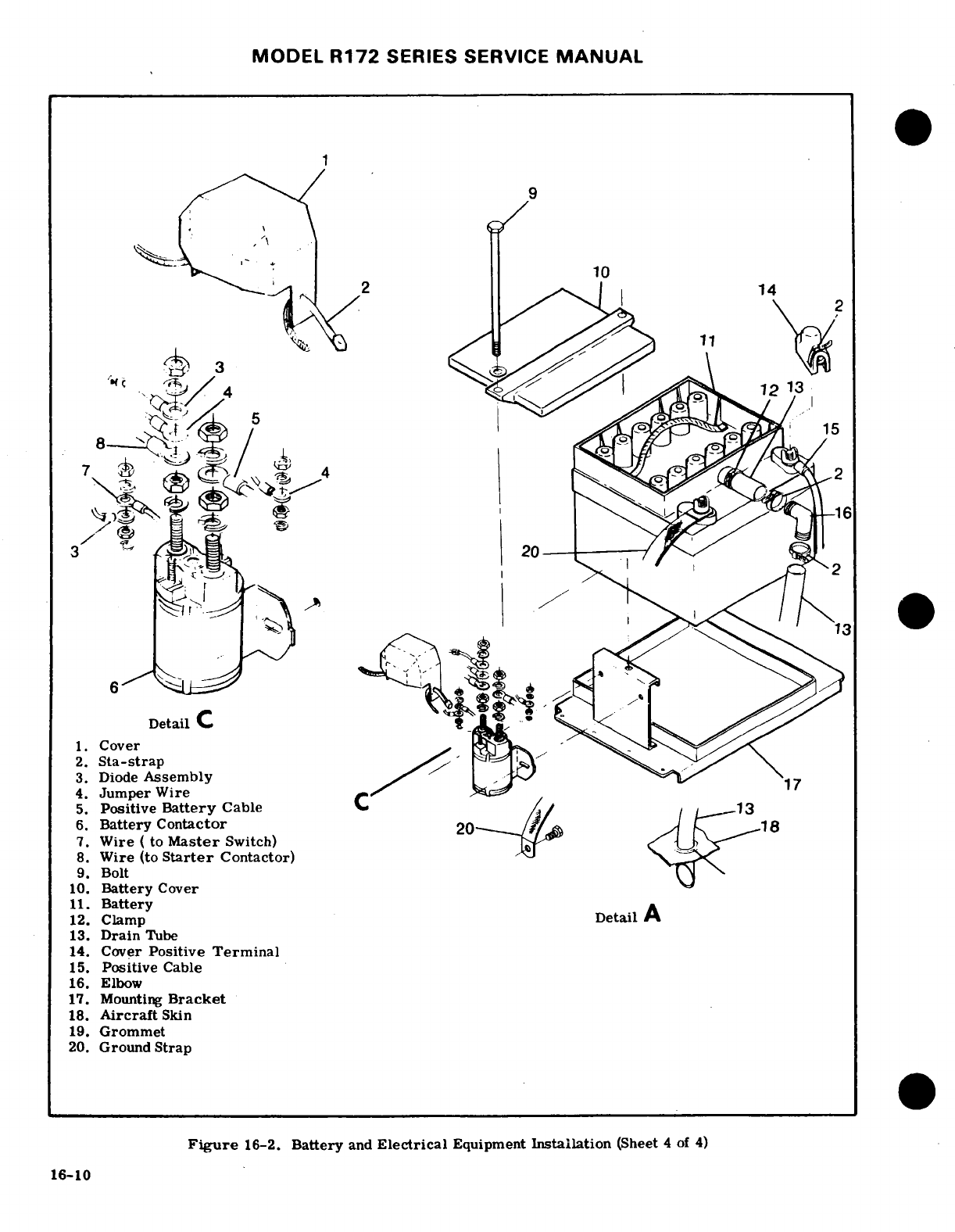
MODEL
R172
SERIES SERVICE
MANUAL
-
Detail
C
1.
Cover
2.
Sta-strap
3.
Diode
Assembly
4.
Jumper
Wire
5.
Positive
Battery
Cable
13
6.
Battery Contactor
7.
Wire
( to
Master
Switch)
8.
Wire
(to
Starter
Contactor)
9.
Bolt
10.
Battery
Cover
11.
Battery
12.
Clamp
Detail
A
13.
Drain
Tube
14.
Cover
Positive
Terminal
15.
Positive
Cable
16.
Elbow
17.
Mounting
Bracket
18.
Aircraft
Skin
19.
Grommet
20.
Ground
Strap
Figure
16-2.
Battery
and
Electrical
Equipment
Installation
(Sheet
4
of
4)
16-10
MODEL
R172
SERIES
SERVICE
MANUAL
WARNING
16-25.
DESCRIPTION.
The
battery
contactor
is
bolt-
ed
to
the
side
of
the
battery
box
thru
1977
models
and
on a
bracket
aft
of
the
battery
box
beginning
with
1978
When
a
battery
is
being
charged,
hydrogen models.
The
contactor
is
plunger
type
actuated
by
turn-
and
oxygen
gases are
generated.
Accumula-
ing
the
master
switch
on.
When
the
master
switch
is
tion
of
these
gases
can
create
a
hazardous
off,
the
battery
is
disconnected
from
the
electrical
explosive
condition.
Always
keep
sparks
system.
A
silicon
diode
is
used
to
eliminate
spiking
and
open
flame
away
from
the
battery.
of
transistorized
radio
equipment.
The
large
terminal
of
the
diode
connects
to
the
battery
terminal
of
the
Allow
unrestricted
ventilation
of
the
battery
battery
contactor.
The
small
terminal
of
the
diode
area
during charging.
and
the
master
switch
wire
connect
to
the minus
ter-
minal
of
the
contactor coil.
A
nylon
cover
is
install-
The
main
points
of
consideration
during a
battery
ed
on
the
contactor
terminals
to
prevent
accidental
charge
are
excessive
battery
temperature
and
violent
short
circuits.
gassing.
Test
the
battery
with
a
hydrometer
to
de-
termine
the
amount
of
charge.
Decrease
the
charging
16-26.
REMOVAL
AND
INSTALLATION.
(See
rate
or
stop
charging
temporarily
if
the
battery
tem-
figure
16-2.
)
perature
exceeds
125°F.
a.
Remove
aft
floor
of
baggage
compartment
b.
Remove
battery
box
cover
and
disconnect
ground
16-20.
BATTERY
BOX.
cable
from
negative
battery
terminal.
c.
Cut
sta-straps
and
remove
nylon
cover/covers
16-21.
DESCRIPTION.
The
battery
is
completely
from
contactor/terminals.
enclosed
in
a
box
which
is
painted
with
acid
proof
d.
Remove
nuts,
washers securing
battery
cable
paint.
The
box
has
a
vent
tube
which
protrudes
and
starter
contactor
cable.
through
the
bottom
of
the
aircraft
allowing
battery
e.
Remove
nut,
washer
securing
ignition
switch
gasses
and
spilled
electrolyte
to
escape.
The
battery
wire.
box
is
riveted
to
mounting
brackets
in
the
tailcone
thru
f.
Remove
bolt,
washer
and
nut
securing
each
side
1977
models,
beginning
with
1978
models
the
battery
of
the
battery
contactor
and
remove
the
contactor.
box
is
held in
place
by
a
strap
riveted
to
the
mounting
g.
To
install
battery
contactor,
reverse
the
preced-
brackets.
ing
steps,
be
sure
to
install
diode
assembly
if
re-
moved.
16-22.
REMOVAL
AND
INSTALLATION.
(Refer
to
figure
16-2.
)
Thru
1977
models
to
remove
the
battery
16-27. BATTERY
CONTACTOR
CLOSING
CIRCUIT.
box,
drill
out
rivets
securing
the
box
to
the
mounting
brackets.
When
a
battery
box
is
installed
,
all
rivets
16-28. DESCRIPTION.
This
circuit
consists
of
a
and
scratches
inside
the
box
should
be
painted
with
acid
5
amp fuse,
a
resistor
and
a
diode
located
on
a
proff
lacquer
Part
No.
CES1054-381,
available
from
bracket
adjacent
to
the
battery.
This
serves
to
the
Cessna
Service
Parts
Center.
Beginning
with
1978
shunt
a
small
charge
around
the
battery
con-
models
the
box
is
held
in
place
by
straps
riveted
to
tactor
so
that
ground
power
may
be
used
to
close
the
mounting
brackets.
the
contactor
when
the
battery
is
too
dead
to
energize
the
contactor
by
itself.
16-23.
MAINTENANCE
OF
BATTERY
BOX.
The
battery
box
should
be
inspected
and
cleaned
periodi-
16-29.
GROUND
SERVICE
RECEPTACLE.
cally.
The
box
and
cover
should
be
cleaned
with
a
strong
solution
of
bicarbonate
of
soda
(baking
soda)
16-30.
DESCRIPTION.
A
ground
service
receptacle
and
water.
Hard
deposits
may
be
removed
with
a
is
offered
as
optional
equipment
to
permit
use
of ex-
wire brush.
When
all
corrosive
deposits
have
been
ternal
power
for
cold
weather
starting
or
when
per-
removed from
the
box,
flush
it
thoroughly
with
clean
forming
lengthy
electrical
maintenance.
A
reverse
water.
polarity protection
system
is
utilized
whereby
ground
WARNING
power
must
pass
through
an
external
power
contactor
to be
connected
to the
bus.
A
silicon
junction
diode
is
connected
in
series
with
the
coil
on
the
external
Do
not
allow
acid
deposits
to
come
in
contact
power
contactor
so
that
if
the
ground
power
source
is
with
skin
or
clothing.
Serious
acid
burns
may
inadvertently
connected
with
a
reverse
polarity,
the
result
unless
the
affected
area
is
washed
im-
external
power
contactor
will
not
close.
This
feature
mediately
with
soap
and
water.
Clothing
will
protects
the
diodes
in
the
alternator,
and
other
semi-
be
ruined
upon
contact
with
battery
acid. conductor
devices
used
in the
aircraft
from
possible
reverse
polarity
damage.
Inspect
the
cleaned
box
and
cover
for
physical
damage
and
for
areas
lacking
proper
acid
proofing.
A
badly
NOTE
damaged
or
corroded
box
should
be
replaced.
If the
box
or
lid
require
acid
proofing,
paint
the
area
with
Thru
1977
models
application
of
external
acid
proof
lacquer
Part
No.
CES1054-381,
available
power
opened
the
relay
supplying
voltage
to
from
the
Cessna
Service
Parts
Center.
the
electronics
bus.
Beginning
with
1978
models
this
relay
is
replaced
by an
avionics
16-24.
BATTERY
CONTACTOR.
master
switch.
The
avionics
master
switch
must
be
OFF
when
external
power
is
applied.
16-11
MODEL
R172
SERIES
SERVICE
MANUAL
NOTE
battery
contactor
will
damage
the
diodes
in
the
alternator
and
other
semiconductor
de-
On
Aircraft
Serials
R1722000
thru
R1722835
vices
used
in
the
aircraft.
refer
to
Cessna
Single-engine
Service
Letter
SE78-19,
dated
March
27. 1978. NOTE
When
using
ground
power
to
start
the
aircraft
CAUTION
close
the
master
switch
before
removing
the
ground
power
plug.
This will
ensure
closure
Failure
to
observe
polarity
when
connecting
of
the
battery
contactor
and
excitation
of
the
an
external
power
source
directly
to
the bat-
alternator
field
tery or
directly
to
the
battery
side
of
the
16-31.
TROUBLE
SHOOTING.
TROUBLE PROBABLE
CAUSE
REMEDY
STARTER
ENGAGES
WHEN
Shorted
or
reversed
diode
in
Check
wiring
to,
and
condition
GROUND
POWER
IS
CON-
split bus-bar
system.
of
diode
mounted
on
the
split
NECTED.
(THRU
1977
MODELS)
bus relay
bracket adjacent
to
the
magneto
switch.
Correct
wiring.
Replace
diode
board
assembly.
GROUND
POWER
WILL
NOT
Ground
service
connector
1.
Check
for
voltage
at
all
CRANK
ENGINE.
wired
incorrectly.
three
terminals
of
external
power
contactor
with
ground
power
connected
and
master
switch
off.
If
voltage
is
pre-
sent
on
input
and
coil
termin-
als
but
not
on
the
output
ter-
minal,
proceed
to
step
4.
If
voltage
is
present
on
the
input
terminal
but not
on
the
coil
terminal,
proceed
to
step
2.
If
voltage
is
present
on
all
three
terminals,
check
wiring
between
contactor
and
bus.
2.
Check
for
voltage
at
small
terminal
of
ground
service
re-
ceptacle.
If
voltage
is
not
pre-
sent,
check
ground
service
plug
wiring.
If
voltage
is
present,
proceed
to
step
3.
Open
or
mis-wired
diode
on
3.
Check
polarity
and
continuity
ground
service
diode
board
of
diode
on
diode
board
at
rear
of
assembly.
ground
service receptacle.
If
diode
is
open
or
improperly
wired,
replace
diode
board
assembly.
Faulty
external
power
con-
4.
Check
resistance
from
small
tactor.
(coil)
terminal
of
external
power
contactor
to ground
(master
switch
off
and
ground power
unplugged
.
Normal
indication
is
16-24
ohms
on
the
12
volt
and
50-70
on
the
24
volt.
If
resistance
indicates
an
open
coil,
replace
contactor.
If
resistance
is
normal,
proceed
16-12
MODEL
R172
SERIES SERVICE
MANUAL
16-31.
TROUBLE
SHOOTING
(Cont.)
TROUBLE
PROBABLE
CAUSE
REMEDY
GROUND
POWER
WILL
NOT
Faulty
contacts
in
external
5.
With
master
switch
off
and
CRANK
ENGINE
(Cont.) power
contactor.
ground
power
applied,
check
for
voltage
drop
between
two
large
terminals
of
external
power
(turn
on
taxi
light
for
a
load).
Normal
indication
is
zero volts.
If
voltage
is
intermittently
pres-
ent
or
present
all
the
time,
replace
contactor.
16-32.
REMOVAL
AND
INSTALLATION.
(See
side
of
the
firewall
and
a
circuit
breaker
located
on
figure
16-3.)
the
instrument
panel.
The
system
is
controlled
by
a.
Open
battery
box
and
disconnect
the
ground
the
left
hand
portion
of
the
split
rocker,
master
cable
from
the
negative
terminal
of
the
battery
and
switch
labeled
"ALT".
Thru
1978
models
and
over-
pull
the
cable
from
the
battery
box.
voltage
sensor
switch
and
red
warning
light
labeled
b.
Remove
the nuts,
washers,
ground
strap
and
"HIGH
VOLTAGE"
are
incorporated
to
protect
the
diode
board
from
the
studs
of
the
receptacle
and
system.
Beginning with
1979
models,
over-voltage
remove
the
battery
cable.
and
under-voltage
switches
are
contained within the
c.
Remove
the
screws
and
nuts
holding
the
recep-
alternator
control
unit
and
a
red
warning
light
label-
tacle.
The
receptacle
will
then
be
free
from
the
ed
"LOW
VOLTAGE"
is
installed
on
the
instrument
bracket.
panel.
The
aircraft
battery supplies
the
source
of
d.
To
install
a
ground
service receptacle,
reverse
power
for
excitation
of
the
alternator.
this
procedure.
Be
sure
to
place
the
ground
strap
on
the
negative
stud
of
the
receptacle.
16-35.
ALTERNATOR.
16-33.
ALTERNATOR
POWER
SYSTEM.
16-36.
DESCRIPTION.
The
60-ampere
alternator
is
three
phase,
delta
connected
with
integral
silicon
16-34.
DESCRIPTION.
The
alternator
system
con-
diode
rectifiers.
The
alternator
is
belt
driven
and is
sists
of
a
engine
driven
alternator,
a
voltage
regula-
rated
at
14
volts
at
60
amperes
continous
output
thru
tor/alternator
control
unit,
mounted
on
the left
hand
1977
models
and
28
volts
at
38
amperes
beginning
with
1978
models.
SHOP
NOTES:
16-13
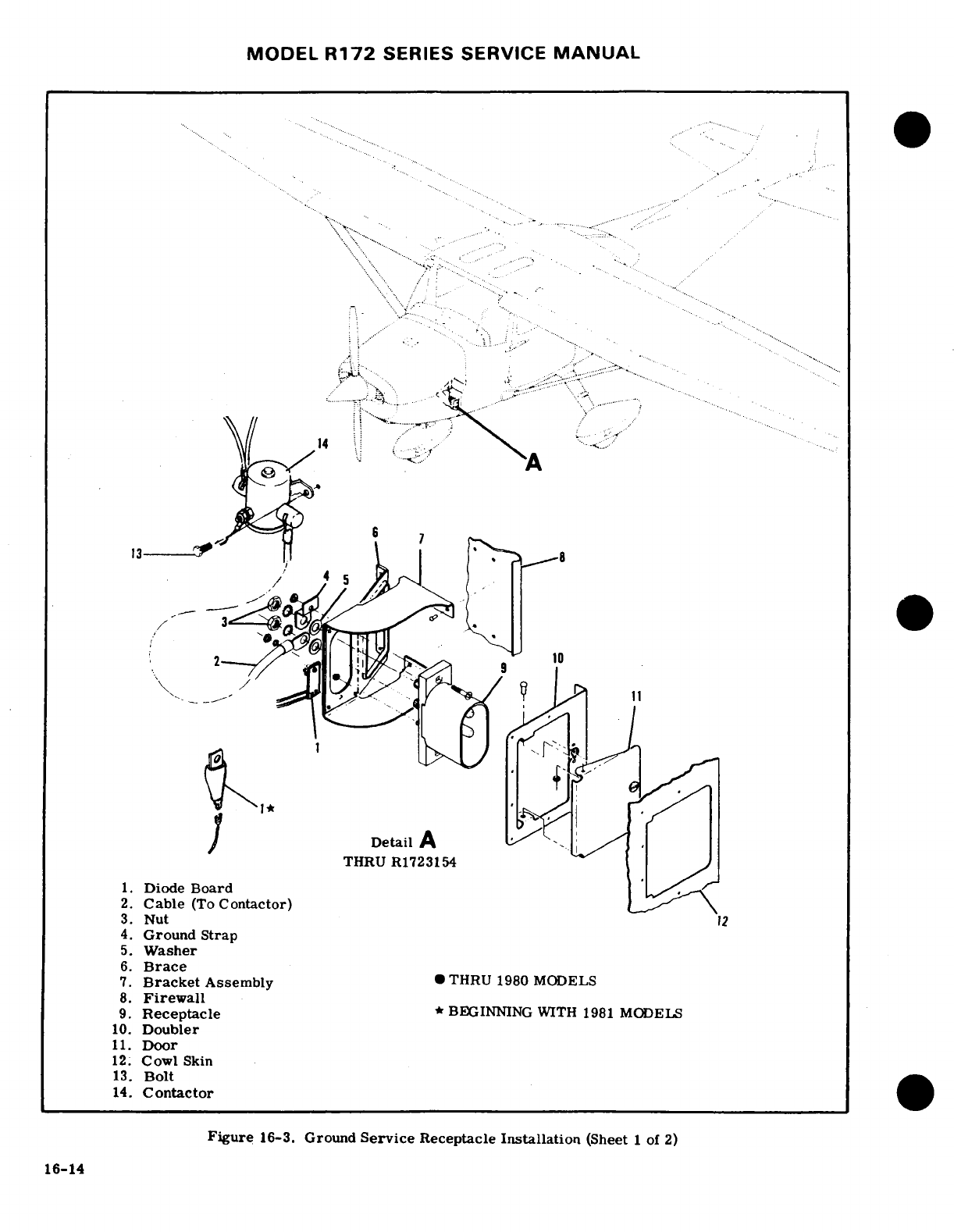
MODEL
R172
SERIES SERVICE
MANUAL
2 9 10
Detail
A
--
., .
THRU
R1723154
1.
Diode
Board
2.
Cable
(To
Contactor)
3.
Nut
12
4.
Ground
Strap
5.
Washer
6.
Brace
7.
Bracket
Assembly
THRU
1980 MODELS
8.
Firewall
9.
Receptacle
BEGINNING
WITH
1981
MODELS
10.
Doubler
11.
Door
12.
Cowl
Skin
13.
Bolt
14.
Contactor
Figure
16-3.
Ground
Service
Receptacle
Installation
(Sheet
1
of
2)
16-14
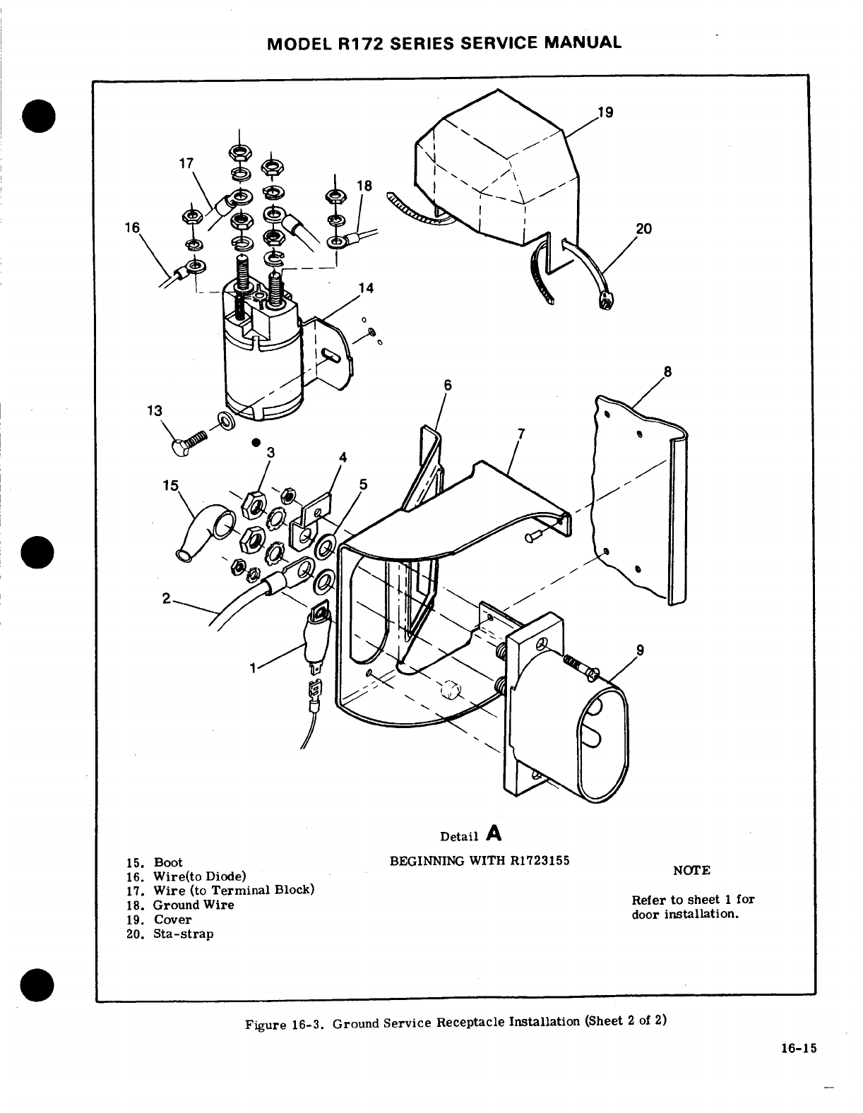
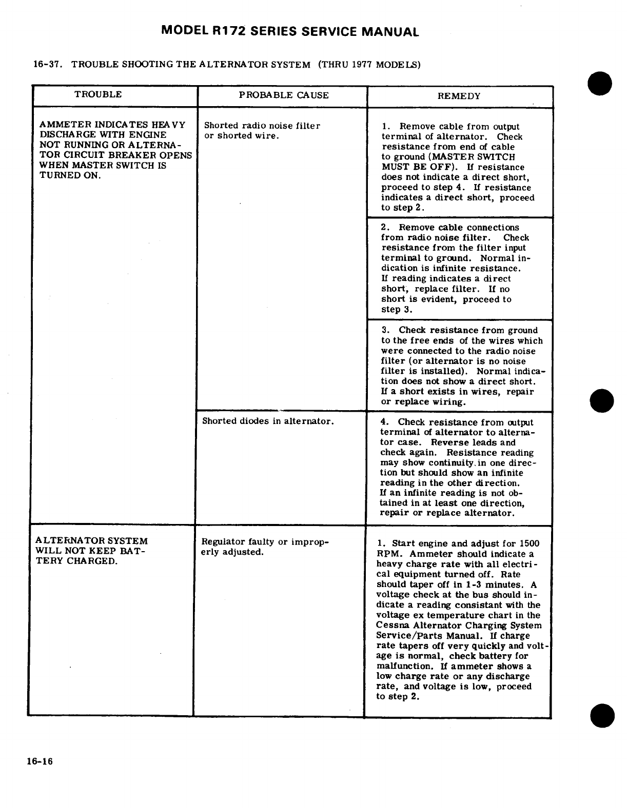
MODEL
R172
SERIES
SERVICE
MANUAL
16-37.
TROUBLE
SHOOTING
THE
ALTERNATOR
SYSTEM
(THRU
1977
MODELS)
TROUBLE
PROBABLE
CAUSE
REMEDY
AMMETER
INDICATES
HEAVY
Shorted
radio
noise
filter
1.
Remove
cable
from
output
DISCHARGE
WITH
ENGINE
or
shorted
wire.
terminal
of
alternator.
Check
NOT
RUNNING
OR
ALTERNA-
resistance
from
end
of
cable
TOR
CIRCUIT
BREAKER
OPENS
to ground
(MASTER
SWITCH
WHEN
MASTER
SWITCH
IS
MUST
BE
OFF).
If
resistance
TURNED
ON.
does
not
indicate
a
direct
short,
proceed
to
step
4.
If
resistance
indicates
a
direct
short,
proceed
to
step
2.
2.
Remove
cable
connections
from
radio noise
filter.
Check
resistance
from
the
filter
input
terminal
to
ground. Normal
in-
dication
is
infinite
resistance.
If
reading
indicates
a
direct
short,
replace
filter.
If
no
short
is
evident,
proceed
to
step
3.
3.
Check
resistance
from
ground
to
the
free
ends
of
the
wires
which
were
connected
to
the
radio
noise
filter
(or
alternator
is
no
noise
filter
is
installed).
Normal
indica-
tion
does
not
show
a
direct
short.
If
a
short
exists
in
wires,
repair
or
replace
wiring.
Shorted
diodes
in
alternator.
4.
Check
resistance
from
output
terminal
of
alternator
to alterna-
tor
case.
Reverse
leads
and
check
again.
Resistance
reading
may show
continuity
in
one
direc-
tion
but
should
show
an
infinite
reading
in
the
other
direction.
If
an
infinite
reading
is
not
ob-
tained
in
at
least
one
direction,
repair
or
replace
alternator.
ALTERNATOR
SYSTEM
Regulator
faulty
or improp-
1.
Start
engine
and
adjust
for
1500
WILL
NOT
KEEP
BAT-
erly
adjusted.
RPM.
Ammeter
should
indicate
a
TERY
CHARGED.
heavy
charge
rate
with
all
electri-
cal
equipment
turned
off.
Rate
should
taper
off
in 1-3
minutes.
A
voltage
check
at
the
bus
should
in-
dicate
a
reading
consistant
with
the
voltage
ex
temperature
chart
in
the
Cessna Alternator
Charging
System
Service/Parts
Manual.
If
charge
rate
tapers
off
very
quickly
and
volt-
age
is
normal,
check
battery
for
malfunction.
If
ammeter
shows
a
low
charge
rate
or
any
discharge
rate,
and
voltage
is
low,
proceed
to
step
2.
16-16
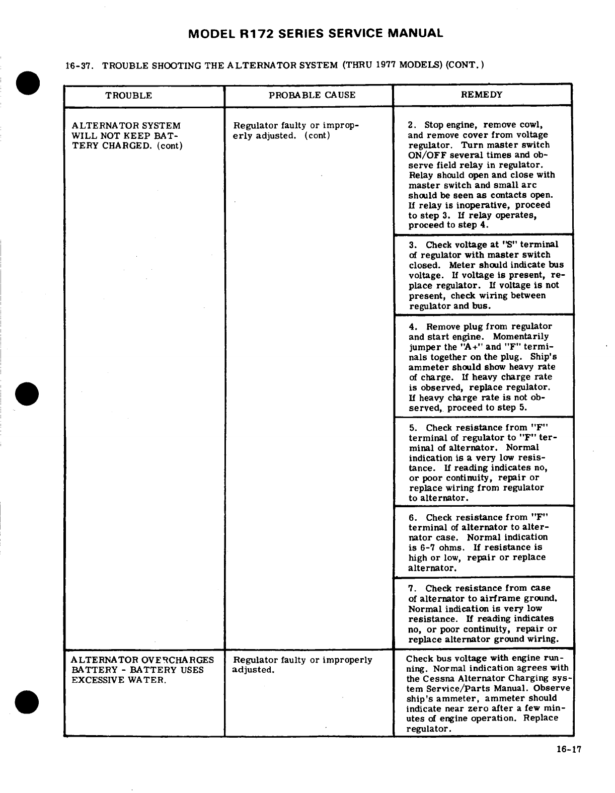
MODEL
R172
SERIES
SERVICE
MANUAL
16-37.
TROUBLE
SHOOTING
THE
ALTERNATOR
SYSTEM
(THRU
1977
MODELS)
(CONT.)
TROUBLE
PROBABLE
CAUSE
REMEDY
ALTERNATOR
SYSTEM
Regulator
faulty
or improp-
2.
Stop
engine,
remove
cowl,
WILL
NOT
KEEP
BAT-
erly
adjusted.
(cont)
and
remove
cover
from
voltage
TERY
CHARGED.
(cont)
regulator.
Turn
master
switch
ON/OFF
several
times
and
ob-
serve
field
relay
in
regulator.
Relay
should
open
and
close
with
master
switch and
small
arc
should
be
seen
as
contacts
open.
If
relay
is
inoperative,
proceed
to
step
3.
If
relay operates,
proceed
to
step
4.
3.
Check
voltage
at
"S"
terminal
of
regulator
with
master
switch
closed.
Meter
should
indicate
bus
voltage.
If
voltage
is
present,
re-
place
regulator.
If
voltage
is
not
present,
check
wiring
between
regulator
and
bus.
4.
Remove
plug from
regulator
and
start
engine.
Momentarily
jumper
the
"A+"
and
"F"
termi-
nals
together
on
the
plug.
Ship's
ammeter
should
show
heavy
rate
of
charge.
If
heavy
charge
rate
is
observed,
replace
regulator.
If
heavy
charge
rate
is
not
ob-
served,
proceed
to
step
5.
5.
Check
resistance
from
"F"
terminal
of
regulator
to "F"
ter-
minal
of
alternator.
Normal
indication
is
a
very
low
resis-
tance.
If
reading
indicates
no,
or
poor
continuity,
repair
or
replace
wiring
from
regulator
to
alternator.
6.
Check
resistance
from
"F"
terminal
of
alternator
to
alter-
nator
case.
Normal
indication
is
6-7
ohms. If
resistance
is
high
or
low,
repair
or
replace
alternator.
7.
Check
resistance
from
case
of
alternator
to
airframe
ground.
Normal indication
is
very
low
resistance.
If
reading
indicates
no,
or
poor
continuity,
repair
or
replace
alternator
ground
wiring.
ALTERNATOR
OVERCHARGES
Regulator
faulty
or improperly
Check
bus voltage
with
engine
run-
BATTERY
-
BATTERY
USES
adjusted.
ning.
Normal
indication
agrees
with
EXCESSIVE
WATER.
the
Cessna
Alternator
Charging
sys-
tem
Service/Parts
Manual.
Observe
ship's
ammeter,
ammeter
should
indicate
near
zero
after
a
few
min-
utes
of
engine
operation.
Replace
regulator.
16-17
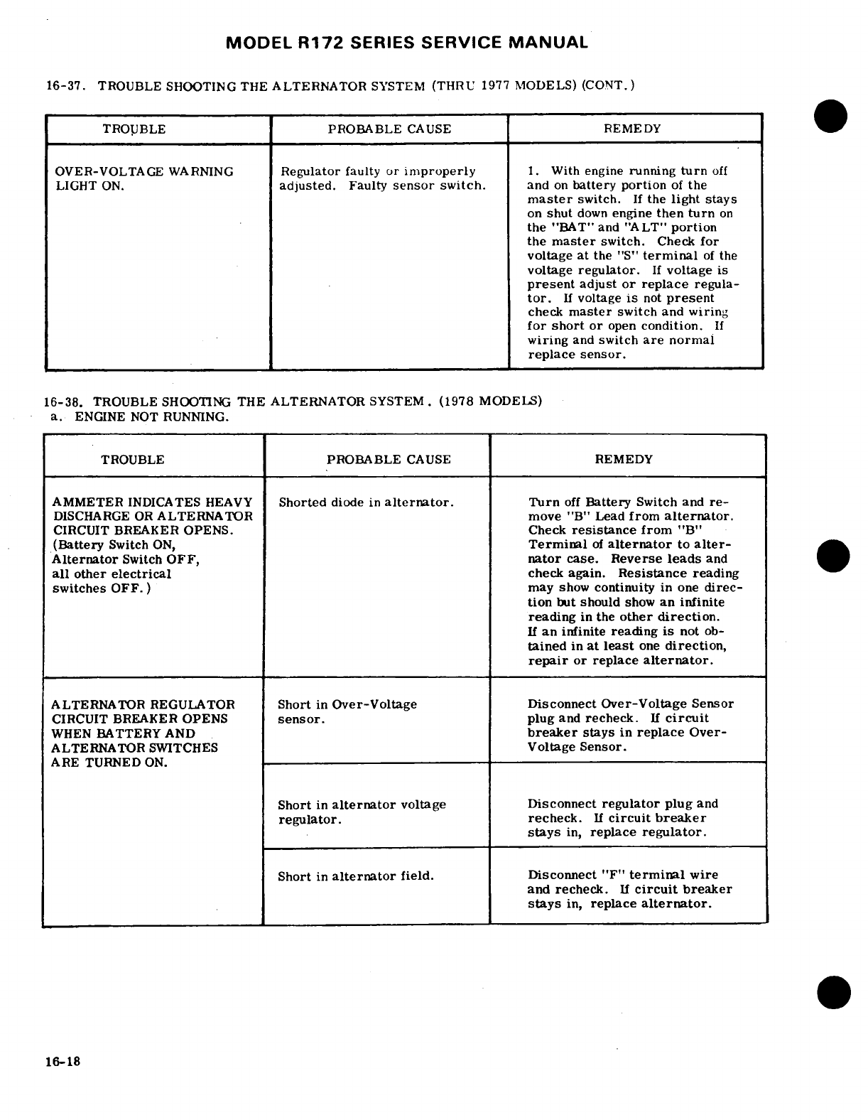
MODEL
R172
SERIES
SERVICE
MANUAL
16-37.
TROUBLE
SHOOTING
THE
ALTERNATOR
SYSTEM
(THRU
1977
MODELS)
(CONT.)
TROUBLE
PROBABLE
CAUSE
REMEDY
OVER-VOLTAGE
WARNING
Regulator
faulty
or
improperly
1.
With
engine
running
turn
off
LIGHT
ON.
adjusted.
Faulty
sensor
switch.
and
on
battery
portion
of
the
master
switch.
If
the
light
stays
on
shut
down
engine
then
turn
on
the
"BAT"
and
"ALT"
portion
the
master
switch.
Check for
voltage at
the
"S"
terminal
of
the
voltage
regulator.
If
voltage
is
present
adjust
or
replace
regula-
tor.
If
voltage
is
not
present
check
master
switch
and
wiring
for
short
or
open
condition.
If
wiring
and
switch
are
normal
replace
sensor.
16-38.
TROUBLE
SHOOTING
THE ALTERNATOR
SYSTEM.
(1978
MODELS)
a.
ENGINE
NOT
RUNNING.
TROUBLE
PROBABLE
CAUSE
REMEDY
AMMETER
INDICATES
HEAVY
Shorted
diode
in
alternator.
Turn
off
Battery
Switch and
re-
DISCHARGE
OR
ALTERNATOR
move
"B"
Lead
from
alternator.
CIRCUIT
BREAKER
OPENS.
Check
resistance
from
"B"
(Battery
Switch
ON,
Terminal
of
alternator
to
alter-
Alternator
Switch
OFF,
nator
case. Reverse
leads
and
all
other
electrical
check
again.
Resistance
reading
switches
OFF.
) may
show
continuity
in
one
direc-
tion
but
should
show
an
infinite
reading
in
the
other
direction.
If
an
infinite
reading
is
not
ob-
tained
in
at
least
one
direction,
repair
or
replace
alternator.
ALTERNATOR
REGULATOR
Short
in
Over-Voltage Disconnect
Over-Voltage
Sensor
CIRCUIT
BREAKER
OPENS
sensor.
plug
and
recheck.
If
circuit
WHEN
BATTERY AND
breaker
stays
in
replace
Over-
ALTERNATOR
SWITCHES
Voltage
Sensor.
ARE
TURNED
ON.
Short
in
alternator
voltage
Disconnect
regulator
plug
and
regulator.
recheck.
If
circuit
breaker
stays
in,
replace
regulator.
Short
in
alternator
field.
Disconnect
"F"
terminal
wire
and recheck.
If
circuit
breaker
stays
in,
replace
alternator.
16-18
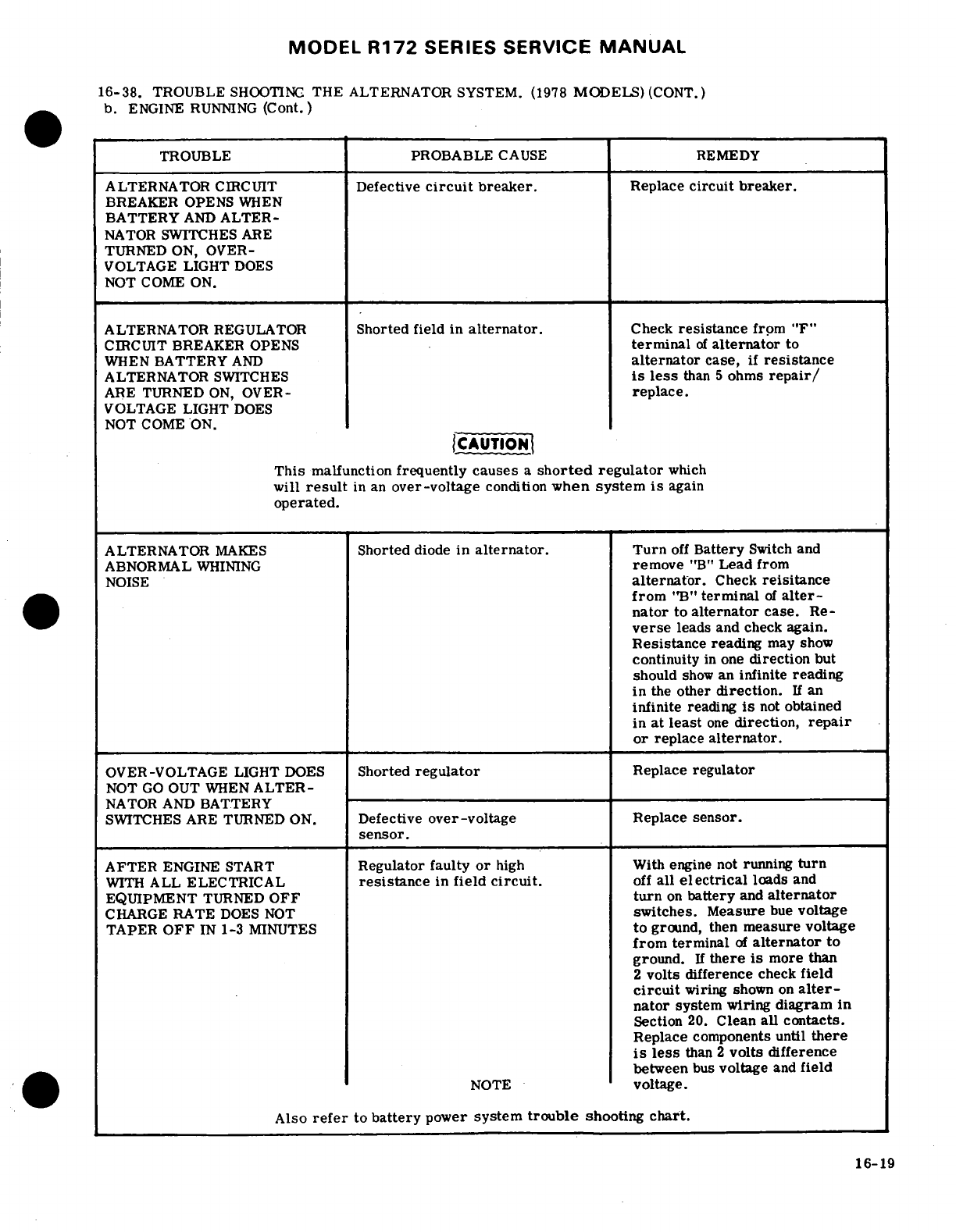
MODEL
R172
SERIES
SERVICE
MANUAL
16-38.
TROUBLE
SHOOTING
THE
ALTERNATOR
SYSTEM.
(1978
MODELS)
(CONT.)
b.
ENGINE
RUNNING
(Cont.)
TROUBLE
PROBABLE
CAUSE
REMEDY
ALTERNATOR
CIRCUIT
Defective
circuit
breaker.
Replace
circuit
breaker.
BREAKER
OPENS
WHEN
BATTERY
AND
ALTER-
NATOR
SWITCHES
ARE
TURNED
ON,
OVER-
VOLTAGE LIGHT
DOES
NOT
COME ON.
ALTERNATOR
REGULATOR
Shorted
field in
alternator.
Check
resistance
from "F"
CIRCUIT
BREAKER
OPENS
terminal
of
alternator
to
WHEN
BATTERY
AND
alternator
case,
if
resistance
ALTERNATOR
SWITCHES
is
less
than
5
ohms
repair/
ARE TURNED
ON,
OVER-
replace.
VOLTAGE
LIGHT
DOES
NOT COME
ON.
CAUTION
This
malfunction
frequently
causes
a
shorted
regulator
which
will
result
in an
over-voltage
condition
when
system
is
again
operated.
ALTERNATOR
MAKES
Shorted
diode
in
alternator.
Turn
off
Battery
Switch
and
ABNORMAL
WHINING
remove
"B"
Lead
from
NOISE
alternator.
Check
reisitance
from
"B"
terminal
of
alter-
nator
to
alternator
case.
Re-
verse
leads
and
check
again.
Resistance
reading
may
show
continuity
in
one
direction
but
should
show
an
infinite
reading
in
the
other
direction.
If
an
infinite
reading
is
not
obtained
in
at
least
one
direction,
repair
or
replace
alternator.
OVER-VOLTAGE
LIGHT
DOES
Shorted
regulator
Replace
regulator
NOT
GO
OUT
WHEN
ALTER-
NATOR
AND
BATTERY
SWITCHES
ARE
TURNED ON.
Defective
over-voltage
Replace
sensor.
sensor.
AFTER
ENGINE
START
Regulator faulty
or
high
With
engine
not
running
turn
WITH
ALL
ELECTRICAL
resistance
in
field
circuit.
off
all
electrical
loads
and
EQUIPMENT
TURNED
OFF
turn
on
battery
and
alternator
CHARGE
RATE
DOES
NOT
switches.
Measure
bue
voltage
TAPER
OFF
IN
1-3
MINUTES
to
ground, then
measure
voltage
from
terminal
of
alternator
to
ground.
If
there
is
more
than
2
volts
difference
check
field
circuit
wiring
shown
on
alter-
nator
system
wiring
diagram
in
Section
20.
Clean
all contacts.
Replace
components
until
there
is
less
than
2
volts
difference
between
bus
voltage
and
field
NOTE
voltage.
Also
refer
to
battery
power
system
trouble
shooting
chart.
16-19
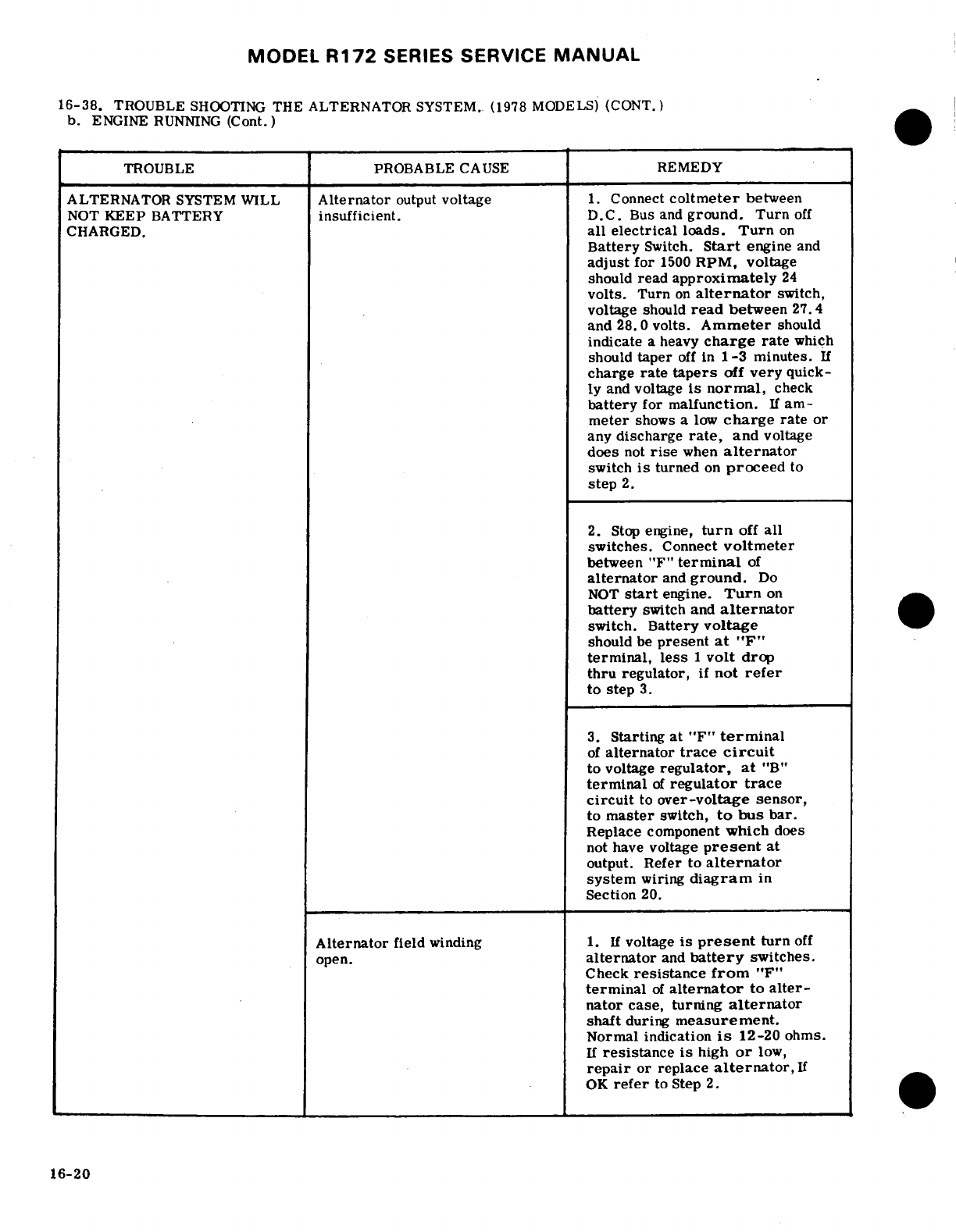
MODEL
R172
SERIES
SERVICE
MANUAL
16-38.
TROUBLE
SHOOTING
THE
ALTERNATOR
SYSTEM.
(1978
MODELS)
(CONT.)
b.
ENGINE
RUNNING
(Cont.)
TROUBLE
PROBABLE
CAUSE
REMEDY
ALTERNATOR
SYSTEM
WILL
Alternator
output
voltage
1.
Connect
coltmeter
between
NOT
KEEP
BATTERY
insufficient.
D.C.
Bus and
ground.
Turn
off
CHARGED.
all
electrical
loads.
Turn
on
Battery
Switch.
Start
engine
and
adjust
for
1500
RPM,
voltage
should
read
approximately
24
volts.
Turn
on
alternator
switch,
voltage
should
read
between
27.4
and
28.0
volts.
Ammeter
should
indicate
a heavy
charge
rate
which
should
taper
off
in
1-3
minutes.
If
charge
rate
tapers
off
very
quick-
ly
and
voltage
is
normal,
check
battery
for
malfunction.
If
am-
meter
shows
a
low
charge
rate
or
any
discharge
rate,
and
voltage
does
not
rise
when
alternator
switch
is
turned
on
proceed
to
step
2.
2.
Stop
engine,
turn
off
all
switches.
Connect
voltmeter
between "F"
terminal
of
alternator
and
ground.
Do
NOT
start
engine.
Turn
on
battery
switch
and
alternator
switch.
Battery
voltage
should
be
present
at
"F"
terminal,
less
1
volt
drop
thru
regulator,
if
not
refer
to
step
3.
3.
Starting
at
"F"
terminal
of
alternator
trace
circuit
to
voltage
regulator,
at
"B"
terminal
of
regulator
trace
circuit
to
over-voltage
sensor,
to
master
switch,
to
bus
bar.
Replace
component
which
does
not
have
voltage
present
at
output.
Refer
to
alternator
system
wiring
diagram
in
Section
20.
Alternator
field
winding
1.
If
voltage
is
present
turn
off
open.
alternator
and
battery
switches.
Check
resistance
from
"F"
terminal
of
alternator
to
alter-
nator case,
turning
alternator
shaft
during
measurement.
Normal indication
is
12-20
ohms.
If
resistance
is
high
or
low,
repair
or
replace
alternator,
If
OK
refer
to
Step
2.
16-20
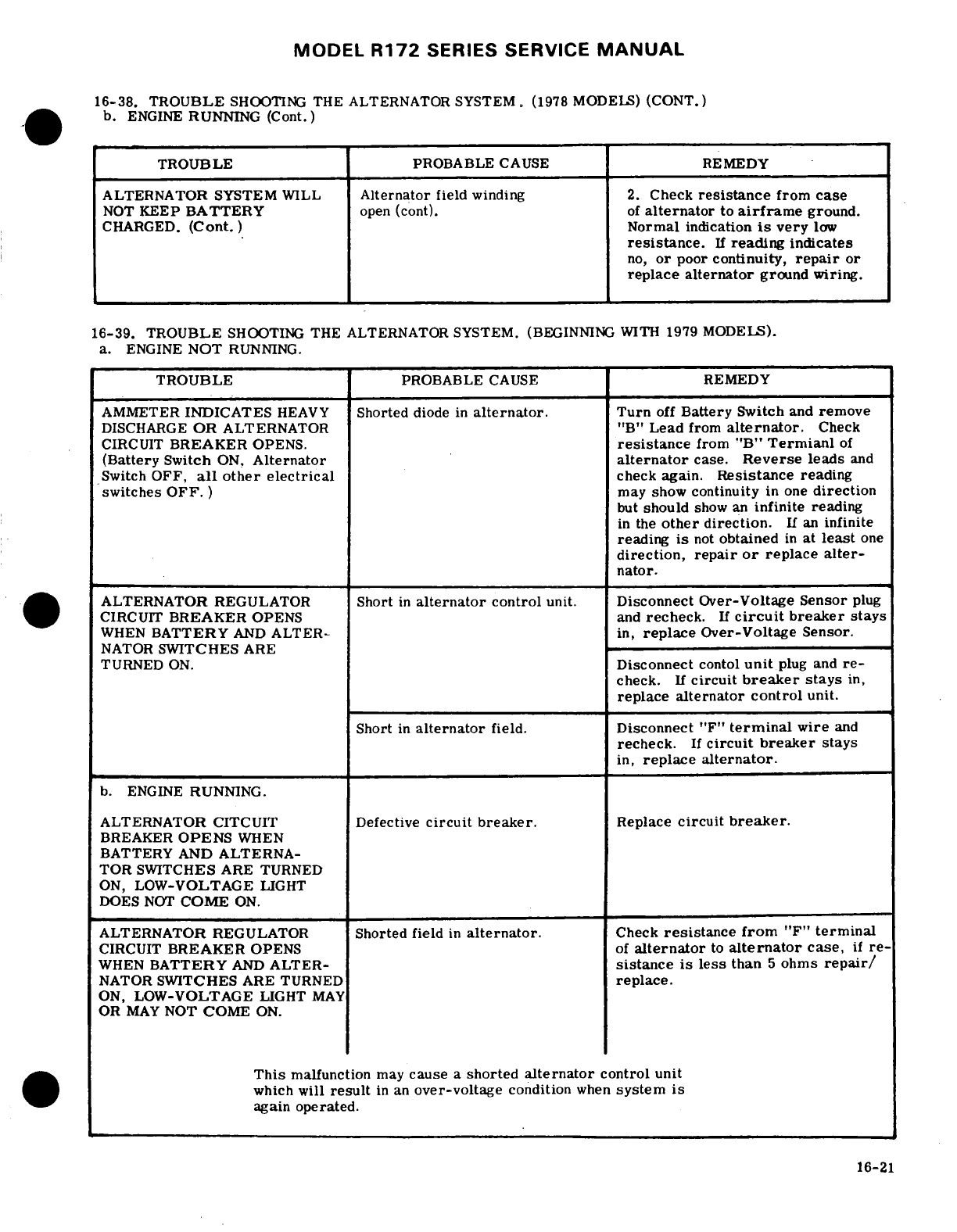
MODEL
R172
SERIES
SERVICE
MANUAL
16-38. TROUBLE
SHOOTING
THE
ALTERNATOR SYSTEM. (1978
MODELS)
(CONT.)
b.
ENGINE
RUNNING (Cont.)
TROUBLE
PROBABLE
CAUSE
REMEDY
ALTERNATOR SYSTEM
WILL
Alternator
field
winding
2.
Check
resistance
from
case
NOT
KEEP
BATTERY
open (cont).
of
alternator
to
airframe
ground.
CHARGED.
(Cont.)
Normal
indication
is
very
low
resistance.
If
reading
indicates
no,
or
poor
continuity,
repair
or
replace
alternator
ground wiring.
16-39.
TROUBLE
SHOOTING
THE
ALTERNATOR
SYSTEM.
(BEGINNING WITH
1979
MODELS).
a.
ENGINE
NOT
RUNNING.
TROUBLE
PROBABLE
CAUSE
REMEDY
AMMETER
INDICATES
HEAVY
Shorted
diode
in
alternator.
Turn
off
Battery
Switch
and
remove
DISCHARGE
OR
ALTERNATOR
"B"
Lead
from
alternator.
Check
CIRCUIT
BREAKER
OPENS.
resistance
from
"B"
Termianl
of
(Battery
Switch
ON,
Alternator
alternator
case.
Reverse
leads
and
Switch
OFF,
all
other electrical
check
again.
Resistance
reading
switches
OFF.
) may show
continuity
in
one
direction
but
should
show
an
infinite
reading
in
the
other
direction.
If
an
infinite
reading
is
not
obtained
in
at
least
one
direction,
repair
or
replace
alter-
nator.
ALTERNATOR
REGULATOR
Short
in
alternator
control
unit.
Disconnect
Over-Voltage Sensor
plug
CIRCUIT
BREAKER
OPENS
and
recheck.
If
circuit
breaker
stays
WHEN
BATTERY
AND
ALTER-
in,
replace
Over-Voltage Sensor.
NATOR
SWITCHES
ARE
TURNED
ON.
Disconnect
contol
unit
plug
and
re-
check.
If
circuit
breaker
stays
in,
replace
alternator
control
unit.
Short
in
alternator
field.
Disconnect
"F"
terminal
wire
and
recheck.
If
circuit
breaker
stays
in,
replace
alternator.
b.
ENGINE
RUNNING.
ALTERNATOR
CITCUIT
Defective
circuit
breaker.
Replace
circuit
breaker.
BREAKER
OPENS
WHEN
BATTERY
AND
ALTERNA-
TOR
SWITCHES
ARE
TURNED
ON,
LOW-VOLTAGE
LIGHT
DOES
NOT
COME
ON.
ALTERNATOR
REGULATOR
Shorted
field
in
alternator.
Check
resistance
from
"F"
terminal
CIRCUIT
BREAKER
OPENS
of
alternator
to
alternator
case,
if
re-
WHEN
BATTERY
AND
ALTER-
sistance
is
less
than
5
ohms
repair/
NATOR
SWITCHES
ARE
TURNED
replace.
ON,
LOW-VOLTAGE
LIGHT
MAY
OR
MAY
NOT
COME
ON.
This
malfunction
may
cause
a
shorted
alternator
control
unit
which
will
result
in
an
over-voltage
condition
when
system
is
again
operated.
16-21
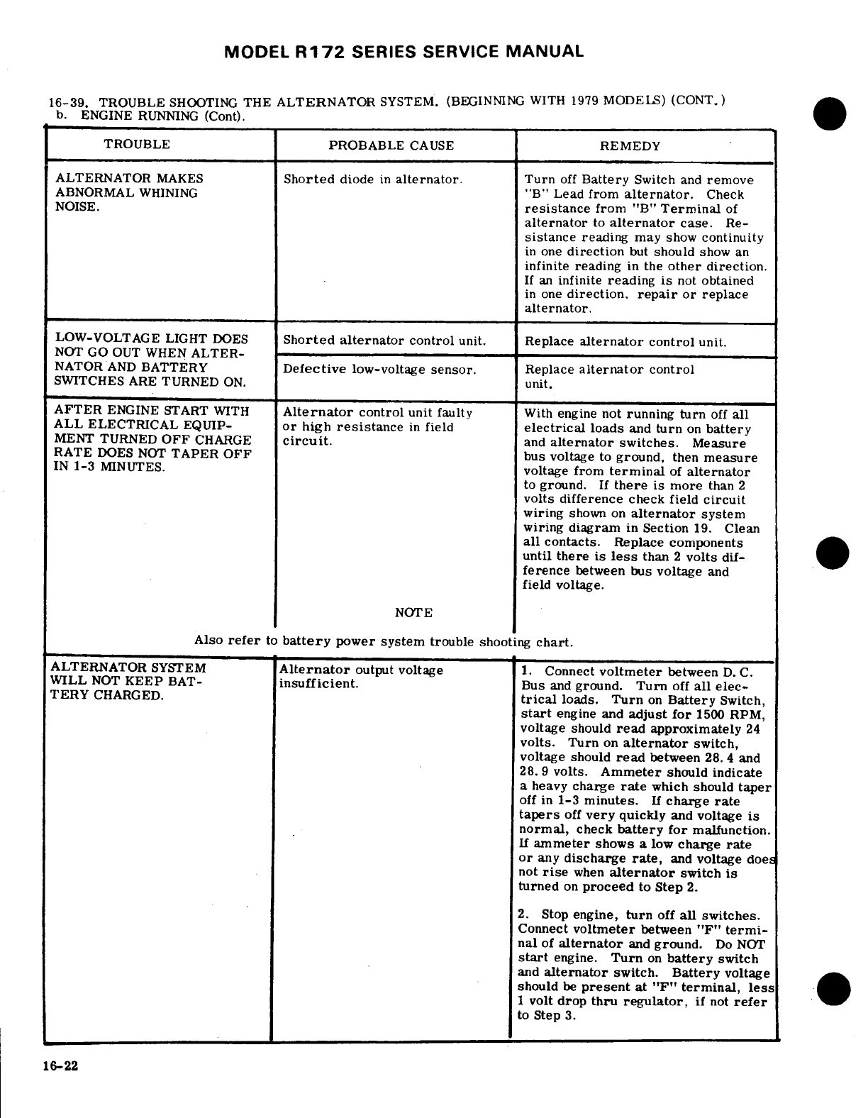
MODEL
R172
SERIES
SERVICE
MANUAL
16-39.
TROUBLE
SHOOTING
THE
ALTERNATOR
SYSTEM.
(BEGINNING
WITH
1979
MODELS)
(CONT.)
b. ENGINE
RUNNING
(Cont).
TROUBLE
PROBABLE
CAUSE
REMEDY
ALTERNATOR
MAKES
Shorted
diode
in
alternator.
Turn
off
Battery
Switch
and
remove
ABNORMAL
WHINING
"B"
Lead
from
alternator.
Check
NOISE.
resistance
from
"B"
Terminal
of
alternator
to
alternator
case.
Re-
sistance
reading
may
show
continuity
in
one
direction
but
should
show
an
infinite
reading
in
the
other
direction.
If
an
infinite
reading
is
not
obtained
in
one
direction,
repair
or
replace
alternator.
LOW-VOLTAGE
LIGHT
DOES
Shorted
alternator
control
unit. Replace
alternator
control
unit.
NOT GO
OUT WHEN
ALTER-
NATOR
AND
BATTERY
Defective
low-voltage
sensor.
Replace
alternator
control
SWITCHES
ARE
TURNED
ON.
unit.
AFTER
ENGINE START
WITH
Alternator
control
unit
faulty
With
engine
not
running
turn
off
all
ALL
ELECTRICAL
EQUIP-
or
high
resistance
in
field
electrical
loads
and
turn
on
battery
MENT
TURNED
OFF
CHARGE
circuit.
and
alternator
switches.
Measure
RATE
DOES
NOT
TAPER
OFF bus
voltage
to
ground,
then
measure
IN
1-3
MINUTES.
voltage
from
terminal
of
alternator
to
ground.
If
there
is
more
than 2
volts difference
check
field
circuit
wiring
shown
on
alternator
system
wiring
diagram
in
Section
19.
Clean
all
contacts.
Replace
components
until
there
is
less
than
2
volts
dif-
ference
between
bus
voltage
and
field
voltage.
NOTE
Also
refer
to
battery
power
system
trouble
shooting
chart.
ALTERNATOR
SYSTEM
Alternator
output
voltage
1.
Connect
voltmeter
between
D.
C.
WILL
NOT
KEEP
BAT-
insufficient.
Bus
and
ground.
Turn
off
all
elec-
TERY
CHARGED.
trical
loads.
Turn
on
Battery
Switch,
start
engine and
adjust
for
1500
RPM,
voltage
should
read
approximately
24
volts.
Turn
on
alternator
switch,
voltage
should
read
between
28.
4
and
28.
9
volts.
Ammeter
should
indicate
a
heavy
charge
rate
which
should
taper
off
in
1-3
minutes.
If
charge
rate
tapers
off
very
quickly
and
voltage
is
normal,
check
battery
for
malfunction.
If
ammeter
shows
a
low
charge
rate
or
any
discharge
rate,
and
voltage
doe
not
rise
when
alternator
switch
is
turned
on
proceed
to
Step
2.
2.
Stop
engine,
turn
off
all switches.
Connect
voltmeter
between
"F"
termi-
nal
of
alternator
and
ground.
Do
NOT
start
engine.
Turn
on
battery
switch
and
alternator
switch.
Battery
voltage
should
be
present
at
"F"
terminal,
less
1
volt
drop
thru
regulator,
if
not
refer
to
Step
3.
16-22
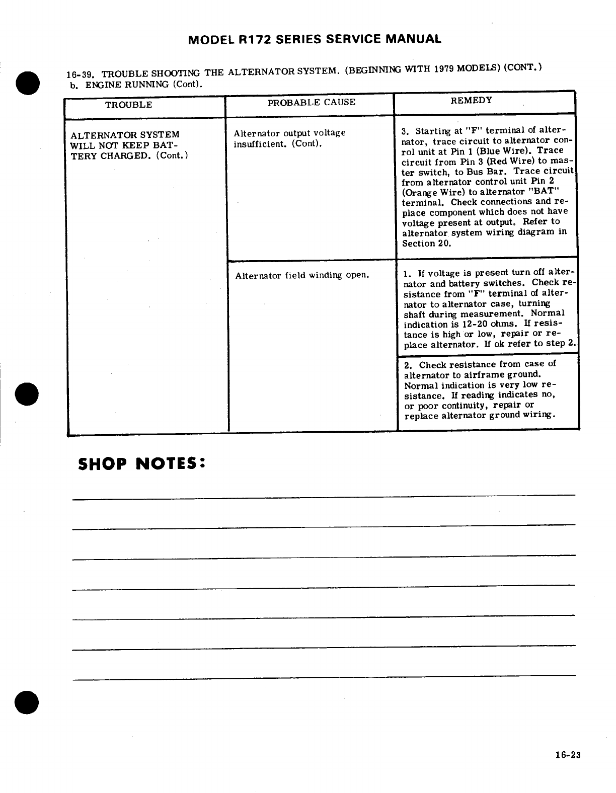
MODEL
R172
SERIES SERVICE
MANUAL
16-39.
TROUBLE
SHOOTING
THE
ALTERNATOR
SYSTEM.
(BEGINNING
WITH
1979
MODELS)
(CONT.)
b.
ENGINE RUNNING
(Cont).
TROUBLE
PROBABLE
CAUSE
REMEDY
ALTERNATOR
SYSTEM
Alternator
output
voltage
3.
Starting
at
"F"
terminal
of
alter-
WILL
NOT
KEEP
BAT-
insufficient.
(Cont).
nator,
trace
circuit
to
alternator
con-
TERY
CHARGED.
(Cont.)
rol
unit
at
Pin
1
(Blue
Wire).
Trace
circuit
from
Pin
3
(Red
Wire)
to
mas-
ter
switch,
to
Bus
Bar. Trace
circuit
from
alternator
control
unit Pin
2
(Orange
Wire)
to
alternator
"BAT"
terminal.
Check
connections
and
re-
place
component which
does
not
have
voltage
present at
output.
Refer
to
alternator
system
wiring
diagram
in
Section
20.
Alternator
field
winding open.
1.
If
voltage
is
present turn
off
alter-
nator
and
battery
switches.
Check
re-
sistance
from
"F"
terminal
of
alter-
nator to
alternator
case,
turning
shaft
during
measurement.
Normal
indication
is
12-20 ohms.
If
resis-
tance
is
high
or
low,
repair
or
re-
place
alternator.
If
ok
refer
to
step
2.
2.
Check
resistance
from
case
of
alternator
to
airframe
ground.
Normal
indication
is
very
low
re-
sistance.
If
reading indicates
no,
or
poor
continuity,
repair
or
replace
alternator
ground
wiring.
SHOP
NOTES:
16-23
MODEL
R172
SERIES SERVICE
MANUAL
16-40.
REMOVAL
AND
INSTALLATION.
(See
Beginning
with
1979
Models
the
over-voltage
sensor
figure
16-4.)
is
contained
within
the
alternator
control
unit.
The
a.
Insure
that
the
master
switch
is
off
and
the
neg-
unit
also
contains
a
low-voltage
sensor.
A
red
warn-
ative
lead
is
disconnected
from
the
battery.
ing
light
labeled
"LOW
VOLTAGE"
is
installed
on
the
b.
Remove
wiring
from
the
alternator
and
label,
instrument
panel.
When
an
over-voltage
condition
c.
Remove
screw
and
nut holding
blast
tube
to
sup-
occurs
the
over-voltage
sensor turns
off
the
alterna-
port
strap
clamp,
blast
tube
will then
be
free
for
tor
and
the
voltage
in
the
system
drops.
When
system
removal.
voltage drops
below
24.8
volts
the
low-voltage
sensor
d.
Remove nuts
and
washers
from
alternator
mount-
turns
on
the
low-voltage
light
indicating
a
drain
on
the
ing
bolts,
battery
and
the
ammeter
will
show
a
discharge.
Turn
e.
Remove
alternator.
off
both
sections
of
the
master
switch
to
recycle
the
f.
To
replace
alternator, reverse
this
procedure. over-voltage
sensor,
If
the
over-voltage
condition
was
transient,
the
normal
alternator
charging
will
16-41.
OVER-VOLTAGE
WARNING
SYSTEM.
resume
and
no
further
action
is
necessary.
If
the
over-voltage
tripoff
recurs,
then
a
generating
system
16-42.
DESCRIPTION.
The
over-voltage
system
malfunction
has
occurred
such
that
the
electrical
consists
of
an
over-voltage
sensor
switch
and
a
red
accessories
must
be
operated
from
the
aircraft
bat-
warning
light
labeled
"HIGH
VOLTAGE".
The
over-
tery
only.
Conservation
of
electrical
energy must
be
voltage
sensor
is attached
to
the
wire
bundle
behind
practiced
until
the
flight
can
be
terminated.
The
the
instrument
panel
thru
1977
models
and
on
a
mount-
over-voltage
light
filament
may
be
tested
at
any
time
ing
bracket
just
forward
of
the
instrument
panel
on
the
by
turning
off
the
"Alternator"
portion
of
the
master
left
hand
side
beginning
with
1978
models.
When
an
switch
and
leaving
the
battery portion
on.
This
test
over-voltage
tripoff
occurs
the
over-voltage
sensor
does
not
induce
an
over-voltage
condition
on
the
elec-
turns
off
the
alternator
system
and
the
red
warning
trical
system.
light
comes
on.
The
ammeter
will
show
a
discharge.
Turn
off
both
sections
of
the
master
switch
to
recycle
16-43.
ALTERNATOR
VOLTAGE REGULATOR.
the
over-voltage
sensor.
If
the
over-voltage
condi-
tion
was
transient,
the
normal
alternator
charging
16-44.
DESCRIPTION.
Thru
1977
Models
the
voltage
will
resume
and
no
further
action
is
necessary.
If
regulator
is
semi-solid
state.
The
mechanical
relay
the
over-voltage
tripoff
recurs,
then
a
generating
in
the
regulator
is
actuated
by
the
aircraft
master
system
malfunction
has
occurred
such
that
the
elec-
switch
and
connects
the
regulator
to
the
battery.
The
trical
accessories
must
be
operated
from
the
aircraft
solid
state
portion
is voltage
sensitive
and
controls
battery
only.
Conservation
of
electrical
energy
must
the
current
applied
to the
field
windings
of
the
alter-
be
practiced
until
the
flight
can
be
terminated.
The
nator.
The
regulator
is
a
remove
and
replace
item
over-voltage
light
filament
may
be
tested
at
any
time
and
not
repairable.
The
regulatoris
adjustable,
but
by
turning
off
the
"Alternator"
portion
of
the
master
adjustment
on
the
aircraft
is
not
recommended.
A
switch
and
leaving
the
battery portion
on.
This
test
bench
adjustment procedure
is
outlined
in
the
Cessna
does
not
induce
an
over-voltage
condition
on
the
elec-
Alternator
Charging Systems
Service/Parts
Manual.
trical
system.
Thru
1978
Models
the
voltage
regulator
is
solid-state.
The
regulator
is
a
remove
and
replace
item,
and
not
NOTE
repairable.
The
regulator
is
adjustable,
but
adjust-
ment
on
the
aircraft
is
not
recommended.
A
bench
The
over-voltage
sensor
switch
contains
solid
adjustment
procedure
is
outlined
in
the
Cessna
Alter-
state
devices.
Observe
proper
polarity
before
nator
Charging
Systems
Service/Parts
Manual.
A
supplying
power.
Grounding
the
orange lead
or
Cessna
Alternator
Charging System
Test
Box
Assem-
interconnecting orange
and
black leads
will
de-
bly
(PN-9870000-1)
is
available
through
the
Cessna
stroy
the device.
When
removal
is
required
Service/Parts
Center
for
use
in
isolating failures
in
for
replacement,
identify
(tag) wiring
and
fol-
the
28-volt
regulator
and
the
28-volt
alternator.
low
the
wiring
diagram
in
Section
20
for
re-
Refer
to
paragraph
16-43.
wiring.
16-45.
ALTERNATOR
CONTROL
UNIT.
16-24
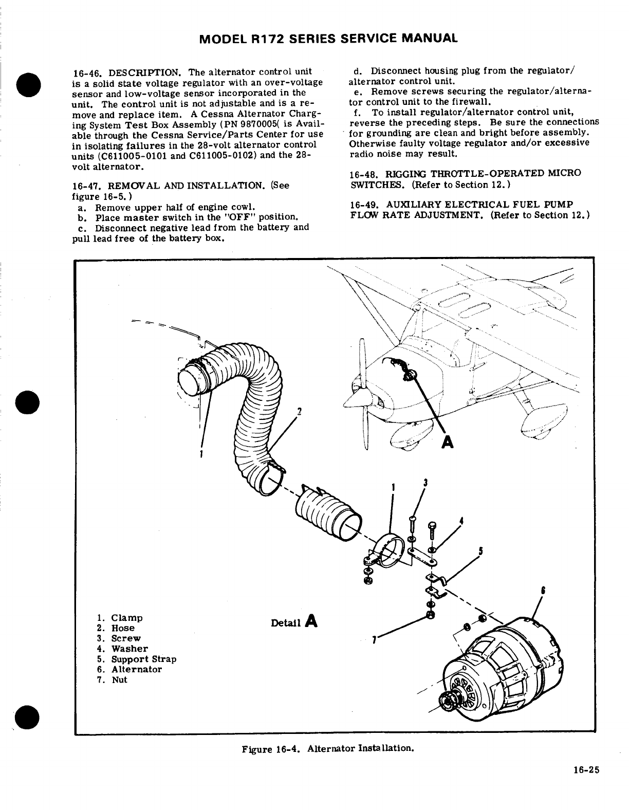
MODEL
R172
SERIES SERVICE
MANUAL
16-46.
DESCRIPTION.
The
alternator
control
unit
d.
Disconnect
housing
plug
from
the
regulator/
is
a
solid
state
voltage
regulator
with an
over-voltage
alternator
control unit.
sensor
and
low-voltage
sensor
incorporated
in
the
e.
Remove
screws
securing
the
regulator/alterna-
unit.
The
control
unit
is
not
adjustable
and
is
a
re-
tor
control
unit
to the
firewall.
move
and
replace
item.
A
Cessna
Alternator
Charg-
f.
To
install
regulator/alternator
control
unit,
ing
System
Test
Box
Assembly
(PN
9870005(
is
Avail-
reverse
the
preceding steps.
Be
sure
the
connections
able
through
the
Cessna
Service/Parts
Center
for
use
for
grounding
are
clean
and
bright
before
assembly.
in
isolating
failures
in
the
28-volt
alternator
control Otherwise
faulty
voltage
regulator
and/or
excessive
units
(C611005-0101
and
C611005-0102)
and
the
28-
radio
noise
may
result.
volt
alternator.
16-48.
RIGGING
THROTTLE-OPERATED
MICRO
16-47. REMOVAL
AND
INSTALLATION.
(See
SWITCHES.
(Refer
to
Section
12.)
figure
16-5.)
a.
Remove
upper
half
of
engine
cowl.
16-49.
AUXILIARY
ELECTRICAL
FUEL
PUMP
b.
Place
master
switch
in
the
"OFF"
position.
FLOW
RATE
ADJUSTMENT.
(Refer
to
Section
12.)
c.
Disconnect
negative
lead
from
the
battery
and
pull
lead
free
of
the
battery
box.
................
... .
.. '
.....
.
...... ......
..
..........
5
.Support
Strap
.
6.
Alternator
2.
Hose
-.
3.
Screw
.. . . .
4.
Washer
5.
Support
Strap
6.
Alternator
7.
Nut
Figure
16-4.
Alternator
Installation.
16-25
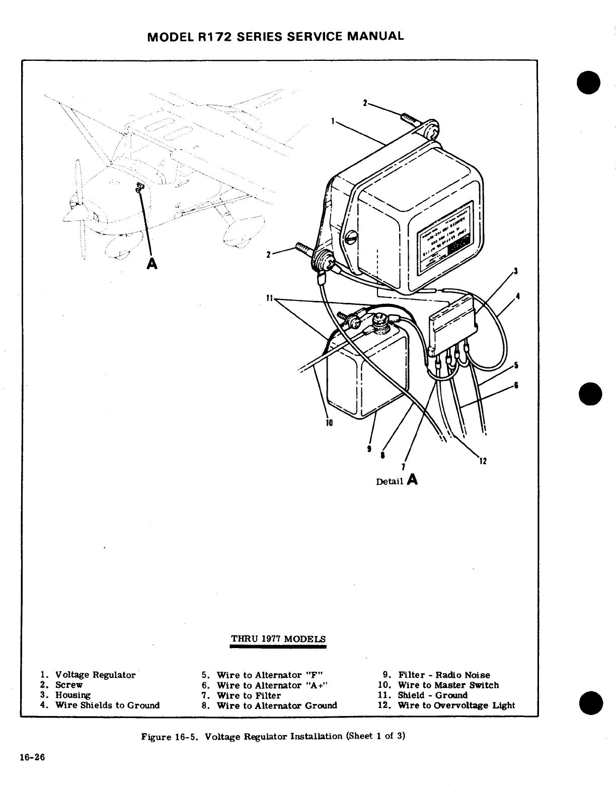
MODEL
R172
SERIES
SERVICE
MANUAL
*...... .....
Detail
A
THRU
1977
MODELS
1.
Voltage
Regulator
5.
Wire
to
Alternator
"F"
9.
Filter
-
Radio
Noise
2.
Screw
6.
Wire
to
Alternator
"A+"
10.
Wire
to
Master
Switch
3.
Housing 7.
Wire
to
Filter
11.
Shield -
Ground
4.
Wire Shields
to
Ground
8.
Wire
to
Alternator
Ground
12.
Wire to
Overvoltage
Light
Figure
16-5.
Voltage
Regulator
Installation
(Sheet
1
of
3)
16-26
16-26
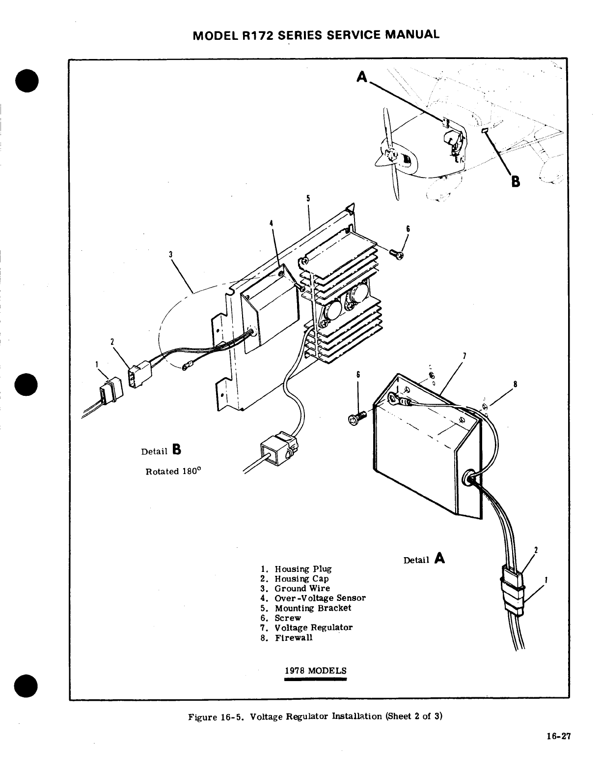
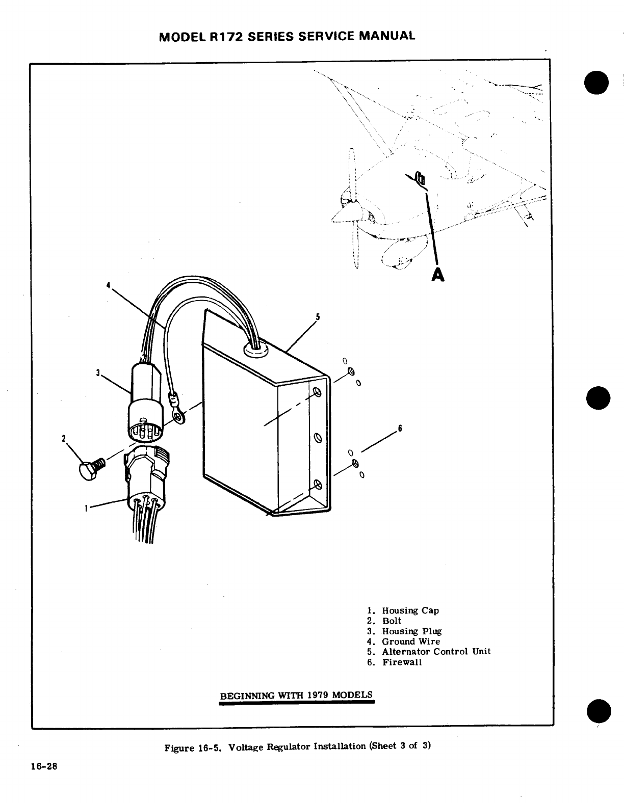
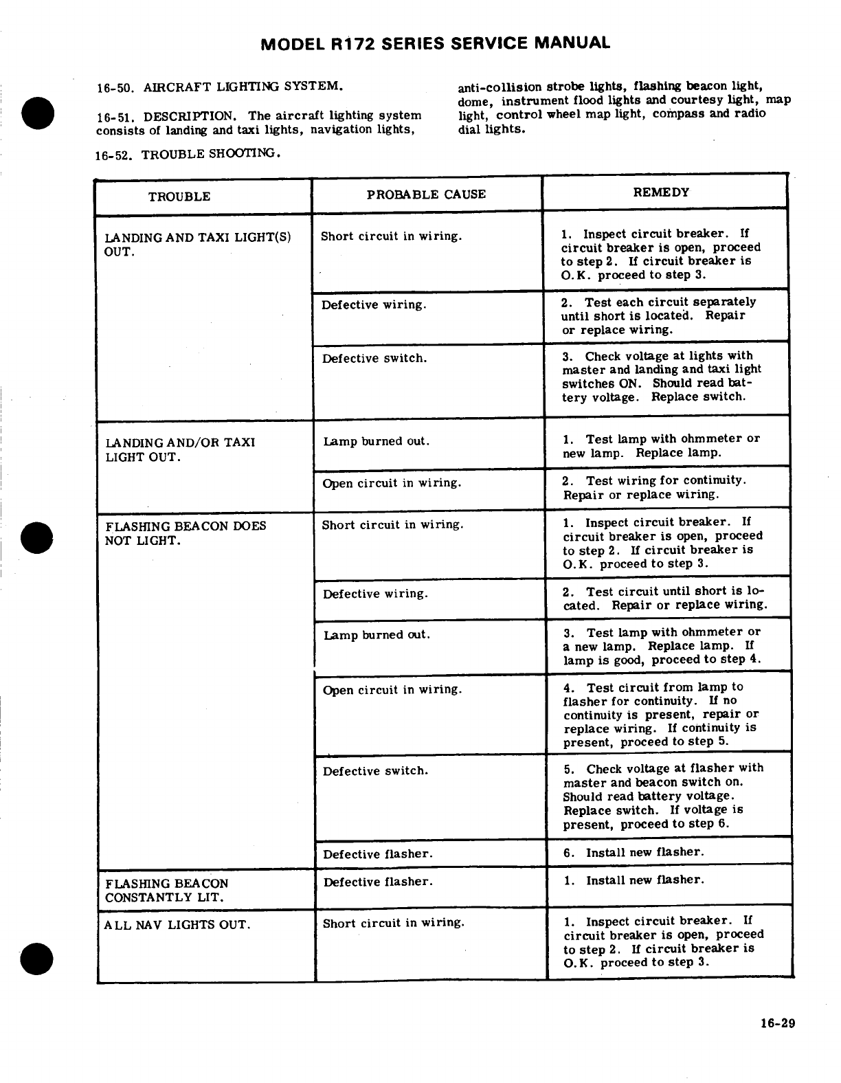
MODEL
R172
SERIES
SERVICE
MANUAL
16-50.
AIRCRAFT
LIGHTING
SYSTEM.
anti-collision
strobe
lights, flashing
beacon
light,
dome,
instrument
flood
lights
and
courtesy
light,
map
16-51.
DESCRIPTION.
The
aircraft
lighting
system
light,
control
wheel
map light,
compass
and
radio
consists
of
landing
and
taxi
lights,
navigation
lights, dial
lights.
16-52.
TROUBLE
SHOOTING.
TROUBLE
PROBABLE
CAUSE
REMEDY
LANDING
AND
TAXI
LIGHT(S)
Short
circuit
in
wiring.
1.
Inspect
circuit
breaker.
If
OUT.
circuit
breaker
is
open,
proceed
to
step
2.
If
circuit
breaker
is
O.K.
proceed
to
step
3.
Defective
wiring.
2.
Test
each
circuit
separately
until
short
is
located.
Repair
or
replace
wiring.
Defective
switch.
3.
Check
voltage
at
lights
with
master
and
landing and
taxi
light
switches
ON.
Should
read
bat-
tery
voltage.
Replace
switch.
LANDING
AND/OR
TAXI
Lamp
burned
out.
1.
Test
lamp
with
ohmmeter
or
LIGHT
OUT.
new
lamp. Replace
lamp.
Open
circuit
in
wiring.
2.
Test
wiring
for
continuity.
Repair
or
replace
wiring.
FLASHING
BEACON
DOES
Short
circuit
in
wiring.
1.
Inspect
circuit
breaker.
If
NOT
LIGHT.
circuit
breaker
is
open,
proceed
to
step
2.
If
circuit
breaker
is
O.K.
proceed
to
step
3.
Defective
wiring.
2.
Test circuit
until
short
is
lo-
cated.
Repair
or
replace
wiring.
Lamp
burned
out.
3.
Test
lamp
with
ohmmeter
or
a
new
lamp.
Replace
lamp.
If
lamp
is
good,
proceed
to
step
4.
Open
circuit
in
wiring.
4.
Test
circuit
from
lamp
to
flasher
for
continuity.
If
no
continuity
is
present,
repair
or
replace
wiring.
If
continuity
is
present,
proceed
to
step
5.
Defective
switch.
5.
Check
voltage
at
flasher
with
master
and
beacon
switch
on.
Should
read
battery
voltage.
Replace
switch.
If
voltage
is
present,
proceed
to
step
6.
Defective
flasher.
6.
Install
new
flasher.
FLASHING
BEACON
Defective
flasher.
1.
Install
new
flasher.
CONSTANTLY
LIT.
ALL
NAV
LIGHTS
OUT.
Short
circuit
in
wiring.
1.
Inspect
circuit
breaker.
If
circuit
breaker
is
open,
proceed
to
step
2.
If
circuit
breaker
is
O.K.
proceed
to
step
3.
16-29
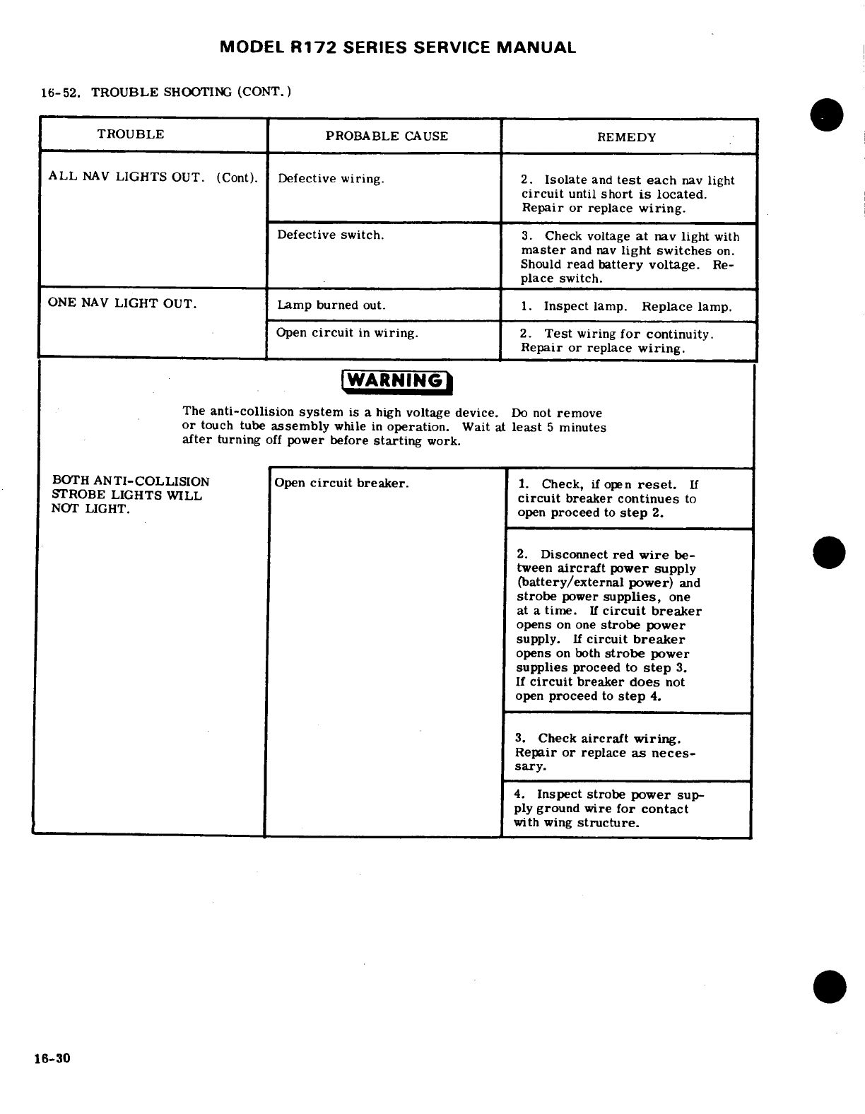
MODEL
R172
SERIES SERVICE
MANUAL
16-52.
TROUBLE
SHOOTING
(CONT.)
TROUBLE
PROBABLE
CAUSE
REMEDY
ALL
NAV
LIGHTS
OUT.
(Cont).
Defective
wiring.
2.
Isolate
and
test
each
nav
light
circuit
until
short
is
located.
Repair
or
replace
wiring.
Defective
switch.
3.
Check
voltage
at
nav
light
with
master
and
nav
light
switches
on.
Should
read
battery
voltage.
Re-
place
switch.
ONE
NAV
LIGHT
OUT.
Lamp
burned
out.
1.
Inspect
lamp.
Replace
lamp.
Open
circuit
in
wiring.
2.
Test
wiring
for
continuity.
Repair or
replace
wiring.
WARNING
The
anti-collision system
is
a
high
voltage device.
Do
not
remove
or
touch
tube
assembly
while
in
operation.
Wait
at
least
5
minutes
after
turning
off
power before
starting
work.
BOTH
ANTI-COLLISION
Open
circuit
breaker.
1.
Check,
if
open
reset.
If
STROBE
LIGHTS WILL
circuit
breaker
continues
to
NOT
LIGHT.
open
proceed
to
step
2.
2.
Disconnect
red
wire
be-
tween
aircraft
power
supply
(battery/external
power)
and
strobe
power
supplies,
one
at
a
time.
If
circuit
breaker
opens
on
one
strobe
power
supply.
If
circuit
breaker
opens
on
both
strobe
power
supplies
proceed
to
step
3.
If
circuit
breaker
does
not
open
proceed
to
step
4.
3.
Check
aircraft
wiring.
Repair or
replace
as
neces-
sary.
4.
Inspect
strobe
power
sup-
ply
ground
wire
for
contact
with
wing
structure.
16-30
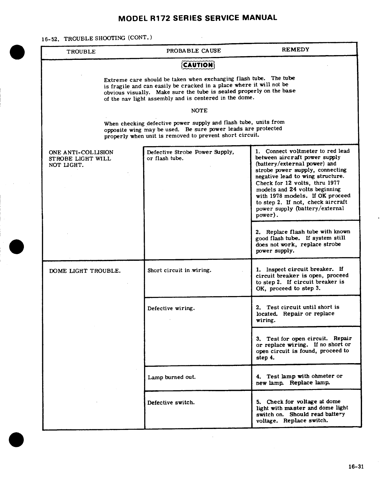
MODEL
R172
SERIES
SERVICE
MANUAL
16-52.
TROUBLE
SHOOTING
(CONT.)
TROUBLE PROBABLE
CAUSE
REMEDY
CAUTION
Extreme
care
should
be
taken
when
exchanging
flash
tube.
The
tube
is
fragile
and can
easily
be
cracked
in
a
place
where it will
not
be
obvious
visually.
Make
sure
the tube
is
seated
properly
on
the
base
of
the
nav
light
assembly
and
is centered
in
the
dome.
NOTE
When
checking
defective
power
supply
and
flash
tube,
units from
opposite
wing
may
be
used.
Be
sure
power
leads
are
protected
properly
when
unit
is
removed
to
prevent
short
circuit.
ONE
ANTI-COLLISION
Defective
Strobe
Power
Supply,
1.
Connect
voltmeter
to
red
lead
STROBE LIGHT
WILL
or
flash
tube.
between
aircraft
power
supply
NOT
LIGHT.
(battery/external
power)
and
strobe
power
supply,
connecting
negative
lead
to
wing
structure.
Check
for
12
volts,
thru
1977
models
and
24
volts
beginning
with
1978
models.
If
OK
proceed
to
step
2.
If
not,
check
aircraft
power
supply
(battery/external
power).
2.
Replace
flash
tube
with
known
good
flash
tube.
If
system
still
does
not
work,
replace strobe
power
supply.
DOME
LIGHT
TROUBLE.
Short
circuit
in
wiring.
1.
Inspect
circuit
breaker.
If
circuit
breaker
is
open,
proceed
to
step
2.
If
circuit
breaker
is
OK,
proceed
to
step
3.
Defective
wiring.
2.
Test
circuit
until
short
is
located.
Repair or
replace
wiring.
3.
Test
for
open
circuit.
Repair
or
replace
wiring.
If
no
short
or
open
circuit
is
found,
proceed
to
step
4.
Lamp burned out.
4.
Test
lamp
with
ohmeter
or
new
lamp.
Replace
lamp.
Defective
switch.
5.
Check
for
voltage
at dome
light
with
master
and
dome
light
switch
on.
Should
read
battery
voltage.
Replace
switch.
16-31
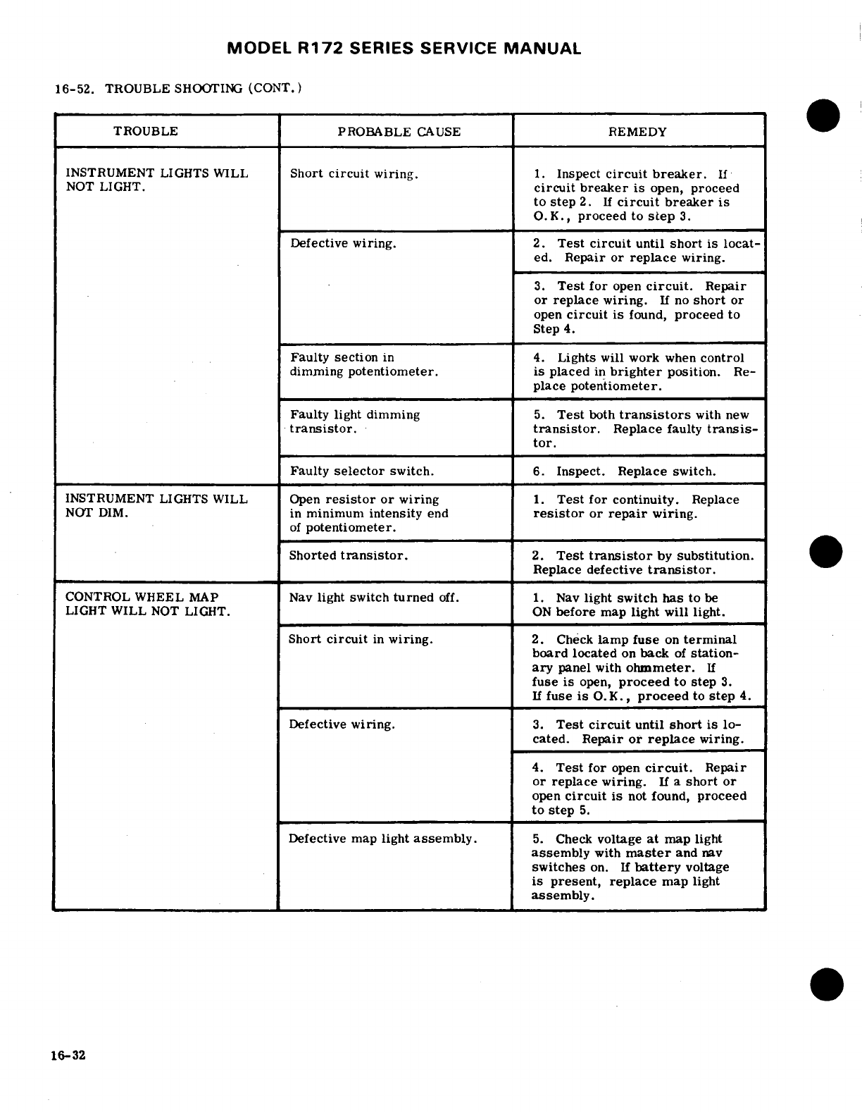
MODEL
R172
SERIES
SERVICE
MANUAL
16-52.
TROUBLE
SHOOTING (CONT.)
TROUBLE
PROBABLE
CAUSE
REMEDY
INSTRUMENT
LIGHTS
WILL
Short
circuit
wiring.
1.
Inspect
circuit
breaker.
If
NOT
LIGHT.
circuit breaker
is
open,
proceed
to
step
2.
If
circuit
breaker
is
O.K.,
proceed
to
step
3.
Defective
wiring.
2.
Test
circuit
until
short
is
locat-
ed.
Repair
or
replace
wiring.
3.
Test
for
open
circuit.
Repair
or
replace
wiring.
If
no
short
or
open
circuit
is
found,
proceed
to
Step
4.
Faulty
section
in
4.
Lights
will
work
when
control
dimming
potentiometer. is
placed
in
brighter
position.
Re-
place
potentiometer.
Faulty light dimming
5.
Test
both
transistors
with
new
transistor.
transistor.
Replace
faulty
transis-
tor.
Faulty
selector
switch.
6.
Inspect. Replace
switch.
INSTRUMENT
LIGHTS
WILL Open
resistor
or
wiring
1.
Test for
continuity.
Replace
NOT
DIM.
in
minimum
intensity
end
resistor
or
repair
wiring.
of
potentiometer.
Shorted
transistor.
2.
Test
transistor
by
substitution.
Replace
defective
transistor.
CONTROL
WHEEL
MAP
Nav
light switch
turned
off. 1.
Nav
light
switch
has
to
be
LIGHT
WILL
NOT
LIGHT.
ON
before
map
light
will
light.
Short
circuit
in
wiring.
2.
Check
lamp
fuse
on
terminal
board
located
on
back
of
station-
ary
panel
with
ohmmeter.
If
fuse
is
open,
proceed
to
step
3.
If
fuse
is
O.K.,
proceed
to
step
4.
Defective
wiring.
3.
Test
circuit
until
short
is
lo-
cated.
Repair
or
replace
wiring.
4.
Test
for
open
circuit.
Repair
or
replace
wiring.
If
a
short
or
open
circuit
is
not
found,
proceed
to
step
5.
Defective
map
light
assembly.
5.
Check
voltage
at
map light
assembly
with
master
and
nav
switches
on.
If
battery
voltage
is
present,
replace
map
light
assembly.
16-32
MODEL
R172
SERIES
SERVICE
MANUAL
16-53.
LANDING
AND
TAXI
LIGHTS.
16-60.
ANTI-COLLISION
STROBE
LIGHTS.
16-54.
DESCRIPTION.
Cowl
mounted
landing
and
16-61.
DESCRIPTION.
A
white
strobe
light
may
be
taxi
lights
are
installed.
The
left
hand
light
is
used
installed
on
each
wing
tip
with
the
navigation
lights.
for
taxi
and
the
right
hand
light
for
landing.
Two
Strobe
lights
are
vibration
resistant
and
operate
on
rocker
type
switches
on
the
pilots switch
panel
con-
the
principle
of
a
capacitor
discharge
into
a
xenon
trol
the
lights.
A
20
amp
circuit
breaker
is
installed
tube,
producing
an
extremely
high
intensity
flash.
to
protect
the
system.
Energy
is
supplied
to
the
lights
from
individual
power
supplies
mounted
on
each
wing
tip
rib.
16-55.
REMOVAL
AND
INSTALLATION. (See
figure
16-6. 16-62.
REMOVAL
AND
INSTALLATION.
For
re-
a.
Remove
screws
(1)
and
pull
bracket
assembly
(2)
moval
and
installation
of
strobe
light
and
power
sup-
from
nose
cap
to
gain
access
to
electrical
leads.
ply
see
figure
16-7.
b.
Disconnect
electrical
leads
from
lamps
making
sure
switches
are
off
and
leads
do
not
short
out.
WARNING
c.
Remove
screws
(9)
from plate
(7)
and
remove
lamp
assembly
from
bracket
(2).
If
left
hand
(taxi)
The
anti-collision
system
is
a
high
voltage
light is being
removed,
note
position
of
spacers
(3)
device.
Do
not
remove
or
touch
tube
assem-
and
(11)
for
reinstallation.
bly
while
in
operation.
Wait
at
least
5
min-
d.
Remove
screws
(10)
from
bracket
(4)
to
dis-
utes
after
turning
off
power
before
starting
assemble
lamp
assembly.
work.
e.
Install
new
lamp
and
reassemble.
16-56.
ADJUSTMENT.
Park
the
aircraft
3
feet
16-63. OPERATIONAL
REQUIREMENTS
(THRU
from
a
wall
or
any
suitable
light
reflecting
surface
1977
MODELS).
(distance
is
measured
between
landing
light
and
wall).
With
the
nose
gear
shock
strut
extended
2
inches,
the
center
of
the
landing
light beam
(right
hand)
on
the
CAUTION
wall
should
be
35
3/4
inches
above
the
floor.
The
center
of
the
taxi
light beam,
(left
hand) on
the
wall
The
capacitors
in
the
strobe
light
power
should
be
32
1/8
inches
above
the
floor.
supplies must
be
reformed
if
not
used
for
a
period
of
(6)
months.
The
following
pro-
16-57.
NAVIGATION
LIGHTS.
cedure
must
be
used.
16-58.
DESCRIPTION.
The
navigation
lights
are
Connect
the
power
supply,
red
wire
to
plus,
black
to
mounted
on
each
wing
tip
and
the
aft
end
of
the
verti-
ground
to
6
volt
DC
source.
Do Not
connect
strobe
cal
fin
tip.
The
lights
are
controlled
by
a
rocker
tube.
Turn
on
6
volt
supply.
Note
current
draw
after
type
switch
located
on
the
instrument
panel.
A
cir-
one
minute.
If
less
than
1
ampere,
continue
opera-
cuit
breaker
is
installed
on
the
panel
to
protect
the
tion
for
24
hours.
Turn
off
DC
power
source.
Then
system.
connect
to
the
proper
voltage,
12
volt.
Connect
tube
to
output
of
strobe
power
supply
and
allow
to
operate,
flashing,
for
15
minutes.
Remove
strobe
tube.
Oper-
16-59.
REMOVAL
AND
INSTALLATION.
For
re-
ating
power
supply
at
12
volts,
note
the
current
drain
moval
and
installation
of
navigation
lights
see
after
one
minute.
If
less
than
0.
5
amperes,
operate
figure
16-7.
for
6
hours.
If
current
draw
is
greater
than
0.
5
am-
peres,
reject
the
unit.
SHOP NOTES:
16-33
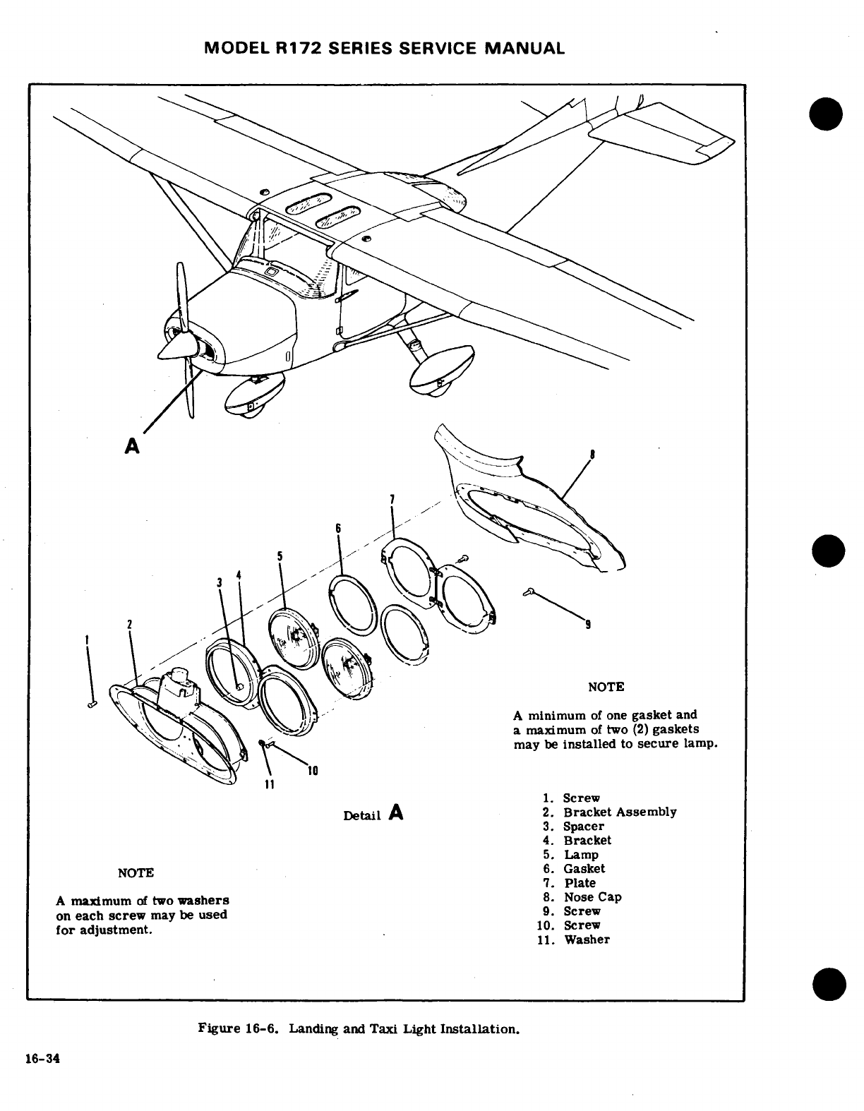
MODEL
R172
SERIES
SERVICE
MANUAL
5
2
A
minimum
of
one
gasket
and
a
maximum
of
two
(2)
gaskets
may
be
installed
to
secure
lamp.
1.
Screw
Detail
A
2.
Bracket
Assembly
3.
Spacer
4.
Bracket
5.
Lamp
NOTE
6.
Gasket
7.
Plate
A
maximum
of
two
washers
8.
Nose
Cap
on
each
screw
may
be
used
9.
Screw
for
adjustment.
10.
Screw
11.
Washer
Figure
16-6.
Landing and
Taxi
Light
Installation.
16-34
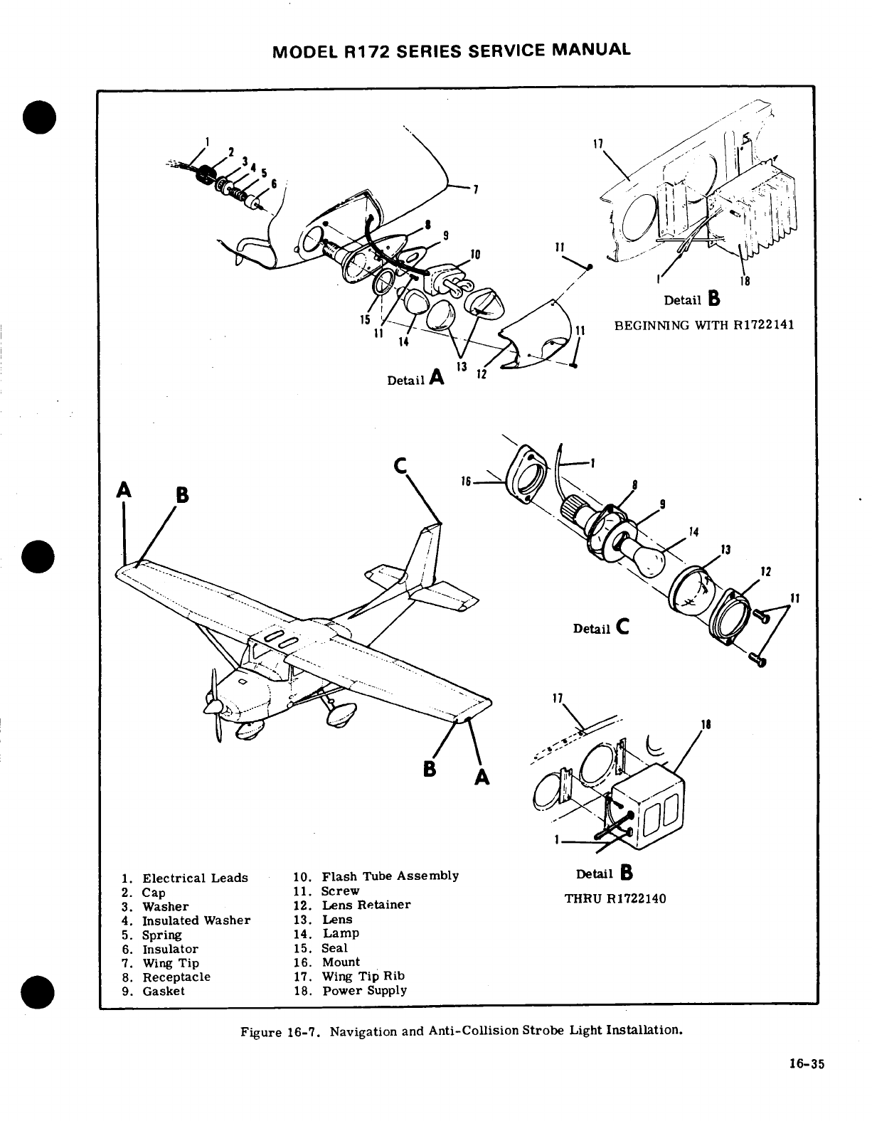
MODEL
R172
SERIES
SERVICE
MANUAL
Detail
B
11
BEGINNING
WITH
R1722141
Detail
A
C
Detail
C
1.
Electrical
Leads
10.
Flash
Tube
Assembly
Detail
B
2.
Cap
11.
Screw
3.
Washer
12.
Lens
Retainer
THRU
R1722140
4.
Insulated
Washer
13.
Lens
5.
Spring
14.
Lamp
6.
Insulator
15.
Seal
7.
Wing
Tip
16.
Mount
8.
Receptacle
17.
Wing
Tip
Rib
9.
Gasket
18.
Power
Supply
Figure
16-7.
Navigation
and
Anti-Collision Strobe
Light
Installation.
16-35
MODEL
R172
SERIES SERVICE
MANUAL
16-64.
FLASHING
BEACON.
16-75.
INSTRUMENT
POST
LIGHTING,
16-65.
DESCRIPTION.
The
flashing
beacon
light
is
16-76. DESCRIPTION.
Individual
post
lighting
may
attached
to
the
vertical
fin
tip.
The
lamp
is
iodine-
be
installed
to
provide nonglare
instrument
lighting.
vapor,
electrically
switched
by
a
solid-state
flasher
The
post
light
consists
of
a
cap
and
a
clean
lamp
assembly.
The
flasher
assembly
is
mounted
in
the
assembly
with
a
tinted
lens
bonded to
the
decorative
aft
section
of
the
tailcone.
The
switching
frequency
covers.
The
intensity
of
the
post
lights
is
controlled
of
the
flasher
assembly operates
the beacon
at ap-
by
the
radio
light
dimming
rheostat
located
on
the
in-
proximately
45
flashes
per
minute.
A
1.5
ohm
re-
strument
panel.
sistor
is
installed
thru
1977
models
and a
6
ohm
resistor
is
installed
beginning
with
1978
models
to
16-77.
REMOVAL
AND
INSTALLATION.
For
re-
eliminate
a
pulsing
effect
on
the
cabin
lighting
and
moval
and
installation
of
post lamp,
slide
the
cap
and
ammeter.
lens
assembly from
the
base.
Slide
the
lamp
from
the
socket
and
replace.
16-66.
REMOVAL
AND
INSTALLATION.
For
re-
moval
and
installation
of
flashing
beacon
see
fig-
16-78.
TRANSISTORIZED
LIGHT
DIMMING.
ure
16-8.
16-79.
DESCRIPTION.
A
remotely
located,
two-
16-67.
INSTRUMENT
AND
DOME LIGHTS.
circuit
transistorized
dimming
assembly is
installed
to
control
instrument
lighting.
One
circuit
controls
16-68.
DESCRIPTION.
The
instrument
flood
light
the
compass
light, map
light
and
instrument
flood
and
dome
light
are
installed
in
the
overhead
console,
lights.
The
other
circuit
controls
radio
lighting. A
The
dome light
consists
of
a
frosted
lens
and a
single
concentric
knob
arrangement
on
a
dual
rheostat assem-
bulb
controlled
by
a
switch
mounted
forward
of
the bly
mounted
on
the
instrument
paneL
light.
The
instrument
flood
light
consists
of
a
red
lens
and a
single
bulb
controlled
by
an
off/on
switch
16-80.
REMOVAL
AND
INSTALLATION.
For
re-
mounted
aft
of
the
light.
Intensity
of
the
lamp
is
con-
moval
and
installation
of
transistorized
dimming
assem-
trolled
by
a
rheostat
switch
located
on
the
instrument
bly,
see
figure
16-10.
panel.
16-81.
MAP
LIGHTING.
16-69.
REMOVAL
AND
INSTALLATION.
For
re-
moval and
installation
of
instrument
and
dome
light,
16-82.
DESCRIPTION.
White
map
lighting
and
red-
see figure
16-9.
non-glare
instrument
lighting
are
provided
by
an
ad-
justable
light
mounted
on
the
upper
forward
part
of
16-70.
COURTESY
LIGHTS.
the
left door
post.
The
switch
is
a
three
position
type
with
red,
white
and
off
positions.
The
map
light
16-71. DESCRIPTION.
The
courtesy
lights
are
m
contains
a
white
bulb
for
general
purpose
lighting
and
mounted
in
the
underside
of
each
wing,
inboard
of
the
a
red
bulb
for
adjustable
instrument
lighting. The
upper
wing
strut
attach.
The
light
consists
of
a
lens
intensisty
of
the
red
bulb
is
controlled
by
the
center
socket
and
a single
bulb.
The
lights
are
controlled
portion
of
a
concentric
knob
arrangement
thru
a
dual
by
the dome
light
switch,
rheostat
assembly
located
on
the
pilot's
switch
paneL
16-72.
REMOVAL
AND
INSTALLATION.
For
re-
16-83.
REMOVAL
AND
INSTALLATION.
(See
moval
and
installation
of
the
courtesy
lights
see figure
16-11.)
figure
16-9.
a.
For
replacement
of
defective
lamp
slide
the
hood
and
lens
from
the map
light
assembly
and
remove
the
16-73.
COMPASS
AND
RADIO
DIAL
LIGHTING.
bayonet
type
bulb.
b.
For removal
of
the map
light
assembly,
remove
16-74.
DESCRIPTION.
The
compass
and
radio
dial
the
screws
from
the
front
door
post shield.
Remove
lights
are
contained
within the
individual
units.
The
the
washer
and
nut
attaching
the
map
light.
Remove
lights
are
controlled
by
the
instrument
flood
light
the
ground
wire
from
the
map
light
screw.
Detach
switch
on
the
overhead
console.
Intensity
is
control-
the
wires
at
the quick
disconnect
fasteners
and
re-
led
by
a
rheostat
located
on
the
instrument
panel.
move
the
map
light
assembly.
16-36
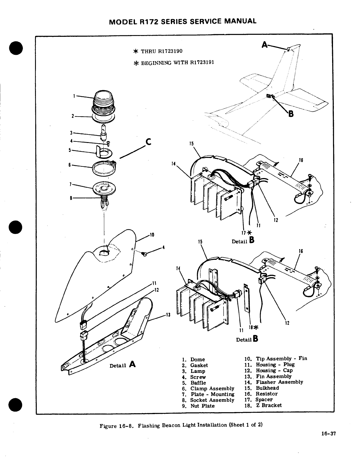
MODEL
R172
SERIES SERVICE
MANUAL
*
THRU
R1723190
-
*
BEGINNING
WITH R1723191
,
...
Detail
B
1. Dome
10.
Tip
Assembly
-
Fin
Detail
A
2.
Gasket
11.
Housing -
Plug
3.
Lamp
12.
Housing - Cap
4.
Screw
13..
Fin
Assembly
5.
Baffle
14.
Flasher
Assembly
6.
Clamp
Assembly
15.
Bulkhead
7.
Plate
- Mounting
16.
Resistor
8.
Socket
Assembly
17.
Spacer
9.
Nut
Plate
18. Z
Bracket
Figure
16-8.
Flashing
Beacon
Light
Installation
(Sheet
1 of
2)
16-37
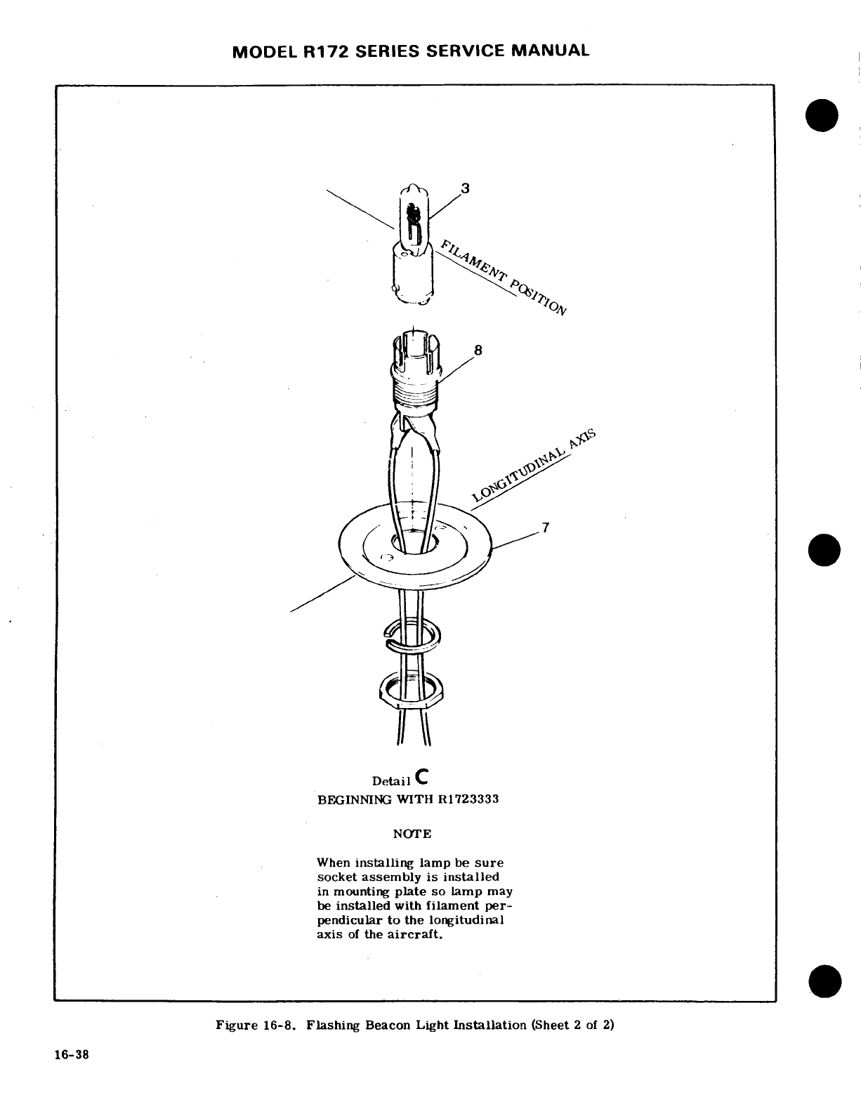
MODEL
R172
SERIES
SERVICE
MANUAL
Detail
C
BEGINNING
WITH
R1723333
NOTE
When
installing
lamp
be
sure
socket
assembly
is
installed
in mounting
plate
so lamp
may
be
installed
with
filament
per-
pendicular
to
the longitudinal
axis
of
the
aircraft.
Figure
16-8.
Flashing
Beacon
Light
Installation
(Sheet
2
of
2)
16-38
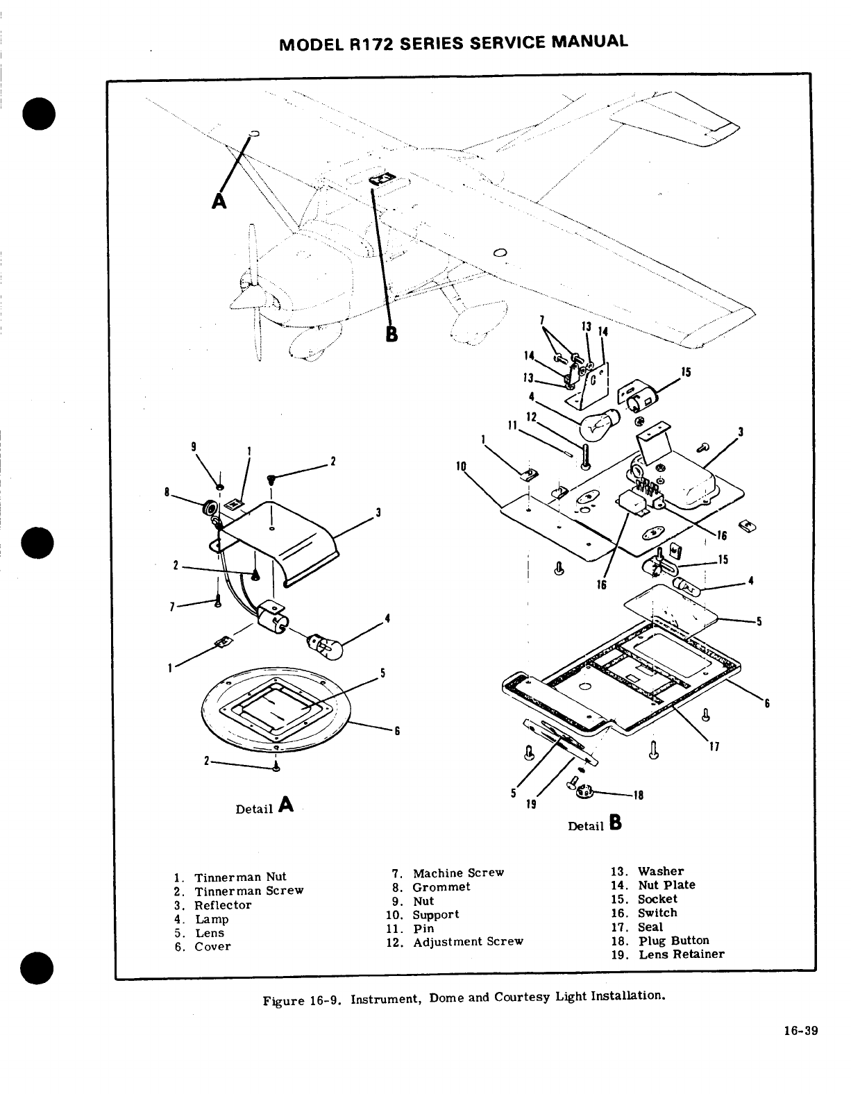
MODEL
R172
SERIES
SERVICE
MANUAL
Detail
A
Detail
B
1.
Tinnerman
Nut
7.
Machine
Screw
13.
Washer
2.
Tinnerman
Screw
8.
Grommet
14.
Nut
Plate
3.
Reflector
9.
Nut
15.
Socket
4.
Lamp
10.
Support
16.
Switch
6.
Cover
12.
Adjustment
Screw
18.
Plug
Button
19.
Lens Retainer
Figure
16-9.
Instrument,
Dome
and
Courtesy
Light
Installation.
16-39
16-39
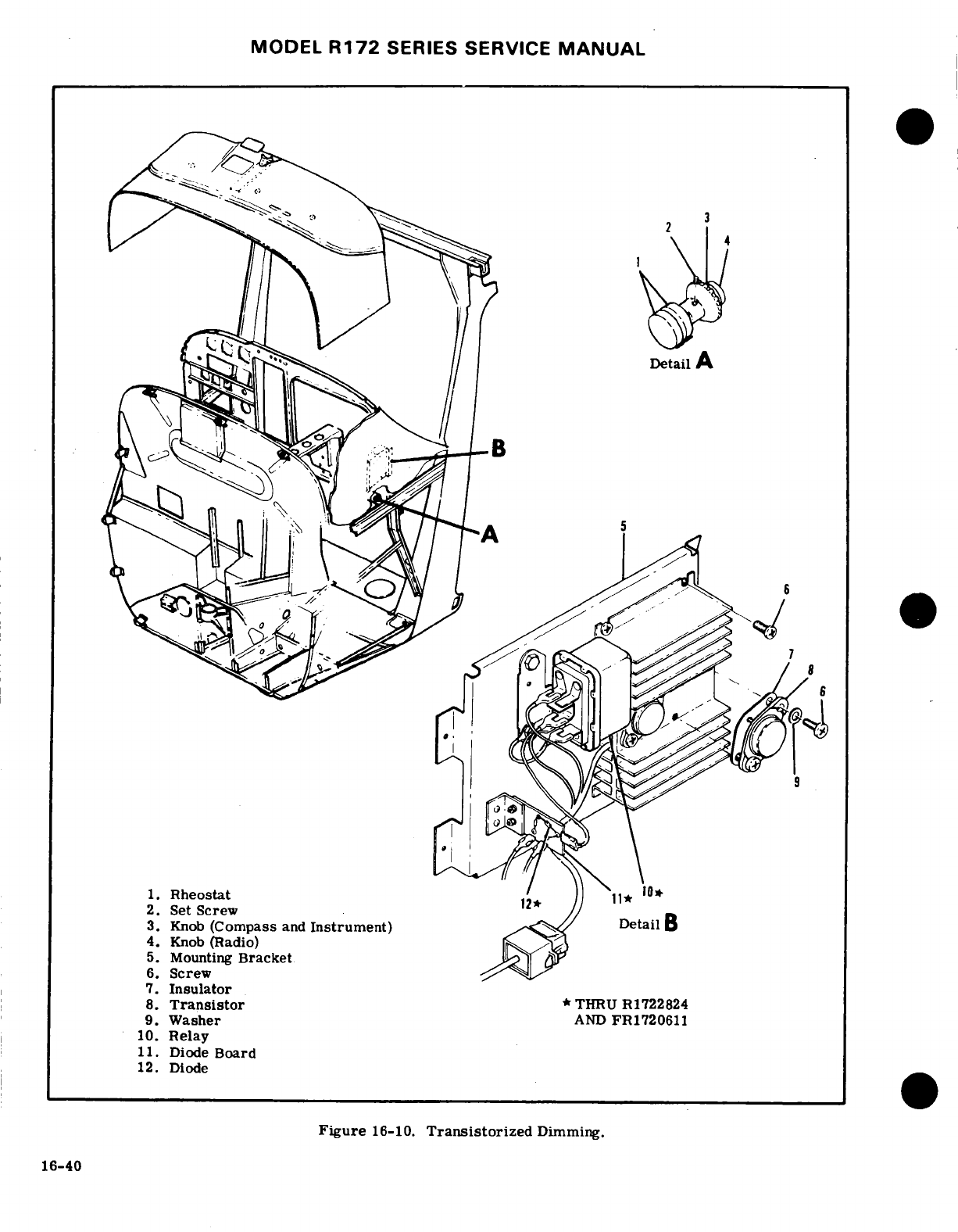
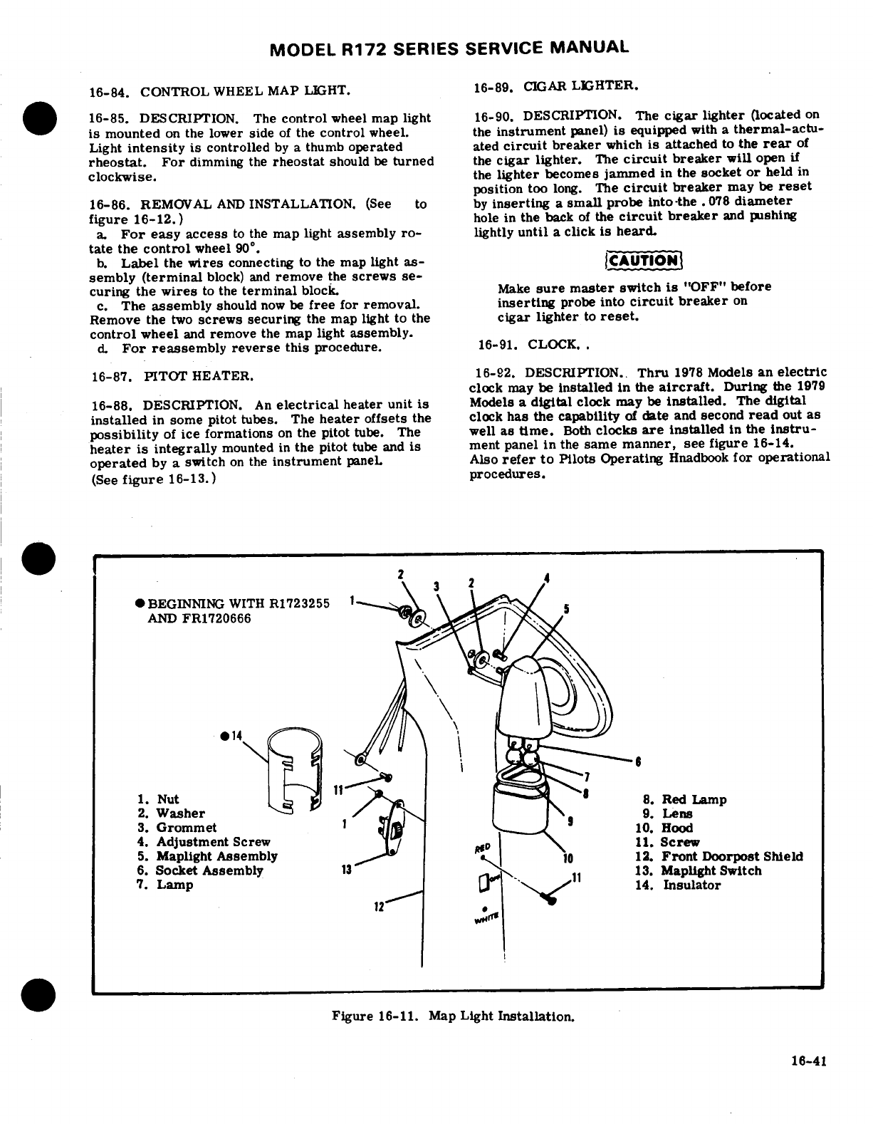
MODEL
R172
SERIES
SERVICE
MANUAL
16-84.
CONTROL
WHEEL MAP
LIGHT.
16-89.
CIGAR
LIGHTER.
16-85.
DESCRIPTION.
The
control
wheel
map
light
16-90.
DESCRIPTION.
The
cigar
lighter
(located
on
is
mounted
on
the
lower
side
of
the
control
wheel.
the
instrument
panel)
is
equipped
with
a
thermal-actu-
Light
intensity
is
controlled
by
a
thumb
operated
ated
circuit
breaker
which
is
attached
to
the
rear
of
rheostat.
For
dimming
the
rheostat
should
be
turned
the
cigar
lighter.
The
circuit
breaker
will
open
if
clockwise,
the
lighter
becomes
jammed
in
the
socket
or
held
in
position
too
long.
The
circuit
breaker
may
be
reset
16-86.
REMOVAL
AND
INSTALLATION. (See
to
by
inserting
a
small
probe into
the
.078
diameter
figure
16-12.)
hole
in
the
back
of
the
circuit
breaker
and
pushing
a.
For
easy
access
to
the
map light
assembly
ro-
lightly
until
a
click
is
heard.
tate
the
control
wheel
90
° .
b.
Label
the
wires
connecting
to the
map
light
as-
CAUTION
sembly
(terminal
block)
and
remove
the
screws
se-
curing
the
wires
to
the
terminal
block.
Make
sure
master
switch
is
"OFF"
before
c.
The
assembly
should
now
be
free
for
removal.
inserting
probe
into
circuit
breaker
on
Remove
the
two
screws
securing
the map light
to
the
cigar lighter
to
reset.
control
wheel
and
remove
the
map
light
assembly.
d.
For
reassembly reverse
this
procedure.
16-91. CLOCK..
16-87.
PITOT
HEATER.
16-92. DESCRIPTION..
Thru
1978
Models
an
electric
clock
may
be
installed
in
the
aircraft.
During
the
1979
16-88.
DESCRIPTION.
An
electrical
heater unit
is
Models
a
digital
clock may
be
installed.
The
digital
installed
in
some
pitot
tubes.
The
heater
offsets
the clock
has
the
capability
of
date
and
second
read
out
as
possibility
of
ice
formations
on
the
pitot
tube.
The
well
as
time.
Both
clocks
are
installed
in
the
Instru-
heater
is
integrally
mounted
in
the pitot
tube
and
is
ment
panel
in
the
same
manner,
see
figure
16-14.
operated
by
a switch
on
the
instrument
paneL
Also
refer
to
Pilots
Operating
Hnadbook
for
operational
(See
figure
16-13.)
procedures.
BEGINNING
WITH
R1723255
AND
FR1720666
,
1.
Nut
8.
Red
Lamp
2.
Washer
3.
Grommet
4.
Adjustment
Screw
11.
Screw
5.
Maplight
Assembly
12.
Front
Doorpost
Shield
6.
Socket
Assembly
13.
Maplight Switch
7.
Lamp
14Insulator
Figure
16-11.
Map
Light
Installation.
16-41
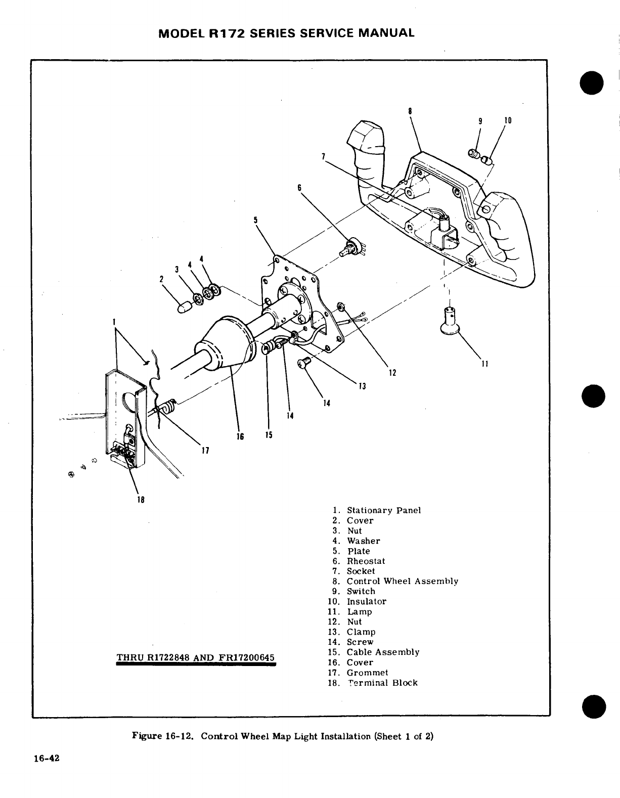
MODEL
R172
SERIES
SERVICE
MANUAL
1.tationary
Panel
2.
Cover
3.
Nut
4.
Washer
5.
Plate
6.
Rheostat
7.
Socket
8.
Control
Wheel
Assembly
9.
Switch
10.
Insulator
11.
Lamp
12.
Nut
13.
Clamp
14.
Screw
THRU
R1722848
AND
FR17200645
15.
Cable
Assembly
16.
Cover
17.
Grommet
18.
Terminal
Block
Figure
16-12.
Control
Wheel
Map
Light
Installation
(Sheet
1
of
2)
16-42
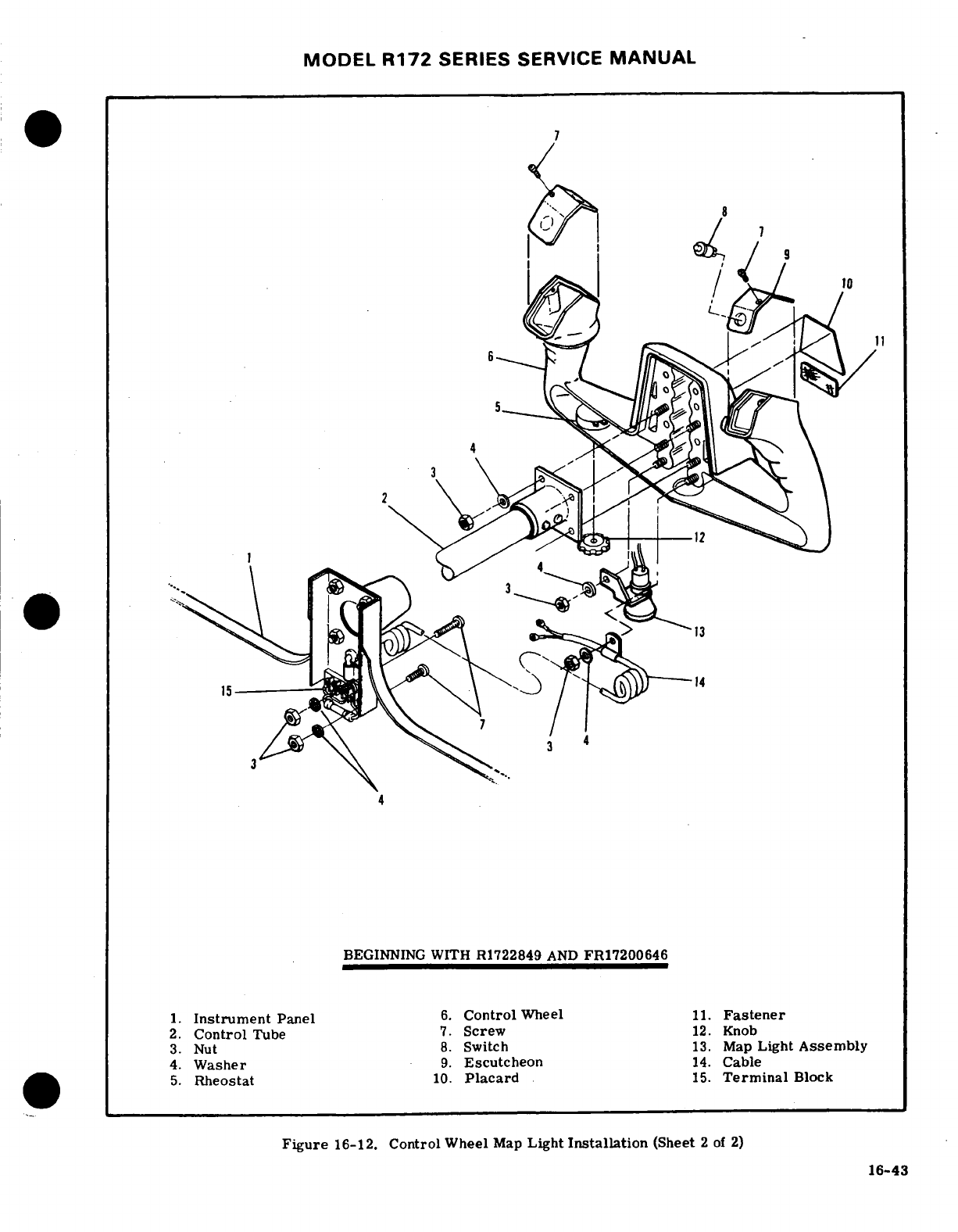
MODEL
R172
SERIES
SERVICE
MANUAL
BEGINNING
WITH
R1722849
AND
FR17200646
1.
Instrument
Panel
6.
Control
Wheel
11.
Fastener
2.
Control
Tube
7.
Screw
12.
Knob
3.
Nut
8.
Switch
13.
Map
Light
Assembly
4.
Washer
9.
Escutcheon
14.
Cable
5.
Rheostat
10.
Placard
15.
Terminal
Block
Figure
16-12.
Control
Wheel
Map
Light
Installation
(Sheet
2
of
2)
16-43
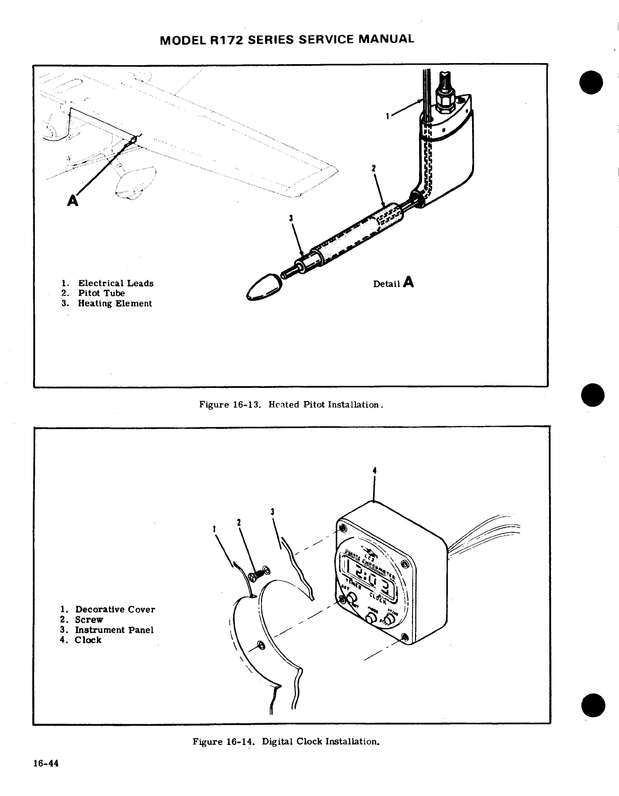
MODEL
R172
SERIES
SERVICE
MANUAL
16-93,
EMERGENCY LOCATOR
TRANSMITTER.
16-96.
CHECKOUT INTERVAL:
THRU
R17222287.
100
HOURS.
16-94.
DESCRIPTION.
The ELT
is
a
self-contained,
solid
state
unit,
having
its
own
power
supply,
with
an
a.
Turn
aircraft
master
switch
ON.
externally
mounted
antenna.
The
C589510-0209
trans-
b.
Turn
aircraft
transceiver
ON
and
set
frequency
mitter
is
designed
to
transmit
simultaneously
on
dual
on
receiver
to
121.5
MHZ.
emergency
frequencies
of
121.
5
and
243.0
Megahertz.
c.
Remove
the
ELT's
antenna
cable
from
the
ELT
The
C589510-0211
transmitter
used
for
Canadian
unit.
registry,
operates
on
121.5
only.
The
unit
is
mount-
d.
Place
the
ELT's
function
selector
switch
in the
ed
in
the
tailcone,
aft
of
the
baggage
curtain
on
the
ON
position
for
5
seconds
or
less.
Immediately
re-
right
hand
side.
The
transmitters
are
designed
to
place the
ELT function
selector
switch
in the
ARM
provide
a
broadcast
tone
that
is
audio
modulated
in
a
position
after
testing
ELT.
swept
manner
over
the
range
of 1600
to
300
Hz
in
a
e.
Test
should
be
conducted
only
within
the
time
distinct, easily
recognizable
distress
signal
for
re-
period
made
up
of
the
first
five
minutes
after
any
ception
by
search
and
rescue
personnel
and
others
hour.
monitoring
the
emergency
frequencies.
Power
is
supplied to
the
transmitter
by
a
battery-pack
which
CAUTION
has
the
service
life
of
the
batteries
placarded
on
the
batteries
and
also
on
the
outside
end
of
the
transmit-
Tests
with
the
antenna
connected
should
be
ter.
ELT's
are
equipped with
a
battery-pack
contain-
approved
and
confirmed
by
the
nearest
con-
ing four
lithium
"D"
size
batteries
which
are
stacked
trol
tower
in
two's
(See
figure
16-13).
The
ELT
exhibits
line
of
sight
transmission
characteristics
which
correspond
NOTE
approximately
to
100
miles
at
a
search
altitude
of
10,
000
feet.
When
battery
inspection
and
replacement
Without
its
antenna
connected,
the
ELT
will
schedules
are
adhered
to,
the
transmitter
will
broad-
produce
sufficient
signal to
reach your
re-
cast
an
emergency
signal
at rated
power
(75
MW-
ceiver,
yet
it
will
not
disturb
other
commun-
minimum),
for
a
continuous
period
of
time
as
listed ications or
damage
output
circuitry.
in
the following
table.
NOTE
TRANSMITTER
LIFE
TO
75
MILLIWATTS
OUTPUT
After
accumulated
test
or
operation
time
equals
1
hour,
battery-pack
replacement
4
Cell
is
required.
Temperature
Lithium
f.
Check
calendar
date
for
replacement
of
battery-
Battery
Pack
pack.
This
date
is
supplied
on
a
sticker
attached
to
+130°F
115
hrs
the
outside
of
the
ELT
case
and
to
each
battery.
+
70°F
115
hrs
16-97.
REMOVAL
AND
INSTALLATION
OF
TRANS-
-
40°F
23
hrs
MITTER.
(See
figure
16-15.)
a.
Remove
baggage
curtain
to
gain
access
to the
transmitter
and
antenna.
Battery-packs
have
a
normal
shelf
life
of
five
to ten
b.
Disconnect
co-axial
cable
from
end
of
transmit-
(5-10)
years
and
must
be
replaced
at
1/2
of
normal
ter.
shelf
life
in
accordance
with
TSO-C91.
Cessna
speci-
c.
Cut
sta-strap
securing
antenna
cable
and
unlatch
fies
5
years
replacement
of
lithium
(4-cell)
battery
metal
strap
to
remove
transmitter.
packs.
NOTE
16-95.
OPERATION.
A
three
position
switch
on
the
forward
end
of
the
unit
controls
operation.
Placing
Transmitter
is
also
attached
to
the
mounting
the
switch
in
the
ON
position will
energize
the
unit to
bracket
by
velcro
strips;
pull
transmitter
to
start
transmitting
emergency
signals.
In
the
OFF
free
from
mounting
bracket
and
velcro.
position,
the
unit
is inoperative.
Placing
the
switch
in the
ARM
position
will
set
the
unit to
start
trans-
NOTE
mitting
emergency
signals
only
after
the unit has
re-
ceived
a
5g
(tolerances
are
+2g
and
-0g)
impact
force,
To
replace
velcro
strips,
clean
surface
thor-
for
a
duration
of
11-16
milliseconds.
oughly
with
clean
cloth
saturated
in
one
of
the
following
solvents:
Trichloric
thylene,
CAUTION
Aliphatic
Napthas,
Methyl
Ethyl
Ketone
or
Enmar
6094
Lacquer
Thinner.
Cloth
should
Do
not
leave
the
emergency
locator
transmit-
be
folded
each
time
the
surface
is
wiped to
ter
in
the
ON
position
longer
than
5
seconds
present
a
clean
area
and
avoid
redepositing
or
you
may
activate
downed
aircraft
proce-
of
grease.
Wipe
surface
immediately
with
dures
by
C.A.
P.,
D.
O.
T.
or
F.A.A.
per-
clean
dry
cloth,
do not
allow
solvent
to
dry
sonnel.
on
surface.
Apply
Velcro
#40
adhesive
to
16-45
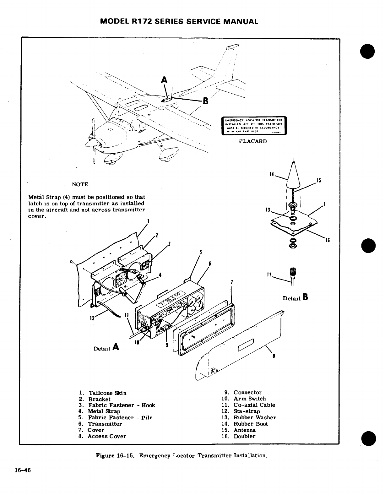
MODEL
R172
SERIES SERVICE
MANUAL
.
-... ..
-
PLACARD
NOTE
Metal
Strap
(4)
must
be
positioned
so that
latch
is
on
top
of
transmitter
as
installed
1
in
the
aircraft
and
not
across
transmitter
cover.
1.
Tailcone
Skin
9.
Connector
2.
Bracket
10.
Arm
Switch
3.
Fabric
Fastener
-
Hook
11.
Co-axial
Cable
4.
Metal
Strap
12.
Sta-strap
5.
Fabric
Fastener
-
Pile
13.
Rubber
Washer
6.
Transmitter
14.
Rubber
Boot
7.
Cover
15.
Antenna
8.
Access
Cover
16.
Doubler
Figure
16-15.
Emergency
Locator
Transmitter
Installation.
16-46
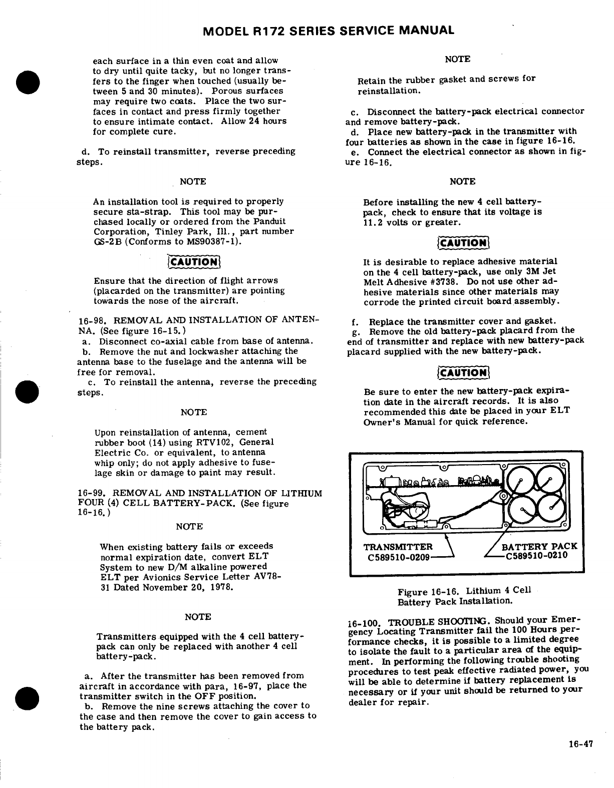
MODEL
R172
SERIES SERVICE
MANUAL
each
surface
in
a
thin even
coat
and
allow
NOTE
to
dry until
quite
tacky,
but
no
longer
trans-
fers
to
the
finger
when
touched
(usually
be-
Retain the
rubber
gasket and
screws
for
tween
5
and
30
minutes).
Porous
surfaces
reinstallation.
may
require
two
coats.
Place
the
two
sur-
faces
in
contact
and
press
firmly
together
c.
Disconnect
the
battery-pack
electrical
connector
to
ensure
intimate
contact.
Allow
24
hours
and
remove
battery-pack.
for
complete
cure.
d.
Place
new
battery-pack
in
the
transmitter
with
four
batteries
as
shown
in
the
case
in
figure
16-16.
d.
To
reinstall
transmitter,
reverse
preceding
e.
Connect
the
electrical
connector
as
shown
in
fig-
steps.
ure
16-16.
NOTE
NOTE
An
installation
tool
is
required
to
properly
Before
installing
the
new
4
cell
battery-
secure
sta-strap.
This
tool
may
be
pur-
pack,
check
to
ensure
that its
voltage
is
chased
locally
or ordered
from
the
Panduit
11.2
volts
or
greater.
Corporation,
Tinley
Park,
Ill.,
part
number
GS-2B
(Conforms to
MS90387-1).
CAUTIONJ
(CAUTION
It
is
desirable
to
replace
adhesive
material
on
the
4
cell
battery-pack,
use
only
3M
Jet
Ensure
that
the
direction
of
flight
arrows
Melt
Adhesive
#3738.
Do
not
use
other
ad-
(placarded
on
the
transmitter)
are
pointing
hesive
materials
since
other
materials
may
towards
the
nose
of
the
aircraft.
corrode
the
printed circuit
board
assembly.
16-98.
REMOVAL
AND
INSTALLATION
OF
ANTEN-
f.
Replace
the
transmitter
cover
and
gasket.
NA.
(See
figure
16-15.)
g.
Remove
the
old
battery-pack
placard
from
the
a.
Disconnect
co-axial
cable from
base
of
antenna,
end
of
transmitter
and
replace
with
new
battery-pack
b.
Remove
the nut
and
lockwasher
attaching
the
placard
supplied
with
the
new
battery-pack.
antenna
base
to the
fuselage
and
the
antenna
will
be
free
for
removal.
CAUTION
c.
To
reinstall
the
antenna,
reverse
the
preceding
steps.
Be
sure
to
enter
the
new
battery-pack expira-
tion
date
in
the
aircraft
records.
It
is
also
NOTE
recommended
this
date
be
placed
in
your
ELT
Owner's
Manual
for
quick
reference.
Upon
reinstallation
of
antenna,
cement
rubber
boot
(14)
using
RTV102,
General
Electric
Co.
or
equivalent,
to
antenna
whip
only;
do
not
apply
adhesive
to
fuse-
lage
skin
or
damage
to
paint
may
result.
16-99.
REMOVAL
AND
INSTALLATION
OF
LITHIUM
FOUR
(4)
CELL
BATTERY-PACK.
(See
figure
16-16.)
NOTE
When
existing
battery
fails
or
exceeds
TRANSMITTER
BATTERY
PACK
normal expiration
date,
convert
ELT
C589510-0209
C589510-0210
System
to
new
D/M
alkaline
powered
ELT
per
Avionics
Service
Letter
AV78-
31
Dated
November
20,
1978.
Figure
16-16.
Lithium
4
Cell
Battery
Pack
Installation.
NOTE
16-100.
TROUBLE
SHOOTING.
Should
your
Emer-
Transmitters
equipped
with
the
4
cell
battery-
gency
Locating
Transmitter
fail
the
100
Hours
per-
pack
can
only
be
replaced
with
another
4
cell
formance
checks,
it is
possible
to
a
limited
degree
battery-pack.
to
isolate
the
fault
to
a
particular area
of
the
equip-
ment.
In
performing
the
following
trouble
shooting
a.
After
the
transmitter
has
been
removed
from
procedures
to
test
peak
effective
radiated
power,
you
aircraft
in
accordance
with
para,
16-97,
place
the
will
be
able
to
determine
if
battery
replacement
is
transmitter
switch
in
the
OFF
position.
necessary
or
if
your
unit should
be
returned
to
your
b.
Remove
the
nine
screws
attaching
the
cover to
dealer for
repair.
the
case
and
then
remove the
cover
to gain
access
to
the
battery
pack.
16-47
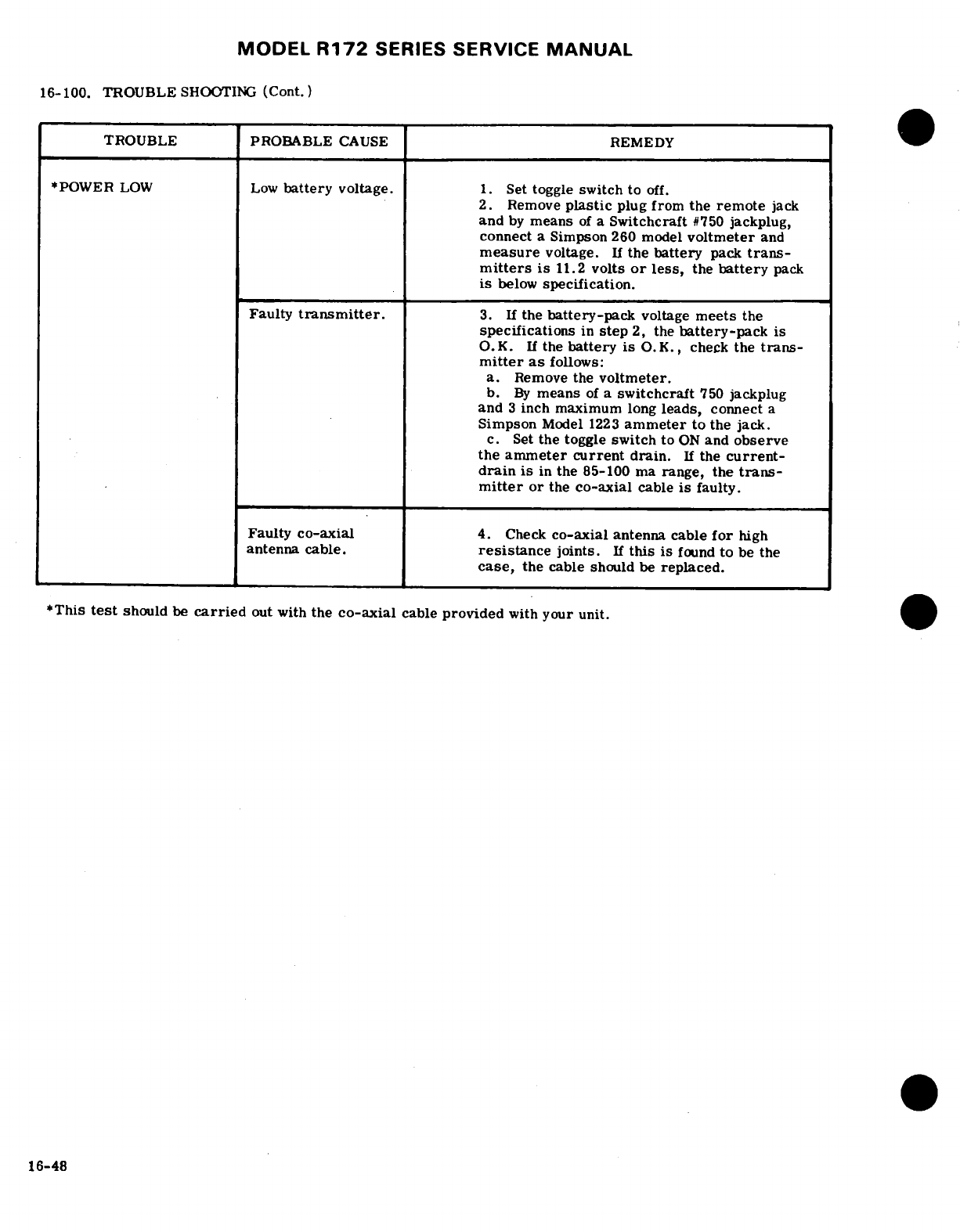
MODEL
R172
SERIES
SERVICE
MANUAL
16-100.
TROUBLE
SHOOTING
(Cont.)
TROUBLE PROBABLE
CAUSE
REMEDY
*POWER
LOW
Low
battery
voltage.
1.
Set
toggle
switch
to
off.
2.
Remove
plastic
plug
from
the
remote
jack
and
by
means
of
a
Switchcraft
#750
jackplug,
connect
a
Simpson
260 model
voltmeter
and
measure
voltage.
If
the
battery
pack
trans-
mitters
is
11.2
volts
or
less,
the
battery
pack
is
below
specification.
Faulty
transmitter.
3.
If
the
battery-pack
voltage
meets
the
specifications
in
step
2,
the
battery-pack
is
O.K.
If
the
battery
is O.K.,
check
the
trans-
mitter
as
follows:
a.
Remove
the
voltmeter.
b.
By
means
of
a
switchcraft
750
jackplug
and
3
inch maximum
long
leads,
connect
a
Simpson
Model
1223
ammeter
to
the
jack.
c.
Set
the
toggle
switch
to
ON
and
observe
the
ammeter
current
drain.
If
the
current-
drain
is
in
the
85-100
ma
range,
the
trans-
mitter
or
the
co-axial
cable
is
faulty.
Faulty
co-axial
4.
Check
co-axial
antenna cable
for
high
antenna
cable.
resistance
joints.
If
this
is
found
to
be
the
case,
the
cable
should
be
replaced.
*This
test
should
be
carried
out
with
the
co-axial
cable
provided
with
your
unit.
16-48
MODEL
R172
SERIES
SERVICE
MANUAL
BEGINNING
WITH
R1722288
CAUTION
Do
not
leave
the
emergency
locator
transmit-
16-102.
DESCRIPTION.
The ELT
is
a
self-contained,
ter
in the
ON
position
longer
than
5
seconds
solid
state
unit,
having
its
own
power
supply,
with
an
or
you
may
activate
downed
aircraft
proce-
externally
mounted
antenna.
The C589511-0103
is
dures
by
C.A.P.,
D.O.T.
or
F.A.A.
per-
used thru
1978
and
the
C589511-0117
beginning with
sonnel.
1979
models.
The
transmiiters
are
designed
to
trans-
mit
simultaneously
on
dual
emergency
frequencies
of
16-104.
CHECKOUT
INTERVAL:
121.
5
and
243.
0
Megahertz.
Aircraft
with
Canadian
registry
utilize
the C589511-0104
thru
1978
and
the
100
HOURS.
C589511-0113
transmitters
beginning with
1979
a. Turn
aircraft
master
switch
ON.
models.
These
transmitters
operate
on
121.
5
only. b.
Turn
aircraft
transceiver
ON
and
set
frequency
The
unit
is
mounted
in
the
tailcone,
aft
of
the
baggage
on
receiver
to
121.5
MHz.
curtain
on
the
right
hand
side.
The
transmitters
are
c.
Remove
the
ELT's
antenna cable
from
the
ELT
designed
to
provide
a
broadcast
tone
that
is
audio
unit.
modulated
in
a
swept
manner
over
the
range
of
1600 d.
Place
the
ELT's
function
selector
switch
in
the
to
300 Hz
in
a
distinct,
easily
recognizable
distress
ON
position
for
5
seconds
or
less.
Immediately
re-
signal
for
reception
by
search
and
rescue
personnel
place
the ELT function
selector
switch
in
the
ARM
and
others
monitoring
the
emergency
frequencies.
position
after
testing
ELT.
Power
is
supplied
to
the
transmitter
by
a
battery-
e.
Test
should
be
conducted
only
within
the
time
pack
which
has
the
service
life
of
the
batteries
plac-
period
made
up
of
the
first
five
minutes
after
any
arded
on
the
batteries
and
also
on
the
outside
end
of
hour.
the
transmitter.
C589511-0104
and
C589511-0103
ELT's
equipped
with
a
lithium
battery-pack
must
be
CAUTION
modified
by
SK185-20
as
outlined
in
Avionics
Service
Letter
AV78-31,
dated
20
November,
to
incorporate
Tests
with
the
antenna
connected
should
be
the
new
alkaline
batteries
which
are
installed
begin- approved
and
confirmed
by
the
nearest
con-
ning
with
1979
models
(see
figure
16-14). The
ELT
trol
tower.
exhibits
line
of
sight
transmission
characteristics
which
correspond
approximately
to
100
miles
at
a
NOTE
search
altitude
of
10,000
feet.
When
battery
inspec-
tion
and
replacement
schedules
are
adhered
to,
the
Without
its
antenna
connected,
the
ELT
will
ELT
supplied
domestic
aircraft
thru
1978
models
produce
sufficient
signal
to
reach
your
re-
transmit
on
both
distress
frequencies
simultaneously
ceiver,
yet
it
will
not
disturb
other commun-
at
75
mw
rated
power
output
for
48
continuous
hours
ications
or
damage
output
circuitry.
in
the
temperature
range
of
-40°F
to
+131°F~-40°C
to
55
0
C).
The
ELT
unit
in
export
aircraft
transmits
NOTE
on
121.
5
MHz
at
25
mw
rated
power output
for
100
continuous
hours
in
the
temperature
range
of
-40°F
After
accumulated
test
or
operation
time
to
+131°F
(-40°C
to
+55°C).
Battery-packs
have
a equals
1
hour,
battery-pack
replacement
normal
shelf life
of
five
to
ten
(5-10)
years
and
must
is
required.
with
TSO-C91.
Cessna
specified
5
years
replace-
f.
Check
calendar
date
for
replacement
of
batt,;ry-
with TSO-C91.
Cessna
specified
5
years replace-
pack.
This
date
is
supplied
on
a
sticker
attached
to
ment
of
lithium
(4-cell)
battery-packs,
C589511-0105.
the
utside
of
the ELT
case
ond
ticker
attahed
Beginning
with
1979
models
the
ELT
supplied
domes-
tic
aircraft
transmits
on
both
distress
frequencies
16-105.
REMOVAL
AND
INSTALLATION
OF
TRANS-
simultaneously at
75
mw
rated
power
output
for
con-
MITTER.
(See
figure
16-17.
tinuous
hours
in
the
temperature
range
of
-4°F
to
+3tinuous
hours
in
the
temperature
range
of
-4F
to
a.
Remove
baggage
curtain
to
gain
access
to
the
+131°F
(-20°C
to
+55°C).
The ELT
unit
in
export
transmitter
and
antenna.
aircraft
transmits
on
121.
5
MHz
at
25 mw
rated
b.
Disconnect
co-axial
cable
from
end
of
transmit-
power output
for
100
continuous
hours
in
the
temper-
ter
ature
range
of
-4°F
to
+131°F
(-20°C
to
55°C).
Alka-
c.
Remove
the
two
#10
screws
from
the
baseplate
line
battery-packs
have the
service
life
of
the
battery-
of
the
ELT
and
remove
ELT.
pack
stamped
on
the
battery-pack,
on
the
end
of
the
d.
To
reinstall
transmitter,
reverse
preceding
transmitter
below
the switch
and
on
top
of
the
trans-
steps.
mitter.
16-103.
OPERATION.
A
three
position
switch
on
the
ICAUTION
forward
end
of
the
umt
controls
operation.
Placing
the
switch
in
the
ON
position
will
energize
the
unit
to
Ensure
that
the direction
of
fight
arrows
start
transmitting
emergency
signals.
In
the
OFF
(placarded
on
the
transmitter)
are
pointing
position,
the
unit
is
inoperative.
Placingtowards the
switchnose of
the
aircraft.
in
the
ARM
position
will
set
the
unit to
start
trans-
mitting
emergency
signals
only
after
the
unit
has
re-
ceived
a
5g
(tolerances
are
+2g
and
-Og)
impact
force,
for
a
duration
of
11-16
milliseconds.
16-49
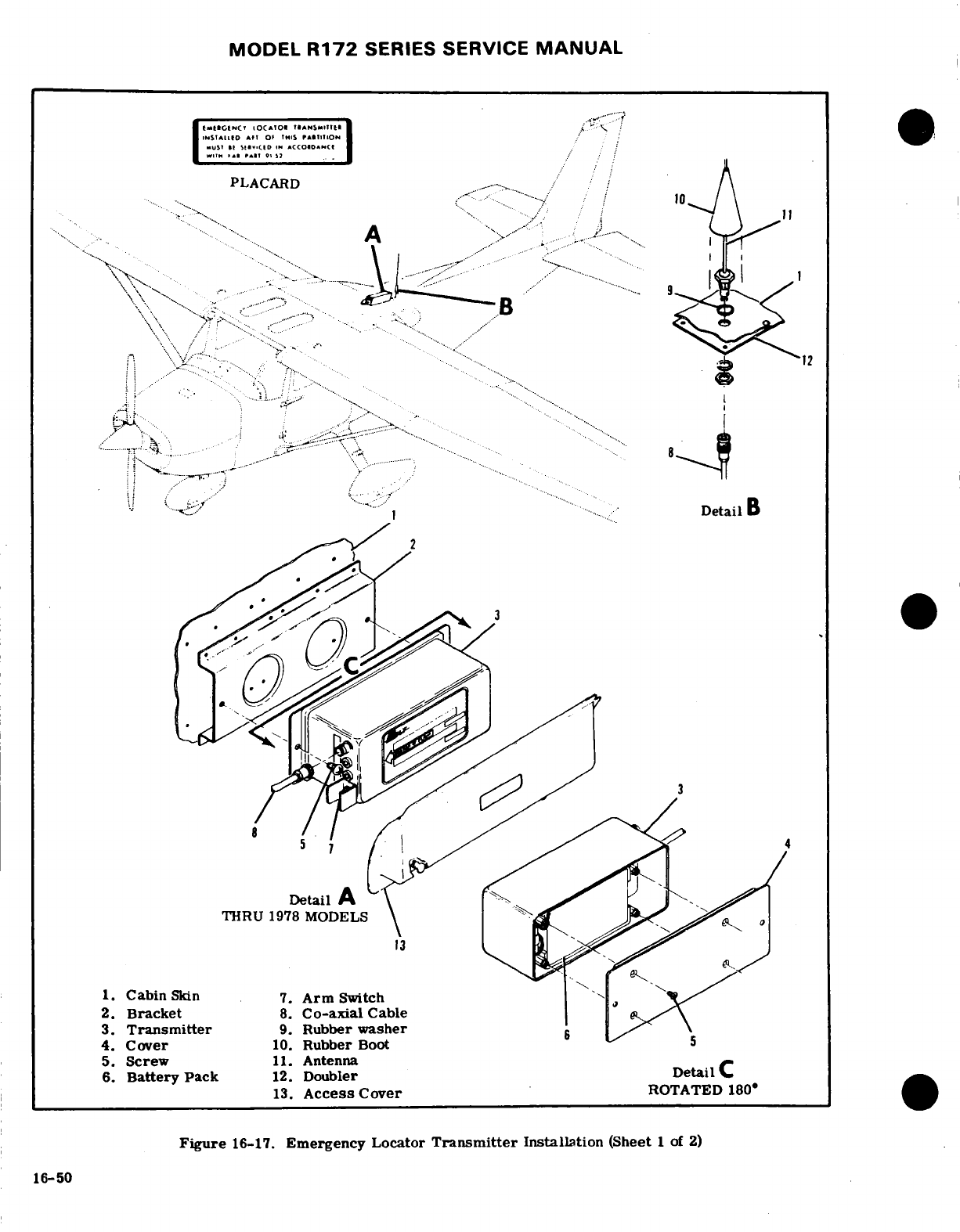
MODEL
R172
SERIES
SERVICE
MANUAL
.
.....
.....
I
t-v~.»tlD
.
,.
LACARD
,
-
.....
. . .. ..
........
.
..
.... ....
-
.....
DetailB
1.
Cabin
Skin 7.
Arm
Switch
2.
Bracket
8.
Co-axial
Cable
3.
Transmitter
9.
Rubber
washer
4.
Cover
10.
Rubber
Boot
13.
Access
Cover
ROTATED
180
6..
r
Figure
16-17.
Emergency
Locator
Transmitter
Installation
(Sheet
1
of
2)
16-50
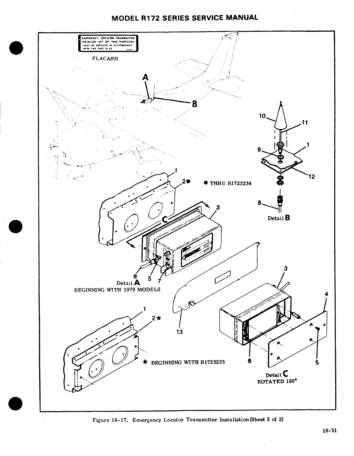
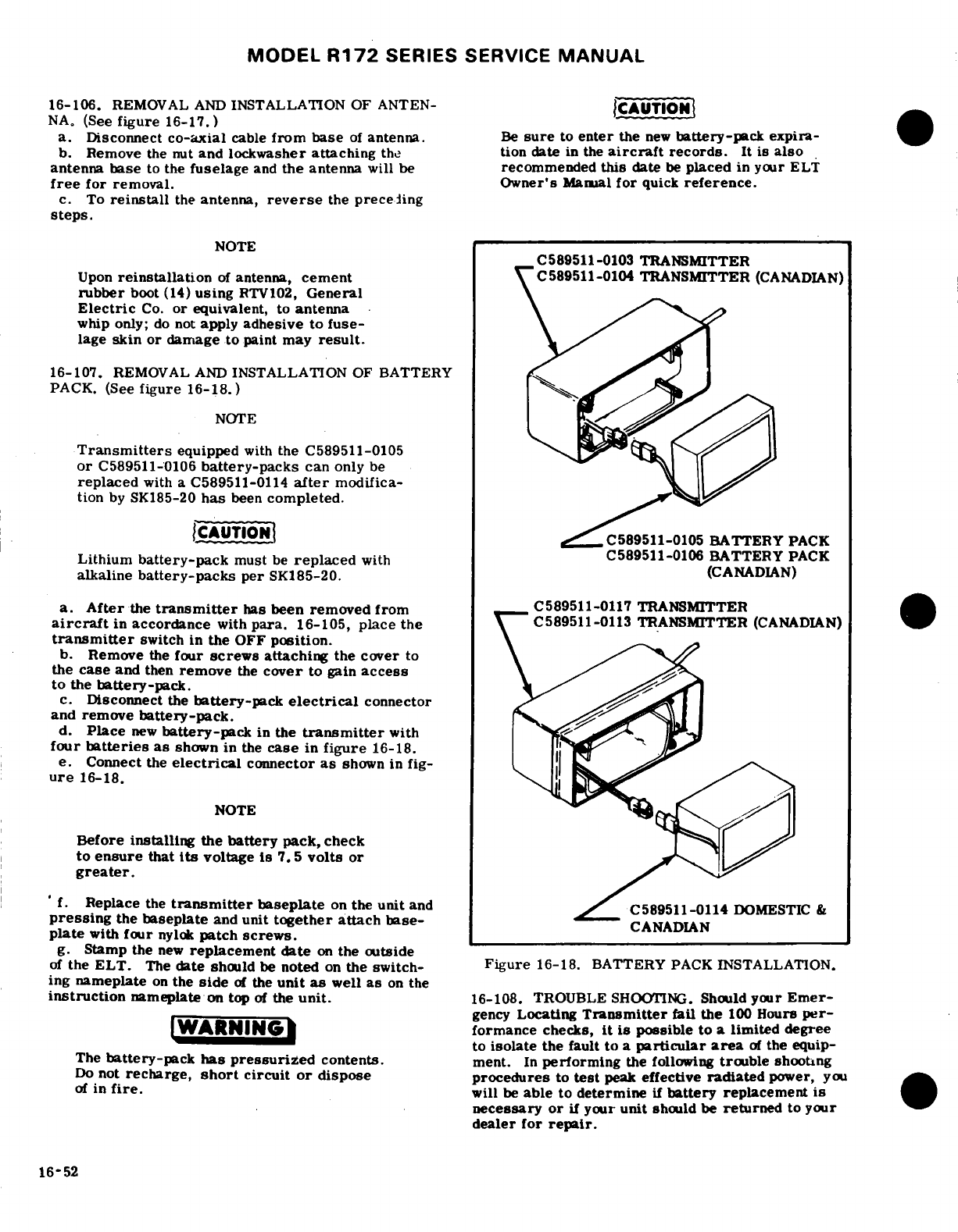
MODEL
R172
SERIES
SERVICE
MANUAL
16-106.
REMOVAL
AND
INSTALLATION
OF
ANTEN-
CAUTION
NA,
(See
figure
16-17.)
a. Disconnect
co-axial
cable
from base
of
antenna.
Be
sure
to
enter
the
new
battery-pack
expira-
b.
Remove
the nut
and
lockwasher
attaching
the
tion date
in
the
aircraft
records.
It
is
also
antenna
base
to
the
fuselage
and
the
antenna
will
be
recommended
this
date
be
placed
in your
ELT
free
for
removal. Owner's
Manual
for
quick
reference.
c.
To
reinstall
the
antenna,
reverse
the
preceding
steps.
NOTE
C589511-0103
TRANSMITTER
Upon
reinstallation
of
antenna,
cement
C589511-0104
TRANSMITTER
(CANADIAN)
rubber
boot
(14)
using
RTV102,
General
Electric
Co.
or
equivalent,
to
antenna
whip
only;
do
not
apply
adhesive
to
fuse-
lage
skin
or
damage
to
paint may
result.
16-107.
REMOVAL
AND
INSTALLATION
OF
BATTERY
PACK.
(See
figure
16-18.)
NOTE
Transmitters
equipped
with
the C589511-0105
or
C589511-0106
battery-packs
can
only
be
replaced
with a
C589511-0114
after
modifica-
tion
by
SK185-20
has
been
completed.
ICAUTIONI
C589511-0105
BATTERY
PACK
Lithium
battery-pack
must
be
replaced
withC589511-0106
BATTERY
PACK
alkaline
battery-packs
per
SK185-20.
(CANADIAN)
a.
After
the
transmitter
has
been
removed
from
C589511-0117
TRANSMITTER
aircraft
in
accordance
with
para.
16-105,
place
the
C589511-0113
TRANSMITTER
(CANADIAN)
transmitter
switch
in
the
OFF
position.
b.
Remove
the
four
screws
attaching
the
cover
to
the
case
and
then
remove
the
cover
to
gain
access
to the
battery-pack.
c.
Disconnect
the
battery-pack
electrical
connector
and
remove
battery-pack.
d.
Place
new
battery-pack
in
the
transmitter
with
four
batteries
as
shown
in
the
case
in
figure
16-18.
e.
Connect
the
electrical
connector
as
shown
in
fig-
ure
16-18.
NOTE
Before
installing
the
battery
pack,
check
to
ensure
that
Its
voltage
Is
7.
5
volts
or
greater.
'
f.
Replace
the
transmitter
baseplate
on
the
unit
and
C589511-0114
DOMESTIC
&
pressing
the
baseplate
and
unit
together
attach
base-
CANADIAN
plate
with
four
nylok
patch
screws.
g.
Stamp
the
new
replacement
date
on
the outside
of
the
ELT.
The
date
should
be
noted
on
the
switch-
Figure
16-18.
BATTERY
PACK
INSTALLATION.
ing
nameplate
on
the
side
of
the
unit
as
well
as
on
the
instruction
nameplate
on
top
of
the
unit.
16-108.
TROUBLE
SHOOTING.
Should
your
Emer-
gency
Locating
Transmitter
fail the
100
Hours
per-
IWARNING
formance
checks,
it
is
possible
to
a
limited degree
to
isolate
the
fault
to
a
particular
area
of
the equip-
The
battery-pack
has
pressurized
contents.
ment.
In
performing
the
following
trouble
shooting
Do
not
recharge,
short
circuit
or
dispose
procedures
to
test
peak
effective
radiated
power,
you
of
in
fire.
will
be
able
to
determine
if
battery
replacement
is
necessary
or
if
your
unit
should
be
returned
to
your
dealer
for
repair.
16-52
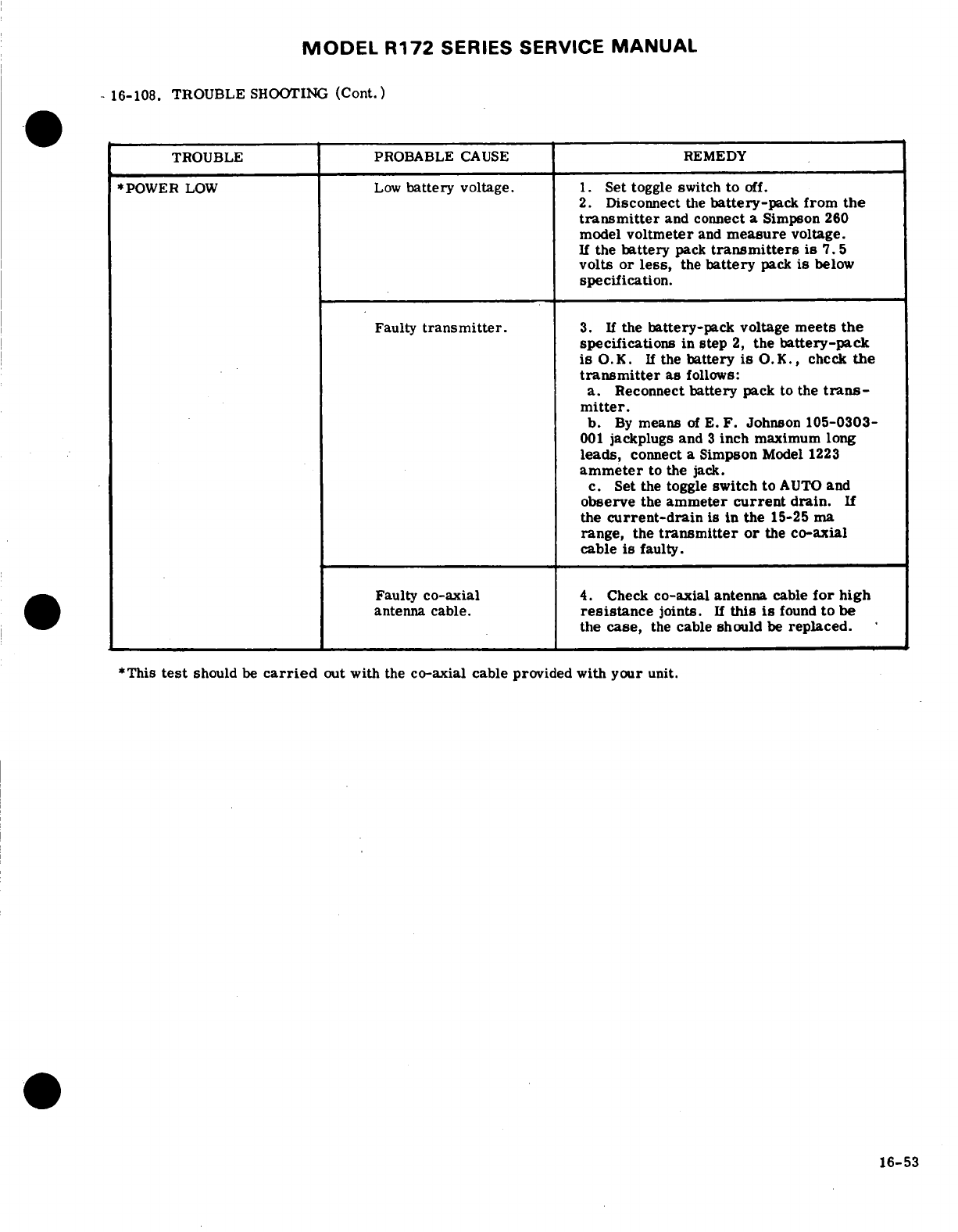
MODEL
R172
SERIES
SERVICE
MANUAL
-
16-108.
TROUBLE
SHOOTING
(Cont.)
TROUBLE
PROBABLE
CAUSE
REMEDY
*POWER
LOW
Low
battery
voltage.
1.
Set toggle switch
to
off.
2.
Disconnect
the
battery-pack
from
the
transmitter
and connect
a
Simpson
260
model
voltmeter
and
measure
voltage.
If
the
battery
pack
transmitters
is
7.
5
volts
or
less,
the
battery
pack
is
below
specification.
Faulty
transmitter.
3.
If
the
battery-pack
voltage
meets
the
specifications
in
step
2,
the
battery-pack
is
O.K.
If
the
battery
is
O.K.,
check
the
transmitter
as
follows:
a.
Reconnect
battery
pack
to the
trans-
mitter.
b.
By
means
of
E.
F.
Johnson
105-0303-
001
jackplugs
and
3
inch
maximum
long
leads,
connect
a
Simpson
Model
1223
ammeter
to
the
jack.
c.
Set
the
toggle
switch
to
AUTO
and
observe
the
ammeter
current
drain.
If
the
current-drain
is in
the
15-25
ma
range, the
transmitter
or
the
co-axial
cable
is
faulty.
Faulty
co-axial
4.
Check
co-axial
antenna
cable
for
high
antenna
cable.
resistance
joints.
If
this
is
found
to
be
the
case,
the
cable
should
be
replaced.
*This
test
should
be
carried
out
with
the
co-axial
cable
provided
with
your
unit.
16-53
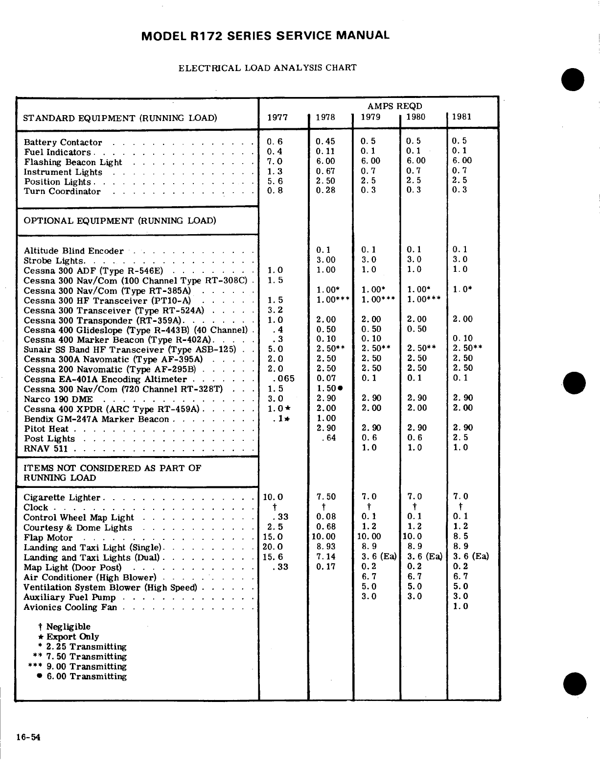
MODEL
R172
SERIES
SERVICE
MANUAL
ELECTRICAL
LOAD
ANALYSIS
CHART
AMPS
REQD
STANDARD
EQUIPMENT
(RUNNING
LOAD)
1977
1978
1979
1980
1981
Battery
Contactor
...............
0.
6
0.45
0.5
0.5
0.5
Fuel
Indicators.
.............
...
0.4
0.11
0.1
0.1
0.1
Flashing
Beacon
Light
...
.........
7.0
6.00
6.
00
6.00
6.00
Instrument
Lights
.
...........
.
1.3
0.67
0.7 0.7
0.
7
Position
Lights
. ...
.........
5. 6
2.50
2.5 2.5
2.
5
Turn
Coordinator
.
.......
. . .
0.
8
0.28
0.3
0.3
0.
3
OPTIONAL
EQUIPMENT
(RUNNING
LOAD)
Altitude
Blind
Encoder
. . ... ......
0.1
1 0.11
0.1
Strobe
Lights.
.....
.......
..
3.00
3.0
3.0
3.0
Cessna
300
ADF
(Type
R-546E) .
.......
1.0
1.00
1.0
1.0
1.0
Cessna
300
Nav/Com
(100
Channel
Type
RT-308C)
.
1.
5
Cessna
300
Nav/Com
(Type
RT-385A)
.
1.00*
1.00*
1.00*
1.0*
Cessna
300
HF
Transceiver
(PT10-A)
.. . . .
1.5
1.00***
1.00***
1.00***
Cessna
300
Transceiver
(Type
RT-524A)
.....
3.2
Cessna
300
Transponder
(RT-359A).
.....
.
1.0
2.00
2.00 2.00
2.00
Cessna
400
Glideslope
(Type
R-443B)
(40
Channel)
.
.4
0.
50
0. 50 0.
50
Cessna
400
Marker
Beacon
(Type
R-402A).
. ..
.3
0.10
0.10
0.10
Sunair
SS
Band HF
Transceiver
(Type
ASB-125) . .
5.0
2.50**
2.50**
2.50**
2.50**
Cessna
300A
Navomatic
(Type
AF-395A)
... ..
2.0
2.50
50
2.
50
2.50
2.50
Cessna
200
Navomatic
(Type AF-295B)
. . . . ..
2.0
2.50
2.50
2.
50
2.50
Cessna
EA-401A
Encoding
Altimeter
....
.
.065
0.07
0.
1
0.1
0.
1
Cessna
300
Nav/Com
(720
Channel
RT-328T)
.
1.5 1.50
Narco
190
DME
... . . . . . ..... . .
3.0
2.90
2.90
2.90
2.90
Cessna
400
XPDR
(ARC
Type
RT-459A)
.
.....
1.0*
2.00 2.00
2.00
2.00
Bendix
GM-247A
Marker
Beacon......
.
1*
1.00
Pitot
Heat.2.0 ...................
2.90
2.90
2.90
2.90
Post
Lights
....
. . ... . .. ......
.64
0.6
0.6
2.5
RNAV
511
.
.............
1.0
1.0
1.00
ITEMS
NOT
CONSIDERED
AS
PART
OF
RUNNING
LOAD
Cigarette
Lighter.
........ ... .
.10.0
7.50
7.0
7.0
7.0
Clock
..... ................
.
Control
Wheel
Map
Light
............
.33
0.08 0.1
0.1
0.1
Courtesy
&
Dome
Lights.
. . . . . . . . . .
2.5
0.68
1.2 1.2
1.2
Flap
Motor
.. . . . . .
....
.. . .. .
.15.0
10.00
10.00
10.0
8.5
Landing
and
Taxi Light
(Single).
. . . . . . . . .
20.0
8.93
8.9
8.9
8.
9
Landing
and
Taxi
Lights
(Dual)
... .. .
15. 6
7.14
3.
6
(Ea)
3.6
(Ea)
3.
6
(Ea)
Map
Light
(Door
Post)
.............
33
0.17
0.2
0.2
0.2
Air Conditioner
(High
Blower)
... . .
6.7
6.7
6.7
Ventilation
System
Blower
(High Speed)
...
5.0
5.0
5.0
Auxiliary
Fuel
Pump
............
..
3.0
3.0
3.0
Avionics
Cooling
Fan
.............. 1.0
t
Negligible
*
Export
Only
*
2.25
Transmitting
**
7.
50
Transmitting
***
9.
00
Transmitting
*
6.00
Transmitting
16-54
MODEL
R172
SERIES
SERVICE
MANUAL
SECTION
17
STRUCTURAL
REPAIR
Page
No.
TABLE
OF
CONTENTS
Aerofiche/Manual
STRUCTURAL
REPAIR
.......
.
2D20/17-1
Wing
Leading
Edge
...
2D23/17-4
Repair
Criteria
........
.2D20/17-1
Negligible
Damage
....
2D23/17-4
Equipment
and
Tools
.......
2D21/17-2
Repairable
Damage
...
2D23/17-4
Support
Stands
........
2D21/17-2
Damage
Necessitating
Re-
Fuselage
Repair
Jigs
.....
2D21/17-2
placement
of
Parts
. .
.2D23/17-4
Wing
Jigs
..........
2D21/17-2
Elevators
and
Rudder ..
2D23/17-4
Wing
Twist
and
Stabilizer
Negligible
Damage
...
2D23/17-4
Incidence
........
.
2D21/17-2
Repairable
Damage
.....
2D23/17-4
Repair
Materials
..
.2D21/17-2
Damage
Necessitating
Re-
Wing
.............
2D21/17-2
placement
of
Parts
.....
2D23/17-4
Description
.....
.
2D21/17-2
Elevator
and Rudder
Balancing. 2D23/17-4
Wing
Skin
.......
.
2D21/17-2
Fin
and
Stabilizer
....
2D23/17-4
Neglibigle
Damage
.. .
.2D21/17-2 Negligible
Damage
...
2D23/17-4
Repairable
Damage
.. .
2D21/17-2
Repairable
Damage
......
2D23/17-4
Damage
Necessitating
Re-
Damage
Necessitating
Re-
placement
of
Parts
...
2D22/17-3
placement
of
Parts
..
2D23/17-4
Wing
Stringers
.
.....
.
2D22/17-3
Fuselage
.
....
23/17-4
Negligible
Damage
. ...
2D22/17-3
Description
........
2D23/174
Repairable
Damage
....
2D22/17-3
Negligible
Damage
......
2D23/17-4
Damage
Necessitating
Re-
Repairable
Damage
.
.....
2D24/17-5
placement
of
Parts
..
2D22/17-3
Damage
Necessitating
Re-
2D24/17-5
Wing
Auxiliary Spars
...
.2D22/17-3
placement
of
Parts
..
.2D24/17-5
Negligible
Damage
.....
2D22/17-3
Bonded
Doors
..........
2D24/17-5
Repairable
Damage .. .
2D22/17-3
Repairable
Damage
.. .
2D24/17-5
Damage
Necessitating
Re-
Bulkheads
..
2D24/17-5
placement
of
Parts
..
2D22/17-3
Landing
Gear
Bulkheads. 2D24/17-5
Wing
Ribs
..........
2D22/17-3
Repair
After
Hard
Landing.
2D24/17-5
Negligible
Damage
....
2D22/17-3
Replacement
of
Hi-Shear Rivets
.
2D24/17-5
Repairable
Damage
.. .
2D22/17-3
Firewall
Damage
..
2D24/17-5
Damaging
Necessitating
Re-
Engine
Mount
... .
2D24/17-5
placement
of
Parts
...
2D22/17-3
Description
.........
2D24/17-5
Wing
Spars
.........
2D22/17-3
General
Considerations
....
2D24/175
Negligible
Damage
... .
2D22/17-3
Engine
Mount
Support
Cradle
Repairable
Damage
....
2D22/17-3
Damage
..........
2D24/17-5
Damage
Necessitating
Re-
Damage
Involving
Engine
placement
of
Parts
..
.2D22/17-3
Mounting
Lugs
and
Engine
Ailerons.
.........
.
2D22/17-3
Mount
to
Fuselage Attach
Repairable
Damage
....
2D22/17-3
Baffles
.............
2D24/17-5
Damage
Necessitating
Re-
Engine
Cowling .
........
2D24/17-5
placement
of
Parts
..
2D22/17-3
Repair
of
Cowling
Skins .
2E1/17-6
Aileron
Balancing
...
2D22/17-3
Repair
of
Reinforcement
Wing
Flaps
.........
2D22/17-3
Angles
......
2E1/17-6
Negligible
Damage
. ...
2D22/17-3 Repair
of
Glass-Fiber
Repairable
Damage
....
2D22/17-3
Constructed
Components
....
2E2/17-7
Damage
Necessitating
Re-
placement
of
Parts
.
2D22/17-3
17-1.
STRUCTUREAL
REPAIR.
factors
as
time
and
labor
available,
and
by
a
com-
parison
of
labor
costs
with
the
price
of
replacement
17-2.
REPAIR
CRITERIAL.
Although
this
section
assemblies.
Past
experience
indicates
that
replace-
outlines
repair
permissible
on
structure
of
the
air-
ment,
in
many
cases,
is
less
costly
than
major
re-
craft,
the
decision
of
whether
to
repair
or
replace
a
pair.
Certainly,
when
the
aircraft
must
be
restored
major
unit
of
structure
will
be
influenced
by
such
to
its
airworthy
condition
in
a
limited
length
of
time,
17-1
MODEL
R172
SERIES
SERVICE
MANUAL
replacement
is
preferable.
Restoration
of
a
damaged
this
manual
is
made
from
2024
aluminum
alloy,
heat
aircraft
to
its
original
design
strength,
shape, and
treated
to a
-T3,
-T4,
or
-T42
condition.
If
the
type
alignment
involves
careful
evaluation
of
the
damage,
of
material
cannot
readily
be
determined,
2024-T3
followed
by
exacting
workmanship
in
performing
the
may
be
used
in
making
repairs,
since
the
strength
repairs.
This
section
suggests
the
extent
of
struc-
of
-T3
is
greater
than
-T4
or
-T42
(-T4
and
-T42
tural
repair
practicable
on
the
aircraft,
and
supple-
may
be
used
interchangeably,
but
they
may
not
be
ments
Federal
Aviation
Regulation,
Part
43.
Con-
substituted
for
-T3).
When
necessary
to
form
a
part
suit
the
factory
when
in
doubt
about
a
repair
not
with
a
smaller
bend
radius
than
the
standard
cold
specifically
mentioned
here,
bending
radius
for
2024-T4,
use
2024-0
and heat
treat
to
2024-T42
after
forming.
The
repair
mate-
17-3.
EQUIPMENT
AND
TOOLS.
rial
used
in
making
a
repair
must equal
the
gauge
of
the
material
being
replaced
unless otherwise
noted.
17-4.
SUPPORT
STANDS.
Padded,
reinforced
saw-
It
is
often
practical
to
cut
repair
pieces
from
service
horse
or tripod
type
support
stands,
sturdy
enough to
parts
listed
in the
Parts
Catalog.
A
few
components
support
any
assembly
placed
upon
them,
must
be
(empennage
tips,
for
example)
are
fabricated
from
used
to
store
a
removed
wing
or
tailcone.
Plans
for
thermo-formed
plastic
or
glass-fiber
constructed
local
fabrication
of
support stands
are
contained
in
material.
figure
17-1.
The
fuselage
assembly,
from
the
tail-
cone
to
the
firewall,
must
NOT be
supported
from
17-10.
WING
the
underside,
since
the
skin
bulkheads
are
not
de-
signed
for
this
purpose.
Adapt
support
stands
to
17-11. DESCRIPTION.
The
wing
assemblies
are
a
fasten
to
the
wing
attach
points
or
landing
gear
attach
semicantilever
type
employing semimoncoque
type
points
when
supporting
a
fuselage.
of
structure.
Basically,
the
internal
structure
con-
sists
of
built-up front
and
rear
spar
assemblies,
a
17-5. FUSELAGE
REPAIR
JIGS.
Whenever
a
repair
formed auxiliary
spar
assembly
and
formed
sheet
is
to
be
made
which
could
affect
structural
alignment,
metal
nose,
intermediate,
and
trailing
edge
ribs.
suitable
jigs
must
be
used
to
assure
correct
align-
Stressed
skin,
riveted
to the
rib
and
spar
structures,
ment
of
major
attach
points,
such
as
fuselage,
fire-
completes
the
rigid
structure.
Access
openings
wall,
wing
and
landing
gear.
These
fuselage
repair
(hand
holes
with
removable
cover
plates)
are
located
jigs
are
obtainable
from
the
factory.
in
the
underside
of
the
wing
between
the
wing
root
and
tip
section.
These
openings
afford
access
to
17-6.
WING
JIGS.
These
jigs
serve
as
a
holding
fix-
aileron
bellcranks,
flap
bellcranks,
electrical
wiring,
ture
during
extensive
repair
of
a
damaged
wing,
and
strut
attach
fittings, control cables
and
pulleys,
and
locates
the
root
rib,
leading
edge
and
tip
rib
of
the
control
disconnect
points.
wing.
These
jigs
are
also
obtainable
from
the
factory.
17-12.
WING
SKIN.
17-7.
WING
TWIST
AND
STABILIZER
ANGLE-OF-
INCIDENCE.
17-13.
NEGLIGIBLE
DAMAGE.
Any
smooth
dents
in
the
wing
skin that
are
free
from
cracks,
abrasions
17-8.
Wing
twist
(washout) and
horizontal
stabilizer
and
sharp
corners,
which
are
not
stress
wrinkles
and
angle
fo
incidence
are
shown
below.
Stabilizers
do
do
not
interfere
with
any
internal
structure
or
mech-
not
have
twist.
Wings
have
no
twist
from
the
root
to
anism,
may
be
considered
as
negligible
damage.
In
the
lift
strut
station.
All
twist
in
the
wing
panel
areas
of
low
stress
intensity,
cracks,
deep
scratches,
occurs
between
this
station
and
the
tip
rib.
Refer
to
or
deep,
sharp
dents,
which
after
trimming
or
stop-
figure
18-2
for
wing
twist measurement,
drilling
can
be
enclosed
by
a
two-inch
circle,
can
be
considered
negligible
if
the damaged
area
is
at
least
WING
one
diameter
of
the
enclosing
circle
away
from
all
Twist
(Washout)
3
°
37'
existing
rivet lines
and
material
edges.
Stop
drilling
is
considered
a
temporary
repair
and
a
permanent
STABILIZER
repair
must
be
made
as
soon
as
practicable.
Angle
of
Incidence
-3
°
30'
17-14. REPAIRABLE
DAMAGE.
Figure
17-5
out-
lines
typical
repair
to
be
employed
in
patching
skin.
Before
installing
a
patch,
trim
the
damaged
area
to
form
a
retangular
pattern,
leaving at
least
a
one-
half
inch
radius
at
each
corner,
and
de-burr.
The
17-9.
REPAIR
MATERIALS.
Thickness
of
a
mate-
sides
of
the
hole
should
lie
span-wise or chord-wise.
rial
on
which
a
repair
is
to
be
made
can
easily
be
de-
A
circular
patch
may
also
be
used.
If
the
patch
is
termined
by
measuring
with
a
micrometer.
In
gen-
in
an
area
where flush
rivets
are
used,
make
a
flush
eral,
material
used
in
Cessna
aircraft
covered
in
patch
type
of
repair;
if
in
an
area
where
flush
rivets
17-2
MODEL
R172
SERIES
SERVICE
MANUAL
are
not
used,
make an
overlapping
type
of
repair.
which
wing
spars
encounter,
very
little
damage
can
Where
optimum
appearance
and
airflow
are
desired,
be
considered
negligible.
All
cracks,
stress
wrink-
the
flush
patch
may
be
used.
Careful
workmanship
les,
deep
scratches,
and
sharp
dents must
be
re-
will eliminate gaps
at
butt-joints;
however,
an
epoxy
paired.
Smooth
dents,
light
scratches
and
abrasions
type
filler
may
be
used
at such
joints.
may
be
considered
negligible.
17-15.
DAMAGE
NECESSITATING
REPLACEMENT 17-30
REPAIRABLE
DAMAGE.
Figure
17-8
illus-
OF
PARTS.
If
a
skin
is
badly
damaged,
repair
must
trates
typical
spar
repairs.
It
is
often
practical
to
be
made
by
replacing
an
entire
skin
panel,
from
one
cut
repair
pieces from
service
parts
listed
in
the
structural
member
to
the next.
Repair
seams
must
Parts
Catalog.
Service
Kits
are
available
for
certain
be
made
to
lie
along
structural
members
types
of
spar
repairs.
and each
seam
must
be
made
exactly
the
same
in
re-
gard
to
rivet
size,
spacing,
and
pattern
as
the
manu-
17-31.
DAMAGE
NECESSITATING
REPLACEMENT
factured
seams at
the
edges
of
the
original
sheet.
If
OF
PARTS.
Damage
so
extensive
that
a
repair
is
not
the
manufactured
seams
are
different,
the
stronger
practicable
requires replacement
of
a
complete
wing
must
be
copied.
If
the
repair
ends
at
a
structural
spar.
Also
refer
to
paragraph
17-2.
member where
no
seam
is
used,
enough
repair
panel
must
be
used
to
allow an
extra
row
of
staggered
17-32.
AILERONS
rivets,
with
sufficient
edge
margin,
to
be
installed.
17-33.
NEGLIGIBLE DAMAGE.
Refer
to
paragraph
17-16.
WING
STRINGERS.
17-13.
17-17.
NEGLIGIBLE
DAMAGE.
Refer
to
paragraph
17-34.
REPAIRABLE
DAMAGE.
The
repair
shown
17-13.
in
figure
17-10
may
be
used
as
a
guide to
repair
da-
mage
to
aileron
leading
edge
skins.
Figure
17
5
may
17-18.
REPAIRABLE
DAMAGE.
Figure
17-6 out-
be
used
to
repair
damage
to
flat
surfaces
between cor-
lines
a
typical
wing
stringer
repair.
Two
such
re-
rugations.
When
damaged
airea
includes
corrugations,
pairs
may
be
used
to
splice
a
new
section
of
stringer
soo
figure
17-4.
It
is
recommended
that
material
for
material
in
position,
without
the
filler
material.
repair
be
cut
from
spare
parts
of
the
same
gage
and
corrugation
spacing.
The
aileron
must
be
balanced
af-
17-19.
DAMAGE
NECESSITATING
REPLACEMENT
ter
repair.
Refer
to
paragraph
17-36
and
see
figure
OF PARTS.
If
a
stringer
is
so
badly damaged
that
17-3
for
aileron
balancing.
If
damage
would
require
a
.
more
than
one
section
must
be
spliced,
replacement
repair
which
could not
be
made
between
adjacent
ribs,
is
recommended.
refer
to
following
paragraph.
17-20.
WING
AUXILIARY
SPARS.
17-35.
DAMAGE
NECESSITATING
REPLACEMENT
OF
PARTS.
If
the
damage
would
require
a
repair
17-21.
NEGLIGIBLE
DAMAGE.
Refer
to
paragraph
which
could
not
be
made
between
adjacent
ribs,
com-
17-13.
plete skin
panels
must
be
replaced.
Ribs
and
spars
may
be
repaired,
but
replacement
is
generally
pre-
17-22.
REPAIRABLE
DAMAGE.
Figure
17-9
illus-
ferable.
Where
extensive
damage
has
occured,
re-
trates
a
typical
auxiliary
spar
repair.
placement
of
the
aileron
assembly
is
recommended.
After
repair
and/or
replacement,
balance
aileron
17-23.
DAMAGE
NECESSITATING
REPLACEMENT
in
accordance
with
paragraph
17-36
and
figure
17-3.
OF
PARTS.
If
damage
to
an
auxiliary
spar
would
require
a
repair
which could
not
be
made between ad-
17-36.
AILERON BALANCING.
Following
repair,
jacent
ribs,
the
auxiliary
spar
must
be
replaced, replacement
or
painting,
the
aileron
must
be
balanced.
Complete
instructions
for
fabricating
balancing
fix-
17-24.
WING
RIBS.
tures
and
mandrels
and
their
use
are
given
in
figure
17-3..
17-25.
NEGLIGIBLE
DAMAGE.
Refer
to
paragraph
17-13.
17-37.
WING
FLAPS.
17-26.
REPAIRABLE
DAMAGE.
Figure
17-7
illus-
17-38.
NEGLIGIBLE
DAMAGE.
Refer to
paragraph
trates
a
typical
wing
rib repair.
17-13.
17-27.
DAMAGE
NECESSITATING
REPLACEMENT
17-39.
REPAIRABLE
DAMAGE.
Flap
repair
should
OF
PARTS.
Leading
and
trailing
edge
ribs
that
are
be
similar
to
aileron
repairs
discussed
in
paragraph
extensively
damaged
can
be
replaced.
However,
due
17-34.
A
flap
leading
edge
repair
is
shown
in
figure
to
the
necessity
of
unfastening
an
excessive
amount
of
17-11.
If
an
overlapping
patch
is
to
be
used,
be
sure
skin
in
order
to
replace
.he
rib,
they should
be
re-
it
will
not
interfere
with
the
wing
during
flap
operation.
paired
if
practicable. Center
ribs,
between the
front
and
rear
spar
should
always
be
repaired
if
practicable.
17-40.
DAMAGE
NECESSITATING
REPLACEMENT
OF
PARTS.
Flap
repairs
which
require
replacement
17-28.
WING
SPARS.
of
parts
should
be
similar
to
aileron
repairs
discussed
in
paragraph
17-35.
Since
the
flap
is
not
considered
a
17-29.
NEGLIGIBLE
DAMAGE.
Due
to
the
stress
moveable
control
surface,
no
balnacing
is
required.
17-3
MODEL
R172
SERIES
SERVICE
MANUAL
17-41.
WING
LEADING
EDGE.
bottom
of
the fin.
Access
to
the
internal
fin
structure
is
best
gained
by
removing
skin
attaching
rivets
on
17-42.
NEGLIGIBLE
DAMAGE.
Refer
to
paragraph
one
side
of
the
rear
spar
and
ribs,
and
springing
17-13.
back
the
skin.
Access
to
the
stabilizer
structure
may
be
gained
by
removing
skin
attaching
rivets
on
17-43.
REPAIRABLE
DAMAGE.
A
typical
leading
one
side
of
the
rear
spar
and
ribs,
and
springing
edge
skin
repair
is
shown
in
figure
17-10.
An
epoxy-
back
the
skin.
If
the
damaged
area
would
require
a
type
filler
may
be
used
to
fill
gaps
at
butt-joints.
repair
which
could
not
be
made
between
adjacent
To
facilitate
repair,
extra
access
holes
may
be
in-
ribs,
or
a
repair
would
be
located
in
an
area
with
stalled
in
the
locations
noted
in
figure
17-12.
If
the
compound
curves,
see
the
following
paragraph.
damage
would
require
a
repair
which could
not
be
made
between
adjacent
ribs,
refer
to
the following
17-53.
DAMAGE
NECESSITATING
REPLACEMENT
paragraph.
OF PARTS.
If
the
damaged
area
would
require
a
repair
which
could
not
be
made
between
adjacent
ribs,
17-44.
DAMAGE
NECESSITATING
REPLACEMENT
or
the
repair
would
be
located
in
an
area
with com-
OF
PARTS.
For
extensive
damage,
complete
lead-
pound
curves,
complete
skin
panels
must
be
replaced.
ing
edge
skin
panels
must
be
replaced.
To
facilitate
Ribs
and
spars
may
be
repaired,
but
replacement
is
replacement, extra
access
holes
may
be
installed
in
generally
preferable.
Where
damage
is
extensive,
the
locations
noted
in
figure
17-12.
replacement
of
the
entire
assembly
is
recommended.
17-45.
ELEVATORS
AND
RUDDER.
17-54.
FUSELAGE.
17-46.
NEGLIGIBLE
DAMAGE.
Refer
to
paragraph
17-55.
DESCRIPTION.
The
fuselage
is
of
semi-
17-13.
The
exception
to
negligible
damage
on
the
monocoque
construction, consisting
of
formed
elevator
surfaces
is
the front
spar,
where
a
crack
bulkheads,
longitudinal
stringers,
reinforcing
chan-
appearing
in
the
web
at
the
hinge
fittings
or
in
the
nels,
and
skin
panels.
structure
which
supports
the
overhanging balance
weight
is
not
considered
negligible.
Cracks
in
the
17-56. NEGLIGIBLE
DAMAGE.
Refer
to
paragraph
overhanging
tip rib,
in
the
area
at
the
front
spar
17-13.
Mild
corrosion
appearing
upon
Alclad
sur-
intersection
with
the
web
of
the
rib,
also
cannot
be
faces
does
not
necessarily
indicate
incipient failure
considered
negligible.
of
the
base metal.
However,
corrosion
of
all
types
must
be
carefully
considered,
and
approved
reme-
17-47. REPAIRABLE
DAMAGE.
Skin
patches
illus-
dial
action
taken.
Small
cans
appear
in
the
skin
trated
in
figure
17-5
may
be
used
to
repair
skin
structure
of
all
metal
aircraft.
It
is
strongly
rec-
damage
between
corrugations.
For
skin
damage
which
ommended however,
that
wrinkles
which
appear
to
includes
corrugations,
see
figure
17-4.
Following
the
have
originated
from
other
sources,
or
which
do
repair,
the
elevator/rudder
must
be
balanced.
See not
follow
the
general
appearance
of
the
remainder
figure
17-3
for
balancing.
If
damage
would
require
a
of
the
skin
panels,
be
thoroughly
investigated.
repair
which
could
not
be
made
between
adjacent
ribs,
Except
in
the
landing
gear
bulkhead
areas,
wrinkles
refer
to
the
following
paragraph,
occurring
over
stringers
which
disappear
when
the
rivet
pattern
is
removed,
may
be
considered
neglig-
17-48.
DAMAGE
NECESSITATING
REPLACEMENT
ible.
However,
the
stringer
rivet
holes
may
not
OF
PARTS.
If
the
damaged
area
would
require
a
re-
align perfectly
with
the
skin holes
because
of
a
per-
pair
which could
not
be
made
between
adjacent
ribs,
manent
"set"
in
the
stringer.
If
this
is
apparent,
complete skin
panels
must
be
replaced.
Ribs
and
replacement
of
the
stringer
will
usually
restore
the
spars
may
be
repaired,
but
replacement
is
generally
original
strength
characteristics
of
the
area.
preferable.
Where
extensive
damage
has
occurred,
replacement
of
the
entire
assembly
is
recommended.
NOTE
After
repair
and/or
replacement,
balance
elevators
and
rudder
in
accordance
with
paragraph
17-49
and
Wrinkles
occurring
in
the
skin
of
the
main
figure
17-3.
landing
gear
bulkhead
areas
must
not
be
considered
negligible.
The
skin
panel
must
17-49.
ELEVATOR
AND
RUDDER
BALANCING.
be
opened
sufficiently
to
permit
a
thorough
Following
repair,
replacement
or
painting,
the
ele-
examination
of
the
lower
portion
of
the
land-
vators
and
rudder
must
be
balanced.
Complete
in-
ing
gear
bulkhead
and
its tie-in
structure.
structions
for fabricating
balancing
fixtures
and
mandrels
and
their
use
are
given
in
figure
17-3.
Wrinkles
occurring
in
open
areas
which
disappear
when
the
rivets
at
the
edge
of
the
sheet
are
removed,
17-50.
FIN
AND
STABILIZER.
or
a wrinkle
which
is
hand
removable,
may often
be
repaired
by
the
addition
of a
1/2
x
1/2
x
.060
inch
17-51.
NEGLIGIBLE
DAMAGE.
Refer
to
paragraph
2024-T4
extruded
angle,
riveted
over
the
wrinkle and
17-13.
extended
to
within
1/16 to
1/8
inch
of
the
nearest
structural
members.
Rivet
pattern
should
be
identi-
17-52.
REPAIRABLE
DAMAGE.
Skin
patches
illus-
cal
to
existing
manufactured
seam
at
edge
of
sheet.
trated
in
figure
17-8
may
be
used
to
repair
skin
Negligible damage
to
stringers,
formed
skin
flanges,
damage.
Access
to
the
dorsal
area
of
the
fin
may
be
bulkhead
channels,
and
like
parts
is
similar
to
that
gained
by
removing
the
horizontal closing
rib
at
the
for
the
wing
skin,
given
in
paragraph
17-13.
17-4
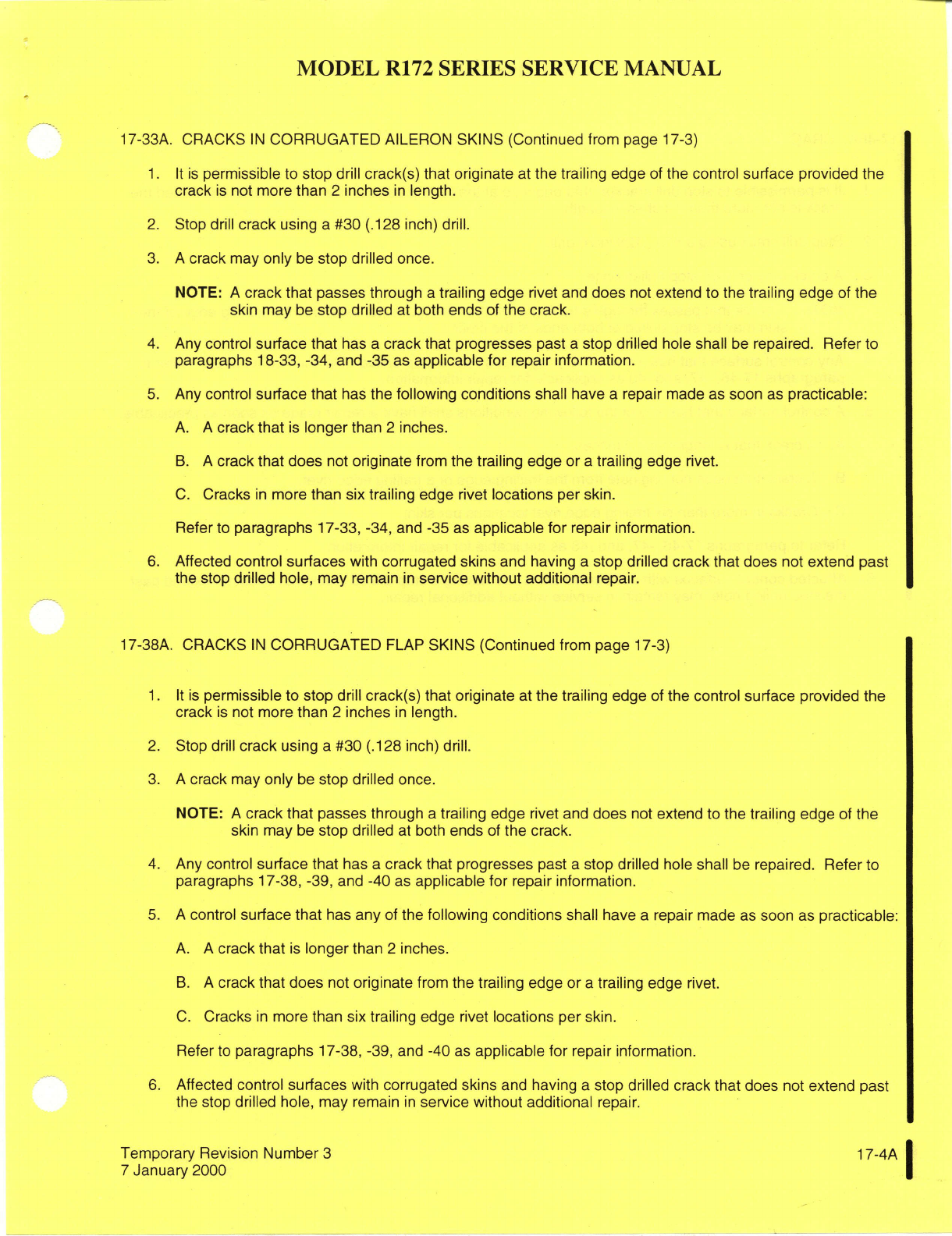
MODEL
R172
SERIES
SERVICE
MANUAL
17-33A.
CRACKS
IN
CORRUGATED
AILERON
SKINS
(Continued
from page
17-3)
1. It is
permissible
to
stop
drill
crack(s) that
originate
at
the
trailing
edge
of
the
control
surface
provided
the
crack
is
not
more
than
2
inches
in
length.
2.
Stop
drill
crack
using
a
#30
(.128 inch) drill.
3.
A
crack
may
only
be
stop
drilled
once.
NOTE:
A
crack that
passes through
a
trailing
edge
rivet
and
does
not
extend
to
the
trailing
edge
of the
skin may
be
stop drilled
at
both
ends
of
the
crack.
4.
Any
control
surface
that
has
a
crack that progresses
past
a
stop drilled
hole
shall
be
repaired.
Refer
to
paragraphs
18-33,
-34,
and
-35
as
applicable
for
repair
information.
5.
Any
control
surface that
has
the
following
conditions
shall have
a
repair
made as
soon
as
practicable:
A.
A
crack
that
is
longer
than
2
inches.
B.
A
crack that does
not
originate
from
the
trailing
edge or
a
trailing
edge
rivet.
C.
Cracks
in
more
than
six
trailing
edge
rivet
locations
per skin.
Refer
to paragraphs
17-33,
-34,
and
-35
as
applicable
for
repair
information.
6.
Affected
control
surfaces
with
corrugated
skins
and
having
a
stop
drilled
crack that
does
not
extend
past
the
stop
drilled hole, may
remain
in
service without additional
repair.
17-38A. CRACKS
IN
CORRUGATED
FLAP
SKINS
(Continued
from
page
17-3)
1. It
is
permissible
to
stop
drill
crack(s) that originate
at
the
trailing
edge
of
the control
surface
provided
the
crack
is
not
more
than
2
inches
in
length.
2.
Stop
drill
crack
using
a
#30 (.128
inch)
drill.
3.
A
crack
may
only
be
stop
drilled once.
NOTE:
A
crack
that
passes through
a
trailing
edge
rivet
and
does
not
extend
to the
trailing
edge
of the
skin
may
be
stop drilled
at
both
ends
of
the
crack.
4.
Any
control
surface
that
has
a
crack
that
progresses
past
a
stop
drilled hole
shall
be
repaired.
Refer
to
paragraphs
17-38, -39,
and
-40
as
applicable
for
repair information.
5. A
control
surface
that
has
any
of
the
following conditions
shall have
a
repair
made
as
soon
as
practicable:
A. A
crack
that
is
longer
than
2
inches.
B. A
crack
that does
not
originate
from
the
trailing
edge
or
a
trailing
edge
rivet.
C.
Cracks
in
more
than
six
trailing
edge rivet
locations
per skin.
Refer to
paragraphs
17-38,
-39,
and
-40
as
applicable
for
repair
information.
6.
Affected
control
surfaces
with
corrugated
skins
and
having
a
stop
drilled crack
that
does
not
extend
past
the
stop drilled hole,
may
remain
in
service without additional
repair.
Temporary
Revision Number
3
17-4A
7
January
2000
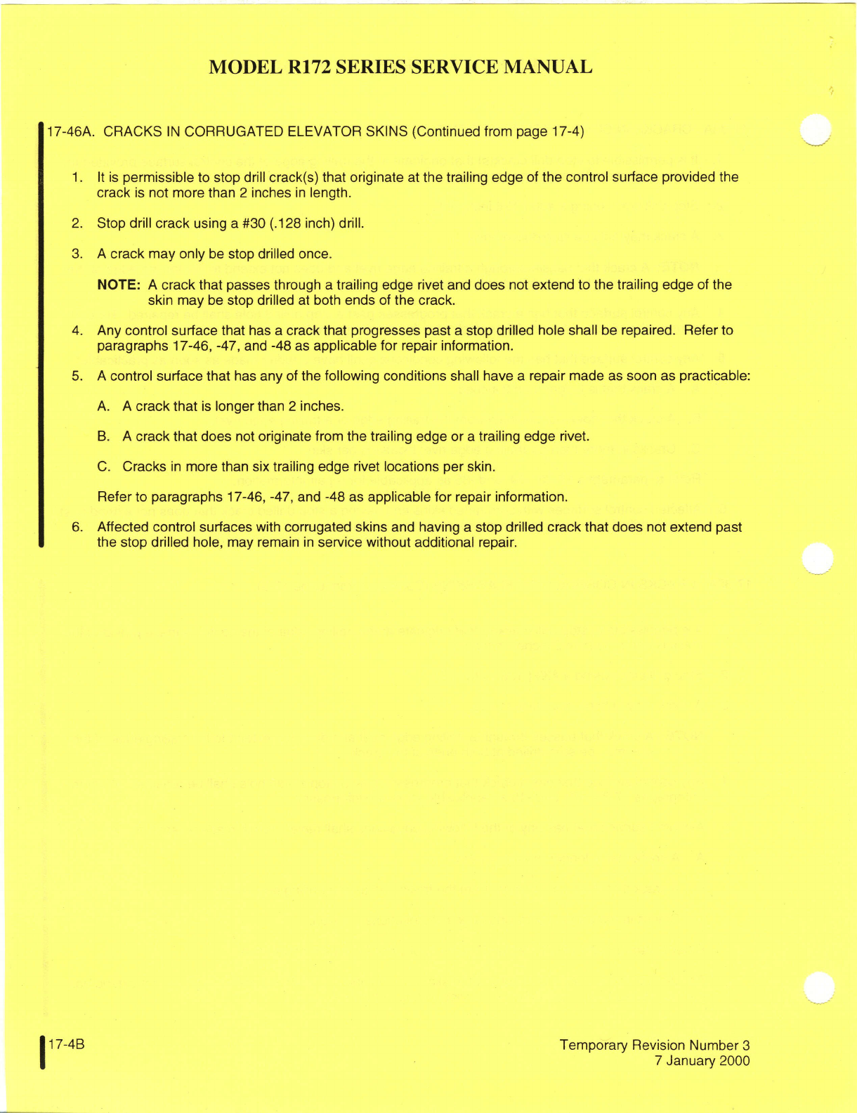
MODEL
R172
SERIES
SERVICE
MANUAL
17-46A. CRACKS
IN
CORRUGATED
ELEVATOR
SKINS (Continued
from
page
17-4)
1. It
is
permissible
to
stop
drill
crack(s) that
originate
at
the trailing
edge
of
the
control surface
provided
the
crack
is
not
more
than
2
inches
in
length.
2.
Stop
drill
crack
using
a
#30
(.128
inch)
drill.
3.
A
crack
may only
be
stop drilled
once.
NOTE:
A
crack
that
passes through
a
trailing
edge rivet
and
does
not
extend to
the
trailing
edge
of the
skin
may
be
stop drilled
at both
ends
of
the
crack.
4.
Any
control surface
that
has
a
crack that progresses
past
a
stop
drilled
hole shall
be
repaired. Refer
to
paragraphs
17-46,
-47,
and
-48
as
applicable for
repair information.
5.
A
control
surface that
has
any
of
the
following conditions
shall have
a
repair
made
as
soon
as
practicable:
A. A
crack
that
is
longer
than
2
inches.
B.
A
crack
that
does
not
originate
from the
trailing
edge
or
a
trailing
edge
rivet.
C.
Cracks
in
more
than
six
trailing
edge
rivet
locations
per
skin.
Refer
to
paragraphs
17-46,
-47, and
-48
as
applicable
for
repair
information.
6.
Affected
control
surfaces
with
corrugated
skins
and
having
a
stop drilled
crack
that
does
not
extend
past
the
stop drilled
hole,
may
remain
in
service
without additional
repair.
17-4B
Temporary
Revision Number
3
7
January
2000
MODEL
R172
SERIES
SERVICE
MANUAL
17-57. REPAIRABLE
DAMAGE.
Fuselage
skin
re-
without
machined
flat
surfaces
around
attachment
pairs
may
be
accomplished
in
the
same
manner
as
holes.
wing
skin
repairs
outlined
in
paragraph
17-14.
*Dash
numbers
are
to
be
determined
according
to
the
Stringers,
formed
skin
flanges,
bulkhead
channels holes
and
the
grip
lengths
required.
Bolt
grip
length
and
similar parts
may
be
repaired
as
shown
in
fig-
should
be
chosen
so
that
no
threads
remain
in the
ure
18-6.
bearing
area.
18-58.
DAMAGE
NECESSITATING
REPLACEMENT
17-65. FIREWALL
DAMAGE.
Firewall
sheet
may
OF
PARTS.
Fuselage
skin
major
repairs
may
be
be
repaired
by
removing
the
damaged
material
(MIL-
accomplished
in
the
same manner
as
the
wing
re-
S-5059)
corrosion-resistant
(18-8)
steel,
and
splicing
pairs
outlined
in
paragraph
17-15.
Damaged
fittings
in
a
new
section.
The
new
portion
must
be
lapped
must
be
replaced.
Seat
rails
serve
as structural
over
the
old
material,
sealed
with
Pro
Seal
#700
parts
of
the
fuselage
and
must
be
replaced
if
damaged.
(Coast
Pro-Seal
Co.,
Chemical
Division,
2235
Bever-
ly
Blvd.,
Los
Angeles,
California),
compound
or
17-59.
BONDED
DOORS.
equivalent,
and
secured
with
steel
(MS20450)
rivets.
Patches,
splices
and
joints
should
be
repaired
with
17-60.
REPAIRABLE
DAMAGE.
Bonded
doors
steel
rivets.
Angles
around
the
periphery
of
the
fire-
may
be
repaired
by
the
same
methods
used
for
wall
are
secured
with
steel
rivets,
except
where
en-
riveted
structure.
Rivets
are
a
satisfactory
substi-
gine
shock
mount
brackets
are
attached
with
aluminum
tute
for
bonded
seams
on
these
assemblies.
The
(MS20470)
rivets.
The diagonal
support
angles
on
the
strength
of
the
bonded
seams
in
doors
may
be
re-
upper
firewall
are
secured
with
steel
rivets.
Nutplates
placed
by
a
single
3/32,
2117-AD
rivet
per
running
are
attached
with aluminum
rivets.
The
diagonal
sup-
inch
of bond
seam.
The
standard
repair
procedures
port angles
on
the
lower
firewall
are
secured
with alu-
outlined
in
AC43.13-1
are
also
applicable
to
bonded
minum
rivets.
doors.
17-66.
ENGINE
MOUNT.
17-61.
BULKHEADS.
17-67.
DESCRIPTION.
The
mount
for
the
aircraft
17-62.
LANDING
GEAR
BULKHEADS.
Since
these
engine
is
constructed
of
4130
chrome-molybdenum
bulkheads
are
highly
stressed
members,
irregularly
steel
tubing.
A
truss
structure,
fastened
to
the
fire-
formed
to
provide
clearance
for
control
cables,
fuel
wall
at
four
points,
supports
a
cradle
arrangement.
lines,
etc.,
the
patch-type
repairs
will
be,
for
the
This
cradle
arrangement
with
its
supporting lugs,
most
part,
impractical.
Minor
damage,
consisting
forms
the
base
for
rubber
shock
mounted
engine
sup-
of
small
nicks
or
scratches,
may
be
repaired
by
ports.
dressing
out
the
damaged
area, or
by
replacement
of
rivets.
Any
other
damage
must
be
repaired
by
17-68. GENERAL
CONSIDERATIONS.
All
welding
replacing
the
landing
gear
support assembly as
an
on
the
engine
mount
must
be
of
the
highest
quality
aligned
unit.
since
the
tendency
of
vibration
is
to
accentuate
any
minor
defect
present
and
cause
fatigue
cracks.
En-
17-63.
REPAIR
AFTER
HARD LANDING.
Buckled gine
mount
members
are
preferably
repaired
by
skin
or
floorboards,
and
loose
or
sheared
rivets
in
using a
larger
diameter
replacement
tube,
telescoped
the
area
of
the
main
gear
support will
give
evidence
over
the
stub
of
the
original member
using
fishmouth
of
damage
to the
structure
from
an
extremely
hard
and
rosette
type
welds.
However,
reinforced
30-
landing.
When
such
evidence
is
present,
the
entire
degree
scarf
welds
in
place
of
the
fishmouth
welds
support
structure
must
be
examined,
and
all
support
are
considered
satisfactory
for
engine mount
repair
forgings
must
be
checked
for
cracks,
using
a
dye
work.
Refer
to
Section
18
for
engine
mount
painting.
penetrant
and
proper
magnification.
Bulkheads
in
the
damaged
area
must
be
checked
for
alignment,
17-69.
ENGINE
MOUNT
SUPPORT
CRADLE
DAM-
and
deformation
of
the
bulkhead webs
must
be
deter-
AGE.
Minor
damage
such
as
a
crack
adjacent
to
an
mined
with
the
aid
of
a
straightedge.
Damaged
sup-
engine
attaching
lug
may
be
repaired
by
rewelding
port
structure,
buckled
floorboards
and
skins,
and
the
cradle
tube
and
extending
a
gusset
past
the dam-
damaged
or
questionable
forgings
must
be
replaced.
aged
area.
Extensively
damaged
parts
must
be
re-
placed.
17-64.
REPLACEMENT
OF
HI-SHEAR
RIVETS.
Hi-
shear rivet
replacement
with
close-tolerance
bolts
or
17-70.
DAMAGE
INVOLVING
ENGINE MOUNTING
other commercial
fasteners
of
equivalant
strength
LUGS
AND
ENGINE MOUNT
TO
FUSELAGE
ATTACH-
properties
is
permissible.
Holes
must
not
be
elon-
ING
FITTINGS.
Engine
mounting
lugs and
engine
gated
and
the
Hi-shear
substitute
must
be
a smooth
mount-to-fuselage
attaching
fittings
should
not
be
re-
push-fit.
Field replacement
of
main
landing
gear
paired
but
must
be
replaced.
forgings
on
bulkheads
may
be
accomplished
by
using
the
following
fasteners.
17-71.
BAFFLES. Baffles
ordinarily
require
re-
a.
NAS464P-* bolt.
MS21042-* nut
and AN960-*
placement
if
damaged
for
cracked.
However,
small
washer
in
place
of
Hi-shear
rivets
for
forgings
with
plate
reinforcements
riveted
to
the
baffle
will
often
machined
flat
surfaces
around
attachment
holes. prove
satisfactory
both
to
the
strength
and
cooling
b. NAS464P-*
bolt.
ESNA
2935-*
mating
base
wa-
requirements
of
the
unit.
sher
and
ESNA
RM52LH2935-*
self-aligning
nut
for
forgings
(with
draft
angle
of
up
to
a
maximum
of
8
°
)
17-72.
ENGINE
COWLING.
17-5
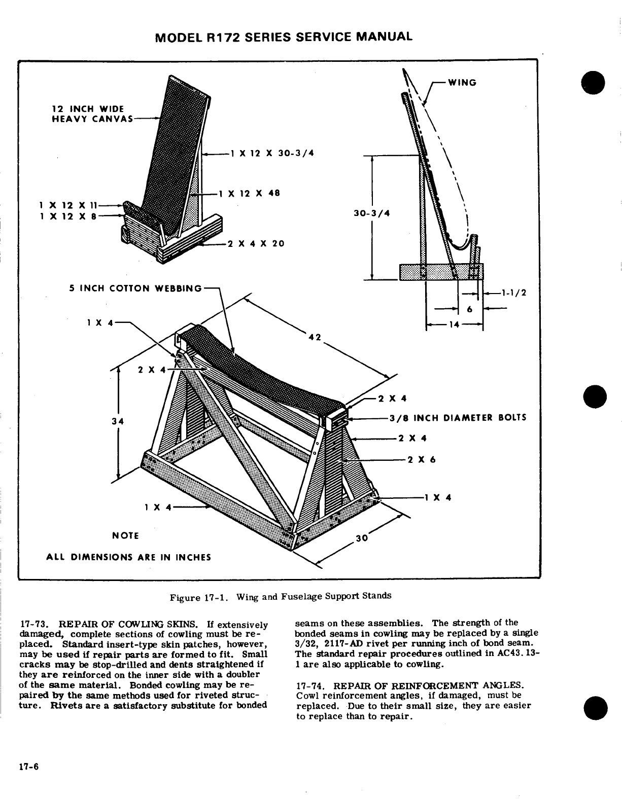
MODEL
R172
SERIES SERVICE
MANUAL
WING
12
INCH WIDE
HEAVY
CANVAS
1 X
12
X
30-3/4
1
X
12
X
48
1
X
12
X
11
1
X
12
X
8
30-3/4
2
X
4
X
20
5
INCH
COTTON
WEBBING
1-1/2
42
34
-----
3/8
INCH
DIAMETER
BOLTS
2
X
4
NOTE
30
ALL
DIMENSIONS
ARE
IN
INCHES
Figure
17-1.
Wing
and
Fuselage
Support Stands
17-73.
REPAIR
OF
COWLING
SKINS.
If
extensively
seams
on
these
assemblies.
The
strength
of
the
damaged,
complete
sections
of
cowling
must
be
re-
bonded
seams
in
cowling
may
be
replaced
by a
single
placed.
Standard
insert-type
skin
patches,
however,
3/32,
2117-AD
rivet
per
running
inch
of
bond
seam.
may
be
used
if
repair
parts
are
formed
to
fit.
Small The
standard
repair
procedures
outlined in
AC43.
13-
cracks
may
be
stop-drilled
and
dents
straightened
if
1
are
also
applicable
to
cowling.
they
are
reinforced
on
the
inner side
with
a
doubler
of
the
same
material.
Bonded
cowling
may be
re-
17-74. REPAIR
OF
REINFORCEMENT
ANGLES.
paired
by the
same methods
used
for
riveted struc-
Cowl
reinforcement
angles,
if
damaged,
must
be
ture.
Rivets
are
a
satisfactory
substitute
for
bonded
replaced.
Due
to
their
small
size,
they
are
easier
to
replace
than
to
repair.
17-6
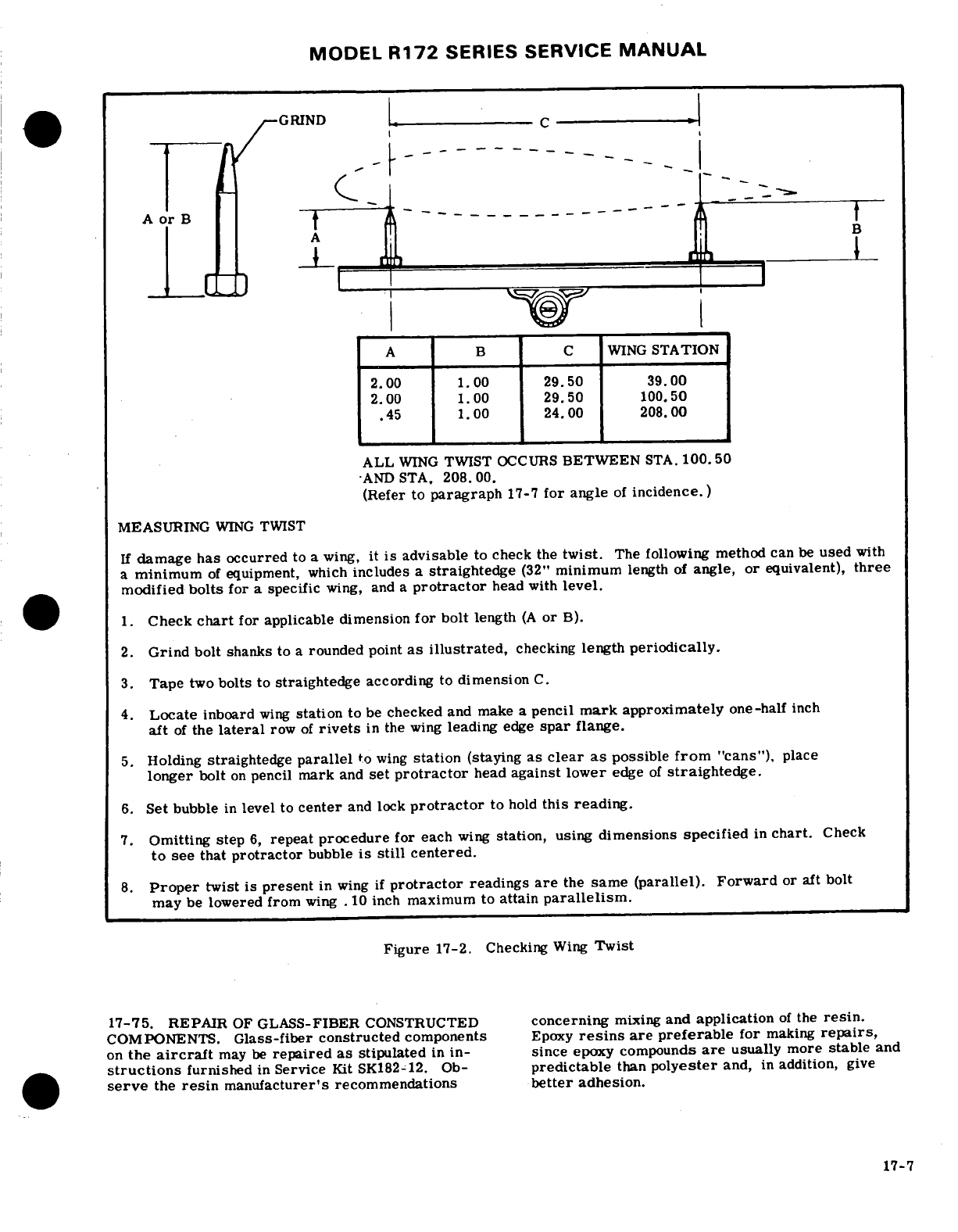
MODEL
R172
SERIES
SERVICE
MANUAL
-
A
----------------
WING
STATION
2.00
1.00
29.50 39.00
2.00
1.00 29.50
100.50
.45
1.00
24.00
208.00
ALL
WING
TWIST
OCCURS
BETWEEN
STA.
100.50
*AND
STA,
208.
00.
(Refer
to
paragraph
17-7
for
angle
of
incidence.)
MEASURING
WING
TWIST
If
damage
has
occurred
to
a
wing,
it
is
advisable
to
check
the
twist.
The
following
method
can
be
used
with
a
minimum
of
equipment,
which
includes
a
straightedge
(32"
minimum
length
of
angle,
or
equivalent),
three
modified
bolts
for
a
specific
wing, and
a
protractor
head
with
level.
1.
Check
chart
for applicable dimension
for
bolt
length
(A
or
B).
2.
Grind
bolt
shanks to
a
rounded
point
as
illustrated,
checking
length
periodically.
3.
Tape
two
bolts
to
straightedge
according
to
dimension
C.
4.
Locate
inboard
wing
station
to
be
checked
and
make
a
pencil
mark
approximately
one-half
inch
aft
of
the
lateral
row
of
rivets
in
the
wing
leading
edge
spar
flange.
5.
Holding
straightedge
parallel
to
wing
station
(staying
as
clear
as
possible
from
"cans"),
place
longer
bolt
on
pencil
mark
and
set
protractor
head
against lower
edge
of
straightedge.
6.
Set
bubble
in
level
to
center
and
lock
protractor
to
hold
this
reading.
7.
Omitting
step
6,
repeat
procedure
for
each
wing
station, using
dimensions
specified
in
chart.
Check
to
see
that
protractor
bubble
is
still
centered.
8.
Proper
twist
is
present
in
wing
if
protractor
readings
are
the
same
(parallel).
Forward
or
aft
bolt
may
be
lowered
from
wing
.
10
inch
maximum
to
attain
parallelism.
Figure
17-2.
Checking
Wing
Twist
17-75.
REPAIR
OF
GLASS-FIBER
CONSTRUCTED
concerning
mixing
and
application
of
the
resin.
COMPONENTS.
Glass-fiber
constructed
components
Epoxy
resins
are preferable
for
making
repairs,
on
the
aircraft
may
be
repaired
as
stipulated
in
in-
since
epoxy compounds
are
usually
more
stable
and
structions
furnished
in
Service
Kit
SK182-12.
Ob-
predictable
than
polyester
and,
in
addition,
give
serve
the
resin
manufacturer's
recommendations
better
adhesion.
17-7
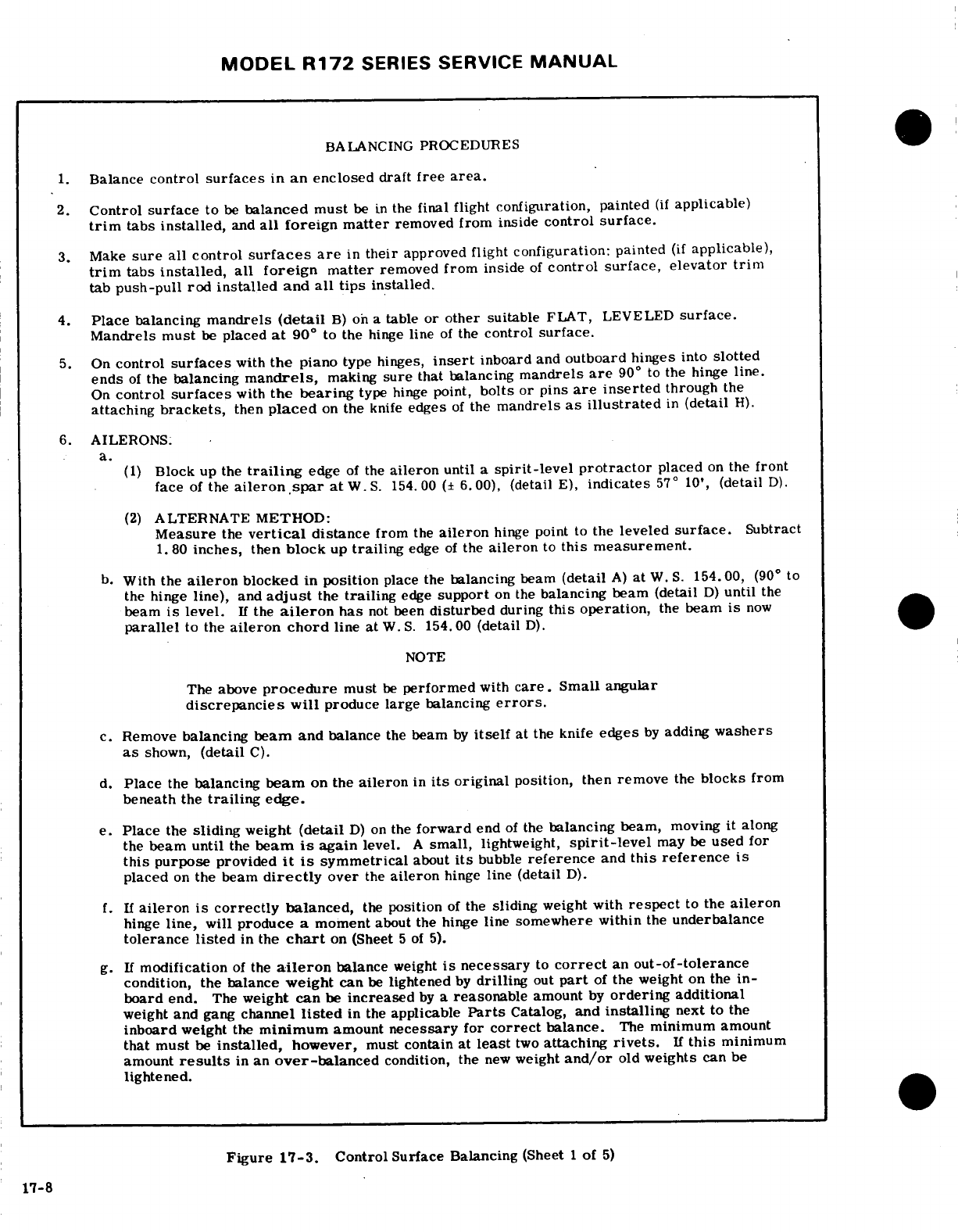
MODEL
R172
SERIES
SERVICE
MANUAL
BALANCING
PROCEDURES
1.
Balance
control
surfaces
in
an
enclosed
draft
free
area.
2.
Control
surface
to
be
balanced
must
be
in
the
final flight
configuration, painted
(if
applicable)
trim
tabs
installed,
and
all
foreign
matter
removed
from
inside
control
surface.
3.
Make
sure
all
control
surfaces are
in
their
approved
flight
configuration:
painted
(if
applicable),
trim
tabs
installed,
all
foreign
matter
removed
from
inside
of
control
surface, elevator trim
tab
push-pull
rod
installed
and
all
tips
installed.
4.
Place
balancing
mandrels
(detail
B)
on
a
table
or
other
suitable
FLAT, LEVELED
surface.
Mandrels
must
be
placed
at
90
°
to the
hinge
line
of
the
control
surface.
5.
On
control
surfaces
with
the
piano
type hinges,
insert
inboard
and
outboard
hinges
into
slotted
ends
of
the
balancing
mandrels,
making
sure
that
balancing
mandrels
are
90
°
to
the
hinge
line.
On
control
surfaces
with
the bearing
type
hinge
point,
bolts
or
pins
are
inserted
through
the
attaching
brackets,
then
placed
on
the
knife
edges
of
the
mandrels
as
illustrated
in
(detail
H).
6.
AILERONS.
a.
(1)
Block
up
the
trailing
edge
of the
aileron
until
a
spirit-level
protractor
placed
on
the
front
face
of
the
aileron.spar
at
W.S.
154.00
(±
6.00),
(detail
E),
indicates
57
°
10',
(detail
D).
(2)
ALTERNATE
METHOD:
Measure
the
vertical
distance
from
the
aileron
hinge
point
to
the
leveled
surface.
Subtract
1.
80
inches,
then
block
up
trailing
edge
of
the
aileron
to
this
measurement.
b.
With
the
aileron
blocked
in
position
place
the
balancing
beam
(detail
A)
at
W.
S.
154.00,
(90
°
to
the
hinge
line),
and
adjust
the
trailing
edge
support
on
the
balancing
beam
(detail
D)
until
the
beam
is
level.
If
the
aileron
has
not
been
disturbed
during
this
operation,
the
beam
is
now
parallel
to
the
aileron chord
line
at
W.
S.
154.00
(detail
D).
NOTE
The above
procedure
must
be
performed
with
care.
Small
angular
discrepancies will
produce large
balancing
errors.
c.
Remove
balancing
beam
and
balance
the
beam
by
itself
at
the
knife
edges
by
adding
washers
as
shown,
(detail
C).
d.
Place
the
balancing
beam
on
the
aileron
in
its
original
position, then
remove
the
blocks
from
beneath
the
trailing
edge.
e.
Place
the
sliding
weight
(detail
D)
on
the
forward
end
of
the
balancing
beam,
moving
it
along
the
beam
until
the
beam
is
again
level.
A
small,
lightweight,
spirit-level
may
be
used
for
this
purpose
provided
it is
symmetrical
about
its
bubble
reference
and
this
reference
is
placed
on
the beam
directly
over
the
aileron
hinge
line
(detail
D).
f.
If
aileron
is
correctly
balanced,
the
position
of
the
sliding
weight
with
respect
to
the
aileron
hinge
line,
will
produce
a
moment
about
the
hinge
line
somewhere
within
the
underbalance
tolerance
listed
in
the
chart
on
(Sheet
5
of
5).
g.
If
modification
of
the
aileron
balance
weight
is
necessary
to
correct
an
out-of-tolerance
condition,
the balance
weight
can
be
lightened
by
drilling
out
part
of
the
weight
on
the in-
board
end.
The
weight
can
be
increased
by
a
reasonable
amount
by
ordering
additional
weight
and
gang
channel
listed
in
the
applicable
Parts
Catalog,
and
installing
next
to the
inboard
weight
the
minimum
amount
necessary
for
correct
balance.
The
minimum amount
that
must
be
installed,
however,
must
contain
at
least
two
attaching
rivets.
If
this
minimum
amount
results
in
an
over-balanced
condition,
the
new
weight
and/or
old
weights
can
be
lightened.
Figure
17-3.
Control
Surface
Balancing
(Sheet
1
of
5)
17-8
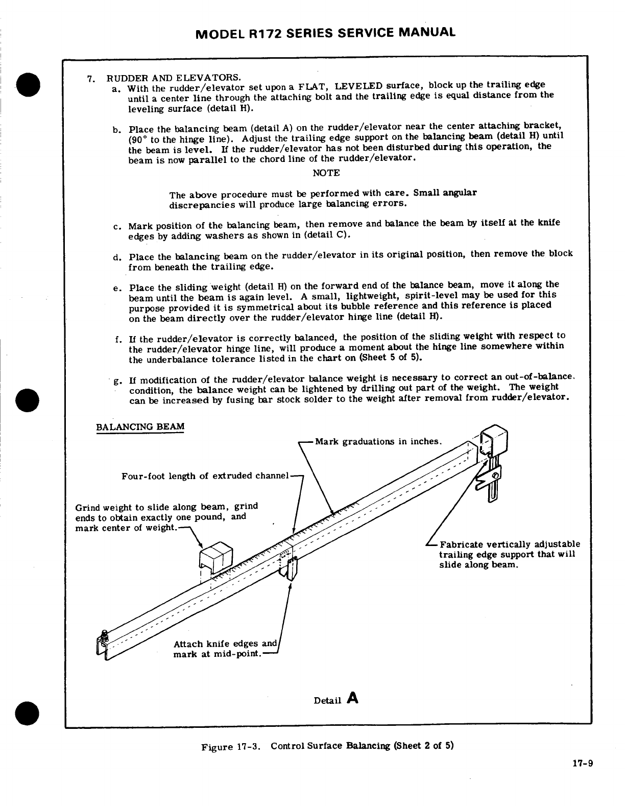
MODEL R172
SERIES
SERVICE
MANUAL
7.
RUDDER
AND
ELEVATORS.
a.
With
the
rudder/elevator
set
upon
a
FLAT,
LEVELED
surface,
block
up
the
trailing
edge
until
a
center
line
through
the
attaching
bolt
and
the
trailing
edge
is
equal
distance from
the
leveling
surface
(detail
H).
b.
Place
the
balancing
beam
(detail
A)
on
the
rudder/elevator
near
the
center attaching
bracket,
(90
°
to
the
hinge line).
Adjust
the
trailing
edge
support
on
the
balancing
beam
(detail
H)
until
the
beam
is
level.
If
the
rudder/elevator
has
not
been
disturbed
during
this
operation,
the
beam
is
now
parallel
to
the
chord
line
of
the
rudder/elevator.
NOTE
The
above procedure
must
be
performed
with
care.
Small
angular
discrepancies
will
produce
large
balancing
errors.
c.
Mark
position
of
the
balancing
beam,
then
remove
and
balance
the
beam
by
itself
at
the
knife
edges
by
adding
washers
as
shown
in
(detail
C).
d.
Place
the
balancing
beam
on
the
rudder/elevator
in
its
original
position,
then remove
the
block
from
beneath
the
trailing
edge.
e.
Place
the
sliding
weight
(detail
H)
on
the
forward
end
of
the
balance
beam,
move
it
along
the
beam
until
the
beam
is
again
level.
A
small,
lightweight,
spirit-level
may
be
used
for
this
purpose
provided
it is
symmetrical
about
its
bubble
reference
and
this
reference
is
placed
on
the
beam
directly
over
the
rudder/elevator
hinge
line
(detail
H).
f.
If
the
rudder/elevator
is
correctly
balanced,
the
position
of
the
sliding
weight
with
respect
to
the
rudder/elevator
hinge
line,
will
produce
a
moment about
the hinge
line
somewhere within
the
underbalance
tolerance
listed
in
the
chart
on
(Sheet
5
of
5).
g.
If
modification
of
the
rudder/elevator
balance
weight
is
necessary
to
correct
an
out-of-balance.
condition,
the
balance
weight
can
be
lightened
by
drilling
out
part
of
the
weight.
The
weight
can
be
increased
by
fusing
bar
stock
solder
to
the
weight
after
removal
from
rudder/elevator.
BALANCING
BEAM
Mark
graduations
in
inches
Four-foot
length
of
extruded
channel
Grind
weight to
slide
along
beam,
grind
ends
to
obtain
exactly
one
pound,
and
mark
center
of
weight.\
Fabricate vertically
adjustable
trailing
edge
support
that
will
slide
along beam.
Attach knife
edges
and
mark
at
mid-point.
*
Detail
A
Figure
17-3.
Control
Surface
Balancing
(Sheet
2
of
5)
17-9
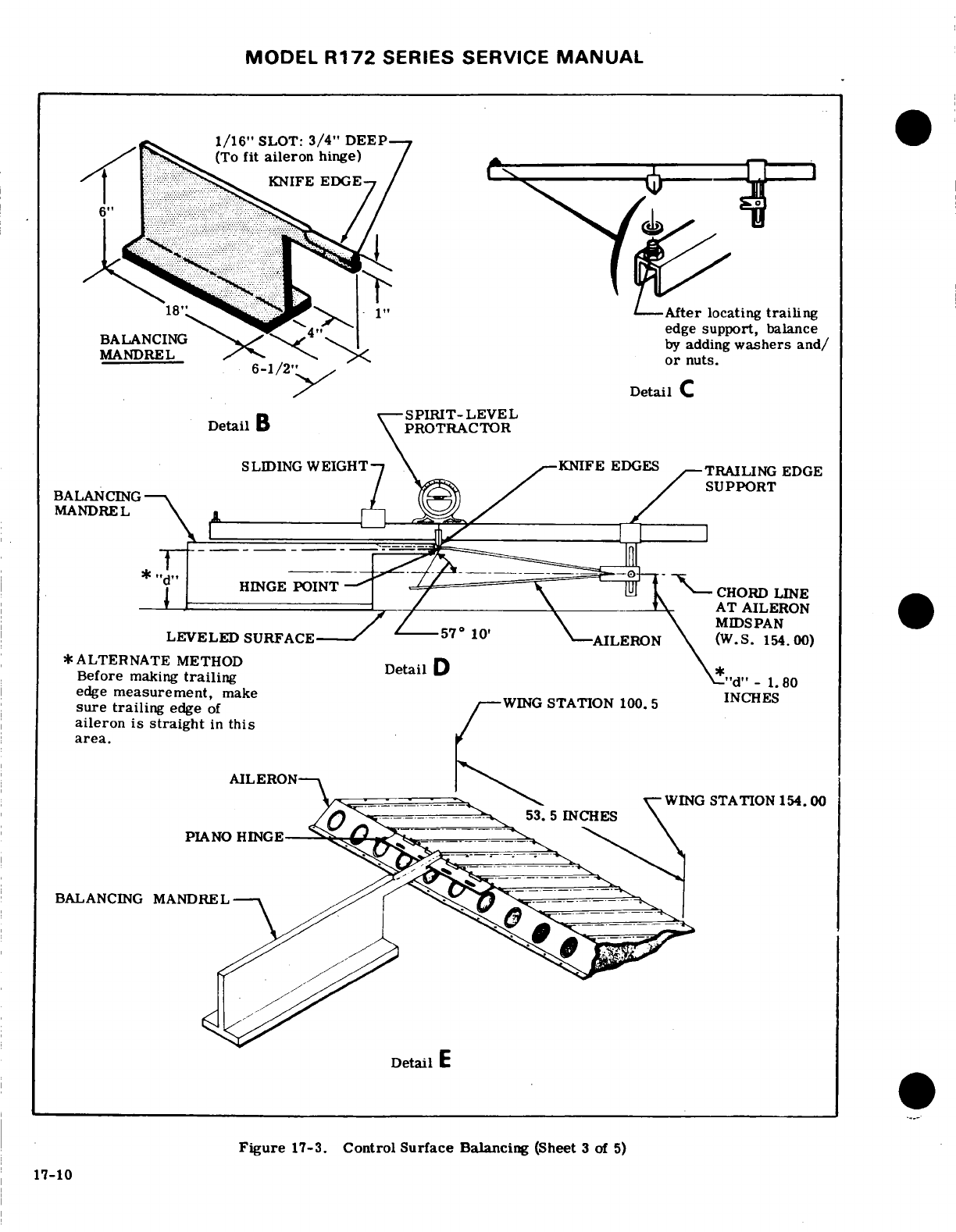
MODEL
R172
SERIES
SERVICE
MANUAL
1/16"
SLOT:
3/4"
DEEP
(To
fit
aileron
hinge)
KNIFE
EDGE
After
locating
trailing
edge
support,
balance
BALANCING
by
adding
washers and/
MANDREL
or
nuts.
6-1/2
Detail
C
SPIRIT-LEVEL
Detail
B
PROTRACTOR
SLIDING
WEIGHT
\
R-KNIFE
EDGES
TRAILING EDGE
SUPPORT
BALANCING
MANDREL
..
"d"
HINGE
POINT
-
-
CHORD
LINE
--
AT
AILERON
MIDSPAN
LEVELED
SURFACE
AILERON
(W.S.154.00)
*
ALTERNATE
METHOD
Detail
D
*
Before
making
trailing
-
edge
measurement,
make
WING
STATION
1005
INCHES
sure trailing
edge
of
BALANCING
MANDREL
aileron
is
straight
in
this
area.
17-3.
Control
Surface
Balancing
(Sheet
3
of
5)
AILERON-N
....
-WING
STATION
154.00
Detail
E
Figure
17-3.
Control
Surface
Balancing
(Sheet
3
of
5)
17-10
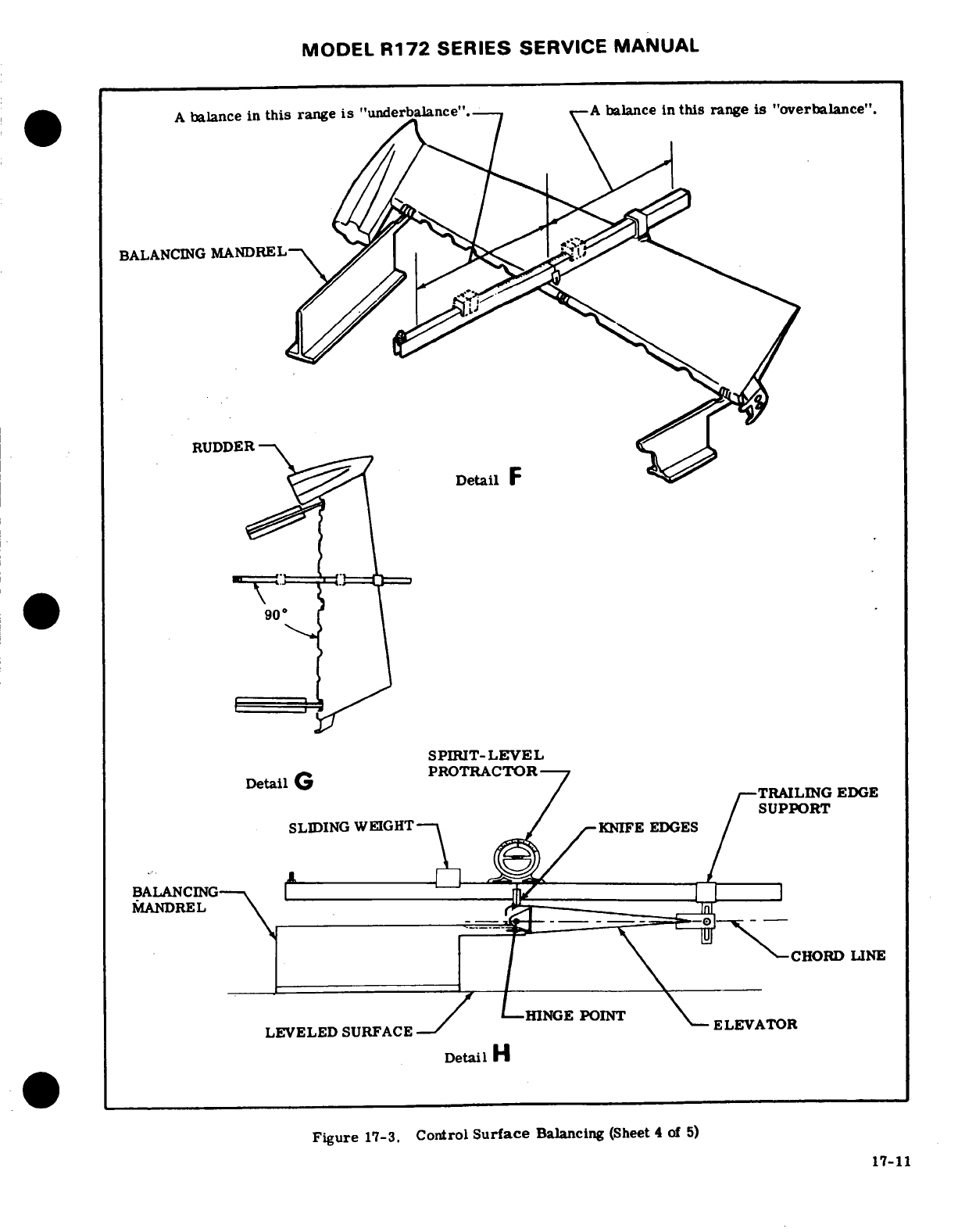
MODEL
R172
SERIES
SERVICE
MANUAL
A
balance in
this
range
is
"underbalance".--
A
balance in
this
range
is
"overbalance".
BALANCING
MANDREL
RUDDER
Detail
F
SPIRIT-LEVEL
Detail
G
PROTRACTOR
TRAILING
EDGE
SUPPORT
SLIDING WEIGHT KNIFE
EDGES
BALANCING
MANDREL
CHORD
LINE
HINGE POINT
LEVELED
SURFACE
-
ELEVATOR
Detail
H
Figure
17-3.
Control
Surface
Balancing
(Sheet
4
of
5)
17-11
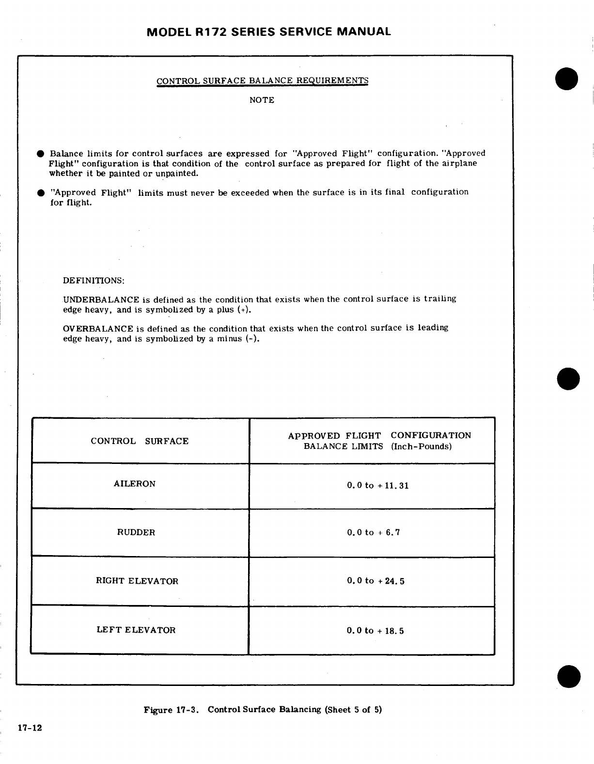
MODEL
R172
SERIES SERVICE
MANUAL
CONTROL
SURFACE
BALANCE
REQUIREMENTS
NOTE
*
Balance
limits
for
control
surfaces
are
expressed
for
"Approved
Flight"
configuration.
"Approved
Flight"
configuration
is
that
condition
of
the
control
surface
as
prepared
for flight
of
the
airplane
whether
it
be
painted
or
unpainted.
*
"Approved
Flight"
limits
must
never
be
exceeded
when
the
surface
is
in
its
final
configuration
for
flight.
DEFINITIONS:
UNDERBALANCE
is
defined
as
the condition
that
exists
when
the
control
surface
is
trailing
edge
heavy, and
is
symbolized
by
a
plus
(+).
OVERBALANCE
is
defined
as
the
condition
that
exists
when
the
control
surface
is
leading
edge
heavy,
and
is
symbolized
by
a
minus
(-).
APPROVED FLIGHT CONFIGURATION
BALANCE
LIMITS
(Inch-Pounds)
AILERON
0.0
to
+11.31
RUDDER
0.0
to
+
6.7
RIGHT
ELEVATOR
0.
0
to
+
24.
5
LEFT
ELEVATOR
0.0
to
+
18.5
Figure
17-3.
Control
Surface
Balancing
(Sheet
5
of
5)
17-12
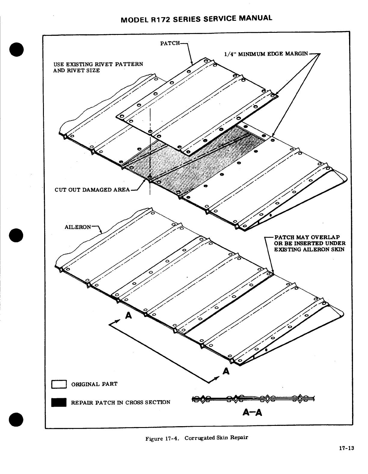
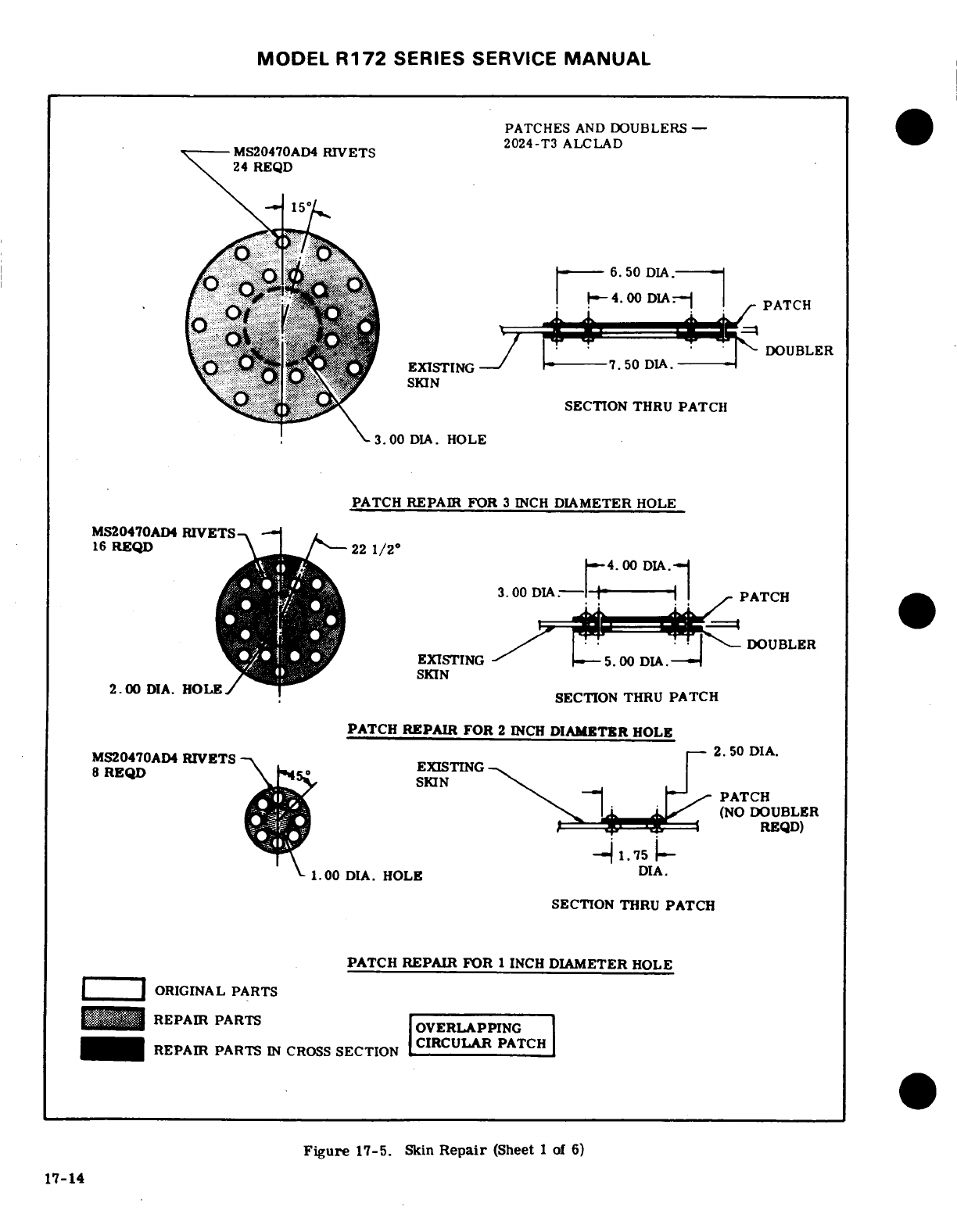
MODEL
R172
SERIES
SERVICE
MANUAL
PATCHES
AND
DOUBLERS
-
2024-T3
ALCLAD
MS20470AD4
RIVETS
24 REQD
DOUBLER
EXISTING
SKIN
SECTION
THRU
PATCH
3.00
DIA.
HOLE
PATCH
REPAIR
FOR
3
INCH
DIAMETER
HOLE
MS20470AD4
RIVETS
DOUBLER
16
REQD
,-4.00 DIA.-
EXISTING
5.00
DIA.7--
SKIN
SECTION
THRU
PATCH
PATCH
REPAIR
FOR
2
INCH
DIAMETER
HOLE
2.50
DIA.
MS20470AD4
RIVETS
EXISTING
8
REQD
SKIN
PATCH
(NO
DOUBLER
REQD)
1.75
C.
1.00
DIA.
HOLE
DIA.
SECTION
THRU
PATCH
PATCH REPAIR
FOR
1
INCH
DIAMETER
HOLE
.
ORIGINAL
PARTS
REPAIR
PARTS
OVERLAPPING
REPAIR
PARTS
IN
CROSS
SECTION
CI
R C U L
AR
PATCH
Figure
17-5.
Skin
Repair
(Sheet
1
of
6)
17-14
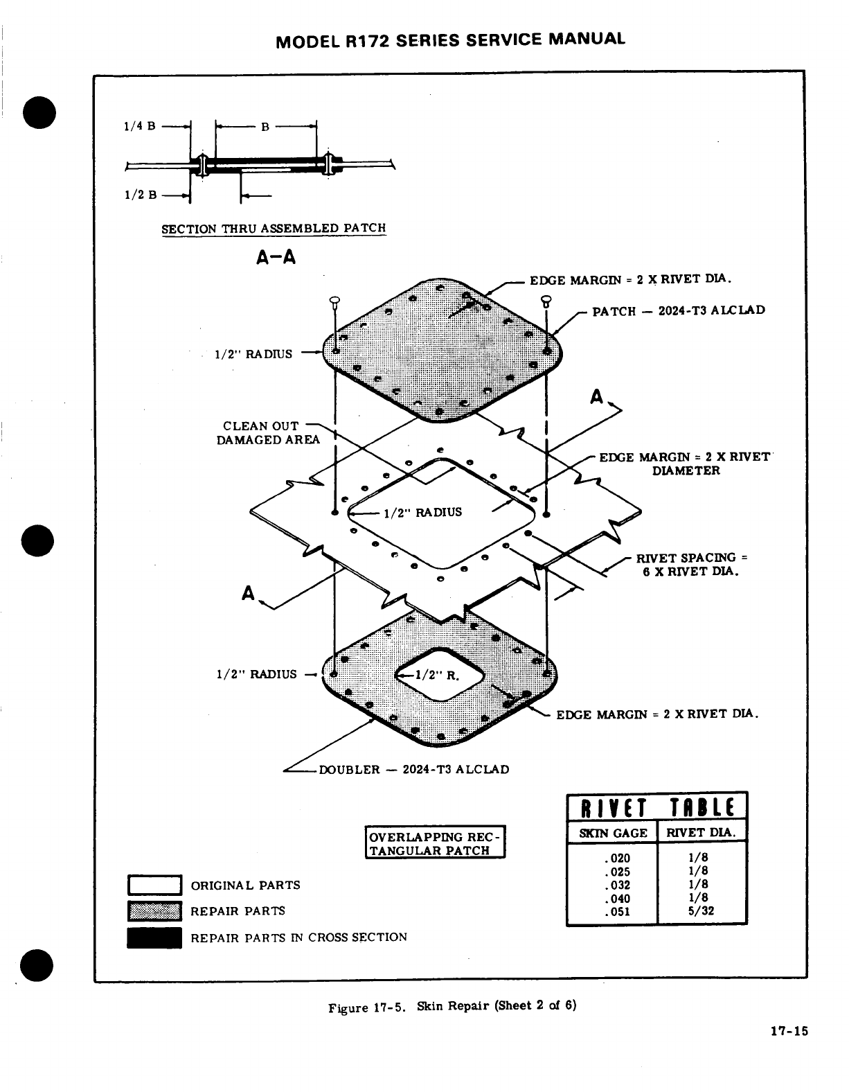
MODEL
R172
SERIES
SERVICE
MANUAL
1/2
B
SECTION
THRU
ASSEMBLED
PATCH
A-A
EDGE
MARGIN
=
2
X
RIVET
DIA.
PATCH
-
2024-T3
ALCLAD
-
DAMAGED
AREA
EDGE
MARGIN
=
2
X
RIVET
..-...
,-........
---
.,---DIAMETER
,
1/2"
RADIUS
-.
....
1/2"
RADIUS-
, .-
l
EDGE
MARGIN
=
2
X
RIVET
DIA.
DOUBLER
-
2024-T3
ALCLAD
RIVET
TABLE
OVERLAPPNG REC-SKIN
GAGE
RIVET
DIA.
TANGULAR
PATCH
.............
..
025
1/8
.ORIGINAL
PARTS
.032
.........
....
REPAIR
PARTS
051
5/32
REPAIR
PARTS
IN
CROSS
SECTION
Figure
15.
Skn
Repair
(Sheet
2
of
6)
RIVET
Figure
17-5.
Skin
Repair
(Sheet
2
of
6)
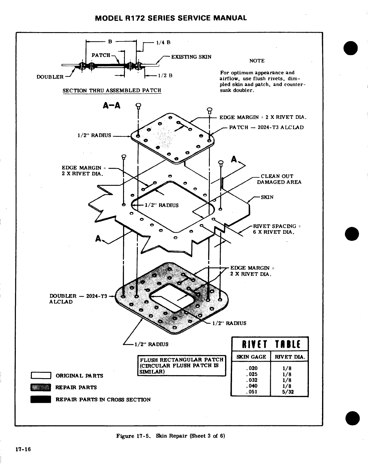
MODEL
R172
SERIES
SERVICE
MANUAL
-B
.
--
or
optimum
appearance
and
airflow,
use
flush
rivets,
dim-
pled
skin
and
patch,
and
counter-
SECTION
THRU
ASSEMBLED
PATCH
sunk
doubler.
A-A
EDGE
MARGIN
= 2
X
RIVET
DIA.
PATCH
-
2024-T3
ALCLAD
2
X
RIVET
DIA.
,,,,
CLEAN
OUT
^
RIVET
SPACING
=
6
X
RIVET
DIA.
-
"EDGE
MARGIN
=
2
X RIVET DIA.
DOUBLER
-
2024-T3
" ..
1
^
RIVET
(CIRCULAR FLUSH
PATCH
IS
020
1/8
ORIGINAL
PARTS
SMILAR)
2H 1/8
.032
1/8
REPAIR
PARTS
.040
1/8
.051
5/32
REPAIR
PARTS
IN
CROSS
SECTION
Figure
17-5.
Skin
Repair
(Sheet
3
of
6)
17-16
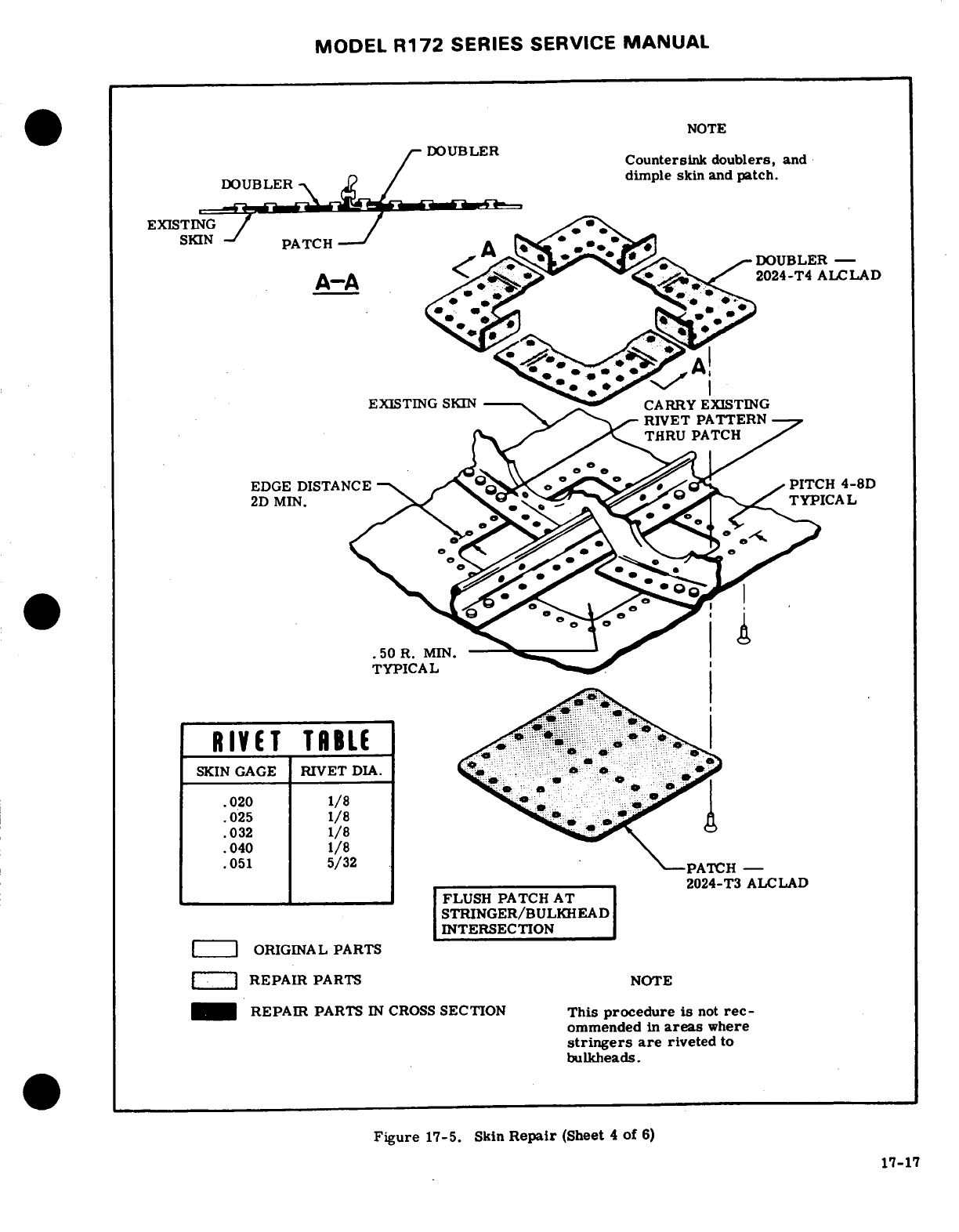
MODEL
R172
SERIES
SERVICE
MANUAL
NOTE
DOUBLER
Countersink
doublers,
and
DOUBLER
-
dimple
skin
and
patch.
EXISTING
SKIN
PATCH
DOUBLER
-
RIVET
PATTERNL
THRU PATCH
2D
MIN.
TYPICAL
.50
R. MIN.
RIVET
TABLE
SKIN
GAGE
RIVET
DIA.
.020
1/8
.025
1/8
.032
1/8
.040
1/8
.051
5/32
-PATCH
2024-T3
ALCLAD
FLUSH
PATCH
AT
STRINGER/BULKHEAD
INTERSECTION
ORIGINAL
PARTS
REPAIR
PARTS
NOTE
REPAIR
PARTS
IN
CROSS
SECTION
This
procedure
is
not
rec-
ommended
in
areas
where
stringers
are
riveted
to
bulkheads.
Figure
17-5.
Skin
Repair
(Sheet
4
of
6)
17-17
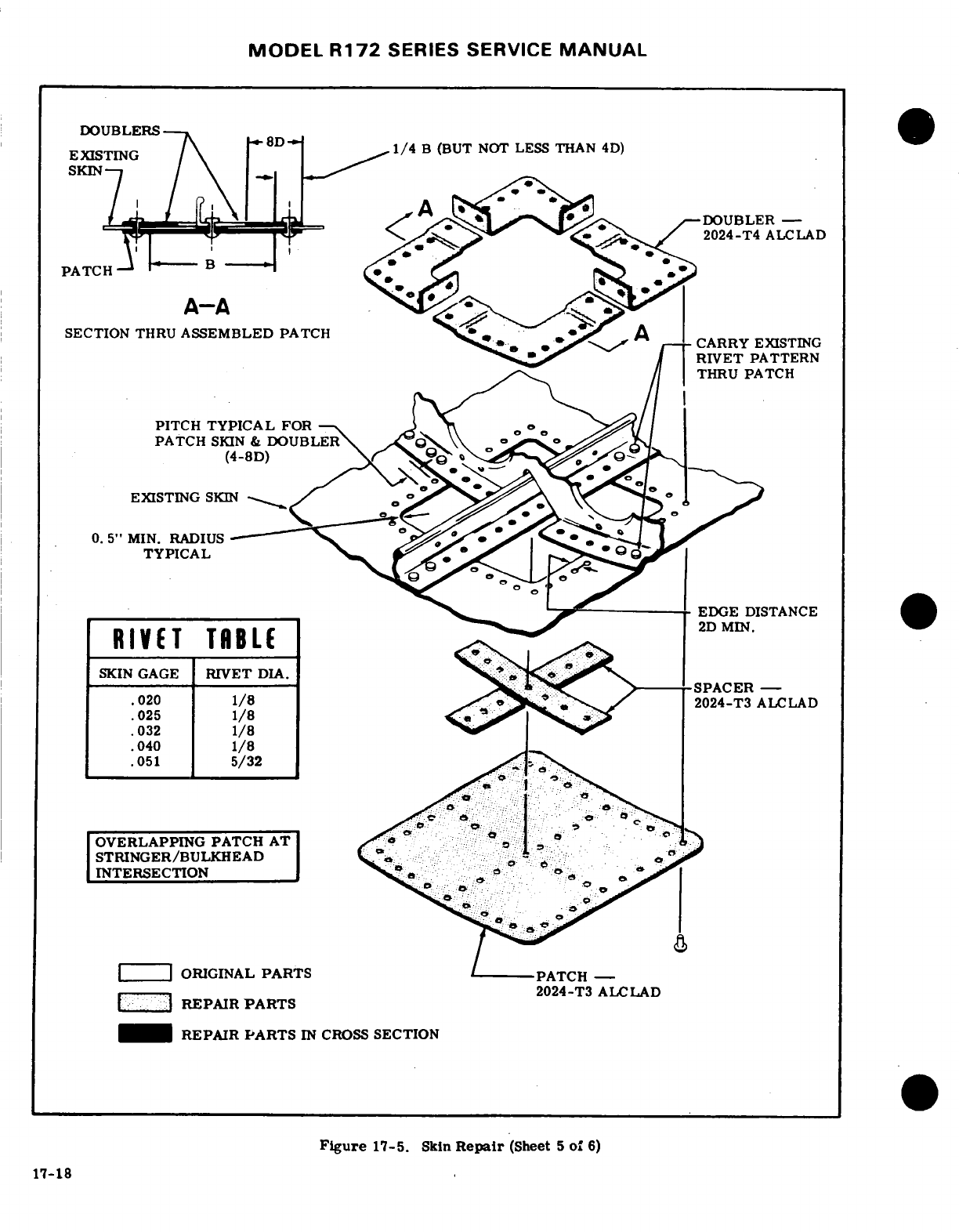
MODEL
R172
SERIES SERVICE
MANUAL
DOUBLERS
EXISTING
1/4
B
(BUT
NOT
LESS THAN
4D)
SKIN
.....
-O-DOUBLER
-
*
2024-T4
ALCLAD
PATCH
A-A
SECTION
THRU
ASSEMBLED
PATCH
...
RIVET
PATTERN
PITCH
TYPICAL FOR
PATCH
SKIN
&
DOUBLERU
.
EXISTING
SKIN
0.
5"
MIN.
RADIUS
TYPICAL
-
EDGE
DISTANCE
RIVET
TABLE
SKIN
GAGE
RIVET
DIA.
-------- --------
-
.020
1/8
2024-T3
ALCLAD
.025
1/8
·
032
1/8
.040
1/8
.051
5/32
OVERLAPPING PATCH
AT
STRINGER/BULKHEAD
INTERSECTION
.
ORIGINAL
PARTS /
PATCH
2024-T3
ALCLAD
REPAIR
PARTS
REPAIR
PARTS
IN
CROSS
SECTION
Figure
17-5.
Skin
Repair
(Sheet
5
of
6)
17-18
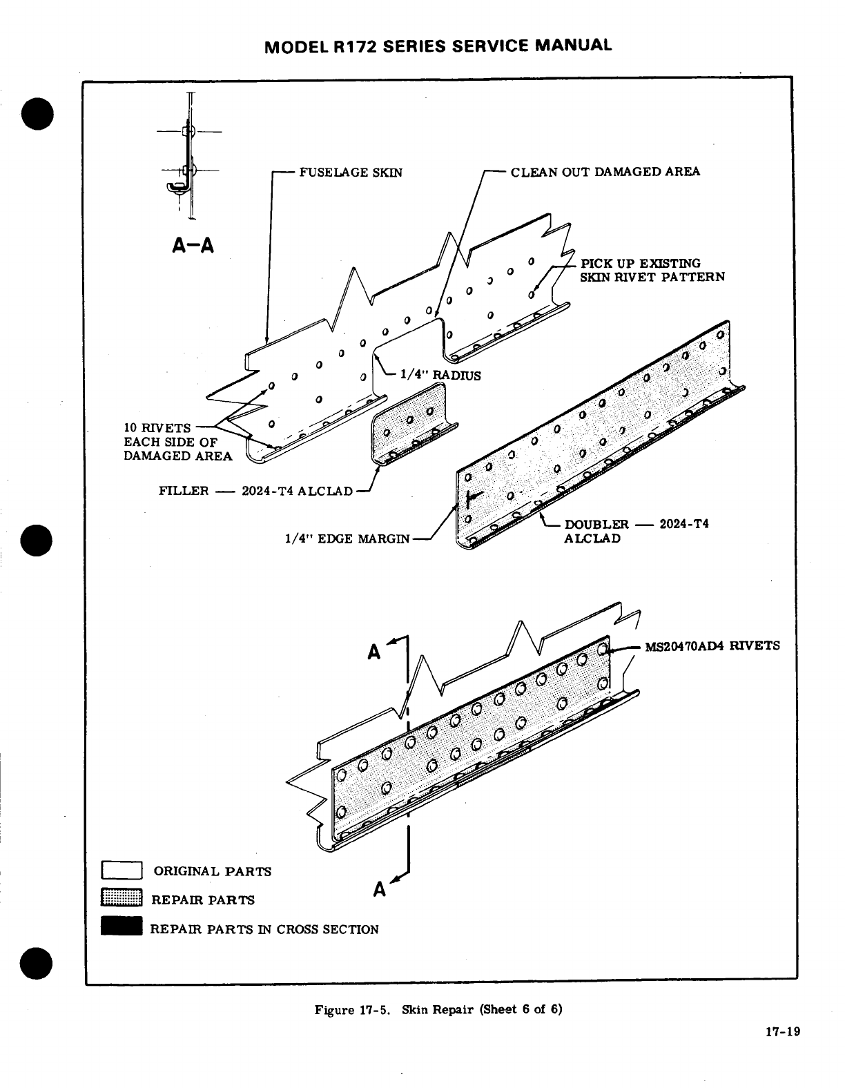
MODEL
R172
SERIES
SERVICE
MANUAL
FUSELAGE
SKIN
--
CLEAN
OUT
DAMAGED
AREA
A-A
PICK
UP
EXISTING
-
SKIN
RIVET
PATTERN
10
RIVETS
EACH SIDE
OF
DAMAGED
AREA
FILLER-
2024-T4
ALCLAD
DOUBLER
-
2024-T4
1/4"
EDGE
MARGIN-
ALCLAD
MS20470AD4
RIVETS
ORIGINAL
PARTS
REPAIR
PARTS
REPAIR
PARTS
IN
CROSS
SECTION
Figure
17-5.
Skin
Repair
(Sheet
6
of
6)
17-19
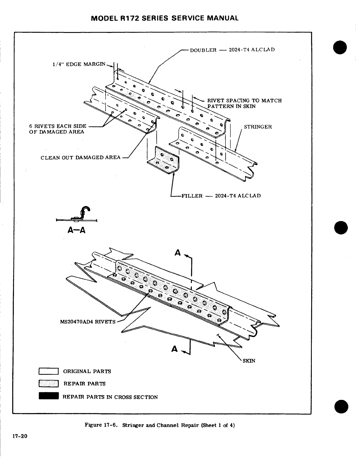
MODEL
R172
SERIES
SERVICE
MANUAL
DOUBLER
-
2024-T4
ALCLAD
1/4"
EDGE
MARGIN
RIVET
SPACING
TO
MATCH
-.
PATTERN
IN
SKIN
6
RIVETS
EACH
SIDE
STRINGER
OF
DAMAGED
AREA
CLEAN
OUT
DAMAGED
AREA
FILLER
2024-T4
ALCLAD
MS20470AD4
RIVETS
SKIN
ORIGINAL
PARTS
*
REPAIR
PARTS
REPAIR
PARTS
IN
CROSS
SECTION
Figure
17-6.
Stringer
and
Channel Repair
(Sheet
1
of
4)
17-20
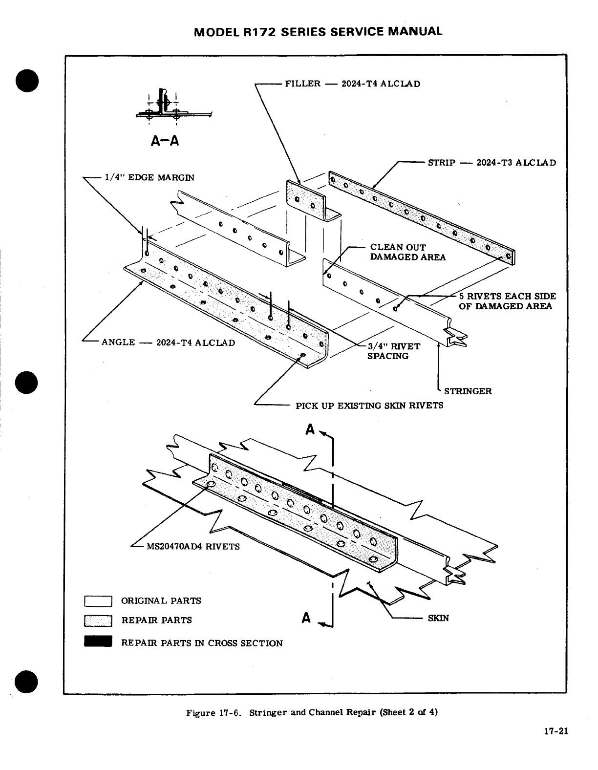
MODEL
R172
SERIES
SERVICE
MANUAL
FILLER
-
2024-T4
ALCLAD
A-A
STRIP-
2024-T3
ALCLAD
1/4"
EDGE
MARGIN
CLEAN
OUT
' .
DAMAGED
AREA
5
RIVETS
EACH
SIDE
OF
DAMAGED
AREA
ANGLE
-2024-T4
ALCLAD
RIVET
3/4"
RIVET
SPACING
STRINGER
PICK
UP
EXISTING
SKIN
RIVETS
MS20470AD4
RIVETS
ORIGINAL
PARTS
REPAIR
PARTS
A
s
REPAIR
PARTS
IN
CROSS
SECTION
Figure
17-6.
Stringer
and
Channel
Repair
(Sheet
2
of
4)
17-21
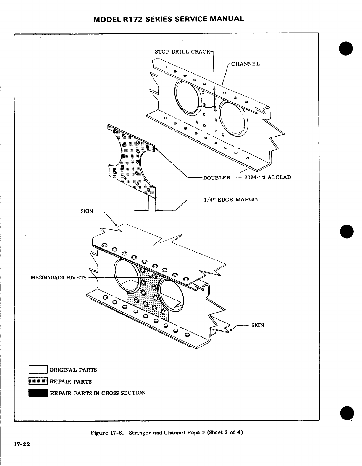
MODEL
R172
SERIES SERVICE
MANUAL
STOP DRILL
CRACK
^
CHANNEL
-DOUBLER
-
2024-T3
ALCLAD
1/4"
EDGE
MARGIN
SKIN
-- -
MS20470AD4
RIVETS
ORIGINAL
PARTS
..
REPAIR
PARTS
REPAIR
PARTS
IN
CROSS
SECTION
Figure
17-6.
Stringer
and
Channel
Repair
(Sheet
3
of
4)
17-22
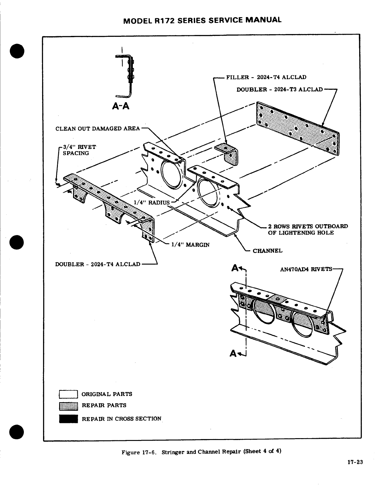
MODEL
R172
SERIES
SERVICE
MANUAL
FILLER
-
2024-T4
ALCLAD
A-\
DOUBLER - 2024-T3
ALCLAD
CLEAN
OUT
DAMAGED
AREA
SPACING
1/4"
RADIUS
-2
ROWS
RIVETS
OUTBOARD
OF
LIGHTENING
HOLE
1/4"
MARGIN
CHANNEL
DOUBLER
-
2024-T4
ALCLAD
AN470AD4
RIVETS·
W
ORIGINAL
PARTS
REPAIR
PARTS
REPAIR
IN
CROSS
SECTION
Figure
17-6.
Stringer
and
Channel
Repair
(Sheet
4
of
4)
17-23
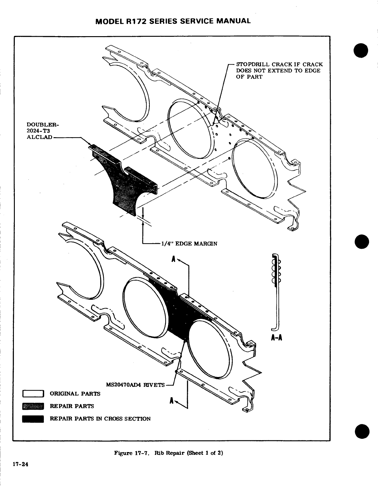
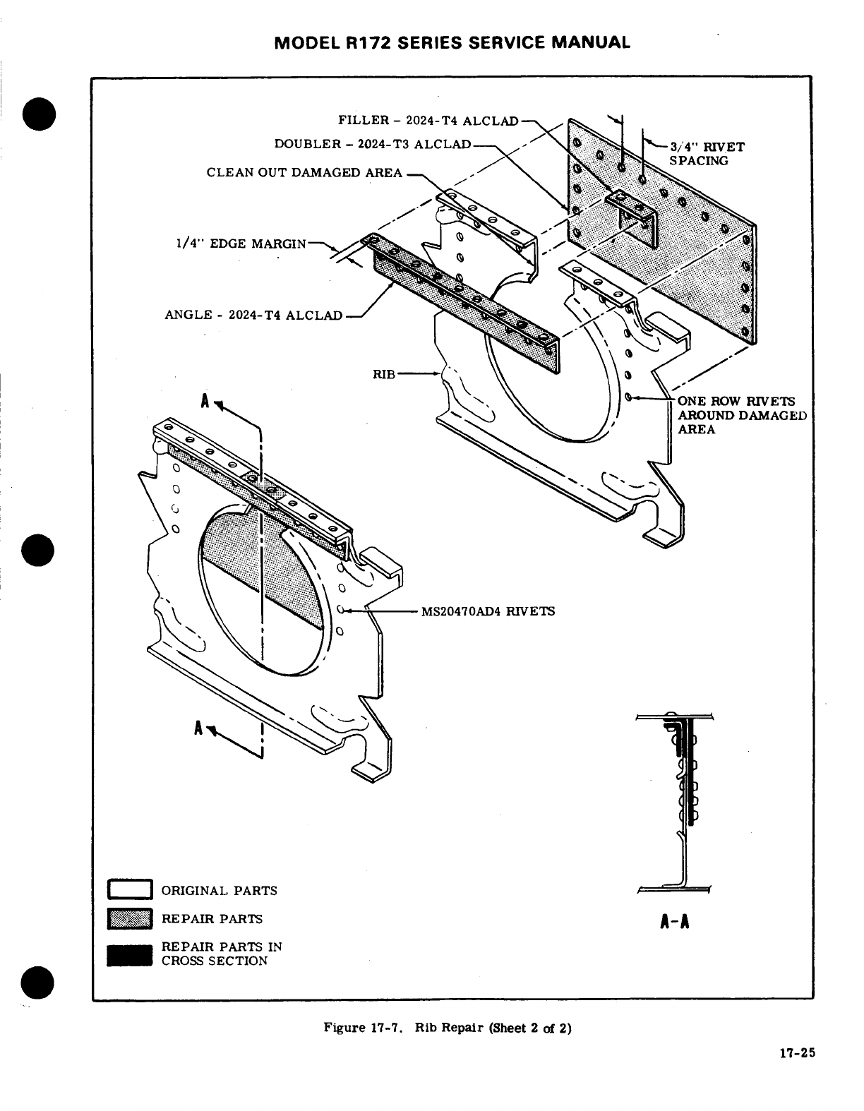
MODEL
R172
SERIES
SERVICE
MANUAL
FILLER
-
2024-T4
ALCLAD
DOUBLER
-
2024-T3
ALCLAD
3/'4"
RIVET
SPACING
CLEAN
OUT
DAMAGED AREA
.
1/4"
EDGE
MARGIN-
.
..-
ANGLE-
2024-T4
ALCLAD
ONE
ROW
RIVETS
AROUND DAMAGED
AREA
---
MS20470AD4
RIVETS
ORIGINAL
PARTS
REPAIR
PARTS
A-A
REPAIR
PARTS
IN
CROSS
SECTION
Figure
17-7.
Rib
Repair
(Sheet
2
of
2)
17-25
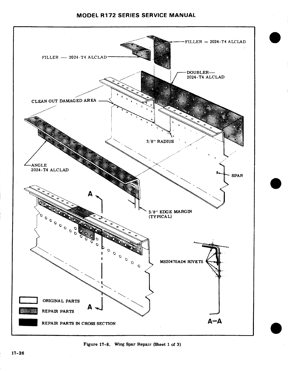
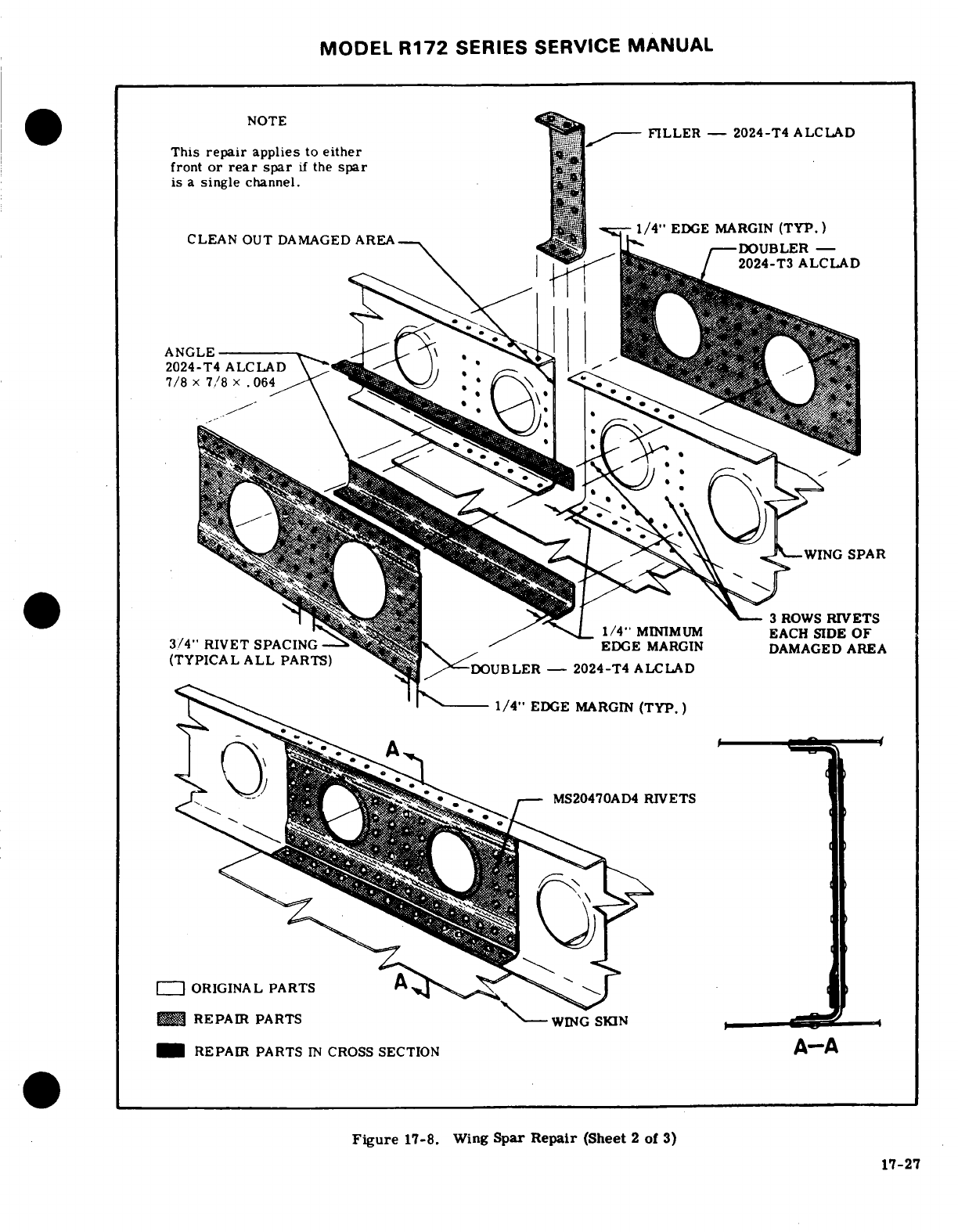
MODEL
R172
SERIES
SERVICE
MANUAL
NOTE
FILLER
-
2024-T4
ALCLAD
This
repair
applies
to
either
front
or
rear
spar
if
the
spar
is
a
single
channel.
CLEAN
OUT
DAMAGED
AREA
1/4"
EDGE MARGIN
(TYP.)
3/4"
RIVET
SPACING
1/4'
MINIMUM
EACH
SIDE
OF
DOUBLER
-
ANGLE
7/8
x
x
1/4"
MINIMUM
EACH
SIDE
OF
1/4"
EDGE
MARGIN
(TYP.)
MS20470AD4
RIVETS
-
ORIGINAL
PARTS
REPAIR
PARTS
REPAIR
PARTS
IN
CROSS
SECTION
Figure
17-8.
Wing
Spar
Repair
(Sheet
2
of
3)
17-27
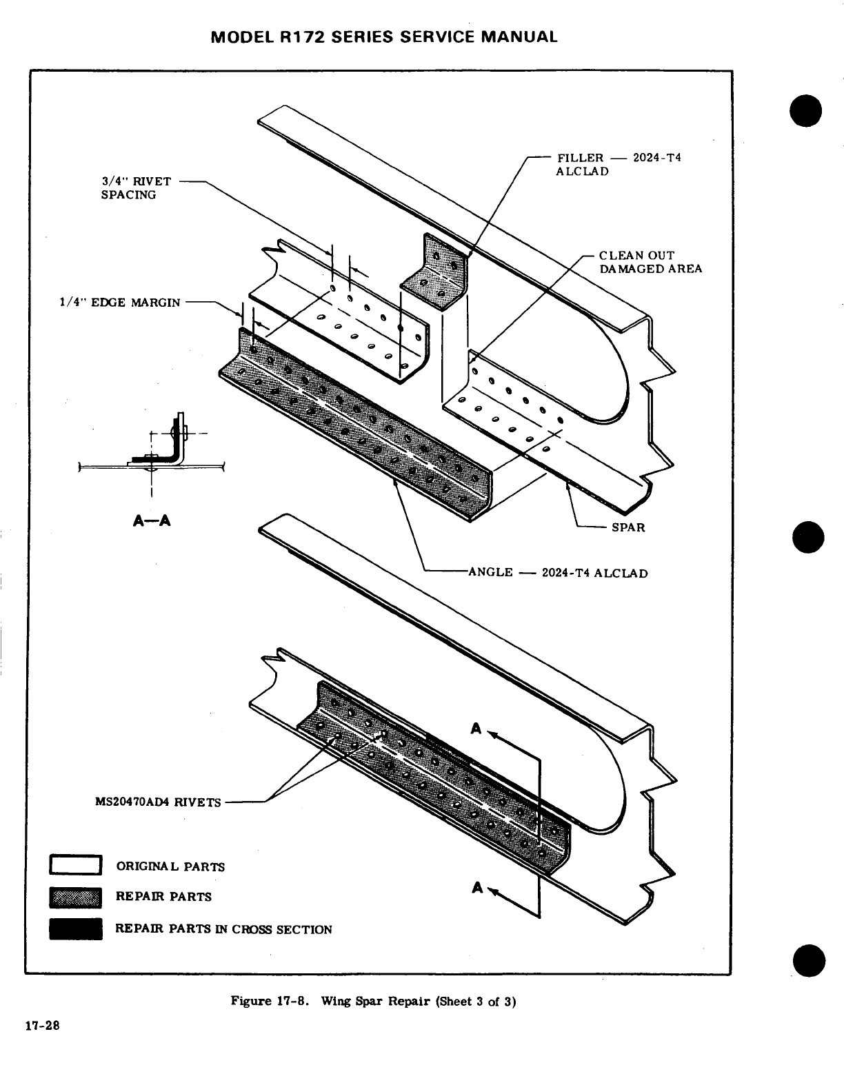
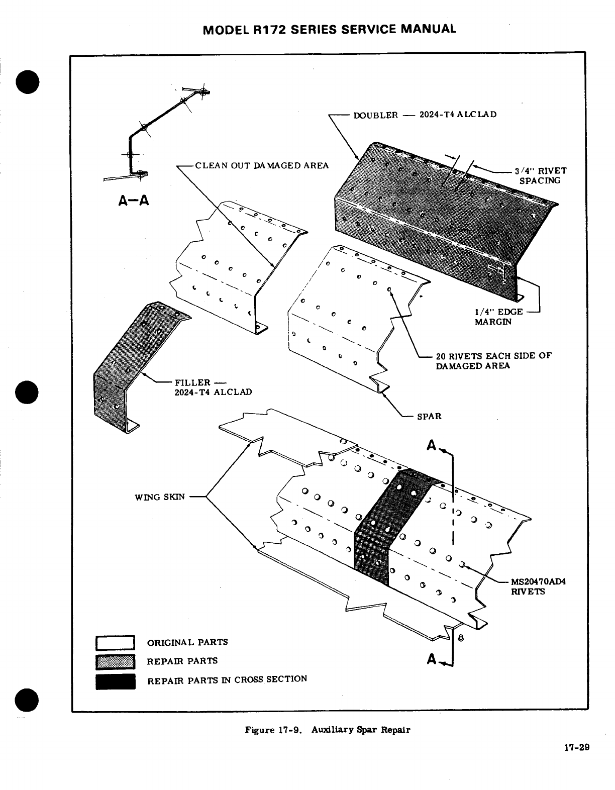
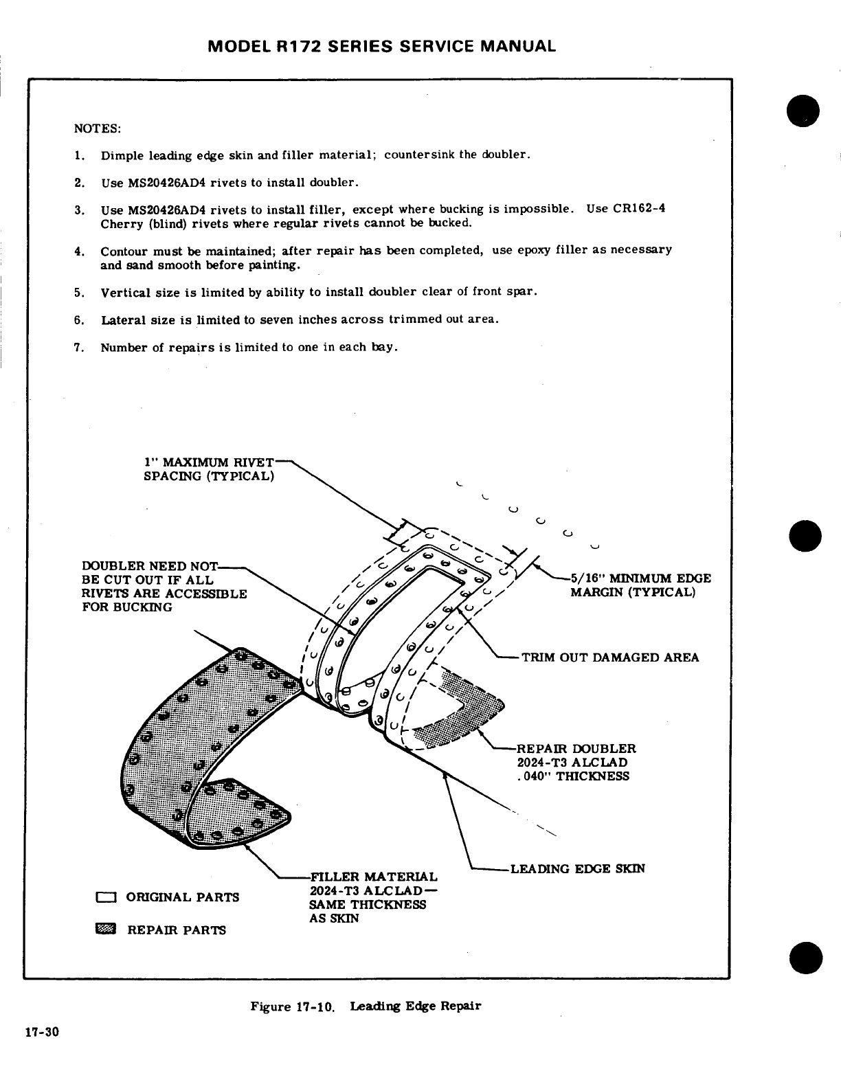
MODEL
R172
SERIES
SERVICE
MANUAL
NOTES:
1.
Dimple
leading
edge
skin
and
filler
material;
countersink
the
doubler.
2.
Use
MS20426AD4
rivets
to
install
doubler.
3.
Use
MS20426AD4
rivets
to
install
filler,
except
where
bucking
is impossible.
Use
CR162-4
Cherry
(blind)
rivets
where
regular
rivets
cannot
be bucked.
4.
Contour
must
be
maintained;
after
repair
has
been
completed,
use
epoxy
filler
as
necessary
and
sand
smooth before
painting.
5.
Vertical
size
is
limited
by
ability
to
install
doubler
clear
of
front
spar.
6.
Lateral
size
is
limited
to
seven
inches
across
trimmed
out
area.
7.
Number
of
repairs
is
limited
to
one
in each
bay.
1"
MAXIMUM
RIVET
SPACING
(TYPICAL)
DOUBLER
NEED
NOT
BE
CUT
OUT
IF
ALL
5/16"
MINIMUM
EDGE
RIVETS
ARE
ACCESSIBLE
MARGIN
(TYPICAL)
FOR
BUCKING
TRIM
OUT
DAMAGED
AREA
.....
...
......... ....
2024-T3
ALCLAD
.040"
THICKNESS
FILLER
MATERIAL
ORIGINAL
PART
SAME
THICKNESS
AS
SKIN
REPAIR
PARTS
Figure
17-10.
Leading
Edge
Repair
17-30
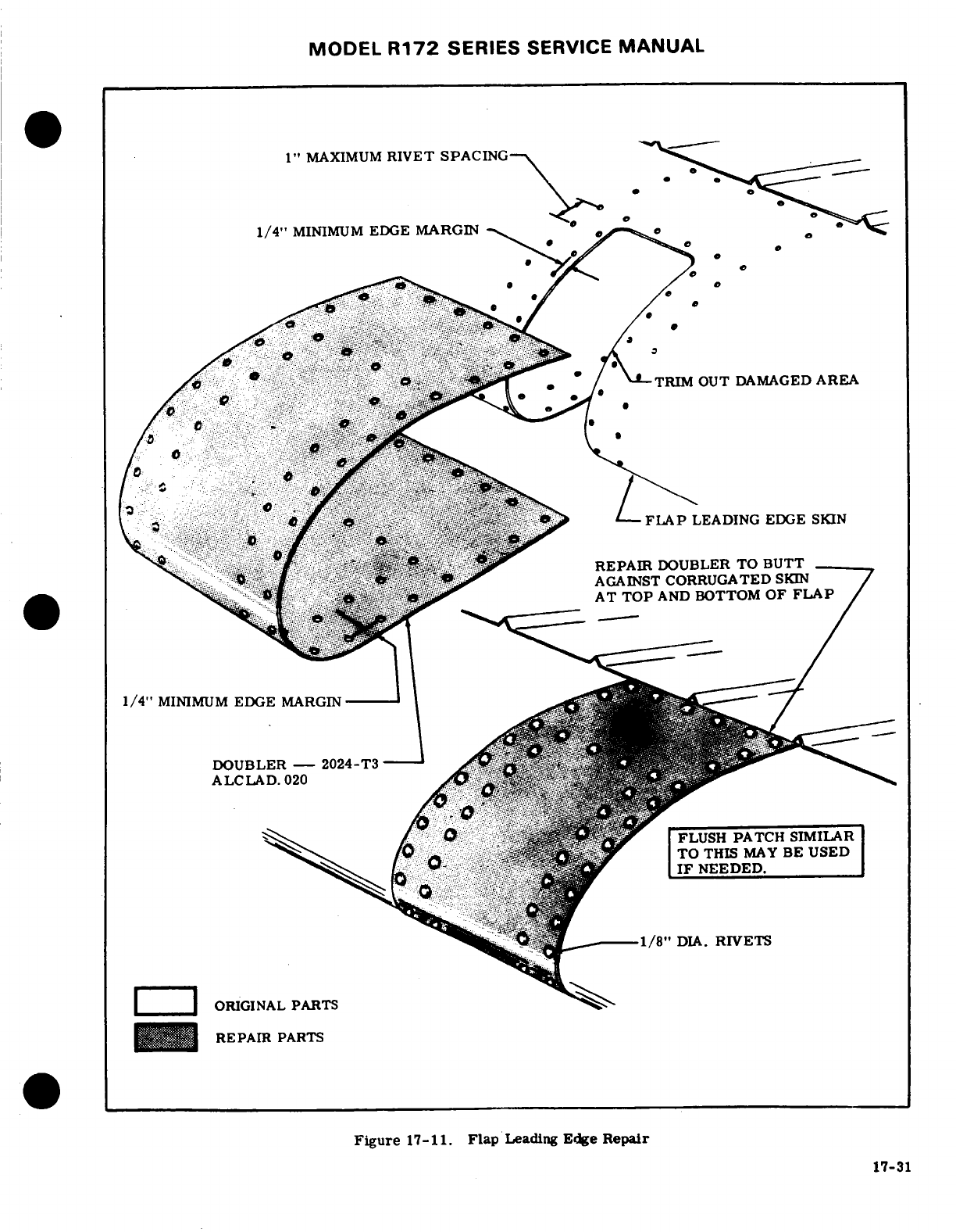
MODEL
R172
SERIES
SERVICE
MANUAL
1"
MAXIMUM
RIVET
SPACING
1/4"
MINIMUM
EDGE
MARGIN
RIM
OUT DAMAGED
AREA
*
-
FLAP
LEADING
EDGE
SKIN
..
'.~'.,,,,,.,-'
*REPAIR
DOUBLER
TO
BUTT
AGAINST
CORRUGATED
SKIN
AT
TOP
AND
BOTTOM
OF
FLAP
1/4"
MINIMUM
EDGE
MARGIN
DOUBLER
-
2024-T3
ALCLAD.
020
FLUSH
PATCH
SIMILAR
TO
THIS
MAY
BE
USED
IF
NEEDED.
1/8"
DIA.
RIVETS
ORIGINAL
PARTS
REPAIR
PARTS
Figure
17-11. Flap
Leading
Edge
Repair
17-31
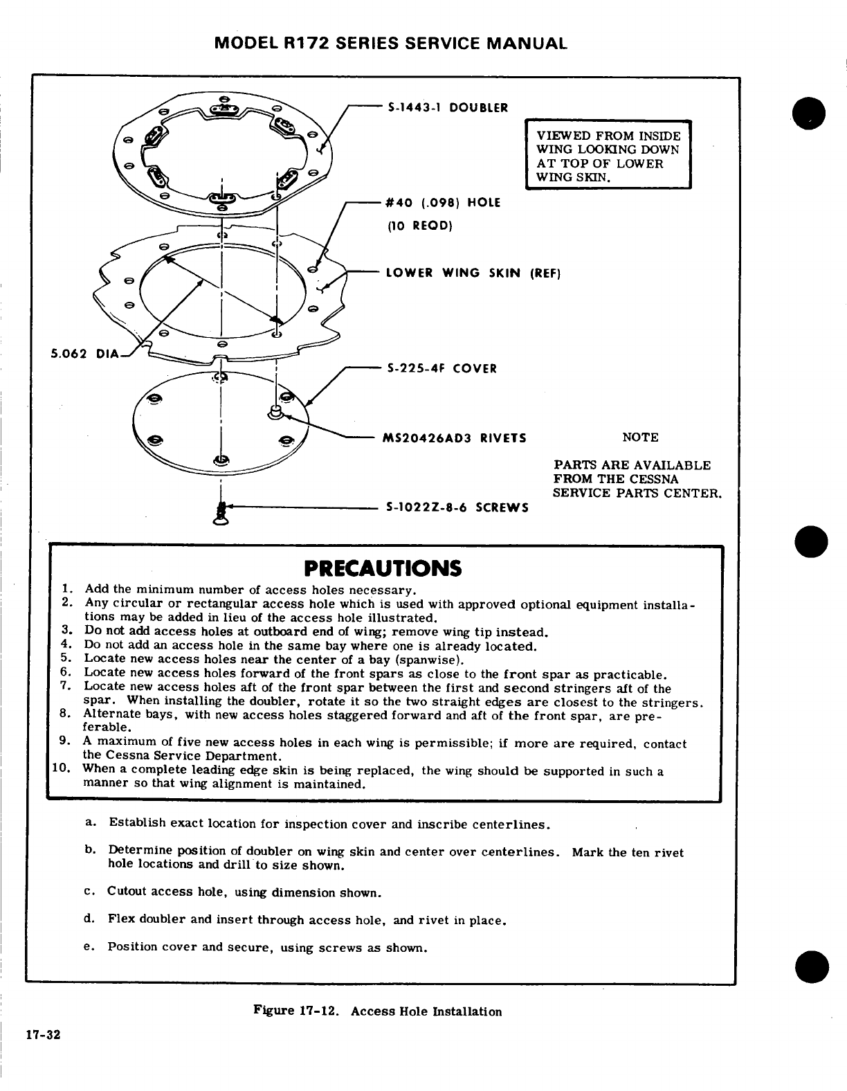
MODEL
R172
SERIES
SERVICE
MANUAL
S-1443-1
DOUBLER
-
VIEWED
FROM
INSIDE
WING
LOOKING
DOWN
~AT
TOP
OF
LOWER
,
WING
SKIN.
~
-#40
(.098)
HOLE
(10
REOD)
LOWER
WING
SKIN
(REF)
5.062
DIA-,
^,
S-225-4F
COVER
MS20426AD3
RIVETS
NOTE
PARTS ARE
AVAILABLE
FROM
THE
CESSNA
SERVICE
PARTS
CENTER.
S-1022Z-8-6
SCREWS
PRECAUTIONS
1.
Add
the
minimum number
of
access
holes
necessary.
2.
Any
circular
or rectangular
access
hole
which
is
used
with
approved
optional
equipment
installa-
tions
may
be
added
in
lieu
of
the
access
hole
illustrated.
3.
Do
not
add
access
holes at
outboard
end
of
wing;
remove
wing
tip
instead.
4.
Do
not
add
an
access
hole
in
the
same
bay
where
one
is already
located.
5.
Locate
new
access
holes
near
the
center
of
a bay
(spanwise).
6.
Locate
new
access
holes
forward
of
the
front
spars
as close
to
the
front
spar
as
practicable.
7.
Locate
new
access
holes
aft
of
the
front
spar
between
the
first
and
second
stringers
aft
of
the
spar.
When
installing
the
doubler,
rotate
it
so
the
two
straight
edges
are
closest
to
the
stringers.
8.
Alternate
bays,
with
new
access
holes
staggered
forward
and
aft
of
the
front
spar,
are
pre-
ferable.
9.
A
maximum
of
five
new
access
holes
in
each
wing
is
permissible;
if
more
are
required,
contact
the
Cessna Service
Department.
10.
When
a
complete
leading
edge
skin
is
being
replaced,
the
wing
should
be
supported
in
such
a
manner
so
that
wing
alignment
is
maintained.
a.
Establish
exact
location
for
inspection
cover
and
inscribe
centerlines.
b.
Determine
position
of
doubler
on
wing
skin
and
center
over
centerlines.
Mark
the
ten
rivet
hole
locations
and
drill
to
size
shown.
c.
Cutout
access
hole,
using
dimension
shown.
d.
Flex
doubler
and
insert
through
access
hole,
and
rivet
in
place.
e.
Position
cover
and
secure,
using
screws
as
shown.
Figure
17-12.
Access
Hole
Installation
17-32
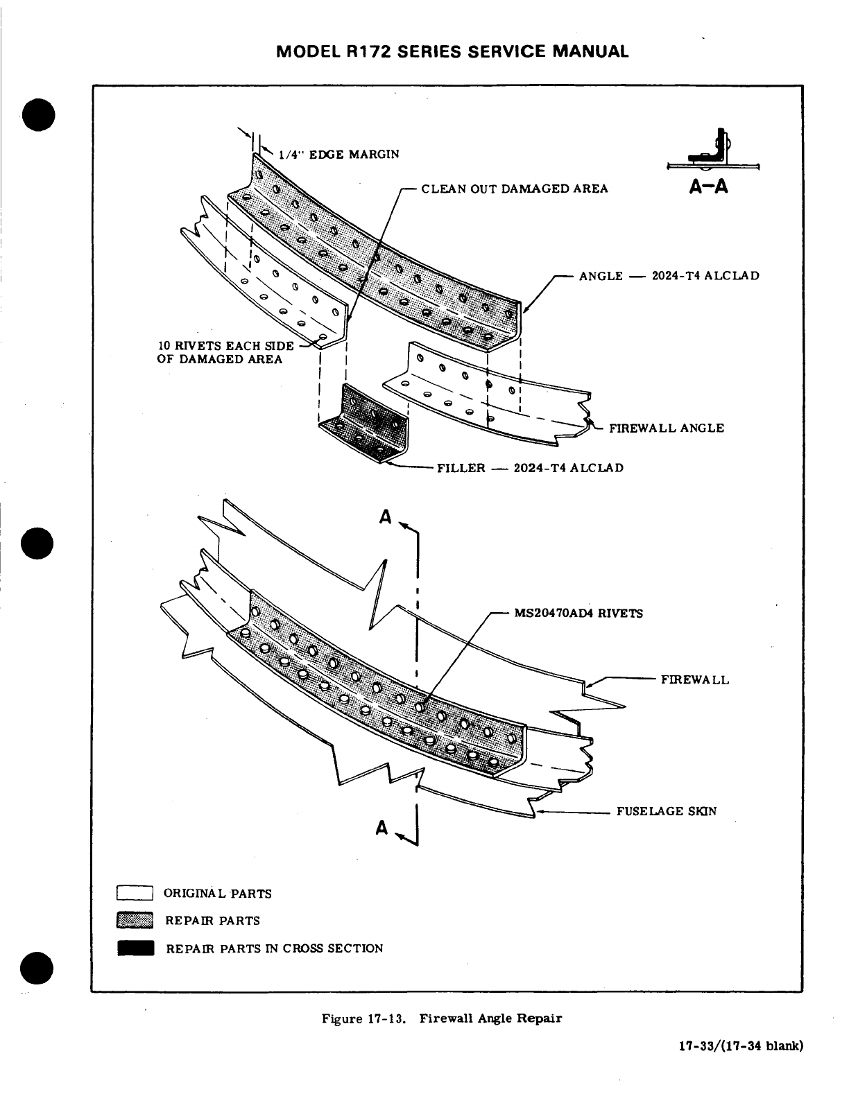
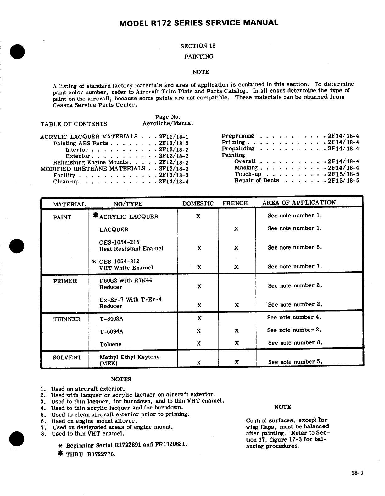
MODEL
R172
SERIES
SERVICE
MANUAL
SECTION
18
PAINTING
NOTE
A
listing
of
standard
factory
materials
and
area
of
application
is
contained
in
this
section.
To
determine
paint
color
number,
refer
to
Aircraft
Trim Plate
and
Parts
Catalog.
In
all
cases
determine
the
type
of
paint
on
the
aircraft,
because
some
paints
are
not
compatible.
These
materials
can
be
obtained
from
Cessna Service
Parts
Center.
Page
No.
TABLE
OF
CONTENTS
Aerofiche/Manual
ACRYLIC
LACQUER
MATERIALS
...
2F11/18-1
Prepriming
..
......
.
2F14/18-4
Painting
ABS
Parts
........
2F12/18-2
Priming
............
2F14/18-4
Interior
...........
2F12/18-2 Prepainting
..........
2F14/18-4
Exterior
..........
2F12/18-2
Painting
Refinishing
Engine
Mounts.
.....
2F12/18-2 Overall
.......
.
2F14/18-4
MODIFIED
URETHANE
MATERIALS
. .
2F13/18-3
Masking.
.........
2F14/18-4
Facility
............
2F13/18-3
Touch-up
......
.
2F15/18-5
Clean-up
..
........
2F14/18-4
Repair
of
Dents
......
.2F15/18-5
MATERIAL
NO/TYPE
DOMESTIC
FRENCH
AREA
OF
APPLICATION
PAINT
*ACRYLIC
LACQUER
X
See
note
number
1.
LACQUER X
See
note
number
1.
CES-1054-215
Heat
Resistant
Enamel
X
X
See
note
number
6.
*
CES-1054-812
VHT
White
Enamel
X
X
See
note
number
7.
PRIMER
P60G2
With
R7K44
Reducer
X
See
note
number
2.
Ex-Er-7
With
T-Er-4
Reducer
X
X
See
note
number
2.
THINNER
T-8402A
X
See
note
number
4.
T-6094A
X
X
See
note
number
3.
Toluene
X
X
See
note
number
8.
SOLVENT
Methyl
Ethyl
Keytone
(MEK)
X
X
See
note
number
5.
NOTES
1.
Used on
aircraft
exterior.
2.
Used
with
lacquer
or
acrylic
lacquer
on
aircraft
exterior.
3.
Used
to
thin
lacquer, for
burndown, and
to
thin
VHT
enamel.
4.
Used
to
thin
acrylic
lacquer
and
for
burndown.
NOTE
5.
Used
to
clean
aircraft exterior
prior
to
priming.
6.
Used
on
engine
mount
allover.
Control
surfaces,
except
Tor
7.
Used
on
designated
areas
of
engine
mount.
wing
flaps,
must
be
balanced
8.
Used
to
thin
VHT
enamel.
after
painting.
Refer
to Sec-
tion
17,
figure
17-3
for bal-
Beginning
Serial
R1722891
and
FR1720631.
ancing
procedures.
*
THRU
R1722776.
18-1
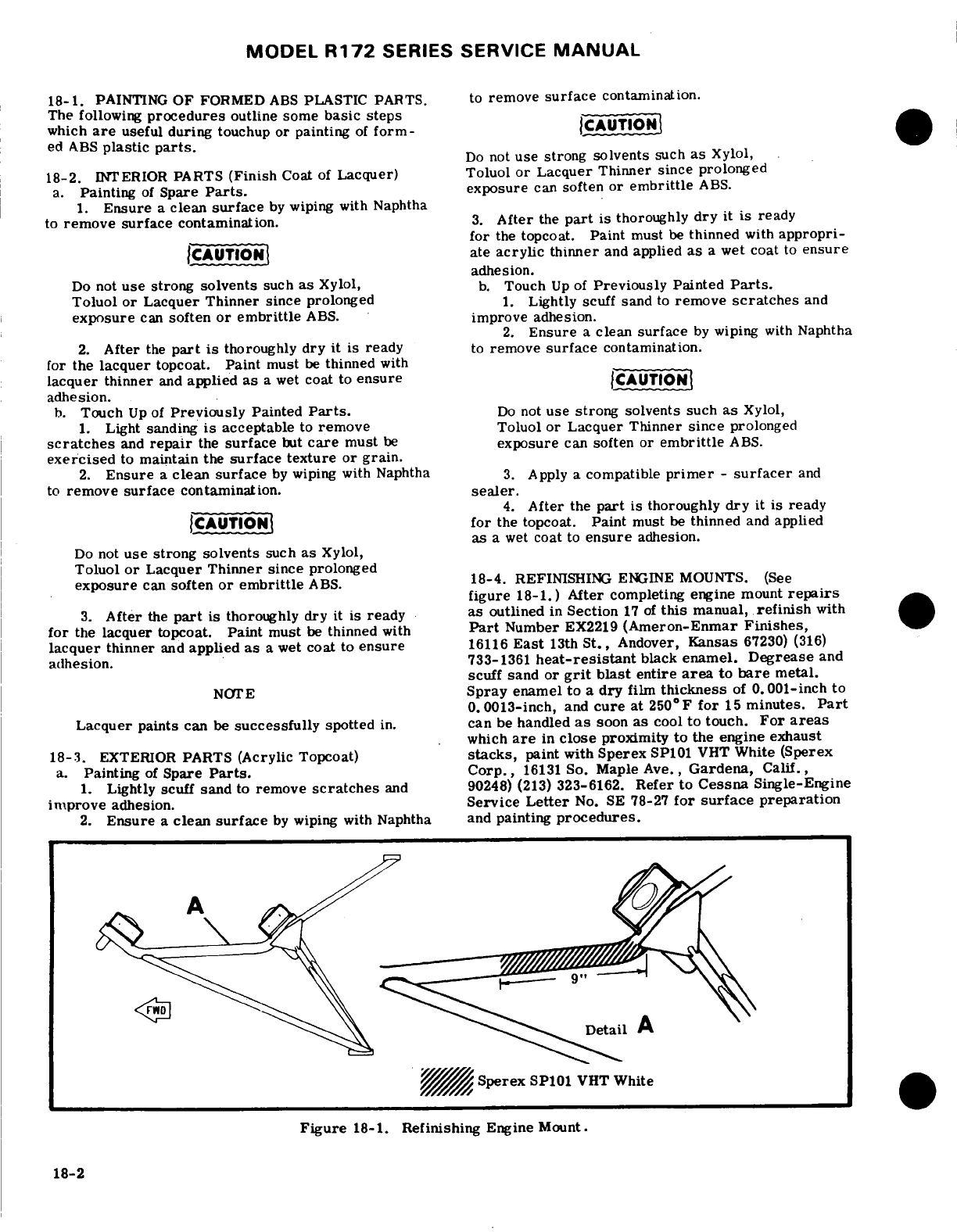
MODEL
R172
SERIES SERVICE
MANUAL
18-1.
PAINTING
OF
FORMED
ABS
PLASTIC
PARTS.
to
remove
surface
contamination.
The
following
procedures
outline
some
basic
steps
which
are
useful
during
touchup
or
painting
of
form-
CAUTION
ed
ABS
plastic
parts.
Do
not
use
strong
solvents
such
as
Xylol,
18-2.
INTERIOR
PARTS
(Finish
Coat
of
Lacquer)
Toluol
or
Lacquer Thinner since prolonged
a.
Painting
of
Spare
Parts.
exposure
can
soften
or
embrittle
ABS.
1.
Ensure
a
clean
surface
by
wiping
with Naphtha
to
remove
surface
contamination.
3.
After
the
part
is
thoroughly
dry
it is
ready
for
the
topcoat.
Paint
must
be
thinned
with
appropri-
CAUTION
ate
acrylic
thinner
and
applied
as
a
wet
coat
to
ensure
adhesion.
Do
not
use
strong
solvents
such
as
Xylol,
b.
Touch
Up
of
Previously
Painted
Parts.
Toluol
or
Lacquer Thinner since
prolonged
1.
Lightly
scuff
sand
to
remove
scratches
and
exposure
can
soften
or
embrittle
ABS.
improve
adhesion.
2.
Ensure
a
clean
surface
by
wiping
with
Naphtha
2.
After
the
part
is
thoroughly
dry
it
is
ready
to
remove
surface
contamination.
for
the
lacquer
topcoat.
Paint
must
be
thinned
with
lacquer
thinner
and
applied
as
a
wet
coat
to
ensure
CAUTION
adhesion.
b.
Touch
Up
of
Previously
Painted
Parts.
Do
not
use
strong
solvents
such
as
Xylol,
1.
Light
sanding
is
acceptable
to
remove
Toluol
or Lacquer Thinner
since
prolonged
scratches
and
repair
the
surface
but
care
must
be
exposure
can
soften
or
embrittle
ABS.
exercised
to
maintain
the
surface texture
or grain.
2.
Ensure
a
clean
surface
by
wiping with Naphtha
3.
Apply
a
compatible
primer
-
surfacer
and
to
remove
surface
contamination.
sealer.
4.
After
the
part
is
thoroughly
dry
it is
ready
CAUTION
for
the
topcoat.
Paint
must
be
thinned
and
applied
as
a
wet
coat
to
ensure
adhesion.
Do
not
use
strong solvents
such
as
Xylol,
Toluol
or
Lacquer
Thinner
since
prolonged
exposure
can
soften
or embrittle
ABS.
18-4.
REFINISHING
ENGINE
MOUNTS.
(See
figure
18-1.)
After
completing
engine
mount
repairs
3.
After
the
part
is
thoroughly
dry
it
is
ready
as
outlined
in
Section
17
of
this
manual,
refinish
with
for
the
lacquer
topcoat.
Paint
must
be
thinned
with
Part
Number
EX2219
(Ameron-Enmar
Finishes,
lacquer
thinner
and
applied
as
a
wet
coat
to
ensure
16116
East
13th
St.,
Andover,
Kansas
67230)
(316)
adhesion.
733-1361
heat-resistant
black
enamel.
Degrease
and
scuff
sand
or
grit
blast
entire
area
to
bare
metal.
NOTE
Spray
enamel
to
a
dry
film
thickness
of
0.001-inch
to
0.0013-inch,
and
cure
at
250
F
for
15
minutes.
Part
Lacquer
paints
can
be
successfully
spotted
in.
can
be
handled
as
soon
as
cool
to
touch.
For
areas
which
are
in
close
proximity
to
the
engine
exhaust
18-3.
EXTERIOR
PARTS
(Acrylic
Topcoat)
stacks,
paint with
Sperex
SP101 VHT
White
(Sperex
a.
Painting
of
Spare
Parts.
Corp.,
16131
So.
Maple
Ave.,
Gardena,
Calif.,
1.
Lightly scuff
sand
to
remove
scratches
and 90248)
(213)
323-6162.
Refer
to
Cessna
Single-Engine
improve
adhesion.
Service
Letter
No.
SE
78-27
for
surface
preparation
2.
Ensure
a
clean
surface
by
wiping with
Naphtha
and
painting
procedures.
Detail
A
Sperex
SP101
VHT
White
Figure
18-1.
Refinishing
Engine
Mount.
18-2
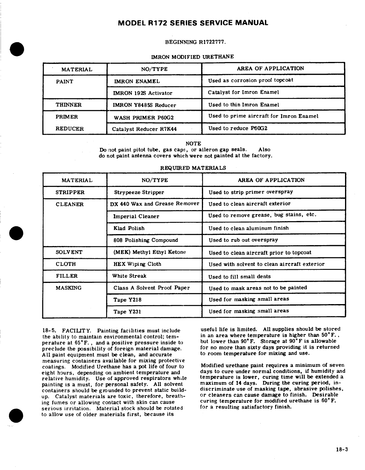
MODEL
R172
SERIES SERVICE
MANUAL
BEGINNING
R1722777.
IMRON
MODIFIED
URETHANE
MATERIAL
NO/TYPE
AREA
OF
APPLICATION
PAINT
IMRON
ENAMEL
Used
as
corrosion
proof
topcoat
IMRON
192S
Activator
Catalyst
for
Imron
Enamel
THINNER
IMRON
Y8485S
Reducer
Used
to
thin
Imron
Enamel
PRIMER
WASH
PRIMER
P60G2
Used
to
prime
aircraft
for
Imron Enamel
REDUCER
Catalyst
Reducer
R7K44
Used
to
reduce
P60G2
NOTE
Do
not
paint
pitot
tube,
gas
caps,
or
aileron
gap
seals.
Also
do
not
paint
antenna
covers
which
were
not
painted
at
the
factory.
REQUIRED
MATERIALS
MATERIAL
NO/TYPE
AREA
OF
APPLICATION
STRIPPER
Strypeeze
Stripper
Used
to
strip primer
overspray
CLEANER
DX
440
Wax
and
Grease
Remover
Used
to
clean
aircraft
exterior
Imperial
Cleaner
Used
to
remove
grease,
bug
stains,
etc.
Klad
Polish
Used
to
clean
aluminum
finish
808
Polishing
Compound
Used
to
rub
out
overspray
SOLVENT
(MEK)
Methyl Ethyl
Ketone
Used
to
clean
aircraft
prior
to
topcoat
CLOTH
HEX
Wiping Cloth
Used with
solvent to
clean
aircraft
exterior
FILLER
White
Streak
Used
to
fill small
dents
MASKING
Class
A
Solvent
Proof
Paper
Used
to
mask
areas
not
to
be
painted
Tape
Y218
Used
for
masking
small
areas
Tape
Y231
Used
for
masking
small
areas
18-5.
FACILITY.
Painting
facilities
must
include
useful
life
is
limited.
All
supplies
should
be
stored
the
ability
to
maintain
environmental
control;
ter-
in
an
area
where
temperature
is
higher
than
50°F.,
perature
at
65°F.,
and
a
positive
pressure
inside
to
but
lower
than
900F.
Storage
at
90
0
F
is
allowable
preclude
the
possibility
of
foreign
material
damage.
for
no
more
than
sixty
days
providing
it
is
returned
All
paint
equipment
must
be
clean,
and
accurate
to
room
temperature
for
mixing
and
use.
measuring
containers
available for
mixing
protective
coatings.
Modified
Urethane
has
a
pot
life
of
four
to
Modified
urethane
paint
requires
a
minimum
of
seven
eight
hours,
depending
on
ambient
temperature
and
days
to
cure
under
normal
conditions,
if
humidity
and
relative
humidity.
Use
of
approved
respirators
while
temperature
is
lower,
curing
time
will
be
extended
a
painting
is
a
must,
for
personal
safety.
All
solvent
maximum
of
14
days.
During
the
curing
period,
in-
containers
should
be
grounded to
prevent
static
build-
discriminate
use
of
masking
tape,
abrasive
polishes,
up.
Catalyst
materials
are
toxic,
therefore,
breath-
or cleaners
can
cause
damage
to
finish.
Desirable
ing
fumes
or
allowing
contact
with
skin
can
cause
curing
temperature
for
modified
urethane
is
60
°
F.
serious
irritation.
Material
stock
should
be
rotated
for
a
resulting satisfactory
finish.
to
allow
use
of
older
materials
first,
because
its
18-3
MODEL
R172
SERIES
SERVICE
MANUAL
18-6.
CLEAN
UP.
WARNING
a.
Inspect airplane
for
any
surface
defects,
such
as
dents
or
unsatisfactory
previous
repairs,
and
correct
AIRCRAFT
SHOULD
BE
GROUNDED
PRIOR
according
to
paragraph
18-13.
TO
PAINTING
TO
PREVENT STATIC
ELEC-
b.
Wipe
excess
sealer
from
around
windows
and
skin
TRICITY
BUILD-UP
AND
DISCHARGE.
laps.
Mask
windows,
ABS
parts,
and
any
other
areas
not to
be
primed,
with
3M
tape
and
Class
A
Solvent 18-8.
PRIMING.
Proof
Paper.
Care
must
be
exercised
to
avoid
cuts,
a. Apply
primer
in
one
wet
even
coat.
Dry
film
scratches
or
gouges
by
metal
objects
to
all
plexiglass thickness
to
be
.
0003
to
.
0005
inches.
Do
not
top-
surfaces,
because
cuts
and
scratches
may
contribute
coat
until
sufficiently
cured.
When
scratching
with
to
crazing
and
failure
of
plexiglass
windows.
firm
pressure
of
the
fingernail
does
not
penetrate
c.
Methyl
Ethyl
Ketone
(MEK)
solvent
should
be
the
coating,
the
primer
is
cured.
Primer
should
be
used
for
final
cleaning
of
airplanes
prior
to
painting.
topcoated
within
four
hours
after
application.
The
wiping
cloths
shall
be
contaminant
and
lint
free
HEX.
Saturate
cloth
in
the
solvent
and
wring
out so
18-9
PREPAINTING
it
does
not
drip.
Wipe
the
airplane
surface
with
the
a.
On
standard
aircraft
mix
the
required
amount
of
solvent
saturated
cloth
in
one
hand,
and
immediately
Imron
with
Imron
192S
Activator
in
a
3
to
1
ratio.
dry
with
a
clean cloth
in
the
other
hand.
It
is
impor-
Mix
thoroughly
(no
induction
time
required
before
tant
to
wipe
dry
solvent
before
it
evaporates,
spraying).
Imron
shall
be
thinned
with
Y8485S
Imron Reducer
to
obtain
a
spraying
viscosity
of
18
When
an
airplane has paint
or
zinc
chromate
over-
spray
on
the
exterior,
stripper
may
be
used
to
re-
to
20
seconds
on
a
No.
2
Zahn
Cup.
Viscosity
move
the
overspray.
The
stripper
may
be
applied
should
be
checked
after
4
hours
and
adjusted
if
neces-
by
brush
and
will
require
a
few
minutes
to
soften
the
sary.
overspray.
Heavy
coatings
may
require
more
than
b.
When
applying
modified
urethane
finishes,
the
one
application
of
the
stripper.
Use
extreme
care
to
painter
shoud
wear
an
approved
respirator,
which
prevent
stripper
from
running
into
faying
surfaces
on
has
a
dust
filter
and
organic
vapor
cartridge,
or
an
corrosion
proofed
airplanes.
After
removal
of
the
air
supplied
respirator.
All
modified
urethane
fin-
overspray,
clean
the
airplane
with
Methyl
Ethyl
Ke-
ishes
contain
some
isocyanate,
which
may
cause
irri-
tone
(MEK)
solvent
in
the
prescribed
manner.
tation
to
the
respiratory
tract
or
an
allergic
reaction.
Individuals
may
become
sensitized
to
isocyanates.
NOTE
c.
The
pot
life
of
the
mixture
is approximately
6-8
hours
at
75°F.
Pot
pressure
should
be
approximately
It
is
imperative
that
clean
solvent
be
used
in
12
psi
during
application.
Air
pressure
at
the
gun
cleaning
airplanes.
Dispose
of
contaminated should
be
40
to
50
psi.
solvent
immediately.
Fresh
solvent
should
d.
Scuff
sand
the
primer
only
where
runs
or dirt
be
used
on
each
airplane.
particles
are
evident.
Minor
roughness
or
grit
may
be
removed
by
rubbing
the
surface
with
brown
Kraft
paper
which
has
been thoroughly
wrinkled.
Unmask
WARNING
ABS
and
other
preprimed parts
and
check
tapes.
Use
explosion
proof
containers
for
storing
Clean
surface
with
a
jet
of
low
pressure-dry
air.
wash
solvents
and
other
flammable
materials.
18-10.
PAINTING
ALL-OVER
WHITE
OR
COLOR.
18-7. PRE-PRIMING.
a. Complete
painting
of
the
plane
should
be
done
with
2
or
3
wet,
even
coats.
Dry
coats
will
not
re-
flow,
and
will
leave
a
grainy appearance.
a.
For
all
standard
aircraft,
P60G2
primer
shall
b.
Allow
5
minute
period
for
the
finish
to
flash
off
be
mixed
one
part
primer
to
one
and
one
half
parts
before
moving
aircraft
to
the
oven.
R7K44
catalyst
by
volume.
Mix
only
in
stainless
c.
Move
to
the
force
dry
oven
and
dry
for
approxi-
steel
or
lined
containers.
After
mixing,
allow
mately
1
1/2
hours
at
120°F
to
140°F.
primer
to
set
for
thirty
minutes
before
spraying.
d.
Dry
film
thickness
of
the
overall
color
should
be
Pot
life
of
the
mixed
primer
is
six
hours.
All
mixed
approximately
2.0
mils.
Films
in
excess
of
3.0
material
should
be
discarded
if
not
used
within
this
mils
are
not
desirable.
time.
Pot
pressure
during
spray
operation
should
be
approximately
10
±1
psi.
Air
pressure
should
be
18-11.
MASKING
FOR
STRIPES.
40
to
50
psi
at
the
gun.
Blow
loose
contaminant
off
a.
Remove
airplane
from
the
oven.
Allow
airplane
the
airplane
with
a
jet
of
clean,
dry
air.
Cover
the
to
cool
to
room
temperature
before masking.
flap
tracks,
nose
gear
strut
tube,
wheels,
and
b.
Mask
stripe area
using
3M
Tape
Y231
or
3M
Tape
shimmy dampener
rod
ends.
ABS
parts
and
other
Y218
and
Class
A
solvent
proof
paper.
Double
tape
pre-primed
parts
do
not receive
wash
primer.
all
skin
laps
to
prevent
blow by.
18-4
MODEL
R172
SERIES
SERVICE
MANUAL
c.
Airplanes
which
will
have
a
stripe
only
configura-
a.
Dry
overspray
and
rough
areas
may
be
compound-
tion
shall
be
masked,
cleaned,
and
primed,
in
stripe
ed
out
with
DuPont
#808
rubbing
compound.
area
only.
b.
Grease,
bug
stains,
etc.,
may
be
removed from
d.
If
the
base
coat
is
not
over
72
hours
old,
the
painted
surfaces
with
DX440
Wax
and
Grease
Remover
stripe
area
does
not
require
sanding.
If
sanding
is
or
Imperial
Cleaner.
Klad
Polish
may
be
used
on
bare
necessary
because
of
age
or
to
remove
surface
de-
aluminum
to
remove
stains,
oxides,
etc.
fects,
use
#400
or
#600
sand
paper.
Course paper
c.
Rework
areas,
where
paint
or
primer
removal
is
will
leave
sand
marks
which
will
decrease
gloss
and
required,
may
be
stripped
with
Strypeeze
Paint
Re-
depth
of
gloss
of
the
finish.
The
use
of
power
sander
s
moval.
All
traces
of
stripper
must
be
removed before
should
be
held
to
a
minimum,
if
used,
exercise
care
refinishing.
to preclude
sanding through
the
white
base
coat.
Wipe
surface
to
be
striped
with
a
tack
cloth
and
check
all
18-13.
REPAIR OF
DENTS.
e.
Stripe
colors
on
Imron
base
coat
will
be
Imron a.
To
repair
dents
use
White
Streak
Filler
or
equiv-
alent.
Mix
White
Streak
in
the
correct
proportion
as
Enamel.
Mix
as
outlined
in
paragraph
18-9.
recommended
by
the
manufacturer.
b.
Do
not
apply
White
Streak
Filler
over
paint.
All
wet-even
coats.
Dry
coats
will
not
reflow,
and
will
be
removed
in
the
repair
area
and
the
alu-
leave
a
grainy
appearance.
Stripes
may
be
force
paint
shall
be
removed
in
the
repair
area
and
the
alu-
dried
or
air
dried.
Film
thickness
of
a
stripe
is
ap-
minum
the
White
Steak
to
increas
adesion.
proximately
1.5
to
2.0
mils
Apply
the
White
Streak
to
a
level
slightly
above
the
surrounding
skin. After
drying
for
I0
-
15
minutes,
g.
Do
not
remove
masking
tape
and
paper
until
the
surrounding
skin. After
drying
for
10
-
15
minutes,
Donotremove
askintapeandpperutsand
the
filler
flush
with
the
skin
surface,
using
care
paint
has
dried
to
a
"dry
to
touch"
condition.
Care
sand
the
filler
flush
with
the
skin
surface,
using
care
should
be
exercised
in
removal
of
the
masking
to
pr-
to
eater
e
ees
vent
damage
to
the
finish.
NOTE
h.
Modified
urethane finishes
are
sensitive
to
mois-
ture,
therefore,
should
be
stored
out
of
rain
until Refer to
paragraph
18-4,
for
engine
mount
cured.
refinishing
procedures
and
paint
application.
18-12.
TOUCH-UP.
When
necessary
to
touch
up
or
refinish
an
area,
the
NOTE
defect
should
be
sanded
with
#400
and
followed
by #600
sandpaper.
Avoid,
if
possible,
sanding
through
the
Refer
to
Section
17
for
repair
of
damaged
primer.
If
the
primer
is
penetrated
over
an
area
1/2
area(s).
Dent
repair
as
described
in
this
inch
square
or
larger,
repriming
is
necessary.
Avoid
Section
is
applicable
only
to
smooth
dents
spraying
primer
on
the
adjacent
panel
as
much
as
pos- in
the
skin
that
are
free
from
cracks,
sharp
sible.
Since
urethane
finishes
cannot be
"spotted
in"
corners,
are
not
stress
wrinkles
and
do
not
repairs
should
be
in
sections
extending
to
skin
laps
or
interfere
with any
internal
mechanism.
stripe
lines.
NOTE
Application
of
a
top
coat
thickness
in
excess
of
5.
0
mils,
requires
a
control
surface
balance
check.
SHOP
NOTES:
18-5/(18-6
blank)
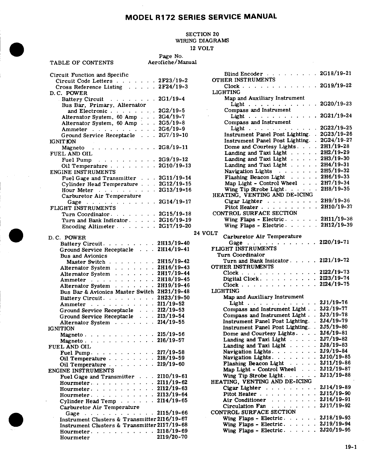
MODEL
R172
SERIES SERVICE
MANUAL
SECTION
20
WIRING
DIAGRAMS
12
VOLT
Page
No.
TABLE
OF
CONTENTS
Aerofiche/Manual
Circuit
Function
and
Specific
Blind
Encoder
.......
..
2G18/19-21
Circuit
Code
Letters
.......
2F23/19-2
OTHER
INSTRUMENTS
Cross
Reference
Listing
....
.
2F24/19-3
Clock
.............
2G19/19-22
D.C.
POWER
LIGHTING
Battery
Circuit
....
... .
2G1/19-4
Map
and
Auxiliary
Instrument
Bus
Bar,
Primary,
Alternator
Light
............
2G20/19-23
and
Electronic
........
2G2/19-5
Compass
and
Instrument
Alternator
System,
60
Amp
...
2G4/19-7
Light
............
2G21/19-24
Alternator
System,
60
Amp
. .
2G5/19-8
Compass
and
Instrument
Ammeter
...........
2G6/19-9
Light
............
2G22/19-25
Ground
Service
Receptacle
.. .
2G7/19-10
Instrument
Panel
Post
Lighting
.
2G23/19-26
IGNITION
Instrument
Panel
Post
Lighting.
.2G24/19-27
Magneto
..... ......
2G8/19-11
Dome
and
Courtesy
Lights.
. ..
2H1/19-28
FUEL
AND
OIL
Landing
and
Taxi
Light
.....
22/19-29
Fuel
Pump
..........
2G9/19-12
Landing
and Taxi Light
..
2H3/19-30
Oil
Temperature
........
2G10/19-13
Landing
and
Taxi
Light
.....
2H4/19-31
ENGINE
INSTRUMENTS
Navigation
Lights
.......
2H5/19-32
Fuel
Gage
and
Transmitter
..
2G11/19-14 Flashing
Beacon
Light
.....
2H6/19-33
Cylinder
Head
Temperature
.
2G12/19-15
Map
Light
-
Control
Wheel .. .
2H7/19-34
Hour
Meter
..........
2G13/19=16
Wing
Tip Strobe
Light
.....
2H8/19-35
Carburetor
Air
Temperature
HEATING, VENTING
AND
DE-ICING
Gage
............
.
2G14/19-17
Cigar
Lighter
........
.
2H9/19-36
FLIGHT
INSTRUMENTS
Pitot
Heater
..........
2H10/19-37
Turn Coordinator
.
.......
2G15/19-18
CONTROL SURFACE SECTION
Turn
and
Bank
Indicator
.....
2G16/19-19
Wing
Flaps
-
Electric
......
2H11/19-38
Encoding
Altimeter
.
......
2G17/19-20
Wing
Flaps
-
Electric.
......
2H12/19-39
24
VOLT
D. C.
POWER
Carburetor
Air Temperature
Battery Circuit
........
2H13/19-40
Gage
............
2I20/19-71
Ground
Service
Receptacle
..
2H14/19-41
FLIGHT
INSTRUMENTS
Bus
and
Avionics
Turn
Coordinator
Master
Switch
........
2H15/19-42
Turn
and
Bank
Insicator
....
2I21/19-72
Alternator
System
.......
2H16/19-43
OTHER
INSTRUMENTS
Alternator
System
.......
217/19-44
Clock
.
...........
.
2I22/19-73
Ammeter
.
..........
2H18/19-45
Digital
Clock.
.........
2I23/19-74
Alternator
System
......
.
2H19/19-46
Clock
.
............
2I24/19-75
Bus
Bar
&
Avionics
Master
Switch
2H21/19-48
LIGHTING
Battery
Circuit.
........
2H23/19-50
Map
and
Auxiliary
Instrument
Ammeter
.
..........
2I1/19-52
Light
.
...........
2J1/19-76
Ground
Service
Receptacle
. .
2I2/19-53
Compass
and
Instrument
Light
.
2J2/19-77
Ground
Service
Receptacle
. .
2I3/19-54
Compass
and
Instrument
Light
.
2J3/19-78
Alternator
System
.......
2I4/19-55 Instrument
Panel
Post
Lighting.
2J4/19-79
IGNITION
Instrument
Panel
Post
Lighting.
.
2J5/19-80
Magneto.
...........
2I5/19-56
Dome
and
Courtesy
Lights.
. ..
2J6/19-81
Magneto
..... .......
2I6/19-57
Landing and
Taxi
Light
....
.
2J7/19-82
FUEL
AND
OIL
Landing
and
Taxi
Light
.....
2J8/19-83
Fuel
Pump.
..........
2I7/19-58
Navigation
Lights
.......
2J9/19-84
Oil
Temperature
........
2I8/19-59
Navigation Lights.
........
2J10/19-85
Oil
Temperature
........
2I9/19-60
Flashing
Beacon
Light
.....
2J11/19-86
ENGINE
INSTRUMENTS
Map
Light
-
Control
Wheel
...
2J12/19-87
Fuel
Gage and
Transmitter
. .
2I10/19-61
Wing
Tip
Strobe
Light.
.....
.
2J13/19-88
Hourmeter
.
.........
2I11/19-62
HEATING, VENTING
AND
DE-ICING
Hourmeter
.
..........
2I12/19-63
Cigar
Lighter
.........
2J14/19-89
Hourmeter
.............
2I13/19-64
Pitot
Heater
..........
2J15/19-90
Cylinder
Head
Temp
......
2I14/19-65
Air
Conditioner
.......
.
2J16/19-91
Carburetor
Air
Temperature
Circulation
Fan
........
2J17/19-92
Gage
............
2I15/19-66
CONTROL SURFACE
SECTION
Instrument
Clusters
&
Transmitter2I16/19-67
Wing
Flaps
-
Electric.
....
.
2J18/19-93
Instrument
Clusters
&
Transmitter2I17/19-68
Wing
Flaps
-
Electric
.....
2J19/19-94
Hourmeter
..........
2I18/19-69
Wing
Flaps
-
Electric.
.....
2J20/19-95
Hourmeter 2I19/20-70
19-1
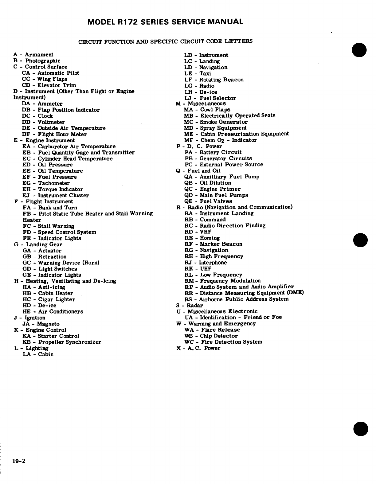
MODEL
R172
SERIES SERVICE
MANUAL
CIRCUIT
FUNCTION
AND
SPECIFIC
CIRCUIT
CODE
LETTERS
A
-
Armament
LB
-
Instrument
B
-
Photographic
LC
-
Landing
C
-
Control
Surface
LD
-
Navigation
CA
-Automatic
Pilot
LE
-
Taxi
CC
-
Wing
Flaps
LF
-
Rotating
Beacon
CD
-
Elevator
Trim
LG
-
Radio
D
-
Instrument
(Other
Than
Flight or
Engine
LH
-
De-ice
Instrument)
LJ
-
Fuel
Selector
DA
-
Ammeter
M
-
Miscellaneous
DB
-
Flap
Position Indicator
MA
-
Cowl
Flaps
DC
-Clock
MB
-
Electrically
Operated
Seats
DD
-
Voltmeter
MC
-
Smoke
Generator
DE
-
Outside
Air
Temperature
MD
-
Spray
Equipment
DF
-
Flight
Hour
Meter
ME
-
Cabin
Pressurization
Equipment
E
-
Engine
Instrument
MF
-
Chem
0
2
-
Indicator
EA
-
Carburetor
Air
Temperature
P
-
D.
C.
Power
EB
-
Fuel
Quantity
Gage
and
Transmitter
PA
-
Battery
Circuit
EC
-
Cylinder
Head
Temperature
PB
-
Generator
Circuits
ED
- Oil
Pressure
PC
-
External
Power
Source
EE
-Oil
Temperature
Q
-
Fuel
and
Oil
EF
-
Fuel
Pressure
QA
-
Auxilliary
Fuel
Pump
EG
-
Tachometer
QB
-
Oil
Dilution
EH
-
Torque
Indicator
QC
-
Engine
Primer
EJ
-
Instrument
Cluster
QD
-
Main
Fuel
Pumps
F
-
Flight
Instrument
QE
-
Fuel
Valves
FA
-
Bank
and
Turn
R
-
Radio
(Navigation
and
Communication)
FB
-
Pitot
Static
Tube
Heater
and
Stall Warning
RA
-
Instrument
Landing
Heater
RB
-
Command
FC
-
Stall
Warning
RC
-
Radio
Direction
Finding
FD
-
Speed
Control
System
RD
-
VHF
FE
-
Indicator
Lights
RE
-
Homing
G
-
Landing
Gear RF
-
Marker
Beacon
GA
-
Actuator
RG
- Navigation
GB
-
Retraction
RH
-
High
Frequency
GC
-
Warning
Device
(Horn)
RJ
-
Interphone
GD
-
Light
Switches
RK
-
UHF
GE
-
Indicator
Lights
RL
-
Low
Frequency
H
-
Heating,
Ventilating
and
De-Icing
RM-
Frequency
Modulation
HA
-
Anti-icing
RP
-
Audio
System
and
Audio
Amplifier
HB
-
Cabin
Heater
RR
-
Distance
Measuring
Equipment
(DME)
HC
-
Cigar
Lighter
RS
-
Airborne
Public
Address System
HD
-
De-ice
S
-
Radar
HE
-
Air
Conditioners
U
-
Miscellaneous
Electronic
J
-
Ignition
UA
-
Identification
-
Friend or
Foe
JA
-
Magneto
W
-
Warning
and
Emergency
K
-
Engine
Control
WA
-
Flare
Release
KA
-
Starter
Control
WB
-
Chip
Detector
KB
-
Propeller
Synchronizer
WC
-
Fire
Detection
System
L
-
Lighting
X
-
A.
C.
Power
LA
- Cabin
19-2
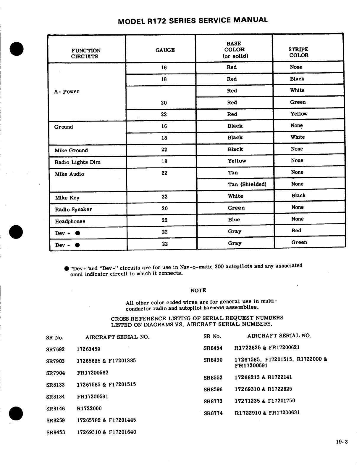
MODEL
R172
SERIES SERVICE
MANUAL
BASE
FUNCTION
GAUGE
COLOR
STRIPE
CIRCUITS
(or
solid)
COLOR
16
Red
None
18
Red Black
A+
Power
Red
White
20
Red
Green
22
Red
Yellow
Ground
16
Black
None
18
Black
White
Mike
Ground
22
Black
None
Radio
Lights
Dim
18
Yellow
None
Mike
Audio
22
Tan
None
Tan
(Shielded)
None
Mike
Key
22
White
Black
Radio
Speaker
20
Green
None
Headphones
22
Blue
None
Dev
+ *
22
Gray
Red
Dev-
*
22
Gray
Green
"Dev+"and
"Dev-"
circuits
are
for
use
in
Nav-o-matic
300
autopilots
and
any
associated
omni
indicator
circuit
to
which
it
connects.
NOTE
All
other
color
coded
wires are
for
general
use
in
multi-
conductor
radio
and
autopilot
harness
assemblies.
CROSS
REFERENCE
LISTING
OF
SERIAL
REQUEST
NUMBERS
LISTED
ON
DIAGRAMS
VS.
AIRCRAFT SERIAL
NUMBERS.
SR
No.
AIRCRAFT
SERIAL
NO.
SR
No.
AIRCRAFT
SERIAL
NO.
SR7692
17263459 SR8454
R1722825
&
FR17200621
SR7903
17265685
&
F17201385
SR8490
17267585,
F17201515, R1722000
&
FR17200591
SR7904
FR17200562
SR8552
17268213
&
R1722141
SR8133
17267585
&
F17201515
SR8596
17269310
&
R1722825
SR8134
FR17200591
SR8773
17271235
&
F17201750
SR8146
R1722000
SR8774
R1722910
&
FR17200631
SR8259
17265782
&
F17201445
SR8453
17269310
&
F17201640
19-3
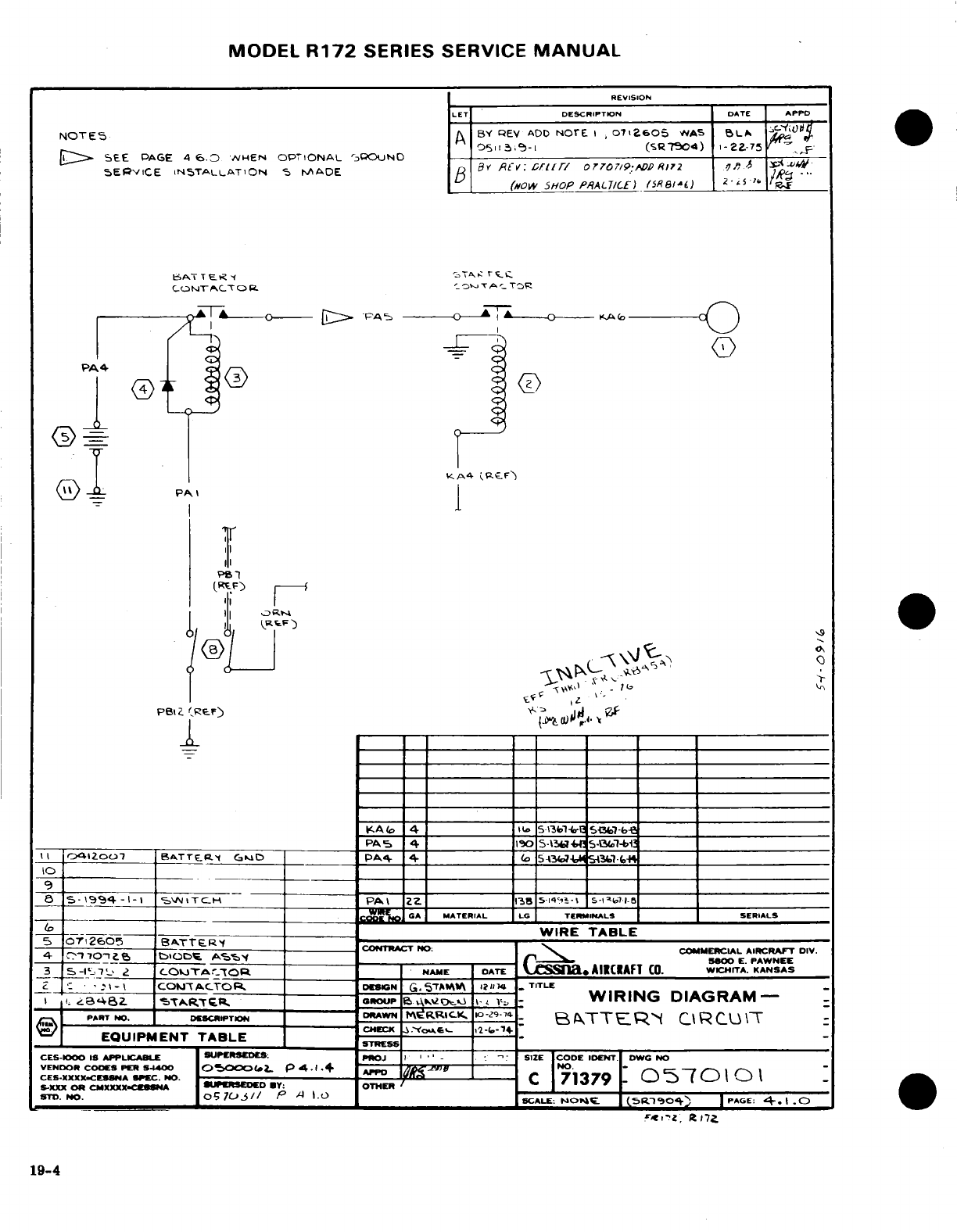
MODEL
R172
SERIES
SERVICE
MANUAL
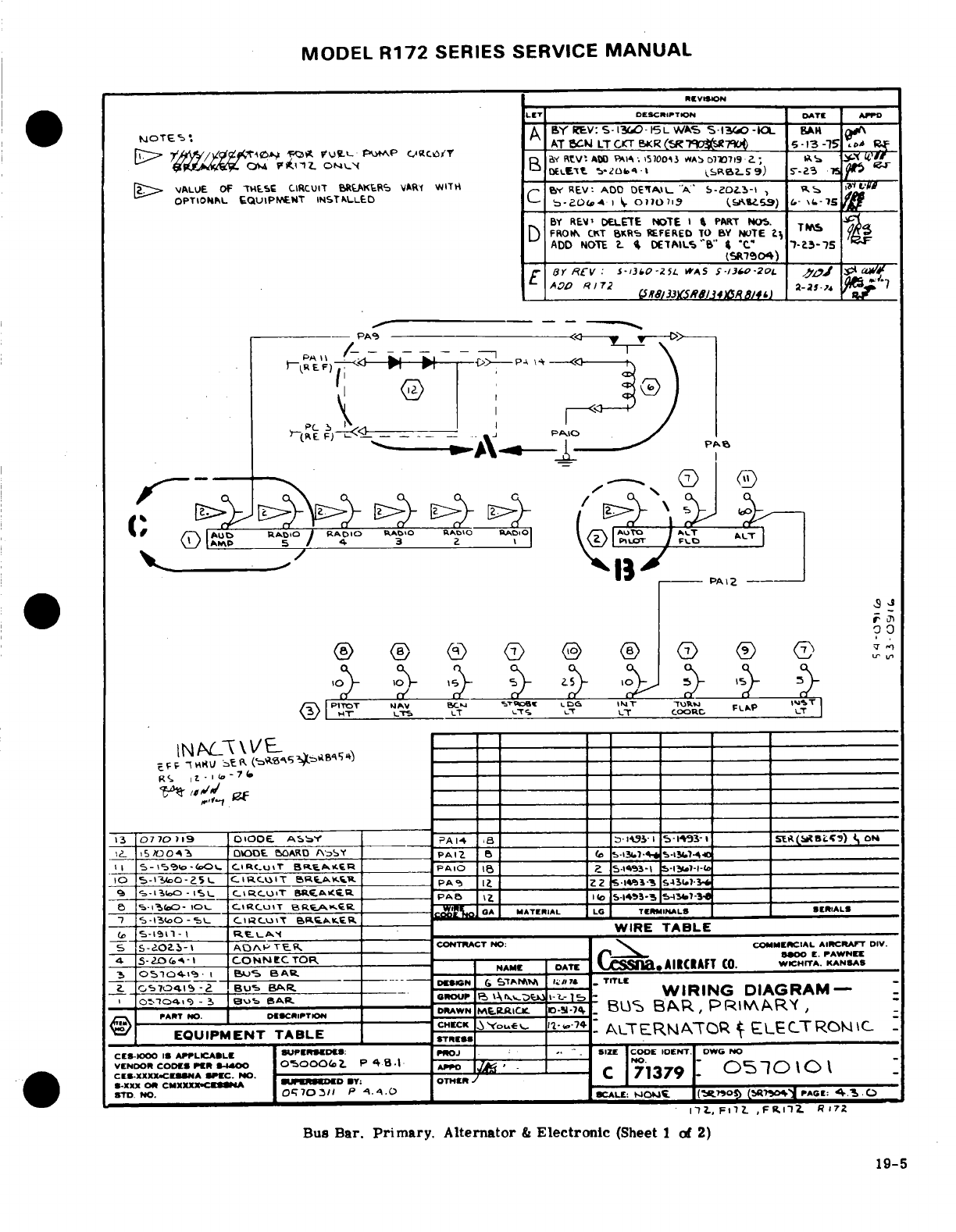
MODEL
R172
SERIES
SERVICE
MANUAL
REVISION
Bus Bar.
Primary.
Alternator
&
Electronic
(Sheet
1
of
2)
19-5
19-5
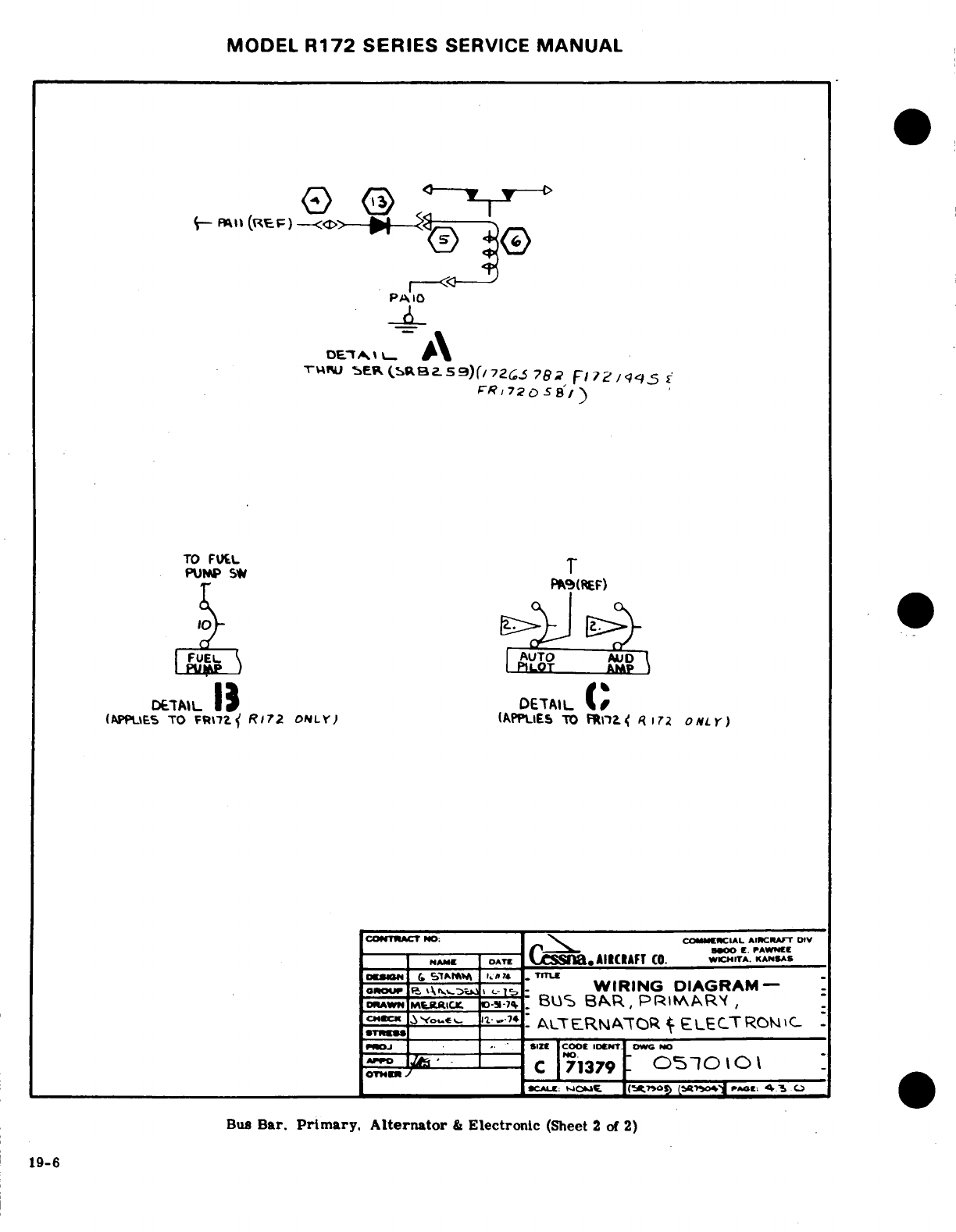
MODEL
R172
SERIES
SERVICE
MANUAL
--
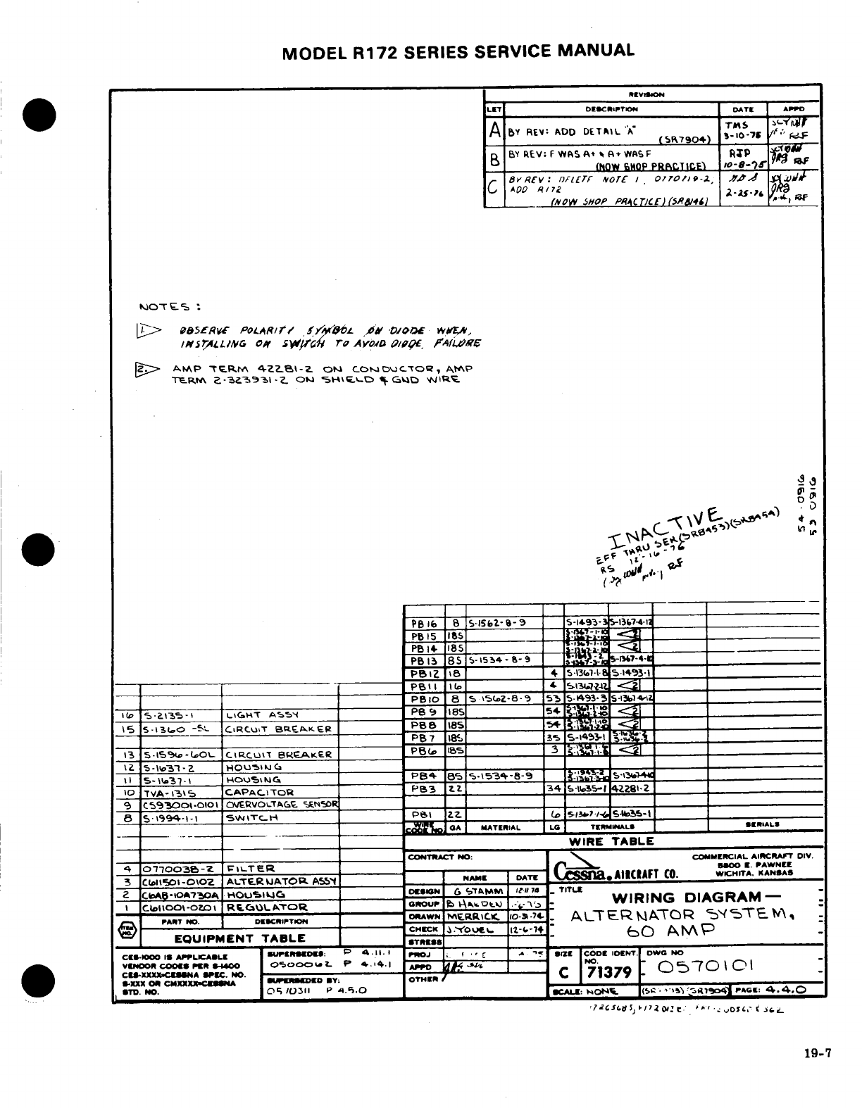
MODEL
R172
SERIES
SERVICE
MANUAL
II
5-lbo3
7
HOU
-
N
____
P84
es
\ 5*i-S-9 _
:
19-7
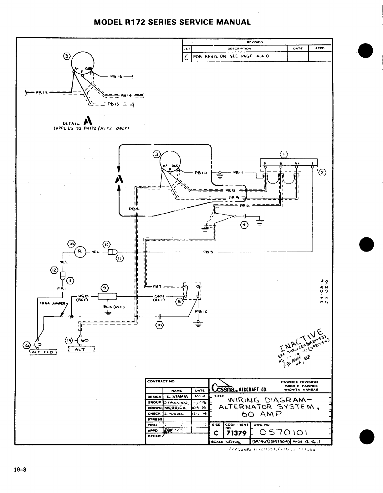
MODEL
R172
SERIES
SERVICE
MANUAL
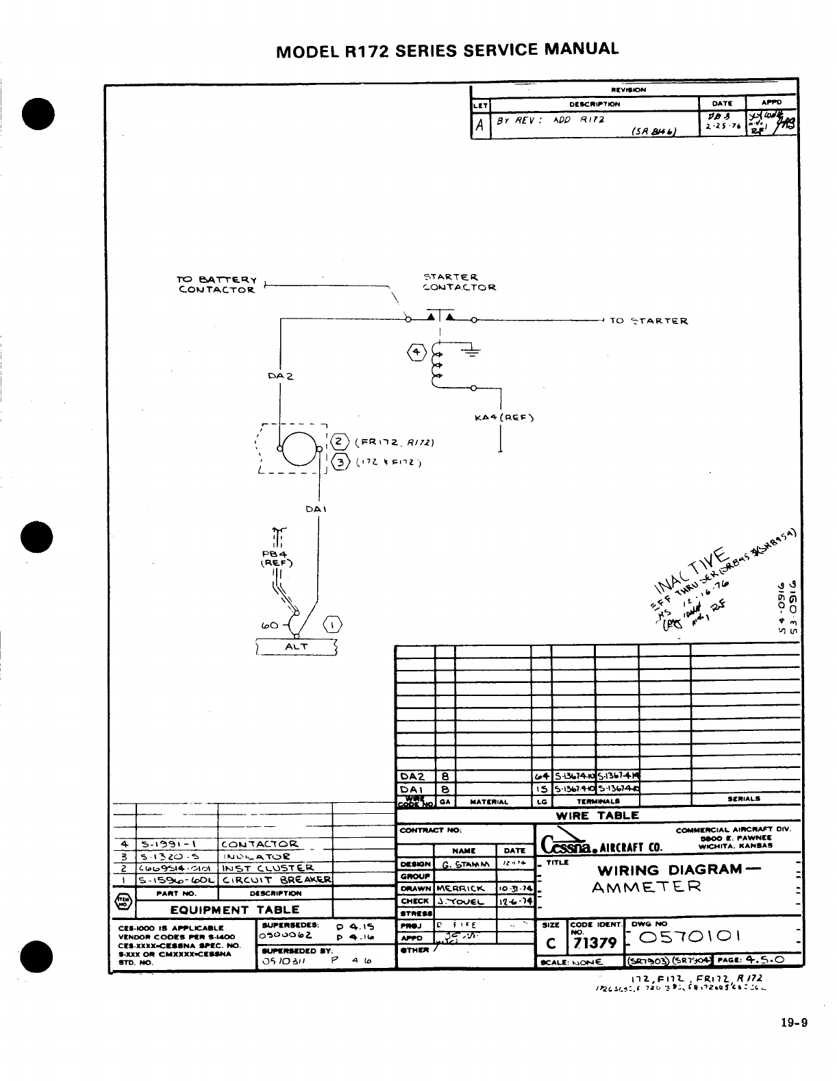
MODEL
R172
SERIES SERVICE
MANUAL
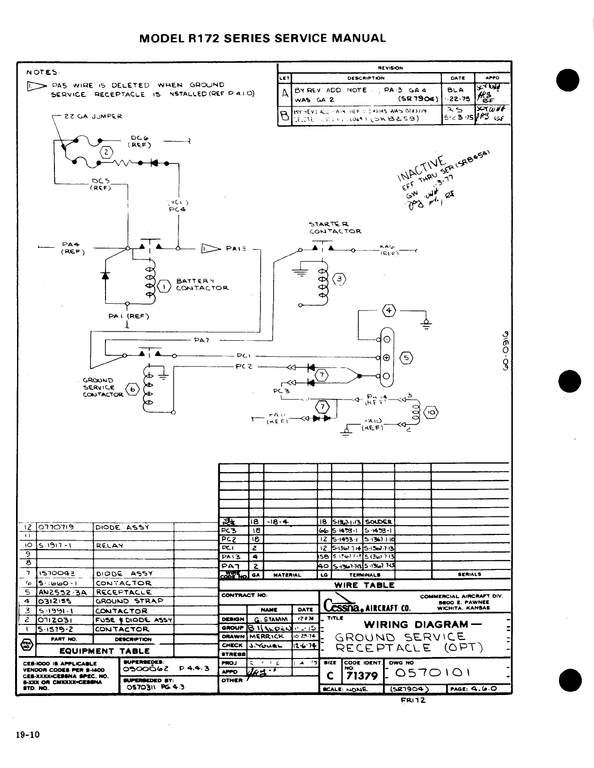
MODEL
R172
SERIES
SERVICE
MANUAL
NOTES.
LET
DESCRIPTION
DATE
APPD
1
PA5
WIRE
IS
DELETED
WHEN
GROUND
SEVICE
RECEPTACLE
IS
INSTALLED
(EF
P 4.1.0)
A
BY
REV
ADD
NOTE
PA3
GA
4
BLA
WAS
GA
2
(SR7904)
22
GA
JUMPER
I
( ORCc
0
EQUIPMENT
TABLE
19-10
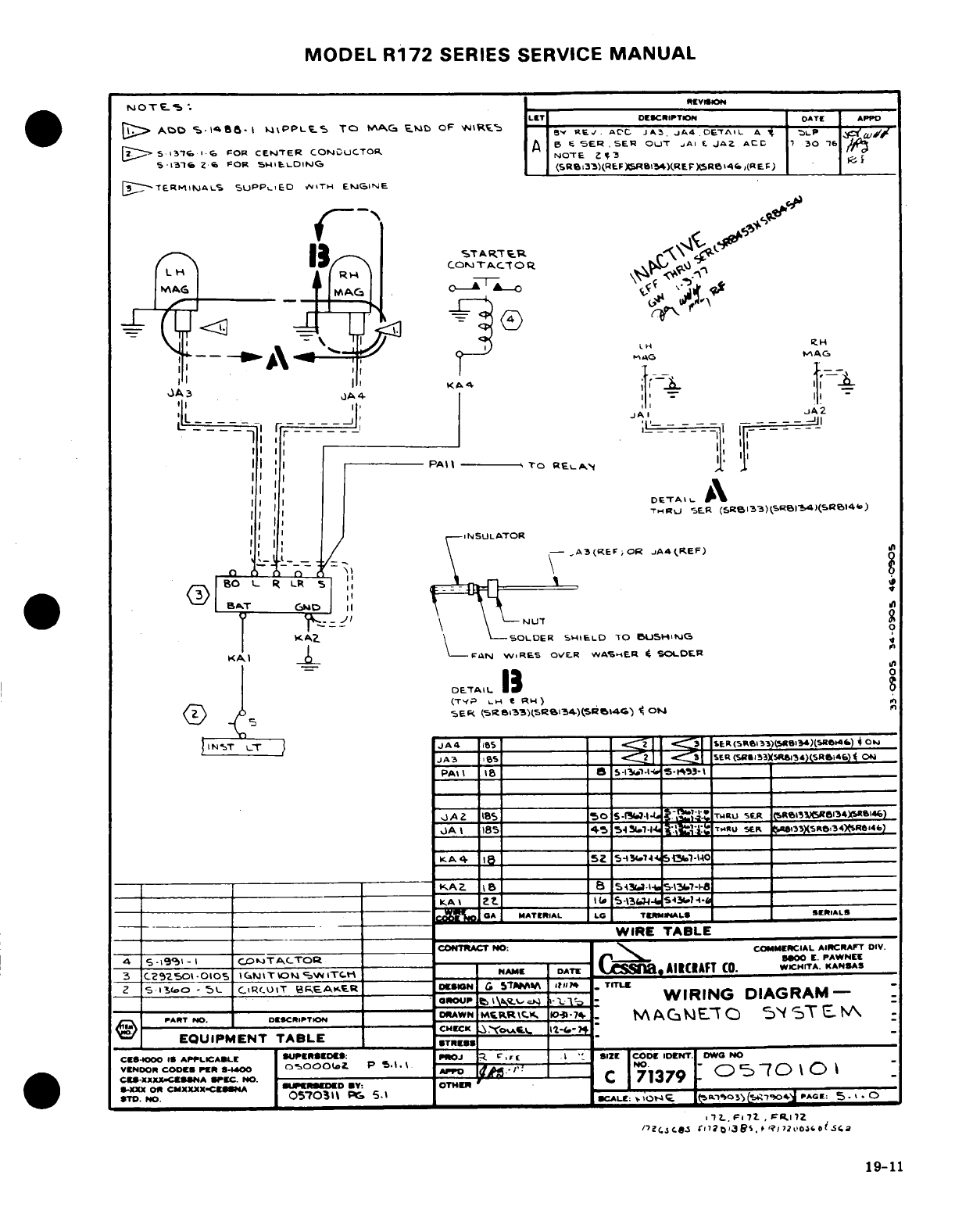
MODEL
R172
SERIES
SERVICE
MANUAL
19-11
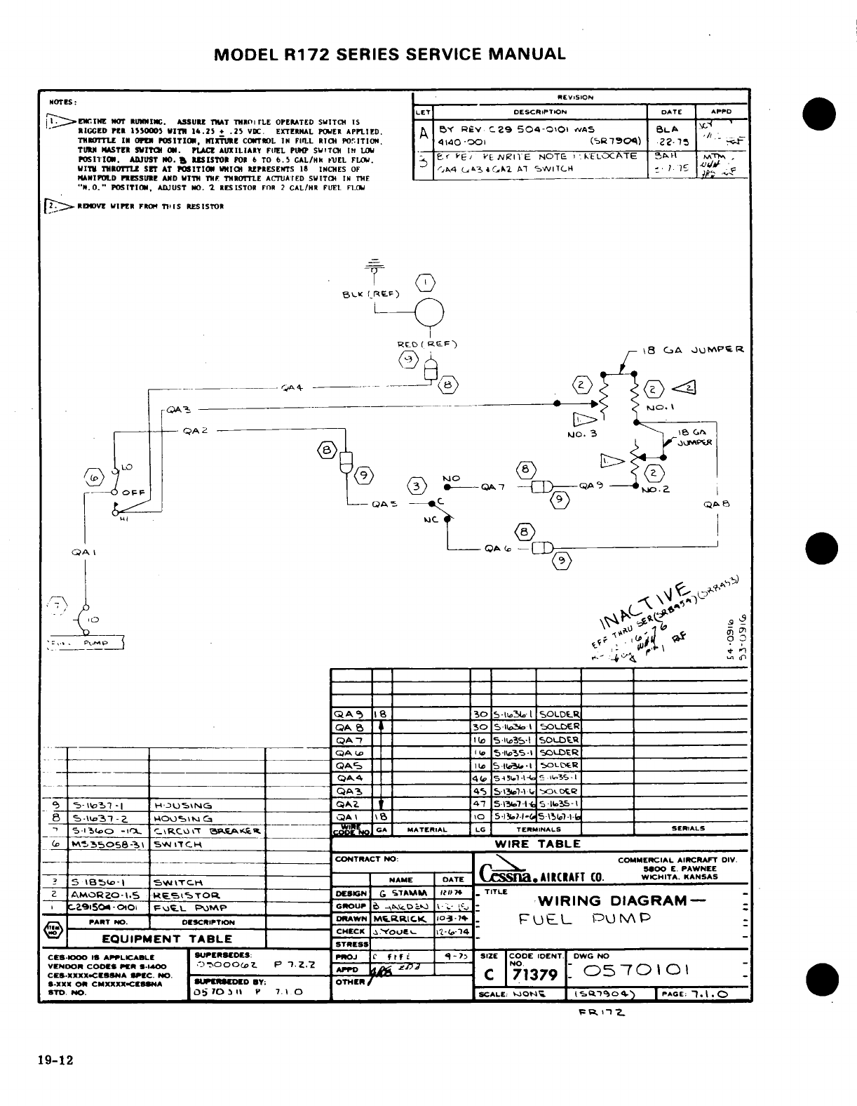
MODEL
R172
SERIES SERVICE
MANUAL
NOTES:
REVISION
LET
DESCRIPTION
DATE
APPD
1
ENGINE
NOT RUNNING. ASSURE THAT
THROTTLE
OPERATED
SWITCH
IS
--- --
--
.
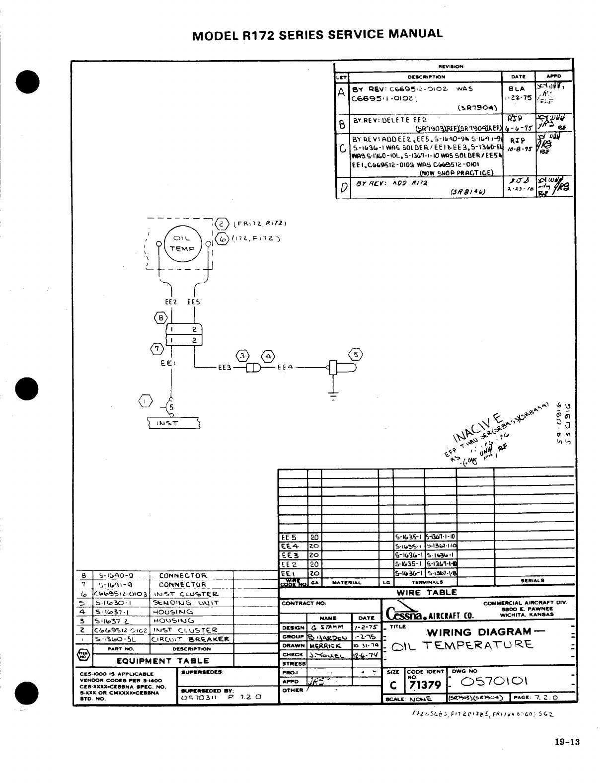
MODEL
R172
SERIES
SERVICE MANUAL
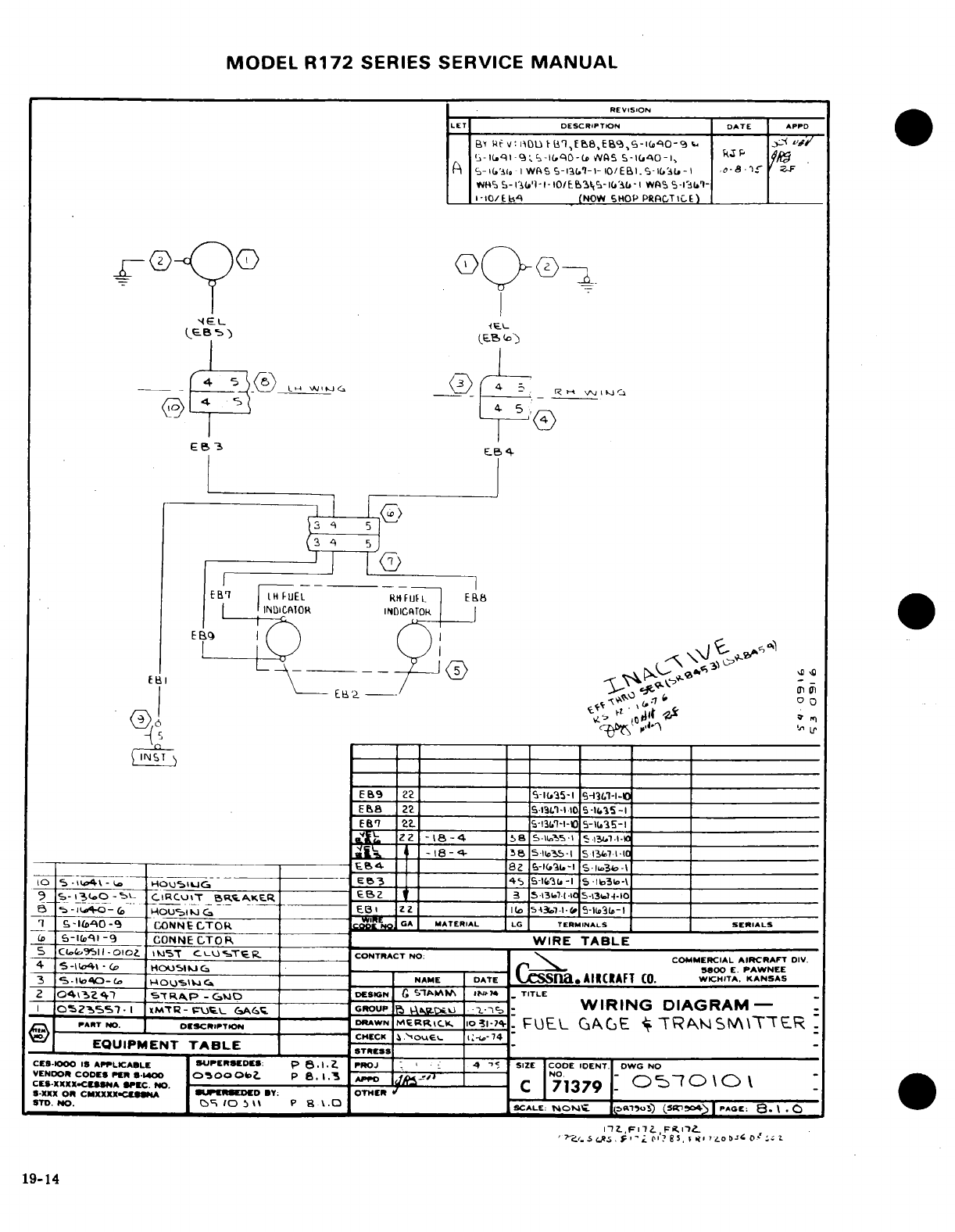
MODEL
R172
SERIES
SERVICE
MANUAL
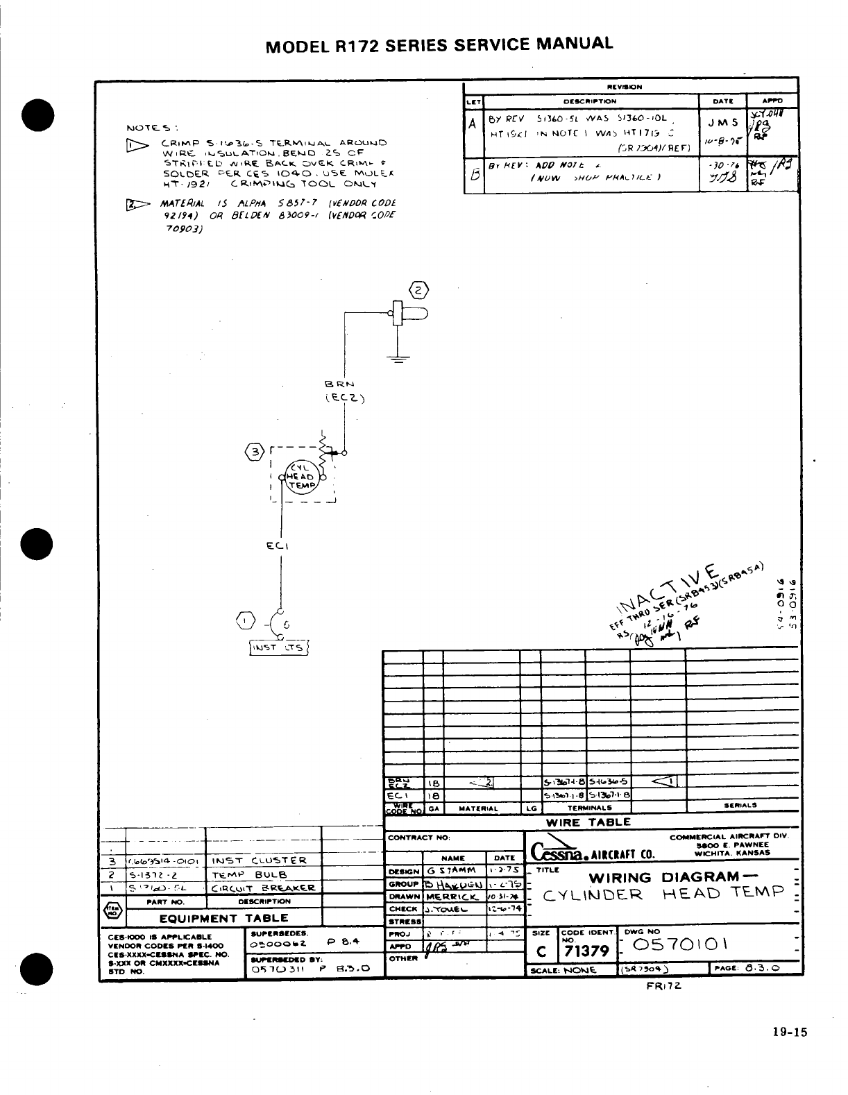
MODEL
R172
SERIES SERVICE
MANUAL
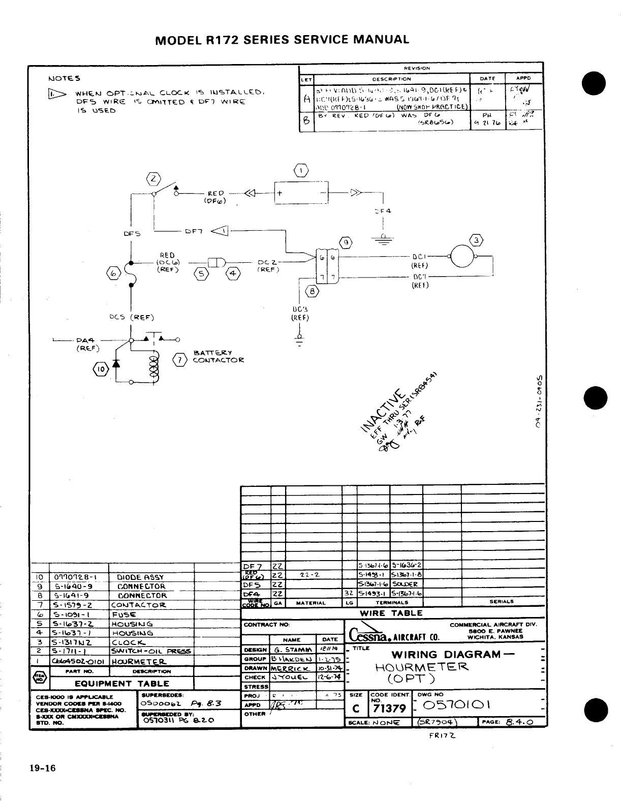
MODEL
R172
SERIES
SERVICE
MANUAL
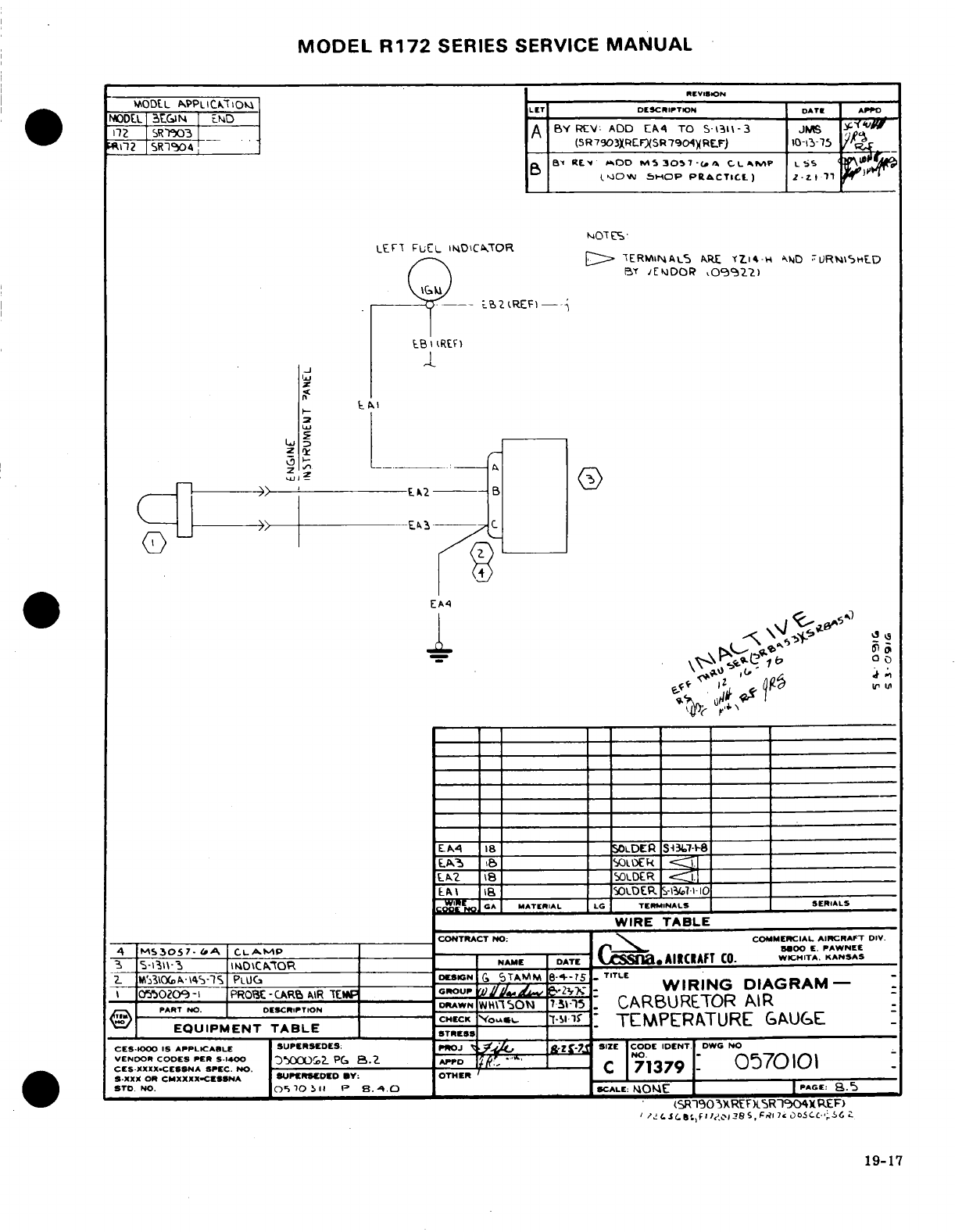
MODEL
R172
SERIES SERVICE
MANUAL
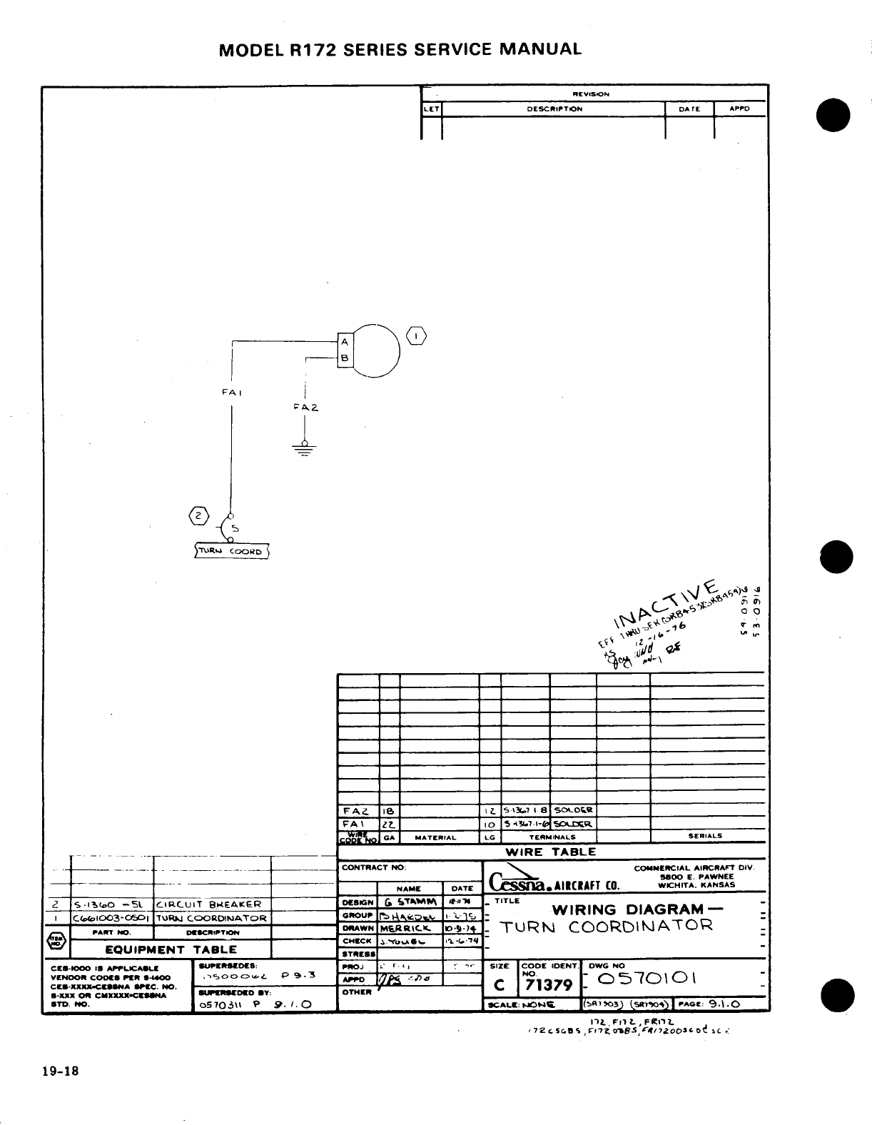
MODEL
R172
SERIES SERVICE
MANUAL
REVISION
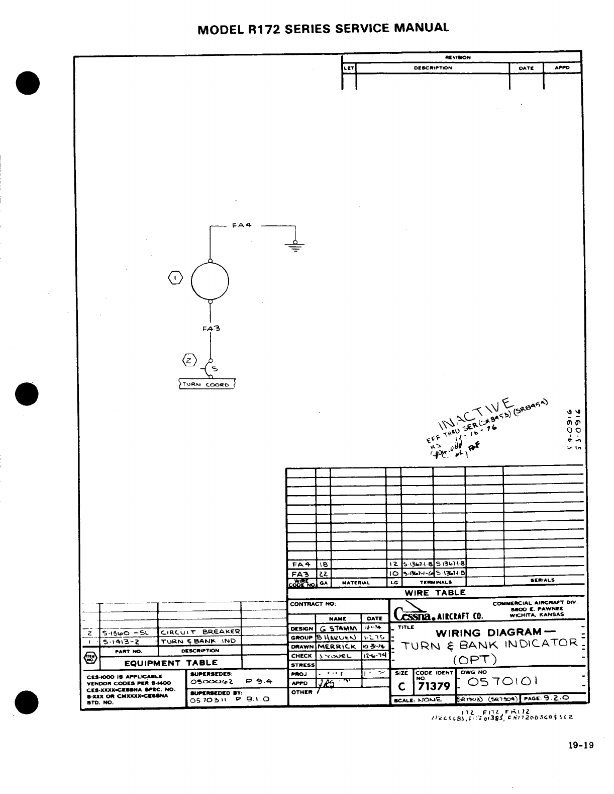
MODEL
R172
SERIES
SERVICE
MANUAL
REVISION
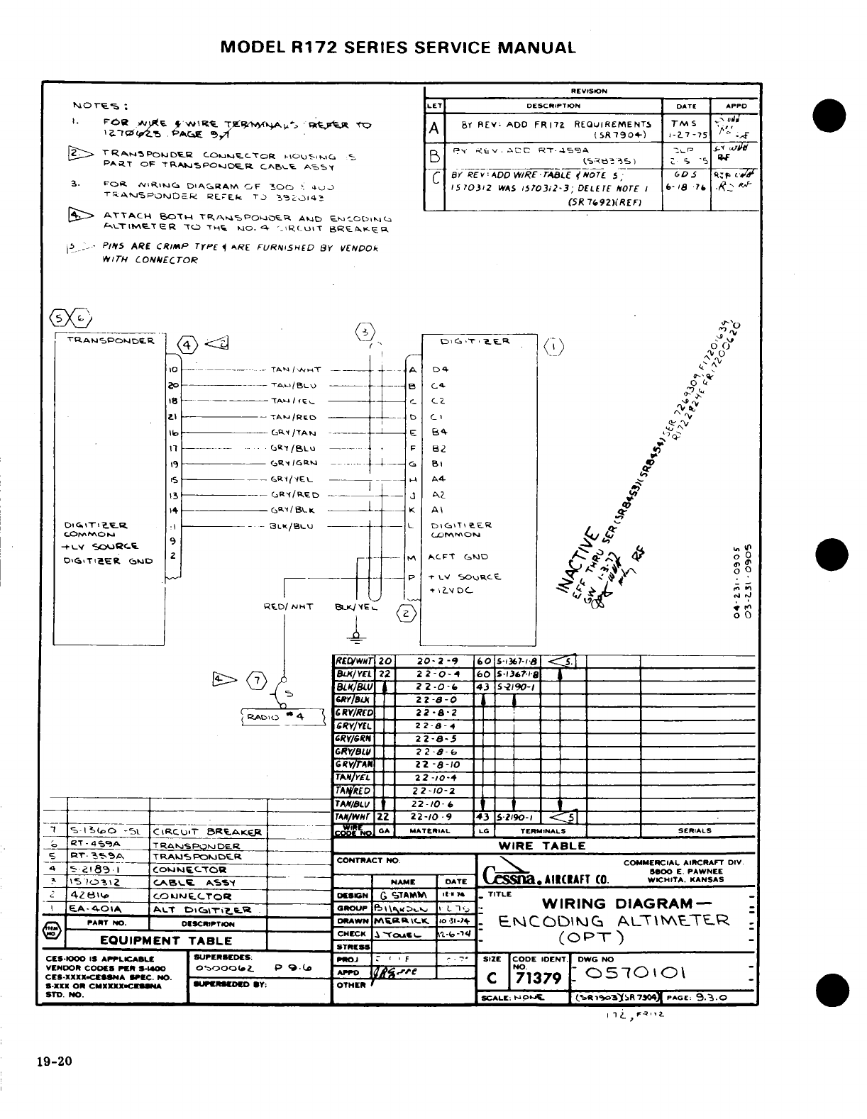
MODEL
R172
SERIES SERVICE
MANUAL
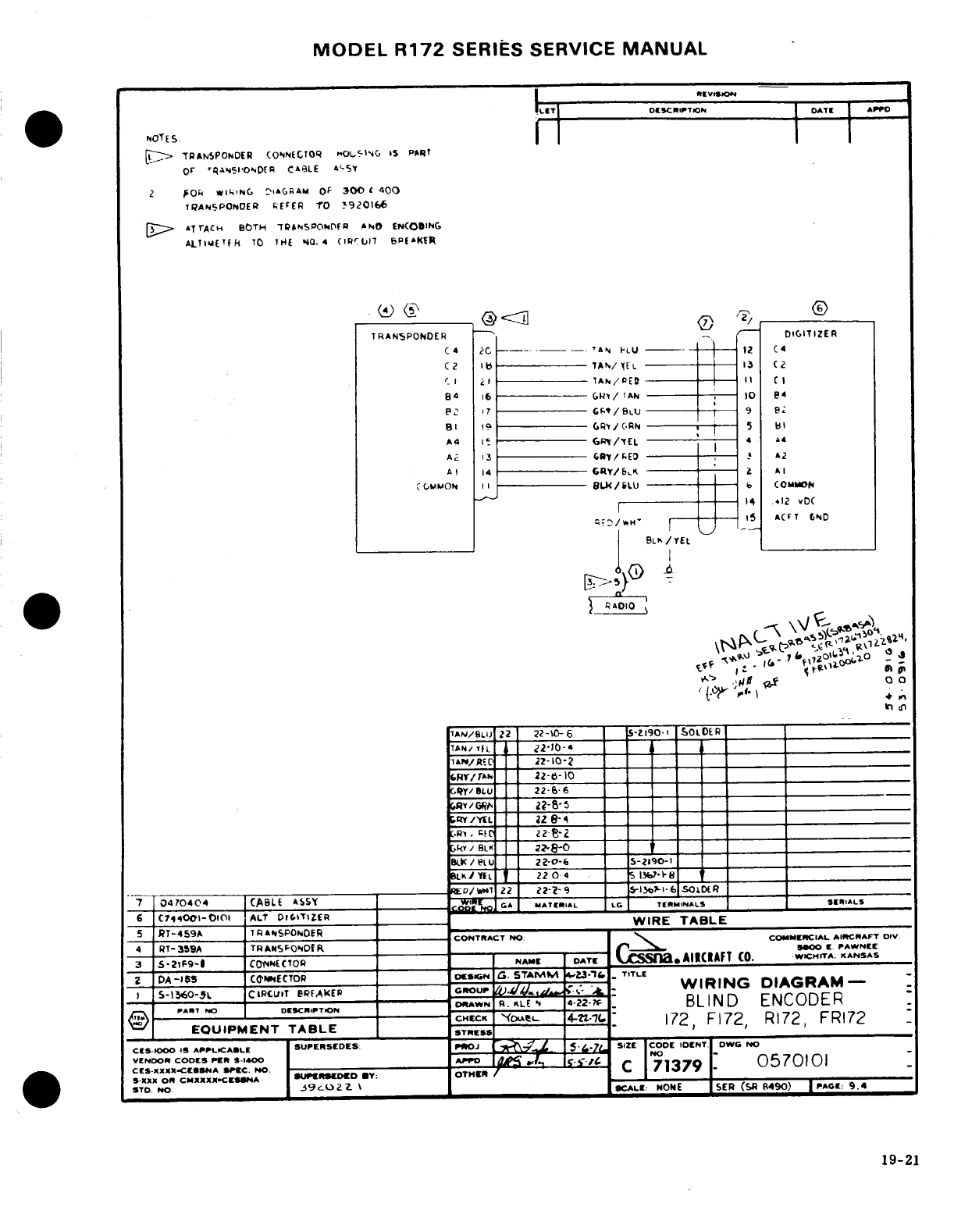
MODEL
R172
SERIES
SERVICE
MANUAL
REVISION
LET
DESCRIPTION DATE
APPO
NOTES
1
TRANSPONDER
CONNECTOR
HOUSING
IS
PART
OF
TRANSPONDER
CABLE
ASSY
2
FOR
WIRING
DIAGRAM
OF
300
&
400
TRANSPONDER
REFER
TO
3920166
3
ATTACH
BOTH
TRANSPONDER
AND
ENCODING
ALTIMETER
TO
THE
NO.
.4 CIRCUIT BREAKER
TRANSPONDER
DIGITIZER
C4
5
RADIO
TAN/BLU
22
22-1O-
6
5-2190-1
SOLOER
TAN/ YEL 22-10-4
TAN/RED
22-10-2
GRY/TAN
22-8-10
GRY/BLU
22-8-
6
GRY
/YEL
22-8-4
-
4
------------
7
0470404
CABLE
ASSy
6
C744001-O101
ALT
DIGITIZER
-
-WIRE
TABLE
5
RT-459A
TRANSPONOER
4
RT-359A
TRANSPONDER
CONTRACT NO
:
COMMERCIAL
AIRCRAFT
DIV.
4
RT-359A
-
500
C
PAWNEE
3
5-21P9-1
COTNECTOR
NAME
DATE
SSIa.
AIICIAFT
(0.
WICHITA.
KANSAS
DA-155
CONNECTOR
DESION
G.
STAMM
4.23.76
.
TITLE
S-1360-5l
CIRCUIT
BREAKER
GROUP
4.
-
WIRING
DIAGRAM-
PART
NO
DESCRIPTION
----
DRAWN
R.
KLEN
4-22-7f
BLIND
ENCODER
AEOUIPM IENT E
CHECK
"(OAPENL
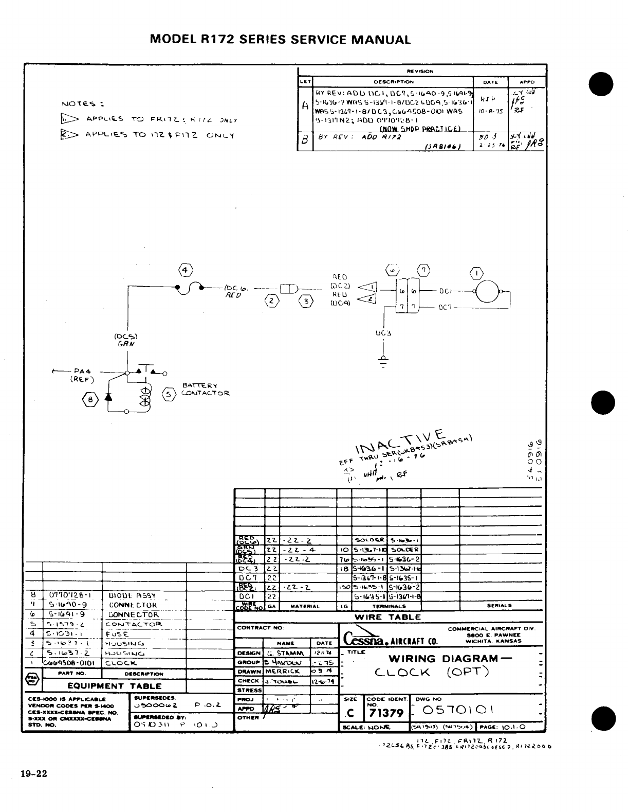
MODEL
R172
SERIES SERVICE
MANUAL
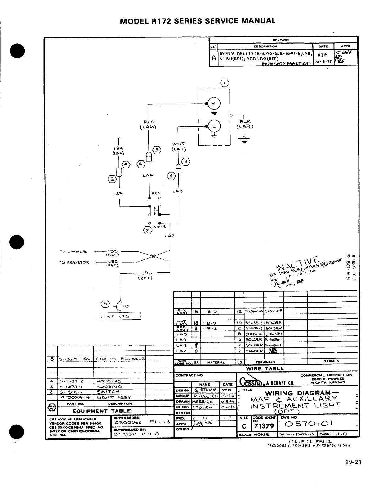
MODEL
R172
SERIES
SERVICE
MANUAL
19-23
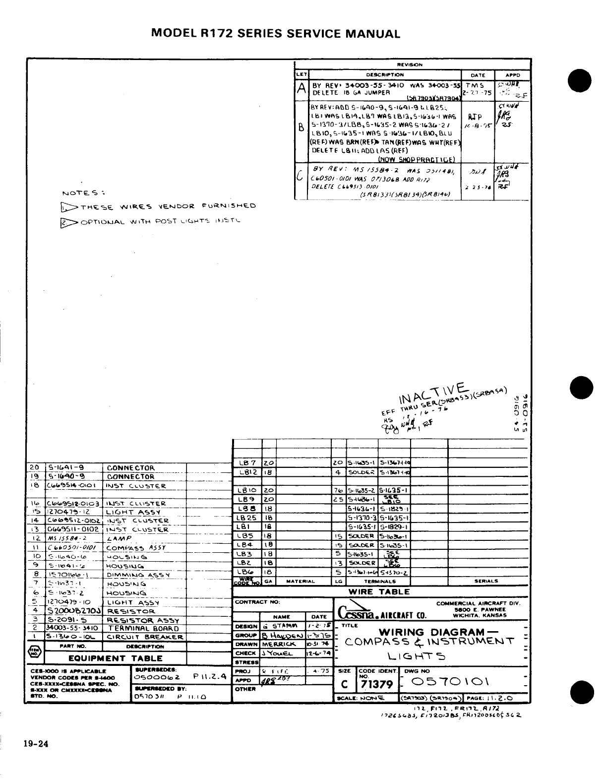
MODEL
R172
SERIES SERVICE
MANUAL
REVISION
LET
DESCRIPTION
DATE APPD
A
BY
REV
34003-55-3410
WAS
34-003-55
TMS
DELETE
18 GA
JUMPER
1
THESE
WIRES
VENDOR
FURNISHED
2
OPTIONAL
WITH
POST
LIGHTS
INSTL
19-24
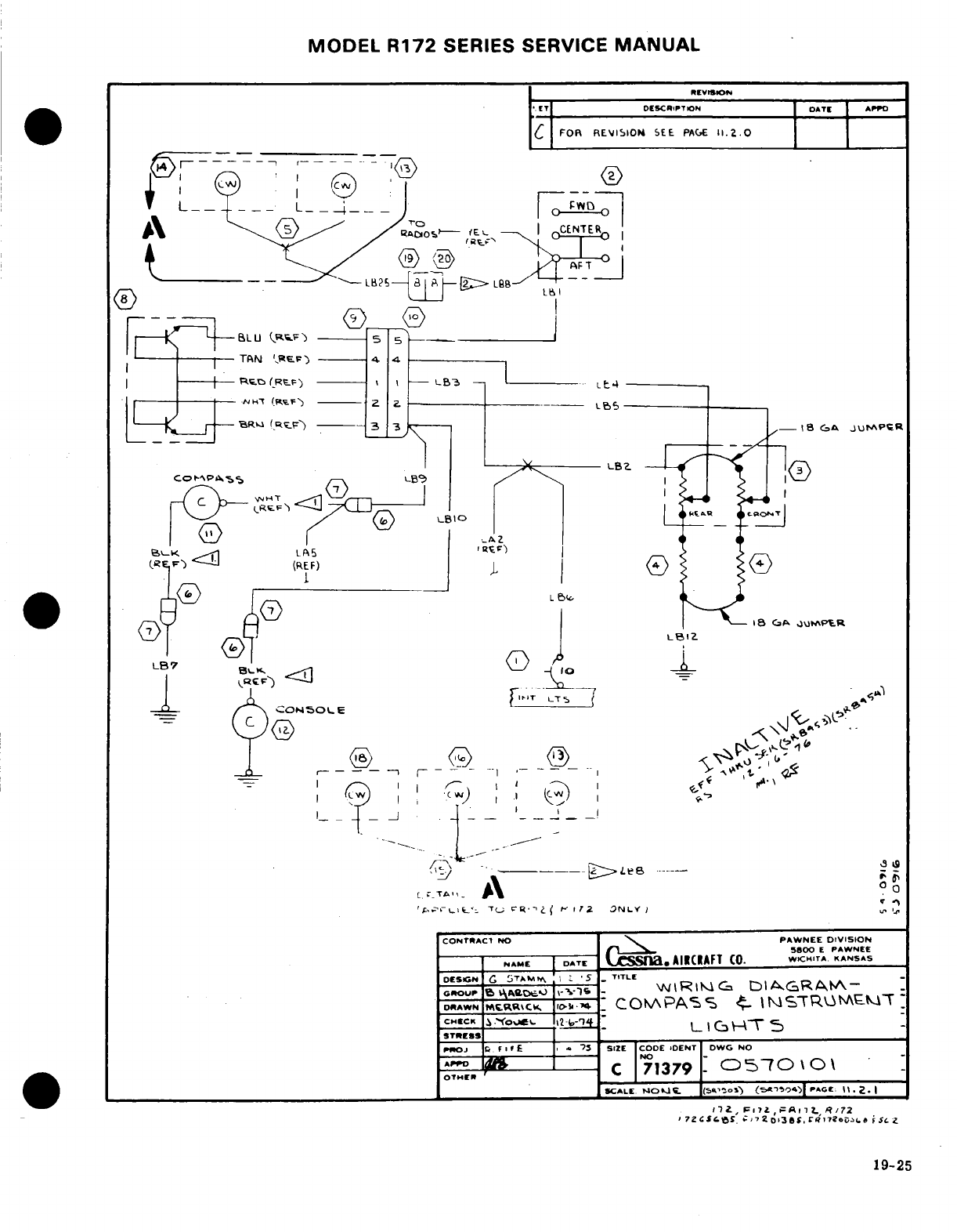
MODEL
R172
SERIES
SERVICE
MANUAL
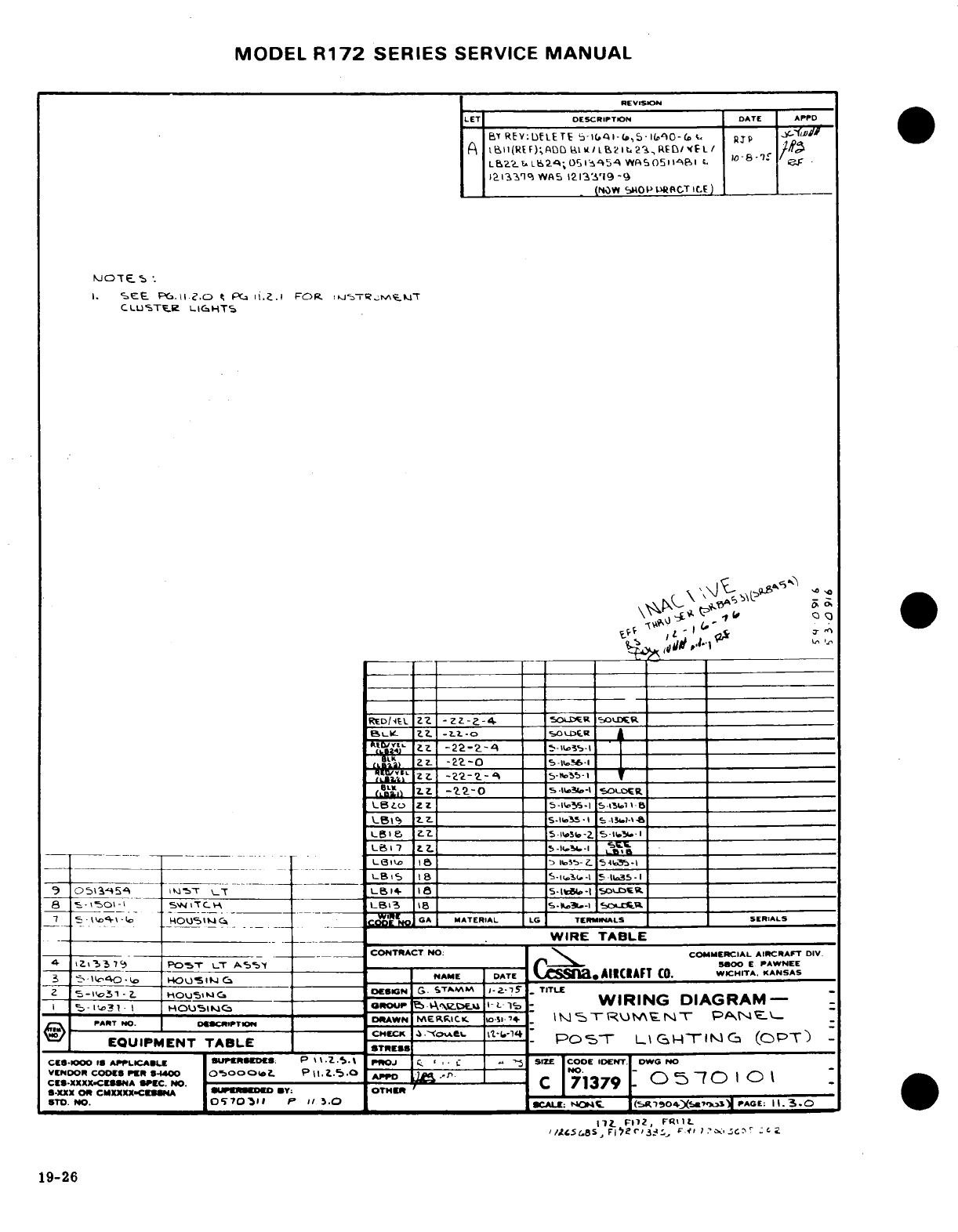
MODEL
R172
SERIES
SERVICE
MANUAL
19-26
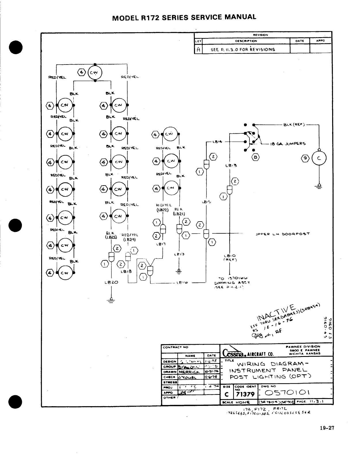
MODEL
R172
SERIES
SERVICE
MANUAL
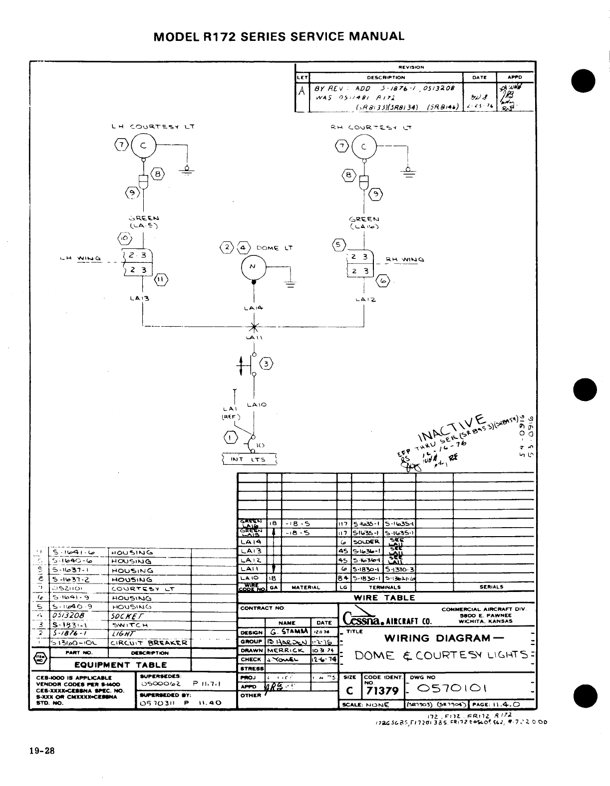
MODEL
R172
SERIES
SERVICE
MANUAL
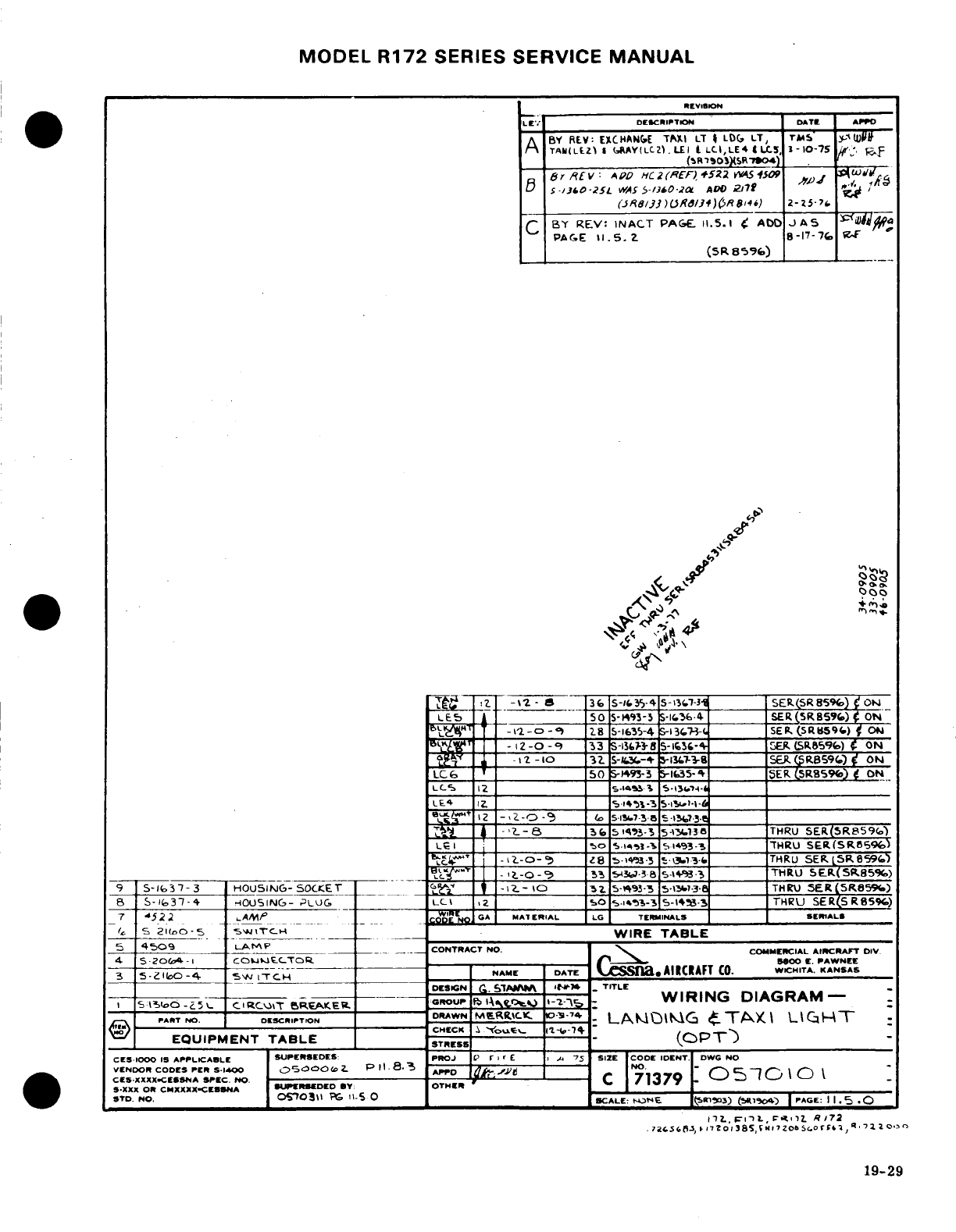
MODEL
R172
SERIES
SERVICE
MANUAL
REVISION
DESCRIPTION DATE
APPD
A
BY
REV:
EXCHANGE
TAXI
LT
LDG
LT,
8
S-16
3
7
HOIN-
PLUG
_
LC\I
,7
50R.U*-7_
s-I7
DTFIR
SE
R(S
R859C)
19-29
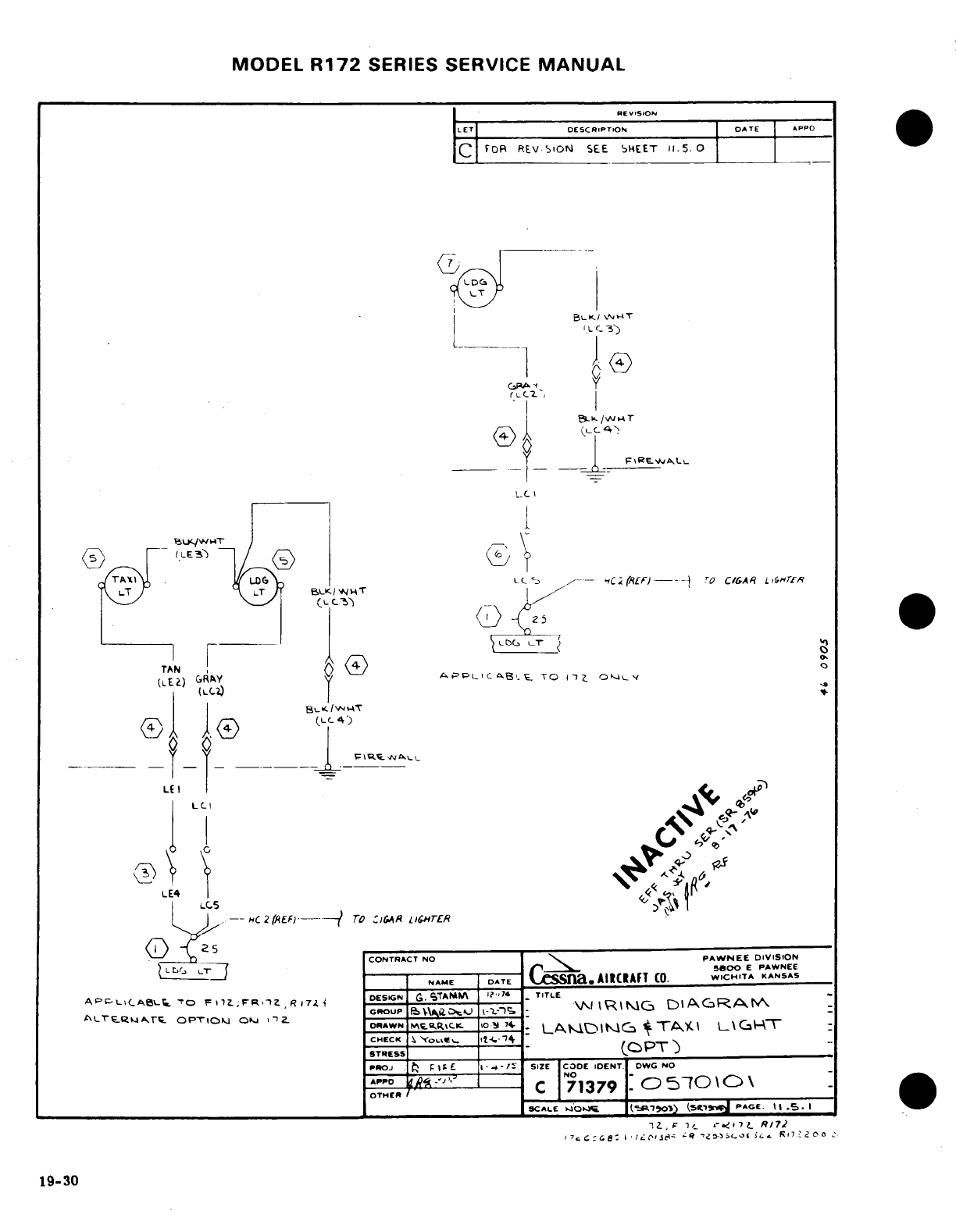
MODEL
R172
SERIES
SERVICE
MANUAL
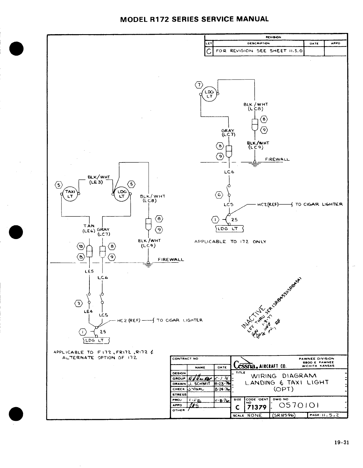
MODEL
R172
SERIES SERVICE
MANUAL
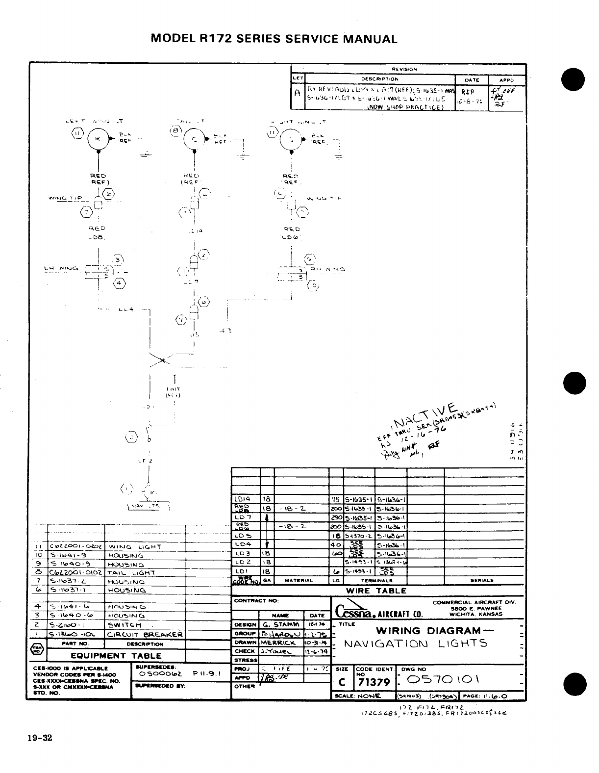
MODEL
R172
SERIES
SERVICE
MANUAL
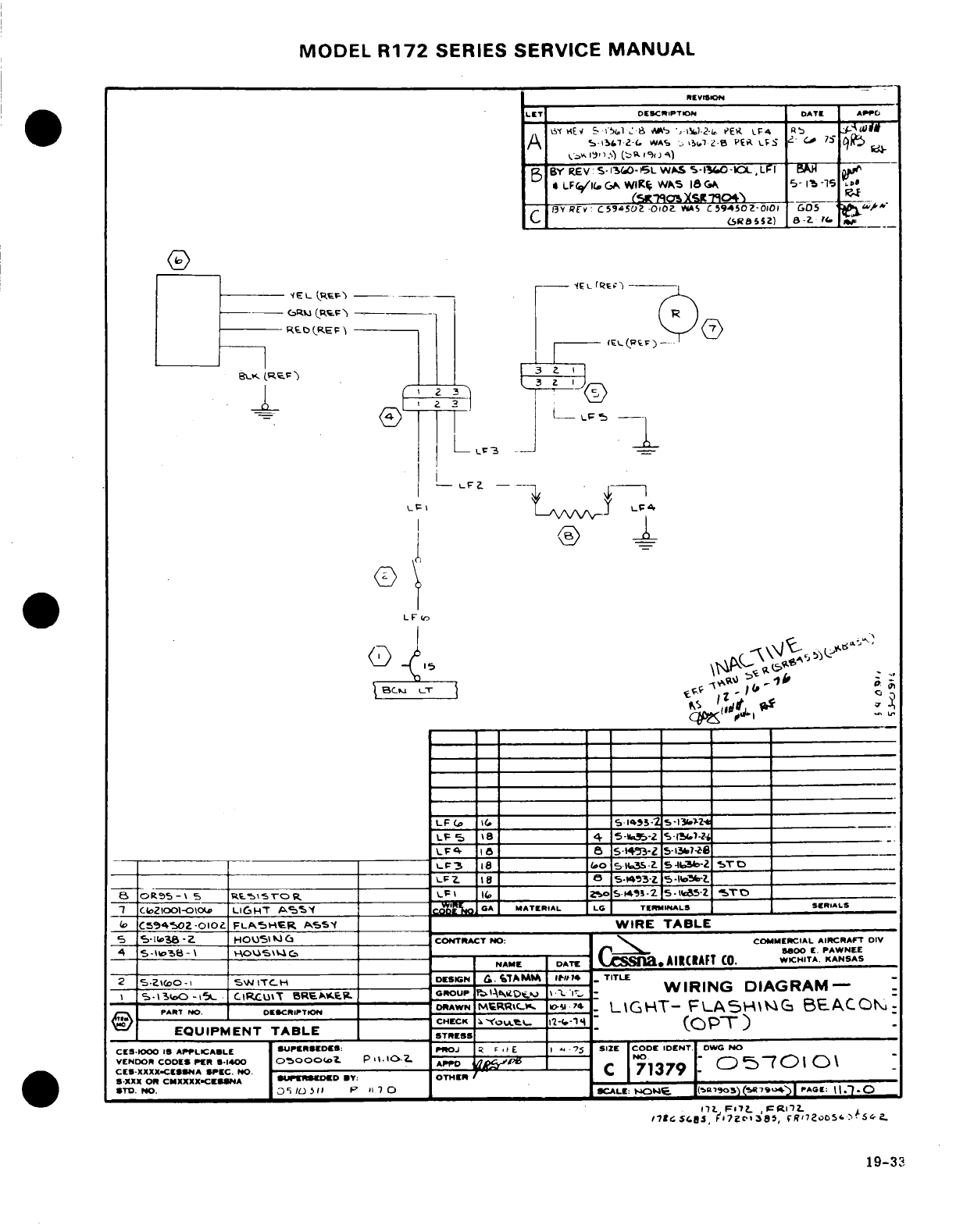
MODEL
R172
SERIES
SERVICE
MANUAL
Li3
-
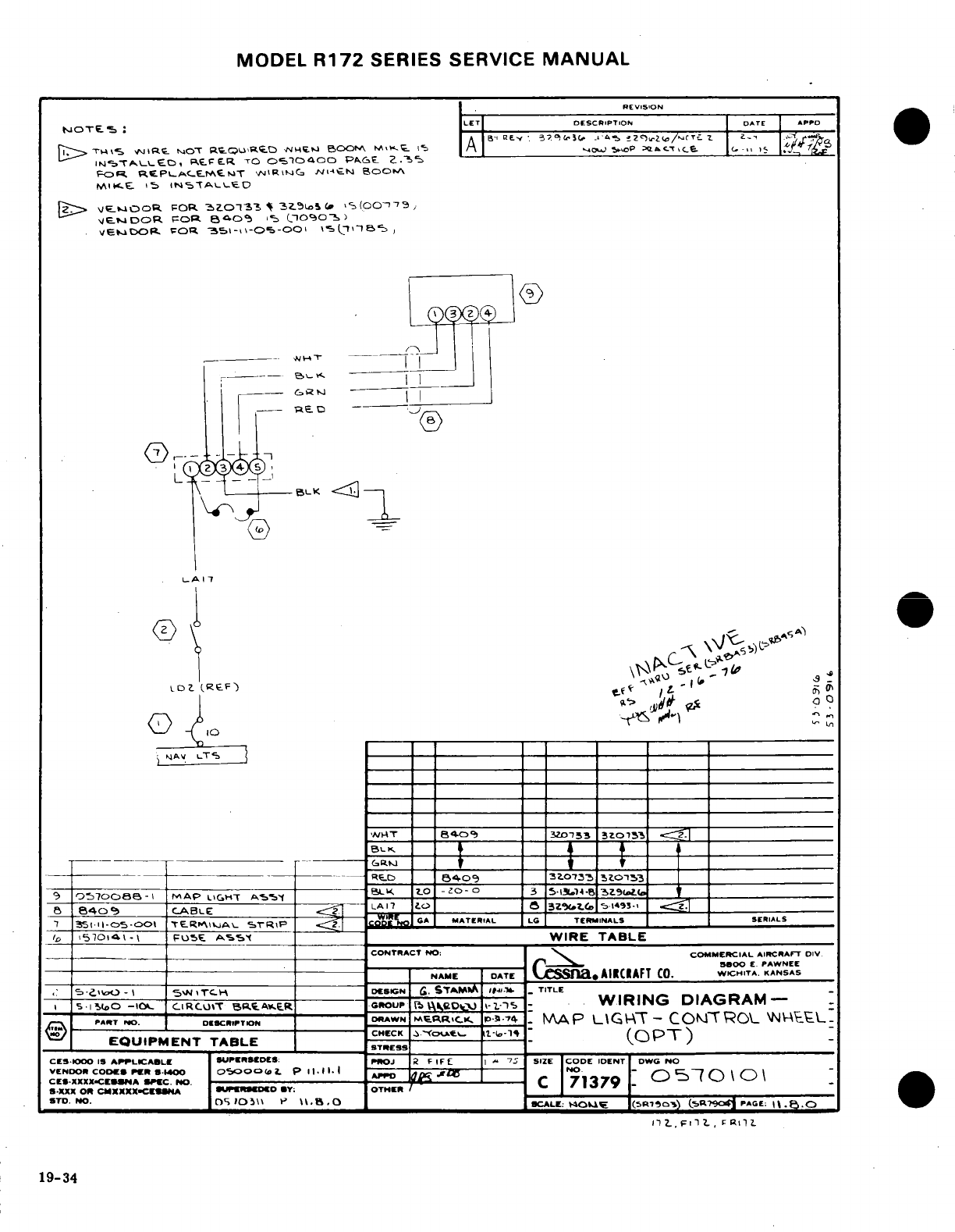
MODEL
R172
SERIES
SERVICE
MANUAL
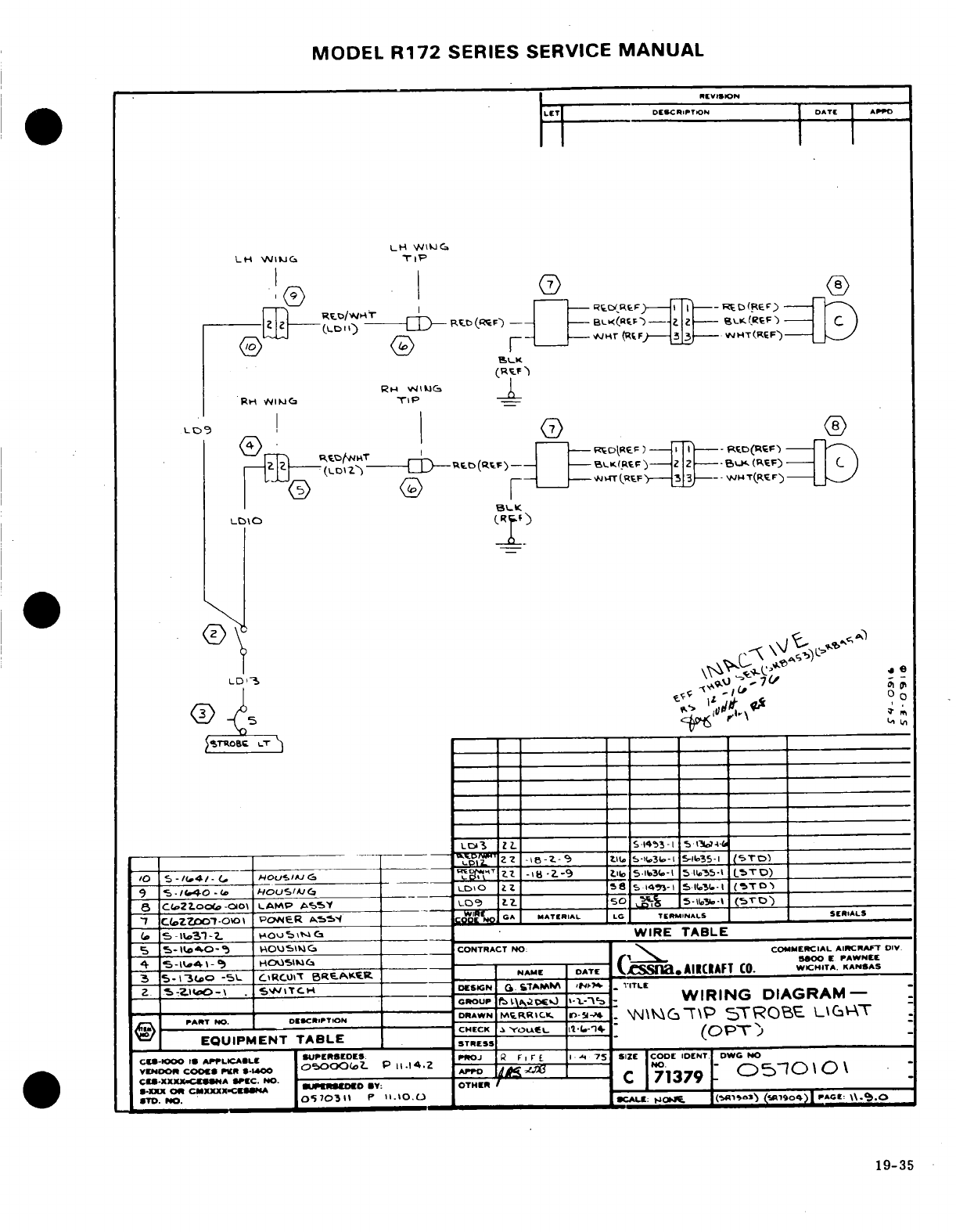
MODEL
R172
SERIES SERVICE
MANUAL
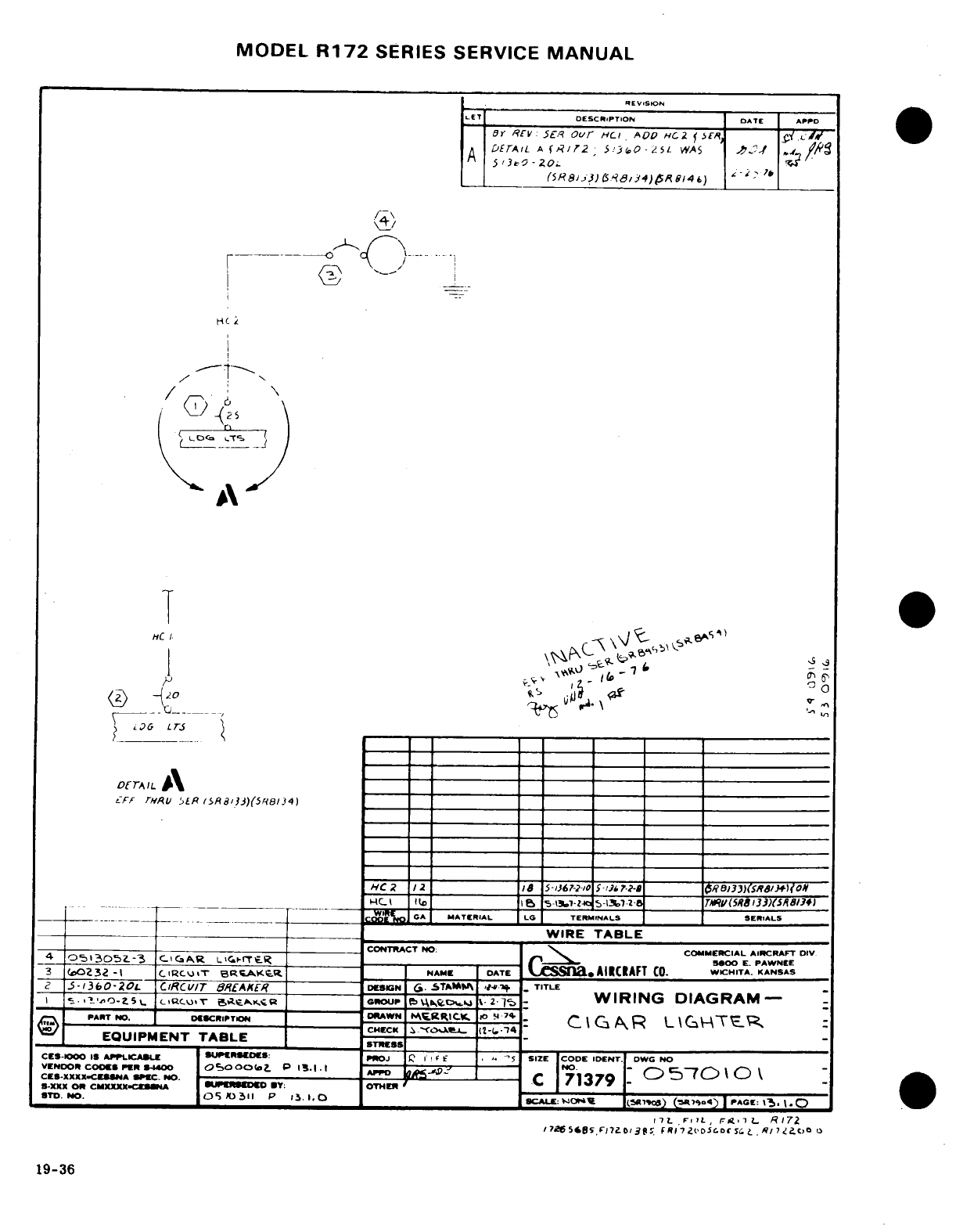
MODEL
R172
SERIES
SERVICE
MANUAL
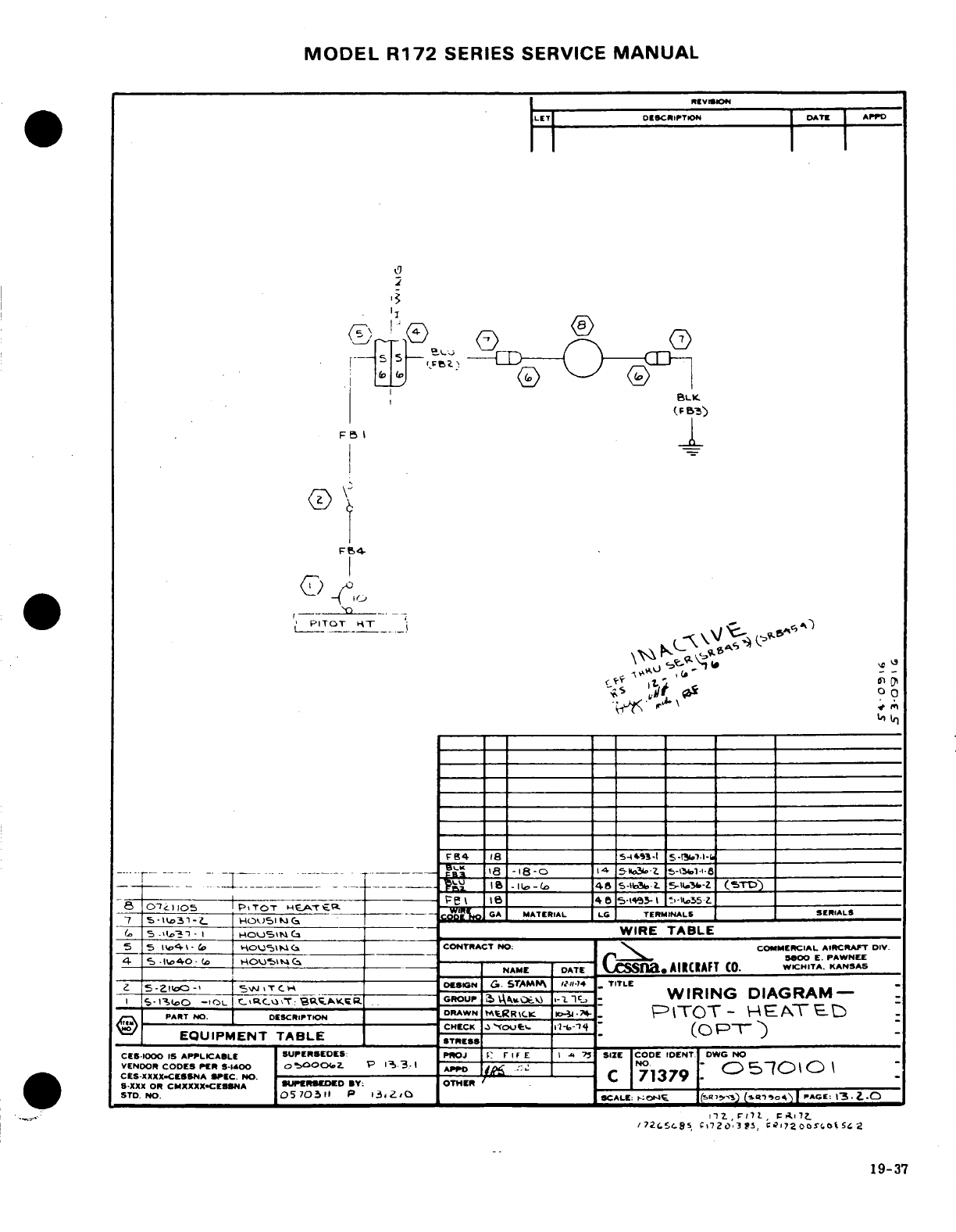
MODEL
R172
SERIES
SERVICE
MANUAL
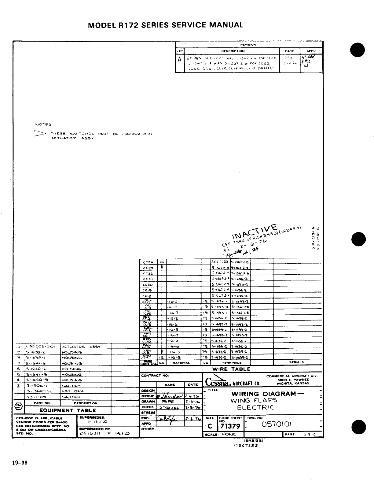
MODEL
R172
SERIES
SERVICE
MANUAL
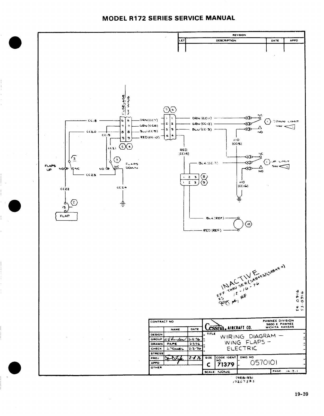
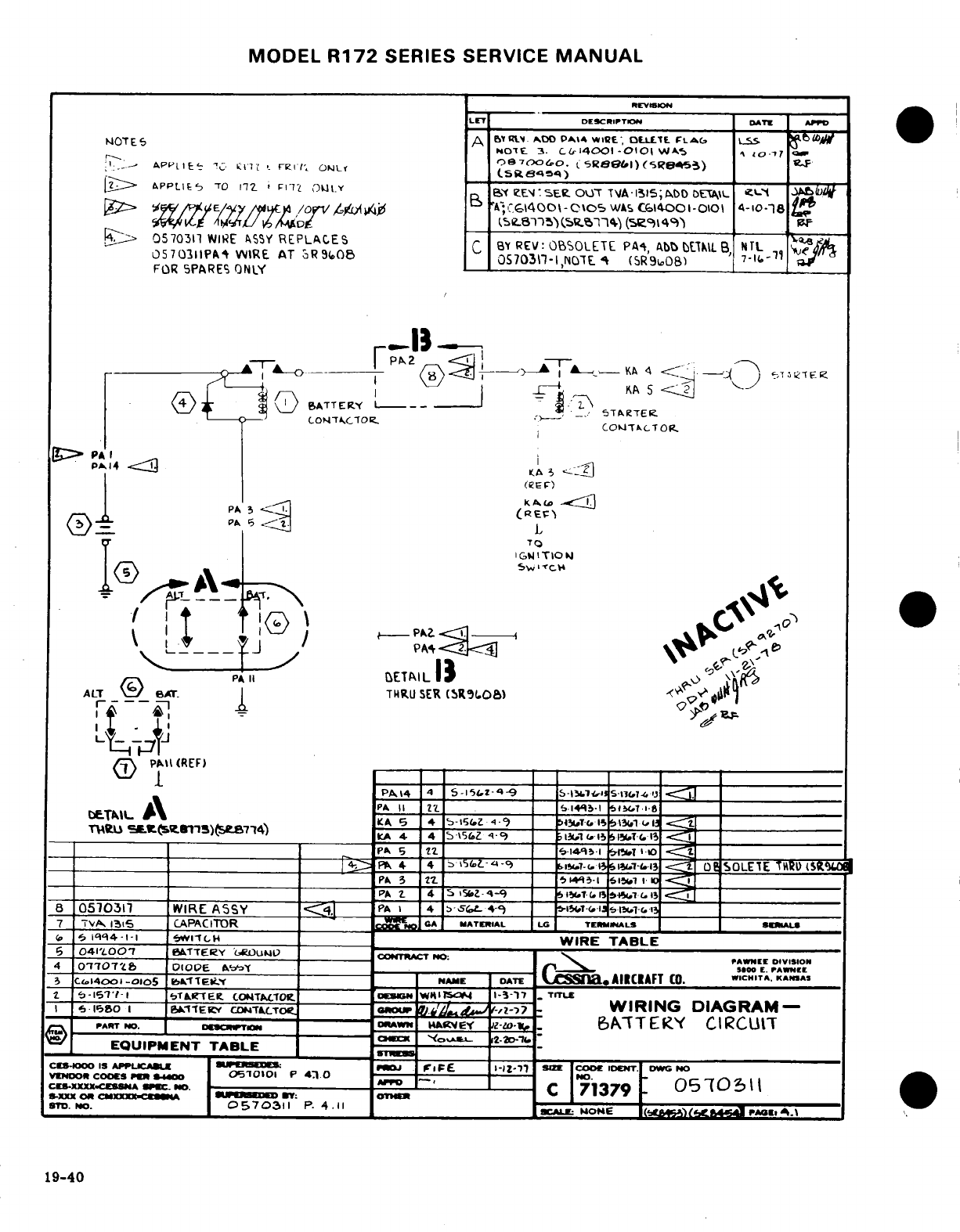
MODEL
R172
SERIES SERVICE
MANUAL
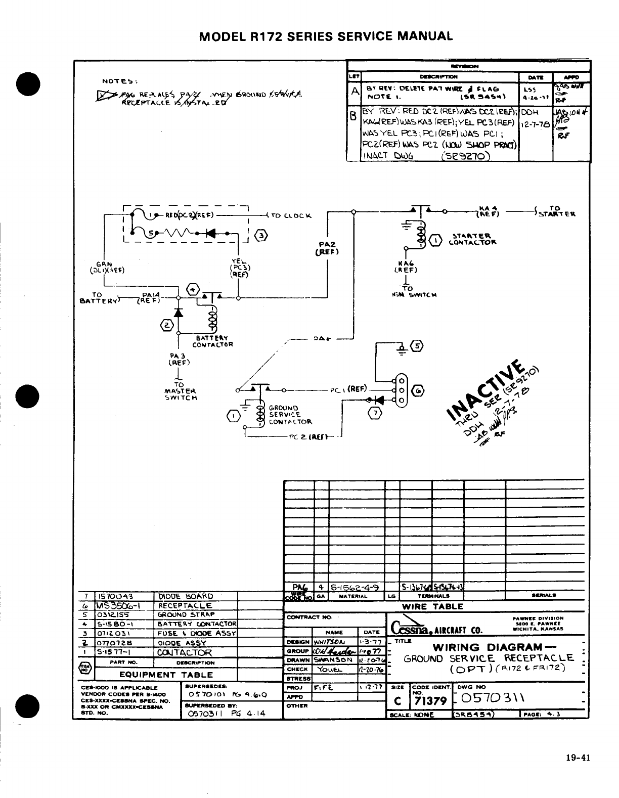
MODEL
R172
SERIES
SERVICE
MANUAL
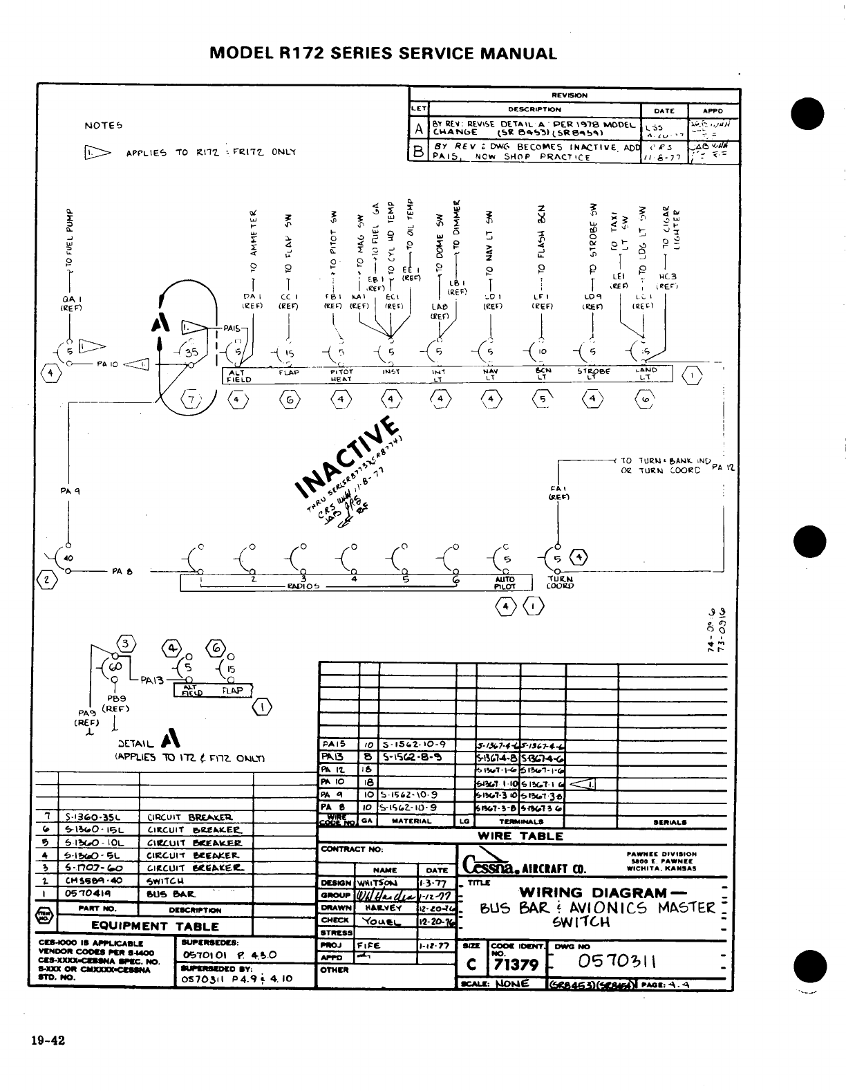
MODEL
R172
SERIES
SERVICE
MANUAL
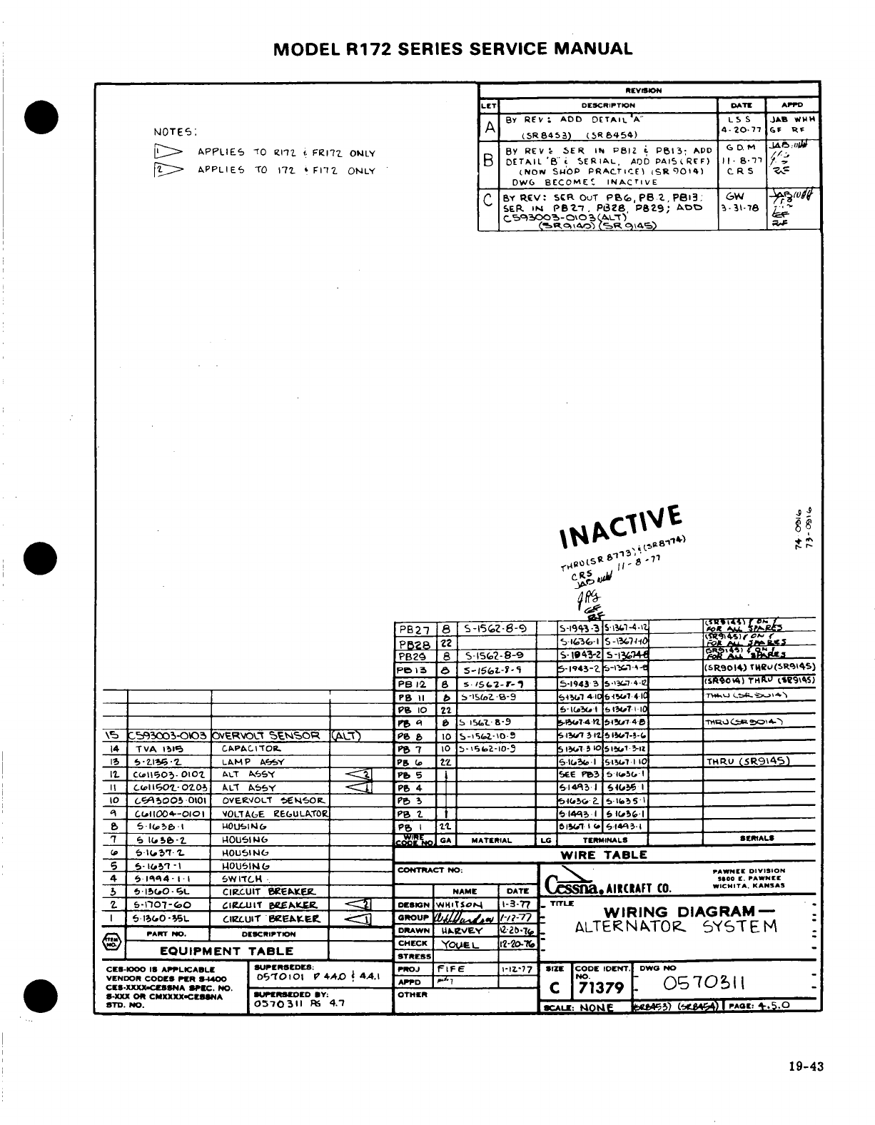
MODEL
R172
SERIES SERVICE
MANUAL
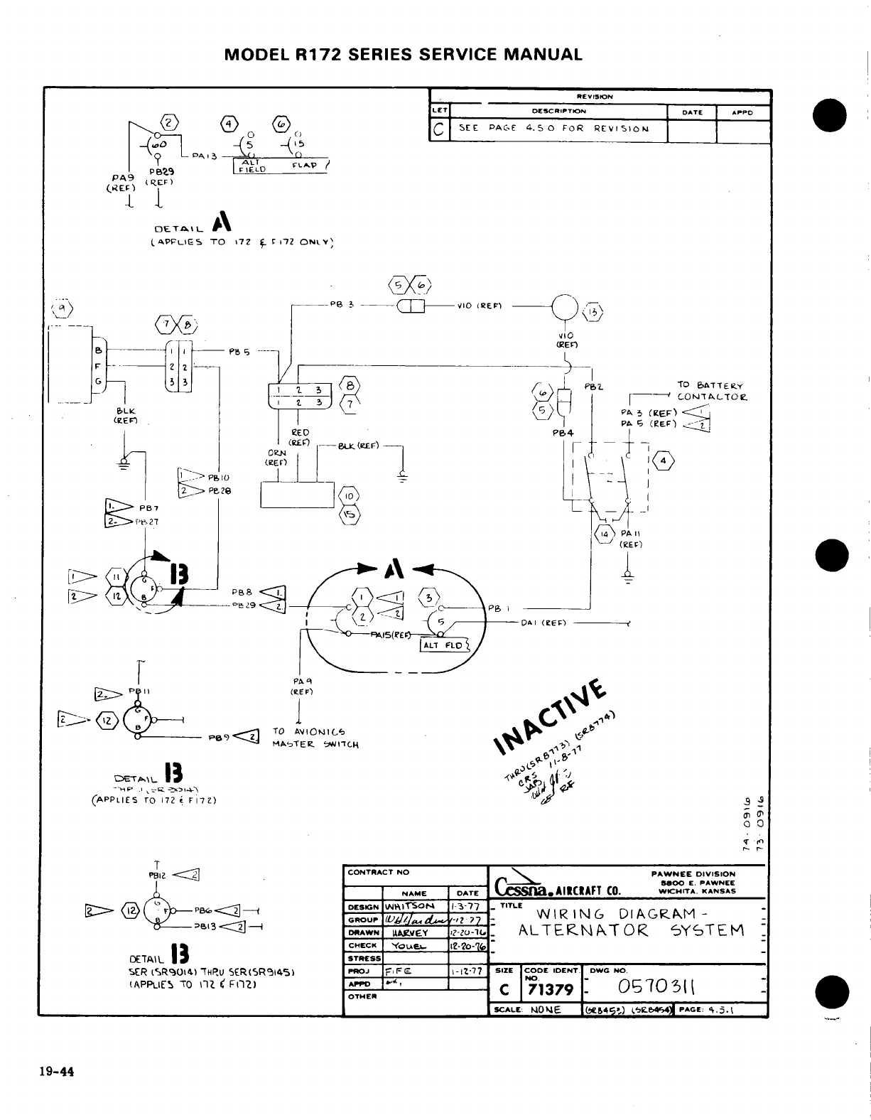
MODEL
R172
SERIES
SERVICE
MANUAL
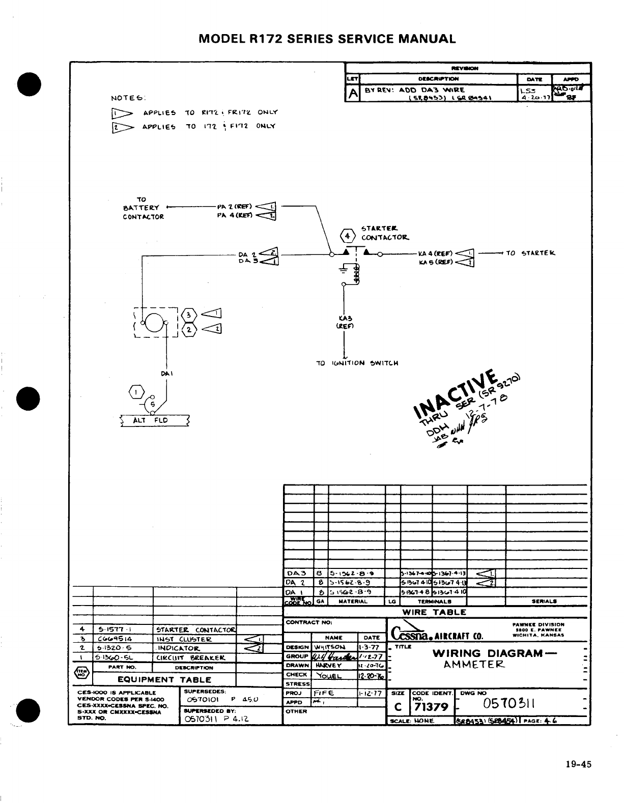
MODEL
R172
SERIES
SERVICE
MANUAL
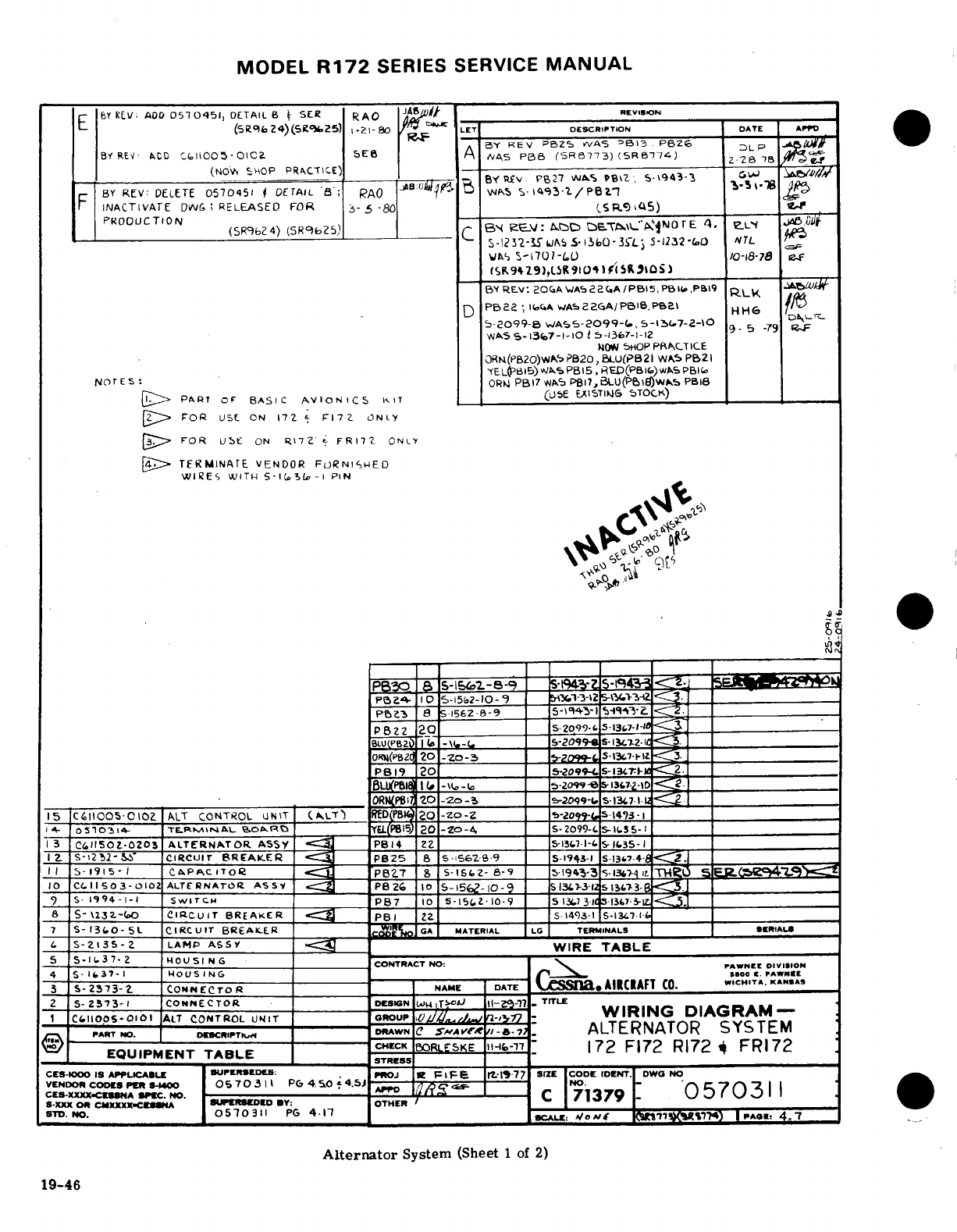
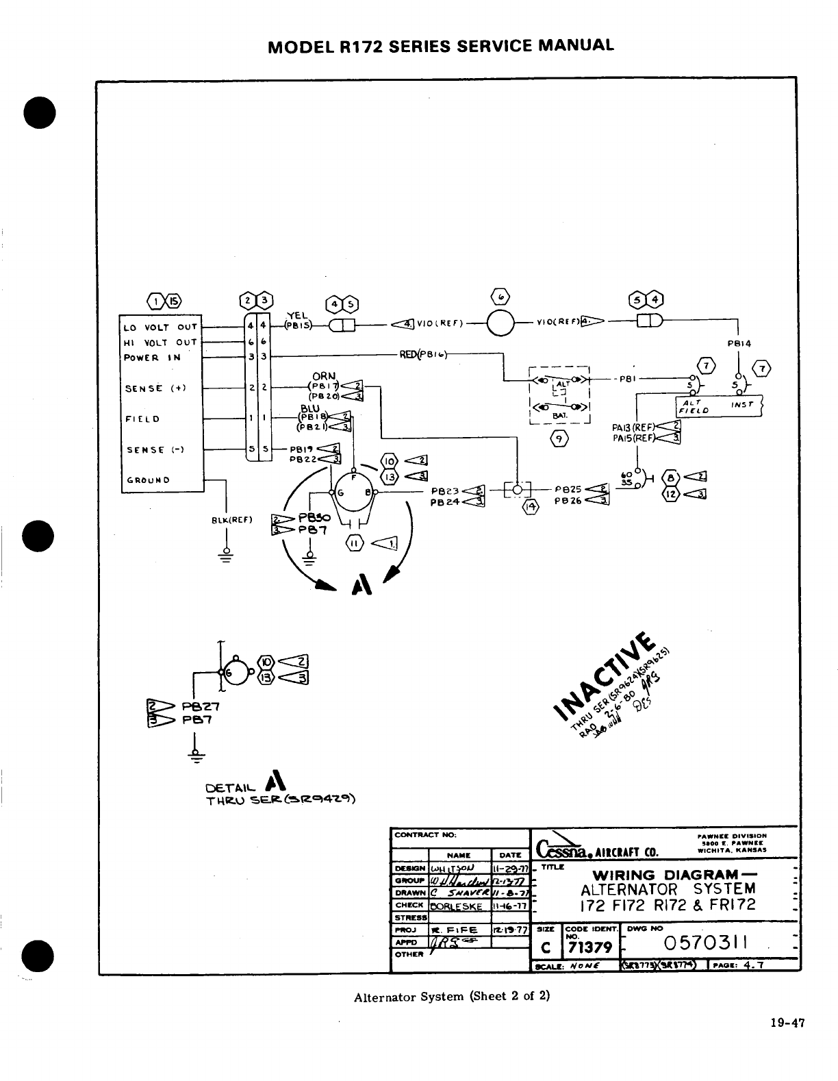
MODEL
R172
SERIES
SERVICE
MANUAL
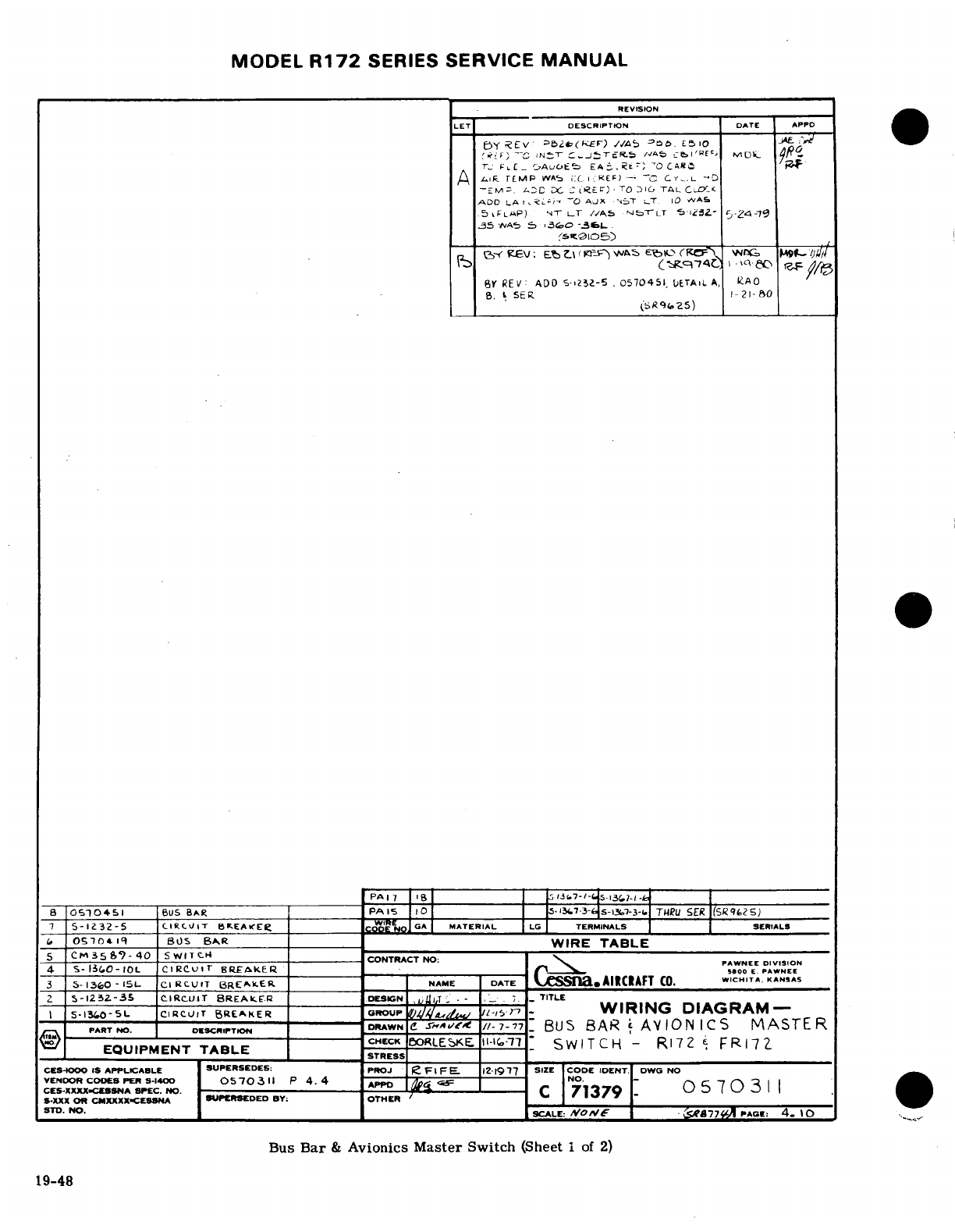
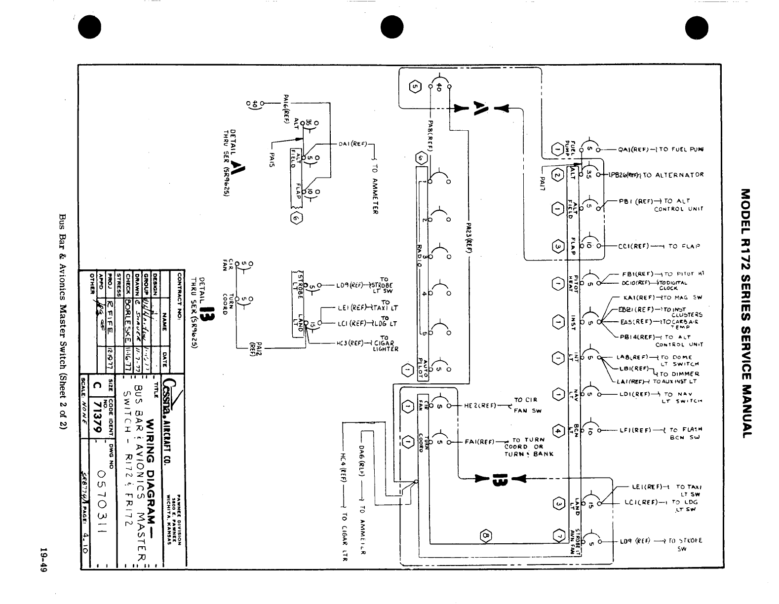
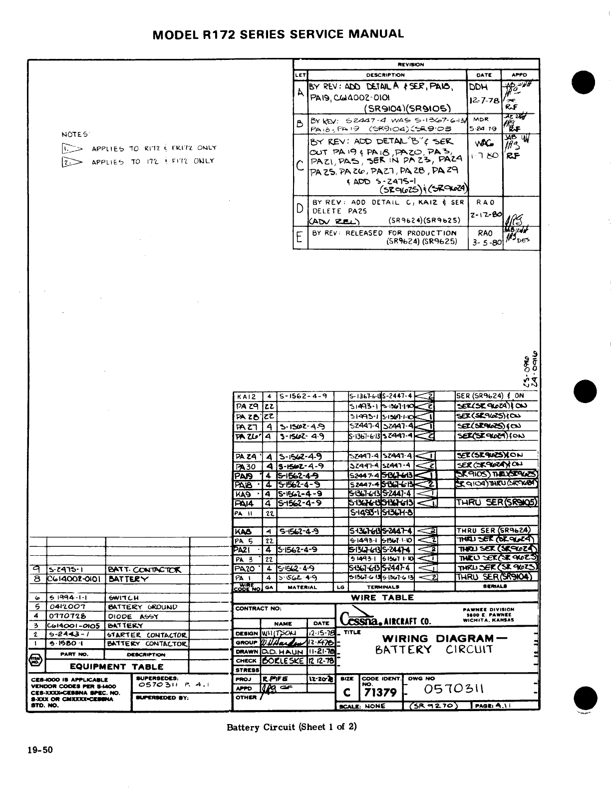
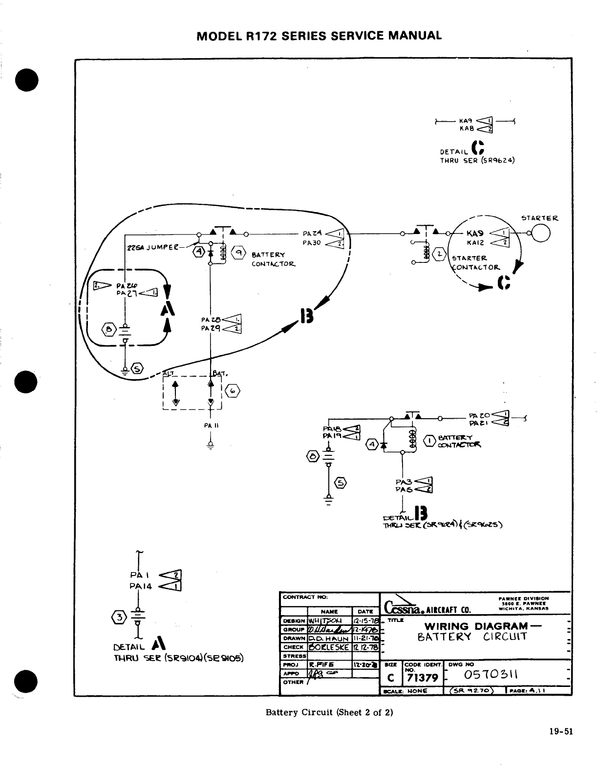
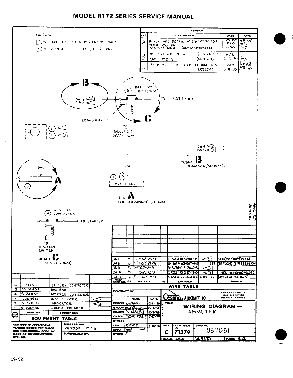
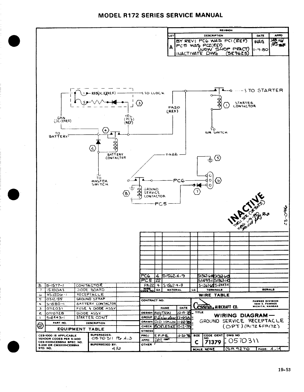
MODEL
R172
SERIES
SERVICE
MANUAL
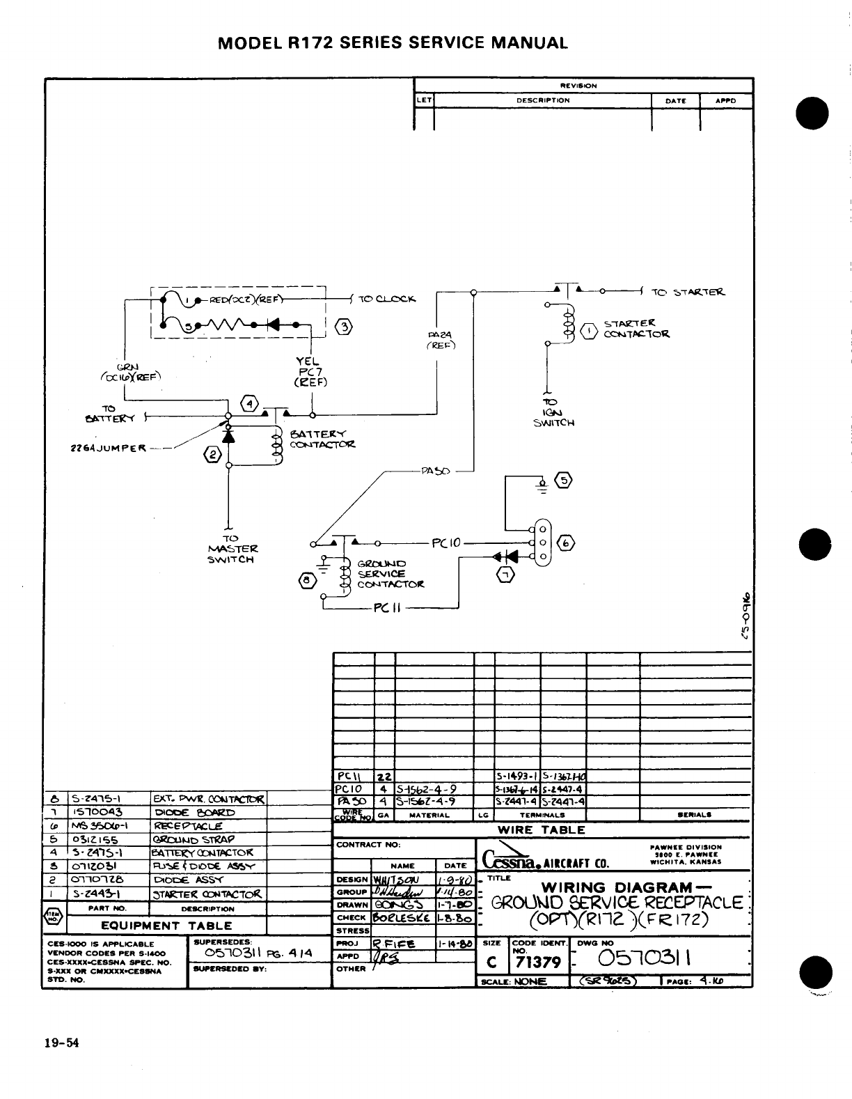
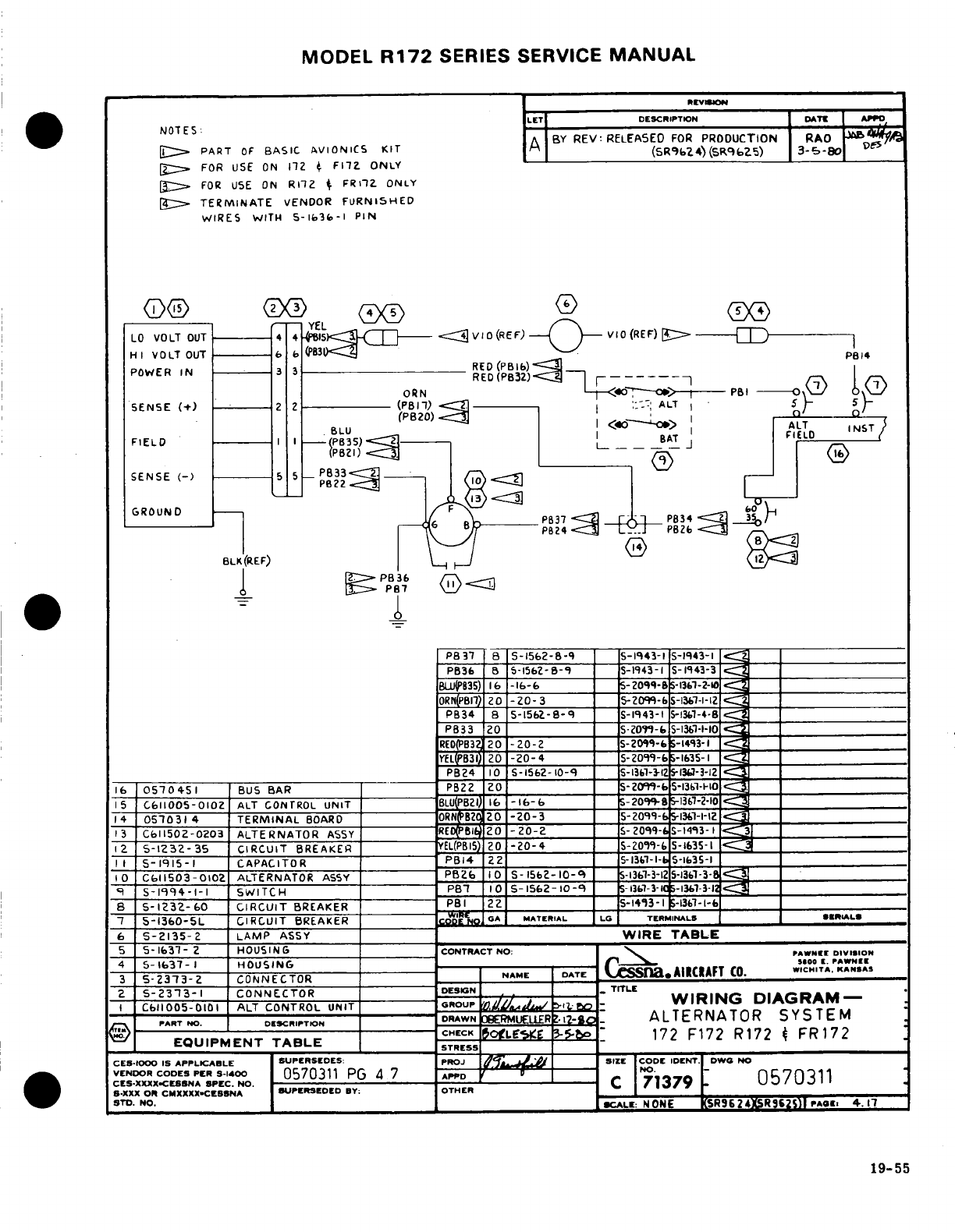
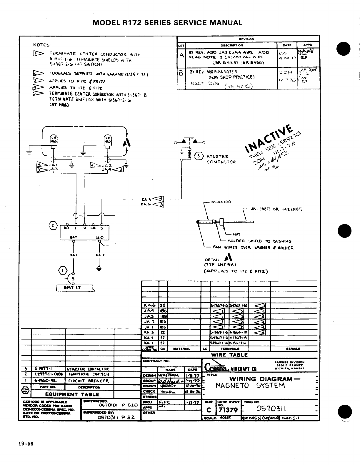
MODEL
R172
SERIES
SERVICE
MANUAL
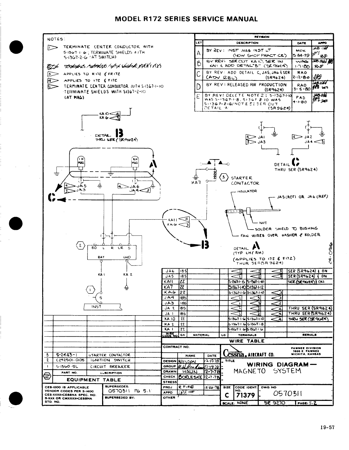
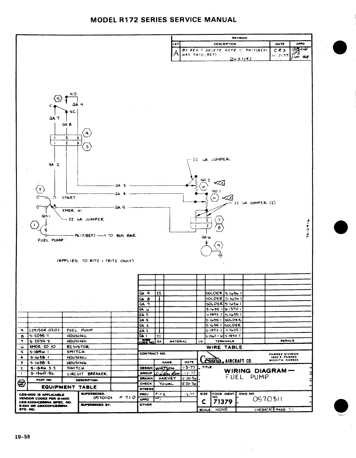
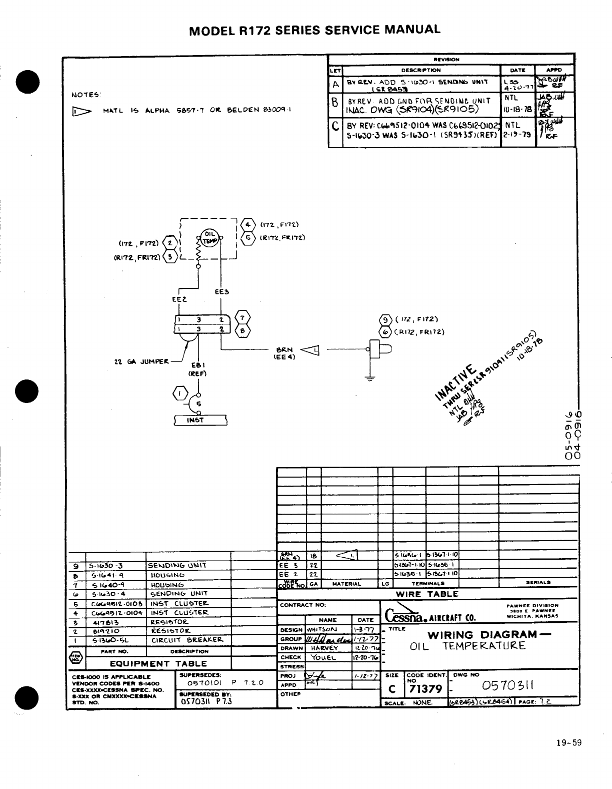
MODEL
R172
SERIES
SERVICE
MANUAL
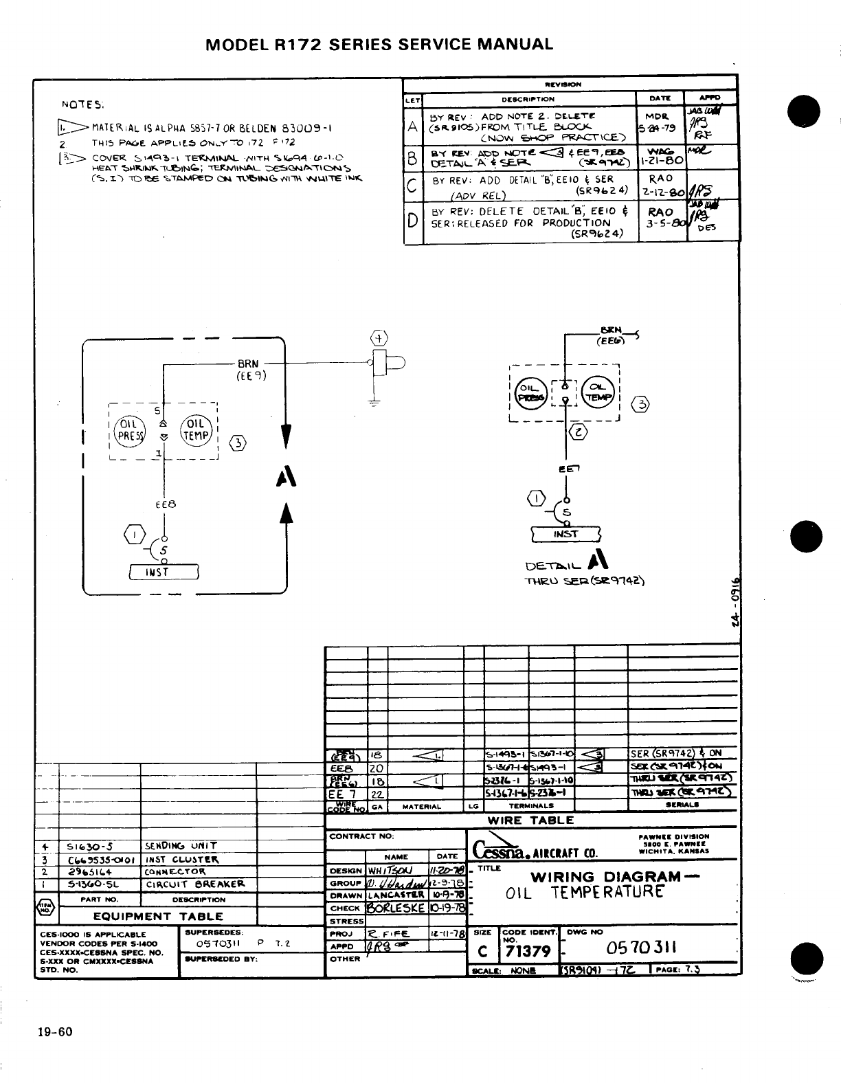
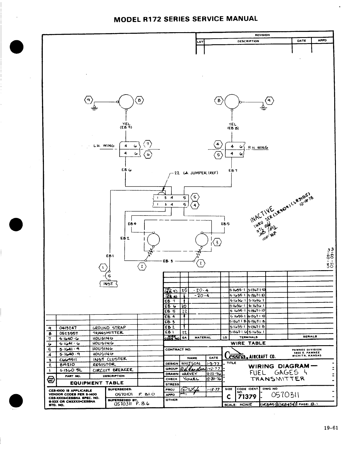
MODEL
R172
SERIES SERVICE
MANUAL
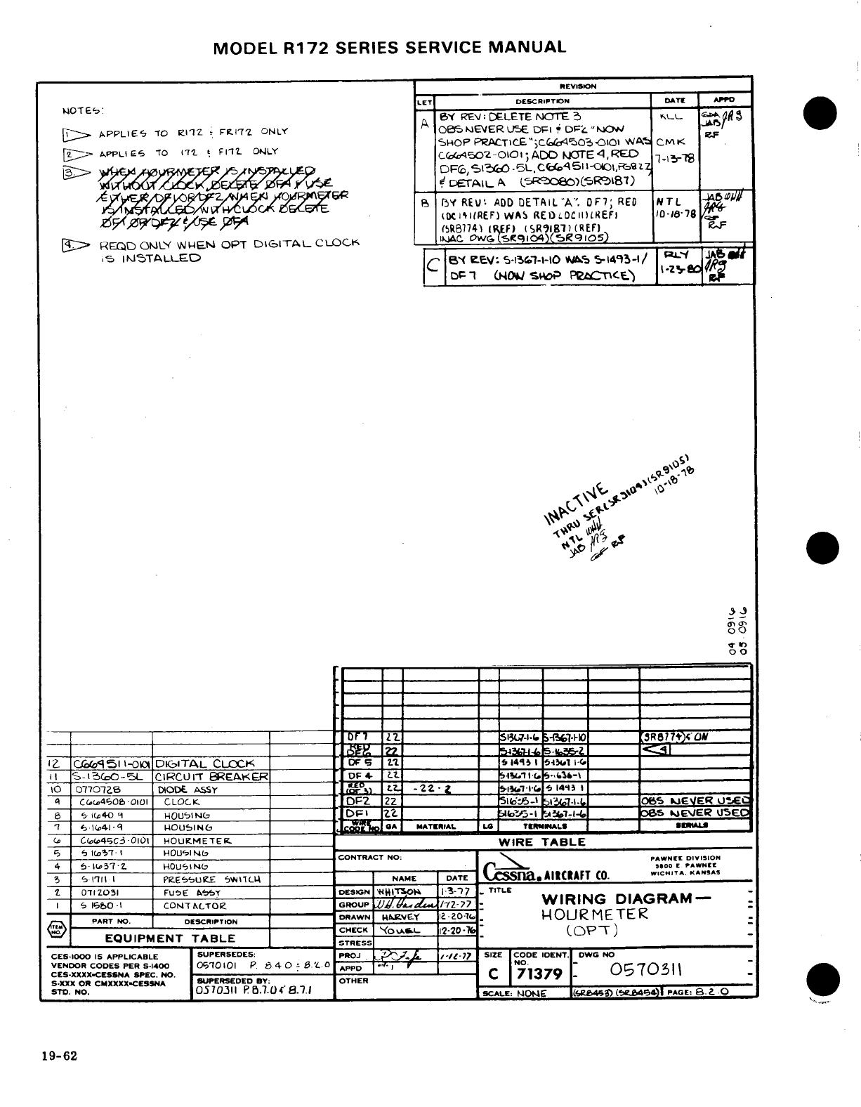
MODEL
R172
SERIES
SERVICE
MANUAL
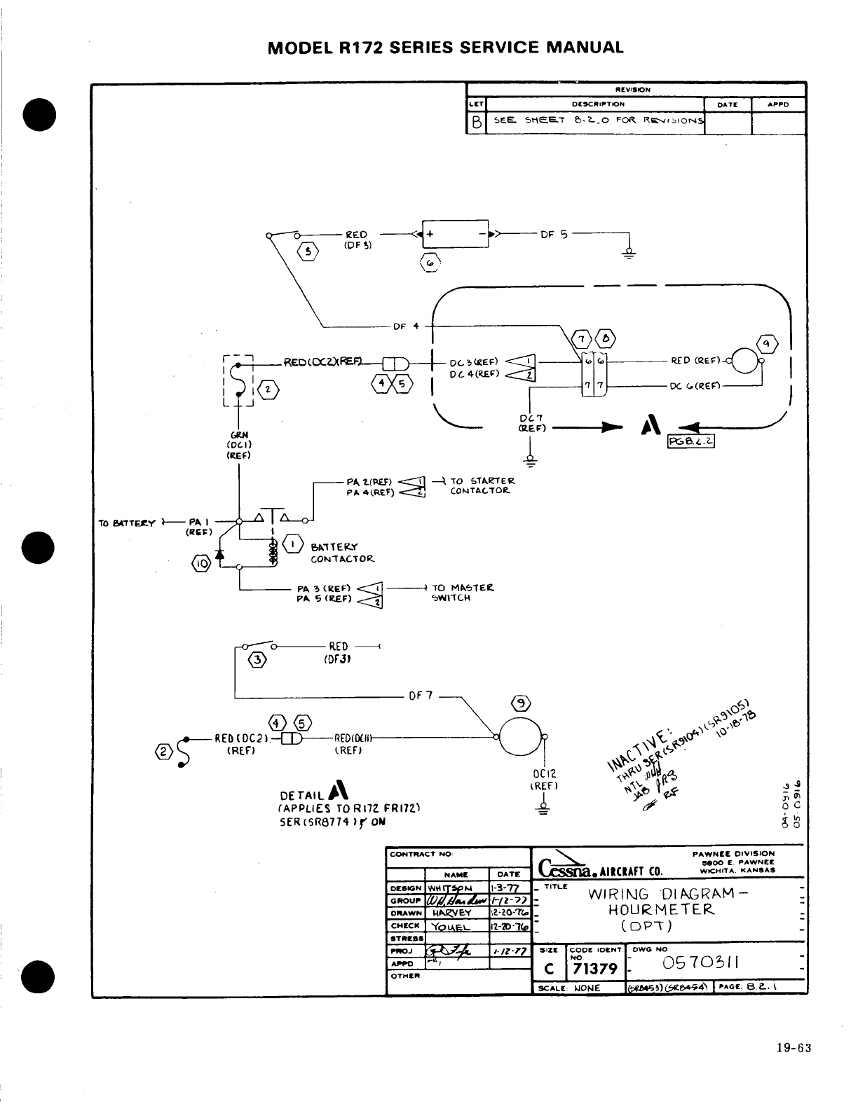
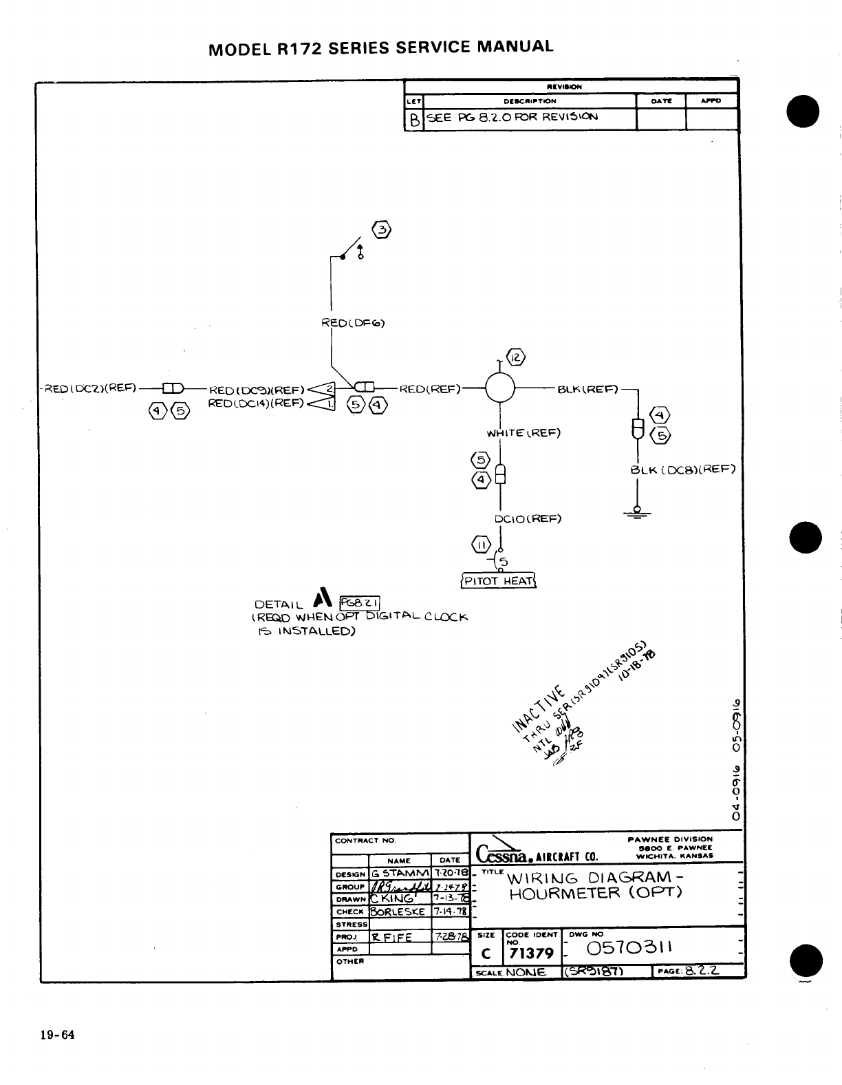
MODEL
R172
SERIES
SERVICE
MANUAL
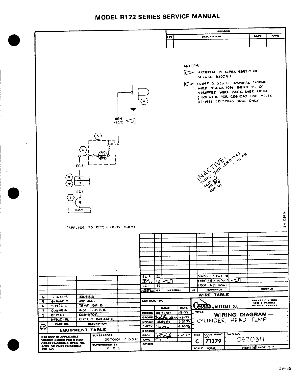
MODEL
R172
SERIES SERVICE
MANUAL
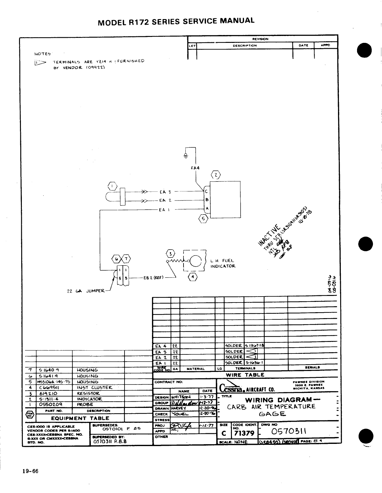
MODEL
R172
SERIES
SERVICE
MANUAL
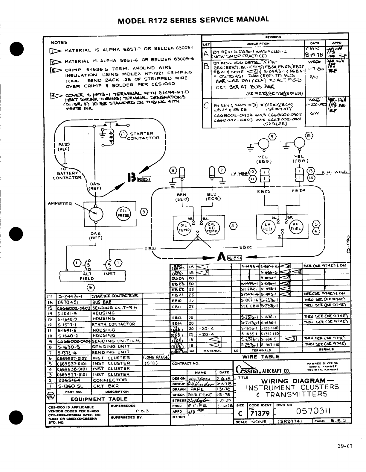
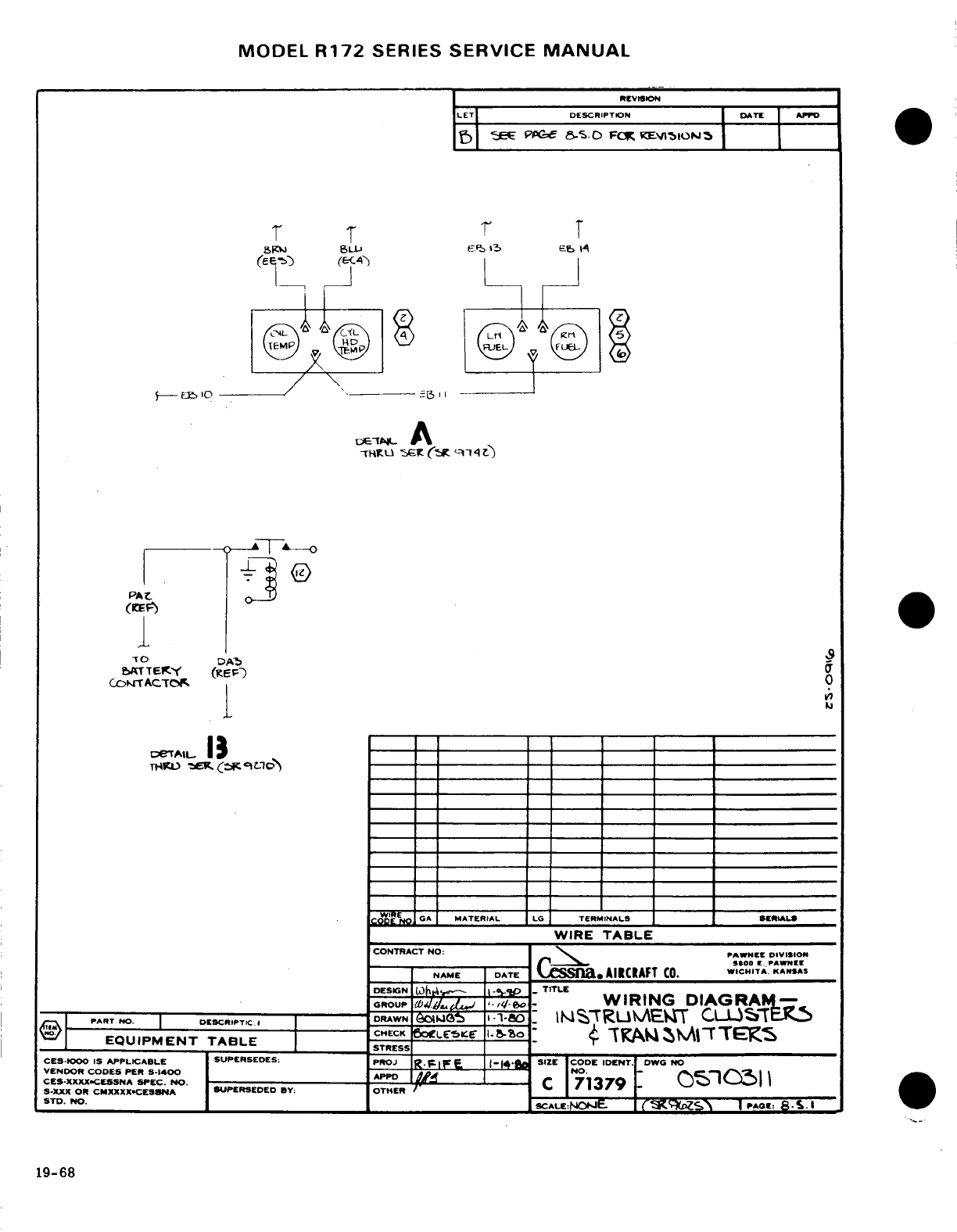
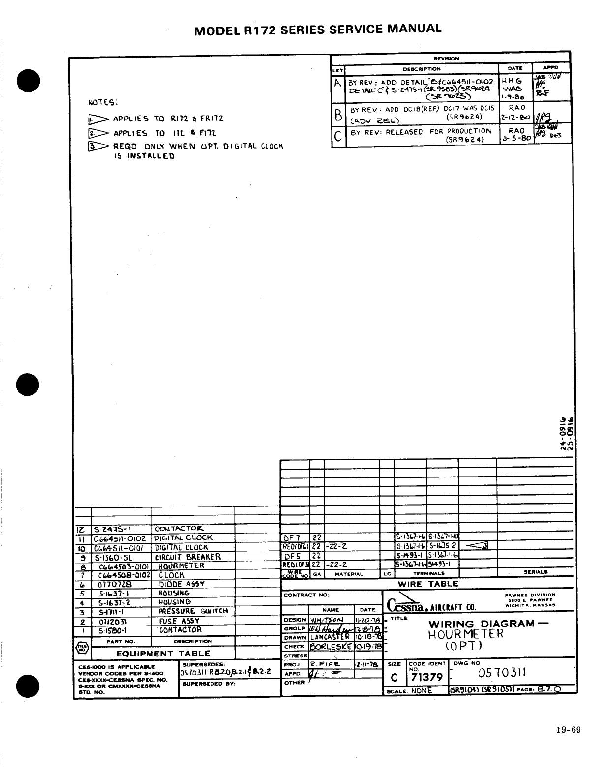
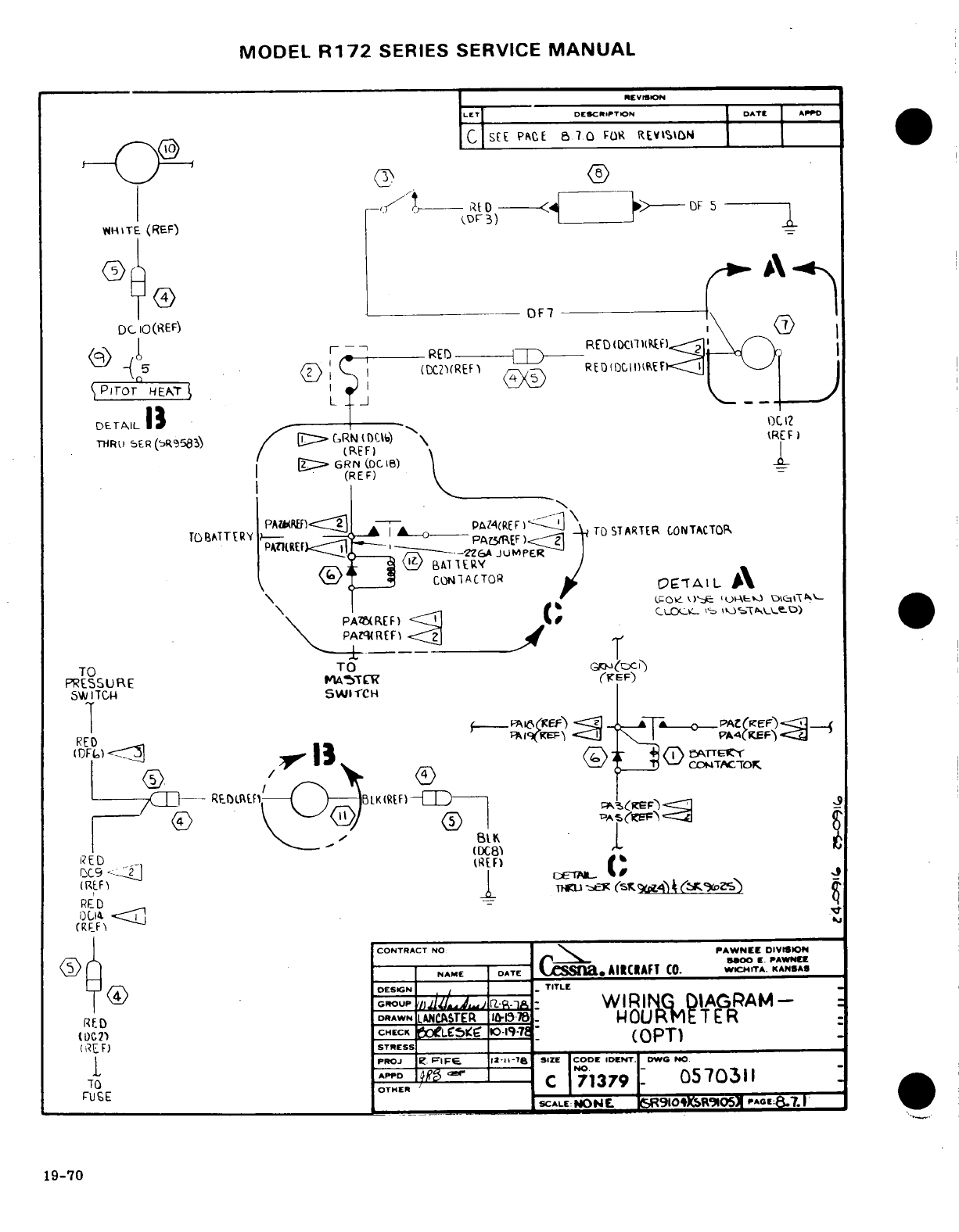
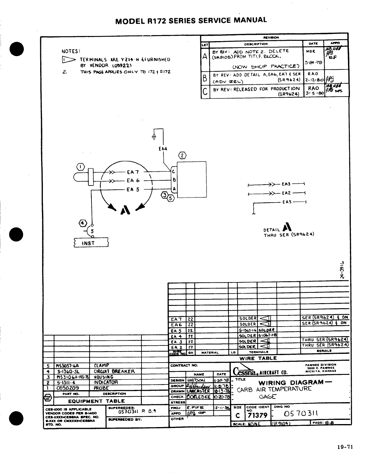
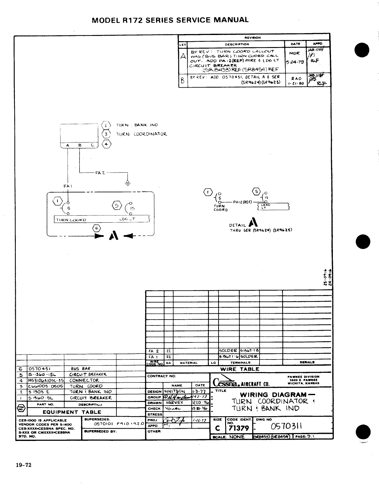
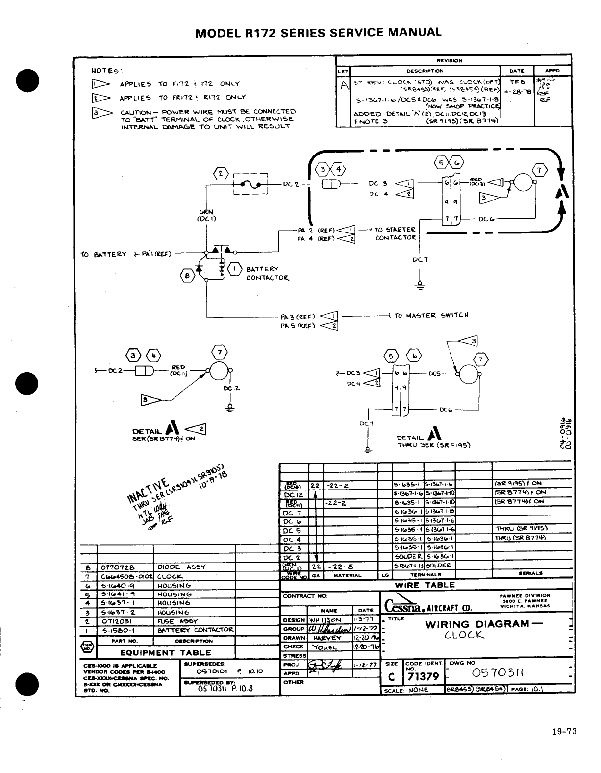
MODEL
R172
SERIES
SERVICE
MANUAL
REVISION
DESCRIPTION
DATE
APPD
1
APPLIES
TO
F172
172
ONLY
2
APPLIES
TO
FR172
R172
ONLY
3
CAUTION
-
POWER
WIRE
MUST
CONNECTED
TO
"BATT"
TERMINAL
OF
CLOCK,
OTHERWISE
INTERNAL
DAMAGE
TO
UNIT
WILL
RESULT
7
C(460So&
-0102
CLOCK.
__
GA
MATERIAL
LG
TERINALS
SERIALS
19-73
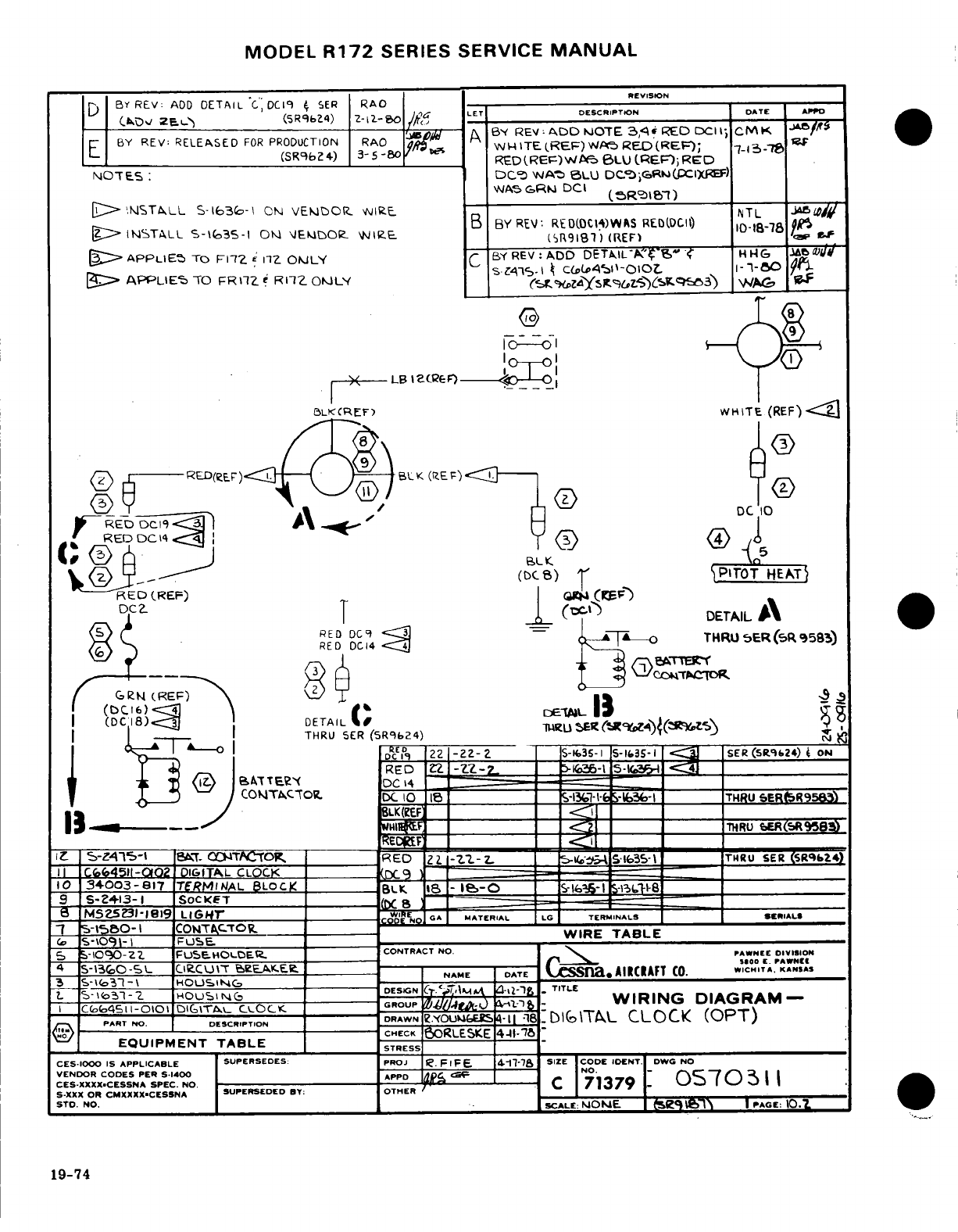
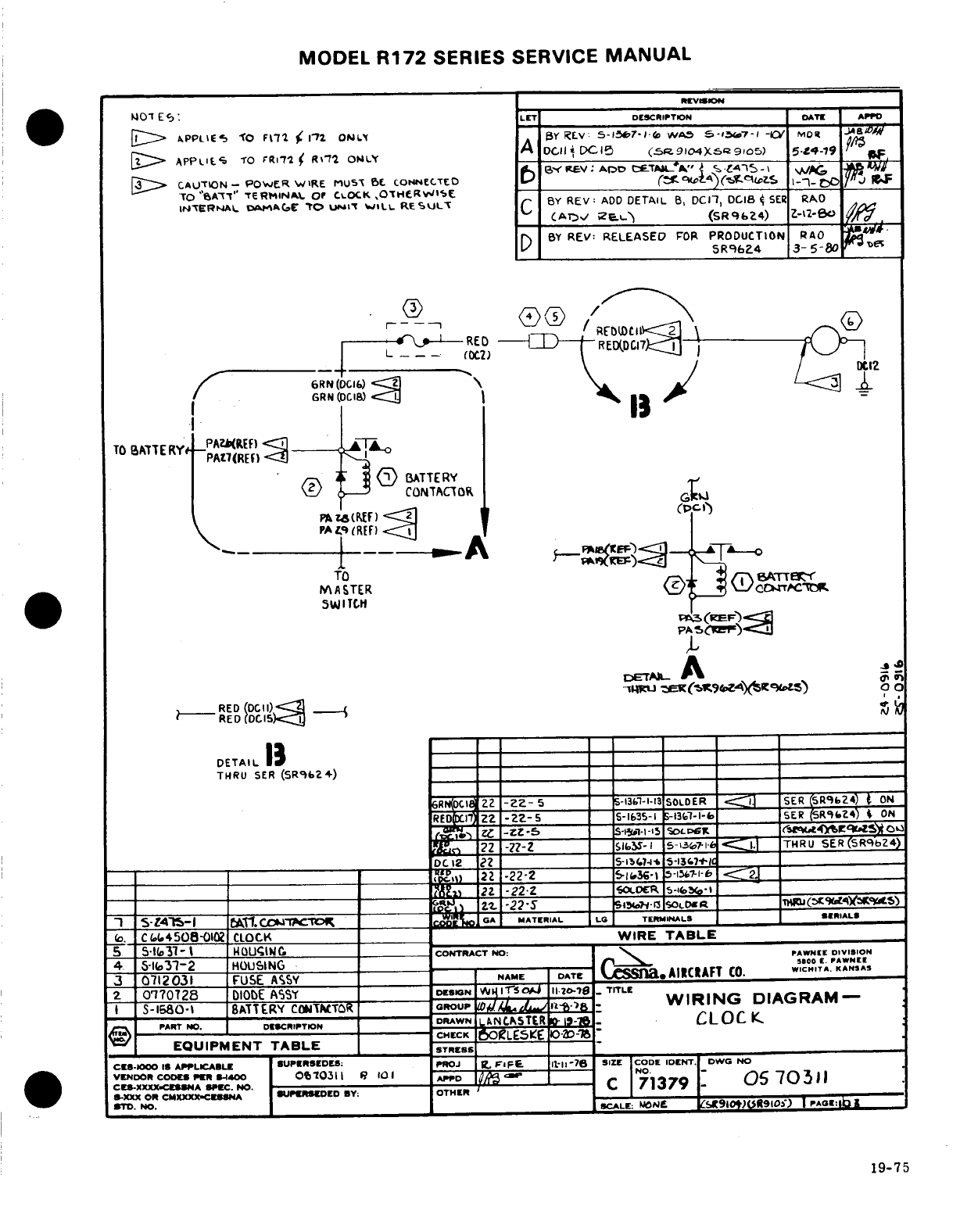
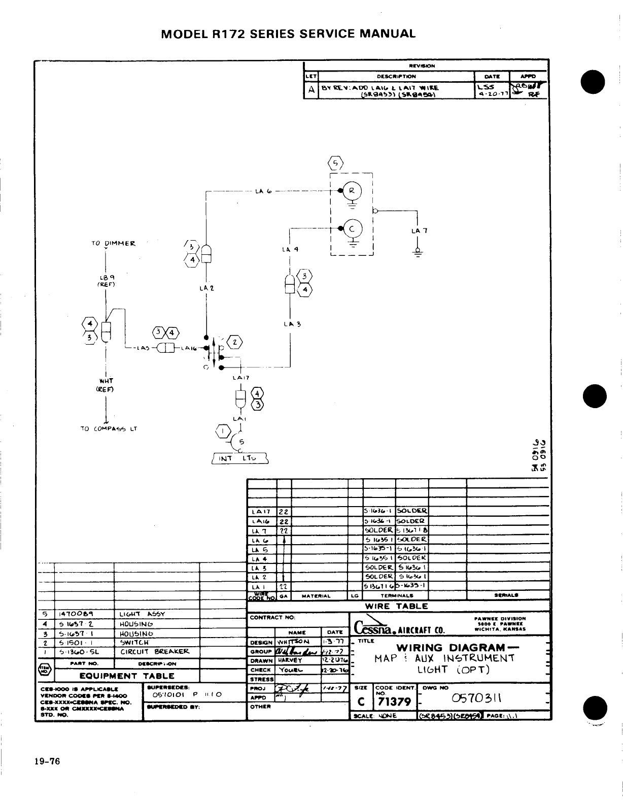
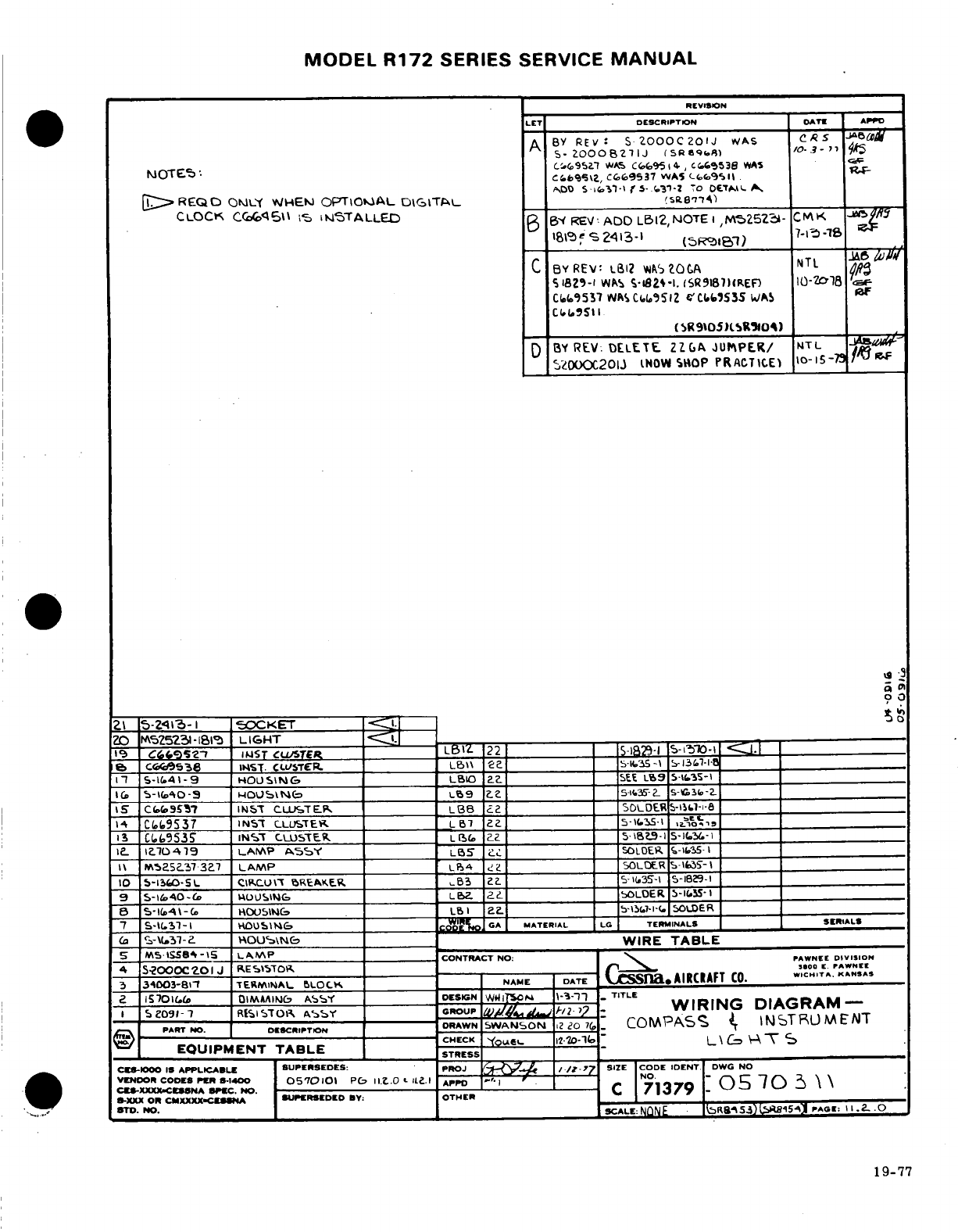
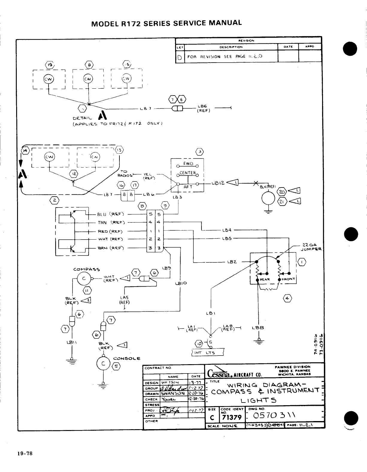
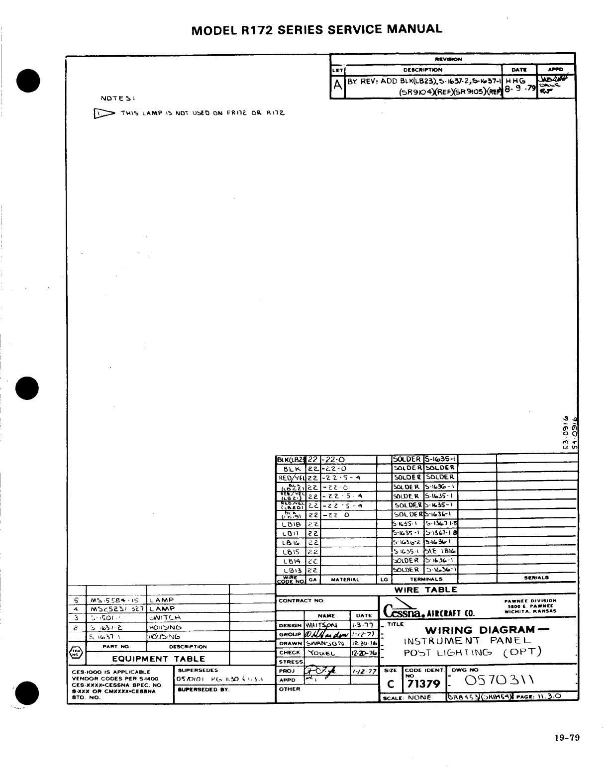
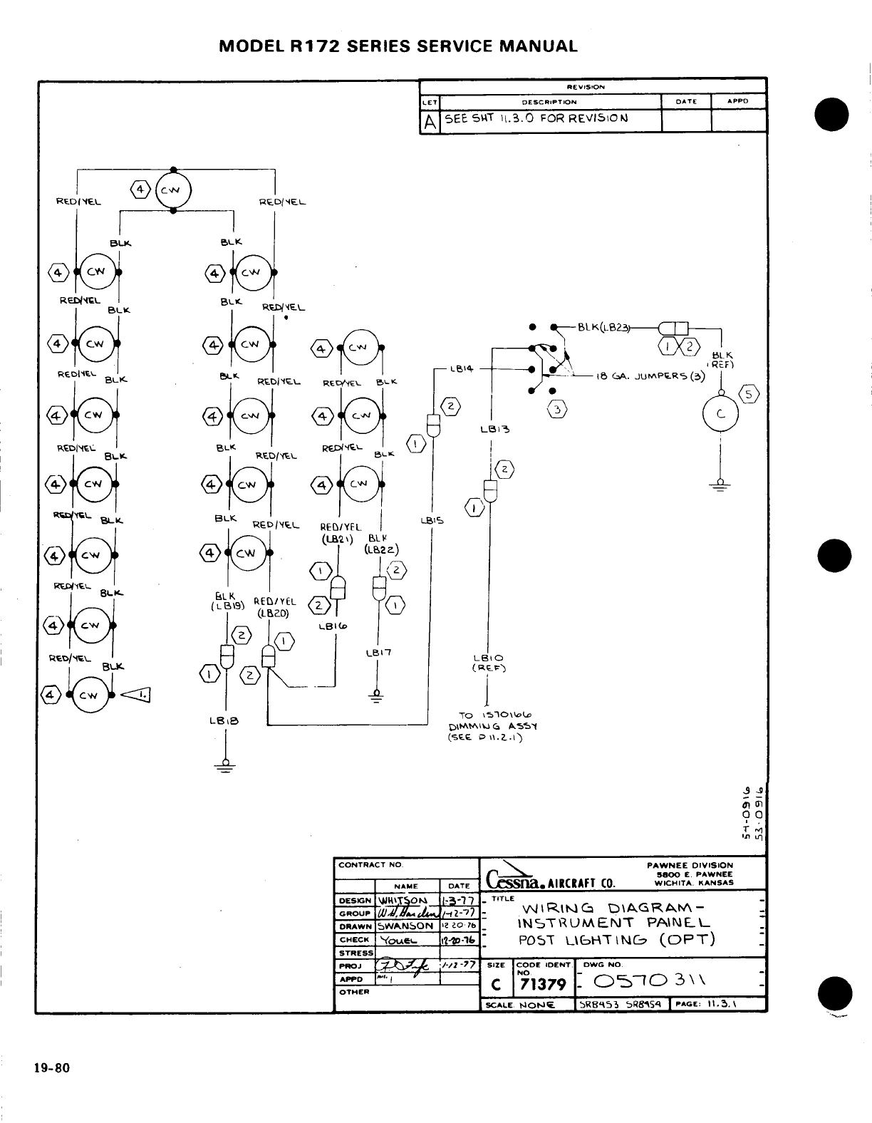
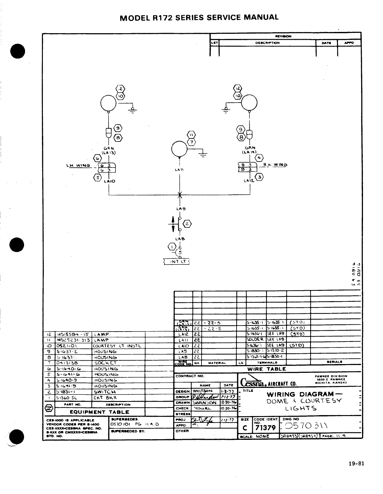
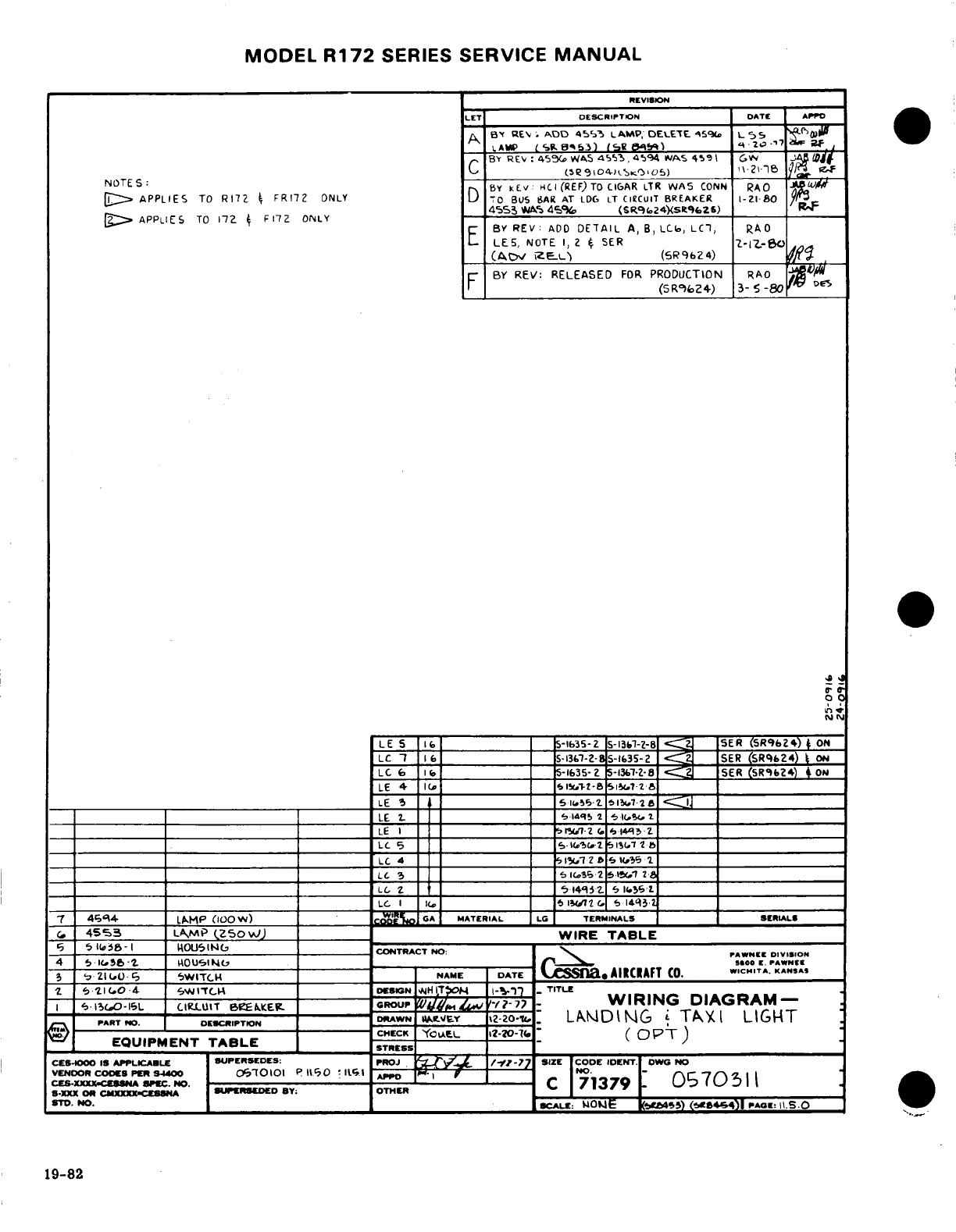
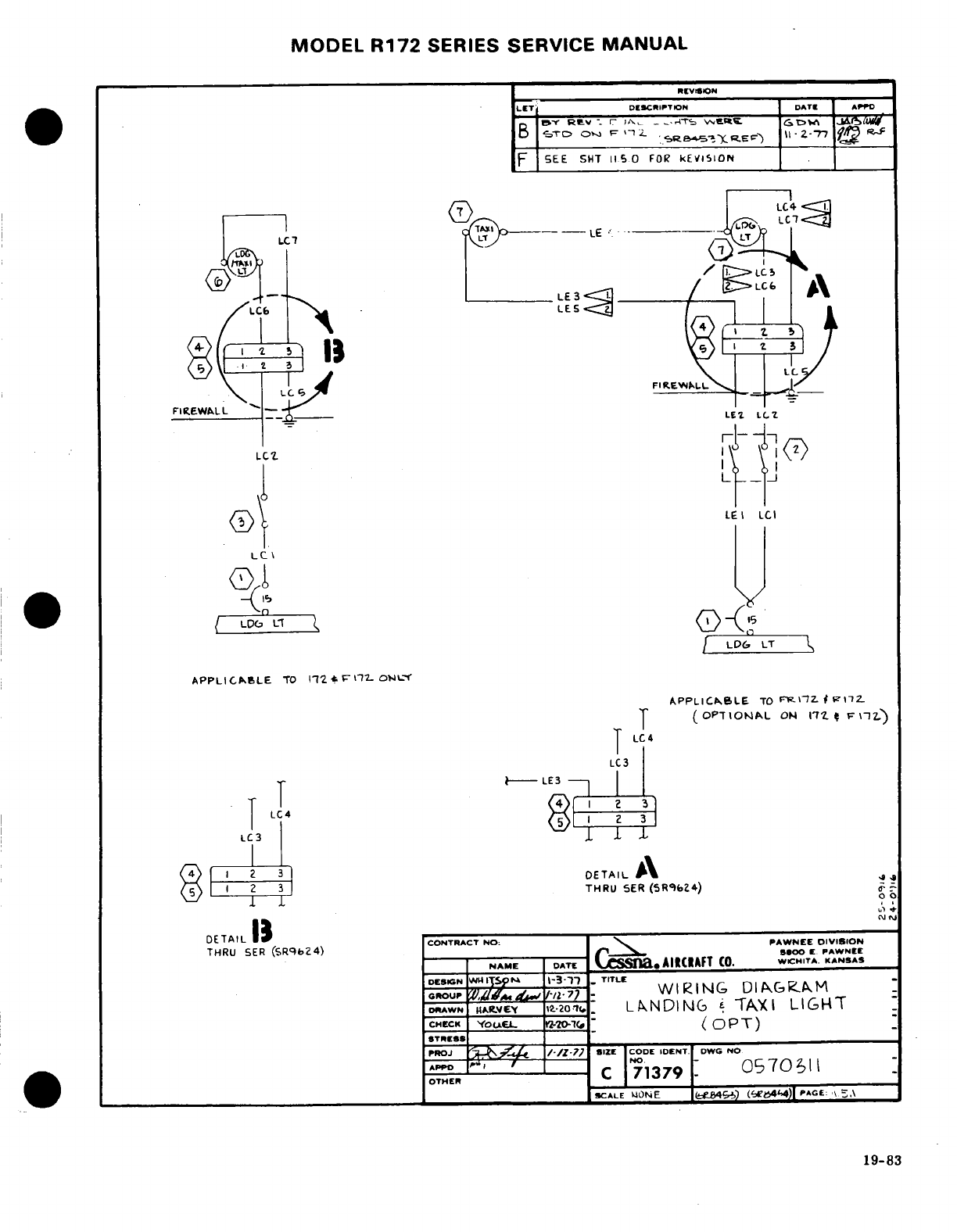
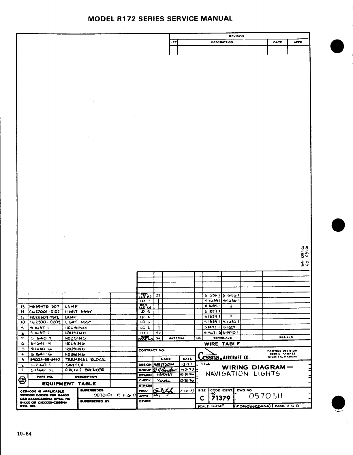
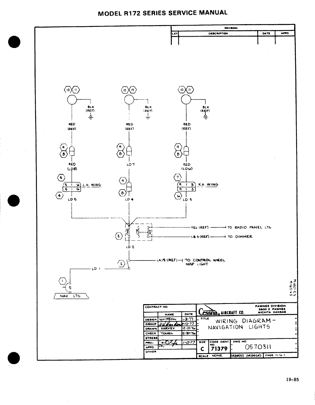

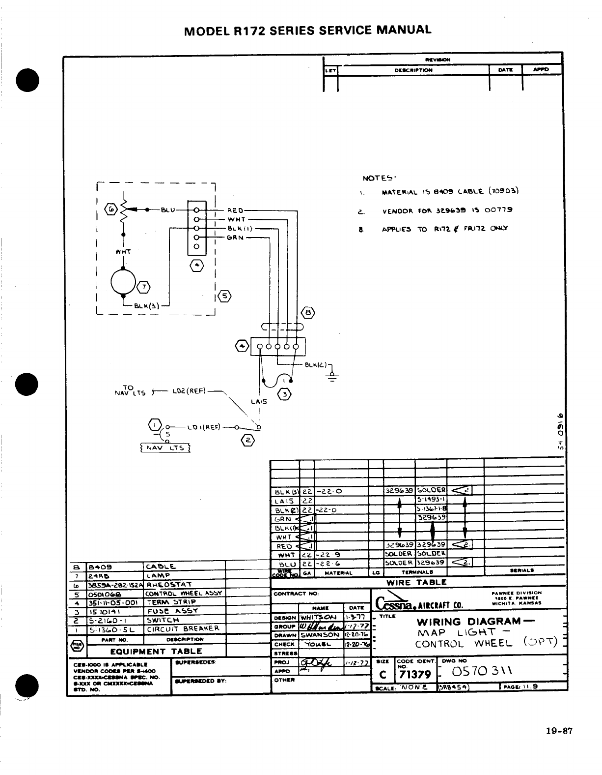
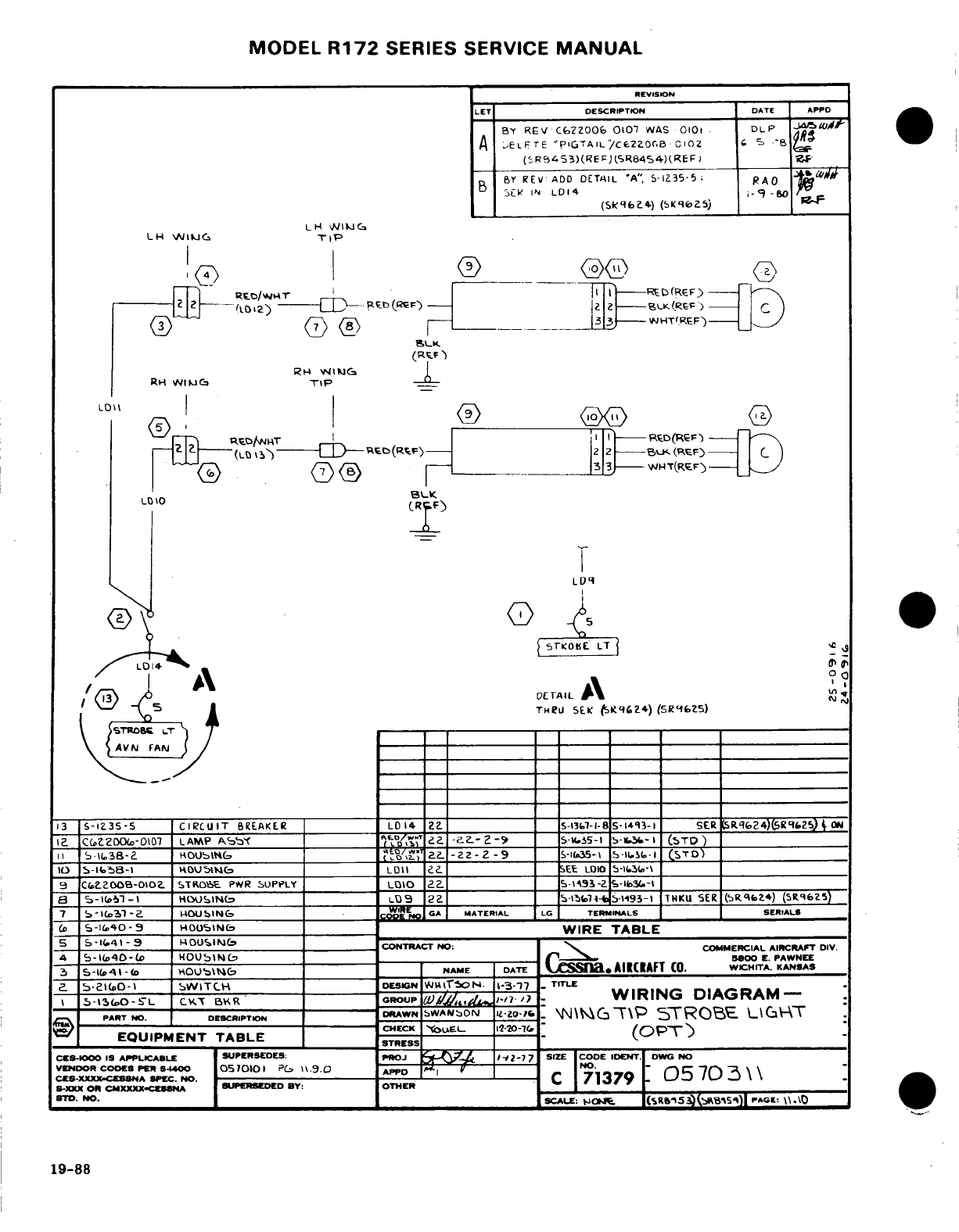
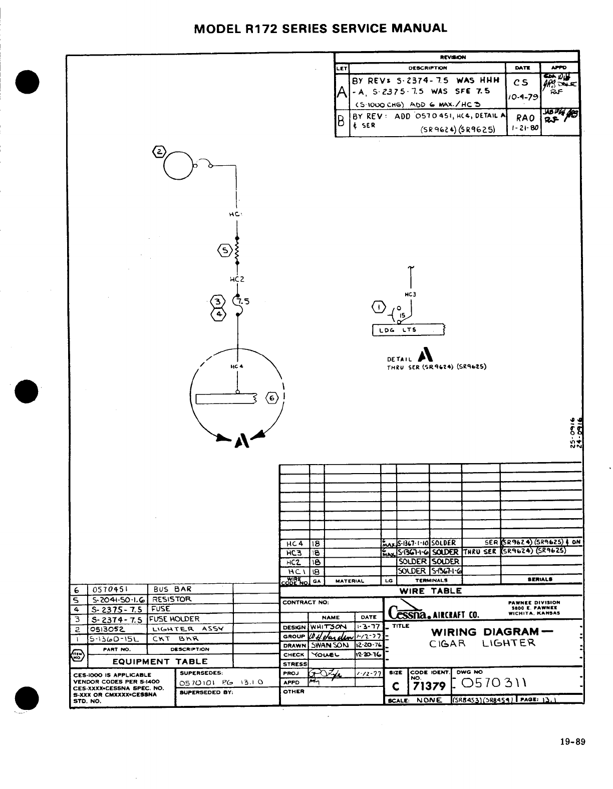
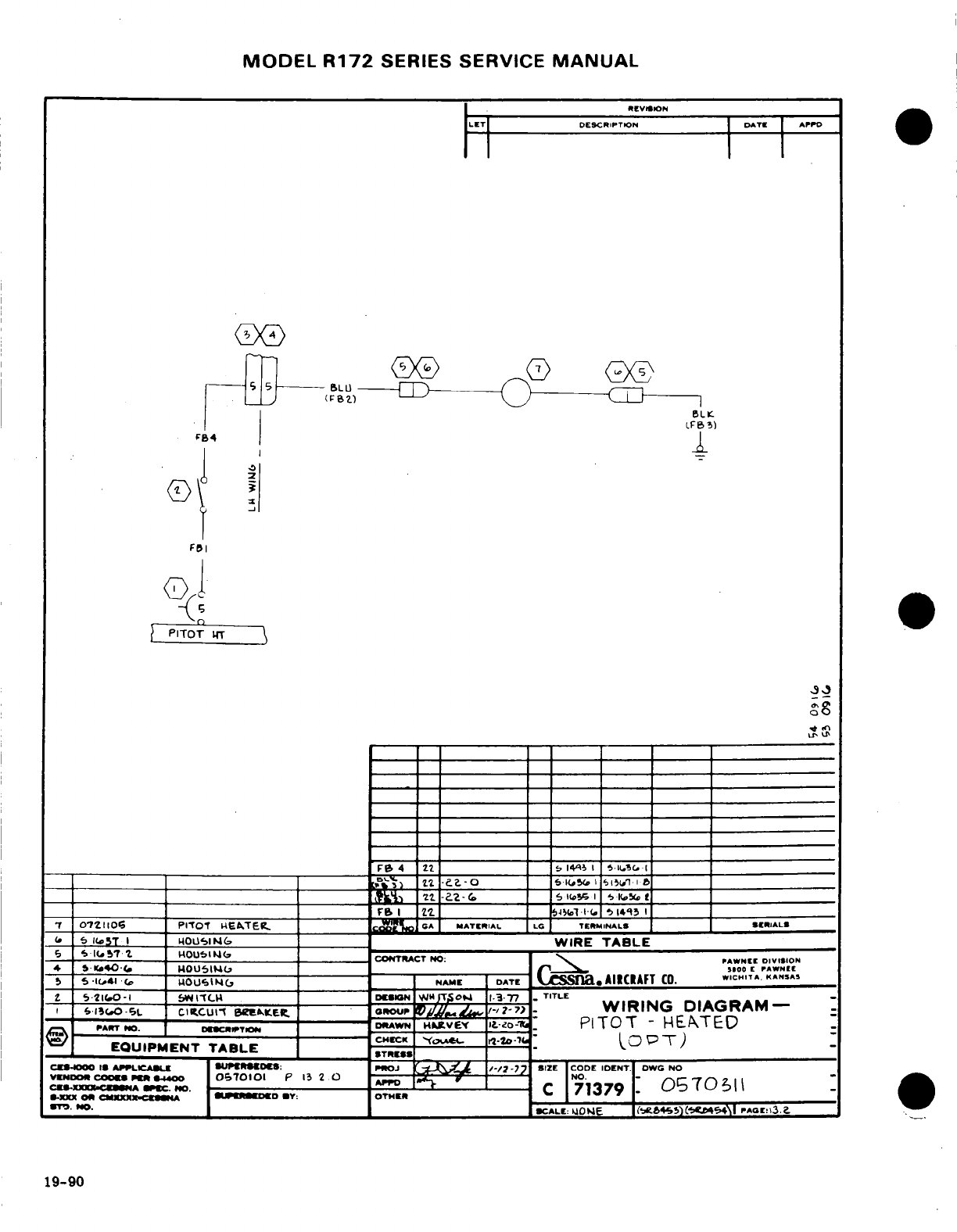
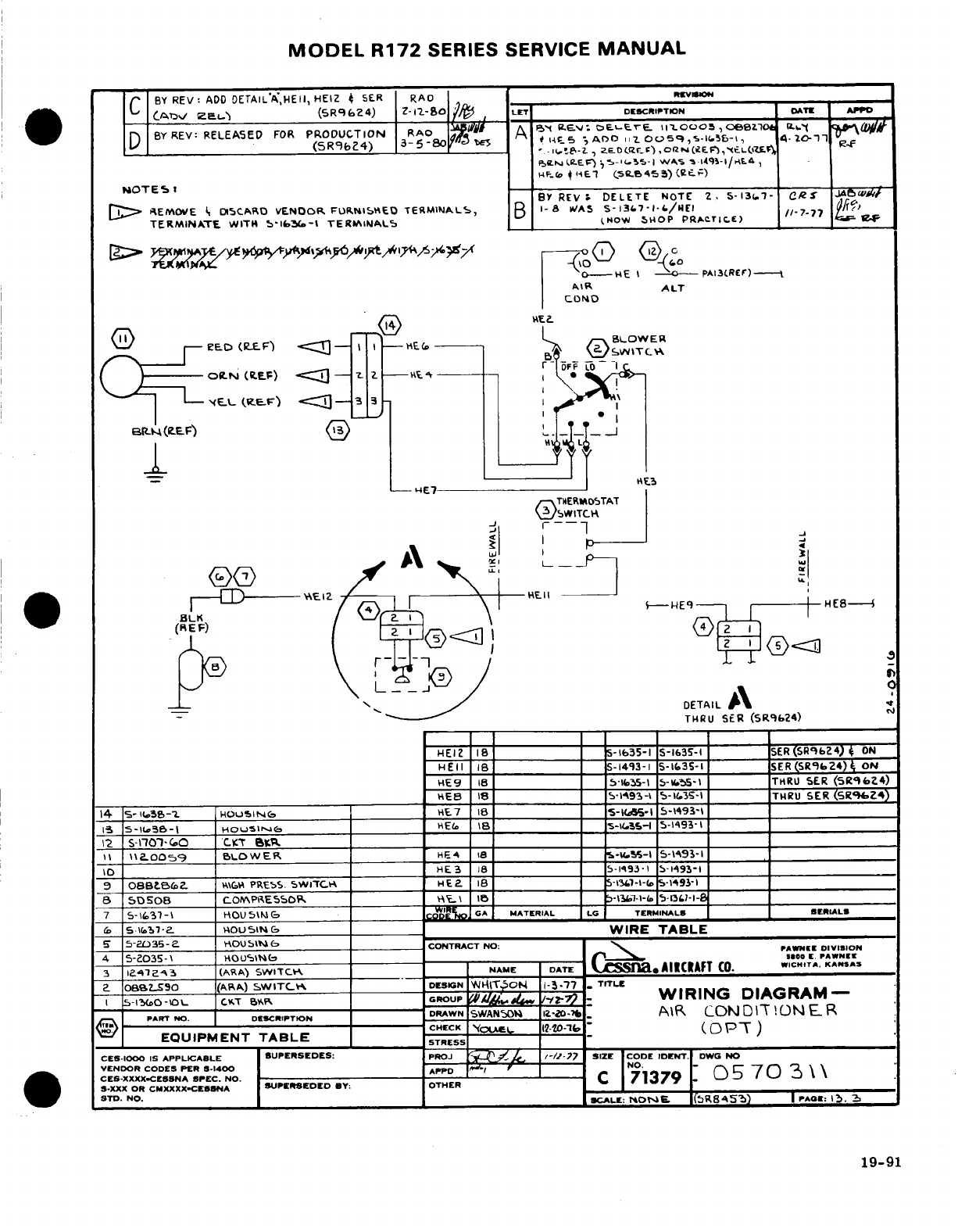
MODEL
R172
SERIES
SERVICE
MANUAL
BY
REV:
ADD
DETAIL
"A",HEII,
HEIZ
SER
RAD
REVSION
(ADV
REL)
(SR9624)
LET
DESCRIPTION
DATE
BY
REV:
RELEASED
FOR
PRODUCTION
(SR9624)
A
NOTES:
BY
REV:
DELETE
NOTE
2, 5-1367-
1
REMOVE
DISCARD
VENDOR
FURNISHED
TERMINALS,
B
TERMINATE
WITH
5-1636-1
TERMINALS
NOW
SHOP
PRACTICE)
(9
EIE
8
13
5-1c56
-|
HOuSING
V& IR 1-35
-193-1
19-91
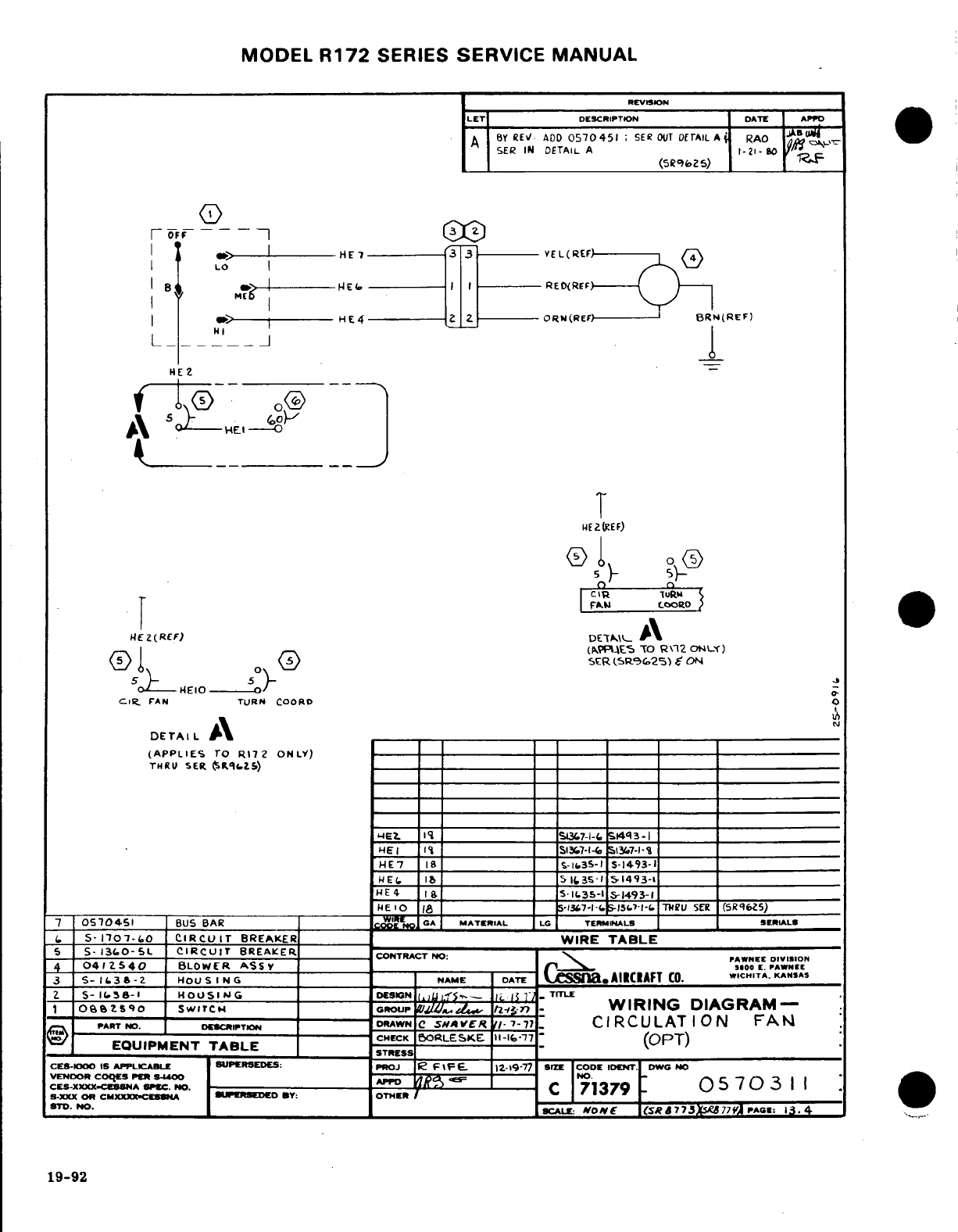
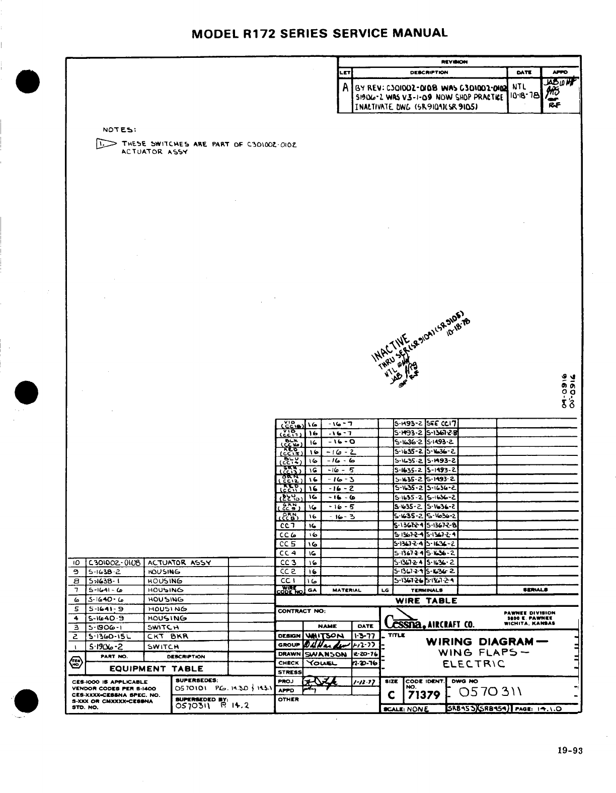
MODEL
R172
SERIES
SERVICE
MANUAL
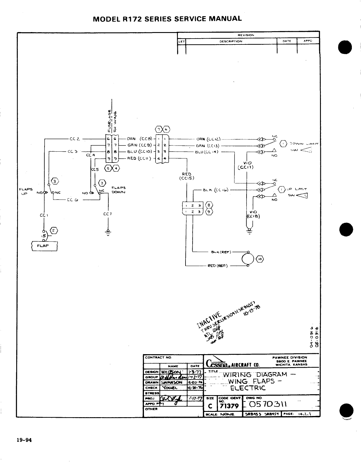
MODEL
R172
SERIES
SERVICE
MANUAL
REVISION
LET
DESCRIPTION
DATE APPD