1964 Cessna 150 Patroller Cessna_182_C182J 1966 Owners_manual Retyped 182 C182J Owners Manual
User Manual: Cessna_182_C182J-1966-owners_manual-retyped
Open the PDF directly: View PDF ![]() .
.
Page Count: 31
1966 Cessna 182-J Skylane
Performance and Specifications
Gross weight 2,800 lbs.
Speed
Top Speed at sea level 170 mph
Cruise, 75% power at 6500 ft 162 mph
Range
Cruise, 75% Power at 6500 ft 695 mi.
79.0 Gallons 5.7 hours
162 mph
Optimum Range at 10,000 ft 1215 mi.
35.0 Gallons 10.0 hours
121 mph
Rate of Climb at sea level 980 fpm
Service Ceiling 18,900
Takeoff
Ground Run 625 ft
Total Distance over 50’ obstacle 1,2055 ft
Landing
Landing Roll 590 ft
Total Distance over 50’ obstacle 1,350 ft
Empty Weight 1,620 lbs.
Baggage 120 lbs
Wing Loading 16.1 lb./sf.
Power loading 12.1 lb./HP
Fuel Capacity total 84 gal
Oil Capacity 12 US qts
Propeller, Fixed Pitch, metal, dia. 82 in
Power - - Continental O-470-R Engine, 230 HP at 2600 RPM
page i page ii
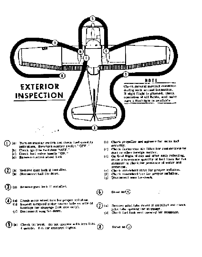
TABLE OF CONTENTS
SECTION I OPEATING CHECKLIST 1-1
SECTION II DESCRIPTION
AND OPERATING DETAILS 2-1
SECTION III OPEATING LIMITATIONS 3-1
SECTION IV CARE OF THE AIRPLANE 4-1
SECTION V OPERATIONAL DATA 5-1
ALPHABETICAL INDEX
page iii page iv
Section I
Operating Check List
One of the first steps in obtaining the utmost performance, service,
and flying enjoyment from your Cessna is to familiarize yourself with
your airplane’s equipment, systems, and controls. This can best be
done by reviewing this equipment while sitting in the airplane. Those
items whose functions and operation are not obvious are covered in
Section II
Section I lists, in the Pilot’s Check List form, the steps necessary to
operate your airplane efficiently and safely. It is not a checklist in its
true form as it is considerably longer, but it does cover briefly all of
the points that you would want to or should know concerning the
information you need for a typical flight.
The flight and operation characteristics of your airplane are normal in
all respects. There are no unconventional characteristics or
operations that need to be mastered. All controls respond in the
normal way within the entire range of operation. All airspeeds
mentioned in Sections I and II are indicated airspeeds.
Corresponding calibrated airspeeds may be obtained from the
Airspeed Correction Table in Section V.
BEFORE ENTERING THE AIRPLANE
1. Make an exterior inspection in accordance with figure 1-1
BEFORE STARTING THE ENGINE
1. Seats and seat belts – Adjust and Lock
2. Flight Controls -- Check
3. Brakes – Test and set
Page 1-1
Master Switch – On
4. Cowl Flaps –Open (Move lever out of locking hole to reposition)
5. Elevator and Rudder Trim – Takeoff setting
6. Fuel Selector –On
7. Turn all radio switches OFF
STARTING THE ENGINE
1. Carburetor Heat – Cold
2. Mixture – Rich
3. Propeller – High RPM
4. Throttle –Cracked (one-half inch)
5. Primer – As Required
6. Ignition switch – Start - Hold until engine fires, but not longer
than 30 seconds
7. Ignition Switch -- Release to BOTH immediately after engine
fires
NOTE
If engine has been overprimed, start with throttle open ¼ to ½ full
open. Reduce throttle to idle when engine fires.
NOTE
After starting, check for oil pressure indication within 30 seconds in
normal temperatures and 60 seconds in cold temperatures. If no
indication appears shut off engine and investigate.
BEFORE TAKE – OFF
1. Throttle Setting – 1700 RPM
2. Engine Instruments – Check
3. Carburetor Heat – Check operation, then set to cold unless icing
conditions prevail
4. Ammeter – Check
Page 1-2
5. Suction gauge - - Check (4.6 to 5.4 inches of mercury
6. Magnetos – Check (50 RPM maximum differential between
magnetos)
7. Propeller – Cycle from high to low RPM; return to high RPM
(full in)
8. Flight Controls – Recheck
9. Wing Flaps - - Check operation and set 0° to 20°
10. Cowl Flaps _Full OPEN
11. Elevator and Rudder Tab – Takeoff
12. Cabin doors – Closed and locked
13. Flight Instruments and Radios – Set
TAKE OFF
NORMAL TAKE OFF
1. Wing flaps – Up
2. Carburetor Heat – Cold
3. Throttle – Full “Open” and 2600 RPM
4. Elevator Control – Lift nose wheel at 60 mph
5. Climb Speed – 90 MPH until all obstacles are cleared, then set up
climb speed as shown in NORMAL CLIMB paragraph
MAXIMUM PERFORMANCE TAKE OFF
1. Wing Flaps – 20°
2. Carburetor Heat – Cold
3. Brakes – Apply
4. Power – Full throttle and 2600 RPM
5. Brakes – release
6. Elevator Control – Slightly tail low
7. Climb Speed – 60 MPH until all obstacles are cleared, then set up
climb speed as shown in MAXIMUM PERFORMANCE CLIMB
8. Wing Flaps – Up after obstacles are cleared
page 1-3
CLIMB
NORMAL CLIMB
1. Air Speed – 100 to 120 MPH
2. Power – 23” and 2450 RPM
3. Mixture – Rich (unless engine is rough)
4. Cowl Flaps – Open as required
MAXIMUM PERFORMANCE CLIMB
1. Air Speed – 88 MPH (sea level) to 84 MPH (10,000)
2. Power – Full throttle and 2600 RPM
3. Mixture – Rich (unless engine is rough)
4. Cowl Flaps – Open as required
CRUISING
1. Power – 15” to 23" manifold pressure and 2200 to 2450 RPM
2. Cowl Flaps – Open as required
3. Elevator and Rudder Trim – Adjust
4. Mixture – Lean
LET DOWN
1. Mixture – Rich
2. Power – As desired
3. Carburetor Heat – Apply (if icing conditions exist)
BEFORE LANDING
1. Fuel Selector Valve –BOTH
2. Mixture – Rich
page 1-4
3. Propeller – High RPM
4. Cowl Flaps – Closed
5. Carburetor Heat – Apply full heat before closing throttle
6. Airspeed – 80 to 90 MPH (flaps retracted)
7. Wing Flaps -- 0° to40° (below 110 MPH
8. Airspeed – 70 to 80 MPH with flaps extended
9. Elevator and Rudder Trim -- Adjust
NORMAL LANDING
1. Landing Technique – Conventional for all flap settings
AFTER LANDING
1. Cowl Flaps – OPEN
2. Wing Flaps – Up
3. Carburetor Heat – Cold
SECURE AIRCRAFT
1. Mixture – Idle Cut-off
NOTE
Do not open throttle as engine stops since this actuates the accelerator
pump.
2. All Switches – Off
3. Parking Brake – Set
4. Control Lock – Installed
page 1-5
Section II
Description and Operating Details
The following paragraphs describe the systems and equipment whose
function and operation is not obvious when sitting in the airplane.
This section also covers in somewhat greater detail some of the items
listed in checklist form in Section I
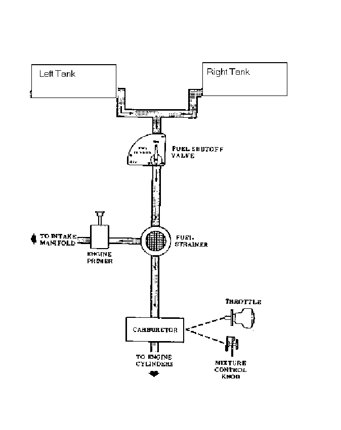
FUEL SYSTEM
Fuel is supplied to the engine from two tanks, one in each wing. The
total usable fuel, for all flight conditions, is 79 gallons for optional
long-range tanks.
NOTE
Unusable fuel is at a minimum due to the design of the fuel system.
However, with ¼ tank or less, prolonged uncoordinated flight, such
as slips or skids can uncover the fuel tank outlets, causing fuel
starvation and engine stoppage when operating on a single tank.
Therefore, to avoid this problem with low fuel reserves, the fuel
selector should be set at BOTH position.
Fuel from each wing taken flows by gravity to a selector valve.
Depending upon the setting of the selector valve, fuel from the left,
right, or both tanks flows through a fuel strainer and carburetor to the
engine induction system.
page 2-1
NOTE
Take off with the fuel selector valve handle in the BOTH position to
prevent inadvertent take-off on an empty tank. However, when the
selector is in the BOTH position, unequal fuel flow from each tank
may occur after extended flight if the wings are not maintained
exactly level. Resulting wing heaviness can be alleviated gradually
by turning the selector valve handle to the tank in the heavy wing.
The recommended cruise fuel management for extended flight is to
use the left and right tank alternately.
ELECTRICAL SYSTEM
Electrical energy is supplied by a 14-volt, direct-current system,
powered by an engine-driven alternator. The 12-volt storage battery
is located aft of the rear baggage compartment wall.
CIRCUIT BREAKERS
All electrical circuits in the airplane, except the clock circuit, are
protected by circuit breakers. The clock has a separate fuse mounted
adjacent to the battery. The stall warning transmitter and horn circuit
and the optional turn-and-bank indicator circuits are protected by a
single automatically resetting circuit breaker mounted behind the
instrument panel. The cigar lighter is protected by a manually reset
type circuit breaker mounted directly on the back of the lighter behind
the instrument panel The remaining circuits are protected by push-to-
reset circuit breakers on the instrument panel.
ROTATING BEACON
The rotating beacon should not be used when flying through clouds or
overcast; the moving beams reflected from water droplets or particles
in the atmosphere, particularly at night, can produce vertigo and loss
of orientation.
page 2-2 page 2-3
CABIN HEATING VENTILATING SYSTEM AND
DEFROSTING SYSTEM
The temperature and volume of airflow into the cabin can be
regulated to any degree desired by manipulation of the push-pull
CABIN HEAT and CABIN AIR knobs. Both control knobs are the
double-button type with friction locks to permit intermediate settings.
NOTE
Always pull out the CABIN AIR knob slightly when the CABIN
HEAT knob is out. This action increases airflow through the system,
increasing efficiency, and blends cool outside air with the exhaust
manifold heated air, thus eliminating the possibility of overheating
the system ducting.
The rotary type DEFROST know regulates the airflow for windshield
defrosting
Front cabin head and ventilating air is supplied by outlet holes spaced
across a cabin manifold just forward of the pilot’s and copilot’s feet.
Rear cabin heat and air is supplied by two ducts from the manifold,
one extending down each side of the cabin. Windshield defrost air is
also supplied by a duct leading from the cabin manifold.
Separate adjustable ventilators supply additional air;; one near each
upper corner of the windshield supplies air for the pilot and copilot,
and two in the rear cabin ceiling supply air to the rear seat passengers.
page 2-4
figure 2-2
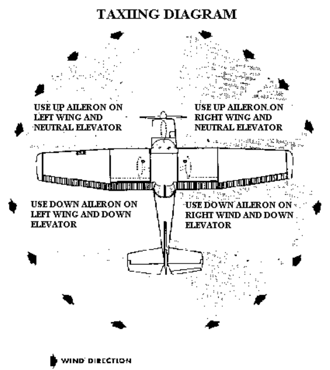
NOTE:
Strong quartering tailwinds require caution. Avoid sudden bursts of
the throttle and sharp braking when the airplane is in this attitude.
Use the steerable nose-wheel and rudder to maintain direction
page 2-5
STARTING ENGINE
Ordinarily the engine starts easily with one or two strokes of primer
in warm temperatures to six strokes in cold weather, with the throttle
open approximately 1/2 inch. In extremely cold temperatures, it may
be necessary to continue to priming while cranking. Weak
intermittent explosions followed by puffs of black smoke from the
exhaust stack indicates overpriming or flooding. Excess fuel can be
cleaned from the combustion chambers by the following procedure:
Set the mixture control in full lean position, throttle full open, and
crank the engine trough several revolutions with the starter. Repeat
the starting procedure without any additional priming.
If the engine is underprimed (most likely in cold weather with a cold
engine) it will not fire at all, and additional priming will be necessary.
As soon as the cylinders begin to fire, open the throttle slightly to
keep it running.
If prolonged cranking is necessary, allow the starter motor to cool at
frequent intervals, since excessive heat may damage the armature
TAXIING
The carburetor air heat know should be pushed full in during all
ground operations unless is absolutely necessary for smooth engine
operations. When the know is pulled out to the heat position, air
entering the engine is not filtered
Taxiing over loose gravel or cinders should be done at low engine
speed to avoid abrasion and stone damage to the propeller tips
BEFORE TAKEOFF
Since the engine is closely cowled for efficient in-flight-cooling,
precautions should be taken to avoid overheating on the ground.
page 2-6
Full throttle checks on the ground are not recommended unless the
pilot has good reason to suspect that the engine is not turning up
properly.
The magneto check should be make at 1700 RPM as follows: Move
the ignition switch first to "R" position and note RPM. Then move
switch back to "BOTH" to clear the other set of plugs. Then move
switch to "L" position and note RPM. The difference between the
two magnetos operated individually should not be more than 50
RPM. If there is a doubt concerning the operation of the ignition
system, RPM checks at higher engine speeds will usually confirm
whether a deficiency exists
An absence of RPM drop may be an indication of faulty grounding of
one side of the ignition system or should be cause for suspicion that
the magneto timing is set in advance of the setting specified.
TAKE-OFF
It is important to check full-throttle engine operation early in the
takeoff run. Any signs of rough engine operation or sluggish engine
acceleration is good cause for discontinuing the take-off.
Full throttle runups over loose gravel are especially harmful to
propeller tips. When take-offs must be made over a gravel surface, it
is very important that the throttle be advanced slowly. This allows
the airplane to start rolling before high RPM is developed, and the
gravel will be blow back of the propeller rather than pulled into it.
Most engine wear occurs from improper operations before the engine
is up to normal operating temperatures, and operating at high power
and RPMs. For this reason the use of maximum power for take-off
should be limited to that absolutely necessary for safety. Whenever
possible, reduce take-off power to normal climb power.
page 2-7

Normal take-offs are accomplished with wing flaps up, cowl flaps
open, full throttle, and 2600 RPM. Reduce power to 23" of manifold
pressure and 2450 RPM as soon as practical to minimize engine wear.
Using 20º wing flaps reduces the ground run and total distance over
the obstacle by approximately 20 per cent. soft field take-offs are
performed with 20º flaps by lifting the airplane off the ground as soon
as practical in a slightly tail-low attitude. However the airplane
should be leveled off immediately to accelerate to a safe climb speed.
If 20º wing flaps are used for take-off, they should be left down until
all obstacles are cleared. To clear an obstacle with wing flaps 20º ,
the best angle-of-climb speed (60 MPH IAS) should be used. If no
obstructions are ahead, a best "flaps up" rate-of-climb sped (90MPH
IAS) would be most efficient. These speeds vary slightly with
altitude, but they are close enough for average field conditions
Flap deflections of 30º to 40º are not recommended at any time for
takeoff.
Take-offs into strong crosswinds normal are performed with the
minimum flap setting necessary for the field length, to minimize the
drift angle immediately after take-off. The airplane is accelerated to a
speed slightly higher than normal, then pull off abruptly to prevent
possible settling back to the runway while drifting. When clear of the
ground, make a coordinated turn into the wind to correct for drift.
CLIMB
A cruising climb at 23" of manifold pressure, 2450 RPM
(approximately 75% power) and 100 to 120 MPH is recommended to
save time and fuel for the overall trip. In addition, this type of climb
provides better engine cooling, less engine wear, and more passenger
comfort due to lower noise level.
page 2-8
If it is necessary to climb rapidly to clear mountains or reach
favorable winds at high altitudes, the best rate-of-climb speed should
be used with maximum power. This speed is 88 MPH at sea level,
decreasing 2 MPH for each 5000 feet above sea level.
CRUISE
Normal cruising is done at 65% to 75% power. The settings required
to obtain these powers at various altitudes and outside temperatures
can be determined by using your Cessna Power Computer.
OPTIMUM CRUISE PERFORMANCE
% BHP ALTITUDE TRUE A/S (mph
75 6,500 162
70 8,000 160
65 10,000 158
figure 2-3
The Optimum Cruise Performance table (figure 2-3), shows that
cruising cane done most efficiently at higher altitudes because very
nearly the same cruising speed can be maintained at much less power.
For a given throttle setting, select the lowest engine RPM in the green
arc range that will give smooth engine operation.
The cowl flaps should be adjusted to maintain the cylinder head
temperature near the middle of the normal operating (green arc) range
to assure prolonged engine life.
to achieve the range figures shown in Section V, the mixture should
be leaned as follows: pull the mixture control out until engine
becomes rough; then enrich mixture slightly beyond this point. Any
change in altitude, power or carburetor heat will require a change in
the lean mixture setting.
page 2-9
Application of full carburetor heat may enrich the mixture to the point
of engine roughness. To avoid this, lean the mixture as instructed in
the preceding paragraph.
STALLS
The stall characteristics are conventional and aural warning is
provided by a stall warning horn which sounds between 5 and 10
PMH above the stall in all configurations.
Power-off stall speeds at maximum gross weight and aft c.g. position
are presented in figure 5-2 as calibrated airspeeds since indicated
airspeeds are unreliable near the stall.
Spins
Intentional spins are prohibited in this airplane. Should an inadvertent
spin occur, standard light plane recovery techniques should be used.
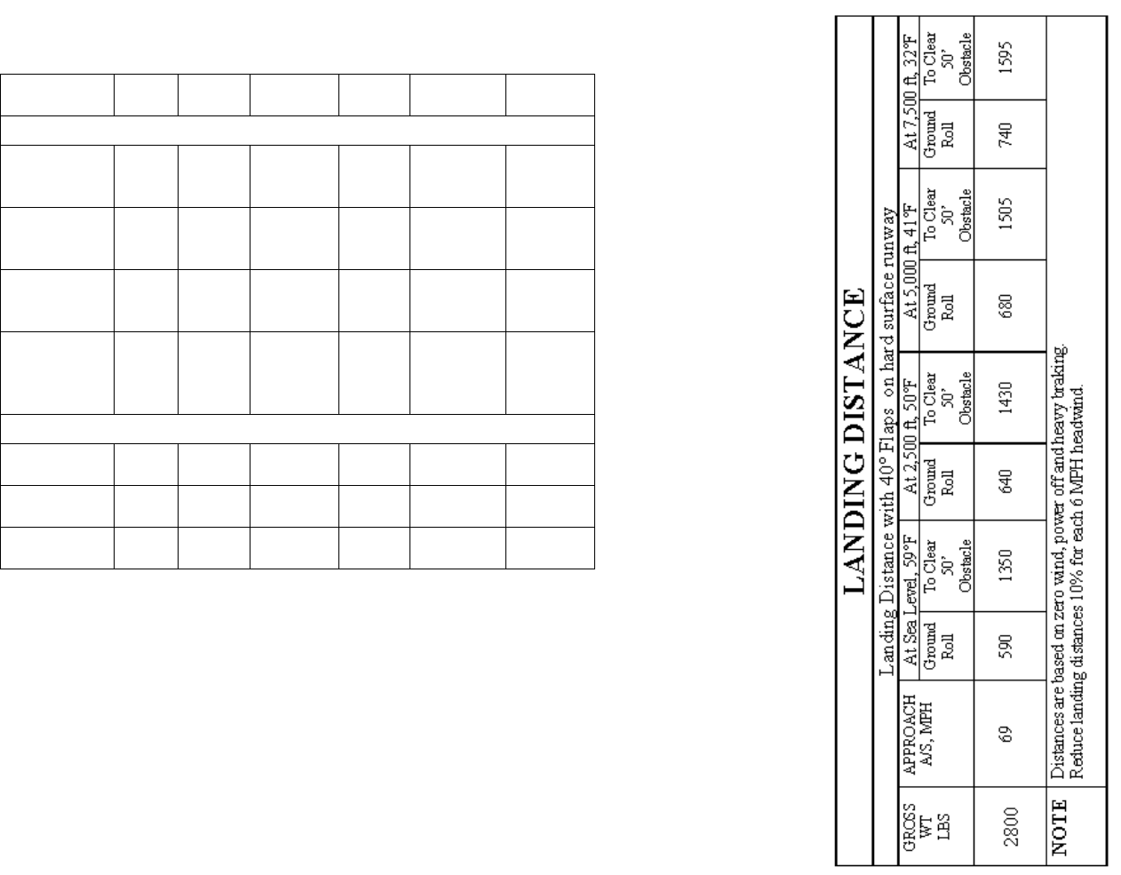
LANDING
Landings are usually made on the main wheels first to reduce the
landing speed and the subsequent need for braking in the landing roll.
The nosewheel is lowered gently to the runway after the speed has
diminished to avoid unnecessary nose gear load. This procedure is
especially important in rough field landings.
For short field landings, make a power off approach at 69 MPH, IAS
with 40º flaps and land on the main wheels first. Immediately after
touchdown, lower the nose gear to the ground and apply heavy
braking as required. For maximum brake effectiveness, after all three
wheels are on the ground, retract the flaps, hold nose-up elevator and
apply maximum brake pressure without sliding the tires
page 210
CROSSWIND LANDINGS
When landing is a strong crosswind, use the minimum flap setting
required for the field length. Use a wing low, crab, or combination
method of drift correction and land in a nearly level attitude. Hold a
straight course with the steerable nosewheel and occasional braking if
necessary.
COLD WEATHER OPEATION
Prior to starting on clod mornings, it is advisable to pull the propeller
through several times by hand to "break loose" or "limber" the oil,
thus conserving battery energy. In extremely cold (-20ºF) weather
the use of an external preheater is recommended whenever possible to
reduce wear and abuse to the engine and electrical system. Cold
weather starting procedures are as follows:
With preheat
1. Clear propeller
2. Master Switch -- On
3. With magneto switch "OFF" and throttle closed, prime the engine
four to ten strokes as the engine is being turned over
NOTE
Use heavy strokes of primer for best atomization of fuel. After
priming, push primer all the way in and turn to locked position to
avoid possibility of engine drawing fuel through the primer.
4. Turn magneto switch to "Both"
5. Open throttle to 1/4" and engage starter
page 2-11
Without preheat
1. Prime the engine 8 to 10 heavy strokes while the propeller is
being turn by hand.
2. Clear propeller
3. Pull the master switch "On"
4. Turn magneto switch to "Both"
5. Open throttle 1/4"
6. Pull carburetor air heat knob to full on
7. Engage the starter and continue to prime engine until it is running
smoothly
8. Keep carburetor heat on until engine has warmed up.
NOTE
If the engine does not start the first time it is probable that the
spar plugs have been frosted over. Preheat must be used before
another start is attempted.
During cold weather operation, no indication will be apparent on the
oil temperature gauge prior to take of if outside air temperatures are
very cold. After a suitable warm-up period (2 to 5 minutes at 1000
RPM) accelerate the engine several times to higher engine RPM. If
the engine accelerates smoothly and the oil pressure remains normal
and steady, the airplane is ready for take-off
When operating sub-zero temperature, avoid using partial carburetor
heat. Partial heat may increase the carburetor air temperature to the
32º to 80ºF range, where icing is critical under certain atmospheric
conditions.
An optional winterization kit is available for use when operating to
temperatures below 20º F.
page 2-12
Section III
OPERATING LIMITATIONS
OPEATIONS AUTHORIZED
Your Cessna 182, with standard equipment as certified under FAA
Type Certificate 3A13 is approved for day and night operation under
VFR.
Additional optional equipment is available to increase its utility and
to make it authorized under IFR day and night. An owner of a
properly equipped Cessna is eligible to obtain approval for its
operation on single-engine scheduled airline service under VFR.
Your Cessna Dealer will be happy to assist you in selecting
equipment best suited to your needs.
MANEUVERS - - NORMAL CATEGORY
The airplane exceeds the requirements for airworthiness of the
Federal Aviation Regulations, Part 23, set forth by the United States
Government. Spins and aerobatic maneuvers are not permitted
normal category airplanes in compliance with these regulations. In
connection with the foregoing, the following gross weight and flight
load factors apply:
Maximum Gross Weight 2800 lbs.
Flight Maneuvering Load factor, *Flaps Up +3.8 to -1.52
Flight Maneuvering Load Factor, *Flaps Down +3.5
* The design load factors are 150% of the above and in all cases the
structure meets or exceeds design loads.
page 3-1
Your airplane must be operated in accordance with all FAA-approved
markings, placards and checklists in the airplane. If there is any
information in this section which contradicts the FAA-approved
markings, placards and checklists, it is to be disregarded.
AIRSPEED LIMITATIONS
The following are the certificated calibrated airspeed limits for your
Cessna
Maximum (Glide or dive, smooth air) 193 MPH (red line)
Caution Range 160 - 193 MPH (yellow arc)
Maximum Structural Cruising Speed 160 MPH
(Level flight or climb)
Normal Operation Range 67 - 160 MPH (green arc)
Maximum Speed, Flaps Extended 110 MPH
Flap Operation Range 60 - 110 MPH (white arc)
Maneuvering Speed * 128 MPH
* The maximum speed at which you can use abrupt control travel
without exceeding the design load factor
ENGINE OPEATION LIMITAIONS
Power and Speed 100 BHP at 2750 RPM
ENGINE OPERATION LIMITATINS
Power and Speed 230 BHP at 2600 RPM
ENGINE ISNTRUMENT MARKINGS
OIL TEMPERATURE GAUGE
Normal Operating Range Green Arc
Do Not Exceed 225º (red line)
Page 3-2
OIL PRESSURE GUAGE
Minimum Idling 10 psi (red line)
Normal Operating Range 30 - 50 psi
Maximum 100 psi (red line)
MANIFOLD PRESSURE GAUGE
Normal Operating Range 15" to 23" Hg. (green arc)
CYLINDER HEAD TEMPERATURE GAUGE
Normal Operating Range 300º to 460º (green arc)
Do Not Exceed 460º (red line)
TACHOMETER
Normal Operating Range: 2200 -2450 (inner green arch)
Cautionary Range 2450 to 2600 RPM
Do Not Exceed 2600 RPM (red line)
FUEL QUANTITY INDICATORS
Empty E (red line)
page 3-3
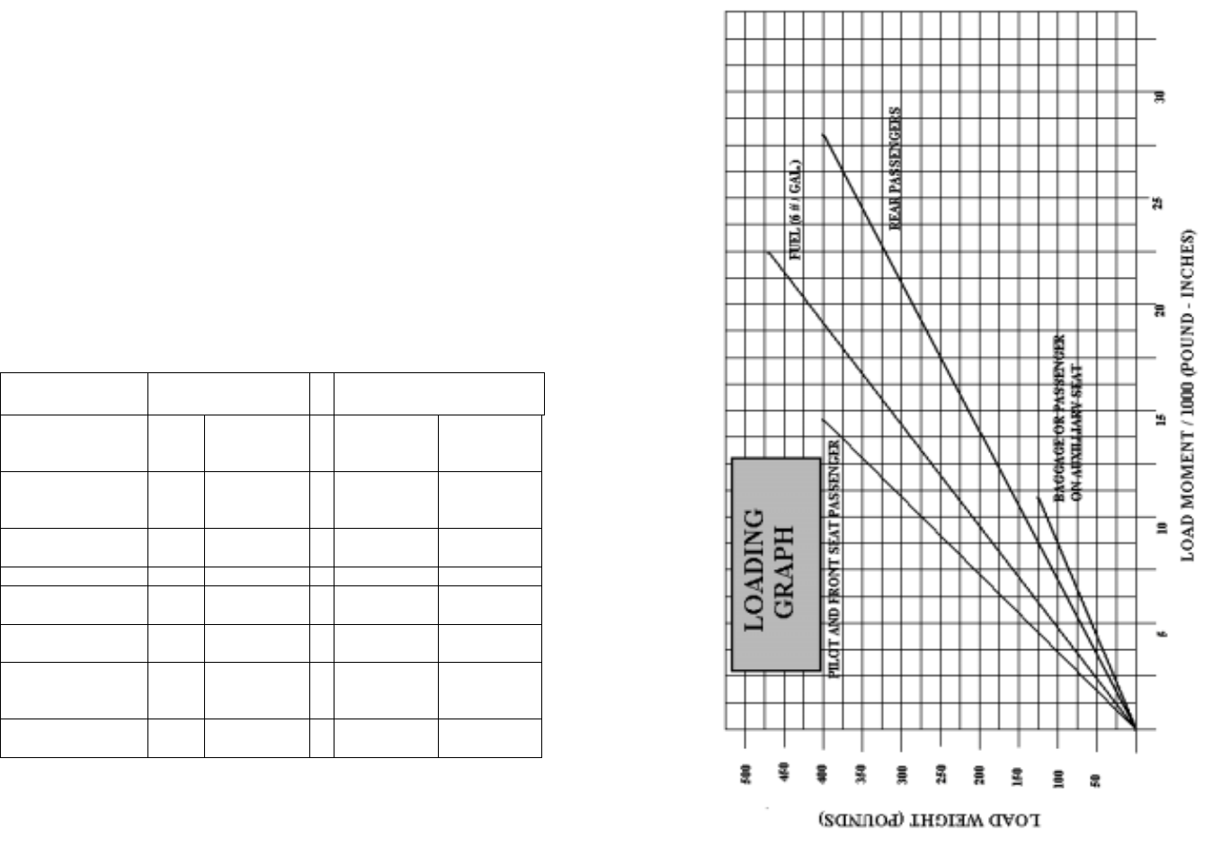
WEIGHT AND BALANCE
The following information will enable you to operate your Cessna
within the prescribed weight and center of gravity limitations. To
figure the weight and balance for your particular airplane, use the
Sample Problem, Loading Graph, and Center of Gravity Moment
Envelope as follows:
Take the licensed Empty Weight and Moment/1000 from the Weight
and Balance Data Sheet, plus any changes noted on forms FAA-337
carried in your airplane, and write them down in the proper columns.
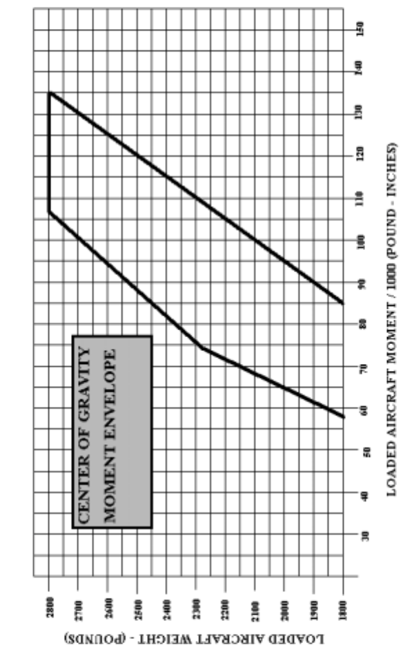
Using the Loading Graph, determine the moment/1000 of each item
to be carried. Total the weights and moments/1000 and use the
Center of Gravity Moment Envelope to determine whether the point
falls within the envelope and if the loading is acceptable.
SAMPLE
AIRPLANE YOUR
AIRPLANE
SAMPLE
LOADING
PROBLEM
WT
(lbs) Moment (lb-
in)
/ 1000)
WT
(lbs) Moment (lb-
in)
/ 1000)
Licensed Empty
Weight (sample
airplane)
1660 57.9
Oil 12 qts ** 22 -.03
Pilot and Passenger 340 12.2
Fuel (60 Gal at 6 #
/ gal 360 17.3
Rear Passengers 340 24.1
Baggage (or
passenger on
auxiliary seat
78 7.6
Total Aircraft
Weight 2800 118.8
Locate this point (2800 at 118.8) on the Center of Gravity envelope chart and since
this falls within the envelope, the loading is acceptable.
** NOTE: Normally, full oil may be assumed for all flights
page 3-4
page 3-5
page 3-6
Section IV
CARE OF THE AIRPLANE
If your airplane is to retain that new plane performance, stamina, and
dependability, certain inspection and maintenance requirements must
be followed. It is always wise to follow a planned schedule of
lubrication and maintenance based on the climatic and flying
conditions encountered in your locality.
Keep in touch with your Cessna dealer, and take advantage of his
knowledge and experience. He knows your airplane and how to
maintain it. He will remind you when lubrications and oil changes
are necessary and about outer seasonal and periodic services.
GROUND HANDLING
The airplane is most easily and safely maneuvered by hand with a
tow-bar attached to the nose wheel
NOTE
When using the tow-bar, never exceed the turning angle of 29º either
side of center, or damage to the gear will result.
MOORING YOUR AIRPLANE
Proper tie-down is the best precaution against damage to your parked
airplane by gusty or strong winds.
To tied down your airplane securely, proceed as follows:
1. Set parking brake and install control wheel lock
2. Install a surface control lock between each aileron and flap
3. Tie sufficiently strong ropes or chains (700 pounds tensile
strength) to wing, and tail tail-down fittings and secure each rope
to ramp tie-down
4. Install a pitot tube cover page 4-1
WINDSHIELD - - WINDOWS
The plastic windshield and windows should be kept clean and waxed
at all times. To prevent scratches and crazing, wash them carefully
with plenty of soap and water, using the palm of the hand to feel and
dislodge dirt and mud. A soft cloth, chamois or sponge may be used,
but only to carry water to the surface. Rinse thoroughly, then dry
with a clean moist chamois. Rubbing the surface of the plastic with a
dry cloth builds up an electrostatic charge so that it attracts dust
particles in the air. Wiping with a moist chamois will remove both
the dust and this charge
Remove oil and grease with a cloth moistened with kerosene. Never
use gasoline, benzine, alcohol, acetone, carbon tetrachloride, fire
extinguisher or anti-ice fluid, lacquer thinner or glass cleaner. These
materials will soften the plastic and may cause it to craze.
After removing dirt and grease, if the surface is not badly scratched, it
should be waxed with a good grade of commercial wax. The wax
will fill in minor scratches and help prevent further scratching. Apply
a thin even coat of was and bring it to a high polish by rubbing lightly
with a clean, dry, soft flannel cloth. Do not use a power buffer; the
heat generated by the buffing pad may soften the plastic.
Do not use a canvas cover on the windshield unless freezing rain or
sleet is anticipated. Canvas covers may scratch the plastic surface.
ALUMINUM SURFACES
The clad aluminum surfaces of your Cessna require only a minimum
of care to keep them bright and clean. The airplane may be washed
with clear water to remove dirt; oil and grease may be removed with
gasoline, naphtha, carbon tetrachloride or other non-alkaline solvents.
Dulled aluminum surfaces may be cleaned effectively with an aircraft
aluminum polish.
page 4-2
After cleaning and periodically thereafter, waxing with a good
automotive was will preserve the bright appearance and retard
corrosion. Regular waxing is especially recommended for airplanes
operated in salt-water areas as a protection against corrosion.
PAINTED SURFACES
The painted surfaces of your new Cessna require an initial curing
period which may be as long as 90 days after the finish is applied.
During this curing period some precautions should be taken to avoid
damaging the finish or interfering with the curing process. The finish
should be cleaned only by washing with clean water and mild soap,
followed by a rinse with water and drying with cloths or a chamois.
Do not use polish or wax, which would exclude air from the surface,
during this 90-day curing period. Do not rub or buff the finish and
avoid flying through rain, sleet or hail.
Once the finish has cured completely, it may be waxed with a good
automotive wax. A heavier coating of was on the leading edges of
the wings and tail and on the engine nose cap and propeller spinner
will help reduce the abrasion encountered in these areas.
PROPELLER CARE
Preflight inspection of propeller blades for nicks, and wiping them
occasionally with an oily cloth to clean off grass and bug stains will
assure long, trouble-free service. It is vital that small nicks on the
propellers, particularly near the tips and on the leading edges, are
dressed out as soon as possible since these nicks produce stress
concentrations, and if ignored, may result in cracks. Never use an
alkaline cleaner on the blades. Remove grass and dirt with carbon
tetrachloride or Stoddard solvent.
page 4-3
INTERIOR CARE
To remove dust and loose dirt from the upholstery, headliner, and
carpet, clean the interior regularly with a vacuum cleaner.
Blot up any spilled liquid promptly, with cleansing tissue or rags.
Don’t pat the spot; press the blotting material firmly and hold it for
several seconds. Continue blotting until no more liquid is taken up.
Scrape off sticky materials with a dull knife, then spot-clean the area.
Oily spots may be cleaned with household spot removers used
sparingly. Before using any solvent, read the instructions on the
container and test it on an obscure place on the fabric to be cleaned.
Never saturate the fabric with a volatile solvent; it may damage the
padding and backing materials.
Soiled upholstery and carpet may be cleaned with foam-type
detergent, and used according to the manufacturer's instructions. To
minimize wetting the fabric, keep the foam as dry as possible and
remove it with a vacuum cleaner,
The plastic trim, instrument panel and control knobs need only be
wiped off with a damp cloth. Oil and grease on the control wheel and
control knobs can be removed with a cloth moistened with kerosene.
Volatile solvents, such as mentioned in paragraphs on care of the
windshield, must never be used since they soften the craze the plastic.
page 4-4
INSPECTION SERVICE AND INSPECTION PERIODS
With your airplane you will receive an Owner's Service Policy.
Coupons attached to the policy entitle you to an initial inspection and
the first 100-hour inspection at no charge. If you take delivery from
your Dealer, he will perform the initial inspection before delivery of
the airplane to you. If you pick up the airplane at the factory, plan to
take it to your Dealer reasonably soon after you take deliver on it.
This will permit him to check it over and to make any minor
adjustments that may appear necessary. Also, plan an inspection by
your Dealer at 100 hours or 90 days, which ever comes first. This
inspection also is performed by your Dealer for you at no charge.
While these important inspections will be performed for you by any
Cessna Dealer, in most cases you will prefer to have the Dealer from
whom you purchased the airplane accomplish this work.
Federal Air Regulations required that all airplanes have a periodic
(annual) inspection as prescribed by the administrator, and performed
a person designated by the administrator. In addition, 100-hour
periodic inspections made by an "appropriately-rated mechanic" are
required if the airplane is flown for hire. The Cessna Aircraft
Company recommends the 100-hour periodic inspection for your
airplane. The procedure for this 100-hour inspection has been
carefully worked out by the factory and is followed by the Cessna
Dealer Organization. The complete familiarity of the Cessna Dealer
Organization with Cessna equipment and factory-approved
procedures provides the highest type of service possible at lower cost.
page 4-5
AIRPLANE FILE
There are miscellaneous data, information and licenses that are a part
of the airplane file. The following is a checklist for that file. In
addition, a periodic check should be made of the latest Civil Air
Regulations in insure that all data requirements are met.
1) To be displayed in the airplane at all times:
a) Aircraft Airworthiness Certificate (Form FAA-1362)
b) Aircraft Registration Certificate (Form FAA -500A)
c) Airplane Radio Station License (Form FCC-404, if transmitter
installed)
2) To be carried in the airplane at all times
a) Weight and Balance, and associated papers (latest copy of the
Repair and Alteration Form, FAA-337 if applicable)
b) Airplane Equipment List
3) To be made available upon request:
a) Airplane Log Book
b) Engine Log Book
NOTE
Cessna recommends that these items, plus the Owner's Manual and
the 'Cessna Flight Guide" (Flight Computer) be carried in the airplane
at all times.
Most of the items listed are required by the United States Federal
Aviation regulations. Since the regulations of other nations may
require other documents and data, owners of exported airplanes
should check with their own aviation officials to determine their
individual requirements.
page 4-6
LUBRICATION AND SERVICING PROCEDURES
Specific servicing information is provided here for items requiring
daily attention. A Service Frequency checklist is included to inform
the pilot when to have other items checked and serviced
DAILY
Fuel Tank Filler
Service after each flight with 80/87 minimum grade fuel. The
capacity of each wing tank is 42.0 gallons with optional long-range
tanks
Fuel Strainer
On the first flight of the day and after each refueling, drain for about
four seconds, to clear fuel strainer of possible water and sediment.
Turn the drain knob, then check that strainer drain is close after
draining.
Oil Dipstick
Check oil level before each flight. Do not operate on less than 9
quarts. To minimize loss of oil through breather, fill to 10-quart level
for normal flights of less than 3 hours. For extended flight, fill to 12
quarts. If optional oil filter is installed, one additional quart is
required when the filter element is changed.
page 4-7
Oil Filler
When preflight check shows low oil level, service with aviation grade
engine oil: SAE 20 below 40ºF and SAE 40 above 40ºF. Your
Cessna was delivered from the factory with straight mineral oil (non-
detergent) and should be operated with straight mineral oil for the
first 25 hours. The use of mineral oil during the 25-hour break-in
period will help seat the piston rings and will result in less oil
consumption. After the first 25 hours, either mineral oil or detergent
oil may be used. If a detergent oil is used, it must conform to
Continental Motors Corporation Specification MHS-24. Your Cessna
Dealer can supply an approved brand.
SERVICING INTERVALS CHECKLIST
EACH 50 HOURS
BATTERY- - Check and Service. Check oftener (at least every 30
days) if operating in hot weather)
ENGINE OIL AND OIL FILTER - - Change engine oil and replace
filter element. If optional oil filter is not installed changed oil and
clan screen every four months even thought less than 50 hours have
been accumulated. Reduce periods for prolonged operation in dusty
area, cold climates, or when short flights and long idle periods result
in sludging conditions.
CARBURETOR AIR FILTER - -Clean or replace. Under extremely
dusty conditions, daily maintenance of the filter is recommended
NOSE GEAR TORQUE LINKS - - Lubricate
page 4-8
EACH 100 HOURS
FUEL STRAINER - - Disassemble and clean
FUEL TANK SUMP DRAIN PLUGS - Remove and drain
FUEL LINE DRAIN PLUG - - Remove and drain
BRAKE MASTER CYLENDERS - -Check and Fill
SHIMMY DAMPENER - - Check and Fill
VACUUM SYSTEM OIL SEPARATOR (OPT) - - Clean
SUCTION RELIEF VALVE INLET SCREEN (OPT) - -Clean
EACH 500 HOURS
WHEEL Bearings - -Lubricate. Lubricate at first 100 hours and at
500 hours thereafter
VACUUM SYSTEM AIR FLITER (OPT) - - Replace filter element.
Replace sooner if suction gauge reading drops to 4.6" Hg.
AS REQUIRED
NOSE GEAR SHOCK STRUT - - Keep inflated and filled
Gyro instrument air filters (OPT) - - Replace at instrument overhaul
page 4-9

Section V
OPERATIONAL DATA
The operational data shown on the following pages are presented for
two purposes: first, so that you may know what to expect from your
airplane under various conditions, and second, to enable you to plan
your flights in detail and with reasonable accuracy.
The data in the charts has been compiled from actual flight tests with
the airplane and engine in good condition and using average piloting
techniques. Note also that the range charts make on allowances for
wind, navigational error, warm-up, take-off, climb, etc. You must
estimate these variables for yourself and make allowances
accordingly.
Remember that the charts contained herein are based on standard day
conditions. Form more precise power, fuel consumption, and
endurance information, consult the Cessna Flight Guide (Power
Computer) supplied with your aircraft. With the flight Guide, you
can easily take into account temperature variations from standard at
any flight altitude..
page 5-1
AIRSPEED CORRECTION TABLE
IAS 60 80 100 120 140 160 180 --
FLAPS
UP CAS 68 83 100 118 137 156 175 --
IAS405060708090100110
FLAPS
DOWN
20°-40° CAS586368758492101110
Maximum Flap Speed 110 MPH, CAS
figure 5-1
STALLING SPEEDS
Power off, (mph)
ANGLE OF BANK
Gross
Weight
2800 lbs. 0º 30º 60º
Flaps 0º 64 69 91
Flaps 20º 57 61 81
Flaps 40º 55 59 78
figure 5-2
page 5-2

----------------- TAKE – OFF DISTANCE ------------------
TAKEOFF DISTANCE WITH 20° FLAPS FROM HARD
SURFACE RUNWAY
At Sea Level, 59°F At 2,500 ft, 50°FGROSS
WT
LBS
IAS
MPH HEAD
WIND
MPH
GROUND
RUN TO
CLEAR
50’ OBS.
GROUND
RUN TO
CLEAR
50’ OBS.
2000 52 0
15
30
295
160
65
655
425
235
350
195
80
745
490
280
2400 57 0
15
30
440
255
115
895
600
355
525
310
150
1035
705
425
2800 61 0
15
30
625
380
190
1205
830
515
745
460
240
1420
990
630
At 5,000 ft, 41°F At 7,500 ft, 32°FGROSS
WT
LBS
IAS
MPH HEAD
WIND
MPH
GROUND
RUN TO
CLEAR
50’ OBS.
GROUND
RUN TO
CLEAR
50’ OBS.
2000 52 0
15
30
415
235
105
855
570
35
500
290
135
1005
680
405
2400 57 0
15
30
630
380
190
1210
835
515
765
470
245
1400
1020
645
2800 61 0
15
30
895
565
305
1695
1200
780
1095
700
390
2090
1505
1000
NOTE Increase distance 10% for each 25° F above standard temperature
figure 5-3
page 5-3
MAXIMUM RATE OF CLIMB DATA
At Sea Level, 59°FGROSS
WT
LBS IAS
MPH RATE OF
CLIMB
FPM
FUEL
USED,
GAL
2000
2400
2800
84
86
88
1710
1295
980
1.5
1.5
1.5
At 5,000 ft, 41°FGROSS
WT
LBS IAS
MPH RATE OF
CLIMB
FPM
FUEL
USED,
GAL
2000
2400
2800
82
84
86
1350
1005
745
2.7
3.1
3.7
At 10,000 ft, 23°FGROSS
WT
LBS IAS
MPH RATE OF
CLIMB
FPM
FUEL
USED,
GAL
2000
2400
2800
79
82
84
995
720
510
4.1
5.0
6.3
At 15,000 ft, 23°FGROSS
WT
LBS IAS
MPH RATE OF
CLIMB
FPM
FUEL
USED,
GAL
2000
2400
2800
76
79
82
640
435
280
5.9
7.6
10.2
At 20,000 ft, 23°FGROSS
WT
LBS IAS
MPH RATE OF
CLIMB
FPM
FUEL
USED,
GAL
2000
2400
2800
74
77
80
280
150
50
9.2
12.9
20.5
NOTE: Flaps up, full throttle and 2600 RPM. M mixture leaned to smooth
operation above 5000 ft. Fuel used includes warm-up and takeoff
allowance
page 5-4

CRUISE PERFORMANCE
LEAN MIXTURE
Standard Conditions -- Zero Wind – Gross Weight 2800 Pounds
RPM MP %BHP GAL/
HR
TAS
MPH
END.
(HOURS)
RANGE
(MILES)
2500 FEET
2450 23
22
21
20
76
72
68
63
14.2
13.4
12.7
12.0
158
154
151
148
5.6
5.9
6.2
6.6
885
910
940
995
2300 23
22
21
20
71
67
62
59
13.1
12.2
11.5
11.0
154
149
145
142
6.0
6.5
6.9
7.2
925
970
055
10220
2200 23
22
21
20
67
63
59
55
12.1
11.4
10.8
10.2
149
146
142
138
6.5
6.9
7.3
7.7
980
1010
1040
1045
2000
MAXIMUM
RANGE
SETTINGS
20
19
18
17
47
43
39
35
8.7
8.2
7.5
7.0
126
121
113
105
9.1
9.6
10.5
11.3
1135
1170
1185
1190
5000 FEET
2450 23
22
21
20
78
73
70
65
14.5
13.6
13.0
12.2
163
159
156
151
5.4
5.8
6.1
6.5
885
925
950
985
2300 23
22
21
20
73
69
64
60
13.4
12.6
11.9
11.2
158
155
151
146
5.9
6.3
6.6
7.1
930
965
1005
1035
2200 23
22
21
20
68
64
60
57
12.4
11.7
11.0
10.5
155
151
146
143
6.4
6.8
7.2
7.5
985
1020
1050
1075
2000
MAXIMUM
RANGE
SETTINGS
19
18
17
16
45
41
37
34
8.5
7.9
7.3
6.8
126
118
111
103
9.3
10.0
10.8
11.6
1175
1190
1200
1190
figure 5.4 (Sheet 1 of 3)
page 5-5
CRUISE PERFORMANCE
LEAN MIXTURE
Standard Conditions -- Zero Wind – Gross Weight 2800 Pounds
RPM MP %BHP GAL/
HR
TAS
MPH
END.
(HOURS)
RANGE
(MILES)
7,500 FEET
2450 21
20
19
18
71
67
62
58
13.1
12.4
11.7
11.0
161
157
152
147
6.0
6.4
6.8
7.2
960
1005
1025
1055
2300 21
20
19
18
66
62
58
54
12.2
11.6
11.0
10.5
156
151
147
142
6.5
6.8
7.2
7.5
1005
1025
1050
1065
2200 21
20
19
18
62
58
54
51
11.4
10.7
10.2
9.7
152
148
143
138
6.9
7.4
7.7
8.1
1055
1090
1105
1130
2000
MAXIMUM
RANGE
SETTINGS
19
18
17
16
47
43
39
36
8.7
8.1
7.6
7.0
131
123
116
107
9.1
9.8
10.4
11.3
1185
1200
1210
1210
10,000 FEET
2450 19
18
17
16
63
60
55
51
11.9
11.2
10.6
10.0
156
152
146
141
6.6
7.1
7.5
7.9
1035
1055
1090
1105
2300 19
18
17
16
60
56
51
47
11.1
10.5
9.8
9.2
152
147
141
134
7.1
7.5
8.1
8.6
1080
1105
1130
1145
2200 19
18
17
16
56
52
49
45
10.4
9.8
9.3
8.7
148
142
136
129
7.6
8.1
8.5
9.1
1120
1155
1160
1175
2000
MAXIMUM
RANGE
SETTINGS
18
17
16
15
44
40
38
35
8.4
7.8
7.4
6.9
128
120
14
105
9.4
10.1
10.7
11.4
1200
1215
1215
1200
figure 5.4 (Sheet 2 of 3) page 5-6
CRUISE PERFORMANCE
LEAN MIXTURE
Standard Conditions -- Zero Wind – Gross Weight 2800 Pounds
RPM MP %BHP GAL/
HR
TAS
MPH
END.
(HOURS)
RANGE
(MILES)
15,000 FEET
2450 16
15
14
54
50
46
10.4
9.8
9.2
150
142
135
7.6
8.1
8.6
1135
1155
1160
2300 16
15
14
50
47
42
9.6
9.1
8.5
143
136
127
8.2
8.7
9.3
1170
1185
1185
2200 16
15
14
47
44
40
9.1
8.6
8.0
138
130
120
8.7
9.2
9.9
1200
1200
1190
2000
MAXIMUM
RANGE
SETTINGS
16
15
14
40
37
34
7.8
7.3
6.8
122
112
101
10.1
10.8
11.6
1240
1210
1175
20,000 FEET
2450 13
12 44
40 9.0
8.3 133
122 8.8
9.5 1175
1155
2300 13
12 42
38 8.4
7.7 126
113 9.4
10.3 1190
1155
2200 13
12 39
35 7.8
7.2 118
103 10.1
11.0 1190
1135
figure 5.4 (Sheet 3 of 3)
page 5-7 page 5-8
Page 5-9
Section VI
OPTIONAL SYSTEMS
This section contains a description, operating procedures, and
performance data (when applicable) for some of the optional
equipment which may be installed in your Cessna. Owner’s Manual
Supplements are provided to cover operation of other optional
equipment systems when installed in your airplane. Contact your
Cessna Dealer for a complete list of available optional equipment.
LONG RANGE FUEL TANKS
Special wings with long-range fuel tanks are available to replace the
standard wings and fuel tanks for greater endurance and range. When
these tanks are installed, the total usable fuel, for all flight conditions
is 79 gallons.
COLD WEATHER EQUIPMENT
WINTERIZATION KIT AND NON-CONGELALING OIL
COOLER
(not installed)
GROUND SERVICE PLUG RECEPTACLE
A ground service plug receptacle may be installed to permit the use of
an external power source for cold weather starting and during lengthy
maintenance work on the electrical system.
Before connecting a generator type external power source, it is
important that the master switch be turned on. This will enable the
battery to absorb transient voltages which otherwise might damage
the semiconductors in the electronic equipment. When using a
battery type external power source, the master switch should be
turned off to prevent an unnecessary power drain form the power
source batteries to the airplane’s battery. page 6-1

IMPORTANT
Be certain that the polarity of any external power source or batteries
is correct (positive to positive and negative to negative). A polarity
reversal will result in immediate damage to semiconductors in the
airplane’s electronic equipment.
OIL DILUTION SYSTEM
(not installed)
STATIC PRESSURE ALTERNATE SOURCE
A static pressure alternate source valve may be installed in the static
system for use when the external static sources are malfunctioning.
This valve also permits draining condensate from the static lines.
If erroneous instrument reading are suspected due to water or ice in
the static pressure lines, the static pressure alternate source valve
should be opened, thereby supplying static pressure from the cabin.
Cabin pressures will vary, however, with open cabin ventilators or
windows. The most adverse combinations will result in airspeed and
altimeter variations of no more than 2 mph and 20 feet respectively.
RADIO SELECTOR SWITCHES
RADIO SELECTOR SWITCH OPERATION
Operation of the radio equipment is normal as covered in the
respective radio manuals. When more than one radio is installed, an
audio switching is necessary. The operation of this switching system
is described below.
TRANSMITTER SELECTOR SWITCH
The transmitter selector switch has two positions. When two
transmitters are installed, it is necessary to switch the microphone to
the radio unit the pilot desires to use for transmission. This is
accomplished by placing the transmitter selector switch in the
position corresponding to the radio unit which is to be used.
page 6-2
SPEAKER-PHONE SWITCHES
The speaker-phone switches determine whether the output of the
receiver is use is fed to the headphones or through the audio amplifier
to the speaker. Place the switch for the desired receiving system
either in the up position for speaker operation or in the down position
for headphones
AUTOPILOT –OMNI SWITCH
When a Nav-O-Matic autopilot is installed with two compatible omni
receivers, an autopilot-omni switch is utilized. This switch select the
omni receiver to be used for the omni course sensing function of the
autopilot. The up position selects the upper receiver in the radio
panel stack, and the down position selects the lower omni receiver.
page 6-3

OXYGEN SYSTEM – not installed
CESSNA ECONOMY MIXTUERE INDICATOR
The Cessna Economy Mixture Indicator is an exhaust gas temperature
sensing device which is used to aid the pilot in selecting the most
desirable fuel-air mixture for cruising flight at less than 75% power.
Exhaust gas temperature (EGT) varies with the ratio of fuel-to-air
mixture entering the engine cylinders.
OPERATING INSTRUCTIONS
1. In take-off and full power climb, use full rich mixture
2. In level flight (or cruising climb at less than 75% power), lean the
mixture to peak EGT; then enrichen as desire using the following
table as a guide
MIXTURE
DESCRIPTION EGT TAS LOSS
FROM BEST
POWER
RANGE
INCREASE
FROM BEST
POWER
BEST POWER
(Maximum
speed)
Peak minus
125°
(enrichen)
0 MPH 0 %
NORMAL
LEAN (Owner’s
Manual &
Computer
Performance)
Peak minus
75°
(enrichen)
1 MPH 10 %
MAXIMUM
LEAN Peak minus
25°
(enrichen)
3 MPH 20 %
page 6-4
NOTES
Changes in altitude or power setting require the EGT to be rechecked
and the mixture re-set
Operation at peak EGT is not authorized for normal continuous
operation, except to establish peak EGT for reference. Operation on
the lean side of peak EGT or within 25° of peak EGT is not approved.
3. Use rich mixture (or mixture appropriate for field elevation) in
idle descents or landing approaches. Leaning techniques for
cruise descents may be with EGT reference method (at least every
5000 feet) or by simply enriching to avoid engine roughness if
numerous power reductions are made.
TRUE AIRSPEED INDICATOR
A true airspeed indicator is available to replace the standard airspeed
indicator in your airplane. The true airspeed indicator ha a calibrated
rotatable ring which works in conjunction with the airspeed indicator
dial in a manner similar to the operation of a flight computer.
To obtain True airspeed, rotate ring until pressure altitude is aligned
altitude is aligned with outside temperature in degrees Fahrenheit.
Then read true airspeed on rotatable ring opposite airspeed needle.
NOTE
Pressure altitude should not be confused with indicated altitude. To
obtain pressure altitude, set barometric scale on altimeter to 29.92”
and read pressure altitude on altimeter. Be sure to return altimeter
barometric scale to original barometric setting after pressure altitude
has been obtained.
page 6-5

Altitude Temp (F) Temp (C)
Sea Level- 59 15
1,000 55.5 13
2,000 52 11
3,000 48.5 9
4,000 45 7
5,000 41.5 5
6,000 38 3
7,000 34.5 1
8,000 31 -1
9,000 27.5 -3
10,000 24 -5
11,000 20.5 -7
12,000 17 -9
13,000 13.5 -11
14,000 10 -13
15,000 6.5 -15
16,000 3 -17
17,000 -0.5 -19
18,000 -4 -21
19,000 -7.5 -23
20,000 -11 -25
Standard Temperatures
ALPHABETICAL INDEX
A
After landing, 1-5
Air Filter
carburetor 4-8
gyro instrument 4-8
vacuum system 4-8
Airplane
before entering, 1-1
file, 4-6
ground handling, 4-1
mooring, 4-1
secure, 1-5
Airspeed correction table, 5-2
Airspeed limitations, 3-2
Aluminum surfaces, 4-2
Authorized operations, 3-1
B
Baggage capacity, i
Battery 4-78Beacon, rotating 2-2
Before entering airplane, 1-1
Before landing, 1-4
Before starting engine, 1-2
Before takeoff, 1-2, 2-6
Brake Master cylinders 4-9
C
Cabin heating and ventilating system, 2-4
Capacity
fuel, i
oil, i
Carburetor, 2-2
Care
interior, 4-34 propeller, 4-3
Center of gravity moment envelope, 3-6
Checklist, servicing intervals, 4-8, 4-9
Circuit Breakers 2-2
Climb, 1-4
maximum performance, 1-4
normal, 1-4
Cold Weather Equipment. 6-1
Cold weather operation, 2-11
operations 2-11
starting 2-11
Correction Table, airspeed, 5-2
Cruise performance table, 5-4
Cruising, 1-4
D
Diagram, exterior inspection, iv
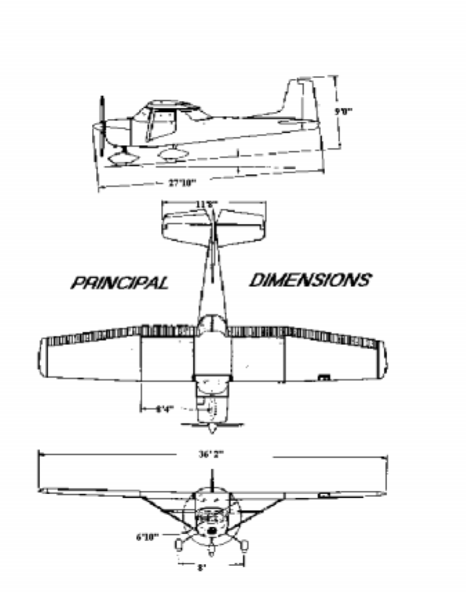
Dimensions, principal, ii
Dipstick, oil 4-7
E
Economy Mixture Indicator 6-4
operating instructions, 6-4
Electrical system, 2-2
circuit breakers, 2-2
ground service receptacle 6-1
rotating beacon 2-2
Empty weight, i
Engine,
before starting, 1-1
instrument markings, 3-2
operation limitations, 3-2
primer, 2-2
starting, 1-2
Equipment, cold weather 6-1
Exterior Inspection , iv
F
File, airplane, 4-5
Fuel System, 2-1
capacity, i
carburetor, 2-2
engine primer, 2-2
fuel line drain plug 4-7
fuel strainer,,2-2, 4-6, 4-7
fuel tank fillers, 4-6
fuel tank sump drains, 4-7
mixture control, 2-2
schematic, 2-2
selector valve 2-2
throttle, 2-2
wing tanks, 2-2,6-1
G
Graph,
center of gravity moment
envelope, 3-6
Loading, 3-5
Gross weight, i
Ground handling, 4-1
Ground Service Plug Receptacle, 6-1
Gyro Instrument Air Filters, 4-7
H
Handling Airplane on ground, 4-1
Heating and ventilation system, cabin, 2-4
Hot Weather operation, 2-12
Hydraulic Fluid (after index)
I
Inspection diagram, exterior, iv
Inspection service and inspection periods, 4-4
Instrument markings, engine,3-3
Interior care, 4-3
L
Landing, i, 2-9
after, 1-4
before, 1-3
distance table, 6-2
normal, 1-3
Let Down, 1-4
Limitations,
airspeed, 3-2
Loading graph, 3-5
Loading problem, sample, 3-4
Lubrications and servicing procedures, 4-6
M
Maneuvers, utility category, 3-1
Master Cylinders, brake, 4-7
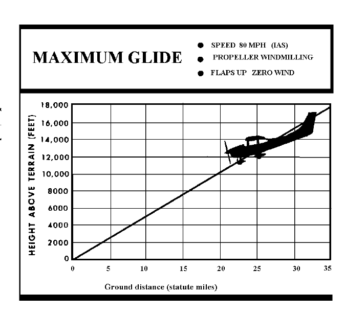
Maximum Glide, 5-8
Maximum performance climb, 1-3
Maximum performance takeoff, 1-2
Mixture Control 2-2
Moment Envelope, Center of Gravity, 3-6
Mooring your airplane, 4-1
N
Normal Category -Maneuvers, 3-1
Normal climb, 1-3
Normal landing, 1-3
Normal takeoff, 1-2
Nose Gear Shock Strut, 4-7
Nose Gear Torque Links, 4-7
O
Oil System
capacity, i
Dipstick, 4-7
Filler, 4-6
Temperature gauge, 3-3
Pressure gauge, 3-3
Operation, cold weather 2-10
Operation, hot weather, 2-12
Operations, limitations, engine, 3-2
Operations, authorized, 3-1
Optimum Cruise Performance. 2-8
Owner follow-up system, 4-5
P
Painted Surfaces, 4-2
Performance - specifications, i
Power checks, 2-7
Power, i
Power loading, i
Pressure, Tire, after index
Primer, engine, 2-2
Principal dimensions, ii
Propeller care, 4-3
R
Radio Selector Switches, 6-4
autopilot-omni switch, 6-4,6-5
operations, 6-4
speaker-phone,6-4,6-5
transmitter selector, 6-4
Range, i, 5-4
Rate of climb, i
Rotating Beacon, 2-3
S
Sample loading problem, 3-4
Secure aircraft, 1-4
Selector valve, Fuel, 3-2
Service ceiling, i
Servicing and lubrication, 4-6
Servicing intervals, check list, 4-7, 4-8
servicing requirements table , after index
Shimmy Dampener, 4-7
Shut-off valve, fuel, 2-2
Specifications, performance, i
Speed, i
Spins, 2-9
Stalls, 2-9
speed chart, 5-2
Starting engine, 1-2, 2-4
Static Pressure, alternate source, 6-3
Strainer, fuel, 2-2
Suction relief valve inlet, screen, 4-7
Surfaces,
aluminum, 4-2
painted, 4-2
System
cabin heating and ventilating, 2-4
electrical, 2-3
fuel, 2-1
owner follow-up, 4-5
T
Tachometer, 3-3
Takeoff, i, 1-2, 2-7
before takeoff, 1-2, 2-6
crosswind, 2-8
distance table, 5-3
maximum performance, 1-2
normal, 1-2
Taxiing, 2-4
diagram, 2-5
Throttle, 2-2
Tire pressure (after index)
True Airspeed indicator, 6-11
V
Vacuum System Air filter, 4-7
Vacuum System oil separator, 4-7
Valve, fuel shutoff, 2-2
W
Weight,
empty, i
gross, i
Weight and balance, 3-3
center of gravity moment envelope, 3-6
loading graph, 3-6-5
sample loading problem, 3-4
Windshield - windows, 4-2
Wing loading, i
Servicing Requirements
FUEL
Aviation Grade 80/87 Minimum, grade
Capacity, each 42 gallons
ENGINE OIL
aviation grade SAE 20 below 40º
SAE 24 above 40º
Capacity of sump 12 quarts
HYDRAULIC FLUID
MIL - H - 5606 Hydraulic fluid
TIRE PRESSURE
Nose gear 32 psi
Main gear 32 psi (5:00 x 5 tire)
