182SMM14 182/T182 SERIES (1997 AND ON) Cessna_182S_1997on_MM_182SMM Cessna 182S 1997on MM 182SMM
User Manual: Cessna_182S_1997on_MM_182SMM
Open the PDF directly: View PDF ![]() .
.
Page Count: 1127 [warning: Documents this large are best viewed by clicking the View PDF Link!]
- 182SMM14 - MODEL 182/T182 SERIES (1997 AND ON)
- LIST OF EFFECTIVE PAGES
- RECORD OF REVISION
- RECORD OF TEMPORARY REVISIONS
- TABLE OF CONTENTS
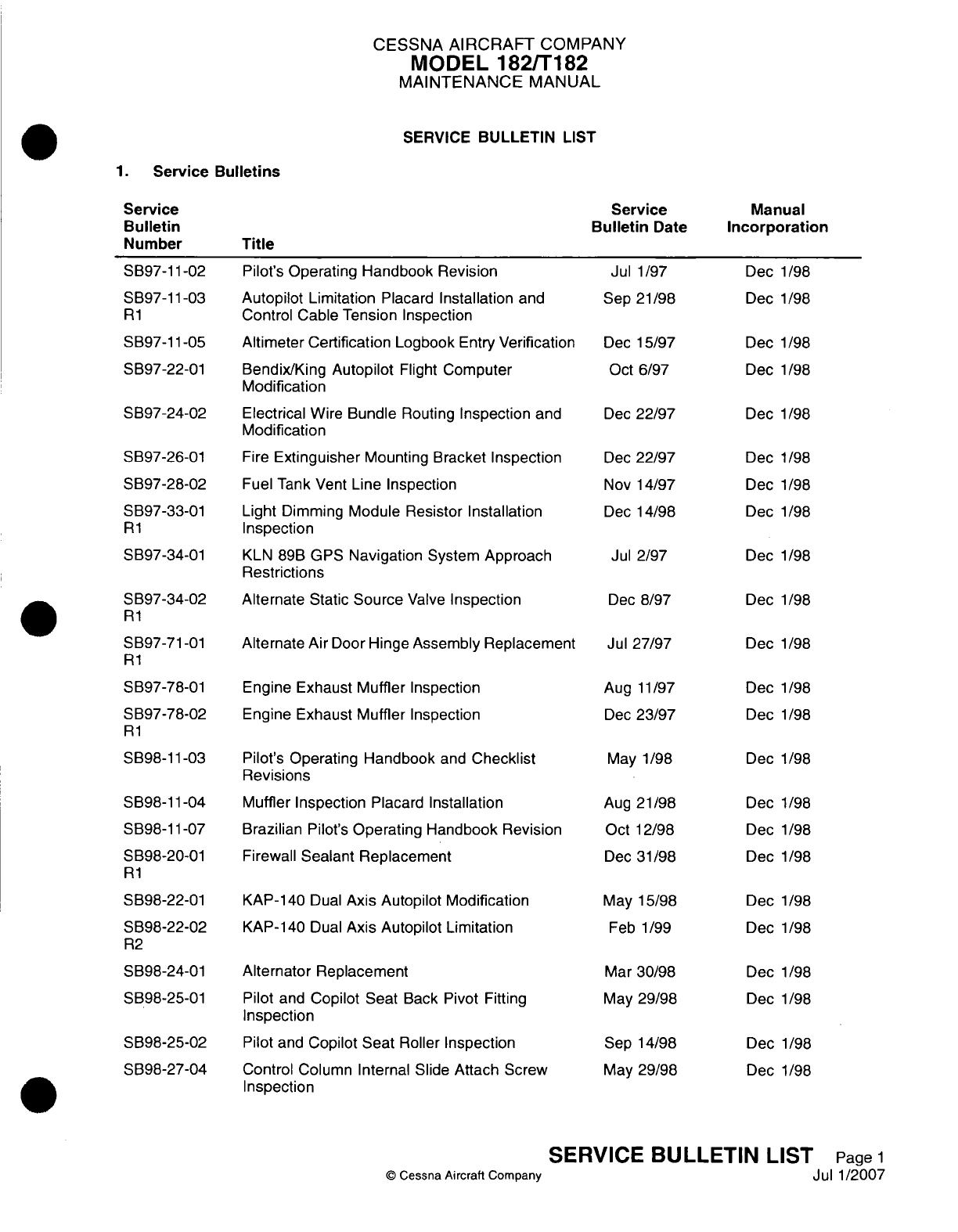
- SERVICE BULLETIN LIST
- INTRODUCTION
- GENERAL
- CROSS REFERENCE LISTING OF POPULAR NAME VERSES MODEL NUMBERS AND SERIALS
- COVERAGE AND FORMAT
- TEMPORARY REVISIONS
- SERIALIZATION
- MATERIAL PRESENTATION
- SERVICE BULLETINS
- USING THE MAINTENANCE MANUAL
- EFFECTIVITY PAGES
- REVISION FILING INSTRUCTIONS
- IDENTIFYING REVISED MATERIAL
- WARNINGS, CAUTIONS AND NOTES
- CESSNA PROPELLER AIRCRAFT CUSTOMER CARE SUPPLIES AND PUBLICATIONS CATALOG
- CUSTOMER COMMENTS ON MANUAL
- LIST OF REVISIONS
- LIST OF MANUFACTURERS TECHNICAL PUBLICATIONS
- LIST OF CHAPTERS
- CHAPTER 5 - TIME LIMITS/MAINTENANCE CHECKS
- LIST OF EFFECTIVE PAGES
- RECORD OF TEMPORARY REVISIONS
- TABLE OF CONTENTS
- TIME LIMITS/MAINTENANCE CHECKS
- AIRWORTHINESS LIMITATIONS - FAA APPROVED DATA
- INSPECTION TIME INTERVALS
- INSPECTION TIME LIMITS
- COMPONENT TIME LIMITS
- PROGRESSIVE CARE PROGRAM
- INSPECTION OPERATION 1
- INSPECTION OPERATION 2
- INSPECTION OPERATION 3
- INSPECTION OPERATION 4
- INSPECTION OPERATION 5
- PROGRESSIVE CARE
- INSPECTION OPERATION 7
- PROGRESSIVE CARE
- INSPECTION OPERATION 9
- INSPECTION OPERATION 10
- INSPECTION OPERATION 11
- PROGRESSIVE CARE
- INSPECTION OPERATION 14
- INSPECTION OPERATION 15
- INSPECTION OPERATION 16
- INSPECTION OPERATION 17
- INSPECTION OPERATION 18
- INSPECTION OPERATION 19
- INSPECTION OPERATION 20
- INSPECTION OPERATION 21
- INSPECTION OPERATION 22
- INSPECTION OPERATION 23
- INSPECTION OPERATION 24
- INSPECTION OPERATION 25
- INSPECTION OPERATION 26
- UNSCHEDULED MAINTENANCE CHECKS
- CHAPTER 6 - DIMENSIONS AND AREAS
- LIST OF EFFECTIVE PAGES
- RECORD OF TEMPORARY REVISIONS
- TABLE OF CONTENTS
- DIMENSIONS AND AREAS - GENERAL
- AIRPLANE DIMENSIONS AND SPECIFICATIONS - DESCRIPTION AND OPERATION
- AIRPLANE STATIONS - DESCRIPTION AND OPERATION
- AIRPLANE ZONING - DESCRIPTION AND OPERATION
- ACCESS/INSPECTION PLATES - DESCRIPTION AND OPERATION
- CHAPTER 7 - LIFTING AND SHORING
- CHAPTER 8 - LEVELING AND WEIGHING
- CHAPTER 9 - TOWING AND TAXIING
- CHAPTER 10 - PARKING AND MOORING
- CHAPTER 11 - PLACARDS AND MARKINGS
- CHAPTER 12 - SERVICING
- LIST OF EFFECTIVE PAGES
- RECORD OF TEMPORARY REVISIONS
- TABLE OF CONTENTS
- SERVICING - GENERAL
- REPLENISHING - DESCRIPTION AND OPERATION
- NOSE LANDING GEAR SHOCK STRUT - SERVICING
- NOSE LANDING GEAR SHIMMY DAMPER - SERVICING
- HYDRAULIC BRAKES - SERVICING
- FUEL AND ENGINE OIL - DESCRIPTION AND OPERATION
- FUEL - SERVICING
- ENGINE OIL - SERVICING
- INDUCTION AIR FILTER - SERVICING
- VACUUM SYSTEM FILTERS - SERVICING
- BATTERY - SERVICING
- TIRES - SERVICING
- SCHEDULED SERVICING - DESCRIPTION AND OPERATION
- LUBRICANTS - DESCRIPTION AND OPERATION
- BATTERY TERMINALS - SERVICING
- LANDING GEAR AND PARKING BRAKE - SERVICING
- FLIGHT CONTROLS - SERVICING
- ENGINE CONTROL CABLES - SERVICING
- HEATING AND VENTILATION CONTROL CABLES - SERVICING
- AIRPLANE EXTERIOR - CLEANING/PAINTING
- INTERIOR - CLEANING/PAINTING
- UNSCHEDULED SERVICING - DESCRIPTION AND OPERATION
- CHAPTER 20 - STANDARD PRACTICES - AIRFRAME
- LIST OF EFFECTIVE PAGES
- RECORD OF TEMPORARY REVISIONS
- TABLE OF CONTENTS
- STANDARD PRACTICES AIRFRAME - GENERAL
- MATERIAL AND TOOL CAUTIONS - DESCRIPTION AND OPERATION
- TORQUE DATA - MAINTENANCE PRACTICES
- SAFETYING - MAINTENANCE PRACTICES
- CONTROL CABLE WIRE BREAKAGE AND CORROSION LIMITATIONS - MAINTENANCE PRACTICES
- SOLVENTS, SEALANTS, AND ADHESIVES - DESCRIPTION AND OPERATION
- ACCEPTABLE REPLACEMENTS FOR CHEMICALS AND SOLVENTS - DESCRIPTION AND OPERATION
- GENERAL SOLVENTS/CLEANERS - MAINTENANCE PRACTICES
- INTERIOR AND EXTERIOR FINISH - CLEANING/PAINTING
- FUEL, WEATHER AND HIGH - TEMPERATURE SEALING - MAINTENANCE PRACTICES
- CONVERSION DATA - DESCRIPTION AND OPERATION
- CHAPTER 21 - AIR CONDITIONING
- LIST OF EFFECTIVE PAGES
- RECORD OF TEMPORARY REVISIONS
- TABLE OF CONTENTS
- AIR CONDITIONING - GENERAL
- FRESH AIR DISTRIBUTION - DESCRIPTION AND OPERATION
- FRESH AIR DISTRIBUTION - TROUBLESHOOTING
- FRESH AIR DISTRIBUTION - MAINTENANCE PRACTICES
- AVIONICS COOLING FAN - MAINTENANCE PRACTICES
- GENERAL
- FIREWALL AVIONICS COOLING FAN REMOVAL/INSTALLATION (AIRPLANES WITHOUT GARMIN G1000)
- PRIMARY FLIGHT DISPLAY (PFD) FAN REMOVAL/INSTALLATION (AIRPLANES WITH GARMIN G1000)
- MULTI-FUNCTION DISPLAY (MFD) FAN REMOVAL/INSTALLATION (AIRPLANES WITH GARMIN G1000)
- DECK SKIN FAN REMOVAL/INSTALLATION (AIRPLANES WITH GARMIN G1000)
- REMOTE AVIONICS COOLING FAN REMOVAL/INSTALLATION (AIRPLANES WITH GARMIN G1000)
- PRIMARY FLIGHT DISPLAY (PFD) AND MULTI-FUNCTION DISPLAY (MFD) FAN OPERATIONAL CHECK (AIRPLANES WITH GARMIN G1000)
- HEATING AND DEFROSTING - TROUBLESHOOTING
- HEATING AND DEFROSTING - MAINTENANCE PRACTICES
- CHAPTER 22 - AUTO FLIGHT
- LIST OF EFFECTIVE PAGES
- RECORD OF TEMPORARY REVISIONS
- TABLE OF CONTENTS
- AUTO FLIGHT - GENERAL
- AUTOPILOT - MAINTENANCE PRACTICES
- GENERAL
- KC- 140 (SINGLE-AXIS) AUTOPILOT FLIGHT COMPUTER REMOVAL/INSTALLATION
- KC-140 (DUAL-AXIS) AUTOPILOT FLIGHT COMPUTER REMOVAL/INSTALLATION
- ROLL SERVO REMOVAL/INSTALLATION
- PITCH SERVO REMOVAL/INSTALLATION
- PITCH TRIM SERVO REMOVAL/INSTALLATION
- ROLL SERVO INSPECTION
- PITCH SERVO INSPECTION
- PITCH TRIM SERVO INSPECTION
- PITCH TRIM RIGGING INSPECTION
- SERVO CAPSTAN CLUTCH ADJUSTMENT
- SET THE AUTOPILOT ROLL NULL
- AUTOPILOT - MAINTENANCE PRACTICES
- GENERAL
- GFC-700 AUTOPILOT FLIGHT COMPUTER REMOVAL/INSTALLATION
- ROLL SERVO ACTUATOR REMOVAL/INSTALLATION
- ROLL SERVO AND CABLE REMOVAL/INSTALLATION
- PITCH SERVO MOTOR REMOVAL/INSTALLATION
- PITCH SERVO AND CABLE REMOVAL/INSTALLATION
- PITCH TRIM SERVO ACTUATOR REMOVAL/INSTALLATION
- PITCH TRIM SERVO AND CABLE REMOVAL/INSTALLATION
- PITCH TRIM RIGGING INSPECTION
- SERVO CAPSTAN CLUTCH ADJUSTMENT
- CHAPTER 23 - COMMUNICATIONS
- CHAPTER 24 - ELECTRICAL POWER
- LIST OF EFFECTIVE PAGES
- RECORD OF TEMPORARY REVISIONS
- TABLE OF CONTENTS
- ELECTRICAL POWER - GENERAL
- ALTERNATOR SYSTEM - TROUBLESHOOTING
- ALTERNATOR - MAINTENANCE PRACTICES
- BATTERY - TROUBLESHOOTING
- BATTERY - MAINTENANCE PRACTICES
- STANDBY BATTERY - MAINTENANCE PRACTICES AIRPLANES WITH GARMIN G1000
- 12-VOLT CABIN POWER SYSTEM - TROUBLESHOOTING
- POWER JUNCTION BOX - MAINTENANCE PRACTICES
- ALTERNATOR CONTROL UNIT - MAINTENANCE PRACTICES
- CIRCUIT BREAKER - MAINTENANCE PRACTICES
- ESSENTIAL AND CROSSFEED BUS DIODES - MAINTENANCE PRACTICES
- ELECTRICAL LOAD ANALYSIS - DESCRIPTION AND OPERATION
- CHAPTER 25 - EQUIPMENT/ FURNISHINGS
- LIST OF EFFECTIVE PAGES
- RECORD OF TEMPORARY REVISIONS
- TABLE OF CONTENTS
- EQUIPMENT/FURNISHING - GENERAL
- FRONT SEATS AND RAILS - MAINTENANCE PRACTICES
- MAP COMPARTMENT - MAINTENANCE PRACTICES
- SEAT BELTS/RESTRAINTS - MAINTENANCE PRACTICES
- INFLATABLE RESTRAINTS - MAINTENANCE PRACTICES AIRPLANES WITH AMSAFE INFLATABLE RESTRAINT SYSTEM
- GENERAL
- INFLATABLE RESTRAINT COMPONENT CLEANING
- INFLATABLE RESTRAINT - INSPECTION
- STORAGE OF SPARES
- AMSAFE INFLATABLE RESTRAINT DISARM/ARM
- INFLATABLE RESTRAINT - REMOVAL/INSTALLATION
- AMSAFE AVIATION INFLATABLE RESTRAINT (AAIR) SYSTEM ADJUSTMENT/TEST
- AMSAFE AVIATION INFLATABLE RESTRAINT (AAIR) SYSTEM TROUBLESHOOTING
- REAR SEAT - MAINTENANCE PRACTICES
- INTERIOR UPHOLSTERY - MAINTENANCE PRACTICES
- CARGO TIE-DOWNS - MAINTENANCE PRACTICES
- POINTER EMERGENCY LOCATOR TRANSMITTER - MAINTENANCE PRACTICES
- ARTEX C406-N EMERGENCY LOCATOR TRANSMITTER - MAINTENANCE PRACTICES
- ARTEX C406-N EMERGENCY LOCATOR TRANSMITTER - INSPECTION/CHECK
- ARTEX ME406 EMERGENCY LOCATOR TRANSMITTER SYSTEM - DESCRIPTION AND OPERATION
- ARTEX ME406 EMERGENCY LOCATOR TRANSMITTER SYSTEM - TROUBLESHOOTING
- ARTEX ME406 EMERGENCY LOCATOR TRANSMITTER SYSTEM - MAINTENANCE PRACTICES
- ARTEX ME406 EMERGENCY LOCATOR TRANSMITTER (ELT) SYSTEM - INSPECTION/CHECK
- CARBON MONOXIDE DETECTOR - MAINTENANCE PRACTICES
- SOUNDPROOFING AND INSULATION - MAINTENANCE PRACTICES
- CHAPTER 26 - FIRE PROTECTION
- CHAPTER 27 - FLIGHT CONTROLS
- LIST OF EFFECTIVE PAGES
- RECORD OF TEMPORARY REVISIONS
- TABLE OF CONTENTS
- FLIGHT CONTROLS - GENERAL
- AILERON CONTROL SYSTEM - TROUBLESHOOTING
- AILERON CONTROL SYSTEM - MAINTENANCE PRACTICES
- RUDDER CONTROL SYSTEM - TROUBLESHOOTING
- RUDDER CONTROL SYSTEM - MAINTENANCE PRACTICES
- RUDDER TRIM - TROUBLESHOOTING
- RUDDER TRIM CONTROL SYSTEM - MAINTENANCE PRACTICES
- ELEVATOR SYSTEM - TROUBLESHOOTING
- ELEVATOR CONTROL SYSTEM - MAINTENANCE PRACTICES
- ELEVATOR TRIM CONTROL - TROUBLESHOOTING
- ELEVATOR TRIM CONTROL - MAINTENANCE PRACTICES
- STALL WARNING SYSTEM - MAINTENANCE PRACTICES
- FLAP CONTROL SYSTEM - TROUBLESHOOTING
- FLAP CONTROL SYSTEM - MAINTENANCE PRACTICES
- FLAP FOLLOW-UP AND INDICATING SYSTEM - MAINTENANCE PRACTICES
- CHAPTER 28 - FUEL
- LIST OF EFFECTIVE PAGES
- RECORD OF TEMPORARY REVISIONS
- TABLE OF CONTENTS
- FUEL - GENERAL
- FUEL STORAGE AND DISTRIBUTION - DESCRIPTION AND OPERATION
- FUEL STORAGE AND DISTRIBUTION - MAINTENANCE PRACTICES
- GENERAL
- PRECAUTIONS
- FUEL DRAIN VALVE REMOVAL/INSTALLATION
- FUEL QUANTITY SENDER REMOVAL/INSTALLATION
- FUEL TANK VENTS ADJUSTMENT/TEST
- FUEL FILLER CAP VENT CLEANING/SEAL REPLACEMENT
- FUEL SELECTOR VALVE REMOVAL/INSTALLATION
- FUEL STRAINER DISASSEMBLY/CLEANING/ASSEMBLY
- ELECTRIC AUXILIARY FUEL PUMP REMOVAL/INSTALLATION (AIRPLANES 18280001 THRU 18280944)
- ELECTRIC AUXILIARY FUEL PUMP REMOVAL/INSTALLATION (AIRPLANES 18280945 AND ON AND AIRPLANES T18208001 AND ON)
- AUXILIARY FUEL PUMP SERVICEABILITY TEST (AIRPLANES 18280001 THRU 18280944)
- FUEL STORAGE AND DISTRIBUTION - ADJUSTMENT/TEST
- GENERAL
- FUEL QUANTITY CALIBRATION AND CHECK (AIRPLANES WITHOUT GARMIN G1000)
- FUEL QUANTITY CALIBRATION AND FUEL FLOW TEST (AIRPLANES WITH GARMIN G1000 WITH SOFTWARE VERSION 563.01 OR EARLIER)
- FUEL QUANTITY CALIBRATION AND FUEL FLOW TEST (AIRPLANES WITH GARMIN G1000 WITH SOFTWARE VERSION 563.02 OR LATER)
- FUEL BAY SEALING - MAINTENANCE PRACTICES
- CHAPTER 30 - ICE AND RAIN PROTECTION
- CHAPTER 31 - INDICATING/ RECORDING SYSTEMS
- LIST OF EFFECTIVE PAGES
- RECORD OF TEMPORARY REVISIONS
- TABLE OF CONTENTS
- INDICATING/RECORDING SYSTEMS - GENERAL
- INSTRUMENT AND CONTROL PANELS - MAINTENANCE PRACTICES
- INSTRUMENT AND CONTROL PANELS - MAINTENANCE PRACTICES AIRPLANES WITH GARMIN G1000
- DIGITAL CLOCK - MAINTENANCE PRACTICES
- HOUR METER - MAINTENANCE PRACTICES
- ANNUNCIATOR PANEL - MAINTENANCE PRACTICES
- CHAPTER 32 - LANDING GEAR
- LIST OF EFFECTIVE PAGES
- RECORD OF TEMPORARY REVISIONS
- TABLE OF CONTENTS
- LANDING GEAR - GENERAL
- MAIN LANDING GEAR - TROUBLESHOOTING
- MAIN LANDING GEAR - MAINTENANCE PRACTICES
- NOSE LANDING GEAR - TROUBLESHOOTING
- NOSE LANDING GEAR - MAINTENANCE PRACTICES
- GENERAL
- NOSEWHEEL SPEED FAIRING REMOVAL/INSTALLATION
- NOSE LANDING GEAR REMOVAL/INSTALLATION
- NOSE GEAR SHOCK STRUT DISASSEMBLY/ASSEMBLY
- NOSE GEAR SHOCK STRUT INSPECTION/REPAIR
- SHIMMY DAMPER REMOVAL/INSTALLATION
- SHIMMY DAMPER DISASSEMBLY/ASSEMBLY (FOR AIRPLANES THAT DO NOT HAVE THE LORD SHIMMY DAMPER)
- NOSE WHEEL STEERING REMOVAL/INSTALLATION
- RIGGING NOSE WHEEL STEERING
- MAIN LANDING GEAR WHEEL AND AXLE - MAINTENANCE PRACTICES
- NOSE LANDING GEAR WHEEL - MAINTENANCE PRACTICES
- BRAKE SYSTEM - TROUBLESHOOTING
- BRAKE SYSTEM - MAINTENANCE PRACTICES
- CHAPTER 33 - LIGHTS
- LIST OF EFFECTIVE PAGES
- RECORD OF TEMPORARY REVISIONS
- TABLE OF CONTENTS
- LIGHTING - GENERAL
- FLOOD LIGHTING - MAINTENANCE PRACTICES
- GENERAL
- FLOODLIGHT BULB REMOVAL/INSTALLATION
- LIGHT ASSEMBLY REMOVAL/INSTALLATION
- LIGHT ASSEMBLY SWITCH REMOVAL/INSTALLATION
- POTENTIOMETER REMOVAL/INSTALLATION
- OXYGEN PANEL LIGHT BULB REMOVAL/INSTALLATION (AIRPLANES WITH GARMIN G1000)
- OXYGEN PANEL LIGHT ASSEMBLY REMOVAL/INSTALLATION (AIRPLANES WITH GARMIN G1000)
- GLARESHIELD LIGHTING - MAINTENANCE PRACTICES
- PEDESTAL LIGHTING - MAINTENANCE PRACTICES
- INSTRUMENT LIGHTING - MAINTENANCE PRACTICES
- RADIO LIGHTING - MAINTENANCE PRACTICES
- PILOT CONTROL WHEEL LIGHTING - MAINTENANCE PRACTICES
- NAVIGATION AND STROBE LIGHTS - MAINTENANCE PRACTICES
- VERTICAL FIN FLASHING BEACON - MAINTENANCE PRACTICES
- LANDING/TAXI LIGHTS - TROUBLESHOOTING
- LANDING/TAXI LIGHTS - MAINTENANCE PRACTICES
- COURTESY LIGHTS - MAINTENANCE PRACTICES
- CHAPTER 34 - NAVIGATION
- LIST OF EFFECTIVE PAGES
- RECORD OF TEMPORARY REVISIONS
- TABLE OF CONTENTS
- NAVIGATION - GENERAL
- PITOT AND STATIC SYSTEMS - MAINTENANCE PRACTICES
- GENERAL
- PITOT TUBE REMOVAL/INSTALLATION
- SUMP ASSEMBLY REMOVAL/INSTALLATION
- ALTERNATE STATIC SOURCE VALVE REMOVAL/INSTALLATION
- BLIND ENCODER REMOVAL/INSTALLATION (ON AIRPLANES WITHOUT GARMIN G1000)
- VERTICAL SPEED INDICATOR REMOVAL/INSTALLATION
- ALTIMETER REMOVAL/INSTALLATION
- AIRSPEED INDICATOR REMOVAL/INSTALLATION
- STATIC PRESSURE SYSTEM LEAK TEST/INSPECTION
- PITOT SYSTEM LEAK TEST/INSPECTION
- OUTSIDE AIR TEMPERATURE GAUGE - MAINTENANCE PRACTICES
- AIR DATA SYSTEM - MAINTENANCE PRACTICES
- ATTITUDE AND DIRECTION - DESCRIPTION AND OPERATION
- ATTITUDE AND DIRECTION - MAINTENANCE PRACTICES
- GENERAL
- OPERATION NOTES
- PRECAUTIONS
- PREPARE THE GYROSCOPIC INSTRUMENTS FOR SHIPPING
- HORIZON ATTITUDE GYRO DESCRIPTION AND OPERATION
- HORIZON ATTITUDE GYRO REMOVAL AND INSTALLATION
- HORIZON ATTITUDE GYRO OPERATIONAL CHECK
- DIRECTIONAL GYRO DESCRIPTION AND OPERATION
- DIRECTIONAL GYRO REMOVAL AND INSTALLATION (AIRPLANES WITHOUT GARMIN G1000)
- DIRECTIONAL GYRO OPERATIONAL CHECK
- TURN COORDINATOR REMOVAL/INSTALLATION (AIRPLANES WITHOUT GARMIN G1000)
- TURN COORDINATOR REMOVAL AND INSTALLATION (AIRPLANES WITH GARMIN G1000)
- COMPASS INSTALLATION - MAINTENANCE PRACTICES
- MAGNETOMETER - MAINTENANCE PRACTICES
- ATTITUDE HEADING REFERENCE SYSTEM (AHRS) - MAINTENANCE PRACTICES
- MARKER BEACON - DESCRIPTION AND OPERATION
- MARKER BEACON - MAINTENANCE PRACTICES
- INDEPENDENT POSITION DETERMINING - DESCRIPTION AND OPERATION
- KMH-880 MULTI-HAZARD AWARENESS SYSTEM - MAINTENANCE PRACTICES
- KTA-870 TRAFFIC ADVISORY SYSTEM (TAS) - MAINTENANCE PRACTICES
- WX-500 STORMSCOPE - MAINTENANCE PRACTICES
- KX-155A COMM/NAV SYSTEM - MAINTENANCE PRACTICES
- GIA - 63 INTEGRATED AVIONICS INSTALLATION - MAINTENANCE PRACTICES
- KLN-89/KLN-89B/KLN-94 GPS - MAINTENANCE PRACTICES
- KR-87 ADF SYSTEM - MAINTENANCE PRACTICES
- KT-76C TRANSPONDER - MAINTENANCE PRACTICES
- KT-73 MODE S TRANSPONDER - MAINTENANCE PRACTICES
- GTX - 33 TRANSPONDER - MAINTENANCE PRACTICES
- GDL-69A FIS - DESCRIPTION AND OPERATION
- GDL-69A FIS - MAINTENANCE PRACTICES
- DME - MAINTENANCE PRACTICES
- KMD-540 MULTI-FUNCTION DISPLAY - MAINTENANCE PRACTICES
- CONTROL DISPLAY UNIT - MAINTENANCE PRACTICES
- CHAPTER 35 - OXYGEN
- CHAPTER 37 - VACUUM
- LIST OF EFFECTIVE PAGES
- RECORD OF TEMPORARY REVISIONS
- TABLE OF CONTENTS
- VACUUM SYSTEM - GENERAL
- VACUUM SYSTEM - TROUBLESHOOTING
- VACUUM SYSTEM - MAINTENANCE PRACTICES
- DESCRIPTION AND OPERATION
- VACUUM PUMP REMOVAL/INSTALLATION
- VACUUM MANIFOLD REMOVAL/INSTALLATION
- VACUUM REGULATOR FILTER REMOVAL/INSTALLATION
- GYRO FILTER REMOVAL/INSTALLATION
- VACUUM GAGE REMOVAL/INSTALLATION
- VACUUM TRANSDUCER REMOVAL/INSTALLATION
- VACUUM MANIFOLD TEST (FOR AIRPLANES WITH THE PARKER AIRBORNE MANIFOLD)
- VACUUM PRESSURE ADJUSTMENT/TEST (FOR AIRPLANES WITH THE PARKER AIRBORNE REGULATOR VALVE OR THE AERO ACCESSORIES REGULATOR VAL
- CHAPTER 51 - STANDARD PRACTICES - STRUCTURES
- CHAPTER 52 - DOORS
- LIST OF EFFECTIVE PAGES
- RECORD OF TEMPORARY REVISIONS
- TABLE OF CONTENTS
- DOORS - GENERAL
- CABIN DOORS - DESCRIPTION AND OPERATION
- CABIN DOORS - MAINTENANCE PRACTICES
- GENERAL
- CABIN DOOR REMOVAL/INSTALLATION
- CABIN DOOR WEATHERSTRIP REMOVAL/INSTALLATION
- CABIN DOOR LATCH LOCK REMOVAL/INSTALLATION
- CABIN DOOR LATCH ASSEMBLY REMOVAL/INSTALLATION
- CABIN DOOR LATCH CABLE ASSEMBLY INSTALLATION
- CABIN DOOR LOCK ASSEMBLY REMOVAL/INSTALLATION (ON AIRPLANES WITH STANDARD LOCKS)
- CABIN DOOR LOCK ASSEMBLY REMOVAL/INSTALLATION (ON AIRPLANES WITH MEDECO LOCKS)
- CABIN DOOR LOCK CAM ASSEMBLY REMOVAL/INSTALLATION (ON AIRPLANES WITH STANDARD LOCKS)
- CABIN DOOR LOCK CAM ASSEMBLY REMOVAL/INSTALLATION (ON AIRPLANES WITH MEDECO LOCKS)
- CABIN DOOR ADJUSTMENT/TEST
- CABIN DOOR LATCH CABLE ASSEMBLY RIGGING
- CABIN DOOR INSIDE HANDLE RIGGING
- LATCH ASSEMBLY ADJUSTMENT/TEST
- BAGGAGE DOOR - MAINTENANCE PRACTICES
- CHAPTER 55 - STABILIZERS
- CHAPTER 56 - WINDOWS
- CHAPTER 57 - WINGS
- CHAPTER 61 - PROPELLERS
- CHAPTER 71 - POWER PLANT
- LIST OF EFFECTIVE PAGES
- RECORD OF TEMPORARY REVISIONS
- TABLE OF CONTENTS
- POWERPLANT - GENERAL
- ENGINE - DESCRIPTION AND OPERATION
- ENGINE - TROUBLESHOOTING
- ENGINE - MAINTENANCE PRACTICES
- COWL - MAINTENANCE PRACTICES
- ENGINE MOUNT - MAINTENANCE PRACTICES
- AIR INDUCTION SYSTEM - MAINTENANCE PRACTICES
- DRAIN LINES - MAINTENANCE PRACTICES
- CHAPTER 73 - ENGINE FUEL AND CONTROL
- LIST OF EFFECTIVE PAGES
- RECORD OF TEMPORARY REVISIONS
- TABLE OF CONTENTS
- ENGINE FUEL AND CONTROL - GENERAL
- FUEL INJECTION SYSTEM - DESCRIPTION AND OPERATION
- FUEL INJECTION SYSTEM - TROUBLESHOOTING
- FUEL INJECTION SYSTEM - MAINTENANCE PRACTICES
- GENERAL
- PRECAUTIONS
- FUEL/AIR CONTROL UNIT REMOVAL/INSTALLATION
- FUEL DISTRIBUTION VALVE REMOVAL/INSTALLATION
- INJECTION NOZZLES REMOVAL/INSTALLATION
- INJECTION NOZZLE FLOW TEST
- IDLE AND MIXTURE ADJUSTMENT
- INJECTOR NOZZLE CLEANING
- FUEL STRAINER CLEANING
- AIR THROTTLE SHAFT LUBRICATION
- ENGINE DRIVEN FUEL PUMP PRESSURE SETTING (T182)
- FUEL FLOW INDICATOR - MAINTENANCE PRACTICES
- CHAPTER 74 - IGNITION
- CHAPTER 76 - ENGINE CONTROLS
- CHAPTER 77 - ENGINE INDICATING
- LIST OF EFFECTIVE PAGES
- RECORD OF TEMPORARY REVISIONS
- TABLE OF CONTENTS
- ENGINE INDICATING - GENERAL
- TACHOMETER - MAINTENANCE PRACTICES
- ENGINE TEMPERATURE - DESCRIPTION AND OPERATION
- ENGINE TEMPERATURE INDICATING SYSTEM - MAINTENANCE PRACTICES
- MANIFOLD PRESSURE TRANSDUCER - MAINTENANCE PRACTICES
- GEA-71 ENGINE/AIRFRAME UNIT - MAINTENANCE PRACTICES
- CHAPTER 78 - EXHAUST
- CHAPTER 79 - OIL
- CHAPTER 80 - STARTING
- CHAPTER 81 - TURBINES

A
.aw
Camepn.
Maintenance
Manual
a)
Member
of
GAMA
COPYRIGHT©0
1997
CESSNA AIRCRAFT
COMPANY
WICHITA,
KANSAS,
USA
3
FEBRUARY
1997
182SMM 14
~~REVISION
141JUY20
1
JULY
2007
182SMM14
CESSNA AIRCRAFT
COMPANY
MODEL
182/Ti
82
MAINTENANCE
MANUAL
LIST
OF
EFFECTIVE PAGES
CHAPTER-SECTION-SUBJECT
00-Title
00-List
of
Effective
Pages
00-Record
of
Revisions
00-Record
of
Temporary
Revisions
00-Table
of
Contents
SERVICE BULLETIN LIST
INTRODUCTION
LIST
OF
REVISIONS
LIST
OF
MANUFACTURERS TECHNICAL
PUBLICATIONS
LIST
OF
CHAPTERS
©
Cessna Aircraft
Company
00
-
LIST
OF
EFFECTIVE
PAGES
Page
1
of
1
Jul
1/2007
PAGE
DATE
Jul
1/2007
April
1/2002
Jul
1/2007
Janl1/2007
Jul 1/2007
Pages
1-6
Pages
1-7
Page
1
Pages
1-5
Page
1
Revision
Date
Date
Number
Inserted
Removed
Page
Revision
Date
Date
Page
Number Number
Inserted
Removed
Number

Temporary
Revision
Number
RECORD
OF
TEMPORARY
REVISIONS
Page
Number
Issue
Date
By
Date
Removed
By
CESSNA
AIRCRAFT
COMPANY
MODEL
182/Ti
82
MAINTENANCE
MANUAL
CONTENTS
SERVICE BULLETIN
LIST.............................
Service
Bulletins...............................
INTRODUCTION.................................
General...................................
Cross
Reference Listing
of
Popular
Name
Verses
Model
Numbers
and
Serials..
Coverage
and
Format
............................
Temporary
Revisions.............................
Serialization.................................
Material
Presentation.............................
Service
Bulletins...............................
Using the
Maintenance
Manual
........................
Effectivity
Pages...............................
Revision
Filing
Instructions
..........................
Identifying
Revised
Material..........................
Warnings, Cautions
and
Notes
........................
Cessna Propeller
Aircraft
Customer
Care
Supplies
and
Publications
Catalog
...
Customer
Comments
on
Manual
.......................
LIST
OF
REVISIONS
...............................
Revisions..................................
LIST
OF
MANUFACTURERS
TECHNICAL
PUBLICATIONS
.............
List
of
Manufacturers Technical Publications
..................
LIST
OF
CHAPTERS
...............................
00
-
CONTENTS
Page
1
of
1
Jul
1/2007
©
Cessna
Aircraft Company
Page
1
Page
1
Page
1
Page
1
Page
1
Page
2
Page
2
Page
2
Page
2
Page
3
Page
3
Page
6
Page
6
Page
6
Page
6
Page
7
Page
7
Page
1
Page
1
Page
1
Page
1
Page
1
CESSNA AIRCRAFT
COMPANY
MODEL
182/Ti182
MAINTENANCE
MANUAL
SERVICE
BULLETIN
LIST
1.
Service
Bulletins
Service
Bulletin
Date
Title
Manual
Incorporation
Pilot's Operating
Handbook Revision
Autopilot
Limitation
Placard
Installation
and
Control
Cable
Tension Inspection
Altimeter Certification
Logbook
Entry
Verification
Bendix/King Autopilot
Flight
Computer
Modification
Electrical
Wire
Bundle
Routing
Inspection
and
Modification
Fire
Extinguisher
Mounting
Bracket
Inspection
Fuel
Tank
Vent
Line
Inspection
Light
Dimming
Module
Resistor
Installation
Inspection
KLN 89B GPS
Navigation
System
Approach
Restrictions
Alternate
Static
Source
Valve
Inspection
Alternate
Air Door Hinge
Assembly Replacement
Engine Exhaust
Muffler
Inspection
Engine Exhaust
Muffler
Inspection
Pilot's
Operating
Handbook
and
Checklist
Revisions
Muffler Inspection Placard Installation
Brazilian
Pilot's
Operating
Handbook Revision
Firewall
Sealant
Replacement
KAP-140
Dual
Axis
Autopilot
Modification
KAP-140
Dual
Axis
Autopilot
Limitation
Alternator
Replacement
Pilot
and
Copilot
Seat
Back Pivot Fitting
Inspection
Pilot
and
Copilot
Seat
Roller
Inspection
Control
Column
Internal Slide
Attach
Screw
Inspection
©0
Cessna
Aircraft
Company
SERVICE
BULLETIN
LIST
Page
1
Jul
1/2007
Service
Bulletin
Number
Jul
1/97
Sep 21/98
Dec
15/97
Oct
6/97
Dec
22/97
Dec
1/98
Dec
1/98
Dec
1/98
Dec
1/98
Dec
1/98
Dec
Dec
Dec
1/98
1/98
1/98
SB97-1
1-02
SB97-11-03
R1
SB97-1
1-05
SB97-22-01
SB97-24-02
SB97-26-01
SB97-28-02
SB97-33-01
R1
SB97-34-01
SB897-34-02
R1
SB97-71-01
R1
SB97-78-01
SB897-78-02
R1
SB98-11-03
SB98-1
1-04
5898-11-07
SB98-20-01
Ri1
SB98-22-01
SB98-22-02
R2
SB98-24-01
SB98-25-01
SB98-25-02
SB98-27-04
Dec
22/97
Nov
14/97
Dec
14/98
Jul
2/97
Dec
8/97
Jul 27/97
Aug
11
/97
Dec
23/97
May 1/98
Dec
1/98
Dec
1/98
Dec
1/98
Dec
1/98
Dec
1/98
Dec
1/98
Aug
21/98
Oct
12/98
Dec
31/98
Dec
Dec
Dec
1/98
1/98
1/98
May
15/98
Feb
1/99
Mar
30/98
May
29/98
Sep
14/98
May
29/98
Dec
1/98
Dec
1/98
Dec
1/98
Dec
1/98
Dec
1/98
Dec
1/98

CESSNA
AIRCRAFT
COMPANY
MODEL
182/Ti182
MAINTENANCE
MANUAL
Title
Flight
Control
Cables
and
Travel Inspection
Engine Fuel
Pressure
Transducer
Inspection
and
Replacement
KLN
89B
GPS
Navigation System
IFR
Non-Precision
Approach
Limitation
Engine Air
Filter Replacement
Engine
Exhaust
Muffler
Pressure
Test
and
Ball
Joint
Inspection
Airborne
Vacuum Pump
Inspection
Horizontal
Stabilizer
Forward
Inboard
Rib
To
Spar
Gap
Inspection
Engine
Exhaust
Muffler
Replacement
German Pilot's
Operating
Handbook
and
Checklist Revisions
Fresh Air Vent
Replacement
Electrical
Power
System
Modification
Circuit
Panel
Assembly
Cover Installation
Emergency Locator
Transmitter
(ELT)
Operational
Test
Wing
Fuel
Tank
Vent
Check
Valve
Inspection
Brake Torque
Plate
Inspection
KLN
89B
GPS
Navigation System
Modification
Service
Bulletin
Date
Jun
15/98
Mar
2/98
Aug
3/98
Jul
27/98
Dec
14/98
Mar 8/99
Nov
30/98
Feb
14/98
Sep
27/99
Mar 15/99
Mar
15/99
Dec
27/99
Dec
27/99
Apr
26/99
May
10/99
Apr 24/00
Manual
Incorporation
Dec
1/98
Dec
1/98
Dec
1/98
Dec
1/98
Dec
1/98
Dec
1/99
Dec
1/99
Dec
1/99
Dec
1/99
Dec
1/99
Dec
1/99
Nov
1/00
Jun
1/00
Dec
1/99
Dec
1/99
Dec
1/99
Vacuum
Hose Modification
Firewall
Doubler
Inspection
and
Engine
Cowl
Shock
Mount
Installation
Tailcone
Skin Installation Inspection
Engine
Piston
Pin
Plug
Wear Inspection
Engine
Valve Seat
Inspection
KAP-1
40
Autopilot
Servo
Inspection/Modification
Main
Power
Junction
Box
Circuit
Breaker
Retrofit
Kit
Installation
Electrical
Panel Wiring
Modifications
Lower
Forward Elevator
Control
Cable
Pulley
Brackets
Inspection
Pitot Tube
Heater
Assembly
Insulation
Installation
©D
Cessna
Aircraft
Company
SERVICE
BULLETIN
LIST
Page
2
Jul
1/2007
Service
Bulletin
Number
SB98-27-06
SB98-28-01
SB98-34-01
R1
SB98-71
-02
SB98-78-02
R1
SB98-37-01
R1
SB98-55-03
SB98-78-03
SB99-1
1-02
SB99-21
-01
SB99-24-01
SB99-24-02
SB99-25-01
R1
SB99-28-01
SB99-32-01
SB99-34-01
R1
SB99-37-01
SB99-53-01
SB99-53-02
SB99-71
-01
R2
SB99-71
-05
SBOO-22-01
SBOO-24-01
SBOO-24-02
SBOO-27-0
1
R1
SBOO-34-01
Dec
27/99
Mar
8/99
Apr 26/99
Jul
12/99
Oct
25/99
Feb
14/00
Mar
13/00
Jun
5/00
Aug
28/00
Apr
1
0/00
Nov
1 /00
Dec
1/99
Dec
1/99
Dec
1/99
Jun
1/00
Nov
1/00
Nov
1/00
Nov
1/00
Nov
1/00
Nov
1/00
CESSNA AIRCRAFT
COMPANY
MODEL
182/Ti
82
MAINTENANCE
MANUAL
Service
Bulletin
Date
Title
Manual
Incorporation
Vacuum
System
Air
Filter
Element
Inspection/Replacement
Center
Cabin
Rivet
Inspection/Installation
Engine
Fuel
Injection Lines
and
Support
Clamps
Inspection
Engine
Low
Oil
Pressure
Switch
Replacement
Pilot's Operating Handbook
and
Pilot's
Checklist
Revision
Aileron
Control
Cable
Quadrant
Inspection
Inspection/Modification
Engine
Driven
Fuel
Pump
Inspection
Ignition Switch
Center
Ground
Terminal
Inspection
Engine
Turbocharger
Mounting
Bolt
Replacement
Glareshield
Shroud
Installation
Fuel
Quantity
Level
Sender/Transmitter
Inspection
Coin
Antenna Replacement
Pilot's
Operating Handbook Revisions
Pilot's
Operating
Handbook
Revisions
Honeywell
Kap
140
Autopilot
System
Modification
Pilot
and
Copilot
Shoulder
Harness
Guide
Removal
Fuel
Line
Inspection
Goodrich
WX-500
Weather
Mapping Sensor
Modification
Vacuum
System
Reducer
Fitting
Replacement
Dry
Vacuum
Pump
and
Coupling
Replacement
Requirements
Vacuum
System Reducer
Fitting
Replacement
Airborne
Air
and
Fuel
Products Check
Valve
Manifold
Inspection
Cabin
Door
Handle
Replacement
Fuselage
Ballast
Weight
Installation
©
Cessna Aircraft
Company
SERVICE
BULLETIN
LIST
Page
3
Jul
1/2007
Service
Bulletin
Number
SBOO-37-01
SBOO-53-01
R1
SBOO-73-01
R2
SBOO-79-01
R1
S
BOO-i11-05
SBOO-27-02
R1
SBO1
-73-01
R2
SBO1
-74-01
SBO01
-71
-03
SBO1
-25-01
SBO1
-28-04
SBO1
-34-01
SB02-1
1
-1
SB02-11-02
SB02-22-01
SB02-25-01
SB02-28-01
R1
SB02-34-01
SB02-37-01
SB02-37-02
SB02-37-03
SB02-37-04
SB02-52-01
S
B02-53-01
Aug
14/00
Apr
1
0/00
Dec
24/01
Feb
21/00
Dec
26/00
Nov
6/00
Oct
10/05
Jun 25/01
Aug
20/01
Dec
24/01
Oct
1 /01
Sep
3/01
Jan
21/02
Jan
21/02
Nov
25/02
Apr
29/02
Dec
16/02
Nov
25/02
Jan
21/02
Feb
18/02
Feb
18/02
Oct
28/02
Jan
21/02
Sep 9/02
Nov
1/00
Jun
18/01
Jan
2/06
Nov
1/00
Jun
18/01
Jun
18/01
No Effect
Jun
18/01
No
Eff
ect
No
Eff
ect
No
Eff
ect
No Eff
ect
No
Effect
No
Eff
ect
No
Eff
ect
No
Eff
ect
No
Eff
ect
No
Eff
ect
No
Eff
ect
No
Eff
ect
No
Eff
ect
No
Eff
ect
No
Eff
ect
No
Eff
ect

CESSNA
AIRCRAFT
COMPANY
MODEL
182/Ti
182
MAINTENANCE
MANUAL
Title
Elevator
Rivet
Installation
Engine
Crankshaft
Gear
Retaining
Bolt
Replacement
Engine
Induction
System
Fuel
Overboard
Drain
Relocation
Engine
Oil
Pump Plug
Inspection
Service
Bulletin
Date
Oct
14/02
May
10/04
Nov
25/02
Feb
03/03
Manual
Incorporation
No
Eff
ect
No
Eff
ect
No
Eff
ect
No
Eff
ect
SB03-23-01
SB03-24-01
SB03-24-02
SB03-27-01
SB03-27-02
SB03-28-01
SB03-32-01
SB03-34-01
SB03-34-02
R1
SB03-37-01
SB03-53-01
SB03-53-03
R1
SB03-71
-02
SB03-73-01
SB04-11-03
SB04-22-01
SB04-23-01
S
B04-24-0
1
SB04-25-01
R4
SB04-25-02
R1
SB04-25-04
SB04-27-01
R2
SB04-28-02
Honeywell
KMA 26
Audio
Panel
Modification
Alternator
Replacement
MC01
-3A
Main
Electrical Power
Junction
Box
Modification
Flap
Actuator
Motor
Inspection
Flap
Control Bracket
Attach Bolts
Replacement
Fuel
Cap
Lanyard
Removal
Nose
Landing
Gear Wheel
Fairing
Modification
Honeywell
KS
2700,
KS
271
C
and
KS
272C
Servo
Friction
Inspection
Altimeter
Inspection
Vacuum Manifold
Inspection/Replacement
Aft
Cabin Stringer
Inspection
Nose
Landing
Gear
Fairing
Attachment
Inspection
Fuel
Injection
Servo
Inspection
Throttle
Arm
Retention
Inspection
NAV
III
Pilot's
Checklist
Autopilot
Circuit Breaker
Extension
Cap
Installation
Garmin
GIA
63
Inspection/Modification
Alternator
Control
Unit
Inspection/Replacement
Crew Seat
Recline
Modification
Crew Seat
Back
Cylinder
Lock
Inspection
and
Crank
Arm
Modification
Crew
Seat
Back
Cylinder
Lock
Control
Inspection/Adjustment
Elevator
Rivet
Inspection
Fuel
Strainer
Installation
Inspection
C
Cessna
Aircraft
Company
SERVICE
BULLETIN
LIST
Page
4
Jul
1/2007
Service
Bulletin
Number
SB02-55-01
SB02-71
-03
R2
SB02-7
1-04
SB02-71
-05
R1
Jul
28/03
Jul
28/03
Oct 13/03
Sep
29/03
Dec
22/03
Oct 27/03
Sep 29/03
Oct
27/03
Feb
16/04
Nov
10/03
May
26/03
Mar
15/04
May
26/03
Nov
4/03
Aug
30/04
Sep
13/04
Sep
13/04
Mar
1/04
Dec
26/06
Oct
17/05
Oct
11/04
Sep
13/04
May
10/04
No
Eff
ect
No
Effect
No Effect
No
Eff
ect
No
Eff
ect
Jan 2/06
No
Eff
ect
No
Eff
ect
No
Eff
ect
No
Eff
ect
No
Eff
ect
No
Eff
ect
No
Eff
ect
No
Eff
ect
No
Eff
ect
No
Eff
ect
No
Eff
ect
No
Eff
ect
No
Eff
ect
No
Eff
ect
No
Eff
ect
No
Eff
ect
No
Eff
ect

CESSNA
AIRCRAFT
COMPANY
MODEL
182/Ti
82
MAINTENANCE
MANUAL
Title
Marker
Beacon
Placard
Installation
Vertical
Navigation
Placard
Installation
Security
Lock
Installation
Firewall
Doubler
Flange
Modification
and
Shock
Mount
Inspection
Forward
Door
Post
Bulkhead
Washer
Inspection
Engine
Cowl
Flap
Rivet
Inspection
Engine Starter
Inspection/Replacement
Engine
Fuel
Injection
Lines
and
Support
Clamps
Inspection
Pilot's
Operating
Handbook
Revisions
Trim
Servo
Cable
Chain
Inspection
Honeywell
KAP-140
Autopilot Software
Modification
MC01
-3A Main
Electrical
Power
Junction
Box
Circuit
Breakers
Inspection
Inflatable
Seat
Belt
Restraint
Installation
Inspection
Inflatable
Seat
Restraints
Installation
Fuel
Strainer
Gasket
Inspection
High
Intensity
Discharge
(HID)
Landing
and
Taxi
Light Installation
Garmin
G1000 System
Software
Upgrade
Garmin
GMA
1347
Audio
Panel
Modifications
Garmin
GMA
63
Integrated Avionics
Unit
Modification
Garmin
GMA
63
Integrated Avionics
Unit
Modification
Garmin G1000
System Software
Upgrade
Garmin G1000 GDL-69A Weather
and
Digital
Audio Entertainment
Interface
Installation
Garmin
G1lOQO
Obstacle
And Terrain
Avoidance
System
Database
Update
Garmin
G1000
System Software Upgrade
Garmin
G
1000
GDL-69A
Weather
And
Digital
Audio Entertainment
Interface
Installation
Aft
Avionics
And
Electrical
Wire
Bundle
Inspection
Service
Bulletin
Date
Nov
22/04
Dec
27/04
Jun
28/04
Apr
11/05
Oct
11
/04
Apr
26/04
Nov
8/04
Aug
30/04
Mar
28/05
Dec
5/05
Dec
5/05
Jan
31/05
Mar
7/05
Apr
25/05
Jan
17/05
May
9/05
Jan
31/05
Feb
14/05
Feb
14/05
Apr
25/05
Jul
29/05
Jul
29/05
Sep
26/05
Sep
26/05
Sep
26/05
Nov
21/05
Manual
Incorporation
No
Eff
ect
No
Eff
ect
No
Eff
ect
No
Eff
ect
No
Eff
ect
No
Effect
No
Eff
ect
Jan
2/06
No
Eff
ect
No
Effect
No
Effect
No
Effect
No
Eff
ect
No
Eff
ect
No
Eff
ect
Jan
2/06
No
Eff
ect
No
Eff
ect
No
Eff
ect
No
Eff
ect
No
Effect
No
Effect
No
Effect
No
Eff
ect
No
Eff
ect
No
Eff
ect
©
Cessna Aircraft
Company
SERVICE
BULLETIN
LIST
Page
5
Jul
1/2007
Service
Bulletin
Number
SB04-34-01
SB04-34-02
SB04-52-01
SB04-53-02
R1
SB04-53-03
SB04-71
-01
SB04-71
-02
SB04-73-01
SB05-1
1-02
SB05-22-01
SB05-22-02
SB05-24-01
SB05-25-01
SB05-25-02
SB05-28-01
SB05-33-01
SB05-34-01
SB05-34-02
SB05-34-03
SB05-34-04
SB05-34-05
SB05-34-06
SB05-34-07
SB05-34-08
SB05-34-09
SB05-34-1 0

CESSNA AIRCRAFT
COMPANY
MODEL
182/7182
MAINTENANCE
MANUAL
Title
Garmin
GIA 63
Integrated
Avionics
Unit
Outside
Cover
Replacement
Garmin
G1000
Display
Unit
(GDU)
1040
Cover
Glass
Delamination
Vacuum
Pump
Inspection/Replacement
Tunnel Bulkhead
Rivet
Inspection
Wing
Trailing
Edge
Rib
Inspection
Engine
Crankshaft Replacement
Engine
Driven
Fuel
Pump
Inspection
Service
Bulletin
Date
Nov 21/05
Dec
5/05
Nov
7/05
Sep
12/05
Oct
10/05
Jul
18/05
Mar
7/05
Manual
Incorporation
No
Eff
ect
No
Eff
ect
No
Eff
ect
No
Eff
ect
No
Eff
ect
No
Eff
ect
No
Eff
ect
Pilot's
Operating
Handbook Revisions
Pilot's
Checklist Revisions
Honeywell
KS270C
Pitch
Servo
and
KS271C
Roll
Servo
Tach
Generator
Modification
Electrical
Ground
Strap
Inspection
60
Ampere
Alternator
Rotor
Replacement
60
Ampere
Alternator
Brush
Replacement
Circuit
Breaker
Inspection
Circuit
Breaker
Panel
Assembly
Inspection
Flap
Aft
Roller
Bearing
Installation
Modification
Brake
Master Cylinder Covers Inspection
Honeywell
KT
73
MODE
S
Transponder
Installation
Garmin
G1000
System
Software
Upgrade
Enablement
of
Garmin
G1000
Terrain
Awareness
Warning
System
CLASS-B
(TAWS-B)
Automatic
Direction
Finder
(ADF)
and
Distance
Measuring Equipment
(DMVE)
Installation
Cabin
Door
Modification
Fuselage
Stringer
Rivet
Inspection
Engine
Crankshaft
Retirement
Engine
Compartment
Fuel
Hoses
Security
Inspection
©
Cessna
Aircraft
Company
SERVICE
BULLETIN
LIST
Page
6
Jul
1/2007
Service
Bulletin
Number
SB05-34-1
1
SB05-34-1
2
SB05-37-01
SB05-53-02
SB05-57-01
SB05-71
-01
SB05-73-01
SB06-11
-01
SB06-1
1-02
SB06-22-01
SB06-24-01
SB06-24-02
R1
SB06-24-03
SB06-24-04
SB06-24-05
SB06-27-0
1
SB06-32-01
SB06-34-01
SB06-34-02
R1
SB06-34-03
S
B06-34-04
SB06-52-01
SB06-53-01
SB06-71
-01
R1
SB06-71
-02
Mar 27/06
Nov
6/06
Apr 24/06
May
8/06
Dec
18/06
Dec
18/06
Dec
26/06
Dec
26/06
Apr
10/06
Sep
25/06
Feb
27/06
Mar 27/06
May 22/06
Oct 23/06
Mar
27/06
Oct 23/06
May 8/06
Jun
19/06
No
Eff
ect
No
Eff
ect
No
Eff
ect
No
Eff
ect
No
Eff
ect
No
Eff
ect
No
Eff
ect
No
Eff
ect
No
Eff
ect
No
Eff
ect
No
Eff
ect
No
Eff
ect
No
Eff
ect
No
Eff
ect
No
Eff
ect
No
Eff
ect
No
Eff
ect
No
Eff
ect
CESSNA AIRCRAFT
COMPANY
MODEL
182/T182
MAINTENANCE
MANUAL
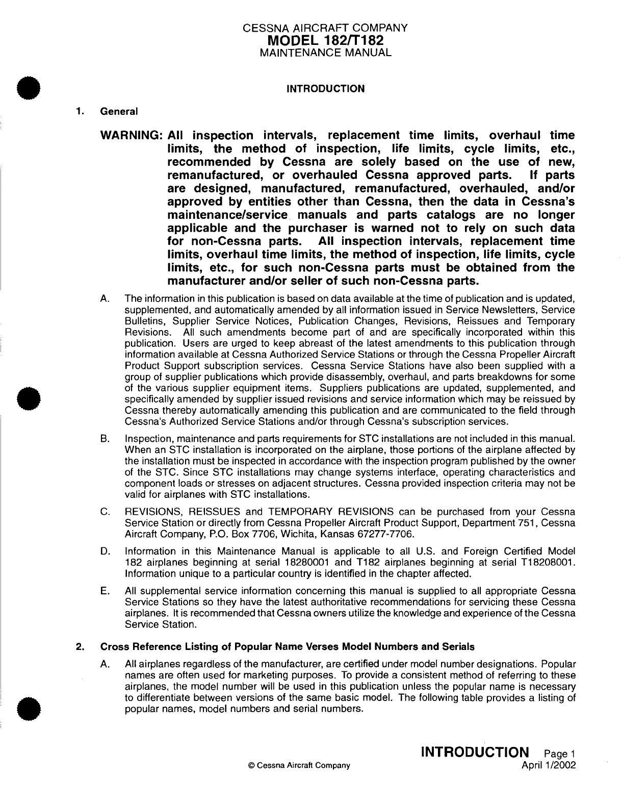
INTRODUCTION
1.
General
WARNING:
All
inspection
intervals,
replacement
time
limits,
overhaul
time
limits,
the
method
of
inspection,
life
limits,
cycle
limits,
etc.,
recommended
by Cessna
are
solely
based
on
the
use
of
new,
remanufactured,
or
overhauled
Cessna
approved
parts.
If
parts
are
designed,
manufactured, remanufactured,
overhauled,
and/or
approved
by
entities
other
than
Cessna,
then
the
data
in
Cessna's
maintenance/service
manuals
and
parts
catalogs
are
no
longer
applicable
and
the
purchaser
is
warned
not to
rely
on
such
data
for
non-Cessna parts.
All
inspection
intervals,
replacement
time
limits,
overhaul
time
limits,
the
method
of
inspection,
life
limits,
cycle
limits,
etc.,
for
such
non-Cessna
parts must
be
obtained
from
the
manufacturer and/or
seller
of
such
non-Cessna
parts.
A.
The information
in
this
publication
is
based
on
data
available
at
the time
of
publication
and
is
updated,
supplemented,
and
automatically
amended by
all
information
issued
in
Service
Newsletters, Service
Bulletins,
Supplier
Service
Notices,
Publication
Changes,
Revisions,
Reissues
and
Temporary
Revisions.
All
such
amendments become
part
of
and
are
specifically
incorporated within this
publication.
Users
are
urged to
keep
abreast
of
the latest amendments
to
this
publication
through
information
available
at
Cessna
Authorized
Service
Stations
or
through
the
Cessna
Propeller
Aircraft
Product
Support
subscription
services.
Cessna
Service Stations
have
also
been
supplied
with
a
group
of
supplier
publications
which
provide
disassembly,
overhaul, and
parts
breakdowns
for
some
of
the
various
supplier
equipment
items.
Suppliers
publications
are
updated,
supplemented,
and
specifically
amended
by
supplier
issued
revisions
and
service
information
which may
be
reissued
by
Cessna
thereby
automatically
amending
this publication
and
are
communicated
to
the
field
through
Cessna's
Authorized Service Stations
and/or
through
Cessna's subscription
services.
B.
Inspection,
maintenance
and
parts
requirements
for
STC
installations
are
not
included
in
this
manual.
When
an
STC
installation
is
incorporated
on
the
airplane,
those
portions
of
the
airplane
affected
by
the
installation
must
be
inspected
in
accordance
with
the
inspection
program
published
by
the
owner
of
the
STC.
Since
STC
installations
may
change
systems
interface, operating
characteristics
and
component
loads
or
stresses
on
adjacent structures.
Cessna
provided
inspection
criteria
may
not
be
valid
for
airplanes
with
STC
installations.
C.
REVISIONS,
REISSUES
and
TEMPORARY
REVISIONS
can
be
purchased
from
your
Cessna
Service Station
or
directly
from
Cessna Propeller Aircraft
Product Support,
Department
751,
Cessna
Aircraft Company,
P.O.
Box
7706,
Wichita,
Kansas
67277-7706.
D.
Information
in
this Maintenance
Manual
is
applicable
to
all
U.S.
and Foreign
Certified
Model
182
airplanes beginning
at
serial
18280001
and T182
airplanes
beginning
at
serial
T18208001.
Information unique
to
a
particular
country
is
identified
in
the
chapter
affected.
E.
All
supplemental
service
information
concerning this
manual
is
supplied
to
all
appropriate
Cessna
Service
Stations
so
they
have the
latest
authoritative
recommendations
for
servicing
these
Cessna
airplanes.
It is
recommended
that
Cessna
owners
utilize
the
knowledge
and
experience
of
the
Cessna
Service
Station.
2.
Cross
Reference
Listing
of
Popular
Name
Verses
Model Numbers
and
Serials
A.
All
airplanes regardless
of
the
manufacturer, are
certified
under
model
number
designations.
Popular
names
are
often
used
for
marketing
purposes.
To
provide
a
consistent
method
of
referring
to
these
airplanes,
the
model
number
will
be
used
in
this publication
unless
the
popular
name
is
necessary
to
differentiate
between
versions
of
the
same
basic
model.
The following
table
provides
a
listing
of
popular
names, model
numbers
and serial
numbers.
INTRODUCTION
Page
1
©
Cessna
Aircraft
Company
April
1/2002
CESSNA
AIRCRAFT
COMPANY
MODEL
182/T182
MAINTENANCE
MANUAL
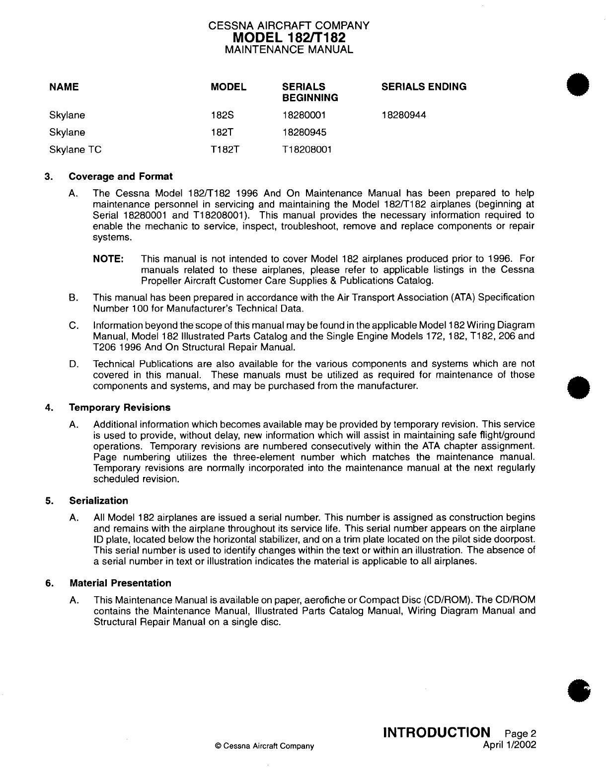
NAME
MODEL
SERIALS
SERIALS
ENDING
BEGINNING
Skylane
182S 18280001
18280944
Skylane
182T
18280945
Skylane
TC
T182T
T18208001
3.
Coverage
and Format
A.
The
Cessna
Model 182/T182
1996
And
On
Maintenance
Manual has been prepared
to
help
maintenance
personnel
in
servicing
and
maintaining
the Model
182/T182
airplanes
(beginning
at
Serial
18280001
and
T18208001).
This
manual
provides
the
necessary
information
required
to
enable the mechanic
to
service,
inspect, troubleshoot,
remove
and
replace
components
or
repair
systems.
NOTE:
This
manual
is
not
intended
to
cover
Model
182
airplanes produced
prior
to
1996.
For
manuals
related
to
these
airplanes,
please
refer
to
applicable
listings
in
the
Cessna
Propeller
Aircraft Customer
Care
Supplies
&
Publications
Catalog.
B.
This
manual
has been
prepared
in
accordance
with
the
Air
Transport
Association
(ATA)
Specification
Number
100
for Manufacturer's
Technical
Data.
C.
Information
beyond
the
scope
of
this
manual
may
be
found
in
the
applicable
Model
182
Wiring
Diagram
Manual,
Model
182
Illustrated
Parts
Catalog
and the
Single Engine
Models
172,
182,
T182,
206
and
T206
1996
And
On
Structural
Repair
Manual.
D.
Technical
Publications
are
also
available
for
the
various
components
and
systems
which
are
not
covered
in
this
manual.
These
manuals must
be
utilized
as
required
for
maintenance
of
those
components
and
systems,
and
may
be
purchased
from
the manufacturer.
4.
Temporary
Revisions
A.
Additional
information
which
becomes
available
may
be
provided
by
temporary
revision.
This
service
is
used
to
provide, without
delay,
new
information which
will
assist
in
maintaining
safe
flight/ground
operations.
Temporary
revisions
are
numbered
consecutively
within
the
ATA
chapter
assignment.
Page
numbering
utilizes
the
three-element
number
which matches
the
maintenance
manual.
Temporary
revisions
are
normally incorporated
into the
maintenance
manual
at
the next
regularly
scheduled
revision.
5.
Serialization
A.
All
Model
182
airplanes
are
issued
a
serial number.
This
number
is
assigned
as
construction
begins
and
remains with the
airplane
throughout
its
service
life.
This
serial number appears
on
the
airplane
ID
plate, located
below
the
horizontal
stabilizer,
and
on a
trim plate
located
on
the
pilot
side doorpost.
This serial number
is
used
to identify
changes
within
the
text
or
within
an
illustration.
The
absence
of
a
serial
number
in
text
or
illustration
indicates
the
material
is
applicable
to
all
airplanes.
6.
Material
Presentation
A.
This
Maintenance
Manual
is
available
on
paper,
aerofiche
or
Compact
Disc
(CD/ROM).
The
CD/ROM
contains
the Maintenance
Manual,
Illustrated
Parts
Catalog Manual, Wiring
Diagram Manual
and
Structural Repair
Manual
on
a
single
disc.
INTRODUCTION
Page
2
©
Cessna
Aircraft
Company
April
1/2002

CESSNA
AIRCRAFT
COMPANY
MODEL 182/T182
MAINTENANCE
MANUAL
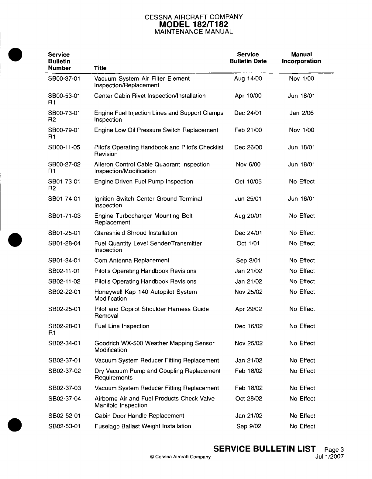
7.
Service
Bulletins
A.
Service
Bulletins
may
require
special
inspections
and
authorize
modifications
to
the
airplane
and/or
system.
As
service
bulletins
are
issued,
they
will
be
incorporated
in
the
next
scheduled
revision
and
noted
in
the
Service
Bulletin
List,
located
previous
to
the
Introduction.
The list
of
service
bulletins
utilizes
four
columns
to
summarize
information.
(1)
Service
Bulletin Number
-
This
Service
Bulletin number
column identifies
the
bulletin
by
number.
Service
Bulletins
are numbered
consecutively
within
ATA
chapter
assignment.
(2)
Service
Bulletin
Date
-
The
service
bulletin
date
column
indicates
the
initial
date
the
bulletin
became
active.
(3)
Title
-
The
title
column identifies
the
service
bulletin
by
nomenclature.
It is
the
same
title displayed
on
page
one
of the
service
bulletin.
(4)
Manual
Incorporation
-
The
manual
incorporation column
indicates
if
the
service
bulletin
has
been
incorporated
in
the
maintenance
manual
by
date,
if
the
service bulletin
had
no
effect
on
the
maintenance
manual
(No
Effect),
or
if
the
service bulletin
has
not
been
worked (dashed
lines).
8.
Using
the
Maintenance
Manual
A.
Division
of
Subject
Matter.
(1)
The
Maintenance
Manual
is
divided
into
four
major
sections.
The
major
sections
are
in
turn
separated
into
chapters,
with each
chapter
having
its
own
effectivity
page
and
table
of
contents.
The manual
divisions
are
as
follows:
(a)
Major
Section
1
-
Airplane
General
Chapter
Title
5
Time
Limits/Maintenance Checks
6
Dimensions
and
Areas
7
Lifting
and
Shoring
8
Leveling
and
Weighing
9
Towing and
Taxiing
10
Parking, Mooring,
Storage
and
Return
to
Service
11
Placards and
Markings
12
Servicing
(b)
Major Section
2
-
Airframe
Systems
Chapter
Title
20
Standard
Practices
-
Airframe
21
Air
Conditioning
22
Auto
Flight
23
Communications
24 Electrical
Power
25
Equipment/Furnishings
26
Fire
Protection
27 Flight
Controls
28
Fuel
INTRODUCTION
Page
3
©
Cessna
Aircraft
Company
April 1/2002
CESSNA AIRCRAFT
COMPANY
MODEL
182/T182
MAINTENANCE
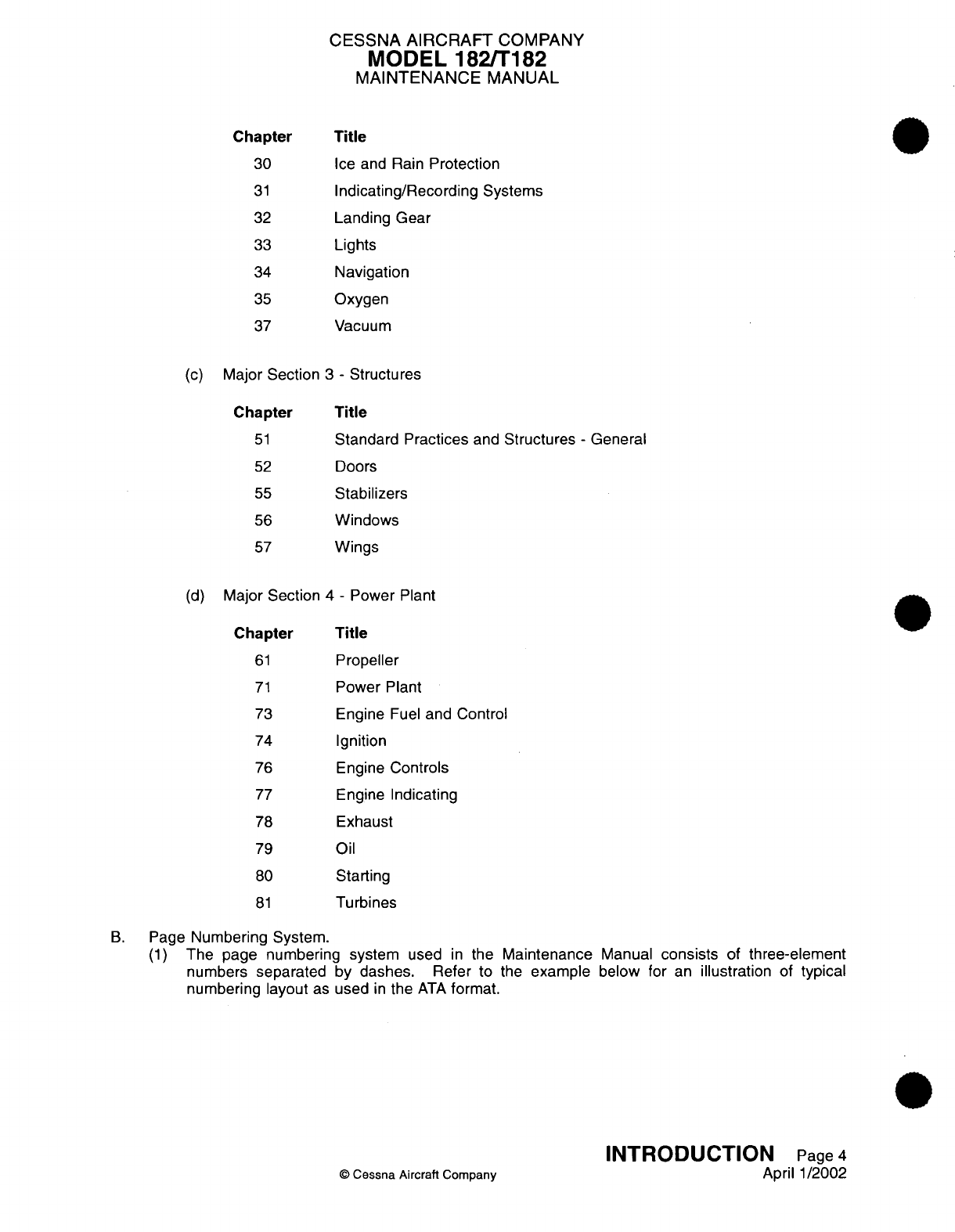
MANUAL
Chapter
Title
30
Ice
and
Rain
Protection
31
Indicating/Recording
Systems
32
Landing
Gear
33
Lights
34
Navigation
35
Oxygen
37
Vacuum
(c)
Major
Section
3
-
Structures
Chapter
Title
51
Standard Practices
and
Structures
-
General
52
Doors
55
Stabilizers
56
Windows
57
Wings
(d)
Major
Section
4
-
Power
Plant
Chapter
Title
61
Propeller
71
Power
Plant
73
Engine
Fuel
and
Control
74
Ignition
76
Engine
Controls
77
Engine
Indicating
78
Exhaust
79
Oil
80
Starting
81
Turbines
B.
Page
Numbering System.
(1)
The
page
numbering system
used
in
the
Maintenance
Manual
consists
of
three-element
numbers
separated
by
dashes.
Refer
to
the
example
below
for
an
illustration
of
typical
numbering layout
as
used
in
the
ATA
format.
INTRODUCTION
Page
4
©
Cessna
Aircraft
Company
April
1/2002

CESSNA
AIRCRAFT
COMPANY
MODEL
182/T182
MAINTENANCE
MANUAL
Chapter/System
22-10-00
Subject/Unit
(Auto
Flight)
(Auto
Pilot)
Section/Subsystem
(Auto
Pilot)
(2)
When
the
chapter/system
element
number
is
followed
with
zeros
in
the
section/subsystem
and
subject/unit
element
number (21-00-00), the information
is
applicable
to
the entire
system.
(3)
When
the
section/subsystem
element
number
is
followed
with
zeros
in
the
subject/unit
element
number
(21-51-00),
the information
is
applicable
to
the
subsystem
within
the system.
(4)
The
subject/unit
element number
is
used
to
identify
information
applicable
to units
within
the
subsystems.
The
subject/unit
element
number
progresses
sequentially
from
the
number
-01
in
accordance
with
the
number
of
subsystem
units
requiring
maintenance
information.
(5)
All
system/subsystem/unit
(chapter/section/subject)
maintenance
data
is
separated
into
specific
types
of
information:
description
and
operation, troubleshooting,
maintenance practices.
Blocks
of
sequential
page
numbers
are
used
to identify
the
type
of
information:
Page
1
through
99
-
Description
and
Operation
Page
101
through
199
-
Troubleshooting
Page
201
through
299
-
Maintenance
Practices
Page
301
through
399
-
Servicing
Page
401
through
499
-
Removal/Installation
Page
501
through
599
-
Adjustment/Test
Page
601
through
699
-
Inspection/Check
Page
701
through
799
-
Cleaning/Painting
Page
801
through
899
-
Approved
Repairs
NOTE:
In
most
cases,
the
individual
topics
have been
combined
into
a
200-series
document
(Maintenance
Practices).
When
specific topics
require
lengthy
explanation, they
will
utilize
the
page
blocks
mentioned
above.
(6) A
typical
page
number:
22-10-00
Page
202
Second
Page
of
Nov
3/97
Auto Pilot
Auto Flight
Auto
Pilot
Date
of
Page
Issue
Auto
Pilot
(7)
Illustrations
are
also
tied into
the
page
block
numbering
system.
For
example,
all
illustrations
within
a
Maintenance
Practices section will
begin
with
the number
2
(i.e.
Figure
201,
Figure
202,
etc.).
Conversely,
all
illustrations
within
an
Approved
Repair
section
will
begin
with
the
number
8
(i.e.
Figure
801,
Figure
802,
etc.).
INTRODUCTION
Page
5
©
Cessna
Aircraft Company
April
1/2002

CESSNA AIRCRAFT
COMPANY
MODEL
182/T182
MAINTENANCE
MANUAL
9.
Effectivity
Pages
A.
A
list of
effectivity
pages
are
provided
at
the
beginning
of
each
maintenance
manual
chapter.
All
pages
in
the
specific
chapter
are
listed
in
numerical
sequence
on
the
Effectivity
Page(s)
with
the date
of
issue
for
each
page.
10.
Revision
Filing
Instructions
A.
Regular Revision.
(1)
Pages
to
be
removed
or
inserted
in
the maintenance
manual
are
determined
by
the effectivity
page.
Pages
are
listed
in
sequence
by the
three-element
number
(chapter/section/subject)
and
then
by
page
number.
When two
pages
display
the
same
three-element
number
and
page
number,
the
page
with the
most
recent
Date
of
Page
Issue
shall
be
inserted
in
the
maintenance
manual.
The date
column
on
the
corresponding
chapter effectivity
page shall
verify
the
active
page.
B.
Temporary
Revision.
(1)
File
temporary
revisions
in
the
applicable chapter
in
accordance
with
filing
instructions
appearing
on
the
first
page
of
the temporary
revision.
(2)
The
rescission
of
a
temporary revision
is
accomplished
by
incorporation
into
the
maintenance
manual
or
by
a
superseding
temporary
revision.
A
Record
of
Temporary
Revisions
is
furnished
in
the
Temporary
Revision
List located
previous
to
the Introduction.
A
Manual
Incorporation
Date
column
on
the
Temporary Revision
List page
will
indicate
the
date
the
temporary
revision was
incorporated,
thus
authorizing
the
rescission
of
the
temporary
revision.
11.
Identifying
Revised
Material
A.
Additions
or
revisions
to
text
in
an
existing section
will
be
identified
by
a
revision
bar
in
the
left margin
of
the page and
adjacent
to
the
change.
B.
When
technical changes cause
unchanged
text
to appear
on
a
different
page(s),
a
revision
bar
will
be
placed
in
the
left margin
opposite the
chapter/section/subject,
page
number
and
date
of
all
affected
pages,
providing
no
other
revision
bar
appears
on
the
page.
These
pages will
display
the current
revision date
in
the Date of
Page Issue
location.
C.
Chapter
5
may
contain revision
bars to
indicate
revised
text.
However,
inspection
items are
noted
as
revised, added
or
deleted
by the
date
of
changed
item
code.
Also,
a
revision date
is
indicated
below
the
page number.
D.
When
extensive
technical
changes
are
made
to
text
in
an
existing
section
that
requires
extensive
revision, revision
bars
will
appear
the
full
length
of text.
E.
Revised and
new
illustrations
will
be
indicated
by
either
a
revision
bar
along
the
side
of
the
page
or
a
hand
indicator directing
attention
to
the area.
12.
Warnings,
Cautions
and
Notes
A.
Throughout
the
text
in
this
manual,
warnings,
cautions
and
notes
pertaining
to
the
procedures
being
accomplished
are
utilized. These
adjuncts
to
the
text
are
used
to
highlight
or
emphasize
important
points.
Warnings
and
Cautions
precede
the
text
they
pertain
to, and
Notes
follow
the
text
they
pertain
to.
(1)
WARNINGS
-
Calls attention
to
use of
materials,
processes,
methods,
procedures
or
limits
which
must
be
followed
precisely
to
avoid
injury
or death
to
persons.
(2)
CAUTIONS
-
Calls
attention
to
methods
and
procedures
which
must
be
followed
to
avoid
damage
to
airplane
and
equipment.
(3)
NOTES
-
Contains information
only.
INTRODUCTION
Page
6
0
Cessna
Aircraft
Company
April
1/2002
CESSNA
AIRCRAFT
COMPANY
MODEL
182/T182
MAINTENANCE
MANUAL
13.
Cessna
Propeller
Aircraft
Customer
Care
Supplies
and
Publications
Catalog
A.
A
Cessna Propeller
Aircraft Customer
Care
Supplies
and
Publications
Catalog
is
available
from
a
Cessna
Service
Station
or
directly
from
Cessna Propeller Aircraft Product
Support
Dept.
751
Cessna
Aircraft
Company,
P.O.
Box
7706,
Wichita,
Kansas
67277-7706. The
catalog lists all
publications
and
Customer
Care
Supplies available
from
Cessna
for
prior
year
models
as
well
as
new
products.
To
maintain
this catalog
in
a
current status,
it
is
revised
yearly
and
issued
in
paper and
aerofiche
form.
14.
Customer
Comments
on
Manual
A.
Cessna
Aircraft Company
has
endeavored
to
furnish
you with
an
accurate,
useful,
up-to-date
manual.
This
manual
can
be
improved with
your
help.
Please
use the return
card, provided with
your
manual,
to
report
any
errors,
discrepancies,
and
omissions
in
this
manual
as
well
as
any
general
comments
you
wish
to
make.
INTRODUCTION
Page
7
©
Cessna
Aircraft
Company
April 1/2002
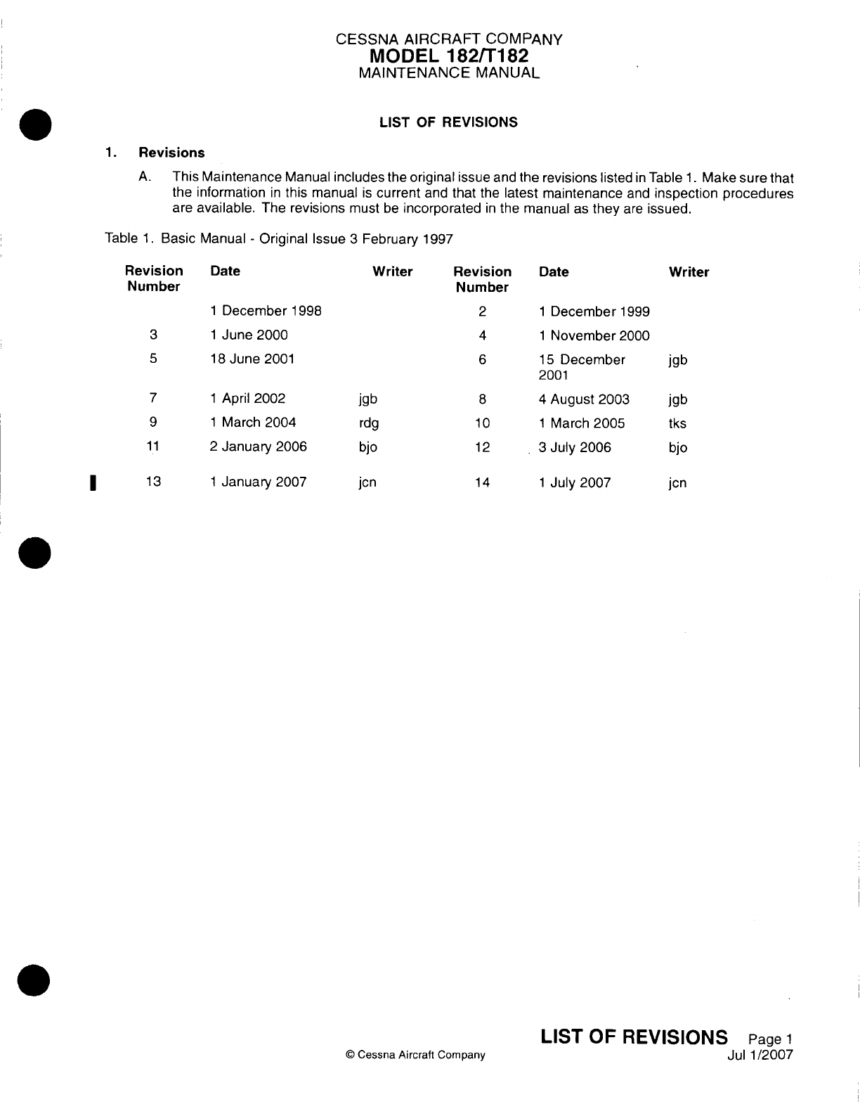
CESSNA AIRCRAFT
COMPANY
MODEL
182/Ti
82
MAINTENANCE
MANUAL
LIST
OF
REVISIONS
1.Revisions
A.
This
Maintenance
Manual
includes
the
original
issue
and
the
revisions
listed
in
Table
1.
Make
sure
that
the
information
in
this manual
is
current
and
that
the
latest maintenance
and
inspection
procedures
are
available.
The
revisions
must
be
incorporated
in
the
manual
as
they
are
issued.
Table
1.
Basic
Manual
-
Original
Issue
3
February
1997
Date
Writer
1
December
1998
3 1
June 2000
5
l8
June
2001
1
April
2002
1
March
2004
1 1 2
January
2006
1
13
1
January
2007
Revision
Number
2
Date
Writer
1
December
1999
4 1
November
2000
6
15
December
2001
8 4
August
2003
1 0 1
March
2005
12
3
July
2006
jgb
rdg
bjo
jcn
1
4
1
July
2007
©D
Cessna
Aircraft
Company
jgb
jgb
tks
bjo
jcn
LIST
OF
REVISIONS
Page
1
Jul
1/2007
Revision
Number
7
9
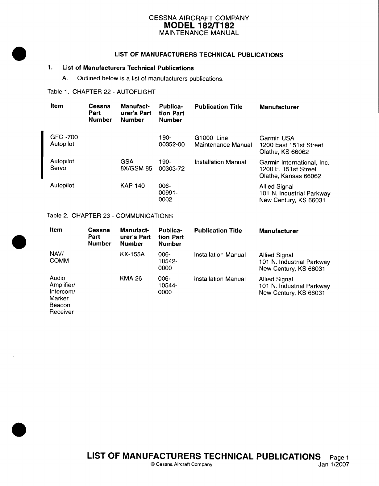
CESSNA AIRCRAFT
COMPANY
MODEL
182/Ti
82
MAINTENANCE
MANUAL
LIST
OF
MANUFACTURERS
TECHNICAL
PUBLICATIONS
1.
List
of
Manufacturers Technical
Publications
A.
Outlined
below
is a
list
of
manufacturers
publications.
Table
1.
CHAPTER
22
-
AUTOFLIGHT
Publica-
tion
Part
N
umber
Publication
Title
190-
G1000 Line
00352-00
Maintenance
Manual
GSA
190-
8X/GSM
85
00303-72 Installation
Manual
KAP
140
006-
00991-
0002
Manufacturer
Garmin
USA
1200
East
1
51
st
Street
Olathe,
KS
66062
Garmin
International,
Inc.
1200
E.
151st
Street
Olathe, Kansas
66062
Allied
Signal
101
N.
Industrial Parkway
New
Century,
KS
66031
Table
2.
CHAPTER
23
-
COMMUNICATIONS
Publication
Title
Manufacturer
KX-155A
006-
10542-
0000
KMA
26
006-
10544-
0000
Installation
Manual
Installation
Manual
Allied
Signal
101
N.
Industrial
Parkway
New
Century,
KS
66031
Allied
Signal
101
N.
Industrial
Parkway
New Century,
KS
66031
LIST
OF
MANUFACTURERS
TECHNICAL PUBLICATIONS
Page
1
©
Cessna
Aircraft
Company
Janl1/2007
Item
Cessna
Part
Number
Manufact-
urer's
Part
Number
GFC
-700
Autopilot
Autopilot
Servo
Autopilot
Item
Cessna
Part
Number
Manufact-
urer's
Part
Number
NAV/
Comm
Publica-
tion
Part
Number
Audio
Amplifier/
Intercom/
Marker
Beacon
Receiver
Item
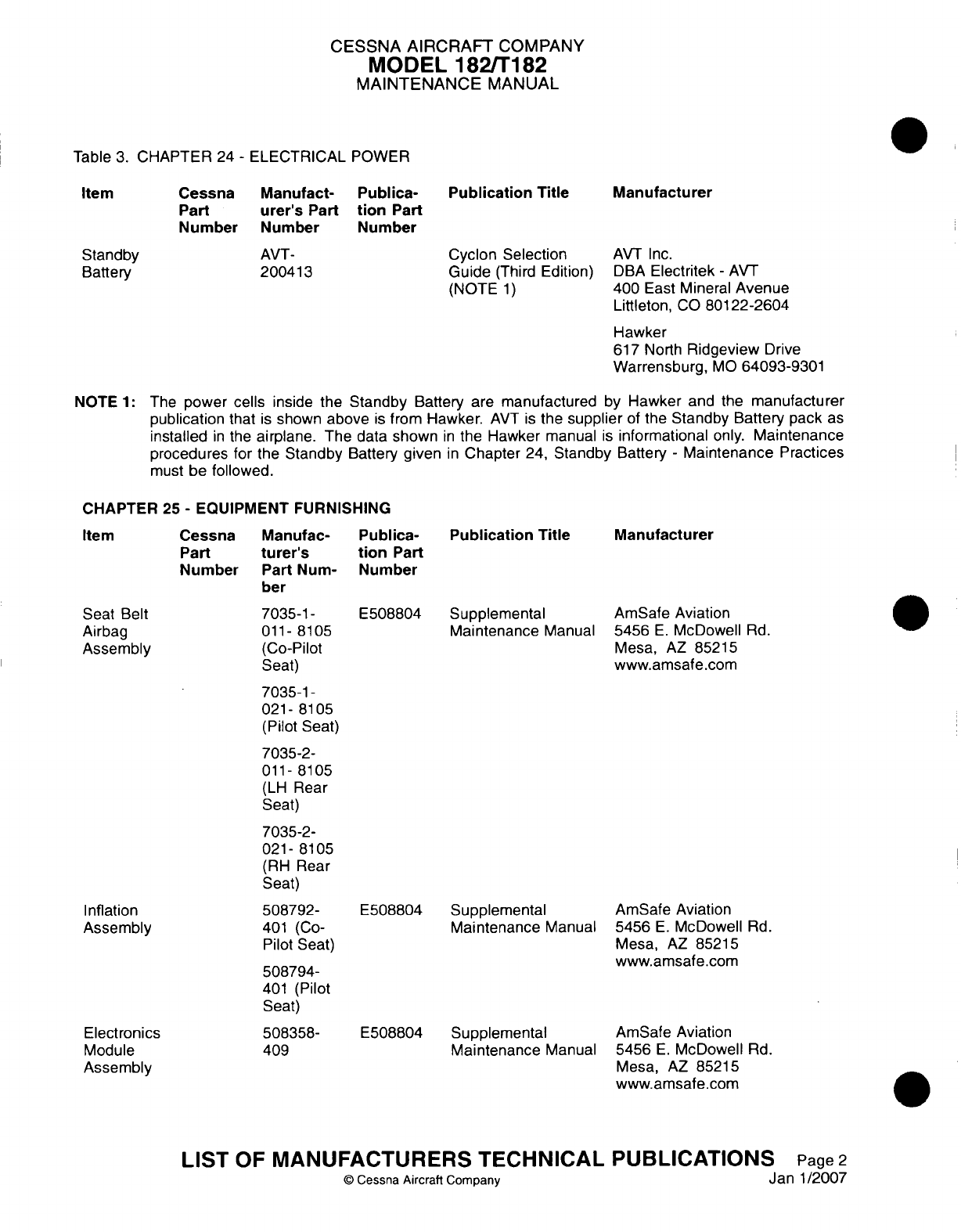
CESSNA AIRCRAFT
COMPANY
MODEL
182/Ti
182
MAINTENANCE
MANUAL
Table
3.
CHAPTER
24
-
ELECTRICAL
POWER
Publication
Title
Cyclon
Selection
Guide
(Third
Edition)
(NOTE
1)
Manufacturer
AVT
Inc.
DBA
Electritek
-
AVT
400 East Mineral
Avenue
Littleton,
CO
80122-2604
Hawker
617
North
Ridgeview
Drive
Warrensburg,
MO
64093-9301
NOTE
1:
The
power cells
inside the
Standby
Battery
are
manufactured
by
Hawker
and
the
manufacturer
publication
that
is
shown
above
is
from
Hawker.
AVT
is
the
supplier
of
the
Standby Battery
pack
as
installed
in
the
airplane.
The
data
shown
in
the
Hawker
manual
is
informational
only.
Maintenance
procedures
for
the
Standby
Battery
given
in
Chapter
24,
Standby
Battery
-
Maintenance Practices
must
be
followed.
CHAPTER 25
-
EQUIPMENT
FURNISHING
Publica-
tion
Part
Number
Publication
Title
E508804 Supplemental
Maintenance
Manual
E508804 Supplemental
Maintenance
Manual
E508804
Supplemental
Maintenance
Manual
Manufacturer
AmSafe
Aviation
5456
E.
McDowell
Rd.
Mesa,
AZ
85215
www.amsafe.com
AmSafe
Aviation
5456
E.
McDowell
Rd.
Mesa,
AZ
85215
www.amsafe.com
AmSafe
Aviation
5456
E.
McDowell
Rd.
Mesa,
AZ
85215
www.amsafe.com
LIST
OF
MANUFACTURERS
TECHNICAL PUBLICATIONS
©
Cessna
Aircraft
Company
Item
Cessna
Part
Number
Standby
Battery
Manufact-
urer's
Part
Number
AVT-
200413
Publica-
tion
Part
Number
Item
Cessna
Part
Number
Manufac-
turer's
Part
Num-
ber
7035-1
-
011-
8105
(GO-Pilot
Seat)
7035-1
-
021-
8105
(Pilot
Seat)
7035-2-
011-
8105
(LH
Rear
Seat)
7035-2-
021-
8105
(RH
Rear
Seat)
508792-
401 (Co-
Pilot
Seat)
508794-
401
(Pilot
Seat)
508358-
409
Seat
Belt
Airbag
Assembly
Inflation
Assembly
Electronics
Module
Assembly
Page
2
an
1/2007
J
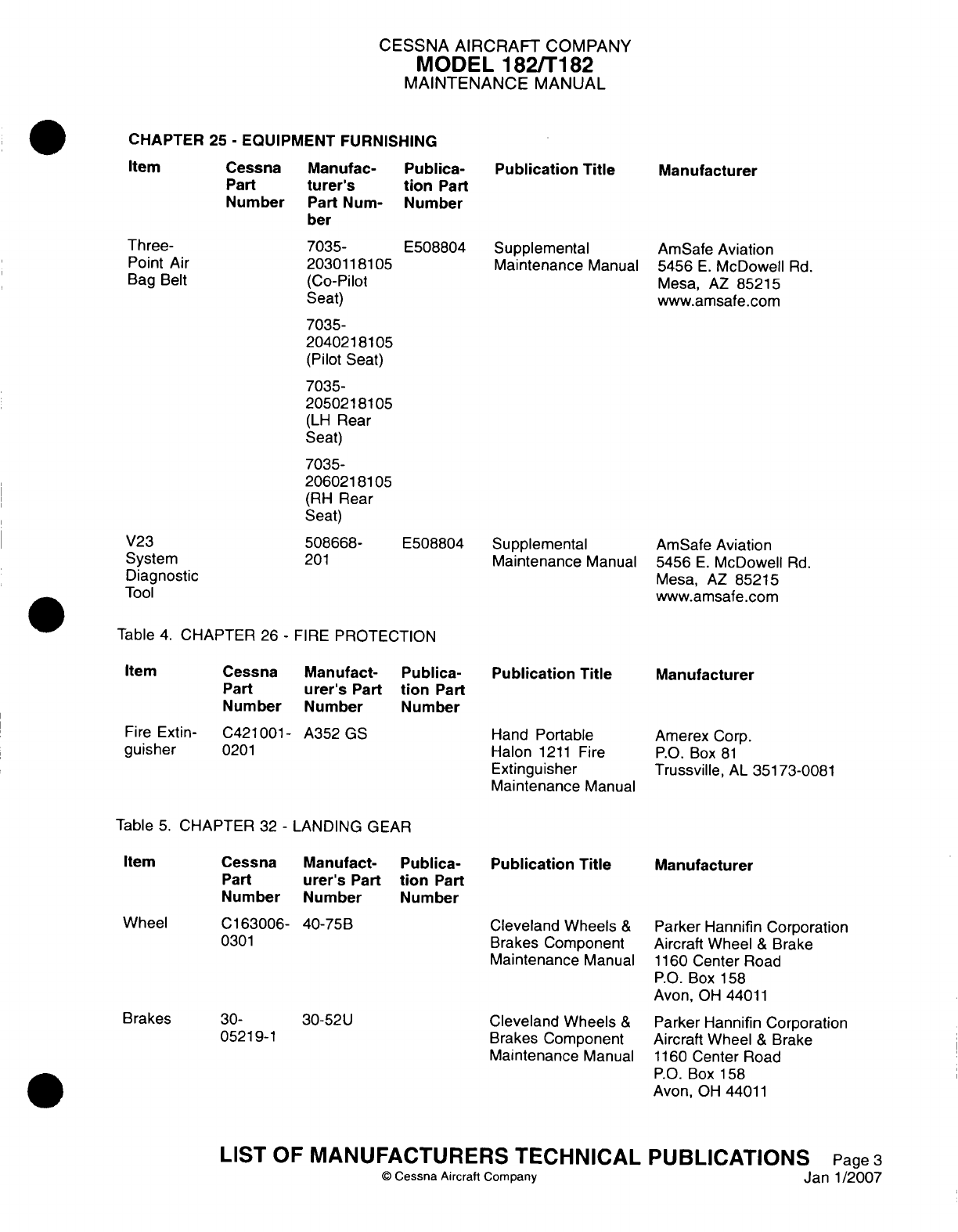
CESSNA
AIRCRAFT
COMPANY
MODEL
182/Ti
182
MAINTENANCE
MANUAL
CHAPTER
25
-
EQUIPMENT FURNISHING
Publication
Title
Manufacturer
7035-
20301181
05
(Co-Pilot
Seat)
7035-
2040218105
(Pilot
Seat)
7035-
205021
8105
(LH
Rear
Seat)
7035-
206021
81
05
(RH
Rear
Seat)
508668-
201
E508804
Supplemental
Maintenance
Manual
E508804
Supplemental
Maintenance
Manual
AmSafe
Aviation
5456
E.
McDowell
Rd.
Mesa,
AZ
85215
www.amsafe.com
AmSafe
Aviation
5456
E.
McDowell
Rd.
Mesa,
AZ
85215
www.amsafe.com
Table
4.
CHAPTER
26
-
FIRE
PROTECTION
Publication
Title
Manufacturer
Fire
Extin- C421001-
A352
GS
guisher
0201
Hand
Portable
Halon
1211
Fire
Extinguisher
Maintenance
Manual
Amerex
Corp.
P.O.
Box
81
Trussville,
AL
351
73-0081
Table
5.
CHAPTER
32
-
LANDING
GEAR
Cessna
Part
Number
Manufact-
urer's
Part
Number
Publica-
tion
Part
Number
C163006-
40-75B
0301
30-
0521
9-1
30-52U
Publication
Title
Cleveland Wheels
&
Brakes
Component
Maintenance
Manual
Cleveland
Wheels
&
Brakes
Component
Maintenance
Manual
Manufacturer
Parker Hannifin Corporation
Aircraft
Wheel
&
Brake
1160
Center
Road
P.O.
Box
158
Avon,
OH
44011
Parker Hannifin
Corporation
Aircraft
Wheel
&
Brake
1160
Center
Road
P.O.
Box
158
Avon,
OH 44011
LIST
OF
MANUFACTURERS TECHNICAL
©
Cessna Aircraft
Company
PUBLICATIONS
Page
3
Janl1/2007
Part
Number
Man
ufac-
turer's
Part
Num-
ber
Publica-
tion
Part
Number
Three-
Point
Air
Bag
Belt
V23
System
Diagnostic
Tool
Item
Cessna
Part
Number
Manufact-
urer's
Part
Number
Publica-
tion
Part
Number
Item
Wheel
Brakes
Item
Item
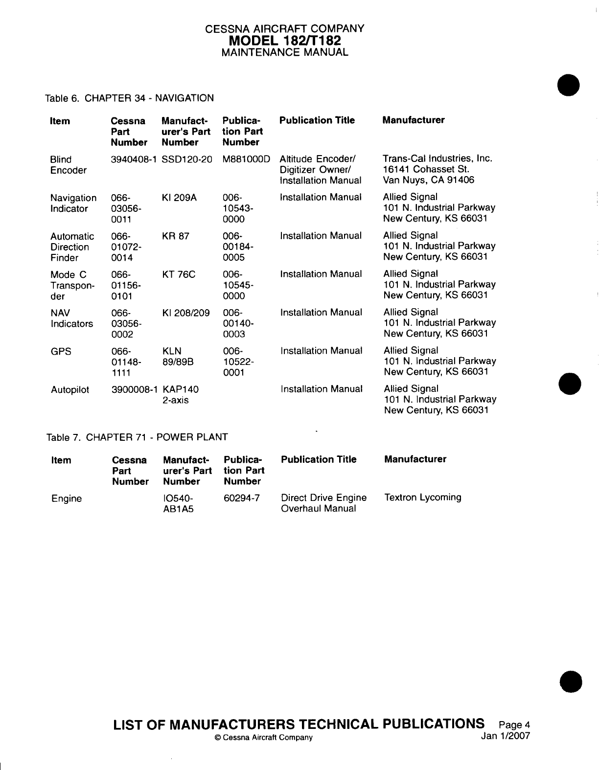
CESSNA
AIRCRAFT
COMPANY
MODEL
182/T
182
MAINTENANCE
MANUAL
Table
6.
CHAPTER
34
-
NAVIGATION
Item
Blind
Encoder
Cessna
Part
Number
Manufact-
urer's
Part
Number
3940408-1
SSD1
20-20
Navigation
066-
Indicator
03056-
0011
Automatic
Direction
Finder
Mode
C
Transpon-
der
066-
01
072-
0014
066-
01156-
0101
NAV
066-
Indicators
03056-
0002
GPS
066-
01148-
1111
Publica-
tion
Part
Number
Publication
Title
M881000D Altitude Encoder/
Digitizer
Owner/
Installation
Manual
KI
209A
006-
10543-
0000
KR
87
006-
001
84-
0005
KT
76C
006-
10545-
0000
KI
208/209
006-
00140-
0003
KLN
89/89B
Autopilot
3900008-1
KAP140
2-axis
006-
10522-
0001
Installation
Manual
Installation
Manual
Installation
Manual
Installation
Manual
Installation
Manual
Installation
Manual
Manufacturer
Trans-Cal
Industries,
Inc.
16141
Cohasset
St.
Van
Nuys,
CA
91406
Allied
Signal
101
N.
Industrial
Parkway
New
Century,
KS
66031
Allied
Signal
101
N.
Industrial
Parkway
New
Century,
KS
66031
Allied
Signal
101
N.
Industrial
Parkway
New
Century,
KS
66031
Allied
Signal
101
N.
Industrial Parkway
New
Century,
KS
66031
Allied
Signal
101
N.
Industrial Parkway
New
Century,
KS
66031
Allied
Signal
101
N.
Industrial
Parkway
New Century,
KS
66031
Table
7.
CHAPTER
71
-
POWER PLANT
Publica-
Publication
Title
tion
Part
Number
60294-7
Direct
Drive
Engine
Overhaul
Manual
Manufacturer
Textron
Lycoming
LIST
OF
MANUFACTURERS
TECHNICAL
PUBLICATIONS
Item
Cessna
Part
Number
Engine
Manufact-
urer's
Part
N
umber
10540-
AB1A5
Page
4
an
1/2007
i
Q
Cessna
Aircraft
Company
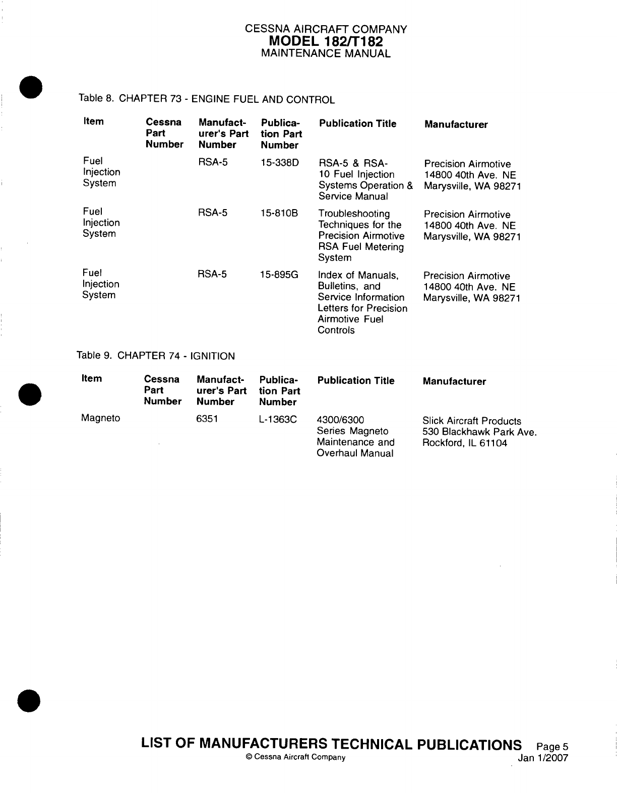
CESSNA
AIRCRAFT
COMPANY
MODEL
182/Ti
182
MAINTENANCE
MANUAL
Table
8.
CHAPTER
73
-
ENGINE
FUEL
AND
CONTROL
Publica-
tion
Part
Number
Publication
Title
1
5-338D
RSA-5
&
RSA-
10
Fuel
Injection
Systems Operation
&
Service
Manual
15-81
OB
Troubleshooting
Techniques for
the
Precision
Airmotive
RSA
Fuel
Metering
System
15-895G
Index
of
Manuals,
Bulletins,
and
Service
Information
Letters
for
Precision
Airmotive
Fuel
Controls
Manufacturer
Precision
Airmotive
14800
40th
Ave.
NE
Marysville,
WA
98271
Precision
Airmotive
14800
40th
Ave.
NE
Marysville,
WA
98271
Precision
Airmotive
14800
40th
Ave.
NE
Marysville,
WA
98271
Table
9.
CHAPTER
74
-
IGNITION
Publica-
tion
Part
Number
Publication
Title
L-1363C
4300/6300
Series
Magneto
Maintenance
and
Overhaul
Manual
Manufacturer
Slick
Aircraft
Products
530
Blackhawk Park
Ave.
Rockford,
IL
61104
LIST
OF
MANUFACTURERS
TECHNICAL PUBLICATIONS
Page5
©
Cessna
Aircraft
Company
Janl1/2007
Item
Cessna
Part
Number
Fuel
Injection
System
Fuel
Injection
System
Fuel
Injection
System
Manufact-
urer's
Part
Number
RSA-5
RSA-5
RSA-5
Item
Cessna
Part
Number
Magneto
Manufact-
urer's
Part
Number
6351
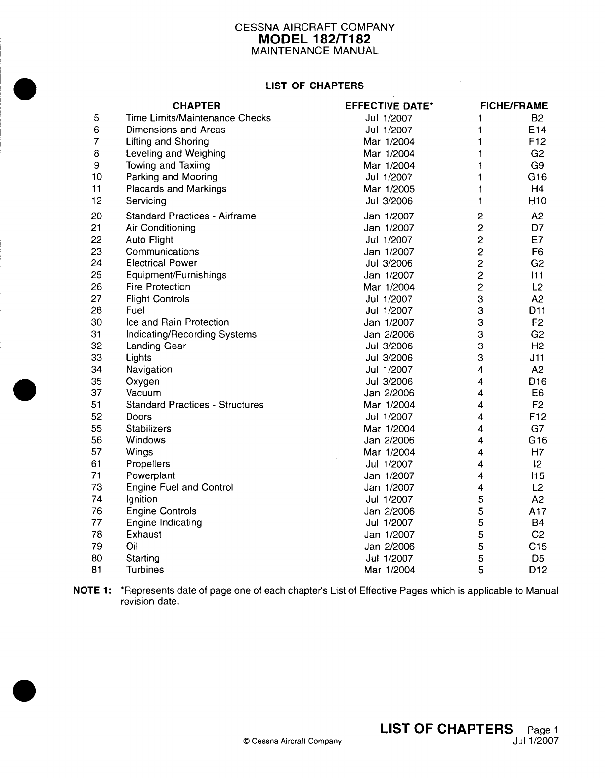
CESSNA AIRCRAFT
COMPANY
MODEL
182/Ti
82
MAINTENANCE
MANUAL
LIST
OF
CHAPTERS
CHAPTER
Time
Limits/Maintenance
Checks
Dimensions
and
Areas
Lifting and
Shoring
Leveling
and
Weighing
Towing
and Taxiing
Parking
and
Mooring
Placards
and
Markings
Servicing
Standard
Practices
-
Airframe
Air
Conditioning
Auto
Flight
Communications
Electrical
Power
Equipment/Furnishings
Fire
Protection
Flight
Controls
Fuel
Ice
and
Rain
Protection
Indicating/Recording
Systems
Landing Gear
Lights
Navigation
Oxygen
Vacuum
Standard
Practices
-
Structures
Doors
Stabilizers
Windows
Wings
Propellers
Powerplant
Engine
Fuel
and
Control
Ignition
Engine
Controls
Engine
Indicating
Exhaust
Oil
Starting
Turbines
EFFECTIVE
DATE*
Jul
1/2007
Jul
1/2007
Mar
1/2004
Mar
1/2004
Mar
1/2004
Jul
1/2007
Mar
1/2005
Jul 3/2006
Jan
1/2007
Jan
1/2007
Jul
1/2007
Jan
1/2007
Jul 3/2006
Jan
1/2007
Mar 1/2004
Jul
1/2007
Jul
1/2007
Jan
1/2007
Jan 2/2006
Jul
3/2006
Jul 3/2006
Jul
1/2007
Jul 3/2006
Jan 2/2006
Mar
1/2004
Jul
1/2007
Mar
1/2004
Jan
2/2006
Mar
1/2004
Jul
1/2007
Jan
1/2007
Jan
1/2007
Jul 1/2007
Jan
2/2006
Jul 1/2007
Jan
1/2007
Jan
2/2006
Jul
1/2007
Mar 1/2004
FICHE/FRAME
1 B2
1
E14
1
F12
1 G2
1 G9
1
G16
1 H4
1
H10
2
A2
2 D7
2 E7
2 F6
2
G2
2
Ill
2
L2
3
A2
3
Dll
3 F2
3 G2
3 H2
3
Jill
4
A2
4
D16
4 E6
4 F2
4
F12
4 G7
4
G16
4 H7
4 12
4
115
4
L2
5 A2
5
A17
5
B4
5
C2
5
C15
5 D5
5
D12
NOTE
1:
*Represents date
of
page
one
of
each
chapter's
List
of
Effective Pages
which
is
applicable
to
Manual
revision
date.
LIST
OF
CHAPTERS
Page
1
©
Cessna
Aircraft
Company
Jul
1/2007
5
6
7
8
9
10
1
1
1
2
20
21
22
23
24
25
26
27
28
30
31
32
33
34
35
37
51
52
55
56
57
61
71
73
74
76
77
78
79
80
81
CHAPTER
TIME
LIMITS/
MAINTENANCE
CHECKS

CESSNA AIRCRAFT
COMPANY
MODEL
182/Ti
82
MAINTENANCE
MANUAL
LIST
OF
EFFECTIVE
PAGES
CHAPTER-SECTION-SUBJECT
05-Title
05-List
of Effective
Pages
05-Record
of
Temporary
Revisions
05-Table
of
Contents
5-00-00
5-00-10
5-10-00
5-1
0-01
5-11-00
5-12-00
5-12-0
1
5-1
2-02
5-12-03
5-12-04
5-1
2-05
5-12-06
5-12-07
5-1
2-08
5-1
2-09
5-12-10
5-12-11
5-12-13
5-12-14
5-12-15
5-12-16
5-12-17
5-12-18
5-12-19
5-12-20
5-12-2
1
5-1
2-22
5-1
2-23
5-12-24
5-1
2-25
5-12-26
5-50-00
Q
Cessna
Aircraft Company
05
-
LIST
OF
EFFECTIVE
PAGES
Page
1
of
1
Jul
1/2007
PAGE
Pages
1-2
Page
1
Pages
1-2
Pages
1-17
Pages
1-3
Pages
1-2
Pages
1-7
Pages
1-6
Pages
1-7
Pages
1-5
Page
1
Page
1
Page
1
Page
1
Page
1
Page
1
Page
1
Page
1
Page
1
Page
1
Page
1
Page
1
Page
1
Page
1
Page
1
Page
1
Page
1
Page
1
Page
1
Page
1
Page
1
Pages
1-5
DATE
Jul
1/2007
Mar
1/2004
Jul
3/2006
Jul
3/2006
Jul
1/2007
Jul
1/2007
Jul
3/2006
Jul
3/2006
Jul
3/2006
Jul 3/2006
Jul 3/2006
April
1/2002
Jul
3/2006
April 1/2002
Jul
3/2006
Jul
3/2006
Jul
3/2006
April
1/2002
Jul 3/2006
Jul
3/2006
Jul
3/2006
Jul
3/2006
Jul
3/2006
Jul
3/2006
Jul
3/2006
Jul
3/2006
Jul
3/2006
Jul
3/2006
Jul
3/2006
Jul
3/2006
Jul
3/2006
Jan
2/2006
Temporary
Revision
Number
RECORD
OF
TEMPORARY
REVISIONS
Page
Number
Issue
Date
By
Date
Removed
By
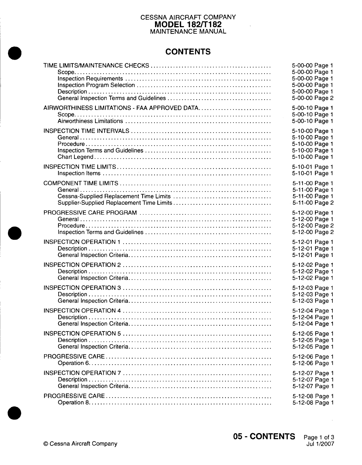
CESSNA
AIRCRAFT
COMPANY
MODEL
182/Ti
82
MAINTENANCE
MANUAL
CONTENTS
TIME
LIMITS/MAINTENANCE
CHECKS
......................
Scope....................................
Inspection
Requirements...........................
Inspection
Program
Selection.........................
Description
.................................
General Inspection
Terms and
Guidelines
...................
AIRWORTHINESS
LIMITATIONS
-
FAA
APPROVED
DATA..............
Scope....................................
Airworthiness
Limitations...........................
INSPECTION
TIME
INTERVALS..........................
General...................................
Procedure..................................
Inspection
Terms
and
Guidelines
.......................
Chart Legend
................................
INSPECTION
TIME
LIMITS
............................
Inspection
Items...............................
COMPONENT
TIME
LIMITS............................
General...................................
Cessna-Supplied Replacement
Time
Limits
..................
Supplier-Supplied Replacement
Time Limits
..................
PROGRESSIVE
CARE
PROGRAM
........................
General...................................
Procedure..................................
Inspection
Terms and
Guidelines
.......................
INSPECTION
OPERATION
1 ...........................
Description
.................................
General
Inspection
Criteria
..........................
INSPECTION
OPERATION
2 ...........................
Description
.................................
General
Inspection Criteria
..........................
INSPECTION
OPERATION
3 ...........................
Description
.................................
General Inspection
Criteria
..........................
INSPECTION OPERATION
4 ...........................
Description
.................................
General Inspection
Criteria
..........................
INSPECTION OPERATION
S ...........................
Description
.................................
General
Inspection
Criteria
..........................
PROGRESSIVE
CARE
..............................
Operation
6 .................................
INSPECTION
OPERATION
7
...........................
Description
.................................
General
Inspection Criteria
..........................
PROGRESSIVE
CARE
..............................
Operation
8 .................................
5-00-00
Page
1
5-00-00
Page
1
5-00-00
Page
1
5-00-00
Page
1
5-00-00
Page
1
5-00-00
Page
2
5-00-10
Page
1
5-00-10
Page
1
5-00-10
Page
1
5-10-00
Page
1
5-10-00
Page
1
5-10-00
Page
1
5-10-00
Page
1
5-1
0-00
Page
1
5-1
0-01
Pagel1
5-1
0-01
Page
1
5-11
-00
Page
1
5-11
-00
Page
1
5-11
-00
Page
1
5-11
-00
Page
2
5-12-00
Page
1
5-12-00
Page
1
5-12-00
Page
2
5-12-00
Page
2
5-12-01
Page
1
5-12-01
Page
1
5-12-01
Page
1
5-12-02
Page
1
5-12-02
Page
1
5-12-02
Page
1
5-12-03
Page
1
5-12-03
Page
1
5-12-03
Page
1
5-12-04
Page
1
5-12-04
Page
1
5-12-04
Page
1
5-12-05
Page
1
5-12-05
Page
1
5-12-05
Page
1
5-12-06
Page
1
5-12-06
Page
1
5-12-07
Page
1
5-12-07
Page
1
5-1
2-07
Page
1
5-12-08
Page
1
5-12-08
Page
1
05
-
CONTENTS
Page
1
of
3
Jul
1/2007
©
Cessna
Aircraft
Company
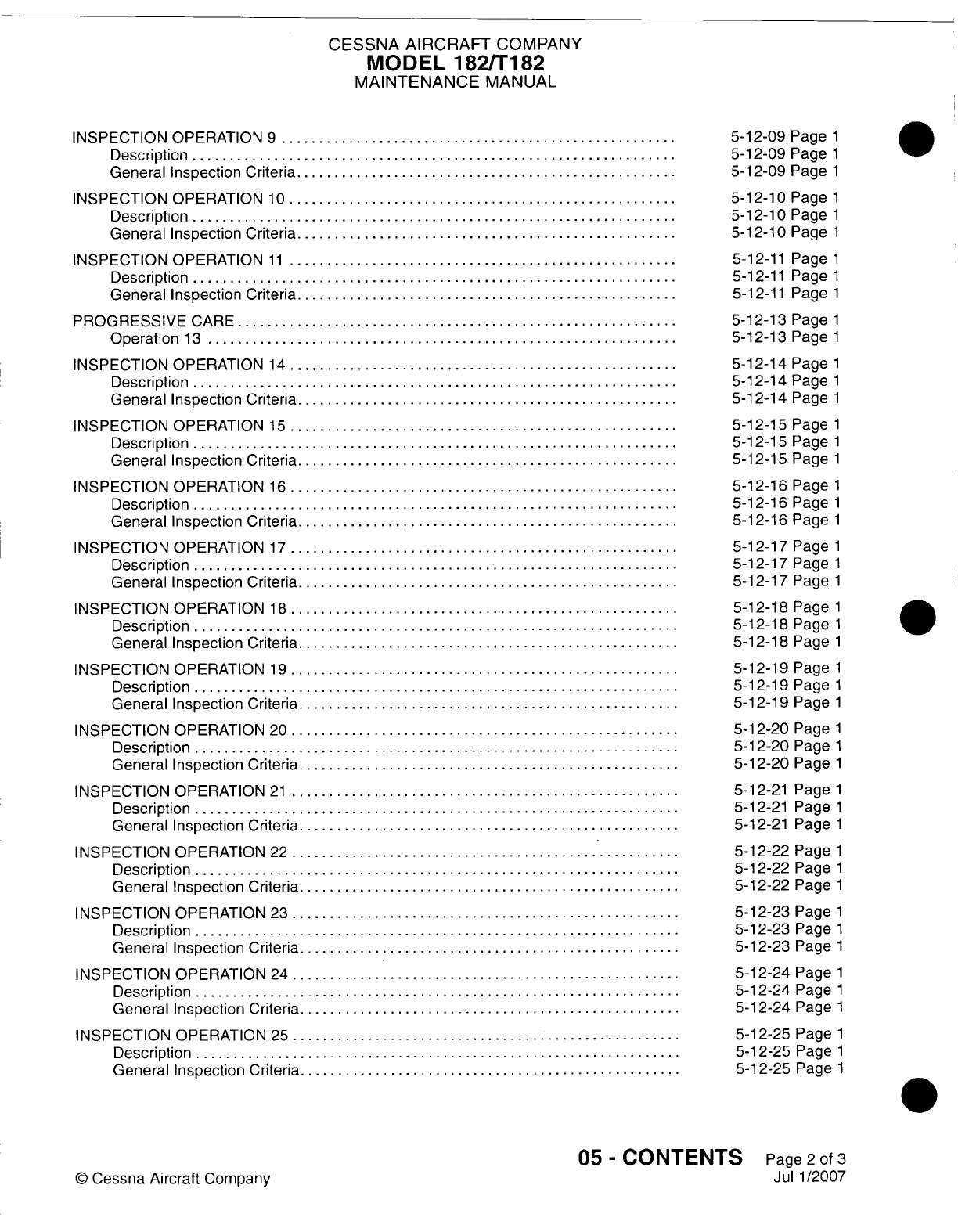
CESSNA
AIRCRAFT
COMPANY
MODEL
182/T182
MAINTENANCE
MANUAL
INSPECTION
OPERATION
9 ...........................
Description
............
General Inspection
Criteria
..........................
INSPECTION
OPERATION
10...........................
Description
.................................
General Inspection
Criteria
..........................
INSPECTION OPERATION
11...........................
Description
.................................
General Inspection
Criteria
..........................
PROGRESSIVE
CARE
..............................
Operation
13
................................
INSPECTION OPERATION
14...........................
Description
.................................
General Inspection
Criteria
..........................
INSPECTION
OPERATION
15...........................
Description
.................................
General Inspection
Criteria
..........................
INSPECTION OPERATION
16...........................
Description
.................................
General Inspection
Criteria
..........................
INSPECTION
OPERATION
17...........................
Description
.................................
General Inspection
Criteria
..........................
INSPECTION OPERATION
18...........................
Description
.................................
General Inspection
Criteria
..........................
INSPECTION OPERATION
19...........................
Description
.................................
General Inspection
Criteria
..........................
INSPECTION
OPERATION
20...........................
Description
.................................
General Inspection
Criteria
..........................
INSPECTION OPERATION
21...........................
Description
.................................
General Inspection
Criteria
..........................
INSPECTION OPERATION
22
...........................
Description
.................................
General
Inspection
Criteria
..........................
INSPECTION OPERATION
23...........................
Description
.................................
General Inspection
Criteria
..........................
INSPECTION OPERATION
24...........................
Description
.................................
General Inspection
Criteria
..........................
INSPECTION
OPERATION
25...........................
Description
.................................
General Inspection
Criteria
..........................
5-12-09
Page
1
5-12-09
Page
1
5-12-09
Page
1
5-12-10
Page
1
5-12-10
Page
1
5-12-10
Page
1
5-12-11
Page
1
5-12-11
Page
1
5-12-11
Page
1
5-12-13
Page
1
5-12-13
Page
1
5-12-14
Page
1
5-12-14
Page
1
5-12-14
Page
1
5-12-15
Page
1
5-12-15
Page
1
5-12-15
Page
1
5-12-16
Page
1
5-12-16
Page
1
5-12-16
Page
1
5-12-17
Page
1
5-12-17
Page
1
5-12-17
Page
1
5-12-18
Page
1
5-12-18
Page
1
5-12-18
Page
1
5-12-19
Page
1
5-12-19
Page
1
5-12-19
Page
1
5-12-20
Page
1
5-12-20
Page
1
5-12-20
Page
1
5-12-21
Page
1
5-12-21
Page
1
5-12-21
Page
1
5-12-22
Page
1
5-12-22
Page
1
5-12-22
Page
1
5-12-23
Page
1
5-12-23
Page
1
5-12-23
Page
1
5-12-24
Page
1
5-12-24
Page
1
5-12-24
Page
1
5-12-25
Page
1
5-12-25
Page
1
5-12-25
Page
1
05
-
CONTENTS
Page
2
of
3
Jul
1/2007
©
Cessna
Aircraft
Company
CESSNA AIRCRAFT
COMPANY
MODEL
182/Ti
82
MAINTENANCE
MANUAL
INSPECTION
OPERATION
26...........................
Description
.................................
General
Inspection Criteria
..........................
UNSCHEDULED
MAINTENANCE
CHECKS
....................
General...................................
Unscheduled
Maintenance
Checks
Defined
and
Areas
of
Inspection
.......
5-12-26
Page
1
5-12-26
Page
1
5-12-26
Page
1
5-50-00
Page
1
5-50-00
Page
1
5-50-00
Page
1
05
-
CONTENTS
Page
3
of
3
Jul
1/2007
©
Cessna
Aircraft Company

CESSNA
AIRCRAFT
COMPANY
MODEL
182/Ti
82
MAINTENANCE
MANUAL
TIME
LIMITS/MAINTENANCE CHECKS
1.Scope
A.
This
chapter
provides
the
time limits
and
maintenance
checks
for
the
Model
182
airplanes.
It is
divided
into
several
sections,
each
with
a
specific
purpose
toward
providing
information
necessary
to
establish
inspection
criteria.
2.
Inspection Requirements
A.
As
required
by
U.S.
Federal
Aviation
Regulations,
all
civil
aircraft
of
U.S.
registry
must
undergo
a
complete
inspection
(annual)
each
twelve
calendar
months.
In
addition
to
the
required
annual
inspection, aircraft
operated
commercially
(for hire)
must have
a
complete inspection every
100
hours
of
operation.
B.
Compliance
with the
regulations
is
accomplished
using
one
of
three methods:
(1)
Traditional
(Annual/i100
Hour)
inspection
program
which
utilizes
14
CFR
43,
Appendix
D
(scope
and
detail)
to
inspect
the
airplane.
In
addition,
Cessna recommends
certain
components
or
items
be
inspected
at
50 hour
intervals. These
inspection
items
are
listed
in
Inspection
Time
Intervals, Section
5-10-01.
(2)
Progressive
Care
inspection
program
which allows
the
work
load
to be
divided
into
smaller
operations
that
can
be
accomplished
in
a
shorter
time
period.
This
method
is
detailed
in
Progressive
Care
Program,
Section
5-12-00.
(3)
PhaseCard
inspection
program
which
is
geared toward
high-utilization
flight
operations
(approximately
600
flight
hours per
year).
This
system
utilizes
50-hour
intervals
(Phase
1
and
Phase
2)
to
inspect
high-usage systems
and
components.
At
12
months or
600
flight
hours,
whichever
occurs
first,
the
airplane undergoes
a
complete
(Phase
3)
inspection.
PhaseCard
Inspection
programs can
be
ordered through
Propeller Aircraft
Product
Support.
P.O.
Box
7706,
Wichita,
KS
67277,
Phone
(316)
517-5800,
Fax
(316)
942-9006.
3.
Inspection
Program
Selection
A.
The
selection
of an
inspection
program
(Annual,
Progressive
Care
or
PhaseCard)
is
primarily
based
on
owner/operator
preferences,
whether
an
airplane
is
flown
for
hire,
and
numbers
of
hours flown
during the
year.
4.
Description
A.
Listed
below
is a
brief
description
and
intended
purpose
of
each
section
of
this
chapter.
For
detailed
information
related
to
each
particular
inspection
program, refer
to
the specific section within this
chapter.
B.
Section
5-00-00,
Time
Limits/Maintenance
Checks
-
General.
This
section
provides
a
general
overview
of
inspection
requirements.
C.
Section
5-1 0-01,
Inspection
Time
Intervals.
The
primary
purpose
of
this
section
is
to
provide
a
central
location
for
inspection
time
intervals.
This
section
may
also
be
utilized
in
conjunction
with
14
CFR
Part 43
to
provide greater detail
on
inspection
criteria
when
performing
Annual/i
00
Hour
inspections.
D.
Section
5-11
-00,
Component
Time Limits.
This
section
provides
a
list
of
components
which
are life-
or
time-limited.
Although
these
components
are
not
listed
in
any
of
Cessna's
inspection
programs,
they
must
be
considered
and
included
in
whatever
inspection
program
is
used.
E.
Section
5-12-00, Progressive
Care
Program.
This
section
outlines
the
progressive
inspection
program.
The program
is
divided
into
four
primary
operations
which
cover
all
inspection
requirements
up
through
the
200-hour
interval inspection
items.
The
remaining
operations
cover inspections
which
are
at
intervals
other
than
what
the
four
primary
operations
cover. Refer
to
the
Progressive
Care
Program
section
for
a
more
detailed
description
of
the
Progressive
Care
Program.
5-00-00
Page
1
C
Cessna Aircraft Company
Jul
1/2007

CESSNA
AIRCRAFT
COMPANY
MODEL
182/Ti
82
MAINTENANCE
MANUAL
5.
General
Inspection
Terms and
Guidelines
NOTE:
When
inspections
criteria
are
required,
these
criteria
are
spelled
out
in
the
text.
If
more
detailed
instructions
are
required
for
an
inspection,
these instructions
will
refer
to
the
appropriate
locations (supplier
publications
and/or
the
maintenance
manual).
A.
Definitions
of
terms
used
through the
inspection
programs
are
as
follows:
(1)
ON
CONDITION
is
defined
as
the
necessary inspections
and/or
checks
to
determine
that
a
malfunction
or
failure
of
the
component
will
not
occur
prior
to
the
next
scheduled inspection.
(2)
CONDITION
is
defined
as
inspection for
(but not
limited
to)
cleanliness,
cracks,
deformation,
corrosion,
wear,
and
loose
or
missing
fasteners.
(3)
SECURITY
is
defined
as
an
inspection
for
looseness
of
fasteners
and
fastener
securing
devices
such
as
safety
wire,
cotter
pins
and
self-locking
nuts.
B.
During
Inspections,
use
the
following
general guidelines:
(1)
MOVABLE PARTS:
Inspect
for
lubrication, servicing,
security
of
attachment,
binding,
excessive
wear,
safetying, proper operation,
proper
adjustment, correct
travel,
cracked fittings,
security
of
hinges,
defective
bearings,
cleanliness,
corrosion,
deformation, sealing,
and
tension.
(2)
FLUID
LINES
AND
HOSES:
Inspect
for
leaks,
cracks,
bulging,
collapsed,
twisted,
dents,
kinks,
chafing, proper
radius,
security, discoloration,
bleaching,
deterioration,
and
proper
routing;
rubber
hoses
for
hardness
or
flexibility
and
metal
lines
for
corrosion.
(3)
METAL PARTS:
Inspect for
security
of
attachment, cracks,
metal
distortion,
and
heat
deterioration.
(4)
WIRING:
Inspect
for
security, chafing,
burning, arcing,
defective insulation,
loose
or
broken
terminals,
heat
deterioration,
and
corroded
terminals.
CAUTION:
Torque
values
listed
in
this
manual
are
not to
be
used
for checking
tightness
of
installed
parts
during
service.
(5)
STRUCTURAL
FASTENERS:
Inspect for
correct
torque
in
accordance
with
applicable torque
values.
Refer
to
Chapter
20,
Torque
Data
-
Maintenance
Practices, during
installation
or
when
visual
inspection
indicates
the
need
for
a
torque
check.
(6)
FILTERS,
SCREENS,
AND
FLUIDS:
Inspect
for
cleanliness
and
the
need
for
replacement
at
specified
intervals.
(7) A
system
check
(operation
or
function) that
requires
electrical
power,
must
be
performed
using
28.5
Volts,
+0.25 or
-1
.00
Volts,
bus
voltage.
This
will
make
sure
that
all
components
are
I ~ ~~~operating
at
their
operational voltage.
C.
Airplane
file.
(1)
Miscellaneous
data,
information,
and
licenses
are
a
part
of
the
airplane
file.
Check
that
the
following documents
are
up-to-date
and
in
accordance
with
current
Federal
Aviation
Regulations.
Most
of
the
items
listed
are
required
by
the
Federal
Aviation
Regulations.
Since the
regulations
of
other
nations
may
require
other
documents
and
data,
owners
of
airplanes
operated
outside
the United
States
should
check
with
their
own
aviation
officials
to
determine
their
individual
requirements.
(a)
To
be
displayed
in
the
airplane
at
all
times:
1
Standard
Airworthiness
Certificate
(FAA
Form
8100-2).
2
Aircraft
Registration
Certificate
(FAA
Form
8050-3).
3
Aircraft Radio
Station License
(Federal
Communication Commission
Form
556
if
transmitter
is
installed).
(b)
To
be
carried
in
the
airplane
at
all
times:
1
Weight
and
Balance
Data
Sheets
and
associated
papers
(all
copies
of
the Repair
and
Alteration
Form,
FAA
Form
337, are
applicable).
2
Equipment
List.
3
Pilot's
Operating
Handbook
and
FAA
Approved
Airplane Flight Manual.
(c)
To
be
made
available
upon request:
1
Airplane,
Engine and
Propeller Logbooks.
5-00-00
Page
2
©
Cessna
Aircraft
Company
Jul
1/2007
CESSNA
AIRCRAFT
COMPANY
MODEL
182/T182
MAINTENANCE
MANUAL
AIRWORTHINESS
LIMITATIONS
-
FAA
APPROVED
DATA
1.
Scope
A.
The
Airworthiness
Limitations section
is
FAA
approved
and
specifies
maintenance required
under
Parts
43.16
and
91.403
of the Federal
Aviation
Regulations unless
an
alternative
program
has been
FAA
approved.
2.
Airworthiness
Limitations
A.
There
are
no
airworthiness
limitations
associated
with
this
airplane.
5-00-10
Page
1
Mar
1/2004
©
Cessna
Aircraft
Company
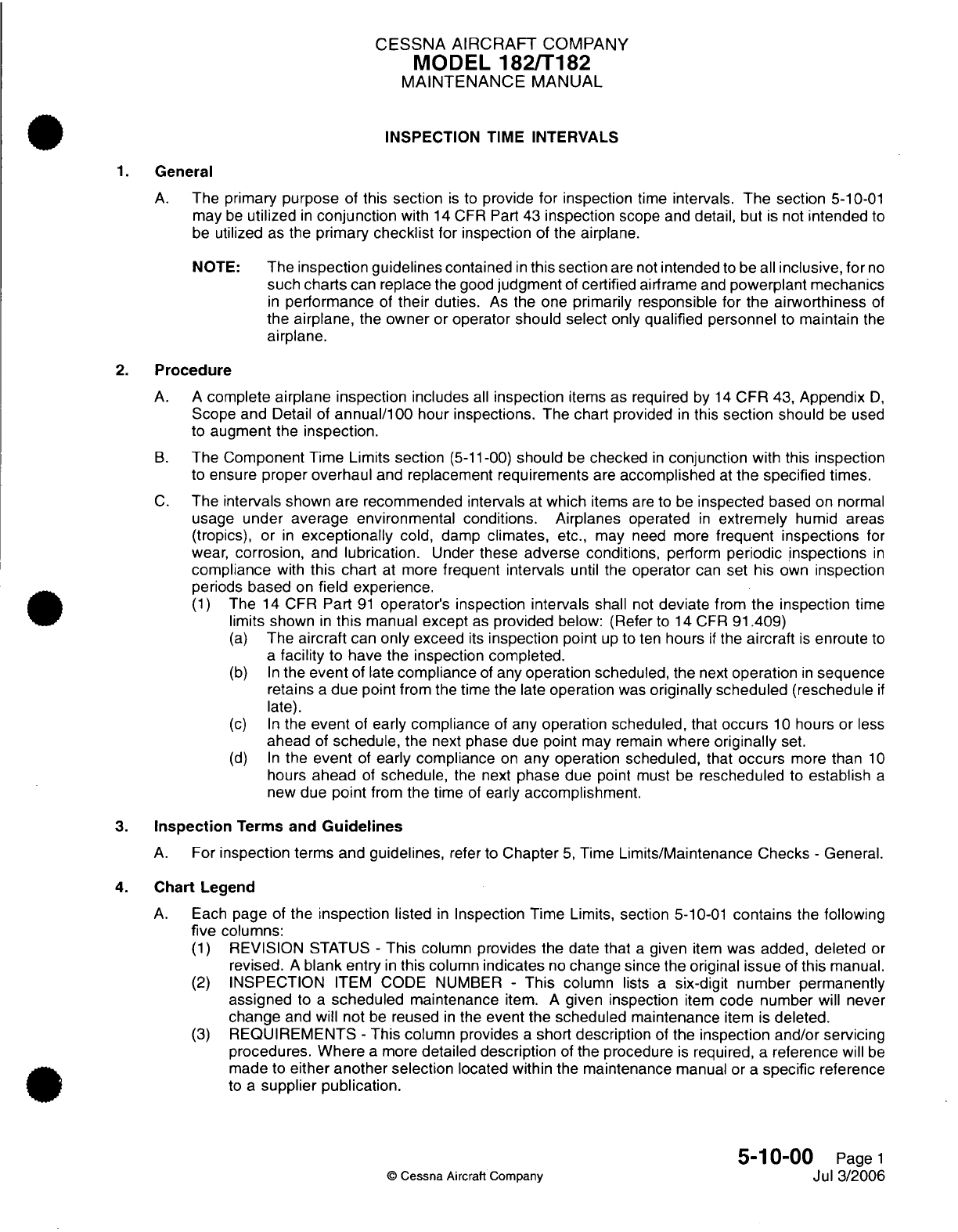
CESSNA
AIRCRAFT
COMPANY
MODEL
182/T182
MAINTENANCE
MANUAL
INSPECTION
TIME
INTERVALS
1.
General
A.
The primary
purpose
of
this
section
is
to
provide
for inspection
time
intervals.
The section
5-10-01
may
be
utilized
in
conjunction
with
14
CFR Part
43
inspection
scope
and
detail,
but
is
not
intended
to
be
utilized
as
the
primary
checklist
for
inspection
of
the
airplane.
NOTE:
The
inspection guidelines
contained
in
this
section
are not
intended
to
be
all
inclusive,
for
no
such charts
can
replace
the
good
judgment
of
certified
airframe
and
powerplant mechanics
in
performance
of
their
duties.
As
the
one
primarily responsible for
the
airworthiness
of
the
airplane,
the
owner
or
operator
should
select
only
qualified personnel
to
maintain
the
airplane.
2.
Procedure
A.
A
complete
airplane inspection
includes
all
inspection
items
as
required
by
14
CFR
43,
Appendix
D,
Scope
and
Detail
of
annual/100
hour
inspections.
The
chart
provided
in
this
section
should
be
used
to
augment
the
inspection.
B.
The
Component
Time
Limits
section
(5-11-00)
should
be
checked
in
conjunction
with this
inspection
to
ensure
proper
overhaul
and replacement
requirements
are
accomplished
at
the specified
times.
C.
The
intervals
shown are recommended
intervals
at
which
items
are
to
be
inspected
based
on
normal
usage
under
average environmental conditions. Airplanes
operated
in
extremely
humid
areas
(tropics), or
in
exceptionally
cold,
damp
climates,
etc., may
need
more
frequent inspections
for
wear,
corrosion,
and
lubrication.
Under
these
adverse
conditions,
perform
periodic
inspections
in
compliance
with
this chart
at
more
frequent
intervals
until
the
operator
can
set
his
own
inspection
periods
based
on
field experience.
(1)
The
14
CFR
Part
91
operator's inspection
intervals
shall
not
deviate
from
the
inspection
time
limits
shown
in
this
manual except
as
provided
below: (Refer
to
14
CFR
91.409)
(a)
The
aircraft
can
only
exceed
its
inspection
point
up
to
ten
hours
if
the
aircraft
is
enroute
to
a
facility
to
have the
inspection completed.
(b) In
the
event
of
late
compliance
of
any
operation
scheduled,
the
next
operation
in
sequence
retains
a
due
point from
the
time
the
late
operation
was
originally
scheduled
(reschedule
if
late).
(c) In
the
event
of
early
compliance
of
any
operation scheduled, that
occurs
10
hours
or
less
ahead
of
schedule,
the
next
phase due point
may
remain
where
originally
set.
(d) In
the
event
of
early compliance
on
any
operation
scheduled,
that
occurs
more
than
10
hours
ahead
of
schedule,
the
next
phase due
point
must
be
rescheduled
to
establish
a
new
due
point
from
the
time
of
early accomplishment.
3.
Inspection
Terms and
Guidelines
A.
For
inspection
terms
and
guidelines,
refer
to
Chapter
5,
Time
Limits/Maintenance
Checks
-
General.
4.
Chart
Legend
A.
Each
page
of
the
inspection
listed
in
Inspection
Time Limits,
section
5-10-01
contains
the
following
five
columns:
(1)
REVISION
STATUS
-
This
column
provides
the
date
that
a
given
item
was added,
deleted
or
revised.
A
blank
entry
in
this
column
indicates
no
change
since the original
issue
of
this
manual.
(2)
INSPECTION
ITEM
CODE
NUMBER
-
This
column
lists
a
six-digit number
permanently
assigned
to
a
scheduled
maintenance
item.
A
given
inspection
item
code
number
will
never
change
and
will
not
be
reused
in
the
event
the
scheduled
maintenance
item is
deleted.
(3)
REQUIREMENTS
-
This
column
provides
a
short
description
of the
inspection and/or
servicing
procedures.
Where
a
more
detailed
description
of
the procedure
is
required,
a
reference
will
be
made
to
either another selection
located
within
the maintenance
manual or
a
specific
reference
to
a
supplier
publication.
5-10-00
Page
1
©
Cessna
Aircraft Company
Jul
3/2006
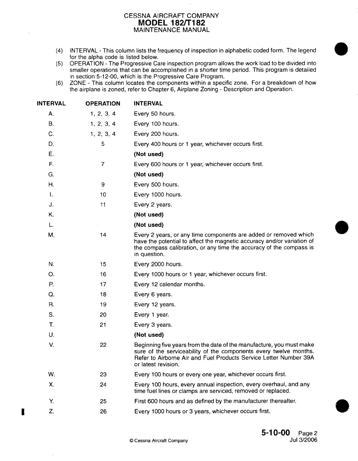
CESSNA
AIRCRAFT
COMPANY
MODEL
182/T182
MAINTENANCE
MANUAL
(4)
INTERVAL
-
This
column
lists
the frequency
of
inspection
in
alphabetic
coded
form.
The
legend
for
the
alpha
code
is
listed
below.
(5)
OPERATION
-
The
Progressive
Care
inspection
program
allows the work
load
to
be
divided
into
smaller
operations
that
can
be
accomplished
in
a
shorter
time
period.
This
program
is
detailed
in
section 5-12-00,
which
is
the
Progressive
Care
Program.
(6)
ZONE
-
This column locates
the
components
within
a
specific zone.
For
a
breakdown
of
how
the
airplane
is
zoned,
refer
to
Chapter
6,
Airplane
Zoning
-
Description
and
Operation.
INTERVAL
A.
B.
C.
D.
E.
F.
G.
H.
1.
J.
K.
L.
M.
N.
O.
P.
Q.
R.
S.
T.
U.
V.
W.
X.
Y.
Z.
OPERATION
1, 2, 3,
4
1, 2, 3,
4
1, 2, 3,
4
5
7
9
10
11
14
15
16
17
18
19
20
21
22
23
24
25
26
INTERVAL
Every
50
hours.
Every
100
hours.
Every
200
hours.
Every
400
hours
or
1
year, whichever occurs
first.
(Not
used)
Every
600
hours
or
1
year, whichever occurs
first.
(Not
used)
Every
500
hours.
Every
1000
hours.
Every
2
years.
(Not
used)
(Not
used)
Every
2
years,
or
any
time components
are
added
or
removed
which
have the potential
to
affect
the
magnetic
accuracy and/or variation
of
the
compass
calibration,
or
any
time
the
accuracy
of
the
compass
is
in
question.
Every
2000
hours.
Every
1000
hours
or
1
year, whichever
occurs
first.
Every
12
calendar
months.
Every
6
years.
Every
12
years.
Every
1
year.
Every
3
years.
(Not
used)
Beginning
five
years
from
the
date
of
the
manufacture, you
must
make
sure
of
the
serviceability
of
the
components
every
twelve months.
Refer
to
Airborne Air
and
Fuel
Products
Service Letter
Number
39A
or
latest
revision.
Every
100
hours
or
every
one
year,
whichever
occurs
first.
Every
100
hours,
every
annual
inspection,
every overhaul,
and
any
time
fuel
lines
or
clamps
are
serviced,
removed
or
replaced.
First
600
hours and
as
defined
by
the
manufacturer thereafter.
Every
1000
hours or
3
years,
whichever occurs
first.
5-10-00
Page
2
©
Cessna
Aircraft
Company
Jul
3/2006
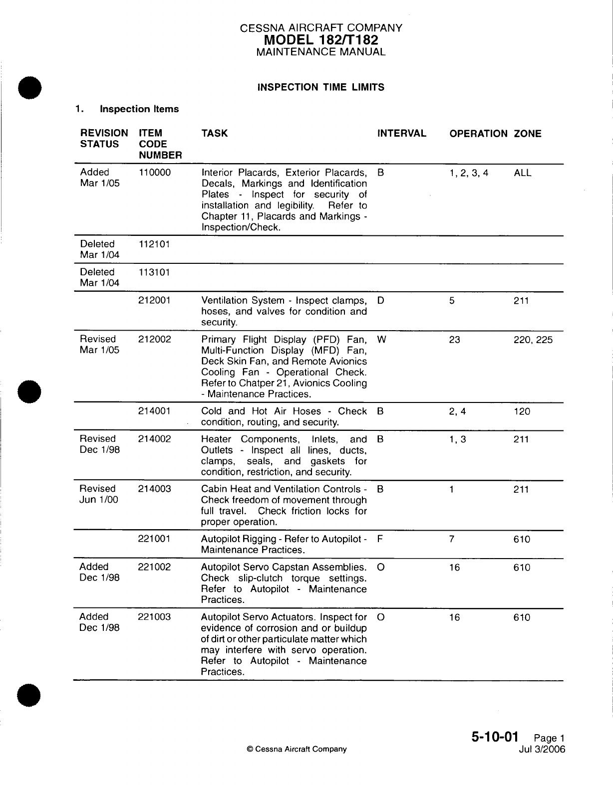
CESSNA
AIRCRAFT
COMPANY
MODEL
182/T182
MAINTENANCE
MANUAL
INSPECTION
TIME
LIMITS
1.
Inspection
Items
REVISION
ITEM
TASK INTERVAL OPERATION
ZONE
STATUS
CODE
NUMBER
Added
110000
Interior Placards,
Exterior
Placards,
B
1,2,3,4
ALL
Mar
1/05
Decals,
Markings
and
Identification
Plates
-
Inspect
for
security
of
installation
and
legibility.
Refer
to
Chapter
11,
Placards
and
Markings
-
Inspection/Check.
Deleted
112101
Mar
1/04
Deleted
113101
Mar
1/04
212001
Ventilation
System
-
Inspect
clamps,
D 5
211
hoses,
and
valves
for
condition
and
security.
Revised
212002
Primary
Flight
Display
(PFD) Fan, W
23
220,
225
Mar
1/05
Multi-Function
Display
(MFD)
Fan,
Deck
Skin
Fan,
and
Remote
Avionics
Cooling
Fan
-
Operational
Check.
Refer
to
Chatper
21,
Avionics
Cooling
-
Maintenance
Practices.
214001
Cold
and
Hot
Air
Hoses
-
Check
B 2, 4
120
condition,
routing,
and
security.
Revised
214002
Heater Components,
Inlets,
and
B
1,3
211
Dec
1/98
Outlets
-
Inspect
all
lines,
ducts,
clamps,
seals,
and
gaskets
for
condition,
restriction,
and
security.
Revised
214003
Cabin
Heat
and
Ventilation
Controls
-
B 1
211
Jun
1/00
Check
freedom
of
movement
through
full
travel. Check
friction
locks
for
proper
operation.
221001
Autopilot
Rigging-
Refer
to
Autopilot-
F 7
610
Maintenance
Practices.
Added
221002
Autopilot
Servo Capstan
Assemblies.
O
16
610
Dec
1/98
Check
slip-clutch
torque
settings.
Refer
to
Autopilot
-
Maintenance
Practices.
Added
221003
Autopilot
Servo
Actuators. Inspect
for
O
16
610
Dec
1/98
evidence
of
corrosion
and
or
buildup
of
dirt
or
other
particulate
matter
which
may
interfere
with
servo
operation.
Refer
to
Autopilot
-
Maintenance
Practices.
5-10-01
Page
1
©
Cessna Aircraft
Company
Jul 3/2006
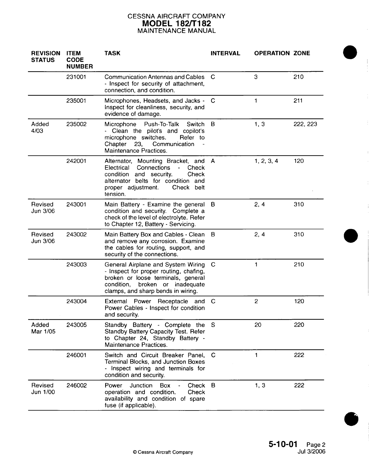
CESSNA AIRCRAFT
COMPANY
MODEL
182/T182
MAINTENANCE MANUAL
REVISION
ITEM
TASK
INTERVAL OPERATION
ZONE
STATUS
CODE
NUMBER
231001
Communication
Antennas and
Cables
C 3
210
-
Inspect
for
security
of
attachment,
connection,
and
condition.
235001
Microphones,
Headsets,
and Jacks
-
C 1
211
Inspect for cleanliness,
security,
and
evidence
of
damage.
Added 235002 Microphone
Push-To-Talk
Switch
B 1, 3
222,
223
4/03
-
Clean the
pilot's
and
copilot's
microphone
switches.
Refer
to
Chapter
23,
Communication
Maintenance
Practices.
242001
Alternator,
Mounting
Bracket,
and
A
1,2,
3,
4
120
Electrical Connections
-
Check
condition
and
security.
Check
alternator
belts
for
condition
and
proper adjustment. Check
belt
tension.
Revised
243001
Main
Battery
-
Examine
the
general
B
2,
4
310
Jun
3/06 condition
and security.
Complete
a
check
of the
level
of
electrolyte.
Refer
to
Chapter
12,
Battery
-
Servicing.
Revised
243002
Main
Battery
Box and
Cables
-
Clean
B 2,
4
310
Jun
3/06
and
remove
any
corrosion.
Examine
the
cables
for
routing,
support,
and
security
of
the
connections.
243003 General Airplane
and
System
Wiring
C 1
210
-
Inspect
for
proper
routing,
chafing,
broken
or
loose
terminals,
general
condition,
broken
or
inadequate
clamps,
and
sharp
bends
in
wiring.
243004
External Power
Receptacle
and
C 2
120
Power
Cables
-
Inspect
for
condition
and
security.
Added 243005 Standby
Battery
-
Complete
the
S
20
220
Mar
1/05
Standby
Battery
Capacity
Test.
Refer
to
Chapter
24,
Standby
Battery
-
Maintenance
Practices.
246001
Switch
and
Circuit
Breaker
Panel,
C 1
222
Terminal
Blocks,
and
Junction
Boxes
-
Inspect
wiring
and
terminals
for
condition
and
security.
Revised
246002 Power
Junction
Box
-
Check
B 1, 3
222
Jun
1/00
operation
and
condition.
Check
availability
and
condition
of
spare
fuse
(if
applicable).
5-10-01
Page
2
Cessna
Aircraft
Company
Jul
3/2006
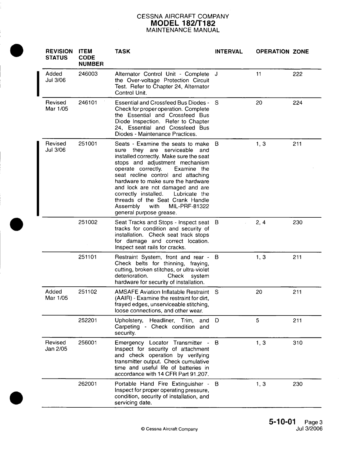
CESSNA
AIRCRAFT
COMPANY
MODEL
182/T182
MAINTENANCE
MANUAL
REVISION
ITEM
TASK
INTERVAL
OPERATION ZONE
STATUS CODE
NUMBER
Added
246003
Alternator
Control
Unit
-
Complete
J
11
222
Jul 3/06
the
Over-voltage
Protection
Circuit
Test.
Refer
to
Chapter
24,
Alternator
Control
Unit.
Revised
246101
Essential
and
Crossfeed
Bus
Diodes
-
S
20
224
Mar
1/05
Check
for
proper
operation.
Complete
the
Essential
and
Crossfeed
Bus
Diode
Inspection.
Refer
to
Chapter
24,
Essential
and
Crossfeed
Bus
Diodes
-
Maintenance
Practices.
Revised
251001
Seats
-
Examine
the
seats
to
make
B
1,
3
211
Jul 3/06
sure
they
are
serviceable
and
installed
correctly.
Make sure
the seat
stops
and
adjustment
mechanism
operate
correctly.
Examine the
seat
recline
control
and
attaching
hardware
to make sure
the hardware
and
lock are
not
damaged
and
are
correctly
installed.
Lubricate
the
threads
of
the
Seat Crank Handle
Assembly
with
MIL-PRF-81322
general
purpose
grease.
251002
Seat
Tracks
and Stops
-
Inspect
seat
B
2,
4
230
tracks
for
condition
and
security
of
installation.
Check
seat
track
stops
for
damage
and
correct location.
Inspect
seat
rails
for
cracks.
251101
Restraint
System, front
and
rear
-
B
1,3
211
Check
belts
for
thinning, fraying,
cutting,
broken stitches, or
ultra-violet
deterioration.
Check
system
hardware
for
security
of
installation.
Added
251102
AMSAFE
Aviation
Inflatable
Restraint
S
20
211
Mar
1/05
(AAIR)
-
Examine
the
restraint
for
dirt,
frayed
edges,
unserviceable
stitching,
loose
connections,
and
other
wear.
252201
Upholstery, Headliner,
Trim,
and
D 5
211
Carpeting
-
Check
condition
and
security.
Revised
256001
Emergency Locator Transmitter
-
B
1,
3 310
Jan 2/05 Inspect for
security
of
attachment
and
check
operation
by
verifying
transmitter
output.
Check
cumulative
time
and
useful
life
of
batteries
in
accordance
with
14
CFR Part
91.207.
262001
Portable
Hand
Fire
Extinguisher
-
B
1,
3
230
Inspect for proper
operating
pressure,
condition, security
of
installation,
and
servicing
date.
5-10-01
Page
3
©
Cessna
Aircraft
Companv
Jul 3/2006
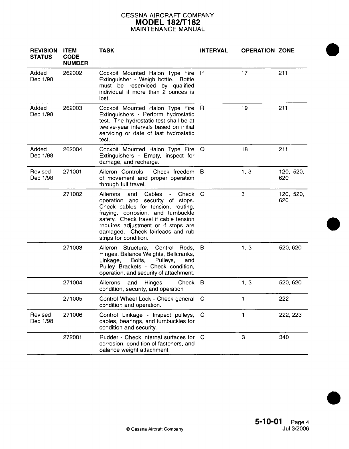
CESSNA
AIRCRAFT
COMPANY
MODEL
182/T182
MAINTENANCE
MANUAL
REVISION
ITEM
TASK
INTERVAL
OPERATION
ZONE
STATUS CODE
NUMBER
Added
262002
Cockpit
Mounted
Halon Type
Fire
P
17
211
Dec 1/98
Extinguisher
-
Weigh
bottle.
Bottle
must be
reserviced
by
qualified
individual
if
more
than
2
ounces
is
lost.
Added
262003
Cockpit
Mounted
Halon
Type
Fire
R
19
211
Dec
1/98
Extinguishers
-
Perform
hydrostatic
test.
The
hydrostatic
test
shall
be
at
twelve-year
intervals
based
on
initial
servicing
or
date
of
last
hydrostatic
test.
Added 262004
Cockpit
Mounted
Halon
Type
Fire
Q
18
211
Dec
1/98
Extinguishers
-
Empty,
inspect
for
damage, and
recharge.
Revised
271001
Aileron
Controls
-
Check
freedom
B
1,3
120,
520,
Dec
1/98
of
movement
and proper
operation
620
through full
travel.
271002
Ailerons
and Cables
-
Check
C 3
120,
520,
operation
and
security
of
stops.
620
Check
cables
for tension,
routing,
fraying,
corrosion,
and
turnbuckle
safety.
Check
travel
if
cable
tension
requires
adjustment
or
if
stops
are
damaged.
Check
fairleads
and
rub
strips
for
condition.
271003 Aileron
Structure,
Control
Rods,
B
1,3
520,
620
Hinges,
Balance
Weights,
Bellcranks,
Linkage,
Bolts,
Pulleys,
and
Pulley
Brackets
-
Check condition,
operation,
and
security
of
attachment.
271004 Ailerons
and
Hinges
-
Check
B 1, 3
520,
620
condition,
security,
and
operation
271005
Control
Wheel
Lock
-
Check
general
C 1
222
condition
and operation.
Revised 271006
Control
Linkage
-
Inspect
pulleys,
C 1
222,
223
Dec 1/98
cables,
bearings,
and
turnbuckles
for
condition
and
security.
272001
Rudder
-
Check
internal
surfaces
for
C
3
340
corrosion,
condition
of
fasteners,
and
balance
weight
attachment.
5-1
0-01
Page
4
Jul 3/2006
Cessna
Aircraft
Company
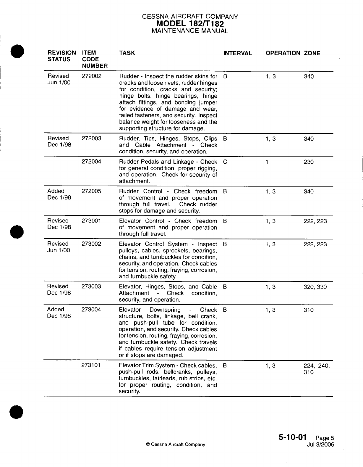
CESSNA
AIRCRAFT
COMPANY
MODEL
182/T182
MAINTENANCE
MANUAL
REVISION
ITEM
TASK
INTERVAL OPERATION
ZONE
STATUS
CODE
NUMBER
Revised 272002
Rudder
-
Inspect
the
rudder
skins
for
B 1, 3
340
Jun
1/00
cracks
and loose rivets,
rudder hinges
for
condition, cracks
and
security;
hinge bolts, hinge
bearings,
hinge
attach fittings,
and
bonding
jumper
for
evidence
of
damage
and
wear,
failed
fasteners,
and
security.
Inspect
balance weight
for
looseness
and
the
supporting
structure
for
damage.
Revised 272003
Rudder, Tips,
Hinges,
Stops,
Clips
B 1, 3
340
Dec
1/98
and
Cable
Attachment
-
Check
condition,
security, and
operation.
272004
Rudder
Pedals
and
Linkage
-
Check
C 1
230
for general
condition,
proper
rigging,
and
operation.
Check for
security
of
attachment.
Added
272005
Rudder
Control
-
Check
freedom
B 1, 3
340
Dec
1/98
of
movement
and
proper
operation
through
full
travel. Check
rudder
stops
for
damage
and
security.
Revised
273001
Elevator
Control
-
Check
freedom
B
1,3
222,
223
Dec
1/98
of
movement
and
proper
operation
through
full
travel.
Revised 273002
Elevator
Control
System
-
Inspect
B 1, 3
222,
223
Jun
1/00
pulleys, cables,
sprockets,
bearings,
chains,
and
turnbuckles
for
condition,
security,
and
operation.
Check
cables
for
tension,
routing,
fraying,
corrosion,
and
turnbuckle
safety
Revised
273003
Elevator,
Hinges,
Stops,
and
Cable
B 1, 3
320, 330
Dec
1/98
Attachment
-
Check
condition,
security,
and
operation.
Added
273004
Elevator
Downspring
-
Check
B
1,3
310
Dec 1/98
structure,
bolts,
linkage,
bell
crank,
and
push-pull
tube for
condition,
operation,
and
security.
Check cables
for tension,
routing,
fraying,
corrosion,
and
turnbuckle
safety.
Check
travels
if
cables
require
tension adjustment
or
if
stops
are
damaged.
273101
ElevatorTrim System -
Check cables,
B 1, 3
224,
240,
push-pull
rods,
bellcranks, pulleys,
310
turnbuckles, fairleads,
rub
strips,
etc.
for
proper
routing,
condition,
and
security.
5-10-01
Page
5
©
Cessna Aircraft Company
Jul
3/2006
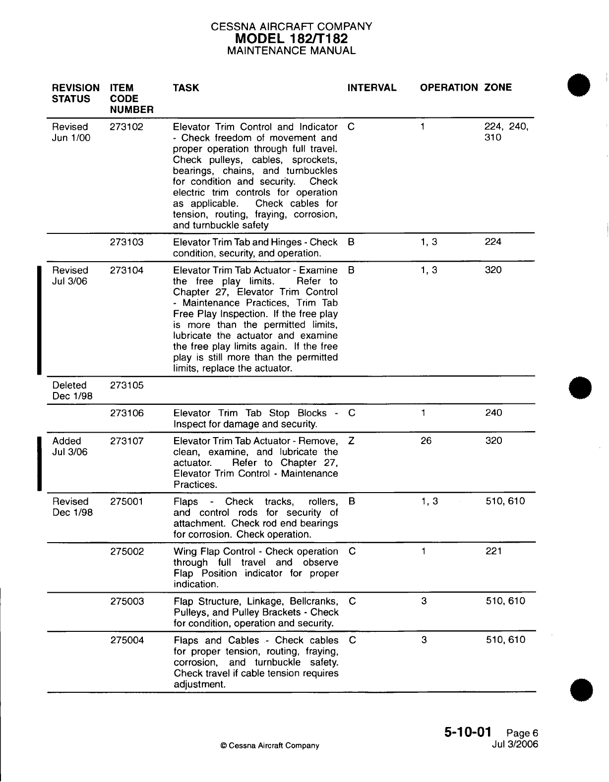
CESSNA AIRCRAFT
COMPANY
MODEL
182/T182
MAINTENANCE
MANUAL
REVISION
ITEM
TASK
INTERVAL
OPERATION ZONE
STATUS
CODE
NUMBER
Revised
273102 Elevator
Trim
Control
and
Indicator
C 1
224,
240,
Jun
1/00
-
Check
freedom
of
movement
and
310
proper operation
through
full
travel.
Check
pulleys,
cables,
sprockets,
bearings, chains,
and
turnbuckles
for condition
and
security.
Check
electric
trim
controls
for
operation
as
applicable.
Check
cables
for
tension,
routing, fraying,
corrosion,
and
turnbuckle
safety
273103
ElevatorTrimTaband
Hinges-Check
B 1, 3
224
condition,
security,
and
operation.
Revised 273104 Elevator
Trim
Tab
Actuator
-
Examine
B 1,
3
320
Jul
3/06
the
free
play
limits. Refer
to
Chapter
27,
Elevator
Trim
Control
-
Maintenance
Practices,
Trim
Tab
Free
Play
Inspection.
If
the free
play
is
more
than
the permitted
limits,
lubricate
the
actuator
and
examine
the
free
play
limits
again.
If
the
free
play
is
still
more
than
the permitted
limits,
replace the
actuator.
Deleted
273105
Dec
1/98
273106
Elevator
Trim
Tab
Stop
Blocks
-
C
1
240
Inspect
for damage
and
security.
Added
273107 Elevator
Trim
Tab
Actuator
-
Remove,
Z
26
320
Jul
3/06
clean,
examine,
and
lubricate
the
actuator.
Refer
to
Chapter
27,
Elevator
Trim
Control
-
Maintenance
Practices.
Revised
275001
Flaps
-
Check
tracks,
rollers,
B
1,3
510,
610
Dec
1/98
and
control
rods
for
security
of
attachment. Check
rod
end
bearings
for
corrosion.
Check
operation.
275002
Wing
Flap
Control
-
Check
operation
C
1
221
through
full
travel
and
observe
Flap
Position indicator
for
proper
indication.
275003
Flap
Structure,
Linkage,
Bellcranks,
C 3
510,
610
Pulleys,
and
Pulley
Brackets
-
Check
for condition,
operation
and
security.
275004
Flaps
and
Cables
-
Check
cables
C 3
510,
610
for
proper tension,
routing,
fraying,
corrosion,
and
turnbuckle
safety.
Check
travel
if
cable
tension
requires
adjustment.
5-10-01
Page
6
C
Cessna
Aircraft
Comoanv
Jul 3/2006
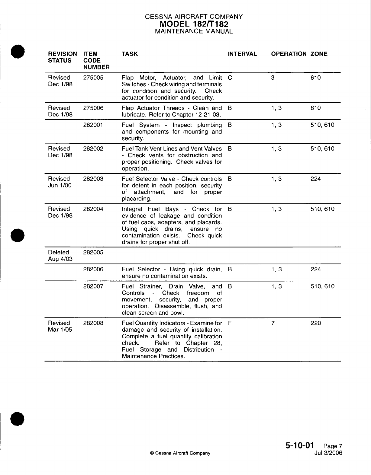
CESSNA AIRCRAFT
COMPANY
MODEL
182/T182
MAINTENANCE
MANUAL
REVISION
ITEM
TASK
INTERVAL
OPERATION
ZONE
STATUS
CODE
NUMBER
Revised
275005
Flap
Motor,
Actuator,
and
Limit
C 3
610
Dec 1/98
Switches
-
Check
wiring
and
terminals
for
condition
and
security.
Check
actuator for
condition
and security.
Revised 275006
Flap
Actuator
Threads
-
Clean
and
B 1, 3
610
Dec 1/98
lubricate.
Refer
to
Chapter
12-21-03.
282001
Fuel
System
-
Inspect plumbing
B
1,3
510,
610
and
components
for
mounting
and
security.
Revised 282002
Fuel Tank
Vent
Lines
and
Vent
Valves
B
1,3
510,
610
Dec
1/98
-
Check
vents for
obstruction
and
proper
positioning.
Check
valves
for
operation.
Revised
282003
Fuel
Selector
Valve
-
Check
controls
B 1, 3
224
Jun
1/00
for
detent
in
each
position,
security
of
attachment,
and
for
proper
placarding.
Revised
282004
Integral
Fuel Bays
-
Check
for
B 1,
3
510,
610
Dec 1/98
evidence
of
leakage
and
condition
of
fuel
caps,
adapters,
and
placards.
Using
quick
drains, ensure
no
contamination
exists.
Check quick
drains
for
proper
shut
off.
Deleted
282005
Aug
4/03
282006
Fuel
Selector
-
Using
quick
drain,
B
1,3
224
ensure
no
contamination
exists.
282007
Fuel
Strainer,
Drain
Valve,
and
B 1, 3
510,
610
Controls
-
Check
freedom
of
movement,
security,
and
proper
operation.
Disassemble, flush,
and
clean screen
and
bowl.
Revised
282008
Fuel
Quantity
Indicators
-
Examine
for
F 7
220
Mar
1/05
damage
and
security
of
installation.
Complete
a
fuel
quantity calibration
check.
Refer
to
Chapter
28,
Fuel
Storage
and
Distribution
-
Maintenance
Practices.
5-10-01
Page
7
©
Cessna
Aircraft
Company
Jul 3/2006
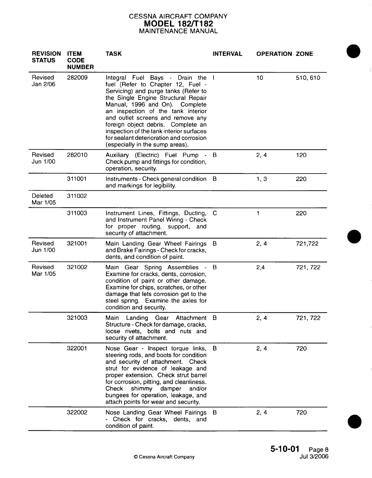
CESSNA
AIRCRAFT
COMPANY
MODEL
182/T182
MAINTENANCE
MANUAL
REVISION
ITEM
TASK
INTERVAL OPERATION
ZONE
STATUS
CODE
NUMBER
Revised 282009
Integral
Fuel Bays
-
Drain
the
I
10
510,
610
Jan 2/06
fuel
(Refer
to Chapter
12,
Fuel
-
Servicing)
and purge
tanks
(Refer
to
the
Single
Engine
Structural
Repair
Manual,
1996
and On).
Complete
an
inspection
of
the
tank
interior
and
outlet screens
and
remove
any
foreign
object
debris. Complete
an
inspection
of
the
tank
interior
surfaces
for
sealant
deterioration
and
corrosion
(especially
in
the
sump
areas).
Revised
282010
Auxiliary
(Electric)
Fuel
Pump
-
B 2, 4
120
Jun
1/00
Check pump
and
fittings for
condition,
operation,
security.
311001
Instruments -
Check general
condition
B 1, 3
220
and
markings
for legibility.
Deleted
311002
Mar
1/05
311003
Instrument
Lines,
Fittings,
Ducting,
C 1
220
and
Instrument
Panel
Wiring
-
Check
for
proper
routing,
support,
and
security
of
attachment.
Revised
321001
Main
Landing
Gear
Wheel Fairings
B 2,
4
721,722
Jun
1/00
and
Brake
Fairings
-
Check
for
cracks,
dents,
and
condition
of
paint.
Revised
321002
Main
Gear
Spring
Assemblies
-
B
2,4
721,722
Mar
1/05
Examine
for
cracks,
dents, corrosion,
condition
of
paint
or
other
damage.
Examine
for chips, scratches,
or
other
damage
that
lets
corrosion
get
to
the
steel
spring.
Examine
the
axles
for
condition
and
security.
321003
Main
Landing
Gear Attachment
B 2,
4
721,722
Structure
-
Check
for damage,
cracks,
loose rivets,
bolts
and
nuts
and
security
of
attachment.
322001
Nose
Gear
-
Inspect
torque
links,
B 2,
4
720
steering
rods, and
boots
for condition
and
security
of
attachment.
Check
strut
for
evidence
of
leakage
and
proper
extension.
Check strut
barrel
for corrosion,
pitting,
and
cleanliness.
Check shimmy damper
and/or
bungees
for
operation,
leakage,
and
attach
points
for
wear and
security.
322002
Nose
Landing
Gear
Wheel Fairings
B
2,
4
720
-
Check
for
cracks,
dents,
and
condition
of
paint.
5-10-01
Page
8
©
Cessna Aircraft
Company
Jul
3/2006
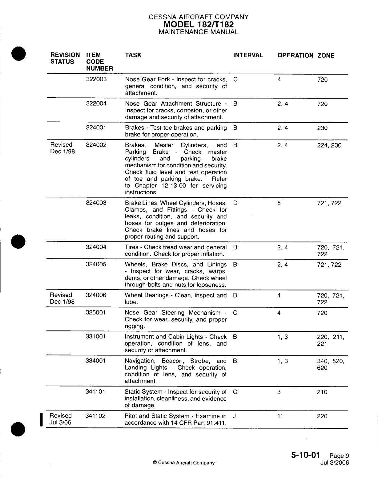
CESSNA
AIRCRAFT
COMPANY
MODEL
182/T182
MAINTENANCE
MANUAL
REVISION
ITEM
TASK
INTERVAL OPERATION ZONE
STATUS
CODE
NUMBER
322003
Nose
Gear
Fork
-
Inspect
for
cracks,
C 4
720
general condition,
and
security
of
attachment.
322004
Nose
Gear
Attachment
Structure
-
B 2,
4
720
Inspect
for
cracks, corrosion,
or
other
damage
and
security
of
attachment.
324001
Brakes
-
Test
toe
brakes
and
parking
B 2,
4
230
brake
for
proper operation.
Revised 324002 Brakes, Master
Cylinders,
and
B 2,
4
224, 230
Dec 1/98
Parking
Brake
-
Check
master
cylinders
and
parking
brake
mechanism
for
condition
and
security.
Check fluid
level
and
test
operation
of
toe and
parking
brake.
Refer
to
Chapter
12-13-00
for
servicing
instructions.
324003
Brake
Lines, Wheel
Cylinders,
Hoses,
D 5
721,
722
Clamps,
and
Fittings
-
Check
for
leaks, condition,
and
security
and
hoses for
bulges
and
deterioration.
Check
brake lines
and
hoses
for
proper
routing
and
support.
324004
Tires
-
Check tread
wear
and
general
B 2,
4
720,
721,
condition.
Check
for
proper
inflation.
722
324005
Wheels,
Brake
Discs,
and
Linings
B 2,
4
721,722
-
Inspect
for
wear,
cracks,
warps,
dents,
or
other damage.
Check
wheel
through-bolts
and nuts
for
looseness.
Revised
324006
Wheel Bearings
-
Clean,
inspect
and
B 4
720,
721,
Dec
1/98
lube.
722
325001
Nose
Gear
Steering
Mechanism
-
C 4
720
Check
for
wear,
security,
and
proper
rigging.
331001
Instrument
and
Cabin
Lights
-
Check
B 1, 3
220,
211,
operation, condition
of
lens,
and
221
security
of
attachment.
334001
Navigation,
Beacon,
Strobe,
and
B 1, 3
340,
520,
Landing
Lights
-
Check
operation,
620
condition
of
lens,
and
security
of
attachment.
341101
Static
System
-
Inspect
for
security
of
C 3
210
installation,
cleanliness,
and
evidence
of
damage.
Revised
341102
Pitot and
Static
System
-
Examine
in J
11
220
Jul
3/06
accordance
with
14
CFR
Part
91.411.
5-10-01
Page
9
©
Cessna Aircraft
Company
Jul
3/2006

CESSNA AIRCRAFT
COMPANY
MODEL
182/T182
MAINTENANCE
MANUAL
REVISION
ITEM
TASK
INTERVAL
OPERATION ZONE
STATUS CODE
NUMBER
341103
Pitot Tube
and
Stall Warning
Vane
-
A
1,2,
3, 4
510
Check
for
condition
and
obstructions
and
verify operation
of
anti-ice
heat.
342101
Magnetic
Compass
-
Inspect
for
C 1
225
security
of
installation, cleanliness,
and
evidence
of
damage.
Revised
342102
Magnetic
Compass
-
Calibrate.
M
14
220
Dec
1/98
Revised
345001
Instrument
Panel
Mounted
Avionics
C 1
225
Dec
1/98
Units
(Including
Audio
Panel,
VHF
Nav/Com(s),
ADF,
GPS,
Transponder, Compass
System,
Multi-function
Display, and
Primary
Flight
Display)
and Remote
Mounted
Avionics
Components.
Inspect
for
deterioration,
cracks,
and
security
of
instrument
panel
mounts.
Inspect
for
security
of
electrical
connections,
condition,
and
security
of
wire
routing.
345002
Avionics
Operating
Controls
-
Inspect
C 1
225
for security
and
proper
operation
of
controls
and
switches
and
ensure
that
all
digital
segments
will
illuminate
properly.
345003
Navigation
Indicators, Controls,
and
C 1
220,
225
Components
-
Inspect for
condition
and
security.
345004 Navigation Antennas
and
Cables
-
C 1
310
Inspect
for
security
of
attachment,
connection,
and
condition.
Added
351001
Oxygen
System
(if
applicable)
-
C 1
211
Nov
1/00
Inspect
masks, hoses, lines,
and
fittings
for
condition,
routing,
and
support.
Test
operation
and
check
for
leaks.
Added
351002
Oxygen
Cylinder
(if
applicable)
T
21 211
Nov
1/00
-
Inspect
for condition,
check
hydrostatic
test date
and
perform
hydrostatic
test,
if
due.
371001
Vacuum
System
-
Inspect
for
B
2, 4
120
condition
and
security.
371002
Vacuum Pumps
-
Check
for
condition
B 2,
4
120
and
security.
Check vacuum
system breather
line
for
obstructions,
condition,
and
security.
5-10-01
Page
10
©
Cessna
Aircraft Company
Jul
3/2006

CESSNA
AIRCRAFT
COMPANY
MODEL
182/T182
MAINTENANCE
MANUAL
REVISION
ITEM
TASK
INTERVAL
OPERATION
ZONE
STATUS
CODE
NUMBER
371003
Vacuum
System Hoses
-
Inspect
for
B 2, 4
120
hardness,
deterioration, looseness,
or
collapsed
hoses.
Revised
371004
Gyro
Filter
-
Inspect
for
damage,
B 2, 4
120
Dec
1/98
deterioration
and
contamination.
Clean
or
replace
if
required.
Deleted
371005
Aug
4/03
Revised
371006
Vacuum
Manifold
Check
Valve
V
22
120
Jan
2/06
-
Complete
a
check
for
proper
operation.
(Only
airplanes
with
dual vacuum
pumps
and
Airborne
manifolds.
Refer
to
the
Airborne
Air
&
Fuel
Products
Service
Letter
Number
39A
or latest revision,
and
in
accordance
with
SB02-37-04.)
Refer
to
Chapter
37,
Vacuum
System
-
Maintenance Practices
for
the
removal
and
installation
of
the check
valve.
Added
371007
Do
an
inspection
of
the
wear
indicator
Y
25
120
Jan 2/06
ports
on
the
vacuum
pumps
described
in
Tempest
Service
Letter
004.
521001
Doors
-
Inspect general condition.
B
1,3
210
Check
latches,
hinges,
and
seals
for
condition,
operation,
and
security
of
attachment.
531001
Fuselage
Surface
-
Inspect for skin
B
1,3
210
damage,
loose
rivets,
condition
of
paint,
and
check
pitot-static
ports
and
drain
holes
for obstruction.
Inspect
covers
and
fairings
for
security.
531002
Firewall
Structure
-
Inspect for
C 2
120
wrinkles,
damage,
cracks,
sheared
rivets,
etc.
Check
cowl
shock
mounts
for
condition
and
security.
531003
Internal
Fuselage Structure
-
Inspect
C 1
211
bulkheads,
doorposts, stringers,
doublers,
and
skins for corrosion,
cracks,
buckles,
and
loose rivets,
bolts
and nuts.
5-10-01
Page
11
©
Cessna
Aircraft
Company
Jul
3/2006
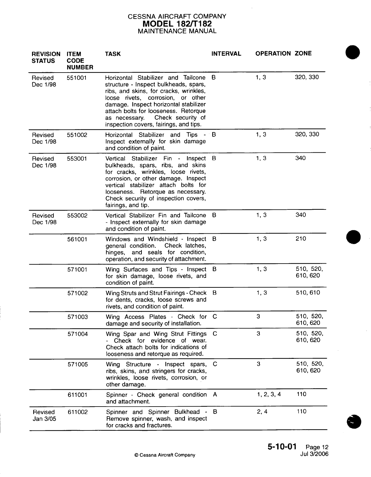
CESSNA
AIRCRAFT
COMPANY
MODEL
182/T182
MAINTENANCE
MANUAL
REVISION
ITEM
TASK
INTERVAL
OPERATION ZONE
STATUS
CODE
NUMBER
Revised
551001
Horizontal
Stabilizer
and
Tailcone
B 1, 3
320,
330
Dec 1/98
structure
-
Inspect bulkheads,
spars,
ribs,
and
skins,
for
cracks,
wrinkles,
loose
rivets,
corrosion,
or
other
damage.
Inspect horizontal stabilizer
attach
bolts
for looseness.
Retorque
as
necessary.
Check security
of
inspection
covers,
fairings,
and
tips.
Revised
551002 Horizontal
Stabilizer
and
Tips
-
B 1, 3
320,
330
Dec
1/98
Inspect
externally
for skin
damage
and
condition
of
paint.
Revised
553001
Vertical
Stabilizer
Fin
-
Inspect
B 1, 3
340
Dec 1/98
bulkheads,
spars,
ribs, and
skins
for
cracks, wrinkles,
loose
rivets,
corrosion,
or
other
damage.
Inspect
vertical
stabilizer
attach bolts
for
looseness. Retorque
as
necessary.
Check
security
of
inspection
covers,
fairings,
and
tip.
Revised
553002
Vertical
Stabilizer
Fin
and
Tailcone
B 1, 3
340
Dec 1/98
-
Inspect
externally
for
skin
damage
and
condition
of
paint.
561001
Windows
and
Windshield
-
Inspect
B 1, 3
210
general
condition.
Check
latches,
hinges,
and
seals
for
condition,
operation,
and
security
of
attachment.
571001
Wing
Surfaces
and
Tips
-
Inspect
B 1, 3
510, 520,
for
skin
damage,
loose rivets,
and
610,
620
condition
of
paint.
571002
Wing Struts
and
Strut Fairings
-
Check
B 1, 3
510,
610
for
dents,
cracks,
loose
screws
and
rivets,
and
condition
of
paint.
571003
Wing
Access
Plates
-
Check for
C 3
510, 520,
damage
and
security
of
installation.
610,
620
571004
Wing
Spar and
Wing Strut Fittings
C
3
510,
520,
-
Check
for
evidence
of
wear.
610,
620
Check
attach
bolts
for
indications
of
looseness
and retorque
as
required.
571005
Wing
Structure
-
Inspect spars,
C
3
510, 520,
ribs,
skins,
and
stringers
for
cracks, 610,
620
wrinkles,
loose
rivets,
corrosion,
or
other
damage.
611001
Spinner
- Check
general
condition
A
1, 2, 3,
4
110
and
attachment.
Revised
611002
Spinner
and
Spinner
Bulkhead
-
B
2,
4
110
Jan 3/05
Remove
spinner,
wash,
and
inspect
for
cracks
and
fractures.
5-10-01
Page
12
©
Cessna
Aircraft Company
Jul
3/2006
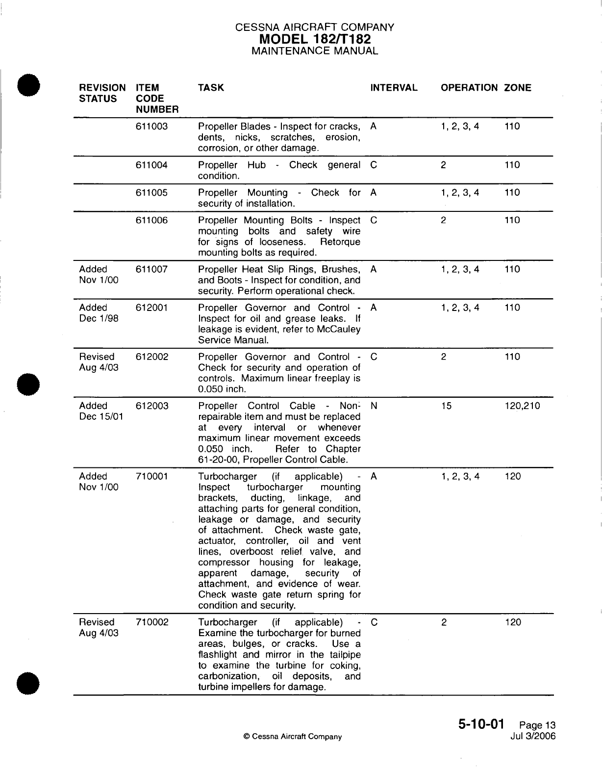
CESSNA
AIRCRAFT
COMPANY
MODEL
182/T182
MAINTENANCE
MANUAL
REVISION
ITEM
STATUS CODE
NUMBER
611003
611004
611005
611006
Added
Nov
1/00
Added
Dec 1/98
Revised
Aug
4/03
Added
Dec
15/01
Added
Nov
1/00
Revised
Aug
4/03
611007
612001
612002
612003
710001
710002
TASK
Propeller Blades
-
Inspect
for
cracks,
dents,
nicks,
scratches,
erosion,
corrosion,
or
other
damage.
Propeller
Hub
-
Check
general
condition.
Propeller
Mounting
-
Check
for
security
of
installation.
Propeller
Mounting
Bolts
-
Inspect
mounting
bolts
and
safety
wire
for
signs
of
looseness.
Retorque
mounting
bolts
as
required.
Propeller Heat
Slip
Rings,
Brushes,
and
Boots
-
Inspect
for condition,
and
security. Perform
operational
check.
Propeller
Governor
and
Control
-
Inspect
for
oil
and
grease
leaks.
If
leakage
is
evident,
refer
to
McCauley
Service
Manual.
Propeller
Governor
and
Control
-
Check
for
security
and
operation
of
controls.
Maximum
linear
freeplay
is
0.050
inch.
Propeller
Control
Cable
-
Non-
repairable
item
and
must
be
replaced
at
every
interval
or whenever
maximum
linear
movement exceeds
0.050
inch.
Refer
to
Chapter
61-20-00,
Propeller
Control Cable.
Turbocharger
(if
applicable)
Inspect
turbocharger
mounting
brackets, ducting,
linkage,
and
attaching
parts
for
general
condition,
leakage
or
damage, and
security
of
attachment. Check
waste
gate,
actuator,
controller,
oil
and
vent
lines,
overboost
relief
valve,
and
compressor
housing
for
leakage,
apparent
damage,
security
of
attachment,
and
evidence
of
wear.
Check waste
gate return
spring
for
condition
and
security.
Turbocharger
(if
applicable)
Examine the
turbocharger
for
burned
areas,
bulges,
or
cracks.
Use
a
flashlight
and
mirror
in
the
tailpipe
to
examine
the
turbine
for
coking,
carbonization,
oil
deposits,
and
turbine
impellers
for
damage.
INTERVAL OPERATION ZONE
A
C
A
1,2,
3,4
2
110
110
1,2,3,4
110
C
A
2
1,2,3,4
110
110
1,2,3,4
110
A
C2
15
N
A
C
110
120,210
1,2,3,4
120
2
120
5-10-01
Page
13
Jul
3/2006
©
Cessna
Aircraft Company
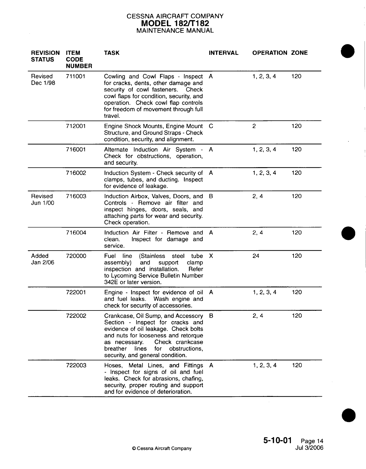
CESSNA AIRCRAFT
COMPANY
MODEL 182/T182
MAINTENANCE
MANUAL
REVISION
ITEM
STATUS
CODE
NUMBER
TASK
INTERVAL OPERATION ZONE
Cowling
and
Cowl
Flaps
-
Inspect
for cracks,
dents, other
damage
and
security
of
cowl
fasteners.
Check
cowl
flaps
for
condition,
security,
and
operation. Check
cowl
flap
controls
for
freedom
of
movement through
full
travel.
Engine
Shock
Mounts, Engine
Mount
Structure,
and
Ground
Straps
-
Check
condition,
security,
and
alignment.
Alternate
Induction
Air
System
-
Check
for obstructions,
operation,
and
security.
Induction System
-
Check
security
of
clamps,
tubes,
and
ducting.
Inspect
for
evidence
of
leakage.
Induction
Airbox,
Valves, Doors,
and
Controls
-
Remove
air
filter
and
inspect
hinges,
doors,
seals,
and
attaching
parts
for
wear
and
security.
Check
operation.
Induction
Air
Filter
-
Remove
and
clean.
Inspect
for
damage
and
service.
Fuel
line
(Stainless
steel tube
assembly)
and
support
clamp
inspection
and
installation.
Refer
to
Lycoming
Service
Bulletin Number
342E
or
later version.
Engine
-
Inspect for
evidence
of
oil
and
fuel
leaks.
Wash
engine
and
check for
security
of
accessories.
Crankcase,
Oil
Sump, and
Accessory
Section
-
Inspect for
cracks
and
evidence
of
oil
leakage. Check
bolts
and
nuts
for looseness
and
retorque
as
necessary. Check
crankcase
breather
lines
for
obstructions,
security,
and
general
condition.
Hoses,
Metal
Lines,
and Fittings
-
Inspect for
signs
of
oil
and fuel
leaks.
Check
for
abrasions, chafing,
security,
proper
routing and
support
and
for
evidence
of
deterioration.
A
C
A
A
1,2,3,4
120
2
1,2,3,4
120
120
1,2,3,4
120
B
2,
4
A
2,
4
X
A
24
120
120
120
1,2,3,4
120
B
2,
4
A
120
1,2,3,4
120
5-10-01
Page
14
Jul
3/2006
©
Cessna
Aircraft
Company
Revised
Dec
1/98
711001
712001
716001
716002
Revised
Jun
1/00
716003
716004
Added
Jan
2/06
720000
722001
722002
722003
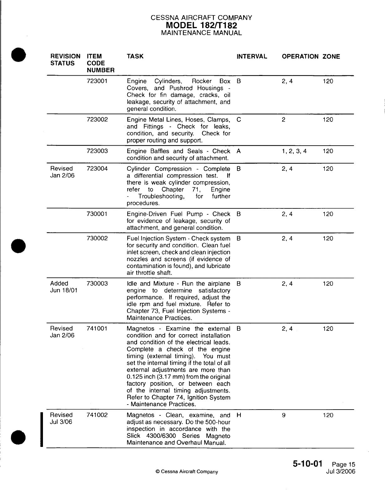
CESSNA
AIRCRAFT
COMPANY
MODEL
182/T182
MAINTENANCE
MANUAL
.
REVISION
ITEM
TASK
INTERVAL
OPERATION ZONE
STATUS
CODE
NUMBER
723001
Engine Cylinders, Rocker
Box
B 2,
4
120
Covers,
and
Pushrod
Housings
-
Check
for
fin
damage,
cracks,
oil
leakage,
security
of
attachment,
and
general
condition.
723002
Engine
Metal
Lines,
Hoses,
Clamps,
C 2
120
and
Fittings
-
Check
for
leaks,
condition,
and
security.
Check
for
proper
routing
and
support.
723003
Engine
Baffles
and
Seals
-
Check
A
1,2,
3,
4
120
condition
and
security
of
attachment.
Revised
723004
Cylinder
Compression
-
Complete
B 2, 4
120
Jan
2/06
a
differential compression
test.
If
there
is
weak
cylinder
compression,
refer
to
Chapter
71,
Engine
-Troubleshooting,
for
further
procedures.
730001
Engine-Driven
Fuel
Pump
-
Check
B 2, 4
120
for
evidence
of
leakage,
security
of
attachment,
and
general
condition.
730002
Fuel
Injection System
-
Check system
B 2, 4
120
for
security
and
condition.
Clean
fuel
inlet
screen,
check
and
clean
injection
nozzles
and
screens
(if
evidence
of
contamination
is
found),
and
lubricate
air
throttle
shaft.
Added
730003
Idle
and
Mixture
-
Run
the
airplane
B 2,
4
120
Jun
18/01
engine
to
determine
satisfactory
performance.
If
required,
adjust
the
idle
rpm
and
fuel
mixture.
Refer
to
Chapter
73,
Fuel
Injection Systems
-
Maintenance
Practices.
Revised
741001
Magnetos
-
Examine
the
external
B 2,
4
120
Jan
2/06
condition
and
for
correct
installation
and
condition
of
the electrical
leads.
Complete
a
check
of
the engine
timing
(external timing).
You
must
set
the
internal
timing
if
the
total
of
all
external
adjustments
are
more
than
0.125
inch (3.17
mm)
from
the
original
factory
position,
or between
each
of
the
internal
timing
adjustments.
Refer
to
Chapter
74,
Ignition
System
-
Maintenance
Practices.
Revised
741002
Magnetos
-
Clean,
examine,
and
H 9
120
Jul
3/06
adjust
as
necessary.
Do
the
500-hour
inspection
in
accordance
with
the
Slick
4300/6300
Series
Magneto
Maintenance
and
Overhaul
Manual.
5-10-01
Page
15
©
Cessna
Aircraft
Company
Jul
3/2006
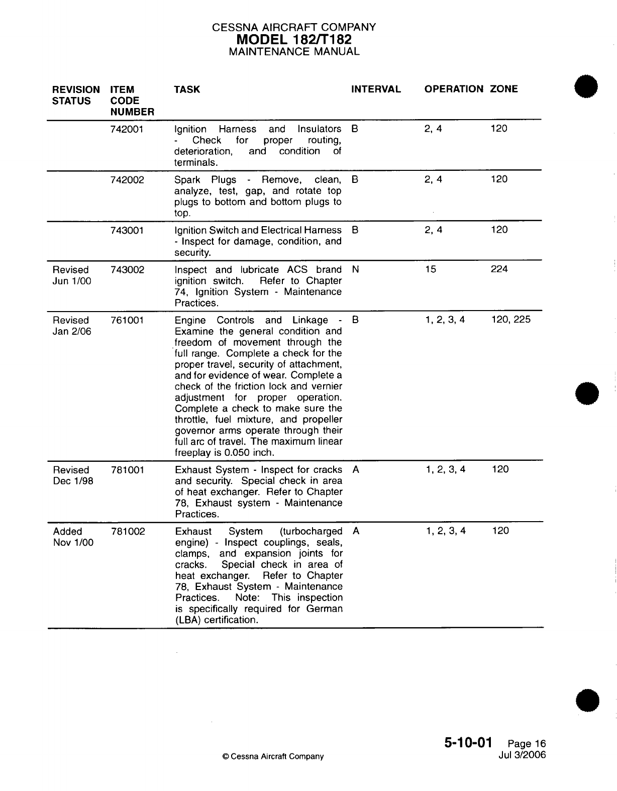
CESSNA
AIRCRAFT
COMPANY
MODEL 182/T182
MAINTENANCE
MANUAL
REVISION
ITEM
STATUS
CODE
NUMBER
742001
742002
743001
Revised
Jun
1/00
Revised
Jan
2/06
Revised
Dec
1/98
Added
Nov
1/00
743002
761001
781001
781002
TASK
Ignition
Harness
Check
for
deterioration,
ar
terminals.
and
Insulators
proper
routing,
nd
condition
of
Spark Plugs
-
Remove, clean,
analyze,
test,
gap,
and
rotate
top
plugs
to
bottom
and
bottom
plugs
to
top.
Ignition
Switch and Electrical
Harness
-
Inspect for
damage, condition,
and
security.
Inspect
and
lubricate
ACS
brand
ignition
switch. Refer
to
Chapter
74,
Ignition
System
-
Maintenance
Practices.
Engine
Controls
and
Linkage
-
Examine
the
general
condition
and
freedom
of
movement
through
the
full
range.
Complete
a
check
for
the
proper
travel,
security
of
attachment,
and
for evidence
of
wear.
Complete
a
check
of
the
friction
lock
and
vernier
adjustment for
proper
operation.
Complete
a
check
to
make
sure
the
throttle,
fuel
mixture,
and
propeller
governor
arms
operate
through
their
full
arc of
travel. The
maximum
linear
freeplay
is
0.050
inch.
Exhaust
System
-
Inspect
for
cracks
and
security. Special check
in
area
of
heat
exchanger.
Refer
to
Chapter
78,
Exhaust
system
-
Maintenance
Practices.
Exhaust
System (turbocharged
engine)
-
Inspect
couplings,
seals,
clamps,
and
expansion
joints
for
cracks.
Special
check
in
area
of
heat
exchanger.
Refer
to Chapter
78,
Exhaust
System
-
Maintenance
Practices.
Note:
This
inspection
is
specifically
required
for
German
(LBA)
certification.
INTERVAL OPERATION
ZONE
2,
4
B
B
B
N
B
A
A
2,4
2,
4
15
120
120
120
224
1,2,3,4
120,225
1,2,3,4
120
1,
2, 3,4
5-10-01
©
Cessna Aircraft
Company
120
Page
16
Jul
3/2006
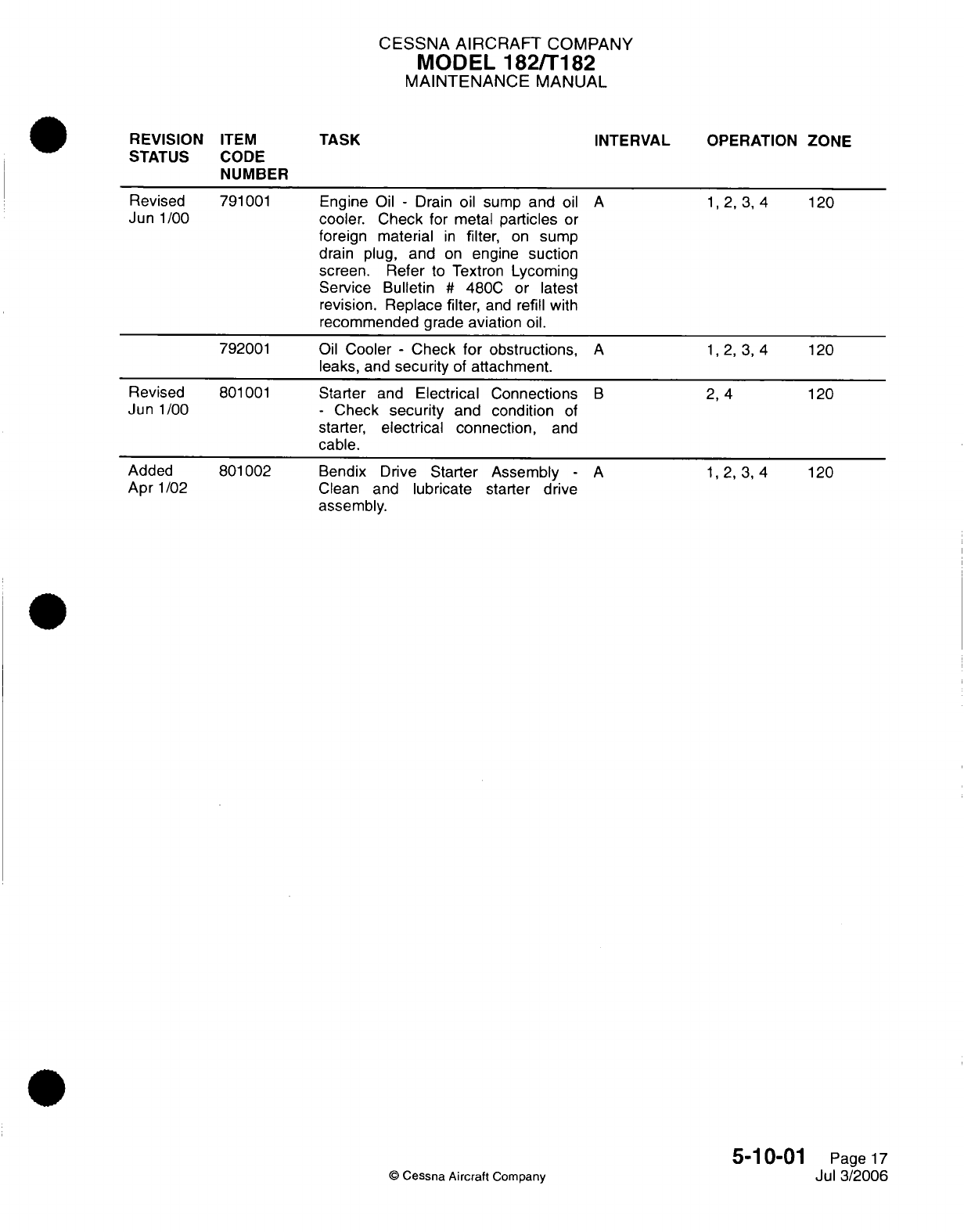
CESSNA
AIRCRAFT
COMPANY
MODEL
182/T182
MAINTENANCE
MANUAL
REVISION
ITEM
STATUS
CODE
NUMBER
TASK
INTERVAL OPERATION
ZONE
Engine
Oil
-
Drain
oil
sump
and
oil
cooler.
Check
for metal
particles
or
foreign material
in
filter,
on
sump
drain
plug,
and
on
engine
suction
screen. Refer
to
Textron
Lycoming
Service Bulletin
#
480C
or
latest
revision.
Replace
filter,
and
refill
with
recommended
grade
aviation
oil.
Oil
Cooler
-
Check
for
obstructions,
leaks,
and
security
of
attachment.
Starter
and
Electrical Connections
-
Check
security
and condition
of
starter,
electrical connection,
and
cable.
Bendix
Drive
Starter
Assembly
-
Clean
and
lubricate starter
drive
assembly.
A
1,2,3,4
120
A
1,2,3,4
120
B
2,4
A
120
1,2,3,4
120
5-10-01
Page
17
Jul
3/2006
©
Cessna Aircraft
Company
Revised
Jun
1/00 791001
792001
Revised
Jun
1/00
Added
Apr
1/02
801001
801002
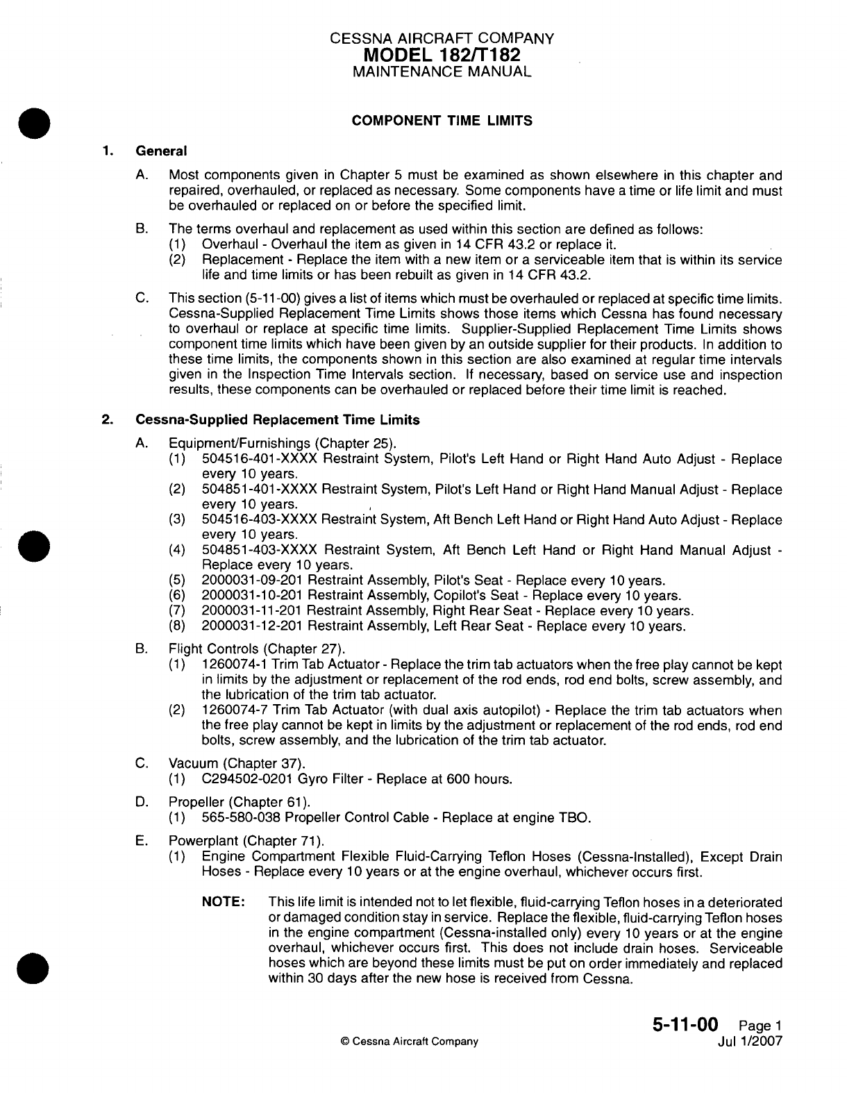
CESSNA AIRCRAFT
COMPANY
MODEL
182/Ti
82
MAINTENANCE
MANUAL
COMPONENT
TIME
LIMITS
1.General
A.
Most
components
given
in
Chapter
5
must
be
examined
as
shown
elsewhere
in
this
chapter
and
repaired,
overhauled,
or
replaced
as
necessary.
Some
components
have
a
time
or
life
limit
and
must
be
overhauled
or
replaced
on
or
before
the
specified
limit.
B.
The
terms
overhaul
and
replacement
as
used
within
this section
are
defined
as
follows:
(1)
Overhaul
-
Overhaul
the
item
as
given
in
14
CFR
43.2
or
replace
it.
(2)
Replacement
-
Replace
the
item
with
a
new
item
or
a
serviceable
item
that
is
within
its
service
life
and
time
limits or
has
been
rebuilt
as
given
in
14
CFR
43.2.
C.
This
section
(5-11
-00)
gives
a
list
of
items
which
must
be
overhauled
or
replaced
at
specific
time
limits.
Cessna-Supplied
Replacement
Time
Limits
shows
those
items
which
Cessna
has
found
necessary
to
overhaul
or
replace at
specific
time
limits.
Supplier-Supplied
Replacement
Time
Limits
shows
component
time
limits
which
have
been
given
by
an
outside
supplier
for
their
products.
In
addition
to
these
time
limits,
the
components
shown
in
this
section
are
also
examined
at
regular time
intervals
given
in
the
Inspection
Time
Intervals
section.
If
necessary,
based
on
service
use
and
inspection
results,
these components
can
be
overhauled
or
replaced
before
their
time
limit
is
reached.
2.
Cessna-Supplied
Replacement
Time
Limits
A.
Equipment/Furnishings
(Chapter
25).
(1)
504516-401
-XXXX
Restraint
System, Pilot's
Left
Hand
or
Right
Hand
Auto
Adjust
-
Replace
every
10
years.
(2)
504851-401-XXXX
Restraint
System,
Pilot's
Left
Hand
or
Right
Hand
Manual
Adjust
-
Replace
every
10
years.
(3)
50451
6-403-XXXX
Restraint System,
Aft
Bench Left
Hand
or
Right
Hand
Auto
Adjust
-
Replace
every
10
years.
(4)
504851-403-XXXX
Restraint
System,
Aft
Bench
Left
Hand
or
Right
Hand Manual
Adjust
-
Replace every
10
years.
(5)
2000031-09-201 Restraint Assembly,
Pilot's
Seat
-
Replace
every
10
years.
(6)
2000031-10-201
Restraint Assembly, Copilot's
Seat
-
Replace
every
10
years.
(7)
2000031-11
-201
Restraint Assembly,
Right
Rear
Seat
-
Replace
every
1 0
years.
(8)
2000031-12-201
Restraint Assembly,
Left
Rear
Seat
-
Replace
every
10
years.
B.
Flight
Controls (Chapter
27).
(1)
1260074-1
Trim
Tab
Actuator
-
Replace
the
trim
tab
actuators
when
the
free
play
cannot
be
kept
in
limits
by
the
adjustment
or
replacement
of
the
rod
ends,
rod
end
bolts,
screw
assembly,
and
the lubrication
of
the
trim
tab
actuator.
(2)
1260074-7
Trim
Tab
Actuator
(with
dual
axis
autopilot)
-
Replace
the
trim
tab
actuators
when
the
free
play
cannot
be
kept
in
limits
by the
adjustment
or
replacement
of
the
rod
ends,
rod
end
bolts,
screw
assembly,
and
the
lubrication
of
the
trim
tab
actuator.
C.
Vacuum
(Chapter
37).
(1)
C294502-0201
Gyro Filter
-
Replace
at
600 hours.
D.
Propeller
(Chapter
61).
(1)
565-580-038 Propeller
Control
Cable
-
Replace
at
engine
TBO.
E.
Powerplant
(Chapter
71).
(1)
Engine Compartment
Flexible
Fluid-Carrying
Teflon
Hoses (Cessna-Installed), Except
Drain
Hoses
-
Replace
every
1
0
years
or
at
the
engine
overhaul,
whichever
occurs
first.
NOTE:
This
life
limit
is
intended
not
to
let
flexible,
fluid-carrying
Teflon
hoses
in a
deteriorated
or
damaged condition
stay
in
service. Replace
the
flexible,
fluid-carrying
Teflon
hoses
in
the
engine compartment
(Cessna-installed
only)
every
10
years
or
at
the engine
overhaul,
whichever
occurs first.
This
does
not
include
drain
hoses.
Serviceable
hoses which
are
beyond
these limits must
be
put
on
order
immediately
and
replaced
within
30
days after
the
new
hose
is
received
from
Cessna.
5-1
1-00
Page
1
C
Cessna
Aircraft
Company
Jul
1/2007
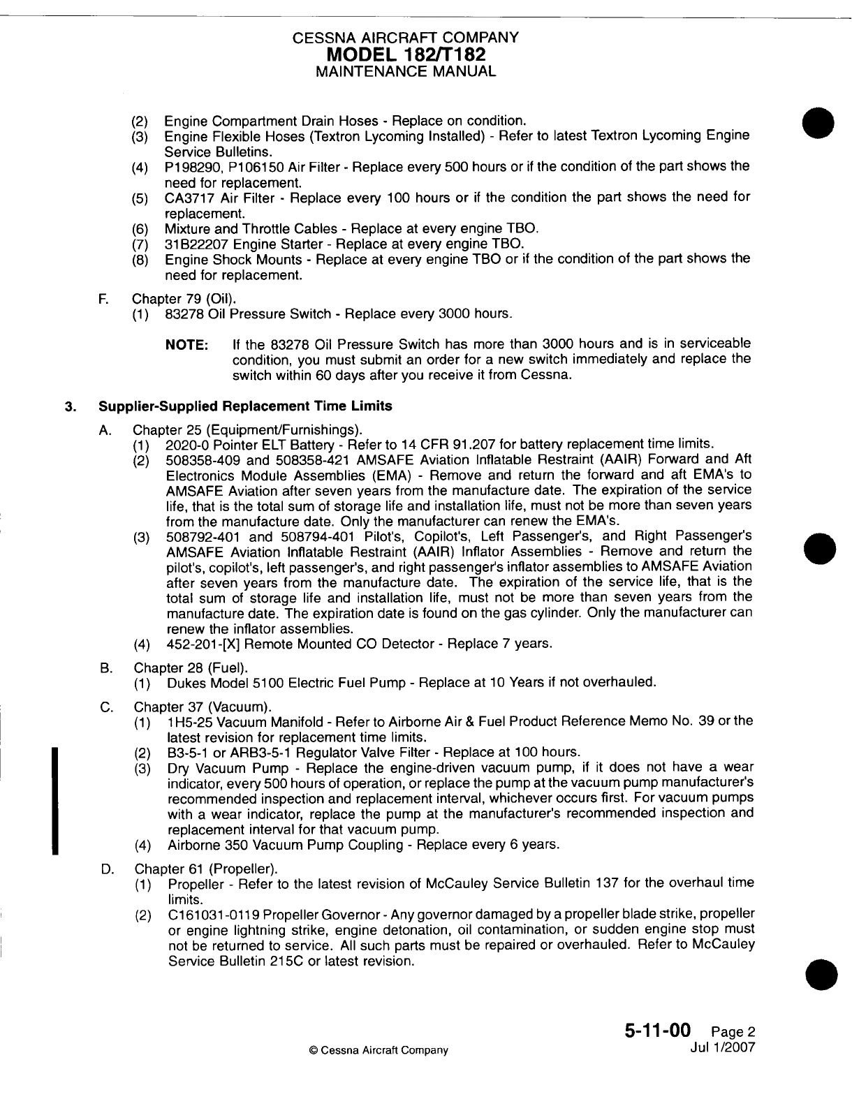
CESSNA
AIRCRAFT
COMPANY
MODEL
182/Ti82
MAINTENANCE
MANUAL
(2)
Engine
Compartment
Drain
Hoses
-
Replace
on
condition.
(3)
Engine
Flexible Hoses
(Textron
Lycoming Installed)
-
Refer
to
latest Textron
Lycoming
Engine
Service
Bulletins.
(4)
P1
98290.
P1
06150
Air
Filter
-
Replace
every
500
hours
or
if
the
condition
of
the part
shows
the
need
for
replacement.
(5)
CA3717
Air
Filter
-
Replace every
100
hours
or
if
the
condition
the
part
shows
the
need
for
replacement.
(6)
Mixture
and
Throttle
Cables
-
Replace
at
every engine
TBO.
(7)
31
B22207 Engine
Starter
-
Replace
at
every
engine
T1RO.
(8)
Engine
Shock
Mounts
-
Replace
at
every engine
TBO
or
if
the
condition
of the
part
shows
the
need
for
replacement.
F.
Chapter
79
(Oil).
(1)
83278
Oil
Pressure
Switch
-
Replace every
3000
hours.
NOTE:
If
the
83278
Oil
Pressure
Switch
has
more
than 3000 hours
and
is in
serviceable
condition,
you must
submit
an
order for
a
new
switch
immediately
and
replace
the
switch
within
60
days after
you
receive
it
from
Cessna.
3.
Supplier-Supplied
Replacement
Time
Limits
A.
Chapter
25
(Equipment/Furnishings).
(1)
2020-0
Pointer
ELT
Battery
-
Refer
to
14
CFR
91.207
for battery
replacement
time
limits.
(2)
508358-409
and
508358-421 AMSAFE
Aviation
Inflatable
Restraint
(AAIR)
Forward
and
Aft
Electronics
Module
Assemblies
(EMA)
-
Remove
and
return
the
forward
and
aft EMA's
to
AMSAFE
Aviation
after
seven
years
from
the
manufacture
date.
The
expiration
of
the
service
life,
that
is
the
total sum
of
storage
life
and
installation
life,
must
not
be
more
than
seven
years
from
the
manufacture
date.
Only
the
manufacturer
can
renew
the
EMA's.
(3)
508792-401 and 508794-401 Pilot's,
Copilot's,
Left
Passenger's,
and Right
Passenger's
AMSAFE
Aviation Inflatable
Restraint
(AAIR)
Inflator
Assemblies
-
Remove
and return
the0
pilot's, copilot's,
left
passenger's,
and
right
passenger's inflator
assemblies
to
AMSAFE
Aviation
after seven
years
from the
manufacture
date.
The
expiration
of
the
service
life,
that
is
the
total
sum
of
storage
life
and
installation
life, must
not
be
more
than
seven years
from
the
manufacture
date.
The
expiration
date
is
found
on the gas
cylinder.
Only
the
manufacturer
can
renew
the
inflator
assemblies.
(4)
452-201
-[X]
Remote
Mounted
CO
Detector
-
Replace
7
years.
B.
Chapter
28
(Fuel).
(1)
Dukes
Model
51
00 Electric
Fuel
Pump
-
Replace
at
1 0
Years
if
not
overhauled.
C.
Chapter
37
(Vacuum).
(1) 1
H5-25
Vacuum
Manifold
-
Refer
to
Airborne Air
&
Fuel
Product
Reference
Memo
No.
39
or
the
latest
revision
for replacement
time limits.
(2)
183-5-1
or
AR1B3-5-1
Regulator
Valve
Filter
-
Replace
at
1
00
hours.
(3)
Dry
Vacuum
Pump
-
Replace
the
engine-driven
vacuum
pump,
if it
does
not
have
a
wear
indicator,
every
500 hours
of
operation,
or replace
the
pump
at
the
vacuum
pump
manufacturer's
recommended
inspection
and
replacement
interval,
whichever
occurs
first.
For
vacuum
pumps
with
a
wear indicator,
replace
the
pump
at
the
manufacturer's
recommended
inspection
and
replacement
interval for
that
vacuum
pump.
(4)
Airborne
350
Vacuum Pump
Coupling
-
Replace
every
6
years.
D.
Chapter
61
(Propeller).
(1)
Propeller
-
Refer
to
the
latest
revision
of
McCauley Service Bulletin
137
for
the
overhaul time
limits.
(2)
C1
61031-0119 Propeller
Governor
-
Any
governor
damaged
by
a
propeller
blade strike,
propeller
or
engine lightning strike,
engine detonation,
oil
contamination,
or
sudden
engine
stop
must
not
be
returned
to
service.
All
such
parts
must
be
repaired
or
overhauled.
Refer
to
McCauley
Service
Bulletin
215SC
or
latest
revision.
5-11-00
Page2
C
Cessna
Aircraft
Company
Jul
1/2007
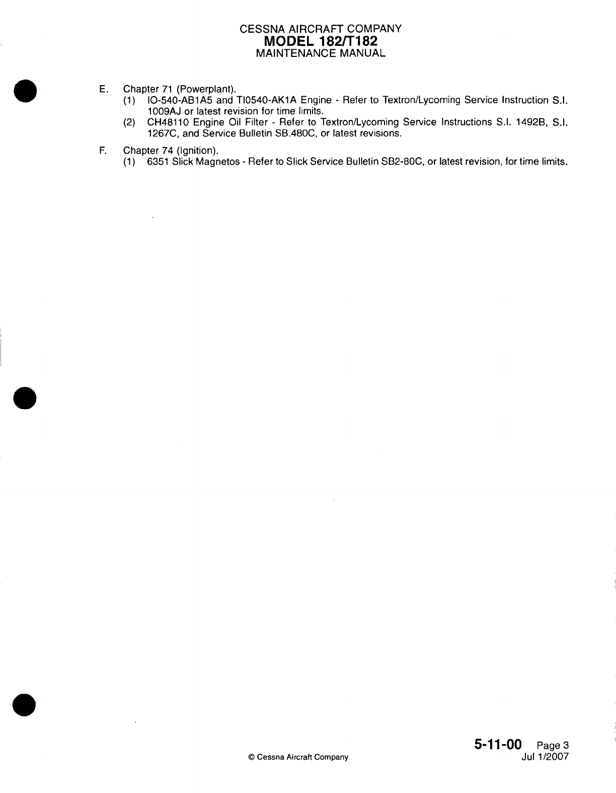
CESSNA AIRCRAFT
COMPANY
MODEL
1821T182
MAINTENANCE
MANUAL
E.
Chapter
71
(Powerplant).
(1)
10-540-ABlA5
and
T10540-AKl1A
Engine
-
Refer
to
Textron/Lycoming
Service
Instruction
S.I.
1009AJ
or
latest revision
for
time
limits.
(2)
CH48110
Engine
Oil
Filter
-
Refer
to
Textron/Lycoming
Service
Instructions
S.1.
1492B,
S.1.
1267C,
and
Service
Bulletin
SB.4800,
or
latest
revisions.
F.
Chapter
74
(Ignition).
(1)
6351
Slick
Magnetos
-
Refer
to
Slick
Service
Bulletin SB2-80C,
or
latest
revision,
for
time
limits.
5-1
1-00
Page
3
©
Cessna Aircraft Company
Jul
1
/2007
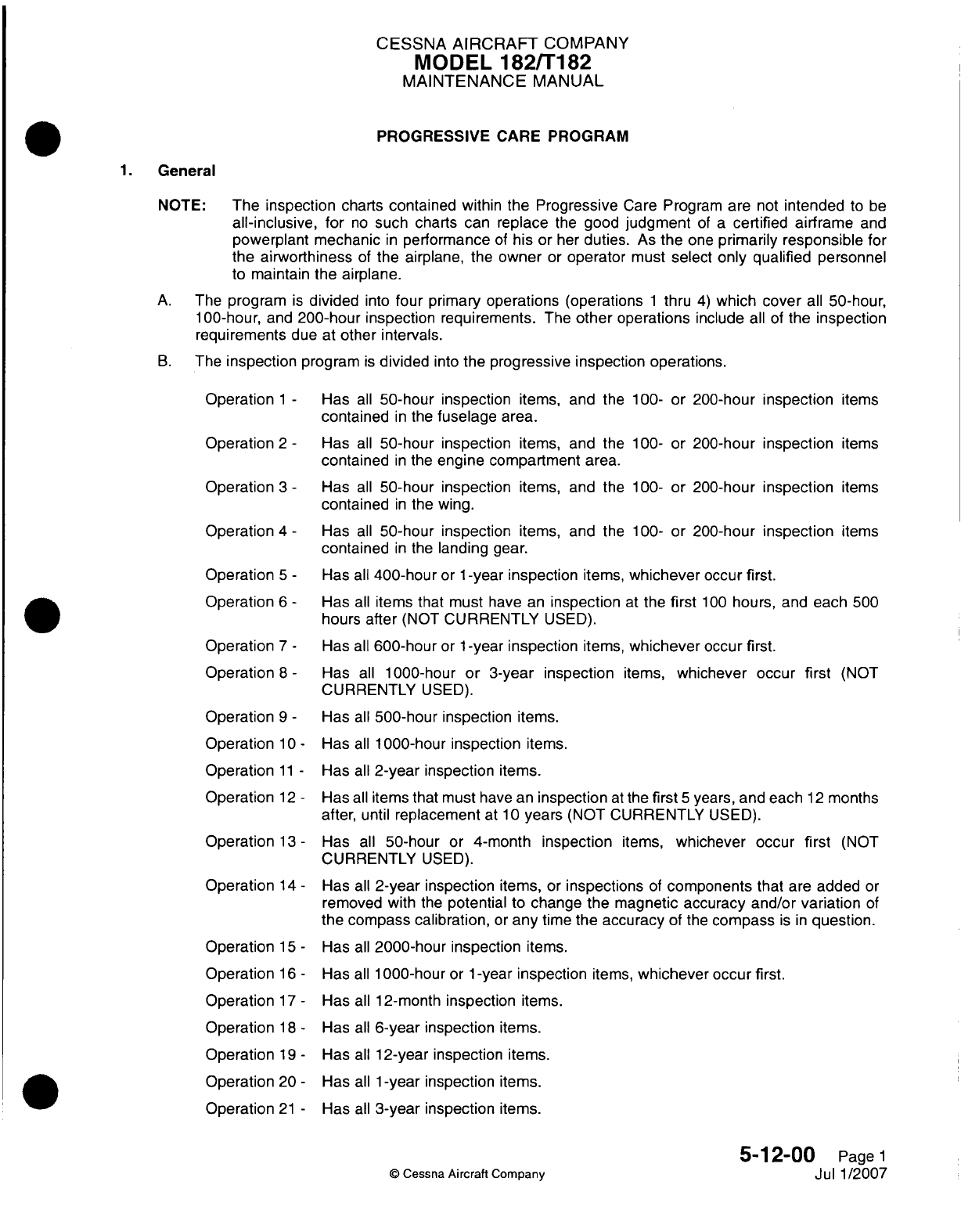
CESSNA
AIRCRAFT
COMPANY
MODEL
182/Ti
82
MAINTENANCE
MANUAL
PROGRESSIVE
CARE
PROGRAM
General
NOTE:
The
inspection
charts
contained
within
the
Progressive
Care
Program
are
not
intended
to
be
all-inclusive,
for
no
such
charts can
replace
the
good
judgment
of
a
certified
airframe
and
powerplant
mechanic
in
performance
of
his
or
her
duties.
As
the
one
primarily
responsible
for
the
airworthiness
of
the
airplane,
the
owner
or
operator
must
select only qualified
personnel
to
maintain
the airplane.
A.
The
program
is
divided
into
four
primary operations
(operations
1
thru
4)
which
cover
all
50-hour,
1
00-hour,
and
200-hour
inspection requirements.
The
other
operations
include
all
of
the
inspection
requirements
due
at
other
intervals.
B.
The
inspection
program
is
divided
into the
progressive
inspection operations.
Operation
1
-
Operation
2
-
Operation
3
-
Operation
4
-
Operation
5
-
Operation
6
-
Operation
7
-
Operation
8
-
Ope
ration
9
-
Operation
1
0-
Operation
11
-
Operation
12
-
Operation
13
-
Operation
14
-
Operation
15
-
Operation
16
-
Operation
17
-
Operation
1 8
-
Operation
19
-
Operation
20
-
Operation
21
-
Has
all
50-hour inspection
items,
and
the
100-
or
200-hour inspection
items
contained
in
the
fuselage
area.
Has
all
50-hour
inspection
items,
and
the
100-
or
200-hour inspection
items
contained
in
the
engine
compartment
area.
Has
all
50-hour
inspection
items,
and
the
100-
or
200-hour inspection
items
contained
in
the
wing.
Has
all
50-hour
inspection
items,
and
the
100-
or
200-hour
inspection
items
contained
in
the
landing
gear.
Has
all
400-hour
or
1
-year
inspection
items,
whichever
occur first.
Has
all
items
that
must
have
an
inspection
at the
first
100
hours,
and
each
500
hours
after
(NOT
CURRENTLY
USED).
Has
all
600-hour
or
1
-year
inspection
items,
whichever
occur
first.
Has
all
1000-hour or
3-year
inspection
items,
whichever
occur
first
(NOT
CURRENTLY
USED).
Has
all
500-hour
inspection
items.
Has
all
1
000-hour
inspection
items.
Has
all
2-year
inspection
items.
Has
all
items
that
must
have an
inspection
at
the
first
5
years, and
each
12
months
after,
until
replacement
at
1 0
years
(NOT
CURRENTLY
USED).
Has
all
50-hour
or
4-month
inspection
items,
whichever
occur
first
(NOT
CURRENTLY
USED).
Has
all
2-year
inspection
items,
or
inspections
of
components
that
are
added
or
removed
with
the
potential
to
change the magnetic accuracy
and/or variation
of
the
compass calibration,
or
any
time
the
accuracy
of
the
compass
is in
question.
Has
all
2000-hour inspection
items.
Has
all
1
000-hour
or
1
-year
inspection
items,
whichever
occur
first.
Has
all
12-month
inspection
items.
Has
all
6-year
inspection
items.
Has
all
12-year inspection items.
Has
all
1
-year
inspection
items.
Has
all
3-year
inspection
items.
5-12-00
Page
1
©
Cessna
Aircraft
Company
Jul
1/2007

CESSNA
AIRCRAFT
COMPANY
MODEL
182/Ti
182
MAINTENANCE
MANUAL
Operation
22
-
Has
all
5-year inspection
items
from
the
date
of
manufacture.
Serviceability
of
the
components
must
be
examined
each
12
months.
Refer
to
Airborne
Air
and
Fuel
Products
Service Letter
Number
39A
or
latest
revision.
Operation
23
-
Has
all
1
00-hour
or
1
-year
inspection
items,
whichever
occur
first.
Operation
24
-
Every 100
hours,
every
annual
inspection,
every overhaul,
and any time
fuel
lines
or
clamps
are
serviced,
removed
or
replaced.
Operation
25
-
First
600
hours
and
as
defined
by
the manufacturer
thereafter.
Operation
26
-
Everyl1000hours
or
3years,
whichever
occurs
first.
2.
Procedure
A. A
FULL
AIRPLANE INSPECTION
includes
all
50-,
100-,
and
200-hour
inspection
items
plus those
Inspection
Items
contained
in
other
operations
which
are
due
at
the
specified
time.
B.
The
Component
Time
Limits Section
(5-11
-00)
must
be
read
at
each
inspection
interval
to
make
sure
that
the
correct
overhaul
and
replacement requirements
are
done
at
the
specified
times.
C.
The
Inspection
Operations
have been
develope
d
based
on normal
usage
under
average
environmental
conditions. Airplanes
operated
in
extremely
humid
areas
(tropics),
or
in
exceptionally
cold,
damp climates,
etc.,
may
need
more
frequent inspections
for
wear,
corrosion,
and
lubrication.
Under
these
adverse
conditions,
do
the
periodic
inspections
in
compliance
with
the
Inspection
Operations
at
more
frequent intervals
until
the
operator
can
set
his
own
inspection periods
based
on
field
experience.
The operator's
inspection
intervals
must
not
deviate
from
the
inspection
time
limits
shown
in
this manual
except
as
given
below:
(1)
Each
inspection
interval
can
be
extended
by
1 0
hours
(if
time-controlled),
or
by
30
days
(if
date-
controlled)
or can
be
performed early
at
any time prior
to
the
regular
interval
as
provided
below:
(a) In
the
event
of
late
compliance
of
any
operation
scheduled,
the next
operation
in
sequence
keeps
a
due
point
from
the
time
the
late
operation
was
originally
scheduled.
(b) In
the
event
of
early
compliance
of
any
operation scheduled, that
occurs
1
0
hours
or
less
ahead
of
schedule,
the
next
phase
due
point
can stay
where
originally
set.
(c) In
the
event
of
early
compliance
of
any
operation
scheduled, that occurs
more
than
10
hours ahead
of
schedule,
the
next
operation
due point
must
be
rescheduled
to
establish
a
new
due
point
from the
time
of
early
compliance.
3.
Inspection
Terms
and
Guidelines
A.
For
inspection
terms
and
guidelines,
refer
to
Time
Limits/Maintenance
Checks
-
General.
5-1
2-00
Page
2
©
Cessna
Aircraft Company
Jul
1/2007
I
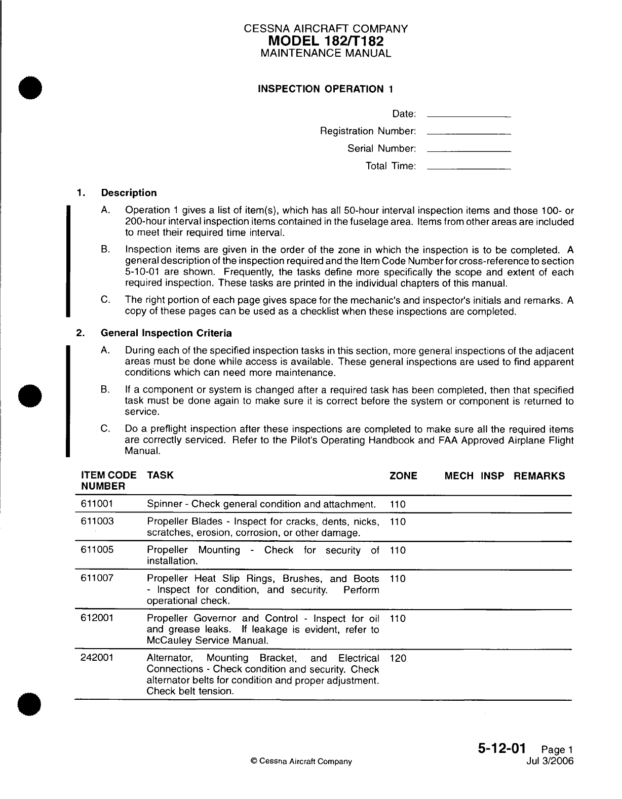
CESSNA AIRCRAFT
COMPANY
MODEL
182/T182
MAINTENANCE
MANUAL
INSPECTION
OPERATION
1
Date:
Registration
Number:
Serial Number:
Total
Time:
1.
Description
A.
Operation
1
gives
a
list
of
item(s),
which
has
all
50-hour
interval
inspection
items and
those
100- or
200-hour
interval
inspection
items
contained
in
the
fuselage
area.
Items from
other
areas
are
included
to meet
their
required
time interval.
B.
Inspection
items
are
given
in
the order
of
the
zone
in
which
the
inspection
is
to
be
completed.
A
general
description
of
the inspection
required
and
the
Item
Code
Number
for
cross-reference
to
section
5-10-01
are
shown. Frequently,
the
tasks
define
more
specifically
the
scope
and
extent
of
each
required
inspection. These tasks
are printed
in
the
individual chapters
of
this manual.
C.
The
right
portion
of
each
page
gives
space for
the
mechanic's
and
inspector's
initials
and
remarks.
A
copy
of
these
pages
can
be
used
as
a
checklist
when
these
inspections
are
completed.
2.
General
Inspection
Criteria
A.
During
each
of
the specified inspection tasks
in
this
section,
more
general
inspections
of
the
adjacent
areas
must
be
done
while
access
is
available. These
general
inspections
are
used to
find
apparent
conditions which
can need
more
maintenance.
B. If a
component
or
system
is
changed after
a
required
task
has
been
completed, then
that
specified
task
must
be
done
again
to
make
sure
it is
correct
before
the
system or
component
is
returned
to
service.
C.
Do
a
preflight inspection
after
these inspections
are
completed
to
make
sure
all
the
required
items
are
correctly
serviced.
Refer
to
the
Pilot's Operating
Handbook
and
FAA
Approved
Airplane
Flight
Manual.
ITEM
CODE
TASK
ZONE
MECH
INSP
REMARKS
NUMBER
611001
Spinner
-
Check
general
condition
and
attachment.
110
611003
Propeller
Blades
-
Inspect
for cracks,
dents,
nicks,
110
scratches,
erosion,
corrosion,
or
other
damage.
611005
Propeller
Mounting
-
Check
for
security
of
110
installation.
611007
Propeller
Heat
Slip
Rings, Brushes,
and Boots
110
-
Inspect for
condition,
and
security. Perform
operational check.
612001
Propeller
Governor
and Control
-
Inspect
for
oil
110
and
grease
leaks.
If
leakage
is
evident,
refer
to
McCauley
Service
Manual.
242001
Alternator, Mounting Bracket,
and
Electrical
120
Connections
-
Check condition
and
security. Check
alternator
belts for
condition
and
proper
adjustment.
Check
belt
tension.
5-12-01
Page
1
©
Cessna Aircraft
Company
Jul
3/2006
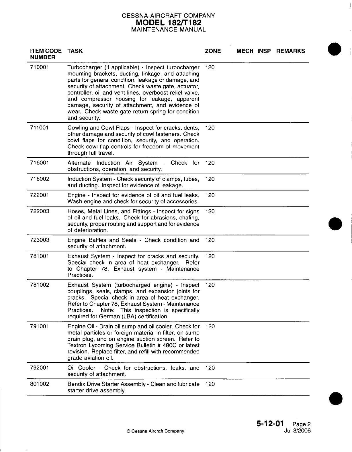
CESSNA AIRCRAFT
COMPANY
MODEL
182/T182
MAINTENANCE
MANUAL
ITEM CODE
TASK
ZONE
MECH INSP
REMARKS
NUMBER
710001
Turbocharger
(if
applicable)
-
Inspect
turbocharger
120
mounting
brackets,
ducting,
linkage,
and
attaching
parts
for
general
condition,
leakage
or
damage,
and
security
of
attachment. Check
waste
gate, actuator,
controller,
oil
and vent lines,
overboost
relief
valve,
and
compressor
housing
for
leakage,
apparent
damage,
security
of
attachment,
and
evidence
of
wear.
Check
waste
gate
return
spring
for
condition
and
security.
711001
Cowling
and Cowl Flaps
-
Inspect for
cracks,
dents,
120
other
damage
and
security
of
cowl
fasteners.
Check
cowl
flaps
for
condition,
security,
and
operation.
Check
cowl
flap controls
for
freedom
of
movement
through
full
travel.
716001
Alternate
Induction
Air
System
-
Check
for
120
obstructions,
operation,
and
security.
716002
Induction
System
-
Check
security
of
clamps, tubes,
120
and
ducting.
Inspect
for
evidence
of
leakage.
722001
Engine
-
Inspect
for
evidence
of
oil
and
fuel
leaks.
120
Wash
engine
and
check
for security
of
accessories.
722003
Hoses,
Metal
Lines,
and
Fittings
-
Inspect
for
signs
120
of
oil
and
fuel
leaks.
Check for
abrasions,
chafing,
security, proper
routing
and
support
and
for
evidence
of
deterioration.
723003
Engine
Baffles
and
Seals
-
Check
condition
and
120
security
of
attachment.
781001
Exhaust
System
-
Inspect
for
cracks
and
security.
120
Special check
in
area
of
heat
exchanger.
Refer
to
Chapter
78,
Exhaust system
-
Maintenance
Practices.
781002 Exhaust
System
(turbocharged
engine)
-
Inspect
120
couplings,
seals, clamps,
and
expansion joints
for
cracks.
Special
check
in
area
of
heat
exchanger.
Refer to
Chapter
78,
Exhaust
System
-
Maintenance
Practices.
Note:
This
inspection
is
specifically
required for German
(LBA)
certification.
791001
Engine
Oil
-
Drain oil
sump
and
oil
cooler.
Check
for
120
metal
particles
or
foreign
material
in
filter,
on
sump
drain plug,
and
on
engine
suction
screen.
Refer
to
Textron
Lycoming
Service
Bulletin
#
480C
or
latest
revision.
Replace
filter,
and
refill
with
recommended
grade
aviation
oil.
792001
Oil
Cooler
-
Check
for
obstructions,
leaks,
and
120
security
of
attachment.
801002
Bendix
Drive
Starter Assembly
-
Clean
and
lubricate
120
starter
drive
assembly.
5-12-01
Page
2
©
Cessna
Aircraft
Company
Jul
3/2006
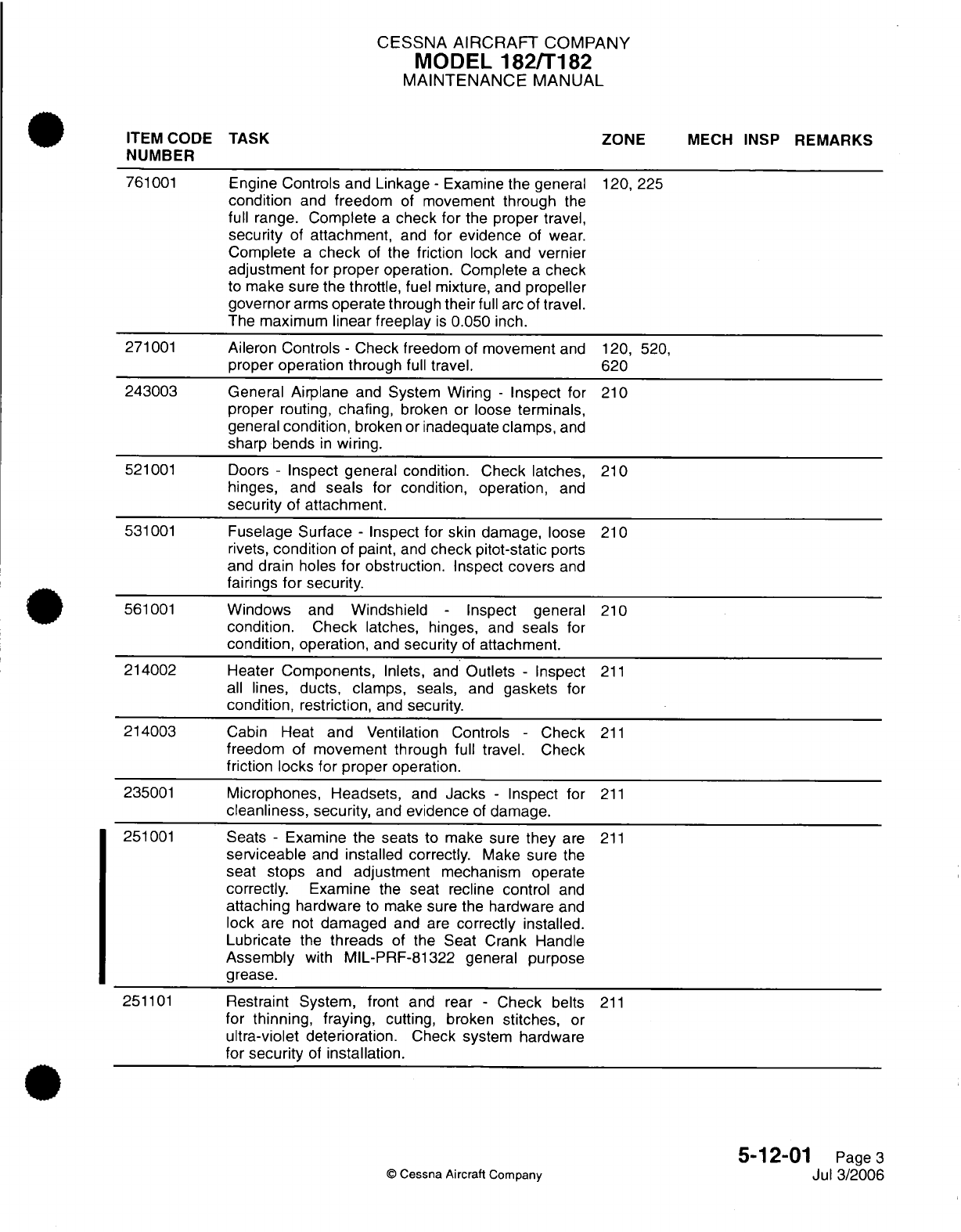
CESSNA
AIRCRAFT
COMPANY
MODEL
182/T182
MAINTENANCE
MANUAL
ITEM
CODE
TASK
ZONE
MECH INSP
REMARKS
NUMBER
761001
Engine
Controls
and
Linkage
-
Examine
the
general
120,
225
condition
and
freedom
of
movement
through
the
full range.
Complete
a
check
for
the proper travel,
security
of
attachment,
and
for
evidence
of
wear.
Complete
a
check
of
the
friction
lock
and vernier
adjustment
for
proper
operation.
Complete
a
check
to
make sure
the
throttle,
fuel mixture,
and
propeller
governor
arms
operate
through
their
full
arc of
travel.
The
maximum
linear
freeplay
is
0.050
inch.
271001
Aileron
Controls
-
Check
freedom
of
movement
and
120, 520,
proper
operation
through
full
travel.
620
243003
General Airplane
and
System Wiring
-
Inspect
for
210
proper
routing,
chafing,
broken or
loose
terminals,
general
condition,
broken or
inadequate
clamps,
and
sharp
bends
in
wiring.
521001
Doors
-
Inspect general condition.
Check latches,
210
hinges,
and
seals
for condition,
operation,
and
security
of
attachment.
531001
Fuselage Surface
-
Inspect
for
skin damage, loose
210
rivets,
condition
of
paint,
and
check
pitot-static
ports
and
drain
holes
for
obstruction.
Inspect
covers
and
fairings
for
security.
561001
Windows
and
Windshield
-
Inspect general
210
condition.
Check
latches,
hinges,
and
seals
for
condition,
operation,
and
security
of
attachment.
214002
Heater
Components,
Inlets, and
Outlets
-
Inspect
211
all
lines, ducts,
clamps,
seals,
and
gaskets
for
condition, restriction,
and
security.
214003
Cabin
Heat
and
Ventilation Controls
-
Check
211
freedom
of
movement
through
full
travel.
Check
friction
locks
for
proper
operation.
235001
Microphones, Headsets,
and
Jacks
-
Inspect
for
211
cleanliness,
security,
and
evidence
of
damage.
251001
Seats
-
Examine the
seats
to
make sure
they
are
211
serviceable
and
installed
correctly.
Make
sure
the
seat
stops
and
adjustment
mechanism
operate
correctly.
Examine
the
seat
recline
control
and
attaching
hardware
to
make sure
the
hardware
and
lock are
not
damaged
and
are
correctly installed.
Lubricate
the
threads
of
the Seat
Crank
Handle
Assembly
with
MIL-PRF-81322 general purpose
grease.
251101
Restraint
System,
front
and rear
-
Check
belts
211
for
thinning, fraying,
cutting, broken
stitches,
or
ultra-violet
deterioration.
Check
system hardware
for
security
of
installation.
5-12-01
Page
3
©
Cessna
Aircraft
Company
Jul
3/2006
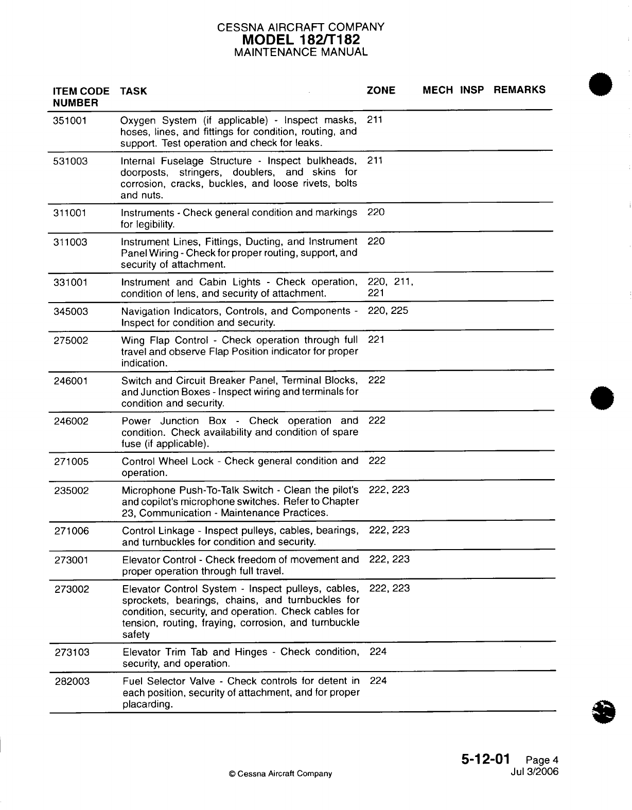
CESSNA
AIRCRAFT
COMPANY
MODEL
182/T182
MAINTENANCE
MANUAL
ITEM
CODE TASK
ZONE
MECH
INSP
REMARKS
NUMBER
351001
Oxygen
System
(if
applicable)
-
Inspect
masks,
211
hoses,
lines,
and
fittings
for
condition,
routing,
and
support.
Test
operation
and
check for
leaks.
531003
Internal
Fuselage
Structure
-
Inspect
bulkheads,
211
doorposts,
stringers,
doublers,
and
skins for
corrosion, cracks, buckles,
and
loose
rivets,
bolts
and
nuts.
311001
Instruments
-
Check
general
condition
and
markings
220
for
legibility.
311003 Instrument
Lines, Fittings, Ducting,
and Instrument
220
Panel
Wiring
-
Check
for
proper
routing,
support,
and
security
of
attachment.
331001
Instrument
and
Cabin
Lights
-
Check operation,
220,
211,
condition
of
lens,
and
security
of
attachment.
221
345003
Navigation Indicators, Controls,
and
Components
-
220,
225
Inspect
for
condition
and
security.
275002
Wing
Flap
Control
-
Check
operation
through
full
221
travel
and
observe
Flap
Position
indicator for
proper
indication.
246001
Switch
and
Circuit
Breaker
Panel,
Terminal
Blocks,
222
and
Junction
Boxes
-
Inspect
wiring
and
terminals
for
condition
and
security.
246002
Power
Junction
Box
-
Check
operation
and
222
condition.
Check
availability
and
condition
of
spare
fuse
(if
applicable).
271005
Control
Wheel Lock
-
Check
general
condition
and
222
operation.
235002
Microphone
Push-To-Talk
Switch
-
Clean the pilot's
222, 223
and
copilot's microphone switches.
Refer
to
Chapter
23,
Communication
-
Maintenance
Practices.
271006
Control
Linkage
-
Inspect
pulleys,
cables,
bearings,
222, 223
and
turnbuckles
for
condition
and
security.
273001
Elevator
Control
-
Check freedom
of
movement and
222,
223
proper
operation through full
travel.
273002
Elevator
Control
System
-
Inspect
pulleys, cables,
222, 223
sprockets, bearings, chains,
and
turnbuckles
for
condition,
security,
and
operation. Check
cables
for
tension,
routing,
fraying, corrosion,
and
turnbuckle
safety
273103
Elevator
Trim
Tab
and
Hinges
-
Check
condition,
224
security, and
operation.
282003
Fuel
Selector
Valve
-
Check controls
for
detent
in
224
each
position,
security
of
attachment,
and
for
proper
placarding.
5-12-01
Page
4
©
Cessna
Aircraft
Company
Jul 3/2006
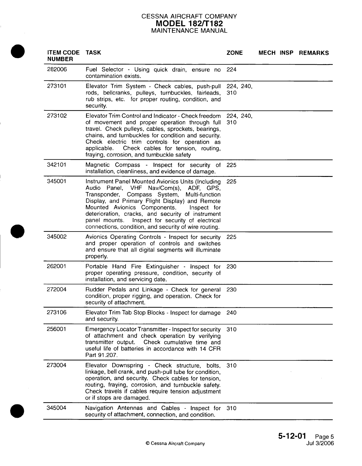
CESSNA AIRCRAFT
COMPANY
MODEL
182/T182
MAINTENANCE
MANUAL
ITEM
CODE
TASK ZONE
MECH
INSP
REMARKS
NUMBER
282006
Fuel
Selector
-
Using
quick
drain,
ensure
no
224
contamination
exists.
273101
Elevator
Trim
System
-
Check
cables, push-pull
224, 240,
rods,
bellcranks,
pulleys,
turnbuckles,
fairleads,
310
rub
strips,
etc.
for
proper
routing,
condition,
and
security.
273102 Elevator
Trim
Control
and
Indicator
-
Check
freedom 224, 240,
of
movement and proper
operation
through
full
310
travel. Check
pulleys,
cables,
sprockets,
bearings,
chains,
and
turnbuckles
for
condition
and
security.
Check
electric
trim
controls
for
operation
as
applicable. Check
cables for tension,
routing,
fraying,
corrosion,
and
turnbuckle
safety
342101
Magnetic Compass
-
Inspect for
security
of
225
installation,
cleanliness,
and
evidence
of
damage.
345001
Instrument Panel
Mounted
Avionics
Units
(Including
225
Audio
Panel, VHF
Nav/Com(s),
ADF, GPS,
Transponder, Compass
System,
Multi-function
Display,
and
Primary
Flight Display)
and
Remote
Mounted
Avionics
Components. Inspect
for
deterioration,
cracks,
and
security
of
instrument
panel
mounts.
Inspect
for
security
of
electrical
connections,
condition,
and
security
of
wire
routing.
345002
Avionics Operating
Controls
-
Inspect
for
security
225
and
proper
operation
of
controls
and
switches
and
ensure
that
all
digital
segments
will
illuminate
properly.
262001
Portable
Hand
Fire
Extinguisher
-
Inspect for
230
proper
operating
pressure,
condition, security
of
installation,
and
servicing
date.
272004
Rudder Pedals
and
Linkage
-
Check for
general
230
condition, proper
rigging,
and
operation.
Check
for
security
of
attachment.
273106 Elevator
Trim
Tab
Stop
Blocks
-
Inspect
for
damage
240
and
security.
256001
Emergency
Locator Transmitter-
Inspect
for
security
310
of
attachment
and
check
operation
by
verifying
transmitter output.
Check
cumulative
time
and
useful
life
of
batteries
in
accordance
with
14
CFR
Part
91.207.
273004 Elevator Downspring
-
Check
structure,
bolts,
310
linkage,
bell
crank,
and
push-pull
tube for
condition,
operation,
and
security.
Check cables
for
tension,
routing,
fraying,
corrosion,
and
turnbuckle
safety.
Check
travels
if
cables
require
tension adjustment
or
if
stops
are
damaged.
345004 Navigation
Antennas
and
Cables
-
Inspect for
310
security
of
attachment,
connection,
and
condition.
5-12-01
Page
5
©
Cessna
Aircraft
Company
Jul
3/2006

CESSNA AIRCRAFT
COMPANY
MODEL
182/T182
MAINTENANCE
MANUAL
ITEM
CODE
TASK
ZONE
MECH INSP
REMARKS
NUMBER
273104
Elevator
Trim
Tab
Actuator
-
Examine
the
free
320
play
limits.
Refer
to
Chapter
27,
Elevator
Trim
Control
-
Maintenance
Practices,
Trim
Tab
Free
Play
Inspection.
If
the
free
play
is
more
than
the
permitted
limits,
lubricate
the
actuator
and
examine
the
free
play
limits
again.
If
the
free
play
is
still
more
than the
permitted limits, replace
the
actuator.
273003
Elevator,
Hinges,
Stops,
and
Cable
Attachment
-
320,
330
Check
condition,
security,
and
operation.
551001
Horizontal
Stabilizer
and
Tailcone
structure
-
320,330
Inspect
bulkheads,
spars,
ribs,
and
skins,
for
cracks, wrinkles,
loose
rivets,
corrosion,
or
other
damage.
Inspect
horizontal
stabilizer
attach bolts
for
looseness.
Retorque
as
necessary.
Check
security
of
inspection covers, fairings,
and
tips.
551002
Horizontal
Stabilizer
and
Tips
-
Inspect
externally
for
320,
330
skin damage
and
condition
of
paint.
272002 Rudder
-
Inspect
the
rudder
skins for
cracks
and
340
loose
rivets,
rudder hinges
for
condition,
cracks
and
security;
hinge
bolts,
hinge
bearings, hinge
attach
fittings,
and
bonding
jumper
for
evidence
of
damage
and
wear, failed
fasteners,
and
security.
Inspect
balance
weight
for
looseness
and
the
supporting
structure
for
damage.
272003 Rudder,
Tips,
Hinges,
Stops,
Clips
and Cable
340
Attachment
-
Check
condition,
security,
and
operation.
272005
Rudder
Control
-
Check
freedom
of
movement
and
340
proper
operation through
full travel.
Check
rudder
stops
for damage and
security.
553001
Vertical
Stabilizer
Fin
-
Inspect
bulkheads,
spars,
340
ribs,
and
skins
for cracks, wrinkles,
loose
rivets,
corrosion,
or
other
damage.
Inspect
vertical
stabilizer
attach
bolts
for
looseness.
Retorque
as
necessary.
Check
security
of
inspection
covers,
fairings,
and
tip.
553002 Vertical
Stabilizer
Fin
and
Tailcone
-
Inspect
340
externally
for
skin
damage
and
condition
of
paint.
334001
Navigation,
Beacon, Strobe,
and
Landing
Lights
-
340,
520,
Check
operation,
condition
of
lens,
and
security
of
620
attachment.
341103
Pitot
Tube
and Stall Warning
Vane
-
Check
for
510
condition
and
obstructions
and
verify
operation
of
anti-ice
heat.
571001
Wing
Surfaces
and
Tips
-
Inspect
for
skin
damage,
510,
520,
loose
rivets, and
condition
of
paint. 610, 620
5-12-01
Page
6
©
Cessna
Aircraft
Company
Jul
3/2006
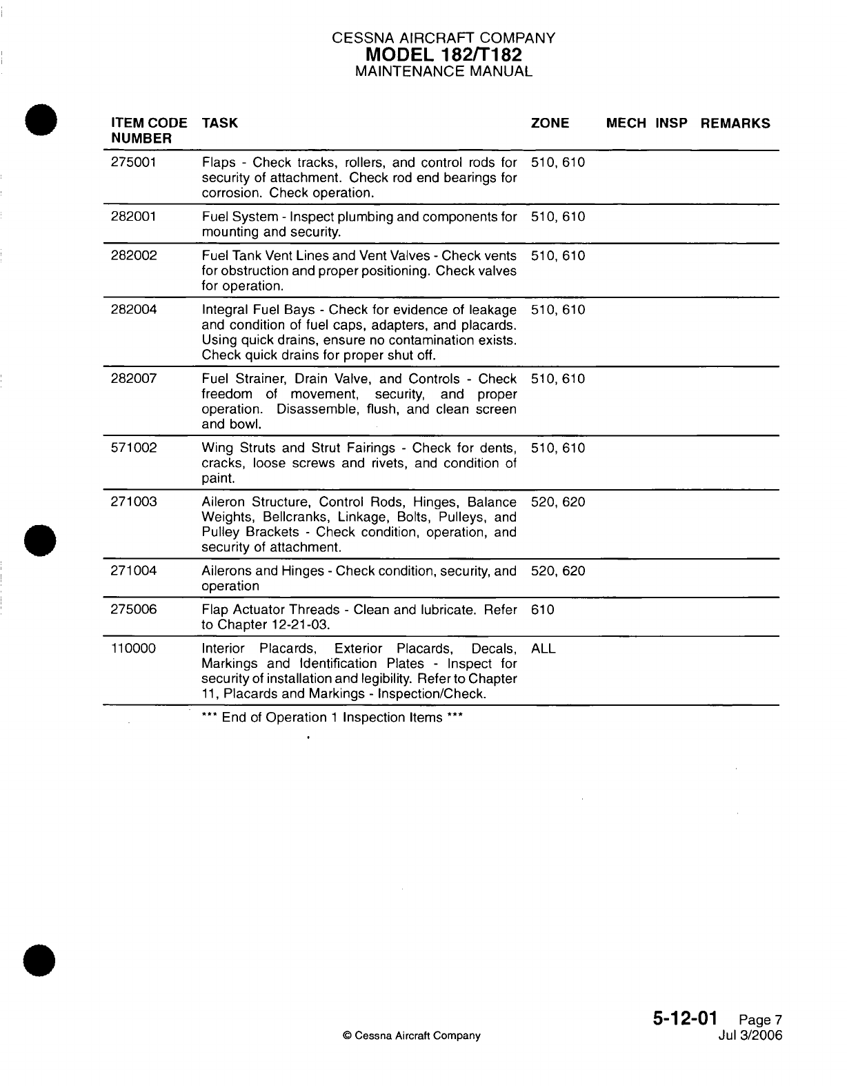
CESSNA AIRCRAFT
COMPANY
MODEL
182/T182
MAINTENANCE
MANUAL
ITEM
CODE
TASK
ZONE
MECH
INSP
REMARKS
NUMBER
275001
Flaps
-
Check
tracks,
rollers, and
control
rods
for
510,
610
security
of
attachment.
Check
rod
end
bearings
for
corrosion.
Check
operation.
282001
Fuel
System
-
Inspect plumbing
and
components
for
510,
610
mounting
and
security.
282002
Fuel
Tank
Vent
Lines and
Vent
Valves
-
Check
vents 510,
610
for
obstruction
and
proper positioning. Check
valves
for operation.
282004
Integral
Fuel
Bays
-
Check
for
evidence
of
leakage
510,
610
and
condition
of
fuel
caps,
adapters,
and
placards.
Using
quick
drains,
ensure
no
contamination exists.
Check
quick
drains for proper
shut
off.
282007
Fuel
Strainer,
Drain Valve,
and
Controls
-
Check
510,
610
freedom
of
movement,
security,
and
proper
operation.
Disassemble, flush,
and
clean
screen
and
bowl.
571002
Wing
Struts
and Strut
Fairings
-
Check
for
dents,
510,
610
cracks,
loose
screws
and rivets,
and
condition
of
paint.
271003
Aileron
Structure,
Control
Rods,
Hinges, Balance
520,
620
Weights, Bellcranks, Linkage,
Bolts,
Pulleys,
and
Pulley
Brackets
-
Check condition, operation,
and
security
of
attachment.
271004
Ailerons
and
Hinges
-
Check condition,
security,
and
520,
620
operation
275006
Flap
Actuator Threads
-
Clean
and
lubricate.
Refer
610
to
Chapter
12-21-03.
110000
Interior
Placards, Exterior
Placards,
Decals,
ALL
Markings
and
Identification
Plates
-
Inspect
for
security
of
installation
and
legibility.
Refer
to
Chapter
11,
Placards
and
Markings
-
Inspection/Check.
***
End
of
Operation
1
Inspection
Items
***
5-12-01
Page
7
©
Cessna
Aircraft
Company
Jul
3/2006

CESSNA AIRCRAFT
COMPANY
MODEL
182/T182
MAINTENANCE
MANUAL
INSPECTION
OPERATION
2
Date:
Registration
Number:
Serial Number:
Total
Time:
1.
Description
A.
Operation
2
gives
a
list
of
item(s),
which
has
all
50-hour
interval
inspection
items
and
those
100-
or
200-hour
interval
inspection
items
contained
in
the
engine
compartment.
Items
from
other areas
are
included
to
meet
their
required
time
interval.
B.
Inspection
items
are
given
in
the order
of
the zone
in
which
the
inspection
is
to
be
completed.
A
general
description
of
the
inspection
required
and the
Item
Code
Number for
cross-reference
to
section
5-10-01
are
shown.
Frequently,
the
tasks
define
more
specifically
the
scope
and
extent
of
each
required
inspection. These
tasks
are
printed
in
the
individual
chapters
of
this
manual.
C.
The
right
portion
of
each
page
gives space
for
the
mechanic's
and
inspector's
initials
and
remarks.
A
copy
of
these
pages can
be
used
as
a
checklist
when
these
inspections
are
completed.
2.
General
Inspection
Criteria
A.
During
each
of
the
specified inspection
tasks
in
this
section,
more
general
inspections
of
the
adjacent
areas
must
be
done
while
access
is
available.
These
general
inspections
are
used
to
find
apparent
conditions
which
can
need
more
maintenance.
B. If
a
component
or system
is
changed after
a
required
task
has
been
completed,
then
that
specified
task
must
be
done
again
to
make
sure
it is
correct
before
the system
or component
is
returned
to
service.
C.
Do
a
preflight
inspection
after
these inspections
are
completed
to
make
sure
all
the
required
items
are
correctly
serviced.
Refer
to
the
Pilot's
Operating
Handbook
and
FAA
Approved Airplane
Flight
Manual.
ITEM
CODE
TASK ZONE
MECH
INSP
REMARKS
NUMBER
611001
Spinner
-
Check
general
condition
and attachment.
110
611002
Spinner
and
Spinner
Bulkhead
-
Remove
spinner,
110
wash,
and
inspect
for
cracks
and
fractures.
611003
Propeller
Blades
-
Inspect
for
cracks,
dents, nicks,
110
scratches,
erosion, corrosion,
or
other
damage.
611004
Propeller
Hub
-
Check general
condition.
110
611005
Propeller Mounting
-
Check
for
security
of
110
installation.
611006
Propeller Mounting
Bolts
-
Inspect
mounting
bolts
110
and
safety
wire
for
signs
of
looseness.
Retorque
mounting
bolts
as required.
611007
Propeller Heat
Slip Rings,
Brushes, and
Boots
110
-
Inspect
for
condition,
and
security.
Perform
operational check.
5-12-02
Page
1
Cessna
Aircraft
Company
Jul
3/2006
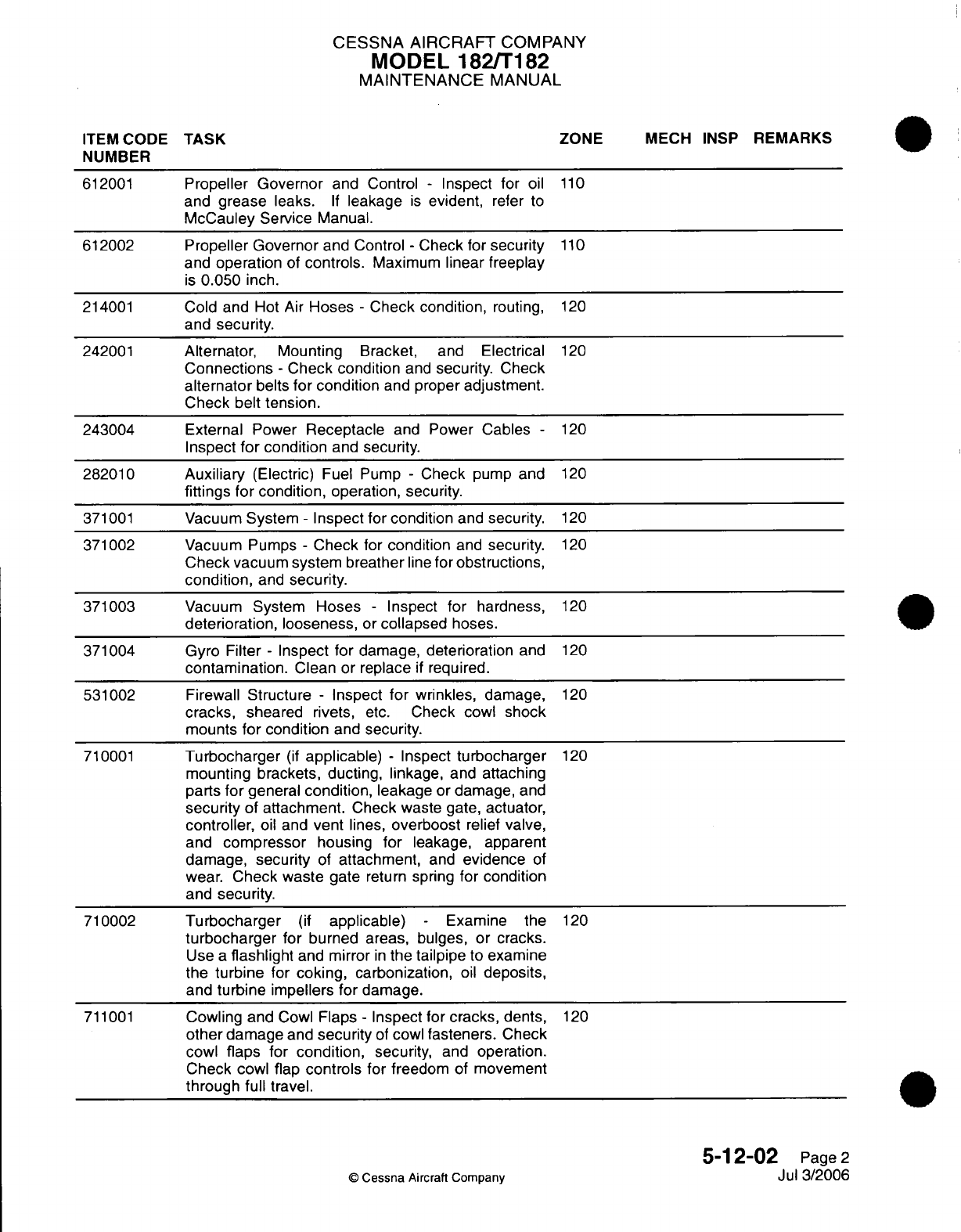
CESSNA AIRCRAFT
COMPANY
MODEL
182/T182
MAINTENANCE
MANUAL
ITEM
CODE
TASK
ZONE
MECH
INSP
REMARKS
NUMBER
612001
Propeller
Governor
and
Control
-
Inspect for
oil
110
and
grease
leaks.
If
leakage
is
evident,
refer
to
McCauley Service
Manual.
612002
Propeller
Governor
and
Control
-
Check for
security
110
and
operation
of
controls.
Maximum
linear
freeplay
is
0.050
inch.
214001
Cold
and
Hot Air
Hoses
-
Check
condition,
routing,
120
and
security.
242001
Alternator,
Mounting
Bracket,
and
Electrical
120
Connections -
Check condition
and
security.
Check
alternator
belts
for condition
and
proper
adjustment.
Check belt tension.
243004 External
Power
Receptacle
and Power Cables
-
120
Inspect
for
condition
and
security.
282010
Auxiliary
(Electric)
Fuel Pump
-
Check
pump
and
120
fittings
for
condition,
operation, security.
371001
Vacuum
System
-
Inspect for
condition
and
security.
120
371002
Vacuum
Pumps
-
Check for
condition
and
security.
120
Check
vacuum system
breather
line
for
obstructions,
condition,
and
security.
371003
Vacuum
System
Hoses
-
Inspect
for
hardness,
120
deterioration, looseness,
or
collapsed
hoses.
371004
Gyro
Filter
-
Inspect
for
damage,
deterioration
and
120
contamination.
Clean
or
replace
if
required.
531002 Firewall
Structure
-
Inspect
for
wrinkles,
damage,
120
cracks,
sheared
rivets,
etc.
Check
cowl shock
mounts
for condition
and
security.
710001
Turbocharger
(if
applicable) -
Inspect
turbocharger
120
mounting
brackets,
ducting,
linkage, and
attaching
parts
for
general
condition,
leakage
or
damage,
and
security
of
attachment.
Check waste
gate,
actuator,
controller,
oil
and
vent
lines,
overboost
relief
valve,
and
compressor
housing
for
leakage,
apparent
damage,
security
of
attachment,
and
evidence
of
wear.
Check waste
gate
return
spring
for
condition
and
security.
710002
Turbocharger
(if
applicable)
-
Examine
the
120
turbocharger
for burned areas, bulges,
or
cracks.
Use
a
flashlight
and
mirror
in
the
tailpipe
to examine
the
turbine
for
coking,
carbonization,
oil
deposits,
and
turbine
impellers
for
damage.
711001
Cowling and
Cowl
Flaps
-
Inspect
for
cracks,
dents,
120
other
damage
and
security
of
cowl
fasteners.
Check
cowl
flaps
for
condition,
security,
and operation.
Check
cowl flap
controls
for
freedom
of
movement
through
full
travel.
5-12-02
Page
2
©
Cessna
Aircraft
Company
Jul
3/2006
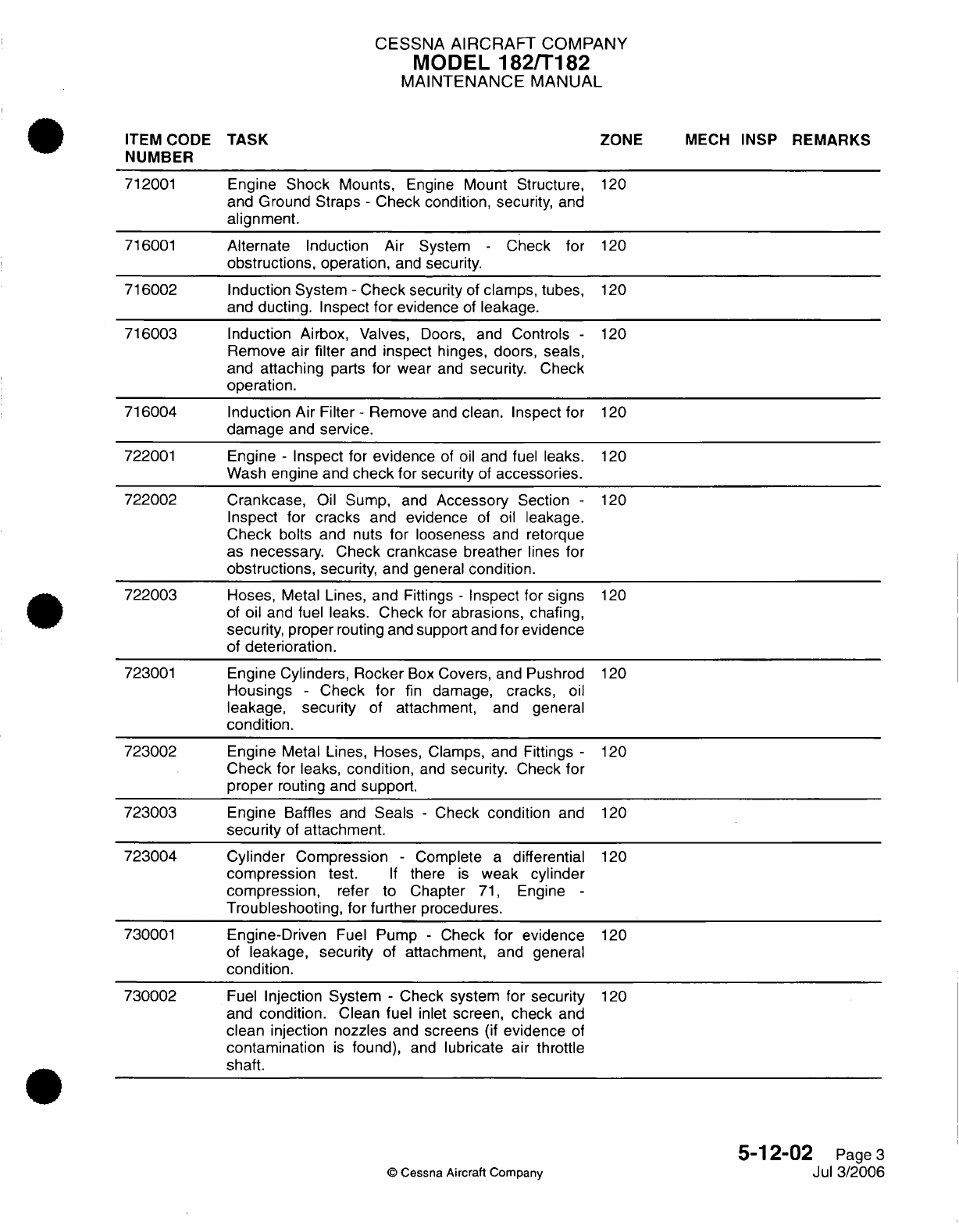
CESSNA
AIRCRAFT
COMPANY
MODEL
182/T182
MAINTENANCE
MANUAL
ITEM CODE
TASK
ZONE
MECH
INSP
REMARKS
NUMBER
712001
Engine
Shock
Mounts,
Engine
Mount
Structure,
120
and
Ground
Straps
-
Check condition,
security,
and
alignment.
716001
Alternate
Induction
Air System
-
Check
for
120
obstructions,
operation,
and
security.
716002
Induction System
-
Check
security
of
clamps,
tubes,
120
and
ducting.
Inspect
for
evidence
of
leakage.
716003
Induction
Airbox,
Valves,
Doors,
and
Controls
-
120
Remove
air
filter
and
inspect
hinges,
doors, seals,
and
attaching
parts
for
wear
and
security.
Check
operation.
716004
Induction
Air
Filter
-
Remove
and
clean. Inspect
for
120
damage
and
service.
722001
Engine
-
Inspect
for
evidence
of
oil
and
fuel
leaks.
120
Wash
engine
and
check for
security
of
accessories.
722002 Crankcase,
Oil Sump,
and
Accessory
Section
-
120
Inspect for cracks
and evidence
of
oil
leakage.
Check
bolts
and
nuts
for
looseness
and
retorque
as
necessary.
Check crankcase breather
lines
for
obstructions,
security,
and
general
condition.
722003
Hoses,
Metal
Lines,
and
Fittings
-
Inspect for
signs
120
of
oil
and
fuel
leaks. Check
for
abrasions,
chafing,
security,
proper
routing
and
support
and
for
evidence
of
deterioration.
723001
Engine
Cylinders,
Rocker
Box
Covers,
and
Pushrod
120
Housings
-
Check
for
fin
damage,
cracks,
oil
leakage,
security
of
attachment,
and
general
condition.
723002
Engine
Metal
Lines,
Hoses,
Clamps,
and
Fittings
-
120
Check
for leaks,
condition,
and
security.
Check
for
proper
routing
and
support.
723003
Engine
Baffles
and
Seals
-
Check
condition
and
120
security
of
attachment.
723004
Cylinder
Compression
-
Complete
a
differential
120
compression
test.
If
there
is
weak cylinder
compression,
refer
to
Chapter
71,
Engine
-
Troubleshooting, for further
procedures.
730001
Engine-Driven
Fuel
Pump
-
Check
for
evidence
120
of
leakage,
security
of
attachment,
and
general
condition.
730002
Fuel
Injection System
-
Check
system
for
security
120
and
condition.
Clean
fuel
inlet
screen,
check
and
clean injection
nozzles
and
screens
(if
evidence
of
contamination
is
found),
and
lubricate
air throttle
shaft.
5-12-02
Page
3
©
Cessna Aircraft Company
Jul
3/2006
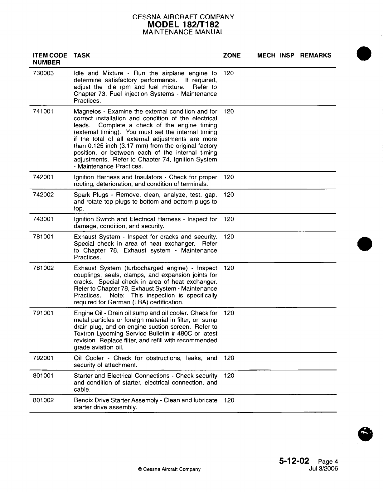
CESSNA
AIRCRAFT
COMPANY
MODEL
182/T182
MAINTENANCE
MANUAL
ITEM CODE
TASK
ZONE
MECH
INSP
REMARKS
NUMBER
730003
Idle
and
Mixture
-
Run
the
airplane engine
to
120
determine
satisfactory
performance.
If
required,
adjust
the
idle
rpm
and
fuel
mixture.
Refer
to
Chapter
73,
Fuel
Injection Systems
-
Maintenance
Practices.
741001
Magnetos
-
Examine the
external
condition
and
for
120
correct
installation
and
condition
of
the
electrical
leads.
Complete
a
check
of
the
engine timing
(external
timing).
You
must
set
the
internal timing
if
the
total
of
all
external
adjustments
are
more
than
0.125
inch
(3.17
mm)
from
the
original
factory
position,
or
between each
of
the
internal timing
adjustments.
Refer
to
Chapter
74,
Ignition
System
-
Maintenance
Practices.
742001
Ignition
Harness
and
Insulators
-
Check
for
proper
120
routing,
deterioration,
and
condition
of
terminals.
742002
Spark
Plugs
-
Remove, clean,
analyze,
test,
gap,
120
and rotate
top
plugs
to
bottom
and
bottom plugs
to
top.
743001
Ignition
Switch
and
Electrical Harness
-
Inspect for
120
damage,
condition,
and
security.
781001
Exhaust
System
-
Inspect
for
cracks
and
security.
120
Special
check
in
area
of heat
exchanger.
Refer
to
Chapter
78,
Exhaust system
-
Maintenance
Practices.
781002
Exhaust
System
(turbocharged engine)
-
Inspect
120
couplings,
seals,
clamps,
and
expansion
joints
for
cracks.
Special
check
in
area
of
heat
exchanger.
Refer
to
Chapter
78,
Exhaust System
-
Maintenance
Practices.
Note:
This
inspection
is
specifically
required
for
German
(LBA)
certification.
791001
Engine
Oil
-
Drain
oil
sump
and
oil
cooler.
Check
for
120
metal
particles
or
foreign
material
in
filter,
on
sump
drain
plug,
and
on
engine
suction
screen. Refer
to
Textron
Lycoming
Service
Bulletin
#
480C
or
latest
revision.
Replace
filter,
and
refill
with
recommended
grade
aviation
oil.
792001
Oil
Cooler
-
Check
for obstructions,
leaks,
and
120
security
of
attachment.
801001
Starter
and
Electrical
Connections
-
Check
security
120
and
condition
of
starter, electrical
connection,
and
cable.
801002
Bendix
Drive
Starter Assembly
-
Clean
and
lubricate
120
starter drive
assembly.
5-12-02
Page
4
©
Cessna
Aircraft
Company
Jul
3/2006
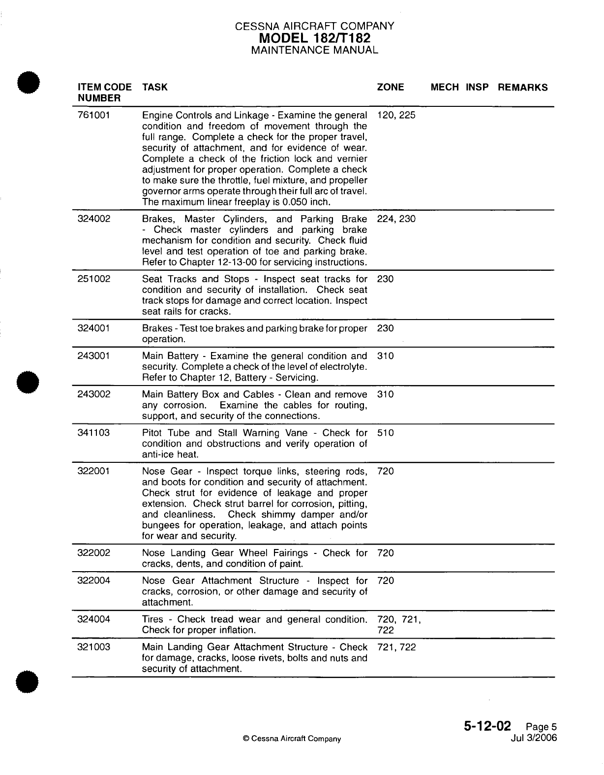
CESSNA AIRCRAFT
COMPANY
MODEL
182/T182
MAINTENANCE
MANUAL
ITEM
CODE
TASK ZONE
MECH
INSP
REMARKS
NUMBER
761001
Engine
Controls
and
Linkage
-
Examine
the
general
120,
225
condition
and
freedom of
movement
through
the
full
range.
Complete
a
check
for
the
proper
travel,
security
of
attachment,
and
for
evidence
of
wear.
Complete
a
check
of
the
friction
lock
and
vernier
adjustment
for
proper
operation.
Complete
a
check
to
make sure
the
throttle, fuel
mixture,
and
propeller
governor
arms
operate
through
their
full
arc
of
travel.
The maximum
linear
freeplay
is
0.050
inch.
324002
Brakes,
Master
Cylinders,
and
Parking Brake
224,230
-
Check
master
cylinders
and
parking
brake
mechanism
for
condition
and
security.
Check
fluid
level
and
test
operation
of
toe
and
parking
brake.
Refer
to
Chapter
12-13-00
for
servicing
instructions.
251002
Seat
Tracks
and
Stops
-
Inspect
seat
tracks
for
230
condition
and
security
of
installation.
Check seat
track
stops
for damage
and correct location. Inspect
seat
rails
for cracks.
324001
Brakes
-
Test
toe
brakes and
parking
brake
for
proper
230
operation.
243001
Main
Battery
-
Examine
the
general
condition
and
310
security.
Complete
a
check
of the
level
of
electrolyte.
Refer
to
Chapter
12,
Battery
-
Servicing.
243002
Main
Battery
Box
and
Cables
-
Clean
and
remove
310
any
corrosion.
Examine the
cables
for
routing,
support,
and
security
of
the
connections.
341103
Pitot
Tube
and
Stall
Warning
Vane
-
Check for
510
condition
and
obstructions
and
verify
operation
of
anti-ice
heat.
322001
Nose
Gear
-
Inspect
torque
links,
steering
rods, 720
and
boots for
condition
and
security
of
attachment.
Check
strut
for
evidence
of
leakage
and
proper
extension.
Check
strut
barrel
for
corrosion,
pitting,
and
cleanliness.
Check
shimmy
damper
and/or
bungees for
operation, leakage,
and
attach points
for
wear
and
security.
322002
Nose
Landing
Gear
Wheel
Fairings
-
Check
for
720
cracks, dents,
and
condition
of paint.
322004
Nose
Gear Attachment
Structure
-
Inspect
for
720
cracks,
corrosion,
or
other
damage
and
security
of
attachment.
324004
Tires
-
Check
tread
wear
and
general condition.
720,
721,
Check
for
proper
inflation.
722
321003
Main
Landing
Gear Attachment
Structure
-
Check
721,
722
for
damage,
cracks,
loose
rivets,
bolts
and
nuts
and
security
of
attachment.
5-12-02
Page
5
©
Cessna
Aircraft
Company
Jul
3/2006
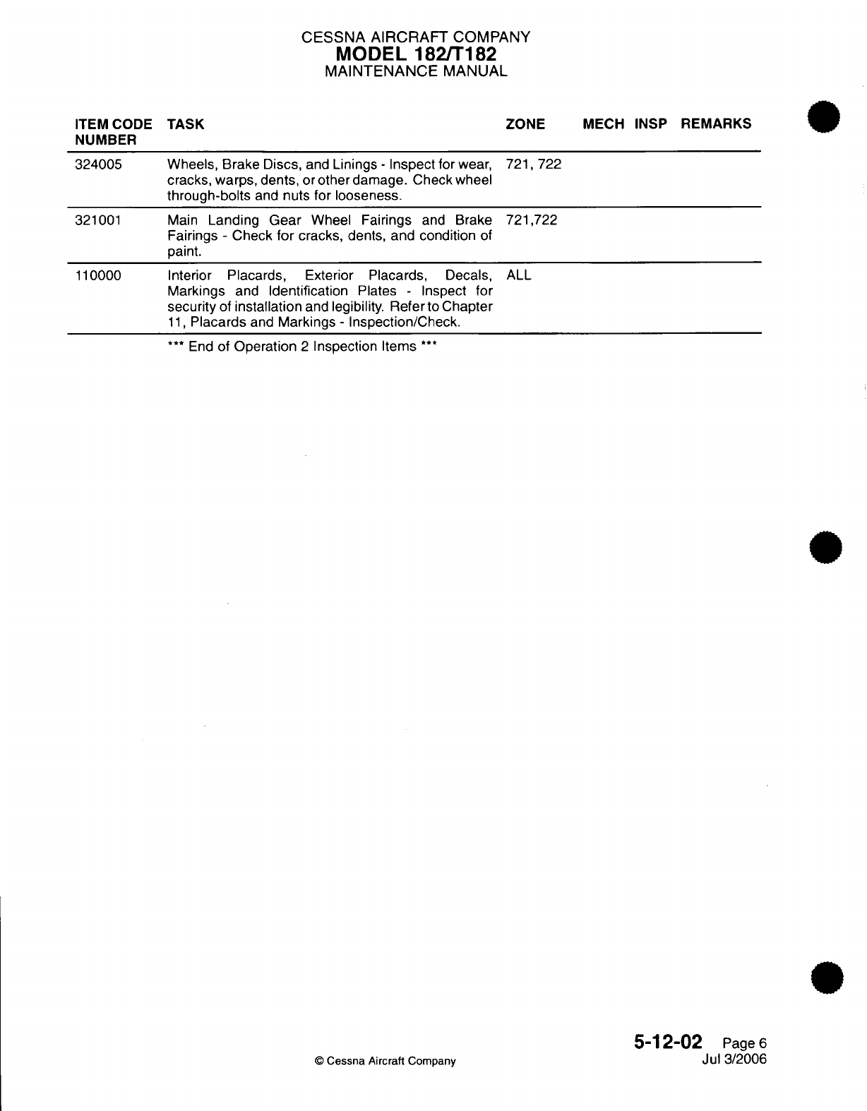
CESSNA AIRCRAFT
COMPANY
MODEL 182/T182
MAINTENANCE
MANUAL
Wheels,
Brake
Discs,
and
Linings
-
Inspect
for
wear,
721,
722
cracks,
warps, dents,
or
other
damage.
Check wheel
through-bolts
and
nuts
for
looseness.
Main
Landing
Gear
Wheel
Fairings
and
Brake
721,722
Fairings
-
Check
for
cracks,
dents,
and condition
of
paint.
Interior
Placards,
Exterior
Placards,
Decals,
ALL
Markings
and
Identification
Plates
-
Inspect
for
security
of
installation
and
legibility. Refer
to
Chapter
11,
Placards
and
Markings
-
Inspection/Check.
***
End
of
Operation
2
Inspection
Items
***
5-12-02
Page
6
Jul 3/2006
©
Cessna Aircraft
Company
ITEM
CODE
TASK
NUMBER
324005
321001
110000
ZONE
MECH INSP
REMARKS
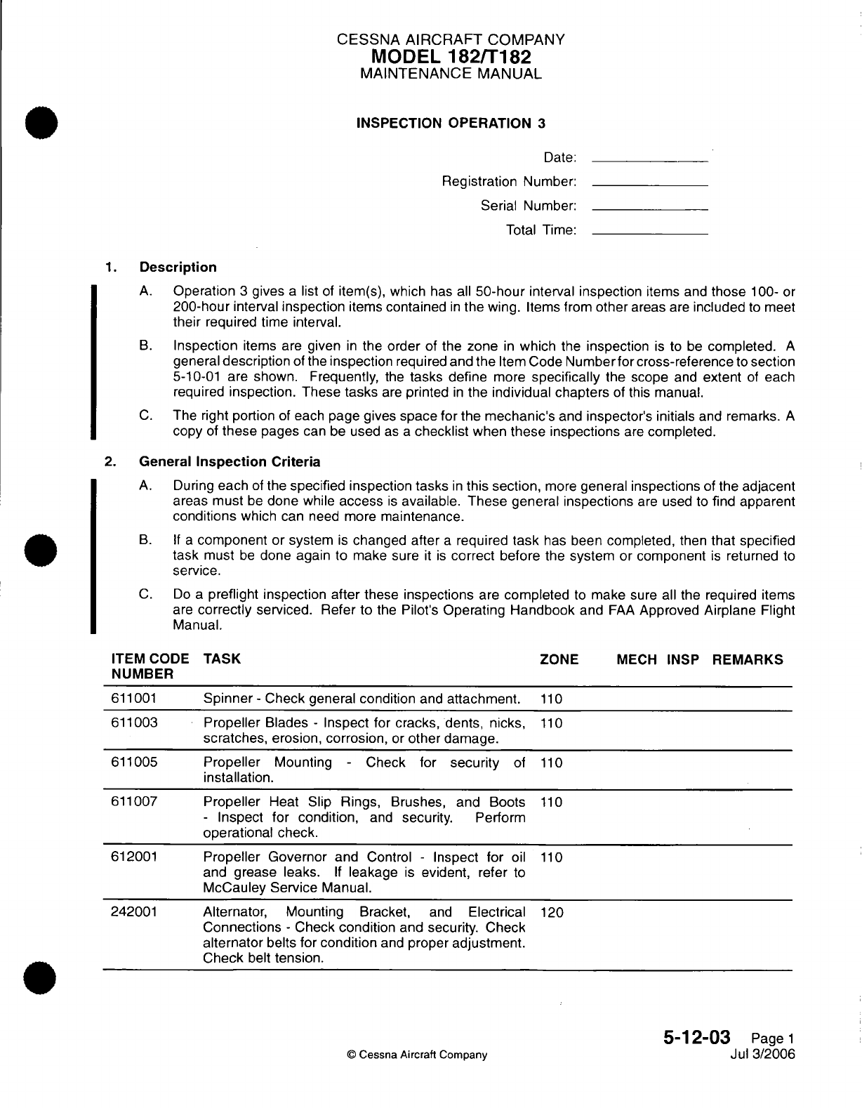
CESSNA
AIRCRAFT
COMPANY
MODEL
182/T182
MAINTENANCE
MANUAL
INSPECTION
OPERATION
3
Date:
Registration
Number:
Serial
Number:
Total
Time:
1.
Description
A.
Operation
3
gives
a
list
of
item(s),
which
has all
50-hour
interval inspection
items
and
those
100-
or
200-hour
interval
inspection
items
contained
in
the
wing.
Items from
other
areas
are
included
to
meet
their
required time
interval.
B.
Inspection
items
are
given
in
the
order
of
the
zone
in
which
the
inspection
is
to
be
completed.
A
general
description
of
the
inspection
required
and the
Item
Code
Numberfor
cross-reference
to
section
5-10-01
are
shown. Frequently,
the
tasks
define
more
specifically
the scope
and
extent
of
each
required
inspection.
These
tasks
are
printed
in
the
individual chapters
of
this
manual.
C.
The
right
portion
of each
page gives
space
for
the mechanic's
and
inspector's
initials
and
remarks.
A
copy
of
these
pages
can
be
used
as
a
checklist
when
these
inspections
are
completed.
2.
General
Inspection Criteria
A.
During
each
of
the
specified
inspection
tasks
in
this
section,
more
general
inspections
of
the
adjacent
areas must
be
done
while
access
is
available. These general inspections
are
used to
find
apparent
conditions
which
can
need
more
maintenance.
B. If a
component
or
system
is
changed
after
a
required
task
has
been
completed,
then
that specified
task
must
be
done
again
to make sure
it is
correct before
the
system
or
component
is
returned
to
service.
C.
Do
a
preflight inspection after
these
inspections
are
completed
to
make
sure
all
the
required
items
are
correctly
serviced.
Refer
to
the
Pilot's
Operating
Handbook
and
FAA
Approved
Airplane
Flight
Manual.
ITEM CODE
TASK
ZONE
MECH
INSP
REMARKS
NUMBER
611001
Spinner
-
Check general
condition
and
attachment.
110
611003
Propeller
Blades
-
Inspect for
cracks,
dents,
nicks,
110
scratches,
erosion,
corrosion,
or
other
damage.
611005
Propeller
Mounting
-
Check
for
security
of
110
installation.
611007
Propeller
Heat
Slip
Rings,
Brushes,
and
Boots
110
-
Inspect
for
condition,
and
security.
Perform
operational
check.
612001
Propeller Governor
and
Control
-
Inspect for
oil
110
and
grease
leaks.
If
leakage
is
evident,
refer
to
McCauley
Service
Manual.
242001
Alternator, Mounting
Bracket,
and
Electrical
120
Connections
-
Check
condition
and
security.
Check
alternator
belts for
condition
and
proper
adjustment.
Check
belt
tension.
5-12-03
Page
1
©
Cessna Aircraft
Company
Jul
3/2006
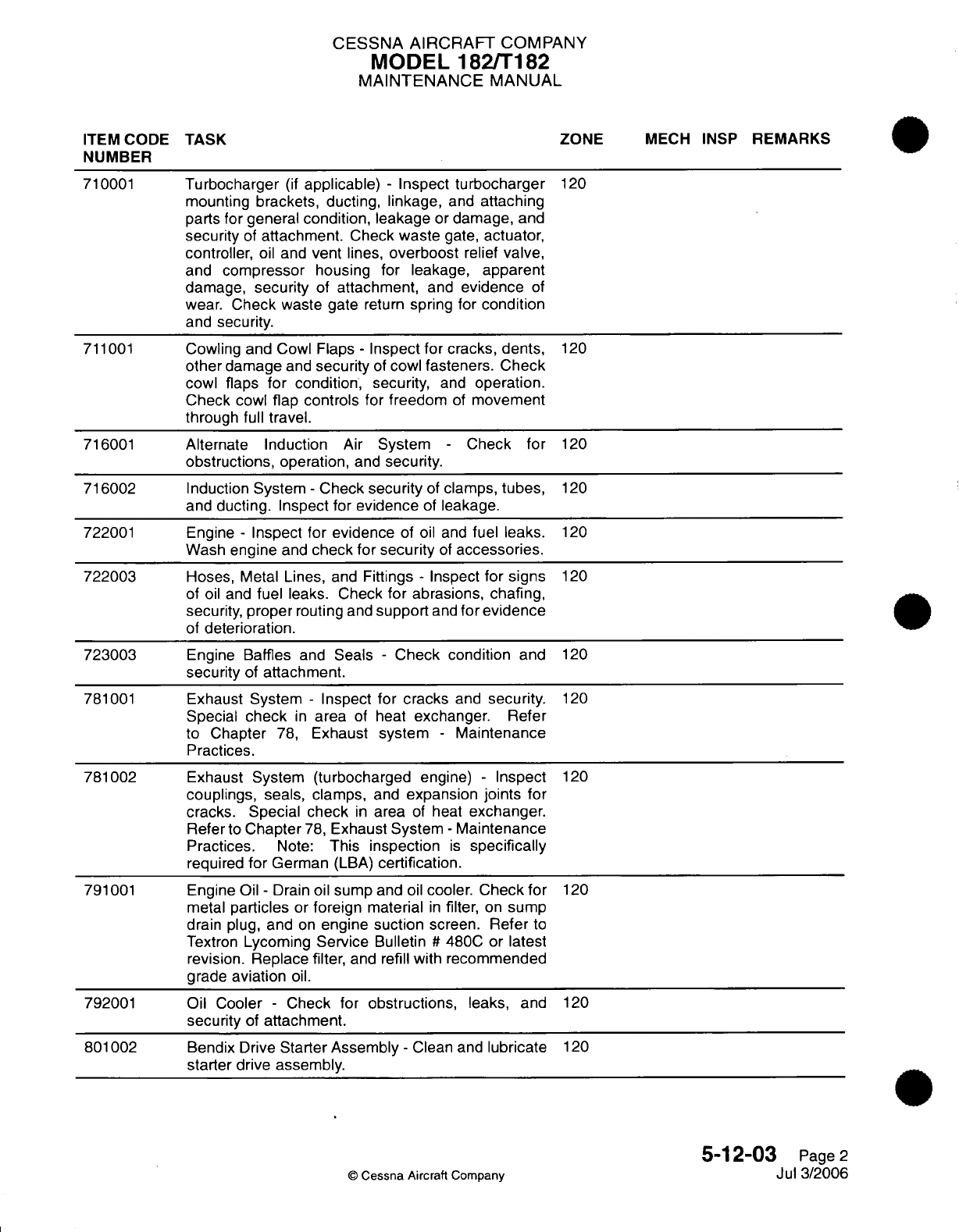
CESSNA AIRCRAFT
COMPANY
MODEL
182/T182
MAINTENANCE
MANUAL
ITEM
CODE
TASK ZONE
MECH
INSP
REMARKS
NUMBER
710001
Turbocharger
(if
applicable)
-
Inspect
turbocharger
120
mounting brackets,
ducting,
linkage,
and
attaching
parts for
general
condition,
leakage
or
damage,
and
security
of
attachment.
Check
waste
gate,
actuator,
controller,
oil
and
vent
lines,
overboost
relief
valve,
and
compressor
housing for leakage,
apparent
damage,
security
of
attachment,
and
evidence
of
wear. Check waste gate
return
spring
for
condition
and security.
711001
Cowling and
Cowl
Flaps
-
Inspect
for
cracks,
dents,
120
other
damage
and
security
of
cowl
fasteners.
Check
cowl flaps
for
condition,
security,
and
operation.
Check
cowl
flap controls
for freedom
of
movement
through full
travel.
716001
Alternate Induction
Air
System
-
Check for
120
obstructions,
operation,
and
security.
716002
Induction
System
-
Check
security
of
clamps,
tubes,
120
and
ducting.
Inspect
for
evidence
of
leakage.
722001
Engine
-
Inspect
for
evidence
of
oil
and
fuel leaks.
120
Wash
engine
and
check
for
security
of
accessories.
722003
Hoses,
Metal Lines,
and
Fittings
-
Inspect
for signs
120
of
oil
and
fuel
leaks.
Check
for
abrasions,
chafing,
security,
proper
routing
and
support
and
for
evidence
of
deterioration.
723003
Engine
Baffles
and
Seals
-
Check condition
and
120
security
of
attachment.
781001
Exhaust System
-
Inspect
for
cracks
and
security.
120
Special
check
in
area
of heat
exchanger.
Refer
to
Chapter
78,
Exhaust
system
-
Maintenance
Practices.
781002
Exhaust System
(turbocharged
engine)
-
Inspect
120
couplings,
seals, clamps,
and
expansion
joints
for
cracks. Special
check
in
area
of
heat
exchanger.
Refer
to
Chapter
78,
Exhaust
System
-
Maintenance
Practices.
Note:
This
inspection
is
specifically
required
for
German
(LBA)
certification.
791001
Engine
Oil
-
Drain
oil
sump
and
oil
cooler.
Check for
120
metal
particles
or
foreign
material
in
filter,
on
sump
drain
plug,
and
on
engine
suction
screen.
Refer
to
Textron
Lycoming
Service
Bulletin
#
480C or
latest
revision. Replace
filter,
and refill
with
recommended
grade
aviation
oil.
792001
Oil Cooler
-
Check for
obstructions,
leaks, and
120
security
of
attachment.
801002
Bendix
Drive
Starter Assembly
-
Clean
and
lubricate
120
starter
drive
assembly.
5-12-03
Page
2
©
Cessna Aircraft Company
Jul
3/2006
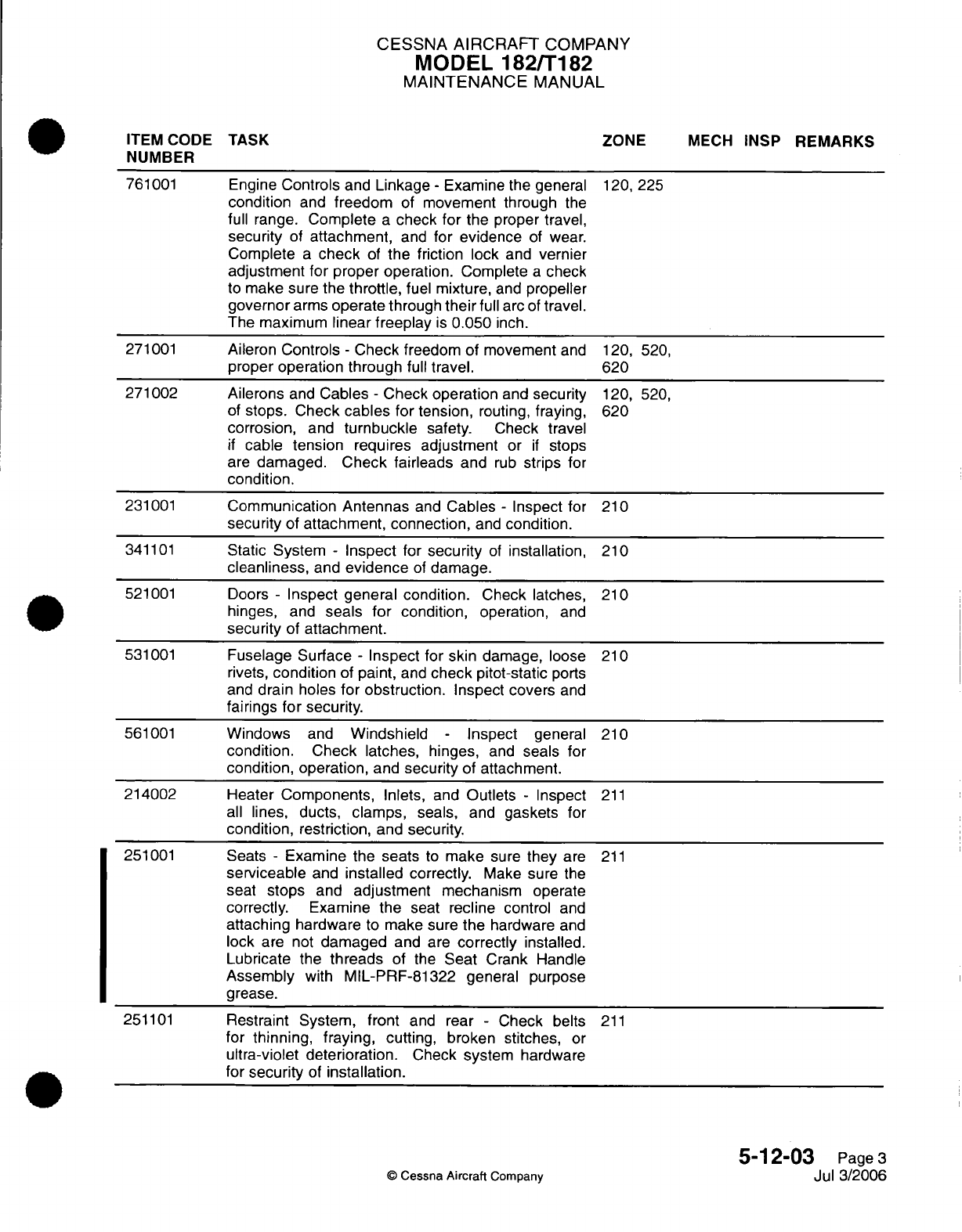
CESSNA AIRCRAFT
COMPANY
MODEL
182/T182
MAINTENANCE
MANUAL
ITEM
CODE
TASK
ZONE
MECH
INSP
REMARKS
NUMBER
761001
Engine
Controls
and
Linkage
-
Examine
the general
120,
225
condition
and
freedom
of
movement through
the
full
range.
Complete
a
check
for
the proper travel,
security
of
attachment,
and
for evidence
of
wear.
Complete
a
check
of
the friction
lock
and
vernier
adjustment
for
proper operation.
Complete
a
check
to
make sure
the
throttle,
fuel
mixture,
and
propeller
governor
arms
operate
through
their
full
arc
of
travel.
The
maximum
linear
freeplay
is
0.050
inch.
271001
Aileron Controls
-
Check
freedom
of
movement
and
120, 520,
proper
operation through
full
travel.
620
271002 Ailerons
and
Cables
-
Check
operation
and
security
120,
520,
of
stops.
Check
cables
for tension,
routing,
fraying,
620
corrosion,
and
turnbuckle
safety.
Check
travel
if
cable
tension
requires
adjustment
or
if
stops
are
damaged.
Check fairleads
and
rub
strips
for
condition.
231001
Communication
Antennas
and
Cables
-
Inspect
for
210
security
of
attachment,
connection,
and
condition.
341101
Static
System
-
Inspect
for
security
of
installation,
210
cleanliness,
and
evidence
of
damage.
521001
Doors
-
Inspect
general condition.
Check latches,
210
hinges,
and
seals
for
condition,
operation,
and
security
of
attachment.
531001
Fuselage Surface
-
Inspect for skin
damage,
loose 210
rivets,
condition
of
paint,
and
check
pitot-static
ports
and
drain
holes
for
obstruction.
Inspect
covers
and
fairings
for
security.
561001
Windows
and
Windshield
-
Inspect
general
210
condition.
Check
latches,
hinges,
and
seals
for
condition, operation,
and
security
of attachment.
214002
Heater
Components,
Inlets,
and
Outlets
-
Inspect
211
all
lines, ducts,
clamps,
seals,
and
gaskets
for
condition, restriction,
and
security.
251001
Seats
-
Examine the
seats
to
make
sure
they
are
211
serviceable
and
installed
correctly.
Make
sure
the
seat
stops
and
adjustment
mechanism
operate
correctly. Examine
the
seat
recline
control
and
attaching
hardware
to
make
sure
the
hardware
and
lock
are
not
damaged
and
are
correctly
installed.
Lubricate
the
threads
of the
Seat
Crank
Handle
Assembly
with
MIL-PRF-81322
general purpose
grease.
251101
Restraint
System,
front
and
rear
-
Check belts
211
for
thinning,
fraying,
cutting,
broken stitches,
or
ultra-violet
deterioration.
Check
system
hardware
for
security
of
installation.
5-12-03
Page
3
©
Cessna
Aircraft
Company
Jul
3/2006

CESSNA
AIRCRAFT
COMPANY
MODEL
182/T182
MAINTENANCE
MANUAL
ITEM CODE
TASK
ZONE
MECH
INSP
REMARKS
NUMBER
311001
Instruments
-
Check
general condition
and
markings
220
for
legibility.
331001
Instrument
and
Cabin
Lights
-
Check operation,
220,
211,
condition
of
lens, and
security
of
attachment.
221
246002 Power
Junction
Box
-
Check
operation
and
222
condition. Check
availability
and
condition
of
spare
fuse
(if
applicable).
235002 Microphone
Push-To-Talk Switch
-
Clean
the
pilot's
222, 223
and
copilot's microphone
switches. Refer
to
Chapter
23, Communication
-
Maintenance Practices.
273001
Elevator
Control
-
Check
freedom
of
movement
and
222,
223
proper
operation
through
full
travel.
273002 Elevator Control
System
-
Inspect
pulleys,
cables,
222, 223
sprockets, bearings, chains,
and
turnbuckles
for
condition, security,
and
operation. Check cables
for
tension,
routing,
fraying,
corrosion,
and
turnbuckle
safety
273103
Elevator
Trim
Tab
and
Hinges
-
Check
condition,
224
security,
and
operation.
282003
Fuel
Selector
Valve
-
Check
controls
for detent
in
224
each
position,
security
of
attachment,
and
for
proper
placarding.
282006
Fuel
Selector -
Using
quick
drain,
ensure
no
224
contamination exists.
273101
Elevator
Trim
System
-
Check
cables,
push-pull
224,
240,
rods,
bellcranks,
pulleys, turnbuckles,
fairleads,
310
rub
strips,
etc.
for
proper
routing,
condition,
and
security.
262001
Portable Hand
Fire
Extinguisher
-
Inspect
for
230
proper
operating
pressure,
condition,
security
of
installation,
and
servicing
date.
256001
Emergency
Locator
Transmitter
-
Inspect
for
security
310
of
attachment
and
check
operation
by
verifying
transmitter output.
Check cumulative
time
and
useful
life
of
batteries
in
accordance
with
14
CFR
Part
91.207.
273004 Elevator
Downspring
-
Check
structure,
bolts,
310
linkage,
bell
crank,
and
push-pull
tube
for
condition,
operation,
and
security. Check
cables
for tension,
routing,
fraying, corrosion,
and
turnbuckle
safety.
Check
travels
if
cables
require
tension
adjustment
or
if
stops are
damaged.
5-12-03
Page
4
©
Cessna
Aircraft Company
Jul
3/2006
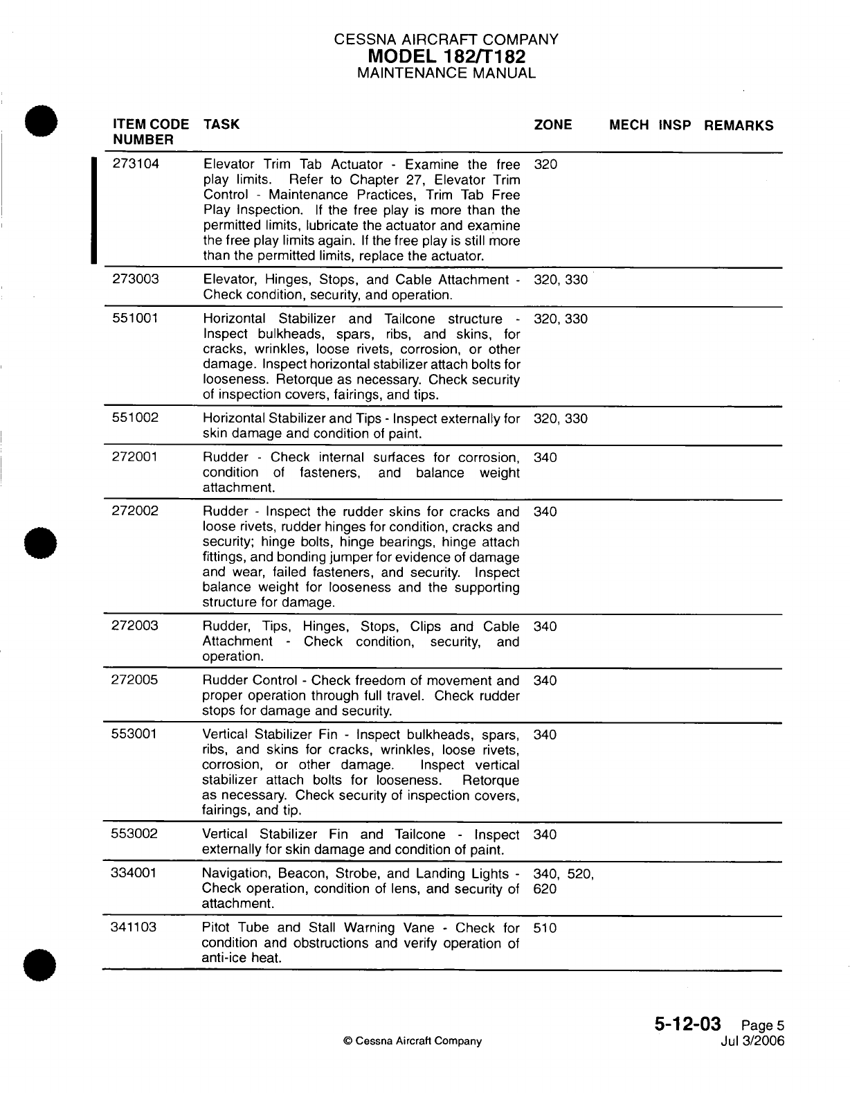
CESSNA
AIRCRAFT
COMPANY
MODEL
182/T182
MAINTENANCE
MANUAL
ITEM CODE
TASK
ZONE
MECH
INSP
REMARKS
NUMBER
273104
Elevator
Trim
Tab
Actuator
-
Examine
the
free
320
play limits. Refer
to
Chapter
27,
Elevator
Trim
Control
-
Maintenance
Practices,
Trim
Tab
Free
Play
Inspection.
If
the
free
play
is
more
than
the
permitted
limits, lubricate
the
actuator
and
examine
the
free play limits
again.
If
the
free play
is
still
more
than
the
permitted limits,
replace
the
actuator.
273003
Elevator,
Hinges, Stops,
and
Cable
Attachment
-
320,
330
Check
condition,
security,
and
operation.
551001
Horizontal
Stabilizer
and Tailcone
structure
-
320,330
Inspect
bulkheads, spars,
ribs,
and
skins,
for
cracks,
wrinkles,
loose
rivets,
corrosion,
or
other
damage.
Inspect
horizontal
stabilizer
attach
bolts
for
looseness.
Retorque as necessary. Check
security
of
inspection
covers,
fairings,
and
tips.
551002
Horizontal
Stabilizer
and
Tips
-
Inspect
externally
for
320,
330
skin damage
and
condition
of
paint.
272001
Rudder
-
Check
internal
surfaces for
corrosion,
340
condition
of
fasteners,
and
balance weight
attachment.
272002
Rudder
-
Inspect
the rudder
skins
for
cracks
and
340
loose rivets, rudder
hinges
for
condition,
cracks
and
security;
hinge
bolts,
hinge
bearings,
hinge attach
fittings,
and
bonding
jumper
for
evidence
of
damage
and
wear,
failed
fasteners,
and
security.
Inspect
balance weight
for
looseness
and
the
supporting
structure
for
damage.
272003
Rudder, Tips,
Hinges,
Stops,
Clips and
Cable
340
Attachment
-
Check
condition,
security,
and
operation.
272005
Rudder Control
-
Check freedom
of
movement
and
340
proper
operation through
full
travel. Check
rudder
stops for damage
and
security.
553001
Vertical
Stabilizer
Fin
-
Inspect
bulkheads,
spars,
340
ribs,
and
skins
for
cracks,
wrinkles,
loose rivets,
corrosion,
or
other
damage. Inspect
vertical
stabilizer
attach bolts
for
looseness. Retorque
as
necessary.
Check
security
of
inspection
covers,
fairings,
and
tip.
553002
Vertical
Stabilizer
Fin
and
Tailcone
-
Inspect
340
externally
for skin damage
and
condition
of
paint.
334001
Navigation,
Beacon,
Strobe,
and
Landing
Lights
-
340,
520,
Check
operation, condition
of
lens,
and
security
of
620
attachment.
341103
Pitot
Tube
and Stall
Warning
Vane
-
Check for
510
condition
and
obstructions
and
verify
operation
of
anti-ice
heat.
5-12-03
Page
5
©
Cessna Aircraft
Company
Jul 3/2006
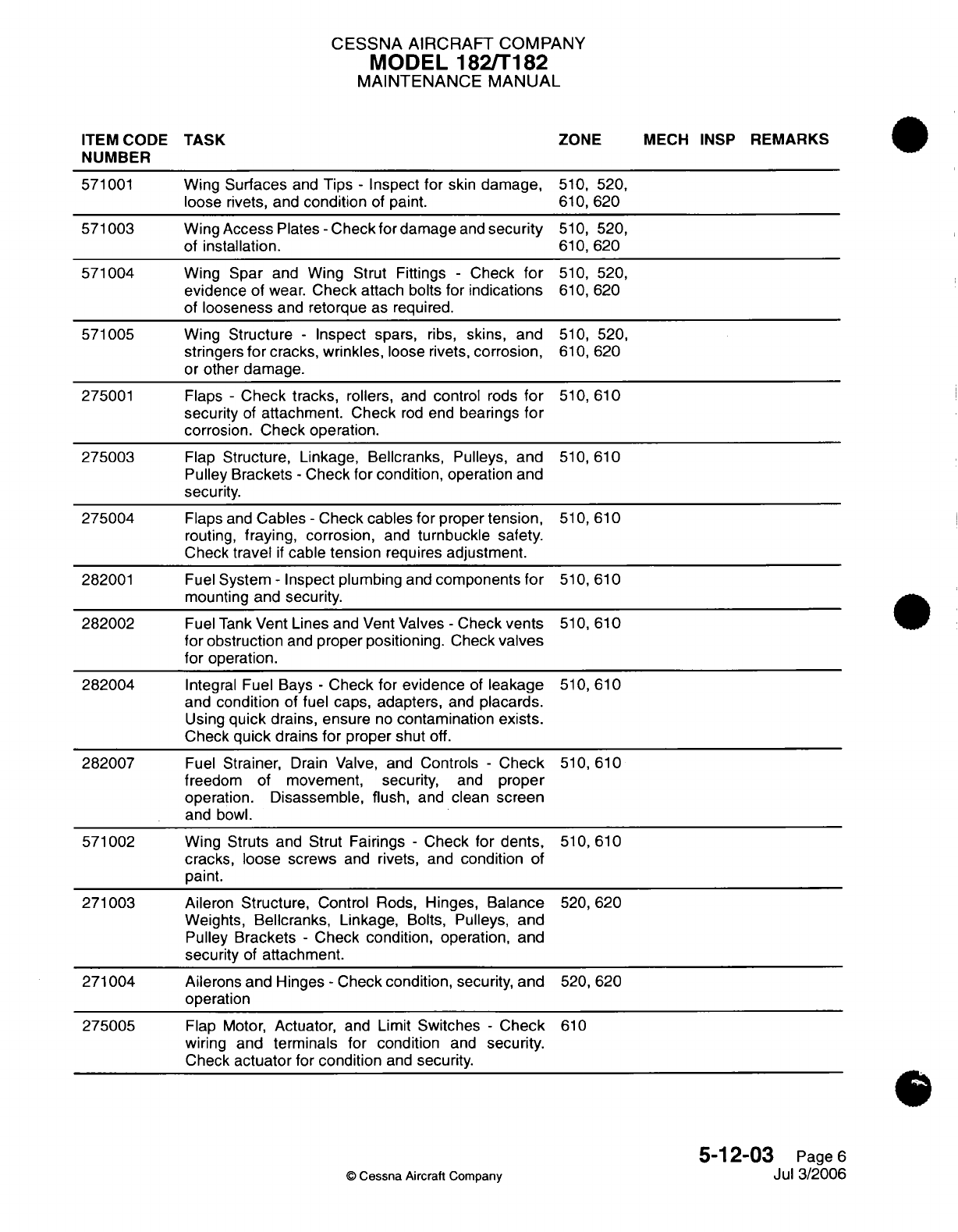
CESSNA
AIRCRAFT
COMPANY
MODEL
182/T182
MAINTENANCE MANUAL
ITEM CODE
TASK
ZONE
MECH
INSP
REMARKS
NUMBER
571001
Wing
Surfaces
and
Tips
-
Inspect
for
skin
damage,
510,
520,
loose
rivets,
and
condition
of
paint.
610,
620
571003
Wing
Access
Plates
-
Check
for damage
and
security
510,
520,
of
installation.
610,
620
571004
Wing
Spar
and
Wing Strut
Fittings
-
Check
for
510,
520,
evidence
of
wear.
Check attach
bolts
for
indications
610,
620
of
looseness
and retorque as required.
571005
Wing
Structure
-
Inspect
spars,
ribs,
skins, and
510,
520,
stringers
for
cracks,
wrinkles,
loose rivets,
corrosion,
610, 620
or
other
damage.
275001
Flaps
-
Check tracks,
rollers,
and
control
rods
for
510,
610
security
of
attachment.
Check
rod
end
bearings
for
corrosion.
Check operation.
275003
Flap
Structure,
Linkage, Bellcranks,
Pulleys,
and
510,
610
Pulley Brackets
-
Check for
condition,
operation
and
security.
275004
Flaps
and
Cables
-
Check
cables
for proper
tension,
510,
610
routing,
fraying,
corrosion,
and
turnbuckle
safety.
Check
travel
if
cable
tension
requires
adjustment.
282001
Fuel
System
-
Inspect plumbing
and
components
for
510,
610
mounting and
security.
282002
Fuel
Tank
Vent Lines
and Vent
Valves
-
Check
vents
510,
610
for
obstruction
and
proper positioning.
Check
valves
for
operation.
282004
Integral Fuel
Bays
-
Check
for
evidence
of
leakage
510,
610
and
condition
of
fuel
caps, adapters,
and
placards.
Using
quick
drains, ensure
no
contamination
exists.
Check
quick
drains
for
proper shut
off.
282007
Fuel
Strainer,
Drain
Valve, and
Controls
-
Check
510,
610
freedom
of
movement,
security,
and
proper
operation.
Disassemble,
flush,
and
clean
screen
and
bowl.
571002
Wing Struts and Strut
Fairings
-
Check
for dents,
510,
610
cracks, loose
screws
and
rivets,
and
condition
of
paint.
271003
Aileron
Structure,
Control
Rods,
Hinges,
Balance
520,
620
Weights,
Bellcranks,
Linkage,
Bolts,
Pulleys,
and
Pulley
Brackets
-
Check
condition, operation,
and
security
of
attachment.
271004
Ailerons and Hinges
-
Check
condition,
security,
and
520, 620
operation
275005
Flap
Motor,
Actuator,
and
Limit
Switches
- Check
610
wiring
and
terminals
for
condition
and
security.
Check
actuator
for
condition
and
security.
5-12-03
Page
6
©
Cessna
Aircraft Company
Jul
3/2006

CESSNA AIRCRAFT
COMPANY
MODEL
182/T182
MAINTENANCE
MANUAL
ITEM
CODE
TASK
NUMBER
275006
110000
Flap
Actuator
Threads
-
Clean
and
lubricate.
Refer
610
to
Chapter
12-21-03.
Interior
Placards,
Exterior
Placards,
Decals,
ALL
Markings
and
Identification
Plates
-
Inspect
for
security
of
installation
and
legibility.
Refer to
Chapter
11,
Placards
and
Markings
-
Inspection/Check.
***
End
of
Operation
3
Inspection
Items
***
5-12-03
Page
7
Jul
3/2006
©
Cessna Aircraft
Company
ZONE
MECH
INSP
REMARKS
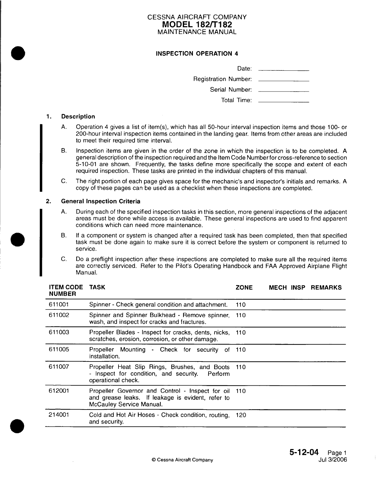
CESSNA
AIRCRAFT
COMPANY
MODEL
182/T182
MAINTENANCE
MANUAL
INSPECTION
OPERATION
4
Date:
Registration
Number:
Serial
Number:
Total
Time:
1.
Description
A.
Operation
4
gives
a
list
of
item(s), which
has all
50-hour
interval
inspection
items
and
those
100-
or
200-hour
interval
inspection
items
contained
in
the
landing
gear.
Items from
other
areas
are
included
to
meet
their
required
time
interval.
B.
Inspection
items
are
given
in
the
order
of
the
zone
in
which
the
inspection
is
to
be
completed.
A
general
description
of the
inspection
required
and
the
Item
Code
Number
for cross-reference
to
section
5-10-01
are
shown. Frequently,
the
tasks
define
more
specifically
the scope
and
extent
of
each
required
inspection. These
tasks
are
printed
in
the
individual
chapters
of
this manual.
C.
The
right
portion
of
each
page
gives space
for
the
mechanic's
and
inspector's initials
and
remarks.
A
copy
of
these
pages
can
be
used
as
a
checklist
when these
inspections
are
completed.
2.
General
Inspection Criteria
A.
During
each
of
the
specified inspection tasks
in
this section,
more
general
inspections
of
the
adjacent
areas
must
be
done while
access
is
available.
These
general
inspections
are
used
to
find
apparent
conditions
which
can
need more
maintenance.
B. If a
component
or
system
is
changed after
a
required
task
has
been
completed,
then
that
specified
task
must
be
done
again
to
make sure
it is
correct
before
the
system or
component
is
returned
to
service.
C.
Do
a
preflight inspection
after
these
inspections
are
completed
to make
sure
all
the
required
items
are
correctly
serviced.
Refer
to the
Pilot's
Operating Handbook
and
FAA
Approved
Airplane
Flight
Manual.
ITEM CODE
TASK ZONE
MECH
INSP
REMARKS
NUMBER
611001
Spinner
-
Check
general
condition
and
attachment.
110
611002
Spinner
and
Spinner
Bulkhead
-
Remove
spinner,
110
wash,
and
inspect for cracks
and
fractures.
611003
Propeller
Blades
-
Inspect
for
cracks,
dents,
nicks,
110
scratches,
erosion,
corrosion,
or
other
damage.
611005
Propeller
Mounting
-
Check
for
security
of
110
installation.
611007
Propeller
Heat
Slip
Rings,
Brushes,
and
Boots
110
-
Inspect
for
condition,
and
security.
Perform
operational check.
612001
Propeller
Governor
and
Control
-
Inspect
for
oil
110
and
grease
leaks.
If
leakage
is
evident,
refer
to
McCauley
Service
Manual.
214001
Cold
and
Hot
Air
Hoses
-
Check
condition,
routing,
120
and
security.
5-12-04
Page
1
©
Cessna
Aircraft
Company
Jul
3/2006
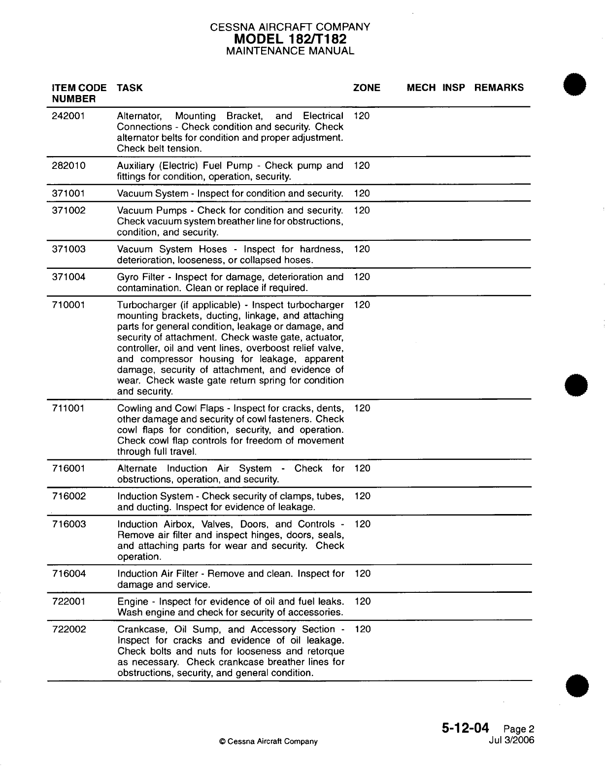
CESSNA
AIRCRAFT
COMPANY
MODEL
182/T182
MAINTENANCE
MANUAL
ITEM
CODE
TASK
ZONE
MECH
INSP
REMARKS
NUMBER
242001
Alternator,
Mounting
Bracket,
and
Electrical
120
Connections
-
Check
condition
and
security.
Check
alternator
belts
for condition
and
proper
adjustment.
Check belt
tension.
282010
Auxiliary
(Electric)
Fuel
Pump
-
Check
pump
and
120
fittings for condition,
operation,
security.
371001
Vacuum
System
-
Inspect
for
condition
and
security.
120
371002
Vacuum
Pumps
-
Check
for
condition
and
security.
120
Check
vacuum
system
breather
line
for
obstructions,
condition,
and
security.
371003
Vacuum
System Hoses
-
Inspect
for
hardness,
120
deterioration, looseness, or collapsed
hoses.
371004
Gyro
Filter
-
Inspect
for
damage,
deterioration
and
120
contamination.
Clean
or
replace
if
required.
710001
Turbocharger
(if
applicable) -
Inspect
turbocharger
120
mounting brackets, ducting,
linkage, and
attaching
parts
for general
condition,
leakage
or
damage,
and
security
of
attachment. Check
waste
gate,
actuator,
controller,
oil
and
vent
lines,
overboost
relief
valve,
and
compressor
housing
for
leakage,
apparent
damage,
security
of
attachment,
and
evidence
of
wear.
Check
waste
gate return
spring
for
condition
and
security.
711001
Cowling and
Cowl Flaps
-
Inspect for
cracks, dents,
120
other
damage
and
security
of
cowl
fasteners.
Check
cowl
flaps for
condition,
security,
and
operation.
Check
cowl
flap controls
for
freedom
of
movement
through
full
travel.
716001
Alternate
Induction
Air System
-
Check
for
120
obstructions,
operation,
and
security.
716002
Induction System
-
Check
security
of
clamps,
tubes,
120
and
ducting. Inspect for
evidence
of
leakage.
716003
Induction Airbox,
Valves,
Doors,
and
Controls
-
120
Remove
air
filter
and
inspect
hinges,
doors,
seals,
and
attaching
parts
for
wear
and
security.
Check
operation.
716004
Induction
Air
Filter
-
Remove
and
clean.
Inspect
for
120
damage
and
service.
722001
Engine
-
Inspect
for
evidence
of
oil
and
fuel
leaks.
120
Wash
engine
and
check
for
security
of
accessories.
722002
Crankcase,
Oil Sump,
and
Accessory
Section
-
120
Inspect
for
cracks
and
evidence
of
oil
leakage.
Check
bolts
and
nuts
for
looseness
and
retorque
as
necessary.
Check crankcase
breather
lines
for
obstructions,
security,
and
general
condition.
5-12-04
Page
2
©
Cessna
Aircraft Company
Jul 3/2006
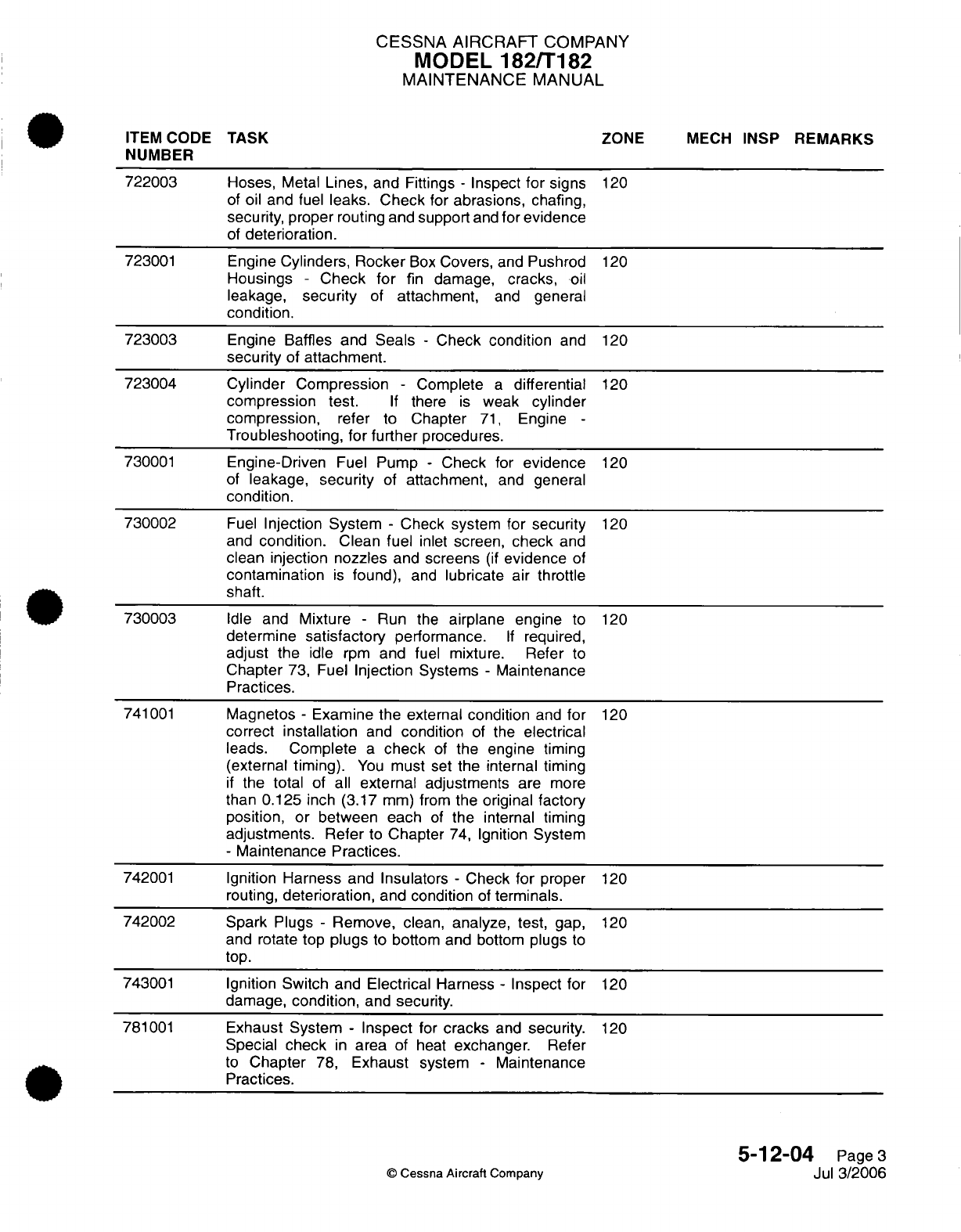
CESSNA AIRCRAFT
COMPANY
MODEL
182/T182
MAINTENANCE
MANUAL
ITEM
CODE
TASK
ZONE
MECH
INSP
REMARKS
NUMBER
722003
Hoses,
Metal
Lines,
and
Fittings
-
Inspect
for
signs
120
of
oil
and fuel
leaks.
Check
for
abrasions,
chafing,
security,
proper
routing
and
support
and
for
evidence
of
deterioration.
723001
Engine
Cylinders,
Rocker
Box
Covers,
and
Pushrod
120
Housings
- Check
for
fin
damage,
cracks,
oil
leakage,
security
of
attachment,
and
general
condition.
723003
Engine Baffles
and
Seals
-
Check
condition
and
120
security
of
attachment.
723004
Cylinder
Compression
-
Complete
a
differential
120
compression
test.
If
there
is
weak
cylinder
compression,
refer
to
Chapter
71,
Engine
-
Troubleshooting,
for
further
procedures.
730001
Engine-Driven
Fuel
Pump
-
Check
for
evidence
120
of
leakage,
security
of
attachment,
and
general
condition.
730002
Fuel
Injection
System
-
Check
system
for
security
120
and
condition.
Clean
fuel
inlet
screen,
check
and
clean
injection
nozzles
and
screens
(if
evidence
of
contamination
is
found),
and
lubricate
air
throttle
shaft.
730003
Idle
and
Mixture
-
Run
the
airplane engine
to
120
determine
satisfactory
performance.
If
required,
adjust the
idle
rpm
and fuel
mixture.
Refer
to
Chapter
73,
Fuel
Injection
Systems
-
Maintenance
Practices.
741001
Magnetos
-
Examine the
external condition
and
for
120
correct
installation
and
condition
of the
electrical
leads.
Complete
a
check
of
the
engine
timing
(external
timing).
You
must set
the internal
timing
if
the
total
of
all
external
adjustments
are
more
than
0.125
inch
(3.17
mm)
from
the
original factory
position, or
between
each
of
the
internal timing
adjustments. Refer
to
Chapter
74,
Ignition
System
-
Maintenance
Practices.
742001
Ignition
Harness
and Insulators
-
Check
for
proper
120
routing,
deterioration,
and
condition
of
terminals.
742002
Spark
Plugs
-
Remove,
clean,
analyze,
test,
gap,
120
and rotate
top
plugs
to
bottom
and bottom
plugs
to
top.
743001
Ignition Switch and
Electrical
Harness
-
Inspect
for
120
damage,
condition,
and
security.
781001
Exhaust
System
-
Inspect
for
cracks
and
security.
120
Special
check
in
area of
heat
exchanger.
Refer
to
Chapter
78,
Exhaust
system
-
Maintenance
Practices.
5-12-04
Page
3
©
Cessna
Aircraft
Company
Jul
3/2006
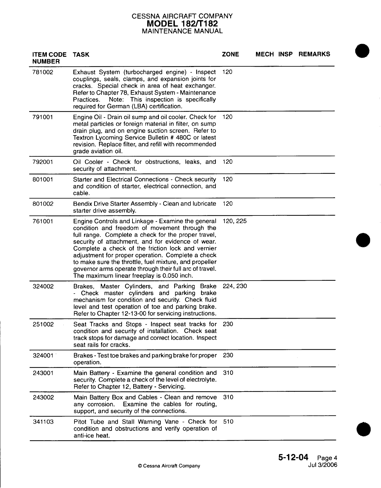
CESSNA
AIRCRAFT
COMPANY
MODEL
182/T182
MAINTENANCE
MANUAL
ITEM
CODE
TASK
ZONE
MECH
INSP
REMARKS
NUMBER
781002
Exhaust
System (turbocharged
engine)
-
Inspect
120
couplings,
seals,
clamps,
and
expansion joints
for
cracks.
Special
check
in
area
of heat
exchanger.
Refer
to
Chapter
78,
Exhaust
System
-
Maintenance
Practices.
Note:
This
inspection
is
specifically
required
for
German
(LBA)
certification.
791001
Engine
Oil
-
Drain
oil
sump and
oil
cooler.
Check
for
120
metal
particles
or
foreign
material
in
filter,
on
sump
drain
plug,
and
on
engine
suction
screen.
Refer
to
Textron
Lycoming Service
Bulletin
#
480C or
latest
revision.
Replace
filter,
and
refill
with
recommended
grade
aviation
oil.
792001
Oil
Cooler
-
Check
for
obstructions,
leaks,
and
120
security
of
attachment.
801001
Starter
and
Electrical Connections
-
Check security
120
and
condition
of
starter,
electrical connection,
and
cable.
801002
Bendix Drive
Starter Assembly
-
Clean
and
lubricate
120
starter
drive
assembly.
761001
Engine
Controls
and
Linkage
-
Examine
the
general
120,
225
condition
and
freedom
of
movement
through
the
full
range.
Complete
a
check
for
the
proper
travel,
security
of
attachment,
and
for
evidence
of
wear.
Complete
a
check
of the
friction
lock
and
vernier
adjustment for
proper operation.
Complete
a
check
to
make
sure
the
throttle,
fuel
mixture,
and
propeller
governor
arms
operate
through
their
full
arc
of
travel.
The
maximum
linear freeplay
is
0.050
inch.
324002
Brakes,
Master Cylinders,
and
Parking
Brake
224,
230
-
Check
master
cylinders
and
parking brake
mechanism
for
condition
and
security.
Check
fluid
level
and
test
operation
of
toe
and
parking
brake.
Refer
to
Chapter
12-13-00
for
servicing instructions.
251002
Seat
Tracks
and
Stops
-
Inspect seat
tracks
for
230
condition
and
security
of
installation. Check seat
track
stops
for damage
and
correct location.
Inspect
seat
rails
for
cracks.
324001
Brakes
-
Test
toe
brakes
and
parking
brake
for
proper
230
operation.
243001
Main
Battery
-
Examine the general
condition
and
310
security.
Complete
a
check
of
the
level
of
electrolyte.
Refer
to
Chapter
12,
Battery
-
Servicing.
243002
Main
Battery
Box
and
Cables
-
Clean
and remove
310
any
corrosion.
Examine the
cables for
routing,
support, and
security
of
the
connections.
341103
Pitot
Tube
and
Stall
Warning
Vane
-
Check
for
510
condition
and
obstructions
and
verify operation
of
anti-ice
heat.
5-12-04
Page
4
©
Cessna
Aircraft
Company
Jul
3/2006
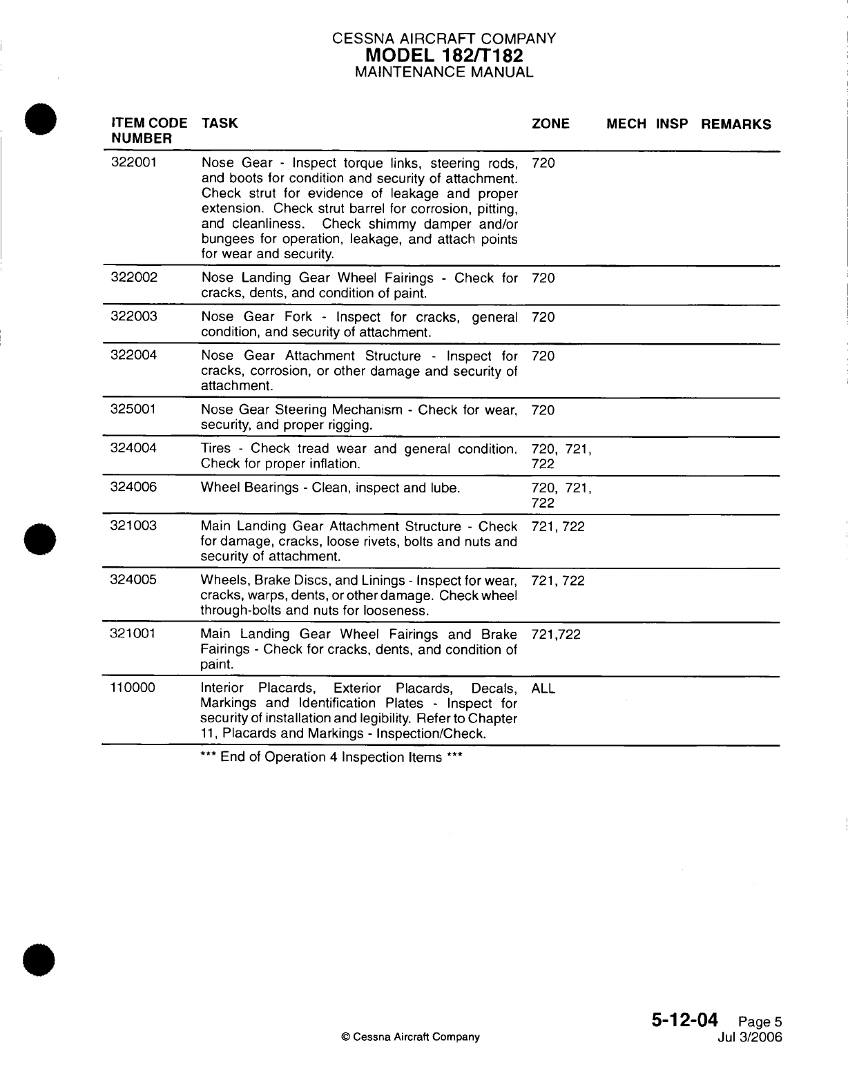
CESSNA
AIRCRAFT
COMPANY
MODEL
182/T182
MAINTENANCE
MANUAL
ITEM
CODE
TASK
ZONE
MECH
INSP
REMARKS
NUMBER
322001
Nose
Gear
-
Inspect
torque
links,
steering
rods,
720
and
boots for condition
and
security
of
attachment.
Check
strut for evidence
of
leakage
and proper
extension.
Check
strut
barrel
for
corrosion,
pitting,
and
cleanliness.
Check
shimmy
damper
and/or
bungees for
operation, leakage, and
attach points
for
wear
and
security.
322002
Nose
Landing
Gear
Wheel
Fairings
-
Check
for
720
cracks,
dents,
and
condition
of
paint.
322003
Nose
Gear
Fork
-
Inspect
for
cracks,
general
720
condition,
and
security
of
attachment.
322004
Nose
Gear Attachment
Structure
-
Inspect
for
720
cracks,
corrosion,
or
other
damage
and
security
of
attachment.
325001
Nose
Gear Steering
Mechanism
-
Check
for
wear,
720
security,
and
proper
rigging.
324004
Tires
-
Check
tread wear
and
general
condition.
720,
721,
Check
for
proper
inflation.
722
324006
Wheel Bearings
-
Clean,
inspect
and
lube. 720,
721,
722
321003
Main
Landing Gear Attachment
Structure
-
Check
721,
722
for damage,
cracks,
loose
rivets,
bolts
and
nuts
and
security
of
attachment.
324005
Wheels,
Brake
Discs,
and
Linings
-
Inspect
for
wear,
721, 722
cracks,
warps,
dents,
or
other damage.
Check
wheel
through-bolts
and
nuts
for
looseness.
321001 Main
Landing Gear
Wheel Fairings and
Brake
721,722
Fairings
-
Check
for
cracks, dents,
and
condition
of
paint.
110000
Interior
Placards,
Exterior
Placards,
Decals,
ALL
Markings and Identification
Plates
-
Inspect
for
security
of
installation
and
legibility.
Refer
to
Chapter
11,
Placards
and
Markings
-
Inspection/Check.
***
End
of
Operation
4
Inspection
Items
***
5-12-04
Page
5
©
Cessna
Aircraft
Company
Jul
3/2006
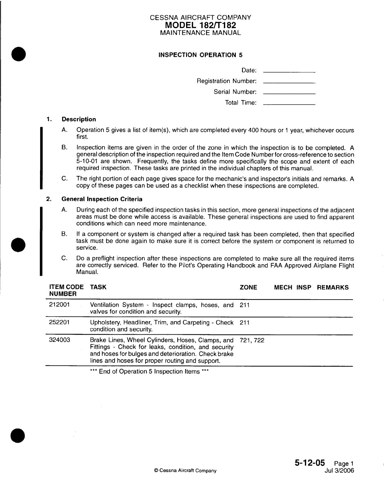
CESSNA AIRCRAFT
COMPANY
MODEL
182/T182
MAINTENANCE
MANUAL
INSPECTION
OPERATION
5
Date:
Registration
Number:
Serial
Number:
Total
Time:
1.
Description
A.
Operation
5
gives
a
list
of
item(s), which
are
completed every
400
hours or
1
year,
whichever
occurs
first.
B.
Inspection
items
are
given
in
the
order
of
the
zone
in
which
the
inspection
is
to
be
completed.
A
general
description
of
the inspection
required
and
the
Item
Code
Number for
cross-reference
to
section
5-10-01
are shown.
Frequently,
the
tasks
define
more
specifically
the
scope and extent
of
each
required
inspection.
These
tasks
are
printed
in
the
individual
chapters
of
this
manual.
C.
The
right
portion
of
each
page
gives
space
for
the
mechanic's
and
inspector's
initials
and
remarks.
A
copy
of
these
pages
can
be
used
as
a
checklist
when these
inspections
are
completed.
2.
General
Inspection Criteria
A.
During
each
of
the
specified
inspection
tasks
in
this
section,
more
general
inspections
of
the
adjacent
areas must
be
done
while
access
is
available. These
general
inspections
are
used
to
find
apparent
conditions
which
can need
more
maintenance.
B. If
a
component
or
system
is
changed
after
a
required
task
has been
completed,
then
that
specified
task
must
be
done
again
to
make sure
it
is
correct before the
system
or
component
is
returned
to
service.
C.
Do
a
preflight inspection
after
these
inspections
are
completed
to
make
sure
all
the
required
items
are
correctly
serviced.
Refer
to
the
Pilot's
Operating Handbook
and
FAA
Approved Airplane
Flight
Manual.
ITEM
CODE
TASK ZONE
MECH
INSP REMARKS
NUMBER
212001
Ventilation
System
-
Inspect clamps,
hoses, and
211
valves
for
condition
and
security.
252201
Upholstery,
Headliner,
Trim,
and
Carpeting
-
Check
211
condition
and
security.
324003
Brake
Lines,
Wheel Cylinders,
Hoses, Clamps,
and
721,
722
Fittings
-
Check
for
leaks,
condition,
and
security
and
hoses
for
bulges
and
deterioration.
Check
brake
lines
and
hoses
for
proper
routing
and
support.
***
End
of
Operation
5
Inspection
Items
**
5-12-05
Page
1
©
Cessna
Aircraft
Company
Jul 3/2006
CESSNA
AIRCRAFT
COMPANY
MODEL
182/T182
MAINTENANCE
MANUAL
PROGRESSIVE
CARE
1.
Operation
6
THERE
ARE
CURRENTLY
NO
PROGRESSIVE
CARE
OPERATIONS
CONTAINED
IN
THIS
SECTION.
5-12-06
Page
1
©
Cessna Aircraft
Company
April
1/2002
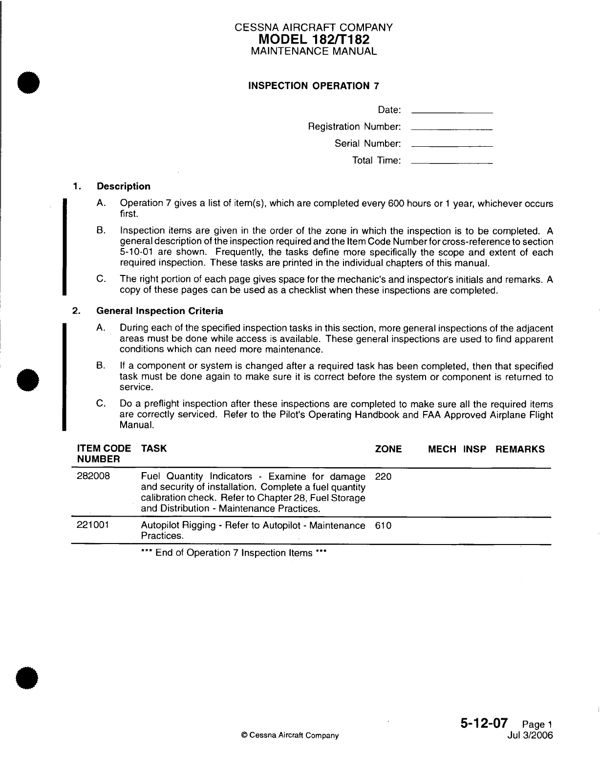
CESSNA AIRCRAFT
COMPANY
MODEL
182/T182
MAINTENANCE
MANUAL
INSPECTION OPERATION
7
Date:
Registration
Number:
Serial Number:
Total
Time:
1.
Description
A.
Operation
7
gives
a
list
of
item(s),
which
are
completed
every
600 hours
or
1
year,
whichever occurs
first.
B.
Inspection
items
are given
in
the
order of
the
zone
in
which
the
inspection
is
to
be
completed.
A
general
description
of
the
inspection
required
and
the
Item
Code
Number
for
cross-reference
to
section
5-10-01
are
shown. Frequently,
the
tasks
define
more
specifically
the
scope
and
extent
of
each
required
inspection. These
tasks
are
printed
in
the
individual
chapters
of
this
manual.
C.
The
right
portion
of
each
page
gives space for
the
mechanic's
and
inspector's
initials
and
remarks.
A
copy
of
these
pages
can
be
used
as
a
checklist
when
these
inspections
are
completed.
2.
General
Inspection
Criteria
A.
During
each
of
the
specified
inspection
tasks
in
this section,
more
general
inspections
of the
adjacent
areas
must
be
done while
access
is
available. These
general
inspections
are
used
to
find
apparent
conditions
which
can
need more
maintenance.
B.
If
a
component
or
system
is
changed after
a
required
task
has been
completed, then that
specified
task
must
be
done
again
to
make
sure
it
is
correct
before
the
system or
component
is
returned
to
service.
C.
Do
a
preflight
inspection
after
these
inspections
are
completed
to
make
sure
all
the
required
items
are
correctly serviced.
Refer
to
the
Pilot's
Operating Handbook
and
FAA
Approved
Airplane
Flight
Manual.
ITEM
CODE
NUMBER
282008
221001
TASK
ZONE
MECH
INSP
Fuel
Quantity
Indicators
-
Examine
for
damage
and
security
of
installation.
Complete
a
fuel
quantity
calibration
check.
Refer
to
Chapter 28,
Fuel
Storage
and
Distribution
-
Maintenance
Practices.
Autopilot
Rigging
-
Refer to
Autopilot
-
Maintenance
Practices.
***
End of
Operation
7
Inspection
Items
***
©
Cessna
Aircraft
Company
REMARKS
220
610
5-12-07
Page
1
Jul 3/2006

CESSNA
AIRCRAFT
COMPANY
MODEL
182/T182
MAINTENANCE
MANUAL
PROGRESSIVE
CARE
1.
Operation
8
THERE
ARE
CURRENTLY
NO
PROGRESSIVE
CARE
OPERATIONS
CONTAINED
IN
THIS
SECTION.
5-12-08
Page
1
©
Cessna Aircraft Company
April
1/2002
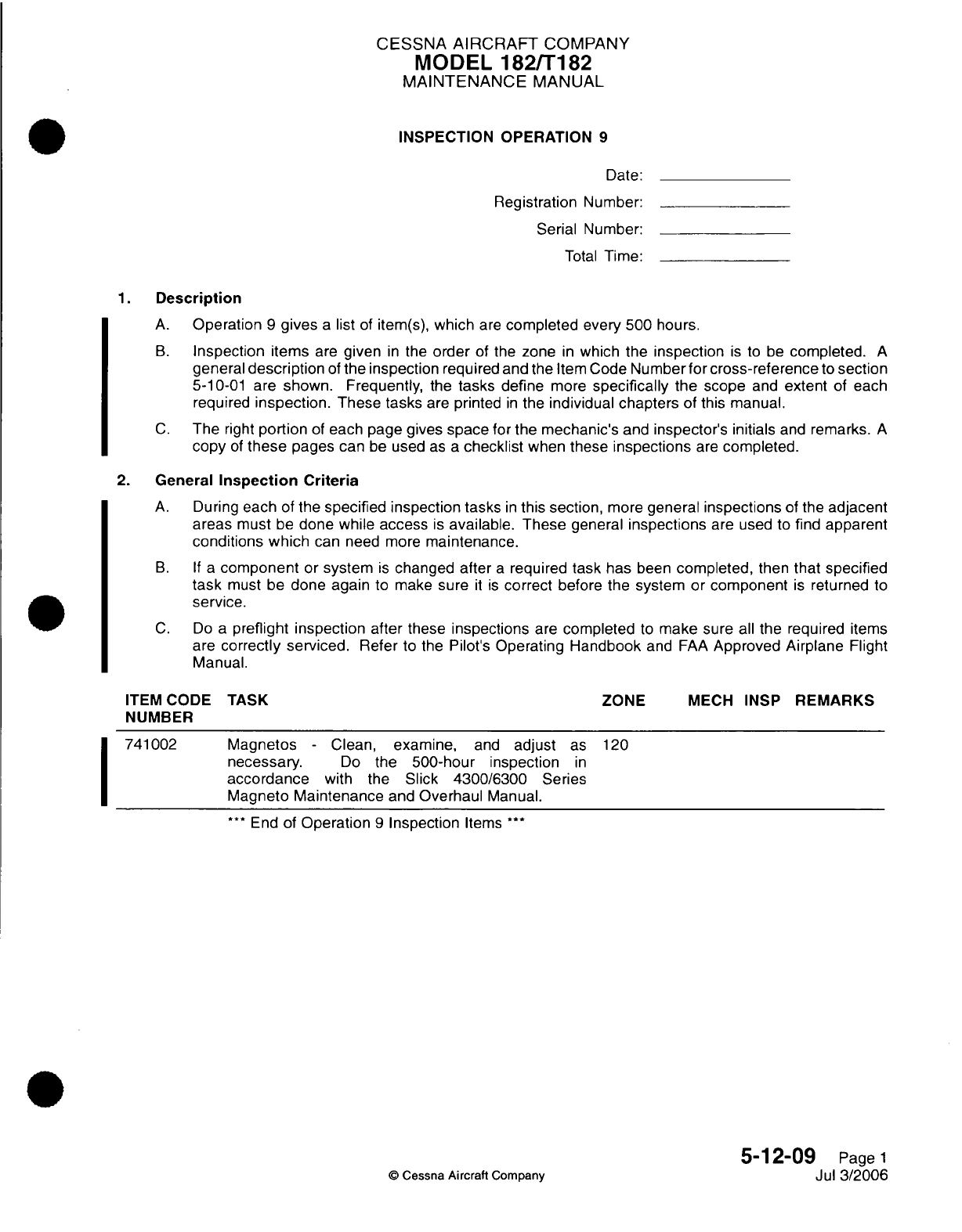
CESSNA
AIRCRAFT
COMPANY
MODEL
182/T182
MAINTENANCE
MANUAL
INSPECTION OPERATION
9
Date:
Registration
Number:
Serial
Number:
Total
Time:
1.
Description
A.
Operation
9
gives
a
list
of
item(s),
which
are
completed
every 500 hours.
B.
Inspection
items
are
given
in
the
order
of
the
zone
in
which
the
inspection
is
to
be
completed.
A
general
description
of
the
inspection
required
and the
Item
Code
Number
for
cross-reference
to
section
5-10-01
are
shown.
Frequently,
the
tasks
define
more
specifically
the
scope
and
extent
of each
required
inspection.
These tasks
are
printed
in
the
individual
chapters
of
this manual.
C.
The
right
portion
of
each
page
gives
space
for
the
mechanic's
and
inspector's initials
and
remarks.
A
copy
of
these
pages
can
be
used
as
a
checklist
when
these
inspections
are
completed.
2.
General
Inspection
Criteria
A.
During
each
of
the
specified inspection tasks
in
this
section,
more
general
inspections
of
the
adjacent
areas
must
be
done while
access
is
available.
These
general
inspections
are used
to
find
apparent
conditions which
can
need
more
maintenance.
B. If a
component
or
system
is
changed
after
a
required
task
has
been
completed,
then
that
specified
task
must
be
done again
to
make
sure
it is
correct
before
the
system or
component
is
returned
to
service.
C.
Do
a
preflight inspection
after
these
inspections
are
completed
to
make
sure
all
the
required
items
are
correctly serviced.
Refer
to the
Pilot's
Operating
Handbook
and
FAA
Approved
Airplane
Flight
Manual.
ITEM
CODE
TASK
ZONE
MECH
INSP
REMARKS
NUMBER
741002
Magnetos
-
Clean,
examine,
and
adjust
as
120
necessary.
Do
the
500-hour
inspection
in
accordance
with
the
Slick
4300/6300
Series
Magneto
Maintenance
and
Overhaul
Manual.
***
End
of
Operation
9
Inspection
Items
***
5-12-09
Page
1
©
Cessna Aircraft
Company Jul
3/2006
CESSNA AIRCRAFT
COMPANY
MODEL
182/T182
MAINTENANCE
MANUAL
INSPECTION
OPERATION
10
Date:
Registration Number:
Serial Number:
Total
Time:
1.
Description
A.
Operation
10
gives
a
list
of
item(s),
which
are
completed
every
1000
hours.
B.
Inspection
items
are
given
in
the
order
of
the zone
in
which
the
inspection
is
to
be
completed.
A
general
description
of
the
inspection
required
and
the
Item
Code
Number for
cross-reference
to
section
5-10-01
are
shown.
Frequently,
the
tasks
define
more
specifically
the
scope
and
extent
of
each
required
inspection. These tasks
are
printed
in
the
individual chapters
of
this manual.
C.
The
right
portion
of
each page
gives
space
for
the
mechanic's
and
inspector's initials
and
remarks.
A
copy
of
these
pages
can
be
used
as
a
checklist
when
these
inspections
are
completed.
2.
General
Inspection Criteria
A.
During
each
of the
specified inspection
tasks
in
this
section,
more
general
inspections
of
the
adjacent
areas
must
be
done
while
access
is
available.
These
general
inspections
are
used to
find
apparent
conditions
which
can
need
more
maintenance.
B. If a
component
or
system
is
changed
after
a
required
task
has
been
completed,
then that
specified
task
must
be
done
again
to make sure
it is
correct
before
the
system
or
component
is
returned
to
service.
C.
Do
a
preflight
inspection after these
inspections
are
completed
to
make
sure
all
the
required
items
are
correctly
serviced.
Refer
to
the Pilot's
Operating Handbook
and
FAA
Approved Airplane
Flight
Manual.
ITEM CODE
TASK
ZONE
MECH
INSP
REMARKS
NUMBER
282009
Integral
Fuel
Bays
-
Drain
the
fuel
(Refer
to
Chapter
510,
610
12,
Fuel
-
Servicing)
and purge
tanks
(Refer
to the
Single
Engine
Structural Repair
Manual,
1996
and
On).
Complete
an
inspection
of
the
tank
interior
and
outlet screens
and
remove
any foreign
object
debris.
Complete
an
inspection
of
the
tank
interior
surfaces
for
sealant
deterioration
and
corrosion (especially
in
the sump
areas).
***
End
of
Operation
10
Inspection
Items
***
5-12-10
Page
1
©
Cessna
Aircraft
Company
Jul 3/2006
CESSNA AIRCRAFT
COMPANY
MODEL
182/T182
MAINTENANCE
MANUAL
INSPECTION
OPERATION
11
Date:
Registration
Number:
Serial
Number:
Total
Time:
1.
Description
A.
Operation
11
gives
a
list of
item(s),
which
are
completed every
2
years.
B.
Inspection
items
are
given
in
the
order
of the
zone
in
which
the
inspection
is
to be
completed.
A
general
description
of
the
inspection
required
and
the
Item
Code
Number
for
cross-reference
to
section
5-10-01
are shown. Frequently,
the
tasks
define
more
specifically
the
scope
and
extent
of
each
required
inspection.
These tasks
are
printed
in
the
individual chapters
of
this
manual.
C.
The
right
portion
of
each
page gives
space for
the
mechanic's
and
inspector's
initials
and
remarks.
A
copy
of
these
pages
can
be
used
as
a
checklist
when
these
inspections
are
completed.
2.
General
Inspection
Criteria
A.
During
each
of
the
specified
inspection
tasks
in
this
section,
more
general
inspections
of
the
adjacent
areas
must
be
done
while access
is
available. These
general
inspections
are
used
to
find
apparent
conditions which
can need
more
maintenance.
B. If
a
component
or
system
is
changed
after
a
required
task
has
been
completed,
then that
specified
task
must
be
done
again
to make
sure
it is
correct
before the
system
or
component
is
returned
to
service.
C.
Do
a
preflight inspection
after these
inspections
are
completed
to make
sure
all
the
required
items
are
correctly
serviced.
Refer
to
the
Pilot's
Operating
Handbook
and
FAA
Approved Airplane
Flight
Manual.
ITEM CODE
TASK
ZONE
MECH
INSP
REMARKS
NUMBER
341102
Pitot
and
Static
System
-
Examine
in
accordance
220
with
14
CFR Part 91.411.
246003 Alternator
Control
Unit
-
Complete the
Over-voltage
222
Protection
Circuit
Test.
Refer to
Chapter
24,
Alternator
Control
Unit.
***
End
of
Operation
11
Inspection
Items
***
5-12-11
Page
1
Jul
3/2006
0
Cessna
Aircraft
Company

CESSNA
AIRCRAFT
COMPANY
MODEL
182/T182
MAINTENANCE
MANUAL
PROGRESSIVE
CARE
1.
Operation
13
THERE
ARE
CURRENTLY
NO
PROGRESSIVE
CARE
OPERATIONS
CONTAINED
IN
THIS
SECTION.
5-12-13
Page
1
©
Cessna
Aircraft
Company
April
1/2002
CESSNA
AIRCRAFT
COMPANY
MODEL
182/T182
MAINTENANCE
MANUAL
INSPECTION OPERATION
14
Date:
Registration
Number:
Serial
Number:
Total
Time:
1.
Description
A.
Operation
14
gives
a
list
of
item(s),
which
are
completed every
2
years,
or
anytime
components
are
added
or
removed from
the
airplane
which
have
the
potential
to
affect
the
magnetic
accuracy
and/or
variation
of
the compass calibration,
or
anytime the
accuracy
of
the
compass
is in
question.
B.
Inspection
items
are
given
in
the
order
of
the zone
in
which
the
inspection
is
to
be
completed.
A
general
description
of
the
inspection
required
and the
Item
Code
Number for
cross-reference
to
section
5-10-01
are
shown.
Frequently,
the
tasks
define
more
specifically
the
scope
and
extent
of
each
required
inspection.
These tasks
are
printed
in
the
individual chapters
of
this manual.
C.
The
right
portion
of
each
page
gives space
for
the
mechanic's
and
inspector's
initials
and
remarks.
A
copy
of
these
pages
can
be
used
as
a
checklist
when
these
inspections
are
completed.
2.
General
Inspection
Criteria
A.
During
each
of
the
specified
inspection
tasks
in
this
section,
more
general inspections
of
the
adjacent
areas
must
be
done while
access
is
available.
These general
inspections
are
used
to
find
apparent
conditions which
can
need
more
maintenance.
B. If a
component
or system
is
changed
after
a
required
task
has
been
completed,
then
that
specified
task
must
be
done
again
to make
sure
it is
correct
before the
system
or
component
is
returned
to
service.
C.
Do
a
preflight inspection
after
these
inspections
are
completed
to
make
sure
all
the
required
items
are
correctly
serviced.
Refer
to
the
Pilot's
Operating Handbook
and
FAA
Approved Airplane
Flight
Manual.
ITEM
CODE
NUMBER
342102
TASK
Magnetic Compass
-
Calibrate.
***
End
of
Operation
14
Inspection
Items
***
ZONE
MECH
INSP
REMARKS
220
5-12-14
Page
1
Jul
3/2006
©
Cessna
Aircraft
Company
CESSNA AIRCRAFT
COMPANY
MODEL
182/T182
MAINTENANCE
MANUAL
INSPECTION
OPERATION
15
Date:
Registration Number:
Serial
Number:
Total
Time:
1.
Description
A.
Operation
15
gives
a
list
of
item(s),
which
are
completed
every
2000
hours.
B.
Inspection
items
are
given
in
the
order
of
the zone
in
which
the
inspection
is
to
be
completed.
A
general
description
of
the inspection
required
and the
Item
Code
Number
for
cross-reference
to
section
5-10-01
are
shown. Frequently,
the
tasks
define
more
specifically
the
scope
and
extent
of
each
required
inspection. These tasks
are
printed
in
the
individual
chapters
of
this
manual.
C.
The
right
portion
of
each
page
gives
space
for
the
mechanic's
and
inspector's
initials
and
remarks.
A
copy
of
these
pages
can
be
used
as
a
checklist
when
these
inspections
are
completed.
2.
General
Inspection Criteria
A.
During
each
of
the
specified
inspection tasks
in
this section,
more
general
inspections
of
the
adjacent
areas must
be
done
while access
is
available.
These
general
inspections
are
used
to
find apparent
conditions
which
can
need
more
maintenance.
B. If a
component or system
is
changed
after
a
required
task
has
been
completed,
then
that
specified
task
must
be
done
again
to
make
sure
it is
correct
before
the system
or
component
is
returned
to
service.
C.
Do
a
preflight
inspection
after
these
inspections
are
completed
to
make
sure
all
the required
items
are
correctly
serviced.
Refer
to
the
Pilot's
Operating
Handbook
and
FAA
Approved
Airplane
Flight
Manual.
ITEM
CODE
TASK
ZONE
MECH
INSP
REMARKS
NUMBER
612003
Propeller
Control
Cable
-
Non-repairable
item
and
120,210
must
be
replaced
at
every
interval
or
whenever
maximum
linear
movement exceeds 0.050
inch.
Refer
to
Chapter 61-20-00,
Propeller
Control
Cable.
743002
Inspect
and
lubricate
ACS
brand
ignition
switch.
224
Refer
to
Chapter
74,
Ignition System
-
Maintenance
Practices.
***
End
of
Operation
15
Inspection
Items
***
5-12-15
Page
1
©
Cessna
Aircraft Company
Jul 3/2006

CESSNA AIRCRAFT
COMPANY
MODEL
182/T182
MAINTENANCE
MANUAL
INSPECTION OPERATION
16
Date:
Registration
Number:
Serial
Number:
Total
Time:
1.
Description
A.
Operation
16
gives
a
list
of
item(s),
which
are
completed every
1000
hours
or
1
year,
whichever occurs
first.
B.
Inspection
items
are given
in
the
order
of the
zone
in
which
the
inspection
is
to
be
completed.
A
general
description
of
the
inspection
required and
the
Item Code
Number
for
cross-reference
to
section
5-10-01
are
shown.
Frequently,
the
tasks
define
more
specifically
the
scope
and
extent
of
each
required
inspection.
These
tasks
are
printed
in
the
individual chapters
of
this manual.
C.
The
right portion
of
each
page
gives
space
for
the
mechanic's
and
inspector's
initials
and
remarks.
A
copy
of
these
pages
can
be
used
as
a
checklist
when
these
inspections
are
completed.
2.
General
Inspection Criteria
A.
During
each
of
the
specified
inspection
tasks
in
this
section,
more
general
inspections
of the
adjacent
areas
must
be
done
while
access
is
available.
These
general
inspections
are
used to
find
apparent
conditions
which
can
need
more
maintenance.
B. If
a
component or
system
is
changed after
a
required
task
has
been
completed,
then
that
specified
task
must
be
done
again
to make
sure
it
is
correct
before
the
system
or
component
is
returned
to
service.
C.
Do
a
preflight
inspection after
these
inspections
are
completed to
make sure
all
the
are
correctly
serviced.
Refer
to the
Pilot's
Operating Handbook
and
FAA
Approved
Manual.
required
items
Airplane
Flight
ITEM
CODE
NUMBER
221002
221003
TASK
Autopilot
Servo
Capstan
Assemblies.
Check
slip-clutch
torque
settings. Refer
to
Autopilot
-
Maintenance
Practices.
Autopilot
Servo Actuators.
Inspect for
evidence
of
corrosion
and
or
buildup
of
dirt
or
other
particulate
matter
which
may
interfere
with
servo
operation.
Refer
to
Autopilot
-
Maintenance Practices.
***
End
of
Operation
16
Inspection
Items
***
ZONE
MECH
INSP
610
610
5-12-16
Page
1
Jul 3/2006
©
Cessna Aircraft
Company
REMARKS
CESSNA
AIRCRAFT
COMPANY
MODEL
182/T182
MAINTENANCE
MANUAL
INSPECTION
OPERATION
17
Date:
Registration
Number:
Serial
Number:
Total
Time:
1.
Description
A.
Operation
17
gives
a
list
of
item(s),
which
are
completed every
12
calendar
months.
B.
Inspection
items
are
given
in
the
order
of
the zone
in
which
the
inspection
is
to
be
completed.
A
general
description
of
the
inspection
required
and
the
Item
Code
Number
for
cross-reference
to
section
5-10-01
are
shown. Frequently,
the
tasks
define
more
specifically
the scope
and
extent
of each
required
inspection. These
tasks
are
printed
in
the
individual
chapters
of
this manual.
C.
The
right
portion
of
each
page
gives
space
for
the
mechanic's
and inspector's
initials
and
remarks.
A
copy
of
these
pages
can
be
used
as
a
checklist
when
these inspections
are
completed.
2.
General
Inspection
Criteria
A.
During
each
of
the
specified
inspection tasks
in
this
section,
more
general
inspections
of the
adjacent
areas
must
be
done
while
access
is
available. These
general
inspections
are
used to
find
apparent
conditions
which
can
need more
maintenance.
B.
If
a
component
or
system
is
changed
after
a
required
task
has been
completed,
then that
specified
task
must
be
done
again to
make
sure
it
is
correct
before
the system
or
component
is
returned
to
service.
C.
Do
a
preflight
inspection
after
these inspections
are
completed
to
make
sure
all
the
required
items
are
correctly
serviced.
Refer
to
the Pilot's
Operating
Handbook
and
FAA
Approved
Airplane
Flight
Manual.
TASK
Cockpit
Mounted
Halon
Type
Fire
Extinguisher-
Weigh bottle.
Bottle
must
be
reserviced
by
qualified
individual
if
more
than
2
ounces
is
lost.
***
End
of
Operation
17
Inspection
Items
***
©
Cessna
Aircraft
Company
ZONE
MECH
INSP
REMARKS
211
5-12-17
Page
1
Jul
3/2006
ITEM CODE
NUMBER
262002
CESSNA
AIRCRAFT
COMPANY
MODEL
182/T182
MAINTENANCE
MANUAL
INSPECTION
OPERATION
18
Date:
Registration
Number:
Serial Number:
Total
Time:
1.
Description
A.
Operation
18
gives
a
list
of
item(s),
which
are
completed
every
6
years.
B.
Inspection
items
are
given
in
the order
of the
zone
in
which
the
inspection
is
to
be
completed.
A
general
description
of
the
inspection
required
and
the
Item
Code
Number
for
cross-reference
to
section
5-10-01
are
shown.
Frequently, the
tasks
define
more
specifically
the
scope
and
extent
of
each
required
inspection. These
tasks
are
printed
in
the
individual
chapters
of
this
manual.
C.
The
right
portion
of
each
page
gives
space
for
the
mechanic's
and
inspector's initials
and
remarks.
A
copy
of
these
pages
can
be
used
as
a
checklist
when
these inspections
are
completed.
2.
General
Inspection Criteria
A.
During
each
of
the specified
inspection
tasks
in
this
section,
more
general
inspections
of
the
adjacent
areas
must
be
done
while
access
is
available. These
general
inspections
are used
to
find
apparent
conditions
which
can
need
more
maintenance.
B. If
a
component or
system
is
changed
after
a
required
task
has
been
completed,
then
that
specified
task
must
be
done
again
to make sure
it is
correct
before
the
system
or
component
is
returned
to
service.
C.
Do
a
preflight inspection
after these inspections
are
completed
to make sure
all
the
required
items
are
correctly serviced.
Refer
to the
Pilot's
Operating
Handbook
and
FAA
Approved
Airplane
Flight
Manual.
ITEM
CODE
NUMBER
262004
TASK
Cockpit
Mounted
Halon
Type
Fire
Extinguishers
-
Empty,
inspect
for
damage,
and
recharge.
***
End of
Operation
18
Inspection
Items
***
ZONE
MECH
INSP
211
5-12-18
Page
1
Jul
3/2006
©
Cessna
Aircraft
Company
REMARKS
CESSNA
AIRCRAFT
COMPANY
MODEL
182/T182
MAINTENANCE
MANUAL
INSPECTION
OPERATION
19
Date:
Registration
Number:
Serial
Number:
Total
Time:
1.
Description
A.
Operation
19
gives
a
list of
item(s), which
are
completed
every
12
years.
B.
Inspection
items
are
given
in
the
order
of
the zone
in
which the
inspection
is
to
be
completed.
A
general
description
of
the
inspection
required
and
the
Item
Code
Number for
cross-reference
to
section
5-10-01
are
shown.
Frequently,
the
tasks
define
more
specifically
the
scope
and
extent
of
each
required
inspection. These
tasks
are
printed
in
the
individual
chapters
of
this
manual.
C.
The
right
portion
of
each
page gives
space
for
the
mechanic's
and
inspector's initials
and
remarks.
A
copy
of
these
pages
can
be
used
as
a
checklist
when
these inspections
are
completed.
2.
General
Inspection Criteria
A.
During
each
of
the
specified inspection
tasks
in
this
section,
more
general
inspections
of
the
adjacent
areas
must
be
done while
access
is
available.
These
general
inspections
are
used
to
find
apparent
conditions
which can
need
more
maintenance.
B. If a
component or
system
is
changed after
a
required
task
has been
completed,
then
that specified
task
must
be
done again
to
make
sure
it is
correct
before
the
system
or
component
is
returned
to
service.
C.
Do
a
preflight inspection
after
these inspections
are
completed
to
make sure
all
the required
items
are
correctly
serviced.
Refer
to
the
Pilot's
Operating Handbook
and
FAA
Approved
Airplane
Flight
Manual.
ITEM
CODE
NUMBER
262003
TASK
Cockpit
Mounted
Halon
Type
Fire
Extinguishers
-
Perform
hydrostatic
test.
The
hydrostatic
test
shall
be
at
twelve-year
intervals
based
on
initial
servicing
or
date
of
last
hydrostatic
test.
***
End
of
Operation
19
Inspection
Items
***
ZONE
MECH
INSP
REMARKS
211
5-12-19
Page
1
Jul
3/2006
©
Cessna
Aircraft
Company
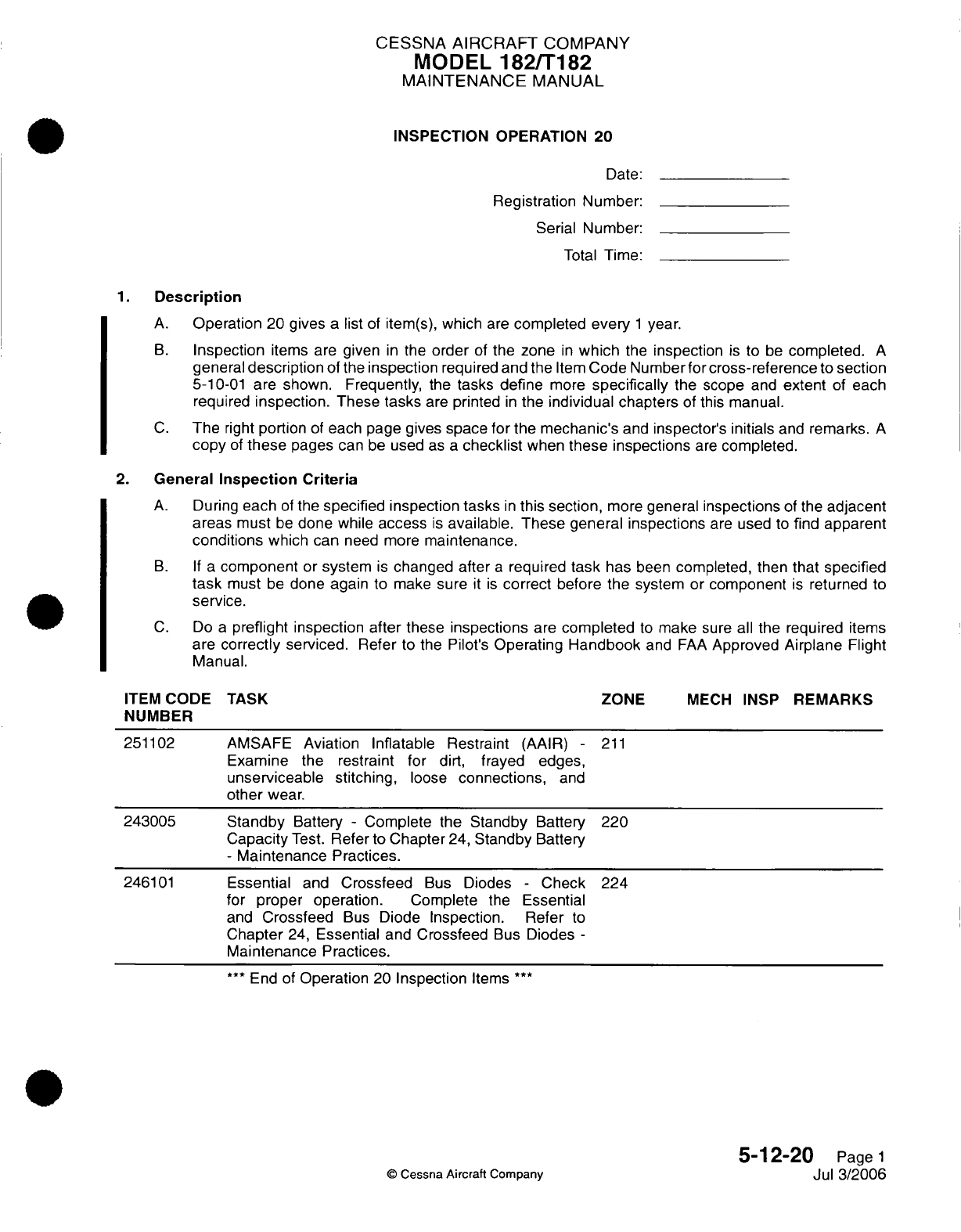
CESSNA
AIRCRAFT
COMPANY
MODEL
182/T182
MAINTENANCE
MANUAL
INSPECTION OPERATION
20
Date:
Registration
Number:
Serial
Number:
Total
Time:
1.
Description
A.
Operation
20
gives
a
list
of
item(s),
which
are
completed
every
1
year.
B.
Inspection
items
are
given
in
the
order
of
the zone
in
which
the
inspection
is
to
be
completed.
A
general
description
of the
inspection
required
and
the
Item
Code
Number for
cross-reference
to
section
5-10-01
are shown.
Frequently,
the
tasks define
more
specifically
the scope
and
extent
of each
required
inspection.
These
tasks
are
printed
in
the
individual chapters
of
this
manual.
C.
The
right
portion
of
each page gives
space for
the mechanic's
and
inspector's
initials
and
remarks.
A
copy
of
these
pages
can
be
used
as
a
checklist
when
these
inspections
are
completed.
2.
General
Inspection Criteria
A.
During
each
of
the
specified inspection tasks
in
this
section,
more
general
inspections
of
the
adjacent
areas
must
be
done
while
access
is
available.
These general
inspections
are
used
to
find
apparent
conditions
which
can
need more
maintenance.
B. If
a
component
or
system
is
changed after
a
required
task
has
been
completed,
then
that
specified
task
must
be
done again
to
make
sure
it is
correct
before
the
system
or
component
is
returned
to
service.
C.
Do
a
preflight inspection
after
these
inspections
are
completed
to
make
sure
all
the required
items
are
correctly
serviced.
Refer to the Pilot's
Operating
Handbook
and
FAA
Approved
Airplane
Flight
Manual.
ITEM
CODE
TASK
ZONE
MECH
INSP
REMARKS
NUMBER
251102
AMSAFE
Aviation
Inflatable Restraint
(AAIR)
-
211
Examine the restraint
for
dirt, frayed edges,
unserviceable stitching,
loose
connections,
and
other
wear.
243005
Standby
Battery
-
Complete
the
Standby
Battery
220
Capacity
Test.
Refer
to
Chapter
24,
Standby
Battery
-
Maintenance
Practices.
246101
Essential
and
Crossfeed
Bus
Diodes
-
Check
224
for
proper operation.
Complete
the
Essential
and
Crossfeed
Bus
Diode Inspection.
Refer
to
Chapter
24,
Essential
and
Crossfeed
Bus
Diodes
-
Maintenance
Practices.
***
End
of
Operation
20
Inspection
Items
***
5-12-20
Page
1
©
Cessna
Aircraft
Company
Jul 3/2006
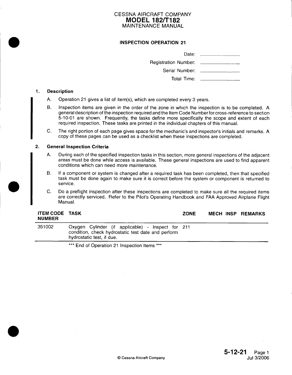
CESSNA AIRCRAFT
COMPANY
MODEL
182/T182
MAINTENANCE
MANUAL
INSPECTION OPERATION
21
Date:
Registration
Number:
Serial Number:
Total
Time:
1.
Description
A.
Operation
21
gives
a
list of item(s),
which
are
completed
every
3
years.
B.
Inspection
items
are
given
in
the
order
of the
zone
in
which
the
inspection
is
to
be
completed.
A
general
description
of
the
inspection
required and
the
Item
Code
Number for
cross-reference
to
section
5-10-01
are
shown. Frequently,
the
tasks
define
more
specifically
the
scope
and
extent
of
each
required
inspection. These
tasks
are
printed
in
the
individual
chapters
of
this manual.
C.
The
right
portion
of
each page
gives space
for
the
mechanic's
and
inspector's initials
and
remarks.
A
copy
of
these
pages
can
be
used
as
a
checklist
when
these inspections
are
completed.
2.
General
Inspection Criteria
A.
During
each
of
the
specified
inspection
tasks
in
this
section,
more
general
inspections
of
the
adjacent
areas must
be
done while
access
is
available.
These
general
inspections
are
used
to
find
apparent
conditions
which
can
need
more
maintenance.
B. If a
component
or
system
is
changed after
a
required
task
has been
completed,
then
that
specified
task
must
be
done again
to
make
sure
it is
correct
before the system
or
component
is
returned
to
service.
C.
Do
a
preflight
inspection after these
inspections
are
completed
to
make
sure
all
the
required
items
are
correctly
serviced. Refer
to
the
Pilot's
Operating
Handbook
and
FAA
Approved
Airplane
Flight
Manual.
ITEM CODE
TASK
ZONE
MECH
INSP
REMARKS
NUMBER
351002
Oxygen
Cylinder
(if
applicable)
-
Inspect
for
211
condition,
check
hydrostatic
test date
and
perform
hydrostatic
test,
if
due.
***
End
of
Operation
21
Inspection
Items
***
5-12-21
Page
1
©
Cessna
Aircraft Company
Jul
3/2006
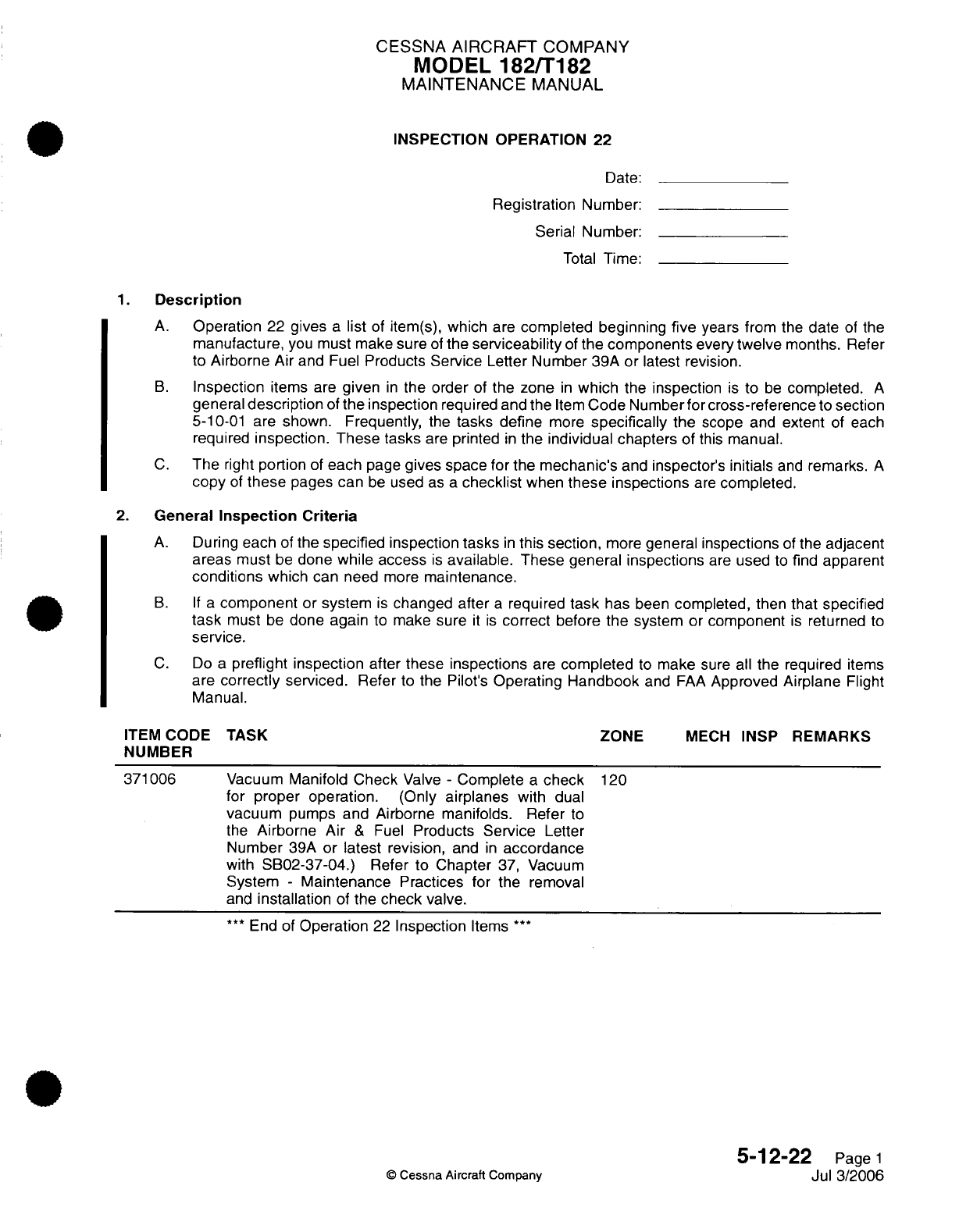
CESSNA
AIRCRAFT
COMPANY
MODEL
182/T182
MAINTENANCE
MANUAL
INSPECTION OPERATION
22
Date:
Registration Number:
Serial
Number:
Total
Time:
1.
Description
A.
Operation
22
gives
a
list
of
item(s),
which
are
completed beginning
five
years
from the
date
of
the
manufacture,
you
must
make
sure
of
the
serviceability
of
the components
every
twelve
months.
Refer
to
Airborne
Air
and
Fuel
Products
Service
Letter Number
39A or latest revision.
B.
Inspection
items
are
given
in
the
order
of
the
zone
in
which
the inspection
is
to
be
completed.
A
general
description
of
the
inspection
required
and
the
Item
Code Number
for
cross-reference
to
section
5-10-01
are shown.
Frequently,
the
tasks
define
more
specifically
the
scope
and
extent
of
each
required
inspection. These tasks
are
printed
in
the
individual
chapters of
this
manual.
C.
The
right
portion
of
each
page
gives space for
the mechanic's
and
inspector's
initials
and
remarks.
A
copy
of
these
pages
can
be
used
as
a
checklist
when
these
inspections
are
completed.
2.
General
Inspection Criteria
A.
During
each
of
the
specified
inspection
tasks
in
this
section,
more
general
inspections
of
the adjacent
areas
must
be
done
while access
is
available. These
general
inspections
are
used
to
find
apparent
conditions
which
can
need
more
maintenance.
B. If a
component
or
system
is
changed
after
a
required
task
has
been
completed,
then
that
specified
task
must
be
done again
to
make
sure
it is
correct before the
system
or
component
is
returned
to
service.
C.
Do
a
preflight
inspection
after these
inspections
are
completed
to
make
sure
all
the
required
items
are
correctly
serviced.
Refer
to
the
Pilot's
Operating
Handbook
and
FAA
Approved
Airplane
Flight
Manual.
ITEM
CODE
TASK
ZONE
MECH
INSP
REMARKS
NUMBER
371006
Vacuum
Manifold
Check
Valve
-
Complete
a
check
120
for
proper
operation. (Only airplanes
with
dual
vacuum
pumps
and
Airborne manifolds. Refer
to
the
Airborne Air
&
Fuel
Products
Service
Letter
Number
39A
or
latest
revision,
and
in
accordance
with
SB02-37-04.)
Refer
to
Chapter
37,
Vacuum
System
-
Maintenance
Practices
for
the
removal
and
installation
of
the
check
valve.
***
End
of
Operation
22
Inspection
Items
***
5-12-22
Page
1
©
Cessna
Aircraft Company
Jul
3/2006
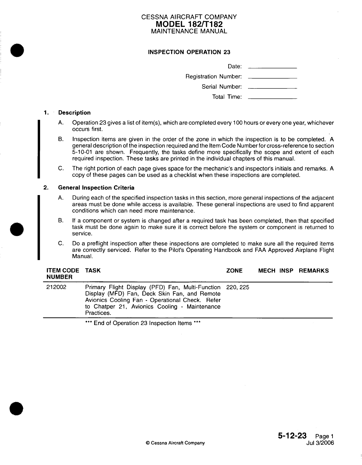
CESSNA AIRCRAFT
COMPANY
MODEL
182/T182
MAINTENANCE
MANUAL
INSPECTION
OPERATION
23
Date:
Registration
Number:
Serial Number:
Total
Time:
1.
Description
A.
Operation
23
gives
a
list
of
item(s), which
are
completed every
100
hours
or
every
one
year,
whichever
occurs
first.
B.
Inspection
items
are
given
in
the order
of
the
zone
in
which
the
inspection
is
to
be
completed.
A
general
description
of
the
inspection
required and the
Item
Code Number
for
cross-reference
to
section
5-10-01
are
shown.
Frequently,
the
tasks
define
more
specifically
the scope
and
extent
of
each
required
inspection. These
tasks
are
printed
in
the
individual
chapters
of
this manual.
C.
The
right
portion
of
each page
gives space for
the
mechanic's
and
inspector's
initials
and
remarks.
A
copy
of
these
pages
can
be
used
as
a
checklist
when
these
inspections
are
completed.
2.
General
Inspection Criteria
A.
During
each
of
the
specified
inspection tasks
in
this
section,
more
general
inspections
of
the
adjacent
areas
must
be
done
while
access
is
available. These
general
inspections
are
used
to
find
apparent
conditions
which
can
need
more
maintenance.
B. If a
component
or
system
is
changed after
a
required
task
has
been
completed, then
that
specified
task
must
be
done again
to
make
sure
it is
correct
before
the
system
or component
is
returned
to
service.
C.
Do
a
preflight inspection after these inspections
are
completed
to
make sure
all
the
required
items
are
correctly
serviced.
Refer
to
the
Pilot's
Operating Handbook
and
FAA
Approved
Airplane
Flight
Manual.
ITEM
CODE
NUMBER
212002
TASK
ZONE
MECH
INSP
Primary Flight
Display
(PFD) Fan,
Multi-Function
Display
(MFD)
Fan,
Deck
Skin
Fan,
and
Remote
Avionics
Cooling
Fan
-
Operational
Check.
Refer
to
Chatper
21,
Avionics
Cooling
-
Maintenance
Practices.
***
End
of
Operation
23
Inspection
Items
***
©
Cessna
Aircraft
Company
REMARKS
220,
225
5-12-23
Page
1
Jul
3/2006
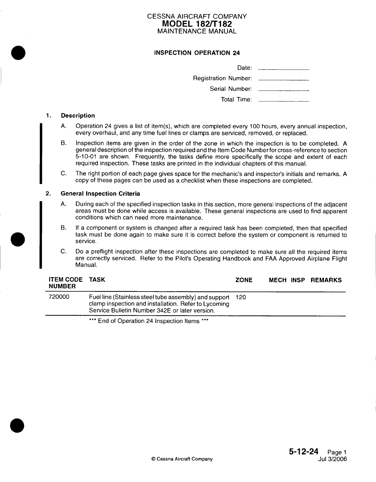
CESSNA AIRCRAFT
COMPANY
MODEL
182/T182
MAINTENANCE
MANUAL
INSPECTION OPERATION
24
Date:
Registration
Number:
Serial
Number:
Total
Time:
1. Description
A.
Operation
24
gives
a
list
of
item(s),
which are
completed
every
100
hours,
every annual
inspection,
every
overhaul,
and
any
time
fuel lines
or
clamps
are
serviced,
removed,
or
replaced.
B.
Inspection
items
are
given
in
the
order
of
the
zone
in
which
the
inspection
is
to
be
completed.
A
general
description
of
the
inspection
required
and
the
Item
Code
Numberfor
cross-reference
to
section
5-10-01 are
shown.
Frequently,
the
tasks define
more
specifically
the
scope
and
extent
of
each
required
inspection. These tasks
are
printed
in
the
individual chapters
of
this
manual.
C.
The
right
portion
of
each
page gives space
for
the
mechanic's
and
inspector's
initials
and
remarks.
A
copy
of
these
pages
can
be
used
as
a
checklist
when
these
inspections
are
completed.
2.
General
Inspection Criteria
A.
During
each
of
the
specified
inspection
tasks
in
this
section,
more
general
inspections
of
the
adjacent
areas
must
be
done while
access
is
available. These
general
inspections
are
used
to
find
apparent
conditions
which
can
need more
maintenance.
B. If
a
component
or
system
is
changed
after
a
required
task
has
been
completed,
then that
specified
task
must
be
done
again
to
make sure
it
is
correct
before
the system
or
component
is
returned
to
service.
C.
Do
a
preflight inspection
after
these
inspections
are
completed
to
make
sure
all
the
required
items
are
correctly
serviced.
Refer
to the Pilot's
Operating
Handbook
and
FAA
Approved Airplane
Flight
Manual.
ITEM
CODE
NUMBER
720000
TASK
Fuel
line
(Stainless steel tube
assembly)
and
support
clamp
inspection
and
installation.
Refer
to
Lycoming
Service
Bulletin
Number
342E
or later
version.
***
End of
Operation
24
Inspection
Items
***
ZONE
MECH
INSP
REMARKS
120
5-12-24
Page
1
Jul 3/2006
©
Cessna
Aircraft
Company
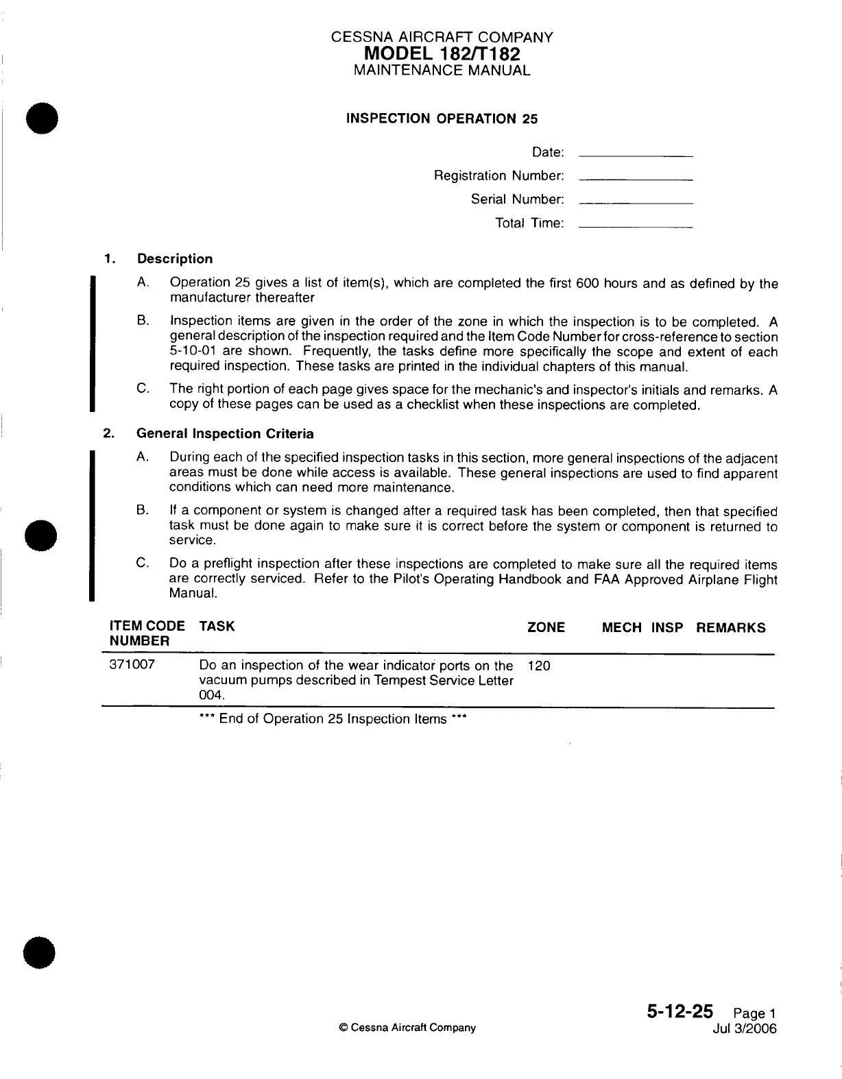
CESSNA AIRCRAFT
COMPANY
MODEL
182/T182
MAINTENANCE
MANUAL
INSPECTION
OPERATION
25
Date:
Registration
Number:
Serial Number:
Total Time:
1.
Description
A.
Operation
25
gives
a
list
of
item(s),
which
are
completed
the
first
600
hours
and
as
defined
by
the
manufacturer thereafter
B.
Inspection
items
are
given
in
the order
of
the
zone
in
which
the
inspection
is
to
be
completed.
A
general
description
of
the
inspection
required
and
the
Item
Code
Number
for
cross-reference
to
section
5-10-01
are
shown.
Frequently,
the
tasks
define
more
specifically
the
scope
and
extent
of
each
required
inspection. These tasks
are printed
in
the
individual
chapters
of
this manual.
C.
The
right
portion
of
each
page
gives space
for
the
mechanic's
and
inspector's
initials
and
remarks.
A
copy
of
these
pages
can
be
used
as
a
checklist
when
these
inspections
are
completed.
2.
General
Inspection
Criteria
A.
During
each of
the specified inspection
tasks
in
this section,
more
general
inspections
of
the
adjacent
areas
must
be
done
while
access
is
available. These
general
inspections
are used
to
find
apparent
conditions
which
can
need
more
maintenance.
B. If
a
component or
system
is
changed
after
a
required
task
has
been
completed,
then
that
specified
task
must
be
done again
to
make sure
it
is
correct before
the
system
or
component
is
returned
to
service.
C.
Do
a
preflight
inspection
after
these inspections
are
completed
to
make sure
all
the
required
items
are
correctly serviced. Refer
to
the
Pilot's
Operating
Handbook
and
FAA
Approved
Airplane
Flight
Manual.
ITEM
CODE
NUMBER
371007
TASK
Do
an
inspection
of
the
wear
indicator
ports
on
the
vacuum
pumps
described
in
Tempest
Service
Letter
004.
***
End
of
Operation
25
Inspection
Items
***
ZONE
MECH
INSP
REMARKS
120
5-12-25
Page
1
Jul
3/2006
©
Cessna
Aircraft
Company
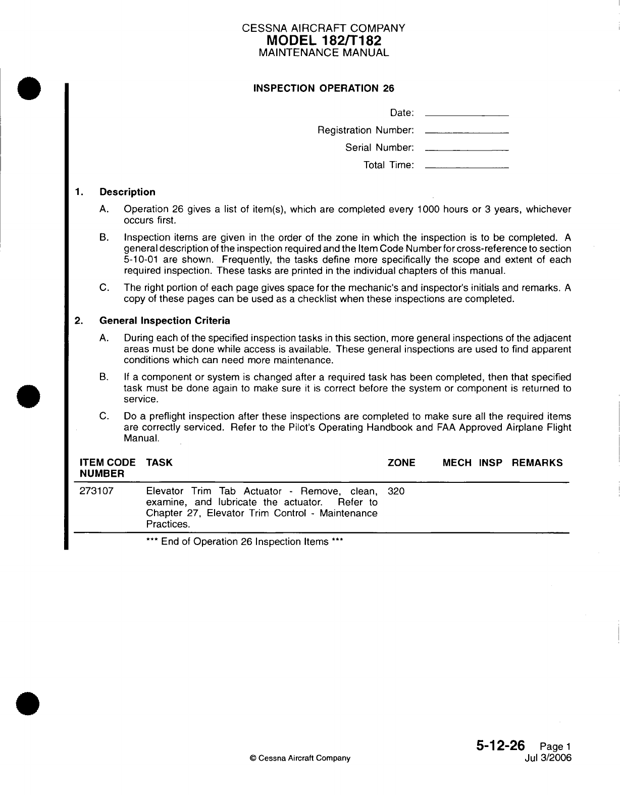
CESSNA AIRCRAFT
COMPANY
MODEL
182/T182
MAINTENANCE
MANUAL
INSPECTION
OPERATION
26
Date:
Registration
Number:
Serial
Number:
Total
Time:
1. Description
A.
Operation
26
gives
a
list
of item(s),
which
are
completed
every
1000 hours
or
3
years, whichever
occurs
first.
B.
Inspection
items
are
given
in
the order
of
the
zone
in
which
the
inspection
is
to
be
completed.
A
general
description
of
the
inspection
required and the
Item Code
Number
for
cross-reference
to
section
5-10-01
are shown. Frequently,
the
tasks
define
more
specifically
the
scope
and
extent
of
each
required
inspection. These tasks
are
printed
in
the
individual
chapters
of
this manual.
C.
The
right
portion
of
each page gives
space
for
the
mechanic's
and
inspector's
initials
and
remarks.
A
copy
of
these
pages can
be
used
as
a
checklist
when
these
inspections
are
completed.
2. General
Inspection Criteria
A.
During
each
of
the
specified
inspection
tasks
in
this section,
more
general
inspections
of the
adjacent
areas
must
be
done
while
access
is
available.
These
general
inspections
are
used
to
find
apparent
conditions
which
can
need
more
maintenance.
B. If
a
component
or
system
is
changed
after
a
required
task
has
been
completed,
then
that
specified
task
must
be
done
again
to make sure
it
is
correct
before
the system
or
component
is
returned
to
service.
C.
Do
a
preflight
inspection
after
these
inspections
are
completed
to make sure
all
the
required
items
are
correctly
serviced. Refer
to the Pilot's
Operating Handbook
and
FAA
Approved
Airplane
Flight
Manual.
TASK
Elevator
Trim
Tab
Actuator
-
Remove,
clean,
examine,
and
lubricate
the
actuator. Refer
to
Chapter
27,
Elevator
Trim
Control
-
Maintenance
Practices.
320
***
End
of
Operation
26
Inspection
Items
***
5-12-26
Page
1
Jul
3/2006
©
Cessna
Aircraft
Company
ITEM
CODE
NUMBER
273107
ZONE
MECH
INSP
REMARKS
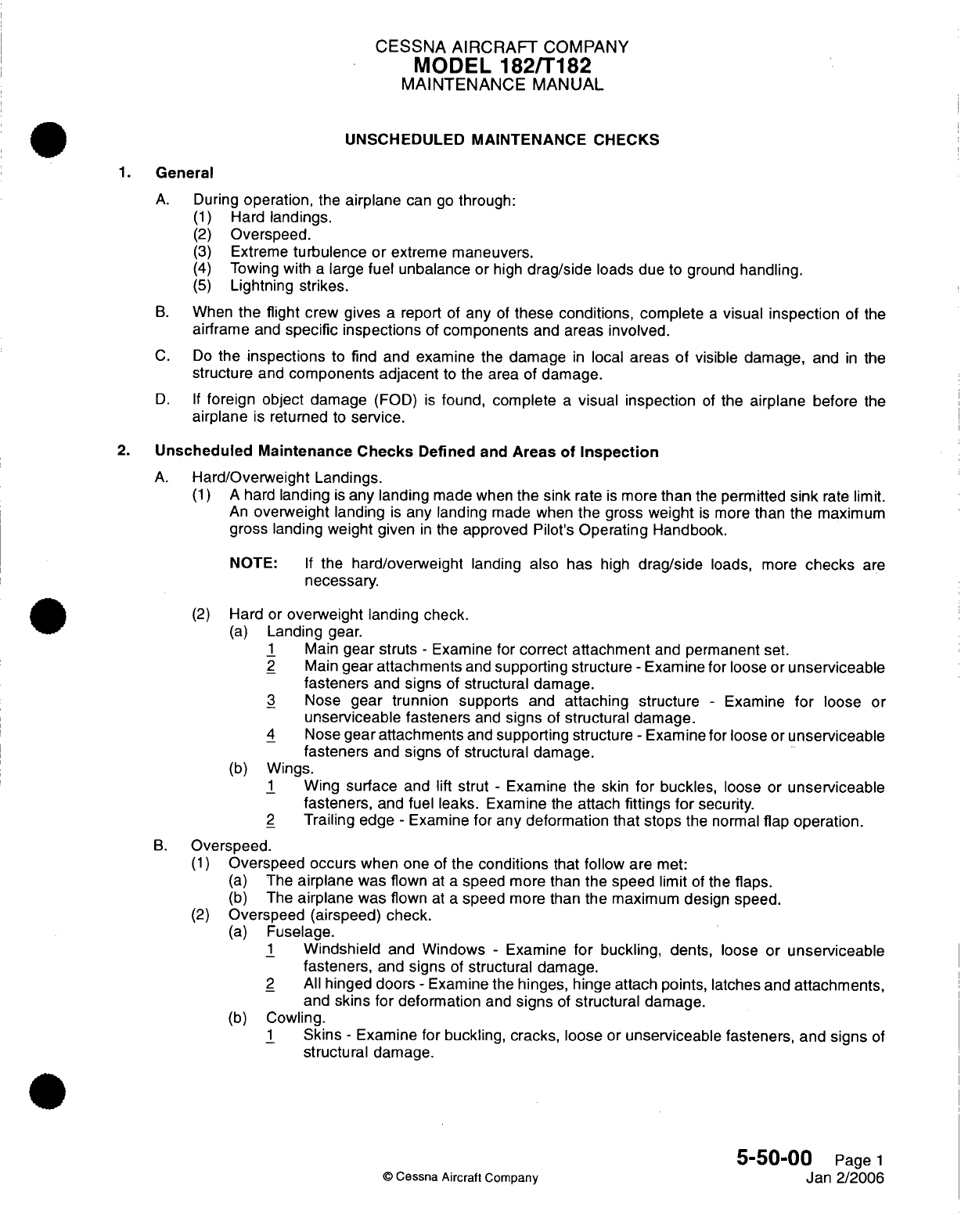
CESSNA
AIRCRAFT
COMPANY
MODEL
182/T182
MAINTENANCE
MANUAL
UNSCHEDULED MAINTENANCE CHECKS
1.
General
A.
During
operation,
the
airplane
can
go
through:
(1)
Hard
landings.
(2)
Overspeed.
(3)
Extreme
turbulence
or
extreme
maneuvers.
(4)
Towing with
a
large
fuel unbalance
or
high
drag/side
loads
due
to ground
handling.
(5)
Lightning
strikes.
B.
When
the flight
crew
gives
a
report
of
any
of
these conditions,
complete
a
visual
inspection
of
the
airframe
and
specific inspections
of
components
and
areas
involved.
C.
Do
the
inspections
to
find
and examine the
damage
in
local
areas of visible
damage,
and
in
the
structure
and
components
adjacent
to
the
area
of
damage.
D. If
foreign object
damage
(FOD)
is
found, complete
a
visual
inspection
of
the
airplane
before
the
airplane
is
returned
to
service.
2.
Unscheduled
Maintenance
Checks
Defined
and
Areas
of
Inspection
A.
Hard/Overweight
Landings.
(1) A
hard
landing
is
any landing
made when
the
sink
rate
is
more
than
the
permitted
sink
rate
limit.
An
overweight
landing
is
any landing
made
when
the gross
weight
is
more
than
the
maximum
gross
landing
weight
given
in
the
approved
Pilot's
Operating
Handbook.
NOTE:
If
the
hard/overweight
landing
also has
high
drag/side
loads,
more
checks
are
necessary.
(2)
Hard
or
overweight
landing
check.
(a)
Landing
gear.
1
Main
gear
struts
-
Examine for
correct
attachment
and
permanent
set.
2
Main
gear
attachments
and
supporting
structure
-
Examine
for
loose
or
unserviceable
fasteners
and
signs
of
structural
damage.
3
Nose
gear trunnion supports
and
attaching
structure
-
Examine
for
loose
or
unserviceable fasteners
and
signs
of
structural damage.
4
Nose
gear attachments
and
supporting structure
-
Examine for
loose
or
unserviceable
fasteners
and
signs
of
structural
damage.
(b)
Wings.
1
Wing
surface
and
lift
strut
-
Examine
the
skin
for
buckles,
loose
or
unserviceable
fasteners,
and
fuel
leaks.
Examine
the
attach
fittings
for
security.
2
Trailing
edge
-
Examine
for any deformation that stops
the normal
flap
operation.
B.
Overspeed.
(1)
Overspeed
occurs
when one
of
the
conditions
that
follow
are
met:
(a)
The
airplane
was flown
at
a
speed
more
than
the
speed
limit
of
the
flaps.
(b)
The
airplane
was flown
at
a
speed
more
than
the
maximum
design speed.
(2)
Overspeed
(airspeed)
check.
(a)
Fuselage.
1
Windshield
and
Windows
-
Examine
for
buckling, dents,
loose
or
unserviceable
fasteners,
and
signs
of
structural damage.
2
All
hinged doors
-
Examine
the
hinges,
hinge
attach
points,
latches and
attachments,
and
skins
for deformation
and
signs
of
structural damage.
(b)
Cowling.
1
Skins
-
Examine
for
buckling, cracks, loose
or
unserviceable fasteners,
and
signs
of
structural
damage.
5-50-00
Page
1
©
Cessna
Aircraft
Company
Jan 2/2006
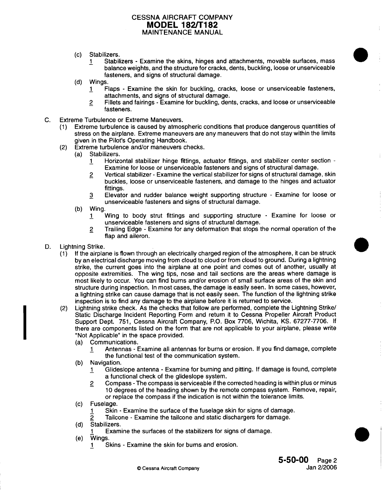
CESSNA AIRCRAFT
COMPANY
MODEL
182/T182
MAINTENANCE
MANUAL
(c)
Stabilizers.
1
Stabilizers
-
Examine the
skins,
hinges
and
attachments,
movable surfaces,
mass
balance weights,
and the
structure
for
cracks,
dents,
buckling,
loose
or
unserviceable
fasteners,
and
signs
of
structural
damage.
(d)
Wings.
1
Flaps
-
Examine
the
skin
for
buckling, cracks,
loose or
unserviceable
fasteners,
attachments,
and
signs
of
structural damage.
2
Fillets
and
fairings
-
Examine
for
buckling, dents,
cracks,
and
loose
or
unserviceable
fasteners.
C.
Extreme
Turbulence
or
Extreme
Maneuvers.
(1)
Extreme
turbulence
is
caused
by
atmospheric conditions
that produce
dangerous
quantities
of
stress
on
the
airplane.
Extreme
maneuvers
are
any
maneuvers
that
do
not
stay
within the
limits
given
in
the Pilot's Operating
Handbook.
(2)
Extreme
turbulence and/or
maneuvers
checks.
(a)
Stabilizers.
1
Horizontal
stabilizer
hinge
fittings,
actuator
fittings,
and
stabilizer
center
section
-
Examine
for
loose
or
unserviceable fasteners
and
signs
of
structural
damage.
2
Vertical
stabilizer
-
Examine
the
vertical
stabilizer for
signs
of
structural
damage,
skin
buckles,
loose
or
unserviceable fasteners,
and
damage
to
the
hinges
and
actuator
fittings.
3
Elevator
and rudder balance
weight
supporting
structure
-
Examine for
loose
or
unserviceable fasteners
and
signs
of
structural
damage.
(b)
Wing.
1
Wing
to
body
strut
fittings
and
supporting
structure
-
Examine
for
loose
or
unserviceable fasteners
and
signs
of
structural
damage.
2
Trailing
Edge
-
Examine
for
any deformation that stops
the normal
operation
of the
flap
and
aileron.
D.
Lightning
Strike.
(1) If
the
airplane
is
flown
through
an
electrically
charged
region
of
the
atmosphere,
it
can
be
struck
by
an
electrical discharge
moving
from
cloud
to
cloud or
from
cloud
to
ground.
During
a
lightning
strike,
the
current
goes
into
the airplane
at one
point
and
comes
out
of
another,
usually
at
opposite extremities.
The
wing
tips,
nose
and
tail
sections
are
the
areas
where
damage
is
most
likely
to
occur.
You
can
find bums
and/or erosion
of
small
surface areas
of
the
skin
and
structure
during inspection.
In
most cases,
the
damage
is
easily
seen.
In
some
cases,
however,
a
lightning strike
can
cause damage
that
is
not
easily
seen.
The
function
of
the
lightning
strike
inspection
is
to
find any damage
to
the
airplane
before
it
is
returned
to
service.
(2)
Lightning
strike
check.
As
the
checks
that
follow
are
performed,
complete the
Lightning
Strike/
Static Discharge
Incident
Reporting
Form
and
return
it
to
Cessna Propeller
Aircraft
Product
Support
Dept.
751,
Cessna
Aircraft
Company,
P.O.
Box
7706,
Wichita,
KS.
67277-7706.
If
there
are
components
listed
on
the
form
that
are
not
applicable
to
your airplane,
please
write
"Not
Applicable"
in
the
space
provided.
(a)
Communications.
1
Antennas
-
Examine all
antennas
for
burns
or
erosion.
If
you
find
damage, complete
the
functional
test
of
the communication
system.
(b)
Navigation.
1
Glideslope
antenna
-
Examine
for
burning and pitting.
If
damage
is
found, complete
a
functional
check
of
the
glideslope
system.
2
Compass
-
The
compass
is
serviceable
if
the
corrected
heading
is
within
plus
or minus
10
degrees of
the
heading
shown
by
the
remote
compass
system. Remove,
repair,
or
replace
the
compass
if
the
indication
is
not
within the
tolerance
limits.
(c)
Fuselage.
1
Skin
-
Examine the
surface
of
the fuselage
skin for
signs
of
damage.
2
Tailcone
-
Examine
the
tailcone
and
static
dischargers
for
damage.
(d)
Stabilizers.
1
Examine the
surfaces
of
the
stabilizers
for
signs
of
damage.
(e)
Wings.
1
Skins
-
Examine the
skin
for bums
and erosion.
5-50-00
Page
2
©
Cessna
Aircraft
Company
Jan
2/2006
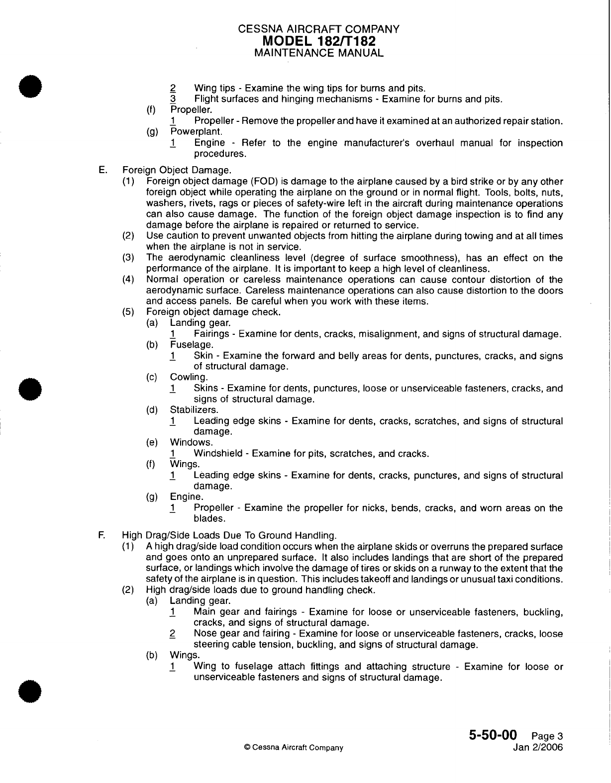
CESSNA
AIRCRAFT
COMPANY
MODEL
182/T182
MAINTENANCE
MANUAL
2
Wing
tips
-
Examine
the wing
tips
for
burns
and
pits.
3
Flight
surfaces
and
hinging
mechanisms
-
Examine for
burns and
pits.
(f)
Propeller.
1
Propeller
-
Remove
the
propeller
and
have
it
examined
at
an
authorized
repair
station.
(g)
Powerplant.
1
Engine
-
Refer
to
the
engine manufacturer's
overhaul
manual
for
inspection
procedures.
E.
Foreign
Object
Damage.
(1)
Foreign
object
damage
(FOD)
is
damage
to
the
airplane
caused
by
a
bird
strike
or
by
any
other
foreign object
while
operating
the
airplane
on
the
ground
or
in
normal
flight.
Tools,
bolts,
nuts,
washers,
rivets,
rags
or
pieces
of
safety-wire
left
in
the
aircraft
during
maintenance
operations
can
also
cause
damage.
The
function
of
the foreign object
damage
inspection
is
to
find
any
damage
before
the
airplane
is
repaired
or returned
to
service.
(2)
Use
caution
to
prevent unwanted
objects
from
hitting
the
airplane
during
towing
and
at all
times
when the
airplane
is
not
in
service.
(3)
The
aerodynamic
cleanliness
level
(degree
of
surface
smoothness),
has
an
effect
on
the
performance
of
the
airplane.
It
is
important
to
keep
a
high
level of
cleanliness.
(4)
Normal
operation
or
careless
maintenance
operations
can
cause
contour distortion
of
the
aerodynamic
surface. Careless
maintenance operations
can
also
cause
distortion
to
the doors
and
access
panels.
Be
careful
when
you
work
with
these
items.
(5)
Foreign
object
damage
check.
(a)
Landing
gear.
1
Fairings
-
Examine
for
dents,
cracks,
misalignment,
and
signs
of
structural damage.
(b)
Fuselage.
1
Skin
-
Examine the
forward
and
belly
areas
for
dents, punctures, cracks,
and
signs
of
structural
damage.
(c)
Cowling.
1
Skins
-
Examine
for dents,
punctures,
loose
or
unserviceable
fasteners,
cracks,
and
signs
of
structural damage.
(d)
Stabilizers.
1
Leading
edge
skins
-
Examine
for dents, cracks, scratches,
and
signs
of
structural
damage.
(e)
Windows.
1
Windshield
-
Examine
for
pits,
scratches,
and
cracks.
(f)
Wings.
1
Leading
edge
skins
-
Examine
for dents, cracks,
punctures,
and
signs
of
structural
damage.
(g)
Engine.
1
Propeller
-
Examine
the
propeller
for nicks,
bends, cracks,
and
worn
areas
on
the
blades.
F.
High
Drag/Side Loads
Due
To
Ground
Handling.
(1) A
high
drag/side
load
condition occurs
when
the
airplane skids
or
overruns
the
prepared surface
and
goes
onto
an
unprepared
surface.
It
also
includes
landings that
are
short
of the
prepared
surface,
or
landings
which
involve
the
damage
of
tires
or
skids
on a
runway
to
the
extent
that
the
safety of
the
airplane
is
in
question.
This
includes
takeoff
and
landings
or
unusual
taxi
conditions.
(2)
High
drag/side
loads
due
to ground
handling check.
(a)
Landing
gear.
1
Main
gear and
fairings
-
Examine
for
loose
or
unserviceable
fasteners, buckling,
cracks,
and
signs
of
structural damage.
2
Nose
gear and
fairing
-
Examine
for
loose
or
unserviceable
fasteners,
cracks,
loose
steering cable
tension, buckling,
and
signs
of
structural
damage.
(b)
Wings.
1
Wing
to
fuselage
attach
fittings
and
attaching structure
-
Examine
for
loose
or
unserviceable
fasteners
and
signs
of
structural damage.
5-50-00
Page
3
©
Cessna
Aircraft
Company
Jan 2/2006
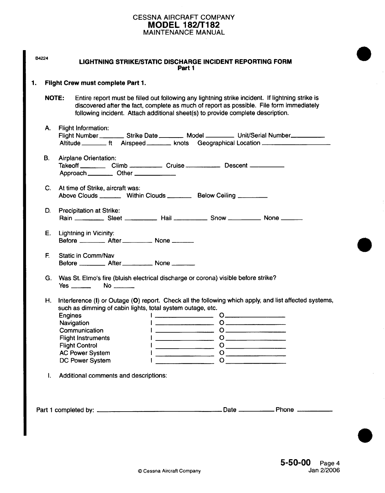
CESSNA
AIRCRAFT
COMPANY
MODEL
182/T182
MAINTENANCE
MANUAL
B4224
LIGHTNING
STRIKE/STATIC
DISCHARGE INCIDENT REPORTING
FORM
Part
1
1.
Flight
Crew
must
complete
Part
1.
NOTE:
Entire
report
must
be
filled
out
following
any
lightning
strike
incident.
If
lightning
strike
is
discovered
after the
fact,
complete
as
much
of
report
as possible.
File
form
immediately
following
incident.
Attach
additional
sheet(s)
to
provide complete
description.
A.
Flight
Information:
Flight
Number_
Strike
Date_
Model
_
Unit/Serial
Number
Altitude
_
ft
Airspeed knots
Geographical
Location
B.
Airplane Orientation:
Takeoff Climb
Approach Other
Cruise
Descent
C.
At
time
of
Strike,
aircraft
was:
Above
Clouds
__
Within
Clouds
__
Below Ceiling
D.
Precipitation
at
Strike:
Rain
Sleet
E.
Lightning
in
Vicinity:
Before
After
F.
Static
in
Comm/Nav
Before
After
Hail
None
None
None
G.
Was
St.
Elmo's
fire
(bluish
electrical
discharge
or
corona)
visible
before
strike?
Yes
_
No
H.
Interference
(I)
or Outage
(0)
report. Check
all
the following
which
apply,
and
list
affected
systems,
such
as
dimming
of
cabin lights,
total
system
outage, etc.
Engines
Navigation
Communication
Flight
Instruments
Flight
Control
AC
Power
System
DC
Power
System
0
0
0
0
0
0
0
I.
Additional
comments
and
descriptions:
Date
Part
1
completed
by:
©
Cessna
Aircraft Company
Phone
5-50-00
Page
4
Jan
2/2006
Snow
I
I
I
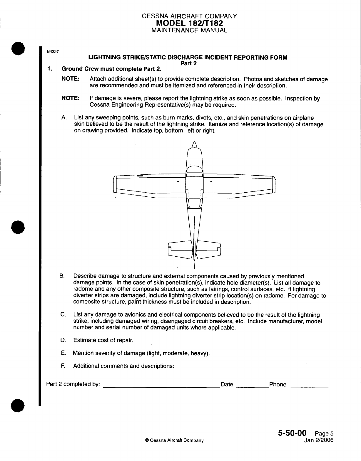
CESSNA
AIRCRAFT
COMPANY
MODEL 182/T182
MAINTENANCE
MANUAL
B4227
LIGHTNING
STRIKE/STATIC
DISCHARGE
INCIDENT
REPORTING
FORM
Part
2
1.
Ground
Crew
must
complete
Part
2.
NOTE:
Attach
additional
sheet(s)
to
provide
complete description.
Photos
and
sketches
of
damage
are
recommended
and
must
be
itemized
and
referenced
in
their description.
NOTE:
If
damage
is
severe,
please
report the
lightning
strike
as
soon
as
possible.
Inspection
by
Cessna
Engineering
Representative(s)
may
be
required.
A.
List
any sweeping
points,
such
as
burn
marks,
divots,
etc.,
and
skin
penetrations
on
airplane
skin
believed
to be
the
result
of the
lightning strike.
Itemize
and
reference
location(s)
of
damage
on
drawing
provided.
Indicate top, bottom,
left
or
right.
B.
Describe
damage to
structure
and external
components
caused
by
previously
mentioned
damage
points.
In
the
case
of
skin
penetration(s),
indicate
hole
diameter(s). List
all
damage
to
radome
and
any
other composite
structure, such
as
fairings, control
surfaces,
etc.
If
lightning
diverter
strips
are
damaged,
include
lightning
diverter
strip
location(s)
on
radome.
For
damage
to
composite structure, paint
thickness
must
be
included
in
description.
C.
List
any damage to
avionics
and
electrical components
believed
to
be
the
result of
the
lightning
strike,
including damaged
wiring,
disengaged
circuit
breakers, etc. Include manufacturer,
model
number and
serial number
of
damaged units where applicable.
D.
Estimate
cost
of
repair.
E.
Mention
severity
of damage (light,
moderate, heavy).
F.
Additional
comments
and
descriptions:
Part
2
completed
by:
Date
©
Cessna
Aircraft
Company
Phone
5-50-00
Page
5
Jan 2/2006
CHAPTER
DIMENSIONS
AND
AREAS

CESSNA AIRCRAFT
COMPANY
MODEL
182/Ti
82
MAINTENANCE
MANUAL
LIST
OF
EFFECTIVE
PAGES
CHA
PTER-SECTION-SU
BJ
ECT
06-Title
06-List
of
Effective
Pages
06-Record
of
Temporary
Revisions
06-Table
of
Contents
6-00-00
6-1
0-00
6-1
5-00
6-20-00
6-20-02
Page
1
Pages
1-5
Pages
1-3
Pages
1-4
Pages
1-11
©D
Cessna
Aircraft
Company
06
-
LIST
OF
EFFECTIVE PAGES
Page
1
of
1
Jul
1/2007
PAGE
DATE
April
1/2002
April
1/2002
April
1/2002
Jul
1/2007
Jul 1/2007
Temporary
Revision
Number
RECORD
OF
TEMPORARY
REVISIONS
Page
Number
Issue
Date
By
Date
Removed
By
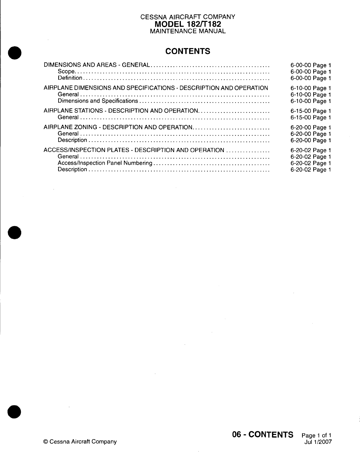
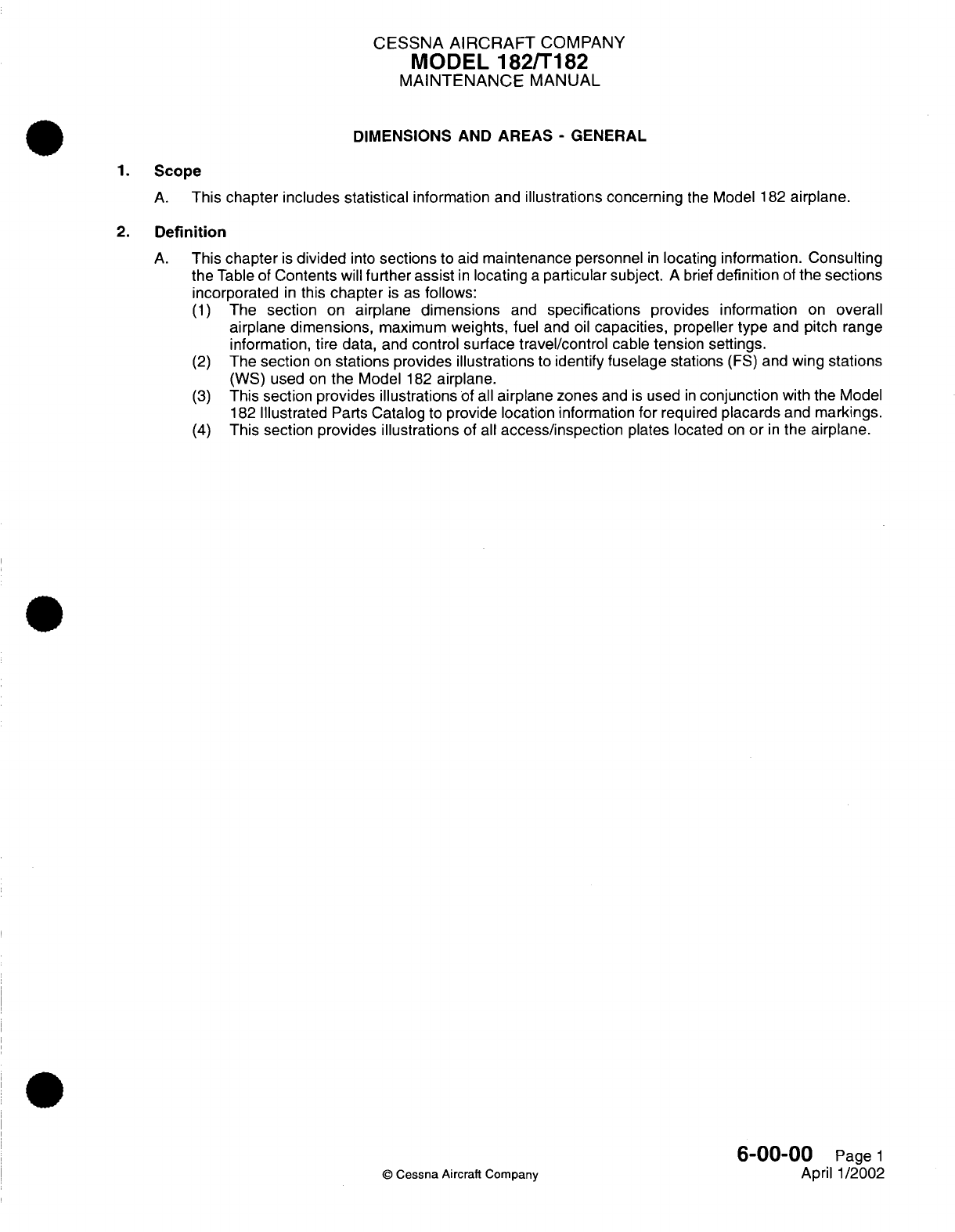
CESSNA AIRCRAFT
COMPANY
MODEL
182/T182
MAINTENANCE
MANUAL
DIMENSIONS AND
AREAS
-
GENERAL
1.
Scope
A.
This
chapter includes statistical
information
and
illustrations
concerning
the
Model
182
airplane.
2.
Definition
A.
This
chapter
is
divided
into
sections
to
aid
maintenance
personnel
in
locating
information.
Consulting
the
Table
of
Contents
will
further
assist
in
locating
a
particular subject.
A
brief
definition
of
the
sections
incorporated
in
this
chapter
is
as
follows:
(1)
The
section
on
airplane dimensions
and
specifications
provides
information
on
overall
airplane dimensions,
maximum
weights,
fuel
and
oil
capacities,
propeller
type
and
pitch
range
information, tire
data,
and
control
surface travel/control
cable
tension settings.
(2)
The
section
on
stations
provides
illustrations
to
identify
fuselage
stations
(FS)
and
wing
stations
(WS)
used
on
the
Model
182
airplane.
(3)
This section
provides illustrations
of
all
airplane
zones
and
is
used
in
conjunction
with
the
Model
182
Illustrated
Parts
Catalog
to
provide location
information
for
required
placards
and
markings.
(4)
This section provides illustrations
of
all
access/inspection
plates
located
on
or
in
the airplane.
6-00-00
Page
1
©
Cessna
Aircraft
Company
April 1/2002
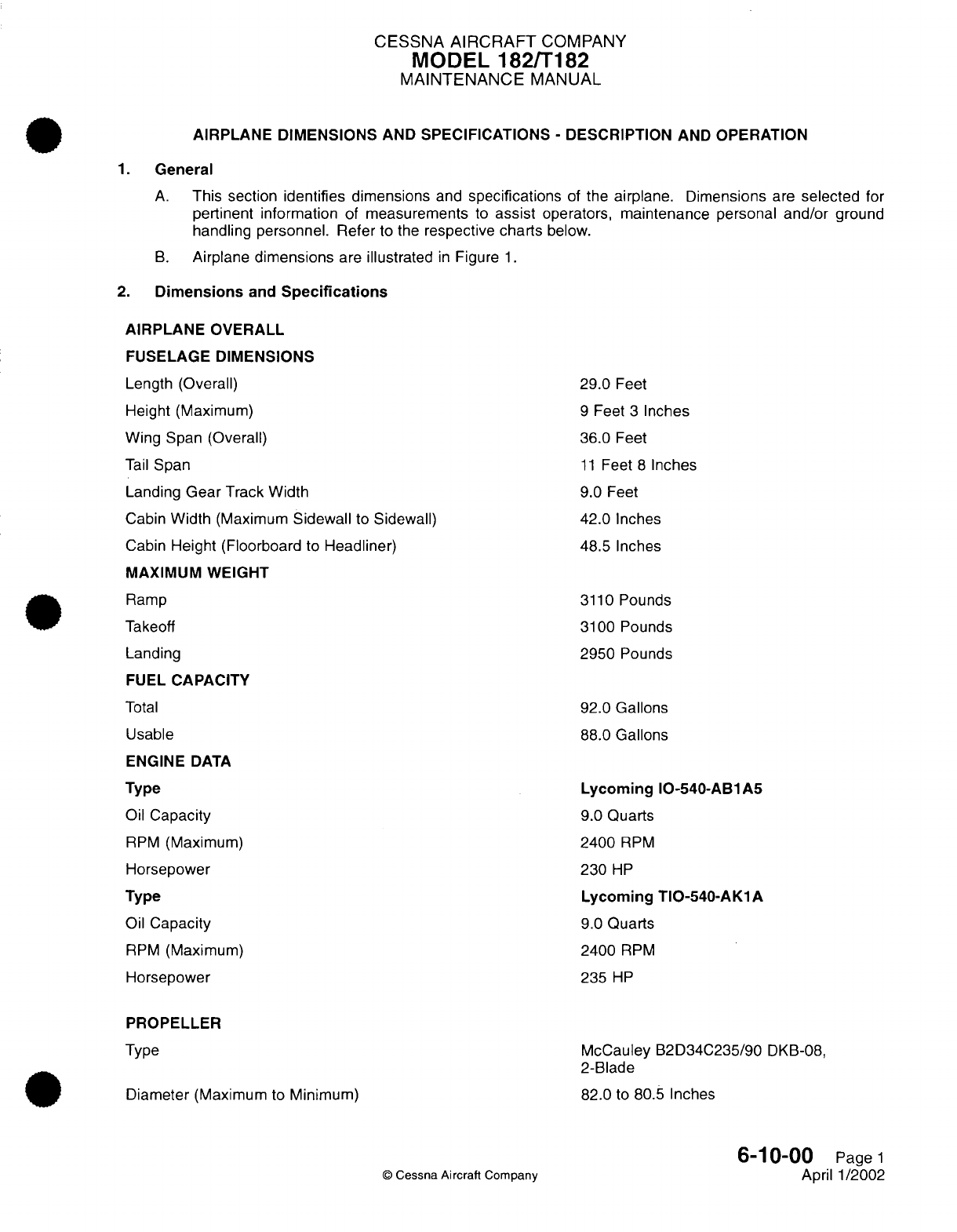
CESSNA
AIRCRAFT
COMPANY
MODEL
182/T182
MAINTENANCE
MANUAL
AIRPLANE
DIMENSIONS
AND
SPECIFICATIONS
-
DESCRIPTION
AND OPERATION
1.
General
A.
This section
identifies
dimensions
and
specifications
of
the
airplane.
Dimensions
are
selected
for
pertinent
information
of
measurements
to
assist
operators,
maintenance personal
and/or
ground
handling
personnel. Refer
to the
respective
charts
below.
B.
Airplane
dimensions
are
illustrated
in
Figure
1.
2.
Dimensions
and
Specifications
AIRPLANE
OVERALL
FUSELAGE DIMENSIONS
Length
(Overall)
Height (Maximum)
Wing Span
(Overall)
Tail
Span
Landing
Gear
Track
Width
Cabin
Width
(Maximum
Sidewall
to
Sidewall)
Cabin
Height
(Floorboard to
Headliner)
MAXIMUM
WEIGHT
Ramp
Takeoff
Landing
FUEL
CAPACITY
Total
Usable
ENGINE
DATA
Type
Oil
Capacity
RPM
(Maximum)
Horsepower
Type
Oil
Capacity
RPM
(Maximum)
Horsepower
PROPELLER
Type
Diameter
(Maximum
to
Minimum)
©
Cessna
Aircraft
Company
29.0
Feet
9
Feet
3
Inches
36.0
Feet
11
Feet
8
Inches
9.0 Feet
42.0
Inches
48.5 Inches
3110
Pounds
3100
Pounds
2950
Pounds
92.0 Gallons
88.0
Gallons
Lycoming
IO-540-AB1A5
9.0
Quarts
2400
RPM
230
HP
Lycoming TIO-540-AK1A
9.0
Quarts
2400
RPM
235
HP
McCauley
B2D34C235/90
DKB-08,
2-Blade
82.0
to
80.5 Inches
6-1
0-00
Page
1
April
1/2002
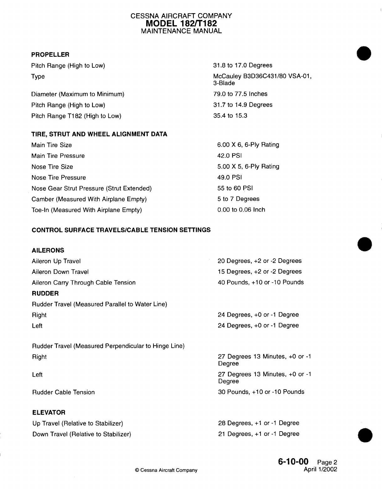
CESSNA AIRCRAFT
COMPANY
MODEL
182/T182
MAINTENANCE
MANUAL
PROPELLER
Pitch
Range
(High
to
Low)
Type
Diameter
(Maximum
to
Minimum)
Pitch
Range
(High
to
Low)
Pitch
Range T182
(High
to Low)
TIRE,
STRUT AND WHEEL
ALIGNMENT
DATA
Main
Tire
Size
Main
Tire
Pressure
Nose
Tire
Size
Nose Tire
Pressure
Nose
Gear
Strut
Pressure
(Strut
Extended)
Camber (Measured
With
Airplane
Empty)
Toe-In
(Measured
With
Airplane
Empty)
31.8
to
17.0
Degrees
McCauley
B3D36C431/80
VSA-01,
3-Blade
79.0
to
77.5
Inches
31.7
to
14.9
Degrees
35.4
to
15.3
6.00
X
6,
6-Ply
Rating
42.0
PSI
5.00
X 5,
6-Ply
Rating
49.0
PSI
55
to 60
PSI
5
to
7
Degrees
0.00
to
0.06
Inch
CONTROL
SURFACE
TRAVELS/CABLE
TENSION
SETTINGS
AILERONS
Aileron
Up
Travel
Aileron
Down
Travel
Aileron
Carry
Through
Cable Tension
RUDDER
Rudder
Travel
(Measured Parallel
to
Water
Line)
Right
Left
Rudder
Travel
(Measured
Perpendicular
to Hinge
Line)
Right
Left
Rudder
Cable Tension
ELEVATOR
Up
Travel (Relative
to
Stabilizer)
Down
Travel
(Relative
to
Stabilizer)
©
Cessna Aircraft
Company
20
Degrees,
+2
or
-2
Degrees
15
Degrees,
+2
or
-2
Degrees
40
Pounds,
+10
or -10
Pounds
24
Degrees,
+0
or
-1
Degree
24
Degrees,
+0
or
-1
Degree
27
Degrees
13
Minutes,
+0
or
-1
Degree
27
Degrees
13
Minutes,
+0
or
-1
Degree
30
Pounds,
+10 or
-10
Pounds
28
Degrees,
+1
or
-1
Degree
21
Degrees,
+1 or-1
Degree
6-10-00
Page
2
April
1/2002
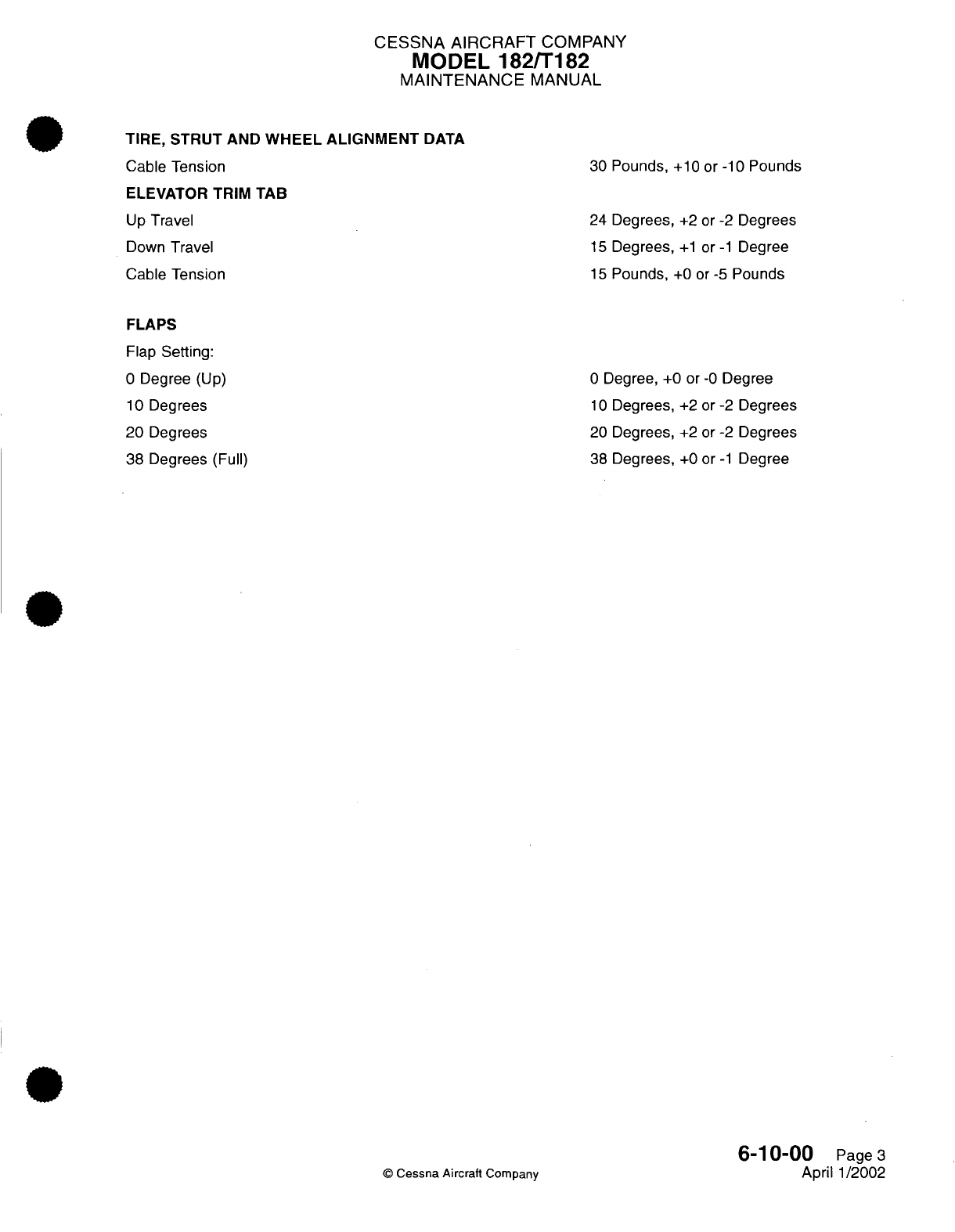
CESSNA
AIRCRAFT
COMPANY
MODEL
182/T182
MAINTENANCE
MANUAL
TIRE,
STRUT AND
WHEEL ALIGNMENT
DATA
Cable
Tension
ELEVATOR TRIM TAB
Up
Travel
Down
Travel
Cable Tension
FLAPS
Flap
Setting:
0
Degree
(Up)
10
Degrees
20
Degrees
38 Degrees
(Full)
©
Cessna
Aircraft
Company
30
Pounds,
+10 or
-10
Pounds
24
Degrees,
+2 or -2
Degrees
15
Degrees,
+1 or-1
Degree
15
Pounds,
+0
or
-5
Pounds
0
Degree,
+0 or
-0
Degree
10
Degrees,
+2
or
-2
Degrees
20
Degrees,
+2
or
-2
Degrees
38
Degrees,
+0
or
-1
Degree
6-10-00
Page
3
April 1/2002
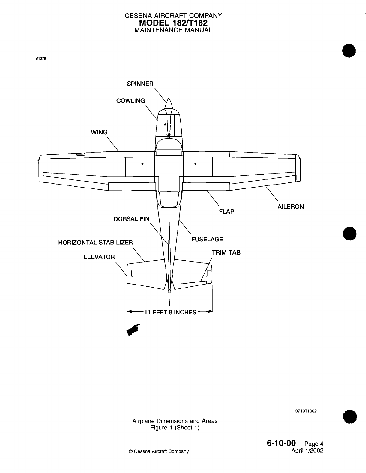
CESSNA
AIRCRAFT
COMPANY
MODEL
182/T182
MAINTENANCE
MANUAL
B1076
SPINNER
COWLING
WING
\
J
0
L
S
FLAP
AGE
HORIZONTAL
STABI
ELEVATOR
TRIM
TAB
1
FEET
8
INCHES
071 OT1002
Airplane
Dimensions
and
Areas
Figure
1
(Sheet
1)
6-10-00
Page
4
April
1/2002
©
Cessna
Aircraft
Company
Al
LERON
[
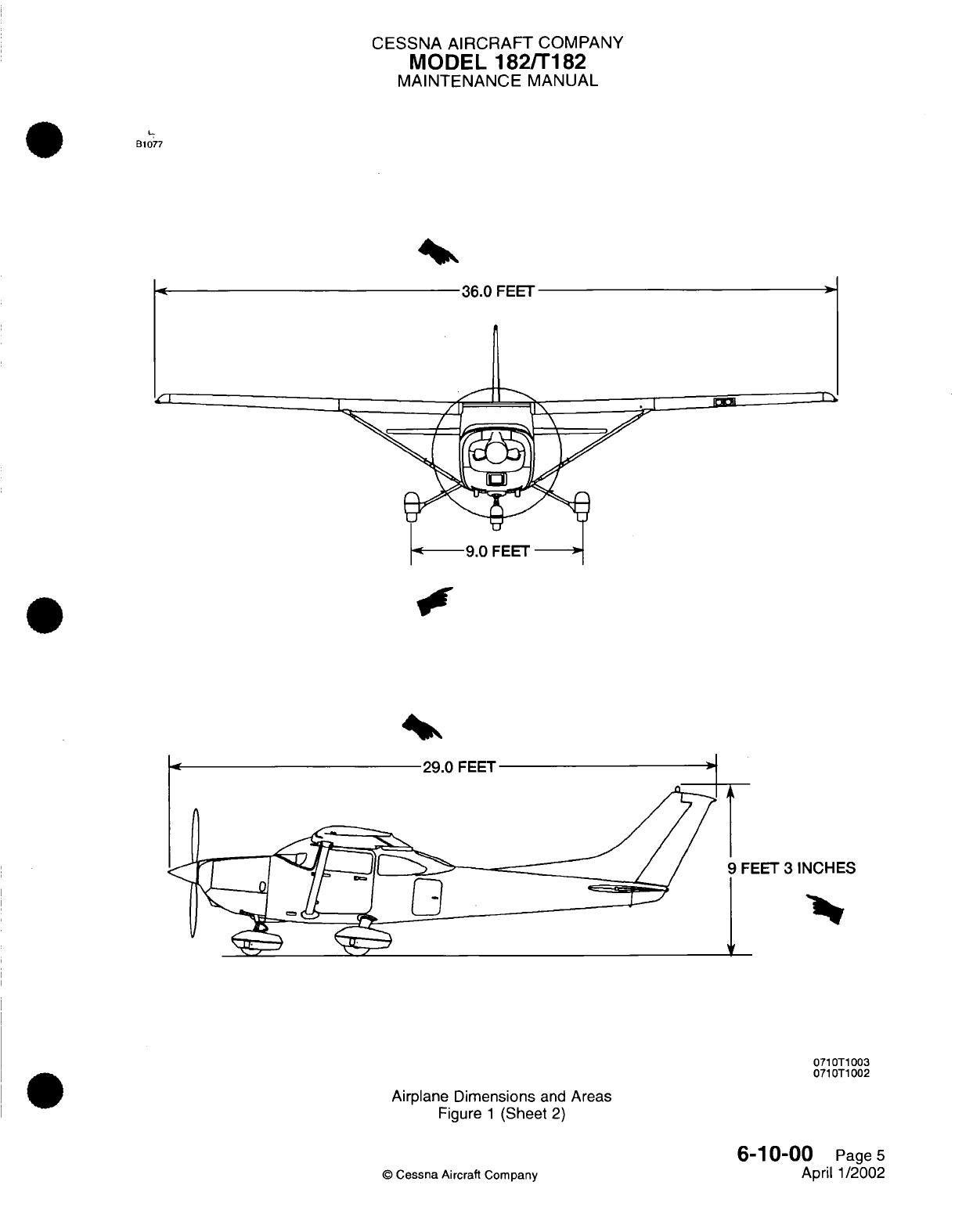
CESSNA
AIRCRAFT
COMPANY
MODEL
182/T182
MAINTENANCE
MANUAL
B1077
36.0
FEET
ino
I1
pg
29.0
FEET
A
EET
3
INCHES
v
0710T1003
0710T1002
Airplane
Dimensions
and
Areas
Figure
1
(Sheet
2)
6-10-00
Page
5
April 1/2002
©
Cessna
Aircraft Company
4
Z
I
CESSNA AIRCRAFT
COMPANY
MODEL
182/T182
MAINTENANCE
MANUAL
AIRPLANE
STATIONS
-
DESCRIPTION
AND OPERATION
1.
General
A.
The
airplane
is
laid
out
according
to
fuselage
stations
(FS)
and wing
stations
(WS).
These stations
provide
fixed
reference
points
for
all
components
located
on or
within
the
airplane.
Fuselage
Stations
begin
at
the
firewall
(FS
0.00)
and
extend
to the
tailcone
area
(FS
230.18). Wing
Stations
begin
at
the
root
(WS
23.62) and
extend
to
the tip
(WS
208.00).
Both
Fuselage
Stations and Wing
Stations
are
measured
in
inches. For example,
FS
185.50
is
185.50
inches
aft of
the
firewall
(FS
0.00).
B.
For
an
illustration
of
Fuselage
Stations,
refer to Figure
1.
For an
illustration
of
Wing
Stations,
refer
to
Figure
2.
6-15-00
Page
1
©
Cessna
Aircraft
Company
April
1/2002
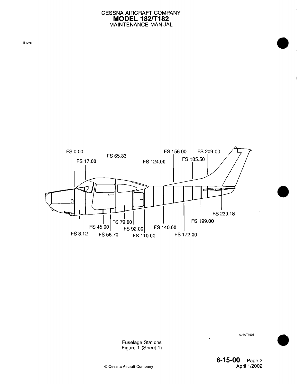
CESSNA
AIRCRAFT
COMPANY
MODEL
182/T182
MAINTENANCE
MANUAL
B1078
FS
0.00
FS
FS
17.00
FS
156.00
FS
209.00
FS
124.00
FS
185.50
FS 230.18
FS
199.00
FS
140.00
FS8.12
FS56
.70
FS
110.00
FS
172.00
Fuselage
Stations
Figure
1
(Sheet
1)
6-15-00
Page
2
April
1/2002
©
Cessna
Aircraft
Company
0710T1006

CESSNA
AIRCRAFT
COMPANY
MODEL
182/T182
MAINTENANCE
MANUAL
B1079
WS
40.12
WS
WS
136.00
WS
208.00
0710T1013
Wing
Stations
Figure
2
(Sheet
1)
6-15-00
Page
3
April
1/2002
©
Cessna
Aircraft
Company
.'-
.- .
AA
v

CESSNA
AIRCRAFT
COMPANY
MODEL
182/Ti
82
MAINTENANCE
MANUAL
AIRPLANE
ZONING
-
DESCRIPTION AND
OPERATION
General
A.
The
Model
1
82fTi
82
is
divided
into
numbered zones
to
provide
a
method
for
locating
components
and/or
placards throughout
the
airplane.
The
zones
are
identified
by
a
three-digit number
as
shown
in
the
example
below. The
first
digit
in
the
sequence
denotes
the major
zone
(300
series
for
aft
of
cabin,
500
series
for
left
wing,
etc.).
The
second
digit
in
the
sequence
further
divides
the
zone
into
submajor
zones
(Zone
51
0
for
inboard
portion
of
the
left
wing
and
Zone
520
for
outboard
portion
of
the
left wing,
etc.).
The third
digit
further
divides
the
submajor
zones into
subdivisions
(if
no
subdivision
is
needed,
this digit
is
typically
assigned
as
0
(zero).
EXAMPLE
310
Major
Zone
I ISubdivision
Zone
Submajor
Zone
B.
Major Zones.
(1)
100
-
Forward
side
of
firewall
and forward.
(2)
200
-
Aft
side
of
firewall
to
end
of
cabin.
(3)
300
-
Aft
of
cabin
to
end
of
airplane.
(4)
500
-
Left
wing.
(5)
600
-
Right
wing.
(6)
700
-
Landing
gear.
2.
Description
A.
For
a
breakdown
of
airplane
zones,
refer
to
Figure
1.
6-20-00
Page
1
Jul
1/2007
©
Cessna
Aircraft
Company
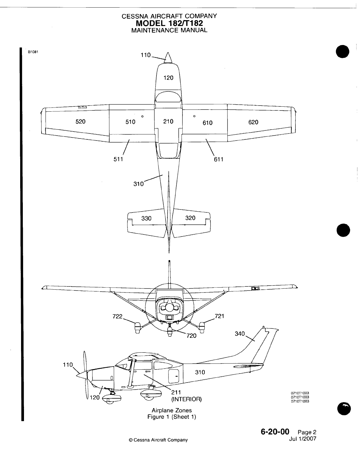
CESSNA
AIRCRAFT
COMPANY
MODEL
182/Ti82
MAINTENANCE
MANUAL
110
51
310
611
(INTERIOR)
Airplane
Zones
Figure
1
(Sheet
1)
6-20-00
Page
2
Jul
1/2007
0
Cessna
Aircraft
Company
21081
1
1
T1
003
Ti
003
T1
003
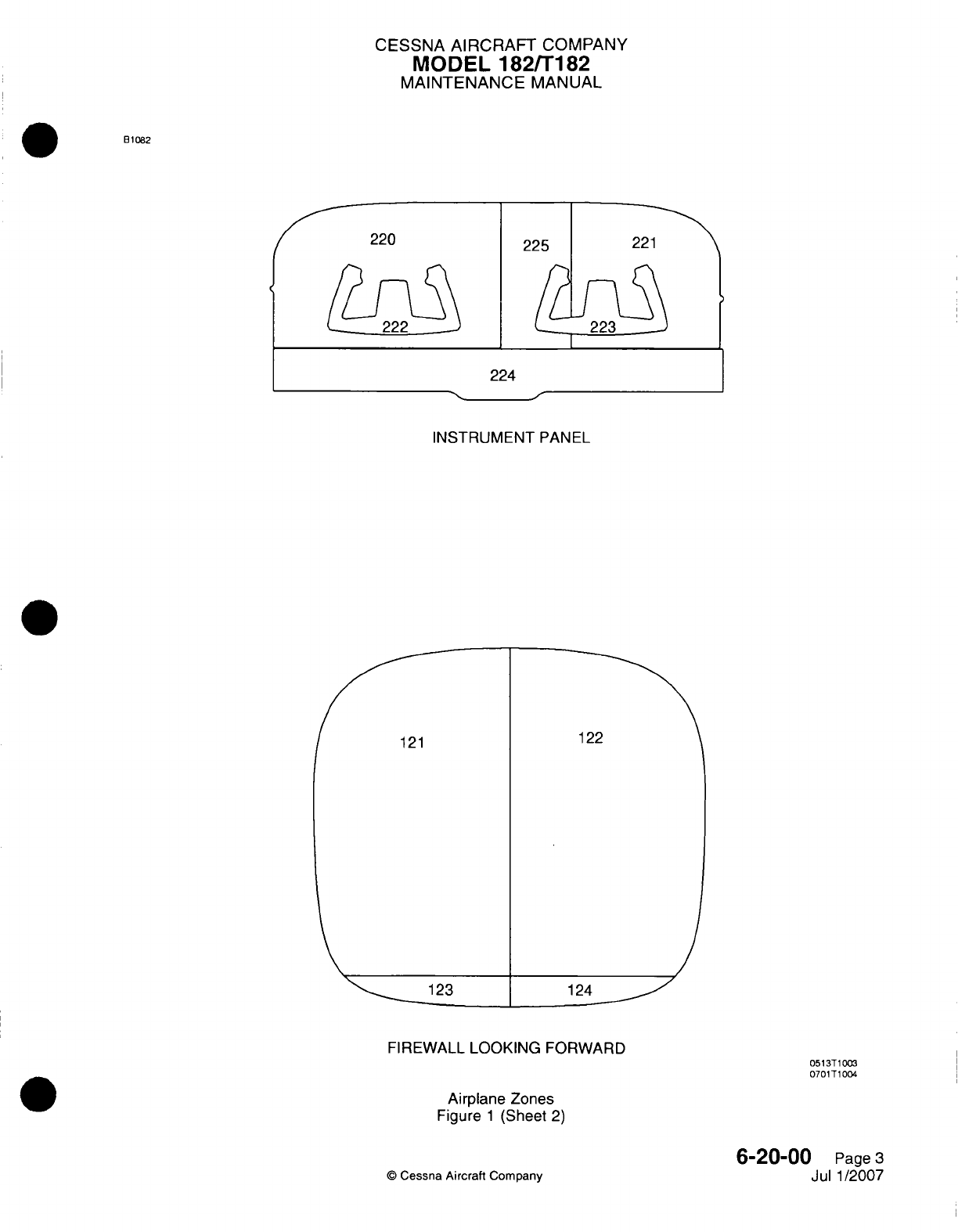
CESSNA AIRCRAFT
COMPANY
MODEL
182/Ti
82
MAINTENANCE
MANUAL
81082
INSTRUMENT
PANEL
FIREWALL
LOOKING
FORWARD
Airplane Zones
Figure
1
(Sheet
2)
6-20-00
Page
3
Jul 1/2007
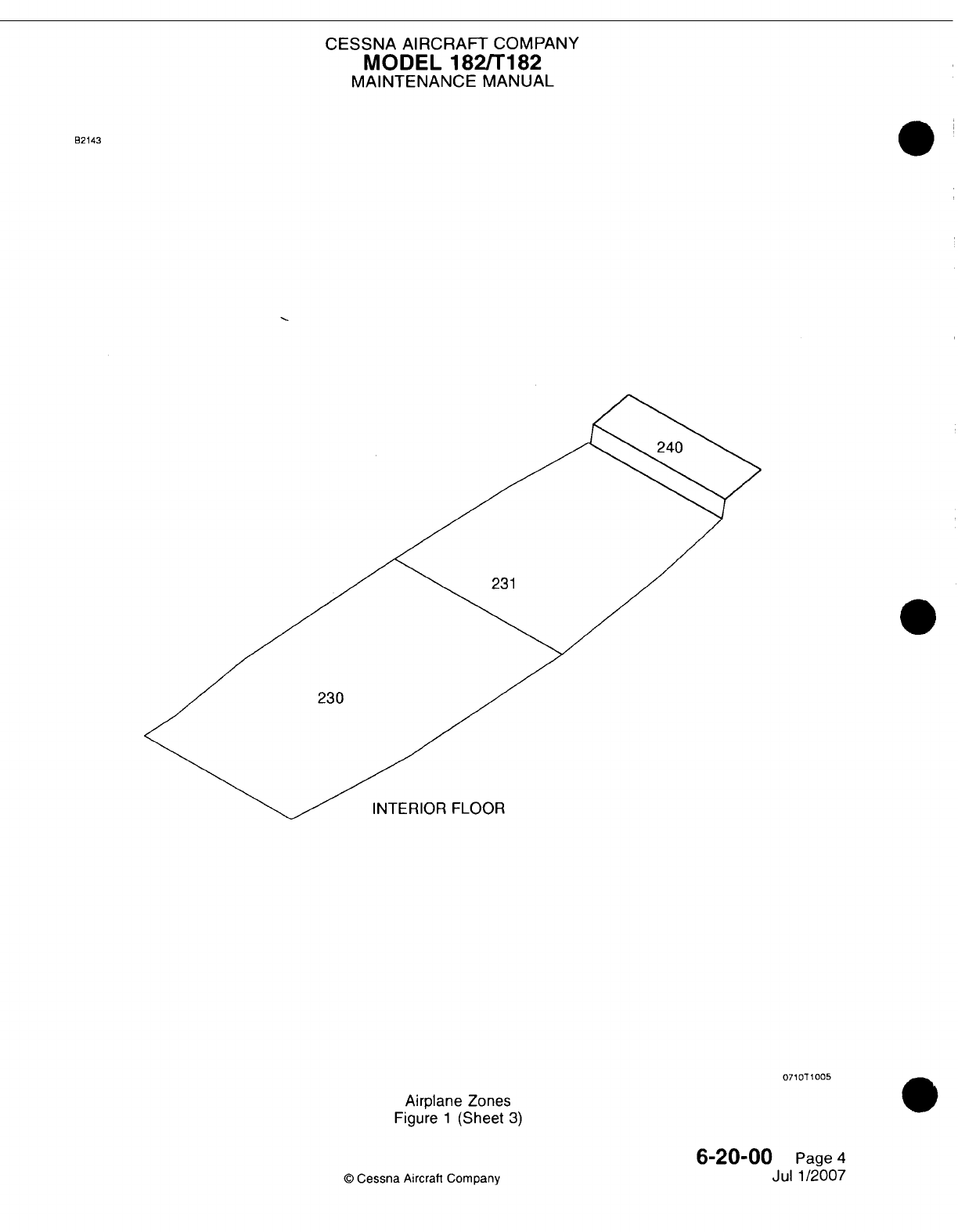
CESSNA
AIRCRAFT
COMPANY
MODEL
182/Ti
182
MAINTENANCE
MANUAL
B2143
230
INTERIOR FLOOR
071
OT
1
005
Airplane Zones
Figure
1
(Sheet
3)
6-20-00
Page
4
Jul 1/2007
©
Cessna
Aircraft Company
CESSNA
AIRCRAFT
COMPANY
MODEL
182/Ti
82
MAINTENANCE
MANUAL
ACCESS/INSPECTION
PLATES
-
DESCRIPTION
AND
OPERATION
1.General
A.
There
are
access
and
inspection
panels
on
the
interior
and
exterior
of
the
airplane.
These
panels give
access
to
components
and
airframe
areas.
NOTE:
Panels
that
have
hinges
attached
to
them
(like the
oil
door
for
example)
are
not
referred
to
as
panels
and
are not
included
in
this
section.
B.
This
section
can
be
used
in
conjunction
with
inspection
practices
(Chapter
5)
or
standard
maintenance
practices
to
quickly
find
related
components
throughout
the
airplane.
2.
Access/inspection
Panel
Numbering
A.
All
access/inspection
panels
have
a
series
of
numbers
and
letters which
identify
their zone location,
sequence,
and
orientation.
(1)
Zone
Location
-
Zone
location
is
identified
by the
first
three
numbers
of
any
panels.
This
three-
number sequence
is
specified
in
Airplane
Zoning
-
Description
and Operation.
(2)
Sequence
-
The
sequence
is
identified
by
alphabetical
letters
follow
the
three-number
sequence.
The
first panel
is
identified
as
"A,"
the
second
panel
is
identified
as
"B",
and
so
on.
(3)
Orientation
-
The
orientation
for each panel
is
identified
by
one
of
four
letters
that
come
after
the
sequence
letter.
The
orientation
letters
are
"T"
for
top,
"B"
for
bottom,
"L"
for
left,
and
"R"
for
right.
B.
With
(1)
(2)
(3)
access
panel
510AB
as
an
example,
the
breakdown
is
as
follows:
Zone Location
=
51
0
(inboard portion
of
left
wing)
Sequence
=
A
(the
first panel within
the
zone)
Orientation
=
B
(
located
on
the
bottom
of
the
zone).
3.
Description
A.
Access/Inspection
Panels.
6-20-02
Page
1
Jul 1/2007
©
Cessna Aircraft
Company
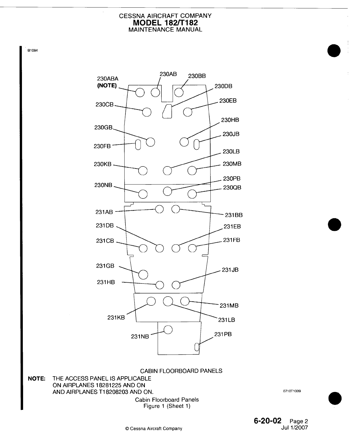
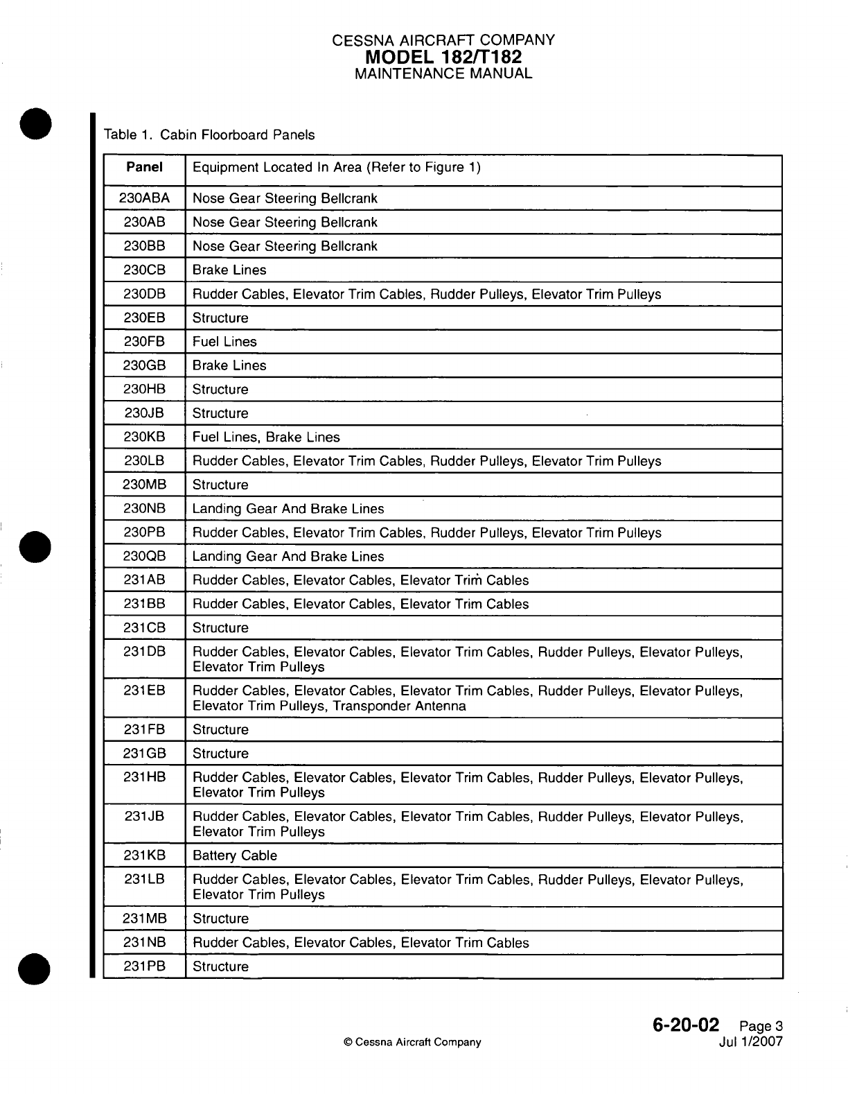
CESSNA
AIRCRAFT
COMPANY
MODEL
182/Ti
82
MAINTENANCE
MANUAL
Table
1.
Cabin
Floorboard Panels
Panel
Equipment Located
In
Area
(Refer
to
Figure
1)
230ABA
Nose
Gear
Steering
Bellcrank
230AB
Nose
Gear
Steering Bellcrank
230BB
Nose
Gear
Steering Bellcrank
230GB
Brake
Lines
230DB
Rudder Cables,
Elevator
Trim
Cables, Rudder
Pulleys,
Elevator
Trim
Pulleys
230EB
Structure
230FB
Fuel
Lines
230GB
Brake
Lines
230HB Structure
230JB
Structure
230KB
Fuel
Lines,
Brake
Lines
230LB Rudder Cables,
Elevator
Trim
Cables, Rudder
Pulleys,
Elevator
Trim
Pulleys
230MB
Structure
230NB
Landing
Gear
And
Brake
Lines
230PB Rudder Cables,
Elevator
Trim
Cables, Rudder Pulleys,
Elevator
Trim
Pulleys
230QB
Landing
Gear
And
Brake
Lines
231
AB
Rudder
Cables,
Elevator
Cables,
Elevator
Triri,
Cables
231
BB
Rudder Cables,
Elevator
Cables,
Elevator
Trim
Cables
231 CB
Structure
231
DB
Rudder Cables,
Elevator
Cables,
Elevator
Trim
Cables, Rudder
Pulleys,
Elevator
Pulleys,
Elevator
Trim
Pulleys
231 EB
Rudder Cables,
Elevator
Cables,
Elevator
Trim
Cables, Rudder
Pulleys,
Elevator
Pulleys,
Elevator
Trim
Pulleys,
Transponder
Antenna
231
FB
Structure
231
GB3
Structure
231
HB11
Rudder Cables,
Elevator
Cables,
Elevator
Trim
Cables,
Rudder Pulleys,
Elevator
Pulleys,
Elevator
Trim
Pulleys
231JB
Rudder Cables,
Elevator
Cables, Elevator
Trim
Cables,
Rudder
Pulleys,
Elevator
Pulleys,
Elevator
Trim
Pulleys
231
KB
Battery Cable
231
LB
Rudder Cables,
Elevator
Cables,
Elevator
Trim
Cables,
Rudder Pulleys, Elevator
Pulleys,
Elevator
Trim
Pulleys
231
MVB
Structure
231 NB
Rudder Cables,
Elevator
Cables, Elevator
Trim
Cables
231 PB
Structure
6-20-02
Page
3
Jul
1/2007
Q
Cessna
Aircraft Company
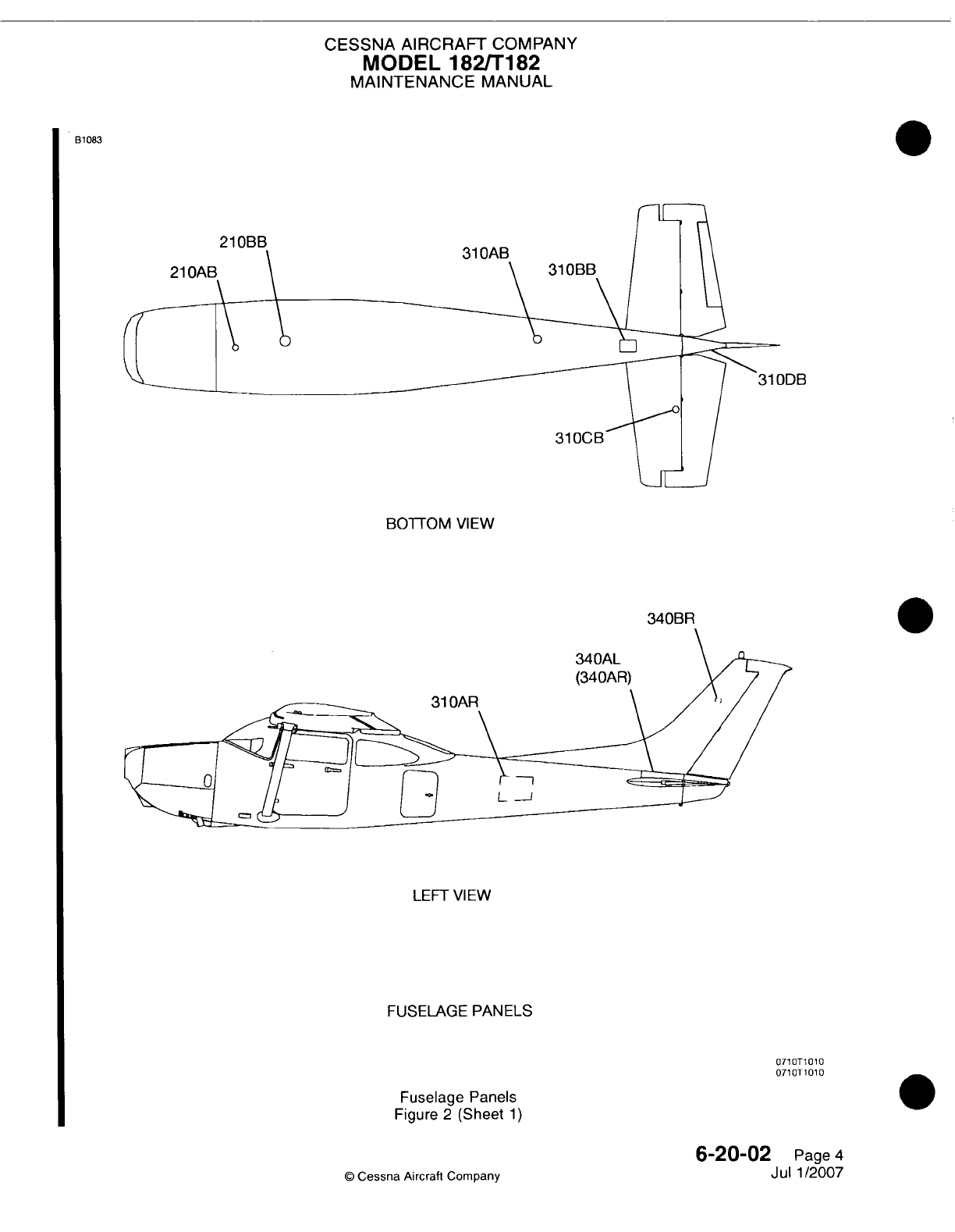
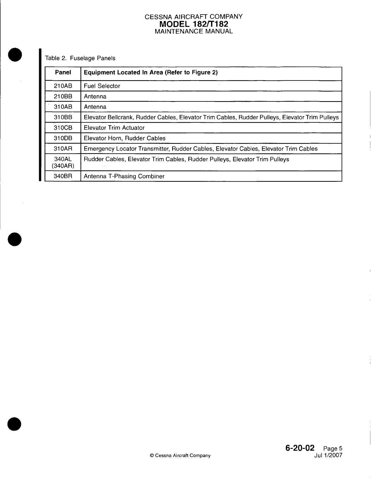
CESSNA AIRCRAFT
COMPANY
MODEL
182/Ti
82
MAINTENANCE
MANUAL
Table
2.
Fuselage
Panels
Panel
Equipment
Located
In
Area
(Refer
to
Figure
2)
210OAB
Fuel
Selector
21
ORB
Antenna
31
OAR
Antenna
31
OBR
Elevator
Bellcrank,
Rudder
Cables,
Elevator
Trim
Cables, Rudder Pulleys,
Elevator
Trim
Pulleys
31
OCB
Elevator
Trim
Actuator
31
0DB
Elevator
Horn,
Rudder
Cables
31
OAR
Emergency
Locator
Transmitter,
Rudder
Cables, Elevator
Cables,
Elevator
Trim
Cables
340AL Rudder
Cables,
Elevator
Trim
Cables,
Rudder Pulleys,
Elevator
Trim
Pulleys
(34OAR)
340BR
Antenna
T-Phasing
Combiner
6-20-02
Page
5
Jul 1/2007
Q
Cessna
Aircraft Company
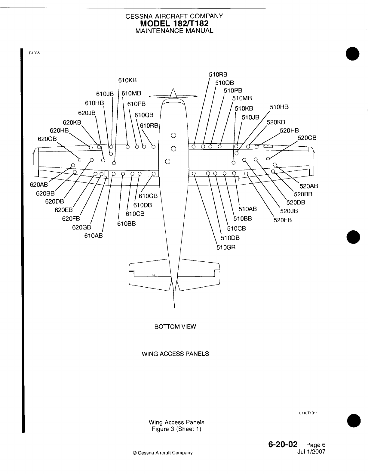

CESSNA
AIRCRAFT
COMPANY
MODEL
182/Ti
82
MAINTENANCE
MANUAL
B1
086
51
OCT
51
51
OBT
61
OCT
I
61
ODT
61
OBT
TOP
VIEW
WING
ACCESS
PANELS
0710T1002
Wing
Access
Panels
Figure
3
(Sheet
2)
6-20-02
Page
7
Jul
1/2007
©
Cessna Aircraft
Company
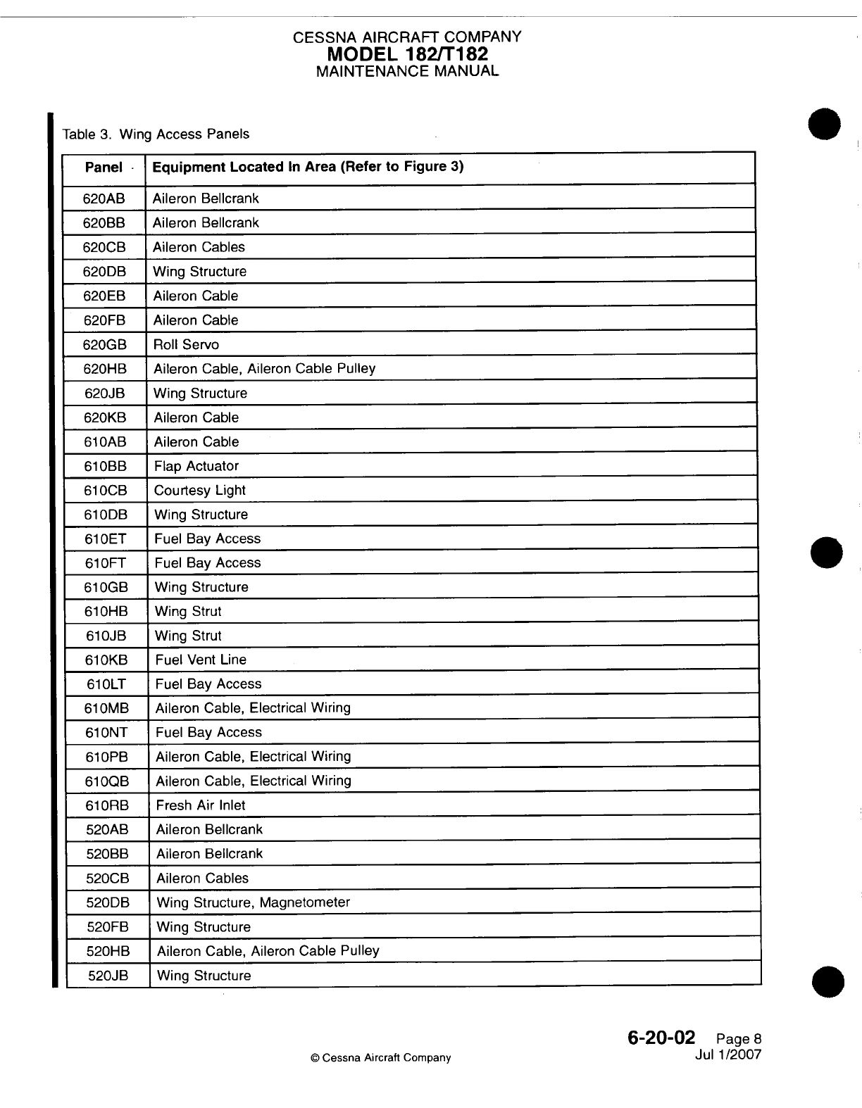
CESSNA
AIRCRAFT
COMPANY
MODEL
182/Ti182
MAINTENANCE
MANUAL
Table
3.
Wing
Access
Panels
Panel
-
Equipment
Located
In
Area
(Refer to
Figure
3)
620AB Aileron Bellcrank
620BB
Aileron Bellcrank
620CB
Aileron
Cables
620DB
Wing
Structure
620EB
Aileron
Cable
620FB Aileron
Cable
620GB
Roll
Servo
620HB Aileron
Cable,
Aileron
Cable Pulley
620JB
Wing
Structure
620KB
Aileron
Cable
610OAB
Aileron
Cable
610OBB
Flap
Actuator
610OCB
Courtesy
Light
61
0DB
Wing
Structure
61
OET Fuel
Bay
Access
61
OFT
Fuel
Bay
Access
61
0GB
Wing
Structure
610HB
Wing
Strut
610OJB
Wing Strut
61
0KB
Fuel Vent
Line
61
OLT
Fuel
Bay
Access
61
0MB Aileron
Cable,
Electrical
Wiring
61
ONT
Fuel
Bay
Access
61
OPB
Aileron
Cable,
Electrical Wiring
6100OB
Aileron
Cable, Electrical
Wiring
61
ORB
Fresh Air Inlet
520AB
Aileron
Bellcrank
520BB
Aileron Bellcrank
520CB Aileron
Cables
520DB
Wing
Structure, Magnetometer
520FB Wing
Structure
520HB Aileron
Cable,
Aileron Cable Pulley
520JB
Wing
Structure
0
Cessna Aircraft
Company
0
6-20-02
Page
8
Jul
1/2007
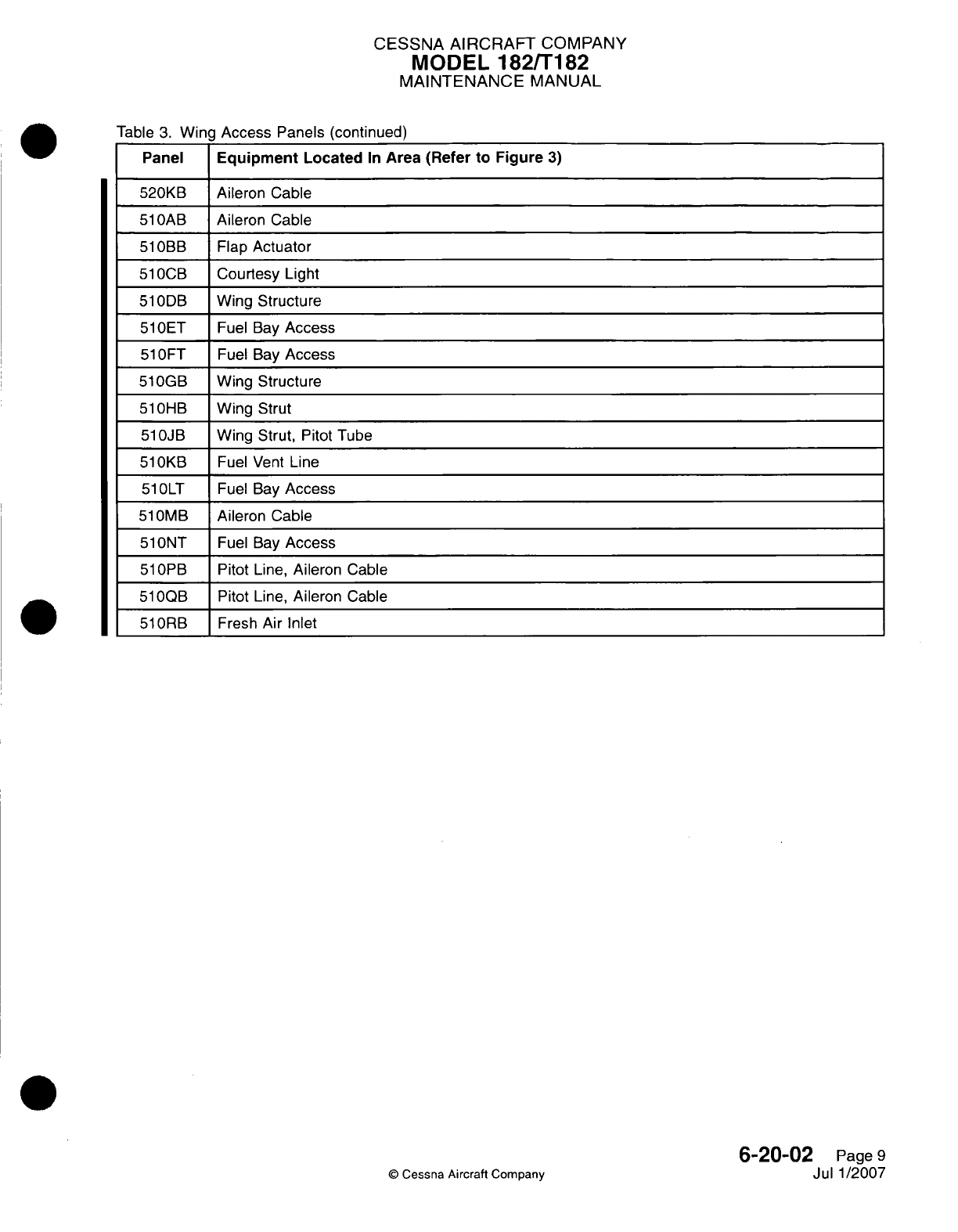
CESSNA
AIRCRAFT
COMPANY
MODEL
182/Ti
82
MAINTENANCE
MANUAL
Table
3.
Wing
Access
Panels
(continued)
Panel
Equipment
Located
In
Area
(Refer
to
Figure
3)
520KB Aileron Cable
51lOAB
Aileron Cable
51
OBB
Flap
Actuator
51
0GB
Courtesy
Light
51
0DB
Wing
Structure
51lOET
Fuel
Bay
Access
51
OFT
Fuel
Bay
Access
510OGB
Wing
Structure
51
OHB
_Wing
Strut
510JB
Wing
Strut,
Pitot Tube
51
0KB
Fuel Vent
Line
51lOLT
Fuel
Bay
Access
51
0MB
Aileron
Cable
51lONT
Fuel
Bay
Access
51
OPB
Pitot
Line,
Aileron Cable
51lOQB
Pitot
Line,
Aileron Cable
51
ORB
Fresh
Air
Inlet
©
Cessna
Aircraft
Company
6-20-02
Page
9
Jul
1/2007
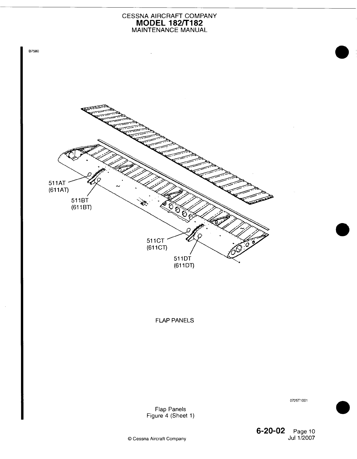
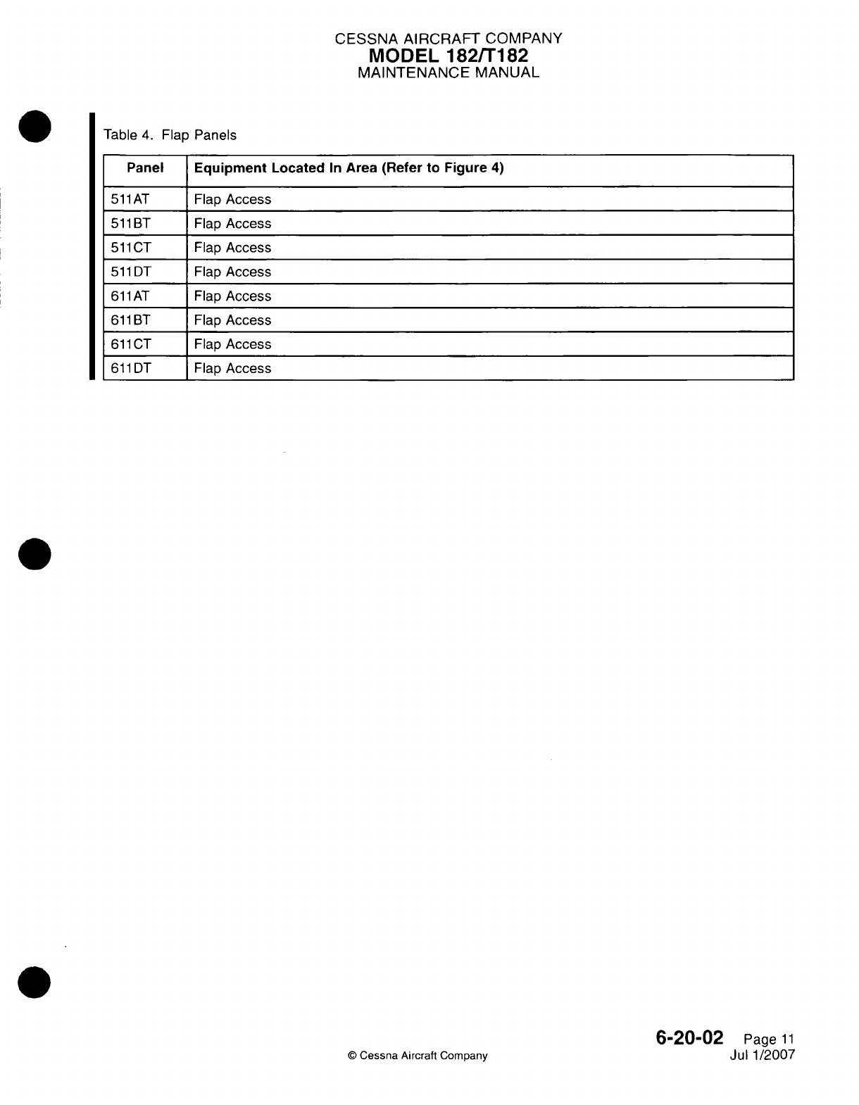
CESSNA AIRCRAFT
COMPANY
MODEL
182/Ti
82
MAINTENANCE
MANUAL
Table
4.
Flap
Panels
Panel
Equipment
Located
In
Area
(Refer
to
Figure
4)
51ilAT
Flap
Access
511
BT Flap
Access
511
CT
Flap
Access
511
DT
Flap
Access
611
AT
Flap
Access
611
BT
Flap
Access
611
CT
Flap
Access
611
DT Flap
Access
©
Cessna Aircraft
Company
6-20-02
Page
11
Jul
1/2007

CHAPTER
LIFTING
AND
SHORING

CESSNA
AIRCRAFT
COMPANY
MODEL 182/T182
MAINTENANCE
MANUAL
LIST
OF
EFFECTIVE PAGES
CHAPTER-SECTION-SUBJECT
07-Title
07-List
of
Effective
Pages
07-Record
of
Temporary
Revisions
07-Table
of
Contents
7-00-00
7-10-00
7-11-00
PAGE
Page
1
Pages 201-202
Page
201
©
Cessna Aircraft
Company
07
-
LIST
OF
EFFECTIVE
PAGES
Page
1
of
1
Mar 1/2005
DATE
April
1/2002
April
1/2002
April
1/2002
Temporary
Revision
Number
RECORD
OF
TEMPORARY REVISIONS
Page
Number
Issue
Date
By
Date
Removed
By

CESSNA
AIRCRAFT
COMPANY
MODEL
182/T182
MAINTENANCE
MANUAL
CONTENTS
LIFTING
AND
SHORING
-
GENERAL
.............................................
Scope
......................................................................
Tools,
Equipment
and
Material
...............................................
Definition
...................................................................
JACKING
-
MAINTENANCE PRACTICES
.......................................
General
....................................................................
Tools,
Equipment
and
Materials
..............................................
Jacking
Procedure
..........................................................
EMERGENCY
LIFTING/HOISTING
-
MAINTENANCE PRACTICES
..................
Lifting
Procedure............................................................
7-00-00
Page
1
7-00-00
Page
1
7-00-00
Page
1
7-00-00
Page
1
7-10-00
Page
201
7-10-00
Page
201
7-10-00
Page
201
7-10-00
Page
201
7-11-00
Page
201
7-11-00
Page
201
CONTENTS
Page
1
of
1
Mar
1/2005
©
Cessna Aircraft
Company
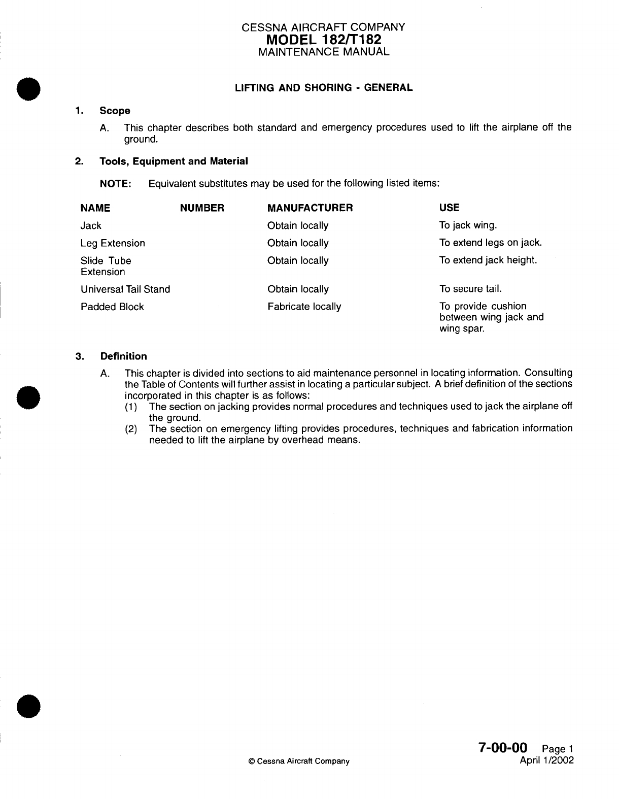
CESSNA
AIRCRAFT
COMPANY
MODEL
182/T182
MAINTENANCE
MANUAL
LIFTING
AND
SHORING
-
GENERAL
1.
Scope
A.
This
chapter
describes
both
standard
and
emergency
procedures
used
to
lift
the
airplane
off
the
ground.
2.
Tools,
Equipment
and Material
NOTE:
Equivalent
substitutes
may
be
used
for
the
following
listed items:
NAME
NUMBER
MANUFACTURER
USE
Jack
Obtain
locally
To
jack
wing.
Leg
Extension
Obtain
locally
To
extend
legs
on
jack.
Slide
Tube Obtain
locally
To
extend
jack
height.
Extension
Universal
Tail
Stand Obtain
locally
To
secure
tail.
Padded
Block Fabricate
locally
To
provide
cushion
between
wing
jack
and
wing
spar.
3.
Definition
A.
This
chapter
is
divided
into
sections
to
aid
maintenance
personnel
in
locating
information. Consulting
the
Table
of
Contents
will
further assist
in
locating
a
particular
subject.
A
brief
definition
of
the
sections
incorporated
in
this chapter
is
as follows:
(1)
The
section
on
jacking
provides
normal
procedures
and
techniques
used
to
jack
the
airplane
off
the ground.
(2)
The
section
on
emergency
lifting
provides procedures,
techniques
and
fabrication
information
needed
to
lift
the
airplane
by
overhead means.
7-00-00
Page
1
©
Cessna
Aircraft
Company
April
1/2002
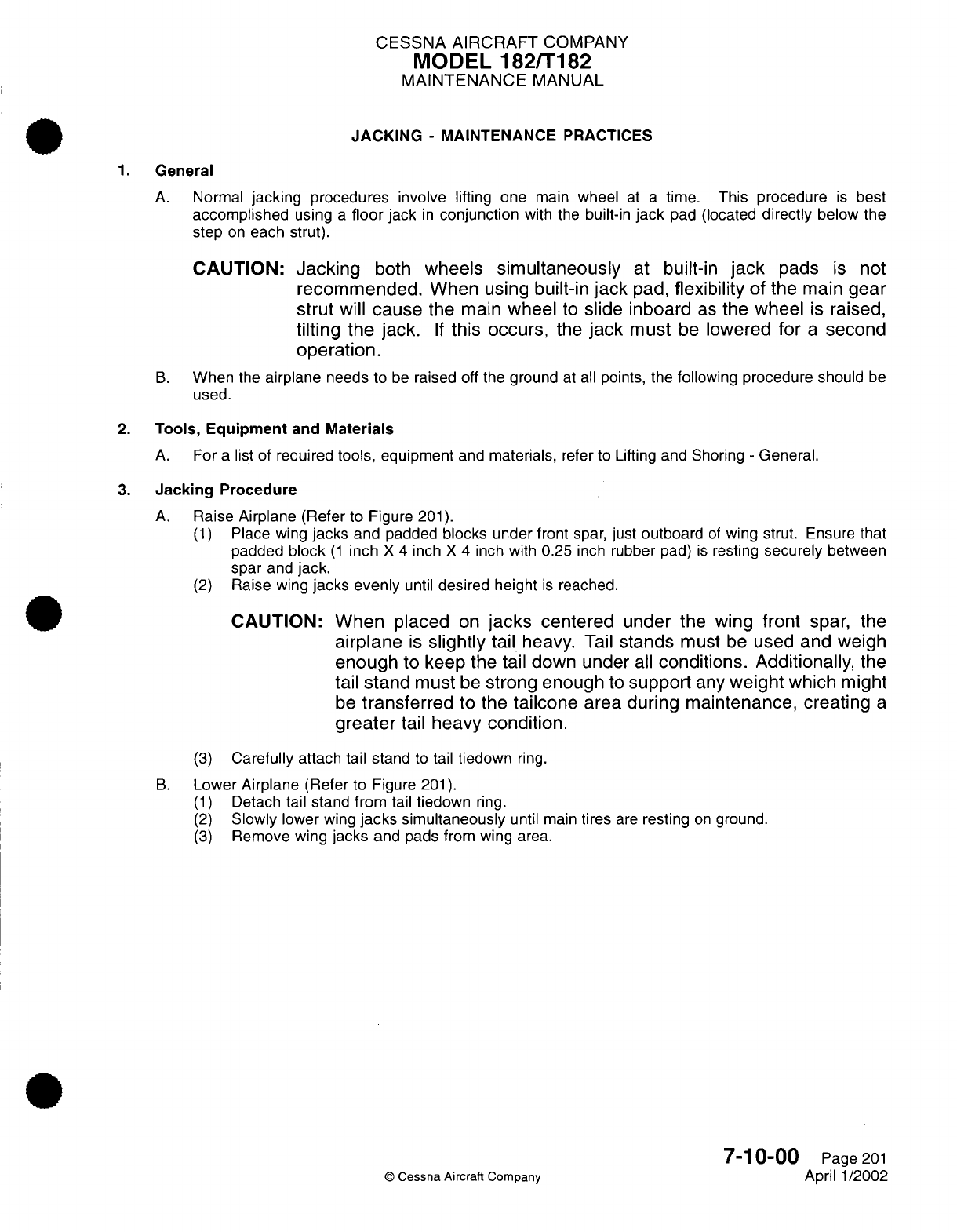
CESSNA AIRCRAFT
COMPANY
MODEL
182/T182
MAINTENANCE
MANUAL
JACKING
-
MAINTENANCE
PRACTICES
1.
General
A.
Normal
jacking
procedures
involve
lifting
one
main
wheel
at
a
time.
This
procedure
is
best
accomplished
using
a
floor
jack
in
conjunction
with
the
built-in
jack
pad
(located
directly
below
the
step
on
each
strut).
CAUTION:
Jacking
both
wheels
simultaneously
at
built-in
jack
pads
is
not
recommended.
When using
built-in
jack
pad,
flexibility
of
the
main
gear
strut
will
cause
the
main
wheel
to
slide inboard
as
the
wheel
is
raised,
tilting
the
jack.
If
this
occurs,
the
jack
must
be
lowered
for
a
second
operation.
B.
When
the
airplane
needs
to
be
raised
off
the
ground
at
all
points,
the following
procedure should
be
used.
2.
Tools,
Equipment
and
Materials
A.
For
a
list of
required
tools, equipment
and
materials,
refer
to
Lifting
and
Shoring
-
General.
3.
Jacking
Procedure
A.
Raise Airplane
(Refer
to
Figure
201).
(1)
Place
wing
jacks
and
padded
blocks
under front
spar,
just
outboard
of
wing
strut.
Ensure
that
padded
block
(1
inch
X
4
inch
X
4
inch
with
0.25
inch
rubber
pad)
is
resting
securely
between
spar
and
jack.
(2)
Raise
wing
jacks
evenly
until
desired
height
is
reached.
CAUTION: When placed
on
jacks
centered
under
the wing
front
spar,
the
airplane
is
slightly
tail
heavy.
Tail
stands
must
be
used
and
weigh
enough
to
keep
the
tail
down under
all
conditions.
Additionally,
the
tail
stand
must
be
strong enough
to
support
any
weight
which
might
be
transferred
to
the
tailcone
area
during maintenance, creating
a
greater
tail
heavy
condition.
(3)
Carefully
attach
tail stand
to
tail
tiedown
ring.
B.
Lower
Airplane (Refer
to
Figure
201).
(1)
Detach
tail
stand from
tail
tiedown
ring.
(2)
Slowly
lower
wing
jacks
simultaneously
until main
tires
are
resting
on
ground.
(3)
Remove wing
jacks
and pads
from
wing
area.
7-10-00
Page
201
©
Cessna
Aircraft
Company
April
1/2002
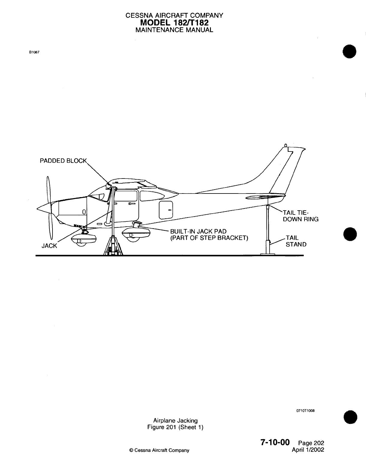
CESSNA AIRCRAFT
COMPANY
MODEL 182/T182
MAINTENANCE
MANUAL
B1087
PADDED
ING
BUILT-IN
JACK
PAD
(PART OF
STEP BRACKET)
_
-TAIL
S
ASTAND
071
0T1008
Airplane
Jacking
Figure
201
(Sheet
1)
©
Cessna
Aircraft
Company
7-10-00
Page
202
April
1/2002
CESSNA
AIRCRAFT
COMPANY
MODEL
182/T182
MAINTENANCE
MANUAL
EMERGENCY
LIFTING/HOISTING
-
MAINTENANCE
PRACTICES
1.
Lifting
Procedure
A.
The
airplane
may
be
lifted
by
means
of
suitable
slings.
The
front
sling
should
be
hooked
to
each
upper engine
mount
at
the firewall,
and
the
aft
sling
should
be
positioned
around
the
fuselage
at
the
first
bulkhead
forward
of
the
leading edge
of
the
stabilizer.
7-11-00
Page
201
©
Cessna
Aircraft Company
April
1/2002
CHAPTER
LEVELING
AND
WEIGHING
CESSNA
AIRCRAFT
COMPANY
MODEL
182/T182
MAINTENANCE
MANUAL
LIST
OF
EFFECTIVE PAGES
PAGE
CHAPTER-SECTION-SUBJECT
08-Title
08-List
of
Effective
Pages
08-Record
of
Temporary
Revisions
08-Table
of
Contents
8-00-00
8-10-00
Page
1
Pages
201-202
©
Cessna Aircraft
Company
08
-
LIST
OF
EFFECTIVE
PAGES
Page
1
of
1
Mar 1/2005
DATE
April
1/2002
April
1/2002

Temporary
Revision
Number
RECORD
OF
TEMPORARY REVISIONS
Page
Number
Issue
Date
By
Date
Removed
By
CESSNA
AIRCRAFT
COMPANY
MODEL
182/T182
MAINTENANCE
MANUAL
CONTENTS
LEVELING
AND
WEIGHING
-
GENERAL
..........................................
S
cope......................................................................
Tools,
Equipment
and Material
...............................................
Definition
...................................................................
LEVELING
-
MAINTENANCE
PRACTICES.........................................
General
....................................................................
Tools,
Equipment
and
Materials
..............................................
Leveling
Points
.............................................................
8-00-00
Page
1
8-00-00 Page
1
8-00-00
Page
1
8-00-00
Page
1
8-10-00
Page
201
8-10-00
Page
201
8-10-00
Page
201
8-10-00
Page
201
CONTENTS
Page
1
of
1
Mar 1/2005
©
Cessna Aircraft
Company
CESSNA
AIRCRAFT
COMPANY
MODEL 182/T182
MAINTENANCE
MANUAL
LEVELING AND
WEIGHING
-
GENERAL
1.
Scope
A.
This
chapter provides
information
necessary
to
properly
level
the
airplane.
B.
For
information
on
airplane
weighing
procedures,
refer to
Section
6
of
the
Pilot's
Operating Handbook
And
FAA
Approved
Airplane
Flight Manual.
2.
Tools,
Equipment and
Material
NOTE:
Equivalent
substitutes
may
be
used
for
the
following
items:
MANUFACTURER
Commercially available
USE
Bubble
level
used
to
level
airplane.
3.
Definition
A.
This
chapter
is
divided
into
sections
to
aid
maintenance personnel
in
locating
information.
Consulting
the
Table
of
Contents
will
further
assist
in
locating
a
particular
subject.
A
brief
definition
of
the
sections
incorporated
in
this
chapter
is
as
follows:
(1)
The
section
on
leveling provides maintenance practices
and
instructions for
longitudinal
and
lateral
leveling
of
the
airplane.
8-00-00
Page
1
©
Cessna Aircraft
Company
April
1/2002
NAME
Spirit
Level
NUMBER

CESSNA AIRCRAFT
COMPANY
MODEL
182/T182
MAINTENANCE
MANUAL
LEVELING
-
MAINTENANCE PRACTICES
1.
General
A.
This section provides
reference
points
for
leveling the
airplane
laterally
and
longitudinally.
B.
For
an
illustration
of
leveling
points,
refer
to
Figure
201.
2.
Tools,
Equipment
and
Materials
A.
For
a
list of
required
tools,
equipment
and
materials, refer
to
Leveling
And
Weighing
-
General.
3.
Leveling Points
A.
Lateral
Leveling.
(1)
The
airplane
may
be
leveled
laterally
by
selecting
two
corresponding
points
on
the
upper door
sills (left
and
right)
and
placing the
level
across
these
points.
NOTE:
Out
of
level
tolerance
for
wing
tips
is
3
inches
total.
B.
Longitudinal Leveling.
(1)
Locate
two
NAS221-7 screws
on
left
side
of
fuselage
at
FS
139.65
and
FS
171.65.
(2)
Remove screws
and
replace
with
studs
of
suitable
length
(approximately
2
inches
long).
(3)
Place
level
on
protruding studs.
NOTE:
The
screws
located
at
FS
139.65 and
FS
171.65
are
on
Water
Line
(WL
13.25).
8-10-00
Page
201
©
Cessna
Aircraft
Company
April
1/2002
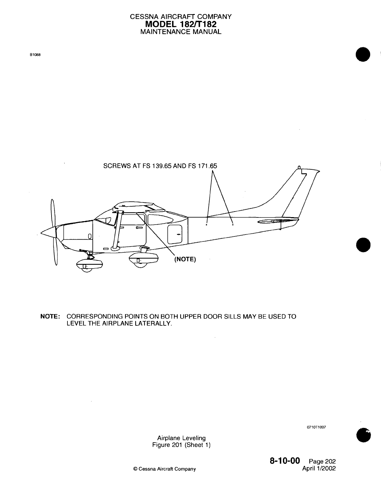
CESSNA AIRCRAFT
COMPANY
MODEL
182/T182
MAINTENANCE
MANUAL
B1088
<" \A/" IC'
AT
CC
F 4 'ro nI'
AK
Ir~
r-e
.
7x4
^1-
(NOTE)
NOTE:
CORRESPONDING
POINTS
ON
BOTH UPPER
DOOR SILLS
MAY
BE
USED
TO
LEVEL THE
AIRPLANE
LATERALLY.
0710T1007
Airplane Leveling
Figure
201
(Sheet
1)
8-10-00
©
Cessna
Aircraft
Company
Page
202
April
1/2002

CHAPTER
TOWING
AND TAXIING

CESSNA
AIRCRAFT
COMPANY
MODEL
182/T182
MAINTENANCE
MANUAL
LIST
OF
EFFECTIVE
PAGES
CHAPTER-SECTION-SUBJECT
09-Title
09-List
of
Effective
Pages
09-Record
of
Temporary
Revisions
09-Table
of
Contents
9-00-00
9-10-00
PAGE
Page
1
Pages 201-202
©
Cessna Aircraft
Company
09
-
LIST
OF
EFFECTIVE PAGES
Page
1
of
1
Mar 1/2005
DATE
April
1/2002
April
1/2002
Temporary
Revision
Number
RECORD
OF
TEMPORARY REVISIONS
Page
Number
Issue
Date
By
Date
Removed
By
CESSNA AIRCRAFT
COMPANY
MODEL
182/T182
MAINTENANCE
MANUAL
CONTENTS
TOWING
AND
TAXIING
-
GENERAL
..............................................
S
cope......................................................................
Definition
...................................................................
TOWING
-
MAINTENANCE PRACTICES
..........................................
G
eneral
....................................................................
9-00-00
Page
1
9-00-00
Page
1
9-00-00
Page
1
9-10-00
Page
201
9-10-00
Page
201
CONTENTS
Page
1
of
1
Mar
1/2005
©
Cessna Aircraft
Company
CESSNA
AIRCRAFT
COMPANY
MODEL
182/T182
MAINTENANCE
MANUAL
TOWING
AND
TAXIING
-
GENERAL
1.
Scope
A.
This
chapter
describes
towing
procedures for
movement
of the
airplane
on
the
ground.
2.
Definition
A.
This
chapter
is
divided
into
sections
to
aid
maintenance
personnel
in
locating information. Consulting
the
Table
of
Contents
will
further assist
in
locating
a
particular
subject.
A
brief
definition
of the
section
incorporated
in
this chapter
is
as
follows;
(1)
The
section
on
towing describes
those
procedures
and
cautions
applicable
for
the
Model
182
airplanes.
9-00-00
Page
1
April
1/2002
©
Cessna
Aircraft
Company
CESSNA AIRCRAFT
COMPANY
MODEL
182/T182
MAINTENANCE
MANUAL
TOWING
-
MAINTENANCE PRACTICES
1.
General
A.
Towing.
CAUTION: When
towing
the
airplane, never
turn
the
nose
wheel
more
than
29
degrees either
side
of
center
or
the
gear will
be
damaged.
Do not
push
on
control
surfaces
or
outboard
empennage
surfaces.
When
pushing
on the
tailcone,
always
apply pressure
at
a
bulkhead
to
avoid
buckling
the
skin.
(1)
Moving
the airplane
by
hand
is
accomplished
by
using
the wing
struts and
nose
landing
gear
strut
as
push points.
A
tow
bar
attached
to the
nose
gear
should
be
used
for steering
and
maneuvering
the
airplane
on the ground.
(2)
When
no
tow
bar
is
available,
press
down at the
horizontal
stabilizer
front
spar
adjacent
to
the
fuselage
to
raise
the
nose wheel
off
the ground. With the
nose
wheel
clear
of
the
ground,
the
aircraft
can
be
turned
by
pivoting
it
about the
main
wheels.
9-10-00
Page
201
©
Cessna
Aircraft
Company
April
1/2002
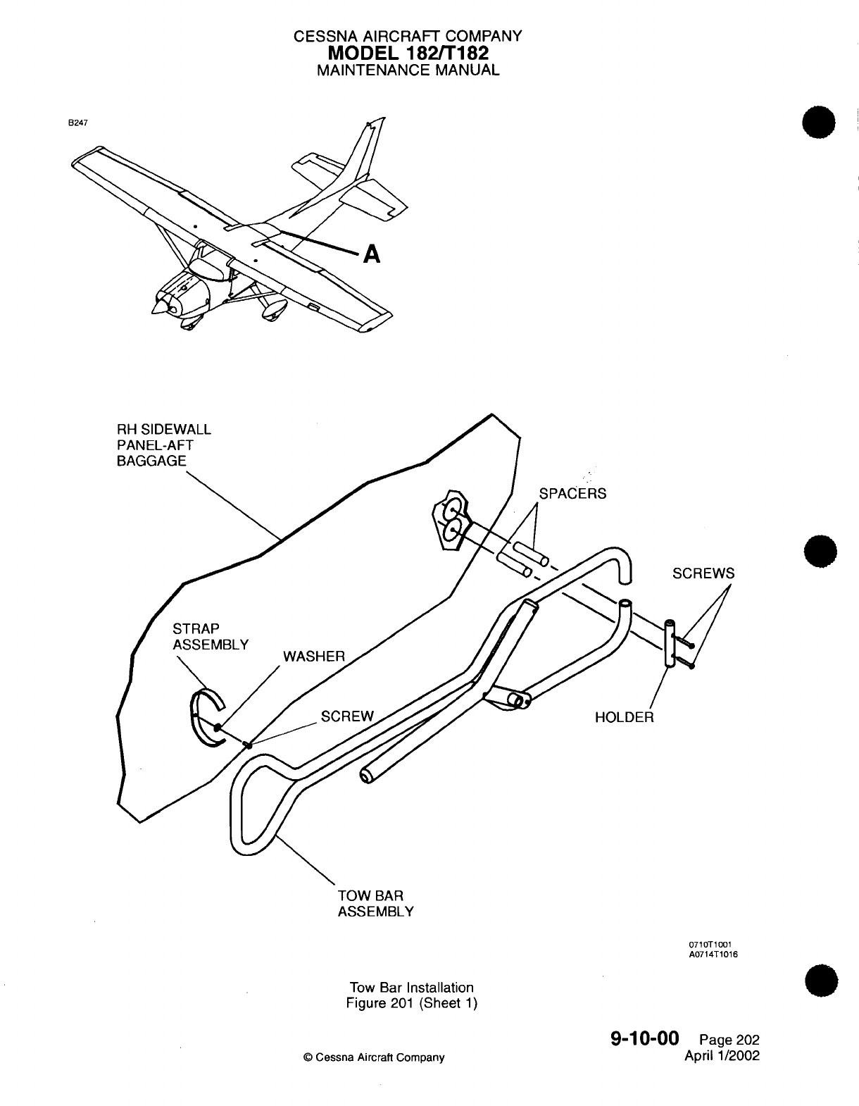
CESSNA AIRCRAFT
COMPANY
MODEL
182/T182
MAINTENANCE
MANUAL
TOW
BAR
ASSEMBLY
0710T1001
A0714T1016
Tow
Bar
Installation
Figure
201
(Sheet
1)
©
Cessna
Aircraft
Company
9-10-00
Page
202
April
1/2002

CHAPTER
PARKING
AND
MOORING
CESSNA
AIRCRAFT
COMPANY
MODEL
182/Ti
82
MAINTENANCE
MANUAL
LIST
OF
EFFECTIVE
PAGES
CHAPTER-SECTION-SUBJECT
1
0-Title
10O-List
of Effective
Pages
10O-Record
of
Temporary
Revisions
10-Table
of
Contents
10-00-00
10-10-00
10-11-00
10-20-00
10-30-00
PAGE
Page
1
Page
201
Pages
201
-204
Page
201
Page
201
©
Cessna
Aircraft
Company
10
-LIST
OF
EFFECTIVE
PAGES
Pagel1ofl1
Jul
1/2007
DATE
April
1/2002
April
1/2002
Jul
1/2007
April
1/2002
April
1/2002

Temporary
Revision
Number
RECORD
OF
TEMPORARY
REVISIONS
Page
Number
Issue
Date
By
Date
Removed
By
CESSNA AIRCRAFT
COMPANY
MODEL
182/Ti
82
MAINTENANCE
MANUAL
CONTENTS
PARKING,
MOORING,
STORAGE
AND
RETURN
TO
SERVICE
-
GENERAL.
Scope....................................
Tools,
Equipment
and
Materials........................
Definition
..................................
PARKING
-
MAINTENANCE
PRACTICES......................
General...................................
Parking
Instructions
.............................
STORAGE
-
MAINTENANCE
PRACTICES
.....................
General...................................
Flyable
Storage
...............................
Temporary
Storage..............................
Indefinite Storage
..............................
Inspection
During
Flyable
Storage.......................
Inspection
During
Temporary
Storage
.....................
Inspection
During
Indefinite
Storage......................
MOORING
-
MAINTENANCE
PRACTICES
.....................
General...................................
Mooring
Procedures
.............................
RETURN
TO
SERVICE
-
MAINTENANCE
PRACTICES
...............
General...................................
Flyable
Storage
Return
to
Service.......................
Temporary Storage
Return
to
Service......................
Indefinite Storage Return
to
Service......................
1
0-00-00
Page
1
1
0-00-00
Page
1
1
0-00-00
Page
1
1
0-00-00
Page
1
1
0-
10-00 Page
201
1
0-
10-00 Page
201
1
0-
10-00 Page
201
1
0-1
1-00
Page
201
1
0-
1
1-00
Page
201
1
0-
1
1-00
Page
201
1
0-1
1-00
Page
201
1
0-1
1-00
Page
202
1
0-
1
1-00
Page
203
1
0-
1
1-00
Page
203
1 0- 1
1-00
Page 204
10-20-00
Page
201
10-20-00
Page
201
10-20-00
Page
201
10-30-00
Page
201
10-30-00
Page
201
10-30-00
Page
201
10-30-00
Page
201
10-30-00
Page
201
10-
CONTENTS
Pagel1ofl1
Jul
1/2007
©
Cessna
Aircraft
Company
CESSNA AIRCRAFT
COMPANY
MODEL
182/T182
MAINTENANCE
MANUAL
PARKING,
MOORING,
STORAGE AND
RETURN
TO
SERVICE
-
GENERAL
1.
Scope
A.
This chapter
provides
maintenance instructions for
parking,
mooring,
storage
and
return
to
service.
2.
Tools,
Equipment
and
Materials
NOTE:
Equivalent
substitutes
may
be
used
for
the
following
items:
NAME
NUMBER
Wheel
Chocks
Engine
Air
Inlet
Cover
Pitot
Tube
Cover
Static
Ground
Cable
Rope (0.375
inch
diameter
minimum)
or
equivalent
Dehydrator
Plugs
Corrosion
Preventive
Oil
Preservative
Oil
MS27215-1
or
-2
One
part
MIL-L-6529,
Type
1,
with
one part
Royal
"D"
MIL-C-6529
MANUFACTURER
Available
Commercially
Cessna Aircraft
Cessna
Parts
Distribution
Department
701,
CPD
25800
East
Pawnee
Road
Wichita,
KS
67218-5590
Cessna
Aircraft
Available
Commercially
Available
Commercially
Available
Commercially
Royal
Lubricants
Co.
Inc.
72
Eagle Rock Ave.
East
Hanover,
NJ
07936
Available
Commercially
USE
To
chock
landing
wheels.
To
prevent entry
of
moisture
and/or foreign
particles
through
cowling.
To
prevent
entry
of
moisture
and/or
foreign
particles
in
pitot
tubes.
To
static
ground
airplane.
To
tie
down
wing
and
tail.
To
prevent moisture
in
cylinders
during
indefinite
storage.
Preserve
engine
during
long
term
storage.
Preserve
engine during
long
term
storage.
3.
Definition
A.
This
chapter
is
divided
into
sections
to
aid
maintenance personnel
in
locating
information.
Consulting
the
Table
of
Contents
will
further assist
in
locating
a
particular
subject.
A
brief
definition
of
the
sections
incorporated
in
this chapter
is
as
follows:
(1)
The
section
on
parking
describes
methods,
procedures
and
precautions
used when
parking
the
airplane.
(2)
The
section
on
mooring
describes
procedures
and
equipment
used
to
moor the
airplane.
(3)
The
section
on
storage
provides
information
on
recommended
storage procedures.
Recommendations
vary
with
the
length
of
time
the
airplane
is
to be stored.
(4)
The
section
on
return
to
service
describes procedures
used
when
returning
the
airplane
to
service
from
flyable,
temporary
or
indefinite storage.
10-00-00
Page
1
©
Cessna
Aircraft Company
April
1/2002
CESSNA
AIRCRAFT
COMPANY
MODEL
182/T182
MAINTENANCE MANUAL
PARKING
-
MAINTENANCE PRACTICES
1.
General
A.
These maintenance
practices
cover procedures
used
to
park
the
airplane.
B.
The
airplane
should
be
moored
if
high
winds
are
anticipated
or
anytime
the
airplane remains outside
for
extended
periods
of
time.
Refer to Mooring
-
Maintenance
Practices
for
mooring
procedures.
Refer
to
Storage
-
Maintenance Practices for
detailed
instructions
regarding short
term
or
long
term
storage.
2.
Parking
Instructions
A.
Hard
Surface
and Sod.
(1)
Position airplane
on
level
surface
headed
into
wind.
(2)
Set
parking
brake
or
chock
main
gear
wheels.
CAUTION:
Do
not
set
parking brake
during
cold
weather.
Accumulated
moisture
may
freeze
brakes,
or
when
brakes
are
overheated.
(3)
Install control column
lock.
©
Cessna
Aircraft
Company
10-10-00
Page
201
April
1/2002
CESSNA
AIRCRAFT
COMPANY
MODEL
182/Ti182
MAINTENANCE
MANUAL
STORAGE
-
MAINTENANCE PRACTICES
1.
General
A.
This
section provides maintenance
instructions
and
inspection
criteria for
airplanes
in
flyable,
temporary
and
indefinite
storage. Refer
to
the
Lycoming Service Letter
Li
80B
(or
latest revision).
(1)
Flyable
storage
is
defined
as
a
maximum
of
30
days
of
nonoperational status
and/or
the
first
25
hours
of
intermittent
engine
operation.
(2)
Temporary
storage
is
defined
as
a
maximum
of 90
days
of
nonoperational
status.
(3)
Indefinite
storage
is
defined
as
more
than
90
days
of
nonoperational
status.
2.
Flyable Storage
A.
Flyable
storage
is a
maximum
of
30
days storage
with
no
engine operation and/or
the
first
25
hours
of
intermittent
engine
operation.
B.
Engine
temperature
and
length
of
operation
time
are
very important
in
the
control
of
corrosion. The
desired
flight
time
for
air cooled
engines
is
at
least
one
continuous
hour
at
oil
temperatures
of 165
degrees
F
(74
degrees
C)
to
200
degrees
F
(93
degrees
C)
at
intervals
not to
exceed
30
days.
The
one
hour
does
not
include
taxi,
take-off,
and
landing
time.
C.
The
aircraft
temperature gages
must
operate correctly.
D.
The
cooling
air baffles must
be
in
good
condition
and
fitted
properly.
E.
The
oil
cooler
system
must
be
of
the
proper
size
for
the
engine
and
airframe.
Oil
coolers
that
are
not
the
correct
size
can
cause
an
engine
to
operate
at
too high or low
a
temperature.
Low
temperatures
are as
dangerous
as
high
temperatures
because
of
build-up
of
water
and
acids.
F.
Pulling
the
propeller
through
by
hand
is
not
recommended
when
the
airplane
has
not
operated
for
approximately
aweek.
Pulling
the
propellerthrough
by
hand
before
you
start
the
engine
orto
minimize
corrosion
can
cause damage.
When
the
propeller
is
pulled
through
by hand,
the
rings
can
remove
oil
from
the
cylinder
walls. The
cam
load
made
by
the
valve train
removes
oil from
the
cam
and
followers.
After two
or
three
times
of
pulling
the
propeller
through
by
hand
without
engine
starts, the
cylinders,
cam, and
followers
are left
without
the
correct
quantity
of
oil
film. Engine
starts
without
the
correct
lubrication
can
cause
the
engine
parts
to
score,
which
can
cause
damage
to
the
engine.
G.
The pitot
tube,
static
air
vents,
air
vents,
openings
in
the
engine
cowl,
and
other
openings
must
have
protective
covers
installed
to
prevent entry
of
foreign
object
debris.
3.
Temporary
Storage
NOTE: The
airplane
is
constructed
of
corrosion
resistant,
epoxy
primed
aluminum,
which
will
last
indefinitely
under
normal
conditions,
if
kept
clean.
The
alloys
are
subject
to
oxidation.
The
first
indication
of
corrosion
on
unpainted
surfaces
is in
the
form
of
white
deposits
or
spots.
Corrosion
on
painted
surfaces shows
up
as
the
paint
being
discolored
or
blistered.
Storage
in
a
dry
hangar
is
necessary
for
good
preservation
and
must
be
procured
if
possible.
A.
Temporary
Storage
of
the
Airplane
(1)
The
tiedown
rings
must
be
used
as
electrical
ground
points
for
all ground
wires
during
the
refuel
procedures.
(2)
Fill
the
fuel
tanks
with the
correct
grade
of
gasoline.
WARNING:
During
all
fueling
procedures, fire
fighting
equipment
must
be
available.
In
case
of
an
accidental
disconnect
of
a
ground
wire.
Two
ground
wires must
be
used
from
different
points
on
the
airplane
which
are
attached
to
separate
ground
stakes
.
Make
sure to
ground
the
fuel
nozzle the
airplane.
(3)
Clean
and
wax
the
airplane
thoroughly.
(4)
Clean
all
oil or
grease
from
the
tires.
1
0-1
1-00
Page
201
C
Cessna
Aircraft
Company
Jul
1
/2007
CESSNA
AIRCRAFT
COMPANY
MODEL
182rT182
MAINTENANCE
MANUAL
(5)
Apply
a
tire
preservative
to
the
tires.
(6)
Cover
the
tires
to
protect
against
grease
and
oil.
(7)
Block
up
the
fuselage
to
relieve
the
pressure
on
the
tires
or
rotate
the
wheels
every
30
days.
NOTE:
This
aids
to
change supporting
points
and
prevent
flat
spotting
on the
tires.
(8)
Lubricate
all
airframe
items
and
cover
all
openings
which allow moisture
and/or
dust
to
enter.
(9)
Turn
battery
and
store
in a
cool,
dry place.
Service
the
battery
periodically
and
charge
as
required.
(1 0)
Disconnect
the
spark
plug leads.
(1 1)
Remove
the upper
and
lower
spark
plugs
from each
cylinder.
(12)
Use
a
portable
pressure
sprayer
to
spray
a
preservative
oil
in
the
upper
spark
plug
hole
of
each
cylinder
(the
piston
must
be
in a
down
position).
Rotate
the
crankshaft
as
each
pair
of
cylinders
is
sprayed.
(13)
Rotate
the
crankshaft
so
that
no
piston
is
at
a
top
position.
(14)
If
the
airplane
is
to
be
stored
outside,
set
the
two
bladed
propeller
in a
horizontal position
to
provide
maximum
clearance
for
passing airplanes.
(15)
Spray
each
cylinder
without
moving
the
crankshaft
to
cover
all
interior
surfaces
of
the
cylinder
above
the
piston.
(16)
Install the
spark
plugs
and
attach
the
spark
plug
leads.
(17)
Spray
two
ounces
of the
preservative
oil
into the
engine
interior
through
the
oil
filler
tube.
(18)
Seal
all
engine
openings exposed
to
the
atmosphere
using
suitable
plugs.
Attach
a
red
streamer
at
each
point
that
a
plug
is
installed.
CAUTION:
The
pitot
tube,
static
source
vents,
air
vent
openings
in
the
engine
cowling
and
other
similar
openings
must
have
protective covers
installed
to
prevent
entry
of
foreign
material.
(1 9) If
the
airplane
is
to
be
stored
outside,
tie
it
down
using the
procedures
outlined
in
Chapter
1 0,
Mooring
-
Maintenance
Practices.
(20)
Attach
a
warning placard
to
the
propeller
to
identify
that
the
propeller
must
not
be
moved
while
the
engine
is in
storage.
4.
Indefinite
Storage
A.
Put
the
airplane
in
indefinite storage.
NOTE:
Periodic inspections
must
be
performed
to
make sure
of
the
integrity
of
preservation
methods..
Refer
to
Chapter
10,
Inspection
During
Indefinite
Storage.
(1)
Operate
the
engine
for
the
oil
temperature
to
reach
the normal
operating
temperature.
NOTE:
Normal
operating
temperature
is
within
the
green
arc
of
the
oil temperature
gage.
The
engine
oil
must
be
drained while
the
engine
is
still
warm.
(2)
Shut
off
the
engine
and
remove
the
lower cowling
to
drain
the engine
oil.
Refer
to
Chapter
71,
Cowling
-
Maintenance
Practices.
(3)
Lift
the
nose
of
the
airplane
slightly
to
aid
in
the
removal
of
sludge
in
the
engine
oil
sump.
WARNING: Avoid
skin
contact
with
engine
oil.
Any
engine
oil
that
inadvertently
gets
on
the
skin
should
be
immediately
removed.
(4)
Remove
and
discard
the
wire
from
the
drain
plug.
(5)
Remove
the
drain
plug
and
let
the
oil
drain
into
an
applicable
container.
(6)
Install
plug
in
sump
when
all oil
is
drained.
1
0-1
1-00
Page 202
0
Cessna
Aircraft Company
Jul
1/2007
CESSNA
AIRCRAFT
COMPANY
MODEL
182/Ti182
MAINTENANCE
MANUAL
CAUTION:
The
corrosion preventive
mixture
is
harmful
to
paint
and
shall
be
wiped
from
painted
surfaces
immediately.
(7)
Fill
oil
sump
to
normal
capacity
with
thoroughly
mixed
corrosion preventative
oil. Refer
to
Chapter
10,
Parking,
Mooring,
Storage
and
Return
to
Service
-
General.
(8)
Remove
the top spark
plugs.
(9)
Slowly
turn
the
propeller
with
the
crankcase
full
of
oil,
through
two
revolutions.
(1 0)
Allow
the
engine
to
stand
for
ten
minutes, then
turn
the
propeller
back
and
forth
through
90
degrees
for
twelve
cycles.
(1 1)
Drain
the
preservative
oil.
(12)
Use
MIL-C-6529
oil
Type
1,
to
spray
the
exhaust
port and
valve
of
each
cylinder.
The
piston
must
be
approximately
1/4
turn
before
top
center
of
the
exhaust
stroke.
(13)
Use
an
airless
spray
gun
to
spray
two
ounces
of
MIL-C-6529
oil,
Type
1,
into each
cylinder
through
the
spark
plug
hole.
(14)
For
all
spraying,
the
spray
nozzle
temperature
must
be
maintained
between
200'F
(93.33
0C)
and
220
0F
(104.44
0C).
(15)
Install
dehydrator
plugs
in
the
upper
spark
plug
holes.
Make
sure
the
dehydrator
plugs
are
blue
in
color
when installed.
(16)
Cover
spark
plug lead
terminals
with
shipping
plugs
or
other
suitable
covers.
(17)
Set
the
throttle
in
the full
open
position.
(18)
Place
a
bag
of
desiccant
in
the
induction
air
intake
and
seal the
opening
with
moisture resistant
paper
and
tape.
(19)
Place
a
bag
of
desiccant
in
the
exhaust
tailpipe
and
seal
openings
with
moisture
resistant
tape.
(20)
Seal the
cold
air
inlet
to
the
heater
muff
with
moisture resistant
tape.
(21)
Seal
the
engine breather
tube
by
inserting
a
plug
in
the
breather
hose
and
clamping
it in
place.
(22)
Seal
all
other
engine
openings
exposed
to
the
atmosphere.
Use
applicable
plugs
or
non-hydroscopic
tape.
(23)
Attach
a
red
streamer
to
each
location where plugs
or
tapes
are
installed. Attach the
red
streamers
outside
the
sealed area
with
tape
or
to
the
inside
of
the
sealed area with
safety wire
to
prevent
wicking
of
moisture
into
the
sealed
area.
CAUTION:
The
corrosion
preventive
mixture
is.
harmful
to
paint
and
must
be
wiped
from
painted
surfaces
immediately.
(24)
Drain
corrosion
preventative
mixture
from
engine
sump.
(25)
Install
and
safety
the drain
plug
with
wire. Refer
to
Chapter
20,
Safetying
-
Maintenance
Practices.
(26)
Install
the
lower
cowling.
Refer
to
Chapter
71,
Cowling
-
Maintenance
Practices.
(27)
Attach
a
warning
placard
on
the
throttle
control
knob
to
identify
that
the
engine
contains
no
lubricating
oil.
(28)
Placard
the
propeller
to the
effect that
it
must
not
be
moved while
the
engine
is in
storage.
NOTE: As
an
alternate
method
of
indefinite storage,
the
airplane
may
be
serviced according
to the
temporary storage procedures.
Run
up
at
the
maximum
intervals
of 90
days,
and
then
service
again
according
to the
procedures
in
temporary storage.
5.
Inspection
During
Flyable
Storage
A.
There
are
no
inspection
requirements
for
airplanes
in
flyable
storage.
6.
Inspection
During Temporary
Storage
A.
Airplanes
in
temporary
storage
must use
the
following
procedure
to
complete
an
inspection.
(1)
Inspect
the
airframe
for
corrosion
every
30
days.
(2)
Remove
the
dust
collections
as
frequently
as
possible.
(3)
Clean
and
wax
airplane
as
necessary.
1
0-1
1-00
Page
203
©
Cessna
Aircraft
Company
Jul
1/2007
CESSNA
AIRCRAFT
COMPANY
MODEL
182/Ti 182
MAINTENANCE
MANUAL
(4)
Every
30
days
do
a
minimum
of
one
cylinder
inspection for
interior corrosion.
NOTE:
Do
not
move
the
crankshaft
during
an
inspection
of
the
interior
of
cylinder.
7.
Inspection
During
Indefinite
Storage
A.
Airplanes
in
indefinite storage
must
use the
following
procedure
to
complete
an
inspection.
(1)
Inspect
cylinder
Protex
plugs every seven
days.
Change
Protex plugs
if
their color
indicates
an
unsafe
condition.
(2) If
Protex plugs
have
changed
color
in
one
half
of the
cylinders,
all
desiccant
material
in
the
engine
must
be
replaced with
new
material.
(3)
Inspect
the
interior
of
one
cylinder
for
corrosion through
the
spark
plug
hole and remove
at
least
one
rocker
box
cover
and
inspect
the
valve
mechanism.
CAUTION:
The
corrosion
preventive
mixture
is
harmful
to
paint
and
shall
be
wiped
from
painted
surfaces immediately.
(4)
Spray
cylinder
interiors
with
corrosion
preventative
mixture
every
six
months
and
replace
the
desiccant
and
Protex
plugs.
1
0-1
1-00
Page 204
©
Cessna
Aircraft
Company
Jul
1/2007
CESSNA
AIRCRAFT
COMPANY
MODEL
182/T182
MAINTENANCE
MANUAL
MOORING
-
MAINTENANCE PRACTICES
1.
General
A.
This section
provides
instructions
for
mooring
the
airplane.
2.
Mooring
Procedures
A.
When
mooring
the airplane
in
the
open,
head into the
wind
if
possible.
Tie
down
the
airplane
as
follows:
(1)
Tie ropes,
cables,
or
chains
to
the
wing
tie-down
fittings
located
at
the
upper
end
of
each
wing
strut. Secure
the
opposite
ends
of ropes,
cables,
or
chains to
ground
anchors.
(2)
Secure
a
tie-down
rope
(no
chains
or
cables)
to
upper
strut
of
the
nose
gear,
and
secure
opposite
end of
rope
to
a
ground
anchor.
(3)
Secure the
middle
of
a
rope
to
the
tail tie-down
ring.
Pull
each end
of rope
away
at
a
45°angle
and
secure
to
ground
anchors
at
each
side
of
tail.
(4)
Secure
control
lock
on
pilot
control
column.
If
control
lock
is not
available,
tie
pilot
control
wheel
back
with
front
seat
belt.
(5)
These
aircraft
are
equipped
with
a
spring-loaded
steering
bungee
which affords
protection
against
normal
wind
gusts.
However,
if
extremely
high
wind
gusts
are
anticipated,
additional
external
locks
may
be
installed.
10-20-00
Page
201
©
Cessna
Aircraft
Company
April
1/2002
CESSNA
AIRCRAFT
COMPANY
MODEL 182/T182
MAINTENANCE
MANUAL
RETURN
TO
SERVICE
-
MAINTENANCE
PRACTICES
1.
General
A.
Airplanes
which
have
been
in
storage
must
be
returned to
service
prior
to
first
flight.
Procedures
for
returning
an
airplane
to
service
depend
on
length
of
time
the airplane
was
stored.
Refer
to
the following
procedures for
return
to
service after flyable storage,
temporary
storage
and
indefinite
storage.
2.
Flyable
Storage
Return to
Service
A.
Accomplish
the
following:
(1)
Perform
a
thorough
preflight inspection.
NOTE: At
the
end
of
the
first
25
hours
of
engine
operation,
drain
engine oil,
change
oil
filter
and
service
engine correct
grade
and
quantity
of
engine
oil.
3.
Temporary
Storage Return
to
Service
A.
Accomplish
the
following:
(1)
Remove
airplane
from
blocks
and
check
tires
for proper inflation.
Check
for
proper
nose
gear
strut
inflation.
(2)
Check
battery
and
install.
(3)
Ensure
oil
sump
has
proper
grade
and
quantity
of
engine
oil.
(4)
Service
induction air
filter
and
remove
warning
placard
from
propeller.
(5)
Remove
materials
used to
cover
openings.
(6)
Remove,
clean
and
gap
spark
plugs.
(7)
While
spark
plugs
are
removed,
rotate
propeller
several revolutions
to
clear excess
rust
preventative
oil
from
cylinders.
(8)
Install
spark
plugs.
Torque
plugs
to 330
inch-pounds
and
connect
spark
plug leads.
(9)
Check
fuel
strainer.
Remove
and
clean
filter
screen
if
necessary.
Check fuel
tanks
and
fuel lines
for
moisture
and
sediment.
Drain
enough
fuel
to
eliminate
any
moisture
and
sediment.
(10)
Perform
a
thorough preflight inspection, then
start
and
warm
up
engine.
4.
Indefinite
Storage
Return to
Service
A.
Accomplish
the
following:
(1)
Remove
aircraft
from
blocks.
Check tires
for
correct Inflation.
(2)
Check
and
install
battery.
(3)
Remove all
materials
used
to
seal
and
cover
openings.
(4)
Remove
warning placards
posted
at
throttle
and
propeller.
(5)
Remove
drain
plug and
allow preservative
oil
to drain from
engine
sump.
NOTE:
Preservative
oil
which
remains
in
sump
will
mix
with
engine
oil.
Flushing
of
the
oil
system
is
not
required.
(6)
Remove old
oil
filter.
Install
new
oil
filter.
(7)
Reinstall
drain
plug
and
service
engine
with
correct
quantity
and grade
of
engine
oil.
(8)
Service
and
install induction
air
filter.
(9)
Remove
dehydrator
plugs
and
spark plugs/plugs installed
in
spark
plug
holes. Rotate
propeller
several
revolutions
by hand
to
clear corrosion
preventative mixture
from
cylinders.
(10)
Clean,
gap
and install spark
plugs.
(11)
Rotate
propeller
by hand
through
compression stroke
of
each
cylinders
to
check
for
possible
liquid
lock.
Torque
plugs
to
330
inch-pounds.
(12)
Check
fuel
strainer.
Remove
and
clean
filter
screen
if
necessary.
Check
fuel
tanks
and
fuel
lines
for
moisture and sediment.
Drain
enough
fuel
to
eliminate
any
moisture
and
sediment.
(13)
Perform
a
thorough preflight inspection, then
start
and
warm
up
engine.
(14)
Thoroughly
clean and
test
fly
airplane.
10-30-00
Page
201
©
Cessna
Aircraft Company
April
1/2002

CHAPTER
PLACARDS
AND
MARKINGS
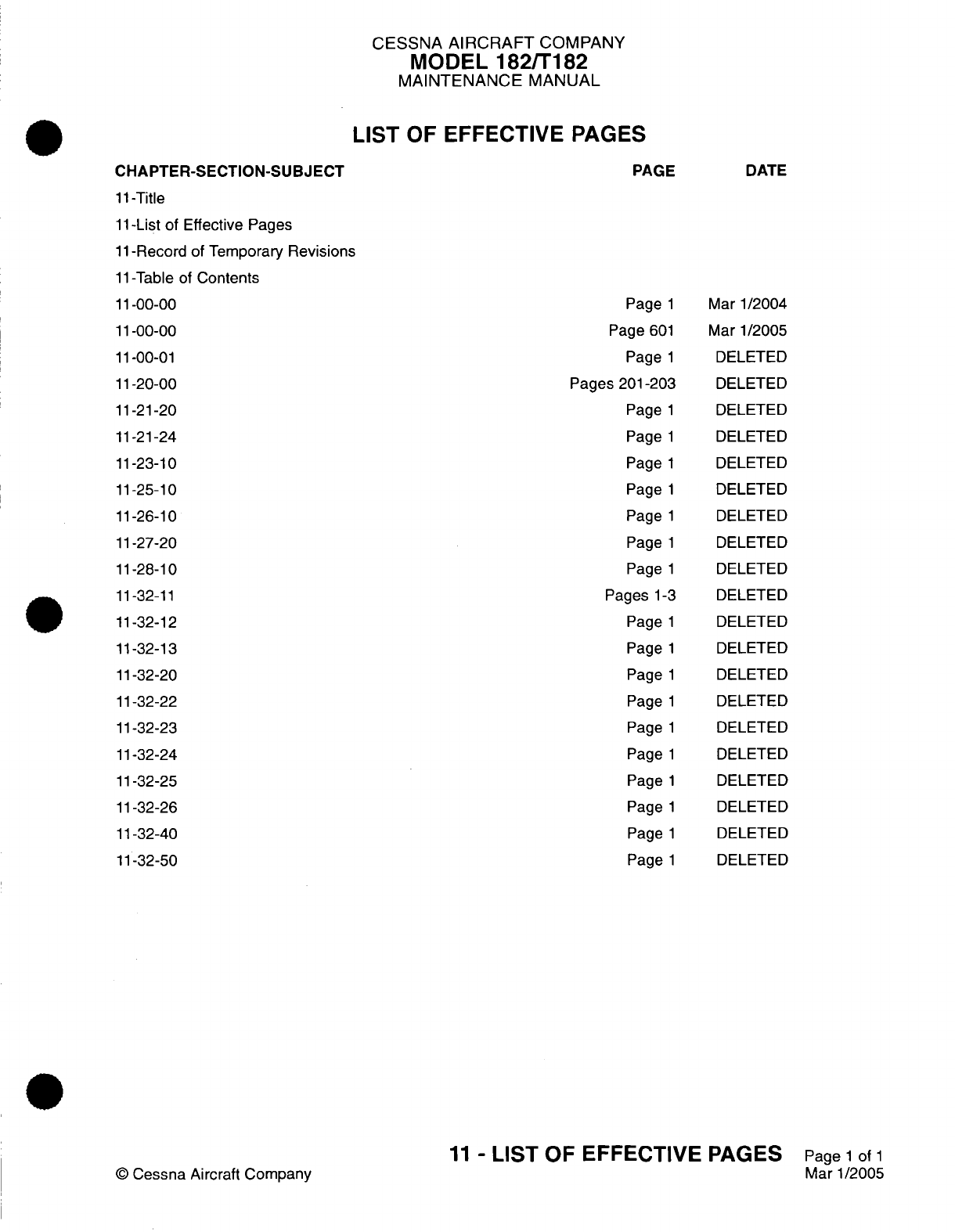
CESSNA
AIRCRAFT
COMPANY
MODEL
182/T182
MAINTENANCE
MANUAL
LIST
OF
EFFECTIVE
PAGES
11-Title
11-List
of
Effective
Pages
11-Record
of
Temporary
Revisions
11-Table
of
Contents
11-00-00
11-00-00
11-00-01
11-20-00
11-21-20
11-21-24
11-23-10
11-25-10
11-26-10
11-27-20
11-28-10
11-32-11
11-32-12
11-32-13
11-32-20
11-32-22
11-32-23
11-32-24
11-32-25
11-32-26
11-32-40
11-32-50
©
Cessna Aircraft
Company
Page
1
Page
601
Page
1
Pages
201-203
Page
1
Page
1
Page
1
Page
1
Page
1
Page
1
Page
1
Pages
1-3
Page
1
Page
1
Page
1
Page
1
Page
1
Page
1
Page
1
Page
1
Page
1
Page
1
Mar
1/2004
Mar
1/2005
DELETED
DELETED
DELETED
DELETED
DELETED
DELETED
DELETED
DELETED
DELETED
DELETED
DELETED
DELETED
DELETED
DELETED
DELETED
DELETED
DELETED
DELETED
DELETED
DELETED
11
-
LIST
OF
EFFECTIVE
PAGES
Page
1
of
1
Mar 1/2005
CHAPTER-SECTION-SUBJECT
PAGE
DATE
Temporary
Revision
Number
RECORD
OF
TEMPORARY REVISIONS
Page
Number
Issue
Date
By
Date
Removed
By
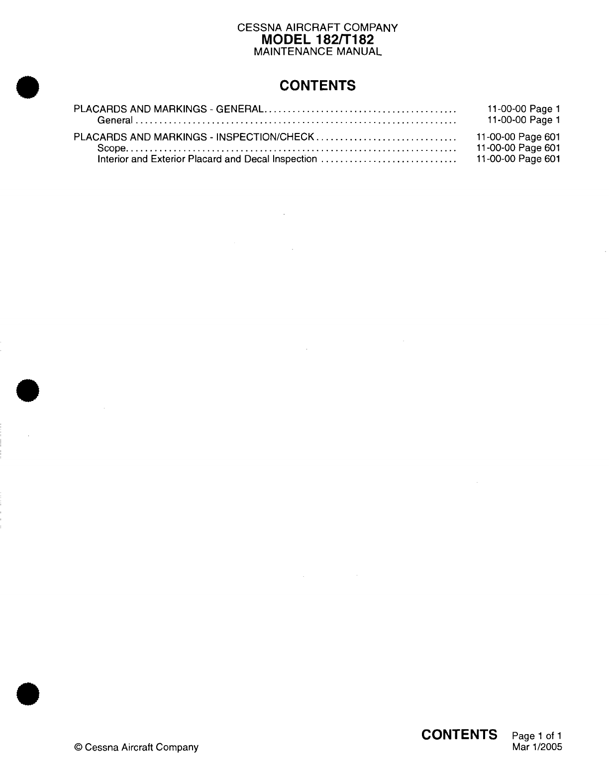
CESSNA
AIRCRAFT
COMPANY
MODEL
182/T182
MAINTENANCE
MANUAL
CONTENTS
PLACARDS
AND
MARKINGS
-
GENERAL.........................................
General
....................................................................
PLACARDS
AND
MARKINGS
-
INSPECTION/CHECK
..............................
S
cope......................................................................
Interior
and
Exterior
Placard
and
Decal
Inspection
.............................
11-00-00
Page
1
11-00-00
Page
1
11-00-00 Page
601
11-00-00
Page
601
11-00-00
Page
601
CONTENTS
Page
1
of
1
Mar 1/2005
©
Cessna Aircraft
Company
CESSNA
AIRCRAFT
COMPANY
MODEL
182/T182
MAINTENANCE
MANUAL
PLACARDS
AND
MARKINGS
-
GENERAL
1.
General
A.
Placards
and
markings
on
the
exterior
surfaces
of
the
airplane
are
found
in
the
Model
182
Illustrated
Parts
Catalog,
Chapter
11.
11-00-00
Page
1
©
Cessna
Aircraft
Company
Mar
1/2004
I

CESSNA AIRCRAFT
COMPANY
MODEL
182/T182
MAINTENANCE
MANUAL
PLACARDS
AND
MARKINGS
-
INSPECTION/CHECK
1.
Scope
A.
This
section
gives
information
about the
inspection
of
interior
and
exterior
placards.
2.
Interior
and
Exterior
Placard
and
Decal
Inspection
NOTE:
This
inspection
is
intended
to
be
an
overall
inspection
of
all
placards, decals,
and
markings
on
the
airplane.
A.
Inspect
the
Placards,
Decals
and
Markings.
(1)
Examine
the
interior
of the
airplane,
including
the
aft baggage
areas,
for
the installation
of
all
necessary
placards, decals
and
markings.
(a)
For
necessary
placards, decals,
and markings,
refer to
the
Model 182,
Illustrated
Parts
Catalog.
(2)
Examine the
exterior
of the
airplane for
the
installation
of
all
necessary
placards,
decals,
and
markings.
(a)
For
necessary
placards, decals,
and markings,
refer to
the
Model 182,
Illustrated
Parts
Catalog.
(3)
Examine
the
airplane identification
plate.
(a)
The
ID
plate
is
found
on
the
left
side
of
the
stinger, Zone
310.
Refer
to
the
Model
182,
Illustrated
Parts Catalog
and
Chapter
6,
Airplane
Zoning
-
Description
and
Operation.
11-00-00
Page
601
©
Cessna
Aircraft Company
Mar
1/2005
CHAPTER
SERVICING

CESSNA
AIRCRAFT
COMPANY
MODEL
182/T182
MAINTENANCE
MANUAL
LIST
OF
EFFECTIVE PAGES
CHAPTER-SECTION-SUBJECT
12-Title
12-List
of
Effective
Pages
12-Record
of
Temporary
Revisions
12-Table
of
Contents
12-00-00
12-10-00
12-11-00
12-12-00
12-13-00
12-14-00
12-14-01
12-14-02
12-15-00
12-16-00
12-17-00
12-18-00
12-20-00
12-21-00
12-21-01
12-21-02
12-21-03
12-21-04
12-21-05
12-22-00
12-23-00
12-30-00
PAGE
Page
1
Pages
1-3
Page
301
Pages
301-303
Page
301
Page
1
Pages
301-304
Pages
301-303
Pages
301-302
Pages
301-302
Page
301
Pages
301-302
Page
1
Pages
1-3
Pages
301-302
Pages
301-303
Pages
301-306
Page
301
Page 301
Pages
701-705
Pages
701-703
Pages
1-2
DATE
April
1/2002
Jan
2/2006
Aug
4/2003
Jul
3/2006
Aug
4/2003
April
1/2002
Jul
3/2006
April
1/2002
April
1/2002
April
1/2002
April
1/2002
April
1/2002
April
1/2002
Jan
2/2006
April
1/2002
April
1/2002
April
1/2002
April 1/2002
April 1/2002
Mar 1/2005
Jan
2/2006
Jan
2/2006
©
Cessna
Aircraft
Company
12
-
LIST
OF
EFFECTIVE
PAGES
Page
1
of
1
Jul 3/2006

Temporary
Revision
Number
RECORD
OF
TEMPORARY REVISIONS
Page
Number
Issue
Date
By
Date
Removed
By

CESSNA AIRCRAFT
COMPANY
MODEL
182/T182
MAINTENANCE
MANUAL
CONTENTS
SERVICING
-
GENERAL
.........
................................................
Scope....
..................................................................
Definition
...................................................................
REPLENISHING
-
DESCRIPTION
AND
OPERATION
...............................
G
e n e
ra
l.
.....
.......
. ...
......
............
.......
....................
.....
D
escription
................................................................
Fuel
Capacity
Table
.........................................................
Approved
Fuel
Table
........................................................
Engine
Oil
Capacity
Table....................................................
NOSE
LANDING GEAR
SHOCK
STRUT
-
SERVICING
.............................
General
....................................................................
Shock
Strut
Servicing Procedures
............................................
NOSE
LANDING GEAR
SHIMMY
DAMPER
-
SERVICING
..........................
General...................................................................
Shimmy
Damper
Servicing
(For
airplanes that
do
not
have
the Lord
Shimmy
Damper)
.................. .........
..
..........
Shimmy Damper
Servicing
(On
Airplanes
with
the
Lord
Shimmy
Damper)
........
HYDRAULIC
BRAKES
-
SERVICING
..............................................
G
eneral
............................
........................................
FUEL AND
ENGINE
OIL
-
DESCRIPTION
AND
OPERATION........................
G
en
eral
....................................................................
Fuel
Precautions
.........
............................
.....................
O
il
Precautions
.............................................................
FUEL
-
SERVICING
..............................................................
General
....................................................................
Safety
and
Maintenance Precautions
.........................................
Fuel
Servicing
..............................................................
Fuel
Additive
(DiEGME)
Precautions
.........................................
Fuel
Additive Procedures
............................
........................
ENGINE
OIL
-
SERVICING
.......................................................
General
............................
.........
...............................
Oil
Change
Intervals..........
.........
.....................................
Checking
Engine
Oil.........................................................
Changing Engine
Oil
........................................................
INDUCTION AIR
FILTER
-
SERVICING
..........................................
General
....................................................................
Air
Filter
Servicing...........................................................
VACUUM
SYSTEM
FILTERS
-
SERVICING
........................................
General
....................................................................
Central
Air
Filter
Servicing
...................................................
Vacuum
System Relief
Valve
Filter............................................
BATTERY
-
SERVICING
..........................................................
G
eneral
....................................................................
Battery
Servicing............................................................
TIRES
-
SERVICING
.........
....................................................
General
............................
........................................
Safety
Precautions
and
Notes............................
....................
Tire
Servicing
...............................................................
Cold
Weather
Servicing......................................................
12-00-00
Page
1
12-00-00
Page
1
12-00-00
Page
1
12-10-00
Page
1
12-10-00
Page
1
12-10-00
Page
1
12-10-00
Page
1
12-10-00
Page
1
12-10-00
Page
1
12-11-00
Page
301
12-11-00
Page
301
12-11-00
Page
301
12-12-00
Page
301
12-12-00
Page
301
12-12-00
Page
301
12-12-00
Page
303
12-13-00
Page
301
12-13-00
Page
301
12-14-00
Page
1
12-14-00
Page
1
12-14-00
Page
1
12-14-00
Page
1
12-14-01
Page
301
12-14-01
Page
301
12-14-01
Page
301
12-14-01
Page
301
12-14-01
Page
302
12-14-01
Page
303
12-14-02
Page
301
12-14-02
Page
301
12-14-02
Page
301
12-14-02
Page
301
12-14-02
Page
301
12-15-00
Page
301
12-15-00
Page
301
12-15-00
Page
301
12-16-00
Page
301
12-16-00
Page
301
12-16-00
Page
301
12-16-00
Page
301
12-17-00
Page
301
12-17-00
Page
301
12-17-00
Page
301
12-18-00
Page
301
12-18-00
Page
301
12-18-00
Page
301
12-18-00
Page
301
12-18-00
Page
302
CONTENTS
Page
1
of
3
Jul 3/2006
©
Cessna Aircraft
Company
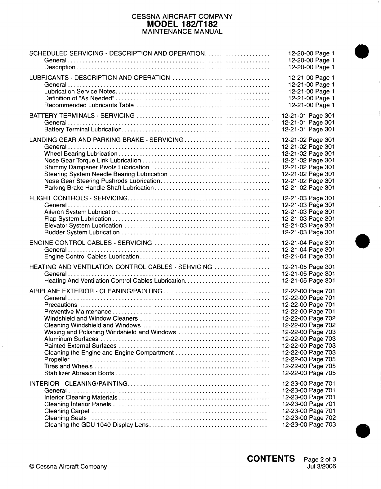
CESSNA
AIRCRAFT
COMPANY
MODEL 182/T182
MAINTENANCE
MANUAL
SCHEDULED SERVICING
-
DESCRIPTION
AND
OPERATION.....................
General
....................................................................
Description
.................................................................
LUBRICANTS
-
DESCRIPTION
AND
OPERATION
.................................
General
....................................................................
Lubrication Service
Notes....................................................
Definition
of
"As
Needed"
...................................................
Recommended
Lubricants
Table
.............................................
BATTERY
TERMINALS
-
SERVICING
............................................
General
....................................................................
Battery
Terminal
Lubrication..................................................
LANDING
GEAR
AND
PARKING BRAKE
-
SERVICING
.............................
General
....................................................................
Wheel
Bearing
Lubrication...................................................
Nose
Gear
Torque
Link
Lubrication
...........................................
Shimmy
Dampener
Pivots
Lubrication
........................................
Steering
System
Needle
Bearing
Lubrication
..................................
Nose
Gear
Steering
Pushrods
Lubrication
....................................
Parking
Brake
Handle
Shaft
Lubrication.......................................
FLIGHT
CONTROLS
-
SERVICING..............................................
General
....................................................................
Aileron System
Lubrication...................................................
Flap
System
Lubrication
.....................................................
Elevator
System
Lubrication
.................................................
Rudder
System
Lubrication
..................................................
ENGINE
CONTROL
CABLES
-
SERVICING
.......................................
General
...................................................................
Engine
Control
Cables
Lubrication
...........................................
HEATING
AND
VENTILATION
CONTROL
CABLES
-
SERVICING
...................
General
....................................................................
Heating
And
Ventilation Control
Cables
Lubrication.............................
AIRPLANE
EXTERIOR
-
CLEANING/PAINTING
....................................
General
....................................................................
P
recautio
ns
................................................................
Preventive Maintenance
.....................................................
Windshield
and
Window Cleaners
............................................
Cleaning
Windshield
and
Windows
...........................................
Waxing
and
Polishing
Windshield
and
Windows
...............................
Aluminum Surfaces
.........................................................
Painted
External
Surfaces
...................................................
Cleaning
the
Engine
and Engine
Compartment
................................
Propeller
...................................................................
Tires
and
Wheels
...........................................................
Stabilizer
Abrasion
Boots
....................................................
INTERIOR
-
CLEANING/PAINTING................................................
General
....................................................................
Interior Cleaning
Materials
...................................................
Cleaning Interior
Panels
.....................................................
Cleaning
Carpet
............................................................
Cleaning
Seats
.........
....................................................
Cleaning
the
GDU
1040
Display Lens
.........................................
12-20-00
Page
1
12-20-00
Page
1
12-20-00
Page
1
12-21-00
Page
1
12-21-00
Page
1
12-21-00
Page
1
12-21-00
Page
1
12-21-00
Page
1
12-21-01
Page 301
12-21-01
Page
301
12-21-01
Page
301
12-21-02
Page
301
12-21-02
Page
301
12-21-02
Page
301
12-21-02
Page
301
12-21-02
Page 301
12-21-02
Page
301
12-21-02
Page 301
12-21-02
Page 301
12-21-03
Page 301
12-21-03
Page
301
12-21-03
Page
301
12-21-03
Page
301
12-21-03
Page 301
12-21-03
Page
301
12-21-04
Page
301
12-21-04
Page
301
12-21-04
Page 301
12-21-05
Page
301
12-21-05
Page
301
12-21-05
Page
301
12-22-00
Page
701
12-22-00
Page
701
12-22-00
Page
701
12-22-00
Page
701
12-22-00
Page
702
12-22-00 Page
702
12-22-00
Page 703
12-22-00
Page
703
12-22-00
Page
703
12-22-00
Page
703
12-22-00
Page
705
12-22-00
Page
705
12-22-00
Page
705
12-23-00
Page
701
12-23-00
Page
701
12-23-00
Page
701
12-23-00
Page
701
12-23-00
Page
701
12-23-00
Page
702
12-23-00
Page
703
CONTENTS
Page
2
of
3
Jul
3/2006
©
Cessna
Aircraft
Company
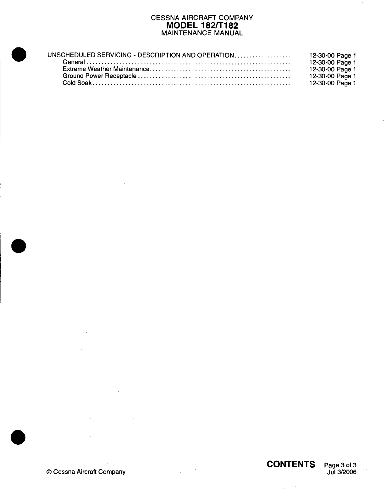
CESSNA
AIRCRAFT
COMPANY
MODEL
182/T182
MAINTENANCE
MANUAL
UNSCHEDULED
SERVICING
-
DESCRIPTION AND
OPERATION
..................
G eneral
....................................................................
Extreme
Weather
Maintenance...............................................
Ground
Power
Receptacle
...................................................
Cold
Soak
............................
......................................
12-30-00
Page
1
12-30-00
Page
1
12-30-00
Page
1
12-30-00
Page
1
12-30-00
Page
1
CONTENTS
Page
3
of
3
Jul
3/2006
©
Cessna
Aircraft Company

CESSNA
AIRCRAFT
COMPANY
MODEL
182/T182
MAINTENANCE
MANUAL
SERVICING
-
GENERAL
1.
Scope
A.
This
chapter provides instructions
for
the
replenishment
of
fluids,
scheduled
and
unscheduled
servicing
applicable
to
the
entire
airplane. Personnel
shall
observe
safety
precautions
pertaining
to
the
individual
servicing
application.
2.
Definition
A.
This
chapter
is
divided
into
sections
to
aid
maintenance
personnel
in
locating
information. Consulting
the
Table
of
Contents
will
further assist
in
locating
a
particular subject.
A
brief
description
of
each
section
follows.
(1)
The
section
on
replenishing
is
subdivided
into
categories
to
group
servicing
information,
such
as,
systems
requiring
hydraulic
fluid
or
compressed
gas.
A
brief
description
of
the
subdivision
subjects
follows.
(a)
Replenishing
charts for
the
liquids
most
commonly
used
to
service
the
airplane
are
grouped
together
to
aid
maintenance personnel
in
servicing.
(b)
The
subdivision
of
fuel
and
oil
provides maintenance
personnel with general
servicing
procedures. Safety
precautions
and
servicing
procedures
required
by
federal
and
local
regulations
may
supersede
the
procedures
described.
(c)
The
subject
on
hydraulic fluid
servicing
provides
servicing
procedures
for
the
airplane
hydraulic
brake system,
nose
gear shimmy
damper
and
nose
gear
strut.
(d)
The
remaining subject
subdivisions
provide
service
information
on
either
a
system,
an
assembly
or
a
component.
(2)
The
section
on
scheduled
servicing includes lubrication
information,
external
cleaning
and
internal
cleaning.
The
section
is
subdivided
to
provide individual
system,
assembly
or
component
service
information.
12-00-00
Page
1
April 1/2002
©
Cessna
Aircraft
Company

CESSNA
AIRCRAFT
COMPANY
MODEL
182/T182
MAINTENANCE
MANUAL
REPLENISHING
-
DESCRIPTION
AND OPERATION
1.
General
A.
This section
provides maintenance
personnel
with
servicing
information
for
replenishing
fuel
and
oil.
2.
Description
A.
For
an
illustration of
service
points located
on
the airplane,
refer
to Figure
1.
This illustration
may
be
used
in
conjunction
with
replenishing
tables
to
aid
maintenance
technicians
in
servicing
the
airplane.
B.
The
following
tables
are
provided
to
establish replenishment
capacities
of
various
systems:
(1)
Fuel
Capacity
(Table
1)
(2)
Approved
Fuels
(Table
2)
(3)
Engine
Oil
Capacity
(Table
3)
3.
Fuel
Capacity
Table
A.
The
following table
lists
airplane
fuel
capacity.
WARNING:
Only aviation
grade
fuels
are
approved
for
use.
Table
1.
Fuel
Capacity
TANK
Fuel
Capacity
Usable
Fuel
U.S.
92.0
Gallons
88.0
Gallons
4.
Approved
Fuel
Table
A.
The
following
table
lists
approved
fuels
for
use
in
the
airplane.
Table
2.
Approved
Fuels
TYPE
OF
FUEL
100
LL
100
SPECIFICATION
ASTM-D910
ASTM-D910
For
other fuels that
can
be
used
in
Russia,
refer
to
Lycoming
Service
Instruction
No.
1070M
(or
subsequently
approved
Lycoming
Service
Instruction
revision).
5.
Engine
Oil Capacity
Table
A.
The
following
table
lists oil
capacity
for
the
airplane.
12-10-00
Page
1
Jan
2/2006
©
Cessna Aircraft
Company
COLOR
Blue
Green
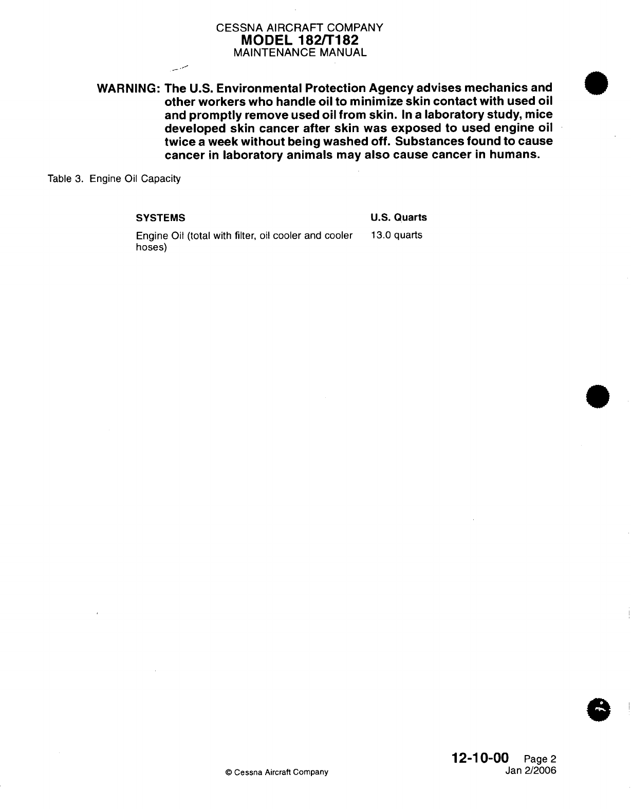
CESSNA AIRCRAFT
COMPANY
MODEL
182/T182
MAINTENANCE
MANUAL
WARNING:
The
U.S.
Environmental
Protection
Agency
advises
mechanics
and
other workers
who handle
oil
to
minimize
skin
contact
with
used
oil
and
promptly
remove
used
oil
from
skin.
In
a
laboratory
study,
mice
developed
skin
cancer
after
skin
was
exposed
to
used
engine
oil
twice
a
week
without
being
washed
off.
Substances
found to
cause
cancer
in
laboratory
animals
may
also
cause
cancer
in
humans.
Table
3.
Engine
Oil
Capacity
SYSTEMS
U.S.
Quarts
Engine
Oil (total with
filter,
oil
cooler
and
cooler
13.0
quarts
hoses)
©
Cessna
Aircraft
Company
12-10-00
Page
2
Jan
2/2006
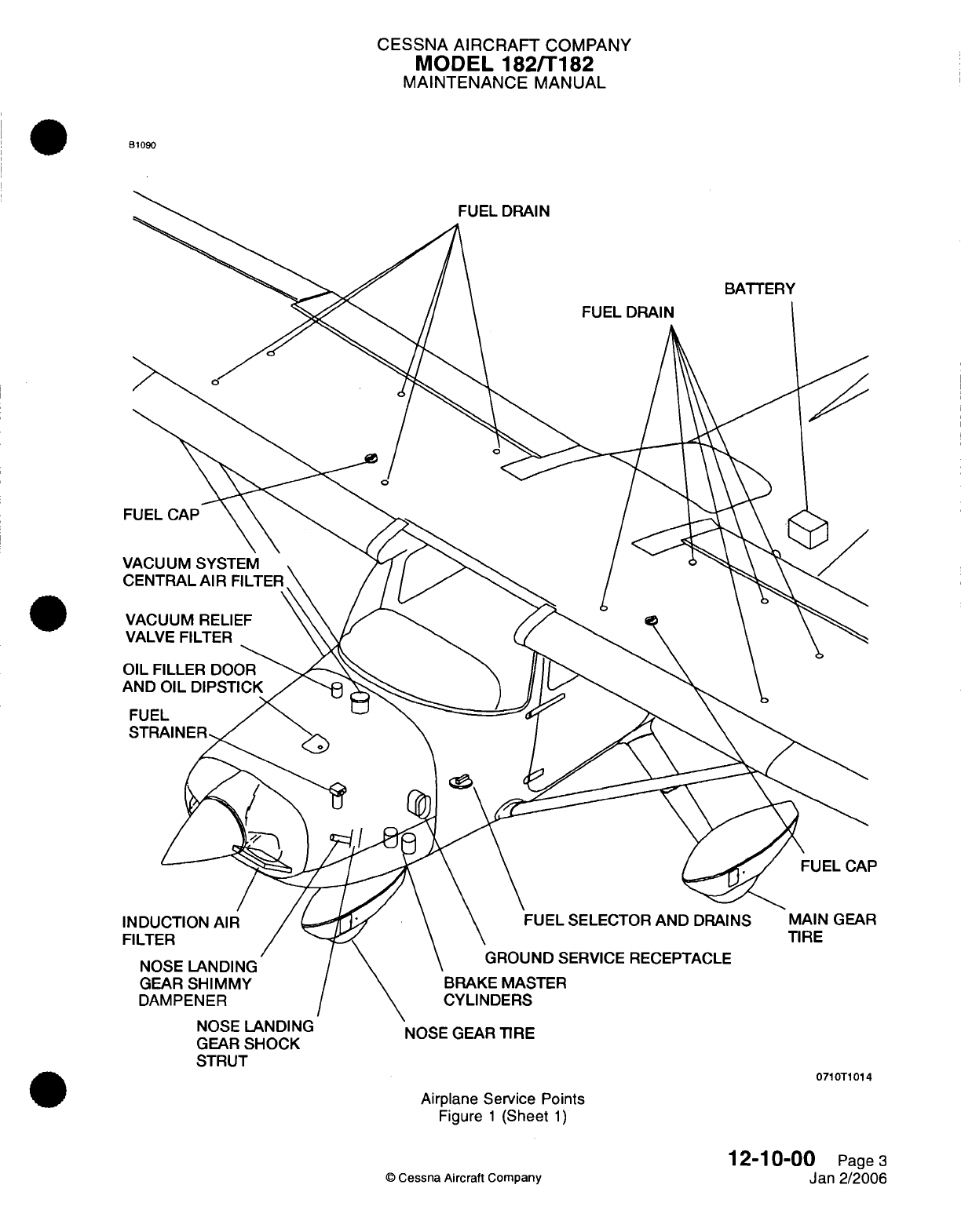
CESSNA
AIRCRAFT
COMPANY
MODEL
182/T182
MAINTENANCE
MANUAL
B1090
FUEL
SELECTOR
AND
DRAINS
GROUND
SERVICE
RECEPTACLE
NOSE
LANDING
GEAR
SHOCK
STRUT
NOSE
GEAR
TIRE
0710T1014
Airplane Service
Points
Figure
1
(Sheet
1)
12-10-00
Page3
Jan
2/2006
©
Cessna
Aircraft
Company
CESSNA
AIRCRAFT
COMPANY
MODEL
182/T182
MAINTENANCE
MANUAL
NOSE
LANDING
GEAR
SHOCK
STRUT
-
SERVICING
1.
General
A.
It
is
necessary
to
examine
the
nose
gear
shock
strut
at
intervals
to make sure
the
strut
is
filled
with
hydraulic
fluid
and
is
inflated
to
the
correct
air
pressure. This
procedure
only
gives
instructions
to
fill
the
nose
gear
shock
strut
and to
service
the
nose
gear
shock
strut.
For
procedures
to
disassemble
and
repair, refer
to Chapter
32,
Nose
Landing
Gear
-
Maintenance
Practices.
2.
Shock
Strut Servicing
Procedures
A.
Service
the
nose
gear
shock
strut
as
follows:
(1)
Remove the
air
valve
cap
and
release
all
air.
(2)
Remove the air
valve
housing
assembly.
(3)
Compress
the
strut
fully
until
the strut's bottom fork
touches
the
top
barrel
housing.
(4)
Examine
the
hydraulic
fluid
level
and add
fluid
as
necessary.
NOTE:
Fluid
used must agree with
specification
MIL-PRF-5606.
(5)
(6)
(7)
(a)
Make
sure
the
hydraulic
fluid
level
is
at
the
bottom
of
the
air
valve
installation
hole.
Fully extend
the
strut.
Install
the
air valve housing
assembly.
With
strut
fully
extended
and
the
nose
wheel
off
of
the
ground,
inflate
the strut to
55
to 60
PSI.
NOTE:
The
nose
landing gear
shock
strut
will use
only
minimum
service.
Strut
extension
pressure
must
be
kept
at
55
to 60
PSI.
Use
a
clean,
lint-free
cloth
soaked
with
MIL-
PRF-5606
or
kerosene
to
clean the machined
surfaces
of
dirt
and
dust.
12-11-00
Page
301
©
Cessna Aircraft Company
Aug
4/2003

CESSNA AIRCRAFT
COMPANY
MODEL
182/T182
MAINTENANCE
MANUAL
NOSE
LANDING
GEAR
SHIMMY
DAMPER
-
SERVICING
1.
General
A.
The
nose
gear
shimmy damper
(on
airplanes
that
do
not
have
the
Lord
Shimmy
Damper)
contains
a
compensating
mechanism
in
the
hollow
piston
rod.
This
is
for
thermal
expansion
and
contraction
of
the
hydraulic
fluid
in
the damper.
The
shimmy
damper
must
be
filled fully
with
hydraulic
fluid
and
be
free
of
air.
Before
the
servicing
of
the
shimmy damper,
make
sure that
the
compensating
piston
is at
the bottom
in
the
piston
rod.
To
disassemble
the
shimmy
damper, refer
to
Chapter
32,
Nose
Gear
-
Maintenance Practices.
B.
The nose
gear
shimmy damper
(on
airplanes
with
the
Lord
Shimmy
Damper)
uses
rubber
with
a
lubricant
to
absorb
nose
wheel
vibration.
The
damper
piston
shaft
is
attached
to
a
stationary
part,
and
the
housing
is
attached
to the
nosewheel
steering
torque
arm
assembly, which moves
as
the
nosewheel turns,
causing
relative
motion between
the
damper shaft
and the
housing.
2.
Shimmy
Damper
Servicing
(For
airplanes that
do
not
have
the
Lord
Shimmy
Damper)
A.
Do
the servicing
of
the shimmy
damper
as
follows
(Refer
to
Figure
301).
(1)
Remove the
shimmy
damper
from
the
airplane.
Refer
to
Chapter
32,
Nose
Landing Gear
-
Maintenance
Practices.
(2)
Hold
the
shimmy damper
in a
vertical
position
with
the
filler
plug
pointed
up.
(3)
Loosen the
filler
plug
to
drain
the
unwanted
fluid.
(4)
Let
the
spring
go
to
the
bottom of
the
floating
piston
in
the
shimmy damper
rod.
(5)
When
the
flow
of the
fluid
stops,
put
a
length
of
rigid
wire
through
the
bleed
air
hole
in
the
setscrew
which
is
found
at the
end
of
the
piston
rod
until the
rigid
wire
touches
the
floating
piston.
(6)
Insert
the
wire
to
the
depth
of
3.81
inches (95.25
mm).
NOTE:
If
the
wire
insertion
is
less than
3.81
inches (95.25
mm),
the
floating
piston
will
not
move
freely
in
the
shaft.
(a)
Use
the
rigid
wire
to
release
the
floating
piston.
(b) If
the
floating
piston cannot
be
released
with
the
rigid
wire,
you
must
replace
the
rod
assembly
and
the piston.
(7)
Make
sure
that
the
floating
piston
is at
the
bottom.
(8)
Move
the
damper
rod
to put the
piston
at
the
end
of
the
barrel
which
is
opposite
of
the
filler
plug.
CAUTION:
Dirt
and
dust
can
cut
the
seals
in
the
barrel.
Use
a
clean,
lint-free
cloth
soaked
with
MIL-PRF-5606
hydraulic
fluid
or
kerosene
to
keep
the
machined
surfaces
clean.
(9)
Remove the
filler
plug
and
fill
the shimmy
damper
with
hydraulic
fluid.
(a)
To
fill
the
shimmy
damper,
make sure
the
shimmy
damper
and
MIL-PRF-5606
hydraulic
fluid
are
at
70°F
to
80°F
(21°C
to
26°C).
(b)
Keep
the
shimmy
damper
and
the
visual
parts of the
piston shaft
clean
from
dirt and
dust.
(10)
Install the
filler
plug and
clean the damper
in
cleaning agent.
(11)
Dry
the
damper
with
a
clean cloth.
(12)
Install the
damper
on
the
airplane.
Refer
to Chapter
32,
Nose
Landing
Gear
-
Maintenance
Practices.
12-12-00
Page
301
©
Cessna Aircraft Company
Jul 3/2006
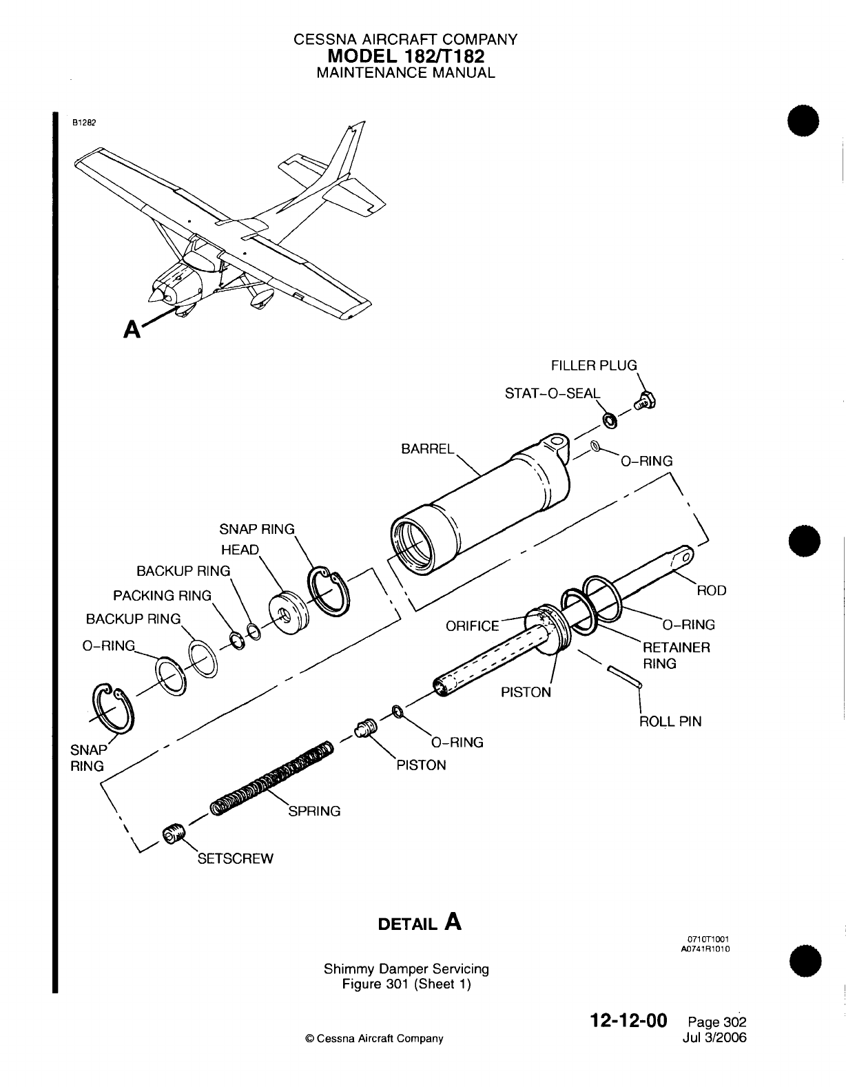
CESSNA
AIRCRAFT
COMPANY
MODEL 182/T182
MAINTENANCE
MANUAL
M
FILLER
BARREL
SNAP
RING
N
HEAD
BACKUP
RING
PACKING
RING
BACKUP
RING
RING
ROLL
PIN
RING
PISTON
SETSCREW
DETAIL
A
Shimmy
Damper
Servicing
Figure
301
(Sheet
1)
©
Cessna Aircraft
Company
12-12-00
Page 302
Jul
3/2006
0710T1001
A0741R
1010
CESSNA
AIRCRAFT
COMPANY
MODEL 182/T182
MAINTENANCE
MANUAL
3.
Shimmy
Damper
Servicing
(On
Airplanes with
the
Lord
Shimmy
Damper)
A.
Lord
Shimmy
Dampers
do
not
need
special servicing.
However,
you
must
lubricate
the
nose
wheel
shimmy
damper
pivots
with
general
purpose
oil
MIL-L-7870.
B.
Keep
the
shimmy damper
clean.
(1)
Clean
the
shimmy
damper
with
a
clean,
lint-free cloth
to
prevent the
collection
of
dust and
grit.
(2)
Make
sure
that
the
part
of the
damper
piston
shaft
that
you
can
see
is
always
clean.
(3)
Clean
the
machined surfaces
of
the
shimmy damper
with
a
clean,
lint-free
cloth
to
prevent
the
collection
of
dust
and
dust.
C. If
necessary,
exercise
a
shimmy
damper
before
installation.
(1) If a
shimmy
damper
has
been
in
storage
for
a
long period, make
sure
that
it
moves
freely
before
you
install
it.
CAUTION:
Make
sure
that
you
do
not
push
or
pull
on
the
shaft
of
the
shimmy
damper
after
it
has
reached
its
limit
in
either
the
up
or
the
down
position.
If
you
continue
to
push
a
fully
compressed,
bottomed-
out
shaft,
you
can
cause
damage
to
the
shimmy
damper.
If
you
continue
to
pull
on
a
fully
extended
shaft,
you
can
cause
damage
to
the
shimmy
damper.
(2) If
the
shimmy damper
does
not
move
freely,
push
and pull
the
shaft
through
complete
cycles
until
it
does
move
freely.
When
the
shimmy damper shaft
has
come
to
its
limit of
travel
up and
down
as
you
push
and
pull, make sure
that
you
do
not
continue
to push
or pull
it
beyond
that
limit
of
travel.
12-12-00
©
Cessna
Aircraft
Company
Page
303
Jul
3/2006
CESSNA
AIRCRAFT
COMPANY
MODEL
182/T182
MAINTENANCE
MANUAL
HYDRAULIC
BRAKES
-
SERVICING
1.
General
A.
Complete
the
brake
master
cylinders servicing
as
specified
in
the
time
intervals set
in
Chapter
5,
Inspection
Time
Limits.
B.
Brake
master
cylinders
are
found
on
the rudder pedals
and
are
filled
with
MIL-PRF-5606
hydraulic
fluid.
To
fill
and
bleed
the
brake system,
refer
to
Chapter
32,
Brakes
-
Maintenance
Practices.
12-13-00
Page
301
©
Cessna
Aircraft Company
Aug
4/2003
CESSNA
AIRCRAFT
COMPANY
MODEL
182/T182
MAINTENANCE
MANUAL
FUEL
AND
ENGINE
OIL
-
DESCRIPTION
AND
OPERATION
1.
General
A.
This
section provides
servicing
procedures
for
the
fuel
and
engine
oil system.
It is
subdivided
as
follows:
(1)
The
fuel
system section
includes
procedures
for
adding
fuel,
defueling
the
airplane
and
mixing
anti-icing additives
to
the
fuel.
(2)
The engine
oil
section includes
procedures
for
checking,
adding
and
changing
engine
oil.
2.
Fuel
Precautions
A.
Safety
Precautions.
(1)
The
safety precautions
on
fueling
and
defueling
may
be
superseded
by
local
directives.
However,
following
is
a
typical
list
of
precautions.
(a)
Ground,
by
designated
grounding
cables,
the
fueling and/or defueling
vehicle
to
the
airplane.
Also,
a
static
ground
device
shall
contact the fueling
or
defueling
vehicle
and
ground.
(b)
Fire
fighting
equipment
shall
be
immediately
available.
(c)
Wear proper
clothing.
1
Do
not
wear
clothing that
has
a
tendency
to
generate
static
electricity,
such
as,
nylon
or
synthetic
fabrics.
2
Do
not
wear
metal
taps
on
shoes
when
working
in
areas
where
fuel
fumes
may
accumulate
at
ground
level.
(d)
The
airplane
shall
be
in a
designated
fuel
loading
or
unloading
area.
(e)
High
wattage,
pulse
transmitting
avionics
equipment
shall
not
be
operated
in
the immediate
vicinity.
B.
Maintenance Precautions.
(1)
Use
designated equipment
for
fuel
loading
and
unloading
to
prevent contamination.
(2)
Use
proper
procedures
when adding
fuel
inhibitors.
(3)
Use
specified
type
of
fuel.
3.
Oil Precautions
A.
Maintenance Precautions.
(1)
Use
proper
servicing
procedures; do
not
overfill,
do not
mix
manufacturers brands
of
oil.
12-14-00
Page
1
©
Cessna
Aircraft
Company
April
1/2002
CESSNA
AIRCRAFT
COMPANY
MODEL
182/T182
MAINTENANCE
MANUAL
FUEL
-
SERVICING
1.
General
A.
Fuel Tanks.
(1)
Each
wing
has
a
fuel
tank.
You
can
find
the
fuel
tanks
between
the
forward
and aft
spars
that
extend
from
WS
23.62
to
WS
85.96.
You
must
fill the
fuel
tanks
immediately
after
each
flight
to
decrease
the amount
of
condensation that
can
be
produced
in
the
tanks
and
fuel
lines.
A
fuel
filler
cap
that
vents
is
found
on
top
of
each
wing
to
fuel
and
defuel
each fuel
tank.
B.
Fuel
Drains.
(1)
Fuel
drains
are
at
various
places
throughout
the
fuel
system,
and
are
used
to
collect
fuel
samples
for
analysis.
To
collect
fuel
samples,
you put
a
fuel
sample
cup
up
to
the
valve
and
push
up on
the
valve
with
the
rod
on
the
cup.
NOTE:
For
detailed description
and
maintenance
practices
related
to
the
fuel
system,
refer
to
Chapter
28,
Fuel
-
General.
2.
Safety
and
Maintenance
Precautions
A.
Safety
Precautions.
WARNING:
Keep
fire
fighting
equipment
available
for
all
fuel
system
service
procedures.
To
prevent
accidental
disconnection
of
a
ground
wire,
you must
use
two ground
wires
from
the
tiedown
rings
on
the
airplane
attached
to
approved ground
stakes.
Make
sure the
battery
switch
is
turned
off,
unless
otherwise
specified.
(1)
Connect
an
electrical
ground.
(a)
Ground the
airplane
with
two
ground wires.
Connect
the
wires
from
the
tie-down
rings
to
the
ground
stakes.
(b)
Ground the
vehicle
(or hose
cart)
to
the same ground
stakes
as
the
airplane.
(c)
Ground
the
vehicle
(or hose
cart)
to
the
airplane.
(d)
Ground the
refuel
nozzle
to
the airplane.
(2)
Make sure
the
equipment
to
fight fires
is
available.
(3)
Do
not
wear
clothes such
as
nylon
or
synthetic
fabrics
that
can
make
static
electricity.
(4)
Do
not
wear
metal
taps
on
shoes.
(5)
The
airplane
must
be
in
a
designated
fuel
loading/unloading
area.
(6)
High
wattage,
pulse
transmitted
avionics
equipment
must
not be
operated
in
the area
when
you
fill
or
drain the
fuel.
B.
Maintenance
Precautions.
(1)
Use
approved equipment
to
fill
or
remove
fuel
to
prevent
contamination.
(2)
Use
the authorized
type
of
fuel
and
anti-ice additive.
It is
very
important that
the
correct anti-ice
additive
mix
procedures
be
followed.
Incorrect
mixture
of
the
fuel
and
anti-ice additive
will
cause
damage
to the
interior finish
of
the
fuel
tank, which
increases
corrosion.
(3)
Use
an
authorized
type
of
fuel
and
anti-ice additive.
(4)
When
you
fuel
the
airplane,
make
sure
you
do
not
mix the
fuel
with
the
anti-ice
additive
and
the
fuel without
the
anti-ice
additive.
3.
Fuel
Servicing
A.
Fuel
Fill
Procedures.
12-14-01
Page
301
©
Cessna
Aircraft
Company
Jul 3/2006
CESSNA
AIRCRAFT
COMPANY
MODEL 182/T182
MAINTENANCE
MANUAL
CAUTION:
Make sure
that
the
correct
grade
and
type
of
fuel
is
used
to
service
the
airplane.
Refer
to
Pilot's
Operating
Handbook
and
FAA
Approved
Airplane
Flight
Manual
for
a
list
of
approved fuels.
(1)
Electrically ground
airplane
and
vehicle.
Refer
to
the
Safety
and
Maintenance
Precautions.
(2)
Make
sure
that
the battery
switch
is
turned
to
OFF.
(3)
Put
a
protective
mat
around
the
fuel
filler
area
and
remove
the
fuel
filler
caps.
(4)
Fuel
the
airplane
with the
correct
grade
of
aviation
fuel.
(5)
Install
the
filler
caps.
Wipe
up
the
excess
fuel
from
the
wing area.
(6)
Remove
the
equipment
that
you
used to
ground
the
airplane.
B.
Fuel
Removal
Procedures.
(1)
Electrically ground
the
airplane
and
the
vehicle.
(2)
Make sure
that
the
battery
switch
is
turned
to
OFF.
(3)
Remove
the
fuel
filler
caps.
(4)
Put
the
defueling
nozzle
into
the
fuel
bay
and
begin
to
defuel.
(5)
Remove
as
much
fuel
as
possible
with
the defuel
nozzle.
(6)
Remove
the drain
valves
from
the
bottom
of
the
fuel
tank
and
drain
the
remaining fuel.
(7)
Remove
grounding equipment.
4.
Fuel
Additive
(DiEGME)
Precautions
WARNING:
WARNING:
CAUTION:
CAUTION:
MIL-1-85470
anti-ice additive
is
toxic.
It
is
dangerous
to
health
when
breathed
and/or
absorbed
into
the
skin.
When
you
service
fuel
with
the
anti-ice
additive
in
an
unventilated
area,
use
applicable
personal
protective
equipment
such
as
eye
goggles/shield,
respirator
with
organic
vapor
cartridges,
non-absorbing
gloves
and
additional skin
protection
from
spraying
or
splashing
anti-ice
additive.
If
anti-ice
additive
enters
the eyes,
flush
with
water
and
contact
a
physician
immediately.
Anti-icing
additives
that
contain
DiEGME
are
harmful
if
inhaled,
swallowed,
or
absorbed
through
the
skin
and
will
cause
eye
irritation.
DIEGME
is
also
combustible.
Before
you
use
this
material,
refer
to
all
of
the safety
information
on
the
container.
It
is
extremely
important
to
mix
anti-ice
additives
with
fuel
correctly,
because
more
concentration
than
recommended
can
cause damage
to
the
fuel
tanks,
such
as
deterioration
of
protective
primer
and
sealants
and
damage
to
O-rings
and
seals
in
the
fuel
system
and
engine
compounds.
Use
only equipment that
is
recommended
by
the
manufacturer
to make
sure
that
you
get the
correct
proportion
when
you
blend the
anti-ice
additives
with the
fuel.
Do
not
let
the
concentrated
anti-ice
additive
come
in
contact
with
the
airplane
finish
or fuel
cell,
as
it
can
cause
damage.
A.
When you
service
fuel with
anti-icing
additives
that
contain Diethylene
glycol
monomethyl
ether
(DiEGME,
MIL-I-
85470), remember that
they
are
harmful
if
inhaled,
swallowed,
or
absorbed
through
the
skin,
and will
cause
eye
irritation.
Also,
they
are
combustible.
Before
you
use
this
material,
refer
to
all
safety
information
on
the container.
B.
DiEGME
is
toxic
under
sustained
exposure environments.
When
inhaled,
DiEGME
is
primarily
a
central
nervous
system depressant, although various
animal
studies
have
revealed
that
acute
inhalation
overexposure
may
cause kidney
injury.
The
primary symptoms
of
inhalation
overexposure
12-14-01
Page
302
©
Cessna
Aircraft
Company
Jul
3/2006
CESSNA
AIRCRAFT
COMPANY
MODEL
182/T182
MAINTENANCE
MANUAL
in
confined
or
poorly
ventilated
areas
include
headache, drowsiness,
blurred
vision,
weakness,
lack
of
coordination,
tremor,
unconsciousness,
and
even
death.
When
ingested (swallowed)
in
massive
doses,
DiEGME
is
reported
to
exhibit
a
narcotic
action,
but
at
lower dosage levels,
death
is
delayed
and
is
accompanied
by
lung
edema
(excessive serious
fluid
in
lungs),
slight
liver
injury
and
marked
kidney
injury.
DiEGME
is
only mildly
irritating
to the
eyes
and
skin;
however,
it
can
be
readily
absorbed
through the
skin
in
toxic
amounts.
Symptoms
of
overexposure
due
to
skin
absorption
are
essentially
the
same
as
those
outlined
for inhalation.
C. In
the
event
DiEGME
contact
is
experienced,
the
following
emergency
and
first
aid
procedures
should
be
used.
(1) If
DiEGME
is
inhaled,
remove
person
to
fresh
air.
If
the
person
is
not
breathing, give
artificial
respiration, preferably
mouth-to-mouth;
however,
if
breathing
is
difficult,
administer
oxygen.
Always
call
a
physician.
(2) If
ingested (swallowed),
drink
large
quantities
of water.
Then
induce vomiting by placing
a
finger
far
back
into
the
throat.
Contact
a
physician
immediately.
If
vomiting cannot
be
induced,
take
victim
immediately
to
the
hospital
or
a
physician.
If
victim
is
unconscious
or
in
convulsions,
take
victim
immediately
to the
hospital
or
a
physician.
Do not
induce
vomiting
or
give anything
by
mouth to
an
unconscious
person.
(3) If
eye
or
skin
contact
is
experienced, flush
with
plenty
of
water
(use
soap
and
water
for skin)
for
at
least
15
minutes
while
removing
contaminated clothing
and
shoes.
Call
a
physician. Thoroughly
wash
contaminated
clothing
and
shoes
before
reuse.
D.
Additional
antistatic
and
biocidal
protection
may
be
provided
using
approved products.
Refer
to
the
Tools,
Equipment
and
Materials
section
for
approved
manufacturers. Refer
to
the
Pilot's
Operating
Handbook
and
FAA
Approved Airplane
Flight Manual
for
concentration levels
of
these products.
5.
Fuel
Additive
Procedures
A.
Strict
adherence
to
recommended preflight draining
instructions
will
eliminate
any
free water
accumulations
from
the
tank
sumps.
While
small amounts
of
water
may
still
remain
in
solution
in
the
gasoline,
it
will
normally
be
consumed
and
go
unnoticed
in
the
operation
of
the
engine.
B.
One
exception
to
this
can
be
encountered
when
operating
under
the
combined effect
of:
1)
use
of
certain
fuels,
with
2)
high
humidity
conditions
on
the
ground
3)
followed
by
flight
at
high
altitude
and
low
temperature.
Under
these
unusual
conditions
small
amounts
of
water
in
solution
can
precipitate
from the
fuel
stream and
freeze
in
sufficient quantities
to
induce
partial
icing
of
the
engine fuel
system.
C.
While
these
conditions
are
quite
rare
and
will not
normally
pose
a
problem
to
owners
and
operators,
they
do
exist
in
certain
areas
of
the world
and
consequently
must
be
dealt
with,
when
encountered.
D.
Therefore,
to
alleviate
the
possibility
of
fuel
icing
occurring
under
these
unusual
conditions,
it
is
acceptable
to add
isopropyl
alcohol
or
Diethylene glycol
monomethyl
ether
(DiEGME)
compound
to
the
fuel
supply.
E.
The
introduction
of
alcohol
or
DIEGME
compound
into
the
fuel gives
two
distinct
effects:
1)
it
absorbs
the
dissolved
water
from
the
gasoline
and
2)
alcohol
has
a
freezing temperature
depressant
effect.
F.
Alcohol
which
meets
specification
MIL-F-5566
or
Federal
Specification
TT-I-735
and has
a
maximum
water
content
not
exceeding
0.4
percent
by
volume,
may be
used.
If
used,
it is
to
be
blended
with
the
fuel
in
a
concentration
of
1%
by
volume.
Concentrations
greater
than
1%
are
not
recommended
since they
can
be
detrimental
to
fuel
tank
materials.
G.
The manner
in
which
the
alcohol
is
added
to
the
fuel
is
significant
because alcohol
is
most
effective
when
it
is
completely dissolved
in
the
fuel.
To
ensure
proper
mixing,
the
following
is
recommended:
(1)
For
best
results
the
alcohol
should
be
added
during
the
fueling operation
by
pouring
the
alcohol
directly
on
the
fuel
stream
issuing
from
the fueling
nozzle.
(2)
An
alternate
method
that
may
be
used
is
to premix
the
complete alcohol dosage
with
some
fuel
in a
separate
clean
container (approximately
2
to
3
gallon
capacity)
and
then
transfer this
mixture
to
the
tank
prior
to
the
fuel
operation.
12-14-01
Page
303
©
Cessna
Aircraft Company
Jul
3/2006
CESSNA
AIRCRAFT
COMPANY
MODEL
182/T182
MAINTENANCE
MANUAL
H.
Diethylene
glycol
monomethyl
ether
(DiEGME)
compound
in
compliance
with
MIL-I-85470,
if
used,
must
be
carefully
mixed. Refer
to
Pilot's
Operating Handbook
And
FAA
Approved Airplane
Flight
Manual
for
fuel/DiEGME
mixing ratios.
I.
Prolonged
storage
of
the
airplane
will result
in a
water
buildup
in
the
fuel
which
"leeches
out"
the
additive.
An
indication
of
this
is
when
an
excessive
amount
of
water
accumulates
in
the
fuel
tank
sumps.
The
concentration
can
be
checked
using
a
concentration
tester.
It
is
imperative
that
the
technical
manual for
the
tester
be
followed
explicitly
when
checking
the
additive concentration.
12-14-01
Page
304
©
Cessna
Aircraft
Company
Jul
3/2006

CESSNA
AIRCRAFT
COMPANY
MODEL
182/T182
MAINTENANCE
MANUAL
ENGINE
OIL
-
SERVICING
1.
General
A.
This
section provides instructions
to
examine
and
change
the
engine
oil.
2.
Oil
Change
Intervals
NOTE:
An
inspection
of the
filter
can
aid
in
the
detection
of
premature
engine
wear.
Refer to Lycoming
Service Bulletin
480D
or
latest
revision.
A.
Oil
Change Intervals.
(1)
Airplanes
are
delivered
from
the
factory
with
aviation
grade
mineral
oil
conforming
to SAE
J1966.
During
the
first
25
hours
of
engine operation,
it
may
be
necessary
to
add
oil.
Use
an
aviation
grade mineral
oil
of
the recommended
viscosity
conforming
to
SAE
J1966.
After
the first
25
hours,
drain
the
engine
oil
and
change
the
filter.
Fill
the
oil
sump
with
aviation grade mineral
oil
of
the
recommended
viscosity,
conforming
to
SAE
J1966.
Use
it
until
a
total
of
50
hours
of
engine
operation
has
occurred
or oil
consumption
has
stabilized.
Then
the
sump
must
be
drained
and
ashless dispersant
oil
conforming
to
SAE
J1899, must
be
added
to
the
engine.
NOTE:
The
turbocharged
engines
use
only
ashless
dispersant
oil
conforming
to
SAE
J1899,
even
during
the
engine
break-in period.
(2)
For
other
engine change
intervals,
refer to
Chapter
5,
Inspection
Time
Limits.
3.
Checking
Engine
Oil
A.
Engine
Oil
Checking
Procedures.
Refer
to
Chapter
71,
Engine
-
Description
And
Operation,
Figure
1.
(1)
Five
to
ten
minutes
after
the
engine
has
been
stopped,
exam
the
engine
oil
with
the
dipstick .
The
airplane
must
be
in
a
level
position
as
much
as
possible
for
the best
indication.
(2)
Open
the engine
oil
door
on
the
upper
cowling.
(3)
Remove
the
dipstick
from
the
engine
and
wipe
down with
a
clean
cloth.
(4)
Insert
the
dip
stick
fully
and
remove.
(5)
Exam
the
oil
level
on
the
dipstick.
(6)
If
the
oil
is
low,
add
the correct
quantity
and
viscosity
of
aviation
grade
engine
oil.
NOTE:
The airplane
may be
operating
with
SAE
J1966
(straight mineral
oil)
during
the
initial
break-in
period or
after
an
overhaul.
After
the
break-in
period,
use
a
ashless
dispersant
oil
conforming
to
SAE
J1899.
Make sure
the
proper
oil
type
is
used when
servicing
the
engine.
(7)
Insert
the
dipstick
in
the
filler
tube
and do
a
check for
correct
seating.
(8)
Close
the engine
oil door.
4.
Changing
Engine
Oil
A.
Oil
Changing
Procedures. Refer
to
Chapter
71,
Figure
1
Engine
-
Description
And
Operation.
NOTE:
The nose
of
the
airplane
must
be
raised
slightly
for
more
positive draining
of
any
sludge
which
may have
collected
in
the engine
oil
sump.
(1)
Operate
engine
until
oil
temperature
is
at
a
normal
operating
temperature.
NOTE: Normal
operating temperature
is
within
the
green
arc
of
the oil
temperature
gage.
The
engine
oil
must
be
drained
while
the
engine
is
still
warm.
(2)
Shut
off
engine
and
remove
the
upper
and
lower
cowling
to get
access
to the
oil
drain plug
and
external
oil
filter.
Refer
to
Chapter
71,
Cowling
-
Maintenance
Practices.
12-14-02
Page
301
©
Cessna Aircraft Company
April
1/2002
CESSNA
AIRCRAFT
COMPANY
MODEL 182/T182
MAINTENANCE
MANUAL
WARNING:
Avoid
skin contact
with
engine
oil.
Any
engine
oil
that
inadvertently
gets
on
the
skin
should
be
immediately
removed.
(3)
Remove
and
discard
the
wire
from
the
drain
plug.
(4)
Remove the drain
plug
and
let
the
oil
drain
into
an
applicable
container.
(5)
After the
engine
oil
has
drained, install
and
safety
the
drain
plug
with wire. Refer
to
the
Lycoming
SSP-1776
Table of
Limits
or latest
revision, for torque
requirements
and
refer to
Chapter
20,
Safetying
-
Maintenance
Practices.
(6)
Remove the
suction screen
from
the
oil
sump.
(a)
Do
an
inspection
for
metal
particles.
1 If
metal
content
is
shown,
keep the
material
for
identification.
Additional
investigation
will
be
required
to
determine
the
source
of
the
metal
and
possible
need
for
corrective
maintenance.
Refer
to
Lycoming
SSP500
(or
latest
revision)
and
contact
a
Textron
Lycoming
representative.
(b)
Install
the
suction
screen
with
a
new
gasket.
Refer
to
the Lycoming
SSP-1776
Table
of
Limits
or latest
revision,
for
torque
requirements.
(c)
Safety the suction
screen
with
wire. Refer
to
Chapter
20,
Safetying
-
Maintenance
Practices.
(7)
Remove the
external
oil
filter.
(a)
Open
the
filter
can
and
check the
oil
from
the
filter
for signs
of
metal
in
the filter.
(b)
Carefully
remove
and
unfold
the
paper
element. Examine the material
in
the
filter.
1 If
metal
content
is
shown,
keep
the
material
for identification. Additional
investigation
will
be
required
to
determine
the
source
of
the
metal
and
possible
need
for
corrective
maintenance. Refer
to
Lycoming
SSP500
and
contact
a
Textron
Lycoming
representative.
(c)
Install
a
new
external
oil
filter.
(d)
Safety the
oil
filter
with wire.
Refer
to
Chapter
20,
Safetying
-
Maintenance
Practices.
(8)
Fill
the engine
oil
sump through
the
filler
tube.
Use
the
correct
grade
and
quantity
of
oil.
Refer
to
Replenishing
-
Description
and
Operation
for
oil quantity. Refer
to
Figure
301
for
oil
grade
verses
temperature chart.
(9)
Install
the
dipstick
and
make sure
proper seating
on
the
filler
tube.
(10)
Operate
the
engine
until
the
normal
operating
temperature
is
reached.
(11)
Shut
down
the
engine
and do
a
leak
check.
12-14-02
Page 302
©
Cessna
Aircraft
Company
April
1/2002
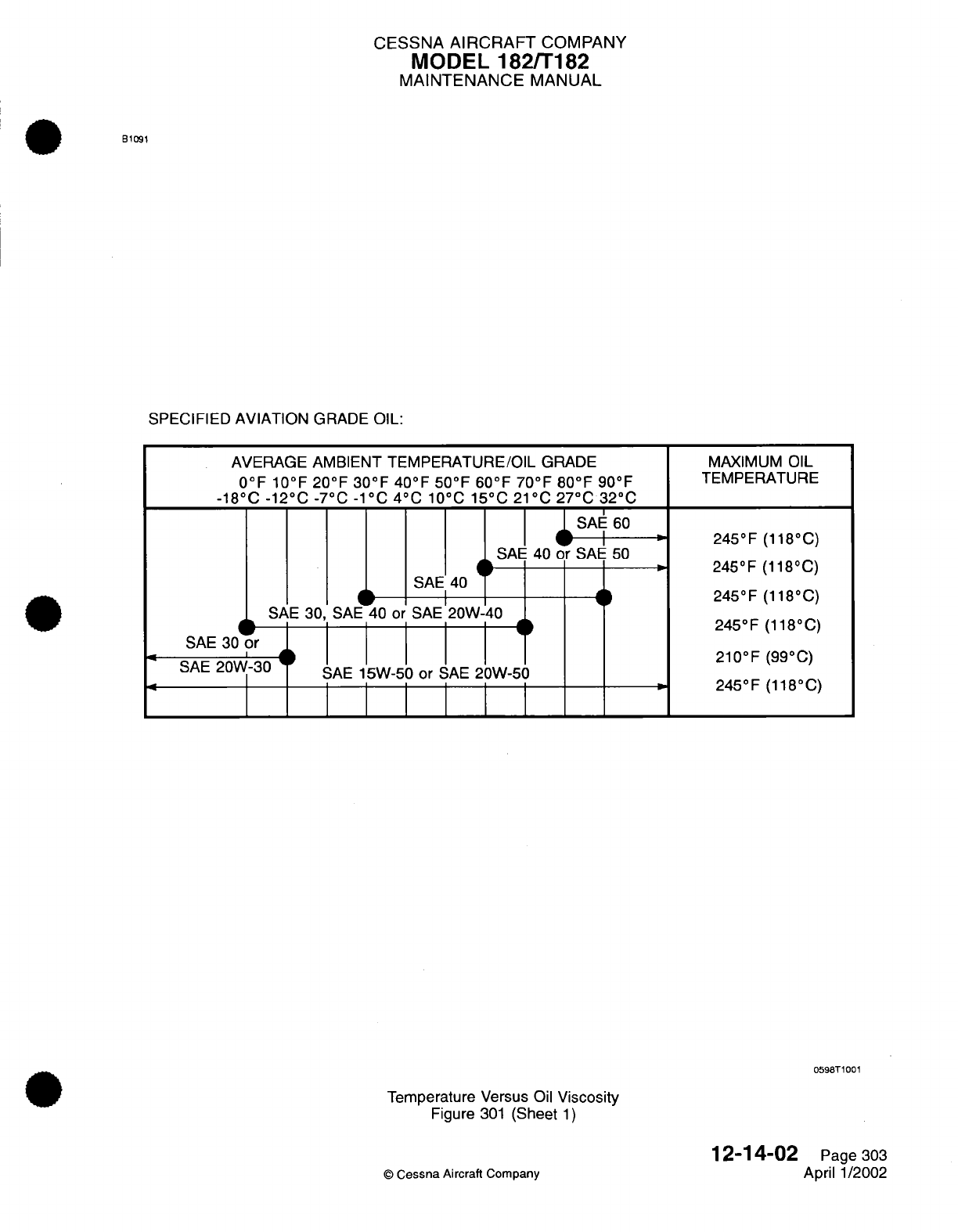
CESSNA
AIRCRAFT
COMPANY
MODEL
182/T182
MAINTENANCE
MANUAL
B1091
SPECIFIED
AVIATION
GRADE
OIL:
AVERAGE AMBIENT
TEMPERATURE/OIL
GRADE
0OF
10OF
20OF
30OF
40OF 50OF 60OF 70OF 80OF
90°F
-18°C
-120
C
-7
0C -1°C 40
C
10°C
15°C
21°C
270C
32°C
|
SAE
60
SAE
40
or
SAE
50
SAE 40
SAE
30,
SAE
40
or
SAE
20W-40
SAE
30
or
SAE
20
SAE
20W-30
SAE
15W-50 or
SAE
20W-50
'I
MAXIMUM
OIL
TEMPERATURE
245°F
(118°C)
245°F
(118°C)
245°F (118°C)
245°F
(118°C)
210°F
(99°C)
245°F
(118°C)
0598T1001
Temperature
Versus
Oil
Viscosity
Figure
301
(Sheet
1)
©
Cessna
Aircraft Company
12-14-02
Page
303
April
1/2002

CESSNA
AIRCRAFT
COMPANY
MODEL
182/T182
MAINTENANCE
MANUAL
INDUCTION AIR
FILTER
-
SERVICING
1.
General
A.
The
induction
airfilter
keeps
dust
and dirt
from
entering
the
induction
system. The value
of
maintaining
the
air
filter
in
a
good
clean
condition
can
never
be
over
stressed.
More
engine
wear
is
caused
through
the
use
of
a
dirty
or
damaged air
filter
than
is
generally
believed.
The
frequency
with
which
the
filter
should
be
removed,
inspected,
and
cleaned
will be
determined
primarily
by
airplane operating
conditions.
Under
extremely
dusty
conditions,
daily
servicing
of
the
filter
may
be
required.
2.
Air
Filter
Servicing
A.
The
CA3717
Induction
Air
Filter
should
be
serviced
at
50
hours,
is
life
limited and must
be
replaced
at
100
hours.
The P198290 Induction
Air
Filter
should
be
serviced
at
50
hours,
is
life
limited
and must
be
replaced
at
500
hours.
(Refer
to
Chapter
5,
Inspection
Time
Limits.)
B.
Servicing Procedures.
(1)
To
service
the
CA3717 Air filter:
(a)
Remove
filter
from
airplane.
If
damaged
or
split,
replace
filter.
If
filter
is
in
serviceable
condition,
proceed
with
following steps.
(b)
Clean
filter
by
blowing with
compressed
air
from direction opposite
of
normal
air
flow.
(c)
Ensure
air
box
is
clean
and
free
of
debris
before
installing
filter.
(d)
Install
filter
at
entrance
to
air
box.
(2)
To
service
the
P198290
Air
filter:
(a)
Remove
the
filter
from the
airplane.
NOTE: Use
care
to
prevent damage
to filter element
when
cleaning filter
with
compressed air.
(b)
Clean
filter
by
blowing
with
compressed
air
(not
over
100
psi)
from
direction
oppposite
of
normal
air
flow.
Arrows
on
filter
case
indicate
direction
of
normal
air
flow.
(c)
Check
bonding
of
the
paper
pleats
to
the
face
screen. The bonding holds the
paper
pleats
in
place
and
if
broken,
the
pleats
are
free
to
shift
which
can
impair
filtration.
A
face
screen
that
is
loose or
gapping away
from
the
paper
pleats
is
indicative
of
broken
bonding
and
is
cause
to
replace
the
filter
element.
CAUTION:
Do
not
use
solvent
or
cleaning
fluids
to
wash
filter.
Use
only
a
water
and
household
detergent
solution
when
washing
the
filter.
(d)
After cleaning
as
outlined
in
step
"b",
the
filter
may be
washed,
if
necessary,
in a
solution
of warm
water
and
a
mild
household
detergent.
A
cold water
solution
may
be
used.
NOTE:
The
filter
assembly
may be
cleaned with
compressed
air
a
maximum
of
30
times
or
it
may
be
washed
a
maximum
of
20
times.
A
new
filter
must
be
installed
after
using
500
hours of
engine
operating
time
or
one
year,
whichever
should
occur
first.
However,
a
new
filter
must
be
installed
anytime
the
existing
filter
is
damaged.
A
damaged
filter
may have
sharp
or
broken
edges
in
the
filtering
panels
which
would
allow
unfiltered
air
to
enter
the
induction
system. Any
filter
that
appears doubtful,
shall
have
a
new
filter
installed
in
its
place.
(e)
After washing,
rinse
filter
with
clear water
until
rinse
water
draining
from
the
filter
is
clear.
Allow
water
to drain
from
filter
and
dry
with
compressed
air (not
over
100 psi).
NOTE:
The
filtering
panels
of
the
filter
may
become distorted
when
wet,
but
they
will
return
to
their
original
shape
when
dry.
(f)
Be
sure
airbox
is
clean,
and
inspect
filter.
If
filter
is
damaged,
a new
filter
must
be
installed.
12-15-00
Page
301
©
Cessna Aircraft
Company
April
1/2002
CESSNA
AIRCRAFT
COMPANY
MODEL
182/T182
MAINTENANCE
MANUAL
(g)
Install
filter
at
entrance
to
airbox with
gasket
on
aft face
of
filter
frame
and
with
flow
arrows
on
filter
frame
pointed
in
the
correct
(normal
air
flow)
direction.
12-15-00
Page
302
©
Cessna
Aircraft
Company
April
1/2002
CESSNA AIRCRAFT
COMPANY
MODEL
182/T182
MAINTENANCE
MANUAL
VACUUM
SYSTEM
FILTERS
-
SERVICING
1.
General
A.
The
vacuum system
contains
two
filters
which
require
occasional
servicing.
The
vacuum
system
central
air
filter
is
located
behind
the instrument
panel,
and
the
vacuum
system relief
valve
filter
is
located
in
the engine compartment.
NOTE:
Smoking
in
cabin
will
significantly
decrease
the
vacuum
system
central
air
filter
life.
If
air
filter
becomes
sufficiently
clogged
to
cause
suction
gage readings
to
drop below 4.6
in.Hg,
air
filter
must
be
replaced regardless
of time
remaining
until
inspection/replacement.
2.
Central
Air
Filter
Servicing
A.
The
central
air
filter
should
be
serviced
using
time
intervals
set
forth
in
Chapter
5,
Inspection
Time
Limits.
B.
Servicing Procedures
(Refer
to
Figure
301).
CAUTION:
Do
not
operate
the
vacuum system with
air filter
removed or
with
a
vacuum
line
disconnected.
Particles or
dust
or
other foreign
matter
may
enter
the
system and
damage
the
vacuum
operated
instruments.
(1)
(2)
(3)
(4)
Locate
air
filter
forward
of
instrument panel.
Remove
bolt
and
washer
securing
air
filter
to
cover.
Check
for
damage,
deterioration
and
contamination.
Clean
(or replace)
as
required.
Install
air
filter
in
cover
and
secure
using
bolt
and
washer.
3.
Vacuum
System
Relief
Valve
Filter
A.
The
relief
valve
filter
should
be
serviced
using
time
intervals
set
forth
in
Chapter
5,
Limits.
©
Cessna
Aircraft
Company
Inspection Time
12-16-00
Page
301
April
1/2002
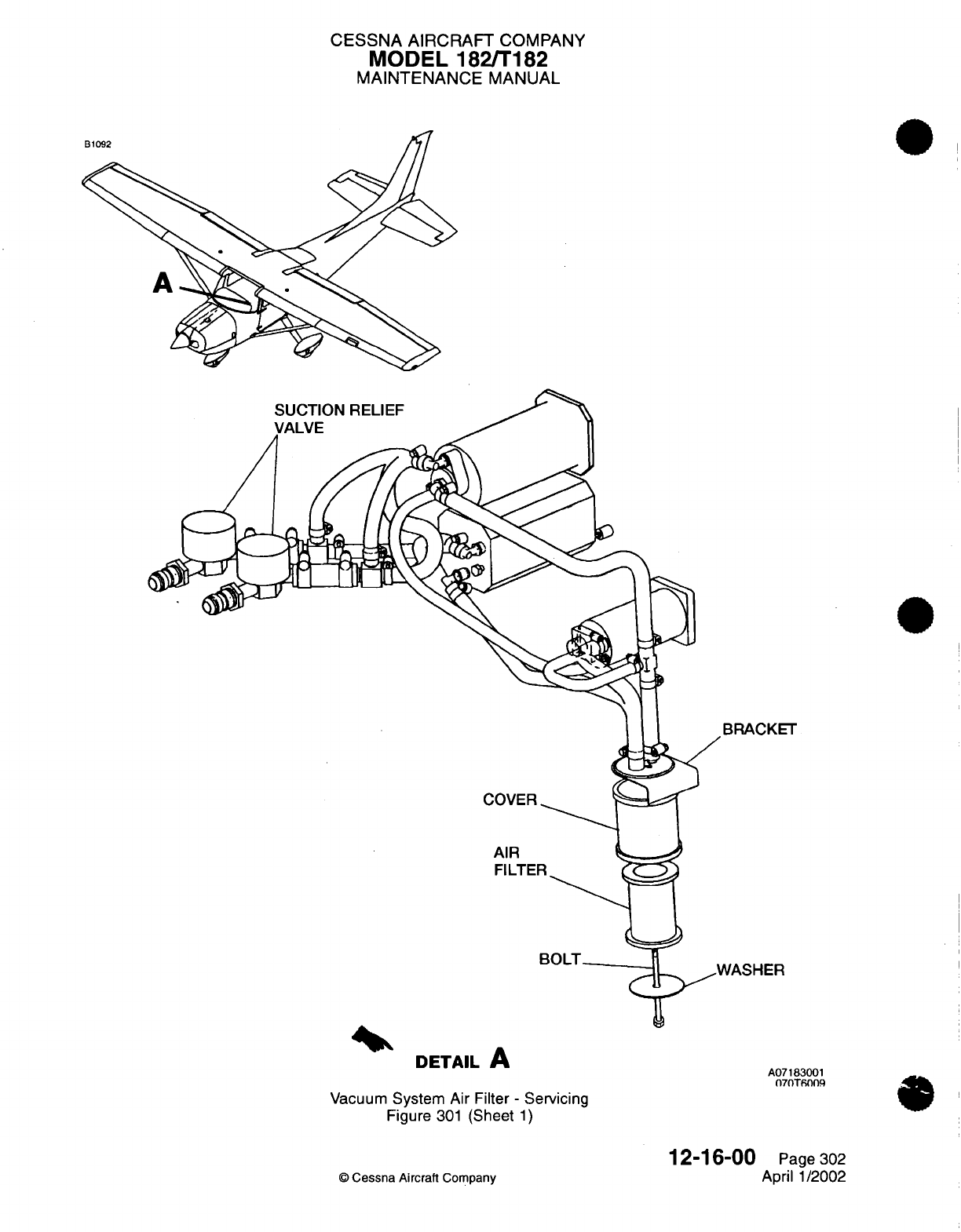
CESSNA
AIRCRAFT
COMPANY
MODEL 182/T182
MAINTENANCE
MANUAL
SUCTION
RELIEF
COVER
AIR
FILTER
BRACKET
NASHER
DETAIL
A
A07183001
07nTfins:
Vacuum
System
Air Filter
-
Servicing
Figure
301
(Sheet
1)
© Cessna
Aircraft
Company
12-16-00
Page
302
April
1/2002
CESSNA
AIRCRAFT
COMPANY
MODEL
182/T182
MAINTENANCE
MANUAL
BATTERY
-
SERVICING
1.
General
A.
This
procedure
provides instructions
for
adding water to
the
battery.
For
testing,
charging
and
maintenance
on
the
battery,
refer to
Chapter
24, Battery
-
Maintenance
Practices.
2.
Battery
Servicing
A.
The
battery
should
be
serviced
according
to
time
limits
set
forth
in
Chapter
5,
Inspection
Time
Limits.
B.
Battery
servicing
involves
adding
distilled
water
to
maintain
the
electrolyte
even with
the
horizontal
baffle plate
at
the bottom
of the
filler
holes,
checking
the
battery cable
connections,
and
neutralizing
and
cleaning
off
any spilled electrolyte or
corrosion.
Use
bicarbonate
of
soda
(baking soda)
and
water
to
neutralize
electrolyte or
corrosion.
Follow
with
a
thorough
flushing
with
a
wire
brush,
then coat
with petroleum
jelly
before
connecting.
The
battery
box
should also
be
checked
and
cleaned
if
any
corrosion
is
noted.
Distilled
water,
not
acid
or
"rejuvenators" should
be
used
to
maintain
electrolyte
level.
Inspect
the
battery
in
accordance
with
time
limits
spelled out
in
Chapter
5,
Inspection
Time
Limits.
12-17-00
Page
301
©
Cessna
Aircraft Company
April 1/2002
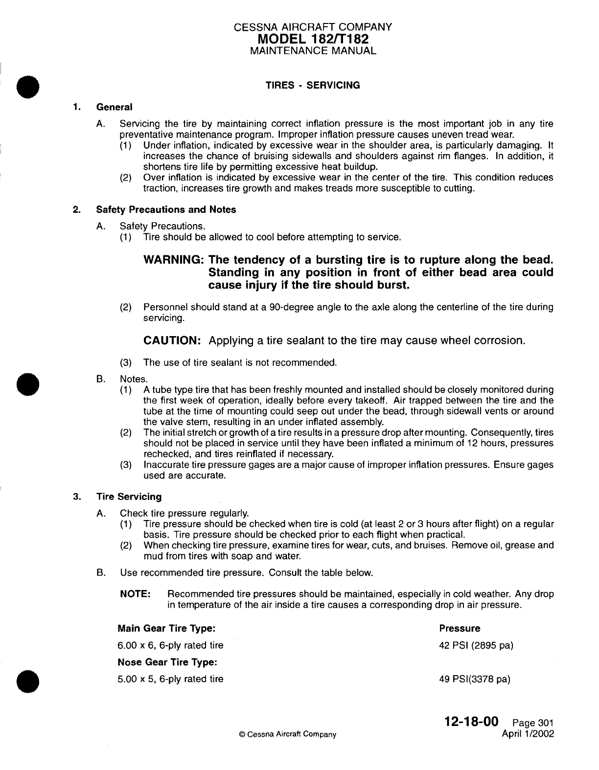
CESSNA
AIRCRAFT
COMPANY
MODEL
182/T182
MAINTENANCE
MANUAL
TIRES
-
SERVICING
1.
General
A.
Servicing
the tire by maintaining
correct
inflation
pressure
is
the
most
important
job
in
any
tire
preventative
maintenance
program.
Improper inflation pressure
causes
uneven
tread wear.
(1)
Under
inflation,
indicated
by
excessive
wear
in
the
shoulder
area,
is
particularly
damaging.
It
increases
the
chance
of
bruising
sidewalls
and
shoulders
against
rim
flanges.
In
addition,
it
shortens
tire
life
by
permitting
excessive
heat
buildup.
(2)
Over
inflation
is
indicated
by
excessive
wear
in
the
center
of
the
tire.
This
condition
reduces
traction,
increases
tire
growth
and
makes
treads
more
susceptible
to
cutting.
2.
Safety
Precautions
and
Notes
A.
Safety
Precautions.
(1)
Tire
should
be
allowed
to
cool before
attempting
to
service.
WARNING:
The
tendency
of
a
bursting
tire
is
to
rupture along the
bead.
Standing
in
any
position
in
front
of
either
bead
area
could
cause
injury if
the
tire
should
burst.
(2)
Personnel
should stand
at
a
90-degree angle
to
the
axle
along
the
centerline
of the tire
during
servicing.
CAUTION:
Applying
a
tire
sealant
to
the
tire
may
cause
wheel
corrosion.
(3)
The
use
of
tire
sealant
is
not
recommended.
B.
Notes.
(1)
A
tube type
tire that
has
been
freshly
mounted
and
installed should
be
closely
monitored during
the first week
of
operation,
ideally
before
every takeoff.
Air
trapped
between
the
tire
and
the
tube
at
the
time
of
mounting could seep
out
under
the
bead,
through sidewall vents
or around
the
valve
stem, resulting
in
an
under
inflated assembly.
(2)
The
initial
stretch
or
growth
of
a
tire
results
in a
pressure
drop
after
mounting.
Consequently, tires
should
not
be
placed
in
service
until
they
have
been
inflated
a
minimum
of
12
hours,
pressures
rechecked,
and tires reinflated
if
necessary.
(3)
Inaccurate tire
pressure
gages
are
a
major
cause
of
improper inflation
pressures.
Ensure
gages
used are
accurate.
3.
Tire
Servicing
A.
Check
tire
pressure
regularly.
(1)
Tire
pressure should
be
checked
when
tire
is
cold
(at
least
2
or
3
hours
after
flight)
on
a
regular
basis.
Tire
pressure should
be
checked
prior
to
each
flight
when practical.
(2)
When
checking
tire
pressure,
examine
tires for
wear,
cuts,
and bruises.
Remove
oil,
grease
and
mud
from
tires
with
soap
and
water.
B.
Use
recommended
tire
pressure. Consult
the
table
below.
NOTE:
Recommended
tire
pressures should
be
maintained,
especially
in
cold
weather.
Any
drop
in
temperature
of
the air
inside
a
tire
causes
a
corresponding
drop
in
air
pressure.
Main Gear
Tire
Type: Pressure
6.00
x 6,
6-ply
rated
tire
42
PSI
(2895
pa)
Nose
Gear
Tire
Type:
5.00
x 5,
6-ply
rated
tire
49
PSI(3378
pa)
12-18-00
Page 301
©
Cessna
Aircraft Company
April 1/2002

CESSNA AIRCRAFT
COMPANY
MODEL 182/T182
MAINTENANCE
MANUAL
4.
Cold Weather
Servicing
A.
Cold
Weather
Servicing.
(1)
Check
tires
for
excessive
deflation.
NOTE:
Tire
air
pressure
will
decrease
somewhat
as
the
temperature drops,
but
excessive
deflation
could
indicate
cold
weather
leakage
at
the air
valve.
Avoid
unnecessary
pressure
checks.
(2) If it
is
necessary
to
pressure
check
tires
in
cold
climates,
always
apply
heat
to
air
valves
and
surrounding
areas
before
unseating valves.
(3)
Continue
application
of heat
during
reinflation
to
ensure air
valve
seal
flexibility
when
valve
closes.
(4)
Do
not
allow
tires
to
stand
in
snow soaked
with
fuel,
or
on
fuel covered
ramp
areas.
(5) If
tires become
frozen
to parking
ramp,
use
hot
air
or
water
to
melt
ice
bond before
attempting
to
move
airplane.
12-18-00
Page 302
©
Cessna Aircraft
Company
April
1/2002
CESSNA
AIRCRAFT
COMPANY
MODEL
182/T182
MAINTENANCE
MANUAL
SCHEDULED
SERVICING
-
DESCRIPTION AND OPERATION
1.
General
A.
This
section
provides instructions
necessary
to
carry
out
scheduled
servicing
as
well
as
internal/external
cleaning.
It
also
includes
instructions
for
lubricating
specific
points identified
in
periodic
inspection and/or preventive
maintenance
programs.
This section does
not
include
lubrication procedures
required
for
the
accomplishment
of
maintenance
practices.
2.
Description
A.
This
section
is
subdivided
to
provide maintenance
personnel with charts,
text
and
illustrations
to
prevent
confusion.
Also
included
in
this
section
is
a
table
containing
a
list
of
lubricants.
(1)
The
subdivisions
are
separated
according
to
airplane
systems. This
aids
maintenance
personnel
in
locating
service
information.
12-20-0
©
Cessna
Aircraft
Company
10
Page
1
April
1/2002
CESSNA
AIRCRAFT
COMPANY
MODEL
182/T182
MAINTENANCE
MANUAL
LUBRICANTS
-
DESCRIPTION
AND OPERATION
1.
General
A.
This
section
is
designed
to
assist
the
operator
in
selecting recommended
lubricants.
For
best
results
and
continued trouble
free service,
use
clean
and
approved lubricants.
B.
For
a
list
of
recommended lubricants,
refer
to
Recommended Lubricants
Table.
2.
Lubrication
Service
Notes
A.
Lubricant
Application.
(1)
Cleanliness
is
essential
to
good
lubrication.
Lubricants
and
dispensing equipment
must
be
kept
clean.
Use
only
one
lubricant
in
a
grease
gun
or oil can.
(2)
Store
lubricants
in a
protected
area.
Containers
should
be
closed
at
all
times
when
not
in
use.
(3)
Wipe
grease
fittings
and
areas
to
be
lubricated
with
clean,
dry
cloths
before
lubricating.
(4)
When
lubricating
bearings
which
are
vented,
force grease
into
fitting
until
old
grease
is
extruded.
(5)
After any
lubrication,
clean
excess lubricant
from all
but
actual working
parts.
(6)
All
sealed
or
prepacked antifriction
bearings
are
lubricated
with
grease
by
the
manufacturer
and
require
no
further
lubrication.
(7)
Friction
bearings
of the
porous, sintered-
type
are
prelubricated.
An
occasional squirt
can
oiling
of
such
bearings
with
general
purpose oil
(MIL-L-7870)
extends
its
service
life.
(8)
Lubricate
unsealed pulley bearings,
rod
ends,
pivot
end
hinge
points
and
any other friction
point
obviously
needing lubrication,
with
general
purpose
oil
(MIL-L-
7870).
(9)
Paraffin
wax
rubbed
on
seat
rails
will
ease
sliding
the
seats
fore
and aft.
(10)
Do
not
lubricate roller chains
or
cables
except
under
sea coast conditions.
Wipe with
a
clean,
dry
cloth.
(11)
All
piano
hinges
may
be
lubricated
using
(PG)
powered
graphite
(SS-G-659)
when
assembly
is
installed.
(12)
Lubricate
door
latching
mechanism
with
MIL-G-81322 general
purpose
grease,
applied sparingly
to
friction points,
if
binding
occurs.
No
lubrication
is
recommended
on
the
rotary
clutch.
3.
Definition
of
"As
Needed"
A. In
the following
sections,
time
requirements for lubrication
are
presented
in
one of
two
formats.
When
specific
time
intervals
for
lubrication
exist, those
intervals
are
defined
in
Chapter
5,
Inspection
Time
Limits. When
no time
limit has
been
established,
lubrication
is
on an
"as
needed"
basis.
This
leaves
much
of
the
decision
making
process
in
the
hands of
the airframe
and
powerplant
mechanic,
who
has
been
trained
to
make
these types
of
decisions.
B. In
an
effort to
standardize
the
decision
making
process,
the
following
guidelines
may
be
considered
to
determine
if
a
component
needs
lubrication.
Any one
of
the
following conditions
would
indicate
a
need
for lubrication,
and
may
additionally
indicate
the
need
for inspection:
(1) A
visual
inspection
which
indicates
dirt
or
wear
residue
near
the movement
contact
area.
(2)
An
audible inspection
which
indicates
squeaks,
grinding
or
other
abnormal
sounds.
(3)
A
tactile
(touch
and
feel)
inspection
which
indicates
jerky
or restricted
movement
throughout
portions
of the
travel
range.
4.
Recommended
Lubricants
Table
NOTE:
Equivalent
substitutes
may
be
used
for
the following
items:
12-21-00
Page
1
©
Cessna
Aircraft
Company
Jan
2/2006

CESSNA
AIRCRAFT
COMPANY
MODEL
182/T182
MAINTENANCE
MANUAL
Table
1.
Recommended
Lubricants
PROCURE-
MENT
SPECI-
FICATION
LUBRICANT
DESCRIPTION
MIL-G-81322
Grease,
wide
temperature
range.
Mobil
grease
28
Mobil
Oil
Corp.
150
E.
42nd
Street
New
York,
NY
10017
Royco
22C
Royal
Lubricants
Co.,
Inc.
River
Road
East
Hanover,
NJ
07936
Aeroshell
Shell
Oil
Co.
grease
22
One Shell
Plaza
Houston,
TX 77001
MIL-G-23827
Grease,
aircraft
and
instrument,
gear
and
actuator
screw.
Southwest
Grease
16215
Aeroshell
grease
7
Southwest
Petro- Chem,
Inc.
Division
-
Witco
1400
S.
Harrison
Olathe,
KS
66061
Shell
Oil
Co.
Royco
27A
Royal
Lubricants
Co.,
Inc.
Amoco
Oil
Co.
200
East
Randolph
Dr.
Chicago,
IL
60601
Burmah-Castrol,
Inc.
Bray
Products
Div.
16815
Von
Karman Ave.
Irving,
CA
92714
Burmah-Castrol,
Inc.
Southwest Petro-Chem,lnc.
Brumah-Castrol,
Inc.
Royco
363
Royal
Lubricants
Co.,
Inc.
Petrotect
7870A
Windsor
lube
L-1018
Octoil
70
Penreco
106
South
Main
Street
Butler,
PA
16001
Anderson
Oil
&
Chemical
Co.,
Inc.
Portland,
CT
06480
Octagon
Process, Inc.
596
River
Road
Edgewater,
NJ
07020
12-21-01
©
Cessna Aircraft
Company
O
Page
2
Jan
2/2006
SYMBOL
GR
PRODUCT
PART
NUMBER
SUPPLIER
GH
Supermil
grease
No.
A72832
Braycote
6275
Castrolease
A1
TG-11900
low
temp
grease
EP
Brayco
885
OG
MIL-L-7870
Oil,
general
purpose

CESSNA
AIRCRAFT
COMPANY
MODEL
182/T182
MAINTENANCE
MANUAL
Table
1.
Recommended Lubricants
(continued)
PROCURE-
MENT
SPECI-
FICATION
VV-P-236
SS-G-659
MIL-G-21164
LUBRICANT
DESCRIPTION
Petrolatum
technical
Powdered
Graphite
High and
Low
Temperature
Grease
PRODUCT
PART
NUMBER
Everlube
211-G Moly
Grease
SUPPLIER
Available
Commercially
Available
Commercially
E/M
Corporation
Box
2200
Highway
52
N.W.
West Lafayette,
IN
47906
Number
10
weight,
nondetergent
oil
Light
Oil
Grease,
general
purpose
Royco
64
Royal
Lubricants
Co.,
Inc.
Available
Commercially
U000992
©
Cessna Aircraft
Company
Available
Commercially
Cessna Aircraft
Co.
1
Cessna
Blvd.
Wichita,
Ks
67277-7704
12-21-00
Page
3
Jan 2/2006
SYMBOL
PL
PG
GL
GP
NONE
VV-L-800
OL
I
CESSNA
AIRCRAFT
COMPANY
MODEL
182/T182
MAINTENANCE
MANUAL
BATTERY
TERMINALS
-
SERVICING
1.
General
A.
It
is
recommended
the
airplane
be
secured
in
an
area
free
of
contamination
from
sand,
dust
or
other
environmental conditions
that
may
contribute
to
improper lubrication
practices.
2.
Battery
Terminal
Lubrication
A.
Battery
terminals
should
be
lubricated
when
cables
are
installed
to
terminals.
B.
Refer
to
Figure
301
for
lubrication
requirements
of
the battery
terminals.
12-21-01
Page
301
©
Cessna Aircraft Company
April
1/2002
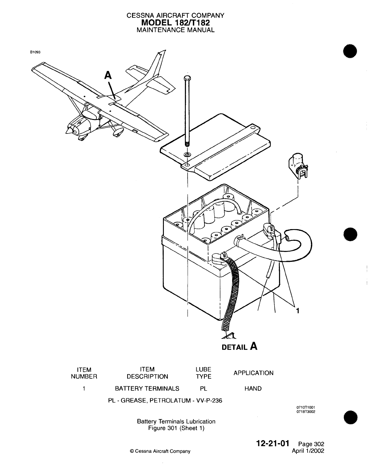
CESSNA
AIRCRAFT
COMPANY
MODEL
182/T182
MAINTENANCE
MANUAL
LANDING
GEAR
AND PARKING
BRAKE
-
SERVICING
1.
General
A.
It
is
recommended
that
the
airplane
be
secured
in
an
area
free
of
contamination
from sand,
dust
or
other
environmental
conditions
that
may
contribute
to
improper lubrication
practices.
2.
Wheel
Bearing
Lubrication
A.
Wheel bearings should
be
lubricated
using
time
intervals
set
forth
in
Chapter
5,
Inspection
Time
Limits.
WARNING:
When
cleaning
wheel
bearings,
use
low-pressure
shop air
to
dry
bearings.
Do
not
spin
bearing
cones
with
compressed
air.
Dry
bearings
without lubrication
may
explode
at
high
rpm.
B.
Refer
to
Figure
301
for lubrication requirements
of
the
wheel
bearings.
3.
Nose
Gear
Torque
Link Lubrication
A.
Nose
gear torque
links
should
be
lubricated using
time
intervals
set forth
in
Chapter
5,
Inspection
Time
Limits.
B.
Refer
to
Figure
301
for lubrication requirements
of the
nose gear
torque
links.
4.
Shimmy
Dampener
Pivots
Lubrication
A.
Shimmy
dampener
pivots
should
be
lubricated
on
an
"as
needed"
basis
and
when
assembled
or
installed.
B.
Refer
to
Figure
301
for
lubrication requirements
of
the
shimmy
dampener
pivots.
5.
Steering
System
Needle
Bearing
Lubrication
A.
Steering
system
needle
bearings
should
be
lubricated
on an
"as
needed"
basis and
when
assembled
or
installed.
B.
Refer
to
Figure
301
for
lubrication requirements
of
the steering system
needle
bearings.
6.
Nose Gear
Steering
Pushrods
Lubrication
A.
Nose
gear steering pushrods should
be
lubricated
using
time
intervals
set
forth
in
Chapter
5,
Inspection
Time
Limits.
B.
Refer
to
Figure
301
for
lubrication requirements
of the
nose gear
steering
pushrods.
7.
Parking
Brake Handle
Shaft
Lubrication
A.
The parking brake handle
shaft should
be
lubricated
on
an
"as
needed"
basis and
when
assembled
or
installed.
B.
Refer
to
Figure
302
for lubrication requirements
of the
parking brake handle
shaft.
12-21-02
Page
301
©
Cessna
Aircraft
Company
April
1/2002
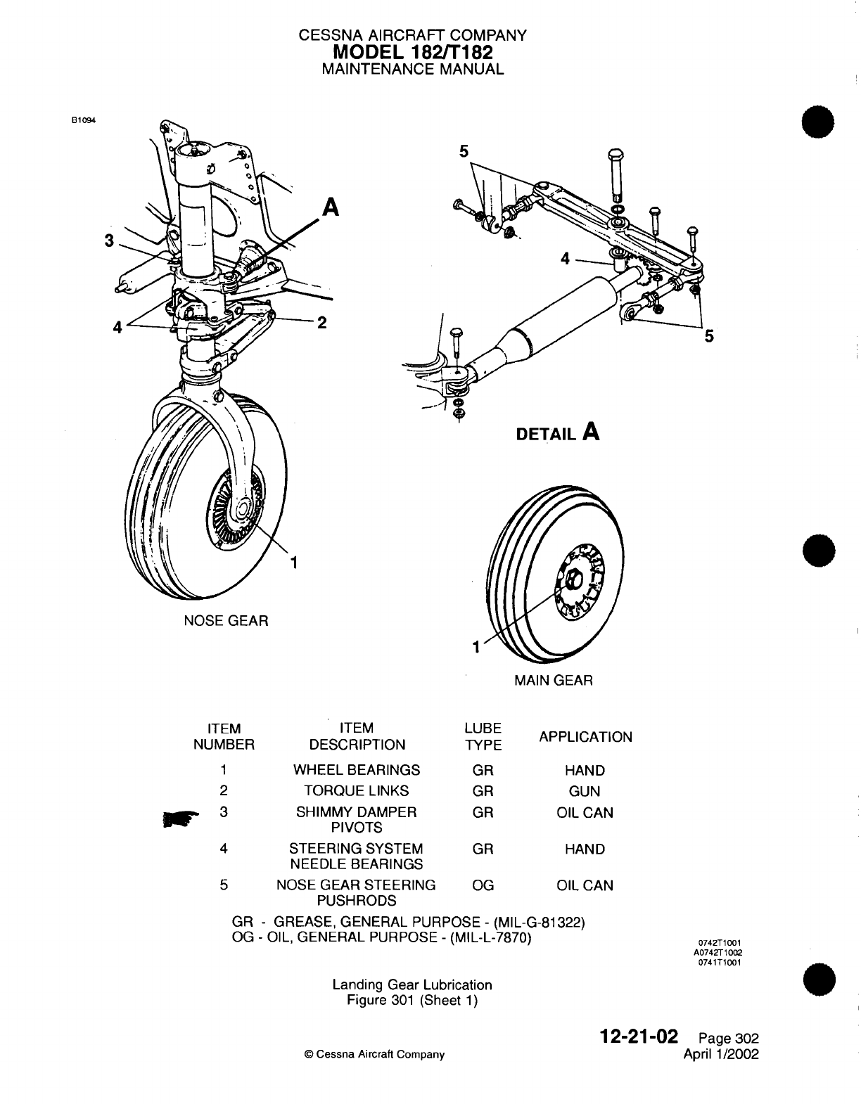
CESSNA
AIRCRAFT
COMPANY
MODEL 182/T182
MAINTENANCE
MANUAL
B1094
3
5
DETAIL
A
NOSE
GEAR
1
MAIN
GEAR
ITEM
DESCRIPTION
LUBE
TYPE
APPLICATION
1
WHEEL BEARINGS
2
TORQUE
LINKS
3
SHIMMY
DAMPER
PIVOTS
4
STEERING
SYSTEM
NEEDLE
BEARINGS
5
NOSE
GEAR STEERING
PUSHRODS
GR
GR
GR
GR
OG
HAND
GUN
OIL
CAN
HAND
OIL
CAN
GR
-
GREASE,
GENERAL
PURPOSE
-
(MIL-G-81322)
OG
-
OIL,
GENERAL
PURPOSE
-
(MIL-L-7870)
Landing Gear
Lubrication
Figure
301
(Sheet
1)
©
Cessna Aircraft
Company
12-21-02
Page
302
April
1/2002
ITEM
NUMBER
0742T1001
A0742T1002
0741T1001
r
L
l
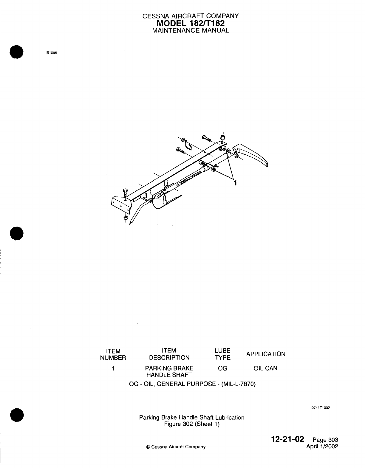
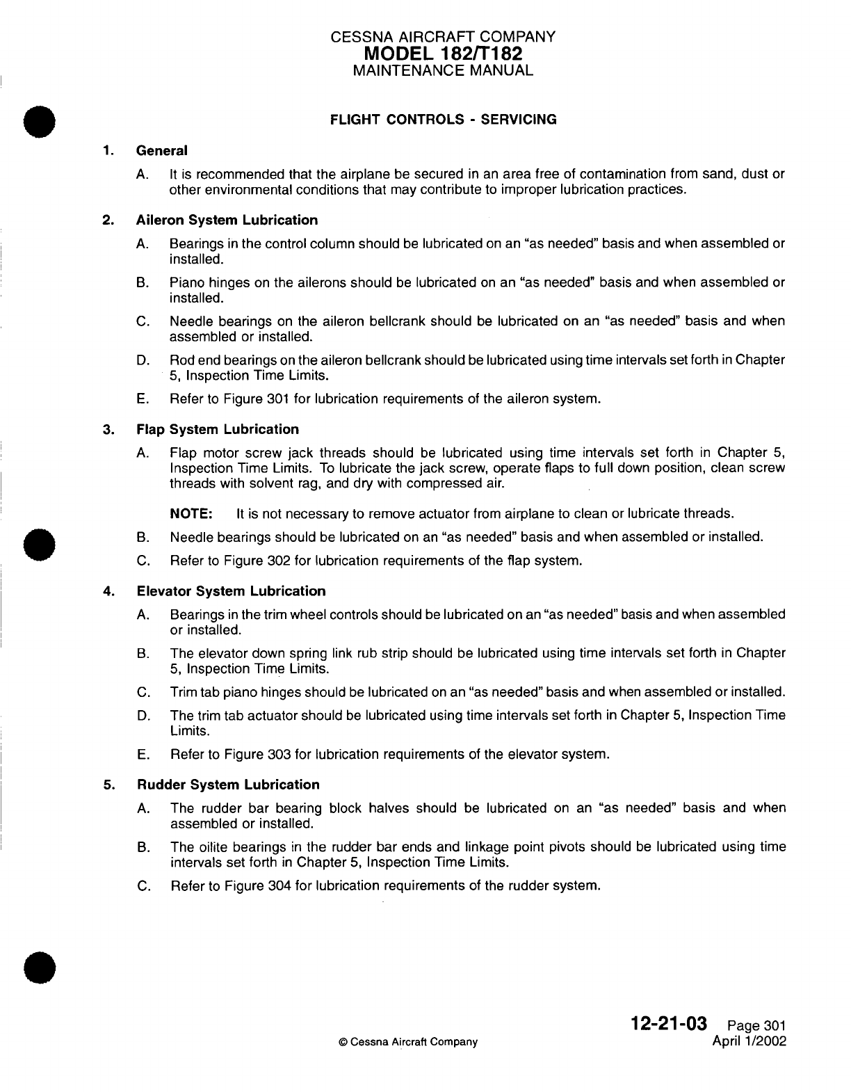
CESSNA
AIRCRAFT
COMPANY
MODEL
182/T182
MAINTENANCE
MANUAL
FLIGHT
CONTROLS
-
SERVICING
1.
General
A. It
is
recommended
that
the
airplane
be
secured
in
an
area
free
of
contamination
from
sand,
dust
or
other
environmental
conditions
that
may
contribute
to
improper
lubrication
practices.
2.
Aileron
System
Lubrication
A.
Bearings
in
the
control
column
should
be
lubricated
on
an
"as
needed"
basis
and
when
assembled
or
installed.
B.
Piano
hinges
on
the
ailerons should
be
lubricated
on
an
"as
needed"
basis
and
when
assembled
or
installed.
C.
Needle
bearings
on
the
aileron
bellcrank should
be
lubricated
on
an
"as
needed"
basis
and when
assembled
or
installed.
D.
Rod
end
bearings
on
the aileron
bellcrank
should
be
lubricated
using
time
intervals
set
forth
in
Chapter
5,
Inspection
Time
Limits.
E.
Refer
to
Figure
301
for
lubrication
requirements
of
the
aileron system.
3.
Flap
System
Lubrication
A.
Flap
motor
screw
jack
threads should
be
lubricated
using time
intervals set
forth
in
Chapter
5,
Inspection
Time Limits.
To
lubricate
the
jack
screw,
operate flaps
to
full
down
position, clean
screw
threads
with
solvent
rag,
and
dry
with
compressed
air.
NOTE:
It
is not
necessary
to
remove
actuator
from
airplane
to
clean
or
lubricate
threads.
B.
Needle
bearings
should
be
lubricated
on
an
"as
needed"
basis
and
when
assembled
or
installed.
C.
Refer
to
Figure
302
for
lubrication
requirements
of
the
flap
system.
4.
Elevator
System
Lubrication
A.
Bearings
in
the
trim
wheel
controls
should
be
lubricated
on
an
"as
needed"
basis
and
when
assembled
or
installed.
B.
The
elevator
down
spring
link
rub
strip should
be
lubricated
using
time intervals
set forth
in
Chapter
5,
Inspection
Time
Limits.
C.
Trim
tab
piano
hinges
should
be
lubricated
on
an
"as
needed"
basis
and
when
assembled
or
installed.
D.
The
trim
tab
actuator
should
be
lubricated
using time
intervals
set
forth
in
Chapter
5,
Inspection
Time
Limits.
E.
Refer
to
Figure
303
for
lubrication
requirements
of
the
elevator
system.
5.
Rudder
System
Lubrication
A.
The
rudder bar bearing
block halves
should
be
lubricated
on an
"as
needed"
basis
and
when
assembled
or
installed.
B.
The
oilite
bearings
in
the
rudder bar ends and
linkage point pivots should
be
lubricated
using time
intervals
set
forth
in
Chapter
5,
Inspection
Time Limits.
C.
Refer
to
Figure
304
for
lubrication
requirements
of
the
rudder system.
12-21-03
Page
301
©
Cessna
Aircraft
Company
April
1/2002
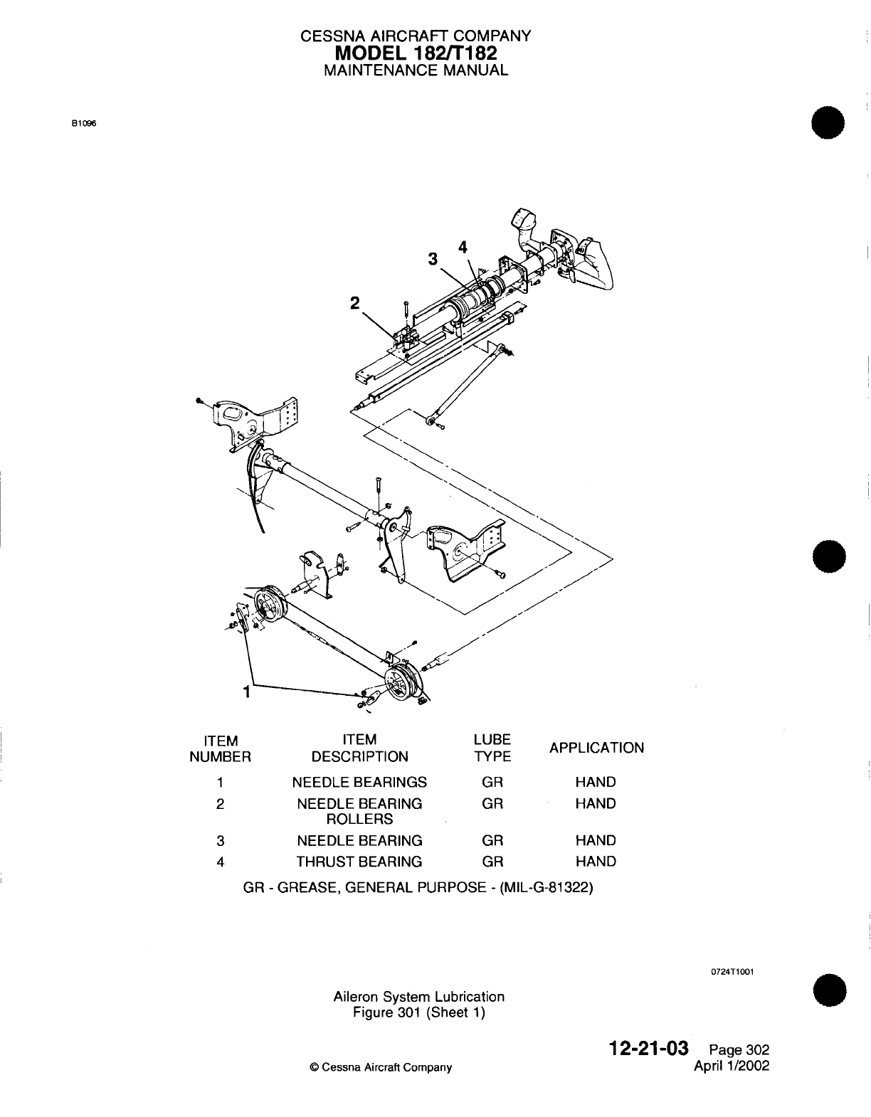
CESSNA AIRCRAFT
COMPANY
MODEL
182/T182
MAINTENANCE
MANUAL
B1096
ITEM
DESCRIPTION
NEEDLE
BEARINGS
NEEDLE
BEARING
ROLLERS
NEEDLE BEARING
THRUST
BEARING
LUBE
TYPE
GR
GR
GR
GR
APPLICATION
HAND
HAND
HAND
HAND
GR
-
GREASE, GENERAL PURPOSE
-
(MIL-G-81322)
0724T1001
Aileron
System
Lubrication
Figure
301
(Sheet
1)
12-21-03
©
Cessna
Aircraft
Company
ITEM
NUMBER
1
2
3
4
Page
302
April
1/2002

CESSNA AIRCRAFT
COMPANY
MODEL
182/T182
MAINTENANCE
MANUAL
B1097
2
AILERON
BELLCRANK
1
AILERON
HINGES
EM ITEM
MBER
DESCRIPTION
1
AILERON PIANO
HINGES
2
BELLCRANK
NEEDLE
BEARINGS
3
ROD
END
BEARINGS
LUBE
TYPE
PG
GR
OG
APPLICATION
SYRINGE
HAND
OIL
CAN
PG
-
POWDERED GRAPHITE
(SS-G-659)
GR
-
GREASE, GENERAL PURPOSE
-
(MIL-G-81322)
OG
-
OIL,
GENERAL PURPOSE
-
(MIL-L-7870)
0724T1002
0724T1003
Aileron
System
Lubrication
Figure
301
(Sheet
2)
©
Cessna
Aircraft Company
12-21-03
Page 303
April 1/2002
IT
NUW
3
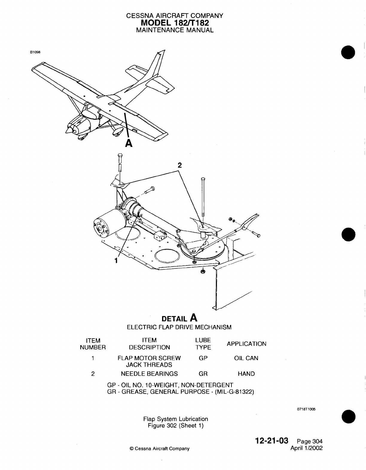
CESSNA AIRCRAFT
COMPANY
MODEL
182/T182
MAINTENANCE
MANUAL
DETAIL
A
ELECTRIC
FLAP DRIVE
MECHANISM
'EM
ITEM
ABER
DESCRIPTION
1
FLAP
MOTOR
SCREW
JACK
THREADS
2
NEEDLE
BEARINGS
LUBE
TYPE
GP
GR
APPLICATION
OIL
CAN
HAND
GP
-
OIL
NO.
1
-WEIGHT,
NON-DETERGENT
GR
-
GREASE, GENERAL
PURPOSE
-
(MIL-G-81322)
0718T1005
Flap System
Lubrication
Figure 302 (Sheet
1)
12-21-03
©
Cessna
Aircraft
Company
IT
NUN
Page
304
April
1/2002
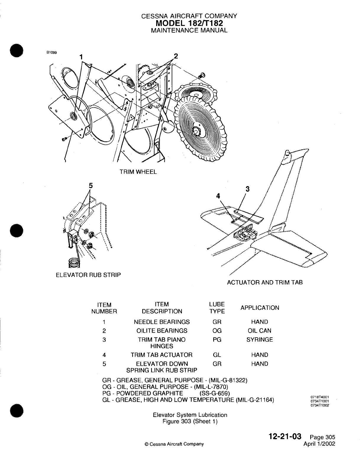
CESSNA
AIRCRAFT
COMPANY
MODEL
182/T182
MAINTENANCE
MANUAL
RB10n
TRIM
WHEEL
5
4
II
I
I
.I
ELEVATOR
RUB
STRIP
ACTUATOR
AND
TRIM TAB
ITEM
DESCRIPTION
NEEDLE
BEARINGS
OILITE BEARINGS
TRIM
TAB
PIANO
HINGES
TRIM
TAB ACTUATOR
ELEVATOR
DOWN
SPRING
LINK
RUB
STRIP
LUBE
TYPE
GR
OG
PG
GL
GR
APPLICATION
HAND
OIL
CAN
SYRINGE
HAND
HAND
GR
-
GREASE, GENERAL PURPOSE
-
(MIL-G-81322)
OG
-
OIL,
GENERAL
PURPOSE
-
(MIL-L-7870)
PG
-
POWDERED
GRAPHITE (SS-G-659)
GL
-
GREASE,
HIGH
AND
LOW TEMPERATURE (MIL-G-21164)
Elevator
System
Lubrication
Figure
303
(Sheet
1)
©
Cessna Aircraft
Company
12-21-03
Page
305
April 1/2002
3
ITEM
NUMBER
1
2
3
4
5
0718T4001
0734T1001
0734T1002
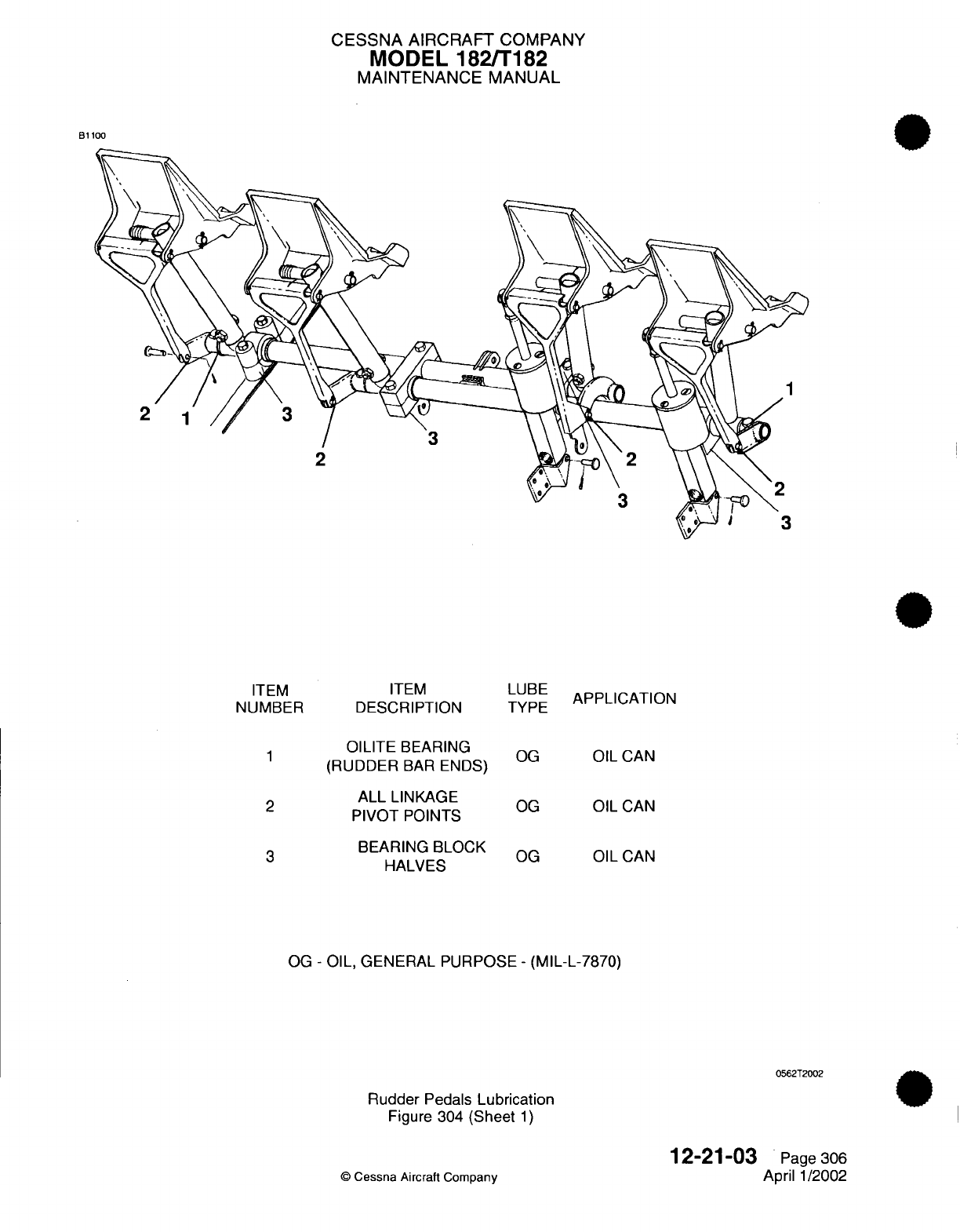
CESSNA AIRCRAFT
COMPANY
MODEL
182/T182
MAINTENANCE
MANUAL
B1100
ITEM
ITEM
NUMBER DESCRIPTION
~1
OILITE
BEARING
(RUDDER
BAR
ENDS)
ALL
LINKAGE
PIVOT POINTS
BEARING
BLOCK
HALVES
LUBE
TYPE
OG
OG
OG
APPLICATION
OIL
CAN
OIL
CAN
OIL
CAN
OG
-
OIL, GENERAL PURPOSE
-
(MIL-L-7870)
0562T2002
Rudder
Pedals
Lubrication
Figure 304
(Sheet
1)
©
Cessna
Aircraft Company
12-21-03
Page
306
April
1/2002
CESSNA
AIRCRAFT
COMPANY
MODEL
182/T182
MAINTENANCE
MANUAL
ENGINE
CONTROL CABLES
-
SERVICING
1.
General
A. It
is
recommended
that
the
airplane
be
secured
in
an
area
free
of
contamination
from
sand, dust
or
other environmental
conditions
that
may
contribute
to
improper lubrication
practices.
2.
Engine
Control
Cables
Lubrication
A.
All
housed,
pull-type,
push-pull
or
vernier controls
should
have
each
outer
housing
lightly lubricated
internally
with
VV-L-800
General Purpose
Lube
Oil.
12-21-04
Page
301
©
Cessna
Aircraft
Company
April 1/2002
CESSNA
AIRCRAFT
COMPANY
MODEL
182/T182
MAINTENANCE
MANUAL
HEATING
AND VENTILATION
CONTROL CABLES
-
SERVICING
1.
General
A. It is
recommended that the
airplane
be
secured
in
an
area
free
of
contamination
from
sand, dust
or
other
environmental
conditions
that
may
contribute
to
improper lubrication practices.
2.
Heating
And
Ventilation Control
Cables
Lubrication
A.
All
housed,
pull-type,
push-pull
or
vernier
controls
should
have
each
outer
housing
lightly lubricated
internally with VV-L-800 General Purpose
Lube
Oil.
12-21-05
Page
301
©
Cessna Aircraft
Company
April
1/2002
CESSNA
AIRCRAFT
COMPANY
MODEL
182/T182
MAINTENANCE
MANUAL
AIRPLANE
EXTERIOR
-
CLEANING/PAINTING
1.
General
A.
The
airplane
must
be
cleaned
frequently
to
keep
the
external
surface
in
good
condition
and
to
prevent
corrosion. The
painted
area
of
the
airplane
must
be
polished
at
intervals
to remove
chalking
paint
and
to
make sure
that
it
has
a
smooth,
glossy
finish.
B.
Use
water
and
detergent
when you
clean
the
external
surface
of
the
airplane.
2.
Precautions
A.
Obey
all
manufacturer instructions, warnings,
and
cautions
about
all
cleaning
agents
and
solvent
compounds.
B.
Do
not
use
silicone-based
wax
to
polish
the
external
surface
of
the
airplane.
Silicone-based
wax,
especially
if
buffed to
a
high
shine,
can
help
to cause
the
buildup
of
P-static.
C.
Do
not
park or keep
the
airplane
in
an
area where
it
can
come
into
direct
contact
with
fluid
or
vapors
from
methanol,
denatured alcohol,
gasoline,
benzene,
xylene, methyl-propyl ketone, acetone,
carbon
tetrachloride,
lacquer thinners,
commercial
or
household
window
cleaners,
paint
strippers, or
other
types
of
solvents.
D.
Do
not
leave
sun
visors
against
the
windshield
when not
in
use.
The
reflected
heat
from
these
items
increases
the
temperature
on
the
windshield.
If
solar
screens
are
installed
on
the
inside
of
the
airplane,
make sure
that
they
are
the
silver,
reflective type.
E.
Do
not use
a
power
drill
motor or
other
powered device
to
clean,
polish,
or
apply
wax
to
surfaces.
3.
Preventive
Maintenance
A.
Keep
all
surfaces
of
the windshield
and
the
windows
clean.
B. If
necessary,
apply
wax
to
acrylic surfaces.
C.
Put
a
cover
over
all
surfaces
while
the
airplane
is
painted, the
engine
is
cleaned,
or
other procedure
is
done
that uses any
type
of
solvent or
chemical.
Table
701
gives
approved
protective
coatings
to
prevent
solvent
damage.
Table 701.
Approved
Protective
Coatings
NUMBER
MIL-C-6799,
Type
1,
Class
II
Masking
Paper
Poly-Spotstick
WPL-3
SXN
MANUFACTURER
Commercially
Available
Champion
Intl.
Corp.
Forest
Product
Division
7785 Bay
Meadows
Way
Jacksonville,
FL
32256
Champion
Intl.
Corp.
Mask Off
Company
345
Marie
Avenue
Monrovia,
CA
USE
Gives
surfaces
protection
from
solvents.
Gives
surfaces
protection
from
solvents.
Gives
surfaces
protection
from
solvents.
Gives
surfaces
protection
from
solvents.
12-22-00
©
Cessna Aircraft
Company
NAME
Spray
Protex
40
Page
701
Mar
1/2005
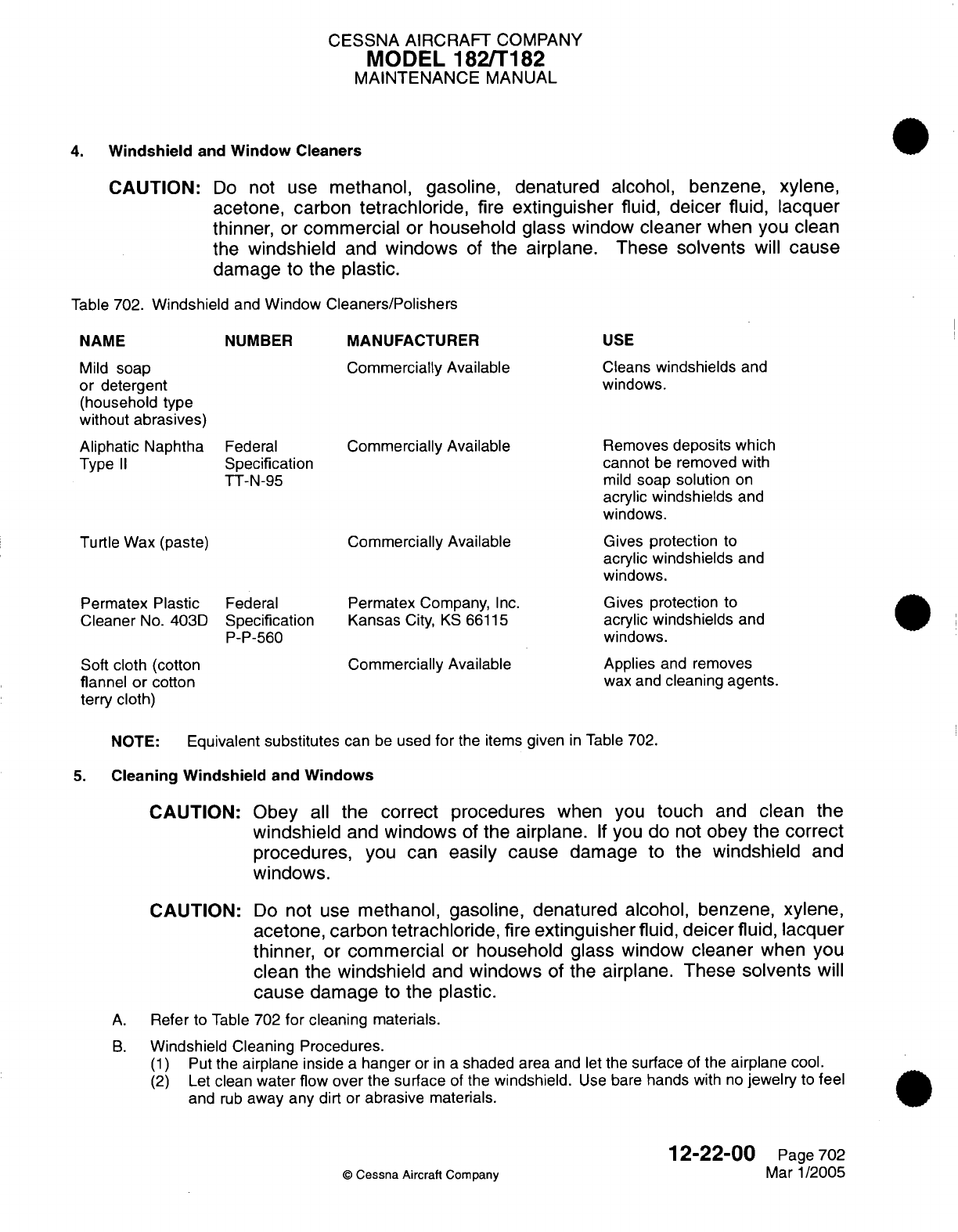
CESSNA
AIRCRAFT
COMPANY
MODEL 182/T182
MAINTENANCE
MANUAL
4.
Windshield
and
Window
Cleaners
CAUTION:
Do
not use
methanol,
gasoline,
denatured
alcohol,
benzene,
xylene,
acetone, carbon
tetrachloride,
fire
extinguisher
fluid,
deicer fluid,
lacquer
thinner,
or
commercial
or
household
glass
window
cleaner
when
you
clean
the
windshield
and
windows
of
the airplane.
These solvents
will
cause
damage
to
the
plastic.
Table
702.
Windshield
and
Window
Cleaners/Polishers
NAME
Mild
soap
or
detergent
(household
type
without
abrasives)
Aliphatic
Naphtha
Type
II
NUMBER
Federal
Specification
TT-N-95
Turtle Wax (paste)
MANUFACTURER
Commercially Available
Commercially
Available
Commercially Available
USE
Cleans
windshields
and
windows.
Removes
deposits which
cannot
be
removed
with
mild
soap solution
on
acrylic
windshields
and
windows.
Gives
protection
to
acrylic
windshields
and
windows.
Permatex
Plastic
Cleaner
No.
403D
Federal
Specification
P-P-560
Soft
cloth
(cotton
flannel
or
cotton
terry
cloth)
Permatex
Company,
Inc.
Kansas
City,
KS
66115
Commercially Available
Gives
protection
to
acrylic
windshields
and
windows.
Applies
and
removes
wax
and
cleaning
agents.
NOTE:
Equivalent
substitutes
can
be
used
for
the items
given
in
Table
702.
5.
Cleaning
Windshield
and
Windows
CAUTION:
CAUTION:
Obey
all
the
correct procedures
when
you
touch
and
clean
the
windshield
and
windows
of
the airplane.
If
you do not
obey
the
correct
procedures, you
can
easily cause
damage to
the
windshield
and
windows.
Do
not
use
methanol,
gasoline,
denatured
alcohol,
benzene,
xylene,
acetone, carbon
tetrachloride,
fire
extinguisher
fluid,
deicer
fluid, lacquer
thinner,
or
commercial
or
household glass
window
cleaner
when
you
clean
the
windshield
and
windows
of
the airplane.
These
solvents
will
cause
damage
to
the
plastic.
A.
Refer
to
Table
702
for
cleaning
materials.
B.
Windshield
Cleaning
Procedures.
(1)
Put
the
airplane
inside
a
hanger
or
in
a
shaded
area
and
let
the
surface
of the
airplane
cool.
(2)
Let
clean
water
flow
over
the
surface
of
the
windshield.
Use
bare
hands
with
no
jewelry
to
feel
and
rub
away
any dirt
or
abrasive
materials.
12-22-00
Page
702
©
Cessna
Aircraft Company
Mar
1/2005
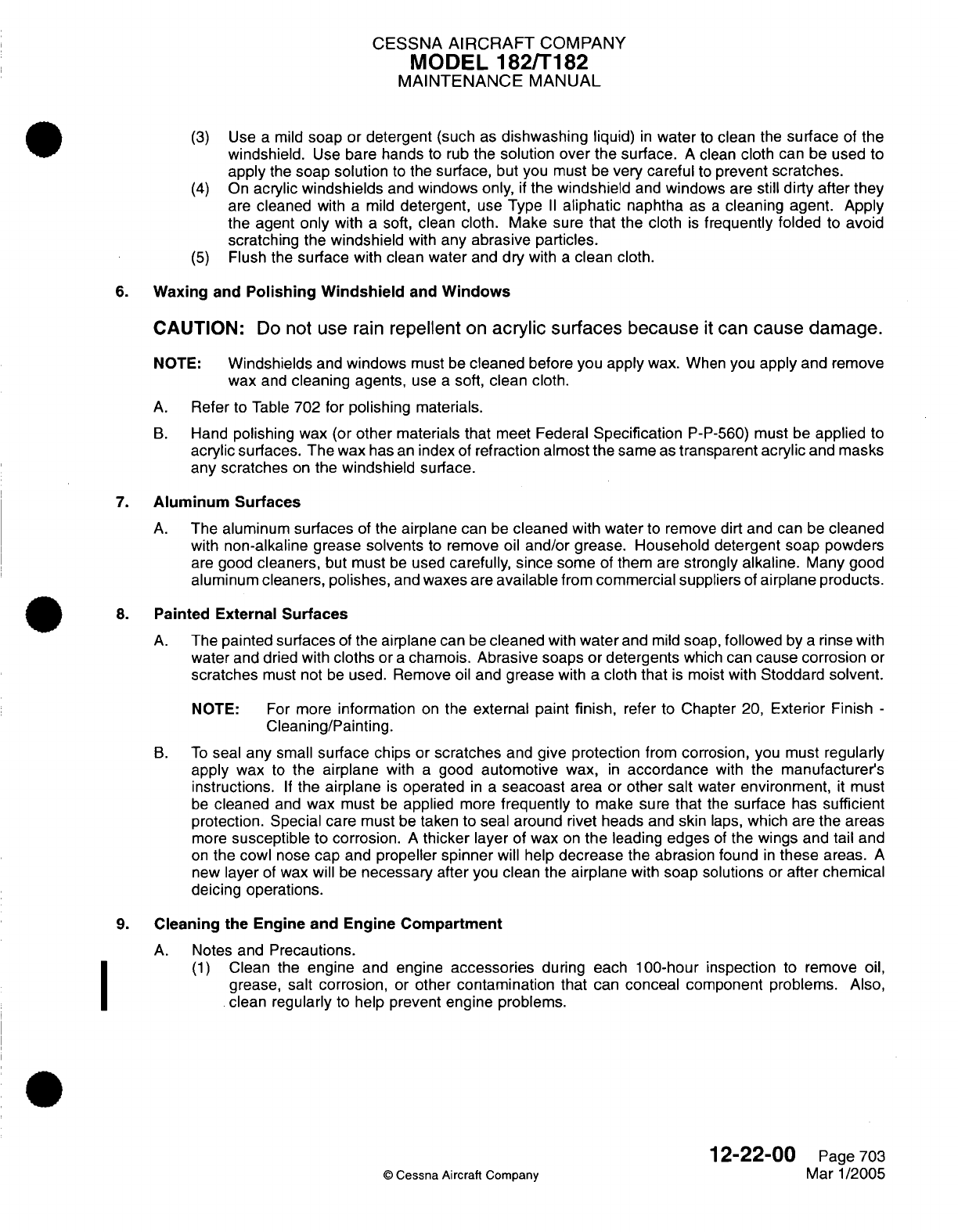
CESSNA
AIRCRAFT
COMPANY
MODEL
182/T182
MAINTENANCE
MANUAL
(3)
Use
a
mild
soap
or
detergent
(such
as
dishwashing
liquid)
in
water
to
clean
the
surface
of the
windshield.
Use
bare
hands
to rub
the
solution over
the surface.
A
clean
cloth
can
be
used
to
apply
the
soap solution
to
the
surface,
but
you
must
be
very careful
to
prevent
scratches.
(4)
On
acrylic
windshields
and
windows
only,
if
the
windshield
and
windows
are still
dirty
after they
are
cleaned
with
a
mild
detergent,
use
Type
II
aliphatic
naphtha
as
a
cleaning
agent. Apply
the
agent
only
with
a
soft, clean
cloth. Make
sure
that the
cloth
is
frequently folded
to
avoid
scratching
the
windshield
with any
abrasive particles.
(5)
Flush
the
surface
with clean
water
and
dry
with
a
clean cloth.
6.
Waxing
and
Polishing Windshield
and
Windows
CAUTION:
Do
not use
rain
repellent
on
acrylic
surfaces
because
it
can
cause
damage.
NOTE:
Windshields
and
windows
must
be
cleaned
before
you apply
wax.
When
you
apply
and
remove
wax
and
cleaning
agents,
use
a
soft,
clean cloth.
A.
Refer
to
Table
702
for polishing
materials.
B.
Hand
polishing
wax
(or
other
materials that
meet
Federal
Specification
P-P-560)
must
be
applied
to
acrylic surfaces.
The
wax
has
an
index of
refraction
almost
the same
as
transparent
acrylic
and
masks
any
scratches
on
the
windshield
surface.
7.
Aluminum
Surfaces
A.
The aluminum
surfaces
of the
airplane
can
be
cleaned
with
water
to remove
dirt
and
can
be
cleaned
with
non-alkaline
grease
solvents
to
remove oil
and/or grease. Household detergent
soap powders
are
good
cleaners,
but
must
be
used
carefully,
since
some
of
them are
strongly
alkaline.
Many
good
aluminum
cleaners, polishes,
and
waxes
are
available
from
commercial
suppliers
of
airplane products.
8.
Painted
External Surfaces
A.
The
painted
surfaces
of
the
airplane
can
be
cleaned
with
water
and
mild
soap,
followed
by
a
rinse with
water
and
dried with
cloths
or
a
chamois.
Abrasive
soaps
or
detergents
which
can
cause corrosion
or
scratches
must
not
be
used. Remove
oil
and
grease
with
a
cloth
that
is
moist
with
Stoddard
solvent.
NOTE:
For
more
information
on
the
external
paint
finish,
refer
to
Chapter
20,
Exterior
Finish
-
Cleaning/Painting.
B.
To
seal
any
small
surface chips
or
scratches
and
give protection
from
corrosion,
you
must
regularly
apply
wax
to
the airplane
with
a
good
automotive
wax,
in
accordance
with
the
manufacturer's
instructions.
If
the
airplane
is
operated
in a
seacoast
area
or
other
salt
water
environment,
it
must
be
cleaned
and
wax
must
be
applied
more
frequently
to make
sure
that
the
surface
has
sufficient
protection. Special
care must
be
taken
to
seal
around
rivet
heads
and
skin
laps,
which
are
the
areas
more
susceptible
to
corrosion.
A
thicker
layer
of
wax
on
the
leading
edges
of
the
wings
and
tail
and
on
the
cowl
nose
cap
and
propeller
spinner
will help
decrease
the
abrasion found
in
these
areas.
A
new
layer
of
wax will
be
necessary
after
you clean
the
airplane
with soap
solutions
or
after
chemical
deicing operations.
9.
Cleaning
the
Engine
and
Engine
Compartment
A.
Notes and
Precautions.
(1)
Clean
the
engine
and engine
accessories
during
each
100-hour inspection
to
remove
oil,
grease,
salt
corrosion,
or
other
contamination
that
can
conceal
component problems.
Also,
clean
regularly
to
help
prevent
engine
problems.
12-22-00
Page 703
©
Cessna
Aircraft Company
Mar 1/2005

CESSNA AIRCRAFT
COMPANY
MODEL
182/T182
MAINTENANCE
MANUAL
WARNING:
WARNING:
Put
on
protective
devices
(rubber
gloves, aprons,
face
shields,
etc.)
and
work only
in
a
well-ventilated
area
when
you
use
solvents
and
cleaning
agents.
These
materials
and
their
fumes
are
poisonous.
Do
not
smoke
or
have
an
open
flame
within
100
feet
of
the
work
area
because
it
can
cause
a
fire.
Many
solvents
and
cleaning
agents
are
very
flammable.
Make
sure
that
sufficient
fire
and
safety equipment
are
available.
NOTE:
If
you use
compressed air
to
apply
solvent
or
to
dry
components,
adjust
the
pressure
to
the
lowest
possible
setting.
(2)
Use
a
stiff-bristle
brush
as
an
alternative
to
a
steel
brush
if
cleaning
agents
do
not remove
unwanted
grease
and
contamination
while
flushing
the area.
B.
Cleaning Procedures.
(1)
Remove
the
engine
cowl.
(2)
Carefully
put
a
cover
on
the
coupling
area
between the
vacuum
pump
and the
engine
drive
shaft
so
no
cleaning
agent
or
solvent
can
touch
the
coupling
or
seal.
(3)
Put
a
cover
on
the open
end
of
the
vacuum
discharge tube.
(4)
If
the
engine
has
salt
or
corrosive
chemical
contamination,
first
flush
the
engine compartment
with
clean
water.
WARNING:
WARNING:
CAUTION:
Do
not
use
gasoline
or other
flammable materials
to
clean
the
engine
compartment.
If
used,
these materials
can
cause
a
fire.
Do
not
try
to
clean
an
engine
that
is
hot
or
in
operation.
This
can
cause
a
fire,
serious
injury,
or
death.
Always
stop
the
engine
and
let
the
engine
cool
before
cleaning.
Do
not
let
cleaning
agents
or
water
touch
the openings
on
the
starter,
magnetos, alternator,
or
vacuum
pump.
This
can
cause
damage
to
these
engine
components.
(5)
Apply
the
solvent
or
cleaning agent
to the
engine
compartment.
The
solutions
that
follow
(or
their
equivalent)
can
be
used
to
satisfactorily
clean the
engine
compartment:
(a)
Stoddard
Solvent
(Specification
P-D-680,
Type
II).
(b)
Water
alkaline
detergent
cleaner
(MIL-C-25769
mixed
1
part
cleaner,
with
2
to
3
parts
water
and
8
to
12
parts
Stoddard
Solvent).
(c)
Solvent-based emulsion
cleaner
(MIL-C-4361
mixed
1
part
cleaner
with
3
parts Stoddard
Solvent).
(6)
After
you
apply
the
cleaning agent
or
solvent,
flush
the
engine
compartment
with clean
warm
water.
NOTE:
Cleaning
agents
must
not
be
left
on
engine
components
for
an
extended
period
of
time. Failure
to
remove them can
cause damage
to
the
components
and cause
more
corrosion.
For
example,
solvents
and
cleaning
agents
can
easily
cause
damage
to
neoprene seals
and
silicone
fire
sleeves.
(7)
Fully
dry
the engine and engine
accessories
with
compressed
air.
(8)
Remove
the
cover
from
the
coupling
area.
(9)
Remove
the
cover
from the
vacuum discharge
tube.
12-22-00
©
Cessna Aircraft
Company
Page
704
Mar
1/2005

CESSNA
AIRCRAFT
COMPANY
MODEL
182/T182
MAINTENANCE
MANUAL
(10)
If
necessary, the
engine
cowl
can
be
cleaned
with
the
same cleaning
agents,
then
flushed
with
water
and
dried
with
a
soft,
clean cloth.
After
you
clean
the
engine,
lubricate
all
the
control
arms
and
moving
parts,
as
necessary.
(11)
Install the engine
cowl.
WARNING:
Make
sure
that
the
magneto
switches
are
off,
the
throttle is
closed,
the
mixture
control
is
in
the
idle
cutoff
position,
and
the
airplane
is
stable
before
you
turn
the propeller
by
hand.
Do
not
stay
within
the
arc
of
the
propeller
blades
while you
turn
the
propeller. If
the
engine
accidentally
starts,
the
propeller
blades
can
cause
serious
injury
or
death.
(12)
Before
you
start
the
engine,
turn
the
propeller
by
hand
a
minimum
of
four
full
revolutions.
10.
Propeller
A.
Rub
clean, lightweight
oil
onto
the
propeller
with
a
soft,
clean cloth
to
remove
grass
and
bug
stains.
In
salt water
areas,
the
oil
will
also
help
prevent
corrosion
of
the
propeller.
11.
Tires
and
Wheels
A.
Remove
oil,
grease,
and mud
from
the tires and wheels with
soap
and
water.
12.
Stabilizer Abrasion Boots
A.
Stabilizer
abrasion
boots
must
be
cleaned
and
examined
regularly.
Keep
the
boots
clean
and
free
from
oil,
grease,
and
other solvents
which
can
cause
damage
to
the
rubber.
12-22-00
Page
705
©
Cessna
Aircraft Company
Mar
1/2005
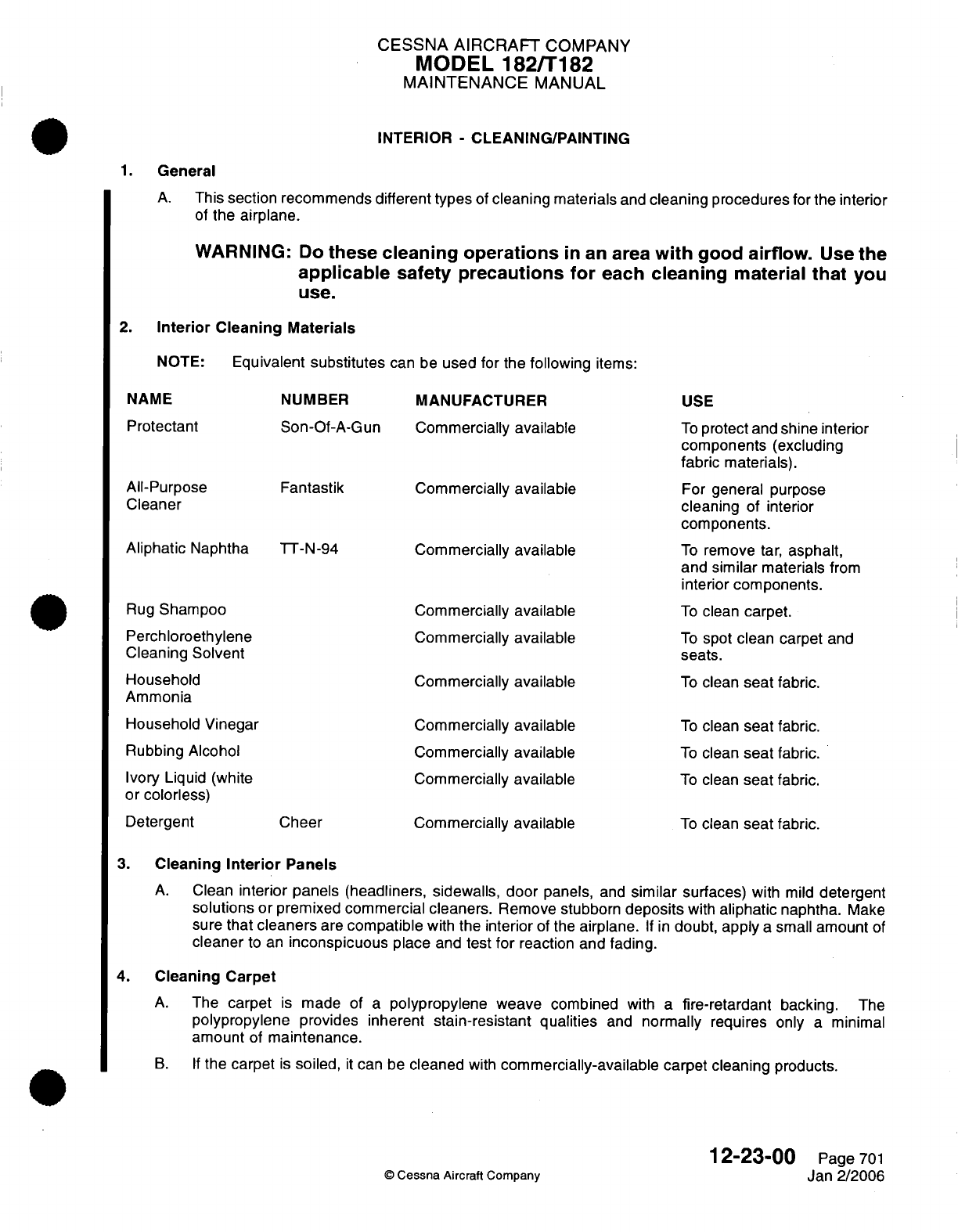
CESSNA
AIRCRAFT
COMPANY
MODEL
182/T182
MAINTENANCE
MANUAL
INTERIOR
-
CLEANING/PAINTING
1.
General
A.
This
section
recommends
different
types
of
cleaning materials
and
cleaning
procedures
for
the interior
of
the
airplane.
WARNING:
Do
these
cleaning operations
in
an
area
with
good
airflow.
Use
the
applicable
safety
precautions
for
each
cleaning
material
that
you
use.
2.
Interior
Cleaning Materials
NOTE:
Equivalent
substitutes
can
be
used
for
the
following
items:
NAME
NUMBER
Protectant
All-Purpose
Cleaner
Aliphatic
Naphtha
Son-Of-A-Gun
Fantastik
TT-N-94
Rug
Shampoo
Perchloroethylene
Cleaning Solvent
Household
Ammonia
MANUFACTURER
Commercially
available
Commercially
available
Commercially
available
Commercially available
Commercially
available
Commercially
available
USE
To
protect
and
shine interior
components
(excluding
fabric
materials).
For
general
purpose
cleaning
of
interior
components.
To
remove
tar,
asphalt,
and
similar
materials
from
interior
components.
To
clean
carpet.
To
spot
clean carpet
and
seats.
To
clean
seat
fabric.
Household Vinegar
Rubbing
Alcohol
Ivory
Liquid
(white
or
colorless)
Detergent
Commercially
available
Commercially available
Commercially
available
Commercially
available
Cheer
To
clean
seat
fabric.
To
clean
seat
fabric.
To
clean
seat
fabric.
To
clean
seat fabric.
3.
Cleaning
Interior
Panels
A.
Clean
interior panels
(headliners, sidewalls,
door
panels,
and
similar
surfaces)
with
mild
detergent
solutions
or
premixed commercial
cleaners.
Remove
stubborn
deposits
with
aliphatic
naphtha.
Make
sure
that
cleaners
are
compatible
with
the
interior
of
the
airplane.
If
in
doubt,
apply
a
small
amount
of
cleaner
to
an
inconspicuous
place
and
test
for
reaction
and
fading.
4.
Cleaning
Carpet
A.
The
carpet
is
made
of
a
polypropylene weave
combined
with
a
fire-retardant backing.
The
polypropylene
provides inherent
stain-resistant
qualities
and
normally
requires only
a
minimal
amount
of
maintenance.
B.
If
the
carpet
is
soiled,
it
can be
cleaned
with
commercially-available carpet cleaning
products.
12-23-00
©
Cessna
Aircraft
Company
Page
701
Jan 2/2006
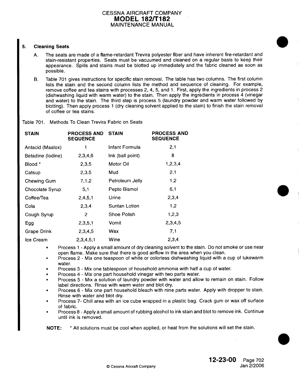
CESSNA
AIRCRAFT
COMPANY
MODEL
182/T182
MAINTENANCE
MANUAL
5.
Cleaning Seats
A.
The
seats
are
made
of
a
flame-retardant
Trevira
polyester
fiber
and
have
inherent
fire-retardant
and
stain-resistant
properties.
Seats
must
be
vacuumed
and
cleaned
on
a
regular basis
to
keep
their
appearance.
Spills
and
stains
must
be
blotted
up
immediately
and the
fabric
cleaned
as
soon
as
possible.
B.
Table
701
gives
instructions
for
specific
stain
removal. The
table
has
two
columns.
The
first
column
lists
the
stain
and
the
second
column
lists
the
method
and
sequence
of
cleaning.
For
example,
remove
coffee
and
tea
stains
with
processes
2, 4, 5,
and
1.
First,
apply
the
ingredients
in
process
2
(dishwashing
liquid
with
warm
water)
to
the
stain.
Then apply
the
ingredients
in
process
4
(vinegar
and
water) to
the
stain. The
third
step
is
process
5
(laundry powder
and
warm
water
followed
by
blotting).
Then
apply process
1
(dry
cleaning
solvent
applied
to
the stain)
to
finish
the stain
removal
of
coffee
or
tea
stains.
Table
701.
Methods
To
Clean Trevira
Fabric
on
Seats
STAIN
PROCESS
AND STAIN
PROCESS
AND
SEQUENCE SEQUENCE
Antacid
(Maalox)
1
Infant
Formula
2,1
Betadine
(Iodine)
2,3,4,6
Ink
(ball
point)
8
Blood
*
2,3,5
Motor
Oil
1,2,3,4
Catsup
2,3,5
Mud
2,1
Chewing
Gum
7,1,2
Petroleum
Jelly
1,2
Chocolate
Syrup
5,1
Pepto
Bismol
6,1
Coffee/Tea
2,4,5,1
Urine
2,3,4
Cola
2,3,4
Suntan
Lotion
1,2
Cough
Syrup
2
Shoe
Polish
1,2,3
Egg
2,3,5,1
Vomit
2,3,4,5
Grape
Drink
2,3,4,5
Wax
7,1
Ice
Cream
2,3,4,5,1
Wine
2,3,4
.
Process
1
-
Apply
a
small
amount
of
dry
cleaning
solvent
to the
stain.
Do
not
smoke
or
use
near
open
flame.
Make
sure
that
there
is
good
airflow
in
the
area
when you
clean.
.
Process
2
-
Mix
one
teaspoon
of
white
or
colorless dishwashing
liquid
with
a
cup
of
lukewarm
water.
.
Process
3
-
Mix
one
tablespoon
of
household
ammonia
with
half
a
cup
of
water.
.
Process
4
-
Mix
one
part
household
vinegar
with two
parts
water.
.
Process
5
-
Mix
a
solution
of
laundry
powder
with
water
and
allow
to
remain
on
stain.
Follow
label
directions.
Rinse
with
warm
water
and
blot
dry.
.
Process
6
-
Mix
one
part
household bleach
with
nine parts
water.
Apply
with
dropper
to
stain.
Rinse
with
water
and
blot
dry.
.
Process
7-
Chill
area with
an
ice
cube
wrapped
in
a
plastic
bag.
Crack
gum
or
wax
off
surface
of
fabric.
.
Process
8
-
Apply
a
small
amount
of
rubbing
alcohol
to
ink
stain and
blot
to
remove ink.
Continue
until
ink
is
removed.
NOTE:
*
All
solutions
must
be
cool
when
applied,
or
heat from
the
solutions
will
set
the
stain.
12-23-00
Page
702
©
Cessna
Aircraft
Company
Jan
2/2006
CESSNA
AIRCRAFT
COMPANY
MODEL
182/T182
MAINTENANCE
MANUAL
6.
Cleaning
the GDU
1040
Display
Lens
NOTE: The
Primary
Flight
Display
(PFD)
and
Multi-Function
Display
(MFD) are
the
GDU
1040
displays
in
airplanes
with
Garmin G1000.
CAUTION:
If
possible,
do not
touch
the
GDU
1040
display
lens.
The lens has
a
layer
of
anti-reflective
material
which
is
very sensitive
to
skin
oils, waxes,
and
abrasive
cleaners.
CAUTION:
Do
not
use
cleaners
that
contain
ammonia.
Ammonia
will
cause damage
to
the
anti-reflective
material.
A.
Clean
the
GDU
1040
Display
Lens.
(1)
To
clean
the
lens,
use
a
clean, lint-free
cloth
and
an
eyeglass
lens
cleaner
that
is
specified
as
safe
for
anti-reflective
material.
12-23-00
Page
703
C
Cessna
Aircraft Company
Jan 2/2006
CESSNA
AIRCRAFT
COMPANY
MODEL
182/T182
MAINTENANCE
MANUAL
UNSCHEDULED
SERVICING
-
DESCRIPTION
AND
OPERATION
1.
General
A.
This
section
gives
procedures
and
recommendations for normally unscheduled
servicing.
B.
Instructions
are
given
in
the
Cold
Soak procedures
for
operation
of
the
airplane
during
very
cold
temperatures.
NOTE:
During
operation
at
outside
air temperatures below International
Standard
Atmosphere
(ISA)
Standard,
the
engine
can
develop
more
than
its
rated
power
at
normal-rated
RPM.
This
occurs
more
at
lower
altitudes.
2.
Extreme
Weather
Maintenance
A.
Seacoast
and
Humid
areas.
(1) In
salt
water areas,
special
care
should
be
taken
to keep
engine,
accessories,
and
airframe
clean
to
help
prevent
oxidation.
(2)
In
humid
areas,
fuel
and
oil
should
be
checked
frequently
and
drained
of
condensation
to
prevent
corrosion.
3.
Ground
Power
Receptacle
A.
Connect
to
24-volt
DC,
negative
ground
power
unit
with
a
maximum
output
of
28.8
volts, for
cold
weather
starting, and
lengthy
ground
maintenance
of the
airplane electrical equipment,
with
exception
of
electronic
equipment.
Refer to
Pilot's
Operating
Handbook
and
FAA
Approved Airplane
Flight
Manual
for
engine
starting instructions
with
auxiliary
power.
NOTE:
The
ground
power
receptacle
circuit
incorporates
a
polarity
reversal
protection.
Power
from
the
external
power source
will
flow
only
if
the
ground
service
plug is
connected
correctly
to
the
airplane.
4.
Cold
Soak
A.
If
extended exposure
to
cold
weather
is
expected,
refer to
this
procedure
to
prepare
the
airplane
for
cold soak.
If
the
airplane
has
cold
soaked
for
more than
two hours
at
temperatures
colder
than
-10
°C (14
°F),
refer
to
this
procedure
and
the Pilot's
Operating Handbook
and
FAA
Approved Airplane
Flight Manual
to
prepare the
airplane
for
flight.
(1)
Cold
temperatures
have
an
effect
on
control
cable
tension.
Refer
to
Chapter
27,
Aileron
Control
System
-
Maintenance Practices,
Rudder
Control
System
-
Maintenance Practices,
Elevator
Control
System
-
Maintenance Practices,
Elevator
Trim
Control
-
Maintenance Practices,
and
Flap
Control
System
-
Maintenance
Practices
for
flight
control
cable
tensions.
(2)
For
information
on
lubrication
and
greasing
of
moving
parts,
refer
to
Chapter
12,
Lubricants
-
Description and Operation.
(3)
Refer
to
the
Pilot's
Operating Handbook
and
FAA
Approved
Airplane
Flight
Manual
for
the
correct
engine
oil
viscosity.
(4)
Refer
to
the
Pilot's
Operating
Handbook
and
FAA
Approved Airplane
Flight
Manual
for additional
information
on
procedures
for
operation
of
the
airplane
in
cold
temperatures.
B.
The
engine
must
be
preheated
before
an
engine
start
when
exposed
to
very
cold
temperatures.
Preheat
the
engine
as
follows:
(1)
Direct
warm
air
into
the engine cooling
inlets behind
the
propeller.
CAUTION:
Do
not
use air
with
a
temperature
of
more
than
120
°C
(248
°F)
when
you
preheat
the
engine.
Air
with
a
temperature
of
more
than
120
°C
(248
°F)
can
do
damage
to
the
exterior
paint
of
the
airplane.
(2)
Make
sure
that
the
temperature
of the
warm
air
is
no more
than
120 °C
(248
°F).
12-30-00
Page
1
©
Cessna Aircraft
Company
Jan
2/2006
CESSNA AIRCRAFT
COMPANY
MODEL
182/T182
MAINTENANCE
MANUAL
WARNING:
Never
bring
open
flames
near
the
airplane.
Use
of
a
heater
with
an
open flame
to
preheat
the
engine
can
cause
damage
to
the
airplane
and
injury to
personnel.
(3)
(4)
(5)
Do
not use
a
heater
with open
flames
to
supply
the
warm
air
to preheat
the
engine.
Preheat
the
engine
before
an
engine start
if
the
engine temperature
is
less
then
-6
°C (20
°F).
When
the
temperature
is
less
than
0
°C
(32
°F),
preheat
the
engine
to
more
than
0 °C (32
°F)
before
you
start
the
engine
again
after
an
engine start
and
stop.
NOTE: When
the
temperature
is
less
than
0
°C
(32
°F),
water
from
combustion
can
freeze
to
the
engine
spark
plugs
if
the
engine
does
not
continue
to
operate after
it
is
started.
This
will
prevent
the engine
from
starting
again.
C.
The
Garmin
GDU
1040 PFD/MFD
requires
warm-up time
when
exposed
to
very
cold
temperatures.
(1) A
warm-up time
of
up
to
30
minutes
is
necessary
when
the
GDU
is
exposed
to
down
to -40
°C
(-40
°F)
for
an
extended
period.
(2) A
warm-up time
of
up
to
15
minutes
is
necessary
when
the
GDU
is
exposed
to
down
to
-30 °C
(-22
°F)
for
an
extended
period.
D.
Before
takeoff,
preheat
the
airplane
cabin
to
more
than
-30
°C (-22
°F)
for
correct
operation
of
the
standby
altimeter.
NOTE:
If
there
is
no
warning that
an
instrument
is
not
operating
correctly,
all
other
instruments
will
operate
continuously
until at the
minimum
temperature of
the
airplane.
12-30-00
Page
2
©
Cessna
Aircraft
Company
Jan
2/2006

CHAPTER
STA
MDAR
PRACICE
CESSNA AIRCRAFT
COMPANY
MODEL
182/T182
MAINTENANCE
MANUAL
LIST
OF
EFFECTIVE PAGES
CHAPTER-SECTION-SUBJECT
20-Title
20-List
of
Effective Pages
20-Record
of
Temporary
Revisions
20-Table
of
Contents
20-00-00
20-10-00
20-11-00
20-12-00
20-1
3-00
20-30-00
20-3
1-00
20-31
-00
20-31-00
20-32-00
20-50-00
©
Cessna Aircraft
Company
PAGE
Page
1
Pages
1-4
Pages
201
-207
Pages
201
-211
Pages 201-202
Page
1
Pages
1-3
Pages 201-204
Pages 701-705
Pages
201 -218
Pages
1-17
DATE
April
1/2002
Mar
1/2004
Janl1/2007
Mar
1/2004
Mar
1/2004
April
1/2002
Mar
1/2004
Mar
1/2005
April
1/2002
Jul
3/2006
April
1/2002
20
-
LIST
OF
EFFECTIVE
PAGES
Page
1
of
1
Jan11/2007
Temporary
Revision
Number
RECORD
OF
TEMPORARY
REVISIONS
Page
Number
Issue
Date
By
Date
Removed
By
CESSNA AIRCRAFT
COMPANY
MODEL
182/T1
82
MAINTENANCE
MANUAL
CONTENTS
STANDARD PRACTICES AIRFRAME
-
GENERAL
.................
Scope....................................
Definition
..................................
MATERIAL
AND
TOOL
CAUTIONS
-
DESCRIPTION
AND
OPERATION........
Titanium...................................
Mercury...................................
Asbestos
..................................
Cadmium
Plated
Fasteners..........................
Maintenance
Precautions...........................
General
Usage
Solvents
...........................
National
Emissions Standards
for
Hazardous
Air
Pollutants
...........
Facilities
and
Equipment
...........................
TORQUE
DATA
-
MAINTENANCE
PRACTICES...................
General...................................
Torque
Requirements
for Bolts,
Screws
and
Nuts................
Torque
Requirements
for
Hi-Lok
Fasteners...................
Torque
Requirements for
Electrical
Current
Carrying
And
Airframe
Ground
Fasteners.................................
Torque
Requirements
for
Rigid
Tubing
and
Hoses................
SAFETYING
-
MAINTENANCE PRACTICES
....................
General...................................
Safety
Wire
.................................
Safety
Wire
Installation............................
Cotter
Pin
Installation.............................
Safetying Turnbuckles
............................
CONTROL
CABLE
WIRE BREAKAGE
AND
CORROSION
LIMITATIONS
-
MAINTENANCE PRACTICES
...........................
Examination
of
Control
Cables
........................
SOLVENTS, SEALANTS,
AND
ADHESIVES
-
DESCRIPTION
AND
OPERATION
...
General...................................
Description
.................................
ACCEPTABLE
REPLACEMENTS
FOR
CHEMICALS
AND
SOLVENTS
-
DESCRIPTION
AND
OPERATION
................................
General...................................
Hand-Wipe
Cleaning Operations
.......................
Priming
Operations..............................
Topcoat
Operations
.............................
Paint
Stripping
Operations
..........................
GENERAL SOLVENTS/CLEANERS
-
MAINTENANCE PRACTICES
.........
General...................................
Tools,
Equipment
and
Materials........................
Safety
Precautions..............................
D
escription
......
. . . . ...... . . . ........... . . . . .
INTERIOR
AND
EXTERIOR
FINISH
-
CLEANING/PAINTING.............
General...................................
Interior
and
Exterior Finishes
.........................
Paint
Facility.................................
Sanding
Surfacer
..............................
Paint
Stripping................................
Hand
Solvent
Cleaning............................
Maintenance
of
the
Interior
and
Exterior
Primary
Coatings
and
Topcoat......
©
Cessna
Aircraft Company
20-00-00
Page
1
20-00-00
Page
1
20-00-00
Page
1
20-10-00
Page
1
20-10-00
Page
1
20-10-00
Page
1
20-10-00
Page
1
20-10-00
Page
1
20-10-00
Page
1
20-1
0-00
Page
2
20-10-00
Page
3
20-1
0-00
Page
3
20-11
-00
Page
201
20-11
-00
Page
201
20-1
1-00
Page
204
20-11
-00
Page
205
20-11
-00
Page
206
20-11
-00
Page
206
20-12-00
Page
201
20-12-00
Page
201
20-12-00
Page
201
20-12-00
Page
202
20-12-00
Page
206
20-12-00
Page
208
20-13-00
Page
201
20-13-00
Page
201
20-30-00
Page
1
20-30-00
Page
1
20-30-00
Page
1
20-31
-00
Page
1
20-31
-00
Page
1
20-31
-00
Page
1
20-3
1-00 Page
1
20-3
1
-00
Page
2
20-31
-00
Page
3
20-31 -00
Page
201
20-31
-00
Page
201
20-31
-00
Page
201
20-31
-00 Page
201
20-31
-00
Page
201
20-31
-00
Page
701
20-3
1
-00
Page
701
20-31
-00
Page
701
20-31
-00
Page
701
20-31
-00
Page
701
20-3
1
-00
Page
702
20-31
-00
Page
704
20-3
1
-00
Page
705
20
-
CONTENTS
Page
1
of
2
Janl1/2007
CESSNA
AIRCRAFT
COMPANY
MODEL
182/Ti
182
MAINTENANCE
MANUAL
FUEL,
WEATHER
AND
HIGH-TEMPERATURE
SEALING
-
MAINTENANCE
PRACTICES
...................................
General...................................
Tools
and
Equipment.............................
Definition
of
Sealing
Terms
..........................
Materials
..................................
General
Requirements............................
Sealant
Curing................................
Mixing
of
Sealants..............................
Cleaning
..................................
Sealing
Application..............................
Sealant
Repair................................
CONVERSION
DATA
-
DESCRIPTION
AND
OPERATION
..............
General...................................
Formulas for
Conversion
Computations
....................
20-32-00
Page
201
20-32-00
Page
201
20-32-00
Page
201
20-32-00
Page
204
20-32-00
Page
205
20-32-00
Page 206
20-32-00
Page
207
20-32-00
Page
207
20-32-00
Page
21
0
20-32-00
Page
211
20-32-00
Page
217
20-50-00
Page
1
20-50-00
Page
1
20-50-00
Page
1
20
-
CONTENTS
Page
2
of
2
Janl1/2007
©D
Cessna
Aircraft Company

CESSNA
AIRCRAFT
COMPANY
MODEL
182/T182
MAINTENANCE
MANUAL
STANDARD PRACTICES AIRFRAME
-
GENERAL
1.
Scope
A.
This
Chapter
describes
the standard
maintenance
practices for
maintaining
and
repairing
items
of
the
airframe
and
systems
that
are
typical
to
more
than
one
area or system.
Maintenance
practices
which
are
unique
to
a
particular
system or
subject
are
described
in
the
appropriate
chapter
and
section
in
the
maintenance
manual.
B.
For
repairs
beyond the scope
of
this manual,
refer
to
the
1996
and On
100
Series Structural
Repair
Manual.
2.
Definition
A.
This
chapter
is
divided
into
sections
to
aid
maintenance personnel
in
locating
information. Consulting
the
Table
of
Contents
will
further
assist
in
locating
a
particular
subject.
A
brief
definition
of
the
subjects
and
sections
incorporated
in
this
chapter
is
as
follows.
(1)
The
section
on
Material
and
Tool
Cautions describes
general
cautions
and
warnings
applicable
to
maintenance
on
or
around
the
airplane.
(2)
The
section
on
Torque
Data
provides
tables, formulas, requirements
and
torque
limits
for
various
type
fasteners.
(3)
The
section
on
Safetying
describes
the proper methods
and use of
safety
wire/lockwire,
cotter
pins and
lock
clip
installations.
(4)
The
section
on
Control
Cables and Pulleys
describes
the
construction, examination
and
storage
of
cable
assemblies
and
pulleys.
(5)
The
section
on
Solvents,
Sealants
and
Adhesives provides
the
description
and
uses
for solvents
and
cleaners;
fuel,
weather,
pressure
and
high
temperature
sealing; and the
application
of
adhesives
and
solvent
bonding.
(6)
The
section
on
Conversion
Data
contains
information
converting
the
more
commonly
used
measuring units found
in
the
Maintenance
Manual.
20-00-00
Page
1
©
Cessna
Aircraft
Company
April 1/2002

CESSNA
AIRCRAFT
COMPANY
MODEL
182/T182
MAINTENANCE
MANUAL
MATERIAL
AND
TOOL
CAUTIONS
-
DESCRIPTION AND
OPERATION
1.
Titanium
CAUTION:
Do
not
use
cadmium-plated tools
on
titanium
parts.
Cadmium
particles
can
stay
on
such parts.
The
cadmium
particles
will
cause
an
unwanted
condition
with
the
titanium
when
heated. The
titanium
part
will
become brittle
in
the
area
of
the
unwanted
condition
and
make
cracks.
CAUTION:
Do
not
let
cadmium-plated
fasteners
touch
titanium
parts.
2.
Mercury
CAUTION:
Do
not use
thermometers
and
other mercury-based
test
equipment
on
the
airplane.
A.
Corrosion Caused
by Mercury.
(1)
There
is
no
known
procedure
to
stop
corrosion
when
it
has
started.
(2)
Mercury
can
go
into
any
crack
in
the
finish,
paint,
or
seal
layer
of
a
metal.
An
oxide
layer
on
a
dry metal
surface
will
prevent
corrosion.
A
bright
surface,
a
polished
surface,
or
a
surface
with
scratches
will
increase
the
rate
of
corrosion.
(3)
Dirt,
grease,
or
other
contaminants that
have
no
effect
on
the
metal
surfaces
will help
prevent
corrosion.
(4)
The
corrosion
and
the
embrittlement caused
by
corrosion
can
be
very
fast
in
structural
members.
3.
Asbestos
WARNING:
Do
not
let
asbestos
fibers
make
entry
into
the
body
of
personnel.
Asbestos
fibers
can
cause
injury
or
death.
A.
Do
not
breathe
the
dust
of
asbestos fibers.
To
not
breathe
the
dust
of
asbestos
fibers,
use
either
of
the methods
that
follows.
(1)
Use
engineering
control,
which
includes
work
in a
correctly
filtered
exhaust
chamber.
Use
wet
procedures
to keep
personnel
less
than
Occupational
Safety
Health
Administration
(OSHA)
personnel exposure
limits.
(2)
Use
breathing
equipment
with
high
quality
filters. Other protection
must
include
protective
clothing, gloves
and
eye
protection.
B.
Refer
to
all
local,
state,
and
federal
regulations
to
discard
asbestos
material.
4.
Cadmium
Plated Fasteners
CAUTION:
Put
a
complete layer
of
fuel
sealant
on
cadmium
plated
fasteners
that
are
used
in
fuel
areas.
Cadmium
particles
from
cadmium
plated
fasteners
can
cause damage
to
the
engine.
5.
Maintenance
Precautions
WARNING:
Obey
the
precautions
during
maintenance,
repair, and
service
procedures
of
the airplane
to
prevent
injury
because
of
the
different
materials
and
environmental
conditions.
A.
Carefully
read
and
follow
all
instructions.
(1)
Obey
all
cautions
and
warnings
given
by
the
manufacturer
of
the
product
that
is
used.
(a)
Use
the
applicable safety equipment
such
as
goggles,
face
shields,
breathing
equipment,
protective
clothing
and
gloves.
(2)
Do
not get
dangerous
chemicals
in
the
eyes
or
on
the
skin.
20-10-00
Page
1
©
Cessna
Aircraft Company
Mar 1/2004
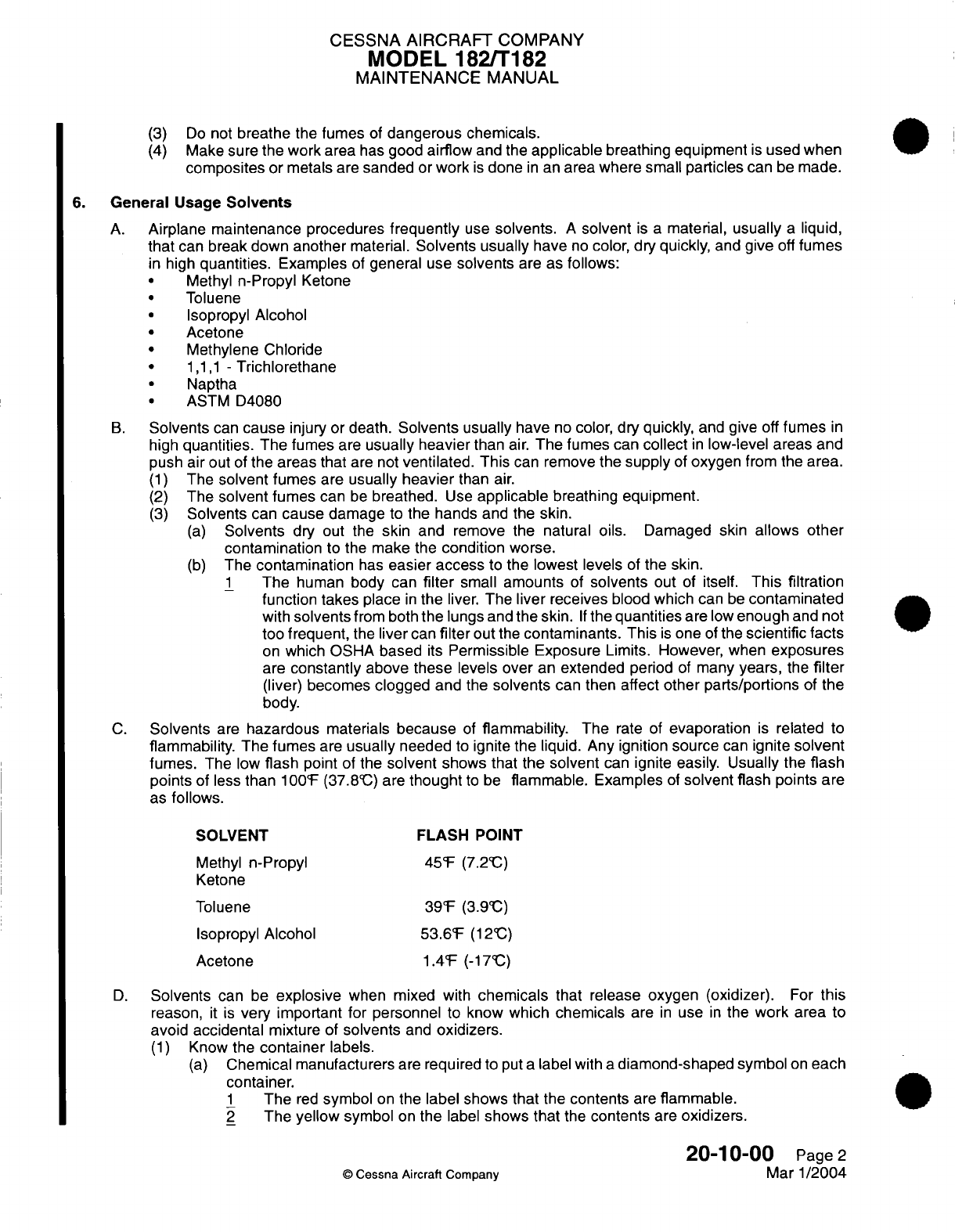
CESSNA
AIRCRAFT
COMPANY
MODEL 182/T182
MAINTENANCE
MANUAL
(3)
Do
not
breathe
the fumes
of
dangerous
chemicals.
(4)
Make sure
the work area
has
good
airflow
and
the
applicable
breathing
equipment
is
used when
composites
or metals
are
sanded
or
work
is
done
in
an
area
where
small
particles
can
be
made.
6.
General
Usage
Solvents
A.
Airplane
maintenance
procedures
frequently
use
solvents.
A
solvent
is
a
material,
usually
a
liquid,
that
can
break
down
another
material.
Solvents usually
have
no
color,
dry
quickly,
and
give
off
fumes
in
high
quantities.
Examples
of
general
use
solvents
are as
follows:
·
Methyl
n-Propyl
Ketone
Toluene
·
Isopropyl
Alcohol
Acetone
·
Methylene Chloride
1,1,1
-
Trichlorethane
·
Naptha
ASTM
D4080
B.
Solvents
can
cause
injury or
death.
Solvents usually
have
no
color,
dry quickly,
and
give
off
fumes
in
high
quantities.
The fumes
are
usually heavier
than
air.
The
fumes
can
collect
in
low-level
areas
and
push
air
out
of
the
areas
that
are
not
ventilated.
This
can
remove
the supply
of
oxygen
from the
area.
(1)
The
solvent
fumes
are
usually
heavier
than
air.
(2)
The
solvent
fumes
can
be
breathed.
Use
applicable
breathing
equipment.
(3)
Solvents
can
cause
damage
to
the hands
and the
skin.
(a)
Solvents
dry out the
skin
and
remove
the
natural oils.
Damaged skin
allows
other
contamination
to the
make
the
condition
worse.
(b)
The
contamination
has
easier
access
to
the
lowest levels
of
the
skin.
1
The
human
body
can
filter
small
amounts
of
solvents
out
of itself.
This filtration
function takes
place
in
the
liver.
The
liver
receives
blood
which
can
be
contaminated
with
solvents
from both
the
lungs and the
skin.
If
the
quantities
are
low
enough
and not
too
frequent,
the
liver
can
filter
out
the
contaminants.
This
is
one
of
the
scientific facts
on
which OSHA based
its
Permissible
Exposure
Limits. However, when
exposures
are
constantly
above
these
levels over
an
extended
period
of
many
years,
the
filter
(liver)
becomes
clogged
and
the
solvents
can then
affect
other parts/portions
of the
body.
C.
Solvents
are
hazardous
materials
because
of
flammability.
The
rate
of
evaporation
is
related
to
flammability.
The
fumes
are
usually
needed
to
ignite
the
liquid. Any ignition
source
can
ignite
solvent
fumes.
The low
flash
point
of
the
solvent
shows that
the solvent
can
ignite
easily.
Usually the
flash
points
of
less
than
100'F
(37.8"C)
are
thought
to
be
flammable.
Examples
of
solvent flash
points
are
as
follows.
SOLVENT
FLASH
POINT
Methyl
n-Propyl
45F
(7.2'C)
Ketone
Toluene
39F
(3.9;C)
Isopropyl
Alcohol
53.6F
(12cC)
Acetone
1.4F
(-17cC)
D.
Solvents
can
be
explosive
when mixed with
chemicals
that release
oxygen (oxidizer).
For
this
reason,
it
is
very
important
for personnel
to
know
which
chemicals
are
in
use
in
the
work
area
to
avoid
accidental
mixture
of
solvents
and
oxidizers.
(1)
Know
the
container
labels.
(a)
Chemical manufacturers
are
required
to
put
a
label
with
a
diamond-shaped
symbol
on
each
container.
1
The
red
symbol
on
the
label shows
that
the
contents
are
flammable.
2
The
yellow
symbol
on
the
label
shows
that
the
contents
are
oxidizers.
20-10-00
Page
2
©
Cessna Aircraft Company
Mar
1/2004
CESSNA
AIRCRAFT
COMPANY
MODEL
182/T182
MAINTENANCE
MANUAL
7.
National
Emissions
Standards
for
Hazardous
Air
Pollutants
A.
National
Emissions Standards
for
Hazardous
Air
Pollutants
(NESHAP).
(1)
The
NESHAP
standards
have put
a
limit
on
the
use of
certain chemicals
and
solvents.
(2)
For
complete details
of the
regulatory
standards, see
the Federal
Register,
40
CFR
Part
63,
[Ad-FRL-5636-1],
RIN
2060-AG65.
B.
NESHAP
Requirements.
(1)
Hand-Wipe Cleaning.
(a)
All
hazardous
air
pollutants
or
organic compounds that
release
dangerous fumes that
are
used
as hand
wipe
cleaning
solvents
must
meet
a
composition requirement and have
a
vapor
pressure
less
than
or
equal
to
1.75
Hg
at
69°(45
mm
Hg
at
2
O'C.)
(b)
The
requirements specified
may be met
by
an
alternative
compliance
plan used by
the
permitting
authority
and
approved
under
Section
112(1)
of
the
Clean
Air
Act.
(2)
Primer
Application.
(a)
The
organic
hazardous air
pollutant content
is
limited
to
350
g/l
(2.9
pounds-per-gallon),
less
water,
as
applied.
(b)
The
volatile organic
compound limit
is
350
g/l
(2.9
pounds
per
gallon),
less
water,
as
applied.
(c)
Use
coatings
below
the
content
limit or
use
monthly volume-weighted
averaging
to
get
the
content
limits
to meet
content
limits.
(3)
Topcoat
Application.
(a)
The base coat
organic
hazardous air pollutant
content
must
be
less than
420
g/l
(3.5
pounds-per-gallon),
less water,
as
applied.
(b)
The
volatile
organic
compound
limit
is
420
g/l
(3.5
pounds
per
gallon),
less water,
as
applied.
(c)
The
topcoats
must
meet
the
requirements
of
MIL-C-85285.
(d)
Stripe paint requirements
are
the
same
as
the
base coat
requirements.
If
the
recommended
supplier
cannot
be
used,
then
use
base coat
materials
to
paint
stripes.
NOTE:
All
paints
and
primers must
have
specific
application
techniques.
If
an
alternative
is
supplied,
use
only
the
materials
that
are
less than or
equal
in
emissions,
to
less than
the
HVLP
or
electrostatic
spray
application
techniques.
NOTE:
Operate
all
application
equipment
according
to
the
manufacturer's
specifications,
company
procedures
or locally
specified
operating procedures.
(4)
Paint
Removal
(a)
Paint removal
operations apply
to
the
outer
surface
of
the
airplane
and
do not
apply
to
parts
or
units
normally
removed.
Fuselage,
wings
and
stabilizers
are
covered. Radomes
and
parts
normally
removed
are
exempt
from
the
following
requirements:
1
No
organic hazardous
air
pollutants
are
to
come
from
chemical
strippers
or
softeners.
2
Inorganic
hazardous
air pollutant
fumes
must
be
kept
to
a
minimum during
periods
of
non-chemical
based
equipment malfunctions.
3
The
use
of organic
hazardous air pollutant
material
for
spot
stripping and
decal
removal
is
kept
to
a
minimum
of
190
pounds
per
airplane
per
year.
(b)
Operating requirements
for
paint
removal
operations that
give
airborne
inorganic
hazardous
air
pollutants
include control
with
particulate filters
or
water
wash
systems.
(c)
Mechanical
and hand
sanding
are
exempt
from
these
requirements.
8.
Facilities
and
Equipment
A.
Facilities
(1) A
system
must
be
supplied
to
collect
processing waters
to
treat
for
chromium
and
pH
or
to
be
removed.
(2)
Facilities
must
have
proper
safety
equipment.
20-10-00
Page
3
©
Cessna
Aircraft
Company
Mar 1/2004
CESSNA AIRCRAFT
COMPANY
MODEL 182/T182
MAINTENANCE
MANUAL
B.
Equipment
(1)
Applied
spray
of
cleaning
solvents,
paint
removers or
color
chemical
film
treatment
solutions
is
to be
prevented unless
all
requirements
of
NESHAP
are met.
(2)
Spraying equipment to wash
the
airplane
with
alkaline
cleaner
can
be used.
This
equipment
is
sufficient
to
spray
deoxidizer, chemical
film
solutions
and
rinse
water.
(3)
A
high
pressure
washer
is
recommended,
with or
without
hot
water.
(4)
Respirators
and/or
dust
masks
must
be
used.
20-10-00
Page
4
©
Cessna
Aircraft
Company
Mar 1/2004

CESSNA AIRCRAFT
COMPANY
MODEL
182/Ti
82
MAINTENANCE
MANUAL
TORQUE
DATA
-
MAINTENANCE PRACTICES
General
A.
To
ensure
security
of
installation
and
prevent
over
stressing
of
components
during
installation,
the
torque
values
outlined
in
this
section
and
other
applicable
chapters
of
this
manual
should
be
used
during
installation
and
repair
of
components.
B.
The
torque
value
tables,
listed
in
this section,
are
standard
torque
values for
the
nut
and
bolt
combinations
shown.
If a
component
requires
special torque
values,
those
values
will be
listed
in
the
applicable
maintenance
practices section.
C.
Torque
is
typically
applied
and
measured
using
a
torque wrench.
Different
adapters,
used
in
conjunction
with
the
torque
wrench,
may
produce
an
actual
torque
to
the
nut
or bolt
which
is
different
from
the torque reading.
Figure
201
is
provided
to
help
calculate
actual
torque
in
relation
to
specific
adaptors
used
with
the
torque
wrench.
D.
Running
Torque
Value.
(1)
Running torque value
is
the
torque
value
required
to
rotate
a
nut
on
a
threaded
shaft,
without
tightening.
Running torque
value does
not
represent the
torque values
listed
in
the
tables
of
this
section.
Torque
values
listed
in
the
tables
represent
the
torque
values above
running
torque.
For
example,
if
final
torque
required
is
to
be 150
inch-pounds
and
the
running
torque
is
25
inch-
pounds,
then
the
running
torque must
be
added
to
the
required
torque
to
achieve final
torque
of
150
+25
=
175
inch-pounds.
(2)
Breakaway
torque
value
is
the
value
of
torque required
to
start
a
nut
rotating
on
a
thread shaft,
and
does
not
represent
running torque
value.
It
should
be
noted
that
on
some
installations
the
breakaway
torque
value
cannot
be
measured.
E.
General
Torquing
Notes.
(1)
These
requirements
do
not
apply
to
threaded
parts
used
for
adjustment,
such
as
turnbuckles
and
rod
ends.
(2)
Torque
values
shown
are
for
clean,
non-lubricated
parts.
Threads should
be
free
of
any
contamination.
Lubricants,
other
than
those
on
the
nut as
purchased,
should
not
be
used
on
any
bolt
installation
unless
specified.
(3)
Assembly
of
threaded fasteners, such
as
bolts,
screws
and
nuts,
should
conform
to
torque
values
shown
in
Table
201.
(4)
When
necessary
to
tighten
from
the bolt
head,
increase
maximum
torque
value
by
an
amount
equal
to
shank friction.
Measure
shank
friction
with
a
torque
wrench.
(5)
Sheet
metal
screws should
be
tightened
firmly,
but not
to
a
specific
torque
value.
(6)
Countersunk washers
used with
close
tolerance
bolts
must
be
installed
correctly
to
ensure
proper
torquing
(refer
to
Figure 202).
(7)
For
Hi-Lok
fasteners
used
with
MS21
042
self-locking
nuts,
fastener
and
nut
should
be
lubricated
prior
to
tightening.
(8)
Tighten
accessible
nuts
to
torque values per
Table
201.
Screws
attached
to
nutplates,
or
screws
with
threads
not
listed
in
Table
201
should
be
tightened
firmly,
but
not
to
a
specific
torque value.
Screws
used
with
dimpled
washers
should
not
be
drawn
tight
enough
to
eliminate
the
washer
crown.
(9)
Table
201
is
not
applicable
to
bolts,
nuts and
screws
used
in
control
systems
or
installations
where
the
required
torque would
cause
binding,
or
would interfere
with
proper
operation
of
parts.
On
these installations,
the
assembly
should
be
firm
but not
binding.
(1
0)
Castellated
Nuts.
(a)
Self-locking
and
non
self-locking
castellated
nuts,
except
MS1
7826,
require
cotter
pins
and
should
be
tightened
to
the
minimum
torque
value
shown
in
Table
201.
The
torque
may
be
increased
to
install
the
cotter
pin,
but
this
increase
must
not
exceed
the
alternate torque
values.
(b)
MS1
7826
self-locking, castellated
nuts
shall
be
torqued per
Table
201.
(c)
The
end of
the bolt or
screw
should
extend
through
the
nut at
least
two
full
threads including
the
chamfer.
20-1
1-00
Page
201
(D
Cessna
Aircraft
Company
Jan11/2007
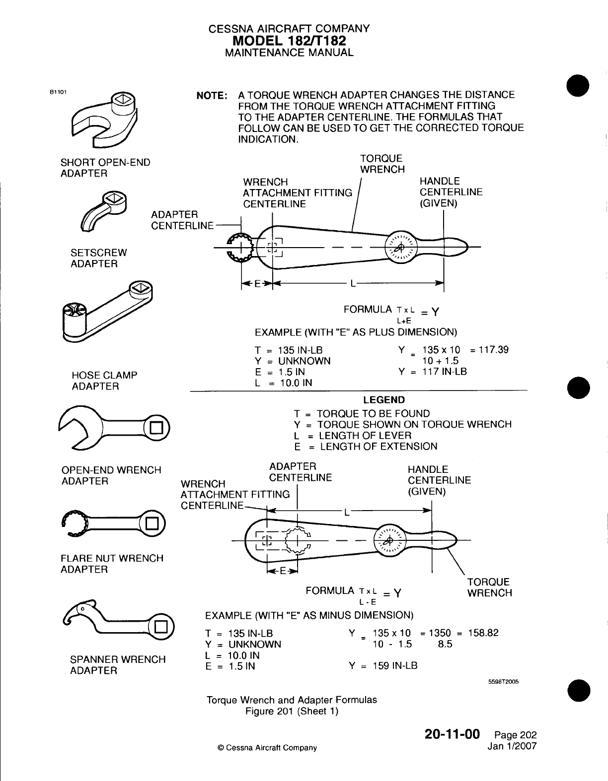
CESSNA
AIRCRAFT
COMPANY
MODEL
182/T1
182
MAINTENANCE
MANUAL
NOTE:
A
TORQUE
WRENCH ADAPTER
CHANGES
THE
DISTANCE
FROM
THE
TORQUE
WRENCH
ATTACHMENT
FITTING
TO
THE
ADAPTER CENTERLINE.
THE
FORMULAS
THAT
FOLLOW
CAN
BE
USED
TO
GET
THE
CORRECTED
TORQUE
INDICATION.
B1
101
SHORT
OPEN-END
ADAPTER
ADAPTER
CENTERLINE
SETSCREW
ADAPTER
TORQUE
WRENCH
WRENCH
ATTACHMENT
FITTING
CENTERLINE
FORMULA
Tx
L
- Y
L+E
EXAMPLE (WITH
"E"
AS
PLUS
DIMENSION)
T
=
135
IN-LB
Y
=
UNKNOWN
E
=
1.5
IN
L
=
10.0
IN
HOSE
CLAMP
ADAPTER
Y =
135
x
10
=
117.39
10
+ 1.5
Y
=
1 17
IN-LB
LEGEND
T
=
TORQUE
TO
BE
FOUND
Y
=
TORQUE
SHOWN
ON
TORQUE
WRENCH
L
=
LENGTH
OF
LEVER
E
=
LENGTH
OF
EXTENSION
OPEN-END
WRENCH
ADAPTER
FLARE
NUT
WRENCH
ADAPTER
SPANNER
WRENCH
ADAPTER
ADAPTER
%AIDE:MrLJ
CENTERILINE
ATTACHM
CENTERLI
HANDLE
CENTERLINE
FORMULA
Tx
L
=
y
L
-E
EXAMPLE (WITH
"E"
AS
MINUS
DIMENSION)
T
=
135
IN-LB
Y
=
UNKNOWN
L
=
1
0.0
IN
E
=
1.5
IN
TORQUE
WRENCH
Y
= 135
x
10
=
1350
=
158.82
10
-
1.5
8.5
Y
=
159
IN-LB
5598T2005
Torque
Wrench
and
Adapter
Formulas
Figure
201
(Sheet
1)
©
Cessna Aircraft Company
20-1
1-00
Page
202
Janl1/2007
JO)
6
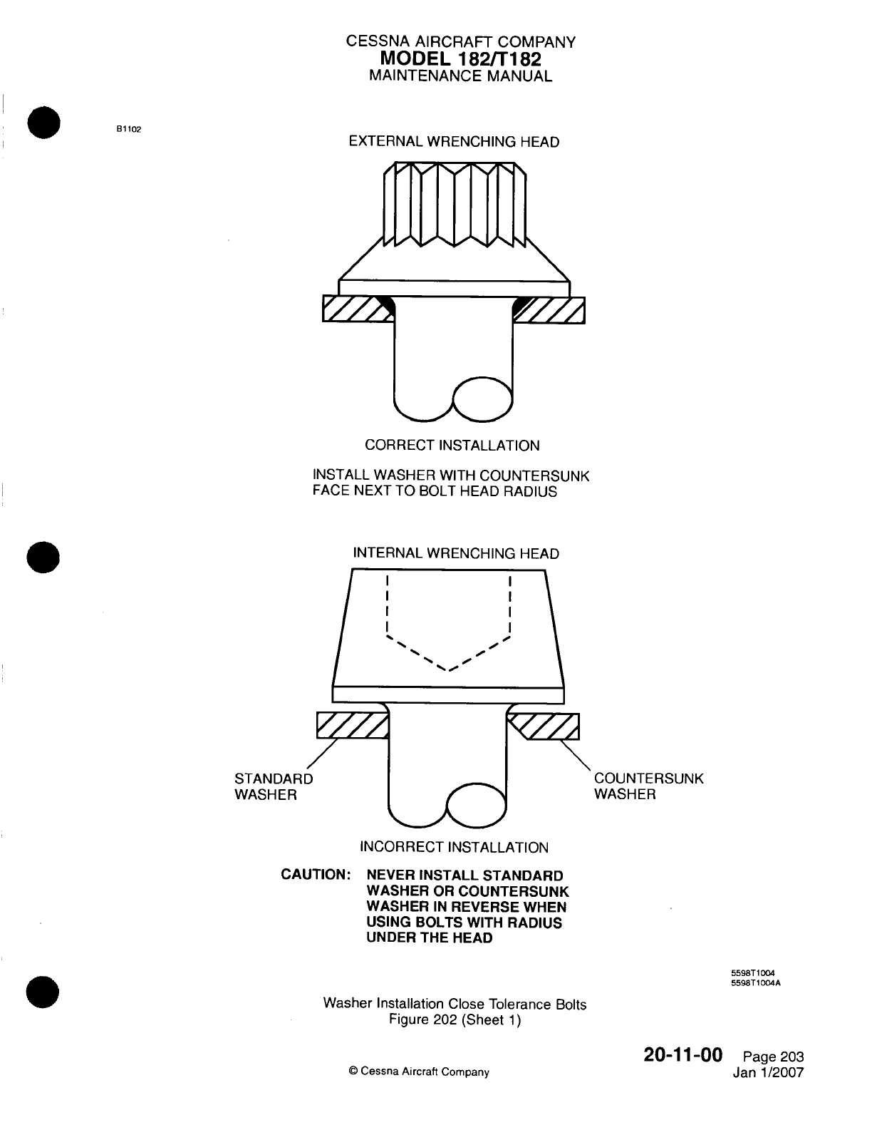
CESSNA AIRCRAFT
COMPANY
MODEL
182/Ti182
MAINTENANCE
MANUAL
EXTERNAL
WRENCHING
HEAD
CORRECT
INSTALLATION
INSTALL WASHER
WITH
COUNTERSUNK
FACE
NEXT TO
BOLT HEAD
RADIUS
INTERNAL
WRENCHING
HEAD
COUNTERSUNK
WASHER
INCORRECT
INSTALLATION
CAUTION:
NEVER
INSTALL
STANDARD
WASHER
OR
COUNTERSUNK
WASHER
IN
REVERSE
WHEN
USING
BOLTS
WITH
RADIUS
UNDER THE
HEAD
5598T1
004
5598T1
004A
Washer
Installation
Close
Tolerance
Bolts
Figure
202
(Sheet
1)
Q
Cessna
Aircraft
Company
20-1
1-00
Page
203
Janl1/2007
Bi
102
STANDAR[
WASHER
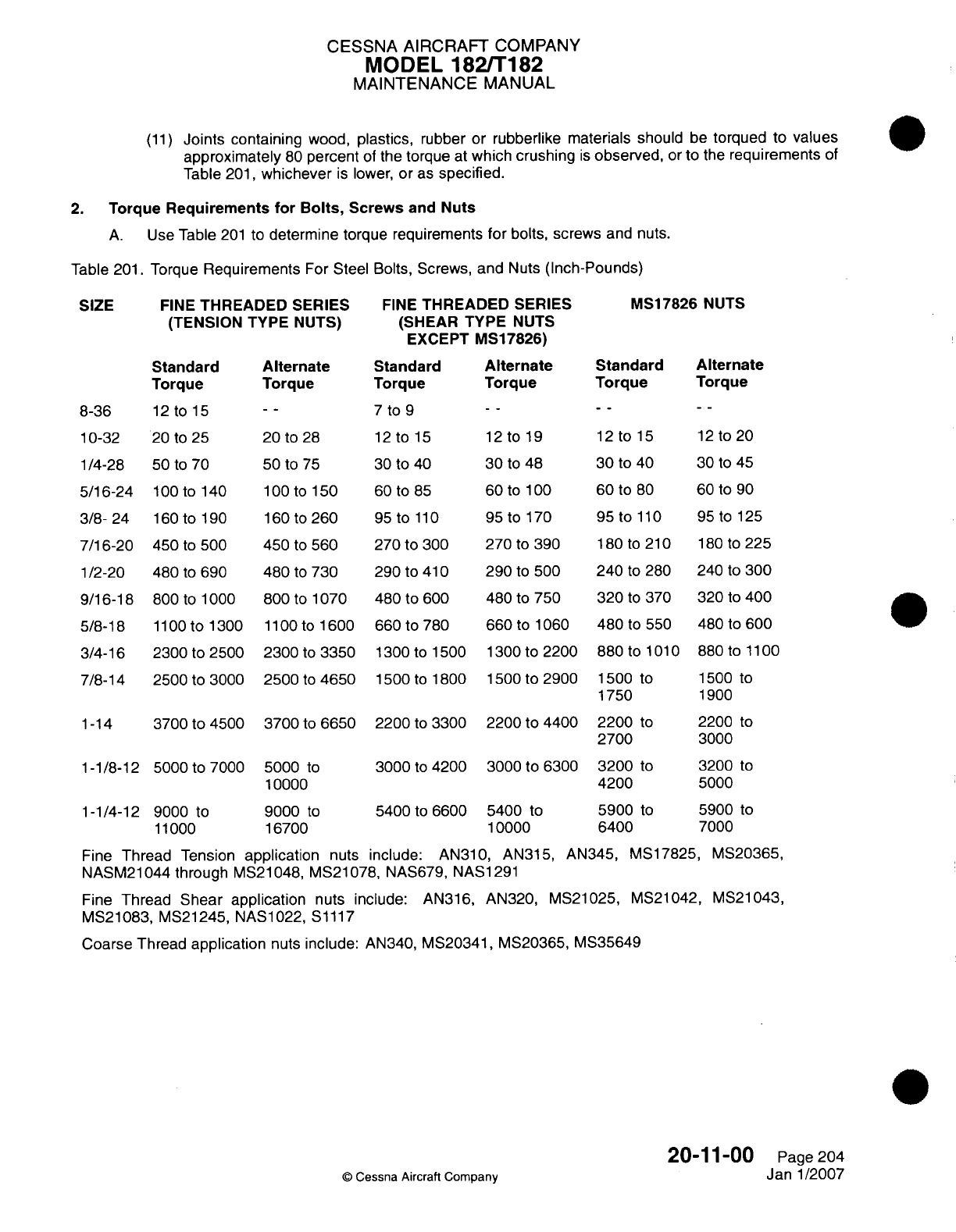
CESSNA
AIRCRAFT
COMPANY
MODEL
182/Ti 182
MAINTENANCE
MANUAL
(11)
Joints
containing
wood,
plastics,
rubber
or
rubberlike materials
should
be
torqued
to
values
approximately
80
percent
of
the
torque
at
which crushing
is
observed,
or
to
the
requirements
of
Table
201,
whichever
is
lower, or
as
specified.
2.
Torque
Requirements
for
Bolts,
Screws
and
Nuts
A.
Use
Table
201
to
determine
torque requirements
for
bolts,
screws
and
nuts.
Table
201.
Torque
Requirements
For
Steel
Bolts,
Screws,
and
Nuts
(Inch-Pounds)
SIZE
Standard
Torque
8-36
12
tolS5
10-32
20
to
25
1/4-28
50
to
70
5/16-24
100
to
140
3/8-
24 160
to
190
7/16-20
450
to
500
1/2-20
480
to
690
9/16-18
800
to
1
000
5/8-18
llO
to1300
3/4-16
2300
to
2500
7/8-14
2500
to
3000
1-14
3700
to
4500
1-1/8-12
5000
to
7000
1-1/4-12
9000
to
11000
FINE
THREADED
SERIES
(SHEAR TYPE NUTS
EXCEPT
IVI17826)
Alternate
Standard
Torque
Torque
--
~~7
to
9
20
to
28
12
to
15
50
to
75 30
to
40
100
tolSO0
60
to
85
160
to 260
95
to
110
450
to
560
270
to
300
480
to
730 290
to41
0
800
to
1070 480
to
600
llO
00tol1600
660
to 780
2300
to
3350
1300
to
1500
2500
to
4650
1500
to
1800
3700
to
6650
5000
to
10000
9000
to
16700
2200
to
3300
3000
to
4200
5400
to
6600
12
to
19
30
to
48
60Oto
100
95
to
170
270
to
390
290
to
500
480
to
750
660
to
1060
1300
to
2200
1500
to
2900
2200
to
4400
3000
to
6300
5400
to
10000
Fine
Thread
Tension
application
nuts
include:
AN310, AN315,
AN345,
MS17825,
MVS20365,
NASM21
044
through
MVS21
048,
MVS21
078,
NAS679,
NASi
291
Fine
Thread
Shear application
nuts include: AN316,
AN320,
MVS21025, MVS21042,
IVS21043,
MVS21083,
MVS21245,
NAS1022,
S1117
Coarse
Thread
application
nuts
include:
AN340,
MVS20341, MVS20365,
MS35649
20-1
1-00
Page
204
©
Cessna
Aircraft
Company
Janl1/2007
FINE
THREADED
SERIES
(TENSION
TYPE
NUTS)
MS1
7826
NUTS
Alternate
Standard
Alternate
Torque Torque Torque
12
to
15
30
to
40
60
to
80
95
to
110
180
to
210
240
to
280
320
to
370
480
to
550
880
to
1010
1500
to
1750
2200
to
2700
3200
to
4200
5900
to
6400
12
to
20
30
to
45
60
to
90
95
to
125
180
to
225
240
to
300
320
to
400
480
to
600
880
to
1
100
1500
to
1900
2200
to
3000
3200 to
5000
5900
to
7000

CESSNA
AIRCRAFT
COMPANY
MODEL
182/Ti182
MAINTENANCE
MANUAL
Meters)
FINE
THREADED
SERIES
(TENSION
TYPE
NUTS)
FINE
THREADED SERIES
(SHEAR TYPE NUTS
EXCEPT
MS1
7826)
MS17826
NUTS
Alternate
Standard
- -
~~0.8-1
.0
2.3-3.2
1.4-1.7
5.6-8.5
3.4-4.5
11.3-16.9
6.8-9.6
18.1-29.4
10.7-12.4
50.8-63.3 30.5-33.9
54.2-82.5
32.8-46.3
90.4-120.9
54.2-67.8
124.3-180.8
74.6-88.1
259.9-378.5
146.9-169.5
282.5-525.4
169.5-203.4
418.0-751.3
248.6-372.9
564.9-1129.9
339.0-
474.5
1016.9-
610.1-745.7
1886.9
Alternate
1.4-2.1
3.4-5.4
6.8-11.3
10.7-19.2
30.5-44.1
32.8-56.5
54.2-84.7
74.6-119.8
146.9-248.6
169.5-327.7
248.6-497.1
339.0-711.8
61
0.1-1129.9
3.
Torque
Requirements
for
Hi-Lok
Fasteners
A.
Use
Table
202
to
determine
torque
requirements
for
Hi-Lok
fasteners.
NOTE:
This
table
is
used
in
conjunction
with
MS21042
self- locking
nuts.
Table
202.
Torque
Values
Hi-Lok Fasteners
(Used
with
MS21042
Self-Locking
Nuts)
NOMINAL
FASTENER
DIAMETER
6-32
8-32
10-32
1/4-28
5/16-24
3/8-24
7/16-20
1/2-20
ALLOY
STEEL 180
-
200
KSI
(INCH-POUNDS)
8-10
12-15
20-25
50-70
100-1
40
160-1 90
450-500
480-690
©
Cessna
Aircraft
Company
20-1
1-00
Page
205
Janl1/2007
(Newton
SIZE
OF
BOLT,
NUT
OR
SCREW
8-36
.10-32
1/4-28
5/16-24
3/8-
24
7/16-20
1/2-20
9/16-18
5/8-18
3/4-16
7/8-14
1-14
1-1/8-12
1-1/4-12
Standard
1.4-
1.7
2.3-2.8
5.6-7.9
11.3-15.8
18.1-21.5
50.8-56-5
54.2-78.0
90.4-113.0
124.3-146.9
259.9-282.5
282.5-339.0
418.0-508.4
564.9-790.9
1016.9-
1242.8
Standard
1.4-1.7
3.4-4.5
6.8-9.0
10.7-12.4
20.3-23.7
27.1-31.6
36.2-41.8
54.2-62.1
99.4-114.1
169.5-197.7
248.6-305.1
361.6-474.5
666.6-723.1
Alternate
1.4-2.3
3.4-5.1
6.8-10.2
10.7-14.
1
20.3-25.4
27.1-33.9
36.2-45.2
54.2-67.8
99.4-124.3
169.5-214.7
248.6-339.0
361.6-564.9
666.6-790.9
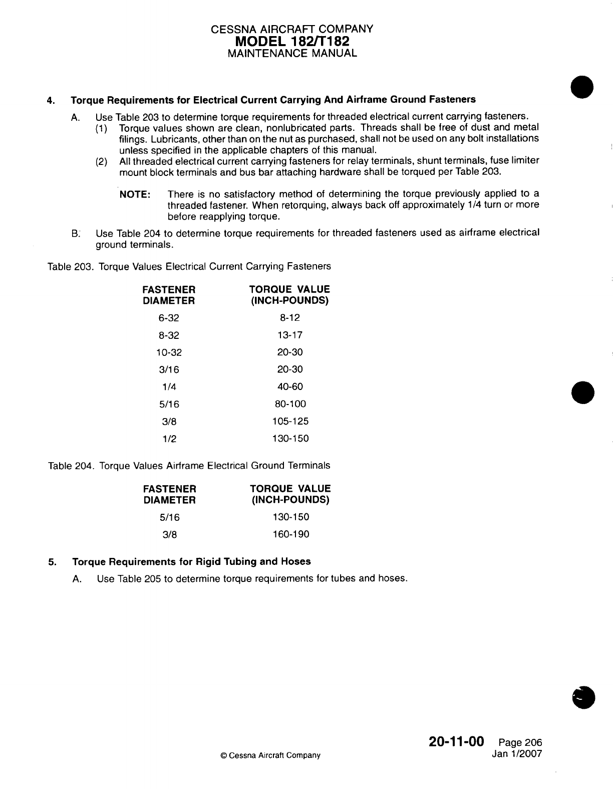
CESSNA
AIRCRAFT
COMPANY
MODEL
182/Ti
182
MAINTENANCE
MANUAL
4.
Torque
Requirements
for
Electrical Current
Carrying
And
Airframe
Ground
Fasteners
A.
Use
Table
203
to
determine
torque
requirements
for
threaded
electrical
current carrying
fasteners.
(1)
Torque
values
shown
are
clean,
nonlubricated
parts.
Threads
shall
be
free
of
dust
and
metal
filings.
Lubricants,
other
than
on
the
nut
as
purchased,
shall
not
be
used
on
any
bolt
installations
unless
specified
in
the
applicable
chapters
of
this
manual.
(2)
All
threaded
electrical
current
carrying
fasteners
for
relay
terminals, shunt terminals,
fuse
limiter
mount
block terminals
and
bus
bar
attaching
hardware
shall
be
torqued per
Table
203.
NOTE:
There
is
no
satisfactory
method
of
determining
the torque
previously
applied
to
a
threaded
fastener. When retorquing,
always
back
off
approximately
1/4
turn
or
more
before
reapplying torque.
B.
Use
Table 204
to
determine
torque
requirements
for
threaded
fasteners
used
as
airframe
electrical
ground
terminals.
Table
203.
Torque
Values
Electrical
Current Carrying
Fasteners
FASTENER
DIAMETER
6-32
8-32
10-32
3/16
1/4
5/16
3/8
11/2
TORQUE VALUE
(INCH-POUNDS)
8-12
13-17
20-30
20-30
40-60
80-100
105-125
130-150
Table
204. Torque
Values
Airframe
Electrical Ground
Terminals
FASTENER
DIAMETER
5/16
3/8
TORQUE
VALUE
(INCH-POUNDS)
130-1
50
160-19go
5.
Torque
Requirements
for Rigid
Tubing
and
Hoses
A.
Use
Table
205 to
determine torque requirements
for
tubes
and
hoses.
20-11-00
©
Cessna
Aircraft
Company
Page
206
Janl1/2007
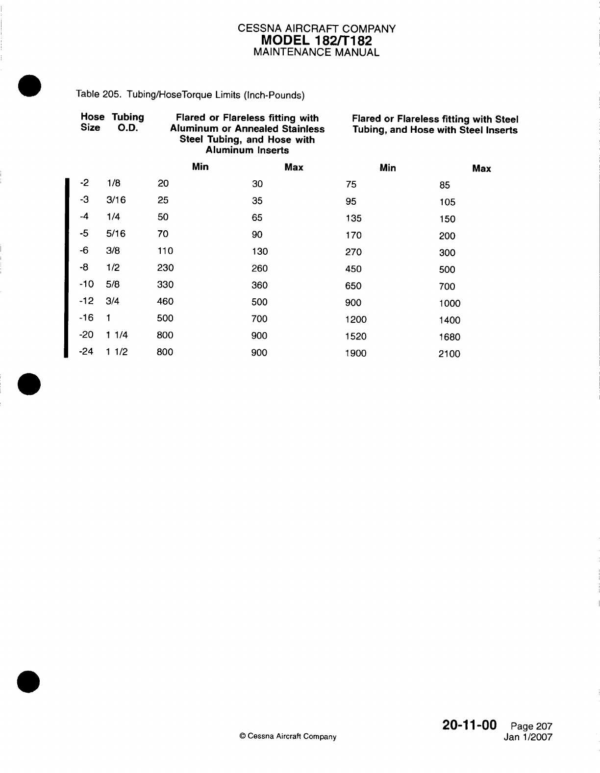
CESSNA
AIRCRAFT
COMPANY
MODEL
1821T182
MAINTENANCE
MANUAL
Table
205.
Tubing/HoseTorque
Limits
(Inch-Pounds)
Hose
Tubing
Size
O.D.
-2
-3
-4
-5
-6
-8
-10
-12
-16
-20
-24
1
/8
3/16
1/4
5/16
3/8
1/2
5/8
3/4
1
1 1/4
1 1/2
Flared
or
Flareless
fitting
with
Aluminum
or
Annealed
Stainless
Steel
Tubing,
and
Hose
with
Aluminum
Inserts
Min
Max
20
25
50
70
110
230
330
460
500
800
800
30
35
65
90
130
260
360
500
700
900
900
Flared
or Flareless
fitting
with
Steel
Tubing,
and
Hose
with
Steel
Inserts
Min
75
95
135
170
270
450
650
900
1200
1520
1900
Max
85
105
150
200
300
500
700
1000
1400
1680
2100
Q
Cessna
Aircraft
Company
20-11
-00
Page
207
Janl1/2007
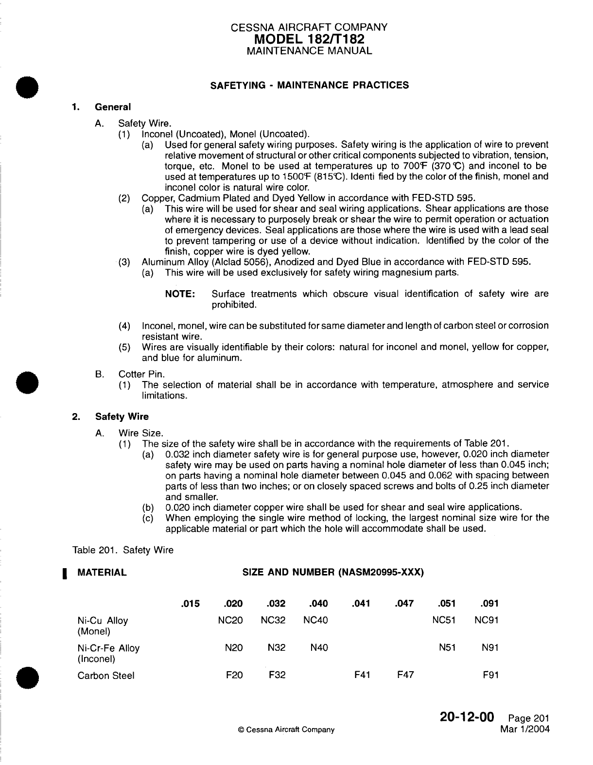
CESSNA
AIRCRAFT
COMPANY
MODEL
182/T182
MAINTENANCE
MANUAL
SAFETYING
-
MAINTENANCE PRACTICES
1.
General
A.
Safety
Wire.
(1)
Inconel
(Uncoated),
Monel
(Uncoated).
(a)
Used
for
general safety
wiring purposes.
Safety
wiring
is
the
application
of
wire
to
prevent
relative
movement
of
structural
or
other critical components
subjected
to
vibration,
tension,
torque,
etc.
Monel
to
be
used
at
temperatures
up
to
700'F
(370
'C)
and
inconel to
be
used
at temperatures
up
to
1500F
(8151C).
Identi
fled
by
the
color
of
the
finish,
monel
and
inconel
color
is
natural
wire color.
(2)
Copper, Cadmium
Plated
and
Dyed
Yellow
in
accordance
with
FED-STD 595.
(a)
This
wire
will
be
used
for shear
and
seal
wiring
applications.
Shear
applications
are
those
where
it
is
necessary
to
purposely
break
or
shear
the
wire
to permit
operation
or
actuation
of
emergency
devices.
Seal
applications
are
those
where
the
wire
is
used
with
a
lead
seal
to
prevent tampering
or
use of
a
device
without indication.
Identified
by
the
color
of the
finish,
copper
wire
is
dyed
yellow.
(3)
Aluminum
Alloy
(Alclad 5056),
Anodized
and Dyed Blue
in
accordance
with
FED-STD
595.
(a)
This
wire
will be
used
exclusively for
safety
wiring
magnesium
parts.
NOTE:
Surface treatments
which
obscure
visual
identification
of
safety
wire
are
prohibited.
(4)
Inconel,
monel,
wire can
be
substituted
for
same
diameter
and
length
of
carbon
steel
or
corrosion
resistant
wire.
(5)
Wires
are
visually
identifiable
by
their
colors:
natural
for inconel
and
monel,
yellow
for
copper,
and
blue
for
aluminum.
B.
Cotter
Pin.
(1)
The
selection
of
material
shall
be
in
accordance
with
temperature, atmosphere
and
service
limitations.
2.
Safety
Wire
A.
Wire
Size.
(1)
The
size
of
the safety
wire
shall
be
in
accordance
with
the
requirements
of
Table
201.
(a)
0.032
inch
diameter safety
wire
is
for
general
purpose
use,
however,
0.020
inch
diameter
safety
wire
may be
used
on
parts having
a
nominal
hole
diameter
of
less than
0.045
inch;
on
parts having
a
nominal
hole
diameter
between
0.045
and
0.062
with
spacing
between
parts
of
less
than two
inches;
or on
closely
spaced screws
and bolts
of
0.25
inch
diameter
and
smaller.
(b)
0.020
inch
diameter
copper
wire
shall
be
used
for
shear
and
seal
wire
applications.
(c)
When
employing
the
single
wire method
of
locking, the
largest
nominal
size
wire
for
the
applicable
material or
part
which the
hole
will
accommodate
shall
be
used.
Table
201.
Safety
Wire
MATERIAL
SIZE
AND
NUMBER
(NASM20995-XXX)
.015
.020
.032
.040
.041
.047
.051
.091
Ni-Cu
Alloy
NC20 NC32
NC40
NC51
NC91
(Monel)
Ni-Cr-Fe
Alloy
N20 N32 N40
N51
N91
(Inconel)
Carbon
Steel
F20 F32
F41
F47
F91
20-12-00
Page
201
©
Cessna
Aircraft
Company
Mar
1/2004
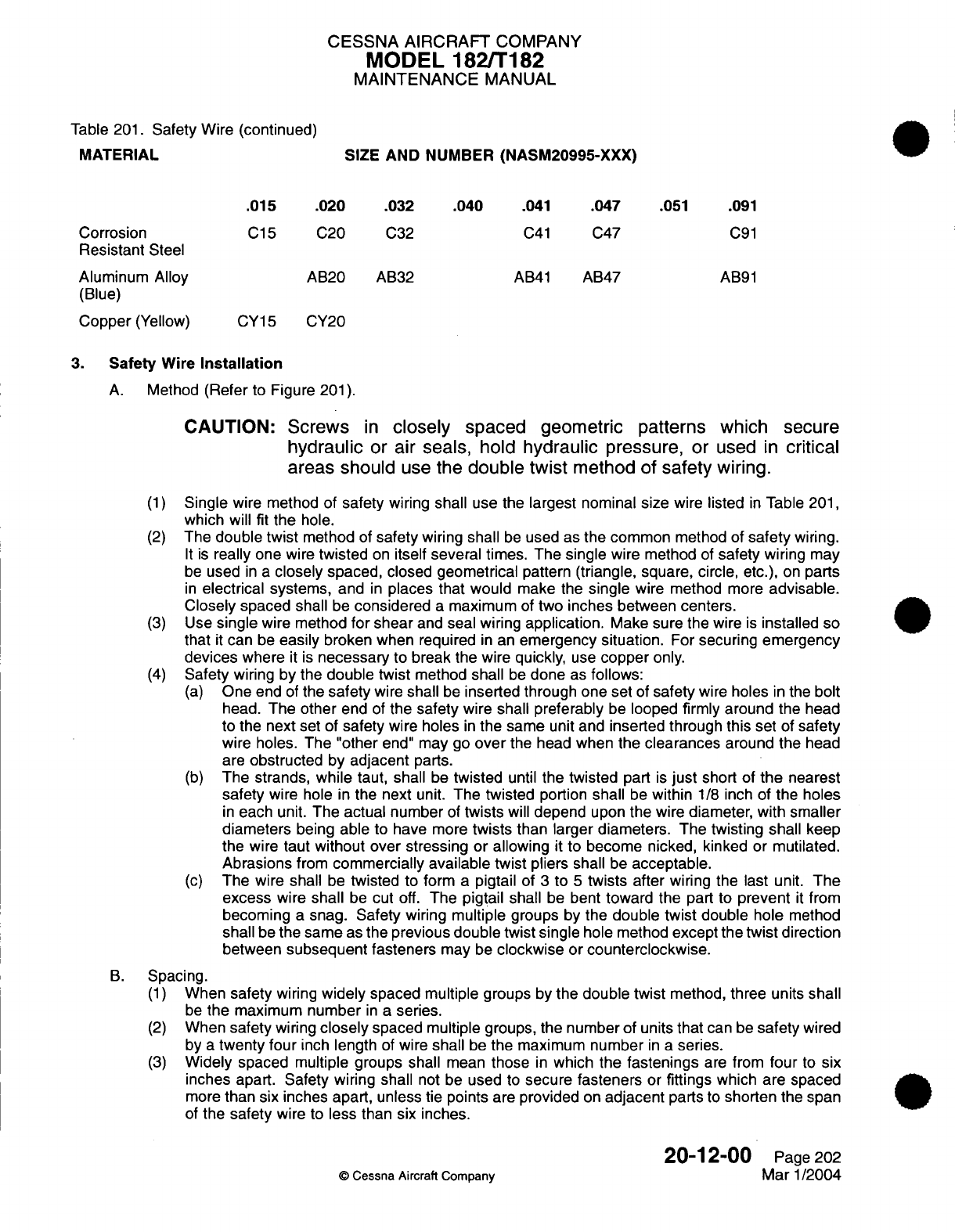
CESSNA AIRCRAFT
COMPANY
MODEL
182/T182
MAINTENANCE
MANUAL
Table
201.
Safety
Wire
(continued)
MATERIAL
SIZE
AND
NUMBER
(NASM20995-XXX)
.015
.020
.032 .040
.041
.047
.051
.091
Corrosion
C15
C20
C32
C41
C47
C91
Resistant
Steel
Aluminum Alloy
AB20 AB32
AB41
AB47 AB91
(Blue)
Copper
(Yellow) CY15
CY20
3.
Safety
Wire
Installation
A.
Method
(Refer
to
Figure
201).
CAUTION:
Screws
in
closely
spaced geometric
patterns which secure
hydraulic
or
air
seals,
hold
hydraulic
pressure,
or
used
in
critical
areas
should
use
the
double
twist
method
of
safety
wiring.
(1)
Single
wire method
of
safety
wiring
shall
use the
largest nominal
size
wire
listed
in
Table
201,
which
will
fit
the
hole.
(2)
The
double
twist
method
of
safety
wiring shall
be
used
as
the common
method of
safety
wiring.
It
is
really one
wire
twisted
on
itself
several times. The
single
wire
method
of
safety
wiring
may
be
used
in a
closely
spaced,
closed geometrical
pattern
(triangle,
square,
circle,
etc.),
on
parts
in
electrical
systems,
and
in
places that would
make the
single
wire
method
more
advisable.
Closely
spaced
shall
be
considered
a
maximum
of
two
inches
between
centers.
(3)
Use
single
wire method
for
shear
and
seal wiring
application.
Make sure
the
wire
is
installed
so
that
it
can
be
easily
broken when
required
in
an
emergency
situation.
For
securing
emergency
devices
where
it
is
necessary
to
break
the wire
quickly,
use
copper
only.
(4)
Safety
wiring
by the
double
twist
method
shall
be
done
as
follows:
(a)
One
end
of
the
safety
wire
shall
be
inserted
through one
set
of
safety
wire
holes
in
the
bolt
head.
The
other
end
of
the safety
wire shall
preferably
be
looped
firmly around the
head
to the
next
set
of
safety
wire
holes
in
the same
unit
and
inserted through
this
set
of
safety
wire
holes.
The
"other
end"
may go
over
the head
when
the clearances
around the
head
are
obstructed by
adjacent
parts.
(b)
The
strands,
while
taut,
shall
be
twisted
until
the
twisted
part
is
just
short
of
the
nearest
safety
wire hole
in
the
next
unit.
The twisted
portion
shall
be
within
1/8
inch
of
the
holes
in
each
unit.
The actual number
of
twists
will
depend
upon
the wire
diameter,
with smaller
diameters
being
able
to
have
more
twists
than
larger
diameters. The
twisting shall
keep
the
wire
taut
without over stressing or
allowing
it
to
become
nicked,
kinked
or
mutilated.
Abrasions
from
commercially
available twist
pliers
shall
be
acceptable.
(c)
The wire shall
be
twisted
to form
a
pigtail
of
3
to
5
twists
after
wiring the last
unit.
The
excess
wire
shall
be
cut
off.
The
pigtail
shall
be
bent
toward
the
part
to
prevent
it
from
becoming
a
snag.
Safety
wiring multiple groups
by
the
double
twist
double
hole
method
shall
be
the
same
as
the
previous
double twist single
hole
method
except
the
twist
direction
between
subsequent
fasteners
may
be
clockwise or counterclockwise.
B.
Spacing.
(1)
When
safety
wiring
widely
spaced multiple
groups
by
the double
twist
method,
three
units shall
be
the
maximum
number
in
a
series.
(2)
When
safety
wiring
closely
spaced multiple
groups, the number
of
units
that
can
be
safety
wired
by
a
twenty four
inch
length
of
wire
shall
be
the
maximum
number
in
a
series.
(3)
Widely
spaced
multiple groups
shall
mean
those
in
which
the
fastenings
are
from
four
to
six
inches apart. Safety wiring
shall
not be
used
to
secure
fasteners
or
fittings
which are
spaced
more
than
six
inches apart, unless
tie points
are
provided
on
adjacent
parts
to
shorten
the
span
of
the
safety
wire
to
less
than
six
inches.
20-12-00
Page
202
©
Cessna Aircraft Company
Mar
1/2004
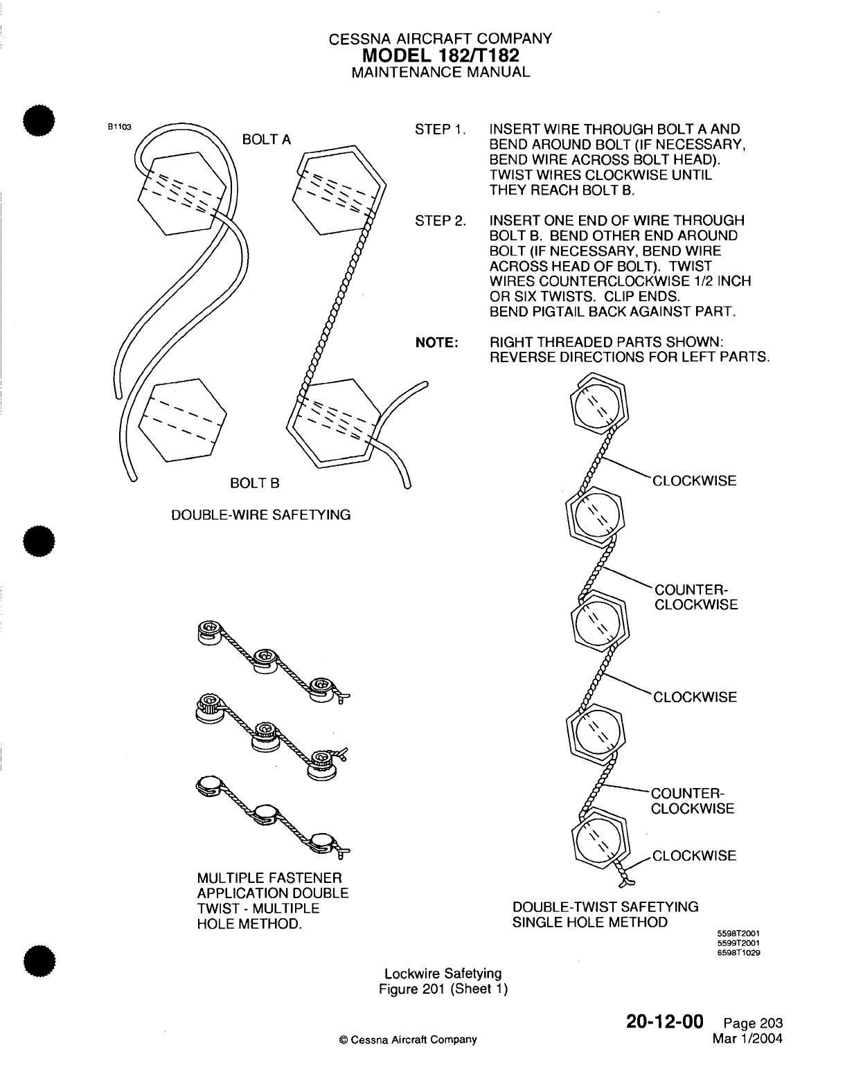
CESSNA AIRCRAFT
COMPANY
MODEL
182/T182
MAINTENANCE
MANUAL
!OLT
A
STEP
1.
INSERT
WIRE
THROUGH BOLT
A
AND
Mrklr% A
rD
i *kirK -t
- /-
r
.
kl1Thr
SI(C
A
MV/
DtINU
MnUUINU
DULI
1ir
NICUCOOMI-iT,
BEND
WIRE
ACROSS
BOLT HEAD).
TWIST
WIRES
CLOCKWISE
UNTIL
THEY
REACH
BOLT
B.
FEP
2.
INSERT
ONE
END
OF
WIRE
THROUGH
BOLT
B.
BEND
OTHER
END
AROUND
BOLT
(IF
NECESSARY, BEND WIRE
ACROSS
HEAD
OF
BOLT).
TWIST
WIRES COUNTERCLOCKWISE
1/2
INCH
OR SIX
TWISTS.
CLIP ENDS.
BEND
PIGTAIL
BACK
AGAINST
PART.
3TE:
RIGHT
THREADED
PARTS
SHOWN:
REVERSE
DIRECTIONS
FOR
LEFT
PARTS.
DOUBLE-WIRE
SAFETYING
-COUNTER-
CLOCKWISE
MULTIPLE FASTENER
APPLICATION
DOUBLE
TWIST- MULTIPLE
HOLE
METHOD.
DOUBLE-TWIST
SAFETYING
SINGLE
HOLE METHOD
Lockwire Safetying
Figure
201
(Sheet
1)
20-12-00
©
Cessna
Aircraft
Company
1
T
l
5598T2001
5599T2001
6598T1029
Page
203
Mar
1/2004
U-VLL
I
L
-
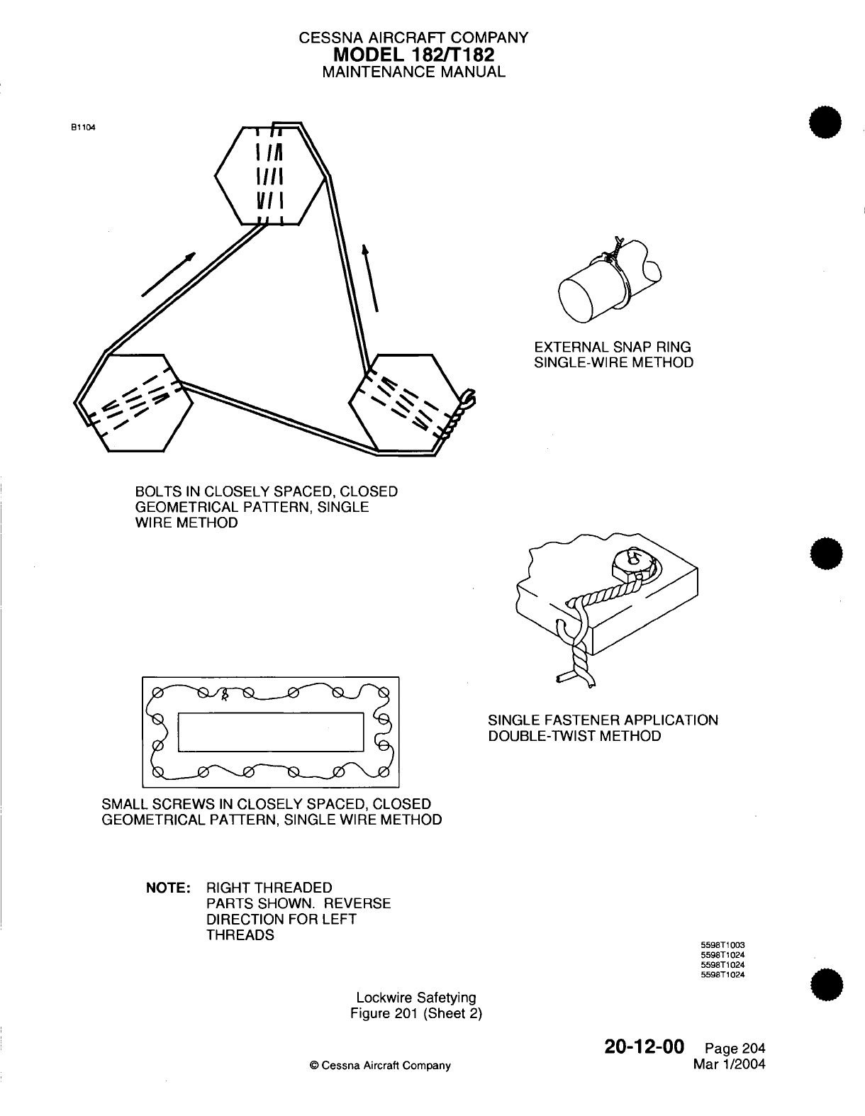
CESSNA AIRCRAFT
COMPANY
MODEL
182/T182
MAINTENANCE
MANUAL
EXTERNAL
SNAP
RING
SINGLE-WIRE
METHOD
BOLTS
IN
CLOSELY
SPACED, CLOSED
GEOMETRICAL
PATTERN,
SINGLE
WIRE
METHOD
SINGLE
FASTENER
APPLICATION
DOUBLE-TWIST
METHOD
SMALL SCREWS
IN
CLOSELY
SPACED,
CLOSED
GEOMETRICAL
PATTERN,
SINGLE
WIRE
METHOD
NOTE:
RIGHT THREADED
PARTS
SHOWN. REVERSE
DIRECTION
FOR
LEFT
THREADS
Lockwire
Safetying
Figure
201
(Sheet
2)
20-12-00
©
Cessna
Aircraft Company
5598T1003
5598T1024
5598T1024
5598T1024
Page
204
Mar
1/2004
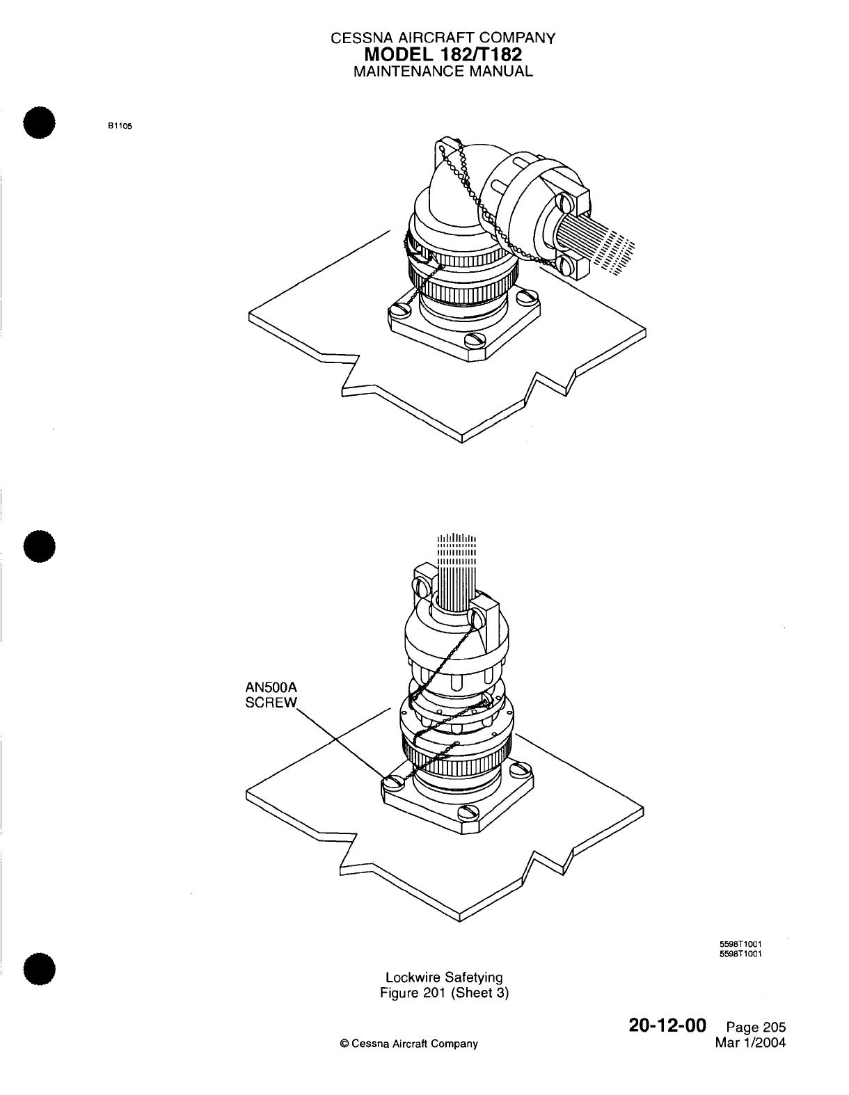
CESSNA
AIRCRAFT
COMPANY
MODEL
182/T182
MAINTENANCE
MANUAL
B1105
hllllllllllll
1111111111111
II1illlllllll
AN500A
5598T1001
5598T1001
Lockwire
Safetying
Figure
201
(Sheet
3)
©
Cessna Aircraft
Company
20-12-00
Page 205
Mar
1/2004
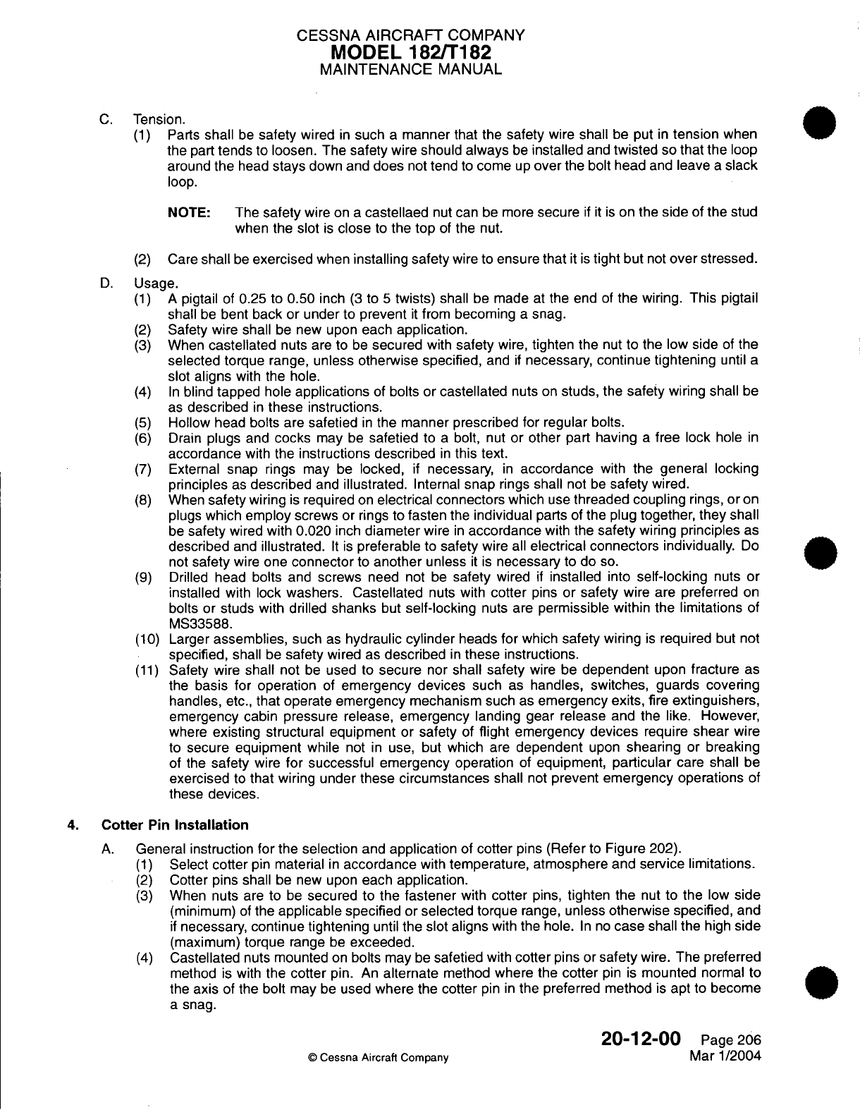
CESSNA
AIRCRAFT
COMPANY
MODEL 182/T182
MAINTENANCE
MANUAL
C.
Tension.
(1)
Parts
shall
be
safety
wired
in
such
a
manner that
the
safety
wire
shall
be
put
in
tension
when
the
part
tends
to
loosen. The
safety
wire
should
always
be
installed
and
twisted
so
that
the
loop
around
the
head
stays
down and
does
not
tend
to
come
up
over
the
bolt head
and
leave
a
slack
loop.
NOTE:
The
safety
wire
on
a
castellaed
nut
can
be more
secure
if it is
on
the
side
of
the
stud
when
the slot
is
close
to
the
top
of
the
nut.
(2)
Care
shall
be
exercised
when
installing
safety
wire to
ensure
that
it is
tight
but
not
over
stressed.
D.
Usage.
(1)
A
pigtail
of
0.25 to
0.50
inch
(3
to
5
twists)
shall
be made
at
the end
of
the
wiring.
This
pigtail
shall
be
bent
back
or
under
to
prevent
it
from
becoming
a
snag.
(2)
Safety wire
shall
be
new upon
each
application.
(3)
When
castellated
nuts
are
to
be
secured
with
safety
wire,
tighten the
nut
to
the
low
side
of
the
selected
torque
range,
unless otherwise specified,
and
if
necessary,
continue
tightening
until
a
slot
aligns
with
the hole.
(4)
In
blind
tapped
hole
applications
of
bolts
or
castellated
nuts
on
studs,
the
safety
wiring shall
be
as
described
in
these
instructions.
(5)
Hollow
head
bolts
are
safetied
in
the
manner
prescribed for regular
bolts.
(6)
Drain
plugs
and
cocks
may
be
safetied
to
a
bolt,
nut
or
other
part having
a
free
lock
hole
in
accordance
with
the
instructions described
in
this
text.
(7)
External
snap
rings
may
be
locked,
if
necessary,
in
accordance
with
the
general
locking
principles
as
described
and
illustrated.
Internal
snap
rings
shall
not
be
safety
wired.
(8)
When
safety
wiring
is
required
on
electrical connectors
which
use
threaded
coupling
rings,
or
on
plugs
which employ
screws
or
rings to
fasten
the
individual
parts of
the
plug
together,
they
shall
be
safety
wired with
0.020
inch
diameter
wire
in
accordance
with
the
safety
wiring
principles
as
described
and
illustrated.
It is
preferable
to
safety
wire
all
electrical connectors
individually.
Do
not
safety
wire
one
connector
to
another
unless
it
is
necessary
to do
so.
(9)
Drilled
head
bolts
and
screws
need
not
be
safety
wired
if
installed
into
self-locking
nuts
or
installed
with lock
washers. Castellated
nuts
with
cotter
pins
or
safety
wire
are preferred
on
bolts
or
studs
with drilled
shanks
but
self-locking
nuts
are
permissible
within
the
limitations
of
MS33588.
(10)
Larger
assemblies, such
as
hydraulic
cylinder
heads
for
which
safety
wiring
is
required
but
not
specified,
shall
be
safety
wired
as
described
in
these instructions.
(11)
Safety
wire
shall
not
be
used
to
secure
nor
shall safety
wire
be
dependent
upon
fracture
as
the
basis for
operation
of
emergency
devices
such
as
handles,
switches,
guards covering
handles,
etc.,
that
operate emergency mechanism
such
as
emergency
exits,
fire
extinguishers,
emergency cabin pressure
release,
emergency landing
gear
release
and
the
like.
However,
where
existing
structural equipment
or
safety
of
flight
emergency
devices
require
shear
wire
to
secure equipment while
not
in
use, but
which
are
dependent
upon
shearing
or
breaking
of the
safety
wire
for successful
emergency
operation
of
equipment,
particular
care
shall
be
exercised
to
that
wiring under
these
circumstances
shall
not
prevent emergency operations
of
these
devices.
4.
Cotter
Pin
Installation
A.
General
instruction for
the
selection
and
application
of
cotter
pins
(Refer
to
Figure 202).
(1)
Select
cotter
pin
material
in
accordance
with
temperature,
atmosphere
and
service
limitations.
(2)
Cotter pins
shall
be new
upon
each
application.
(3)
When nuts
are
to
be
secured to
the
fastener
with
cotter
pins,
tighten
the
nut
to
the
low
side
(minimum)
of
the
applicable
specified
or
selected torque
range,
unless
otherwise specified,
and
if
necessary, continue tightening
until
the slot aligns
with
the
hole.
In
no
case
shall
the
high
side
(maximum)
torque
range
be
exceeded.
(4)
Castellated
nuts
mounted
on
bolts
may
be
safetied
with
cotter
pins
or
safety
wire.
The preferred
method
is with
the
cotter
pin.
An
alternate
method
where
the
cotter
pin
is
mounted
normal
to
the
axis
of the
bolt
may
be
used
where
the
cotter
pin
in
the
preferred method
is
apt
to
become
a
snag.
20-12-00
Page
206
©
Cessna Aircraft Company
Mar
1/2004
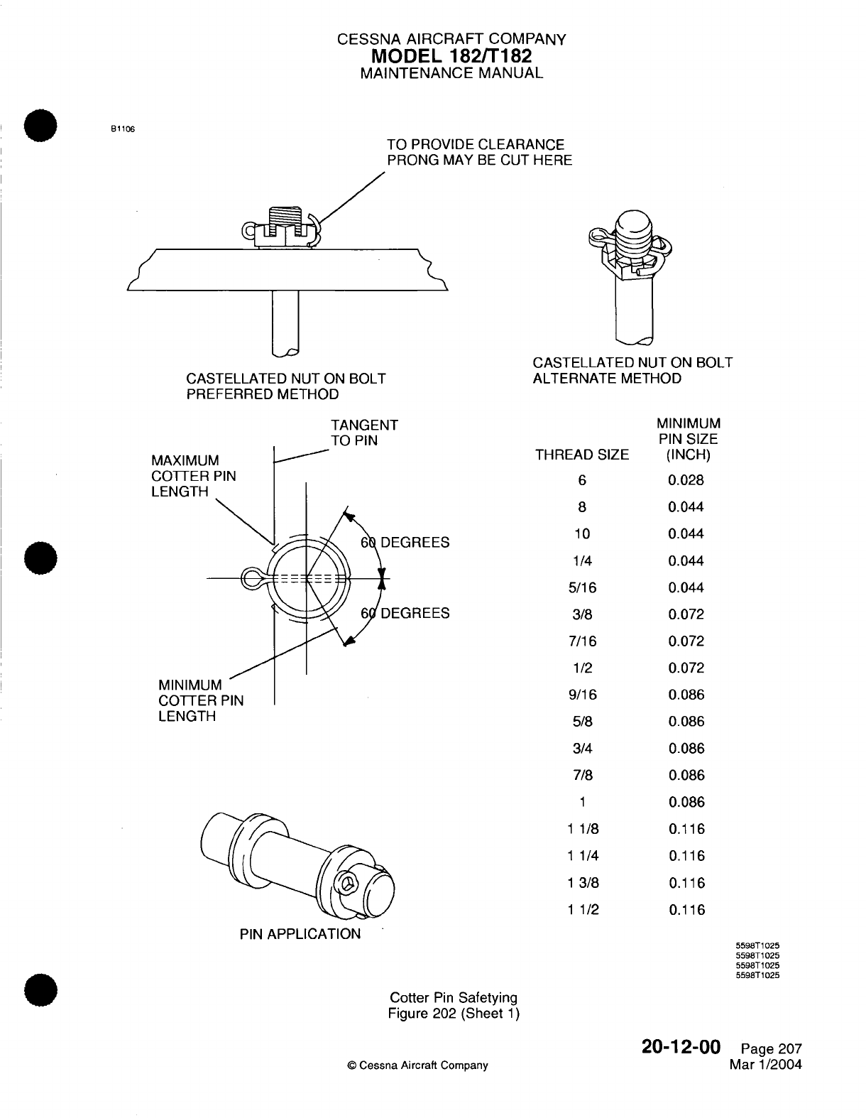
CESSNA AIRCRAFT
COMPANY
MODEL
182/T182
MAINTENANCE
MANUAL
B1106
TO
PROVIDE
CLEARANCE
PRONG
MAY
BE
CUT
HERE
CASTELLATED
NUT ON
BOLT
PREFERRED
METHOD
CASTELLATED
NUT
ON
BOLT
ALTERNATE
METHOD
TANGENT
TO
PIN
MAXIMUM
COTTER
PIN
LENGTH
MINIMUM
COTTER
PIN
LENGTH
THREAD
SIZE
6
8
10
1/4
5/16
3/8
7/16
1/2
9/16
5/8
3/4
7/8
1
1
1/8
1 1/4
1
3/8
1
1/2
PIN
APPLICATION
Cotter
Pin
Safetying
Figure
202
(Sheet
1)
©
Cessna Aircraft
Company
20-12-00
Page
207
Mar
1/2004
MINIMUM
PIN
SIZE
(INCH)
0.028
0.044
0.044
0.044
0.044
0.072
0.072
0.072
0.086
0.086
0.086
0.086
0.086
0.116
0.116
0.116
0.116
5598T1025
5598T1025
5598T1025
5598T1025
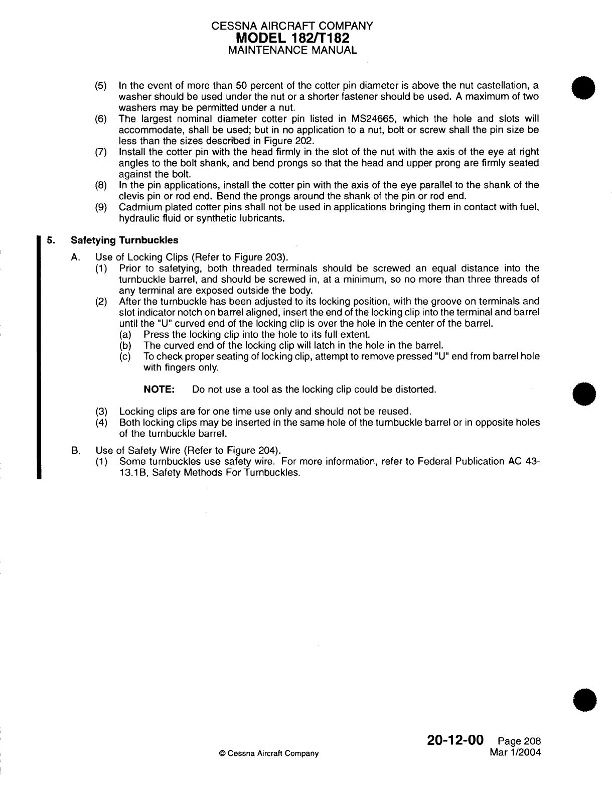
CESSNA
AIRCRAFT
COMPANY
MODEL
182/T182
MAINTENANCE
MANUAL
(5) In
the event
of
more
than
50
percent
of
the
cotter
pin
diameter
is
above the
nut
castellation,
a
washer
should
be
used
under
the
nut or
a
shorter
fastener
should
be
used.
A
maximum
of
two
washers
may
be
permitted
under
a
nut.
(6)
The largest
nominal
diameter
cotter
pin
listed
in
MS24665,
which
the
hole and
slots will
accommodate,
shall
be
used;
but
in
no
application
to
a
nut,
bolt or
screw
shall
the
pin
size
be
less than
the
sizes
described
in
Figure
202.
(7)
Install
the
cotter
pin
with the
head
firmly
in
the
slot
of
the nut
with
the
axis
of
the
eye
at
right
angles
to
the
bolt
shank,
and
bend
prongs so that the
head and
upper
prong
are
firmly seated
against
the
bolt.
(8) In
the
pin
applications,
install
the
cotter
pin
with
the
axis
of
the
eye
parallel
to
the shank
of
the
clevis
pin
or
rod
end.
Bend
the
prongs
around
the
shank
of
the
pin
or
rod
end.
(9)
Cadmium plated
cotter
pins
shall
not
be
used
in
applications
bringing
them
in
contact
with
fuel,
hydraulic
fluid
or synthetic
lubricants.
5.
Safetying
Turnbuckles
A.
Use
of
Locking
Clips
(Refer
to
Figure 203).
(1)
Prior
to
safetying,
both
threaded
terminals
should
be
screwed
an
equal
distance
into
the
turnbuckle
barrel,
and
should
be
screwed
in,
at
a
minimum,
so
no
more
than
three threads
of
any terminal
are
exposed outside
the body.
(2)
After
the turnbuckle
has
been
adjusted
to
its
locking position, with the groove
on
terminals
and
slot indicator
notch
on
barrel aligned,
insert
the
end
of the
locking
clip
into
the
terminal
and
barrel
until
the
"U"
curved end
of
the locking
clip
is
over
the
hole
in
the
center
of
the
barrel.
(a)
Press
the
locking clip
into
the
hole
to
its
full
extent.
(b)
The curved
end
of
the
locking
clip
will
latch
in
the
hole
in
the
barrel.
(c)
To
check
proper
seating
of
locking clip, attempt
to
remove
pressed
"U"
end
from barrel
hole
with
fingers
only.
NOTE:
Do
not use
a
tool
as
the
locking
clip
could
be
distorted.
(3)
Locking
clips
are
for
one time
use
only
and
should
not
be
reused.
(4) Both
locking
clips
may
be
inserted
in
the same
hole of
the
turnbuckle
barrel
or
in
opposite
holes
of
the
turnbuckle
barrel.
B.
Use
of
Safety
Wire
(Refer
to
Figure
204).
(1)
Some
turnbuckles
use
safety
wire.
For more
information,
refer
to
Federal
Publication
AC
43-
13.1B,
Safety
Methods
For
Turnbuckles.
20-12-00
Page
208
©
Cessna
Aircraft
Company
Mar
1/2004

CESSNA AIRCRAFT
COMPANY
MODEL
182/T182
MAINTENANCE
MANUAL
B1107
(NOTE)
BARREL
CABLE
TERMINAL
I I -./
(NOTE)
NOTE: PULL WITH
YOUR FINGERS
FOR
AN
INSPECTION
TO
MAKE
SURE
THE
CLIP
WILL
NOT
COME
OUT.
STRAIGHT
END
HOOK
SHOULDER
END
LOOP
HOOK
LIP
HOOK
LOOP
SAFETY
CLIP
INSTALLATION
SAFETY CLIP
INSTALLATION
0798T1005
0798T1003
0798T1004
Safetying
Turnbuckle Assemblies
with
Safety
Clips
Figure
203
(Sheet
1)
20-12-00
©
Cessna Aircraft
Company
Page
209
Mar
1/2004
B
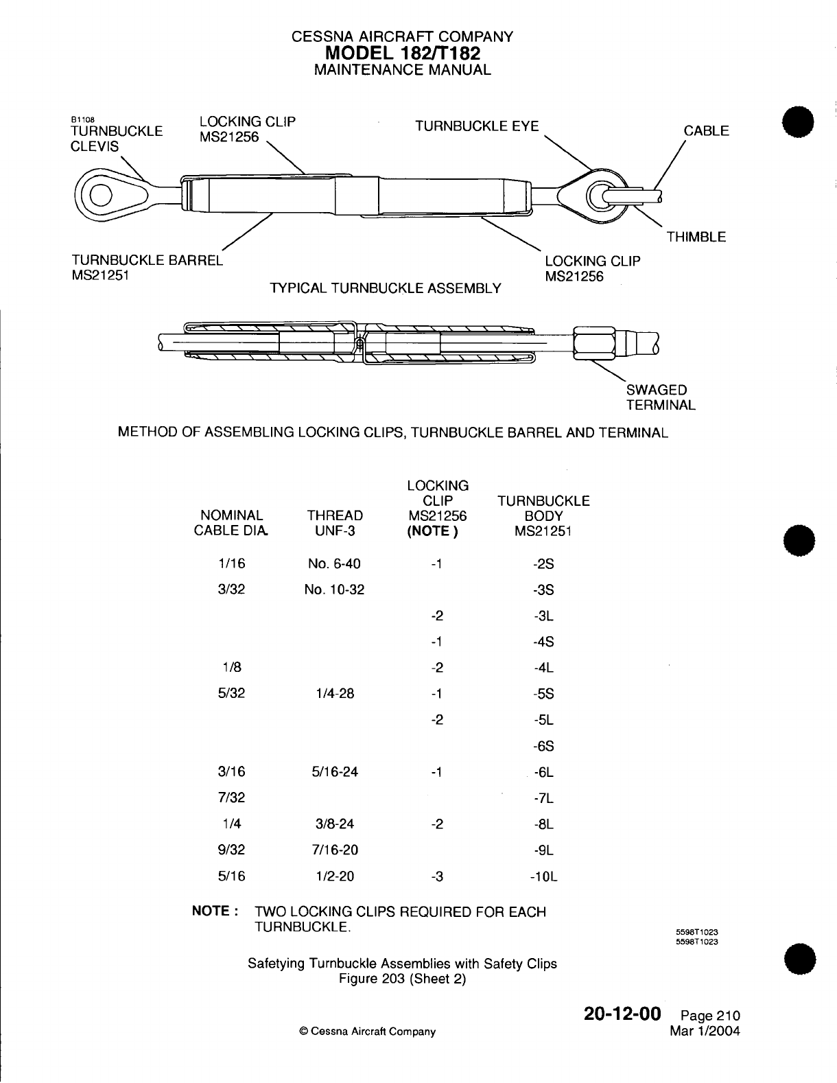
CESSNA AIRCRAFT
COMPANY
MODEL
182/T182
MAINTENANCE
MANUAL
Bto108
LOCKING
CLIP
TURNBUCKLE
MS21256
CLEVIS
0 I
I
TURNBUCKLE
BARREL
MS21251
TURNBUCKLE
EYE
][
TYPICAL
TURNBUCKLE ASSEMBLY
LOCKING
CLIP
MS21256
L1n I \ \ \
'
\
'\
X
"
\ \ \ \
I
'A
\
'
['
' '
\
-
EID
SWAGED
TERMINAL
METHOD
OF
ASSEMBLING
LOCKING CLIPS,
TURNBUCKLE
BARREL
AND
TERMINAL
LOCKING
CLIP
MS21256
(NOTE)
-1
-2
-1
-2
-1
-2
TURNBUCKLE
BODY
MS21251
-2S
-3S
-3L
-4S
-4L
-5S
-5L
-6S
-1
-2
-3
-6L
-7L
-8L
-9L
-10L
NOTE:
TWO
LOCKING
CLIPS REQUIRED
FOR
EACH
TURNBUCKLE.
Safetying
Turnbuckle
Assemblies
with
Safety
Clips
Figure
203
(Sheet
2)
5598T1023
5598T1023
20-12-00
©
Cessna
Aircraft
Company
CARI
F
THIMBLE
NOMINAL
CABLE
DIA
1/16
3/32
THREAD
UNF-3
No.
6-40
No.
10-32
1/8
5/32
1/4-28
3/16
7/32
1/4
9/32
5/16
5/16-24
3/8-24
7/16-20
1/2-20
Page
210
Mar
1/2004
I
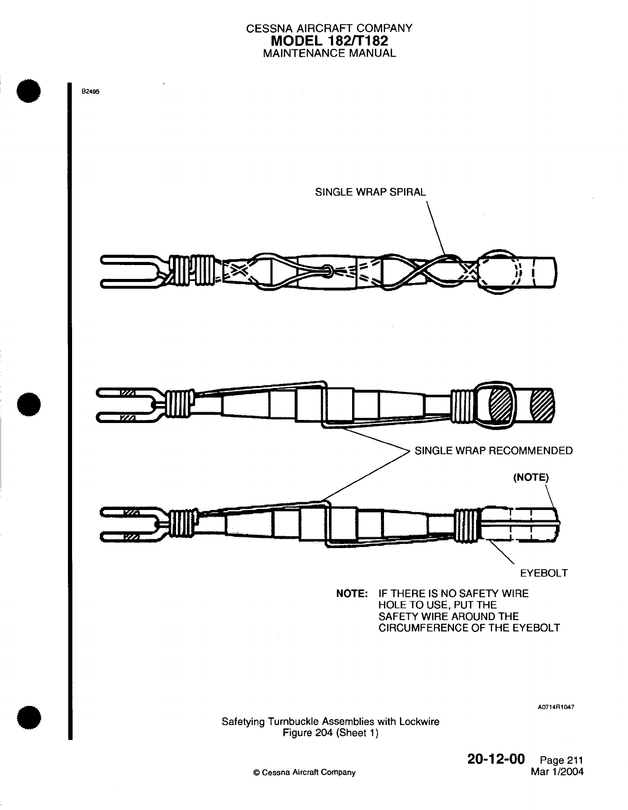
CESSNA AIRCRAFT
COMPANY
MODEL 182/T182
MAINTENANCE
MANUAL
B2495
SINGLE WRAP SPIRAL
EYEBOLT
NOTE:
IF
THERE
IS
NO
SAFETY
WIRE
HOLE
TO
USE,
PUT
THE
SAFETY WIRE
AROUND
THE
CIRCUMFERENCE
OF
THE
EYEBOLT
A0714R1047
Safetying
Turnbuckle
Assemblies
with
Lockwire
Figure
204
(Sheet
1)
©
Cessna
Aircraft
Company
20-12-00
Page
211
Mar
1/2004
ED
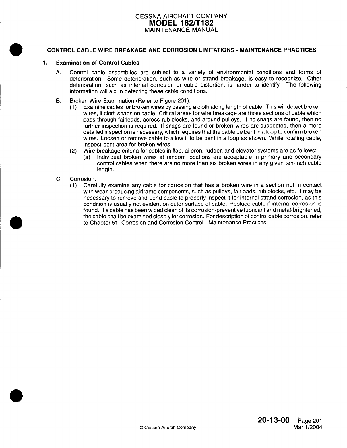
CESSNA
AIRCRAFT
COMPANY
MODEL
182/T182
MAINTENANCE
MANUAL
CONTROL CABLE
WIRE
BREAKAGE
AND CORROSION
LIMITATIONS
-
MAINTENANCE
PRACTICES
1.
Examination
of
Control
Cables
A.
Control
cable assemblies
are
subject
to
a
variety
of
environmental conditions
and
forms
of
deterioration.
Some
deterioration,
such
as
wire
or
strand
breakage,
is
easy to
recognize.
Other
deterioration,
such
as
internal
corrosion
or
cable
distortion,
is
harder
to
identify.
The
following
information
will
aid
in
detecting
these
cable
conditions.
B.
Broken
Wire
Examination
(Refer
to
Figure
201).
(1)
Examine
cables
for
broken
wires
by
passing
a
cloth
along
length
of
cable.
This
will
detect
broken
wires,
if
cloth
snags
on
cable.
Critical
areas
for
wire
breakage
are those
sections
of
cable
which
pass through
fairleads,
across
rub
blocks,
and
around
pulleys.
If
no
snags
are
found, then
no
further inspection
is
required.
If
snags
are
found
or
broken
wires
are
suspected,
then
a
more
detailed inspection
is
necessary,
which
requires
that
the
cable
be
bent
in a
loop
to
confirm
broken
wires.
Loosen
or
remove
cable
to
allow
it
to
be
bent
in a
loop
as
shown.
While rotating
cable,
inspect
bent
area
for
broken wires.
(2)
Wire breakage criteria
for cables
in
flap, aileron,
rudder,
and
elevator
systems
are as
follows:
(a)
Individual
broken
wires at
random
locations
are
acceptable
in
primary
and
secondary
control
cables
when
there
are
no
more
than
six
broken
wires
in
any
given
ten-inch
cable
length.
C.
Corrosion.
(1)
Carefully examine any cable for
corrosion that
has
a
broken wire
in a
section
not
in
contact
with
wear-producing
airframe
components,
such as
pulleys,
fairleads,
rub
blocks,
etc.
It
may
be
necessary
to
remove
and bend
cable
to
properly
inspect
it
for
internal
strand
corrosion,
as
this
condition
is
usually
not
evident
on
outer
surface
of
cable. Replace
cable
if
internal
corrosion
is
found.
If
a
cable
has
been
wiped
clean
of
its
corrosion-preventive
lubricant
and
metal-brightened,
the
cable
shall
be
examined
closely
for corrosion.
For
description
of control
cable
corrosion,
refer
to
Chapter
51,
Corrosion
and
Corrosion Control
-
Maintenance
Practices.
20-13-00
Page
201
©
Cessna
Aircraft
Company
Mar
1/2004
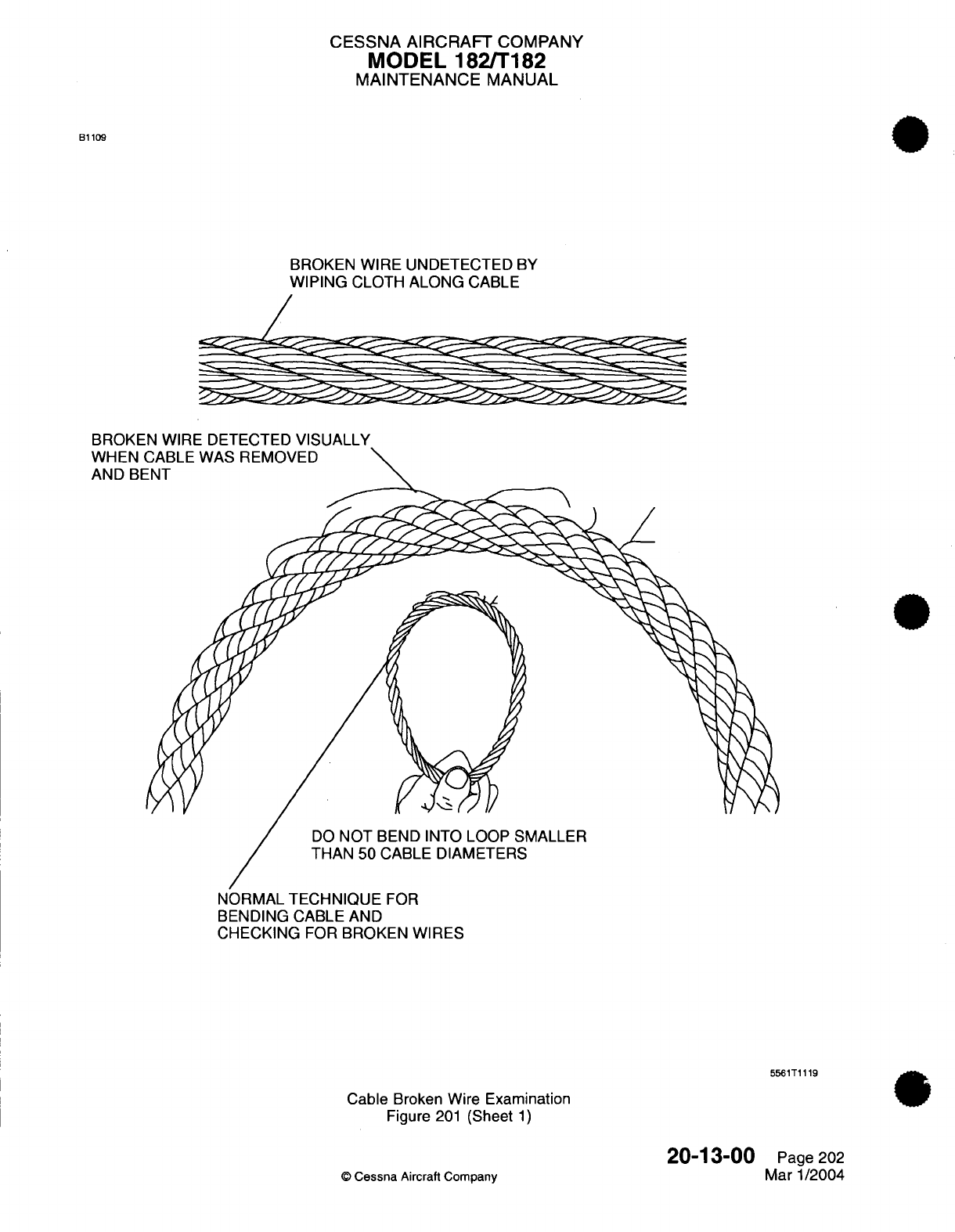
CESSNA AIRCRAFT
COMPANY
MODEL
182/T182
MAINTENANCE
MANUAL
B1109
BROKEN
WIRE UNDETECTED
BY
WIPING
CLOTH
ALONG
CABLE
a
=-5=5
~
~
BROKEN WIRE
DETECTED
VISUALLY
WHEN
AND
BE
DO
NOT
BEND
INTO
LOOP
SMALLER
THAN
50 CABLE DIAMETERS
NORMAL TECHNIQUE
FOR
BENDING
CABLE
AND
CHECKING
FOR
BROKEN
WIRES
5561T1119
Cable
Broken
Wire Examination
Figure
201
(Sheet
1)
20-13-00
©
Cessna
Aircraft
Company
Page
202
Mar
1/2004
CESSNA
AIRCRAFT
COMPANY
MODEL
182/T182
MAINTENANCE
MANUAL
SOLVENTS,
SEALANTS,
AND ADHESIVES
-
DESCRIPTION
AND
OPERATION
1.
General
A.
Solvents,
sealants
and
adhesives
are
composed
of
a
group
of
chemicals
that
often
prove
toxic.
Anyone engaged
in
maintenance,
repair
and
operation
of
airplane
and
airplane
accessories
may
be
exposed
to
these
chemicals.
B.
To
help
avoid
the
effects
of
these
toxic
substances,
work
only
in a
clean,
well-lighted
and
well-ventilated
area.
Rubber
gloves
and
protective
clothing should
be worn.
Avoid breathing
spray
vapors as
they
are
highly
toxic.
C.
When
working
with
toxic
substances,
always
be
alert
for symptoms of
poisoning.
If
symptoms
are
observed,
immediate
removal
of
the
victim
from the
contaminated
area
is
most
important.
2.
Description
A.
For
clarification,
the
description
of
solvents,
sealants
and
adhesives
are
presented
in
individual
paragraphs.
(1)
Solvents.
(a)
Solvents
are
composed
of
chemicals
which
are
capable
of
dissolving other
materials
and
are
primarily
used as
a
cleaning
agent.
Solvent
cleaning
should
be
used
when
it
is
not
practical
to
clean
parts
by
vapor
degreasing
or
immersion
in
chemical
cleaners.
(2)
Sealants.
(a)
Sealants
are
composed
of
chemical
compounds
which
are
primarily
used
as
a
seal
against
the
passage of
air
and
liquids. Classification
of
sealants
are
categorized
by
type
according
to
their
application.
(3)
Adhesives.
(a)
Adhesives
are
composed
of
a
mixture
of
chemicals which
make an
adherent
that
is
primarily
used
for bonding
like
or
unlike
materials,
and
are
classified according
to
their
application.
20-30-00
Page
1
©
Cessna
Aircraft
Company
April 1/2002
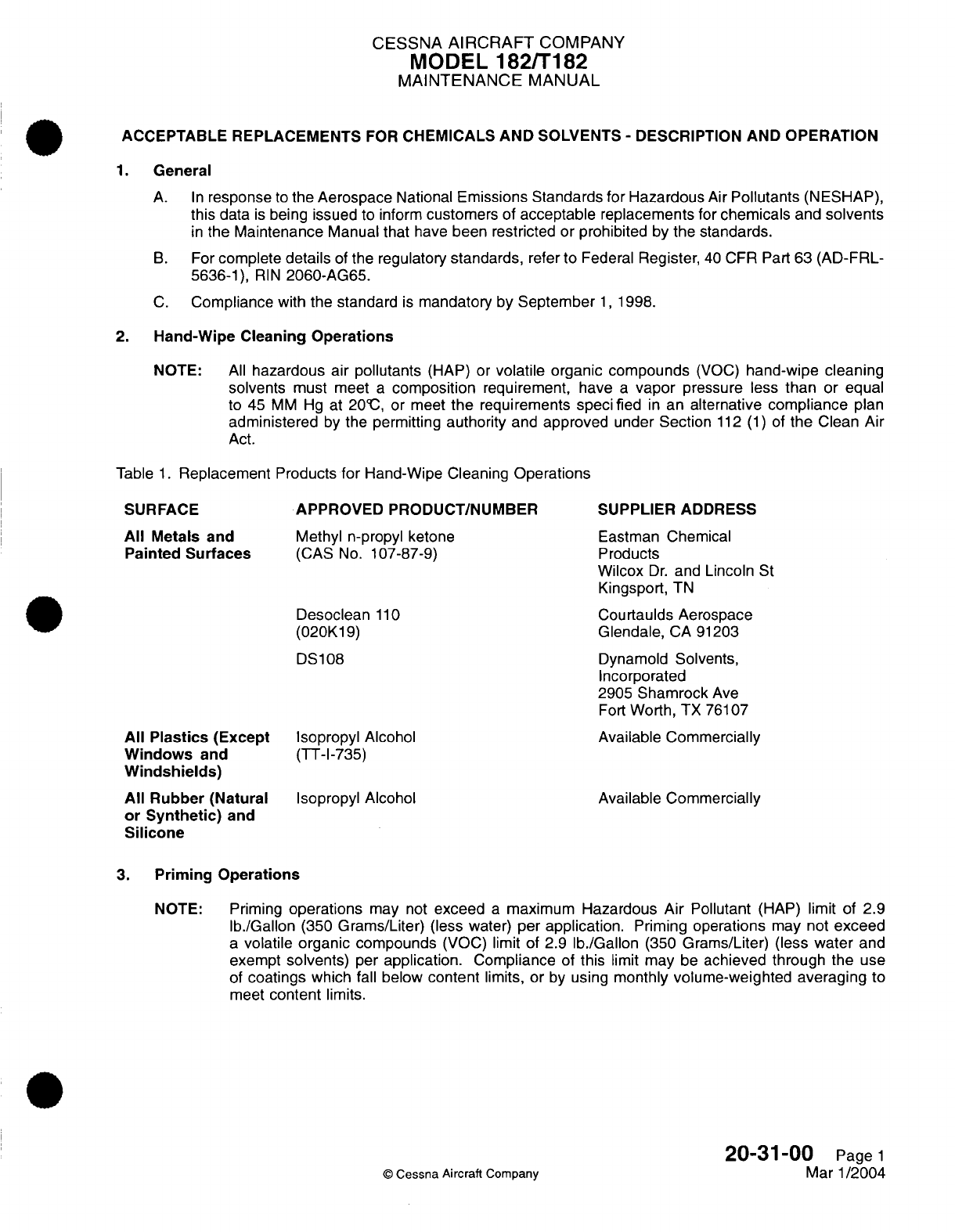
CESSNA
AIRCRAFT
COMPANY
MODEL
182/T182
MAINTENANCE
MANUAL
ACCEPTABLE REPLACEMENTS
FOR
CHEMICALS
AND
SOLVENTS
-
DESCRIPTION AND
OPERATION
1.
General
A.
In
response
to
the
Aerospace
National Emissions
Standards
for
Hazardous
Air
Pollutants
(NESHAP),
this
data
is
being
issued
to inform
customers
of
acceptable
replacements
for
chemicals
and
solvents
in
the
Maintenance
Manual
that
have
been
restricted
or
prohibited
by
the
standards.
B.
For
complete
details
of
the regulatory
standards,
refer
to
Federal
Register,
40
CFR
Part
63
(AD-FRL-
5636-1),
RIN
2060-AG65.
C.
Compliance
with
the
standard
is
mandatory by
September
1,
1998.
2.
Hand-Wipe Cleaning
Operations
NOTE:
All
hazardous
air
pollutants
(HAP) or
volatile
organic
compounds
(VOC)
hand-wipe
cleaning
solvents
must
meet
a
composition
requirement, have
a
vapor
pressure
less
than
or
equal
to 45
MM
Hg
at
209C,
or
meet
the
requirements
specified
in
an
alternative
compliance
plan
administered
by
the
permitting
authority
and
approved
under Section
112
(1)
of
the
Clean
Air
Act.
Table
1.
Replacement
Products
for
Hand-Wipe Cleaning
Operations
All
Plastics
(Except
Windows
and
Windshields)
All
Rubber
(Natural
or
Synthetic)
and
Silicone
APPROVED
PRODUCT/NUMBER
Methyl
n-propyl
ketone
(CAS
No.
107-87-9)
Desoclean
110
(020K19)
DS108
Isopropyl
Alcohol
(TT-I-735)
Isopropyl
Alcohol
SUPPLIER
ADDRESS
Eastman
Chemical
Products
Wilcox
Dr.
and
Lincoln
St
Kingsport,
TN
Courtaulds Aerospace
Glendale,
CA
91203
Dynamold
Solvents,
Incorporated
2905
Shamrock
Ave
Fort
Worth,
TX 76107
Available
Commercially
Available
Commercially
3.
Priming Operations
NOTE:
Priming
operations
may
not
exceed
a
maximum
Hazardous Air Pollutant
(HAP)
limit
of
2.9
lb./Gallon
(350
Grams/Liter)
(less
water) per
application.
Priming
operations
may not
exceed
a
volatile organic
compounds
(VOC) limit of 2.9
lb./Gallon
(350
Grams/Liter)
(less
water
and
exempt
solvents)
per
application.
Compliance
of
this
limit
may
be
achieved through
the
use
of
coatings
which
fall
below
content
limits, or
by
using
monthly
volume-weighted averaging
to
meet
content
limits.
20-31-00
Page
1
©
Cessna
Aircraft
Company
Mar
1/2004
SURFACE
All
Metals
and
Painted
Surfaces
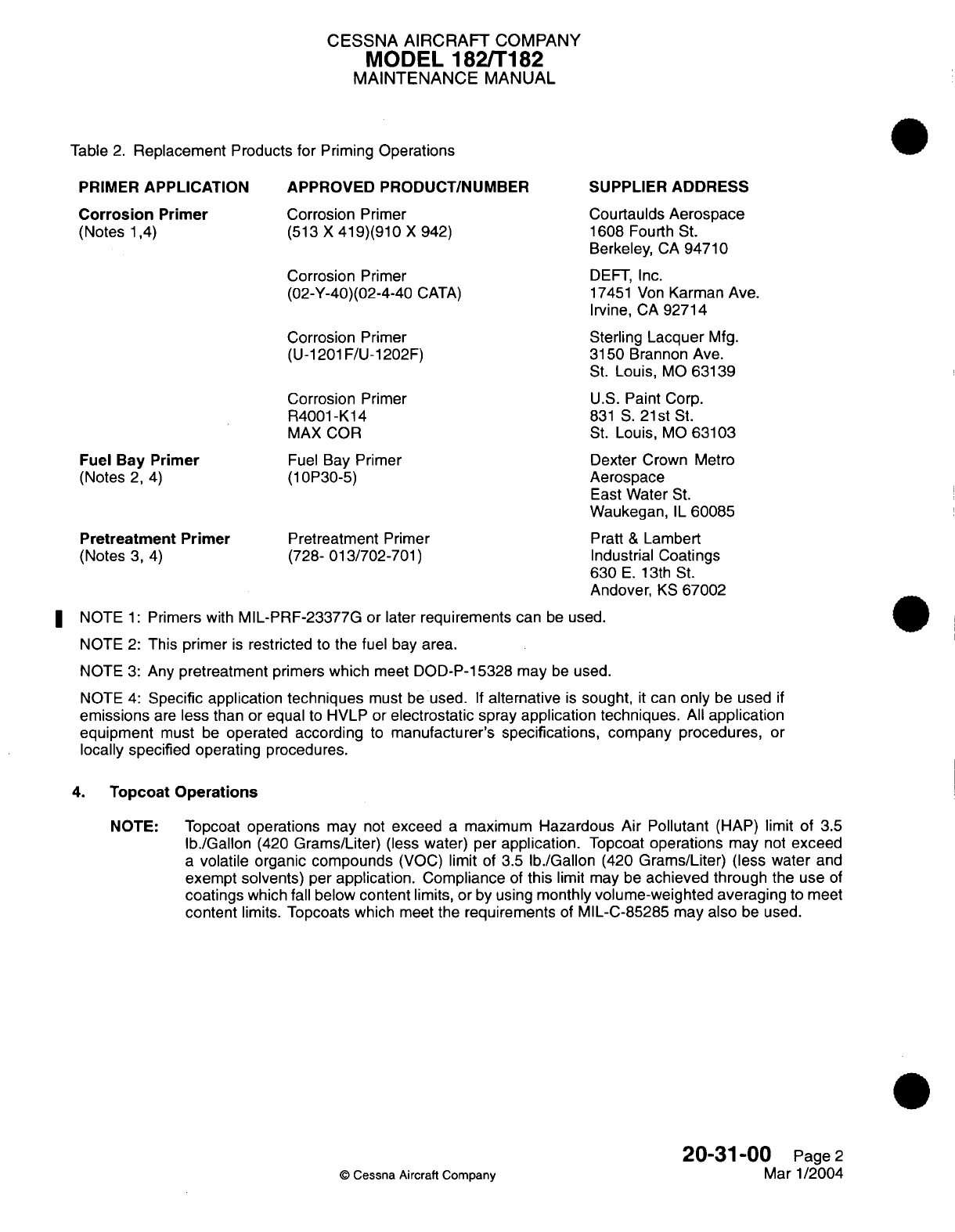
CESSNA
AIRCRAFT
COMPANY
MODEL
182/T182
MAINTENANCE
MANUAL
Table
2.
Replacement
Products
for
Priming
Operations
PRIMER
APPLICATION
Corrosion
Primer
(Notes
1,4)
APPROVED
PRODUCT/NUMBER
Corrosion
Primer
(513
X
419)(910
X
942)
Corrosion
Primer
(02-Y-40)(02-4-40
CATA)
Corrosion
Primer
(U-1201
F/U-1202F)
Corrosion
Primer
R4001-K14
MAX
COR
Fuel
Bay
Primer
(Notes
2,
4)
Pretreatment
Primer
(Notes
3,
4)
Fuel
Bay
Primer
(10P30-5)
Pretreatment
Primer
(728-
013/702-701)
SUPPLIER
ADDRESS
Courtaulds
Aerospace
1608 Fourth
St.
Berkeley,
CA
94710
DEFT,
Inc.
17451
Von
Karman
Ave.
Irvine,
CA
92714
Sterling
Lacquer
Mfg.
3150
Brannon Ave.
St.
Louis,
MO
63139
U.S.
Paint Corp.
831
S.
21st
St.
St.
Louis,
MO
63103
Dexter
Crown
Metro
Aerospace
East
Water
St.
Waukegan,
IL
60085
Pratt
&
Lambert
Industrial Coatings
630
E.
13th
St.
Andover,
KS
67002
NOTE
1:
Primers
with
MIL-PRF-23377G
or later
requirements
can
be
used.
NOTE
2:
This primer
is
restricted
to
the
fuel
bay
area.
NOTE
3:
Any
pretreatment
primers
which
meet
DOD-P-15328
may
be
used.
NOTE
4:
Specific application
techniques
must
be
used.
If
alternative
is
sought,
it
can
only
be
used
if
emissions
are
less
than or
equal
to
HVLP or
electrostatic
spray
application techniques.
All
application
equipment
must
be
operated
according
to
manufacturer's
specifications,
company procedures,
or
locally specified operating
procedures.
4.
Topcoat
Operations
NOTE:
Topcoat
operations
may
not
exceed
a
maximum
Hazardous
Air Pollutant
(HAP)
limit
of
3.5
Ib./Gallon
(420
Grams/Liter)
(less
water)
per
application.
Topcoat
operations
may
not
exceed
a
volatile
organic
compounds
(VOC)
limit
of
3.5
Ib./Gallon
(420
Grams/Liter)
(less
water
and
exempt
solvents)
per
application.
Compliance
of
this
limit may be
achieved through
the
use
of
coatings
which
fall
below
content
limits,
or
by
using
monthly
volume-weighted averaging
to meet
content
limits.
Topcoats which
meet
the
requirements
of
MIL-C-85285 may
also
be
used.
20-31-00
Page
2
©
Cessna Aircraft Company
Mar
1/2004
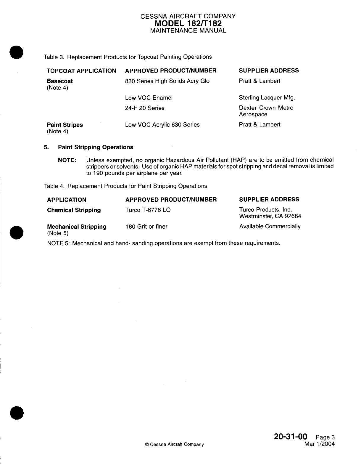
CESSNA
AIRCRAFT
COMPANY
MODEL
182/T182
MAINTENANCE
MANUAL
Table
3.
Replacement
Products
for
Topcoat
Painting Operations
TOPCOAT
APPLICATION APPROVED
PRODUCT/NUMBER
Basecoat
830 Series
High
Solids
Acry
Glo
(Note
4)
Low
VOC
Enamel
24-F
20
Series
Paint
Stripes
(Note
4)
Low VOC
Acrylic
830
Series
SUPPLIER ADDRESS
Pratt
&
Lambert
Sterling
Lacquer
Mfg.
Dexter
Crown
Metro
Aerospace
Pratt
&
Lambert
5.
Paint
Stripping
Operations
NOTE:
Unless exempted,
no
organic Hazardous Air Pollutant
(HAP)
are
to
be
emitted from
chemical
strippers
or
solvents.
Use
of
organic
HAP
materials
for
spot
stripping
and
decal removal
is
limited
to
190
pounds
per
airplane
per
year.
Table
4.
Replacement
Products
for
Paint
Stripping Operations
APPLICATION
Chemical
Stripping
Mechanical
Stripping
(Note
5)
APPROVED
PRODUCT/NUMBER
Turco
T-6776
LO
180
Grit
or
finer
SUPPLIER ADDRESS
Turco
Products,
Inc.
Westminster,
CA
92684
Available
Commercially
NOTE
5:
Mechanical
and
hand-
sanding
operations
are
exempt
from
these
requirements.
20-31-00
Page
3
©
Cessna
Aircraft
Company
Mar
1/2004

CESSNA
AIRCRAFT
COMPANY
MODEL
182/T182
MAINTENANCE
MANUAL
GENERAL
SOLVENTS/CLEANERS
-
MAINTENANCE
PRACTICES
1.
General
A.
Solvents
are
used
in
a
wide
range
of
cleaning
activities.
Selected
solvents,
which
are
used to
remove
oil,
grease,
and dirt
from objects,
cause
no
damage
to
metal,
plastics,
or
elastomeric
parts.
2.
Tools, Equipment
and
Materials
NOTE:
Equivalent substitutes
may
be
used
for
the following
items.
NAME
NUMBER
MANUFACTURER
USE
Detergent
Commercially
available
General
cleaning.
ScotchBrite
Pads
Type
A
Minnesota
Mining
and
Mfg. Co.
Light
abrasion
of
metal
3M
Center surfaces.
St. Paul,
MN
55101
Sandpaper
320 Grit
Commercially
available
Light
abrasion
of
metal
surfaces.
Rymple
Cloth
Commercially
available
Wiping
and
applying
cleaning
agents.
Wiping
cloth
white,
Commercially
available
Wiping
and
applying
oil
free,
absorbent cleaning
agents.
3.
Safety
Precautions
A.
Solvents
are
composed
of
a
group
of chemicals
that
often
proves
toxic.
Anyone
engaged
in
maintenance,
repair
and
operation
of
airplane
and
airplane
accessories
may
be
exposed
to
these
chemicals.
B.
To
help
avoid the
effects
of
these
toxic
substances,
work
only
in
a
clean,
well-lighted,
and
well-
ventilated
area. Rubber
gloves
and
protective clothing
must
be
worn.
Avoid
breathing
spray
vapors
as
they
are
highly toxic.
C.
When
working
with
toxic
substances,
always
be
alert
for symptoms of
poisoning.
If
symptoms
are
observed,
immediate
removal of
the
victim
from
the
contaminated
area
is
most
important.
4.
Description
A.
Solvents
exhibit
a
selective
solvent
action
which permits
its
use
in
the
removal
of
oil,
grease
or dirt.
For
selection
of
proper
solvent,
refer
to
Table
201.
For
the
cleaning
of
metal,
plastics
or
rubber,
proceed
as
follows:
(1)
Metal.
NOTE:
Prior
to
bonding
or
priming,
lightly
abrade
surface
with
either
a
ScotchBrite
pad
or
sandpaper
prior
to
cleaning.
(a)
Wipe
off
all
excess
oil,
grease
or
dirt
from
surface.
(b)
Apply
solvent
to
a
clean
cloth
by
pouring
solvent
on
the
cloth
from
a
safety
can
or
other
approved container.
The
cloth should
be
well
saturated
but not
to
the
point
of
dripping.
(c)
Wipe
the
surface
with
the moistened cloth
as
required
to
dissolve or
loosen
soil.
Work
on
small enough area so
the
surface
being
cleaned
remains
wet.
(d)
With
a
clean dry cloth,
immediately wipe
the
surface while
the
solvent
is
still
wet.
Do
not
allow
the
surface
to
evaporate
dry.
(e)
Repeat
steps
(b)
through
(d)
until
there
is
no
discoloration
on
the
drying
cloth.
20-31-00
Page
201
©
Cessna
Aircraft
Company
Mar 1/2005

CESSNA AIRCRAFT
COMPANY
MODEL
182/T182
MAINTENANCE
MANUAL
(2)
Plastic
or
Rubber.
NOTE:
If
cleaning
a
bonding surface, lightly
abrade the
bonding surface
with
sandpaper
prior
to
cleaning.
(a)
Remove
heavy
soil from
surface
by
washing
with
a
water
detergent solution.
(b)
Apply
solvent
to
a
clean
cloth
by pouring
solvent
onto
cloth
from
a
safety
can
or
other
approved container.
The
cloth
should
be
well
saturated
but not
to the
point
where
dripping.
(c)
Wipe
the
surface
with
the moistened cloth as required
to
dissolve
or
loosen soil.
Work
on
a
small
enough area so
that
the surface
being
clean
remains
wet.
(d)
Using
a
clean
dry
cloth, immediately
wipe the
surface
while the
surface
is
still
wet.
Do
not
allow the
surface
to
evaporate
dry.
(e)
Repeat
steps
(b)
through
(d)
until
there
is
no
discoloration
on
the drying
cloth.
Table
201.
General
Solvents
FED-
ERAL
SPECIFI-
CATION
TYPE
CLASSIFI-
CATION
MIL-
Type
I
-100F
PRF-680
Type
II
-140'F
1,1,1
O-T-620
Type
I
-
Inhibited
Regular Type
Technical
II -
with
Trichloroethane dauber
Type
III
-
Aerosol
USE/
DESCRIPTION
FUNCTION
General
cleaning solvent.
Dry
cleaning
of
textile
materials.
Grease
removal.
Spot removing from
fabrics.
General
cleaning
solvent.
Cleaning
of
assembled
equipment.
CAUTION/
WARNING
FLAMMABLE.
USE
WITH ADEQUATE
VENTILATION.
AVOID
PROLONGED
BREATHING
OF
VAPOR.
AVOID
PROLONGED
CONTACT
WITH
SKIN.
Turco
Seal
Solvent
Turco
Products
Penwalt
2331
Carbon
Removing
Compound
Cleaning
Compound
Cleaning/Degreasing
metal parts.
Preparing
metal
plate
for
painting.
P-C-
111A
Use
in
soak
tank
to
facilitate
removal
of
carbon,
gum,
oil
and
other
surface
contaminants
except
rust
or
corrosion
from
engine
and
other
metal parts.
Heavy duty
electro
cleaner
used
for
removal
of
soils
from
ferrous
metal
surfaces
prior
to
electroplating or
other
treatments.
P-
C-535
©
Cessna
Aircraft
Company
ACID
ACTIVATED
SOLVENT,
DO
NOT
USE
ON
PLASTICS.
REMOVES
PAINT.
AVOID
CONTACT WITH SKIN.
20-31-00
CLEANER/
SOLVENT
Dry
Page
202
Mar 1/2005
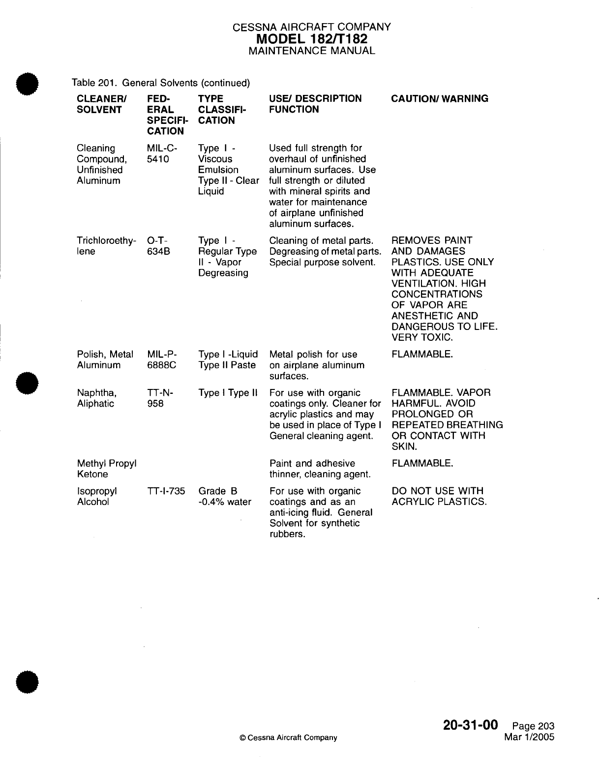
CESSNA
AIRCRAFT
COMPANY
MODEL
182/T182
MAINTENANCE
MANUAL
Table 201.
General
Solvents
(continued)
CLEANER/
SOLVENT
Cleaning
Compound,
Unfinished
Aluminum
Trichloroethy-
lene
Polish,
Metal
Aluminum
Naphtha,
Aliphatic
Methyl
Propyl
Ketone
Isopropyl
Alcohol
FED-
ERAL
SPECIFI-
CATION
TYPE
CLASSIFI-
CATION
MIL-C- Type
I -
5410
Viscous
Emulsion
Type
II -
Clear
Liquid
O-T-
634B
Type
I -
Regular
Type
II -
Vapor
Degreasing
MIL-P-
Type
I
-Liquid
6888C
Type
II
Paste
TT-N-
958
Type
I
Type
II
TT-1-735
Grade
B
-0.4%
water
USE/
DESCRIPTION
FUNCTION
Used
full
strength
for
overhaul
of
unfinished
aluminum
surfaces.
Use
full
strength
or
diluted
with
mineral
spirits
and
water
for
maintenance
of
airplane
unfinished
aluminum
surfaces.
Cleaning
of metal
parts.
Degreasing
of
metal
parts.
Special purpose
solvent.
Metal
polish
for
use
on
airplane
aluminum
surfaces.
For
use
with
organic
coatings only. Cleaner
for
acrylic
plastics
and
may
be
used
in
place
of
Type
I
General
cleaning
agent.
Paint
and
adhesive
thinner,
cleaning
agent.
For
use
with
organic
coatings
and
as
an
anti-icing fluid.
General
Solvent for synthetic
rubbers.
CAUTION/
WARNING
REMOVES
PAINT
AND
DAMAGES
PLASTICS.
USE
ONLY
WITH ADEQUATE
VENTILATION. HIGH
CONCENTRATIONS
OF
VAPOR
ARE
ANESTHETIC
AND
DANGEROUS TO
LIFE.
VERY
TOXIC.
FLAMMABLE.
FLAMMABLE.
VAPOR
HARMFUL.
AVOID
PROLONGED
OR
REPEATED
BREATHING
OR CONTACT
WITH
SKIN.
FLAMMABLE.
DO
NOT
USE
WITH
ACRYLIC
PLASTICS.
20-31-00
©
Cessna
Aircraft
Company
Page
203
Mar
1/2005
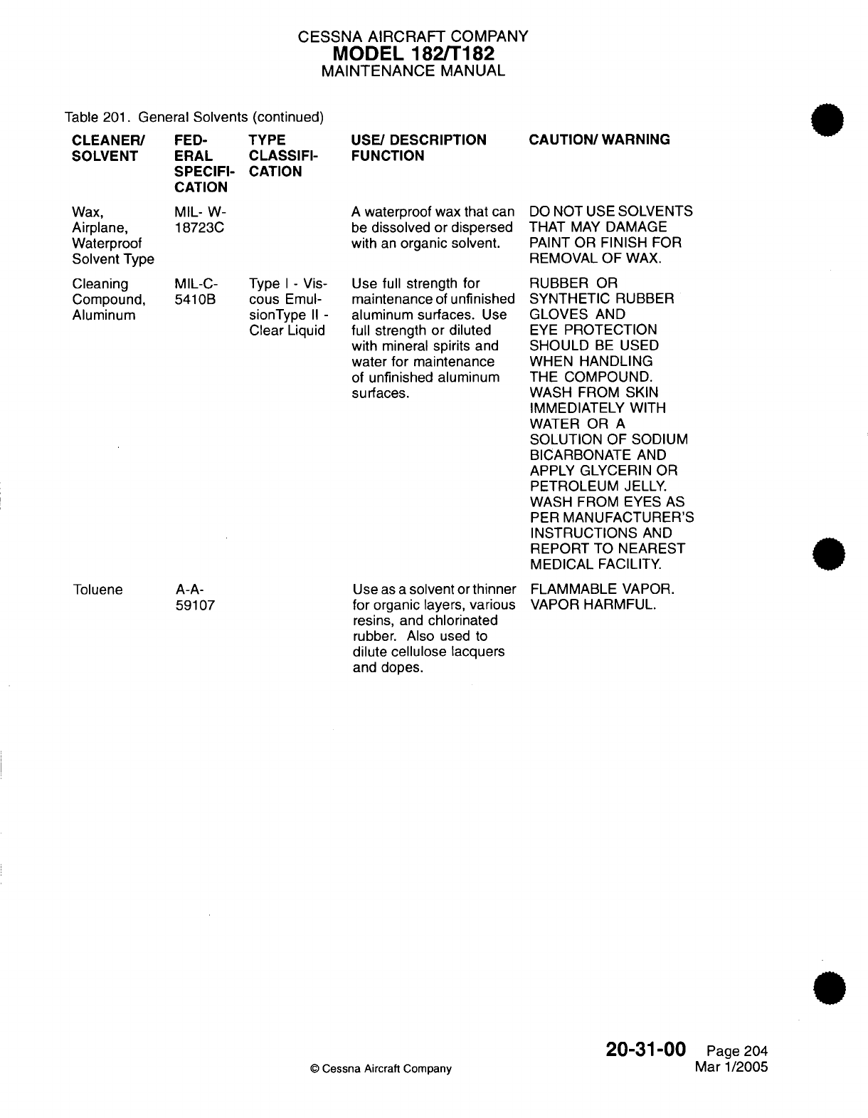
CESSNA AIRCRAFT
COMPANY
MODEL
182/T182
MAINTENANCE
MANUAL
Table
201.
General
Solvents (continued)
CLEANER/
SOLVENT
Wax,
Airplane,
Waterproof
Solvent Type
Cleaning
Compound,
Aluminum
Toluene
FED-
ERAL
SPECIFI-
CATION
MIL- W-
18723C
TYPE
CLASSIFI-
CATION
USE/
DESCRIPTION
FUNCTION
A
waterproof
wax
that
can
be
dissolved or dispersed
with
an
organic
solvent.
MIL-C-
Type
I -
Vis-
5410B
cous
Emul-
sionType
II -
Clear
Liquid
A-A-
59107
Use
full
strength
for
maintenance
of
unfinished
aluminum
surfaces.
Use
full
strength
or
diluted
with
mineral
spirits
and
water for maintenance
of
unfinished
aluminum
surfaces.
Use
as
a
solvent
or
thinner
for
organic
layers,
various
resins,
and
chlorinated
rubber.
Also
used
to
dilute cellulose lacquers
and
dopes.
CAUTION/
WARNING
DO
NOT
USE
SOLVENTS
THAT
MAY
DAMAGE
PAINT
OR
FINISH
FOR
REMOVAL
OF
WAX.
RUBBER
OR
SYNTHETIC
RUBBER
GLOVES
AND
EYE
PROTECTION
SHOULD
BE
USED
WHEN
HANDLING
THE
COMPOUND.
WASH FROM
SKIN
IMMEDIATELY
WITH
WATER
OR
A
SOLUTION
OF
SODIUM
BICARBONATE
AND
APPLY GLYCERIN
OR
PETROLEUM
JELLY.
WASH
FROM EYES
AS
PER
MANUFACTURER'S
INSTRUCTIONS
AND
REPORT
TO
NEAREST
MEDICAL
FACILITY.
FLAMMABLE
VAPOR.
VAPOR
HARMFUL.
20-31-00
©
Cessna Aircraft
Company
Page
204
Mar 1/2005
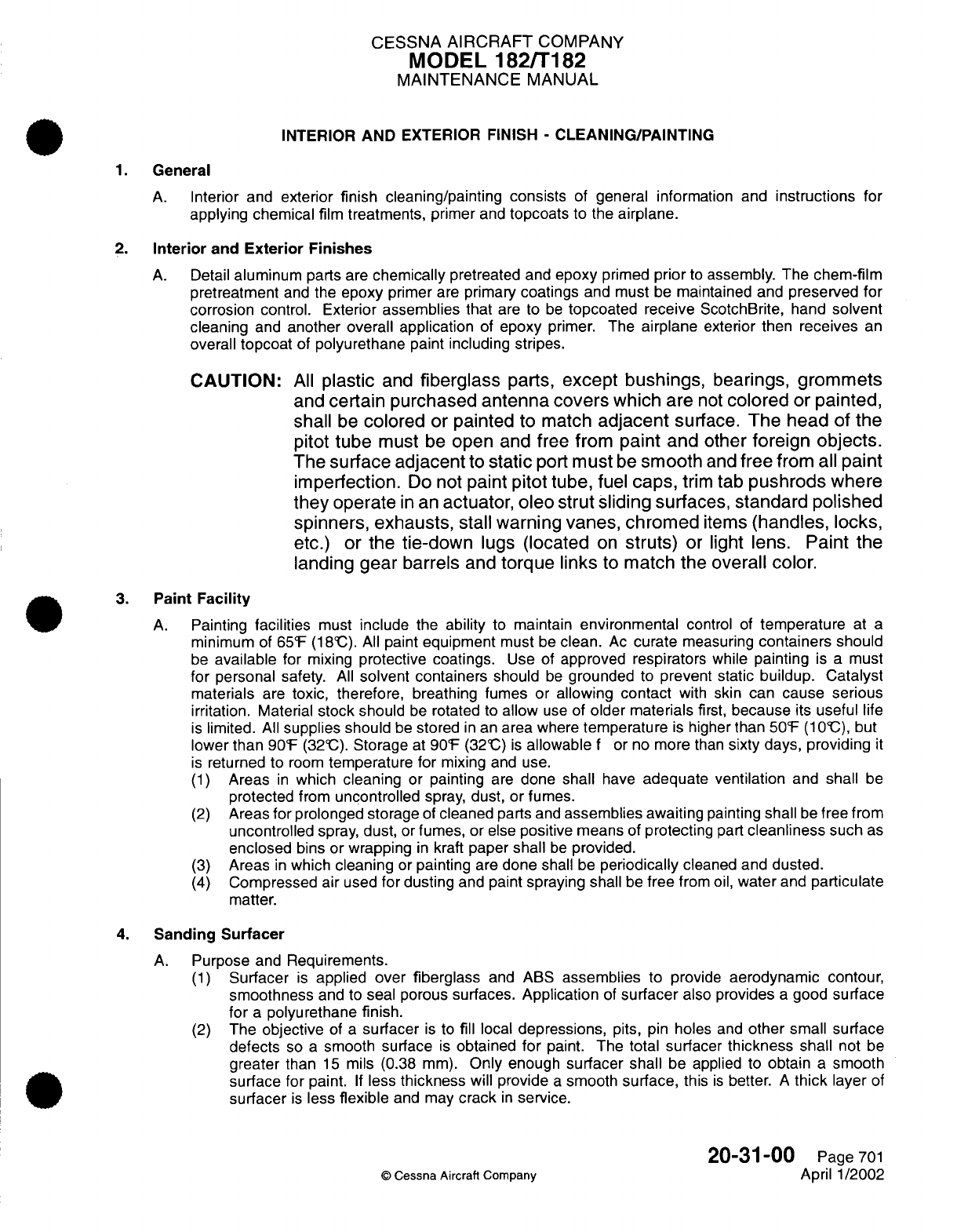
CESSNA
AIRCRAFT
COMPANY
MODEL
182/T182
MAINTENANCE
MANUAL
INTERIOR
AND
EXTERIOR
FINISH
-
CLEANING/PAINTING
1.
General
A.
Interior
and
exterior
finish
cleaning/painting consists
of
general
information
and
instructions
for
applying
chemical
film
treatments,
primer
and
topcoats to
the
airplane.
2.
Interior
and
Exterior
Finishes
A.
Detail
aluminum
parts
are
chemically
pretreated
and
epoxy
primed
prior
to
assembly. The
chem-film
pretreatment
and
the
epoxy
primer
are
primary
coatings
and
must
be
maintained
and
preserved
for
corrosion
control.
Exterior assemblies that
are
to
be
topcoated receive
ScotchBrite, hand
solvent
cleaning
and
another
overall
application
of
epoxy
primer.
The
airplane
exterior
then
receives
an
overall
topcoat
of
polyurethane
paint including stripes.
CAUTION:
All
plastic
and
fiberglass
parts,
except bushings,
bearings,
grommets
and
certain
purchased
antenna
covers
which
are
not
colored
or
painted,
shall
be
colored
or painted
to
match
adjacent
surface.
The
head of the
pitot tube
must
be
open
and
free
from
paint
and other
foreign
objects.
The
surface
adjacent
to
static
port
must
be
smooth
and
free
from all
paint
imperfection.
Do
not
paint
pitot tube,
fuel
caps,
trim
tab
pushrods where
they
operate
in
an
actuator,
oleo
strut
sliding
surfaces,
standard
polished
spinners, exhausts,
stall
warning
vanes, chromed
items
(handles,
locks,
etc.)
or
the
tie-down
lugs
(located
on
struts)
or
light
lens.
Paint
the
landing gear
barrels
and
torque
links
to
match
the
overall
color.
3.
Paint
Facility
A.
Painting
facilities
must
include
the
ability
to maintain
environmental
control
of
temperature
at
a
minimum
of
65'F
(18IC).
All
paint
equipment
must
be
clean.
Ac
curate
measuring
containers
should
be
available
for
mixing
protective coatings.
Use
of
approved respirators
while
painting
is
a
must
for
personal
safety.
All
solvent containers
should
be
grounded
to
prevent
static
buildup. Catalyst
materials
are
toxic,
therefore,
breathing
fumes or
allowing
contact
with
skin can
cause serious
irritation.
Material
stock should
be
rotated
to
allow
use
of
older
materials
first,
because
its
useful
life
is
limited.
All
supplies should
be
stored
in
an
area
where
temperature
is
higher
than
50F
(1
'C),
but
lower
than
90'F
(32'C).
Storage
at
90F
(32@C)
is
allowable
f
or no
more
than
sixty days,
providing
it
is
returned
to
room
temperature for
mixing
and
use.
(1)
Areas
in
which
cleaning
or
painting
are
done
shall
have
adequate ventilation
and
shall
be
protected
from
uncontrolled
spray,
dust, or fumes.
(2)
Areas
for
prolonged storage
of
cleaned
parts
and
assemblies
awaiting
painting
shall
be
free
from
uncontrolled
spray,
dust,
or
fumes,
or
else
positive
means
of
protecting
part
cleanliness
such
as
enclosed
bins
or
wrapping
in
kraft
paper
shall
be
provided.
(3)
Areas
in
which
cleaning
or
painting
are
done
shall
be
periodically
cleaned
and
dusted.
(4)
Compressed air
used
for dusting
and
paint
spraying
shall
be
free
from
oil,
water
and
particulate
matter.
4.
Sanding
Surfacer
A.
Purpose
and
Requirements.
(1)
Surfacer
is
applied
over
fiberglass
and
ABS
assemblies
to
provide
aerodynamic
contour,
smoothness
and
to
seal porous surfaces.
Application
of
surfacer
also
provides
a
good
surface
for
a
polyurethane finish.
(2)
The
objective
of
a
surfacer
is
to
fill
local
depressions,
pits,
pin
holes
and
other
small
surface
defects
so
a
smooth
surface
is
obtained
for
paint.
The
total
surfacer
thickness
shall
not
be
greater
than
15
mils (0.38
mm).
Only
enough
surfacer shall
be applied to
obtain
a
smooth
surface for
paint.
If
less
thickness
will
provide
a
smooth
surface,
this
is
better.
A
thick
layer
of
surfacer
is
less
flexible
and
may
crack
in
service.
20-31-00
Page
701
©
Cessna
Aircraft Company
April
1/2002

CESSNA AIRCRAFT
COMPANY
MODEL
182/T182
MAINTENANCE
MANUAL
(3)
To
complete
the
airplane's
polyurethane
finish
over
surfacer,
begin
by
applying
the
intermediate
coat.
Apply
topcoat (polyurethane
enamel)
using
same procedure.
(4)
Should
a
repair
be
required
(cracked
or
chipped
paint)
to
areas
where
surfacer
is
applied,
sanding
surfacer
should
be
removed
to
expose
fiberglass
or
Kevlar.
It
may
be
necessary
to
remove
all
sanding surfacer
on
that individual
assembly
and/or
component
to
obtain
a
satisfactory
finish.
For
additional
information,
refer
to
Cleaning.
(5)
Sanding
surfacer
methods.
(a)
Do
not
intermix
vendor
material or
substitute
material. Also,
do
not
substitute
instructions.
Select
and use
one
vendor's
material and
use
the
corresponding
instructions.
B.
Cleaning.
CAUTION:
Do
not
use
chemical strippers
on
ABS
plastic
and
fiberglass
assemblies.
Paint
stripper
solvent
will
damage
these
assemblies.
CAUTION:
Sanding
of
paint
and/or sanding
surfacer
must
be
very
carefully
accomplished.
Do
not
sand
into the
fabric layers of
composite
assemblies
as
this
will
result
in
loss of
strength.
(1)
Remove
paint
covering sanding surfacer
by
sanding.
Paint
should
be
removed
well
beyond
damaged
area.
For
best
results,
it is
recommended
to
remove
all
paint
covering
sanding
surfacer
of
that
individual composite component.
(2)
Remove sanding
surfacer
by
sanding
from
individual component
to
expose
fabric.
(3)
Scuff sand
area
to
be
refinished
with
320
grit paper.
Do
not
over
expose
fabric.
(4)
Clean
surface
with Methyl n-Propyl
Ketone.
Follow
manufacturer's
instructions
for
final
cleaning
prior
to
sanding
surfacer application.
5.
Paint
Stripping
A.
Mechanical
Stripping
(1)
Mechanical
methods
of
stripping
include power
sanding
with
a
disc
or
jitterbug
type sander,
grinder,
hand
sanding,
and
wire
brushing.
(a)
Ensure
mechanical
methods
do not
damage
surfaces
being
stripped.
Damage
may
include,
but
is
not
limited
to,
cutting
fibers
of
composite structures or
scratches
in
the
surface
of
metallic
surfaces.
CAUTION:
Do
not
use
low
carbon steel
brushes
on
aluminum,
magnesium,
copper,
stainless
steel or
titanium
surfaces.
Steel
particles
may
become
embedded
in
the
surfaces,
and
later
rust
or
cause galvanic corrosion
of
the
metal
surfaces.
(2)
Mechanical stripping
must
be used
for
stripping
composite
or
plastic
surfaces.
(3)
Mechanical stripping
is
recommended
for
surfaces
which
might
entrap
chemical
strippers
and
result
in
corrosion.
(4)
Mechanical
stripping
is
required
for
painted
surfaces
masked during
chemical
stripping.
B.
Chemical
Stripping.
20-31-00
Page
702
©
Cessna Aircraft Company
April
1/2002
CESSNA
AIRCRAFT
COMPANY
MODEL
182/T182
MAINTENANCE
MANUAL
WARNING:
All
paint
strippers
are
harmful
to
eyes
and
skin.
All
operators
should
wear
goggle-type
eyeglasses,
rubber gloves,
aprons
and
boots.
In
case
of
contact
with
skin,
flush
with water.
In
case
of
contact
with
eyes,
flush
eyes
thoroughly
with
water
and
consult
physician
immediately.
Paint
stripping
should
be
done
in
a
well
ventilated
area.
WARNING:
Use
of
a
heater
with
an
open
flame
in
an
area
in
which
stripping with
a
methylene
chloride-type
stripper
is
used
produces
hydrochloric
acid
fumes. If acid
is
deposited
on
airplane
it
will
corrode
all
surfaces.
(1)
Thoroughly
clean
airplane surfaces
to
remove all grease
and
other dirt which
might
keep
stripping agent
from
attacking
paint.
(2)
All
seams
and
joints
must
be
protected
by
applying
a
tape,
resistant
to
strippers,
to every
joint
to
prevent
stripping
chemicals
from
entering
the
skin
joints.
Chemicals
used
for
stripping
polyurethane
paint
are
very
difficult
to
remove
from
joints,
and
may
promote
corrosion
or
deteriorate
bonding agents
used
in
assembly
of
airplane.
(3)
Mask
following
surfaces
using
plastic sheeting
or
waxed
paper and
plastic
tape
so as
to
make
a
safety
margin
of at
least
one-half
inch
(13
mm)
between
protected
surface
and
surface
to
be
stripped.
NOTE:
Do
not
use
masking
tape.
(a)
Mask
all
windows
and
transparencies.
CAUTION:
Acrylic windows
may
be
softened
or
otherwise
damaged
by
paint
stripper,
solvent
or paint.
Use
water
and
grease-proof
barrier
material
and
polyethylene
coated
tape
to
protect
windows.
1
Place barrier
material
over
window
and seal
around
periphery
with
polyethylene
backed
masking
tape.
2
Cut
second sheet
of
barrier
material
an
inch
(26 mm)
or
more
larger
than
window.
3
Place
second
sheet
of
barrier
material
over
window and
seal
with
polyethylene
tape.
(b)
Mask all rubber
and
other
non
metals.
(c)
Composites
if
possible,
shall
be
removed
from
airplane prior
to
stripping.
(d)
Mask
all
honeycomb
panels
and
all
fasteners
which
penetrate
honeycomb panels.
(e)
Mask all
pivots, bearings
and
landing
gear.
(f)
Titanium,
if
used
on
airplane,
must
be
protected
from
strippers.
(g)
Mask
all
skin laps,
inspection
holes,
drain holes,
or
any
opening
that
would
allow
stripper
to
enter
airplane structure.
CAUTION:
Do
not
allow
paint
stripper
to
contact
high
heat
treated
steel
pins,
such
as
pins
attaching
landing
gear
components.
Paint
strippers
may
induce hydrogen
embrittlement
in
high
heat
treated
steel.
(4)
Apply
approved
stripper
by
spray
or
brush method.
20-31-00
Page 703
©
Cessna
Aircraft Company
April 1/2002
CESSNA
AIRCRAFT
COMPANY
MODEL 182/T182
MAINTENANCE
MANUAL
WARNING:
Use
normal safety
precautions
when
using
flammable
materials
during
cleaning
and
painting
procedures.
WARNING:
Paint
stripper
solution
is
harmful
to
eyes
and
skin.
Wear
goggles,
rubber
gloves,
apron
and
boots
when
working
with paint
stripper.
Also
wear
appropriate
respirator
when
applying
"spray-on"
strippers.
The
chemical
supplier
bulletins
and
instructions
should
be
closely
followed
for
proper
mixing
of
solution,
application
methods
and
safety
precautions.
(a)
If
using
spray
method,
apply
a
mist
coat
to
area
to
be
stripped,
then when
paint
begins
to
lift,
apply
a
second
heavy coat.
(b) If
applying
with
brush, brush
across
the
surface only once,
in
one
direction.
(5)
Allow
stripper coating
to
lay
on
the
surface
until
paint
lifts.
(6)
After
paint begins
to
lift,
use
a
propylene bristle
brush to
agitate stripper
to
allow
deeper
penetration
of
stripper.
(7)
Remove
lifted
paint with
a
plastic
squeegee.
Dispose
of
residue
in
accordance
with
local
regulations.
(8)
Inspect
all
surfaces
for
incomplete
paint
removal.
(a)
Repeat
previous procedural
steps
as
necessary
until
all
paint
is
removed.
(9)
After
stripping
airplane,
thoroughly
rinse
to remove
any stripping
residue.
(10)
Remove
tape applied to
protect
joints
and
other
masked
areas.
(11)
Carefully
remove
remaining
paint
at
skin
joints
and
masked
areas
by
sanding with
a
hand
or
jitterbug
type sander.
(12)
If
necessary
to remove
paint
from
inside
skin
joints,
refer to
Cleanout
of
Skin
Joints.
(13)
If
corrosion
is
encountered,
refer
to
Structural Repair
Manual,
Chapter
51,
Corrosion/Repair,
for
corrosion treatment.
C.
Cleanout
of
Skin
Joints.
(1)
Install
a
surface
conditioning disc
on a
pneumatic
drill.
(2)
Taper
edge
of
disc
to
an
edge which
will
allow
edge to
fit
into
skin
joint
seam.
(a)
Run
disc against
a
piece
of
coarse
abrasive
paper
or
a
mill
file
until
edge
is
tapered.
CAUTION:
Excessive
pressure
or
dwell
time
will cause
scratches
or
grooves
in
metal.
Ensure
doubler
at
bottom
of
joint
is
not
damaged
or
gouged
in
any way
by
this
process.
(3)
Using
tapered surface
conditioning
disc, remove
paint
and
other
material
from
joint
seams.
(4)
Carefully,
and
using
as
low
speed
as
possible,
remove
paint and
all
other
material
from
joint.
NOTE:
Surface
conditioning
disc will
wear
rapidly,
it
will
be
necessary
to
resharpen
(retaper)
disc frequently.
6.
Hand
Solvent
Cleaning
WARNING:
Work
in
a
well
ventilated
area
free
from
sources of
ignition.
Use
only
approved
solvents
and
materials.
CAUTION:
Airplane
shall
be
grounded during
solvent
wipe.
A.
Surface
Cleaning.
(1)
Apply
solvent
to
a
clean
wiping
cloth
by
pouring
from
a
safety can
or
other approved
container.
The
cloth
should
be
well
saturated
with
solvent.
Avoid
dipping
wipers
into
open
solvent
containers
as
this
contaminates
the
solvent.
(2)
Wipe
the
surface
with
the
wet
cloth
as
required
to
dissolve
or
loosen
soils. Work
on a
small
enough
area
so that
the
area
being
cleaned
remains
wet
with
solvent.
20-31-00
Page 704
©
Cessna
Aircraft
Company
April
1/2002

CESSNA
AIRCRAFT
COMPANY
MODEL
182/T182
MAINTENANCE
MANUAL
(3)
With
a
clean
dry
cloth, immediately
wipe
dry
the
area
being
cleaned.
Do
not
allow
the
surface
to
evaporate
dry.
(4)
Repeat
steps
(1)
through
(3)
as
required and
change cloths often.
7.
Maintenance
of
the
Interior
and
Exterior
Primary
Coatings
and
Topcoat
A.
Rework and repair
primary
coatings
on
airplane
interior
and
exterior
surfaces
for
protection
and
corrosion
control.
(1)
Minor
scratches
or
defects,
which
do not
penetrate
the
epoxy
primer
or
which
penetrate
the
primer
and
expose
bare
metal,
with
the
total
area
of
exposed
bare
metal
less
than
the
size
of
a
dime,
touch
up
as
follows:
(a)
Hand
solvent
clean
and
sand
with
320
grit
or
finer
sandpaper.
(b)
Clean with
compressed
air,
hand
solvent
clean again,
then
wipe
with
a
tack
rag.
(c)
Mix
and reapply
epoxy
primer (MIL
P-23377
or
equivalent)
as
directed
by
the
primer
manufacturer
or
supplier.
(d)
On
a
properly
prepared surface,
mix and
apply
polyurethane
topcoat
as
directed
by
the
paint manufacturer
or
supplier.
(2)
Major
defects
which
expose
bare
metal
to
an
area
larger than
the
size
of
a
dime,
touch
up
as
follows:
(a)
Hand
solvent
clean
and
sand
with
320
grit
or
finer
sandpaper.
(b)
Clean
with
compressed
air,
hand
solvent
clean
again, then
wipe
with
a
tack
rag.
(c)
Apply
a
spray wash
primer
or
(preferred method)
brush
chem
film
primer. Mask
the
area
to
minimize
the
amount
of
primer
from
spreading over
the
existing
epoxy
primer.
Let
cure
according
to
the
product manufacturers
recommendations.
(d)
Mix
and
apply
epoxy
primer
(MIL
P-23377
or equivalent)
to
the
affected
area
within
four
hours.
(e) If
an
exterior
painted
surface,
mix
and
apply
polyurethane
topcoat
as
directed
by
the
paint
manufacturer
or supplier.
20-31-00
Page
705
©
Cessna
Aircraft Company
April
1/2002
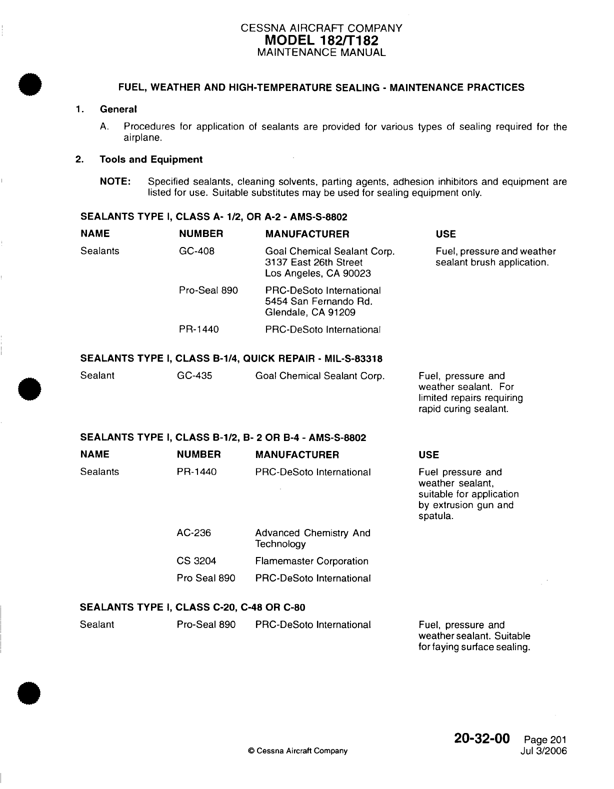
CESSNA
AIRCRAFT
COMPANY
MODEL
182/T182
MAINTENANCE
MANUAL
FUEL, WEATHER AND HIGH-TEMPERATURE
SEALING
-
MAINTENANCE
PRACTICES
1.
General
A.
Procedures for
application
of
sealants
are
provided
for
various types
of
sealing
required
for
the
airplane.
2.
Tools
and
Equipment
NOTE:
Specified sealants, cleaning
solvents,
parting
agents,
adhesion
inhibitors
and
equipment
are
listed
for
use.
Suitable
substitutes
may
be
used
for
sealing equipment
only.
SEALANTS
TYPE
I,
CLASS
A-
1/2,
OR
A-2
-
AMS-S-8802
NUMBER
GC-408
Pro-Seal
890
PR-1440
MANUFACTURER
Goal Chemical Sealant
Corp.
3137
East 26th
Street
Los
Angeles,
CA
90023
PRC-DeSoto
International
5454
San
Fernando
Rd.
Glendale,
CA
91209
PRC-DeSoto
International
USE
Fuel,
pressure
and
weather
sealant
brush
application.
SEALANTS
TYPE
I,
CLASS
B-1/4, QUICK
REPAIR
-
MIL-S-83318
Goal Chemical
Sealant
Corp.
Fuel,
pressure
and
weather
sealant.
For
limited
repairs
requiring
rapid
curing
sealant.
SEALANTS
TYPE
I,
CLASS
B-1/2,
B-
2
OR B-4
-
AMS-S-8802
MANUFACTURER
PRC-DeSoto
International
USE
Fuel
pressure
and
weather
sealant,
suitable
for application
by extrusion
gun
and
spatula.
AC-236
CS
3204
Pro
Seal
890
Advanced
Chemistry
And
Technology
Flamemaster Corporation
PRC-DeSoto
International
SEALANTS
TYPE
I,
CLASS
C-20, C-48
OR
C-80
Pro-Seal
890
PRC-DeSoto
International
Fuel,
pressure
and
weather
sealant.
Suitable
for
faying surface
sealing.
©
Cessna Aircraft
Company
20-32-00
Page
201
Jul
3/2006
NAME
Sealants
Sealant GC-435
NAME
Sealants
NUMBER
PR-1440
Sealant
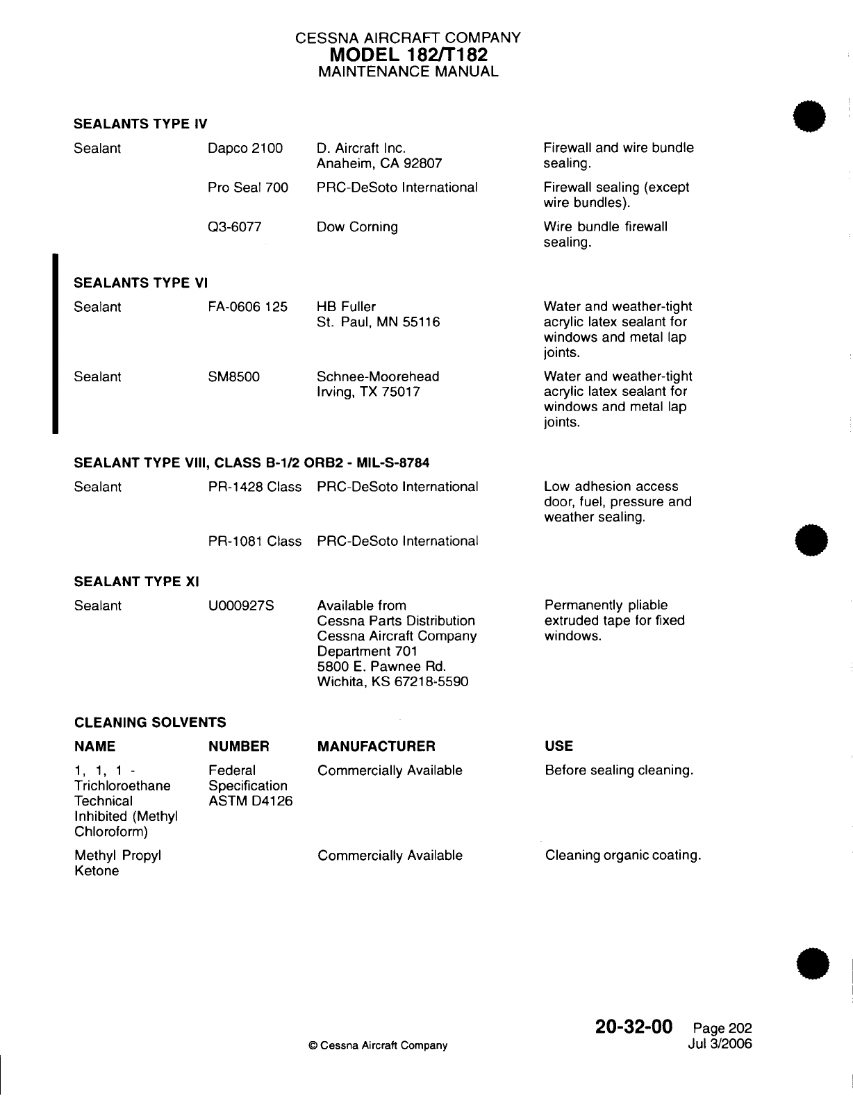
CESSNA AIRCRAFT
COMPANY
MODEL 182/T182
MAINTENANCE
MANUAL
SEALANTS
TYPE
IV
Dapco 2100
Pro
Seal
700
Q3-6077
D.
Aircraft
Inc.
Anaheim,
CA
92807
PRC-DeSoto
International
Dow
Corning
Firewall
and
wire
bundle
sealing.
Firewall
sealing
(except
wire
bundles).
Wire
bundle
firewall
sealing.
SEALANTS
TYPE
VI
FA-0606
125
SM8500
HB
Fuller
St.
Paul,
MN
55116
Schnee-Moorehead
Irving,
TX
75017
Water
and
weather-tight
acrylic
latex
sealant
for
windows
and
metal
lap
joints.
Water
and
weather-tight
acrylic
latex
sealant
for
windows
and
metal
lap
joints.
SEALANT
TYPE
VIII,
CLASS
B-1/2
ORB2
-
MIL-S-8784
PR-1428 Class
PRC-DeSoto
International
Low
adhesion
access
door,
fuel,
pressure
and
weather
sealing.
PR-1081
Class
PRC-DeSoto
International
SEALANT TYPE
XI
Sealant
U000927S
CLEANING SOLVENTS
NAME
1, 1,
1 -
Trichloroethane
Technical
Inhibited
(Methyl
Chloroform)
Methyl
Propyl
Ketone
NUMBER
Federal
Specification
ASTM D4126
Available
from
Cessna
Parts
Distribution
Cessna
Aircraft
Company
Department
701
5800
E.
Pawnee
Rd.
Wichita,
KS
67218-5590
MANUFACTURER
Commercially
Available
Commercially
Available
Permanently
pliable
extruded tape
for
fixed
windows.
USE
Before
sealing
cleaning.
Cleaning organic
coating.
©
Cessna
Aircraft
Company
20-32-00
Page
202
Jul
3/2006
Sealant
Sealant
Sealant
Sealant
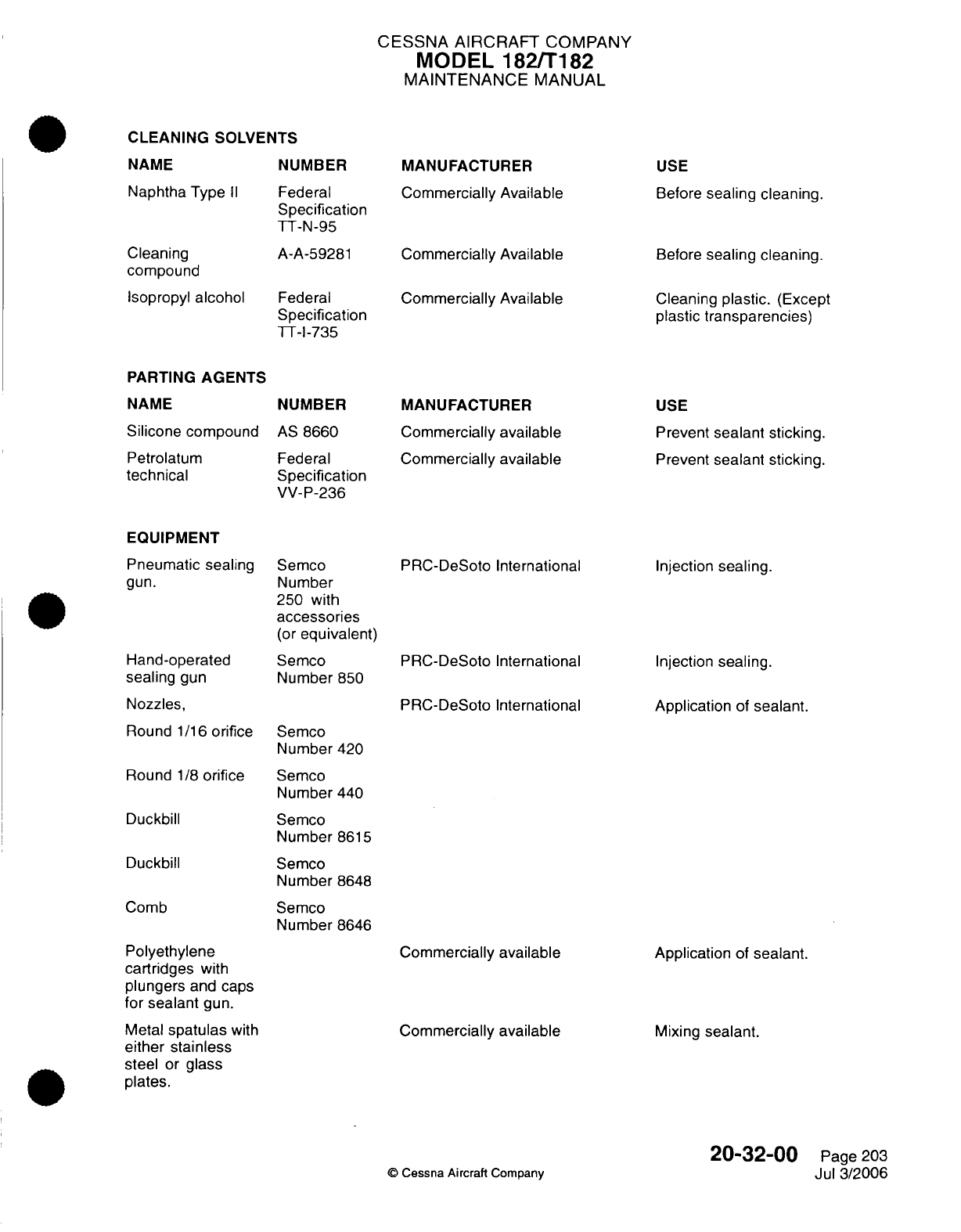
CESSNA AIRCRAFT
COMPANY
MODEL
182/T182
MAINTENANCE
MANUAL
CLEANING
SOLVENTS
NAME
Naphtha
Type
II
Cleaning
compound
Isopropyl
alcohol
PARTING
AGENTS
NAME
Silicone
compound
Petrolatum
technical
EQUIPMENT
Pneumatic sealing
gun.
Hand-operated
sealing
gun
Nozzles,
Round
1/16
orifice
Round
1/8
orifice
Duckbill
Duckbill
Comb
NUMBER
Federal
Specification
TT-N-95
A-A-59281
Federal
Specification
TT-I-735
NUMBER
AS
8660
Federal
Specification
VV-P-236
Semco
Number
250
with
accessories
(or
equivalent)
Semco
Number
850
MANUFACTURER
Commercially
Available
Commercially Available
Commercially
Available
MANUFACTURER
Commercially
available
Commercially
available
PRC-DeSoto
International
PRC-DeSoto
International
PRC-DeSoto
International
USE
Before
sealing cleaning.
Before
sealing cleaning.
Cleaning
plastic.
(Except
plastic
transparencies)
USE
Prevent
sealant
sticking.
Prevent
sealant
sticking.
Injection
sealing.
Injection
sealing.
Application
of
sealant.
Semco
Number
420
Semco
Number
440
Semco
Number
8615
Semco
Number
8648
Semco
Number
8646
Polyethylene
cartridges
with
plungers
and
caps
for
sealant
gun.
Metal
spatulas
with
either stainless
steel
or
glass
plates.
Commercially
available
Commercially available
Application
of
sealant.
Mixing
sealant.
20-32-00
©
Cessna
Aircraft
Company
Page
203
Jul
3/2006
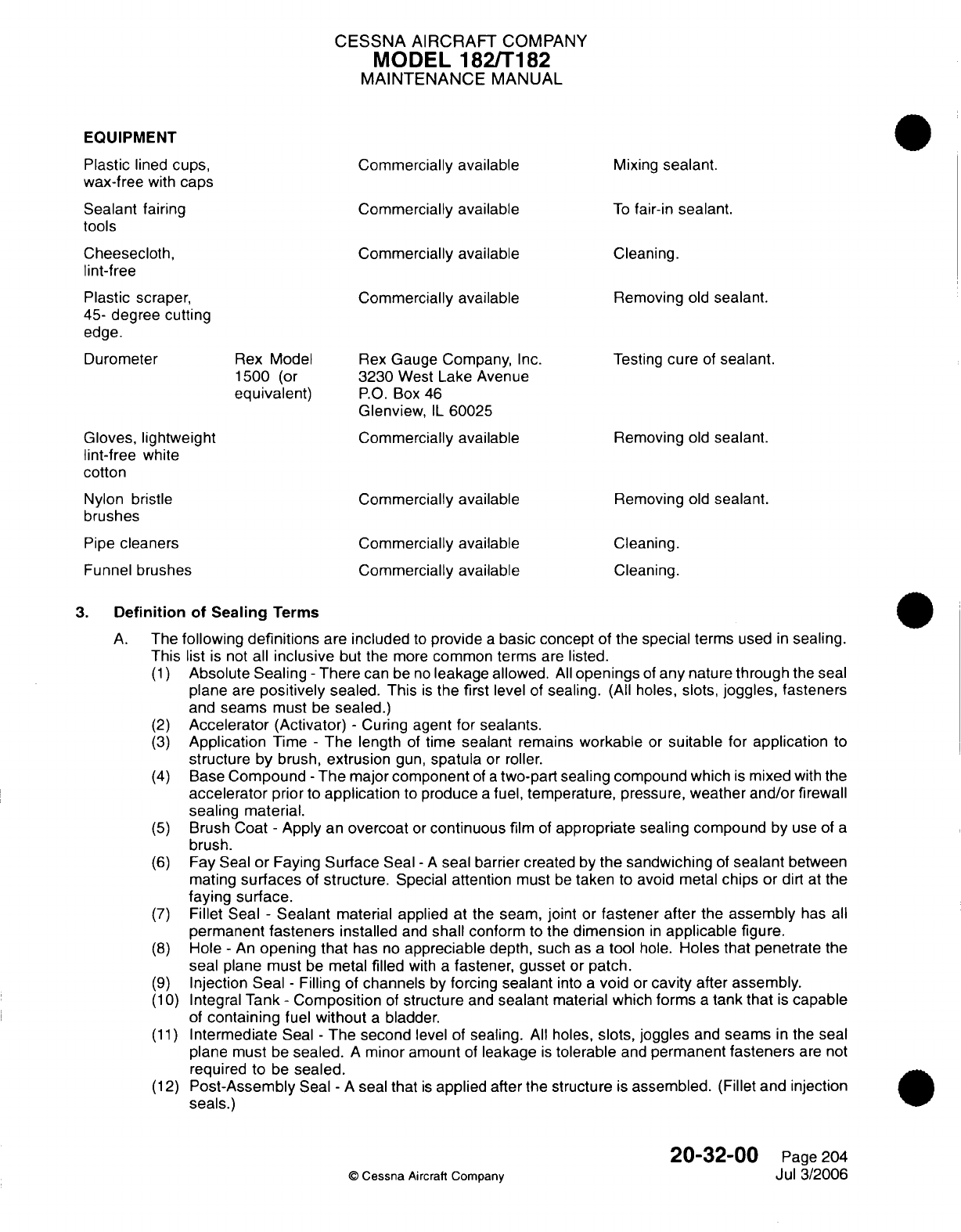
CESSNA
AIRCRAFT
COMPANY
MODEL
182/T182
MAINTENANCE
MANUAL
EQUIPMENT
Plastic
lined
cups, Commercially available
Mixing
sealant.
wax-free
with
caps
Sealant
fairing
Commercially available
To
fair-in
sealant.
tools
Cheesecloth,
Commercially
available
Cleaning.
lint-free
Plastic
scraper,
Commercially available
Removing
old
sealant.
45-
degree
cutting
edge.
Durometer
Rex
Model
Rex
Gauge
Company,
Inc.
Testing
cure
of
sealant.
1500
(or
3230
West
Lake
Avenue
equivalent)
P.O.
Box
46
Glenview,
IL
60025
Gloves,
lightweight
Commercially
available
Removing
old
sealant.
lint-free
white
cotton
Nylon
bristle
Commercially available
Removing
old
sealant.
brushes
Pipe
cleaners Commercially available
Cleaning.
Funnel
brushes Commercially
available
Cleaning.
3.
Definition
of
Sealing
Terms
A.
The
following
definitions
are
included
to
provide
a
basic
concept
of
the
special
terms
used
in
sealing.
This
list
is
not
all
inclusive
but the
more
common terms
are
listed.
(1)
Absolute Sealing
-
There
can
be
no
leakage allowed.
All
openings
of
any
nature
through
the seal
plane
are
positively
sealed.
This
is
the
first
level
of
sealing. (All
holes,
slots,
joggles,
fasteners
and
seams
must
be
sealed.)
(2)
Accelerator (Activator)
-
Curing
agent
for sealants.
(3)
Application
Time
-
The
length
of
time
sealant
remains
workable
or
suitable
for
application
to
structure
by
brush,
extrusion
gun,
spatula
or
roller.
(4)
Base
Compound
-
The
major
component
of
a
two-part
sealing
compound
which
is
mixed
with
the
accelerator
prior
to
application
to
produce
a
fuel, temperature, pressure,
weather
and/or
firewall
sealing
material.
(5)
Brush
Coat
-
Apply
an
overcoat
or
continuous
film
of
appropriate
sealing
compound
by
use
of
a
brush.
(6)
Fay Seal
or
Faying
Surface
Seal
-
A
seal barrier created
by
the sandwiching
of
sealant
between
mating
surfaces
of
structure.
Special
attention
must
be
taken
to
avoid
metal
chips
or
dirt
at the
faying
surface.
(7)
Fillet Seal
-
Sealant
material
applied at
the
seam,
joint
or
fastener
after
the
assembly
has
all
permanent
fasteners
installed
and
shall
conform
to the
dimension
in
applicable
figure.
(8)
Hole
-
An
opening
that
has
no
appreciable
depth,
such
as
a
tool
hole.
Holes
that penetrate
the
seal plane must
be
metal
filled
with
a
fastener,
gusset
or
patch.
(9)
Injection
Seal
-
Filling
of
channels
by
forcing
sealant
into
a
void
or
cavity
after
assembly.
(10)
Integral
Tank
-
Composition
of
structure
and
sealant
material
which
forms
a
tank that
is
capable
of
containing
fuel
without
a
bladder.
(11)
Intermediate
Seal
-
The second
level of
sealing.
All
holes,
slots, joggles
and
seams
in
the
seal
plane must
be
sealed.
A
minor
amount
of
leakage
is
tolerable
and
permanent
fasteners
are
not
required
to
be
sealed.
(12)
Post-Assembly
Seal
-
A
seal
that
is
applied after
the
structure
is
assembled.
(Fillet
and
injection
seals.)
20-32-00
Page
204
©
Cessna
Aircraft
Company
Jul 3/2006
CESSNA AIRCRAFT
COMPANY
MODEL
182/T182
MAINTENANCE
MANUAL
(13)
Preassembly
Seal
-
Sealant
material
that
must
be
applied
during or
prior
to
the
assembly
of the
structure.
(Faying
surface
and
pre-pack seals.)
(14)
Pre-Pack
Seal
-
A
preassembly
seal
used
to
fill
voids
and
cavities;
can
be
a
primary seal
used
to
provide
seal
continuity
when used
in
conjunction
with
a
fillet
seal.
It
can
be
used
as
a
backup
seal to
support
a
fillet
across
a
void.
Fill
the entire
cavity
to
be
prepacked.
Usage
as
a
primary
seal
should
be
kept
to
a
minimum.
(15)
Primary
Seal
-
Sealant
material
that prevents leakage
and
forms
a
continuous
seal
plane.
This
seal
is
in
direct contact
with
fuel, vapor,
air, acid,
etc.
With
few
exceptions,
it
is
in
the form
of
a
fillet seal.
(16)
Sealant
-
A
compound applied
to
form
a
seal barrier.
(17)
Seal
Plane
-
A
surface
composed
of
structure,
sealant
and
fasteners
on
which
the
continuity
of
seal
is
established.
(18)
Shank Sealing
-
Sealant
compound
shall
be
applied
to the
hole
or
to both
the shank
and
the
under
head
area
of
the
fastener
in
sufficient quantity that the
entire
shank
is
coated
and
a
small
continuous
bead of
sealant
is
extruded
out around the
complete
periphery
of
each
end
of
the
fastener
when
installed.
The
fastener
shall
be
installed
within
the
application
time
of
the
sealing
compound
used.
(19)
Squeeze-Out
Life
-
Length
of
time sealant
remains
suitable
for structure
assembly
in
faying
surface
seal
application.
(20) Tack-Free
Time
-
Tack-free
time
is
a
stage,
during
the
cure
of
the
sealant compound,
after which
the
sealant
compound
is
no
longer
tacky.
When
the
sealant
compound
is
pressed firmly
with
the
knuckles,
but
no
longer
adheres
to the
knuckles,
the
sealant
compound
is
tack-free.
4.
Materials
A.
Type
of
Sealants
-
Sealants
are
categorized
by
type
of
usage.
Type
I
sealants
are
separated
into
classes
to
differentiate
the
materials according
to
method
of
application.
Dash
numbers
following
the
class designation
indicate
the
minimum
application
time
(in
hours)
for
Class
A
and Class
B,
and
minimum work
life
(in
hours)
for
Class
C.
Refer
to
Table
201
for
application
time, curing
rate,
etc., for
Type
I
sealants.
(1)
Type
I
-
Fuel,
pressure,
and
weather
sealant.
(a)
Class
A
-
Sealant
which
is
suitable
for
brush
application.
(b)
Class
B
-
Sealant which
is
suitable
for
application
by
extrusion
gun,
spatula,
etc.
(c)
Class
C
-
Sealant
which
is
suitable
in
faying
surface applications.
(d)
Quick
Repair Sealant
-
This
material
is
for
use
only
in
making
repairs when
an
extremely
rapid
curing
sealant
is
required.
A
possible
application
includes
sealing
a
leaking fuel
tank
on an
airplane
which
must
be
dispatched
within
a
few
hours.
CAUTION:
Quick
repair
sealant
must
be
applied
within
its
working
life
of
15
minutes. Attempts
to
work
quick
repair
sealant
beyond
working
life
will
result
in
incomplete wetting of surface
and
will
result
in
a
failed
seal.
(2)
Type
VIII
-
Low
Adhesion
Access
Door
Sealant.
This Class
B
sealant
is
designed
for
sealing
faying surfaces
where
easy
separation
of
the
joined
surfaces
is
required.
The
sealant
has
low
adhesion
and
forms
a
gasket
that
molds
itself
to
fill
all
irregularities
between
two
surfaces.
The
sealant
is
exceptionally
resistant
to
fuels,
greases,
water,
most
solvents
and
oils
including
hydraulic
oil.
NOTE: Time
periods
presented
below are
based
on
a
temperature
of
77°F
(25°C)
and
50
percent
relative
humidity.
Any
increase
in
either
temperature
or
relative
humidity
may
shorten
these
time
periods
and
accelerate
the
sealant
cure.
20-32-00
Page 205
©
Cessna
Aircraft
Company
Jul
3/2006

CESSNA
AIRCRAFT
COMPANY
MODEL
182/T182
MAINTENANCE
MANUAL
Table 201.
Curing
Properties
of Type
I
Sealant
CLASS
APPLICATION
WORK
LIFE TACK-FREE
CURING
RATE
TIME
(HOURS,
(HOURS,
TIME
(HOURS,
(HOURS,
MINIMUM)
MINIMUM)
MAXIMUM) MAXIMUM)
A-1/2
1/2
10
40
A-2
2
40
72
B-1/2
1/2
4
6
B-2 2
40
72
B-4
4
48
90
C-24
8
24
96
168 (7
days)
C-48
12
48
120
336
(14
days)
C-80
8
80
120
504
(21
days)
5.
General
Requirements
A.
When
working
with
sealants observe
the
following
requirements.
(1)
Unmixed
sealants
shall
not be more
than
two
months
old
when
received. These
sealants
shall
not
be more
than
six
months
old
when
used.
(2)
Unmixed
sealants
stored
at
temperatures exceeding
80°F
(27°C)
shall
be
used within
five
weeks.
(3)
Sealants
which
have
been
premixed,
degassed
and
flash frozen
shall
be
maintained
at
-40°F
(-40°C)
or
lower
and
shall
not
be
received
more
than
two
weeks
beyond the
date
of mixing.
These sealants
shall
not be
used more
than
six
weeks
after
the
date
of
mixing.
(4)
Frozen
sealant
shall
be
thawed
before being
used.
If
sealant
were
applied
at
a
temperature
below
60°F
(15°C),
it
would
not
be
sufficiently
pliable for
proper
application
and
adhesion
could
be
critically
reduced
by
condensation
of
moisture.
On the
other
hand,
although
sealant
must
extrude
freely
for
proper application,
it
would
be
subject
to
excessive
slumping
if
applied
at
a
temperature
above
80°F
(27°C).
Frozen
sealant
may
be
thawed
by
any
suitable
means
which
does
not
cause
contamination
or
overheating
of the
sealant
and
does
not
shorten
the
application
time
of
the
sealant
to
an
impractical
period.
Examples:
Thawing
by
exposure
to
ambient
air
temperature,
accelerated
thawing
by
exposure
in a
constant temperature
bath (using
clean,
hot
water),
accelerated
thawing
in
a
microwave
oven.
In
any
case,
thawing
temperature
and
time
shall
be
adjusted
to
give
a
thawed
sealant
temperature
between
60°F,
and
80°F
(15°C
and
27°C)
at
the
time
the
sealant
is
applied.
(5)
Mixed, frozen
sealants
which
have
thawed shall
not be
refrozen.
(6)
Complete
preassembly operations, such
as
fitting,
filing,
drilling,
countersinking, dimpling
and
deburring,
prior
to
cleaning
and
sealant
application.
(7)
Surfaces
must
be
clean
and
dry,
free
from
dust,
lint,
grease, chips,
oil
condensation
or
other
moisture
and
all
other contaminating
substances
prior
to
the
application
of
sealant.
(a)
All
exposed bonding
primer
or
bonded
assemblies
which
are
to
be
sealed
shall
be
cleaned
using Scotch
Brite
followed
by
solvent
cleaning
using
Trichloroethane.
NOTE: Bond
primer
shall
not be
removed;
just
lightly scuffed
with
Scotch
Brite.
(8)
Sealant
materials
may
be
applied
to
unprimed
or
primed
surfaces. Nonchromated
or epoxy
primers shall
have
good
adhesion
to
the
substrate
material
and
shall have
aged at
least
48
hours prior to sealant
application.
Adhesive
bonding
primer
shall
be
scotchbrited
and
cleaned
before
applying
sealant.
(9)
Sealants
shall
not be
applied
when
the
temperature
of
either
the
sealant
or
the
structure
is
below
60°F
(15°C).
(10)
Sealant
applied
by
the
fillet
or
brush
coat
methods
shall
always
be
applied
to the
pressure
side
of
a
joint
if
possible.
20-32-00
Page
206
©
Cessna
Aircraft
Company
Jul
3/2006
CESSNA
AIRCRAFT
COMPANY
MODEL
182/T182
MAINTENANCE
MANUAL
(11)
After
application,
sealants
shall
be
free
of
entrapped air bubbles
and
shall
not
exhibit
poor
adhesion.
All
fillets
shall
be
smoothed
down
and
pressed
into
the
seam
or
joint
with
a
filleting
tool before
the
sealant
application
time
has
expired.
(12)
Where
fasteners
have
been
shank
or under
head
sealed, extruded
sealant
shall
be
evident
around
the
complete
periphery
of
the
fastener
to
indicate adequate sealing.
Sealant extruded
through
a
hole
by
a
rivet
shall
be
wiped
from
the
end
of
the rivet before
bucking. Threaded
fasteners
which
have
been shank or under
head
sealed
shall
not
be
retorqued
after
the
expiration
of
the
application
time
of the
sealant.
Prior
to
torquing, sealant
shall
be
removed
from
the
threads.
In
torquing,
turn
the
nut
rather than
the
bolt,
if
possible.
(13)
Pressure
testing shall
not
be
accomplished
until
the
sealant
is
cured.
(14)
Sealant shall
not be
applied
over
ink,
pencil
or
wax pencil
marks.
If
these
materials
extend
into
the
sealing
area,
they
must
be
removed.
(15)
If
sealing
is
to
be
accomplished
over
primer
and
the
primer
is
removed
during
the
cleaning
process,
it
is
permissible
to seal
directly over
the
cleaned
area
and
then
touch
up
the
exposed
areas after
the
sealant
has
been
applied
and
is
tack
free.
(16)
Sealed
structure
shall
not
be
handled
or moved
until
sealant
is
tack free
(sealant
may
be
dislodged
or
have
the
adhesion damaged). Excessive vibration
of
structure,
such
as
riveting,
engine
run
up,
etc.
is
not
permitted.
(17)
Drilling
holes
and
installing
fasteners
through
a
fay sealed
area
shall
be
performed during
the
working
life
of
the
faying
sealant
or
the
entire
shank
and
area under
fastener
head
shall
be
fay
sealed.
6.
Sealant Curing
A.
Room
Temperature.
(1)
Room
temperature
curing properties
are
based
on
a
temperature
of
77°F,
+5
or -5°F
(25°C,
+3
or
-
3°C)
and
a
relative humidity
of
50
percent
unless otherwise
indicated.
(2)
Room
temperature
curing properties
of
Type
I
sealants
are
given
in
Table 201.
(3)
Curing
properties
of Type
VIII,
Class
B
sealants
are
the same
as
for
Type
I,
Class
B.
Adhesion
to
aluminum
should
be
(peel)
less
than two
pounds
per inch width
(1.4
N
per
10 mm
width).
B.
Accelerated
Curing.
(1)
Accelerated curing
of
sealant
can
be
accomplished
in
several
ways.
The
procedure
to
be
used
is
dependent
on
the
type
of
sealant
and
other
factors.
(2)
The cure
of
Type
I
sealants
can be
accelerated
by
an
increase
in
temperature
and/or
relative
humidity.
Warm
circulating
air
at
a
temperature
not
to
exceed
140°F
(60°C) may be
used
to
accelerate
cure.
Heat
lamps
may
be
used
if
the
surface
temperature
of
the
sealant
does
not
exceed
140°F
(60°C).
At
temperatures
above
120°F
(49°C),
the
relative
humidity
will normally
be
so low
(below
40
percent)
that
sealant
curing
will
be
retarded.
If
necessary,
the relative
humidity
may
be
increased
by
the
use
of
water containing
less
than
100
parts
per
million
total
solids
and
less
than
10
parts per million
chlorides.
7.
Mixing
of
Sealants
A.
Requirements.
(1)
Sealants
shall
be
mixed or
thinned
in
accordance
with
the
manufacturers
recommendations
and
thoroughly
blended
prior
to
application.
All
mixed
sealant
shall
be
as
void
free
as
possible.
(2)
Prior
to
mixing,
the sealing
compound base
and
its
curing
agent,
both
in
their respective
original
unopened
containers, shall
be
brought
to
a
temperature
between 75°F
and 90°F
(24°C
and
32°C)
along
with
all
required mixing
equipment.
B.
Hand Mixing
of
Sealant.
(1)
Weigh into
clean,
wax free
containers the correct
amount
of
base and
curing
agent,
per
manufacturers
instructions,
immediately prior
to
mixing.
An
alternate method
is
to
mix
the
sealant
on
a
flat
plate with
a
spatula.
The
scales
and
weighing
process
must
be
controlled
within
+2
or
-2
percent
to
ensure
good
quality.
(2)
Do
not
allow
the
accelerator
to
come
into
contact
with
the
sides
of
the container.
(3)
Materials
shall
be
accurately
weighed
on
scales
that
are
calibrated
and
maintained
for
required
accuracy.
20-32-00
Page
207
©
Cessna Aircraft Company
Jul
3/2006
CESSNA AIRCRAFT
COMPANY
MODEL
182/T182
MAINTENANCE
MANUAL
(4)
Mix
the
components
until
the
color
is
uniform
taking
care
not
to
trap
air
in
the
sealant.
(5)
Transfer
the sealant
to
another
clean
container
and complete
the
mix.
C.
Sem-Kit
Mixing.
(Refer
to
Figure
201)
WARNING:
The
cartridge should
be
held
firmly,
but
must
not
be
squeezed,
as
the
dasher
blades
may
penetrate
the
cartridge
and
injure
the
hand.
(1)
Pull
dasher
rod
to the
FULL
OUT
position
so
that the
dasher
is
at
the
nozzle
end of
the
cartridge.
(2)
Insert ramrod
in
the
center
of
the
dasher
rod
against
the piston
and
push
the
piston
in
approximately
one
inch
(25 mm).
NOTE:
Extra
force
will
be
needed
on
the
ramrod
at
the
beginning
of
accelerator
injection
into
the
base
material.
(3)
Move
the
dasher
rod
in
approximately
one
inch
(25
mm),
then push
the
piston
in
another
inch
(25
mm).
Repeat
this
action
until
accelerator
is
distributed
along
the
entire length
of
the
cartridge.
NOTE:
The
accelerator
has
been
fully
injected
into
the
cartridge
when
the
ramrod
is
fully
inserted
into
the
dasher
rod.
(4)
Remove
and
properly
discard
the
ramrod.
NOTE:
Mixing
the
accelerator
and
base
material
can
be
accomplished
manually, or
as
an
alternate
method,
with
the
use
of
a
drill
motor.
(5)
Manual
Mixing.
(a)
Begin
mixing
operation
by
rotating
the
dasher
rod
in a
clockwise direction
while
slowly
moving
it
to
the
FULL
OUT
position.
NOTE:
Do
not
rotate the
dasher
rod
counterclockwise;
the
four blade
dasher
inside
the
cartridge
will
unscrew
and
separate
from
the
dasher
rod.
(b)
Continue
clockwise
rotation
and
slowly
move the
dasher
rod
to
the
FULL
IN
position.
1
A
minimum
of
five
full
clockwise
revolutions
must
be
made
for
each
full
out
stroke
and
for
each full
in
stroke
of
the
dasher
rod.
Approximately sixty
strokes
are
necessary
for
a
complete
mix.
NOTE:
If
streaks
are
present
in
the
sealant
(viewing
through
the side
of
the
cartridge),
the
sealant
is
not
completely
mixed.
(c)
End
mixing
operation
with
the
four
blade
dasher
at
the
bottom
of
the
cartridge.
(d)
Hold
cartridge
upright;
unscrew
dasher
rod
from the
four
blade
dasher
by
gripping
the
cartridge
at
the
four
blade
dasher
and turn
the
dasher
rod
counterclockwise.
Remove
dasher
rod.
(e)
Screw
appropriate
nozzle
into
the
cartridge.
If
sealant
gun
is
to
be
used,
install
cartridge
in
gun.
(6)
Drill
motor
mixing.
NOTE:
A
tapered
rotary file or
a
25/64
inch
drill
bit
may be
used
with
a
drill
motor
to
turn
the
dasher
rod.
(a)
Insert
the rotary
file/drill
bit
into
the
dasher
rod
approximately
1/2
inch
(13 mm).
20-32-00
Page
208
©
Cessna
Aircraft
Company
Jul
3/2006
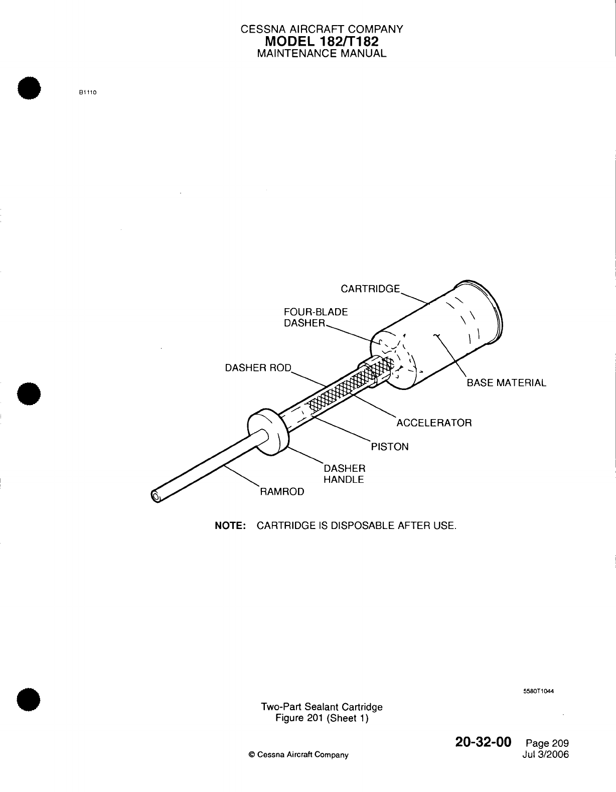
CESSNA
AIRCRAFT
COMPANY
MODEL
182/T182
MAINTENANCE
MANUAL
B1110
CARTRIDGE
FOUR-BLADE
DASHER
ROD
ATERIAL
ACCELERATOR
DASHER
HANDLE
NOTE:
CARTRIDGE
IS
DISPOSABLE
AFTER
USE.
5580T1044
Two-Part
Sealant
Cartridge
Figure
201
(Sheet
1)
20-32-00
©
Cessna Aircraft
Company
Page
209
Jul
3/2006

CESSNA
AIRCRAFT
COMPANY
MODEL
182/T182
MAINTENANCE
MANUAL
WARNING:
The
cartridge should
be
held
firmly,
but
not
squeezed,
as
the
dasher
blades
may
penetrate the
cartridge
and
injure
the
hand.
(b)
Verify
the
drill motor
will rotate the
dasher
rod
clockwise
(looking
toward
the
nozzle
end
of
the
cartridge).
(c)
With
the
cartridge
held
firmly
in
one
hand
and
the
drill
motor
in
the
other,
rotate the
dasher
rod
at
approximately
50
revolutions-per-minute
while
moving
the
dasher
rod
to
FULL
IN
and FULL
OUT
positions.
1
Mix
sealant
for
at least 50
strokes
(a
stroke
is
one
complete
full
in
and
full
out
stroke
of
the
dasher
rod).
NOTE:
If
streaks
are
present
in
the
sealant (viewing
through the side
of
the
cartridge),
the
sealant
is
not
completely
mixed.
(d)
End
mixing
operation
with
the
four blade
dasher
at
the
bottom
of
the
cartridge.
(e)
Hold
cartridge
upright; remove
drill
motor and
rotary
file/drill
bit
from the
dasher
rod;
unscrew
dasher
rod
from
the four
blade
dasher
by
gripping
the
cartridge
at
the
four blade
dasher
and
turn
the
dasher
rod
counterclockwise.
Remove
dasher
rod.
(f)
Screw
appropriate
nozzle
into
the
cartridge.
If
sealant
gun
is
to
be
used,
install
cartridge
in
gun.
8.
Cleaning
A.
All
surfaces
to
which
sealant
is
to
be
applied
shall
be
clean
and
dry.
B.
Remove
all
dust,
lint,
chips, shavings,
etc.
with
a
vacuum
cleaner
where
necessary.
C.
Cleaning
shall
be
accomplished
by
scrubbing
the
surface
with
clean cheesecloth
moistened
with
solvent.
The
cloth
shall
not
be
saturated
to
the
point
where dripping
will
occur.
For
channels
and
joggles,
pipe
cleaners
and/or
funnel brushes
may
be
used
instead
of
cheesecloth.
(1)
Use
solvent
A-A-59281 to
first
clean
the
integral
fuel
tank.
(2)
Use
0-T-620,
1, 1, 1
-
Trichloroethane,
Technical, Inhibited
only
must
be
used
last
to
finish
clean.
D.
The
cleaning solvent
should
never
be
poured
or
sprayed
on the
structure.
E.
The
cleaning
solvent
shall
be
wiped
from the
surfaces
before
evaporation
using
a
piece
of
clean, dry
cheesecloth
in
order that
oils,
grease,
wax
etc., will
not
be
redeposited.
F. It is
essential that
only clean
cheesecloth
and
clean
solvent
be
used
in
the
cleaning
operations.
Solvents
shall
be kept
in
safety
containers
and
shall
be
poured
onto
the
cheesecloth.
The
cheesecloth
shall
not
be
dipped
into
the solvent containers
and
contaminated
solvents
shall
not
be
returned to the
clean
solvent containers.
G.
Final
cleaning
shall
be
accomplished
immediately
prior
to
sealant
application
by
the
person
who
is
going
to
apply the
sealant.
(1)
The
area
which
is
to
be
sealed
shall
be
thoroughly
cleaned.
A
small
clean
paint
brush
may
be
needed
to
clean
corners,
gaps,
etc.
Always
clean
an
area
larger
than
the
area
where
the
sealant
is
to
be
applied.
Never clean
an
area
larger
than
30 inches
(0.8
m) in
length
when
practical.
When
the
area
is
being
scrubbed
with
a
moistened
cloth
in
one
hand,
another clean
dry
cloth
shall
be
held
in
the
other
hand
and
shall
be
used
to
dry
the
structure.
The
solvent
must
be
wiped from the
surfaces
before
it
evaporates.
(2)
The
above procedure
shall
be
repeated until there
is
no
discoloration
on
the
clean
drying
cloth.
Marks
resulting
from wax
or
grease
pencils
must
be
removed
from
parts
prior
to
sealing.
H.
Allow
all
cleaned surfaces
to
dry
a
minimum
of
5
minutes
before
the
application
of
sealant
materials.
I.
Sealant shall
be
applied
as soon
as
possible
after
cleaning
and
drying
the
surfaces
to
be
sealed.
Do
not
handle the
parts
between
the
cleaning
and
sealing operations.
Sealant
application
personnel
handling
cleaned
surfaces
shall
wear
clean
white gloves
to
prevent
surface
contamination.
In
the
event
contamination does
occur, the
surfaces
shall
be
recleaned.
20-32-00
Page
210
©
Cessna Aircraft
Company
Jul
3/2006
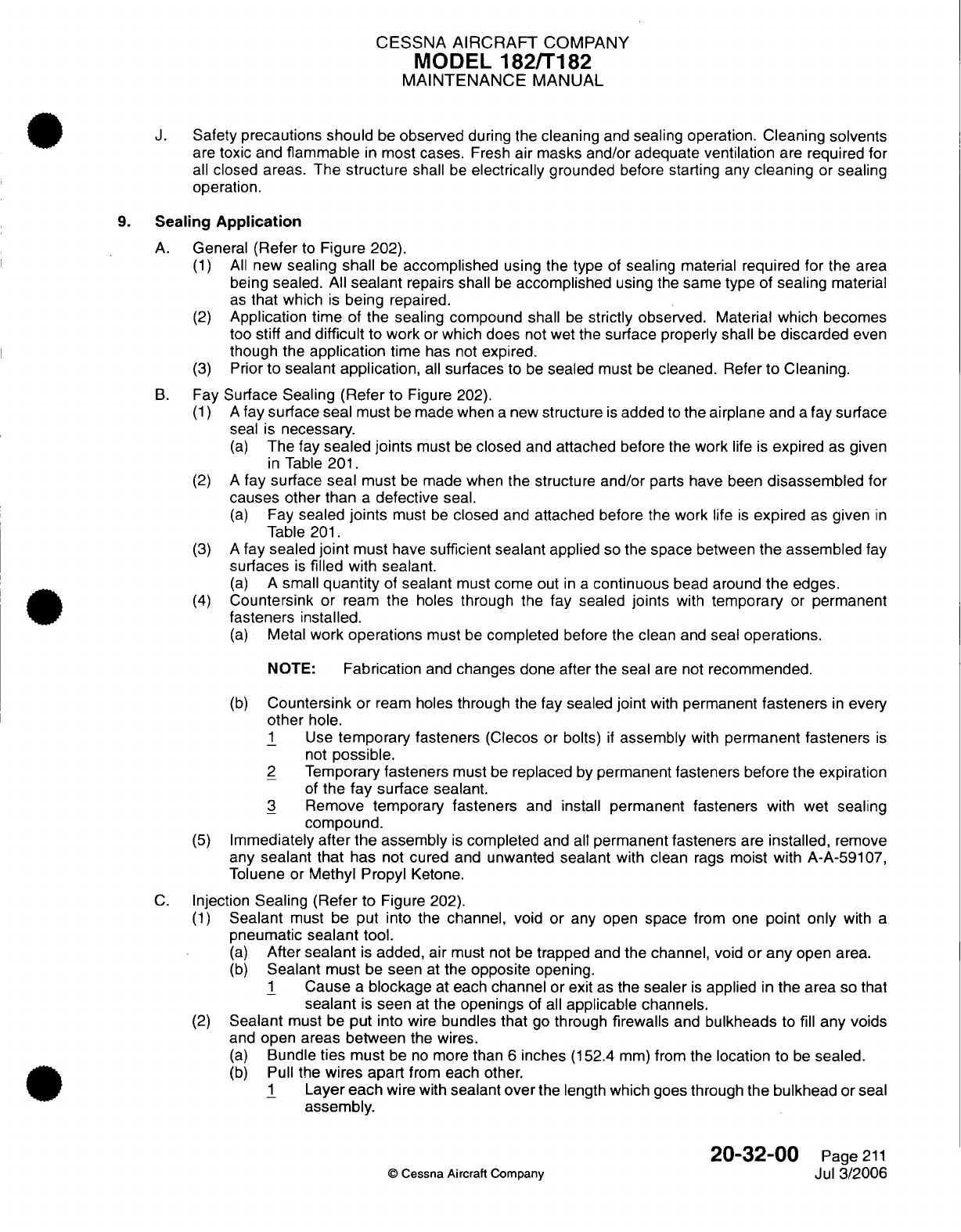
CESSNA AIRCRAFT
COMPANY
MODEL
182/T182
MAINTENANCE
MANUAL
J.
Safety
precautions should
be
observed
during
the
cleaning
and
sealing
operation.
Cleaning
solvents
are
toxic and
flammable
in
most cases.
Fresh
air
masks and/or
adequate
ventilation
are
required
for
all
closed areas. The
structure
shall
be
electrically
grounded
before
starting any
cleaning
or
sealing
operation.
9.
Sealing
Application
A.
General
(Refer
to
Figure 202).
(1)
All
new
sealing shall
be
accomplished
using
the
type
of
sealing
material
required
for
the
area
being
sealed.
All
sealant
repairs shall
be
accomplished
using
the
same type
of
sealing
material
as
that
which
is
being
repaired.
(2)
Application
time
of
the
sealing compound
shall
be
strictly
observed.
Material which becomes
too
stiff
and
difficult
to
work
or
which does
not
wet
the
surface properly
shall be
discarded
even
though
the
application
time
has
not
expired.
(3)
Prior
to
sealant
application,
all
surfaces
to
be
sealed
must
be
cleaned.
Refer
to Cleaning.
B.
Fay
Surface Sealing
(Refer
to
Figure
202).
(1) A
fay
surface seal
must
be
made
when
a
new
structure
is
added
to
the airplane
and
a
fay surface
seal
is
necessary.
(a)
The
fay
sealed joints
must
be
closed
and
attached
before
the
work
life
is
expired
as
given
in
Table
201.
(2) A
fay
surface
seal
must
be
made when
the
structure
and/or
parts have been
disassembled
for
causes
other
than
a
defective
seal.
(a)
Fay
sealed
joints
must
be
closed
and
attached
before
the
work
life
is
expired
as
given
in
Table
201.
(3) A
fay
sealed
joint
must
have
sufficient sealant
applied
so
the
space
between
the assembled
fay
surfaces
is
filled
with
sealant.
(a)
A
small
quantity
of
sealant
must
come
out
in a
continuous
bead
around
the
edges.
(4)
Countersink
or
ream
the
holes
through
the
fay
sealed
joints
with
temporary
or
permanent
fasteners
installed.
(a)
Metal
work
operations
must
be
completed
before the
clean
and
seal
operations.
NOTE:
Fabrication
and
changes
done
after
the seal
are
not
recommended.
(b)
Countersink or
ream
holes
through the
fay
sealed
joint
with
permanent
fasteners
in
every
other
hole.
1
Use
temporary
fasteners
(Clecos
or
bolts)
if
assembly
with
permanent
fasteners
is
not
possible.
2
Temporary
fasteners
must
be
replaced
by
permanent
fasteners
before
the
expiration
of
the
fay
surface
sealant.
3
Remove
temporary
fasteners
and install
permanent
fasteners
with wet
sealing
compound.
(5)
Immediately
after
the assembly
is
completed
and
all
permanent fasteners
are
installed,
remove
any
sealant that
has
not
cured
and
unwanted
sealant
with clean
rags
moist
with A-A-59107,
Toluene or
Methyl Propyl
Ketone.
C.
Injection
Sealing (Refer
to
Figure
202).
(1)
Sealant
must be
put
into
the
channel,
void
or any open
space
from
one
point
only
with
a
pneumatic
sealant
tool.
(a)
After
sealant
is
added,
air
must
not be
trapped
and
the
channel,
void
or
any
open
area.
(b)
Sealant
must
be
seen
at
the
opposite
opening.
1
Cause
a
blockage
at
each
channel
or exit
as
the
sealer
is
applied
in
the
area
so
that
sealant
is
seen
at
the
openings
of
all
applicable channels.
(2)
Sealant
must be
put
into
wire
bundles
that
go
through
firewalls
and
bulkheads
to
fill
any
voids
and
open areas
between
the wires.
(a)
Bundle
ties
must
be
no
more
than
6
inches
(152.4
mm)
from the
location
to
be
sealed.
(b)
Pull
the
wires
apart
from
each
other.
1
Layer each
wire with
sealant
over
the
length
which
goes
through the
bulkhead
or
seal
assembly.
20-32-00
Page
211
©
Cessna Aircraft Company
Jul
3/2006
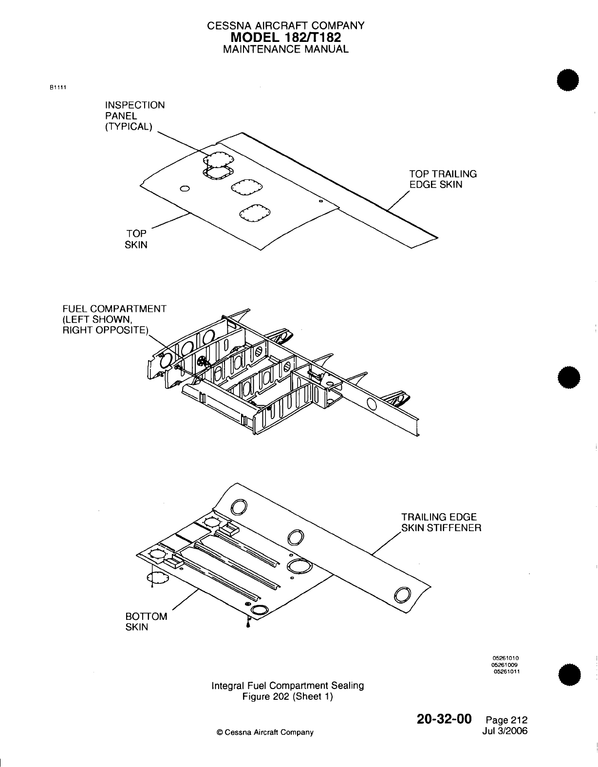
CESSNA
AIRCRAFT
COMPANY
MODEL 182/T182
MAINTENANCE
MANUAL
B1111
INSPECTION
PANEL
(TYPICAL)
RAILING
SKIN
TO
SK
NG EDGE
STIFFENER
BO
05261010
05261009
05261011
Integral
Fuel
Compartment
Sealing
Figure 202
(Sheet
1)
20-32-00
©
Cessna
Aircraft Company
Page
212
Jul 3/2006
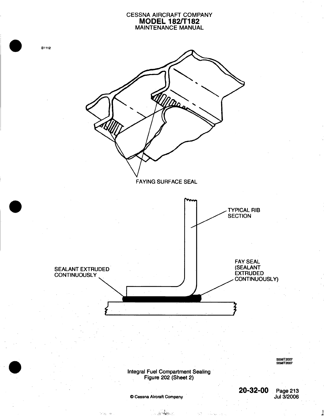
CESSNA
AIRCRAFT
COMPANY
MODEL
182/T182
MAINTENANCE
MANUAL
81112
FAYING
SURFACE
SEAL
TYPICAL
RIB
SECTION
SEALANT
EXTRUDED
CONTINUOUSLY
FAY
SEAL
(SEALANT
EXTRUDED
CONTINUOUSLY)
Integral
Fuel
Compartment
Sealing
Figure 202 (Sheet
2)
20-32-00
Cessna
Aircraft
Company
5598T2007
5598T2007
Page
213
Jul
3/2006
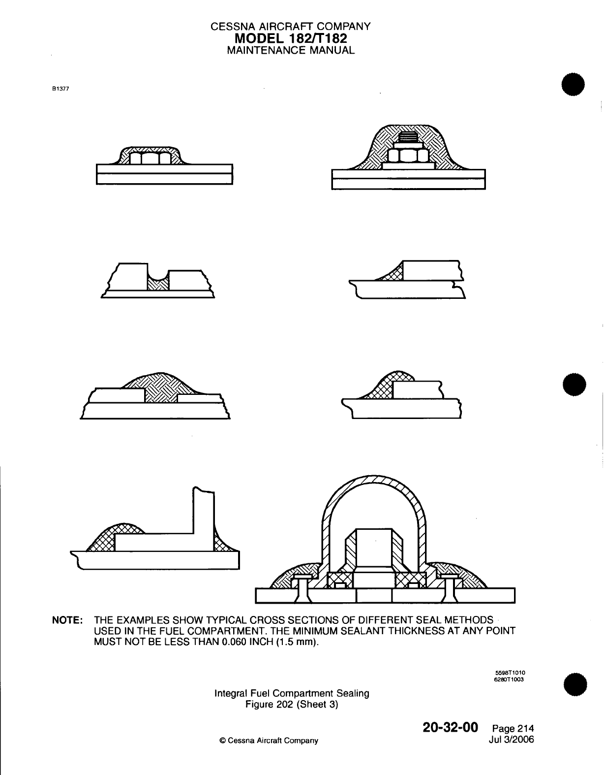
CESSNA
AIRCRAFT
COMPANY
MODEL
182/T182
MAINTENANCE
MANUAL
B1377
NOTE:
THE
EXAMPLES
SHOW TYPICAL
CROSS
SECTIONS
OF
DIFFERENT
SEAL
METHODS
USED
IN
THE FUEL
COMPARTMENT.
THE
MINIMUM SEALANT
THICKNESS
AT
ANY
POINT
MUST
NOT
BE
LESS
THAN
0.060
INCH
(1.5
mm).
5598T1010
6280T 1003
Integral
Fuel
Compartment
Sealing
Figure
202
(Sheet
3)
©
Cessna Aircraft
Company
20-32-00
Page
214
Jul
3/2006
I
I
II
I
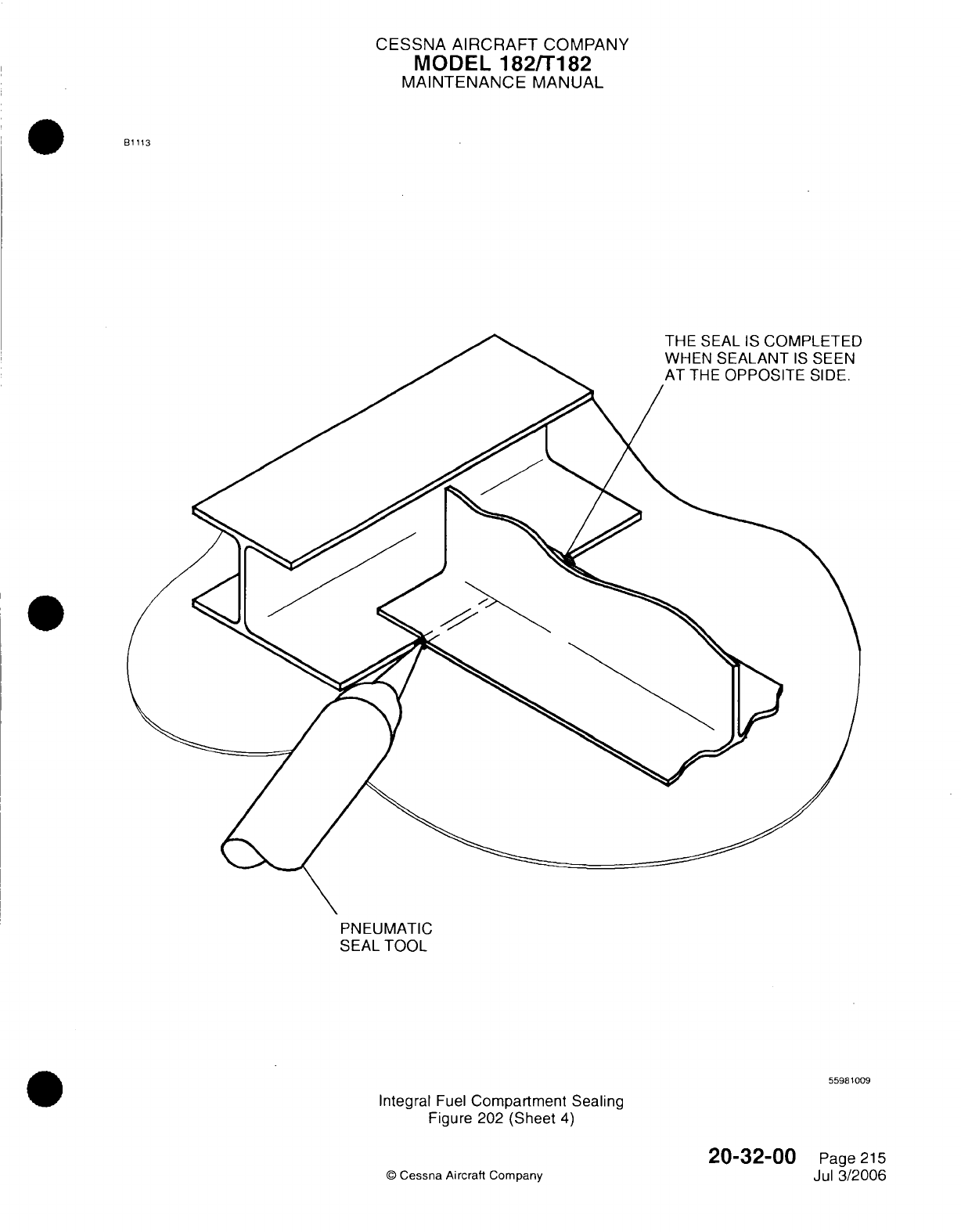
CESSNA AIRCRAFT
COMPANY
MODEL
182/T182
MAINTENANCE
MANUAL
B1113
PNEUMATIC
SEAL
TOOL
55981009
Integral
Fuel
Compartment Sealing
Figure 202
(Sheet
4)
20-32-00
©
Cessna Aircraft
Company
Page
215
Jul
3/2006

CESSNA AIRCRAFT
COMPANY
MODEL
182/T182
MAINTENANCE
MANUAL
2
Layer
each
wire with
sealant
0.5
inch (12.7
mm)
added
length
on
each side
of the
bulkhead
or
seal
assembly.
3
Pull
the
wires
through
the
bulkhead
or
seal
assembly
into
position.
4
Fill
the
open
areas
of
the
wires
that
remain
until
the
sealant
is
seen
from
the
opposite
side.
(3)
Remove
unwanted
sealant
before
the
work
life
of
the
sealant
is
expired.
(4)
Use
an
applicable
tool
to
make
the
sealant
smooth
and
flush
with
the
surface.
D.
Fillet
Sealing.
(1)
Fastener
considerations:
(a)
Do
not
fillet
seal
any
parts
until
they
are
held
completely
together
by
permanent
fasteners.
(b)
Prior to
filleting
the
periphery
of
bolted
structure
and
fittings,
it is
necessary
that
all
bolts,
accomplishing
the
attachment,
be
properly torqued.
(2)
The
sealant
shall
be
applied
using
a
sealant
gun
or
spatula.
(3)
When
using
a
sealant
gun
for
fillet
sealing,
the
nozzle
tip shall
be
pointed
into
the
seam
or
joint
and
shall
be
maintained
nearly
perpendicular
to
the
line
of
travel.
A
continuous
bead
of
sealant
shall
precede
the
tip
and the
tip
size,
shape and
rate
of
travel
shall
be
such
that
sufficient
sealant
shall
be
applied
to
produce
the
required
fillet.
(4)
Fillets
shall
be
shaped
or
formed
to
meet the
size
and
shape
requirements
as
shown
in
applicable
figures using
the
nozzle
tip
and/or fairing
tools
to
press
against
the
sealant
while
moving
parallel
to
the
bead.
Exercise
caution
to
prevent
folds
and entrapment
of
air
during
application
and
shaping
of
the
fillet
and work out
any visible
air bubbles. The
fillet
shall
be
formed
so
that
the
highest
portion
of
the
fillet
is
centered over
the
edge
of
the
structure
or
fitting. Lubrication
in
any form
shall
not
be used
for smoothing
purposes.
In
all
cases,
fillet
size
shall
be
kept
as
near
minimum
as
practical.
(5)
Where
it
is
more
convenient
or
fillet
slumping
is
encountered,
the
fillet may
be
applied
in
two
stages.
A
small
first
fillet
should
be
applied which
is
allowed
to
cure
to
a
tack-free
state,
followed
by
a
second
application
of
sealant sufficient
to
form the final
fillet
conforming
to
the
specified
dimensions for
a
fillet
seal.
If
the first fillet
has
cured,
it
must
be
cleaned
before
the
second
application
of
sealant
is
made.
If
the
fillet
has
only
cured
to
a
tack-free
state,
it
shall
be
wiped
lightly
with
a
gauze
pad
or
cheesecloth
pad
dampened
with
cleaning
solvent.
(6)
Allow the
sealant to cure
to
a
tack-free condition
prior
to the
airplane
being moved,
handled
and/or worked
on.
(7) In
cases
where
a
fillet
seal
connects
to
an
injection
seal, the
full bodied
fillet
shall
extend past
the
end
of
the
injection
and
then
taper
out.
(8)
Lap
joint
and seam
fillets
shall
be
as
shown
in
Figure
202,
Sheet
3.
(9)
Butt
joint
fillets
shall
be
as
shown
in
Figure
202,
Sheet
3.
(10)
Bolts
shall
be
fillet
sealed
as
shown
in
Figure
202,
Sheet
3.
The
area
for
sealing
shall
consist
of
the
area
of
the
structure surrounding
the base
of
the
fastener
end
plus
the
entire exposed
area
of
the
fastener.
An
optional
method
of
sealing threaded fasteners
is
to
apply
a
brush
coat
of
Type
I,
Class
A
sealant.
Where
brush
coating
is
used
as
the
method
of
sealing
threaded
fasteners,
the
sealant
must be
worked
around each
fastener
with
a
stiff
brush
and
considerable
care
to
be
effective.
A
simple pass
of
the
brush
with
the
sealant
is
not
sufficient
to
produce
an
effective
seal.
(11)
Dome
type
nutplates shall
be
fillet
sealed
as
shown
in
Figure 202,
Sheet
3.
The
area
for sealing
shall
consist
of
the
area
of
the
structure surrounding
the
base
of
the
fastener
and
from
there
up
over
the
rivets
to
the
dome.
(12)
Hole
filling
and
slot
fillets
shall
be
as
shown
in
Figure 202,
Sheet
3.
(a)
Tooling holes
shall
be
plugged
with
a
shank
sealed
soft
rivet and
then
brush
coated
with
Type
I,
Class
A
sealant.
20-32-00
Page
216
©
Cessna Aircraft
Company
Jul
3/2006
CESSNA
AIRCRAFT
COMPANY
MODEL
182/T182
MAINTENANCE
MANUAL
10.
Sealant
Repair
A.
Materials
-
Repairs,
in
general,
shall
be
accomplished
with
the
same
type
of
material
as
that
being
repaired.
NOTE: Type
I,
Class
B-1/2
is
recommended
for
use
during
cold
weather
to
obtain
an
accelerated
cure.
NOTE: Type
I,
Quick
Repair sealant
may
be
used
as
a
repair
for sealant
in
fuel tanks
if
desired
for
fast
cure
and
rapid
dispatch.
B.
Temperature
Requirements.
(1)
The
structure
shall
be
above
60°F
(15°C)
before the
sealant
is
applied
and shall
remain
above
60°F
(15°C)
until the
sealant
is
tack-free.
NOTE: For
outside
operations
only,
the
temperature
of the
structure
may
be
allowed
to
drop
below
60°F
(15°C)
but not
below
58°F
(14°C),
after
application
for
a
period
of
time
not
to exceed
48
hours;
however,
the
structure
must
be
subsequently
heated
to
above
60°F
(15°C)
and the
sealant
allowed
to
become
tack-free
before
the
tanks
are
refueled.
(2)
The maximum
air
temperature allowed
to
come
in
contact
with
the
curing
sealant
is
120°F (49°C).
C.
Fillet
and
Fastener
Sealing
Repairs.
(1)
Repair
of
damaged
or
faulty
sealant
applications
shall
be
accomplished
as
follows:
(a)
Remove all
damaged
or
faulty
sealant
to
ensure solid residual
material.
(b)
Sealant
shall
be
cut
to
produce
a
smooth
continuous
scarfed face.
The
sealant
shall
be
completely
removed
in
the
affected
areas.
The cutting
tools
should
only
be
made
from
nonmetallic
materials
that
are
softer
than
aluminum.
(c)
Inspect
repair
areas
for
clean
and
smooth
cuts.
Loose
chunks
or
flaps
of
sealant
on
the
cut
areas
shall
be
removed.
(d)
Clean
the
area
to
be
sealed,
including
the scarfed face
of
the old
seal.
Refer
to
Cleaning.
(e)
Apply new
fillet
seals. Slight
overlapping
of
the
fresh
material
over
the
existing fillet
is
permissible.
A
large
buildup
of
sealant
shall
not be
allowed.
(f)
Rework
of
a
fillet
which
has
been
oversprayed
or
brushed with primer shall
be
accomplished
by
a
scarfed
joint
and
removal
of
the
fillet
having primer
on
it, in
the
area
of
the
repair.
The
primer shall
not
be
sandwiched
between
the
old
and new
sealants.
(g) If
the
primer
is
removed
during
the
cleaning operation,
it
is
permissible
to
apply
the
new
fillet
seal
directly
over
the
clean
bare metal
and
then
touch
up
with
the
proper
primer
all
exposed
areas
of
bare
metal
after
the
sealant
has
been
applied.
D.
Faying
Surface
Sealing
Repair
-
After
determining
the
area which
contains
the
faulty
and/or
leaking
faying surface
seal,
the
repair shall
be
accomplished
by
applying
a
fillet
seal
along
the edge
of the
part
adjacent
to
the
faying
surface
seal long
enough
to
fully
cover
the
area
of
the
faulty
and/or
leaking
seal.
E.
Brush
Coat
Sealing
Repair
-
Repair
of
damaged
or
leaking
brush
coat
seals
shall
be
accomplished
by
removing
the
discrepant
brush
coat. Clean
the
area
of
sealant
removal
and
the
surrounding structure
and
sealant.
Refer
to
Cleaning.
F.
Integral
Fuel
Tank
Sealing
Using
PR-1826 Class
B
Rapid
Curing
Sealant.
(1)
Remove
damaged section
of
sealant
with
a
sharp
plexiglass
scraper.
Taper
all
cuts
in
old
sealant
at
45-degree
angles.
20-32-00
Page
217
©
Cessna Aircraft
Company
Jul
3/2006
CESSNA AIRCRAFT
COMPANY
MODEL
182/T182
MAINTENANCE
MANUAL
(2)
Thoroughly
clean with
solvent
and
abrade
old
areas which
are
to
be
over
coated.
Clean
one
small area
at
a
time,
then
dry
with
a
clean
cloth
before
the
solvent evaporates.
NOTE:
Always pour solvent
on
the
cloth
to
maintain
a
clean solvent
supply.
NOTE:
In
fuel
tanks
which
have been
in
operation,
the
sealant
will
be
soaked
and
should
be
dried
in
area
of
the
repair
with
a
vapor
proof
heat
lamp
or
hot
air
blower
before
new
sealant
is
applied.
(3)
After
the
surface has
been
cleaned
and
dried,
apply
a
sufficient
layer
of
PR-1826
Adhesion
Promoter
with
a
clean
brush
or
gauze
pad.
Allow
adhesion
promoter
a
minimum
of
30
minutes
to
dry.
NOTE: Care
must
be
taken
to
get
a
equal,
thin
layer
of
adhesion promoter
applied
to the
surface. There
must
be
a
sufficient
layer
for
the
full
surface,
but
not
too
much
that
will
cause
it
to
drip.
(4)
(5)
Mix
PR-1826 Class
B
sealant according
to
instructions
supplied
with
the
material.
Apply
PR-1826
Class
B
sealant,
0.125
to
0.375
inch
(3.2
to
9.5
mm)
thick,
to
the repair
area
with
a
spatula
or
paddle
shaped tool.
Firmly
press
sealant
in
place
and
form to
desired
shape.
Overlap
PR-1826 Class
B
sealant over
old
sealant
from
0.125
to
0.25
inch
(3.2
to
6.4
mm).
NOTE:
Sealant
may
be
applied
up
to
8
hours
after
the
application
of
adhesion
promoter. After
8
hours,
the
surface
should
be
recleaned
and
adhesion
promoter
reapplied.
(6)
Allow
sealant
to
cure
a
minimum
of
2
hours at
77°F
(25°C)
before refueling.
Curing
time
is
based
solely
on
temperature
and
will
be
halved
for
every
18°F
(10°C)
increase,
and
doubled
for
every
18°F
(10°C)
decrease
from
the
standard
77°F (25°C).
G.
Firewall
Wire
Bundle
Seal Assembly.
(1)
Fay
surface
seal
the
mating
parts
of
the
seal
assembly
plate
and
the
firewall.
Refer
to
Sealing
Application.
(a)
Seal
only
with Type
IV
DAPCO
2100 from
D.
Aircraft
Inc. or
seal
with
Type
IV
Q3-6077
from
Dow
Corning.
Refer
to Tools and
Equipment.
(2)
Injection
seal
the wire bundle
that passes through
the seal
assembly.
Refer
to
Sealing
Application.
(a)
Seal
only
with
Type
IV
DAPCO
2100
from
D.
Aircraft
Inc. or
seal
with
Type
IV
Q3-6077
from
Dow
Corning.
Refer
to
Tools
and
Equipment.
20-32-00
Cessna Aircraft
Company
Page
218
Jul 3/2006
CESSNA
AIRCRAFT
COMPANY
MODEL
182/T182
MAINTENANCE
MANUAL
CONVERSION
DATA
-
DESCRIPTION AND OPERATION
1.
General
A.
This
section
contains
information converting
the
more
commonly
used
measuring
units
found
in
this
manual
from
the
North
American
system
to
the
metric
system.
B.
Tables have been
prepared
for
the
convenience
of
the
user.
Formulas,
examples
and
a
table
of
conversion
factors
are
included for
individual
computations.
2.
Formulas
for
Conversion
Computations
A.
Work
and
Energy.
(1)
Mechanical
Energy
Formula
-
Refer
to
conversion
factors
in
Figure
1
to
convert inch-pounds
and
foot-pounds
into
metric
measure
of
centimeter
kilograms
and
meter
kilograms.
(2)
Figure
2
is
a
table containing
conversion
data
for
converting
inch-pounds to
centimeter
kilograms,
centimeter
kilograms
to
inch-pounds, foot-pounds
to
meter
kilograms,
meter
kilograms
to
foot-pounds.
B.
Distance
and
Length.
(1)
Formula
-
One
multiplied
by
2.540
=
centimeter;
inch
=
2.54 cm.
One
multiplied
by
25.40
=
millimeter;
inch
=
25.40
mm.
NOTE:
Reference
conversion
factors
in
Figure
1.
(2)
Figure
3
is
a
table
containing
conversion
data
for
converting inches to
millimeters.
The
procedure
for
converting
inches
to
millimeters
by
using
figure
as
follows:
Example,
convert 0.032
inches
to
millimeters.
(a)
Read down
inch
column
to
0.003.
(b)
Read
across
top
inch
column
to
0.0002.
(c)
Locate
where
these
two
columns intersect
(0.0032
inch
is
0.0812
millimeters).
(3)
Figure
4
is
a
table containing
conversion
data
for
converting
fraction
of
an inch
to
decimal
equivalent
and
to
millimeter. Locate
fraction
of
an
inch
figure
and
move
to
the
right
horizontally
to
locate
decimal
equivalent
figure
in
the
decimal
equivalent
column
and
millimeter
numeral
in
the
millimeter
column.
C.
Temperature.
(1)
Formula:
'F
=
9/5
('C
+32)
'C
=
5/9
(F
-32)
(2)
Figure
5
is
a
table containing conversion
data
for converting
temperature
from
either Celsius
to
Fahrenheit
or Fahrenheit
to
Celsius.
(a)
Select
the
desired
number
in
the
middle column
of
the
three
column
presentation.
If
the
number
you
selected
is
in
degrees
Celsius,
read
the
degrees
Fahrenheit
equivalent
in
the
right
column
of
the
three-column presentation.
(b)
Select
the
desired
number
in
the
middle
column
of the
three-column
presentation.
If
the
number
selected
is
in
degrees
Fahrenheit,
read
degrees
Celsius
equivalent
in
the
left
column
of
the three-column presentation.
D.
Drill
Sizes
and
Tap
Sizes.
(1)
Figure
6
is
a
table containing conversion
data
for
converting standard
and
millimeter
drill
sizes
to
decimal
equivalents.
Also
included
is
a
chart
for
determining
tap
size
when
a
hole
ID
is
known.
(a)
To
find decimal equivalent
of
a
standard
drill
size,
go
down
the chart to
the
standard
drill
size
and
read
decimal
equivalent
in
the
right
column.
(b)
To
find
standard drill
size for
a
known
decimal
equivalent
size,
go
down
decimal column
to
decimal
size
and
read
drill
size
in
the
left
column.
(c)
To
find
decimal
equivalent
of
a
millimeter
drill
size,
go
down
the
chart
to
the
millimeter
drill
size
and
read
decimal
equivalent
in
the
right
column.
(d)
To
find millimeter
drill
size
for
a
known decimal
equivalent size,
go
down
the
chart
to
the
decimal
equivalent
size
and
read
millimeter
drill
size
in
the
left
column.
(e)
To
find
a
tap
size,
go
down
the
hole
ID
chart
to
the
size
hole
to
be
tapped
and
read
the
tap
size
in
the
left
column.
20-50-00
Page
1
©
Cessna
Aircraft Company
April
1/2002

CESSNA
AIRCRAFT
COMPANY
MODEL
182/T182
MAINTENANCE
MANUAL
MULTIPLY
CENTIMETERS
CUBIC
CENTIMETERS
BY
0.3937
0.03281
0.001
0.06102
0.0002642
TO
OBTAIN
INCHES
FEET
LITERS
CUBIC INCHES
U.S.
GALLONS
CUBIC
FEET
CUBIC INCHES
CUBIC
METERS
FEET
FOOT-POUNDS
28,320
1,728
7.481
28.32
16.39
0.01639
0.004329
0.01732
1,000,000
35.31
61,023
264.2
999.97
0.3048
12,000
304.8
0.3333
0.1383
0.001285
0.000000376
CUBIC
CENTIMETERS
CUBIC
INCHES
U.S.
GALLONS
LITERS
CUBIC
CENTIMETERS
LITERS
U.S.
GALLONS
QUARTS
CUBIC CENTIMETERS
CUBIC
FEET
CUBIC INCHES
GALLON
LITERS
METERS
MILS
MILLIMETERS
YARDS
METER-KILOGRAMS
BRITISH
THERMO
UNIT
KILOWATTS
PER
HOUR
FLUID OUNCE
GALLON,
IMPERIAL
GALLON,
U.S.
DRY
GALLON,
U.S.
LIQUID
INCHES
8
29.6
277.4
1.201
4.546
268.8
0.1556
1.164
4.405
231.0
0.1337
3.785
0.8327
128
2.540
.08333
DRAM
CUBIC
CENTIMETERS
CUBIC INCHES
U.S.
GALLON
LITERS
CUBIC
INCHES
CUBIC
FEET
U.S.
GALLON,
LIQUID
LITERS
CUBIC INCHES
CUBIC
FEET
LITERS
IMPERIAL GALLON
FLUID
OUNCES
CENTIMETERS
FEET
Conversion
Factors
Figure
1
(Sheet
1)
20-50-00
Page
2
April
1/2002
©
Cessna Aircraft
Company
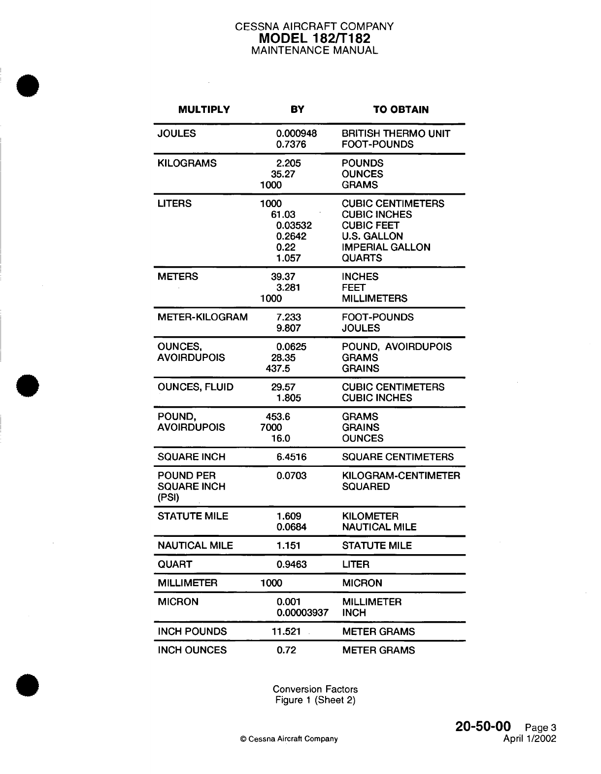
CESSNA
AIRCRAFT
COMPANY
MODEL
182/T182
MAINTENANCE
MANUAL
BY
JOULES
KILOGRAMS
LITERS
METERS
METER-KILOGRAM
OUNCES,
AVOIRDUPOIS
OUNCES, FLUID
0.000948
0.7376
2.205
35.27
1000
1000
61.03
0.03532
0.2642
0.22
1.057
39.37
3.281
1000
7.233
9.807
0.0625
28.35
437.5
29.57
1.805
BRITISH
THERMO
UNIT
FOOT-POUNDS
POUNDS
OUNCES
GRAMS
CUBIC
CENTIMETERS
CUBIC
INCHES
CUBIC
FEET
U.S.
GALLON
IMPERIAL GALLON
QUARTS
INCHES
FEET
MILLIMETERS
FOOT-POUNDS
JOULES
POUND,
AVOIRDUPOIS
GRAMS
GRAINS
CUBIC CENTIMETERS
CUBIC INCHES
POUND,
AVOIRDUPOIS
SQUARE
INCH
POUND
PER
SQUARE
INCH
(PSI)
STATUTE
MILE
NAUTICAL
MILE
453.6
7000
16.0
6.4516
0.0703
1.609
0.0684
1.151
GRAMS
GRAINS
OUNCES
SQUARE
CENTIMETERS
KILOGRAM-CENTIMETER
SQUARED
KILOMETER
NAUTICAL
MILE
STATUTE
MILE
QUART
MILLIMETER
MICRON
INCH
POUNDS
INCH
OUNCES
0.9463
1000
0.001
0.00003937
11.521
0.72
LITER
MICRON
MILLIMETER
INCH
METER
GRAMS
METER
GRAMS
Conversion
Factors
Figure
1
(Sheet
2)
20-50-00
Page
3
April 1/2002
©
Cessna
Aircraft
Company
MULTIPLY
TO
OBTAIN
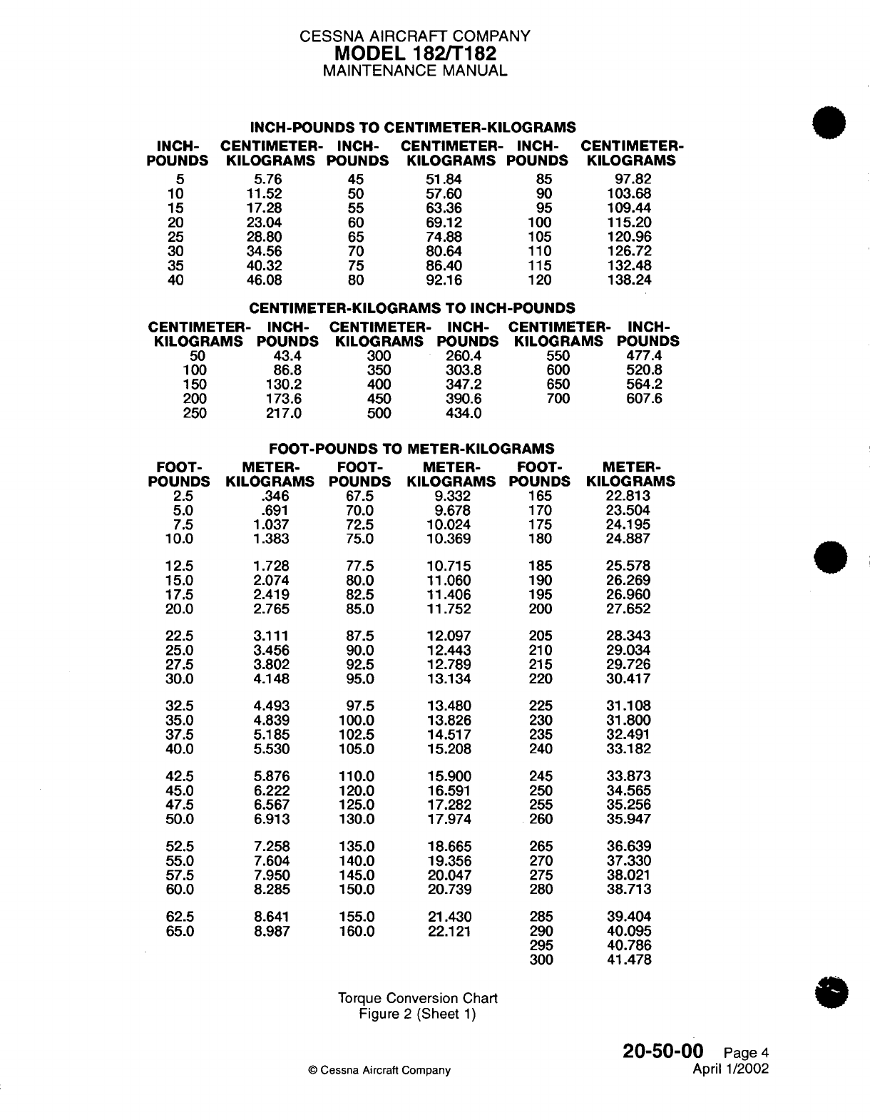
CESSNA
AIRCRAFT
COMPANY
MODEL
182/T182
MAINTENANCE
MANUAL
INCH-POUNDS
TO
CENTIMETER-KILOGRAMS
CENTIMETER-
INCH-
KILOGRAMS
POUNDS
5.76
45
11.52
50
17.28
55
23.04
60
28.80
65
34.56
70
40.32
75
46.08
80
CENTIMETER-
INCH-
KILOGRAMS
POUNDS
51.84
85
57.60
90
63.36
95
69.12
100
74.88
105
80.64
110
86.40
115
92.16
120
CENTIMETER-
KILOGRAMS
97.82
103.68
109.44
115.20
120.96
126.72
132.48
138.24
CENTIMETER-KILOGRAMS
TO
INCH-POUNDS
CENTIMETER-
INCH-
CENTIMETER-
INCH-
CENTIMETER-
KILOGRAMS
POUNDS
KILOGRAMS
POUNDS
KILOGRAMS
50
43.4
300 260.4
550
100
86.8
350
303.8
600
150
130.2 400
347.2
650
200
173.6 450
390.6
700
250
217.0 500
434.0
INCH-
POUNDS
477.4
520.8
564.2
607.6
FOOT-POUNDS
TO
METER-KILOGRAMS
METER-
KILOGRAMS
.346
.691
1.037
1.383
1.728
2.074
2.419
2.765
3.111
3.456
3.802
4.148
4.493
4.839
5.185
5.530
5.876
6.222
6.567
6.913
7.258
7.604
7.950
8.285
8.641
8.987
FOOT-
POUNDS
67.5
70.0
72.5
75.0
77.5
80.0
82.5
85.0
87.5
90.0
92.5
95.0
97.5
100.0
102.5
105.0
110.0
120.0
125.0
130.0
135.0
140.0
145.0
150.0
155.0
160.0
METER-
KILOGRAMS
9.332
9.678
10.024
10.369
10.715
11.060
11.406
11.752
12.097
12.443
12.789
13.134
13.480
13.826
14.517
15.208
15.900
16.591
17.282
17.974
18.665
19.356
20.047
20.739
21.430
22.121
FOOT-
POUNDS
165
170
175
180
185
190
195
200
205
210
215
220
225
230
235
240
245
250
255
260
265
270
275
280
285
290
295
300
METER-
KILOGRAMS
22.813
23.504
24.195
24.887
25.578
26.269
26.960
27.652
28.343
29.034
29.726
30.417
31.108
31.800
32.491
33.182
33.873
34.565
35.256
35.947
36.639
37.330
38.021
38.713
39.404
40.095
40.786
41.478
Torque
Conversion
Chart
Figure
2
(Sheet
1)
20-50-00
©
Cessna Aircraft
Company
INCH-
POUNDS
5
10
15
20
25
30
35
40
FOOT-
POUNDS
2.5
5.0
7.5
10.0
12.5
15.0
17.5
20.0
22.5
25.0
27.5
30.0
32.5
35.0
37.5
40.0
42.5
45.0
47.5
50.0
52.5
55.0
57.5
60.0
62.5
65.0
Page
4
April
1/2002

CESSNA
AIRCRAFT
COMPANY
MODEL
182/T182
MAINTENANCE
MANUAL
METER-
KILOGRAMS
1
2
3
4
5
6
7
METER-KILOGRAMS
TO
FOOT-POUNDS
FOOT-
METER-
FOOT-
METER-
POUNDS
KILOGRAMS
POUNDS
KILOGRAMS
7.23
8
57.86
15
14.46
9
65.89
16
21.69
10
72.32
17
28.93
11
79.56
18
36.16
12
86.79
19
43.39
13
94.02
20
50.63
14
101.26
21
22
Torque
Conversion
Chart
Figure
2
(Sheet
2)
20-50-00
Page
5
April 1/2002
©
Cessna
Aircraft
Company
FOOT-
POUNDS
108.49
115.72
122.95
130.19
137.42
144.65
151.89
159.12
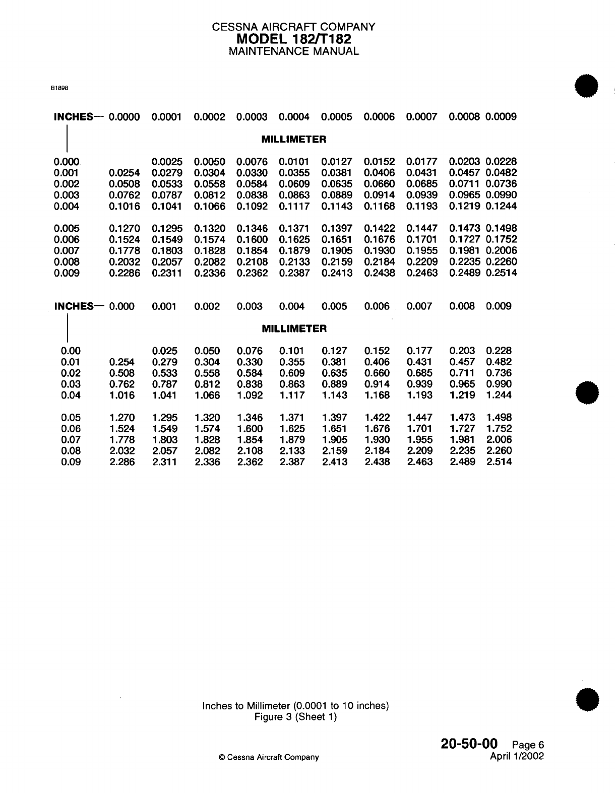
CESSNA
AIRCRAFT
COMPANY
MODEL
182/T182
MAINTENANCE
MANUAL
B1898
INCHES-
0.0000
0.0001
0.0002
0.0003
0.0004
0.0005 0.0006
0.0007 0.0008
0.0009
MILLIMETER
0.0076
0.0101
0.0127
0.0330
0.0355
0.0381
0.0584
0.0609
0.0635
0.0838
0.0863
0.0889
0.1092
0.1117
0.1143
0.1346
0.1371
0.1397
0.1600
0.1625
0.1651
0.1854
0.1879 0.1905
0.2108
0.2133
0.2159
0.2362
0.2387
0.2413
0.0152
0.0406
0.0660
0.0914
0.1168
0.1422
0.1676
0.1930
0.2184
0.2438
0.0177
0.0431
0.0685
0.0939
0.1193
0.1447
0.1701
0.1955
0.2209
0.2463
0.0203
0.0228
0.0457 0.0482
0.0711
0.0736
0.0965 0.0990
0.1219
0.1244
0.1473
0.1498
0.1727 0.1752
0.1981
0.2006
0.2235 0.2260
0.2489
0.2514
INCHES-
0.000
0.001
0.002
0.003
0.004
0.005
0.006
0.007
0.008 0.009
0.177
0.431
0.685
0.939
1.193
1.447
1.701
1.955
2.209
2.463
0.203
0.228
0.457 0.482
0.711
0.736
0.965 0.990
1.219
1.244
1.473
1.498
1.727
1.752
1.981
2.006
2.235
2.260
2.489
2.514
Inches
to
Millimeter
(0.0001
to
10
inches)
Figure
3
(Sheet
1)
20-50-00
Page
6
April
1/2002
©
Cessna Aircraft
Company
0.000
0.001
0.002
0.003
0.004
0.005
0.006
0.007
0.008
0.009
0.0254
0.0508
0.0762
0.1016
0.1270
0.1524
0.1778
0.2032
0.2286
0.0025
0.0279
0.0533
0.0787
0.1041
0.1295
0.1549
0.1803
0.2057
0.2311
0.0050
0.0304
0.0558
0.0812
0.1066
0.1320
0.1574
0.1828
0.2082
0.2336
MILLIMETER
0.00
0.01
0.02
0.03
0.04
0.05
0.06
0.07
0.08
0.09
0.254
0.508
0.762
1.016
1.270
1.524
1.778
2.032
2.286
0.025
0.279
0.533
0.787
1.041
1.295
1.549
1.803
2.057
2.311
0.050
0.304
0.558
0.812
1.066
1.320
1.574
1.828
2.082
2.336
0.076
0.330
0.584
0.838
1.092
1.346
1.600
1.854
2.108
2.362
0.101
0.355
0.609
0.863
1.117
1.371
1.625
1.879
2.133
2.387
0.127
0.381
0.635
0.889
1.143
1.397
1.651
1.905
2.159
2.413
0.152
0.406
0.660
0.914
1.168
1.422
1.676
1.930
2.184
2.438
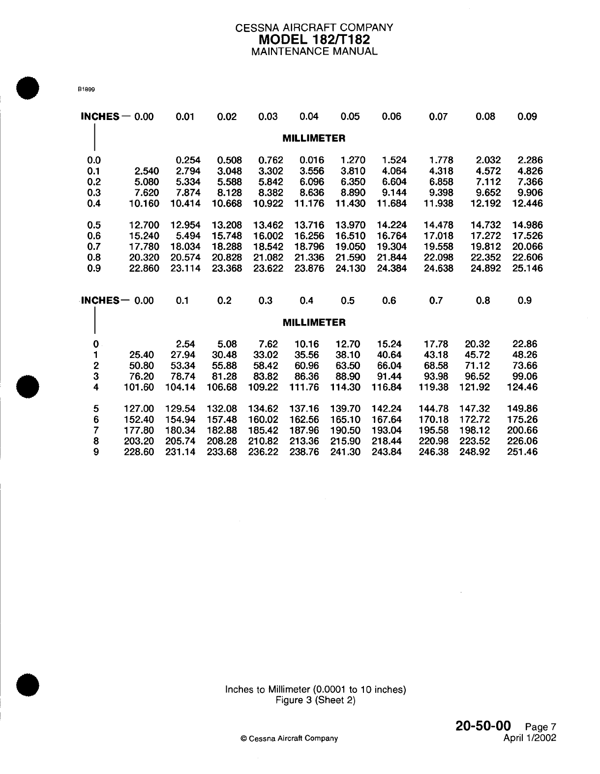
CESSNA
AIRCRAFT
COMPANY
MODEL
182/T182
MAINTENANCE
MANUAL
B1899
INCHES-
0.00
0.01
0.02
0.03
0.04 0.05
0.06
0.07
0.08 0.09
MILLIMETER
0.254
2.540
2.794
5.080 5.334
7.620
7.874
10.160
10.414
12.700 12.954
15.240 5.494
17.780 18.034
20.320 20.574
22.860
23.114
0.508
3.048
5.588
8.128
10.668
13.208
15.748
18.288
20.828
23.368
0.762 0.016
1.270
1.524
3.302 3.556 3.810
4.064
5.842
6.096
6.350 6.604
8.382
8.636
8.890 9.144
10.922
11.176
11.430
11.684
13.462
13.716
13.970
14.224
16.002 16.256
16.510
16.764
18.542 18.796
19.050
19.304
21.082 21.336
21.590
21.844
23.622 23.876
24.130
24.384
INCHES-
0.00
0.1
0.2
0.3
0.4 0.5
0.6
0.7
0.8
0.9
MILLIMETER
2.54
25.40
27.94
50.80 53.34
76.20
78.74
5.08
30.48
55.88
81.28
7.62 10.16
12.70
15.24
33.02
35.56
38.10 40.64
58.42
60.96
63.50
66.04
83.82
86.36
88.90 91.44
4
101.60
104.14 106.68
109.22 111.76
114.30 116.84
5
127.00
129.54 132.08
134.62 137.16 139.70
142.24
6
152.40
154.94 157.48
160.02
162.56
165.10
167.64
7
177.80
180.34 182.88
185.42
187.96
190.50 193.04
8
203.20
205.74 208.28
210.82
213.36
215.90 218.44
9
228.60 231.14 233.68 236.22
238.76
241.30 243.84
17.78 20.32
43.18
45.72
68.58
71.12
93.98
96.52
119.38
121.92
144.78
147.32
170.18
172.72
195.58 198.12
220.98
223.52
246.38
248.92
22.86
48.26
73.66
99.06
124.46
149.86
175.26
200.66
226.06
251.46
Inches to
Millimeter
(0.0001 to
10
inches)
Figure
3
(Sheet
2)
20-50-00
Page
7
April 1/2002
©
Cessna
Aircraft
Company
0.0
0.1
0.2
0.3
0.4
0.5
0.6
0.7
0.8
0.9
1.778
4.318
6.858
9.398
11.938
14.478
17.018
19.558
22.098
24.638
2.032
4.572
7.112
9.652
12.192
14.732
17.272
19.812
22.352
24.892
2.286
4.826
7.366
9.906
12.446
14.986
17.526
20.066
22.606
25.146
0
1
2
3
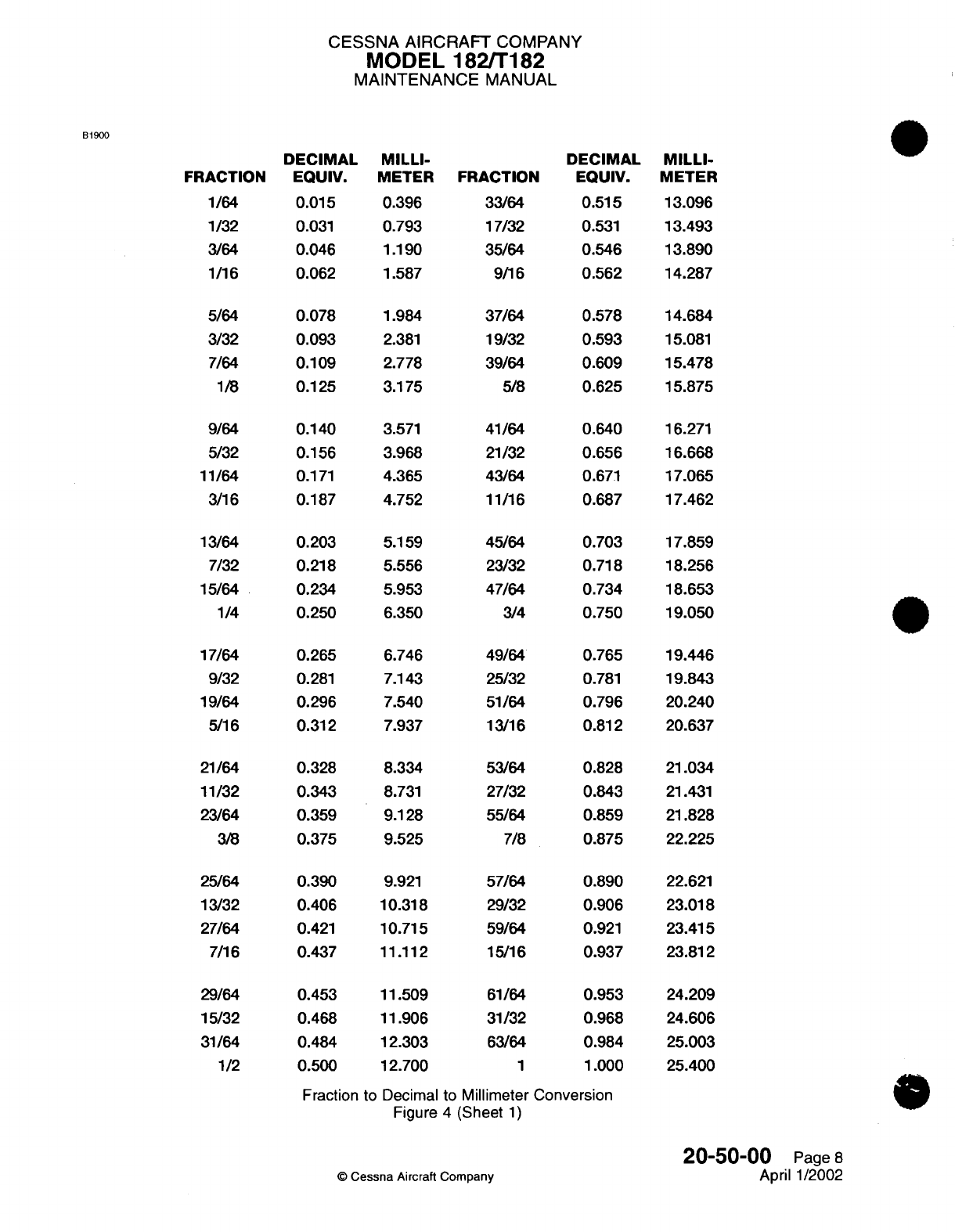
CESSNA
AIRCRAFT
COMPANY
MODEL
182/T182
MAINTENANCE
MANUAL
B1900
FRACTION
1/64
1/32
3/64
1/16
5/64
3/32
7/64
1/8
9/64
5/32
11/64
3/16
13/64
7/32
15/64
1/4
17/64
9/32
19/64
5/16
21/64
11/32
23/64
3/8
25/64
13/32
27/64
7/16
29/64
15/32
31/64
1/2
DECIMAL
EQUIV.
0.015
0.031
0.046
0.062
0.078
0.093
0.109
0.125
0.140
0.156
0.171
0.187
0.203
0.218
0.234
0.250
0.265
0.281
0.296
0.312
0.328
0.343
0.359
0.375
0.390
0.406
0.421
0.437
0.453
0.468
0.484
0.500
Fraction
MILLI-
METER
0.396
0.793
1.190
1.587
1.984
2.381
2.778
3.175
3.571
3.968
4.365
4.752
5.159
5.556
5.953
6.350
6.746
7.143
7.540
7.937
8.334
8.731
9.128
9.525
9.921
10.318
10.715
11.112
11.509
11.906
12.303
12.700
FRACTION
33/64
17/32
35/64
9/16
37/64
19/32
39/64
5/8
41/64
21/32
43/64
11/16
45/64
23/32
47/64
3/4
49/64
25/32
51/64
13/16
53/64
27/32
55/64
7/8
57/64
29/32
59/64
15/16
61/64
31/32
63/64
1
DECIMAL
EQUIV.
0.515
0.531
0.546
0.562
0.578
0.593
0.609
0.625
0.640
0.656
0.671
0.687
0.703
0.718
0.734
0.750
0.765
0.781
0.796
0.812
0.828
0.843
0.859
0.875
0.890
0.906
0.921
0.937
0.953
0.968
0.984
1.000
to Decimal
to Millimeter Conversion
Figure
4
(Sheet
1)
20-50-00
Page
8
April
1/2002
©
Cessna
Aircraft Company
MILLI-
METER
13.096
13.493
13.890
14.287
14.684
15.081
15.478
15.875
16.271
16.668
17.065
17.462
17.859
18.256
18.653
19.050
19.446
19.843
20.240
20.637
21.034
21.431
21.828
22.225
22.621
23.018
23.415
23.812
24.209
24.606
25.003
25.400
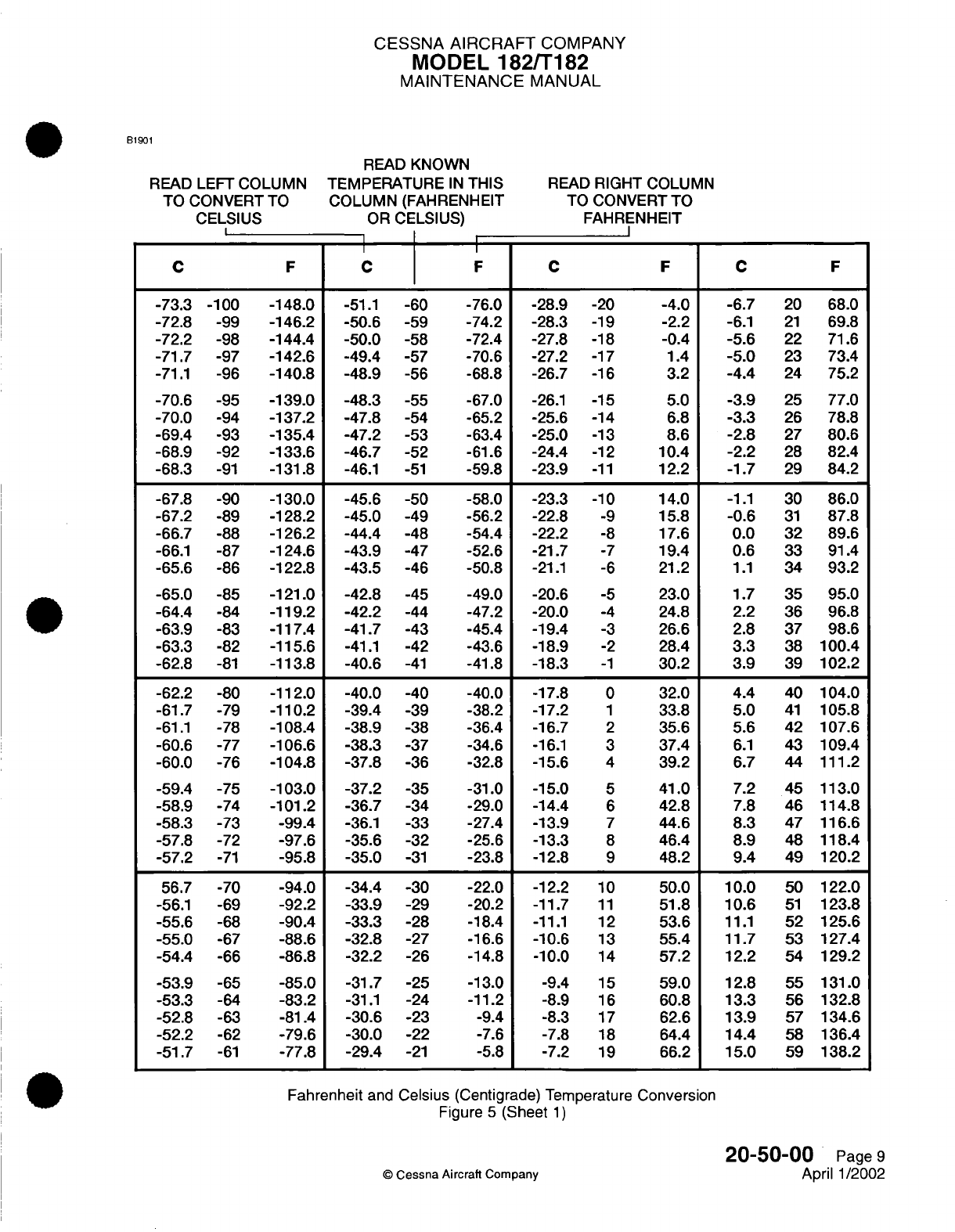
CESSNA
AIRCRAFT
COMPANY
MODEL
182/T182
MAINTENANCE
MANUAL
B1901
READ
KNOWN
READ
LEFT
COLUMN
TEMPERATURE
IN
THIS
TO
CONVERT
TO
COLUMN
(FAHRENHEIT
CELSIUS
OR
CELSIUS)
I
I
C
FI
I
C F
-73.3 -100 -148.0
-51.1
-60
-72.8
-99
-146.2
-50.6
-59
-72.2
-98
-144.4
-50.0
-58
-71.7
-97
-142.6 -49.4
-57
-71.1
-96
-140.8 -48.9
-56
-70.6
-95
-139.0 -48.3
-55
-70.0
-94
-137.2 -47.8
-54
-69.4
-93
-135.4 -47.2
-53
-68.9
-92
-133.6 -46.7
-52
-68.3
-91
-131.8
-46.1
-51
-67.8
-90
-130.0 -45.6
-50
-67.2
-89 -128.2
-45.0
-49
-66.7
-88
-126.2
-44.4
-48
-66.1
-87
-124.6 -43.9
-47
-65.6
-86
-122.8 -43.5
-46
-65.0
-85
-121.0 -42.8
-45
-64.4
-84
-119.2
-42.2
-44
-63.9
-83
-117.4
-41.7
-43
-63.3
-82
-115.6
-41.1
-42
-62.8
-81
-113.8 -40.6
-41
-62.2
-80
-112.0
-40.0
-40
-61.7
-79
-110.2
-39.4
-39
-61.1
-78
-108.4
-38.9
-38
-60.6
-77
-106.6
-38.3
-37
-60.0
-76
-104.8 -37.8
-36
-59.4
-75
-103.0
-37.2
-35
-58.9
-74
-101.2 -36.7
-34
-58.3
-73
-99.4
-36.1 -33
-57.8
-72
-97.6
-35.6
-32
-57.2
-71
-95.8 -35.0
-31
56.7
-70
-56.1
-69
-55.6
-68
-55.0
-67
-54.4
-66
-53.9
-65
-53.3 -64
-52.8 -63
-52.2 -62
-51.7
-61
-94.0 -34.4
-30
-92.2 -33.9
-29
-90.4 -33.3
-28
-88.6 -32.8
-27
-86.8 -32.2
-26
-85.0
-31.7
-25
-83.2
-31.1
-24
-81.4 -30.6
-23
-79.6 -30.0
-22
-77.8
-29.4
-21
-76.0
-74.2
-72.4
-70.6
-68.8
-67.0
-65.2
-63.4
-61.6
-59.8
-58.0
-56.2
-54.4
-52.6
-50.8
-49.0
-47.2
-45.4
-43.6
-41.8
-40.0
-38.2
-36.4
-34.6
-32.8
-31.0
-29.0
-27.4
-25.6
-23.8
-22.0
-20.2
-18.4
-16.6
-14.8
-13.0
-11.2
-9.4
-7.6
-5.8
READ
RIGHT
COLUMN
TO CONVERT
TO
FAHRENHEIT
I
C
-28.9
-28.3
-27.8
-27.2
-26.7
-26.1
-25.6
-25.0
-24.4
-23.9
-23.3
-22.8
-22.2
-21.7
-21.1
-20.6
-20.0
-19.4
-18.9
-18.3
-17.8
-17.2
-16.7
-16.1
-15.6
-15.0
-14.4
-13.9
-13.3
-12.8
-12.2
-11.7
-11.1
-10.6
-10.0
-9.4
-8.9
-8.3
-7.8
-7.2
-20
-19
-18
-17
-16
-15
-14
-13
-12
-11
-10
-9
-8
-7
-6
-5
-4
-3
-2
-1
0
1
2
3
4
5
6
7
8
9
10
11
12
13
14
15
16
17
18
19
F
-4.0
-2.2
-0.4
1.4
3.2
5.0
6.8
8.6
10.4
12.2
14.0
15.8
17.6
19.4
21.2
23.0
24.8
26.6
28.4
30.2
32.0
33.8
35.6
37.4
39.2
41.0
42.8
44.6
46.4
48.2
50.0
51.8
53.6
55.4
57.2
59.0
60.8
62.6
64.4
66.2
Fahrenheit
and
Celsius
(Centigrade)
Temperature
Conversion
Figure
5
(Sheet
1)
20-50-00
Page
9
April 1/2002
©
Cessna
Aircraft
Company
C
-6.7
-6.1
-5.6
-5.0
-4.4
-3.9
-3.3
-2.8
-2.2
-1.7
-1.1
-0.6
0.0
0.6
1.1
1.7
2.2
2.8
3.3
3.9
4.4
5.0
5.6
6.1
6.7
7.2
7.8
8.3
8.9
9.4
10.0
10.6
11.1
11.7
12.2
12.8
13.3
13.9
14.4
15.0
F
20
68.0
21
69.8
22
71.6
23
73.4
24
75.2
25
77.0
26
78.8
27
80.6
28
82.4
29
84.2
30
86.0
31
87.8
32 89.6
33
91.4
34 93.2
35
95.0
36
96.8
37
98.6
38
100.4
39
102.2
40
104.0
41
105.8
42
107.6
43 109.4
44
111.2
45 113.0
46
114.8
47
116.6
48
118.4
49
120.2
50
122.0
51
123.8
52
125.6
53
127.4
54
129.2
55
131.0
56 132.8
57 134.6
58 136.4
59
138.2
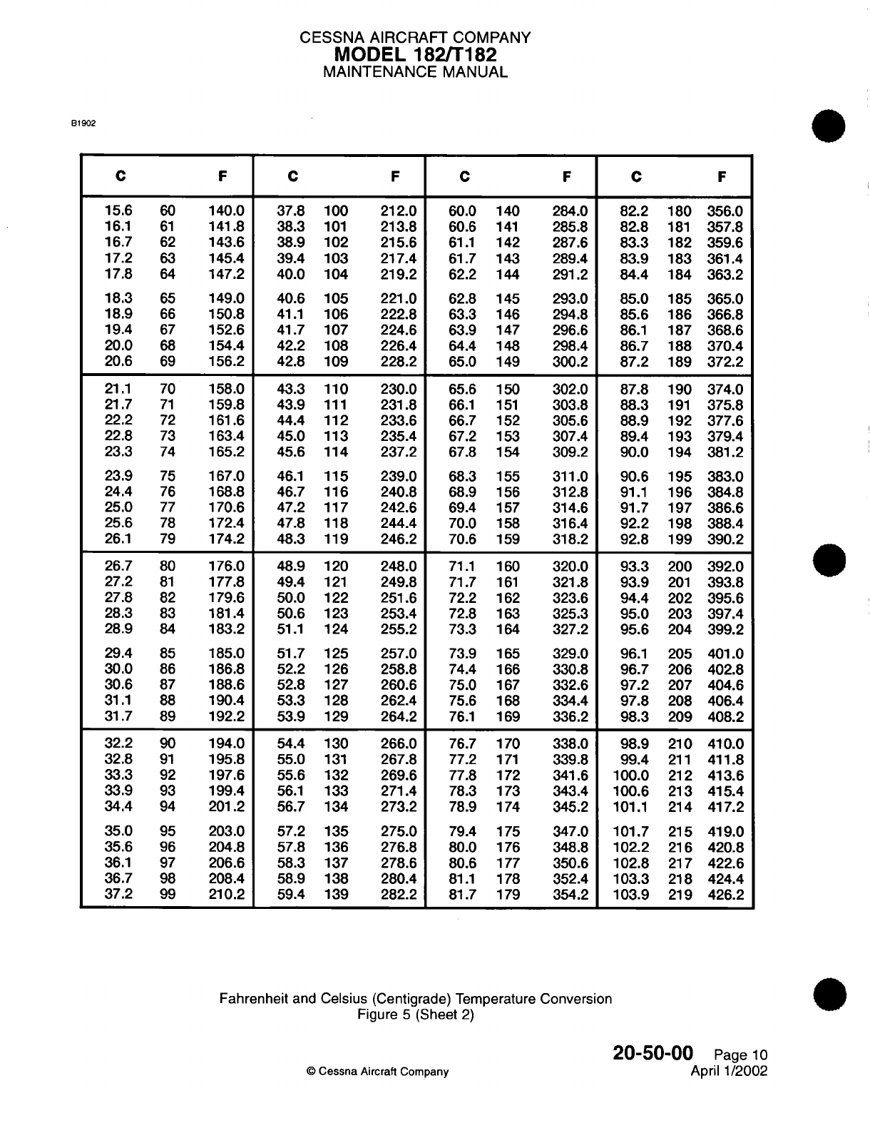
CESSNA AIRCRAFT
COMPANY
MODEL
182/T182
MAINTENANCE
MANUAL
B1902
C
F
C
F
C
F
C
F
15.6
60
140.0 37.8 100
212.0
60.0
140 284.0
82.2
180 356.0
16.1
61
141.8 38.3
101
213.8
60.6
141
285.8
82.8
181
357.8
16.7
62
143.6
38.9
102
215.6
61.1
142 287.6
83.3
182 359.6
17.2
63
145.4 39.4 103
217.4
61.7
143 289.4
83.9
183
361.4
17.8
64
147.2
40.0
104
219.2
62.2
144 291.2
84.4
184 363.2
18.3
65
149.0
40.6
105
221.0
62.8
145 293.0
85.0
185
365.0
18.9
66
150.8
41.1
106
222.8
63.3
146 294.8
85.6
186
366.8
19.4
67
152.6 41.7 107
224.6
63.9
147
296.6
86.1
187 368.6
20.0
68
154.4
42.2
108
226.4
64.4
148
298.4
86.7
188
370.4
20.6
69
156.2 42.8 109
228.2
65.0
149 300.2
87.2
189 372.2
21.1
70
158.0
43.3
110
230.0
65.6
150
302.0
87.8
190 374.0
21.7
71
159.8
43.9
111
231.8
66.1
151
303.8
88.3
191
375.8
22.2
72
161.6 44.4 112
233.6
66.7
152
305.6
88.9
192
377.6
22.8
73
163.4
45.0
113
235.4
67.2
153
307.4
89.4
193 379.4
23.3
74
165.2
45.6
114
237.2
67.8
154
309.2
90.0
194
381.2
23.9
75
167.0
46.1
115
239.0
68.3
155
311.0
90.6
195 383.0
24.4
76
168.8
46.7
116
240.8
68.9
156
312.8
91.1
196 384.8
25.0
77
170.6
47.2
117
242.6
69.4
157
314.6
91.7
197 386.6
25.6
78
172.4
47.8
118
244.4
70.0
158
316.4
92.2
198 388.4
26.1
79
174.2
48.3
119
246.2
70.6
159
318.2
92.8
199 390.2
26.7
80
176.0
48.9
120
248.0
71.1
160
320.0
93.3
200 392.0
27.2
81
177.8
49.4
121
249.8
71.7
161
321.8
93.9
201
393.8
27.8
82
179.6
50.0
122
251.6
72.2
162
323.6
94.4
202 395.6
28.3
83
181.4
50.6
123
253.4
72.8
163
325.3
95.0
203
397.4
28.9
84
183.2
51.1
124
255.2
73.3
164
327.2
95.6
204 399.2
29.4
85
185.0
51.7
125
257.0
73.9 165
329.0
96.1
205
401.0
30.0
86
186.8
52.2 126
258.8
74.4
166
330.8
96.7
206
402.8
30.6
87
188.6 52.8
127
260.6
75.0 167
332.6
97.2
207 404.6
31.1
88
190.4
53.3
128
262.4
75.6 168
334.4
97.8
208 406.4
31.7
89
192.2 53.9
129
264.2
76.1
169
336.2
98.3
209
408.2
32.2
90
194.0 54.4
130
266.0
76.7
170
338.0
98.9
210
410.0
32.8
91
195.8
55.0
131
267.8
77.2
171
339.8
99.4
211
411.8
33.3
92
197.6 55.6 132
269.6
77.8
172
341.6
100.0
212 413.6
33.9
93
199.4
56.1
133
271.4
78.3
173 343.4
100.6 213 415.4
34.4
94
201.2
56.7
134
273.2
78.9
174 345.2
101.1
214 417.2
35.0
95
203.0 57.2 135
275.0
79.4
175
347.0 101.7 215 419.0
35.6
96
204.8
57.8
136
276.8 80.0
176 348.8
102.2
216 420.8
36.1
97
206.6 58.3
137
278.6 80.6
177
350.6
102.8
217 422.6
36.7
98
208.4 58.9 138 280.4
81.1
178 352.4
103.3
218 424.4
37.2
99
210.2 59.4 139 282.2 81.7
179
354.2
103.9
219 426.2
Fahrenheit
and
Celsius
(Centigrade) Temperature
Conversion
Figure
5
(Sheet
2)
20-50-00
Page
10
©
Cessna
Aircraft Company
April
1/2002
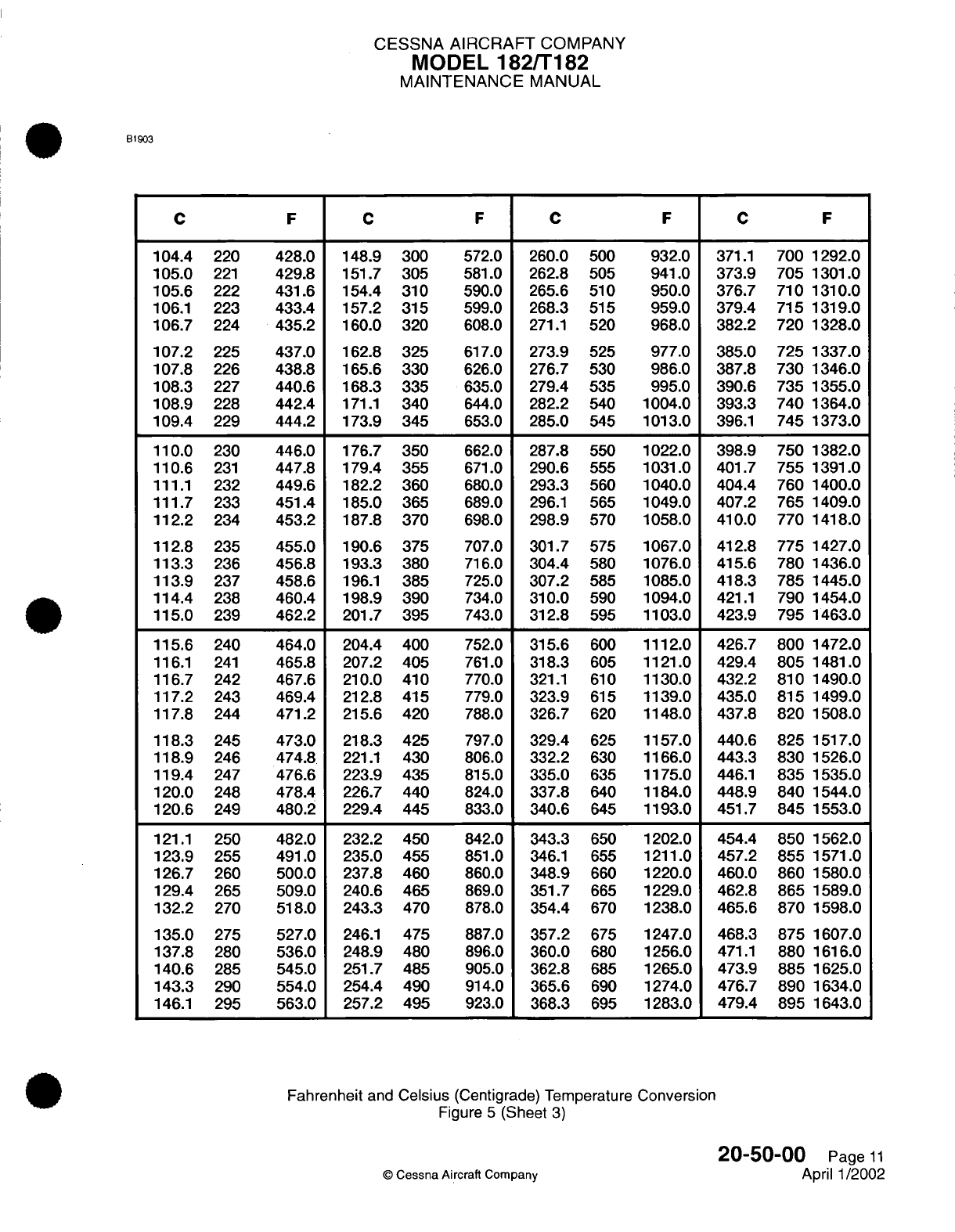
CESSNA
AIRCRAFT
COMPANY
MODEL
182/T182
MAINTENANCE
MANUAL
B1903
C
F
C
F
C
104.4
220
105.0
221
105.6
222
106.1
223
106.7
224
107.2
225
107.8
226
108.3
227
108.9
228
109.4
229
110.0
230
110.6
231
111.1
232
111.7
233
112.2
234
112.8
235
113.3
236
113.9
237
114.4
238
115.0
239
115.6
240
116.1
241
116.7
242
117.2
243
117.8
244
118.3
245
118.9
246
119.4
247
120.0
248
120.6
249
121.1
250
123.9
255
126.7
260
129.4
265
132.2
270
135.0
275
137.8
280
140.6
285
143.3
290
146.1
295
428.0
429.8
431.6
433.4
435.2
437.0
438.8
440.6
442.4
444.2
446.0
447.8
449.6
451.4
453.2
455.0
456.8
458.6
460.4
462.2
464.0
465.8
467.6
469.4
471.2
473.0
474.8
476.6
478.4
480.2
482.0
491.0
500.0
509.0
518.0
527.0
536.0
545.0
554.0
563.0
148.9
300
151.7
305
154.4
310
157.2
315
160.0
320
162.8
325
165.6
330
168.3
335
171.1
340
173.9
345
176.7
350
179.4
355
182.2
360
185.0
365
187.8 370
190.6 375
193.3
380
196.1
385
198.9
390
201.7 395
204.4
400
207.2
405
210.0
410
212.8
415
215.6
420
218.3
425
221.1
430
223.9
435
226.7 440
229.4
445
232.2
450
235.0
455
237.8
460
240.6
465
243.3
470
246.1
475
248.9
480
251.7
485
254.4
490
257.2
495
572.0
581.0
590.0
599.0
608.0
617.0
626.0
635.0
644.0
653.0
662.0
671.0
680.0
689.0
698.0
707.0
716.0
725.0
734.0
743.0
752.0
761.0
770.0
779.0
788.0
797.0
806.0
815.0
824.0
833.0
842.0
851.0
860.0
869.0
878.0
887.0
896.0
905.0
914.0
923.0
260.0
500
262.8
505
265.6
510
268.3
515
271.1
520
273.9
525
276.7
530
279.4
535
282.2
540
285.0
545
287.8
550
290.6
555
293.3
560
296.1
565
298.9
570
301.7
575
304.4
580
307.2
585
310.0
590
312.8
595
315.6
600
318.3
605
321.1
610
323.9
615
326.7
620
329.4
625
332.2
630
335.0
635
337.8
640
340.6
645
343.3
650
346.1
655
348.9
660
351.7
665
354.4
670
357.2
675
360.0
680
362.8
685
365.6
690
368.3
695
932.0
941.0
950.0
959.0
968.0
977.0
986.0
995.0
1004.0
1013.0
1022.0
1031.0
1040.0
1049.0
1058.0
1067.0
1076.0
1085.0
1094.0
1103.0
1112.0
1121.0
1130.0
1139.0
1148.0
1157.0
1166.0
1175.0
1184.0
1193.0
1202.0
1211.0
1220.0
1229.0
1238.0
1247.0
1256.0
1265.0
1274.0
1283.0
371.1
700 1292.0
373.9 705
1301.0
376.7 710 1310.0
379.4 715 1319.0
382.2
720 1328.0
385.0
725 1337.0
387.8 730
1346.0
390.6
735 1355.0
393.3 740
1364.0
396.1
745 1373.0
398.9
750 1382.0
401.7
755
1391.0
404.4 760 1400.0
407.2 765 1409.0
410.0
770 1418.0
412.8
775 1427.0
415.6 780
1436.0
418.3 785
1445.0
421.1
790
1454.0
423.9
795
1463.0
426.7 800
1472.0
429.4
805
1481.0
432.2
810
1490.0
435.0 815
1499.0
437.8 820
1508.0
440.6 825
1517.0
443.3 830
1526.0
446.1
835
1535.0
448.9
840
1544.0
451.7 845
1553.0
454.4
850
1562.0
457.2 855
1571.0
460.0 860
1580.0
462.8
865
1589.0
465.6
870
1598.0
468.3 875
1607.0
471.1
880
1616.0
473.9
885
1625.0
476.7
890
1634.0
479.4 895
1643.0
Fahrenheit
and
Celsius
(Centigrade)
Temperature
Conversion
Figure
5
(Sheet
3)
20-50-00
Page
11
©
Cessna
Aircraft
Company
April
1/2002
F
C
F
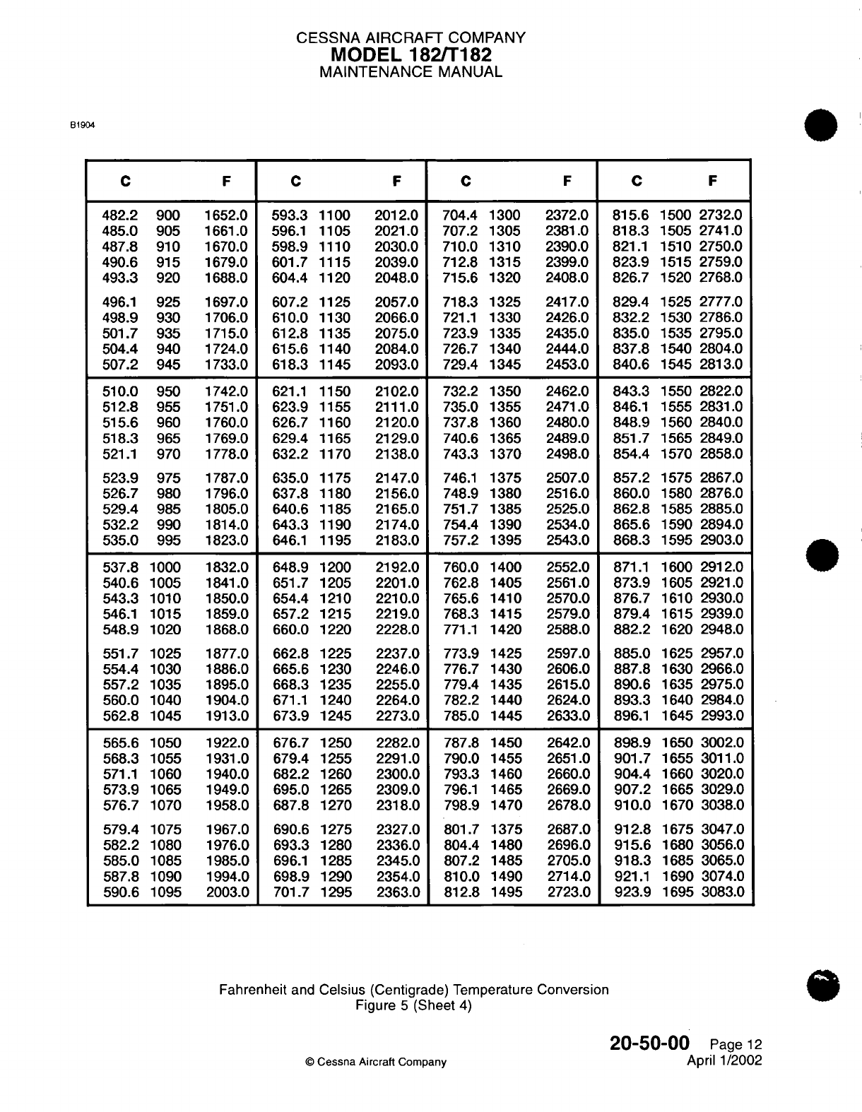
CESSNA
AIRCRAFT
COMPANY
MODEL 182/T182
MAINTENANCE
MANUAL
B1904
CFCFC
482.2
900
485.0
905
487.8
910
490.6
915
493.3
920
496.1
925
498.9
930
501.7
935
504.4
940
507.2
945
510.0
950
512.8
955
515.6
960
518.3
965
521.1
970
523.9
975
526.7
980
529.4
985
532.2
990
535.0
995
537.8
1000
540.6
1005
543.3
1010
546.1
1015
548.9
1020
551.7
1025
554.4
1030
557.2
1035
560.0
1040
562.8
1045
565.6
1050
568.3
1055
571.1
1060
573.9
1065
576.7
1070
579.4
1075
582.2
1080
585.0
1085
587.8
1090
590.6
1095
1652.0
1661.0
1670.0
1679.0
1688.0
1697.0
1706.0
1715.0
1724.0
1733.0
1742.0
1751.0
1760.0
1769.0
1778.0
1787.0
1796.0
1805.0
1814.0
1823.0
1832.0
1841.0
1850.0
1859.0
1868.0
1877.0
1886.0
1895.0
1904.0
1913.0
1922.0
1931.0
1940.0
1949.0
1958.0
1967.0
1976.0
1985.0
1994.0
2003.0
593.3
1100
596.1
1105
598.9
1110
601.7
1115
604.4
1120
607.2
1125
610.0
1130
612.8
1135
615.6
1140
618.3
1145
621.1
1150
623.9
1155
626.7
1160
629.4
1165
632.2
1170
635.0
1175
637.8
1180
640.6
1185
643.3
1190
646.1
1195
648.9
1200
651.7
1205
654.4
1210
657.2
1215
660.0
1220
662.8
1225
665.6
1230
668.3
1235
671.1
1240
673.9
1245
676.7
1250
679.4
1255
682.2
1260
695.0
1265
687.8
1270
690.6
1275
693.3
1280
696.1
1285
698.9
1290
701.7
1295
2012.0
2021.0
2030.0
2039.0
2048.0
2057.0
2066.0
2075.0
2084.0
2093.0
2102.0
2111.0
2120.0
2129.0
2138.0
2147.0
2156.0
2165.0
2174.0
2183.0
2192.0
2201.0
2210.0
2219.0
2228.0
2237.0
2246.0
2255.0
2264.0
2273.0
2282.0
2291.0
2300.0
2309.0
2318.0
2327.0
2336.0
2345.0
2354.0
2363.0
704.4 1300
707.2 1305
710.0
1310
712.8
1315
715.6 1320
718.3 1325
721.1
1330
723.9 1335
726.7 1340
729.4
1345
732.2
1350
735.0 1355
737.8 1360
740.6 1365
743.3 1370
746.1
1375
748.9
1380
751.7
1385
754.4
1390
757.2 1395
760.0
1400
762.8
1405
765.6
1410
768.3
1415
771.1
1420
773.9
1425
776.7
1430
779.4
1435
782.2
1440
785.0
1445
787.8
1450
790.0 1455
793.3 1460
796.1
1465
798.9 1470
801.7
1375
804.4 1480
807.2 1485
810.0
1490
812.8
1495
2372.0
2381.0
2390.0
2399.0
2408.0
2417.0
2426.0
2435.0
2444.0
2453.0
2462.0
2471.0
2480.0
2489.0
2498.0
2507.0
2516.0
2525.0
2534.0
2543.0
2552.0
2561.0
2570.0
2579.0
2588.0
2597.0
2606.0
2615.0
2624.0
2633.0
2642.0
2651.0
2660.0
2669.0
2678.0
2687.0
2696.0
2705.0
2714.0
2723.0
815.6
1500
2732.0
818.3
1505
2741.0
821.1
1510 2750.0
823.9
1515 2759.0
826.7
1520
2768.0
829.4
1525
2777.0
832.2
1530
2786.0
835.0
1535 2795.0
837.8
1540 2804.0
840.6
1545
2813.0
843.3
1550
2822.0
846.1
1555
2831.0
848.9
1560
2840.0
851.7
1565 2849.0
854.4
1570 2858.0
857.2
1575 2867.0
860.0
1580
2876.0
862.8
1585 2885.0
865.6
1590 2894.0
868.3
1595 2903.0
871.1
1600 2912.0
873.9
1605 2921.0
876.7
1610 2930.0
879.4
1615 2939.0
882.2
1620 2948.0
885.0
1625 2957.0
887.8
1630 2966.0
890.6
1635
2975.0
893.3
1640
2984.0
896.1
1645 2993.0
898.9
1650
3002.0
901.7
1655
3011.0
904.4
1660
3020.0
907.2
1665
3029.0
910.0
1670
3038.0
912.8
1675
3047.0
915.6
1680
3056.0
918.3
1685
3065.0
921.1
1690 3074.0
923.9
1695
3083.0
Fahrenheit
and
Celsius
(Centigrade)
Temperature
Conversion
Figure
5
(Sheet
4)
20-50-00
Page
12
©
Cessna
Aircraft
Company
April
1/2002
FCF
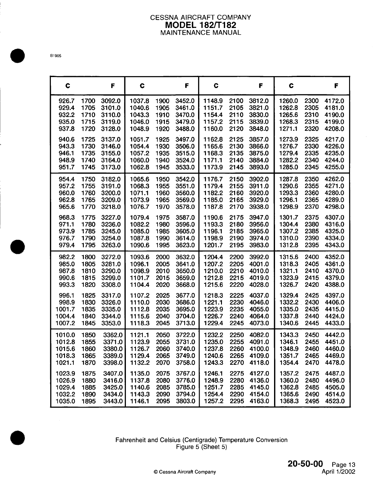
CESSNA
AIRCRAFT
COMPANY
MODEL
182/T182
MAINTENANCE
MANUAL
B1905
F
C
1148.9
1151.7
1154.4
1157.2
1160.0
1162.8
1165.6
1168.3
1171.1
1173.9
1176.7
1179.4
1182.2
1185.0
1187.8
1190.6
1193.3
1196.1
1198.9
1201.7
1204.4
1207.2
1210.0
1212.8
1215.6
1218.3
1221.1
1223.9
1226.7
1229.4
1232.2
1235.0
1237.8
1240.6
1243.3
1246.1
1248.9
1251.7
1254.4
1257.2
F
2100
2105
2110
2115
2120
2125
2130
2135
2140
2145
2150
2155
2160
2165
2170
2175
2180
2185
2190
2195
2200
2205
2210
2215
2220
2225
2230
2235
2240
2245
2250
2255
2260
2265
2270
2275
2280
2285
2290
2295
3812.0
3821.0
3830.0
3839.0
3848.0
3857.0
3866.0
3875.0
3884.0
3893.0
3902.0
3911.0
3920.0
3929.0
3938.0
3947.0
3956.0
3965.0
3974.0
3983.0
3992.0
4001.0
4010.0
4019.0
4028.0
4037.0
4046.0
4055.0
4064.0
4073.0
4082.0
4091.0
4100.0
4109.0
4118.0
4127.0
4136.0
4145.0
4154.0
4163.0
C
1260.0
1262.8
1265.6
1268.3
1271.1
1273.9
1276.7
1279.4
1282.2
1285.0
1287.8
1290.6
1293.3
1296.1
1298.9
1301.7
1304.4
1307.2
1310.0
1312.8
1315.6
1318.3
1321.1
F
2300
2305
2310
2315
2320
2325
2330
2335
2340
2345
2350
2355
2360
2365
2370
2375
2380
2385
2390
2395
2400
2405
2410
4172.0
4181.0
4190.0
4199.0
4208.0
4217.0
4226.0
4235.0
4244.0
4255.0
4262.0
4271.0
4280.0
4289.0
4298.0
4307.0
4316.0
4325.0
4334.0
4343.0
4352.0
4361.0
4370.0
1323.9
2415 4379.0
1326.7
2420
4388.0
1329.4
2425
4397.0
1332.2
2430 4406.0
1335.0
2435 4415.0
1337.8
2440 4424.0
1340.6
2445
4433.0
1343.3
2450
4442.0
1346.1
2455
4451.0
1348.9
2460 4460.0
1351.7
2465 4469.0
1354.4
2470
4478.0
1357.2
2475
4487.0
1360.0
2480
4496.0
1362.8
2485
4505.0
1365.6
2490
4514.0
1368.3
2495 4523.0
Fahrenheit
and
Celsius
(Centigrade) Temperature
Conversion
Figure
5
(Sheet
5)
20-50-00
Page
13
©
Cessna
Aircraft Company
April 1/2002
C C
926.7
929.4
932.2
935.0
937.8
940.6
943.3
946.1
948.9
951.7
954.4
957.2
960.0
962.8
965.6
968.3
971.1
973.9
976.7
979.4
982.2
985.0
987.8
990.6
993.3
996.1
998.9
1001.7
1004.4
1007.2
1010.0
1012.8
1015.6
1018.3
1021.1
1023.9
1026.9
1029.4
1032.2
1035.0
F
3092.0
3101.0
3110.0
3119.0
3128.0
3137.0
3146.0
3155.0
3164.0
3173.0
3182.0
3191.0
3200.0
3209.0
3218.0
3227.0
3236.0
3245.0
3254.0
3263.0
3272.0
3281.0
3290.0
3299.0
3308.0
3317.0
3326.0
3335.0
3344.0
3353.0
3362.0
3371.0
3380.0
3389.0
3398.0
3407.0
3416.0
3425.0
3434.0
3443.0
1700
1705
1710
1715
1720
1725
1730
1735
1740
1745
1750
1755
1760
1765
1770
1775
1780
1785
1790
1795
1800
1805
1810
1815
1820
1825
1830
1835
1840
1845
1850
1855
1860
1865
1870
1875
1880
1885
1890
1895
1037.8
1040.6
1043.3
1046.0
1048.9
1051.7
1054.4
1057.2
1060.0
1062.8
1065.6
1068.3
1071.1
1073.9
1076.7
1079.4
1082.2
1085.0
1087.8
1090.6
1093.6
1096.1
1098.9
1101.7
1104.4
1107.2
1110.0
1112.8
1115.6
1118.3
1121.1
1123.9
1126.7
1129.4
1132.2
1135.0
1137.8
1140.6
1143.3
1146.1
1900
1905
1910
1915
1920
1925
1930
1935
1940
1945
1950
1955
1960
1965
1970
1975
1980
1985
1990
1995
2000
2005
2010
2015
2020
2025
2030
2035
2040
2045
2050
2055
2060
2065
2070
2075
2080
2085
2090
2095
3452.0
3461.0
3470.0
3479.0
3488.0
3497.0
3506.0
3515.0
3524.0
3533.0
3542.0
3551.0
3560.0
3569.0
3578.0
3587.0
3596.0
3605.0
3614.0
3623.0
3632.0
3641.0
3650.0
3659.0
3668.0
3677.0
3686.0
3695.0
3704.0
3713.0
3722.0
3731.0
3740.0
3749.0
3758.0
3767.0
3776.0
3785.0
3794.0
3803.0
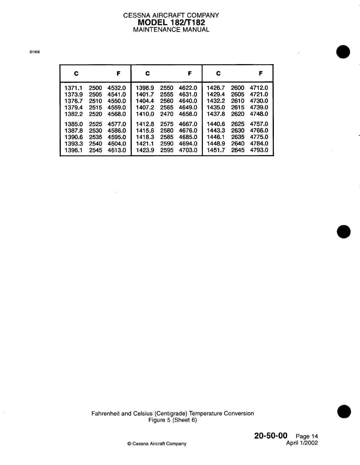
CESSNA
AIRCRAFT
COMPANY
MODEL 182/T182
MAINTENANCE
MANUAL
B1906
CFCFC
2500
4532.0
2505
4541.0
2510
4550.0
2515
4559.0
2520
4568.0
2525
4577.0
2530
4586.0
2535
4595.0
2540
4604.0
2545
4613.0
1398.9
1401.7
1404.4
1407.2
1410.0
1412.8
1415.6
1418.3
1421.1
1423.9
2550
4622.0
2555 4631.0
2560
4640.0
2565
4649.0
2470
4658.0
2575
4667.0
2580
4676.0
2585
4685.0
2590
4694.0
2595
4703.0
1426.7
1429.4
1432.2
1435.0
1437.8
1440.6
1443.3
1446.1
1448.9
1451.7
2600
4712.0
2605
4721.0
2610
4730.0
2615 4739.0
2620
4748.0
2625
4757.0
2630
4766.0
2635
4775.0
2640
4784.0
2645 4793.0
Fahrenheit
and
Celsius
(Centigrade)
Temperature
Conversion
Figure
5
(Sheet
6)
20-50-00
Page
14
©
Cessna
Aircraft
Company
April
1/2002
1371.1
1373.9
1376.7
1379.4
1382.2
1385.0
1387.8
1390.6
1393.3
1396.1
F
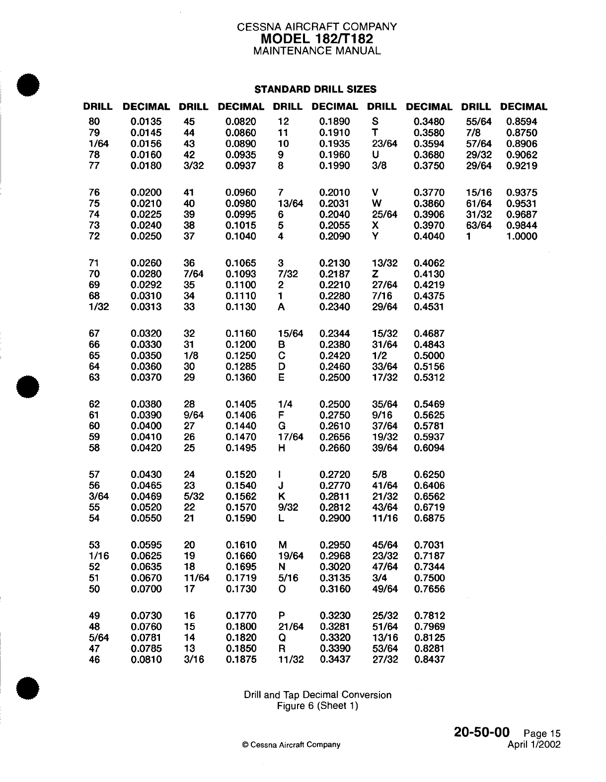
CESSNA
AIRCRAFT
COMPANY
MODEL
182/T182
MAINTENANCE
MANUAL
STANDARD
DRILL SIZES
DRILL
DECIMAL DRILL
DECIMAL
DRILL DECIMAL
DRILL
DECIMAL
DRILL DECIMAL
80
0.0135
45
0.0820
12
79
0.0145
44
0.0860
11
1/64 0.0156
43
0.0890
10
78
0.0160
42
0.0935
9
77
0.0180
3/32
0.0937
8
0.0200
41
0.0210
40
0.0225
39
0.0240
38
0.0250
37
0.1890
S
0.3480
55/64
0.8594
0.1910
T 0.3580 7/8
0.8750
0.1935
23/64
0.3594
57/64
0.8906
0.1960
U
0.3680
29/32
0.9062
0.1990
3/8
0.3750
29/64
0.9219
0.0960
7
0.2010
V
0.3770
15/16
0.9375
0.0980
13/64
0.2031
W
0.3860
61/64
0.9531
0.0995
6
0.2040
25/64 0.3906
31/32
0.9687
0.1015
5
0.2055
X
0.3970
63/64
0.9844
0.1040
4
0.2090
Y
0.4040
1
1.0000
71
0.0260
36
0.1065
3
0.2130 13/32 0.4062
70
0.0280 7/64
0.1093
7/32
0.2187 Z
0.4130
69
0.0292
35
0.1100
2
0.2210 27/64
0.4219
68
0.0310
34
0.1110
1
0.2280 7/16
0.4375
1/32 0.0313
33
0.1130
A
0.2340 29/64
0.4531
0.0320
32
0.0330
31
0.0350
1/8
0.0360
30
0.0370
29
0.1160
15/64 0.2344
15/32
0.4687
0.1200
B
0.2380
31/64
0.4843
0.1250
C
0.2420
1/2
0.5000
0.1285
D
0.2460
33/64
0.5156
0.1360
E
0.2500
17/32
0.5312
62
0.0380
28
0.1405
1/4
0.2500
35/64
0.5469
61
0.0390
9/64
0.1406
F
0.2750
9/16
0.5625
60
0.0400
27
0.1440
G
0.2610
37/64
0.5781
59
0.0410
26
0.1470
17/64
0.2656
19/32 0.5937
58
0.0420
25
0.1495
H
0.2660
39/64 0.6094
57
0.0430
24
0.1520
I
0.2720
5/8
0.6250
56
0.0465
23
0.1540
J
0.2770
41/64
0.6406
3/64
0.0469
5/32
0.1562
K
0.2811
21/32 0.6562
55
0.0520
22
0.1570
9/32
0.2812
43/64
0.6719
54
0.0550
21
0.1590
L
0.2900 11/16 0.6875
53
0.0595
20
0.1610
M
0.2950
45/64
0.7031
1/16 0.0625
19
0.1660 19/64 0.2968
23/32
0.7187
52
0.0635
18
0.1695
N
0.3020
47/64
0.7344
51
0.0670
11/64
0.1719
5/16
0.3135
3/4
0.7500
50
0.0700
17
0.1730
O
0.3160
49/64
0.7656
49
0.0730
16
0.1770
P
0.3230
25/32
0.7812
48
0.0760
15
0.1800
21/64
0.3281
51/64
0.7969
5/64
0.0781
14
0.1820
Q
0.3320
13/16
0.8125
47
0.0785
13
0.1850
R
0.3390
53/64
0.8281
46
0.0810
3/16
0.1875
11/32
0.3437
27/32 0.8437
Drill
and
Tap
Decimal
Conversion
Figure
6
(Sheet
1)
©
Cessna
Aircraft
Company
20-50-00
Page
15
April
1/2002
76
75
74
73
72
67
66
65
64
63
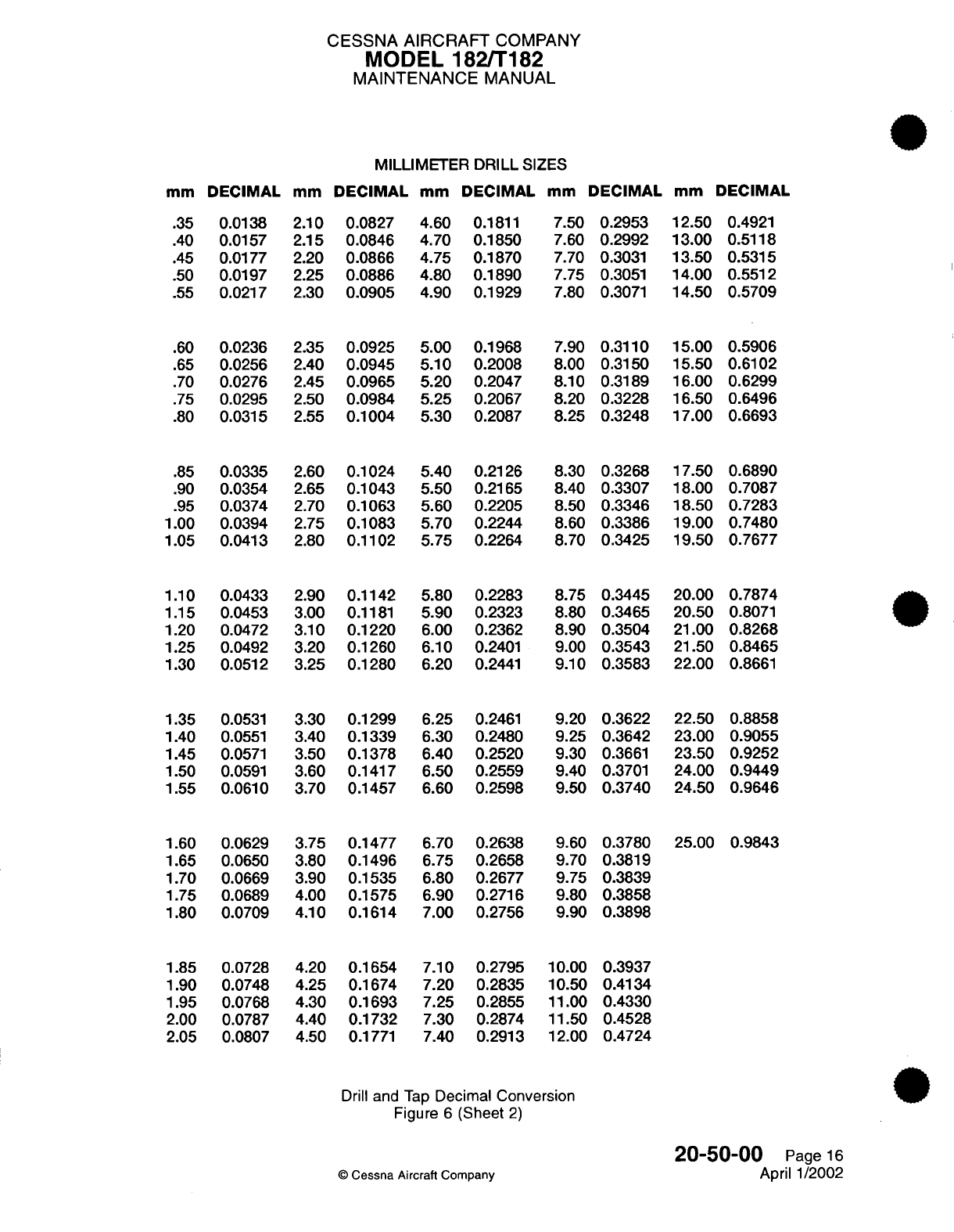
CESSNA
AIRCRAFT
COMPANY
MODEL 182/T182
MAINTENANCE
MANUAL
MILLIMETER DRILL
SIZES
mm
DECIMAL
mm
DECIMAL
mm
DECIMAL
mm
DECIMAL
mm
DECIMAL
2.10
0.0827
2.15
0.0846
2.20
0.0866
2.25
0.0886
2.30
0.0905
2.35
0.0925
2.40
0.0945
2.45
0.0965
2.50
0.0984
2.55
0.1004
2.60
0.1024
2.65
0.1043
2.70
0.1063
2.75
0.1083
2.80
0.1102
2.90
0.1142
3.00
0.1181
3.10
0.1220
3.20
0.1260
3.25 0.1280
3.30
0.1299
3.40
0.1339
3.50
0.1378
3.60
0.1417
3.70 0.1457
3.75
0.1477
3.80
0.1496
3.90
0.1535
4.00 0.1575
4.10 0.1614
4.60
0.1811
4.70 0.1850
4.75 0.1870
4.80
0.1890
4.90
0.1929
5.00
0.1968
5.10 0.2008
5.20
0.2047
5.25
0.2067
5.30
0.2087
5.40 0.2126
5.50
0.2165
5.60
0.2205
5.70 0.2244
5.75 0.2264
5.80 0.2283
5.90
0.2323
6.00
0.2362
6.10
0.2401
6.20
0.2441
6.25
0.2461
6.30
0.2480
6.40
0.2520
6.50 0.2559
6.60 0.2598
6.70
0.2638
6.75
0.2658
6.80 0.2677
6.90
0.2716
7.00
0.2756
7.50
0.2953
7.60
0.2992
7.70
0.3031
7.75 0.3051
7.80
0.3071
7.90
0.3110
8.00
0.3150
8.10
0.3189
8.20 0.3228
8.25 0.3248
8.30
0.3268
8.40
0.3307
8.50 0.3346
8.60
0.3386
8.70
0.3425
8.75 0.3445
8.80
0.3465
8.90
0.3504
9.00
0.3543
9.10
0.3583
9.20
0.3622
9.25
0.3642
9.30
0.3661
9.40
0.3701
9.50 0.3740
9.60
0.3780
9.70
0.3819
9.75
0.3839
9.80
0.3858
9.90
0.3898
12.50
0.4921
13.00
0.5118
13.50
0.5315
14.00
0.5512
14.50 0.5709
15.00
0.5906
15.50 0.6102
16.00 0.6299
16.50 0.6496
17.00 0.6693
17.50 0.6890
18.00 0.7087
18.50 0.7283
19.00
0.7480
19.50 0.7677
20.00
0.7874
20.50
0.8071
21.00 0.8268
21.50 0.8465
22.00
0.8661
22.50 0.8858
23.00 0.9055
23.50 0.9252
24.00
0.9449
24.50 0.9646
25.00 0.9843
4.20
0.1654
4.25 0.1674
4.30
0.1693
4.40
0.1732
4.50
0.1771
7.10 0.2795
7.20
0.2835
7.25
0.2855
7.30 0.2874
7.40
0.2913
10.00
0.3937
10.50
0.4134
11.00
0.4330
11.50
0.4528
12.00
0.4724
Drill
and
Tap
Decimal
Conversion
Figure
6
(Sheet
2)
©
Cessna
Aircraft
Company
20-50-00
Page
16
April
1/2002
.35
.40
.45
.50
.55
.60
.65
.70
.75
.80
.85
.90
.95
1.00
1.05
1.10
1.15
1.20
1.25
1.30
1.35
1.40
1.45
1.50
1.55
1.60
1.65
1.70
1.75
1.80
0.0138
0.0157
0.0177
0.0197
0.0217
0.0236
0.0256
0.0276
0.0295
0.0315
0.0335
0.0354
0.0374
0.0394
0.0413
0.0433
0.0453
0.0472
0.0492
0.0512
0.0531
0.0551
0.0571
0.0591
0.0610
0.0629
0.0650
0.0669
0.0689
0.0709
1.85
1.90
1.95
2.00
2.05
0.0728
0.0748
0.0768
0.0787
0.0807
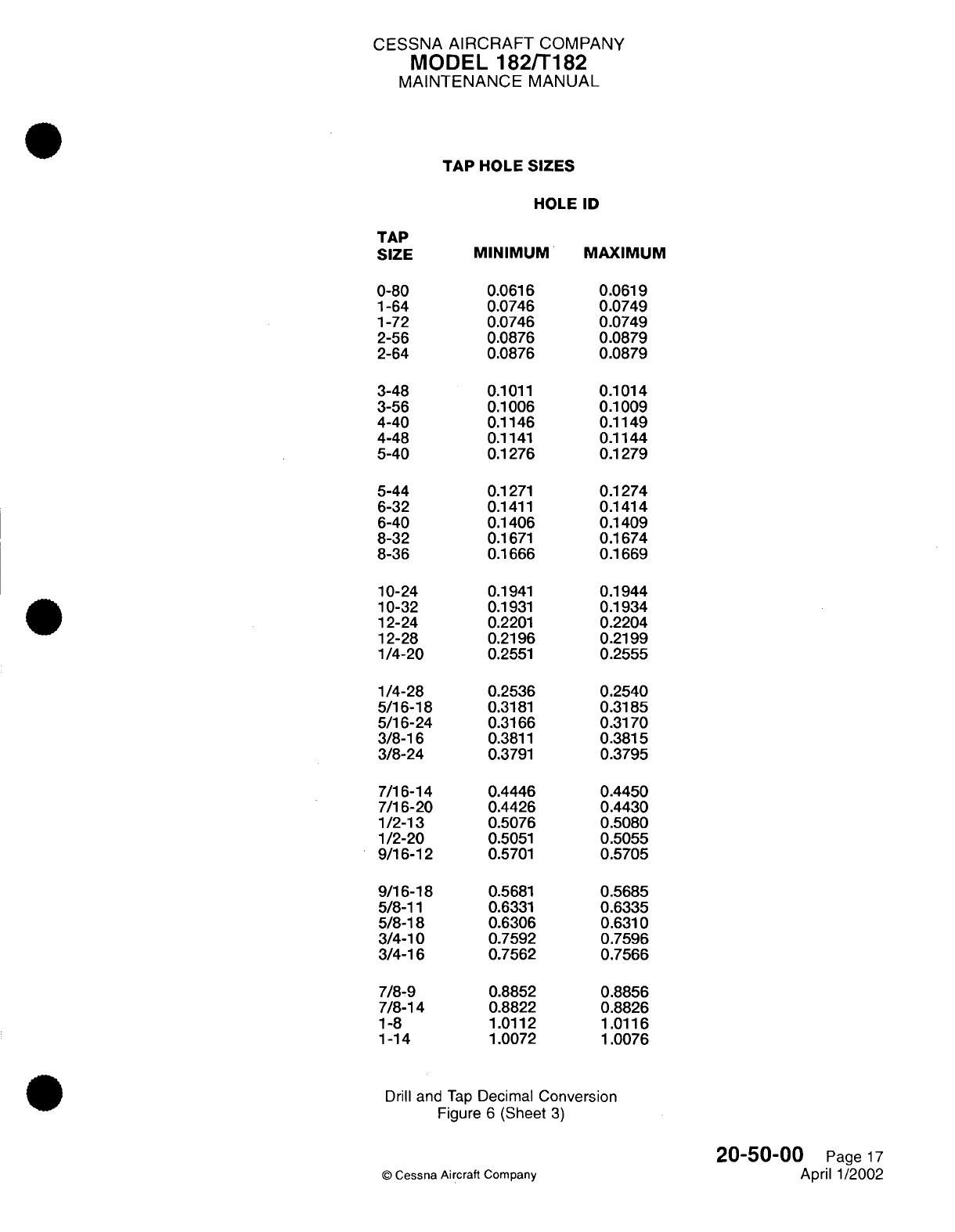
CESSNA
AIRCRAFT
COMPANY
MODEL
182/T182
MAINTENANCE
MANUAL
TAP
HOLE
SIZES
HOLE
ID
TAP
SIZE
0-80
1-64
1-72
2-56
2-64
MINIMUM
MAXIMUM
0.0616
0.0746
0.0746
0.0876
0.0876
0.1011
0.1006
0.1146
0.1141
0.1276
3-48
3-56
4-40
4-48
5-40
5-44
6-32
6-40
8-32
8-36
0.1271
0.1411
0.1406
0.1671
0.1666
10-24
10-32
12-24
12-28
1/4-20
1/4-28
5/16-18
5/16-24
3/8-16
3/8-24
7/16-14
7/16-20
1/2-13
1/2-20
9/16-12
9/16-18
5/8-11
5/8-18
3/4-10
3/4-16
7/8-9
7/8-14
1-8
1-14
0.1941
0.1931
0.2201
0.2196
0.2551
0.2536
0.3181
0.3166
0.3811
0.3791
0.4446
0.4426
0.5076
0.5051
0.5701
0.5681
0.6331
0.6306
0.7592
0.7562
0.8852
0.8822
1.0112
1.0072
0.0619
0.0749
0.0749
0.0879
0.0879
0.1014
0.1009
0.1149
0.1144
0.1279
0.1274
0.1414
0.1409
0.1674
0.1669
0.1944
0.1934
0.2204
0.2199
0.2555
0.2540
0.3185
0.3170
0.3815
0.3795
0.4450
0.4430
0.5080
0.5055
0.5705
0.5685
0.6335
0.6310
0.7596
0.7566
0.8856
0.8826
1.0116
1.0076
Drill
and
Tap
Decimal
Conversion
Figure
6
(Sheet
3)
©
Cessna
Aircraft
Company
20-50-00
Page
17
April 1/2002
CHAPTER
aI
CODIIOIN
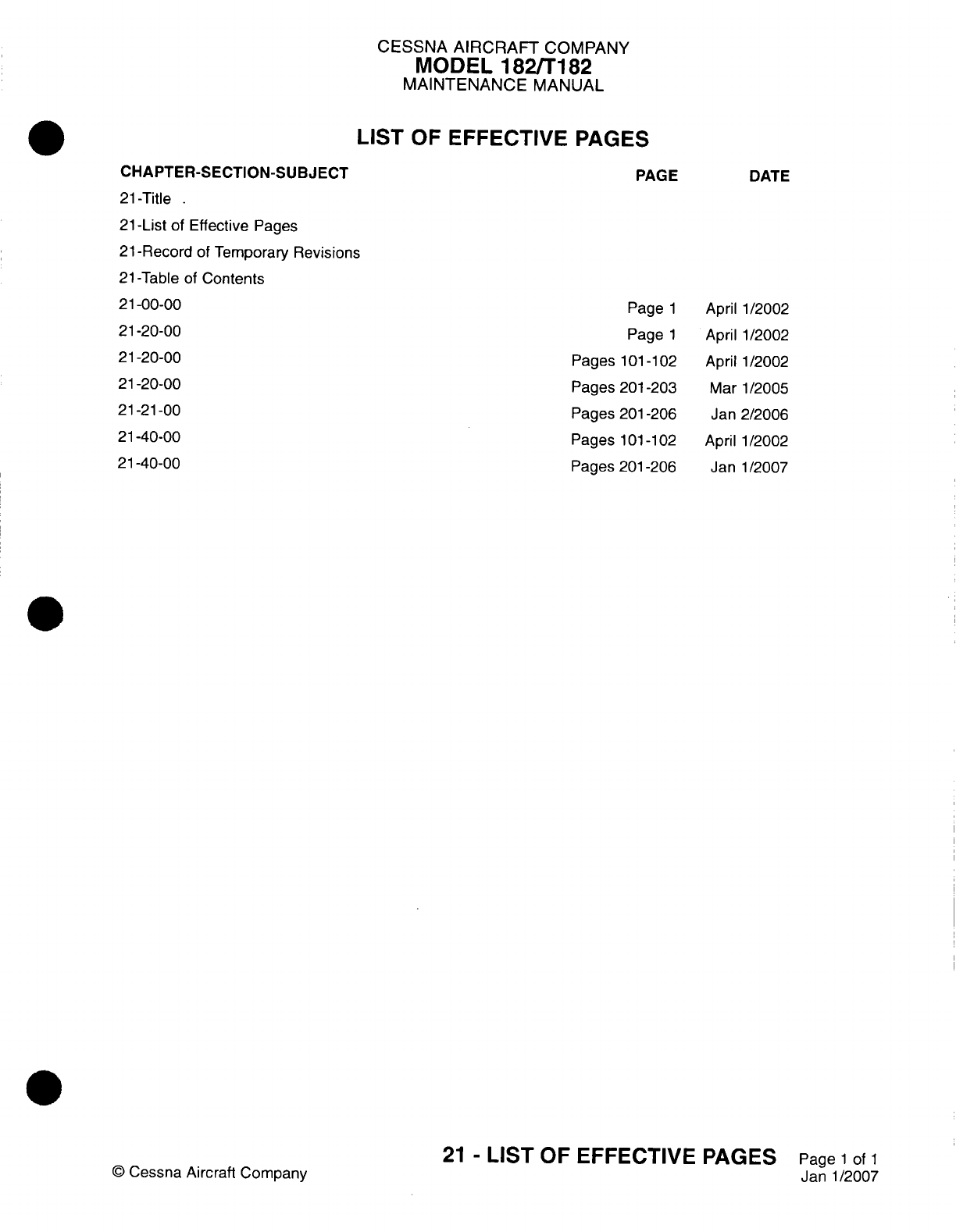
CESSNA
AIRCRAFT
COMPANY
MODEL
182/T182
MAINTENANCE
MANUAL
LIST
OF
EFFECTIVE
PAGES
CHAPTER-SECTION-SUBJECT
21
-Title
21
-List
of
Effective
Pages
21
-Record
of
Temporary
Revisions
21
-Table
of
Contents
21-00-00
21-20-00
21-20-00
21-20-00
21-21-00
21-40-00
21-40-00
©
Cessna Aircraft
Company
PAGE
Page
1
Page
1
Pages
101
-1
02
Pages
201
-203
Pages
201-206
Pages
101
-102
Pages
201-206
DATE
April
1/2002
April 1/2002
April
1/2002
Mar
1/2005
Jan
2/2006
April
1/2002
Janl1/2007
21
-
LIST
OF
EFFECTIVE
PAGES
Page
1
of
1
Janl1/2007
Temporary
Revision
Number
RECORD
OF
TEMPORARY
REVISIONS
Page
Number
Issue
Date
By
Date
Removed
By
CESSNA AIRCRAFT
COMPANY
MODEL
182/Ti
82
MAINTENANCE
MANUAL
CONTENTS
AIR
CONDITIONING
-
GENERAL
.........................
Scope....................................
Tools,
Equipment
and
Materials........................
Definition.
FRESH
AIR
DISTRIBUTION
-
DESCRIPTION
AND
OPERATION...........
General...................................
Description
.................................
System
Operation
..............................
FRESH
AIR
DISTRIBUTION
-
TROUBLESHOOTING
................
General...................................
FRESH
AIR
DISTRIBUTION
-
MAINTENANCE
PRACTICES.............
General...................................
Air Outlet
Valve
Removal/Installation......................
Cabin
Air
Control
Cable
Removal/Installation..................
Distribution
Duct
Removal/installation
.....................
AVIONICS
COOLING
-
MAINTENANCE PRACTICES
................
General
..................................
Firewall
Avionics
Cooling
Fan
Removal/installation
(Airplanes
without
Garmin
G
100o)
.................................
Primary Flight Display
(PFD)
Fan
Removal/Installation
(Airplanes
with Garmin
GlOQO)
.................................
Multi-Function
Display
(MFD)
Fan
Removal/Installation
(Airplanes
with
Garmin
G
1000)..................................
Deck
Skin
Fan
Removal/Installation
(Airplanes
with
Garmin
G1000)
.......
Remote
Avionics
Cooling
Fan
Removal/Installation
(Airplanes
with
Garmin
G1
000)
Primary
Flight
Display
(PFD)
and
Multi-Function
Display
(MFD) Fan
Operational
Check (Airplanes
with
Garmin
G1000)....................
HEATING
AND
DEFROSTING
-
TROUBLESHOOTING
...............
General...................................
HEATING
AND
DEFROSTING
-
MAINTENANCE
PRACTICES............
General...................................
System
Operation
..............................
Heat
Shroud
Removal/installation.......................
Shutoff
Valve
Removal/Installation.......................
Cabin
Heat
Control Cable
Removal/Installation.................
Defrost Control
Cable
Removal/Installation...................
Distribution System Components
Removal/Installation..............
©
Cessna
Aircraft
Company
21
-00-00
Page
1
21-00-00
Page
1
21
-00-00
Page
1
21-00-00
Page
1
21-20-00
Page
1
21-20-00
Page
1
21-20-00
Page
1
21-20-00
Page
1
21
-20-00
Page
101
21-20-00
Page
101
21-20-00
Page
201
21
-20-00
Page
201
21-20-00
Page
201
21
-20-00 Page
201
21-20-00
Page
201
21-21
-00
Page
201
21 -21
-00
Page
201
21-21
-00
Page
201
21-21
-00
Page
201
21-21
-00 Page
201
21 -21
-00
Page
204
21-21-00
Page
204
21 -21
-00
Page
206
21
-40-00
Page
101
21
-40-00
Page
101
21
-40-00
Page
201
21-40-00
Page
201
21-40-00
Page
201
21
-40-00 Page
201
21-40-00
Page
201
21-40-00
Page
201
21-40-00
Page
206
21-40-00
Page
206
21
-CONTENTS
Pagel1of
1
Janl1/2007
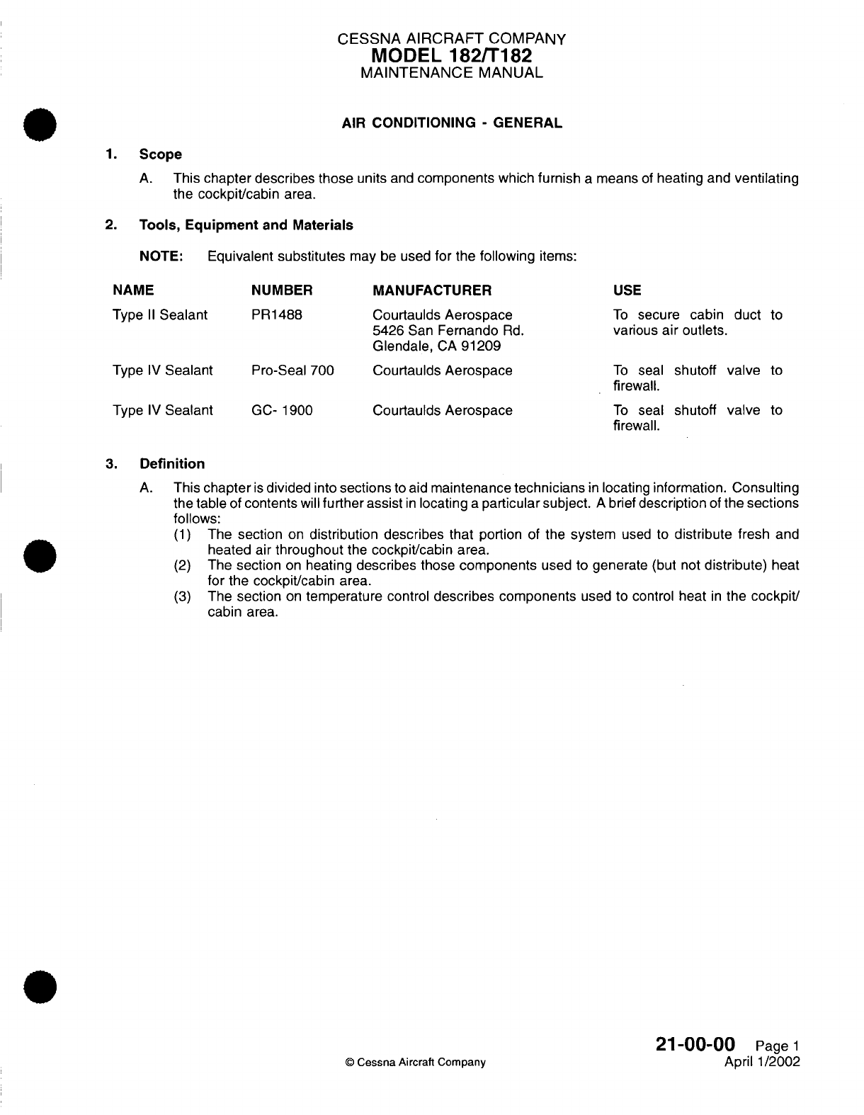
CESSNA
AIRCRAFT
COMPANY
MODEL
182/T182
MAINTENANCE
MANUAL
AIR CONDITIONING
-
GENERAL
1.
Scope
A.
This
chapter
describes
those
units
and
components
which
furnish
a
means
of
heating and
ventilating
the
cockpit/cabin
area.
2.
Tools, Equipment
and
Materials
NOTE:
Equivalent
substitutes
may be
used
for
the
following
items:
NAME
NUMBER
MANUFACTURER
USE
Type
II
Sealant
PR1488
Courtaulds
Aerospace
To
secure
cabin duct
to
5426
San
Fernando
Rd.
various
air
outlets.
Glendale,
CA
91209
Type
IV
Sealant
Pro-Seal
700 Courtaulds Aerospace
To
seal
shutoff
valve
to
Type
IV
Sealant
GC-
1900
Courtaulds
Aerospace
firewall.
To
seal
shutoff
valve
to
firewall.
3.
Definition
A.
This
chapter
is
divided
into
sections
to
aid
maintenance
technicians
in
locating
information. Consulting
the
table
of
contents
will
further
assist
in
locating
a
particular subject.
A
brief
description
of
the
sections
follows:
(1)
The
section
on
distribution
describes that
portion
of
the
system
used
to
distribute
fresh
and
heated air
throughout
the
cockpit/cabin
area.
(2)
The
section
on
heating
describes
those
components
used to
generate
(but not
distribute)
heat
for
the
cockpit/cabin
area.
(3)
The
section
on
temperature
control
describes
components
used to control
heat
in
the
cockpit/
cabin
area.
21-00-00
Page
1
©
Cessna
Aircraft Company
April
1/2002
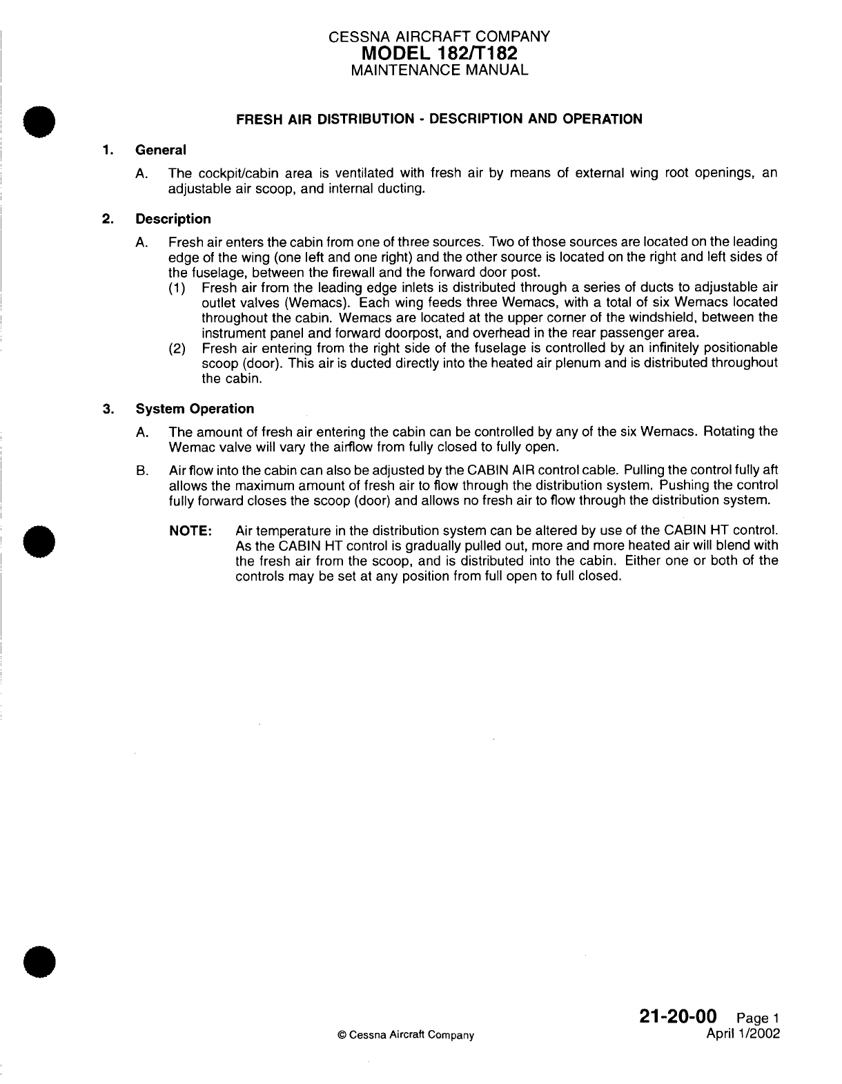
CESSNA
AIRCRAFT
COMPANY
MODEL
182/T182
MAINTENANCE
MANUAL
FRESH
AIR
DISTRIBUTION
-
DESCRIPTION
AND OPERATION
1.
General
A.
The
cockpit/cabin
area
is
ventilated
with fresh
air
by
means
of
external
wing
root
openings,
an
adjustable
air
scoop, and
internal
ducting.
2.
Description
A.
Fresh
air enters
the cabin
from
one
of
three
sources.
Two of
those
sources
are
located
on
the
leading
edge
of
the wing
(one
left
and
one right)
and
the
other source
is
located
on
the right and
left
sides
of
the
fuselage,
between
the
firewall
and the
forward
door post.
(1)
Fresh
air from
the
leading
edge
inlets
is
distributed
through
a
series
of
ducts
to
adjustable
air
outlet
valves
(Wemacs).
Each
wing
feeds
three
Wemacs,
with
a
total
of
six
Wemacs located
throughout
the cabin.
Wemacs are located
at
the
upper
corner
of the
windshield,
between
the
instrument
panel
and
forward
doorpost,
and
overhead
in
the
rear
passenger
area.
(2)
Fresh
air
entering
from
the
right
side
of
the
fuselage
is
controlled
by
an
infinitely positionable
scoop
(door).
This
air
is
ducted
directly
into
the
heated
air
plenum
and
is
distributed
throughout
the
cabin.
3.
System
Operation
A.
The amount
of
fresh
air
entering
the
cabin
can
be
controlled
by
any
of
the
six
Wemacs. Rotating
the
Wemac
valve
will
vary the
airflow
from
fully
closed
to
fully
open.
B.
Airflow
into the
cabin
can
also
be
adjusted
by
the
CABIN
AIR
control
cable.
Pulling
the
control
fully
aft
allows
the
maximum
amount
of
fresh
air
to
flow
through
the
distribution
system.
Pushing
the
control
fully
forward
closes
the
scoop
(door)
and
allows
no
fresh
air
to
flow
through
the
distribution
system.
NOTE: Air
temperature
in
the
distribution
system
can be
altered
by
use
of
the
CABIN
HT
control.
As
the
CABIN
HT
control
is
gradually
pulled
out,
more
and more
heated
air
will
blend
with
the
fresh air
from the
scoop,
and
is
distributed
into
the
cabin.
Either
one
or
both
of
the
controls
may
be
set
at
any
position
from
full
open
to
full
closed.
21-20-00
Page
1
©
Cessna Aircraft
Company
April
1/2002

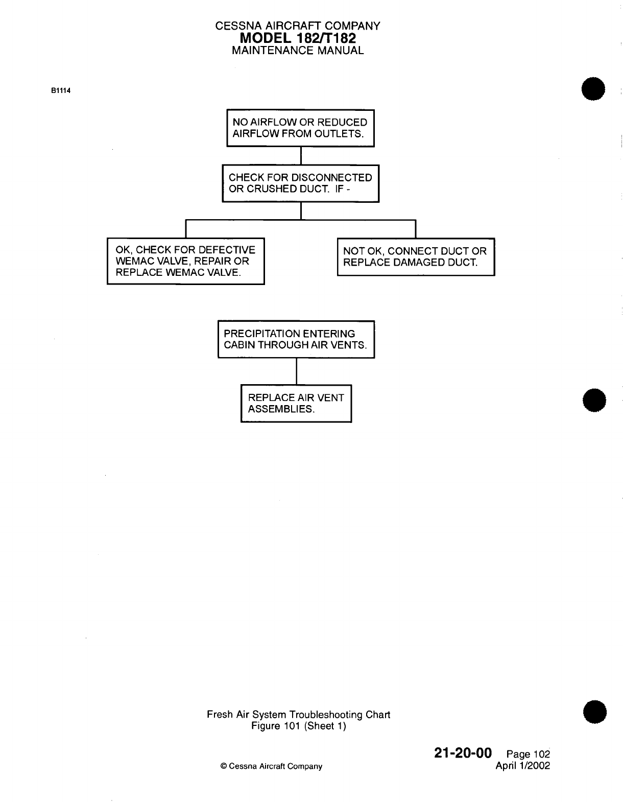
CESSNA AIRCRAFT
COMPANY
MODEL
182/T182
MAINTENANCE
MANUAL
B1114
NO
AIRFLOW
OR
REDUCED
AIRFLOW
FROM
OUTLETS.
CHECK FOR
DISCONNECTED
OR
CRUSHED
DUCT.
IF -
I
OK,
CHECK FOR
DEFECTIVE
WEMAC
VALVE,
REPAIR
OR
REPLACE WEMAC
VALVE.
NOT
OK,
CONNECT
DUCT
OR
REPLACE
DAMAGED
DUCT.
PRECIPITATION ENTERING
CABIN
THROUGH
AIR VENTS.
REPLACE
AIR
VENT
ASSEMBLIES.
Fresh
Air
System
Troubleshooting
Chart
Figure
101
(Sheet
1)
©
Cessna
Aircraft
Company
21-20-00
Page
102
April
1/2002
CESSNA
AIRCRAFT
COMPANY
MODEL
182/T182
MAINTENANCE
MANUAL
FRESH
AIR DISTRIBUTION
-
MAINTENANCE PRACTICES
1.
General
A.
Fresh
air
is
distributed
through ducts
from
two
inlet
openings,
one
in
each
wing
leading
edge,
to
air
outlet
valves
located
in
the cockpit/cabin
area
at
the
wing roots
by
the
upper corners
of
the
windshield,
in
the
side
walls
just
aft of the
instrument
panel,
and
above the
passenger
seat.
Air
outlet
valve
removal/installation
is
typical
at
each location.
A
door
assembly,
located
on
the
right
side
of
the
fuselage
between
the
firewall
and
door
post,
also
allows
fresh
air
to
be routed
into
the
heat
ducts.
The
door
is
operated
by
a
control
on
the
instrument
panel
labeled
CABIN
AIR.
2.
Air
Outlet
Valve
Removal/Installation
A.
Remove
Air
Outlet
Valve
(Refer
to
Figure
201).
(1)
Remove retaining
ring
from
air
outlet valve.
(2)
Remove
upholstery
panel
or
headliner.
Refer
to
chapter
25,
Interior Upholstery
-
Maintenance
Practices.
(3)
Remove
clamp securing ducting
hose to
air outlet
valve
adapter.
(4)
Remove
air outlet
valve
and
adapter.
B.
Install
Wing Root Air
Outlet
Valve
(Refer
to Figure
201).
(1)
Install air
outlet
valve
and
valve adapter
to
ducting. Secure
with
clamp.
(2)
Install
upholstery
panel
or
headliner.
Refer
to
Chapter
25,
Interior Upholstery
-
Maintenance
Practices.
(3)
Install
retaining
ring to
air
outlet valve.
3.
Cabin
Air
Control
Cable
Removal/Installation
A.
Remove
Cabin
Air
Control
Cable
(Refer
to
Figure
201).
(1)
Carefully straighten
end
of CABIN AIR
control
cable.
(2)
Loosen
clamp
bolt
on
control
arm
and
withdraw
cable
from
control
arm.
(3)
Remove
screws securing
clamp.
(4)
Gain
access
to the
backside
of
the CABIN
AIR
control
cable.
(5)
Loosen
nut
on
backside
of
control
cable.
(6)
Carefully withdraw cable
from
instrument
panel.
B.
Install Cabin Air Control
Cable
(Refer
to
Figure
201).
(1)
Thread
end
of
control cable
through
hole
in
instrument
panel.
(2)
Secure
CABIN AIR
control
cable
to
backside
of
instrument panel
using
existing jamnut.
(3)
Thread
end of
control
cable
through
the clamp
bolt.
(4)
Clamp
control
housing.
(5)
Test
control
cable
to
ensure
full
range of
travel.
Travel
may
be
adjusted
by
positioning
control
housing
in
clamps.
(6)
When full range
of
travel
has
been
established,
bend end
of
control
cable
around
clamp
bolt.
4.
Distribution
Duct
Removal/Installation
A.
The
majority
of the
fresh air
distribution
system
components
are
riveted
to
the
airframe
and do
not
require
replacement during
normal
maintenance.
Ducts
are
secured
to
these
components
using
clamps.
If
ducts
become damages
or
worn,
they
should
be
replaced.
21-20-00
Page
201
©
Cessna Aircraft
Company
Mar
1/2005
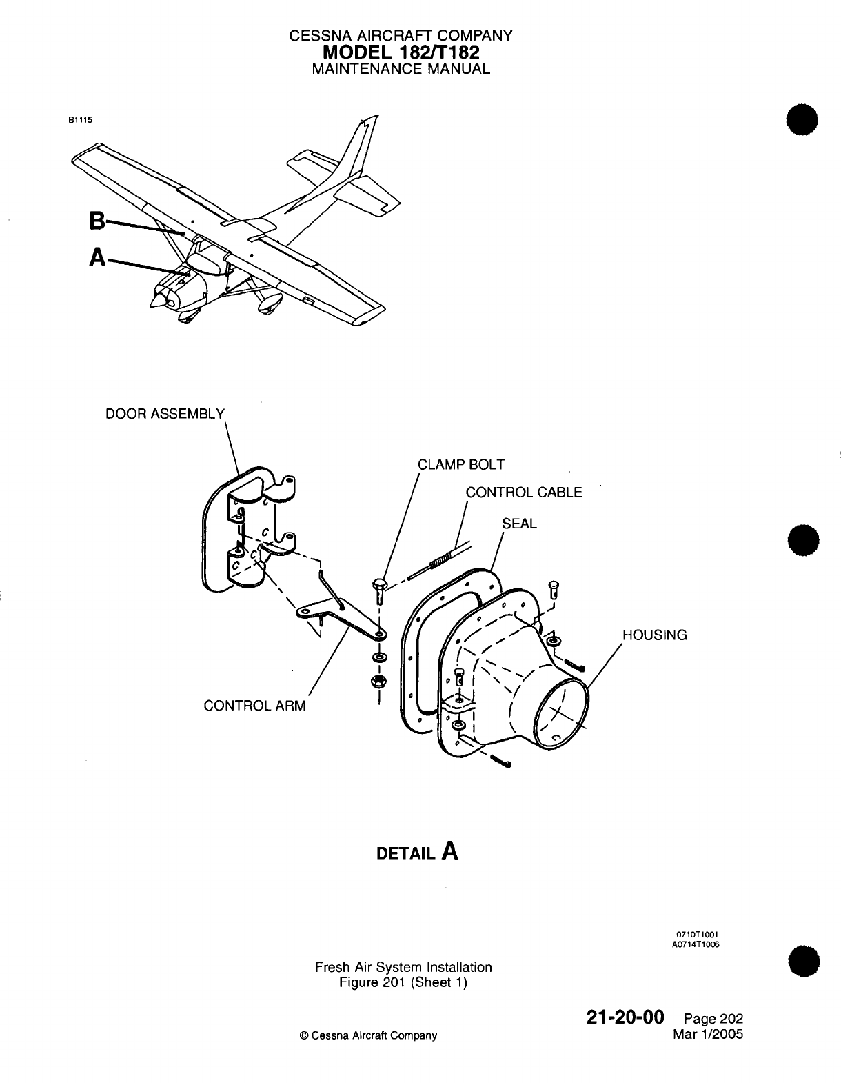
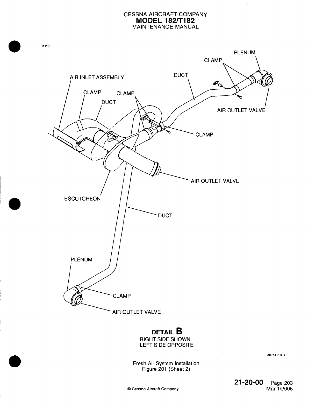
CESSNA AIRCRAFT
COMPANY
MODEL
182/T182
MAINTENANCE
MANUAL
B1116
PLENUM
CLAMP
JR
INLET ASSEMBLY
CLAMP
CLAMP
DUCT
DUCT
AIR OUTLET VALVE
CLAMP
AIR
OUTLET
VALVE
ESCUTCHEON
DUCT
PLENUM
CLAMP
AlI
UU
I
LE
I
VMLVr
DETAIL
B
RIGHT
SIDE
SHOWN
LEFT
SIDE
OPPOSITE
A0714T1001
Fresh
Air
System
Installation
Figure
201
(Sheet
2)
©
Cessna
Aircraft
Company
21-20-00
Page
203
Mar
1/2005
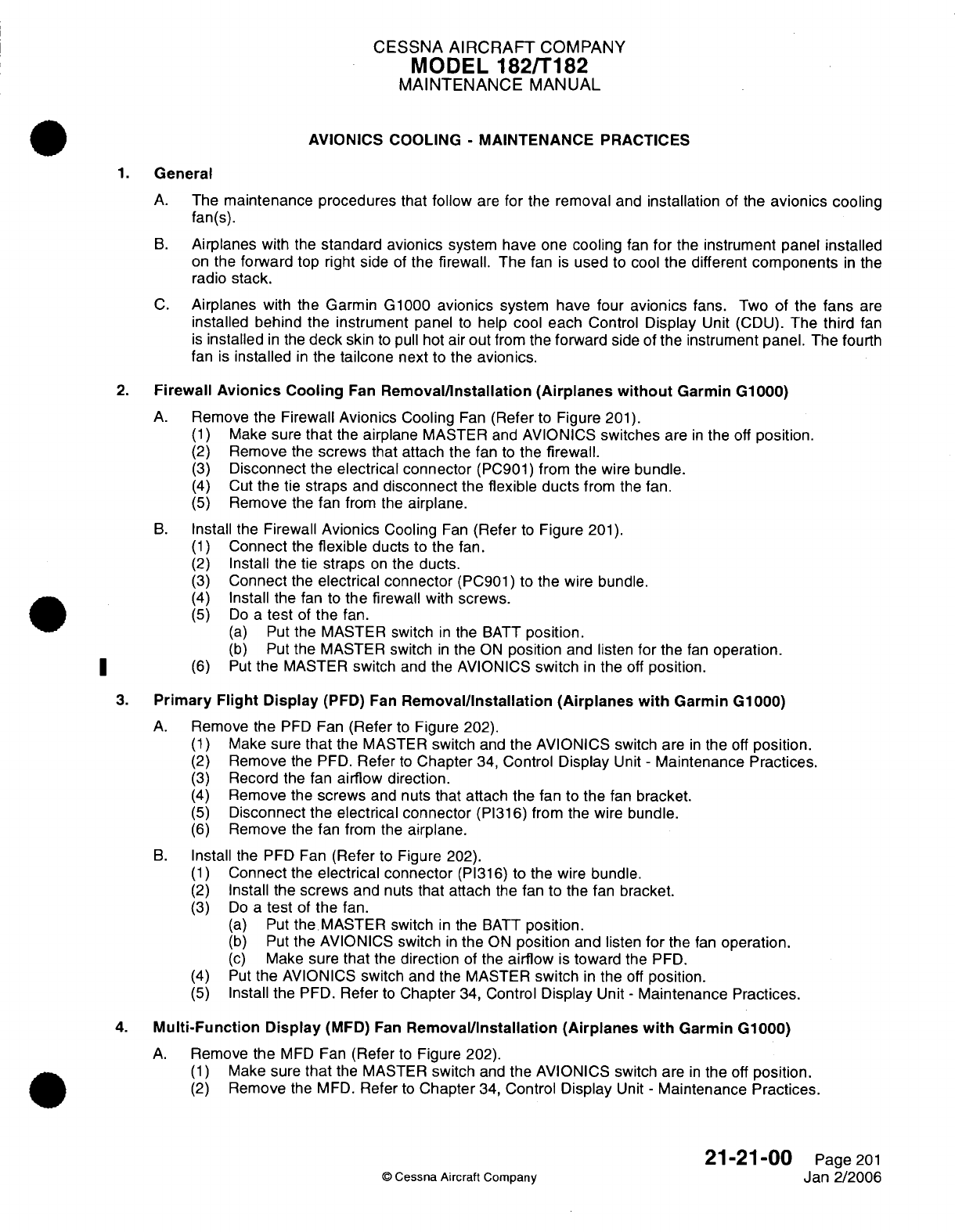
CESSNA
AIRCRAFT
COMPANY
MODEL
182/T182
MAINTENANCE
MANUAL
AVIONICS
COOLING
-
MAINTENANCE
PRACTICES
1.
General
A.
The
maintenance procedures
that
follow
are
for
the
removal
and
installation
of
the
avionics
cooling
fan(s).
B.
Airplanes
with
the
standard
avionics
system have
one
cooling
fan
for
the
instrument
panel
installed
on
the
forward
top right side
of
the
firewall. The
fan
is
used
to
cool
the
different
components
in
the
radio
stack.
C.
Airplanes
with
the
Garmin
G1000
avionics
system have
four
avionics
fans.
Two
of the
fans
are
installed behind
the
instrument
panel
to
help
cool
each
Control
Display
Unit (CDU).
The third
fan
is
installed
in
the
deck
skin
to
pull hot
air
out
from
the
forward
side
of
the
instrument
panel. The
fourth
fan
is
installed
in
the tailcone
next
to the
avionics.
2.
Firewall
Avionics
Cooling
Fan
Removal/Installation
(Airplanes
without
Garmin
G1000)
A.
Remove
the
Firewall
Avionics
Cooling
Fan
(Refer
to
Figure
201).
(1)
Make
sure
that
the
airplane
MASTER
and
AVIONICS
switches
are
in
the
off
position.
(2)
Remove
the
screws that attach
the fan
to
the
firewall.
(3)
Disconnect
the
electrical connector
(PC901)
from
the wire
bundle.
(4)
Cut
the
tie
straps
and
disconnect
the
flexible
ducts
from
the fan.
(5)
Remove
the
fan
from the
airplane.
B.
Install
the
Firewall
Avionics
Cooling
Fan
(Refer
to
Figure
201).
(1)
Connect
the
flexible
ducts
to the
fan.
(2)
Install
the
tie
straps
on
the
ducts.
(3)
Connect
the
electrical connector
(PC901)
to the wire
bundle.
(4)
Install the
fan
to
the
firewall
with
screws.
(5)
Do
a
test
of
the
fan.
(a)
Put
the MASTER switch
in
the
BATT
position.
(b)
Put
the MASTER switch
in
the
ON
position
and
listen
for
the
fan
operation.
(6)
Put
the
MASTER
switch
and
the
AVIONICS
switch
in
the
off
position.
3.
Primary
Flight
Display
(PFD) Fan
Removal/Installation (Airplanes with
Garmin G1000)
A.
Remove
the
PFD
Fan
(Refer
to
Figure
202).
(1)
Make
sure
that
the
MASTER
switch
and
the AVIONICS switch
are
in
the
off
position.
(2)
Remove
the
PFD.
Refer
to
Chapter
34,
Control
Display
Unit
-
Maintenance
Practices.
(3)
Record the
fan
airflow direction.
(4)
Remove
the
screws
and
nuts
that attach the
fan to
the
fan
bracket.
(5)
Disconnect the
electrical
connector
(PI316)
from
the
wire
bundle.
(6)
Remove
the
fan
from the
airplane.
B.
Install
the
PFD Fan
(Refer
to
Figure
202).
(1)
Connect
the
electrical connector
(PI316) to the wire
bundle.
(2)
Install the
screws and
nuts
that
attach
the fan to the fan
bracket.
(3)
Do
a
test
of
the
fan.
(a)
Put
the MASTER
switch
in
the
BATT
position.
(b)
Put
the
AVIONICS
switch
in
the
ON
position
and
listen
for
the
fan
operation.
(c)
Make
sure
that
the
direction
of
the
airflow
is
toward
the
PFD.
(4)
Put
the AVIONICS
switch and
the MASTER
switch
in
the
off
position.
(5)
Install the
PFD.
Refer
to
Chapter
34,
Control
Display
Unit
-
Maintenance Practices.
4.
Multi-Function Display
(MFD)
Fan
Removal/Installation
(Airplanes
with
Garmin
G1000)
A.
Remove
the
MFD
Fan
(Refer
to
Figure 202).
(1)
Make
sure
that
the
MASTER
switch
and
the
AVIONICS switch
are
in
the
off
position.
(2)
Remove
the
MFD.
Refer
to
Chapter
34,
Control
Display
Unit
-
Maintenance
Practices.
21-21-00
Page
201
©
Cessna Aircraft Company
Jan
2/2006
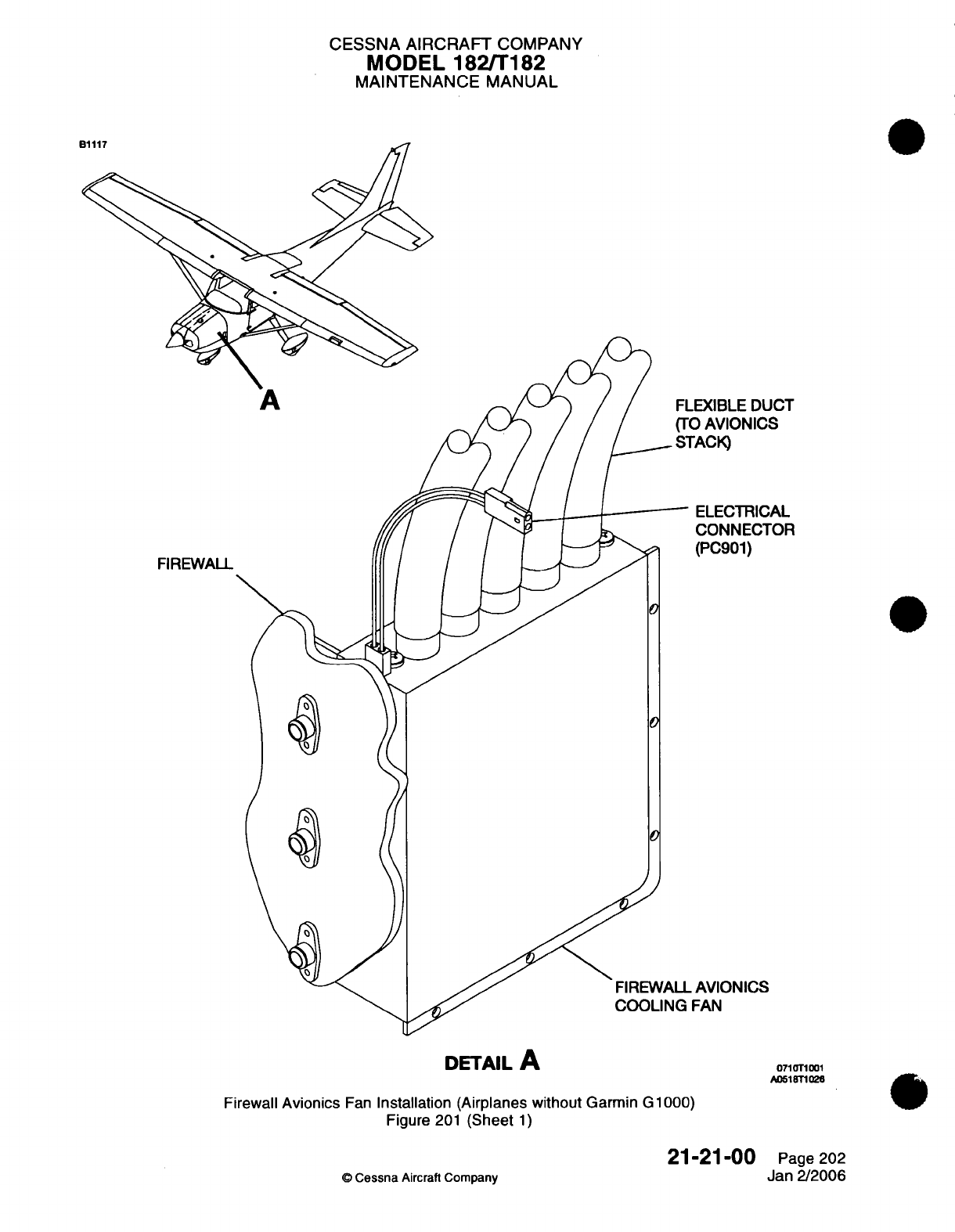
CESSNA
AIRCRAFT
COMPANY
MODEL
182/T182
MAINTENANCE
MANUAL
EXIBLE
DUCT
O
AVIONICS
TACK)
ELECTRICAL
CONNECTOR
(PC901)
0
0
AVIONICS
FAN
071T1T001
A051T1026
Firewall
Avionics
Fan
Installation (Airplanes
without
Garmin
G
1000)
Figure
201
(Sheet
1)
©
Cessna
Aircraft
Company
21-21-00
Page
202
Jan 2/2006
A
FIREWALL
DETAIL
A
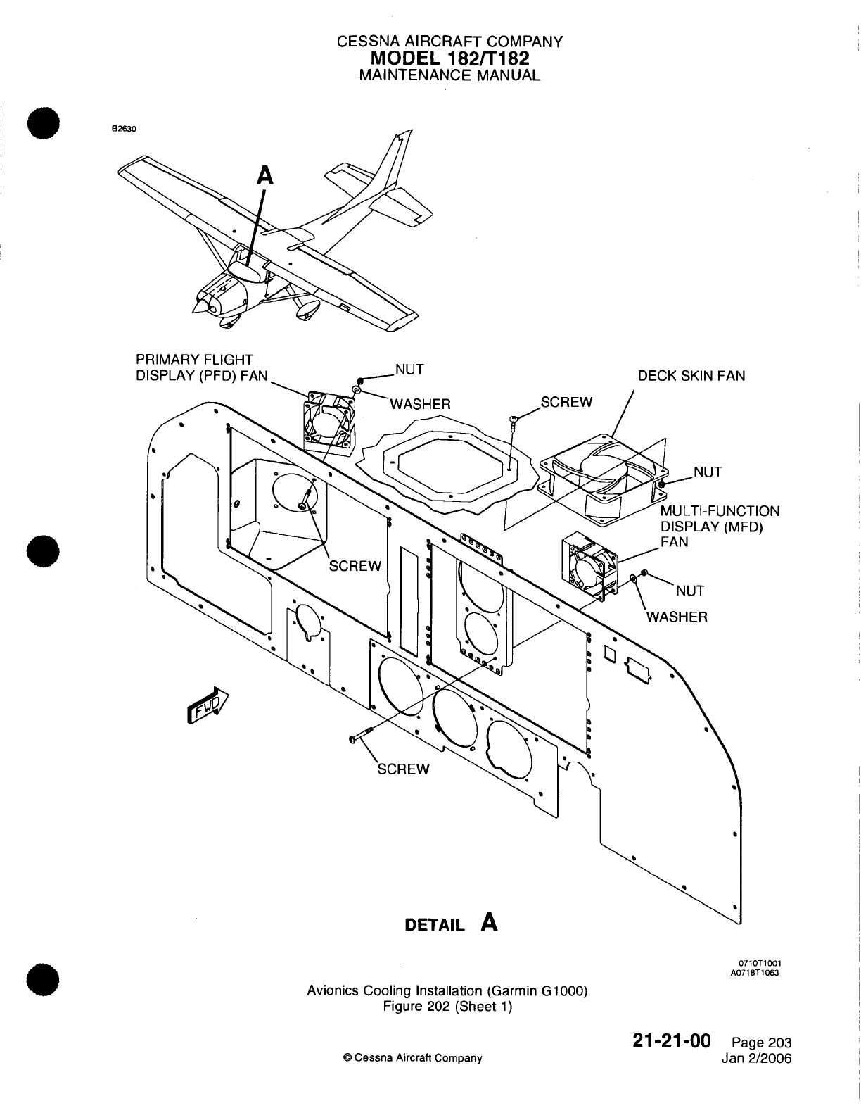
CESSNA
AIRCRAFT
COMPANY
MODEL
182/T182
MAINTENANCE
MANUAL
PRIMARY
Fl
I(1-IT
D
0710T1001
A0718T1063
Avionics
Cooling
Installation
(Garmin G1000)
Figure
202
(Sheet
1)
©
Cessna Aircraft
Company
21-21-00
Page 203
Jan
2/2006
CESSNA
AIRCRAFT
COMPANY
MODEL
182/T182
MAINTENANCE
MANUAL
(3)
Remove
the
turn
coordinator.
Refer
to
Chapter
34,
Attitude
and
Direction
-
Maintenance
Practices.
(4)
Record the
fan
airflow
direction.
(5)
Remove
the
screws
and
nuts
that
attach the
fan to the fan
bracket.
(6)
Disconnect
the
electrical connector
(PI315)
from
the
wire
bundle.
(7)
Remove
the fan
from
the
airplane.
B.
Install
the
MFD
Fan
(Refer
to
Figure
202).
(1)
Connect
the
electrical
connector
(PI315)
to
the
wire
bundle.
(2)
Make sure
that
the
airflow
direction
is
towards
the
MFD.
(3)
Install
the
screws
and
nuts
that
attach
the
fan
to
the
fan
bracket.
(4)
Do
a
test
of
the
fan.
(a)
Put
the MASTER
switch
in
the
BATT
position.
(b)
Put
the AVIONICS
switch
to
the
ON
position
and
listen
for
the fan
operation.
(5)
Put
the
AVIONICS
switch
and
the
MASTER
switch
in
the
off
position.
(6)
Install
the
turn
coordinator.
Refer
to
Chapter
34,
Attitude and
Direction
-
Maintenance
Practices.
(7)
Install
the
MFD.
Refer
to Chapter
34,
Control
Display
Unit
-
Maintenance
Practices.
5.
Deck
Skin
Fan
Removal/nstallation
(Airplanes
with
Garmin
G1000)
A.
Remove
the
Deck Skin
Fan
(Refer
to
Figure
202).
(1)
Make
sure
that the
MASTER
switch
and
the
AVIONICS
switch are
in
the
off
position.
(2)
Remove the
PFD.
Refer
to
Chapter
34,
Control
Display
Unit
-
Maintenance Practices.
(3)
Record
the
airflow
direction.
(4)
Remove
the
screws
and
nuts
that
attach
the
fan
to the
deck
skin.
(5)
Disconnect
the
electrical connector
(PI314)
from
the
wire
bundle.
(6)
Remove
the fan
from
the
airplane.
B.
Install
the Deck
Skin
Fan
(Refer
to
Figure
202).
(1)
Connect
the
electrical
connector
(PI314)
to
the
wire
bundle.
(2)
Make
sure that
the
direction
of the
airflow
is
away
from
the
deck
skin
and
toward
the
windshield.
(3)
Install
the
screws
and
nuts
that
attach the fan
to
the
deck
skin.
(4)
Do
a
test
of
the fan.
(a)
Put
the
MASTER
switch
in
the
BATT
position.
(b)
Put
the
AVIONICS
switch
to the
ON
position
and
listen
for
the
fan
operation.
(5)
Put
the
AVIONICS
switch
and the MASTER
switch
in
the off
position.
(6)
Install
the
PFD.
Refer
to
Chapter
34,
Control
Display
Unit
-
Maintenance
Practices.
6.
Remote
Avionics
Cooling
Fan
Removal/nstallation
(Airplanes with
Garmin G1000)
A.
Remove
the
Remote
Avionics
Cooling
Fan
(Refer to
Figure
203).
(1)
Make
sure
that the MASTER
switch
and
the
AVIONICS
switch are
in
the
off
position.
(2)
Remove
the
upholstery.
Refer
to
Chapter
25,
Interior
Upholstery
-
Maintenance
Practices.
(3)
Remove
the
screws
that
attach
the
fan
to
the structure.
(4) If
necessary,
remove
the
caps
from
the
unused
ports.
(5)
Disconnect
the
electrical connector
(PT901)
from
the wire
bundle.
(6)
Remove
the
clamps
from the
flexible
ducts
of
the
fan.
(7)
Disconnect
the
flexible
ducts
from
the
fan.
(8)
Remove
the
fan
from
the
airplane.
B.
Install
the Remote
Avionics
Cooling
Fan
(Refer
to
Figure
203).
(1)
Connect
the
flexible ducts
to
the
fan.
(2)
Put
the
clamps
on
the
flexible
ducts.
(3)
Connect
the
electrical
connector
(PT901)
to
the wire bundle.
(4)
Install
the
screws that attach
the
fan
to
the
structure.
(5) If
necessary, install
the
caps
on
the
unused
ports.
(6)
Do
a
test
of
the fan.
(a)
Put
the
MASTER
switch
in
the
BATT
position.
(b)
Put
the
AVIONICS
switch
to the
ON
position
and
listen for
the
fan
operation.
(7)
Put
the AVIONICS
switch
and
the
MASTER
switch
in
the
off
position.
21-21-00
Page
204
©
Cessna
Aircraft
Company
Jan
2/2006
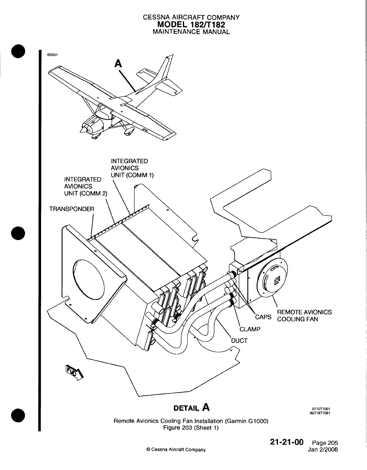
CESSNA
AIRCRAFT
COMPANY
MODEL 182/T182
MAINTENANCE
MANUAL
INTEGRATED
A I
I
REMOTE
AVIONICS
CAPS
COOLING
FAN
DETAIL
A
0710T1001
A0718T1081
Remote
Avionics Cooling
Fan
Installation
(Garmin
G1000)
Figure
203
(Sheet
1)
21-21-00
©
Cessna
Aircraft
Company
Page
205
Jan 2/2006
CESSNA
AIRCRAFT
COMPANY
MODEL
182/T182
MAINTENANCE
MANUAL
(8)
Install
the
upholstery.
Refer
to
Chapter
25,
Interior Upholstery
-
Maintenance
Practices.
7.
Primary
Flight
Display
(PFD)
and
Multi-Function
Display
(MFD)
Fan
Operational Check
(Airplanes
with
Garmin G1000)
A.
PFD
and
MFD
Fan
Operational
Check
(Refer
to
Figure 202).
(1)
Remove
the
PFD
and
the
MFD.
Refer
to
Control
Display
Unit
-
Maintenance
Practices.
(2)
Put
the
MASTER
switch
and
AVIONICS
switch
in
the
ON
position.
(3)
Listen
and
look for
the
correct operation
of both
fans.
(4)
Install the
PFD
and
the
MFD.
Refer
to
Control
Display
Unit
-
Maintenance
Practices.
21-21-00
Page 206
c
Cessna
Aircraft
Company
Jan
2/2006

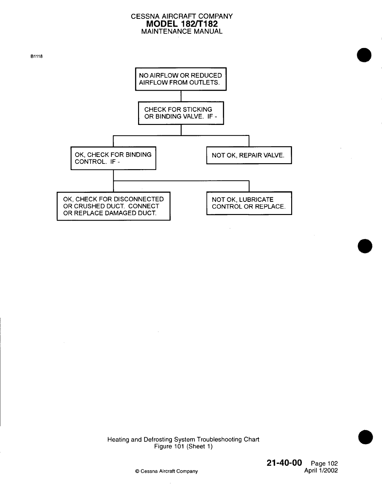
CESSNA AIRCRAFT
COMPANY
MODEL 182/T182
MAINTENANCE
MANUAL
B1118
NO
AIRFLOW
OR REDUCED
AIRFLOW
FROM
OUTLETS.
CHECK FOR STICKING
I
OR
BINDING
VALVE.
IF
-
I
OK,
CHECK
CONTROL.
FOR
BINDING
IF-
NOT
OK,
REPAIR
VALVE.
OK,
CHECK
FOR
DISCONNECTED
OR
CRUSHED
DUCT.
CONNECT
OR
REPLACE
DAMAGED DUCT.
NOT
OK,
LUBRICATE
CONTROL
OR
REPLACE.
Heating and Defrosting
System
Troubleshooting Chart
Figure
101
(Sheet
1)
©
Cessna
Aircraft
Company
21-40-00
Page
102
April
1/2002
I
I
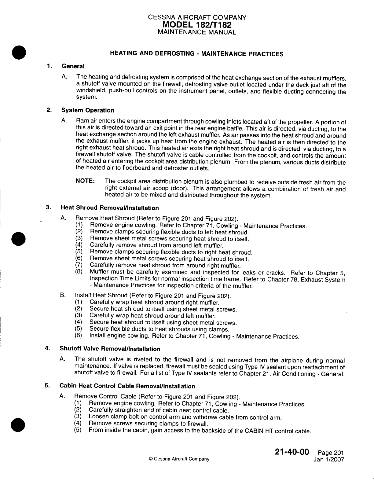
CESSNA AIRCRAFT
COMPANY
MODEL
182/T1
82
MAINTENANCE
MANUAL
HEATING
AND
DEFROSTING
-
MAINTENANCE PRACTICES
1.General
A.
The heating
and
defrosting
system
is
comprised
of
the
heat
exchange section
of
the
exhaust
mufflers,
a
shutoff valve
mounted
on
the
firewall,
defrosting
valve
outlet
located
under
the
deck
just
aft
of
the
windshield, push-pull
controls
on
the
instrument
panel,
outlets,
and
flexible ducting
connecting
the
system.
2.
System
Operation
A.
Ram
air
enters
the
engine
compartment
through cowling inlets
located
aft
of
the
propeller.
A
portion
of
this
air
is
directed
toward
an
exit
point
in
the
rear
engine
baffle.
This
air
is
directed,
via
ducting,
to
the
heat
exchange section
around
the
left
exhaust
muffler.
As
air
passes
into
the
heat
shroud
and
around
the
exhaust
muffler,
it
picks
up
heat
from the
engine exhaust.
The
heated
air
is
then
directed
to
the
right
exhaust
heat
shroud.
This
heated
air
exits
the
right
heat
shroud
and
is
directed,
via
ducting,
to
a
firewall
shutoff
valve.
The
shutoff
valve
is
cable
controlled
from
the
cockpit,
and
controls
the
amount
of
heated
air
entering
the
cockpit
area
distribution
plenum.
From the
plenum,
various
ducts
distribute
the
heated
air
to
floorboard
and
defroster
outlets.
NOTE:
The
cockpit
area
distribution
plenum
is
also
plumbed
to
receive
outside
fresh
air
from
the
right
external
air
scoop
(door).
This
arrangement
allows
a
combination
of
fresh
air
and
heated
air
to
be
mixed
and
distributed throughout
the
system.
3.
Heat
Shroud
Removal/installation
A.
Remove
Heat
Shroud
(Refer
to
Figure
201
and Figure 202).
(1)
Remove
engine cowling.
Refer
to
Chapter
71,
Cowling
-
Maintenance Practices.
(2)
Remove
clamps
securing
flexible
ducts
to
left
heat
shroud.
(3)
Remove
sheet
metal
screws securing
heat
shroud to itself.
(4)
Carefully
remove
shroud
from
around
left
muffler.
(5)
Remove
clamps securing
flexible
ducts
to
right
heat
shroud.
(6)
Remove
sheet
metal
screws
securing
heat
shroud
to
itself.
(7)
Carefully
remove
heat
shroud
from
around
right
muffler.
(8)
Muffler
must
be
carefully
examined
and
inspected
for
leaks
or
cracks.
Refer
to
Chapter
5,
Inspection
Time
Limits
for
normal
inspection
time frame.
Refer
to
Chapter
78,
Exhaust
System
-
Maintenance
Practices for inspection
criteria
of
the
muffler.
B.
Install
Heat
Shroud
(Refer
to
Figure
201
and
Figure
202).
(1)
Carefully
wrap
heat
shroud around
right
muffler.
(2)
Secure
heat
shroud
to
itself using
sheet
metal
screws.
(3)
Carefully
wrap
heat
shroud
around
left
muffler.
(4)
Secure
heat
shroud
to
itself
using
sheet
metal
screws.
(5)
Secure
flexible
ducts
to
heat
shrouds
using
clamps.
(6)
Install
engine cowling.
Refer
to
Chapter
71,
Cowling
-
Maintenance
Practices.
4.
Shutoff
Valve
Removal/installation
A.
The
shutoff
valve
is
riveted to
the
firewall
and
is
not
removed
from
the
airplane
during
normal
maintenance.
If
valve
is
replaced,
firewall
must
be
sealed
using
Type
IV
sealant
upon
reattachment
of
shutoff
valve
to
firewall.
For
a
list
of
Type
IV
sealants
refer
to
Chapter
21,
Air
Conditioning
-
General.
5.
Cabin
Heat
Control
Cable
Removal/installation
A.
Remove
Control
Cable
(Refer
to
Figure
201
and
Figure 202).
(1)
Remove
engine cowling.
Refer
to
Chapter
71,
Cowling
-
Maintenance
Practices.
(2)
Carefully
straighten
end
of
cabin heat
control
cable.
(3)
Loosen
clamp
bolt
on
control
arm
and
withdraw
cable
from
control
arm.
(4)
Remove
screws securing
clamps
to
firewall.
(5)
From
inside
the
cabin,
gain
access
to
the
backside
of
the
CABIN
HT
control cable.
21-40-00
Page
201
©
Cessna
Aircraft Company
Janl1/2007
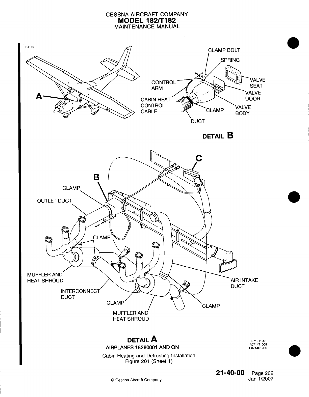
CESSNA AIRCRAFT
COMPANY
MODEL
182/T1
182
MAINTENANCE
MANUAL
CLAMP BOLT
SPRING
CONTRC
ARM
CABIN
HEAT
CONTROL
CABLE
SEAT
VALVE
DOOR
VALVE
BODY
DETAIL
B
IINTAKE
ICT
MUFFLER AND
HEAT
SHROUD
DETAIL
A
AIRPLANES
18280001
AND
ON
Cabin
Heating
and
Defrosting
Installation
Figure
201
(Sheet
1)
071
0T100
1
A071
4T1
009
B0714R1030
21-40-00
©
Cessna
Aircraft
Company
Page
202
Janl1/2007
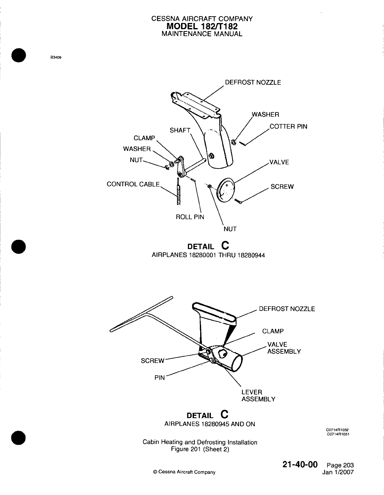
CESSNA
AIRCRAFT
COMPANY
MODEL
182/Ti
182
MAINTENANCE
MANUAL
833409
DEFROST
NOZZLE
PIN
w
CONTR
NUT
DETAIL
C
AlIRPLAN
ES
18280001
THRU
18280944
-FROST
NOZZLE
LAMP
,VALVE
ASSEMBLY
LEVER
ASSEMBLY
DETAIL
C
AIRPLANES 18280945
AND
ON
Cabin Heating
and
Defrosting
Installation
Figure
201
(Sheet
2)
0
Cessna Aircraft
Company
21-40-00
Page
203
Janl1/2007
C0714R1032
C0714R1031
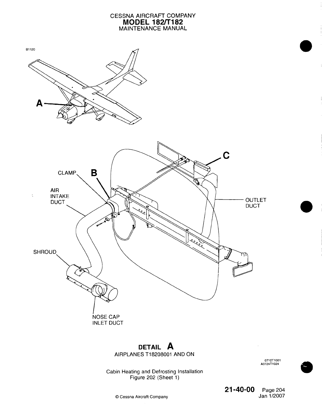
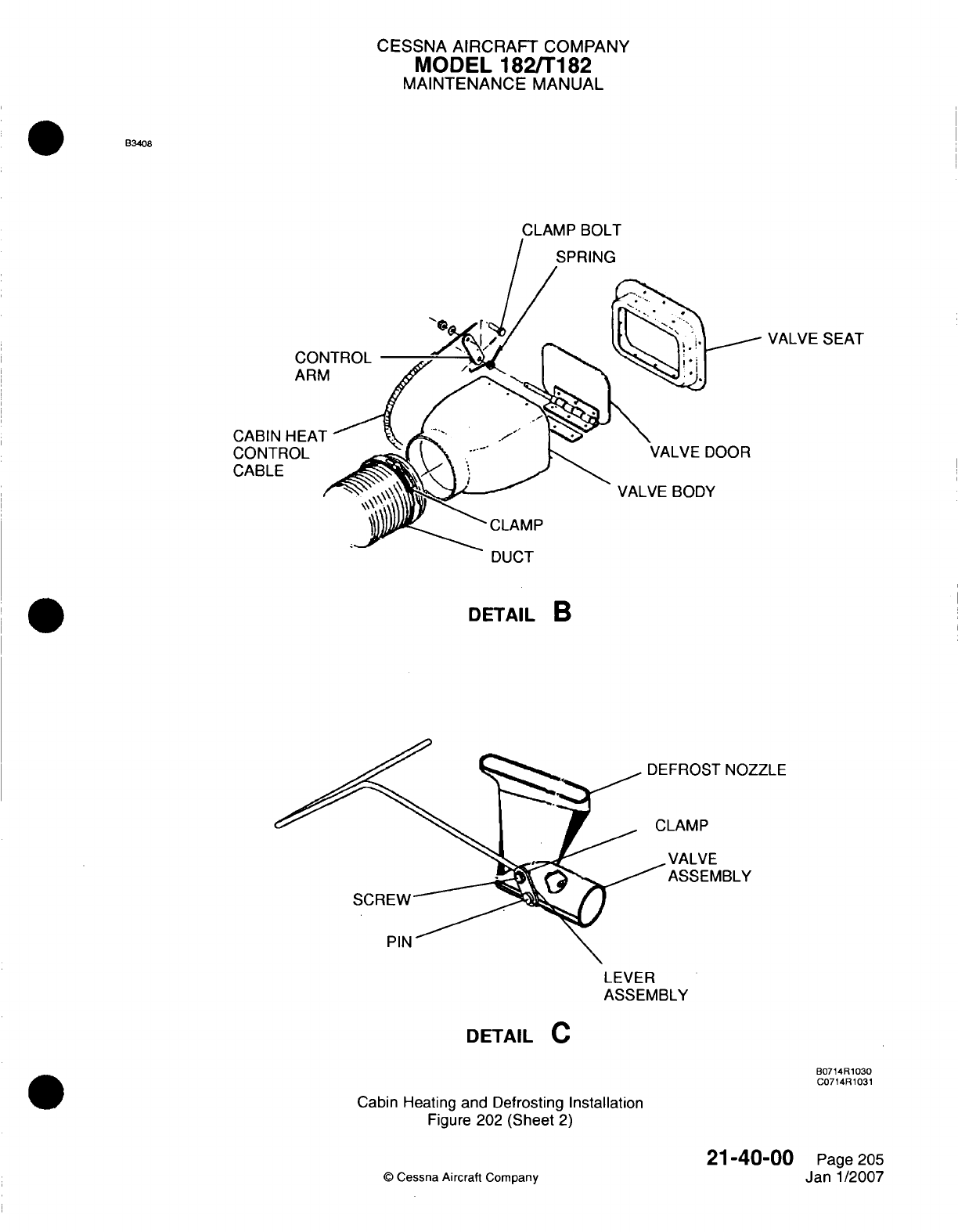
CESSNA
AIRCRAFT
COMPANY
MODEL
1821182
MAINTENANCE
MANUAL
B34o8
CLAMP
BOLT
VALVE
SEAT
COI
AR1
CABIN
HEAT
CONTROL
CABLE
VALVE DOOR
VALVE
BODY
CLAMP
iDutn
I
DETAIL
B
-FROST
NOZZLE
~LAMP
.VALVE
ASSEMBLY
LEVER
ASSEMBLY
DETAIL
C
B0714R1030
C0714F11031
Cabin
Heating
and
Defrosting
Installation
Figure
202
(Sheet
2)
©
Cessna
Aircraft
Company
21-40-00
Page
205
Janl1/2007
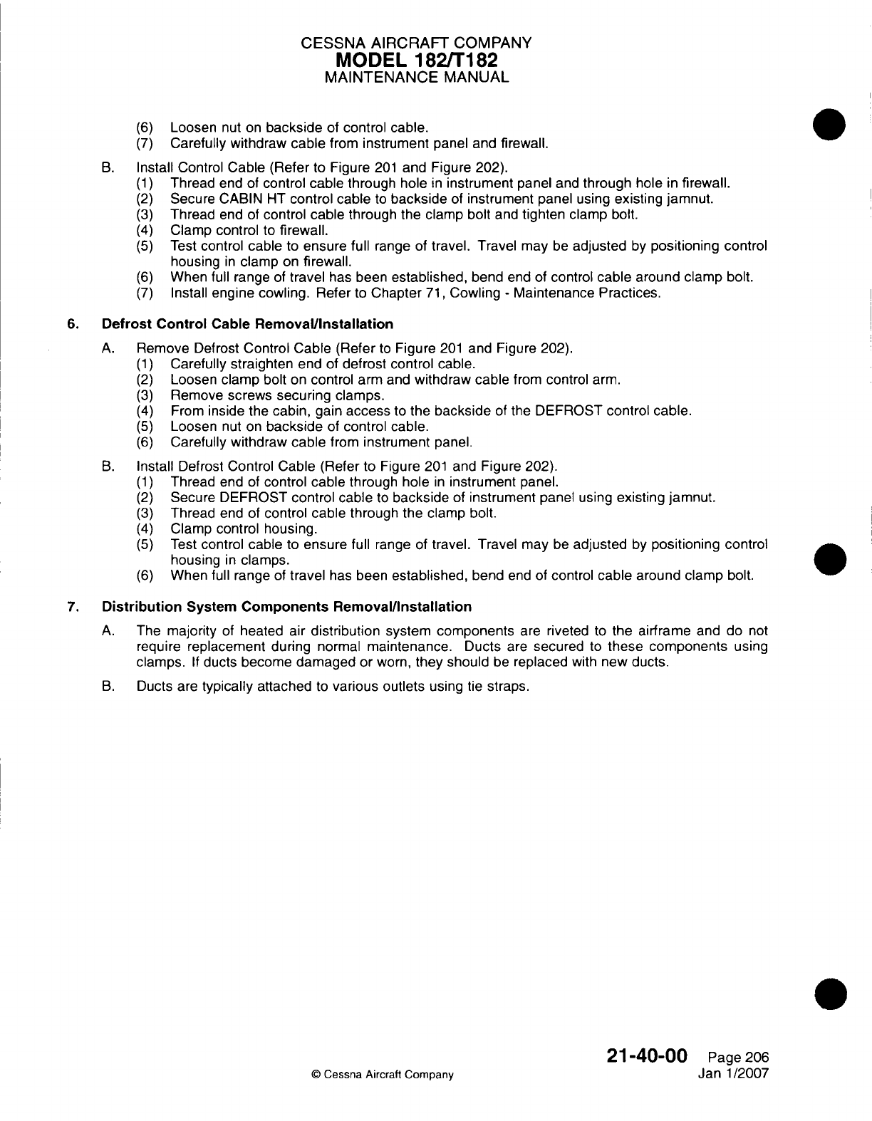
CESSNA AIRCRAFT
COMPANY
MODEL
182/Ti182
MAINTENANCE
MANUAL
(6)
Loosen
nut
on
backside
of
control
cable.
(7)
Carefully withdraw cable
from
instrument
panel
and
firewall.
B.
Install Control
Cable
(Refer
to
Figure
201
and Figure
202).
(1)
Thread end
of
control cable
through
hole
in
instrument
panel
and
through
hole
in
firewall.
(2)
Secure
CABIN
HT
control
cable
to
backside
of
instrument
panel
using
existing jamnut.
(3)
Thread
end
of
control
cable
through
the
clamp
bolt
and
tighten clamp
bolt.
(4)
Clamp
control
to
firewall.
(5)
Test
control cable
to
ensure full
range
of
travel.
Travel
may
be
adjusted
by
positioning
control
housing
in
clamp
on
firewall.
(6)
When
full
range
of
travel
has
been
established,
bend
end
of
control
cable
around
clamp
bolt.
(7)
Install
engine cowling.
Refer
to
Chapter
71,
Cowling
-
Maintenance Practices.
6.
Defrost Control
Cable
Removall/Installation
A.
Remove
Defrost
Control
Cable
(Refer
to
Figure
201
and
Figure 202).
(1)
Carefully
straighten
end
of
defrost
control cable.
(2)
Loosen
clamp
bolt
on
control
arm
and
withdraw
cable
from
control
arm.
(3)
Remove
screws
securing
clamps.
(4)
From
inside
the
cabin,
gain
access
to
the
backside
of
the
DEFROST
control
cable.
(5)
Loosen
nut
on
backside
of
control
cable.
(6)
Carefully withdraw cable
from
instrument
panel.
B.
Install Defrost
Control Cable
(Refer
to
Figure
201
and
Figure 202).
(1)
Thread
end
of
control
cable
through hole
in
instrument
panel.
(2)
Secure DEFROST
control
cable
to
backside
of
instrument panel
using
existing
jamnut.
(3)
Thread
end
of
control cable
through
the
clamp bolt.
(4)
Clamp
control housing.
(5)
Test
control
cable
to
ensure
full
range
of
travel. Travel
may
be
adjusted
by
positioning
control
housing
in
clamps.
(6)
When
full range
of
travel
has
been
established,
bend
end
of
control cable around clamp
bolt.
7.
Distribution
System
Components
Removal/Installation
A.
The
majority
of
heated
air
distribution
system
components
are
riveted
to
the
airframe
and
do
not
require
replacement
during
normal
maintenance.
Ducts
are
secured
to
these
components
using
clamps.
If
ducts
become damaged
or
worn,
they
should
be
replaced
with
new
ducts.
B.
Ducts
are
typically
attached
to
various
outlets
using
tie
straps.
21-40-00
Page
206
©
Cessna
Aircraft
Company
Janl1/2007

CHAPTER
AUTO
FLIGHT
CESSNA
AIRCRAFT
COMPANY
MODEL
182/T182
MAINTENANCE
MANUAL
LIST
OF EFFECTIVE
PAGES
CHAPTER-SECTION-SUBJECT
22-Title
22-List
of
Effective Pages
22-Record
of
Temporary
Revisions
22-Table
of
Contents
22-00-00
22-10-00
22-11-00
PAGE
Page
1
Pages
201
-212
Pages 201-207
©
Cessna
Aircraft
Company
22
-
LIST
OF
EFFECTIVE
PAGES
Page
1
of
1
Jul
1/2007
DATE
Janl1/2007
Jul
1/2007
Janl1/2007
Temporary
Revision
Number
RECORD
OF
TEMPORARY
REVISIONS
Page
Number
Issue
Date
By
Date
Removed
By
CESSNA
AIRCRAFT
COMPANY
MODEL
182/Ti
82
MAINTENANCE
MANUAL
CONTENTS
AUTO
FLIGHT
-
GENERAL
............................
Scope
and
Definition.............................
Tools,
Equipment
and
Materials........................
AUTOPILOT
-
MAINTENANCE PRACTICES
....................
General
..................................
KC-
140
(Single-Axis)
Autopilot
Flight
Computer
Removal/installation.......
KC-140
(Dual-Axis)
Autopilot
Flight
Computer
Removal/Installation........
Roll
Servo
Removal/Installation........................
Pitch
Servo
Removal/installation
.:.....................
Pitch
Trim
Servo
Removal/Installation
.....................
Roll
Servo
Inspection.............................
Pitch
Servo Inspection
............................
Pitch
Trim
Servo
Inspection..........................
Pitch Trim
Rigging
Inspection.........................
Servo
Capstan
Clutch
Adjustment.......................
Set the
Autopilot
Roll
Null...........................
AUTOPILOT
-
MAINTENANCE
PRACTICES
....................
General...................................
GFC-700 Autopilot
Flight Computer
Removal/Installation
............
Roll
Servo Actuator
Removal/Installation....................
Roll
Servo
And
Cable
Removal/Installation...................
Pitch
Servo
Motor
Removal/Installation
....................
Pitch
Servo
And
Cable
Removal/installation
..................
Pitch Trim
Servo
Actuator
Removal/Installation.................
Pitch Trim
Servo
and
Cable
Removal/Installation
................
Pitch
Trim
Rigging
Inspection.........................
Servo
Capstan
Clutch
Adjustment.......................
22-00-00
Page
1
22-00-00
Page
1
22-00-00
Page
1
22-1
0-00
Page
201
22-1
0-00
Page
201
22-10-00
Page
201
22-10-00
Page
201
22-10-00
Page
201
22-1
0-00
Page 207
22-1
0-00
Page 207
22-10-00
Page
208
22-10-00
Page
209
22-1
0-00
Page
209
22-1
0-00
Page
21
0
22-1
0-00
Page
21
0
22-10-00
Page
211
22-11
-00
Page
201
22-11
-00
Page
201
22-11
-00
Page
201
22-11
-00
Page
201
22-11
-00
Page
201
22-11
-00
Page 205
22-11-00
Page
205
22-1 1-00
Page
205
22-11
-00
Page
206
22-11
-00
Page
206
22-11
-00
Page
207
22
-
CONTENTS
Page
1
of
1
Jul
1/2007
©
Cessna
Aircraft
Company
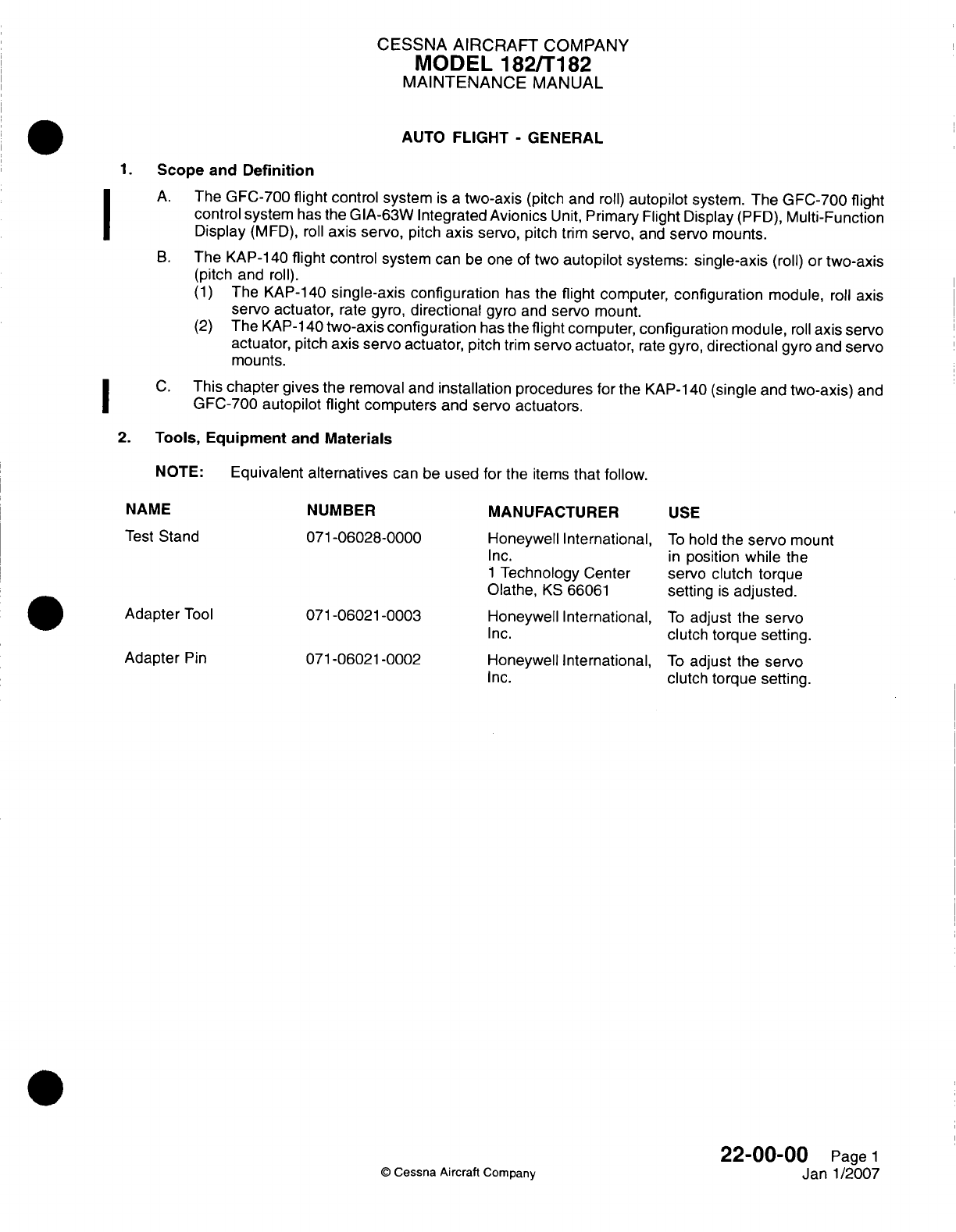
CESSNA AIRCRAFT
COMPANY
MODEL
182/Ti182
MAINTENANCE
MANUAL
AUTO
FLIGHT
-
GENERAL
1.Scope
and
Definition
A.
The
GFC-700
flight
control system
is
a
two-axis
(pitch
and
roll)
autopilot
system.
The
GFC-700
flight
control
system
has
the
GIA-63W Integrated
Avionics
Unit,
Primary
Flight Display
(PFD),
Multi-Function
Display
(MFD),
roll
axis
servo,
pitch
axis
servo,
pitch
trim
servo,
and
servo
mounts.
B.
The
KAP-1
40
flight
control system
can
be
one
of
two
autopilot
systems:
single-axis
(roll) or
two-axis
(pitch
and
roll).
(1)
The
KAP-140
single-axis
configuration
has
the
flight
computer,
configuration
module,
roll
axis
servo
actuator,
rate gyro,
directional
gyro
and
servo
mount.
(2)
The
KAP-1
40
two-axis
configuration
has
the
flight
computer,
configuration
module,
roll
axis
servo
actuator,
pitch
axis
servo actuator,
pitch
trim
servo
actuator,
rate
gyro,
directional
gyro and
servo
mounts.
C.
This
chapter
gives
the removal
and
installation procedures
for
the
KAP-1
40
(single
and
two-axis)
and
GFC-700
autopilot
flight
computers
and
servo actuators.
2.
Tools, Equipment
and
Materials
NOTE:
Equivalent
alternatives
can
be
used
for
the
items
that
follow.
NAME
Test
Stand
Adapter
Tool
Adapter
Pin
NUMBER
071-06028-0000
071-06021-0003
071-06021-0002
MANUFACTURER
Honeywell
International,
Inc.
1
Technology
Center
Olathe,
KS
66061
Honeywell International,
Inc.
Honeywell
International,
Inc.
USE
To
hold
the
servo
mount
in
position while
the
servo clutch torque
setting
is
adjusted.
To
adjust the
servo
clutch torque
setting.
To
adjust
the
servo
clutch
torque setting.
0
Cessna
Aircraft
Company
22-00-00
Page
1
Janl1/2007
I
I
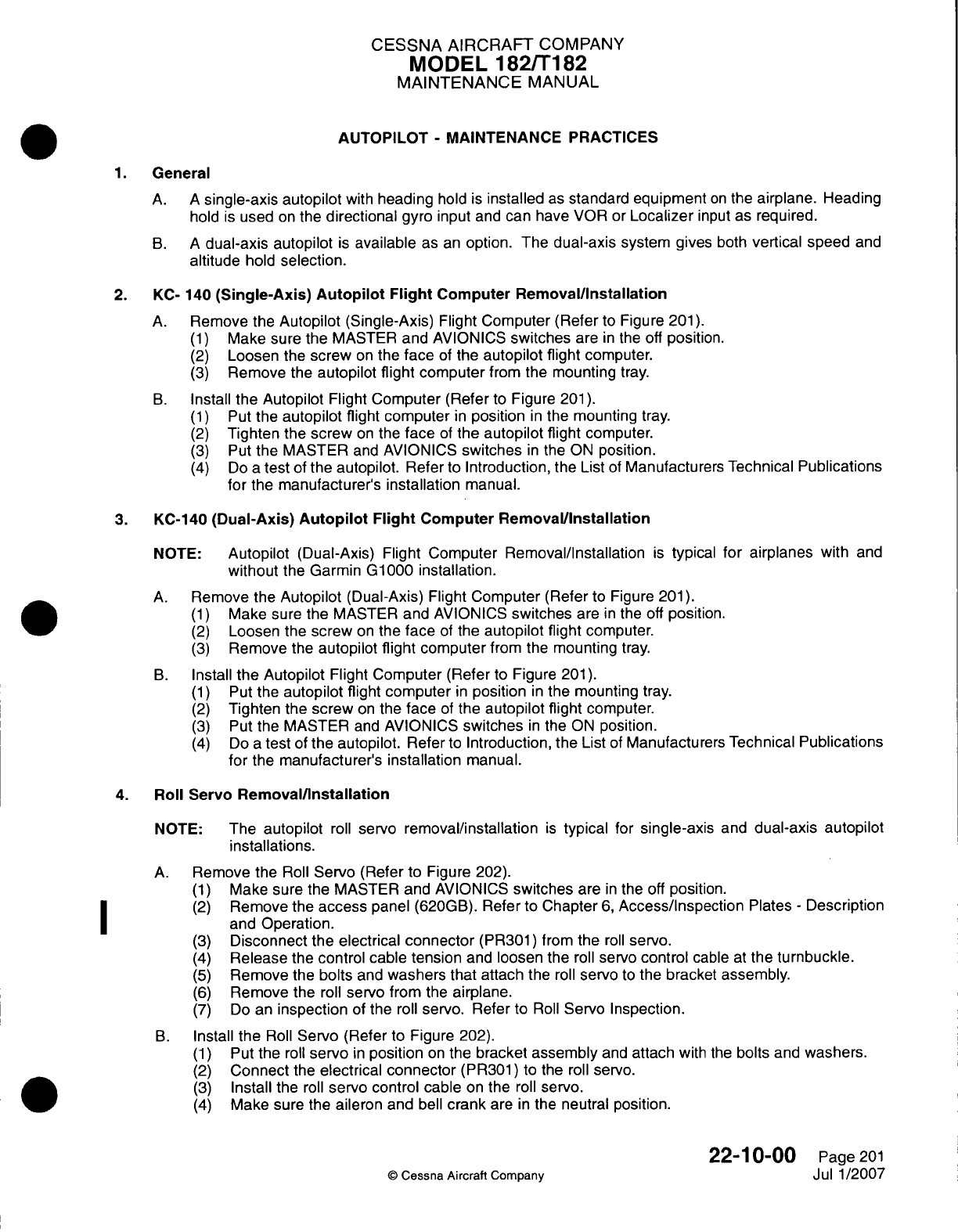
CESSNA AIRCRAFT
COMPANY
MODEL
182/Ti182
MAINTENANCE
MANUAL
AUTOPILOT
-
MAINTENANCE PRACTICES
1.General
A. A
single-axis
autopilot
with
heading
hold
is
installed
as
standard
equipment
on
the
airplane.
Heading
hold
is
used
on
the
directional
gyro
input
and
can
have
VOR
or
Localizer
input
as
required.
B. A
dual-axis
autopilot
is
available
as
an
option. The
dual-axis
system gives
both
vertical
speed
and
altitude
hold
selection.
2.
KC-
140
(Single-Axis)
Autopilot
Flight
Computer
Removal/installation
A.
Remove
the
Autopilot
(Single-Axis)
Flight
Computer (Refer
to
Figure
201).
(1)
Make
sure the
MASTER
and
AVIONICS
switches
are
in
the
off
position.
(2)
Loosen
the
screw
on
the
face
of
the
autopilot
flight
computer.
(3)
Remove
the
autopilot flight
computer
from
the
mounting
tray.
B.
Install
the Autopilot
Flight
Computer
(Refer
to
Figure
201).
(1)
Put the
autopilot
flight computer
in
position
in
the mounting
tray.
(2)
Tighten
the
screw
on
the
face
of
the
autopilot
flight
computer.
(3)
Put
the
MASTER
and
AVIONICS
switches
in
the
ON
position.
(4)
Do
a
test
of
the autopilot.
Refer
to
Introduction,
the
List
of
Manufacturers
Technical
Publications
for
the
manufacturer's
installation
manual.
3.
KC-140
(Dual-Axis)
Autopilot
Flight
Computer Remova~l/nstallation
NOTE:
Autopilot
(Dual-Axis) Flight Computer
Removal/Installation
is
typical
for
airplanes
with
and
without
the
Garmin
G1000 installation.
A.
Remove
the
Autopilot
(Dual-Axis) Flight
Computer
(Refer
to
Figure
201).
(1)
Make sure
the MASTER and
AVIONICS
switches
are
in
the
off
position.
(2)
Loosen
the
screw
on
the
face
of
the
autopilot
flight
computer.
(3)
Remove
the
autopilot
flight
computer
from
the
mounting
tray.
B.
Install
the Autopilot
Flight
Computer
(Refer
to
Figure
201).
(1)
Put
the
autopilot flight
computer
in
position
in
the
mounting
tray.
(2)
Tighten
the
screw
on
the
face
of
the
autopilot flight
computer.
(3)
Put
the MASTER
and
AVIONICS
switches
in
the
ON
position.
(4)
Do
a
test
of
the
autopilot.
Refer
to
Introduction, the
List
of
Manufacturers
Technical
Publications
for
the
manufacturer's installation
manual.
4.
Roll
Servo
Removal/installation
NOTE: The
autopilot
roll
servo
removal/installation
is
typical
for
single-axis
and
dual-axis
autopilot
installations.
A.
Remove the
Roll
Servo
(Refer
to
Figure 202).
(1)
Make sure
the
MASTER and
AVIONICS
switches
are
in
the
off
position.
(2)
Remove
the
access
panel (620GB).
Refer
to
Chapter
6,
Access/inspection
Plates
-
Description
I ~ ~~and
Operation.
(3)
Disconnect
the
electrical
connector
(PR301) from the
roll
servo.
(4)
Release
the
control
cable
tension
and
loosen
the
roll
servo
control
cable
at
the
turnbuckle.
(5)
Remove
the
bolts
and
washers that attach
the
roll
servo
to
the
bracket
assembly.
(6)
Remove
the
roll
servo
from
the
airplane.
(7)
Do
an
inspection
of
the
roll
servo. Refer
to
Roll
Servo Inspection.
B.
Install
the
Roll
Servo
(Refer to Figure 202).
(1)
Put
the
roll
servo
in
position
on
the
bracket assembly
and
attach
with
the
bolts and
washers.
(2)
Connect
the
electrical
connector
(PR301) to
the
roll
servo.
(3)
Install
the
roll
servo
control
cable
on
the
roll
servo.
(4)
Make
sure the
aileron
and
bell
crank
are
in
the
neutral
position.
22-1
0-00
Page
201
©
Cessna Aircraft
Company
Jul 1/2007
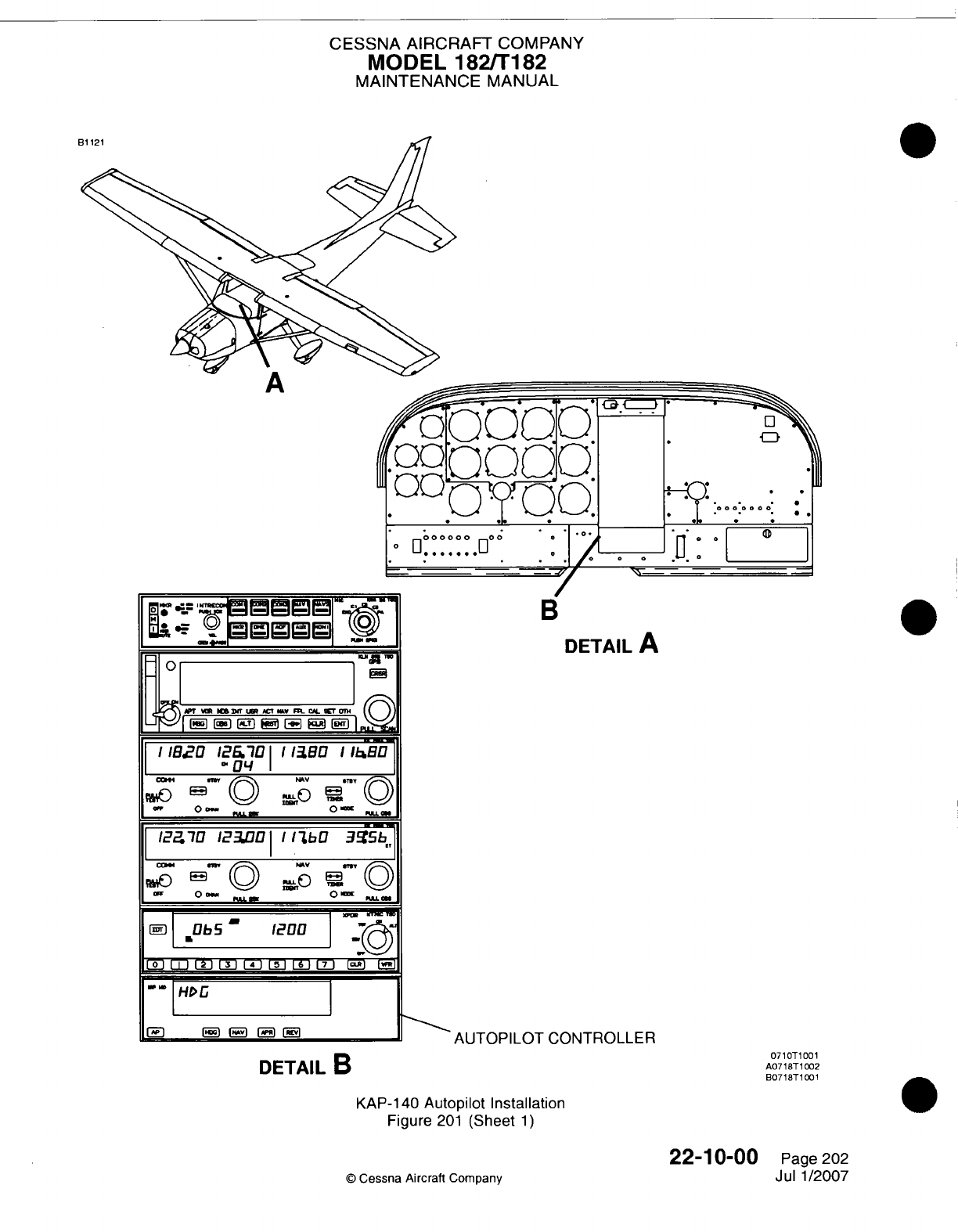
CESSNA AIRCRAFT
COMPANY
MODEL
182/Ti82
MAINTENANCE
MANUAL
DETAIL
A
AUTOPILOT
CONTROLLER
DETAIL
B
KAP-140
Autopilot
Installation
Figure
201
(Sheet
1)
22-10-00
©
Cessna
Aircraft
Company
0710T1001
AO718T1002
B0718T1X01
Page
202
Jul
1/2007
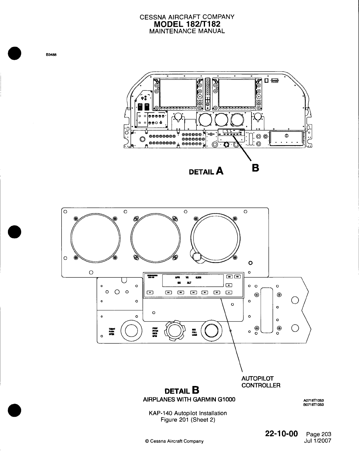
CESSNA
AIRCRAFT
COMPANY
MODEL
182/Ti
82
MAINTENANCE
MANUAL
B3488
DETAIL
A
B
DETAIL
B
AIRPLANES
WITH
GARMIN
G1000
AUTOPILOT
CONTROLLER
ALJ71
9T1
0ss
B071
8T1
063
KAP-140
Autopilot
Installation
Figure
201
(Sheet
2)
©
Cessna
Aircraft
Company
22-1
0-00
Page
203
Jul
1/2007
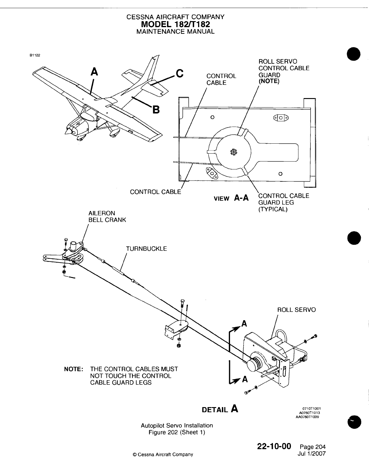
CESSNA
AIRCRAFT
COMPANY
MODEL
1821T182
MAINTENANCE
MANUAL
CONTROL
CABLE
ROLL
SERVO
CONTROL
CABLE
GUARD
(NOTE)
viewv
P%-P%
AILERON
BELL CRANK
GUARD
LEG
(TYPICAL)
TU
RNBUCKLE
ROLL
SERVO
NOTE:
THE
CONTROL
CABLES
MUST
NOT
TOUCH
THE
CONTROL
CABLE GUARD LEGS
DETAIL
A
0710T1001
A076OT
1013
AA076OT10019
Autopilot
Servo
Installation
Figure
202
(Sheet
1)
22-10-00
C
Cessna
Aircraft
Company
Page
204
Jul
1/2007
C
CONTROL
t
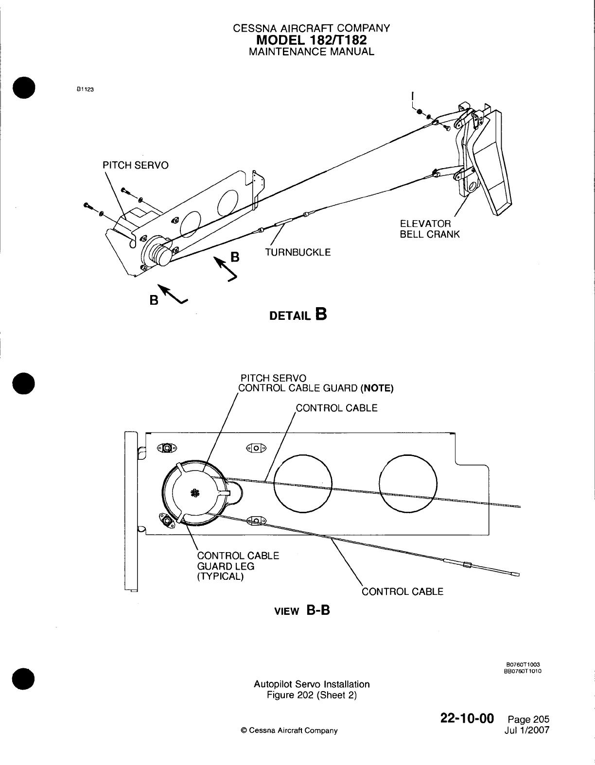
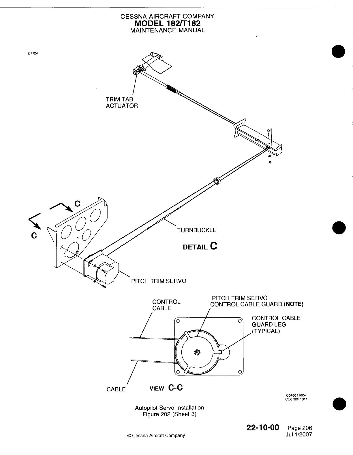
CESSNA AIRCRAFT
COMPANY
MODEL
182/Ti
182
MAINTENANCE
MANUAL
TRIM TAB
ACTUATOR
TU
RN
BUCKLE
DETAIL
C
PITCH
TRIM
SERVO
CON.TROL
PITCH
TRIM
SERVO
CONTROL
CABLE
GUARD
(NOTE)
CONTROL
CABLE
GUARD LEG
.(TYPICAL)
VIEW
G-LU
C076OT
1004
CCO76OT
101
1
Autopilot
Servo
Installation
Figure
202
(Sheet
3)
22-10-00
©
Cessna Aircraft
Company
81 124
C
0
CABLE
Page
206
Jul
1/2007
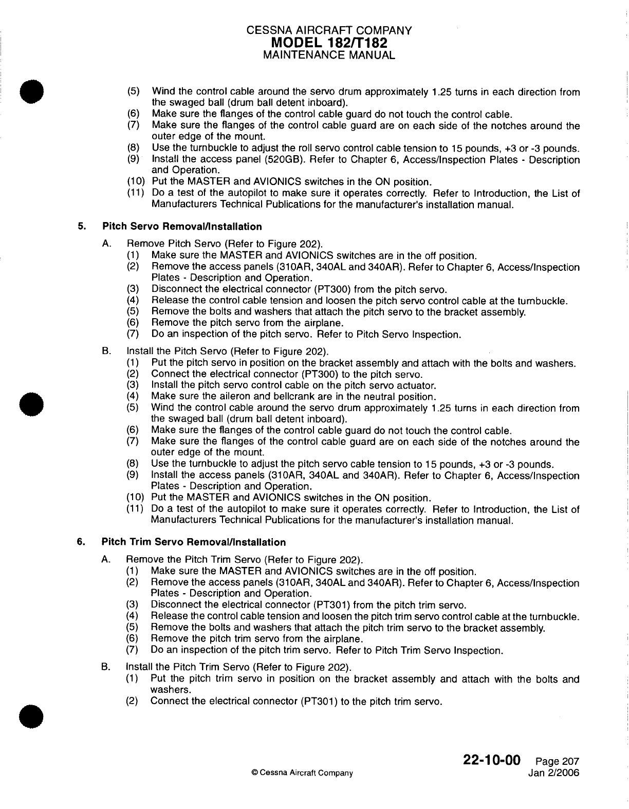
CESSNA
AIRCRAFT
COMPANY
MODEL
182/T182
MAINTENANCE
MANUAL
(5)
Wind the
control
cable
around the
servo
drum
approximately
1.25
turns
in
each
direction
from
the
swaged
ball
(drum
ball
detent
inboard).
(6)
Make sure the
flanges
of
the
control
cable
guard
do
not touch the control
cable.
(7)
Make sure
the
flanges
of
the
control cable
guard
are
on
each
side
of
the
notches
around
the
outer
edge
of
the
mount.
(8)
Use
the
turnbuckle
to
adjust
the
roll
servo
control
cable
tension
to
15
pounds,
+3
or
-3
pounds.
(9)
Install the
access
panel
(520GB).
Refer
to
Chapter
6,
Access/Inspection
Plates
-
Description
and
Operation.
(10) Put
the MASTER and
AVIONICS
switches
in
the
ON
position.
(11)
Do
a
test
of
the
autopilot
to
make sure
it
operates
correctly.
Refer
to
Introduction,
the
List
of
Manufacturers
Technical
Publications for
the manufacturer's
installation
manual.
5.
Pitch Servo
Removal/Installation
A.
Remove
Pitch
Servo (Refer
to
Figure
202).
(1)
Make
sure
the
MASTER
and
AVIONICS
switches
are
in
the
off
position.
(2)
Remove
the
access
panels
(31OAR,
340AL
and 340AR).
Refer
to
Chapter
6,
Access/Inspection
Plates
-
Description
and
Operation.
(3)
Disconnect
the
electrical
connector
(PT300)
from
the
pitch
servo.
(4)
Release
the
control cable tension
and
loosen the
pitch
servo
control
cable
at the
turnbuckle.
(5)
Remove
the
bolts
and
washers
that attach
the
pitch
servo
to the
bracket
assembly.
(6)
Remove
the
pitch
servo
from
the
airplane.
(7)
Do
an
inspection
of
the
pitch
servo.
Refer
to
Pitch
Servo
Inspection.
B.
Install
the
Pitch
Servo
(Refer
to
Figure
202).
(1)
Put
the pitch
servo
in
position
on
the
bracket assembly
and
attach
with
the
bolts
and
washers.
(2)
Connect
the
electrical
connector
(PT300)
to
the
pitch
servo.
(3)
Install the
pitch servo control
cable
on
the
pitch
servo
actuator.
(4)
Make
sure the
aileron
and
bellcrank
are
in
the neutral
position.
(5)
Wind
the
control
cable
around the
servo
drum
approximately
1.25
turns
in
each
direction
from
the
swaged
ball
(drum
ball
detent
inboard).
(6)
Make
sure the
flanges
of
the
control
cable
guard
do
not
touch
the control
cable.
(7)
Make
sure
the
flanges
of
the control
cable
guard
are
on
each
side
of
the
notches
around
the
outer
edge
of
the
mount.
(8)
Use
the
turnbuckle
to
adjust
the
pitch
servo
cable tension
to
15
pounds,
+3
or
-3
pounds.
(9)
Install
the
access
panels
(310AR,
340AL
and
340AR).
Refer
to
Chapter
6,
Access/Inspection
Plates
-
Description
and
Operation.
(10)
Put
the MASTER and AVIONICS
switches
in
the
ON
position.
(11)
Do
a
test
of
the
autopilot
to
make
sure
it
operates correctly.
Refer
to
Introduction,
the
List
of
Manufacturers
Technical
Publications for
the
manufacturer's
installation
manual.
6.
Pitch
Trim
Servo
Removal/Installation
A.
Remove
the Pitch
Trim
Servo (Refer
to Figure 202).
(1)
Make
sure
the
MASTER
and AVIONICS
switches
are
in
the off
position.
(2)
Remove
the
access
panels
(31
OAR,
340AL
and
340AR).
Refer
to Chapter
6,
Access/Inspection
Plates
-
Description
and
Operation.
(3)
Disconnect
the
electrical
connector
(PT301) from
the
pitch
trim
servo.
(4)
Release
the control cable
tension
and
loosen
the
pitch trim
servo
control
cable
at
the
turnbuckle.
(5)
Remove
the
bolts
and
washers
that
attach the
pitch
trim
servo
to
the
bracket
assembly.
(6)
Remove
the
pitch
trim
servo
from
the
airplane.
(7)
Do
an
inspection
of
the pitch
trim
servo.
Refer
to
Pitch
Trim
Servo
Inspection.
B.
Install the
Pitch
Trim
Servo
(Refer
to
Figure
202).
(1)
Put
the pitch
trim
servo
in
position
on
the bracket
assembly
and
attach
with
the
bolts
and
washers.
(2)
Connect
the
electrical
connector
(PT301)
to the
pitch
trim
servo.
22-10-00
Page
207
©
Cessna
Aircraft
Company
Jan
2/2006
CESSNA AIRCRAFT
COMPANY
MODEL
182/Ti
82
MAINTENANCE
MANUAL
(3)
Do
the
pitch
trim
servo
control
cable
rigging.
(a)
The
servo
trim
chain
must
be
on
the
aft
sprocket
of
the
actuator
before
the
manual
trim
system
rigging can
be
done.
(b)
You
must
do
the manual
trim
system
rigging
before
the
servo
trim
system
rigging.
Refer to
Chapter
27,
Elevator
Trim
Control
-
Maintenance
Practices,
Trim
Tab
Control
Adjustment!
Test.
(c)
Put
the
elevator
in
the
neutral
position.
(d)
Use
an
inclinometer
to
put
the
trim
tab to
5
degrees
up
in
relation
to
the
elevator.
NOTE:
The
chain
sprocket
on
the
actuator
will
be
at
approximately
the
halfway
point
in
its
rotation
from
the
mechanical
stops.
(e)
Move
the
servo
trim
chain
on
the
aft
sprocket
of
the
actuator
so
that
equal lengths
of
the
chain
are
on
either
side
of
the
sprocket.
(f)
Wind
the
control
cable
around
the pitch
trim
servo
drum
approximately
1
.25
turns
each
direction
from
the
swaged
ball.
(g)
Make
sure the
flanges
of
the
control
cable guard
do
not
touch
the
control
cable.
(h)
Make
sure
the
flanges
of
the
control cable
guard
are on
either
side
of
the
notches
around
the
outer
edge
of
the mount.
(i)
Use
the
turnbuckle
to
adjust
the
pitch
trim
servo
control cable
tension
to
15
pounds,
+3
or
-3
pounds.
(4)
Install
the
access
panels
(310AR,
340AL
and
340AR). Refer
to
Chapter
6,
Access/inspection
Plates
-
Description
and
Operation.
(5)
Put the
MASTER
and
AVIONICS
switches
in
the ON
position.
(6)
Do
a
test
of
the
autopilot
to
make
sure
it
operates
correctly.
Refer
to
Introduction,
the
List
of
Manufacturers
Technical
Publications,
for
the
manufacturer's
installation
manual.
7.
Roll
Servo
Inspection
A.
Do
Inspection the
Roll
Servo (Refer
to
Figure 202).
(1)
Remove
the
servo cover.
CAUTION: Make
sure
the
maintenance
personnel
and the
table
are
electrically
grounded.
Do
disassembly
or
assembly
of
the servo
at
an
electrostatic-safe
area.
(a)
Put
an
electrical
ground
on the
maintenance
personnel
and
table.
(b)
Remove
the
two
screws
that
attach
the
cover
to
the
unit.
(c)
Carefully
remove
the
cover
over
the
wiring
harness.
(d)
Put
the
servo
on
the table
so
the
inner
parts
of
the
unit
will
not
be
damaged.
(2)
Do
inspection
of
the
solenoid
and
clutch.
(a)
Make
sure
the
solenoid
shaft
moves
freely
in
and
out of
the
solenoid
body.
(b)
Make
sure
there
is
no
dirt,
contamination
or
corrosion
around
the
solenoid
shaft.
(c)
Make sure
the
release
spring
freely
pulls
the
shaft
out
of
the
solenoid
and
against
the
stop
fitting.
(d)
Make
sure
the
pinion
gear
turns
and
does
not
touch
the
clutch gears.
(3)
Do
a
general
inspection
of
the
roll
servo.
(a)
Examine
the
electrical
wiring
for
indication
of
wear
or
damage
of
the
insulation.
(b)
Examine
the
servo
for any loose hardware
or
other
defects.
(4)
Install the
cover.
(a)
Carefully
put the
cover
in
position.
(b)
Install
the screws
with
Loctite 222
or
Loctite
242.
(5)
Remove
the
servo
capstan
assembly
and
do
a
check
of
the
slip-clutch
torque setting
(Refer
to
Servo
Capstan
Clutch
Adjustment).
22-1
0-00
Page
208
0
Cessna
Aircraft Company
Jul
1
/2007
CESSNA
AIRCRAFT
COMPANY
MODEL
182/Ti
82
MAINTENANCE
MANUAL
8.
Pitch Servo
Inspection
A.
Do
Inspection
of
the
Pitch
Servo
(Refer
to
Figure
202).
(1)
Remove
the
servo
cover.
CAUTION:
Make
sure
the
maintenance
personnel
and
the
table
are
electrically
grounded.
Do
disassembly
or
assembly
of
the
servo
at
an
electrostatic-safe
area.
(a)
Put
an
electrical
ground
on
the maintenance personnel
and
table.
(b)
Remove
the
two
screws
that
attach
the
cover
to
the
unit.
(c)
Carefully
remove the
cover
from the
wiring
harness.
CAUTION:
Do
not
move any
wires,
tie
wraps or
the
spring
clamp.
The
position
of
each
is
set
by
the
manufacturer
and
is
necessary
for correct
operation.
(d)
Put the
servo
on
the
table
so
the inner
parts
of
the unit
will
not
be
damaged.
(2)
Do
inspection
of
the
solenoid
and
clutch.
(a)
Make
sure the
solenoid
shaft
moves
freely
in
and
out
of
the
solenoid
body.
(b)
Make sure
there
is no
dirt,
contamination
or
corrosion
around
the
solenoid
shaft.
(c)
Make
sure
the
release
spring
freely
pulls
the
shaft
out
of
the
solenoid
and
against
the
stop
fitting.
(d)
Make
sure
the
pinion
gear turns
and
does
not
touch
the
clutch
gears.
(3)
Do
a
general
inspection.
(a)
Examine
the
electrical
wiring
for
indication
of
wear
or
damage
of
the
insulation.
(b)
Examine
the
servo for any
loose
hardware
or
other
defects.
(4)
Do
an
inspection
of
the
pitch
servo
motor.
(a)
Put
the
servo
in
position
so
the
baseplate
is
on
the bottom
side
of
the
unit.
(b)
Hold
the
top
section
of
the
motor
and
carefully
turn
the
motor
shaft.
(c)
The
motor
shaft
must
turn
freely
from
side
to
side
a
small
quantity.
(5)
Install
the
cover.
(a)
Carefully
put
the
cover
in
position.
(b)
Install
the
screws with Loctite
222
or
Loctite
242.
(6)
Remove
the
servo
capstan
assembly
and
do
a
check
of
the
slip-clutch
torque
setting
(Refer
to
Servo Capstan Clutch
Adjustment).
9.
Pitch
Trim
Servo
Inspection
A.
Do
Inspection
of
the
Pitch
Trim
Servo
(Refer
to
Figure 202).
(1)
Remove
the
servo cover.
CAUTION:
Make
sure
the
maintenance
personnel
and
the
table
are
electrically
grounded.
Do
disassembly
or
assembly
of
the
servo
at
an
electrostatic-safe
area.
(a)
Put
an
electrical
ground
on
the
maintenance
personnel
and
table.
(b)
Remove
the
two
screws
that
attach
the
cover
to
the unit.
(c)
Carefully
remove
the
cover
over
the
wiring
harness.
(d)
Put
the
servo
on
the
table
so
the inner
parts
of
the unit will
not
be
damaged.
(2)
Do
inspection
of
the
solenoid
and
clutch.
(a)
Make sure
the
solenoid
shaft
moves
freely
in
and
out
of
the
solenoid
body.
(b)
Make
sure
there
is no
dirt,
contamination
or
corrosion
around
the
solenoid
shaft.
(c)
Make
sure
the
release
spring
freely
pulls
the
shaft
out
of
the solenoid
and
against
the
stop
fitting.
(d)
Make sure the
pinion
gear
turns
and
does
not
touch
the
clutch
gears.
22-1
0-00
Page
209
©
Cessna Aircraft
Company
Jul
1/2007
CESSNA AIRCRAFT
COMPANY
MODEL
182/Ti
182
MAINTENANCE
MANUAL
(3)
Do
a
general
inspection.
(a)
Examine
the
electrical
wiring
for
indication
of
wear
or
damage
of
the
insulation.
(b)
Examine
the
servo
for any
loose
hardware
or
other
defects.
(4)
Install
the
cover.
(a)
Carefully
put the
cover
in
position.
(b)
Install
the
screws
with
Loctite
222
or
Loctite
242.
(5)
Remove
the
servo
capstan assembly
and
check
the
slip-clutch
torque setting
(Refer
to
Servo
Capstan
Clutch
Adjustment).
10.
Pitch
Trim
Rigging Inspection
A.
Do
a
check
of
the
pitch
trim
rigging.
(1)
Attach
an
inclinometer
to
the trim
tab.
(2)
Put
the
trim
tab
in
the
0
degree
position.
(3)
Manually operate
the
trim
tab
to the
up
and
down
limits.
(4)
Record the
limits
of
travel.
(5)
Put
an
observer
at
the
right-hand
access
opening
of
the
tailcone.
(6)
Put
the
electrical
trim
to
the
full
nose-up
position
until the
observer
sees
the
clutch slip.
(7)
Turn
the
manual
trim
wheel
nose-up
(test
load
condition)
1/4
turn
more
while
the
clutch
slips.
(8)
Make
sure
the
swaged
ball
on
the
control
cable
assembly does
not
turn aft
of
the
tangent
point.
(9)
Release
the
trim
wheel
and
disengage
the
autopilot.
(1 0)
Manually
operate the
trim
to
the
full
nose-up position.
(1 1)
Do
a
check
of
the
trim
tab
position
with
an
inclinometer.
(12)
Trim
tab
position that
is
greater
than
the limits
of
travel
values
recorded
is
an
indication
that
the
stop blocks slipped.
(a)
Do
the
trim
system
rigging again.
(b)
Make sure the
stop
block
bolts
torque
is
correct.
(c)
Repeat
the
check
of
the pitch
trim
rigging.
(13)
If
necessary,
make
adjustments
to
the
swaged
ball
position.
(a)
Put
the
control cable
assembly
chain
in
the
applicable
position
on
the
gear
teeth
of
the
actuator
sprocket.
NOTE: One
chain
link
adjustment
is
related
to
approximately
17
degrees
of
travel
on
the
capstan.
(b)
Apply
the
applicable
tension
to
the
control
cable
and
repeat the
check
of
the
pitch
trim
rigging.
(14)
Do
the
procedure again
for
the
full
nose-down
trim
condition.
11.
Servo
Capstan
Clutch Adjustment
A.
Do
a
check
of
the
clutch torque
setting.
(1)
Remove the
servo capstan.
(2)
Remove
the
control
cable
guard
from
the
servo
capstan.
(3)
Attach
the
servo capstan
on
the
capstan
test
stand. Refer to
Autopilot
-
General
for
a
list
of
tools
and
equipment.
(4)
Place
the
adapter
tool
over
the
servo
capstan.
(5)
Insert
the
adapter
pin from
the
straight
up
position
to
attach
the
adapter
tool.
(6)
Insert
the
torque
wrench.
(7)
Apply
28
VDC
(1
amp
maximum)
electrical power
to
the
test
stand.
(8)
Do
a
check
of
the
torque
reading
with
the
test
stand
motor
in
the
clockwise
operation.
NOTE:
The
check
of
the
torque
reading will
be
done
three
times.
(a)
Put
the
capstan
switch
in
the
clockwise
position.
(b)
Record the
torque
reading
of
the
torque
wrench.
(c)
Put
the
switch
in
the
off
position.
22-1
0-00
Page
21
0
©
Cessna
Aircraft
Company
Jul
1/2007
CESSNA
AIRCRAFT
COMPANY
MODEL
182/Ti
82
MAINTENANCE
MANUAL
(9)
Do
a
check
of the
torque
reading
with
the
test
stand
motor
in
the
counterclockwise
operation.
NOTE: The
check
of
the
torque
reading will
be
done
three
times.
(a)
Put
the
capstan
switch
in
the
counterclockwise
position.
(b)
Record
the
torque reading
of
the
torque
wrench.
(c)
Put
the
switch
in
the
off
position.
(10)
Average
the
six
torque readings.
NOTE:
The torque
reading
to
be used
is
the
average
of
the
six
torque
readings.
(11)
Refer
to
Table
201
for
the
correct torque
reading
of
the
servo
capstan.
Table
201.
KAP-140
Autopilot
Servo
Clutch
Torque
Setting
182S
182T/T182T
Roll
Servo Capstan
55,
+5
or
-5
inch-pounds
(6.2,
35,
+3
or
-3
inch-pounds
(3.95,
+0.56
or
-0.56
N-in)
+0.34
or -0.34
N-in)
Pitch
Servo Capstan
26,
+2
or
-2
inch-pounds
(2.9,
38,
+3
or
-3
inch-pounds
(4.3,
+0.23
or
-0.23
N-in)
+0.34
or -0.34
N-i)
Pitch
Trim
Servo
Capstan
45,
+5
or
-5
inch-pounds
(5.1,
45,
+5
or
-5
inch-pounds
(5.1,
+0.56
or
-0.56
N-in)
+0.56
or
-0.56
N-in)
(a) If
the torque
indication
is
below
the
value
given
in
Table 201, rotate
the
clutch adjust
nut
clockwise
and
do
the
check
of the
torque
readings
again.
(b) If
the
torque
indication
is
above
the
value
given
in
Table
201,
rotate
the
clutch adjust
nut
counterclockwise
and
do
the
check
of
the
torque readings
again.
(12)
Record the
slip clutch
torque
indication,
airplane
type,
axis,
and
date
on
the decal
attached
to
the
servo
mount
body.
(13)
Install the
control
cable
guard
on
the
servo capstan.
(14)
Install the
servo
capstan.
12.
Set
the
Autopilot
Roll
Null
A.
Set
the
Autopilot
Roll
Null
(If
the
Autopilot
is
Installed).
(1)
Make
sure
the
autopilot flight computer
completes
the
pre-flight
test.
(2)
Disconnect
the
roll
servo
connector
from
the
airplane
harness.
(3)
Apply
a
ground
to
pin
K
of
the
harness connector.
(4)
Connect
a
digital
multimeter across
the
harness
connector
at
pins
D
and
L
to
monitor the
servo
drive
voltage.
(5)
Push the
autopilot
AP
button
on
the
autopilot flight
computer
to
engage
it.
(a)
Make
sure
the
default
ROL
mode
is
set.
NOTE:
For
example,
the
HDG,
NAV
or
APR
modes
are
not
engaged.
(b)
Use
a
DMVM
to
measure
the
DC
voltage
across
pins
D
and
L
of
the
roll
servo
harness
connector.
(c)
Adjust
the
pot until
a
value
of
0
volts,
+0.020
or
-0.020
volts
are
measured.
1 If
the
end of
the
pot
movement
is
reached
before
the
servo
drive
is
nulled,
disengage
the autopilot,
turn
the pot
fully
to
the
opposite
stop
and then
engage
the
autopilot.
(d)
The
roll
null
adjustment
range
emulates
a
four
turn
pot
that
lets
the
method
of
the
pot
adjustment
range
to
be
set.
NOTE:
This
adjustment
lets
offsets
be
in
the
roll
axes.
This includes
the
turn
coordinator.
(e)
Continue
to
turn
the
pot
to
null
the
voltage.
22-1
0-00
Page
211
©
Cessna
Aircraft
Company
Jul
1/2007
CESSNA
AIRCRAFT
COMPANY
MODEL
1821T182
MAINTENANCE
MANUAL
(6)
Connect
the
airplane
roll
servo harness
connector
to
the
servo
connector.
22-1
000
Page
212
Q
Cessna Aircraft Company
Jul
1
/2007
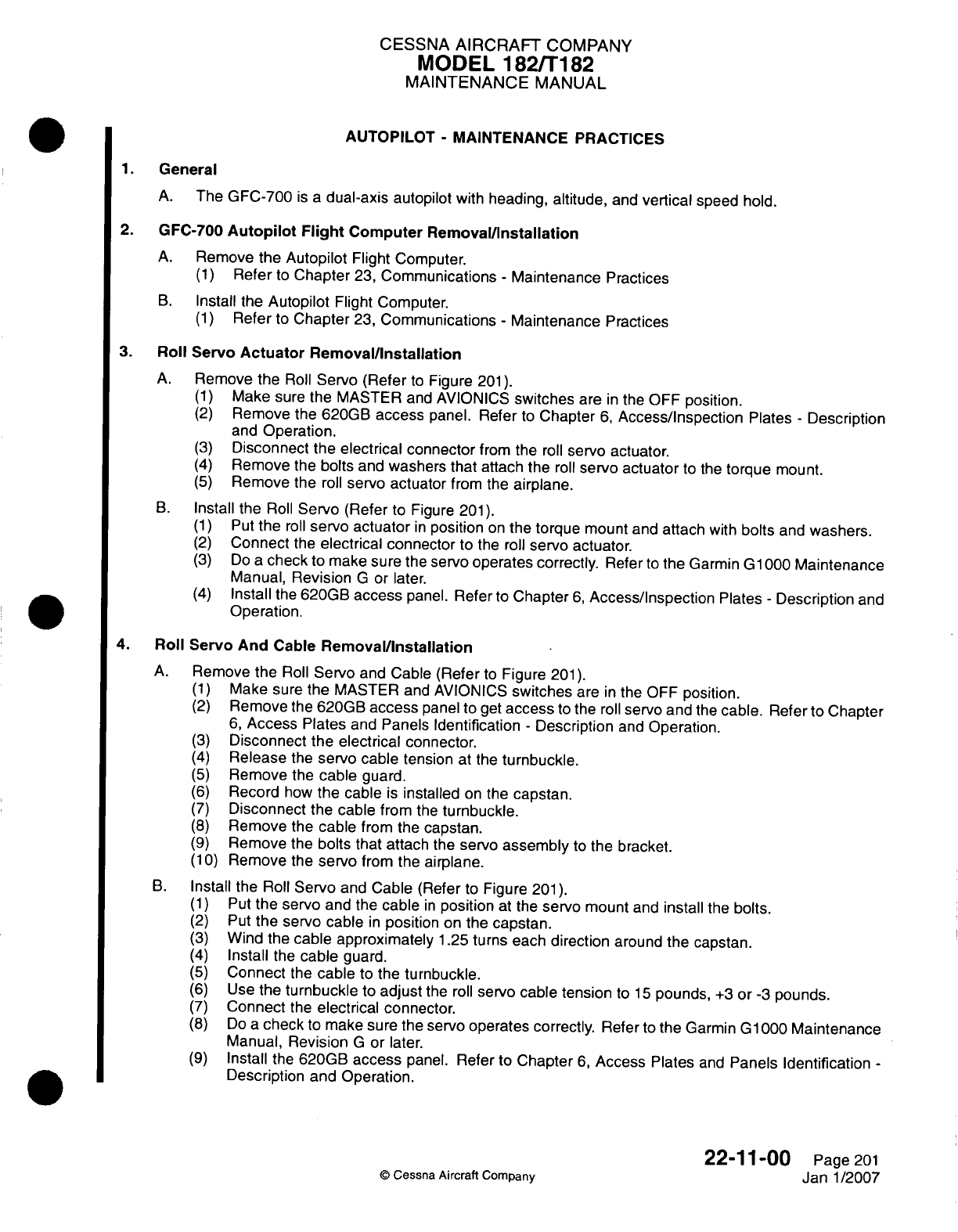
CESSNA AIRCRAFT
COMPANY
MODEL
1821T182
MAINTENANCE
MANUAL
AUTOPILOT
-
MAINTENANCE PRACTICES
1.General
A.
The
GFC-700
is a
dual-axis
autopilot
with heading,
altitude,
and
vertical
speed
hold.
2.
GFC-700
Autopilot
Flight
Computer Remova~l/nstallation
A.
Remove
the Autopilot
Flight Computer.
(1)
Refer
to
Chapter
23,
Communications
-
Maintenance
Practices
B.
Install
the
Autopilot
Flight
Computer.
(1)
Refer
to
Chapter
23,
Communications
-
Maintenance Practices
3.
Roll
Servo
Actuator
Removal/installation
A.
Remove
the
Roll
Servo
(Refer
to
Figure
201).
(1)
Make
sure the
MASTER
and
AVIONICS
switches
are
in
the
OFF
position.
(2)
Remove
the
620GB
access
panel.
Refer
to
Chapter
6,
Access/inspection
Plates
-
Description
and
Operation.
(3)
Disconnect
the
electrical connector
from the
roll
servo
actuator.
(4)
Remove
the
bolts
and
washers
that
attach
the
roll
servo actuator
to
the
torque
mount.
(5)
Remove
the
roll
servo
actuator
from the
airplane.
B.
Install the
Roll
Servo
(Refer
to Figure
201).
(1)
Put
the
roll
servo
actuator
in
position
on
the
torque
mount
and
attach
with
bolts
and
washers.
(2)
Connect
the
electrical connector
to
the
roll
servo
actuator.
(3)
Do
a
check
to
make
sure
the
servo
operates correctly.
Refer
to
the
Garmin
G1
000
Maintenance
Manual,
Revision
G
or
later.
(4)
Install
the
620GB
access
panel.
Refer to
Chapter
6,
Access/Inspection
Plates
-
Description
and
Operation.
4.
Roll
Servo
And
Cable
Removal/installation
A.
Remove
the Roll
Servo
and
Cable
(Refer
to
Figure
201).
(1)
Make sure
the
MASTER
and
AVIONICS
switches
are
in
the
OFF
position.
(2)
Remove
the
620GB
access
panel
to
get
access
to
the
roll
servo
and
the
cable.
Refer
to Chapter
6,
Access
Plates
and
Panels
Identification
-
Description
and
Operation.
(3)
Disconnect
the
electrical
connector.
(4)
Release
the
servo
cable tension
at
the
turnbuckle.
(5)
Remove
the
cable
guard.
(6)
Record
how
the
cable
is
installed
on
the
capstan.
(7)
Disconnect
the
cable
from
the
turnbuckle.
(8)
Remove
the
cable
from
the
capstan.
(9)
Remove
the
bolts that
attach
the
servo
assembly
to
the
bracket.
(1
0)
Remove
the
servo
from
the
airplane.
B.
Install
the
Roll
Servo
and
Cable
(Refer
to
Figure
201).
(1)
Put
the
servo
and
the
cable
in
position
at
the
servo
mount
and
install
the
bolts.
(2)
Put
the
servo
cable
in
position
on the
capstan.
(3)
Wind
the
cable
approximately
1.25
turns each
direction
around
the
capstan.
(4)
Install
the
cable
guard.
(5)
Connect
the
cable
to
the
turnbuckle.
(6)
Use
the
turnbuckle
to
adjust
the
roll
servo
cable
tension
to 15
pounds,
+3
or
-3
pounds.
(7)
Connect
the
electrical connector.
(8)
Do
acheck
to
make
sure the
servo
operates correctly.
Refer
to
the
Garmin
G1000Maintenance
Manual,
Revision
G
or
later.
(9)
Install
the
620GB
access
panel.
Refer
to
Chapter
6,
Access Plates
and
Panels
Identification
-
Description and Operation.
22-1
1-00
Page
201
©Cessna
Aircraft
Company
Janl1/2007
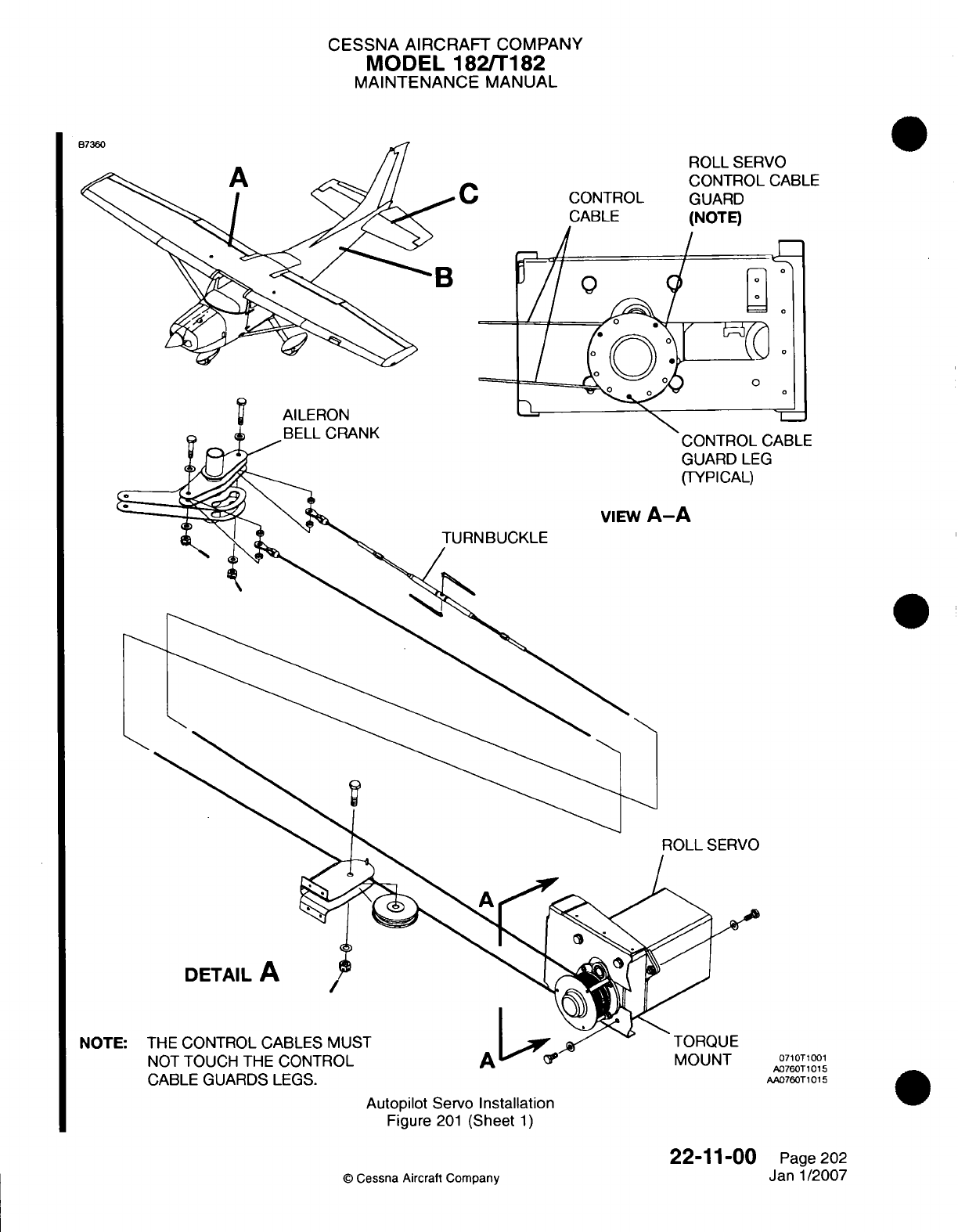
CESSNA AIRCRAFT
COMPANY
MODEL
182/T
182
MAINTENANCE
MANUAL
C
AILERON
*BELL
CRANK
CONTROL
CABLE
ROLL
SERVO
CONTROL
CABLE
GUARD
(NOTE)
CABLE
G
viEw
A-A
TURN
BUCKLE
CABLE
GUARDS
LEGS.
Autopilot
Servo
Installation
Figure
201
(Sheet
1)
22-11-00
©
Cessna Aircraft Company
NOTI
0710T1001
A076OT
10 15
AA076OT101
5
Page
202
Janl1/2007
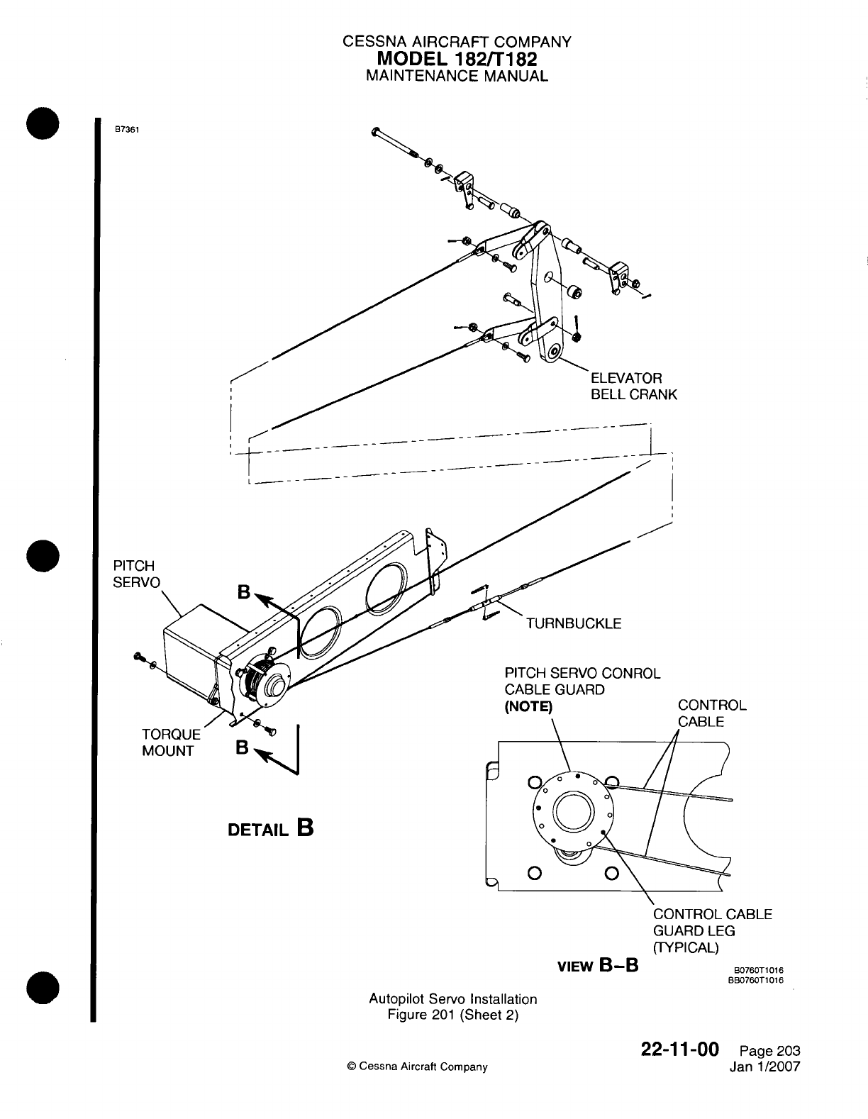
CESSNA AIRCRAFT
COMPANY
MODEL
182/Ti
82
MAINTENANCE
MANUAL
B7361
NJK
;~~~~~~~~~~~~~~~~~~ -A--
-
PIT
SEF
I
ROL
CONTROL
MOUNT
B4~
DETAIL
B
VIEW
B-B
GUARD
LEG
(TYPICAL)
B076OT1016
BB076OT1016
Autopilot
Servo
Installation
Figure
201
(Sheet
2)
©
Cessna
Aircraft
Company
22-1
1-00
Page
203
Janl1/2007
i
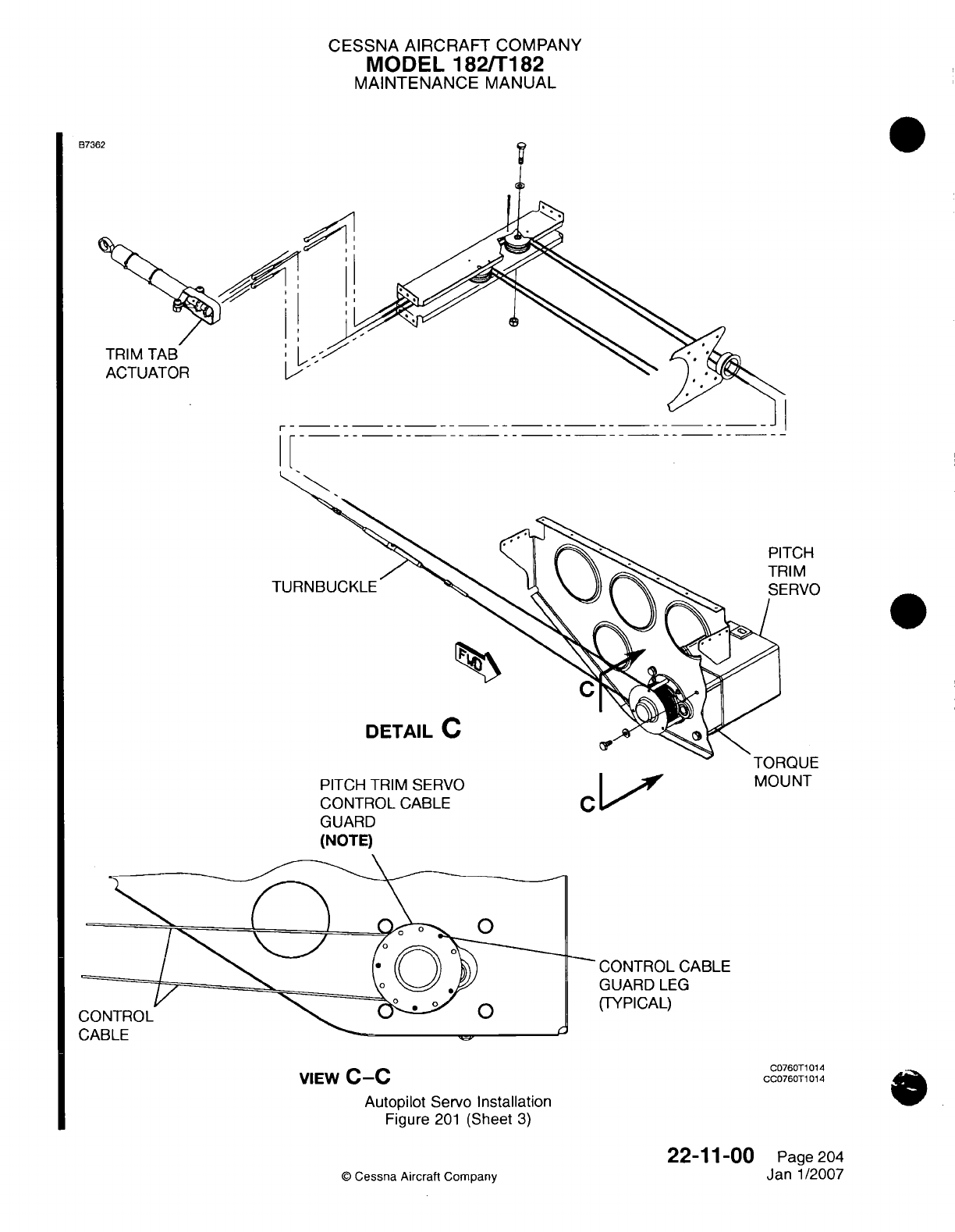
CESSNA
AIRCRAFT
COMPANY
MODEL
1821T182
MAINTENANCE
MANUAL
873'
TRIM
TAB
ACTUATOR
I
PITCH
TRIM SERVO
CONTROL
CABLE
GUARD
(NOTE)
C
-
t
MOUNT
CONTROL CABLE
GUARD
LEG
(TYPICAL)
VIEW
C-C
Autopilot
Servo
Installation
Figure
201
(Sheet
3)
22-11-00
©
Cessna Aircraft Company
PITCH
TRIM
C076OT1
014
0CC76OT1
014
0
Page 204
Janl1/2007
h
CESSNA AIRCRAFT
COMPANY
MODEL
182/Ti
182
MAINTENANCE
MANUAL
5.
Pitch Servo
Motor
Removalllnstallation
A.
Remove
Pitch
Servo
(Refer
to
Figure
201).
(1)
Make sure
the
MASTER
and
AVIONICS
switches
are
in
the OFF
position.
(2)
Remove
the
31
OAR,
340AL
and
340AR
access
panels.
Refer
to
Chapter
6,
Access/Inspection
Plates
-
Description
and
Operation.
(3)
Disconnect
the
electrical
connector
from
the pitch
servo.
(4)
Remove
the bolts
and
washers
that
attach
the
pitch
servo
to
the
torque
mount.
(5)
Remove
the
pitch
servo actuator
from
the
airplane.
B.
Install the
Pitch
Servo
(Refer
to
Figure
201).
(1)
Put
the
pitch
servo
in
position
on
the
torque mount
and
attach
with
the
bolts.
(2)
Connect
the
electrical
connector
to
the
pitch
servo.
(3)
Do
a
check
to
make
sure
the
servo
operates correctly.
Refer
to
the
Garmin
G1
000
Maintenance
Manual, Revision
G
or
later.
(4)
Install
the
31
OAR,
340AL
and
340AR
access
panels.
Refer
to
Chapter
6,
Access/Inspection
Plates
-
Description
and
Operation.
6.
Pitch Servo
And
Cable
Remova~installation
A.
Remove
the
Pitch
Servo
and
Cable
(Refer
to
Figure
201).
(1)
Make
sure
the
MASTER
and
AVIONICS
switches
are
in
the
OFF
position.
(2)
Remove
the
31
OAR,
340AL
and
340AR
access
panels
to
get
access
to
the pitch
servo
and
the
cable.
Refer
to
Chapter
6,
Access
Plates
and
Panels Identification
-
Description
and
Operation.
(3)
Disconnect
the
electrical
connector .
(4)
Release
the
servo
cable tension
at
the
turnbuckle.
(5)
Remove
the
cable
guard.
(6)
Record
how
the
cable
is
installed
on
the
capstan.
(7)
Disconnect
the
cable
from the
turnbuckle.
(8)
Remove
the
cable
from
the capstan.
(9)
Remove
the
bolts that
attach
the
servo
assembly
to
the
bracket.
(1
0)
Remove
the
servo
from
the
airpiane.
B.
Install
the
Pitch
Servo
and
Cable
(Refer
to
Figure
201).
(1)
Put
the
servo
and
the
cable
in
position
at
the
servo
mount
and
install
the
bolts.
(2)
Put
the servo
cable
in
position
on
the
capstan.
(3)
Wind
the
cable
approximately
1.25
turns
each
direction
around
the
capstan.
(4)
Install
the
cable
guard.
(5)
Connect
the
cable
to
the
turnbuckle.
(6)
Use
the
turnbuckle
to
adjust
the
roll
servo
cable
tension
to
15
pounds,
+3
or
-3
pounds.
(7)
Connect
the
electrical
connector.
(8)
Do
a
check
to
make
sure
the
servo
operates
correctly.
Refer
to
the
Garmin
G1
000
Maintenance
Manual, Revision
G
or
later.
(9)
Install
the
31
OAR,
340AL
and
340AR
access
panel.
Refer
to
Chapter
6,
Access
Plates
and
Panels Identification
-
Description
and
Operation.
7.
Pitch
Trim
Servo
Actuator
RemovaVlnstallation
A.
Remove the
Pitch
Trim
Servo
(Refer
to
Figure
201).
(1)
Make sure the
MASTER
and
AVIONICS
switches
are
in
the
OFF
position.
(2)
Remove
the
31
OAR,
340AL
and
340AR
access
panels.
Refer
to
Chapter
6,
Access/Inspection
Plates
-
Description
and
Operation.
(3)
Disconnect
the
electrical connector
from the
pitch
trim
servo.
(4)
Remove
the
bolts
and
washers
that attach
the
pitch trim
servo
to
the
torque
mount.
(5)
Remove
the
pitch trim
servo
from
the
airplane.
B.
Install
the Pitch
Trim
Servo
(Refer
to
Figure
201).
(1)
Put
the
pitch
trim
servo
in
position
on
the
torque
mount
and
attach
with
the
bolts
and
washers.
(2)
Connect
the
electrical
connector
to
the
pitch
trim
servo.
22-1
1-00
Page
205
Janl/2007
0
Cessna
Aircraft
Company
CESSNA
AIRCRAFT
COMPANY
MODEL
182fT182
MAINTENANCE
MANUAL
(3)
Do
a
check
to
make sure
the
servo
operates correctly.
Refer
to
the
Garmin
G1
000
Maintenance
Manual,
Revision
G
or
later.
(4)
Install
the
31
OAR,
340AL
and
340AR
access
panels.
Refer
to
Chapter
6,
Access/inspection
Plates
-
Description
and
Operation.
8.
Pitch
Trim
Servo
and
Cable
Removallinstallation
A.
Remove
the
Pitch
Trim
Servo (Refer
to
Figure
201).
(1)
Make
sure
the
MASTER
and
AVIONICS
switches
are
in
the
OFF
position.
(2)
Remove
the
31
OAR,
340AL
and 340AR
access
panels.
Refer
to
Chapter
6,
Access/inspection
Plates
-
Description
and
Operation.
(3)
Disconnect the
electrical
connector
from
the
pitch
trim
servo.
(4)
Release
the
control
cable
tension
and
loosen
the
pitch
trim
servo
control
cable
at
the
turnbuckle.
(5)
Remove
the
bolts
and
washers
that
attach
the
pitch
trim
servo
to
the
bracket.
(6)
Remove
the
pitch trim
servo
from
the
airplane.
B.
Install
the
Pitch
Trim
Servo
(Refer
to
Figure
201).
(1)
Put
the pitch
trim
servo
in
position
on
the
bracket
and
attach
with
the
bolts
and
washers.
(2)
Connect
the
electrical
connector
to
the
pitch trim
servo.
(3)
Do
the
pitch
trim
servo
control
cable rigging.
(a)
The
servo
trim
chain
must
be
on
the aft
sprocket
of
the
actuator
before
the
manual
trim
system
rigging can
be
done.
(b)
You
must
do the
manual
trim
system rigging
before
the
servo
trim
system rigging. Refer
to
Chapter
27,
Elevator
Trim Control
-
Maintenance
Practices,
Trim
Tab
Control
Adjustment]
Test.
(c)
Put
the
elevator
in
the
neutral
position.
(d)
Use
an
inclinometer
to
put
the
trim
tab
to
5
degrees
up
in
relation
to
the
elevator.
NOTE:
The
chain
sprocket
on
the
actuator
will
be at
approximately
the
halfway
point
in
its
rotation
from
the
mechanical
stops.
(e)
Move
the servo
trim
chain
on
the aft
sprocket
of
the
actuator
so
that
equal
lengths
of
the
chain
are
on
either
side
of
the
sprocket.
(f) Wind the
control
cable
around the
pitch trim
servo
drum
approximately
1
.25
turns
each
direction
from
the
swaged
ball.
(g)
Make
sure
the
flanges
of
the
control cable
guard
do
not
touch
the
control
cable.
(h)
Make sure
the
flanges
of
the
control
cable
guard
are on
either
side
of
the
notches
around
the
outer
edge
of
the
mount.
(i)
Use
the
turnbuckle
to
adjust
the
pitch
trim
servo
control
cable
tension
to
15
pounds,
+3
or
-3
pounds.
(4)
Do
a
check
to
make
sure the servo
operates correctly.
Refer
to
the Garmin
G1
000
Maintenance
Manual,
Revision
G
or later.
(5)
Install
the
31
OAR,
340AL
and 340AR
access
panels.
Refer
to
Chapter
6,
Access/Inspection
Plates
-
Description
and
Operation.
9.
Pitch
Trim
Rigging
Inspection
A.
Do
a
check
of
the pitch
trim
rigging.
(1)
Attach
an
inclinometer
to
the
trim
tab.
(2)
Put
the
trim
tab
in
the
0
degree position.
(3)
Manually operate
the
trim
tab
to
the
up
and
down
limits.
(4)
Record
the
limits
of
travel.
(5)
Put
an
observer
at
the
right-hand
access opening
of
the
tailcone.
(6)
Put
the
electrical
trim
to
the
full nose-up
position
until
the
observer
sees
the
clutch
slip.
(7)
Turn
the
manual
trim
wheel nose-up
(test
load
condition)
1/4
turn more
while
the
clutch
slips.
(8)
Make
sure
the
swaged
ball
on
the
control
cable
assembly
does
not turn aft
of
the
tangent
point.
(9)
Release
the
trim
wheel
and
disengage
the
autopilot.
(1
0)
Manually operate
the
trim
to
the
full
nose-up
position.
(1 1)
Do
a
check
of
the
trim
tab
position
with
an
inclinometer.
22-1
100
Page
206
©
Cessna
Aircraft
Company
Janl1/2007
CESSNA AIRCRAFT
COMPANY
MODEL
182/T182
MAINTENANCE
MANUAL
(12)
Trim
tab
position
that
is
greater
than the
limits
of
travel values
recorded
is
an
indication
that the
stop
blocks
slipped.
(a)
Do
the
trim
system
rigging again.
(b)
Make
sure
the
stop block
bolts
torque
is
correct.
(c)
Do
the
check
of
the
pitch
trim
rigging again.
(13)
If
necessary,
make
adjustments
to
the
swaged
ball
position.
(a)
Put
the
control
cable assembly
chain
in
the
applicable
position
on the
gear teeth
of the
actuator sprocket.
NOTE: One
chain
link
adjustment
is
related
to
approximately
17
degrees
of
travel
on
the
capstan.
(b)
Apply
the
applicable
tension
to
the
control
cable
and
do
the check
of
the
pitch
trim
rigging
again.
(14) Do
the procedure
again
for
the
full
nose-down
trim
condition.
10.
Servo
Capstan
Clutch
Adjustment
A.
Adjust
the
servo
capstan
clutch
in
accordance
with
the
manufactures installation
manual.
Refer
to
Introduction,
the
List
of
Manufacturers
Technical
Publications
for
the manufacturer's
installation
manual.
IRoll
Servo Clutch
Plate
IPitch
Servo
Clutch
Plate
IPitch
Trim
Servo Clutch
Plate
55,
+7
or
-7
inch-pounds
(6.2,
+0.79
or -0.79
N-in)
35,
+5
or
-5
inch-pounds
(3.95,
+0.56
or
-0.56
N-in)
45,
+6
or
-6
inch-pounds
(5.1,
+0.68
or
-0.68 N-in)
©
Cessna Aircraft
Company
22-1100
Page
207
Janl1/2007

CHAPTER
COMMUNICATIONS

CESSNA
AIRCRAFT
COMPANY
MODEL
182/Ti
82
MAINTENANCE
MANUAL
LIST
OF
EFFECTIVE PAGES
CHAPTER-SECTION-SUBJECT
23-Title
23-List
of
Effective Pages
23-Record
of
Temporary
Revisions
23-Table
of
Contents
23-00-00
23-10-00
23-50-00
23-60-00
PAGE
Page
1
Pages
201-209
Pages
201
-204
Pages
201
-202
©
Cessna
Aircraft
Company
23
-
LIST
OF
EFFECTIVE
PAGES
Page
1
of
1
Janl1/2007
DATE
April
1/2002
Janl1/2007
Mar
1/2004
April
1/2002

Temporary
Revision
Number
RECORD
OF
TEMPORARY
REVISIONS
Page
Number
Issue
Date
By
Date
Removed
By
CESSNA
AIRCRAFT
COMPANY
MODEL
182/Ti
82
MAINTENANCE
MANUAL
CONTENTS
COMMUNICATIONS
-
GENERAL
.........................
Scope....................................
Definition
..................................
COMMUNICATIONS
-
MAINTENANCE
PRACTICES
................
General...................................
Troubleshooting
...............................
NAV/COM
Radio
Removal/Installation.....................
GIA
63
Integrated
Avionics
Unit
(Garmin
G1000)
Removal/installation
......
VHF
Antenna
Removal/installation.......................
NAV
Antenna
Removal/Installation.......................
Microphone
Switch
Removal/Installation....................
Microphone
Switch
Button
Cleaning......................
AUDIO
PANEL
-
MAINTENANCE
PRACTICES
...................
General...................................
Audio
Panel
Removal/Installation
.......................
Pilot/Front
Intercom
Jacks
Removal/Installation.................
Rear
Passenger
Intercom
Jacks
Removal/installation..............
STATIC
WICKS
-
MAINTENANCE
PRACTICES...................
General...................................
Tools
and
Equipment.............................
Static
Wicks
Removal/Installation
.......................
Bonding Straps
Removal/Installation......................
23-00-00
Page
1
23-00-00
Page
1
23-00-00
Page
1
23-10-00
Page
201
23-1
0-00
Page
201
23-1
0-00
Page
201
23-1
0-00
Page
201
23-10-00
Page
201
23-1
0-00
Page
204
23-1
0-00
Page 204
23-1
0-00 Page
208
23-10-00
Page
208
23-50-00
Page
201
23-50-00
Page
201
23-50-00
Page
201
23-50-00
Page
201
23-50-00
Page
201
23-60-00
Page
201
23-60-00
Page
201
23-60-00
Page
201
23-60-00
Page
201
23-60-00
Page
201
23
-
CONTENTS
Page
1
of
1
Janl1/2007
©
Cessna Aircraft
Company
CESSNA AIRCRAFT
COMPANY
MODEL
182/T182
MAINTENANCE
MANUAL
COMMUNICATIONS
-
GENERAL
1.
Scope
A.
This
chapter
describes
and
provides
maintenance
instructions
for equipment which
furnishes
a
means
of
communicating
from
one
part
of
the
airplane to
another, and
between
the
airplane
and
other airplanes
or
ground
stations
B.
Additional
information
on
communications
equipment
can
be
found
in
the
Wiring
Diagram
Manual
supplied
with
the
airplane.
C.
Technical
publications
available
from the
manufacturer
of
the
various
components
and
systems which
are
not
covered
in
this
manual must
be
utilized
as required
for
maintenance
of
those components
and
systems.
2.
Definition
A.
Information
contained
in
this chapter
provides
the
basic procedures
which
can
be
accomplished
at
the
flight
line
level;
such
as,
removal and
installation
of
components
and system
operation.
B.
This
chapter
is
divided
into
sections
to
aid
maintenance
personnel
in
locating
information.
A
brief
description
of
each
section
is
as
follows:
(1)
The
speech communication
section describes
radio
equipment
used
for
reception
and
transmission
of
voice
communication.
(2)
The
audio integrating
system section
describes
that
portion
of
the
system
which
controls
the
output
of
the
communications
and
navigation
receivers
into
the
pilot
and
passengers
headphones
and
speakers,
and
the
output
of the
pilot's microphone
into
the
communications
transmitters.
(3)
The
static discharging section
describes
the
static
discharge
wicks
used
to
dissipate
static
electricity.
23-00-00
Page
1
©
Cessna
Aircraft
Company
April 1/2002
CESSNA AIRCRAFT
COMPANY
MODEL
182/Ti182
MAINTENANCE
MANUAL
COMMUNICATIONS
-
MAINTENANCE PRACTICES
1.General
A.
This
section
gives
maintenance practices
for
the
NAV/COM
component
removal and
installation.
B.
The
dual
navigation/communications
(NAV/GOM/)
radio
is in
the
instrument
panel.
C.
For
airplanes
with
the
Garmin
G1000,
the
center
of
the
Garmin G1000
is
the GIA
63
Integrated
Avionics
Unit
(IAUJ),
which
is
in
the
tailcone.
The
GIA
63
operates
as
a
primary
communications
center
that
connects
all
of
the
Line
Replaceable
Units (LRUs)
with
the
Primary
Function
Display
(PFD)
and
Multi-Function
Display
(MFD). The
GIA
63
has
the
GPS
receiver,
VHF NAV/COM
receivers,
and
system integration
microprocessors.
The
GIA
63W
has
the
Wide Area
Augmentation
System
(WAAS)
installed.
The
GIA 63
transmits directly
to
the PFD
and
MFD
by
a
High-Speed
Data
Bus
(HSDB)
Ethernet
connection.
Software
and
configurations
are
sent
from
the
displays through
the GIA 63
to
the
LRU's
in
the
system.
2.
Troubleshooting
A.
For
troubleshooting
procedures
of
the
GIA
63
Integrated
Avionics
Units
in
airplanes
with
Garmin
G1000,
refer
to
the
Garmin G1000
Line
Maintenance
Manual.
3.
NAVICOM
Radio
Removal/installation
CAUTION:
Do
not
interchange
the
KX-155A
and
the
KX-165A
NAV/COM
radios.
The
wiring
is
not
the same for
the
two
different
radios.
If
these
radios
are
interchanged
and
used
with
the
same
wiring, damage
can
occur
to the
KX-1
55A
and/or
the
KX-1
65A
NAV/COM
radios.
NOTE:
The
airplane
has dual
NAV/COM
units
installed.
One
NAV/COM unit
contains
the
glideslope
function.
The
removal
and
installation
are
typical.
A.
Remove the
NAV/COM
Unit
(Refer
to
Figure
201).
(1)
Put
the
MASTER
switch
in
the OFF
position.
(2)
Put
the
NAV/COM
switch
in
the
OFF position.
(3)
Disengage
the
NAV/COM
1
and/or
NAV/COM
2
circuit
breaker.
(4)
Turn the
recessed mounting
screw
on
the
face
of
the
NAV/COM
unit
counterclockwise
until
the
locking
paw
releases
from
the
mounting
tray.
(5)
Move
the
NAV/COM unit aft
out
of
the
mounting
tray
to
disconnect
the
electrical
connectors
(PI1004,
P11000,
and
P11
002).
(6)
Remove
the
NAV/COM
unit from the
mounting
tray.
B.
Install
the
NAV/COM
Unit
(Refer
to
Figure
201).
(1)
Put
the NAV/COM unit
in
the
mounting
tray
and
move
the
unit
forward.
(2)
Connect
the
electrical
connectors
(PI1004,
P11000,
and
P11002).
(3)
Turn
the
recessed
mounting
screw
on
the
face
of
the
NAV/COM
unit
clockwise
until
the
NAV/
COM unit
is
attached
to
the
mounting
tray.
(4)
Engage
the NAV/COM
1
and/or
NAV/COM
2
circuit
breaker.
(5)
Put
the
MASTER
switch
in
the
ON
position.
(6)
Put the NAV/COM
switch
in
the
ON
position
and
make
sure that
the
electronic
display
comes
on.
(7)
Put
the MASTER
and
NAV/COM
switches
in
the
OFF
position.
4. GIA
63
Integrated
Avionics
Unit
(Garmin
G1000)
Remova~linstallation
NOTE:
The
airplane
has
dual
integrated
avionics
units
installed.
The
removal
and
installation
are
typical.
A.
Remove
the
Integrated
Avionics
Unit
(Refer
to
Figure
202).
(1)
Put
the
MASTER
switch
in
the
OFF
position.
(2)
Disengage
the
NAV/COM
1
and/or
NAV/COM
2
circuit
breaker.
23-1
0-00
Page
201
©
Cessna
Aircraft
Company
Janl1/2007
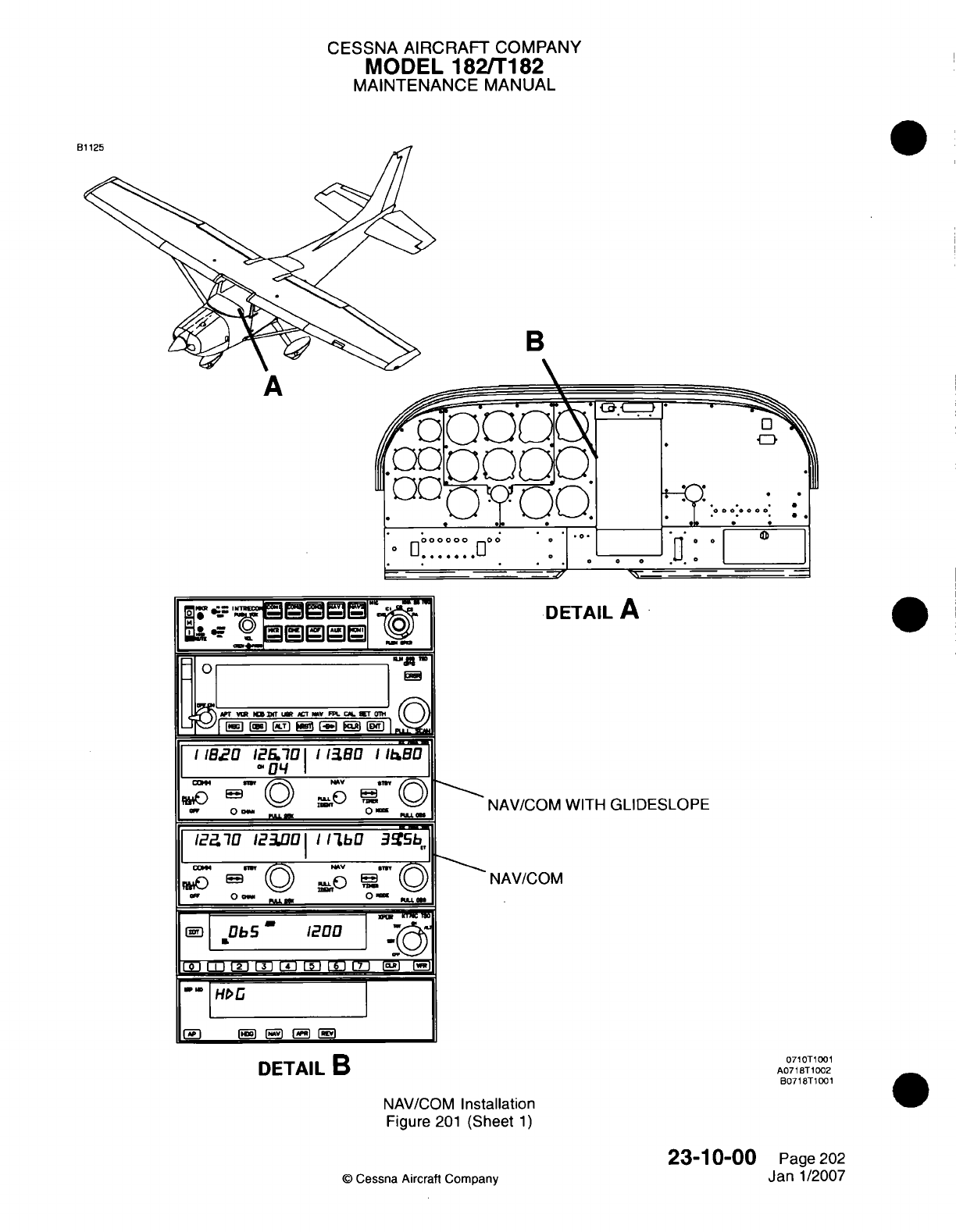
CESSNA AIRCRAFT
COMPANY
MODEL
182ffT182
MAINTENANCE
MANUAL
B
CinTc
*oOn.
O
000000 00
A-a
it--
2. I1-N
0 0
0
0
0
LIZZ
DIETAIL
A
.NAV/COM
WITH
GLIDESLOPE
.NAV/COM
0710T1001
A0718T
1002
B0718BT1O01
DETAIL
B
NAV/COM
Installation
Figure
201
(Sheet
1)
23-10-00
Cessna
Aircraft
Company
Page 202
Jan
1/2007
A
-
I 0
1- 7
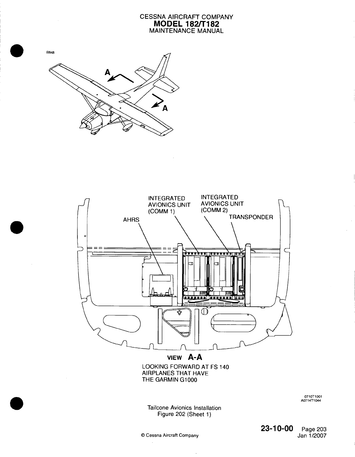
CESSNA
AIRCRAFT
COMPANY
MODEL
182/Ti
182
MAINTENANCE
MANUAL
VIEW
A-A
LOOKING
FORWARD
AT
ES
140
AIRPLANES
THAT
HAVE
THE GARMIN
G1000
071
OT1
001
A07
14TIO04
Tailcone
Avionics Installation
Figure
202
(Sheet
1)
Q
Cessna
Aircraft
Company
23-1
0-00
Page
203
Janl1/2007
I..-
CESSNA AIRCRAFT
COMPANY
MODEL
182/Ti
182
MAINTENANCE
MANUAL
(3)
Remove
the
tailcone
access/inspection
plate
(31
OAR)
to
get
access
to
the
integrated
avionics
units. Refer
to
Chapter
6,
Access/inspection
Plates
-
Description
and
Operation.
(4)
Push
on
the
screw
and turn
it
90
degrees
counterclockwise
to
release
the
lever.
(5)
Move
the
lever
up
to
disengage
the
locking
stud
with
the
dogleg
slot
in
the
mounting
rack.
(6)
Remove
the
unit
from
the mounting
rack.
B.
Install
the Integrated
Avionics
Unit
(Refer
to
Figure
202).
CAUTION: Make sure
that
the
unit
goes
into
position
without
resistance.
Damage
to
the
connectors,
unit,
or
mounting
rack
will
occur
if
the
unit
is
pushed
into
position
with
force.
NOTE:
The
unit
must
be
in
position
in
the mounting
rack
to
let
the
locking stud
engage
the
channel.
(1)
Carefully
put the
unit
in
position
in
the mounting rack.
(2)
Push
the
lever
down
toward
the
bottom
of
the unit
to
engage
the
locking
stud
with
the
dogleg
slot
in
the mounting rack.
(3)
Push
on
the
screw
and
turn
it
90
degrees
clockwise
to
attach
the
lever.
(4)
Install
the
tailcone
access/inspection
plate
(31
OAR).
Refer
to
Chapter
6,
Access/Inspection
Plates
-
Description
and
Operation.
(5)
Engage
the
NAV/COM
1
and/or
NAV/COM
2
circuit
breaker.
(6)
Put
the
MASTER
switch
in
the ON
position.
(7)
Do
a
check
for
correct operation.
Refer
to
the
Garmin
G1lOQO
Line
Maintenance
Manual.
(8)
Put
the
MASTER
and NAV/COM
switches
in
the
OFF
position.
5.
VHF
Antenna
Removal/installation
NOTE:
The
removal
and
installation procedures
are
typical for
all
VHF
antennas.
NOTE:
The
left
VHF
antenna
is
also
the
GDL-69A
antenna
and
a
GPS
antenna.
A.
Remove
the
VHF
Antenna (Refer
to
Figure
203).
(1)
Put
the
MASTER
switch
in
the
OFF
position.
(2)
Remove the
four screws that attach
the VHF
antenna
to
the upper
surface
of
the
fuselage.
(3)
Pull
the
antenna
away
from the
fuselage
to
disconnect
the coax
connector
from the
antenna.
NOTE:
Coax
connector
reference designators
for
airplanes
without
the
Garmin
G1000
are
PC1
001
for
VHF1
and
PC1
002
for
VHF2.
NOTE:
Coax
connector
reference
designators
for
airplanes
with
the
Garmin
G1000
are
PF1
002
for
VHF1
and
PC1
007
for
VHF2.
(4)
Attach
the
coax
cable
to
the
airplane structure
so
it
will
not fall
into
the
headliner
area.
B.
Install
the
VHF
Antenna
(Refer
to
Figure
203).
(1)
Connect
the
coaxial
connector
to
the
antenna.
NOTE:
Coax
connector
reference designators
for
airplanes without
the
Garmin
G1000
are
PC1
001
for
VHF1
and
PC1
002
for
VHF2.
NOTE:
Coax
connector
reference
designators
for airplanes
with
the
Garmin
G1000
are
PF1
002
for
VHF1
and
PC1
007
for
VHF2.
(2)
Attach
the
antenna
to
the
upper
surface
of
the
fuselage
with
the
four
screws.
6.
NAV
Antenna
Removal/installation
A.
Remove
the
NAV
Antenna
(Refer
to Figure
204).
(1)
Put
the
MASTER
switch
in
the
OFF
position.
23-1
0-00
Page
204
©
Cessna Aircraft
Company
Jan
1/2007
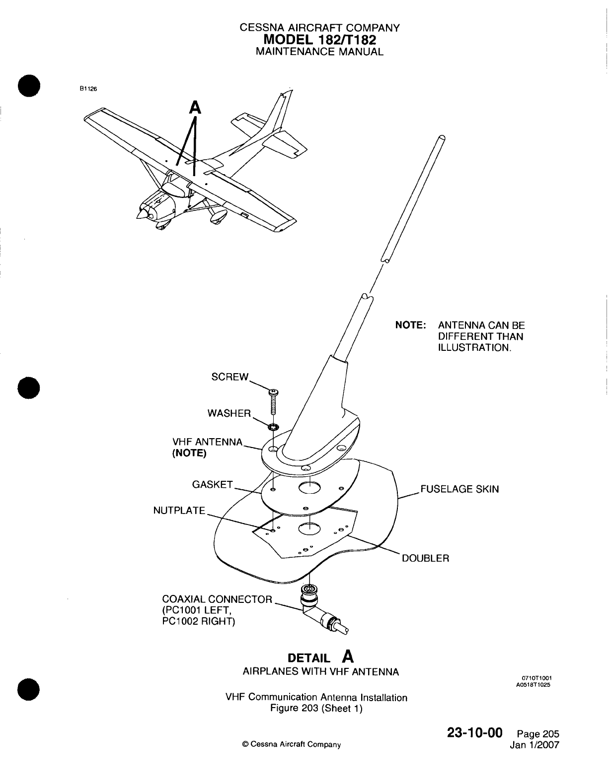
CESSNA
AIRCRAFT
COMPANY
MODEL
182/Ti
82
MAINTENANCE
MANUAL
NTENNA CAN
BE
IFEERENT
THAN
LUSTRATION.
LAGE
SKIN
DETAIL
A
AIRPLANES
WITH
VHF
ANTENNA
071
OT1
001
A0518T
1025
VHF
Communication
Antenna Installation
Figure 203
(Sheet
1)
Q
Cessna
Aircraft
Company
SCREW~
VHF
(NOI
NUTPLAN
COAXIj
(PC1
00
PC1
001
23-1
0-00
Page 205
Janl1/2007
t
I
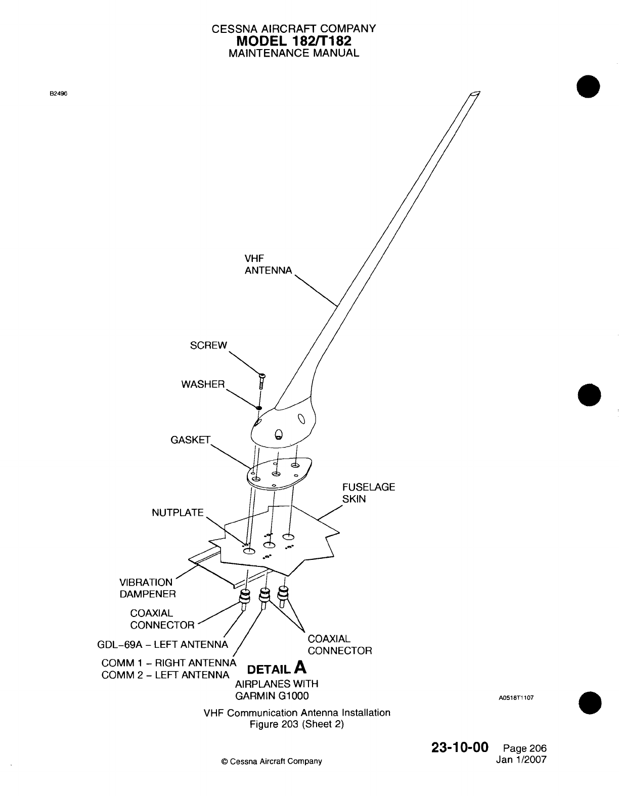
CESSNA
AIRCRAFT
COMPANY
MODEL
182/1182
MAINTENANCE
MANUAL
B2496
VHF
SCREW
WASHER
C
NUT[
VIBRATION
DAMPENER
COAXIAL
CON
NEC'
GDL-69A
-
LEF]
FUSELAGE
SKIN
COAXIAL
CONNECTOR
COMM
1
-
RIGHT
ANTENNA
DETAIL
A
COMM
2
-
LEFT
ANTENNA AIRPLANES
WITH
GARMIN
G1000
VHF
Communication
Antenna
Installation
Figure
203
(Sheet
2)
A0518T1
107
23-1
0-00
©
Cessna
Aircraft Company
Page
206
Janl1/2007
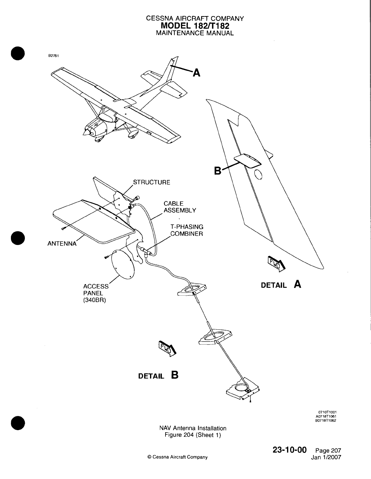
CESSNA
AIRCRAFT
COMPANY
MODEL
182/Ti182
MAINTENANCE
MANUAL
B,
CABLE
,ASSEMBLY
T-PHASING
DETAIL
A
PANEL
(340BR)
DETAIL
B
0710T1001
A0718T1061
B0718T
1062
NAV
Antenna
Installation
Figure 204
(Sheet
1)
Q
Cessna
Aircraft
Company
23-1
0-00
Page
207
Janl1/2007
I
CESSNA
AIRCRAFT
COMPANY
MODEL
182/Ti
82
MAINTENANCE
MANUAL
(2)
Remove
the
screws
that attach
the
NAV
antenna
to
the
tail.
(3)
Carefully
remove
the
fillet
seal
from
the
junction
of
the
NAV
antenna
and
the
skin
of
the
airplane.
(4)
Pull
the
antenna
away
from
the
fuselage
to
disconnect
the
coax
connector
from
the
antenna.
B.
Install
the
NAV
Antenna (Refer
to
Figure
204).
(1)
Connect
the
coaxial
connector
to
the
antenna.
(2)
Attach
the antenna
to
the
tail
with
the
screws.
(3)
Clean
and
fillet
seal
the
interface
area
of
the
antenna
base
and
fuselage
with
Type
VI
sealant.
Refer
to
Chapter
20,
Fuel,
Weather
and
High
Temperature Sealing
for
a
list
of
Type
VI
sealants.
7.
Microphone
Switch
Remova~llnstallation
A.
Remove
the
Microphone
Switch (Refer
to
Figure
205).
(1)
Remove
the
nut
that
attaches
the
microphone switch
(Si)
to
the
escutcheon.
(2)
Remove
the
screw
that
attaches
the
escutcheon
to the
control
wheel.
(3)
Lift
up
the
escutcheon
to
get
access
to
the
microphone
switch
and
disconnect
the
microphone
switch
from
the
control wheel
connection.
B.
Install
the Microphone Switch
(Refer
to
Figure
205).
(1)
Connect
the
microphone switch
(Si1)
to
the
connection
in
the
control
wheel.
(2)
Attach the
microphone
switch
to
the
escutcheon
with
the
nut.
(3)
Set
the
escutcheon
in
position
and
install
the
screw
in
the
escutcheon.
8.
Microphone
Switch Button
Cleaning
A.
Clean the
Switch
Button
(Refer
to
Figure 205).
CAUTION:
Make sure
that
you
clean
the
switch.
Oil
and
dirt
can
collect
on
the
internal
electrical
contacts
of
the
switch
and
cause
the
button to
operate
incorrectly.
(1)
Apply
a
sufficient quantity
of
electrical
contact
cleaning spray
around
the
full
edge of
the
button
so
it
will
soak
down into the
switch.
NOTE:
The
electrical
cleaner
will help
to
remove
oil
and
dirt
from
the
internal
electrical
contacts
of
the
switch.
The
recommended
contact
cleaner
is
Electro
Contact Cleaner
03116
or
equivalent,
which
can
be
supplied
by
LPS
Laboratories,
Inc.
The phone
number
is
1-800-241-8334.
(2)
Press
the
button many times
to
make
sure
the
cleaner
gets
into
the
internal
electrical
contacts
of
the
switch.
(3)
Complete
an
operational
check
of
the
switch.
NOTE:
The
transmit
light
on the
comn
radio
will come
on
when the
power
is
turned
on.
(4) If
the
button
does
not
operate
after
the
first
application
of
the
electric
cleaner,
apply
more
cleaner.
(5) If
the
button
continues
to
operate
incorrectly,
replace
the
microphone
switch. Refer
to
Microphone
Switch
Removal/installation.
23-1
0-00
Page
208
©
Cessna
Aircraft Company
Janl1/2007
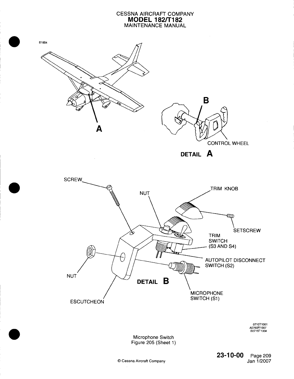
CESSNA
AIRCRAFT
COMPANY
MODEL
182/T182
MAINTENANCE
MANUAL
A
UUN
I HUL
WHEEL
DETAIL
A
5qflRFW
KNOB
NUT
TRIM
SWITCH
(S3
AND
S4)
DETAIL
B
S.,..
-.
%Sj
S.II
ESCUTCHEON
0710T1001
A07608R1007
8071
5T
1004
Microphone
Switch
Figure
205
(Sheet
1)
23-1
0-00
©
Cessna
Aircraft
Company
NUT
Page
209
Janl1/2007
R
'T
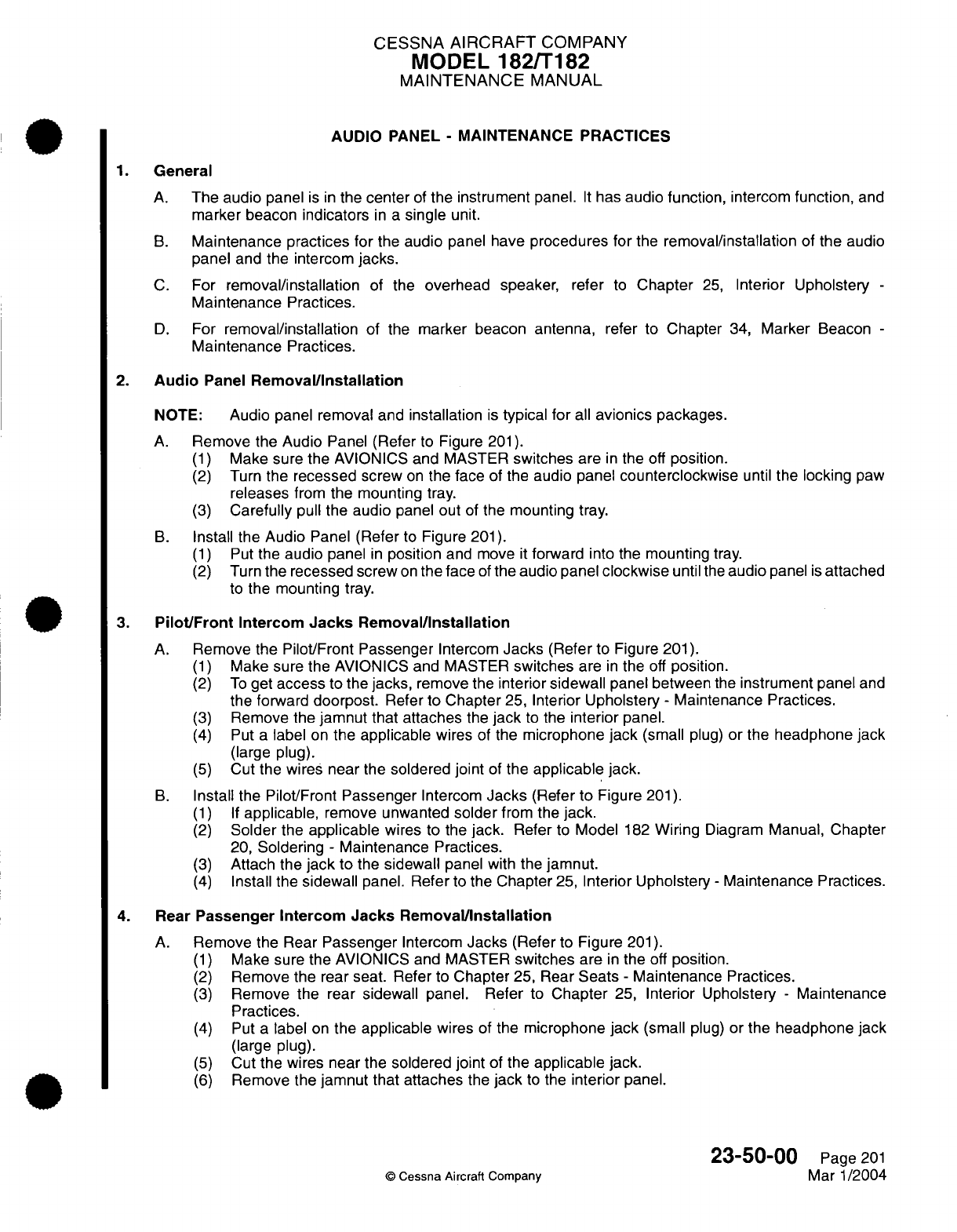
CESSNA AIRCRAFT
COMPANY
MODEL
182/T182
MAINTENANCE
MANUAL
AUDIO
PANEL
-
MAINTENANCE
PRACTICES
1.
General
A.
The
audio
panel
is
in
the center
of
the instrument
panel.
It
has
audio function,
intercom
function,
and
marker
beacon
indicators
in
a
single
unit.
B.
Maintenance practices
for
the
audio
panel
have
procedures for
the
removal/installation
of
the
audio
panel
and
the intercom
jacks.
C.
For
removal/installation
of
the overhead
speaker,
refer
to
Chapter
25,
Interior
Upholstery
-
Maintenance
Practices.
D.
For
removal/installation
of the
marker beacon
antenna,
refer
to
Chapter
34,
Marker
Beacon
-
Maintenance
Practices.
2.
Audio
Panel
Removal/Installation
NOTE:
Audio
panel removal
and
installation
is
typical
for
all
avionics
packages.
A.
Remove the
Audio
Panel
(Refer
to
Figure
201).
(1)
Make sure
the
AVIONICS and MASTER
switches
are
in
the
off
position.
(2)
Turn
the recessed
screw
on
the
face
of the
audio panel
counterclockwise
until the
locking
paw
releases
from
the mounting tray.
(3)
Carefully
pull
the
audio
panel
out
of
the
mounting
tray.
B.
Install
the Audio
Panel
(Refer
to
Figure
201).
(1)
Put
the
audio
panel
in
position
and
move
it
forward
into the mounting
tray.
(2)
Turn
the recessed screw
on
the face
of
the
audio panel
clockwise
until
the
audio
panel
is
attached
to
the mounting
tray.
3.
Pilot/Front
Intercom
Jacks
Removal/Installation
A.
Remove
the Pilot/Front
Passenger
Intercom
Jacks
(Refer
to Figure
201).
(1)
Make
sure
the
AVIONICS and MASTER
switches
are
in
the
off
position.
(2)
To
get
access
to
the
jacks,
remove
the
interior
sidewall
panel
between
the
instrument panel
and
the
forward
doorpost.
Refer
to Chapter
25,
Interior Upholstery
-
Maintenance
Practices.
(3)
Remove
the
jamnut
that attaches
the
jack
to
the
interior
panel.
(4)
Put
a
label
on
the
applicable
wires
of the
microphone
jack
(small
plug)
or
the
headphone
jack
(large plug).
(5)
Cut
the
wires
near the
soldered
joint
of
the
applicable
jack.
B.
Install the Pilot/Front
Passenger
Intercom
Jacks
(Refer
to
Figure
201).
(1) If
applicable,
remove
unwanted
solder
from
the
jack.
(2)
Solder
the
applicable
wires
to the
jack.
Refer
to
Model
182
Wiring
Diagram
Manual, Chapter
20,
Soldering
-
Maintenance Practices.
(3)
Attach the
jack
to
the
sidewall
panel with
the
jamnut.
(4)
Install
the
sidewall
panel.
Refer
to the
Chapter
25,
Interior Upholstery
-
Maintenance Practices.
4.
Rear
Passenger
Intercom
Jacks
Removal/Installation
A.
Remove the
Rear
Passenger
Intercom
Jacks
(Refer
to
Figure
201).
(1)
Make
sure
the
AVIONICS and MASTER
switches
are
in
the
off
position.
(2)
Remove the
rear
seat. Refer
to
Chapter
25,
Rear
Seats
-
Maintenance Practices.
(3)
Remove the
rear
sidewall
panel. Refer
to
Chapter
25,
Interior
Upholstery
-
Maintenance
Practices.
(4)
Put
a
label
on
the applicable
wires
of
the
microphone
jack
(small
plug)
or
the
headphone
jack
(large
plug).
(5)
Cut
the
wires
near the
soldered
joint
of
the
applicable
jack.
(6)
Remove
the
jamnut
that attaches
the
jack
to
the
interior
panel.
23-50-00
Page
201
©
Cessna Aircraft
Company
Mar
1/2004
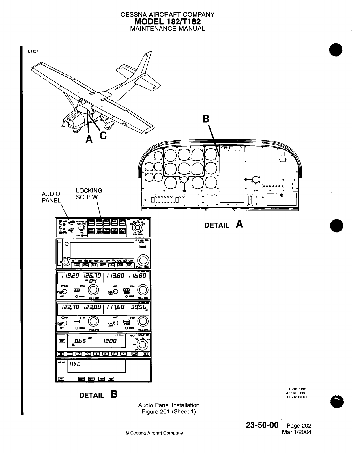
CESSNA AIRCRAFT
COMPANY
MODEL
182/T182
MAINTENANCE
MANUAL
B
B
AUDIO
DAMICI
r Iul
'
LOCKING
SCREW
*- *
--
-k-z
Ii 'I-"
"'
11-11
1" _
/
DETAIL
A
APT
%
K
IT
S
D f
C
UN
T.
CAM OWV
Ml
/1I
IBE
IEDi'
0
EBO
I
I
I As1
|/2270
123.0|1
IlbO
335b]
cam4 _
^
V
m
M
O 1 NO la P.
°
0- 0m 0 b-
P
-©F
..
©%L=
U
_ KMT
I
Db5
'
1200o
LJ0 I I I L
L
E
LH
1
I
-
I
HDG
r»
1
1»5
[SH [i
5
DETAIL
B
Audio
Panel
Installation
Figure
201
(Sheet
1)
©
Cessna
Aircraft Company
0710T1001
A0718T1002
B0718T1001
23-50-00
Page
202
Mar
1/2004
-..
:6
a0:0
a
0
i
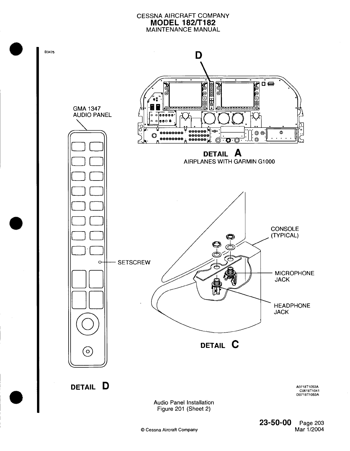
CESSNA
AIRCRAFT
COMPANY
MODEL
182/T182
MAINTENANCE
MANUAL
D
GMA
1347
AUDIO
PANEL
EZ
ID
00F[
31
F-1
0
D
F-00-
00
a-Oa
[][
* 0
.
. .
L
DETAIL
A
AIRPLANES
WITH GARMIN
C
SETSCREW
31000
CONSOLE
(TYPICAL)
MICROPHONE
JACK
HEADPHONE
JACK
DETAIL
C
®
DETAIL
D
A0718T1053A
C0518T1041
D0718T1053A
Audio
Panel
Installation
Figure
201
(Sheet
2)
©
Cessna Aircraft
Company
23-50-00
Page
203
Mar 1/2004
B3475
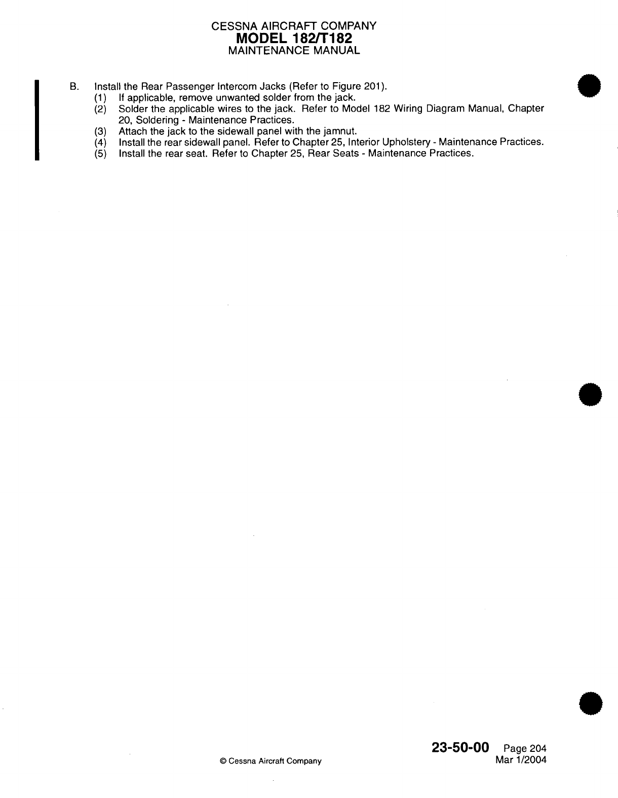
CESSNA AIRCRAFT
COMPANY
MODEL
182/T182
MAINTENANCE
MANUAL
B.
Install the
Rear
Passenger
Intercom
Jacks
(Refer
to
Figure
201).
(1) If
applicable,
remove
unwanted
solder
from
the
jack.
(2)
Solder
the
applicable
wires
to
the
jack.
Refer
to
Model
182
Wiring
Diagram
Manual, Chapter
20,
Soldering
-
Maintenance Practices.
(3)
Attach
the
jack
to
the
sidewall
panel
with the
jamnut.
(4)
Install
the
rear
sidewall
panel. Refer
to
Chapter
25,
Interior
Upholstery
-
Maintenance
Practices.
(5)
Install
the
rear
seat.
Refer
to
Chapter
25,
Rear
Seats
-
Maintenance
Practices.
23-50-00
Page 204
©
Cessna
Aircraft
Company
Mar
1/2004
CESSNA
AIRCRAFT
COMPANY
MODEL
182/T182
MAINTENANCE MANUAL
STATIC
WICKS
-
MAINTENANCE
PRACTICES
1.
General
A.
Maintenance
of
the
static
(discharger)
wicks
consists
of
removal/replacement
of
the
wick assembly
and
ensuring that bonding
straps
are
properly connected
between
control
surfaces
and
primary
structure.
B.
Static wicks
are
mounted
on
the
trailing edges
of
the
ailerons,
rudder
and
the
elevators.
Bonding
straps
are
secured
to
flight
control
surfaces
and
electrically
connect
those
surfaces
to the
primary
structure.
2.
Tools
and
Equipment
A.
For
a
list
of
applicable
tools
and
equipment,
refer
to
Communications
-
General.
3.
Static Wicks
Removal/Installation
A.
Remove
Static
Wick
(Refer
to
Figure
201).
(1)
Carefully
drill
out
mounting
rivets
which attach
static
wick
to structure. Ensure
holes
are
not
drilled
oversize.
(2)
Remove
static wick
from the
airplane
skin.
B.
Install
Static
Wick
(Refer
to
Figure
201).
(1)
Clean
surface
of
airplane
skin
where
static
wick
will
attach
to
skin.
Remove
all
traces
of
contaminants (including
paint/primer)
using
scotchbrite
and
P-D-680
solvent.
(2)
Secure static wick
to
airplane skin
using
rivets.
(3)
Repaint
base
of new
wick
(if
required).
4.
Bonding
Straps
Removal/Installation
A.
Bonding straps
are
provided
to
ensure that
electrical potential
between
primary
and
secondary
structure
remains
nearly
equal.
If
bonding
straps
are removed,
they
should
be
reinstalled
using
hardware
called
out
in
the
Model
182
Illustrated
Parts
Catalog.
B.
The
maximum
allowable
resistance
(in
ohms)
for
bonding straps
is
0.0025
ohms.
C.
Primary
and
secondary
structure
should
be
cleaned
using
scotchbrite
pad
and
P-D-
680
solvent
before
installing bonding
hardware.
Aluminum
surfaces
should
be
chemically
protected
(alodine
or
equivalent)
before
attaching
bonding
hardware
to
surface.
23-60-00
©
Cessna Aircraft
Company
Page
201
April 1/2002
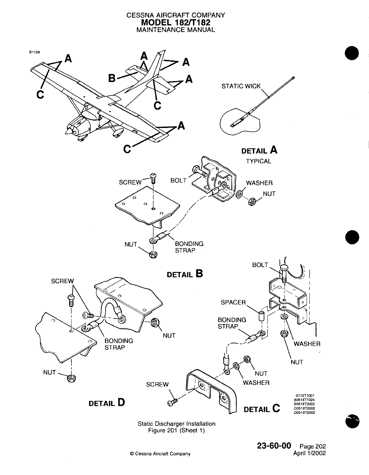
CESSNA
AIRCRAFT
COMPANY
MODEL
182/T182
MAINTENANCE
MANUAL
A
STATIC
WICK
DETAIL
A
;AL
IER
NUT
DING
AP
BOLT
N
NUT
SCREW
DETAIL
D
WASHER
DETAIL
C
Static
Discharger Installation
Figure
201
(Sheet
1)
©
Cessna
Aircraft
Company
23-60-00
Page
202
April 1/2002
0710T1001
A0518T1024
B0518T2002
C0518T2002
D0518T2002
A
gi
I
Rt
I
CHAPTER
ELECTRICAL
POWER
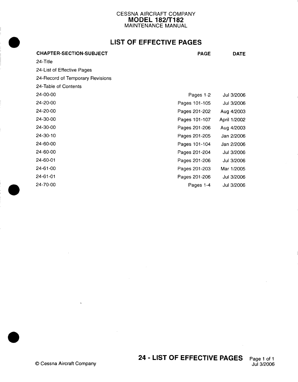
CESSNA
AIRCRAFT
COMPANY
MODEL
182/T182
MAINTENANCE
MANUAL
LIST
OF
EFFECTIVE PAGES
CHAPTER-SECTION-SUBJECT
24-Title
24-List
of
Effective
Pages
24-Record
of Temporary
Revisions
24-Table
of
Contents
24-00-00
24-20-00
24-20-00
24-30-00
24-30-00
24-30-10
24-60-00
24-60-00
24-60-01
24-61-00
24-61-01
24-70-00
©
Cessna
Aircraft
Company
PAGE
Pages
1-2
Pages
101-105
Pages
201-202
Pages
101-107
Pages
201-206
Pages
201-205
Pages
101-104
Pages
201-204
Pages
201-206
Pages 201-203
Pages 201-206
Pages
1-4
DATE
Jul
3/2006
Jul
3/2006
Aug
4/2003
April
1/2002
Aug
4/2003
Jan
2/2006
Jan
2/2006
Jul
3/2006
Jul
3/2006
Mar
1/2005
Jul
3/2006
Jul
3/2006
24
-
LIST
OF
EFFECTIVE
PAGES
Page
1
of
1
Jul
3/2006
Temporary
Revision
Number
RECORD
OF
TEMPORARY REVISIONS
Page
Number
Issue
Date
By
Date
Removed
By
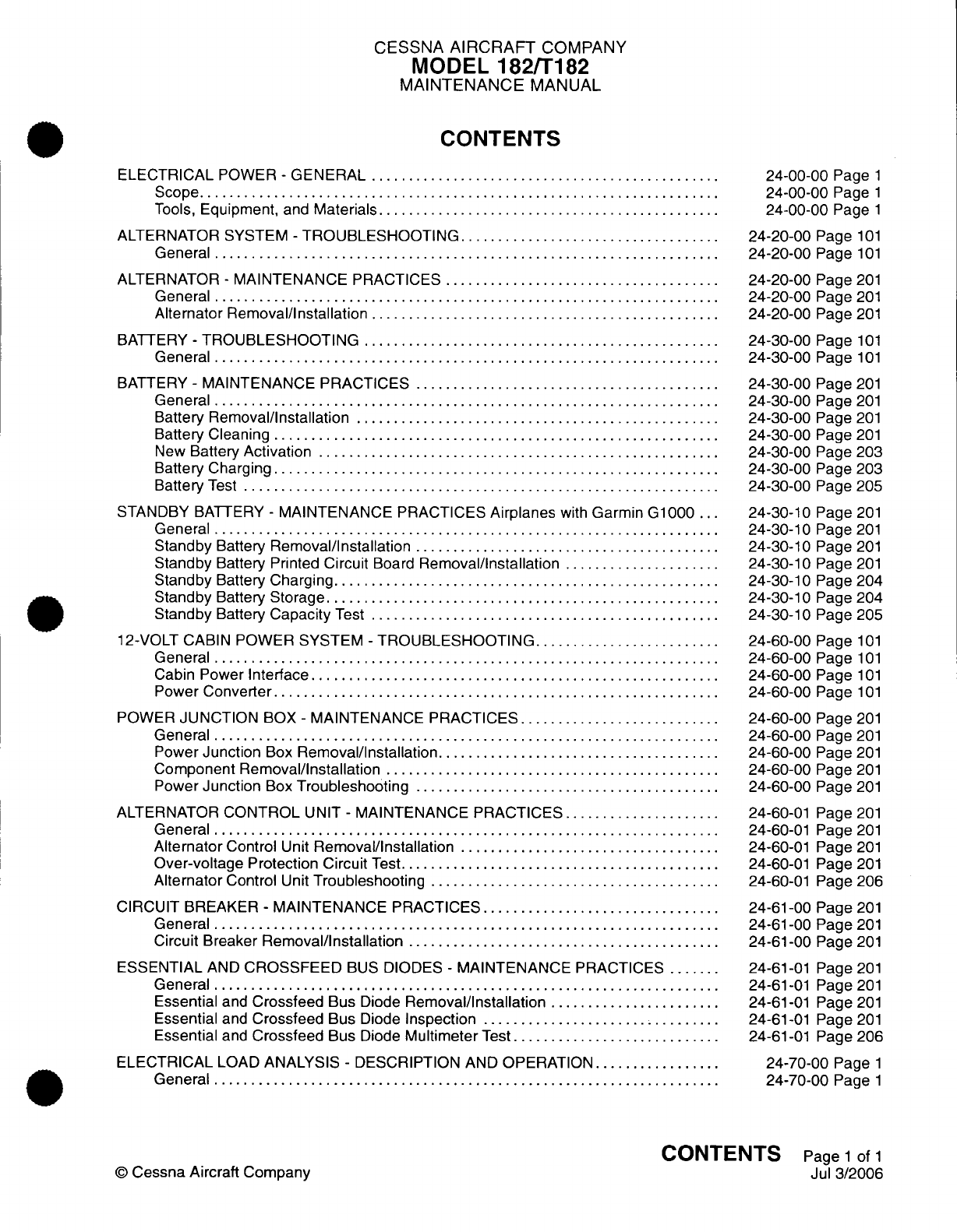
CESSNA
AIRCRAFT
COMPANY
MODEL
182/T182
MAINTENANCE
MANUAL
CONTENTS
ELECTRICAL
POWER
-
GENERAL
..............................................
Scope......................................................................
Tools,
Equipment,
and
Materials..............................................
ALTERNATOR SYSTEM
-
TROUBLESHOOTING...................................
General
....................................................................
ALTERNATOR
-
MAINTENANCE
PRACTICES
.....................................
General
....................................................................
Alternator Removal/Installation
...............................................
BATTERY
-
TROUBLESHOOTING
...............................................
General
....................................................................
BATTERY
-
MAINTENANCE
PRACTICES
........................................
General
....................................................................
Battery
Removal/Installation
.........
.........
...............................
Battery Cleaning
............................................................
New
Battery
Activation
......................................................
Battery
Charging............................................................
Battery
Test
................................................................
STANDBY
BATTERY
-
MAINTENANCE
PRACTICES
Airplanes
with
Garmin
G1000
...
General
....................................................................
Standby
Battery
Removal/Installation
.........................................
Standby
Battery Printed
Circuit
Board
Removal/Installation
.....................
Standby
Battery
Charging....................................................
Standby
Battery
Storage.....................................................
Standby
Battery
Capacity
Test
...............................................
12-VOLT CABIN
POWER
SYSTEM
-
TROUBLESHOOTING.........................
General
...................................................................
Cabin
Power
Interface
......................................................
Power
Converter............................................................
POWER
JUNCTION
BOX
-
MAINTENANCE
PRACTICES...........................
General
...................................................................
Power
Junction
Box
Removal/Installation......................................
Component
Removal/Installation
.............................................
Power
Junction
Box
Troubleshooting
.........................................
ALTERNATOR
CONTROL
UNIT
-
MAINTENANCE
PRACTICES.....................
General
....................................................................
Alternator
Control
Unit
Removal/Installation
..................................
Over-voltage
Protection
Circuit
Test...........................................
Alternator
Control
Unit
Troubleshooting
.......................................
CIRCUIT
BREAKER
-
MAINTENANCE
PRACTICES
...............................
General
....................................................................
Circuit
Breaker
Removal/Installation
..........................................
ESSENTIAL
AND
CROSSFEED
BUS
DIODES
-
MAINTENANCE
PRACTICES
.......
General
...................................................................
Essential
and
Crossfeed
Bus
Diode
Removal/Installation
.......................
Essential
and
Crossfeed
Bus
Diode
Inspection
................................
Essential
and
Crossfeed
Bus
Diode
Multimeter
Test
............................
ELECTRICAL
LOAD
ANALYSIS
-
DESCRIPTION
AND
OPERATION
.................
General
....................................................................
24-00-00
Page
1
24-00-00
Page
1
24-00-00
Page
1
24-20-00
Page
101
24-20-00
Page
101
24-20-00
Page
201
24-20-00
Page
201
24-20-00
Page
201
24-30-00
Page
101
24-30-00
Page
101
24-30-00
Page
201
24-30-00
Page
201
24-30-00
Page
201
24-30-00
Page
201
24-30-00
Page
203
24-30-00
Page
203
24-30-00
Page
205
24-30-10
Page
201
24-30-10
Page
201
24-30-10
Page
201
24-30-10
Page
201
24-30-10
Page
204
24-30-10
Page
204
24-30-10
Page
205
24-60-00
Page
101
24-60-00
Page
101
24-60-00
Page
101
24-60-00
Page
101
24-60-00
Page
201
24-60-00
Page
201
24-60-00
Page
201
24-60-00
Page
201
24-60-00
Page
201
24-60-01
Page
201
24-60-01
Page
201
24-60-01
Page
201
24-60-01
Page
201
24-60-01
Page
206
24-61-00
Page
201
24-61-00
Page
201
24-61-00
Page
201
24-61-01
Page
201
24-61-01
Page
201
24-61-01
Page
201
24-61-01
Page
201
24-61-01
Page
206
24-70-00
Page
1
24-70-00
Page
1
CONTENTS
Page
1
of
1
Jul 3/2006
©
Cessna
Aircraft
Company
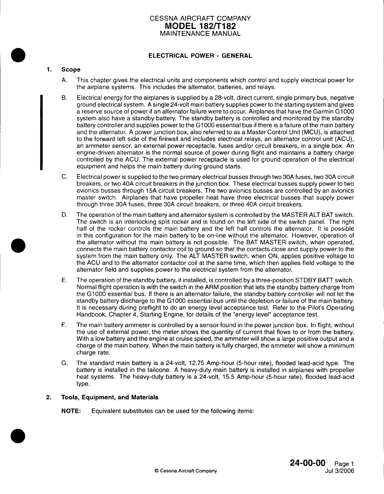
CESSNA
AIRCRAFT
COMPANY
MODEL
182/T182
MAINTENANCE
MANUAL
ELECTRICAL
POWER
-
GENERAL
1.
Scope
A.
This
chapter
gives
the
electrical
units
and
components
which
control
and
supply
electrical
power
for
the
airplane
systems. This
includes
the alternator,
batteries,
and
relays.
B.
Electrical
energy
for
the
airplanes
is
supplied
by
a
28-volt,
direct
current,
single
primary
bus,
negative
ground
electrical
system.
A
single
24-volt
main
battery
supplies
power to
the
starting
system
and
gives
a
reserve
source
of
power
if
an
alternator
failure
were
to
occur. Airplanes
that
have
the Garmin
G1000
system
also
have
a
standby
battery.
The standby
battery
is
controlled
and
monitored
by
the
standby
battery
controller
and
supplies
power
to the
G1000
essential
bus
if
there
is
a
failure
of
the
main
battery
and the
alternator.
A
power
junction
box, also referred to
as
a
Master Control
Unit
(MCU),
is
attached
to the
forward
left
side
of the
firewall
and
includes
electrical
relays, an
alternator
control
unit
(ACU),
an
ammeter
sensor,
an
external
power
receptacle,
fuses
and/or
circuit
breakers,
in
a
single
box.
An
engine-driven
alternator
is
the normal
source
of power
during
flight
and
maintains
a
battery
charge
controlled
by
the
ACU.
The
external power receptacle
is
used
for ground
operation
of
the
electrical
equipment
and
helps the
main battery
during
ground
starts.
C.
Electrical
power
is
supplied
to
the
two
primary
electrical
busses through
two
30A
fuses,
two
30A
circuit
breakers,
or
two
40A
circuit
breakers
in
the
junction
box.
These electrical
busses
supply
power
to two
avionics busses
through
15A
circuit
breakers.
The
two
avionics
busses
are
controlled
by
an
avionics
master
switch.
Airplanes
that
have
propeller
heat
have
three
electrical
busses
that
supply
power
through
three
30A
fuses,
three
30A
circuit
breakers, or
three
40A
circuit
breakers.
D.
The
operation
of
the
main
battery
and
alternator
system
is
controlled
by
the
MASTER
ALT
BAT
switch.
The
switch
is
an
interlocking
split
rocker
and
is
found
on the
left
side
of
the
switch
panel.
The
right
half
of
the
rocker
controls
the
main
battery
and
the
left
half
controls
the
alternator.
It
is
possible
in
this
configuration
for
the
main
battery
to
be
on-line
without
the
alternator.
However,
operation
of
the
alternator
without
the
main
battery
is
not
possible.
The
BAT
MASTER
switch,
when
operated,
connects
the
main
battery
contactor
coil to ground
so
that
the
contacts
close
and
supply
power
to
the
system
from
the
main
battery
only.
The
ALT
MASTER
switch,
when
ON,
applies
positive voltage
to
the
ACU
and
to
the
alternator
contactor
coil
at
the
same
time,
which then
applies field voltage
to
the
alternator
field
and
supplies
power
to
the
electrical system
from
the
alternator.
E.
The
operation
of
the
standby
battery,
if
installed,
is
controlled
by
a
three-position
STDBY
BATT
switch.
Normal
flight
operation
is
with
the
switch
in
the
ARM
position
that
lets
the
standby
battery
charge from
the
G1000
essential
bus.
If
there
is
an
alternator
failure,
the
standby
battery
controller
will
not
let
the
standby
battery
discharge
to
the
G1000
essential
bus
until
the
depletion
or
failure of
the
main
battery.
It
is
necessary during
preflight
to do an
energy
level
acceptance
test.
Refer to
the
Pilot's
Operating
Handbook,
Chapter
4,
Starting
Engine,
for details
of the
"energy
level"
acceptance
test.
F.
The
main
battery
ammeter
is
controlled
by
a
sensor
found
in
the
power junction
box.
In
flight, without
the use
of external
power,
the
meter
shows
the
quantity
of
current
that
flows
to
or
from
the battery.
With
a
low
battery
and
the
engine
at
cruise
speed,
the
ammeter
will
show
a
large
positive
output
and
a
charge
of
the
main
battery.
When
the
main
battery
is
fully
charged, the ammeter
will show
a
minimum
charge
rate.
G.
The
standard
main
battery
is
a
24-volt,
12.75
Amp-hour
(5-hour
rate),
flooded
lead-acid type.
The
battery
is
installed
in
the
tailcone.
A
heavy-duty
main
battery
is
installed
in
airplanes
with
propeller
heat
systems.
The
heavy-duty
battery
is
a
24-volt,
15.5
Amp-hour (5-hour
rate),
flooded lead-acid
type.
2.
Tools,
Equipment, and
Materials
NOTE:
Equivalent
substitutes
can
be
used for
the
following
items:
24-00-00
Page
1
©
Cessna
Aircraft
Company
Jul 3/2006
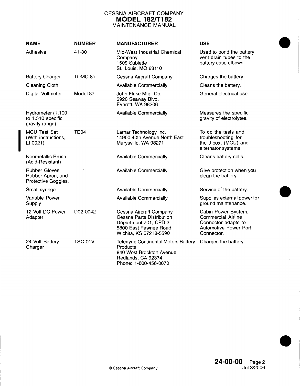
NAME
Adhesive
Battery
Charger
Cleaning
Cloth
Digital
Voltmeter
Hydrometer
(1.100
to
1.310
specific
gravity
range)
MCU
Test
Set
(With
instructions,
LI-0021)
Nonmetallic
Brush
(Acid-Resistant)
Rubber
Gloves,
Rubber
Apron,
and
Protective
Goggles.
Small syringe
Variable
Power
Supply
12
Volt
DC
Power
Adapter
24-Volt Battery
Charger
NUMBER
41-30
TDMC-81
Model
87
TE04
D02-0042
TSC-01
V
CESSNA
AIRCRAFT
COMPANY
MODEL
182/T182
MAINTENANCE
MANUAL
MANUFACTURER
Mid-West Industrial Chemical
Company
1509
Sublette
St.
Louis,
MO
63110
Cessna Aircraft
Company
Available Commercially
John
Fluke
Mfg.
Co.
6920 Seaway
Blvd.
Everett,
WA
98206
Available
Commercially
Lamar
Technology
Inc.
14900 40th
Avenue
North
East
Marysville,
WA
98271
Available
Commercially
Available
Commercially
Available
Commercially
Available
Commercially
Cessna Aircraft
Company
Cessna
Parts
Distribution
Department
701,
CPD
2
5800
East
Pawnee
Road
Wichita,
KS
67218-5590
Teledyne
Continental
Motors
Battery
Products
840
West
Brockton
Avenue
Redlands,
CA
92374
Phone:
1-800-456-0070
USE
Used
to
bond
the
battery
vent
drain
tubes
to the
battery
case
elbows.
Charges the
battery.
Cleans the
battery.
General
electrical
use.
Measures
the
specific
gravity
of
electrolytes.
To
do
the
tests
and
troubleshooting
for
the J-box,
(MCU)
and
alternator
systems.
Cleans
battery
cells.
Give
protection
when
you
clean
the
battery.
Service
of
the
battery.
Supplies external
power
for
ground
maintenance.
Cabin
Power
System.
Commercial
Airline
Connector
adapts
to
Automotive
Power
Port
Connector.
Charges
the
battery.
24-00-OC
©
Cessna
Aircraft
Company
I
Page
2
Jul
3/2006
I
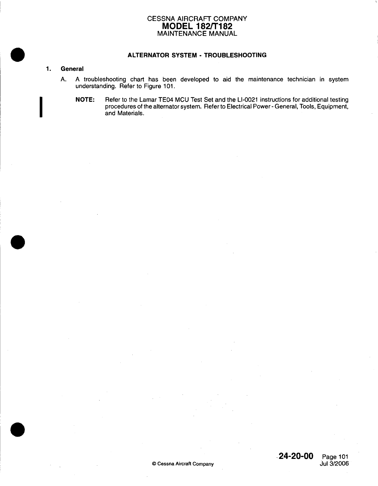
CESSNA
AIRCRAFT
COMPANY
MODEL
182/T182
MAINTENANCE
MANUAL
ALTERNATOR
SYSTEM
-
TROUBLESHOOTING
1.
General
A. A
troubleshooting
chart
has
been
developed
to
aid
the
maintenance
technician
in
system
understanding. Refer
to Figure
101.
NOTE:
Refer
to
the
Lamar
TE04
MCU
Test
Set
and the
LI-0021
instructions
for
additional testing
procedures
of the
alternator
system.
Refer
to
Electrical
Power- General,
Tools,
Equipment,
and
Materials.
24-20-00
Page
101
O
Cessna Aircraft Company
Jul
3/2006
I
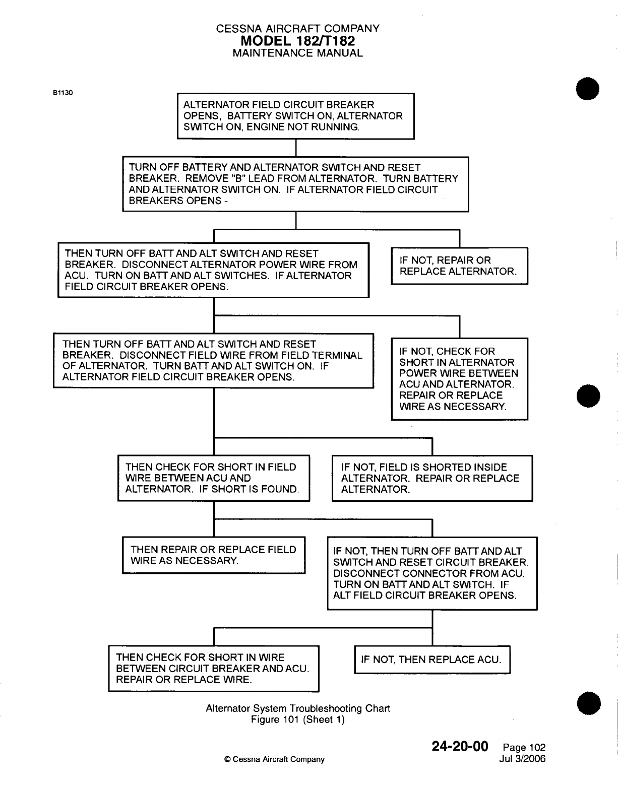
CESSNA
AIRCRAFT
COMPANY
MODEL
182/T182
MAINTENANCE
MANUAL
ALTERNATOR
FIELD
CIRCUIT
BREAKER
OPENS,
BATTERY
SWITCH
ON,
ALTERNATOR
SWITCH
ON,
ENGINE
NOT
RUNNING.
I
TURN OFF
BATTERY
AND
ALTERNATOR
SWITCH
AND
RESET
BREAKER. REMOVE
"B"
LEAD FROM
ALTERNATOR. TURN
BATTERY
AND
ALTERNATOR
SWITCH
ON.
IF
ALTERNATOR FIELD
CIRCUIT
BREAKERS
OPENS
-
I
THEN
TURN
OFF
BATT AND
ALT SWITCH
AND RESET
BREAKER. DISCONNECT
ALTERNATOR POWER
WIRE
FROM
ACU.
TURN
ON
BATTAND
ALT
SWITCHES.
IF
ALTERNATOR
FIELD
CIRCUIT
BREAKER
OPENS.
THEN TURN
OFF
BATT AND
ALT
SWITCH
AND
RESET
BREAKER.
DISCONNECT
FIELD WIRE
FROM
FIELD
TERMINAL
OF
ALTERNATOR.
TURN
BATT
AND
ALT
SWITCH
ON.
IF
ALTERNATOR
FIELD
CIRCUIT BREAKER
OPENS.
THEN
CHECK
FOR
SHORT
IN
FIELD
WIRE
BETWEEN
ACU
AND
ALTERNATOR.
IF
SHORT
IS
FOUND.
THEN
REPAIR
OR
REPLACE
FIELD
WIRE AS NECESSARY.
THEN CHECK FOR
SHORT
IN
WIRE
BETWEEN
CIRCUIT
BREAKER
AND ACU.
REPAIR
OR
REPLACE WIRE.
IF
NOT,
REPAIR
OR
REPLACE
ALTERNATOR.
IF
NOT,
CHECK
FOR
SHORT
IN
ALTERNATOR
POWER WIRE
BETWEEN
ACU
AND ALTERNATOR.
REPAIR
OR REPLACE
WIRE
AS
NECESSARY.
IF
NOT,
FIELD
IS
SHORTED INSIDE
ALTERNATOR.
REPAIR OR
REPLACE
ALTERNATOR.
IF
NOT,
THEN
TURN
OFF
BATT
AND
ALT
SWITCH
AND RESET CIRCUIT
BREAKER.
DISCONNECT
CONNECTOR
FROM
ACU.
TURN ON
BATT
AND
ALT
SWITCH.
IF
ALT
FIELD
CIRCUIT
BREAKER
OPENS.
I
IF
NOT, THEN REPLACE
ACU.
Alternator
System
Troubleshooting
Chart
Figure
101
(Sheet
1)
©
Cessna
Aircraft
Company
24-20-00
Page
102
Jul
3/2006
B1130
I
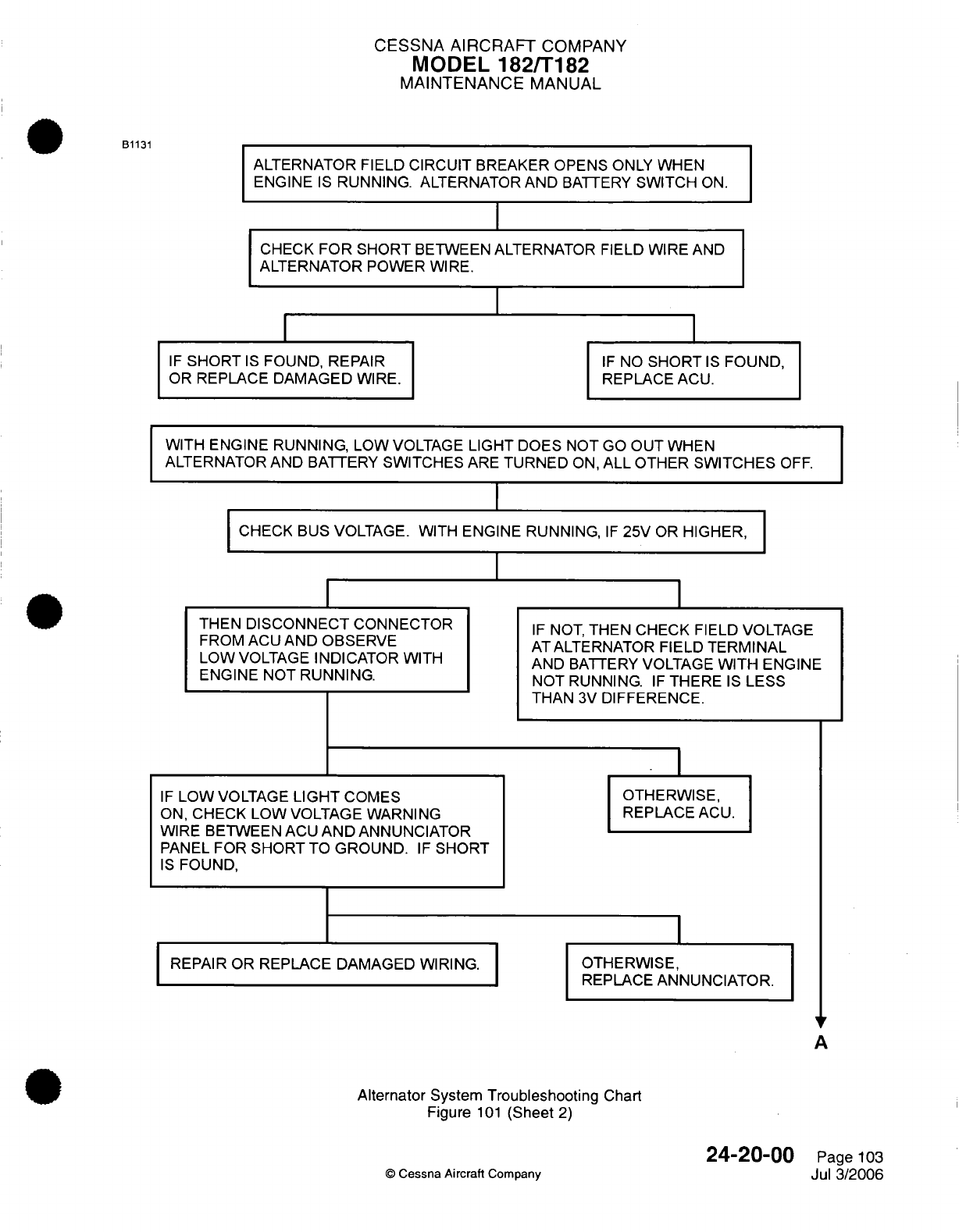
CESSNA AIRCRAFT
COMPANY
MODEL
182/T182
MAINTENANCE
MANUAL
ALTERNATOR
FIELD
CIRCUIT
BREAKER
OPENS
ONLY
WHEN
ENGINE
IS
RUNNING.
ALTERNATOR
AND
BATTERY
SWITCH
ON.
CHECK
FOR SHORT
BETWEEN
ALTERNATOR
FIELD
WIRE
AND
ALTERNATOR
POWER
WIRE.
IF
SHORT
IS
FOUND,
REPAIR
OR
REPLACE DAMAGED
WIRE.
IF
NO
SHORT
IS
FOUND,
REPLACE
ACU.
WITH
ENGINE
RUNNING,
LOW
VOLTAGE
LIGHT
DOES
NOT
GO
OUT
WHEN
ALTERNATOR
AND
BATTERY
SWITCHES
ARE
TURNED
ON,
ALL
OTHER SWITCHES
OFF.
CHECK
BUS VOLTAGE.
WITH
ENGINE
RUNNING,
IF
25V
OR
HIGHER,
THEN
DISCONNECT
CONNECTOR
FROM
ACU
AND
OBSERVE
LOW
VOLTAGE
INDICATOR
WITH
ENGINE NOT
RUNNING.
IF
LOW
VOLTAGE
LIGHT
COMES
ON,
CHECK
LOW
VOLTAGE
WARNING
WIRE BETWEEN
ACU
AND
ANNUNCIATOR
PANEL
FOR
SHORT
TO
GROUND.
IF
SHORT
IS
FOUND,
REPAIR OR
REPLACE
DAMAGED
WIRING.
IF
NOT,
THEN
CHECK
FIELD VOLTAGE
AT
ALTERNATOR
FIELD
TERMINAL
AND
BATTERY
VOLTAGE
WITH
ENGINE
NOT
RUNNING.
IF
THERE
IS
LESS
THAN
3V
DIFFERENCE.
* I
OTHERWISE,
REPLACE
ACU.
OTHERWISE,
REPLACE
ANNUNCIATOR.
A
Alternator
System
Troubleshooting
Chart
Figure
101
(Sheet
2)
©
Cessna Aircraft
Company
B1131
24-20-00
Page
103
Jul
3/2006
I
I
I
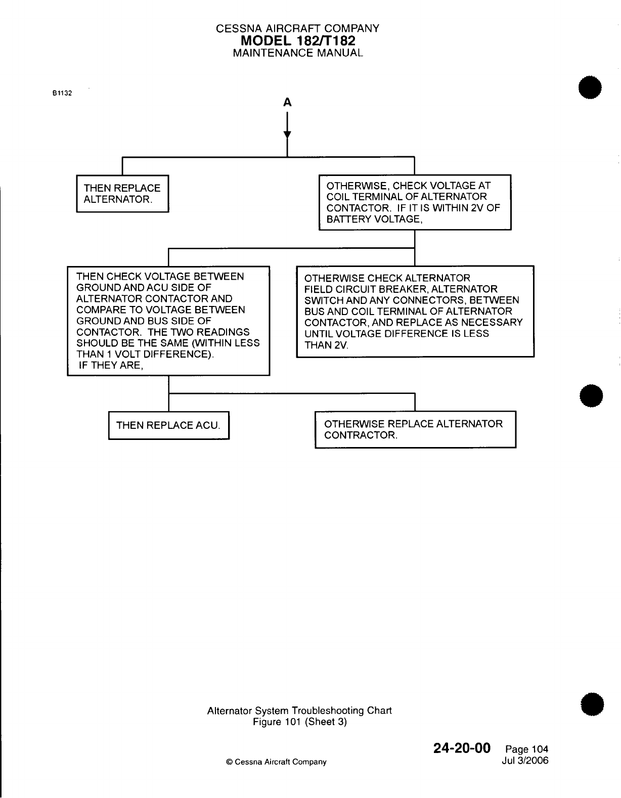
CESSNA AIRCRAFT
COMPANY
MODEL 182/T182
MAINTENANCE
MANUAL
A
OTHERWISE,
CHECK
VOLTAGE
AT
COIL
TERMINAL
OF
ALTERNATOR
CONTACTOR.
IF IT
IS
WITHIN
2V
OF
BATTERY VOLTAGE,
THEN
CHECK VOLTAGE
BETWEEN
GROUND
AND ACU
SIDE
OF
ALTERNATOR
CONTACTOR
AND
COMPARE
TO
VOLTAGE
BETWEEN
GROUND
AND
BUS
SIDE
OF
CONTACTOR.
THE TWO
READINGS
SHOULD
BE
THE SAME
(WITHIN
LESS
THAN
1
VOLT DIFFERENCE).
IF
THEY
ARE,
THEN
REPLACE ACU.
OTHERWISE
CHECK ALTERNATOR
FIELD
CIRCUIT
BREAKER,
ALTERNATOR
SWITCH
AND ANY
CONNECTORS,
BETWEEN
BUS
AND
COIL
TERMINAL
OF
ALTERNATOR
CONTACTOR,
AND
REPLACE AS
NECESSARY
UNTIL
VOLTAGE
DIFFERENCE
IS
LESS
THAN
2V.
OTHERWISE
REPLACE
ALTERNATOR
CONTRACTOR.
Alternator
System
Troubleshooting
Chart
Figure
101
(Sheet
3)
24-20-00
©
Cessna Aircraft
Company
Page
104
Jul
3/2006
B1132
THEN
REPLACE
ALTERNATOR.
I
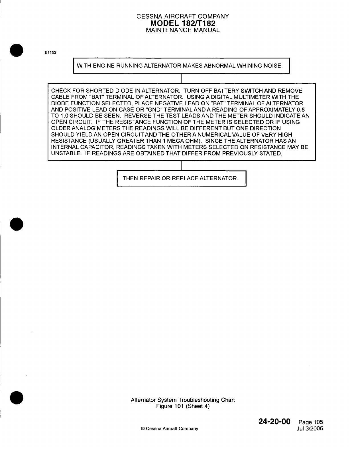
CESSNA
AIRCRAFT
COMPANY
MODEL
182/T182
MAINTENANCE
MANUAL
B1133
WITH
ENGINE
RUNNING
ALTERNATOR
MAKES
ABNORMAL
WHINING
NOISE.
CHECK
FOR
SHORTED
DIODE
IN
ALTERNATOR.
TURN
OFF
BATTERY
SWITCH
AND
REMOVE
CABLE FROM
"BAT"
TERMINAL
OF
ALTERNATOR.
USING
A
DIGITAL
MULTIMETER WITH
THE
DIODE
FUNCTION
SELECTED,
PLACE NEGATIVE
LEAD
ON
"BAT"
TERMINAL
OF
ALTERNATOR
AND
POSITIVE
LEAD ON
CASE
OR "GND"
TERMINAL
AND
A
READING
OF
APPROXIMATELY
0.8
TO
1.0
SHOULD
BE
SEEN. REVERSE
THE
TEST
LEADS
AND
THE
METER SHOULD
INDICATE
AN
OPEN
CIRCUIT.
IF
THE
RESISTANCE
FUNCTION
OF
THE METER
IS
SELECTED
OR
IF
USING
OLDER
ANALOG
METERS
THE
READINGS
WILL
BE
DIFFERENT
BUT
ONE
DIRECTION
SHOULD YIELD
AN
OPEN
CIRCUITAND
THE
OTHER
A
NUMERICAL
VALUE
OF
VERY
HIGH
RESISTANCE (USUALLY
GREATER
THAN
1
MEGA
OHM).
SINCE THE
ALTERNATOR
HAS
AN
INTERNAL
CAPACITOR,
READINGS
TAKEN
WITH METERS SELECTED
ON
RESISTANCE
MAY
BE
UNSTABLE.
IF
READINGS
ARE
OBTAINED THAT
DIFFER
FROM
PREVIOUSLY
STATED,
I
THEN
REPAIR OR
REPLACE ALTERNATOR.
Alternator System Troubleshooting
Chart
Figure
101
(Sheet
4)
©
Cessna
Aircraft
Company
24-20-00
Page
105
Jul
3/2006
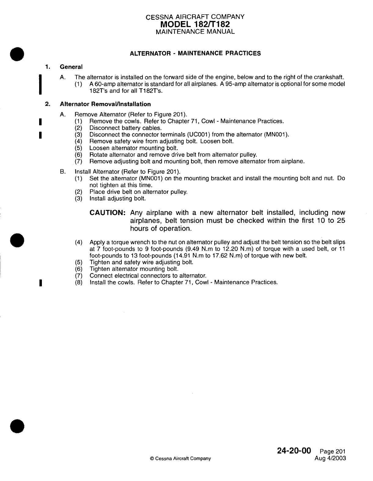
CESSNA
AIRCRAFT
COMPANY
MODEL
182/T182
MAINTENANCE
MANUAL
ALTERNATOR
-
MAINTENANCE PRACTICES
1.
General
A.
The
alternator
is
installed
on
the
forward
side
of
the
engine, below
and
to
the
right
of
the
crankshaft.
(1) A
60-amp
alternator
is
standard for
all
airplanes.
A
95-amp
alternator
is
optional for
some
model
182T's and
for
all
T182T's.
2.
Alternator
Removal/Installation
A.
Remove
Alternator
(Refer
to Figure
201).
(1)
Remove
the cowls. Refer
to
Chapter
71,
Cowl
-
Maintenance
Practices.
(2)
Disconnect
battery
cables.
(3)
Disconnect
the
connector
terminals
(UC001)
from
the
alternator
(MN001).
(4)
Remove
safety
wire
from
adjusting
bolt. Loosen
bolt.
(5)
Loosen
alternator
mounting
bolt.
(6)
Rotate
alternator
and
remove
drive
belt from
alternator
pulley.
(7)
Remove
adjusting
bolt
and
mounting
bolt,
then
remove
alternator
from
airplane.
B.
Install
Alternator
(Refer
to
Figure
201).
(1)
Set
the
alternator
(MN001)
on
the
mounting
bracket
and
install
the
mounting
bolt
and
nut.
Do
not
tighten
at
this time.
(2)
Place
drive
belt
on
alternator
pulley.
(3)
Install
adjusting
bolt.
CAUTION:
Any
airplane
with
a
new
alternator
belt
installed,
including
new
airplanes,
belt
tension
must
be
checked
within
the
first
10
to
25
hours
of
operation.
(4)
Apply
a
torque
wrench
to
the
nut
on
alternator pulley
and
adjust the
belt
tension
so
the
belt
slips
at
7
foot-pounds
to
9
foot-pounds
(9.49
N.m
to
12.20
N.m)
of
torque
with
a
used
belt, or
11
foot-pounds
to
13
foot-pounds
(14.91
N.m to
17.62 N.m)
of
torque
with
new
belt.
(5)
Tighten
and
safety
wire
adjusting
bolt.
(6)
Tighten
alternator
mounting
bolt.
(7)
Connect
electrical connectors
to
alternator.
(8)
Install
the
cowls.
Refer
to
Chapter
71,
Cowl
-
Maintenance
Practices.
24-20-00
Page
201
©
Cessna
Aircraft
Company
Aug
4/2003
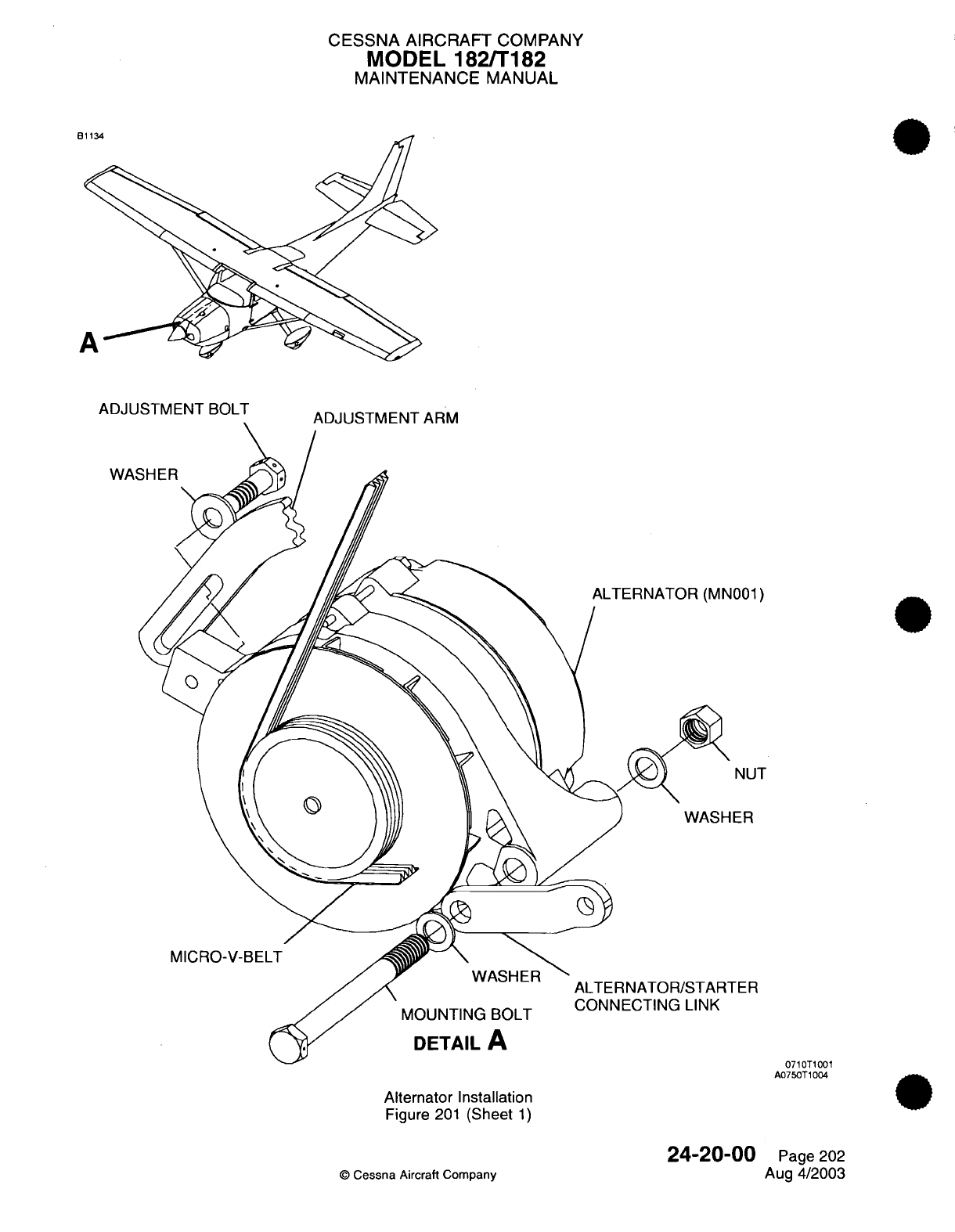
CESSNA
AIRCRAFT
COMPANY
MODEL
182/T182
MAINTENANCE
MANUAL
WASHER
1001)
NUT
ER
MICRO-V-BELT
TER
IVIUUIN
I IIU
DUL
I
DETAIL
A
0710T1001
A0750T1004
Alternator
Installation
Figure
201
(Sheet
1)
24-20-00
©
Cessna
Aircraft
Company
Page 202
Aug
4/2003
ndd~J
k AI/-% Ik
ITII
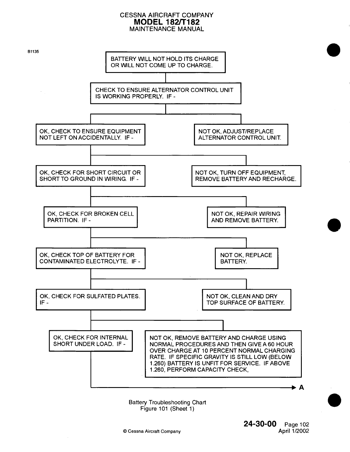
CESSNA
AIRCRAFT
COMPANY
MODEL
182/T182
MAINTENANCE
MANUAL
BATTERY
WILL
NOT
HOLD
ITS
CHARGE
OR
WILL
NOT
COME
UP
TO
CHARGE.
CHECK
TO
ENSURE ALTERNATOR
CONTROL
UNIT
IS
WORKING
PROPERLY.
IF
-
OK, CHECK
TO ENSURE
EQUIPMENT
NOT
LEFT
ON ACCIDENTALLY.
IF
-
OK,
CHECK FOR
SHORT
CIRCUIT
OR
SHORT
TO
GROUND
IN
WIRING.
IF
-
OK,
CHECK
FOR
BROKEN
CELL
PARTITION.
IF-
OK, CHECK
TOP
OF
BATTERY FOR
CONTAMINATED
ELECTROLYTE.
IF
-
OK,
CHECK
FOR SULFATED PLATES.
IF-
OK,
CHECK
FOR
INTERNAL
SHORT
UNDER LOAD.
IF
-
NOT
OK,
ADJUST/REPLACE
ALTERNATOR
CONTROL
UNIT.
NOT
OK,
TURN
OFF
EQUIPMENT,
REMOVE
BATTERY
AND RECHARGE.
NOT
OK,
REPAIR
WIRING
AND
REMOVE
BATTERY.
NOT
OK,
REPLACE
BATTERY.
NOT
OK,
CLEAN
AND
DRY
TOP
SURFACE
OF
BATTERY.
NOT OK, REMOVE
BATTERY
AND
CHARGE USING
NORMAL
PROCEDURES AND
THEN GIVE
A
60
HOUR
OVER
CHARGE
AT
10
PERCENT NORMAL CHARGING
RATE.
IF
SPECIFIC
GRAVITY
IS
STILL
LOW
(BELOW
1.260)
BATTERY
IS
UNFIT FOR
SERVICE.
IF
ABOVE
1.260,
PERFORM
CAPACITY CHECK,
, A
Battery
Troubleshooting
Chart
Figure
101
(Sheet
1)
O
Cessna
Aircraft
Company
24-30-00
Page
102
April
1/2002
B1135
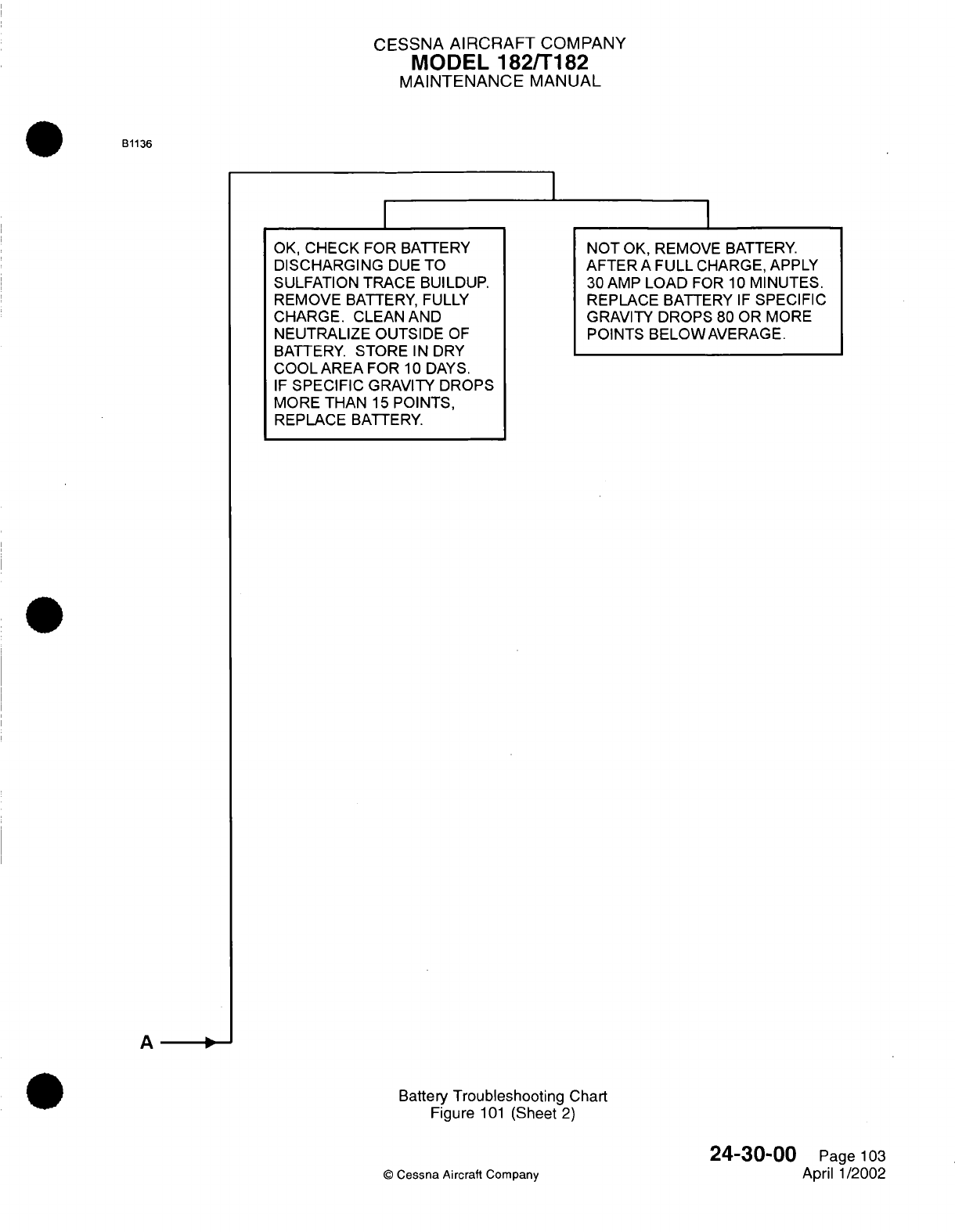
CESSNA
AIRCRAFT
COMPANY
MODEL
182/T182
MAINTENANCE
MANUAL
B1136
I
OK,
CHECK
FOR
BATTERY
DISCHARGING
DUE
TO
SULFATION
TRACE
BUILDUP.
REMOVE
BATTERY, FULLY
CHARGE.
CLEAN
AND
NEUTRALIZE
OUTSIDE
OF
BATTERY.
STORE
IN
DRY
COOLAREA
FOR
10
DAYS.
IF
SPECIFIC
GRAVITY
DROPS
MORE THAN
15
POINTS,
REPLACE
BATTERY.
NOT
OK, REMOVE
BATTERY.
AFTER
A
FULL
CHARGE,
APPLY
30
AMP
LOAD
FOR
10
MINUTES.
REPLACE
BATTERY
IF
SPECIFIC
GRAVITY
DROPS
80
OR MORE
POINTS
BELOWAVERAGE.
A
--
Battery
Troubleshooting Chart
Figure
101
(Sheet
2)
©
Cessna Aircraft
Company
24-30-00
Page
103
April
1/2002
I
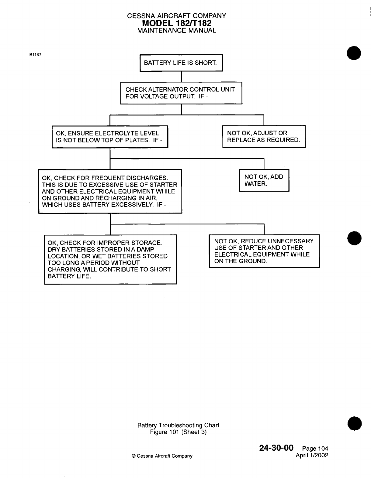
CESSNA
AIRCRAFT
COMPANY
MODEL
182/T182
MAINTENANCE
MANUAL
B1137
BATTERY
LIFE
IS
SHORT.
I
CHECK
ALTERNATOR
CONTROL
UNIT
FOR
VOLTAGE
OUTPUT.
IF
-
OK,
ENSURE
ELECTROLYTE
LEVEL
IS
NOT BELOW
TOP
OF
PLATES.
IF
-
OK,
CHECK FOR
FREQUENT DISCHARGES.
THIS
IS
DUE
TO
EXCESSIVE
USE
OF
STARTER
AND
OTHER ELECTRICAL
EQUIPMENT WHILE
ON
GROUND
AND
RECHARGING
IN
AIR,
WHICH
USES
BATTERY
EXCESSIVELY.
IF
-
OK, CHECK
FOR
IMPROPER
STORAGE.
DRY
BATTERIES
STORED
IN
A
DAMP
LOCATION, OR WET BATTERIES
STORED
TOO
LONG
A
PERIOD
WITHOUT
CHARGING,
WILL
CONTRIBUTE
TO
SHORT
BATTERY
LIFE.
NOT
OK,
ADJUST
OR
REPLACE
AS
REQUIRED.
NOT
OK,
ADD
WATER.
NOT
OK, REDUCE
UNNECESSARY
USE
OF STARTER AND
OTHER
ELECTRICAL EQUIPMENT
WHILE
ON
THE
GROUND.
Battery
Troubleshooting
Chart
Figure
101
(Sheet
3)
24-30-00
©
Cessna
Aircraft
Company
Page
104
April
1/2002
I
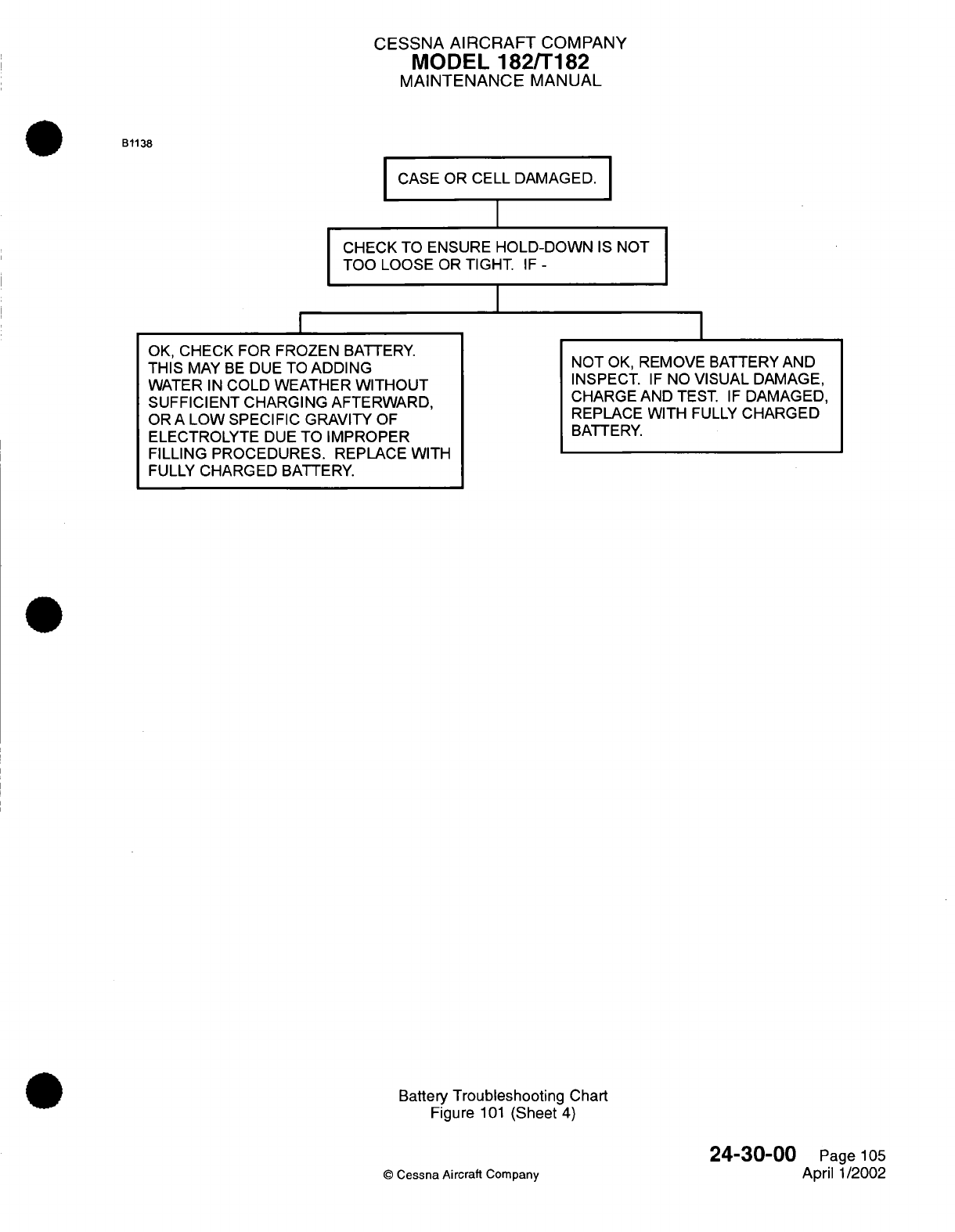
CESSNA
AIRCRAFT
COMPANY
MODEL
182/T182
MAINTENANCE
MANUAL
B1138
CASE OR
CELL
DAMAGED.
CHECK TO ENSURE
HOLD-DOWN
IS
NOT
TOO
LOOSE
OR
TIGHT.
IF
-
I
OK,
CHECK FOR
FROZEN
BATTERY.
THIS
MAY
BE
DUE
TO
ADDING
WATER
IN
COLD WEATHER
WITHOUT
SUFFICIENT CHARGING
AFTERWARD,
OR A
LOW
SPECIFIC GRAVITY
OF
ELECTROLYTE
DUE
TO
IMPROPER
FILLING PROCEDURES.
REPLACE
WITH
FULLY
CHARGED
BATTERY.
NOT
OK,
REMOVE
BATTERY
AND
INSPECT.
IF
NO
VISUAL
DAMAGE,
CHARGE AND
TEST.
IF
DAMAGED,
REPLACE WITH
FULLY
CHARGED
BATTERY.
Battery
Troubleshooting
Chart
Figure
101
(Sheet
4)
©
Cessna Aircraft
Company
24-30-00
Page
105
April
1/2002
I
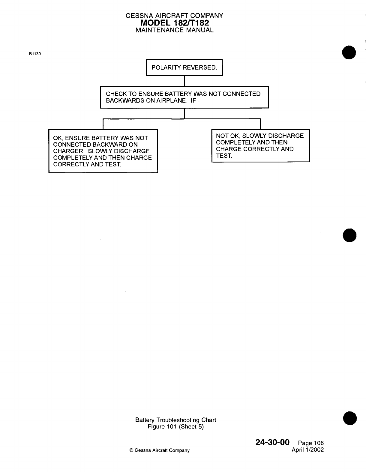
CESSNA AIRCRAFT
COMPANY
MODEL
182/T182
MAINTENANCE
MANUAL
B1139
POLARITY
REVERSED.
I
CHECK TO
ENSURE
BATTERY WAS
NOT
CONNECTED
BACKWARDS
ON
AIRPLANE.
IF
-
I
OK,
ENSURE
BATTERY WAS NOT
CONNECTED
BACKWARD
ON
CHARGER.
SLOWLY
DISCHARGE
COMPLETELY AND
THEN CHARGE
CORRECTLY AND
TEST.
NOT
OK,
SLOWLY
DISCHARGE
COMPLETELY
AND
THEN
CHARGE
CORRECTLY
AND
TEST.
Battery
Troubleshooting
Chart
Figure
101
(Sheet
5)
©
Cessna
Aircraft Company
24-30-00
Page
106
April
1/2002
I
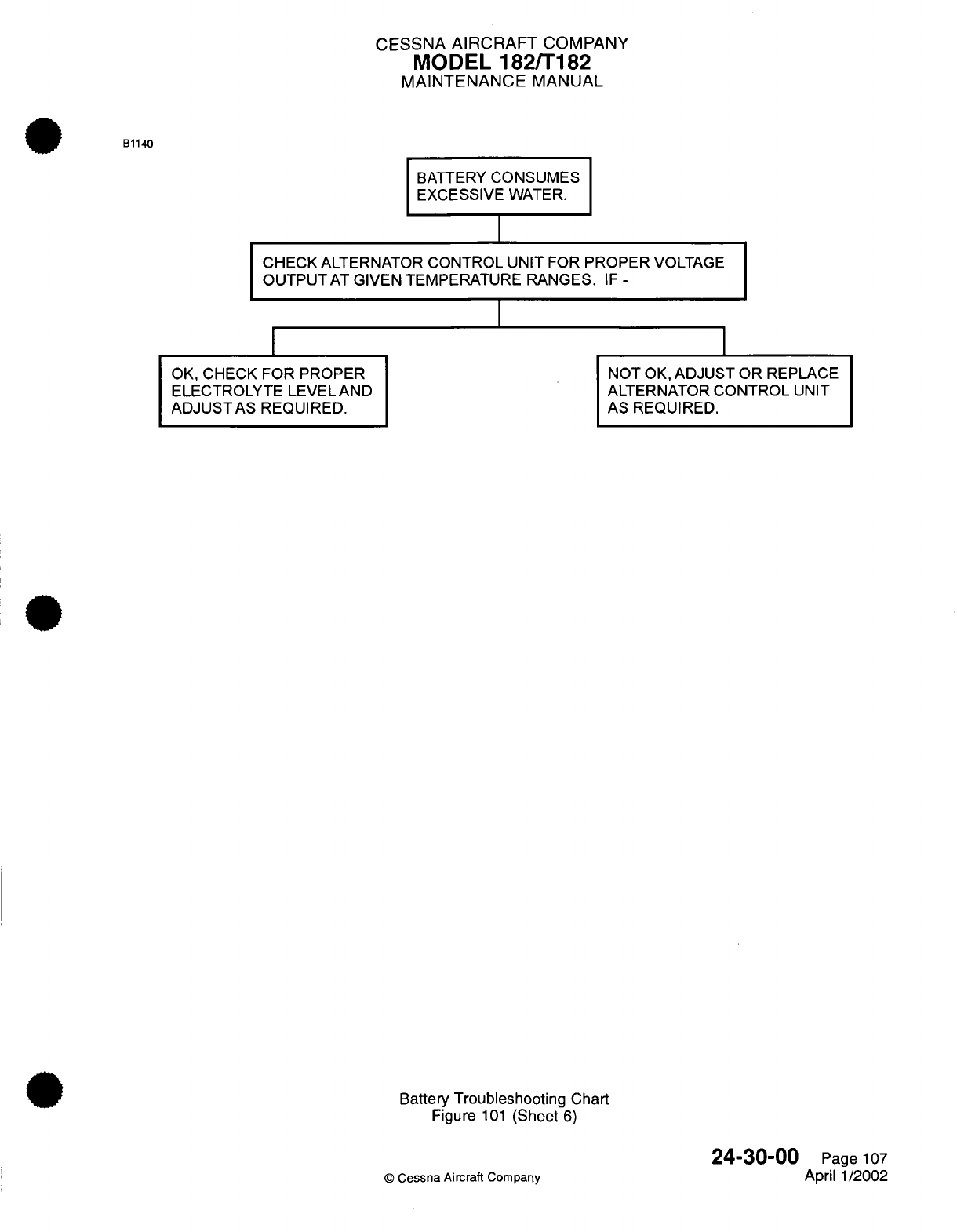
CESSNA
AIRCRAFT
COMPANY
MODEL
182/T182
MAINTENANCE
MANUAL
B1140
BATTERY
CONSUMES
EXCESSIVE
WATER.
CHECK ALTERNATOR
CONTROL
UNIT
FOR
PROPER
VOLTAGE
OUTPUTAT
GIVEN TEMPERATURE RANGES.
IF
-
I
I
I
OK,
CHECK FOR
PROPER
ELECTROLYTE
LEVELAND
ADJUSTAS
REQUIRED.
NOT
OK,
ADJUST
OR REPLACE
ALTERNATOR
CONTROL
UNIT
AS
REQUIRED.
Battery
Troubleshooting Chart
Figure
101
(Sheet
6)
©
Cessna
Aircraft
Company
24-30-00
Page
107
April 1/2002
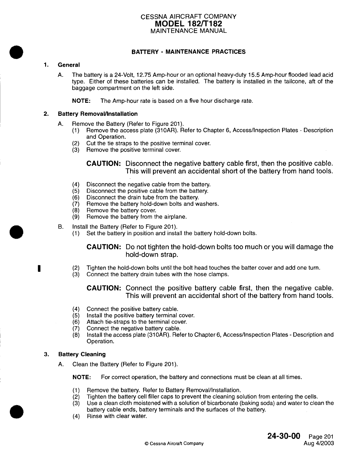
CESSNA AIRCRAFT
COMPANY
MODEL
182/T182
MAINTENANCE
MANUAL
BATTERY
-
MAINTENANCE
PRACTICES
1.
General
A.
The battery
is
a
24-Volt,
12.75
Amp-hour
or
an
optional
heavy-duty
15.5
Amp-hour
flooded
lead
acid
type.
Either
of
these
batteries
can
be
installed.
The
battery
is
installed
in
the
tailcone,
aft
of the
baggage
compartment
on
the
left
side.
NOTE:
The
Amp-hour
rate
is
based
on a
five
hour
discharge
rate.
2.
Battery
Removal/Installation
A.
Remove the Battery (Refer
to
Figure
201).
(1)
Remove the
access
plate
(31
OAR).
Refer
to
Chapter
6,
Access/Inspection
Plates
-
Description
and
Operation.
(2)
Cut
the
tie
straps
to
the
positive
terminal
cover.
(3)
Remove the
positive
terminal
cover.
CAUTION:
Disconnect
the
negative
battery cable
first,
then
the
positive
cable.
This
will
prevent
an
accidental
short
of
the
battery
from
hand
tools.
(4)
Disconnect
the
negative
cable
from
the
battery.
(5)
Disconnect
the
positive
cable
from the
battery.
(6)
Disconnect
the
drain
tube
from the
battery.
(7)
Remove
the battery hold-down
bolts
and
washers.
(8)
Remove
the
battery
cover.
(9)
Remove the battery
from
the airplane.
B.
Install
the
Battery
(Refer
to Figure
201).
(1)
Set
the battery
in
position
and
install the
battery hold-down
bolts.
CAUTION:
Do
not
tighten
the
hold-down bolts
too
much
or
you
will
damage
the
hold-down
strap.
|* ~ (2)
Tighten the
hold-down
bolts
until
the
bolt
head
touches
the
batter
cover
and add
one
turn.
(3)
Connect
the
battery
drain
tubes
with
the
hose clamps.
CAUTION:
Connect
the
positive
battery
cable first,
then
the
negative cable.
This
will
prevent
an
accidental short
of
the
battery
from
hand
tools.
(4)
Connect
the
positive
battery
cable.
(5)
Install
the
positive
battery terminal
cover.
(6)
Attach
tie-straps
to
the
terminal
cover.
(7)
Connect
the negative
battery
cable.
(8)
Install the
access
plate
(31
OAR).
Refer
to
Chapter
6,
Access/Inspection
Plates
-
Description
and
Operation.
3.
Battery Cleaning
A.
Clean
the Battery
(Refer
to
Figure
201).
NOTE:
For
correct operation,
the
battery
and
connections
must
be
clean
at
all
times.
(1)
Remove the
battery.
Refer
to
Battery
Removal/Installation.
(2)
Tighten
the
battery
cell
filler
caps
to
prevent
the
cleaning
solution
from
entering the
cells.
(3)
Use
a
clean
cloth
moistened
with
a
solution
of
bicarbonate
(baking
soda)
and
water to
clean
the
battery cable
ends,
battery
terminals
and the
surfaces
of
the battery.
(4)
Rinse
with
clear
water.
24-30-00
Page
201
©
Cessna Aircraft
Company
Aug
4/2003
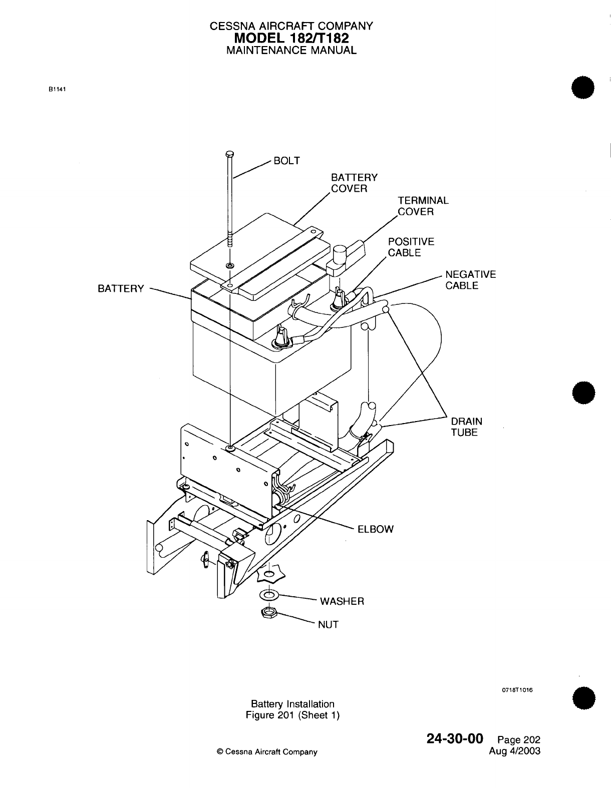
CESSNA AIRCRAFT
COMPANY
MODEL
182/T182
MAINTENANCE
MANUAL
B1141
BOLT
BATTERY
COVER
BATTERY
EGATIVE
ABLE
DRAIN
TUBE
-
f
ANUnti-
NUT
0718T1016
Battery
Installation
Figure
201
(Sheet
1)
©
Cessna
Aircraft Company
24-30-00
Page
202
Aug
4/2003
CESSNA
AIRCRAFT
COMPANY
MODEL
182/T182
MAINTENANCE
MANUAL
(5)
Use
a
dry
cloth
to
clean
off
the
water
and
let
the
battery
dry.
(6)
Polish
the cable
ends
and
battery
terminals
with
an
emery
cloth
or
a
wire
brush.
(7)
Install
the
battery.
Refer
to Battery
Removal/Installation.
(8)
Apply
petroleum
jelly
or
an
ignition
spray product
to
the
battery terminals
to
decrease corrosion.
4. New
Battery
Activation
A.
Activate
the
New Battery.
(1)
Do
a
specific
gravity
check
to
make sure the
correct strength
of
electrolyte
is
used.
The
electrolyte
must
be
1.285
+0.005
or
-0.005
specific
gravity
when
it
is
measured
between
75TF
to
85'F
(24<C
to 30'C).
(2)
To
charge
a
new
battery,
use
the
manufacturer's
instructions
supplied
with
the
battery.
(3)
Before
you install
the
battery,
clean
the battery
box.
Refer
to Chapter
12,
Battery
-
Servicing.
(4)
Install
the
battery
in
the
airplane.
Refer
to Battery
Removal/Installation.
5.
Battery Charging
NOTE:
The
procedures
that
follow
are
for batteries
that
use
a
Gill
TSC-01V
or
a
Gill
TDMC
Battery
Charger.
WARNING:
You
must
keep
sparks
and
open flame away
from
the
battery.
The
battery
makes
hydrogen
and
oxygen
gases
when
it
is
charged.
The
gases
will collect
and
create
a
hazardous,
explosive
condition.
You
must
have
free
ventilation
of
the
battery
area
when
you
charge
it.
WARNING:
The
battery
cell
temperature must
not
be
more
than
115T
(46xC).
Reduce
the charge
rate
if
the
temperature
increases
more
than
115T
(46'C).
The
charge
must
not
cause
acid
to
be
blown
from
the
ven
ts.
A. If
you use
a
Gill
TSC-01
V
battery charger,
do
the
instructions
that
follow.
NOTE:
The
Gill
TSC-01V
is
automated
with
a
typical charge
time
of
approximately
two
hours.
Some
batteries
will
take
more
time
to
charge as
a
result
of
the
battery
condition.
(1)
Remove
the
battery
from
the
airplane
and
place
it in a
well
ventilated
area
to charge. Refer
to
Battery
Removal/Installation.
(2)
Remove
the
vent
caps
and
make
sure
the
electrolyte
level
is
above
the
plates
and
separator
material.
Do
not
fill
the battery
to
the
split
rings
at
this
time.
(3)
Do
a
specific
gravity
check
of the
battery
electrolyte
with
a
hydrometer
such
as
the Gill
FR-1
(or
equivalent)
to
determine the
battery charge.
Refer to
Table
201
and
Table
202.
(4)
Record
the value
for
each
battery cell.
(5)
Install
the
vent
caps.
(6)
Attach
the
red
cable
to the
positive
battery
terminal
and
the
black
cable
to
the
negative
battery
terminal.
(7)
Connect
the
charger
to
AC
power.
The
procedures that
follow
will
result:
(a)
The
AC
POWER
ON
indicator
light
will come
on.
(b)
The
three
battery
level
indicators
will
flash
one
time.
(c)
The
EMPTY
battery
level
indicator
will
flash
on
and
remain on.
NOTE:
The
EMPTY
battery
level
indicator
shows
that
the
battery
is
correctly
connected
and
charging.
24-30-00
Page
203
©
Cessna
Aircraft
Company
Aug
4/2003

CESSNA
AIRCRAFT
COMPANY
MODEL
182/T182
MAINTENANCE
MANUAL
(8) If
the
battery
is
not
fully
charged,
the
PARTIALLY
CHARGED
indicator light
will
come
on.
Make
sure
that
the
battery
stays connected
at
this
time.
NOTE:
Make
sure
that
you
let
the
battery
fully
charge. This
will make
sure
of
a
good
battery
life
and
performance.
(a)
Do
not
disconnect
the
battery.
The
charger
will
not
operate
correctly
if
the
battery
is
disconnected
and
then
connected after
the
PARTIALLY
CHARGED
indicator
light comes
on.
If
the
battery
is
disconnected,
you must
disconnect
and
connect
the
charger
at the
electrical outlet
to
start
the
charge
process.
(9)
When
the
battery
is
fully
charged,
the
BATTERY
READY
indicator
will
come
on.
(10)
The
electrolyte
level must
touch
the bottom
of
the
split
ring while the
battery
is
warm
and
still
on
the
charger.
(a)
If
the
electrolyte
level
needs
to
be
increased, use only
distilled
or
mineral
free
water
to
adjust the electrolyte
level.
The battery
must
be
warm
when
the electrolyte
level
is
increased.
NOTE:
The
electrolyte
level
decreases
as the
battery temperature decreases.
(11)
Do
not
add
any
more
fluid
after
these
instructions
unless
the battery
electrolyte spills.
(a) If
the
fluid
level
is
below the
plates
and
separator
material
because
a
spill
occurs,
add
electrolyte
with
a
value
of 1.285
specific
gravity.
(12)
When
the
BATTERY
READY
indicator
light comes
on,
turn
the
AC
power
off.
(13)
Disconnect
the
battery
charger
from
the
electrical outlet.
(14)
Disconnect
and
remove
the
battery
from the
charger.
(15)
Do
a
specific gravity
check
of
the
battery
electrolyte.
Refer
to Table
201
and
Table
202.
(a)
The
specific
gravity values
between
cells
must
not
have
a
difference
of
more
than
0.020.
(b)
Acceptable specific
gravity
values
that
are
adjusted
for
temperature,
must
be
between
1.260
and
1.290.
(c)
If
the
battery
does
not
give
sufficient
power
to
crank the
engine
with
the
starter, then
replace
it
with
a
new
battery.
Refer
to
New Battery
Activation.
B. If
you
use
a
Gill
TDMC
battery charger,
do
the instructions
that
follow.
(1)
Remove
the
battery
from
the
airplane
and
place
it in a
well
ventilated
area
to
charge.
Refer to
Battery
Removal/Installation.
(2)
Remove
the
vent
caps
and
make
sure
the
electrolyte
level
is
above the plates
and
separator
material.
Do
not
fill
the
battery
to
the
split
rings at
this
time.
(3)
Do
a
specific
gravity
check
of
the
battery
electrolyte
with
a
hydrometer
such
as
the
Gill
FR-1
(or
equivalent)
to
determine
the
battery
charge.
Refer
to
Table
201
and Table 202.
(4)
Record
the
value
for
each
battery
cell.
(5)
Install
the
vent
caps.
(6)
Click the
Gill
TDMC
charger
ON
button two times
to
select
the
24
volt
position.
(7)
Set
the
timer
for
8
to
10
hours.
NOTE:
The
charger
is
in
a
constant
current
mode
when
the
timer
is
on.
(8)
Set
the
charge
rate
to
1.5
amps.
CAUTION:
Do
not
let
the
battery
charger charge
at
32
volts
for
more
than
thirty
minutes.
(9)
Charge
the
battery
until
the
voltage
stabilizes
for
three
consecutive
hours
or
shows
32
volts,
whichever occurs
first.
NOTE:
The
charge
is
measured
across
the
battery
terminals
with
the
charger
on.
24-30-00
Page
204
©
Cessna Aircraft Company
Aug
4/2003
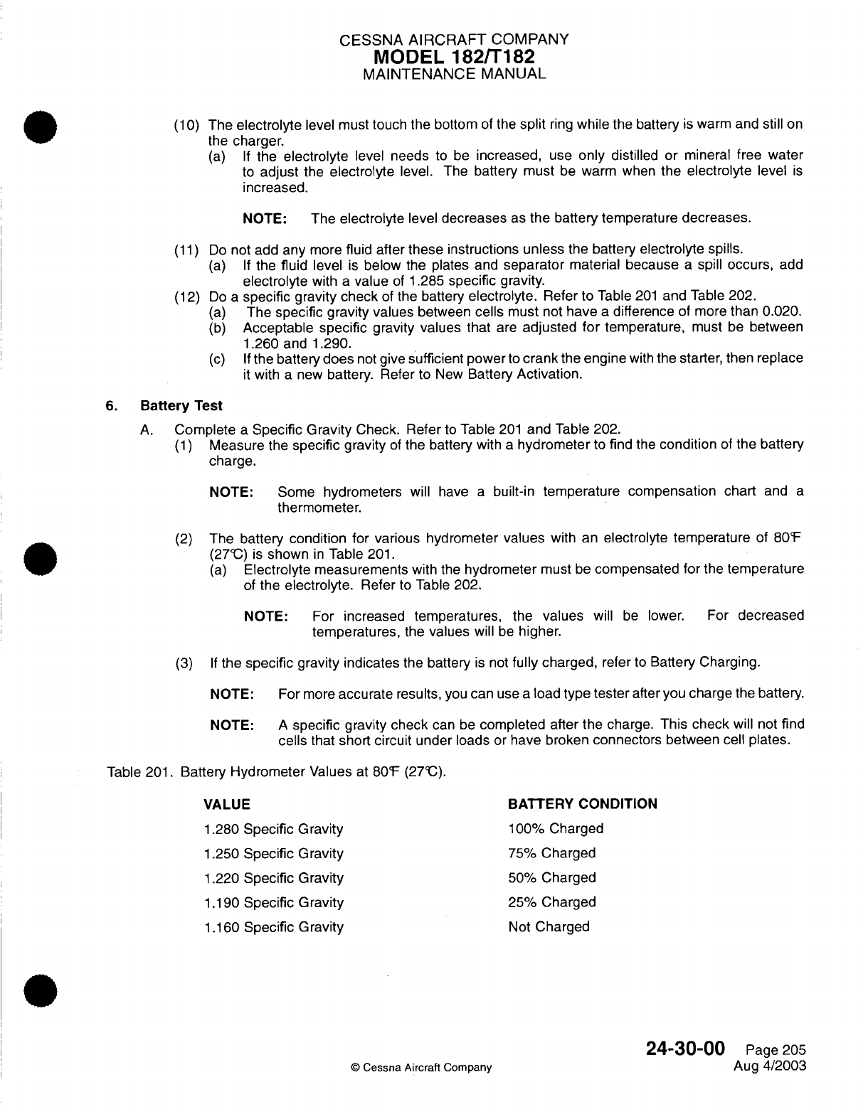
CESSNA
AIRCRAFT
COMPANY
MODEL
182/T182
MAINTENANCE
MANUAL
(10)
The
electrolyte
level
must
touch the
bottom
of
the
split
ring
while
the battery
is
warm
and
still
on
the
charger.
(a)
If
the
electrolyte
level
needs
to
be
increased,
use
only
distilled
or
mineral
free water
to
adjust
the
electrolyte
level.
The
battery
must
be
warm when
the
electrolyte
level
is
increased.
NOTE:
The
electrolyte
level
decreases
as
the battery
temperature
decreases.
(11)
Do
not add
any
more
fluid
after
these instructions unless
the
battery
electrolyte spills.
(a)
If
the
fluid
level
is
below
the plates and
separator
material because
a
spill
occurs,
add
electrolyte
with
a
value
of
1.285
specific
gravity.
(12)
Do
a
specific gravity check
of the battery
electrolyte.
Refer to
Table
201
and
Table
202.
(a)
The
specific
gravity
values
between
cells
must
not
have
a
difference
of
more
than 0.020.
(b)
Acceptable
specific
gravity values that
are
adjusted
for
temperature,
must
be
between
1.260 and
1.290.
(c)
If
the battery
does
not
give
sufficient power
to
crank
the
engine
with
the
starter,
then
replace
it
with
a
new
battery.
Refer to
New
Battery
Activation.
6.
Battery
Test
A.
Complete
a
Specific Gravity
Check. Refer
to
Table
201
and
Table
202.
(1)
Measure
the
specific
gravity
of
the battery
with
a
hydrometer
to
find
the
condition
of
the
battery
charge.
NOTE:
Some
hydrometers
will
have
a
built-in
temperature compensation chart
and
a
thermometer.
(2)
The
battery
condition
for various hydrometer
values
with
an
electrolyte temperature
of
80'F
(27'C)
is
shown
in
Table
201.
(a)
Electrolyte measurements
with
the
hydrometer
must
be
compensated
for
the
temperature
of
the
electrolyte.
Refer
to
Table
202.
NOTE:
For
increased
temperatures,
the
values
will
be
lower.
For
decreased
temperatures,
the
values
will
be
higher.
(3)
If
the
specific
gravity indicates
the
battery
is
not
fully
charged,
refer
to
Battery Charging.
NOTE: For
more
accurate
results,
you
can
use
a
load
type
tester
after you
charge
the
battery.
NOTE:
A
specific
gravity check
can
be
completed after
the
charge.
This
check
will
not
find
cells
that
short
circuit
under
loads
or
have broken connectors
between
cell plates.
Table 201.
Battery
Hydrometer
Values
at
80F
(27'C).
VALUE
BATTERY CONDITION
1.280
Specific Gravity
100%
Charged
1.250
Specific Gravity
75%
Charged
1.220
Specific Gravity
50%
Charged
1.190
Specific Gravity
25%
Charged
1.160
Specific Gravity
Not
Charged
24-30-00
Page 205
©
Cessna Aircraft
Company
Aug
4/2003
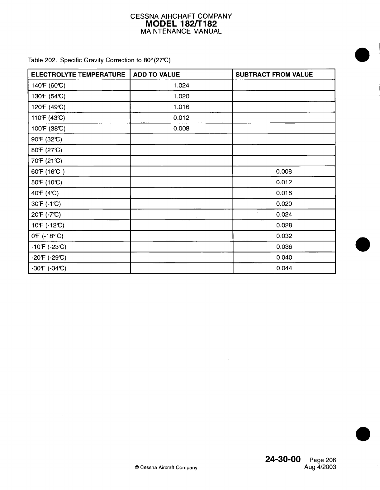
CESSNA
AIRCRAFT
COMPANY
MODEL
182/T182
MAINTENANCE
MANUAL
Table
202.
Specific Gravity
Correction
to
80°(27CC)
ELECTROLYTE TEMPERATURE ADD
TO
VALUE
140F
(60'C)
1.024
130'F
(54'C)
1.020
120F
(49C)
1.016
11OF
(43C)
0.012
1
00F
(38'C)
0.008
90'F
(32C)
80F
(270C)
70F
(21
C)
60TF
(16C
)
50F
(103C)
40F
(40C)
30'F
(-1
C)
20'F
(-7C)
10
F
(-12'C)
OF
(-18
°
C)
-10F
(-23C)
-20F
(-29'C)
-30F
(-34'C)
SUBTRACT
FROM
VALUE
0.008
0.012
0.016
0.020
0.024
0.028
0.032
0.036
0.040
0.044
24-30-00
©
Cessna
Aircraft
Company
Page
206
Aug
4/2003
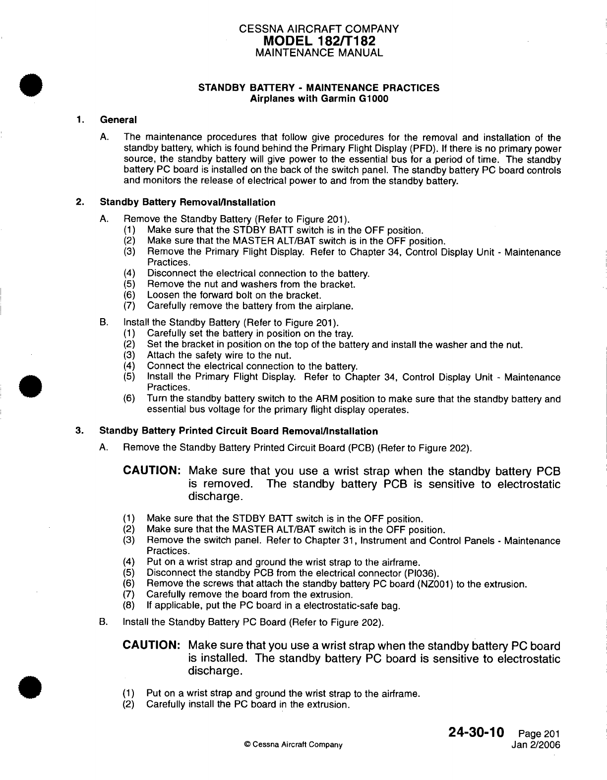
CESSNA
AIRCRAFT
COMPANY
MODEL
182/T182
MAINTENANCE
MANUAL
STANDBY
BATTERY
-
MAINTENANCE PRACTICES
Airplanes with
Garmin
G1000
1.
General
A.
The
maintenance procedures
that
follow
give
procedures
for
the removal
and
installation
of
the
standby
battery,
which
is
found
behind
the
Primary
Flight
Display
(PFD).
If
there
is
no
primary
power
source,
the
standby
battery
will
give
power
to
the
essential
bus for
a
period
of
time. The
standby
battery
PC
board
is
installed
on
the
back
of
the
switch
panel.
The
standby
battery
PC
board
controls
and monitors
the
release
of electrical
power
to
and
from
the
standby
battery.
2.
Standby
Battery
Removal/Installation
A.
Remove
the
Standby
Battery
(Refer to Figure
201).
(1)
Make sure
that
the STDBY
BATT
switch
is
in
the
OFF
position.
(2)
Make sure
that
the
MASTER
ALT/BAT
switch
is
in
the
OFF
position.
(3)
Remove
the
Primary
Flight
Display.
Refer
to
Chapter
34,
Control
Display
Unit
-
Maintenance
Practices.
(4)
Disconnect
the
electrical
connection
to the
battery.
(5)
Remove
the
nut
and
washers
from
the
bracket.
(6)
Loosen
the forward
bolt
on
the
bracket.
(7)
Carefully
remove the
battery
from
the
airplane.
B.
Install
the
Standby
Battery
(Refer
to Figure
201).
(1)
Carefully
set
the
battery
in
position
on
the
tray.
(2)
Set
the
bracket
in
position
on
the
top
of the
battery and
install
the
washer
and the
nut.
(3)
Attach
the
safety
wire
to
the nut.
(4)
Connect
the
electrical connection
to
the
battery.
(5)
Install the
Primary
Flight
Display.
Refer
to
Chapter
34,
Control Display
Unit
-
Maintenance
Practices.
(6)
Turn
the
standby
battery
switch
to
the
ARM
position
to make
sure
that
the
standby
battery
and
essential
bus
voltage
for
the
primary
flight
display
operates.
3.
Standby
Battery Printed
Circuit
Board
Removal/Installation
A.
Remove
the
Standby
Battery
Printed
Circuit
Board
(PCB)
(Refer
to
Figure
202).
CAUTION:
Make
sure
that
you use
a
wrist
strap
when the
standby
battery
PCB
is
removed.
The
standby
battery
PCB
is
sensitive
to
electrostatic
discharge.
(1)
Make
sure
that
the STDBY
BATT
switch
is
in
the
OFF
position.
(2)
Make
sure
that
the
MASTER
ALT/BAT
switch
is
in
the
OFF
position.
(3)
Remove
the
switch
panel.
Refer
to
Chapter
31,
Instrument
and Control
Panels
-
Maintenance
Practices.
(4) Put
on
a
wrist
strap
and
ground
the
wrist
strap
to
the
airframe.
(5)
Disconnect
the
standby
PCB
from
the
electrical connector
(PI036).
(6)
Remove
the
screws
that
attach
the
standby
battery
PC
board
(NZ001)
to
the
extrusion.
(7)
Carefully
remove
the
board
from
the
extrusion.
(8)
If
applicable,
put
the
PC
board
in a
electrostatic-safe
bag.
B.
Install
the
Standby
Battery
PC
Board
(Refer
to
Figure
202).
CAUTION:
Make
sure that
you
use
a
wrist
strap
when
the
standby battery
PC
board
is
installed.
The
standby
battery
PC
board
is
sensitive
to
electrostatic
discharge.
(1)
Put
on a
wrist
strap
and
ground
the
wrist
strap
to
the
airframe.
(2)
Carefully install
the
PC
board
in
the
extrusion.
24-30-10
Page
201
©
Cessna
Aircraft
Company
Jan 2/2006
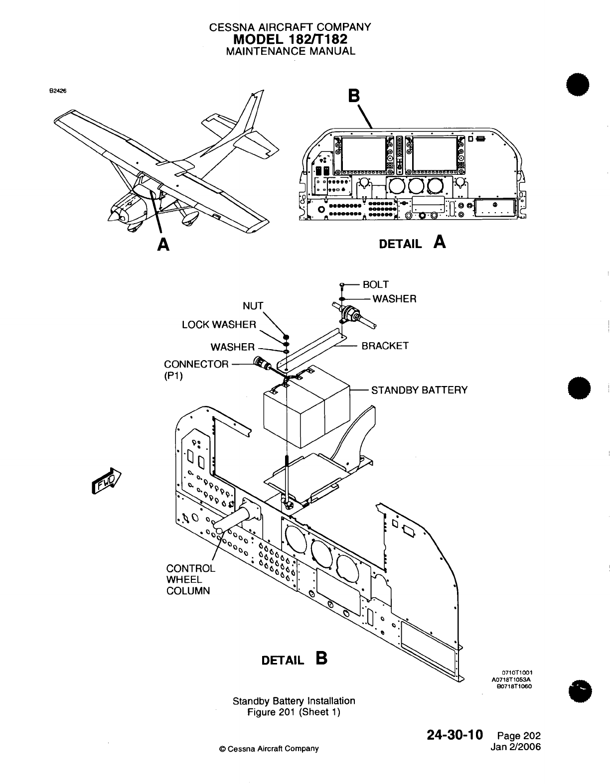
CESSNA
AIRCRAFT
COMPANY
MODEL
182/T182
MAINTENANCE
MANUAL
B
Q-
BOLT
NUT
Standby
Battery
Installation
Figure
201
(Sheet
1)
24-30-10
©
Cessna
Aircraft
Company
A
DETAIL
A
*-
WASHER
lz>%i
0710T1001
A0718T1053A
B0718T1060
Page
202
Jan
2/2006
I^
0
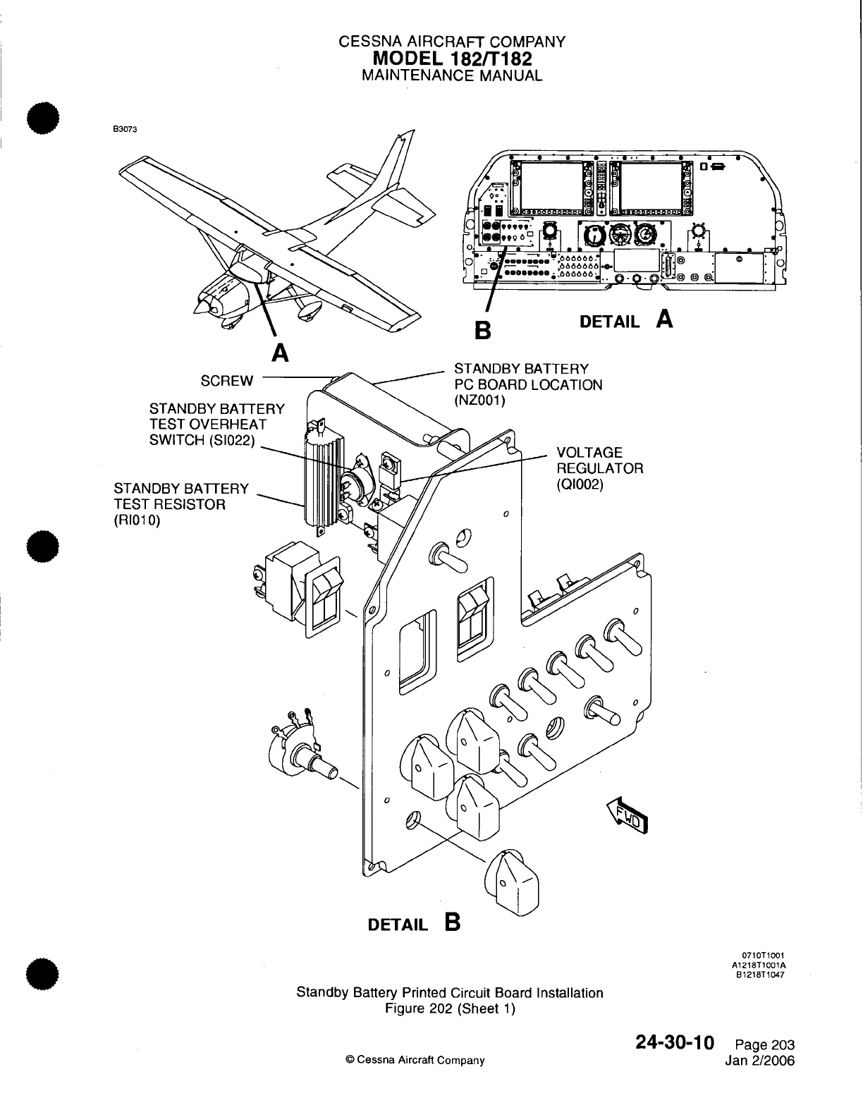
CESSNA
AIRCRAFT
COMPANY
MODEL
182/T182
MAINTENANCE
MANUAL
B
' ' .
.....
...:
^
^.[Q'®®..
.P
*uums
6
·
:1
eee
-
,--eoa-o-
o
666664.
.
I0 a r66.
0.
.'
o
a '
_
'
?•~~~.
SCREW
STANDBY
BATI
TEST OVERHE/
SWITCH
(S1022)
STANDBY
BATTERY
TEST
RESISTOR
(RI01
0)
DETAIL
B
0710T1001
A1218T1001A
B1218T1047
Standby
Battery
Printed Circuit
Board
Installation
Figure
202 (Sheet
1)
©
Cessna
Aircraft
Company
24-30-10
Page
203
Jan
2/2006
A
9
I
.0
B
DETAIL
A
Am
A
CESSNA
AIRCRAFT
COMPANY
MODEL
182/T182
MAINTENANCE
MANUAL
(3)
Install
the
screws
that attach the
board
to
the
extrusion.
(4)
Connect
the
board to the
electrical
connector
(PI036).
(5)
Install
the switch
panel. Refer
to
Chapter
31,
Instrument
and
Control
Panels
-
Maintenance
Practices.
4.
Standby
Battery
Charging
A.
Charge
the
Battery.
(1)
Remove
the
battery
from
the
airplane
and
put
it in
a
well-ventilated
area
to
charge.
Refer
to
Chapter
24,
Standby
Battery
-
Removal/Installation.
(2)
Connect
the
battery to
the
charger
with the
black,
round
Standby
Battery Connector
(P1).
A
mating
connector
(JC032)
is
available
from
Cessna
Aircraft
Company. Refer
to
the
Model
182S/
182T/T182T
Wiring
Diagram
Manual,
Chapter
24
Electrical
Power
-
Battery
System.
NOTE:
To
charge the
standby
battery,
a
constant voltage charger,
constant
current
charger,
or
a
modification
of both
is
used.
Use
only
chargers
that
are
made
to
charge
lead
acid batteries.
A
constant voltage
"fast" charge
can
be
done with
a
charger that
has
a
DC
voltage
between 28.3
and
30.0
volts.
A
"float"
charge
can be
done
with
a
charger
that
has
a
DC
voltage
between
27.2
and
28.2
volts.
|I
CAUTION:
Never set
the
charger
to
a
level
higher than 30.0
volts
or you can
damage
the
battery.
(3)
For
a
constant
current
charger,
charge
the battery per the
charger's
instructions.
NOTE:
There
is
no
limit
on
the
initial charge
current
as
long
as the
voltage
is
not
more
than
30.0
volts.
If it
is
necessary
to
set
the
charger
to
the
battery
capacity,
use
8
amp-hour
as
the standby
battery
capacity.
(4)
For
a
constant
voltage
charger,
charge
the battery
for
up
to
16
hours
with
a
"fast"
charge
voltage
between
28.3
and
30.0
volts.
NOTE:
Charge times
of less
than
16
hours
can
be
done,
depending
on
the state
of
charge
of
the
battery.
The
battery
can
be
thought
to
be
completely charged
if
the
charge
current stays
stable
(approximately
.1
to
.2
amps)
for
a
minimum
of
one
hour.
You
can
charge
the battery
for
more
than
16
hours
if
you
keep
the
charge
voltages
between
the
recommended float charge
range
(between
27.2
and
28.2
volts).
(5)
Install
the battery. Refer
to Chapter
24,
Standby
Battery
-
Removal/Installation.
(6)
Do
the
Standby
Battery Energy
Level
Test
in
the
Pilot's
Operating Handbook,
Chapter
4
-
Starting
Engine
Procedures.
Make
sure
that
the green
test light
for
the
standby
battery
comes
on and
stays
on
for
the
specified
time
period.
5.
Standby
Battery
Storage
A.
For
the best battery
life,
keep the
standby
battery
in
a
fully charged
state
when
not
in
use.
This
is
true
when
installed
on
the
aircraft
and
when
in
long-term
storage.
To
leave
the
battery
in
an
uncharged
state
for
a
given
period
of
time
will
decrease
the
life
of
the
battery.
It
is
recommended
to
charge
the
battery
at
a
minimum
of
once
every three
months
of
inactivity.
In
warm
climates,
a
more
frequent
charge
will
be
necessary.
B.
Do
not
keep the
battery
in
storage
for
long
periods
of
time
in
an
environment where
the
temperature
is
more
than
approximately
77
°F
(25 °C).
Sun
shades
that
cover
the
aircraft
deck
skin
that
decrease
the
temperature
of
the
battery
are
recommended
when
the
aircraft
is
parked
in
direct sunlight.
24-30-10
Page
204
©
Cessna
Aircraft Company
Jan
2/2006
CESSNA
AIRCRAFT
COMPANY
MODEL
182/T182
MAINTENANCE
MANUAL
6.
Standby Battery
Capacity
Test
A.
The
battery
capacity
must
be
tested.
Refer
to
Chapter
5,
Inspection
Time
Limits.
This
test
is
also
necessary
to give
the battery
condition
if
the
battery
voltage
decreases
to less
than 20.0
volts,
such
as
in
unintentional
deep
discharge.
B.
Battery
Capacity
Test
(1)
Make
sure
that
the
battery
is
fully charged
before
the
capacity
test
is
started.
If
charge
condition
is
unknown,
charge the
battery.
Refer
to
Chapter
24
Standby
Battery
-
Maintenance
Practices.
(2)
Put
the
airplane
in
an
area where
there
are
high
cabin light
levels.
Use
sunlight or
a
well-lit
hangar facility.
NOTE:
The
photocell
on the
PFD
must
cause
the
PFD
light
level
to
be
full bright.
The
AVIONICS
rheostat
cannot
operate
with
the
primary
alternator
and
battery
off.
(3)
Turn
the
STDBY
IND
rheostat
to
the
full
clockwise
position.
NOTE:
A
stopwatch
will
be
necessary
in
the
following
steps
to
time
the
battery
discharge.
(4)
With
the
BAT/ALT
MASTER
switch
in
the
OFF
position, set
the
STDBY
BATT
switch
to
the
ARM
position
and immediately
start
the
stopwatch.
(5)
Make
sure
that
all
of
the
equipment
on
the
essential
bus
operates
correctly.
NOTE:
After
initialization,
the
PFD
operates
in
full
bright
mode
with
only
red X's
over
the
NAV
2,
COM
2,
and XPDR
functions.
(6)
Make
sure
that
all
the
standby
indicator lights
come
on.
(7)
Make sure
that
the
MFD
and
all
the
other
electrical
and
avionic
equipment
on
the
primary
busses
are
not
on.
(a) If
the
conditions
in
steps
6
through
8
are
not
met,
stop
the
test
and
correct
these
conditions.
(b)
Start
at
Step
1
when
the condition
has
been
corrected.
NOTE:
The
standby
battery
initial current
discharge
is
between
2.1
and
3.1
amps
as
shown
on
the
PFD
standby battery
ammeter.
The
essential
bus
initial
voltage
is
approximately
24.2
volts
as
shown
on
the
PFD
essential
bus voltmeter.
(8)
Continuously
monitor
the
essential
bus
voltage
as
shown
on
the
PFD
essential bus voltmeter.
The
battery
capacity
is
satisfactory
if
the
bus
voltage stays
above
20.0
volts
for
a
minimum
of
55
minutes.
(9)
Set
the
STDBY
BATT
switch
to
OFF
if
the
essential bus decreases
to
20.0
volts
or
after
55
minutes.
CAUTION:
Do
not
let
the
essential
bus
voltage
decrease
below 20.0
volts
or
you
can
cause
damage
to
the
standby
battery.
Set
the
STDBY
BATT
switch
to
the OFF
position
before
the
voltage drops
below
20.0
volts.
Voltage
values
less
than
22.5
volts
can
decrease
quickly
so
monitor
the
voltage
closely.
If
the
voltage
drops below
20.0
volts,
charge
the
battery immediately
and
do
the
test
again.
NOTE:
If
the
standby
battery
does
not
stay above
20.0 volts
for
55
minutes during
the capacity
test, the
battery
is
not
acceptable
for
return
to
service.
(10)
Charge the
battery.
Refer
to
Chapter
24,
Battery
-
Maintenance
Practices,
Battery
Charging.
24-30-10
Page
205
©
Cessna Aircraft
Company
Jan
2/2006
CESSNA
AIRCRAFT
COMPANY
MODEL
182/T182
MAINTENANCE
MANUAL
12-VOLT
CABIN
POWER
SYSTEM
-
TROUBLESHOOTING
1.
General
A.
The
12-volt
cabin power
outlet
on the
pedestal uses
a
power
converter
to
convert 28-volt
DC
input
power
to
13.8-volt
DC
output
power.
In
airplanes
with
the
Garmin G1000
the
power
converter
is
in
the
cockpit
on the
aft,
right
side
of the
firewall.
The
power
converter
in
all
other
airplanes
is
in
the
tailcone.
B.
The 12-volt cabin
power
outlet
behind
the
copilot's
seat
and
near
the
headset
jacks
on
airplanes
with
Garmin
G
1000
uses
a
power converter
to
convert
28-volt
DC
input
power
to
13.8-volt
DC
output
power.
The
20
amps
of
12-volt power are split
evenly
between the forward
and
the aft
power
outlets.
In
airplanes
with
the Garmin
G1000
installed,
a
CABIN
PWR
12V
switch
is
located on the
switch panel.
C.
The
converter output
is
used to
power
electrical devices that
require
a
12-volt
power
input.
The
electrical connections
are
made
with
the
use
of
a
terminal
block
that
is
on
the
side
of
the
converter.
The
converter's output
can
be
turned
on
and
off
by
the
use
of the
ON/OFF
signal
terminal
on
the
converter's
terminal
block.
When
28
VDC
is
applied
to
this
terminal, the
converter
will
turn
the
output
on.
When
the
28
VDC
is
removed
from
the
terminal,
the
output
is
turned
off.
2.
Cabin
Power
Interface
A.
Complete
a
Test
of
the
Cabin Power Interface (Refer
to Figure
101).
(1)
Make
sure
the ALT/BAT
Master
switch
is in
the
ON
position.
(2)
For
airplanes
with
serials
18280001 thru
18281197
and
airplanes
T18208001 thru
T18208185,
use
a
12-Volt
DC
power
adapter
to
do
the
test.
Refer
to
Tools,
Equipment
and
Materials.
(a)
Attach the
adapter
to the
cabin
power
system.
(3)
Use
a
voltmeter
to
make
sure
the output
shows
13.4
volts,
+0.9
or
-0.9
volts
at
the
cabin
power
interface.
(4) If
the
correct
voltage
is
not
indicated,
refer to
the
Power
Converter troubleshooting procedures.
3.
Power
Converter
A.
Test
the
Power
Converter
(Refer
to
Figure
102
and
to
the
Model
182
Wire
Diagram
Manual,
Chapter
24,
Power
Interface).
(1)
Disconnect
the
connector
(JI).
(2)
Test
for
approximately
24-Volts between
VI+
and
VI-
at
the
connector
(JI).
(3)
Test
for
approximately
24-Volts
between
the
ON/OFF
and
VI-
at
the
connector
(JI).
(4)
If
there
is
no
voltage,
examine the
wiring
from
the power
convertor
to
the
connector
(JI)
for
damage
or
bad
connections.
(a)
Repair or
replace the
connector
(JI)
or
the
wiring as
necessary.
1
Attach
the
connector
(JI).
2
Test
the
cabin
power
interface
for
correct
operation.
Refer
to
Cabin
Power
Interface.
3
Proceed
to
step
3.A.(5)
if the
cabin
power
interface does
not
operate correctly.
(5)
Test
the
pins
VO+
and
VO-
for
an
output
of
13.4
volts,
+0.9
or
-0.9
volts.
(a) If
the
correct
voltage
is
supplied,
test
the
continuity
from
the
connector
(JI)
to
the cabin
power
interface
in
Figure
101.
1 If
the
wire
continuity
is
not
correct
or
the
wire
is
damaged, replace
the
wiring
as
necessary.
2 If
the
wire
continuity
is
correct,
replace
the
power
converter.
24-60-00
Page
101
©
Cessna
Aircraft Company
Jan
2/2006
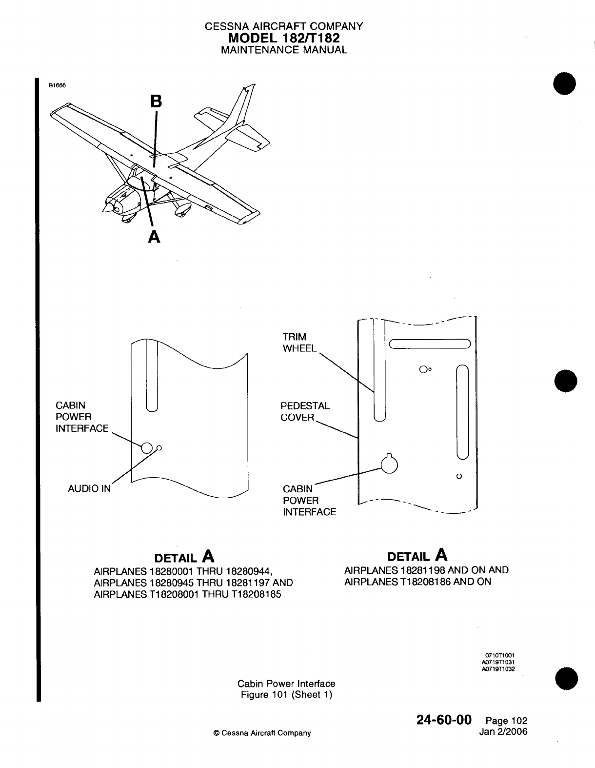
CESSNA
AIRCRAFT
COMPANY
MODEL
182/T182
MAINTENANCE
MANUAL
A
TRIM
WHEEL
PEDESTAL
COVER
CABIN
POWER
INTERFACE
AUDIO IN
AUDIO IN
(
0o
0
CABIN
POWER
- - -
INTERFACE
DETAIL
A
AIRPLANES
18280001
THRU
18280944,
AIRPLANES
18280945
THRU
18281197
AND
AIRPLANES
T18208001
THRU
T18208185
DETAIL
A
AIRPLANES
18281198
AND
ON
AND
AIRPLANES
T18208186
AND
ON
0710T1001
A071 9T1031
A0719T1032
Cabin Power
Interface
Figure
101
(Sheet
1)
24-60-00
©
Cessna
Aircraft
Company
Page
102
Jan
2/2006
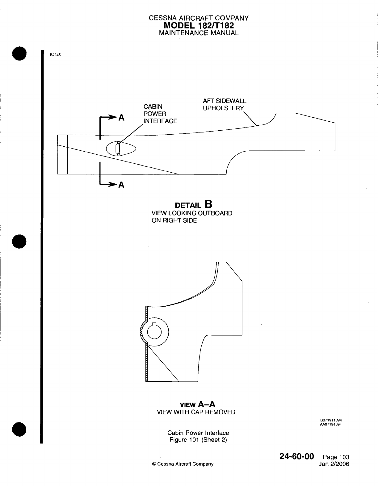
CESSNA
AIRCRAFT
COMPANY
MODEL
182/T182
MAINTENANCE
MANUAL
B4145
CABIN
nf^'\Airc
AFT
SIDEWALL
UPHOLSTERY
A
DETAIL
B
VIEW
LOOKING
OUTBOARD
ON
RIGHT
SIDE
VIEW
A-A
VIEW
WITH
CAP
REMOVED
B0719T1094
AA0719T094
Cabin
Power Interface
Figure
101
(Sheet
2)
24-60-00
©
Cessna Aircraft
Company Page
103
Jan
2/2006
*A
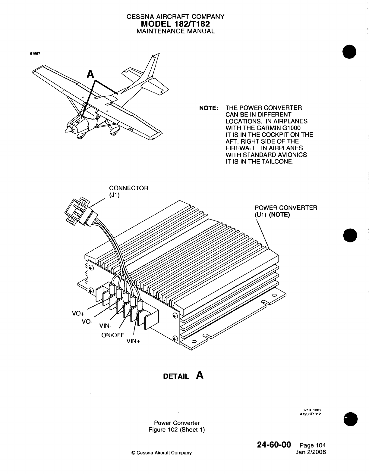
CESSNA
AIRCRAFT
COMPANY
MODEL
182/T182
MAINTENANCE
MANUAL
NOTE: THE
POWER
CONVERTER
CAN
BE
IN
DIFFERENT
LOCATIONS.
IN
AIRPLANES
WITH THE GARMIN G1000
IT
IS
IN
THE
COCKPIT
ON
THE
AFT,
RIGHT
SIDE
OF
THE
FIREWALL.
IN
AIRPLANES
WITH
STANDARD
AVIONICS
IT IS IN
THE
TAILCONE.
CONNECTOR
(J1)
JVERTER
DETAIL
A
0710T1001
A1260T1012
Power
Converter
Figure
102
(Sheet
1)
24-60-00
0
Cessna
Aircraft
Company
Page
104
Jan 2/2006
neon
c
CESSNA AIRCRAFT
COMPANY
MODEL
182/T182
MAINTENANCE
MANUAL
POWER
JUNCTION
BOX
-
MAINTENANCE
PRACTICES
1.
General
A.
The
power
junction
box,
also
referred
to as
a
Master
Control
Unit
(MCU),
is
installed
on
the forward,
left
side
of
the
firewall.
The
power
junction
box has
a
battery relay,
starter
relay,
alternator
relay,
current
sensor,
external
power
relay,
alternator
control
unit,
power
distribution
bus,
and
bus
fuses
(or
circuit
breakers as
applicable).
2.
Power
Junction
Box
Removal/Installation
A.
Remove
the
Power
Junction
Box
(Refer to
Figure
201).
(1)
Remove
the
access
plate
(31
OAR)
and
disconnect
the
battery cables
(UC001).
Refer
to
Chapter
6,
Access/Inspection
Plates
-
Description
and
Operation.
(2)
Remove
the
cover
from
the
power
junction
box.
(3)
Disconnect
the
electrical connectors,
cables,
and
ground
strap
from
the
power
junction
box.
(4)
Remove
the
screws
that attach the
power
junction
box to
the
firewall.
(5)
Remove
the
power
junction
box.
B.
Install
the
Power
Junction
Box
(Refer
to
Figure
201).
(1)
Position the power
junction
box
on
the
firewall
and
attach
it
with
the
screws.
(2)
Connect
the
electrical connectors,
cables,
and
ground strap
to
the
power
junction
box.
(3)
Install
the
cover
on
the
power
junction
box.
(4)
Connect
the
battery
cables
(UC001), and
install
the
access
plate
(31
OAR).
Refer
to
Chapter
6,
Access/Inspection
Plates
-
Description
and
Operation.
3.
Component
Removal/Installation
A.
General
Precautions
and
Notes.
CAUTION:
Make
sure
that
all
electrical
power
is
removed
from
the
airplane
and
that
the
battery
is
disconnected
before
you
work
on
components
of
the
junction
box.
(1)
Individual
components
such
as
relays,
transducers,
and the
alternator
control
unit
can
be
replaced
on
an
as-needed
basis.
Refer
to
the
Model
182
Illustrated
Parts
Catalog
for
replacement
part numbers.
(2)
Before
you
disconnect
the
wires,
identify
and
put
a
label
on
the
wires
for
later
installation.
(3)
Torque
values
for
ground
and
current-carrying
studs
can
be
found
in
Chapter 20,
Torque
Data
-
Maintenance Practices.
4.
Power
Junction
Box
Troubleshooting
A.
Complete
the
Power
Junction
Box
Troubleshooting.
(1)
The
power
junction
box
troubleshooting
is
done
with
the Lamar
TE04
MCU
Test Set. Use
the
LI-0021
instructions.
Refer
to
Electrical
Power
-
General,
Tools,
Equipment, and
Materials.
24-60-00
Page
201
Jul
3/2006
Q
Cessna
Aircraft
Company
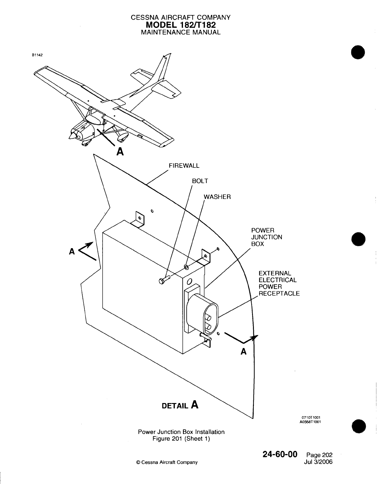
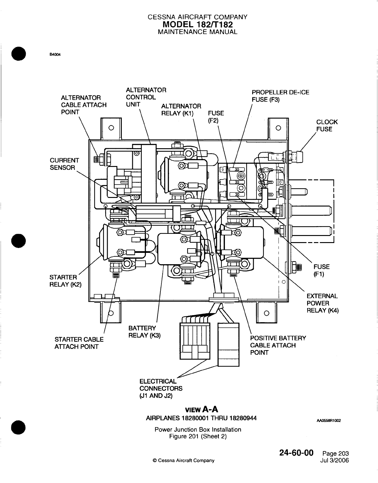
CESSNA
AIRCRAFT
COMPANY
MODEL
182/T182
MAINTENANCE
MANUAL
ALTERNATOR
ALTERNATOR
CONTROL
CABLE
POIN
PROPELLER
DE-ICE
FUSE
(F3)
CURREN
SENSOR
STARTER
RELAY
(K
STARTER
CABLE
ATTACH
POINT
POSITIVE BATTERY
CABLE
ATTACH
POINT
ELECTRICAL
CONNECTORS
(J1
AND
J2)
VIEWA-A
AIRPLANES 18280001 THRU
18280944
Power
Junction
Box
Installation
Figure
201
(Sheet
2)
©
Cessna
Aircraft
Company
24-60-00
Page
203
Jul
3/2006
CLOCK
FUSE
I
D
D
FUSE
(F1)
EXTERNAL
OWER
ELAY
(K4)
AA0558R1002
RELAY
(K3)
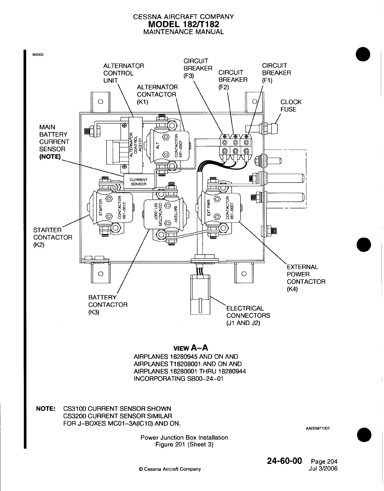
CESSNA
AIRCRAFT
COMPANY
MODEL
182/T182
MAINTENANCE
MANUAL
B4005
ALTERNATOR
CIRCUIT
BREAKER
D IT
CIRCUIT
ALTERNATOR
CONTACTOR
(K1)
ST
C
(K
[
TERNAL
WER
NTACTOR
CONNECTORS
(J1
AND
J2)
VIEW
A-A
AIRPLANES
18280945
AND
ON
AND
AIRPLANES
T18208001
AND
ON
AND
AIRPLANES
18280001
THRU
18280944
INCORPORATING
SB00-24-01
NOTE:
CS3100
CURRENT SENSOR
SHOWN
CS3200
CURRENT SENSOR
SIMILAR
FOR
J-BOXES
MC01-3A(IC10)
AND
ON.
Power
Junction
Box
Installation
Figure
201
(Sheet
3)
24-60-00
Cessna
Aircraft
Company
AA0558T1007
Page
204
Jul
3/2006
CK
D
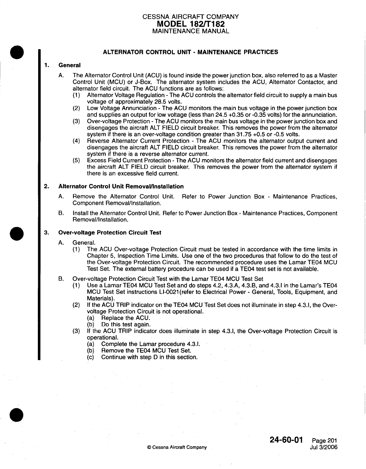
CESSNA
AIRCRAFT
COMPANY
MODEL
182/T182
MAINTENANCE
MANUAL
ALTERNATOR
CONTROL
UNIT
-
MAINTENANCE
PRACTICES
1.
General
A.
The Alternator Control
Unit
(ACU)
is
found
inside the
power
junction
box,
also
referred
to
as
a
Master
Control
Unit
(MCU)
or
J-Box.
The
alternator system
includes
the
ACU,
Alternator
Contactor,
and
alternator
field
circuit.
The
ACU
functions
are
as
follows:
(1)
Alternator
Voltage
Regulation
-
The
ACU
controls the
alternator
field
circuit
to
supply
a
main
bus
voltage
of
approximately
28.5
volts.
(2)
Low
Voltage
Annunciation
-
The
ACU
monitors the
main
bus
voltage
in
the
power
junction
box
and
supplies
an
output
for
low
voltage
(less
than
24.5 +0.35
or
-0.35
volts)
for
the
annunciation.
(3)
Over-voltage
Protection
-
The
ACU
monitors the
main
bus
voltage
in
the
power
junction
box
and
disengages
the
aircraft
ALT
FIELD
circuit
breaker.
This
removes the
power
from
the
alternator
system
if
there
is
an
over-voltage condition greater
than
31.75
+0.5
or
-0.5
volts.
(4)
Reverse
Alternator
Current
Protection
-
The
ACU
monitors the
alternator
output
current
and
disengages
the
aircraft
ALT
FIELD
circuit
breaker.
This removes the
power
from
the
alternator
system
if
there
is
a
reverse
alternator
current.
(5)
Excess Field Current Protection
-
The
ACU
monitors
the
alternator
field
current
and
disengages
the
aircraft
ALT
FIELD
circuit
breaker.
This
removes
the
power
from
the
alternator
system
if
there
is
an
excessive
field
current.
2.
Alternator
Control
Unit
Removal/Installation
A.
Remove
the
Alternator
Control
Unit.
Refer
to
Power
Junction
Box
-
Maintenance
Practices,
Component
Removal/Installation.
B.
Install
the
Alternator
Control
Unit.
Refer
to
Power
Junction
Box
-
Maintenance
Practices, Component
Removal/Installation.
3.
Over-voltage
Protection
Circuit
Test
A.
General.
(1)
The
ACU
Over-voltage
Protection
Circuit
must
be
tested
in
accordance
with
the
time
limits
in
Chapter
5,
Inspection
Time Limits.
Use
one
of
the
two
procedures
that
follow
to
do the
test
of
the
Over-voltage
Protection Circuit.
The recommended
procedure
uses
the
Lamar
TE04
MCU
Test
Set.
The external
battery procedure
can
be
used
if
a
TE04
test
set
is
not
available.
B.
Over-voltage
Protection Circuit
Test
with
the
Lamar TE04
MCU
Test
Set
(1)
Use
a
Lamar TE04
MCU
Test
Set
and
do
steps
4.2, 4.3.A, 4.3.B,
and
4.3.1
in
the
Lamar's
TE04
MCU
Test
Set
instructions
LI-0021
(refer
to Electrical
Power
-
General,
Tools,
Equipment,
and
Materials).
(2)
If
the
ACU
TRIP
indicator
on the
TE04
MCU
Test
Set does
not
illuminate
in
step
4.3.1,
the
Over-
voltage
Protection
Circuit
is
not
operational.
(a)
Replace
the
ACU.
(b)
Do
this
test again.
(3)
If
the
ACU
TRIP
indicator
does
illuminate
in
step
4.3.1,
the
Over-voltage
Protection
Circuit
is
operational.
(a)
Complete
the
Lamar
procedure
4.3.1.
(b)
Remove
the TE04
MCU
Test Set.
(c)
Continue
with
step
D in
this section.
24-60-01
Page
201
©
Cessna Aircraft Company
Jul
3/2006
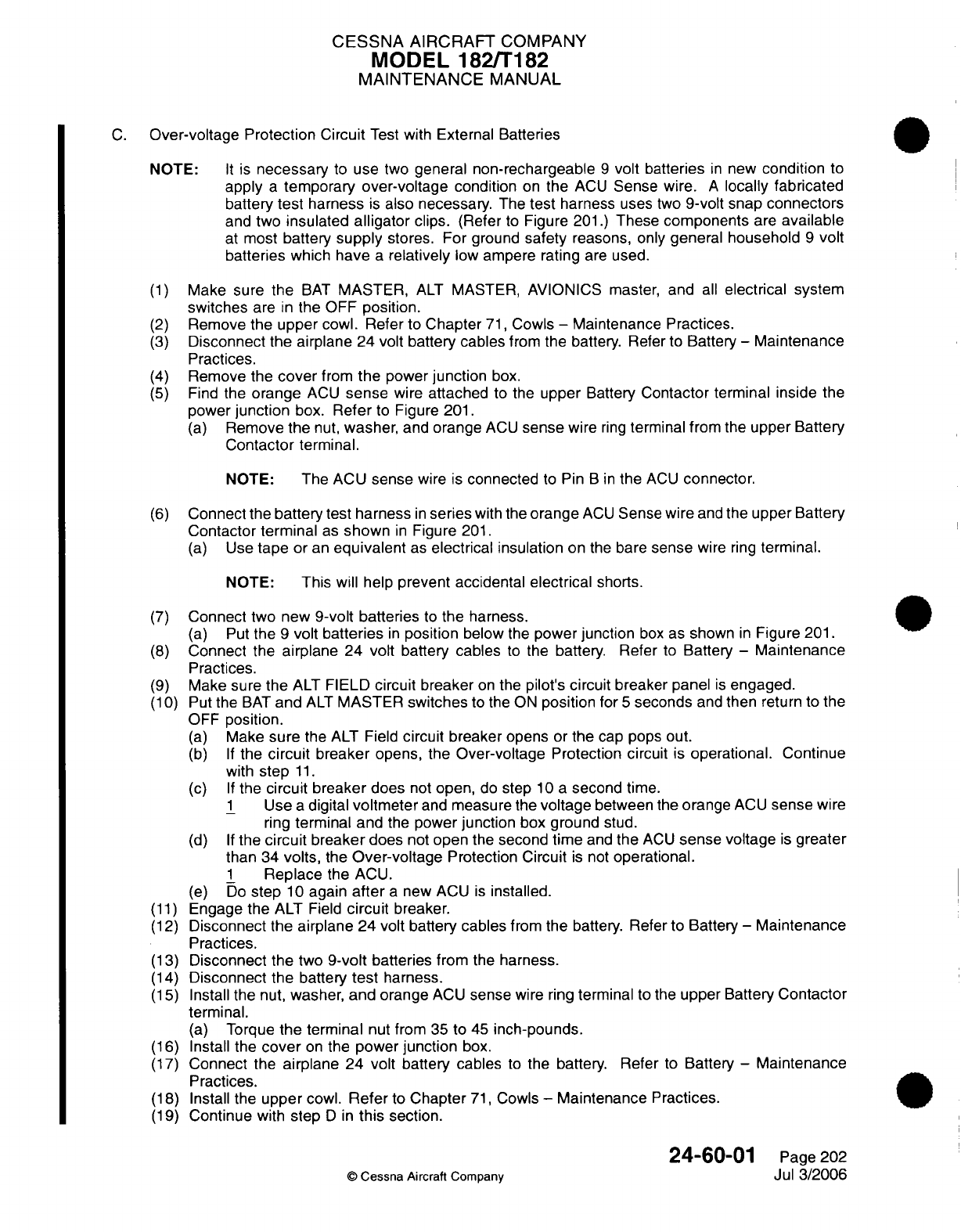
CESSNA
AIRCRAFT
COMPANY
MODEL
182/T182
MAINTENANCE
MANUAL
C.
Over-voltage Protection
Circuit
Test
with
External
Batteries
NOTE:
It
is
necessary
to
use
two
general
non-rechargeable
9
volt
batteries
in
new
condition
to
apply
a
temporary
over-voltage
condition
on
the
ACU
Sense
wire.
A
locally fabricated
battery
test
harness
is
also necessary.
The
test
harness
uses
two
9-volt
snap
connectors
and
two
insulated
alligator
clips.
(Refer
to
Figure
201.)
These
components
are
available
at
most
battery
supply
stores.
For
ground
safety
reasons,
only
general household
9
volt
batteries
which
have
a
relatively
low
ampere
rating are used.
(1)
Make
sure
the
BAT
MASTER,
ALT
MASTER, AVIONICS master, and
all
electrical
system
switches
are
in
the
OFF
position.
(2)
Remove
the
upper
cowl.
Refer
to
Chapter
71,
Cowls
-
Maintenance
Practices.
(3)
Disconnect
the
airplane
24
volt
battery
cables
from
the battery.
Refer
to
Battery
-
Maintenance
Practices.
(4)
Remove
the
cover
from
the
power
junction
box.
(5)
Find
the
orange
ACU
sense
wire
attached
to
the
upper
Battery
Contactor
terminal
inside
the
power
junction
box.
Refer
to Figure
201.
(a)
Remove
the
nut,
washer,
and
orange
ACU
sense
wire
ring
terminal
from the upper
Battery
Contactor
terminal.
NOTE:
The
ACU
sense
wire is
connected
to
Pin
B in
the
ACU
connector.
(6)
Connect the
battery test harness
in
series
with
the
orange
ACU
Sense
wire
and
the
upper Battery
Contactor terminal
as
shown
in
Figure
201.
(a)
Use
tape
or
an
equivalent
as
electrical
insulation
on
the
bare
sense
wire
ring
terminal.
NOTE:
This
will help
prevent accidental
electrical
shorts.
(7)
Connect
two new
9-volt batteries
to
the
harness.
(a)
Put
the
9
volt
batteries
in
position
below
the
power
junction
box
as
shown
in
Figure
201.
(8)
Connect the
airplane
24 volt
battery
cables
to
the battery.
Refer
to
Battery
-
Maintenance
Practices.
(9)
Make
sure
the
ALT
FIELD
circuit
breaker
on
the
pilot's
circuit
breaker
panel
is
engaged.
(10)
Put
the
BAT
and
ALT
MASTER
switches
to the
ON
position
for
5
seconds
and
then
return
to
the
OFF
position.
(a)
Make
sure
the
ALT
Field
circuit
breaker
opens
or
the
cap
pops out.
(b) If
the
circuit
breaker
opens, the
Over-voltage
Protection
circuit
is
operational. Continue
with
step
11.
(c) If
the
circuit
breaker
does
not
open,
do
step
10 a
second
time.
1
Use
a
digital
voltmeter
and
measure
the
voltage
between
the
orange
ACU
sense
wire
ring
terminal and
the
power
junction
box ground
stud.
(d) If
the
circuit
breaker
does
not
open
the
second time
and
the
ACU
sense
voltage
is
greater
than
34
volts,
the
Over-voltage
Protection
Circuit
is
not
operational.
1
Replace
the
ACU.
(e)
Do
step
10
again
after
a
new
ACU
is
installed.
(11)
Engage
the
ALT
Field
circuit
breaker.
(12)
Disconnect
the
airplane
24
volt
battery
cables
from the
battery.
Refer
to
Battery
-
Maintenance
Practices.
(13)
Disconnect
the
two
9-volt
batteries
from
the
harness.
(14)
Disconnect
the
battery
test
harness.
(15)
Install
the
nut,
washer,
and
orange
ACU
sense
wire
ring
terminal
to the
upper
Battery
Contactor
terminal.
(a)
Torque
the
terminal
nut
from
35
to
45
inch-pounds.
(16)
Install
the
cover
on
the
power
junction
box.
(17)
Connect
the
airplane
24 volt
battery
cables
to the
battery. Refer
to
Battery
-
Maintenance
Practices.
(18)
Install
the
upper
cowl.
Refer
to
Chapter
71,
Cowls
-
Maintenance Practices.
(19)
Continue
with
step
D in
this
section.
24-60-01
Page
202
©
Cessna
Aircraft
Company
Jul
3/2006
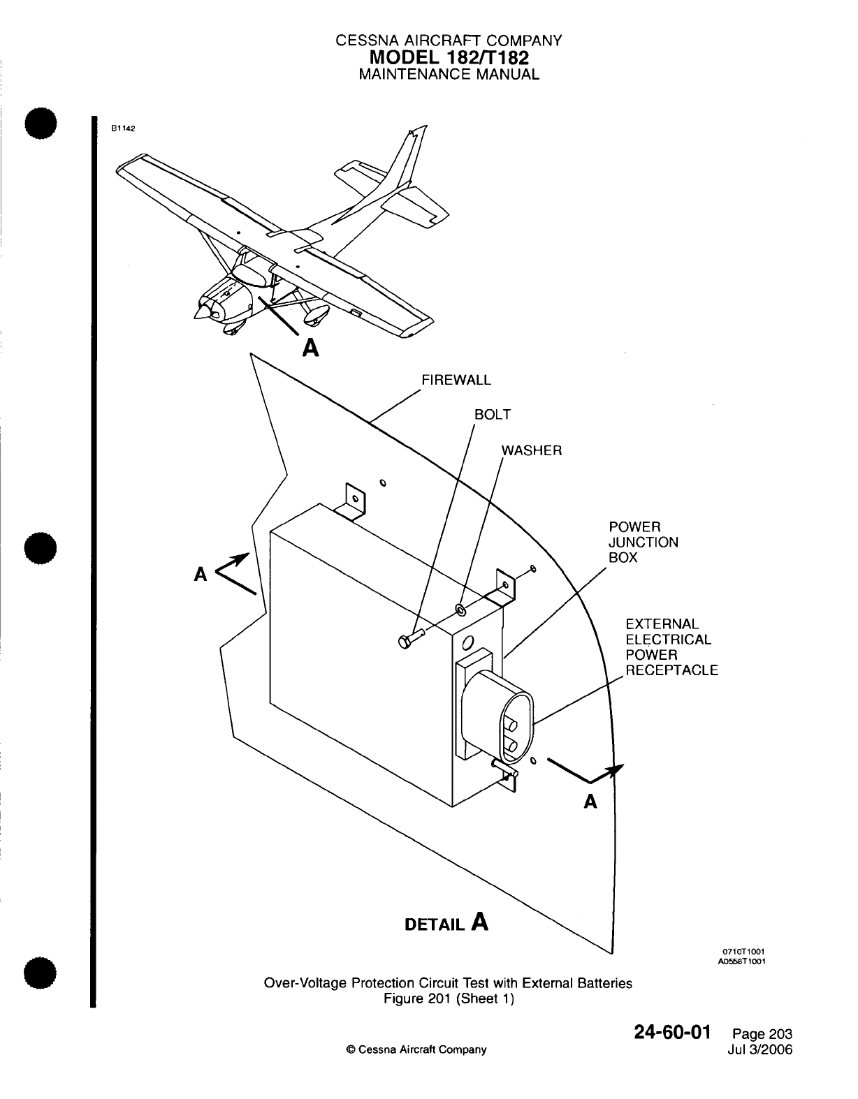
CESSNA
AIRCRAFT
COMPANY
MODEL
182/T182
MAINTENANCE
MANUAL
B
BOLT
WASHER
POWER
JUNCTION
BOX
A
EXTERNAL
A
DETAIL
A
A0558T1001
Over-Voltage
Protection
Circuit
Test with
External
Batteries
Figure
201
(Sheet
1)
24-60-01
Page
203
©
Cessna Aircraft Company
Jul
3/2006
0710T1001
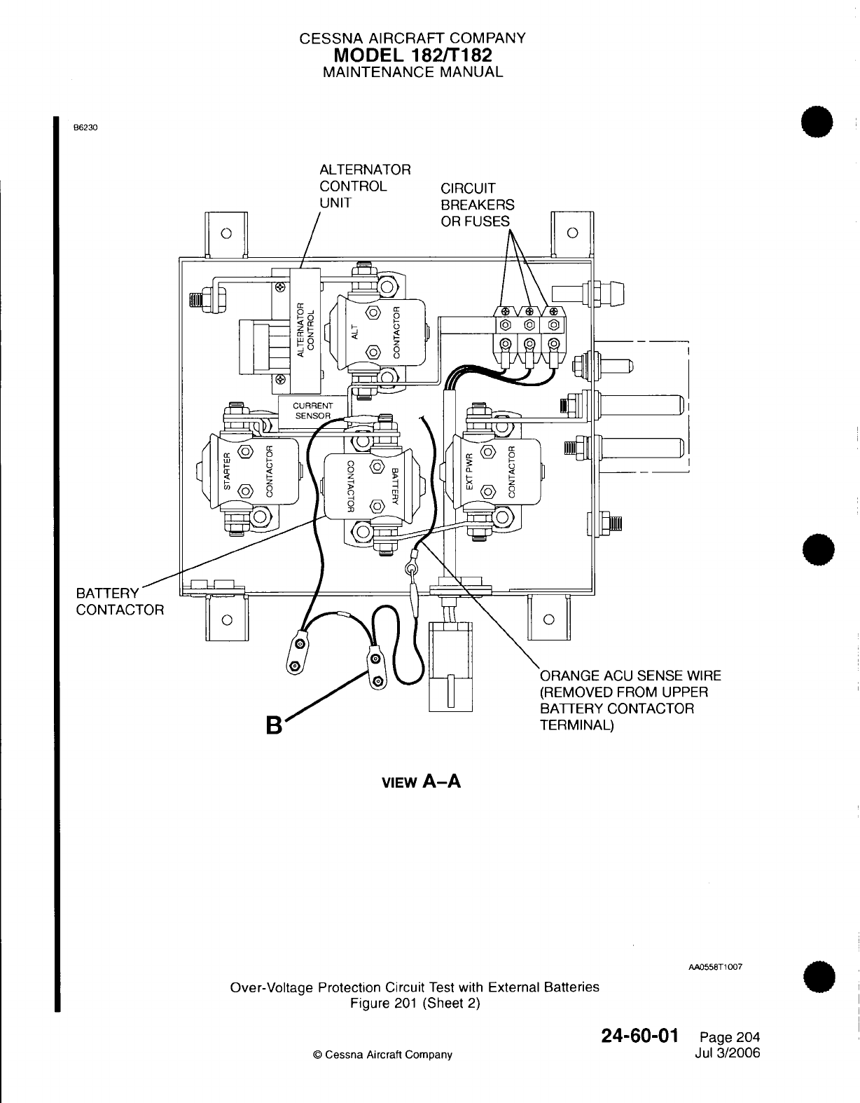
CESSNA AIRCRAFT
COMPANY
MODEL 182/T182
MAINTENANCE
MANUAL
B6230
ALTERNATOR
CONTROL
UNIT
CIRCUIT
BREAKERS
D
D
SENSE
WIRE
ROM
UPPER
NTACTOR
VIEW
A-A
AA0558T1007
Over-Voltage
Protection Circuit
Test
with
External
Batteries
Figure
201
(Sheet
2)
Page
204
Jul
3/2006
BATTERY
CONTACT
24-60-01
©
Cessna Aircraft
Company
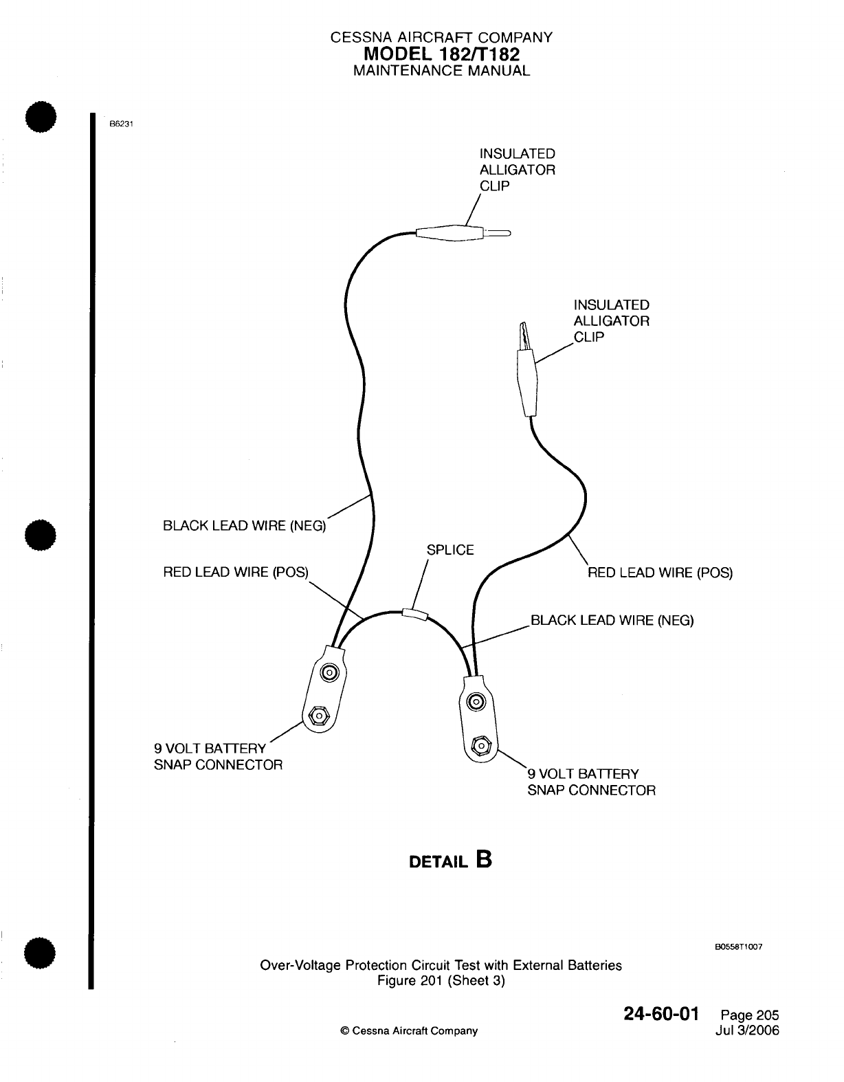
CESSNA
AIRCRAFT
COMPANY
MODEL
182/T182
MAINTENANCE
MANUAL
B6231
INSULATED
ALLIGATOR
INSULATED
ALLIGATER
BLACK
LEAD
WIRE
RED LEAD
WIRE
9
VOLT
BATTERY
SNAP
CONNECTOR
LEAD
WIRE
(POS)
WIRE
(NEG)
9 VOLT
BATTERY
SNAP
CONNECTOR
DETAIL
B
B0558T1007
Over-Voltage
Protection
Circuit
Test with
External
Batteries
Figure
201
(Sheet
3)
24-60-01
©
Cessna Aircraft
Company
Page
205
Jul
3/2006
CESSNA
AIRCRAFT
COMPANY
MODEL 182/T182
MAINTENANCE
MANUAL
D.
Make
sure
of
the
correct
ACU
functions
immediately
after
the
next engine
start.
(1)
Start
the engine
in
accordance
with
the
Pilot's
Operating Handbook,
Starting Engine (Using
Battery)
procedure
but
make
sure
the ALT MASTER
switch
is
in
the OFF
position.
(2)
After
the
engine start
and
oil pressure
check,
set
the
engine
RPM
to
idle.
(3)
Make
sure
the
Low Voltage
annunciator
is
On.
(4)
While
you
monitor
the
aircraft
voltmeter,
set
the
ALT
MASTER
switch
to
the
ON
position.
(a)
If
the
voltmeter
shows
more than
29
volts,
immediately
set
the
ALT
MASTER
switch to
the
OFF
position
and
stop
the
engine.
NOTE:
The
ACU
regulation
circuit
is
non
operational.
The
ALT
FLD
circuit
breaker
should
open
if
the
voltage
is
more
than
32
volts.
1
Replace
the
ACU
and
do
the Over-voltage
Protection
Test
again.
(b)
If
the
voltmeter
shows
less
than 29
volts,
slowly
increase
the
throttle
to
an
engine
speed
of
1300
RPM.
(5) If
the
voltmeter
shows
approximately
28
volts
at
an
engine
speed
of
1300
RPM
the
ACU
regulation
circuit
is
operational.
(6)
Make
sure
the
battery
charge
is
shown on the
aircraft
battery
ammeter.
(7)
Make
sure
the
LOW VOLTS
annunciator
is
off.
4.
Alternator
Control
Unit
Troubleshooting
A.
Complete
the
Alternator
Control
Unit Troubleshooting.
(1)
The
Alternator
Control
Unit
troubleshooting
is
done
with
the
Lamar
TE04
MCU
Test
Set. The
instructions
are
contained
in
the
test set.
Refer to
Electrical
Power
-
General,
Tools,
Equipment,
and Materials.
24-60-01
Page 206
©
Cessna
Aircraft Company
Jul
3/2006
CESSNA AIRCRAFT
COMPANY
MODEL
182/T182
MAINTENANCE
MANUAL
CIRCUIT
BREAKER
-
MAINTENANCE PRACTICES
1.
General
A.
The
circuit breaker
panel
is
on
the
left
lower instrument
panel,
below
the
pilot's
control wheel.
The
circuit
breaker
panel
has
electrical
circuit
breakers,
the
ignition/magneto
switches, the
master switch,
the avionics
master
switch,
and
the
light
switches.
2.
Circuit
Breaker
RemovaVlnstallation
A.
Remove
the
Circuit
Breaker
(Refer
to
Figure
201
or
Figure 202).
(1)
Remove
the
access/inspection
plate
(31
OAR)
and
disconnect
the
battery
(UC001)
cables.
Refer
to
Chapter
6,
Access/Inspection
Plates
-
Description
and
Operation.
(2)
In
the cockpit,
remove
the
screws
that
attach
the
circuit
breaker
panel
to
the
lower
instrument
panel.
(3)
Remove
the
screws that
attach the
circuit
breaker
cover
to
the
circuit
breaker
panel.
(4)
Remove
the
circuit
breaker
cover.
(5)
Put
a
label
on
the
applicable
circuit
breaker
wires.
(6)
Disconnect
the
applicable
circuit
breaker
wires.
(7)
Remove
the
screws
and the
washers
that
attach
the
bus
bar
to
the
circuit
breakers.
(8)
Remove the
bus
bar.
(9)
Remove the
nut
that
attaches
the
circuit
breaker
to
the
circuit
breaker
panel.
(10)
Remove
the
circuit
breaker.
B.
Install
the
Circuit Breaker
(Refer
to
Figure
201
or
Figure
202).
(1)
Put
the
circuit
breaker
in
the
circuit
breaker
panel
and attach
the
circuit
breaker
with
the
nut.
(2)
Attach the
bus
bar
to
the
circuit
breakers
with
the
screws
and washers.
(3)
Remove
the labels
and
connect
the
wires
to
the
circuit
breakers.
(4)
Install
the
circuit
breaker
cover
assembly.
(a)
Put
three
tie
straps
between the
circuit
breakers
and
the
panel.
(b)
Put
the
circuit
breaker cover
assembly over
the circuit
breakers.
(c)
The
flanges
on
the
cover
fit
between
the
circuit
breakers
and
the
panel.
(d)
The
recessed
areas
in
the
cover
must
align
with
the
screw
holes
in
the panel.
(e)
Put
the
main
power
bus
wires
and
the
circuit breaker
panel assembly wire
bundle
out
of
the
left
side of the
cover.
(f)
Attach the
cover
with
three tie straps.
(5)
Attach the
circuit
breaker
cover
to
the
circuit
breaker
panel
with
the
screws.
(6)
Put
the
circuit
breaker
panel
on
the
lower
instrument
panel
and
attach
with
the
screws.
(7)
Connect
the
battery
cables
(UC001)
and
install
the
access/inspection
plate
(310AR). Refer
to
Chapter
6,
Access/Inspection
Plates
-
Description
and
Operation.
24-61-00
Page
201
©
Cessna Aircraft
Company
Mar
1/2005
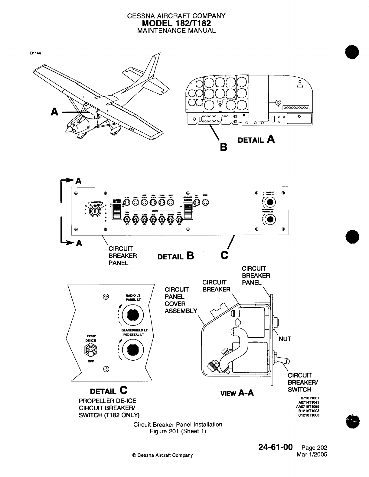
CESSNA AIRCRAFT
COMPANY
MODEL 182/T182
MAINTENANCE
MANUAL
0
\
looooooooooI
:o
o
o ______
1w
: =.-a
-
n-
-
0
-
I
-
*~~I o U~_
CIRCUIT
BREAKER
PANEL
DETAIL
B
CIRCUIT
PANEL
COVER
ASSEMBLY
DETAIL
C
PROPELLER
DE-ICE
CIRCUIT
BREAKER/
SWITCH
(T182
ONLY)
/
C
CIRCUIT
BREAKER
CIRCUIT
BREAKER
PANEL
VIEW
A-A
NUT
CIRCUIT
BREAKER/
SWITCH
071
OT
001
A0714T1041
AA071
8T1059
B1218T1003
C1218T1003
Circuit Breaker
Panel
Installation
Figure
201
(Sheet
1)
©
Cessna
Aircraft
Company
24-61-00
Page
202
Mar 1/2005
A
IL. I "I
-L
A
B
*
0~
PROP
DE
E
OFF
RADIO
LT
PANEL
LT
QLARESHIELD
LT
PEDEiTAL
LT
Al....
B
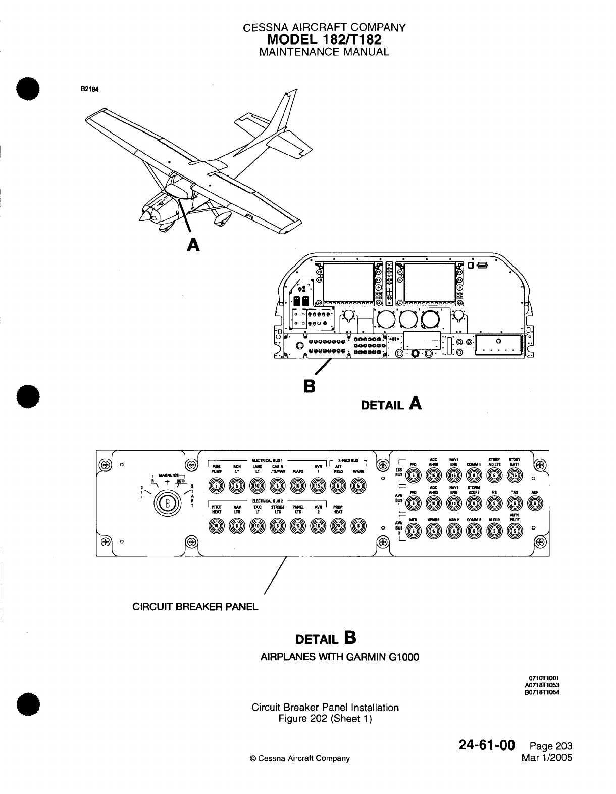
CESSNA
AIRCRAFT
COMPANY
MODEL
182/T182
MAINTENANCE
MANUAL
e
A
/
B
DETAIL
A
|I
--
B.ECCAL
BUS
I
-W
i-
X-BDBB
-
I UEL. BCNO LAND CAlN AN I I ALT
I
PUMP LT IT LTSI RAM I FELD
WArI
iP-- EL-CALBUSITBI.IAICJl. BPlRO
PTrT NAV TA TOlBE PANBr A
'
P
HEAT LTI LT LT LT 2I HEAT
6666696 6rn pra m'rr~
-
AOC AVI Y
l
TDBiT fS
I PER AlEl
l
I D
LT"BAT
[(
ADC NAVI BTON
M ANS INE SCOMPE RS TAA AN
I MR XPDR AV 1 CODMM
I
AUDID LOT
rI-i/Z \
)\
) {
O
A
CIRCUIT
BREAKER PANEL
DETAIL
B
AIRPLANES
WITH
GARMIN
G1000
0710T1001
A0718T1053
B0718T1054
Circuit Breaker
Panel
Installation
Figure
202
(Sheet
1)
©
Cessna Aircraft
Company
24-61-00
Page
203
Mar
1/2005
A.
.
.m
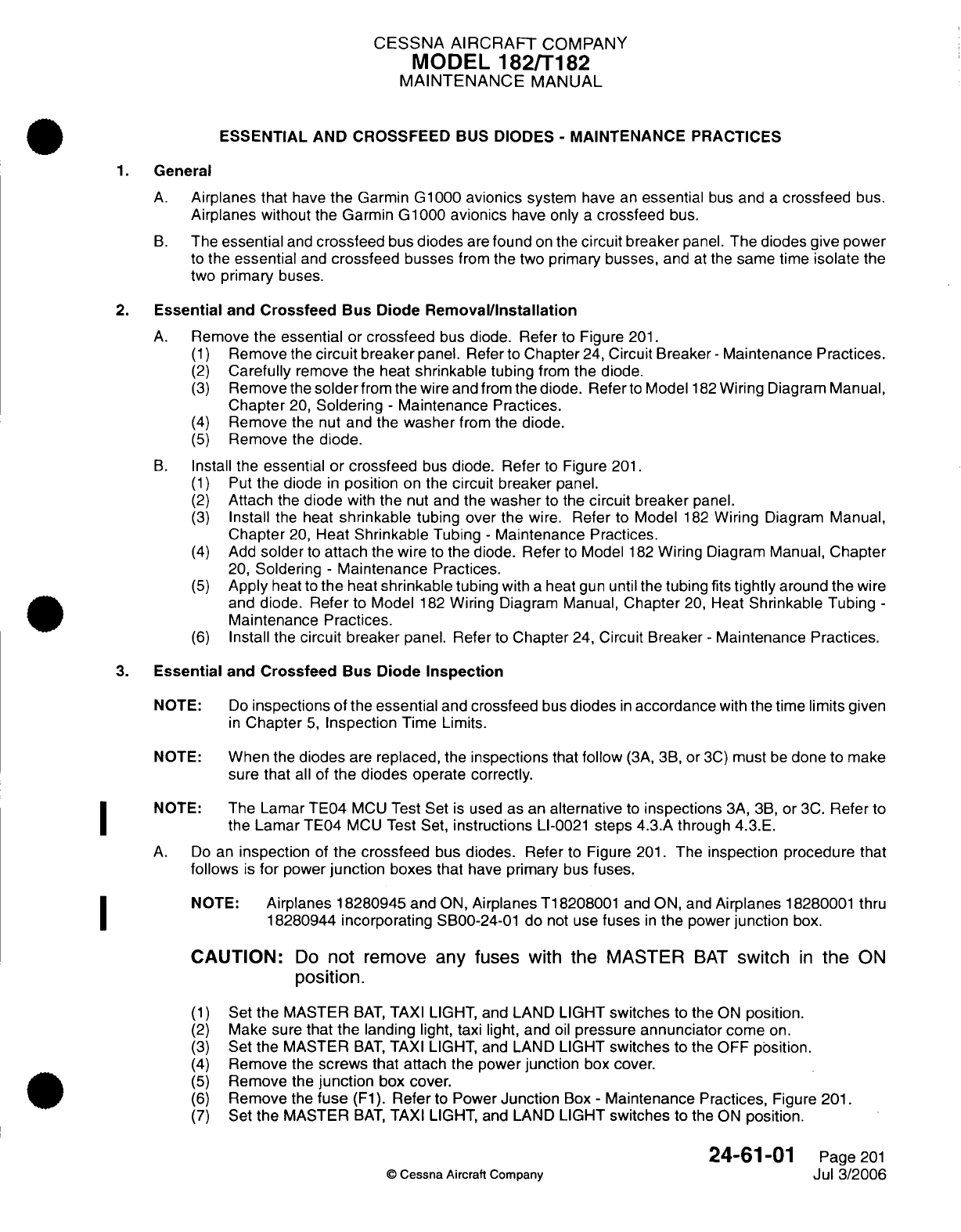
CESSNA
AIRCRAFT
COMPANY
MODEL
182/T182
MAINTENANCE
MANUAL
ESSENTIAL
AND
CROSSFEED
BUS
DIODES
-
MAINTENANCE
PRACTICES
1.
General
A.
Airplanes that
have
the
Garmin
G1000
avionics
system
have
an
essential
bus
and
a
crossfeed
bus.
Airplanes without
the
Garmin
G1000
avionics
have
only
a
crossfeed
bus.
B.
The
essential
and
crossfeed
bus
diodes
are
found
on
the
circuit
breaker
panel.
The diodes give
power
to
the
essential
and
crossfeed
busses
from
the
two
primary
busses,
and
at
the
same time
isolate
the
two
primary
buses.
2.
Essential
and
Crossfeed Bus
Diode
Removal/Installation
A.
Remove
the essential or
crossfeed
bus
diode. Refer
to
Figure
201.
(1)
Remove
the
circuit
breaker
panel.
Refer
to
Chapter
24,
Circuit
Breaker
-
Maintenance
Practices.
(2)
Carefully
remove
the
heat
shrinkable
tubing
from
the
diode.
(3)
Remove
the
solder
from
the
wire
and
from
the
diode.
Refer
to
Model
182
Wiring
Diagram
Manual,
Chapter
20,
Soldering
-
Maintenance Practices.
(4)
Remove the
nut and
the
washer
from
the
diode.
(5)
Remove
the
diode.
B.
Install
the
essential
or
crossfeed
bus
diode.
Refer
to
Figure
201.
(1)
Put
the
diode
in
position
on the
circuit
breaker
panel.
(2)
Attach
the
diode
with
the
nut
and
the
washer
to the
circuit
breaker
panel.
(3)
Install
the
heat
shrinkable
tubing over
the wire. Refer
to
Model
182
Wiring
Diagram
Manual,
Chapter
20,
Heat
Shrinkable
Tubing
-
Maintenance
Practices.
(4)
Add
solder
to
attach
the wire
to
the diode. Refer
to
Model
182
Wiring
Diagram
Manual,
Chapter
20,
Soldering
-
Maintenance
Practices.
(5)
Apply
heat
to
the
heat
shrinkable
tubing
with
a
heat
gun
until
the tubing
fits
tightly
around
the
wire
and
diode.
Refer
to
Model
182
Wiring
Diagram
Manual,
Chapter
20,
Heat
Shrinkable
Tubing
-
Maintenance
Practices.
(6)
Install
the
circuit
breaker
panel. Refer
to
Chapter
24,
Circuit Breaker
-
Maintenance
Practices.
3.
Essential
and
Crossfeed
Bus Diode
Inspection
NOTE:
Do
inspections
of
the
essential
and
crossfeed
bus
diodes
in
accordance
with
the time
limits given
in
Chapter
5,
Inspection
Time
Limits.
NOTE:
When
the
diodes
are
replaced, the
inspections
that
follow
(3A, 3B,
or
3C)
must
be
done
to
make
sure that
all
of
the diodes
operate
correctly.
NOTE:
The
Lamar
TE04
MCU
Test Set
is
used
as
an
alternative
to
inspections
3A,
3B,
or
3C.
Refer
to
the
Lamar TE04
MCU
Test Set,
instructions
LI-0021
steps 4.3.A through
4.3.E.
A.
Do
an
inspection
of
the
crossfeed
bus
diodes. Refer
to
Figure
201.
The
inspection procedure
that
follows
is
for
power
junction
boxes
that
have
primary
bus
fuses.
NOTE:
Airplanes 18280945
and
ON,
Airplanes
T18208001 and
ON, and
Airplanes
18280001
thru
18280944
incorporating
SB00-24-01
do
not
use
fuses
in
the
power
junction
box.
CAUTION:
Do
not
remove
any
fuses
with
the
MASTER
BAT
switch
in
the
ON
position.
(1)
Set
the
MASTER
BAT,
TAXI
LIGHT,
and LAND
LIGHT
switches
to
the
ON
position.
(2)
Make
sure
that the
landing
light, taxi
light,
and
oil
pressure
annunciator
come
on.
(3)
Set
the
MASTER
BAT,
TAXI
LIGHT,
and LAND
LIGHT
switches
to the
OFF
position.
(4)
Remove
the
screws
that
attach
the
power
junction
box
cover.
(5)
Remove
the
junction
box
cover.
(6)
Remove
the
fuse
(F1).
Refer
to
Power
Junction
Box
-
Maintenance
Practices,
Figure
201.
(7)
Set
the
MASTER
BAT,
TAXI
LIGHT,
and LAND
LIGHT
switches
to the
ON
position.
24-61-01
Page
201
0
Cessna Aircraft Company
Jul
3/2006
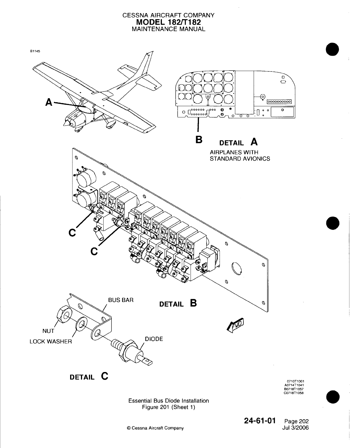
CESSNA AIRCRAFT
COMPANY
MODEL 182/T182
MAINTENANCE
MANUAL
OO
B
DETAIL
A
C
BUS
BAR
DETAIL
B
ODE
Essential
Bus
Diode
Installation
Figure
201
(Sheet
1)
©
Cessna
Aircraft
Company
NUT
LOCK
WA
DETAIL
C
0710T1001
A0714T1041
B0718T1057
C0718T1058
24-61-01
Page
202
Jul
3/2006
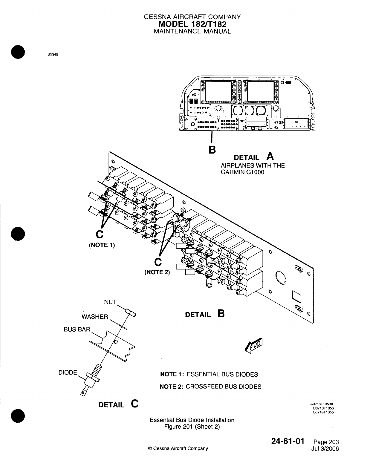
CESSNA AIRCRAFT
COMPANY
MODEL
182/T182
MAINTENANCE
MANUAL
B2245
I
B
DETAIL
A
AIRPLANES WITH
THE
GARMIN
G1000
C
(NOTE
1)
C
(NOTE
2)
W
DETAIL
B
BUS
NOTE 1:
ESSENTIAL
BUS DIODES
NOTE 2:
CROSSFEED
BUS
DIODES
Essential
Bus
Diode
Installation
Figure
201
(Sheet
2)
©
Cessna
Aircraft
Company
DETAIL
C
A0718T1053A
B0718T1056
C0718T1055
24-61-01
Page
203
Jul
3/2006
CESSNA
AIRCRAFT
COMPANY
MODEL
182/T182
MAINTENANCE
MANUAL
(8)
Make
sure that
the
landing
light
and
oil
pressure
annunciator
come
on.
If
the taxi
light
comes
on
or
the
oil pressure
annunciator
does
not
come
on,
do
a
test
of
the
crossfeed
bus
diodes
with
the
diode
test
function
of
a
digital
multimeter
to
find
which
diodes
must
be
replaced.
Refer
to
Essential
and
Crossfeed
Bus Diode
Multimeter
Test.
(9)
Set
the
MASTER
BAT,
TAXI
LIGHT,
and
LAND
LIGHT
switches
to
the
OFF
position.
(10)
Install
the
fuse
(F1)
into the
power
junction
box.
NOTE:
If
the
fuse
is
pitted,
arced,
or does
not
fit
tightly
into
the
fuse receptacle,
replace
the
fuse
with
one
of
the
same
type.
Do
not
replace
the
fuse
with
a
fuse
with
thinner
blades.
(11)
Remove
the
fuse
(F2).
Refer
to
Power
Junction
Box
-
Maintenance
Practices,
Figure
201.
(12)
Set
the
MASTER
BAT,
TAXI
LIGHT,
and
LAND
LIGHT
switches
to
the
ON
position.
(13)
Make
sure that
the taxi
light
and
oil
pressure
annunciator
come
on.
If
the
landing light
comes
on, or
the
oil
pressure
annunciator
does
not
come
on,
do
a
test
of
the
crossfeed
bus
diodes
with
the
diode
test
function
of
a
digital
multimeter
to
find
which
diodes
must
be
replaced.
Refer
to
Essential
and
Crossfeed
Bus Diode
Multimeter
Test.
(14)
Set
the
MASTER
BAT,
TAXI
LIGHT,
and
LAND
LIGHT
switches
to
the
OFF
position.
(15)
Install
the
fuse
(F2)
into
the
power
junction
box.
NOTE:
If
the
fuse
is
pitted,
arced,
or
does
not
fit
tightly
into the
fuse
receptacle,
replace
the
fuse
with
one
of
the
same
type.
Do
not
replace
the
fuse
with
a
fuse
with
thinner
blades.
NOTE:
If
the
diodes
are
replaced,
do
this
test
again
to
make sure
that
all
the
diodes
operate
correctly.
(16)
Install
the
junction
box
cover
with
the
screws.
B.
Do
an
inspection
of
the
crossfeed
bus
diodes.
Refer
to
Figure
201.
The
inspection
procedure
that
follows
is
for power
junction
boxes
that
have
primary
bus circuit
breakers.
NOTE:
The
inspection
procedure
that
follows
is
for
airplanes without
the
Garmin
G1000
avionics
system.
CAUTION:
Do
not remove
bus wires
from
the circuit breakers
with
the
MASTER
BAT
switch
in
the
ON
position.
(1)
Set
the
MASTER
BAT,
TAXI
LIGHT,
and
LAND
LIGHT
switches
to
the
ON
position.
(2)
Make
sure that
the landing
light,
taxi
light,
and
oil
pressure
annunciator
come
on.
(3)
Set
the
MASTER
BAT, TAXI
LIGHT, and
LAND
LIGHT
switches
to
the
OFF
position.
(4)
Remove
the
screws
that
attach
the
power
junction
box
cover.
(5)
Remove
the
power
junction
box
cover.
(6)
Remove
the
hex nut and
the
lock
washer
that
connect
the bus
wire
to the
circuit breaker
(F1).
Refer
to
Power
Junction
Box
-
Maintenance Practices,
Figure
201.
(7)
Remove
the
wire
terminal
from
the
F1
circuit breaker
stud
that
has
a
label of
AUX
and
isolate
the
end
of
the
bus wire.
(8)
Set
the
MASTER
BAT, TAXI
LIGHT, and
LAND
LIGHT
switches
to
the
ON
position.
(9)
Make
sure that
the
landing
light
and
oil
pressure
annunciator
come
on.
If
the taxi light
comes
on
or
the
oil
pressure
annunciator
does
not
come
on, do
a
test
of
the
crossfeed
bus
diodes
with
the
diode
test
function
of
a
digital
multimeter
to
find
which
diodes
must
be
replaced.
Refer
to
Essential
and
Crossfeed
Bus
Diode
Multimeter
Test.
(10)
Set
the
MASTER
BAT,
TAXI
LIGHT, and
LAND
LIGHT
switches
to
the
OFF
position.
(11)
Install
the
bus wire
to
the
F1
circuit
breaker
terminal.
Use
the
same
hex
nut and
the
washer
that
were
removed.
(12)
Torque
the
nut to
between 20
and
25
inch-pounds
(between
2.3 and
2.8
N-m).
(13)
Remove
the
hex nut
and
the lock washer
that
connect
the
bus
wire
to
the
circuit
breaker
(F2).
Refer
to
Power
Junction
Box
-
Maintenance
Practices,
Figure
201.
24-61-01
Page
204
©
Cessna
Aircraft
Company
Jul
3/2006
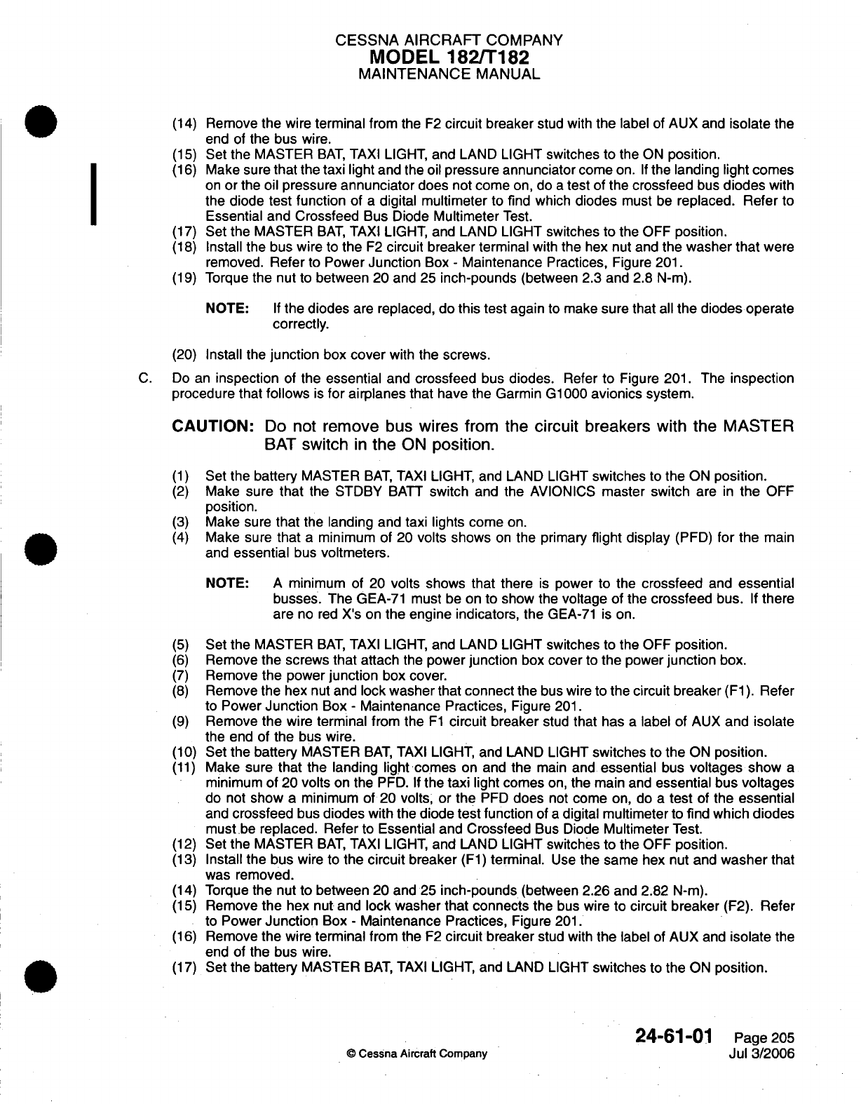
CESSNA AIRCRAFT
COMPANY
MODEL
182/T182
MAINTENANCE
MANUAL
(14)
Remove
the
wire
terminal
from
the
F2
circuit
breaker
stud with
the
label of AUX and
isolate
the
end of
the
bus
wire.
(15)
Set
the
MASTER
BAT,
TAXI
LIGHT,
and
LAND
LIGHT
switches to
the
ON
position.
(16)
Make sure
that
the
taxi light
and
the
oil
pressure
annunciator
come
on.
If
the
landing
light comes
on
or
the
oil
pressure
annunciator
does
not
come
on,
do
a
test
of
the
crossfeed
bus
diodes
with
the
diode
test
function
of
a
digital
multimeter
to
find
which
diodes
must
be
replaced. Refer
to
Essential
and
Crossfeed
Bus
Diode
Multimeter
Test.
(17)
Set
the
MASTER
BAT,
TAXI
LIGHT,
and LAND
LIGHT
switches
to
the
OFF
position.
(18)
Install
the
bus
wire
to
the
F2
circuit
breaker
terminal
with
the
hex
nut and
the
washer
that
were
removed.
Refer
to
Power
Junction
Box
-
Maintenance
Practices,
Figure
201.
(19)
Torque
the
nut
to
between
20
and 25
inch-pounds
(between
2.3 and
2.8
N-m).
NOTE:
If
the diodes
are
replaced,
do this test
again
to
make
sure
that
all
the diodes
operate
correctly.
(20)
Install
the
junction
box
cover
with
the screws.
C.
Do
an
inspection
of
the
essential
and
crossfeed
bus
diodes.
Refer
to
Figure
201.
The
inspection
procedure that
follows
is
for
airplanes that
have
the
Garmin
G1000
avionics
system.
CAUTION:
Do
not
remove
bus
wires
from
the
circuit
breakers
with the
MASTER
BAT
switch
in
the
ON
position.
(1)
Set
the
battery
MASTER
BAT,
TAXI
LIGHT,
and
LAND
LIGHT
switches to
the
ON
position.
(2)
Make
sure that
the STDBY
BATT
switch
and
the
AVIONICS
master
switch
are
in
the
OFF
position.
(3)
Make
sure
that
the
landing
and taxi lights
come
on.
(4)
Make sure
that
a
minimum
of
20
volts
shows
on
the
primary
flight display
(PFD)
for the
main
and
essential
bus
voltmeters.
NOTE:
A
minimum
of 20
volts
shows
that
there
is
power
to
the
crossfeed
and
essential
busses.
The
GEA-71
must
be on
to show
the
voltage
of
the
crossfeed
bus.
If
there
are
no
red
X's on
the
engine indicators, the
GEA-71
is on.
(5)
Set
the
MASTER
BAT,
TAXI
LIGHT,
and
LAND
LIGHT
switches
to
the
OFF
position.
(6)
Remove
the
screws
that attach
the
power
junction
box
cover
to
the
power
junction
box.
(7)
Remove
the power
junction
box
cover.
(8)
Remove the
hex
nut
and
lock washer
that
connect the
bus
wire
to
the
circuit
breaker
(F1).
Refer
to
Power
Junction
Box
-
Maintenance
Practices,
Figure
201.
(9)
Remove
the
wire
terminal
from
the
F1
circuit
breaker
stud
that
has
a
label
of
AUX
and
isolate
the
end of
the
bus
wire.
(10)
Set
the battery
MASTER
BAT,
TAXI
LIGHT,
and LAND
LIGHT
switches
to
the
ON
position.
(11)
Make
sure
that
the
landing light
comes
on and
the
main
and
essential
bus
voltages
show
a
minimum
of
20
volts
on the
PFD.
If
the
taxi
light comes
on,
the
main
and
essential
bus
voltages
do not
show
a
minimum
of
20
volts, or
the
PFD
does
not
come
on, do
a
test
of
the essential
and
crossfeed
bus
diodes
with
the
diode
test
function
of
a
digital multimeter
to
find which
diodes
must
be
replaced.
Refer
to
Essential
and
Crossfeed
Bus Diode
Multimeter
Test.
(12)
Set
the
MASTER
BAT,
TAXI
LIGHT,
and
LAND
LIGHT
switches to
the
OFF
position.
(13)
Install
the
bus
wire
to
the
circuit
breaker
(F1)
terminal.
Use
the same
hex
nut
and
washer
that
was removed.
(14)
Torque
the
nut
to between
20 and
25
inch-pounds
(between
2.26
and
2.82
N-m).
(15)
Remove
the
hex
nut
and
lock
washer that
connects
the
bus
wire
to
circuit breaker
(F2).
Refer
to
Power
Junction
Box
-
Maintenance Practices,
Figure
201.
(16)
Remove
the
wire
terminal
from the
F2
circuit
breaker
stud with
the
label of AUX and
isolate
the
end
of
the
bus
wire.
(17)
Set
the battery
MASTER
BAT,
TAXI
LIGHT,
and
LAND
LIGHT
switches to
the
ON
position.
24-61-01
Page
205
©
Cessna Aircraft
Company
Jul
3/2006
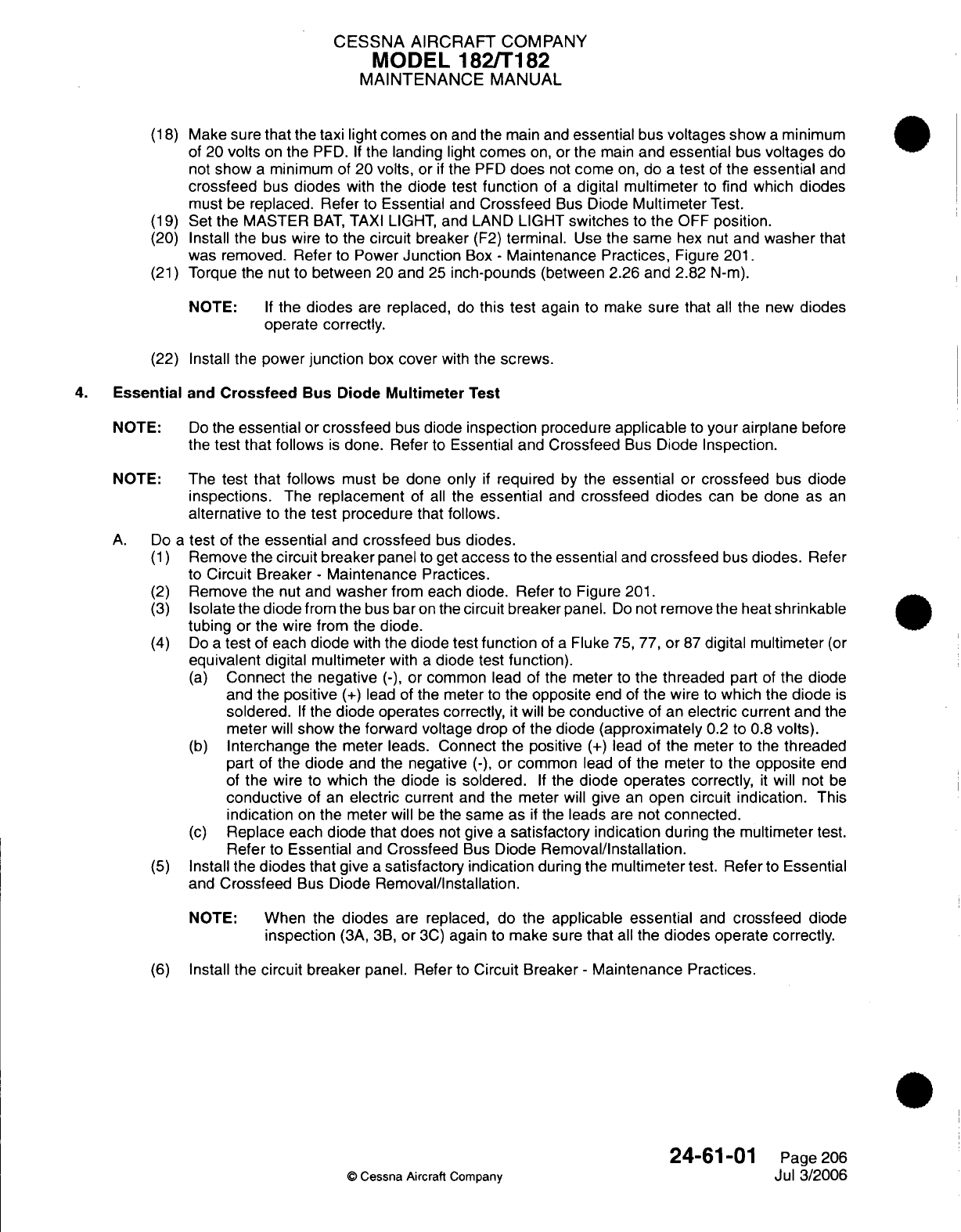
CESSNA
AIRCRAFT
COMPANY
MODEL
182/T182
MAINTENANCE
MANUAL
(18)
Make
sure
that
the
taxi light
comes
on
and
the
main
and
essential
bus
voltages show
a
minimum
of
20
volts
on
the
PFD.
If
the
landing
light
comes
on,
or
the
main
and
essential
bus
voltages
do
not
show
a
minimum of
20
volts, or
if
the
PFD
does
not
come
on,
do
a
test
of
the
essential
and
crossfeed
bus
diodes
with
the
diode test
function
of
a
digital multimeter
to
find
which
diodes
must
be
replaced.
Refer
to
Essential
and
Crossfeed
Bus
Diode
Multimeter
Test.
(19)
Set
the
MASTER
BAT,
TAXI
LIGHT, and
LAND
LIGHT
switches
to
the
OFF
position.
(20)
Install
the
bus
wire to
the
circuit
breaker
(F2)
terminal.
Use
the
same
hex
nut
and
washer
that
was removed. Refer
to
Power
Junction
Box
-
Maintenance
Practices,
Figure
201.
(21)
Torque
the
nut to
between
20
and
25
inch-pounds
(between 2.26
and
2.82
N-m).
NOTE:
If
the diodes
are
replaced,
do
this
test
again
to
make
sure
that
all
the new
diodes
operate
correctly.
(22)
Install
the
power
junction
box
cover
with
the
screws.
4.
Essential
and
Crossfeed
Bus
Diode
Multimeter
Test
NOTE:
Do
the
essential
or
crossfeed
bus
diode
inspection
procedure
applicable
to
your
airplane before
the
test that
follows
is
done. Refer
to
Essential
and
Crossfeed
Bus
Diode
Inspection.
NOTE:
The
test
that
follows
must
be
done
only
if
required
by
the
essential
or
crossfeed
bus
diode
inspections.
The
replacement
of
all
the
essential
and
crossfeed diodes
can
be
done
as
an
alternative
to
the
test
procedure
that
follows.
A. Do
a
test
of
the
essential
and
crossfeed
bus
diodes.
(1)
Remove the
circuit
breaker
panel
to
get
access
to
the
essential
and
crossfeed
bus
diodes.
Refer
to
Circuit
Breaker
-
Maintenance
Practices.
(2)
Remove the
nut
and
washer
from
each
diode.
Refer
to
Figure
201.
(3)
Isolate
the
diode
from
the
bus
bar
on
the
circuit
breaker panel.
Do
not
remove the
heat
shrinkable
tubing
or
the wire from the
diode.
(4)
Do
a
test
of
each
diode
with
the
diode test
function
of
a
Fluke
75,
77,
or
87
digital
multimeter
(or
equivalent
digital
multimeter
with
a
diode
test
function).
(a)
Connect
the
negative
(-),
or common
lead of
the
meter
to
the
threaded
part
of
the
diode
and
the
positive
(+)
lead
of the
meter
to
the
opposite
end
of
the
wire
to
which
the
diode
is
soldered.
If
the
diode
operates
correctly,
it
will
be
conductive
of an
electric current
and
the
meter
will
show
the
forward voltage
drop
of
the
diode
(approximately
0.2 to 0.8
volts).
(b)
Interchange
the meter
leads.
Connect
the
positive
(+)
lead of
the
meter
to the
threaded
part
of
the diode
and the negative
(-),
or
common
lead of
the
meter
to
the
opposite
end
of
the
wire
to
which
the
diode
is
soldered.
If
the
diode operates
correctly,
it
will
not
be
conductive
of
an
electric
current
and
the
meter will
give
an
open
circuit
indication. This
indication
on
the
meter will
be
the same as
if
the leads
are
not
connected.
(c)
Replace
each
diode
that
does
not
give
a
satisfactory
indication during
the
multimeter
test.
Refer
to Essential
and
Crossfeed
Bus
Diode
Removal/Installation.
(5)
Install the
diodes
that
give
a
satisfactory
indication
during the
multimeter
test.
Refer
to
Essential
and
Crossfeed
Bus
Diode
Removal/Installation.
NOTE:
When
the
diodes
are replaced,
do the
applicable
essential
and
crossfeed
diode
inspection
(3A,
3B,
or
3C)
again
to
make
sure
that
all
the
diodes operate
correctly.
(6)
Install
the
circuit
breaker
panel.
Refer
to
Circuit Breaker
-
Maintenance
Practices.
24-61-01
Page
206
©
Cessna Aircraft
Company
Jul 3/2006
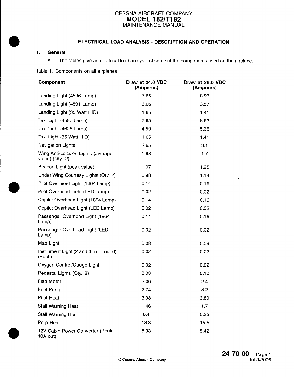
CESSNA
AIRCRAFT
COMPANY
MODEL
182/T182
MAINTENANCE
MANUAL
ELECTRICAL
LOAD
ANALYSIS
-
DESCRIPTION AND OPERATION
1.
General
A.
The
tables give
an
electrical
load
analysis
of
some
of
the
components
used
on
the
airplane.
Table
1.
Components
on
all
airplanes
Component
Landing Light
(4596
Lamp)
Landing
Light
(4591
Lamp)
Landing
Light
(35
Watt
HID)
Taxi
Light
(4587
Lamp)
Taxi
Light
(4626
Lamp)
Taxi
Light
(35
Watt HID)
Navigation
Lights
Wing
Anti-collision
Lights
(average
value)
(Qty.
2)
Beacon
Light (peak
value)
Under Wing
Courtesy
Lights
(Qty.
2)
Pilot
Overhead
Light (1864
Lamp)
Pilot
Overhead
Light
(LED
Lamp)
Copilot
Overhead Light
(1864
Lamp)
Copilot
Overhead Light
(LED
Lamp)
Passenger
Overhead Light
(1864
Lamp)
Passenger Overhead
Light
(LED
Lamp)
Map
Light
Instrument Light
(2
and
3
inch
round)
(Each)
Oxygen
Control/Gauge
Light
Pedestal Lights
(Qty.
2)
Flap
Motor
Fuel
Pump
Pitot
Heat
Stall
Warning
Heat
Stall
Warning
Horn
Prop Heat
12V
Cabin
Power
Converter
(Peak
10A
out)
Draw at
24.0
VDC
(Amperes)
7.65
3.06
1.65
7.65
4.59
1.65
2.65
1.98
1.07
0.98
0.14
0.02
0.14
0.02
0.14
0.02
0.08
0.02
0.02
0.08
2.06
2.74
3.33
1.46
0.4
13.3
6.33
Draw
at
28.0
VDC
(Amperes)
8.93
3.57
1.41
8.93
5.36
1.41
3.1
1.7
1.25
1.14
0.16
0.02
0.16
0.02
0.16
0.02
0.09
0.02
0.02
0.10
2.4
3.2
3.89
1.7
0.35
15.5
5.42
24-70-00
Page
1
Jul
3/2006
©
Cessna
Aircraft
Company
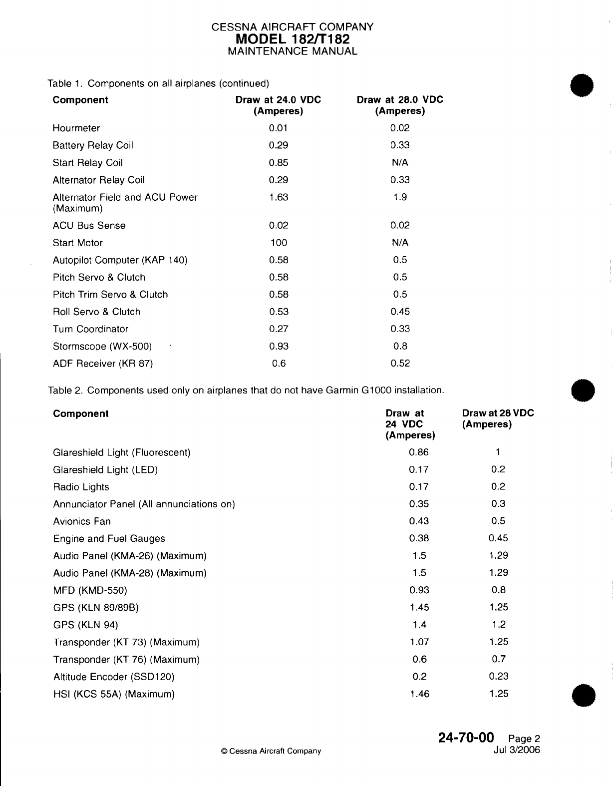
CESSNA AIRCRAFT
COMPANY
MODEL
182/T182
MAINTENANCE
MANUAL
Table
1.
Components
on all
airpla
Component
Hourmeter
Battery
Relay
Coil
Start Relay
Coil
Alternator
Relay
Coil
Alternator
Field
and
ACU
Power
(Maximum)
ACU
Bus
Sense
Start
Motor
Autopilot
Computer
(KAP
140)
Pitch
Servo
&
Clutch
Pitch
Trim
Servo
&
Clutch
Roll
Servo
&
Clutch
Turn
Coordinator
Stormscope
(WX-500)
ADF
Receiver
(KR
87)
nes
(continued)
Draw
at
24.0
VDC
(Amperes)
0.01
0.29
0.85
0.29
1.63
0.02
100
0.58
0.58
0.58
0.53
0.27
0.93
0.6
Draw
at
28.0
VDC
(Amperes)
0.02
0.33
N/A
0.33
1.9
0.02
N/A
0.5
0.5
0.5
0.45
0.33
0.8
0.52
Table
2.
Components
used
only
on
airplanes that
do
not
have Garmin
G1000
installation.
Component
Glareshield
Light
(Fluorescent)
Glareshield
Light
(LED)
Radio
Lights
Annunciator
Panel
(All
annunciations
on)
Avionics
Fan
Engine and
Fuel
Gauges
Audio
Panel
(KMA-26)
(Maximum)
Audio
Panel (KMA-28)
(Maximum)
MFD
(KMD-550)
GPS
(KLN
89/89B)
GPS
(KLN
94)
Transponder
(KT
73)
(Maximum)
Transponder
(KT
76)
(Maximum)
Altitude
Encoder
(SSD120)
HSI (KCS
55A)
(Maximum)
©
Cessna
Aircraft
Company
Draw
at
24
VDC
(Amperes)
0.86
0.17
0.17
0.35
0.43
0.38
1.5
1.5
0.93
1.45
1.4
1.07
0.6
0.2
1.46
Draw
at
28
VDC
(Amperes)
1
0.2
0.2
0.3
0.5
0.45
1.29
1.29
0.8
1.25
1.2
1.25
0.7
0.23
1.25
24-70-00
Page
2
Jul 3/2006
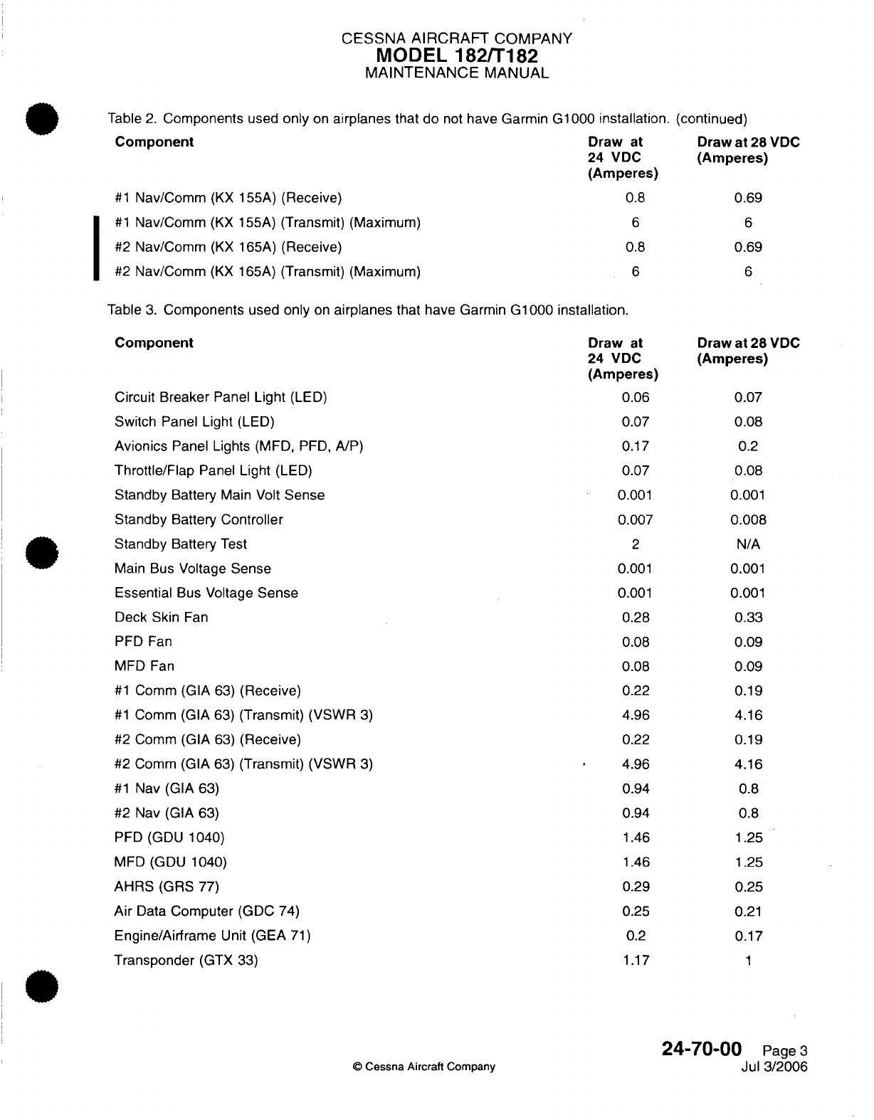
CESSNA AIRCRAFT
COMPANY
MODEL
182/T182
MAINTENANCE
MANUAL
Table
2.
Components
used
only
on
airplanes
that do
not
have Garmin G1000
installation.
Component
Draw
at
24
VDC
(Amperes)
#1
Nav/Comm
(KX
155A)
(Receive)
0.8
#1
Nav/Comm
(KX
155A)
(Transmit)
(Maximum)
#2
Nav/Comm
(KX
165A)
(Receive)
#2
Nav/Comm
(KX
165A)
(Transmit)
(Maximum)
6
0.8
6
(continued)
Draw
at
28
VDC
(Amperes)
0.69
6
0.69
6
Table
3.
Components
used
only
on
airplanes
that
have
Garmin
G1000
installation.
Component
Circuit Breaker
Panel
Light
(LED)
Switch
Panel
Light
(LED)
Avionics
Panel
Lights
(MFD,
PFD,
A/P)
Throttle/Flap
Panel
Light
(LED)
Standby
Battery
Main Volt
Sense
Standby
Battery
Controller
Standby
Battery
Test
Main
Bus
Voltage
Sense
Essential
Bus
Voltage
Sense
Deck Skin
Fan
PFD
Fan
MFD
Fan
#1
Comm
(GIA
63)
(Receive)
#1
Comm
(GIA
63)
(Transmit)
(VSWR
3)
#2
Comm
(GIA
63)
(Receive)
#2
Comm
(GIA
63)
(Transmit)
(VSWR
3)
#1
Nav
(GIA
63)
#2
Nav
(GIA
63)
PFD (GDU 1040)
MFD (GDU 1040)
AHRS
(GRS
77)
Air
Data
Computer
(GDC
74)
Engine/Airframe
Unit
(GEA
71)
Transponder
(GTX
33)
Draw
at
24
VDC
(Amperes)
0.06
0.07
0.17
0.07
0.001
0.007
2
0.001
0.001
0.28
0.08
0.08
0.22
4.96
0.22
4.96
0.94
0.94
1.46
1.46
0.29
0.25
0.2
1.17
©
Cessna
Aircraft
Company
Draw
at
28
VDC
(Amperes)
0.07
0.08
0.2
0.08
0.001
0.008
N/A
0.001
0.001
0.33
0.09
0.09
0.19
4.16
0.19
4.16
0.8
0.8
1.25
1.25
0.25
0.21
0.17
1
24-70-00
Page
3
Jul
3/2006
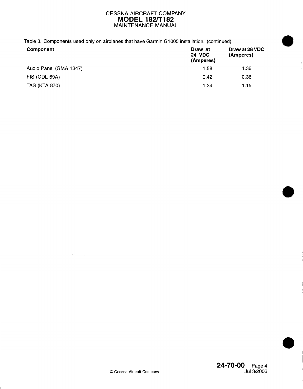
CESSNA
AIRCRAFT
COMPANY
MODEL
182/T182
MAINTENANCE
MANUAL
Table
3.
Components
used
only
on
airplanes
that
have
Garmin
G1000 installation.
(continued)
Component
Draw
at
D
24 VDC
(/
(Amperes)
Audio
Panel
(GMA
1347)
1.58
FIS
(GDL
69A)
0.42
TAS
(KTA
870)
1.34
raw at
28
VDC
Amperes)
1.36
0.36
1.15
©
Cessna Aircraft
Company
24-70-00
Page
4
Jul
3/2006
CHAPTER
EQUIPMENT/
FURNISHINGS
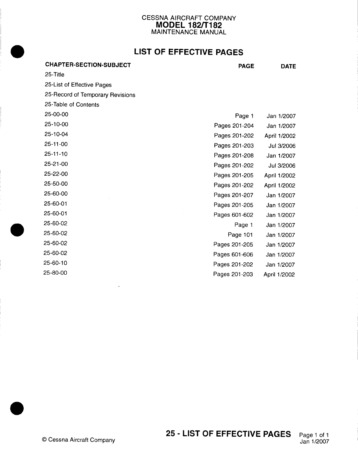
CESSNA AIRCRAFT
COMPANY
MODEL
182/Ti
82
MAINTENANCE
MANUAL
LIST
OF
EFFECTIVE
PAGES
CHAPTER-SECTION-SUBJECT
25-Title
25-List
of Effective
Pages
25-Record
of
Temporary
Revisions
25-Table
of
Contents
25-00-00
25-10-00
25-10-04
25-11-00
25-11-10
25-2
1-00
25-22-00
25-50-00
25-60-00
25-60-01
25-60-01
25-60-02
25-60-02
25-60-02
25-60-02
25-60-10
25-80-00
©
Cessna
Aircraft
Company
PAGE
Page
1
Pages
201
-204
Pages
201
-202
Pages
201-203
Pages
201
-208
Pages
201-202
Pages
201
-205
Pages
201-202
Pages
201
-207
Pages
201-205
Pages
601
-602
Page
1
Page
101
Pages
201
-205
Pages
601
-606
Pages
201
-202
Pages
201-203
DATE
Janl1/2007
Janl1/2007
April
1/2002
Jul
3/2006
Jan
1/2007
Jul
3/2006
April 1/2002
April
1/2002
Janl1/2007
Janl1/2007
Jan
1/2007
Janl1/2007
Janl1/2007
Janl1/2007
Jan-1/2007
Janl1/2007
April
1/2002
25
-
LIST
OF
EFFECTIVE
PAGES
Page
1
of
1
Janl1/2007
Temporary
Revision
Number
RECORD
OF
TEMPORARY REVISIONS
Page
Number
Issue
Date
By
Date
Removed
By
CESSNA
AIRCRAFT
COMPANY
MODEL
182/T1
82
MAINTENANCE
MANUAL
CONTENTS
EQUIPMENT/FURNISHING
-
GENERAL
......................
Scope....................................
Tools,
Equipment
and
Materials........................
Definition
..................................
FRONT
SEATS AND RAILS
-
MAINTENANCE PRACTICES
.............
General...................................
Seat
Removal/installation...........................
Seat
Rail
Removal/Installation.........................
MAP
COMPARTMENT
-
MAINTENANCE
PRACTICES................
General...................................
Map
Compartment
Removal/installation
....................
SEAT
BELTS/RESTRAINTS
-
MAINTENANCE PRACTICES
.............
General...................................
Seat
Belt/Restraints
Removal
and
Installation..................
Restraint
Testing...............................
INFLATABLE
RESTRAINTS
-
MAINTENANCE PRACTICES
Airplanes
with
AMSAFE
Inflatable
Restraint
System.............................
General
...................................
Inflatable
Restraint
Component
Cleaning....................
Inflatable
Restraint
-
Inspection
........................
Storage
of
Spares
..............................
AMVSAFE
Inflatable
Restraint
Disarm/Arm
...................
Inflatable Restraint
-
Removal/Installation
...................
AMSAFE
Aviation Inflatable
Restraint
(AAIR)
System Adjustment/Test
......
AMSAFE
Aviation Inflatable
Restraint
(AAIR)
System
Troubleshooting
......
REAR SEAT
-
MAINTENANCE
PRACTICES
....................
General...................................
Rear
Seat
Removal/Installation
........................
INTERIOR
UPHOLSTERY
-
MAINTENANCE
PRACTICES..............
General...................................
Cabin
Panels
Removal/installation.......................
Door
Panels
and
Carpet
Removal/Installation..................
CARGO
TIE-DOWNS
-
MAINTENANCE
PRACTICES
................
General...................................
POINTER EMERGENCY
LOCATOR
TRANSMITTER
-
MAINTENANCE
PRACTICES..
General...................................
Pointer
ELT
Removal/installation
.......................
Pointer
ELT
Remote Switch
Removal/Installation
................
ELT
Antenna
Removal/Installation
(integral
Base
with
Coax
Cable)........
ELT
Whip
Antenna
Removal/installation
....................
Pointer
ELT
Battery
Pack
Removal/Installation
.................
Pointer
ELT
Operational
Test
.........................
ARTEX
C406-N EMERGENCY
LOCATOR
TRANSMITTER
-
MAINTENANCE
PRACTICES
...................................
General...................................
Artex
C406-N
ELT
Removal/installation
....................
Artex
C406-N
ELT
Remote
Switch
Removal/Installation.............
Artex
C406-N
ELT
Rod
Antenna
Removal/installation..............
Artex
C406-N
Buzzer
Removal/Installation...................
25-00-00
Page
1
25-00-00
Page
1
25-00-00
Page
1
25-00-00
Page
1
25-1
0-00
Page
201
25-1
0-00
Page
201
25-10-00
Page
201
25-10-00
Page
201
25-10-04
Page
201
25-10-04
Page
201
25-10-04
Page
201
25-11
-00
Page
201
25-11
-00
Page
201
25-11
-00
Page
201
25-1
1-00
Page
201
25-11
-1
0
Page
201
25-11
-1
0
Page
201
25-11
-1
0
Page
201
25-11
-1
0
Page 202
25-1
1-1
0
Page 202
25-1
1-1
0
Page
202
25-11
-1
0 Page 203
25-11
-1
0
Page
207
25-11
-1
0
Page
208
25-21
-00
Page
201
25-21 -00 Page
201
25-21 -00
Page
201
25-22-00
Page
201
25-22-00
Page
201
25-22-00
Page
201
25-22-00
Page
201
25-50-00
Page
201
25-50-00
Page
201
25-60-00
Page
201
25-60-00
Page
201
25-60-00
Page
201
25-60-00
Page 204
25-60-00
Page 204
25-60-00
Page 205
25-60-00
Page 205
25-60-00
Page
206
25-60-01
Page
201
25-60-01 Page
201
25-60-01
Page
201
25-60-0
1
Page
201
25-60-01 Page
204
25-60-01
Page
204
25
-
CONTENTS
Page
1
of
2
Janl1/2007
©
Cessna
Aircraft
Company
CESSNA AIRCRAFT
COMPANY
MODEL 182/T182
MAINTENANCE
MANUAL
ARTEX C406-N
EMERGENCY
LOCATOR
TRANSMITTER
-
INSPECTION/CHECK
...
General...................................
Artex
C406-N
ELT
Functional
Test.......................
ARTEX
ME406
EMERGENCY
LOCATOR
TRANSMITTER
SYSTEM
-
DESCRIPTION
AND
OPERATION
................................
General...................................
Description
.................................
Operation..................................
ARTEX
ME406
EMERGENCY
LOCATOR
TRANSMITTER
SYSTEM
-
TROUBLESHOOTING
..............................
General...................................
Tools
and
Equipment.............................
ME406
Emergency
Locator
Transmitter
Self
Test
Preparation
..........
ARTEX
ME406
EMERGENCY
LOCATOR
TRANSMITTER
SYSTEM
-
MAINTENANCE
PRACTICES
...................................
General...................................
Emergency Locator
Transmitter
(ELT)
Removal/Installation
...........
ELT
Buzzer
Removal/installation
.......................
Remote
Switch
Removal/Installation......................
ELT
Antenna
Removal/Installation.......................
ARTEX
ME406
EMERGENCY
LOCATOR
TRANSMITTER
(ELT)
SYSTEM
-
INSPECTION/CHECK...............................
General...................................
Tools
and
Equipment.............................
Artex ME406
Emergency
Locator Transmitter
(ELT)
Inspection..........
Artex
ME406
Emergency
Locator
Functional
Test................
CARBON
MONOXIDE
DETECTOR
-
MAINTENANCE
PRACTICES..........
General...................................
Carbon
Monoxide
Detector
Removal/Installation
................
SOUNDPROOFING
AND
INSULATION
-
MAINTENANCE
PRACTICES........
General...................................
25-60-01
Page
601
25-60-01
Page
601
25-60-01
Page
601
25-60-02
Page
1
25-60-02
Page
1
25-60-02
Page
1
25-60-02
Page
1
25-60-02
Page
1 01
25-60-02
Page
101
25-60-02
Page
101
25-60-02
Page
101
25-60-02
Page
201
25-60-02
Page
201
25-60-02
Page
201
25-60-02
Page
201
25-60-02
Page
204
25-60-02
Page 204
25-60-02
Page
601
25-60-02
Page
601
25-60-02
Page
601
25-60-02
Page
601
25-60-02
Page
602
25-60-1
0 Page
201
25-60-1
0 Page
201
25-60-1
0 Page
201
25-80-00
Page
201
25-80-00
Page
201
25
-
CONTENTS
Page
2
of
2
Janl1/2007
©
Cessna
Aircraft
Company
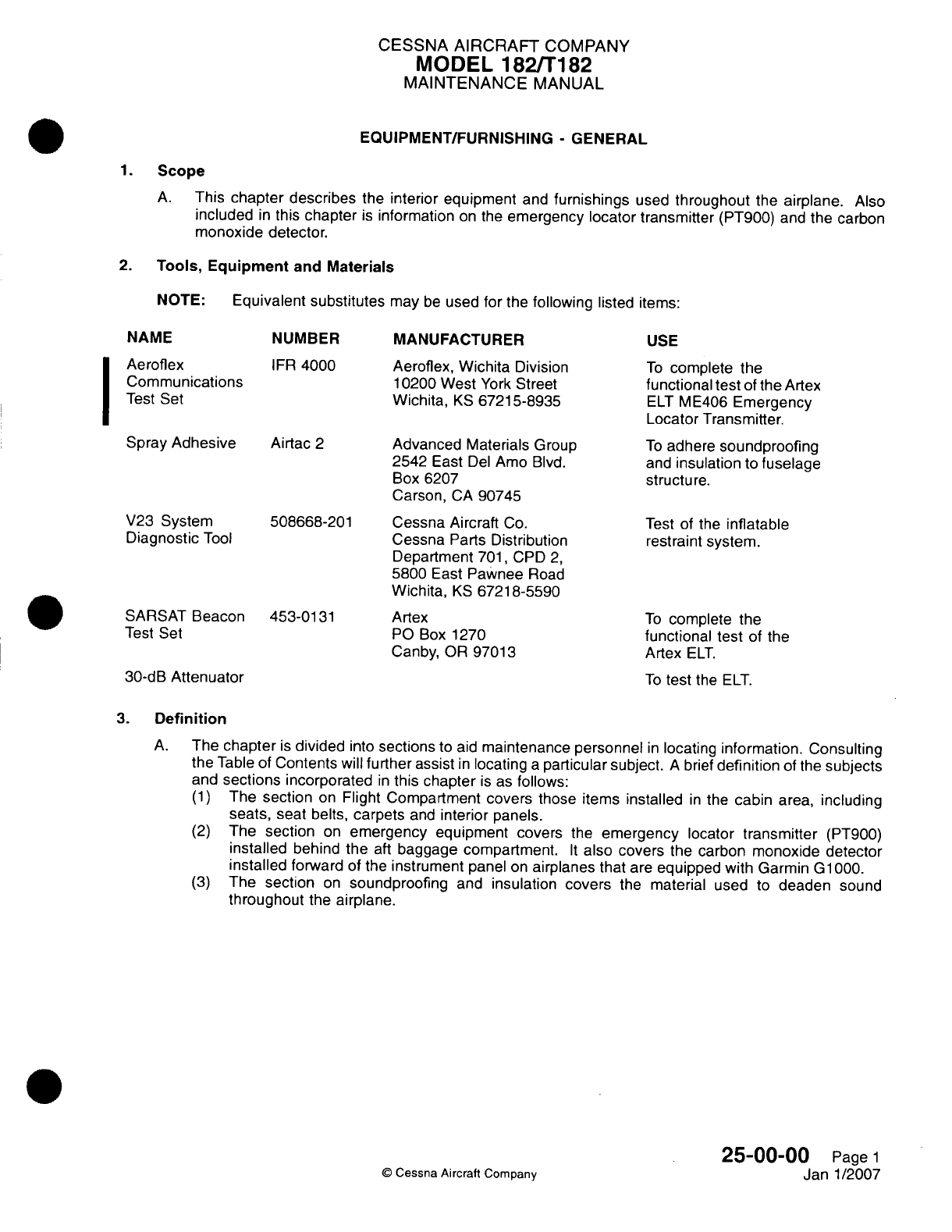
CESSNA
AIRCRAFT
COMPANY
MODEL
182/Ti
182
MAINTENANCE
MANUAL
EQUIPMENT/FURNISHING
-
GENERAL
1.Scope
A.
This
chapter
describes
the
interior equipment
and
furnishings
used
throughout
the
airplane.
Also
included
in
this
chapter
is
information
on
the
emergency
locator transmitter
(PT900)
and
the
carbon
monoxide
detector.
2.
Tools, Equipment
and
Materials
NOTE:
Equivalent substitutes
may
be
used
for
the
following
listed
items:
NAME
Aeroflex
Communications
Test
Set
Spray
Adhesive
V23
System
Diagnostic
Tool
SARSAT
Beacon
Test Set
NUMBER
IFR
4000
Airtac
2
508668-201
453-0131
MANUFACTURER
Aeroflex,
Wichita
Division
10200 West
York
Street
Wichita,
KS
67215-8935
Advanced
Materials
Group
2542
East
Del
Amo
Blvd.
Box 6207
Carson,
CA
90745
Cessna
Aircraft
Co.
Cessna
Parts
Distribution
Department
701,
CPD
2,
5800
East
Pawnee
Road
Wichita,
KS
67218-5590
Artex
P0
Box 1270
Canby,
OR
97013
30-dB
Attenuator
USE
To
complete
the
functional
test
of
the
Artex
ELT
ME406
Emergency
Locator
Transmitter.
To
adhere
soundproofing
and
insulation
to
fuselage
structure.
Test
of
the
inflatable
restraint
system.
To
complete
the
functional test
of
the
Artex
ELT.
To
test
the
ELT.
3.
Definition
A.
The
chapter
is
divided
into
sections
to
aid
maintenance personnel
in
locating
information. Consulting
the
Table of
Contents
will
further
assist
in
locating
a
particular subject.
A
brief
definition
of
the
subjects
and
sections
incorporated
in
this
chapter
is
as
follows:
(1)
The
section
on
Flight
Compartment covers those
items
installed
in
the
cabin
area,
including
seats,
seat belts,
carpets
and
interior
panels.
(2)
The
section
on
emergency
equipment
covers
the
emergency
locator
transmitter
(PT900)
installed
behind
the
aft
baggage
compartment.
It
also
covers
the
carbon
monoxide detector
installed
forward
of the
instrument
panel
on
airplanes
that
are
equipped
with
Garmin
G
1000.
(3)
The
section
on
soundproofing
and
insulation covers
the
material used
to
deaden
sound
throughout
the
airplane.
25-00-04
©D
Cessna Aircraft
Company
J
Pagel1
Janl1/2007
I
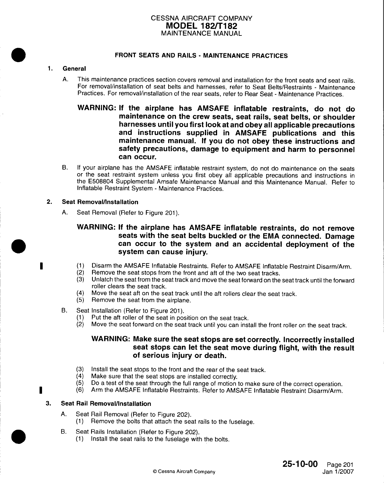
CESSNA
AIRCRAFT
COMPANY
MODEL
182/T1
82
MAINTENANCE
MANUAL
FRONT
SEATS AND
RAILS
-
MAINTENANCE PRACTICES
1.General
A.
This
maintenance practices
section
covers
removal
and
installation
for
the
front
seats
and
seat
rails.
For
removal/installation
of
seat
belts
and
harnesses,
refer
to
Seat
Belts/Restraints
-
Maintenance
Practices.
For
removal/installation
of
the
rear
seats, refer
to
Rear
Seat
-
Maintenance
Practices.
WARNING:
If
the
airplane
has
AMSAFE
inflatable
restraints,
do
not
do
maintenance
on
the
crew
seats, seat
rails,
seat
belts, or
shoulder
harnesses
until
you
first
look
at
and
obey
all
applicable
precautions
and
instructions
supplied
in
AMSAFE
publications
and
this
maintenance
manual.
If
you
do
not
obey
these
instructions
and
safety
precautions,
damage
to equipment
and
harm
to
personnel
can
occur.
B. If
your
airplane
has the
AMVSAFE
inflatable
restraint
system,
do
not
do
maintenance
on
the
seats
or
the
seat
restraint
system
unless you
first obey
all
applicable
precautions
and
instructions
in
the
E508804
Supplemental
Amsafe
Maintenance
Manual
and
this Maintenance
Manual.
Refer
to
Inflatable
Restraint
System
-
Maintenance
Practices.
2.
Seat
Removal/installation
A.
Seat
Removal
(Refer
to
Figure
201).
WARNING:
If
the
airplane
has
AMSAFE
inflatable restraints,
do
not
remove
seats
with
the
seat
belts buckled
or
the
EMA
connected.
Damage
can
occur
to
the
system
and
an
accidental deployment
of
the
system
can
cause
injury.
(1)
Disarm the
AMVSAFE
Inflatable
Restraints.
Refer
to
AMVSAFE
Inflatable
Restraint
Disarm/Arm.
(2)
Remove
the
seat
stops
from the
front
and
aft
of
the
two
seat
tracks.
(3)
Unlatch the
seat
from the
seat
track
and
move
the
seat
forward
on the seat
track
until
the
forward
roller clears
the
seat
track.
(4)
Move
the
seat
aft
on
the
seat track
until
the
aft
rollers
clear
the
seat
track.
(5)
Remove
the
seat
from
the
airplane.
B.
Seat
Installation
(Refer
to
Figure
201).
(1)
Put
the
aft
roller
of
the seat
in
position
on
the seat track.
(2)
Move the
seat
forward
on
the
seat
track
until
you
can
install the
front
roller
on
the
seat track.
WARNING:
Make
sure
the seat
stops
are
set
correctly.
Incorrectly
installed
seat
stops
can
let
the
seat move
during
flight,
with
the
result
of
serious
injury
or
death.
(3)
Install
the
seat
stops
to
the
front and
the rear
of
the
seat
track.
(4)
Make sure
that
the
seat
stops
are
installed
correctly.
(5)
Do
a
test
of
the
seat through
the
full
range
of
motion
to
make
sure
of
the
correct operation.
(6)
Arm
the
AMVSAFE
Inflatable
Restraints.
Refer
to
AMVSAFE
Inflatable Restraint
Disarm/Arm.
3.
Seat Rail
Removal/installation
A.
Seat
Rail
Removal
(Refer to
Figure
202).
(1)
Remove
the bolts
that
attach
the
seat
rails
to
the
fuselage.
B.
Seat
Rails
Installation (Refer
to
Figure 202).
(1)
Install
the
seat
rails
to the
fuselage
with
the
bolts.
25-1
0-00
Page
201
©
Cessna
Aircraft
Company
Janl1/2007
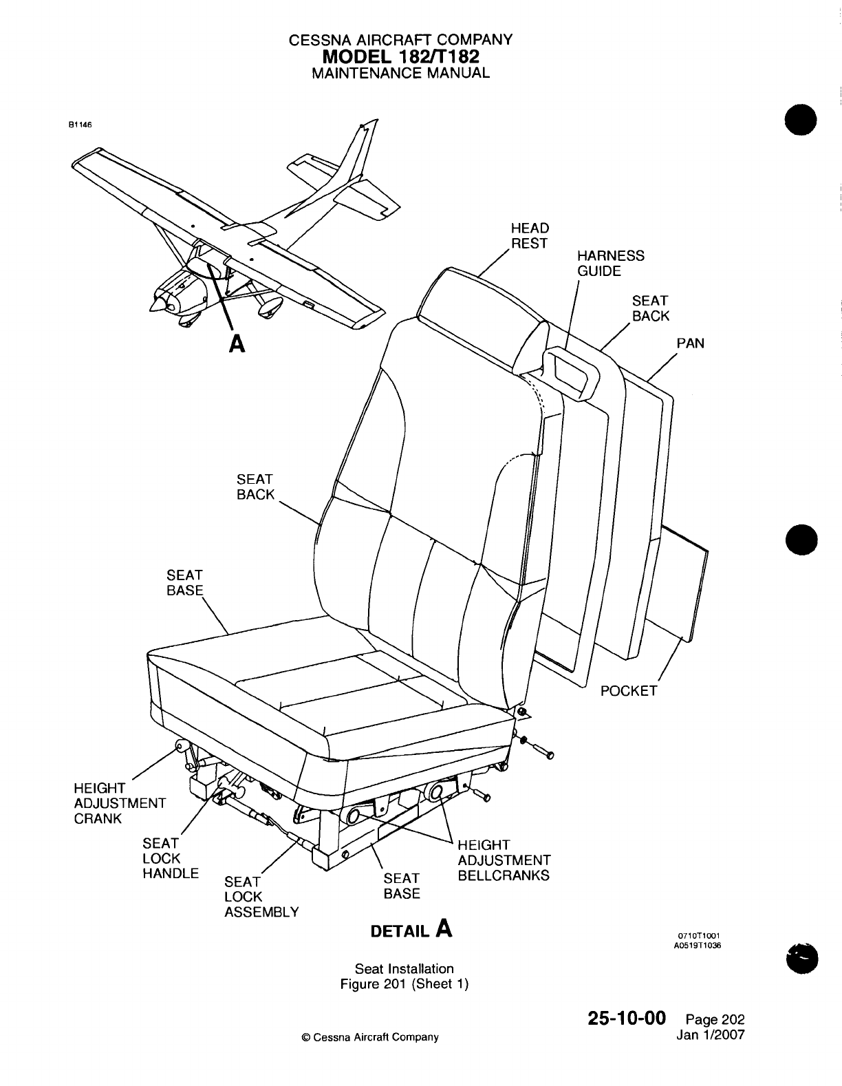
CESSNA AIRCRAFT
COMPANY
MODEL
182ffT182
MAINTENANCE
MANUAL
0
LOCK
ASSEMBLY
BASE
DETAIL
A
0710T1001
A0519T1O36
Seat
Installation
Figure
201
(Sheet
1)
25-1
0-00
©
Cessna Aircraft
Company
Page 202
Janl1/2007
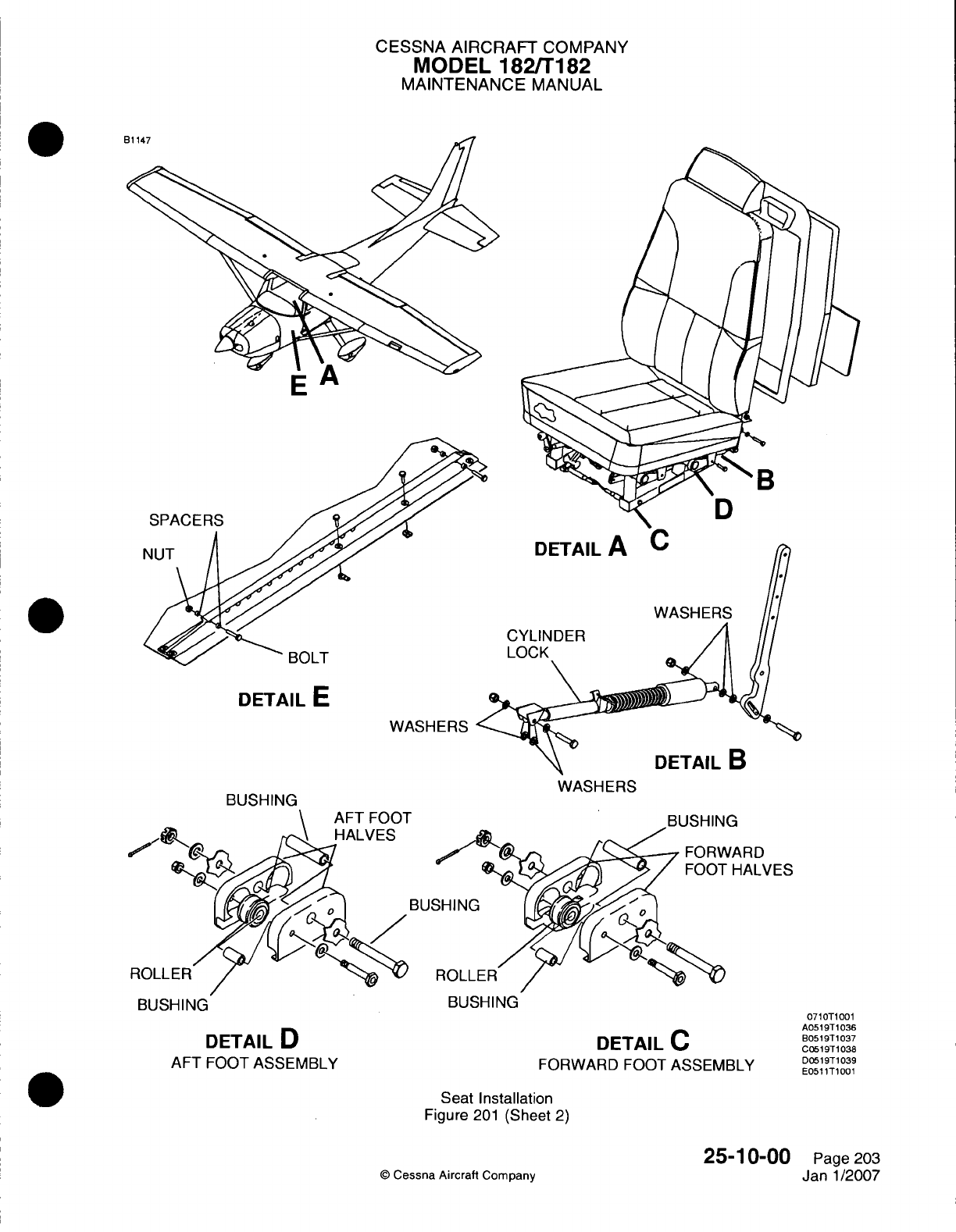
CESSNA
AIRCRAFT
COMPANY
MODEL
1821T182
MAINTENANCE
MANUAL
CYLINDER
LOCK
DETAIL
E
WASHERS
WASHERS
BUSHING BUSHING
DETAIL
D
AFT
FOOT
ASSEMBLY
DETAIL
C
FORWARD
FOOT
ASSEMBLY
Seat Installation
Figure
201
(Sheet
2)
©
Cessna
Aircraft
Company
25-1
0-00
Page
203
Janl1/2007
BOLT
BUSHING
kRD
-IALVES
0710T1001
A0519T
1036
B0519T
1037
C0519T1038
DOS519T1039
E051
1T1001
CESSNA AIRCRAFT
COMPANY
MODEL
182/Ti
182
MAINTENANCE
MANUAL
S
FLOORBOARD
RAIL
BOLT
SPACER
WARNING:
IT IS
EXTREMELY
IMPORTANT THAT PILOT'S SEAT
STOPS
ARE
INSTALLED,
SINCE
ACCELERATION
AND DECELERATION
COULD
POSSIBLY
PERMIT SEAT
TO
BECOME
DISENGAGED
FROM
SEAT
RAILS
AND
CREATE
A
HAZARDOUS
SITUATION, ESPECIALLY
DURING
TAKEOFF
AND
LANDING.
051
1TIO01
Seat
Stop
Installation
Figure
202
(Sheet
1)
C
Cessna
Aircraft Company
25-1
0-00
Page
204
Janl1/2007
81
148
CESSNA
AIRCRAFT
COMPANY
MODEL
182/T182
MAINTENANCE
MANUAL
MAP
COMPARTMENT
-
MAINTENANCE
PRACTICES
1.
General
A.
This
maintenance practices section consists
of removal
and
installation
of the
map
compartment.
2.
Map
Compartment
Removal/Installation
A.
Remove
Map
Compartment
(Refer
to
Figure 201).
(1)
Remove
interior screws securing
map
compartment
to
instrument
panel
structure.
B.
Install
Map
Compartment
(Refer
to
Figure
201).
(1)
Place
map
compartment
in
position
and
secure
to
instrument panel
structure using
screws.
25-10-04
Page
201
©
Cessna Aircraft Company
April 1/2002
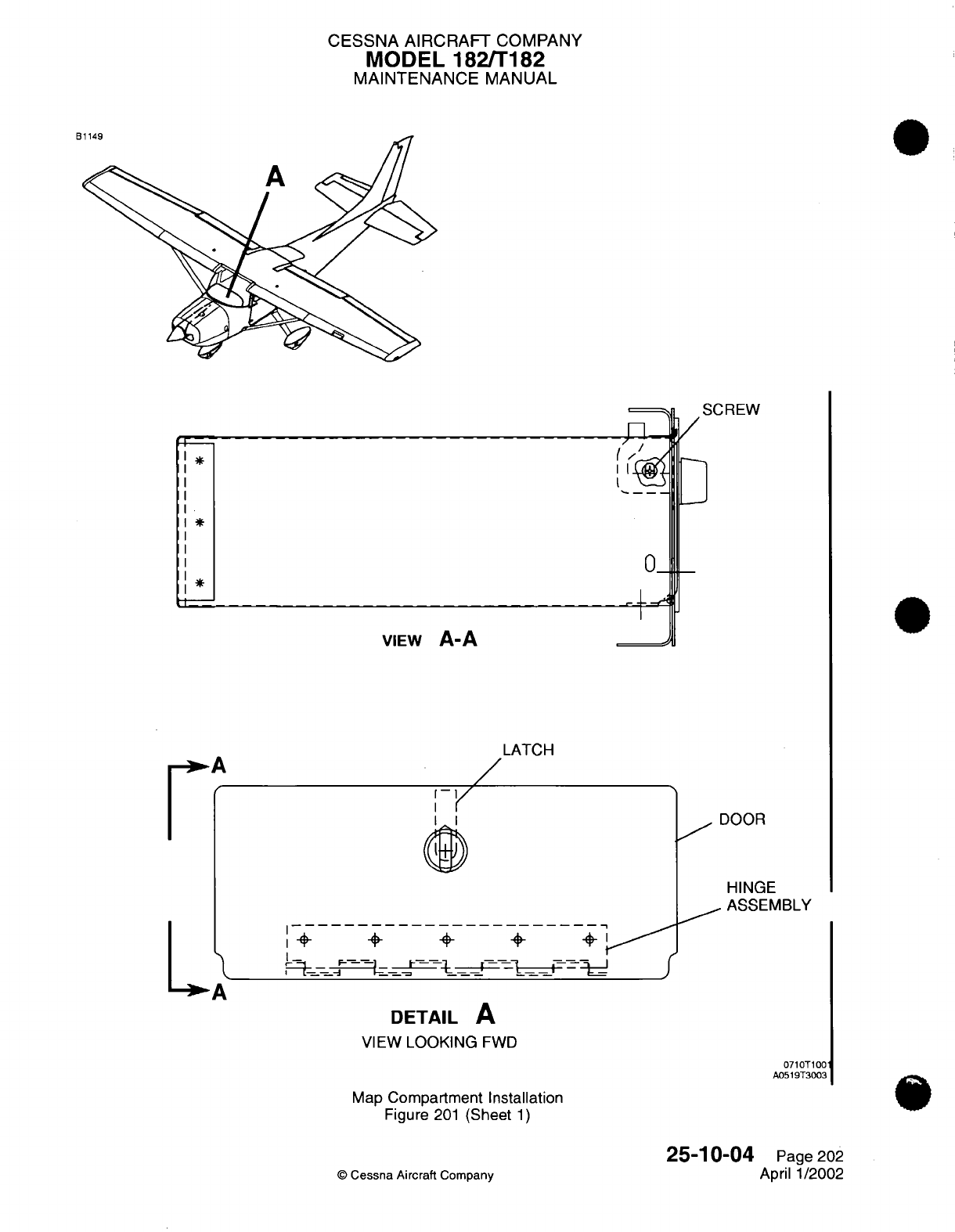
CESSNA
AIRCRAFT
COMPANY
MODEL
182/T182
MAINTENANCE
MANUAL
SCREW
0_
VIEW
A-A
LATCH
I I~
I--
1+
+
+ +
DOOR
HINGE
ASSEMBLY
~
I
r-<
J
DETAIL
A
VIEW
LOOKING
FWD
0710T1001
A0519T3003
Map
Compartment
Installation
Figure
201
(Sheet
1)
©
Cessna
Aircraft
Company
25-10-04
Page
202
April
1/2002
F
I
1*
*
LA
D 4
A
::
- -
=-
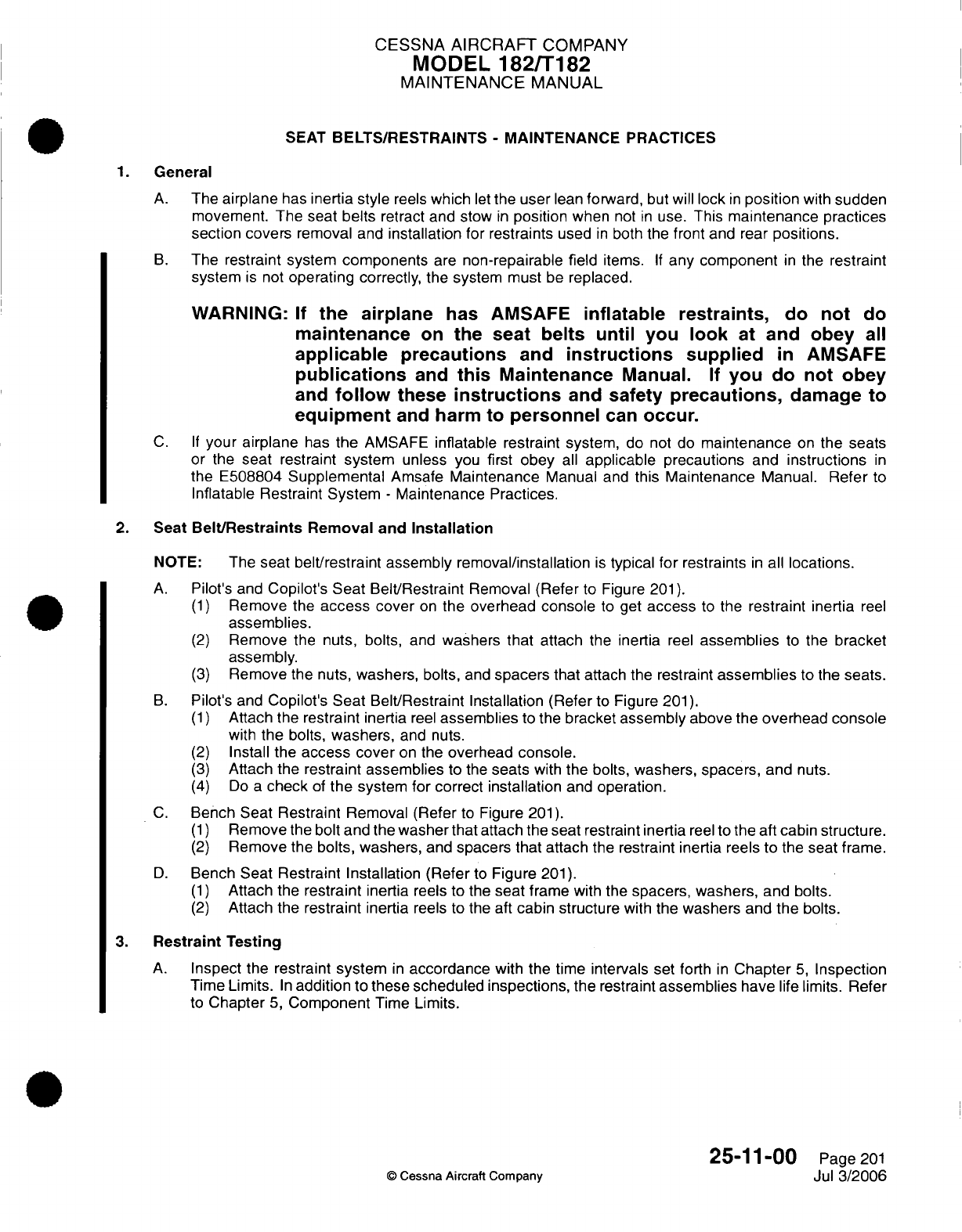
CESSNA
AIRCRAFT
COMPANY
MODEL
182/T182
MAINTENANCE
MANUAL
SEAT
BELTS/RESTRAINTS
-
MAINTENANCE PRACTICES
1.
General
A.
The
airplane
has
inertia
style
reels
which
let
the
user
lean
forward,
but
will
lock
in
position
with
sudden
movement.
The
seat
belts
retract and
stow
in
position
when
not
in
use.
This
maintenance practices
section
covers
removal
and
installation for restraints
used
in
both
the
front
and rear
positions.
B.
The
restraint
system
components
are
non-repairable field
items.
If
any
component
in
the restraint
system
is
not
operating correctly,
the
system must
be
replaced.
WARNING:
If
the
airplane
has
AMSAFE
inflatable
restraints,
do
not
do
maintenance
on
the seat
belts
until
you
look
at
and
obey
all
applicable
precautions
and
instructions
supplied
in
AMSAFE
publications
and
this
Maintenance
Manual.
If
you
do not
obey
and
follow
these
instructions
and
safety
precautions,
damage
to
equipment
and
harm
to
personnel
can
occur.
C. If
your
airplane
has
the
AMSAFE
inflatable
restraint
system,
do not do
maintenance
on
the
seats
or
the
seat
restraint
system
unless
you
first obey
all
applicable
precautions
and
instructions
in
the E508804
Supplemental
Amsafe
Maintenance
Manual
and
this
Maintenance
Manual.
Refer
to
Inflatable
Restraint
System
-
Maintenance Practices.
2.
Seat
Belt/Restraints
Removal
and
Installation
NOTE: The
seat
belt/restraint assembly removal/installation
is
typical
for
restraints
in
all
locations.
A.
Pilot's
and
Copilot's
Seat
Belt/Restraint
Removal (Refer
to
Figure
201).
(1)
Remove
the
access
cover
on
the
overhead
console
to
get
access
to
the
restraint
inertia
reel
assemblies.
(2)
Remove
the
nuts, bolts,
and
washers
that
attach
the
inertia
reel
assemblies
to
the
bracket
assembly.
(3)
Remove
the
nuts,
washers,
bolts,
and
spacers
that
attach the restraint
assemblies
to the
seats.
B.
Pilot's
and
Copilot's Seat Belt/Restraint Installation
(Refer
to Figure
201).
(1)
Attach
the
restraint
inertia
reel
assemblies
to
the
bracket
assembly
above the
overhead console
with
the
bolts,
washers,
and
nuts.
(2)
Install
the
access
cover
on
the
overhead
console.
(3)
Attach
the
restraint
assemblies
to
the
seats
with
the bolts,
washers, spacers,
and
nuts.
(4)
Do
a
check
of
the
system for correct
installation
and
operation.
C.
Bench
Seat
Restraint
Removal (Refer
to
Figure
201).
(1)
Remove
the
bolt
and the
washer
that
attach the seat restraint inertia
reel
to
the aft cabin
structure.
(2)
Remove the
bolts, washers,
and
spacers that
attach
the
restraint inertia
reels
to
the seat
frame.
D.
Bench
Seat
Restraint Installation (Refer
to
Figure
201).
(1)
Attach the
restraint
inertia
reels
to
the
seat
frame with
the
spacers, washers,
and bolts.
(2)
Attach the
restraint
inertia
reels to the aft
cabin structure
with
the washers and
the
bolts.
3.
Restraint
Testing
A.
Inspect
the
restraint
system
in
accordance
with the
time
intervals
set
forth
in
Chapter
5,
Inspection
Time
Limits.
In
addition
to
these scheduled inspections, the
restraint
assemblies
have
life limits. Refer
to
Chapter
5,
Component
Time
Limits.
25-11-00
Page
201
©
Cessna
Aircraft Company
Jul
3/2006
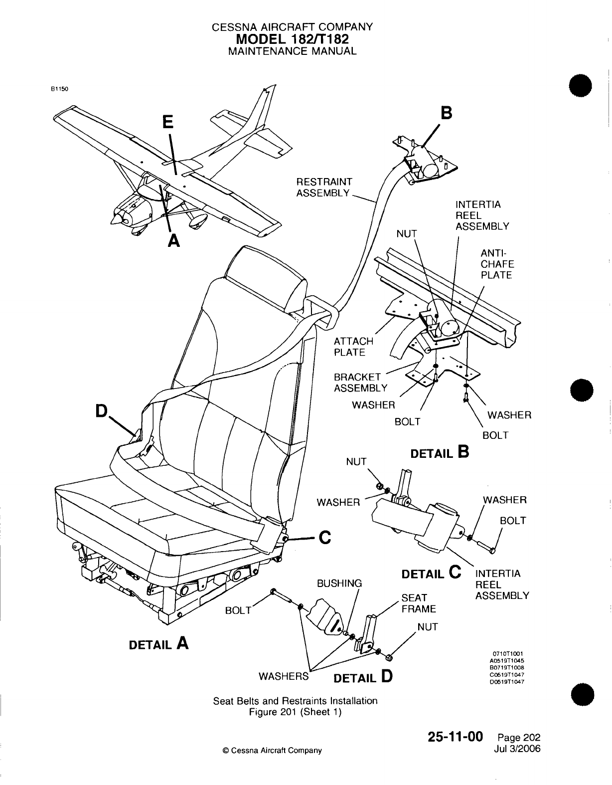
CESSNA AIRCRAFT
COMPANY
MODEL 182/T182
MAINTENANCE
MANUAL
B
RESTRAINT
ASSEMBLY
ANTI-
CHAFE
PLATE
BRACKET
ASSEMBLY
WASHER
BOLT BOLT
NUT
DETAIL
B
WASHER
DETAIL
C
Y
NUT
WASHERS
DETAIL
U
Seat Belts
and
Restraints
Installation
Figure
201
(Sheet
1)
©
Cessna
Aircraft
Company
25-11-00
Page
202
Jul
3/2006
D
DETAIL
A
C0519T1047
D05 19T1047
ER
5
8
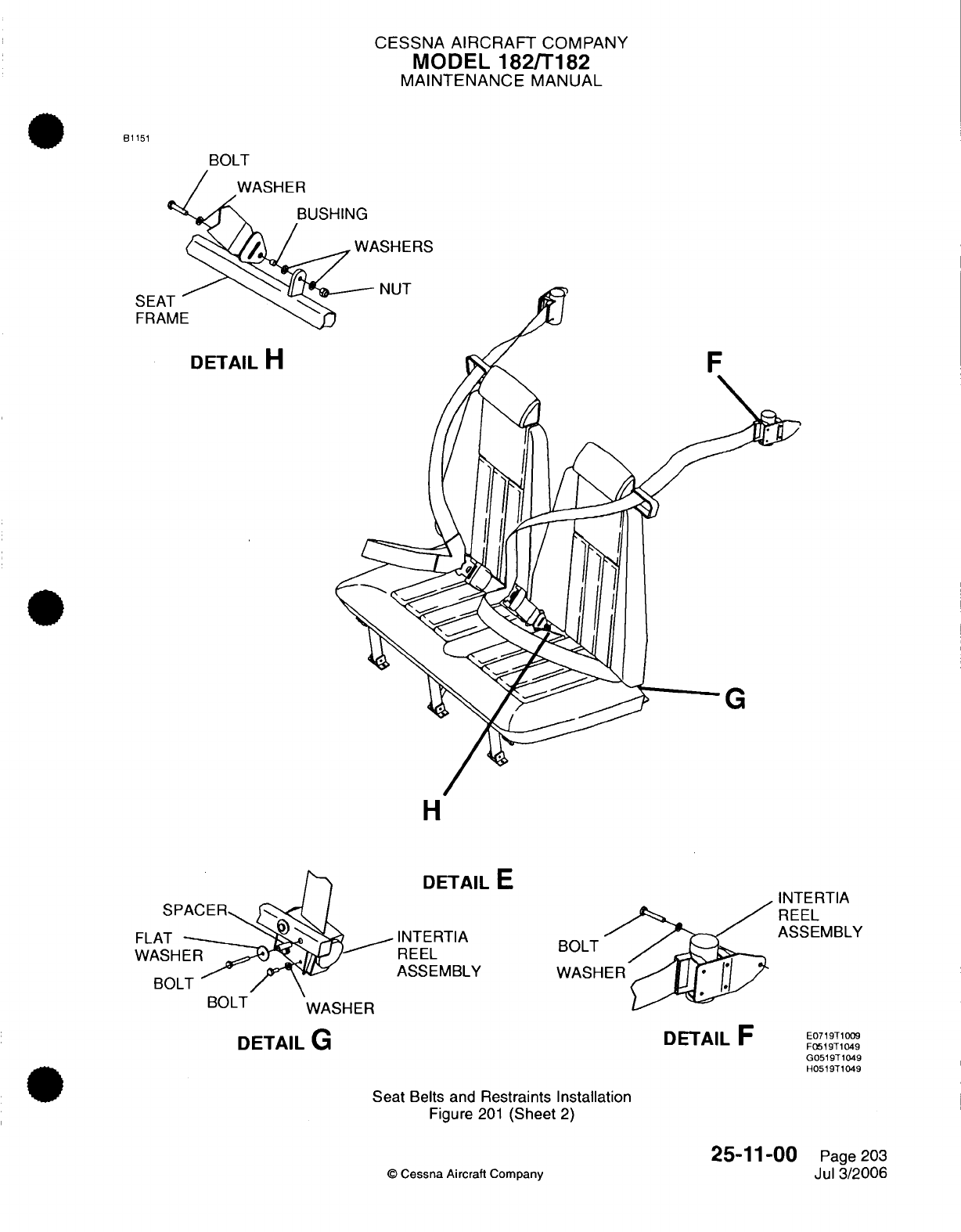
CESSNA
AIRCRAFT
COMPANY
MODEL
182/T182
MAINTENANCE
MANUAL
B1151
BOLT
WASHER
BUSHING
ASHERS
SEA
FRA
DETAIL
H
G
H
DETAIL
SPACER
FLAT
INTERTIA
WASHER
REEL
ASSEMBLY
BOLT
BOLT
BOLT
WASH
WASHER
DETAIL
G
DETAIL
F
Seat
Belts and
Restraints Installation
Figure
201
(Sheet
2)
©
Cessna
Aircraft
Company
F
INTERTIA
REEL
ASSEMBLY
E0719T1009
F0519T1049
G0519T1049
H0519T1049
25-11-00
Page
203
Jul
3/2006
E
CESSNA
AIRCRAFT
COMPANY
MODEL
182/Ti182
MAINTENANCE
MANUAL
INFLATABLE
RESTRAINTS
-
MAINTENANCE PRACTICES
Airplanes with
AMSAFE
Inflatable
Restraint
System
1.General
A.
This
section
gives
maintenance
information
for
the
AMVSAFE
Aviation
Inflatable
Restraint
(AAIR).
The
AAIR
is a
self-contained,
modular,
three-point
restraint
system that
protects
occupants
from
head-
impact
injury during
an
accident.
The AAIR
system
has
four
core
components:
the air
bag
assembly,
the
inflator
assembly,
the
electronics
module
assembly
(EMVA),
and
the
cable
interface
assembly.
WARNING:
Do
not
try
to
open the
inflator
assembly.
Do
not
apply
an
electric
current
to
the
electronics connection.
The
inflator
assembly
is
a
stored,
gas/energetic
material
device
and
can
cause
injury
if
accidentally
deployed.
2.
Inflatable
Restraint
Component
Cleaning
A.
AMVSAFE
recommends
that
the AAIR
components
be
cleaned
on
a
regular (annual) basis.
Buildup
of
dirt
and
unwanted
material
can
cause
problems
with
system
operation, decrease
the
life
of
the
system,
and
cause
corrosion
of
the metal
parts
in
the
system.
Clean
the
belt
assembly,
hoses,
cables, inflation
device/cap
assembly,
and
the
EMA.
CAUTION:
CAUTION:
CAUTION:
CAUTION:
CAUTION:
Use
care
to
keep
contamination
and
cleaning
agents
away
from
the
hardware
assemblies.
Do
not
let
any
part
of
the AAIR
soak
in
any
solution.
This
can
cause
damage
to
the
AAIR
system.
Do
not use
too
much
water when
you
clean
the AAIR parts.
Too
much
water
can
cause
damage
to
the internal
components
and
cause
them
to
be
unserviceable.
Only
use
sufficient
cleaning
agent
to
make minimal
suds.
Excess
soap
must
be
removed before the
part
is
installed
in
the
system.
Do
not
dry
the
belt
assembly
in
sunlight
or
near
any
source
of
heat.
Do
not
dry
clean
the belt
assembly.
Do
not
put
the
belt
assembly
fully
into
water.
Keep
the
isopropyl
alcohol
away
from
the
webbing,
air
bag
cover,
and
the
gas
hose
material.
CAUTION:
Do
not
use
soap
or
water
on
metal
parts.
(1)
Clean
non-metallic
parts
with
warm
water
and
a
household soap/laundry
detergent
and
a
moist
cloth.
(2)
Flush
the
parts
with
clear
water
on
a
clean
cloth.
(3)
Use
a
soft brush,
and
cold
soapy
solution
to
clean
the
webbing,
air
bag
cover,
and
gas hose
by
hand.
Use
a
household
liquid
soap
or
detergent
(4)
Let the belt
assembly
dry
by
air.
(5)
Clean
all
spacers,
washers,
nuts,
and
bolts
with
a
lint-free
cloth
and
isopropyl
alcohol.
(6)
Cover
the
cable
opening
into
the
EMVA
with
pieces
of
cloth.
Clean
the
inflator
and
cables
by
hand
with
a
lint-free cloth
and
a
cold
water
and
mild
soap
solution.
25-11-1
0
Page
201
©
Cessna
Aircraft Company
Janl1/2007
CESSNA AIRCRAFT
COMPANY
MODEL
182/T182
MAINTENANCE
MANUAL
3.
Inflatable
Restraint
-
Inspection
A.
Do
an
inspection
of the AAIR
system
parts.
(1)
Air
bag
assembly.
(a)
Make sure
that
the
attachments
are
tightly connected.
(b)
Do
a
visual
inspection
for
dirt,
oil,
grease,
or
other unwanted material.
(c)
Do
a
check
for
wear
on
the
edges
of the
belt.
(d)
Do
a
check
for
damage
of
the
stitching
or
fabric
threads.
(e). Do
a
check
for
holes
or
wear
on
the
air
bag
cover.
(f)
Do
a
check
of
the
end
fittings,
buckle,
and
connector
for
cracks,
dents,
or
corrosion.
(2)
Inflator
hose.
(a)
Do
a
check
for
frayed edges,
wear,
or
tears.
(3)
Cable
interface assembly.
(a)
Make sure
that
all
attachments
are
tightly
connected.
(4)
Inflator
assembly.
(a)
Do
a
check
for
loose
mounting
hardware.
(b)
Do
a
check
of
the hose
connection.
(c)
Do
a
check
of
the
electrical connection.
(5)
Electronics
module
assembly
(EMA).
(a)
Do
a
check
for
loose
connections
and
mounting hardware.
4.
Storage
of
Spares
A.
Inflator
Assembly.
NOTE:
The maximum
continuous
storage
time
for
the
inflator
assembly
is
seven
years
from
the
date
of
manufacture.
After seven years,
send
the
inflator
assembly
to
AMSAFE
Aviation
for
inspection
and
repair.
(1)
Keep
the
inflator
assembly
in a
cool
and
dry
area.
The
inflator
assembly
must
be
kept
at
a
temperature
between
-22
0F
and
131
OF
(-30
0C
and
55
0C).
(2)
Keep
the
inflator assembly
away
from
sunlight,
dust, moisture,
and
other contamination.
(3)
Keep
the
inflator assembly
away
from high
electromagnetic,
radio
frequency,
and
electrostatic
environments.
(4)
Obey
all
local
storage
regulations.
B.
Electronics
Module
Assembly
(EMA).
NOTE:
The
maximum
continuous
storage
time
for
the
EMA
is
seven
years
from
the
date
of
manufacture.
After seven years, send
the
EMA
to
AMSAFE
Aviation
for
inspection
and
repair.
(1)
Keep
the
EMA
assembly
in
a
cool and
dry
area.
The
EMA
assembly
must
be
kept
at
a
temperature
between
-22
0F
and
131
OF
(-30OC
and
550C).
(2)
Keep
the
EMA
away
from
sunlight,
dust,
moisture,
and
other
contamination.
(3)
Keep
the
EMA
away
from
high
electromagnetic,
radio
frequency,
and
electrostatic
environments.
(4)
Obey
all
local
storage regulations.
C.
Air
Bag
Assembly.
(1)
Keep
the air bag
assembly
in a
cool
and
dry
area.
The
air
bag
assembly
must
be
kept at
a
temperature
between
-22
0F
and
1
31
OF
(-30
0C
and
55
0C).
(2)
Keep
the air
bag
assembly
away
from
sunlight,
dust,
moisture, and
other
contamination.
I5.
AMVSAFE
Inflatable
Restraint
Disarm/Arm
A.Disarm
the
AMSAFE
Inflatable
Restraints.
A.(1)
Make
sure
all
seat
belts
are
unbuckled.
*
~~(2)
Find
the
end-release
connector
at
the
seat
base.
*
~~(3)
Remove
the
tie straps that attach
the
cable
and
end-release connector.
25-1
1-1
0
Page
202
c
Cessna
Aircraft
Company
Janl1/2007
CESSNA
AIRCRAFT
COMPANY
MODEL
182/Ti
182
MAINTENANCE
MANUAL
(4)
Disconnect
the
end-release
connector
to
disable
the
inflatable
restraint.
B.
Arm
the
AMSAFE
Inflatable
Restraints.
I ~~(1)
Connect
the
end-release
connector.
(2)
Attach
the
cable
and
end-release
connector
to
the
seat
frame with
tie
wraps.
6.
Inflatable
Restraint
-
Removalllnstallation
WARNING:
Keep
all
magnetic
fields
away from
the
EMA
during
the
removal
and
installation
procedure.
Accidental
deployment
of
the
system
can
cause
injury.
A.
Restraint
System
Removal (Refer
to
Figure
201).
WARNING:
Do
not remove
seats
from
the
airplane
with
the
seat
belts
buckled
or
the
electronic
module
assembly
(EMVA)
connected.
Damage
can
occur
to the
system,
and
accidental
deployment
of
the
system
can
cause
injury.
WARNING:
Do
not
connect
the
EMA
to
the
cable
interface
assembly
unless
the
EMA
is
mounted
to
the
airplane
structure.
*
~~(1)
Disarm
the
AMSAFE
inflatable
restraints.
Refer
to
AMSAFE
Inflatable
Restraint
Disarm/Arm.
(2)
Disconnect
the
squib
connector
from the
inflator
assembly.
(3)
Disconnect
the
gas
hose
from
the
inflator
assembly.
NOTE:
The
gas
hose
barb
has
a
layer
of
Loctite
and
is
tightly
attached
to
the
fitting.
Use
soft-grip
channel-lock
type pliers
to
hold
the
barb
while
you
disconnect
the hose
(4)
Loosen
the
clamps
on
the
inflator
assembly
mounting
bracket.
(5)
Remove
the
inflator
assembly
from the
mounting
bracket.
(6)
Put
shipping
caps
on
the
inflator hose
connector
fitting
(Refer
to Table
201).
Table
201.
Torque
Values and
Tool
Sizes
PART
DESCRIPTION
RELATED
TOOL
AND
SIZE
TORQUE
(IN.
LBS.)
SUBASSEMBLY
Inflator
Shipping
Cap Inflator
Assembly
Torque
Wrench
(in.
5
-10
Lb.
type)
Hose
Connection
to
SAA/Inflator
Assembly
Torque
Wrench
(In.
110
-
130
the
Inflator
Lb.
type)
(7)
Remove
the
inertia
reel
(three-point
air bag
belt)
from
the
airplane.
Refer
to
Chapter
25,
Seat
Belts/Restraints-
Maintenance Practices.
(8)
Remove
the
end-release
buckle
assembly
from
the
airplane. Refer
to
Chapter
25,
Seat
Belts/
Restraints
-
Maintenance
Practices.
(9)
Disconnect
the
cable interface
assembly
from the
EMA.
(a)
Push
down
on
the
locking
clip
on
the
EMA
connector
and pull
on
the
connector.
(1 0)
Remove
the cable
interface
assembly
from
the
airplane.
(1
1)
Remove
the
EMA
from
the
aircraft.
(a)
Remove
the
nuts,
washers
and
bolts
that attach
the
EMA
to
the
floorboard.
(b)
Carefully
remove
the
EMA
from
the
aircraft.
25-1
1-1 0
Page 203
©
Cessna Aircraft Company
Janl1/2007
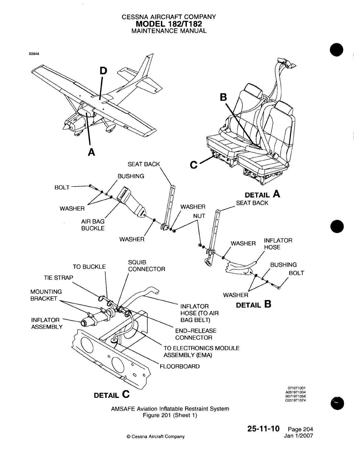
CESSNA AIRCRAFT
COMPANY
MODEL
182ffT182
MAINTENANCE
MANUAL
t8
A
SEAT
BACK
rC
BUSHING
WASHER
DETAIL
A
SEAT BACK
INFLATOR
DETAIL
B
HOSE
(TO
AIR
BAG
BELT)
ND-RELEASE
;ONN
ECTOR
-ECTRONICS
MODULE
MBLY
(EMVA)
!BOARD
AMVSAFE
Aviation Inflatable
Restraint
System
Figure
201
(Sheet
1)
25-11-10
Q
Cessna
Aircraft
Company
BOLT
WA~c
TIE
S
MOUNTIN
BRACKET
INFLATOF
ASSEIVBL
G
IOLT
DETAIL
C
0710T1
001
A051
9T1 0014
B071
9T1
056
G051ST1
074
Page
204
Janl1/2007
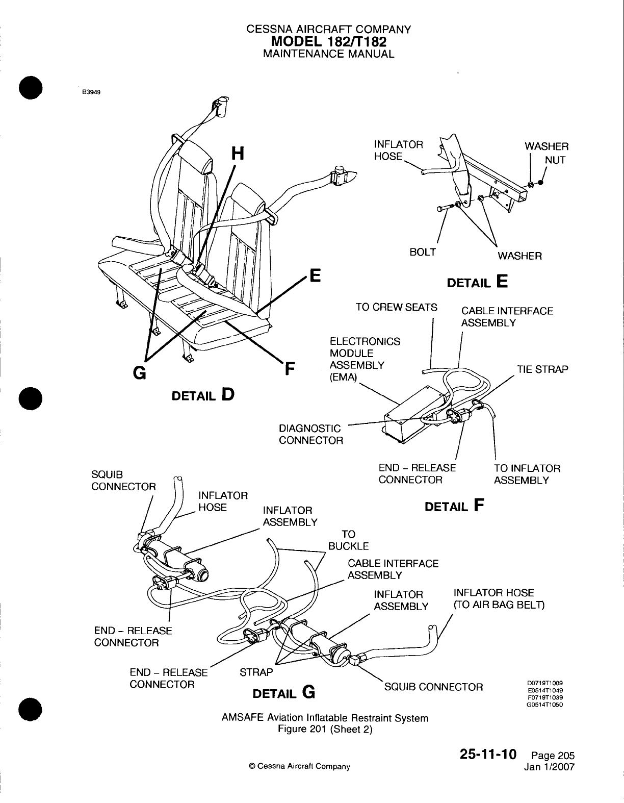
CESSNA AIRCRAFT
COMPANY
MODEL
182/Ti
82
MAINTENANCE
MANUAL
B3949
H
IN
FLA
HOSE
BOLT
WASHER
DIETAIL
E
FO
CREW
SEATS
CABLE
INTERFACE
I-RONICS
JLE
TIE
STRAP
DETAIL
D
DIAGNOSTIC
CONNECTOR
END
-
RELEASE
TO
INFLATOR
ASSEMBLY
CABLE INTERFACE
ASSEMBLY
INFLATOR
ASSEMBLY
INFLATOR
HOSE
(TO
AIR
BAG
BELT)
END
-
F
CONNE'
STRAP
UUNNEW
IH
DETAILIG
SQUIB
CONNECTOR
AMVSAFE
Aviation Inflatable Restraint
System
Figure
201
(Sheet
2)
©
Cessna
Aircraft
Company
HER
4JUT
E
G
(EM
5qfll
lip
CONNEC
INFLATOR
HOSE
INFLATOR
ASSEMBLY
UL
F
TO
D071
9T1
009
E051
4T1
049
F0719T1039
G0514T1
050
25-11-10
Page 205
Janl1/2007
I
I
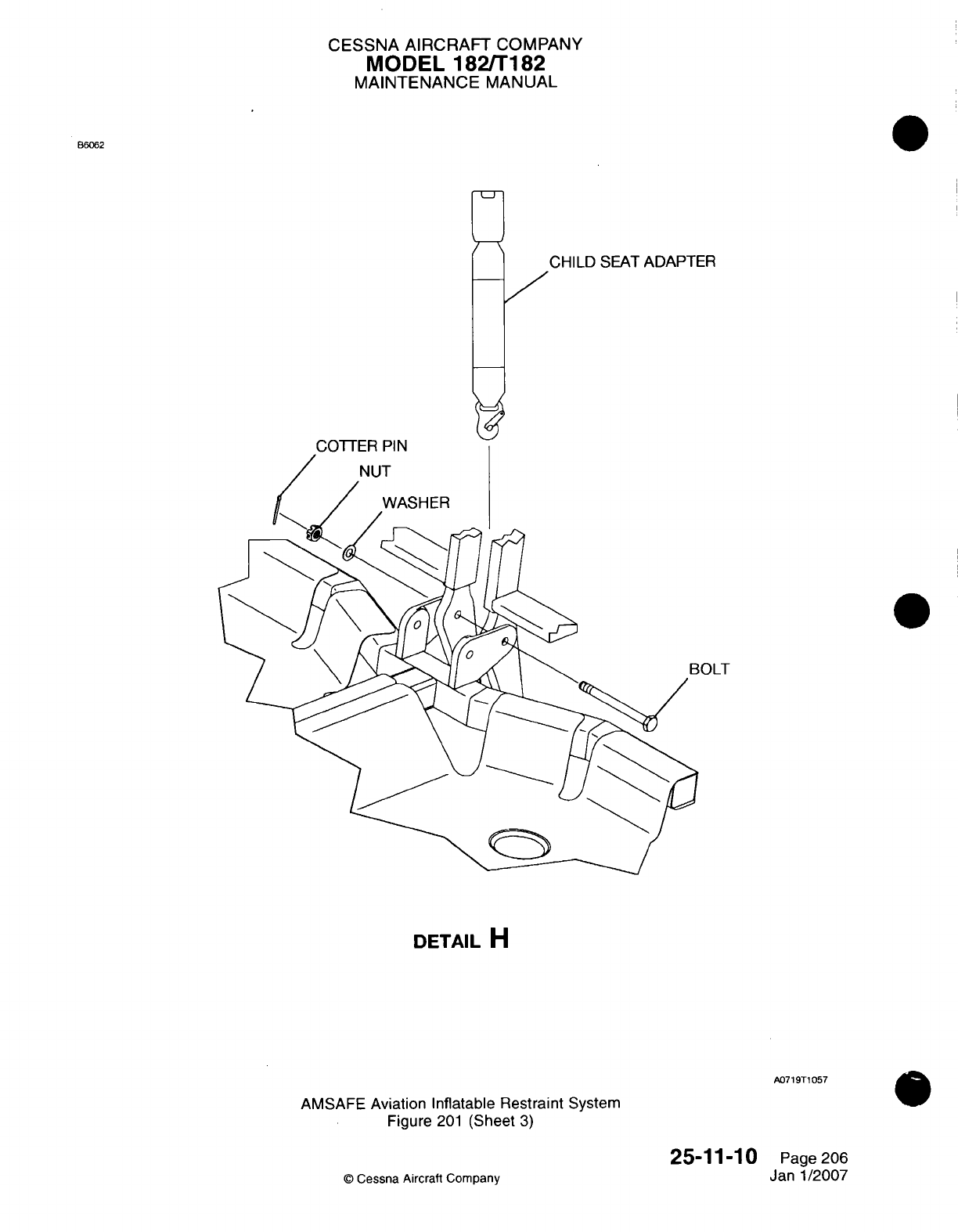
CESSNA AIRCRAFT
COMPANY
MODEL
1821T182
MAINTENANCE
MANUAL
B6062
CHILD
SEAT
ADAPTER
DETAIL
H
A07
19T1
057
AMVSAFE
Aviation Inflatable
Restraint
System
Figure
201
(Sheet
3)
25-11-10
©
Cessna Aircraft Company
Page
206
Janl1/2007
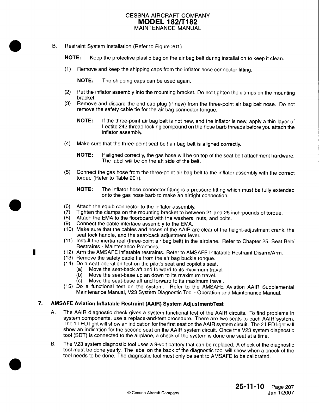
CESSNA
AIRCRAFT
COMPANY
MODEL
182/Ti82
MAINTENANCE
MANUAL
B.
Restraint
System
Installation
(Refer
to
Figure
201).
NOTE: Keep the
protective
plastic
bag
on
the
air
bag
belt
during
installation
to
keep
it
clean.
(1)
Remove
and
keep
the
shipping caps
from
the
inflator-hose
connector
fitting.
NOTE:
The
shipping caps
can
be
used
again.
(2)
Put
the
inflator
assembly
into the
mounting
bracket.
Do
not
tighten
the
clamps
on
the
mounting
bracket.
(3)
Remove
and
discard
the
end cap
plug
(if
new) from
the
three-point
air
bag
belt
hose.
Do
not
remove
the
safety
cable
tie
for
the
air
bag
connector
tongue.
NOTE:
If
the
three-point
air
bag
belt
is
not
new,
and
the
inflator
is
new,
apply
a
thin
layer
of
Loctite
242
thread-locking
compound
on
the
hose barb
threads
before
you
attach
the
inflator assembly.
(4)
Make
sure
that
the
three-point
seat
belt
air
bag
belt
is
aligned
correctly.
NOTE:
If
aligned correctly,
the gas
hose
will
be
on
top
of
the seat belt
attachment
hardware.
The
label
will
be
on
the
aft side
of
the belt.
(5)
Connect
the
gas
hose
from the
three-point
air
bag
belt
to
the
inflator
assembly
with
the
correct
torque
(Refer
to Table
201).
NOTE:
The
inflator hose
connector fitting
is a
pressure
fitting
which must
be
fully
extended
onto
the
gas hose
barb
to
make
an
airtight connection.
(6)
Attach
the
squib
connector
to
the
inflator
assembly.
(7)
Tighten
the
clamps
on
the
mounting
bracket
to
between
21
and
25
inch-pounds
of
torque.
(8)
Attach
the
EMA
to
the
floorboard
with
the
washers,
nuts,
and
bolts.
(9)
Connect
the
cable
interface
assembly
to
the
EMVA.
(1
0)
Make sure that
the
cables
and
hoses
of
the
AAIR
are
clear
of
the
height-adjustment
crank,
the
seat
lock
handle,
and
the
seat-back adjustment
lever.
(1 1)
Install the
inertia
reel
(three-point
air
bag
belt)
in
the
airplane.
Refer
to
Chapter
25,
Seat
Belt!
Restraints
-
Maintenance
Practices.
*
~~(12)
Arm
the AMSAFE
inflatable
restraints.
Refer
to
AMVSAFE
Inflatable
Restraint
Disarm/Arm.
(13)
Remove
the
safety
cable
tie
from the air
bag
buckle tongue.
(14)
Do
a
seat
operation
test
on
the
pilot's
seat
and
copilot's
seat.
(a)
Move
the
seat-back
aft
and
forward
to
its
maximum
travel.
(b)
Move the
seat-base
up
an
down
to
its
maximum
travel.
(c)
Move the
seat-base
aft
and
forward
to
its
maximum
travel.
(15)
Do
a
functional test
on
the
system. Refer
to
the AMSAFE Aviation
AAIR
Supplemental
Maintenance
Manual,
V23
System
Diagnostic
Tool
-
Operation
and
Maintenance Manual.
7.
AMVSAFE
Aviation
Inflatable
Restraint
(AAIR) System
Adjustment/Test
A.
The
AAIR
diagnostic
check
gives
a
system
functional
test
of
the
AAIR
circuits.
To
find
problems
in
system
components,
use
a
replace-and-test
procedure.
There
are
two
seats
to
each
AAIR
system.
The
1
LED
light
will
show
an
indication
for
the
first
seat
on
the
AAIR
system
circuit.
The
2
LED
light
will
show
an
indication
for
the
second
seat
on
the
AAIR
system
circuit.
Once
the
V23
system
diagnostic
tool
(SDT)
is
connected
to
the
airplane,
a
check
of
the
system
is
done
one
seat
at
a
time.
B.
The
V23
system
diagnostic
tool
uses
a
9-volt
battery
that
can
be
replaced.
A
check
of
the
diagnostic
tool
must
be
done
yearly.
The
label
on
the back
of
the
diagnostic
tool
will
show
when
a
check
of
the
tool needs
to
be
done.
The
diagnostic
tool
must
only
be
sent
to
AMVSAFE
to
be
calibrated.
25-11-10
Page2O7
C
Cessna
Aircraft
Company
Janl1/2007
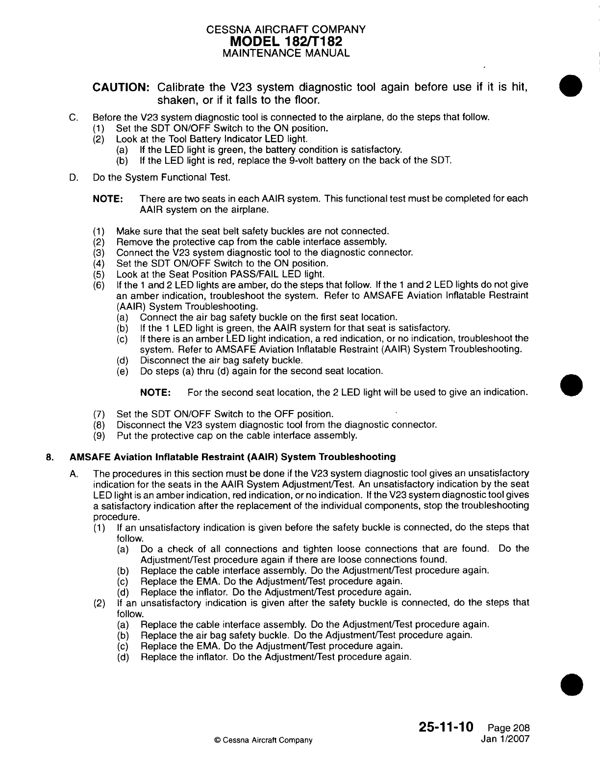
CESSNA AIRCRAFT
COMPANY
MODEL
1821T182
MAINTENANCE
MANUAL
CAUTION:
Calibrate
the
V23
system
diagnostic
tool
again
before
use
if it
is
hit,
shaken,
or
if it
falls
to
the
floor.
C.
Before the V23
system
diagnostic
tool
is
connected
to
the
airplane,
do
the
steps
that follow.
(1)
Set
the
SDT
ON/OFF
Switch
to
the
ON
position.
(2)
Look
at
the
Tool
Battery
Indicator
LED
light.
(a) If
the
LED
light
is
green,
the
battery
condition
is
satisfactory.
(b) If
the
LED
light
is
red,
replace the
9-volt
battery
on
the
back
of
the
SDT.
D.
Do
the System
Functional
Test.
NOTE:
There
are
two
seats
in
each
AAIR
system.
This
functional
test must
be
completed
for
each
AAIR
system
on the
airplane.
(1)
Make sure
that
the
seat
belt
safety
buckles
are not
connected.
(2)
Remove
the
protective
cap
from
the
cable
interface assembly.
(3)
Connect
the V23
system
diagnostic
tool
to the
diagnostic
connector.
(4)
Set
the SDT
ON/OFF
Switch
to the
ON
position.
(5)
Look
at
the
Seat
Position
PASS/FAIL
LED
light.
(6) If
the
1
and
2
LED
lights
are
amber,
do
the
steps
that
follow.
If
the
1
and
2
LED
lights
do
not
give
an
amber
indication,
troubleshoot
the
system. Refer
to
AMSAFE
Aviation
Inflatable
Restraint
(AAIR)
System
Troubleshooting.
(a)
Connect
the
air
bag
safety
buckle
on the
first
seat location.
(b) If
the
1
LED
light
is
green,
the
AAIR
system for
that seat
is
satisfactory.
(c) If
there
is
an
amber
LED
light
indication,
a
red
indication,
or
no
indication,
troubleshoot
the
system.
Refer
to
AMSAFE
Aviation
Inflatable
Restraint
(AAIR)
System
Troubleshooting.
(d)
Disconnect
the air
bag
safety
buckle.
(e)
Do
steps
(a)
thru
(d)
again
for
the
second
seat
location.
NOTE:
For
the
second
seat
location,
the
2
LED
light
will
be
used
to
give
an
indication.
(7)
Set
the SDT
ON/OFF
Switch
to
the
OFF
position.
(8)
Disconnect
the V23
system
diagnostic
tool
from
the
diagnostic connector.
(9)
Put the
protective
cap
on
the
cable
interface
assembly.
8.
AMVSAFE
Aviation
Inflatable
Restraint
(AAIR)
System
Troubleshooting
A.
The
procedures
in
this section
must
be
done
if
the
V23
system
diagnostic tool
gives
an
unsatisfactory
indication
for
the
seats
in
the
AAIR
System Adjustment/Test.
An
unsatisfactory
indication
by
the seat
LED
light
is
an
amber
indication,
red
indication,
or
no
indication.
If
the
V23
system
diagnostic
tool
gives
a
satisfactory
indication
after
the
replacement
of
the
individual components,
stop
the
troubleshooting
procedure.
(1) If
an
unsatisfactory
indication
is
given
before
the
safety
buckle
is
connected,
do the
steps
that
follow.
(a)
Do
a
check
of
all
connections
and
tighten
loose
connections that
are
found.
Do
the
Adjustment/Test
procedure
again
if
there
are
loose
connections
found.
(b)
Replace
the
cable
interface
assembly.
Do
the
Adjustment/Test
procedure
again.
(c)
Replace
the
EMVA.
Do
the
Adjustment/Test
procedure
again.
(d)
Replace
the
inflator.
Do
the Adjustment/Test procedure
again.
(2)
If
an
unsatisfactory
indication
is
given
after
the
safety buckle
is
connected,
do
the
steps
that
follow.
(a)
Replace
the
cable interface assembly.
Do
the
Adjustment/Test
procedure
again.
(b)
Replace the air
bag
safety
buckle.
Do
the
Adjustment/Test
procedure
again.
(c)
Replace
the
EMVA.
Do
the
Adjustment/Test procedure again.
(d)
Replace
the
inflator.
Do
the Adjustment/Test procedure
again.
25-1
1-1
0
Page
208
C)
Cessna
Aircraft Company
Janl1/2007
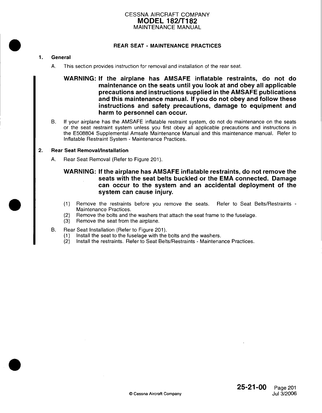
CESSNA
AIRCRAFT
COMPANY
MODEL
182/T182
MAINTENANCE
MANUAL
REAR SEAT
-
MAINTENANCE PRACTICES
1.
General
A.
This
section
provides
instruction
for
removal
and
installation
of
the
rear
seat.
WARNING:
If
the
airplane
has
AMSAFE
inflatable restraints,
do
not
do
maintenance
on
the
seats
until
you
look
at
and
obey
all
applicable
precautions
and
instructions
supplied
in
the
AMSAFE
publications
and
this
maintenance
manual. If
you do
not
obey
and
follow
these
instructions
and
safety
precautions,
damage
to equipment
and
harm
to
personnel
can
occur.
B. If
your
airplane
has the AMSAFE
inflatable
restraint
system,
do
not
do
maintenance
on
the
seats
or
the
seat restraint
system
unless
you
first
obey
all
applicable
precautions
and
instructions
in
the
E508804
Supplemental
Amsafe
Maintenance
Manual
and
this maintenance
manual.
Refer
to
Inflatable
Restraint
System
-
Maintenance Practices.
2. Rear
Seat
Removal/Installation
A.
Rear Seat Removal
(Refer
to Figure
201).
WARNING:
If
the airplane
has
AMSAFE
inflatable restraints,
do
not
remove
the
seats
with
the
seat
belts
buckled
or
the
EMA
connected.
Damage
can
occur
to
the system
and
an
accidental
deployment
of
the
system
can
cause
injury.
(1)
Remove
the
restraints
before
you remove
the seats. Refer
to
Seat
Belts/Restraints
-
Maintenance
Practices.
(2)
Remove
the
bolts
and
the
washers
that attach
the
seat frame
to
the
fuselage.
(3)
Remove
the
seat
from
the
airplane.
B.
Rear Seat
Installation
(Refer
to
Figure
201).
(1)
Install
the
seat
to
the
fuselage
with
the
bolts
and
the
washers.
(2)
Install
the
restraints.
Refer
to
Seat
Belts/Restraints
-
Maintenance
Practices.
25-21-00
Page
201
©
Cessna
Aircraft
Company
Jul 3/2006
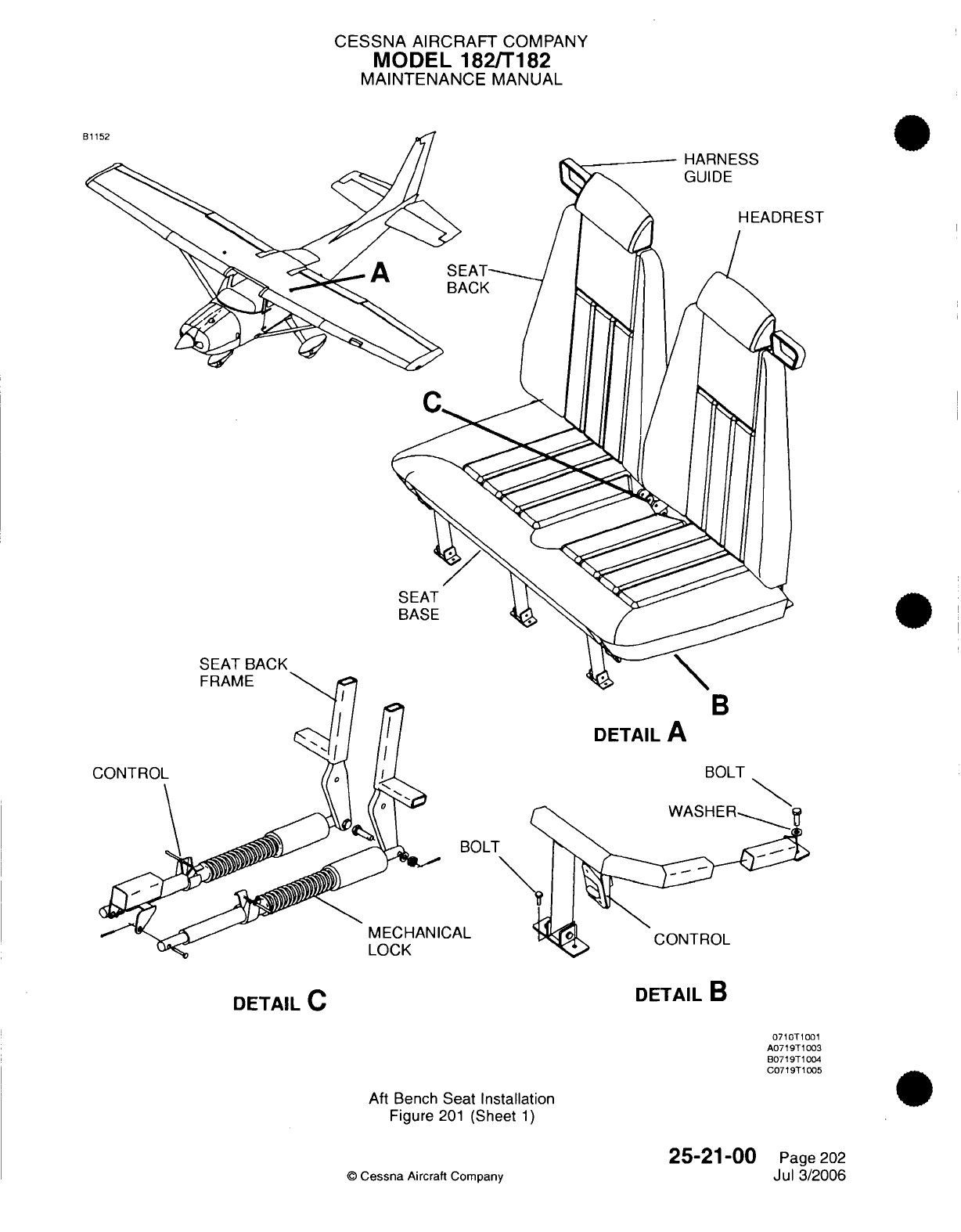
CESSNA
AIRCRAFT
COMPANY
MODEL
182/T182
MAINTENANCE
MANUAL
ST
SEAT
BASE
SEAT
BACK
B
CONTROKL
CAL
DETAIL
A
BOLT
CONTROL
DETAIL
C
DETAIL
B
Aft
Bench
Seat Installation
Figure
201
(Sheet
1)
©
Cessna
Aircraft
Company
0710T1001
A0719T1003
B0719T1004
C0719T1005
25-21-00
Page
202
Jul
3/2006
B1152
CESSNA
AIRCRAFT
COMPANY
MODEL
182/T182
MAINTENANCE
MANUAL
INTERIOR UPHOLSTERY
-
MAINTENANCE
PRACTICES
1.
General
A.
This section
provides
general
instructions
for
removal
and
installation
of
the interior
panels
and
carpet.
2.
Cabin
Panels
Removal/Installation
A.
Interior
panels
are
typically
attached
to
fuselage
structure
using
screws.
Refer
to
Figure
201
for
an
exploded
view
of
the
interior
panels, headliner
and
overhead
console.
3.
Door
Panels and
Carpet
Removal/Installation
A.
Cabin
door
panels
are
typically
attached
to
the
fuselage
and
door
structure
using
small screws.
Carpet
is
attached to
the floorboard
using
velcro.
Refer to
Figure
202
for
a
view
of
the
side
panels
and carpet.
25-22-00
Page
201
©
Cessna Aircraft Company
April
1/2002
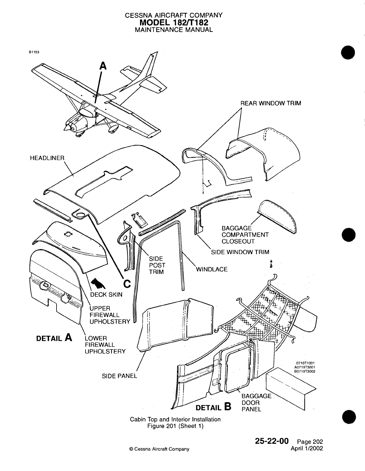
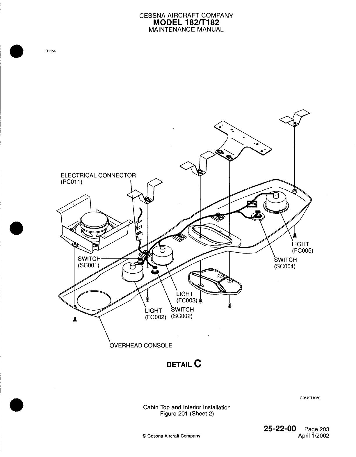
CESSNA
AIRCRAFT
COMPANY
MODEL
182/T182
MAINTENANCE
MANUAL
81154
ELECTRICAL
CONNECTOR
OVERHEAD
CONSOLE
DETAIL
C
C0519T1050
Cabin
Top
and
Interior
Installation
Figure
201
(Sheet
2)
25-22-00
©
Cessna
Aircraft
Company
Page 203
April
1/2002
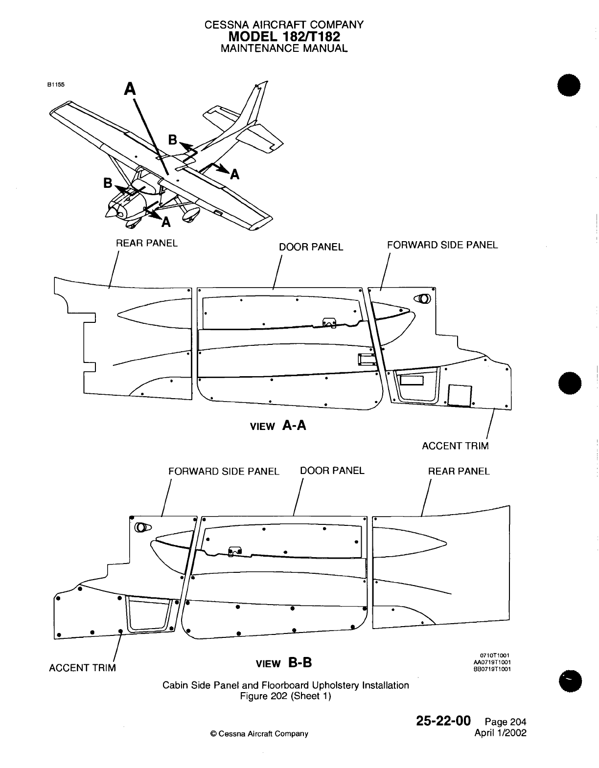
CESSNA
AIRCRAFT
COMPANY
MODEL
182/T182
MAINTENANCE
MANUAL
REAR PANEL
/
DOOR
PANEL
/
FORWARD
SIDE PANEL
/
./I
f*
'
. .
VIEW
A-A
ACCENT TRIM
ACCENT
TRIM
FORWARD
SIDE
PANEL
/
0
DOOR
PANEL
/
REAR
PANEL
/
0
0
0
VIEW
B-B
Cabin
Side
Panel and
Floorboard
Upholstery
Installation
Figure
202
(Sheet
1)
©
Cessna
Aircraft
Company
25-22-00
Page
204
April
1/2002
CD
/
0710T1001
AA0719T1001
BB0719T1001
*
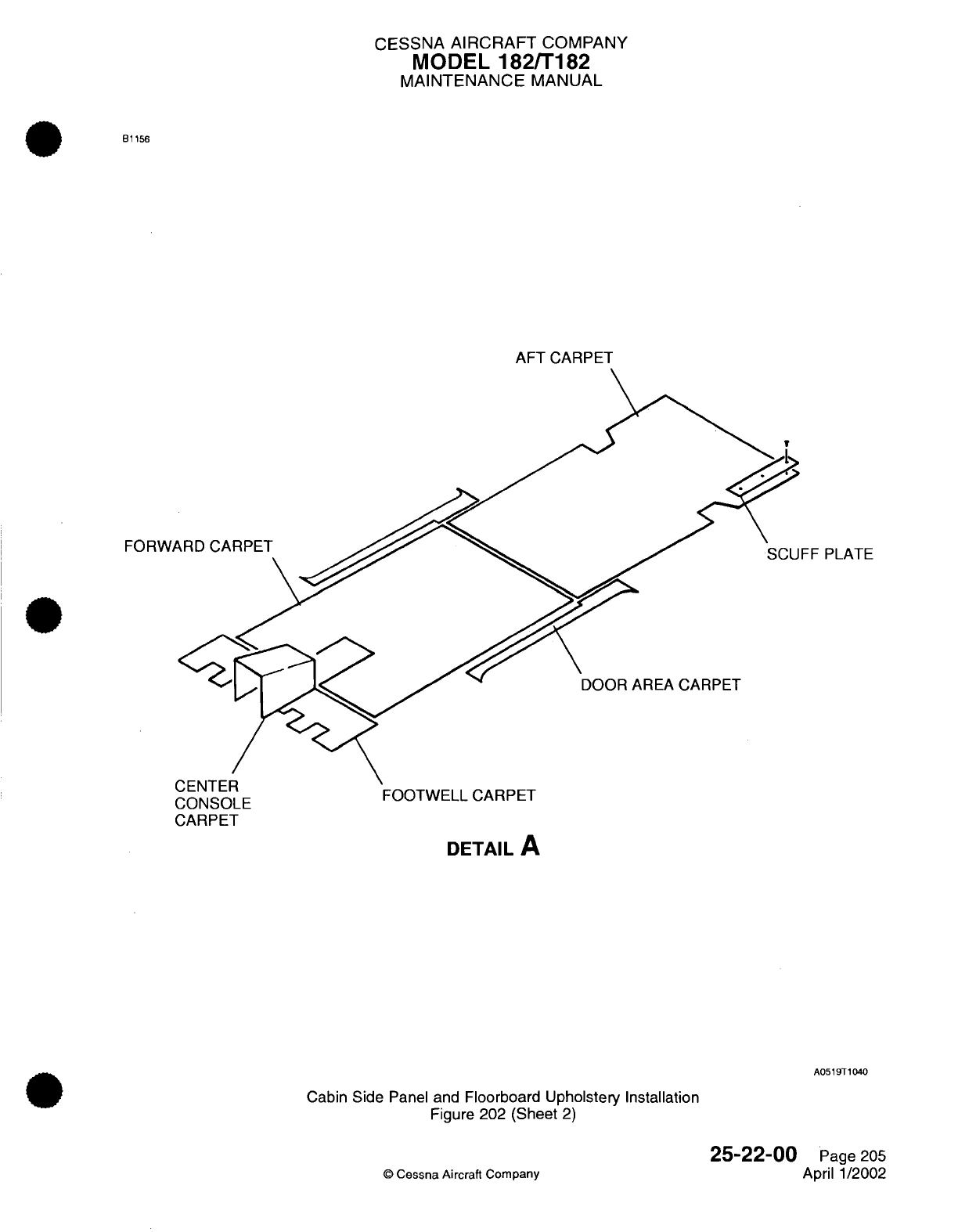
CESSNA
AIRCRAFT
COMPANY
MODEL
182/T182
MAINTENANCE
MANUAL
B1156
AFT
CARPET
FORW/
FF
PLATE
AREA CARPET
U zCONSOLE
FOOTWELL
CARPET
CONSOLE
CARPET
DETAIL
A
A0519T1040
Cabin
Side
Panel
and
Floorboard
Upholstery Installation
Figure
202 (Sheet
2)
©
Cessna
Aircraft Company
25-22-00
Page
205
April 1/2002
I
CESSNA
AIRCRAFT
COMPANY
MODEL
182/T182
MAINTENANCE
MANUAL
CARGO
TIE-DOWNS
-
MAINTENANCE
PRACTICES
1.
General
A.
Cargo
tie-downs
are
provided
for
the
airplane
to
accommodate
a
variety
of
loading
positions. These
tie-downs
are
secured
directly
through
nutplates.
Refer
to
Figure
201
for
an
illustration
of
tie-downs.
25-50-00
Page
201
©
Cessna
Aircraft
Company
April
1/2002
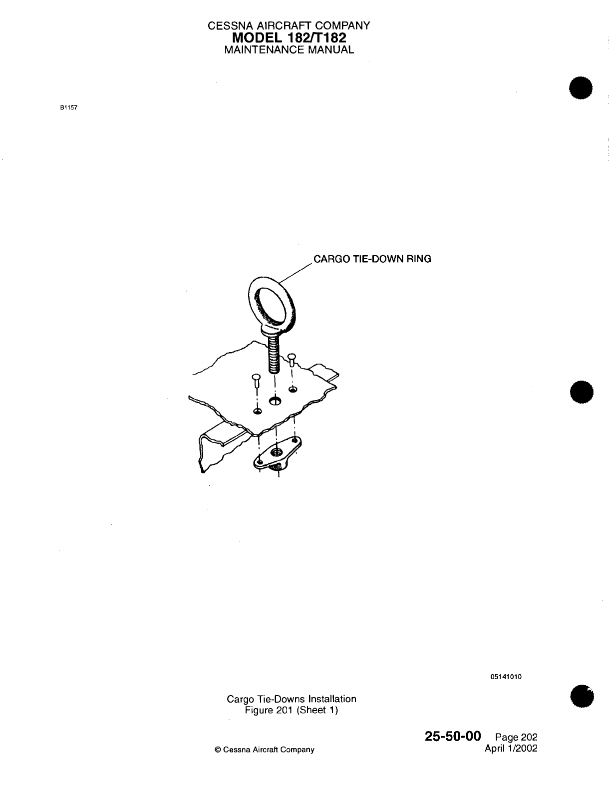
CESSNA AIRCRAFT
COMPANY
MODEL
182/T182
MAINTENANCE
MANUAL
B1157
TIE-DOWN
RING
05141010
Cargo
Tie-Downs
Installation
Figure
201
(Sheet
1)
©
Cessna
Aircraft
Company
25-50-00
Page
202
April
1/2002
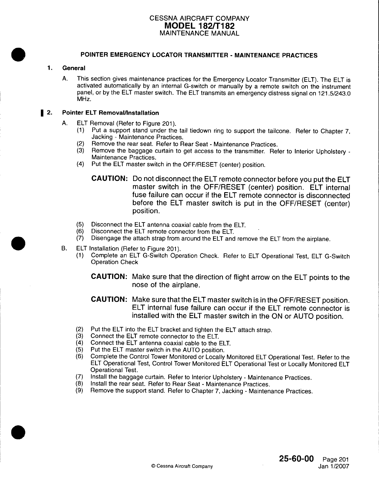
CESSNA
AIRCRAFT
COMPANY
MODEL
182/Ti
82
MAINTENANCE
MANUAL
POINTER
EMERGENCY LOCATOR TRANSMITTER
-
MAINTENANCE PRACTICES
1.General
A.
This
section
gives
maintenance
practices
for
the
Emergency
Locator Transmitter
(ELT).
The
ELT
is
activated
automatically
by
an
internal
G-switch
or
manually
by
a
remote
switch
on
the
instrument
panel,
or
by
the
ELT
master switch. The
ELT
transmits
an
emergency
distress
signal
on
121.5/243.0
MHz.
2.
Pointer
ELT
Removal/installation
A.
ELT
Removal
(Refer
to
Figure
201).
(1)
Put
a
support
stand
under
the
tail
tiedown
ring to
support
the
tailcone.
Refer
to
Chapter
7,
Jacking
-
Maintenance Practices.
(2)
Remove
the
rear
seat.
Refer
to
Rear
Seat
-
Maintenance
Practices.
(3)
Remove
the baggage
curtain
to
get
access
to
the
transmitter.
Refer
to
Interior
Upholstery
-
Maintenance
Practices.
(4) Put
the
ELT
master
switch
in
the
OFF/RESET
(center)
position.
CAUTION:
Do
not
disconnect
the
ELT
remote
connector
before you
put
the
ELT
master switch
in
the
OFF/RESET
(center)
position.
ELT
internal
fuse
failure
can
occur
if
the
ELT
remote
connector
is
disconnected
before
the
ELT
master switch
is
put
in
the
OFF/RESET (center)
position.
(5)
Disconnect
the
ELT
antenna
coaxial
cable
from the
ELT.
(6)
Disconnect
the
ELT
remote
connector
from
the
ELT.
(7)
Disengage
the
attach strap
from
around
the
ELT
and
remove
the
ELT
from the
airplane.
B.
ELT
Installation
(Refer
to
Figure
201).
(1)
Complete
an ELT
G-Switch
Operation Check. Refer
to
ELT
Operational
Test,
ELT
G-Switch
Operation
Check
CAUTION:
Make sure
that
the
direction
of
flight
arrow
on
the
ELT
points
to
the
nose
of
the
airplane.
CAUTION:
Make sure
that
the
ELT
master switch
is
inthe
OFF/RESET
position.
ELT
internal
fuse failure
can
occur
if
the
ELT
remote
connector
is
installed
with the
ELT
master
switch
in
the
ON
or
AUTO
position.
(2)
Put
the ELT
into
the
ELT
bracket
and
tighten
the
ELT attach
strap.
(3)
Connect
the
ELT
remote
connector
to
the
ELT.
(4)
Connect
the
ELT
antenna
coaxial
cable
to
the
ELT.
(5)
Put
the
ELT
master
switch
in
the
AUTO
position.
(6)
Complete
the
Control
Tower
Monitored
or
Locally
Monitored
ELT
Operational
Test.
Refer
to
the
ELT
Operational
Test,
Control
Tower
Monitored
ELT
Operational
Test
or
Locally
Monitored
ELT
Operational
Test.
(7)
Install
the
baggage
curtain. Refer
to
Interior
Upholstery
-
Maintenance Practices.
(8)
Install
the rear
seat.
Refer
to
Rear
Seat
-
Maintenance
Practices.
(9)
Remove
the
support
stand.
Refer
to
Chapter
7,
Jacking
-
Maintenance Practices.
25-60-00
Page
201
©
Cessna
Aircraft Company
Janl1/2007
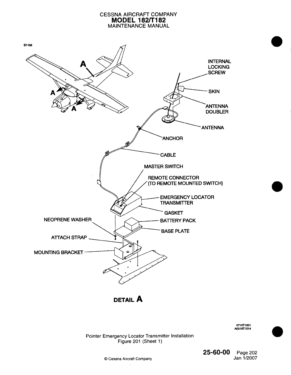
CESSNA AIRCRAFT
COMPANY
MODEL
1821T182
MAINTENANCE
MANUAL
U
INTERNAL
LOCKING
,rl¶vv
:IN
ENNA
JBILER
NNA
'CH)
GASKET
NEOPRENE
WASI-
ATTACH STRA
MOUNTING
BRACKET
,BASE PLATE
DETAIL
A
0710T1001
Afl51
1
014
Pointer
Emergency Locator
Transmitter
Installation
Figure
201
(Sheet
1)
25-60-00
C
Cessna Aircraft
Company
Page
202
Janl1/2007
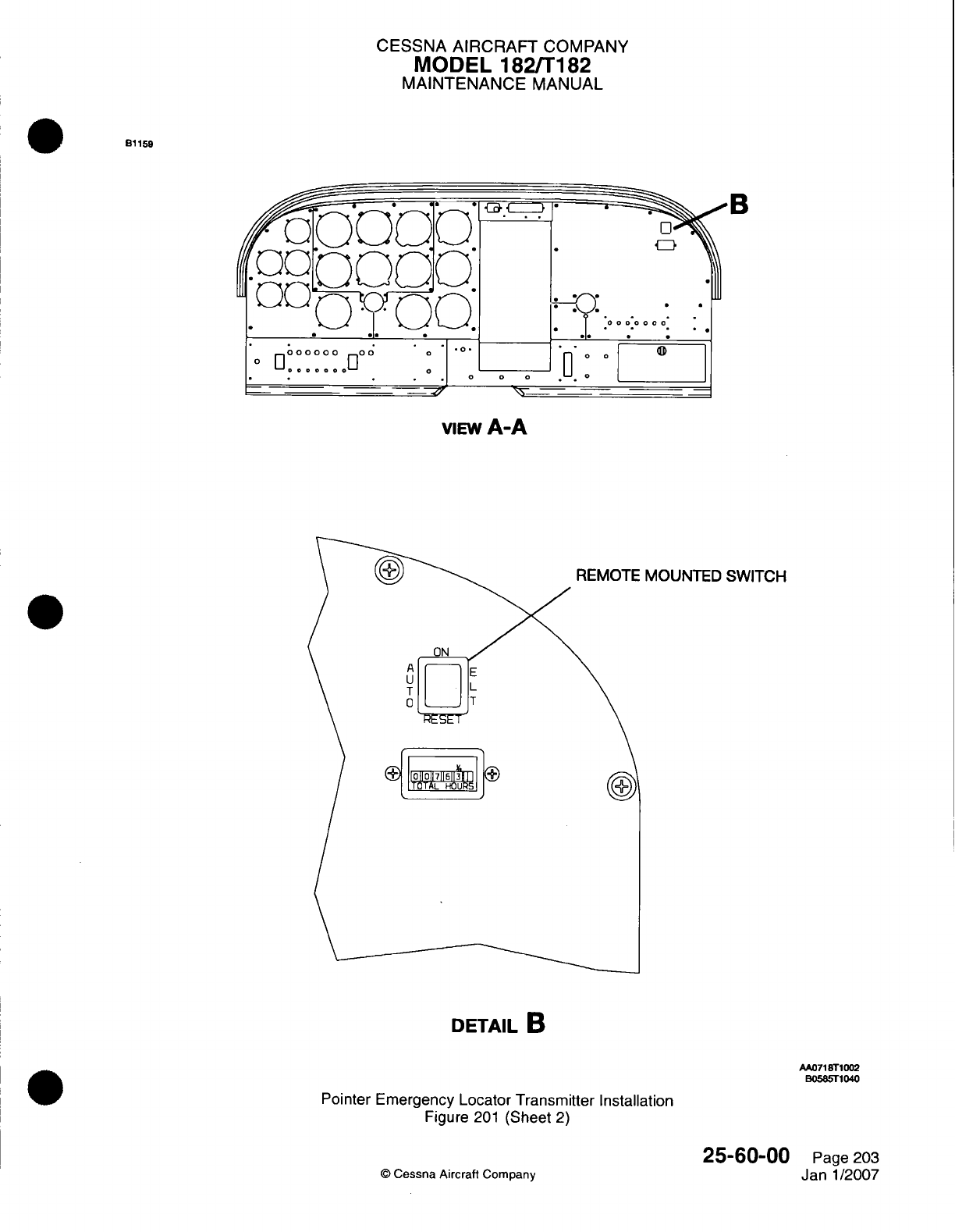
CESSNA AIRCRAFT
COMPANY
MODEL
182/T1
182
MAINTENANCE
MANUAL
B1
159
viEw
A-A
MOUNTED SWITCH
DETAIL
B
AA071
STI
002
B0585T1
040
Pointer
Emergency Locator
Transmitter
Installation
Figure
201
(Sheet
2)
©
Cessna Aircraft
Company
25-60-00
Page
203
Janl1/2007
CESSNA
AIRCRAFT
COMPANY
MODEL
182ffT182
MAINTENANCE
MANUAL
*3.
Pointer
ELT
Remote
Switch
RemovaVlnstallation
CAUTION:
Do
not
disconnect
the
ELT
remote
connector
before
you
put
the
ELT
master
switch
in
the
OFF/RESET
(center)
position.
ELT
internal
fuse
failure
can
occur
if
the
ELT
remote
connector
is
disconnected
before
the
ELT
master
switch
is
put
in
the
OFF/RESET
(center)
position.
CAUTION:
Disconnect
the
ELT
remote
connector
from
the
ELT
before
you
remove
the
ELT
remote
switch
or
disconnect
the
ELT
remote
switch
connector.
ELT
internal
fuse
failure
can
occur
if
the
ELT
remote
switch
or
disconnect
is
removed
before
the
ELT
remote
connector
is
disconnected.
A.
ELT
Remote
Switch
Removal (Refer
to
Figure
201
).
(1)
Put
the
aircraft master switch
(ALT/BAT)
in
the OFF
position.
(2)
Get
access
to
the
back
of
the
remote
mounted
switch.
(3)
Put
the
ELT
master switch
in
OFF/RESET
(center)
position.
(4)
Disconnect
the
electrical
connector
(PT905) from the
ELT.
(5)
Get
access
to
the
back
of
the
ELT
remote
switch
(Zone
221).
(6)
Disconnect
the
ELT
remote
switch
connector.
B.
ELT
Remote Switch
Installation (Refer
to
Figure
201).
(1)
Hold
the
edges
of
the
ELT
remote
switch
and
put
it
into
the
instrument
panel
cutout.
(2)
Make
sure that the
locking tabs engage
and
that
the
switch
is
correctly
installed.
(3)
Connect
the
ELT
remote
switch
connector.
(4)
Put the
ELT
remote
switch
in
the
AUTO
position.
(5)
Connect
the
electrical
connector
(PT905)
to
the
ELT.
(6)
Make
sure
that the
ELT
master switch
is
set
to
the OFF
position.
(7)
Complete the
Control Tower
Monitored
or
Locally
Monitored
ELT
Operational
Test.
Refer
to
ELT
Operational
Test,
Control
Tower
Monitored
ELT
Operational
Test,
or
Locally
Monitored
ELT
Operational
Test.
*4.
ELT
Antenna
RemovaVlnstallation (integral
Base
with
Coax Cable)
A.
ELT
Antenna
Removal
(Refer
to
Figure
201).
(1)
Remove
the
panel
(31
OAR)
from
the
right side
of
the
tailcone
to
get
access
to
the
ELT.
Refer
to
Chapter
6,
Access/Inspection
Plates
-
Description
and
Operation.
(2)
Disconnect
the
ELT
antenna coaxial cable
from
the
ELT.
(3)
Remove
all
of
the
tie
straps
that
attach
the
ELT
antenna coaxial
cable
to
the
fuselage.
(4)
On
the
external
skin
of
the
airplane,
remove the
six
internal
locking screws
that
attach
the
ELT
antenna
to
the
fuselage.
NOTE:
The
ELT
antenna
has
an
integral
base
and
coaxial
cable.
(5)
Remove
the
ELT
antenna
from
the
inside
of
the
airplane.
B.
ELT
Antenna Installation (Refer
to
Figure
201).
(1)
From
inside
the
airplane,
put
the
ELT
antenna
in
position
on
the
fuselage
with
the
ELT
antenna
pointing
aft.
(2)
On
the
external
skin
of
the
airplane,
use
the
internal locking
screws
to
attach the
ELT
antenna
base
to
the
fuselage.
(3)
Connect
the
ELT
antenna coaxial cable
to
the
ELT.
(4)
Use
tie
straps
to
attach
the
ELT
antenna
coaxial cable
to
the
fuselage.
(5)
Complete
the Control
Tower
Monitored
or
Locally
Monitored
ELT
Operational
Test.
Refer
to
ELT
Operational
Test
-
Control
Tower
Monitored
ELT
Operational
Test or
Locally
Monitored
ELT
Operational
Test.
(6)
Install
the
panel
(31
OAR)
on
the
right
side
of
the
tailcone.
Refer
to
Chapter
6,
Access/Inspection
Plates
-
Description and
Operation.
25-60-00
Page
204
©
Cessna
Aircraft
Company
Janl1/2007
CESSNA AIRCRAFT
COMPANY
MODEL
182/Ti182
MAINTENANCE
MANUAL
.
1
~5.
ELT
Whip
Antenna
Removal/installation
A.
ELT
Whip
Antenna
Removal
(Refer
to
Figure
201).
(1)
Get
access
to
the
ELT
and
ELT
whip antenna
through
the
panel
(31
OAR)
on
the
right
side
of
the
tailcone.
(2)
Disconnect
the
ELT
whip
antenna
coaxial
cable
from the
ELT
whip
antenna.
(3)
From
inside
the
airplane,
remove
the
nut
and
washer
that
attach
the
ELT
whip
antenna
to
the
fuselage.
(4)
Remove the
ELT
whip
antenna
from the
external
skin
of
the
airplane.
B.
ELT
Whip
Antenna
Installation
(Refer
to
Figure
201).
(1)
Put
the
ELT
whip
antenna
in
position
on
the
external
skin
of
the
fuselage
with
the
ELT
whip
antenna pointing
aft.
(2)
From
inside
the
airplane,
use
the
nut
and
washer
to
connect
the
ELT
whip antenna
to
the
fuselage.
(3)
Connect
the
ELT
antenna
coaxial
cable
to
the
ELT
whip
antenna.
(4)
Complete
the Control
Tower
Monitored
or
Locally
Monitored
ELT
Operational
Test.
Refer
to
ELT
Operational
Test,
Control
Tower
Monitored
ELT
Operational
Test,
or
Locally
Monitored
ELT
Operational
Test.
(5)
Install
the
panel
(31
OAR)
on
the right
side
of
the
tailcone.
Refer
to
Chapter
6,
Access/inspection
Plates
-
Description
and
Operation.
*6.
Pointer
ELT
Battery
Pack
Removal/Installation
A.
ELT
Battery Pack
Removal
(Refer
to
Figure
201).
WARNING:
Obey
the
correct
procedures
to
discard
the
unserviceable
ELT
battery
packs
to prevent
damage
to
the
environment
and
personal
injury.
(1)
Remove
the
ELT
from
the
airplane.
Refer
to
ELT
Removal/Installation.
(2)
Remove
the
screws that
attach the
ELT
base
plate
to
the
ELT.
(3)
Disconnect
the
battery
pack
connector
for
the
ELT.
(4)
Remove
the
ELT
battery
pack
from
the
ELT.
B.
ELT
Battery
Pack
Installation
(Refer
to
Figure
201).
CAUTION:
Use
only
the
recommended battery
pack for
the
ELT.
If
you use
other
types
of
battery packs,
the
operating
life
and/or signal
strength
of
the
ELT
will
decrease.
The
incorrect
battery
pack
can
also
change
the
mechanical
configuration, which
will
cause
too
much
vibration
and
corrosion.
(1)
Put
the
ELT
battery pack
in
the
ELT.
(2)
Connect the
ELT
battery
pack
connector.
CAUTION:
Do
not
tighten
the
ELT
gasket
and
screws
too
much.
(3)
Use
screws
to
attach
the
ELT
base plate and
gasket
to
the
ELT.
NOTE:
When the
new
battery
pack
expiration
date
is
put
in
the
airplane
records,
it is
also
recommended that
you
record
the
expiration
date
in
the
ELT
owner's
manual
for quick
reference.
(4)
Put
the new
replacement
date
on
the
outside
of
ELT
transmitter
with
a
stamp.
Put
the date
on
the
ELT
switch
nameplate,
on
the side
of
the
ELT
transmitter,
and
in
instruction nameplate
on
top
of
the
ELT
transmitter.
25-60-00
Pagie
205
Janl/2007
Q
Cessna
Aircraft
Company
CESSNA
AIRCRAFT
COMPANY
MODEL
182/Ti
182
MAINTENANCE
MANUAL
(5)
Install
the
ELT
in
the
airplane.
Refer
to
ELT
Removal/Installation.
*7.
Pointer
ELT
Operational
Test
A.
Control
Tower
Monitored
ELT
Operational
Test.
CAUTION:
Operate
the
Emergency
Locator Transmitter
(ELT)
system only
during
the
first
five
minutes
of
each
hour.
Refer
to the
FAA
Advisory
Circular
AC-91
-44A.
(1)
Get
permission
from
the
control
tower
and/or
flight
service
station
to
do
a
test
of
the
ELT
system.
CAUTION:
Do
not
operate
the
ELT
system
for
more
than
three
pulses
of
the
audio signal.
Longer
operation
can
decrease
the
ELT
battery
power
supply.
NOTE:
Do
not
use the
airplane's
VHF
receiver
or
ADF
to
measure
the power
of
the
ELT
audio
signal.
(2)
Put
the
ELT
remote
switch
in
the
ON
position.
(3)
Contact
the
control
tower
and/or
flight service
station
to
make
sure
that the
ELT
system
operates
correctly.
(4)
Momentarily
put the
ELT
remote
switch
to
the
RESET
position.
(5)
Put the
ELT
remote
switch
in
the AUTO
position.
(6)
Contact
the
control
tower
and/or
flight
service station
to
make sure
that
the
ELT
stopped
transmission.
B.
Locally
Monitored
ELT
Operational
Test.
CAUTION:
Operate
the
Emergency
Locator Transmitter
(ELT)
system
only
during
the
first
five minutes
of
each
hour.
Refer
to
the
FAA
Advisory
.Circular
AC-91
-44A.
(1) (1)
Put
a
small,
hand
held
AM
radio
tuned
to
any
frequency,
within
six
inches
of
the
ELT
antenna.
CAUTION:
Do
not
operate
the
ELT
system
for
more
than
three pulses
of
the
audio
signal. Longer
operation
can
decrease the
ELT
battery power
supply.
NOTE:
Do
not
use
the airplane's
VHF
receiver
or
ADIF
to
measure
the power
of
the
ELT
audio
signal.
(2)
Put
the
ELT
remote
switch
in
the
ON
position.
(3)
Make
sure
that
the
ELT
signal
is
heard
on
the
AM
radio.
(4)
Momentarily
put the
ELT
remote
switch
to
the
RESET
position.
(5)
Put the
ELT
remote
switch
in
the
AUTO
position.
C.
ELT
Master
Switch
Operational
Test.
25-60-00
Page
206
Q
Cessna
Aircraft Company
Janl1/2007
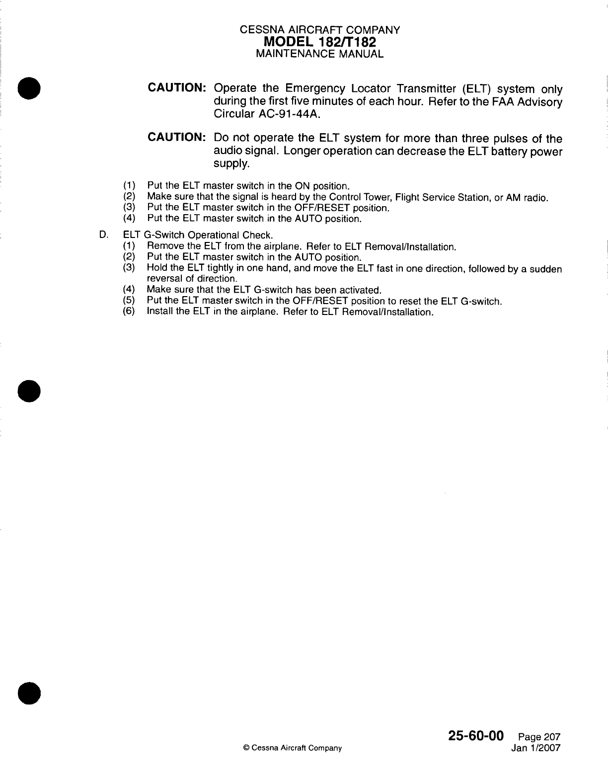
CESSNA AIRCRAFT
COMPANY
MODEL
1821T182
MAINTENANCE
MANUAL
CAUTION:
Operate
the
Emergency Locator Transmitter
(ELT)
system
only
during
the
first
five
minutes
of
each
hour.
Refer
to
the
FAA
Advisory
Circular
AC-91
-44A.
CAUTION:
Do
not
operate
the
ELT
system
for
more than
three
pulses
of
the
audio signal.
Longer
operation
can
decrease
the
ELT
battery
power
supply.
(1)
(2)
(3)
(4)
Put
the
ELT
master
switch
in
the
ON
position.
Make
sure
that
the
signal
is
heard
by
the
Control
Tower,
Flight
Service Station,
or
AM
radio.
Put
the
ELT
master switch
in
the
OFF/RESET
position.
Put the
ELI
master
switch
in
the
AUTO
position.
D.
ELI
G-Switch
Operational
Check.
(1)
Remove
the
ELT
from
the
airplane.
Refer
to
ELI
Removal/Installation.
(2)
Put the
ELI
master switch
in
the
AUTO
position.
(3)
Hold
the
ELI
tightly
in
one hand, and move
the
ELT
fast
in
one
direction,
followed
by
a
sudden
reversal
of
direction.
(4)
Make
sure
that
the
ELI
G-switch
has been
activated.
(5)
Put
the
ELI
master switch
in
the
OFF/RESET position
to
reset
the
ELI
G-switch.
(6)
Install the
ELI
in
the
airplane.
Refer
to
ELI
Removal/installation.
25-60-00
Page 207
©
Cessna
Aircraft
Company Janl1/2007
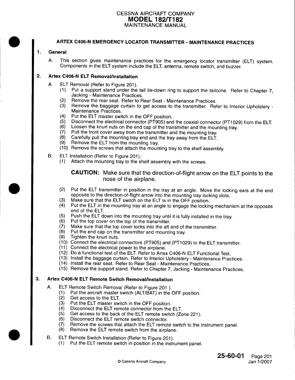
CESSNA
AIRCRAFT
COMPANY
MODEL
182/Ti182
MAINTENANCE
MANUAL
ARTEX
C406-N EMERGENCY
LOCATOR
TRANSMITTER
-
MAINTENANCE
PRACTICES
1.
General
A.
This
section
gives
maintenance practices
for
the
emergency
locator
tr
ansmitter
(ELT)
system.
Components
in
the
ELT
system
include
the
ELT,
antenna,
remote
switch,
and
buzzer.
2.
Artex
C406-N
ELT
Remova~l/nstallation
A.
ELT
Removal
(Refer
to
Figure
201).
(1)
Put
a
support
stand under
the
tail
tie-down
ring to
support
the
tailcone.
Refer
to
Chapter
7,
Jacking
-
Maintenance
Practices.
(2)
Remove
the
rear
seat.
Refer
to
Rear
Seat
-
Maintenance Practices.
(3)
Remove
the
baggage
curtain
to get
access
to
the
transmitter.
Refer
to
Interior
Upholstery
-
Maintenance
Practices.
(4)
Put
the
ELT
master
switch
in
the
OFF
position.
(5)
Disconnect the
electrical
connector
(PT905)
and
the
coaxial
connector
(PT1
029)
from
the
ELT.
(6)
Loosen
the
knurl
nuts
on
the
end
cap
of
the
transmitter
and
the
mounting
tray.
(7)
Pull
the
front
cover
away
from
the
transmitter
and
the
mounting
tray.
(8)
Carefully
pull
the
mounting
tray
end
and
the
tray
away
from
the
ELT.
(9)
Remove
the
ELT
from
the
mounting
tray.
(1 0)
Remove the
screws
that attach the
mounting
tray
to
the shelf
assembly.
B.
ELT
Installation (Refer
to
Figure
201).
(1)
Attach
the
mounting tray
to
the
shelf
assembly
with
the
screws.
CAUTION:
Make
sure
that
the
direction-of-flight
arrow
on
the
ELT
points
to
the
nose
of
the
airplane.
(2)
Put
the
ELT
transmitter
in
position
in
the tray
at an
angle.
Move
the
locking
ears
at
the
end
opposite
to
the
direction-of-flight
arrow
into the
mounting
tray
locking
slots.
(3)
Make
sure
that
the
ELT
switch
on
the
ELT is
in
the
OFF
position.
(4)
Put the
ELT
in
the mounting tray
at
an
angle
to
engage
the
locking
mechanism
at
the
opposite
end of
the
ELT.
(5)
Push
the
ELT
down
into the
mounting tray
until
it is
fully
installed
in
the
tray.
(6)
Put the top
cover
on
the
top
of
the
transmitter.
(7)
Make
sure
that
the top
cover
locks
into
the aft
end of the
transmitter.
(8)
Put
the
end
cap
on
the
transmitter
and
mounting
tray.
(9)
Tighten
the
knurl
nuts.
(1 0)
Connect
the
electrical
connectors
(PT905)
and
(PT1
029)
to
the
ELT
transmitter.
(1
1)
Connect
the
electrical
power
to
the
airplane.
(12)
Do
a
functional
test
of
the
ELT.
Refer
to
Artex C406-N
ELT
Functional
Test.
(13)
Install
the
baggage
curtain.
Refer
to
Interior
Upholstery
-
Maintenance Practices.
(14)
Install
the
rear
seat.
Refer
to
Rear
Seat
-
Maintenance
Practices.
(15)
Remove
the
support
stand.
Refer
to
Chapter
7,
Jacking
-
Maintenance
Practices.
3.
Artex
C406-N
ELT
Remote
Switch
Removal/installation
A.
ELT
Remote
Switch
Removal (Refer
to
Figure
201
).
(1)
Put
the
aircraft
master switch
(ALT/BAT)
in
the
OFF
position.
(2)
Get
access
to
the
ELT.
(3)
Put
the
ELT
master switch
in
the
OFF
position.
(4)
Disconnect
the
ELT
remote
connector
from
the
ELT.
(5)
Get
access
to
the
back
of
the
ELT
remote
switch
(Zone
221).
(6)
Disconnect
the
ELT
remote
switch connector.
(7)
Remove
the
screws that
attach
the
ELT
remote
switch
to
the
instrument
panel.
(8)
Remove
the
ELT
remote
switch
from
the
airplane.
B.
ELT
Remote
Switch Installation
(Refer
to
Figure
201).
(1)
Put
the
ELT
remote
switch
in
position
in
the
instrument
panel.
25-60-01
Page
201
C
Cessna Aircraft Company
Janl1/2007
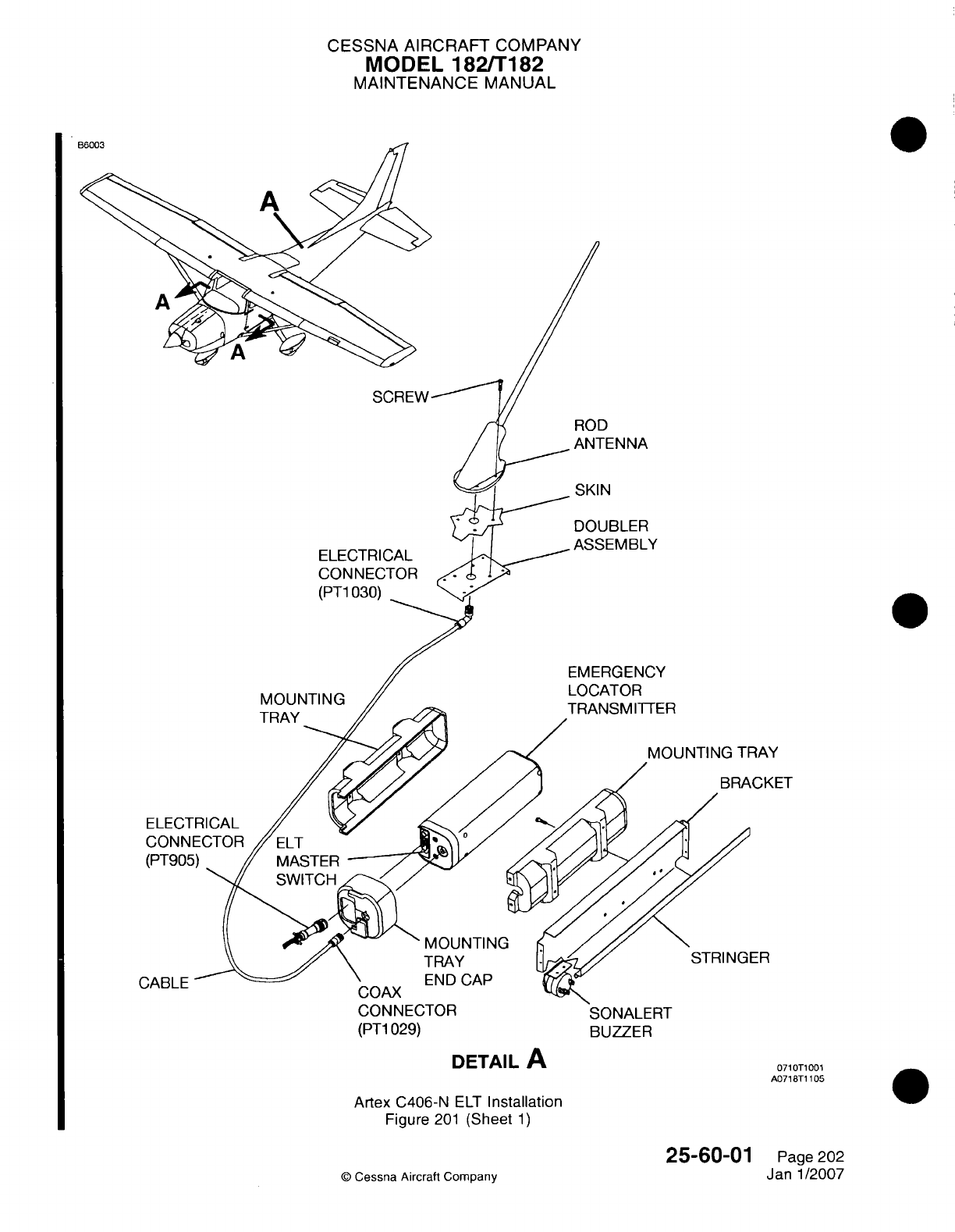
CESSNA AIRCRAFT
COMPANY
MODEL
182/Ti
82
MAINTENANCE
MANUAL
ROD
ANTENNA
SKIN
DOUBLER
ELECTRICAL
CONNECTOR
(PT1
030)
MOUNTING
TRAY
1-
EMERGENCY
LOCATOR
TRANSM
ITTER
1AY
Z;KET
ELECT
CONN
(PT90t
ER
CABLE
(PT1
029)
BUZZER
DETAIL
A
Artex
C406-N
ELT
Installation
Figure
201
(Sheet
1)
25-60-01
©
Cessna
Aircraft
Company
0710T1
001
A0718T1
105
Page
202
Janl1/2007
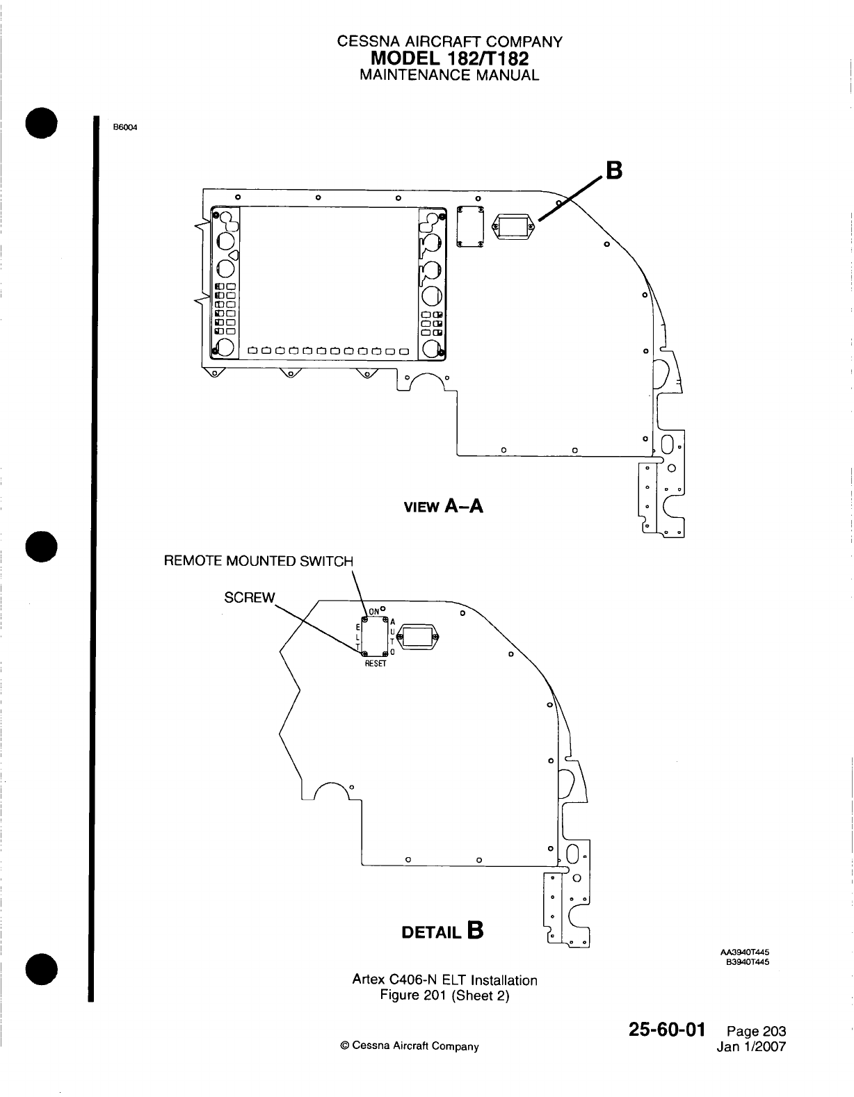
CESSNA
AIRCRAFT
COMPANY
MODEL
182/T182
MAINTENANCE
MANUAL
B6004
R
REMOTE
MVOUN-
SCREW
AA3940T445
B3940T445
Artex
C406-N
ELT
Installation
Figure
201
(Sheet
2)
©
Cessna
Aircraft
Company
25-60-01
Page
203
Janl1/2007
CESSNA
AIRCRAFT
COMPANY
MODEL
1821T182
MAINTENANCE
MANUAL
(2)
Attach
the
ELT
remote
switch
to
the
instrument
panel with
the
screws.
(3)
Connect
the
ELT
remote
switch
connector.
(4)
Put
the
ELT
remote
switch
to
the
AUTO
position.
(5)
Connect
the
ELT
remote
connector
to
the
ELT.
(6)
Make
sure
that
the
ELT
master
switch
is
set
to
the
OFF
position.
(7)
Do
a
functional
test
of
the
ELT.
Refer
to
Artex
C406-N
ELT
Functional
Test.
4.
Artex
C406-N
ELT
Rod
Antenna
Removal/installation
A.
ELT
Antenna
Removal
(Refer
toFigure
201).
(1)
Put
a
support
stand
under
the
tail
tie-down
ring
to
support
the
tailcone.
Refer
to
Chapter
7,
Jacking
-
Maintenance
Practices.
(2)
Remove
the rear seat.
Refer
to
Rear Seat
-
Maintenance
Practices.
(3)
Remove
the
baggage
curtain
to
get
access
to
the
transmitter. Refer
to
Interior
Upholstery
-
Maintenance
Practices.
(4)
Disconnect
the
coaxial
cable connector
(PT1
029)
for
the antenna.
(5)
Remove
the
tie
strap
that
attaches
the
ELT
antenna coaxial
cable
to
the
fuselage.
(6)
Remove the
four
screws
that
attach the
ELT
antenna
to
the
fuselage.
(7)
Remove the
ELT
antenna
from
the
airplane.
B.
ELT
Antenna Installation
(Refer
to
Figure
201).
(1)
Remove
all
of the
old
sealant
from
the
ELT rod
antenna
and
from the
airplane
skin.
Refer
to
Chapter
20,
General
Solvents/Cleaners
-
Maintenance Practices.
(2)
Put
the
ELT
antenna
in
position
on
the
fuselage
with
the
ELT
antenna
pointing
aft.
(3)
Install
the
four screws
that
attach
the
ELT
antenna
to
the
fuselage.
(4)
Connect
the
ELT
antenna
coaxial cable
to
the
ELT.
(5)
With
the
tie
strap,
attach the
ELT
antenna coaxial
cable
to
the
mount
on
the
fuselage.
(6)
Make sure
that
there
is a
correct
electrical
bond
between
the
antenna
and
the
airplane structure.
(a)
Remove
one
screw.
(b)
With
an
ohmmeter, measure
the
electrical resistance
from
the
antenna
base metal insert
to
the
structure
at
the
screw
position.
NOTE:
The maximum
allowable resistance
(in
ohms)
at
each
of
the
four measured
positions
is
0.0025.
(c)
Install the
screw
and remove
and install each
of
the
remaining
screws
in
turn
as
you
measure
the
electrical resistance
at
each
screw
hole.
(7)
Apply
a
fillet
seal
around
the antenna
with
Type
I
Class
B
Sealant.
Do
not
cover
the
screw
head
with
the
sealant. Refer
to
Chapter
20, Fuel,
Weather
and
High-Temperature
Sealing
-
Maintenance
Practices.
(8)
Do
a
functional
test
of
the
ELT.
Refer
to Artex C406-N
ELT
Functional
Test.
(9)
Install
the
baggage
curtain.
Refer
to
Interior Upholstery
-
Maintenance
Practices.
(1 0)
Install the rear
seat. Refer
to
Rear
Seat
-
Maintenance
Practices.
(1
1)
Remove
the
support
stand.
Refer
to
Chapter
7,
Jacking
-
Maintenance
Practices.
5.
Artex
C406-N Buzzer
Removal/installation
A.
Buzzer
Removal
(Refer
to Figure
201).
(1)
Put
a
support
stand under
the
tail
tie-down
ring
to
support
the
tailcone.
Refer
to
Chapter
7,
Jacking
-
Maintenance
Practices.
(2)
Remove
the
rear seat.
Refer
to
Rear
Seat
-
Maintenance Practices.
(3)
Remove
the
baggage
curtain
to
get
access
to
the
transmitter.
Refer
to
Interior
Upholstery
-
Maintenance
Practices.
(4)
Make sure
that
the
ELT
master
switch
on the
ELT
transmitter
is in
the
OFF
position.
(5)
Tag
the
wires
and
terminals
for identification.
(6)
Remove
the
screws
that attach
the
electrical
terminals
to
the
buzzer.
(7)
Loosen
the
black retainer
ring
on
the
outboard
side
of
the
buzzer.
(8)
Remove
the
buzzer
from the
bracket.
25-60-0
1
Page
204
©
Cessna
Aircraft
Company
Janl1/2007
CESSNA
AIRCRAFT
COMPANY
MODEL
182/Ti82
MAINTENANCE
MANUAL
B.
Buzzer
Installation
(Refer
to
Figure
201)
(1)
Put
the
buzzer
in
the
bracket.
(2)
Install
the
black
retainer
ring on
the
outboard
face
of
the
buzzer.
(3)
Connect
the
electrical
wires
to
the
buzzer
with the
screws.
(4)
Do
a
functional
test
of
the
ELT.
Refer
to
Artex
C406-N
ELT
Functional
Test.
(5)
Install
the
baggage
curtain.
Refer
to Interior
Upholstery
-
Maintenance Practices.
(6)
Install
the
rear seat.
Refer
to
Rear
Seat
-
Maintenance
Practices.
(7)
Remove
the
support
stand.
Refer
to
Chapter
7,
Jacking
-
Maintenance Practices.
25-60-0
1
Page
205
©
Cessna
Aircraft
Company
Janl1/2007
CESSNA AIRCRAFT
COMPANY
MODEL
182/Ti
182
MAINTENANCE
MANUAL
ARTEX C406-N
EMERGENCY LOCATOR
TRANSMITTER
-
INSPECTION/CHECK
1.General
A.
This section gives
the
procedures
that
are
necessary
to
do
the
inspection
and
operational
checks
are
necessary
to
comply
with
14
CFR
91
.207, for
the
Artex
0406-N
Emergency
Locator
Transmitter
(ELT)
System.
2.
Artex
C406-N
ELT
Functional
Test
CAUTION: Operate
the
Emergency
Locator Transmitter
system
only
during the
first
five minutes
of
each
hour.
If
you
must
complete
the
functional test
at
a
time
other
than the
first
five minutes
of the hour,
you
must
do
the
test
with
a
direct
connection
to
the
ELT
and
a
30
dB
attenuator.
Refer
to
the
FAA
Advisory Circular
AC-91-44A.
CAUTION:
Do
not
operate
the
emergency
locator
transmitter
for
more
than
five
seconds
at
a
time.
Do
not
operate
the
ELT
again
for
15
seconds.
The
ELT
will
transmit
a
406.028
MHz
signal
after
the
ELT
is
active
for
approximately
50
seconds.
This
signal
is
identified
as
a
distress
signal
A.
Prepare
for
the
Artex
0406-N
ELT
Functional
Test.
(1)
You
must
replace
the
ELT
battery
with
a
new
ELT
battery
if
one
or
more
of
the
conditions
that
follow
occur:
*
Use
of
the
ELT
battery
in
an
emergency
*
Operation
for
an
unknown
amount
of
time
*
Use
for
more
than one
hour
of
cumulative
time
•
On
or
before
the replacement
date
shown
on
the
battery
label.
(2)
Examine
the
ELT
battery
to
make
sure
that
it is
not
due for
replacement.
(3) If
the
battery
must
be
replaced,
follow
the
manufacturer's
instructions
to
replace
it.
(4)
Supply
+28
v,
+0.25
or
-0.25
v,
external electrical
power
to
the
airplane.
(5)
Initialize
the global
positioning
system
(GPS) on the
multi-function
display
(MFD).
B.
Do
the
ELT
Transmitter
Test.
(1)
Adjust
the
volume
to
make
sure
that
the
transmissions
from
the
radio
are
heard
in
the
cockpit.
(2)
Adjust
the
COM
1
frequency
to
121.50
MHz.
Make
sure
that
the
audio
is
heard
through
the
cockpit
speakers.
(3)
Put
the
cockpit
ELT
switch
in
the
ON
position
for
approximately
one
second.
(4)
Make sure
that
the
ELT
audio signal
and
the
cockpit
ELT
switch
light
adjacent
to
the
ELT
remote
switch
come
on.
(5)
Immediately
put
the
cockpit
ELT
switch
in
the
ARM
position.
(6)
Make sure
that
the LED
stays
on
for approximately
one
second
before
it
goes
off.
(7) If
the
ELT
system
has
sensed
a
fault
in
the
system,
the
LED
will
flash
a
fault
code
at
this
time.
Refer
to
the
Installation
and
Operation
Manual
for
the
Artex
ELT
system for information
on
the
possible
codes.
C.
Do
the
NAV
Interface
Test.
(1)
Hold the SARSAT
tester
no
more
than
fifteen
feet
from the
antenna.
NOTE:
The
SARSAT
tester
is
used
as
an
example
to
gather
test information. However,
other
equivalent
test
equipment
such
as
the
Aeroflex
IFR
4000
Communications
Test
Set
is
acceptable.
(2)
Turn
on
the
SARSAT
tester.
(3)
Engage
the
receive
function
of
the
SARSAT tester.
(4)
Make
sure that
the
display
on
the
tester
shows
that
it is
searching
for
a
signal.
(5)
Put
the
ELT
remote
switch
in
the
ON
position.
(6)
Within
15
seconds,
put the
ELT
remote
switch
in
the
ARM
position.
25-60-0
1
Page
601
Q
Cessna Aircraft
Company
Janl1/2007
CESSNA AIRCRAFT
COMPANY
MODEL
1821T182
MAINTENANCE
MANUAL
(7)
Monitor
the SARSAT
tester
to
see
if it
received
a
signal
from
the
ELT
system.
(a) If
no
signal
was
received,
do
the
test again
after
the
15-second
off
cycle.
(8)
Make
sure
that
the
tail
number
on
the
SARSAT
tester
is
correct.
(9)
Make
sure
that
the
Mode
S
code
shown
on
the
SARSAT
tester
is
the
same
as
the
number
that
is
on
the
back
of
the
transmitter.
(1 0)
Make sure
that
the
latitude
and
longitude information
is
the
same
as
that
shown
on
the
MFD
display.
(1 1)
Turn
the
SARSAT
tester
off.
(12)
Disconnect external
electrical
power
from
the
aircraft.
D.
Do
the
G-Switch
Operational
Test.
CAUTION:
CAUTION:
Operate
the
Emergency Locator Transmitter
system only
during
the
first
five minutes
of
each
hour.
If
you
must
complete
the
functional
test
at
a
time
other than
the
first
five
minutes
of
the
hour,
you
must
do
the
test
with
a
direct
connection
to the
ELT
and
a
30
dB
attenuator.
Refer
to
the
FAA
Advisory Circular
AC-91
-44A.
Do
not
operate
the
emergency
locator
transmitter
for
more
than
five
seconds
at
a
time.
Do
not
operate
the
ELT
again
for
15
seconds.
The
ELT
will
transmit
a
406.028
MHz
signal after
the
ELT
is
active
for
approximately
50
seconds.
This
signal
is
identified
as
a
distress
signal.
(1)
Remove
the
ELT
from
the
airplane.
Refer
to ELT
Removal/Installation
(On
airplanes
with
the
Artex
C406-N.
(2)
Install
a
jumper
wire
between pins
12
and
13
on
the
electrical
connector
of
the
ELT.
NOTE:
The
ELT
will
not
activate
with
the
G-switch
unless
electrical
pins
12
and
13
have
a
jumper
wire
installed between
them
(this happens
automatically
when
the
ELT
is
locked
into
the
mount
tray
with
the
electrical connector
in
position). Because
of
the
potential
physical
damage
that
can
occur
if
the
jumper
wire
is
not
installed
correctly,
it is
recommended
that
an
experienced
technician
do
this
procedure.
(3)
Put the
ELT
switch
in
the
OFF
position.
(4)
Use
a
receiver,
and
set
it
to
121
.5
MHz
to
listen for
the
aural
warning
sweep tone.
(5)
Hold the
ELT
transmitter
tightly
in
one
hand
and
make
a
throwing movement
followed
by
an
opposite
movement
of
the
ELT
transmitter.
(6)
Make
sure
that
the
G-switch
operates
and
that
the
aural warning sweep tone
is
heard
on
the
receiver
set
to
121
.5
MHz.
(7)
Set
the
ELT
switch
to
the
ON
position
and
then
back
to
the
OFF
position
to
reset
the
G-switch.
(8)
Remove
the
jumper
wire
from
electrical
pins
12
and
13
on
the
electrical connector
of the
ELT.
(9)
Install
the
emergency locator transmitter
in
the
airplane.
Refer
to
ELT
Removal/Installation
(On
airplanes
with
the Artex C406-N.
25-60-01
©
Cessna
Aircraft
Company
Page
602
Janl1/2007
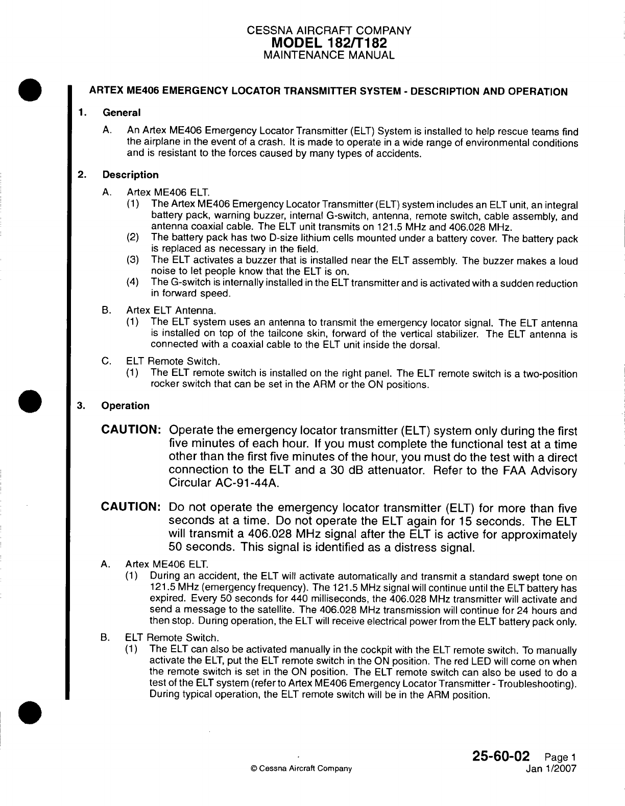
CESSNA
AIRCRAFT
COMPANY
MODEL
182/Ti182
MAINTENANCE
MANUAL
ARTEX
ME406
EMERGENCY
LOCATOR
TRANSMITTER
SYSTEM
-
DESCRIPTION AND OPERATION
1.General
A.
An
Artex
ME406
Emergency Locator
Transmitter
(ELT)
System
is
installed
to
help
rescue
teams find
the
airplane
in
the
event
of
a
crash.
It is
made to
operate
in a
wide range
of
environmental
conditions
and
is
resistant
to
the
forces
caused
by
many
types
of
accidents.
2.
Description
A.
Artex
ME406
ELT.
(1)
The
Artex ME406
Emergency Locator Transmitter
(ELT)
system
includes
an
ELT
unit,
an
integral
battery pack,
warning
buzzer, internal
G-switch,
antenna,
remote
switch,
cable assembly,
and
antenna
coaxial
cable.
The
ELT
unit
transmits
on
121.5
MHz
and
406.028
MHz.
(2)
The
battery
pack
has two
D-size
lithium
cells
mounted
under
a
battery
cover.
The
battery
pack
is
replaced
as
necessary
in
the
field.
(3)
The
ELT
activates
a
buzzer
that
is
installed
near the
ELT
assembly.
The
buzzer
makes
a
loud
noise
to
let
people
know
that
the
ELT
is on.
(4)
The
G-switch
is
internally
installed
in
the
ELT
transmitter
and
is
activated
with
a
sudden
reduction
in
forward
speed.
B.
Artex
ELT
Antenna.
(1)
The
ELT
system
uses
an
antenna
to
transmit
the
emergency locator
signal.
The
ELT
antenna
is
installed
on
top
of
the
tailcone
skin, forward
of
the
vertical stabilizer. The
ELT
antenna
is
connected
with
a
coaxial
cable
to
the
ELT
unit
inside
the
dorsal.
C.
ELT
Remote
Switch.
(1)
The
ELT
remote
switch
is
installed
on
the right
panel. The
ELT
remote
switch
is a
two-position
rocker
switch
that
can
be
set
in
the ARM
or
the
ON
positions.
3.
Operation
CAUTION: Operate
the
emergency
locator
transmitter
(ELT)
system
only
during
the
first
five
minutes
of each
hour.
If
you
must
complete
the
functional
test
at
a
time
other
than
the
first
five
minutes
of the hour,
you
must
do
the
test
with
a
direct
connection
to
the
ELT
and
a
30
dB
attenuator.
Refer
to
the
FAA
Advisory
Circular
AC-91-44A.
CAUTION:
Do
not
operate
the
emergency
locator
transmitter
(ELT)
for
more
than
five
seconds
at
a
time.
Do
not
operate
the
ELT
again
for
15
seconds.
The
ELT
will
transmit
a
406.028
MHz
signal
after
the
ELT
is
active
for
approximately
50
seconds.
This
signal
is
identified
as
a
distress
signal.
A.
Artex
ME406
ELT.
(1)
During
an
accident,
the
ELT
will
activate
automatically
and
transmit
a
standard
swept tone
on
121.5
MHz
(emergency
frequency).
The 121.5
MHz
signal
will
continue
until
the
ELT
battery
has
expired.
Every
50
seconds
for
440
milliseconds,
the
406.028
MHz
transmitter
will
activate
and
send
a
message
to
the
satellite.
The
406.028
MHz
transmission
will
continue
for
24
hours
and
then
stop.
During
operation,
the
ELT
will
receive
electrical
power
from
the
ELT
battery
pack
only.
B.
ELT
Remote
Switch.
(1)
The
ELT
can
also
be
activated manually
in
the
cockpit
with
the
ELT
remote
switch.
To
manually
activate
the
ELT,
put the
ELT
remote
switch
in
the
ON
position. The
red
LED
will
come
on
when
the
remote
switch
is
set
in
the
ON
position.
The
ELT
remote
switch
can
also
be
used
to
do
a
test
of
the
ELT
system
(refer
to
Artex
ME406
Emergency
Locator
Transmitter
-
Troubleshooting).
During
typical
operation,
the
ELT
remote switch
will
be
in
the
ARM
position.
25-60-02
Page
1
©
Cessna
Aircraft
Company
Janl1/2007
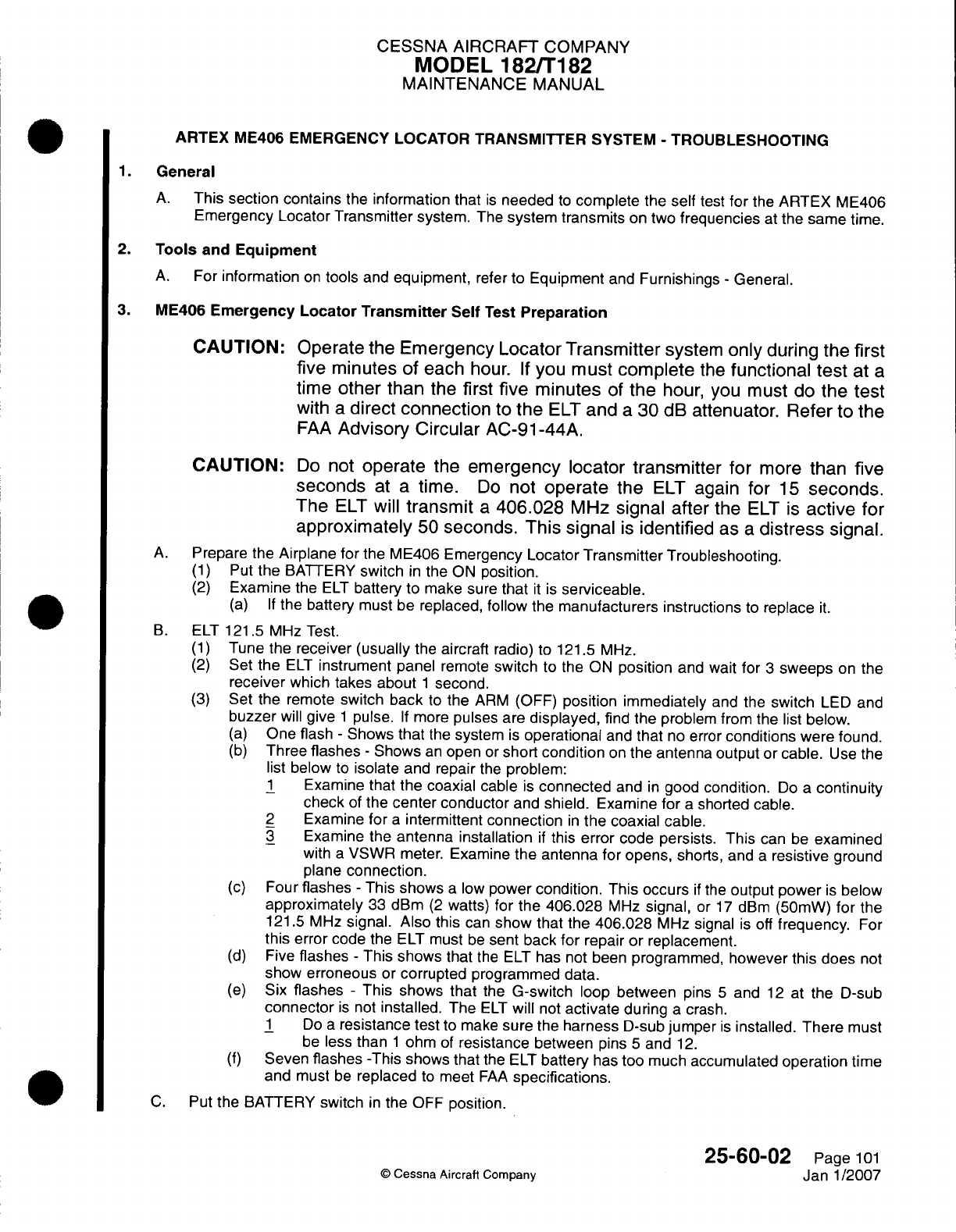
CESSNA AIRCRAFT
COMPANY
MODEL
182/Ti
82
MAINTENANCE
MANUAL
ARTEX
ME406 EMERGENCY
LOCATOR
TRANSMITTER
SYSTEM
-
TROUBLESHOOTING
1.General
A.
This
section
contains
the
information that
is
needed
to
complete
the
self
test
for
the
ARTEX
ME406
Emergency
Locator Transmitter
system.
The
system
transmits
on
two
frequencies
at
the
same
time.
2.
Tools
and
Equipment
A.
For
information
on
tools
and
equipment,
refer
to
Equipment
and
Furnishings
-
General.
3.
ME406
Emergency
Locator
Transmitter Self
Test
Preparation
CAUTION:
Operate
the
Emergency Locator Transmitter
system
only
during
the
first
five
minutes of each
hour.
If
you
must
complete
the
functional
test
at
a
time
other
than
the
first five
minutes
of
the
hour,
you
must
do
the
test
with
a
direct
connection
to
the
ELT
and
a
30
dB
attenuator. Refer
to
the
FAA
Advisory Circular
AC-91-44A.
CAUTION:
Do
not
operate
the
emergency locator
transmitter
for
more
than
five
seconds
at
a
time.
Do
not
operate
the
ELT
again
for
15
seconds.
The
ELT
will
transmit
a
406.028
MHz
signal
after the
ELT
is
active
for
approximately
50
seconds.
This
signal
is
identified
as
a
distress
signal.
A.
Prepare
the
Airplane
for
the ME406
Emergency Locator
Transmitter
Troubleshooting.
(1)
Put
the
BATTERY
switch
in
the
ON
position.
(2)
Examine
the
ELT
battery
to
make
sure
that
it
is
serviceable.
(a) If
the battery
must
be
replaced,
follow
the
manufacturers
instructions
to
replace
it.
B.
ELT
121.5
MHz
Test.
(1)
Tune
the receiver
(usually
the
aircraft
radio)
to
121.5 MHz.
(2)
Set
the
ELT
instrument
panel
remote
switch
to
the
ON
position
and
wait
for
3
sweeps
on
the
receiver
which
takes
about
1
second.
(3)
Set
the
remote
switch
back
to
the
ARM
(OFF)
position
immediately
and
the
switch
LED
and
buzzer
will
give
1
pulse.
If
more
pulses
are
displayed,
find the
problem from
the list
below.
(a)
One
flash
-
Shows
that
the
system
is
operational
and
that
no
error
conditions
were
found.
(b)
Three
flashes
-
Shows
an
open
or
short
condition
on
the
antenna
output
or
cable.
Use
the
list
below
to
isolate
and repair
the
problem:
1
Examine
that the coaxial
cable
is
connected
and
in
good
condition.
Do
a
continuity
check
of
the
center conductor
and
shield.
Examine for
a
shorted cable.
2
Examine for
a
intermittent
connection
in
the
coaxial
cable.
3
Examine
the
antenna installation
if
this
error code
persists.
This
can
be
examined
with
a
VSWR meter.
Examine
the
antenna
for
opens,
shorts, and
a
resistive
ground
plane
connection.
(c)
Four
flashes
-
This
shows
a
low
power
condition.
This
occurs
if
the
output power
is
below
approximately
33
dBm
(2
watts)
for
the
406.028
MHz
signal,
or
17
dBm
(50mW)
for
the
121.5 MHz
signal.
Also
this
can
show
that the
406.028
MHz
signal
is
off
frequency.
For
this
error
code
the
ELT
must
be
sent
back
for
repair
or
replacement.
(d)
Five
flashes
-
This
shows
that
the
ELT
has not
been
programmed,
however this does
not
show erroneous
or
corrupted
programmed
data.
(e)
Six
flashes
-
This
shows
that
the
G-switch
loop
between
pins
5
and
12
at
the
D-sub
connector
is
not
installed.
The
ELT
will
not
activate
during
a
crash.
1
Do
a
resistance
test
to make
sure the
harness
D-sub
jumper
is
installed. There
must
be
less
than
1
ohm
of
resistance
between
pins
5
and
12.
(f)
Seven
flashes
-This
shows
that
the
ELT
battery
has
too much
accumulated
operation
time
and
must
be
replaced
to
meet
FAA
specifications.
C.
Put
the
BATTERY
switch
in
the OFF
position.
25-60-02
Page
101
©
Cessna
Aircraft
Company
Janl1/2007
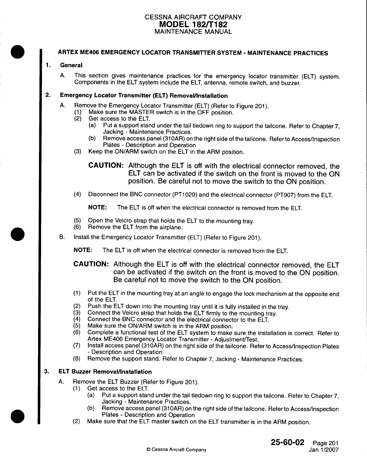
CESSNA AIRCRAFT
COMPANY
MODEL
182/Ti182
MAINTENANCE
MANUAL
ARTEX ME406
EMERGENCY LOCATOR
TRANSMITTER
SYSTEM
-
MAINTENANCE
PRACTICES
1.General
A.
This
section
gives
maintenance
practices
for
the emergency
locator
transmitter
(ELT)
system.
Components
in
the
ELT
system include
the
ELT,
antenna,
remote
switch,
and
buzzer.
2.
Emergency
Locator
Transmitter
(ELT)
Remova~l/nstallation
A.
Rlemove
the
Emergency
Locator Transmitter
(ELT)
(Refer
to
Figure
201).
(1)
Make
sure
the MASTER
switch
is in
the
OFF
position.
(2)
Get
access
to
the
ELT.
(a)
Put
a
support
stand
under the
tail
tiedown
ring to
support
the
tailcone.
Refer
to
Chapter
7,
Jacking
-
Maintenance
Practices.
(b)
Remove
access
panel
(31
OAR)
on
the right
side
of
the
tailcone.
Refer
to
Access/inspection
Plates
-
Description
and
Operation
(3)
Keep the ON/ARM
switch
on
the
ELT
in
the
ARM
position.
CAUTION:
Although
the
ELT
is
off
with
the
electrical connector
removed,
the
ELT
can
be
activated
if
the
switch
on
the
front
is
moved
to
the
ON
position.
Be
careful
not to
move
the
switch
to
the
ON
position.
(4)
Disconnect
the BNC
connector
(PT1
029)
and
the
electrical connector
(PT907)
from
the
ELT.
NOTE:
The
ELT
is
off
when
the
electrical
connector
is
removed
from
the
ELT.
(5)
Open the
Velcro
strap
that
holds
the
ELT
to
the
mounting
tray.
(6)
Remove
the
ELT
from
the
airplane.
B.
Install
the
Emergency Locator
Transmitter
(ELT)
(Refer
to
Figure
201).
NOTE:
The
ELT
is
off
when the
electrical connector
is
removed
from
the
ELT.
CAUTION: Although
the
ELT
is
off
with
the
electrical
connector
removed, the
ELT
can
be
activated
if
the switch
on
the
front
is
moved
to
the
ON
position.
Be
careful
not to
move
the
switch
to
the
ON
position.
(1)
Put
the
ELT
in
the
mounting tray
at
an
angle
to
engage
the
lock
mechanism
at
the
opposite
end
of
the
ELT.
(2)
Push
the
ELT
down
into the
mounting
tray
until
it is
fully
installed
in
the
tray.
(3)
Connect
the
Velcro
strap
that
holds
the
ELT
firmly
to
the
mounting
tray.
(4)
Connect
the
BNC
connector
and
the
electrical connector
to
the
ELT.
(5)
Make
sure
the
ONARM
switch
is in
the ARM
position.
(6)
Complete
a
functional
test
of
the
ELT
system
to
make
sure
the
installation
is
correct.
Refer to
Artex
ME406
Emergency Locator
Transmitter
-
Adjustment/Test.
(7)
Install
access
panel
(31
OAR)
on
the
right
side
of
the
tailcone.
Refer
to
Access/inspection
Plates
-
Description
and
Operation
(8)
Remove
the
support
stand.
Refer
to
Chapter
7,
Jacking
-
Maintenance
Practices.
3. ELT
Buzzer
Removal/installation
A.
Remove
the
ELT
Buzzer
(Refer
to
Figure
201).
(1)
Get
access
to
the
ELT.
(a)
Put
a
support
stand
under
the
tail
tiedown
ring
to
support
the
tailcone.
Refer
to
Chapter
7,
Jacking
-
Maintenance
Practices.
(b)
Remove
access
panel
(31
OAR)
on
the
right
side
of
the
tailcone.
Refer
to
Access/inspection
Plates
-
Description
and
Operation
(2)
Make
sure
that the
ELT
master
switch
on
the
ELT
transmitter
is in
the
ARM
position.
25-60-02
Page
201
©
Cessna Aircraft Company
Janl1/2007
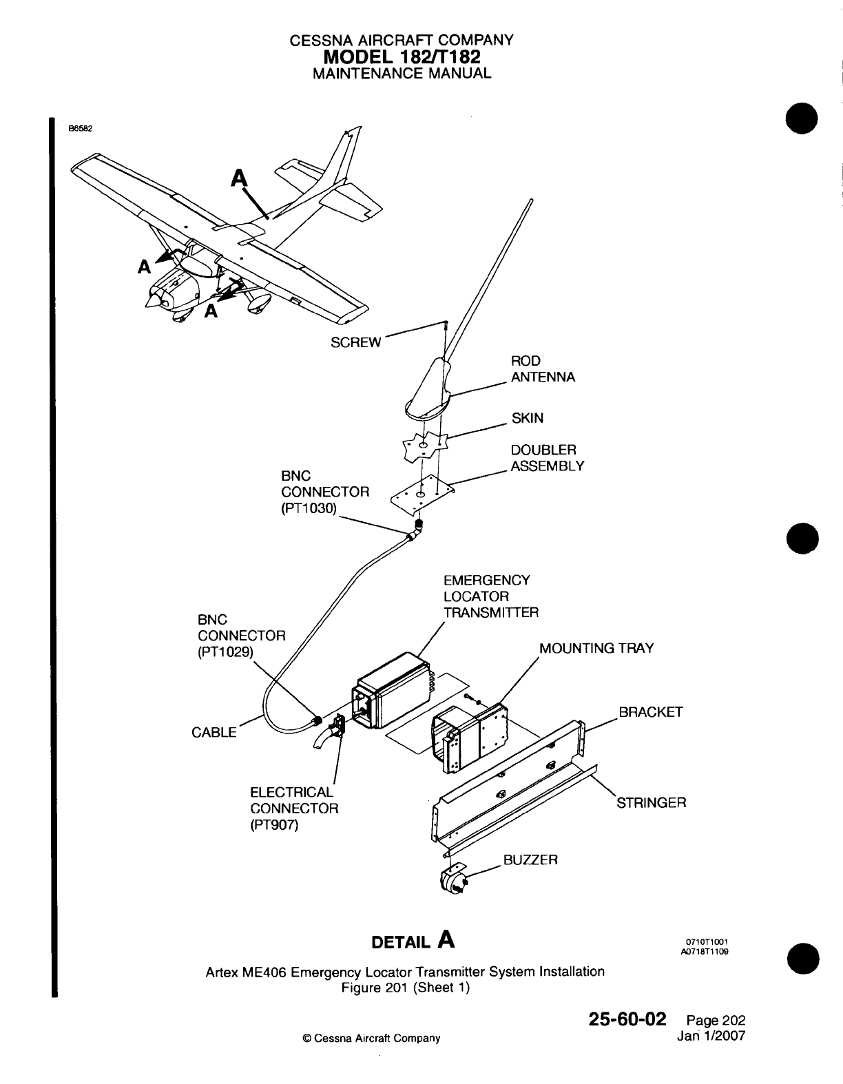
CESSNA
AIRCRAFT
COMPANY
MODEL
1821T182
MAINTENANCE
MANUAL
SCREW
BNC
CONNECTOR
(PT1
030)
BNC
CONN
(PT1
O'
ROD
ANTENNA
~~~
SKIN
DOUBLER
ASSEMBLY
EMERGENCY
LOCATOR
TRANSMITTER
MOUNTING
TRAY
-BRACKET
CABLE
ELECTRICAL
CONNECTOR
(PT907)
BUZZER
DETAIL
A
Artex
ME406
Emergency
Locator
Transmitter
System
Installation
Figure
201
(Sheet
1)
25-60-02
C
Cessna
Aircraft
Company
0710T1
001
A0718T
1109
Page
202
Jan
1/2007
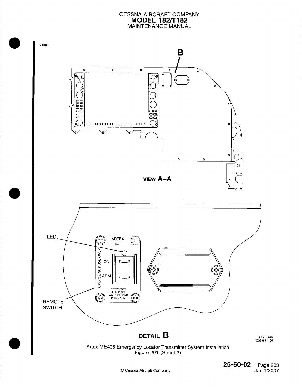
CESSNA
AIRCRAFT
COMPANY
MODEL
1821T182
MAINTENANCE
MANUAL
B6583
B
LED
REMC
SWIT(
DETAIL
B
Artex
ME406
Emergency
Locator Transmitter
System
Installation
Figure
201
(Sheet
2)
V
Cessna
Aircraft
Company
25-60-02
Page
203
Janl1/2007
B3940T445
C0718T1
106
CESSNA AIRCRAFT
COMPANY
MODEL
182/Ti82
MAINTENANCE
MANUAL
(3)
Tag
the
wires
and
terminals
for identification.
(4)
Remove
the screws that
attach
the
electrical
terminals
to
the
buzzer.
(5)
Loosen
the
black retainer
ring
on
the
outboard
side
of the
buzzer.
(6)
Remove
the
buzzer
from
the
bracket.
B.
Install
the
ELT
Buzzer
(Refer
to
Figure
201).
(1)
Put
the
buzzer
in
the
bracket.
(2)
Install
the
black
retainer
ring
on the
outboard
face
of the
buzzer.
(3)
Remove
the
tags
from
the
wires
and
terminals.
(4)
Connect
the electrical
wires
to
the
buzzer
with
the
screws.
(5)
Do
a
check
of
the
ELT
system.
Refer
to
Refer
to
Artex
ME406
ELT
Functional
Test.
(6)
Install
access
panel
(31
OAR)
on
the
right
side
of
the
tailcone.
Refer
to
Access/Inspection
Plates
-
Description
and
Operation
(7)
Remove
the
support
stand. Refer
to
Chapter
7,
Jacking
-
Maintenance
Practices.
4.
Remote
Switch
Removal/Installation
A.
Remove
the
Remote Switch. Refer
to
Figure
201.
(1)
Remove
electrical
power
from the
aircraft.
(2)
Get
access
to
the
ELT.
(a)
Put
a
support
stand
under
the
tail
tiedown
ring
to
support
the
tailcone.
Refer
to
Chapter
7,
Jacking
-
Maintenance
Practices.
(b)
Remove
the
access
panel
(31
OAR)
on
the
right
side
of
the
tailcone.
Refer
to
Access/
Inspection
Plates
-
Description
and
Operation
(3)
Disconnect
the
electrical
connector
(PT907)
from the
ELT.
(4)
Remove
the
screws
from the
front
of
the
remote
switch.
(5)
Pull
the remote
switch
from
the panel
to
get
to
the
electrical connector.
(a)
Disconnect
the
connector
from
the
back
of
the
switch.
B.
Install
the
Remote
Switch.
Refer
to
Figure
201.
(1)
Connect
the
electrical
connector
to
the
back
of
the
switch.
(2)
Put the
remote
switch
into
the
panel.
(a)
Install
the
screws that attach
the
switch
to
the
panel.
(3)
Connect
the
electrical
connector
to
the
ELT.
(4)
Complete
a
functional
test
of
the
ELT
system
to
make
sure
the
installation
is
correct.
Refer
to
Artex
ME406
Emergency
Locator
Transmitter
-
Adjustment/Test.
(5)
Install
access
panel
(31
OAR)
on
the right side
of
the
tailcone.
Refer
to
Access/Inspection Plates
-
Description
and
Operation
(6)
Remove
the
support
stand.
Refer
to
Chapter
7,
Jacking
-
Maintenance
Practices.
5.
ELT
Antenna
Removal/Installation
A.
Remove
the
ELT
Antenna
(Refer
to
Figure
201).
(1)
Remove
the
screws that
attach
the
antenna
to
the
fuselage.
(2)
Pull
the
antenna
upward
from
fuselage
and
disconnect
the
BNC
connector
(PT1030) from
antenna.
(3)
Remove
the
antenna
from
the
airplane.
(4)
Remove
sealant
from
antenna
and
airplane.
B.
Install
the
ELT
Antenna
(Refer
to
Figure
201).
(1)
Put
the
antenna
near
the
mounting
position
and
connect
the
BNC
connector
(PT1
030)
to
the
antenna.
(2)
Install
the
screws that attach
the
antenna
to
the
fuselage.
(3)
Make
sure
that
there
is a
correct
electrical
bond
between
the
antenna
and the
airplane structure.
(a)
Remove
one
screw.
(b)
With an
ohmmeter, measure
the
electrical
resistance
from
the
antenna
base
metal
insert
to
the
structure
at
the
screw
position.
NOTE: The
maximum
allowable
resistance
(in
ohms)
at
each
of
the
four measured
positions
is
0.0025.
25-60-02
Page
204
©
Cessna
Aircraft
Company
Janl1/2007
CESSNA AIRCRAFT
COMPANY
MODEL
182/Ti
182
MAINTENANCE
MANUAL
(c)
Install
the
screw
and
remove
and
install
each
of
the
remaining
screws
in
turn as you
measure
the
electrical
resistance
at
each
screw
hole.
(4)
Apply
a
fillet
seal
around
the
antenna with
Type
I
Class
B
Sealant.
Do
not
cover
the
screw
head with
the
sealant.
Refer to
Chapter
20,
Fuel,
Weather
and
High-Temperature Sealing
-
Maintenance
Practices.
(5)
Do
a
functional
test
of
the
ELT
system.
Refer
to
Artex ME406
Emergency
Locator
Transmitter
-
Adjustment/Test.
25-60-02
Page 205
©
Cessna
Aircraft
Company
Janl1/2007
0
CESSNA
AIRCRAFT
COMPANY
MODEL
182/Ti82
MAINTENANCE
MANUAL
ARTEX
ME406 EMERGENCY
LOCATOR
TRANSMITTER
(ELT)
SYSTEM
-
INSPECTION/CHECK
1.
General
A.
This
section
gives
the
procedures
that
are
necessary
to
do
the
inspection
and
operational
checks
necessary
to
comply
with
14
CFR
91.207,
for
the
Artex ME406
Emergency Locator
Transmitter
(ELT)
System.
The
system transmits
on
two
frequencies.
The
121.5
MHz
f
requency
has
the
standard
swept
tone
that
rescue
personnel
can
follow
to
the
source.
The
other
frequency
is
406.028
MHz
and
is
used
to
activate
a
satellite
tracking system. The
406.028
MHz
frequency
includes
other
information
such
as
the
country
code
of
the
airplane,
the
aircraft
identification
beacon
serial
number,
the
24-bit
address,
the
tail
number,
or
other
identification.
2.
Tools
and
Equipment
A.
For
information
on
tools
and
equipment,
refer
to
Equipment
and
Furnishings
-
General.
3.
Artex
ME406
Emergency
Locator Transmitter
(ELT)
Inspection
A.
Get
access
to
the
ELT.
(1)
Put
a
support
stand
under
the
tail
tiedown
ring
to
support
the
tailcone.
Refer
to
Chapter
7,
Jacking
-
Maintenance Practices.
(2)
Remove
the rear
seat.
Refer
to
Rear Seat
-
Maintenance Practices.
(3)
Remove the
baggage curtain
to get
access
to
the
transmitter.
Refer
to
Interior
Upholstery
-
Maintenance
Practices.
B.
Do
an
inspection
of
the
ELT,
mounting
tray,
antenna,
and
the
ELT
battery
for
condition
and
correct
installation.
(1)
Make
sure that
the
ELT
switch,
found
on
the
forward
end
of
the
ELT.
is
set
to
the
ARM
position.
(2)
Remove
the
ELT
from the
mounting
tray. Refer
to
Artex
ELT
ME406
Emergency
Locator
Transmitter
System
-
Maintenance
Practices.
CAUTION:
Do
not
use
solvents
to
clean the
ELT,
mounting
tray,
or
electrical
contacts.
Solvents
used
in
these
areas
can
cause
damage
to the
ELT
housing.
(3)
Examine
the
ELT
and
the
mounting
tray
for
correct
installation, cleanliness,
cracks,
or
other
damage.
(4)
Examine
the
ELT
battery
for
corrosion.
(5)
Look
at
the battery expiration
date.
(a)
Make
sure
that the
battery
life
limit
is
not
expired.
(b)
Make
sure
that
the
battery expiration
date
is
shown
correctly
in
the
Maintenance
Records.
NOTE:
The battery
manufacturer
puts
a
mark
on
the
battery
to
show
the
battery
life
limit.
When
you
install
a
new
battery
in
an
ELT,
make
sure
a
record
of
the
expiration
date
is
put
in
the
space
given
on
the
ELT
name and
data
plate.
(c) If
you
have
to
replace
the
ELT
battery,
refer to Artex
Maintenance
Manual
570-1600.
(d)
You
must
replace
the
ELT
battery
with
a
new
battery
if
one
or
more
of
the
conditions
that
follow
occur:
*
Use
of
the
ELT
battery
in
an
emergency
*
Operation
for
an
unknown
amount
of
time
*
Use
for
more
than one
hour
of
cumulative time
*
Replacement
date
shown
on
the
battery
label
has
expired.
(e)
Record
the new
battery expiration
date
in
the
maintenance
log
if
you
replaced
it.
(6)
Examine
the
ELT
antenna
for
correct installation
and
cracks
or
other
damage.
(7)
Install
the
ELT
into
the
mounting
tray.
Refer
to
Artex
ELT
ME406
Emergency Locator Transmitter
System
-
Maintenance Practices.
25-60-02
Page
601
©
Cessna
Aircratl Company
Janl1/2007
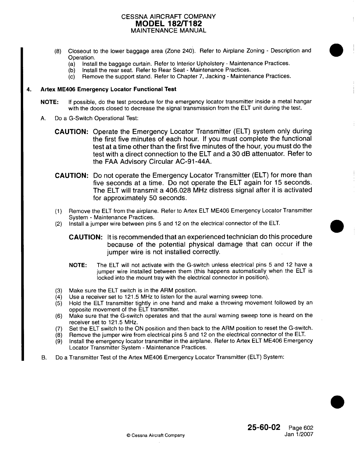
CESSNA AIRCRAFT
COMPANY
MODEL
182/Ti182
MAINTENANCE
MANUAL
(8)
Closeout
to
the
lower
baggage
area
(Zone
240).
Refer
to
Airplane
Zoning
-
Description
and
Operation.
(a)
Install
the
baggage curtain. Refer
to
Interior Upholstery
-
Maintenance
Practices.
(b)
Install
the
rear seat.
Refer
to
Rear
Seat
-
Maintenance
Practices.
(c)
Remove
the
support
stand.
Refer
to
Chapter
7,
Jacking
-
Maintenance
Practices.
4.
Artex
ME406
Emergency
Locator Functional
Test
NOTE:
If
possible,
do
the
test
procedure
for
the
emergency locator
transmitter
inside
a
metal
hangar
with
the
doors
closed
to
decrease
the
signal
transmission
from
the
ELT
unit
during the
test.
A.
Do
a
G-Switch
Operational
Test:
CAUTION: Operate
the
Emergency
Locator Transmitter
(ELT)
system
only
during
the
first
five
minutes
of
each
hour.
If
you
must
complete
the
functional
test
at
a
time
other
than
the
first
five
minutes
of
the
hour,
you
must
do
the
test
with
a
direct
connection
to
the
ELT
and
a
30
dB
attenuator.
Refer
to
the
FAA
Advisory Circular
AC-91-44A.
CAUTION:
Do
not
operate the
Emergency Locator
Transmitter
(ELT)
for
more
than
five
seconds
at
a
time.
Do
not
operate
the
ELT
again
for
15
seconds.
The
ELT
will
transmit
a
406.028
MHz
distress
signal after
it is
activated
for
approximately
50
seconds.
(1)
Remove
the
ELT
from
the
airplane. Refer
to
Artex
ELT
ME406
Emergency
Locator
Transmitter
System
-
Maintenance
Practices.
(2)
Install
a
jumper
wire
between
pins
5
and
12
on
the
electrical
connector
of
the
ELT.
CAUTION:
It is
recommended that
an
experienced technician
do
this
procedure
because
of
the
potential
physical
damage that
can
occur
if
the
jumper
wire
is
not
installed
correctly.
NOTE:
The
ELT
will
not
activate
with
the
G-switch
unless
electrical
pins
5
and
12
have
a
jumper
wire
installed
between them
(this happens
automatically
when the
ELT
is
locked
into the
mount
tray
with
the
electrical
connector
in
position).
(3)
Make sure
the
ELT
switch
is
in
the
ARM
position.
(4)
Use
a
receiver
set
to
121.5 MHz
to
listen
for
the
aural
warning
sweep
tone.
(5)
Hold
the
ELT
transmitter
tightly
in
one hand and
make
a
throwing
movement followed
by
an
opposite
movement
of
the
ELT
transmitter.
(6)
Make
sure
that
the
G-switch
operates
and
that the
aural
warning
sweep
tone
is
heard
on
the
receiver
set
to
121.5
MHz.
(7)
Set
the
ELT
switch
to
the
ON
position
and
then
back
to
the
ARM
position
to
reset
the
G-switch.
(8)
Remove
the
jumper
wire
from
electrical
pins
5
and
12
on
the
electrical
connector
of
the
ELT.
(9)
Install
the emergency
locator
transmitter
in
the
airplane.
Refer
to
Artex
ELT
ME406 Emergency
Locator
Transmitter
System
-
Maintenance Practices.
B.
Do
a
Transmitter
Test
of
the
Artex
ME406
Emergency
Locator Transmitter
(ELT)
System:
25-60-02
Page
602
©
Cessna
Aircraft
Company
Jan
1/2007
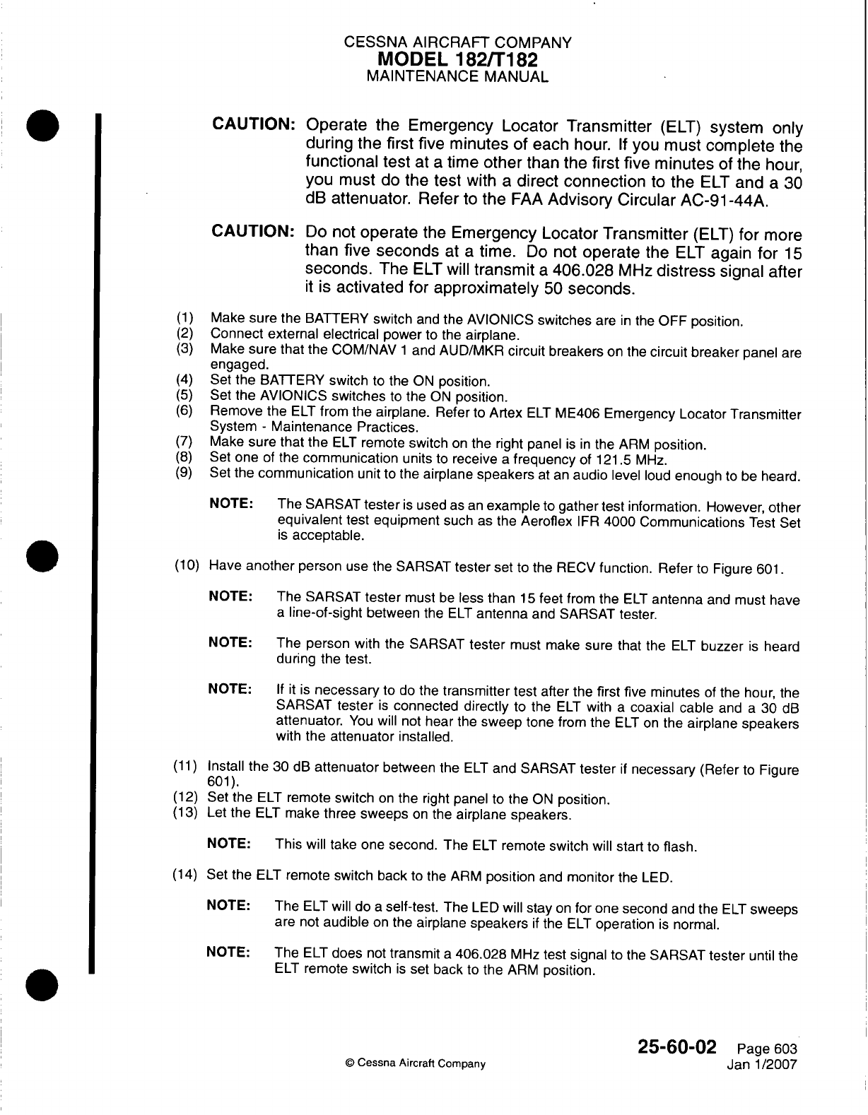
CESSNA AIRCRAFT
COMPANY
MODEL
182/Ti
82
MAINTENANCE
MANUAL
CAUTION: Operate
the
Emergency Locator
Transmitter
(ELT)
system
only
during
the first
five
minutes
of
each hour.
If
you
must
complete
the
functional
test
at
a
time
other
than
the
first
five minutes
of
the
hour,
you
must
do
the
test
with
a
direct
connection
to
the
ELT
and
a
30
dB
attenuator.
Refer
to
the
FAA
Advisory
Circular
AC-91
-44A.
CAUTION:
Do
not
operate
the
Emergency
Locator
Transmitter
(ELT)
for
more
than
five
seconds
at
a
time.
Do
not
operate
the
ELT
again
for
15
seconds.
The
ELT
will
transmit
a
406.028
MHz
distress
signal after
it
is
activated
for
approximately
50
seconds.
(1)
Make
sure
the BATTERY
switch
and
the
AVIONICS
switches
are
in
the
OFF
position.
(2)
Connect
external
electrical
power
to
the
airplane.
(3)
Make
sure
that
the
COM/NAV
1
and AUD/MKR
circuit
breakers
on
the
circuit
breaker panel are
engaged.
(4)
Set
the BATTERY
switch
to the
ON
position.
(5)
Set
the
AVIONICS
switches
to
the
ON
position.
(6)
Remove
the
ELT
from
the
airplane.
Refer
to
Artex
ELT
ME406
Emergency Locator Transmitter
System
-
Maintenance
Practices.
(7)
Make
sure
that
the
ELT
remote
switch
on
the
right panel
is in
the
ARM
position.
(8)
Set
one
of
the
communication
units
to
receive
a
frequency
of
121.5
MHz.
(9)
Set
the
communication
unit
to
the
airplane
speakers
at
an
audio
level
loud
enough
to
be
heard.
NOTE:
The
SARSAT
tester
is
used
as
an
example
to
gather
test
information.
However,
other
equivalent
test
equipment
such
as
the
Aeroflex
IFR
4000
Communications
Test
Set
is
acceptable.
(110)
Have
another
person
use
the
SARSAT
tester
set
to
the
RECV
function. Refer
to
Figure
601.
NOTE:
The
SARSAT
tester
must
be
less
than
15
feet
from
the
ELT
antenna
and
must
have
a
line-of-sight
between
the
ELT
antenna
and
SARSAT tester.
NOTE: The
person
with
the
SARSAT
tester
must
make
sure that the
ELT
buzzer
is
heard
during
the
test.
NOTE:
If it is
necessary
to do
the
transmitter test
after
the
first five minutes
of
the
hour,
the
SARSAT
tester
is
connected
directly
to
the
ELT
with
a
coaxial cable
and
a
30
dB
attenuator.
You
will
not
hear
the
sweep
tone
from the
ELT
on
the
airplane
speakers
with
the
attenuator
installed.
(11)
Install
the
30
dB
attenuator
between
the
ELT
and SARSAT
tester
if
necessary
(Refer
to
Figure
601).
(12)
Set the
ELT
remote
switch
on
the
right
panel
to
the
ON
position.
(13)
Let
the
ELT
make three
sweeps
on
the
airplane
speakers.
NOTE:
This
will
take one second.
The
ELT
remote
switch
will
start to
flash.
(14)
Set
the
ELT
remote
switch
back
to
the
ARM
position
and
monitor
the
LED.
NOTE:
The
ELT
will do
a
self-test.
The
LED
will stay
on
for
one
second
and
the
ELT
sweeps
are
not
audible
on
the
airplane
speakers
if
the
ELT
operation
is
normal.
NOTE: The
ELT
does
not
transmit
a
406.028
MHz
test signal to
the
SARSAT
tester
until
the
ELT
remote
switch
is
set
back
to
the
ARM
position.
25-60-02
Page
603
Q
Cessna Aircratt
Company
Janl1/2007
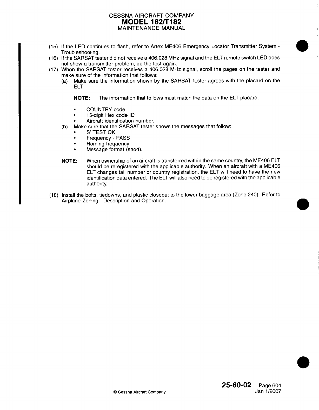
CESSNA
AIRCRAFT
COMPANY
MODEL
182/Ti182
MAINTENANCE
MANUAL
(15)
If
the LED
continues
to
flash,
refer
to
Artex ME406
Emergency
Locator Transmitter System
-
Troubleshooting.
(16)
If
the SARSAT
tester
did
not
receive
a
406.028
MHz
signal
and
the
ELT
remote
switch
LED
does
not
show
a
transmitter
problem,
do
the
test again.
(17)
When
the
SARSAT
tester
receives
a
406.028
MHz
signal,
scroll
the
pages
on
the tester
and
make
sure
of
the
information that
follows:
(a)
Make
sure
the
information
shown
by
the
SARSAT
tester
agrees
with
the
placard
on
the
ELT.
NOTE:
The
information that follows
must
match
the
data
on
the
ELT
placard:
*
COUNTRY
code
*
15-dligit
Hex
code
ID
*
Aircraft
identification
number.
(b)
Mlake
sure
that
the
SARSAT
tester
shows the
messages that
follow:
*
S
TEST
OK
*
Frequency
-
PASS
*
Homing
frequency
*
Message format
(short).
NOTE:
When
ownership
of an
aircraft
is
transferred within
the
same country,
the
ME406
ELT
should
be
reregistered
with
the
applicable
authority. When
an
aircraft
with
a
ME406
ELT
changes tail
number
or
country
registration,
the
ELT
will
need
to
have
the
new
identification
data
entered.
The
ELT
will
also
need
to
be
registered
with
the
applicable
authority.
(1 8)
Install the
bolts,
tiedowns,
and
plastic
closeout
to
the lower
baggage
area
(Zone
240).
Refer
to
Airplane
Zoning
-
Description
and
Operation.
25-60-02
Page
604
Q
Cessna
Aircraft Company
Janl1/2007
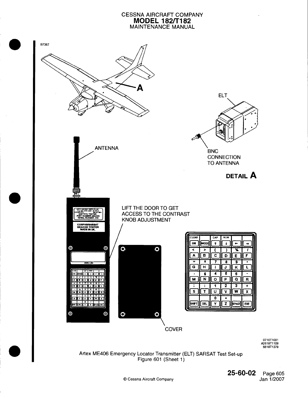
CESSNA
AIRCRAFT
COMPANY
MODEL
182/Ti
82
MAINTENANCE
MANUAL
ELT
BNC
CONNECTION
TO ANTENNA
DETAIL
A
LIFT
THE
DOOR
TO
GET
ACCESS
TO
THE
CONTRA!
KNOB
ADJUSTMENT
3T
CLEAR
CAP
NRUM
a
+
0~~11-
E~JDL
WW
PA1E
F
COVER
0710T1001
A2618T1
109
6618T1
379
Artex
ME406
Emergency
Locator Transmitter
(ELT)
SARSAT
Test
Set-up
Figure
601
(Sheet
1)
25-60-02
©
Cessna
Aircraft
Company
Page
605
Janl1/2007
.1-
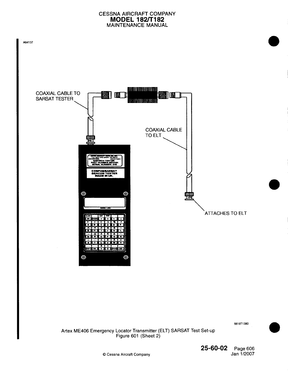
CESSNA
AIRCRAFT
COMPANY
MODEL
1821T
182
MAINTENANCE
MANUAL
A64137
COAXIAL
SARSAT
COAXIAL CABLE
TO
ELT
ATTACHES
TO
ELT
661
8T1
380
Artex
ME406
Emergency
Locator
Transmitter
(ELT)
SARSAT
Test
Set-up
Figure
601
(Sheet
2)
©
Cessna Aircraft Company
25-60-02
Page
606
Janl1/2007
CESSNA
AIRCRAFT
COMPANY
MODEL
182/Ti82
MAINTENANCE
MANUAL
CARBON
MONOXIDE
DETECTOR
-
MAINTENANCE
PRACTICES
1.
General
A.
The
carbon
monoxide
(CO)
detector
is
installed
on
Airplanes
182081742
and
On
and
Airplanes
Ti 82008481 and
On
that
have
the
Garmin
G
1000.
B.
The
CO
detector detects,
measures,
and
gives
an
alert
to
the crew before
the
cockpit
level
of
CO
reaches
a
critical
level.
The
CO
data
is
displayed
and
controlled
through
the
CO
detector
RS232
interface
with
the
multi-function
display
(MFD).
2.
Carbon
Monoxide
Detector
Removal/installation
A.
Carbon
Monoxide
Detector
Removal
(Refer
to
Figure
201).
(1)
Put
the
AVIONICS
MASTER
switch
in
the
off
position.
(2)
Remove
the
MED
from
the
copilot
side
of
the
instrument
panel. Refer
to
Chapter
34,
Control
Display
Unit
-
Maintenance
Practices.
(3)
Disconnect
the
electrical
connector
(P1903)
from
the
CO
detector.
(4)
Remove
and keep
the
three
screws
and
three
washers
that connect the
CO
detector
to
the
avionics
support
structure.
(5)
Remove
the
CO
detector
from
the
airplane.
B.
Carbon
Monoxide
Detector
Installation
(Refer
to
Figure
201).
(1)
Put
the CO
detector
in
position
on
the
avionics
support
structure.
(2)
Attach the
CO
detector
to
the
structure
with
the three kept
screws
and
three
kept
washers.
(3)
Connect
the
electrical connector
(P1
903) to
the
CO
detector.
(4)
Install
the
MED
on
the
copilot
side
of
the
instrument
panel.
Refer
to
Chapter
34,
Control
Display
Unit
-
Maintenance
Practices.
(5)
Put
the
AVIONICS
MASTER
switch
in
the
ON
position.
(6)
On
the
primary
flight
display
(PFD),
do
a
check
to
make
sure
that
the
CO
detector
operates
correctly.
25-60-1
0
Page
201
C
Cessna
Aircraft
Company
Janl1/2007
I
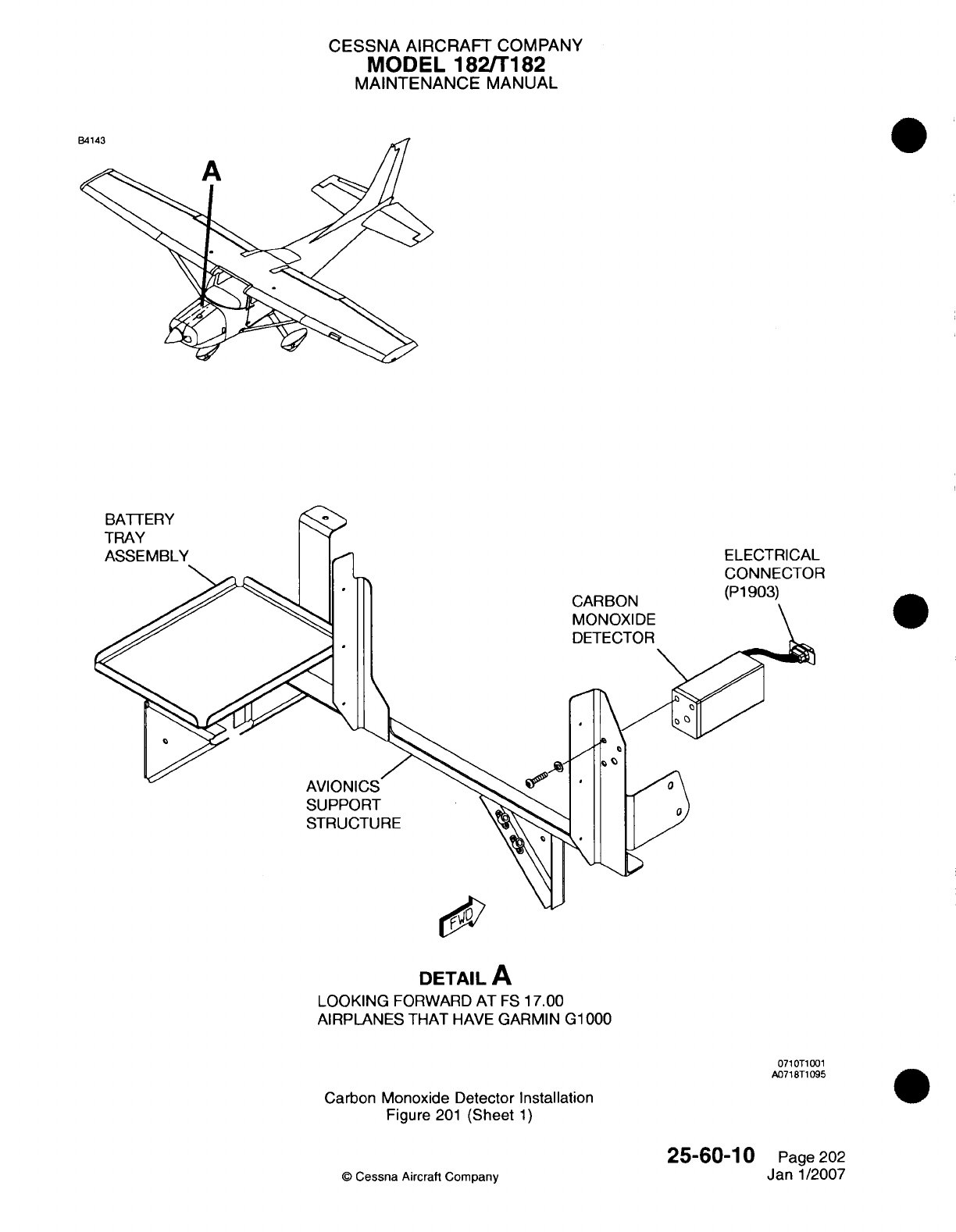
CESSNA
AIRCRAFT
COMPANY
MODEL
182/Ti 182
MAINTENANCE
MANUAL
AVIONICS
SUPPORT
STRUCTURE
R
CARBON
MONOXIDE
DETECTOR
DETAIL
A
LOOKING
FORWARD
AT
ES
17.00
AIRPLANES
THAT
HAVE
GARMIN
G1
000
071
OT1
001
A071ST1
095
Carbon
Monoxide Detector
Installation
Figure
201
(Sheet
1)
©
Cessna Aircraft
Company
25-60-1
0
Page
202
Janl1/2007
BATTERY
TRAY
ASSEMBLY
CESSNA
AIRCRAFT
COMPANY
MODEL
182fT182
MAINTENANCE
MANUAL
SOUNDPROOFING
AND
INSULATION
-
MAINTENANCE
PRACTICES
1.
General
A.
The
airplane
utilizes
soundproofing
and
insulation
throughout
the
fuselage
area.
This material
is
glued
into
place
using
spray
adhesive.
Any
time
old
material
is
being
replaced,
care
should
be
taken
to
ensure
all
traces
are removed
from
fuselage
skin
before
reapplication.
For
a
list
of
spray
adhesives,
refer
to
Equipment/Furnishing
-
General.
B.
For
an
illustration
of
soundproofing
and
insulation locations,
refer
to
Figure
201
and
Figure
202.
25-80-00
Page
201
©
Cessna Aircraft
Company
April 1/2002
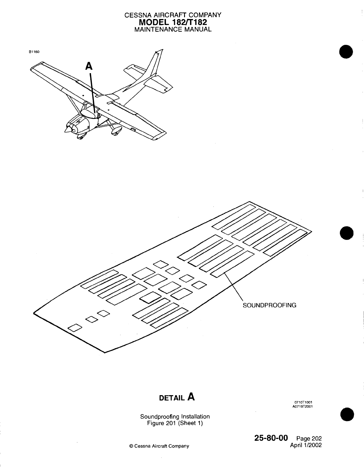
CESSNA AIRCRAFT
COMPANY
MODEL 182/T182
MAINTENANCE
MANUAL
SOUNDPROOFING
DETAIL
A
Soundproofing Installation
Figure
201
(Sheet
1)
25-80-00
©
Cessna
Aircraft
Company
0710T1001
A0719T2001
Page
202
April
1/2002
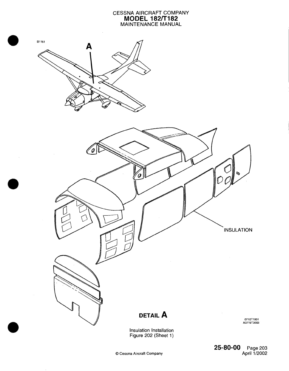
CESSNA
AIRCRAFT
COMPANY
MODEL
182/T182
MAINTENANCE
MANUAL
DETAIL
A
Insulation Installation
Figure
202
(Sheet
1)
©
Cessna
Aircraft
Company
0710T1001
A0719T3003
25-80-00
Page
203
April
1/2002
CHAPTER
FIRE
PROTECTION

CESSNA
AIRCRAFT
COMPANY
MODEL
182/T182
MAINTENANCE
MANUAL
LIST
OF
EFFECTIVE PAGES
CHAPTER-SECTION-SUBJECT
26-Title
26-List
of
Effective Pages
26-Record
of
Temporary
Revisions
26-Table
of
Contents
26-00-00
26-20-00
©
Cessna Aircraft
Company
PAGE
DATE
Page
1
April
1/2002
Pages
1-2
April
1/2002
26
-
LIST
OF
EFFECTIVE
PAGES
Page
1
of
1
Mar 1/2005
Temporary
Revision
Number
RECORD
OF
TEMPORARY REVISIONS
Page
Number
Issue
Date
By
Date
Removed
By
CESSNA AIRCRAFT
COMPANY
MODEL
182/T182
MAINTENANCE
MANUAL
CONTENTS
FIRE
PROTECTION
-
GENERAL..................................................
Scope
and
Definition
........................................................
HAND
FIRE
EXTINGUISHER
-
DESCRIPTION
AND
OPERATION
...................
Description
and
Operation
...................................................
26-00-00
Page
1
26-00-00
Page
1
26-20-00
Page
1
26-20-00
Page
1
CONTENTS
Page
1
of
1
Mar 1/2005
©
Cessna Aircraft
Company
CESSNA
AIRCRAFT
COMPANY
MODEL
182/T182
MAINTENANCE
MANUAL
FIRE
PROTECTION
-
GENERAL
1.
Scope
and
Definition
A.
This
chapter
contains
a
single
section which
describes the
portable
fire
extinguisher
used
in
the cabin.
26-00-00
Page
1
©
Cessna
Aircraft
Company
April
1/2002
CESSNA
AIRCRAFT
COMPANY
MODEL
182/T182
MAINTENANCE
MANUAL
HAND
FIRE
EXTINGUISHER
-
DESCRIPTION
AND
OPERATION
1.
Description
and
Operation
A. A
portable,
hand
operated
fire
extinguisher
is
mounted
on
the
floor
between
the
pilot and
copilot
seats
for
use
in
the
event
of
a
fire.
The
extinguishing
agent
is
Halon
1211
and
may be
used
on
solid combustible, electrical
or liquid
fires. Servicing
of
the
extinguisher
can
be
handled
by
most
fire
equipment dealers.
The
fire
extinguisher
is
mounted
within
a
quick
release,
clamp
type
bracket
assembly.
(Refer
to
Figure
1).
26-20-00
Page
1
©
Cessna Aircraft Company
April 1/2002
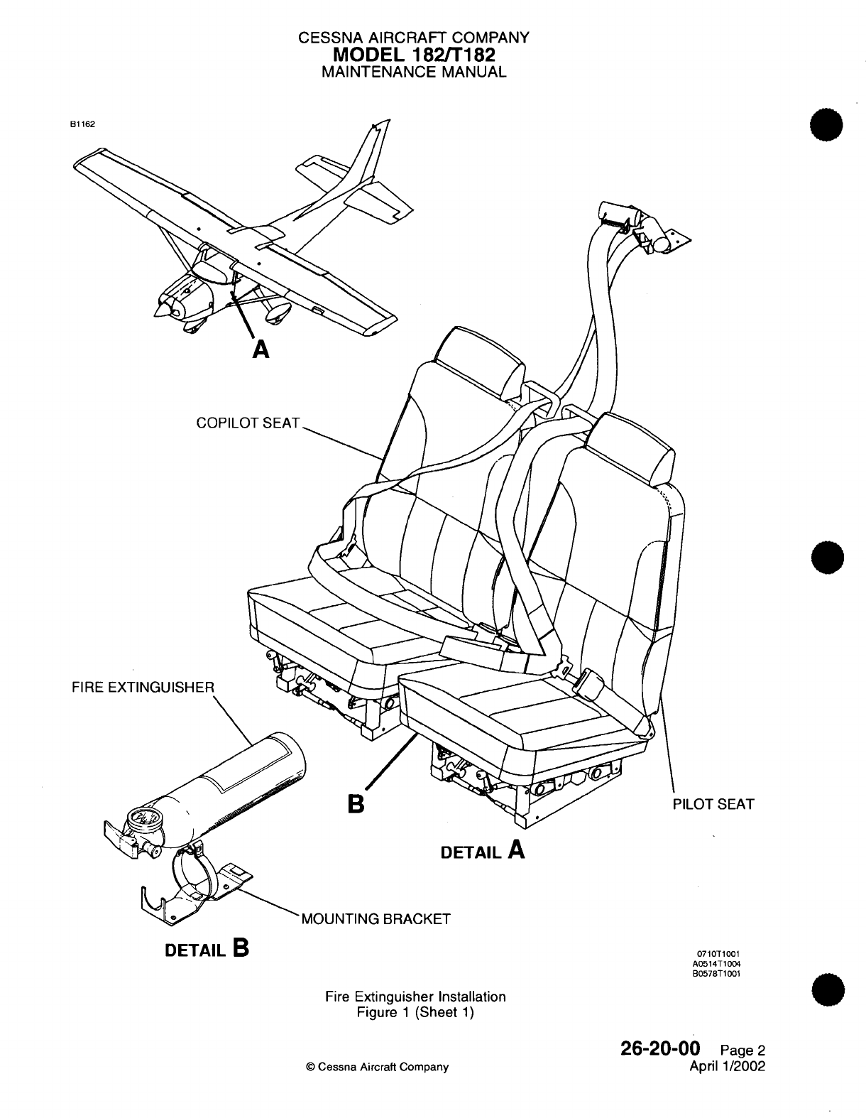
CESSNA AIRCRAFT
COMPANY
MODEL
182/T182
MAINTENANCE
MANUAL
FIRE
LOT
SEAT
'MOUNTING
BRACKET
Fire
Extinguisher
Installation
Figure
1
(Sheet
1)
26-20-00
Page
2
April
1/2002
©
Cessna Aircraft Company
DETAIL
B
0710T1001
A0514T1004
B0578T1001
CHAPTER
FLIGHT
CONTROLS
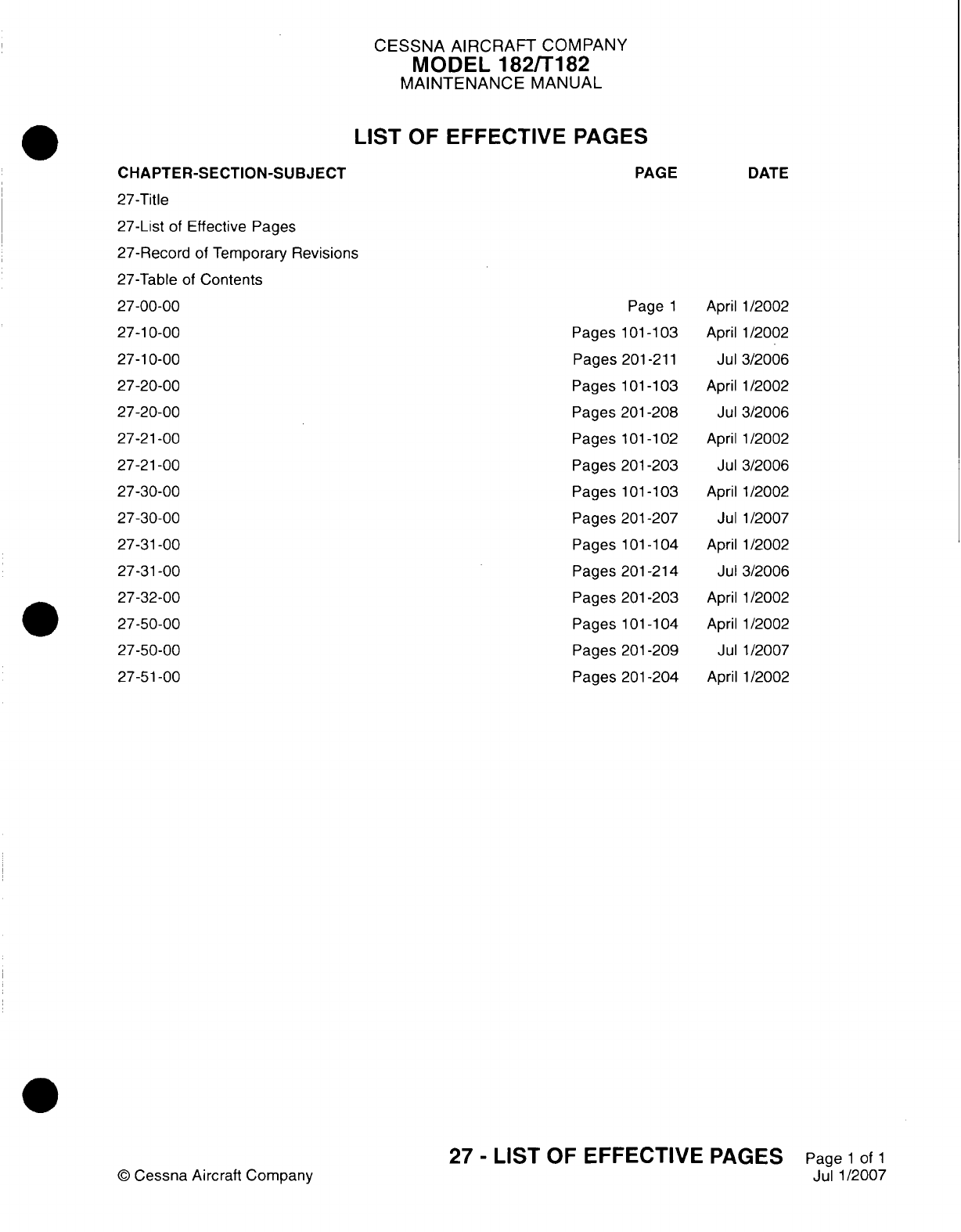
CESSNA
AIRCRAFT
COMPANY
MODEL
182/Ti
82
MAINTENANCE
MANUAL
LIST
OF
EFFECTIVE
PAGES
CHAPTER-SECTION-SUBJECT
27-Title
27-List
of
Effective
Pages
27-Record
of
Temporary
Revisions
27-Table
of
Contents
27-00-00
27-1
0-00
27-1
0-00
27-20-00
27-20-00
27-2
1-00
27-2
1-00
27-30-00
27-30-00
27-3
1-00
27-3
1-00
27-32-00
27-50-00
27-50-00
27-5
1-00
©
Cessna Aircraft
Company
PAGE
Page
1
Pages
101
-103
Pages
201
-211
Pages
101
-1
03
Pages 201-208
Pages
101
-1
02
Pages
201
-203
Pages
101
-103
Pages
201
-207
Pages
101
-104
Pages
201
-214
Pages
201-203
Pages
101
-1
04
Pages
201
-209
Pages
201
-204
DATE
April 1/2002
April
1/2002
Jul
3/2006
April
1/2002
Jul
3/2006
April
1/2002
Jul 3/2006
April 1/2002
Jul
1/2007
April
1/2002
Jul
3/2006
April
1/2002
April
1/2002
Jul 1/2007
April
1/2002
27
-
LIST
OF
EFFECTIVE
PAGES
Page
1
of
1
Jul
1/2007

Temporary
Revision
Number
RECORD
OF
TEMPORARY
REVISIONS
Page
Number
Issue
Date
By
Date
Removed
By
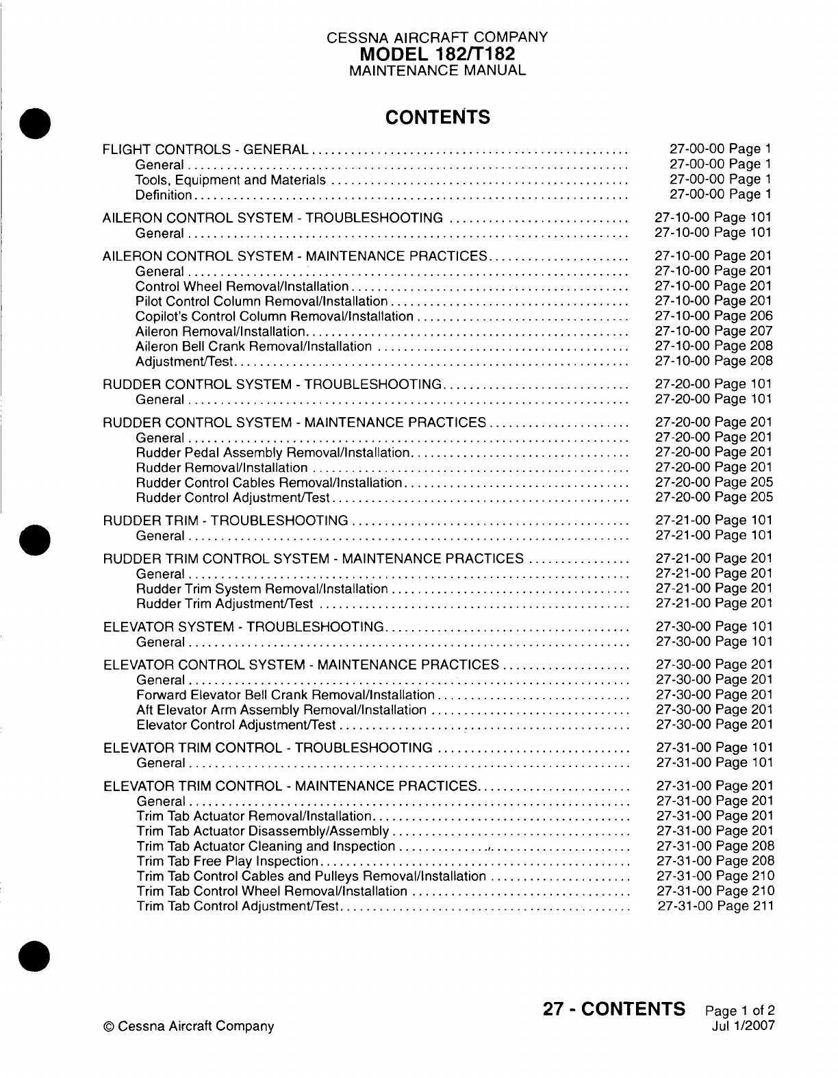
CESSNA
AIRCRAFT
COMPANY
MODEL
182/Ti
82
MAINTENANCE
MANUAL
CONTENTS
FLIGHT CONTROLS
-
GENERAL
.........................
General...................................
Tools,
Equipment
and
Materials........................
Definition
..................................
AILERON
CONTROL
SYSTEM
-
TROUBLESHOOTING...............
General...................................
AILERON
CONTROL
SYSTEM
-
MAINTENANCE
PRACTICES............
General.......
Control
Wheel
Removal/Installation
......................
Pilot
Control
Column
Removal/Installation
...................
Copilot's
Control
Column
Removal/Installation
.................
Aileron
Removal/installation..........................
Aileron
Bell
Crank
Removal/installation
....................
Adjustment/Test
...............................
RUDDER
CONTROL
SYSTEM
-
TROUBLESHOOTING
...............
General...................................
RUDDER
CONTROL
SYSTEM
-
MAINTENANCE
PRACTICES............
General...................................
Rudder
Pedal
Assembly
Removal/Installation..................
Rudder
Removal/installation
.........................
Rudder
Control
Cables
Removal/installation
..................
Rudder
Control
Adjustment/Test........................
RUDDER
TRIM
-
TROUBLESHOOTING
......................
General...................................
RUDDER
TRIM
CONTROL
SYSTEM
-
MAINTENANCE
PRACTICES.........
General...................................
Rudder
Trim
System
Removal/Installation
...................
Rudder
Trim
Adjustment/Test.........................
ELEVATOR
SYSTEM
-
TROUBLESHOOTING....................
General...................................
ELEVATOR
CONTROL
SYSTEM
-
MAINTENANCE
PRACTICES...........
General
..................................
Forward
Elevator
Bell
Crank
Removal/Installation................
Aft
Elevator
Arm
Assembly
Removal/Installation
................
Elevator
Control Adjustment/Test
.......................
ELEVATOR
TRIM
CONTROL
-
TROUBLESHOOTING................
General...................................
ELEVATOR TRIM
CONTROL
-
MAINTENANCE
PRACTICES.............
General...................................
Trim
Tab
Actuator
Removal/Installation.....................
Trim
Tab
Actuator
Disassembly/Assembly
...................
Trim
Tab
Actuator
Cleaning
and
Inspection
........ ..........
Trim
Tab
Free
Play
Inspection.........................
Trim
Tab
Control
Cables
and
Pulleys
Removal/installation............
Trim
Tab
Control
Wheel
Removal/installation..................
Trim
Tab
Control
Adjustment/Test
.......................
27-00-00
Page
1
27-00-00
Page
1
27-00-00
Page
1
27-00-00
Page
1
27-10-00
Page
101
27-10-00
Page
101
27-10-00
Page
201
27-10-00
Page
201
27-10-00
Page
201
27-1
0-00
Page
201
27-1
0-00
Page
206
27-10-00
Page
207
27-10-00
Page
208
27-10-00
Page
208
27-20-00
Page
101
27-20-00
Page
101
27-20-00
Page
201
27-20-00
Page
201
27-20-00
Page
201
27-20-00
Page
201
27-20-00
Page
205
27-20-00
Page
205
27-21
-00
Page
101
27-21-00
Page
101
27-21
-00
Page
201
27-21
-00
Page
201
27-21
-00
Page
201
27-21
-00
Page
201
27-30-00
Page
101
27-30-00
Page
101
27-30-00
Page
201
27-30-00
Page
201
27-30-00
Page
201
27-30-00
Page
201
27-30-00
Page
201
27-31
-00
Page
101
27-31
-00
Page
1 01
27-31 -00
Page
201
27-31
-00
Page
201
27-31
-00
Page
201
27-31
-00
Page
201
27-3
1
-00
Page
208
27-31 -00
Page
208
27-31 -00
Page
21
0
27-31
-00
Page
21
0
27-31
-00
Page
211
27
-
CONTENTS
Page
1
of
2
Jul
1/2007
©
Cessna
Aircraft Company
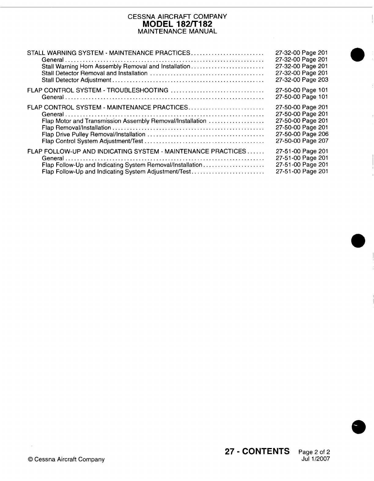
CESSNA
AIRCRAFT
COMPANY
MODEL
182/Ti
82
MAINTENANCE
MANUAL
STALL
WARNING SYSTEM
-
MAINTENANCE PRACTICES
.............
General
..................... .............
Stall
Warning
Horn
Assembly
Removal
and
Installation
.............
Stall
Detector
Removal
and
Installation
....................
Stall
Detector
Adjustment...........................
FLAP
CONTROL
SYSTEM
-
TROUBLESHOOTING.................
General...................................
FLAP
CONTROL
SYSTEM
-
MAINTENANCE
PRACTICES..............
General...................................
Flap Motor
and
Transmission Assembly
Removal/installation
..........
Flap
Removal/Installation...........................
Flap
Drive
Pulley
Removal/Installation.....................
Flap Control
System
Adjustment/Test
.....................
FLAP
FOLLOW-UP
AND
INDICATING
SYSTEM
-
MAINTENANCE
PRACTICES.
General...................................
Flap
Follow-Up
and
Indicating
System
Removal/Installation
...........
Flap
Follow-Up
and
Indicating
System
Adjustment/Test
.............
27-32-00
Page
201
27-32-00
Page
201
27-32-00
Page
201
27-32-00
Page
201
27-32-00
Page 203
27-50-00
Page
101
27-50-00
Page
1
01
27-50-00
Page
201
27-50-00
Page
201
27-50-00
Page
201
27-50-00
Page
201
27-50-00
Page
206
27-50-00
Page
207
27-5
1
-00
Page
201
27-51
-00
Page
201
27-5
1
-00
Page
201
27-51
-00
Page
201
27
-
CONTENTS
Page
2
of
2
Jul 1/2007
©
Cessna
Aircraft Company
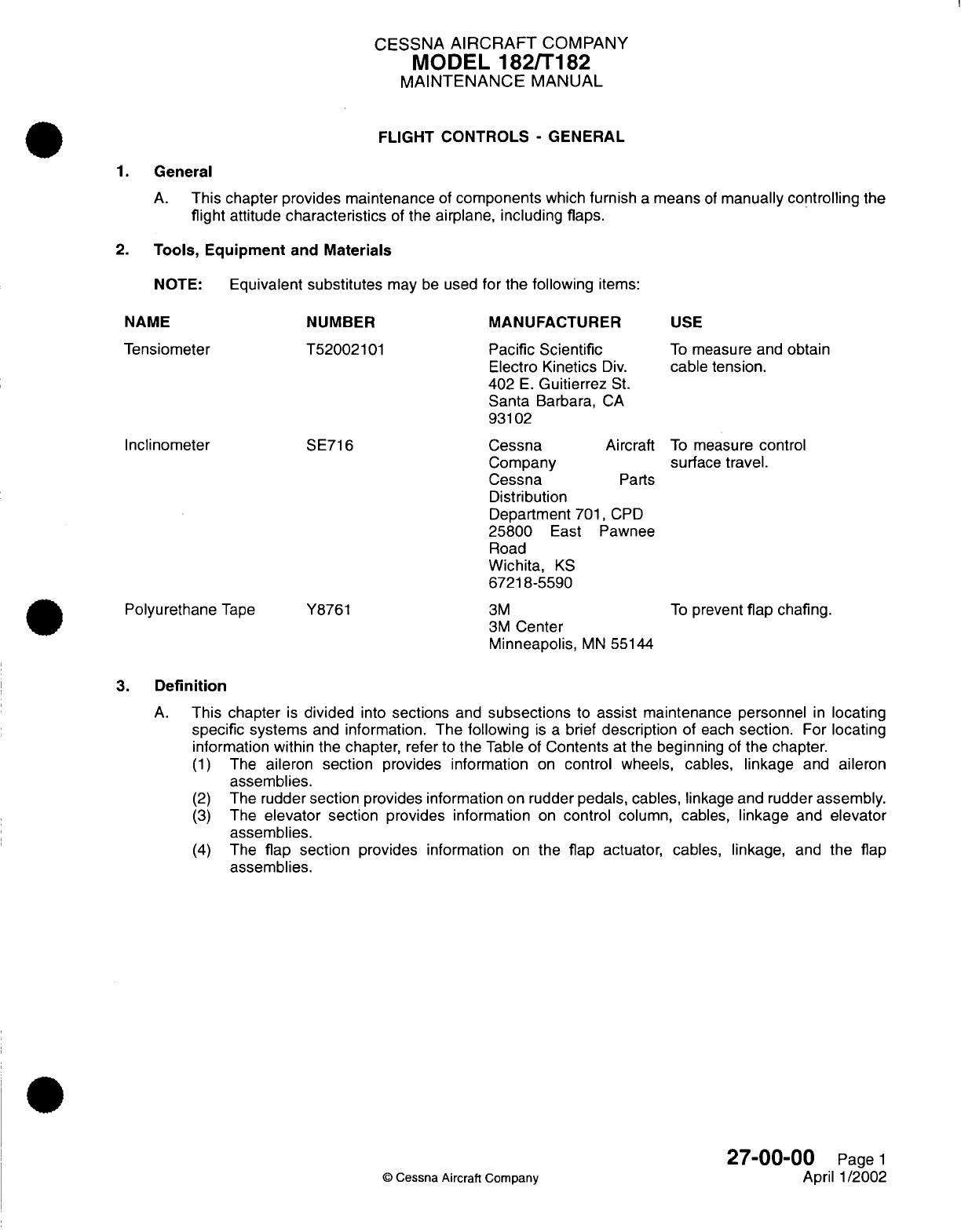
CESSNA
AIRCRAFT
COMPANY
MODEL
182/T182
MAINTENANCE
MANUAL
FLIGHT
CONTROLS
-
GENERAL
1.
General
A.
This
chapter
provides maintenance
of
components
which furnish
a
means
of
manually
controlling
the
flight
attitude
characteristics
of
the
airplane,
including flaps.
2.
Tools,
Equipment
and
Materials
NOTE:
Equivalent
substitutes
may
be
used
for
the
following
items:
NAME
Tensiometer
Inclinometer
Polyurethane
Tape
NUMBER
T52002101
SE716
Y8761
MANUFACTURER
Pacific Scientific
Electro
Kinetics
Div.
402
E.
Guitierrez
St.
Santa
Barbara,
CA
93102
Cessna
Aircraft
Company
Cessna
Parts
Distribution
Department
701,
CPD
25800
East
Pawnee
Road
Wichita,
KS
67218-5590
3M
3M
Center
Minneapolis,
MN
55144
USE
To
measure and
obtain
cable
tension.
To
measure
control
surface
travel.
To
prevent
flap
chafing.
3.
Definition
A.
This
chapter
is
divided
into
sections
and
subsections
to
assist
maintenance personnel
in
locating
specific
systems
and
information. The
following
is
a
brief
description
of
each
section.
For
locating
information
within the
chapter, refer to
the
Table
of
Contents
at the beginning
of
the
chapter.
(1)
The
aileron
section
provides information
on
control
wheels,
cables,
linkage
and
aileron
assemblies.
(2)
The rudder
section
provides
information
on
rudder pedals, cables,
linkage
and
rudder
assembly.
(3)
The
elevator
section
provides information
on
control
column,
cables,
linkage
and
elevator
assemblies.
(4)
The
flap section
provides
information
on
the
flap
actuator,
cables,
linkage,
and
the flap
assemblies.
27-00-C
©
Cessna Aircraft Company
10
Page
1
April
1/2002
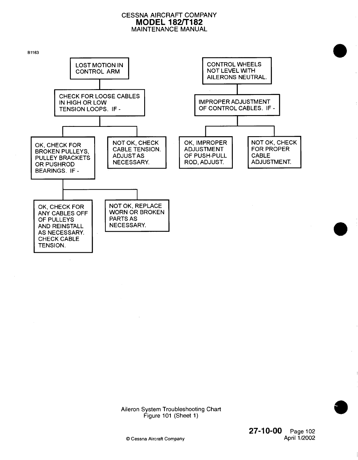
CESSNA AIRCRAFT
COMPANY
MODEL
182/T182
MAINTENANCE
MANUAL
B1163
LOST
MOTION
IN
CONTROL
ARM
CHECK
FOR LOOSE CABLES
IN
HIGH
OR
LOW
TENSION LOOPS.
IF
-
I
CONTROL
WHEELS
NOT
LEVEL WITH
AILERONS
NEUTRAL.
IMPROPER
ADJUSTMENT
OF
CONTROL
CABLES.
IF
-
OK,
CHECK
FOR
BROKEN
PULLEYS,
PULLEY
BRACKETS
OR
PUSHROD
BEARINGS.
IF-
NOT
OK, CHECK
CABLE
TENSION.
ADJUST
AS
NECESSARY.
OK,
IMPROPER
ADJUSTMENT
OF
PUSH-PULL
ROD,
ADJUST.
NOT
OK,
CHECK
FOR
PROPER
CABLE
ADJUSTMENT.
OK,
CHECK
FOR
ANY
CABLES
OFF
OF
PULLEYS
AND
REINSTALL
AS
NECESSARY.
CHECK
CABLE
TENSION.
NOT
OK,
REPLACE
WORN
OR BROKEN
PARTS
AS
NECESSARY.
Aileron
System
Troubleshooting
Chart
Figure
101
(Sheet
1)
©
Cessna
Aircraft
Company
27-10-00
Page
102
April 1/2002
I
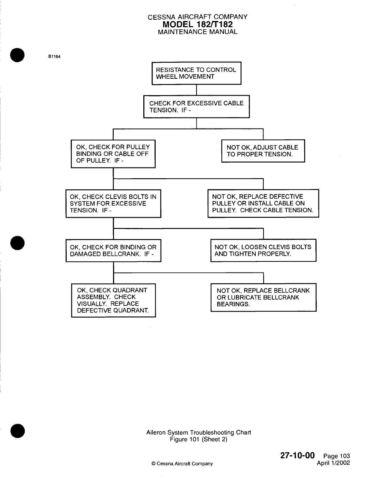
CESSNA
AIRCRAFT
COMPANY
MODEL
182/T182
MAINTENANCE
MANUAL
RESISTANCE TO
CONTROL
WHEEL MOVEMENT
CHECK
FOR EXCESSIVE
CABLE
TENSION.
IF-
I
I
OK,
CHECK
FOR
PULLEY
BINDING
OR
CABLE
OFF
OF
PULLEY.
IF-
OK,
CHECK
CLEVIS
BOLTS
SYSTEM FOR EXCESSIVE
TENSION.
IF-
IN
OK,
CHECK FOR
BINDING
OR
DAMAGED
BELLCRANK.
IF
-
OK,
CHECK
QUADRANT
ASSEMBLY.
CHECK
VISUALLY.
REPLACE
DEFECTIVE
QUADRANT.
NOT
OK,
ADJUST
CABLE
TO
PROPER
TENSION.
NOT
OK,
REPLACE
DEFECTIVE
PULLEY
OR INSTALL
CABLE
ON
PULLEY. CHECK
CABLE
TENSION.
NOT
OK,
LOOSEN
CLEVIS
BOLTS
AND
TIGHTEN
PROPERLY.
NOT
OK,
REPLACE
BELLCRANK
OR LUBRICATE BELLCRANK
BEARINGS.
Aileron
System
Troubleshooting
Chart
Figure
101
(Sheet
2)
27-10-00
©
Cessna Aircraft
Company
B1164
Page
103
April
1/2002
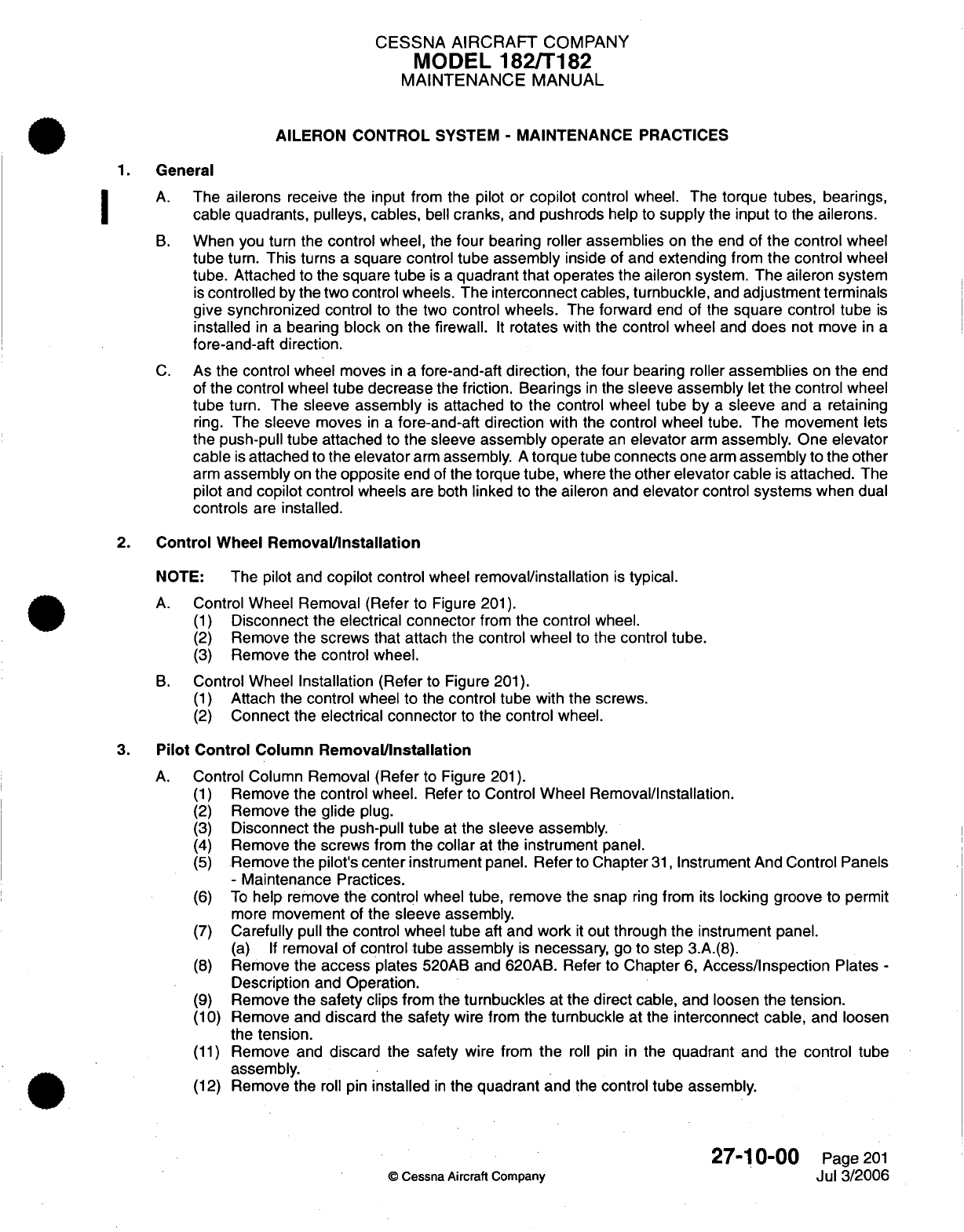
CESSNA
AIRCRAFT
COMPANY
MODEL
182/T182
MAINTENANCE
MANUAL
AILERON
CONTROL
SYSTEM
-
MAINTENANCE
PRACTICES
1.
General
A.
The
ailerons
receive
the
input
from
the
pilot
or
copilot
control
wheel.
The
torque
tubes, bearings,
cable quadrants, pulleys, cables,
bell
cranks,
and
pushrods
help
to
supply
the
input
to
the
ailerons.
B.
When
you
turn
the
control
wheel,
the
four
bearing roller
assemblies
on
the
end
of
the
control
wheel
tube
turn.
This
turns
a
square
control
tube assembly
inside
of and
extending
from
the
control
wheel
tube.
Attached
to the
square
tube
is
a
quadrant
that
operates
the
aileron system.
The aileron
system
is
controlled
by
the
two
control wheels.
The
interconnect
cables,
turnbuckle,
and
adjustment
terminals
give
synchronized
control
to
the
two
control
wheels.
The
forward
end
of
the
square
control
tube
is
installed
in
a
bearing
block
on
the
firewall.
It
rotates
with
the
control
wheel
and
does
not
move
in
a
fore-and-aft
direction.
C.
As
the control wheel
moves
in
a
fore-and-aft
direction,
the
four
bearing
roller
assemblies
on
the
end
of
the
control
wheel
tube
decrease
the
friction. Bearings
in
the
sleeve
assembly
let
the
control
wheel
tube
turn.
The
sleeve assembly
is
attached
to
the
control
wheel tube
by
a
sleeve
and
a
retaining
ring.
The
sleeve
moves
in a
fore-and-aft
direction
with the control
wheel
tube.
The
movement
lets
the
push-pull tube
attached
to
the sleeve
assembly
operate
an
elevator
arm
assembly. One
elevator
cable
is
attached
to
the
elevator
arm
assembly.
A
torque
tube
connects one
arm
assembly
to
the
other
arm
assembly
on
the
opposite
end
of
the
torque
tube,
where
the
other
elevator cable
is
attached.
The
pilot
and
copilot control
wheels
are both
linked
to
the
aileron
and
elevator
control
systems
when
dual
controls
are
installed.
2.
Control
Wheel
Removal/Installation
NOTE:
The pilot
and
copilot
control
wheel
removal/installation
is
typical.
A.
Control
Wheel
Removal
(Refer
to Figure
201).
(1)
Disconnect
the
electrical
connector
from
the control
wheel.
(2)
Remove the
screws
that
attach
the
control
wheel
to
the control
tube.
(3)
Remove
the
control
wheel.
B.
Control
Wheel
Installation (Refer
to
Figure
201).
(1)
Attach
the
control
wheel
to
the
control tube with
the screws.
(2)
Connect
the
electrical
connector
to
the
control
wheel.
3.
Pilot
Control
Column
Removal/Installation
A.
Control
Column
Removal
(Refer
to
Figure
201).
(1)
Remove the
control wheel.
Refer
to
Control
Wheel
Removal/Installation.
(2)
Remove
the glide
plug.
(3)
Disconnect
the
push-pull tube
at
the sleeve
assembly.
(4)
Remove
the
screws
from
the
collar
at the
instrument
panel.
(5)
Remove the
pilot's
center
instrument
panel.
Refer
to
Chapter
31,
Instrument
And
Control
Panels
-
Maintenance
Practices.
(6)
To
help remove
the control
wheel
tube, remove
the
snap
ring
from
its
locking groove
to
permit
more
movement
of
the
sleeve assembly.
(7)
Carefully
pull
the
control wheel
tube
aft
and
work
it
out through
the
instrument panel.
(a) If
removal
of
control
tube
assembly
is
necessary,
go
to
step 3.A.(8).
(8)
Remove the
access
plates
520AB and
620AB.
Refer to Chapter
6,
Access/Inspection
Plates
-
Description
and
Operation.
(9)
Remove the
safety
clips
from
the
turnbuckles
at
the
direct
cable,
and
loosen
the
tension.
(10)
Remove and
discard
the
safety
wire
from
the
turnbuckle
at
the
interconnect cable,
and loosen
the
tension.
(11)
Remove and
discard the
safety
wire from
the
roll pin
in
the
quadrant and
the control
tube
assembly.
(12)
Remove
the
roll
pin
installed
in
the quadrant
and
the
control tube
assembly.
27-10-00
Page
201
©
Cessna
Aircraft
Company
Jul
3/2006
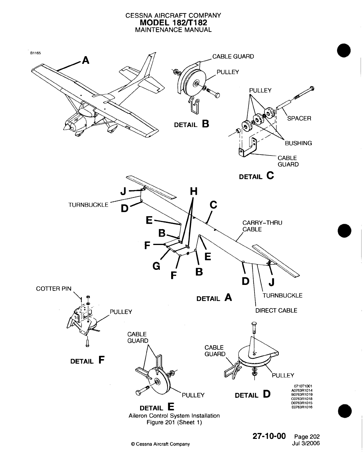
CESSNA AIRCRAFT
COMPANY
MODEL
182/T182
MAINTENANCE MANUAL
CABLE GUARD
'ULLEY
DETAIL
B
CABLE
GUARD
H
TURNBUCKLE
C
CARRY-THRU
CABLE
COTTER
PIN
DETAIL
A
PULLEY
TURNBUCKLE
DIRECT
CABLE
CABLE
GUARD
DETAIL
F
PULLEY
CABLE
GUARD
DETAIL
D
DETAIL
E
Aileron
Control
System
Installation
Figure
201
(Sheet
1)
27-10-00
©
Cessna
Aircraft
Company
DE
F
GFBD
0710T1001
A0763R1014
B0763R1019
C0763R1018
D0763R1015
E0763R1016
Page 202
Jul
3/2006
.
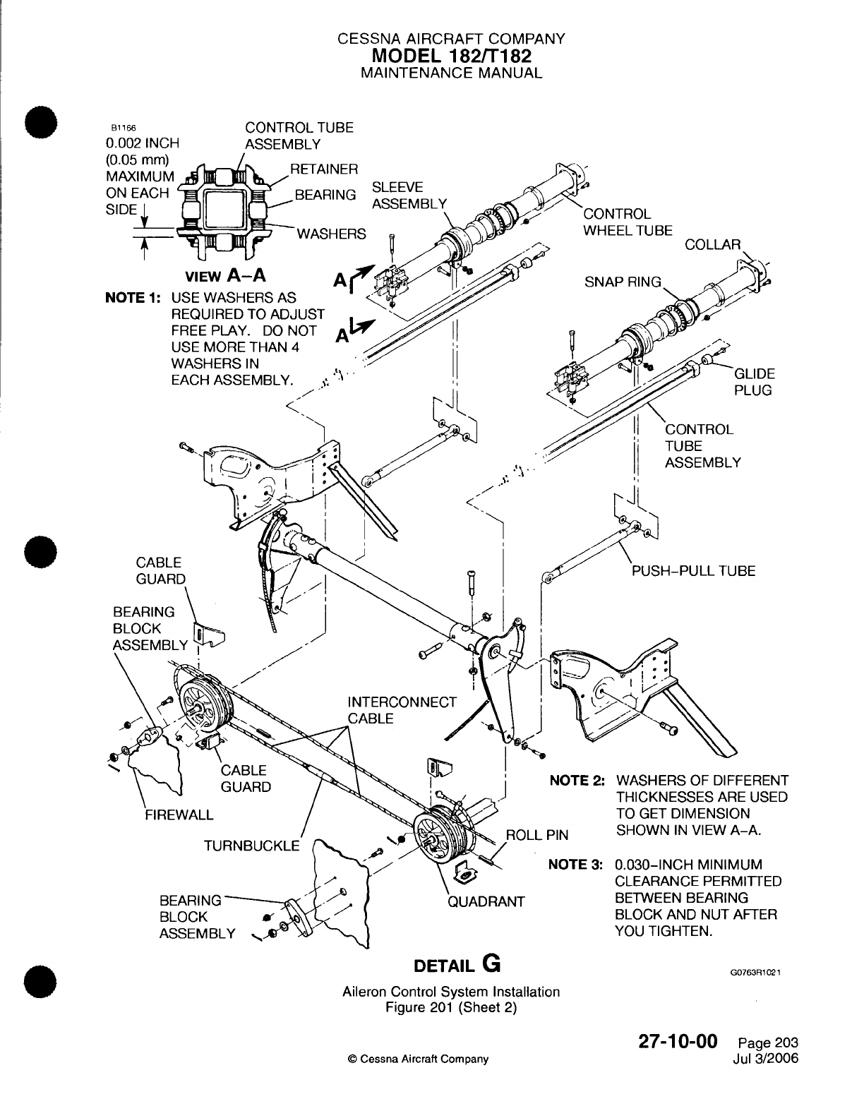
CESSNA
AIRCRAFT
COMPANY
MODEL
182/T182
MAINTENANCE
MANUAL
CONTROL
TUBE
ASSEMBLY
SLEEVE
ASSEMBLY
RETAINER
BEARING
WHEEL
TUBE
VIEW
A-A
A'
CABLE
GUARD
BEARING
BLOCK
CABLE
GUARD
FIREWALL
BEARING
BLOCK
ASSEMBLY
QUADRANT
DETAIL
G
Aileron
Control
System
Installation
Figure
201
(Sheet
2)
©
Cessna
Aircraft
Company
27-10-00
Page
203
Jul
3/2006
B1166
0.002
INCH
BE
DIFFERENT
E
USED
N
-A.
UM
IITTED
GER
AFTER
G0763R1021
I
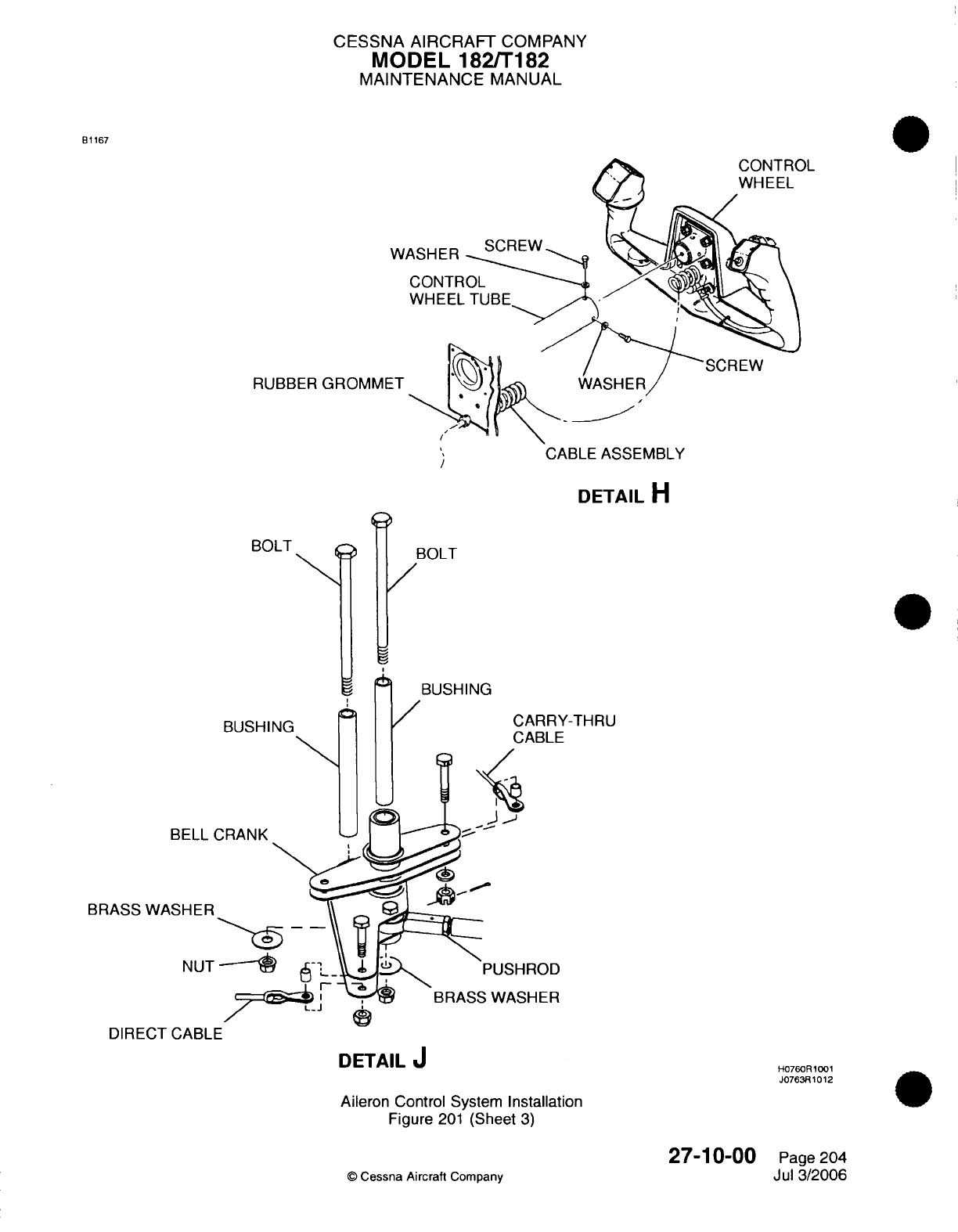
CESSNA AIRCRAFT
COMPANY
MODEL
182/T182
MAINTENANCE
MANUAL
B1167
RUBBER
GROMM
CABLE
ASSEMBLY
DETAIL
H
BOLT BOLT
BUSHING
BUSHING
CARRY-THRU
CABLE
B
BRASS
BRASS
WASHER
DIRECT
CABLE
DETAIL
J
Aileron
Control
System
Installation
Figure
201
(Sheet
3)
27-10-00
©
Cessna
Aircraft
Company
H0760R
1001
J0763R1012
Page
204
Jul
3/2006
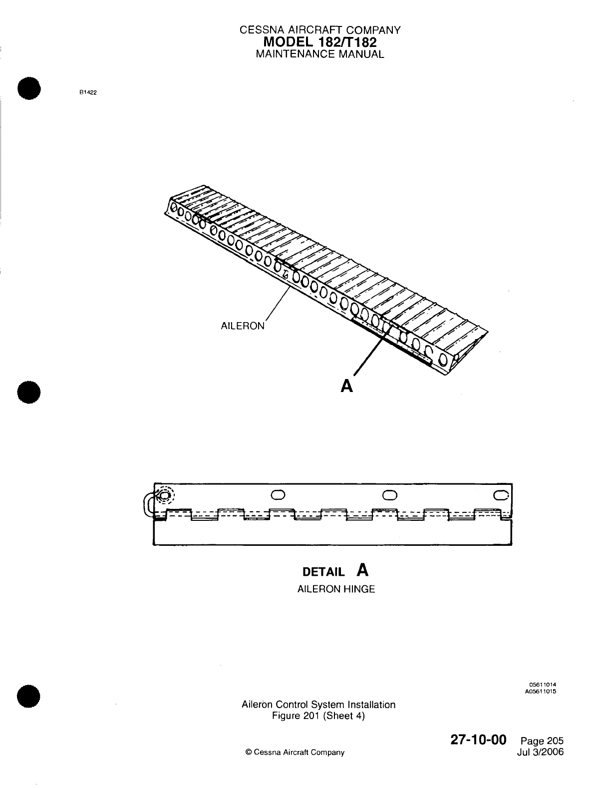
CESSNA
AIRCRAFT
COMPANY
MODEL
182/T182
MAINTENANCE
MANUAL
B1422
AILERON
A
0
DETAIL
A
AILERON
HINGE
05611014
A05611015
Aileron
Control
System
Installation
Figure
201
(Sheet
4)
©
Cessna Aircraft
Company
27-10-00
Page
205
Jul
3/2006
CESSNA AIRCRAFT
COMPANY
MODEL
182/T182
MAINTENANCE
MANUAL
(13)
Remove the
cotter
pin,
nut, and
washer
from
the
center
of
the bearing
block
assembly.
NOTE:
The
control
tube
goes
through
the
center
of
the bearing block
assembly.
(14)
Carefully
pull
the
control tube assembly
in
the aft
direction.
(15)
Remove
the
quadrant.
B.
Control Column
Installation (Refer
to
Figure
201).
NOTE:
If
the
control tube assembly
was
not
removed,
go
to
step
3.B.(4).
(1)
Install the
control
tube
assembly
through
the
instrument
panel.
(2)
Install the control
tube
assembly
through the
quadrant
and
the
firewall.
(3)
Install
the
roll
pin
through the
quadrant
and
the control
tube assembly.
(4)
Safety
the
roll pin
with
wire.
Refer to
Chapter
20,
Safetying
-
Maintenance
Practices.
(5)
Install the
washer,
locknut,
and
cotter
pin
to
the control
tube
assembly
that
goes through
the
bearing block
on
the
forward
side
of
the
firewall. There
must
be
0.03-
inch
minimum
clearance
between
the
bearing
block
and
the
nut
after they
are
tightened.
(6)
Install
the snap
ring
to
the
sleeve assembly.
(7)
Attach
the
push-pull
tube
to
the
sleeve
assembly.
(8)
Install
the
center
instrument
panel.
Refer
to
Chapter
31,
Instrument and
Control
Panels
-
Maintenance
Practices.
(9)
Install
the
collar,
plug,
and glide.
(10)
Adjust
the control
column
for
free
play.
(a)
Tighten the screw
to
remove
lateral free
play
in
the
control
column.
Do
not
tighten
the
screw
too
much.
NOTE:
If
the
screw
is
too
tight,
friction
in
the
fore
and aft
direction
in
the
full
range
of
the
elevator
control
travel
will
result.
(b)
Do
not
leave
the
screw
loose
when
you
adjust
the
drag.
The
adjustment
is
equal
to
a
typical
wheel
bearing
adjustment.
For
example,
tighten
the
screw
until
all
free
play
is
removed
and you
feel
drag.
Loosen
the
adjustment
screw about
1/8th
of
a
turn
for
each
step
until
there
is
minimum
free play
and
no
drag
is
felt.
(11)
Install
the control wheel.
(12)
Install the
access
plates
520AB
and 620AB.
Refer
to
Chapter
6,
Access/Inspection
Plates
-
Description
and
Operation.
(13)
Rig
the
aileron
control system.
Refer
to
the
Adjustment/Test.
4.
Copilot's
Control
Column
Removal/Installation
A.
Control Column
Removal
(Refer
to
Figure
201).
(1)
Remove the control
wheel.
Refer to
Control Wheel
Removal/Installation.
(2)
Remove the
glide
plug.
(3)
Disconnect
the
push-pull
tube
at
the
sleeve
assembly.
(4)
Remove
the screws from
the
attach
plate
at
the
instrument
panel.
(5)
Remove
the
copilot instrument
panel.
Refer
to
Chapter
31,
Instrument
and
Control
Panels
-
Maintenance
Practices.
(6)
To
help remove
the control
wheel
tube,
remove
the snap
ring
from
its
locking
groove
for
more
movement
of
the
sleeve
assembly.
(7)
Carefully
pull
the
control
wheel
tube aft
and
work
it
out through
the
instrument
panel.
(a) If
removal
of
control
tube
assembly
is
necessary,
go
to
step
4.A.(8).
(8)
Remove
the
access plates
520AB
and
620AB.
Refer
to
Chapter
6,
Access/Inspection
Plates
-
Description
and
Operation.
(9)
Remove the
safety clips
from
the
turnbuckles
at
the
direct cable,
and
loosen the
tension.
(10)
Remove and
discard
the safety
wire
from the
turnbuckle
at
the
interconnect
cable,
and
loosen
the tension.
(11)
Remove
and
discard
the
safety
wire
from
the
roll pin
in
the
quadrant
and the
control
tube
assembly.
27-10-00
Page
206
©
Cessna
Aircraft
Company
Jul
3/2006
CESSNA
AIRCRAFT
COMPANY
MODEL
182/T182
MAINTENANCE
MANUAL
(12)
Remove
the
cotter
pin,
nut,
and
washer
from
the
control
tube assembly that
is
attached
to the
forward
side
of
the
firewall.
NOTE:
The
control tube
assembly
goes
through
the
bearing
block assembly
on
the
forward
side
of
the
firewall.
(13)
Carefully
pull
the
control
tube
assembly
aft and
remove
the
quadrant.
(14)
Remove
the radios
and
related equipment
as
necessary
to work
the
control
wheel tube
assembly
out
from
under
the instrument panel.
B.
Control Column
Installation (Refer
to
Figure
201).
(1)
Install
the
control
tube
assembly
through the
instrument
panel.
(2)
Install
the control
tube
assembly
through
the quadrant
and
the
firewall.
(3)
Install
the
roll
pin
through the
quadrant
and
the
control tube assembly.
(4)
Safety
the
roll pin
with
wire.
Refer
to
Chapter 20,
Safetying
-
Maintenance
Practices.
(5)
Install
the washer,
locknut,
and
cotter
pin
to
the
control
tube
assembly
that
comes
through
the
bearing block
on
the forward
side
of
the
firewall. There
must
be
0.03-inch
minimum
clearance
between
the
bearing
block
and
the
nut
after
they
are
tightened.
(6)
Install
the
snap
ring
to
the
sleeve
assembly.
(7)
Connect
the
push-pull tube to
the
sleeve assembly.
(8)
Install
the
instrument
panel. Refer
to
Chapter
31,
Instrument
and
Control
Panels
-
Maintenance
Practices.
(9)
Install
the
collar
and
the
glide
plug.
(10)
Adjust
the
control
column
for
free
play.
(a)
Tighten
the
screw
to
eliminate
lateral
free
play
in
the
control
column.
Do
not
tighten
the
screw too
much.
NOTE:
If
the
screw
is
too
tight,
friction
in
the
fore
and
aft
direction
in
the
entire
elevator
control
travel
will result.
(b)
Do
not
leave
the
screw
loose when
you
adjust
the
drag.
The
adjustment
is
equal
to
a
typical
wheel bearing
adjustment.
For
example,
tighten
the
screw
until
all
free
play
is
removed
and
you
feel
drag.
Loosen the
adjustment screw
about
1/8th of
a
turn
for
each
step
until
there
is
minimum
free
play
and
no
drag
is
felt.
(11)
Install
the control
wheel.
(12)
Install
the
radios
and
related
equipment
that
you removed.
(13)
Install
the access
plates
520AB
and
620AB.
Refer
to
Chapter
6,
Access/Inspection
Plates
-
Description
and Operation.
(14)
Rig
the
aileron
control
system.
Refer
to the
Adjustment/Test.
5.
Aileron Removal/Installation
A.
Aileron Removal (Refer
to Figure
201).
(1)
Disconnect
the
aileron pushrod
at
the aileron.
(2)
Disconnect
the electrical
bonding
straps.
(3)
Remove
the
screws
and
the
nuts
that
attach
the
aileron
hinges
to
the
trailing
edge
of
the wing.
(4)
Carefully
pull
the
aileron out
and down
to
slide the hinges
from under
the
wing
skin
and
the
auxiliary
spar
reinforcements.
B.
Aileron
Installation
(Refer
to
Figure
201).
(1)
Put
the
aileron
hinges between
the
skin
and
the
auxiliary spar
reinforcements.
(2)
Install the
screws
and
the
nuts
that
attach
the
hinges
to
the
trailing
edge
of
the
wing.
(3)
Connect
the
electrical
bonding
straps.
(4)
Attach the
aileron
pushrod
to
the aileron.
(5)
Check
the
aileron
travel.
Refer
to
the Adjustment/Test.
27-10-00
Page
207
©
Cessna Aircraft
Company
Jul
3/2006
CESSNA
AIRCRAFT
COMPANY
MODEL 182/T182
MAINTENANCE
MANUAL
6.
Aileron
Bell
Crank
Removal/Installation
NOTE:
The
left
and
the
right
aileron
bell
crank removal/installation
is
typical.
A.
Aileron
Bell
Crank
Removal (Refer
to Figure
201).
(1)
Remove the
access plates
520AB,
520BB, 620AB, and
620BB
located
inboard
of
the
bell
crank
on
the bottom
of
each wing.
Refer
to
Chapter
6,
Access/Inspection
Plates
-
Description
and
Operation.
(2)
Remove the
safety clip
from
the turnbuckle
at
the carry-thru cable.
(3)
Loosen the
control
cable tension
at
the
turnbuckle.
(4)
Disconnect
the
control
cables
from the
bell
crank.
(5)
Remove
the safety
clip
from
the
turnbuckle
at
the
direct cable.
(6)
Loosen
the
control
cable
tension
at
the turnbuckle.
(7)
Disconnect
the
control
cables
from
the
bell
crank.
(8)
Disconnect
the
aileron
pushrod
at
the
bell
crank.
(9)
Remove the
nuts,
washers,
and bolts
from the
bell
crank
stop bushing and
from
the
bell
crank-
to-wing structure.
(10)
Remove the
bell
crank through
the
access
opening.
Make
sure
that
the
bearing
bushing
is
not
dropped
from
the
bell
crank.
CAUTION:
Use
tape
on
the
open
ends
of
the
bell
crank
to
prevent
dust
and
dirt
from
going
into
the
bell
crank
needle
bearings.
(11)
Use
brass
washers
as
shims
between the
lower
end
of
the
bell
crank
and the
wing
structure.
Keep
the shims.
B.
Aileron
Bell
Crank
Installation (Refer
to Figure
201).
(1)
Install
the
bell
crank
to
the
structure.
Make
sure
that
the
bushings
are
in
the
correct position.
(2)
Install
the brass
washers
between
the
lower
end
of
the
bell
crank
and
the wing
channel
to
remove
unwanted clearance.
(3)
Install
the
bell
crank pivot
bolt.
(4)
Put
the
bell
crank
stop-bushing
in
position
and
install
the
bolt.
(5)
Attach the aileron
pushrod
to
the
bell
crank.
(6)
Attach
the
control
cables
to
the
bell
crank.
Make sure that the
spacers
and
the
bushings
are
correctly
installed.
(7)
Rig
the
aileron system. Refer
to the
Adjustment/Test.
(8)
Install
the
safety
clips
on
the
turnbuckles.
Refer
to
Chapter
20,
Safetying
-
Maintenance
Practices.
(9)
Install
the
access plates
520AB, 520BB,
620AB,
and
620BB.
Refer
to
Chapter
6,
Access/Inspection
Plates
-
Description
and
Operation.
7.
Adjustment/Test
WARNING:
After
the
rigging
is
completed,
make
sure
that
the
ailerons
move
in
the
correct
direction
when
operated
by the
control
wheel.
A.
Rig
the
Aileron
Cables
(Refer
to
Figure
201,
Figure
202,
and
Figure 203).
(1)
Remove the
safety
clips
and loosen the
tension
from the
turnbuckles
at
the
direct
and
the
carry-
thru
cables
at
the
bell
cranks
in
the
wings.
(2)
Disconnect
the
push-pull
rods at
the
bell cranks.
(3)
Remove the
safety
clip
from
the
turnbuckle
at
the
interconnect
cable.
(4)
Adjust
tension
on
the
interconnect
cable
to
40
pounds,
+10
or
-10
pounds
(177.93
N,
+44.48
or
-44.48
N)
at
70
°F
(21
°C).
Refer
to
the
Charts
in
Figure
203
for
the correct
tensions
at
other
temperatures.
(5)
Put
the
control
wheels
in a
level
position
and
tape
a
bar
across
both
control
wheels
to hold
them
in
position.
27-10-00
Page
208
©
Cessna
Aircraft Company
Jul
3/2006
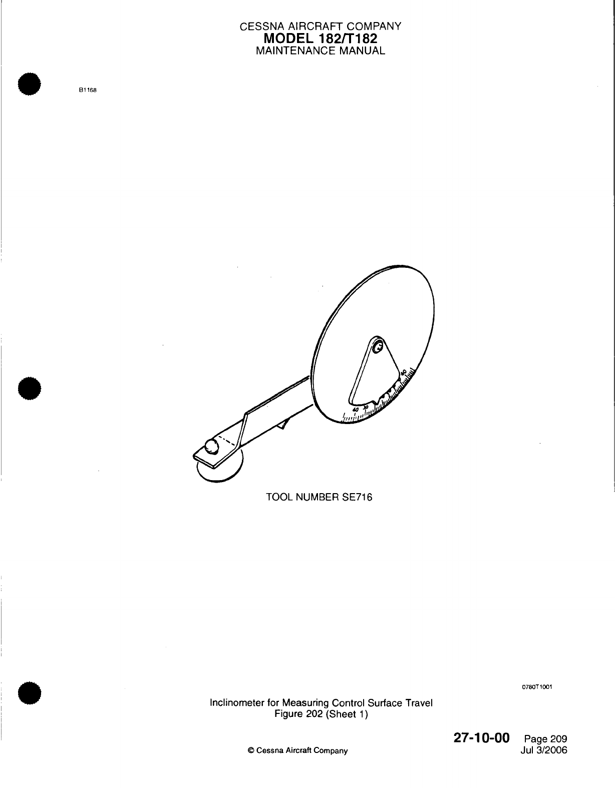
CESSNA
AIRCRAFT
COMPANY
MODEL
182/T182
MAINTENANCE
MANUAL
B1168
TOOL
NUMBER
SE716
0780T1001
Inclinometer for
Measuring
Control Surface
Travel
Figure
202 (Sheet
1)
27-10-00
©
Cessna Aircraft
Company
Page
209
Jul
3/2006
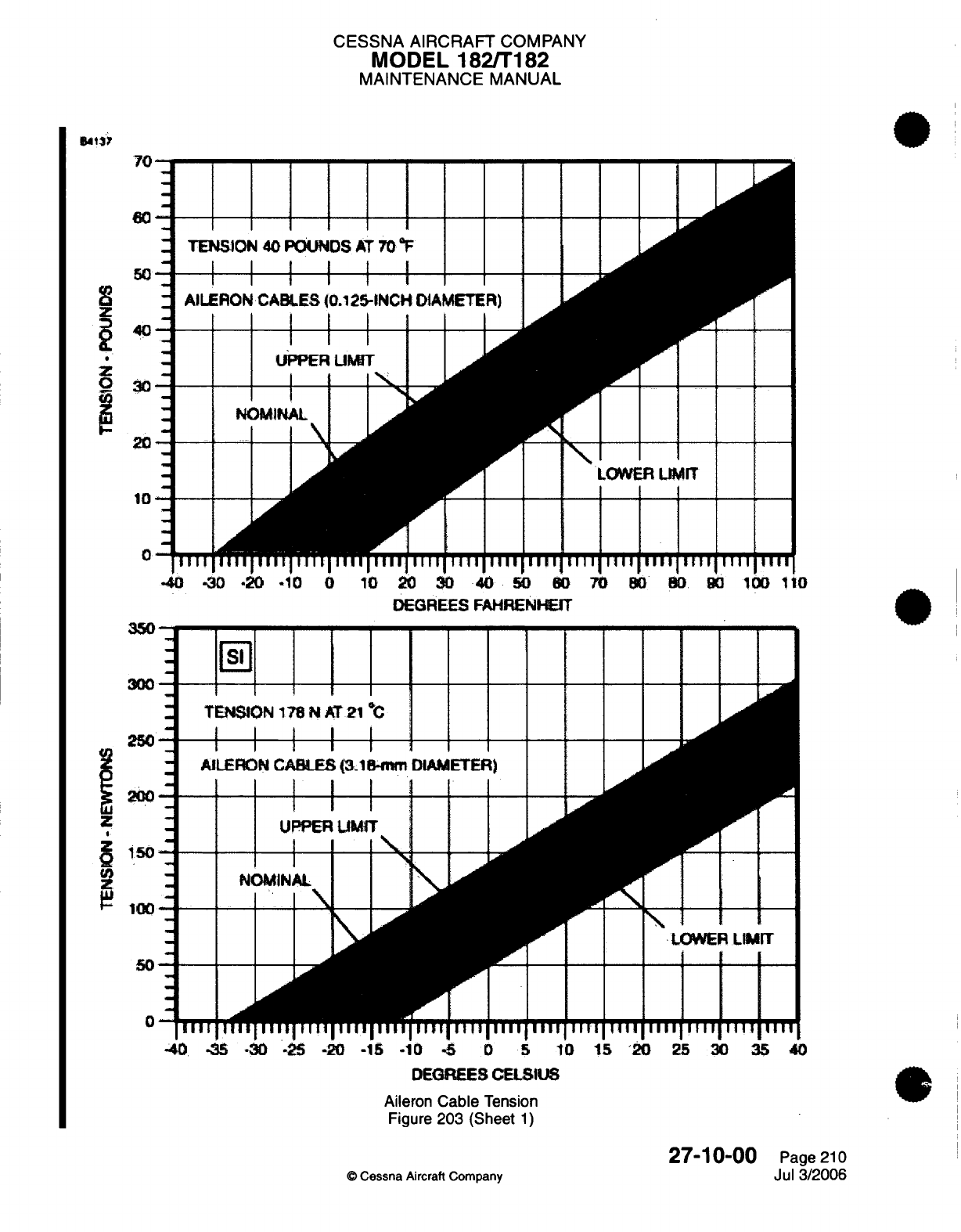
CESSNA AIRCRAFT
COMPANY
MODEL
182/T182
MAINTENANCE
MANUAL
z
3 0
20
10
0
TE
AIU
II11
-40
-30
-20
-10
0
10
20
30
40
50 60
70
BO
80.
0
100
110
DEGREES
FAHRENHEIT
--
ir
300
250
00.
z
i
150
9
100
{
50
-
0-
tI
Al
TMl
-40
35
-30
.25
-20
-15
.10
-5
0
5
10
15
20
25
30
35
40
DEGREES
CELSIUS
Aileron
Cable
Tension
Figure
203
(Sheet
1)
27-10-00
Page
210
©
Cessna
Aircraft Company
Jul
3/2006
7A
I"
YYW
77
I I II
,
CESSNA
AIRCRAFT
COMPANY
MODEL
182/T182
MAINTENANCE MANUAL
(6)
Adjust
the
direct
and
carry-thru
cable
turnbuckles
to
center
the
position
of
the
bell
crank
stop
bushings
in
the
slots. The
tension
on
the
carry-thru cable
must
be
40
pounds,
+10
or
-10
pounds
(177.93
N,
+44.48
or
-44.48
N)
at
70
°F
(21
°C).
Refer
to
the Charts
in
Figure
203
for
the
correct
tensions
at
other
temperatures.
Disregard
the
tension
on
the
direct cables.
(7)
Adjust
the
push-pull
rods
at
each
aileron
until
the
ailerons
are
neutral
with reference
to
trailing
edge
of
wing
flaps.
Make sure
that
the
wing
flaps
are
in
the
full
UP
position
when
you
make this
adjustment.
(8)
With
the
ailerons
in
the
neutral
position
(streamlined),
mount
an
inclinometer
on
the
trailing
edge
of
one aileron
and
set
it
to
0
degrees.
(9)
Remove
the
bar
from
the control wheels.
If
travel
is
not
within limits,
readjust
push-pull
rods
and
cables
as
necessary.
(10)
Check the aileron travel
which
must
be
20
degrees
+2
or
-2
degrees
up
and
15
degrees,
+2
or
-2
degrees
down.
(11)
Make sure
that
the
safety clips
are
correctly installed
in
all
turnbuckles.
Refer
to
Chapter
20,
Safetying
-
Maintenance
Practices.
(12)
Make
sure
that
the
cables
and
the cable guards
are
correctly
installed,
all
jam
nuts
are
tight,
and
all
items
removed for
access
are installed.
27-10-00
Page
211
©
Cessna
Aircraft
Company
Jul 3/2006
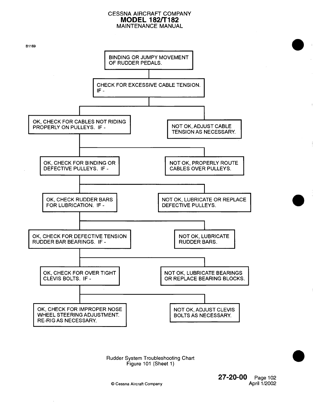
CESSNA AIRCRAFT
COMPANY
MODEL 182/T182
MAINTENANCE
MANUAL
B1169
BINDING
OR
JUMPY
MOVEMENT
OF
RUDDER PEDALS.
CHECK FOR EXCESSIVE
CABLE
TENSION.
IF-
OK,
CHECK
FOR
CABLES
NOT
RIDING
PROPERLY
ON
PULLEYS.
IF
-
OK, CHECK
FOR
BINDING
OR
DEFECTIVE
PULLEYS.
IF
-
OK,
CHECK
RUDDER
BARS
FOR
LUBRICATION.
IF
-
OK,
CHECK FOR
DEFECTIVE
TENSION
RUDDER
BAR
BEARINGS.
IF
-
OK,
CHECK
FOR
OVER
TIGHT
CLEVIS
BOLTS.
IF-
OK, CHECK
FOR
IMPROPER
NOSE
WHEEL
STEERING
ADJUSTMENT.
RE-RIG
AS
NECESSARY.
NOT
OK,
ADJUST
CABLE
TENSION
AS
NECESSARY.
NOT
OK,
PROPERLY ROUTE
CABLES OVER
PULLEYS.
NOT
OK,
LUBRICATE OR
REPLACE
DEFECTIVE
PULLEYS.
I
NOT
OK,
LUBRICATE
RUDDER
BARS.
NOT
OK, LUBRICATE
BEARINGS
OR
REPLACE
BEARING
BLOCKS.
NOT
OK,
ADJUST
CLEVIS
BOLTS
AS
NECESSARY.
Rudder
System
Troubleshooting Chart
Figure
101
(Sheet
1)
27-20-00
©
Cessna
Aircraft
Company
Page
102
April
1/2002
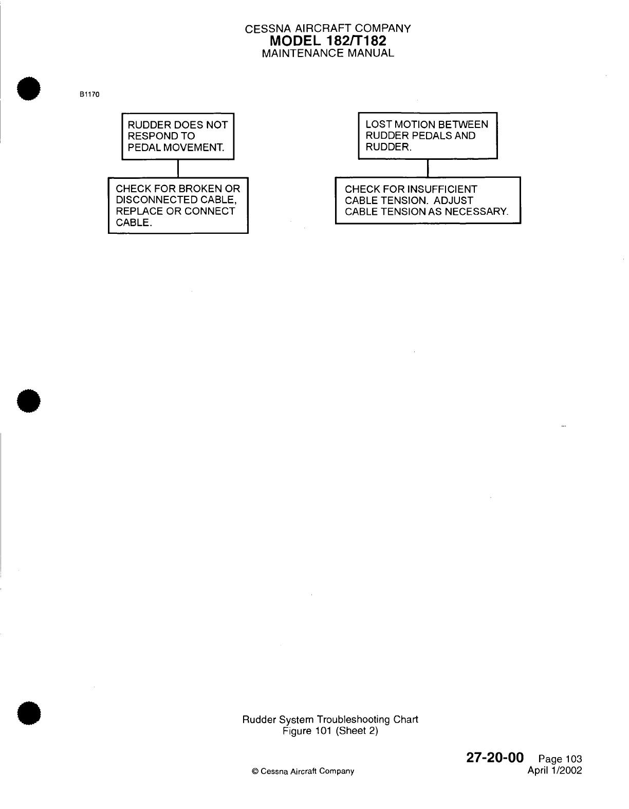
CESSNA
AIRCRAFT
COMPANY
MODEL
182/T182
MAINTENANCE
MANUAL
B1170
RUDDER
DOES
NOT
RESPOND TO
PEDAL MOVEMENT.
CHECK FOR
BROKEN
OR
DISCONNECTED
CABLE,
REPLACE OR
CONNECT
CABLE.
LOST MOTION
BETWEEN
RUDDER
PEDALS
AND
RUDDER.
CHECK
FOR INSUFFICIENT
CABLE
TENSION.
ADJUST
CABLE
TENSION
AS
NECESSARY.
Rudder
System Troubleshooting
Chart
Figure
101
(Sheet
2)
©
Cessna
Aircraft
Company
27-20-00
Page
103
April 1/2002
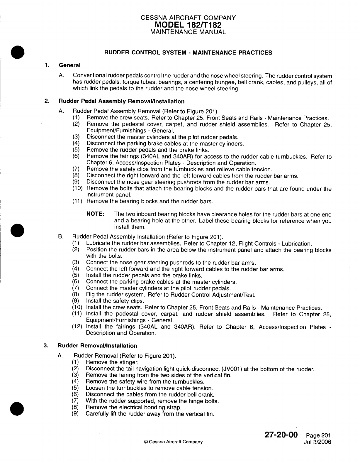
CESSNA
AIRCRAFT
COMPANY
MODEL
182/T182
MAINTENANCE
MANUAL
RUDDER
CONTROL
SYSTEM
-
MAINTENANCE
PRACTICES
1.
General
A.
Conventional
rudder pedals
control
the
rudder
and
the
nose
wheel
steering.
The
rudder
control
system
has rudder pedals,
torque
tubes,
bearings,
a
centering
bungee,
bell
crank, cables,
and
pulleys,
all
of
which
link the
pedals
to
the
rudder
and the
nose wheel
steering.
2.
Rudder
Pedal
Assembly
Removal/Installation
A.
Rudder Pedal
Assembly
Removal
(Refer
to
Figure
201).
(1)
Remove
the
crew
seats.
Refer
to
Chapter
25,
Front
Seats
and
Rails
-
Maintenance
Practices.
(2)
Remove the
pedestal
cover,
carpet,
and rudder
shield
assemblies.
Refer
to
Chapter
25,
Equipment/Furnishings
-
General.
(3)
Disconnect
the
master
cylinders
at the
pilot
rudder pedals.
(4)
Disconnect the
parking brake
cables
at
the
master
cylinders.
(5)
Remove
the
rudder pedals
and
the
brake
links.
(6)
Remove
the
fairings
(340AL
and
340AR)
for
access
to
the rudder cable
turnbuckles.
Refer
to
Chapter
6,
Access/Inspection
Plates
-
Description
and
Operation.
(7)
Remove
the
safety
clips
from
the
turnbuckles
and
relieve cable
tension.
(8)
Disconnect the
right
forward
and
the
left
forward cables
from
the rudder bar
arms.
(9)
Disconnect
the nose
gear
steering pushrods
from the
rudder
bar
arms.
(10)
Remove
the
bolts
that
attach
the
bearing
blocks
and
the
rudder
bars
that
are
found
under
the
instrument
panel.
(11)
Remove the
bearing blocks
and
the rudder
bars.
NOTE:
The
two
inboard
bearing
blocks have
clearance
holes
for
the
rudder
bars
at
one
end
and
a
bearing
hole at
the
other.
Label
these
bearing
blocks for
reference
when
you
install
them.
B.
Rudder
Pedal
Assembly
Installation
(Refer
to
Figure
201).
(1)
Lubricate
the
rudder
bar
assemblies.
Refer
to
Chapter
12,
Flight
Controls
-
Lubrication.
(2)
Position
the
rudder
bars
in
the
area
below
the
instrument
panel
and attach
the
bearing
blocks
with
the bolts.
(3)
Connect the nose
gear
steering pushrods to
the rudder
bar
arms.
(4)
Connect
the
left
forward and the right
forward cables to
the
rudder
bar
arms.
(5)
Install the
rudder
pedals
and
the
brake
links.
(6)
Connect
the
parking
brake
cables
at
the
master cylinders.
(7)
Connect
the
master
cylinders
at
the pilot
rudder
pedals.
(8)
Rig
the
rudder system. Refer
to
Rudder
Control
Adjustment/Test.
(9)
Install
the safety
clips.
(10)
Install
the crew
seats.
Refer
to
Chapter
25, Front
Seats
and
Rails
-
Maintenance
Practices.
(11)
Install
the
pedestal
cover, carpet, and
rudder
shield assemblies.
Refer
to Chapter
25,
Equipment/Furnishings
-
General.
(12)
Install
the
fairings
(340AL
and
340AR).
Refer
to
Chapter
6,
Access/Inspection
Plates
-
Description and Operation.
3.
Rudder
Removal/Installation
A.
Rudder Removal
(Refer
to
Figure
201).
(1)
Remove
the
stinger.
(2)
Disconnect
the
tail
navigation light
quick-disconnect
(JV001)
at
the
bottom of
the
rudder.
(3)
Remove
the
fairing
from
the
two
sides
of
the
vertical
fin.
(4)
Remove
the
safety
wire
from
the
turnbuckles.
(5)
Loosen
the turnbuckles
to
remove
cable
tension.
(6)
Disconnect the
cables
from the
rudder
bell
crank.
(7)
With
the rudder supported,
remove
the
hinge
bolts.
(8)
Remove
the
electrical
bonding
strap.
(9)
Carefully
lift
the
rudder away from the
vertical
fin.
27-20-00
Page
201
©
Cessna Aircraft
Company
Jul 3/2006
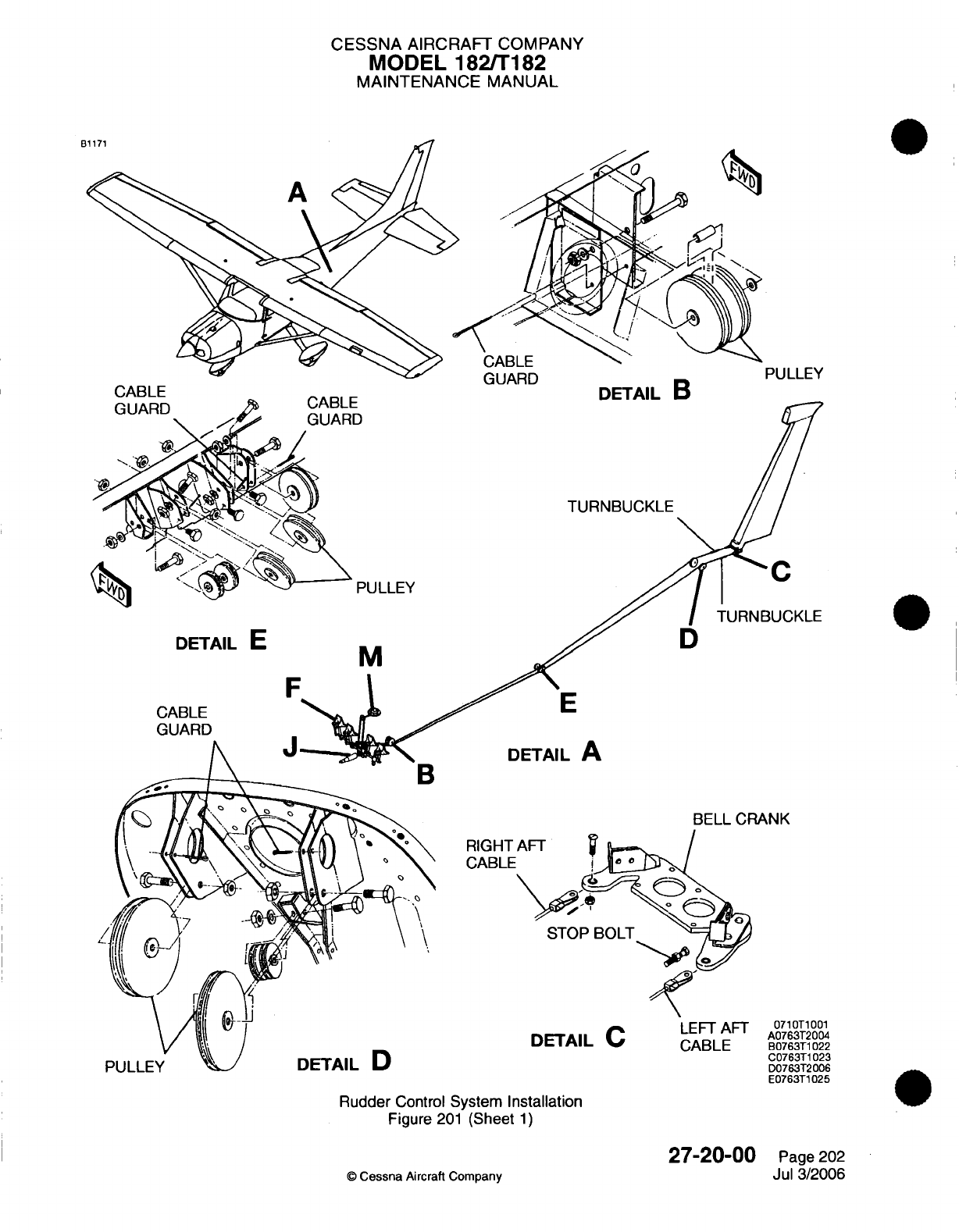
CESSNA
AIRCRAFT
COMPANY
MODEL
182/T182
MAINTENANCE
MANUAL
GUARD PULLEY
DETAIL
B
TURNBUCKLE
TURNBUCKLE
DETAIL
E
CABLE
GUARD
M
E
DETAIL
A
BELL
CRANK
RIGHT
CABLE
STOP
BOLT
DETAIL
C
LEFT
AFT
0710T1001
A0763T2004
CABLE
B0763T1022
C0763T1023
D0763T2006
E0763T1025
Rudder
Control
System
Installation
Figure
201
(Sheet
1)
27-20-00
©
Cessna
Aircraft
Company
Page
202
Jul 3/2006
CABLE
PULLEY
C
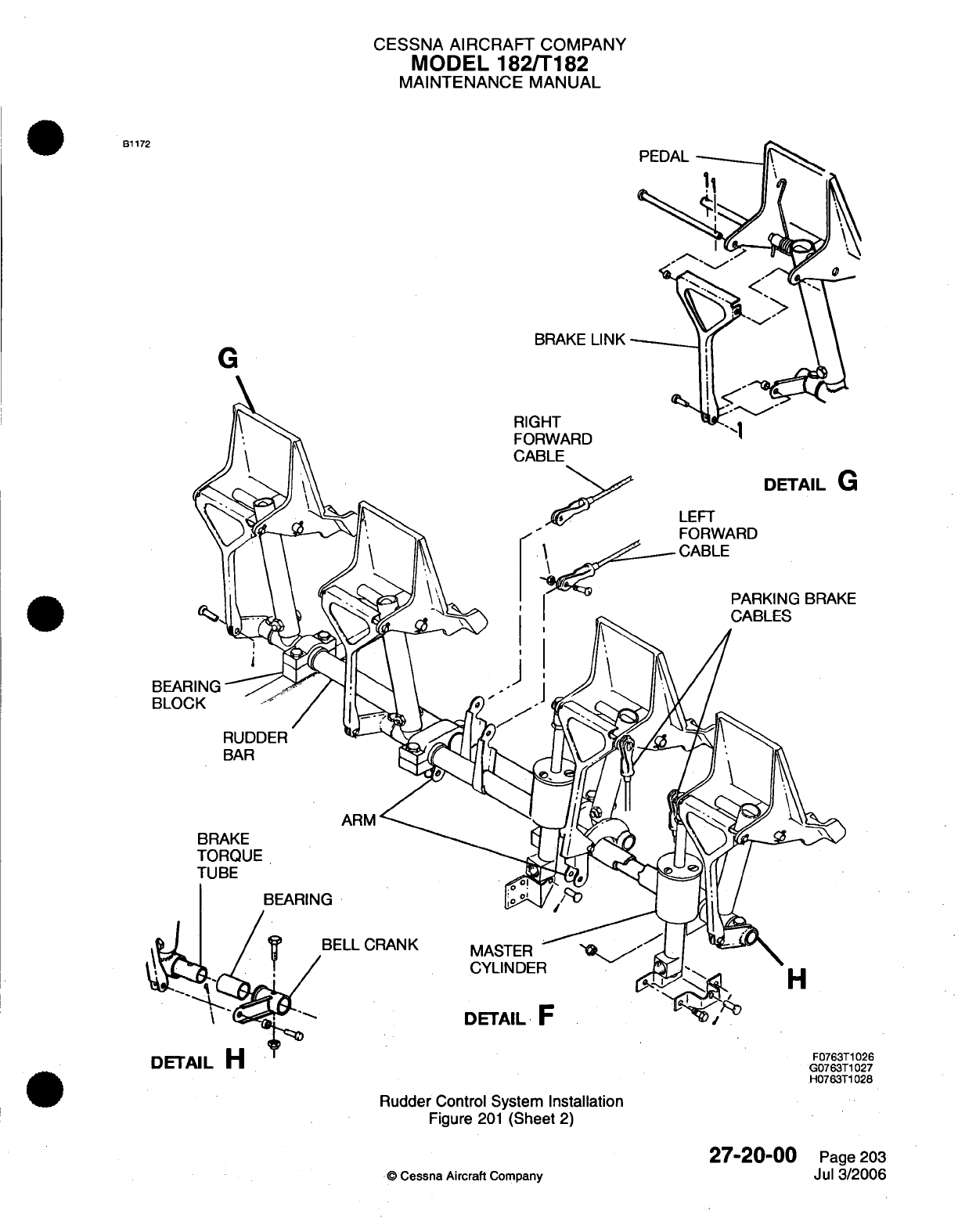
CESSNA
AIRCRAFT
COMPANY
MODEL
182/T182
MAINTENANCE MANUAL
B1172
BRAKE
LINK
G
RIGHT
FORWARD
E
BEAR
BLOC
RUDDER
BAR
ARM
BRAKE
TORQUE
TUBE
BEARING
BELL
CRANK
MASTER
CYLINDER
DETAIL
F
DETAIL
H
Rudder
Control System
Installation
Figure
201
(Sheet
2)
©
Cessna Aircraft
Company
27-20-00
Page
203
Jul 3/2006
H
F0763T1026
G0763T1027
H0763T1028
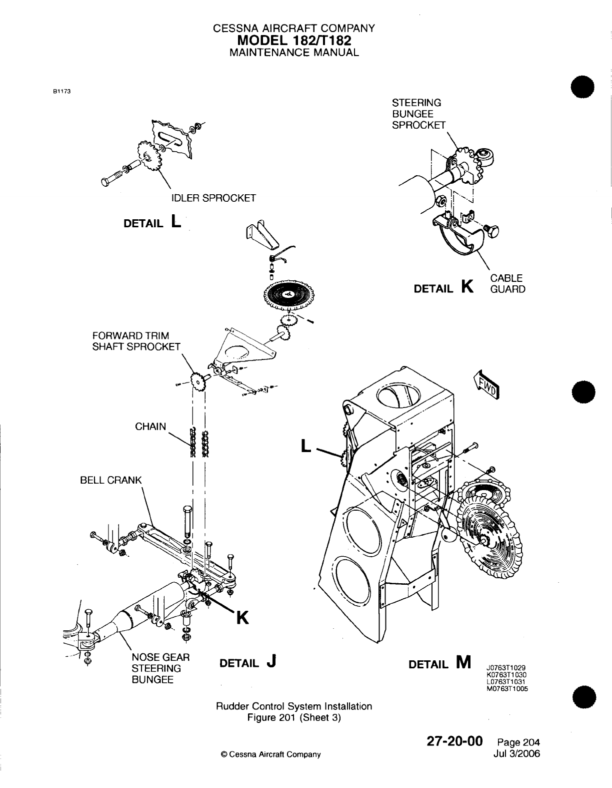
CESSNA
AIRCRAFT
COMPANY
MODEL
182/T182
MAINTENANCE
MANUAL
B1173
STEERING
BUNGEE
SPROCKET
IDLER
SPROCKET
DETAIL
L
DETAIL
K
FORWARD
TRIM
SHAFT SPROCKE
CHAIN
BUNGEE
L
K
TAIL
J
DETAIL
M
Rudder
Control
System Installation
Figure
201
(Sheet
3)
©
Cessna Aircraft
Company
27-20-00
Page
204
Jul
3/2006
CABLE
GUARD
J0763T1029
K0763T1030
L0763T1031
M0763T1005
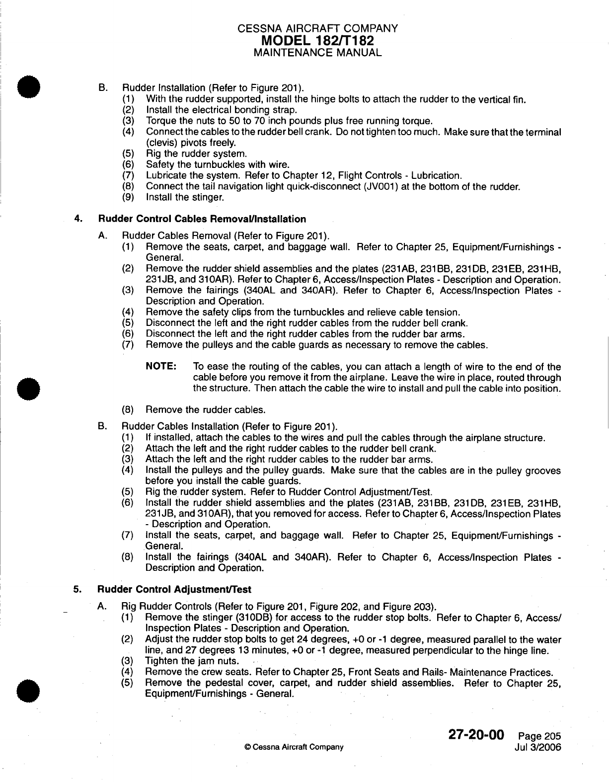
CESSNA
AIRCRAFT
COMPANY
MODEL
182/T182
MAINTENANCE
MANUAL
B.
Rudder Installation
(Refer
to Figure
201).
(1)
With
the rudder
supported, install
the
hinge bolts
to
attach
the
rudder
to
the
vertical
fin.
(2)
Install
the
electrical
bonding
strap.
(3)
Torque
the nuts
to
50
to
70
inch
pounds
plus
free running torque.
(4)
Connect
the
cables
to
the rudder
bell
crank.
Do
not
tighten
too
much. Make
sure
that
the terminal
(clevis)
pivots
freely.
(5)
Rig
the rudder system.
(6)
Safety
the
turnbuckles
with
wire.
(7)
Lubricate
the
system. Refer
to
Chapter
12,
Flight
Controls
-
Lubrication.
(8)
Connect
the
tail
navigation
light
quick-disconnect
(JV001)
at
the
bottom
of
the
rudder.
(9)
Install
the
stinger.
4.
Rudder
Control
Cables
RemovaVlnstallation
A.
Rudder Cables
Removal (Refer
to Figure
201).
(1)
Remove the
seats,
carpet, and baggage wall.
Refer
to Chapter
25,
Equipment/Furnishings
-
General.
(2)
Remove the rudder
shield
assemblies
and
the
plates
(231
AB,
231
BB,
231
DB,
231 EB,
231
HB,
231JB,
and
310AR).
Refer
to Chapter
6,
Access/Inspection
Plates
-
Description
and
Operation.
(3)
Remove
the
fairings
(340AL and 340AR). Refer
to Chapter
6,
Access/Inspection
Plates
-
Description
and
Operation.
(4)
Remove
the
safety clips
from
the
turnbuckles
and
relieve
cable tension.
(5)
Disconnect the
left
and the
right
rudder
cables
from
the
rudder
bell
crank.
(6)
Disconnect the
left and
the right
rudder
cables
from
the
rudder
bar
arms.
(7)
Remove the
pulleys
and
the
cable
guards
as
necessary
to
remove
the
cables.
NOTE:
To
ease
the
routing
of
the
cables,
you can
attach
a
length
of
wire
to
the
end of
the
cable
before
you
remove
it
from the
airplane.
Leave the
wire
in
place,
routed
through
the
structure. Then
attach the
cable
the
wire
to
install
and
pull
the
cable
into
position.
(8)
Remove
the
rudder cables.
B.
Rudder
Cables Installation
(Refer
to Figure
201).
(1) If
installed, attach
the
cables
to
the
wires
and pull
the
cables
through
the
airplane
structure.
(2)
Attach
the
left
and
the
right
rudder
cables
to
the
rudder
bell
crank.
(3)
Attach
the
left
and the
right
rudder
cables
to
the rudder
bar
arms.
(4)
Install
the
pulleys
and
the
pulley
guards.
Make
sure
that
the
cables
are
in
the pulley grooves
before
you
install
the
cable guards.
(5)
Rig
the
rudder
system.
Refer
to
Rudder Control Adjustment/Test.
(6)
Install
the rudder
shield
assemblies
and
the
plates
(231AB, 231BB,
231DB,
231EB,
231HB,
231
JB,
and
31
OAR),
that
you
removed
for
access.
Refer
to
Chapter
6,
Access/Inspection
Plates
-
Description
and
Operation.
(7)
Install the
seats, carpet,
and
baggage wall.
Refer
to Chapter
25,
Equipment/Furnishings
-
General.
(8)
Install the
fairings
(340AL and 340AR).
Refer
to
Chapter
6,
Access/Inspection
Plates
-
Description
and
Operation.
5.
Rudder
Control Adjustment/Test
A.
Rig
Rudder
Controls
(Refer
to Figure
201,
Figure
202,
and Figure 203).
(1)
Remove
the
stinger
(310DB)
for
access
to
the rudder stop
bolts.
Refer
to
Chapter
6,
Access/
Inspection Plates
-
Description
and
Operation.
(2)
Adjust
the
rudder
stop bolts
to
get
24
degrees,
+0
or
-1
degree,
measured
parallel
to
the
water
line,
and 27
degrees
13
minutes,
+0
or
-1
degree, measured
perpendicular
to
the
hinge line.
(3)
Tighten
the
jam
nuts.
(4)
Remove the
crew
seats. Refer
to
Chapter
25, Front
Seats
and
Rails-
Maintenance
Practices.
(5)
Remove
the
pedestal
cover, carpet, and
rudder
shield
assemblies.
Refer to
Chapter
25,
Equipment/Furnishings
-
General.
27-20-00
Page
205
©
Cessna
Aircraft
Company
Jul
3/2006
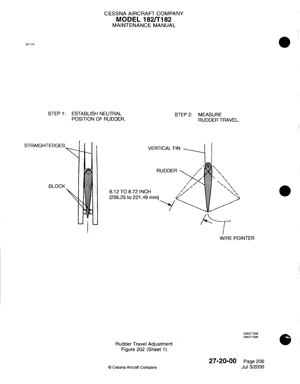
CESSNA AIRCRAFT
COMPANY
MODEL
182/T182
MAINTENANCE
MANUAL
B1174
STEP
1:
ESTABLISH
NEUTRAL
POSITION
OF
RUDDER.
STRAIGHTEDGES
BLOCK
STEP
2:
MEASURE
RUDDER
TRAVEL.
VERT
R
8.12
TO
8.72
INCH
(206.25
to
221.49
mm)
WIRE POINTER
0562T1009
0562T1009
Rudder
Travel
Adjustment
Figure 202
(Sheet
1)
©
Cessna
Aircraft
Company
27-20-00
Page
206
Jul
3/2006
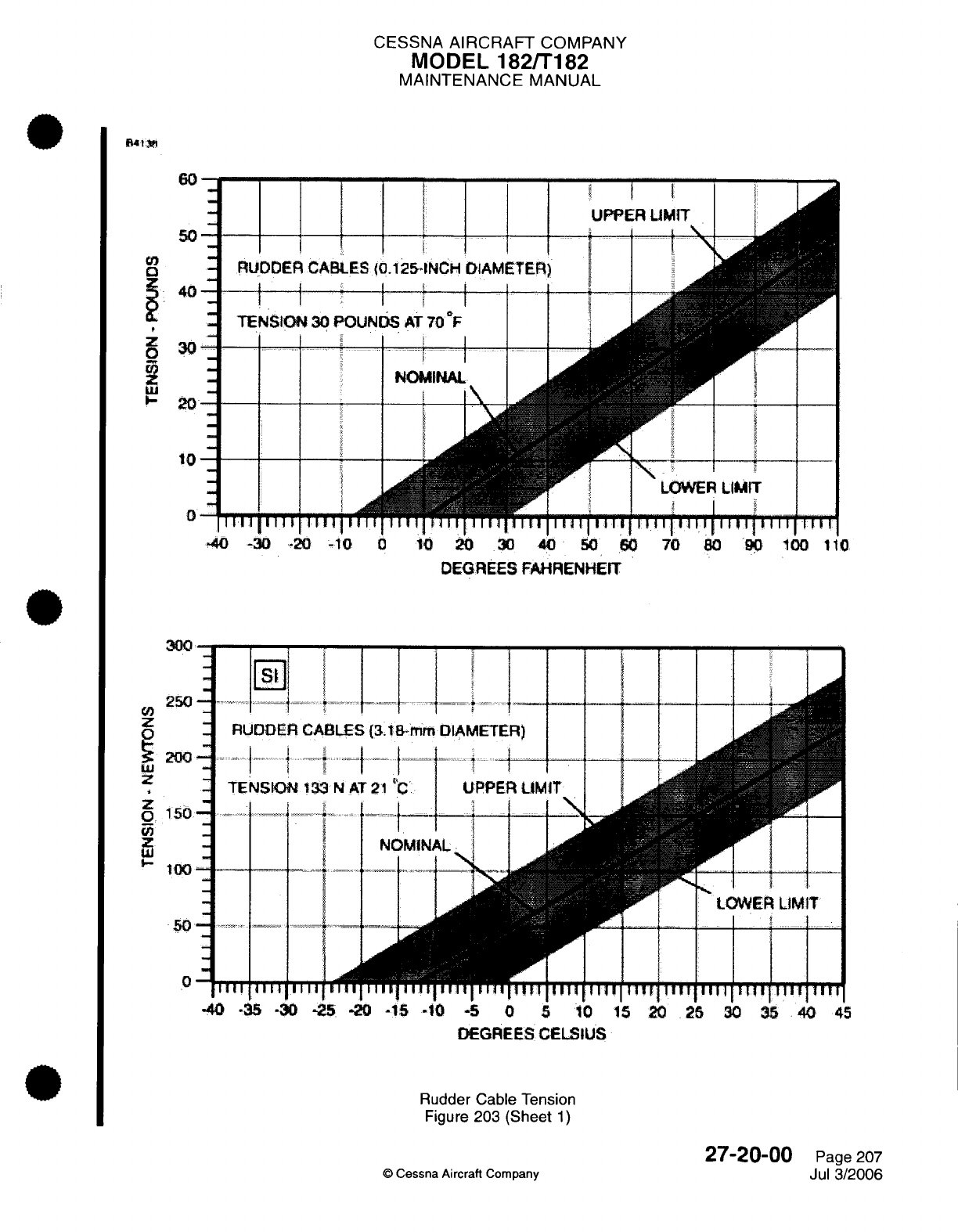
CESSNA
AIRCRAFT
COMPANY
MODEL
182/T182
MAINTENANCE MANUAL
60
50
E
]
RUDDER
CABLES
(0.125-INCH
DIAMETER)
UPPER
I
UPPER
-I
-
TENSION
30
POUNDS
AT
71
NO
M
NOMII
10
LOWER
LIMIT
l 1
1
-40
-30 -20
-10
0 10
20
30
40
50
60 70
80
90
100
110
DEGREES
FAHRENHEIT
RUDDER
3.
8
t
-mm
DIAMETER)
RUDDER
CABLES
(3.18-MM
DIAMETER)
-
LOWER
LIMIT
40
-35 -30
-25
-20
-15
-10
5
0
5
10 15
20
25
30
35
40
45
DEGREES
CELSIUS
Rudder Cable
Tension
Figure
203 (Sheet
1)
©
Cessna
Aircraft
Company
27-20-00
Page
207
Jul
3/2006
40
30
20
300
250
z
200
z
150
100
50
0
I
CESSNA
AIRCRAFT
COMPANY
MODEL
182/T182
MAINTENANCE
MANUAL
(6)
Loosen
the
idler
sprocket
and
disengage
the
chain
from
the
forward
trim
shaft
sprocket
and
the
steering
bungee
sprocket.
(7)
Disconnect
the
steering
bungee
adjustable
rod
end
from
the
bell
crank.
(8)
Remove
the
fairings
(340AL
and
340AR).
Refer
to
Chapter
6,
Access/Inspection
Plates
-
Description
and
Operation.
(9)
Remove
the
safety
clips
from
the
left
and
the right
rudder
cable
turnbuckles
and
relieve
cable
tension.
(10)
Clamp
the
rudder
pedals
in
the
neutral
position and
adjust
the
push-pull
rods
to
center the
bell
crank.
NOTE:
The
bell
crank
is
centered
when
the
bolts
in
each
end are
the
same
distance
from
the
bulkhead
just
forward
of
the bell crank.
(11)
Tighten
the
jam nuts.
(12)
Keep the
rudder
pedals
in
the
neutral
position
and
adjust
the
turnbuckles
on
the
left
and
the
right
rudder
cables.
The
correct
tension adjustment
is
30
pounds,
+10
or
-10
pounds
(133.45
N,
+44.48
or -44.48
N)
at
70
°F
(21
°C)
with
the
rudder
offset
one
degree
to
the
right.
Refer
to
Figure
203 for
the
correct
tensions
at
other
temperatures.
NOTE:
When
the rudder
is
offset
one
degree
to the
right,
this
is
5/16
inch
at
the
lower
trailing
edge
from
the
neutral
position
of
the
rudder.
(13)
Install
the
safety
clips
on
the
rudder
cable
turnbuckles.
(14)
Check
the
rudder
travel. (Refer
to
Figure
202).
(a)
Find
the neutral
position
of the
rudder.
1
Clamp
a
straightedge
on
each
side
of
the
fin and
the
rudder.
2
Block
the
trailing
edge
of
the rudder
at
half
of the
distance
between
the
straightedges.
3
Tape a
length
of
soft
wire to
the stinger
to
let
it
bend
to
index
at
the lower
corner
of
the
rudder
trailing
edge.
4
With
a
soft
lead
pencil,
mark
the
rudder
at
the
at
the
soft
wire
indexing
point (neutral).
(b)
Remove the
straightedges
and
the blocks.
(c)
Hold
the rudder
against
the
right
and
then
the
left
rudder stop.
(d) In
the
two
directions
of
travel, measure
the
distance
from
the
pointer
to
the pencil
mark
on
the
rudder.
The
distance
should
be
between
8.12
inches
and
8.72
inches
(206.25
mm
and
221.49
mm).
(15)
Rig
rudder
trim
system.
Refer
to
Rudder
Trim
Adjustment/Test.
NOTE:
The
rudder control
system,
rudder
trim
control
system,
and
nosewheel
steering
system are
connected. Adjustments
to
one
of
these
systems
have
an
effect
on
the
others.
The
rudder control
system
must
be
correctly
rigged before
you
rig
the
rudder
trim
and
the
nosewheel
steering
system.
(16)
Install
stinger
(310DB),
fairings
(340AL
and
340AR),
pedestal
cover,
carpet,
rudder
shield
assemblies,
and
seats. Refer
to
Chapter
6,
Access/Inspection
Plates
-
Description
and
Operation, Chapter
25,
Front Seats
and
Rails
-
Maintenance
Practices,
and
Chapter
25,
Rear
Seat
-
Maintenance Practices.
WARNING:
Make
sure
that
the
rudder
moves
in
the
correct
direction
when
you
operate
the
rudder
pedals.
(17)
Operate
the
rudder
system
to
check for ease
of
movement,
full
travel,
and
correct
operation.
27-20-00
Page
208
©
Cessna
Aircraft
Company
Jul
3/2006
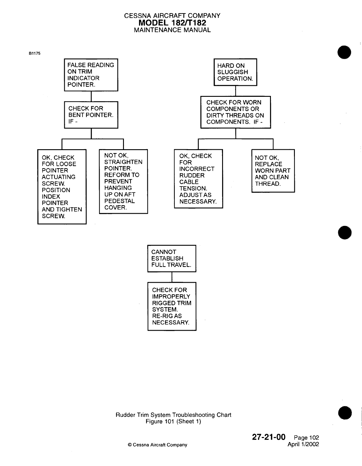
CESSNA AIRCRAFT
COMPANY
MODEL 182/T182
MAINTENANCE
MANUAL
B1175
FALSE
READING
ON
TRIM
INDICATOR
POINTER.
I
CHECK
FOR
BENT
POINTER.
IF-
I
HARD
ON
SLUGGISH
OPERATION.
CHECK FOR
WORN
COMPONENTS
OR
DIRTY
THREADS
ON
COMPONENTS.
IF-
I
OK, CHECK
FOR
LOOSE
POINTER
ACTUATING
SCREW.
POSITION
INDEX
POINTER
AND
TIGHTEN
SCREW.
NOT
OK,
STRAIGHTEN
POINTER.
REFORM
TO
PREVENT
HANGING
UP
ON
AFT
PEDESTAL
COVER.
OK,
CHECK
FOR
INCORRECT
RUDDER
CABLE
TENSION.
ADJUST AS
NECESSARY.
NOT
OK,
REPLACE
WORN
PART
AND
CLEAN
THREAD.
CANNOT
ESTABLISH
FULL TRAVEL.
I
CHECK
FOR
IMPROPERLY
RIGGED
TRIM
SYSTEM.
RE-RIG
AS
NECESSARY.
Rudder
Trim
System
Troubleshooting
Chart
Figure
101
(Sheet
1)
©
Cessna
Aircraft
Company
27-21-00
Page
102
April
1/2002
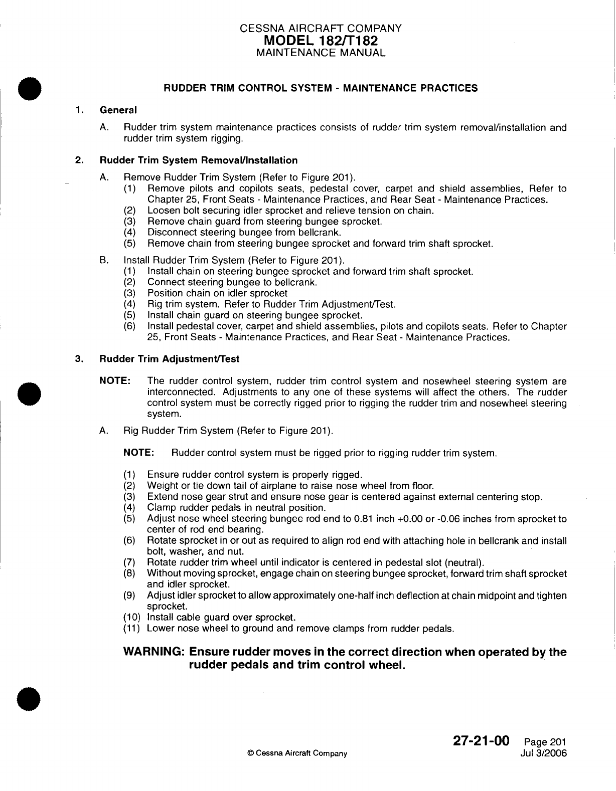
CESSNA
AIRCRAFT
COMPANY
MODEL
182/T182
MAINTENANCE
MANUAL
RUDDER TRIM
CONTROL
SYSTEM
-
MAINTENANCE PRACTICES
1.
General
A.
Rudder
trim
system
maintenance
practices
consists
of
rudder
trim
system
removal/installation
and
rudder
trim
system
rigging.
2.
Rudder
Trim
System
Removal/Installation
A.
Remove
Rudder
Trim
System
(Refer
to
Figure
201).
(1)
Remove
pilots
and
copilots
seats,
pedestal
cover, carpet
and shield
assemblies,
Refer
to
Chapter
25,
Front
Seats
-
Maintenance
Practices,
and
Rear
Seat
-
Maintenance Practices.
(2)
Loosen
bolt
securing idler
sprocket
and
relieve tension
on
chain.
(3)
Remove
chain
guard from
steering bungee
sprocket.
(4)
Disconnect steering
bungee
from
bellcrank.
(5)
Remove
chain
from
steering
bungee
sprocket
and
forward
trim
shaft sprocket.
B.
Install
Rudder
Trim
System (Refer
to
Figure
201).
(1)
Install
chain
on
steering bungee
sprocket
and
forward
trim
shaft
sprocket.
(2)
Connect steering
bungee
to
bellcrank.
(3)
Position chain
on
idler sprocket
(4)
Rig
trim
system. Refer
to
Rudder
Trim
Adjustment/Test.
(5)
Install chain
guard
on
steering bungee
sprocket.
(6)
Install
pedestal
cover,
carpet
and
shield
assemblies,
pilots
and
copilots
seats. Refer
to
Chapter
25,
Front
Seats
-
Maintenance
Practices,
and Rear
Seat
-
Maintenance
Practices.
3.
Rudder
Trim
Adjustment/Test
NOTE:
The rudder
control system, rudder
trim
control
system
and
nosewheel
steering
system
are
interconnected.
Adjustments
to
any
one
of
these systems
will
affect the
others.
The
rudder
control
system
must
be
correctly
rigged
prior
to
rigging
the
rudder
trim
and
nosewheel
steering
system.
A.
Rig
Rudder
Trim
System
(Refer
to
Figure
201).
NOTE:
Rudder
control
system
must
be
rigged
prior
to
rigging
rudder
trim
system.
(1)
Ensure
rudder control
system
is
properly
rigged.
(2)
Weight
or
tie
down
tail
of
airplane
to
raise
nose
wheel
from
floor.
(3)
Extend nose
gear
strut
and
ensure
nose
gear
is
centered
against
external
centering
stop.
(4)
Clamp
rudder
pedals
in
neutral
position.
(5)
Adjust
nose wheel
steering bungee
rod
end
to
0.81
inch
+0.00
or
-0.06
inches
from
sprocket
to
center
of
rod end
bearing.
(6)
Rotate
sprocket
in
or
out
as
required
to
align
rod
end with
attaching
hole
in
bellcrank
and
install
bolt,
washer,
and
nut.
(7)
Rotate
rudder
trim
wheel
until
indicator
is
centered
in
pedestal
slot
(neutral).
(8)
Without
moving
sprocket,
engage chain
on
steering
bungee
sprocket,
forward
trim
shaft
sprocket
and idler
sprocket.
(9)
Adjust
idler
sprocket
to
allow
approximately one-half
inch
deflection
at
chain
midpoint
and
tighten
sprocket.
(10)
Install cable
guard
over
sprocket.
(11)
Lower
nose
wheel
to
ground and
remove
clamps
from
rudder
pedals.
WARNING:
Ensure
rudder
moves
in
the
correct
direction
when
operated
by the
rudder
pedals
and
trim
control
wheel.
27-21-00
Page
201
©
Cessna
Aircraft Company
Jul
3/2006
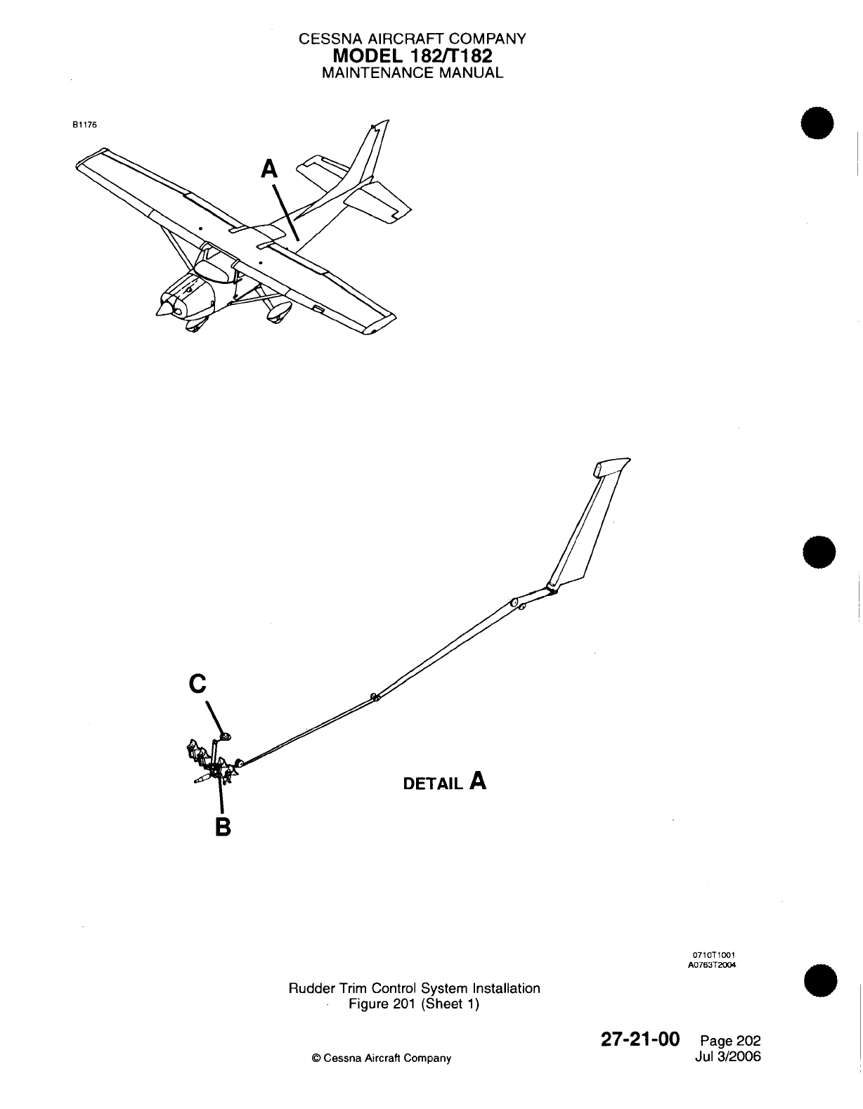
CESSNA
AIRCRAFT COMPANY
MODEL
182/T182
MAINTENANCE
MANUAL
C
DETAIL
A
B
0710T1001
A0763T2004
Rudder
Trim
Control
System
Installation
Figure
201
(Sheet
1)
©
Cessna Aircraft
Company
27-21-00
Page
202
Jul
3/2006
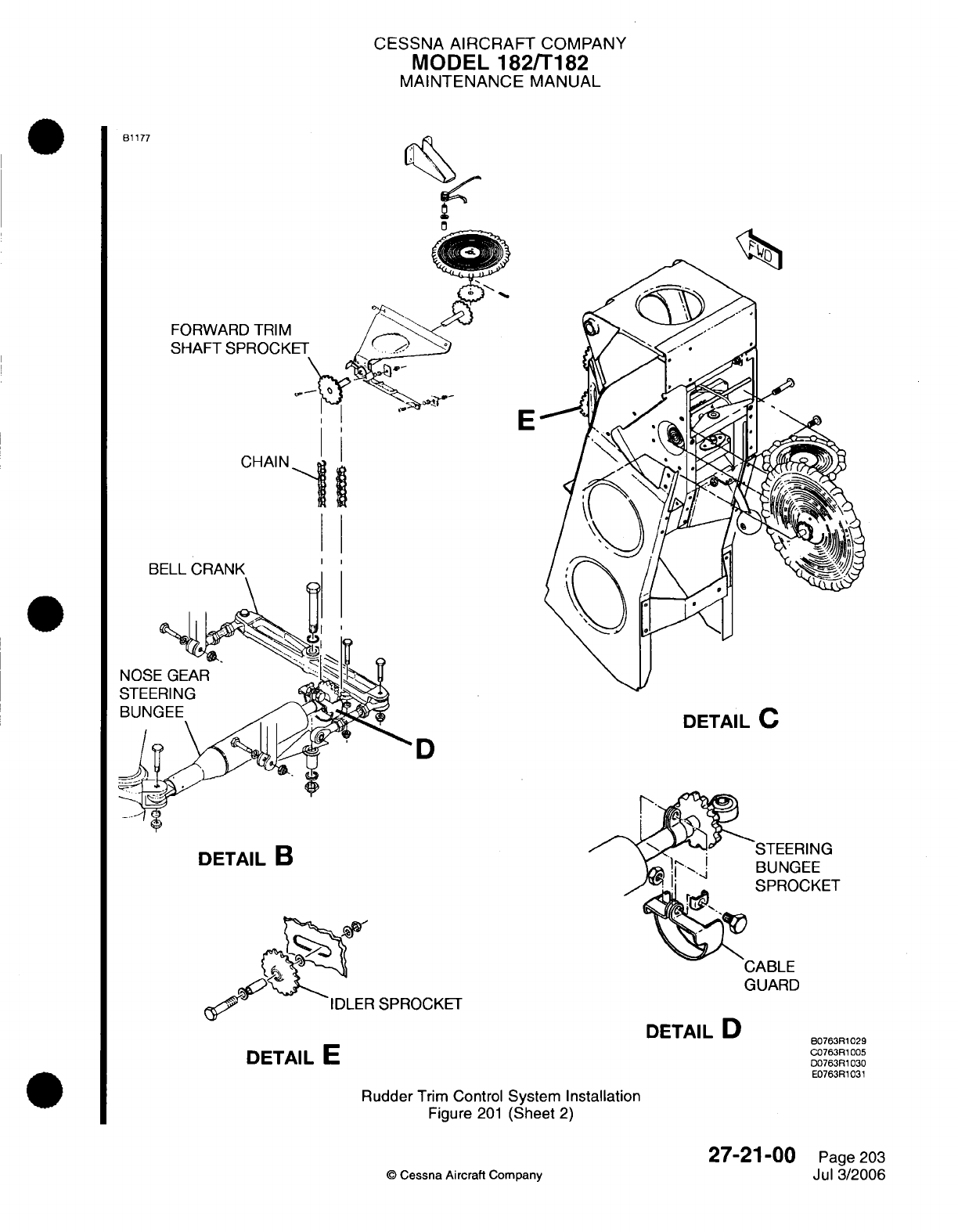
CESSNA
AIRCRAFT
COMPANY
MODEL
182fT182
MAINTENANCE
MANUAL
B1177
FORWARD
TRIM
SHAFT SPROCKE
E
CHAIN
BELL
CRANK
DETAIL
C
D
DETAIL
B
R
SPROCKET
DETAIL
D
DETAIL
E
Rudder
Trim
Control
System
Installation
Figure
201
(Sheet
2)
©
Cessna
Aircraft
Company
27-21-00
Page
203
Jul
3/2006
BE
STEERING
BUNGEE
SPROCKET
CABLE
GUARD
80763R1029
C0763R1005
D0763R1030
E0763R1031
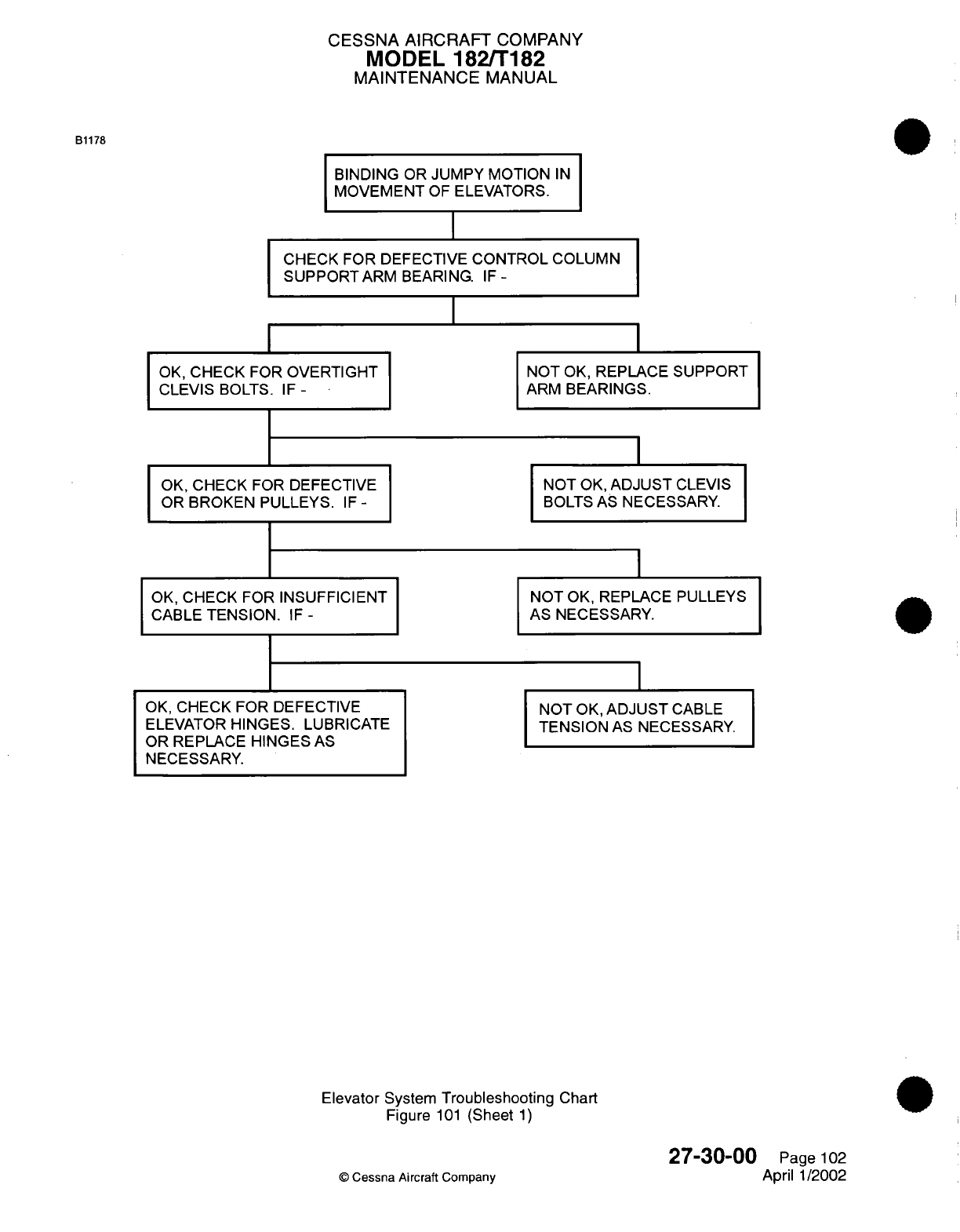
CESSNA
AIRCRAFT
COMPANY
MODEL
182/T182
MAINTENANCE
MANUAL
BINDING
OR
JUMPY
MOTION
IN
MOVEMENT
OF
ELEVATORS.
CHECK
FOR DEFECTIVE
CONTROL
COLUMN
SUPPORTARM
BEARING.
IF-
I
OK,
CHECK
FOR
OVERTIGHT
CLEVIS
BOLTS.
IF-
OK,
CHECK
FOR
DEFECTIVE
OR
BROKEN PULLEYS.
IF-
OK,
CHECK
FOR
INSUFFICIENT
CABLE
TENSION.
IF
-
OK,
CHECK FOR DEFECTIVE
ELEVATOR
HINGES.
LUBRICATE
OR
REPLACE HINGES
AS
NECESSARY.
NOT
OK,
REPLACE
SUPPORT
ARM
BEARINGS.
NOT
OK,
ADJUST
CLEVIS
BOLTS
AS
NECESSARY.
NOT
OK,
REPLACE
PULLEYS
AS NECESSARY.
NOT
OK,
ADJUST
CABLE
TENSION
AS
NECESSARY.
Elevator
System
Troubleshooting
Chart
Figure
101
(Sheet
1)
27-30-00
©
Cessna
Aircraft
Company
Page
102
April
1/2002
B1178
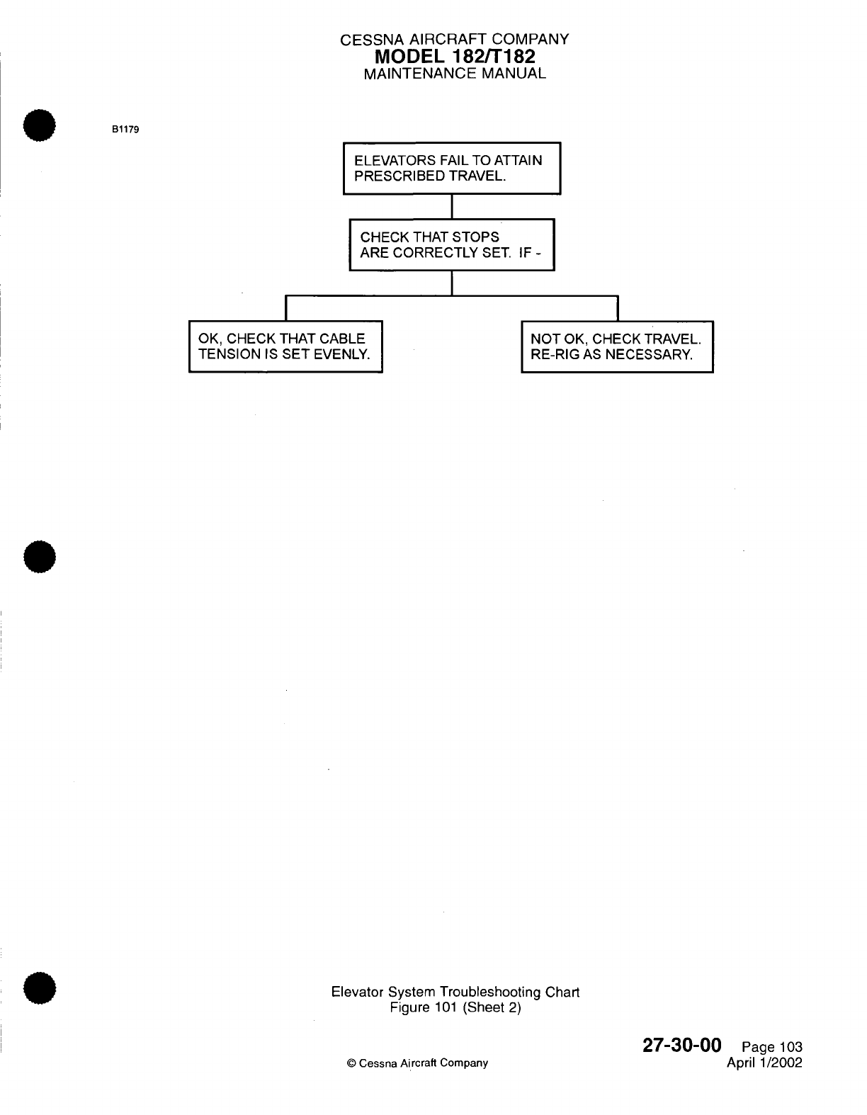
CESSNA AIRCRAFT
COMPANY
MODEL
182/T182
MAINTENANCE
MANUAL
ELEVATORS
FAIL TO
ATTAIN
PRESCRIBED TRAVEL.
I
CHECK
THAT
STOPS
ARE
CORRECTLY
SET.
IF
-
I
OK,
CHECK
THAT CABLE
TENSION
IS
SET
EVENLY.
NOT
OK, CHECK
TRAVEL.
RE-RIG
AS
NECESSARY.
Elevator System
Troubleshooting
Chart
Figure
101
(Sheet
2)
©
Cessna
Aircraft
Company
27-30-00
Page
103
April 1/2002
B1179
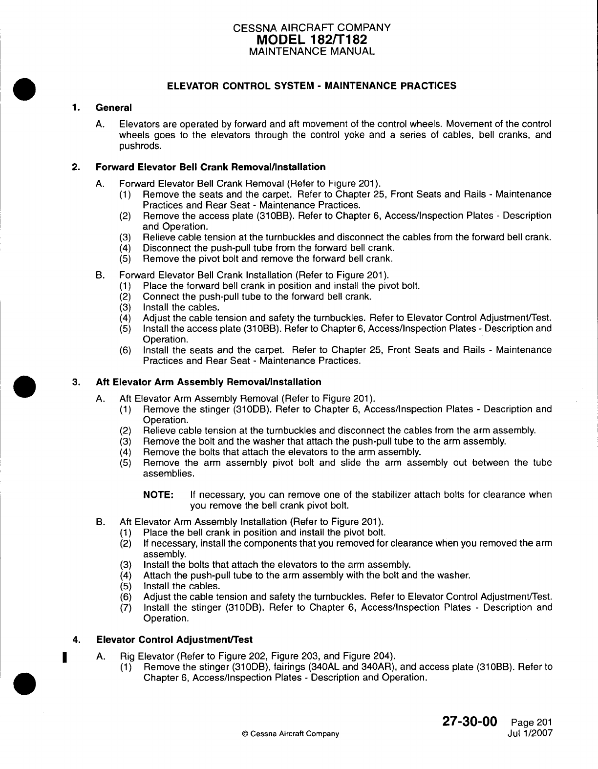
CESSNA
AIRCRAFT
COMPANY
MODEL
182/Ti182
MAINTENANCE
MANUAL
ELEVATOR
CONTROL
SYSTEM
-
MAINTENANCE
PRACTICES
1.General
A.
Elevators
are
operated
by
forward
and
aft
movement
of
the
control
wheels.
Movement
of
the
control
wheels
goes
to
the
elevators
through
the
control
yoke
and
a
series
of
cables,
bell
cranks,
and
push
rods.
2.
Forward
Elevator
Bell
Crank
Removal/installation
A.
Forward
Elevator
Bell
Crank
Removal
(Refer
to
Figure
201).
(1)
Remove
the
seats
and
the
carpet.
Refer
to
Chapter
25,
Front
Seats
and
Rails
-
Maintenance
Practices
and
Rear
Seat
-
Maintenance Practices.
(2)
Remove
the
access
plate
(31
OBB).
Refer
to
Chapter
6,
Access/Inspection
Plates
-
Description
and
Operation.
(3)
Relieve cable
tension
at
the
turnbuckles
and
disconnect
the
cables
from
the
forward
bell
crank.
(4)
Disconnect
the
push-pull
tube
from
the
forward
bell
crank.
(5)
Remove
the
pivot
bolt
and remove
the
forward
bell
crank.
B.
Forward
Elevator
Bell
Crank
Installation
(Refer
to
Figure
201).
(1)
Place
the
forward
bell
crank
in
position
and
install
the
pivot
bolt.
(2)
Connect
the
push-pull
tube
to
the
forward
bell
crank.
(3)
Install
the
cables.
(4)
Adjust
the
cable
tension
and
safety
the
turnbuckles.
Refer
to
Elevator
Control Adjustment/Test.
(5)
Install
the
access
plate
(310OBB).
Refer
to
Chapter
6,
Access/Inspection
Plates
-
Description
and
Operation.
(6)
Install
the
seats
and
the
carpet. Refer
to
Chapter
25,
Front
Seats
and
Rails
-
Maintenance
Practices
and
Rear
Seat
-
Maintenance Practices.
3.
Aft
Elevator
Arm
Assembly
Removal/installation
A.
Aft
Elevator
Arm
Assembly
Removal (Refer
to
Figure
201).
(1)
Remove
the
stinger
(310DB). Refer
to
Chapter
6,
Access/inspection
Plates
-
Description
and
Operation.
(2)
Relieve
cable
tension
at the
turnbuckles
and
disconnect
the
cables
from
the
arm
assembly.
(3)
Remove
the bolt
and
the
washer
that
attach
the
push-pull
tube
to
the
arm
assembly.
(4)
Remove
the
bolts
that
attach
the
elevators
to
the
arm
assembly.
(5)
Remove the
arm
assembly
pivot
bolt
and
slide
the
arm
assembly
out
between
the tube
assemblies.
NOTE:
If
necessary,
you
can
remove one
of
the
stabilizer
attach
bolts
for
clearance
when
you
remove
the
bell
crank
pivot
bolt.
B.
Aft
Elevator
Arm
Assembly
Installation
(Refer
to
Figure
201).
(1)
Place
the
bell
crank
in
position
and
install
the
pivot
bolt.
(2) If
necessary, install
the
components
that
you
removed
for
clearance
when
you removed
the
arm
assembly.
(3)
Install
the
bolts that attach
the
elevators
to
the
arm
assembly.
(4)
Attach the
push-pull
tube
to
the
arm
assembly
with
the bolt
and
the
washer.
(5)
Install
the
cables.
(6)
Adjust
the
cable
tension
and
safety
the
turnbuckles.
Refer
to
Elevator
Control
Adjustment/Test.
(7)
Install
the
stinger
(310DB).
Refer
to
Chapter
6,
Access/Inspection
Plates
-
Description
and
Operation.
4.
Elevator
Control Adjustment/Test
A. Rig
Elevator
(Refer
to
Figure 202,
Figure
203,
and
Figure 204).
(1)
Remove
the
stinger
(310ODB),
fairings
(340AL
and
340AR),
and
access
plate
(31
OBB).
Refer
to
Chapter
6,
Access/Inspection
Plates
-
Description
and
Operation.
27-30-00
Page
201
©
Cessna
Aircraft
Company
Jul
1/2007
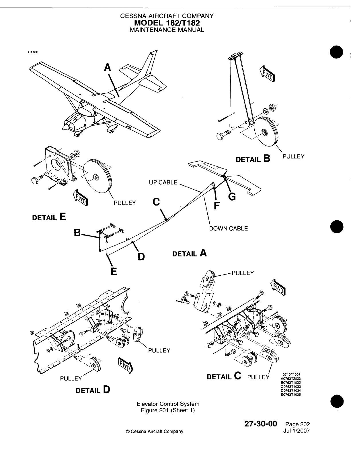
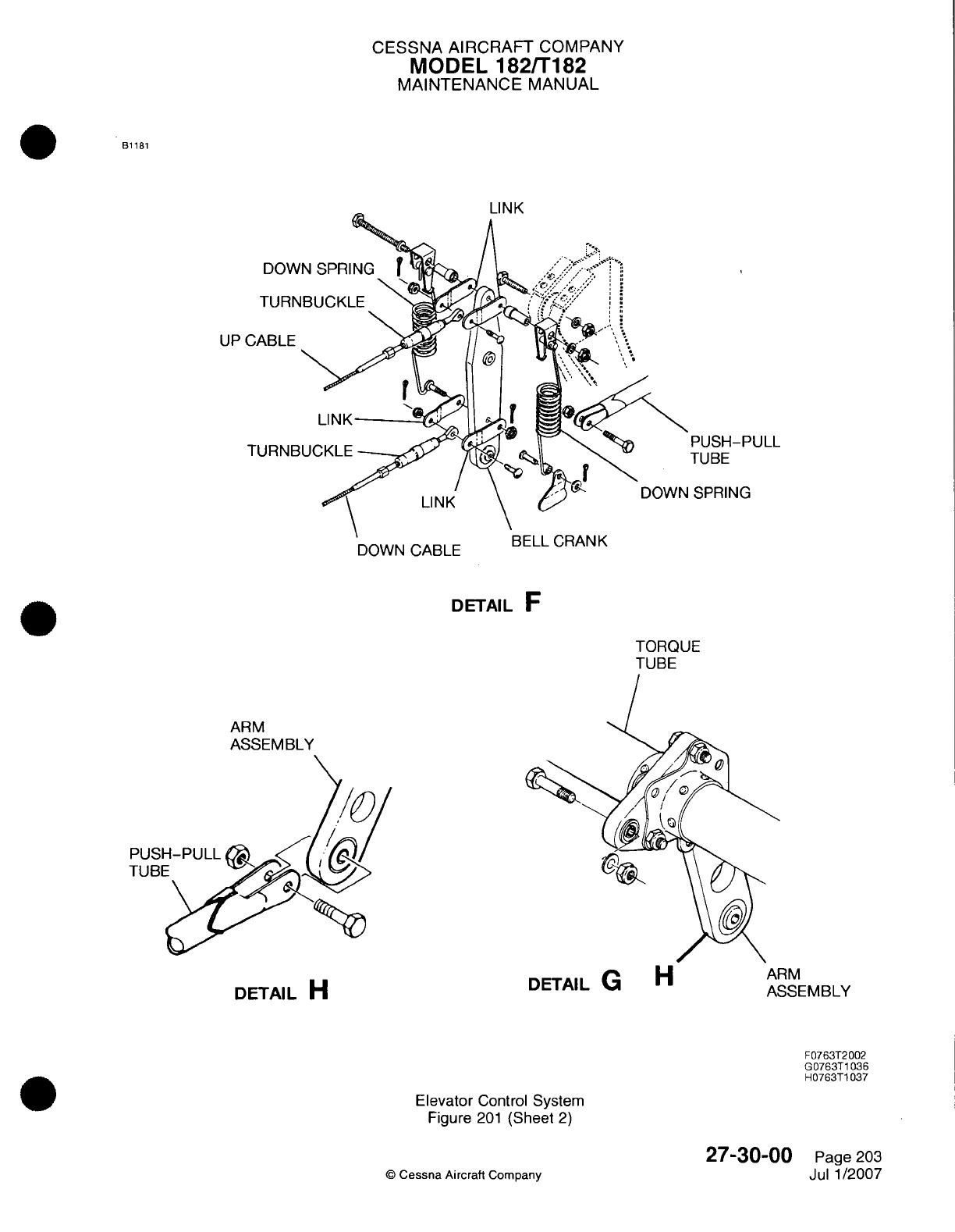
CESSNA
AIRCRAFT
COMPANY
MODEL
1821T182
MAINTENANCE
MANUAL
B1
181
LI
INK
UP
PUSH-PULL
TUBE
SPRING
DOWN
CABLE
t~rLL
UrIMI'%Ir
DETAIL
F
TORQUE
TUBE
ARM
ASSEMBLY
PUSH-PULL
XI
DETAIL
H
Elevator
Control
System
Figure
201
(Sheet
2)
©D
Cessna
Aircratt
Company
27-30-00
Page
203
Jul
1/2007
ASSE-MBLY
F0763T2
002
G0763T1
036
H0763T1
037
IM
---- --- - -
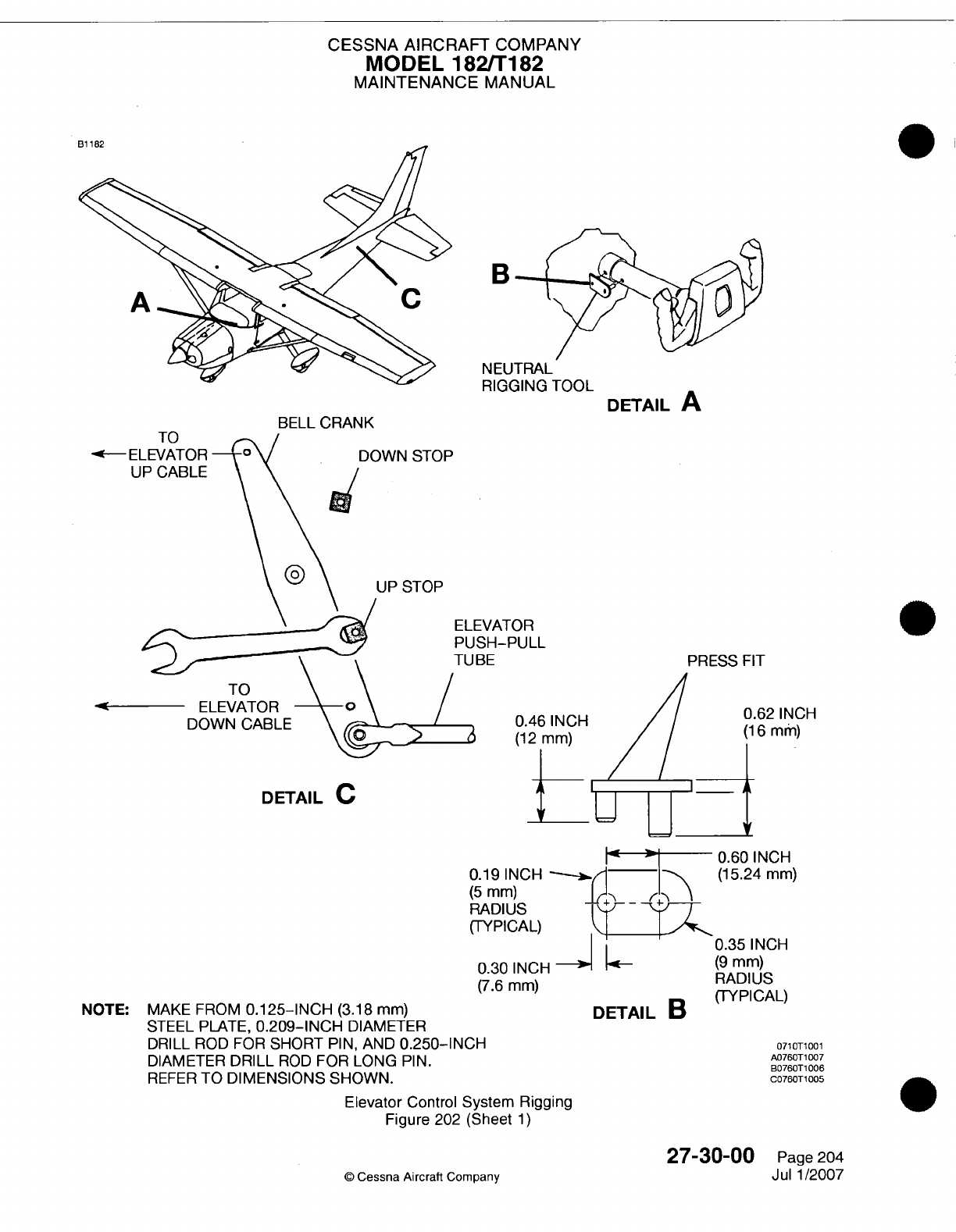
CESSNA AIRCRAFT
COMPANY
MODEL
182/Ti
182
MAINTENANCE
MANUAL
B
BELL CRANK
-a--
El
U
N
EUTRAL
RIGGING
TOOL
DONSO
UP
STOP
DETAIL
A
:-VATOR
SH-PULL
BE
PRESS
FIT
0.46
INCH
(16
(12 mm)
1
NOTE:
MAKE
FROM
0.125-INCH
(3.18
mm)
STEEL
PLATE,
0.209-INCH
DIAMETER
DRILL
ROD FOR
SHORT
PIN,
AND
0.250-IN
DIAMETER
DRILL
ROD
FOR
LONG
PIN.
REFER
TO
DIMENSIONS SHOWN.
!
.4
30
0.60
INCH
0.19
INCH
-~.<(1
5.24
mm)
(5
mm)
RADI
US
F
(TYPICAL)
jz4
0.35
INCH
0.30
INCH
-4(9
mm)
(7.6
mm)
RADIUS
DETAIL
B
(TYPICAL)
CH07T10
A076OT1
007
B0760T1
006
C076OT1
005
Elevator
Control
System
Rigging
Figure
202
(Sheet
1)
27-30-00
©
Cessna
Aircraft
Company
DETAIL
C
,2
INCH
Imm)
Page
204
Jul
1/2007
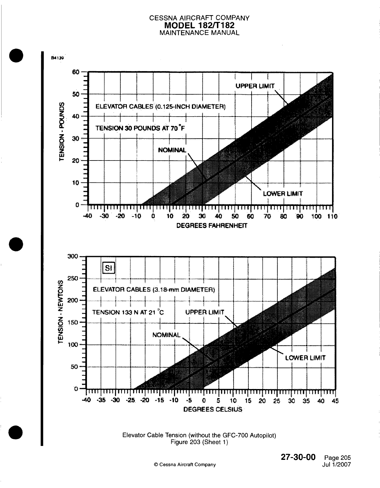
CESSNA AIRCRAFT
COMPANY
MODEL
182/Ti
82
MAINTENANCE
MANUAL
UPPER
UMIT
I I 1, I iI I
I
ELEVATOR
CABLES
.(0.125-INCH
DIAMETERI)
TENSIONi
30
POUNDS
AT
70
-F
II .I I I . ~ ~~~I I
I I
.
I
Aw-
-- --
I
1111
11111111
I I I I I I I I I I I I I I
T
j
I
TUTIT]
D
-30.-213
-10
0
10
20
30
DEGREES
FAHRENHEIT
DMGREES
CELSIUS
Elevator
Cable
Tension
(without
the
GFC-700
Autopilot)
Figure
203 (Sheet
1)
©
Cessna
Aircraft
Company
27-30-00
Page
205
Jul
1/2007
lI.
zI
[
0
-
co
z
z
0,
U,
OW130
An
A
I I
I
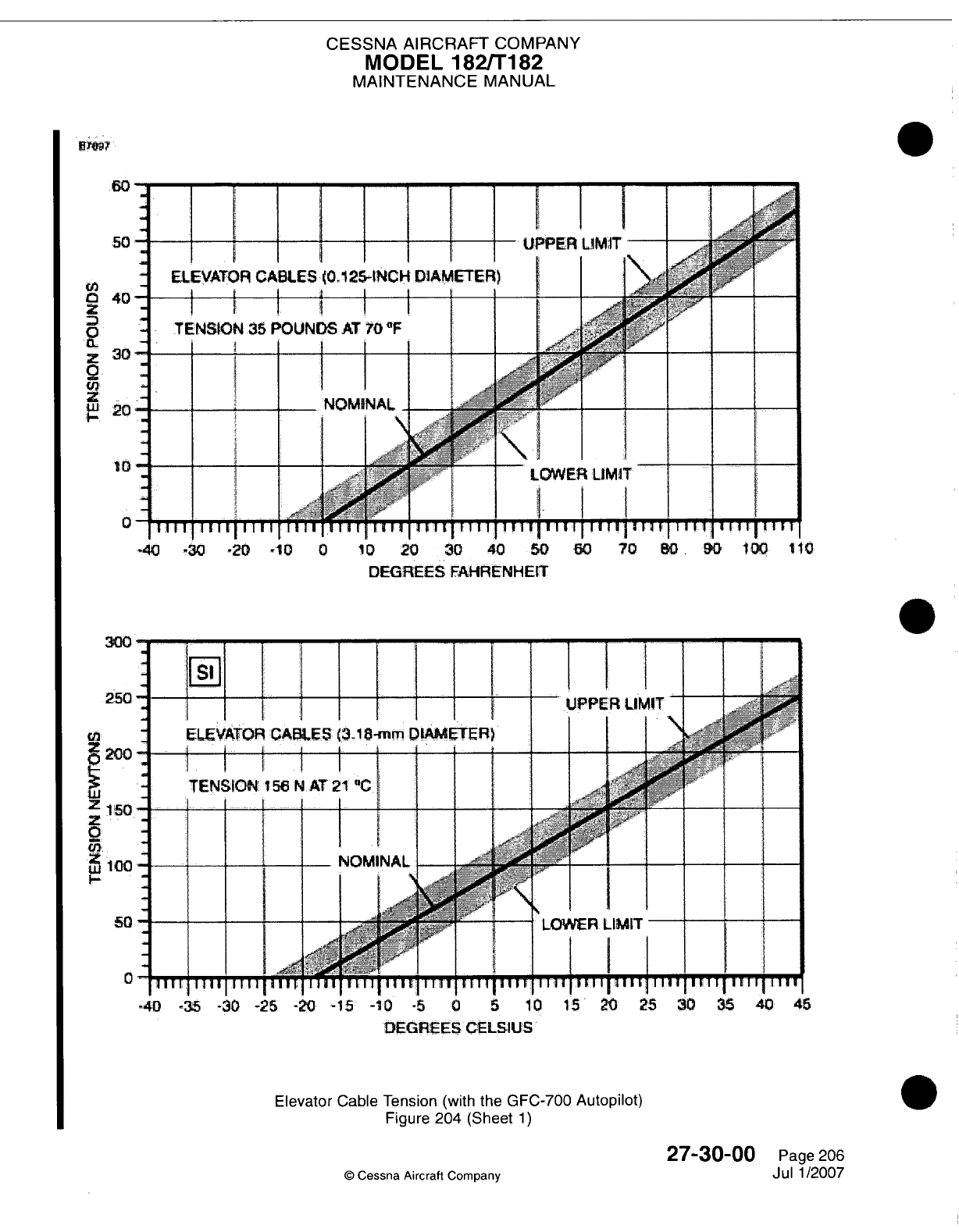
CESSNA AIRCRAFT
COMPANY
MODEL
182/Ti82
MAINTENANCE
MANUAL
DIEGREJES
FAHRENHEIT
DEGREES
CELSIUS'
Elevator
Cable
Tension
(with
the
GFC-700
Autopilot)
Figure
204
(Sheet
1)
©
Cessna Aircraft
Company
27-30-00
Page 206
Jul
1/2007
VI
z
0
02
z
9f
z
t2
C-
z
0,
z
0
I
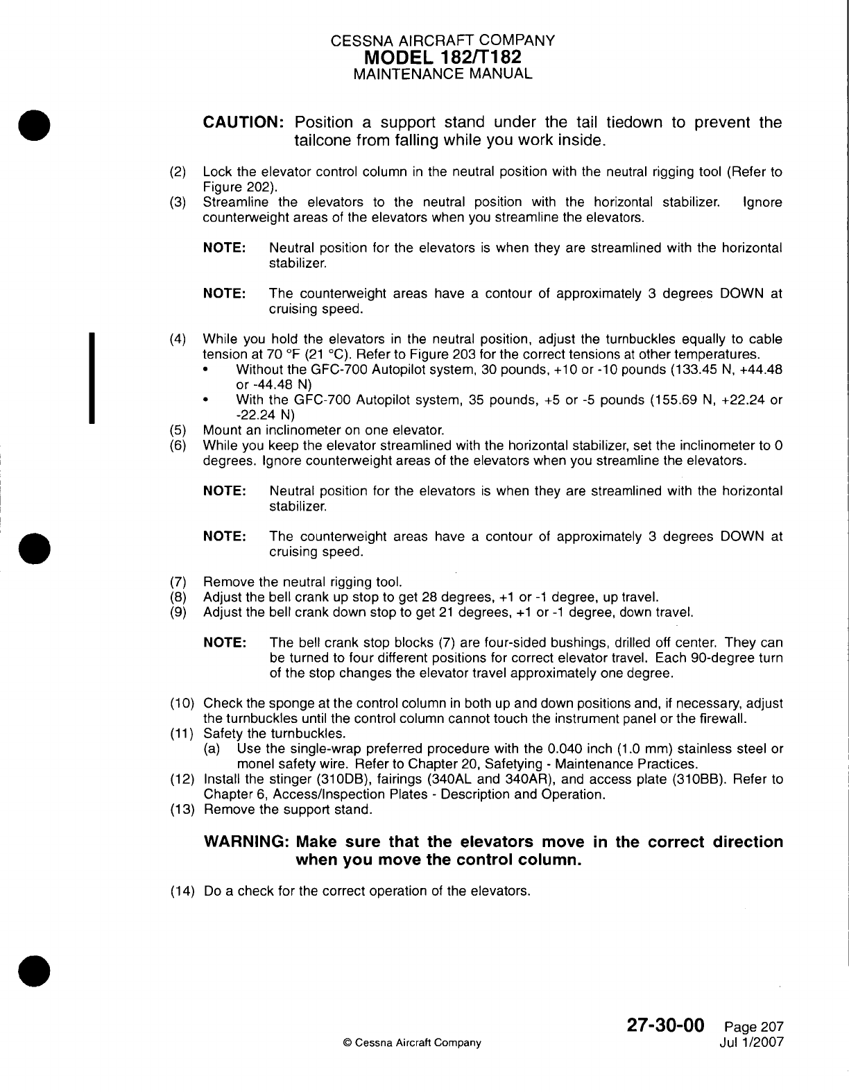
CESSNA
AIRCRAFT
COMPANY
MODEL
182/Ti
82
MAINTENANCE
MANUAL
CAUTION:
Position
a
support
stand
under
the
tail
tiedown
to
prevent
the
tailcone
from
falling
while
you
work
inside.
(2)
Lock
the
elevator
control
column
in
the
neutral
position
with
the
neutral
rigging
tool
(Refer
to
Figure
202).
(3)
Streamline
the
elevators
to
the
neutral
position
with the
horizontal
stabilizer.
Ignore
counterweight
areas
of
the
elevators
when you
streamline
the
elevators.
NOTE:
Neutral position for
the
elevators
is
when
they
are
streamlined
with
the
horizontal
stabilizer.
NOTE:
The
counterweight
areas
have
a
contour
of
approximately
3
degrees
DOWN
at
cruising
speed.
(4)
While
you
hold
the
elevators
in
the
neutral
position, adjust
the
turnbuckles
equally
to
cable
tension
at
70
OF
(21
'C).
Refer
to
Figure 203 for
the
correct
tensions
at
other
temperatures.
*
Without
the
GFC-700
Autopilot
system,
30
pounds,
+10
or
-10
pounds
(133.45
N,
+44.48
or -44.48
N)
*
With
the GFC-700
Autopilot
system,
35
pounds,
+5
or
-5
pounds
(155.69
N,
+22.24
or
-22.24
N)
(5)
Mount
an
inclinometer
on
one
elevator.
(6)
While
you
keep
the
elevator
streamlined
with the
horizontal stabilizer,
set
the
inclinometer
to
0
degrees.
Ignore
counterweight
areas
of
the
elevators
when
you
streamline
the
elevators.
NOTE:
Neutral
position
for
the
elevators
is
when they
are
streamlined
with
the
horizontal
stabilizer.
NOTE: The
counterweight
areas have
a
contour
of
approximately
3
degrees
DOWN
at
cruising
speed.
(7)
Remove
the
neutral rigging tool.
(8)
Adjust
the
bell crank
up
stop
to
get
28
degrees,
+1
or
-1
degree,
up
travel.
(9)
Adjust
the
bell crank
down
stop
to
get
21
degrees,
+1
or
-1
degree,
down
travel.
NOTE:
The
bell
crank
stop blocks
(7)
are
four-sided bushings,
drilled
off
center.
They
can
be
turned
to
four different positions
for
correct
elevator
travel.
Each
90-dlegree
turn
of
the
stop
changes
the
elevator
travel
approximately
one
degree.
(1
0)
Check
the
sponge
at
the
control
column
in
both
up
and
down
positions
and,
if
necessary,
adjust
the
turnbuckles
until the
control
column cannot touch
the
instrument
panel or
the
firewall.
(11)
Safety
the
turnbuckles.
(a)
Use
the
single-wrap
preferred
procedure
with
the
0.040
inch
(1.0
mm)
stainless
steel
or
monel
safety
wire.
Refer
to
Chapter
20,
Safetying
-
Maintenance
Practices.
(12)
Install
the
stinger
(31
0DB),
fairings
(340AL
and
340AR),
and
access
plate
(31
OBB).
Refer to
Chapter
6,
Access/Inspection
Plates
-
Description
and
Operation.
(13)
Remove the
support
stand.
WARNING:
Make
sure
that
the
elevators
move
in
the
correct
direction
when
you
move
the
control
column.
(14) Do
a
check
for
the
correct operation
of
the
elevators.
27-30-00
Page 207
©
Cessna
Aircraft
Company
Jul
1/2007

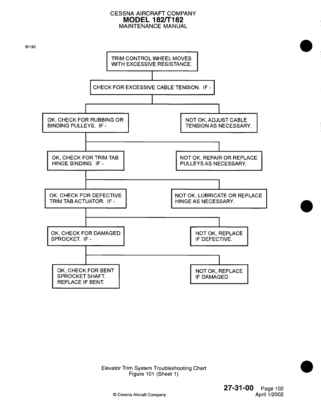
CESSNA AIRCRAFT
COMPANY
MODEL
182/T182
MAINTENANCE
MANUAL
TRIM
CONTROL WHEEL
MOVES
WITH
EXCESSIVE
RESISTANCE.
CHECK
FOR
EXCESSIVE
CABLE
TENSION.
IF
-
I
OK,
CHECK
FOR
RUBBING
OR
BINDING
PULLEYS.
IF-
OK,
CHECK
FOR
TRIM
TAB
HINGE BINDING.
IF
-
OK,
CHECK
FOR
DEFECTIVE
TRIM
TAB
ACTUATOR.
IF
-
OK,
CHECK FOR
DAMAGED
SPROCKET.
IF-
OK,
CHECK FOR
BENT
SPROCKET
SHAFT.
REPLACE
IF
BENT
NOT
OK,
ADJUST
CABLE
TENSION
AS NECESSARY.
NOT
OK,
REPAIR
OR
REPLACE
PULLEYS
AS NECESSARY.
NOT
OK, LUBRICATE
OR REPLACE
HINGE
AS NECESSARY.
I
NOT
OK,
REPLACE
IF
DEFECTIVE.
NOT
OK,
REPLACE
IF
DAMAGED.
Elevator
Trim
System
Troubleshooting
Chart
Figure
101
(Sheet
1)
©
Cessna
Aircraft
Company
B1183
27-31-00
Page
102
April
1/2002
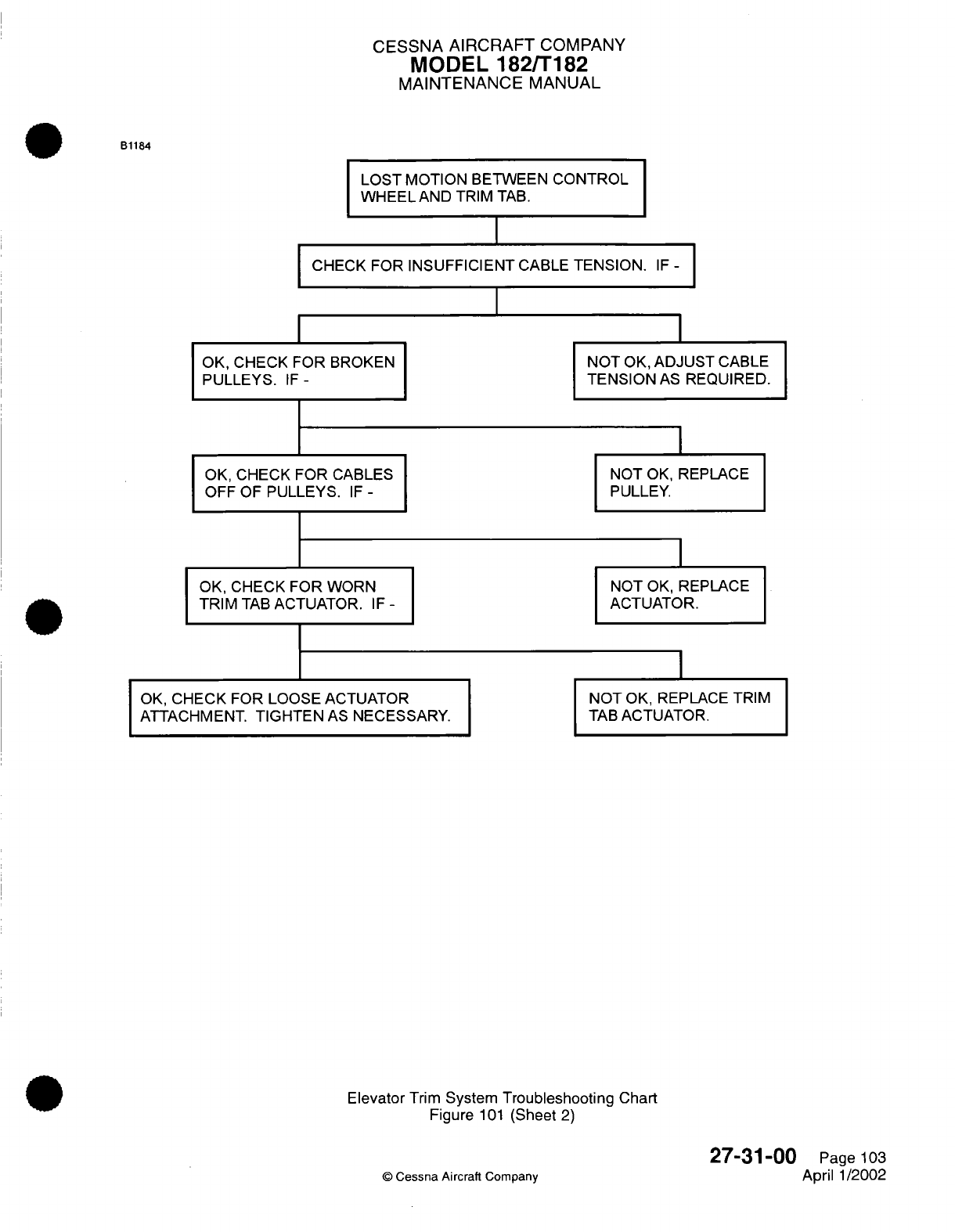
CESSNA
AIRCRAFT
COMPANY
MODEL
182/T182
MAINTENANCE
MANUAL
LOST
MOTION
BETWEEN
CONTROL
WHEEL
AND TRIM
TAB.
CHECK FOR
INSUFFICIENT
CABLE
TENSION.
IF
-
OK,
CHECK FOR
BROKEN
PULLEYS.
IF-
OK,
CHECK
FOR
CABLES
OFF
OF
PULLEYS.
IF
-
OK,
CHECK
FOR
WORN
TRIM
TAB
ACTUATOR.
IF
-
OK,
CHECK FOR
LOOSE
ACTUATOR
ATTACHMENT.
TIGHTEN
AS
NECESSARY.
NOT
OK,
ADJUST
CABLE
TENSION
AS
REQUIRED.
NOT
OK,
REPLACE
PULLEY.
NOT
OK,
REPLACE
ACTUATOR.
NOT
OK, REPLACE
TRIM
TAB
ACTUATOR.
Elevator
Trim
System
Troubleshooting
Chart
Figure
101
(Sheet
2)
©
Cessna
Aircraft
Company
27-31-00
Page
103
April
1/2002
B1184
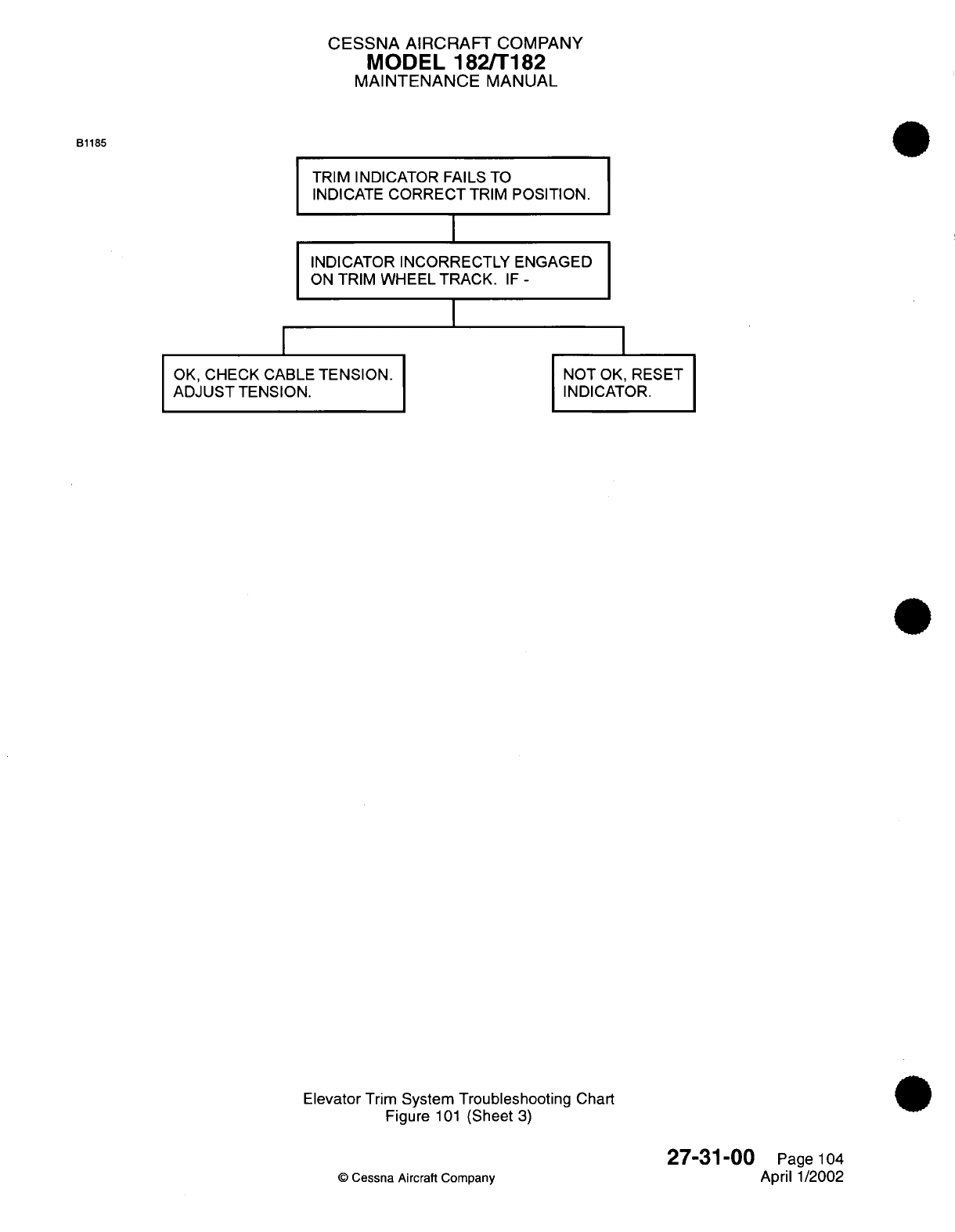
CESSNA
AIRCRAFT
COMPANY
MODEL
182/T182
MAINTENANCE
MANUAL
TRIM
INDICATOR FAILS
TO
INDICATE
CORRECT
TRIM
POSITION.
I
INDICATOR
INCORRECTLY
ENGAGED
ON
TRIM
WHEEL
TRACK.
IF
-
I
OK,
CHECK
CABLE
TENSION.
ADJUST
TENSION.
NOT
OK, RESET
INDICATOR.
Elevator
Trim
System
Troubleshooting
Chart
Figure
101
(Sheet
3)
©
Cessna
Aircraft
Company
27-31-00
Page
104
April
1/2002
B1185
I
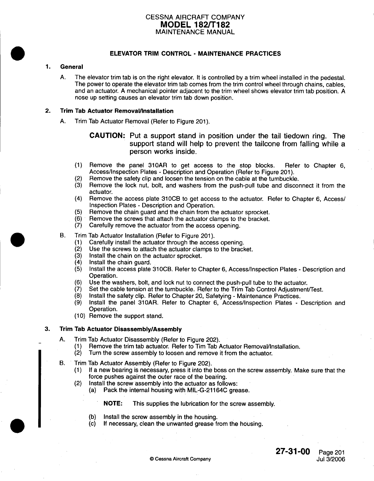
CESSNA
AIRCRAFT
COMPANY
MODEL
182/T182
MAINTENANCE
MANUAL
ELEVATOR TRIM
CONTROL
-
MAINTENANCE
PRACTICES
1.
General
A.
The
elevator
trim
tab
is
on
the
right elevator.
It
is
controlled
by
a
trim
wheel installed
in
the pedestal.
The
power
to
operate the
elevator
trim
tab
comes
from the
trim
control wheel
through
chains,
cables,
and
an
actuator.
A
mechanical
pointer
adjacent
to
the
trim
wheel
shows elevator
trim
tab
position.
A
nose
up
setting
causes
an
elevator
trim tab
down
position.
2.
Trim
Tab
Actuator
Removal/Installation
A.
Trim
Tab
Actuator
Removal
(Refer
to
Figure
201).
CAUTION:
Put
a
support
stand
in
position
under the
tail
tiedown
ring.
The
support stand
will help to
prevent
the
tailcone
from
falling
while
a
person
works inside.
(1)
Remove
the
panel
31OAR
to
get
access
to
the stop
blocks.
Refer
to
Chapter
6,
Access/Inspection
Plates
-
Description and
Operation (Refer
to
Figure
201).
(2)
Remove
the
safety
clip
and
loosen
the
tension
on
the
cable
at
the
turnbuckle.
(3)
Remove
the
lock
nut,
bolt,
and
washers
from the
push-pull
tube
and
disconnect
it
from
the
actuator.
(4)
Remove
the
access
plate
310CB
to
get
access
to
the
actuator.
Refer
to
Chapter
6,
Access/
Inspection Plates
-
Description
and
Operation.
(5)
Remove
the
chain
guard
and
the
chain from
the
actuator
sprocket.
(6)
Remove
the
screws
that
attach
the
actuator
clamps
to
the
bracket.
(7)
Carefully
remove
the
actuator
from
the
access
opening.
B.
Trim
Tab
Actuator
Installation (Refer
to
Figure
201).
(1)
Carefully
install
the
actuator
through
the
access
opening.
(2)
Use
the
screws
to
attach
the actuator clamps
to
the bracket.
(3)
Install
the
chain
on
the
actuator sprocket.
(4)
Install
the chain
guard.
(5)
Install
the
access
plate
310CB.
Refer
to
Chapter
6,
Access/Inspection
Plates
-
Description
and
Operation.
(6)
Use
the
washers,
bolt,
and
lock
nut
to
connect
the
push-pull tube
to
the
actuator.
(7)
Set
the
cable tension at
the turnbuckle.
Refer
to the Trim
Tab
Control
Adjustment/Test.
(8)
Install the
safety
clip.
Refer
to
Chapter
20,
Safetying
-
Maintenance
Practices.
(9)
Install the
panel
310AR.
Refer
to
Chapter
6,
Access/Inspection
Plates
-
Description
and
Operation.
(10)
Remove
the
support stand.
3.
Trim
Tab
Actuator
Disassembly/Assembly
A.
Trim
Tab
Actuator Disassembly
(Refer
to
Figure
202).
(1)
Remove
the
trim
tab
actuator. Refer
to Tim
Tab
Actuator
Removal/Installation.
(2)
Turn
the
screw
assembly
to
loosen
and
remove
it
from
the
actuator.
B.
Trim
Tab
Actuator Assembly
(Refer
to
Figure
202).
(1) If
a
new
bearing
is
necessary, press
it
into
the
boss
on
the
screw
assembly.
Make
sure
that
the
force pushes
against the outer
race of
the
bearing.
(2)
Install
the screw assembly
into
the
actuator
as
follows:
(a)
Pack
the
internal
housing
with MIL-G-21164C
grease.
NOTE:
This
supplies
the
lubrication
for
the screw assembly.
(b)
Install
the screw
assembly
in
the housing.
(c)
If
necessary,
clean
the
unwanted
grease
from
the
housing.
27-31-00
Page
201
©
Cessna
Aircraft
Company
Jul
3/2006
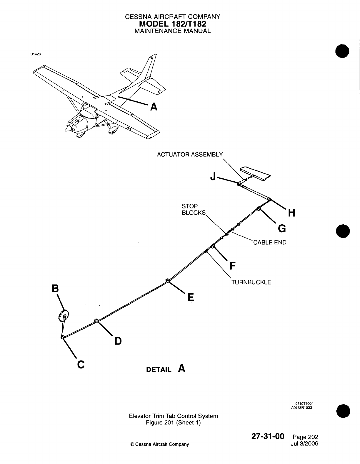
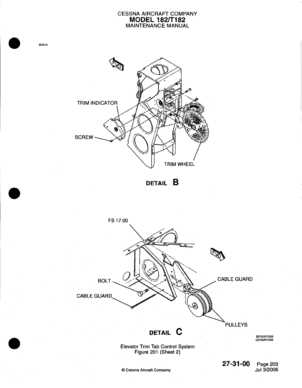
CESSNA
AIRCRAFT
COMPANY
MODEL
182/T182
MAINTENANCE
MANUAL
B3410
TRIM
IN
SCREW
DETAIL
B
FS
17.00
BOLT
CABLE
DETAIL
C
Elevator
Trim
Tab
Control
System
Figure
201
(Sheet
2)
27-31-00
©
Cessna Aircraft
Company
B0763R1005
C0763R1038
Page 203
Jul 3/2006
RD
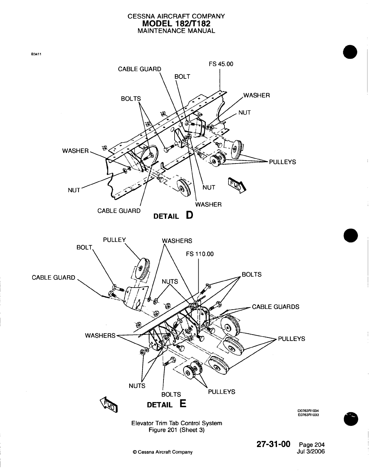
CESSNA
AIRCRAFT
COMPANY
MODEL
182/T182
MAINTENANCE
MANUAL
B3411
FS
45.00
PULLEYS
CABLE
GUARD
DETAIL
D
CABLE
GUARD
iUARDS
PULLEYS
BOLTS
PULLEYS
DETAIL
E
Elevator
Trim
Tab
Control
System
Figure
201
(Sheet
3)
©
Cessna Aircraft
Company
D0763R1034
E0763R1033
27-31-00
Page
204
Jul
3/2006
CABLE
rag MA rmrs
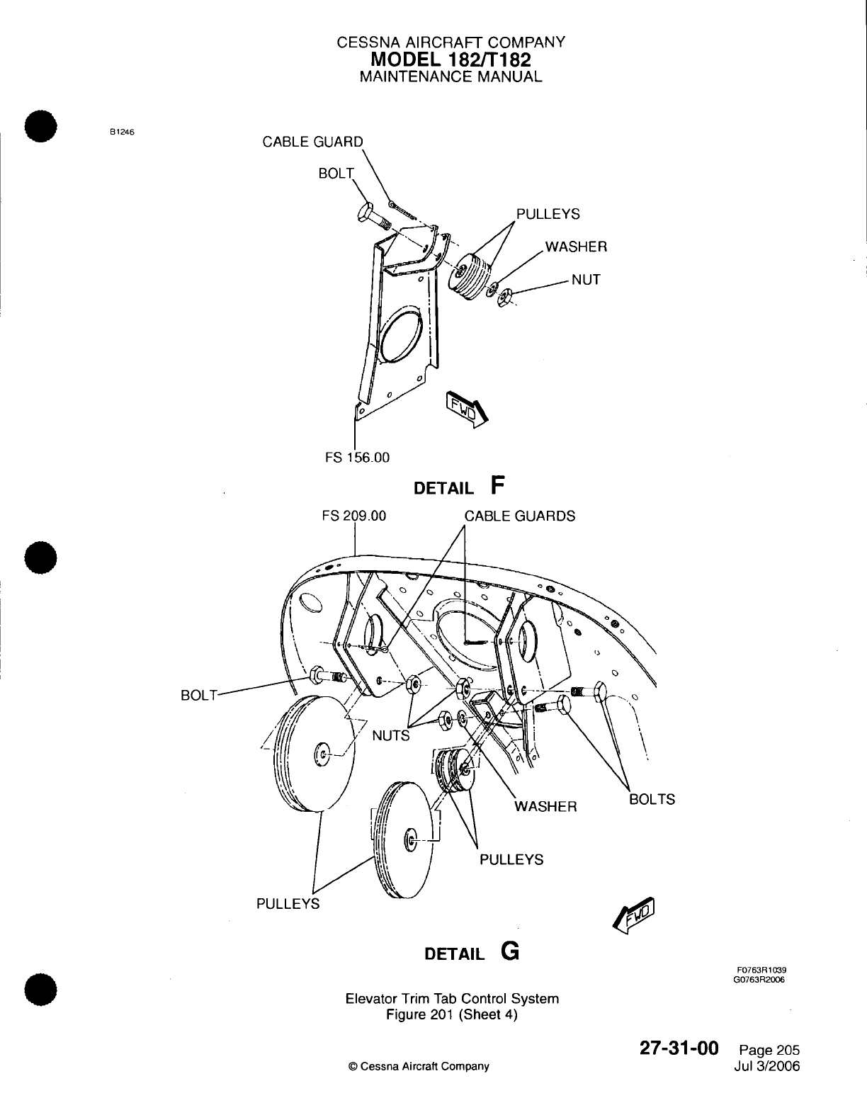
CESSNA
AIRCRAFT
COMPANY
MODEL
182/T182
MAINTENANCE
MANUAL
CABLE
GUARD
BOL
FS
DETAIL
F
BOL
PULLLY
DETAIL
G
F0763R1039
G0763R2006
Elevator
Trim
Tab
Control
System
Figure
201
(Sheet
4)
©
Cessna Aircraft
Company
27-31-00
Page
205
Jul
3/2006
B1246
SHER
NUT
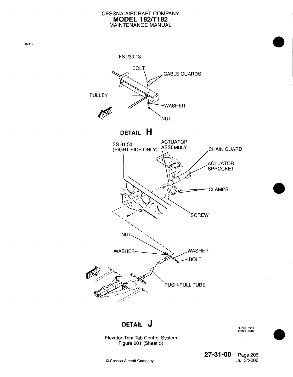
CESSNA AIRCRAFT
COMPANY
MODEL
182/T182
MAINTENANCE
MANUAL
B3412
FS
230.18
UARDS
PULLEY
DETAIL
H
31.50
ACTUATOR
SS
31.50
ASSEMBLY
(Right
Side
Only)
NUT
WASHER WASHER
BOLT
PUSH-PULL
TUBE
DETAIL
J
Elevator
Trim
Tab
Control
System
Figure
201
(Sheet
5)
©
Cessna
Aircraft Company
uARD
H0763T1041
J0763R1040
27-31-00
Page 206
Jul 3/2006
OR
E
T
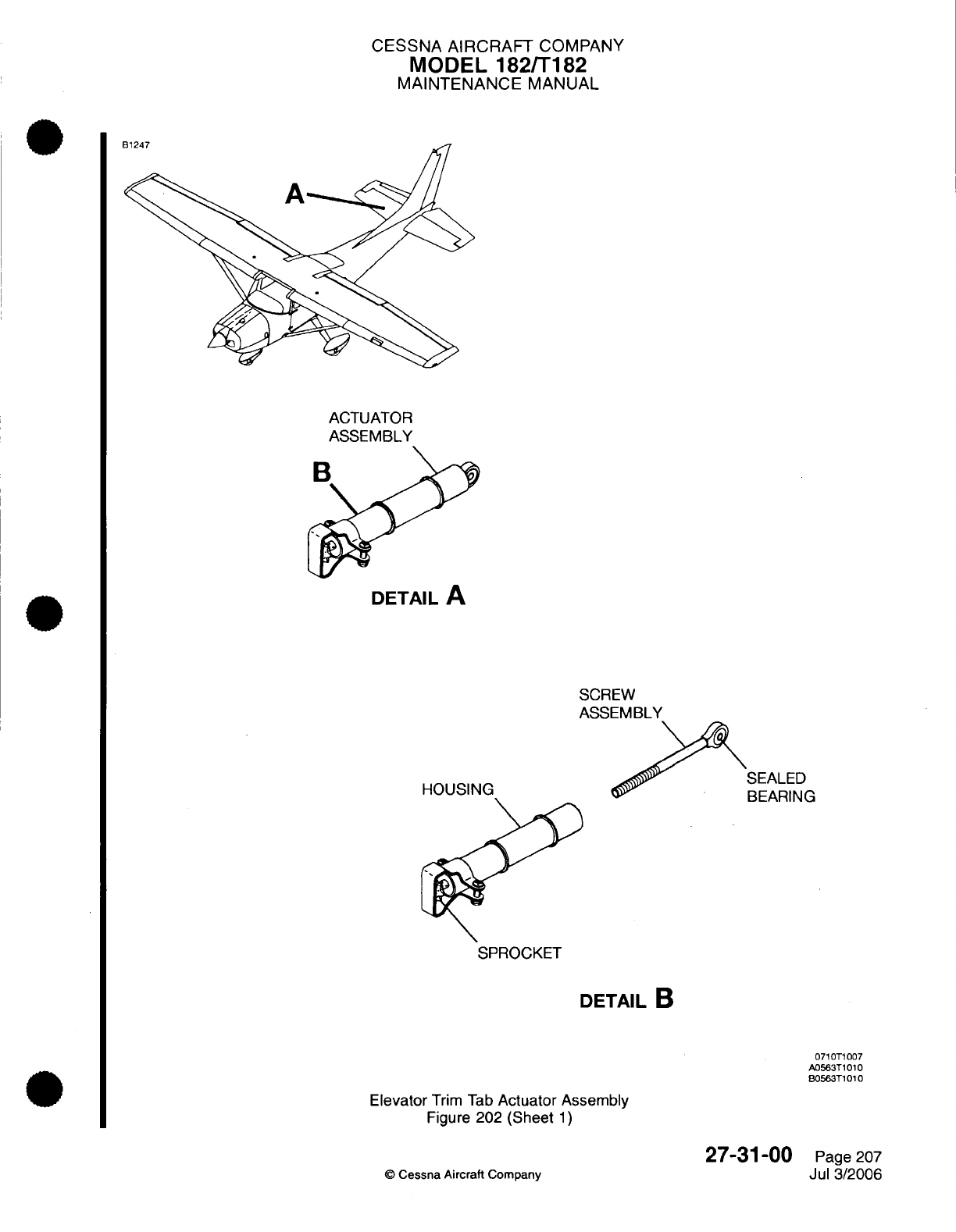
CESSNA
AIRCRAFT
COMPANY
MODEL
182/T182
MAINTENANCE
MANUAL
ACTUATOR
DETAIL
A
SCREW
ASSEMBLY
HOUSING
SPROCKET
DETAIL
B
0710T1007
A0563T1010
B0563T1010
Elevator
Trim Tab
Actuator
Assembly
Figure
202
(Sheet
1)
27-31-00
©
Cessna Aircraft
Company
Page 207
Jul
3/2006
B1247
BEARING
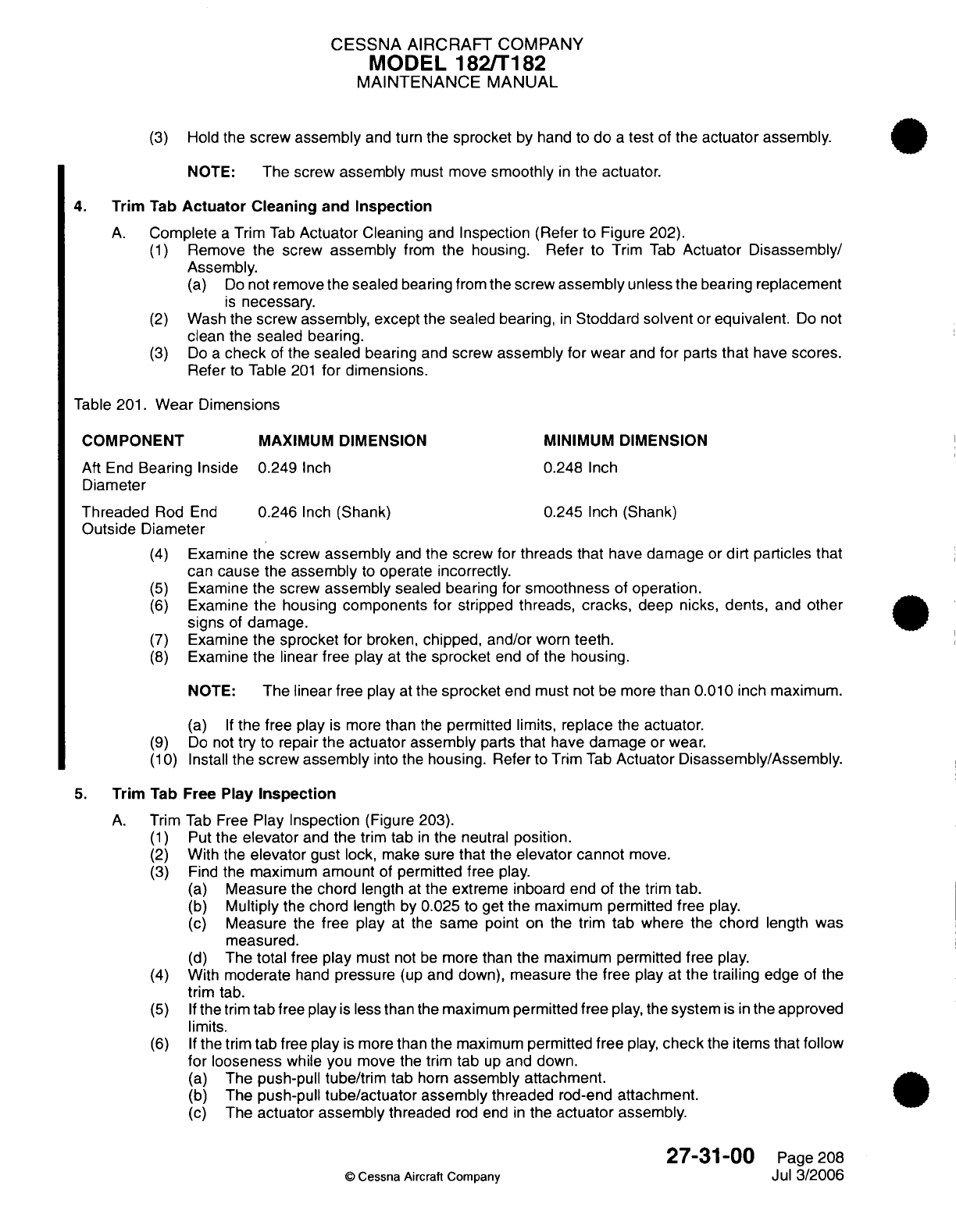
CESSNA AIRCRAFT
COMPANY
MODEL
182/T182
MAINTENANCE
MANUAL
(3)
Hold
the screw
assembly
and
turn
the
sprocket
by hand
to
do
a
test
of
the
actuator
assembly.
NOTE:
The screw
assembly
must
move
smoothly
in
the
actuator.
4.
Trim
Tab
Actuator
Cleaning
and
Inspection
A.
Complete
a
Trim
Tab
Actuator
Cleaning
and
Inspection (Refer
to
Figure 202).
(1)
Remove
the
screw
assembly
from
the housing.
Refer
to
Trim
Tab
Actuator
Disassembly/
Assembly.
(a)
Do
not
remove
the
sealed
bearing
from
the screw
assembly
unless
the bearing
replacement
is
necessary.
(2)
Wash
the
screw assembly,
except
the sealed bearing,
in
Stoddard
solvent
or
equivalent.
Do
not
clean
the
sealed bearing.
(3)
Do
a
check
of
the
sealed
bearing
and
screw
assembly
for wear
and
for
parts
that
have
scores.
Refer
to Table
201
for
dimensions.
Table 201.
Wear
Dimensions
COMPONENT
MAXIMUM
DIMENSION
MINIMUM
DIMENSION
Aft
End
Bearing
Inside
0.249
Inch
0.248
Inch
Diameter
Threaded
Rod
End
0.246
Inch
(Shank) 0.245
Inch
(Shank)
Outside
Diameter
(4)
Examine
the
screw
assembly
and
the
screw for
threads that
have
damage
or
dirt
particles
that
can
cause
the
assembly
to
operate
incorrectly.
(5)
Examine
the
screw
assembly
sealed bearing
for
smoothness
of
operation.
(6)
Examine
the housing
components for stripped
threads,
cracks,
deep
nicks,
dents,
and
other
signs
of
damage.
(7)
Examine
the
sprocket
for
broken,
chipped,
and/or
worn
teeth.
(8)
Examine
the linear free play
at
the
sprocket
end
of
the
housing.
NOTE:
The
linear
free
play
at
the
sprocket
end must
not
be
more
than
0.010 inch maximum.
(a) If
the
free play
is
more
than
the
permitted limits,
replace
the
actuator.
(9)
Do
not
try
to
repair
the
actuator
assembly
parts
that
have
damage
or
wear.
(10)
Install
the
screw
assembly
into
the
housing. Refer
to
Trim
Tab
Actuator
Disassembly/Assembly.
5.
Trim
Tab
Free
Play
Inspection
A.
Trim
Tab
Free
Play Inspection
(Figure
203).
(1)
Put
the
elevator
and
the
trim
tab
in
the
neutral
position.
(2)
With
the
elevator
gust
lock, make
sure
that
the
elevator cannot
move.
(3)
Find
the
maximum
amount
of
permitted free
play.
(a)
Measure
the
chord
length
at
the extreme inboard
end
of
the trim
tab.
(b)
Multiply
the
chord
length
by
0.025
to get
the
maximum permitted
free
play.
(c)
Measure
the
free
play
at
the
same
point
on
the
trim
tab
where
the
chord
length was
measured.
(d)
The
total
free
play
must
not
be
more than
the
maximum permitted free
play.
(4)
With
moderate
hand
pressure
(up
and
down),
measure
the
free
play
at
the trailing
edge
of the
trim
tab.
(5) If
the
trim
tab
free
play
is
less
than
the
maximum permitted
free
play,
the
system
is
in
the
approved
limits.
(6) If
the trim
tab
free
play
is
more
than
the
maximum
permitted
free
play,
check
the
items
that
follow
for
looseness
while
you
move the trim
tab
up
and down.
(a)
The push-pull tube/trim tab
horn
assembly
attachment.
(b)
The
push-pull
tube/actuator
assembly
threaded
rod-end
attachment.
(c)
The
actuator assembly
threaded
rod
end
in
the
actuator
assembly.
27-31-00
Page
208
©
Cessna
Aircraft Company
Jul
3/2006
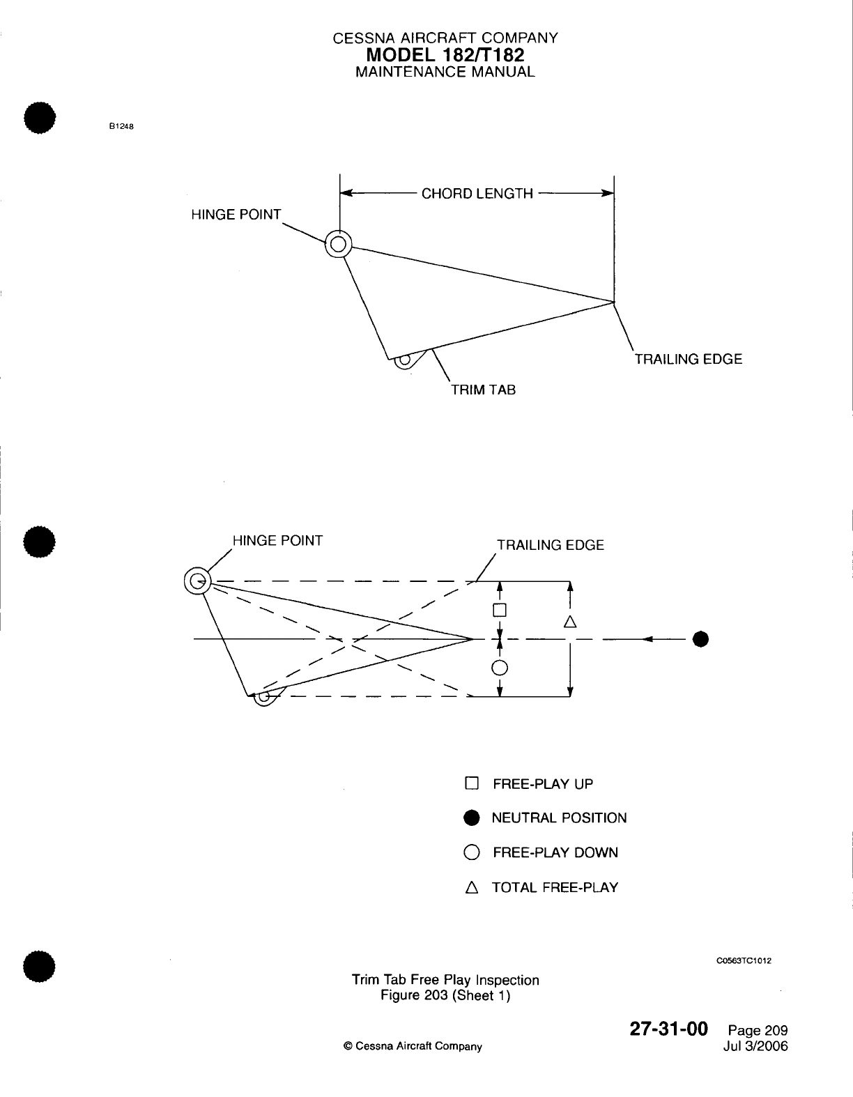
CESSNA
AIRCRAFT
COMPANY
MODEL
182/T182
MAINTENANCE
MANUAL
B1248
CHORD
LENGTH
HINGE
POINT
TRAILING
EDGE
TAB
HINGE
POINT
TRAILING
TRAILING
EDGE
t
A
O
FREE-PLAY
UP
N
FREE-PLAY
DOWN
TOTAL
FREE-PLAY
C0563TC1012
Trim
Tab
Free
Play
Inspection
Figure
203
(Sheet
1)
©
Cessna Aircraft
Company
27-31-00
Page
209
Jul
3/2006
CESSNA
AIRCRAFT
COMPANY
MODEL
182/T182
MAINTENANCE
MANUAL
(7)
If
looseness
is
apparent
while
you
check
the push-pull
tube/tab
horn
assembly, install
new
parts
to
repair.
(8)
If
looseness
is
apparent
while
you
check
the
push-pull
tube/actuator
assembly threaded
rod-end
assembly,
install
new parts
to
repair.
(9)
If
looseness
is
apparent
while
you
check
the
push-pull
tube
threaded
rod
end
in
the
actuator
assembly,
the
threaded
rod
end
is
out
of
tolerance
and
you
must
replace
it.
6.
Trim
Tab
Control
Cables
and
Pulleys Removal/Installation
A.
Cables
and
Pulleys
Removal
(Refer
to Figure
201).
CAUTION:
Position
a
support
stand under
the
tail
tiedown
ring
to
prevent
the
tailcone
from
falling
while
a
person
works
inside.
(1)
Remove the
crew
seats
and
the rear
seat.
Refer
to
Chapter
25,
Front
Seats and Rails
-
Maintenance
Practices
and
Rear
Seat
-
Maintenance
Practices.
(2)
Remove the
pedestal
cover.
(3)
Remove the
access
panel
(31
OAR),
access
plates
(230DB, 230LB,
231 LB,
31
OBB,
and
310CB),
and
fairings
(340AL
and
340AR)
for
access.
Refer
to
Chapter
6,
Access/Inspection
Plates
-
Description
and
Operation.
(4)
Remove
the stop
blocks
from
the
control
cables.
(5)
Remove the
cable
guard
from
the
actuator.
(6)
Remove
the
safety
clip
from
the
turnbuckle
and
disconnect
the cable.
(7)
Disconnect
the
cables
at
the
cable
ends.
NOTE:
To
ease
the
routing
of
the
cables,
a
length
of
wire
can be
attached
to
the
end
of
the
cable
before
you
remove
it
from
the
airplane.
You
can leave
the
wire
in
place,
routed
through the
structure.
Then you
can
attach
the
new
cable
and pull
it
into
position.
(8)
Remove
the
cable
guards
and
the
pulleys.
(9)
Disengage
the
chains
from the
sprockets
and
remove
the
cables
from
the
airplane structure.
B.
Cables
and
Pulleys Installation
(Refer
to
Figure
201).
(1)
Attach the
cables
to
the
wires
that
are
routed
through
the
airplane structure
and pull
the
cables
into
position.
(2)
Engage the
chains
on
the
sprockets
and
install
the chain
guard
on
the
actuator.
(3)
Install
the
pulleys
and the
pulley
guards.
(4)
Connect
the
cable ends
and
install
the
turnbuckle.
(5)
Rig
the
system. Refer
to
Trim
Tab
Control
Adjustment/Test.
(6)
Install
the
access
panel
(310AR),
access plates
(230DB,
230LB, 231LB,
310BB,
and
310CB),
and
fairings
(340AL
and
340AR)
removed
to get
access.
Refer
to
Chapter
6,
Access/Inspection
Plates
-
Description
and
Operation.
(7)
Install
the
pedestal cover.
(8)
Install
the crew
seats
and the
rear
seat.
Refer
to
Chapter
25,
Front
Seats
-
Maintenance
Practices
and
Rear
Seat
-
Maintenance
Practices.
(9)
Remove
the support
stand.
7.
Trim
Tab
Control
Wheel
RemovaVlnstallation
A.
Trim
Tab
Control Wheel Removal (Refer
to
Figure
201).
(1)
Relieve
cable
tension
at
the
turnbuckle.
(2)
Remove the
pedestal
cover.
(3)
Remove the
screws
that
attach the
control
wheel
retainer.
(4)
Remove
the retainer
and
the
pointer.
Do
not
drop
the trim
control
wheel.
B.
Trim
Tab
Control
Wheel Installation
(Refer
to
Figure
201).
(1)
Install
the
retainer and the pointer
with
the
screws.
(2)
Install
the
pedestal cover.
(3)
Set
the
cable tension
at
the
turnbuckle.
Refer
to
Trim
Tab
Control
Adjustment/Test.
27-31-00
Page
210
©
Cessna Aircraft
Company
Jul
3/2006
CESSNA
AIRCRAFT
COMPANY
MODEL
182/T182
MAINTENANCE
MANUAL
8.
Trim
Tab
Control
Adjustment/Test
A.
Set
Trim
Tab
Control
Cable
Tension
(Refer
to Figure
204
and
Figure 205).
CAUTION:
Position
a
support
stand under
the
tail
tiedown
ring
to
prevent
the
tailcone
from
falling
while
a
person
works
inside.
(1)
Remove
the
access
panel (310AR)
and
the
access
plates
as
necessary. Refer
to
Access/
Inspection Plates
-
Description
and
Operation.
(2)
Loosen
the
travel
stop
blocks
on
the
cables.
(3)
Disconnect
the
actuator
from the trim
tab
push-pull
tube.
(4)
Adjust
the
turnbuckle
as
necessary
to get
15
to
20
pounds
(66.72
to
88.96
N)
of
cable
tension
at
70
°F
(21
°C).
Refer
to
the
Charts
in
Figure
205
for
the
correct
tensions
at
other
temperatures.
(5) If
this
trim
tab
adjustment/test
is
done
as part
of
a
chain
and/or
cable installation,
let
the
actuator
screw
turn
freely,
because
the
chains
and
the
cables
are
connected.
(6)
Adjust
the
cable tension
and
safety
the
turnbuckle.
(7)
Turn
the
trim wheel
full
forward
(nose
down). Make
sure
that the pointer
does
not
decrease
the
trim
wheel
movement.
If
necessary,
move
the
pointer
to
a
new
position.
To
move
the
pointer
to
a
new
position,
you can
pry the
trailing
leg
of
the pointer
out
of
the
groove with
a
thin
screwdriver
if
necessary.
NOTE:
At
the
full forward
(nose
down)
position
of
the
trim
wheel,
more
forward
movement
is
prevented
because
the
chain
or
the
cable
ends
contact
the
sprockets
or
the
pulleys.
(8)
With
the
elevator
and
the
trim
tab
both
in
neutral
(streamlined),
mount
an
inclinometer
on
the
tab
and set
it
at
0
degrees.
Ignore
the
counterweight
areas
of
the
elevators when
you
streamline.
These
areas
are
contoured
so
they
will
be
approximately
3
degrees
down at
cruising
speed.
NOTE: Neutral
positions
for
the
elevators
are
streamlined
with
the
horizontal
stabilizer.
Ignore the
counterweight
areas of
the
elevators when
you
streamline.
These
areas
are
contoured
so
they
will
be
approximately
3
degrees
DOWN at
cruising speed.
NOTE:
An
inclinometer
for
measuring control
surface
travel
is
available
from
the
Cessna
Parts
Distribution.
(9)
Turn the
trim
tab
actuator
screw
in
or
out
as
required
to
place
the
trim
tab
up
with
a
maximum
of
2
degrees overtravel,
with
the
actuator
screw connected
to the
push-pull
tube.
(10)
Turn the
trim wheel
to
position the
trim
tab
up
and
down,
and
adjust
the
actuator
screws
as
required
to
get
correct
travel
in
both
directions.
(11)
Put
the
stop
blocks
in
position. Refer
to Figure
204.
(a)
With
the
elevators
in
neutral,
set
the
trim tab
to
neutral.
(b)
Position
the
stop block
(2)
approximately
0.25
inch
(6.35
mm)
forward
of
the
turnbuckle.
(c)
Position the
stop
block
(3)
approximately
0.25
inch
(6.35
mm)
aft
of
the
turnbuckle.
(d)
Attach
the
stop
blocks
(2)
and
(3)
to
cable
A.
(e)
Put
the
inclinometer
on
the trim
tab and lower
it
to
15
degrees,
+1
or
-1
degree.
(f)
Put
the
stop
block
(4)
against
the
stop
block
(3)
and
attach
it
to
cable
B.
(g)
Run
the
trim
tab
up
to
24
degrees,
+2
or
-2
degrees.
(h)
Place
stop
block
(1)
against
stop
block
(2)
and
attach
to
cable
B.
(12)
Make
sure
that
the
trim
wheel
pointer travels
the
same
distance
from the
ends
of
the
slot
in
the
cover.
Move
the
trailing
leg
of
the
pointer
to
a
new
position
if
necessary.
WARNING:
Make
sure
that
the
elevators
travel
in
the
correct
direction
when
you
operate the
control
column.
(13)
Move
the
control
column
to make
sure that
the
elevators
travel
in
the
correct
direction.
27-31-00
Page
211
©
Cessna Aircraft Company
Jul
3/2006
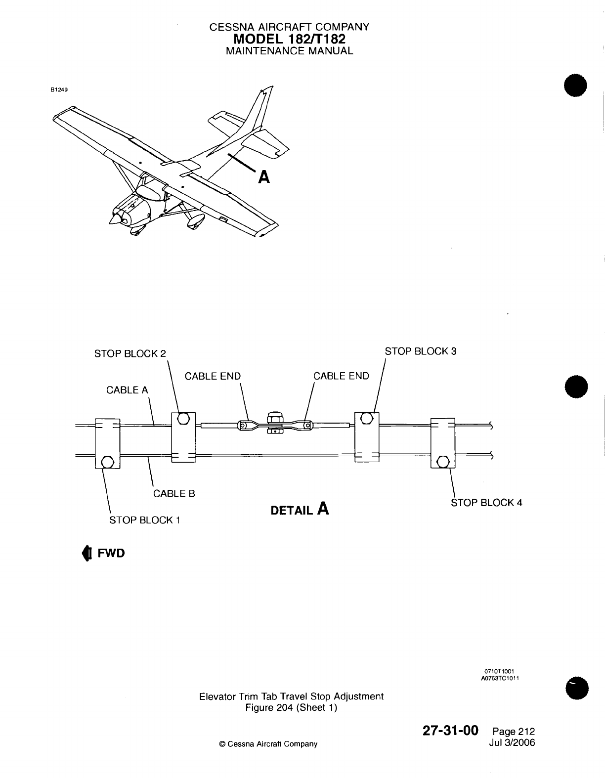
CESSNA
AIRCRAFT
COMPANY
MODEL 182/T182
MAINTENANCE
MANUAL
STOP
BLOCK
2
STOP
BLOCK
3
CABLE
END
CABLE
END
CABLE
A
CABLE
B
STOP
BLOCK
1
STOP
BLOCK
4
DETAIL
A
FWD
0710T1001
A0763TC1011
Elevator
Trim
Tab
Travel
Stop
Adjustment
Figure
204
(Sheet
1)
Cessna Aircraft
Company
27-31-00
Page
212
Jul
3/2006
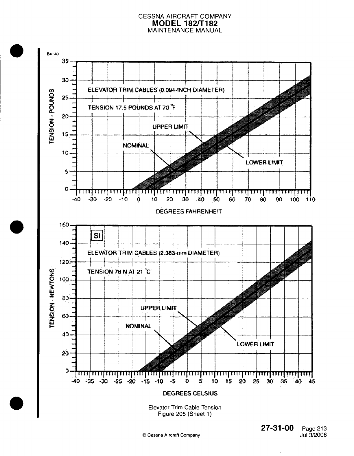
CESSNA
AIRCRAFT
COMPANY
MODEL
182/T182
MAINTENANCE
MANUAL
ft4140
35
30 -
-
ELEVATOR
TRIM
25
-TENSION
175
PO
20
z
5
10
-
5
0
-40
-30
-20
-1
0
10
20
30 40
50
60 70
80
90
100
10
DEGREES FAHRENHEIT
160
140
ELEVATOR
TRIM
C
120.
TENSION
78
N
AT
100
60
40
20
0
-40
35
-30
-25
-20 -15
-1
-5
0
5
10
15
20
25
30
35 40
45
DEGREES
CELSIUS
Elevator
Trim
Cable Tension
Figure
205 (Sheet
1)
27-31-00
Page
213
©
Cessna
Aircraft
Company
Jul
3/2006
CESSNA
AIRCRAFT
COMPANY
MODEL
182/T182
MAINTENANCE
MANUAL
(14)
Make
sure
that the
trim tab
moves
in
the
correct direction
when
it is
operated
by
the
trim
wheel.
NOTE:
Nose
down
trim
corresponds
to
the tab
UP
position.
(15)
Safety
the
turnbuckle
(Refer to
Chapter
20,
Safetying
-
Maintenance Practices).
(16)
Install
all
of the
items
that you
removed
to
get
access
to
the
components.
(17)
Remove
the
support
stand.
27-31-00
Page
214
©
Cessna
Aircraft
Company
Jul
3/2006
CESSNA
AIRCRAFT
COMPANY
MODEL
182/T182
MAINTENANCE
MANUAL
STALL
WARNING
SYSTEM
-
MAINTENANCE PRACTICES
1.
General
A.
The
stall
warning
system
includes
a
stall
warning
horn
and
stall
detector.
The
stall
warning
horn
is
located inside
the
cabin behind
the
headliner,
overhead
and
to
the
outboard side
of
the pilot,
on
the
fuselage
rib.
The
(heated)
stall
detector
is
mounted
on
the leading edge
of
the
left
wing
at
WS
91.25.
The
PITOT HEAT/OFF
switch
on
the
circuit
panel
assembly
provides
power
to
the heating
element
of
the
stall detector.
B.
The
stall
detector
is
actuated
by
airflow
over
the surface
of
the
wing.
The
stall
detector
internal
switch
will
close
as
a
stall
condition
is
approached, actuating
the
stall
warning
horn.
The
stall
detector
should
actuate
the
stall
warning
horn
approximately
4.5 to
9.0
knots
above airplane
stall
speed.
2.
Stall
Warning
Horn
Assembly
Removal
and
Installation
A.
Remove
Stall Warning
Horn
Assembly
(Refer
to
Figure
201).
(1)
Remove
electrical
power
from
airplane.
Disengage
WARN
circuit breaker
on
circuit
panel
assembly.
(2)
Remove
headliner
to access
stall
warning
horn
assembly. Refer
to Chapter
25,
Interior
Upholstery
-
Maintenance
Practices.
(3)
Identify,
tag,
and
disconnect
stall
warning
horn
wiring
at
stall
warning
horn
connector
(P1/JC030).
(4)
Remove nuts
and
washers securing
stall
warning
horn
assembly
to
adapter
plate.
(5)
Remove
stall
warning
horn
assembly
from
airplane.
B.
Install Stall Warning
Horn
Assembly
(Refer
to
Figure
201).
(1)
Position stall
warning
horn
on
adapter plate
and
secure
with
nuts
and
washers.
(2)
Connect
stall
warning
horn
wiring at
stall warning
horn
connector
(P1/JC030).
(3)
Install
headliner.
Refer
to
Chapter
25,
Interior Upholstery
-
Maintenance Practices.
(4)
Restore
electrical
power
to
airplane.
Engage
WARN
circuit
breaker
on
circuit
panel
assembly.
3.
Stall Detector
Removal
and
Installation
A.
Remove
Stall
Detector
(Refer
to
Figure
201).
(1)
Remove
electrical
power
from
airplane.
Disengage
WARN
circuit
breaker
on
circuit
panel
assembly
and
place
PITOT
HEAT/OFF
switch
to
OFF.
(2)
Remove
access
plate 610JB
to
access
stall detector.
Refer
to
Chapter
6,
Access/Inspection
Plates
-
Description
and
Operation.
(3)
Identify,
tag,
and
disconnect
electrical
wiring
from
stall
detector
and
disconnect
stall
warning
connector
(JL021/PL021).
(4)
Remove
screws and
nuts
securing
stall
detector
to
wing
leading
edge.
(5)
Remove stall
detector
from
airplane.
B.
Install Stall
Detector
(Refer
to
Figure
201).
(1)
Place
stall
detector
at
access
plate
opening
and
connect
electrical
wiring to
stall
detector
and
connect
stall warning
connector
(JL021/PL021).
(2)
Position
stall
detector
at
wing
leading edge
and
secure
with
screws
and
nuts.
NOTE:
The
lip
of
the
stall
detector
needs
to
be
approximately
0.06 of
an
inch
(1.52
mm)
below the
centerline
of
the
wing skin
cutout.
(3)
Install
access
plate 610JB.
Refer to
Chapter
6,
Access/Inspection
Plates
-
Description
and
Operation.
(4)
Restore
electrical
power
to
airplane.
Engage
WARN
circuit
breaker
on
circuit
panel
assembly.
(5)
Adjust
stall detector.
Refer
to
Stall
Detector
Adjustment.
27-32-00
Page
201
©
Cessna
Aircraft
Company
April
1/2002
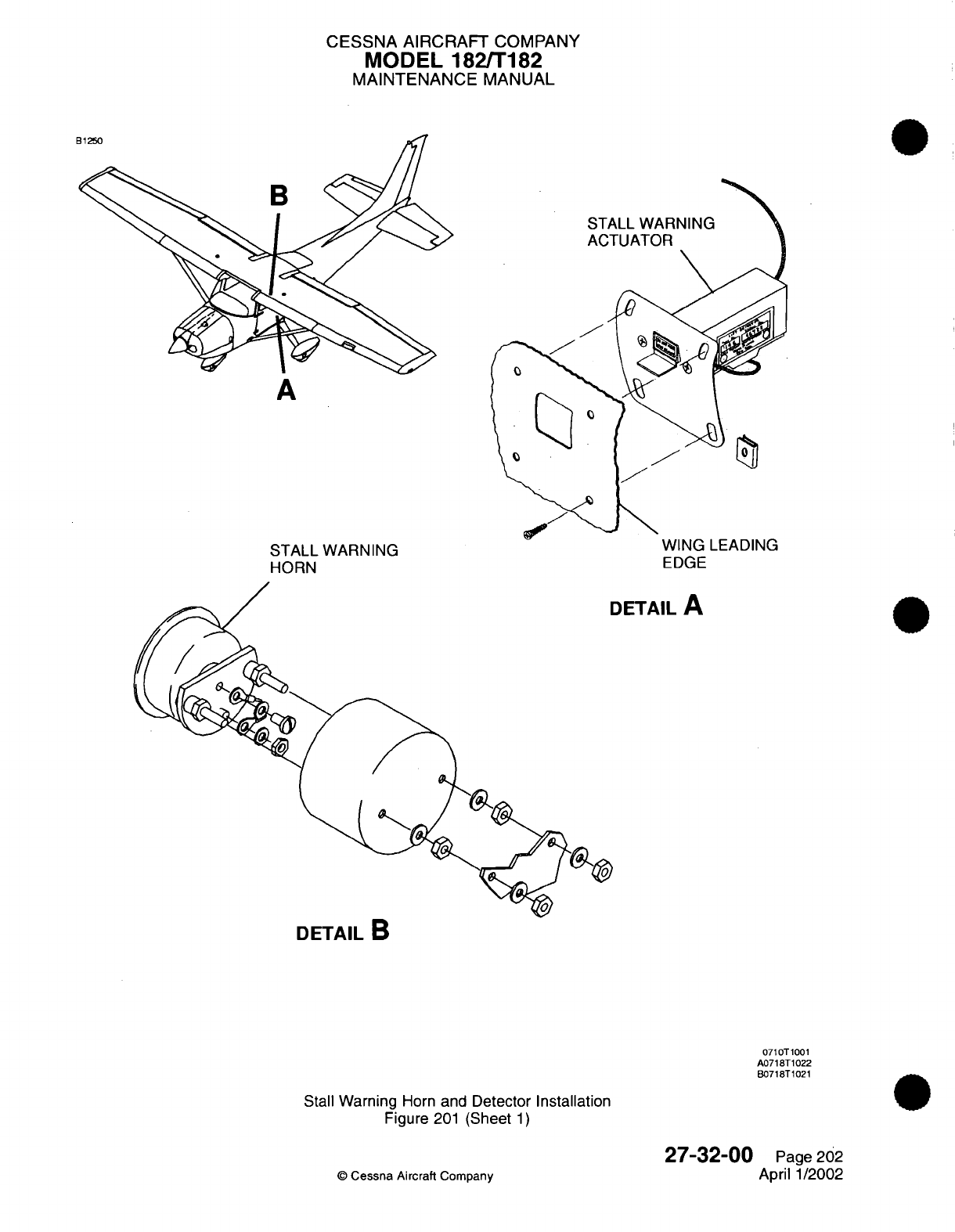
CESSNA AIRCRAFT
COMPANY
MODEL 182/T182
MAINTENANCE
MANUAL
A
STALL
WARNING
HORN
WING
LEADING
EDGE
)ETAIL
A
DETAIL
B
0710T1001
A0718T1022
B0718T1021
Stall
Warning
Horn
and
Detector
Installation
Figure
201
(Sheet
1)
©
Cessna
Aircraft
Company
27-32-00
Page
202
April 1/2002
CESSNA
AIRCRAFT
COMPANY
MODEL
182/T182
MAINTENANCE
MANUAL
4.
Stall
Detector
Adjustment
A.
Adjust
Stall
Detector.
(1) It
is
necessary
to
test
fly
the
airplane
to
determine
if
the
stall
detector
actuates
the
stall
warning
horn
at
the
desired
speed.
Make
the
following adjustments
to
stall detector
based
on
results
of
test
flight.
(a)
If
stall
warning
horn
sounds
at
speeds
in
excess
of
9.0
knots
above
stall
speed,
then
loosen
stall
detector
mounting screws
and
move stall
detector
slightly
down.
Refer
to
Stall Detector
Removal
and
Installation.
WARNING:
Do
not allow
airspeed
to
drop
below airplane
stall
speed.
(b)
If
stall
warning
horn
does
not
sound
before
reaching
stall
speed
plus
4.5
knots (4.5
knots
above
stall
speed),
then
loosen
stall
detector
mounting screws
and move
stall detector
slightly
up.
Refer
to
Stall
Warning
System
-
Maintenance
Practices, Stall
Detector
Removal
and
Installation.
(2) A
successful
test
of
the
stall warning
system
will
cause
the
stall warning
horn
to
sound
at
4.5
to
9.0
knots
above airplane
stall
speed.
27-32-00
Page
203
©
Cessna
Aircraft
Company
April
1/2002

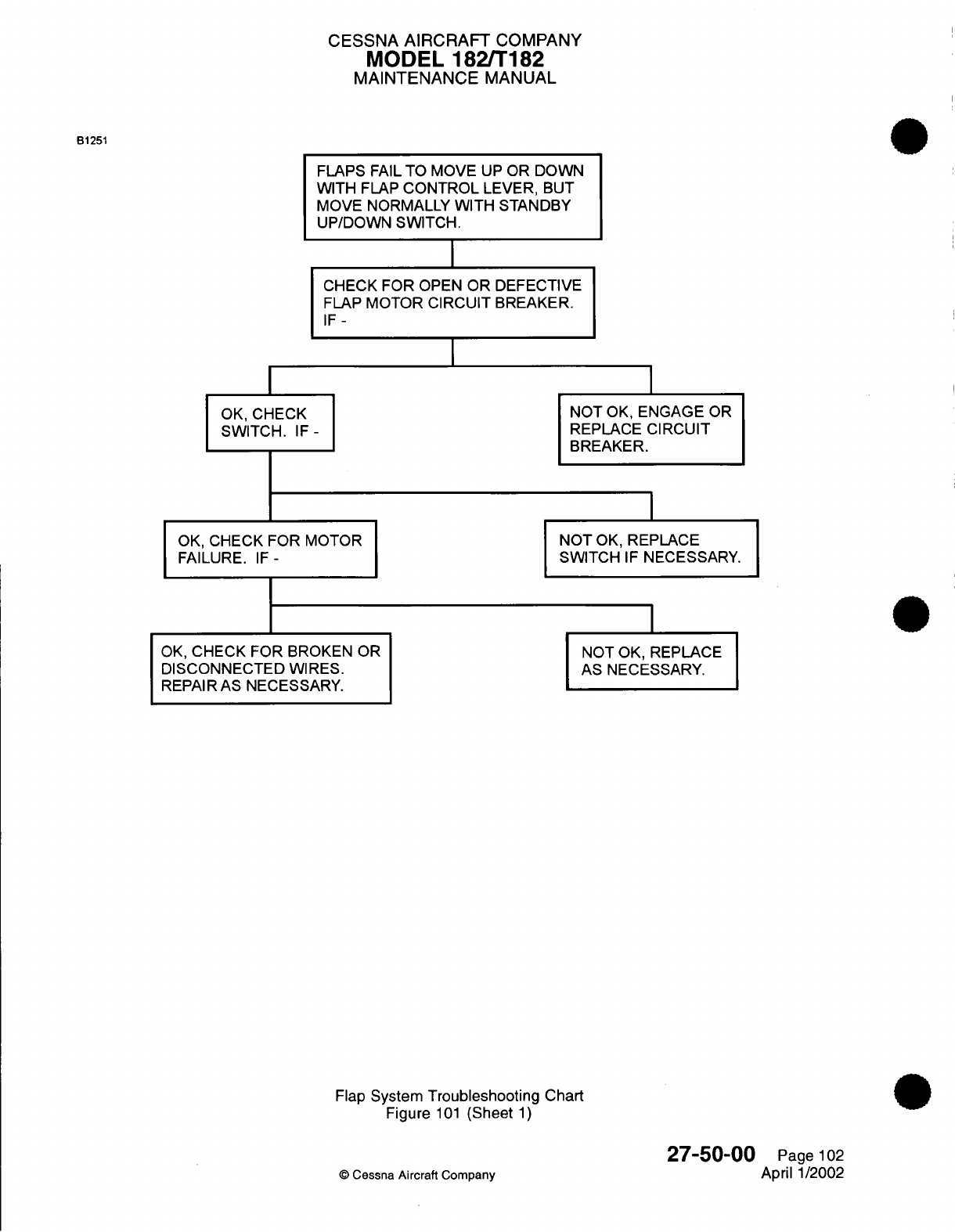
CESSNA
AIRCRAFT
COMPANY
MODEL
182/T182
MAINTENANCE
MANUAL
B1251
FLAPS
FAIL
TO
MOVE
UP
OR
DOWN
WITH
FLAP
CONTROL
LEVER,
BUT
MOVE
NORMALLY
WITH
STANDBY
UP/DOWN SWITCH.
I
CHECK FOR OPEN
OR
DEFECTIVE
FLAP
MOTOR
CIRCUIT
BREAKER.
IF-
OK,
CHECK
SWITCH.
IF-
OK,
CHECK FOR MOTOR
FAILURE.
IF-
OK,
CHECK FOR
BROKEN
DISCONNECTED
WIRES.
REPAIR
AS
NECESSARY.
OR
NOT
OK,
ENGAGE
OR
REPLACE CIRCUIT
BREAKER.
NOT
OK,
REPLACE
SWITCH
IF
NECESSARY.
NOT OK, REPLACE
AS NECESSARY.
Flap
System
Troubleshooting
Chart
Figure
101
(Sheet
1)
©
Cessna
Aircraft
Company
27-50-00
Page
102
April
1/2002
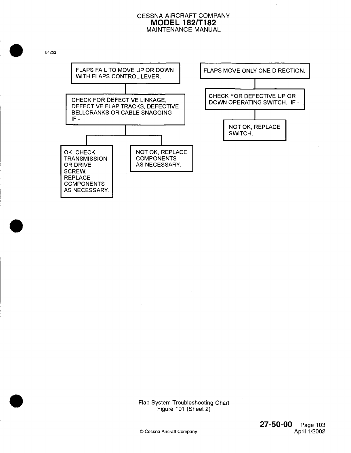
CESSNA
AIRCRAFT
COMPANY
MODEL
182/T182
MAINTENANCE
MANUAL
B1252
FLAPS
FAIL
TO
MOVE
UP
OR
DOWN
WITH FLAPS
CONTROL
LEVER.
CHECK
FOR DEFECTIVE
LINKAGE,
DEFECTIVE FLAP
TRACKS, DEFECTIVE
BELLCRANKS OR
CABLE
SNAGGING.
IF-
OK,
CHECK
TRANSMISSION
OR DRIVE
SCREW.
REPLACE
COMPONENTS
AS
NECESSARY.
FLAPS MOVE
ONLY
ONE
DIRECTION.
I
CHECK
FOR
DEFECTIVE
UP
OR
DOWN
OPERATING SWITCH.
IF
-
NOT
OK,
REPLACE
SWITCH.
NOT
OK,
REPLACE
COMPONENTS
AS
NECESSARY.
Flap
System
Troubleshooting
Chart
Figure
101
(Sheet
2)
©
Cessna Aircraft
Company
27-50-00
Page
103
April
1/2002
I
I
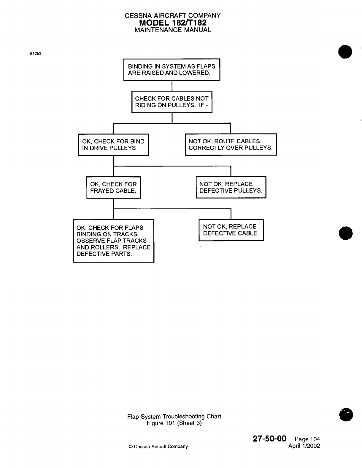
CESSNA AIRCRAFT
COMPANY
MODEL 182/T182
MAINTENANCE
MANUAL
BINDING
IN
SYSTEM
AS
FLAPS
ARE
RAISED
AND
LOWERED.
I
CHECK FOR CABLES
NOT
RIDING
ON
PULLEYS.
IF
-
I
OK,
CHECK
FOR
BIND
IN
DRIVE
PULLEYS.
OK,
CHECK
FOR
FRAYED
CABLE.
OK,
CHECK FOR
FLAPS
BINDING
ON
TRACKS
OBSERVE
FLAP
TRACKS
AND
ROLLERS.
REPLACE
DEFECTIVE
PARTS.
NOT
OK,
ROUTE
CABLES
CORRECTLY
OVER PULLEYS.
I
NOT
OK,
REPLACE
DEFECTIVE
PULLEYS.
I
NOT
OK,
REPLACE
DEFECTIVE CABLE.
Flap
System
Troubleshooting
Chart
Figure
101
(Sheet
3)
27-50-00
©
Cessna
Aircraft
Company
B1253
Page
104
April
1/2002

CESSNA AIRCRAFT
COMPANY
MODEL
182/Ti182
MAINTENANCE
MANUAL
FLAP CONTROL
SYSTEM
-
MAINTENANCE PRACTICES
1.General
A.
The
wing
flap
control system
contains
an
electric
flap
motor,
transmission
assembly,
drive pulleys,
push-pull
rods,
cables,
and
a
follow-up
control.
Power
from
the
motor
and
the
transmission
assembly
is
transmitted
to
the
flaps
by
a
system
of
drive
pulleys, cables,
and
push-pull
rods.
Electric power
to
the
motor
is
controlled
by
two
microswitches
mounted
on
a
floating
arm
assembly,
a
cam
lever,
and
a
follow-up
control.
As
the
flap
control
lever
is
moved
to
the
desired
flap setting,
the
attached
cam
trips
one
of
the
microswitches,
activating
the
flap
motor.
As
the
flaps
move
to
the
position
selected,
the
floating
arm
is
rotated
by
the
follow-up
control
until
the
active
microswitch
clears
the
cam,
breaking
the circuit
and
stopping
the
motor.
To
reverse flap
direction,
the
control lever
is
moved
in
the
opposite
direction,
causing
the cam
to
trip
the
second
microswitch, which
reverses
the
flap
motor.
The
follow-up
control
moves
the
cam
until
it is
clear
of
the
second
switch,
shutting
off
the
flap
motor.
Limit
switches
at
the
flap
actuator
assembly
control flap
travel
as the
flaps
reach
the
full
UP
or
DOWN
positions.
*
B.
For
a
schematic
of
the
flap system, refer
to
Figure
201.
2.
Flap
Motor
and
Transmission Assembly Removal/Installation
*
A.
Flap
Motor
(MR001) and
Transmission Assembly
Removal (Refer
to
Figure
202).
(1)
Lower
the
flaps
fully.
(2)
Set the ALT/BAT
MASTER
switch
to
the
off
position.
(3)
Remove
the
access
panels
61
OBB
and
61
OCB.
Refer
to
Chapter
6,
Access/inspection
Plates
-
Description
and
Operation.
(4)
Remove
the
bolt
that attaches
the
actuating
tube
to
the
drive
pulley.
(5)
Turn
the
actuating
tube
in
toward
the
transmission
as
far
as
possible
by
hand.
(6)
Remove the bolt
that attaches
the
flap
motor hinge
to
the
wing.
Keep
the
brass
washer
between
the
hinge
and
the
wing structure.
(7)
Disconnect
the
electrical connectors
from
the flap
motor
(MR001).
(8)
Disconnect
the
electrical
connectors
from
the
up
limit
switch
(SR001)
and
the
down
limit
switch
(SR002).
(9)
Carefully
remove
the
flap
motor
and the
transmission assembly
from
the
wing
through the
access
opening.
*
B.
Flap
Motor
and
Transmission Assembly
Installation
(Refer
to
Figure
202).
(1)
Carefully
install
the
flap
motor
and
the
transmission assembly
into
the
wing
through the
access
opening.
If
the hinge
assembly
was
removed
from
the
transmission,
make
sure
that
the
short
end
of
the
hinge
is
installed toward
the top.
(2)
Connect
the
electrical connectors
to
the
flap
motor
(MR001).
(3)
Connect the
electrical
connectors
to the
up limit
switch
(SR001)
and
the down limit
switch
(SR002).
(4)
Attach the
flap
motor
hinge
to
the
wing
with the bolt
and the
brass
washer.
(5)
Turn
the
actuating
tube
out toward the
bell
crank.
(6)
Install
the bolt
that
attaches
the
actuating
tube
to
the drive
pulley.
(7)
Install
the
access
panels
61OBB
and
610CB. Refer
to
Chapter
6,
Access/inspection
Plates
-
Description
and
Operation.
(8)
Set
the
ALT/BAT
MASTER
switch
to the
ON
position.
(9)
Make sure
that
the
flaps
operate correctly.
Refer
to
Flap
System
Adjustment/Test
for
rigging
instructions.
3.
Flap
Removal/Installation
*
A.
Flaps
Removal
(Refer
to
Figure
202).
(1)
Lower the
flaps fully
with
the
flap
selector
switch.
(2)
Set the
ALT/BAT
MASTER
switch
to
the
off
position.
(3)
Remove
access
panels
511AT
(611AT),
511BT
(6111BT),
511CT
(611CT),
and
511DT
(611DT)
from the
leading
edge
of the
flap.
Refer
to
Chapter
6,
Access/Inspection
Plates
-
Description
(4
aisondOecatitepshplordanhefa.bakt
a4
isondOeration.shpl
rda
hefabakt
27-50-00
Page
201
©
Cessna
Aircraft
Company
Jul 1/2007

CESSNA AIRCRAFT
COMPANY
MODEL
1821T182
MAINTENANCE
MANUAL
B1 724
FWD
FLAP
MOTOR
AND
DRIVE
PULLEY
DRIVE
PULLEY SETSCREW
TURNBUCKLES
PUSH-PULL
PUSH-PU
LL
ROD
ROD
TO
LEFT
WING
FLAP
TO
RIGHT
WING
FLAP
VIEW
LOOKING
DOWN
0525T1
007
Flap
System
Schematic
Figure
201
(Sheet
1)
27-50-00
0
Cessna
Aircraft
Company
Page
202
Jul
1/2007
)R
I
;I
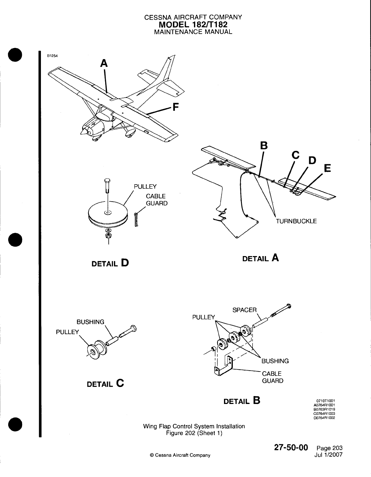
CESSNA AIRCRAFT
COMPANY
MODEL
182/Ti
82
MAINTENANCE
MANUAL
C2
3LE
kRD
DETAIL
D
BUSHING
PUL
SPACER
DETAIL
C
GUARD
DETAIL
B
Wing
Flap
Control
System Installation
Figure
202
(Sheet
1)
©
Cessna
Aircraft
Company
DETAIL
A
BUSHING
0710T1001
A076AR
1001
607638R1019
C0764R1
003
D076481002
27-50-00
Page
203
Jul 1/2007
I
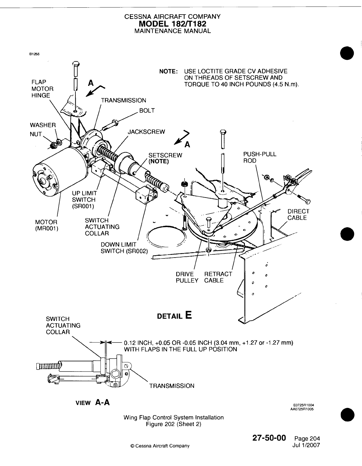
CESSNA
AIRCRAFT
COMPANY
MODEL
182/1182
MAINTENANCE
MANUAL
81255
TRANSMISSION
BOLT
S El
(NC
NOTE:
USE
LOCTITE
GRADE
CV
ADHESIVE
ON
THREADS
OF
SETSCREW
AND
TORQUE
TO 40
INCH
POUNDS
(4.5
N~m).
rsCREW
PUSH-PULL
ITE)
II
ROD
SWITCH
ACTUATING
COLLAR
DOWN
LIMIT
SWITCH (SR002)
DRIVE
RETRACT
PULLEY CABLE
AU
IUA
IINU
COLLAR
DETAIL
E
0
0
C
0
0
\PS
IN
THE
FULL
UP
POSITION
TRANSMISSION
VIEw
A-A
Wing
Flap
Control
System
Installation
Figure 202 (Sheet
2)
27-50-00
©
Cessna
Aircraft
Company
FLAP
MOTOR
HINGE
A
UP
LIMIT
SWITCH
(SR001)
MOTOR
(MR001)
E0725R
1004
AA0725R
1005
Page
204
Jul
1/2007
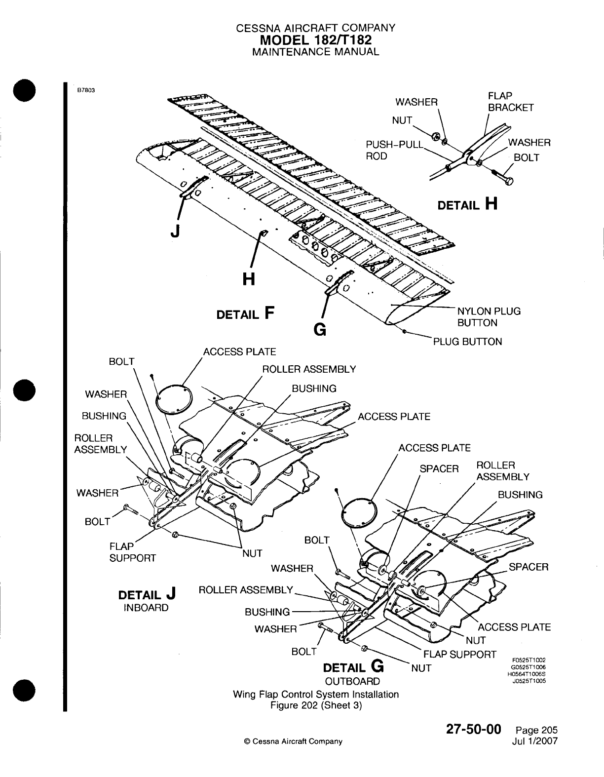
CESSNA
AIRCRAFT
COMPANY
MODEL
182/7182
MAINTENANCE
MANUAL
B7803
J
H
DETAIL
F
PLUG
N
G
ACCESS PLATE
P'LUU
IIU
I I
UN
DETAIL
U
NUT
G0525T1
006
OUTBOARD
J5510
Wing
Flap
Control
System Installation
Figure
202
(Sheet
3)
27-50-00
©
Cessna
Aircraft
Company
Page
205
Jul
1/2007
WASHER
:)
0
Ar'V
It CT
i
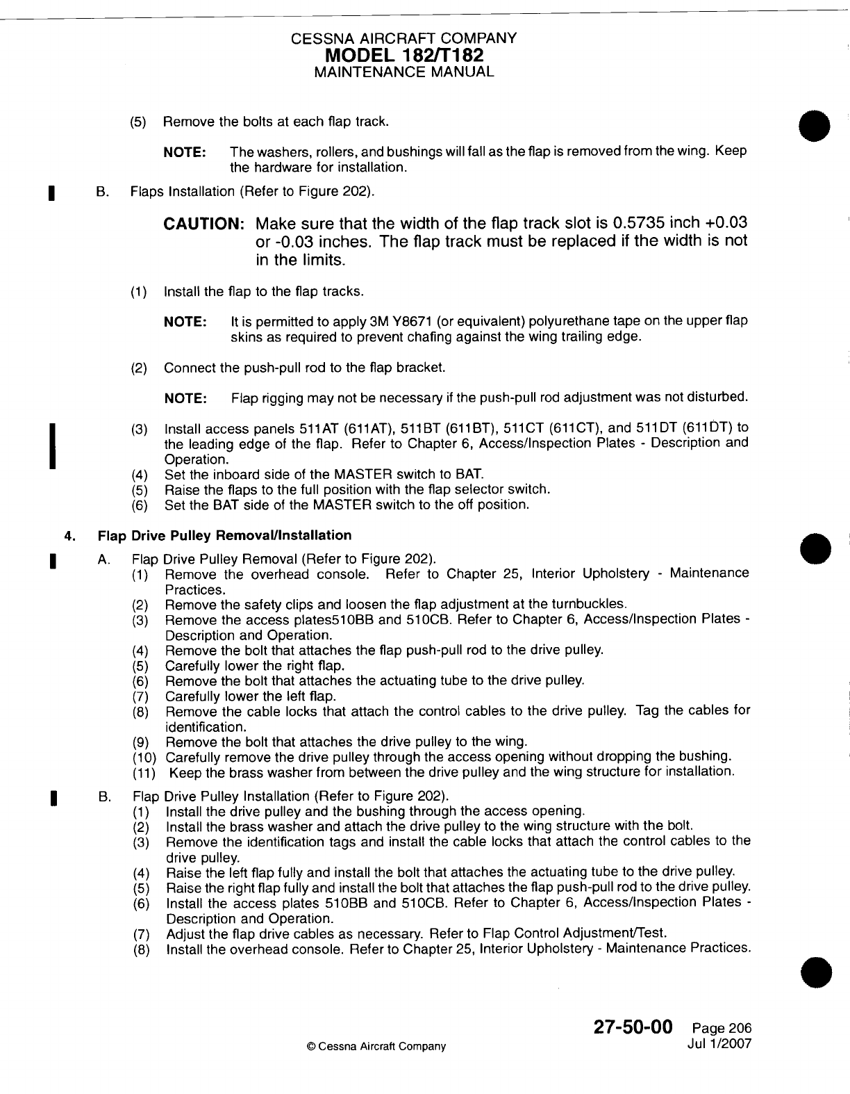
CESSNA
AIRCRAFT
COMPANY
MODEL
182/Ti182
MAINTENANCE
MANUAL
(5)
Remove
the
bolts
at
each
flap
track.
NOTE:
The washers, rollers,
and
bushings
will
fall
as
the
flap
is
removed
from
the
wing.
Keep
the
hardware
for
installation.
*
B.
Flaps
Installation
(Refer
to
Figure
202).
CAUTION:
Make
sure
that
the
width
of
the
flap
track
slot
is
0.5735
inch
+0.03
or
-0.03
inches.
The
flap
track
must
be
replaced
if
the
width
is not
in
the
limits.
(1)
Install the
flap
to
the
flap
tracks.
NOTE:
It is
permitted
to
apply
3M
Y8671
(or
equivalent) polyurethane
tape
on
the
upper
flap
skins
as
required
to
prevent
chafing
against
the
wing
trailing
edge.
(2)
Connect
the
push-pull
rod to
the
flap
bracket.
NOTE:
Flap
rigging may
not
be
necessary
if
the
push-pull
rod
adjustment was
not
disturbed.
(3)
Install
access
panels
511
AT
(61
1AT),
511
BT
(611
BT),
51liCT
(611
CT), and
511
DT
(611
DT)
to
the
leading edge
of
the
flap.
Refer
to
Chapter
6,
Access/Inspection
Plates
-
Description
and
I ~ ~~~Operation.
(4)
Set
the
inboard
side
of
the MASTER
switch
to
BAT.
(5)
Raise
the
flaps
to
the
full
position
with
the
flap
selector
switch.
(6)
Set the
BAT
side
of
the
MASTER
switch
to
the
off
position.
4.
Flap
Drive
Pulley
RemovaVlnstallation
*
A.
Flap
Drive
Pulley
Removal
(Refer
to
Figure
202).
(1)
Remove
the overhead
console.
Refer
to
Chapter
25,
Interior
Upholstery
-
Maintenance
Practices.
(2)
Remove
the
safety
clips
and
loosen
the
flap
adjustment
at
the
turnbuckles.
(3)
Remove
the
access
plates~l
OBB and
51
OCB.
Refer
to
Chapter
6,
Access/inspection
Plates
-
Description
and
Operation.
(4)
Remove
the
bolt
that
attaches
the
flap
push-pull
rod
to
the
drive pulley.
(5)
Carefully lower
the
right
flap.
(6)
Remove
the
bolt
that
attaches
the
actuating
tube
to the
drive pulley.
(7)
Carefully
lower
the
left
flap.
(8)
Remove the
cable
locks that
attach
the
control
cables
to the
drive
pulley.
Tag
the
cables
for
identification.
(9)
Remove
the
bolt
that attaches
the
drive
pulley
to
the
wing.
(1 0)
Carefully
remove
the
drive
pulley
through
the
access
opening
without dropping
the
bushing.
(11)
Keep
the
brass
washer
from between the
drive
pulley
and
the
wing
structure
for
installation.
*
B.
Flap
Drive
Pulley
Installation
(Refer
to
Figure
202).
(1)
Install the
drive
pulley
and
the
bushing through
the
access
opening.
(2)
Install
the
brass
washer
and
attach
the
drive
pulley
to
the wing
structure
with
the
bolt.
(3)
Remove
the
identification tags
and
install
the
cable
locks
that
attach
the
control
cables
to
the
drive
pulley.
(4)
Raise
the left
flap
fully
and
install
the
bolt
that
attaches
the
actuating
tube
to
the
drive
pulley.
(5)
Raise
the
right
flap
fully
and
install
the bolt
that
attaches
the
flap
push-pull
rod
to the
drive
pulley.
(6)
Install the
access
plates
51
OBB
and
51
OCB.
Refer
to
Chapter
6,
Access/Inspection
Plates
-
Description
and
Operation.
(7)
Adjust
the
flap
drive
cables
as
necessary.
Refer
to
Flap
Control
Adjustment/Test.
(8)
Install the
overhead console.
Refer
to
Chapter
25,
Interior
Upholstery
-
Maintenance
Practices.
27-50-00
Page
206
©
Cessna
Aircraft Company
Jul
1
/2007
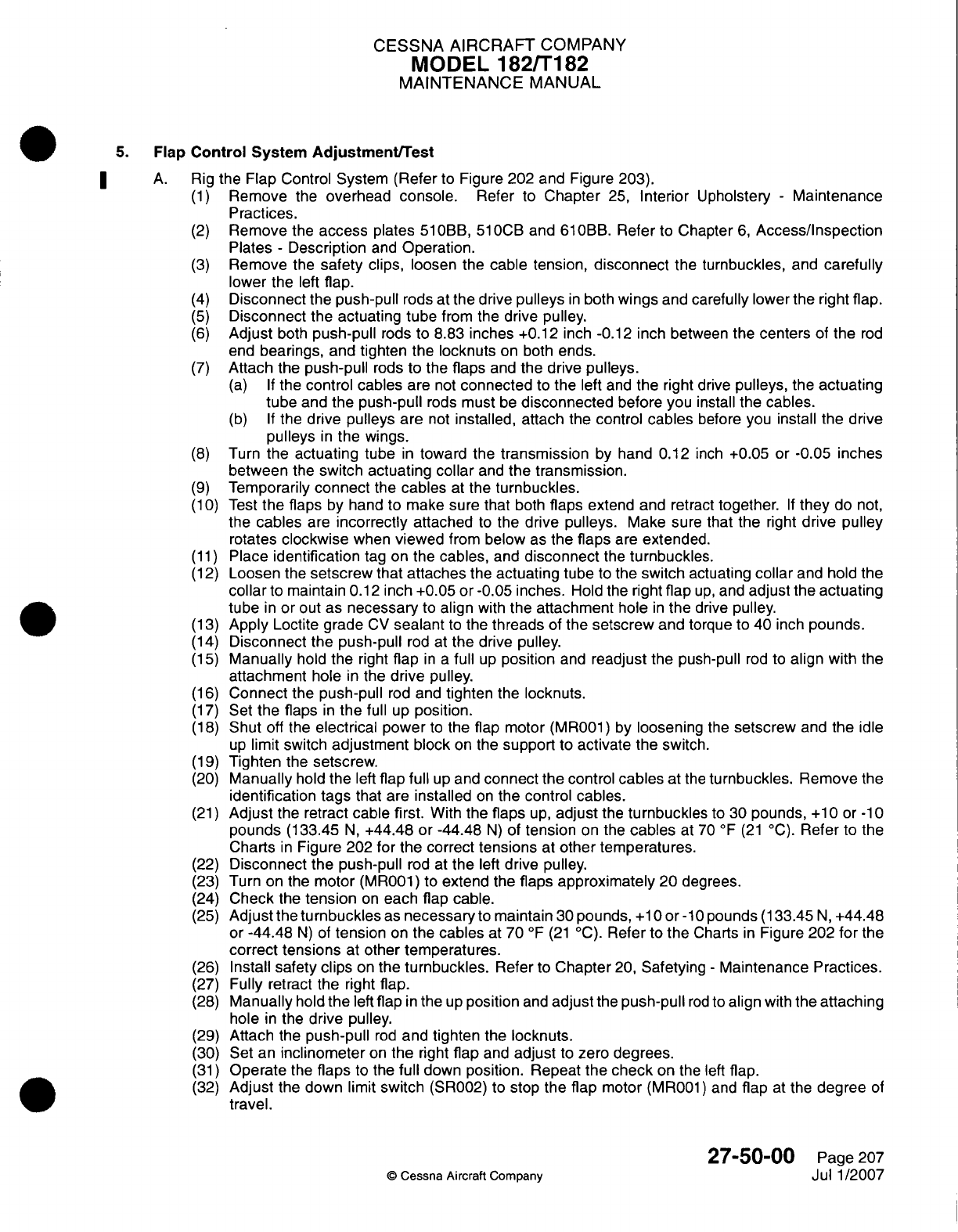
CESSNA AIRCRAFT
COMPANY
MODEL
182/Ti
82
MAINTENANCE
MANUAL
5.
Flap
Control
System
Adjustment/Test
A.
Rig
the
Flap
Control
System (Refer
to
Figure 202 and Figure 203).
(1)
Remove
the
overhead console.
Refer
to
Chapter
25,
Interior
Upholstery
-
Maintenance
Practices.
(2)
Remove
the
access
plates
510OBB,
510OCB
and
61
OBB.
Refer
to
Chapter
6,
Access/Inspection
Plates
-
Description
and
Operation.
(3)
Remove
the
safety
clips,
loosen the
cable tension,
disconnect
the turnbuckles,
and
carefully
lower
the
left
flap.
(4)
Disconnect
the
push-pull
rods
at
the
drive
pulleys
in
both
wings
and
carefully
lower
the
right
flap.
(5)
Disconnect
the
actuating
tube
from
the
drive pulley.
(6)
Adjust
both
push-pull
rods
to
8.83
inches
+0.12
inch
-0.12
inch
between
the
centers
of
the
rod
end
bearings,
and
tighten
the
locknuts
on
both
ends.
(7)
Attach
the
push-pull
rods
to
the flaps
and
the
drive
pulleys.
(a) If
the
control
cables
are
not
connected
to
the left
and
the
right drive
pulleys,
the
actuating
tube
and
the
push-pull
rods
must
be
disconnected
before
you
install
the
cables.
(b) If
the
drive
pulleys are
not
installed,
attach
the
control
cables
before
you install
the
drive
pulleys
in
the
wings.
(8)
Turn
the
actuating
tube
in
toward
the
transmission
by
hand
0.12
inch
+0.05
or
-0.05
inches
between
the
switch
actuating
collar
and
the
transmission.
(9)
Temporarily
connect
the
cables
at
the
turnbuckles.
(1
0)
Test
the flaps
by
hand
to
make sure that
both
flaps
extend
and retract
together.
If
they
do
not,
the
cables
are
incorrectly
attached
to
the
drive
pulleys.
Make
sure that
the
right
drive pulley
rotates
clockwise
when
viewed
from
below
as
the
flaps
are
extended.
(11)
Place
identification
tag
on
the
cables,
and
disconnect
the
turnbuckles.
(12)
Loosen
the
setscrew
that
attaches
the
actuating
tube
to
the
switch
actuating
collar
and
hold the
collar
to maintain
0.1
2
inch +0.05
or
-0.05
inches.
Hold the
right
flap
up,
and
adjust
the
actuating
tube
in
or
out
as
necessary
to
align
with
the
attachment
hole
in
the
drive
pulley.
(13)
Apply
Loctite grade
CV
sealant
to
the
threads
of
the
setscrew
and torque
to
40 inch
pounds.
(14)
Disconnect
the
push-pull
rod at
the
drive pulley.
(15)
Manually
hold
the
right
flap
in a
full
up
position
and
readjust
the push-pull
rod
to
align
with
the
attachment
hole
in
the
drive
pulley.
(16)
Connect
the
push-pull
rod
and
tighten
the
locknuts.
(17)
Set
the
flaps
in
the
full
up
position.
(18)
Shut
off
the
electrical power
to
the
flap motor
(MR001)
by
loosening
the
setscrew
and
the
idle
up
limit
switch
adjustment
block
on
the
support
to
activate
the switch.
(19)
Tighten
the
setscrew.
(20)
Manually
hold
the
left
flap
full
up
and
connect
the
control
cables
at
the
turnbuckles.
Remove
the
identification
tags
that
are
installed
on
the
control
cables.
(21)
Adjust
the retract
cable
first.
With
the
flaps
up,
adjust
the
turnbuckles
to
30
pounds,
+1
0 or
-1
0
pounds
(1
33.45
N,
+44.48
or
-44.48
N)
of tension
on
the
cables
at
70
0F
(21
'C).
Refer
to
the
Charts
in
Figure
202
for
the
correct
tensions
at
other
temperatures.
(22)
Disconnect
the
push-pull
rod
at
the
left
drive
pulley.
(23)
Turn
on the
motor
(MR001)
to
extend
the
flaps
approximately
20
degrees.
(24)
Check
the
tension
on
each
flap
cable.
(25)
Adjust
the
turnbuckles
as
necessary
to
maintain
30
pounds,
+1
0
or
-lO
pounds
(1
33.45
N,
+44.48
or
-44.48
N)
of
tension
on
the
cables
at
70
OF
(21
0
C).
Refer
to
the
Charts
in
Figure
202
for
the
correct
tensions
at
other
temperatures.
(26)
Install
safety
clips
on
the
turnbuckles.
Refer
to
Chapter
20,
Safetying
-
Maintenance
Practices.
(27)
Fully retract
the right
flap.
(28)
Manually
hold
the
left
flap
in
the
up
position
and
adjust
the
push-pull
rod
to
align
with
the
attaching
hole
in
the
drive
pulley.
(29)
Attach
the
push-pull
rod
and
tighten
the
locknuts.
(30)
Set
an
inclinometer
on
the
right
flap
and
adjust
to
zero degrees.
(31)
Operate
the
flaps
to
the
full
down
position.
Repeat
the
check
on
the
left
flap.
(32)
Adjust
the
down
limit
switch
(SR002)
to
stop the
flap
motor
(MR001) and
flap
at
the
degree
of
travel.
27-50-00
Page
207
Q
Cessna
Aircraft Company
Jul
1/2007
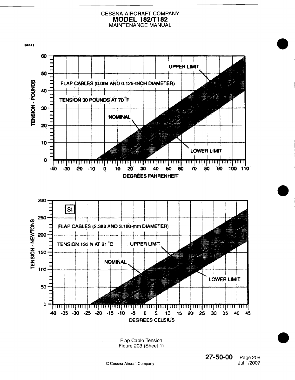
CESSNA AIRCRAFT
COMPANY
MODEL
182/Ti82
MAINTENANCE
MANUAL
5ai4
IUPPER
UMIT
II
I \ -li\L
I II I I I
I
FLAP
CABLES
(0,094
AND
0.1251-lNCH
DLAMMTR)
I I II I I
I
TENSION
30
POUNDS
AT
70
IF
I I ~~~~I
I
.
I
-
-40
=30
-20
=1
0
0
.10
20
30
DEGRIEES
FAHRENHEIT
DEGREES
CELSIUS
Flap
Cable
Tension
Figure
203
(Sheet
1)
©
Cessna
Aircraft
Company
27-50-00
Page
208
Jul
1/2007
El
UK
300
U)250
9
200
z
z
0
150
50
0
0
NW
I
CESSNA
AIRCRAFT
COMPANY
MODEL
182/Ti
82
MAINTENANCE
MANUAL
(33)
Check the
down
limit
switch (SR002)
through
some
flap
cycles.
(34)
Connect
and
rig
the
flap
follow-up
system.
Refer
to
Flap
Follow-Up
and
Indicating System
-
Maintenance
Practices.
(35)
Complete
an
operational
check.
(36)
Check
all
items
for
correct safetying.
Refer
to
Chapter
20,
Safetying
-
Maintenance
Practices.
(37)
Install
the
access plates
51OBB,
510CB
and
611OBB1.
Refer
to
Chapter
6,
Access/Inspection
Plates
-
Description
and
Operation.
(38)
Install
the
overhead
console.
Refer
to
Chapter
25,
Interior
Upholstery
-
Maintenance
Practices.
27-50-00
Page
209
©
Cessna
Aircraft
Company
Jul 1/2007
CESSNA
AIRCRAFT
COMPANY
MODEL
182/T182
MAINTENANCE
MANUAL
FLAP
FOLLOW-UP
AND INDICATING SYSTEM
-
MAINTENANCE
PRACTICES
1.
General
A.
The
flap
follow-up
and
indicating system
consists
of
a
sheathed cable
assembly,
pointers
and
microswitches.
One end
of
the
cable
is
attached
to
the
flap
operating
switch
operating
arm.
The
other
end
is
clamped
to
the
flap direct cable,
above the
headliner
in
the
rear
cabin area.
Motion
of
the
flap cable
is
transmitted
through the
follow-up
control
to
the pointer,
attached
to the
switch mounting
arm.
Pointer
moves
along
a
scale
as the
flaps
are
extended
or
retracted. When
the
motion
of the
switch mounting
arm
with
the
attached operating
switches positions the "active" operating
switch
to
clear
the
cam on
flap
lever,
flap
motor
circuit
is
broken
and
flaps
stop
at selected position.
2.
Flap
Follow-Up
and
Indicating
System
Removal/Installation
A.
Remove
Flap
Control
Lever.
(Refer
to Figure
201).
(1)
Remove
follow-up
control
torque tube
from
switch mounting
arm.
(2)
Remove
flap
UP S1007
and
DOWN
SI008
operating
switches
from
switch mounting
arm.
Do
not
disconnect
electrical
wiring at
switches.
NOTE:
Insulators
are
installed
between
switches
and
switch mounting
arm.
(3)
Remove
knob
from
control
lever.
(4)
Remove remaining washers, bushings,
switch
mounting
arm,
and control
lever
by
removing
mounting
bolt.
Use
care
not
to
drop
parts
into
tunnel
area.
B.
Install
Flap
Control
Lever.
(Refer
to
Figure
201).
(1)
Install
mounting
bolt,
assembling
washers,
bushings,
switch
mounting
arm,
and
control
lever.
NOTE:
Before
installing
knob
on
control
lever, clean
threads
on
control
lever
with methyl
propyl
ketone
or
equivalent.
After
threads
have
thoroughly
dried, prime
with
grade
T
primer.
Allow
primer
to
flash
off
or
dry
for
three
to
five
minutes.
Apply
grade
CU
Loctite
(MIL-S-22473), Loctite
271,
STA-LOK
Catalog
No.
800,
or
equivalent
to
threads
of
control
lever.
(2)
Install knob
and
allow
Loctite
to
cure for
five
to
twenty
minutes before
service.
(3)
Install
flap
UP
S1007
and
DOWN
SI008
operating
switches
on
switch
mounting
arm,
making
sure
to
install
insulators.
(4)
Install
follow-up
control
torque tube
to
switch mounting
arm.
(5)
Rig
system.
Refer
to
Flap
Follow-Up
and
Indicating
System Adjustment/Test.
3.
Flap
Follow-Up
and
Indicating
System
Adjustment/Test
A.
Rig
Flap
Follow-Up
and
Indicating System.
Refer
to
Figure
201.
(1)
Run
flaps
to
full
up
position.
(2)
Remove
overhead center
console.
(3)
Secure
follow-
up
cable
to
retract
cable
with clamp assembly.
(4)
Torque
clamp
nut
to 40
inch-pounds
to
50
inch-pounds
(4.52
N.m
to 5.65
N.m)
and
lock
with
a
second
nut.
(5)
Pull
all
slack
from
follow-up
cable,
and
with
position
indicator
in
full
UP
position
connect
turnbuckle
to
follow-up cable.
(6)
Connect
spring
to
arm
assembly.
(7)
Make
minor
cable
length
adjustments
using
turnbuckle
to
position
indicator
at
"0"
degrees.
(8)
With
control
lever
in
the
full
UP
position
adjust
Up
S1007
operating
and
Down
S1008
operating
switch
in
slotted
holes
until cam
is
centered
between
switch
rollers.
Ensure
control
lever
is
in
full
UP
position
during
this adjustment.
(9)
Mount
inclinometer
on
trailing
edge
of
one
flap
and
set
to
"0"
Degrees.
(10)
Turn
master
switch
S1009
ON
and
move
control
lever
to
"10"
degree position.
(11)
If
flaps
travel
is
more
than
10
Degrees,
+2
or
-2
degrees, adjust flap
DOWN
operating switch
away
from
cam
and recycle
flaps.
27-51-00
Page
201
©
Cessna Aircraft Company
April
1/2002
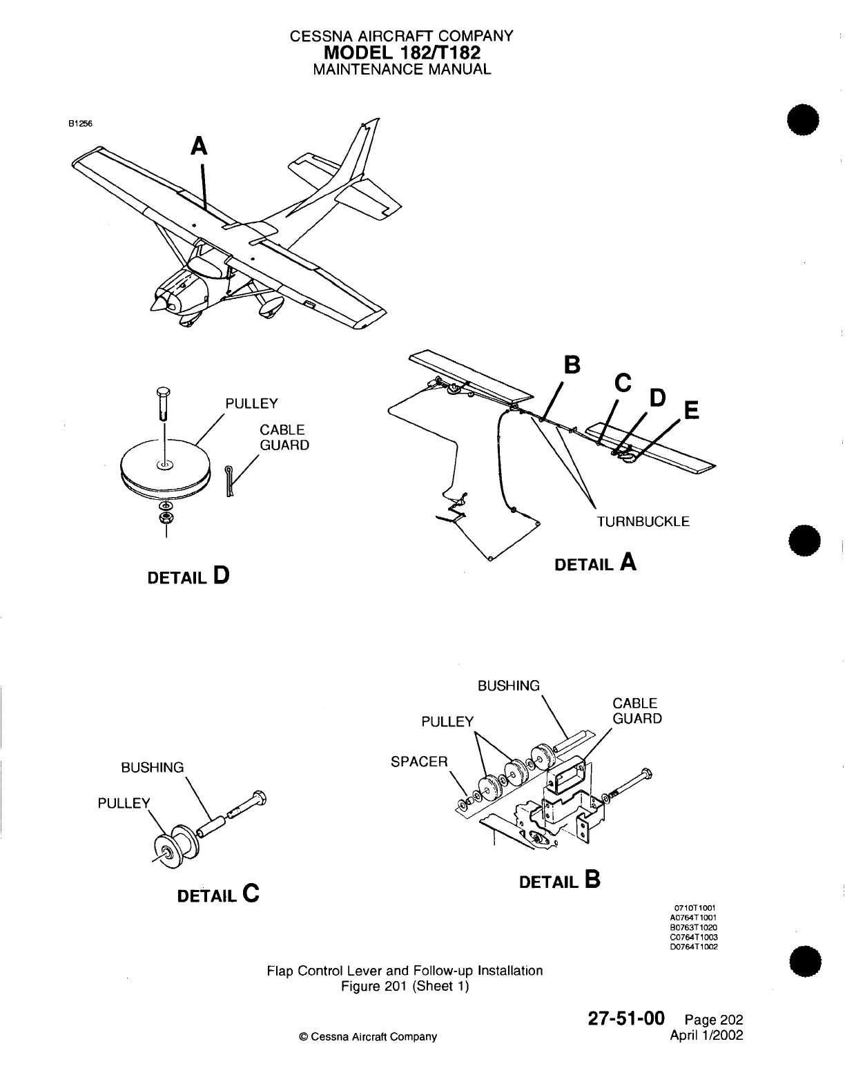
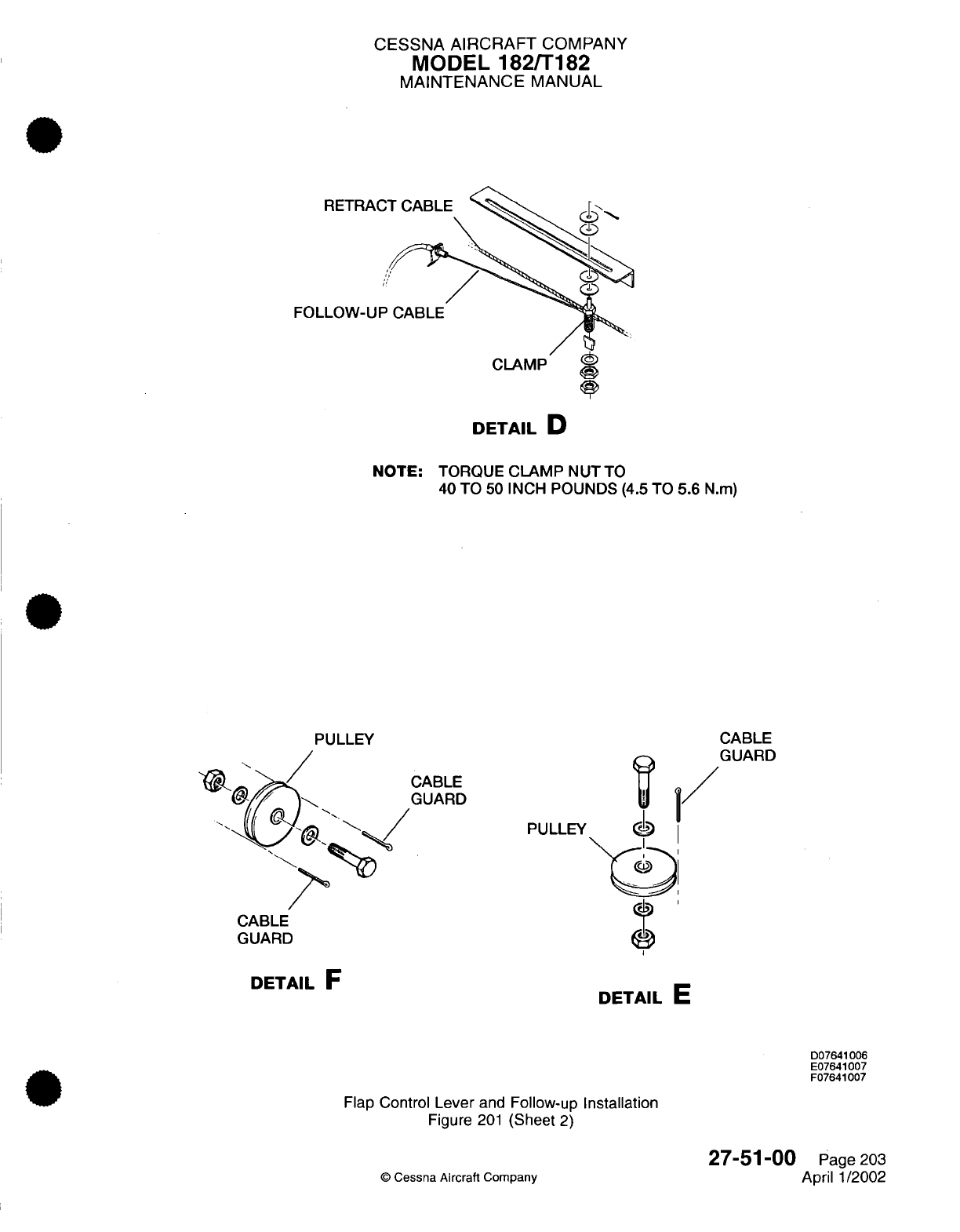
CESSNA
AIRCRAFT
COMPANY
MODEL
182/T182
MAINTENANCE
MANUAL
RETRA(
FOLLOW-UI
DETAIL
D
NOTE:
TORQUE
CLAMP
NUTTO
40
TO
50
INCH
POUNDS
(4.5
TO
5.6
N.m)
PULLEY
CABLE
GUARD
CABLE
GUARD
PULLEY
CABLE
GUARD
DETAIL
E
D07641006
E07641007
F07641007
Flap
Control
Lever
and
Follow-up
Installation
Figure
201
(Sheet
2)
©
Cessna
Aircraft
Company
27-51-00
Page
203
April
1/2002
DETAIL
F
I/
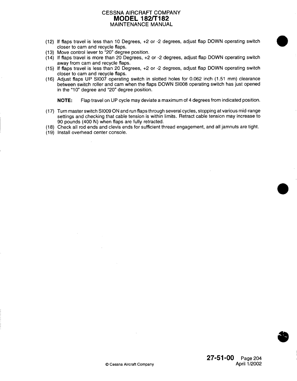
CESSNA
AIRCRAFT
COMPANY
MODEL
182/T182
MAINTENANCE
MANUAL
(12)
If
flaps travel
is
less
than
10
Degrees,
+2
or
-2
degrees,
adjust
flap
DOWN
operating
switch
closer
to
cam
and recycle
flaps.
(13)
Move
control
lever
to
"20"
degree
position.
(14)
If
flaps
travel
is
more
than
20
Degrees,
+2
or
-2
degrees,
adjust
flap
DOWN
operating
switch
away
from
cam and recycle
flaps.
(15)
If
flaps
travel
is
less
than
20 Degrees,
+2
or
-2
degrees,
adjust flap
DOWN
operating
switch
closer
to
cam
and
recycle
flaps.
(16)
Adjust
flaps
UP
SI007
operating
switch
in
slotted
holes
for
0.062
inch
(1.51 mm)
clearance
between
switch
roller and
cam when
the
flaps
DOWN
S1008
operating switch
has
just
opened
in
the
"10"
degree
and
"20"
degree position.
NOTE: Flap
travel
on
UP
cycle
may
deviate
a
maximum
of
4
degrees
from
indicated
position.
(17)
Turn
master
switch
S1009
ON
and
run
flaps
through
several
cycles,
stopping
at
various
mid-range
settings
and
checking
that
cable
tension
is
within
limits.
Retract
cable
tension
may
increase
to
90
pounds
(400
N)
when
flaps
are
fully
retracted.
(18)
Check
all
rod
ends
and
clevis
ends
for
sufficient
thread engagement,
and
all
jamnuts
are
tight.
(19)
Install
overhead center console.
27-51-00
Page
204
©
Cessna
Aircraft Company
April
1/2002

CHAPTER
FUEL

CESSNA
AIRCRAFT
COMPANY
MODEL
182/Ti
82
MAINTENANCE
MANUAL
LIST
OF
EFFECTIVE
PAGES
CHAPTER-SECTION-SUBJECT
28-Title
28-List
of
Effective
Pages
28-Record
of
Temporary
Revisions
28-Table
of
Contents
28-00-00
28-20-00
28-20-00
28-20-00
28-2
1-00
PAGE
Page
1
Pages
1-3
Pages
201
-219
Pages
501-506
Pages
201-203
©
Cessna
Aircraft
Company
28
-
LIST
OF
EFFECTIVE
PAGES
Page
1
of
1
Jul
1/2007
DATE
April
1/2002
April
1/2002
Jul
1/2007
Jul
1/2007
April 1/2002
Temporary
Revision
Number
RECORD
OF
TEMPORARY
REVISIONS
Page
Number
Issue
Date
By
Date
Removed
By
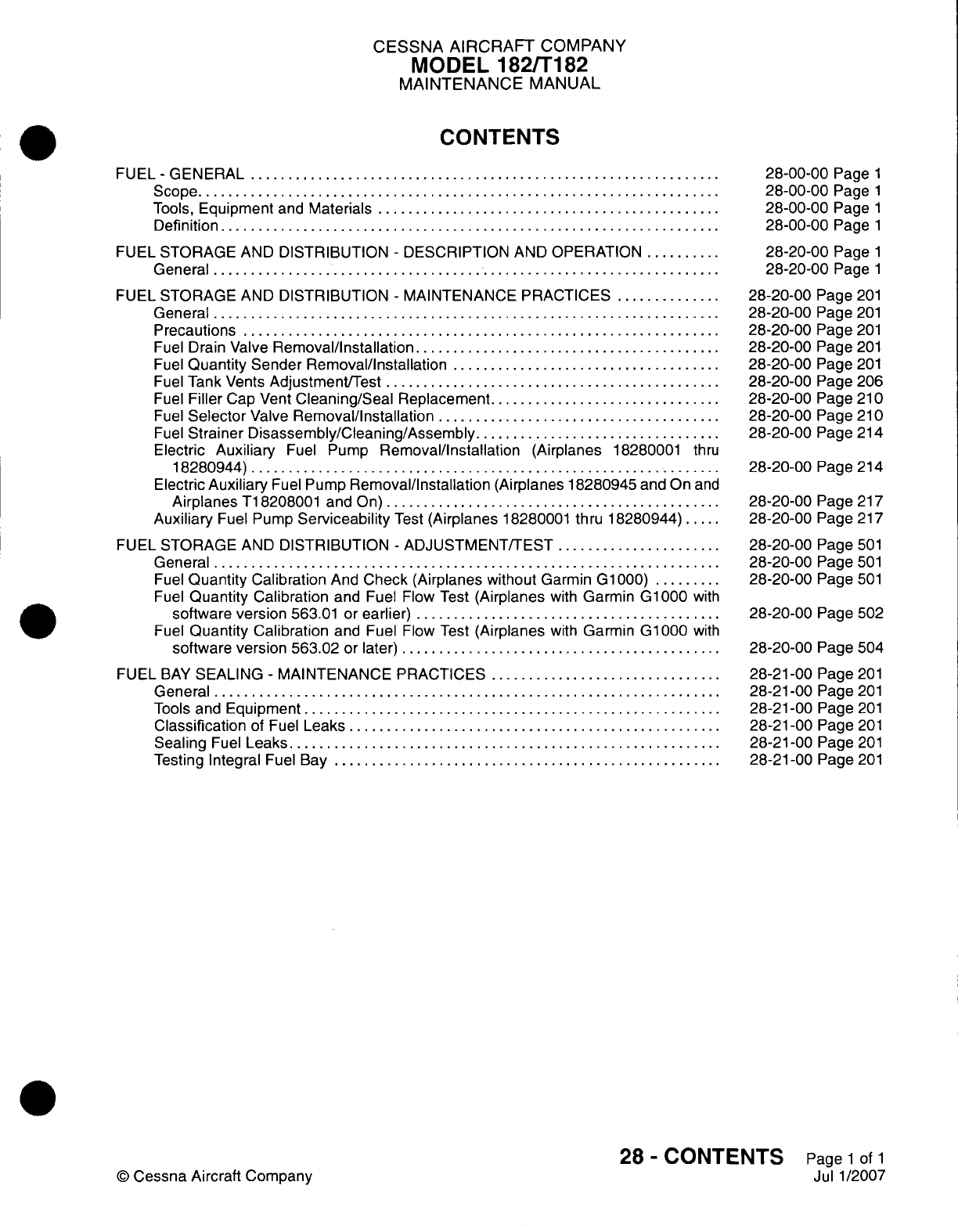
CESSNA AIRCRAFT
COMPANY
MODEL
182/Ti
82
MAINTENANCE
MANUAL
CONTENTS
FUEL
-
GENERAL
................................
Scope....................................
Tools,
Equipment
and
Materials........................
Definition
..................................
FUEL
STORAGE
AND
DISTRIBUTION
-
DESCRIPTION
AND
OPERATION......
General
...................................
FUEL
STORAGE
AND
DISTRIBUTION
-
MAINTENANCE
PRACTICES........
General...................................
Precautions.................................
Fuel Drain
Valve
Removal/Installation
.....................
Fuel
Quantity
Sender
Removal/Installation...................
Fuel
Tank
Vents
Adjustment/Test
.......................
Fuel
Filler
Cap Vent
Cleaning/Seal
Replacement
................
Fuel
Selector
Valve
Removal/Installation....................
Fuel
Strainer
Disassembly/Cleaning/Assembly
.................
Electric
Auxiliary
Fuel
Pump
Removal/Installation
(Airplanes
18280001
thru
18280944)
................................
Electric
Auxiliary
Fuel
Pump
Removal/Installation
(Airplanes
18280945
and On
and
Airplanes
Ti
8208001
and
On)
.......................
Auxiliary
Fuel
Pump
Serviceability
Test
(Airplanes
18280001
thru 18280944)
...
FUEL
STORAGE
AND
DISTRIBUTION
-
ADJUSTMENT/TEST............
General...................................
Fuel
Quantity
Calibration
And
Check
(Airplanes without
Garmin
G1000)
.....
Fuel
Quantity
Calibration
and
Fuel
Flow
Test
(Airplanes
with
Garmin
G1000
with
software
version
563.01
or
earlier)
.....................
Fuel
Quantity
Calibration
and
Fuel
Flow Test
(Airplanes
with
Garmin
G1000
with
software
version
563.02
or
later)
......................
FUEL
BAY
SEALING
-
MAINTENANCE
PRACTICES
................
General...................................
Tools
and
Equipment.............................
Classification
of
Fuel
Leaks..........................
Sealing
Fuel
Leaks..............................
Testing
Integral
Fuel
Bay...........................
28-00-00
Page
1
28-00-00
Page
1
28-00-00
Page
1
28-00-00
Page
1
28-20-00
Page
1
28-20-00
Page
1
28-20-00
Page
201
28-20-00
Page
201
28-20-00
Page
201
28-20-00
Page
201
28-20-00
Page
201
28-20-00
Page
206
28-20-00
Page
21
0
28-20-00
Page
21
0
28-20-00
Page
214
28-20-00
Page
214
28-20-00
Page
217
28-20-00
Page
217
28-20-00
Page
501
28-20-00
Page
501
28-20-00
Page
501
28-20-00
Page 502
28-20-00
Page
504
28-21
-00
Page
201
28-21
-00
Page
201
28-21
-00
Page
201
28-21 -00
Page
201
28-21
-00
Page
201
28-2
1
-00
Page
201
28
-
CONTENTS
Page
1
of
1
Jul
1/2007
©
Cessna
Aircraft
Company
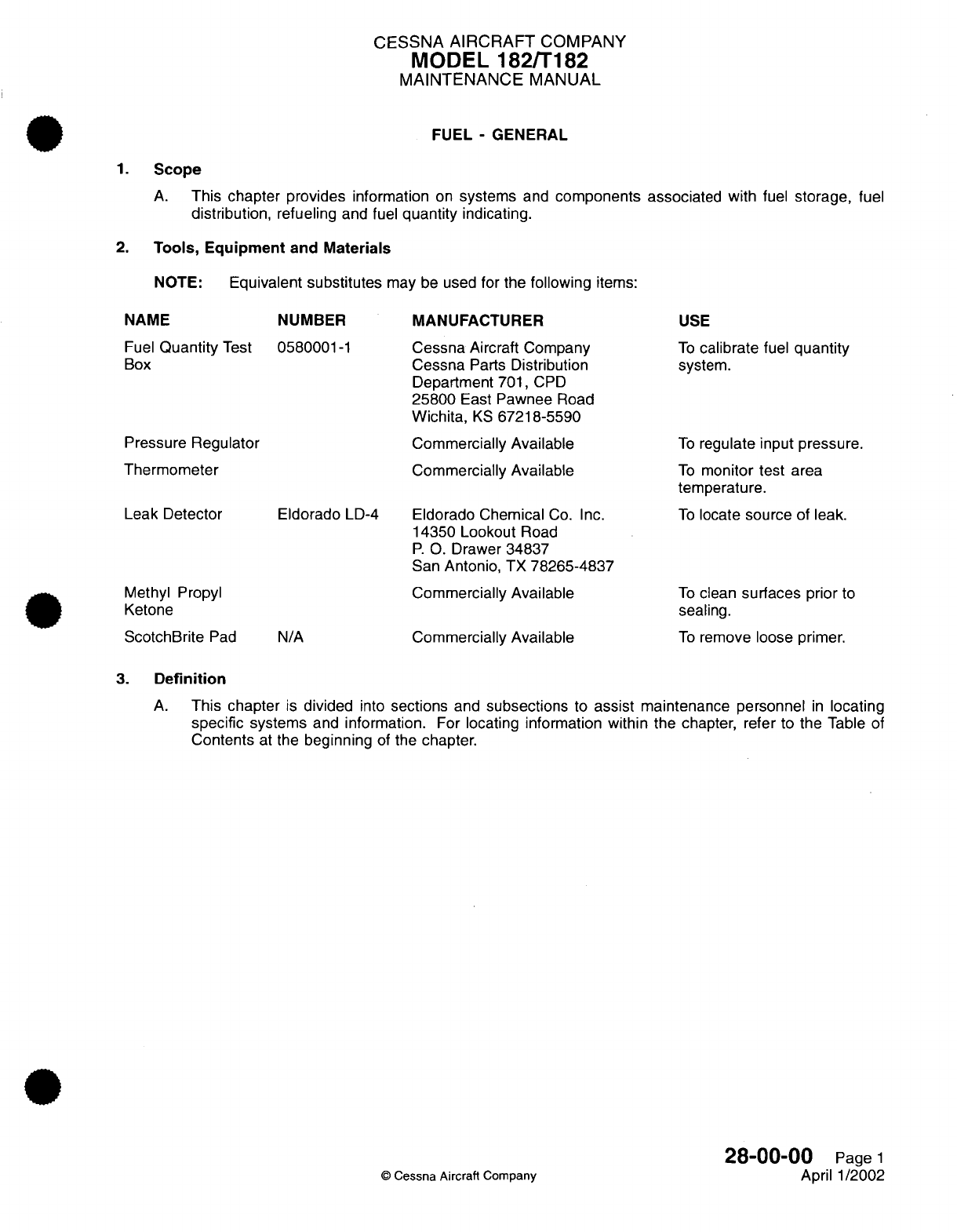
CESSNA
AIRCRAFT
COMPANY
MODEL
182/T182
MAINTENANCE
MANUAL
FUEL
-
GENERAL
1.
Scope
A.
This
chapter
provides
information
on
systems
and
components
associated
with
fuel
storage,
fuel
distribution,
refueling
and fuel
quantity
indicating.
2.
Tools,
Equipment
and
Materials
NOTE:
Equivalent
substitutes
may
be
used
for
the
following
items:
NAME
Fuel
Quantity
Test
Box
NUMBER
0580001-1
Pressure
Regulator
Thermometer
Leak Detector
Methyl Propyl
Ketone
ScotchBrite
Pad
Eldorado
LD-4
N/A
MANUFACTURER
Cessna
Aircraft
Company
Cessna
Parts
Distribution
Department
701,
CPD
25800
East
Pawnee
Road
Wichita,
KS
67218-5590
Commercially
Available
Commercially
Available
Eldorado Chemical
Co.
Inc.
14350
Lookout
Road
P. 0.
Drawer
34837
San
Antonio,
TX
78265-4837
Commercially
Available
Commercially
Available
USE
To
calibrate
fuel
quantity
system.
To
regulate input pressure.
To
monitor
test
area
temperature.
To
locate source
of
leak.
To
clean
surfaces
prior
to
sealing.
To
remove
loose
primer.
3.
Definition
A.
This
chapter
is
divided
into
sections
and
subsections
to
assist
maintenance personnel
in
locating
specific
systems
and
information.
For
locating
information
within
the chapter,
refer
to
the
Table
of
Contents
at
the
beginning
of
the
chapter.
28-00-00
Page
1
©
Cessna
Aircraft Company
April
1/2002
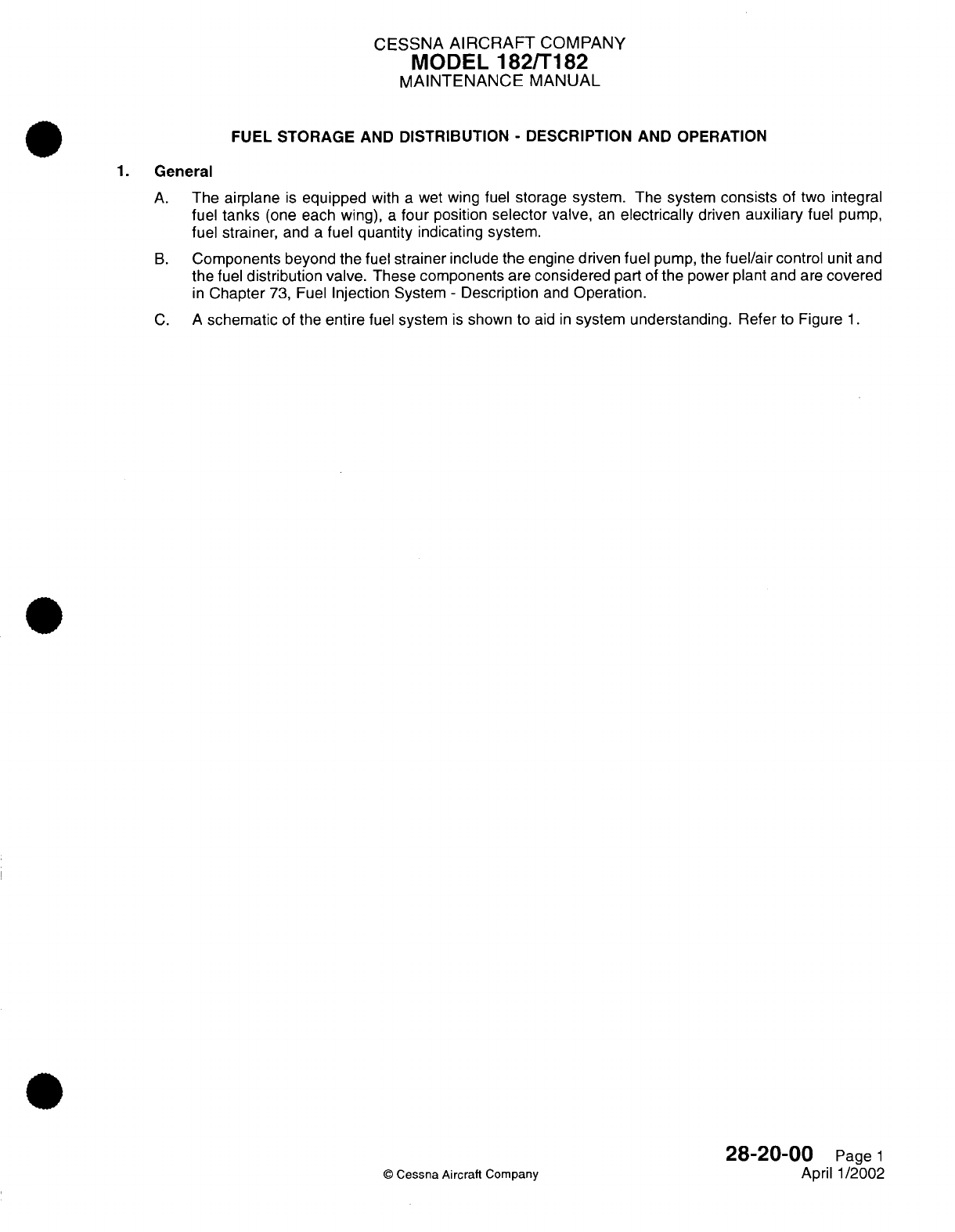
CESSNA
AIRCRAFT
COMPANY
MODEL
182/T182
MAINTENANCE
MANUAL
FUEL
STORAGE
AND
DISTRIBUTION
-
DESCRIPTION
AND
OPERATION
1.
General
A.
The
airplane
is
equipped
with
a
wet
wing
fuel
storage system.
The system
consists
of two
integral
fuel
tanks
(one
each wing),
a
four
position
selector valve,
an
electrically
driven
auxiliary
fuel pump,
fuel
strainer,
and
a
fuel
quantity
indicating system.
B.
Components
beyond the
fuel
strainer
include the
engine
driven
fuel
pump,
the
fuel/air
control
unit
and
the
fuel
distribution valve.
These
components
are
considered
part
of
the
power
plant
and
are
covered
in
Chapter
73,
Fuel
Injection
System
-
Description
and
Operation.
C. A
schematic
of the
entire
fuel system
is
shown
to
aid
in
system
understanding.
Refer
to Figure
1.
28-20-00
Page
1
©
Cessna Aircraft
Company
April
1/2002
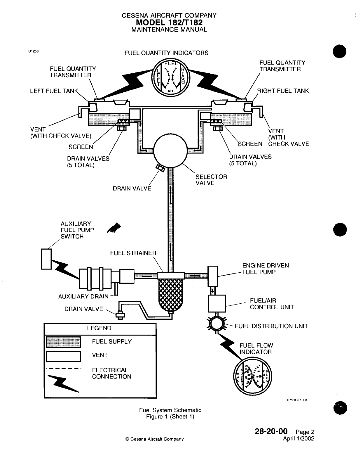
CESSNA
AIRCRAFT
COMPANY
MODEL
182/T182
MAINTENANCE
MANUAL
FUEL
QUANTITY INDICATORS
ITITY
-ER
TANK
VALVE
DRAIN
VALVE
AUXILIARY
FUEL
PUMP
SWITCH
FUEL
STRAINER
AUXILIARY
DRAI
DRAIN
VALVE
LEGEND
I I
FUEL
SUPPLY
I I
VENT
-.. .
~ELECTRICAL
CONNECTION
FUEL FLOW
INDICATOR
Fuel
System Schematic
Figure
1
(Sheet
1)
28-20-00
Page
2
April
1/2002
©
Cessna
Aircraft
Company
B1258
LEFT
I
VENT
(WITH
UNIT
0791CT1001
I-
4*4w.,
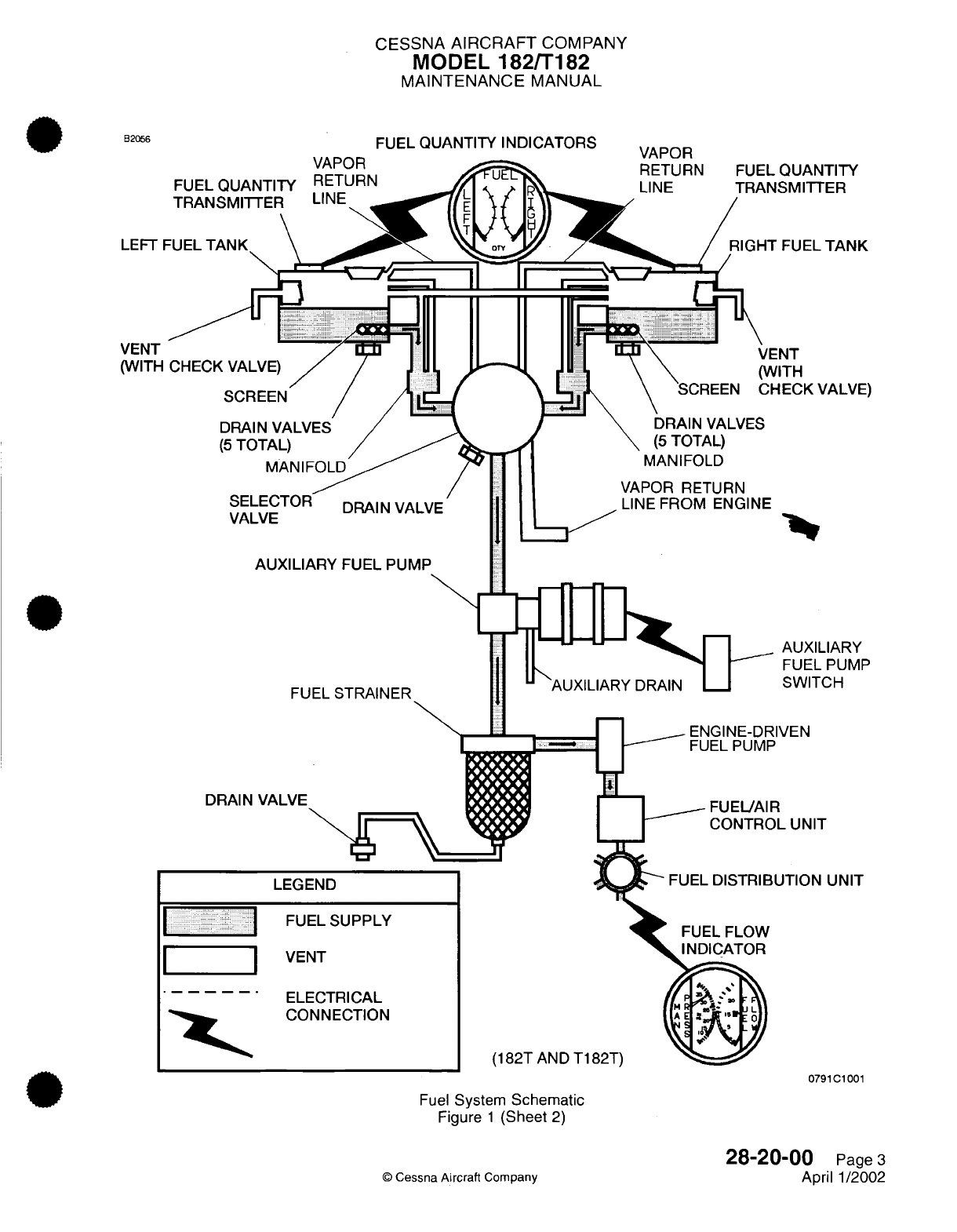
CESSNA
AIRCRAFT
COMPANY
MODEL
182/T182
MAINTENANCE
MANUAL
FUEL
QUANTITY
INDICATORS
LEFT
VALVL
AUXILIARY
FUEL
PUMP
AUXILIARY
FUEL
PUMP
SWITCH
IVEN
IL
UNIT
UTION
UNIT
DRAIN
VALVE
LEG!
FUEL
FLOW
INDICATOR
(182T
AND
T182T)
0791C1001
Fuel
System
Schematic
Figure
1
(Sheet
2)
28-20-0
©
Cessna Aircraft
Company
10
Page
3
April
1/2002
B2056
VAPnR
FL
FU
VEI
ELI
CO
=r----
I
II
I
ltt
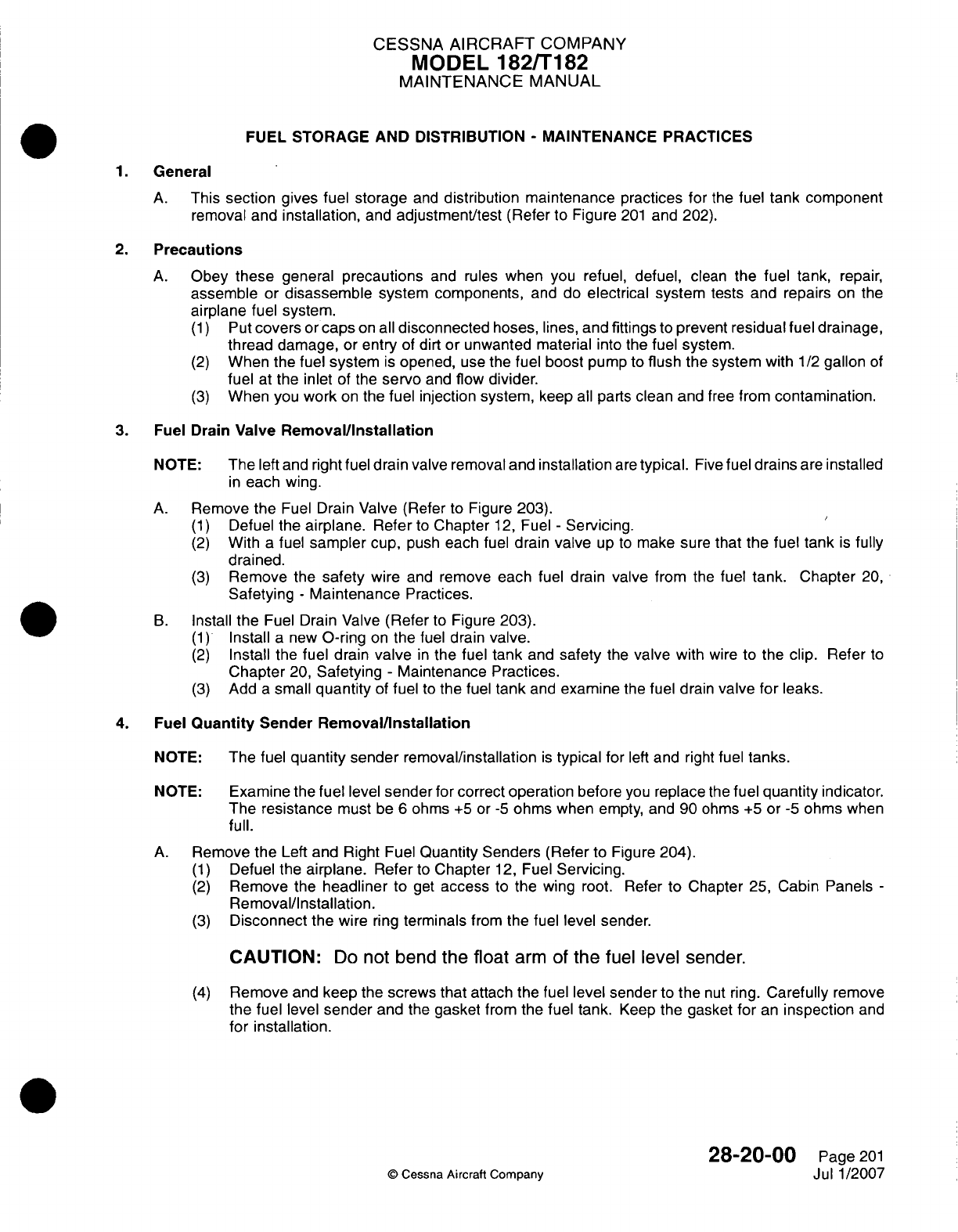
CESSNA
AIRCRAFT
COMPANY
MODEL
182/Ti182
MAINTENANCE
MANUAL
FUEL
STORAGE
AND DISTRIBUTION
-
MAINTENANCE PRACTICES
General
A.
This
section gives
fuel
storage
and
distribution maintenance
practices
for
the
fuel
tank
component
removal and
installation,
and
adjustment/test
(Refer
to
Figure
201
and 202).
2.
Precautions
A.
Obey
these
general
precautions
and rules
when
you
refuel,
defuel,
clean
the
fuel tank,
repair,
assemble
or
disassemble
system components,
and
do
electrical
system tests
and
repairs
on
the
airplane
fuel
system.
(1)
Put
covers
or
caps
on all
disconnected
hoses,
lines,
and
fittings
to
prevent
residual
fuel drainage,
thread
damage,
or
entry
of
dirt
or
unwanted
material
into
the
fuel
system.
(2)
When
the
fuel
system
is
opened,
use
the
fuel
boost
pump
to
flush the
system with
1/2
gallon
of
fuel
at
the
inlet
of
the
servo
and
flow
divider.
(3)
When
you
work
on
the
fuel injection system,
keep
all
parts
clean
and
free
from
contamination.
3.
Fuel
Drain
Valve
Removal/installation
NOTE:
The
left
and
right
fuel
drain
valve
removal
and
installation
are
typical.
Five
fuel
drains
are
installed
in
each
wing.
A.
Remove the
Fuel
Drain
Valve
(Refer
to
Figure
203).
(1)
Defuel the
airplane. Refer
to
Chapter
12,
Fuel
-
Servicing.
(2)
With
a
fuel
sampler
cup,
push
each fuel
drain
valve
up
to
make
sure that
the
fuel
tank
is
fully
drained.
(3)
Remove
the
safety
wire
and
remove each
fuel
drain
valve
from
the
fuel
tank.
Chapter
20,
Safetying
-
Maintenance
Practices.
B.
Install
the
Fuel
Drain
Valve
(Refer
to
Figure
203).
(1)
Install
a new
0-ring
on
the
fuel
drain
valve.
(2)
Install
the
fuel
drain
valve
in
the fuel
tank
and
safety
the
valve
with
wire
to
the
clip.
Refer
to
Chapter
20,
Safetying
-
Maintenance Practices.
(3)
Add
a
small
quantity
of
fuel
to
the
fuel
tank
and
examine
the
fuel
drain
valve
for
leaks.
4.
Fuel
Quantity
Sender
Removal/installation
NOTE:
The
fuel
quantity sender
removal/installation
is
typical
for
left
and
right
fuel
tanks.
NOTE:
Examine
the
fuel
level
sender
for
correct operation
before
you
replace
the
fuel
quantity
indicator.
The
resistance
must
be
6
ohms
+5
or
-5
ohms
when
empty,
and
90
ohms
+5
or
-5
ohms
when
full.
A.
Remove
the
Left and Right Fuel
Quantity
Senders
(Refer
to
Figure
204).
(1)
Defuel
the
airplane.
Refer
to
Chapter
12,
Fuel
Servicing.
(2)
Remove
the
headliner
to
get
access
to the
wing
root.
Refer
to Chapter
25,
Cabin
Panels
-
Removal/Installation.
(3)
Disconnect
the
wire
ring
terminals
from
the
fuel
level sender.
CAUTION:
Do
not
bend
the
float
arm
of
the
fuel
level
sender.
(4)
Remove
and
keep
the
screws
that
attach
the fuel
level
sender
to
the
nut
ring.
Carefully
remove
the
fuel
level
sender
and
the
gasket
from
the fuel
tank.
Keep
the
gasket
for
an
inspection
and
for installation.
28-20-00
Page
201
Q
Cessna
Aircraft
Company
Jul
1/2007
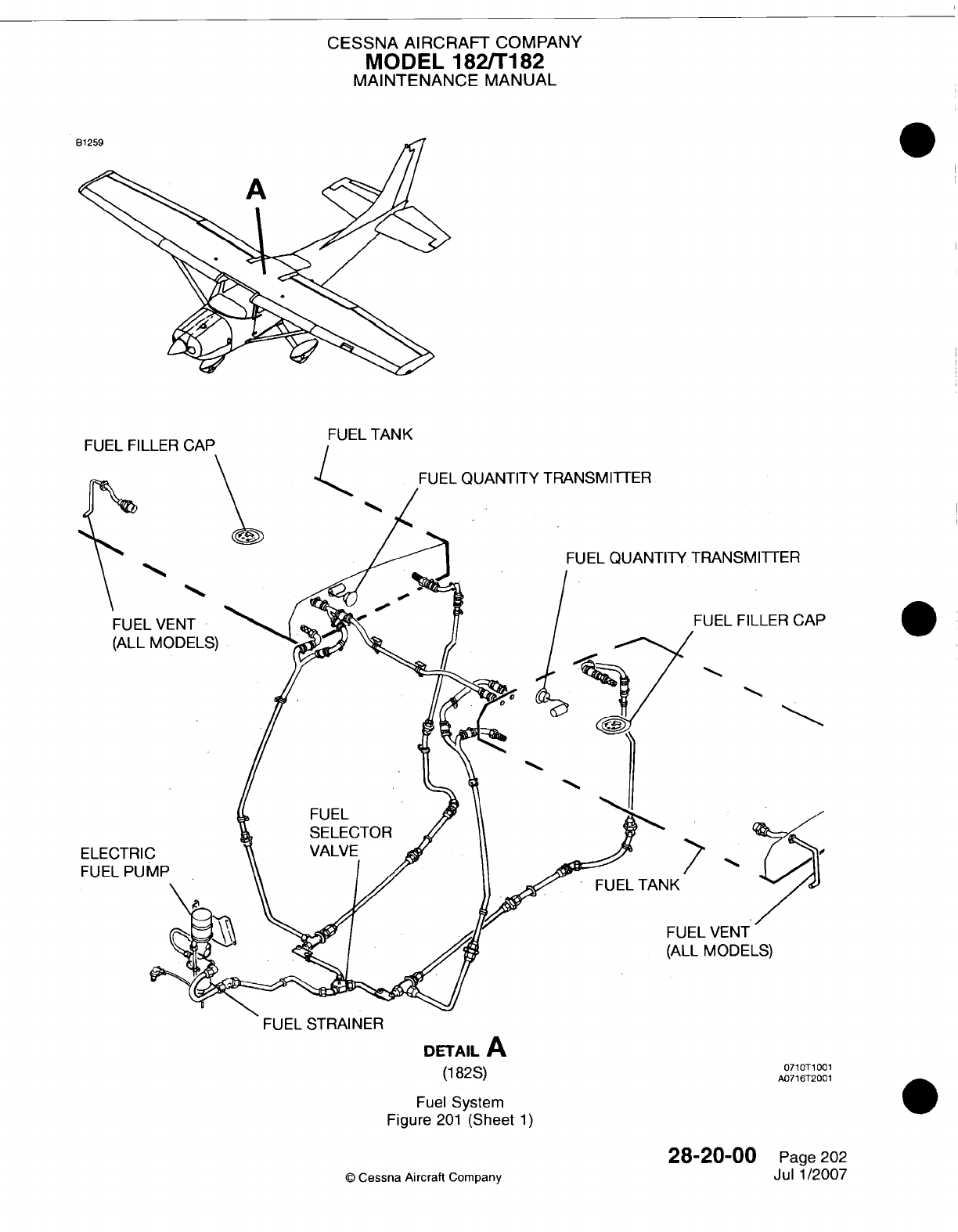
CESSNA AIRCRAFT
COMPANY
MODEL
182/Ti182
MAINTENANCE
MANUAL
CFl
MN
MiI 1
=D
C'Afl
FUEL
TANK
SMTTER
FILLER
CAP
ELE
FUE
JT
)ELS)
FUEL
STRAINER
DETAIL
A
(1
82S)
Fuel
System
Figure
201
(Sheet
1)
28-20-00
©
Cessna
Aircraft
Company
F uK
071
OT1
001
A0716T2001
Page
202
Jul 1/2007
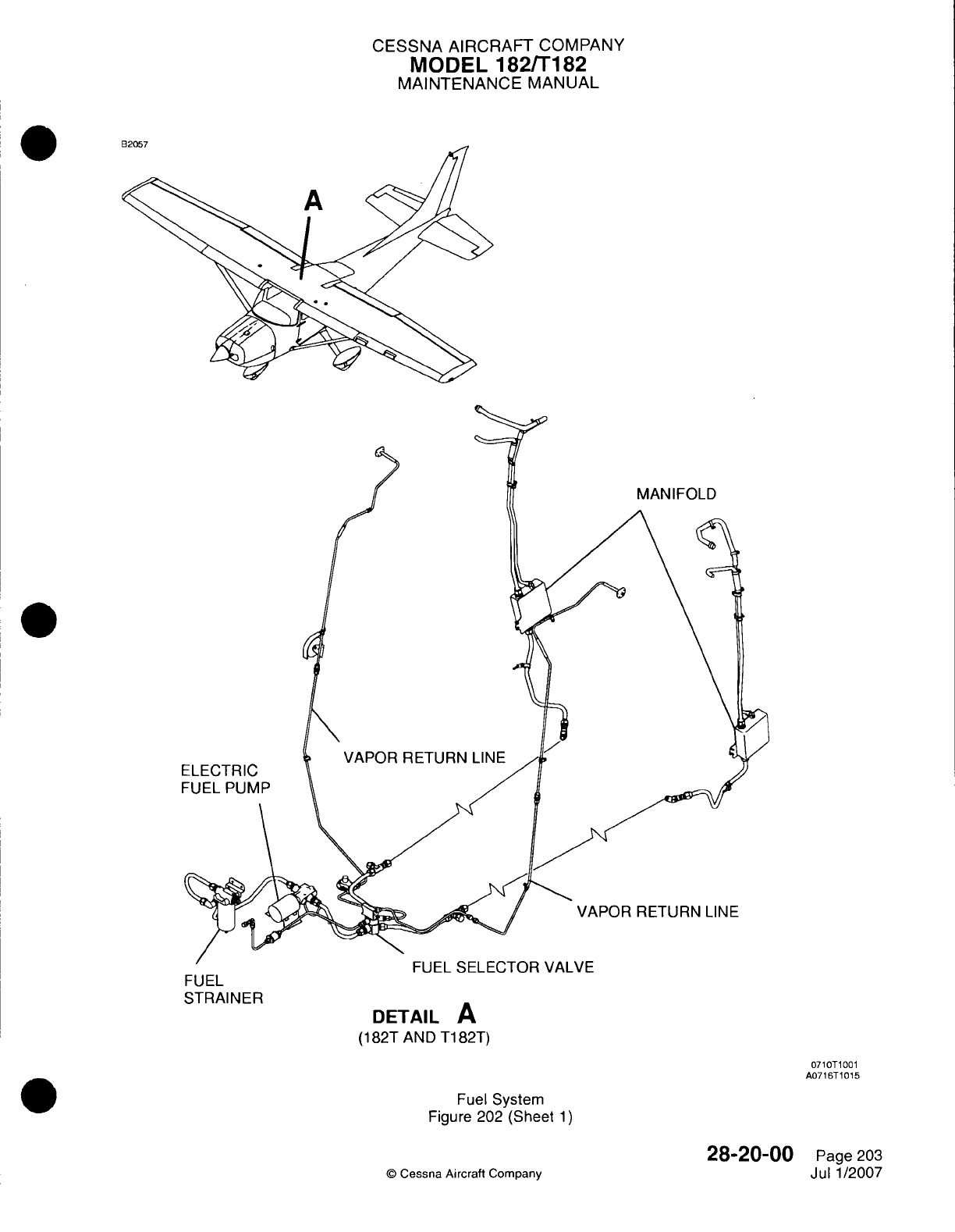
CESSNA AIRCRAFT
COMPANY
MODEL
182/Ti182
MAINTENANCE
MANUAL
VAPOR
RETURN
LINE
rUI-L
OILILU
I
Uri
VMLVI-
DETAIL
A
(1
82T
AND
T1
82T)
07lOTi1001
A0716T
10 15
Fuel
System
Figure
202
(Sheet
1)
©
Cessna
Aircraft
Company
FUEL
STRAINER
28-20-00
Page
203
Jul
1
/2007
1--
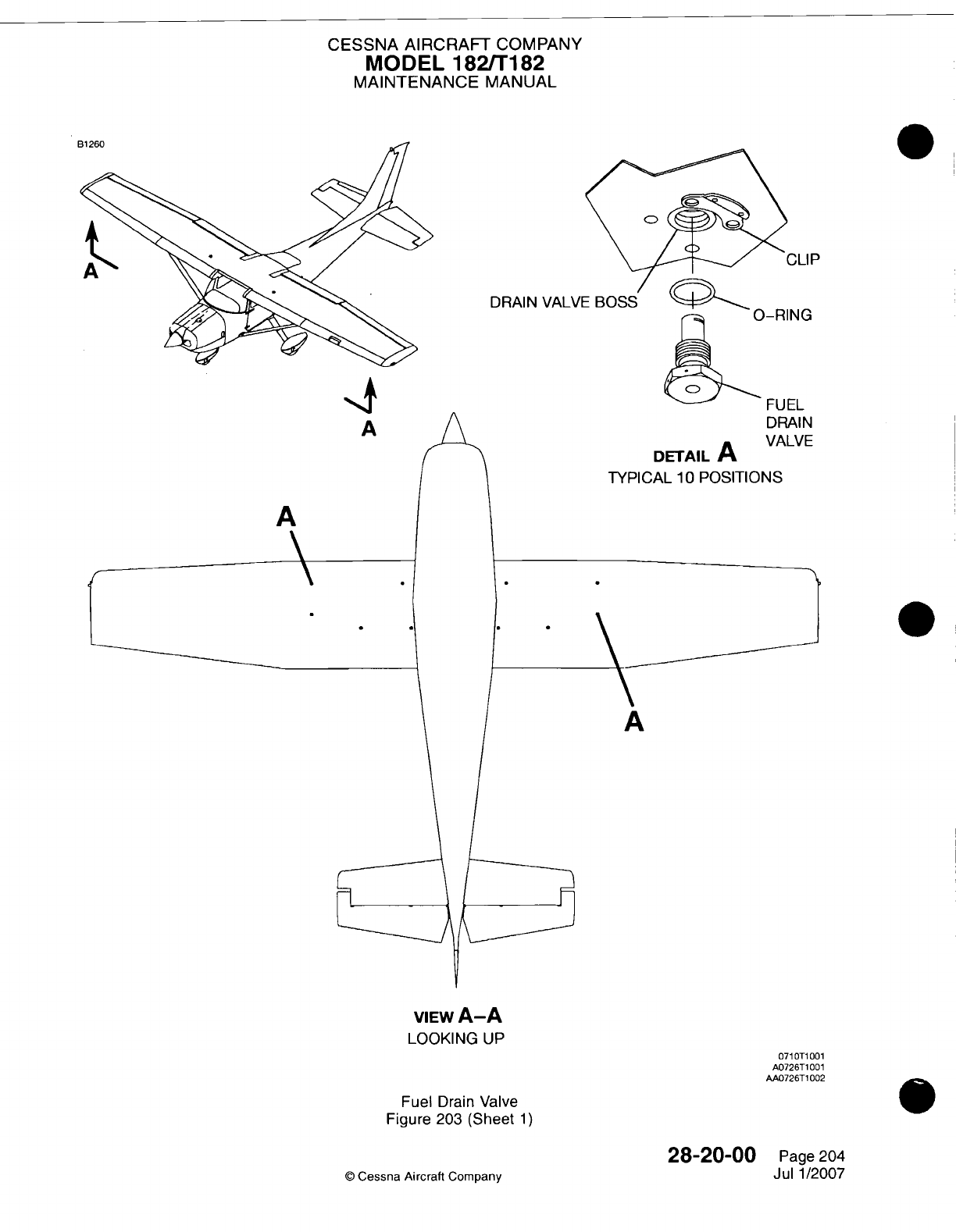
CESSNA AIRCRAFT
COMPANY
MODEL
182/Ti82
MAINTENANCE
MANUAL
0
X I
P
DRAIN
VALVE
BOSS
)-RING
ICI IM~
F_
U ILA
A
A
VIEW
A-A
LOOKING
UP
Fuel
Drain
Valve
Figure
203
(Sheet
1)
28-20-00
0
Cessna Aircraft
Company
071
OT1
001
A0726T1
001
AA0726T1
002
Page
204
Jul
1/2007
-I'+
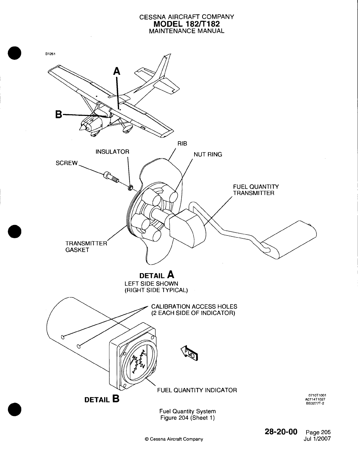
CESSNA AIRCRAFT
COMPANY
MODEL
182/Ti
82
MAINTENANCE
MANUAL
E
RIB
NUT
RING
SCI
FUEL
QUANTITY
TRANSMITTER
DETAIL
A
LEFT SIDE
SHOWN
(RIGHT
SIDE
TYPICAL)
NLIBRATION
ACCESS
HOLES
EACH
SIDE
OF
INDICATOR)
FUEL
QUANTITY
INDICATOR
Fuel
Quantity
System
Figure
204 (Sheet
1)
©
Cessna
Aircraft
Company
DETAIL
B
071
OT1
001
A0714T1027
BS32777-2
28-20-00
Page
205
Jul
1/2007
CESSNA AIRCRAFT
COMPANY
MODEL
182/Ti182
MAINTENANCE
MANUAL
B.
Install
the
Left
and
Right
Fuel
Quantity
Senders
(Refer
to
Figure 204).
NOTE:
Do
the
fuel
quantity calibration
only after installation
of
the
fuel
level
sender.
(1)
Examine
the
gaskets
for
cracks
or
other damage
that
can
prevent
the
gasket
from making
a
good
seal.
If
the
gaskets
have damage,
or
if
there
are
signs
of
fuel
leaks,
install
new
gaskets.
Always
install
new
gaskets
when
you
install
a
new
fuel
level
sender./
CAUTION:
Do
not bend the
float
arm
of
the
fuel
level
sender.
(2)
Carefully
install
the
fuel
quantity
sender
into the fuel
tank
and
attach the
nut
ring
with
screws.
(3)
Connect
the wire
ring
terminals
to the
fuel level
sender.
(4)
Install
the
headliner.
Refer
to
Chapter
25,
Cabin
Panels
-
Removal/Installation.
5.
Fuel
Tank
Vents
Adjustment/Test
A.
DESCRIPTION
-
A
vent
line
is
installed
in
the
outboard
end
of
each
fuel
tank
and
extends overboard
through
the
lower
wing
skin
near
the
point
where
lift
struts
attach
to
the
underside
of
the wings.
B.
TEST
-
Fuel
vents
may
become clogged
as
shown
by
field experience,
and can
cause
fuel
starvation
of
the engine.
If
the
bleed
hole
in
the vent
valve becomes
clogged,
over-
pressurization
can
occur
due
to
normal
temperature
variation.
This
would
usually
occur
when
the
airplane
engine
is
not
operating.
The
procedure that
follows
must
be
used
to
make
sure
that the
fuel
vent
and
bleed
system
operate
correctly.
(1)
Attach
a
rubber
tube
to
the
end
of
the
vent
line
below
the
wing.
WARNING:
Clogged vent
lines
and
bleed
holes
can
cause
either
fuel
starvation
or
the
pressurization
of the
fuel
tanks
by
fuel
expansion.
You
must
clean
any
fuel
vent
found
clogged
or
not
operating
correctly
before
the
airplane
is
returned
to
service.
(2)
As
you
do
the test, put
a
cap
on the
vent
in
the
opposite
wing.
(3)
Blow air
into
the
tube to
pressurize
the
tank.
If
air
can
enter
the
tank,
the
vent
line
is
open.
(4)
After
the
tank
is
pressurized
with
a
small
quantity
of air,
insert the
end of
the
rubber
tube
into
a
container
of
water
and
look
for
a
continuous
stream
of
bubbles. This shows
that the
bleed
hole
in
the
valve
assembly
is
open, and that
the
valve assembly releases
tank pressure.
(5)
After
completing
step
B.(3),
blow
air into the
tube
again
to
pressurize
the tank.
Crimp
the rubber
tube
to keep
pressure
in
the
tank.
Loosen,
but
do not
remove,
the
filler
cap
on
the
opposite
wing.
If
pressure
is
released through
the
filler
cap,
the
cell
crossover
line
is
open. Remove
the
rubber
tube
from
the
end
of
the
vent line
below
the
wing.
(6)
Do
steps
B.(1)
thru
B.(5)
again
on
the
opposite
wing.
NOTE:
A
serviceable
wing
fuel
vent
check valve
will
release
positive
pressure through
the
bypass
port
from
the
fuel
tank.
An
unserviceable
wing
fuel
vent check
valve
will
not
release
positive
pressure
through
the
bypass
port from
the
fuel
tank.
(7) If
the
fuel
vent
check
valve
is
unserviceable,
do
the procedures
that
follow
(Refer
to
Figure
205).
(a)
Defuel
the
airplane.
Refer
to
Chapter
12,
Fuel
-
Servicing.
(b)
Remove
the
wing
access
panels (510KB and 610KB)
to get
access
to
the
wing
fuel
vent
check
valve.
Refer
to
Chapter
6,
Inspection/Access
Plates
-
Description
and
Operation.
(c)
Remove
the
unserviceable
wing
fuel
vent
check
valve
and
replace
it
with
a
new
fuel
vent
check
valve. Make
sure
that
the
bypass
hole
on
the
valve
flap
is
set
at
the
top
of the
fuel
tank.
(d)
Install
and seal
the
wing
fuel
tank
access
plate.
Make
sure
that
the
access
plate
is
fully
sealed.
Refer
to
Chapter
28,
Fuel
Bay
Sealing
-
Maintenance
Practices.
(e)
Do
steps
B(1)
thru
B(7)
again
to
make sure
that
the new
fuel
vent
check valve
operates
correctly.
28-20-00
Page 206
©
Cessna
Aircraft
Company
Jul
1/2007
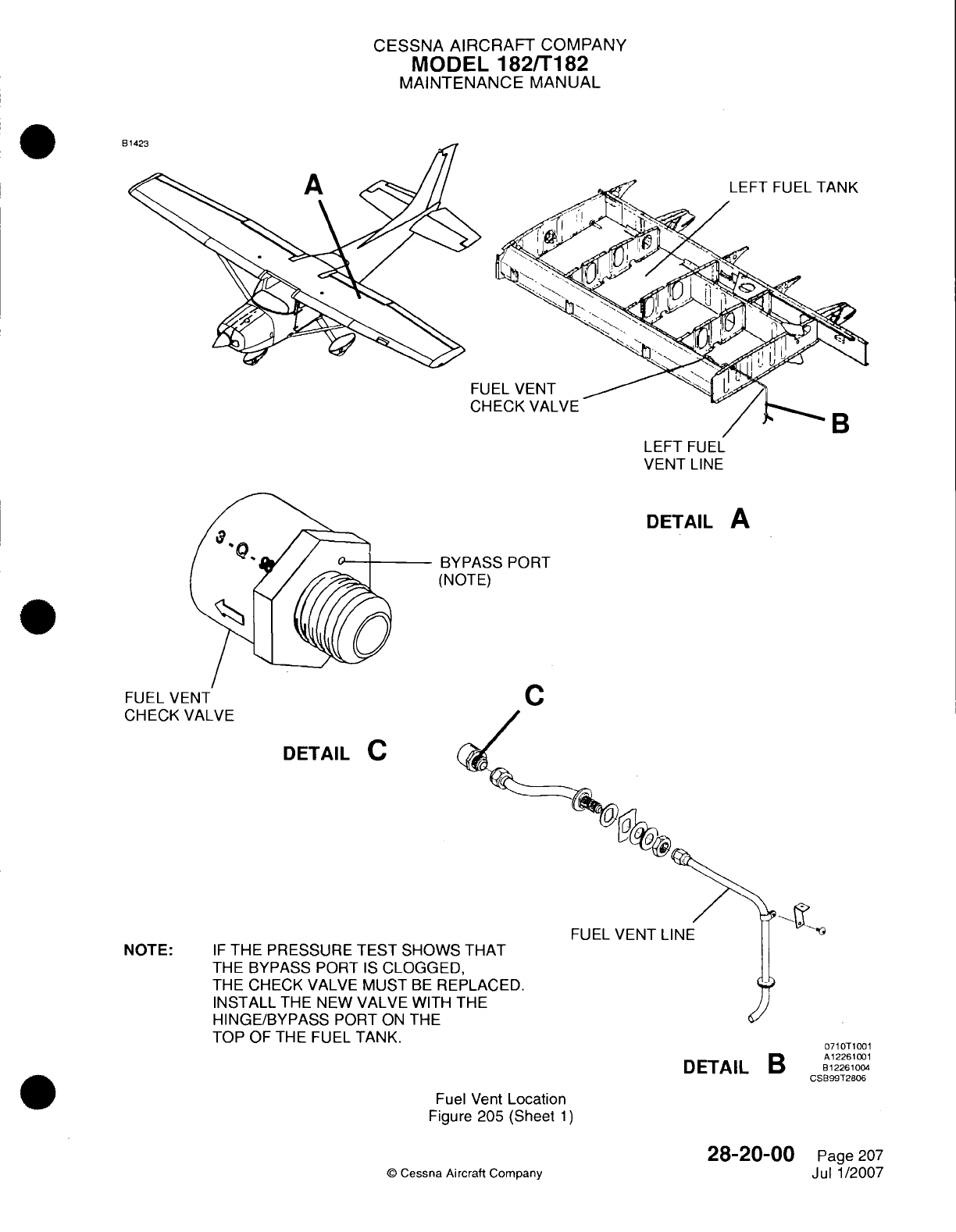
CESSNA AIRCRAFT
COMPANY
MODEL
182/Ti182
MAINTENANCE
MANUAL
E6
LEFT
FUEL
VENT
LINE
DETAIL
A
BYPASS
PORT
(NOTE)
FUEL
VENT
CHECK VALVE
DETAIL
C
NOTE:
IF
THE
PRESSURE TEST
SHOWSc
THE
BYPASS PORT
IS
CLOGGEE
THE CHECK
VALVE
MUST
BE
RE
INSTALL
THE
NEW
VALVE WITH
HINGE/BYPASS
PORT
ON
THE
TOP
OF THE FUEL
TANK.
FUEL
VENT
LINE
Fuel Vent
Location
Figure
205
(Sheet
1)
©
Cessna
Aircraft
Company
28-20-00
Page
207
Jul
1/2007
C
DETAIL
B
071
OT1
001
A12261001
8
1226100-4
CSB99T2806
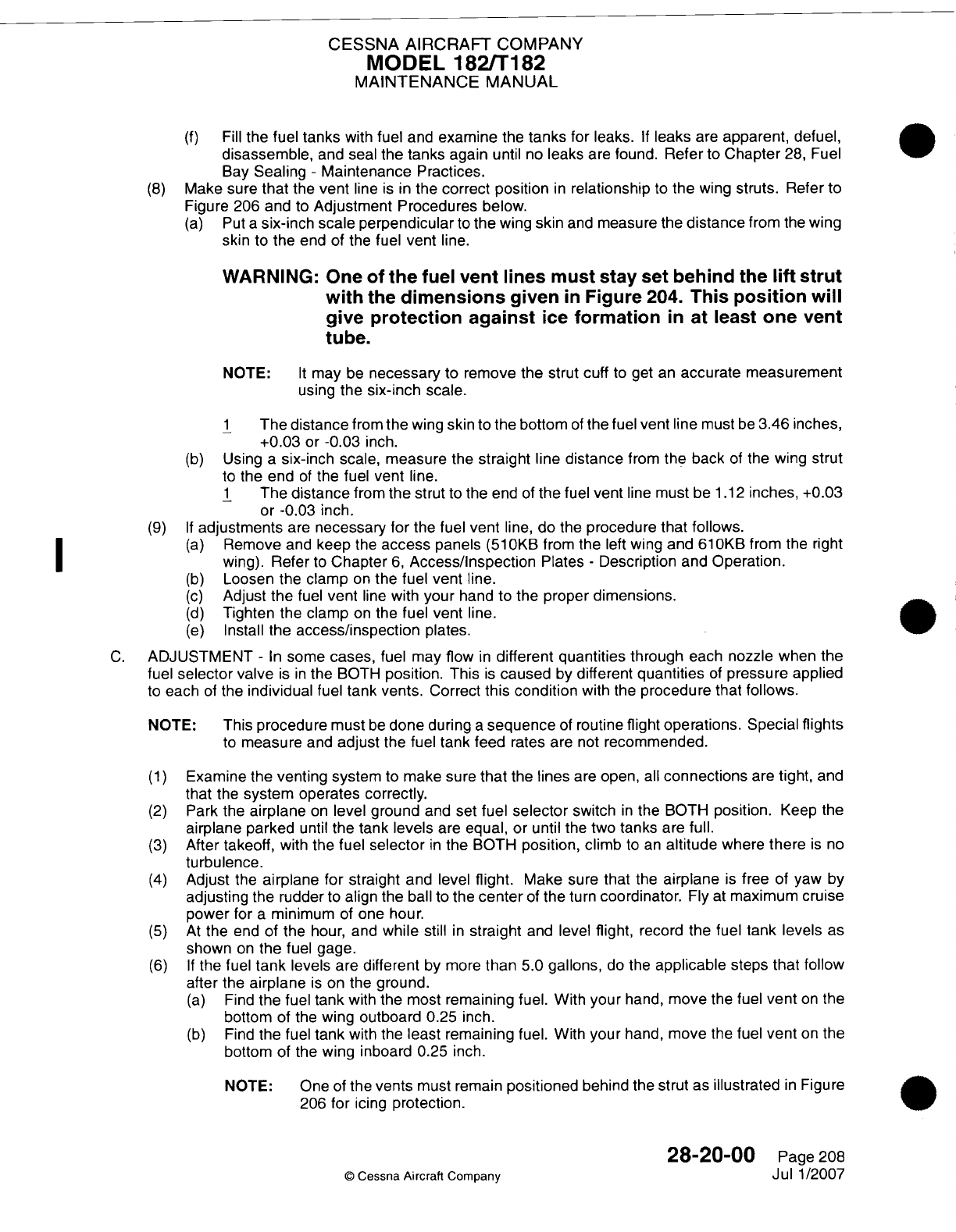
CESSNA AIRCRAFT
COMPANY
MODEL
1821T182
MAINTENANCE
MANUAL
(f)
Fill
the
fuel
tanks
with fuel
and
examine
the
tanks
for leaks.
If
leaks
are
apparent,
defuel,
disassemble,
and
seal
the
tanks again
until
no
leaks
are
found.
Refer
to
Chapter
28,
Fuel
Bay
Sealing
-
Maintenance
Practices.
(8)
Make sure
that
the
vent
line
is in
the
correct
position
in
relationship
to
the
wing
struts.
Refer
to
Figure
206 and
to
Adjustment
Procedures
below.
(a)
Put
a
six-inch
scale
perpendicular
to
the
wing
skin
and
measure
the
distance
from
the
wing
skin
to the
end of
the
fuel
vent
line.
WARNING:
One of
the
fuel
vent lines must
stay
set
behind
the
lift
strut
with
the
dimensions
given
in
Figure
204.
This
position
will
give protection
against
ice
formation
in
at
least
one
vent
tube.
NOTE:
It
may
be
necessary
to
remove
the
strut
cuff
to
get
an
accurate measurement
using the
six-inch
scale.
1
The
distance
from
the
wing
skin to the
bottom
of
the
fuel
vent
line
must
be
3.46
inches,
+0.03
or
-0.03
inch.
(b)
Using
a
six-inch
scale,
measure
the
straight
line
distance
from
the
back
of
the
wing
strut
to
the
end
of
the
fuel
vent
line.
1
The
distance
from the
strut
to
the
end
of
the fuel
vent
line
must
be
1.12
inches,
+0.03
or
-0.03
inch.
(9) If
adjustments
are
necessary
for
the
fuel
vent
line,
do the
procedure that
follows.
(a)
Remove
and
keep
the
access
panels
(510KB1
from
the
left
wing
and
610KB
from
the
right
I ~ ~~~~wing).
Refer
to
Chapter
6,
Access/inspection
Plates
-
Description
and
Operation.
(b)
Loosen
the
clamp
on
the
fuel vent line.
(c)
Adjust the
fuel
vent
line
with
your
hand
to
the
proper
dimensions.
(d)
Tighten
the
clamp
on
the
fuel vent
line.
(e)
Install
the
access/inspection
plates.
C.
ADJUSTMENT
-
In
some cases,
fuel
may
flow
in
different
quantities
through
each
nozzle
when
the
fuel
selector
valve
is in
the
BOTH
position.
This
is
caused
by
different
quantities
of
pressure applied
to each
of
the
individual
fuel
tank vents.
Correct
this
condition
with
the
procedure
that
follows.
NOTE:
This
procedure
must
be
done
during
a
sequence
of
routine
flight
operations.
Special
flights
to
measure
and
adjust
the fuel
tank feed
rates are
not
recommended.
(1)
Examine
the
venting
system
to
make
sure
that
the
lines
are
open,
all
connections
are
tight,
and
that
the
system operates correctly.
(2)
Park
the
airplane
on
level ground
and
set
fuel
selector
switch
in
the
BOTH
position.
Keep
the
airplane
parked
until
the
tank
levels
are
equal, or
until
the
two
tanks
are
full.
(3)
After takeoff, with
the fuel
selector
in
the BOTH
position,
climb
to an
altitude
where
there
is no
turbulence.
(4)
Adjust
the
airplane for
straight
and level
flight.
Make sure
that
the
airplane
is
free
of
yaw
by
adjusting
the
rudder
to
align
the
ball
to
the
center
of
the
turn
coordinator.
Fly
at
maximum
cruise
power
for
a
minimum
of
one
hour.
(5)
At
the
end of
the
hour, and
while
still
in
straight
and
level
flight,
record
the fuel
tank
levels
as
shown
on
the fuel
gage.
(6) If
the fuel
tank
levels
are
different
by
more
than
5.0
gallons,
do
the
applicable
steps
that follow
after
the
airplane
is
on
the
ground.
(a)
Find
the
fuel
tank
with the
most
remaining
fuel.
With
your
hand,
move
the
fuel
vent
on
the
bottom
of
the
wing
outboard
0.25
inch.
(b)
Find
the fuel
tank
with
the
least
remaining
fuel.
With
your
hand,
move the
fuel
vent
on
the
bottom of
the
wing
inboard 0.25
inch.
NOTE: One
of
the
vents
must remain
positioned
behind the
strut
as
illustrated
in
Figure
206
for
icing
protection.
28-20-00
Page
208
©
Cessna
Aircraft
Company
Jul
1/2007
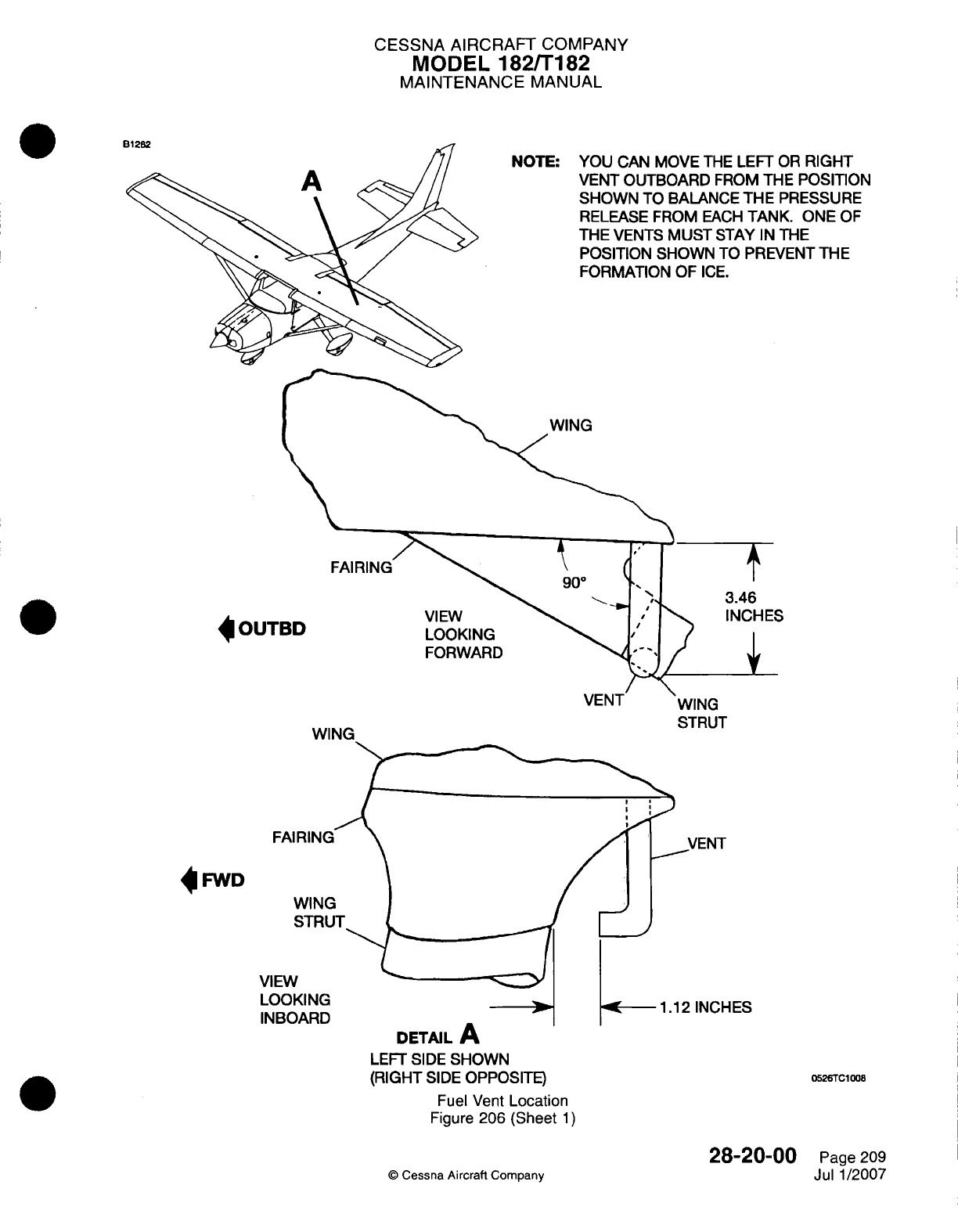
CESSNA
AIRCRAFT
COMPANY
MODEL
182/Ti
82
MAINTENANCE
MANUAL
NOTE: YOU
CAN MOVE
THE
LEIFT
OR
RIGHT
VENT
OUTBOARD
FROM
THE
POSITION
SHOWN
TO
BALANCE
THE PRESSURE
RELEASE
FROM
EACH
TANK.
ONE OF
THE
VENTS
MUST
STAY
IN
THE
POSITION
SHOWN
TO
PREVENT
THE
FORMATION
OF
ICE.
WING
VIEW
LOOKING
FORWARD
WING
STRUT
4 ES
DETAIL
A
LEFT
SIDE
SHOWN
(RIGHT
SIDE
OPPOSITE)
Fuel
Vent
Location
Figure
206 (Sheet
1)
©
Cessna
Aircraft
Company
28-2000
Page 209
Jul
1/2007
4
OUT
4
FWD
0526TC1008
I
Di
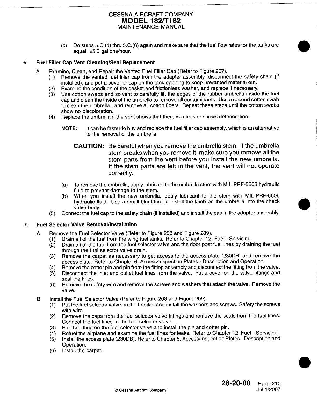
CESSNA AIRCRAFT
COMPANY
MODEL
182ffT182
MAINTENANCE
MANUAL
(c)
Do
steps
5.C.(1)
thru
5.C.(6) again and
make sure
that
the
fuel
flow
rates
for
the
tanks
are
equal,
±5.0
gallons/hour.
6. Fuel
Filler
Cap
Vent
Cleaning/Seal
Replacement
A.
Examine,
Clean,
and
Repair
the Vented
Fuel
Filler
Cap
(Refer
to
Figure
207).
(1)
Remove
the
vented fuel
filler
cap
from
the adapter assembly,
disconnect
the
safety
chain
(if
installed),
and
put
a
cover
or
cap
on
the
tank
opening
to
keep unwanted
material out.
(2)
Examine
the
condition
of
the
gasket
and
frictionless
washer,
and
replace
if
necessary.
(3)
Use
cotton
swabs
and
solvent
to
carefully
lift
the edges
of
the
rubber umbrella
inside
the
fuel
cap
and
clean
the
inside
of
the
umbrella
to remove
all
contaminants.
Use
a
second
cotton swab
to
clean
the umbrella
,
and remove
all
cotton
fibers.
Repeat
these
steps
until
the
cotton
swabs
show
no
discoloration.
(4)
Replace
the
umbrella
if
the
vent shows
that
there
is a
leak
or
shows
deterioration.
NOTE:
It
can
be
faster
to
buy
and
replace
the
fuel
filler
cap
assembly,
which
is
an
alternative
to
the
removal
of
the
umbrella.
CAUTION:
Be
careful
when you remove the
umbrella
stem.
If
the umbrella
stem
breaks
when
you
remove
it,
make sure
you
remove
all
the
stem
parts
from
the
vent
before
you install
the
new
umbrella.
If
the
stem
parts
are
left
in
the
vent, the vent
will
not
operate
correctly.
(a)
To
remove the
umbrella,
apply
lubricant
to
the
umbrella
stem
with
MIL-PRF-5606
hydraulic
fluid
to
prevent damage
to
the
stem.
(b)
When
you
install
the
new
umbrella,
apply
lubricant
to
the
stem
with
MIL-PRF-5606
hydraulic
fluid.
Use
a
small blunt tool
to
install
the knob
on
the umbrella
into
the
check
valve
body.
(5)
Connect the
fuel cap
to
the
safety
chain
(if
installed)
and
install
the
cap
in
the adapter
assembly.
7.
Fuel
Selector
Valve
Removal/Installation
A.
Remove
the
Fuel
Selector
Valve
(Refer
to
Figure
208
and
Figure 209).
(1)
Drain
all
of
the
fuel from the
wing
fuel
tanks. Refer
to
Chapter
12,
Fuel
-
Servicing.
(2)
Drain
all
of
the fuel from
the
fuel
selector
valve
and the
door
post
fuel lines
by
draining
the
fuel
through
the
fuel
selector
valve
drain.
(3)
Remove
the
carpet
as
necessary
to
get
access
to
the
access
plate
(230DB)
and
remove
the
access
plate. Refer
to
Chapter
6,
Access/Inspection
Plates
-
Description
and
Operation.
(4)
Remove
the cotter
pin
and
pin
from the
fitting
assembly
and
disconnect
the
fitting from the
valve.
(5)
Disconnect
the inlet
and
outlet
fuel
lines
from
the
valve.
Put
a
cover
on
the
valve
fittings
and
seal
the
lines.
(6)
Remove
the
safety
wire
and
remove the
screws
and
washers that
attach
the valve.
Remove
the
valve.
B.
Install the
Fuel
Selector
Valve
(Refer
to
Figure
208
and Figure 209).
(1)
Put the
fuel
selector
valve
on
the
bracket
and
install
the
washers
and
screws.
Safety
the
screws
with
wire.
(2)
Remove
the caps
from
the
fuel
selector
valve
fittings
and
remove
the
seals
from
the
fuel lines.
Connect
the
fuel lines
to
the
fuel
selector valve.
(3)
Put
the
fitting
on
the
fuel
selector
valve
and
install
the
pin
and
cotter
pin.
(4)
Refuel
the
airplane
and
examine
the fuel
lines for
leaks. Refer
to
Chapter
12,
Fuel
-
Servicing.
(5)
Install
the
access
plate
(230DB).
Refer
to
Chapter
6,
Access/Inspection
Plates
-
Description
and
Operation.
(6)
Install the
carpet.
28-20-00
Page
21
0
rC
Cessna Aircraft
Company
Jul
1/2007
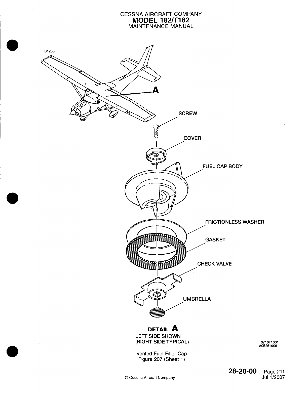
CESSNA AIRCRAFT
COMPANY
MODEL
1821T182
MAINTENANCE
MANUAL
SCREW
r
f%^%
~~~,If
I,
%-I
/'Jv
~r-
=EL
CAP
BODY
1ICTION
LESS
WASHER
kSKET
K
VALVE
DETAIL
A
LEFT
SIDE
SHOWN
(RIGHT
SIDE
TYPICAL)
Vented
Fuel
Filler
Cap
Figure
207
(Sheet
1)
28-20-00
©
Cessna
Aircraft
Company
071
OT1
001
A05261
006
Page
211
Jul
1/2007
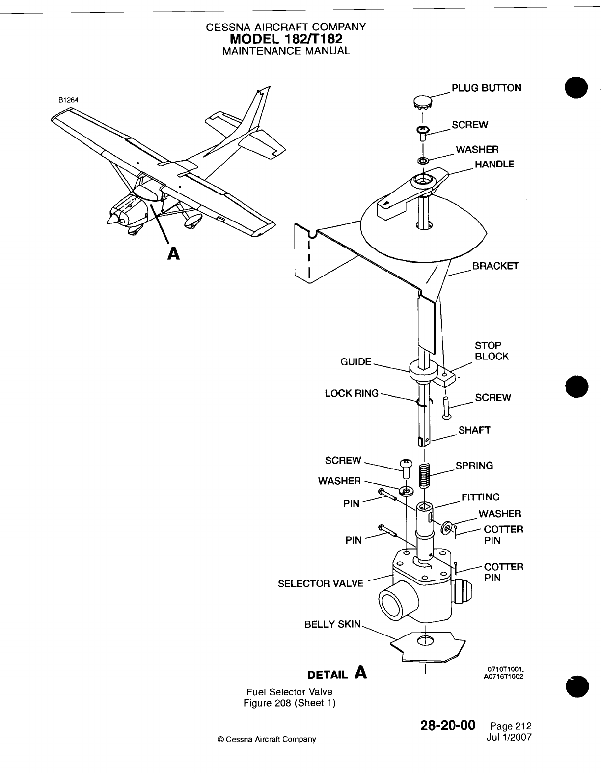
CESSNA AIRCRAFT
COMPANY
MODEL
182/Ti
182
MAINTENANCE
MANUAL
PLUG
BUTTON
I
SCREW
WASH
ER
I
---
W1-Ainfi
r:
A
GUIDE
SCREW
WASHER
PIN
PIN
SELECTOR
VALVE
BELLY
SKIN
rE
MTrAI
I
IE At
Fuel
Selector
Valve
Figure
208
(Sheet
1)
28-20-00
©
Cessna Aircraft
Company
0
,CKET
)CK
IEW
'HER
TTER
TTER
OT1
001.
AIU
I
---
~
Page
212
Jul
1/2007
AU/1011VV4
Lo
9--
1
V%116
N-S
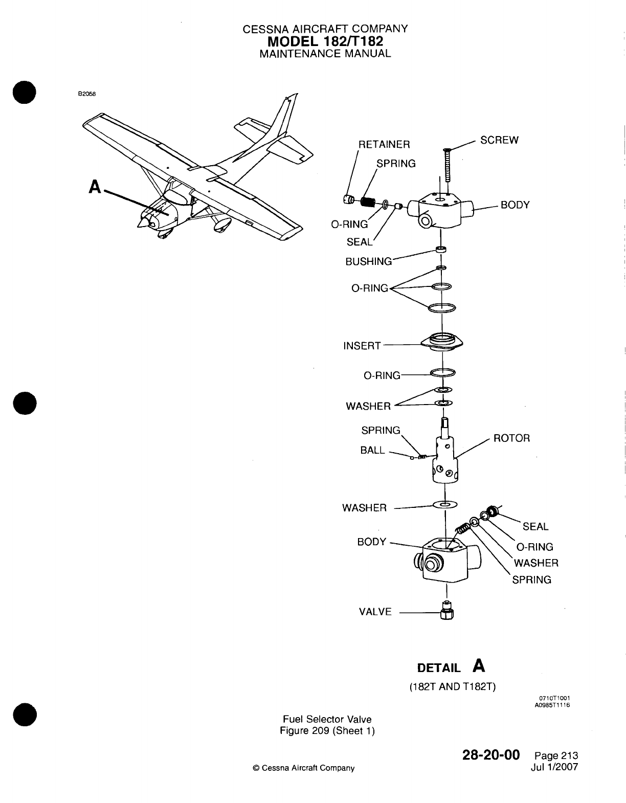
CESSNA AIRCRAFT
COMPANY
MODEL
182/Ti
82
MAINTENANCE
MANUAL
L
RETAINER
ISPRING
SEAL'
BUSHII
O-RING-
INSERT
0-RIN(
WASHER
BALL
WASHER
BODY
SPRING
VALVE
DETAIL
A
(1
82T
AND
T1
82T)
0710T1001
A0985T1 116
Fuel
Selector
Valve
Figure 209
(Sheet
1)
28-20-00
©
Cessna
Aircraft
Company
Page
213
Jul
1/2007
0-RING
Clfl M
r-1
AI
CESSNA
AIRCRAFT
COMPANY
MODEL
182/Ti
182
MAINTENANCE
MANUAL
8.
Fuel
Strainer
Disassembly/CleaninglAssembly0
A.
Disassemble and
Clean
the
Fuel
Strainer
(Refer
to
Figure
210).
(1)
Turn
the
fuel
selector
valve
to
the
OFF
position.
(2)
Disconnect
the
strainer
drain
tube, remove
the
safety
wire,
nut,
and
washer
at
the bottom
of
the
filter
bowl,
and
remove
the
bowl.
(3)
Carefully
remove
the
standpipe.
(4)
Remove
the
filter
screen
and
gasket.
(5)
Clean the
filter
screen
and
the
bowl
in
solvent
and
dry
with
compressed
air.
B.
Assemble
the
Fuel
Strainer
(Refer
to
Figure 210).
(1)
Install the
screen
and
standpipe with
a
new
gasket
between
the
filter
screen
and
the
top
assembly.
Tighten
the
standpipe
with
your
fingers.
(2)
Install the
bowl
with
all new
0-rings.
Torque
the
nut
to
between
25
and
30
inch-pounds.
NOTE:
The
step-washer
at
the
bottom
of
the
bowl
is
installed
so
that the step
is
against the
0-ring.
(3)
Connect the
strainer
to
the drain
tube.
(4)
Turn the
fuel
selector
valve
to
the
ON
position,
close
the
strainer
drain,
and
examine the system
for
leaks.
Make
sure
that
the
system
operates
correctly.
(5)
Loosen
the
fuel
supply
hose
at
the
fuel
injection servo
inlet.
(6)
Set
the
mixture
control
to
the
OFF
position.
(7)
Set
the
throttle control
to
the
IDLE
STOP
position.
(8)
Set
the
FUEL
PUMP
switch
to
the
ON
position.
(9)
Operate
the
electric
auxiliary
fuel
pump
until
the air
is
removed
from
the
fuel
lines
and
the
pump
is
full
of
fuel.
(110)
Set
the FUEL
PUMP
switch
to
the
OFF
position.
(1 1)
Tighten
the
fuel
supply
hose
at
the
fuel
injection
servo
inlet.
Refer
to
Chapter
20,
Torque
Data
-
Maintenance Practices.
(12)
Install
the
safety
wire
from the
bottom
nut
to the
top
of
the
assembly.
Refer to
Chapter
20,
Safetying
-
Maintenance
Practices.
9.
Electric
Auxiliary
Fuel
Pump
Removal/Installation (Airplanes
18280001
thru
18280944)
A.
Remove
the
Electric
Auxiliary
Fuel
Pump (Refer
to
Figure
211).
(1)
Set
the MASTER
ALT
BAT
switch
to
the
OFF
position.
(2)
Turn
the
fuel
selector
handle
to
the
OFF
position.
(3)
Disconnect
the
battery
ground cable
from
the
battery.
(4)
Disconnect
the
electrical
connector
(P1)
from
the
electric
auxiliary
fuel pump
(UFO05).
(5)
Disconnect
the fuel
lines
and
drain
the
line
from the
electric
auxiliary
fuel
pump.
(6)
Loosen
the
mounting
clamps
that
attach
the
electric
auxiliary
fuel pump
and
remove
the
pump
from
the
airplane.
(7)
Remove
all
the
fuel
fittings
from
the
electric
auxiliary
fuel
pump
and
discard
the used
0-rings
from
the
inlet
and
outlet
fuel
fittings.
B.
Install
the
Electric
Auxiliary
Fuel Pump
(Refer
to
Figure
21
1).
(1)
Put the
new
0-rings
on
the
inlet
and
outlet
fuel
fittings.
(2)
Install
the
inlet
and
outlet
fuel
fittings
into the
electric
auxiliary
fuel
pump
and
tighten
the
fittings.
Refer
to
Chapter
20,
Torque
Data
-Maintenance
Practices.
(3)
Install
the
fuel
drain
fitting
into
the
electric
auxiliary
fuel
pump
and
tighten
the
fitting.
Refer
to
Chapter
20, Torque Data
-
Maintenance Practices.
(4)
Put
the
electric
auxiliary
fuel
pump
into
mounting clamps.
(5)
Loosely install
the
mounting
clamps.
(6)
Connect
the
fuel
drain line
to
the
fuel
drain
fitting.
(7)
Connect
and
tighten
the
fuel
lines
to
the
inlet and
outlet
fittings.
(8)
Tighten
the
mounting clamps.
Refer to
Chapter
20,
Torque
Data
-
Maintenance
Practices.
(9)
Tighten
the
fuel lines
onto
the
fittings.
Refer
to
Chapter
20,Torque
Data
-Maintenance
Practices.
0
(1
0)
Connect
the
electrical connectors
to
the
electric
auxiliary
fuel
pump.
28-20-00
Page
214
©
Cessna
Aircraft
Company
Jul
1/2007
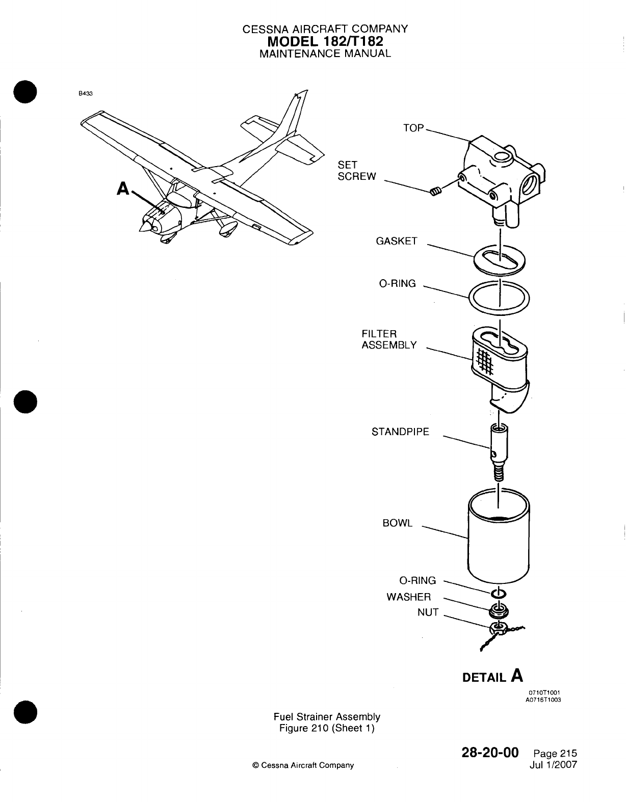
CESSNA AIRCRAFT
COMPANY
MODEL
182/Ti
82
MAINTENANCE
MANUAL
Tfl
D
SET
SCR
E"A
FILTER
ASSEMBLY
STAN
DPIF
BOWL
0-RI
WASHE
DETAIL
A
071 OTi1001
A0716T1003
Fuel
Strainer
Assembly
Figure 210
(Sheet
1)
©
Cessna
Aircraft
Company
28-20-00
Page
215
Jul
1
/2007
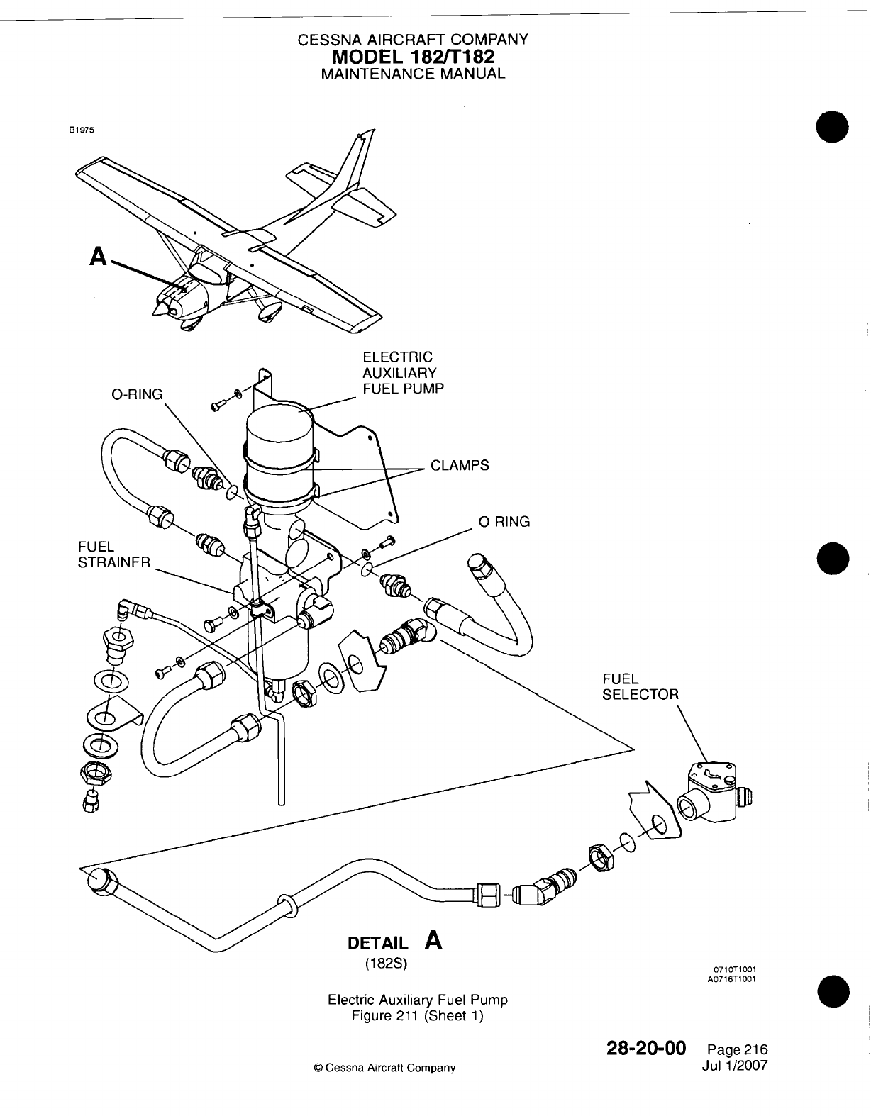
CESSNA
AIRCRAFT
COMPANY
MODEL
182/Ti182
MAINTENANCE
MANUAL
H
ELECTRIC
(1
82S)
Electric
Auxiliary
Fuel
Pump
Figure
211
(Sheet
1)
28-20-00
©
Cessna
Aircraft Company
0710T1001
A0716T1001
Page
216
Jul
1/2007
CESSNA
AIRCRAFT
COMPANY
MODEL
182/Ti
82
MAINTENANCE
MANUAL
(1 1)
Turn
the
fuel
selector
handle
to
the
ON
position.
(12)
Examine
the
electric
auxiliary
fuel
pump
and
fuel
fittings
for
fuel leaks.
(13)
Connect
the
battery
ground
cable to
the
battery.
(14)
Loosen
the
fuel
supply
hose
at
the fuel
injection
servo
inlet.
(15)
Set
the
mixture control
to
the
OFF
position.
(16)
Set
the
throttle
control
to
the
IDLE
STOP
position.
(17)
Set
the MASTER
ALT
BAT
switch
to
the ON
position.
(18)
Set
the
FUEL PUMP
switch
to
the
ON
position.
(19)
Operate
the
electric
auxiliary
fuel
pump until
the air
is
removed
from the fuel
lines
and
the
pump
is
full
of
fuel.
(20)
Set
the
FUEL
PUMP
switch
to
the
OFF
position.
(21)
Tighten
the
fuel
supply
hose
at
the
fuel
injection
servo
inlet.
Refer to
Chapter
20,
Torque
Data
-
Maintenance
Practices.
(22) Set
the
FUEL
PUMP
switch
to
the
ON
position.
(23)
Operate
the
electric
auxiliary
fuel
pump
and
examine
all
fuel
fittings
for
leaks.
(24)
Set
the
FUEL PUMP
switch
to
the
OFF
position.
10.
Electric
Auxiliary
Fuel
Pump
Removal/installation
(Airplanes 18280945
and
On
and
Airplanes
T18208001
and
On)
A.
Remove
the
Electric Auxiliary
Fuel
Pump
(Refer
to
Figure 212).
(1)
Make
sure
that
the
master
switch
is in
the OFF
position.
(2)
Disconnect the battery
ground cable.
(3)
Set
the fuel
selector
to
the
OFF
position.
(4)
Remove
the
copilot's
seat
and
carpet.
Refer
to
Chapter
25,
Front
Seats
and
Rails
-
Maintenance
Practices
and
Chapter
25,
Interior
Upholstery-Maintenance
Practices.
(5)
Remove
the
access
plate
(230AB)
to
get
access
to
the
pump. Refer
to
Chapter
6,
Access/
Inspection
Plates-Description
and
Operation.
(6)
Disconnect the
fuel
lines, drain
line,
and
electrical
connectors
from
the
pump.
(7)
Loosen
the
mounting
clamps
that attach
the pump
and remove
the
pump
from
the
airplane.
B.
Install
the
Electric
Auxiliary
Fuel
Pump
(Refer
to
Figure
212).
(1)
Put
the
pump
in
the
mounting clamps
and
tighten
the
clamps.
Refer
to
Chapter
20,
Torque
Data
-
Maintenance
Practices.
(2)
Connect
all
the
fuel
lines,
drain line,
and
electrical
connectors
to
the
pump.
(3)
Set
the master
switch
to
the
ON
position
and
connect
the
battery
ground
cable.
(4)
Turn
fuel
selector
to
the
ON
position.'
(5)
Operate
the
electric auxiliary
fuel pump
and
examine
all
the
fuel
fittings
for
leaks.
(6)
Install the
access
plate
(230AB).
Refer
to
Chapter
6,
Access/Inspection
Plates-Description
and
Operation.
(7)
Install
the
carpet
and
copilot's
seat.
Refer
to
Chapter
25,
Front
Seats
and
Rails
-
Maintenance
Practices.and Chapter
25,
Interior
Upholstery-Maintenance
Practices.
11.
Auxiliary
Fuel
Pump
Serviceability
Test
(Airplanes
18280001
thru
18280944)
A.
Auxiliary
Fuel
Pump
Test
(Refer
to
Table
201).
WARNING:
Obey
all
fuel
system
fire
and
safety
procedures.
Remove
all
flammable
materials
from
the
airplane
and
from
all
areas
where
the
fumes
are
dangerous.
(1)
Remove
the
fuel
supply
hose
from the
inlet
fitting
of
the engine-driven
fuel
pump.
(2)
Install
a
tee
fitting
on
the fuel
supply
hose.
(3)
Connect
a
calibrated
fuel
pressure
test
gage
and
locally-purchased
fuel
shutoff valve
to
the
tee
fitting.
(4)
Set the fuel
shutoff
valve
so
that
the
fuel
drains
into
a
container.
28-20-00
Page
217
©
Cessna
Aircraft
Company
Jul
1/2007
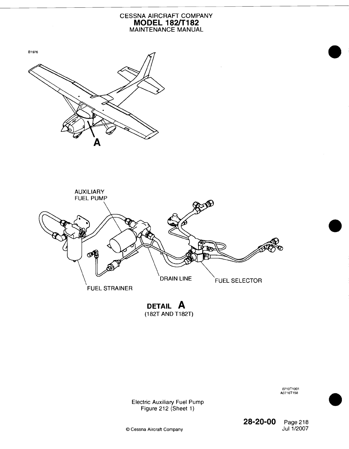
CESSNA AIRCRAFT
COMPANY
MODEL
182/Ti
182
MAINTENANCE
MANUAL
A
AUXILIARY
FI
IR
Pi
MP
DRAIN
LINE
FUEL
SELECTOR
FUEL
STRAINER
DETAIL
A
(1
82T
AND
T1
82T)
07
lT10I0
1
A0716T
158
Electric
Auxiliary
Fuel
Pump
Figure
212
(Sheet
1)
28-20-00
©
Cessna
Aircraft
Company
Page
218
Jul
1/2007
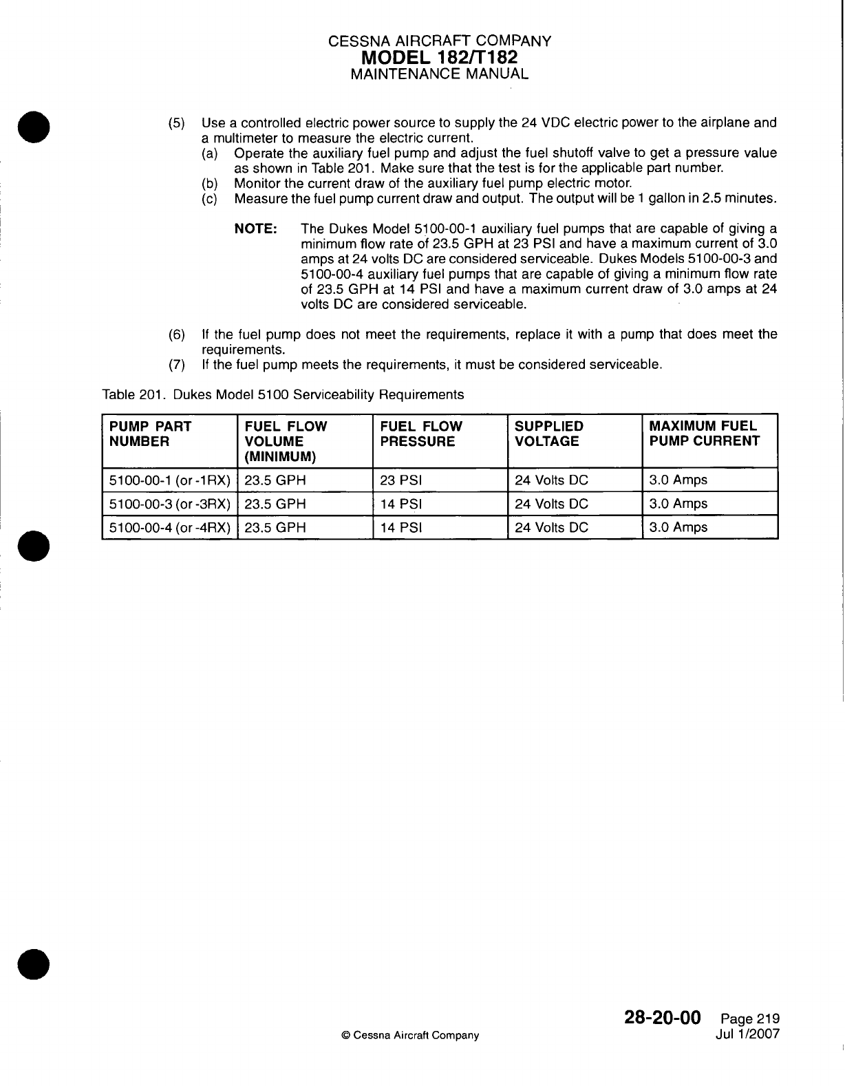
CESSNA
AIRCRAFT
COMPANY
MODEL 182/T182
MAINTENANCE
MANUAL
(5)
Use
a
controlled
electric
power
source
to
supply
the
24
VDC
electric
power
to
the
airplane
and
a
multimeter
to
measure the
electric
current.
(a)
Operate
the
auxiliary
fuel pump
and
adjust
the
fuel
shutoff
valve
to
get
a
pressure value
as
shown
in
Table
201.
Make sure
that
the
test
is
for
the
applicable
part
number.
(b)
Monitor
the
current draw
of
the
auxiliary
fuel
pump
electric
motor.
(c)
Measure
the
fuel
pump
current
draw
and output.
The
output
will
be
1
gallon
in
2.5
minutes.
NOTE:
The
Dukes
Model
51
00-00-1
auxiliary
fuel
pumps
that are
capable
of
giving
a
minimum
flow
rate
of
23.5
GPH
at
23
PSI
and
have
a
maximum
current
of
3.0
amps
at
24 volts
DC
are
considered
serviceable.
Dukes
Models
5100-00-3
and
51
00-00-4
auxiliary
fuel
pumps
that are
capable
of
giving
a
minimum
flow
rate
of
23.5 GPH
at 14
PSI
and
have
a
maximum
current
draw
of
3.0
amps
at
24
volts
DC
are
considered serviceable.
(6) If
the
fuel pump does
not
meet
the
requirements,
replace
it
with
a
pump
that does
meet
the
requirements.
(7) If
the fuel pump
meets
the
requirements,
it
must
be
considered
serviceable.
Table
201.
Dukes Model
51
00
Serviceability
Requirements
PUMP
PART
FUEL
FLOW
FUEL FLOW
SUPPLIED
MAXIMUM
FUEL
NUMBER
VOLUME
PRESSURE VOLTAGE
PUMP
CURRENT
____ ____ ____
(M
INIM
UM
) _ _ _ _ _ _
_
51
00-00-1
(or
-1RX)
23.5
GPH
23 PSI
24
Volts
DC
3.0
Amps
51
00-00-3
(or -3RX)
23.5
GPH
14
PSI
24
Volts
DC
3.0
Amps
51
00-00-4
(or -4RX)
23.5 GPH
14
PSI
24
Volts
DC
3.0
Amps
©
Cessna
Aircrafl
Company
28-20-00
Page
219
Jul
1/2007
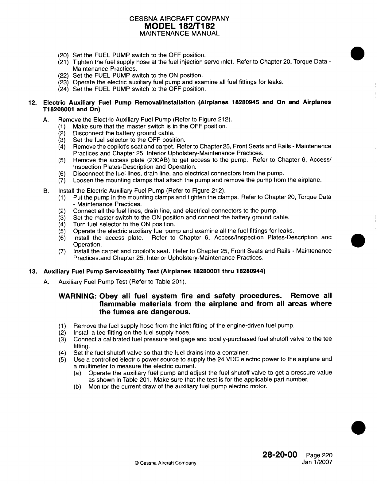
CESSNA AIRCRAFT
COMPANY
MODEL
1821T182
MAINTENANCE
MANUAL
(20)
Set
the
FUEL
PUMP
switch
to
the
OFF
position.
(21)
Tighten
the
fuel
supply
hose
at
the
fuel
injection servo
inlet.
Refer
to
Chapter
20, Torque
Data
-
Maintenance
Practices.
(22)
Set
the
FUEL
PUMP
switch
to
the
ON
position.
(23)
Operate
the
electric
auxiliary
fuel
pump
and
examine
all
fuel
fittings
for leaks.
(24)
Set
the
FUEL
PUMP
switch
to
the OFF
position.
12.
Electric
Auxiliary
Fuel
Pump
RemovaVinstallation
(Airplanes
18280945
and
On
and
Airplanes
T18208001
and
On)
A.
Remove
the
Electric
Auxiliary
Fuel
Pump
(Refer
to
Figure
212).
(1)
Make
sure
that
the
master
switch
is in
the
OFF
position.
(2)
Disconnect
the
battery ground
cable.
(3)
Set
the
fuel
selector
to
the
OFF
position.
(4)
Remove
the copilot's
seat
and
carpet.
Refer
to
Chapter
25,
Front
Seats
and Rails
-
Maintenance
Practices
and
Chapter
25,
Interior
Upholstery-Maintenance
Practices.
(5)
Remove
the
access
plate
(230AB)
to
get
access
to
the
pump.
Refer
to
Chapter
6,
Access/
Inspection
Plates-Description
and
Operation.
(6)
Disconnect
the fuel
lines, drain
line,
and
electrical
connectors
from
the pump.
(7)
Loosen
the
mounting
clamps
that attach
the pump
and
remove
the
pump
from
the
airplane.
B.
Install
the
Electric Auxiliary
Fuel
Pump
(Refer
to
Figure
212).
(1)
Put
the
pump
in
the
mounting
clamps
and
tighten
the
clamps.
Refer
to
Chapter
20,
Torque
Data
-
Maintenance Practices.
(2)
Connect
all
the
fuel
lines,
drain
line, and
electrical connectors
to
the
pump.
(3)
Set
the
master
switch
to
the
ON
position
and
connect
the
battery ground
cable.
(4)
Turn
fuel
selector
to
the
ON
position.
(5)
Operate
the
electric
auxiliary
fuel
pump
and
examine
all
the fuel
fittings
for
leaks.
(6)
Install
the
access
plate.
Refer
to
Chapter
6,
Access/inspection
Plates-Description
and
Operation.
(7)
Install
the
carpet
and
copilot's
seat. Refer
to
Chapter
25,
Front
Seats
and
Rails
-
Maintenance
Practices.and Chapter
25,
Interior
Upholstery-Maintenance
Practices.
13.
Auxiliary
Fuel
Pump
Serviceability
Test
(Airplanes
18280001 thru
18280944)
A.
Auxiliary
Fuel
Pump
Test
(Refer
to Table
201).
WARNING: Obey
all
fuel
system
fire
and
safety
procedures.
Remove
all
flammable materials from
the
airplane
and
from
all
areas
where
the
fumes
are
dangerous.
(1)
Remove the
fuel
supply
hose
from
the
inlet
fitting
of
the
engine-driven fuel
pump.
(2)
Install
a
tee
fitting
on
the
fuel
supply
hose.
(3)
Connect
a
calibrated fuel pressure test
gage
and
locally-purchased
fuel
shutoff
valve
to
the tee
fitting.
(4)
Set
the
fuel
shutoff
valve
so
that
the fuel
drains
into
a
container.
(5)
Use
a
controlled
electric
power source
to
supply the
24
VDC
electric
power
to
the
airplane
and
a
multimeter
to
measure
the
electric
current.
(a)
Operate the
auxiliary
fuel pump
and
adjust
the
fuel
shutoff
valve
to
get
a
pressure
value
as
shown
in
Table
201.
Make
sure
that
the
test
is
for
the
applicable
part
number.
(b)
Monitor
the
current
draw
of
the
auxiliary
fuel
pump
electric
motor.
28-20-00
Page 220
©
Cessna
Aircraft Company
Janl1/2007
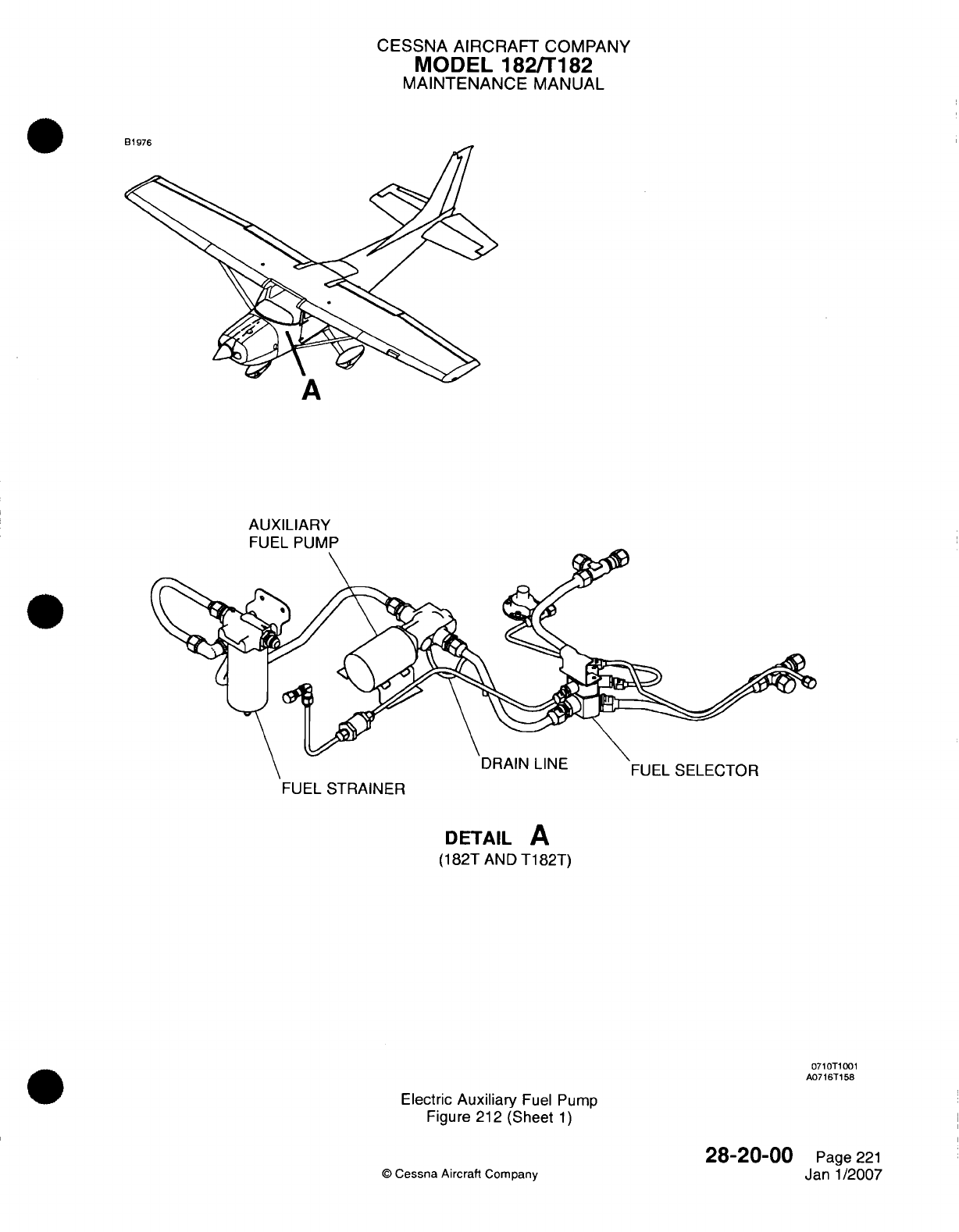
CESSNA
AIRCRAFT
COMPANY
MODEL
182/Ti182
MAINTENANCE
MANUAL
P1
...
A
AUXILIARY
FUEL
PUMP
FUEL
STRAINER
DETAIL
A
(182T
AND
T1
82T)
0710T1001
A0716T158
Electric
Auxiliary
Fuel Pump
Figure
212
(Sheet
1)
Q
Cessna Aircraft
Company
28-20-00
Page
221
Janl1/2007
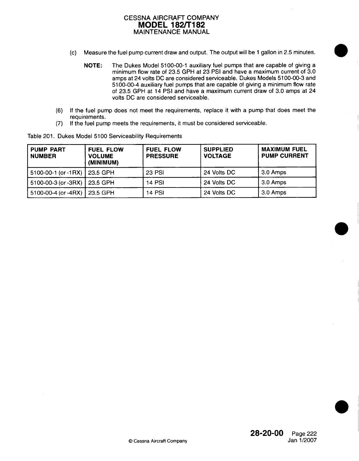
CESSNA AIRCRAFT
COMPANY
MODEL
182/Ti
182
MAINTENANCE
MANUAL
(c)
Measure
the
fuel pump
current
draw
and
output.
The
output
will be
1
gallon
in
2.5
minutes.
NOTE:
The
Dukes
Model
5100-00-1
auxiliary
fuel
pumps
that
are
capable
of
giving
a
minimum flow
rate
of
23.5
GPH
at
23
PSI
and
have
a
maximum current
of
3.0
amps
at
24
volts
DC
are
considered
serviceable.
Dukes Models
5100-00-3
and
51
00-00-4 auxiliary
fuel pumps
that
are
capable
of
giving
a
minimum
flow
rate
of
23.5
GPH
at
14
PSI
and
have
a
maximum
current draw
of
3.0 amps
at
24
volts
DC
are
considered serviceable.
(6) If
the
fuel
pump
does
not
meet the
requirements,
replace
it
with
a
pump
that
does
meet
the
requirements.
(7) If
the fuel
pump meets
the
requirements,
it
must
be
considered
serviceable.
Table
201.
Dukes Model
51
00
Serviceability
Requirements
PUMP
PART
FUEL
FLOW FUEL
FLOW
SUPPLIED
MAXIMUM
FUEL
NUMBER
VOLUME
PRESSURE VOLTAGE
PUMP
CURRENT
____ ____ ____
(M
IN
IM
U
M
)__
_ _ _ _ ___ _ _ _ _ _
_
5100-00-1
(or
-1RX)
23.5
GPH 23
PSI
24
Volts
DC
3.0
Amps
5100-00-3
(or
-3RX) 23.5 GPH
14
PSI
24 Volts
DC
3.0
Amps
5100-00-4 (or
-4RX)
123.5
GPH
14
PSI
24 Volts
DC
3.0
Amps
©
Cessna
Aircrafl
Company
28-20-00
Page
222
Janl1/2007
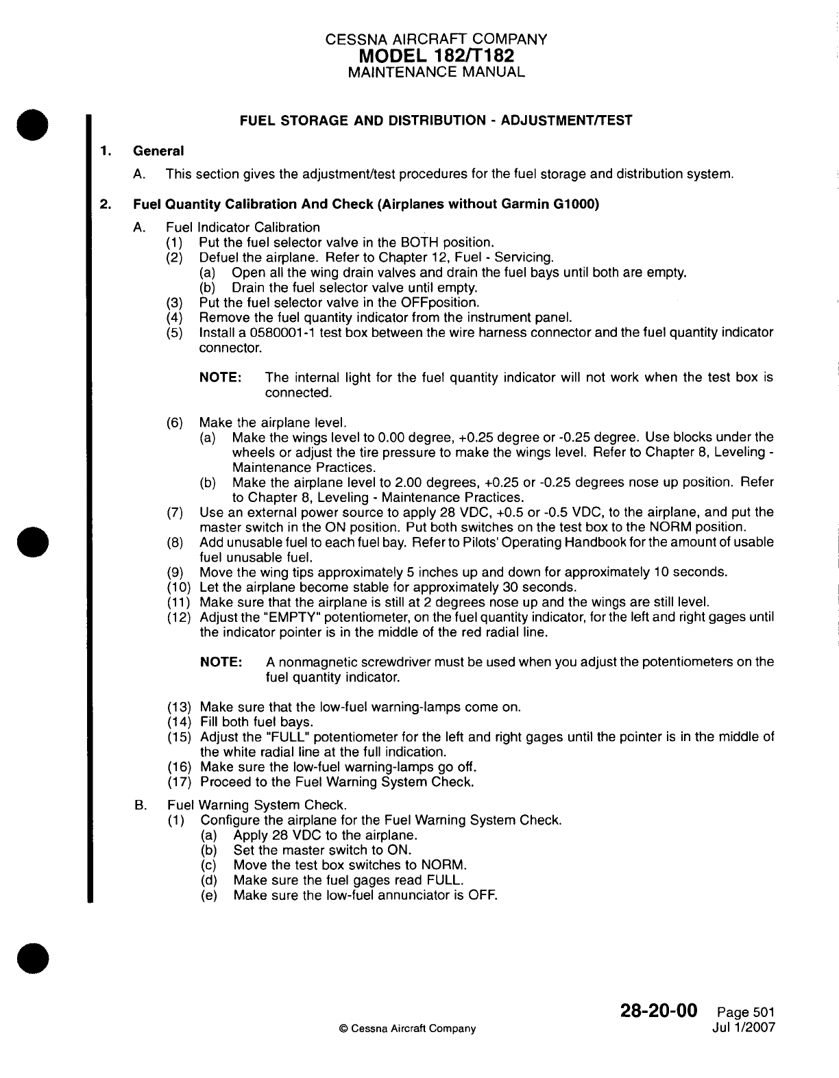
CESSNA
AIRCRAFT
COMPANY
MODEL
182/Ti
82
MAINTENANCE
MANUAL
FUEL
STORAGE
AND
DISTRIBUTION
-
ADJUSTMVENT/TEST
1.General
A.
This
section gives
the
adjustment/test
procedures
for
the
fuel
storage
and
distribution
system.
2.
Fuel
Quantity
Calibration
And Check
(Airplanes
without
Garmin
G1000)
A.
Fuel
Indicator
Calibration
(1)
Put
the
fuel
selector
valve
in
the BOTH
position.
(2)
Defuel
the
airplane.
Refer
to
Chapter
12,
Fuel
-
Servicing.
(a)
Open
all
the
wing
drain
valves
and
drain
the
fuel bays
until both
are
empty.
(b)
Drain
the
fuel
selector
valve
until
empty.
(3)
Put
the
fuel
selector
valve
in
the
OF~position.
(4)
Remove the fuel
quantity
indicator
from the
instrument
panel.
(5)
Install
a
0580001
-1
test box
between the wire
harness
connector
and
the
fuel
quantity
indicator
connector.
NOTE:
The
internal
light
for
the
fuel
quantity
indicator
will
not
work
when
the
test
box
is
connected.
(6)
Make
the
airplane
level.
(a)
Make the
wings level
to
0.00
degree,
+0.25
degree
or
-0.25 degree.
Use
blocks
under
the
wheels
or
adjust
the
tire
pressure
to
make
the
wings
level. Refer
to
Chapter
8,
Leveling
-
Maintenance
Practices.
(b)
Make
the
airplane
level
to
2.00
degrees,
+0.25 or
-0.25
degrees
nose
up
position.
Refer
to
Chapter
8,
Leveling
-
Maintenance
Practices.
(7)
Use an
external
power source
to
apply
28
VDC,
+0.5
or
-0.5
VDC,
to
the
airplane,
and
put
the
master
switch
in
the
ON
position.
Put
both
switches
on
the
test
box
to
the
NORM
position.
(8)
Add
unusable
fuel
to
each fuel
bay.
Refer
to
Pilots'Operating
Handbook
for
the
amount
of
usable
fuel
unusable
fuel.
(9)
Move
the
wing
tips
approximately
5
inches
up
and
down
for
approximately
1 0
seconds.
(1 0)
Let
the
airplane
become
stable
for
approximately
30
seconds.
(1 1)
Make sure
that
the
airplane
is
still
at
2
degrees
nose
up and
the
wings
are
still
level.
(12)
Adjust
the
"EMPTY"
potentiometer,
on
the
fuel
quantity
indicator,
for
the
left and
right
gages
until
the
indicator
pointer
is in
the
middle
of
the
red
radial
line.
NOTE:
A
nonmagnetic screwdriver
must
be used
when
you
adjust
the
potentiometers
on
the
fuel
quantity
indicator.
(13)
Make
sure
that
the
low-fuel
warning-lamps
come
on.
(14)
Fill
both
fuel bays.
(15)
Adjust
the
"FULL"
potentiometer
for
the left
and
right
gages
until
the
pointer
is in
the
middle
of
the
white
radial
line
at
the
full
indication.
(16)
Make
sure
the
low-fuel
warning-lamps
go off.
(17)
Proceed
to the
Fuel
Warning
System
Check.
B.
Fuel
Warning
System Check.
(1)
Configure
the
airplane
for
the Fuel
Warning
System Check.
(a)
Apply
28
VDC to
the
airplane.
(b)
Set
the
master switch
to
ON.
(c)
Move
the
test
box
switches
to
NORM.
(d)
Make
sure
the
fuel gages
read
FULL.
(e)
Make
sure
the
low-fuel
annunciator
is
OFF.
28-20-00
Page
501
©
Cessna
Aircraft
Company
Jul
1/2007
CESSNA
AIRCRAFT
COMPANY
MODEL
182/T
182
MAINTENANCE
MANUAL
(2)
Turn
the
NORM/OPEN
switch
on the
text
box
to
the
OPEN
position
and
start
the
timer.
NOTE:
The
airplane's
digital
clock
can
be
used
in
the
timer
mode
to
measure the
time
of
the
annunciators.
The
interval
for
this test
is
from
switch
operation
until
the
annunciator
begins
to
flash.
The
annunciators
will
flash
for
approximately
1 0
seconds
before
they
come
continuously
on
without
a
flash.
(3)
Monitor
the
fuel
quantity
indicator.
(a)
Make
sure the
pointer
goes
to
the
power
off
position
below
the
first
graduation.
(b)
The
annunciators
must
come
on
within
75
seconds.
(4)
Put
the
NORM/OPEN switch
to
the
NORM
position.
(a)
The
indicators
must
read
full and
the
annunciators
must
go
off.
(b)
Set
the
timer
again.
(5)
Turn
the
SHORT/NORM/i
00+ OHM
switch
to
the
1
00+
OHM
position.
Start
the
timer.
(6)
Monitor
the
fuel
quantity
indicator.
(a)
Make
sure the
pointer
goes
to
the
power
off
position
below
the
first
graduation.
(b)
The
annunciators
must
come
on
within
75
seconds.
(7)
Turn the
SHORT/NORM/i100+
OHM
switch
to
the
NORM
position.
(a)
The
indicators
must
read
full and
the
annunciators
must
go
off.
(b)
Set
the timer
again.
(8)
Turn
the
SHORT/NORM/i100+
OHM
switch
to
the
SHORT
position.
Start
the
timer.
(9)
Monitor
the fuel
quantity
indicator.
(a)
Make
sure the
pointer
goes
to
the
power
off
position
below
the
first
graduation.
(b)
The
annunciators
must
come
on
within
75
seconds.
(1
0)
Turn the
SHORT/NORM/i
00+
OHM
switch
to
the
NORM
position.
(a)
The
indicators
must
read
full and
the
annunciators
must
go off.
(ii1)
Set
the
airplane digital
clock
back
to
the
clock
mode.
(12)
Set the
master switch
to
OFF.
(13)
Remove
the
test
box.0
(14)
Install
the
fuel
quantity indicator
in
the instrument panel.
(15)
Set
the
master switch
to
ON.
(16)
Make sure
the
fuel
quantity
indicators
show
FULL
and the
annunciators
are
off.
(17)
Set
the
master
switch
to OFF.
3.
Fuel
Quantity Calibration
and
Fuel
Flow
Test
(Airplanes
with
Garmin
G1000
with
software
version
563.01
or
earlier)
NOTE:
The software
version
is
shown
on
the
upper
right
corner
of
the
MED
on
the
first page
displayed
after power
is
applied
the
MED
in
normal
operation.
NOTE:
If
the
fuel
quantity
indicator
on
the Garmin
G1000
system
has
a
red
X
on
it
during
normal
operation, examine
the
sender
and
wiring
and
refer
to
the
Garmin
G1000
Line
Maintenance
Manual
for
more
Garmin
system
troubleshooting.
If
the
values
given
on
the
Primary
Flight
Display
(PFD)
are
not the
same
as
the
values
given
in
the
calibration
procedure,
refer
to
the
Garmin
G1lOQO
Line
Maintenance
Manual
for
troubleshooting.
A.
Do
a
Fuel
Quantity
Calibration
and
Fuel
Flow
Test.
(1)
Put
the
selector valve
in
the
BOTH
position.
(2)
Defuel
the
airplane.
Refer
to
Chapter
12,
Fuel
-
Servicing.
(a)
Drain
the fuel
tanks
with
all
wing
drain
valves
until
the
two
tanks
are
empty.
(b)
Drain
the
fuel-selector
drain
valve
until
it is
empty.
(3)
Put the
fuel
selector
valve
in
the
OFF
position.
(4)
Make
the
airplane
level.
(a)
Make
the
wings
level
to 0.0
degrees,
+0.25
or
-0.25
degree.
Use
blocks
under the
wheels
or
adjust the
tire
pressure
to
make
the
wings
level.
Refer
to
Chapter8,
Leveling
-Maintenance
Practices.
(b)
Make
the
airplane
level
to
2.00
degrees,
+0.25
or
-0.25
degree,
in
the
nose
up
position.
Refer
to
Chapter
8,
Leveling
-
Maintenance Practices.
28-20-00
Page
502
©
Cessna
Aircraft Company
Jul
1/2007
CESSNA AIRCRAFT
COMPANY
MODEL
182/Ti182
MAINTENANCE
MANUAL
(5)
Add
unusable
fuel
to
each
fuel
tank. Refer
to
the
Pilot's
Operating
Handbook for
the
amount
of
usable
fuel.
(6)
Move
the
wing
tips
approximately
5
inches
up
and
down
for
approximately
1 0
seconds.
(7)
Let
the
airplane
become
stable
for
approximately
30
seconds.
(8)
Put
the
BAT
MASTER
switch
to
the
ON
position
while
you push
the
ENT
button
on
the
PFD.
(9)
Release
the
ENT
button
after
the
words
INITIALIZING
SYSTEM show
on
the
FED.
NOTE:
The
FED
is
now
in
the
configuration
mode.
(1
0)
Use
the
Flight
Management
System
(EMS)
outer
knob
to
go to
the
CAL
page
group.
(11)
Use
the
EMS
inner
knob
to
go
to
the FUEL
CALIBRATION
page.
(12)
Put
the
AVIONICS
master switch
in
the
ON
position
while
you
hold
down
the
ENT
button
on
the
MED.
(13)
Release
the
ENT
button
after
the
words
INITIALIZING
SYSTEM
show
on
the
MED.
CAUTION:
Before
you
do
the
calibration
procedure,
you
must
turn
on
the
G1000
system
and
let
it
become
stable
for
a
minimum
of
three
minutes.
NOTE:
The
MED
is
now
in
the
configuration
mode.
(14)
Push
the
softkeys
on the
EUEL
CALIBRATION
page
of the
FED,
in
the
sequence
that
follows,
to
enter
the
password.
(a)
Push
Softkey
12
(far
right
softkey).
(b)
Push
Softkey
11.
(c)
Push
Softkey
10.
(d)
Push
Softkey
9.
(15)
Make
sure
that
the
EUEL
FLOW
ENG
1
SCALE
value
is 1
.00000.
(a) If
the
FUEL
ELOW
ENG
1
SCALE
value
is
not
1.00000,
use
the
EMS
knobs
to
make
it
1
.00000.
Push
in
the
inner
EMS
knob
to
activate
the
cursor.
Use
the
outer
EMS
knob
to
select
EUEL
FLOW
ENG
1
SCALE.
Use
the
inner
EMS
knob
to
change
the
value.
(16)
Push
the
L
RESET
softkey
to
set the left
calibration
parameters
to
the
default
values.
NOTE:
When
L
RESET
is
pushed, the
system
shows
the
warning
message
"WARNING!
Pressing
'OK' will
cause
the
calibration
to
revert
to
the
default
settings."
(17)
Push
ENT
to
make
the
OK
selection.
(18)
Make
sure
that
the
airplane
is
level
at
2.0
degrees
nose
up
position
and
0.0
degrees
wings
level
attitude.
(19)
Make
sure
that
the CAL
VAL
value
shown
for
the
LEFT
1
SUB-TANK
is
stable.
(20)
Push
the
L
EMPTY
softkey.
(21)
Push the
R
RESET
softkey
to
set
the
right
calibration
parameters
to
the
default
values.
NOTE:
When
R
RESET
is
pushed,
the
system
shows
the
warning
message
"WARNING!
Pressing
'OK'
will
cause
calibration
to
revert
to
default
settings."
(22) Push
ENT
to make
the
OK
selection.
(23) Make
sure
that
the
CAL
VAL
value
shown
for
the
RIGHT
1
SUB-TANK
is
stable.
(24)
Push
the
R
EMPTY
softkey.
(25) Make
su
re
that
the
CAL VAL
values
are
between
-0. 10
and
+0. 10
gallon
(
-0.38
and
+0.381)
for
the
LEFT
1
SUB-TANK.
(26)
Make
sure
that
the CAL
VAL
values
are
between
-0.10
and
+0.10
gallon
(
-0.38
and
+0.381)
for
the
RIGHT
1
SUB-TANK.
(27) Put
the
AVIONICS
master switch
in
the OFF
position.
(28)
Put
the
BAT
MASTER
switch
in
the OFF
position.
(29)
After
a
minimum
of
1 0
seconds,
put
the
BAT
MASTER switch
in
the
ON
position.
(30)
Make
sure
that
the
left,
L,
and
right,
R,
fuel
quantity
pointers
are
on
the
red
line.
28-20-00
Page
503
0
Cessna Aircraft
Company
Jul 1/2007
CESSNA
AIRCRAFT
COMPANY
MODEL
182/Ti 182
MAINTENANCE
MANUAL
(31)
Put
the
BAT
MASTER switch
in
the
OFF
position.
(32)
Put
the
BAT
MASTER
switch
to
the
ON
position while
the
ENT
button
on
the
PFD
is
held
down.
(33)
Release
the
ENT
button
after
the
words
INITIALIZING
SYSTEM
show
on
the
PFD.
(34)
Use
the
EMS
outer
knob
to
go
to
the
CAL
page
group.
(35)
Use
the
EMS
inner knob
to
go
to
the
FUEL
CALIBRATION
page.
(36)
Put the
AVIONICS
master
switch
to
the
ON
position while
the
ENT
button
on
the
MED
is
held
down.
(37)
Release
the
ENT
button
after
the
words
INITIALIZING
SYSTEM
show
on
the
MED.
CAUTION:
Before
you
do
the
calibration
procedure,
you
must
turn
on
the
G1000
system
and
let
it
become
stable
for
a
minimum
of
three
minutes.
(38)
Add
5
gallons
of
fuel
(low
fuel level)
to
the
left
fuel
tank. Refer
to
Chapter
12,
Fuel
-
Servicing.
(39)
Make
sure
the
fuel
is
sensed
in
the
LEFT
1
SUB-TANK.
(40)
Add
5
gallons
of
fuel
(low
fuel
level)
to
the
right
fuel tank.
Refer
to
Chapter
12,
Fuel
-
Servicing.
(41)
Make
sure
the
fuel
is
sensed
in
the
RIGHT
1
SUB-TANK.
(42)
Move
the
wing
tips
approximately
5
inches
up
and
down
for
approximately
1 0
seconds.
(43)
Let the
airplane
become stable
for
approximately
30
seconds.
(44)
Make
sure
that
the
airplane
is
level
at
2.0
degrees
nose
up
position
and
0.0
degrees
wings
level
attitude.
(45)
Make
sure
the
CAL
VAL
values
are
stable for
the
LEFT
1
SUB-TANK
and
RIGHT
1
SUB-TANK
on the
PFD.
(46)
Make
sure
the
CAL
VAL
value for
the
LEFT
1
SUB-TANK
is
between
6.5
to
9
gallons.
(47)
Make
sure
the
CAL
VAL
value
for
the
RIGHT
1
SUB-TANK
is
between
6.5
to
9
gallons.
(48)
If
the
values
are
in
the
tolerance
range, the
procedure
is
complete.
(49)
If
the
CAL
VAL
values
are
not
in
tolerance:
(a)
Move
the wing
tips
approximately
5
inches
up
and
down
for
approximately
1 0
seconds.
(b)
Let
the
airplane
become stable for
approximately
30
seconds.
(c)
Make
sure
that
the
airplane
is
level
at 2.0
degrees
nose
up
position
and
0.0
degrees
wings
level
attitude.
(d)
Make sure
the
CAL
VAL
values
are
stable
for
the
LEFT
1
SUB-TANK
and
RIGHT
1
SUB-
TANK
on
the
PFD.
(e)
Make sure the
CAL
VAL
value
for
the LEFT
1
SUB-TANK
is
between
6.5
to
9
gallons.
1 If
the
CAL
VAL
is
still
not
in
the
tolerance
range, drain the fuel
from
the
tanks
and
do
the
fuel
calibration
procedure again.
(f) Make sure the
CAL
VAL
value
for
the
RIGHT
1
SUB-TANK
is
between
6.5 to
9
gallons.
1 If
the
CAL
VAL
is
still
not
in
the
tolerance
range,
drain
the
fuel
from
the
tanks
and
do
the
fuel
calibration
procedure again.
(50)
Inflate
the
tire
to the
correct
pressure.
(51)
Put
the
AVIONICS
switch
to
the
OFF
position.
(52)
Put the
BAT
MASTER
switch
to
the
OFF
position.
4.
Fuel
Quantity
Calibration
and
Fuel
Flow
Test
(Airplanes
with
Garmin
G1000
with software
version
563.02
or
later)
NOTE:
The
software version
is
shown
on
the
upper
right
corner
of
the
MED
on
the first page
displayed
after
the
MED
is
powered
on
in
normal
operation.
NOTE:
If
the fuel
quantity indicator
on
the
Garmin
G1000
system
has
a
red
X
on
it
during
normal
operation,
examine
the
fuel
quantity
sender
and
wiring
and refer
to the
Garmin
G1000
Line
Maintenance
Manual
for
more
Garmin
system troubleshooting.
If
the
values given
on
the PFD
are
not
the
same
as
the
values
given
in
the
calibration
procedure,
refer
to
the
Garmin
G1000
Line
Maintenance
Manual
for
troubleshooting.
A.
Do
a
Fuel
Quantity
Calibration
and
Fuel
Flow
Test.
(1)
Put
the
selector
valve
in
the
BOTH
position
28-20-00
Page
504
Q
Cessna
Aircraft
Company
Jul
1/2007
CESSNA
AIRCRAFT
COMPANY
MODEL
1821T182
MAINTENANCE
MANUAL
(2)
Defuel the
airplane.
Refer
to
Chapter
12,
Fuel
-
Servicing.
(a)
Drain
the
fuel
tanks
with
all
wing drain
valves
until
the
two
tanks
are
empty.
(b)
Drain
the
fuel-selector
drain
valve
until
it is
empty.
(3)
Put
the
fuel
selector
valve
in
the
OFF
position.
(4)
Make
the
airplane
level.
(a)
Make the
wings
level
to
0.0
degrees,
+0.25
or
-0.25
degree.
Use
blocks
under the
wheels
or
adjust
tire
pressure
to
make
the
wings
level.
Refer
to
Chapter
8,
Leveling
-
Maintenance
Practices.
(b)
Make
the
airplane
level
to
2.00
degrees,
+0.25
or
-0.25
degrees
nose
up
position.
Refer
to
Chapter
8,
Leveling
-
Maintenance Practices.
(5)
Add
unusable
fuel
to
each
fuel
tank.
Refer
to
the
Pilot's
Operating
Handbook
for
the
unusable
fuel
quantity.
(6)
Move
the
wing tips
approximately
5
inches
up
and
down
for
approximately
10
seconds.
(7)
Let
the
airplane
become
stable
for
approximately
30
seconds.
(8)
Put
the
BAT
MASTER
switch
to
the
ON
position
while
you
push
the
ENT
button
on
the
PFD.
(9)
Release
the
ENT
button
after
the
words
INITIALIZING
SYSTEM
show
on
the
PFD.
NOTE:
The
PFD
is
now
in
the
configuration
mode.
(1
0)
Use
the Flight
Management
System
(FMS)
outer
knob
to
go
to
the
CAL
page
group.
(1 1)
Use
the
FMS
inner
knob
to
go
to
the
FUEL
CALIBRATION page.
(12)
Put
the
AVIONICS
master switch
in
the
ON
position
while
you hold
down
the ENT
button
on
the
Multi-Function
Display
(MFD).
(13)
Release
the ENT
button
after
the
words
INITIALIZING
SYSTEM
show
on
the
MFD.
CAUTION:
Before
you
do the
calibration
procedure,
you
must
turn
on
the
G1000
system
and
let
it
become
stable
for
a
minimum
of
three
minutes.
NOTE:
The
MFD
is
now
in
the
configuration
mode.
(14)
Use
the
FMS
outer
knob
to
go
to
the
GRS
page
group
on
the
MFD.
(15)
Use
the
FMS
inner
knob
to
go
to the
GRS/GMU
CALIBRATION
page
on
the
MFD.
(16)
Push
the
softkeys
on
the
FUEL
CALIBRATION page
of
the
PFD,
in
the
sequence
that follows,
to
enter
the
password.
(a)
Push
Softkey
12
(far
right
softkey).
(b)
Push
Softkey
11.
(c)
Push
Softkey
10.
(d)
Push
Softkey
9.
(17)
Make
sure
that
the
FUEL
FLOW
ENG
1
SCALE
value
is
1.00000.
(a) If
the
FUEL
FLOW
ENG
1
SCALE
value
is
not
1.00000,
use
the FMS
knobs
to
make
it
1.00000.
Push
in
the
inner
FMS
knob
to
activate
the
cursor.
Use
the
outer
FMS
knob
to
select
FUEL
FLOW
ENG
1
SCALE.
Use
the
inner
FMS
knob
to
change
the
value.
(18)
Push
the
TNK
SEL
softkey
to
highlight
the
CURRENT
TANK
field.
(19)
Turn
the
inner
FMS
knob
to
select
LEFT.
(20)
Make sure
that
the
airplane
is
level
at
2.0
degrees
nose
up
and
0.0 degrees
wings
level
attitude.
(21)
Make sure that the
CALIBRATED
TOTAL
value
shown
for
the
LEFT
TANK
is
stable.
(22)
Push
the
EMPTY
softkey
and press
the
enter
(ENT)
button
to add
the
calibration
point
to
the
CALIBRATION
TABLE.
(23)
Make sure
that
the
CALIBRATED
TOTAL
values
are
between
-0.1
0
and
+0.1
0
gallon
(
-0.38
and
+0.381)
for
the
LEFT
TANK.
(24)
Push
the
TNK SEL
softkey
to
highlight
the
CURRENT
TANK
field.
(25)
Turn
the
inner
FMS
knob
to
select
RIGHT.
(26)
Make sure
that
the
CALIBRATED
TOTAL
value
shown
for
the
RIGHT
TANK
is
stable.
(27)
Push
the
EMPTY
softkey
and press
the
ENT
button
to
add
the
calibration
point
to
the
CALIBRATION
TABLE.
28-20-00
Page
505
©
Cessna
Aircraft
Company
Jul
1/2007
CESSNA
AIRCRAFT
COMPANY
MODEL
182/Ti82
MAINTENANCE
MANUAL
(28)
Make sure
that
the CALIBRATED
TOTAL
vaiues
are
between
-0.10
and
+0.10
gallon
(-0.38
and
+0.381)
for
the
RIGHT
TANK.
(29)
Make
sure
there
is
only
one
calibration
point
in
the
CALIBRATION
TABLE.
Under
ACTUAL
QUANTITY
you
must
have '0.00
GL"
and
you must
have one
number
under CALIBRATED
VALUE.
If
you
have
more
points
in
the CALIBRATION
TABLE
highlight
them
and
push
the
DELETE
softkey.
(30)
Make
sure
that
the
left,
L,
and
right,
R,
fuel
quantity
pointers
are
on
the
red
line
on
the
MED
on
the
GRS group
GRS/GMU
CALIBRATION
page.
(31)
Add
5
gallons
of
fuel
(low fuel
level)
to
the
left
fuel
tank.
Refer
to
Chapter
12,
Fuel
-
Servicing.
(32)
Make
sure fuel
is
sensed
in
the
LEFT TANK.
(33)
Add
5
gallons
of
fuel (low
fuel level)
to
the
right
fuel
tank. Refer
to
Chapter
12,
Fuel
-
Servicing.
(34)
Make sure
fuel
is
sensed
in
the RIGHT
TANK.
(35)
Move
the
wing tips
approximately
5
inches
up
and
down
for
approximately
10
seconds.
(36)
Let
the
airplane
become
stable
for
approximately
30
seconds.
(37)
Make sure
that
the
airplane
is
level
at
2.0
degrees
nose
up
and 0.0
degrees
wings
level
attitude..
(38)
Make
sure
the
CALIBRATED
TOTAL
value
for
the
LEFT
TANK
is
stable
and
between
6.5
to
9
gallons.
(39)
Make
sure
the CALIBRATED
TOTAL
value
for
the
RIGHT
TANK
is
stable
and
between
6.5 to
9
gallons.
(40)
If
the
values
are
in
tolerance,
the
procedure
is
complete.
(41)
If
the
CALIBRATED TOTAL
values
are
not
in
the
range:
(a)
Move
the
wing
tips
approximately
5
inches
up
and
down
for
approximately
1 0
seconds.
(b)
Let
the
airplane
become
stable
for
approximately
30
seconds.
(c)
Make
sure
that
the
airplane
is
level
at
2.0
degrees
nose
up
and
0.0
degrees
wings
level
attitude.
(d)
Make
sure
the
CALIBRATED
TOTAL value
for
the
LEFT
TANK
is
stable
and
between
6.5
to
9
gallons.
1 If
the
CALIBRATED
TOTAL is still
not
in
the
tolerance
range,
drain the fuel
from
the
tanks
and
do
the fuel
calibration
procedure
again.
(e)
Make
sure the CALIBRATED
TOTAL
value
for
the
RIGHT
TANK
is
stable
and
between
6.5
to
9
gallons.
1 If
the CALIBRATED
TOTAL
is
still
not
in
the
tolerance
range,
drain
the fuel from the
tanks
and
do
the
fuel
calibration
procedure
again.
(42)
Inflate
the tire
to
the
correct
pressure.
(43)
Put
the
AVIONICS
switch
to
the OFF
position.
(44) Put
the
BAT
MASTER
switch
to
the OFF
position.
28-20-00
Page
506
©
Cessna
Aircraft
Company
Jul
1
/2007
CESSNA
AIRCRAFT
COMPANY
MODEL
182/T182
MAINTENANCE
MANUAL
FUEL
BAY
SEALING
-
MAINTENANCE
PRACTICES
1.
General
A.
The
fuel
bays
may
need
to
be
resealed
if
a
leak
has
developed
or
if
the
wing
has
been
repaired.
This
procedures provides instructions for
sealing
fuel bays,
classifying
fuel
leaks
and
testing
fuel
bays
after
repair.
2.
Tools
and
Equipment
A.
Refer
to
Fuel
-
General,
for
Tools
and
Equipment.
3.
Classification of
Fuel
Leaks
A.
Fuel
leaks
are
classified
in
to
one of
four
categories
based
on
the observed
size
of
the
leaks.
Dependent
on
where the leak
is
located,
immediate
corrective
action
may
be
required
prior
to
flight.
Leaks
may
be
classified
as
follows
and are
illustrated
in
Figure
201:
(1)
Stains
-
An
area
of
0.75
inch (19.05
mm)
or
less
in
diameter.
(2)
Seep
-
An
area
from 0.75
inch
to
1.50
inch
(19.05
mm to
38.1
mm)
in
diameter.
(3)
Heavy
Seep
-
An
area
from
1.50
inch
to
4.00
inch
(38.1
mm
to
101.6
mm)
in
diameter.
(4)
Running
Leak
-
Size varies
with
location
and
intensity
of
leak.
B.
The
following
leaks
require
corrective action
before
further flight:
(1)
Running
leaks
in
any
area.
(2)
Stains, seeps
or
heavy
seeps
in
an
enclosed
area.
NOTE:
An
enclosed
area
is
defined
as
the
wing
leading
edge
and
the
section
of
wing
inboard
or
outboard
of
the
fuel
bays.
C.
The
following
leaks
require
correction
when
the
airplane
is
grounded
for
other
maintenance:
(1)
Stains,
seeps
or
heavy
seeps
not
in
an
enclosed
area.
4.
Sealing
Fuel
Leaks
A.
Determine
Source
of
Leak.
(1)
Fuel
can
flow
along
a
seam
or
structure
of
the
wing
for
several inches, making
the
leak
source
difficult
to
find.
A
stained
area
is
an
indication
of
the
leak
source.
(2)
Fuel
leaks
can
be
found
by
testing
the
complete bay
as
described
in
Testing
Integral
Fuel
Bay.
(3)
Another
method
of
detecting
the
source
of
a
fuel
leak
is
to
remove access
doors
and
blow
with
an
air
nozzle
from
the
inside
of
the bay
in
the area
of
the leak while
soap
bubble
solution
is
applied
to
the
outside
wing
skin.
B.
Repair
Leak.
(1)
Remove
existing
sealant
in
the area
of
the
leak.
(2)
Clean
the
area
and
apply
a
filet
seal.
Press
sealant
into leaking
area
with
a
small paddle, working
out
all
air
bubbles.
(3) If
leakage
occurs
around
a
rivet
or
bolt,
replace
the
rivet
or loosen
bolt,
retorque
and
reseal
around
nutplate.
(4)
Apply
Type
VIII
sealant
to
access
doors,
fuel
quantity
transmitter,
etc., as
required
and
reinstall
to
structure.
Refer
to Chapter
20,
Fuel,
Weather
and
High-Temperature
Sealing
-
Maintenance
Practices.
(5)
Allow
sealant
to
cure
completely.
(6)
Test
fuel bay for
leakage.
Refer
to Testing Integral
Fuel Bay.
5.
Testing
Integral
Fuel
Bay
A.
The
fuel
system
consists
of two
vented, integral fuel
tanks (one
in
each
wing). The
following
procedure
should
be
used
only
after
sealant
has
fully
cured.
(1)
Remove
vent
line
from
vent fitting
and
cap
fitting.
(2)
Disconnect
fuel
lines
from
bay.
28-21-00
Page
201
©
Cessna
Aircraft
Company
April 1/2002
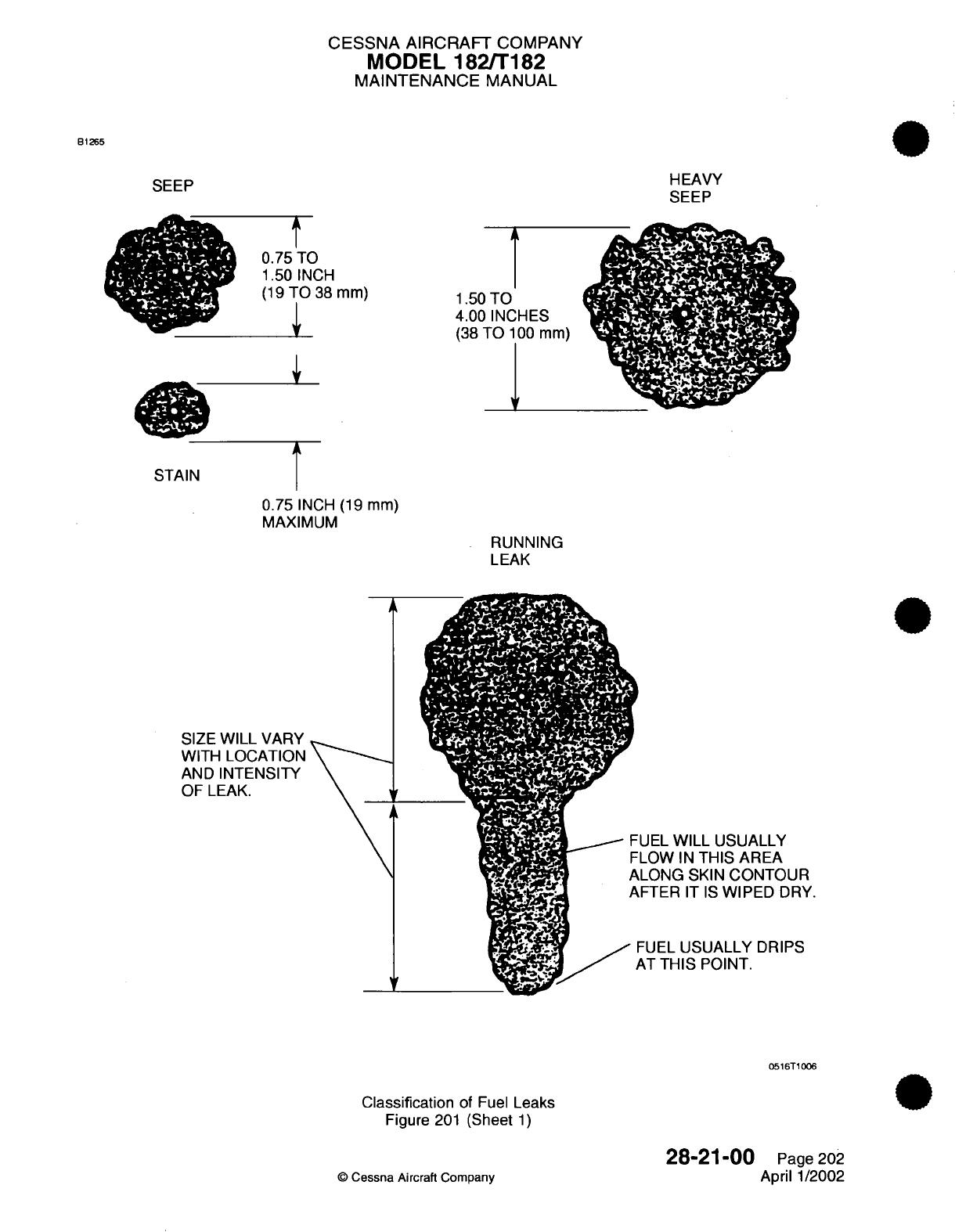
CESSNA
AIRCRAFT
COMPANY
MODEL
182/T182
MAINTENANCE
MANUAL
B1265
SEEP
t
0.75
TO
1.50
INCH
(19
TO
38
mm)
1
1.50
TO
4.00
INCHES
(38
TO
100
mm)
\'
0.75
INCH
(19
mm)
MAXIMUM
RUNNING
LEAK
A
SIZE
WILL
VARY
WITH
LOCATION
AND
INTENSITY
OF
LEAK.
V
UEL
WILL
USUALLY
LOW
IN
THIS AREA
LONG
SKIN
CONTOUR
FTER
IT
IS
WIPED
DRY.
FUEL
USUALLY
DRIPS
AT
THIS
POINT.
0516T1006
Classification
of
Fuel
Leaks
Figure
201
(Sheet
1)
©
Cessna
Aircraft
Company
28-21-00
Page
202
April 1/2002
HEAVY
SEEP
STAIN
4
0
CESSNA
AIRCRAFT
COMPANY
MODEL
182/T182
MAINTENANCE
MANUAL
(3)
To
one
of
the
bay
fittings,
attach
a
water manometer
capable
of
measuring
20
inches
(.508
m)
of
water.
(4)
To
the
other
bay
fitting,
connect
a
well
regulated
supply
of
air
(0.5
PSI
(415
Pa)
maximum,
or
13.8
(0.351
m)
inches
of
water).
Nitrogen
may
be
used
where the
bay might
be
exposed
to
temperature changes
while
testing.
(5)
Make sure
filler
cap
is
installed
and
sealed.
(6)
Apply
pressure
slowly
until
0.5
PSI
(415
Pa)
is
obtained.
(7)
Apply
a
soap solution
as
required.
(8)
Allow
15
to 30
minutes
for pressure
to
stabilize.
(9)
If
bay
holds
for
15
minutes
without pressure
loss,
seal
is
acceptable.
(10)
Reseal
and retest
if
any
leaks
are
found.
28-21-00
Page
203
©
Cessna Aircraft Company
April
1/2002
CHAPTER
ICE
AND
RAIN
PROTECTION
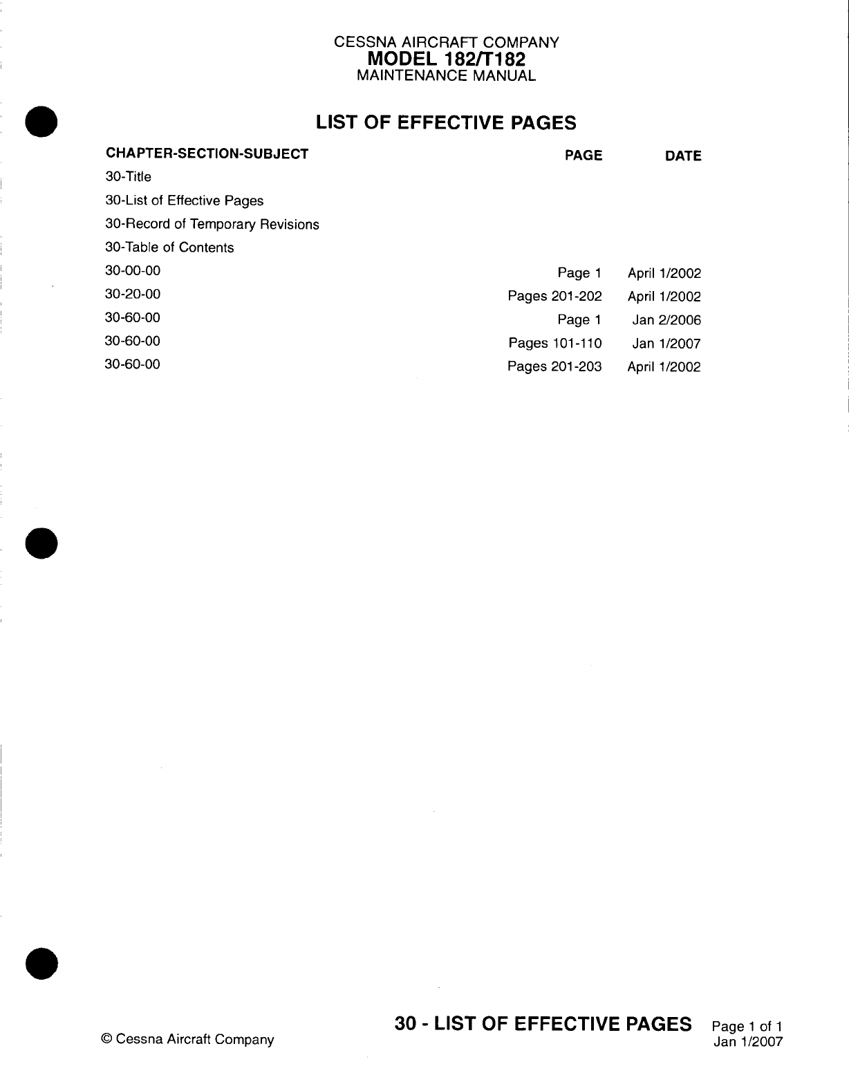
CESSNA
AIRCRAFT
COMPANY
MODEL
182/T182
MAINTENANCE
MANUAL
LIST
OF
EFFECTIVE
PAGES
CHAPTER-SECTION-SUBJECT
30-Title
30-List
of
Effective
Pages
30-Record
of
Temporary
Revisions
30-Table
of
Contents
30-00-00
30-20-00
30-60-00
30-60-00
30-60-00
PAGE
Page
1
Pages
201
-202
Page
1
Pages
1
01
-1 10
Pages
201
-203
©
Cessna
Aircraft
Company
30
-
LIST
OF
EFFECTIVE PAGES
Page
1
of
1
Janl1/2007
DATE
April
1/2002
April
1/2002
Jan
2/2006
Janl1/2007
April
1/2002

Temporary
Revision
Number
RECORD
OF
TEMPORARY REVISIONS
Page
Number
Issue
Date
By
Date
Removed
By
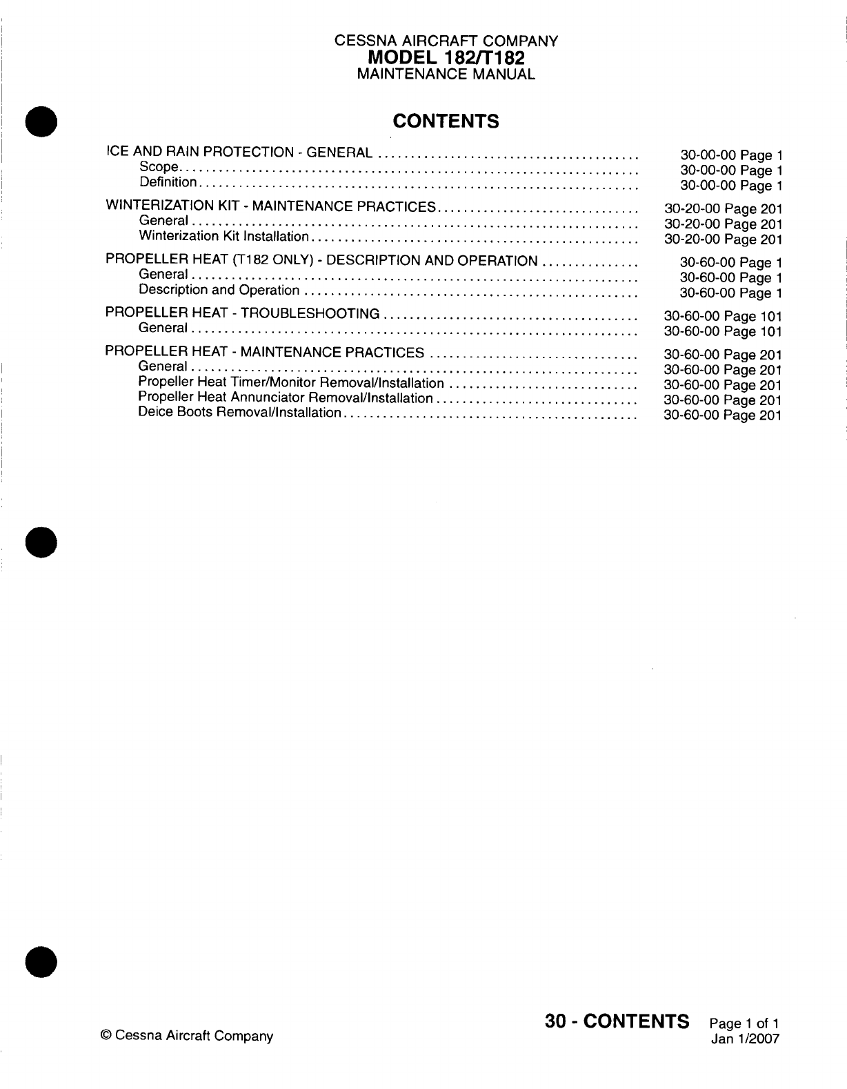
CESSNA
AIRCRAFT
COMPANY
MODEL
182/Ti182
MAINTENANCE
MANUAL
CONTENTS
ICE
AND RAIN
PROTECTION
-
GENERAL.....................
Scope....................................
Definition
..................................
WINTERIZATION
KIT
-
MAINTENANCE
PRACTICES
................
General...................................
Winterization
Kit
Installation..........................
PROPELLER
HEAT
(T182
ONLY)
-
DESCRIPTION
AND
OPERATION
........
General...................................
Description
and
Operation
..........................
PROPELLER
HEAT
-
TROUBLESHOOTING
....................
General...................................
PROPELLER
HEAT
-
MAINTENANCE
PRACTICES.................
General...................................
Propeller
Heat
Timer/Monitor
Removal/Installation
...............
Propeller
Heat
Annunciator
Removal/Installation
................
Deice
Boots
Removal/installation
.......................
©
Cessna
Aircraft
Company
30-00-00
Page
1
30-00-00
Page
1
30-00-00
Page
1
30-20-00
Page
201
30-20-00
Page
201
30-20-00
Page
201
30-60-00
Page
1
30-60-00
Page
1
30-60-00
Page
1
30-60-00
Page
101
30-60-00
Page
101
30-60-00
Page
201
30-60-00
Page
201
30-60-00
Page
201
30-60-00
Page
201
30-60-00
Page
201
30
-
CONTENTS
Page
1
of
1
Janl1/2007

CESSNA
AIRCRAFT
COMPANY
MODEL
182/T182
MAINTENANCE
MANUAL
ICE
AND
RAIN
PROTECTION
-
GENERAL
1.
Scope
A.
This
chapter describes
the
procedures
and
components
used
to
prevent
or
dispose
of
the
formation
of
ice and rain
on
various
parts
of
the
aircraft.
2.
Definition
A.
This
chapter
is
divided
into
sections
and
subsections
to
aid
maintenance personnel
in
locating
information.
Consulting
the
Table of
Contents
will
further
assist
in
locating
a
particular
subject.
A
brief
definition
of
the
sections
incorporated
in
this chapter
is
as
follows.
(1)
The
section
on
winterization
provides
procedures
and
techniques
for
the
installation
of
the
winterization
kit.
(2)
The
section
on
propeller
heat
provides procedures
and
techniques
for
the
maintenance
of
the
propeller
heat
system.
30-00-00
Page
1
©
Cessna
Aircraft
Company
April
1/2002
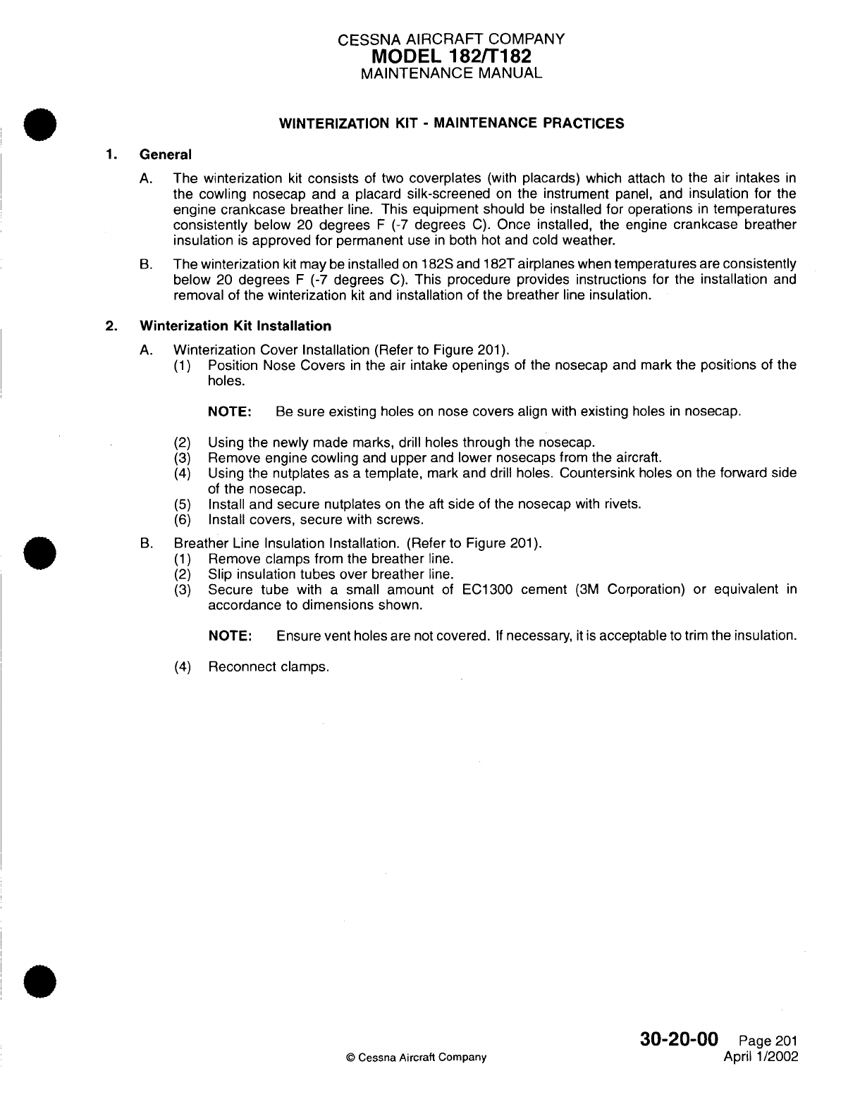
CESSNA
AIRCRAFT
COMPANY
MODEL
182/T182
MAINTENANCE
MANUAL
WINTERIZATION
KIT
-
MAINTENANCE PRACTICES
1.
General
A.
The
winterization
kit
consists
of
two
coverplates
(with
placards) which
attach
to the
air
intakes
in
the
cowling
nosecap and
a
placard
silk-screened
on
the
instrument
panel,
and
insulation
for
the
engine crankcase breather
line.
This
equipment
should
be
installed
for
operations
in
temperatures
consistently
below
20
degrees
F
(-7
degrees
C).
Once installed, the
engine
crankcase
breather
insulation
is
approved
for
permanent
use
in
both
hot
and
cold
weather.
B.
The
winterization
kit
may
be
installed
on
182S
and
182T
airplanes
when
temperatures
are
consistently
below
20
degrees
F
(-7
degrees
C).
This
procedure provides
instructions for
the
installation
and
removal
of
the
winterization
kit
and
installation
of the
breather
line
insulation.
2.
Winterization
Kit
Installation
A.
Winterization
Cover
Installation
(Refer to
Figure
201).
(1)
Position
Nose
Covers
in
the air intake
openings
of
the nosecap
and
mark
the
positions
of the
holes.
NOTE:
Be
sure
existing
holes
on
nose
covers
align
with
existing
holes
in
nosecap.
(2)
(3)
(4)
(5)
(6)
Using
the
newly
made
marks,
drill holes
through the
nosecap.
Remove engine
cowling
and
upper
and
lower nosecaps
from
the
aircraft.
Using
the
nutplates
as
a
template,
mark and
drill
holes.
Countersink
holes
on
the forward
side
of
the
nosecap.
Install and
secure
nutplates
on
the
aft
side
of
the
nosecap
with
rivets.
Install
covers,
secure
with
screws.
B.
Breather
Line
Insulation Installation.
(Refer to
Figure
201).
(1)
Remove
clamps from the
breather
line.
(2)
Slip insulation
tubes
over
breather
line.
(3)
Secure
tube
with
a
small amount
of
EC1300
cement
(3M
Corporation)
or
equivalent
in
accordance
to
dimensions
shown.
NOTE:
Ensure
vent
holes
are
not
covered.
If
necessary,
it
is
acceptable
to
trim
the insulation.
(4)
Reconnect clamps.
30-20-00
C
Cessna
Aircraft
Company
Page
201
April
1/2002
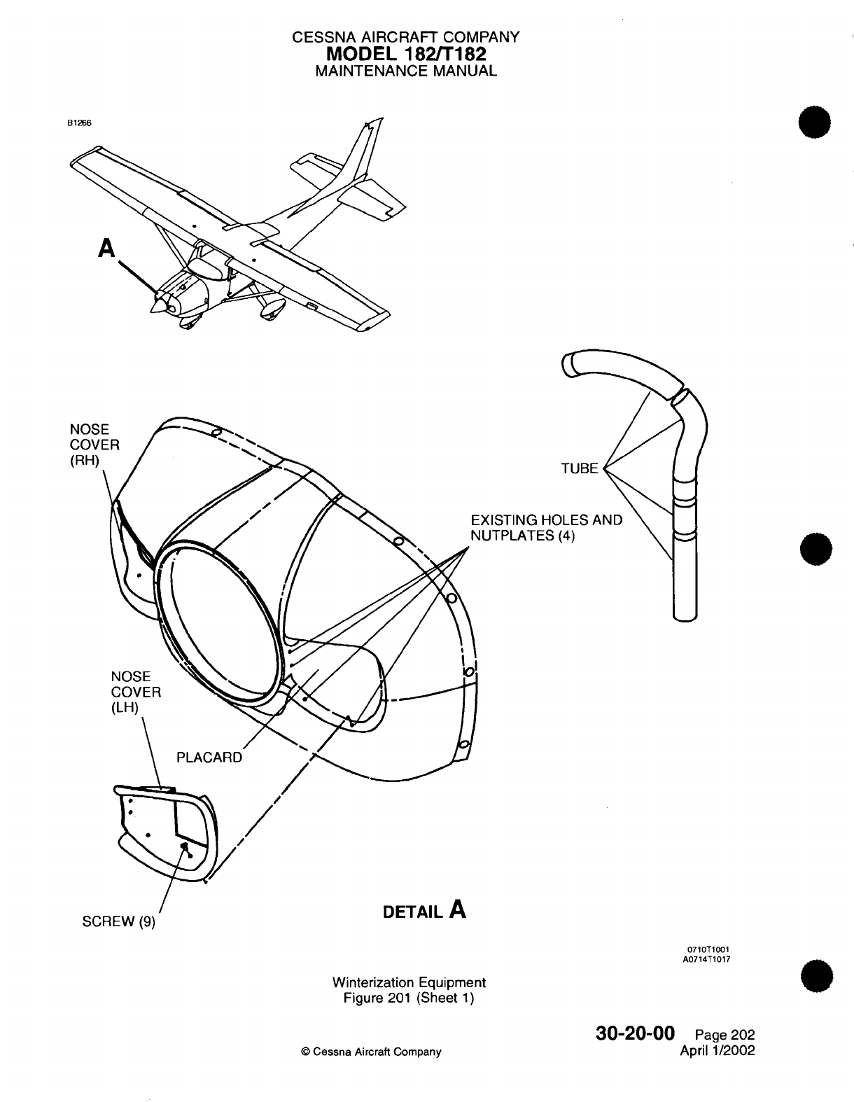
CESSNA
AIRCRAFT
COMPANY
MODEL
182/T182
MAINTENANCE
MANUAL
NOSE
COVE
(RH)
TUBE
EXISTING
HC
4UTPLATES
oitwVV
(t)
0710T1001
A0714T1017
Winterization
Equipment
Figure
201
(Sheet
1)
©
Cessna
Aircraft
Company
30-20-00
Page
202
April
1/2002
rrr
CESSNA
AIRCRAFT
COMPANY
MODEL 182/T182
MAINTENANCE
MANUAL
PROPELLER
HEAT
(T182
ONLY)
-
DESCRIPTION AND OPERATION
1.
General
A.
A
propeller electrical
heated
boot
system
is
standard equipment.
2.
Description
and
Operation
A.
The system
is
of
an
electrothermal
type.
It
has
electrically
heated
boots
bonded
to
each
propeller
blade.
There
is
a
slip
ring
assembly
for
power
distribution
to
the
propeller
boots
and
a
brush
block
assembly
to
transfer
electrical power to
the
rotating
slip
ring.
A
propeller
heat
timer/monitor cycles
electrical
power
to
the
boots
in
the
correct
sequence
and
monitors
the
boot's
heater
current. There
is
propeller
heat
indication
for
either
correct
or
failed
system
operation.
A
toggle
switch
labeled
PROP
HEAT
controls
the
engine
propeller
heat system.
The
propeller
heat system
also
includes
a
larger
alternator
for
additional
current
capacity.
It
has
a
higher Amp/Hour
Battery
to
support
the
additional current
load
required by
the
propeller
heat
system.
The
propeller
heat
system
applies
heat
to
the
surfaces
of
the
propeller
blades
where
ice
would
normally adhere. This
heat,
plus
centrifugal
force
and the
blast
from
the
airstream,
removes
accumulated
ice.
When
the PROP
HEAT
switch
is
placed
in
the
ON
position,
the
timer
controls electrical
power
through
the
brush
block
and
slip
ring
to
the
three propeller
heat
boots
in
intervals
of
90
seconds
on
and
90
seconds
off.
The propeller
heat
system
is
off
when
the
switch
is
placed
in
the
OFF
position.
Operation
of the
propeller
heat
system
can
be
checked
through
the
propeller
heat annunciation.
If
the
correct
amount
of
current
does
not
flow
to
all
three
elements,
the
timer/monitor
recognizes
the
condition,
removes
current
flow
to
all
heating
boots,
and
turns
on
the
amber
PROP
HEAT
annunciation.
The
green PROP
HEAT
annunciation
is
on
during
the
correct
operation
of
the
propeller
heat
system.
30-60-00
Page
1
C
Cessna
Aircraft
Company
Jan
2/2006
CESSNA
AIRCRAFT
COMPANY
MODEL
182/Ti
82
MAINTENANCE
MANUAL
PROPELLER
HEAT
-
TROUBLESHOOTING
General
A. A
troubleshooting
chart
has
been
developed
to
aid
the
maintenance
technician
in
system
understanding.
Referto
Figure
101
for
airplanes
without
Garmin
GlOQO
and
Figure
102
for
airplanes
with
Garmin
G1000.
B.
The
propeller
heat
timer
has
a
90-second
ON
cycle
and
a
90-second
OFF
cycle. The timer measures
the
90-second
cycle
interval
of
the
de-icing
boots and
the
correct
electrical
current
(1
2.5
to
1
9
amps)
delivered
to
the de-icing
boots.
If
the
90-second
cycle
interval
or
the
electrical current
delivered
to
the
de-icing
boots
is
not
in
permitted limits,
the
timer
causes
these
to
show
as
faults.
The
timer
also
monitors
pin
6
and
pin
8
for
electrical
grounds.
If a
ground
is
not
applied
to
pin
6,
the
timer
causes
this
to
show
as
a
fault.
If a
ground
is
applied
to pin
8,
as
occurs
when one
of
the
crew
sets the PROP
HEAT
switch
to
TEST, the
timer
causes
this
to
show
as
a
fault
and
also
resets.
When
there
are
faults,
the
timer
disconnects
the power that
is
supplied
to
the
de-icing
boots
on pin
1,
supplies
a
ground
on
pin
3
to
start
the
amber
alert,
and
removes
a
ground from
pin
2
to
stop
the
green alert.
NOTE:
Operation
of
the
propeller
heat
system
for
longer
than
60
seconds without
the
propeller
rotation
can
cause
damage
to
the
de-icing
boots.
NOTE:
Operation
of
the
propeller
heat
system
at
below
24
volts
can
result
in
less
than
sufficient
power
for
normal
operation.
30-60-00
Page
101
©
Cessna
Aircraft Company
Janl1/2007
I
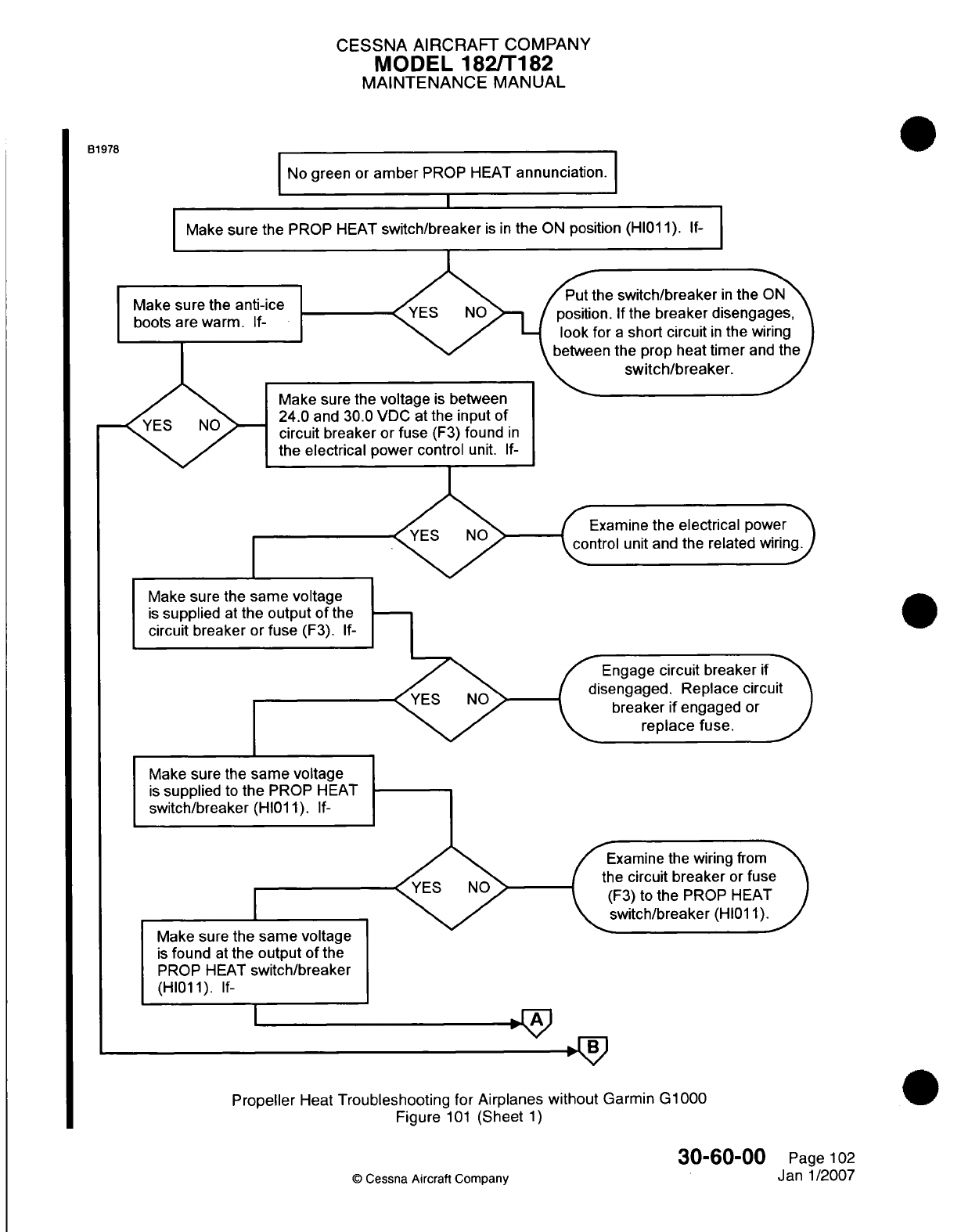
CESSNA
AIRCRAFT
COMPANY
MODEL
182/T1
182
MAINTENANCE
MANUAL
B1978
INo
green
or
amber
PROP
HEAT
annunciation.
IMake
sure
the
PROP
HEAT
switch/breaker
is in
the
ON
position
(HI01
1).
If-I
Make
sure
the
anti-ice
boots
are
warm.
If-
lut
the
switch/breaker
in
the
O
)sition.
If
the
breaker
disengages,
.ok
for
a
short
circuit
in
the
wiring
tween
the
Drop
heat
timer
and
the
switch/breaker.
3ke
sure
the
voltage
is
between
-.
0
and
30.0
VDC
at
the
input
of
-cuit
breaker
or
fuse
(F73)
found
in
E?
electrical
power control
unit.
If-
I
Examine the
electrical
power
-ontrol
unit and the
related
wiring.
Make sure
the
same voltage
is
supplied
at
the output
of
the
circuit breaker
or
fuse
(F3).
If-
Engage
circuit
breaker
i
sengaged.
Replace
circuit
breaker
if
engaged
or
replace
fuse.
Make sure the
same
voltage
is
supplied
to
the
PROP
HEAT
_
switch/breaker
(H101
1).
If-
Examine
the
wiring
from
he
circuit breaker
or
fuse
(F73)
to
the
PROP
HEAT
switch/breaker
(HI01
1).
Make
sure
the
same
voltage
is
found
at
the
output
of
the
PROP
HEAT
switch/breaker
(Hi01ll).
If-
Propeller
Heat
Troubleshooting
for
Airplanes
without
Garmin
G1
0000
Figure
101
(Sheet
1)
30-60-00
0
Cessna Aircraft Company
Page
102
Janl1/2007
I
I I
I
I
I
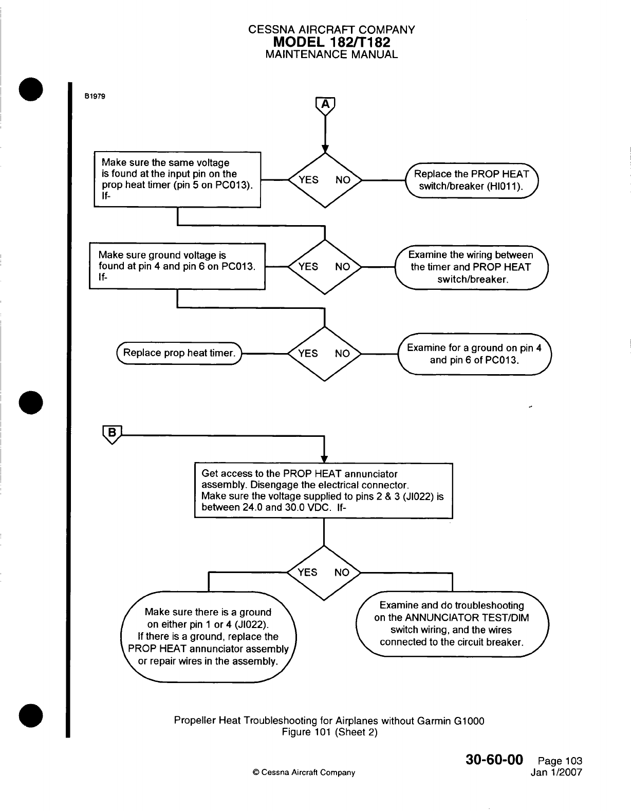
CESSNA AIRCRAFT
COMPANY
MODEL
182/Ti182
MAINTENANCE
MANUAL
B1979
Make sure
the
same voltage
is
found
at
the
input
pin
on
th
prop
heat
timer
(pin
5
on
PCI
If-
Zeplace
the PROP
HEAT
switch/breaker
(HI11l
1).
Make
sure
ground
voltage
is
found
at
pin
4
and
pin
6
on
P
If-
Examine
the
wiring
betwen
the
timer
and
PROP
HEAT
switch/breaker.
iine
for
a
ground
on
pin
and
pin
6
of
PCO1
3.
troubleshooting
oneter
pin
1
or
4
(J1022).
If
there
is;
a
ground,
repla
ce
the
P R O P H E A T a
n n n
cia
o r s s e mnb ly
or e
p
a r w re in th e a s e m b
ly
.
JIILi
IV 1,~ Ir %-'UN1 I
L-2J
I
IJIJIVI
switch
wiring,
and
the
wires
connected
to
the
circuit
breaker.
Propeller
Heat
Troubleshooting for
Airplanes
without
Garmin
G1000
Figure
101
(Sheet
2)
30-60-00
Page
103
©
Cessna Aircraft Company
Janl1/2007
/Make
sure
the
I
I
I
I
I
Get
access
to
the
PROP
HEAT
annunciator
assembly.
Disengage
the
electrical
connector.
Make
sure
the
voltage supplied
to
pins
2
&
3
(J1022)
is
between
24.0 and
30.0
VDC.
If-
I
I
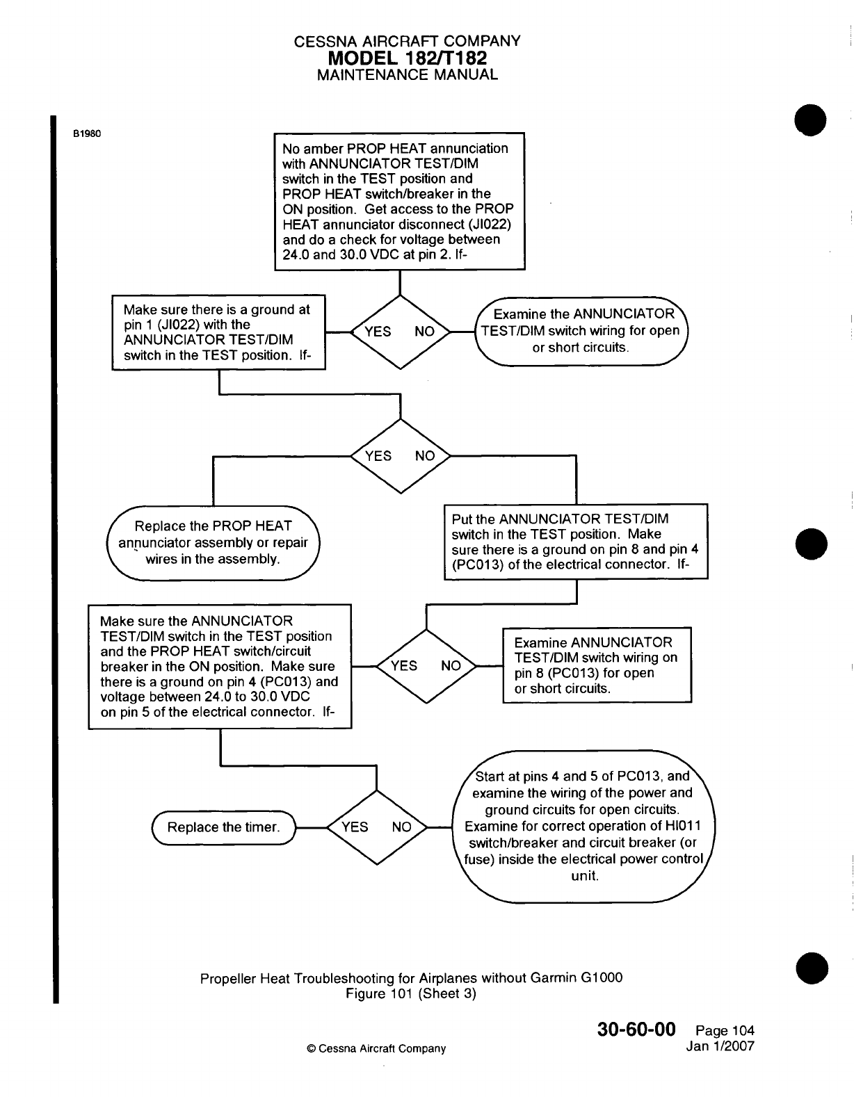
CESSNA AIRCRAFT
COMPANY
MODEL
182/Ti182
MAINTENANCE
MANUAL
B1980
Make sure there
is
a
ground
pin
1
(JI022)
with
the
ANNUNCIATOR
TEST/DIM
switch
in
the
TEST
position.
Examine
the ANNUNCIATOR
EST/DIM
switch
wiring for
open
or
short
circuits.
ep ace the PROP H
~~Put
the
ANNUNCIATI
annunciator
assembly
or
repairswthiteTETp
I wires in the
assembly. ~sure
there
is a
groun(
wires in the assembly.
~~(PCO1
3)
of
the
electri
OR
TEST/DIM
)sition.
Make
I
on pin
8
and
pin
ical
connector.
If-
4
Examine
ANNUNCIATOR
TEST/DIM
switch wiring
on
pin
8
(PCO13)
for
open
or
short
circuits.
at
pins
4
and
5
of
PCO1
3,
and
ine the
wiring
of
the power
and
und
circuits
for
open
circuits.
ie
for
correct
operation
of
H10l1
/breaker
and
circuit
breaker
(or
aside
the
electrical
power control
\\L
~~~unit.
Propeller
Heat
Troubleshooting
for
Airplanes
without
Garmin
G1lOQO
Figure
1
01
(Sheet
3)
30-60-00
Page
104
©
Cessna
Aircraft Company
Jan
1/2007
No
amber
PROP
HEAT
annunciation
with
ANNUNCIATOR
TEST/DIM
switch
in
the TEST
position
and
PROP HEAT
switch/breaker
in
the
ON
position. Get
access
to
the
PROP
HEAT
annunciator
disconnect
(JI022)
and
do
a
check
for
voltage
between
24.0
and
30.0
VDC
at
pin
2. If-
Make
sure
the
ANNUNCIATOR
TEST/DIM
switch
in
the
TEST
position
and
the
PROP
HEAT
switch/circuit
breaker
in
the
ON
position. Make
sure
there
is a
ground
on
pin
4
(PCO1
3)
and
voltage
between
24.0
to
30.0
VDC
on
pin
5
of
the
electrical
connector.
If-
I
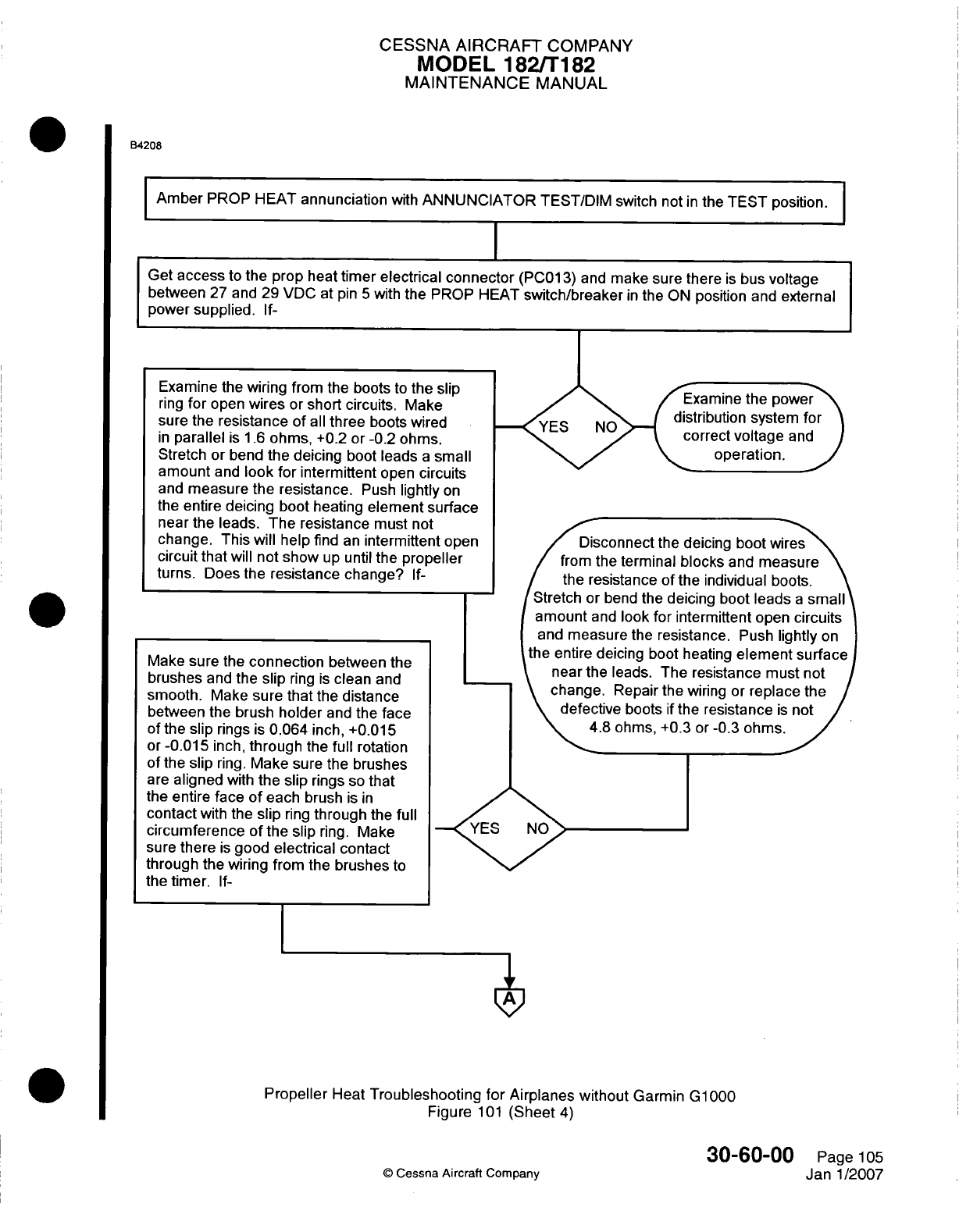
CESSNA
AIRCRAFT
COMPANY
MODEL
182/Ti
82
MAINTENANCE
MANUAL
B4208
IAmber
PROP
HEAT
annunciation
with
ANNUNCIATOR
TEST/DIM
switch not
in
the
TEST
position.
Get
access
to
the
prop
heat
timer electrical
connector
(PCO1
3)
and
make
sure
there
is
bus
voltage
between
27
and
29
VDC
at
pin
5
with
the PROP HEAT
switch/breaker
in
the
ON
position
and
external
power
supplied.
If-
nine
the
power
ution
system
for
z~ct
voltage
and
operation.
andomeasur
the
rescistnce
Pus
ligtlo
thee
tire
deiing
l
bootkheatngdlmn
ufc
nerthelashe resistance
muste
notvid
change.
Repair the
wiring or
replace
the
defective
boots
if
the
resistance
is
nott
4.8 ohms,
+0.3
or
-0.3
ohms.
YES NO
Propeller
Heat
Troubleshooting
for
Airplanes without
Garmin
G1000
Figure
101
(Sheet
4)
30-60-00
©
Cessna
Aircraft
Company
Examine
the
wiring from
the
boots
to
the
slip
ring
for
open
wires
or
short
circuits.
Make
sure
the
resistance
of
all
three
boots
wired
in
parallel
is
1.6
ohms,
+0.2
or
-0.2
ohms.
Stretch
or
bend
the
deicing
boot
leads
a
small
amount
and
look
for
intermittent
open
circuits
and
measure
the
resistance.
Push
lightly
on
the
entire
deicing
boot
heating
element surface
near
the
leads.
The resistance
must
not
change.
This
will
help
find
an
intermittent
open
circuit that
will
not
show
up
until
the
propeller
turns.
Does the
resistance
change?
If-
Make
sure
the
connection
between
the
brushes
and
the
slip
ring
is
clean
and
smooth.
Make
sure
that
the
distance
between
the
brush
holder
and
the
face
of
the slip
rings
is
0.064
inch,
+0.01
5
or
-0.01
5
inch,
through
the
full
rotation
of
the
slip
ring.
Make
sure the
brushes
are
aligned
with
the
slip
rings
so
that
the
entire
face
of
each
brush
is in
contact
with
the
slip
ring
through
the
full
circumference of
the
slip
ring.
Make
sure
there
is
good
electrical
contact
through
the
wiring from
the
brushes
to
the timer.
If-
Page
105
Janl1/2007
I
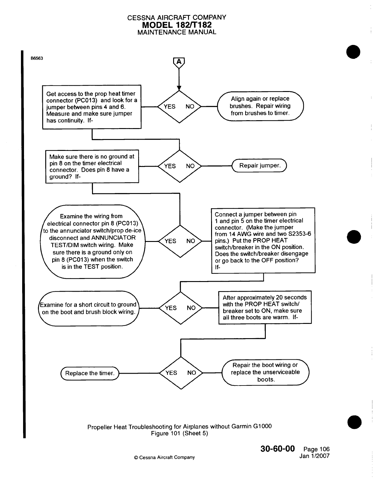
CESSNA
AIRCRAFT
COMPANY
MODEL
182/Ti182
MAINTENANCE
MANUAL
A
Align
again
or
replace
brushes.
Repair
wiring
from
brushes
to
timer.
Make
sure
there
is
no
ground
pin
8
on
the
timer
electrical
connector.
Does
pin
8
have
a
ground?
If-
sure
there
is a
ground
only
or
*)I* I U ¼ L
J1
1
-
.
-Y I tI I L
-
A
Y
Vlt
,
is in
the
TEST
position.
Examine
fr
a
short
circuit
to
groun
on
the
boot
and
brush
block
wiring
After
approximately
20
seconds
with
the
PROP
HEAT
switch/
breaker set
to
ON,
make
sure
all
three
boots
are
warm.
If-
I
ce
the
time epair
the
boot
wiring
or
place the
unserviceable
boots.
Propeller
Heat
Troubleshooting
for
Airplanes
without
Garmin
G1
000
Figure
101
(Sheet
5)
30-60-00
Page
106
©
Cessna Aircraft
Company
Janl1/2007
B6563
Get
access
to
the
prop heat
timer
connector
(PCO1
3)
and
look
for
a
jumper
between
pins
4
and 6.
Measure
and
make
sure
jumper
has
continuit.
If--
Connect
a
jumper
between
pin
1
and
pin
5
on
the
timer
electrical
connector.
(Make the
jumper
from
14
AWG wire
and
two
S2353-6
pins.)
Put
the
PROP
HEAT
switch/breaker
in
the
ON
position.
Does
the
switch/breaker
disengage
or
go
back
to
the
OFF
position?
If-
I
II
I
I
I
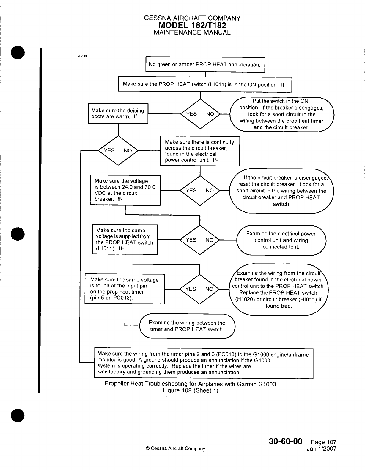
CESSNA
AIRCRAFT
COMPANY
MODEL 182/Ti
82
MAINTENANCE
MANUAL
8B4209
No-
green
or
amber
PROP
HEAT
annunciation.I
IMake
sure
the
PROP
HEAT
switch
(HI01
1) is in
the
ON
position.
If-
Make sure
the deicing
boots
are
warm.
If-
Put
the
switch
in
the
ON
)n.
If
the
breaker
disengages,
2k
for
a
short
circuit
in
the
1
between
the
prop
heat
timer
and
the
circuit
breaker.
Make
sure
there
is
continuity
across
the
circuit
breaker,
found
in
the
electrical
power
control
unit.
If-
Make sure
the
voltage
is
between
24.0
and
30.0
VDC
at
the
circuit
breaker.
If-
If
the
circuit
breaker
is
disengaged
*eset
the
circuit
breaker. Look for
a
hort
circuit
in
the
wiring
between
the
circuit
breaker
and
PROP
HEAT
switch.
Make
sure
the
same
voltage
is
supplied
frc
the
PROP
HEAT
swi
(HI1101).
If-
Examine
the
electrical
powe
control
unit
and
wiring
connected
to
it.
Make
sure
the
is
found
at
the
on
the
prop
hE
(pin
5
on
PCO
mine
the
wiring
from
te
circui
ker
found
in
the
electrical
powe
)I
unit
to
the
PROP
HEAT
swth
!place
the
PROP
HEAT
switc
)20)
or
circuit
breaker
(HI1)
if
tound
bad.
Exainethewirng
etween the
timerand
POP
HAT
switch.
Make
sure the
wiring
from
the
timer
pins
2
and
3
(PCO13)
to
the
G1000
engine/airfra
me
monitor
is
good.
A
ground
should
produce
an
annunciation
if
the
G1000
system
is
operating correctly. Replace
the
timer
if
the
wires
are
satisfactory
and
grounding
them
produces
an
annunciation.
Propeller
Heat
Troubleshooting
for
Airplanes
with
Garmin G1000
Figure
102
(Sheet
1)
30-60-00
Page
107
0
Cessna
Aircraft Company
Janl1/2007
I
I
I
I
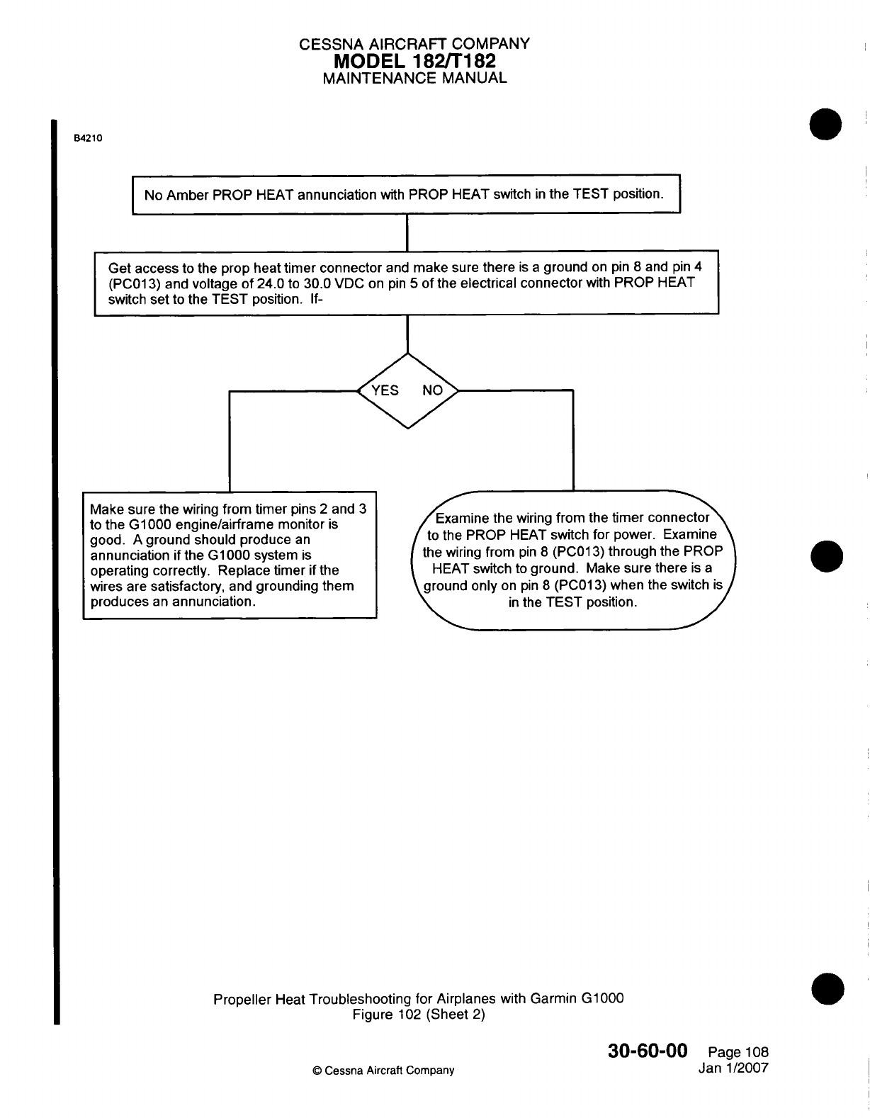
CESSNA AIRCRAFT
COMPANY
MODEL
182/Ti82
MAINTENANCE
MANUAL
54210
INo
Amber
PROP
HEAT
annunciation
with
PROP
HEAT
switch
in
the
TEST
position.I
Get
access
to
the
prop
heat
timer connector
and
make
sure
there
is a
ground
on
pin
8
and
pin
4
(PCO1
3)
and
voltage
of
24.0
to
30.0
VDC
on
pin
5
of
the
electrical connector
with
PROP
HEAT
switch
set
to
the TEST
position.
If-
I
Examine
the
wiring
from
the
timer
conector
tothe
PROP
HEAT
switch
for
power. Examine
the
wiring
from
pin
8
(PCO1
3)
through
the
PROP
HEAT
switch
to
ground.
Make
sure
there
is
a
grudonly
on
pin
8
(PCO1
3)
when
the
switch
is
in
the
TEST
position.
Propeller
Heat
Troubleshooting
for
Airplanes
with
Garmin
G1000
Figure
102
(Sheet
2)
30-60-00
©
Cessna
Aircraft
Company
Make
sure the
wiring
from
timer
pins
2
and
3
to
the
GlOQO0
engine/airframe
monitor
is
good.
A
ground
should
produce
an
annunciation
if
the
G1000
system
is
operating
correctly. Replace
timer
if
the
wires
are
satisfactory,
and
grounding
them
produces
an
annunciation.
Page
108
Janl1/2007
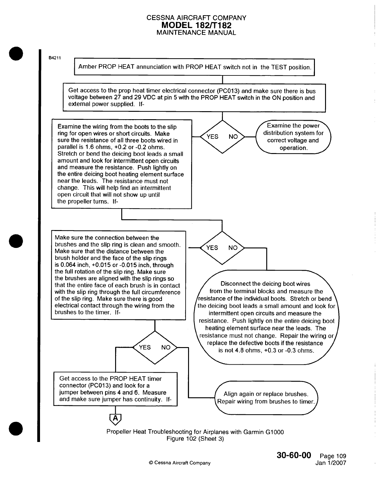
CESSNA
AIRCRAFT
COMPANY
MODEL
1821T182
MAINTENANCE
MANUAL
B4211
Amber
PROP
HEAT
annunciation
with
PROP
HEAT
switch
not
in
the
TEST
position.
Get
access
to
the
prop
heal
timer
electrical connector
(PC01
3)
and
make
sure
there
is
bus
voltage
between
27 and
29
VIDC
at
pin
5
with
the PROP
HEAT
switch
in
the
ON
position
and
external
power
supplied.
If-
Examine
thepoe
istribution
system
for
correct voltage
and
operation.
Get
access
to
the
PROP
HEAT
timer
connector
(PCO1
3)
and
look
for
a
jumper
between
pins
4
and
6.
Measure
and
make sure
jumper
has
continuity.
If-I
Disconnect
the
deicing
boot
wie
from
the
terminal blocks
and
measure
the
resistance
of
the
individual
boots.
Stretchi
or
bend
the
deicing
boot
leads
a
small
amount
and
look
for
intermittent
open
circuits
and
measure
the
resistance.
Push
lightly
on
the
entire
deicing
boot
Align
again
or
replace
brushes.
Repair
wiring from
brushes
to
timer.
Propeller
Heat
Troubleshooting for
Airplanes
with
Garmin
G1000
Figure
102
(Sheet
3)
30-60-00
Page
109
@
Cessna
Aircraft
Company
Janl1/2007
Examine
the wiring
from
the
boots
to
the
slip
ring
for
open wires
or
short circuits.
Make
sure
the
resistance
of
all
three
boots wired
in
parallel
is 1 .6
ohms,
+0.2
or
-0.2
ohms.
Stretch
or bend
the
deicing
boot
leads
a
small
amount
and
look
for intermittent
open
circuits
and
measure
the
resistance.
Push
lightly
on
the
entire
deicing
boot
heating
element
surface
near
the
leads.
The
resistance
must
not
change.
This
will help
find
an
intermittent
open
circuit that
will
not
show
up
until
the
propeller
turns.
If-
Make
sure
the
connection
between
the
brushes
and
the
slip
ring
is
clean
and
smooth.
Make
sure
that
the
distance
between
the
brush
holder
and
the
face
of
the
slip
rings
is
0.064
inch,
+0.01 5
or
-0.01
5
inch,
through
the
full
rotation
of
the
slip
ring.
Make
sure
the
brushes
are
aligned
with
the slip
rings
so
that
the
entire face
of
each
brush
is in
contact
with
the
slip
ring
through
the
full
circumference
of
the
slip
ring.
Make sure
there
is
good
electrical contact
through
the wiring
from
the
brushes
to
the
timer.
If-
I
I
I
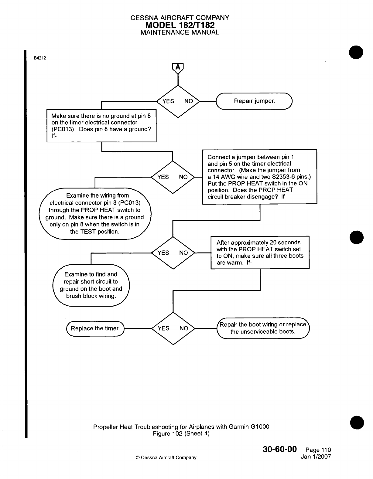
CESSNA
AIRCRAFT
COMPANY
MODEL
182/Ti
82
MAINTENANCE
MANUAL
B4212
A
Make sure
there
is
no
ground
at
pin
8
on
the
timer electrical connector
(PCO13).
Does
pin
8
have
a
ground?
If-
Examine
the
wiring
from
/electrical
connector
o~in
8
(PCO1
3)1
(through
the
PROP
HEAT
switch
to
around.
Make
sure
there
is a
around
onyon
pin
8
when
the
switch
si
1~~
the
TEST
position.
After
approximately
20
seconds
with
the
PROP
HEAT
switch
set
to
ON,
make sure
all
three boots
are
warm.
If-
Examine
to
find
and
repair
short circuit
to
ground
on
the
boot
and
brush
block
wiring.
I
§che
time
Repair
the
boot
wiring
or
replac'
the
unserviceable
boots.
Propeller
Heat
Troubleshooting
for
Airplanes
with
Garmin
G1000
Figure
102
(Sheet
4)
30-60-00
Page
11
0
©
Cessna
Aircraft
Company
Janl1/2007
Connect
a
jumper
between
pin
1
and
pin
5
on
the
timer electrical
connector.
(Make
the
jumper
from
a
14
AWG
wire
and
two
S2353-6
pins.)
Put
the
PROP
HEAT
switch
in
the
ON
position.
Does the
PROP HEAT
circuit
breaker
disengage?
If-
0
I
I
<
1
4
z-1-- --- 1
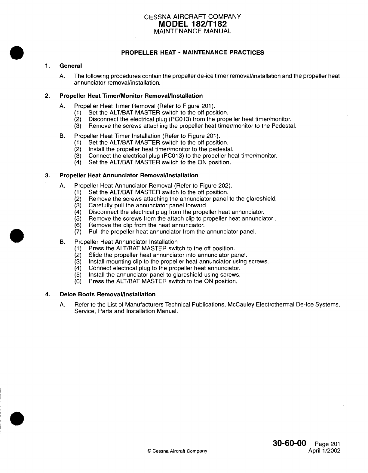
CESSNA
AIRCRAFT
COMPANY
MODEL
182/T182
MAINTENANCE
MANUAL
PROPELLER
HEAT
-
MAINTENANCE PRACTICES
1.
General
A.
The
following
procedures contain
the
propeller de-ice timer
removal/installation
and
the
propeller
heat
annunciator
removal/installation.
2.
Propeller
Heat
Timer/Monitor
Removal/Installation
A.
Propeller
Heat Timer
Removal (Refer
to
Figure
201).
(1)
Set
the
ALT/BAT
MASTER
switch
to the off
position.
(2)
Disconnect
the
electrical
plug
(PC013)
from
the
propeller
heat
timer/monitor.
(3)
Remove the
screws attaching
the
propeller
heat
timer/monitor
to the
Pedestal.
B.
Propeller
Heat
Timer Installation
(Refer
to Figure
201).
(1)
Set
the
ALT/BAT
MASTER
switch
to
the
off
position.
(2)
Install
the propeller
heat
timer/monitor
to
the
pedestal.
(3)
Connect
the
electrical
plug (PC013)
to
the
propeller
heat
timer/monitor.
(4)
Set
the
ALT/BAT
MASTER
switch
to the
ON
position.
3.
Propeller
Heat
Annunciator
Removal/Installation
A.
Propeller
Heat
Annunciator
Removal
(Refer
to
Figure
202).
(1)
Set
the
ALT/BAT
MASTER
switch
to
the
off
position.
(2)
Remove the
screws attaching
the
annunciator
panel
to
the
glareshield.
(3)
Carefully
pull
the
annunciator
panel
forward.
(4)
Disconnect
the
electrical
plug
from the
propeller
heat
annunciator.
(5)
Remove the
screws
from the
attach clip
to
propeller
heat
annunciator.
(6)
Remove
the clip
from
the
heat
annunciator.
(7)
Pull
the
propeller
heat
annunciator
from
the
annunciator
panel.
B.
Propeller
Heat
Annunciator
Installation
(1)
Press
the
ALT/BAT
MASTER
switch
to
the
off
position.
(2)
Slide
the
propeller
heat
annunciator
into
annunciator
panel.
(3)
Install
mounting clip
to
the
propeller
heat
annunciator
using
screws.
(4)
Connect electrical
plug
to
the
propeller
heat
annunciator.
(5)
Install
the
annunciator
panel
to
glareshield
using
screws.
(6)
Press
the
ALT/BAT
MASTER
switch
to
the
ON
position.
4.
Deice
Boots
Removal/Installation
A.
Refer
to the
List
of
Manufacturers
Technical
Publications,
McCauley Electrothermal
De-Ice
Systems,
Service,
Parts
and
Installation
Manual.
30-60-00
Page
201
©
Cessna
Aircraft
Company
April
1/2002
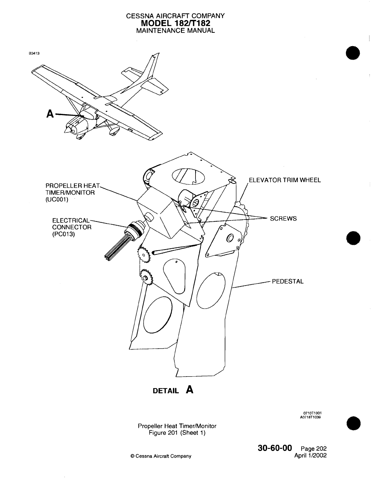
CESSNA
AIRCRAFT
COMPANY
MODEL
182/T182
MAINTENANCE
MANUAL
-OR
TRIM
WHEEL
PROPELLER
HE
TIMER/MONITO
(UC001)
ELECTRICAL
CONNECTOF
(PC013)
SCREWS
PEDESTAL
DETAIL
A
0710T1001
A0718T1039
Propeller
Heat
Timer/Monitor
Figure
201
(Sheet
1)
30-60-00
©
Cessna
Aircraft
Company
Page
202
April
1/2002
rag X
4
LE
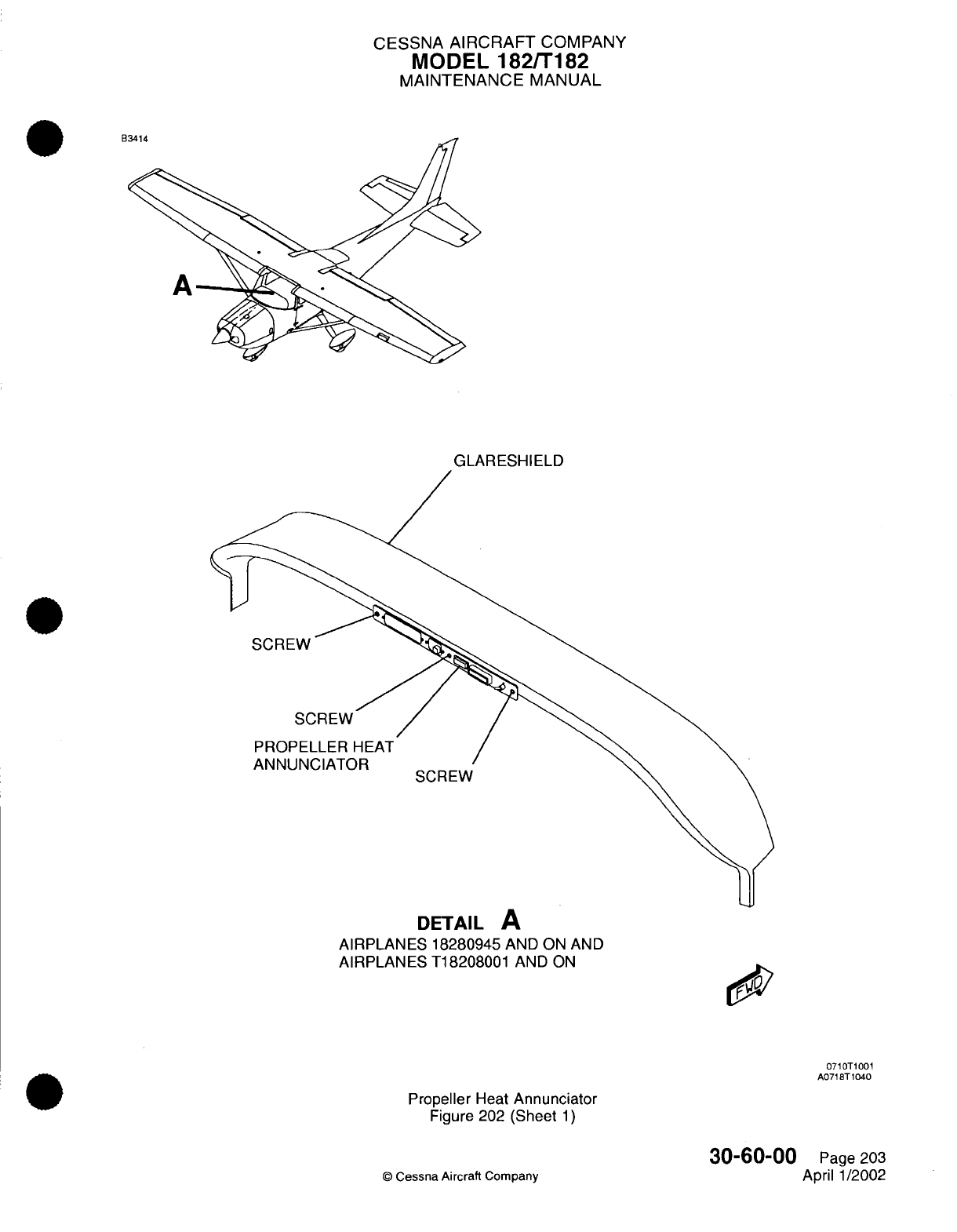
CESSNA
AIRCRAFT
COMPANY
MODEL
182/T182
MAINTENANCE
MANUAL
B
GLARESHIELD
SCREW
SCREW
PROPELLER
HEAT
ANNUNCIATOR
SCREW
DETAIL
A
AIRPLANES
18280945
AND
ON
AND
AIRPLANES
T18208001
AND
ON
0710T1001
A0718T1040
Propeller
Heat
Annunciator
Figure 202
(Sheet
1)
©
Cessna
Aircraft Company
30-60-00
Page
203
April 1/2002
..

CHAPTER
INDICATING/
RECORDING
SYSTEMS
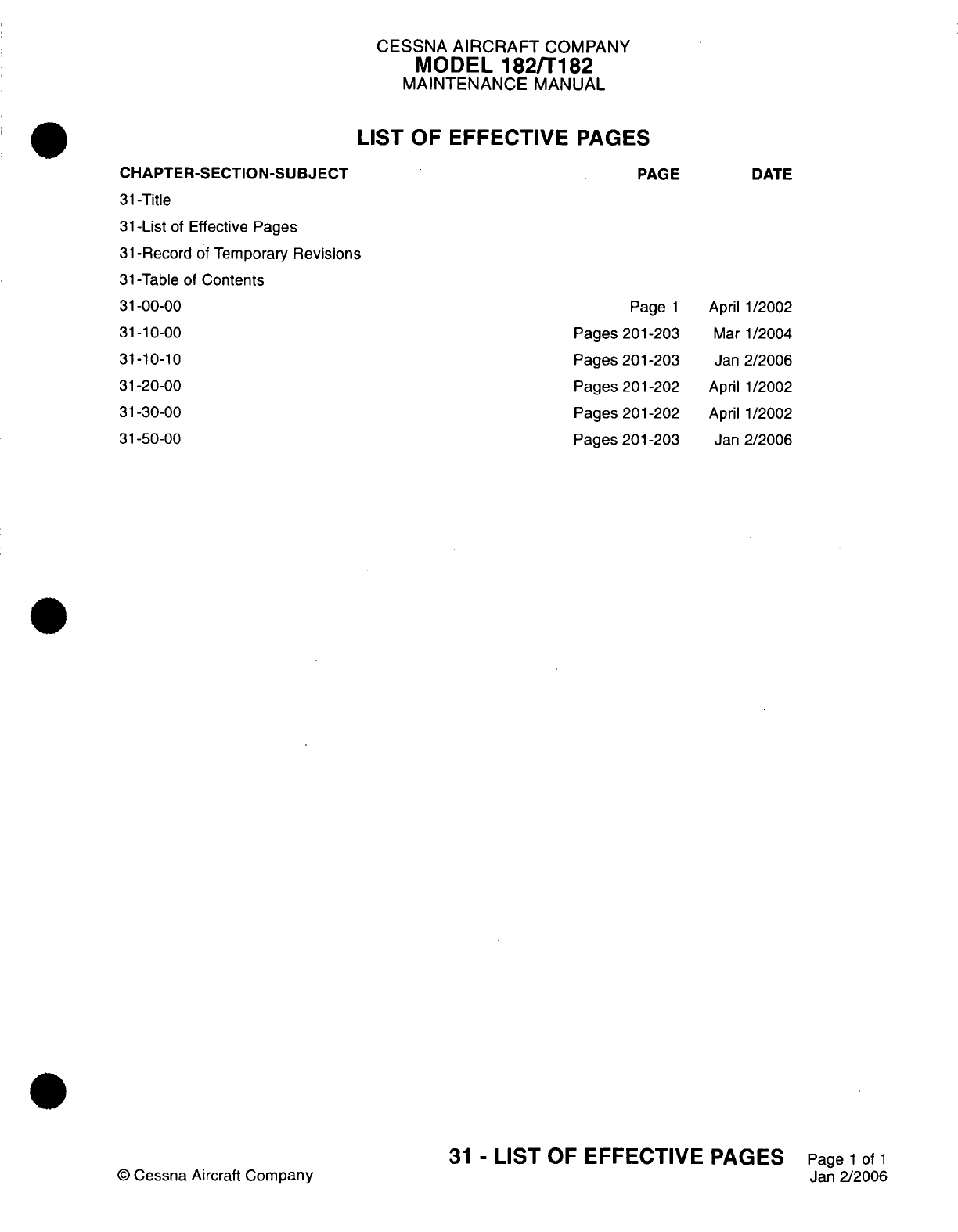
CESSNA
AIRCRAFT
COMPANY
MODEL
182/T182
MAINTENANCE
MANUAL
LIST
OF EFFECTIVE
PAGES
CHAPTER-SECTION-SUBJECT
31-Title
31-List
of
Effective Pages
31-Record
of
Temporary
Revisions
31-Table of
Contents
31-00-00
31-10-00
31-10-10
31-20-00
31-30-00
31-50-00
©
Cessna
Aircraft
Company
PAGE
Page
1
Pages 201-203
Pages
201-203
Pages 201-202
Pages 201-202
Pages
201-203
DATE
April
1/2002
Mar
1/2004
Jan
2/2006
April
1/2002
April
1/2002
Jan
2/2006
31
-
LIST
OF
EFFECTIVE
PAGES
Page
1
of
1
Jan
2/2006

Temporary
Revision
Number
RECORD
OF
TEMPORARY
REVISIONS
Page
Number Issue
Date
By
Date
Removed
By
CESSNA
AIRCRAFT
COMPANY
MODEL
182/T182
MAINTENANCE
MANUAL
CONTENTS
INDICATING/RECORDING
SYSTEMS
-
GENERAL
.................................
Scope......................................................................
Definition
...................................................................
INSTRUMENT
AND
CONTROL
PANELS
-
MAINTENANCE
PRACTICES.............
G eneral
....................................................................
Pilot's
Center
Panel
Removal/Installation
..........
.......................
Pilot's
Inboard/Outboard
Panel
Removal/Installation............................
Copilot's
Panel
Removal/Installation
..........................................
INSTRUMENT
AND
CONTROL
PANELS
-
MAINTENANCE PRACTICES
Airplanes
with
Garmin
G1000.............................................
......................
G eneral
....................................................................
Center
Panel
Removal/Installation
............................................
Switch
Panel
Removal/Installation
............................................
Throttle/Flap
Panel............................
...........
...................
Instrument
Panel
Removal/Installation
......................................
DIGITAL
CLOCK
-
MAINTENANCE
PRACTICES
...................................
Description and
Operation
...................................................
Digital
Clock
Removal/Installation
............................................
HOUR
METER
-
MAINTENANCE
PRACTICES.....................................
Description and Operation
...................................................
Hour
Meter
Removal/Installation
..........
..............................
ANNUNCIATOR
PANEL
-
MAINTENANCE PRACTICES
............................
Description
and Operation
.............................
......................
Annunciator
Panel
Removal/Installation
.......................................
31-00-00
Page
1
31-00-00
Page
1
31-00-00
Page
1
31-10-00
Page
201
31-10-00
Page
201
31-10-00
Page
201
31-10-00
Page
201
31-10-00
Page
201
31-10-10
Page
201
31-10-10
Page
201
31-10-10
Page
201
31-10-10
Page
201
31-10-10
Page
201
31-10-10
Page
201
31-20-00
Page
201
31-20-00
Page
201
31-20-00
Page
201
31-30-00
Page
201
31-30-00
Page
201
31-30-00
Page 201
31-50-00
Page
201
31-50-00
Page
201
31-50-00
Page
202
31
-
CONTENTS
Page
1
of
1
Jan
2/2006
©
Cessna
Aircraft Company
CESSNA
AIRCRAFT
COMPANY
MODEL
182/T182
MAINTENANCE
MANUAL
INDICATING/RECORDING SYSTEMS
-
GENERAL
1.
Scope
A.
This
chapter contains
information
on
those
systems
and
components
used
to
indicate
and/or
record
various
parameters
of
the
engine,
airframe or related
flight operations.
Also
included
in
this
chapter
is
information
on
the
instrument
panels
that house
the
indicating/recording
systems.
2.
Definition
A.
This chapter
is
divided
into
sections
to
aid
maintenance personnel
in
locating
information. Consulting
the
Table
of
Contents
will
assist
in
locating
a
particular subject.
A
brief
definition
of
the
sections
incorporated
in
this
chapter
is
as
follows:
(1)
The section
on
instrument
and
control panels
provides general
removal and
installation
instructions
for
the
various
panels
used
in
the
cockpit.
(2)
The
section
on
indicating
provides
information
on
the
digital
clock.
(3)
The
section
on
recording provides information
on
the
hour
meter.
(4)
The section
on
annunciation
provides information
on
the
multi-system
panel
annunciator.
31-00-00
Page
1
©
Cessna Aircraft
Company
April
1/2002
CESSNA
AIRCRAFT
COMPANY
MODEL
182/T182
MAINTENANCE
MANUAL
INSTRUMENT AND
CONTROL
PANELS
-
MAINTENANCE PRACTICES
1.
General
A.
This section
gives
the
removal
and
installation
of
different
panels
of
the
instrument
panel
2.
Pilot's
Center
Panel
Removal/Installation
A.
Remove
the Pilot's
Center
Panel
(Refer
to
Figure
201).
(1)
Disconnect
the
negative cable
from
airplane
battery.
Refer
to
Chapter
24,
Battery
-
Maintenance
Practices.
(2)
Remove the
screws that
attach the control column collar.
(3)
Remove
the
screws
that attach
the center
panel to
the
pilot's
outboard
and
inboard
panels.
(4)
Put
labels
on all
applicable
electrical connections.
(5)
Disconnect
the
electrical connections
from
the
applicable
instruments.
(6)
Disconnect
all
of
the
pneumatic
lines
from the
instruments.
(7)
Install
caps
and
plugs
on
all
open
pneumatic
lines
to prevent foreign object debris.
(8)
Put
caps
and
plugs
on
all
open
instrument
ports to
prevent
foreign object
debris.
(9)
Remove
pilot's
center
panel assembly.
B.
Install
the
Pilot's
Center
Panel
(Refer to
Figure
201).
(1)
Remove
the
caps
and
plugs
from
the
pneumatic
lines
and
the
instrument ports.
(2)
Connect
the
applicable
pneumatic
lines
to
the
instruments.
(3)
Connect
all
electrical connections.
(4)
Remove
the
labels
from
the
electrical connections.
(5)
Install
the center
panel with screws.
(6)
Install
the
screws that
attach
the
control column
collar.
(7)
Connect
the
negative
battery
cable.
Refer
to
Chapter
24, Battery
-
Maintenance
Practices.
3.
Pilot's
Inboard/Outboard
Panel
Removal/Installation
A.
Remove the Pilot's Inboard/Outboard
Panel
(Refer
to
Figure
201).
(1)
Disconnect
the
negative
cable from
the
airplane
battery.
Refer
to
Chapter
24,
Battery
-
Maintenance
Practices.
(2)
Remove
the
screws
that attach the control column collar.
(3)
Remove
the
screws
that attach the
inboard/outboard
panel
to
the
pilot's
inboard
and
outboard
panels.
(4)
Put
labels
on
all
applicable
electrical connections.
(5)
Disconnect
the
applicable
electrical connections.
(6)
Remove
the
panel assembly.
B.
Install the
Pilot's
Inboard/Outboard
Panel
(Refer
to Figure
201
).
(1)
Connect
all
electrical
connections.
(2)
Remove
the
labels
from
the
electrical connections.
(3)
Install
the inboard/outboard
panel with
screws.
(4)
Install
the
screws
that attach
the
control
column collar.
(5)
Connect
the
negative battery cable.
Refer
to
Chapter
24,
Battery
-
Maintenance
Practices.
4.
Copilot's
Panel
Removal/Installation
A.
Remove the
Copilot's
Panel (Refer
to Figure
201).
(1)
Disconnect
the
negative
cable from the
airplane
battery.
Maintenance
Practices.
(2)
Remove
the
screws that
attach
the
control
column
collar.
(3)
Remove
the
screws
that attach
the
panel.
(4)
Put
labels
on
all
applicable
electrical connections.
(5)
Disconnect
the
electrical
connections.
(6)
Remove
the
panel
assembly.
B.
Install
the
Copilot's
Panel
(Refer
to
Figure
201).
(1)
Connect
all
electrical
connections.
Refer
to
Chapter
24,
Battery
-
31-10-00
©
Cessna Aircraft
Company
Page
201
Mar
1/2004
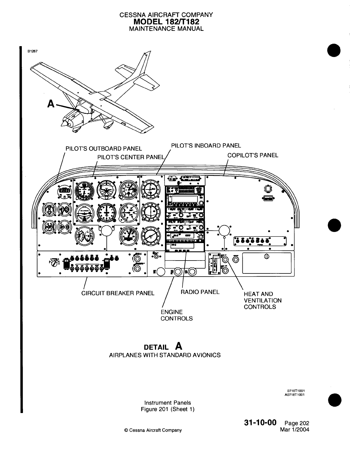
CESSNA AIRCRAFT
COMPANY
MODEL
182/T182
MAINTENANCE
MANUAL
DII
-T'C
rl
ITDR-fADrn
DAhAII
Il
IJ'MJtLJ
rFt1dL/L
PILOT'S
INBOARD
PANEL
OT'S
PANEL
*
a
*
0
'*
66.
&&&
'6
pijjr.
-
999
/
CIRCUIT
BREAKER
PANEL
/
RADIO
PANEL
ENGINE
CONTROLS
0~~~~
00
ir
0
0
HEAT
AND
VENTILATION
rCONTRLI
S
vv,
.... ._v
DETAIL
A
AIRPLANES
WITH
STANDARD
AVIONICS
0710T1001
A0718T1001
Instrument
Panels
Figure
201
(Sheet
1)
31-10-00
©
Cessna
Aircraft
Company
IIL/ I 0 J3-L
Page
202
Mar
1/2004
neon
I0
I
/
I
"'
CESSNA AIRCRAFT
COMPANY
MODEL
182/T182
MAINTENANCE
MANUAL
Remove
the
labels
from the
electrical
connections.
Install
the copilot's
panel
with
screws.
Install
the screws that attach
the
control
column
collar.
Connect
the
negative
battery cable.
Refer
to
Chapter
24,
Battery
-
Maintenance
Practices.
31-10-00
Page
203
©
Cessna
Aircraft
Company
Mar
1/2004
I
(2)
(3)
(4)
(5)
CESSNA
AIRCRAFT
COMPANY
MODEL
182/T182
MAINTENANCE
MANUAL
INSTRUMENT
AND
CONTROL
PANELS
-
MAINTENANCE
PRACTICES
Airplanes with
Garmin
G1000
1.
General
A.
This
section
covers
the removal and
installation
for
the
center
panel,
switch panel,
throttle/flap
panel,
and instrument
panel.
2.
Center
Panel
Removal/Installation
A.
Remove
the
Center
Panel (Refer
to
Figure
201).
(1)
Make
sure
the
MASTER
ALT/BAT
and
AVIONICS
switches
are
in
the
off
position.
(2)
Disengage
the STDBY
IND-LTS
circuit
breaker.
(3)
Remove
the
screws that
attach the
center
panel
to
the
instrument
panel.
(4)
Carefully
pull out
the center
panel
as
necessary
to
get access
behind
the
panel.
(5)
Install
tags for
identification
on
the
electrical connectors
and
hoses
and
disconnect
them
from
the
instruments.
B.
Install
the
Center
Panel
(Refer
to
Figure
201).
(1)
Connect
the
electrical
connectors
and
hoses
to
the
applicable
instruments.
(2)
Remove
the
tags
from the
electrical connectors
and
hoses.
(3)
Carefully
put
the
center
panel
in
the instrument panel.
(4)
Install
the
screws that
attach the
center
panel.
(5)
Engage
the
STDBY
IND
LTS
circuit
breaker.
3.
Switch
Panel
Removal/Installation
A.
Remove
the
Switch Panel
(Refer
to Figure
201).
(1)
Make sure
the
MASTER
ALT/BAT
and
AVIONICS
switches
are
in
the
off
position.
(2)
Remove
the
screws that
attach the
switch panel
to
the
instrument
panel.
(3)
Carefully
pull
the switch
panel
out
from
the
instrument
panel
to
get
access
behind
the
panel.
(4)
Disconnect
the
switches
from
the
electrical
connections.
B.
Install
the
Switch Panel (Refer
to
Figure
201).
(1)
Connect
the
electrical
connections
to
the
switches.
(2)
Put
the
switch panel
in
the
instrument
panel.
(3)
Attach
the switch panel
with
the
screws.
4.
Throttle/Flap
Panel
A.
Throttle/Flap
Panel Removal (Refer
to
Figure
201).
(1)
Disconnect
the
negative
cable
from
airplane
battery.
Refer
to
Chapter
24,
Battery
-
Maintenance
Practices.
(2)
Make
sure
the
MASTER
ALT/BAT
and
AVIONICS
switches
are
in
the
off
position.
(3)
Remove
the
screws that
attach the
throttle/flap
panel
to
the
instrument
panel.
(4)
Carefully
pull
the
throttle/flap
panel
out
from
the
instrument
panel
to get
access
behind
the
panel.
(5)
Disconnect
the
switches
from
the electrical
connections.
B.
Throttle/Flap
Panel
Installation
(Refer
to
Figure
201).
(1)
Connect
the
electrical connections
to
the
switches.
(2)
Put
the
throttle/flap
panel
in
the
instrument
panel.
(3)
Attach the
throttle/flap
panel
with
the
screws.
(4)
Connect
the
negative
battery cable.
Refer to
Chapter
24,
Battery
-
Maintenance Practices.
5.
Instrument
Panel
Removal/Installation
A.
Remove
the
Instrument
Panel
(Refer
to
Figure
201).
(1)
Disconnect electrical
power
to
the
airplane.
(a)
Make sure
the
AVIONICS
switch
is
in
the
off
position.
(b)
Disengage
the
two
PFD
circuit
breakers,
the
MFD,
STDBY
BATT,
STDBY
IND-LTS
AUDIO
circuit
breakers.
31-10-10
Page
201
©
Cessna Aircraft
Company
Jan 2/2006
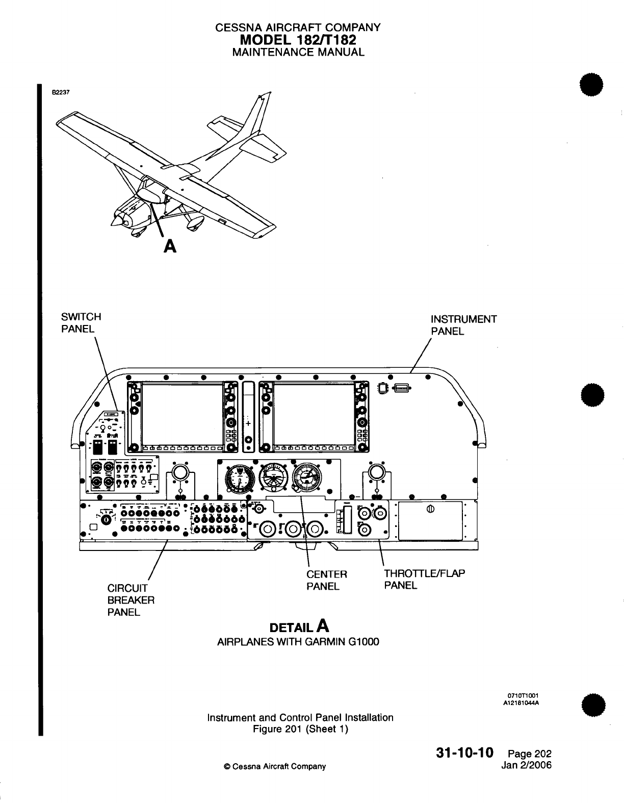
CESSNA
AIRCRAFT
COMPANY
MODEL
182/T182
MAINTENANCE
MANUAL
E
A
SWITCH
PANEL
INSTRUMENT
PANEL
I
-
0
+
bo o
~
~~~on
03
e6d ibbbh bbnn ffi
Ofa
* *
0
.
4
w
o 10
oCm
on
*
99096
9
;
;,r
3-
*.
*riii
0*
0
CENTER
PANEL
CIRCUIT
BREAKER
PANEL
.
* *
THROTTLE/FLAP
PANEL
DETAIL
A
AIRPLANES
WITH
GARMIN
G1000
071
T1
001
A12181044A
Instrument
and
Control Panel
Installation
Figure
201
(Sheet
1)
31-10-10
0
Cessna
Aircraft Company
a
Page
202
Jan
2/2006
CESSNA
AIRCRAFT
COMPANY
MODEL
182/T182
MAINTENANCE
MANUAL
(2)
Remove
the
center
panel. Refer
to
Center
Panel
-
Removal/Installation.
(3)
Remove
the
switch
panel. Refer
to
Switch
Panel
-
Removal/Installation.
|* ~ (4)
Remove
the
throttle/flap
panel.
Refer
to
Throttle/Flap
Panel
-
Removal/Installation.
(5)
Remove
the Audio
Panel.
Refer
to
Audio
Panel
-
Maintenance Practices.
(6)
Remove
the screws
that
attach
the
control
column
collars
to
the instrument panel.
(7)
Remove
the
hourmeter
to
the
instrument
panel.
(a)
Remove
the screws
for
the
hourmeter.
(b)
Pull
the
hourmeter
out
and
disconnect
the
connector.
(8)
Remove
the
Control
Display
Units
(CDU).
(a)
Disengage
the
quick
release
fasteners.
(b)
Carefully
pull
the
CDU
away
from
the
instrument
panel and
disconnect
the
electrical
connector.
(9)
Remove
the
screws
from
the
instrument
panel.
NOTE:
The
ELT
switch
can
only
be
removed
from
the
back of
the
instrument
panel.
(10)
Disconnect
and
remove
the
ELT
switch
from
the
instrument panel.
(11)
Remove
the
instrument
panel.
B.
Install
the
Instrument
Panel (Refer
to
Figure
201).
(1)
Set
the
instrument
panel
in
position.
(2)
Install the
ELT
switch
and
connect
the
electrical
connector.
(3)
Install the
instrument
panel screws.
(a)
Make
sure
to put
the
electrical
connector for
the
hourmeter
through
the
panel hole
for
the
hourmeter
installation.
(4)
Connect
the
electrical
connector
to
the
hourmeter.
(5)
Install
the
hourmeter.
(6)
Attach the
collar
for
the control column
to
the
instrument
panel.
(7)
Set
the
throttle/flap
panel
in
position
and
connect
the
electrical
connections
to
the
switches.
(8)
Install the
throttle/flap
panel
to
the
instrument
panel
with
the screws.
(9)
Set
the switch panel
in
position
and
connect
the
electrical connections
to
the
switches.
(10)
Install
the switch
panel
to
the
instrument
panel
with
the screws.
(11)
Set
the
center
panel
in
position
and
connect the electrical connectors
and vacuum
hoses
to
the
instruments.
(12)
Install
the
center
panel
to
the
instrument
panel
with
the screws.
(13)
Set
the Control
Unit
Displays
(CDU's)
in
position
and
connect
the
electrical
connector.
(14)
Install
the CDU's
with
the
quick
release
fasteners
to
the
instrument
panel.
(15)
Engage
the
two
PFD
circuit
breakers, the
MFD,
STDBY
BATT,
STDBY
IND-LTS
AUDIO
circuit
breakers.
31-10-10
Page
203
©
Cessna Aircraft
Company
Jan 2/2006
CESSNA
AIRCRAFT
COMPANY
MODEL
1821T182
MAINTENANCE
MANUAL
DIGITAL
CLOCK
-
MAINTENANCE PRACTICES
1.
Description
and
Operation
A.
The
digital
clock
is
located
in
the
upper
left
side
of
the
instrument
panel.
The
unit
also gives
an
indication
of
the
temperature
and
voltage.
2.
Digital
Clock Removal/Installation
A.
Remove the
Digital
Clock
(Refer
to
Figure
201).
(1)
Press
the
ALT/BAT
MASTER
switch
to
the
off
position.
(2)
Remove
the
screws that
attach
the digital
clock
to the
instrument
panel.
(3)
Carefully
pull
the
digital
clock
out
from
the
instrument
panel and
disconnect
the
electrical
connector.
B.
Install Digital
Clock
(Refer
to Figure
201).
(1)
Connect
the
electrical
connector
to
the
digital clock.
(2)
Set
in
position
the
digital
clock
in
the
instrument
panel
and
attach
with
the
screws.
(3)
Press the
ALT/BAT
MASTER
switch
to
the
ON
position.
31-20-00
Page
201
©
Cessna Aircraft
Company
April
1/2002
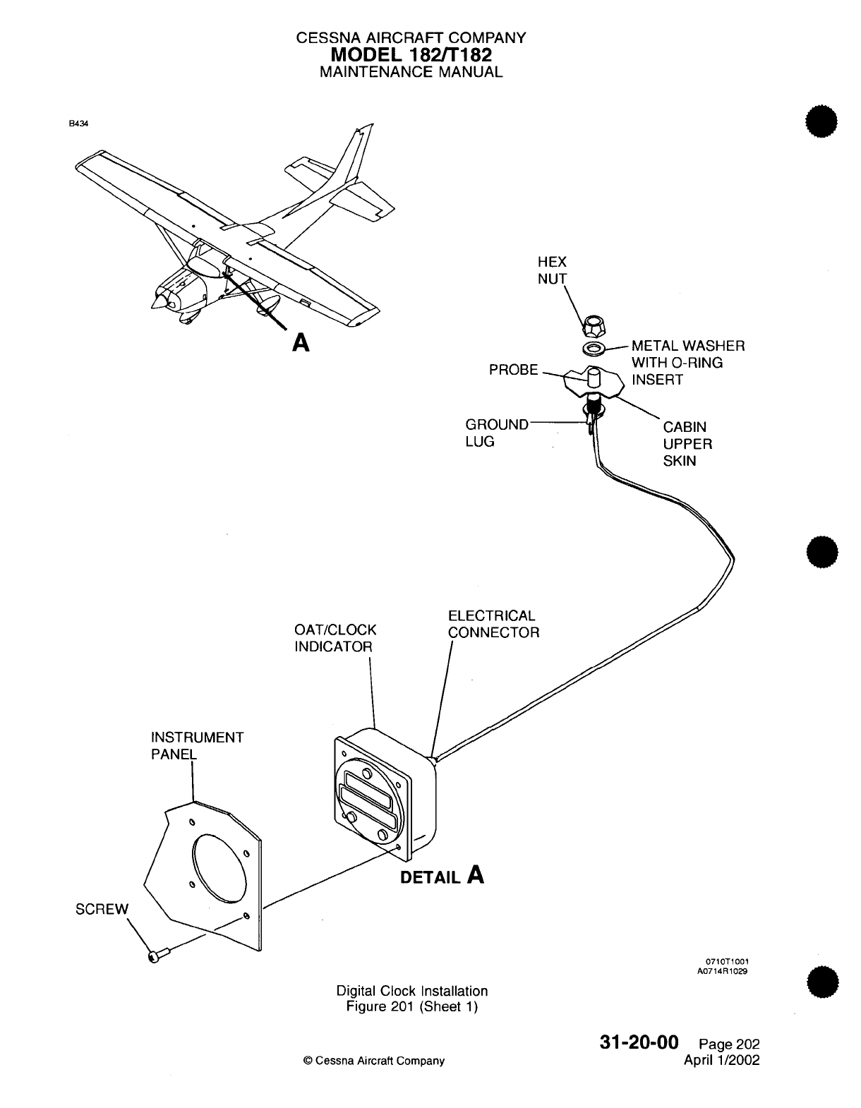
CESSNA
AIRCRAFT
COMPANY
MODEL 182/T182
MAINTENANCE
MANUAL
E
HEX
NUT
\a
A
M-ETAL
WASER
~~~~A
a,
~SCMETAL
WASHER
\AIIT-U
n
DI0Kf-
OAT/CLOCK
INDICATOR
CABIN
UPPER
SKIN
LUG
ELECTRICAL
CONNECTOR
INSTRUMENT
PANEL
DETAIL
A
SCREW
0710T1001
A0714R1029
Digital
Clock Installation
Figure
201
(Sheet
1)
31-20-00
©
Cessna Aircraft
Company
Page
202
April
1/2002
Con.
U-11
CESSNA
AIRCRAFT
COMPANY
MODEL
182/T182
MAINTENANCE
MANUAL
HOUR
METER
-
MAINTENANCE PRACTICES
1.
Description
and
Operation
A.
The
hour
(Hobbs) meter
is
located
in
the
upper
right
corner
of
the
instrument
panel and
provides
indication
of
flight
hours
based
on
engine
operation.
B.
The
hour meter
(E1003)
receives power
through
the
WARN
circuit
breaker
(HI022)
located
on
the
lower
instrument
panel. The hour
meter
is
grounded
through the
Oil Pressure Switch
(SN001),
and
anytime
oil
pressure exceeds
20
PSI a
ground
is
sent
from
the
switch
to
the
hour
meter,
completing
a
circuit
and
activating
the
hour
meter.
2.
Hour
Meter
RemovaVlnstallation
A.
Remove
Hour Meter
(Refer
to Figure
201).
(1)
Gain
access
to
backside
of
instrument
panel
and
hold nuts
while
loosening
screws.
(2)
Disconnect
electrical connectors
leading into hour
meter.
B.
Install Hour
Meter
(Refer
to Figure
201).
(1)
Connect
electrical
connectors
to
hour
meter.
(2)
Install
hour meter
to panel and
secure
using
screws
and
nuts.
©
Cessna
Aircraft
Company
31-30-00
Page
201
April 1/2002
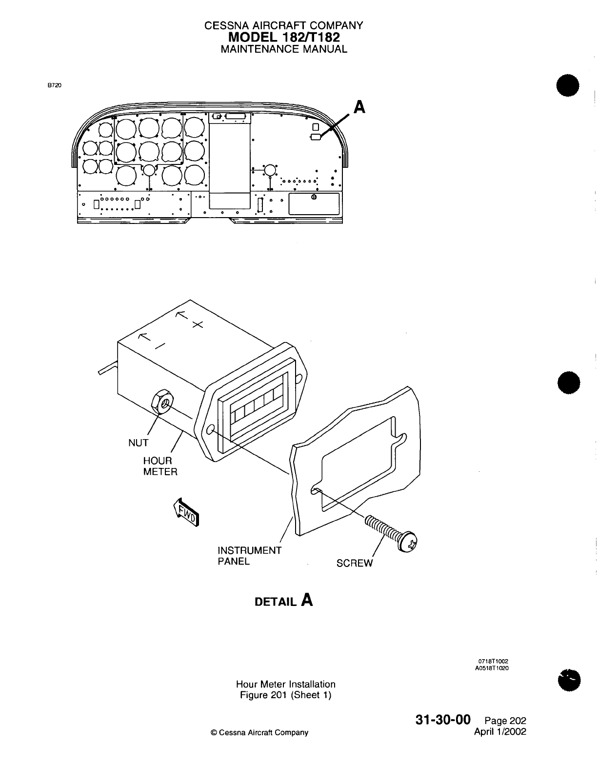
CESSNA
AIRCRAFT
COMPANY
MODEL
182/T182
MAINTENANCE
MANUAL
B720
.foooo
'
c)(D(:
..
:
A
.....
. . ....I
o 1 1''
'
°; o o
I
_
.
n
* *
_
*
NUT
/
HOUR
METER
PANEL
SCREW
DETAIL
A
0718T1002
A0518T1020
Hour Meter
Installation
Figure
201
(Sheet
1)
©
Cessna
Aircraft Company
31-30-00
Page
202
April
1/2002
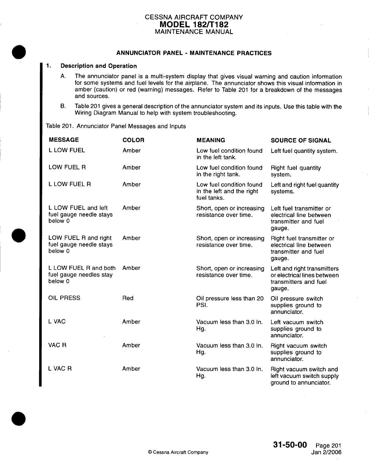
CESSNA
AIRCRAFT
COMPANY
MODEL
182/T182
MAINTENANCE
MANUAL
ANNUNCIATOR
PANEL
-
MAINTENANCE
PRACTICES
1.
Description
and
Operation
A.
The
annunciator
panel
is
a
multi-system
display
that
gives visual
warning
and
caution information
for
some
systems
and
fuel
levels for
the
airplane.
The
annunciator
shows
this visual
information
in
amber
(caution)
or
red
(warning)
messages. Refer
to
Table
201
for
a
breakdown
of
the
messages
and
sources.
B.
Table
201
gives
a
general
description
of
the
annunciator
system
and
its
inputs.
Use
this
table
with
the
Wiring Diagram
Manual
to
help
with
system
troubleshooting.
Table
201.
Annunciator
Panel
Messages
and
Inputs
MESSAGE
L
LOW
FUEL
LOW
FUEL
R
L
LOW
FUEL
R
L
LOW
FUEL
and
left
fuel
gauge
needle
stays
below
0
LOW
FUEL
R
and
right
fuel
gauge
needle
stays
below
0
L
LOW
FUEL
R
and
both
fuel
gauge
needles
stay
below
0
OIL PRESS
L
VAC
VAC
R
L
VAC
R
COLOR
Amber
Amber
Amber
MEANING
Low fuel
condition
found
in
the
left
tank.
Low
fuel
condition
found
in
the
right
tank.
Low
fuel
condition
found
in
the
left
and
the
right
fuel tanks.
Short,
open
or
increasing
resistance over
time.
Amber
Amber
Short,
open or
increasing
resistance over
time.
Amber
Red
Amber
Amber
Amber
Short,
open or
increasing
resistance
over
time.
Oil
pressure
less than
20
PSI.
Vacuum
less
than
3.0
In.
Hg.
Vacuum
less
than 3.0
In.
Hg.
Vacuum
Hg.
less
than 3.0
In.
SOURCE
OF
SIGNAL
Left
fuel
quantity
system.
Right
fuel
quantity
system.
Left
and right
fuel
quantity
systems.
Left
fuel
transmitter
or
electrical
line
between
transmitter
and fuel
gauge.
Right
fuel
transmitter
or
electrical
line
between
transmitter
and
fuel
gauge.
Left and right
transmitters
or
electrical lines
between
transmitters
and
fuel
gauge.
Oil
pressure
switch
supplies
ground
to
annunciator.
Left
vacuum
switch
supplies
ground
to
annunciator.
Right
vacuum switch
supplies
ground
to
annunciator.
Right
vacuum switch
and
left
vacuum
switch
supply
ground to
annunciator.
©
Cessna Aircraft
Company
31-50-00
Page
201
Jan
2/2006
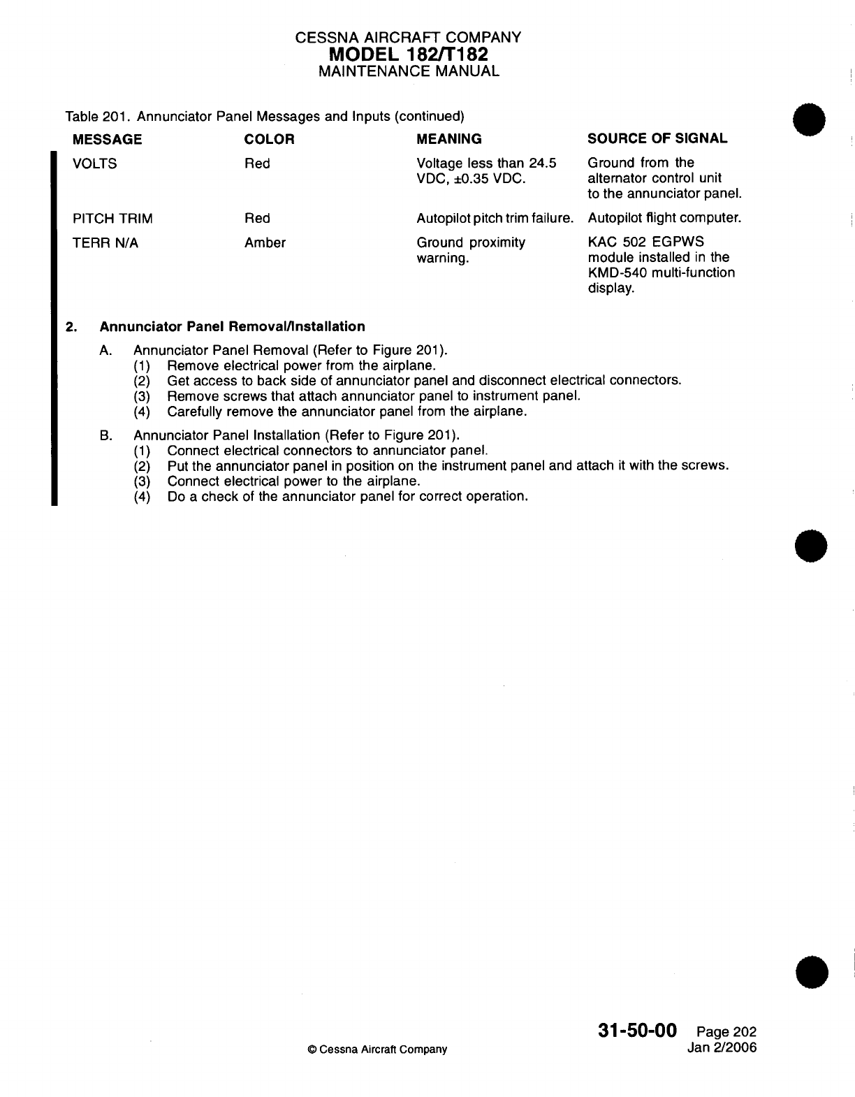
CESSNA AIRCRAFT
COMPANY
MODEL
182/T182
MAINTENANCE
MANUAL
Table
201.
Annunciator
Panel
Messages
and
Inputs
(continued)
MEANING
Voltage
less
than 24.5
VDC,
±0.35
VDC.
SOURCE OF
SIGNAL
Ground
from the
alternator
control
unit
to
the
annunciator
panel.
PITCH
TRIM
TERR
N/A
Red
Amber
Autopilot
pitch
trim
failure.
Autopilot
flight
computer.
Ground
proximity
warning.
KAC
502
EGPWS
module
installed
in
the
KMD-540
multi-function
display.
2.
Annunciator
Panel
Removal/Installation
A.
Annunciator
Panel
Removal
(Refer
to
Figure
201).
(1)
Remove
electrical
power
from
the
airplane.
(2)
Get
access
to
back
side of
annunciator
panel
and
disconnect
electrical
connectors.
(3)
Remove
screws
that
attach
annunciator
panel
to
instrument
panel.
(4)
Carefully
remove
the
annunciator
panel
from
the
airplane.
B.
Annunciator
Panel
Installation
(Refer
to
Figure
201).
(1)
Connect
electrical
connectors
to
annunciator
panel.
(2)
Put
the
annunciator
panel
in
position
on
the
instrument panel
and
attach
it
with
the
screws.
(3)
Connect
electrical
power
to
the
airplane.
(4)
Do
a
check
of
the
annunciator
panel
for
correct
operation.
31-50-00
Page
202
©
Cessna
Aircraft
Company
Jan
2/2006
MESSAGE
VOLTS
COLOR
Red
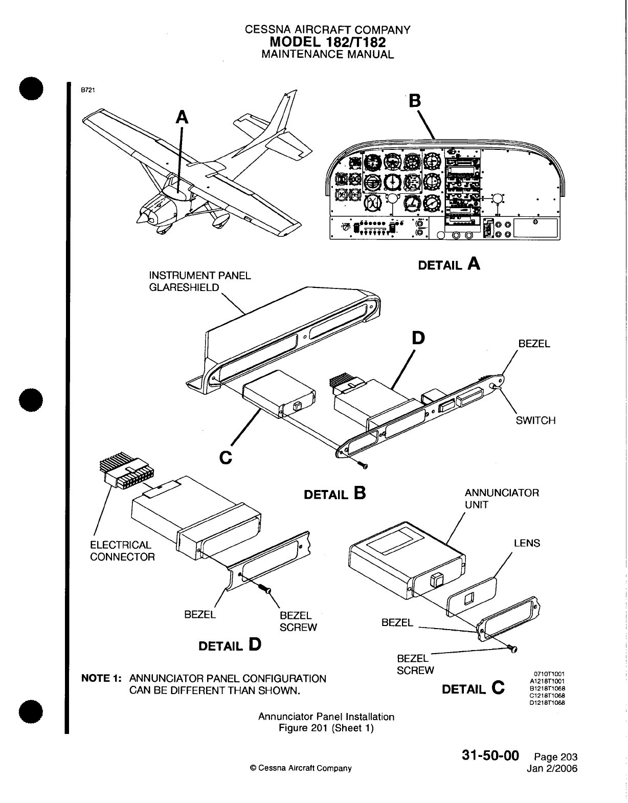
CESSNA
AIRCRAFT
COMPANY
MODEL 182/T182
MAINTENANCE
MANUAL
B
\
INSTRUMENT
PANEL
DETAIL
A
ULAHRE
3EZEL
SWITCH
ANNUNCIATOR
UNIT
DETAIL
D
NOTE
1:
ANNUNCIATOR
PANEL CONFIGURATION
CAN
BE
DIFFERENT
THAN
SHOWN.
BEZEL
SCREW
DETAIL
C
Annunciator
Panel
Installation
Figure
201
(Sheet
1)
31-50-00
©
Cessna
Aircraft
Company
ETAIL
B
BEZEL
BEZEL
SCREW
071T1
001
A1218T1001
B1218T1068
C1218T1068
D1218T1068
Page
203
Jan
2/2006
EA
E
CHAPTER
LANDING
GEAR
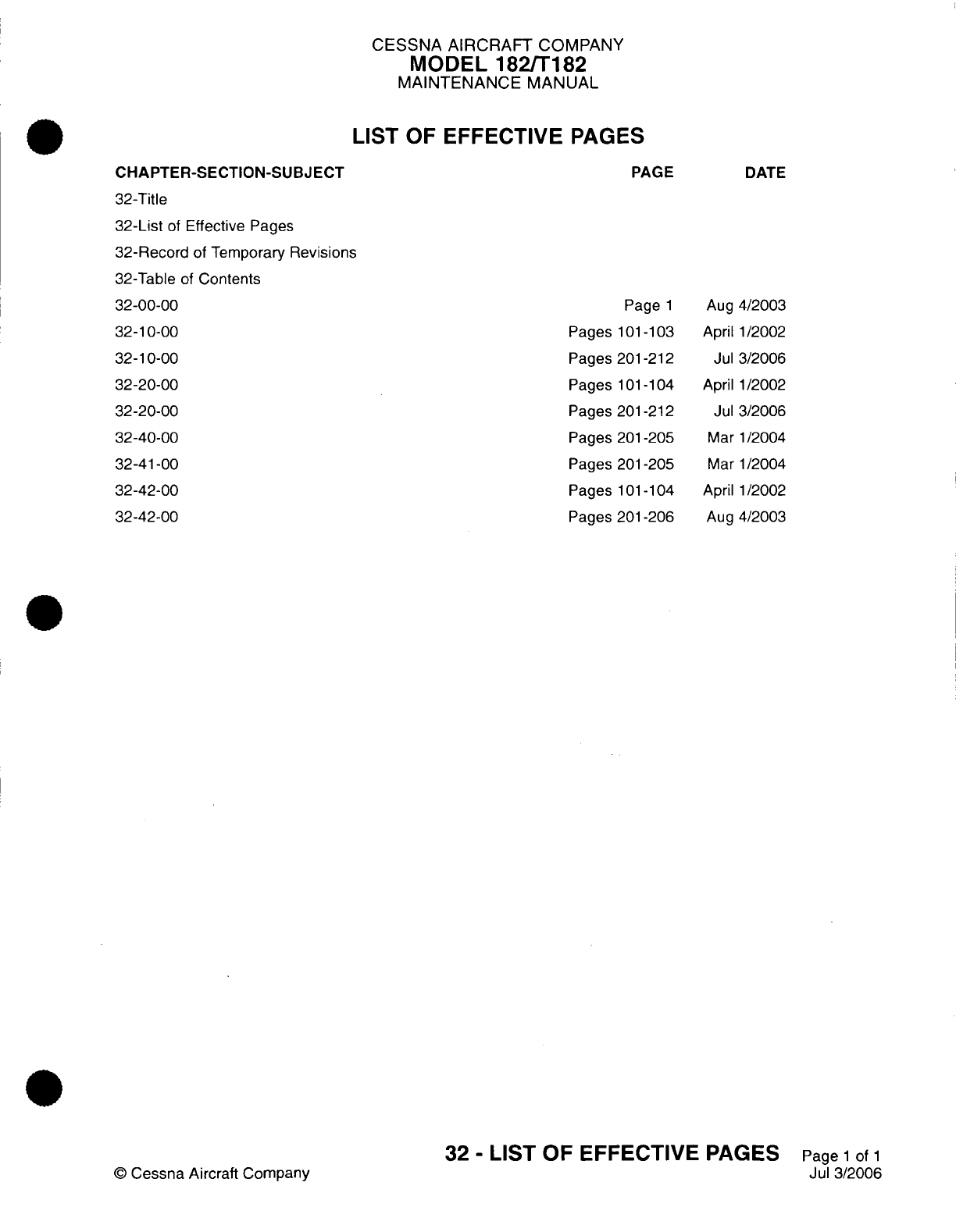
CESSNA AIRCRAFT
COMPANY
MODEL
182/T182
MAINTENANCE
MANUAL
LIST
OF
EFFECTIVE PAGES
CHAPTER-SECTION-SUBJECT
32-Title
32-List
of
Effective
Pages
32-Record
of
Temporary
Revisions
32-Table
of
Contents
32-00-00
32-10-00
32-10-00
32-20-00
32-20-00
32-40-00
32-41-00
32-42-00
32-42-00
©
Cessna Aircraft
Company
PAGE
Page
1
Pages 101-103
Pages
201-212
Pages
101-104
Pages
201-212
Pages
201-205
Pages
201-205
Pages
101-104
Pages
201-206
DATE
Aug
4/2003
April
1/2002
Jul
3/2006
April
1/2002
Jul
3/2006
Mar
1/2004
Mar
1/2004
April
1/2002
Aug
4/2003
32
-
LIST
OF EFFECTIVE
PAGES
Page
1
of
1
Jul
3/2006
Temporary
Revision
Number
RECORD
OF
TEMPORARY
REVISIONS
Page
Number
Issue
Date
By
Date
Removed
By
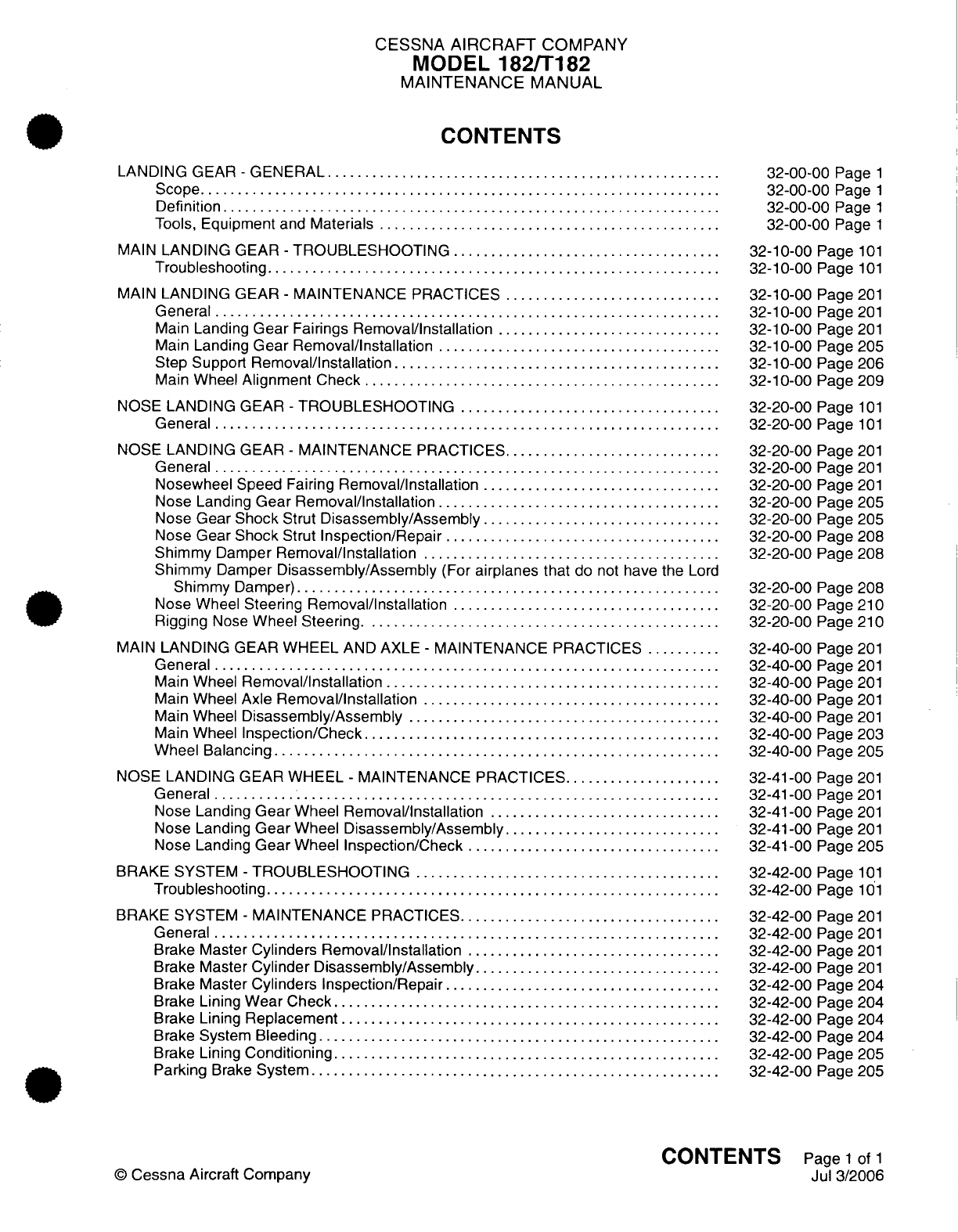
CESSNA
AIRCRAFT
COMPANY
MODEL
182/T182
MAINTENANCE
MANUAL
CONTENTS
LANDING
GEAR
-
GENERAL
..................................................
S
cope......................................................................
D
efinition
...................................................................
Tools,
Equipment
and
Materials
............................................
MAIN
LANDING
GEAR
-
TROUBLESHOOTING
....................................
Troubleshooting
............................................................
MAIN
LANDING
GEAR
-
MAINTENANCE
PRACTICES
.............................
General
....................................................................
Main
Landing
Gear
Fairings
Removal/Installation
..............................
Main
Landing
Gear
Removal/Installation
......................................
Step
Support
Removal/Installation
.........................................
Main
Wheel
Alignment
Check
....................
............................
NOSE LANDING
GEAR
-
TROUBLESHOOTING
...................................
General
....................................................................
NOSE LANDING
GEAR
-
MAINTENANCE
PRACTICES.............................
General
....................................................................
Nosewheel
Speed Fairing
Removal/Installation
................................
Nose Landing
Gear
Removal/nstallation
......................................
Nose
Gear Shock
Strut
Disassembly/Assembly
................................
Nose
Gear Shock
Strut
Inspection/Repair
.....................................
Shimmy
Damper
Removal/Installation
........................................
Shimmy
Damper
Disassembly/Assembly
(For
airplanes that
do
not
have
the
Lord
Shimmy
Damper)
..........
.............................................
Nose
Wheel
Steering
Removal/Installation
....................................
Rigging
Nose
Wheel
Steering.
.........
...........
...........................
MAIN
LANDING
GEAR
WHEEL
AND AXLE
-
MAINTENANCE
PRACTICES
..........
General...................................................................
Main
Wheel
Removal/Installation
.............................................
Main
Wheel
Axle
Removal/Installation
....................
....................
Main
Wheel
Disassembly/Assembly
..........................................
Main
Wheel
Inspection/Check
....................
.........................
W
heel
Balancing
............
...........
...................................
NOSE LANDING GEAR WHEEL
-
MAINTENANCE
PRACTICES.....................
General
....................................................................
Nose
Landing
Gear
Wheel
Removal/Installation
...............................
Nose Landing
Gear
Wheel
Disassembly/Assembly
...........................
Nose Landing
Gear
Wheel
Inspection/Check
..................................
BRAKE SYSTEM
-
TROUBLESHOOTING
.........................................
Troubleshooting
............................................................
BRAKE
SYSTEM
-
MAINTENANCE
PRACTICES...................................
General
....................................................................
Brake
Master
Cylinders
Removal/Installation
..................................
Brake
Master
Cylinder
Disassembly/Assembly
................................
Brake
Master
Cylinders Inspection/Repair
...................................
Brake
Lining
Wear
Check....................................................
Brake
Lining
Replacement
..................................................
Brake System
Bleeding
......................................................
Brake
Lining
Conditioning...................................................
Parking
Brake
System.......................................................
32-00-00
Page
1
32-00-00
Page
1
32-00-00
Page
1
32-00-00
Page
1
32-10-00
Page
101
32-10-00
Page
101
32-10-00
Page
201
32-10-00
Page
201
32-10-00
Page
201
32-10-00
Page
205
32-10-00
Page
206
32-10-00
Page
209
32-20-00
Page
101
32-20-00
Page
101
32-20-00
Page
201
32-20-00
Page
201
32-20-00
Page
201
32-20-00
Page
205
32-20-00
Page
205
32-20-00
Page
208
32-20-00
Page
208
32-20-00
Page
208
32-20-00
Page
210
32-20-00
Page
210
32-40-00
Page
201
32-40-00
Page
201
32-40-00
Page
201
32-40-00
Page
201
32-40-00
Page
201
32-40-00
Page
203
32-40-00
Page
205
32-41-00
Page
201
32-41-00
Page
201
32-41-00
Page
201
32-41-00
Page
201
32-41-00
Page
205
32-42-00
Page
101
32-42-00
Page
101
32-42-00
Page
201
32-42-00
Page
201
32-42-00
Page
201
32-42-00
Page
201
32-42-00
Page
204
32-42-00
Page
204
32-42-00
Page
204
32-42-00
Page
204
32-42-00
Page
205
32-42-00
Page
205
CONTENTS
Page
1
of
1
Jul
3/2006
©
Cessna
Aircraft
Company
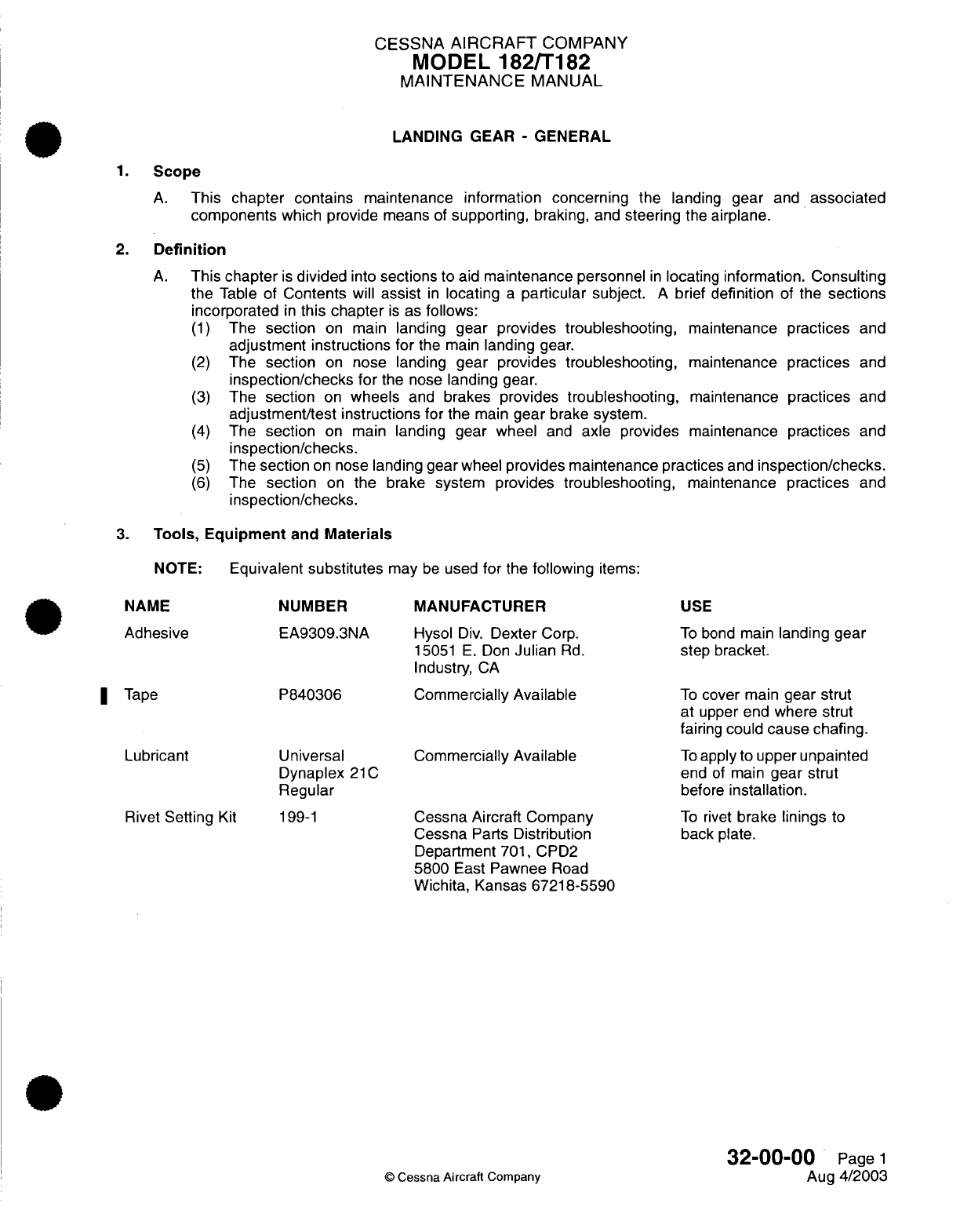
CESSNA
AIRCRAFT
COMPANY
MODEL
182/T182
MAINTENANCE
MANUAL
LANDING
GEAR
-
GENERAL
1.
Scope
A.
This
chapter contains
maintenance
information
concerning
the
landing
gear
and
associated
components
which provide
means
of
supporting,
braking,
and
steering
the
airplane.
2.
Definition
A.
This
chapter
is
divided
into
sections to
aid
maintenance personnel
in
locating
information.
Consulting
the
Table
of
Contents
will
assist
in
locating
a
particular
subject.
A
brief
definition
of
the
sections
incorporated
in
this chapter
is
as
follows:
(1)
The
section
on
main
landing
gear provides
troubleshooting,
maintenance
practices
and
adjustment instructions
for
the
main
landing
gear.
(2)
The
section
on
nose landing
gear
provides
troubleshooting,
maintenance
practices
and
inspection/checks for
the
nose
landing
gear.
(3)
The
section
on
wheels
and
brakes
provides
troubleshooting,
maintenance
practices
and
adjustment/test
instructions
for
the
main
gear
brake
system.
(4)
The
section
on main
landing gear
wheel
and
axle provides
maintenance
practices
and
inspection/checks.
(5)
The
section
on nose
landing gear
wheel
provides
maintenance
practices
and
inspection/checks.
(6)
The
section
on
the
brake
system provides
troubleshooting,
maintenance
practices
and
inspection/checks.
3.
Tools,
Equipment
and
Materials
NOTE:
Equivalent
substitutes
may
be
used
for
the
following
items:
NAME NUMBER
Adhesive
I
Tape
Lubricant
Rivet
Setting
Kit
EA9309.3NA
P840306
Universal
Dynaplex
21C
Regular
199-1
MANUFACTURER
Hysol
Div.
Dexter
Corp.
15051
E.
Don
Julian
Rd.
Industry,
CA
Commercially
Available
Commercially
Available
Cessna Aircraft
Company
Cessna
Parts
Distribution
Department
701,
CPD2
5800
East
Pawnee
Road
Wichita,
Kansas
67218-5590
USE
To
bond
main
landing
gear
step bracket.
To
cover
main
gear
strut
at
upper end
where
strut
fairing
could
cause chafing.
To
apply
to
upper
unpainted
end
of
main
gear
strut
before
installation.
To
rivet
brake linings
to
back
plate.
32-00-00
Page
1
Aug
4/2003
©
Cessna
Aircraft
Company
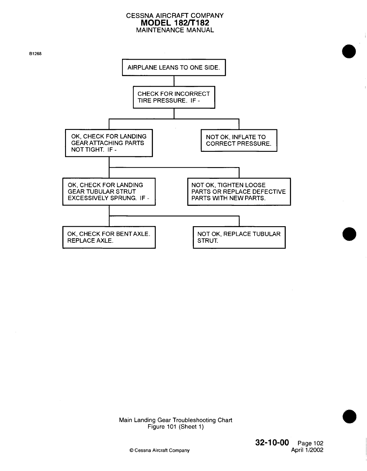
CESSNA AIRCRAFT
COMPANY
MODEL
182/T182
MAINTENANCE
MANUAL
B1268
AIRPLANE
LEANS
TO
ONE SIDE.
I
CHECK
FOR
INCORRECT
TIRE PRESSURE.
IF-
OK,
CHECK
FOR
LANDING NOT
OK,
INFLATE
TO
GEAR
ATTACHING
PARTS
CORRECT PRESSURE.
NOTTIGHT.
IF-
OK,
CHECK FOR LANDING
NOT
OK,
TIGHTEN
LOOSE
GEAR
TUBULAR
STRUT
PARTS
OR REPLACE DEFECTIVE
EXCESSIVELY
SPRUNG.
IF
-
PARTS
WITH
NEW
PARTS.
OK,
CHECK
FOR BENT AXLE.
REPLACE
AXLE.
NOT
OK,
REPLACE
TUBULAR
STRUT.
Main
Landing
Gear Troubleshooting
Chart
Figure
101
(Sheet
1)
©
Cessna
Aircraft
Company
32-10-00
Page
102
April
1/2002
I
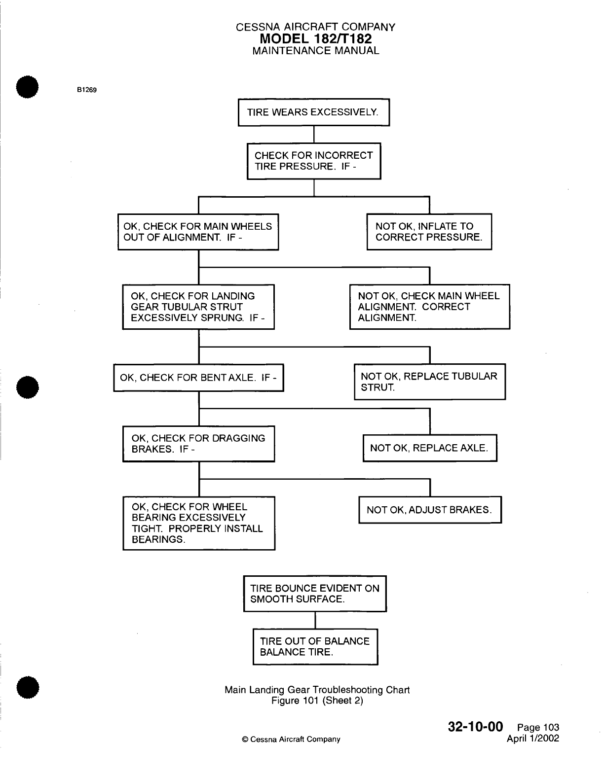
CESSNA
AIRCRAFT
COMPANY
MODEL
182/T182
MAINTENANCE
MANUAL
B1269
TIRE
WEARS
EXCESSIVELY.
CHECK
FOR
INCORRECT
TIRE
PRESSURE.
IF
-
I
OK,
CHECK
FOR
MAIN
WHEELS
OUT
OF
ALIGNMENT.
IF
-
I
NOT
OK,
INFLATE
TO
CORRECT PRESSURE.
OK,
CHECK
FOR
LANDING
GEAR TUBULAR
STRUT
EXCESSIVELY SPRUNG.
IF
-
OK,
CHECK FOR
BENTAXLE.
IF
-
OK,
CHECK FOR
DRAGGING
BRAKES.
IF-
OK,
CHECK
FOR
WHEEL
BEARING EXCESSIVELY
TIGHT.
PROPERLY
INSTALL
BEARINGS.
NOT
OK,
CHECK
MAIN
WHEEL
ALIGNMENT.
CORRECT
ALIGNMENT.
NOT
OK,
REPLACE
TUBULAR
STRUT.
NOT
OK,
REPLACE AXLE.
I
NOT
OK,
ADJUST
BRAKES.
TIRE
BOUNCE EVIDENT
ON
SMOOTH
SURFACE.
I
TIRE
OUT
OF
BALANCE
BALANCE
TIRE.
Main
Landing
Gear Troubleshooting Chart
Figure
101
(Sheet
2)
©
Cessna
Aircraft Company
32-10-00
Page
103
April 1/2002
I
I
I
I
I
I
I
CESSNA
AIRCRAFT
COMPANY
MODEL
182/T182
MAINTENANCE
MANUAL
MAIN
LANDING
GEAR
-
MAINTENANCE
PRACTICES
1.
General
A.
The
main
landing
gear
maintenance
practices
give
removal/installation instructions for
the
left main
landing
gear.
Removal/installation
for
the
right
main
landing
gear
is
typical
unless
noted.
B.
The
tubular,
spring-steel
main
landing gear
struts are attached
to
the
aircraft
at
inboard
and
outboard
forgings
in
the
belly
of the
aircraft.
A
bracket
is
bonded
to
each
strut for
attachment
of
a
step.
Hydraulic
brake
lines go down the
main
gear
struts.
The
axles,
main
wheels,
and
brake
assemblies
are
installed
at
the
lower
end
of
each
strut.
C.
The
aircraft
has
fuselage fairings,
attached
to the
fuselage
and
the
tubular
strut
fairings
with
screws.
The
tubular
strut
fairings
cover
the
tubular
landing
gear
struts,
and
attach
to
the
fuselage
fairings
at
the
upper end
and to
cover
plates
at
the
lower
end.
The
cover
plates
attach
to
the
tubular
strut
fairings
at
the
upper
end and
are
clamped
to
the
tubular
struts
at
the
lower
end. Brake
fairings
are
installed
at
the
lower
end of
the
tubular
strut
fairings
and are
attached
to
the
wheel
speed
fairings
by
screws
around
their
outer perimeters. The speed
fairings
are
installed
over
the wheels
and
are
attached
to
mounting plates
attached
to the
axles.
The
wheel
fairings
have
adjustable
scrapers
installed
in
the
lower
aft
part
of
the
fairings directly
behind
the
wheels.
2.
Main
Landing
Gear
Fairings
Removal/Installation
A.
Brake Fairing Removal (Refer
to
Figure
201).
(1)
Remove
the
screws
from
the
lower
side
of the
brake
fairing.
(2)
Remove
the
brake fairing
from the landing
gear.
B.
Brake Fairing
Installation
(Refer to Figure
201).
(1)
Put
the
brake
fairing
over
the
landing
gear.
(2)
Install
the
screws
to
the
lower
side of
the
brake
fairing.
C.
Main
Wheel
Speed
Fairing Removal
(Refer
to
Figure
201).
(1)
Remove
and
keep
the
screws
that
attach
the
brake
fairing
to the main
wheel speed
fairing.
(2)
Remove
the
screws that attach
the
main
wheel
speed
fairing
to
the mounting
plate.
(3)
Remove
the bolt
that attaches
the outboard
side
of
the
main
wheel
speed
fairing
to
the
axle
nut.
(4)
Loosen
the
scraper,
if
necessary,
and
remove
the
main
wheel
speed fairing from
the
wheel.
D.
Main
Wheel
Speed Fairing
Installation
(Refer
to
Figure
201).
(1)
Put
the
speed
fairing
over
the
wheel. Adjust
the
scraper
if
necessary.
(2)
Install
the
bolt
that
attaches
the
outboard side
of
the main wheel
speed
fairing
to the
axle
nut.
(3)
Install
the
screws
that attach the
main
wheel speed
fairing
to
the
attach plate,
which
is
bolted
to
the
axle.
(4)
Install
the
screws that attach the brake fairing
to the
main-wheel speed
fairing.
CAUTION:
You
must
keep
the
scraper
clean
for
the
tire
to
turn
correctly.
Make
sure
you
complete
a
check
of
the
clearance
every
time
the
scraper
has
been
disturbed,
the
tire
changed,
and
when you
install
the
speed fairings.
You
can
cause
damage
to
the
equipment
if
the
correct
clearance
is
not
set between the
tire
and
the scraper.
If
any
mud,
snow
or
ice
collects
on
the
scraper,
it
will
prevent
the
tire
from
correct
movement.
(5)
Do
a
check
of
the
clearance
between the
tire
and
the
scraper.
(a)
Clean
off
any
dirt
or ice
that
has
collected
on
the
scraper.
(b)
Adjust
the
clearance
as
necessary
to
have
a
minimum
of
0.55
inch
(14
mm)
to
a
maximum
of
0.80
inch
(20
mm).
(6)
Remove
any
fuel
and
oil
from the
speed
fairings
to
prevent stains
and
deterioration.
32-10-00
Page
201
©
Cessna
Aircraft
Company
Jul
3/2006
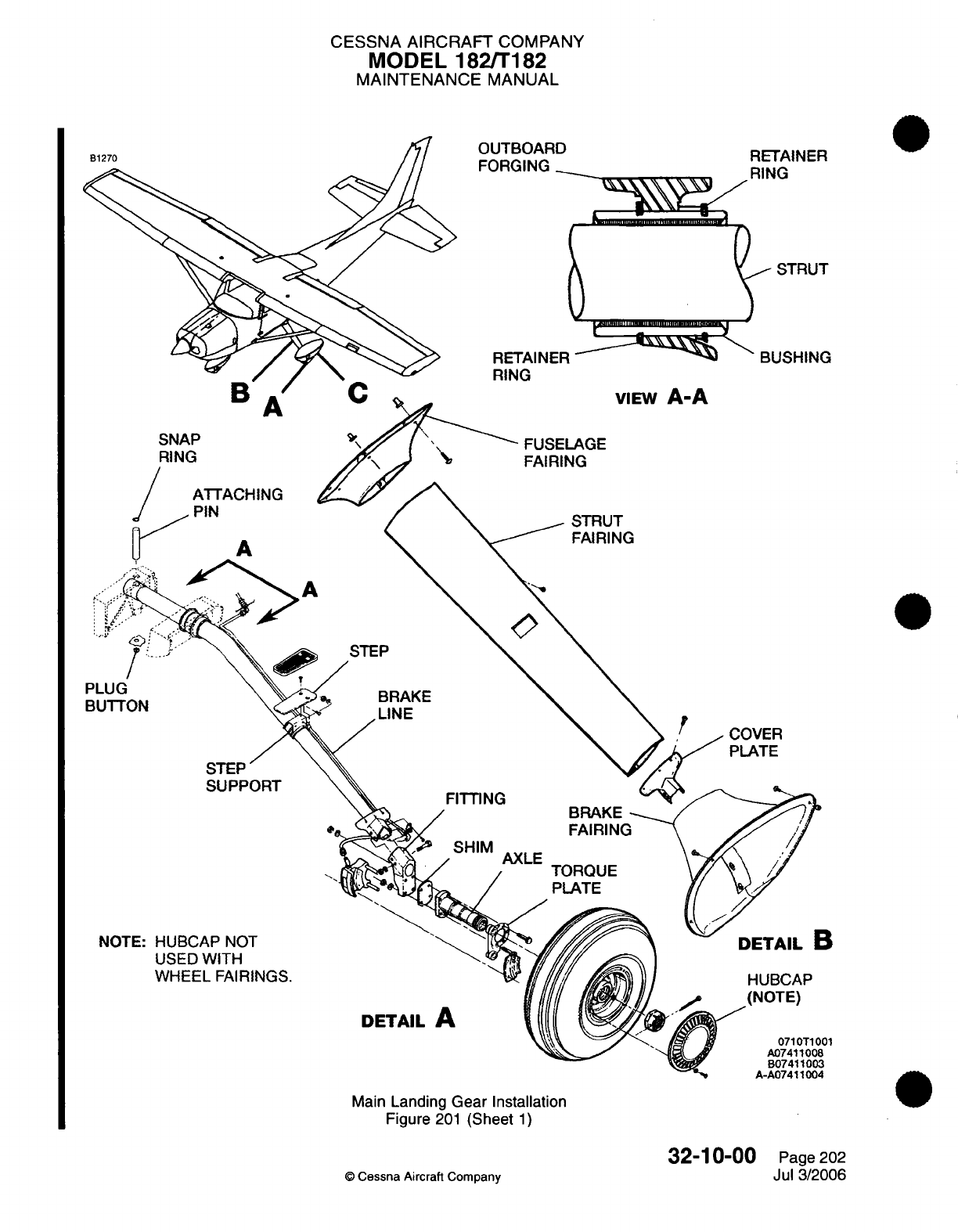
CESSNA
AIRCRAFT
COMPANY
MODEL
182/T182
MAINTENANCE
MANUAL
B1270
SNAP
RING
A
P
TTACHING
IN
A
STEP
BRAKE
LINE
STEP
SUPPORT
FITTING
SHIMAXLE
AXLE
TORQUE
PLATE
NOTE:
HUBCAP
NOT
USED
WITH
WHEEL
FAIRINGS.
DETAIL
A
Main
Landing
Gear Installation
Figure
201
(Sheet
1)
©
Cessna
Aircraft Company
32-10-00
Page
202
Jul
3/2006
PLUG
BUTTON
HUBCAP
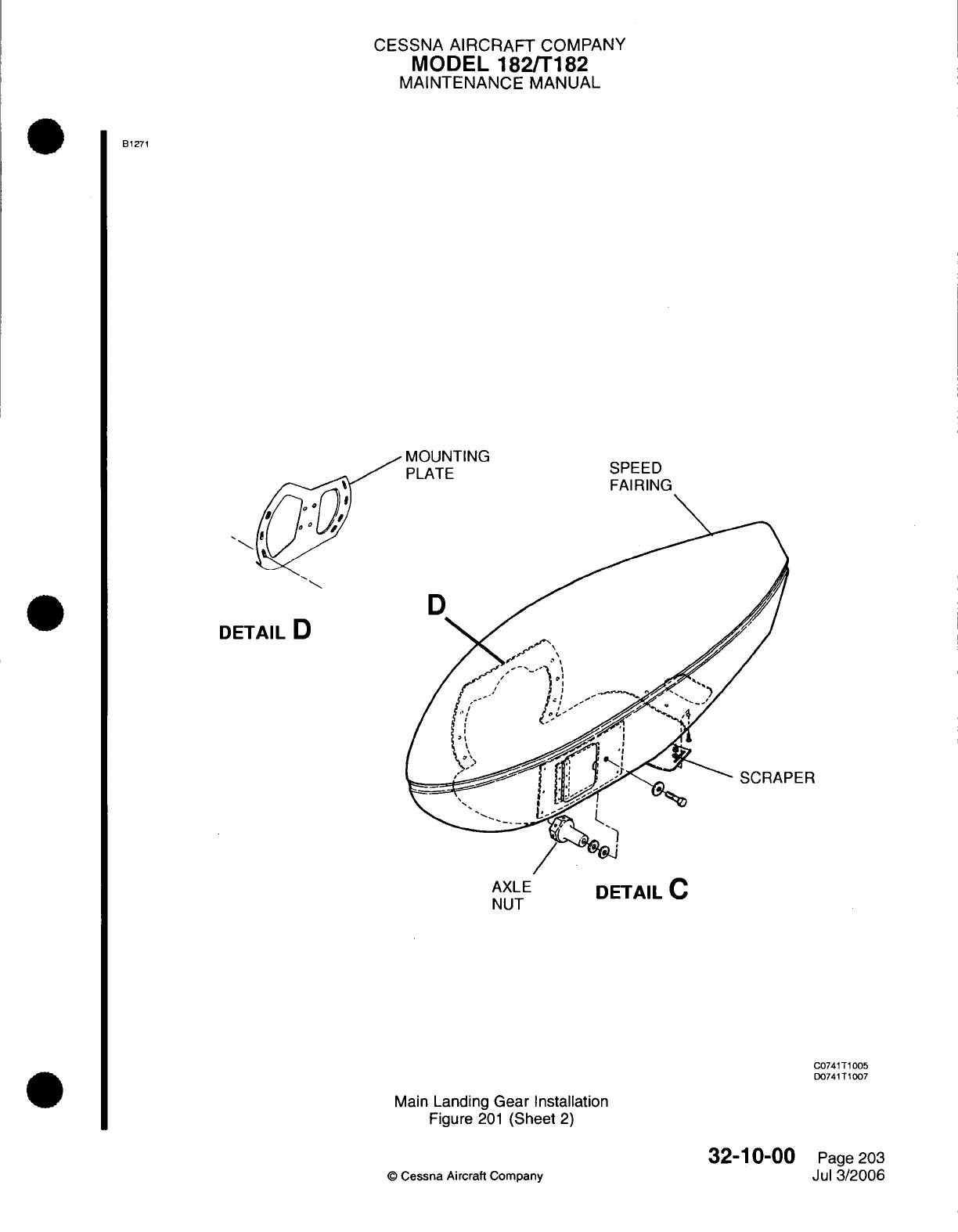
CESSNA
AIRCRAFT
COMPANY
MODEL
182/T182
MAINTENANCE
MANUAL
B1271
MOUNTING
PLATE SPEED
FAIRING
DETAIL
D
PER
AXLE
DETAIL
C
NUT
C0741T1005
D0741T1007
Main
Landing
Gear
Installation
Figure
201
(Sheet
2)
32-10-00
©
Cessna
Aircraft
Company
Page
203
Jul
3/2006
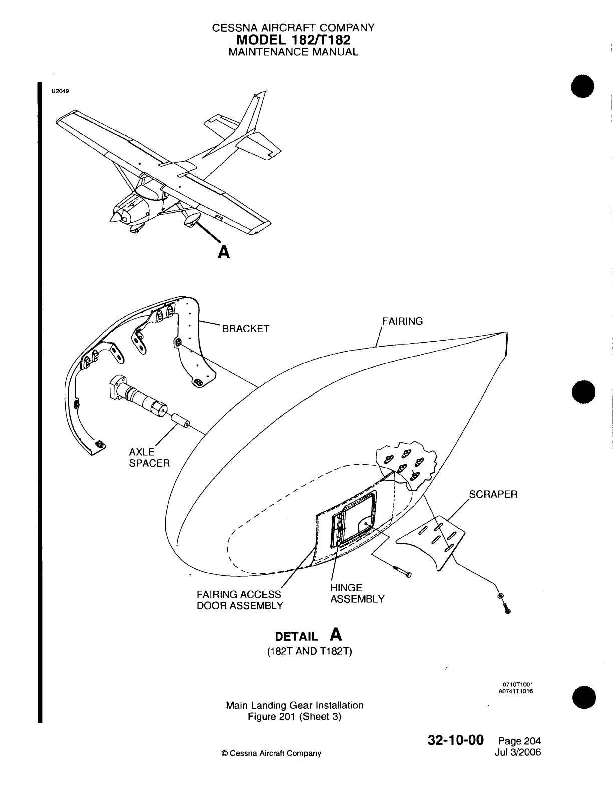
CESSNA
AIRCRAFT
COMPANY
MODEL
182/T182
MAINTENANCE
MANUAL
DETAIL
A
(182T
AND
T182T)
0710T1001
A0741T1016
Main
Landing
Gear Installation
Figure
201
(Sheet
3)
32-10-00
©
Cessna
Aircraft
Company
Page
204
Jul
3/2006
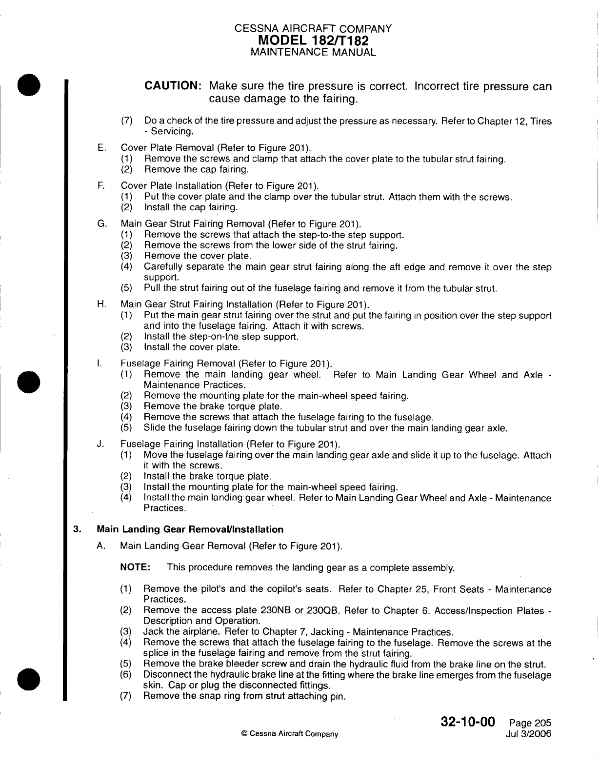
CESSNA
AIRCRAFT
COMPANY
MODEL
182/T182
MAINTENANCE
MANUAL
CAUTION:
Make
sure
the
tire pressure
is
correct. Incorrect
tire
pressure can
cause
damage
to the
fairing.
(7)
Do
a
check
of
the
tire
pressure
and
adjust the
pressure
as
necessary.
Refer
to
Chapter
12,
Tires
-
Servicing.
E.
Cover
Plate
Removal (Refer
to Figure
201).
(1)
Remove
the screws
and
clamp
that
attach
the
cover
plate
to
the
tubular
strut
fairing.
(2)
Remove the
cap fairing.
F.
Cover
Plate
Installation
(Refer
to
Figure
201).
(1)
Put
the
cover
plate
and
the clamp
over
the
tubular
strut. Attach
them
with
the
screws.
(2)
Install
the
cap
fairing.
G.
Main
Gear
Strut
Fairing
Removal (Refer
to
Figure
201).
(1)
Remove
the
screws
that
attach
the
step-to-the
step
support.
(2)
Remove the screws
from
the
lower
side of the strut
fairing.
(3)
Remove
the
cover
plate.
(4)
Carefully separate
the
main
gear
strut
fairing
along
the
aft
edge
and
remove
it
over
the
step
support.
(5)
Pull
the
strut
fairing
out of the
fuselage fairing
and
remove
it
from
the
tubular
strut.
H.
Main
Gear
Strut Fairing
Installation (Refer
to
Figure
201).
(1)
Put
the
main
gear
strut fairing
over
the
strut
and
put
the
fairing
in
position over
the step
support
and
into
the
fuselage
fairing.
Attach
it
with
screws.
(2)
Install the
step-on-the
step
support.
(3)
Install
the
cover
plate.
I.
Fuselage
Fairing
Removal (Refer
to
Figure
201).
(1)
Remove
the
main
landing gear
wheel. Refer
to Main
Landing
Gear
Wheel
and
Axle
-
Maintenance
Practices.
(2)
Remove
the
mounting plate
for
the
main-wheel
speed fairing.
(3)
Remove the brake
torque
plate.
(4)
Remove the
screws that
attach the
fuselage
fairing
to
the
fuselage.
(5)
Slide
the
fuselage
fairing
down
the
tubular
strut
and
over
the
main
landing
gear
axle.
J.
Fuselage
Fairing
Installation
(Refer
to
Figure
201).
(1)
Move
the
fuselage
fairing
over
the
main
landing gear axle
and
slide
it
up
to
the
fuselage.
Attach
it
with
the
screws.
(2)
Install
the
brake
torque
plate.
(3)
Install the mounting plate
for
the
main-wheel
speed
fairing.
(4)
Install the
main
landing
gear
wheel.
Refer
to
Main
Landing
Gear
Wheel and
Axle
-
Maintenance
Practices.
3.
Main
Landing
Gear
Removal/Installation
A.
Main
Landing
Gear
Removal
(Refer
to
Figure
201).
NOTE:
This procedure
removes the
landing
gear
as
a
complete
assembly.
(1)
Remove
the
pilot's
and the
copilot's
seats.
Refer to
Chapter
25,
Front
Seats
-
Maintenance
Practices.
(2)
Remove
the
access
plate
230NB
or
230QB.
Refer
to
Chapter
6,
Access/Inspection
Plates
-
Description
and
Operation.
(3)
Jack
the
airplane.
Refer
to
Chapter
7,
Jacking
-
Maintenance
Practices.
(4)
Remove the
screws that attach
the
fuselage
fairing
to the
fuselage.
Remove
the
screws
at
the
splice
in
the
fuselage
fairing
and
remove
from the
strut
fairing.
(5)
Remove the brake
bleeder
screw
and
drain
the
hydraulic fluid
from
the
brake
line
on
the
strut.
(6)
Disconnect the hydraulic
brake line
at
the
fitting
where
the brake
line
emerges
from the
fuselage
skin.
Cap
or
plug
the
disconnected
fittings.
(7)
Remove
the
snap
ring
from
strut attaching
pin.
32-10-00
Page
205
©
Cessna
Aircraft
Company
Jul
3/2006
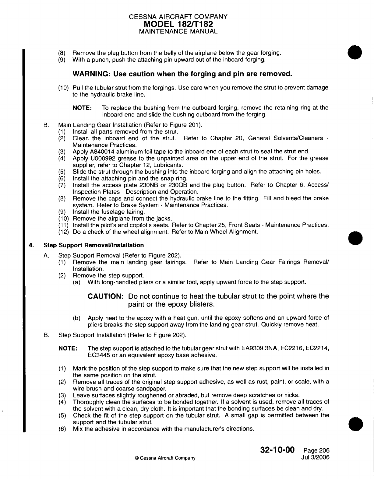
CESSNA AIRCRAFT
COMPANY
MODEL 182/T182
MAINTENANCE
MANUAL
(8)
Remove
the
plug
button
from
the
belly
of
the
airplane
below
the
gear
forging.
(9)
With
a
punch,
push
the attaching
pin upward
out of
the inboard
forging.
WARNING:
Use
caution
when
the
forging
and
pin
are
removed.
(10)
Pull the
tubular
strut
from
the
forgings.
Use
care
when
you
remove
the
strut
to
prevent
damage
to
the
hydraulic
brake
line.
NOTE:
To
replace the
bushing
from
the
outboard forging,
remove
the
retaining
ring
at the
inboard
end and
slide
the bushing
outboard
from
the
forging.
B.
Main
Landing
Gear
Installation
(Refer
to
Figure
201).
(1)
Install
all
parts removed
from
the
strut.
(2)
Clean the inboard end
of
the
strut.
Refer
to
Chapter
20,
General Solvents/Cleaners
-
Maintenance Practices.
(3)
Apply
A840014
aluminum
foil
tape
to the inboard
end of
each
strut
to
seal
the strut
end.
(4)
Apply
U000992
grease
to
the
unpainted
area
on
the upper
end
of the strut.
For
the grease
supplier, refer
to
Chapter
12,
Lubricants.
(5)
Slide
the
strut
through
the bushing
into
the
inboard
forging
and
align
the
attaching
pin
holes.
(6)
Install the
attaching
pin
and the
snap
ring.
(7)
Install
the
access
plate
230NB
or
230QB
and
the
plug
button.
Refer
to
Chapter
6,
Access/
Inspection
Plates
-
Description
and Operation.
(8)
Remove
the
caps
and
connect
the hydraulic brake
line
to
the
fitting.
Fill
and bleed
the
brake
system.
Refer
to
Brake System
-
Maintenance
Practices.
(9)
Install the
fuselage
fairing.
(10)
Remove
the
airplane
from
the
jacks.
(11)
Install the
pilot's
and
copilot's
seats.
Refer
to
Chapter
25,
Front
Seats
-
Maintenance
Practices.
(12)
Do
a
check
of
the
wheel
alignment.
Refer
to
Main
Wheel Alignment.
4.
Step
Support Removal/Installation
A.
Step
Support
Removal (Refer
to
Figure 202).
(1)
Remove
the
main
landing
gear
fairings.
Refer
to
Main
Landing
Gear
Fairings
Removal/
Installation.
(2)
Remove
the
step
support.
(a)
With
long-handled
pliers
or
a
similar
tool,
apply
upward
force
to the
step
support.
CAUTION:
Do
not
continue
to
heat
the
tubular
strut
to
the
point where
the
paint
or
the epoxy blisters.
(b)
Apply
heat
to
the
epoxy
with
a
heat
gun,
until
the
epoxy
softens
and
an
upward
force
of
pliers
breaks
the step
support
away
from
the
landing
gear
strut.
Quickly
remove
heat.
B.
Step
Support Installation
(Refer
to
Figure
202).
NOTE:
The
step
support
is
attached
to
the
tubular
gear
strut with
EA9309.3NA,
EC2216,
EC2214,
EC3445
or
an
equivalent
epoxy
base
adhesive.
(1)
Mark the
position
of
the
step
support
to make
sure
that
the
new
step
support
will be
installed
in
the
same
position
on
the
strut.
(2)
Remove
all
traces
of
the
original step support
adhesive,
as
well as
rust,
paint,
or
scale,
with
a
wire brush and
coarse
sandpaper.
(3)
Leave
surfaces
slightly
roughened
or
abraded,
but
remove
deep
scratches
or nicks.
(4)
Thoroughly
clean
the
surfaces
to
be
bonded together.
If a
solvent
is
used,
remove all
traces
of
the
solvent
with
a
clean,
dry
cloth.
It
is
important
that
the
bonding
surfaces
be
clean and
dry.
(5)
Check
the
fit
of
the
step support
on
the
tubular strut.
A
small gap
is
permitted
between
the
support
and the
tubular
strut.
(6)
Mix
the
adhesive
in
accordance
with
the
manufacturer's
directions.
32-10-00
Page
206
©
Cessna
Aircraft
Company
Jul
3/2006
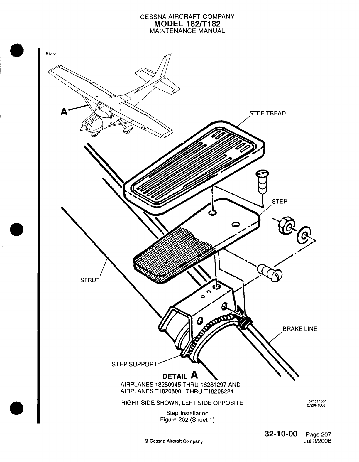
CESSNA
AIRCRAFT
COMPANY
MODEL
182/T182
MAINTENANCE MANUAL
AIRPLANES
18280945
THRU
18281297
AND
AIRPLANES
T18208001
THRU
T18208224
RIGHT
SIDE
SHOWN,
LEFT
SIDE
OPPOSITE
Step
Installation
Figure
202 (Sheet
1)
Cessna
Aircraft
Company
0710T1001
0720R1008
32-10-00
Page
207
Jul
3/2006
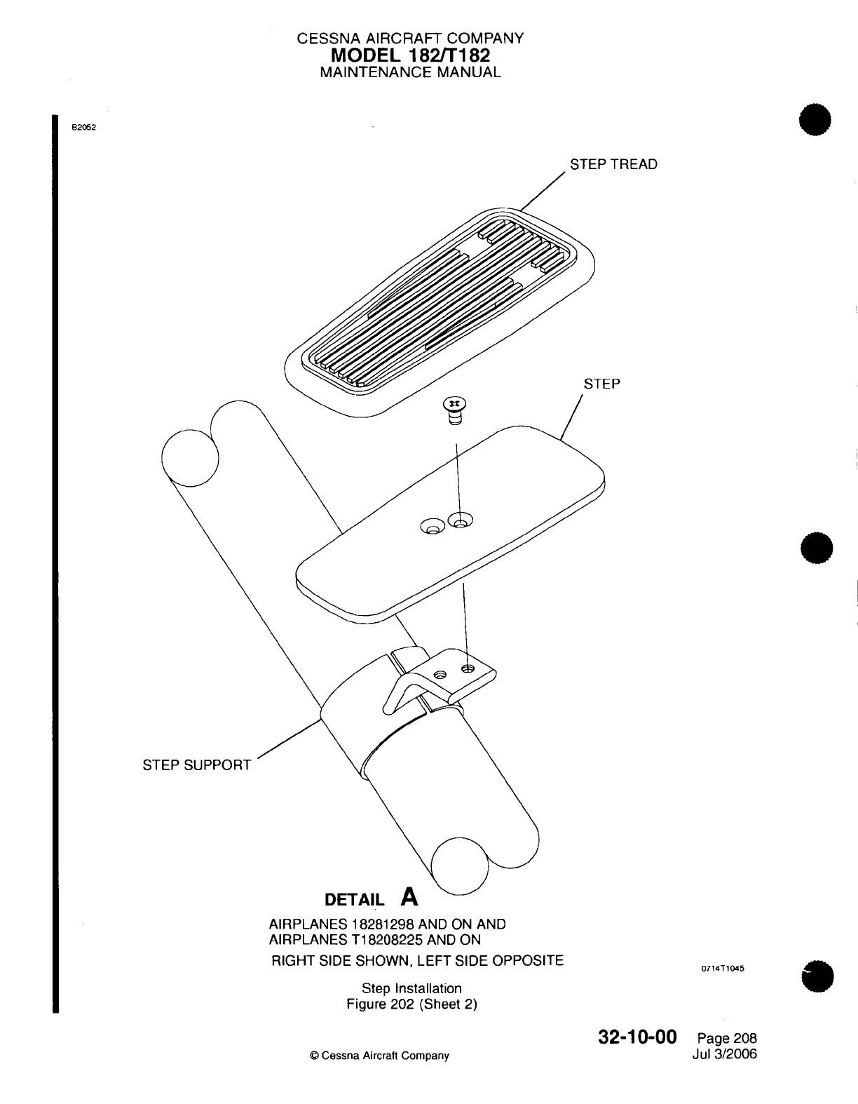
CESSNA AIRCRAFT
COMPANY
MODEL
182/T182
MAINTENANCE
MANUAL
B2052
STEP
TREAD
DETAIL
A
AIRPLANES
18281298
AND
ON
AND
AIRPLANES
T18208225
AND
ON
RIGHT
SIDE
SHOWN,
LEFT
SIDE
OPPOSITE
Step
Installation
Figure
202
(Sheet
2)
©
Cessna
Aircraft Company
32-10-00
Page
208
Jul 3/2006
0714T1045
EP
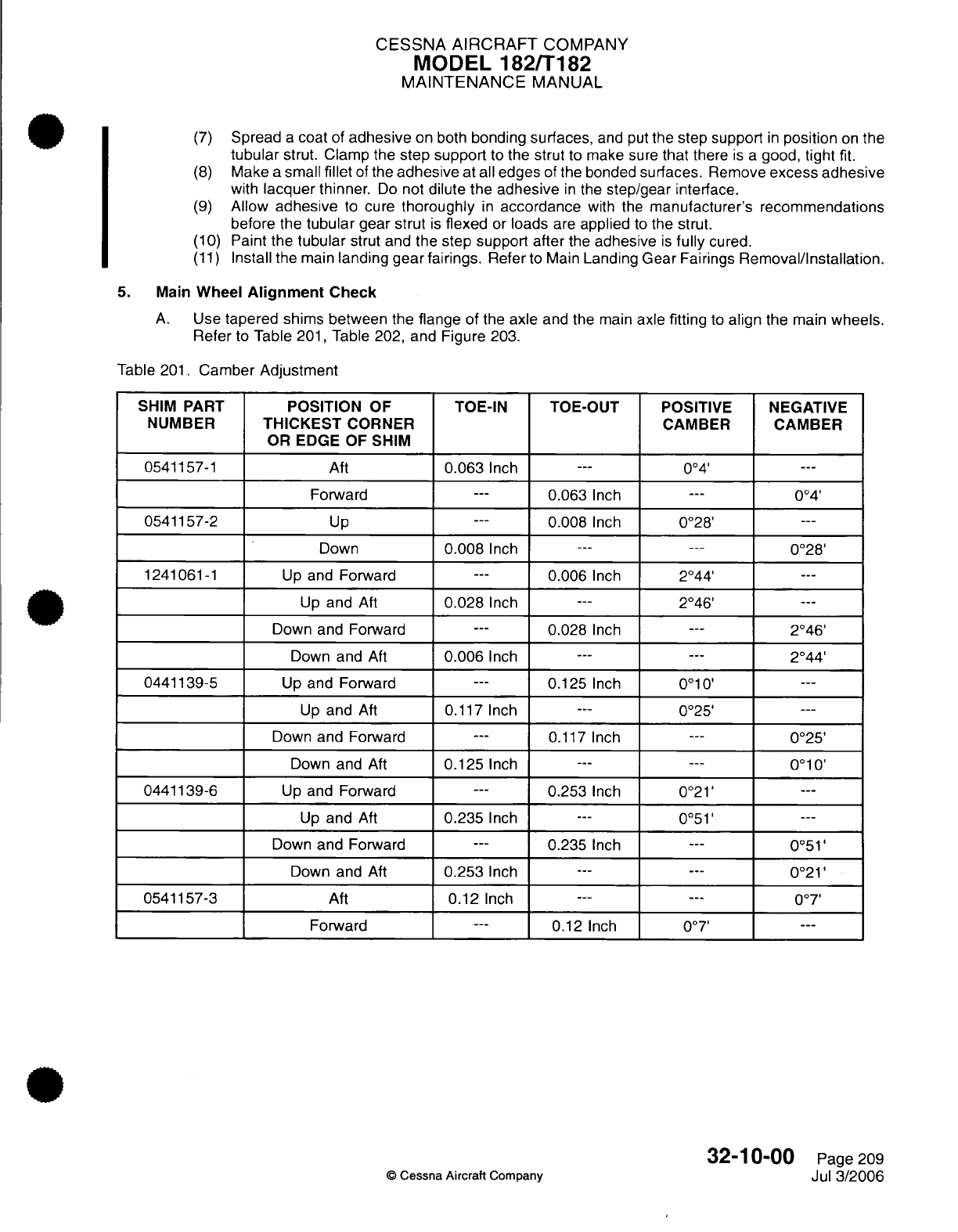
CESSNA AIRCRAFT
COMPANY
MODEL
182/T182
MAINTENANCE
MANUAL
(7)
Spread
a
coat
of
adhesive
on both
bonding
surfaces,
and put
the
step support
in
position
on
the
tubular
strut.
Clamp
the
step support
to
the
strut
to
make sure
that
there
is a
good,
tight
fit.
(8)
Make
a
small
fillet
of
the
adhesive
at
all
edges
of
the
bonded
surfaces.
Remove
excess
adhesive
with
lacquer
thinner.
Do
not
dilute the
adhesive
in
the
step/gear
interface.
(9)
Allow
adhesive
to
cure
thoroughly
in
accordance
with
the
manufacturer's recommendations
before
the
tubular
gear strut
is
flexed
or
loads
are
applied
to
the
strut.
(10)
Paint
the
tubular
strut and the
step
support
after
the
adhesive
is
fully
cured.
(11)
Install
the
main
landing gear
fairings.
Refer
to
Main
Landing Gear
Fairings
Removal/Installation.
5.
Main
Wheel
Alignment
Check
A.
Use
tapered shims between
the
flange
of the
axle
and
the
main
axle
fitting
to
align
the
main
wheels.
Refer
to
Table
201,
Table
202, and
Figure
203.
Table
201.
Camber Adjustment
POSITION
OF
THICKEST
CORNER
OR EDGE OF
SHIM
Aft
Forward
Up
Down
Up
and
Forward
Up
and
Aft
Down
and
Forward
Down
and
Aft
Up
and Forward
Up
and
Aft
Down
and
Forward
Down
and
Aft
Up
and
Forward
Up
and
Aft
Down
and
Forward
Down
and
Aft
Aft
Forward
TOE-IN
0.063
Inch
TOE-OUT
POSITIVE
NEGATIVE
CAMBER CAMBER
004'
0.063
Inch
---
0.008
Inch
0.008
Inch
---
---
0.006
Inch
0.028
Inch
---
---
0.028
Inch
0.006
Inch
---
0.125
Inch
0.117
Inch
-
0.117
Inch
0.125
Inch
---
---
0.253
Inch
0.235
Inch
---
---
0.235
Inch
0.253
Inch
---
0.12
Inch
---
0.12
Inch
0o4'
0°28'
0°28'
2°44'
2°46'
2°46'
2044'
0°10'
0°25'
0°25'
0010'
0°21'
0°51'
0°51'
0°21'
007'
007'
32-10-00
©
Cessna Aircraft
Company
SHIM
PART
NUMBER
0541157-1
0541157-2
1241061-1
0441139-5
0441139-6
0541157-3
Page
209
Jul
3/2006
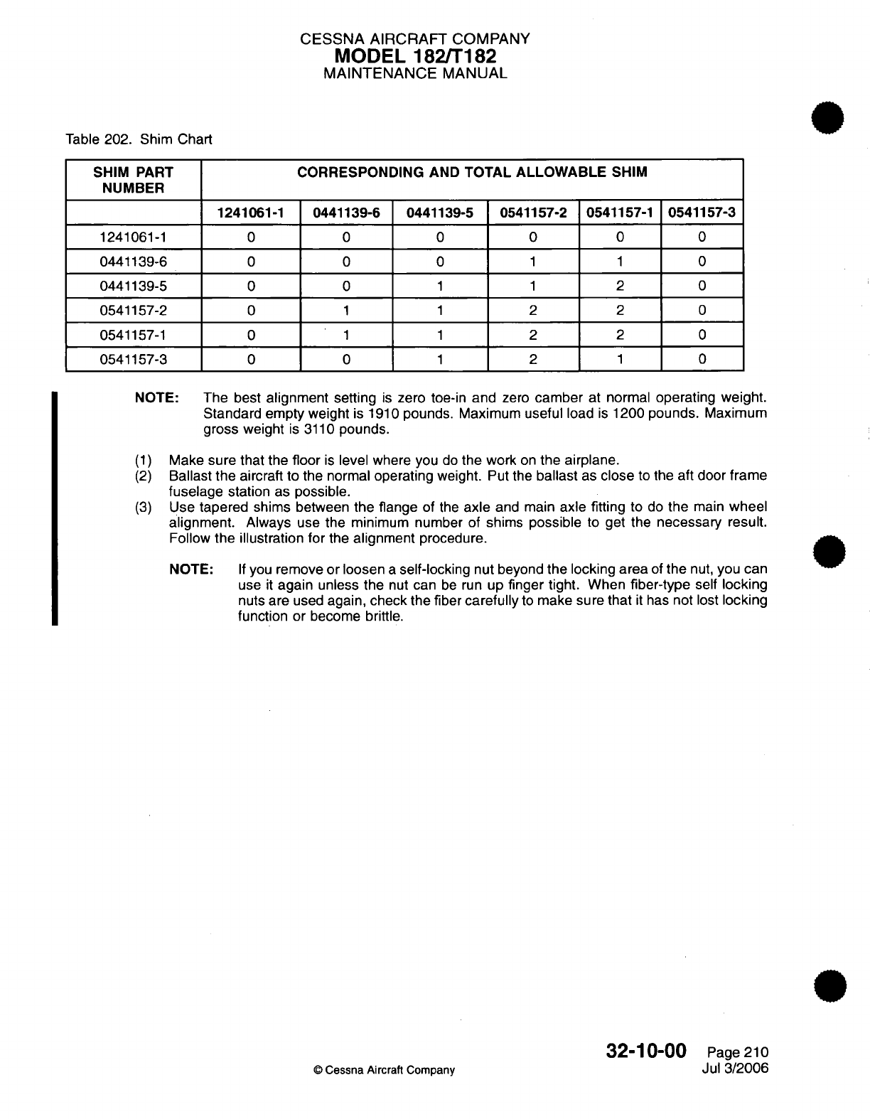
CESSNA AIRCRAFT
COMPANY
MODEL
182/T182
MAINTENANCE
MANUAL
Table
202.
Shim
Chart
SHIM
PART
NUMBER
CORRESPONDING
AND
TOTAL
ALLOWABLE
SHIM
1241061-1
0441139-6
0441139-5 0541157-2
0541157-1
0541157-3
1241061-1
0441139-6
0441139-5
0541157-2
0541157-1
0541157-3
0
0
0
0
0
0
0
0
0
1
1
0
0
0
1
1
1
1
0
1
1
2
2
2
0
1
2
2
2
1
0
0
0
0
0
0
NOTE:
The best
alignment
setting
is
zero
toe-in
and
zero
camber
at
normal
operating
weight.
Standard
empty weight
is
1910
pounds.
Maximum
useful
load
is
1200
pounds.
Maximum
gross
weight
is
3110
pounds.
(1)
Make
sure that
the
floor
is
level
where you
do
the
work
on
the
airplane.
(2)
Ballast
the
aircraft to
the
normal
operating
weight.
Put
the
ballast
as
close
to the
aft
door
frame
fuselage
station
as
possible.
(3)
Use
tapered
shims
between
the
flange of
the
axle
and main
axle
fitting
to
do
the
main
wheel
alignment.
Always
use
the
minimum number
of
shims
possible
to
get the
necessary
result.
Follow
the illustration
for
the
alignment
procedure.
NOTE:
If
you
remove
or loosen
a
self-locking
nut
beyond
the locking area
of
the
nut,
you
can
use
it
again
unless
the
nut
can
be
run
up
finger
tight.
When
fiber-type
self
locking
nuts are used
again,
check
the fiber
carefully
to
make
sure that
it
has
not
lost
locking
function
or
become brittle.
32-10-00
©
Cessna
Aircraft
Company
Page
210
Jul
3/2006
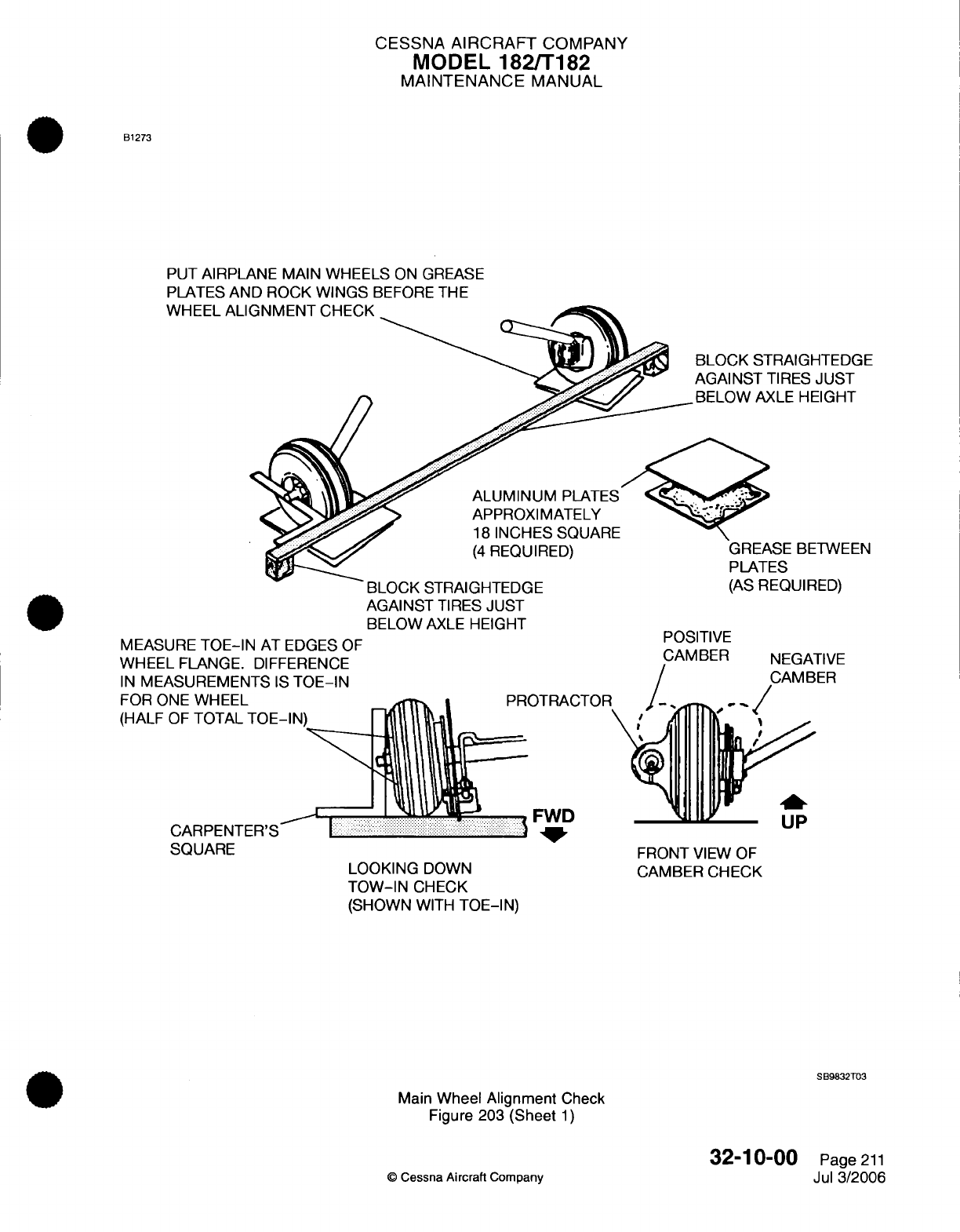
CESSNA
AIRCRAFT
COMPANY
MODEL
182/T182
MAINTENANCE
MANUAL
B1273
PUT
AIRPLANE
MAIN
WHEELS
ON
GREASE
PLATES
AND ROCK
WINGS
BEFORE
THE
WHEEL
ALI
BLOCK STRAIGHTEDGE
AGAINST
TIRES
JUST
BELOW
AXLE
HEIGHT
ALUMINUM
PLATES
APPROXIMATELY
18
INCHES SQUARE
(4 REQUIRED)
MEASURE
TOE-IN
AT
EDGES
OF
WHEEL
FLANGE.
DIFFERENCE
IN
MEASUREMENTS
IS
TOE-IN
FOR
ONE
WHEEL
(HALF
OF
TOTAL
TOE-IN
CARPENTER'S
BLOCK
STRAIGHTEDGE
AGAINST
TIRES
JUST
BELOW
AXLE
HEIGHT
PROTRACTOR
FWD
LOOKING
DOWN
TOW-IN
CHECK
(SHOWN
WITH
TOE-IN)
SQUARE
GREASE
BETWEEN
PLATES
(AS
REQUIRED)
POSITIVE
CAMBER
NEGATIVE
CAMBER
UP
FRONT
VIEW
OF
CAMBER
CHECK
SB9832T03
Main
Wheel Alignment
Check
Figure
203
(Sheet
1)
©
Cessna
Aircraft
Company
32-10-00
Page
211
Jul
3/2006
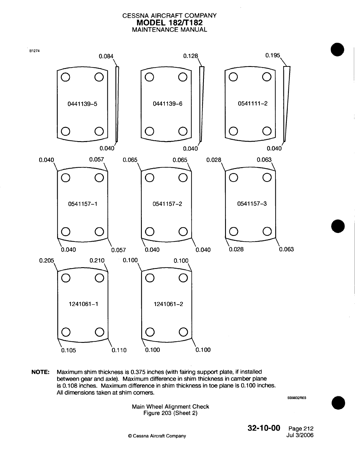
CESSNA
AIRCRAFT
COMPANY
MODEL
182/T182
MAINTENANCE
MANUAL
0441139-6
0.065
0
.040
0.040
0.065
0.028
0541157-3
0541157-2
0.057
0.040
0.100
0 00
0.040
0.100
1241061-2
0.110
0
0.100
0
.1
0.100
NOTE:
Maximum shim
thickness
is
0.375
inches
(with
fairing
support
plate,
if
installed
between
gear and
axle).
Maximum
difference
in
shim
thickness
in
camber
plane
is
0.108
inches.
Maximum
difference
in
shim
thickness
in
toe
plane
is
0.100
inches.
All
dimensions
taken at
shim
corners.
SB9832R03
Main
Wheel
Alignment Check
Figure
203
(Sheet
2)
32-10-00
©
Cessna Aircraft Company
Page
212
Jul 3/2006
B1274
0.084
0441139-5
0.040
05411
0.040
0.195
11-2
0.040
0.063
0.057
0541157-1
0.040
0.205
0.210
0.028
0.063
1241061-1
0.105
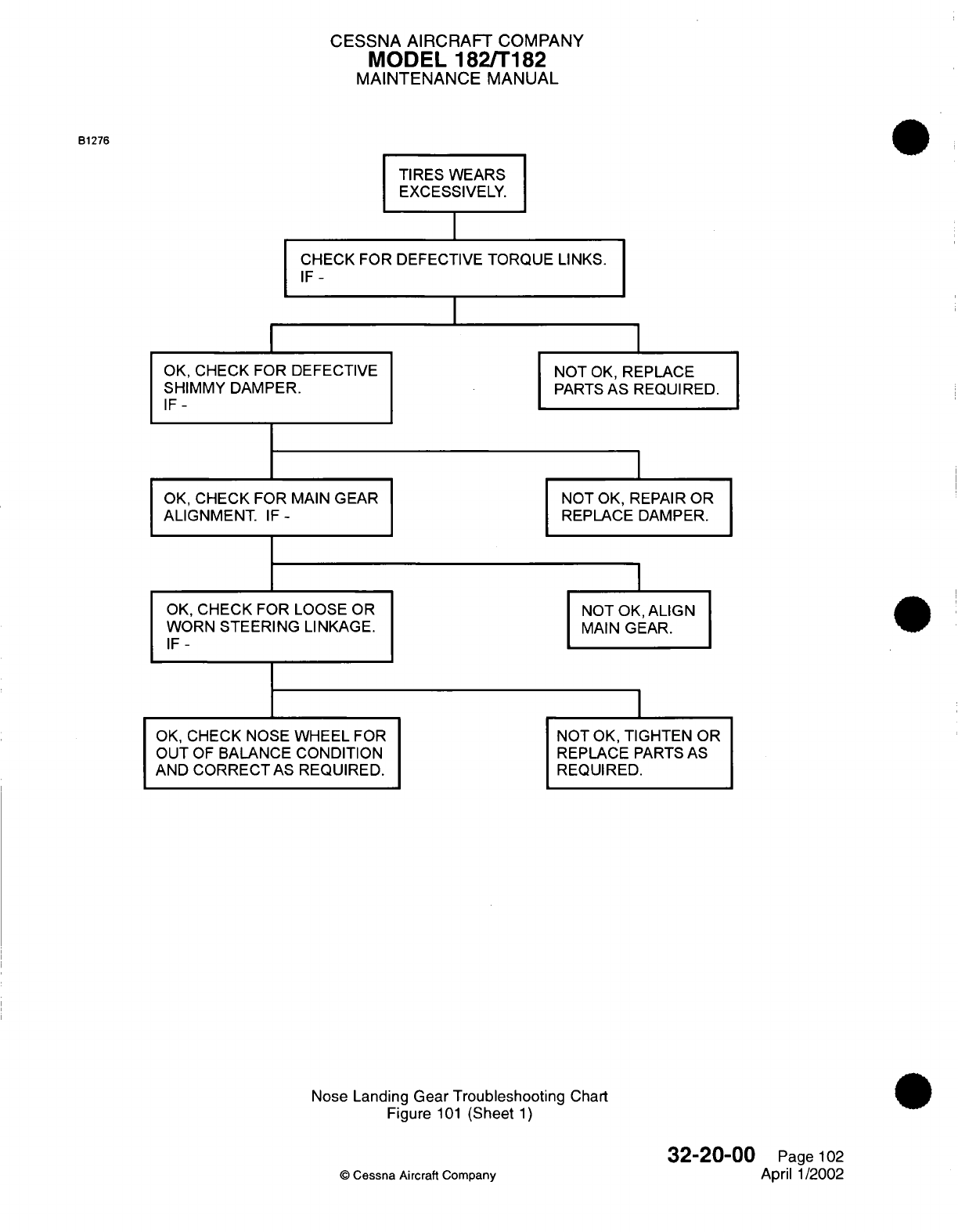
CESSNA AIRCRAFT
COMPANY
MODEL
182/T182
MAINTENANCE
MANUAL
B1276
TIRES
WEARS
EXCESSIVELY.
CHECK FOR DEFECTIVE
TORQUE
LINKS.
IF-
OK,
CHECK FOR DEFECTIVE
SHIMMY DAMPER.
IF-
OK,
CHECK
FOR
MAIN
GEAR
ALIGNMENT.
IF-
OK,
CHECK
FOR
LOOSE
OR
WORN
STEERING
LINKAGE.
IF-
OK,
CHECK
NOSE
WHEEL
FOR
OUT
OF
BALANCE
CONDITION
AND
CORRECT
AS
REQUIRED.
NOT
OK,
REPLACE
PARTS
AS REQUIRED.
NOT
OK,
REPAIR
OR
REPLACE DAMPER.
NOT
OK, ALIGN
MAIN
GEAR.
NOT
OK,
TIGHTEN
OR
REPLACE
PARTS
AS
REQUIRED.
Nose
Landing Gear
Troubleshooting
Chart
Figure
101
(Sheet
1)
©
Cessna
Aircraft Company
32-20-00
Page
102
April
1/2002
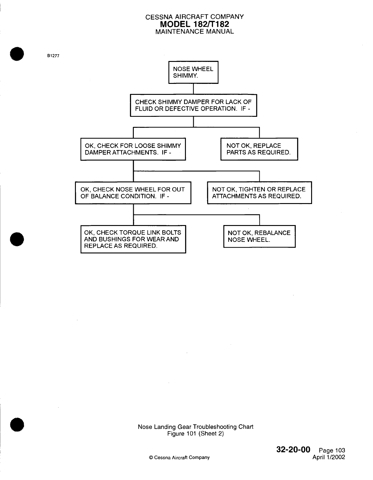
CESSNA AIRCRAFT
COMPANY
MODEL
182/T182
MAINTENANCE
MANUAL
NOSE WHEEL
SHIMMY.
CHECK
SHIMMY
DAMPER
FOR
LACK
OF
FLUID OR
DEFECTIVE
OPERATION.
IF
-
I
I
OK,
CHECK
FOR
LOOSE
SHIMMY
DAMPER ATTACHMENTS.
IF
-
OK,
CHECK
NOSE
WHEEL
FOR OUT
OF
BALANCE
CONDITION.
IF
-
OK,
CHECK
TORQUE
LINK BOLTS
AND
BUSHINGS
FOR
WEAR
AND
REPLACE
AS
REQUIRED.
NOT
OK,
REPLACE
PARTS
AS REQUIRED.
NOT
OK,
TIGHTEN
OR
REPLACE
ATTACHMENTS AS REQUIRED.
NOT
OK,
REBALANCE
NOSE
WHEEL.
Nose Landing
Gear Troubleshooting
Chart
Figure
101
(Sheet
2)
©
Cessna Aircraft
Company
32-20-00
Page
103
April
1/2002
B1277
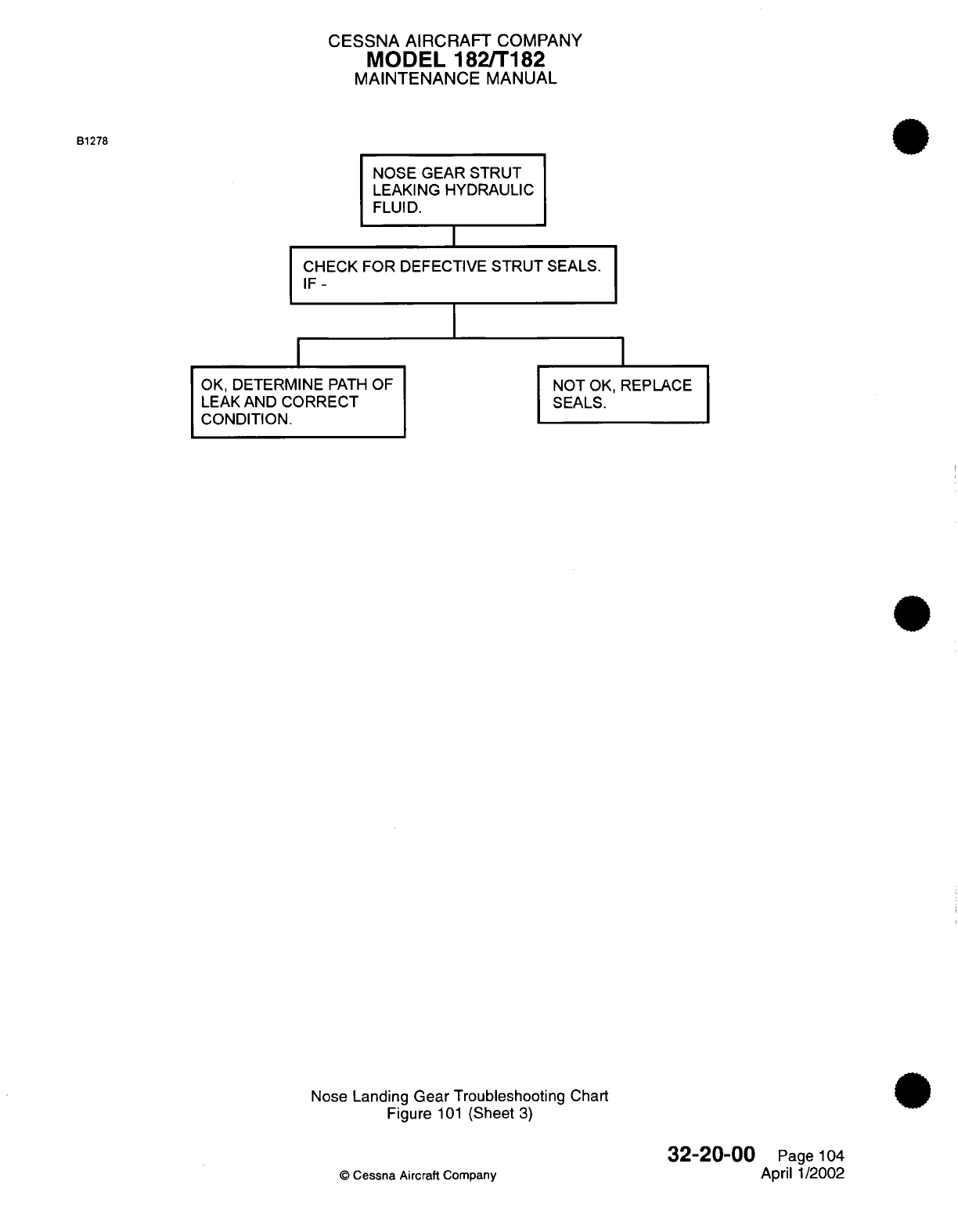
CESSNA AIRCRAFT
COMPANY
MODEL
182/T182
MAINTENANCE
MANUAL
B1278
NOSE GEAR
STRUT
LEAKING HYDRAULIC
FLUID.
CHECK FOR
DEFECTIVE
STRUT
SEALS.
IF-
OK,
DETERMINE
PATH
OF
LEAK
AND
CORRECT
CONDITION.
NOT
OK,
REPLACE
SEALS.
Nose
Landing
Gear
Troubleshooting Chart
Figure
101
(Sheet
3)
©
Cessna
Aircraft
Company
32-20-00
Page
104
April
1/2002
I
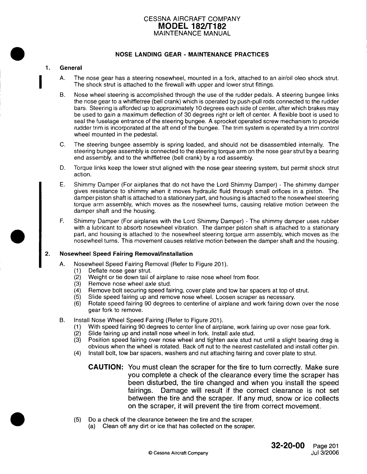
CESSNA
AIRCRAFT
COMPANY
MODEL
182/T182
MAINTENANCE
MANUAL
NOSE
LANDING GEAR
-
MAINTENANCE
PRACTICES
1.
General
A.
The
nose
gear
has
a
steering nosewheel,
mounted
in a
fork, attached
to
an
air/oil oleo
shock strut.
The
shock
strut
is
attached
to
the
firewall
with
upper
and
lower strut
fittings.
B.
Nose wheel
steering
is
accomplished
through
the
use
of
the
rudder
pedals.
A
steering
bungee
links
the
nose
gear
to
a
whiffletree
(bell
crank)
which
is
operated
by
push-pull
rods
connected
to
the
rudder
bars.
Steering
is
afforded
up
to
approximately
10
degrees
each
side
of
center,
after which brakes
may
be
used
to
gain
a
maximum
deflection
of
30
degrees
right
or left
of
center.
A
flexible
boot
is
used
to
seal the
fuselage
entrance
of
the
steering
bungee.
A
sprocket
operated
screw
mechanism
to
provide
rudder
trim
is
incorporated
at
the aft end
of
the
bungee.
The
trim
system
is
operated
by
a
trim
control
wheel mounted
in
the
pedestal.
C.
The
steering
bungee
assembly
is
spring
loaded,
and
should
not
be
disassembled
internally.
The
steering bungee
assembly
is
connected
to
the
steering
torque
arm
on
the
nose
gear
strut
by
a
bearing
end
assembly,
and
to
the whiffletree
(bell
crank)
by
a
rod
assembly.
D.
Torque
links keep
the
lower strut
aligned
with
the
nose
gear
steering
system,
but
permit
shock
strut
action.
E.
Shimmy Damper
(For
airplanes
that
do
not
have
the
Lord
Shimmy
Damper)
-
The
shimmy
damper
gives resistance
to
shimmy
when
it
moves
hydraulic
fluid through
small
orifices
in
a
piston. The
damper
piston shaft
is
attached
to
a
stationary
part,
and
housing
is
attached
to
the
nosewheel steering
torque
arm
assembly,
which moves
as
the
nosewheel
turns,
causing
relative
motion between
the
damper shaft
and the
housing.
F.
Shimmy
Damper
(For
airplanes
with
the
Lord
Shimmy
Damper)
-
The shimmy damper
uses
rubber
with
a
lubricant
to
absorb nosewheel vibration.
The
damper
piston
shaft
is
attached
to
a
stationary
part,
and
housing
is
attached
to
the nosewheel
steering torque
arm
assembly, which
moves
as
the
nosewheel
turns. This movement
causes
relative
motion
between
the
damper
shaft
and the
housing.
2.
Nosewheel Speed
Fairing
Removal/Installation
A.
Nosewheel
Speed
Fairing
Removal (Refer
to
Figure
201).
(1)
Deflate nose
gear
strut.
(2)
Weight
or
tie
down tail
of
airplane
to
raise
nose
wheel
from
floor.
(3)
Remove
nose
wheel axle stud.
(4)
Remove
bolt
securing
speed
fairing, cover
plate
and
tow
bar
spacers
at
top
of
strut.
(5)
Slide speed fairing
up
and
remove
nose
wheel. Loosen
scraper
as
necessary.
(6)
Rotate
speed
fairing
90
degrees to
centerline
of
airplane
and
work fairing
down
over
the
nose
gear
fork
to
remove.
B.
Install
Nose
Wheel
Speed Fairing
(Refer
to
Figure
201).
(1)
With
speed
fairing
90
degrees
to
center
line
of
airplane, work
fairing
up
over
nose
gear
fork.
(2)
Slide
fairing
up
and
install
nose
wheel
in
fork.
Install
axle
stud.
(3)
Position
speed
fairing
over
nose
wheel
and
tighten
axle
stud
nut until
a
slight
bearing drag
is
obvious
when
the
wheel
is
rotated.
Back
off nut
to
the
nearest
castellated
and
install
cotter
pin.
(4)
Install
bolt,
tow
bar
spacers,
washers
and
nut
attaching
fairing
and
cover
plate
to strut.
CAUTION:
You
must
clean
the
scraper
for
the tire
to
turn
correctly.
Make
sure
you
complete
a
check
of
the
clearance
every
time the
scraper
has
been
disturbed,
the
tire
changed
and
when
you
install
the
speed
fairings.
Damage will result
if
the
correct
clearance
is
not
set
between the tire
and
the
scraper.
If
any
mud,
snow
or
ice
collects
on
the
scraper,
it
will
prevent
the
tire
from
correct
movement.
(5)
Do
a
check
of
the clearance
between
the
tire
and
the scraper.
(a)
Clean
off
any dirt
or
ice
that
has
collected
on
the
scraper.
32-20-00
Page
201
©
Cessna Aircraft
Company
Jul
3/2006
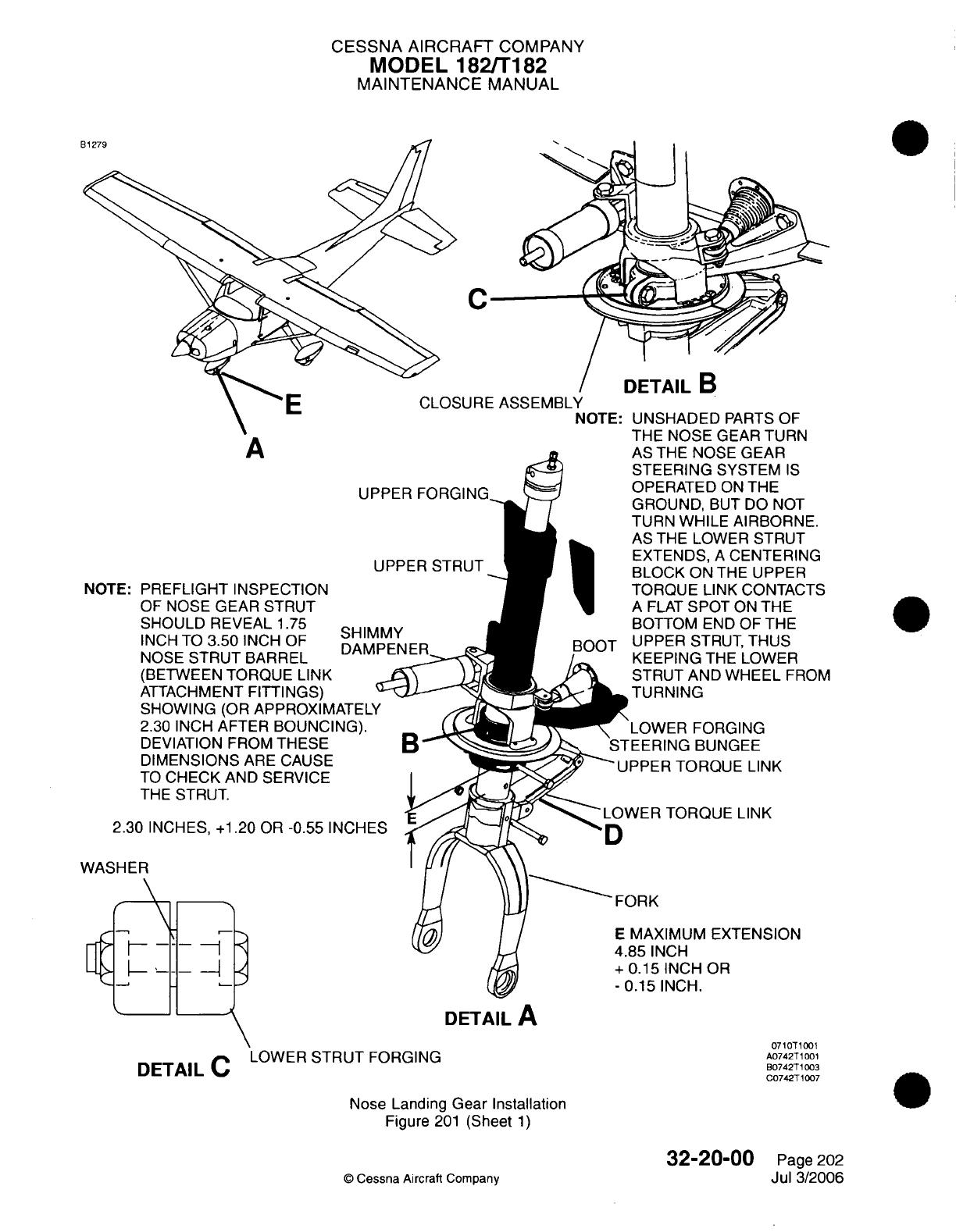
CESSNA AIRCRAFT
COMPANY
MODEL
182/T182
MAINTENANCE
MANUAL
C
SURE
ASSEMBLY
NO1
A
UPPER
FORGING
NOTE:
PREFLIGHT
INSPECTION
OF
NOSE GEAR
STRUT
SHOULD
REVEAL
1.75
INCH
TO
3.50
INCH
OF
SHIMMY
NOSE
STRUT
BARREL
(BETWEEN
TORQUE
LINK
ATTACHMENT
FITTINGS)
SHOWING (OR
APPROXIMATEL
2.30
INCH
AFTER
BOUNCING).
DEVIATION FROM
THESE
DIMENSIONS
ARE CAUSE
TO
CHECK
AND SERVICE
THE
STRUT.
2.30
INCHES, +1.20
OR
-0.55
INCHES
WASHER
-
TE:
UNSHADED
PARTS
OF
THE
NOSE
GEAR
TURN
AS
THE
NOSE
GEAR
STEERING
SYSTEM
IS
OPERATED
ON
THE
GROUND,
BUT
DO NOT
TURN
WHILE
AIRBORNE.
AS
THE
LOWER STRUT
EXTENDS,
A
CENTERING
BLOCK
ON
THE UPPER
TORQUE
LINK
CONTACTS
A
FLAT
SPOT
ON
THE
BOTTOM
END
OF THE
UPPER STRUT, THUS
KEEPING
THE LOWER
STRUT AND
WHEEL
FROM
TURNING
-OWER
FORGING
EERING
BUNGEE
PPER
TORQUE
LINK
WER
TORQUE
LINK
)RK
MAXIMUM
EXTENSION
85
INCH
0.15
INCH
OR
1.15
INCH.
DETAIL
C
LOWER
STRUT
FORGING
DETAILC
Nose Landing
Gear Installation
Figure
201
(Sheet
1)
32-20-00
©
Cessna
Aircraft
Company
DETAIL
A
7100T1001
A0742T1001
B0742T1003
C0742T1007
Page
202
Jul
3/2006
U
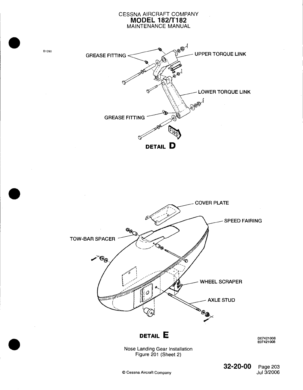
CESSNA AIRCRAFT
COMPANY
MODEL
182/T182
MAINTENANCE MANUAL
B1280
GREASE
FITTIN
GREASE
PER
TORQUE
LINK
OWER
TORQUE
LINK
DETAIL
D
TOW-BAR
S
SPEED
FAIRING
DRAPER
STUD
DETAIL
E
Nose
Landing
Gear Installation
Figure
201
(Sheet
2)
©
Cessna Aircraft
Company
D07421006
E07421008
32-20-00
Page 203
Jul
3/2006
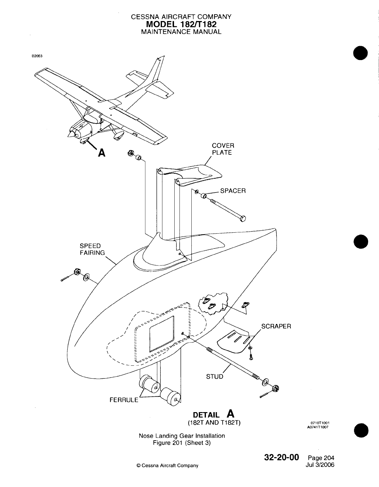
CESSNA AIRCRAFT
COMPANY
MODEL
182/T182
MAINTENANCE
MANUAL
COVER
PLATE
SPACER
PER
DETAIL
A
(182T
AND T182T)
Nose
Landing
Gear
Installation
Figure
201
(Sheet
3)
32-20-00
©
Cessna
Aircraft
Company
A
0710T1001
A0741T1007
Page
204
Jul
3/2006
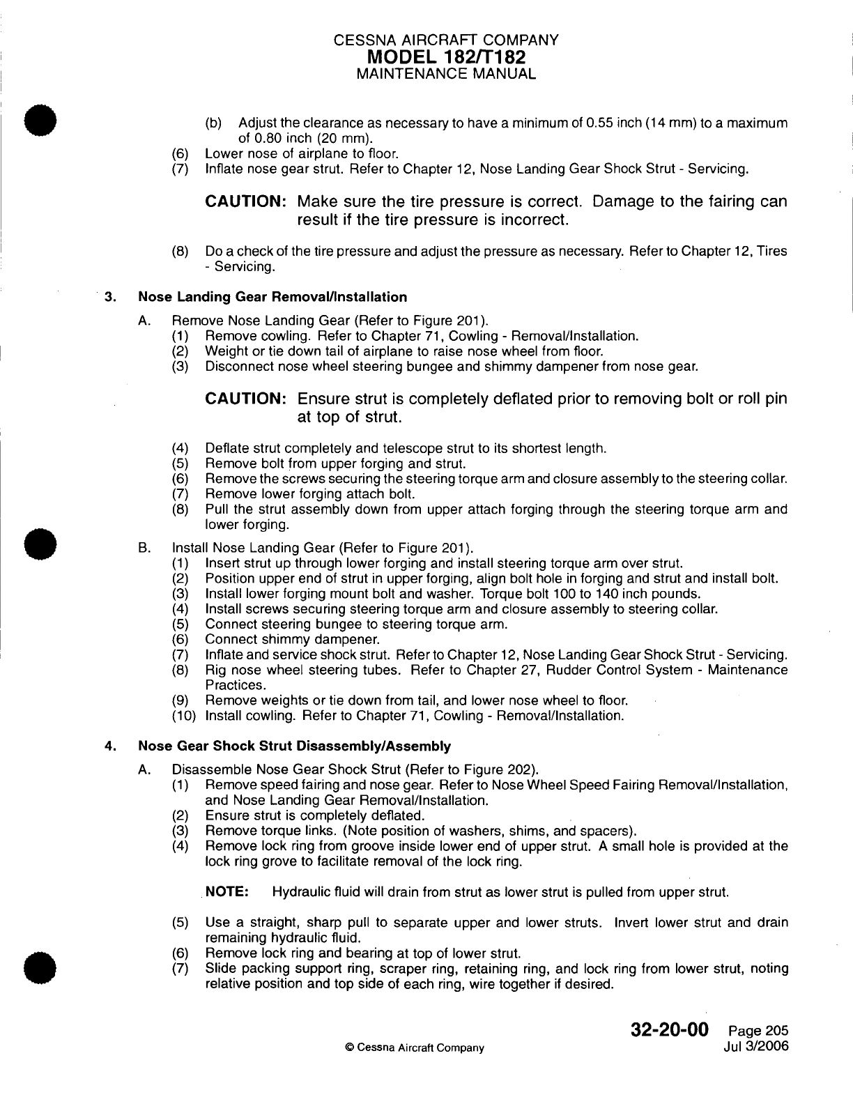
CESSNA AIRCRAFT
COMPANY
MODEL
182/T182
MAINTENANCE
MANUAL
(b)
Adjust
the clearance
as
necessary
to
have
a
minimum
of
0.55
inch
(14
mm)
to
a
maximum
of
0.80
inch
(20 mm).
(6)
Lower
nose
of
airplane
to
floor.
(7)
Inflate
nose
gear
strut. Refer
to
Chapter
12,
Nose
Landing
Gear
Shock Strut
-
Servicing.
CAUTION:
Make
sure
the tire
pressure
is
correct.
Damage
to
the
fairing
can
result
if
the tire
pressure
is
incorrect.
(8)
Do
a
check
of
the
tire
pressure
and
adjust
the
pressure
as
necessary.
Refer
to
Chapter
12,
Tires
-
Servicing.
3.
Nose
Landing
Gear
Removal/Installation
A.
Remove
Nose
Landing Gear
(Refer
to
Figure
201).
(1)
Remove
cowling.
Refer
to
Chapter
71,
Cowling
-
Removal/Installation.
(2)
Weight
or
tie down
tail
of
airplane
to
raise
nose wheel
from
floor.
(3)
Disconnect
nose wheel
steering
bungee
and
shimmy dampener
from
nose
gear.
CAUTION:
Ensure
strut
is
completely
deflated
prior
to
removing
bolt or
roll
pin
at
top
of strut.
(4)
Deflate
strut
completely
and
telescope
strut
to
its
shortest
length.
(5)
Remove bolt
from upper forging and
strut.
(6)
Remove
the
screws securing
the
steering
torque
arm
and
closure
assembly
to the
steering collar.
(7)
Remove
lower forging attach
bolt.
(8)
Pull
the
strut
assembly
down
from
upper
attach forging through
the
steering
torque
arm
and
lower forging.
B.
Install
Nose
Landing Gear
(Refer
to
Figure
201).
(1)
Insert strut
up
through lower forging
and
install steering
torque
arm
over
strut.
(2)
Position upper
end
of
strut
in
upper
forging, align
bolt
hole
in
forging
and
strut
and
install
bolt.
(3)
Install lower
forging
mount bolt
and
washer.
Torque
bolt
100
to
140
inch
pounds.
(4)
Install
screws securing steering torque
arm
and
closure
assembly
to
steering collar.
(5)
Connect steering
bungee
to
steering
torque
arm.
(6)
Connect
shimmy
dampener.
(7)
Inflate
and
service
shock
strut.
Refer
to
Chapter
12,
Nose
Landing Gear
Shock
Strut
-
Servicing.
(8)
Rig
nose
wheel steering
tubes.
Refer
to
Chapter
27,
Rudder
Control
System
-
Maintenance
Practices.
(9)
Remove
weights
or
tie
down
from
tail,
and
lower
nose wheel to floor.
(10)
Install
cowling. Refer
to
Chapter
71,
Cowling
-
Removal/Installation.
4.
Nose
Gear
Shock
Strut
Disassembly/Assembly
A.
Disassemble
Nose
Gear
Shock
Strut
(Refer
to
Figure
202).
(1)
Remove speed
fairing
and
nose gear.
Refer
to Nose
Wheel Speed
Fairing
Removal/Installation,
and Nose
Landing Gear
Removal/Installation.
(2)
Ensure
strut
is
completely
deflated.
(3)
Remove
torque
links.
(Note
position
of
washers,
shims,
and
spacers).
(4)
Remove
lock
ring
from
groove inside
lower
end
of
upper strut.
A
small
hole
is
provided
at
the
lock
ring
grove
to
facilitate
removal
of
the
lock
ring.
NOTE:
Hydraulic
fluid
will drain
from
strut
as
lower
strut
is
pulled
from
upper
strut.
(5)
Use
a
straight,
sharp
pull
to
separate
upper
and
lower
struts.
Invert
lower
strut
and
drain
remaining
hydraulic
fluid.
(6)
Remove
lock
ring
and
bearing
at
top
of
lower strut.
(7)
Slide
packing support
ring,
scraper
ring,
retaining
ring,
and
lock
ring
from lower
strut, noting
relative
position
and
top
side
of
each
ring,
wire
together
if
desired.
32-20-00
Page 205
©
Cessna Aircraft
Company
Jul
3/2006
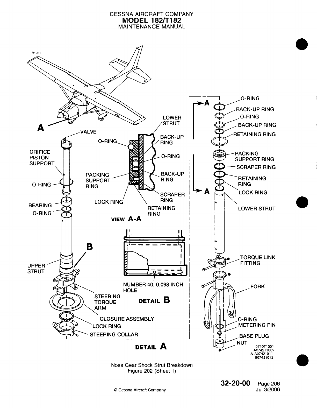
CESSNA
AIRCRAFT
COMPANY
MODEL
182/T182
MAINTENANCE
MANUAL
O-RING
BACK-UP
RING
LOWER
O-RING
VALVE
O-RI
PACKING
SUPPORT
RING
LOCK
VIEW
A-A
BACK-UP
RING
RETAINING
RING
PACKING
-
SUPPORT
RING
SCRAPER
RING
A
RETAINING
RING
I
LOCK
RING
I
RETAI
RING
NING
LOWER
STRUT
I
I
B
LINK
UPPER
STRUT
DETAIL
B
CO
L
L
A
R
_
DETAIL
A
Nose
Gear
Shock
Strut
Breakdown
Figure
202
(Sheet
1)
©
Cessna
Aircraft Company
32-20-00
Page
206
Jul
3/2006
ORIFICE
PISTON
SUPPORT
\
O-RING
BEARING
O-RING
PIN
G
001
T1009
A-A07421011
B07421012
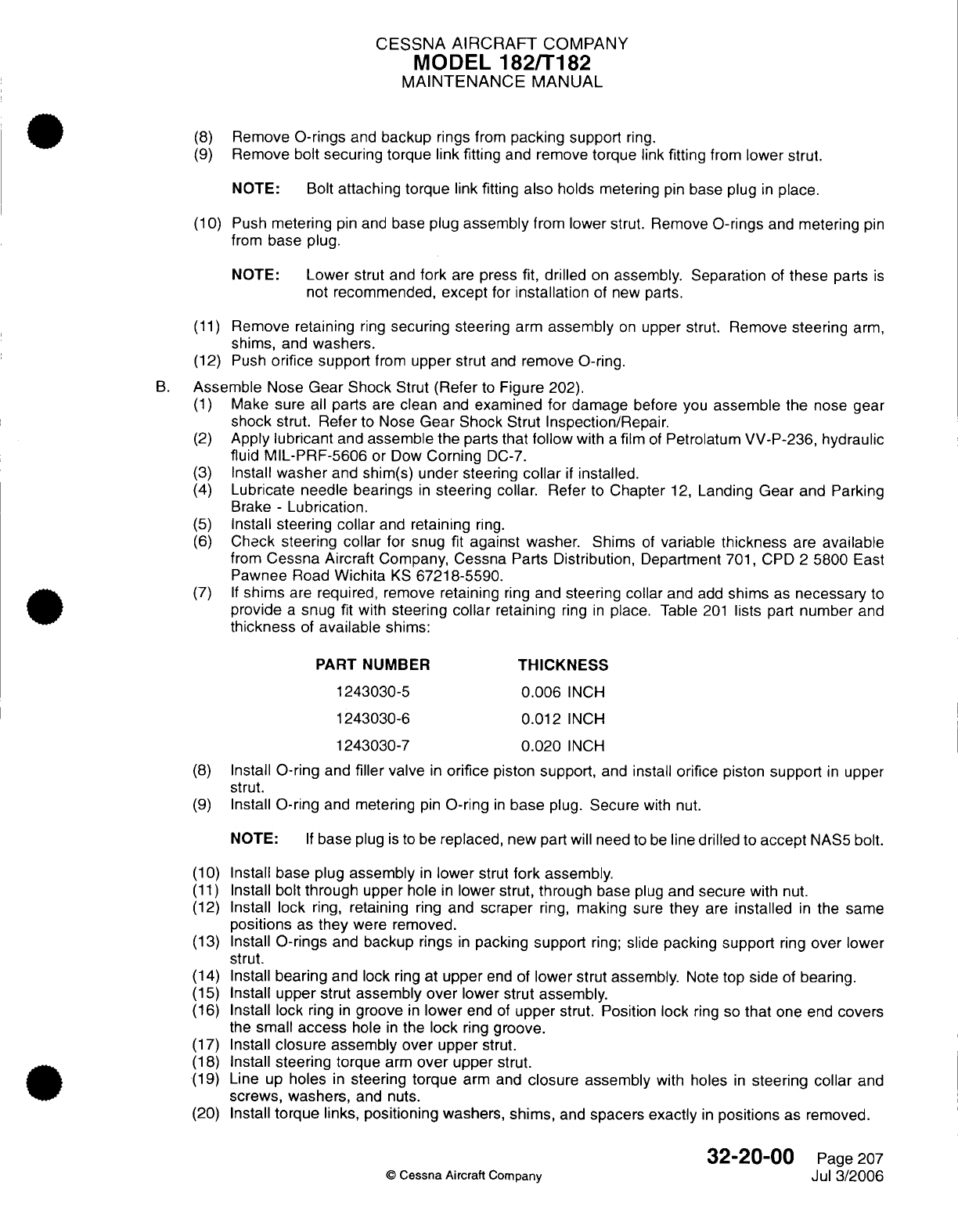
CESSNA
AIRCRAFT
COMPANY
MODEL
182/T182
MAINTENANCE
MANUAL
(8)
Remove
O-rings
and
backup
rings
from
packing
support
ring.
(9)
Remove
bolt
securing
torque link fitting
and
remove torque
link
fitting
from
lower
strut.
NOTE: Bolt
attaching torque
link
fitting
also
holds
metering
pin
base plug
in
place.
(10)
Push
metering
pin
and
base
plug
assembly
from
lower strut.
Remove
O-rings
and
metering
pin
from
base
plug.
NOTE:
Lower
strut and
fork
are
press
fit,
drilled
on
assembly. Separation
of
these
parts
is
not
recommended,
except
for
installation
of
new
parts.
(11)
Remove
retaining
ring
securing
steering
arm
assembly
on
upper
strut. Remove
steering
arm,
shims,
and
washers.
(12)
Push
orifice support
from
upper
strut
and
remove
O-ring.
B.
Assemble
Nose
Gear
Shock
Strut
(Refer
to
Figure
202).
(1)
Make
sure
all
parts
are
clean
and
examined
for
damage
before you
assemble
the
nose
gear
shock
strut.
Refer
to
Nose
Gear Shock
Strut Inspection/Repair.
(2)
Apply
lubricant
and
assemble
the
parts
that
follow
with
a
film
of
Petrolatum
VV-P-236, hydraulic
fluid
MIL-PRF-5606
or Dow
Corning
DC-7.
(3)
Install
washer
and
shim(s)
under steering
collar
if
installed.
(4)
Lubricate needle bearings
in
steering
collar.
Refer
to
Chapter
12,
Landing
Gear
and
Parking
Brake
-
Lubrication.
(5)
Install
steering
collar
and
retaining
ring.
(6)
Check
steering
collar
for snug
fit
against
washer.
Shims
of
variable
thickness
are
available
from
Cessna
Aircraft Company,
Cessna Parts
Distribution,
Department
701,
CPD
2
5800
East
Pawnee
Road
Wichita
KS
67218-5590.
(7) If
shims
are
required, remove
retaining
ring
and
steering collar
and
add
shims
as
necessary
to
provide
a
snug
fit with
steering
collar
retaining
ring
in
place.
Table
201
lists
part
number
and
thickness
of
available
shims:
PART
NUMBER
THICKNESS
1243030-5
0.006
INCH
1243030-6
0.012
INCH
1243030-7
0.020
INCH
(8)
Install
O-ring
and
filler
valve
in
orifice
piston
support,
and
install
orifice piston
support
in
upper
strut.
(9)
Install
O-ring
and
metering
pin
O-ring
in
base
plug.
Secure
with nut.
NOTE:
If
base
plug
is
to
be
replaced,
new
part
will
need
to
be
line
drilled
to
accept
NAS5
bolt.
(10)
Install
base
plug
assembly
in
lower
strut
fork
assembly.
(11)
Install
bolt
through
upper
hole
in
lower
strut,
through
base
plug
and
secure
with
nut.
(12)
Install lock
ring,
retaining
ring
and
scraper
ring,
making
sure
they
are
installed
in
the
same
positions
as
they
were removed.
(13)
Install
O-rings
and
backup
rings
in
packing
support
ring;
slide
packing
support
ring
over
lower
strut.
(14)
Install
bearing
and
lock
ring
at
upper
end of
lower
strut
assembly.
Note
top
side
of
bearing.
(15)
Install upper
strut
assembly over
lower strut
assembly.
(16)
Install
lock
ring
in
groove
in
lower
end of
upper
strut.
Position lock
ring
so
that
one
end
covers
the
small
access
hole
in
the
lock
ring
groove.
(17)
Install
closure
assembly over
upper
strut.
(18)
Install
steering
torque
arm
over
upper
strut.
(19)
Line
up
holes
in
steering torque
arm and
closure assembly
with
holes
in
steering
collar
and
screws,
washers,
and nuts.
(20)
Install
torque
links,
positioning
washers,
shims,
and
spacers
exactly
in
positions
as
removed.
32-20-00
Page 207
©
Cessna
Aircraft Company
Jul
3/2006
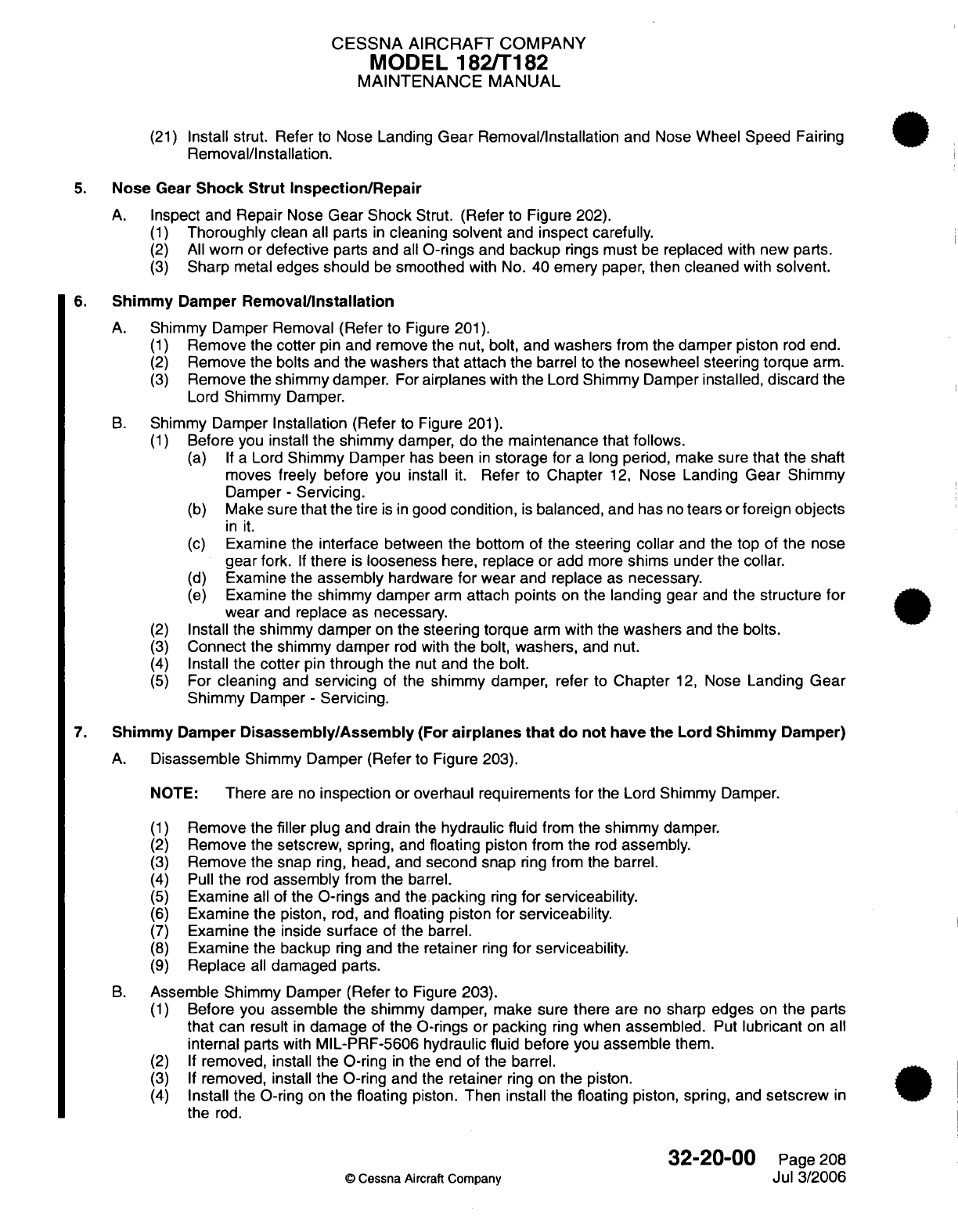
CESSNA
AIRCRAFT
COMPANY
MODEL
182/T182
MAINTENANCE
MANUAL
(21)
Install
strut.
Refer
to
Nose
Landing
Gear
Removal/Installation
and
Nose
Wheel Speed Fairing
Removal/Installation.
5.
Nose
Gear
Shock Strut
Inspection/Repair
A.
Inspect and
Repair
Nose
Gear
Shock
Strut.
(Refer
to
Figure
202).
(1)
Thoroughly
clean all parts
in
cleaning solvent and inspect carefully.
(2)
All
worn or
defective
parts
and
all
0-rings
and
backup
rings must
be
replaced
with
new parts.
(3)
Sharp
metal
edges
should
be
smoothed
with
No.
40
emery
paper,
then
cleaned
with
solvent.
6.
Shimmy
Damper
Removal/Installation
A.
Shimmy Damper
Removal
(Refer
to
Figure
201).
(1)
Remove
the
cotter
pin
and
remove
the
nut,
bolt,
and
washers
from
the
damper
piston
rod
end.
(2)
Remove
the
bolts
and the
washers
that
attach the
barrel
to
the
nosewheel steering
torque
arm.
(3)
Remove
the
shimmy
damper.
For
airplanes
with
the
Lord
Shimmy
Damper
installed,
discard
the
Lord
Shimmy
Damper.
B.
Shimmy
Damper
Installation
(Refer
to
Figure
201).
(1)
Before you
install
the
shimmy
damper,
do
the
maintenance
that
follows.
(a) If a
Lord
Shimmy
Damper
has
been
in
storage
for
a
long
period,
make sure
that the
shaft
moves
freely before
you install
it.
Refer
to Chapter
12,
Nose
Landing
Gear
Shimmy
Damper
-
Servicing.
(b)
Make
sure
that the tire
is
in
good
condition,
is
balanced,
and
has
no
tears
or
foreign objects
in it.
(c)
Examine
the interface
between
the
bottom
of
the
steering
collar
and
the
top
of
the
nose
gear
fork.
If
there
is
looseness
here, replace
or
add
more
shims under the collar.
(d)
Examine
the
assembly
hardware
for
wear
and replace
as
necessary.
(e)
Examine
the
shimmy
damper
arm
attach points on
the
landing gear
and
the structure
for
wear
and
replace
as
necessary.
(2)
Install
the shimmy
damper
on the
steering torque
arm
with
the
washers
and the bolts.
(3)
Connect
the
shimmy damper
rod
with
the
bolt,
washers,
and nut.
(4)
Install
the cotter
pin
through
the
nut
and
the
bolt.
(5)
For
cleaning
and
servicing
of the
shimmy damper,
refer
to Chapter
12,
Nose
Landing
Gear
Shimmy
Damper
-
Servicing.
7.
Shimmy
Damper
Disassembly/Assembly
(For
airplanes
that
do
not
have
the
Lord Shimmy
Damper)
A.
Disassemble
Shimmy Damper
(Refer
to
Figure 203).
NOTE:
There
are
no
inspection or
overhaul requirements
for
the
Lord
Shimmy
Damper.
(1)
Remove
the
filler
plug and drain
the
hydraulic fluid
from
the
shimmy
damper.
(2)
Remove the setscrew, spring,
and
floating
piston
from
the
rod
assembly.
(3)
Remove
the
snap
ring,
head,
and
second snap
ring
from the
barrel.
(4)
Pull
the
rod
assembly
from the
barrel.
(5)
Examine
all
of
the
0-rings
and
the
packing
ring
for
serviceability.
(6)
Examine
the
piston,
rod,
and
floating piston for
serviceability.
(7)
Examine the inside
surface
of the
barrel.
(8)
Examine the
backup
ring
and the
retainer
ring
for
serviceability.
(9)
Replace
all
damaged parts.
B.
Assemble Shimmy
Damper
(Refer
to
Figure
203).
(1)
Before
you
assemble
the
shimmy damper,
make sure
there
are
no
sharp edges
on
the
parts
that can
result
in
damage of
the
0-rings
or
packing
ring
when
assembled.
Put
lubricant
on
all
internal
parts
with
MIL-PRF-5606
hydraulic
fluid before you
assemble
them.
(2) If
removed, install the
0-ring
in
the end
of
the
barrel.
(3) If
removed, install
the
0-ring
and
the
retainer
ring on
the
piston.
(4)
Install the
0-ring
on
the
floating
piston.
Then install
the
floating
piston,
spring,
and
setscrew
in
the
rod.
32-20-00
Page
208
©
Cessna Aircraft Company
Jul
3/2006
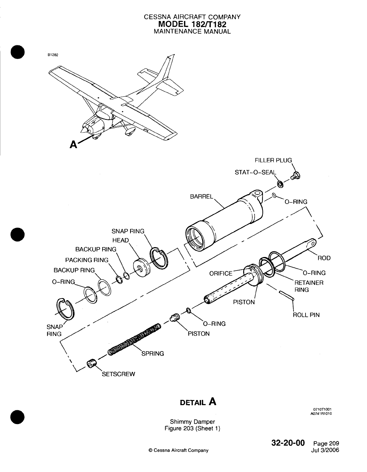
CESSNA
AIRCRAFT
COMPANY
MODEL
182/T182
MAINTENANCE
MANUAL
A
STAT-
FILLER PLUG
O-SEAL
BARREL
SNAP
BACKUP
RIN
PACKING
RING
BACKUP
RING
RETAINER
RING
PISTON
ROLL
PIN
'RING
DETAIL
A
0710T1001
A0741R1010
Shimmy
Damper
Figure
203 (Sheet
1)
Cessna
Aircraft
Company
32-20-00
Page
209
Jul
3/2006
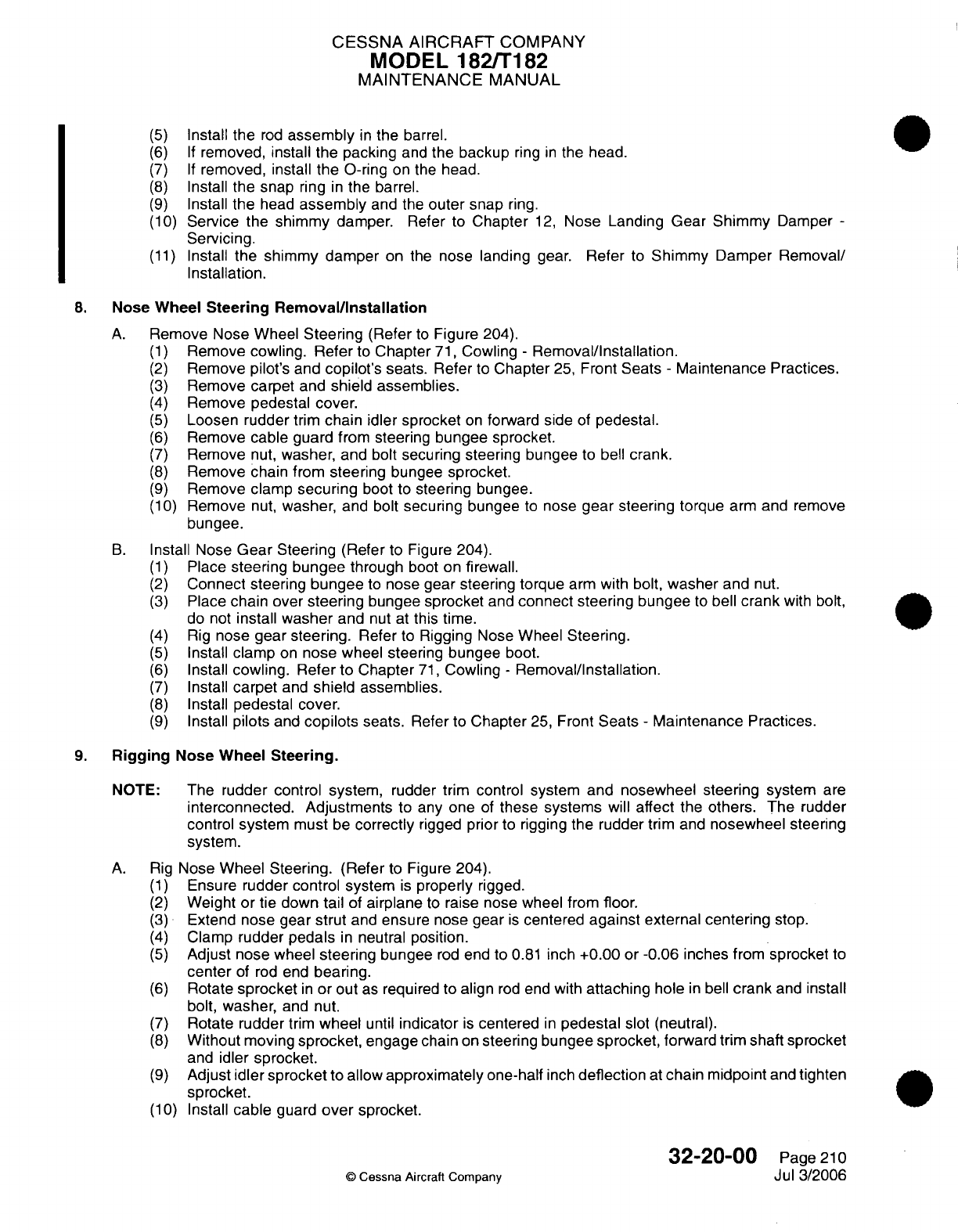
CESSNA AIRCRAFT
COMPANY
MODEL
182/T182
MAINTENANCE
MANUAL
(5)
Install
the
rod
assembly
in
the
barrel.
(6) If
removed,
install
the
packing
and
the
backup
ring
in
the
head.
(7) If
removed, install
the
O-ring
on the
head.
(8)
Install
the
snap
ring
in
the
barrel.
(9)
Install
the
head
assembly
and the
outer
snap
ring.
(10)
Service
the
shimmy
damper.
Refer to
Chapter
12,
Nose
Landing
Gear
Shimmy
Damper
-
Servicing.
(11)
Install
the
shimmy
damper
on the
nose
landing
gear. Refer
to
Shimmy
Damper Removal/
Installation.
8.
Nose
Wheel
Steering
Removal/Installation
A.
Remove Nose Wheel
Steering
(Refer
to
Figure
204).
(1)
Remove cowling.
Refer
to
Chapter
71,
Cowling
-
Removal/Installation.
(2)
Remove
pilot's
and
copilot's
seats.
Refer
to
Chapter
25,
Front
Seats
-
Maintenance
Practices.
(3)
Remove carpet
and
shield assemblies.
(4)
Remove
pedestal
cover.
(5)
Loosen
rudder
trim
chain idler
sprocket
on
forward side
of
pedestal.
(6)
Remove
cable
guard
from
steering
bungee
sprocket.
(7)
Remove
nut,
washer,
and
bolt
securing steering bungee
to
bell
crank.
(8)
Remove
chain from
steering
bungee
sprocket.
(9)
Remove
clamp
securing
boot
to
steering
bungee.
(10)
Remove
nut,
washer,
and bolt
securing
bungee
to
nose
gear steering
torque
arm
and
remove
bungee.
B.
Install Nose
Gear
Steering
(Refer
to Figure
204).
(1)
Place
steering
bungee
through
boot
on
firewall.
(2)
Connect steering
bungee
to
nose
gear steering
torque
arm
with
bolt,
washer
and
nut.
(3)
Place
chain over
steering
bungee
sprocket
and
connect
steering
bungee
to
bell
crank
with
bolt,
do
not
install
washer
and
nut
at
this
time.
(4)
Rig
nose
gear steering.
Refer
to
Rigging
Nose Wheel
Steering.
(5)
Install
clamp
on
nose
wheel
steering
bungee
boot.
(6)
Install
cowling. Refer
to Chapter
71,
Cowling
-
Removal/Installation.
(7)
Install
carpet
and
shield
assemblies.
(8)
Install
pedestal
cover.
(9)
Install
pilots
and
copilots
seats.
Refer to
Chapter
25,
Front
Seats
-
Maintenance
Practices.
9.
Rigging
Nose Wheel
Steering.
NOTE:
The
rudder
control system,
rudder
trim
control system
and
nosewheel steering
system
are
interconnected. Adjustments
to any
one
of
these
systems
will
affect
the
others.
The
rudder
control
system
must
be
correctly
rigged
prior
to
rigging
the
rudder
trim
and
nosewheel
steering
system.
A.
Rig
Nose
Wheel Steering.
(Refer
to
Figure
204).
(1)
Ensure
rudder
control system
is
properly
rigged.
(2)
Weight
or tie
down
tail
of
airplane
to
raise nose wheel from floor.
(3)
Extend
nose
gear strut
and
ensure
nose
gear
is
centered
against
external
centering
stop.
(4)
Clamp
rudder
pedals
in
neutral
position.
(5)
Adjust
nose wheel
steering
bungee
rod
end to
0.81
inch
+0.00
or
-0.06
inches
from
sprocket
to
center
of
rod
end
bearing.
(6)
Rotate
sprocket
in
or
out
as
required to
align
rod
end
with
attaching
hole
in
bell
crank
and install
bolt, washer,
and
nut.
(7)
Rotate
rudder
trim
wheel
until
indicator
is
centered
in
pedestal
slot
(neutral).
(8)
Without
moving
sprocket,
engage
chain
on
steering bungee sprocket, forward trim
shaft
sprocket
and
idler
sprocket.
(9)
Adjust
idler sprocket
to
allow
approximately
one-half
inch
deflection
at
chain
midpoint
and
tighten
sprocket.
(10)
Install
cable
guard
over
sprocket.
32-20-00
Page
210
©
Cessna
Aircraft Company
Jul
3/2006
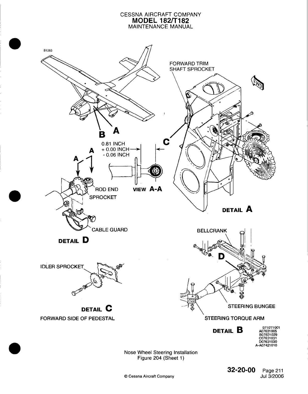
CESSNA
AIRCRAFT
COMPANY
MODEL
182/T182
MAINTENANCE
MANUAL
FORWARD
TRIM
SHAFT
SPROCKET
A
VIEW
A-A
ARD
DETAIL
D
IDLER
SPROCKET
DETAIL
C
FORWARD
SIDE
OF
PEDESTAL STEERING
TORQUE
ARM
071
0T1
001
DETAIL
B
A07631005
B07631029
C07631031
D07631
030
A-A07421010
Nose
Wheel
Steering
Installation
Figure
204
(Sheet
1)
©
Cessna
Aircraft
Company
32-20-00
Page
211
Jul
3/2006
CESSNA
AIRCRAFT
COMPANY
MODEL
182/T182
MAINTENANCE
MANUAL
(11)
Lower nose
wheel
to
ground
and
remove
clamps from rudder
pedals.
WARNING:
Ensure
rudder
moves
in
the
correct
direction
when
operated
by
the
rudder
pedals
and
trim
control
wheel.
32-20-00
Page
212
©
Cessna
Aircraft
Company
Jul
3/2006
CESSNA
AIRCRAFT
COMPANY
MODEL
182/T182
MAINTENANCE
MANUAL
MAIN
LANDING GEAR WHEEL
AND
AXLE
-
MAINTENANCE
PRACTICES
1.
General
A.
Main
landing
gear
wheel
maintenance practices provide removal/installation
instructions
for
left
main
wheel.
Removal/installation
for
right main
wheel
is
typical
unless
otherwise
noted.
2.
Main Wheel
Removal/Installation
NOTE:
Wheel
removal
is
not
necessary
to
reline
brakes
or
to remove
brake
parts,
other
than
the
brake
disc
on
the
torque
plate.
A.
Remove
Main
Wheel (Refer
to Figure
201).
(1)
Jack
airplane.
Refer
to
Chapter
7,
Jacking
-
Maintenance
Practices.
(2)
Remove
speed
fairing
or
hub
cap,
if
installed.
Refer
to
Main
Landing
Gear
-
Maintenance
Practices.
(3)
Remove
cotter
pin
and
axle
nut.
(4)
Remove
bolts
securing
brake
back
plate
to
brake
cylinder.
Remove
back
plate.
(5)
Pull
wheel
from
axle.
B.
Install Main
Wheel (Refer
to
Figure
201).
(1)
Place wheel
assembly
on
axle.
(2)
Install
axle
nut
and
tighten
axle
nut
until
a
slight
bearing
drag
is
obvious
when the
wheel
is
rotated.
Back
off nut
to
nearest
castellated
and
install cotter
pin.
(3)
Place
brake
back plate
in
position
and
secure
with
bolts.
(4)
Install
speed fairing
or
hub
cap. Refer to
Main
Landing
Gear
-
Maintenance Practices.
(5)
Remove
airplane
from
jacks.
Refer
to
Chapter
7,
Jacking
-
Maintenance
Practices.
3.
Main Wheel
Axle Removal/Installation
A.
Remove
Main
Wheel
Axle
(Refer
to
Figure
201).
(1)
Jack
airplane.
Refer
to
Chapter
7,
Jacking
-
Maintenance
Practices.
(2)
Remove
main
wheel
brake fairing,
speed fairing,
and
cap
fairing
cover
plate.
Refer
to
Main
Landing
Gear
-
Maintenance Practices.
(3)
Remove
main
landing gear
wheel.
Refer
to
Main
Wheel
Removal/Installation.
(4)
Disconnect,
drain
and
cap
or plug
hydraulic
brake
line
at
the wheel
brake
cylinder.
NOTE:
When removing
axle
from
strut fitting,
note
number and position
of
wheel
alignment
shims between
axle and
fitting.
Mark
shims
or
tape
together
carefully
so
they
can
be
installed
in
exactly the
same
position
to
ensure wheel
alignment
is
not
disturbed.
(5)
Remove nuts,
washers,
and
bolts
securing
shims, axle,
brake
components,
and
speed fairing
mounting plate from
strut
fitting.
B.
Install
Main
Wheel Axle
(Refer
to
Figure
201).
NOTE: Ensure
wheel
alignment
shims
are
installed
in
the
same
order
and
position
as
when
removed.
(1)
Secure shims, axle,
brake
components,
and
speed fairing
mounting
plate to
strut fitting.
(2)
Install wheel
on
axle.
Refer
to Main
Wheel Removal/Installation.
(3)
Connect
hydraulic
brake
line
to
wheel
brake
cylinder.
(4) Fill
and
bleed
hydraulic
brake
system. Refer
to
Brake
System
-
Maintenance
Practices.
(5)
Install
main
wheel
speed
fairing.
Refer
to
Main
Landing
Gear
-
Maintenance
Practices.
(6)
Remove
airplane
from
jacks.
Refer
to
Chapter
7,
Jacking
-
Maintenance Practices.
4.
Main Wheel
Disassembly/Assembly
A.
Disassemble
Main
Wheel
(Refer
to Figure
202).
32-40-00
Page
201
©
Cessna Aircraft
Company
Mar 1/2004
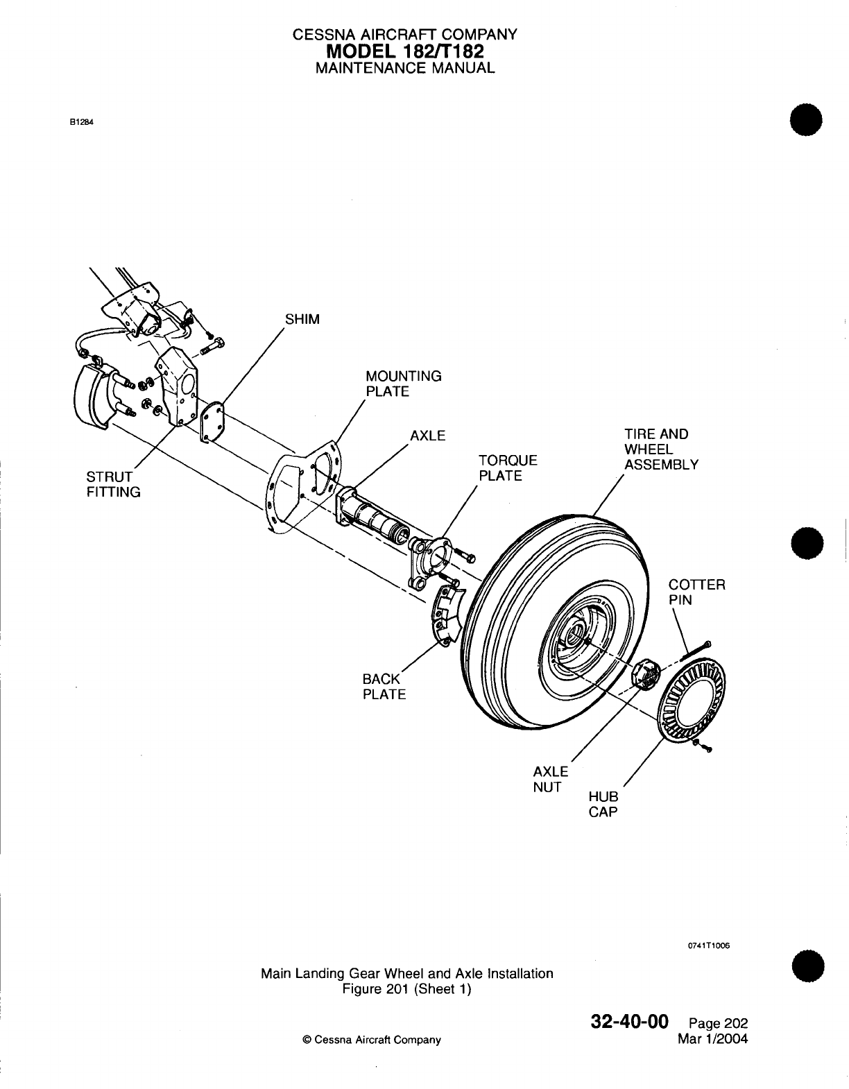
CESSNA
AIRCRAFT
COMPANY
MODEL
182/T182
MAINTENANCE
MANUAL
B1284
SHIM
STRUT
FITTING
BACK
PLATE
HUB
CAP
0741T1006
Main
Landing
Gear
Wheel
and
Axle
Installation
Figure
201
(Sheet
1)
32-40-00
©
Cessna
Aircraft
Company
Page
202
Mar
1/2004
11,
I
CESSNA
AIRCRAFT
COMPANY
MODEL
182/T182
MAINTENANCE
MANUAL
WARNING:
Serious
injury
can
result
from attempting
to
separate
wheel
halves
with
tire
and
tube
inflated.
(1)
Completely deflate
tire
and
tube
and
break
loose
tire
bead. Extreme care
must
be
exercised
to
prevent
tire
tool
damage
when removing
tire
from
wheel
halves.
(2)
Remove
thru-bolts
holding
wheel
halves
together.
(3)
Separate
and
remove
wheel
halves
from
tire
and
tube.
Mark
tube
and
tire
relationship.
(4)
From
each
wheel
half,
remove retaining rings,
grease
seal
retainers, grease
seal
felts,
grease
seal
ring
and bearing
cones.
NOTE:
Bearing
cups
(races) are
a
press fit
in
wheel halves,
and
should
not
be
removed
unless
a
new
part
is
to
be
installed.
(5)
To
remove
bearing
cups,
heat
wheel
half
in
boiling
water
for
30
minutes, or
in
an
oven,
not to
exceed
250F.
Using
an
arbor
press,
if
available,
press
out
b
earing cup
and
press
in
a new
bearing
cup
while
wheel half
is
still
hot.
B.
Assemble
Main
Wheel
(Refer
to
Figure
202).
(1)
Apply
a
small
quantity
of SAE
10
oil
for
lubrication
on
the
felt grease
seal.
(2)
Install bearing
cone,
grease
seal
ring,
grease
seal
felt,
grease
seal
retainer
and
retaining
ring
into each
wheel
half.
(3)
Insert
tube
in
tire,
aligning
index
marks
on
tire
and
tube.
(4)
Place wheel
half
into
tire
and
tube
(side
opposite
valve
stem).
With washer under
head
of
thru-
bolt, insert
bolt
through
wheel half.
(5)
Place
other
wheel
half into
other
side
of
tire
and
tube,
aligning
valve
stem
in
valve slot.
(a)
Ensure
tube
is
not
pinched between
wheel
halves
before
torquing
nuts.
CAUTION:
Uneven
or improper torque
of
the
nuts
can
cause
failure
of
the
bolts
with
resultant
wheel
failure.
CAUTION:
Do
not
use
impact
wrenches
on
thru-bolts
or
nuts.
(6)
Insert
washers
and
nuts
on
thru-bolts,
and
dry
torque
alternately
to
90
inch-pounds,
+2
or
-2
inch-pounds.
(7)
Inflate
tire to
seat
tire beads,
deflate
and
inflate
to
42
PSI
air
pressure.
5.
Main
Wheel
Inspection/Check
A.
Inspect
Main
Wheel
(Refer
to
Figure 202).
(1)
Clean
all
metal
parts
and
grease seal
felts
in
solvent,
and
dry thoroughly.
NOTE:
A
soft bristle
brush
may
be
used
to
remove
hardened grease,
dust
or
dirt.
(2)
Inspect
wheel
halves
for
cracks
or damage.
(3)
Inspect
bearing cones, cups, retaining
rings,
grease seal
retainers,
grease
seal
felts
and grease
seal
rings
for wear
or
damage.
(4)
Inspect
thru-bolts
for cracks
in
bolt
head.
(5)
Replace
cracked
or
damaged wheel
half.
(6)
Replace damaged
retainer
rings
and
seals.
(7)
Replace
worn
or
damaged bearing cups
and
cones.
(8)
Replace
any
worn or
damaged
thru-bolts.
(9)
Remove
any
corrosion
or
small
nicks.
(10)
Repair
reworked areas
of
wheel
by
cleaning
thoroughly, then
applying
one
coat
of
clear
lacquer
paint.
(11)
Apply
a
small
quantity
of
SAE 10
oil
for
lubrication
on
the
grease
seal
felt
(12)
Pack the
bearings
with
MIL-PRF-81322
wheel bearing grease.
(13)
Inspect
Brakes. Refer
to
Chapter
5,
Inspection
Time
Limits.
32-40-00
Page
203
©
Cessna Aircraft
Company
Mar
1/2004
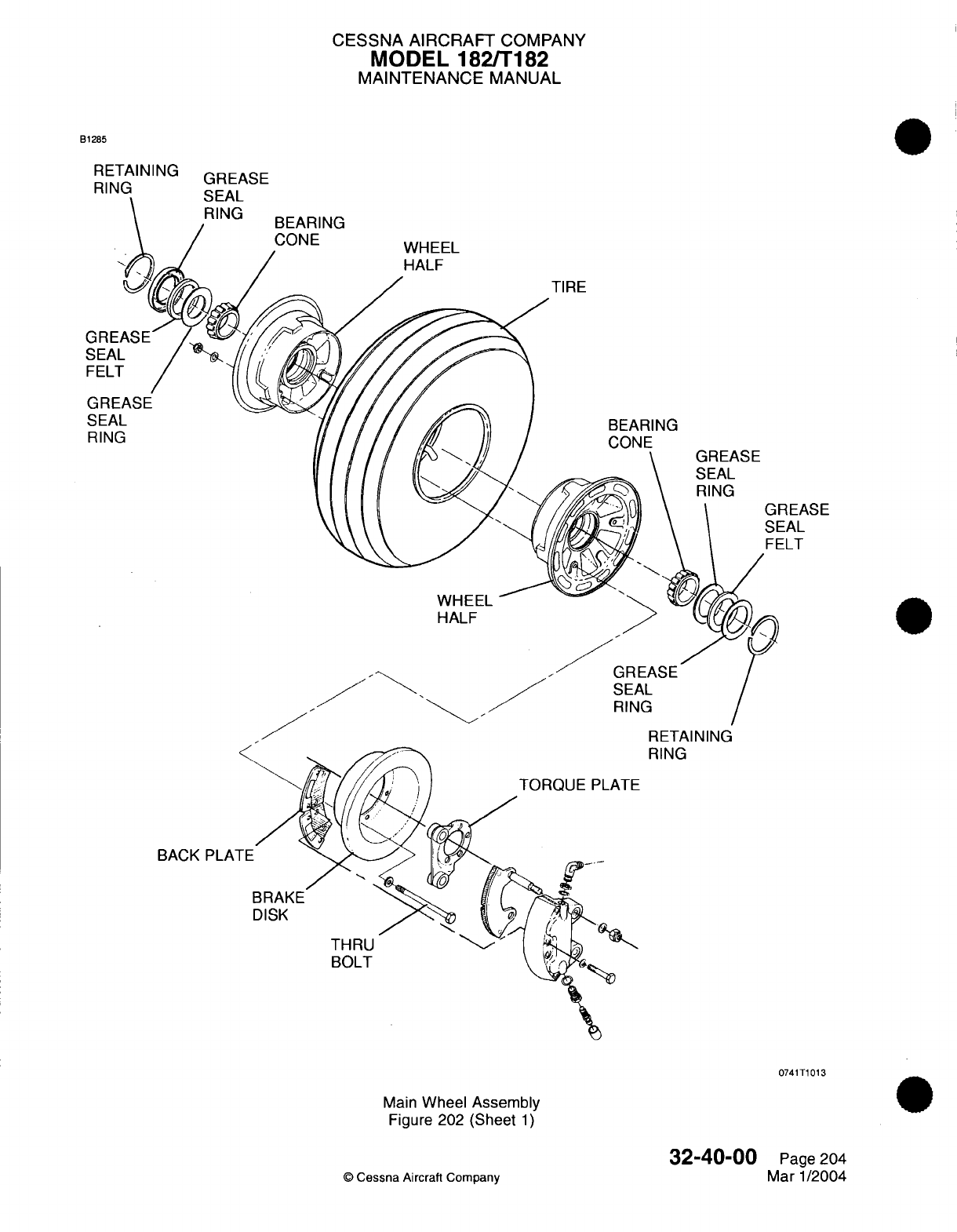
CESSNA
AIRCRAFT
COMPANY
MODEL
182/T182
MAINTENANCE
MANUAL
B1285
RETAINING
BEARING
CONE
WHEEL
HALF
TIRE
BEARING
GREASE
SEAL
RING
REASE
EAL
ILT
WHEEL
HALF
,
I
SEAL
RING
RETAINING
RING
ATE
BACK
PLA1
BRAKI
DISK
THRU
BOLT
0741T1013
Main
Wheel
Assembly
Figure
202
(Sheet
1)
32-40-00
©
Cessna
Aircraft
Company
SEAL
RING
Page
204
Mar 1/2004
rIQFA
QF
CESSNA
AIRCRAFT
COMPANY
MODEL
182/T182
MAINTENANCE
MANUAL
6.
Wheel
Balancing
A.
Since
uneven
tire wear
is
usually
the cause
of
wheel
unbalance,
replacing
the
tire
will
probably correct
this
condition.
Tire
and
tube
manufacturing
tolerance
permits
a
specified
amount of
static
unbalance.
The
light
weight
point
of
this
tire
is
marked
with
a red
dot
on
the tire sidewall
and
the
heavy
weight
point
of
the
tube
is
marked
with
a
contrasting
color
line
(usually
near
the
inflation
valve
stem).
When
installing
a
new
tire,
place
these
marks
adjacent
to
each
other.
If
a
wheel
shows
evidence
of
unbalance
during service,
it
may be
statically
balanced
but
not
dynamically
balanced.
32-40-00
Page
205
©
Cessna
Aircraft Company
Mar
1/2004
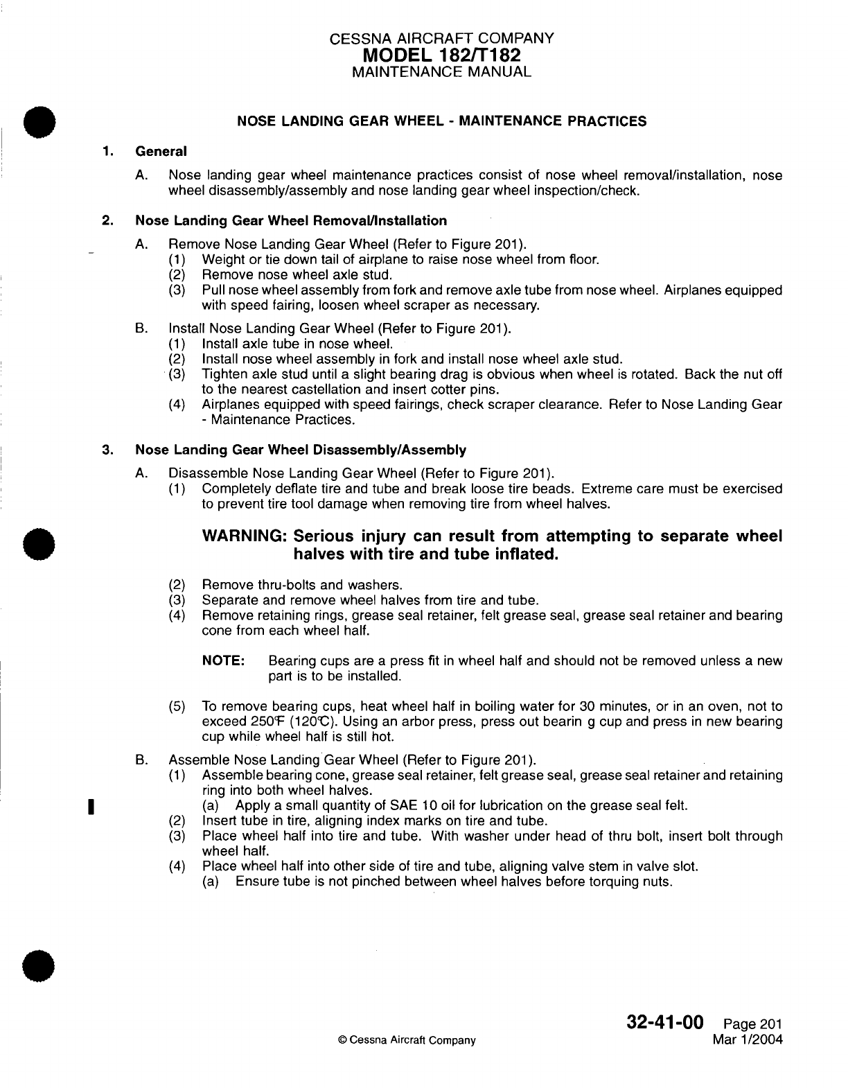
CESSNA
AIRCRAFT
COMPANY
MODEL
182/T182
MAINTENANCE
MANUAL
NOSE
LANDING
GEAR
WHEEL
-
MAINTENANCE
PRACTICES
1.
General
A.
Nose landing gear
wheel
maintenance
practices
consist
of
nose wheel
removal/installation,
nose
wheel
disassembly/assembly
and
nose
landing
gear wheel inspection/check.
2.
Nose
Landing
Gear
Wheel
Removal/Installation
A.
Remove
Nose Landing
Gear
Wheel (Refer
to
Figure
201).
(1)
Weight
or
tie
down tail
of
airplane
to raise
nose
wheel
from
floor.
(2)
Remove nose wheel
axle
stud.
(3)
Pull
nose
wheel
assembly
from
fork
and remove
axle
tube
from
nose
wheel.
Airplanes
equipped
with
speed fairing, loosen
wheel
scraper
as
necessary.
B.
Install Nose Landing
Gear Wheel
(Refer to
Figure
201).
(1)
Install
axle
tube
in
nose
wheel.
(2)
Install
nose
wheel
assembly
in
fork
and
install
nose
wheel axle
stud.
(3)
Tighten axle stud
until
a
slight
bearing
drag
is
obvious
when
wheel
is
rotated. Back
the
nut off
to the
nearest
castellation
and
insert
cotter
pins.
(4)
Airplanes
equipped
with
speed
fairings,
check
scraper clearance.
Refer
to
Nose
Landing
Gear
-
Maintenance
Practices.
3.
Nose
Landing
Gear Wheel
Disassembly/Assembly
A.
Disassemble
Nose
Landing
Gear
Wheel (Refer
to Figure
201).
(1)
Completely deflate
tire
and
tube
and
break
loose
tire
beads.
Extreme
care
must
be
exercised
to
prevent
tire
tool
damage
when
removing tire from wheel
halves.
WARNING:
Serious
injury
can
result
from
attempting
to
separate
wheel
halves
with
tire
and
tube
inflated.
(2)
Remove
thru-bolts
and
washers.
(3)
Separate
and
remove wheel
halves
from
tire
and
tube.
(4)
Remove retaining
rings,
grease
seal
retainer,
felt
grease
seal, grease
seal
retainer
and
bearing
cone from
each
wheel
half.
NOTE:
Bearing
cups
are
a
press fit
in
wheel
half
and
should
not
be
removed
unless
a new
part
is
to
be
installed.
(5)
To
remove bearing
cups,
heat
wheel
half
in
boiling
water
for
30
minutes, or
in an
oven,
not
to
exceed
250'F
(120@C).
Using
an
arbor
press,
press
out
bearin
g
cup
and
press
in
new
bearing
cup while
wheel
half
is
still
hot.
B.
Assemble
Nose
Landing
Gear
Wheel (Refer
to
Figure
201).
(1)
Assemble
bearing cone, grease
seal
retainer,
felt
grease
seal, grease
seal
retainer
and
retaining
ring
into
both
wheel
halves.
(a)
Apply
a
small
quantity
of
SAE
10
oil
for
lubrication
on
the grease
seal
felt.
(2)
Insert
tube
in
tire,
aligning
index marks
on
tire
and
tube.
(3)
Place wheel half
into tire and
tube.
With
washer under
head of
thru
bolt,
insert
bolt
through
wheel
half.
(4)
Place
wheel
half
into
other
side
of
tire
and
tube, aligning
valve
stem
in
valve slot.
(a)
Ensure
tube
is
not
pinched
between
wheel
halves
before
torquing
nuts.
32-41-00
Page
201
©
Cessna Aircraft Company
Mar
1/2004
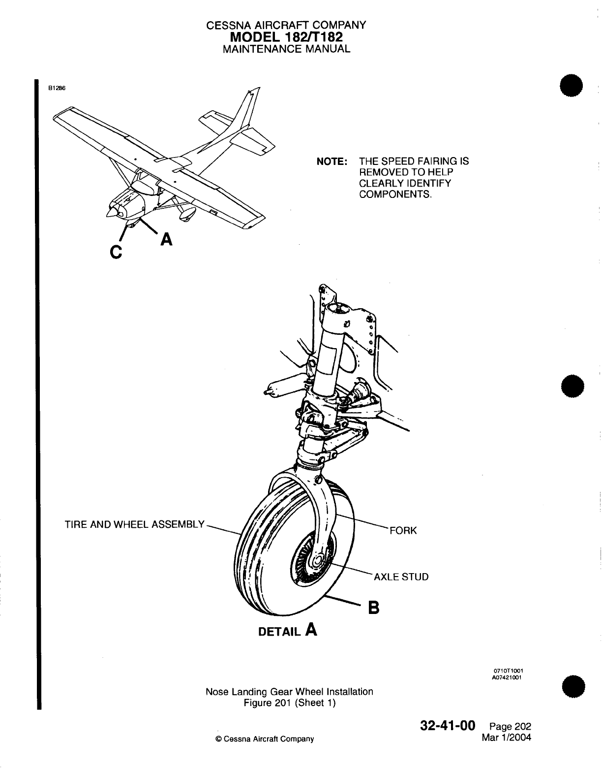
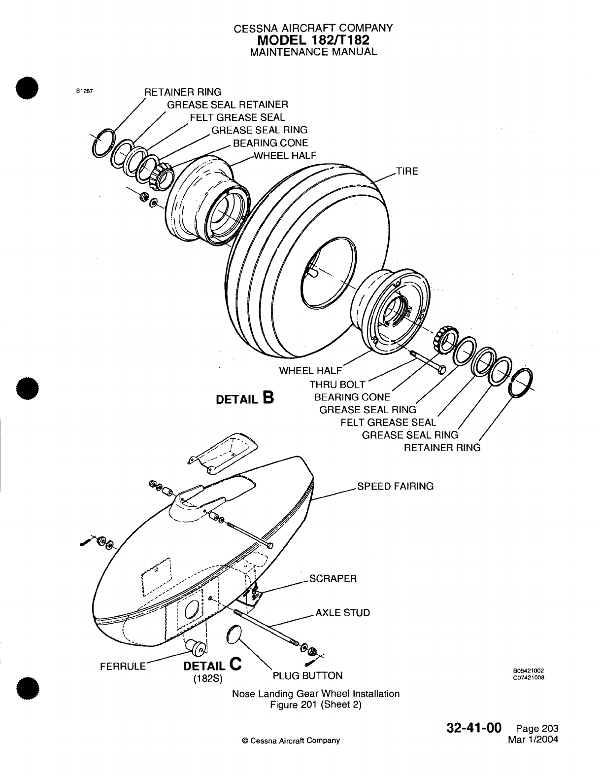
CESSNA
AIRCRAFT
COMPANY
MODEL
182/T182
MAINTENANCE
MANUAL
RETAINER
RING
TIRE
WHEEL
HALF
DETAIL
B
RETAINER
RING
EED
FAIRING
(182S) PLUG BUTTON
Nose
Landing
Gear Wheel
Installation
Figure
201
(Sheet
2)
©
Cessna
Aircraft
Company
32-41-00
Page
203
Mar 1/2004
B1287
B05421002
C07421008
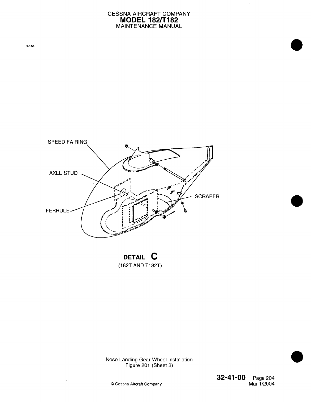
CESSNA
AIRCRAFT
COMPANY
MODEL
182/T182
MAINTENANCE
MANUAL
B2054
DETAIL
C
(182T
AND
T182T)
Nose
Landing Gear
Wheel Installation
Figure
201
(Sheet
3)
©
Cessna
Aircraft Company
32-41-00
Page
204
Mar
1/2004
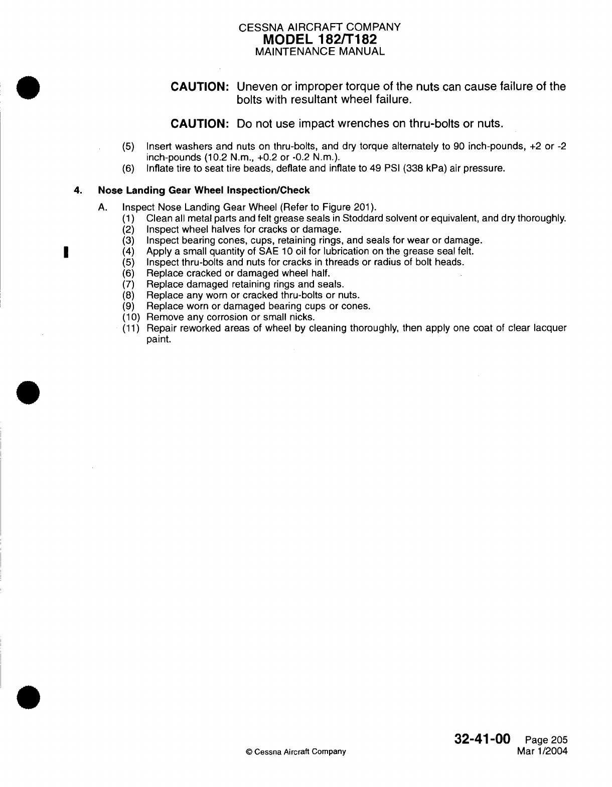
CESSNA
AIRCRAFT
COMPANY
MODEL
182/T182
MAINTENANCE
MANUAL
CAUTION: Uneven or
improper torque
of
the
nuts
can
cause
failure
of
the
bolts
with
resultant
wheel
failure.
CAUTION:
Do
not use
impact
wrenches
on
thru-bolts
or
nuts.
(5)
Insert
washers
and nuts
on
thru-bolts,
and dry
torque
alternately
to
90
inch-pounds,
+2
or
-2
inch-pounds
(10.2
N.m.,
+0.2
or
-0.2
N.m.).
(6)
Inflate tire
to
seat tire beads,
deflate
and
inflate
to
49
PSI
(338
kPa)
air
pressure.
4. Nose
Landing
Gear Wheel
Inspection/Check
A.
Inspect
Nose
Landing
Gear
Wheel
(Refer
to Figure
201).
(1)
Clean
all
metal
parts
and
felt
grease
seals
in
Stoddard
solvent or equivalent,
and
dry
thoroughly.
(2)
Inspect wheel halves
for
cracks
or
damage.
(3)
Inspect
bearing
cones, cups,
retaining
rings,
and
seals
for
wear
or
damage.
(4)
Apply
a
small
quantity
of
SAE
10
oil
for lubrication
on the
grease
seal
felt.
(5)
Inspect
thru-bolts
and
nuts
for
cracks
in
threads
or
radius
of
bolt
heads.
(6)
Replace
cracked
or
damaged wheel
half.
(7)
Replace
damaged retaining
rings
and
seals.
(8)
Replace
any
worn
or
cracked thru-bolts or
nuts.
(9)
Replace
worn or
damaged
bearing
cups
or
cones.
(10)
Remove
any
corrosion
or
small
nicks.
(11)
Repair
reworked
areas
of
wheel
by
cleaning
thoroughly,
then
apply
one
coat
of
clear
lacquer
paint.
32-41-00
Page 205
©
Cessna Aircraft Company
Mar
1/2004
I

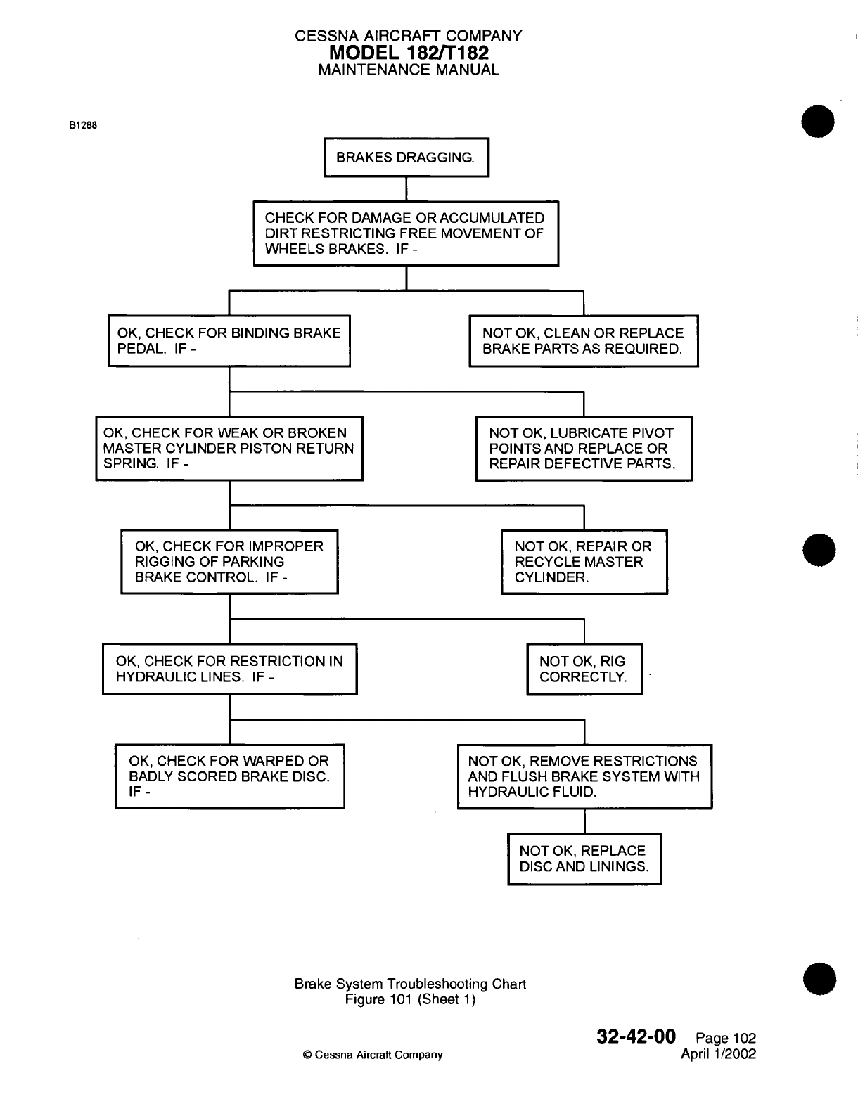
CESSNA
AIRCRAFT
COMPANY
MODEL
182/T182
MAINTENANCE
MANUAL
B1288
BRAKES
DRAGGING.
CHECK
FOR
DAMAGE
OR ACCUMULATED
DIRT
RESTRICTING
FREE
MOVEMENT
OF
WHEELS
BRAKES.
IF-
I
OK,
CHECK
FOR
BINDING
BRAKE
PEDAL.
IF-
OK,
CHECK
FOR
WEAK
OR
BROKEN
MASTER
CYLINDER
PISTON
RETURN
SPRING.
IF-
OK,
CHECK FOR
IMPROPER
RIGGING
OF
PARKING
BRAKE
CONTROL.
IF-
OK,
CHECK FOR
RESTRICTION
IN
HYDRAULIC
LINES.
IF
-
OK,
CHECK FOR
WARPED
OR
BADLY
SCORED
BRAKE DISC.
IF-
NOT OK,
CLEAN OR
REPLACE
BRAKE
PARTS
AS
REQUIRED.
NOT OK,
LUBRICATE
PIVOT
POINTS
AND
REPLACE
OR
REPAIR
DEFECTIVE
PARTS.
NOT
OK,
REPAIR
OR
RECYCLE
MASTER
CYLINDER.
NOT
OK, RIG
CORRECTLY.
NOT
OK,
REMOVE
RESTRICTIONS
AND
FLUSH
BRAKE
SYSTEM WITH
HYDRAULIC
FLUID.
I
NOT
OK,
REPLACE
DISC
AND
LININGS.
Brake
System
Troubleshooting
Chart
Figure
101
(Sheet
1)
32-42-00
©
Cessna
Aircraft Company
Page
102
April 1/2002
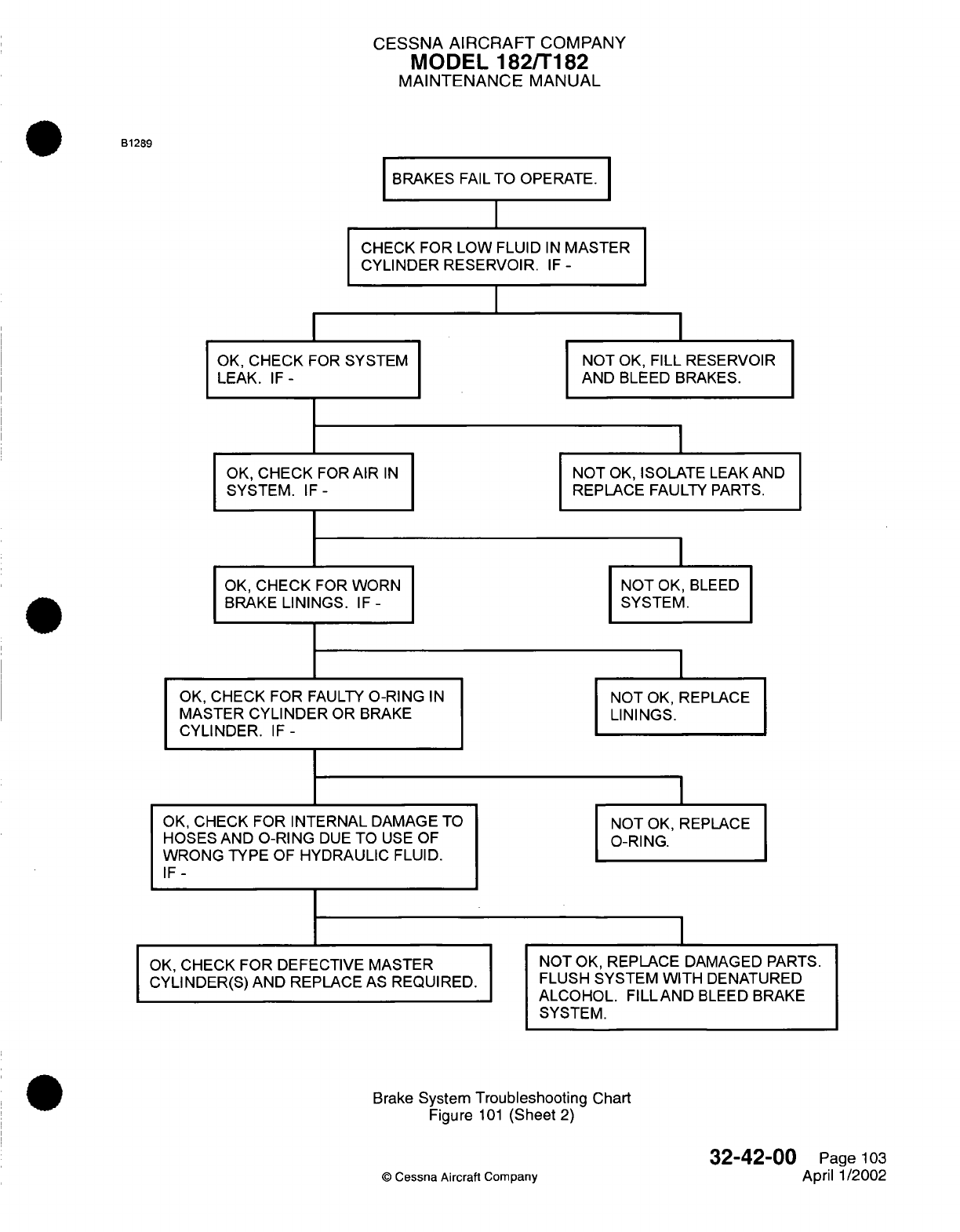
CESSNA
AIRCRAFT
COMPANY
MODEL
182/T182
MAINTENANCE
MANUAL
B1289
BRAKES
FAIL
TO
OPERATE.
CHECK FOR
LOW
FLUID
IN
MASTER
CYLINDER RESERVOIR.
IF
-
I
OK,
CHECK
FOR SYSTEM
LEAK.
IF-
OK,
CHECK
FOR
AIR
IN
SYSTEM.
IF-
OK,
CHECK
FOR
WORN
BRAKE
LININGS.
IF-
OK,
CHECK FOR
FAULTY
O-RING
IN
MASTER
CYLINDER
OR
BRAKE
CYLINDER.
IF-
NOT
OK,
FILL
RESERVOIR
AND
BLEED BRAKES.
NOT
OK,
ISOLATE
LEAK
AND
REPLACE
FAULTY PARTS.
NOT
OK,
SYSTEM.
BLEED
I
NOT
OK, REPLACE
LININGS.
OK,
CHECK FOR
INTERNAL
DAMAGE TO
HOSES
AND
O-RING
DUE
TO
USE OF
WRONG
TYPE
OF
HYDRAULIC
FLUID.
IF-
OK,
CHECK
FOR
DEFECTIVE MASTER
CYLINDER(S) AND
REPLACE
AS
REQUIRED.
NOT
OK, REPLACE
O-RING.
NOT
OK,
REPLACE
DAMAGED
PARTS.
FLUSH
SYSTEM WITH
DENATURED
ALCOHOL.
FILLAND
BLEED
BRAKE
SYSTEM.
Brake
System
Troubleshooting
Chart
Figure
101
(Sheet
2)
©
Cessna Aircraft
Company
32-42-00
Page
103
April
1/2002
I
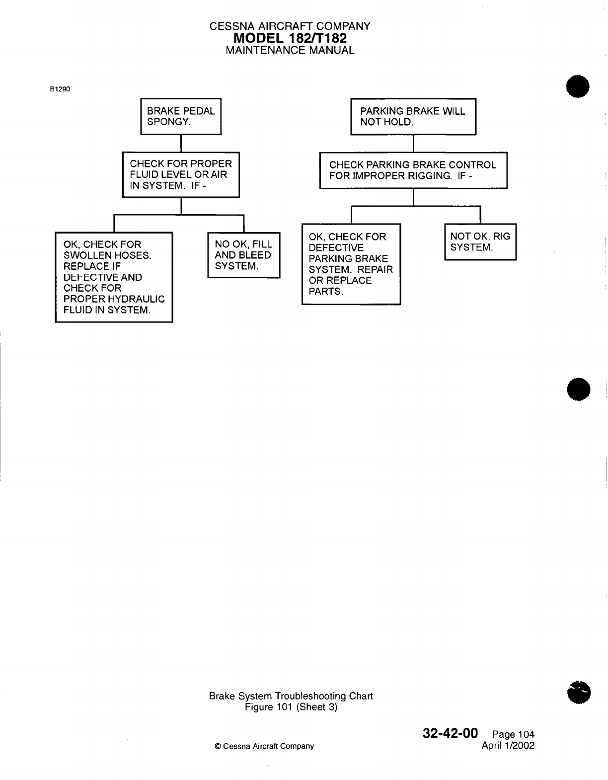
CESSNA AIRCRAFT
COMPANY
MODEL
182/T182
MAINTENANCE
MANUAL
B1290
BRAKE
PEDAL
SPONGY.
CHECK FOR PROPER
FLUID LEVEL
OR
AIR
IN
SYSTEM.
IF-
PARKING BRAKE
WILL
NOT
HOLD.
CHECK
PARKING BRAKE
CONTROL
FOR
IMPROPER
RIGGING.
IF -
OK,
CHECK
FOR
SWOLLEN
HOSES.
REPLACE IF
DEFECTIVE
AND
CHECK
FOR
PROPER
HYDRAULIC
FLUID
IN
SYSTEM.
NO
OK,
FILL
AND
BLEED
SYSTEM.
I
OK,
CHECK
FOR
DEFECTIVE
PARKING
BRAKE
SYSTEM.
REPAIR
OR
REPLACE
PARTS.
NOT
OK,
RIG
SYSTEM.
Brake
System Troubleshooting
Chart
Figure
101
(Sheet
3)
©
Cessna
Aircraft
Company
32-42-00
Page
104
April
1/2002
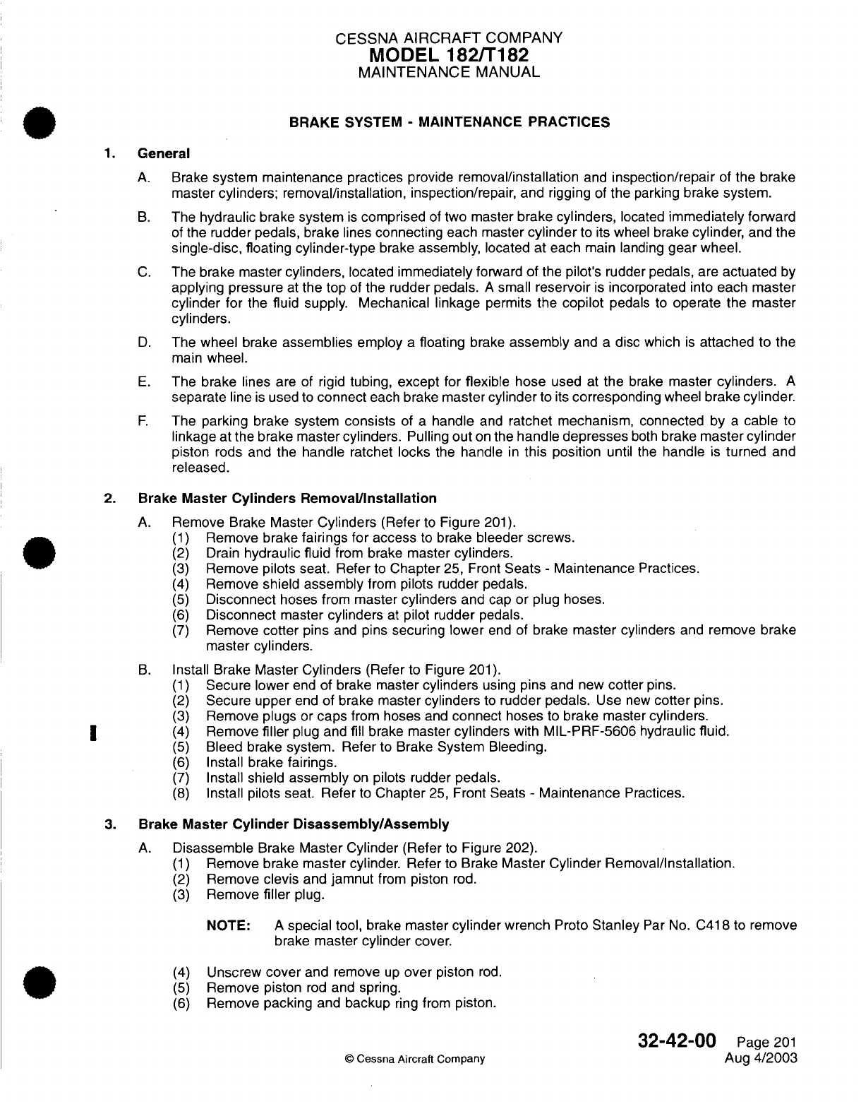
CESSNA
AIRCRAFT
COMPANY
MODEL
182/T182
MAINTENANCE
MANUAL
BRAKE
SYSTEM
-
MAINTENANCE
PRACTICES
1.
General
A.
Brake
system maintenance
practices
provide
removal/installation
and
inspection/repair
of
the
brake
master
cylinders;
removal/installation, inspection/repair,
and
rigging
of
the
parking
brake
system.
B.
The
hydraulic brake
system
is
comprised
of
two
master
brake
cylinders,
located
immediately forward
of
the
rudder
pedals,
brake
lines
connecting
each
master
cylinder
to
its
wheel
brake
cylinder,
and
the
single-disc,
floating
cylinder-type
brake
assembly,
located
at
each
main
landing
gear wheel.
C.
The brake master
cylinders,
located
immediately
forward of the
pilot's
rudder
pedals,
are
actuated
by
applying pressure
at
the
top
of
the
rudder
pedals.
A
small
reservoir
is
incorporated
into
each
master
cylinder for
the fluid supply.
Mechanical
linkage
permits
the
copilot
pedals
to
operate
the
master
cylinders.
D.
The wheel
brake
assemblies
employ
a
floating
brake
assembly
and
a
disc
which
is
attached to
the
main
wheel.
E.
The brake
lines
are
of
rigid
tubing,
except
for
flexible
hose
used
at
the
brake
master
cylinders.
A
separate
line
is
used
to
connect
each brake
master
cylinder
to
its
corresponding
wheel
brake
cylinder.
F.
The
parking
brake system
consists
of
a
handle
and
ratchet mechanism, connected
by
a
cable
to
linkage
at
the
brake master
cylinders.
Pulling
out
on
the
handle
depresses
both
brake
master
cylinder
piston
rods and the
handle ratchet
locks
the
handle
in
this
position
until
the
handle
is
turned
and
released.
2.
Brake
Master
Cylinders
Removal/Installation
A.
Remove
Brake
Master
Cylinders
(Refer
to
Figure
201).
(1)
Remove
brake
fairings for
access
to
brake
bleeder
screws.
(2)
Drain
hydraulic
fluid
from
brake
master
cylinders.
(3)
Remove
pilots
seat. Refer
to
Chapter
25,
Front
Seats
-
Maintenance
Practices.
(4)
Remove
shield
assembly
from
pilots rudder
pedals.
(5)
Disconnect
hoses
from
master
cylinders
and
cap or plug
hoses.
(6)
Disconnect
master
cylinders
at
pilot rudder
pedals.
(7)
Remove
cotter
pins
and
pins
securing
lower
end
of
brake
master
cylinders
and
remove
brake
master
cylinders.
B.
Install Brake
Master
Cylinders
(Refer
to
Figure
201).
(1)
Secure lower
end
of
brake
master
cylinders
using
pins
and
new
cotter
pins.
(2)
Secure
upper
end
of
brake
master
cylinders
to
rudder
pedals.
Use
new
cotter
pins.
(3)
Remove
plugs
or
caps
from
hoses
and
connect
hoses
to
brake master
cylinders.
|* ~
(4)
Remove
filler
plug and
fill
brake master
cylinders
with
MIL-PRF-5606
hydraulic
fluid.
(5)
Bleed brake
system. Refer
to Brake
System
Bleeding.
(6)
Install
brake
fairings.
(7)
Install shield
assembly
on
pilots
rudder
pedals.
(8)
Install pilots
seat.
Refer
to
Chapter
25,
Front
Seats
-
Maintenance
Practices.
3.
Brake Master
Cylinder
Disassembly/Assembly
A.
Disassemble
Brake
Master
Cylinder
(Refer
to
Figure 202).
(1)
Remove
brake
master
cylinder.
Refer
to Brake
Master
Cylinder Removal/Installation.
(2)
Remove
clevis
and
jamnut
from
piston
rod.
(3)
Remove
filler
plug.
NOTE:
A
special
tool,
brake
master
cylinder
wrench
Proto
Stanley
Par
No.
C418
to
remove
brake
master
cylinder
cover.
(4)
Unscrew
cover
and
remove
up
over
piston
rod.
(5)
Remove piston
rod
and spring.
(6)
Remove
packing
and
backup
ring
from
piston.
32-42-00
Page
201
©
Cessna Aircraft
Company
Aug
4/2003
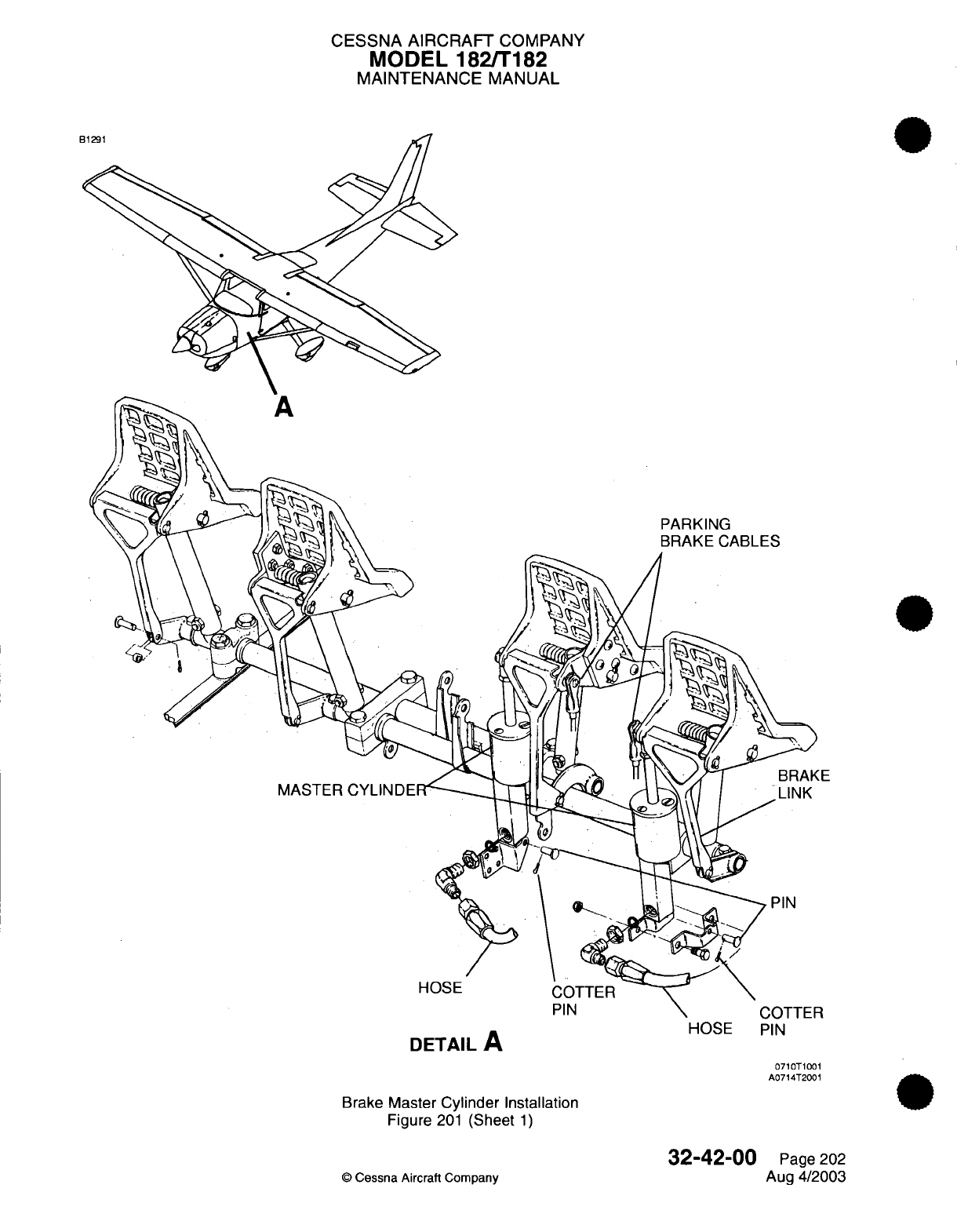
CESSNA
AIRCRAFT
COMPANY
MODEL 182/T182
MAINTENANCE
MANUAL
PARKING
BRAKE
CABLES
E
MASTER
HOSE COTTER
PIN
DETAIL
A
HOSE
PIN
0710T1001
A0714T2001
Brake
Master
Cylinder
Installation
Figure
201
(Sheet
1)
©
Cessna
Aircraft
Company
32-42-00
Page
202
Aug
4/2003
I
I
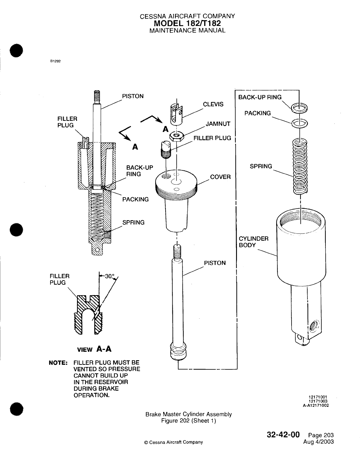
CESSNA
AIRCRAFT
COMPANY
MODEL
182/T182
MAINTENANCE
MANUAL
81292
I
FILLER
PLUG
PISTON
CLEVIS
A
'
A
/
'0
0
|
RING
PACKING
SPRING
N
BACK-UP
R
PACKING
SPRING
CYLINDER
BODY
FILLEF
PLUG
VIEW
A-A
NOTE:
FILLER
PLUG
MUST
BE
VENTED SO
PRESSURE
CANNOT BUILD
UP
IN
THE
RESERVOIR
DURING
BRAKE
OPERATION.
Brake
Master
Cylinder
Assembly
Figure
202
(Sheet
1)
32-42-00
©
Cessna Aircraft
Company
12171001
12171003
A-A12171002
Page
203
Aug
4/2003
Jr
I Ilv I
v
--- ---
e"',
ba
?
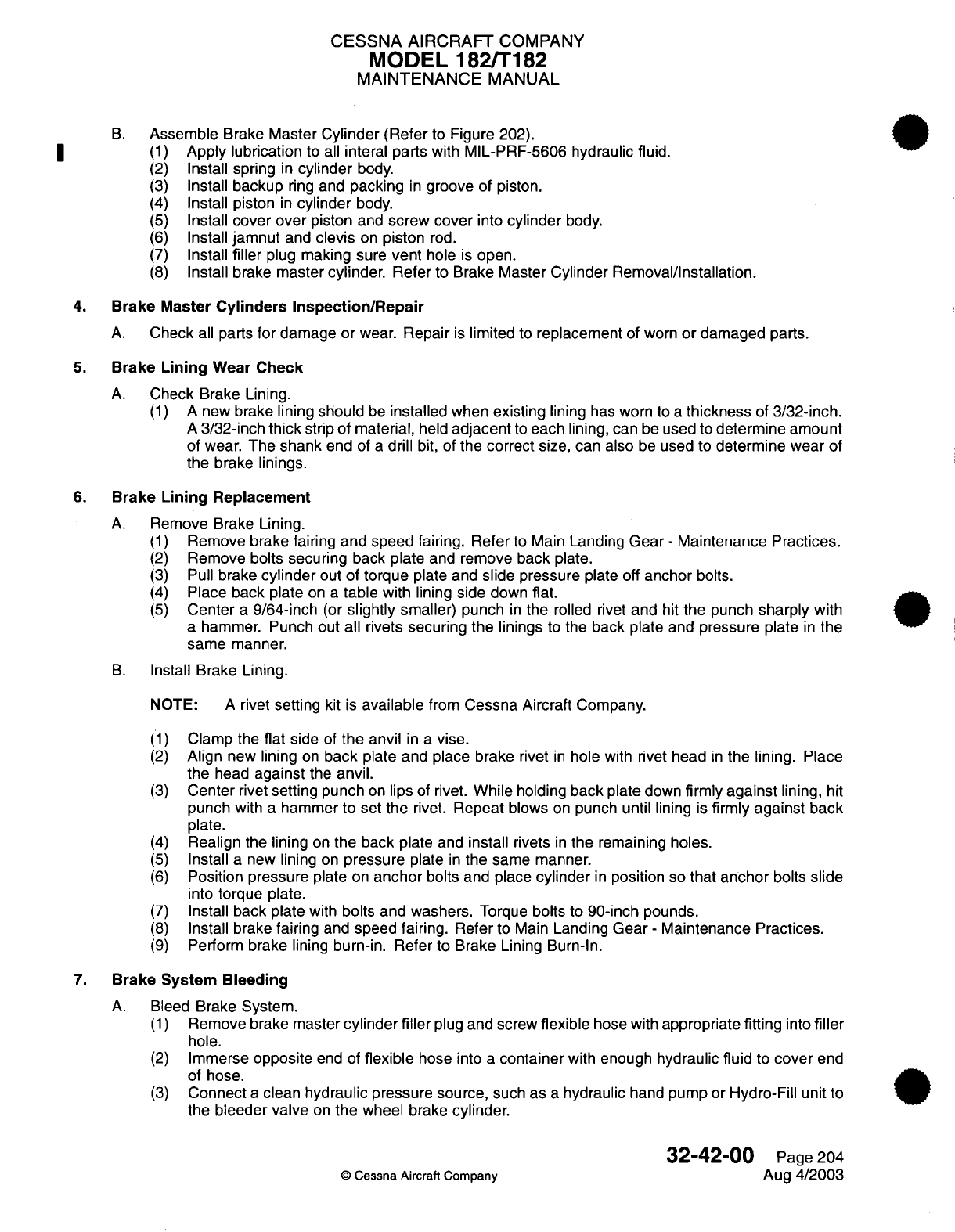
CESSNA
AIRCRAFT
COMPANY
MODEL
182/T182
MAINTENANCE
MANUAL
B.
Assemble
Brake
Master
Cylinder
(Refer
to
Figure
202).
| (1)
Apply
lubrication
to
all
interal parts
with
MIL-PRF-5606
hydraulic fluid.
(2)
Install
spring
in
cylinder
body.
(3)
Install
backup
ring
and
packing
in
groove
of
piston.
(4)
Install
piston
in
cylinder
body.
(5)
Install
cover over
piston
and
screw cover
into
cylinder
body.
(6)
Install
jamnut
and
clevis
on
piston
rod.
(7)
Install
filler
plug
making sure
vent
hole
is
open.
(8)
Install brake
master cylinder. Refer
to Brake
Master
Cylinder Removal/Installation.
4.
Brake
Master
Cylinders
Inspection/Repair
A.
Check
all
parts
for damage
or
wear.
Repair
is
limited
to
replacement
of
worn
or
damaged
parts.
5.
Brake
Lining
Wear Check
A.
Check
Brake Lining.
(1)
A
new
brake
lining
should
be
installed
when
existing
lining
has
worn
to
a
thickness
of
3/32-inch.
A
3/32-inch
thick
strip
of
material,
held
adjacent
to
each
lining,
can
be
used to
determine
amount
of
wear.
The
shank
end
of
a
drill
bit, of
the
correct size,
can
also
be
used to
determine wear
of
the
brake
linings.
6.
Brake
Lining
Replacement
A.
Remove
Brake
Lining.
(1)
Remove brake fairing
and speed fairing. Refer
to
Main
Landing
Gear
-
Maintenance Practices.
(2)
Remove
bolts securing back plate
and
remove
back
plate.
(3)
Pull
brake
cylinder
out
of torque
plate
and
slide
pressure
plate
off
anchor
bolts.
(4)
Place back
plate
on
a
table
with lining
side down
flat.
(5)
Center
a
9/64-inch
(or
slightly
smaller)
punch
in
the
rolled
rivet
and
hit
the
punch
sharply with
a
hammer.
Punch
out
all rivets
securing
the
linings
to
the
back plate
and
pressure plate
in
the
same
manner.
B.
Install
Brake Lining.
NOTE:
A
rivet
setting
kit
is
available
from
Cessna
Aircraft
Company.
(1)
Clamp
the
flat
side
of
the
anvil
in
a
vise.
(2)
Align
new
lining
on
back
plate and place brake
rivet
in
hole
with
rivet head
in
the lining. Place
the
head
against
the
anvil.
(3)
Center
rivet
setting
punch
on
lips
of
rivet.
While
holding
back
plate
down
firmly
against
lining,
hit
punch
with
a
hammer
to
set
the
rivet.
Repeat
blows
on
punch
until lining
is
firmly
against
back
plate.
(4)
Realign
the
lining
on
the
back
plate and
install
rivets
in
the
remaining
holes.
(5)
Install
a
new
lining
on
pressure
plate
in
the
same
manner.
(6)
Position
pressure
plate
on
anchor
bolts and
place
cylinder
in
position
so
that
anchor
bolts
slide
into
torque
plate.
(7)
Install
back
plate
with
bolts and washers.
Torque
bolts
to
90-inch
pounds.
(8)
Install brake
fairing
and
speed fairing. Refer
to
Main
Landing
Gear
-
Maintenance Practices.
(9)
Perform brake
lining
burn-in.
Refer
to
Brake
Lining Burn-In.
7.
Brake System
Bleeding
A.
Bleed
Brake
System.
(1)
Remove
brake
master
cylinder
filler
plug and
screw
flexible
hose with
appropriate
fitting
into
filler
hole.
(2)
Immerse
opposite
end
of
flexible
hose into
a
container
with
enough
hydraulic fluid
to
cover
end
of
hose.
(3)
Connect
a
clean
hydraulic
pressure source,
such
as
a
hydraulic
hand
pump
or
Hydro-Fill
unit
to
the
bleeder valve
on
the
wheel
brake
cylinder.
32-42-00
Page
204
©
Cessna
Aircraft
Company
Aug
4/2003
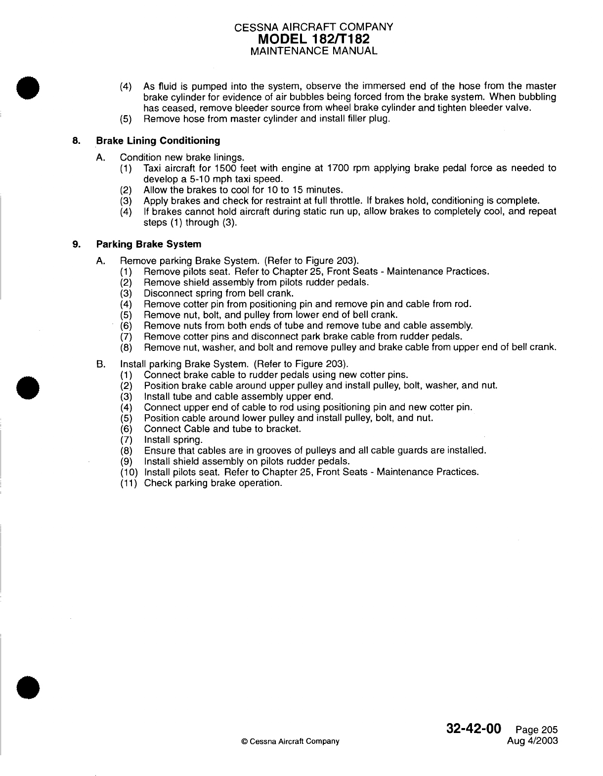
CESSNA
AIRCRAFT
COMPANY
MODEL
182/T182
MAINTENANCE
MANUAL
(4)
As
fluid
is
pumped
into the
system,
observe
the
immersed
end
of
the
hose
from
the
master
brake
cylinder
for
evidence
of
air bubbles
being
forced
from
the
brake
system.
When
bubbling
has
ceased,
remove
bleeder
source
from
wheel
brake
cylinder
and
tighten
bleeder
valve.
(5)
Remove hose
from
master
cylinder
and
install
filler
plug.
8.
Brake
Lining Conditioning
A.
Condition
new
brake
linings.
(1)
Taxi
aircraft
for
1500
feet
with
engine
at
1700
rpm
applying
brake
pedal
force as
needed
to
develop
a
5-10
mph
taxi
speed.
(2)
Allow
the brakes
to
cool
for
10
to
15
minutes.
(3)
Apply
brakes
and
check
for
restraint
at
full throttle.
If
brakes
hold,
conditioning
is
complete.
(4)
If
brakes cannot
hold
aircraft during
static
run up,
allow
brakes
to completely
cool,
and
repeat
steps
(1)
through
(3).
9.
Parking
Brake
System
A.
Remove
parking
Brake
System.
(Refer
to
Figure
203).
(1)
Remove
pilots
seat.
Refer
to
Chapter
25,
Front
Seats
-
Maintenance Practices.
(2)
Remove
shield assembly
from
pilots
rudder pedals.
(3)
Disconnect
spring from
bell
crank.
(4)
Remove
cotter
pin
from
positioning
pin
and remove
pin
and
cable
from
rod.
(5)
Remove
nut,
bolt, and
pulley
from
lower end
of
bell
crank.
(6)
Remove
nuts from both
ends
of
tube
and
remove
tube
and
cable
assembly.
(7)
Remove
cotter
pins and
disconnect
park
brake cable
from
rudder
pedals.
(8)
Remove
nut,
washer,
and
bolt
and
remove
pulley
and
brake
cable
from
upper
end
of
bell
crank.
B.
Install
parking
Brake
System.
(Refer
to
Figure 203).
(1)
Connect
brake cable
to
rudder pedals
using
new
cotter
pins.
(2)
Position brake cable around upper
pulley
and
install pulley,
bolt,
washer,
and
nut.
(3)
Install
tube
and
cable
assembly
upper
end.
(4)
Connect
upper
end
of
cable
to
rod
using
positioning
pin
and
new cotter
pin.
(5)
Position
cable around
lower
pulley
and
install pulley,
bolt,
and
nut.
(6)
Connect
Cable
and
tube
to
bracket.
(7)
Install
spring.
(8)
Ensure
that cables
are
in
grooves
of
pulleys
and
all
cable
guards
are
installed.
(9)
Install
shield
assembly
on
pilots rudder
pedals.
(10)
Install
pilots
seat.
Refer
to
Chapter
25,
Front
Seats
-
Maintenance
Practices.
(11)
Check
parking brake operation.
32-42-00
Page
205
©
Cessna
Aircraft Company
Aug
4/2003
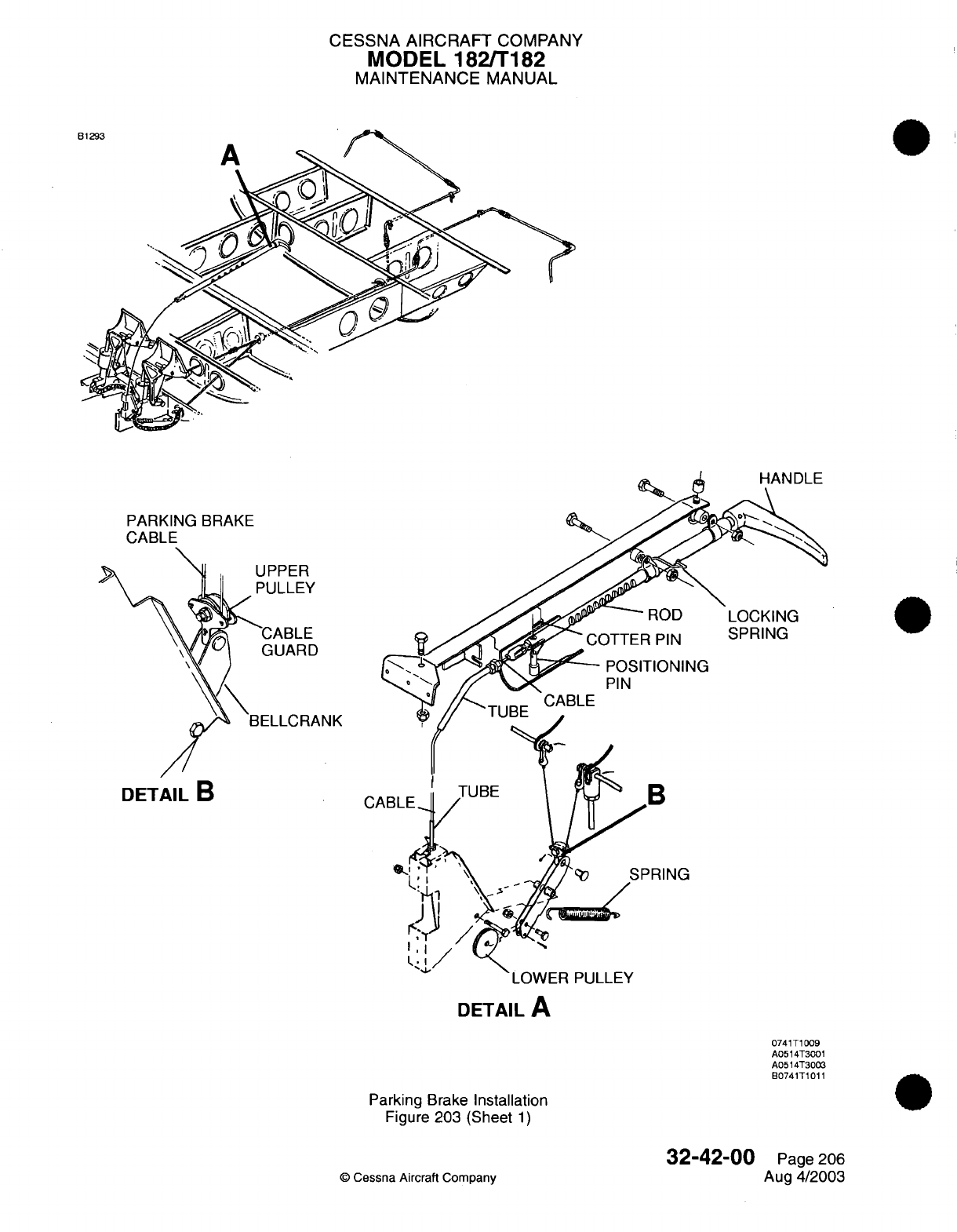
CESSNA AIRCRAFT
COMPANY
MODEL
182/T182
MAINTENANCE
MANUAL
A
PARKING
BRAKE
UPPER
PULLEY
LOCKING
SPRING
POSITIONING
PIN
LOWER
PULLEY
DETAIL
A
Parking
Brake
Installation
Figure
203
(Sheet
1)
©
Cessna
Aircraft
Company
DETAIL
B
C,
0741T1009
A0514T3001
A0514T3003
B0741T1011
0
32-42-00
Page
206
Aug
4/2003
E

CHAPTER
LIGHTS

CESSNA
AIRCRAFT
COMPANY
MODEL
182/T182
MAINTENANCE
MANUAL
LIST
OF
EFFECTIVE
PAGES
CHAPTER-SECTION-SUBJECT
33-Title
33-List
of
Effective
Pages
33-Record
of
Temporary
Revisions
33-Table
of
Contents
33-00-00
33-10-00
33-11-00
33-12-00
33-13-00
33-14-00
33-15-00
33-40-00
33-41-00
33-42-00
33-42-00
33-43-00
©
Cessna Aircraft
Company
PAGE
Page
1
Pages
201-206
Pages
201-204
Pages
201-202
Pages
201-204
Pages
201-202
Pages
201-202
Pages
201-205
Pages
201-203
Pages
101-102
Pages
201-205
Pages 201-202
DATE
April
1/2002
Jul
3/2006
April
1/2002
April
1/2002
Aug
4/2003
Aug
4/2003
April 1/2002
April
1/2002
Jan
2/2006
Jan
2/2006
Jan
2/2006
Aug
4/2003
33
-
LIST
OF
EFFECTIVE PAGES
Page
1
of
1
Jul
3/2006
Temporary
Revision
Number
RECORD
OF
TEMPORARY
REVISIONS
Page
Number
Issue
Date
By
Date
Removed
By
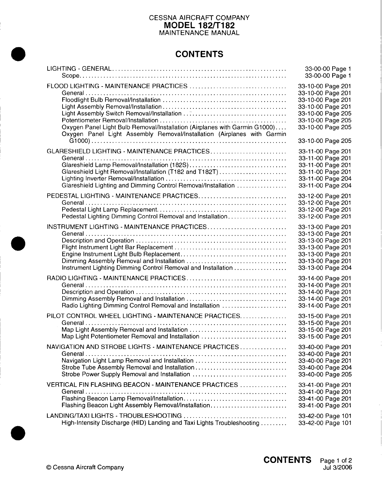
CESSNA
AIRCRAFT
COMPANY
MODEL
182/T182
MAINTENANCE
MANUAL
CONTENTS
LIGHTING
-
GENERAL
............................
...........................
S
cope......................................................................
FLOOD
LIGHTING
-
MAINTENANCE
PRACTICES
.................................
General
...................................................................
Floodlight
Bulb
Removal/Installation
..........................................
Light
Assembly Removal/Installation
..........................................
Light
Assembly
Switch
Removal/Installation
..
...............................
Potentiometer Removal/Installation
...........................................
Oxygen
Panel
Light
Bulb
Removal/Installation
(Airplanes
with
Garmin
G1000)....
Oxygen
Panel
Light
Assembly Removal/Installation
(Airplanes
with Garmin
G
1000)
.................................. ................................
GLARESHIELD
LIGHTING
-
MAINTENANCE PRACTICES
.........................
General
....................................................................
Glareshield
Lamp
Removal/Installation
(182S)
.................................
Glareshield
Light
Removal/Installation
(T182
and
T182T)
.......................
Lighting
Inverter
Removal/Installation
.........................................
Glareshield
Lighting
and
Dimming Control
Removal/Installation
.................
PEDESTAL
LIGHTING
-
MAINTENANCE
PRACTICES..............................
G
e n e
ra
l
.........................................
..
.......
..................
Pedestal
Light
Lamp
Replacement............................................
Pedestal
Lighting
Dimming
Control Removal
and
Installation....................
INSTRUMENT
LIGHTING
-
MAINTENANCE
PRACTICES...........................
General
....................................................................
Description
and
Operation
...................................................
Flight
Instrument
Light Bar
Replacement
......................................
Engine
Instrument
Light
Bulb
Replacement....................................
Dimming
Assembly
Removal
and Installation
..................................
Instrument
Lighting
Dimming Control
Removal
and
Installation
..................
RADIO
LIGHTING
-
MAINTENANCE
PRACTICES..................................
General
....................................................................
Description
and
Operation
...................................................
Dimming
Assembly
Removal and Installation
..................................
Radio
Lighting
Dimming
Control
Removal
and
Installation
......................
PILOT
CONTROL
WHEEL
LIGHTING
-
MAINTENANCE
PRACTICES................
General
...................................................................
Map
Light
Assembly
Removal
and
Installation
.................................
Map
Light
Potentiometer
Removal
and
Installation
.............................
NAVIGATION
AND
STROBE
LIGHTS
-
MAINTENANCE PRACTICES
................
General
....................................................................
Navigation
Light
Lamp
Removal
and
Installation
...............................
Strobe
Tube
Assembly
Removal
and
Installation
...............................
Strobe
Power
Supply
Removal
and
Installation
................................
VERTICAL
FIN
FLASHING
BEACON
-
MAINTENANCE PRACTICES
................
General
....................................................................
Flashing
Beacon
Lamp
Removal/Installation...................................
Flashing
Beacon
Light
Assembly Removal/Installation
........................
LANDING/TAXI LIGHTS
-
TROUBLESHOOTING
.........
..........................
High-Intensity
Discharge
(HID)
Landing
and
Taxi
Lights Troubleshooting
.........
33-00-00
Page
1
33-00-00
Page
1
33-10-00
Page
201
33-10-00
Page
201
33-10-00
Page
201
33-10-00
Page
201
33-10-00
Page
205
33-10-00
Page 205
33-10-00
Page 205
33-10-00
Page
205
33-11-00
Page
201
33-11-00 Page
201
33-11-00 Page
201
33-11-00 Page
201
33-11-00 Page
204
33-11-00 Page
204
33-12-00
Page
201
33-12-00
Page
201
33-12-00
Page
201
33-12-00
Page
201
33-13-00
Page
201
33-13-00
Page
201
33-13-00
Page
201
33-13-00
Page
201
33-13-00
Page
201
33-13-00
Page
201
33-13-00
Page
204
33-14-00
Page
201
33-14-00
Page
201
33-14-00
Page
201
33-14-00
Page
201
33-14-00
Page
201
33-15-00
Page
201
33-15-00
Page
201
33-15-00
Page
201
33-15-00
Page
201
33-40-00
Page
201
33-40-00
Page
201
33-40-00
Page
201
33-40-00
Page
204
33-40-00
Page
205
33-41-00
Page
201
33-41-00
Page
201
33-41-00
Page
201
33-41-00
Page
201
33-42-00
Page
101
33-42-00
Page
101
CONTENTS
Page
1
of
2
Jul
3/2006
©
Cessna
Aircraft
Company
CESSNA AIRCRAFT
COMPANY
MODEL
182/T182
MAINTENANCE
MANUAL
LANDING/TAXI LIGHTS
-
MAINTENANCE PRACTICES
............................
G
en
eral
....................................................................
Troubleshooting
.............................................................
Light
Adjustm
ent
............................
.............................
Light
Removal/Installation................................................
High-Intensity
Discharge
(HID)
Ballast
Removal/Installation
....................
COURTESY LIGHTS
-
MAINTENANCE PRACTICES
...............................
General
....................................................................
Courtesy
Light
Lamp
Removal
and
Installation.................................
33-42-00
Page
201
33-42-00
Page
201
33-42-00
Page
201
33-42-00
Page
201
33-42-00
Page
201
33-42-00
Page 204
33-43-00
Page
201
33-43-00
Page
201
33-43-00
Page
201
CONTENTS
Page
2
of
2
Jul
3/2006
©
Cessna Aircraft
Company
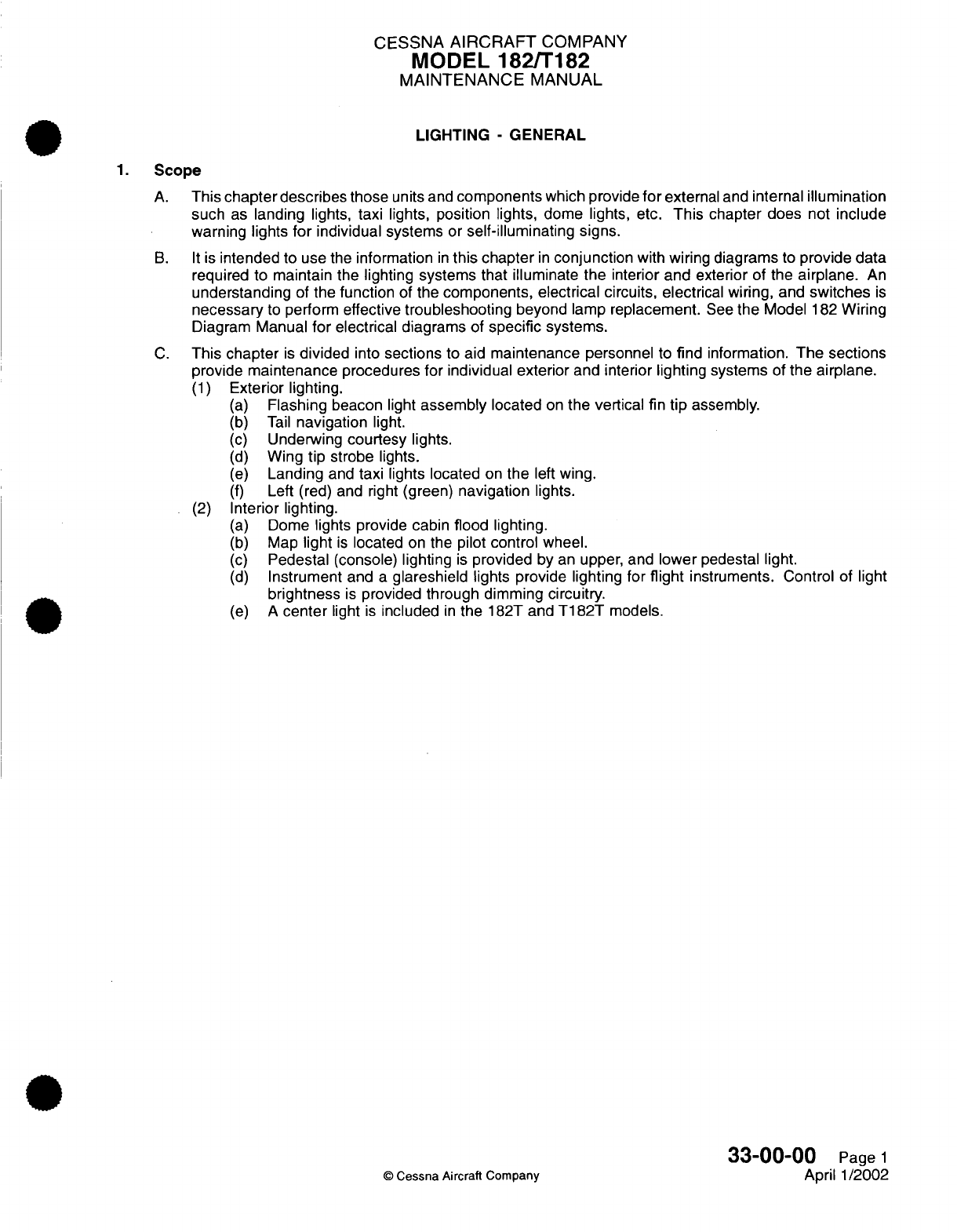
CESSNA
AIRCRAFT
COMPANY
MODEL
182/T182
MAINTENANCE
MANUAL
LIGHTING
-
GENERAL
1.
Scope
A.
This
chapter
describes
those
units
and
components
which
provide
for
external
and
internal
illumination
such
as
landing
lights,
taxi lights, position
lights,
dome lights, etc.
This
chapter
does
not
include
warning lights
for
individual
systems
or
self-illuminating signs.
B. It
is
intended
to use the
information
in
this
chapter
in
conjunction
with
wiring
diagrams
to
provide
data
required
to
maintain the lighting
systems
that
illuminate
the
interior
and
exterior
of the
airplane.
An
understanding
of
the
function
of
the
components, electrical circuits,
electrical
wiring,
and
switches
is
necessary
to
perform
effective
troubleshooting
beyond
lamp
replacement.
See
the
Model
182
Wiring
Diagram
Manual
for
electrical diagrams
of
specific
systems.
C.
This
chapter
is
divided
into
sections
to
aid
maintenance
personnel
to
find
information.
The
sections
provide
maintenance
procedures for individual
exterior
and interior
lighting systems
of
the airplane.
(1)
Exterior lighting.
(a)
Flashing
beacon
light
assembly
located
on
the
vertical
fin
tip
assembly.
(b)
Tail
navigation
light.
(c)
Underwing
courtesy
lights.
(d)
Wing
tip
strobe
lights.
(e)
Landing
and
taxi lights located
on
the
left
wing.
(f)
Left
(red)
and right
(green)
navigation
lights.
(2)
Interior lighting.
(a)
Dome
lights provide cabin
flood lighting.
(b)
Map
light
is
located
on
the
pilot
control
wheel.
(c)
Pedestal
(console) lighting
is
provided
by
an
upper, and
lower
pedestal
light.
(d)
Instrument
and
a
glareshield
lights
provide lighting for
flight
instruments. Control
of
light
brightness
is
provided
through dimming circuitry.
(e)
A
center
light
is
included
in
the
182T
and
T182T
models.
33-00-00
Page
1
©
Cessna Aircraft
Company
April
1/2002
CESSNA
AIRCRAFT
COMPANY
MODEL
182/T182
MAINTENANCE
MANUAL
FLOOD
LIGHTING
-
MAINTENANCE
PRACTICES
1.
General
A.
Cabin
floodlights
are
mounted
in
the aft and
the forward parts
of
the overhead
console.
Each
floodlight
has
a
switch.
The
forward
and the
aft
lights
are
reading
lights.
On
airplanes
with Garmin
G1000
that
are
equipped
with
oxygen,
there
is
a
light
mounted
on
the
oxygen
panel. Dimming
of
the
oxygen
panel
light
is
controlled
by
the STBY
IND
dimmer
switch
located
on
the switch
panel
on
the
pilot
instrument
panel.
WARNING:
Obey
all
oxygen safety
precautions
on
airplanes
that
have
the
oxygen
panel
installed
in
the
overhead
console.
Refer
to
the
oxygen
maintenance
practices
for
correct
procedures
to
use when
you
must
do maintenance
on
or
near
to
the
oxygen
lines.
2.
Floodlight
Bulb Removal/Installation
CAUTION:
Be
careful when
you
remove
and
install
the
floodlight
bulb.
The
floodlight
bulb
can
break
if
too
much
pressure
is
applied
when
you
remove
and
install
it.
NOTE:
Removal/Installation
is
typical
for
all
floodlight
bulbs.
A.
Floodlight
Bulb
Removal
(Refer
to
Figure
201).
(1)
Press
the
lens
holder
up
and
turn
it
counterclockwise.
(2)
Remove the
lens
holder.
(3)
Carefully
push
the
bulb
up
and
turn
it
counterclockwise.
(4)
Remove the
bulb.
B.
Floodlight
Bulb
Installation (Refer
to Figure
201).
(1)
Put
the
bulb
in
position.
(2)
Carefully
push
the
bulb
up
and
turn
it
clockwise.
(3)
Put
the
lens
in
position.
(4)
Push
the
lens
holder
up
and
turn
it
clockwise.
3.
Light
Assembly Removal/Installation
NOTE:
Removal/installation
is
typical for
the
overhead dome
light
assemblies.
A.
Light
Assembly
Removal
(Refer
to
Figure
201).
(1)
Put
the
ALT/BAT
MASTER
switch
in
the
off
position.
CAUTION:
Support
the
overhead console
when
you
remove
the
screws
to
prevent
damage
to
the
electrical
wiring
in
the
overhead
console.
(2)
Remove
the
screws
that
attach the
overhead
console
to
the attach brackets.
(3)
Identify,
tag,
and
disconnect
the
electrical
wires from the light
assembly.
(4)
Remove
the
light
assembly
from
the
overhead
console.
B.
Light
Assembly
Installation
(Refer
to
Figure
201).
(1)
Put
the
light
assembly
in
position.
(2)
Attach
the
light
assembly
to
the overhead
console.
(3)
Connect
the
electrical
wires
to
the
light
assembly.
(4)
Attach
the overhead
console
to
the
attach
brackets
with
the
screws.
(5)
Put
the
ALT/BAT
MASTER
switch
in
the
ON
position.
33-10-00
Page
201
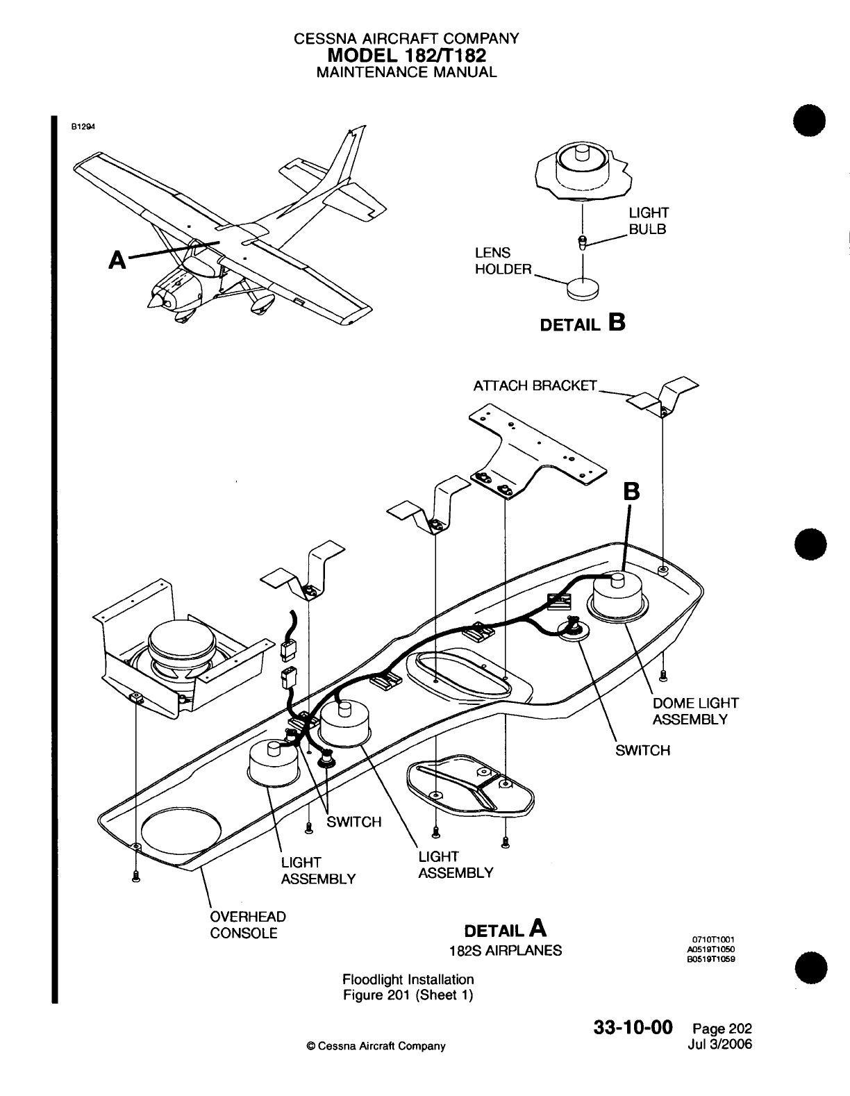
CESSNA
AIRCRAFT
COMPANY
MODEL
182/T182
MAINTENANCE
MANUAL
LIGHT
BULB
LENS
HOLDER
DETAIL
B
ATTACH
BRACKET
B
CONSOLE
DETAIL
A
0710T
182S AIRPLANES
A0519T105
B0519T1059
Floodlight
Installation
Figure
201
(Sheet
1)
33-10-00
©
Cessna Aircraft
Company
Page
202
Jul
3/2006
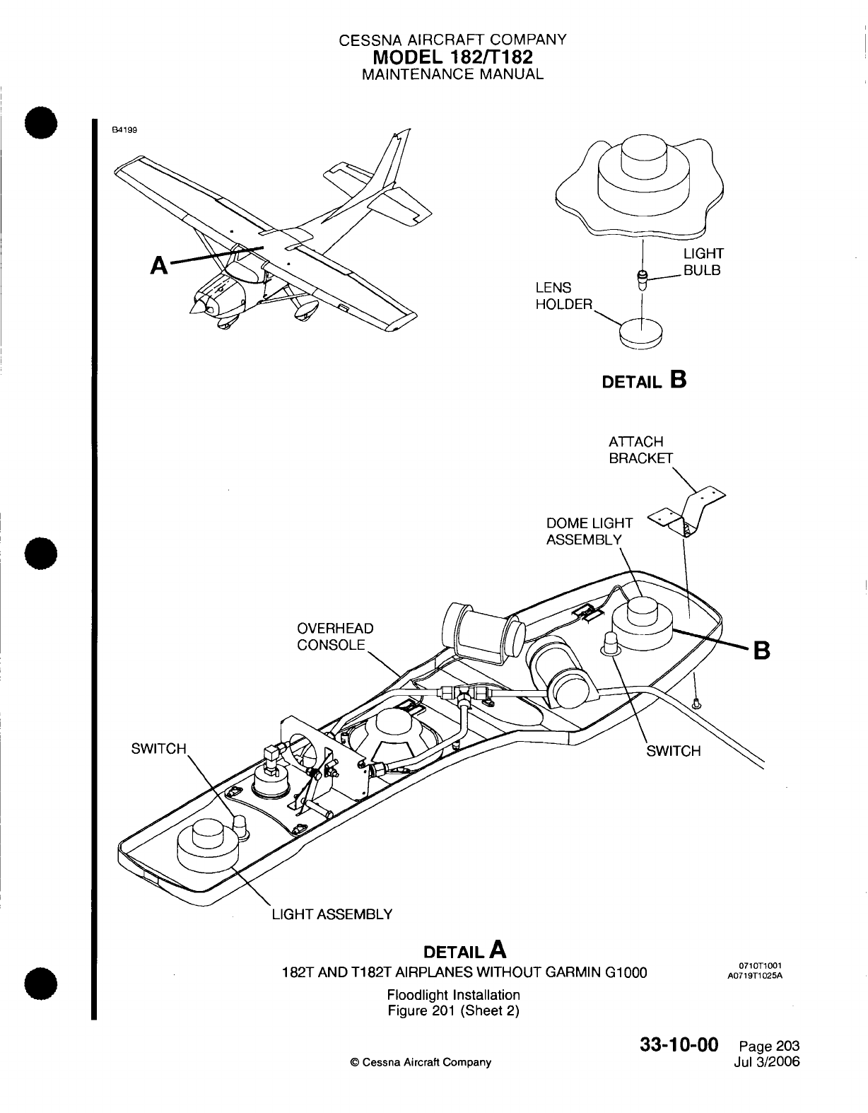
CESSNA
AIRCRAFT
COMPANY
MODEL
182/T182
MAINTENANCE
MANUAL
LEI
HOLDER
DETAIL
B
ATTACH
BRACKET
DOME
LIGH
ASSEMBLY
OVERHEAD
SWITCH
LIGHT
ASSEMBLY
DETAIL
A
182T AND
T182T
AIRPLANES WITHOUT
GARMIN
G1000
Floodlight
Installation
Figure
201
(Sheet
2)
33-10-00
©
Cessna Aircraft
Company
SWITCH
0710T1001
A0719T1025A
Page
203
Jul
3/2006
B4199
B
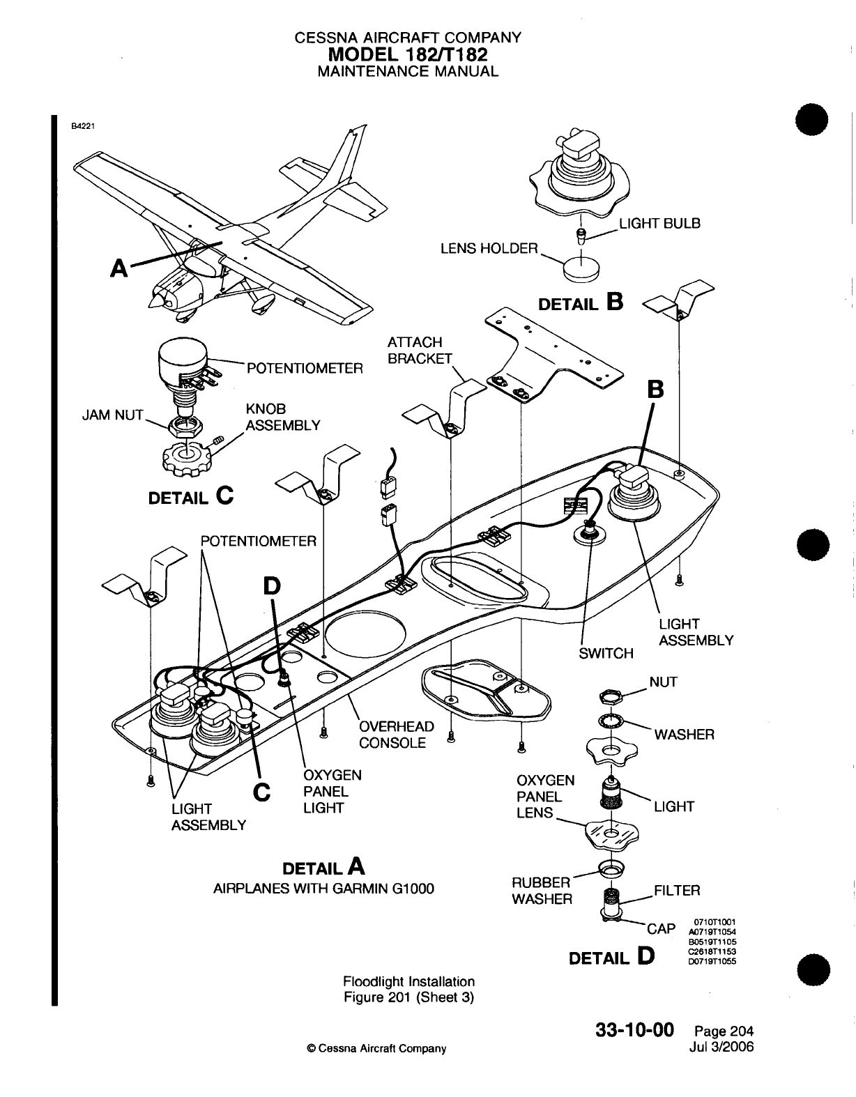
CESSNA
AIRCRAFT
COMPANY
MODEL
182/T182
MAINTENANCE
MANUAL
BULB
LENS
HOLDER
POTENTIOMETER
~
POTENTIOMETER
B
B
JA
LIGHT
ASSEMBLY LIGHT
LIGH
I
DETAIL
A
AIRPLANES
WITH
GARMIN
G1000
FILTER
0710T1001
CAP
A0719T1054
B0519T1105
DETAIL
D
C2618T1153
DETAIL
D
D0719T1055
Floodlight
Installation
Figure
201
(Sheet
3)
33-10-00
©
Cessna Aircraft
Company
Page
204
Jul 3/2006
CESSNA
AIRCRAFT
COMPANY
MODEL
182/T182
MAINTENANCE
MANUAL
4.
Light
Assembly Switch Removal/Installation
A.
Light
Assembly
Switch
Removal
(Refer to
Figure
201).
(1)
Put
the
ALT/BAT
MASTER
switch
in
the off
position.
CAUTION:
Support
the
overhead console
when you
remove
the
screws
to
prevent
damage
to the
electrical
wiring
in
the
overhead
console.
(2)
Remove
the
overhead console
from
the
attach
brackets.
(3)
Identify,
tag, and
disconnect
the
wires
from the
switch.
(4)
Remove
the
switch
from
the
overhead
console.
B.
Light
Assembly
Switch
Installation
(Refer
to Figure
201).
(1)
Install
the
switch
in
the
overhead
console.
(2)
Connect
the
electrical wires
to
the switch.
(3)
Attach
the
overhead
console
to
the
attach
brackets
with
the
screws.
(4) Put
the
ALT/BAT
MASTER
switch
in
the
ON
position.
5.
Potentiometer
Removal/Installation
A.
Potentiometer
Removal
(Refer
to
Figure
201).
(1)
Put
the
ALT/BAT
MASTER
switch
in
the
off
position.
CAUTION:
Support
the
overhead
console
when you remove the
screws
to
prevent
damage
to
the
electrical
wiring
in
the
overhead
console.
(2)
Remove
the
overhead
console
from the
attach brackets.
(3)
Identify,
tag,
and
disconnect
the
wires
from the
switch.
(4)
Remove
the
knob
assembly
and
the
jam
nut
from
the potentiometer.
(5)
Remove
the
potentiometer
from the
overhead
console.
B.
Potentiometer
Installation (Refer
to
Figure
201).
(1)
Install
the
jam
nut
and
the
knob assembly.
(2)
Connect
the
electrical wires
to
the
potentiometer.
(3)
Attach
the
overhead
console
to
the
attach
brackets
with
the
screws.
(4)
Put
the
ALT/BAT
MASTER
switch
in
the
ON
position.
6.
Oxygen
Panel
Light
Bulb
Removal/Installation
(Airplanes
with
Garmin G1000)
CAUTION:
Be
careful
when
you
remove
and
install
the
oxygen
panel
light bulb.
The
oxygen
panel
light
bulb can break
if
too
much
pressure
is
applied
when
you
remove
and
install
it.
A.
Oxygen
Panel
Light
Bulb
Removal (Refer
to Figure
201).
(1)
Put
the
ALT/BAT
MASTER switch
in
the off
position.
(2)
Remove
the
oxygen
panel
light assembly.
(3)
Carefully
turn
the
bulb
counterclockwise.
(4)
Remove
the
bulb
from the
light assembly.
B.
Oxygen
Panel Light
Bulb
Installation
(Refer
to Figure
201).
(1)
Put
the
bulb
in
position.
(2)
Carefully
turn
the
bulb
clockwise.
(3)
Install
the
oxygen
panel
light
assembly.
(4)
Put
the
ALT/BAT
MASTER
switch
in
the
ON
position.
7.
Oxygen
Panel
Light
Assembly
Removal/Installation (Airplanes
with
Garmin G1000)
A.
Oxygen
Panel
Light
Assembly
Removal (Refer
to
Figure
201).
(1)
Put
the
ALT/BAT
MASTER switch
in
the
off
position.
33-10-00
Page
205
Cessna
Aircraft
Company
Jul 3/2006
CESSNA AIRCRAFT
COMPANY
MODEL
182/T182
MAINTENANCE
MANUAL
Turn
the
cap
on
the
oxygen
panel
light
assembly counterclockwise.
Remove
the
cap,
washer, and
light
assembly
from
the
oxygen
panel.
B.
Oxygen
Panel
Light
Assembly
Installation
(Refer
to
Figure
201.)
(1)
Put
the
washer
and
light
assembly
in
position
on
the
oxygen
panel.
(2)
Put
the
cap
in
position
on
the
light
assembly.
(3)
Turn the
cap
clockwise
to
tighten.
(4)
Put the
ALT/BAT
MASTER
switch
in
the
ON
position.
©
Cessna
Aircraft Company
33-10-00
Page
206
Jul
3/2006
(2)
(3)
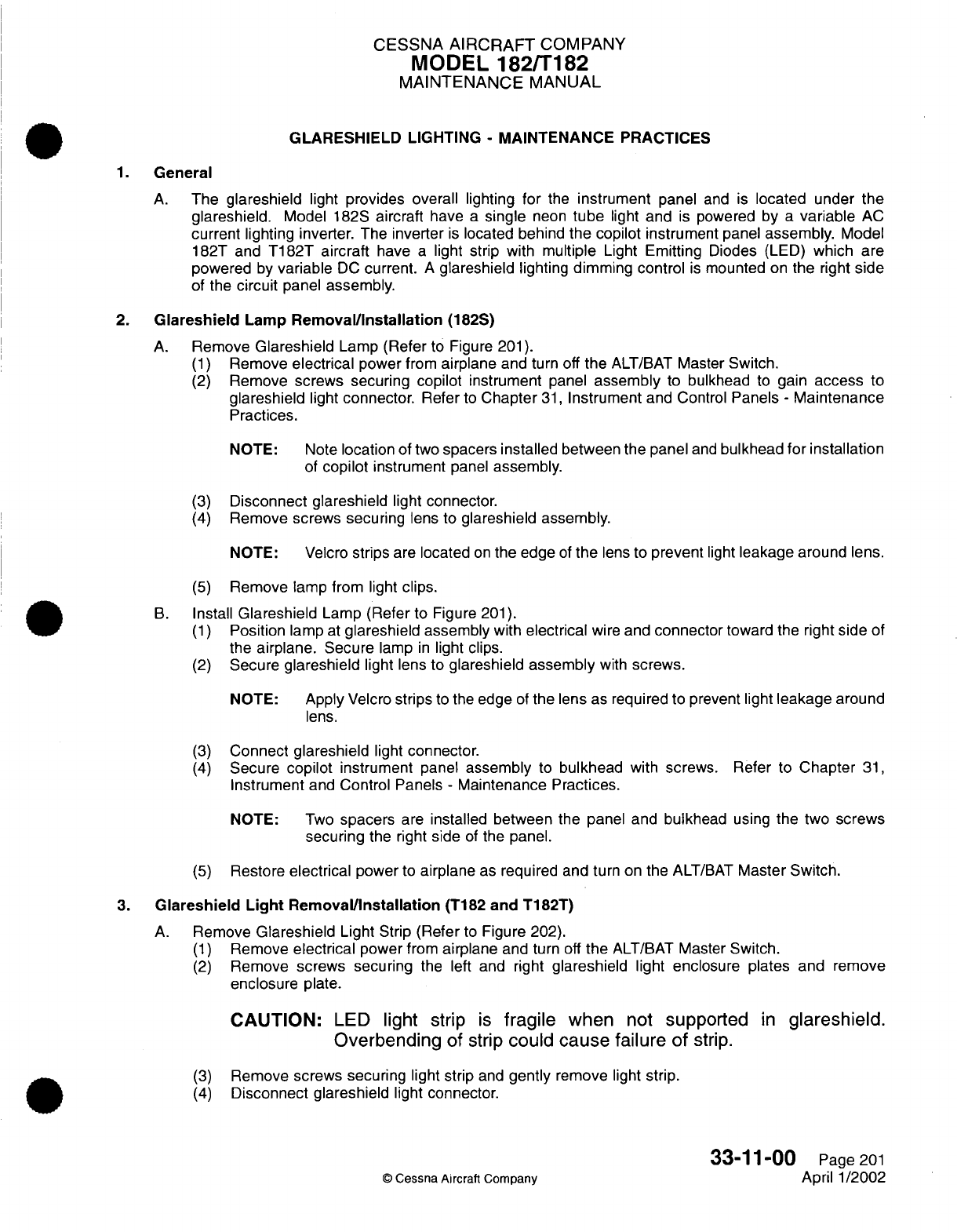
CESSNA
AIRCRAFT
COMPANY
MODEL
182/T182
MAINTENANCE
MANUAL
GLARESHIELD
LIGHTING
-
MAINTENANCE PRACTICES
1.
General
A.
The
glareshield
light
provides
overall lighting
for
the
instrument
panel
and
is
located
under
the
glareshield.
Model
182S
aircraft
have
a
single
neon
tube
light
and
is
powered
by
a
variable
AC
current
lighting inverter.
The
inverter
is
located behind
the
copilot
instrument
panel
assembly.
Model
182T
and
T182T aircraft
have
a
light
strip with
multiple
Light
Emitting
Diodes
(LED)
which
are
powered
by
variable
DC
current.
A
glareshield
lighting
dimming control
is
mounted
on
the
right
side
of
the
circuit
panel
assembly.
2.
Glareshield
Lamp
Removal/Installation
(182S)
A.
Remove
Glareshield
Lamp
(Refer
to
Figure
201).
(1)
Remove
electrical
power
from
airplane
and
turn
off
the
ALT/BAT
Master
Switch.
(2)
Remove
screws securing copilot
instrument
panel
assembly
to
bulkhead
to
gain
access
to
glareshield
light connector.
Refer
to
Chapter
31,
Instrument
and Control
Panels
-
Maintenance
Practices.
NOTE: Note
location
of two
spacers
installed
between the panel
and
bulkhead
for installation
of
copilot
instrument
panel
assembly.
(3)
Disconnect
glareshield
light
connector.
(4)
Remove
screws securing
lens to
glareshield
assembly.
NOTE: Velcro
strips
are
located
on
the
edge
of
the
lens
to
prevent
light
leakage
around lens.
(5)
Remove
lamp from
light
clips.
B.
Install
Glareshield
Lamp
(Refer
to
Figure
201).
(1)
Position
lamp
at
glareshield
assembly
with
electrical
wire
and
connector
toward the right
side
of
the
airplane. Secure
lamp
in
light
clips.
(2)
Secure
glareshield
light
lens to
glareshield
assembly
with
screws.
NOTE:
Apply
Velcro
strips
to
the
edge
of
the
lens
as
required to
prevent
light
leakage
around
lens.
(3)
Connect
glareshield
light
connector.
(4)
Secure
copilot
instrument
panel
assembly
to
bulkhead
with screws. Refer
to
Chapter
31,
Instrument
and
Control
Panels
-
Maintenance
Practices.
NOTE:
Two
spacers
are
installed between the
panel
and
bulkhead
using
the
two
screws
securing
the right
side
of
the
panel.
(5)
Restore
electrical
power
to
airplane
as
required
and
turn
on
the
ALT/BAT
Master Switch.
3.
Glareshield
Light
Removal/Installation
(T182
and
T182T)
A.
Remove
Glareshield
Light
Strip (Refer
to
Figure 202).
(1)
Remove
electrical
power
from
airplane
and turn
off
the
ALT/BAT
Master
Switch.
(2)
Remove
screws securing
the
left and
right
glareshield
light enclosure plates and
remove
enclosure
plate.
CAUTION:
LED
light
strip
is
fragile
when
not
supported
in
glareshield.
Overbending
of
strip
could
cause
failure of
strip.
(3)
Remove
screws securing
light strip
and
gently
remove
light
strip.
(4)
Disconnect
glareshield
light
connector.
33-11-00
Page
201
©
Cessna
Aircraft
Company
April
1/2002
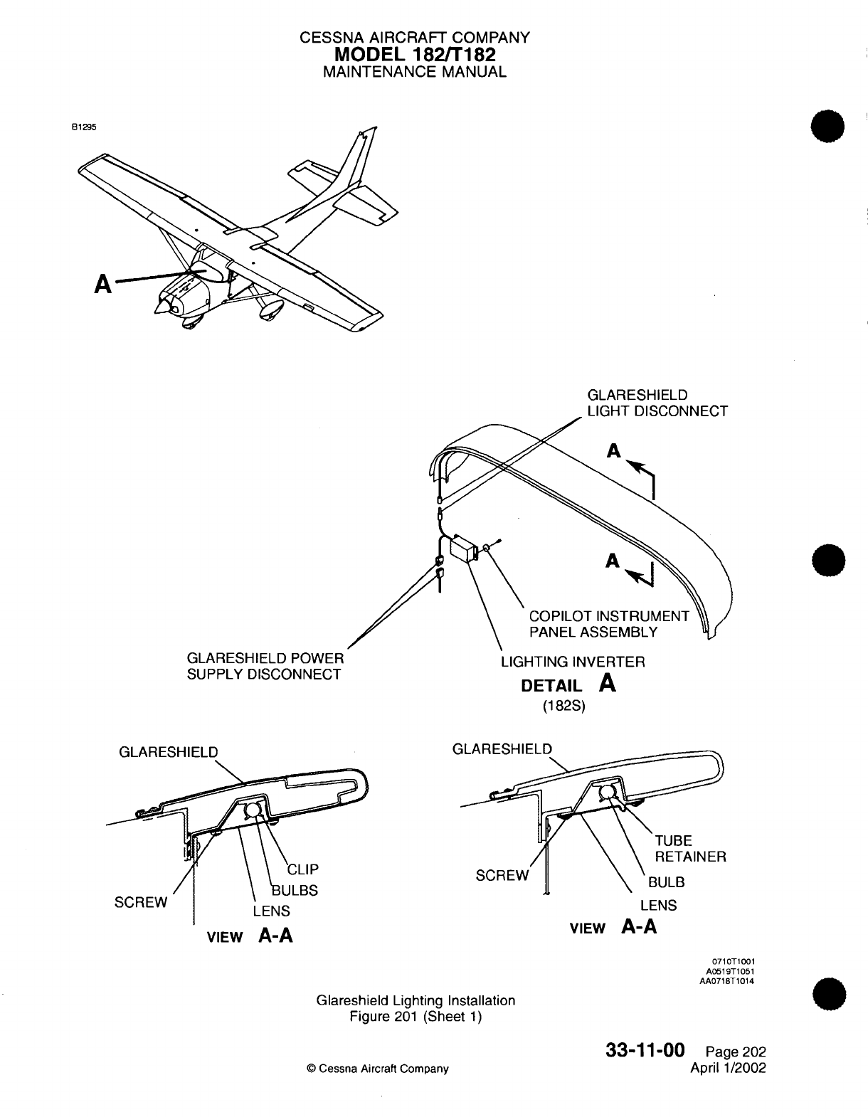
CESSNA AIRCRAFT
COMPANY
MODEL
182/T182
MAINTENANCE
MANUAL
tj
GLARESHIELD
LIGHT
DISCONNECT
A
A
GLARESHIELD
POWER
SUPPLY
DISCONNECT
GLARESHIELD
COPILOT
INSTRUMENT
PANEL
ASSEMBLY
LIGHTING INVERTER
DETAIL
A
(182S)
LENS
VIEW
A-A
LENS
VIEW
A-A
Glareshield
Lighting
Installation
Figure
201
(Sheet
1)
©
Cessna Aircraft
Company
33-11-00
Page
202
April
1/2002
onCr-vv
0710T1001
A0519T1051
AA0718T1014
n<onz
'-i
Arr-OLII--I
n
v
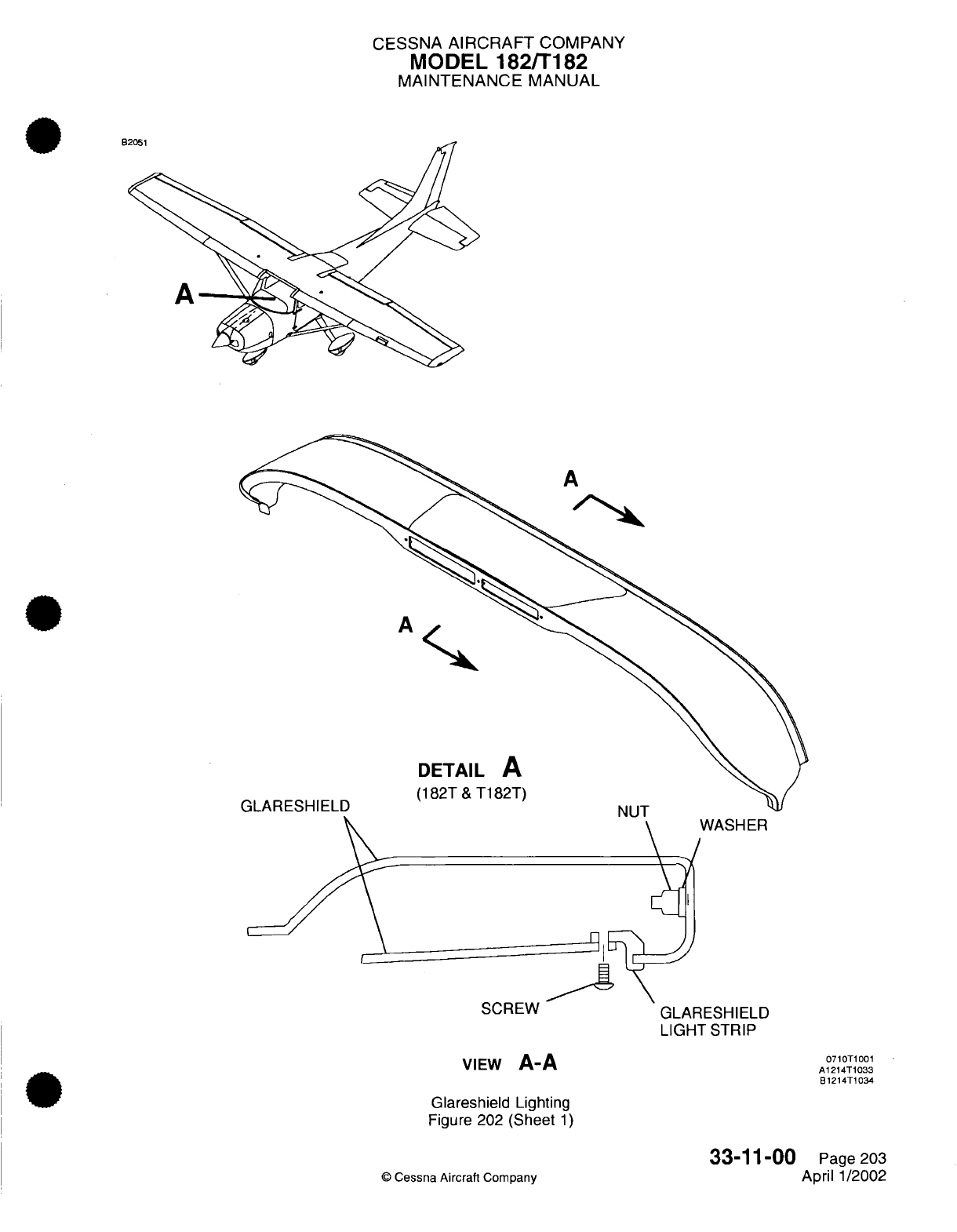
CESSNA
AIRCRAFT
COMPANY
MODEL
182/T182
MAINTENANCE
MANUAL
A
A
DETAIL
A
(182T
&
T182T)
GLARESHIELD
ER
COD-7
Itl-lVV
VIEW
A-A
Glareshield Lighting
Figure 202
(Sheet
1)
GLARESHIELD
LIGHT STRIP
0710T1001
A1214T1033
B1214T1034
33-11-00
©
Cessna
Aircraft
Company
Page 203
April 1/2002
.^
a
,5W,
I
CESSNA AIRCRAFT
COMPANY
MODEL 182/T182
MAINTENANCE
MANUAL
B.
Install
Glareshield
Light Strip (Refer
to Figure
202).
(1)
Connect
glareshield
light connector.
CAUTION:
LED
light
strip
is
fragile
when
not
supported
in
glareshield.
Overbending of
strip
could
cause
failure
of
strip.
(2)
(3)
(4)
Gently
install light strip
into
glareshield.
Secure
light strip,
then
left and
right
enclosure
plates
with
screws.
Restore
electrical power
to
airplane
as
required
and
turn
on the
ALT/BAT
Master
Switch.
4.
Lighting
Inverter
Removal/Installation
A.
Remove
Lighting Inverter (Refer
to
Figure
201).
(1)
Remove
electrical
power
from
airplane
and
turn
off
the
ALT/BAT
Master
Switch.
(2)
Remove
screws
securing
copilot
instrument
panel
assembly
to
bulkhead
to gain
access
to
lighting
inverter
wiring
connectors. Refer
to
Chapter
31,
Instrument
and
Control Panels
-
Maintenance Practices.
NOTE: Note
location
of
two
spacers
installed
between
the
panel
and
bulkhead
for
installation
of
copilot
instrument
panel assembly.
(3)
(4)
(5)
Disconnect glareshield
light
connector
and
glareshield power
supply
connector.
Remove
screws securing
lighting
inverter
to
back
of
instrument
panel
assembly.
Remove
lighting
inverter
from
airplane.
B.
Install
Lighting Inverter
(Refer
to
Figure
201).
(1)
Secure lighting
inverter
to
back
of
instrument
panel
assembly
with
screws.
(2)
Connect
glareshield
light
connector
and
glareshield
power
supply connector.
(3)
Secure
copilot
instrument
panel
assembly
to
bulkhead
with
screws. Refer
to
Chapter
31,
Instrument
and
Control Panels
-
Maintenance
Practices.
NOTE:
Two
spacers
are
installed
between
the
panel and
bulkhead
using
the
two
screws
securing
the
right
side
of
the panel.
(4)
Restore
electrical
power
to
airplane
as
required
and turn
on
the
ALT/BAT
Master
Switch.
5.
Glareshield
Lighting
and
Dimming
Control Removal/Installation
A.
For
the
Glareshield
Lighting
and
Dimming
Control
Removal/Installation,
refer
to
Radio Lighting
-
Maintenance Practices.
33-11-00
©
Cessna
Aircraft
Company
Page
204
April
1/2002
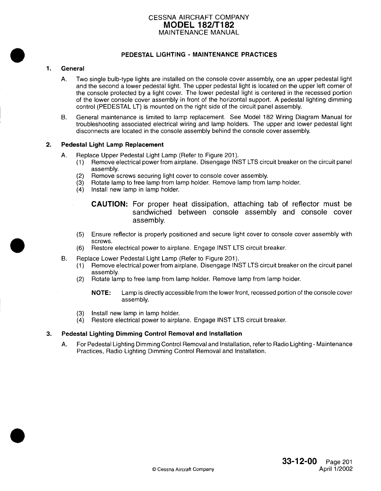
CESSNA
AIRCRAFT
COMPANY
MODEL
182/T182
MAINTENANCE
MANUAL
PEDESTAL
LIGHTING
-
MAINTENANCE PRACTICES
1.
General
A.
Two
single bulb-type
lights
are
installed
on
the
console
cover
assembly,
one
an
upper
pedestal
light
and the
second
a
lower
pedestal
light.
The
upper pedestal
light
is
located
on
the
upper
left
corner
of
the
console
protected by
a
light
cover.
The
lower
pedestal
light
is
centered
in
the
recessed
portion
of
the
lower
console cover
assembly
in
front
of
the
horizontal
support.
A
pedestal lighting dimming
control
(PEDESTAL
LT)
is
mounted
on
the
right
side
of
the
circuit panel
assembly.
B.
General
maintenance
is
limited to lamp
replacement.
See
Model 182 Wiring
Diagram
Manual
for
troubleshooting
associated
electrical
wiring
and
lamp
holders.
The
upper
and
lower
pedestal
light
disconnects
are
located
in
the
console assembly
behind
the
console
cover
assembly.
2.
Pedestal
Light
Lamp
Replacement
A.
Replace Upper
Pedestal
Light
Lamp
(Refer
to
Figure
201).
(1)
Remove
electrical
power
from
airplane.
Disengage
INST
LTS
circuit
breaker
on
the
circuit
panel
assembly.
(2)
Remove
screws
securing
light
cover
to
console
cover
assembly.
(3)
Rotate lamp
to
free
lamp from
lamp
holder.
Remove
lamp
from
lamp
holder.
(4)
Install
new
lamp
in
lamp
holder.
CAUTION:
For
proper
heat
dissipation,
attaching
tab
of
reflector
must
be
sandwiched
between
console
assembly
and
console
cover
assembly.
(5)
Ensure
reflector
is
properly
positioned
and
secure
light cover
to
console
cover
assembly
with
screws.
(6)
Restore
electrical
power
to
airplane.
Engage
INST
LTS
circuit
breaker.
B.
Replace Lower Pedestal
Light
Lamp
(Refer
to
Figure
201).
(1)
Remove
electrical
power
from
airplane.
Disengage
INST
LTS
circuit
breaker
on the
circuit
panel
assembly.
(2)
Rotate lamp
to
free
lamp
from lamp
holder.
Remove
lamp
from
lamp
holder.
NOTE: Lamp
is
directly
accessible
from
the
lower
front,
recessed
portion
of the
console
cover
assembly.
(3)
Install new
lamp
in
lamp
holder.
(4)
Restore
electrical
power
to
airplane. Engage
INST
LTS
circuit
breaker.
3.
Pedestal
Lighting
Dimming
Control
Removal
and
Installation
A.
For
Pedestal Lighting
Dimming Control
Removal
and
Installation,
refer
to
Radio
Lighting
-
Maintenance
Practices, Radio Lighting
Dimming
Control
Removal
and
Installation.
33-12-00
Page
201
©
Cessna
Aircraft
Company
April 1/2002
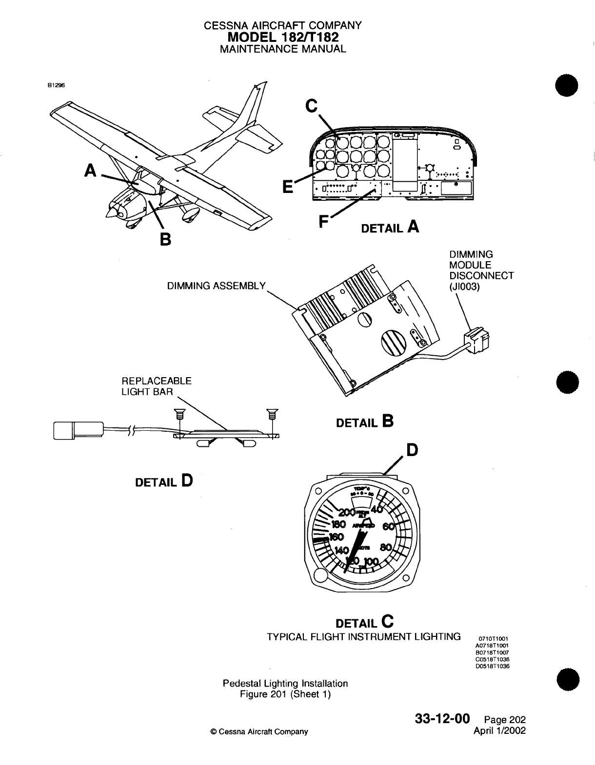
CESSNA AIRCRAFT
COMPANY
MODEL
182/T182
MAINTENANCE
MANUAL
DIMMING
ASSEMBLY
REPLACEABLE
LIGHT
BAR
Li==J
TI
DETAIL
B
D
DETAIL
C
TYPICAL
FLIGHT INSTRUMENT
LIGHTING
Pedestal
Lighting
Installation
Figure
201
(Sheet
1)
©
Cessna
Aircraft Company
B
DIMMING
·
afr"M
l II
NECT
DETAIL
D
0710T1001
A0718T1001
B0718T1007
C0518T1036
D0518T1036
33-12-00
Page
202
April
1/2002
IN
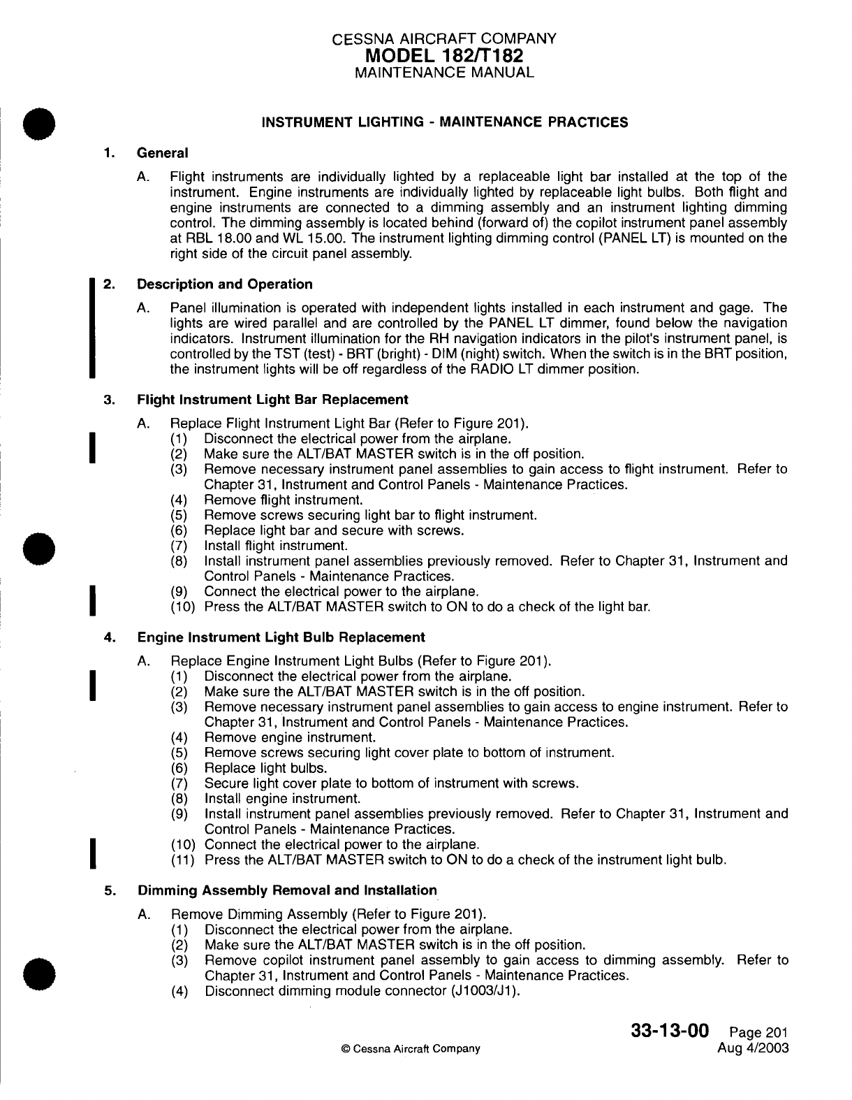
CESSNA
AIRCRAFT
COMPANY
MODEL
182/T182
MAINTENANCE
MANUAL
INSTRUMENT LIGHTING
-
MAINTENANCE
PRACTICES
1.
General
A.
Flight instruments
are
individually
lighted
by
a
replaceable light bar
installed
at
the
top
of the
instrument.
Engine
instruments
are
individually
lighted
by
replaceable
light
bulbs.
Both
flight
and
engine
instruments
are
connected
to
a
dimming
assembly
and
an
instrument
lighting
dimming
control.
The
dimming
assembly
is
located
behind
(forward
of)
the
copilot
instrument
panel assembly
at
RBL
18.00 and
WL
15.00.
The
instrument lighting
dimming
control
(PANEL
LT)
is
mounted
on
the
right
side
of the
circuit
panel
assembly.
2.
Description
and
Operation
A.
Panel
illumination
is
operated
with
independent
lights
installed
in
each instrument and
gage.
The
lights
are
wired
parallel
and
are
controlled
by
the
PANEL
LT
dimmer,
found
below the navigation
indicators.
Instrument
illumination for
the
RH
navigation indicators
in
the
pilot's
instrument
panel,
is
controlled
by
the
TST
(test)
-
BRT
(bright)
-
DIM
(night)
switch.
When
the
switch
is
in
the
BRT
position,
the instrument lights
will
be
off
regardless
of
the
RADIO
LT
dimmer position.
3.
Flight
Instrument
Light
Bar Replacement
A.
Replace
Flight
Instrument Light
Bar
(Refer
to Figure
201).
(1)
Disconnect
the
electrical
power
from
the
airplane.
(2)
Make
sure
the
ALT/BAT
MASTER
switch
is
in
the
off
position.
(3)
Remove
necessary
instrument
panel
assemblies
to
gain
access
to
flight
instrument.
Refer
to
Chapter
31,
Instrument
and
Control
Panels
-
Maintenance
Practices.
(4)
Remove
flight
instrument.
(5)
Remove
screws
securing
light
bar
to
flight
instrument.
(6)
Replace
light
bar
and
secure
with
screws.
(7)
Install
flight
instrument.
(8)
Install
instrument panel
assemblies
previously
removed.
Refer
to
Chapter
31,
Instrument
and
Control Panels
-
Maintenance
Practices.
(9)
Connect
the
electrical
power
to
the
airplane.
(10)
Press the
ALT/BAT
MASTER
switch
to
ON
to
do
a
check
of
the light
bar.
4. Engine
Instrument
Light
Bulb
Replacement
A.
Replace
Engine
Instrument
Light
Bulbs
(Refer
to
Figure
201).
(1)
Disconnect
the
electrical
power
from
the
airplane.
(2)
Make sure
the
ALT/BAT
MASTER
switch
is in
the off
position.
(3)
Remove
necessary
instrument
panel
assemblies
to
gain
access
to
engine
instrument.
Refer
to
Chapter
31,
Instrument
and
Control
Panels
-
Maintenance
Practices.
(4)
Remove engine
instrument.
(5)
Remove
screws
securing
light
cover
plate
to
bottom
of
instrument.
(6)
Replace light
bulbs.
(7)
Secure light cover plate
to
bottom
of
instrument
with screws.
(8)
Install
engine instrument.
(9)
Install
instrument panel
assemblies
previously
removed.
Refer
to
Chapter
31,
Instrument
and
Control
Panels
-
Maintenance Practices.
1| ~
(10)
Connect
the
electrical power
to
the
airplane.
(11)
Press the
ALT/BAT
MASTER
switch
to
ON
to
do
a
check
of
the instrument
light
bulb.
5.
Dimming
Assembly
Removal
and
Installation
A.
Remove
Dimming
Assembly
(Refer
to
Figure
201).
(1)
Disconnect
the
electrical
power from the
airplane.
(2)
Make
sure
the
ALT/BAT
MASTER
switch
is
in
the off
position.
(3)
Remove
copilot
instrument
panel
assembly
to
gain
access
to
dimming
assembly. Refer
to
Chapter
31,
Instrument
and
Control Panels
-
Maintenance
Practices.
(4)
Disconnect
dimming module
connector
(J1003/J1).
33-13-00
Page
201
©
Cessna
Aircraft
Company
Aug
4/2003
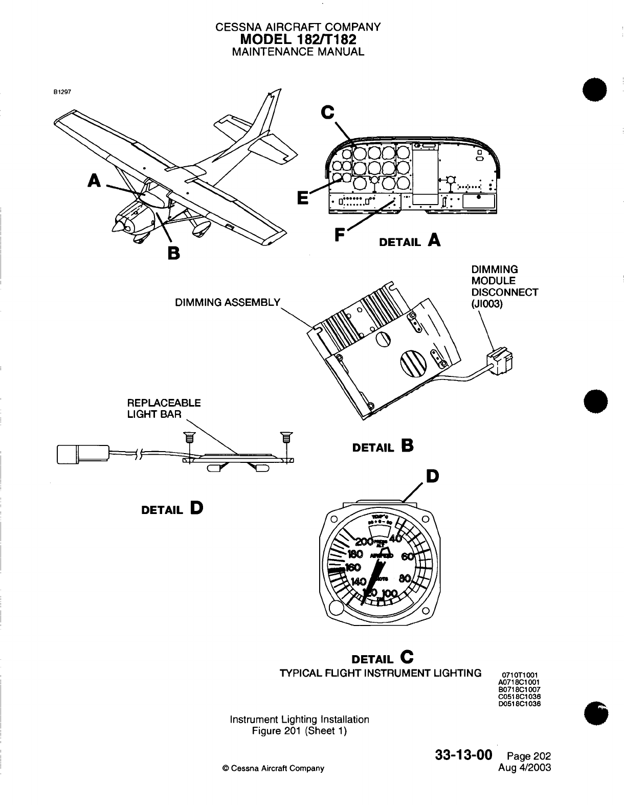
CESSNA AIRCRAFT
COMPANY
MODEL
182/T182
MAINTENANCE
MANUAL
C
B
DIMMING
REPLACEABLE
LIGHT
BAR
DETAIL
B
D
DETAIL
D
DETAIL
C
TYPICAL
FLIGHT INSTRUMENT
LIGHTING
Instrument
Lighting
Installation
Figure
201
(Sheet
1)
33-13-00
©
Cessna
Aircraft
Company
Ue
IAIL
P
DIMMING
innAr
i
11
NECT
0710T1001
A0718C1
001
B0718C1007
C0518C1036
D0518C1036
Page
202
Aug
4/2003
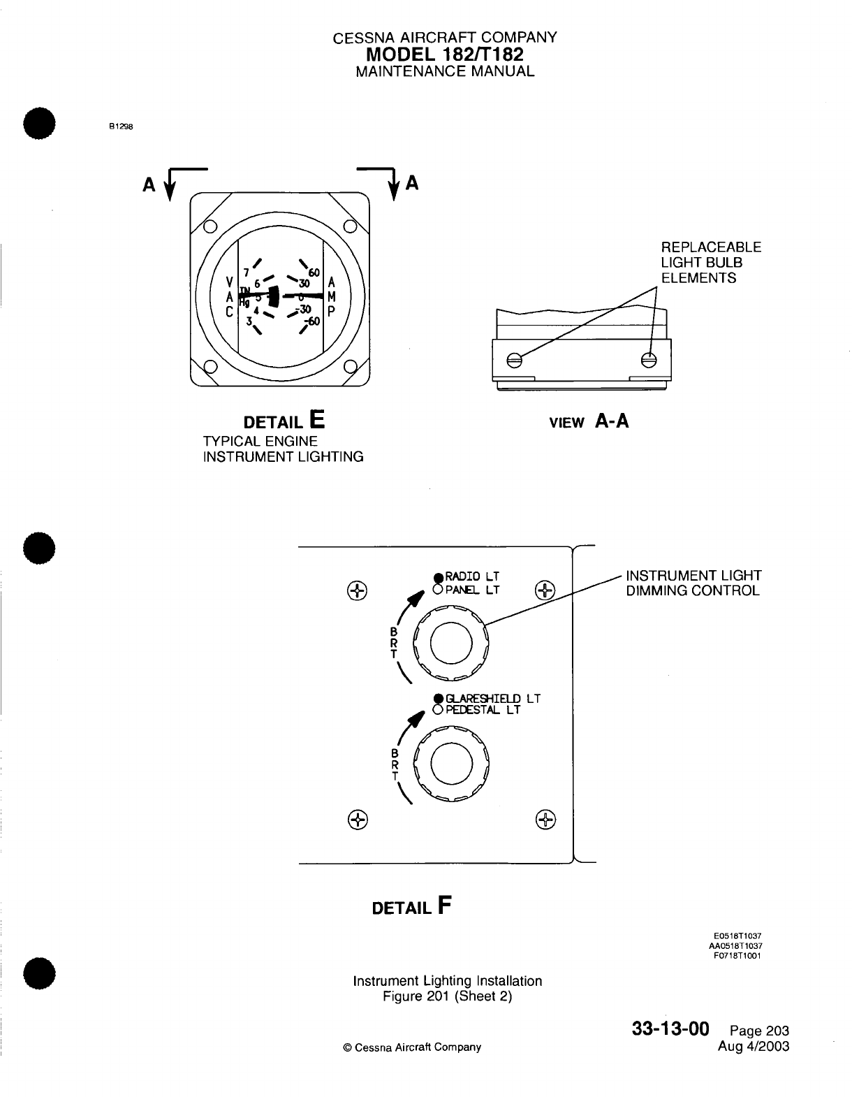
CESSNA
AIRCRAFT
COMPANY
MODEL
182/T182
MAINTENANCE
MANUAL
81298
3HA
/
REPLACEABLE
LIGHT
BULB
ELEMENTS
I Ij
DETAIL
E
TYPICAL
ENGINE
INSTRUMENT
LIGHTING
VIEW
A-A
INSTRUMENT
LIGHT
DIMMING
CONTROL
LT
B
R
T
DETAIL
F
E0518T1037
AA0518T1037
F0718T1001
Instrument
Lighting
Installation
Figure
201
(Sheet
2)
©
Cessna
Aircraft
Company
33-13-00
Page
203
Aug
4/2003
A
f--
/\
\
_ rsvnTn I T
CESSNA
AIRCRAFT
COMPANY
MODEL 182/T182
MAINTENANCE
MANUAL
(5)
(6)
Remove screws securing
dimming
assembly
to
heat
sink
support assembly.
Remove dimming
assembly
from
airplane.
B.
Install
Dimming
Assembly
(Refer
to
Figure
201).
(1)
Position dimming
assembly
and
secure to
heat
sink support assembly
with
screws.
(2)
Connect
dimming module
connector
(J1003/J1).
(3)
Install
copilot
instrument
panel
assembly. Refer
to
Chapter
31,
Instrument
and
Control
Panels
-
Maintenance Practices.
(4)
Connect
the
electrical
power
to
the
airplane.
(5)
Press
the
ALT/BAT
MASTER
switch
to
ON
to
do
a
check
of
the dimming assembly.
6.
Instrument
Lighting
Dimming
Control
Removal and
Installation
A.
For
Instrument
Lighting
Dimming
Control
Removal and
Installation,
refer
to
Radio
Lighting
-
Maintenance Practices,
Radio
Lighting
Dimming Control
Removal
and
Installation.
33-13-00
Page
204
©
Cessna Aircraft Company
Aug
4/2003
I
CESSNA
AIRCRAFT
COMPANY
MODEL
182/T182
MAINTENANCE
MANUAL
RADIO
LIGHTING
-
MAINTENANCE PRACTICES
1.
General
A.
Radio
lighting
consists
of
internally
lighted
radios,
a
dimming assembly,
and
a
radio
lighting
(RADIO
LT)
dimming control. Maintenance
practices
consist
of
removal
and
installation
for
the
dimming
assembly
and
radio
lighting
dimming control.
2.
Description
and
Operation
A.
Panel
illumination
is
operated
with
independent
lights
installed
in
each
instrument
and
gage.
The
lights
are
wired parallel
and
are
controlled
by
the
PANEL
LT
dimmer,
found
below
the
navigation
indicators.
Illumination
intensity
for
the
radios
is
controlled
by
the
TST
(test)
-
BRT
(bright)
-
DIM
(night) switch.
When
the switch
is
in
the
BRT
position,
the
radio
illumination
will
be off
regardless
of
the
RADIO
LT
dimmer
position.
3.
Dimming
Assembly
Removal
and
Installation
A.
For
Dimming
Assembly
Removal
and
Installation,
refer
to
Instrument
Lighting
-
Maintenance
Practices,
Dimming
Assembly
Removal
and
Installation.
4. Radio
Lighting
Dimming
Control
Removal
and
Installation
NOTE:
Two
dimming control potentiometers
are located
on
the
circuit
panel
assembly. One
dimming
control
serves
as
the
radio
lighting
(RADIO
LT)
and
instrument
lighting
(PANEL
LT)
dimming
control, the second
dimming
control serves
as
the
glareshield
lighting
(GLARESHIELD
LT)
and
pedestal
lighting
(PEDESTAL
LT)
dimming control.
Removal
and
installation for
both
dimming
controls
are
typical.
A.
Remove
Dimming Control
(Refer
to
Figure
201).
(1)
Disconnect
the
electrical
power
from
the
airplane.
(2)
Make
sure
the
ALT/BAT
MASTER
switch
in
the
off
position.
(3)
Remove
circuit
panel
assembly. Refer
to
Chapter
31,
Instrument
and
Control
Panels
-
Maintenance
Practices.
(4)
Loosen
setscrew
on
knob
and
remove
knob
to
access
nut
securing
dimming
control
to
circuit
panel
assembly.
(5)
Remove
nut
securing
dimmer
control
to
circuit
panel
assembly.
(6)
Identify, tag
and
disconnect
the
wires
from the
dimming
control.
(7)
Remove dimming
control
from
airplane.
B.
Install Dimming Control
(Refer
to Figure
201).
(1)
Position
dimming
control
and
solder
labeled wires
to
proper
pins.
See
Model
182
Wiring
Diagram
Manual.
(2)
Place dimming
control through
circuit
panel
assembly
and
secure
with nut.
(3)
Position
knob
on
dimming
control
and
set
with setscrew.
(4)
Install
circuit
panel
assembly.
Refer
to
Chapter
31,
Instrument
and
Control
Panels
-
Maintenance
Practices.
(5)
Connect
the
electrical
power
to
the
airplane.
(6)
Press
the
ALT/BAT
MASTER
switch
to
ON
to
do
a
check
of
the
dimming
control.
33-14-00
Page
201
©
Cessna
Aircraft
Company
Aug
4/2003
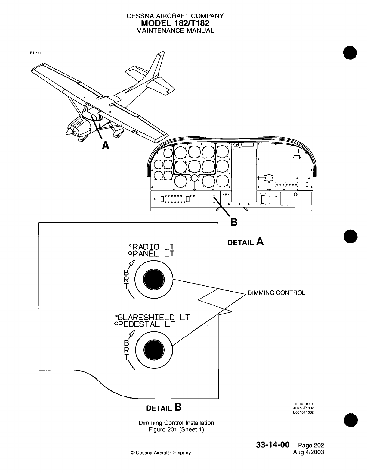
CESSNA
AIRCRAFT
COMPANY
MODEL
182/T182
MAINTENANCE
MANUAL
A
O
Q.*
.1.
*
B
"RADIO
LT
oPANEL
LT
DETAIL
A
DIMMING
CONTROL
DETAIL
B
Dimming Control
Installation
Figure
201
(Sheet
1)
33-14-00
©
Cessna
Aircraft Company
0710T1001
A0718T1002
B0518T1032
Page
202
Aug
4/2003
;
*
_
_
E
I
°GL
oPE
E
1
B
I
Ca
---
1
t
-
.-. 'e
Y.:
...
:..
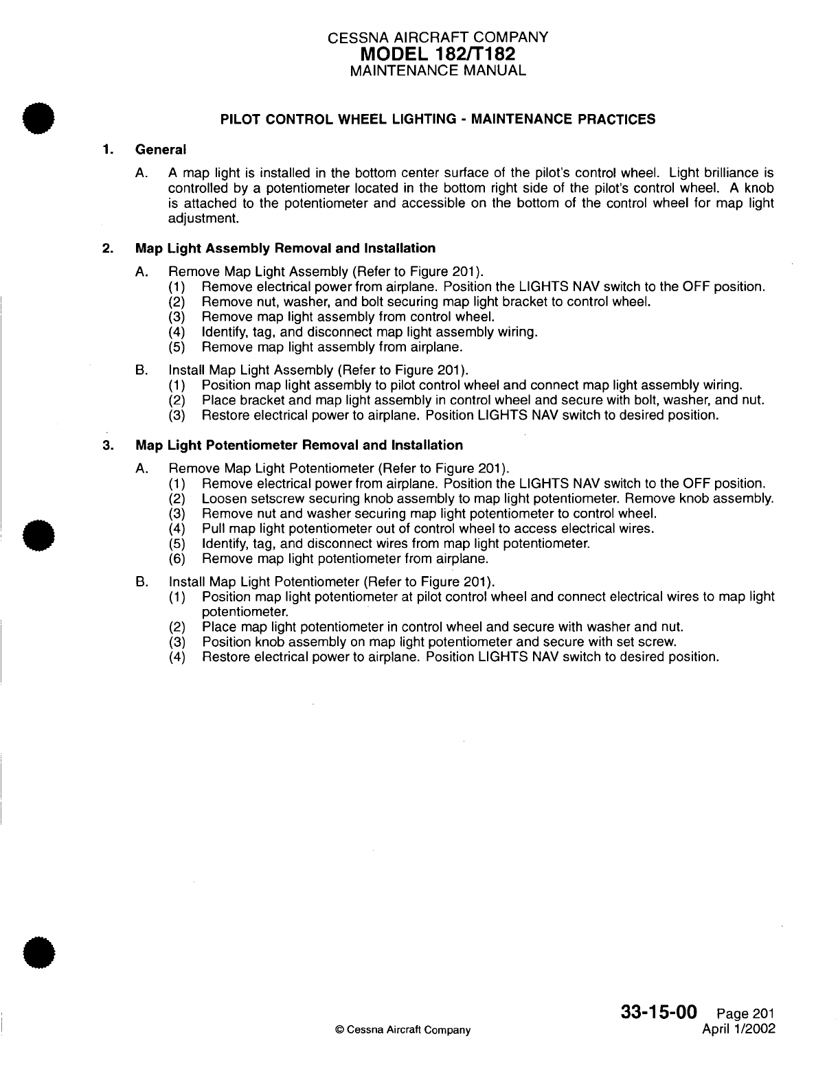
CESSNA
AIRCRAFT
COMPANY
MODEL
182/T182
MAINTENANCE MANUAL
PILOT
CONTROL
WHEEL LIGHTING
-
MAINTENANCE
PRACTICES
1.
General
A.
A
map
light
is
installed
in
the
bottom
center surface
of
the
pilot's control
wheel.
Light
brilliance
is
controlled
by
a
potentiometer
located
in
the
bottom
right
side
of the pilot's
control
wheel.
A
knob
is
attached
to
the potentiometer
and
accessible
on
the
bottom
of
the
control wheel
for
map light
adjustment.
2.
Map
Light
Assembly
Removal
and
Installation
A.
Remove
Map
Light
Assembly
(Refer
to
Figure
201).
(1)
Remove
electrical
power
from
airplane. Position
the
LIGHTS
NAV
switch
to
the
OFF
position.
(2)
Remove
nut,
washer,
and bolt
securing
map
light
bracket
to
control
wheel.
(3)
Remove
map
light
assembly
from
control wheel.
(4)
Identify,
tag,
and
disconnect
map
light
assembly
wiring.
(5)
Remove
map
light
assembly
from
airplane.
B.
Install
Map
Light
Assembly
(Refer to
Figure
201).
(1)
Position
map
light
assembly
to pilot
control
wheel
and
connect
map
light
assembly
wiring.
(2)
Place
bracket
and
map
light
assembly
in
control wheel
and
secure
with
bolt,
washer,
and
nut.
(3)
Restore
electrical
power
to
airplane.
Position LIGHTS
NAV
switch
to
desired
position.
3.
Map
Light
Potentiometer
Removal
and
Installation
A.
Remove
Map
Light
Potentiometer
(Refer
to
Figure
201).
(1)
Remove
electrical
power
from
airplane.
Position the
LIGHTS
NAV
switch
to
the
OFF
position.
(2)
Loosen setscrew
securing
knob
assembly
to
map
light
potentiometer.
Remove
knob assembly.
(3)
Remove
nut
and
washer
securing
map
light
potentiometer
to
control
wheel.
(4)
Pull
map
light
potentiometer
out
of
control
wheel
to
access electrical
wires.
(5)
Identify, tag, and
disconnect
wires
from
map light
potentiometer.
(6)
Remove
map
light potentiometer
from
airplane.
B.
Install
Map
Light
Potentiometer
(Refer
to Figure
201).
(1)
Position
map
light potentiometer
at
pilot
control
wheel
and
connect
electrical
wires
to
map light
potentiometer.
(2)
Place
map
light
potentiometer
in
control
wheel
and
secure
with
washer
and
nut.
(3)
Position
knob
assembly
on
map
light
potentiometer
and
secure
with
set
screw.
(4)
Restore
electrical
power
to
airplane.
Position LIGHTS
NAV
switch
to
desired
position.
33-15-00
Page
201
©
Cessna Aircraft Company
April
1/2002
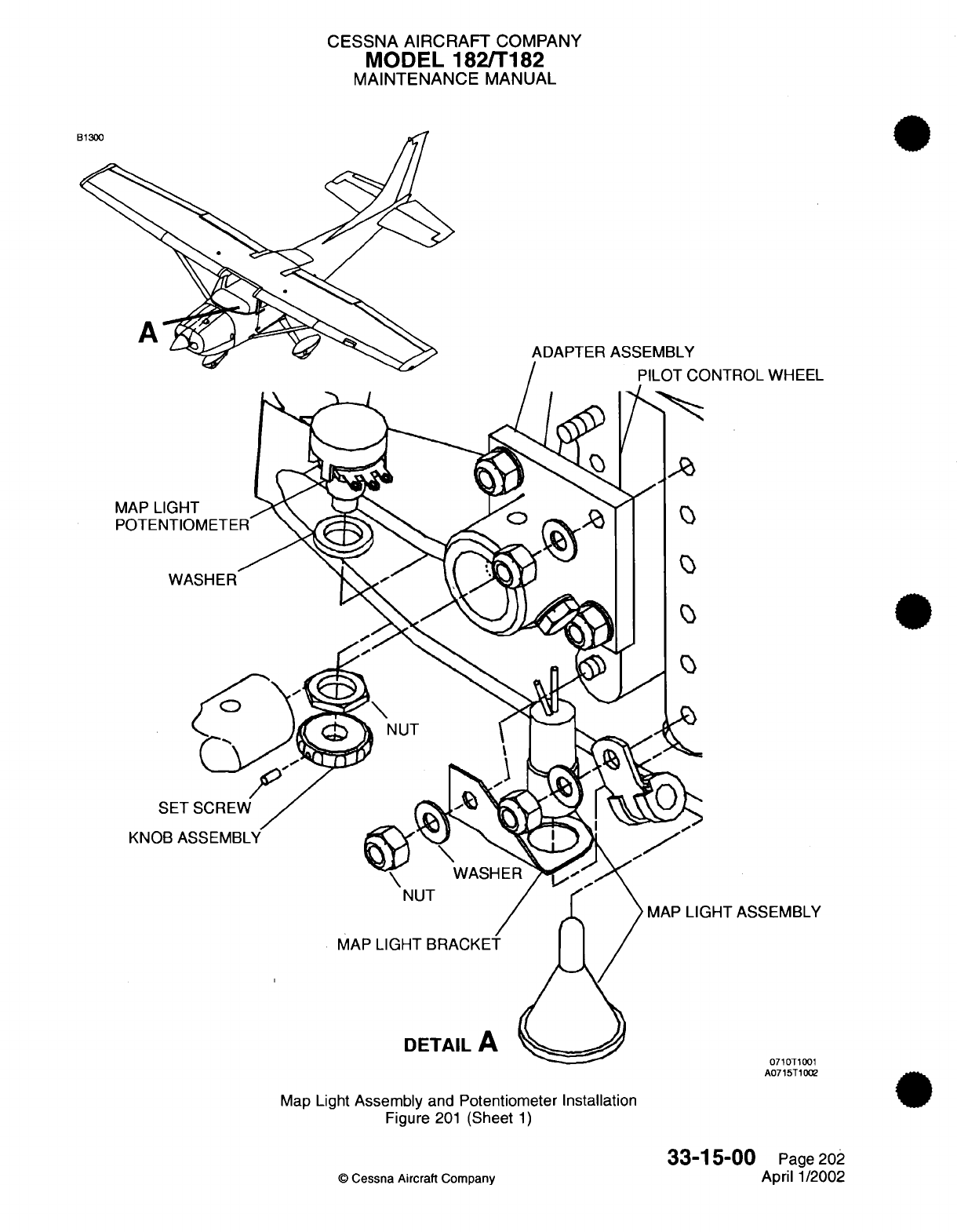
CESSNA
AIRCRAFT
COMPANY
MODEL 182/T182
MAINTENANCE
MANUAL
ADAPTER ASSEMBLY
WHEEL
EEMBLY
0710T1001
A0715T1002
Map
Light
Assembly
and
Potentiometer Installation
Figure
201
(Sheet
1)
©
Cessna Aircraft
Company
33-15-00
Page
202
April
1/2002
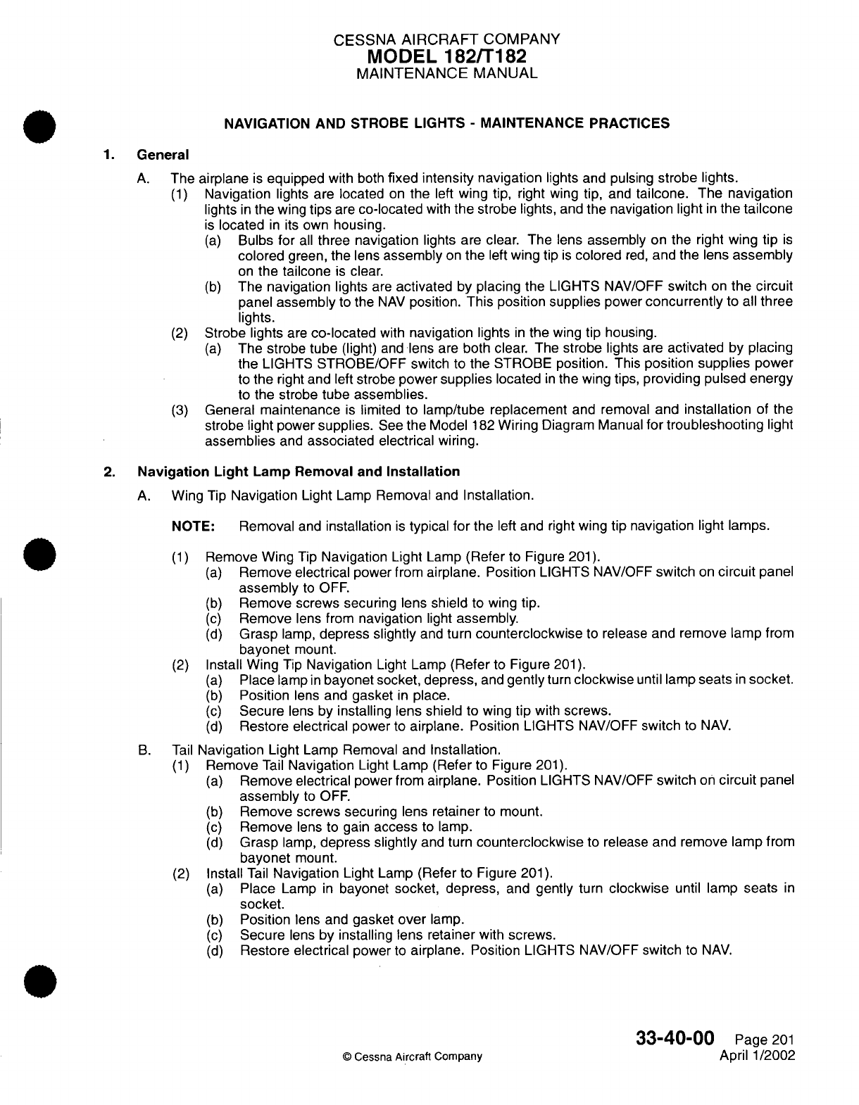
CESSNA
AIRCRAFT
COMPANY
MODEL
182/T182
MAINTENANCE
MANUAL
NAVIGATION
AND STROBE
LIGHTS
-
MAINTENANCE PRACTICES
1.
General
A.
The
airplane
is
equipped
with both
fixed intensity navigation
lights
and pulsing
strobe
lights.
(1)
Navigation
lights
are located
on
the
left
wing tip,
right
wing
tip,
and
tailcone.
The
navigation
lights
in
the
wing
tips
are
co-located
with
the
strobe
lights,
and
the navigation light
in
the
tailcone
is
located
in
its
own
housing.
(a)
Bulbs
for
all
three navigation
lights are
clear.
The
lens
assembly
on
the
right
wing
tip
is
colored
green,
the
lens
assembly
on
the
left
wing tip
is
colored
red,
and
the
lens
assembly
on
the
tailcone
is
clear.
(b)
The
navigation
lights
are
activated
by
placing the
LIGHTS
NAV/OFF
switch
on
the
circuit
panel
assembly
to the
NAV
position.
This position
supplies
power
concurrently
to
all
three
lights.
(2)
Strobe lights
are
co-located
with
navigation
lights
in
the
wing tip
housing.
(a)
The strobe
tube
(light)
and
lens are
both
clear.
The
strobe
lights are
activated
by
placing
the
LIGHTS
STROBE/OFF
switch to
the
STROBE
position.
This
position supplies
power
to
the
right and
left
strobe
power
supplies
located
in
the wing
tips,
providing
pulsed
energy
to
the strobe
tube assemblies.
(3)
General
maintenance
is
limited
to
lamp/tube
replacement
and
removal
and
installation
of the
strobe
light
power
supplies.
See
the
Model
182
Wiring
Diagram
Manual
for troubleshooting
light
assemblies
and
associated electrical
wiring.
2.
Navigation
Light
Lamp Removal
and
Installation
A.
Wing
Tip
Navigation
Light
Lamp
Removal
and
Installation.
NOTE:
Removal
and
installation
is
typical
for
the
left
and
right
wing
tip
navigation
light
lamps.
(1)
Remove
Wing
Tip
Navigation
Light
Lamp
(Refer
to
Figure
201).
(a)
Remove electrical
power
from
airplane. Position
LIGHTS
NAV/OFF
switch
on
circuit
panel
assembly
to
OFF.
(b)
Remove screws securing lens
shield
to
wing
tip.
(c)
Remove
lens from
navigation
light
assembly.
(d)
Grasp
lamp,
depress
slightly
and
turn
counterclockwise
to
release
and
remove lamp
from
bayonet
mount.
(2)
Install Wing
Tip
Navigation
Light
Lamp
(Refer
to
Figure
201).
(a)
Place
lamp
in
bayonet socket,
depress,
and
gently
turn
clockwise
until
lamp
seats
in
socket.
(b)
Position
lens
and
gasket
in
place.
(c)
Secure
lens by
installing
lens shield
to
wing
tip
with
screws.
(d)
Restore
electrical
power
to
airplane.
Position
LIGHTS
NAV/OFF
switch
to
NAV.
B.
Tail
Navigation
Light
Lamp
Removal and
Installation.
(1)
Remove
Tail
Navigation
Light Lamp
(Refer
to
Figure
201).
(a)
Remove electrical
power
from
airplane.
Position
LIGHTS
NAV/OFF
switch
on
circuit
panel
assembly
to
OFF.
(b)
Remove
screws
securing lens retainer
to
mount.
(c)
Remove
lens
to gain
access
to
lamp.
(d)
Grasp
lamp,
depress
slightly
and turn
counterclockwise
to release
and
remove
lamp
from
bayonet
mount.
(2)
Install
Tail
Navigation
Light
Lamp
(Refer
to
Figure
201).
(a)
Place
Lamp
in
bayonet
socket,
depress,
and
gently
turn
clockwise
until
lamp
seats
in
socket.
(b)
Position
lens
and
gasket
over
lamp.
(c)
Secure
lens
by installing
lens
retainer
with
screws.
(d)
Restore
electrical
power
to
airplane.
Position
LIGHTS
NAV/OFF
switch
to
NAV.
33-40-00
Page
201
©
Cessna
Aircraft Company
April 1/2002
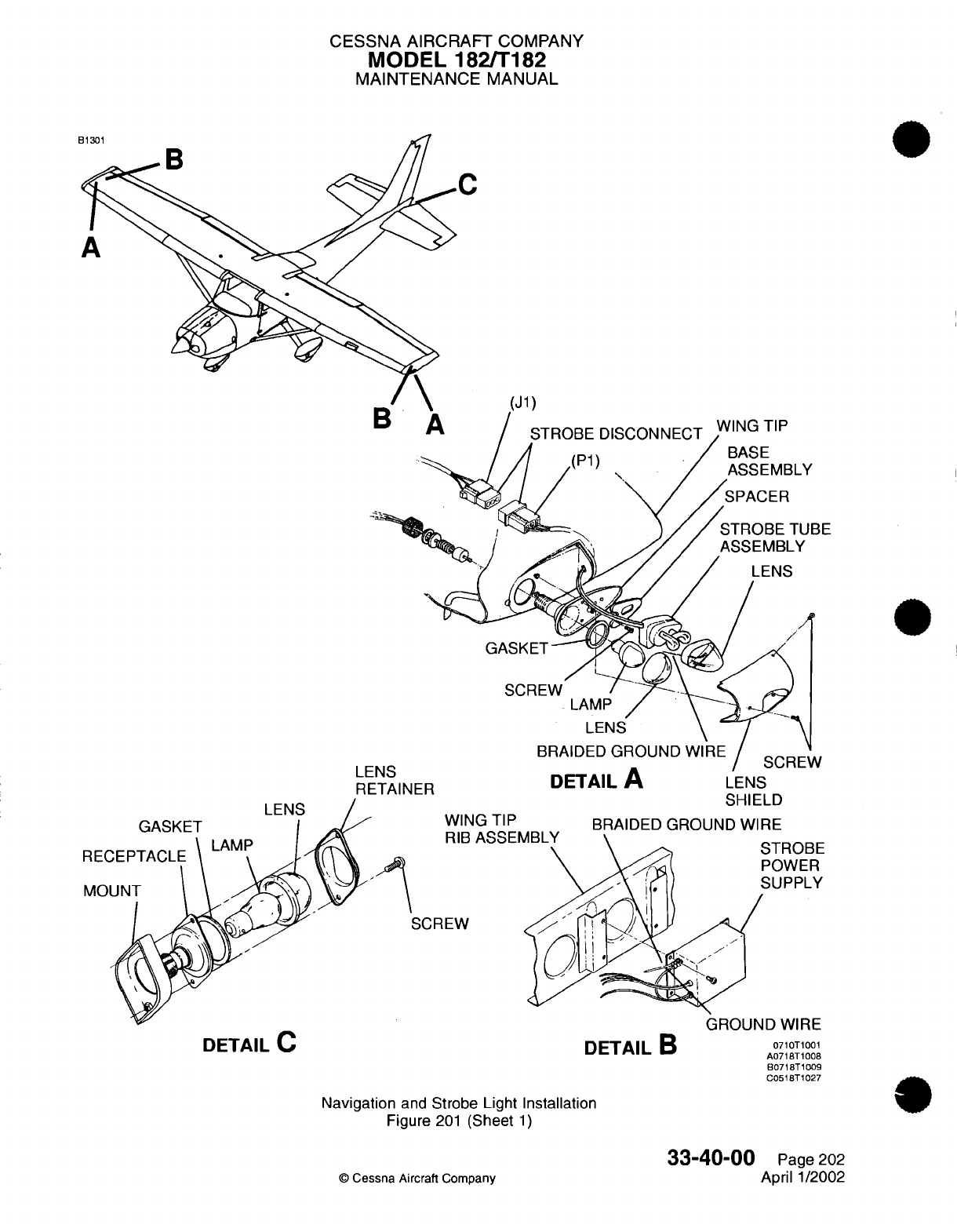
CESSNA
AIRCRAFT
COMPANY
MODEL 182/T182
MAINTENANCE
MANUAL
C
(J1)
STROBE
DISCONNECT WING
TIP
(P1)
/
BASE
I
/ (/
ASSEMBLY
I
r
Lr
I
10
RETAINER
LENS
DETAIL
A
LENS
SHIELD
WING
TIP
RIB
ASSEF
SCREW
DETAIL
C
BRAIDED
GROUND
WIRE
Navigation
and
Strobe Light
Installation
Figure
201
(Sheet
1)
©
Cessna
Aircraft
Company
33-40-00
Page
202
April
1/2002
DETAIL
B
0710T1001
A0718T1008
B0718T1009
C0518T1027
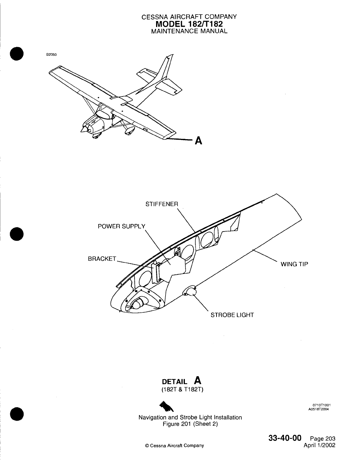
CESSNA
AIRCRAFT
COMPANY
MODEL
182/T182
MAINTENANCE
MANUAL
A
r-
BRI
I
HUtB
LIUH
I
DETAIL
A
(182T
&
T182T)
Navigation
and
Strobe Light Installation
Figure
201
(Sheet
2)
©
Cessna Aircraft
Company
0710T1001
A0518T2004
Page 203
April
1/2002
33-40-00
A
AA_
B
CESSNA
AIRCRAFT
COMPANY
MODEL 182/T182
MAINTENANCE
MANUAL
3.
Strobe
Tube
Assembly
Removal
and
Installation
NOTE:
Removal
and
installation
is
typical
for
both
the
right
and
left
strobe
tube assemblies.
A.
Remove
Strobe Tube
Assembly
(Refer
to Figure
201).
(1)
Remove
electrical
power
from
airplane.
Position LIGHTS
STROBE/OFF
switch
on
circuit
panel
assembly
to
OFF.
(2)
Remove
screws
securing
lens
shield
to
wing
tip.
NOTE:
Following
removal
of
lens
shield
and
prior
to
removing the
strobe
light
lens,
note the
placement
of
the braided ground
wire
positioned
on
the
inside
of
the
lens between
the lens and
strobe
tube
assembly.
(3)
Remove
lens
from
front
of
strobe tube
assembly.
CAUTION:
If
strobe tube
assembly
is
being
removed
to
facilitate
other
maintenance
and not
being replaced with
new
strobe
tube
assembly,
then
use
protective gloves
or
cotton
wrap
to
ensure
fingertip
oil
does
not come
in
contact
with
strobe
tube
assembly.
(4)
Carefully
pull
the
strobe
light
assembly
wiring
to
retrieve
the
strobe
connector
(J1/P1)
from
inside
the
wing
tip.
Disconnect strobe
connector.
NOTE:
If
the strobe
connector cannot
be
retrieved
from
inside
of
wing
tip,
it
will
be
necessary
to
remove
wing
tip
to
gain
access
to
strobe
connector.
(5)
Remove
strobe
tube
assembly
from
base
assembly
and
remove
from
wing
tip.
B.
Install
Strobe
Tube
Assembly
(Refer
to
Figure
201).
CAUTION:
Use
protective gloves
or
cotton
wrap to
ensure
fingertip
oil
does
not
come
in
contact
with strobe
tube
assembly.
(1)
Position strobe
tube
assembly
and
connect
strobe connector.
(a) If
access
to the
strobe
connector
required removal
of the
wing tip,
then perform
the
following:
CAUTION:
Use
protective
gloves
or
cotton
wrap
to
ensure
fingertip
oil
does
not
come
in
contact
with
strobe
tube
assembly.
1
Position wing tip
and
strobe
tube
assembly
at
wing.
2
Feed
strobe
connector
(P1)
and
strobe
light
assembly
wiring
through
wing
tip
and
connect
to
strobe
connector
(J1).
3
Install wing
tip.
(2)
Feed
strobe
connector
and
access
strobe
light
assembly
wiring
into
wing
tip.
NOTE:
If
wing
tip
was removed
to
access strobe
connector,
then
strobe
connector
will
already
be
positioned
in
the
wing
tip.
CAUTION:
Use
protective
gloves
or
cotton
wrap to
ensure
fingertip
oil
does
not
come
in
contact
with
strobe
tube
assembly.
(3)
Position
spacer
and
install
strobe
tube assembly
to
base
assembly.
(4)
Position
lens
at
strobe
tube
assembly
and
place braided ground
wire
inside
of
lens.
33-40-00
Page 204
©
Cessna
Aircraft
Company
April
1/2002
CESSNA
AIRCRAFT
COMPANY
MODEL
182/T182
MAINTENANCE
MANUAL
CAUTION:
Following
placing
lens
unto
strobe tube
assembly,
verify
that
braided
ground
wire
is
properly
positioned
inside
of
lens
and
between
the
lens
and
strobe
tube assembly.
(5)
Place
lens
on
strobe
tube
assembly.
(6)
Secure
lens
by
installing
lens
shield
with
screws.
(7)
Restore
electrical
power
to
airplane.
Position LIGHTS STROBE/OFF switch
to
STROBE
position.
4.
Strobe
Power
Supply
Removal
and
Installation
NOTE:
Removal
and
installation
is
typical
for
both the
left
and
right
strobe
power
supplies.
A.
Remove
Strobe
Power
Supply
(Refer
to Figure
201).
(1)
Remove
electrical
power
from
airplane.
Position
LIGHTS
STROBE/OFF
switch
on
circuit
panel
assembly
to
OFF.
(2)
Remove
wing
tip
to
access
strobe
power
supply.
(3)
Disconnect
the
strobe connector
(J1/P1)
and
strobe power
supply
connector (JL005/PL005
for
left
strobe
power
supply
and
JR004/PR004
for
right
strobe
power
supply).
(4)
Remove
screws
securing
strobe power
supply
to
wing
tip
rib
assembly.
NOTE:
Note
the screw
location
used
for
installation
of
the
strobe
power
supply
ground
wire
and
the
braided
ground wire
from
the lens
for
the
strobe
tube
assembly.
(5)
Remove
strobe
power supply
from
airplane.
B.
Install
Strobe Power
Supply
(Refer
to Figure
201).
(1)
Position strobe
power supply
to
wing
tip
rib
assembly.
(a)
Secure
by
using
all
required
screws,
except for
the screw used
for
the
two
ground
wires.
(b)
Position
ground
wire
and
braided ground
wire
and
secure
with
remaining
screw
used
to
secure
strobe
power
supply.
(2)
Connect
strobe
connector
(J1/P1)
and
strobe
power
supply
connector (JL005/PL005
for
left
strobe power
supply
and
JR004/PR004
for
right
strobe
power supply).
(3)
Install
wing tip.
(4)
Restore
electrical
power
to
airplane.
Position LIGHTS STROBE/OFF
switch
on
circuit
panel
assembly
to
STROBE.
(5)
Check
strobe
for
proper
operation.
33-40-00
Page
205
©
Cessna
Aircraft Company
April
1/2002
CESSNA
AIRCRAFT
COMPANY
MODEL
182/T182
MAINTENANCE
MANUAL
VERTICAL
FIN
FLASHING
BEACON
-
MAINTENANCE
PRACTICES
1.
General
A.
The
vertical
fin
flashing beacon
is
on
top
of
the
vertical
fin
tip
assembly.
It is
a
recognition
light
that
flashes
red.
B.
Put the
LIGHTS BCN/OFF
switch
to
the
BCN
position
to
start
the
flashing
beacon.
This
position
supplies
power
to
the
light.
Internal
circuitry
makes
the
light
flash
on
and
off
at
approximately
50
cycles
per
minute.
2.
Flashing
Beacon
Lamp
Removal/Installation
A.
Flashing
Beacon
Lamp
Removal (Refer
to
Figure
201).
(1)
Remove
electrical
power
from
the airplane.
(2)
Put
the
LIGHTS
BCN/OFF
switch
in
the
OFF
position.
(3)
Loosen
the
screw
on
the clamp around the
flashing
beacon
light
assembly
and
remove
the
clamp.
(4)
Remove
the
lens
from
the
flasher
base
assembly.
CAUTION:
Use
protective gloves
or cotton wrap
to
make
sure
that fingertip
oil
does
not
come
in
contact
with
the
lamp
assembly.
(5)
Remove
the
lamp
assembly
from
the
flasher
base
assembly.
B.
Flashing
Beacon
Lamp
Installation
(Refer
to
Figure
201).
CAUTION:
Use
protective gloves
or cotton
wrap
to
make
sure
fingertip
oil
does
not
come
in
contact
with
the lamp
assembly.
(1)
Align
the
lamp
assembly
with
the
flasher
base
assembly electrical
pins and
slide
the
lamp
assembly
into the
flasher
base
assembly.
(2)
Make
sure
that
the
gasket
is
placed
on
the
flasher
base
assembly
and
place the
lens
on
the
flasher
base
assembly.
(3)
Place
the
lens
with
the
black
masking
forward
on
the
inside
of
the
lens.
(4)
Put
the
clamp
around the
lens
and
attach the
lens
with
the
screw
that
tightens
the
clamp.
(5)
Connect electrical
power
to
the
airplane.
(6)
Put
the
LIGHTS
BCN/OFF
switch
in
the
BCN
position.
(7)
Make sure
that
the
flashing
beacon operates
correctly.
3.
Flashing
Beacon
Light
Assembly Removal/Installation
A.
Flashing
Beacon
Light
Assembly
Removal
(Refer
to Figure
201).
(1)
Remove
the lens and
the
lamp
assembly
for
access
to the
screws
that
attach the
flasher
base
assembly
to the
plate
assembly. Refer
to
Vertical
Fin
Flashing
Beacon
-
Maintenance
Practices,
and
Flashing Beacon
Lamp
Removal/Installation.
(2)
Remove the
screws
that
attach the
flasher
base
assembly
to
the
plate
assembly.
(3)
Lift
the
flasher
base
assembly
for
access
to the
flashing
beacon electrical
wiring.
(4)
Carefully
pull
the
electrical
wiring
until
you get
access
to
the
beacon
light
connector
(JV004/
PV004).
(5)
With
a
tie
strap
or
a
string,
safety
the
electrical
wiring
to make
sure
that
the
beacon
light
connector
(PV004)
does
not
fall
into
the
fin
tip
assembly
after
you
connect
the
beacon light
connector.
(6)
Disconnect
the
beacon
light
connector
(JV004/PV004).
(7)
Remove
the
flasher
base
assembly
from
the
airplane.
B.
Flashing
Beacon
Light
Assembly
Installation (Refer
to
Figure
201).
(1)
Position
the
flasher
base
assembly
at the
fin
tip
assembly
and
connect
the
beacon light
connector
(JV004/PV004).
(2)
Remove
the tie
strap
or
the
string that
kept the
beacon light
connector
(PV004)
away
from the
fin
tip
assembly.
33-41-00
Page
201
©
Cessna
Aircraft Company
Jan
2/2006
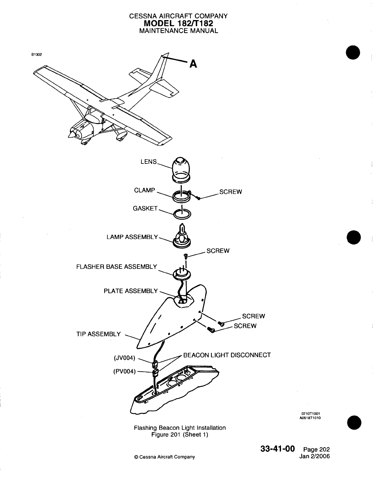
CESSNA
AIRCRAFT
COMPANY
MODEL
182/T182
MAINTENANCE
MANUAL
A
LAMP
ASSEMBLY
FLASHER
B/
PLU
TIP
ASSEMB
Flashing
Beacon
Light
Installation
Figure
201
(Sheet
1)
©
Cessna
Aircraft Company
0710T1001
A0518T1010
33-41-00
Page
202
Jan
2/2006
CT
CESSNA
AIRCRAFT
COMPANY
MODEL
182/T182
MAINTENANCE
MANUAL
(3)
Attach the
flasher
base assembly to
the
plate
assembly
with
the screws.
(4)
Install
the
lamp
assembly
and
the
lens.
Refer
to
Vertical
Fin
Flashing
Beacon
-
Maintenance
Practices, Flashing
Beacon
Lamp
Removal
and
Installation.
33-41-00
Page
203
©
Cessna Aircraft
Company
Jan 2/2006
I
CESSNA
AIRCRAFT
COMPANY
MODEL
182/T182
MAINTENANCE
MANUAL
LANDING/TAXI
LIGHTS
-
TROUBLESHOOTING
1.
High-Intensity
Discharge
(HID)
Landing
and
Taxi
Lights
Troubleshooting
A.
The
troubleshooting
flow
chart
that
follows
is
for
Airplanes
18281504
and On
and
T18208358
and
On, and
Airplanes
18280001
thru
18281503
and
Airplanes
T18208001
thru
T18208357 incorporating
MK206-33-01
that
have
high-intensity
discharge
(HID)
lighting installed.
NOTE:
The
troubleshooting
procedure
is
typical
for
the
landing light
and
the
taxi
light.
33-42-00
Page
101
©
Cessna Aircraft
Company
Jan
2/2006
I
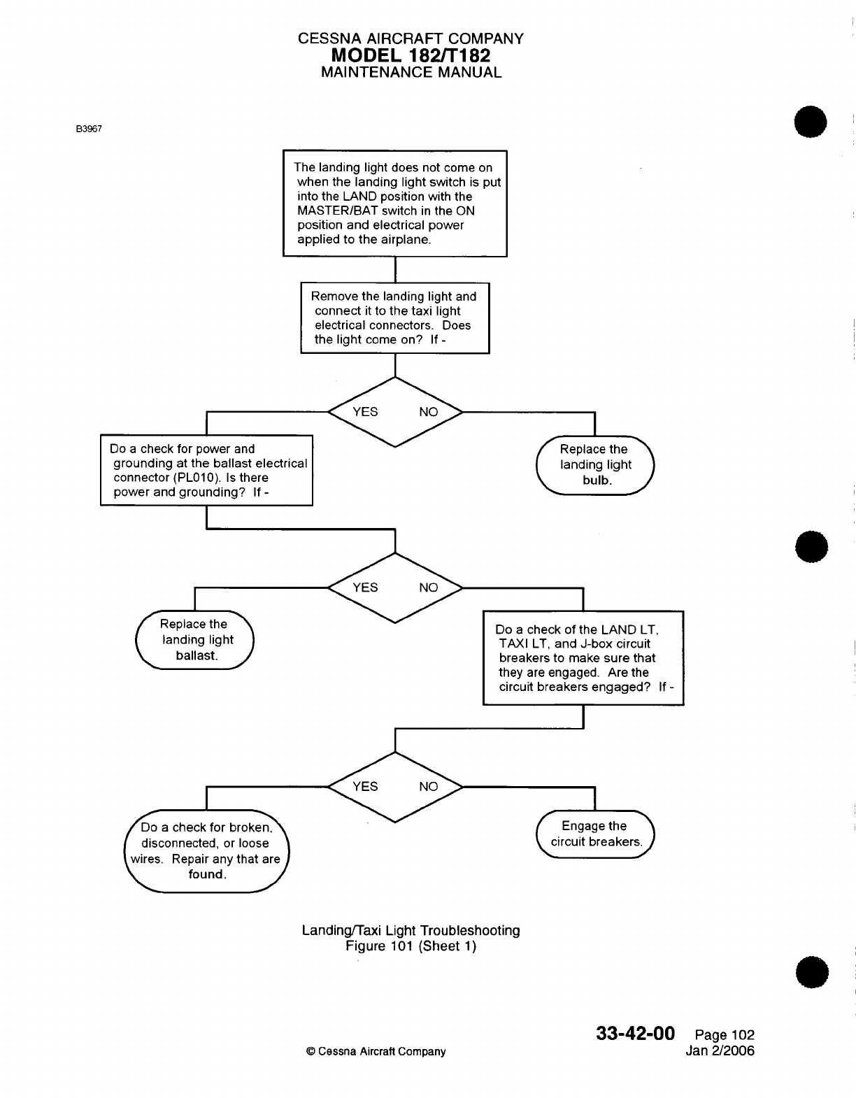
CESSNA AIRCRAFT
COMPANY
MODEL 182/T182
MAINTENANCE
MANUAL
B3967
The
landing
light
does not
come
on
when the landing
light
switch
is
put
into
the
LAND
position
with
the
MASTER/BAT
switch
in
the
ON
position
and
electrical
power
applied to
the
airplane.
I
Remove the
landing
light
and
connect
it
to
the
taxi
light
electrical
connectors.
Does
the
light
come
on?
If
-
Do
a
check for
power
and
grounding
at
the
ballast
electrical
connector
(PL010).
Is
there
power
and
grounding?
If
-
I
Replace
the
landing
light
ballast.
J
Do
a
check
for
broken,
disconnected,
or loose
wires.
Repair
any
that
are
found.
I
Replace
the
landing light
(•
bulb.
J
Do
a
check
of the
LAND
LT,
TAXI
LT,
and
J-box
circuit
breakers
to
make
sure
that
they
are
engaged. Are the
circuit breakers
engaged?
If
-
I
I
Engagethe
circuit
breakersJ
Landing/Taxi
Light
Troubleshooting
Figure
101
(Sheet
1)
33-42-00
©
Cessna Aircraft
Company
Page
102
Jan
2/2006
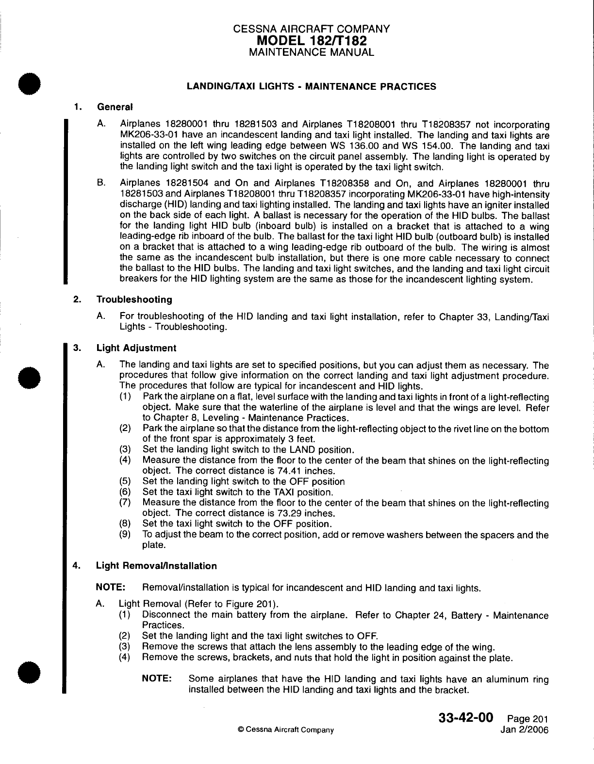
CESSNA
AIRCRAFT
COMPANY
MODEL
182/T182
MAINTENANCE
MANUAL
LANDING/TAXI LIGHTS
-
MAINTENANCE PRACTICES
1.
General
A.
Airplanes
18280001 thru
18281503
and
Airplanes
T18208001
thru
T18208357
not
incorporating
MK206-33-01
have
an
incandescent
landing and
taxi
light installed.
The landing and
taxi lights
are
installed
on
the
left
wing
leading
edge
between
WS
136.00
and
WS 154.00.
The
landing and
taxi
lights
are
controlled
by
two
switches
on
the
circuit
panel
assembly. The
landing
light
is
operated
by
the
landing
light switch
and
the
taxi light
is
operated by the taxi light switch.
B.
Airplanes
18281504
and
On
and
Airplanes
T18208358
and
On,
and
Airplanes
18280001
thru
18281503
and
Airplanes
T18208001
thru
T18208357
incorporating
MK206-33-01
have
high-intensity
discharge
(HID)
landing
and
taxi
lighting
installed.
The
landing
and
taxi
lights
have
an
igniter installed
on
the
back
side
of
each
light.
A
ballast
is
necessary
for
the
operation
of the
HID
bulbs. The
ballast
for
the
landing
light
HID
bulb (inboard
bulb)
is
installed
on a
bracket
that
is
attached
to
a
wing
leading-edge
rib
inboard
of
the
bulb.
The
ballast for
the taxi
light
HID
bulb (outboard bulb)
is
installed
on a
bracket that
is
attached
to
a
wing
leading-edge
rib
outboard of
the
bulb.
The
wiring
is
almost
the
same
as
the
incandescent
bulb
installation,
but
there
is
one
more
cable
necessary
to
connect
the
ballast
to
the
HID
bulbs.
The landing
and
taxi
light
switches,
and
the
landing
and
taxi light
circuit
breakers for
the
HID
lighting
system
are
the
same
as
those
for
the
incandescent
lighting system.
2.
Troubleshooting
A.
For
troubleshooting
of
the
HID
landing
and
taxi
light
installation,
refer
to
Chapter
33,
Landing/Taxi
Lights
-
Troubleshooting.
3.
Light
Adjustment
A.
The
landing and taxi lights
are
set
to
specified
positions,
but
you
can
adjust
them
as
necessary.
The
procedures
that follow
give information
on
the correct landing
and
taxi
light
adjustment
procedure.
The procedures
that
follow
are
typical
for
incandescent
and
HID
lights.
(1)
Park
the
airplane
on
a
flat,
level
surface
with
the
landing
and
taxi
lights
in
front
of
a
light-reflecting
object.
Make sure
that
the
waterline
of
the
airplane
is
level
and
that
the
wings
are level.
Refer
to
Chapter
8,
Leveling
-
Maintenance Practices.
(2)
Park
the
airplane
so
that
the
distance
from
the
light-reflecting
object
to
the
rivet line
on
the
bottom
of
the
front
spar
is
approximately
3
feet.
(3)
Set
the
landing light
switch
to
the
LAND
position.
(4)
Measure
the
distance
from the
floor
to
the
center
of
the beam
that
shines
on
the
light-reflecting
object.
The
correct distance
is
74.41
inches.
(5)
Set
the
landing light
switch
to
the
OFF
position
(6)
Set
the
taxi
light
switch
to
the
TAXI
position.
(7)
Measure
the
distance
from the
floor
to
the
center
of
the beam
that
shines
on
the
light-reflecting
object.
The
correct distance
is
73.29
inches.
(8)
Set
the
taxi
light
switch
to
the
OFF
position.
(9)
To
adjust
the
beam
to
the correct position,
add
or remove
washers
between
the
spacers
and
the
plate.
4.
Light
Removal/Installation
NOTE:
Removal/installation
is
typical
for
incandescent
and
HID
landing
and
taxi
lights.
A.
Light
Removal
(Refer
to
Figure
201).
(1)
Disconnect
the
main
battery
from the
airplane.
Refer
to
Chapter
24,
Battery
-
Maintenance
Practices.
(2)
Set
the
landing light
and
the taxi
light
switches to
OFF.
(3)
Remove
the
screws that attach the
lens
assembly
to
the
leading
edge of the
wing.
(4)
Remove
the
screws,
brackets,
and
nuts
that
hold
the
light
in
position
against
the plate.
NOTE:
Some
airplanes
that
have
the
HID
landing and
taxi
lights
have
an
aluminum
ring
installed
between
the
HID
landing
and taxi
lights
and
the
bracket.
33-42-00
Page
201
©
Cessna Aircraft
Company
Jan
2/2006
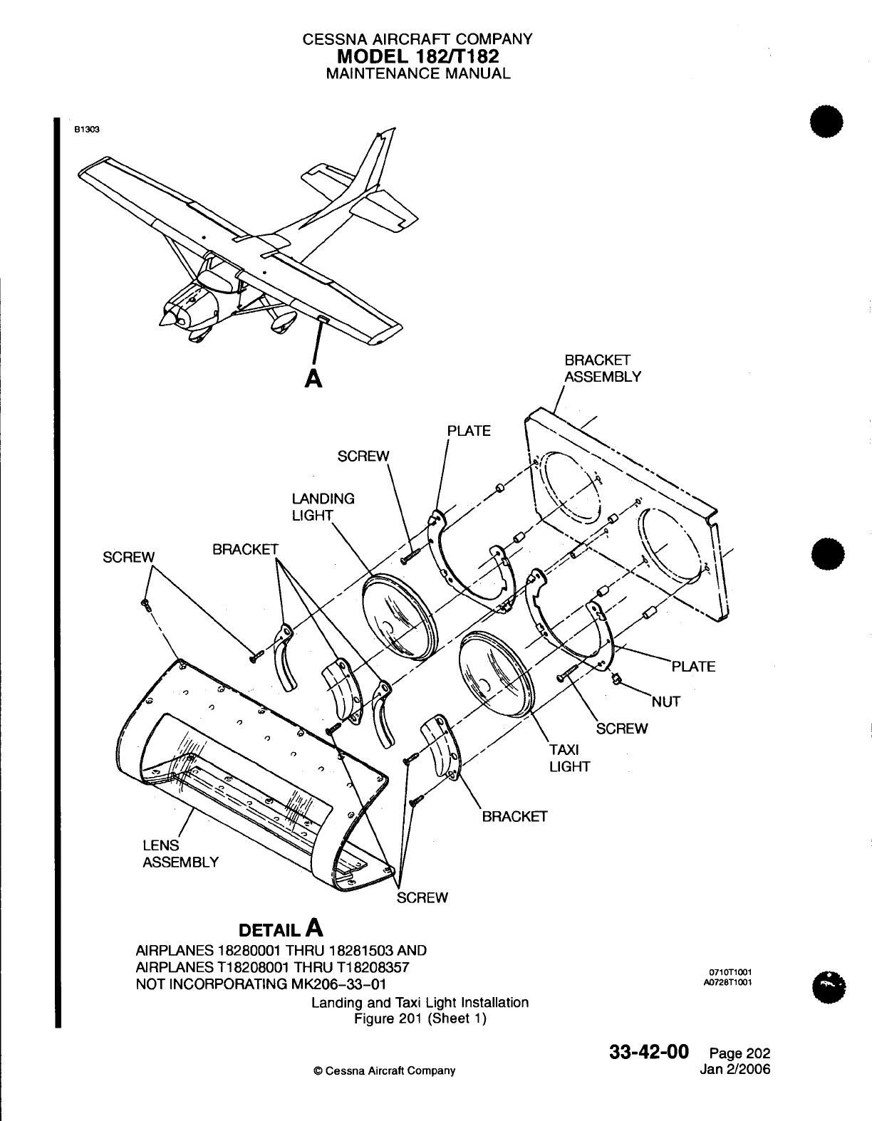
CESSNA AIRCRAFT
COMPANY
MODEL
1821T182
MAINTENANCE
MANUAL
A
BRACKET
ASSEMBLY
SCREW
DETAIL
A
AIRPLANES 18280001 THRU
18281503
AND
AIRPLANES
T18208001 THRU
T18208357
NOT
INCORPORATING
MK206-33-01
Landing
and
Taxi
Light
Installation
Figure
201
(Sheet
1)
33-42-00
0
Cessna
Aircraft
Company
071
T1001
A0728T1001
Page
202
Jan 2/2006
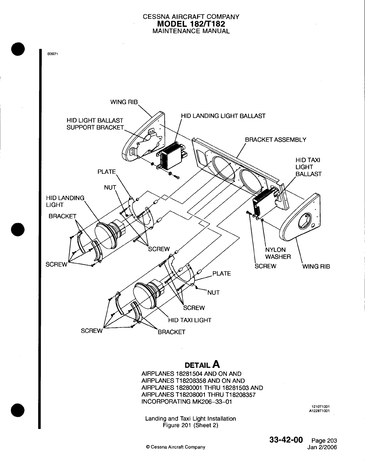
CESSNA
AIRCRAFT
COMPANY
MODEL
182/T182
MAINTENANCE
MANUAL
B3971
HID
LANDING
LIGHT
BALLAST
RIB
DETAIL
A
AIRPLANES
18281504
AND ON
AND
AIRPLANES
T18208358
AND ON
AND
AIRPLANES
18280001 THRU
18281503
AND
AIRPLANES
T18208001
THRU
T18208357
INCORPORATING
MK206-33-01
1210T1001
A1228T1001
Landing
and
Taxi
Light
Installation
Figure
201
(Sheet
2)
©
Cessna
Aircraft
Company
33-42-00
Page
203
Jan 2/2006
CESSNA AIRCRAFT
COMPANY
MODEL
182/T182
MAINTENANCE
MANUAL
(5)
Disconnect
the
electrical
wires
from
the
back side
of
the
light and remove the
light
from
the
airplane.
B.
Light Installation
(Refer
to Figure
201).
(1)
Put
the
light at
the
correct wing
location (between
WS
136.00 and
WS
154.00) and
connect
the
electrical
wires
to
the light.
(2)
With
screws
and nuts,
attach
the
light
to
the
bracket
so
the
light
is
attached
tightly
against
the
plate.
NOTE:
The
tops
of
the
nuts
are
not
flush with
the
lip
of
the
plate. The
remaining
parts
of the
nuts
are
behind
the
plate
at
the
screw
opening.
NOTE:
Some
airplanes
that
have
the
HID
landing
and
taxi
lights
will have
an
aluminum
ring
installed
between
the
HID
landing and
taxi lights
and
the
bracket.
(3)
Install
the
lens
assembly
to
the
leading
edge
of the
wing.
(4)
Connect
the main
battery
to the
airplane.
Refer to
Chapter
24,Battery
-
Maintenance
Practices.
(5)
Set
the
landing
light switch
to
LAND
and
the
taxi
light
switch
to
TAXI.
(6)
Do
a
check
of
the
operation
of
the
landing
and
taxi
lights.
5.
High-Intensity
Discharge
(HID)
Ballast Removal/Installation
NOTE:
The
procedures that follow
are
for airplanes
that
have
the
HID
landing
and
taxi light
installation.
A.
HID
Ballast Removal (Refer
to
Figure
201).
NOTE:
Removal/installation
procedures
are
typical
for
the
HID
landing
and
taxi
lights.
(1)
Disconnect
the
main
battery
from the
airplane.
Refer
to
Chapter
24,
Battery
-
Maintenance
Practices.
(2)
Put
the
landing
and
taxi
light
switches
in
the
OFF
position.
(3)
Remove the
HID
landing
and
taxi
lights.
Refer
to Light
Removal
and
Installation.
(4)
Remove the
screws
and
the
nylon
washers
that
attach
the
HID
ballast
to
the
support bracket
on
the
wing
leading-edge
rib.
(5)
Disconnect
the
electrical connectors
from
the
HID
ballast.
(a)
Landing light connectors:
PL010
and UL005.
(b)
Taxi
light connectors:
PL011
and UL006.
(6)
Remove
the
HID
ballast
from
the
airplane.
B.
HID
Ballast
Installation
(Refer
to
Figure
201).
(1)
Disconnect
the main
battery
from
the
airplane.
Refer
to
Chapter
24,
Battery
-
Maintenance
Practices.
(2)
Put
the
landing
and
taxi light
switches
in
the
OFF
position.
(3)
Put
the
ballast
at
the
correct
wing location.
(a)
Landing
light:
outboard
side
of
the
wing
rib
found
at
WS
136.00.
(b)
Taxi
light:
inboard side
of
the wing
rib
found
at
WS 154.00.
(4)
Connect
the
electrical
connectors
to
the
HID
ballast.
(a)
Landing
light
connectors:
PL010
and UL005.
(b)
Taxi
light
connectors:
PL011
and UL006.
33-42-00
Page
204
©
Cessna
Aircraft
Company
Jan
2/2006
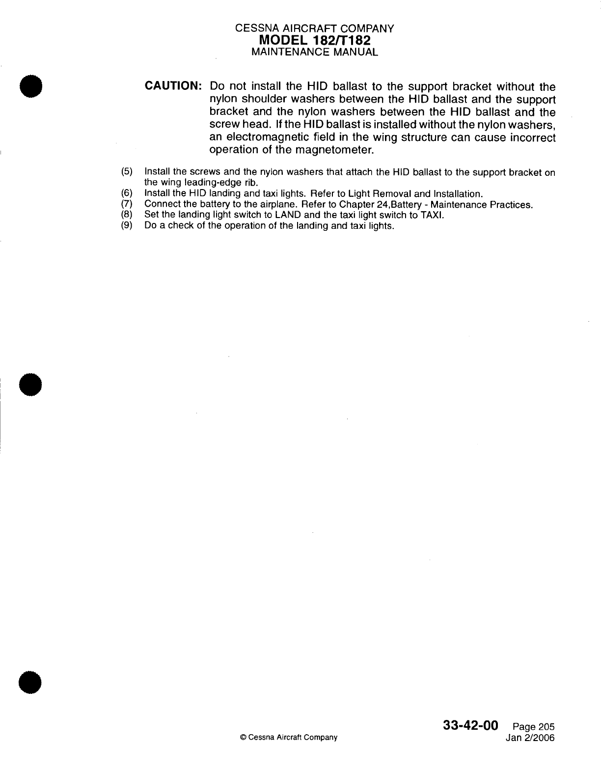
CESSNA
AIRCRAFT
COMPANY
MODEL
182/T182
MAINTENANCE
MANUAL
CAUTION:
Do
not
install the
HID
ballast
to
the
support
bracket
without
the
nylon
shoulder
washers
between
the
HID
ballast
and
the
support
bracket
and
the
nylon
washers
between
the
HID
ballast
and
the
screw
head.
If
the
HID
ballast
is
installed
without the nylon
washers,
an
electromagnetic
field
in
the
wing
structure
can
cause incorrect
operation
of
the magnetometer.
(5)
Install the
screws
and the
nylon
washers
that
attach the
HID
ballast
to
the support
bracket
on
the
wing
leading-edge
rib.
(6)
Install
the
HID
landing
and
taxi
lights. Refer
to
Light
Removal
and
Installation.
(7)
Connect the battery
to the
airplane. Refer
to
Chapter
24,Battery
-
Maintenance Practices.
(8)
Set
the
landing
light
switch
to
LAND
and the
taxi
light switch
to
TAXI.
(9)
Do
a
check
of the
operation
of the
landing
and
taxi lights.
33-42-00
Page
205
©
Cessna
Aircraft Company
Jan
2/2006
CESSNA
AIRCRAFT
COMPANY
MODEL
182/T182
MAINTENANCE
MANUAL
COURTESY
LIGHTS
-
MAINTENANCE PRACTICES
1.
General
A.
Each
wing
is
equipped
with
an
under
wing
courtesy light
located
near
the
strut/wing
intersection.
The
left
wing
courtesy
light
(FL004),
the
right
wing
courtesy
light
(FR002), and
the
rear
dome light
assembly
(FC005)
are
connected
in
parallel
on a
single
circuit.
Pressing
the
overhead light
assembly
switch (SC004)
supplies
power
to
all
three
lights.
Pressing
the
overhead
light
assembly
switch
again
removes
power
from
all
three
lights.
B.
See
Model
182
Wiring
Diagram Manual
for diagrams
for use
in
troubleshooting
the
courtesy
light
lamp
socket
under
the
wing
and
necessary electrical
wiring.
2.
Courtesy
Light
Lamp
Removal
and
Installation
A.
Remove
Courtesy
Light
Lamp
(Refer
to
Figure
201).
NOTE:
Removal
and
Installation
is
typical for
the
left
and
right
wing
courtesy
light
lamps.
(1)
(2)
(3)
(4)
Disconnect
the
electrical
power
from
airplane.
Press the
ALT/BAT
MASTER
switch
to
the
off
position.
Remove
screws
securing
cover
assembly
to
underside
of
wing.
Push
in
on
lamp,
rotate
counterclockwise
and remove
lamp
from
bayonet
socket.
B.
Install
Courtesy
Light
Lamp
(Refer
to
Figure
201).
(1)
Insert
lamp
into
bayonet
socket.
Turn
clockwise
until
lamp
seats
in
socket.
(2)
Reinstall
cover
assembly
to
underside
of
wing
and
secure
with
screws.
(3)
Connect
the
electrical
power
to
the
airplane.
(4) Press the
ALT/BAT
MASTER
switch
to
the
ON
position
to
do
a
check
of
the
courtesy
lights.
33-43-00
Page
201
©
Cessna Aircraft Company Aug
4/2003
I
I
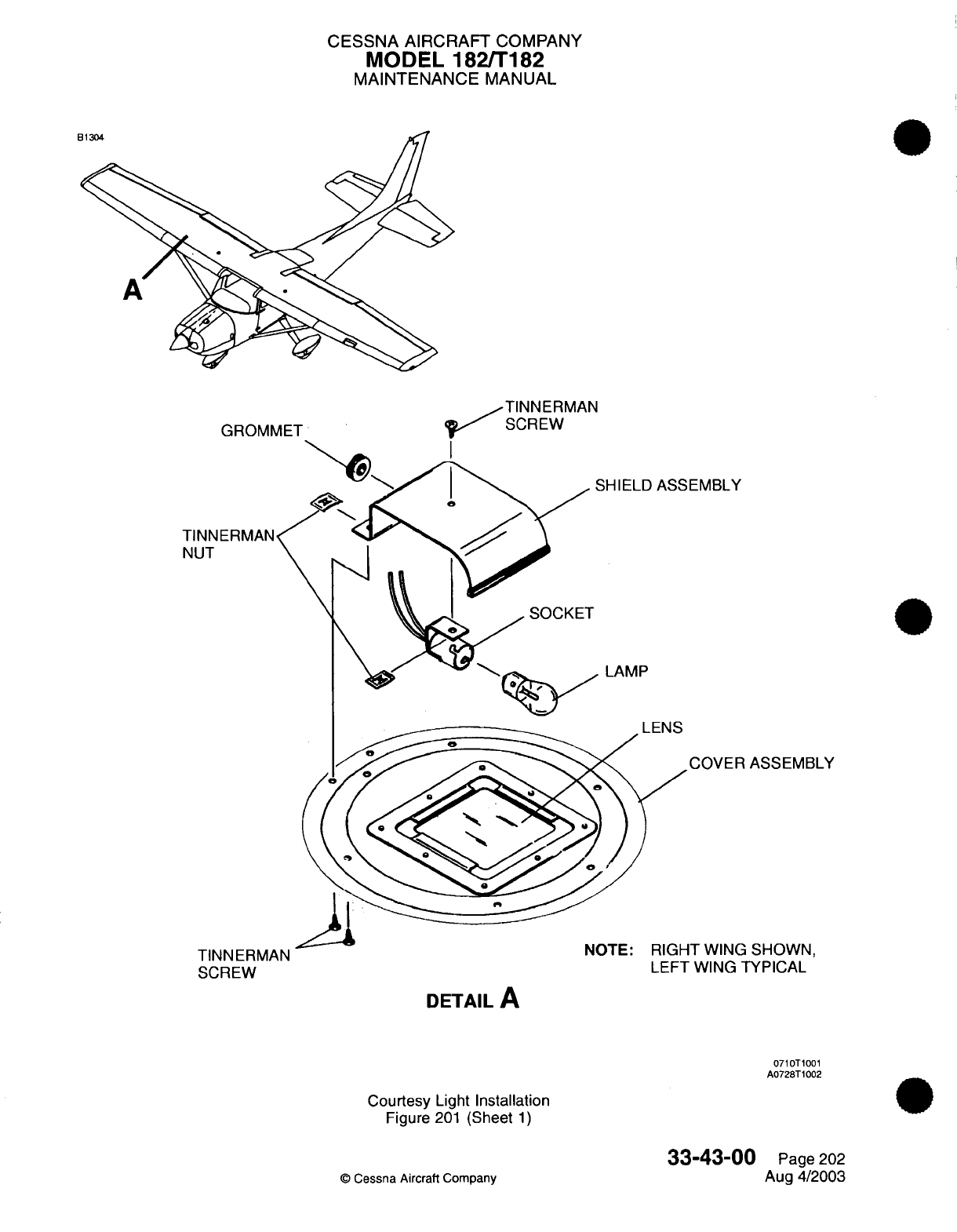
CESSNA AIRCRAFT
COMPANY
MODEL
182/T182
MAINTENANCE
MANUAL
SHIELD
ASSEMBLY
LAMP
I
rIIIc
COVER
ASSEMBLY
IT
\AIIKf'~
C'U\lIAIKI
Iul
IC
r
nIln
I
vviil
O3nJvviI
LEFT WING
TYPICAL
TINNERMAN
SCREW
DETAIL
A
0710T1001
A0728T1002
Courtesy
Light
Installation
Figure
201
(Sheet
1)
©
Cessna Aircraft
Company
33-43-00
Page
202
Aug 4/2003

CHAPTER
NAVIGATION
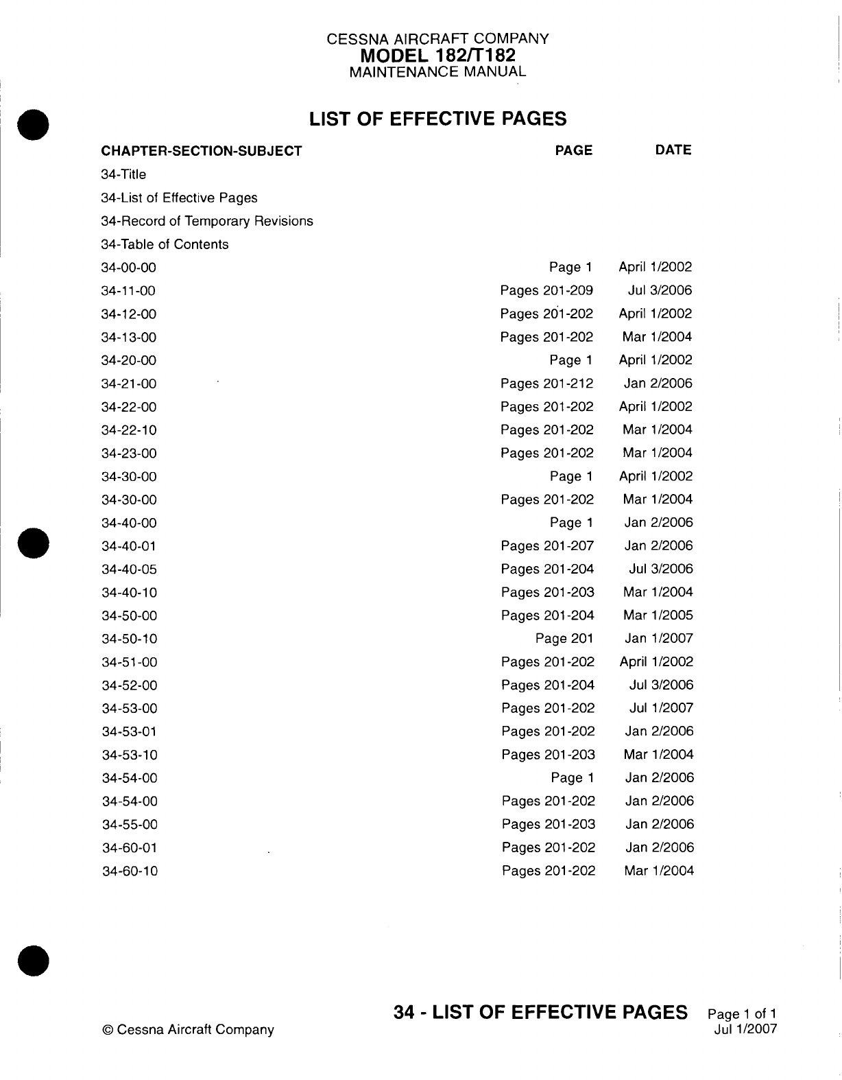
CESSNA
AIRCRAFT
COMPANY
MODEL
182/Ti
82
MAINTENANCE
MANUAL
LIST
OF EFFECTIVE PAGES
CHAPTER-SECTION-SUBJECT
34-Title
34-List
of
Effective Pages
34-Record
of
Temporary
Revisions
34-Table
of
Contents
34-00-00
34-11-00
34-1
2-00
34-1
3-00
34-20-00
34-2
1-00
34-22-00
34-22-10
34-23-00
34-30-00
34-30-00
34-40-00
34-40-01
34-40-05
34-40-10
34-50-00
34-50-10
34-51-00
34-52-00
34-53-00
34-53-01
34-53-10
34-54-00
34-54-00
34-55-00
34-60-01
34-60-10
PAGE
Page
1
Pages
201-209
Pages
201-202
Pages 201-202
Page
1
Pages
201
-212
Pages
201
-202
Pages
201
-202
Pages
201
-202
Page
1
Pages
201-202
Page
1
Pages
201
-207
Pages
201-204
Pages
201-203
Pages
201-204
Page
201
Pages
201-202
Pages
201-204
Pages
201
-202
Pages
201
-202
Pages
201-203
Page
1
Pages
201
-202
Pages
201-203
Pages
201
-202
Pages
201
-202
DATE
April 1/2002
Jul
3/2006
April
1/2002
Mar
1/2004
April
1/2002
Jan
2/2006
April
1/2002
Mar
1/2004
Mar
1/2004
April
1/2002
Mar
1/2004
Jan
2/2006
Jan
2/2006
Jul
3/2006
Mar
1/2004
Mar
1/2005
Janl1/2007
April 1/2002
Jul
3/2006
Jul 1/2007
Jan
2/2006
Mar 1/2004
Jan
2/2006
Jan
2/2006
Jan
2/2006
Jan
2/2006
Mar
1/2004
©D
Cessna Aircraft
Company
34
-
LIST
OF
EFFECTIVE PAGES
Page
1
of
1
Jul
1/2007
Temporary
Revision
Number
RECORD
OF
TEMPORARY
REVISIONS
Page
Number
Issue
Date
By
Date
Removed
By
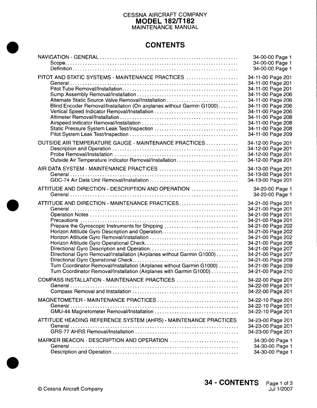
CESSNA
AIRCRAFT COMPANY
MODEL
182/Ti
82
MAINTENANCE
MANUAL
CONTENTS
NAVIGATION
-
GENERAL.............................
Scope....................................
Definition
..................................
PITOT
AND
STATIC
SYSTEMS
-
MAINTENANCE
PRACTICES
...........
General...................................
Pitot
Tube
Removal/Installation
........................
Sump
Assembly
Removal/installation
.....................
Alternate
Static Source
Valve
Removal/Installation
...............
Blind
Encoder
Removal/Installation
(On
airplanes
without
Garmin
G1000).....
Vertical
Speed
Indicator
Removal/Installation..................
Altimeter
Removal/Installation.........................
Airspeed Indicator
Removal/installation
....................
Static Pressure
System
Leak
Test/inspection..................
Pitot
System
Leak
Test/inspection.......................
OUTSIDE
AIR
TEMPERATURE
GAUGE
-
MAINTENANCE
PRACTICES
.......
Description and Operation
..........................
Probe
Removal/installation..........................
Outside
Air Temperature
Indicator
Removal/Installation
.............
AIR
DATA
SYSTEM
-
MAINTENANCE
PRACTICES.................
General...................................
GDC-74 Air
Data
Unit
Removal/Installation...................
ATTITUDE
AND
DIRECTION
-
DESCRIPTION
AND
OPERATION
..........
General...................................
ATTITUDE
AND
DIRECTION
-
MAINTENANCE
PRACTICES.............
General...................................
Operation
Notes...............................
Precautions.................................
Prepare the
Gyroscopic
Instruments
for
Shipping................
Horizon
Attitude
Gyro
Description
and
Operation
................
Horizon
Attitude
Gyro
Removal/Installation...................
Horizon
Attitude
Gyro
Operational
Check....................
Directional
Gyro
Description
and
Operation...................
Directional
Gyro
Removal/installation
(Airplanes
without
Garmin
G1000)
.....
Directional
Gyro
Operational
Check
.............
Turn
Coordinator Removal/installation
(Airplanes
without
Garmin
G1000).....
Turn
Coordinator Removal/Installation
(Airplanes
with
Garmin
G1000)
......
COMPASS INSTALLATION
-
MAINTENANCE
PRACTICES
.............
General...................................
Compass Removal
and
Installation
......................
MAGNETOMETER
-
MAINTENANCE PRACTICES
.................
General...................................
GMU-44
Magnetometer
Removal/installation..................
ATTITUDE
HEADING
REFERENCE SYSTEM (AHRS)
-
MAINTENANCE PRACTICES
General...................................
GRS-77
AHRS
Removal/Installation......................
MARKER
BEACON
-
DESCRIPTION
AND
OPERATION...............
General...................................
Description
and
Operation
..........................
34-00-00
Page
1
34-00-00
Page
1
34-00-00
Page
1
34-11
-00
Page
201
34-11
-00
Page
201
34-11
-00
Page
201
34-11
-00
Page
206
34-11
-00
Page
206
34-11
-00
Page
206
34-11
-00
Page
206
34-11
-00
Page
208
34-11
-00
Page
208
34-11
-00
Page
208
34-11
-00
Page
209
34-12-00
Page
201
34-12-00
Page
201
34-12-00
Page
201
34-12-00
Page
201
34-13-00
Page
201
34-13-00
Page
201
34-13-00
Page
201
34-20-00
Page
1
34-20-00
Page
1
34-21
-00
Page
201
34-21
-00
Page
201
34-21-00
Page
201
34-21-00
Page
201
34-21-00
Page
202
34-21 -00
Page
202
34-21 -00
Page
202
34-21
-00
Page
206
34-21
-00
Page
207
34-2
1
-00
Page
207
34-21
-00
Page
209
34-21
-00
Page 209
34-21
-00
Page
21
0
34-22-00
Page
201
34-22-00
Page
201
34-22-00
Page
201
34-22-1
0
Page
201
34-22-10
Page
201
34-22-10
Page
201
34-23-00
Page
201
34-23-00
Page
201
34-23-00
Page
201
34-30-00
Page
1
34-30-00
Page
1
34-30-00
Page
1
34
-
CONTENTS
Page
1
of
3
Jul
1/2007
©
Cessna Aircraft
Company
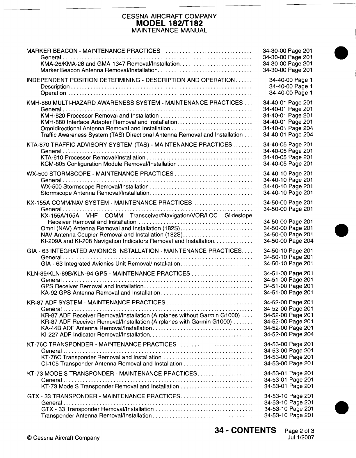
CESSNA AIRCRAFT
COMPANY
MODEL
182/Ti182
MAINTENANCE
MANUAL
MARKER
BEACON
-
MAINTENANCE
PRACTICES.................
General
..................................
KMA-26/KMA-28
and
GMA-1
347
Removal/installation..............
Marker
Beacon
Antenna
Removal/Installation..................
INDEPENDENT POSITION DETERMINING
-
DESCRIPTION
AND
OPERATION....
Description
.................................
Operation..................................
KMH-880
MULTI-HAZARD AWARENESS
SYSTEM
-
MAINTENANCE PRACTICES
...
General...................................
KMH-820
Processor
Removal
and
Installation
.................
KMH-880 Interface
Adapter
Removal
and
Installation
..............
Omnidirectional
Antenna
Removal
and
Installation
...............
Traffic Awareness
System
(TAS)
Directional Antenna Removal
and
Installation
...
KTA-870
TRAFFIC
ADVISORY
SYSTEM
(TAS)
-
MAINTENANCE PRACTICES
....
General...................................
KTA-81
0
Processor
Removal/Installation
.....
..............
KCM-805
Configuration
Module
Removal/installation
..............
WX-500
STORMSCOPE
-
MAINTENANCE
PRACTICES...............
General...................................
WX-500 Stormscope
Removal/Installation
...................
Stormscope
Antenna
Removal/installation
...................
KX-155A
COMM/NAV
SYSTEM
-
MAINTENANCE PRACTICES
...........
General...................................
KX-155A/165A
VHF COMM
Transceiver/NavigationNOR/LOC
Glideslope
Receiver
Removal
and
Installation
.....................
Omni
(NAV)
Antenna
Removal
and
Installation
(1 82S)..............
NAV
Antenna
Coupler
Removal
and
Installation
(1
82S)
.............
KI-209A
and
Kl-208
Navigation
Indicators
Removal
and
Installation........
GIA
-
63
INTEGRATED AVIONICS INSTALLATION
-
MAINTENANCE
PRACTICES
....
General
..................................
GIA
-
63
Integrated
Avionics
Unit
Removal/Installation..............
KLN-89/KLN-89B/KLN-94
GPS
-
MAINTENANCE
PRACTICES............
General...................................
GPS
Receiver
Removal
and
Installation
....................
KA-92 GPS
Antenna
Removal
and
Installation
.................
KR-87
ADF
SYSTEM
-
MAINTENANCE PRACTICES
................
General...................................
KR-87
ADF
Receiver
Removal/Installation
(Airplanes
without
Garmin
G1000)
..
KR-87
ADF
Receiver
Removal/Installation
(Airplanes
with
Garmin
G1000)
....
KA-44B
ADF
Antenna
Removal/Installation...................
KI-227
ADF
Indicator
Removal/installation
...................
KT-76C
TRANSPONDER
-
MAINTENANCE PRACTICES
..............
General...................................
KT-76C
Transponder
Removal
and
Installation.................
Cl-i
05
Transponder
Antenna
Removal
and
Installation
.............
KT-73
MODE
S
TRANSPONDER
-
MAINTENANCE
PRACTICES...........
General...................................
KT-73
Mode
S
Transponder
Removal
and
Installation..............
GTX
-
33
TRANSPONDER
-
MAINTENANCE
PRACTICES..............
General...................................
GTX
-
33
Transponder
Removal/installation
..................
Transponder
Antenna
Removal/installation...................
34-30-00
Page
201
34-30-00
Page
201
34-30-00
Page
201
34-30-00
Page 201
34-40-00
Page
1
34-40-00
Page
1
34-40-00
Page
1
34-40-01 Page
201
34-40-01 Page
201
34-40-01
Page
201
34-40-01
Page
201
34-40-01
Page
204
34-40-01
Page
204
34-40-05
Page
201
34-40-05
Page
201
34-40-05
Page
201
34-40-05
Page
201
34-40-1
0
Page
201
34-40-1
0
Page
201
34-40-1
0
Page
201
34-40-1
0
Page
201
34-50-00
Page
201
34-50-00
Page
201
34-50-00
Page
201
34-50-00
Page
201
34-50-00
Page
201
34-50-00
Page
204
34-50-1
0
Page
201
34-50-1
0
Page
201
34-50-1
0
Page
201
34-51
-00 Page
201
34-51
-00
Page
201
34-51
-00
Page
201
34-51
-00
Page
201
34-52-00
Page
201
34-52-00
Page
201
34-52-00
Page
201
34-52-00
Page
201
34-52-00
Page
201
34-52-00
Page
204
34-53-00
Page
201
34-53-00
Page
201
34-53-00
Page
201
34-53-00
Page
201
34-53-01 Page
201
34-53-01
Page
201
34-53-0
1
Page
201
34-53-1 0
Page
201
34-53-1 0
Page
201
34-53-10
Page
201
34-53-1
0
Page
201
34
-
CONTENTS
Page
2
of
3
Jul
1/2007
©
Cessna
Aircraft
Company
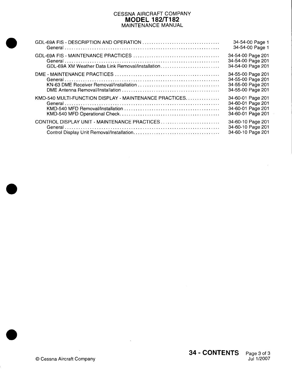
CESSNA AIRCRAFT
COMPANY
MODEL
182/Ti
82
MAINTENANCE
MANUAL
GDL-69A
FIS
-
DESCRIPTION
AND
OPERATION..................
General...................................
GDL-69A
FIS
-
MAINTENANCE
PRACTICES....................
General...................................
GDL-69A
XM
Weather
Data
Link
Removal/installation..............
DME
-
MAINTENANCE
PRACTICES........................
General...................................
KN-63
DME
Receiver
Removal/installation...................
DME
Antenna
Removal/Installation
......................
KMD-540 MULTI-FUNCTION
DISPLAY
-
MAINTENANCE
PRACTICES
........
General...................................
KMD-540
MED
Removal/installation......................
KMD-540
MED
Operational
Check.......................
CONTROL
DISPLAY
UNIT
-
MAINTENANCE
PRACTICES..............
General...................................
Control
Display
U
nit
Removal/Installation....................
34-54-00
Page
1
34-54-00
Page
1
34-54-00
Page
201
34-54-00
Page
201
34-54-00
Page
201
34-55-00
Page
201
34-55-00
Page
201
34-55-00
Page
201
34-55-00
Page
201
34-60-0
1
Page
201
34-60-01 Page
201
34-60-01
Page
201
34-60-01
Page
201
34-60-10
Page
201
34-60-1
0
Page
201
34-60-1
0
Page
201
34
-
CONTENTS
Page
3
of
3
Jul
1/2007
©
Cessna Aircraft
Company
CESSNA
AIRCRAFT
COMPANY
MODEL
182/T182
MAINTENANCE
MANUAL
NAVIGATION
-
GENERAL
1.
Scope
A.
This
chapter
describes
the
navigation
systems,
units,
and
components
which
provide
airplane
navigational
information.
Included
are
pitot
and
static
systems,
air
temperature, gyros,
magnetic
compass,
VOR,
global
positioning,
and
indicators.
For
Bendix/King
KAP-140
Autopilot
information,
refer
to
Chapter
22,
Autopilot
-
Maintenance
Practices
and
the
manufacturer's
manual
listed
in
the
Introduction,
List
of
Manufacturers
Technical
Publications.
2.
Definition
A.
This
chapter
is
divided
into
sections
to
aid
maintenance personnel
in
locating
information.
Consulting
the
table
of
contents
will
further assist
in
locating
a
particular
subject.
A
brief
definition
of
the
sections
incorporated
in
this chapter
is
as
follows:
(1)
The
flight
environmental
data section describes
systems
that
sense
environment
conditions
and
uses
the
data
to
influence
navigation.
This includes systems that
depend
on
pitot and
static
information
and
also
the
outside
air
temperature
system.
(2)
The
attitude
and
direction section describes systems
which use
magnetic
or
inertia
forces
to
sense
and
display
the
direction
or
attitude
of the
airplane. This
includes
items
like
gyros,
magnetic
compass, magnetic
heading,
and
turn
and
bank.
(3)
The
landing
and
taxiing
aids section include
systems
such
as
the marker
beacon
system
which
provide guidance
during
approach,
landing,
and
taxiing.
(4)
The
dependent
position
determining section
describes
systems
which
provides information
to
determine position
and
is
mainly
dependent
on
ground
installations.
This
includes
systems
like
VOR, ADF,
global
positioning,
and
transponders.
34-00-00
Page
1
©
Cessna
Aircraft
Company
April
1/2002
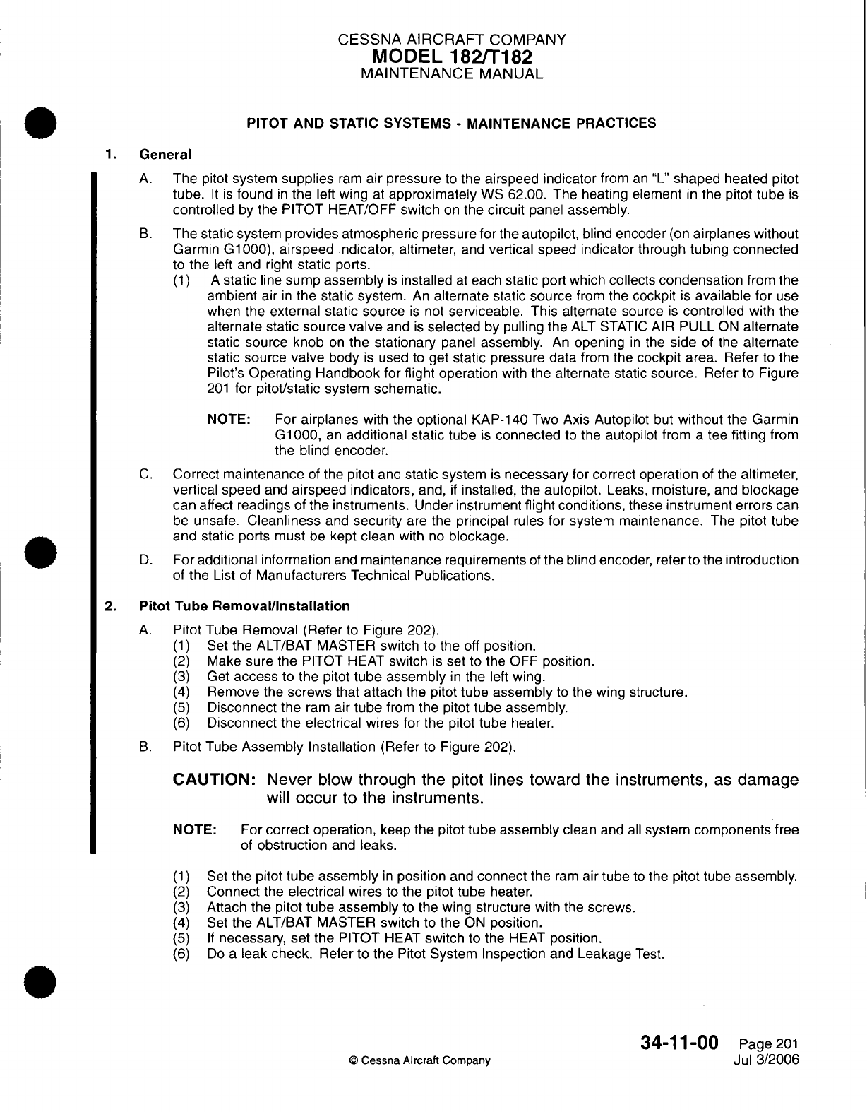
CESSNA AIRCRAFT
COMPANY
MODEL
182/T182
MAINTENANCE
MANUAL
PITOT
AND
STATIC
SYSTEMS
-
MAINTENANCE
PRACTICES
1.
General
A.
The
pitot
system
supplies
ram
air
pressure
to
the
airspeed
indicator
from
an
"L"
shaped
heated
pitot
tube.
It is
found
in
the
left
wing
at
approximately
WS
62.00. The
heating
element
in
the
pitot
tube
is
controlled
by
the
PITOT
HEAT/OFF
switch
on
the
circuit
panel
assembly.
B.
The
static system
provides
atmospheric pressure
for
the
autopilot,
blind
encoder
(on
airplanes
without
Garmin
G1000),
airspeed
indicator, altimeter,
and
vertical speed indicator through tubing
connected
to
the
left
and
right
static
ports.
(1) A
static
line
sump
assembly
is
installed
at
each
static
port
which
collects
condensation
from
the
ambient air
in
the
static
system.
An
alternate
static source
from
the
cockpit
is
available
for
use
when
the
external static source
is
not
serviceable.
This alternate
source
is
controlled
with
the
alternate static source
valve
and
is
selected
by
pulling the
ALT STATIC
AIR
PULL
ON
alternate
static
source
knob
on
the stationary
panel
assembly.
An
opening
in
the
side
of
the
alternate
static
source
valve
body
is
used
to
get
static
pressure
data
from
the
cockpit
area.
Refer
to the
Pilot's
Operating
Handbook
for
flight
operation
with
the
alternate
static
source.
Refer
to
Figure
201
for pitot/static
system
schematic.
NOTE:
For
airplanes
with
the
optional
KAP-140
Two
Axis
Autopilot
but
without
the
Garmin
G1000,
an
additional
static tube
is
connected
to
the
autopilot from
a
tee
fitting
from
the blind
encoder.
C.
Correct
maintenance
of the
pitot
and
static
system
is
necessary
for correct operation
of
the
altimeter,
vertical
speed
and
airspeed
indicators,
and,
if
installed,
the
autopilot.
Leaks,
moisture,
and
blockage
can
affect
readings
of
the
instruments.
Under
instrument
flight
conditions,
these
instrument
errors
can
be
unsafe.
Cleanliness
and
security
are
the
principal
rules for
system maintenance.
The
pitot
tube
and static
ports
must
be
kept
clean
with
no
blockage.
D.
For
additional information
and
maintenance
requirements
of
the
blind
encoder, refer
to the
introduction
of
the
List
of
Manufacturers
Technical
Publications.
2.
Pitot
Tube
Removal/Installation
A.
Pitot
Tube
Removal (Refer
to
Figure
202).
(1)
Set
the
ALT/BAT
MASTER
switch
to
the
off
position.
(2)
Make
sure
the
PITOT
HEAT
switch
is
set
to the OFF
position.
(3)
Get
access
to
the
pitot
tube assembly
in
the
left
wing.
(4)
Remove
the
screws
that attach the
pitot tube
assembly
to
the
wing structure.
(5)
Disconnect
the
ram
air
tube
from
the
pitot
tube
assembly.
(6)
Disconnect
the
electrical
wires
for
the
pitot
tube
heater.
B.
Pitot
Tube
Assembly Installation
(Refer
to
Figure
202).
CAUTION:
Never
blow
through the
pitot lines
toward the
instruments,
as
damage
will
occur
to
the instruments.
NOTE: For
correct operation,
keep
the pitot
tube
assembly
clean
and
all
system components
free
of
obstruction
and
leaks.
(1)
Set
the
pitot
tube assembly
in
position
and
connect
the
ram
air
tube
to
the
pitot
tube assembly.
(2)
Connect
the
electrical
wires
to
the pitot
tube
heater.
(3)
Attach
the
pitot
tube assembly
to
the
wing
structure
with
the
screws.
(4)
Set
the
ALT/BAT
MASTER
switch
to
the
ON
position.
(5) If
necessary,
set
the
PITOT
HEAT
switch
to
the
HEAT
position.
(6)
Do
a
leak
check.
Refer
to
the
Pitot
System
Inspection
and
Leakage
Test.
34-11-00
Page
201
©
Cessna
Aircraft Company
Jul 3/2006
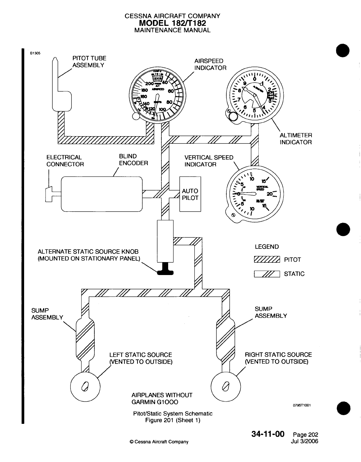
CESSNA
AIRCRAFT
COMPANY
MODEL 182/T182
MAINTENANCE
MANUAL
PITOT
TUBE
ASSEMBLY
AIRSPEED
INDICATOR
LTIMETER
INDICATOR
ELECTRICAL
CONNECTOR ENCODER
/
ALTERNATE
STATIC SOURCE
KNOB
(MOUNTED
ON
STATIONARY
PANEL)
STATIC
SUMP
ASSEMBLY
FT
STATIC
SOURCE
ENTED
TO OUTSIDE)
AIRPLANES WITHOUT
GARMIN
G1000
SUMP
ASSEMBLY
GHT
STATIC
SOURCE
ENTED
TO
OUTSIDE)
0795T1001
Pitot/Static System
Schematic
Figure
201
(Sheet
1)
34-11-00
©
Cessna
Aircraft
Company
Page 202
Jul
3/2006
B1305
LEGEND
PITOT
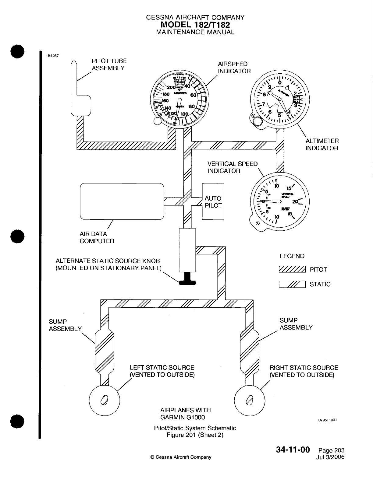
CESSNA
AIRCRAFT
COMPANY
MODEL
182/T182
MAINTENANCE
MANUAL
PITOT
TUBE
ASSEMBLY
AIRSPEED
IDICATOR
///
VERTICAL
SPE
INDICATOR
AUTO
PILOT
/
AIR
DATA
COMPUTER
ALTERNATE
STATIC SOURCE
KNOB
(MOUNTED
ON
STATIONARY
PANEL)
STATIC
SUMP
ASSEMBLY
FT
STATIC
SOURCE
ENTED
TO OUTSIDE)
AIRPLANES
WITH
SUMP
ASSEMBLY
GHT
STATIC
SOURCE
ENTED
TO
OUTSIDE)
GARMIN
G1000
Pitot/Static
System
Schematic
Figure
201
(Sheet
2)
34-11-00
Cessna
Aircraft
Company
B5987
LTIMETER
NDICATOR
LEGEND
PITOT
0795T1001
Page
203
Jul
3/2006
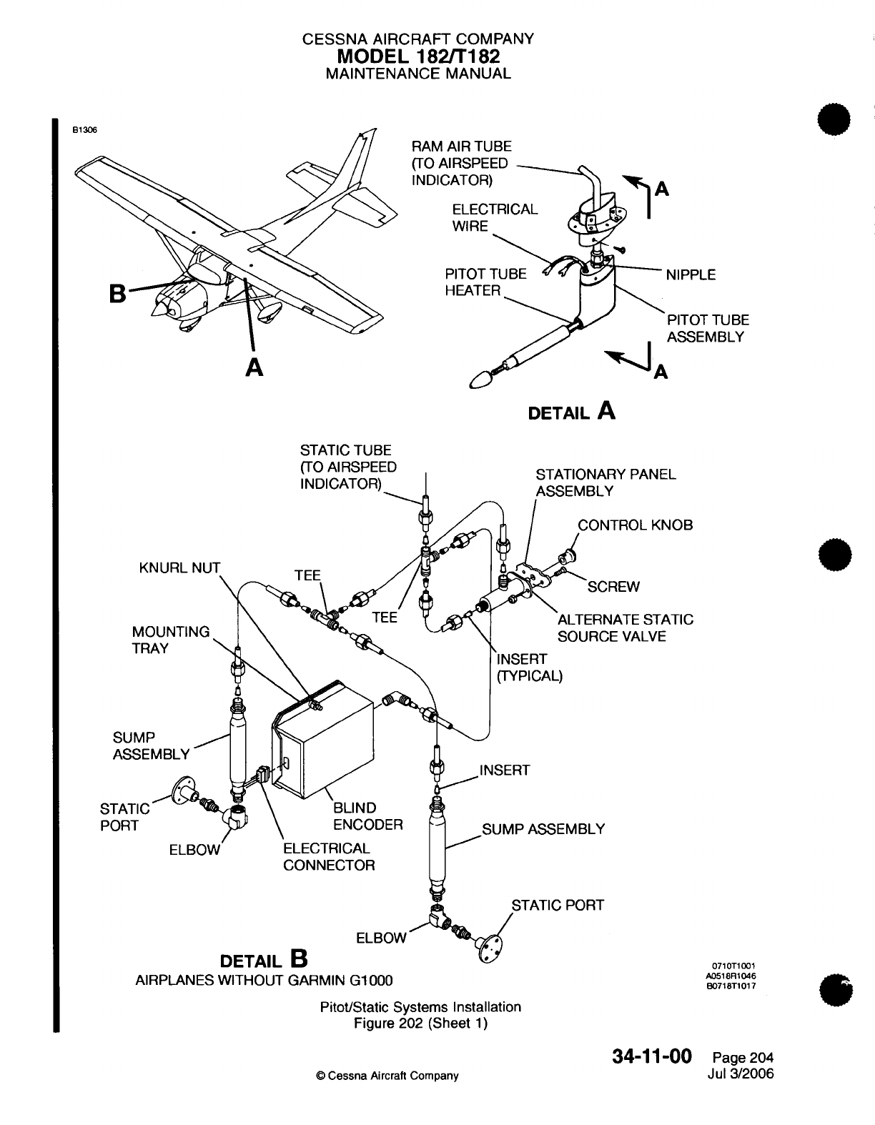
CESSNA
AIRCRAFT
COMPANY
MODEL
182/T182
MAINTENANCE
MANUAL
RAM
AIR TUBE
(TO
AIRSPEES
INDICATOR
WIRE
A
NIPPLE
ASSEMBLY
A
DETAIL
A
STATIC
TUBE
(TO
AIRSPEED
STATIONARY
PANEL
KNURL
NUT
MOUNTING
TRAY
SUMP
ASSEMBLY
TEE
TROL
KNOB
REW
ATE
STATIC
E
VALVE
INSERT
(TYPICAL)
ENCODER
ELECTRICAL
CONNECTOR
PORT
ELBOW
AIRPLANES
WITHOUT GARMIN
G1000
Pitot/Static
Systems
Installation
Figure
202
(Sheet
1)
34-11-00
©
Cessna
Aircraft Company
A
0710T1001
A0518R1046
B0718T1017
Page
204
Jul 3/2006
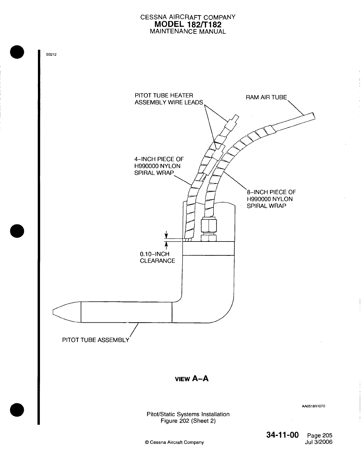
CESSNA
AIRCRAFT
COMPANY
MODEL
182/T182
MAINTENANCE
MANUAL
B3212
PITOT TUBE
HEATER
ASSEMBLY
W
4-INCH
PIECE
H990000
NYLC
SPIRAL WRAP
0.10-INCH
CLEARANCE
PITOT
TUBE
ASSEMBLY
PITOT
TUBE
ASSEMBLY
RAM
AIR
TUBE
8-INCH
PIECE
OF
H990000
NYLON
SPIRAL WRAP
VIEW
A-A
AA0518R1070
Pitot/Static
Systems Installation
Figure 202 (Sheet
2)
©
Cessna
Aircraft
Company
34-11-00
Page 205
Jul 3/2006
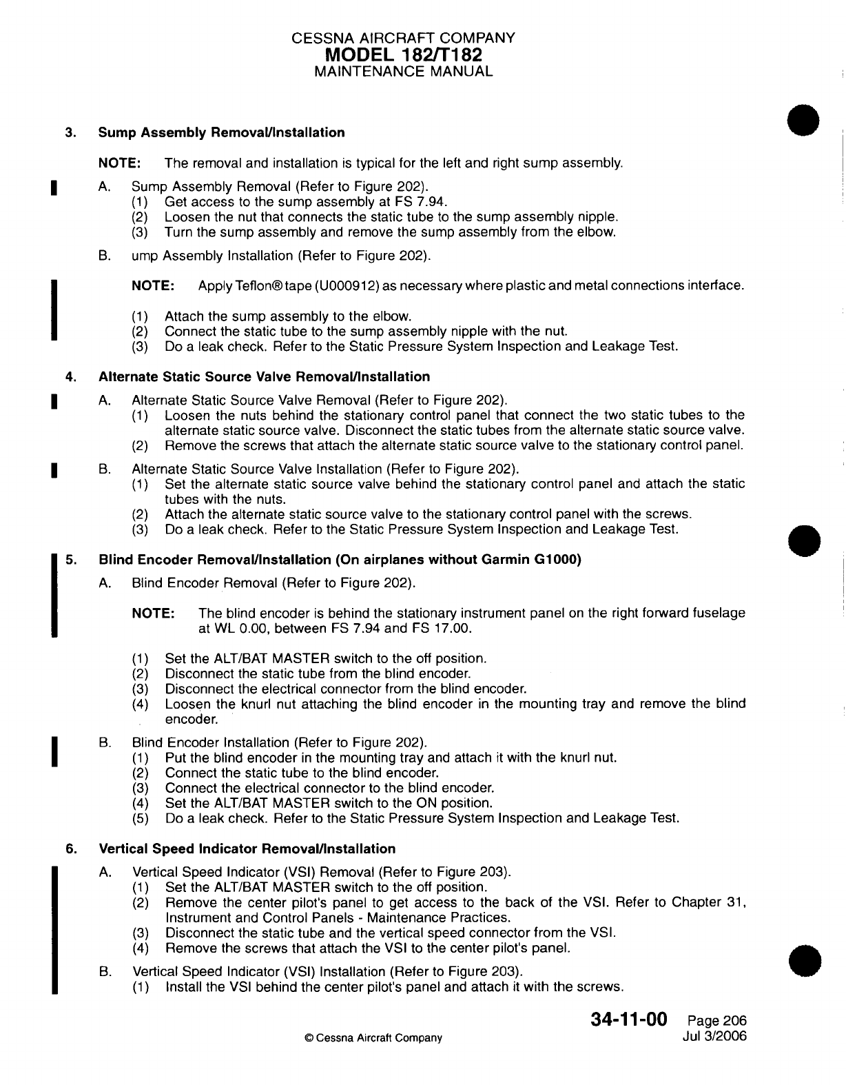
CESSNA AIRCRAFT
COMPANY
MODEL
182/T182
MAINTENANCE
MANUAL
3.
Sump
Assembly Removal/Installation
NOTE:
The
removal
and
installation
is
typical
for
the
left
and
right
sump
assembly.
A.
Sump
Assembly
Removal
(Refer
to
Figure
202).
(1)
Get
access
to
the
sump
assembly
at
FS
7.94.
(2)
Loosen
the
nut
that
connects the
static
tube
to
the sump
assembly
nipple.
(3)
Turn
the
sump
assembly
and
remove
the
sump
assembly
from
the
elbow.
B.
ump
Assembly
Installation
(Refer
to Figure
202).
NOTE:
Apply
Teflon®
tape
(U000912)
as
necessary
where
plastic
and
metal
connections
interface.
(1)
Attach
the sump
assembly
to
the
elbow.
(2)
Connect
the
static tube
to the
sump
assembly
nipple with
the
nut.
(3)
Do
a
leak check. Refer
to
the Static Pressure
System
Inspection
and
Leakage
Test.
4.
Alternate
Static
Source
Valve
Removal/Installation
A.
Alternate Static
Source
Valve
Removal
(Refer
to
Figure
202).
(1)
Loosen the
nuts
behind
the
stationary
control
panel
that
connect
the
two
static
tubes
to the
alternate static source
valve.
Disconnect
the
static
tubes
from
the alternate static source
valve.
(2)
Remove
the
screws that attach
the
alternate
static source
valve
to the
stationary
control
panel.
B.
Alternate Static
Source
Valve
Installation
(Refer
to
Figure
202).
(1)
Set
the
alternate
static
source valve
behind
the
stationary control
panel
and
attach the
static
tubes
with
the
nuts.
(2)
Attach
the
alternate
static source valve
to
the
stationary control
panel
with
the
screws.
(3)
Do
a
leak check.
Refer
to the
Static
Pressure
System
Inspection
and
Leakage
Test.
5.
Blind
Encoder
Removal/Installation
(On
airplanes
without
Garmin
G1000)
A.
Blind
Encoder
Removal
(Refer
to Figure
202).
NOTE:
The blind
encoder
is
behind
the
stationary
instrument
panel
on
the
right
forward
fuselage
at
WL 0.00, between
FS
7.94
and
FS
17.00.
(1)
Set
the
ALT/BAT
MASTER
switch
to
the
off
position.
(2)
Disconnect
the
static
tube
from
the
blind
encoder.
(3)
Disconnect
the
electrical
connector
from the
blind
encoder.
(4)
Loosen
the
knurl nut
attaching
the
blind
encoder
in
the
mounting
tray
and
remove
the
blind
encoder.
B.
Blind
Encoder
Installation
(Refer
to Figure
202).
(1)
Put
the
blind
encoder
in
the mounting
tray
and
attach
it
with
the
knurl nut.
(2)
Connect the
static
tube
to
the blind
encoder.
(3)
Connect
the
electrical
connector
to
the
blind
encoder.
(4)
Set
the
ALT/BAT
MASTER
switch
to
the
ON
position.
(5)
Do
a
leak
check. Refer
to the
Static Pressure System
Inspection
and
Leakage
Test.
6.
Vertical
Speed
Indicator
Removal/Installation
A.
Vertical
Speed
Indicator
(VSI)
Removal
(Refer
to Figure
203).
(1)
Set
the
ALT/BAT
MASTER
switch
to
the
off
position.
(2)
Remove
the
center
pilot's panel
to get
access
to
the
back
of
the
VSI.
Refer
to Chapter
31,
Instrument
and
Control
Panels
-
Maintenance
Practices.
(3)
Disconnect
the
static
tube
and
the
vertical
speed
connector
from
the
VSI.
(4)
Remove
the
screws
that
attach the
VSI
to
the
center
pilot's
panel.
B.
Vertical
Speed Indicator
(VSI)
Installation
(Refer
to
Figure
203).
(1)
Install the
VSI
behind the
center
pilot's
panel
and
attach
it
with
the screws.
34-11-00
Page
206
Cessna
Aircraft
Company
Jul
3/2006
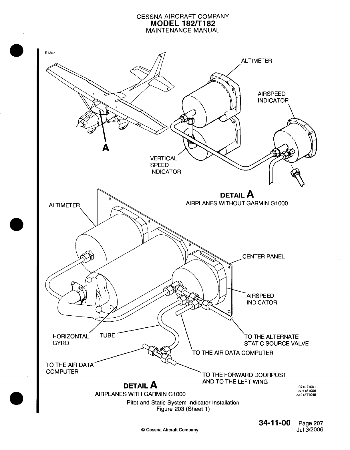
CESSNA
AIRCRAFT
COMPANY
MODEL
182/T182
MAINTENANCE
MANUAL
ALTIMETER
AIRSPEED
INDICATOR
A
VERTICAL
SPEED
INDICATOR
D00
EL
ERNATE
RCE VALVE
DETAIL
A
AIRPLANES
WITH
GARMIN
G1000
AND TO
THE
LEFT
WING
Pitot
and
Static
System
Indicator
Installation
Figure
203
(Sheet
1)
34-11-00
©
Cessna
Aircraft
Company
0710T1001
A07181006
A1218T1045
Page 207
Jul
3/2006
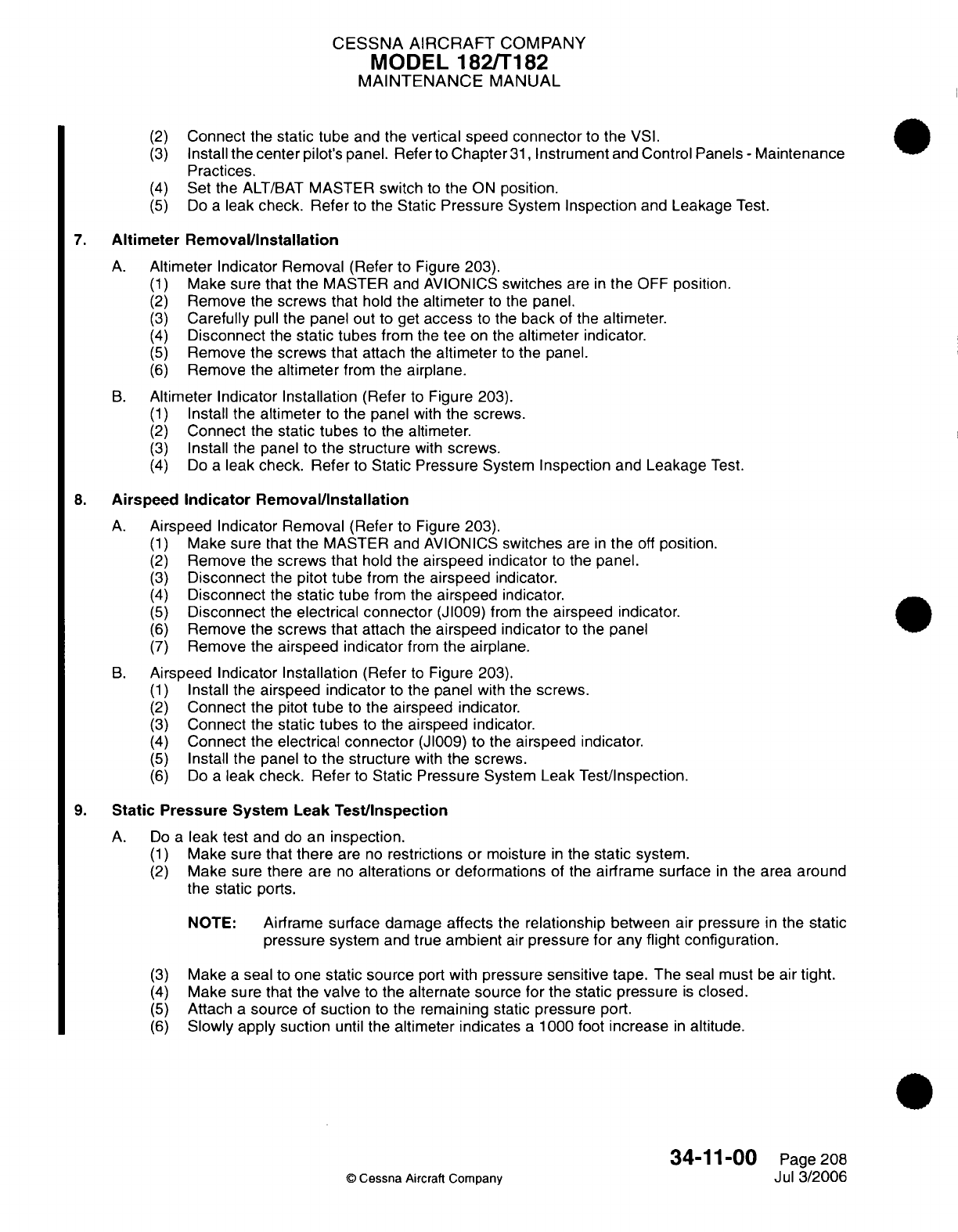
CESSNA AIRCRAFT
COMPANY
MODEL
182/T182
MAINTENANCE
MANUAL
(2)
Connect
the
static
tube
and the
vertical speed
connector
to the
VSI.
(3)
Install
the
center
pilot's
panel.
Refer to
Chapter
31,
Instrument
and
Control
Panels
-
Maintenance
Practices.
(4)
Set
the
ALT/BAT
MASTER
switch
to
the
ON
position.
(5)
Do
a
leak
check.
Refer
to the
Static
Pressure
System
Inspection
and
Leakage
Test.
7.
Altimeter Removal/Installation
A.
Altimeter
Indicator
Removal (Refer
to
Figure 203).
(1)
Make sure
that
the
MASTER and AVIONICS
switches
are
in
the OFF
position.
(2)
Remove
the
screws
that
hold
the
altimeter
to
the
panel.
(3)
Carefully
pull
the
panel out
to get
access
to the
back
of
the altimeter.
(4)
Disconnect
the
static
tubes
from
the
tee
on the
altimeter
indicator.
(5)
Remove
the
screws that attach
the
altimeter
to
the
panel.
(6)
Remove the
altimeter
from the
airplane.
B.
Altimeter Indicator
Installation
(Refer
to
Figure
203).
(1)
Install
the
altimeter
to
the panel
with
the
screws.
(2)
Connect
the
static tubes
to
the
altimeter.
(3)
Install
the
panel
to
the
structure
with
screws.
(4)
Do
a
leak check. Refer
to
Static
Pressure
System
Inspection
and
Leakage
Test.
8.
Airspeed
Indicator
Removal/Installation
A.
Airspeed Indicator Removal
(Refer
to
Figure
203).
(1)
Make
sure
that
the
MASTER and AVIONICS
switches
are
in
the
off
position.
(2)
Remove
the
screws
that
hold
the airspeed
indicator
to
the
panel.
(3)
Disconnect
the
pitot
tube
from
the
airspeed
indicator.
(4)
Disconnect
the
static
tube
from
the
airspeed
indicator.
(5)
Disconnect
the
electrical
connector
(J1009)
from
the
airspeed
indicator.
(6)
Remove
the
screws that
attach
the
airspeed
indicator
to
the
panel
(7)
Remove the
airspeed
indicator
from
the
airplane.
B.
Airspeed Indicator
Installation
(Refer
to
Figure
203).
(1)
Install the
airspeed
indicator
to the
panel
with
the screws.
(2)
Connect
the
pitot
tube
to
the airspeed
indicator.
(3)
Connect
the
static tubes
to
the airspeed
indicator.
(4)
Connect
the
electrical
connector
(JI009)
to the
airspeed
indicator.
(5)
Install the
panel
to
the
structure
with
the
screws.
(6)
Do
a
leak
check. Refer
to
Static
Pressure
System
Leak Test/Inspection.
9.
Static
Pressure
System Leak
Test/Inspection
A.
Do
a
leak test
and do an
inspection.
(1)
Make
sure
that
there
are
no
restrictions or
moisture
in
the
static
system.
(2)
Make
sure
there are
no
alterations
or
deformations
of the
airframe
surface
in
the area
around
the static
ports.
NOTE:
Airframe
surface
damage
affects
the
relationship
between air
pressure
in
the
static
pressure
system
and
true
ambient
air
pressure
for
any
flight
configuration.
(3)
Make
a
seal
to one
static source
port
with pressure
sensitive
tape.
The
seal
must
be
air
tight.
(4)
Make sure
that the
valve
to
the
alternate
source
for
the static pressure
is
closed.
(5)
Attach
a
source
of
suction
to
the
remaining
static
pressure
port.
(6)
Slowly apply
suction
until
the
altimeter indicates
a
1000
foot
increase
in
altitude.
34-11-00
Page
208
©
Cessna
Aircraft
Company
Jul
3/2006
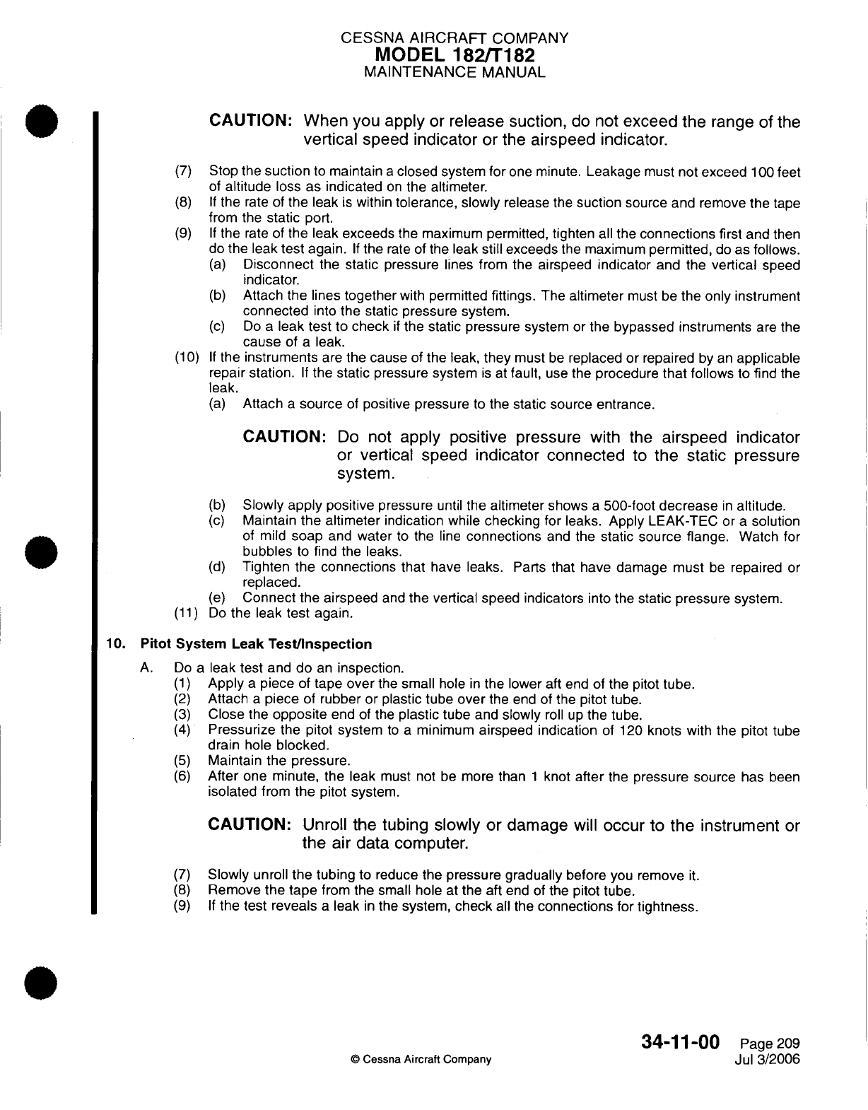
CESSNA
AIRCRAFT
COMPANY
MODEL
182/T182
MAINTENANCE
MANUAL
CAUTION: When
you
apply
or
release suction,
do
not
exceed
the
range
of the
vertical
speed
indicator
or
the
airspeed
indicator.
(7)
Stop
the
suction
to
maintain
a
closed
system
for
one
minute.
Leakage
must not
exceed
100
feet
of
altitude
loss
as indicated
on
the
altimeter.
(8) If
the
rate
of
the leak
is
within
tolerance,
slowly
release
the
suction
source and
remove
the
tape
from the
static
port.
(9) If
the
rate
of
the
leak exceeds
the
maximum permitted,
tighten
all
the
connections
first
and
then
do
the
leak
test
again.
If
the
rate
of
the leak
still exceeds
the maximum
permitted,
do
as follows.
(a)
Disconnect
the
static
pressure
lines
from
the airspeed
indicator
and the
vertical
speed
indicator.
(b)
Attach the
lines
together
with
permitted
fittings.
The
altimeter
must
be
the
only
instrument
connected
into
the
static pressure system.
(c)
Do
a
leak test to
check
if
the
static pressure
system
or
the
bypassed instruments
are
the
cause
of
a
leak.
(10)
If
the
instruments
are
the cause
of
the leak,
they
must
be
replaced
or
repaired
by
an
applicable
repair
station.
If
the
static
pressure
system
is
at
fault,
use
the
procedure
that
follows
to
find
the
leak.
(a)
Attach
a
source
of
positive
pressure
to
the
static source
entrance.
CAUTION:
Do
not
apply
positive
pressure
with
the
airspeed
indicator
or
vertical speed
indicator connected
to
the
static
pressure
system.
(b)
Slowly
apply
positive
pressure
until
the
altimeter
shows
a
500-foot
decrease
in
altitude.
(c)
Maintain
the altimeter
indication
while
checking
for
leaks.
Apply
LEAK-TEC
or
a
solution
of
mild
soap
and
water
to
the
line
connections
and
the
static
source flange.
Watch
for
bubbles
to
find
the
leaks.
(d)
Tighten the
connections
that
have leaks.
Parts
that
have
damage
must
be
repaired
or
replaced.
(e)
Connect
the airspeed
and
the vertical speed indicators
into the
static pressure
system.
(11)
Do
the leak
test
again.
10.
Pitot
System
Leak
Test/Inspection
A.
Do
a
leak
test
and do
an
inspection.
(1)
Apply
a
piece
of
tape
over
the
small
hole
in
the
lower
aft
end
of
the
pitot
tube.
(2)
Attach
a
piece
of
rubber
or
plastic tube
over
the
end
of the
pitot
tube.
(3)
Close
the
opposite
end
of
the
plastic
tube
and
slowly
roll up
the
tube.
(4)
Pressurize
the
pitot
system
to
a
minimum
airspeed indication
of 120
knots
with
the
pitot
tube
drain
hole
blocked.
(5)
Maintain
the
pressure.
(6)
After
one minute,
the leak
must
not be
more
than
1
knot
after
the
pressure
source
has
been
isolated
from
the
pitot system.
CAUTION:
Unroll
the
tubing
slowly
or
damage
will
occur to
the instrument
or
the
air
data
computer.
(7)
Slowly
unroll
the tubing
to
reduce
the
pressure gradually
before
you remove
it.
(8)
Remove
the
tape
from
the
small hole
at
the aft
end
of
the
pitot
tube.
(9) If
the
test reveals
a
leak
in
the
system,
check
all
the
connections
for
tightness.
34-11-00
Page
209
©
Cessna
Aircraft
Company
Jul
3/2006
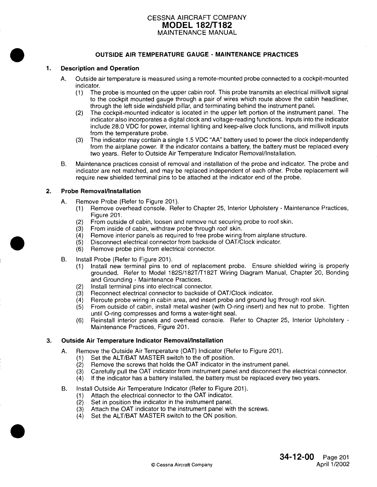
CESSNA
AIRCRAFT
COMPANY
MODEL
182/T182
MAINTENANCE
MANUAL
OUTSIDE AIR
TEMPERATURE GAUGE
-
MAINTENANCE
PRACTICES
1.
Description
and
Operation
A.
Outside
air
temperature
is
measured using
a
remote-mounted probe
connected
to
a
cockpit-mounted
indicator.
(1)
The
probe
is
mounted
on
the upper cabin
roof.
This
probe
transmits
an
electrical millivolt signal
to
the cockpit
mounted
gauge through
a
pair
of
wires
which
route
above the
cabin headliner,
through the
left
side
windshield
pillar,
and
terminating
behind
the
instrument panel.
(2)
The
cockpit-mounted
indicator
is
located
in
the
upper
left
portion
of the
instrument
panel. The
indicator
also
incorporates
a
digital
clock
and
voltage-reading functions.
Inputs into
the
indicator
include
28.0
VDC
for
power,
internal
lighting
and
keep-alive clock
functions,
and
millivolt
inputs
from the
temperature
probe.
(3)
The
indicator
may
contain
a
single
1.5
VDC
"AA"
battery
used
to
power the
clock independently
from the
airplane
power.
If
the
indicator contains
a
battery,
the
battery must
be
replaced
every
two
years. Refer
to
Outside
Air
Temperature
Indicator Removal/Installation.
B.
Maintenance
practices consist
of
removal
and
installation
of
the probe
and
indicator. The
probe
and
indicator
are
not matched,
and
may
be
replaced
independent
of each
other.
Probe
replacement
will
require new
shielded
terminal
pins
to
be
attached
at
the
indicator
end
of
the
probe.
2.
Probe
Removal/Installation
A.
Remove
Probe
(Refer
to
Figure
201).
(1)
Remove
overhead
console.
Refer
to
Chapter
25,
Interior
Upholstery
-
Maintenance
Practices,
Figure
201.
(2)
From
outside
of
cabin,
loosen
and remove
nut
securing
probe
to
roof
skin.
(3)
From
inside
of
cabin,
withdraw
probe
through
roof
skin.
(4)
Remove
interior
panels
as
required
to
free
probe
wiring
from
airplane
structure.
(5)
Disconnect electrical connector
from
backside
of
OAT/Clock
indicator.
(6)
Remove
probe pins
from
electrical
connector.
B.
Install
Probe
(Refer
to
Figure
201).
(1)
Install
new
terminal
pins
to
end
of
replacement
probe.
Ensure
shielded
wiring
is
properly
grounded.
Refer
to
Model
182S/182T/T182T Wiring
Diagram
Manual,
Chapter
20,
Bonding
and
Grounding
-
Maintenance Practices.
(2)
Install
terminal
pins
into
electrical
connector.
(3)
Reconnect
electrical
connector
to
backside
of
OAT/Clock
indicator.
(4)
Reroute probe
wiring
in
cabin
area,
and
insert
probe
and
ground
lug
through
roof
skin.
(5)
From
outside
of
cabin,
install
metal
washer
(with
O-ring
insert)
and
hex nut to
probe.
Tighten
until
O-ring
compresses
and
forms
a
water-tight seal.
(6)
Reinstall interior
panels
and
overhead
console.
Refer
to
Chapter
25,
Interior
Upholstery
-
Maintenance
Practices,
Figure
201.
3.
Outside
Air
Temperature
Indicator
Removal/Installation
A.
Remove
the
Outside
Air
Temperature
(OAT)
Indicator
(Refer
to Figure
201).
(1)
Set
the
ALT/BAT
MASTER
switch
to
the off
position.
(2)
Remove the screws that
holds
the
OAT
indicator
in
the
instrument
panel.
(3)
Carefully
pull
the
OAT
indicator
from
instrument
panel
and
disconnect
the
electrical
connector.
(4)
If
the
indicator
has
a
battery installed,
the
battery must
be
replaced
every
two
years.
B.
Install
Outside
Air
Temperature
Indicator
(Refer
to
Figure
201).
(1)
Attach
the
electrical
connector
to
the
OAT
indicator.
(2)
Set
in
position
the
indicator
in
the
instrument
panel.
(3)
Attach the
OAT
indicator
to
the
instrument
panel with
the
screws.
(4)
Set
the
ALT/BAT MASTER
switch
to
the
ON
position.
34-12-00
Page
201
©
Cessna Aircraft
Company
April
1/2002
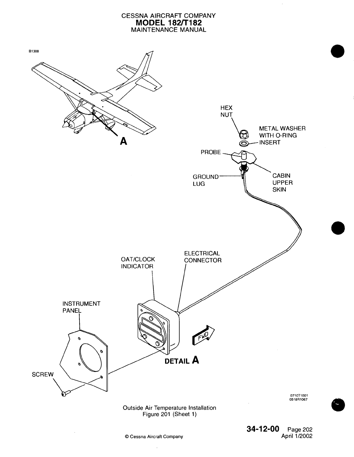
CESSNA
AIRCRAFT
COMPANY
MODEL 182/T182
MAINTENANCE
MANUAL
B
HEX
NUT
METAL
WASHER
@
IWITH
O-RING
(D,
INSERT
CABIN
UPPER
SKIN
ELECTRICAL
OAT/CLOCK
CONNECTOR
INDICATOR
/
INSTRUMENT
DETAIL
A
SCREW
0710T1001
0518R1067
Outside Air
Temperature
Installation
Figure
201
(Sheet
1)
©
Cessna
Aircraft Company
34-12-00
Page
202
April
1/2002
A
.
---
`--
r5t,
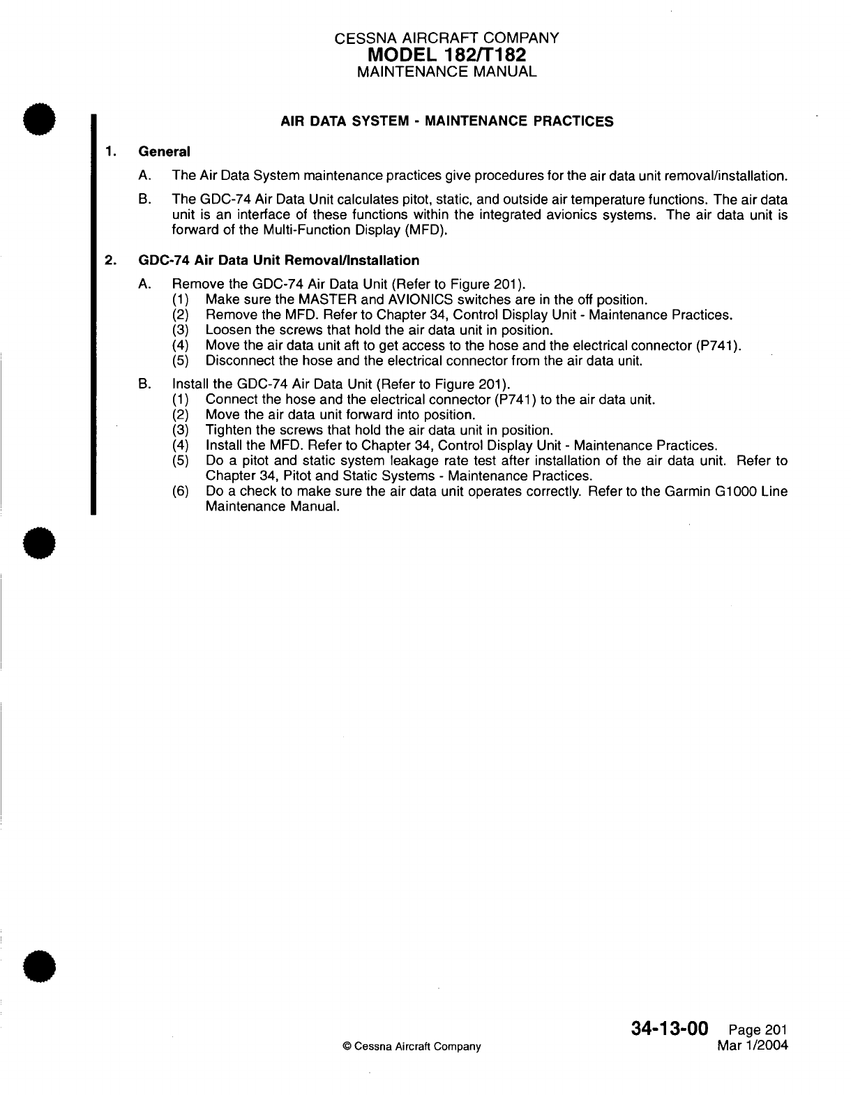
CESSNA
AIRCRAFT
COMPANY
MODEL
182/T182
MAINTENANCE
MANUAL
AIR
DATA
SYSTEM
-
MAINTENANCE
PRACTICES
1.
General
A.
The
Air
Data
System maintenance practices give procedures for
the
air
data
unit
removal/installation.
B.
The GDC-74
Air
Data
Unit
calculates
pitot,
static,
and
outside
air
temperature
functions.
The
air
data
unit
is
an
interface
of
these functions
within
the
integrated
avionics
systems. The air
data
unit
is
forward
of
the
Multi-Function
Display
(MFD).
2.
GDC-74
Air
Data
Unit Removal/Installation
A.
Remove
the
GDC-74
Air
Data
Unit
(Refer
to
Figure
201).
(1)
Make sure
the MASTER and
AVIONICS
switches
are
in
the
off
position.
(2)
Remove the
MFD.
Refer
to
Chapter
34,
Control
Display
Unit
-
Maintenance
Practices.
(3)
Loosen the screws
that
hold
the
air
data unit
in
position.
(4)
Move
the air
data
unit
aft
to
get
access
to
the
hose
and
the
electrical connector
(P741).
(5)
Disconnect
the hose
and
the
electrical
connector
from
the
air
data
unit.
B.
Install
the
GDC-74
Air
Data Unit
(Refer
to
Figure
201).
(1)
Connect
the
hose
and
the
electrical
connector
(P741)
to
the
air
data
unit.
(2)
Move
the air
data
unit
forward
into
position.
(3)
Tighten the screws
that
hold
the air
data
unit
in
position.
(4)
Install
the
MFD.
Refer
to
Chapter
34,
Control
Display
Unit
-
Maintenance
Practices.
(5)
Do
a
pitot
and
static
system
leakage
rate
test
after
installation
of
the
air
data
unit. Refer
to
Chapter
34,
Pitot
and
Static
Systems
-
Maintenance
Practices.
(6)
Do
a
check
to
make sure
the air
data
unit operates correctly.
Refer
to
the
Garmin G1000
Line
Maintenance
Manual.
34-13-00
Page
201
©
Cessna
Aircraft
Company
Mar
1/2004
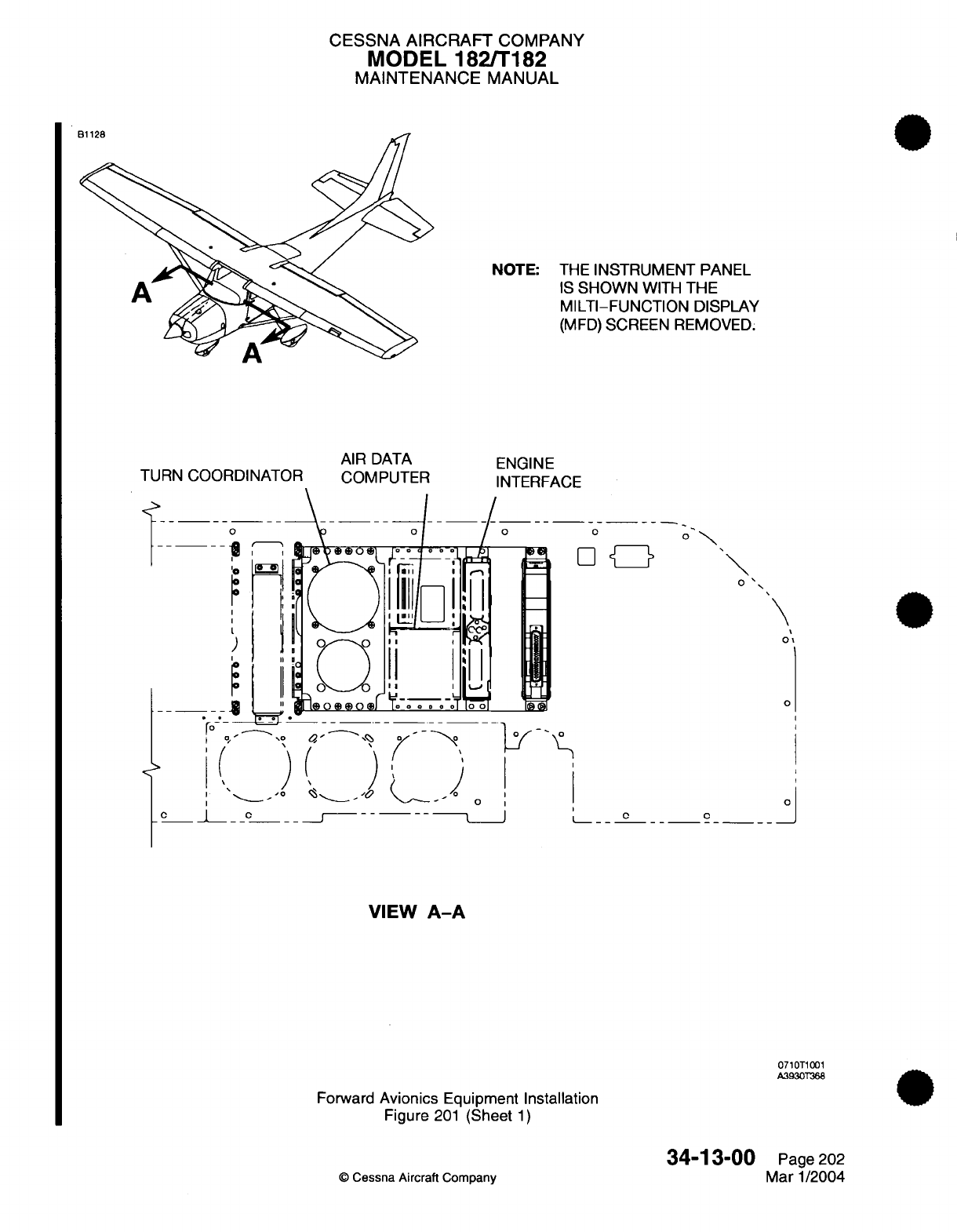
CESSNA
AIRCRAFT
COMPANY
MODEL
182/T182
MAINTENANCE
MANUAL
NOTE:
THE
INSTRUMENT
PANEL
IS
SHOWN
WITH
THE
MILTI-FUNCTION
DISPLAY
(MFD)
SCREEN
REMOVED.
TURN
COORDINATOR
II
AIR
DATA
COMPUTER
I
C 0____Io
I 0_ j
VIEW
A-A
0710T1001
A3930T368
Forward
Avionics
Equipment
Installation
Figure
201
(Sheet
1)
34-13-00
©
Cessna Aircraft
Company
ENGINE
INTERFACE
0
1
C
O
\
S
0
-o
Q
_~
>
0
'
-°'. ^
o.-
.-,
/V'-"'"~~~~~~~~~~
0I
0
O~'
Page
202
Mar
1/2004
,.
.^^
f
--
I
y
-,-
,
j
1
I
- -0
CESSNA
AIRCRAFT
COMPANY
MODEL
182/T182
MAINTENANCE
MANUAL
ATTITUDE
AND
DIRECTION
-
DESCRIPTION AND
OPERATION
1.
General
A.
Attitude and
direction navigation
systems
are
systems
which
use
magnetic or
gyroscopic
forces
to
sense
and
display
the
direction
or
attitude
of
the
airplane. This
includes
the
magnetic
compass,
horizon gyro,
directional
gyro,
and
turn
coordinator
(roll
rate
gyro)
indicator.
B.
The
magnetic
compass
is
located
on
the
airplane
centerline
of
the upper forward
windshield.
The
compass
is
independent
of
other
navigation
systems
and
does
not
supply
information
to
other airplane
systems.
C.
The
three
gyroscopic
instruments that indicate
attitude
and
direction
are
mounted
in
the
center
pilot
panel
assembly. The
directional
gyro and
turn
coordinator
provide
information to
the
autopilot
system.
34-20-00
Page
1
©
Cessna
Aircraft Company
April
1/2002
CESSNA
AIRCRAFT
COMPANY
MODEL
182/T182
MAINTENANCE
MANUAL
ATTITUDE
AND
DIRECTION
-
MAINTENANCE PRACTICES
1.
General
A.
This
section gives
maintenance
information, removal
and
installation
procedures, and
operational
checks
for
the
horizon
attitude
gyro,
directional
gyro,
and
turn
coordinator.
B.
On
airplanes without
Garmin
G1000,
three
gyroscopic
instruments show
the
attitude
and
direction
of
the
airplane.
The
instruments
are
found
in
the
center
pilot
panel.
These instruments
are
the
horizon
attitude
gyro,
directional
gyro,
and turn
coordinator.
C.
On
airplanes
with
Garmin
G1000,
two
gyroscopic
instruments give
attitude and
direction.
The
horizon
gyro
is
in
the
center
instrument
panel.
The
horizon
gyro
gives
attitude
and
direction
and
is
the
middle
standby instrument.
The turn
coordinator gives
roll rate
data
to
the
autopilot
and
is
installed
on
the
left
side
of
the
center
instrument
panel.
The
turn
coordinator cannot
be
seen
in
the
cockpit.
2.
Operation
Notes
A.
The vacuum system
supplies
airflow
necessary
to
move
the
gyro
rotor
in
the
horizon
gyro.
Incorrect
operation
of
the
vacuum
system
will
cause
the
horizon
gyro
to
operate
incorrectly.
B. It
is
necessary
for
the
horizon
gyro
to
have
4.5
to
5.5
in.hg. of
vacuum
to
operate
correctly.
The
gyro
will
reach
rated
performance
with
correct vacuum
applied
in
a
minimum
of
3
minutes of
rotor
spin
time.
C.
The
gyro
rotor can
continue
to
spin
for
approximately
15
minutes
after vacuum
in
the
system
is
removed.
It
can
show
a
change
in
the
roll
and/or
pitch indication
while
the
rotor
speed
decreases.
The
gyro
rotor will
remain
in
a roll
and/or
pitch
indication
when
stopped
until
the
system
starts
again.
D. If a
gyro
has
been
shut
down and started
again
before
the
rotor
has been
permitted
to
stop,
more
time
will
be
necessary
to
get the correct
pitch
and
roll
indication.
3.
Precautions
A.
Gyroscopic
instruments
are
very
sensitive. They
have precision
bearings
on
the
gyroscope
rotor,
pivots,
and
yoke
shaft.
Be
careful
when
you
move
or
touch
the
instrument
when
it
is
out
of
the
airplane.
If
you
are
not
careful
when you
move
or
touch the instrument,
you
can
cause
damage
to
the bearings.
Dirt
and
other
contaminants
can
also
cause
damage
to
the bearings.
Obey these
special precautions
when
you
move,
install,
remove,
or
ship
any
gyroscopic
instruments.
(1)
To
prevent damage to
the
gyro,
do
not move
a gyro
after
the
electrical
power
or
vacuum
pressure
is
removed
and
before
the
gyro
rotor has
stopped. The
gyro
rotor
will
not
fully
stop
for
approximately
15
minutes
after
the
electrical
power
or
vacuum
pressure
is
removed.
(2)
During
the
removal
of
instruments,
put
soft
material between the
instruments
and
the
control
column.
(3)
Do
not
shake
or cause
vibration
of
the
panel
or
the instruments.
(4)
Do
not
hit
the
gyroscope
against
any
other
object.
Do
not
shake
the
gyroscope
or
put
the
gyroscope
on
a
hard
surface.
If
you
are
not careful,
you
can
cause
damage
to
the
instrument.
CAUTION:
Always
be
very
careful
when you
move
or
hold
gyroscopic
instruments, because
you
can
easily cause
damage.
(5)
Do
not remove
any
wires,
labels,
tie
straps,
or
any other
parts
of
the
gyro
that
are
installed
by
the
manufacturer.
(6)
Visually
examine
the gyro
for
any
external
damage. There
must
be
no
scratches,
dents,
or dings
on
any
part
of the
gyro.
Do
not
install
gyros
that
have
scratches,
dents,
or
dings.
(7) If
you
must
ship
a
gyroscopic
instrument,
make
sure
that
all
the
female ports have
plugs
that
you
can remove,
and
that
all
the male
receptacles
have
plastic caps
that
you can remove.
(8)
Put
connector
caps
on
all
the
electrical
pin
connectors
to
make
sure
that
they
are
not
bent
or
broken.
(9)
Put
all
gyros
in
Styrofoam
or
other
soft
material
for
storage
and
transportation.
If
possible,
ship
the
gyroscope
in
the
box
from
the
manufacturer
in
which
it
was
received.
34-21-00
Page
201
©
Cessna
Aircraft
Company
Jan
2/2006
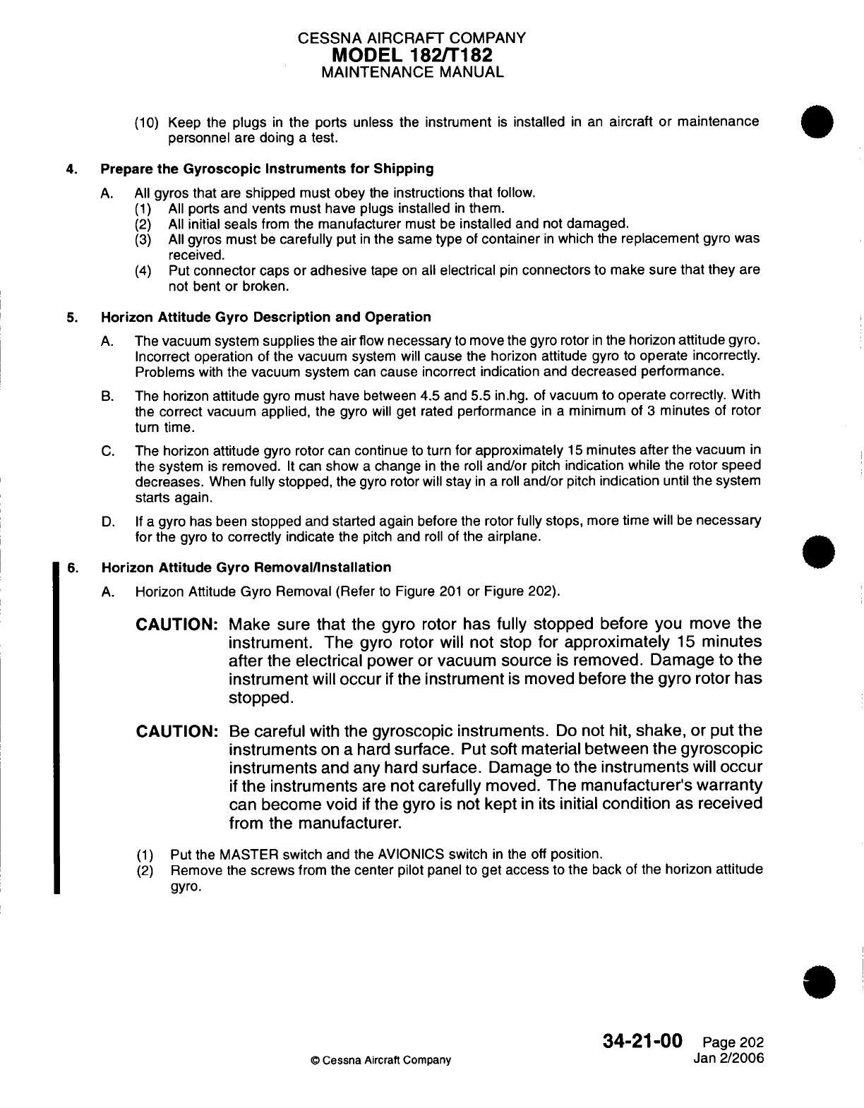
CESSNA
AIRCRAFT
COMPANY
MODEL
182/T182
MAINTENANCE
MANUAL
(10)
Keep
the
plugs
in
the ports unless the
instrument
is
installed
in
an
aircraft or
maintenance
personnel
are
doing
a
test.
4.
Prepare
the
Gyroscopic
Instruments
for
Shipping
A. All
gyros
that
are
shipped
must
obey
the
instructions
that
follow.
(1)
All
ports
and
vents
must
have
plugs
installed
in
them.
(2)
All
initial
seals
from
the
manufacturer
must
be
installed
and not
damaged.
(3)
All
gyros
must
be
carefully
put
in
the same type
of
container
in
which
the
replacement
gyro was
received.
(4)
Put
connector
caps or
adhesive
tape
on
all
electrical
pin
connectors
to
make
sure
that
they
are
not
bent or
broken.
5.
Horizon
Attitude
Gyro
Description
and
Operation
A.
The
vacuum
system
supplies
the air flow
necessary
to
move
the gyro
rotor
in
the
horizon
attitude
gyro.
Incorrect
operation
of
the
vacuum
system
will
cause
the
horizon attitude
gyro
to
operate
incorrectly.
Problems
with
the vacuum system
can
cause
incorrect
indication
and
decreased
performance.
B.
The horizon
attitude
gyro
must
have between
4.5
and
5.5
in.hg.
of
vacuum
to operate
correctly.
With
the
correct
vacuum
applied,
the
gyro
will
get
rated
performance
in a
minimum
of
3
minutes
of
rotor
turn
time.
C.
The
horizon
attitude
gyro
rotor
can
continue
to
turn
for
approximately
15
minutes
after
the
vacuum
in
the
system
is
removed.
It
can
show
a
change
in
the
roll
and/or
pitch
indication
while
the rotor
speed
decreases.
When
fully
stopped,
the
gyro
rotor
will
stay
in
a roll
and/or
pitch
indication
until
the
system
starts
again.
D. If
a
gyro
has
been
stopped
and
started
again
before
the
rotor
fully
stops,
more
time
will
be
necessary
for
the
gyro
to
correctly
indicate
the
pitch
and
roll
of the
airplane.
6.
Horizon
Attitude
Gyro
Removal/Installation
A.
Horizon Attitude
Gyro
Removal (Refer
to
Figure
201
or
Figure 202).
CAUTION:
CAUTION:
(1)
(2)
Make
sure
that
the gyro
rotor
has
fully
stopped
before
you
move
the
instrument.
The gyro
rotor
will not
stop
for
approximately
15
minutes
after
the
electrical
power
or
vacuum
source
is
removed. Damage
to
the
instrument
will
occur
if
the
instrument
is
moved
before
the gyro rotor has
stopped.
Be
careful
with
the
gyroscopic
instruments.
Do
not
hit,
shake,
or
put
the
instruments
on
a
hard
surface.
Put
soft material
between the
gyroscopic
instruments
and any
hard
surface.
Damage
to
the
instruments
will
occur
if
the
instruments
are
not
carefully
moved.
The manufacturer's
warranty
can
become
void
if
the gyro
is
not
kept
in
its
initial
condition
as
received
from
the manufacturer.
Put
the
MASTER
switch
and
the
AVIONICS
switch
in
the
off
position.
Remove
the
screws
from
the center
pilot
panel
to
get access
to the
back
of the
horizon
attitude
gyro.
34-21-00
Page
202
©
Cessna
Aircraft
Company
Jan
2/2006
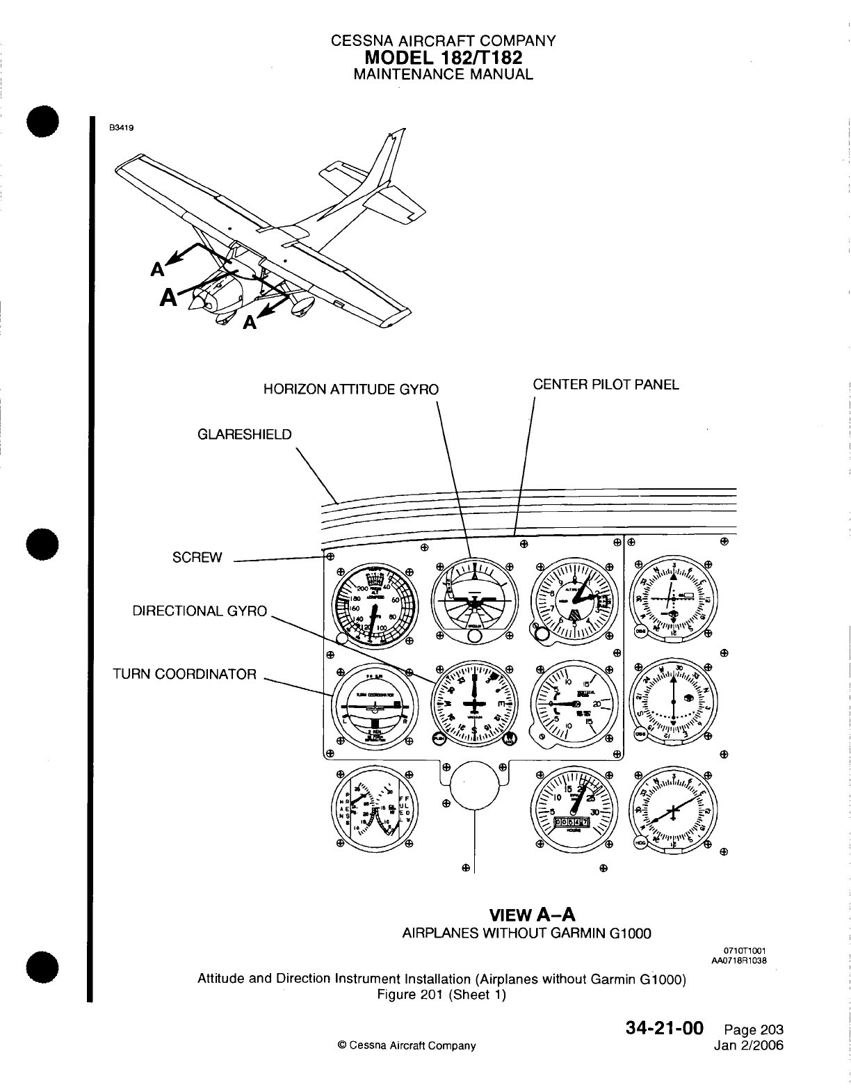
CESSNA
AIRCRAFT
COMPANY
MODEL
182/r182
MAINTENANCE
MANUAL
HORIZON
ATTITUDE
GYRO
CENTER
PILOT
PANEL
I
/
SCREW
DIRECTIONAL
C
TURN
COORDINA1
IO12
VIEW
A-A
AIRPLANES
WITHOUT
GARMIN
G1000
0710T1001
AA0718R1038
Attitude
and Direction
Instrument
Installation (Airplanes without
Garmin
G1000)
Figure
201
(Sheet
1)
34-21-00
©
Cessna
Aircraft
Company
GLAR
Page
203
Jan 2/2006
Rl11t
D
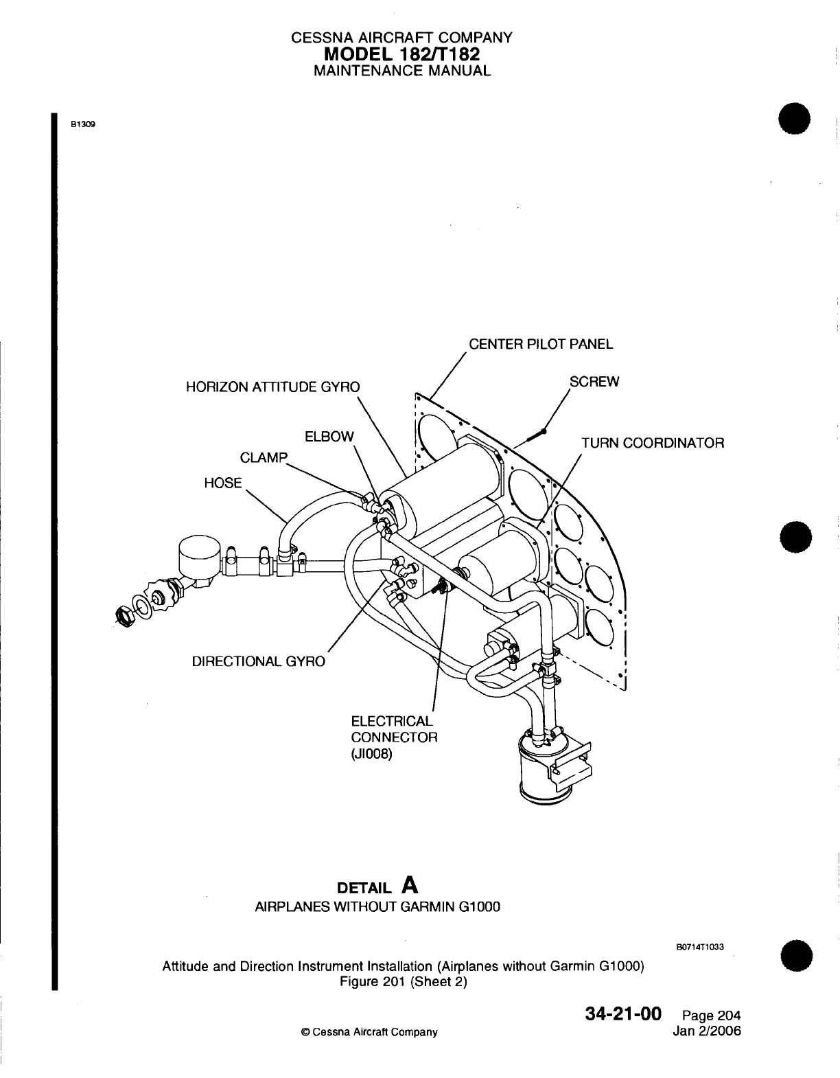
CESSNA
AIRCRAFT
COMPANY
MODEL
182/T182
MAINTENANCE
MANUAL
B1309
CENTER
PILOT
PANEL
HORIZON
ATTITUDE
GYRO
\
ELBOW
CLAMP
HOSE
COORDINATOR
DIRECTIONAL
GYRO
ELECTRICAL
CONNECTOR
(J1008)
DETAIL
A
AIRPLANES
WITHOUT
GARMIN
G1000
B0714T1033
Attitude
and
Direction
Instrument Installation (Airplanes without
Garmin G1000)
Figure
201
(Sheet
2)
34-21-00
O
Cessna
Aircraft
Company
Page
204
Jan
2/2006
J
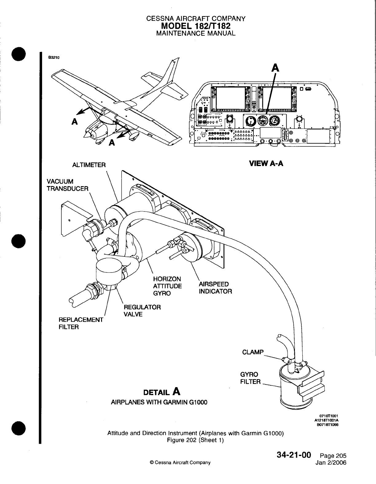
CESSNA
AIRCRAFT
COMPANY
MODEL
182/T182
MAINTENANCE
MANUAL
U
A
ALTIMETER
HORIZON
ATTITUDE
GYRO
REGULATOR
VALVE
FILTER
DETAIL
A
AIRPLANES
WITH
GARMIN
G1000
0710T1001
A1218T1001A
B0718T10
66
Attitude
and
Direction
Instrument (Airplanes with Garmin
G1000)
Figure 202
(Sheet
1)
34-21-00
Page
205
©
Cessna
Aircraft
Company
Jan
2/2006
VACL
TRAN
VIEW
A-A
F
AIRSPEED
INDICATOR
CLAMF
GYRO
FILTER
ADA
A
CESSNA
AIRCRAFT
COMPANY
MODEL 182/T182
MAINTENANCE
MANUAL
CAUTION: Make
sure
that
you
put
soft
material
between
the horizon
attitude
gyro and
the
control column
before
you
remove
the
gyro.
If
you
put
the
sub
panel
on
the
control
column
without
any
protection,
you
can
damage
the
horizon
attitude
gyro
and/or
the
other instruments
in
the
sub
panel.
Be
very careful
when
you
remove
the
sub
panel
so
that
you
do
not
hit
the
gyro.
Put
a
label
on
the air inlet
hose,
vacuum outlet
hose,
and
gage
hose
that
are
attached
to the
horizon
attitude
gyro.
Loosen
the
clamps
and
remove
the
hoses
from
the
horizon
attitude gyro.
Disconnect
the
electrical
connectors
from
the
horizon attitude
gyro.
Put
female
plugs
over
the
ports
and
put
a
connector
cap
on
the
electrical
connector.
Remove
the
screws that attach
the
horizon
attitude
gyro
to
the
center
pilot
panel.
CAUTION:
Put
a
cover
on
the
applicable
hose
or
port,
or
on
the applicable
electrical
connector
when
the
gyroscopic instrument
is
out
of
the
airplane
or
is
to
be
shipped.
Damage
to
the
instrument
will
occur
from
contamination
if
a
cover
is
not used.
(8)
Remove
the
horizon
attitude
gyro
from
the
airplane.
B.
Horizon
Attitude
Gyro
Installation
(Refer
to Figure
201
or
Figure
202).
CAUTION:
Do
not
remove
the
horizon
attitude
gyro
from
the
box
in
which
it
was
shipped
until
it
is
ready to
be
installed
into the
airplane.
This will
minimize
the
possibility
of
accidentally
causing
damage
to
the
gyro.
CAUTION:
Remove
all
plugs
from
the horizon attitude
gyro
before
you
install
it
in
the
aircraft.
CAUTION:
(1)
(2)
(3)
(4)
(5)
(6)
(7)
(8)
(9)
(10)
Be
careful
with
the gyroscopic instruments.
Do
not
hit,
shake,
or
put
the
instruments
on
a
hard
surface.
Put
soft material
between
the
gyroscopic
instruments
and
any
hard
surface.
Damage
to
the
instruments
will
occur
if
the
instruments
are
not
carefully
moved.
The
manufacturer's
warranty
can
become
void
if
the
gyro
is
not
kept
in
its
initial
condition
as received
from
the manufacturer.
Attach the
horizon attitude gyro
to
the
center
pilot
panel
with
the
screws.
Make sure
that
the horizon
altitude
gyro
is
installed
level
in
the
panel.
Remove
the
female plugs
from
the ports and
remove
the
connector
cap
from
the
electrical
connector.
Make
sure that
the vacuum
lines
and
the static
lines
have
no
kinks
in
them.
Attach the
air
inlet
hose,
vacuum
outlet
hose, and
gage
hose
to
the
horizon attitude
gyro
and
tighten
the
clamps.
Attach the horizon
attitude gyro
connector
to
the horizon
attitude
gyro.
Attach the
center
pilot
panel with
the
screws.
Tighten the
screws
in
an
opposite
sequence.
Put
the MASTER
switch
and
the
AVIONICS
switch
in
the
ON
position.
Do
an
operational
check
of
the
horizon
attitude
gyro
to
make
sure
that
it
operates correctly.
7.
Horizon
Attitude
Gyro Operational
Check
A.
Horizon Attitude
Gyro
Operational
Check.
(1)
Start
the
airplane
engine.
(2)
Let
the
engine
run
for
no
less
than
3
minutes.
©
Cessna
Aircraft Company
34-21-00
Page
206
Jan
2/2006
(3)
(4)
(5)
(6)
(7)
CESSNA
AIRCRAFT
COMPANY
MODEL
182/T182
MAINTENANCE
MANUAL
(3)
Make
sure
that
the
vacuum gage
shows
between
4.5 and 5.5
in.hg.
(4)
Make
sure
that
the
horizon
bar becomes
stable
at
the
correct position
for
the
attitude
of
the
airplane,
or
becomes stable at
the
correct
position,
begins
to
vibrate,
and
then
slowly
stops
vibration
altogether.
(5)
Taxi
in
a
straight
line.
Make
sure
that
the
horizon
bar
stays
in
the horizontal position
while
you
taxi.
(6)
Do
a
360-degree
turn.
Do
not
turn
sharply
as
you
make the
turn.
Make
sure
that
the
horizon
bar
does
not
tip more
than
4
degrees
from
the
horizontal
during
the
turn.
(7)
If
the
horizontal
gyro
precession
is
more
than
4
degrees
from
a
heading
in
either
direction
during
a
10-minute
period,
or
does not
operate
within one
or
more
of
the
limits
given
in
steps
4
through
6
of
this
operational
check,
you must
repair the
system
and/or
replace
the
gyro.
8.
Directional Gyro
Description
and
Operation
A.
The
vacuum
system
supplies
the
air
flow
necessary
to
move
the
gyro rotor
in
the
directional
gyro.
Incorrect
operation
of
the
vacuum
system
will
cause
the
horizon attitude
gyro
to
operate
incorrectly.
Problems
with
the
vacuum
system
can
cause
incorrect
indication
and
decreased
performance.
B.
The
directional
gyro
must
have
between
4.5 and
5.5
in.hg. of
vacuum
to
operate correctly.
With
the
correct
vacuum
applied,
the
gyro
will
get
rated
performance
in
a
minimum
of
3
minutes
of
rotor
turn
time.
C.
The
directional
gyro
rotor
can
continue
to
turn
for
approximately
15
minutes
after
the
vacuum
in
the
system
is
removed.
It
can
show
a
change
in
the
directional indication
while
the
rotor
speed
decreases,
or
the
directional
gyro
dial can
start
to
turn.
When
fully
stopped,
the
gyro
rotor will
not
correctly
indicate
changes
in
the airplane's
direction
until
the
system
starts again.
D. If
a
gyro
has
been
stopped
and
started
again
before
the
rotor
fully
stops,
more
time
will
be
necessary
for
the
gyro
to correctly indicate
the
directional
changes
of
the
airplane.
E.
The permitted limits
for
directional
gyro drift
on
the
ground or
in
flight
is 4
degrees
from
a
fixed
heading,
during
a
10-minute
period.
F.
Continuous
turns
around
a
point
and/or
banks
of
more
than
55
degrees
can
cause
the
directional
gyro
to
turn.
This
is
a
limit
of
the
gyro
and
not
a
cause
for
removal.
9.
Directional
Gyro Removal/Installation
(Airplanes
without
Garmin G1000)
A.
Directional
Gyro
Removal (Refer
to
Figure
201).
CAUTION:
Make
sure
that
the
gyro
rotor
has
fully
stopped
before
you
move
the
instrument. The
gyro
rotor
will
not
stop
for
approximately
15
minutes
after
the vacuum
source
is
removed.
Damage
to
the
instrument
will
occur
if
the instrument
is
moved
before the
gyro
rotor
has
stopped.
CAUTION:
Be
careful
with
the
gyroscopic
instruments.
Do
not
hit,
shake,
or put
the
instruments
on
a hard
surface.
Put
soft
material
between
the
gyroscopic
instruments and
any
hard
surface.
Damage to
the
instruments
will
occur
if
the
instruments
are
not
carefully
moved.
The
manufacturer's
warranty
can
become
void
if
the gyro
is
not
kept
in
its
initial condition
as
received
from
the manufacturer.
(1)
Put
the
MASTER
switch and
the
AVIONICS
switch
in
the
off
position.
(2)
Remove
the
screws
from
the center pilot
panel to get
access
to
the back
of
the
directional
gyro.
34-21-00
Page
207
©
Cessna
Aircraft
Company
Jan
2/2006
CESSNA AIRCRAFT
COMPANY
MODEL 182/T182
MAINTENANCE
MANUAL
CAUTION:
Make
sure
that you
put
soft
material
between
the
directional
gyro
and
the
control
column
before
you
remove
the
gyro.
If
you put
the
sub panel
on
the control
column
without
any
protection, you
can
damage
the
directional
gyro
and/or
the
other
instruments
in
the
sub
panel.
Be
very careful
when you remove
the
sub
panel so
that
you
do not to
hit
the
gyro.
(3)
Put
a
label
on
the
air
inlet
hose
and
the
vacuum
outlet
hose
that
are
attached
to
the
directional
gyro.
(4)
Loosen
the
clamps
and
remove
hoses
from
the
directional
gyro.
(5)
Disconnect
the
directional
gyro
connector
and the
electrical
connector
from
the
directional
gyro.
(6)
Put
female plugs
over
the
ports
and
put
a
connector
cap
on
the
electrical
connector.
(7)
Remove
the
screws
that attach
the
directional
gyro
to
the
center
pilot
panel.
CAUTION:
Put
a
cover
on
the
applicable
hose
or
port,
or
on
the
applicable
electrical
connector
when
the
gyroscopic
instrument
is
out
of
the
airplane
or
is
to
be
shipped.
Damage
to
the instrument
will
occur
from
contamination
if
you
do not use
a
cover.
(8)
Remove
the
directional
gyro
from
the
airplane.
B.
Directional Gyro
Installation (Refer
to
Figure
201).
CAUTION:
Do
not
remove the
directional
gyro
from
the
box
in
which
it
was
shipped
until
it
is
ready to
be
installed
into
the
airplane.
This
will
minimize
the
possibility
of
accidentally
causing
damage to
the
gyro.
CAUTION:
Remove
all
plugs
from
the
directional
gyro
before
you
install
it in
the
aircraft.
CAUTION:
(1)
(2)
(3)
(4)
(5)
(6)
(7)
Be
careful
with
the
gyroscopic
instruments.
Do
not
hit,
shake,
or
put
the
instruments
on
a
hard
surface.
Use
soft
material
between the
gyroscopic
instruments
and any
hard
surface.
Damage
to
the instruments
will
occur
if
the
instruments
are
not
carefully
moved.
The manufacturer's
warranty
can
become
void
if
the
gyro
is
not
kept
in
its
initial
condition
as
received
from
the
manufacturer.
Attach
the
directional
gyro
to
the
center
pilot
panel with
the
screws.
Remove
the
female plugs
from
the ports and
remove
the
connector
cap
from
the
electrical
connector.
Attach the
air
intake
hose
and
the
vacuum
outlet
hose
to
the directional
gyro and
tighten
the
clamps.
Attach the
directional
gyro
connector
and the
electrical
connector
to
the
directional
gyro.
Attach
the center
pilot
panel
with
the
screws.
Put
the
MASTER
switch and the
AVIONICS
switch
in
the
ON
position.
Do
an
operational
check
of
the
directional
gyro to
make
sure
that
it
operates
correctly. Refer
to
Directional
Gyro
Operational
Check.
34-21-00
Page
208
©
Cessna
Aircraft Company
Jan
2/2006
CESSNA
AIRCRAFT
COMPANY
MODEL
182/T182
MAINTENANCE
MANUAL
10.
Directional
Gyro
Operational
Check
A.
Directional
Gyro
Operational
Check (Refer
to
Figure
201).
NOTE:
The
permitted
limit
for
gyro
drift
on
the
ground
or
in
flight
is
4
degrees
from
a
fixed
heading,
during
a
10-minute
period.
(1)
(2)
(3)
(4)
Start
the
airplane
engine.
Make
sure
that the
vacuum
system
operates
correctly.
(a)
The
vacuum
gage
must
show
between
4.5
and 5.5 in.hg.
Let
the
directional
gyro
become stable
for
at
least
3
minutes.
If
the
directional
gyro
dial starts
to
turn,
let
the
gyro
become stable
and
then
push
the
gyro-caging
knob.
If
the gyro
dial
continues
to
turn,
repair
the
system
and/or
replace
the gyro.
NOTE:
It is
usual
for
the
directional
gyro
dial
to
turn
when
the
gyro
becomes stable. This
is
a
limit of
the
gyro
and
not
a
cause
for
removal.
(5)
Point the
airplane's heading
to
the
north.
(6)
Set
the
directional
gyro to
the
north.
(7)
Make sure
that
the
directional
gyro
dial
drift
is
not
more
than
4
degrees
in
a
10-minute period.
(8)
Point
the
airplane's heading
and
set
the
directional
gyro
to
each
of
the
other
three
cardinal
headings
in
turn (West,
South,
and
East).
(9)
Make
sure
that
the
directional
gyro
dial
drift
is
not
more
than
4
degrees
in
a
10-minute
period
at
each of
these
cardinal headings.
(10)
If
the
directional
gyro dial
drift
is
not
satisfactory
at
any
heading,
repair
the
system
and/or
replace
the
gyro.
NOTE:
After you
stop
operation
of
the
airplane,
it
is
usual
for
the
directional
gyro
dial
to
continue
to
turn.
This
is
not
a
cause
to
remove
the
gyro.
11.
Turn
Coordinator
Removal/Installation (Airplanes
without
Garmin
G1000)
A.
Turn
Coordinator
Removal
(Refer
to
Figure
201).
CAUTION:
CAUTION:
(1)
(2)
Make
sure
that
the
gyro
rotor
has
fully
stopped
before
you
move
the
instrument.
The
gyro
rotor
will
not
stop
for
approximately
15
minutes
after
the vacuum
source
is
removed. Damage
to
the
instrument
will
occur
if
the
instrument
is
moved before the gyro
rotor
has
stopped.
Be
careful
with the
gyroscopic
instruments.
Do
not
hit,
shake,
or
put
the
instruments
on
a
hard
surface.
Put
soft
material
between the
gyroscopic
instruments
and
any
hard
surface.
Damage
to
the
instruments
will
occur
if
the
instruments
are
not
carefully
moved.
The
manufacturer's
warranty
can
become void
if
the
gyro
is
not
kept
in
its
initial
condition
as received
from
the manufacturer.
Put
the
MASTER
switch
and
the
AVIONICS
switch
in
the
off
position.
Remove
the screws
from
the
center
pilot
panel
to
get
access
to the
back
of
the
turn
coordinator.
34-21-00
Page
209
©
Cessna
Aircraft
Company
Jan
2/2006
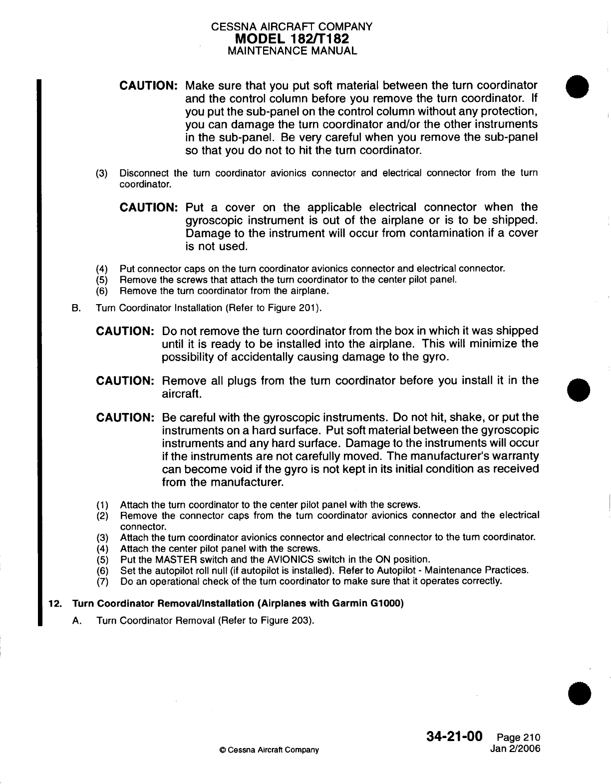
CESSNA
AIRCRAFT
COMPANY
MODEL
182/T182
MAINTENANCE
MANUAL
CAUTION:
Make
sure
that
you put soft material
between
the
turn
coordinator
and
the
control
column
before
you
remove the
turn
coordinator.
If
you
put the
sub-panel
on
the control
column
without
any
protection,
you
can
damage the
turn
coordinator
and/or the
other
instruments
in
the sub-panel.
Be
very
careful
when
you
remove
the sub-panel
so
that
you
do
not
to
hit
the
turn
coordinator.
(3)
Disconnect
the
turn
coordinator avionics
connector
and
electrical
connector
from
the
turn
coordinator.
CAUTION:
Put
a
cover
on
the
applicable
electrical
connector
when
the
gyroscopic
instrument
is
out
of
the
airplane
or
is
to
be
shipped.
Damage
to
the
instrument
will
occur
from
contamination
if
a
cover
is
not used.
(4)
Put
connector
caps
on
the
turn
coordinator
avionics
connector
and
electrical connector.
(5)
Remove the
screws
that
attach
the
turn
coordinator
to the
center
pilot
panel.
(6)
Remove the
turn
coordinator
from
the
airplane.
B.
Turn
Coordinator
Installation
(Refer
to Figure
201).
CAUTION:
Do
not
remove
the
turn
coordinator
from
the
box
in
which
it
was
shipped
until
it
is
ready
to
be
installed
into
the
airplane.
This
will
minimize the
possibility
of
accidentally
causing
damage
to
the gyro.
CAUTION: Remove
all
plugs
from
the
turn
coordinator
before
you
install
it
in
the
aircraft.
CAUTION:
(1)
(2)
(3)
(4)
(5)
(6)
(7)
Be
careful
with
the
gyroscopic instruments.
Do
not
hit,
shake,
or put
the
instruments
on
a
hard
surface.
Put
soft
material
between
the
gyroscopic
instruments
and
any
hard
surface.
Damage
to
the
instruments
will occur
if
the
instruments
are
not
carefully
moved.
The
manufacturer's
warranty
can
become
void
if
the
gyro
is
not
kept
in
its
initial
condition
as
received
from
the manufacturer.
Attach the
turn
coordinator
to
the center
pilot
panel
with
the
screws.
Remove
the
connector
caps
from
the
turn
coordinator avionics
connector
and
the
electrical
connector.
Attach the
turn
coordinator avionics connector
and
electrical connector
to
the
turn
coordinator.
Attach
the
center
pilot
panel
with
the
screws.
Put
the
MASTER
switch
and
the
AVIONICS
switch
in
the
ON
position.
Set
the
autopilot
roll
null
(if
autopilot
is
installed).
Refer
to
Autopilot
-
Maintenance
Practices.
Do
an
operational
check
of
the
turn
coordinator
to
make
sure
that
it
operates
correctly.
12.
Turn
Coordinator
Removal/nstallation
(Airplanes
with
Garmin
G1000)
A.
Turn
Coordinator
Removal
(Refer
to
Figure
203).
o
Cessna
Aircraft
Company
34-21-00
Page 210
Jan
2/2006
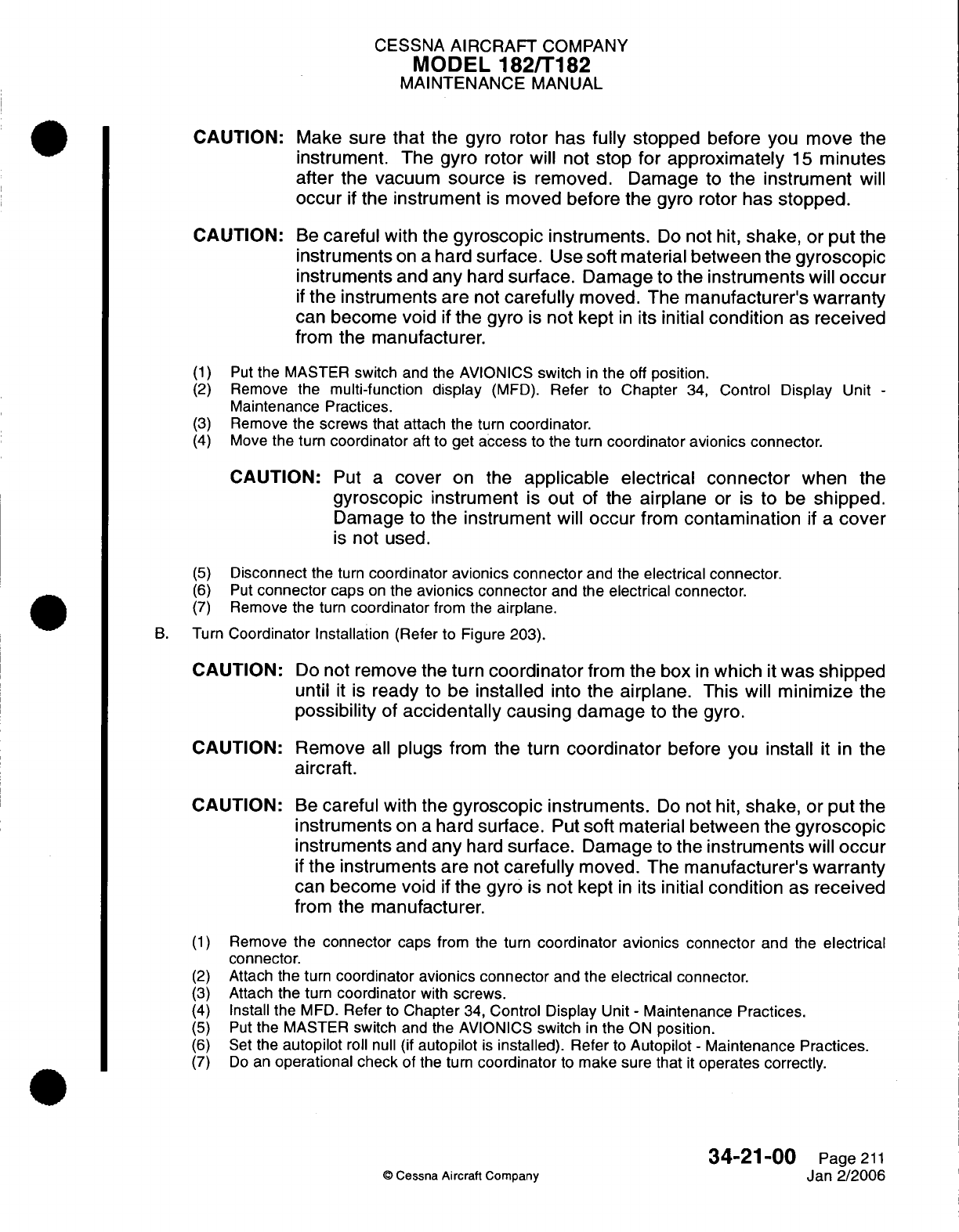
CESSNA
AIRCRAFT
COMPANY
MODEL
182/T182
MAINTENANCE
MANUAL
CAUTION:
CAUTION:
(1)
(2)
(3)
(4)
Make
sure
that
the
gyro
rotor has
fully
stopped
before you
move
the
instrument.
The
gyro
rotor will
not
stop
for
approximately
15
minutes
after
the vacuum
source
is
removed.
Damage
to
the
instrument
will
occur
if
the
instrument
is
moved before the
gyro
rotor
has
stopped.
Be
careful
with the
gyroscopic
instruments.
Do
not
hit,
shake,
or
put
the
instruments
on a
hard
surface.
Use
soft
material
between
the
gyroscopic
instruments
and any
hard
surface.
Damage
to
the
instruments
will
occur
if
the instruments
are
not
carefully
moved. The
manufacturer's
warranty
can
become void
if
the
gyro
is
not
kept
in
its
initial
condition
as
received
from
the manufacturer.
Put
the
MASTER
switch
and
the
AVIONICS
switch
in
the
off
position.
Remove
the
multi-function
display
(MFD).
Refer
to
Chapter
34,
Control
Display
Unit
-
Maintenance
Practices.
Remove the
screws that
attach
the
turn
coordinator.
Move
the
turn
coordinator
aft
to
get
access
to the
turn
coordinator
avionics connector.
CAUTION:
Put
a
cover
on
the
applicable
electrical
connector
when
the
gyroscopic
instrument
is
out
of
the
airplane
or
is
to
be
shipped.
Damage
to
the instrument
will
occur
from
contamination
if
a
cover
is
not
used.
(5)
Disconnect
the
turn
coordinator
avionics connector
and
the
electrical
connector.
(6)
Put
connector
caps
on
the
avionics
connector
and
the
electrical
connector.
(7)
Remove the
turn
coordinator
from the
airplane.
B.
Turn
Coordinator
Installation
(Refer to Figure
203).
CAUTION:
Do
not
remove
the
turn
coordinator
from
the
box
in
which
it
was
shipped
until
it
is
ready
to
be
installed
into
the
airplane.
This
will
minimize
the
possibility
of
accidentally
causing
damage
to
the gyro.
CAUTION:
Remove
all
plugs
from
the
turn
coordinator
before you
install
it
in
the
aircraft.
CAUTION:
Be
careful
with the
gyroscopic
instruments.
Do
not
hit,
shake,
or
put
the
instruments
on
a
hard
surface.
Put
soft
material between
the
gyroscopic
instruments
and
any
hard
surface.
Damage
to
the
instruments
will
occur
if
the instruments are
not
carefully
moved.
The
manufacturer's warranty
can
become
void
if
the gyro
is
not
kept
in
its
initial
condition
as
received
from the
manufacturer.
(1)
Remove
the
connector caps
from the
turn
coordinator avionics connector
and
the
electrical
connector.
(2)
Attach
the
turn
coordinator
avionics connector
and
the
electrical
connector.
(3)
Attach
the
turn
coordinator
with
screws.
(4)
Install
the
MFD.
Refer
to
Chapter
34,
Control Display
Unit
-
Maintenance
Practices.
(5)
Put
the
MASTER
switch
and
the AVIONICS
switch
in
the
ON
position.
(6)
Set
the
autopilot
roll
null
(if
autopilot
is
installed).
Refer
to
Autopilot
-
Maintenance
Practices.
(7)
Do
an
operational check
of
the
turn
coordinator
to
make sure
that
it
operates
correctly.
34-21-00
Page
211
©
Cessna
Aircraft Company
Jan
2/2006
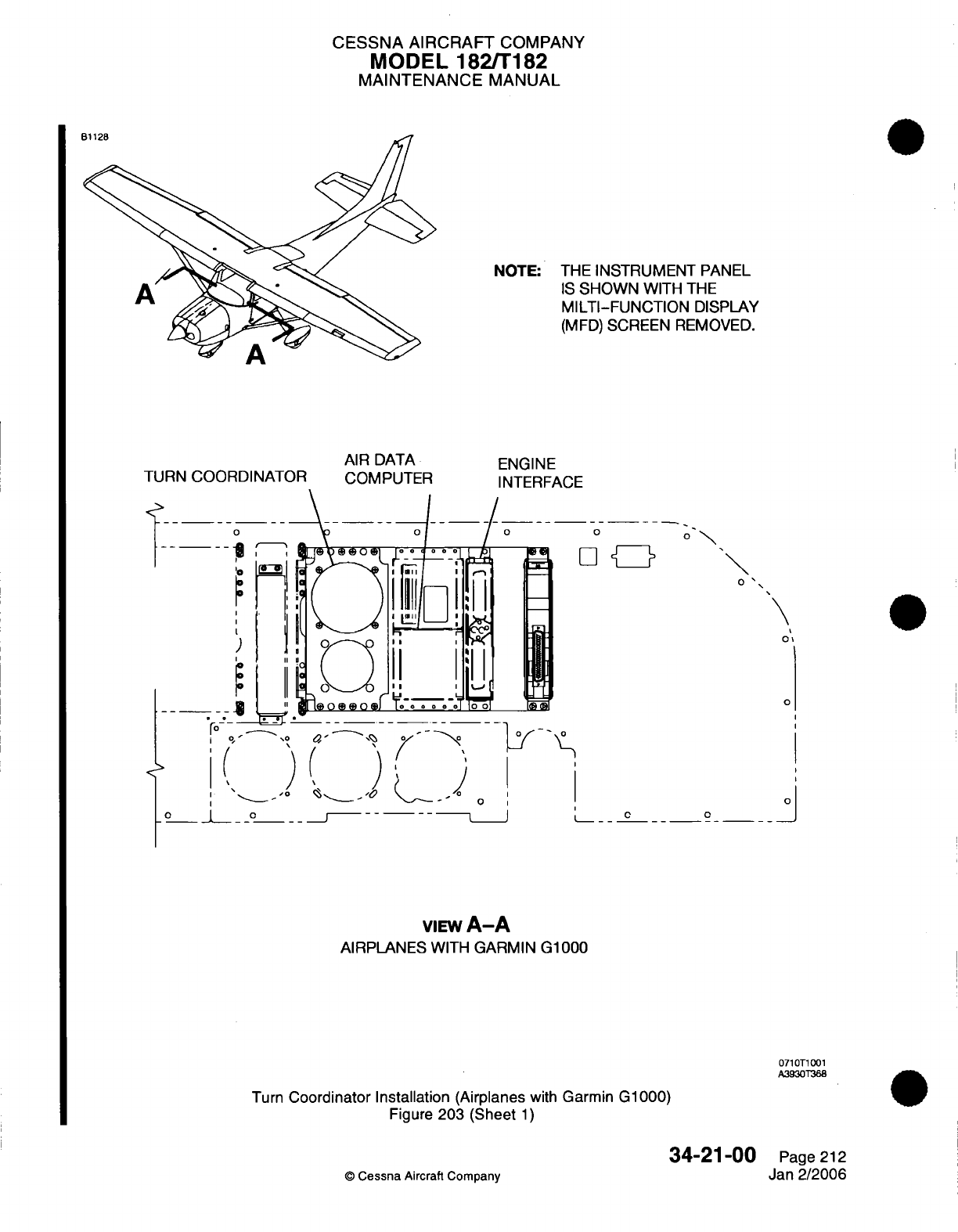
CESSNA AIRCRAFT
COMPANY
MODEL
182/T182
MAINTENANCE
MANUAL
NOTE: THE
INSTRUMENT
PANEL
IS
SHOWN
WITH
THE
MILTI-FUNCTION
DISPLAY
(MFD)
SCREEN
REMOVED.
TURN
COORDINATOR
AIR DATA
COMPUTER
o o o
o
0
|
C i
/
°i0 °
'0
-
' !
eo e[o
Foo
ool
D
'o
" '
.
~
.
...-0
0
o
oI
·
oII L·-
'
_ IJ
'
',-i
O 4, II II
_
Ti (i
,
[i
)
9 I__ i S_°_ ^
-- --
0
I
I
o _
..
l _ __
o
0
\
0
-_- _J
VIEW
A-A
AIRPLANES
WITH
GARMIN
G1000
0710T1001
A3930T368
Turn
Coordinator
Installation
(Airplanes
with
Garmin G1000)
Figure
203
(Sheet
1)
34-21-00
©
Cessna
Aircraft
Company
ENGINE
INTERFACE
Page
212
Jan 2/2006
I
CESSNA
AIRCRAFT
COMPANY
MODEL
182/T182
MAINTENANCE
MANUAL
COMPASS
INSTALLATION
-
MAINTENANCE
PRACTICES
1.
General
A. A
lighted,
magnetic
compass
is
installed
on
the upper
windshield
at the airplane
centerline.
2.
Compass
Removal
and
Installation
A.
Remove
Compass (Refer
to
Figure
201).
(1)
Remove
electrical
power
from
airplane
and turn
master switch
to
"OFF".
(2)
Identify,
tag,
and
disconnect
electrical
wires
for
compass
lighting.
NOTE:
Splices
are
located under
upper
windshield
trim.
(3)
(4)
Remove screw,
post,
and
washers securing compass
to
compass
base.
Remove
compass
from
airplane.
B.
Install
Compass (Refer
to
Figure
201).
(1)
Secure compass to
compass
base
with
screw,
post,
and
washers.
Torque
screw
to
12.5
Inch
pounds,
+2.5
or
-
2.5
Inch
pounds
(1.41
N.m,
+0.28
or
-0.28
N.m).
(2)
Connect
electrical
wires
at
splices.
(3)
Restore
electrical
power
to
airplane
as
required
and turn
master
switch
to
"ON".
(4)
Check compass
accuracy
on
compass
rose.
34-22-00
Page 201
©
Cessna Aircraft
Company
April
1/2002
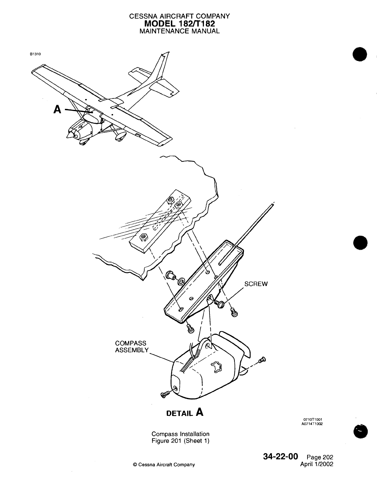
CESSNA
AIRCRAFT
COMPANY
MODEL
182/T182
MAINTENANCE
MANUAL
SCREW
COMPASS
ASSEMBLY
DETAIL
A
Compass
Installation
Figure
201
(Sheet
1)
34-22-00
©
Cessna
Aircraft Company
0710T1001
A0714T1002
Page
202
April
1/2002
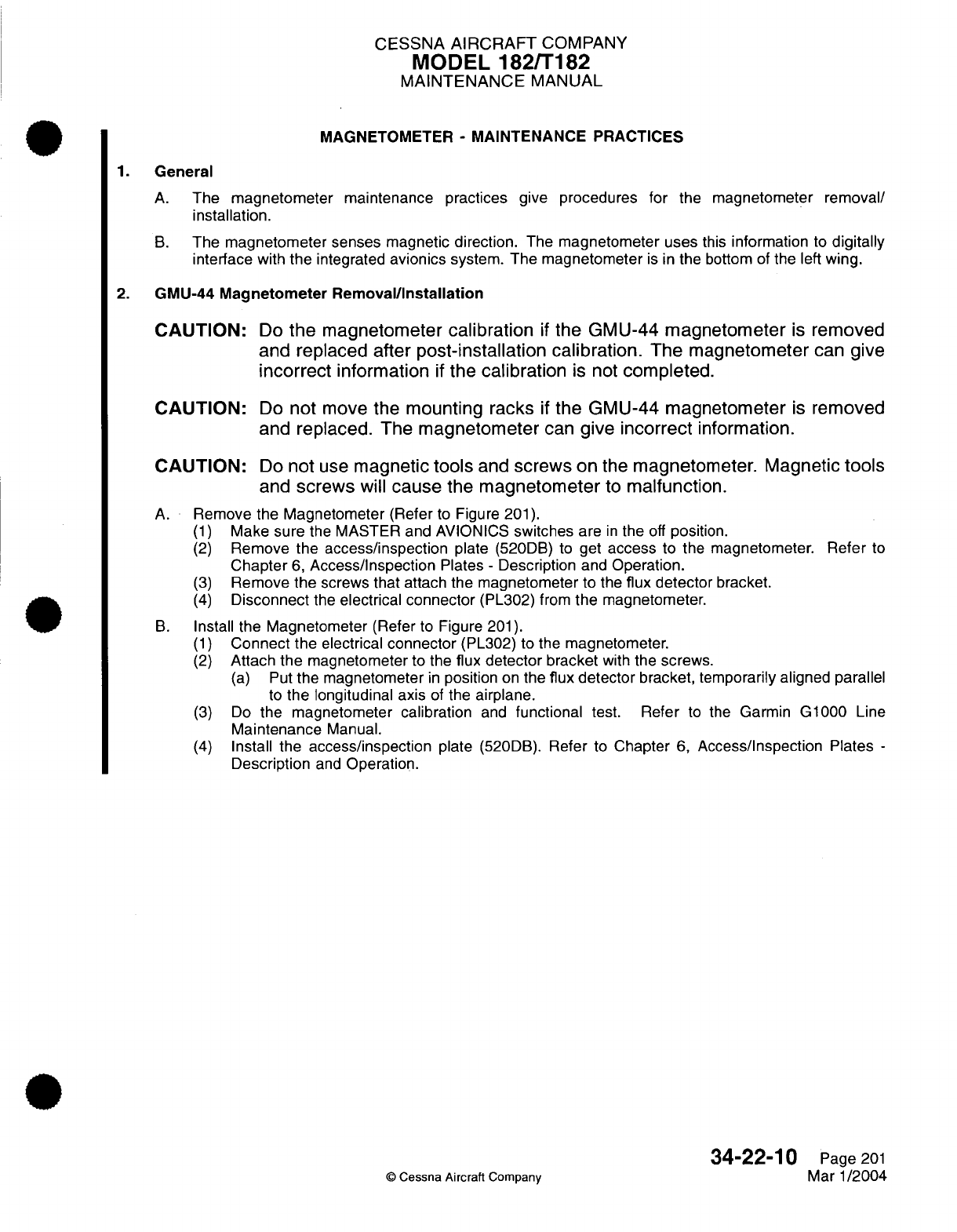
CESSNA
AIRCRAFT
COMPANY
MODEL
182/T182
MAINTENANCE
MANUAL
MAGNETOMETER
-
MAINTENANCE PRACTICES
1.
General
A.
The
magnetometer
maintenance practices
give
procedures for
the
magnetometer
removal/
installation.
B.
The
magnetometer senses magnetic direction.
The
magnetometer uses
this
information
to
digitally
interface
with
the
integrated
avionics
system.
The
magnetometer
is
in
the
bottom
of
the
left
wing.
2.
GMU-44
Magnetometer
Removal/Installation
CAUTION:
Do
the
magnetometer
calibration
if
the
GMU-44
magnetometer
is
removed
and replaced
after
post-installation
calibration.
The
magnetometer
can
give
incorrect
information
if
the
calibration
is
not
completed.
CAUTION:
Do
not
move
the
mounting
racks
if
the
GMU-44
magnetometer
is
removed
and
replaced. The
magnetometer
can
give
incorrect
information.
CAUTION:
Do
not
use
magnetic
tools
and
screws
on the
magnetometer. Magnetic
tools
and
screws
will
cause
the
magnetometer
to
malfunction.
A.
Remove the
Magnetometer
(Refer
to
Figure
201).
(1)
Make
sure
the MASTER and AVIONICS
switches
are
in
the
off
position.
(2)
Remove
the access/inspection
plate
(520DB)
to
get
access
to
the
magnetometer.
Refer
to
Chapter
6,
Access/Inspection
Plates
-
Description
and
Operation.
(3)
Remove
the
screws
that
attach the magnetometer
to the
flux detector
bracket.
(4)
Disconnect
the
electrical connector
(PL302)
from
the
magnetometer.
B.
Install
the
Magnetometer
(Refer
to Figure
201).
(1)
Connect the
electrical
connector
(PL302)
to the
magnetometer.
(2)
Attach
the
magnetometer
to
the
flux detector
bracket
with
the
screws.
(a)
Put
the
magnetometer
in
position
on
the
flux
detector
bracket,
temporarily
aligned parallel
to
the
longitudinal axis
of
the
airplane.
(3)
Do
the magnetometer
calibration
and
functional test.
Refer
to
the Garmin
G1000
Line
Maintenance
Manual.
(4)
Install the
access/inspection
plate
(520DB).
Refer
to
Chapter
6,
Access/Inspection Plates
-
Description
and
Operation.
34-22-10
Page
201
©
Cessna
Aircraft Company
Mar
1/2004
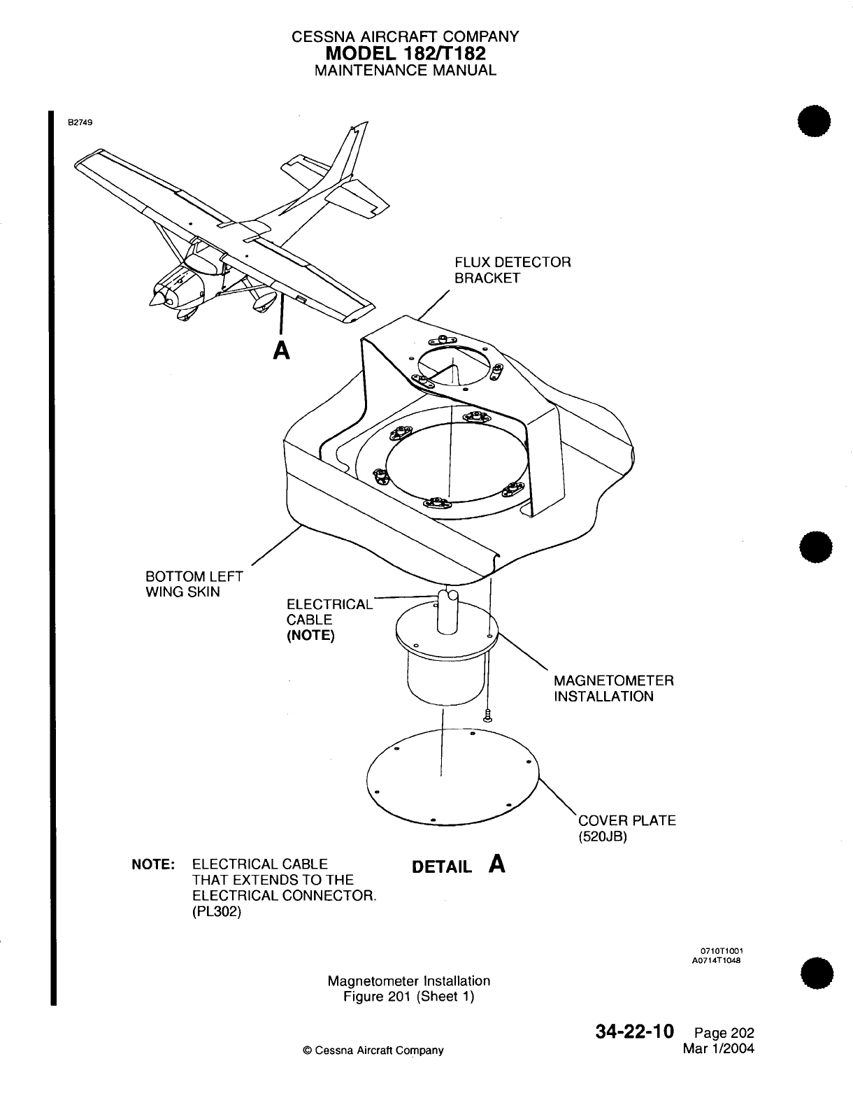
CESSNA
AIRCRAFT
COMPANY
MODEL
182/T182
MAINTENANCE
MANUAL
FLUX
DETECTOR
BRACKET
BOTTOM
LEFT
WING
SKIN
ELECTRICAL
CABLE
(NOTE)
ETER
ON
COVER
PLATE
NOTE:
ELECTRICAL
CABLE
THAT
EXTENDS
TO THE
ELECTRICAL
CONNECTOR.
(PL302)
DETAIL
A
0710T1001
A0714T1048
Magnetometer Installation
Figure
201
(Sheet
1)
34-22-10
©
Cessna
Aircraft
Company
(520JB)
Page
202
Mar
1/2004
....
n
U
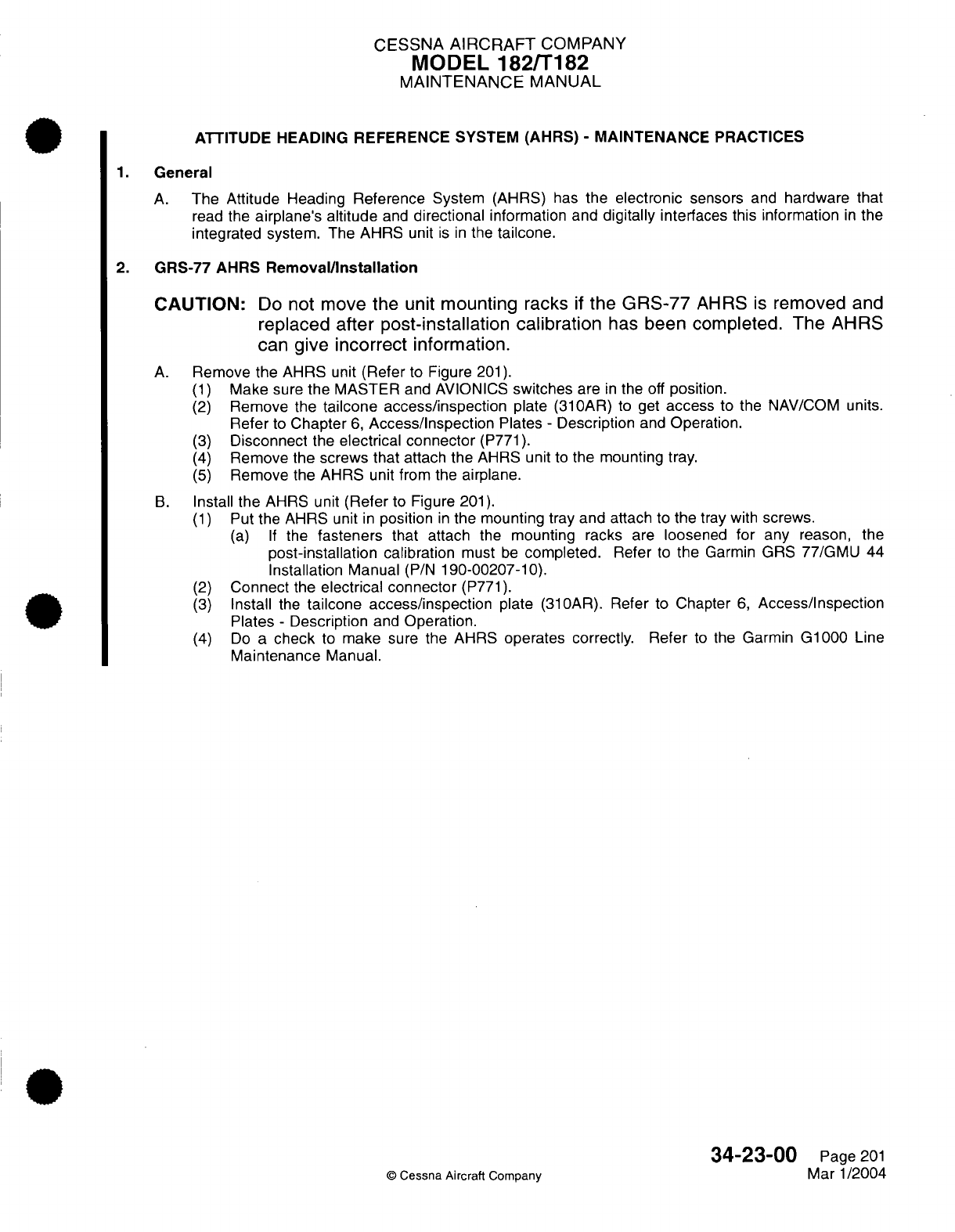
CESSNA
AIRCRAFT
COMPANY
MODEL
182/T182
MAINTENANCE
MANUAL
ATTITUDE HEADING REFERENCE SYSTEM
(AHRS)
-
MAINTENANCE
PRACTICES
1.
General
A.
The
Attitude
Heading
Reference
System
(AHRS)
has
the
electronic
sensors
and
hardware that
read
the
airplane's
altitude
and
directional
information and
digitally
interfaces this information
in
the
integrated
system. The
AHRS unit
is in
the
tailcone.
2.
GRS-77 AHRS
Removal/Installation
CAUTION:
Do
not
move
the
unit
mounting
racks
if
the
GRS-77
AHRS
is
removed
and
replaced
after post-installation calibration
has
been completed.
The
AHRS
can
give
incorrect
information.
A.
Remove
the AHRS
unit
(Refer
to
Figure
201).
(1)
Make
sure
the
MASTER and
AVIONICS
switches
are
in
the
off
position.
(2)
Remove the
tailcone
access/inspection
plate
(310AR)
to
get
access
to the
NAV/COM
units.
Refer
to
Chapter
6,
Access/Inspection
Plates
-
Description
and
Operation.
(3)
Disconnect
the
electrical
connector
(P771).
(4)
Remove the
screws that
attach the
AHRS
unit
to
the
mounting
tray.
(5)
Remove
the
AHRS
unit from the
airplane.
B.
Install
the
AHRS unit
(Refer
to
Figure
201).
(1)
Put
the AHRS unit
in
position
in
the
mounting
tray and
attach
to
the
tray
with
screws.
(a) If
the
fasteners
that
attach
the
mounting
racks
are
loosened
for any
reason, the
post-installation
calibration
must
be
completed.
Refer
to
the
Garmin
GRS
77/GMU
44
Installation
Manual
(P/N
190-00207-10).
(2)
Connect
the
electrical connector
(P771).
(3)
Install
the
tailcone access/inspection
plate
(310AR).
Refer
to
Chapter
6,
Access/Inspection
Plates
-
Description
and
Operation.
(4)
Do
a
check
to
make
sure the
AHRS
operates
correctly. Refer
to
the
Garmin
G1000 Line
Maintenance
Manual.
34-23-00
Page
201
©
Cessna Aircraft
Company
Mar
1/2004
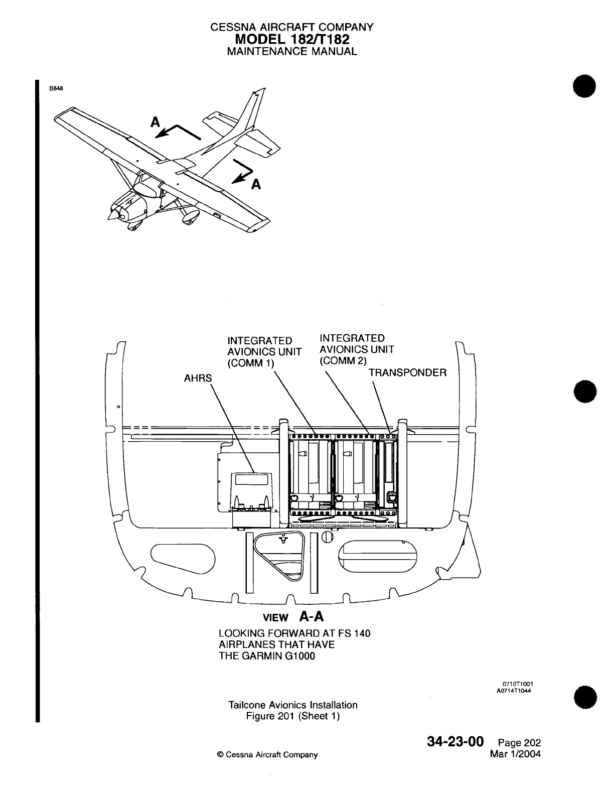
CESSNA AIRCRAFT
COMPANY
MODEL
182/T182
MAINTENANCE
MANUAL
INTEGRATED
AVIONICS
UNIT
(COMM
1)
INTEGRATED
AVIONICS
UNIT
(COMM
2)
VIEW
A-A
LOOKING
FORWARD
AT
FS
140
AIRPLANES THAT
HAVE
THE
GARMIN
G1000
0710T1001
A0714T1044
Tailcone
Avionics Installation
Figure
201
(Sheet
1)
34-23-00
©
Cessna
Aircraft Company
Page
202
Mar
1/2004
A
.A
B
0
C--,
l
CESSNA
AIRCRAFT
COMPANY
MODEL
182/T182
MAINTENANCE
MANUAL
MARKER
BEACON
-
DESCRIPTION
AND
OPERATION
1.
General
A.
Marker beacon
functions
are
included
in
the integrated Bendix/King
KMA-26/KMA-28
Audio
Amplifier/
Intercom/Marker
Beacon
Receiver.
This receiver
is
a
solid
state
unit
and
contains
a
push-button
audio
selector
panel,
speaker
and
headphone isolation
amplifiers,
a
six
station intercom, and
a
marker
beacon
receiver.
2.
Description
and
Operation
A.
As
many
as
three transceivers
and
six
receivers
can
be
controlled
by
the
KMA-26/KMA-28
Audio
Amplifier/Intercom/Marker
Beacon Receiver.
This receiver
also has
two
unswitched
and
mutable
auxiliary
inputs,
four
unswitched
and
unmutable
inputs,
and
two
entertainment
inputs.
B.
Separate
isolation amplifiers
are
provided
for headphones
and
speaker
to
provide
isolation
even
when
the
same
source
is
selected for
both
headphones
and
speaker. Except
for
the
unswitched,
unmuted
inputs, the
speaker
output
is
muted
when
the
MIC
key
is
pressed
to
transmit.
In
the
PA
MIC
selector
mode,
all
the
audio
inputs
are muted
to
the
speaker
while
the microphone
is
keyed. When
the
EMG
position
is
chosen
on
the
MIC
selector,
the
pilot's
headphones
and
microphone are
connected directly
to
COM
1,
continuing
to
operate even when
power
is
lost
to the KMA-26/KMA28 receiver.
C.
The
KMA-26/KMA28 marker
beacon
receiver
presentation
uses three
colored
lenses
(blue,
amber,
and
white)
with
the
letter
designations
O-M-I
engraved
on
the
lens
for
visual
station
passage indication.
The appropriate
marker
audio
tone can
also
be
selected.
HI-LO
sensitivity
and
lamp test
is
selected
with
the
HI
SENS/LO
SENS/TEST
switch
adjacent
to
the
marker
beacon
lights.
A
marker
mute
feature
mutes
the
marker
audio
until
after
the
beacon
has
been
passed.
The
marker
beacon
lights
are
automatically
dimmed
to
compensate for ambient
cockpit
lighting
conditions.
D.
For
operating
instructions
of the KMA-26/KMA28
Audio
Amplifier/lntercom/Marker
Beacon
Receiver,
refer
to
the
manufacturer's
manual
listed
in
the
Introduction,
List
of
Manufacturers
Technical
Publications.
34-30-00
Page
1
©
Cessna
Aircraft
Company
April
1/2002
CESSNA
AIRCRAFT
COMPANY
MODEL
182/T182
MAINTENANCE
MANUAL
MARKER
BEACON
-
MAINTENANCE
PRACTICES
1.
General
A.
Maintenance practices
have
procedures
forthe
removal/installation
of
the
KMA-26/KMA-28
and
GMA-
1347
Audio
Amplifier/lntercom/Marker
Beacon
Receiver
and
marker beacon
antenna.
B.
For
a
check
of
the
KMA-26/KMA-28
and
GMA-1347
receiver,
refer
to
the
manufacturer's
manual
in
the
Introduction,
List
of
Manufacturers
Technical
Publications.
2.
KMA-26/KMA-28
and
GMA-1347 Removal/Installation
A.
For
removal
and
installation
of
the
KMA-26/KMA-28,
GMA-1347
receiver,
refer to
Chapter
23, Audio
Panel
-
Maintenance
Practices.
3.
Marker Beacon
Antenna
Removal/Installation
A.
Remove
the
Marker
Beacon
Antenna
(Refer
to
Figure
201).
(1)
Make
sure
the
MASTER and AVIONICS
switches
are
in
the
off
position.
(2)
Remove
the
baggage
compartment
lower
access
panel. Refer
to
Chapter
25,
Interior
Upholstery
-
Maintenance
Practices.
(3)
Remove
the
aft
floorboard
access/inspection
plate
to
get
access
to
the
marker beacon antenna.
(4)
Disconnect
the
coaxial
cable
(PF1001)
from
the
antenna.
(5)
Remove the
screws that
attach
the
antenna
to
the
bottom
of
the
fuselage.
B.
Install
the Marker
Beacon
Antenna (Refer
to Figure
201).
(1)
Put
the
marker beacon antenna
in
position
on
the
bottom
of the
fuselage.
(2)
Attach
the
antenna
with
screws.
(3)
Attach
the coaxial
cable
(PF1001)
to
the
antenna.
(4)
Install
the
access/inspection
plate
to
the
floor
of
the
airplane.
(5)
Install
the
baggage compartment
lower
access
panel.
Refer
to
Chapter
25,
Interior Upholstery
-
Maintenance
Practices.
34-30-00
Page
201
©
Cessna
Aircraft Company
Mar
1/2004
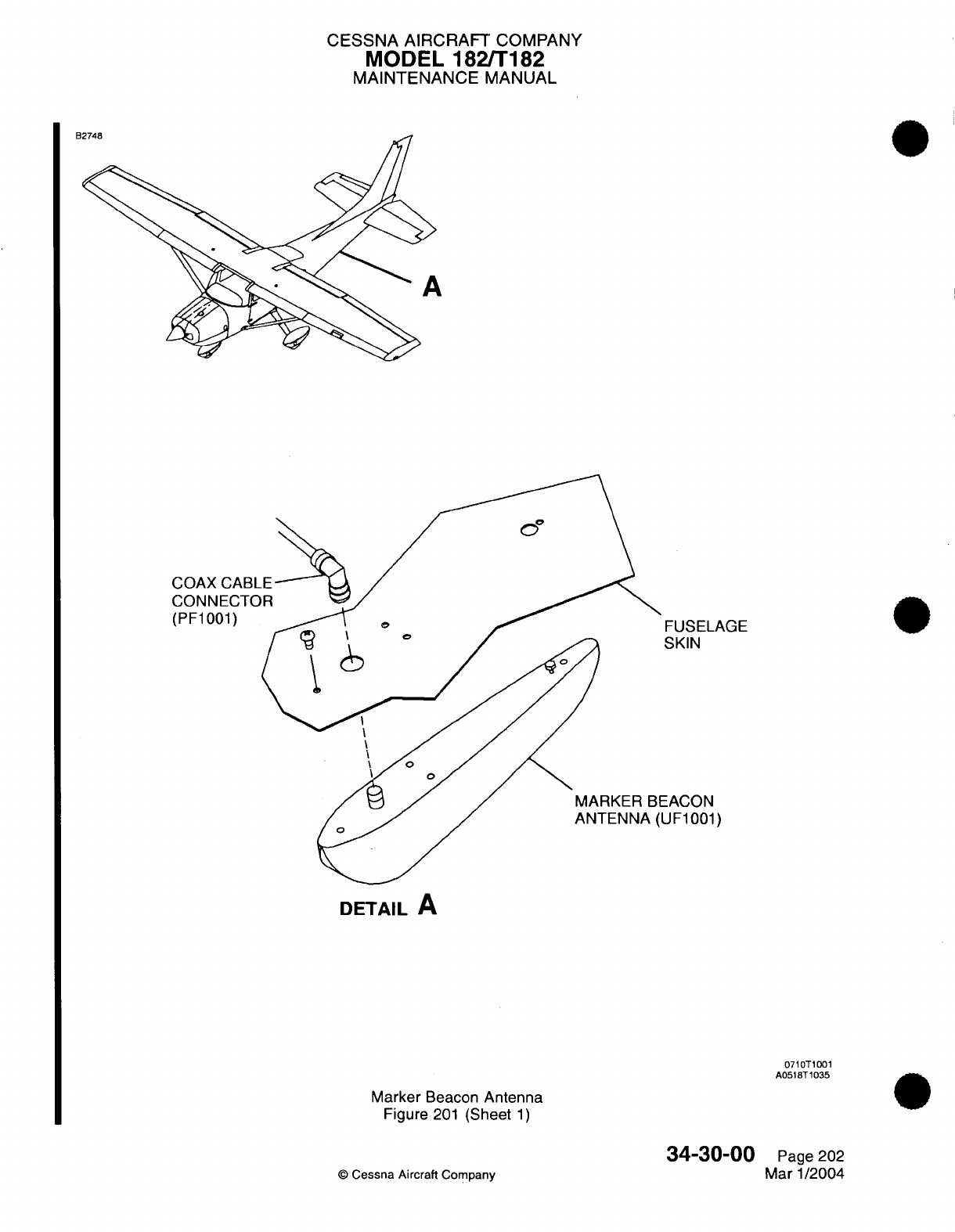
CESSNA AIRCRAFT
COMPANY
MODEL
182/T182
MAINTENANCE
MANUAL
FUSELAGE
SKIN
EACON
UF1001)
DETAIL
A
0710T1001
A0518T1035
Marker
Beacon
Antenna
Figure
201
(Sheet
1)
34-30-00
©
Cessna
Aircraft
Company
Page
202
Mar 1/2004
D07A
1
D
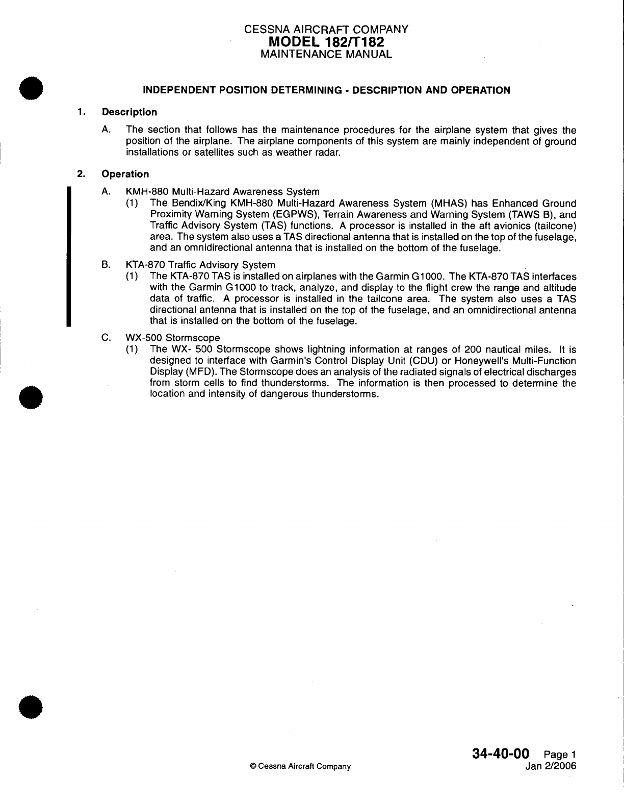
CESSNA
AIRCRAFT
COMPANY
MODEL 182/T182
MAINTENANCE
MANUAL
INDEPENDENT
POSITION
DETERMINING
-
DESCRIPTION AND
OPERATION
1.
Description
A.
The
section
that
follows
has
the
maintenance
procedures
for
the
airplane
system
that
gives
the
position
of
the
airplane.
The
airplane components
of
this
system
are
mainly
independent
of
ground
installations
or
satellites
such
as
weather
radar.
2.
Operation
A.
KMH-880
Multi-Hazard Awareness
System
(1)
The Bendix/King
KMH-880
Multi-Hazard Awareness
System (MHAS) has
Enhanced Ground
Proximity
Warning
System
(EGPWS),
Terrain
Awareness
and
Warning System
(TAWS
B),
and
Traffic
Advisory
System
(TAS)
functions.
A
processor
is
installed
in
the aft
avionics (tailcone)
area.
The system
also
uses
a
TAS
directional
antenna
that
is
installed
on
the top
of
the
fuselage,
and
an
omnidirectional antenna that
is
installed
on
the
bottom
of
the
fuselage.
B.
KTA-870
Traffic
Advisory
System
(1)
The
KTA-870
TAS
is
installed
on
airplanes
with
the
Garmin
G1000.
The
KTA-870
TAS
interfaces
with
the
Garmin
G1000
to
track,
analyze,
and
display
to the
flight
crew
the
range and
altitude
data
of
traffic.
A
processor
is
installed
in
the
tailcone
area. The
system
also
uses
a
TAS
directional antenna
that
is
installed
on the
top
of
the
fuselage,
and
an
omnidirectional antenna
that
is
installed
on the
bottom
of
the
fuselage.
C.
WX-500
Stormscope
(1)
The
WX-
500
Stormscope
shows lightning information
at
ranges
of
200
nautical
miles.
It
is
designed
to
interface
with
Garmin's
Control
Display
Unit
(CDU)
or
Honeywell's
Multi-Function
Display
(MFD).
The
Stormscope
does
an
analysis
of
the
radiated
signals
of
electrical
discharges
from storm
cells
to
find
thunderstorms.
The
information
is
then
processed
to
determine
the
location
and
intensity
of
dangerous
thunderstorms.
34-40-00
Page
1
©
Cessna Aircraft
Company
Jan
2/2006
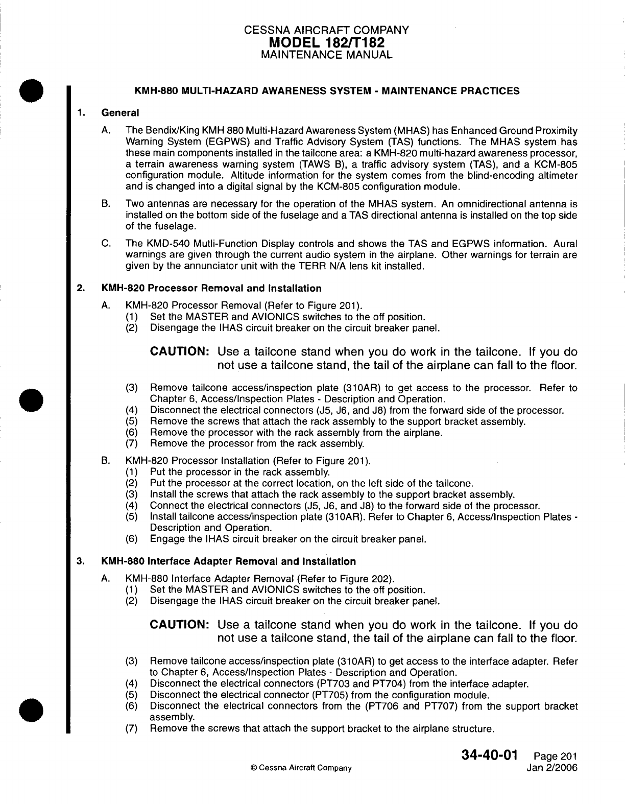
CESSNA
AIRCRAFT
COMPANY
MODEL
182/T182
MAINTENANCE
MANUAL
KMH-880 MULTI-HAZARD
AWARENESS
SYSTEM
-
MAINTENANCE
PRACTICES
1.
General
A.
The Bendix/King
KMH
880
Multi-Hazard
Awareness
System
(MHAS)
has
Enhanced Ground
Proximity
Waming System
(EGPWS)
and
Traffic
Advisory
System
(TAS)
functions.
The
MHAS
system
has
these
main
components
installed
in
the
tailcone
area:
a
KMH-820
multi-hazard
awareness processor,
a
terrain
awareness
warning
system
(TAWS
B),
a
traffic
advisory
system
(TAS),
and
a
KCM-805
configuration
module. Altitude information
for
the
system
comes
from
the
blind-encoding
altimeter
and
is
changed
into
a
digital signal
by
the
KCM-805
configuration
module.
B.
Two
antennas
are
necessary
for
the
operation
of
the
MHAS
system.
An
omnidirectional
antenna
is
installed
on
the
bottom
side
of
the
fuselage
and
a
TAS
directional
antenna
is
installed
on
the
top
side
of the
fuselage.
C.
The
KMD-540
Mutli-Function
Display
controls
and
shows
the
TAS
and
EGPWS
information.
Aural
warnings
are given
through
the
current
audio
system
in
the
airplane. Other
warnings
for
terrain
are
given
by
the
annunciator
unit
with
the TERR
N/A
lens
kit
installed.
2.
KMH-820
Processor
Removal
and
Installation
A.
KMH-820
Processor
Removal
(Refer
to
Figure
201).
(1)
Set
the MASTER and AVIONICS
switches
to
the
off position.
(2)
Disengage the
IHAS
circuit
breaker
on
the
circuit
breaker
panel.
CAUTION:
Use
a
tailcone
stand when
you
do
work
in
the
tailcone.
If
you
do
not use
a
tailcone
stand,
the
tail
of
the
airplane
can
fall
to
the
floor.
(3)
Remove
tailcone
access/inspection
plate
(31OAR)
to
get
access
to
the
processor.
Refer
to
Chapter
6,
Access/Inspection
Plates
-
Description and
Operation.
(4)
Disconnect
the
electrical connectors
(J5,
J6,
and
J8)
from
the
forward
side
of
the
processor.
(5)
Remove
the
screws
that attach
the rack
assembly
to
the
support
bracket assembly.
(6)
Remove
the
processor
with
the rack
assembly
from
the
airplane.
(7)
Remove
the
processor
from
the
rack
assembly.
B.
KMH-820
Processor
Installation
(Refer
to
Figure
201).
(1)
Put
the
processor
in
the
rack
assembly.
(2)
Put
the
processor
at
the correct location,
on
the
left
side
of
the
tailcone.
(3)
Install the
screws that attach
the
rack
assembly
to
the
support bracket assembly.
(4)
Connect
the
electrical connectors
(J5,
J6,
and
J8)
to
the
forward
side
of
the
processor.
(5)
Install
tailcone access/inspection
plate
(31
OAR).
Refer to
Chapter
6,
Access/Inspection
Plates
-
Description
and
Operation.
(6)
Engage
the IHAS
circuit
breaker
on the
circuit
breaker
panel.
3.
KMH-880 Interface
Adapter
Removal
and
Installation
A.
KMH-880
Interface
Adapter
Removal
(Refer
to
Figure
202).
(1)
Set
the
MASTER
and
AVIONICS
switches
to
the
off position.
(2)
Disengage
the
IHAS
circuit
breaker
on
the
circuit
breaker
panel.
CAUTION:
Use
a
tailcone
stand
when
you
do
work
in
the
tailcone.
If
you
do
not use
a
tailcone
stand,
the
tail
of
the
airplane
can fall
to
the
floor.
(3)
Remove
tailcone access/inspection
plate
(31OAR)
to get
access
to
the
interface
adapter.
Refer
to
Chapter
6,
Access/Inspection
Plates
-
Description
and Operation.
(4)
Disconnect
the
electrical connectors
(PT703 and
PT704)
from
the interface adapter.
(5)
Disconnect
the
electrical
connector
(PT705) from
the
configuration
module.
(6)
Disconnect the
electrical
connectors
from the
(PT706 and
PT707)
from
the
support
bracket
assembly.
(7)
Remove
the
screws that
attach the support bracket
to
the
airplane
structure.
34-40-01
Page
201
©
Cessna
Aircraft
Company
Jan
2/2006
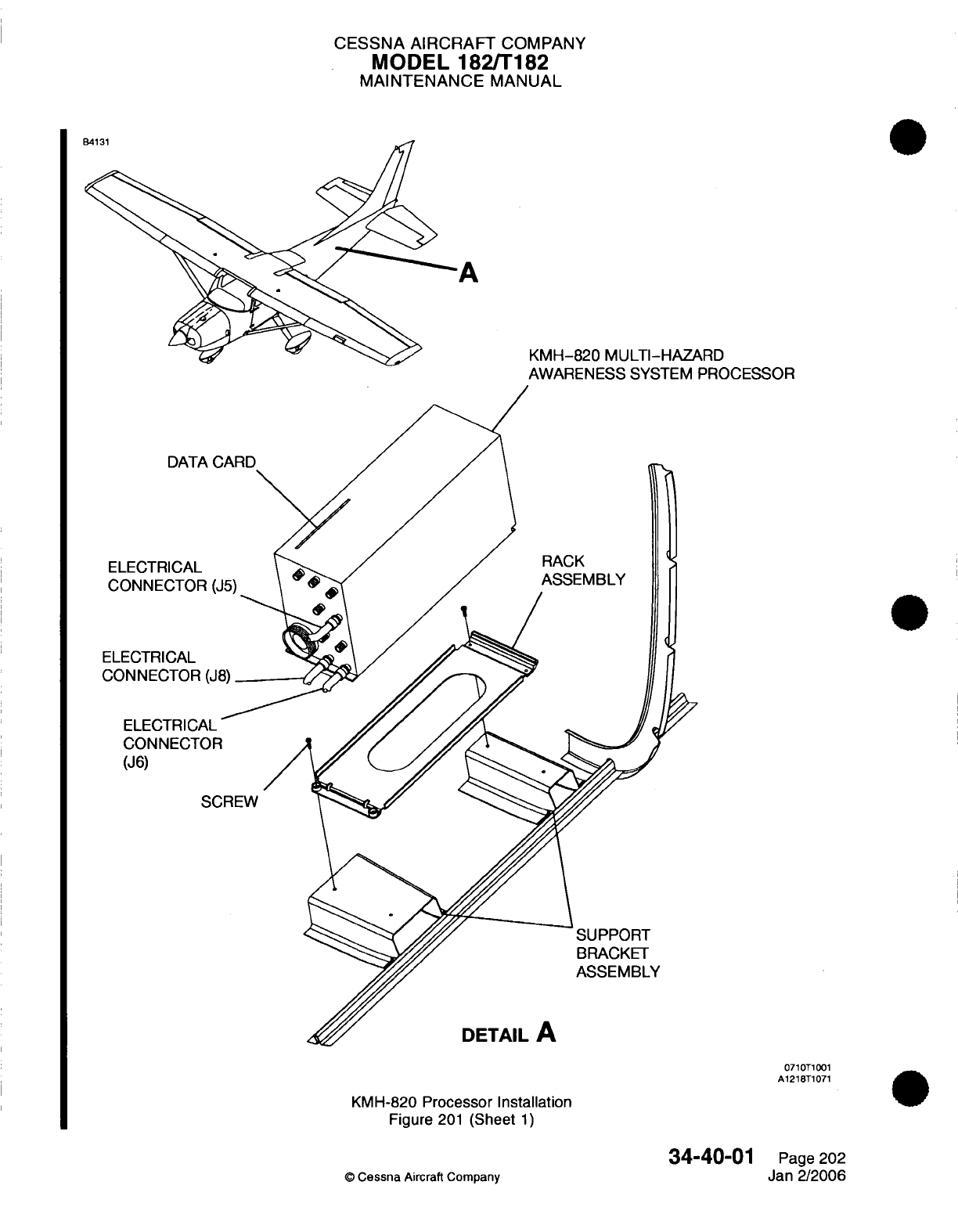
CESSNA AIRCRAFT
COMPANY
MODEL
182/T182
MAINTENANCE
MANUAL
A
KMH-820
MULTI-HAZARD
AWARENESS
SYSTEM
PROCESSOR
DAT
ELECTRICAL
CONNECTOI
ELECTRICAL
CONNECTOR
ELECTRIC.
CONNECT
(J6)
0710T1001
A1218T1071
KMH-820
Processor Installation
Figure
201
(Sheet
1)
©
Cessna
Aircraft Company
34-40-01
Page 202
Jan
2/2006
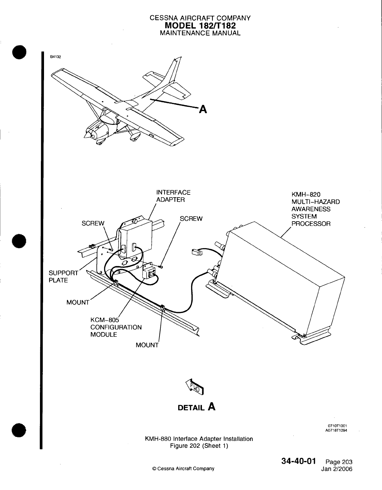
CESSNA
AIRCRAFT
COMPANY
MODEL
182/T182
MAINTENANCE
MANUAL
A
SUPPI
PLATE
IVI-/UI
I
DETAIL
A
0710T1001
A071
8T1094
KMH-880
Interface
Adapter
Installation
Figure 202 (Sheet
1)
©
Cessna Aircraft
Company
34-40-01
Page
203
Jan
2/2006
D"".I
I
I
KITr
-~-A
/-
CESSNA AIRCRAFT
COMPANY
MODEL
182/T182
MAINTENANCE
MANUAL
(8)
Remove
the
support
bracket
from
the
airplane.
(9)
Remove
the
screws
that
attach
the
interface adapter
to
the
support
bracket.
(10)
Remove
the screws that attach
the
configuration module
to
the
support
bracket.
B.
KMH-880
Interface Adapter Installation
(Refer
to
Figure
202).
(1)
Install
the
screws
that attach the
configuration
module
to the
support
bracket.
(2)
Install the
screws
that
attach
the
interface
adapter
to
the
support bracket.
(3)
Put
the
support
bracket
at
the
correct
location
on
the
airplane structure
on the
right
side of
the
tailcone.
(4)
Install
the
screws that
attach
the
support
bracket
to the
airplane structure.
(5)
Connect
the
electrical
connectors
(PT703
and PT704) to the
interface
adapter.
(6)
Connect
the
electrical
connector
(PT705)
to
the
configuration
module.
(7)
Connect
the
electrical
connectors
(PT706
and
PT707) to the
support bracket
assembly.
(8)
Install
tailcone
access/inspection
plate
(31
OAR).
Refer
to
Chapter
6,
Access/Inspection
Plates
-
Description
and
Operation.
(9)
Engage the
IHAS
circuit
breaker
on
the
circuit
breaker
panel.
4.
Omnidirectional
Antenna
Removal
and
Installation
A.
Omnidirectional
Antenna Removal
(Refer to Figure 203).
(1)
Set
the MASTER and AVIONICS
switches to
the
off
position.
(2)
Disengage
the
IHAS
circuit
breaker
on
the
circuit
breaker
panel.
(3)
Pull the
applicable
interior
upholstery back
to
get
sufficient
access
to
the
rear
access
panel
on
the floorboard.
(4)
Remove
the
floor
panel
to
get
access
to
the
omnidirectional
antenna
installation.
(5)
Disconnect
the
adapter
(coax
cable)
from
the
omnidirectional
antenna.
(6)
Remove
the
screws
that
attach
the
omnidirectional antenna
to
the
bottom
of
the
fuselage.
(7)
Remove
the
doubler
and
omnidirectional antenna
from
the
airplane.
B.
Omnidirectional
Antenna
Installation
(Refer
to
Figure
203).
(1)
Put
the
doubler
at the
correct
location
on
the
bottom
of
the
fuselage.
(2)
Put
the
omnidirectional antenna
at the
correct
location
on
the
bottom
side
of
the
fuselage
so
that
the
screw
holes
align
with
the
doubler.
(3)
Install
the screws that
attach
the
omnidirectional antenna
and
doubler
to
the
airplane
skin.
(4)
Connect
the
coax
cable
to
the
omnidirectional
antenna.
(5)
Verify
correct electrical bonding
of
the
antenna
to
the
airplane structure.
(6)
Install
the
floor
panel to
the floorboard.
(7)
Install the interior upholstery.
(8)
Engage
the
IHAS
circuit
breaker
on
the
circuit
breaker panel.
5.
Traffic
Awareness System
(TAS)
Directional
Antenna
Removal
and
Installation
A.
TAS
Directional
Antenna Removal
(Refer
to
Figure
204).
(1)
Set
the
MASTER
and AVIONICS
switches to
the
off
position.
(2)
Disengage
the
IHAS
circuit
breaker
on
the
circuit breaker
panel.
(3)
Remove
the
headliner to
get
access
to
the
directional antenna.
(4)
Put
a
label
on
each of
the four
adapters and
disconnect
them
from
the
directional antenna.
(5)
Remove
the
screws that
attach the
directional
antenna to
the
top
of
the fuselage.
(6)
Remove
the
directional
antenna
and
doubler
from
the
airplane.
B.
TAS
Directional
Antenna
Installation
(Refer
to
Figure
204).
(1)
To
make
sure
that
the
electrical
bonding
requirement for
the
antenna
is
within
the
acceptable
limit, make
sure
that
all
of
the
bonding surfaces
of the
doubler,
antenna,
and
airplane
structure
are
clean.
(2)
Put
the
doubler
and
directional
antenna
on
the
fuselage
so
that
the screw holes
align
through
the airplane
skin.
(3)
Install
the
screws that attach
the
directional
antenna
and
doubler
to
the
airplane skin.
(4)
Remove
the
labels
and
connect
the four
adapters
to the
correct
receptacles
on
the
directional
antenna.
(5)
Verify
correct electrical
bonding
of
the
antenna
to
the
airplane
structure.
34-40-01
Page
204
©
Cessna Aircraft Company
Jan
2/2006
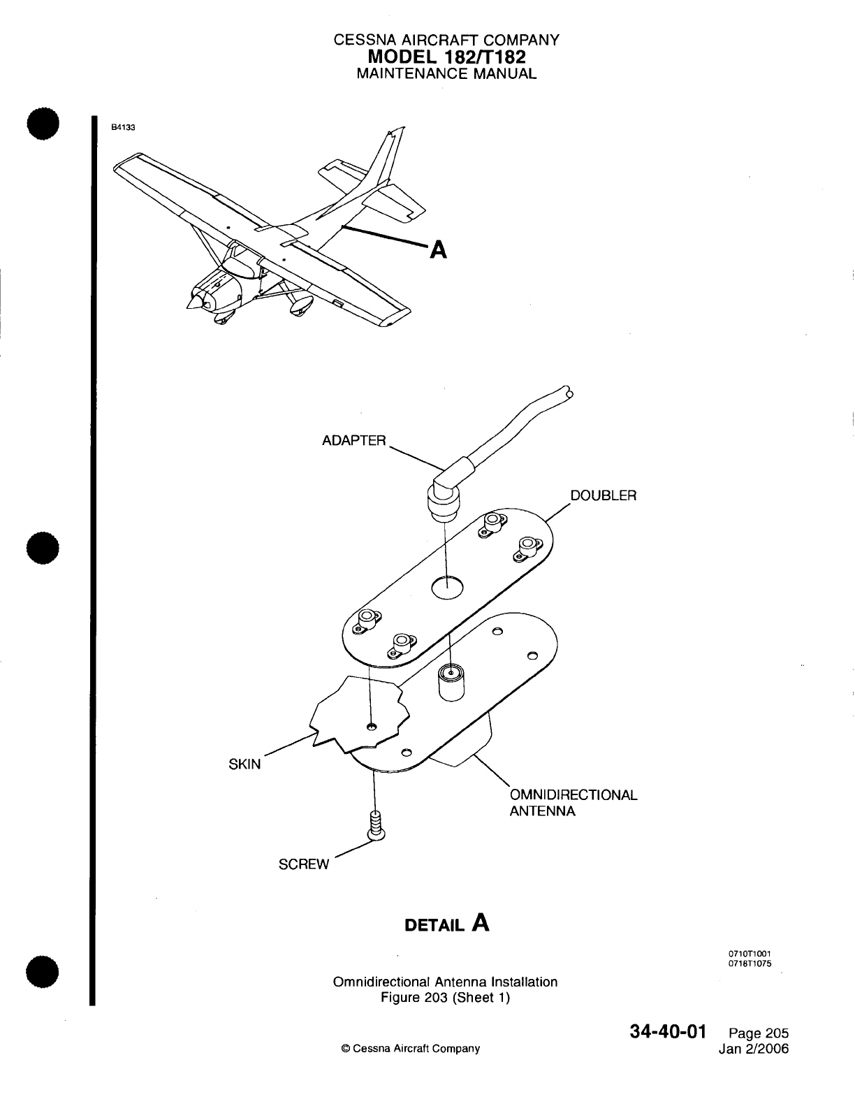
CESSNA
AIRCRAFT
COMPANY
MODEL
182/T182
MAINTENANCE
MANUAL
A
ADAPTER
SKIN
SCREW
DETAIL
A
0710T1001
0718T1075
Omnidirectional
Antenna
Installation
Figure
203
(Sheet
1)
©
Cessna
Aircraft
Company
34-40-01
Page
205
Jan
2/2006
DA"4^
t
-
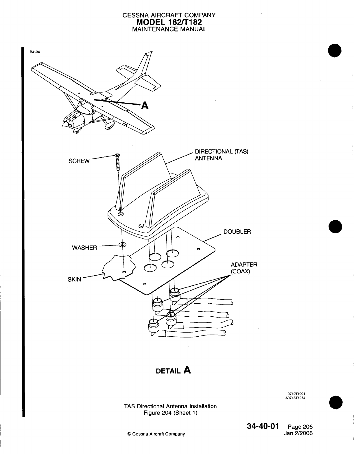
CESSNA AIRCRAFT
COMPANY
MODEL
182/T182
MAINTENANCE
MANUAL
lDTII rifI
A
I rTAAe\
SCRE
JBLER
,DAPTER
COAX)
SKIN
DETAIL
A
071
T1001
A0718T1074
TAS
Directional
Antenna Installation
Figure
204
(Sheet
1)
34-40-01
©
Cessna
Aircraft
Company
Page
206
Jan
2/2006
An..
^
.
I
(
I
)
WA'
CESSNA
AIRCRAFT
COMPANY
MODEL
182/T182
MAINTENANCE
MANUAL
(6)
Fillet
seal
around
the
antenna with
Type
I
Class
B
Sealant.
Refer
to
Chapter
20,
Fuel,
Weather
and
High-Temperature Sealing
-
Maintenance Practices.
(7)
Install the headliner.
(8)
Engage
the
IHAS
circuit
breaker
on
the
circuit
breaker
panel.
34-40-01
Page
207
©
Cessna
Aircraft
Company
Jan
2/2006
I
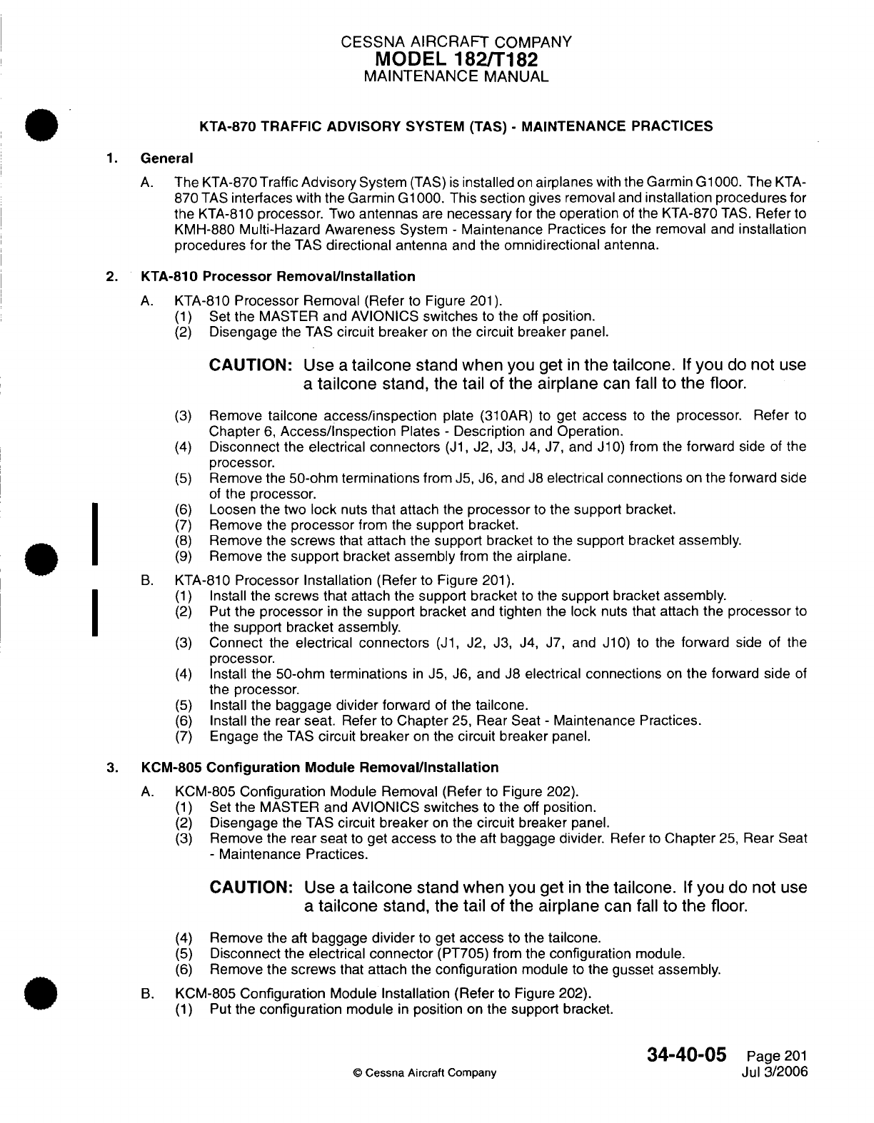
CESSNA
AIRCRAFT
COMPANY
MODEL
182/T182
MAINTENANCE
MANUAL
KTA-870
TRAFFIC ADVISORY
SYSTEM
(TAS)
-
MAINTENANCE
PRACTICES
1.
General
A.
The
KTA-870
Traffic
Advisory
System
(TAS)
is
installed
on
airplanes
with
the Garmin G1000.
The
KTA-
870
TAS
interfaces
with
the Garmin
G1000.
This
section
gives
removal
and
installation procedures
for
the
KTA-810
processor.
Two
antennas
are
necessary
for
the
operation
of
the KTA-870
TAS.
Refer
to
KMH-880
Multi-Hazard
Awareness
System
-
Maintenance Practices
for
the removal
and
installation
procedures
for
the
TAS
directional antenna
and
the
omnidirectional antenna.
2.
KTA-810
Processor
Removal/Installation
A.
KTA-810
Processor
Removal
(Refer
to
Figure
201).
(1)
Set
the
MASTER
and
AVIONICS
switches
to
the
off
position.
(2)
Disengage
the
TAS
circuit
breaker
on
the
circuit
breaker
panel.
CAUTION:
Use
a
tailcone
stand when
you get
in
the
tailcone.
If
you
do
not
use
a
tailcone
stand,
the
tail
of
the
airplane
can
fall
to
the
floor.
(3)
Remove
tailcone
access/inspection
plate
(310AR)
to get
access
to
the
processor.
Refer
to
Chapter
6,
Access/Inspection
Plates
-
Description
and
Operation.
(4)
Disconnect
the
electrical
connectors
(J1,
J2,
J3, J4, J7, and
J10)
from
the
forward
side
of the
processor.
(5)
Remove
the
50-ohm
terminations
from
J5,
J6,
and
J8
electrical
connections
on
the
forward
side
of
the
processor.
(6)
Loosen
the
two
lock
nuts
that
attach
the
processor
to
the
support
bracket.
(7)
Remove
the
processor
from
the
support
bracket.
(8)
Remove
the
screws
that
attach
the
support
bracket
to
the
support
bracket assembly.
(9)
Remove
the
support
bracket
assembly
from the
airplane.
B.
KTA-810
Processor
Installation
(Refer
to
Figure
201).
(1)
Install the
screws
that attach the
support bracket
to
the
support
bracket
assembly.
(2)
Put
the processor
in
the
support
bracket
and
tighten
the
lock
nuts that
attach
the
processor
to
the
support
bracket
assembly.
(3)
Connect
the
electrical
connectors
(J1,
J2,
J3, J4,
J7,
and
J10)
to
the
forward
side of
the
processor.
(4)
Install
the 50-ohm
terminations
in
J5,
J6,
and
J8
electrical
connections
on
the
forward
side
of
the processor.
(5)
Install
the
baggage
divider
forward
of
the
tailcone.
(6)
Install
the
rear
seat.
Refer
to
Chapter
25,
Rear Seat
-
Maintenance
Practices.
(7)
Engage
the
TAS
circuit
breaker
on
the
circuit
breaker
panel.
3.
KCM-805
Configuration
Module
Removal/Installation
A.
KCM-805
Configuration
Module
Removal (Refer
to Figure 202).
(1)
Set
the
MASTER
and
AVIONICS
switches
to
the
off
position.
(2)
Disengage
the
TAS
circuit
breaker
on
the
circuit
breaker
panel.
(3)
Remove
the
rear
seat
to
get
access
to
the
aft
baggage
divider.
Refer
to
Chapter
25,
Rear
Seat
-
Maintenance
Practices.
CAUTION:
Use
a
tailcone
stand when
you get
in
the
tailcone.
If
you
do
not
use
a
tailcone
stand,
the
tail
of
the
airplane
can
fall
to
the
floor.
(4)
Remove the
aft
baggage
divider
to
get
access
to
the
tailcone.
(5)
Disconnect
the
electrical
connector
(PT705)
from
the
configuration
module.
(6)
Remove the
screws
that
attach
the
configuration
module
to
the
gusset
assembly.
B.
KCM-805
Configuration
Module
Installation
(Refer
to
Figure
202).
(1)
Put
the
configuration
module
in
position
on
the
support
bracket.
34-40-05
Page
201
©
Cessna
Aircraft
Company
Jul 3/2006
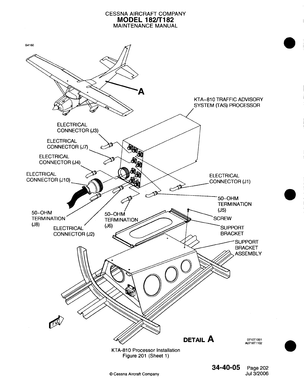
CESSNA
AIRCRAFT
COMPANY
MODEL 182/T182
MAINTENANCE
MANUAL
KTA-810
TRAFFIC ADVISORY
OR
RT
ET
BLY
)T1001
3T1102
KTA-810
Processor
Installation
Figure
201
(Sheet
1)
34-40-(
©
Cessna
Aircraft Company
35
Page
202
Jul 3/2006
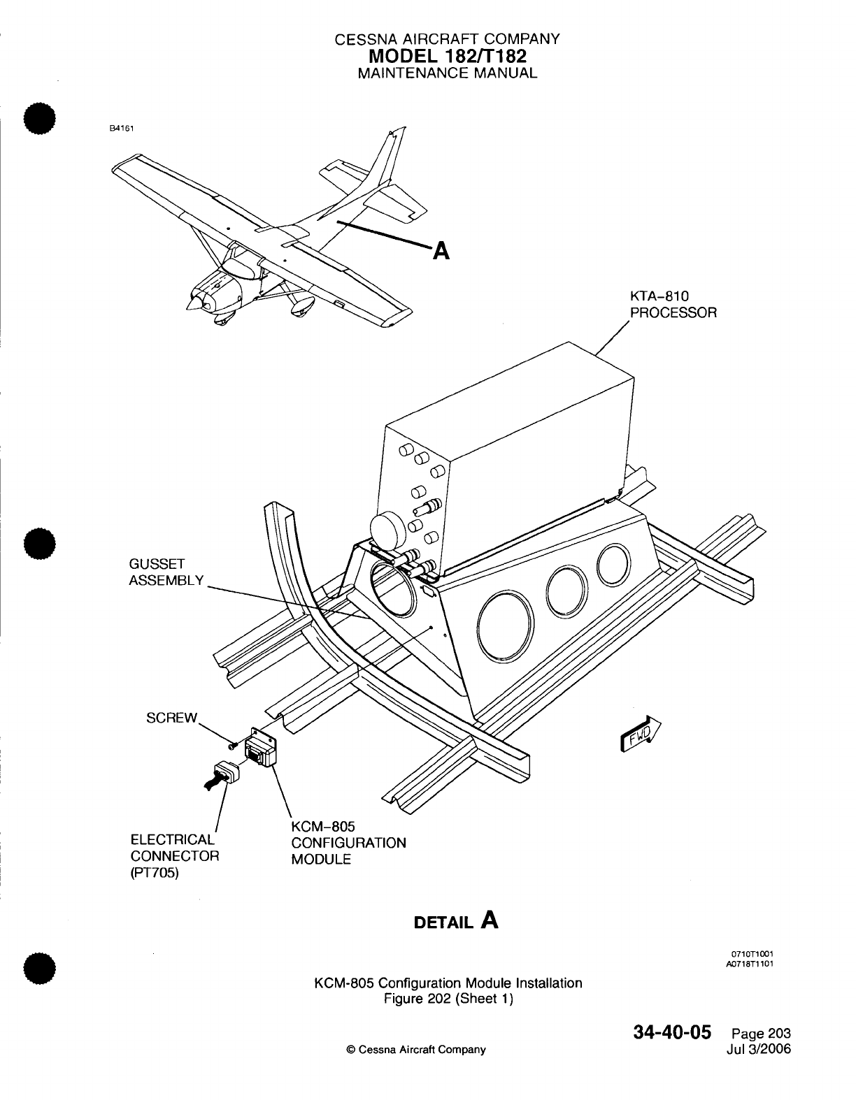
CESSNA
AIRCRAFT
COMPANY
MODEL
182/T182
MAINTENANCE
MANUAL
A
KTA-810
GL
AS
ELECTRICAL
CONNECTOR
(PT705)
CONFIGURATION
MODULE
DETAIL
A
0710T1001
A0718T1101
KCM-805
Configuration
Module
Installation
Figure
202
(Sheet
1)
©
Cessna Aircraft
Company
34-40-05
Page
203
Jul
3/2006
CESSNA
AIRCRAFT
COMPANY
MODEL
182/T182
MAINTENANCE
MANUAL
Install
the
screws
that attach the configuration
module
to
the
gusset
assembly.
Connect
the electrical
connector
(PT705)
to
the
configuration
module.
Install
the
aft
baggage
divider.
Install
the
rear seat.
Refer
to
Chapter
25,
Rear
Seat
-
Maintenance
Practices.
Engage
the
TAS
circuit
breaker
on
the
circuit
breaker
panel.
34-40-05
Page
204
©
Cessna
Aircraft
Company
Jul
3/2006
(2)
(3)
(4)
(5)
(6)
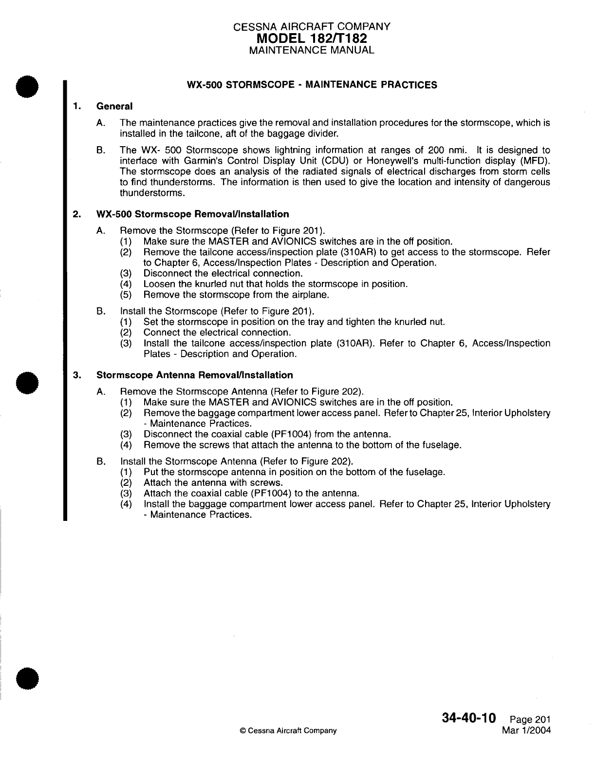
CESSNA
AIRCRAFT
COMPANY
MODEL
182/T182
MAINTENANCE
MANUAL
WX-500 STORMSCOPE
-
MAINTENANCE PRACTICES
1.
General
A.
The
maintenance practices
give
the
removal
and
installation
procedures
for
the
stormscope,
which
is
installed
in
the
tailcone,
aft of
the
baggage divider.
B.
The
WX-
500
Stormscope
shows lightning
information
at
ranges
of
200
nmi.
It
is
designed
to
interface
with
Garmin's
Control
Display
Unit
(CDU)
or
Honeywell's
multi-function
display
(MFD).
The
stormscope does
an
analysis
of
the radiated
signals
of
electrical
discharges
from
storm
cells
to
find thunderstorms.
The information
is
then used to
give the location
and
intensity
of
dangerous
thunderstorms.
2.
WX-500
Stormscope
Removal/Installation
A.
Remove
the
Stormscope
(Refer
to
Figure
201).
(1)
Make
sure
the
MASTER and AVIONICS
switches
are
in
the
off
position.
(2)
Remove the
tailcone access/inspection
plate
(310AR)
to
get
access
to
the
stormscope.
Refer
to
Chapter
6,
Access/Inspection
Plates
-
Description and
Operation.
(3)
Disconnect
the
electrical
connection.
(4)
Loosen
the knurled
nut
that
holds
the
stormscope
in
position.
(5)
Remove
the
stormscope
from
the
airplane.
B.
Install
the
Stormscope
(Refer
to Figure
201).
(1)
Set
the
stormscope
in
position
on
the
tray
and
tighten
the knurled
nut.
(2)
Connect
the
electrical connection.
(3)
Install
the
tailcone access/inspection
plate
(310AR).
Refer
to
Chapter
6,
Access/Inspection
Plates
-
Description
and
Operation.
3.
Stormscope
Antenna
Removal/Installation
A.
Remove the
Stormscope
Antenna
(Refer
to
Figure
202).
(1)
Make
sure
the
MASTER and AVIONICS
switches
are
in
the
off
position.
(2)
Remove the
baggage
compartment
lower
access
panel.
Refer
to
Chapter
25,
Interior Upholstery
-
Maintenance
Practices.
(3)
Disconnect
the
coaxial
cable
(PF1004) from
the
antenna.
(4)
Remove
the
screws that
attach the
antenna
to
the bottom
of
the
fuselage.
B.
Install
the
Stormscope
Antenna
(Refer
to
Figure
202).
(1)
Put
the
stormscope
antenna
in
position
on
the
bottom
of
the
fuselage.
(2)
Attach
the antenna
with
screws.
(3)
Attach
the coaxial
cable
(PF1004)
to
the
antenna.
(4)
Install
the
baggage compartment
lower
access
panel.
Refer
to
Chapter
25,
Interior
Upholstery
-
Maintenance
Practices.
34-40-10
Page
201
©
Cessna Aircraft
Company
Mar 1/2004
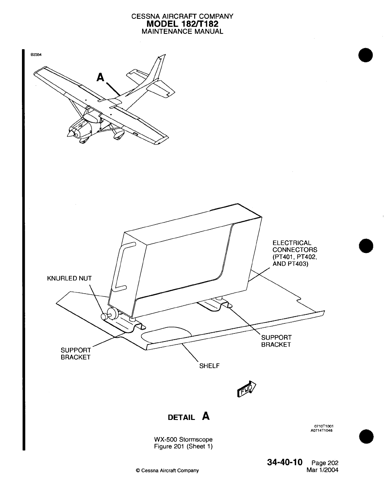
CESSNA AIRCRAFT
COMPANY
MODEL
182/T182
MAINTENANCE
MANUAL
SHELF
DETAIL
A
0710T1001
A0714T1046
WX-500 Stormscope
Figure
201
(Sheet
1)
34-40-10
©
Cessna
Aircraft
Company
Page
202
Mar
1/2004
DOOS:
U
CESSNA
AIRCRAFT
COMPANY
MODEL
182/T182
MAINTENANCE
MANUAL
B
CONNECTOR
1
--,A
LANE
)RMSCOPE
FENNA
SKET
ANTENNA
DETAIL
A
Stormscope
Antenna
Installation
Figure 202
(Sheet
1)
34-40-10
©
Cessna Aircraft
Company
0710T1001
A0714T1049
Page
203
Mar 1/2004
CESSNA
AIRCRAFT
COMPANY
MODEL
182/T182
MAINTENANCE
MANUAL
KX-155A
COMM/NAV
SYSTEM
-
MAINTENANCE
PRACTICES
1.
General
A.
This
section
gives
maintenance
practices
for
the
KX-155A
NAV/COM
System
component
removal
and
installation.
For
more
system
information
and the
post
installation
check,
refer
to
the
manufacturer's
manuals listed
in
the
Introduction,
List
of
Manufacturers Technical
Publications.
2.
KX-155A/165A
VHF COMM
Transceiver/NavigationNOR/LOC Glideslope
Receiver
Removal
and
Installation
CAUTION:
Do
not
interchange
the
KX-155A and
the
KX-165A
NAV/COM
radios.
The
wiring
is
not
the
same for
the two
different
radios.
If
these radios
are
interchanged
and
used
with
the
same
wiring,
damage can
occur
to the
KX-155A
and/or
the
KX-165A
NAV/COM
radios.
A.
For
removal
and
installation
of
the
KX-155A receiver,
refer to
Chapter
23,
Communications
-
Maintenance
Practices.
3.
Omni
(NAV)
Antenna
Removal
and
Installation
(182S)
A.
Remove
the
Omni
(NAV)
Antenna
(Refer
to
Figure
201).
(1)
Remove the
electrical
power
from the
airplane
and
turn
the
master
switch
to
the
OFF
position.
(2)
Remove
the
boots
from the
antenna
radiators.
(3)
Remove the
self-locking
hex
nuts,
and
then
remove
the
antenna
radiators
from the
antenna
base.
(4)
Get
access
to
the
omni
antenna
by
removing the fin
tip.
(5)
Remove
the
screws that
attach
the
antenna
base
to
the
fin
rib.
(6)
Lift
the antenna
base
to
get
access
to
the coax
connector. Disconnect
the
coax
connector
from
the
antenna
base.
(7)
Remove
the
omni
antenna
from the
airplane.
B.
Install the Omni
(NAV)
Antenna
(Refer
to
Figure
201).
(1)
Position
the omni
antenna
on
the fin
and
connect the
coax
connector
to
the
antenna base.
(2)
Attach the
antenna
base
to the
fin
rib
with
screws.
(3)
Install
the fin
tip.
CAUTION: When you
use
self-locking
hex
nuts to
attach
the
antenna
radiators,
do
not
tighten
the
nuts
too
much.
(4)
Attach
the antenna
radiators
to
the
antenna
base with
the
self-locking
hex
nuts.
(5)
Install the
boots
on
the
antenna radiators.
(6)
Supply electrical
power
to
the
airplane
as
necessary,
and
turn
the
master
switch to
the
ON
position.
4.
NAV
Antenna
Coupler
Removal
and
Installation
(182S)
A.
Remove
the
NAV
Antenna
Coupler
(Refer
to
Figure
201).
NOTE:
The
NAV
antenna
coupler
is
found
at
FS
8.00
and
WL
11.77,
between
the
firewall
and
instrument
panel
on
the
left
outboard
stringer assembly.
(1)
Remove the
electrical
power
from the
airplane
and
turn
the
master
switch to
the
OFF
position.
(2)
Get
access
to
the
NAV
antenna
coupler.
(3)
Identify,
put
a
label
on,
and
disconnect
the
antenna
coax
connectors
from
the
NAV
antenna
coupler.
(4)
Remove the
screws
and
washers
that
attach the
NAV
antenna coupler
to
the
fuselage.
(5)
Remove the
NAV
antenna
coupler
from
the
airplane.
34-50-00
Page
201
©
Cessna Aircraft Company
Mar 1/2005
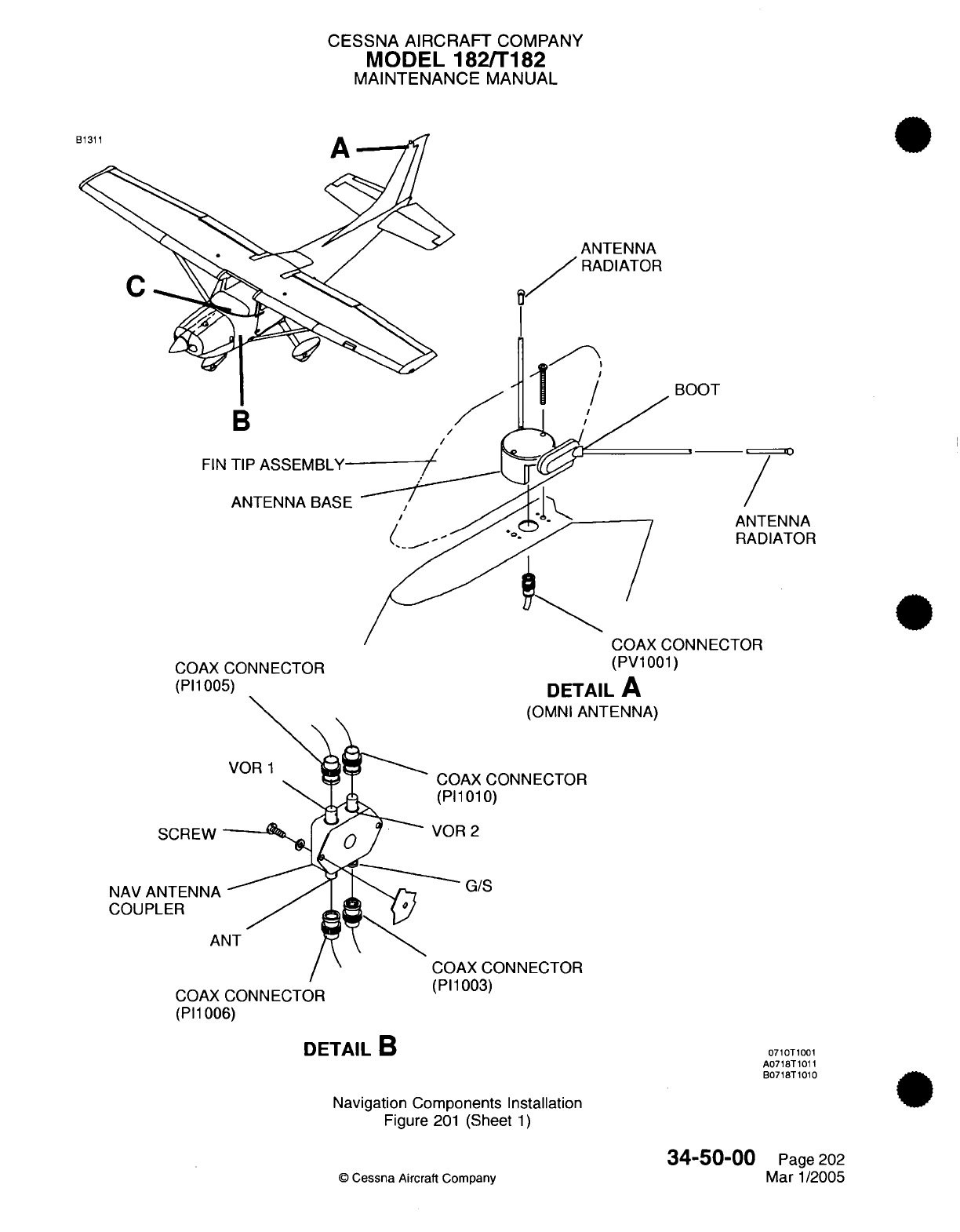
CESSNA AIRCRAFT
COMPANY
MODEL
182/T182
MAINTENANCE
MANUAL
ANTENNA
/
RADIATOR
I
B
FIN
TIP
ASSEMBLY
ANTENNA
BASE
COAX
CONNECTOR
(PI1005)
BOOT
.-T l0
ANTENNA
RADIATOR
N
N
MFrTn
(PV1001)
DETAIL
A
(OMNI
ANTENNA)
SCREW
NAV
ANTENNA
COUPLER
A
COAX
CONNECTOR
(PI1
006)
DETAIL
B
AX
CONNECTOR
1010)
R
2
G/S
\X
CONNECTOR
Ia,,\
r II
UUj)
Navigation Components Installation
Figure
201
(Sheet
1)
©
Cessna
Aircraft Company
0710T1001
A0718T1011
B0718T1010
34-50-00
Page
202
Mar
1/2005
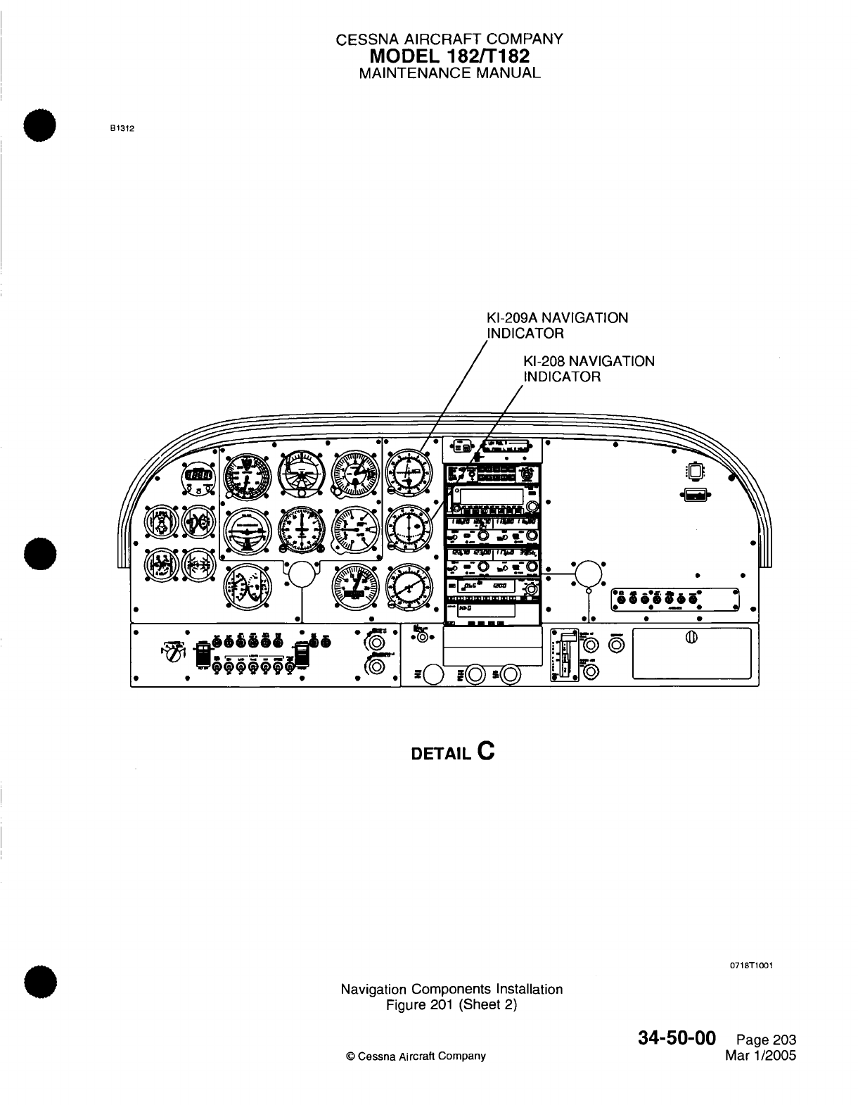
CESSNA
AIRCRAFT
COMPANY
MODEL
182/T182
MAINTENANCE
MANUAL
B1312
KI-209A
NAVIGATION
3ATION
e*
6
&&&&
.
QQqQ
.. .
*a*
* -*
*
on
(
0
ri
I.uuI
Iur-
DETAIL
C
0718T1001
Navigation
Components Installation
Figure
201
(Sheet
2)
34-50-00
©
Cessna Aircraft
Company
Page
203
Mar
1/2005
CESSNA
AIRCRAFT
COMPANY
MODEL
182/T182
MAINTENANCE
MANUAL
B.
Install
the
NAV
Antenna
Coupler
(Refer
to
Figure
201).
(1)
Put
the
NAV
antenna
coupler
on
the
fuselage
and
attach
it
with
the
screws and washers.
(2)
Connect
the
antenna
coax
connectors
to
the
NAV
antenna
coupler.
(3)
Supply
electrical
power to
the
airplane
as
necessary, and
turn
the
master switch
to the
ON
position.
5.
KI-209A
and
KI-208
Navigation
Indicators
Removal
and
Installation
NOTE:
The
KI-209A
Navigation
Indicator
is
the
NAV
1
indicator
and
the
KI-208
is
the
NAV
2
indicator.
Removal
and
Installation
is
typical
for
the
NAV
1
and
NAV
2
indicators.
A.
Remove
the
Navigation
Indicator
(Refer
to
Figure
201).
(1)
Remove
the
electrical power
from
the
airplane
and
turn
the
master
switch
to
the OFF
position.
(2)
Remove
the inboard pilot
panel
assembly
to get
access
to
the rear
of
the
navigation
indicator.
Refer
to
Chapter
31,
Instrument
and
Control Panels
-
Maintenance
Practices.
(3)
Disconnect
the
electrical
connector
from
the navigation
indicator.
(4)
Remove
the screws
that attach
the
navigation indicator
to the
inboard pilot
panel
assembly.
(5)
Remove
the
navigation
indicator
from
the
airplane.
B.
Install
the
Navigation
Indicator
(Refer
to
Figure
201).
(1)
Put
the
navigation indicator
on
the inboard pilot
panel
assembly
and
attach
it
with
the screws.
(2)
Install
the
electrical
connector
to the
navigation
indicator.
(3)
Attach the inboard
pilot panel
assembly
to
the
structure
with
the screws.
Refer
to
Chapter
31,
Instrument
and
Control
Panels
-
Maintenance
Practices.
(4)
Supply the electrical
power
to
the
airplane
as
necessary
and
turn
the
master switch
to
the
ON
position.
34-50-00
Page
204
©
Cessna
Aircraft
Company
Mar
1/2005
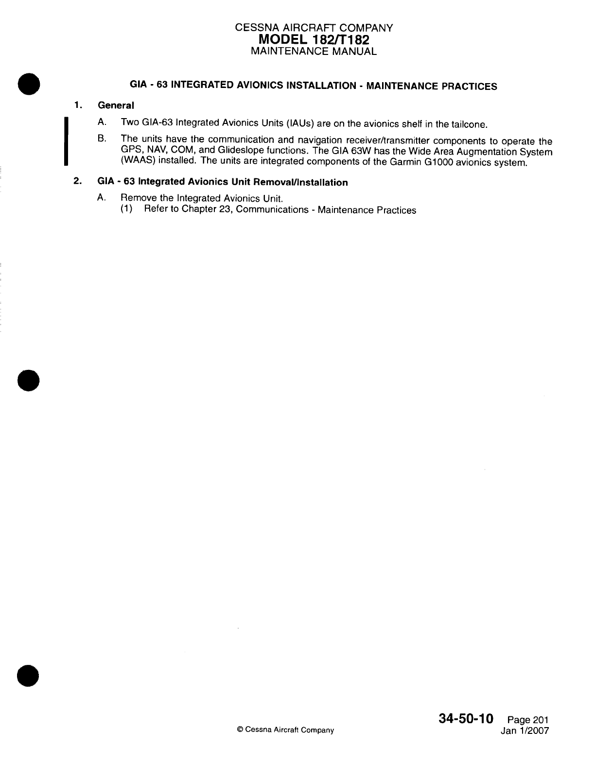
CESSNA AIRCRAFT
COMPANY
MODEL
182ffl182
MAINTENANCE
MANUAL
GIA
-
63
INTEGRATED
AVIONICS
INSTALLATION
-
MAINTENANCE
PRACTICES
1.General
A.
Two
GIA-63
Integrated
Avionics
Units
(IAUs) are
on
the
avionics
shelf
in
the
tailcone.
B.
The
units
have
the
communication
and
navigation receiver/transmitter
components
to
operate
the
GPS,
NAy,
COM,
and
Glideslope
functions.
The
GIA
63W
has
the
Wide
Area
Augmentation
System
(WAAS)
installed.
The
units
are
integrated
components
of
the
Garmin
G1000
avionics
system.
2.
GIA
-
63
Integrated
Avionics
Unit
Rernoval/installation
A.
Remove
the
Integrated
Avionics
Unit.
(1)
Refer
to
Chapter
23,
Communications
-
Maintenance Practices
©
Cessna Aircraft
Company
34-50-1
0
Page
201
Janl1/2007
I
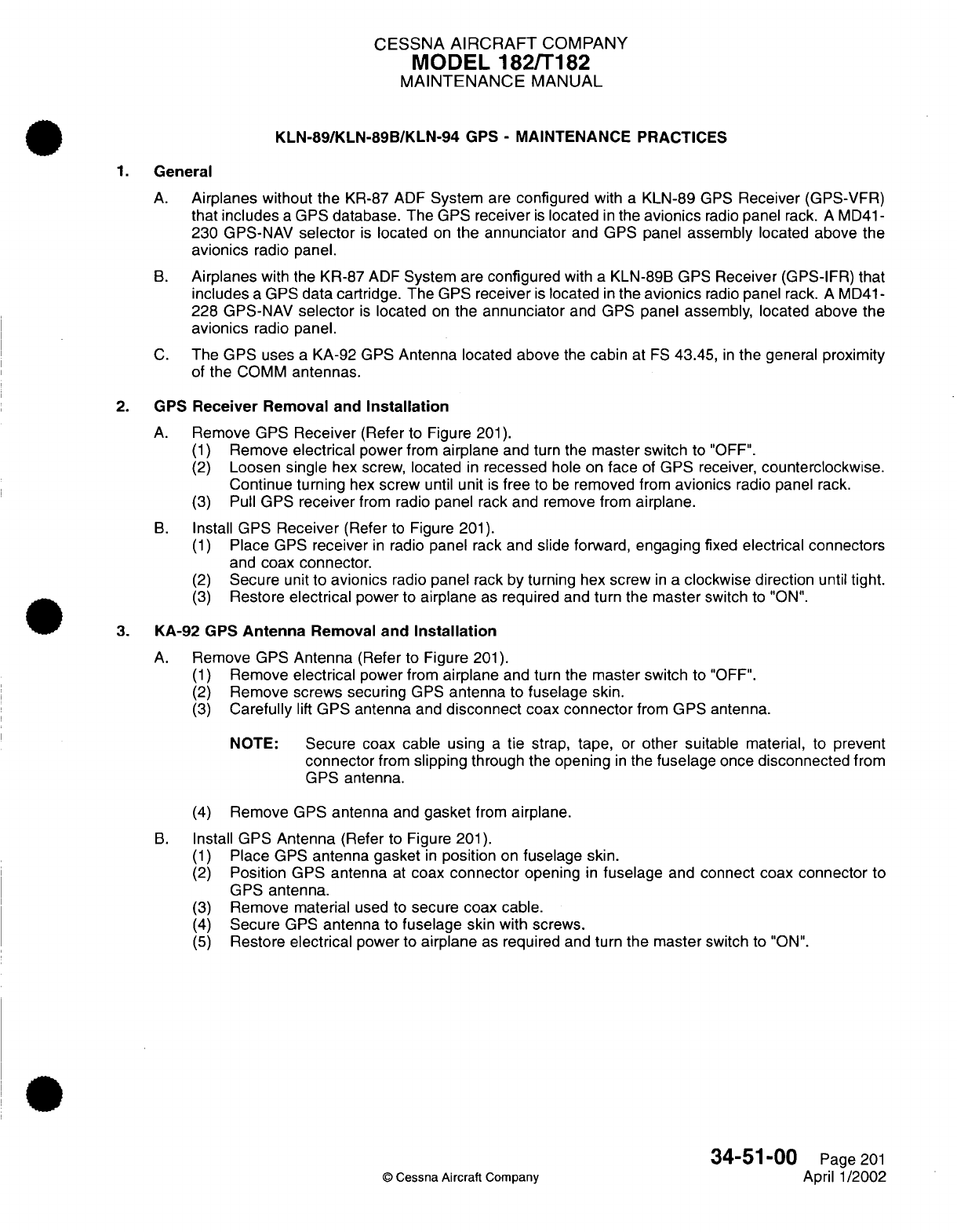
CESSNA
AIRCRAFT
COMPANY
MODEL
182/T182
MAINTENANCE
MANUAL
KLN-89/KLN-89B/KLN-94
GPS
-
MAINTENANCE
PRACTICES
1.
General
A.
Airplanes
without the
KR-87
ADF
System
are
configured
with
a
KLN-89
GPS
Receiver
(GPS-VFR)
that
includes
a
GPS
database.
The
GPS
receiver
is
located
in
the
avionics
radio
panel
rack.
A
MD41-
230
GPS-NAV
selector
is
located
on
the annunciator
and
GPS panel
assembly
located
above
the
avionics
radio
panel.
B.
Airplanes
with
the
KR-87
ADF
System
are
configured
with
a
KLN-89B GPS
Receiver
(GPS-IFR)
that
includes
a
GPS
data cartridge.
The
GPS
receiver
is
located
in
the
avionics
radio
panel rack.
A
MD41-
228
GPS-NAV
selector
is
located
on
the
annunciator
and
GPS
panel assembly,
located
above
the
avionics
radio
panel.
C.
The GPS
uses
a
KA-92
GPS
Antenna
located
above
the
cabin
at
FS
43.45,
in
the general proximity
of
the
COMM
antennas.
2.
GPS
Receiver
Removal
and
Installation
A.
Remove GPS
Receiver
(Refer
to Figure
201).
(1)
Remove
electrical
power
from
airplane
and
turn
the
master switch
to
"OFF".
(2)
Loosen
single
hex
screw, located
in
recessed
hole on
face
of
GPS receiver,
counterclockwise.
Continue
turning
hex
screw
until
unit
is
free
to
be
removed
from
avionics
radio panel rack.
(3)
Pull
GPS
receiver
from radio
panel
rack and
remove
from
airplane.
B.
Install
GPS
Receiver
(Refer
to
Figure
201).
(1)
Place
GPS
receiver
in
radio
panel
rack
and
slide forward,
engaging
fixed
electrical
connectors
and
coax connector.
(2)
Secure
unit
to
avionics
radio
panel
rack
by
turning
hex
screw
in
a
clockwise
direction
until
tight.
(3)
Restore
electrical
power
to
airplane
as
required
and
turn
the
master
switch
to
"ON".
3.
KA-92
GPS
Antenna
Removal and
Installation
A.
Remove
GPS
Antenna
(Refer
to
Figure
201).
(1)
Remove
electrical
power
from
airplane
and
turn
the
master switch
to
"OFF".
(2)
Remove
screws
securing
GPS
antenna
to
fuselage
skin.
(3)
Carefully
lift
GPS antenna
and
disconnect
coax connector
from
GPS
antenna.
NOTE:
Secure coax cable
using
a
tie
strap,
tape,
or
other suitable
material, to
prevent
connector
from
slipping
through
the
opening
in
the
fuselage
once
disconnected
from
GPS
antenna.
(4)
Remove
GPS
antenna
and
gasket
from
airplane.
B.
Install
GPS
Antenna
(Refer
to Figure
201).
(1)
Place GPS
antenna
gasket
in
position
on
fuselage
skin.
(2)
Position GPS antenna
at
coax
connector
opening
in
fuselage
and
connect
coax
connector
to
GPS
antenna.
(3)
Remove material
used
to
secure coax
cable.
(4)
Secure
GPS
antenna
to
fuselage skin
with
screws.
(5)
Restore
electrical
power
to
airplane
as
required
and
turn
the
master switch
to
"ON".
34-51-00
Page 201
©
Cessna Aircraft
Company
April 1/2002
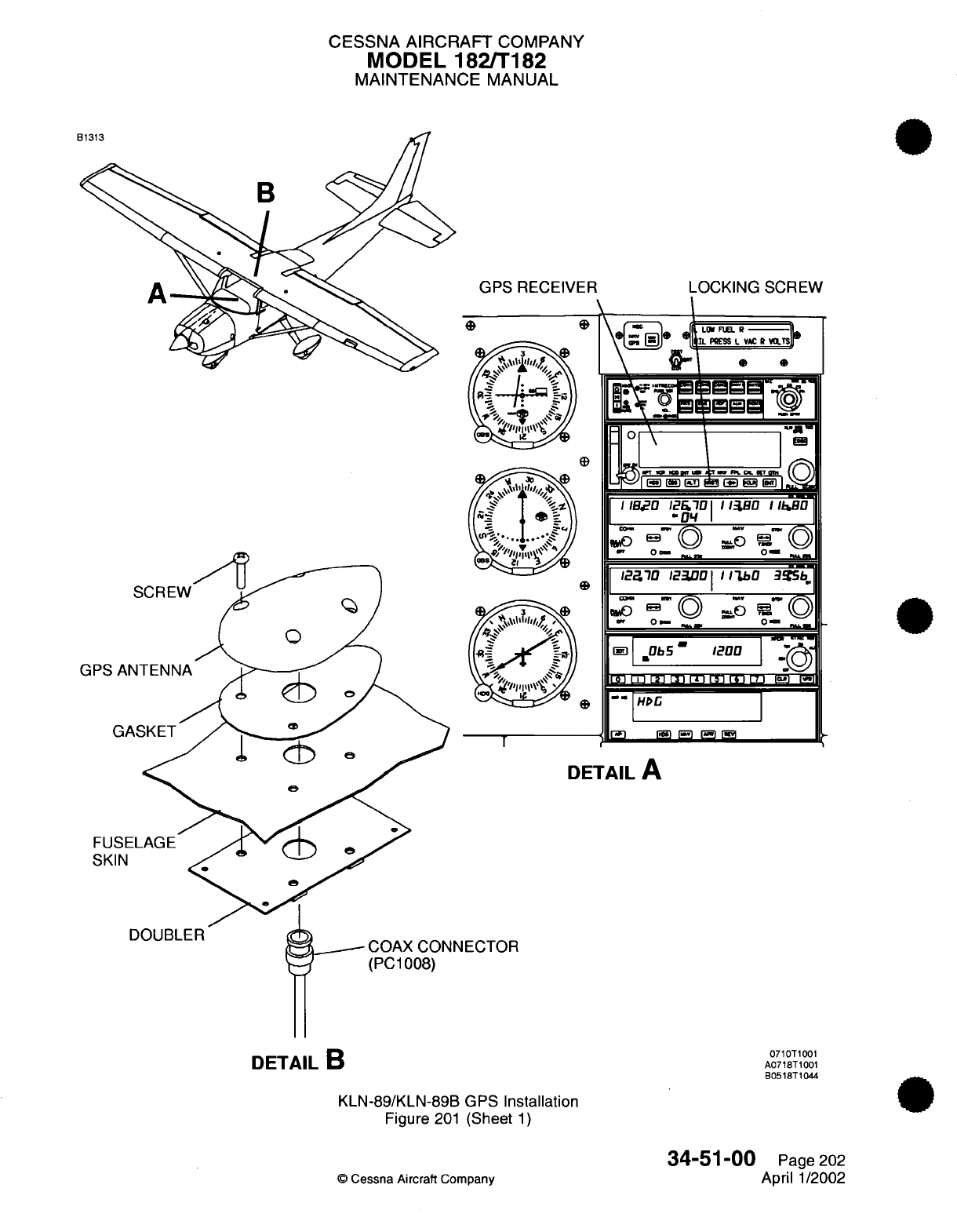
CESSNA AIRCRAFT
COMPANY
MODEL
182/T182
MAINTENANCE
MANUAL
GPS
RECEIVER
LOCKING
SCREW
®
YR;V--S
0~~
n
" ' --
\
WI
F-17'
S1
°
WI
I Ia-
-oD
I
-)
|
,Ob504
1.
-0
-
\\
:GS
1
T~
L.J
LU
IJ i i
Um
--
I
I
HDG
-
I
I
DETAIL
A
FU
SK
DOUBLER NECTOR
1-OLbf
1--
2
0
|"
'
UL
L
i
171
j
-
KLN-89/KLN-89B GPS
Installation
Figure
201
(Sheet
1)
©
Cessna
Aircraft
Company
0e
GPS
DETAIL
B
0710T1001
A0718T1001
B0518T1044
34-51-00
Page
202
April
1/2002
I FnEL
PmESS
I
I
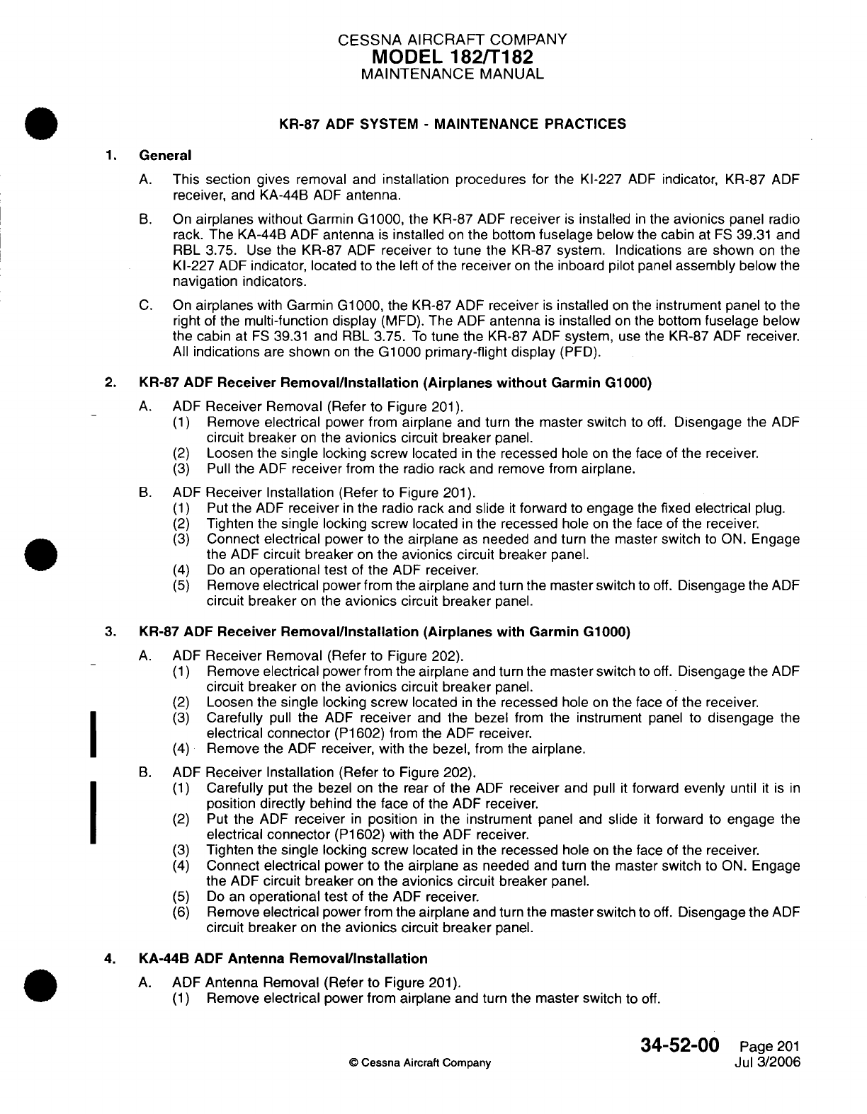
CESSNA AIRCRAFT
COMPANY
MODEL
182/T182
MAINTENANCE
MANUAL
KR-87
ADF SYSTEM
-
MAINTENANCE
PRACTICES
1.
General
A.
This
section
gives
removal and
installation procedures for
the
Kl-227
ADF
indicator,
KR-87
ADF
receiver,
and KA-44B
ADF
antenna.
B.
On
airplanes
without
Garmin
G1000,
the
KR-87
ADF
receiver
is
installed
in
the
avionics
panel
radio
rack. The
KA-44B
ADF
antenna
is
installed
on
the
bottom
fuselage
below
the
cabin
at
FS
39.31
and
RBL
3.75.
Use
the
KR-87
ADF
receiver
to
tune
the
KR-87
system.
Indications
are
shown
on
the
Kl-227
ADF
indicator, located
to
the
left
of
the
receiver
on
the
inboard
pilot
panel
assembly
below
the
navigation
indicators.
C.
On
airplanes
with
Garmin
G1000,
the
KR-87
ADF
receiver
is
installed
on
the
instrument panel
to the
right
of
the
multi-function
display
(MFD).
The
ADF
antenna
is
installed
on
the
bottom
fuselage
below
the cabin
at
FS
39.31
and
RBL
3.75.
To
tune
the
KR-87 ADF
system,
use
the KR-87
ADF
receiver.
All
indications
are
shown
on
the
G1000
primary-flight display
(PFD).
2.
KR-87
ADF Receiver
Removal/Installation (Airplanes
without
Garmin G1000)
A.
ADF
Receiver
Removal
(Refer
to Figure
201).
(1)
Remove
electrical
power from
airplane
and
turn
the
master switch
to
off.
Disengage
the
ADF
circuit
breaker
on
the
avionics
circuit
breaker
panel.
(2)
Loosen
the
single
locking
screw
located
in
the
recessed
hole
on
the
face
of
the
receiver.
(3)
Pull
the
ADF
receiver
from
the
radio
rack
and
remove
from
airplane.
B.
ADF
Receiver
Installation
(Refer
to
Figure
201).
(1)
Put
the
ADF
receiver
in
the
radio rack
and
slide
it
forward
to
engage
the
fixed
electrical
plug.
(2)
Tighten
the
single
locking
screw
located
in
the
recessed
hole
on
the
face
of
the
receiver.
(3)
Connect
electrical
power
to
the
airplane
as
needed
and
turn
the
master
switch
to
ON.
Engage
the
ADF
circuit
breaker
on
the
avionics
circuit
breaker
panel.
(4)
Do
an
operational test
of
the
ADF
receiver.
(5)
Remove
electrical
power from the
airplane
and
turn
the master switch
to
off.
Disengage
the
ADF
circuit
breaker
on
the
avionics
circuit breaker
panel.
3.
KR-87
ADF Receiver
Removal/Installation
(Airplanes with
Garmin
G1000)
A.
ADF
Receiver
Removal (Refer
to
Figure 202).
(1)
Remove
electrical
power
from
the
airplane
and
turn
the master switch
to
off.
Disengage
the
ADF
circuit
breaker
on
the
avionics
circuit breaker
panel.
(2)
Loosen
the
single
locking
screw
located
in
the
recessed
hole
on
the
face
of
the
receiver.
(3)
Carefully
pull
the
ADF
receiver
and
the bezel from
the
instrument
panel
to
disengage
the
electrical
connector
(P1602)
from
the
ADF
receiver.
(4)
Remove the
ADF
receiver,
with
the
bezel,
from the
airplane.
B.
ADF
Receiver
Installation (Refer
to Figure
202).
(1)
Carefully
put
the
bezel
on
the
rear
of
the
ADF
receiver
and pull
it
forward
evenly
until
it
is
in
position
directly
behind
the
face
of
the ADF receiver.
(2)
Put
the
ADF
receiver
in
position
in
the instrument panel
and
slide
it
forward
to
engage
the
electrical
connector
(P1602)
with
the
ADF receiver.
(3)
Tighten
the
single
locking screw
located
in
the
recessed
hole
on
the
face
of
the
receiver.
(4)
Connect
electrical
power to
the
airplane
as needed
and
turn
the
master
switch
to
ON.
Engage
the
ADF
circuit breaker
on
the
avionics circuit
breaker
panel.
(5)
Do
an
operational
test
of
the
ADF
receiver.
(6)
Remove
electrical
power from the
airplane
and
turn
the
master switch
to
off.
Disengage
the
ADF
circuit
breaker
on the
avionics
circuit breaker
panel.
4.
KA-44B
ADF
Antenna
Removal/Installation
A.
ADF
Antenna
Removal (Refer
to Figure
201).
(1)
Remove
electrical
power
from
airplane
and
turn
the master switch
to
off.
34-52-00
Page
201
©
Cessna
Aircraft
Company
Jul
3/2006
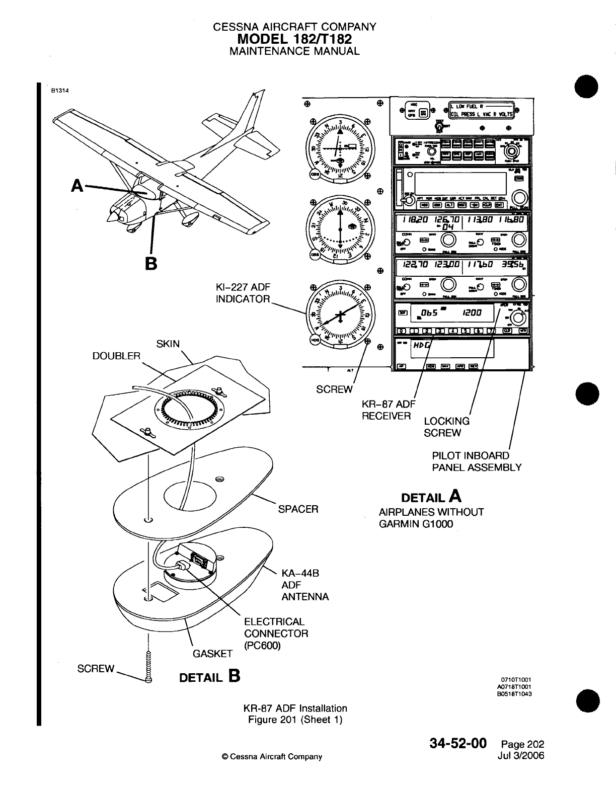
CESSNA
AIRCRAFT
COMPANY
MODEL 182/T182
MAINTENANCE
MANUAL
L
nn
n
B
K-227
ADF
INDICATOR
-
0
b5
SKIN
KR-8
RECE
PILOT
INBOARD
PANEL
ASSEMBLY
SPACER
DETAIL
A
AIRPLANES
WITHOUT
GARMIN
G1000
KA-44B
ADF
ANTENNA
ICAL
CTOR
)
SC
0710T1001
A0718T1001
B0518T1043
KR-87
ADF
Installation
Figure
201
(Sheet
1)
34-52-00
©
Cessna Aircraft
Company
Page
202
Jul 3/2006
B__
.
A
..
I
I
I
I
II
I
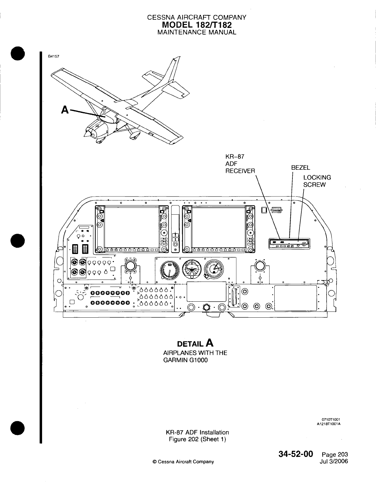
CESSNA
AIRCRAFT
COMPANY
MODEL
182/T182
MAINTENANCE
MANUAL
KR-87
ADF
RECEIVER
0000
DETAIL
A
AIRPLANES WITH
THE
GARMIN
G1000
0710T1001
A1218T1001A
KR-87
ADF
Installation
Figure 202
(Sheet
1)
©
Cessna
Aircraft
Company
BEZEL
LOCKING
SCREW
r
34-52-00
Page
203
Jul
3/2006
CESSNA
AIRCRAFT
COMPANY
MODEL 182/T182
MAINTENANCE
MANUAL
(2)
Remove
the screws that
attach
the
ADF
antenna
to
the
fuselage
skin.
(3)
Disconnect
the
antenna
connector
(PC600)
from the
ADF
antenna.
(4)
Remove
the
ADF
antenna
from the
airplane.
B.
ADF
Antenna
Installation (Refer to
Figure
201).
(1)
Connect
the electrical
connector
(PC600)
to
the
ADF
antenna.
(2)
Attach
the
ADF
antenna
to
the
fuselage
skin
with the
screws.
5.
Kl-227
ADF
Indicator Removal/Installation
A.
ADF
Indicator Removal (Refer to
Figure
201).
(1)
Remove
electrical
power
from
airplane
and
turn
the
master
switch
to off.
(2)
Remove
the
inboard
pilot
panel
assembly
to
gain
access
to
the
ADF
indicator.
Refer
to
Chapter
31,
Instrument
and
Control Panels
-
Maintenance
Practices.
(3)
Disconnect
the
electrical
connector
(P1603) from
the
ADF
indicator.
(4)
Remove
the
screws that attach
the
ADF
indicator
to
the
inboard pilot panel
assembly.
(5)
Remove
the
ADF
indicator
from the
airplane.
B.
ADF
Indicator Installation
(Refer
to
Figure
201).
(1)
Put
the
ADF
indicator
on
the
inboard pilot
panel
assembly
and
attach
with the
screws.
(2)
Connect
the electrical
connector
(P1603) to
the
ADF
indicator.
(3)
Attach
the
inboard
pilot
panel
assembly
to
the
structure
with
the screws.
Refer
to
Chapter
31,
Instrument
and
Control
Panels
-
Maintenance Practices.
34-52-00
Page
204
©
Cessna
Aircraft
Company
Jul
3/2006
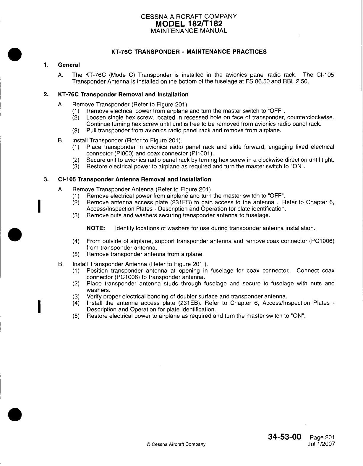
CESSNA AIRCRAFT
COMPANY
MODEL
182/Ti
82
MAINTENANCE
MANUAL
KT-76C
TRANSPONDER
-
MAINTENANCE
PRACTICES
1.General
A.
The
KT-76C
(Mode
C)
Transponder
is
installed
in
the
avionics
panel
radio
rack.
The
CI-105
Transponder
Antenna
is
installed
on
the
bottom
of
the
fuselage
at
FS
86.50
and
RBL
2.50.
2.
KT-76C
Transponder
Removal
and
Installation
A.
Remove
Transponder
(Refer
to
Figure
201).
(1)
Remove
electrical
power
from
airplane
and
turn the
master switch
to "OFF".
(2)
Loosen single
hex
screw,
located
in
recessed
hole
on
face
of
transponder,
counterclockwise.
Continue turning
hex
screw
until
unit
is
free
to
be
removed
from
avionics
radio
panel
rack.
(3)
Pull
transponder
from
avionics
radio panel
rack
and
remove from
airplane.
B.
Install
Transponder
(Refer
to
Figure
201).
(1)
Place
transponder
in
avionics
radio
panel
rack
and
slide
forward, engaging fixed electrical
connector
(PI800)
and
coax connector
(PI1001).
(2)
Secure
unit
to
avionics
radio panel
rack
by
turning
hex
screw
in a
clockwise
direction
until
tight.
(3)
Restore
electrical
power
to
airplane
as
required
and
turn
the
master
switch
to
"ON".
3.
CI-105
Transponder
Antenna
Removal
and
Installation
A.
Remove
Transponder
Antenna
(Refer
to
Figure
201).
(1)
Remove
electrical
power
from
airplane
and
turn
the
master
switch
to
"OFF".
(2)
Remove
antenna access
plate
(231
EB) to
gain
access
to
the
antenna
.
Refer
to
Chapter
6,
Access/Inspection
Plates
-
Description
and
Operation
for
plate
identification.
(3)
Remove
nuts
and
washers securing
transponder
antenna
to
fuselage.
NOTE:
Identify
locations
of
washers
for
use
during
transponder
antenna
installation.
(4)
From
outside
of
airplane, support
transponder
antenna
and
remove
coax
connector
(PC1006)
from
transponder
antenna.
(5)
Remove
transponder
antenna
from
airplane.
B.
Install
Transponder
Antenna (Refer
to
Figure
201
)
(1)
Position
transponder
antenna
at
opening
in
fuselage
for
coax
connector.
Connect
coax
connector
(PCi1006)
to
transponder
antenna.
(2)
Place
transponder antenna
studs
through
fuselage
and
secure
to
fuselage
with
nuts
and
washers.
(3)
Verify
proper
electrical
bonding
of
doubler
surface
and
transponder
antenna.
(4)
Install
the
antenna
access
plate
(231
EB).
Refer
to
Chapter
6,
Access/Inspection
Plates
-
I ~
~~~Description
and
Operation
for
plate
identification.
(5)
Restore
electrical
power
to
airplane
as
required
and
turn the
master switch
to
"ON".
34-5300
Page
201
©
Cessna
Aircraft
Company
Jul
1/2007
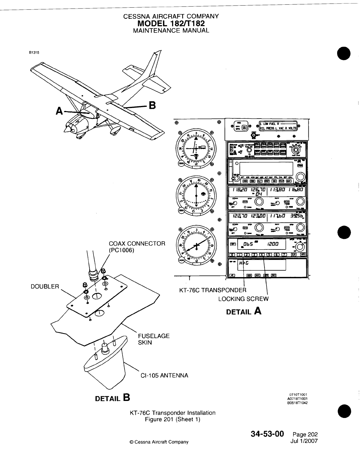
CESSNA AIRCRAFT
COMPANY
MODEL
182/Ti
82
MAINTENANCE
MANUAL
DOUBL
LOCKING
SCREW
DETAIL
A
-ENNA
KT-76C
Transponder
Installation
Figure
201
(Sheet
1)
34-53-00
©
Cessna Aircraft
Company
DETAIL
B
071 OT1
001
A071BT
1001
8051
8T1
042
Page
202
Jul
1/2007
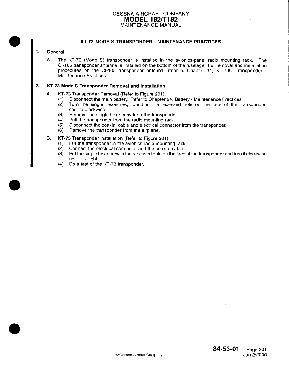
CESSNA
AIRCRAFT
COMPANY
MODEL
182/T182
MAINTENANCE
MANUAL
KT-73
MODE
S
TRANSPONDER
-
MAINTENANCE PRACTICES
General
A.
The
KT-73
(Mode
S)
transponder
is
installed
in
the
avionics-panel
radio
mounting
rack.
The
Cl-105
transponder
antenna
is
installed
on
the bottom
of
the
fuselage.
For
removal
and
installation
procedures
on
the
Cl-105
transponder
antenna,
refer to
Chapter
34,
KT-76C
Transponder
-
Maintenance Practices.
2.
KT-73
Mode
S
Transponder
Removal
and
Installation
A.
KT-73
Transponder
Removal
(Refer
to
Figure
201).
(1)
Disconnect
the main
battery.
Refer
to
Chapter
24,
Battery
-
Maintenance
Practices.
(2)
Turn
the
single
hex-screw, found
in
the
recessed
hole
on
the face
of
the
transponder,
counterclockwise.
(3)
Remove
the
single hex-screw
from
the
transponder.
(4)
Pull
the
transponder
from
the
radio
mounting
rack.
(5)
Disconnect
the
coaxial
cable
and
electrical
connector
from
the
transponder.
(6)
Remove
the
transponder
from
the
airplane.
B.
KT-73
Transponder
Installation
(Refer to Figure
201).
(1)
Put
the
transponder
in
the
avionics
radio
mounting
rack.
(2)
Connect
the
electrical
connector
and
the
coaxial
cable.
(3)
Put
the
single
hex-screw
in
the
recessed
hole
on
the
face
of
the
transponder
and
turn
it
clockwise
until
it
is
tight.
(4)
Do a
test
of
the
KT-73 transponder.
34-53-01
Page
201
©
Cessna
Aircraft
Company
Jan
2/2006
1.
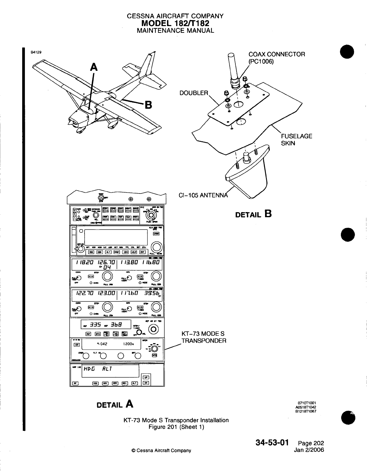
CESSNA
AIRCRAFT
COMPANY
MODEL 182/T182
MAINTENANCE
MANUAL
I e:-
I
"37
I
_
§Jiyn
=ggS
°
DETAIL
B
|
B
[ ]J [E3
|
I
I12O
12E6.701
113.0
1 Ih
/
O
OE,,.a,
"04
.
|P
127
123.001
/1b
3Iib
»S BT
O D A
Sn
\1 0 E
(
OD«.t
^.T
O I
1
.335
3bB
I
H[E1
Ei
I
EP
R
N -° )
KT-73
MODE
S
"
02
1200.
|-
|
TRANSPONDER
~)
""0
0
"a
""
HOIG
RLT
1
DETAIL
A
0710T1001
IDETAILA
^
A0518T1042
B1218T1067
KT-73 Mode
S
Transponder
Installation
Figure
201
(Sheet
1)
34-53-01
Page
202
©
Cessna
Aircraft
Company
Jan
2/2006
_ _
_
it:
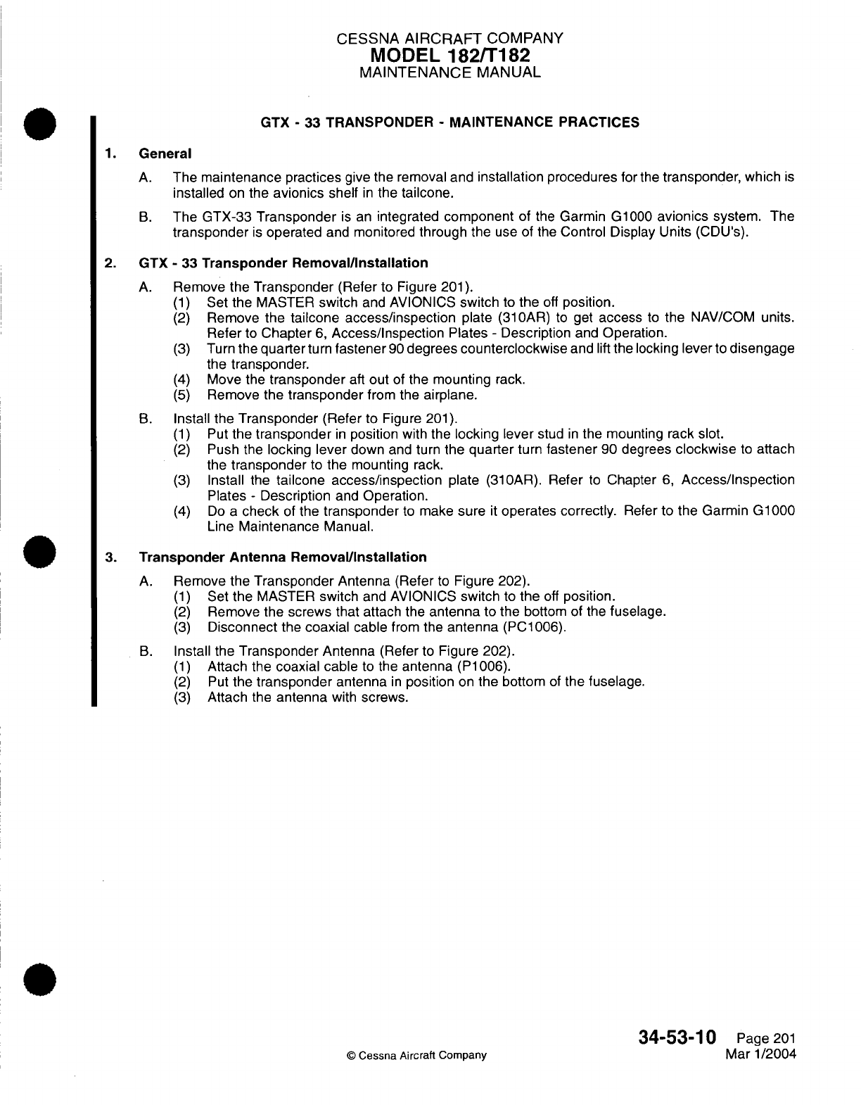
CESSNA
AIRCRAFT
COMPANY
MODEL
182/T182
MAINTENANCE
MANUAL
GTX
-
33
TRANSPONDER
-
MAINTENANCE
PRACTICES
1.
General
A.
The
maintenance
practices
give the removal and
installation
procedures
for
the
transponder,
which
is
installed
on
the
avionics
shelf
in
the
tailcone.
B.
The GTX-33
Transponder
is
an
integrated
component
of
the
Garmin
G1000
avionics
system.
The
transponder
is
operated
and
monitored
through the
use
of
the
Control Display Units
(CDU's).
2. GTX
-
33
Transponder Removal/Installation
A.
Remove
the
Transponder
(Refer
to
Figure
201).
(1)
Set
the
MASTER
switch
and
AVIONICS
switch
to
the
off
position.
(2)
Remove
the
tailcone access/inspection
plate (310AR)
to
get
access
to
the
NAV/COM
units.
Refer
to
Chapter
6,
Access/Inspection
Plates
-
Description
and
Operation.
(3)
Turn
the
quarterturn
fastener
90
degrees
counterclockwise
and
lift
the
locking
lever
to
disengage
the
transponder.
(4)
Move
the
transponder
aft
out
of
the
mounting
rack.
(5)
Remove
the
transponder
from
the
airplane.
B.
Install
the
Transponder
(Refer
to
Figure
201).
(1)
Put
the
transponder
in
position
with
the
locking
lever
stud
in
the
mounting rack
slot.
(2)
Push the
locking
lever
down
and
turn
the quarter
turn
fastener
90
degrees
clockwise
to
attach
the
transponder
to
the
mounting rack.
(3)
Install
the
tailcone access/inspection
plate (310AR).
Refer
to
Chapter
6,
Access/Inspection
Plates
-
Description
and
Operation.
(4)
Do
a
check
of
the
transponder
to
make
sure
it
operates
correctly.
Refer
to
the Garmin G1000
Line
Maintenance
Manual.
3.
Transponder Antenna
Removal/Installation
A.
Remove the
Transponder
Antenna
(Refer
to
Figure
202).
(1)
Set
the
MASTER
switch
and
AVIONICS
switch
to
the
off
position.
(2)
Remove
the screws
that
attach the
antenna
to
the
bottom of the
fuselage.
(3)
Disconnect
the
coaxial
cable
from
the
antenna
(PC1006).
B.
Install the
Transponder
Antenna
(Refer
to
Figure
202).
(1)
Attach
the
coaxial cable
to the
antenna
(P1006).
(2)
Put
the
transponder
antenna
in
position
on
the
bottom
of
the
fuselage.
(3)
Attach
the
antenna
with
screws.
34-53-10
Page
201
©
Cessna Aircraft
Company
Mar
1/2004

CESSNA
AIRCRAFT
COMPANY
MODEL
182/T182
MAINTENANCE
MANUAL
INTEGRATED
AVIONICS
UNIT
(COMM
1)
INTEGRATED
AVIONICS
UNIT
(COMM
2)
VIEW
A-A
LOOKING
FORWARD
AT
FS
140
AIRPLANES THAT
HAVE
THE GARMIN
G1000
0710T1001
A0714T1044
Tailcone
Avionics Installation
Figure
201
(Sheet
1)
34-53-10
©
Cessna
Aircraft Company
AHRE
-1- A kImr'k1,n-r
1
s
Page 202
Mar
1/2004
nose
I:
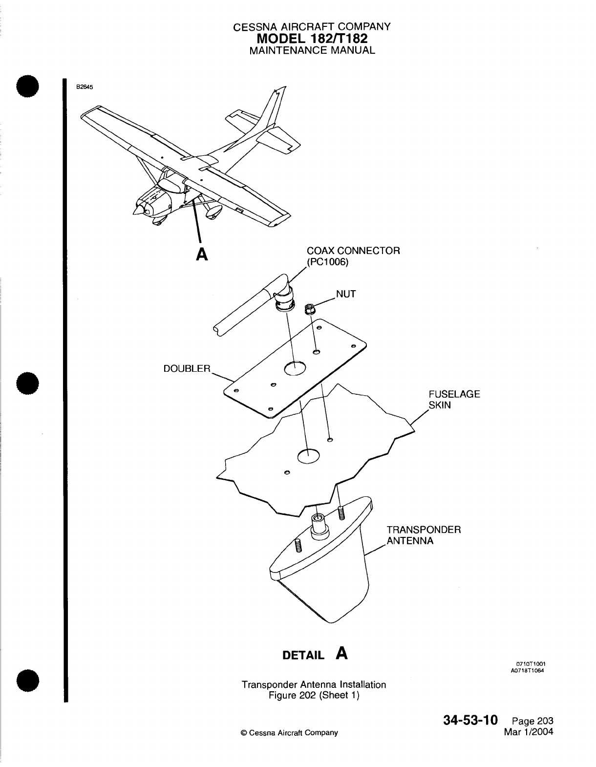
CESSNA AIRCRAFT
COMPANY
MODEL
182/T182
MAINTENANCE
MANUAL
A
COAX
CONNECTOR
(PC1
006)
DOUBLER
*USELAGE
SKIN
NDER
DETAIL
A
Transponder
Antenna Installation
Figure
202 (Sheet
1)
©
Cessna Aircraft
Company
34-53-10
Page
203
Mar
1/2004
0710T1001
A0718T1064
oozer
t
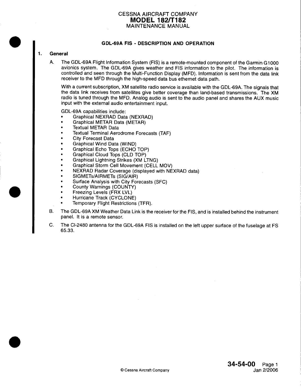
CESSNA
AIRCRAFT
COMPANY
MODEL
182/T182
MAINTENANCE
MANUAL
GDL-69A
FIS
-
DESCRIPTION
AND
OPERATION
1.
General
A.
The
GDL-69A
Flight Information
System
(FIS)
is
a
remote-mounted
component
of the
Garmin
G
1000
avionics
system. The GDL-69A gives
weather
and
FIS
information
to the pilot.
The
information
is
controlled
and
seen through the Multi-Function Display
(MFD).
Information
is
sent
from
the
data
link
receiver
to the
MFD
through
the
high-speed data
bus
ethemet
data
path.
With
a
current
subscription,
XM
satellite
radio
service
is
available
with
the
GDL-69A.
The
signals
that
the
data
link
receives
from
satellites
give
better
coverage
than
land-based transmissions.
The
XM
radio
is
tuned
through the
MFD.
Analog
audio
is
sent
to
the
audio
panel
and
shares the
AUX music
input
with
the
external audio entertainment
input.
GDL-69A
capabilities
include:
·
Graphical
NEXRAD
Data
(NEXRAD)
Graphical
METAR Data (METAR)
·
Textual
METAR
Data
Textual Terminal
Aerodrome
Forecasts
(TAF)
City
Forecast
Data
·
Graphical
Wind
Data (WIND)
Graphical
Echo
Tops
(ECHO
TOP)
·
Graphical
Cloud
Tops (CLD TOP)
Graphical Lightning Strikes
(XM
LTNG)
Graphical
Storm
Cell Movement
(CELL MOV)
NEXRAD
Radar Coverage (displayed
with NEXRAD
data)
SIGMETs/AIRMETs
(SIG/AIR)
·
Surface
Analysis
with
City
Forecasts
(SFC)
County Warnings
(COUNTY)
Freezing
Levels
(FRX
LVL)
Hurricane
Track
(CYCLONE)
Temporary
Flight
Restrictions
(TFR).
B.
The
GDL-69A
XM
Weather
Data
Link
is
the
receiver for
the
FIS,
and
is
installed
behind
the
instrument
panel.
It
is
a
remote
sensor.
C.
The
CI-2480
antenna for
the
GDL-69A
FIS
is
installed
on
the left
upper
surface
of
the
fuselage
at
FS
65.33.
34-54-00
Page
1
©
Cessna Aircraft Company
Jan 2/2006
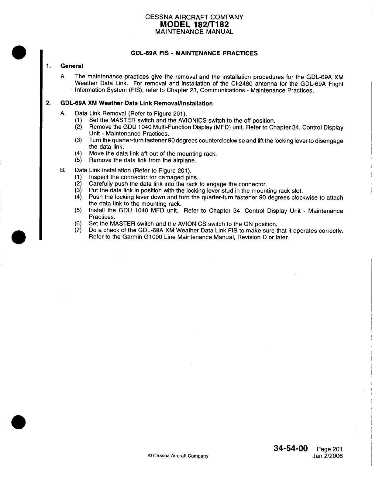
CESSNA
AIRCRAFT
COMPANY
MODEL 182/T182
MAINTENANCE
MANUAL
GDL-69A
FIS
-
MAINTENANCE PRACTICES
1.
General
A.
The
maintenance
practices
give
the
removal and
the
installation procedures
for
the
GDL-69A
XM
Weather
Data
Link.
For
removal
and
installation
of
the
CI-2480
antenna for
the GDL-69A
Flight
Information System
(FIS),
refer
to
Chapter
23,
Communications
-
Maintenance
Practices.
2.
GDL-69A
XM
Weather
Data
Link
Removal/Installation
A.
Data
Link Removal (Refer
to
Figure
201).
(1)
Set
the MASTER
switch
and the AVIONICS
switch
to the
off
position.
(2)
Remove
the
GDU
1040
Multi-Function
Display
(MFD)
unit.
Refer
to
Chapter
34,
Control Display
Unit
-
Maintenance
Practices.
(3)
Turn
the
quarter-turn
fastener
90
degrees
counterclockwise
and
lift
the
locking lever
to
disengage
the
data
link.
(4)
Move
the
data
link
aft out
of the
mounting
rack.
(5)
Remove
the
data
link
from
the
airplane.
B.
Data
Link
installation
(Refer
to
Figure
201).
(1)
Inspect the
connector
for damaged
pins.
(2)
Carefully
push
the
data
link
into the
rack
to
engage the
connector.
(3)
Put
the
data
link
in
position
with
the
locking lever stud
in
the
mounting
rack
slot.
(4)
Push
the
locking
lever
down
and
turn
the
quarter-turn
fastener
90
degrees
clockwise
to
attach
the
data
link
to the
mounting
rack.
(5)
Install
the
GDU
1040
MFD
unit. Refer
to
Chapter
34,
Control
Display
Unit
-
Maintenance
Practices.
(6)
Set
the MASTER
switch
and the AVIONICS
switch
to
the
ON
position.
(7)
Do
a
check
of
the
GDL-69A
XM
Weather
Data
Link
FIS
to
make
sure that
it
operates
correctly.
Refer
to
the
Garmin
G1000
Line
Maintenance
Manual,
Revision
D
or later.
34-54-00
Page
201
O
Cessna
Aircraft Company
Jan
2/2006
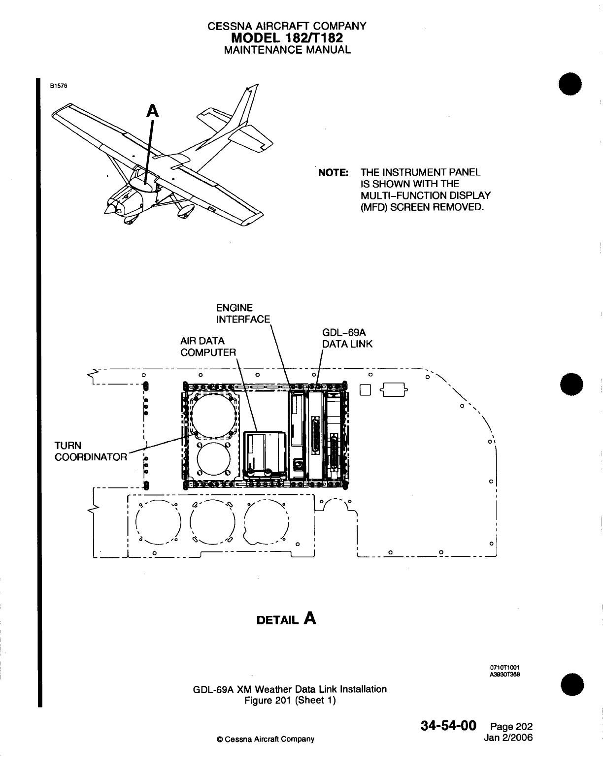
CESSNA
AIRCRAFT
COMPANY
MODEL
182/T182
MAINTENANCE
MANUAL
NOTE:
THE
INSTRUMENT
PANEL
IS
SHOWN
WITH
THE
MULTI-FUNCTION
DISPLAY
(MFD)
SCREEN REMOVED.
ENGINE
O
\
o
0I0%
-_--O--
TURN
COORI
DETAIL
A
0710T1001
A3930T368
GDL-69A
XM
Weather
Data
Link
Installation
Figure
201
(Sheet
1)
34-54-00
0
Cessna
Aircraft
Company
Page
202
Jan
2/2006
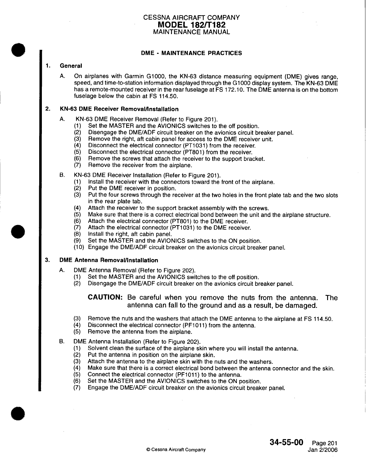
CESSNA
AIRCRAFT
COMPANY
MODEL
182/T182
MAINTENANCE
MANUAL
DME
-
MAINTENANCE PRACTICES
1.
General
A.
On
airplanes
with Garmin
G1000,
the
KN-63
distance
measuring
equipment
(DME)
gives
range,
speed,
and
time-to-station
information
displayed
through
the
G1000
display
system.
The
KN-63
DME
has
a
remote-mounted
receiver
in
the
rear
fuselage
at
FS
172.10.
The
DME
antenna
is
on
the
bottom
fuselage
below
the cabin at
FS
114.50.
2.
KN-63
DME
Receiver
Removal/Installation
A.
KN-63
DME
Receiver
Removal
(Refer
to
Figure
201).
(1)
Set
the
MASTER and
the
AVIONICS
switches
to
the
off
position.
(2)
Disengage
the
DME/ADF
circuit
breaker
on
the
avionics
circuit
breaker panel.
(3)
Remove
the
right,
aft
cabin panel
for
access
to
the
DME
receiver
unit.
(4)
Disconnect
the electrical connector
(PT1031)
from
the
receiver.
(5)
Disconnect
the electrical connector
(PT801)
from
the receiver.
(6)
Remove
the screws
that
attach
the
receiver
to the
support bracket.
(7)
Remove
the
receiver
from
the
airplane.
B.
KN-63
DME
Receiver
Installation
(Refer
to
Figure
201).
(1)
Install
the
receiver
with
the
connectors toward
the front
of
the airplane.
(2)
Put
the
DME
receiver
in
position.
(3)
Put
the
four
screws
through
the
receiver
at
the
two
holes
in
the front
plate
tab
and
the
two
slots
in
the
rear
plate
tab.
(4)
Attach the
receiver
to
the
support
bracket
assembly
with the screws.
(5)
Make sure
that
there
is
a
correct
electrical
bond between
the
unit
and the
airplane
structure.
(6)
Attach
the
electrical connector
(PT801)
to
the
DME
receiver.
(7)
Attach
the
electrical connector
(PT1031)
to
the
DME
receiver.
(8)
Install
the
right,
aft
cabin
panel.
(9)
Set
the MASTER and the AVIONICS
switches
to
the
ON
position.
(10)
Engage the
DME/ADF
circuit
breaker
on
the
avionics circuit
breaker
panel.
3.
DME
Antenna
Removal/Installation
A.
DME
Antenna
Removal
(Refer
to
Figure
202).
(1)
Set
the MASTER and
the
AVIONICS
switches
to the off
position.
(2)
Disengage
the
DME/ADF
circuit
breaker
on
the
avionics
circuit
breaker
panel.
CAUTION:
Be
careful
when
you
remove
the
nuts
from
the
antenna.
The
antenna
can
fall
to
the
ground
and
as
a result, be
damaged.
(3)
Remove
the nuts and the
washers
that
attach the
DME
antenna
to the
airplane
at
FS
114.50.
(4)
Disconnect
the
electrical
connector
(PF1011)
from
the
antenna.
(5)
Remove
the
antenna
from
the
airplane.
B.
DME
Antenna
Installation
(Refer
to
Figure
202).
(1)
Solvent
clean
the
surface
of
the
airplane
skin
where
you
will
install
the
antenna.
(2)
Put
the
antenna
in
position
on
the
airplane
skin.
(3)
Attach
the
antenna to
the
airplane
skin
with the
nuts
and
the
washers.
(4)
Make sure
that
there
is
a
correct
electrical
bond
between the
antenna
connector
and
the
skin.
(5)
Connect
the
electrical connector
(PF1011)
to the
antenna.
(6)
Set
the
MASTER
and the
AVIONICS
switches
to the
ON
position.
(7)
Engage
the
DME/ADF
circuit
breaker
on
the
avionics circuit
breaker
panel.
34-55-00
Page
201
©
Cessna
Aircraft Company
Jan
2/2006
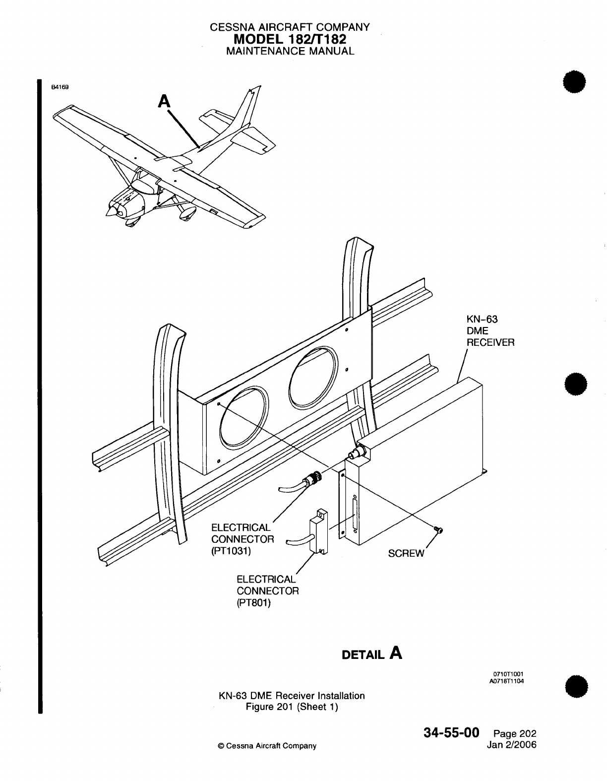
CESSNA AIRCRAFT
COMPANY
MODEL
182/T182
MAINTENANCE
MANUAL
63
EIVER
ELECTRICAL
CONNECTOR
(PT801)
DETAIL
A
0710T1001
A0718T1104
KN-63
DME
Receiver
Installation
Figure
201
(Sheet
1)
34-55-00
©
Cessna
Aircraft Company
Page 202
Jan
2/2006
A
O
4
PX
I
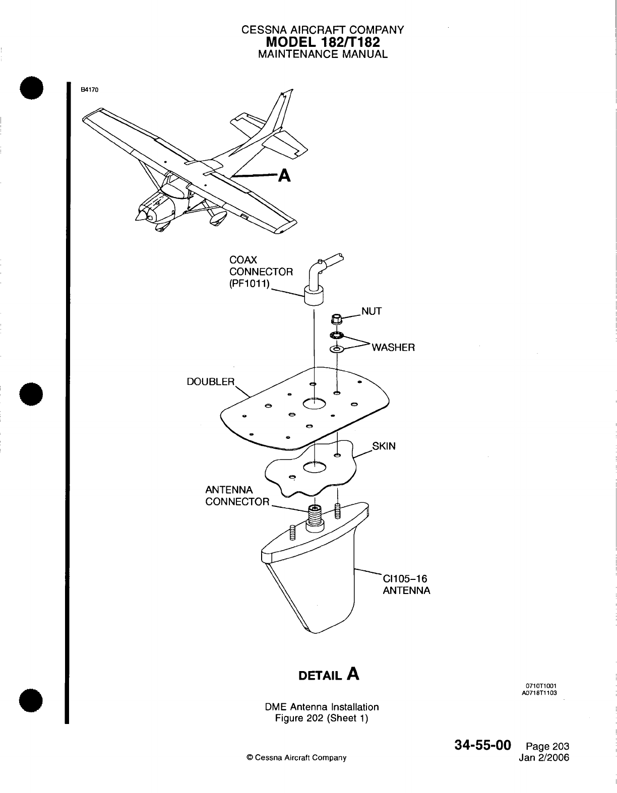
CESSNA
AIRCRAFT
COMPANY
MODEL
182fT182
MAINTENANCE
MANUAL
COAX
CONNEC
(PF1011)
-IER
05-16
TENNA
DETAIL
A
DME
Antenna Installation
Figure
202 (Sheet
1)
©
Cessna Aircraft
Company
0710T1001
A0718T1103
34-55-00
Page 203
Jan 2/2006
nJ4^
l
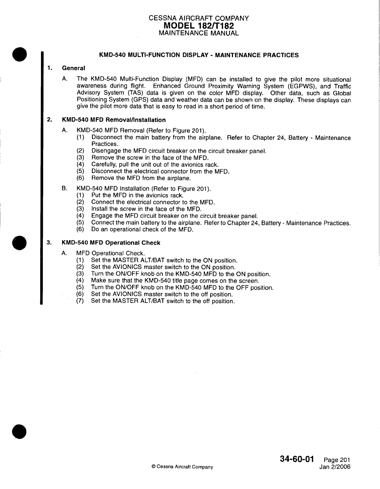
CESSNA
AIRCRAFT
COMPANY
MODEL
182/T182
MAINTENANCE
MANUAL
KMD-540
MULTI-FUNCTION DISPLAY
-
MAINTENANCE
PRACTICES
1.
General
A.
The
KMD-540
Multi-Function
Display
(MFD)
can
be
installed
to
give
the
pilot
more
situational
awareness during flight.
Enhanced Ground
Proximity
Warning System
(EGPWS),
and
Traffic
Advisory
System
(TAS)
data
is
given
on
the
color
MFD
display.
Other data,
such as
Global
Positioning
System
(GPS)
data
and
weather
data
can
be
shown
on the
display.
These
displays
can
give
the
pilot
more
data
that
is
easy
to
read
in a
short
period
of
time.
2.
KMD-540
MFD
Removal/Installation
A.
KMD-540
MFD
Removal (Refer
to
Figure
201).
(1)
Disconnect
the
main
battery
from
the
airplane.
Refer
to
Chapter
24,
Battery
-
Maintenance
Practices.
(2)
Disengage
the
MFD
circuit
breaker
on
the
circuit breaker
panel.
(3)
Remove
the screw
in
the face
of
the
MFD.
(4)
Carefully,
pull
the
unit
out
of
the
avionics
rack.
(5)
Disconnect
the
electrical
connector
from
the
MFD.
(6)
Remove
the
MFD
from
the
airplane.
B.
KMD-540
MFD
Installation
(Refer
to
Figure
201).
(1)
Put
the
MFD
in
the
avionics
rack.
(2)
Connect the electrical
connector
to
the
MFD.
(3)
Install
the
screw
in
the
face
of
the
MFD.
(4)
Engage
the
MFD
circuit
breaker
on
the
circuit
breaker
panel.
(5)
Connect the
main
battery
to
the
airplane. Refer
to
Chapter
24,
Battery
-
Maintenance
Practices.
(6)
Do
an
operational check of
the
MFD.
3.
KMD-540
MFD
Operational
Check
A.
MFD
Operational
Check.
(1)
Set
the
MASTER
ALT/BAT
switch
to
the ON
position.
(2)
Set
the AVIONICS
master switch
to
the ON
position.
(3)
Turn
the
ON/OFF
knob
on
the
KMD-540
MFD
to
the
ON
position.
(4)
Make
sure
that
the KMD-540
title
page
comes
on
the
screen.
(5)
Turn
the
ON/OFF
knob
on
the
KMD-540
MFD
to
the
OFF
position.
(6)
Set
the AVIONICS
master switch
to
the
off
position.
(7)
Set
the MASTER
ALT/BAT
switch
to
the off
position.
34-60-01
Page
201
©
Cessna
Aircraft Company
Jan
2/2006
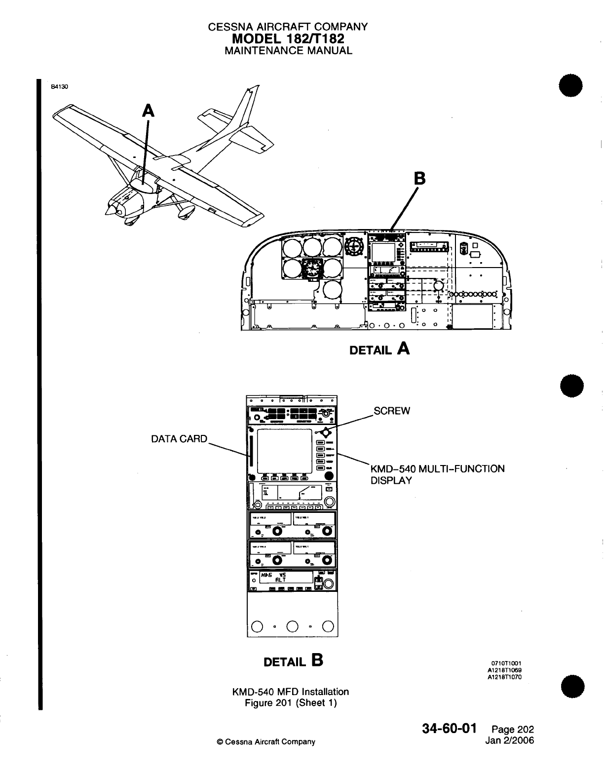
CESSNA
AIRCRAFT
COMPANY
MODEL
182/T182
MAINTENANCE
MANUAL
B
DETAIL
A
o 0 o
lo
o
o111o
o
o
DIA C ^
;o
-
SCREW
DATA
CARD
j-
-
s
KMD-540
MULTI-FUNCTION
7
(BdBt
ii
*
DISPLAY
....
.
'-;
.
o:-
o
. o
.....
II
...
0ira-
~--
'
;,7 - 00, 0
i r T ii
m
i5r
'
O~~~~
| RL
7r.H6n1LT
..
to
O 0 O
°
0
DETAIL
B
071T1
001
A1218T1069
A1218T1070
KMD-540
MFD
Installation
Figure
201
(Sheet
1)
34-60-01
0
Cessna
Aircraft Company
Page
202
Jan
2/2006
A
..
NA
I
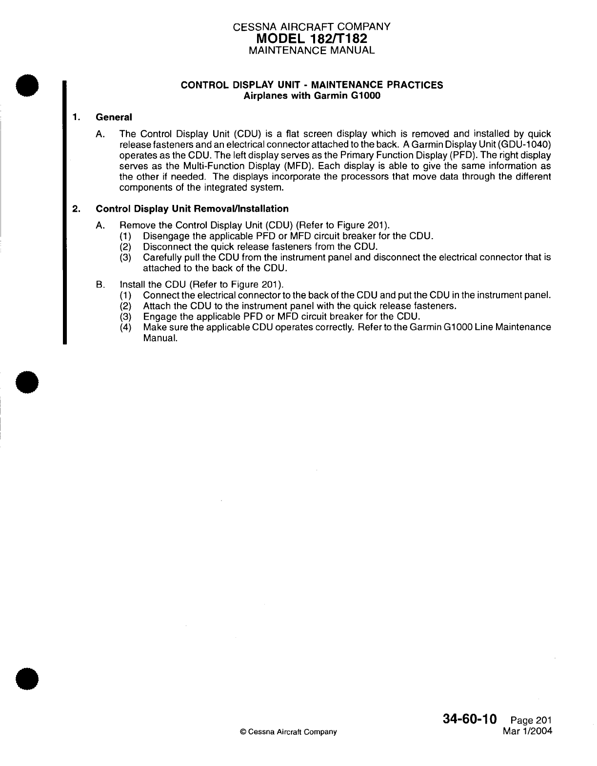
CESSNA
AIRCRAFT
COMPANY
MODEL
182/T182
MAINTENANCE
MANUAL
CONTROL
DISPLAY
UNIT
-
MAINTENANCE
PRACTICES
Airplanes
with
Garmin
G1000
1.
General
A.
The
Control
Display
Unit
(CDU)
is
a
flat
screen
display
which
is
removed and
installed
by
quick
release
fasteners
and
an
electrical
connector
attached
to
the
back.
A
Garmin
Display
Unit
(GDU-1040)
operates
as the
CDU.
The
left
display
serves
as
the
Primary
Function
Display
(PFD).
The right
display
serves
as
the
Multi-Function
Display
(MFD).
Each
display
is
able
to
give the same information
as
the
other
if
needed.
The
displays
incorporate
the
processors that
move
data
through the different
components
of
the
integrated
system.
2.
Control Display
Unit Removal/Installation
A.
Remove
the
Control
Display
Unit
(CDU)
(Refer
to
Figure
201).
(1)
Disengage
the applicable
PFD
or
MFD
circuit
breaker
for
the
CDU.
(2)
Disconnect
the
quick
release
fasteners
from
the
CDU.
(3)
Carefully
pull
the
CDU
from the
instrument
panel
and
disconnect
the
electrical
connector that
is
attached
to
the
back
of
the
CDU.
B.
Install
the
CDU
(Refer
to
Figure
201).
(1)
Connect
the
electrical connector
to
the
back
of
the
CDU and
put
the
CDU
in
the instrument
panel.
(2)
Attach the
CDU to
the
instrument
panel with
the
quick
release fasteners.
(3)
Engage the
applicable
PFD
or
MFD
circuit breaker
for
the
CDU.
(4)
Make
sure
the
applicable
CDU
operates
correctly.
Refer
to
the
Garmin G1000
Line
Maintenance
Manual.
34-60-10
Page
201
©
Cessna
Aircraft
Company
Mar
1/2004
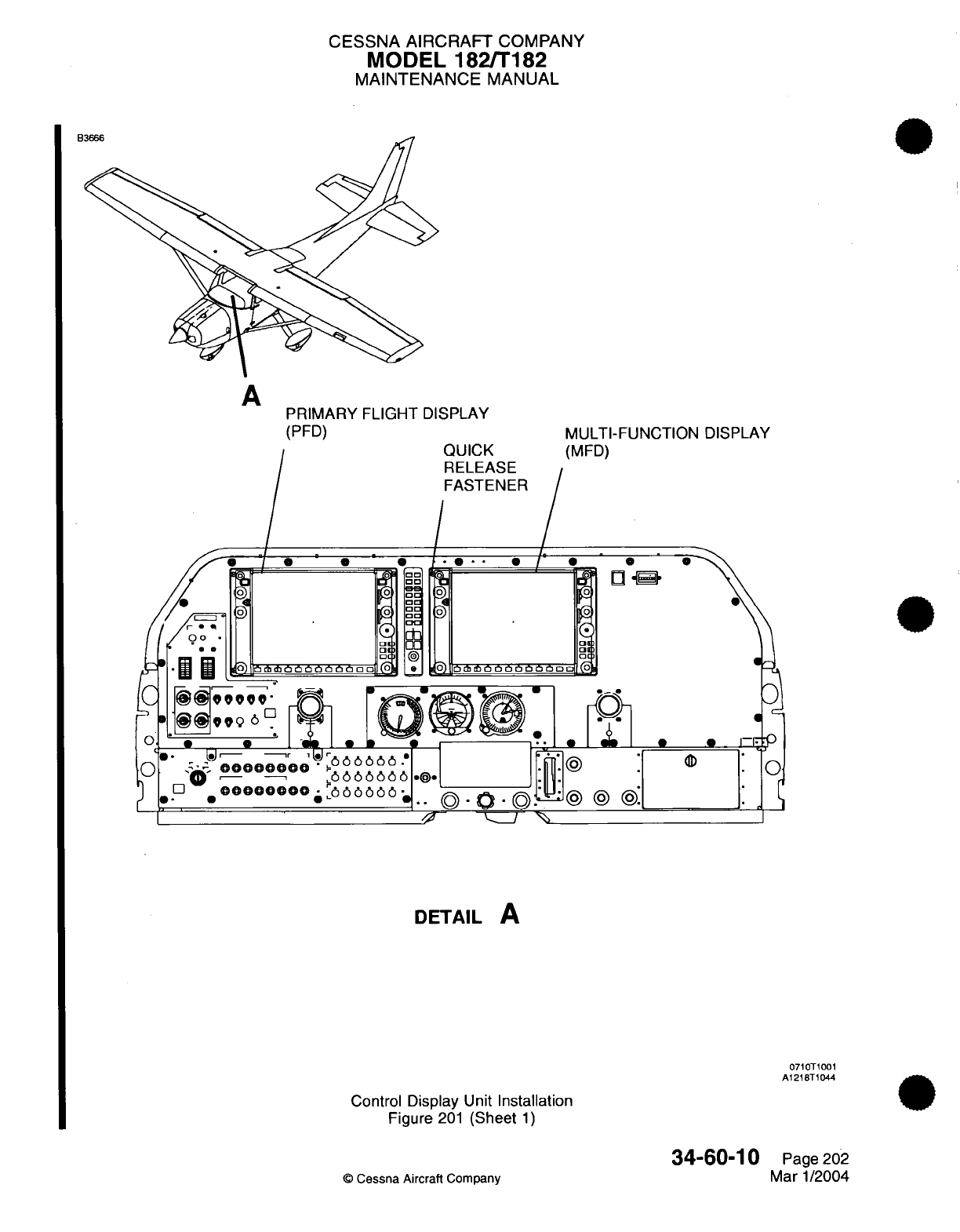
CESSNA
AIRCRAFT
COMPANY
MODEL
182/T182
MAINTENANCE
MANUAL
A
PRIMARY FLIGHT
DISPLAY
(PFD)
QUICK
RELEASE
FASTENER
__.
_ _,
.. /
//1
%1
'
=a
r
// ®
0000000
.
I -'/I ·'
Ci
6
00-
0000000
p666666
0
'
-
*
0
I
°
1
*
.f
0" ,e®®b6b 6666 -
00000000 6 6
6
6
I /D
®®®®®000®
^066666.
I'
'
-^~
0 -0 .__I
MULTI-FUNCTION
DISPLAY
(MFD)
0
0
0
.
0
0
db
I@
@ @.
DETAIL
A
0710T1001
A1218T1044
Control
Display
Unit
Installation
Figure
201
(Sheet
1)
34-60-10
©
Cessna
Aircraft Company
Page
202
Mar
1/2004
---
B

CHAPTER
OXYGEN

CESSNA
AIRCRAFT
COMPANY
MODEL
182/T182
MAINTENANCE
MANUAL
LIST
OF
EFFECTIVE PAGES
CHAPTER-SECTION-SUBJECT
35-Title
35-List
of
Effective
Pages
35-Record
of
Temporary
Revisions
35-Table
of
Contents
35-00-00
35-01-00
35-01-00
PAGE
Page
1
Page
1
Pages
201-208
©
Cessna
Aircraft Company
35
-
LIST
OF EFFECTIVE PAGES
Page
1
of
1
Jul
3/2006
DATE
Jul
3/2006
Mar 1/2005
Jul
3/2006
Temporary
Revision
Number
RECORD
OF
TEMPORARY
REVISIONS
Page
Number
Issue
Date
By
Date
Removed
By
CESSNA
AIRCRAFT
COMPANY
MODEL
182/T182
MAINTENANCE
MANUAL
CONTENTS
OXYGEN
-
GENERAL..........
.........
...........
............................
S
cope......................................................................
Tools,
Equipment
and
Materials
..............................................
Definition...................................................................
OXYGEN
-
DESCRIPTION
AND
OPERATION
.........
..........................
Description and
Operation
...................................................
OXYGEN
-
MAINTENANCE
PRACTICES
.........
.........
.....................
General
....................................................................
Precautions
.........
......
.........
.........
...............................
Replacement
of
Components
.........
.........
..............................
Oxygen
Release
Indicator
Disc...............................................
Oxygen Cylinder Inspection
Requirements
..........
..........................
Oxygen
Mask
Inspection.............................
.......................
Oxygen
Mask
Maintenance
.........
.........................................
Oxygen
System
Functional
Testing
...........................................
System
Leak
Test
............................
...............................
Oxygen
System
Charging....................................................
35-00-00
Page
1
35-00-00
Page
1
35-00-00
Page
1
35-00-00
Page
1
35-01-00
Page
1
35-01-00
Page
1
35-01-00
Page
201
35-01-00
Page
201
35-01-00
Page
201
35-01-00
Page
202
35-01-00
Page
206
35-01-00
Page
206
35-01-00
Page
206
35-01-00
Page
206
35-01-00
Page
207
35-01-00
Page
207
35-01-00
Page
207
CONTENTS
Page
1
of
1
Jul
3/2006
©
Cessna
Aircraft Company
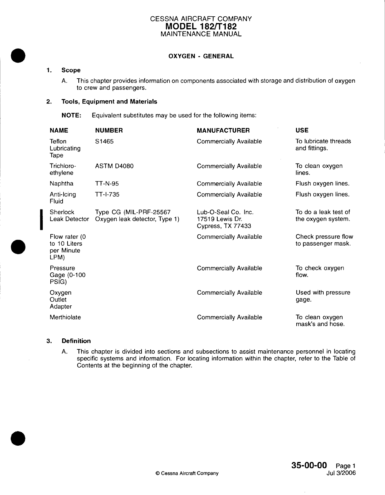
CESSNA
AIRCRAFT
COMPANY
MODEL
182/T182
MAINTENANCE
MANUAL
OXYGEN
-
GENERAL
1.
Scope
A.
This
chapter
provides information
on
components associated
with
storage
and
distribution
of
oxygen
to
crew
and
passengers.
2.
Tools,
Equipment
and
Materials
NOTE:
Equivalent
substitutes
may
be
used
for
the
following
items:
NAME
NUMBER MANUFACTURER
USE
Teflon
Lubricating
Tape
Trichloro-
ethylene
Naphtha
Anti-Icing
Fluid
Sherlock
Leak Detector
S1465 Commercially
Available
ASTM D4080
Commercially
Available
TT-N-95
Commercially
Available
Commercially
Available
TT-1-735
Type
CG
(MIL-PRF-25567
Oxygen
leak
detector, Type
1)
Flow
rater
(0
to
10
Liters
per
Minute
LPM)
Pressure
Gage (0-100
PSIG)
Oxygen
Outlet
Adapter
Merthiolate
Lub-O-Seal
Co.
Inc.
17519
Lewis
Dr.
Cypress,
TX
77433
Commercially
Available
Commercially Available
Commercially
Available
Commercially
Available
To
lubricate
threads
and
fittings.
To
clean
oxygen
lines.
Flush
oxygen
lines.
Flush
oxygen
lines.
To
do
a
leak
test
of
the
oxygen
system.
Check
pressure
flow
to
passenger
mask.
To
check
oxygen
flow.
Used
with
pressure
gage.
To
clean oxygen
mask's
and
hose.
3.
Definition
A.
This
chapter
is
divided
into
sections
and
subsections
to
assist
maintenance
personnel
in
locating
specific
systems
and
information.
For
locating information
within
the
chapter, refer
to
the
Table
of
Contents
at
the
beginning
of
the
chapter.
35-00-C(
©
Cessna Aircraft
Company
Page
1
Jul
3/2006
I
CESSNA
AIRCRAFT
COMPANY
MODEL
182/T182
MAINTENANCE
MANUAL
OXYGEN
-
DESCRIPTION AND OPERATION
1.
Description
and
Operation
A.
The
system
has
an
oxygen
cylinder
and
regulator
assembly,
filler
valve,
pressure
gage,
pressure
lines,
outlets,
and
mask
assemblies.
The
oxygen
cylinder
is
attached
aft
of
the
baggage
compartment.
The
pilot's
mask
supply
line
gives
a
larger
flow
of
oxygen
than
the
passenger
mask
supply
lines.
The
pilot's
mask
has
a
microphone,
keyed
by
a
switch
button
on
the
pilot's
control
wheel. The
filler
valve
is
found
on
the
left
side
of the
tailcone.
WARNING:
Do
not
let
oil,
grease,
or
other
lubricants
near
high-pressure
oxygen
because
it
can
cause
a
fire.
Do
not
smoke
or
have
an
open
flame
in
or
near
the
airplane
while
you
work
on
the
oxygen
system.
B.
Oxygen
flow
to the
outlet
ports
starts
when
the
oxygen
control
valve
knob,
located
in
the overhead
console,
is
put
in
the
ON
position
and
mask
hoses
are
connected
to
the
overhead
oxygen
ports.
NOTE:
Each
oxygen
port
has
a
spring-loaded
valve
which prevents
the
flow
of
oxygen
until
a
mask
hose
is
connected.
Each
mask
hose
has
an
oxygen
flow
indicator for visual
proof
of
oxygen
flow.
C.
The
oxygen system
has
an
emergency
release
indicator
with
a
green
disc
installed.
The
green
disc
will
be
pushed
out
if
there
is
too
much
oxygen
pressure
in
the
system. When
there
is
too
much
pressure
in
the
oxygen
system,
a
safety disc
inside
the
oxygen
regulator
will
release
oxygen
from the
oxygen
tank
to
the
emergency
release
indicator.
The
oxygen pressure
will
then
push
out
the
green
disc
and
release
oxygen outside
the
airplane.
The
indicator
disc
will
release oxygen
at
a
pressure
of 80
psi
+30
or
-30
psi
(551
kPa
+208
or
-208
kPa).
(1)
The
emergency
release
indicator
is
installed
inside
the
tailcone
on
the left
side. The
green
indicator
disc
can
be
seen
when
it is
not
removed,
from
the
outside
of
the
airplane
on
the
left
side
of
the
tailcone.
(2)
A
indicator disc that
has
been
removed
shows
a
possible
problem.
Refer
to
Oxygen
-
Maintenance
Practices.
NOTE:
Airplanes T18208309
and
on
do not
have
an
emergency
release
indicator
disc installed.
These airplanes
have
a
vent
found
in
the
tailcone
for
emergency oxygen
release.
D.
The
information that
follows
is
found
on
the
shoulder,
neck,
or
top
head
of
the
oxygen
cylinder
to
help
in
correct identification.
(1)
Cylinder
specification
followed
by
service
pressure.
For
example,
ICC
or
DOT-E8162.
(2)
Cylinder
serial
number.
This
is
found
below
or
directly
after
the
cylinder
specification.
The
symbol of
the
purchaser,
user, or
maker,
if
registered
with
the
Bureau
of
Explosives,
can
be
found
directly
below
the
serial
number.
The
cylinder
serial
number
can
possibly
be
found
in an
alternative
location
on the
cylinder
top
head.
(3)
Inspector's official
mark.
This
is
found
near
the
serial
number.
(4) Date
of
manufacture. This
is
the
date
of
the
first hydrostatic
test.
For
example,
6-98
for
June
1998.
The
dash between
the
month and
the year
figures
can
be
replaced
with
the mark of the
inspection agency
or
agency
doing
the
test.
For
example,
6L98.
(5)
Hydrostatic
test
date.
The
dates
of
subsequent
hydrostatic tests
must
be
steel-stamped
(month
and
year) directly
below the
original
manufacturer
date. The
dash
between
the
month
and
year
figures
can
be
replaced
with
the
mark
of
the
testing
agency.
(6)
A
Cessna
identification
placard.
This
is
found
near
the
center
of
the
cylinder
body.
(7)
Halogen
test
stamp
(if
applicable).
The
phrase
"Halogen
Tested,"
the date of
the
test
(month,
day,
and year), and
the
inspector's
mark
is
found below
the
Cessna identification
placard.
35-01-00
Page
1
©
Cessna
Aircraft Company
Mar
1/2005
CESSNA
AIRCRAFT
COMPANY
MODEL
182/T182
MAINTENANCE
MANUAL
OXYGEN
-
MAINTENANCE PRACTICES
1.
General
A.
Before you
do
maintenance
on the
oxygen system,
you must
read
and
understand
these
maintenance
practices.
2.
Precautions
WARNING:
Do
not
smoke
or
have
an
open flame
near
the
airplane
while
you
do
maintenance
on
the
oxygen
system.
Make
sure
all
electrical
power
is
disconnected
and
that
the
airplane
is
correctly
grounded.
Oils,
grease,
and
solvents
can
burn
or
explode
when
near
to
oxygen
under
pressure.
A.
Make
sure
every
port on
the
system
is
always
fully
clean and
free
of
water,
oil,
grease,
and
solvent
contamination.
B.
Put
a
cap
on
all
openings
immediately
after
you
remove
a
component.
Do
not
use
tape
or
caps
which
will
cause
moisture to
collect.
C.
Lines
and
fittings
must
be
clean
and
dry.
One of the
methods that
follow
can
be
used to
clean lines.
CAUTION:
Most
air
compressors
are
lubricated
with
oil,
and
a
minimum
amount
of
oil
can
be
carried
by
the
airstream
into
the system.
Use
a
water-
lubricated
compressor
to
blow
tubing
clean
only
when
nitrogen
or
argon
is
not
available.
The
air
must
be
clean,
dry,
and
filtered.
(1)
Wash
with
a
vapor-degreasing
solution
of
stabilized
trichloroethylene
that conforms
to
MIL-T-
7003. Then blow
tubing
clean
with
a
jet
of
nitrogen gas
(BB-N-411)
Type
1,
Class
1,
Grade
A
or
Technical
Argon
(MIL-A-18455).
(2)
Flush with naptha
that conforms
to
Specification
TT-N-95.
Then
blow
clean
and
dry
with clean,
dry
filtered
air.
(3)
Flush
with
anti-icing fluid
that conforms
to
MIL-F-5566
or
anhydrous
ethyl
alcohol.
Rinse
thoroughly
with
fresh
water
and
dry
with
a
jet
of
nitrogen
gas
(BB-N-411)
Type
1,
Class
1,
Grade
A
or Technical Argon
(MIL-A-18455).
(4)
Flush
with
hot
inhibited
alkaline
cleaner
until
free
from
oil
and grease.
Rinse
with
fresh water
and dry
with
a
jet
of
nitrogen
gas
(BB-N-411)
Type
1,
Class
1,
Grade
A
or
Technical
Argon
(MIL-A-18455).
Put
a
cap
on
all
lines
immediately
after
they
are
dry.
(5)
Do
not
fabricate pressure
lines.
Replace lines with
factory
parts,
by
part number.
(6)
Make
sure
that
your
hands
are
free
of
dirt
and
grease
before
you install
the
oxygen
tubing
or
fittings.
35-01-00
Page
201
©
Cessna Aircraft Company
Jul
3/2006
CESSNA
AIRCRAFT
COMPANY
MODEL
182/T182
MAINTENANCE
MANUAL
WARNING:
Do
not
use
tools
that
can
cause sparks.
CAUTION:
With
oxygen bottle charged,
do not put
the
control
in
the
ON
position
with
outlet
ports
(low
pressure)
open
to
the
atmosphere.
Damage
to
the
regulator metering poppet
can occur.
CAUTION: When
a
component
of
the
oxygen
system has
been
removed,
installed,
replaced,
or
the system
has
been
disassembled
in
any
way,
the
oxygen
system
must
be
purged and
a
check
for leaks
must
be
done.
D.
Use
only
S1465
Teflon
lubricating
tape
on
threads
of
male
fittings.
Do
not
use
lubricating
tape
on
coupling sleeves
or
outside
of
flares.
Use
care
to
prevent contamination
of Teflon
tape
with
oil,
grease,
or
other lubricants.
The
Teflon
tape
must
be
used
in
accordance
with
the
instructions
that
follow.
(1)
Lay
the
tape
on
the
threads
close
to
the
end of
the
fitting;
Apply the
tape
clockwise
on
standard
threads and
counter-clockwise
on
the
left-hand
threads.
(2)
Apply
enough
tension
while
you
wind to
make the
tape
form
into
thread
grooves.
(3)
After the
installation
of
the
tape
is
complete,
keep
tension
on
the tape
and
pull
it
apart
in
the
direction
it
was
applied.
The
necessary
result
is
a
ragged
edge,
which makes
the
tape
stay
in
place.
(If
you
shear
or
cut
it,
the tape
can
unwind.)
(4)
Press
the
tape
well
into
the
threads.
(5)
Make
connections.
E.
Keep
all
of
the
tools
used
for
the
installation
of
the
oxygen tubes
or
fittings
free
of
dirt,
grease,
and
oils.
NOTE:
An
accurate
record
of
the
number
of
recharges
must
be
kept
by
the owner or
his
agent
if
the
cylinder
is
recharged
an
average
of
once
every
other
day
or
more.
3.
Replacement
of
Components
A.
Use
Figure
201
to
help
you
as
you
remove
and
install components
in
the
oxygen
system.
NOTE:
Oxygen
cylinder
and
regulator
assemblies cannot
always
be
installed
in
the
field exactly
as
illustrated
in
Figure
201,
which shows
factory
installation.
CAUTION:
The
pressure regulator,
pressure gage
and
line,
and
filler
valve
must
be
removed
and
replaced
only
by
personnel
familiar
with
high-pressure
fittings.
Obey
all
maintenance precautions.
B.
Before you
remove
the cylinder, open
the
cabin
outlets
to release
the
low-pressure
line.
Disconnect
the
push-pull
control cable,
filler
line,
pressure
gage
line, and
outlet
line
from
the
regulator.
WARNING:
Cap
all
lines
immediately.
C.
Filler
Valve
Removal (Refer
to
Figure
201).
(1)
Remove
the
line
from the
quick-disconnect
valve
at
the
regulator.
(2)
Disconnect
the
chain,
but do
not
remove
the cap
from
the
filler valve.
(3)
Remove
the
screws
that
attach
the
valve
and
disconnect
the
pressure
line.
(4)
Cap
and
seat
the
pressure
line.
(5)
Remove
the
filler
valve.
D.
Filler
Valve
Installation
(Refer
to
Figure
201).
(1)
Install
the
filler
valve.
(2)
Uncap
the pressure
line and
seat.
(3)
Attach the
valve
with
the
screws
and
connect
the
pressure
line.
(4)
Connect
the
chain.
(5)
Connect
the
line
to
the
quick-disconnect valve
at
the
regulator.
35-01-00
Page
202
C
Cessna
Aircraft
Company
Jul
3/2006
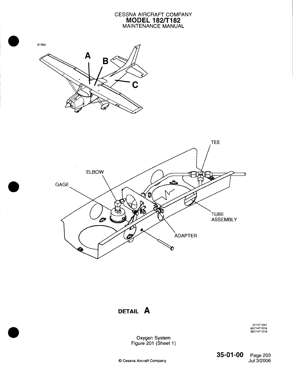
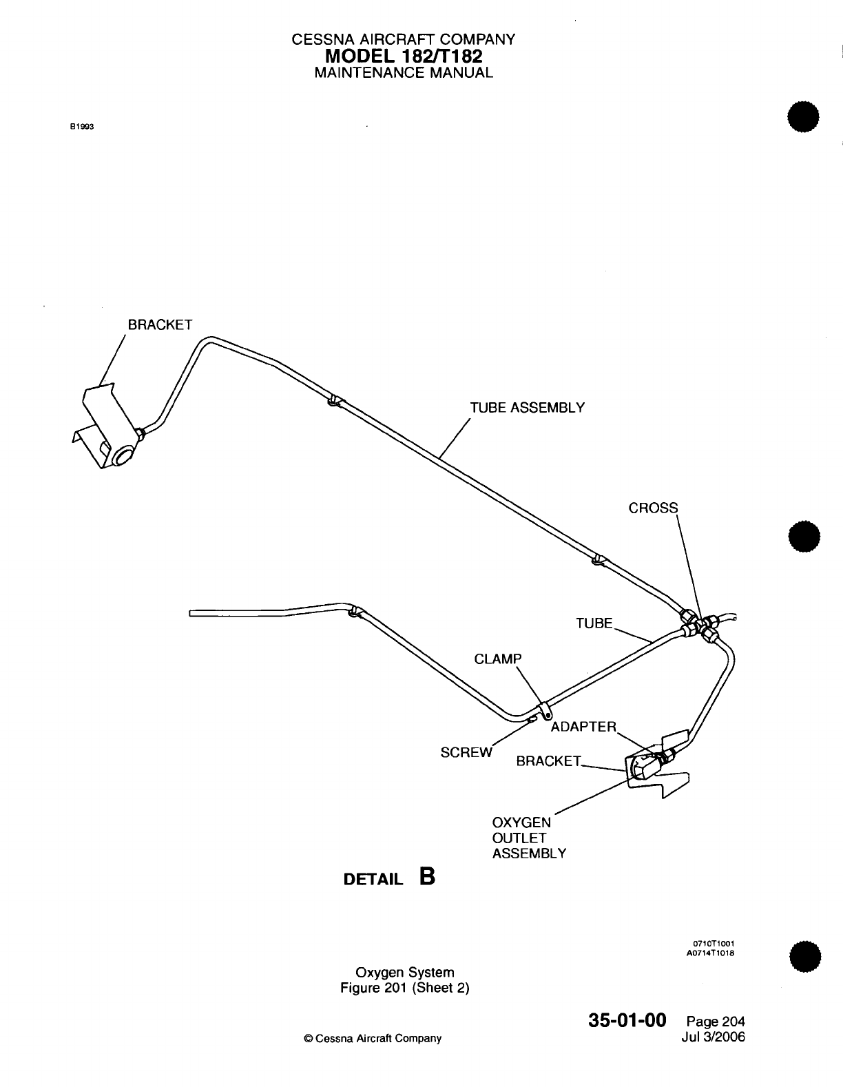
CESSNA
AIRCRAFT
COMPANY
MODEL
182/T182
MAINTENANCE
MANUAL
B1993
BRACKET
TUBE
ASSEMBLY
CROSS
SCRI
OXYGEN
OUTLET
ASSEMBLY
DETAIL
B
0710T1001
A0714T1018
Oxygen
System
Figure
201
(Sheet
2)
35-01-00
©
Cessna Aircraft
Company
Page
204
Jul
3/2006
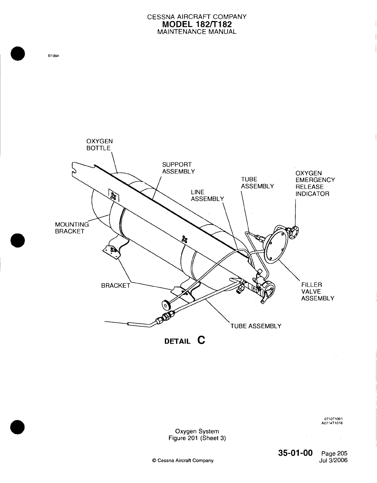
CESSNA
AIRCRAFT
COMPANY
MODEL
182/T182
MAINTENANCE
MANUAL
B1994
OXYGEN
BOTTLE
XYGEN
MERGENCY
ELEASE
IDICATOR
FILLER
VALVE
ASSEMBLY
MOUr
BRAC
DETAIL
C
0710T1001
A0714T1018
Oxygen
System
Figure
201
(Sheet
3)
35-01-00
©
Cessna
Aircraft
Company
Page 205
Jul
3/2006
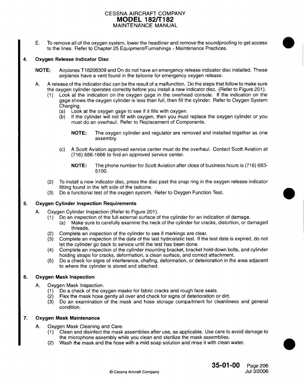
CESSNA
AIRCRAFT
COMPANY
MODEL
182/T182
MAINTENANCE
MANUAL
E.
To
remove
all
of
the
oxygen
system, lower the
headliner
and
remove
the
soundproofing
to
get
access
to
the
lines.
Refer
to
Chapter
25
Equipment/Furnishings
-
Maintenance
Practices.
4.
Oxygen
Release
Indicator
Disc
NOTE:
Airplanes
T18208309
and
On
do not
have
an
emergency
release
indicator
disc
installed.
These
airplanes
have
a
vent
found
in
the
tailcone
for
emergency
oxygen
release.
A.
A
release
of the
indicator disc
can
be
the result
of
a
malfunction.
Do
the
steps
that
follow to
make
sure
the
oxygen
cylinder
operates correctly
before you
install
a
new
indicator
disc.
(Refer
to Figure
201).
(1)
Look
at
the
indication
on the
oxygen
gage
in
the
overhead console.
If
the
indication
on
the
gage
shows
the oxygen
cylinder
is
less
than
full,
then
fill
the cylinder.
Refer
to
Oxygen System
Charging.
(a)
Look
at the
oxygen
gage
to
see
if it
fills
with
oxygen.
(b) If
the
cylinder
will
not
fill
with
oxygen,
then you
must
replace the
oxygen
cylinder
or
you
must
do
an
overhaul.
Refer
to
Replacement
of
Components.
NOTE:
The
oxygen
cylinder
and
regulator
are
removed
and
installed together
as
one
assembly.
(c) A
Scott
Aviation approved
service center
must
do
the
overhaul.
Contact
Scott Aviation
at
(716)
686-1666
to
find
an
approved
service
center.
NOTE:
The phone number
for
Scott
Aviation
after
close
of
business
hours
is
(716)
683-
5100.
(2)
To
install
a
new
indicator
disc,
press
the
disc
past the snap
ring
in
the
oxygen
release
indicator
fitting
found
in
the
left
side
of
the
tailcone.
(3)
Do
a
functional
test
of
the
oxygen
system. Refer
to
Oxygen
Function
Test.
5.
Oxygen
Cylinder Inspection
Requirements
A.
Oxygen Cylinder
Inspection
(Refer
to
Figure
201).
(1)
Do
an
inspection
of
the
full
external surface
of
the
cylinder
for
an
indication
of
damage.
(a)
Make
sure
to
carefully
examine
the
neck
of
the
cylinder
for cracks, distortion,
or
damaged
threads.
(2)
Complete
an
inspection
of
the
cylinder
to
see
if
markings
are
clear.
(3)
Complete
an
inspection
of
the
date
of
the
last
hydrostatic
test.
If
the
test
date
is
expired,
do not
let
the
cylinder
go
back
to
service
until
the
test
has been
done.
(4)
Complete
an
inspection
of
the
cylinder
mounting
bracket, bracket hold-down
bolts, and
cylinder
holding
straps
for cracks,
deformation,
a
clean
surface,
and
correct
attachment.
(5)
Do
a
check
for
signs
of
interference, chafing, deformation,
or
deterioration
in
the
area
adjacent
to
where
the
cylinder
is
stored
and
attached.
6.
Oxygen
Mask
Inspection
A.
Oxygen
Mask
Inspection.
(1)
Do
a
check
of
the
oxygen
masks
for
fabric cracks
and
rough
face seals.
(2)
Flex
the
mask
hose
gently
all
over
and
check
for
signs
of
deterioration or
dirt.
(3)
Do
an
examination
of
the
mask and
hose
storage
compartment
for cleanliness
and
general
condition.
7.
Oxygen
Mask
Maintenance
A.
Oxygen
Mask
Cleaning
and
Care.
(1)
Clean
and
disinfect
the
mask
assemblies
after
use,
as
applicable.
Use
care
to
avoid damage
to
the
microphone
assembly
while you
clean
and
sterilize
the mask
assemblies.
(2)
Wash
the
mask
and
the
hose
with
a
mild
soap
solution
and rinse
it
with
clean
water.
35-01-00
Page
206
©
Cessna
Aircraft Company
Jul 3/2006
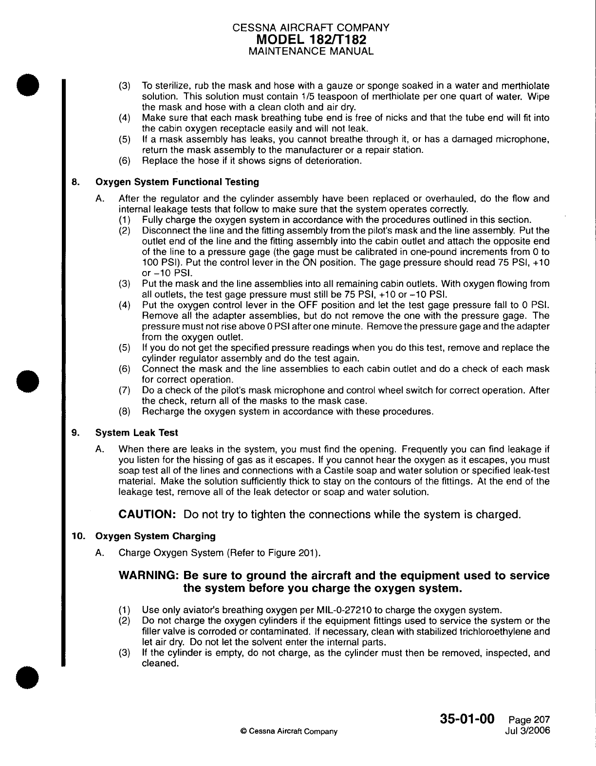
CESSNA
AIRCRAFT
COMPANY
MODEL
182/T182
MAINTENANCE
MANUAL
(3)
To
sterilize,
rub
the
mask
and
hose
with
a
gauze
or
sponge
soaked
in
a
water
and
merthiolate
solution. This
solution
must
contain
1/5
teaspoon
of
merthiolate
per
one
quart
of
water. Wipe
the
mask
and
hose
with
a clean
cloth
and
air
dry.
(4)
Make
sure
that
each mask breathing
tube
end
is
free
of
nicks
and that the
tube
end
will
fit
into
the
cabin
oxygen
receptacle
easily and
will not leak.
(5) If a
mask
assembly
has leaks, you
cannot
breathe through
it,
or
has
a
damaged microphone,
return
the
mask assembly
to
the
manufacturer
or
a
repair
station.
(6)
Replace
the hose
if it
shows
signs
of
deterioration.
8.
Oxygen
System
Functional
Testing
A.
After
the
regulator
and the
cylinder
assembly have
been
replaced
or overhauled,
do
the flow
and
internal
leakage
tests
that
follow
to
make
sure
that
the
system
operates correctly.
(1)
Fully
charge
the
oxygen
system
in
accordance
with
the
procedures
outlined
in
this section.
(2)
Disconnect the
line
and
the
fitting
assembly
from the
pilot's
mask
and
the line
assembly.
Put
the
outlet
end of
the line and the
fitting
assembly
into
the
cabin
outlet
and
attach
the
opposite
end
of
the
line
to
a
pressure
gage (the
gage must
be
calibrated
in
one-pound increments
from 0 to
100 PSI).
Put
the
control lever
in
the
ON
position.
The
gage
pressure
should
read
75
PSI,
+10
or-10
PSI.
(3)
Put
the
mask
and
the
line
assemblies
into
all
remaining
cabin
outlets.
With
oxygen flowing
from
all
outlets,
the
test
gage
pressure
must
still
be
75
PSI,
+10
or
-10
PSI.
(4)
Put
the
oxygen
control
lever
in
the
OFF
position
and
let
the
test
gage
pressure fall
to
0
PSI.
Remove
all
the
adapter assemblies,
but
do
not remove the
one
with
the
pressure
gage.
The
pressure
must
not
rise
above
0 PSI
after
one
minute.
Remove
the
pressure
gage
and
the adapter
from the
oxygen
outlet.
(5) If
you
do
not get
the specified
pressure
readings
when
you
do
this
test,
remove
and replace
the
cylinder
regulator
assembly
and
do
the
test
again.
(6)
Connect
the
mask and
the
line
assemblies
to
each
cabin
outlet
and
do a
check
of
each
mask
for correct operation.
(7)
Do
a
check
of the
pilot's
mask
microphone
and
control
wheel
switch
for
correct
operation.
After
the
check,
return
all
of the
masks
to
the
mask
case.
(8)
Recharge
the
oxygen
system
in
accordance
with
these procedures.
9. System
Leak
Test
A.
When
there
are
leaks
in
the
system, you
must
find
the
opening.
Frequently
you
can
find
leakage
if
you
listen
for
the
hissing
of
gas
as
it
escapes.
If
you
cannot
hear
the
oxygen
as
it
escapes,
you
must
soap
test
all
of
the
lines
and
connections
with
a
Castile
soap
and
water
solution or specified
leak-test
material.
Make
the
solution
sufficiently
thick
to
stay
on
the
contours
of
the
fittings.
At
the
end
of the
leakage
test,
remove
all
of
the leak
detector or
soap
and
water
solution.
CAUTION:
Do
not
try
to
tighten
the
connections
while
the
system
is
charged.
10.
Oxygen System
Charging
A.
Charge
Oxygen System
(Refer
to
Figure
201).
WARNING:
Be
sure
to
ground
the
aircraft
and
the
equipment
used
to
service
the
system
before
you
charge
the oxygen system.
(1)
Use
only
aviator's breathing oxygen
per
MIL-0-27210
to
charge the
oxygen
system.
(2)
Do
not
charge
the
oxygen
cylinders
if
the
equipment
fittings
used
to
service
the
system or
the
filler
valve
is
corroded
or
contaminated.
If
necessary,
clean
with
stabilized
trichloroethylene
and
let
air
dry. Do
not
let
the
solvent
enter
the
internal
parts.
(3) If
the
cylinder
is
empty,
do
not
charge,
as
the
cylinder
must
then
be
removed,
inspected,
and
cleaned.
35-01-00
Page
207
©
Cessna
Aircraft Company
Jul
3/2006
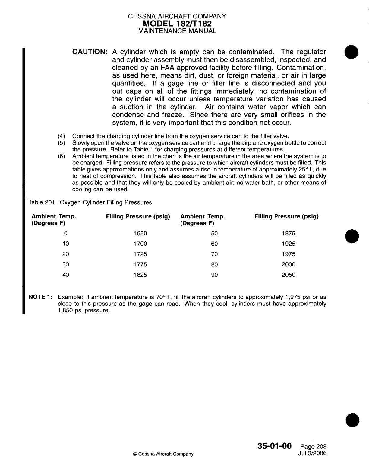
CESSNA
AIRCRAFT
COMPANY
MODEL
182/T182
MAINTENANCE MANUAL
CAUTION:
A
cylinder
which
is
empty
can
be
contaminated.
The
regulator
and
cylinder
assembly
must
then
be
disassembled,
inspected,
and
cleaned
by
an
FAA
approved
facility
before
filling.
Contamination,
as
used
here,
means
dirt,
dust,
or
foreign
material, or
air
in
large
quantities.
If a
gage
line
or
filler
line
is
disconnected
and
you
put
caps
on
all
of
the
fittings
immediately,
no
contamination
of
the
cylinder
will
occur unless
temperature variation
has
caused
a
suction
in
the
cylinder.
Air
contains
water
vapor which
can
condense
and
freeze.
Since
there
are
very
small
orifices
in
the
system,
it
is
very important
that
this
condition
not
occur.
(4)
Connect
the
charging
cylinder
line
from the
oxygen service
cart
to
the
filler
valve.
(5)
Slowly open
the
valve
on
the
oxygen
service
cart
and charge the
airplane oxygen
bottle
to
correct
the
pressure.
Refer
to Table
1
for
charging pressures
at
different
temperatures.
(6)
Ambient
temperature
listed
in
the chart
is
the
air
temperature
in
the
area
where
the
system
is
to
be
charged.
Filling
pressure
refers to
the
pressure
to
which aircraft
cylinders
must
be
filled.
This
table
gives
approximations
only
and
assumes
a
rise
in
temperature
of
approximately
25°
F,
due
to heat
of
compression.
This
table also
assumes
the
aircraft
cylinders
will
be
filled
as
quickly
as
possible
and
that
they
will
only
be
cooled by
ambient
air;
no
water
bath,
or
other
means
of
cooling
can
be
used.
Table 201.
Oxygen
Cylinder
Filling
Pressures
Ambient
Temp.
(Degrees
F)
0
10
20
Filling
Pressure
(psig)
1650
1700
1725
30
40
1775
1825
Ambient
Temp.
(Degrees
F)
50
60
70
80
90
Filling
Pressure
(psig)
1875
1925
1975
2000
2050
NOTE
1:
Example:
If
ambient
temperature
is
70°
F,
fill
the
aircraft
cylinders
to
approximately
1,975
psi or
as
close
to
this
pressure
as
the
gage can
read.
When
they
cool,
cylinders
must
have
approximately
1,850
psi
pressure.
35-01-00
©
Cessna Aircraft
Company
Page
208
Jul 3/2006

CHAPTER
VACUUM
CESSNA
AIRCRAFT
COMPANY
MODEL
182/T182
MAINTENANCE
MANUAL
LIST
OF
EFFECTIVE PAGES
CHAPTER-SECTION-SUBJECT
37-Title
37-List
of
Effective
Pages
37-Record
of
Temporary
Revisions
37-Table
of
Contents
37-00-00
37-10-00
37-10-00
PAGE
Page
1
Pages
101-103
Pages
201-209
©
Cessna
Aircraft
Company
37
-
LIST
OF
EFFECTIVE
PAGES
Page
1
of
1
Jan 2/2006
DATE
April 1/2002
April
1/2002
Jan
2/2006
Temporary
Revision
Number
RECORD OF
TEMPORARY REVISIONS
Page
Number
Issue
Date
By
Date
Removed
By
CESSNA
AIRCRAFT
COMPANY
MODEL
182/T182
MAINTENANCE
MANUAL
CONTENTS
VACUUM
SYSTEM
-
GENERAL...................................................
S
co
p
e
......................................................................
Definition
...................................................................
VACUUM
SYSTEM
-
TROUBLESHOOTING
.....................................
General
....................................................................
VACUUM
SYSTEM
-
MAINTENANCE
PRACTICES.................................
Description
and Operation
...................................................
Vacuum
Pump
Removal/Installation
..........................................
Vacuum
Manifold
Removal/Installation
........................................
Vacuum
Regulator
Filter
Removal/Installation..................................
Gyro
Filter
Removal/Installation
.............................................
Vacuum
Gage
Removal/Installation...........................................
Vacuum
Transducer
Removal/Installation
.....................................
Vacuum
Manifold
Test
(For
airplanes
with
the
Parker
Airborne
manifold)
.........
Vacuum
Pressure
Adjustment/Test
(For
airplanes
with
the
Parker
Airborne
regulator
valve
or
the
Aero
Accessories
regulator
valve)
.............................
37-00-00
Page
1
37-00-00
Page
1
37-00-00
Page
1
37-10-00
Page
101
37-10-00
Page
101
37-10-00
Page
201
37-10-00
Page
201
37-10-00
Page
201
37-10-00
Page
205
37-10-00
Page
207
37-10-00
Page
207
37-10-00
Page
207
37-10-00
Page
207
37-10-00
Page
208
37-10-00
Page
208
37
-
CONTENTS
Page
1
of
1
Jan
2/2006
©
Cessna
Aircraft
Company
CESSNA AIRCRAFT
COMPANY
MODEL
182/T182
MAINTENANCE
MANUAL
VACUUM
SYSTEM
-
GENERAL
1.
Scope
A.
This chapter
describes those
units
and
components
used
to
provide
vacuum
necessary
to
operate
the artificial
horizon
and
directional
gyros.
2.
Definition
A.
This chapter
is
divided
into
sections
to
aid
maintenance
personnel
in
locating
information.
Consulting
the
Table
of
Contents
will
further
assist
in
locating
a
particular
subject.
A
brief
definition
of
the
sections
incorporated
in
this
chapter
is
as
follows:
(1)
The
section
on
distribution
describes those
components
used
in
the
distribution
of
vacuum
air.
(2)
The
section
on
indicating describes those
components
used
to
indicate
relative
vacuum
pressure
in
the
system.
37-00-00
Page
1
April
1/2002
©
Cessna
Aircraft
Company
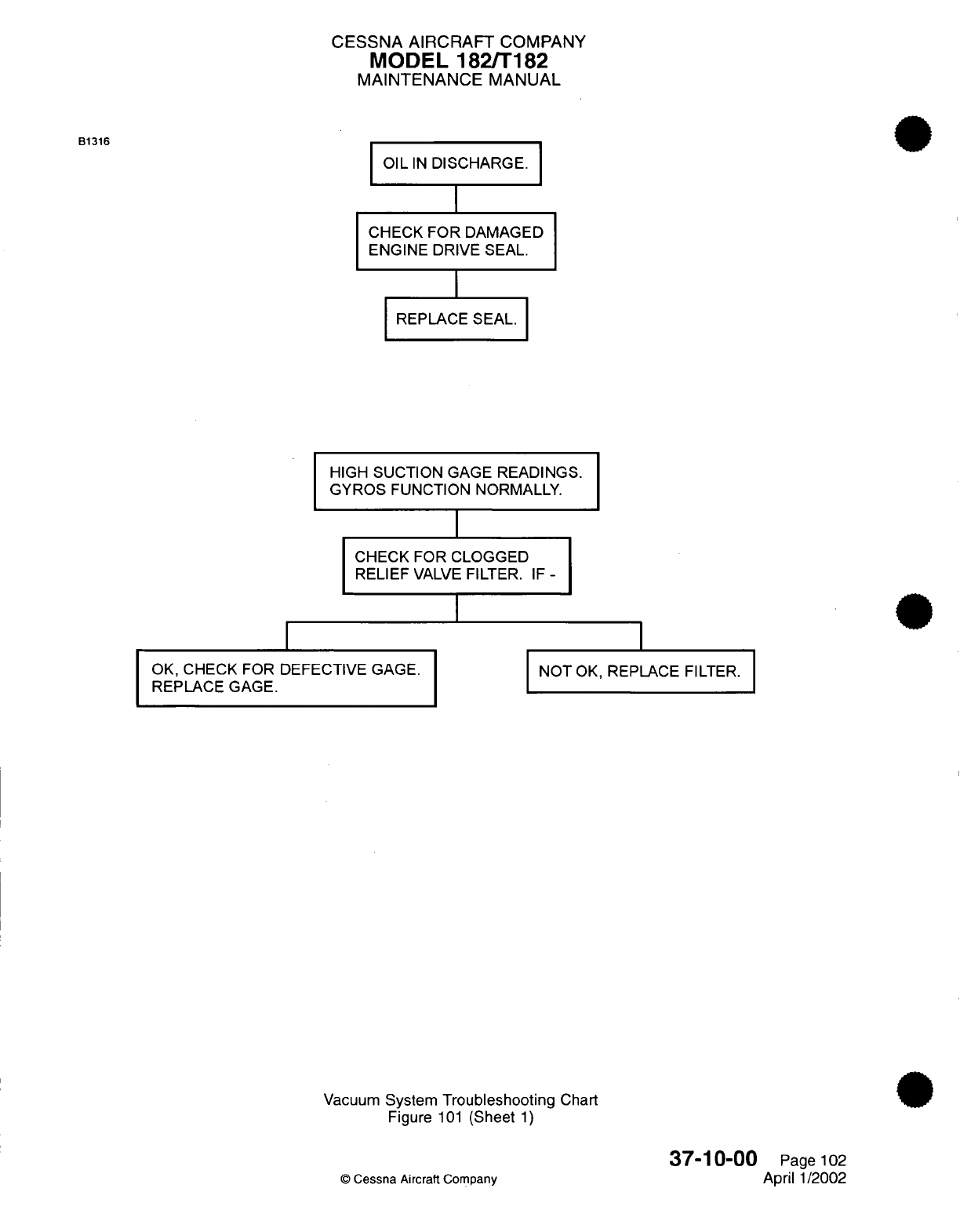
B1316
OK,
CHECK
FOR
REPLACE
GAGE.
CESSNA AIRCRAFT
COMPANY
MODEL
182/T182
MAINTENANCE
MANUAL
OIL
IN
DISCHARGE.
CHECK
FOR
DAMAGED
ENGINE
DRIVE
SEAL.
REPLACE
SEAL.
HIGH
SUCTION
GAGE
READINGS.
GYROS
FUNCTION NORMALLY.
I
CHECK FOR
CLOGGED
RELIEF
VALVE
FILTER.
IF
-
DEFECTIVE
GAGE.
INOT
OK,
REPLACE
FILTER.
DEFECTIVE
GAGE.
NOT
OK,
REPLACE
FILTER.
Vacuum
System
Troubleshooting
Chart
Figure
101
(Sheet
1)
©
Cessna
Aircraft Company
37-10-00
Page
102
April
1/2002
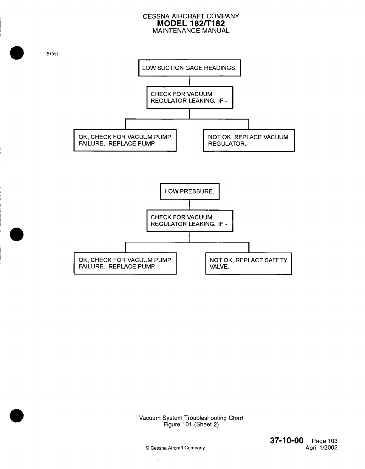
CESSNA
AIRCRAFT
COMPANY
MODEL
182/T182
MAINTENANCE
MANUAL
B1317
LOW
SUCTION
GAGE
READINGS.
I
CHCKFR
ACU
CHECK
FOR
VACUUM
REGULATOR LEAKING.
I
OK,
CHECK
FOR
VACUUM
PUMP
NC
FAILURE.
REPLACE
PUMP.
RE
LOW
PRESSURE.
CHECK
FOR
VACUUM
REGULATOR
LEAKING.
I
OK,
CHECK FOR
VACUUM
PUMP
FAILURE.
REPLACE
PUMP.
)T OK,
REPLACE
VACUUM
G
ULATOR.
IF-
NOT OK,
VALVE.
REPLACE
SAFETY
Vacuum
System
Troubleshooting
Chart
Figure
101
(Sheet
2)
©
Cessna Aircraft
Company
37-10-00
Page
103
April 1/2002
IF
-
I
I
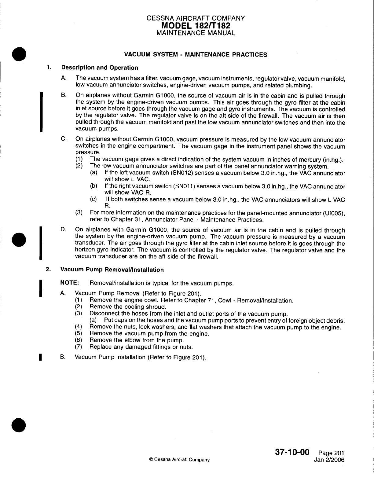
CESSNA
AIRCRAFT
COMPANY
MODEL
182/T182
MAINTENANCE
MANUAL
VACUUM
SYSTEM
-
MAINTENANCE PRACTICES
1.
Description
and
Operation
A.
The
vacuum
system has
a
filter, vacuum gage,
vacuum instruments,
regulator
valve,
vacuum
manifold,
low
vacuum
annunciator
switches, engine-driven
vacuum pumps,
and
related
plumbing.
B.
On
airplanes
without
Garmin
G1000,
the
source
of
vacuum
air
is
in
the
cabin
and
is
pulled through
the
system
by
the
engine-driven
vacuum
pumps.
This air goes
through
the
gyro
filter
at
the cabin
inlet
source
before
it
goes
through
the vacuum gage
and
gyro
instruments.
The
vacuum
is
controlled
by
the
regulator
valve.
The regulator
valve
is
on
the
aft
side of the
firewall.
The
vacuum
air
is
then
pulled through
the
vacuum
manifold
and
past
the
low
vacuum
annunciator
switches
and
then
into
the
vacuum
pumps.
C.
On
airplanes without
Garmin
G1000, vacuum
pressure
is
measured by
the
low
vacuum
annunciator
switches
in
the
engine compartment.
The
vacuum
gage
in
the
instrument
panel
shows
the
vacuum
pressure.
(1)
The
vacuum
gage
gives
a
direct
indication
of the
system
vacuum
in
inches
of
mercury
(in.hg.).
(2)
The low
vacuum
annunciator
switches
are
part
of
the
panel
annunciator
warning
system.
(a) If
the
left
vacuum
switch
(SN012)
senses
a
vacuum
below
3.0
in.hg.,
the
VAC
annunciator
will
show
L
VAC.
(b) If
the right
vacuum
switch
(SN011)
senses
a
vacuum
below
3.0
in.hg.,
the
VAC
annunciator
will
show
VAC
R.
(c) If
both
switches
sense
a
vacuum
below
3.0
in.hg.,
the
VAC
annunciators
will
show
L
VAC
R.
(3)
For
more
information
on
the
maintenance
practices
for
the
panel-mounted
annunciator
(UI005),
refer
to
Chapter
31,
Annunciator
Panel
-
Maintenance
Practices.
D.
On
airplanes
with
Garmin
G1000,
the
source
of
vacuum
air
is
in
the
cabin
and
is
pulled
through
the
system
by
the
engine-driven
vacuum
pump.
The
vacuum
pressure
is
measured
by
a
vacuum
transducer.
The
air
goes
through
the
gyro
filter
at
the
cabin
inlet
source
before
it
is
goes through
the
horizon
gyro indicator.
The
vacuum
is
controlled
by
the
regulator
valve.
The
regulator
valve
and
the
vacuum
transducer
are
on the
aft side of
the
firewall.
2.
Vacuum Pump
Removal/Installation
NOTE:
Removal/installation
is
typical
for
the vacuum
pumps.
A.
Vacuum
Pump
Removal (Refer
to
Figure
201).
(1)
Remove
the
engine
cowl. Refer
to
Chapter
71,
Cowl
-
Removal/Installation.
(2)
Remove the
cooling
shroud.
(3)
Disconnect
the
hoses
from
the
inlet
and
outlet
ports
of the
vacuum
pump.
(a)
Put
caps
on
the hoses
and
the vacuum
pump
ports
to
prevent
entry
of foreign
object
debris.
(4)
Remove
the
nuts,
lock washers,
and
flat
washers that
attach
the
vacuum pump
to
the engine.
(5)
Remove
the vacuum
pump from
the
engine.
(6)
Remove
the elbow
from
the pump.
(7)
Replace any
damaged
fittings
or
nuts.
B.
Vacuum
Pump
Installation
(Refer to Figure
201).
37-10-00
Page
201
©
Cessna
Aircraft
Company
Jan
2/2006
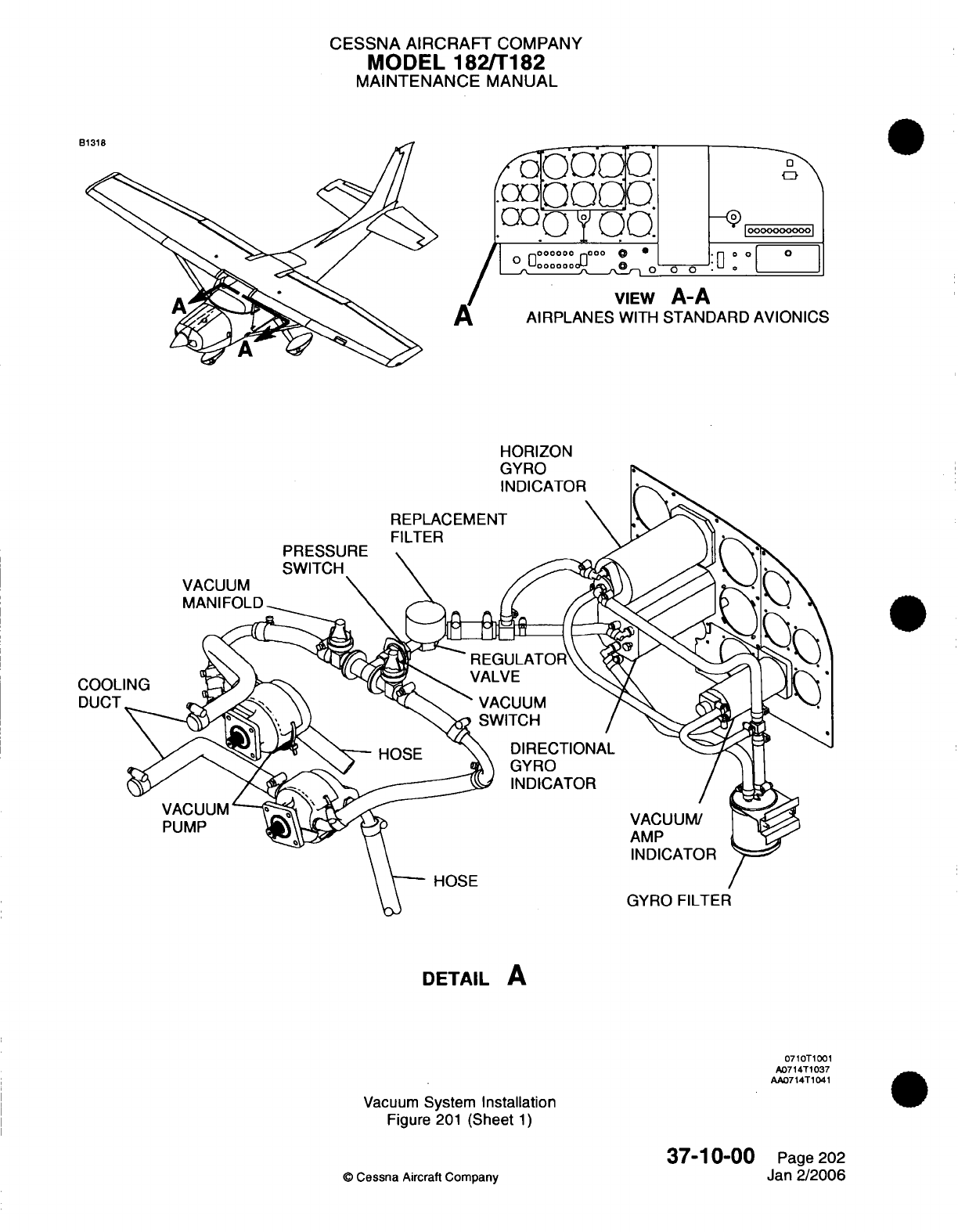
CESSNA
AIRCRAFT
COMPANY
MODEL
182/T182
MAINTENANCE
MANUAL
O
.O
'o o I
0
0
O°°°°°°
-I
° ° 0
0o
o
|
o
0
:g
»
VIEW
A-A
A
AIRPLANES
WITH
STANDARD
AVIONICS
HORIZON
PRESSURE
SWITCH
REPLACEMENT
FILTER
DIRECTIONAL
GYRO
INDICATOR
VACUUM/
AMP
INDICATOR
HOSE
GYRO
FILTER
DETAIL
A
0710T1001
A0714T1037
AA0714T1041
Vacuum
System
Installation
Figure
201
(Sheet
1)
37-10-00
©
Cessna
Aircraft
Company
VACUUM
MANIFOLD
COOLI
DUCT
VACUUM'
PUMP
Page 202
Jan
2/2006
D-11Q
c
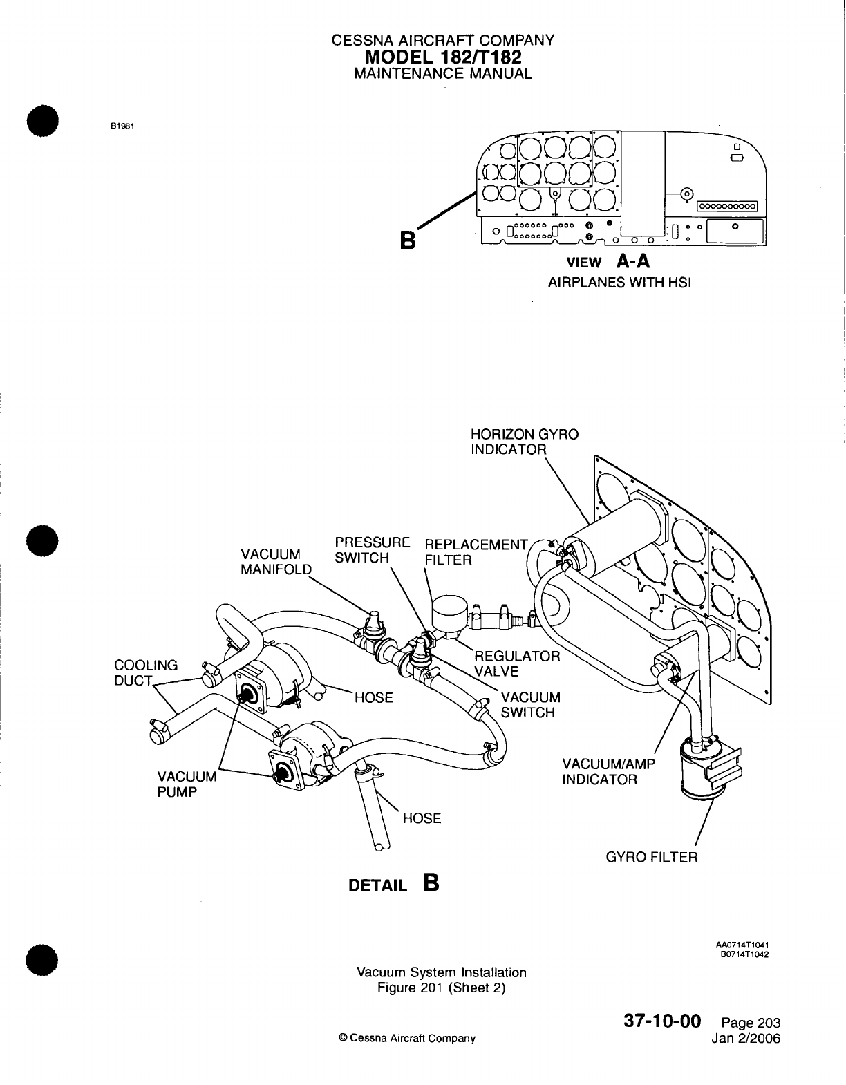
CESSNA
AIRCRAFT
COMPANY
MODEL
182/T182
MAINTENANCE
MANUAL
B1981
B
/o-
T.OO
|°0°°oe:
oo°o
o o
:
o
I
VIEW
A-A
AIRPLANES
WITH
HSI
HORIZON
GYRO
INDICATOR
GYRO
FILTER
DETAIL
B
AA0714T1041
B0714T1042
Vacuum
System
Installation
Figure
201
(Sheet
2)
37-10-00
©
Cessna
Aircraft
Company Page
203
Jan 2/2006
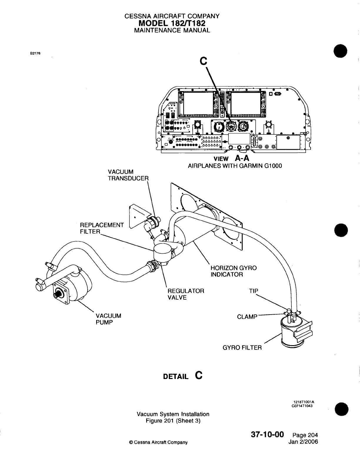
CESSNA
AIRCRAFT
COMPANY
MODEL
182/T182
MAINTENANCE
MANUAL
C
B2176
VACUUM
TRANSDUCER
VIEW
A-A
AIRPLANES
WITH GARMIN G1000
REPLACEMENT
HORIZON
GYRO
INDICATOR
REGULATOR
VALVE
VACUUM
PUMP
TIP
CLAMP
DETAIL
C
1218T1001A
C0714T1043
Vacuum
System
Installation
Figure
201
(Sheet
3)
37-10-00
C
Cessna
Aircraft Company
Page
204
Jan
2/2006
,1l
I I v I
IIL
I L-
I
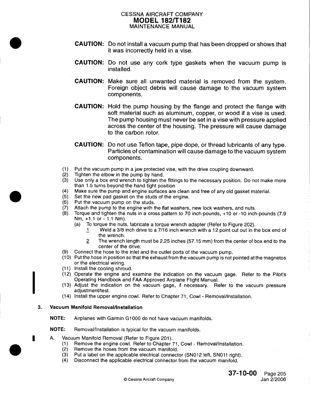
CESSNA
AIRCRAFT
COMPANY
MODEL
182/T182
MAINTENANCE
MANUAL
CAUTION:
CAUTION:
CAUTION:
CAUTION:
CAUTION:
Do
not install
a
vacuum pump
that
has been
dropped
or
shows
that
it
was
incorrectly
held
in
a
vise.
Do
not
use
any
cork
type gaskets
when
the
vacuum pump
is
installed.
Make sure
all
unwanted
material
is
removed from the
system.
Foreign
object
debris
will
cause
damage
to
the vacuum
system
components.
Hold
the
pump
housing
by
the
flange
and
protect the
flange
with
soft material such
as
aluminum,
copper,
or
wood
if
a
vise
is
used.
The pump
housing
must
never
be
set
in
a
vise
with
pressure
applied
across
the
center
of
the
housing.
The
pressure
will
cause damage
to
the
carbon
rotor.
Do
not use
Teflon
tape,
pipe
dope,
or
thread
lubricants
of
any
type.
Particles
of
contamination
will
cause damage
to
the
vacuum
system
components.
(1)
Put
the vacuum
pump
in
a
jaw protected
vise,
with
the
drive
coupling
downward.
(2)
Tighten
the
elbow
in
the
pump by hand.
(3)
Use
only
a
box
end
wrench
to
tighten
the
fittings
to
the
necessary
position.
Do
not
make
more
than
1.5
turns
beyond
the hand
tight
position
(4)
Make sure
the
pump and
engine
surfaces
are
clean
and
free
of any
old
gasket
material.
(5)
Set
the new
pad
gasket
on
the
studs
of
the
engine.
(6)
Put
the
vacuum
pump
on
the
studs.
(7)
Attach
the
pump
to
the
engine
with
the
flat washers,
new
lock
washers,
and
nuts.
(8)
Torque
and
tighten
the
nuts
in a
cross
pattern
to
70
inch-pounds,
+10
or
-10
inch-pounds
(7.9
Nm,
+1.1
or-
1.1
Nm).
(a)
To
torque
the
nuts,
fabricate
a
torque
wrench
adapter
(Refer
to
Figure 202).
1
Weld
a
3/8
inch
drive
to
a
7/16
inch wrench
with
a
12
point cut
out
in
the
box
end
of
the
wrench.
2
The wrench
length must
be
2.25
inches
(57.15
mm)
from
the
center
of box end
to the
center
of the
drive.
(9)
Connect the
hose
to
the inlet
and
the
outlet
ports
of the
vacuum
pump.
(10) Put
the
hose
in
position
so
that
the
exhaust
from the
vacuum
pump
is
not
pointed
at
the magnetos
or
the
electrical
wiring.
(11)
Install
the
cooling
shroud.
(12)
Operate the
engine
and
examine
the
indication
on the
vacuum
gage.
Refer
to
the
Pilot's
Operating
Handbook
and
FAA
Approved
Airplane Flight Manual.
(13)
Adjust
the
indication
on
the vacuum
gage,
if
necessary. Refer
to
the vacuum
pressure
adjustment/test.
(14)
Install the
upper
engine
cowl.
Refer
to
Chapter
71,
Cowl
-
Removal/Installation.
3.
Vacuum
Manifold
Removal/Installation
NOTE:
Airplanes
with Garmin
G1000
do
not
have
vacuum
manifolds.
NOTE:
Removal/Installation
is
typical for
the
vacuum
manifolds.
A.
Vacuum
Manifold
Removal (Refer
to
Figure
201).
(1)
Remove
the
engine
cowl. Refer to
Chapter
71,
Cowl
-
Removal/Installation.
(2)
Remove
the
hoses
from
the
vacuum manifold.
(3)
Put
a
label on
the
applicable
electrical
connector
(SN012
left,
SN011
right).
(4)
Disconnect
the
applicable
electrical
connector
from
the
vacuum
manifold.
37-10-00
©
Cessna Aircraft
Company
Page
205
Jan
2/2006
I
I
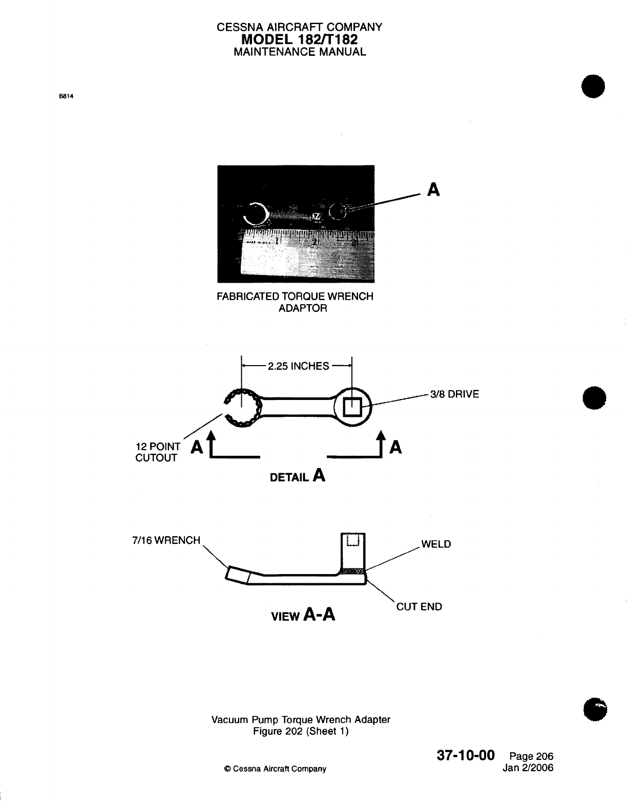
CESSNA AIRCRAFT
COMPANY
MODEL
1821T182
MAINTENANCE
MANUAL
B814
FABRICATED
TORQUE
WRENCH
ADAPTOR
-
2.25
INCHES
-
/o
12
POINT
At
CUTOUT
@
-^-
tn
3/8
DRIVE
tA
DETAIL
A
7/16
WRENCH
\C^
A
A
VIEW
A-A
Vacuum Pump
Torque
Wrench Adapter
Figure
202
(Sheet
1)
WELD
END
37-10-00
©
Cessna
Aircraft
Company
Page
206
Jan
2/2006
A
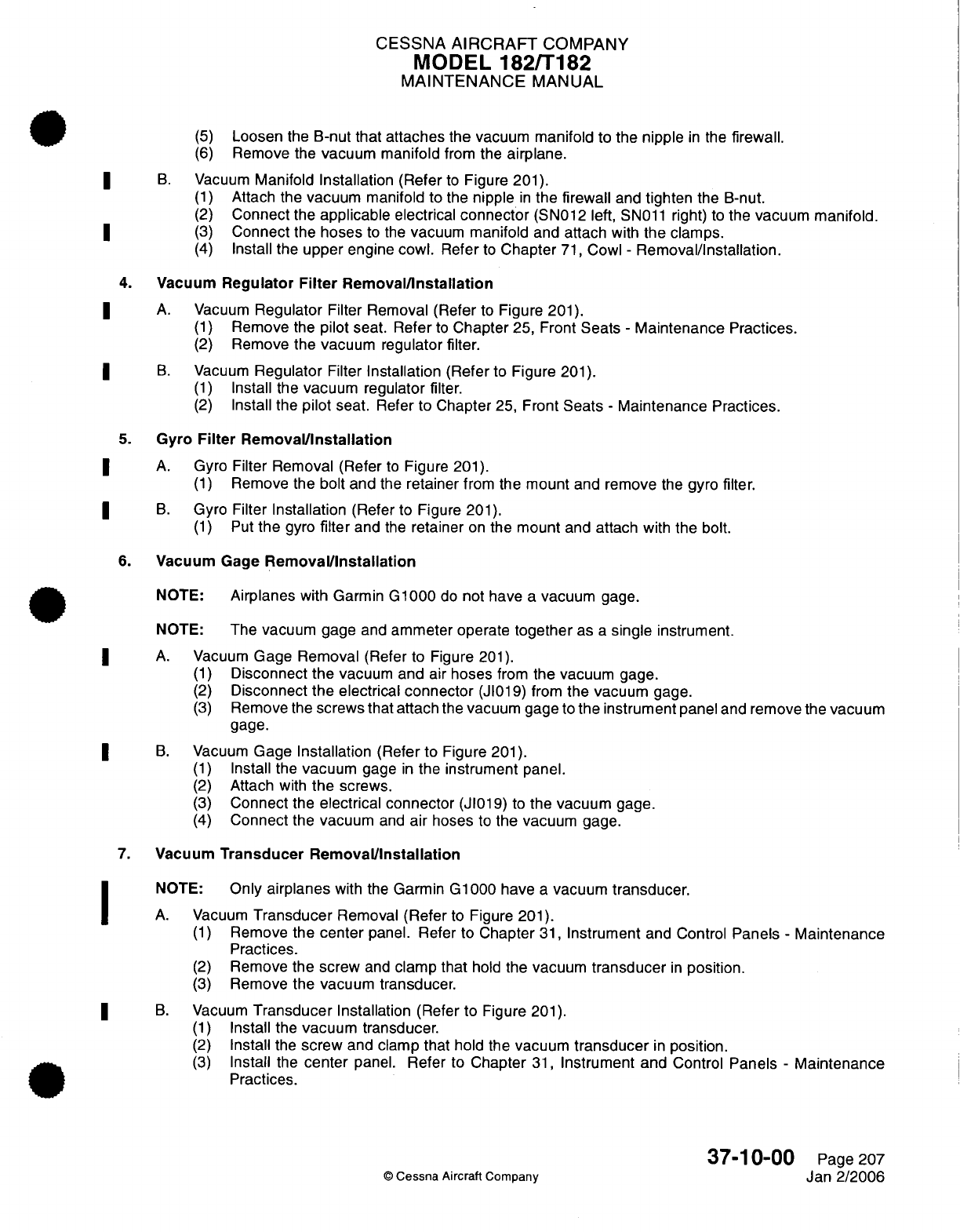
CESSNA
AIRCRAFT
COMPANY
MODEL
182/T182
MAINTENANCE
MANUAL
(5)
Loosen
the
B-nut
that attaches
the
vacuum
manifold
to
the nipple
in
the
firewall.
(6)
Remove
the
vacuum manifold
from
the
airplane.
B.
Vacuum
Manifold
Installation
(Refer
to
Figure
201).
(1)
Attach the
vacuum
manifold
to the
nipple
in
the firewall
and
tighten
the B-nut.
(2)
Connect
the
applicable
electrical
connector
(SN012
left,
SN011
right)
to
the
vacuum
manifold.
(3)
Connect
the
hoses
to the
vacuum
manifold
and
attach
with
the
clamps.
(4)
Install the
upper
engine
cowl.
Refer
to
Chapter
71,
Cowl
-
Removal/Installation.
4.
Vacuum
Regulator
Filter
Removal/Installation
A.
Vacuum
Regulator
Filter Removal (Refer
to
Figure
201).
(1)
Remove
the
pilot
seat.
Refer
to
Chapter
25, Front
Seats
-
Maintenance
Practices.
(2)
Remove
the vacuum regulator
filter.
B.
Vacuum
Regulator
Filter
Installation
(Refer
to
Figure
201).
(1)
Install the
vacuum regulator filter.
(2)
Install the
pilot
seat.
Refer
to
Chapter
25,
Front
Seats
-
Maintenance Practices.
5.
Gyro
Filter
Removal/Installation
A.
Gyro
Filter Removal
(Refer
to
Figure
201).
(1)
Remove the
bolt
and
the
retainer
from
the
mount
and
remove
the
gyro
filter.
B.
Gyro
Filter
Installation
(Refer to
Figure
201).
(1)
Put
the
gyro
filter
and
the
retainer
on
the
mount
and
attach
with
the
bolt.
6.
Vacuum Gage
Removal/Installation
NOTE:
Airplanes
with
Garmin
G1000
do
not
have
a
vacuum
gage.
NOTE:
The vacuum
gage
and
ammeter operate
together
as
a
single
instrument.
A.
Vacuum
Gage
Removal
(Refer
to
Figure
201).
(1)
Disconnect
the
vacuum
and air
hoses
from
the vacuum
gage.
(2)
Disconnect
the electrical
connector
(JI019)
from
the vacuum
gage.
(3)
Remove
the
screws that attach
the
vacuum
gage
to
the instrument panel
and
remove
the
vacuum
gage.
B.
Vacuum
Gage
Installation
(Refer
to Figure
201).
(1)
Install
the
vacuum
gage
in
the
instrument
panel.
(2)
Attach
with
the
screws.
(3)
Connect
the
electrical connector
(JI019)
to
the
vacuum
gage.
(4)
Connect
the
vacuum
and
air
hoses
to
the vacuum
gage.
7.
Vacuum
Transducer
Removal/Installation
NOTE:
Only
airplanes
with
the
Garmin G1000 have
a
vacuum
transducer.
A.
Vacuum
Transducer
Removal
(Refer
to
Figure
201).
(1)
Remove
the
center
panel.
Refer to
Chapter
31,
Instrument
and
Control
Panels
-
Maintenance
Practices.
(2)
Remove
the
screw
and
clamp
that
hold
the
vacuum
transducer
in
position.
(3)
Remove
the vacuum
transducer.
B.
Vacuum
Transducer
Installation
(Refer to
Figure
201).
(1)
Install
the
vacuum
transducer.
(2)
Install
the
screw
and
clamp
that
hold
the
vacuum
transducer
in
position.
(3)
Install
the
center
panel.
Refer
to
Chapter
31,
Instrument and
Control
Panels
-
Maintenance
Practices.
37-10-00
Page 207
0
Cessna Aircraft Company
Jan
2/2006
CESSNA
AIRCRAFT
COMPANY
MODEL
182/T182
MAINTENANCE
MANUAL
8.
Vacuum
Manifold
Test
(For
airplanes with
the
Parker
Airborne
manifold)
A.
The
vacuum
manifold
must
be
tested periodically
to determine
its
condition
and
serviceability.
Refer
to
Chapter
5,
Inspection
Time
Limits
for
inspection
intervals. Refer
to
Parker
Hannifin
Corporation/
Airborne
Division's Product
Reference
Memo
#39
(or
latest revision)
for
the
procedures.
9.
Vacuum
Pressure
Adjustment/Test
(For
airplanes
with
the
Parker
Airborne
regulator valve
or
the
Aero
Accessories
regulator valve)
NOTE: Before
the adjustment
procedure,
the
entire
pneumatic
system
must
be
inspected
and
tested for
leaks,
restrictions,
and unserviceable
components.
Failure
to
correct
all
system
anomalies
will
lead
to
reduced
dry
air
pump
service
life.
A.
Prepare the
System for
the
Test
(Refer
to
Figure
201).
(1)
Remove
the
gyro
(central
air)
filter.
B.
Do
a
Check
of
the
Regulator
Valve.
CAUTION:
Make
sure
that
the temperature
of
the
engine does
not
go
above the
maximum
engine
temperature during the
adjustment/test
of
the regulator
valve.
NOTE:
At
engine
speeds
between
1200 RPM
and
full throttle,
suction must
fall
between 4.5
in.hg.
and
5.5
in.hg. (green range
on
gage).
(1)
Start
the
engine,
warm
up
to
the
normal
operating
temperature,
and
run
at
static
RPM.
Refer
to
Pilot's
Operating
Handbook
and
FAA
Approved
Airplane
Flight
Manual.
(2)
Make
sure
the
suction
gage
indication does
not
go
above
5.5
in.hg.
(3)
Run
the
engine
at
1200
RPM
and
make sure
the
gage
indication
does
not
go
below
4.5 in.hg.
(4) If
the
suction
indication
falls
outside
of
the range,
shut
down
the
engine
and
adjust
the
regulator
valve
in
the
steps that follow.
(a)
Bend
the
locking
tab
upward
on
the lower
surface
of
the
regulator valve.
CAUTION:
Be
careful
when you
turn
the
adjustment
screw.
Do
not turn
it
too
much
in
either
direction.
When
you
turn
it
too
much
in
either
direction, damage
can
occur
to
the
equipment.
(b)
Turn the
adjustment
screw
on
the
lower surface of
the
regulator
valve
in
the
direction
to
increase
or
decrease
the
pressure
as
necessary.
NOTE:
As
you
face
the
adjustment
screw,
when
you turn
it
clockwise
the
pressure
increases.
When
you
turn
it
counterclockwise,
the
pressure
decreases.
(c)
Tap
the
regulator after
you adjust
it
to
help
reset
the
components.
(d)
Bend
the
locking
tab
downward
to
keep
the
adjustment
screw
in
place
when the
correct
pressure
has
been
set.
(5)
Run
the engine
at
static
RPM
and make
sure
the gage
indication does
not
go
above
5.5 in.hg.
(6)
Run
the engine
at 1200
RPM
and make sure
the
gage
indication
does not
go
below
4.5 in.hg.
(7)
Shut down
the
engine.
(a)
For
airplanes
without
the
Garmin
G1000, make
sure
that
the
L
VAC
R
lights
come
on.
(b)
For
airplanes with
the Garmin
G1000, make sure
that
the
low
vacuum
annunciator
visual
and
aural
warnings
come
on.
(8)
Attach
the
filter
element
to
the
gyro
(central
air)
filter.
(9)
Before
you
start
the
engine,
make
sure
that
the
low
vacuum
annunciations
are
on.
(a)
For
airplanes
without
the
Garmin
G1000, make
sure
that
the
L
VAC
R
lights
are
on.
(b)
For
airplanes
with the
Garmin
G1000,
make
sure
that the
low
vacuum
annunciator
visual
warning
is
on.
37-10-00
Page
208
©
Cessna
Aircraft
Comoanv
Jan 2/2006
CESSNA
AIRCRAFT
COMPANY
MODEL
182/T182
MAINTENANCE
MANUAL
(10)
Run
the
engine
for
a
final
time
at
static
RPM
and
observe
the indication
on
the
suction
gage.
(a) If
the
indication falls
noticeably
after
the
filter
is
installed,
replace
the
filter.
(11)
Reduce the
engine speed
to 1200
RPM
and
make
sure
that the
suction
stays
in
the
green
range
(does
not
fall
below 4.5
in.hg.).
and
that
the
low
vacuum
annunciations
are
off.
(a)
For
airplanes
without
the
Garmin
G1000,
make
sure
that
the
L
VAC
R
lights
go
off.
(b)
For
airplanes
with
the
Garmin
G1000,
make
sure
that the
low
vacuum
annunciator
visual
and aural
warnings
go off.
(12)
Shut
down
the engine.
37-10-00
Page 209
©
Cessna
Aircraft
Company
Jan
2/2006

CHAPTER
STANDARD
PRACTICES
-
STRUCTURES
CESSNA
AIRCRAFT
COMPANY
MODEL
182/T182
MAINTENANCE
MANUAL
LIST
OF
EFFECTIVE
PAGES
CHAPTER-SECTION-SUBJECT
51
-Title
51-List
of
Effective Pages
51-Record
of
Temporary
Revisions
51-Table
of
Contents
51-00-00
51-10-00
51-11-00
©
Cessna Aircraft
Company
51
-
LIST
OF
EFFECTIVE
PAGES
Page
1
of
1
Mar
1/2005
PAGE
DATE
April
1/2002
April
1/2002
April
1/2002
Page
1
Page
1
Pages
1-4
Temporary
Revision
Number
RECORD
OF
TEMPORARY
REVISIONS
Page
Number
Issue
Date
By
Date
Removed
By
CESSNA
AIRCRAFT
COMPANY
MODEL
182/T182
MAINTENANCE
MANUAL
CONTENTS
STRUCTURES
-
GENERAL
......................................................
S
cope......................................................................
Definition
...................................................................
STRUCTURES
-
DESCRIPTION
AND
OPERATION
................................
D
escription
.................................................................
CORROSION
-
DESCRIPTION
AND
OPERATION..................................
G
eneral...................................................................
Characteristics
of
Corrosion..................................................
Types
of
Corrosion
..........................................................
Typical Corrosion
Areas
.....................................................
Corrosion
Detection.........................................................
Corrosion
Damage
Limits
....................................................
51-00-00
Page
1
51-00-00
Page
1
51-00-00
Page
1
51-10-00
Page
1
51-10-00
Page
1
51-11-00
Page
1
51-11-00
Page
1
51-11-00
Page
1
51-11-00 Page
1
51-11-00 Page
3
51-11-00 Page
4
51-11-00 Page
4
CONTENTS
Page
1
of
1
Mar
1/2005
©
Cessna Aircraft
Company
CESSNA
AIRCRAFT
COMPANY
MODEL
182/T182
MAINTENANCE
MANUAL
STRUCTURES
-
GENERAL
1.
Scope
A.
This
chapter
provides
a
description
of
general
airplane
structures
and corrosion
characteristics.
For
repair
of
structural
members
and
repair
techniques
used
throughout
the
airplane,
refer
to
the
Single
Engine
Models
172,
182,
T182,
206, and T206
1996
and
On
Structural
Repair
Manual.
2.
Definition
A.
This
chapter
is
divided
into two
sections
briefly
described
below.
(1)
The
section
on
structures
provides
an
overall
description
of
the airplane
structure
and methods
of
construction
used
on
the
airplane.
(2)
The
section
on
corrosion provides
a
general
description
of
corrosion
characteristics, types
of
corrosion
and
typical
corrosion
areas.
51-00-00
Page
1
©
Cessna
Aircraft
Company
April 1/2002
CESSNA
AIRCRAFT
COMPANY
MODEL
182/T182
MAINTENANCE
MANUAL
STRUCTURES
-
DESCRIPTION AND
OPERATION
1.
Description
A.
The
fuselage
is
of
semimonocoque construction
and
consists
of
three
major
sections: forward
section, center section,
and
tailcone
section.
Construction
consists
of
formed
bulkheads, longitudinal
stringers,
reinforcing
channels
and
skin.
Frame
members
of
the
cabin
section
are
constructed
of
formed
bulkhead
channels. Bulkheads
are
formed
"U"
channel sections.
Principal material
is
2024-
0
alclad
aluminum
alloy
which, after
forming,
is
heat
treated to
a
2024-T42
condition
and
painted
with
epoxy
primer.
All
bulkheads
in
the
fuselage
are
constructed
of
formed
sheet
metal or
reinforced
sheet
metal.
B.
The
wings
are
of
all-metal,
strut-braced,
semi
monocoque
construction,
utilizing
two
spars.
Each
wing
consists
of
an
outer
wing
panel
with
an
integral
fuel
bay,
an
aileron
and
a
flap. Flanged
upper
and
lower edges
of
all ribs
serve
as
cap-
strips,
in
addition
to
providing
rigidity
to
the
rib.
The skin,
riveted
directly
to
each
rib
flange, provides
the
cellular
strength for
each
successive
rib
bay.
The
nose,
center,
and
trailing
edge
rib
segments
are riveted
together
through
the
front and
rear
spars
to form
the
basic
airfoil
sections.
Alclad
stringers
stiffen
the
skin
between
ribs.
Spars
are
comprised
of
machine
milled,
tapered
extrusions
riveted
to
sheet
metal
webs.
C.
The
full
cantilever,
all-metal
tail
group
consists
of
a
vertical
stabilizer
and
rudder, and
a
horizontal
stabilizer
and
elevators.
The
horizontal
stabilizer
is
of
one-piece
construction,
consisting
of
spars,
ribs and
skins.
Elevators
are
constructed
of
aluminum spars,
ribs
and
skin
panels. The
skin
panels
are
riveted
to
ribs
and
spars.
A
balance
weight
is
located
in
the
outboard
end of
each elevator,
forward
of
the hinge
line.
An
elevator
trim
tab,
attached
to
the
elevator,
is
constructed
of
a
spar,
ribs,
and
skin;
all
riveted
together. The
vertical
stabilizer
is
constructed
of
a
forward
spar,
an
aft spar,
ribs
and
skin.
The rudder
is
constructed
of
spars,
ribs
and
skin panels.
The rudder
trim
tab
is
constructed
of
a
spar,
ribs,
and
skin;
all
riveted
together.
D.
The
main
landing gear
is
constructed
of
6150
alloy spring steel
tubing
with
attaching
parts
of
high
strength 7075-T73 aluminum
alloy
forgings.
Nose
gear
components
are
4130,
6150
alloy
steel
and
7075-T73
aluminum
alloy forgings.
E.
The engine mount
is
constructed
of
welded 4130
steel
tubing.
F.
The engine
cowling
consists
of
upper
and
lower formed
aluminum
sections. The
upper
section
includes
an oil
inspection/filler
door,
and
the lower
section includes
an
air
induction
scoop
with
an
engine
induction system
air filter.
Both
sections
are
removable.
51-10-00
Page
1
©
Cessna
Aircraft
Company
April
1/2002
CESSNA
AIRCRAFT
COMPANY
MODEL
182/T182
MAINTENANCE
MANUAL
CORROSION
-
DESCRIPTION AND
OPERATION
1.
General
A.
This
section
describes
corrosion
so
the
maintenance
technician
can identify
the
various
types
of
corrosion
and
apply
preventative
measures
to
minimize
corrosion activity.
For
corrosion
control
and
corrosion
damage,
refer
to
the
Single
Engine
Structural
Repair
Manual
1996
and On.
2.
Characteristics
of Corrosion
A.
Corrosion
is
a
natural
phenomenon
which
destroys
metal
by
chemical
or electrochemical
action
and
converts
it
to
a
metallic
compound, such
as
an
oxide,
hydroxide,
or
sulfate.
All
metals
used
in
airplane
construction
are
subject
to
corrosion.
Attack
may
take
place
over
an
entire
metal
surface,
if
exposed,
or
it
may be
penetrating
in
nature, forming
deep
pits.
It
may
follow
grain
boundaries
or
it
may
penetrate
a
surface
at random.
Corrosion
may
be
accentuated
by
stresses
from
external
loads
or
from
lack
of
homogeneity
in
the
metallic structure
or
from
improper
heat
treatment.
It
is
promoted
by
contact
between
dissimilar
metals
or
with
materials
which absorb
moisture,
such
as
wood,
rubber,
felt,
dirt,
etc.
(1)
The
following
conditions
must
exist
for
electrochemical
corrosion
to occur.
Refer
to
Figure
1
for
an
illustration
of
electrochemical corrosion.
(a)
There
must
be
a
metal
that corrodes
and
acts
as the
anode.
(b)
There
must
be a
less
corrodible
metal
that acts
as
the cathode.
(c)
There
must
be a
continuous
liquid
path
between
the
two
metals
which acts
as
the
electrolyte, usually condensation
and
salt or
other
contamination.
(d)
There
must
be a
conductor
to
carry
the
flow
of
electrons
from
the
cathode
to
the
anode.
This conductor
is
usually
in
the form
of
a
metal-to-metal contact
(rivets,
bolts,
welds,
etc.)
(2)
The
elimination
of
any
one
of
the
four
conditions
described
above
will
stop the
corrosion
reaction
process.
(3)
One
of
the
best
ways
to eliminate
one
of
the
four
described conditions
is
to
apply
an
organic
film (such
as
paint, grease,
plastic,
etc.)
to
the
surface
of
the metal
affected.
This
will
prevent
the
electrolyte
from
connecting
the
cathode
to
the anode,
and
current
cannot
flow,
therefore,
preventing
corrosion
reaction.
Refer
to
Figure
1
for
a
typical organic
film
application.
(4) At
normal
atmospheric
temperatures,
metals
do
not
corrode
appreciably
without moisture,
but
the moisture
in
the air
is
usually
enough
to
start
corrosive
action.
(5)
The initial
rate
of
corrosion
is
usually
much
greater
than
the
rate after
a
short
period
of
time.
This
slowing
down
occurs because
of
the
oxide
film
that
forms
on
the
metal's
surface.
This
film
tends to
protect
the
metal
underneath.
(6)
When
components
and
systems constructed
of
many
different
types
of
metals
must
perform
under
various climatic
conditions,
corrosion becomes
a
complex
problem.
Salt
on
metal
surfaces
(from
sea
coast
operation)
greatly increases
the electrical
conductivity
of
any
moisture present
and
accelerates
corrosion.
(7)
Other
environmental conditions
which
contribute
to
corrosion
are:
(a)
Moisture
collecting
on
dirt
particles.
(b)
Moisture
collecting
in
crevices
between
lap
joints,
around rivets,
bolts
and screws.
3.
Types
of
Corrosion
A.
Corrosion Types.
(1)
Direct
Surface Attack
-
The
most
common
type
of
general
surface
corrosion
results
from direct
reaction
of
a
metal
surface
with
oxygen
in
the
atmosphere.
Unless
properly protected,
steel
will
rust
and
aluminum
and
magnesium
will
form
oxides.
The
attack
may
be
accelerated
by
salt
spray
or
salt-bearing
air,
by
industrial
gases
or
by
engine
exhaust
gases.
(2)
Pitting
-
While
pitting can
occur
in
any
metal,
it
is
particularly
characteristic
of
passive
materials,
such as
the
alloys
of
aluminum, nickel
and
chromium.
It
is
first
noticeable as
a
white or
gray
powdery
deposit
similar
to
dust, which
blotches
the
surface. When
the
deposits
are
cleaned
away,
tiny
pits can
be
seen
in
the
surface.
(3)
Dissimilar
Metal
Corrosion
-
When
two
dissimilar
metals
are
in
contact
and
are
connected
by
an
electrolyte
(continuous
liquid or
gas path),
accelerated corrosion
of
one of
the
metals
occurs.
The most
easily
oxidized
surface
becomes
the anode
and
corrodes.
The
less
active
member
51-11-00
Page
1
April 1/2002
©
Cessna
Aircraft Company
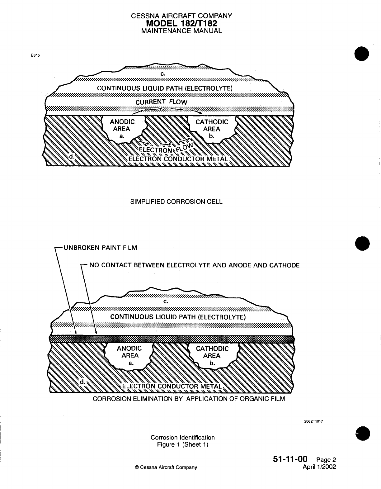
CESSNA AIRCRAFT
COMPANY
MODEL
182/T182
MAINTENANCE
MANUAL
B815
SIMPLIFIED
CORROSION
CELL
UNBROKEN
PAINT
FILM
NO
CONTACT
BETWEEN ELECTROLYTE
AND
ANODE
AND
I
UNRKNPITFL
CATHODE
ELECTRON
CONDUCTOR
METAL
,
%\
% ' .%
\\
. "' %. "
\\ \'\ \\
\^\,
\\
''
CORROSION
ELIMINATION
BY
APPLICATION
OF
ORGANIC
FILM
2682T1017
Corrosion
Identification
Figure
1
(Sheet
1)
51-11-00
Page2
April
1/2002
©
Cessna
Aircraft
Company
CESSNA
AIRCRAFT
COMPANY
MODEL
182/T182
MAINTENANCE
MANUAL
of
the
couple
becomes
the
cathode
of
the
galvanic
cell. The
degree
of
attack
depends
on
the
relative
activity
of
the
two
surfaces;
the
greater
the
difference
in
activity the
more
severe
the
corrosion.
Relative
activity
in
descending order
is
as
follows:
(a)
Magnesium
and
its
alloys.
(b)
Aluminum
alloys
1100,
3003, 5052,
6061,
220,
355,
356,
cadmium
and
zinc.
(c)
Aluminum
alloys
2014,
2017,
2024, 7075
and
195.
(d)
Iron,
lead and
their
alloys
(except
stainless
steel).
(e)
Stainless
steels,
titanium,
chromium,
nickel,
copper, and
their
alloys.
(f)
Graphite (including
dry
film
lubricants
containing
graphite).
(4)
Intergranular
Corrosion
-
Selective
attack
along
the
grain
boundaries
in
metal
alloys
is
referred
to
as
intergranular corrosion.
It
results
from
lack
of
uniformity
in
the
alloy
structure.
It
is
particularly
characteristic
of
precipitation
hardened
alloys
of
aluminum
and
some
stainless
steels.
Aluminum
extrusions
and
forgings
in
general
may
contain nonuniform
areas,
which
in
turn
may
result
in
galvanic attack
along the
grain
boundaries.
When
attack
is
well
advanced, the
metal
may
blister
or
delaminate,
which
is
referred
to
as
'exfoliation'.
(5)
Stress Corrosion
-
This
results
from
the
combined
effect
of
static tensile
stresses
applied
to
a
surface
over
a
period
of
time.
In
general,
cracking
susceptibility
increases
with
stress,
particularly
at
stresses
approaching
the
yield
point,
and
with
increasing temperature,
exposure
time
and
concentration
of
corrosive ingredients
in
the
surrounding environment.
Examples
of
parts
which
are
susceptible
to
stress
corrosion
cracking
are aluminum
alloy
bell
cranks
employing pressed-in
taper
pins,
landing
gear
shock
struts
with
pipe
thread-type
grease
fittings,
clevis joints
and
shrink
fits.
(6)
Corrosion
Fatigue
-
This
is
a
type
of
stress
corrosion
resulting
from the
cyclic
stresses
on
a
metal
in
corrosive surroundings.
Corrosion may
start
at
the
bottom
of
a
shallow
pit
in
the
stressed
area.
Once attack
begins, the
continuous
flexing
prevents
repair
of
protective
surface coating
or
oxide
films
and
additional
corrosion
takes
place
in
the
area
of
stress.
4.
Typical
Corrosion
Areas
A.
This
section
lists
typical
areas
of
the
airplane which
are
susceptible
to
corrosion.
These
areas
should
be
carefully
inspected
at
periodic
intervals
to
detect
corrosion
as
early
as
possible.
(1)
Engine
Exhaust
Trail
Areas.
(a)
Gaps,
seams
and
fairings
on
the
lower
right
side
of
the
fuselage,
aft
of
the
engine exhaust
stack,
are
typical
areas where
deposits
may
be
trapped
and
not
reached by
normal
cleaning
methods.
(b)
Around
rivet
heads,
skin
laps
and
inspection
covers
on
the airplane lower
fuselage,
aft
of
the
engine
secondary
exhaust
stack,
should
be
carefully
cleaned
and
inspected.
(2)
Battery
Box
and
Battery
Vent
Opening.
(a)
The
battery,
battery cover, battery
box
and
adjacent
areas,
especially
areas
below
the
battery
box
where
battery
electrolyte
may have
seeped,
are
particularly
subject
to
corrosive
action.
If
spilled battery
electrolyte
is
neutralized
and
cleaned
up
at
the
same
time
of
spillage,
corrosion
can
be
held to
a
minimum
by
using
a
weak boric
acid
solution
to
neutralize
the battery
electrolyte
(ni-cad
battery)
or
baking
soda
solution
to
neutralize
the
lead
acid-type
battery
electrolyte.
If
boric
acid
or
baking
soda
is
not
available,
flood
the area
with
water.
(3)
Steel Control
Cables
(including
Stainless
Steel).
(a)
Checking for
corrosion
on
control
cables
is
normally
accomplished
during
the preventative
maintenance
check.
During
preventative
maintenance,
broken
wires
and
wear
of
the
control
cables
are
also
checked.
(b)
If
the
surface
of
the
cable
is
corroded,
carefully
force
the
cable
open
by reverse twisting
and
visually
inspect
the
interior.
Corrosion
on
the interior
strands
of
the
cable
constitutes
failure
and
the
cable
must
be
replaced.
If
no
internal
corrosion
is
detected,
remove
loose
external
rust and
corrosion
with
a
clean,
dry,
coarse-weave
rag
or
fiber
brush.
NOTE:
Do
not use
metallic wools
or
solvents
to
clean
installed
cables.
Use
of
metallic
wool
will embed
dissimilar
metal
particles
in
the
cables
and
create
further
corrosion. Solvents
will remove internal
cable
lubricant,
allowing
cable
strands
to
abrade
and
further
corrode.
51-11-00
Page
3
©
Cessna
Aircraft Company
April
1/2002
CESSNA
AIRCRAFT
COMPANY
MODEL 182/T182
MAINTENANCE
MANUAL
(c)
After
thorough cleaning
of
the
exterior
cable surface, apply
a
light
coat
of
lubricant
(VV-L-
800)
to
the
external cable surface.
(4)
Internal
Fuel
Tanks.
(a)
The
presence
of
soil
contamination
(a
brown
slimy substance)
and
pitting-type corrosion
may
occur
in
the lower areas
of
the integral
fuel
tanks
of
certain
airplanes.
This
condition
can
cause
a
general
degradation
of
some
top
coating
and
some
depolymerization
and
loosening
of
sealant
materials
in
lower areas.
(b)
The
contaminants
resemble normal aluminum
corrosion
products,
including
a
considerable
quantity
of
iron.
The
brown,
slimy
deposits
are
microbial
in
nature.
Examination
of
the
corrosion
pits
by
metallurgical
techniques
indicate
the presence
of
intergranular attacks.
5.
Corrosion
Detection
A.
Corrosion Defoliation.
The primary
means
of
corrosion
detection
is
visual,
but
in
situations
where
visual
inspection
is
not
feasible, other
techniques
must
be
used.
The
use of
liquid
dye
penetrant,
magnetic
particle,
X-ray
and
ultra-sonic
devices
can be
used,
but
most
of
these
sophisticated
techniques
are
intended
for
the
detection
of
physical
flaws
within
metal
objects,
rather
than
the
detection
of
corrosion.
(1)
Visual
Inspection.
A
visual
check
of
the
metal
surface
can reveal the
signs
of
corrosive attack,
the
most
obvious
of
which
is
a
corrosive
deposit.
Corrosion
deposits
of
aluminum
or
magnesium
are
generally
a
white
or
grayish-white
powder,
while the
color
of
ferrous
compounds
varies from
red
to
dark
reddish-brown.
(a)
The
indications
of
corrosive
attack
are
small,
localized
discolorations
of
the
metal
surface.
Surfaces
protected
by
paint
or
plating
may
only exhibit
indications
of
more
advanced
corrosive attack
by
the
presence
of
blisters
or
bulges
in
the
protective
film. Bulges
in
lap
joints
are
indications
of
corrosive
build-up which
is
well
advanced.
(b) In
many
cases the inspection
area
is
obscured
by
structural
members,
equipment
installations
or,
for
other
reasons,
are
awkward
to
check
visually.
In
such
cases,
mirrors,
borescope
or
similar devices
can
be
used
to
inspect
the
obscured
areas. Any
means
which
allows
a
thorough
inspection
can
be
used.
Magnifying
glasses
are
valuable
aids
for
determining whether or
not
all
corrosive products
have
been
removed
during
clean
up
operations.
(2)
Liquid
Dye
Penetrant Inspection.
Inspection
for
large
stress-corrosion
or
corrosion
fatigue
cracks
on
nonporous
or
nonferrous
metals may
be
accomplished
using
dye
penetrant
processes.
The
dye
applied
to
a
clean metallic
surface
will
enter small
openings
or
cracks
by
capillary
action.
After
the
dye
has
an
opportunity
to be
absorbed by
any surface discontinuity,
the
excess
dye
is
removed
and
a
developer
is
applied to
the
surface.
The
developer
acts
like
a
blotter
and
draws
the
dye
from
cracks or fissures back
to the
surface,
giving
visible
indication
of
any
fault that
is
present
on
the
surface.
The
magnitude
of
the
fault
is
indicated by the
quantity
of
dye brought
back to
the
surface
by
the
developer.
6.
Corrosion
Damage
Limits
A.
Following
cleaning
and
inspection
of
the
corroded area,
the
actual extent
of the
damage
may
be
evaluated
using the
following
general
guidelines
and
good,
sound
maintenance
judgement.
Determine the
degree
of
corrosion
damage
(light, moderate,
or
severe)
with
a
dial-type
depth
gage,
if
accessibility
permits.
If
the
area
is
inaccessible,
clay
impressions,
or
any
other
means
which will
give
accurate results,
should
be
used.
In
the
event the
corrosion
damage
is
severe, contact
Cessna
Propeller
Aircraft
Product Support
for
assistance.
(1)
Light Corrosion
-
Characterized
by
discoloration
or
pitting
to
a
depth
of
approximately
0.001
inch
maximum.
This
type
of
damage
is
normally
removed
by
light
hand-sanding or
a
minimum
of
chemical treatment.
(2)
Moderate
Corrosion
-
Appears
similar
to
light
corrosion
except
there
may
be
blistering
or
some
evidence
of
scaling or faking.
Pitting depths
may
be
as
deep
as
0.010
inch.
This type
of
damage
is
normally
removed
by
extensive hand-sanding or
mechanical
sanding.
(3)
Severe
Corrosion
-
General
appearance
may
be
similar
to
moderate
corrosion
with
severe
blistering
exfoliation
and
scaling
or
flaking.
Pitting
depths
may
be
as
deep
as
0.10
inch.
This
type
of
damage
is
normally
removed
by
extensive
mechanical sanding
or
grinding
(if not
complete
part replacement).
51-11-00
Page
4
©
Cessna Aircraft
Company
April
1/2002
CHAPTER
DOORS
CESSNA
AIRCRAIFT
COMPANY
MODEL
182/Ti
82
MAINTENANCE
MANUAL
LIST
OF
EFFECTIVE
PAGES
CHAPTER-SECTION-SUBJECT
52-Title
52-List
of
Effective
Pages
52-Record
of Temporary
Revisions
52-Table
of
Contents
52-00-00
52-10-00
52-10-00
52-30-00
PAGE
Page
1
Page
1
Pages 201-209
Pages 201-204
©
Cessna
Aircraft
Company
52
-
LIST
OF
EFFECTIVE
PAGES
Page
1
of
1
Jul
1/2007
DATE
April
1/2002
Jul
3/2006
Jul
3/2006
Jul
1/2007
Temporary
Revision
Number
RECORD
OF
TEMPORARY
REVISIONS
Page
Number
Issue
Date
By
Date
Removed
By
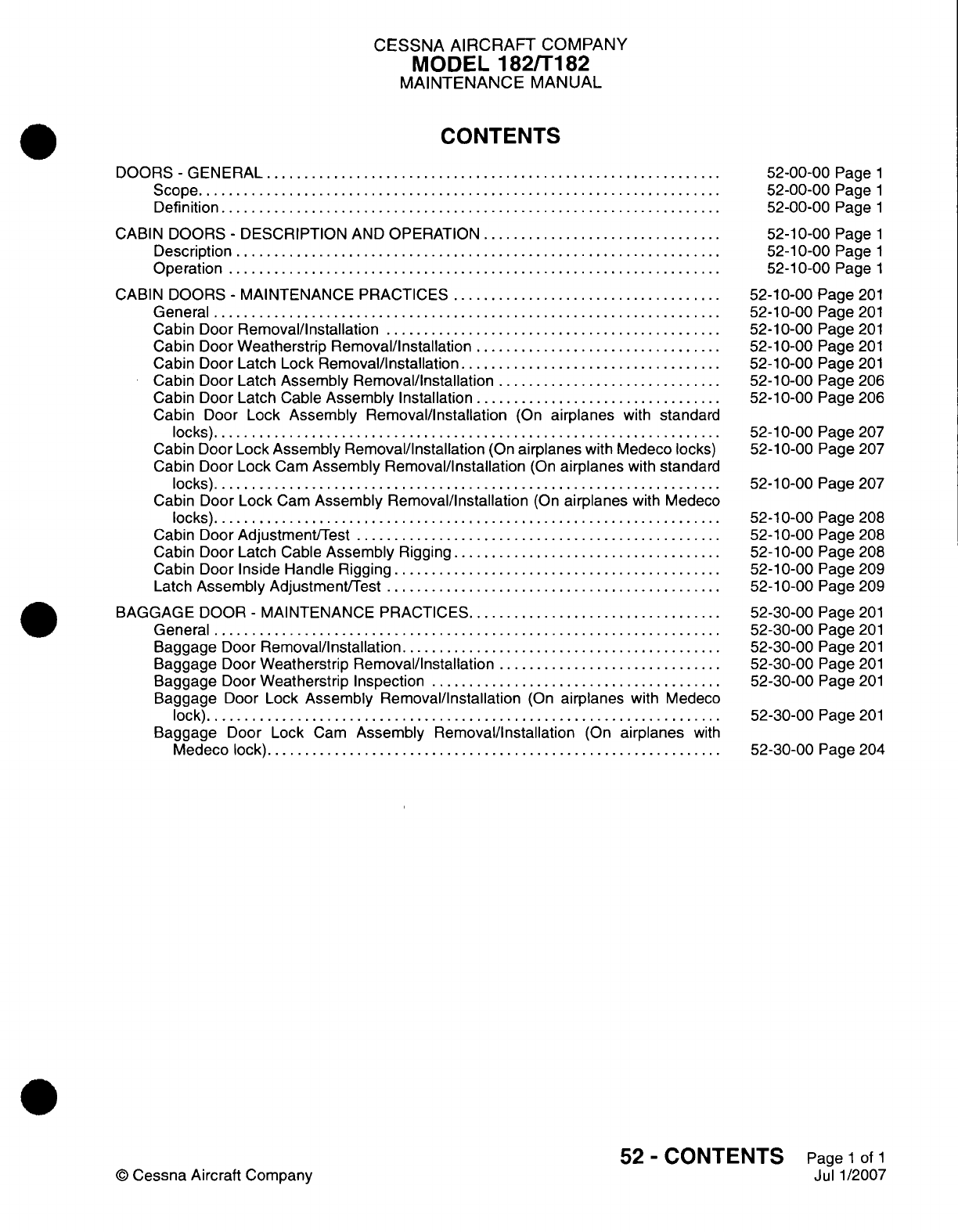
CESSNA
AIRCRAFT
COMPANY
MODEL
182/Ti
82
MAINTENANCE
MANUAL
CONTENTS
DOORS
-
GENERAL
...............................
Scope....................................
Definition
..................................
CABIN
DOORS
-
DESCRIPTION
AND
OPERATION.................
Description
.................................
Operation..................................
CABIN
DOORS
-
MAINTENANCE
PRACTICES...................
General...................................
Cabin Door
Removal/Installation
.......................
Cabin Door
Weatherstrip
Removal/installation
.................
Cabin Door
Latch
Lock
Removal/installation
..................
Cabin Door
Latch Assembly
Removal/installation................
Cabin Door
Latch
Cable
Assembly
Installation
.................
Cabin
Door
Lock
Assembly
Removal/Installation
(On
airplanes
with
standard
locks)...................................
Cabin Door
Lock Assembly
Removal/Installation
(On
airplanes
with Medeco locks)
Cabin
Door
Lock
Cam
Assembly Removal/Installation
(On
airplanes
with
standard
locks)...................................
Cabin
Door
Lock
Cam
Assembly
Removal/installation
(On
airplanes
with
Medeco
locks)...................................
Cabin
Door
Adjustment/Test
.........................
Cabin
Door Latch
Cable
Assembly
Rigging...................
Cabin
Door Inside
Handle
Rigging.......................
Latch
Assembly
Adjustment/Test
.......................
BAGGAGE
DOOR
-
MAINTENANCE
PRACTICES..................
General...................................
Baggage
Door
Removal/Installation
......................
Baggage
Door
Weatherstrip
Removal/Installation................
Baggage
Door
Weatherstrip
Inspection
....................
Baggage
Door
Lock Assembly
Removal/Installation
(On
airplanes
with
Medeco
lock)
...................................
Baggage
Door
Lock
Cam
Assembly
Removal/installation
(On
airplanes
with
Medeco lock)
...............................
52-00-00
Page
1
52-00-00
Page
1
52-00-00
Page
1
52-10-00
Page
1
52-10-00
Page
1
52-10-00
Page
1
52-1
0-00
Page
201
52-10-00
Page
201
52-10-00
Page
201
52-1
0-00
Page
201
52-10-00
Page
201
52-10-00
Page
206
52-10-00
Page
206
52-1
0-00
Page
207
52-10-00
Page
207
52-1
0-00
Page 207
52-10-00
Page
208
52-10-00
Page
208
52-10-00
Page
208
52-10-00
Page
209
52-10-00
Page
209
52-30-00
Page
201
52-30-00
Page
201
52-30-00
Page
201
52-30-00
Page
201
52-30-00
Page
201
52-30-00
Page
201
52-30-00
Page
204
52
-
CONTENTS
Page
1
of
1
Jul
1/2007
©
Cessna
Aircraft
Company
CESSNA
AIRCRAFT
COMPANY
MODEL
182/T182
MAINTENANCE
MANUAL
DOORS
-
GENERAL
1.
Scope
A.
This
chapter
provides
maintenance
information
on
doors.
Provided
are
removal/installation
instructions
and
rigging
procedures.
2.
Definition
A.
This
chapter
is
divided
into
sections
and
subsections
to
assist
maintenance
personnel
in
locating
specific
systems
and
information. The
following
is a
brief
description
of each
section.
For
locating
information within
the
chapter,
refer
to
the
Table
of
Contents
at
the beginning
of
the
chapter.
(1)
The cabin
door section
provides information
on
removal/installation
and
rigging
of
the doors.
(2)
The
baggage door
section
provides
information
on
removal/installation.
52-00-00
Page
1
©
Cessna
Aircraft
Company
April
1/2002
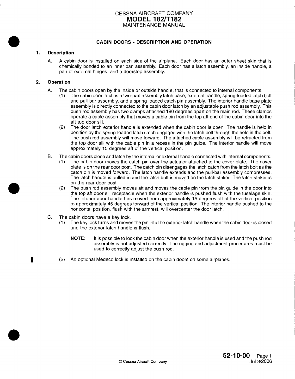
CESSNA
AIRCRAFT
COMPANY
MODEL
182/T182
MAINTENANCE
MANUAL
CABIN
DOORS
-
DESCRIPTION AND OPERATION
1.
Description
A. A
cabin
door
is
installed
on
each
side
of
the
airplane.
Each
door
has
an
outer
sheet
skin
that
is
chemically
bonded
to
an
inner
pan
assembly.
Each
door
has
a
latch assembly,
an
inside
handle,
a
pair
of
external hinges,
and
a
doorstop
assembly.
2.
Operation
A.
The
cabin doors
open
by
the
inside
or
outside handle,
that
is
connected
to
internal
components.
(1)
The
cabin door
latch
is
a
two-part
assembly
latch
base,
external
handle,
spring-loaded
latch
bolt
and
pull-bar
assembly,
and
a
spring-loaded
catch
pin
assembly.
The
interior
handle
base
plate
assembly
is
directly
connected
to
the
cabin
door
latch
by
an
adjustable
push
rod
assembly.
This
push
rod
assembly
has
two
clamps
attached
180
degrees
apart
on
the
main rod.
These
clamps
operate
a
cable
assembly
that
moves
a
cable
pin
from the
top aft
end
of
the
cabin
door
into
the
aft
top
door
sill.
(2)
The
door
latch
exterior
handle
is
extended when
the
cabin
door
is
open.
The
handle
is
held
in
position
by
the
spring-loaded
latch
catch engaged
with
the
latch bolt
through
the
hole
in
the
bolt.
The
push
rod
assembly
will
move
forward.
The
attached
cable
assembly
will
be
retracted
from
the
top
door
sill with
the
cable
pin
in a
recess
in
the
pin
guide.
The
interior
handle will
move
approximately
15
degrees
aft
of
the vertical position.
B.
The
cabin
doors
close
and
latch by
the
internal or
external
handle
connected
with
internal
components.
(1)
The
cabin
door
moves the
catch
pin
over the actuator
attached
to
the
cover
plate.
The
cover
plate
is
on
the
rear
door post.
The
catch
pin
disengages
the latch
catch
from
the
latch
bolt
as the
catch
pin
is
moved
forward. The
latch
handle
extends
and
the
pull-bar assembly
compresses.
The
latch
handle
is
pulled
in
and
the
latch
bolt
is
moved
on
the
latch
striker. The
latch
striker
is
on
the
rear
door
post.
(2)
The
push
rod
assembly
moves
aft
and
moves the cable
pin
from
the pin
guide
in
the
door
into
the
top
aft
door
sill
receptacle
when
the
exterior
handle
is
pushed
flush
with
the
fuselage
skin.
The
interior
door
handle has
moved
from
approximately
15
degrees
aft
of
the vertical
position
to
approximately
45
degrees
forward
of
the
vertical position.
The
interior handle
pushed
to
the
horizontal position,
flush
with
the
armrest, will
overcenter
the
door
latch.
C.
The
cabin doors
have
a
key
lock.
(1)
The key
lock turns
and
moves
the
pin
into
the exterior
latch
handle
when
the
cabin door
is
closed
and
the
exterior
latch
handle
is
flush.
NOTE:
It
is
possible
to
lock
the
cabin door
when
the
exterior
handle
is
used
and
the
push
rod
assembly
is
not
adjusted
correctly.
The
rigging
and
adjustment procedures
must
be
used
to
correctly
adjust
the
push
rod.
(2)
An
optional
Medeco lock
is
installed
on
the cabin doors
on
some airplanes.
52-10-00
Page
1
©
Cessna
Aircraft Company
Jul
3/2006
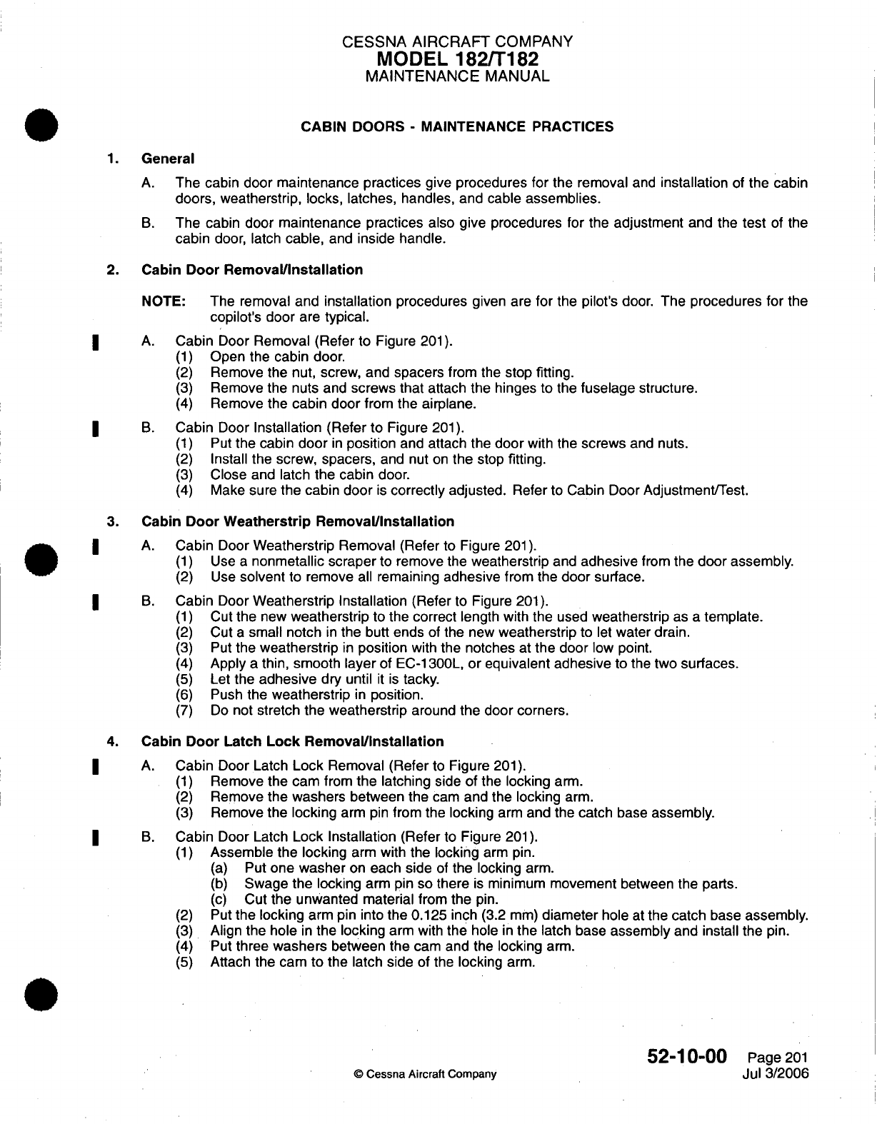
CESSNA
AIRCRAFT
COMPANY
MODEL
182/T182
MAINTENANCE
MANUAL
CABIN
DOORS
-
MAINTENANCE
PRACTICES
1.
General
A.
The
cabin
door maintenance
practices
give
procedures for
the
removal
and
installation
of
the cabin
doors, weatherstrip,
locks, latches,
handles,
and
cable
assemblies.
B.
The
cabin
door
maintenance practices
also give procedures for
the
adjustment
and the
test
of the
cabin
door,
latch
cable,
and
inside
handle.
2.
Cabin
Door
Removal/Installation
NOTE:
The
removal
and
installation
procedures
given are
for
the
pilot's door. The procedures
for
the
copilot's
door
are
typical.
A.
Cabin
Door
Removal (Refer
to
Figure
201).
(1)
Open the
cabin
door.
(2)
Remove
the
nut, screw,
and
spacers
from the
stop
fitting.
(3)
Remove
the
nuts
and
screws
that
attach the hinges
to
the
fuselage
structure.
(4)
Remove
the
cabin door
from the
airplane.
B.
Cabin
Door
Installation
(Refer
to
Figure
201).
(1)
Put
the
cabin
door
in
position
and
attach the
door
with
the
screws
and nuts.
(2)
Install
the
screw,
spacers,
and
nut
on
the
stop
fitting.
(3)
Close
and
latch
the
cabin
door.
(4) Make
sure
the cabin door
is
correctly
adjusted.
Refer
to
Cabin
Door Adjustment/Test.
3.
Cabin
Door Weatherstrip
Removal/Installation
A.
Cabin
Door
Weatherstrip
Removal (Refer
to Figure
201).
(1)
Use
a
nonmetallic scraper
to
remove
the
weatherstrip
and
adhesive
from
the
door
assembly.
(2)
Use
solvent
to
remove
all
remaining
adhesive
from the
door
surface.
B.
Cabin
Door
Weatherstrip Installation
(Refer
to Figure
201).
(1)
Cut
the
new
weatherstrip
to
the
correct
length with the
used
weatherstrip
as
a
template.
(2)
Cut
a
small notch
in
the butt ends
of
the
new
weatherstrip
to
let
water drain.
(3)
Put
the
weatherstrip
in
position
with
the notches
at
the
door
low point.
(4)
Apply
a
thin, smooth
layer
of
EC-1300L,
or equivalent adhesive
to
the
two
surfaces.
(5)
Let
the
adhesive
dry until
it
is
tacky.
(6)
Push
the
weatherstrip
in
position.
(7)
Do
not
stretch
the weatherstrip
around
the
door corners.
4.
Cabin
Door Latch
Lock
Removal/Installation
A.
Cabin
Door Latch
Lock
Removal
(Refer
to
Figure
201).
(1)
Remove
the
cam
from
the latching
side
of
the
locking
arm.
(2)
Remove
the washers
between
the
cam
and
the
locking
arm.
(3)
Remove
the locking
arm
pin
from
the
locking
arm
and the
catch
base
assembly.
B.
Cabin
Door Latch
Lock Installation (Refer
to
Figure
201).
(1)
Assemble the locking
arm
with
the
locking
arm
pin.
(a)
Put
one
washer
on
each
side
of
the locking
arm.
(b)
Swage
the
locking
arm
pin
so there
is
minimum
movement
between
the
parts.
(c)
Cut
the
unwanted
material from
the
pin.
(2)
Put
the locking
arm
pin into
the
0.125 inch
(3.2
mm)
diameter
hole
at
the
catch
base assembly.
(3)
Align
the
hole
in
the locking
arm
with
the
hole
in
the latch base
assembly
and
install
the
pin.
(4)
Put
three
washers
between
the
cam
and the
locking
arm.
(5)
Attach
the
cam
to
the
latch
side
of the
locking
arm.
52-10-00
Page
201
©
Cessna
Aircraft Company
Jul 3/2006
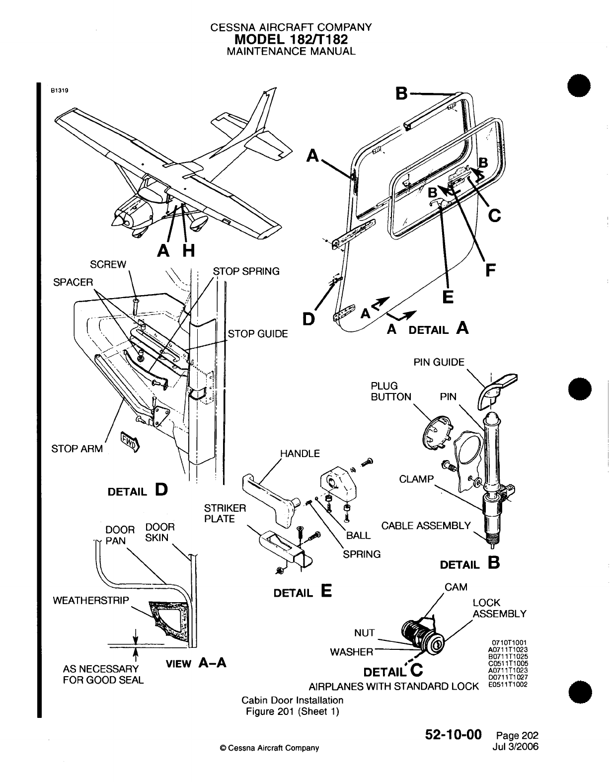
CESSNA
AIRCRAFT
COMPANY
MODEL
182/T182
MAINTENANCE
MANUAL
U-
A'
A
H
SPA
D
PIN
GUIDE
PL
Bl
STOI
ANDLE
DETAIL
D
DOOR DOOR
PAN
SKIN
DETAIL
B
DETAIL
E
WEATHERSTRIP
t
AS
NECESSARY
FOR
GOOD
SEAL
VIEW
A-A
NUT
WASHER
CAM
LOCK
ASSEMBLY
071OT1001
^^_H/
~A0711T1023
B0711T1025
DETAIL
C
AIRPLANES
WITH
STANDARD
LOCK
Cabin Door
Installation
Figure
201
(Sheet
1)
C0511T1005
A0711T1023
D0711T1027
E0511T1002
©
Cessna Aircraft
Company
52-10-00
Page
202
Jul
3/2006
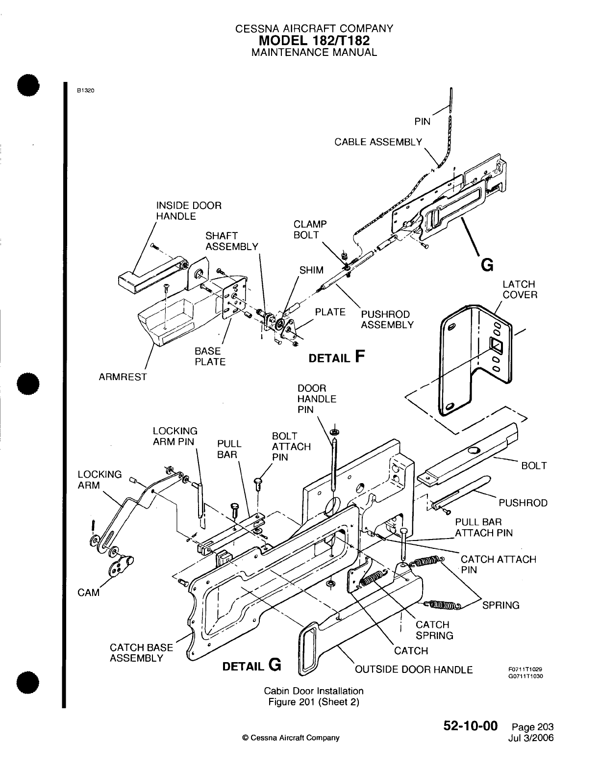
CESSNA AIRCRAFT
COMPANY
MODEL
182/T182
MAINTENANCE
MANUAL
B1320
CABLE
ASSEMBLY
DOOR
E
CLAMP
SHAFT
BOLT
ASSEMBLY
\
G
ATCH
;OVER
PUSHROD
ASSEMBLY
BASE
PLATE
ARMREST
DETAIL
F
DOOR
HANDLE
PIN
OUTSIDE
DOOR HANDLE
Cabin Door
Installation
Figure
201
(Sheet
2)
©
Cessna Aircraft
Company
52-10-00
Page
203
Jul
3/2006
1-1
r
-**Z"",j
e-11-
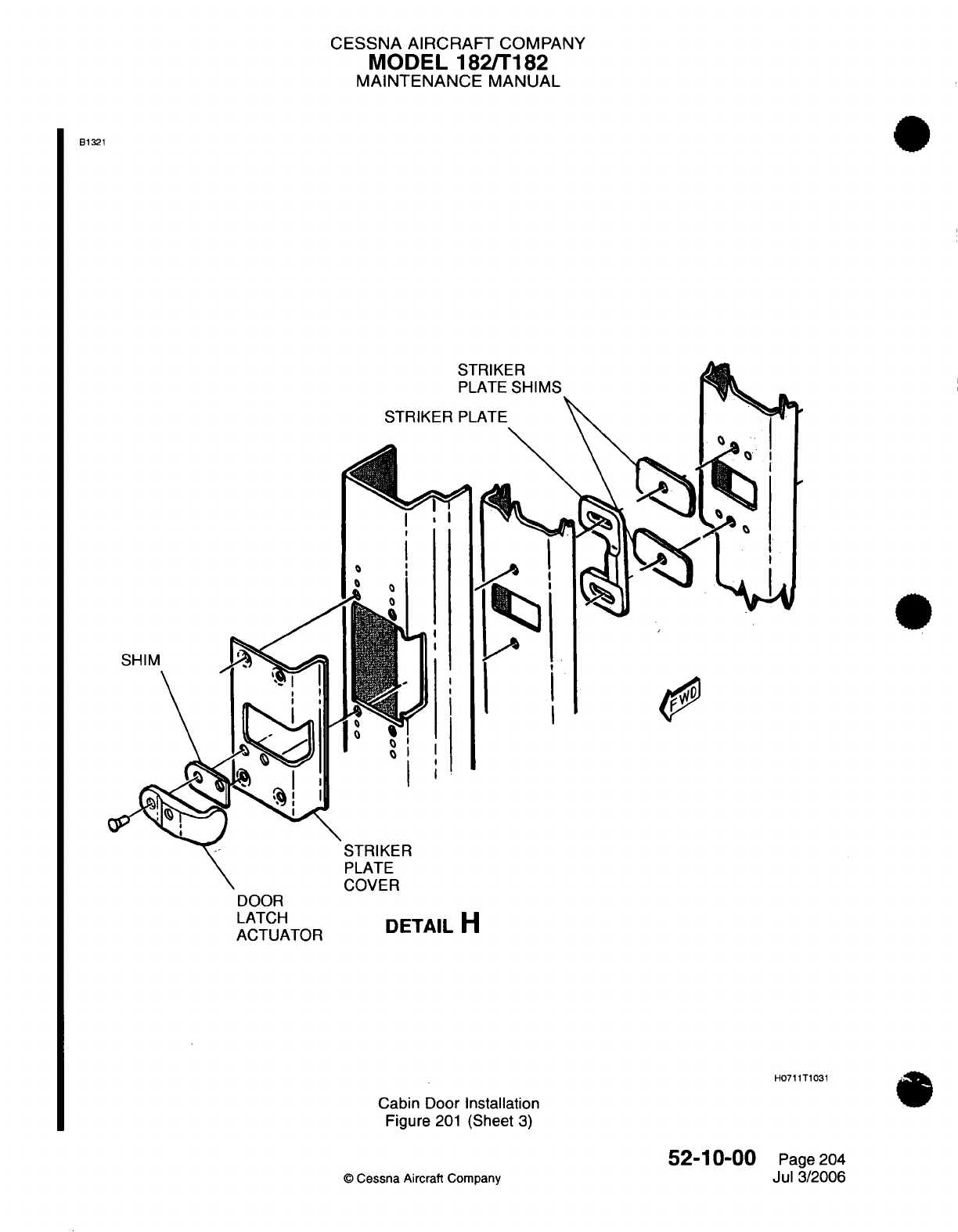
CESSNA AIRCRAFT
COMPANY
MODEL 182/T182
MAINTENANCE
MANUAL
B1321
STRIKER
I
I
DOOR
LATCH
ACTUATOR
DETAIL
H
Cabin
Door
Installation
Figure
201
(Sheet
3)
52-10-00
©
Cessna
Aircraft Company
A
9
H0711T1031
Page 204
Jul
3/2006
0o
I
I
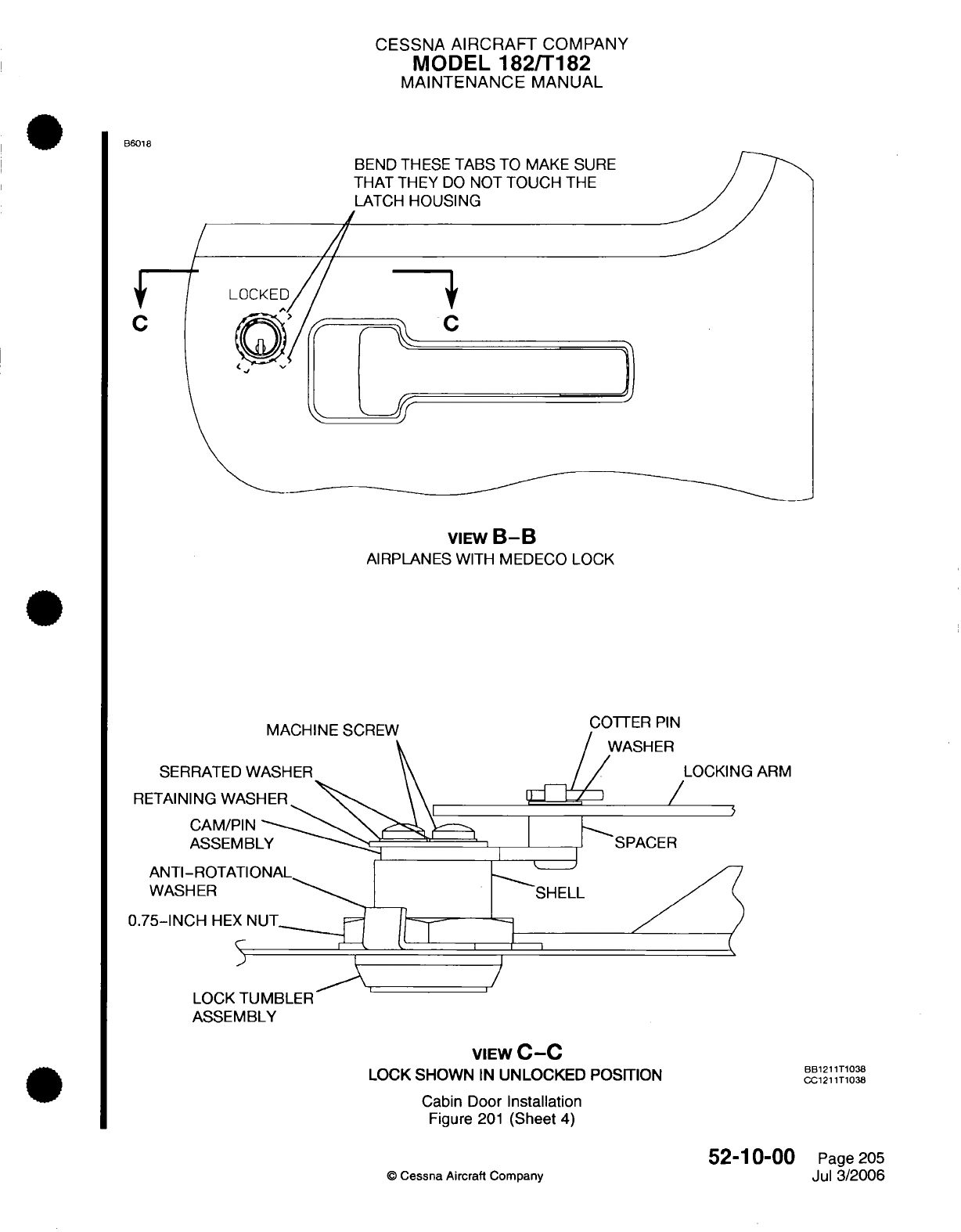
CESSNA
AIRCRAFT
COMPANY
MODEL
182/T182
MAINTENANCE
MANUAL
B6018
BEND THESE
TABS
TO
MAKE
SURE
THAT
THEY
DO
NOT
TOUCH
THE
LATCH
HOUSING
C
VIEW
B-B
AIRPLANES
WITH
MEDECO LOCK
MACHINE
SCREW
SERRATED
WASHER
RETAINING
WASHER
CAM/PIN
ASSEMBLY
LOCKING
ARM
SPACER
ANTI-ROTATI(
WASHER
0.75-INCH
HEX
N
LOCK
TUMBLER
ASSEMBLY
SHELL
VIEW
C-C
LOCK SHOWN
IN
UNLOCKED
POSITION
Cabin
Door
Installation
Figure
201
(Sheet
4)
©
Cessna
Aircraft Company
52-10-00
Page
205
Jul
3/2006
C
BB1211T1038
CC1211T1038
CESSNA AIRCRAFT
COMPANY
MODEL
182/T182
MAINTENANCE
MANUAL
5.
Cabin
Door
Latch
Assembly
Removal/Installation
A.
Cabin
Door
Latch
Assembly
Removal (Refer
to Figure
201).
(1)
Remove
the
cabin
door
lock assembly. Refer
to
Cabin Door
Lock
Assembly
Removal/
Installation.
(2)
Remove
the rivets
that
attach
the
latch
base
to
the
door
skin.
(3)
Remove
the
screws
that attach
the latch to the
door
pan.
(4)
Remove
the
pushrod
and bolt.
(5)
Pull
the
latch
handle through the
cutout
in
the
door
skin.
(6)
Remove
the
latch
assembly
from
the airplane.
B.
Cabin
Door
Latch
Assembly
Installation
(Refer
to
Figure
201).
(1)
Put
the
latch
assembly
in
the
closed position
between
the
door
pan
and the
door
skin.
(2)
Make
sure
the
cable
assembly
is
forward
of
the latch
base
attach
plate,
and
inboard
of
latch
base
cup.
(3)
Extend
the
latch
handle
through
the
cutout
in
the
door
skin.
(4)
Push
the
latch
assembly
aft
so
the bolt
and pushrod extend
through their
related
holes.
(5)
Release
the pushrod
so
the
bolt
is
fully
extended
and
the handle
is
flush.
(6)
Attach
the
latch
to
the door
pan
with
the screws
through
the
base
assembly
and
through the
aft
flange
of
the
door
pan.
(7)
Make
sure
the
door
skin dimension
around the
latch
assembly
is
correct.
CAUTION:
Do
not
make
the
holes
oversize
in
the latch base.
(8)
Drill
eleven
0.128
inch (3.25
mm)
diameter
holes
that
align
with
the
latch
base.
(9)
Make
sure
the
cabin door
latch
cable
assembly
rigging
and the
cabin
door
inside
handle
rigging
is
done
before
the
latch
base
is
attached
to
the
skin.
Refer
to Cabin
Door Latch
Cable Assembly
Adjustment/Test and
Cabin
Door
Inside
Handle Rigging.
(10)
Attach
the
latch
base
to
the
door
skin
with
rivets.
(11)
Install
the
cabin
door
lock
assembly.
Refer
to
Cabin
Door
Lock
Assembly Removal/Installation.
6.
Cabin
Door
Latch
Cable
Assembly Installation
A.
Cabin
Door
Latch
Cable
Assembly
Removal
(Refer
to
Figure
201).
(1)
Remove
the
screw
and clamp
that
attach the
cable
assembly
to
the
door.
(2)
Remove the
plug
button.
(3)
Remove
the
pin
from
the
pin
guide.
(4)
Pull
the
pin
end
of
the
cable
from
the top
of the
door.
(5)
Remove the
nut
and
clamp
from
the
opposite
end
of
the
cable
casing.
(6)
Remove the
cable
assembly
from
the
door.
B.
Cabin
Door Latch Cable
Assembly
Installation (Refer
to
Figure
201).
(1)
Attach
the
clamp and
nut
one
inch
(25
mm)
from the
end
of
the
cable
casing
on
the
pin
end
of
the
cable assembly.
(2)
Put
the
pin
end
of
the
cable
between
the door
pan and
the
door skin
at
the
aft end of the
door.
(3)
Push
the
pin
end
of
the
cable to
the
top
of
the
door.
(4)
Remove
the
plug
button and
align
the
pin
of
the
cable
with
the
pin
guide.
(5)
Put
the
pin
through
the
pin
guide.
(6)
Align the clamp
on
the
cable casing
through
the
hole
that
is
below
the
0.875
inch
(22.22
mm)
access
hole.
(7)
Install
the
screw.
(8)
Make
sure
the
cable
operates
freely.
(a)
Add
washers as
necessary
if
the
cable does
not
operate
freely.
(9)
Do
the
cabin door
latch
cable
assembly
rigging.
Refer to
Cabin
Door
Latch
Cable
Assembly
Rigging.
52-10-00
Page
206
©
Cessna
Aircraft
Company
Jul
3/2006
CESSNA
AIRCRAFT
COMPANY
MODEL
182/T182
MAINTENANCE
MANUAL
7.
Cabin
Door
Lock
Assembly Removal/Installation
(On
airplanes
with
standard
locks)
A.
Cabin Door
Lock
Assembly
Removal
(Refer
to
Figure
201).
(1)
Remove
the
lower
door accent
panel
and main
door
panel
to
get
access
to
the cabin
door
lock
assembly. Refer
to
Chapter
25,
Interior
Upholstery
-
Maintenance
Practices.
(2)
Remove
the
armrest
door
plugs,
door
panel
insert
at
the
armrest,
armrest,
door
handle
and
cover
plate
from
the
door
to
get
access
to
the
cabin
door
lock
assembly.
(3)
Remove
the
nut
and
washer.
(4)
Remove
the
cabin door
lock
assembly.
B.
Cabin
Door
Lock
Assembly
Installation (Refer
to
Figure
201).
(1)
Put
the cabin
door
lock
assembly
in
position.
(2)
Install
the
washer
and nut.
(3)
Install the armrest
door
plugs,
door
panel
insert
at the
armrest, armrest,
door
handle and cover
plate.
(4)
Install
the
lower
door accent
panel
and
main
door
panel. Refer
to
Chapter
25,
Interior Upholstery
-
Maintenance
Practices.
8.
Cabin
Door
Lock
Assembly
Removal/Installation
(On
airplanes with
Medeco
locks)
A.
Cabin Door
Lock
Assembly
Removal
(Refer
to
Figure
201).
(1)
Remove the
lower
door accent
panel
and
main
door
panel
to
get
access
to the
cabin
door
lock
assembly.
Refer
to
Chapter
25,
Interior
Upholstery
-
Maintenance Practices.
(2)
Remove
the
armrest
door
plugs,
door
panel
insert, armrest,
door
handle,
and
cover
plate
from
the
door
to get
access
to
the cabin
door
lock
assembly.
(3)
Remove
the
cotter
pin,
washer,
locking
arm,
and
spacer
from
the
lock
assembly.
(4)
Remove
the hex
nut
and
the
anti-rotational
washer that
attach
the
lock
tumbler assembly
to the
door
structure
and the
cam
assembly.
(5)
Remove
the
lock
assembly
from
the
door.
B.
Cabin Door
Lock
Assembly
Installation (Refer
to
Figure
201).
(1)
Put
the
cabin
door
lock
assembly
in
position
on
the
cabin
door.
(2)
Install
the
hex
nut
and
the
anti-rotational washer
that attach
the
lock
tumbler assembly
to the
door
structure
and
the
cam
assembly.
Install
the
anti-rotational
washer
under
the
hex
nut.
(3)
Torque
the
nut.
(4)
Bend the
applicable
tab
on
the
anti-rotational
washer against
the
flat
part
of
the
nut.
(5)
Install
the
spacer, locking
arm,
washer,
and
cotter
pin
that connect
the
lock
assembly
to the door
handle.
(6)
Bend
the
applicable
tabs
on the
cam-pin
assembly
to
make
sure
that they
do
not
touch
the
latch
housing.
(7)
Install
the armrest
door
plugs,
door
panel
insert,
armrest,
door handle,
and
cover
plate.
(8)
Install
the
lower
door
accent
panel
and
main
door
panel.
Refer to
Chapter
25,
Interior Upholstery
-
Maintenance
Practices.
9.
Cabin
Door
Lock
Cam
Assembly
Removal/Installation
(On
airplanes
with
standard
locks)
A.
Cabin Door
Lock
Cam
Assembly
Removal
(Refer
to Figure
201).
(1)
Remove the
lower
door accent
panel
and
main
door
panel
to
get
access
to
the cabin
door
lock
cam
assembly.
Refer
to Chapter
25,
Interior
Upholstery
-
Maintenance Practices.
(2)
Remove the
armrest
door
plugs,
door
panel insert
at
the
armrest, armrest,
door
handle,
and
cover
plate
from
the
door
to
get
access
to
the
cabin
door
lock cam
assembly.
(3)
Remove the
cam
stop screw
from the
cabin
door
lock
cam
assembly.
(4)
Remove the cam
assembly.
B.
Cabin Door Lock
Cam
Assembly
Installation
(Refer
to
Figure
201).
(1)
Put
the
cam
assembly
in
position.
(2)
Install
the
cam
stop screw
with
Loctite
242.
(3)
Install the armrest
door
plugs,
door
panel
insert
at
the
armrest,
armrest,
door
handle, and
cover
plate.
52-10-00
Page 207
©
Cessna
Aircraft
Company
Jul
3/2006
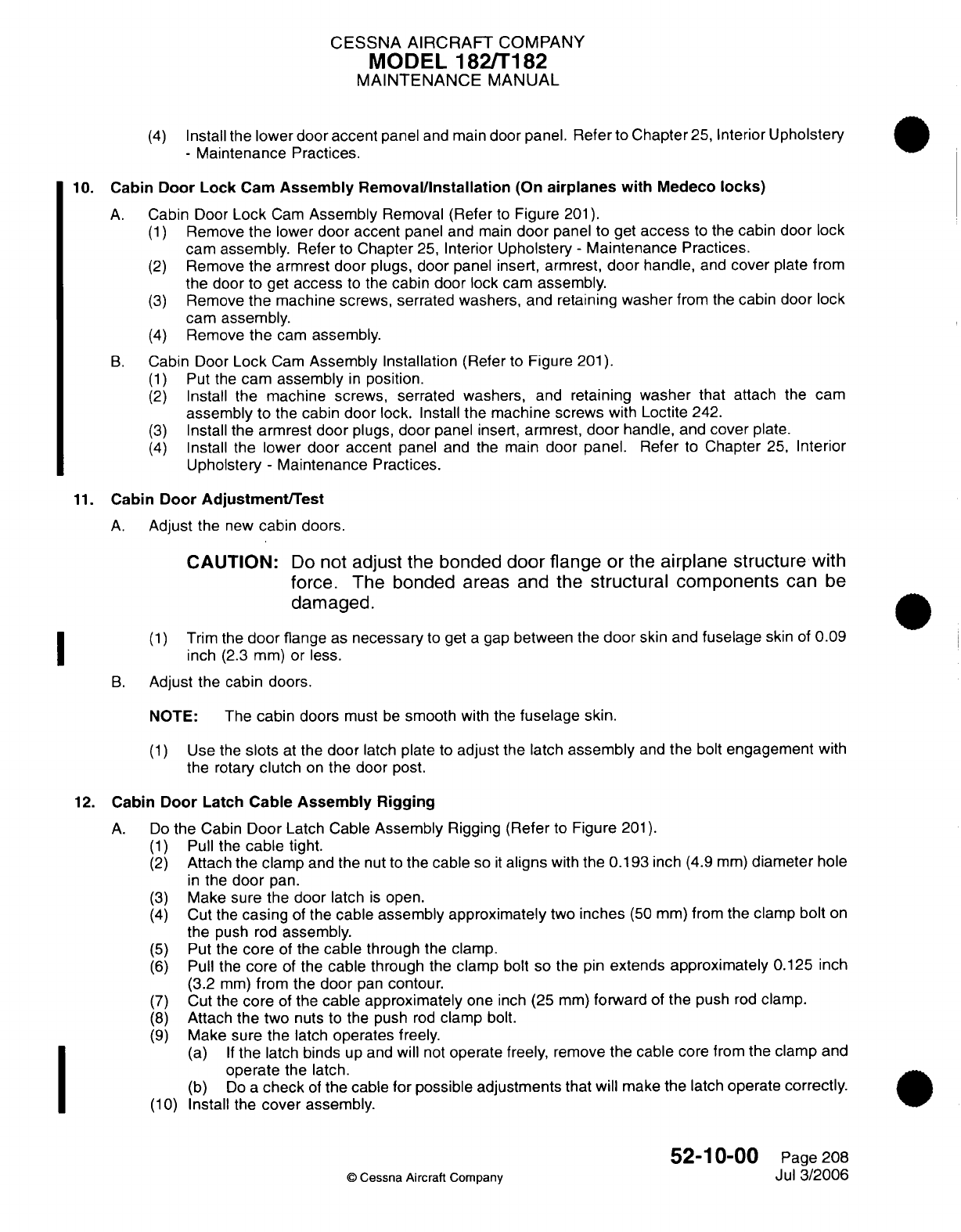
CESSNA
AIRCRAFT
COMPANY
MODEL
182/T182
MAINTENANCE
MANUAL
(4)
Install
the
lower
door accent
panel
and main
door
panel.
Refer
to
Chapter
25,
Interior
Upholstery
-
Maintenance
Practices.
10.
Cabin
Door
Lock
Cam
Assembly
Removal/nstallation
(On
airplanes with
Medeco
locks)
A.
Cabin
Door
Lock
Cam
Assembly
Removal
(Refer
to
Figure
201).
(1)
Remove
the
lower
door
accent
panel
and
main
door
panel
to get
access
to
the cabin
door
lock
cam
assembly.
Refer
to
Chapter
25,
Interior
Upholstery
-
Maintenance
Practices.
(2)
Remove
the
armrest door
plugs,
door
panel
insert,
armrest,
door
handle,
and
cover
plate
from
the
door
to
get
access
to
the
cabin door
lock cam
assembly.
(3)
Remove
the
machine
screws, serrated
washers,
and retaining
washer
from the
cabin
door
lock
cam assembly.
(4)
Remove
the
cam
assembly.
B.
Cabin Door
Lock
Cam
Assembly
Installation
(Refer to Figure
201).
(1)
Put
the
cam
assembly
in
position.
(2)
Install
the
machine screws,
serrated
washers,
and
retaining
washer
that
attach the
cam
assembly
to
the
cabin
door
lock.
Install
the machine screws
with Loctite
242.
(3)
Install
the
armrest
door
plugs,
door
panel
insert,
armrest,
door
handle,
and
cover
plate.
(4)
Install
the
lower
door accent
panel
and
the main
door
panel.
Refer
to
Chapter
25,
Interior
Upholstery
-
Maintenance
Practices.
11.
Cabin
Door
Adjustment/Test
A.
Adjust
the
new
cabin doors.
CAUTION:
Do
not
adjust
the
bonded
door
flange
or
the
airplane structure
with
force.
The
bonded
areas
and
the
structural components
can
be
damaged.
(1)
Trim
the
door
flange
as
necessary
to
get
a
gap
between the
door
skin
and
fuselage
skin
of
0.09
inch
(2.3
mm)
or
less.
B.
Adjust the cabin doors.
NOTE:
The
cabin
doors
must
be
smooth
with
the
fuselage
skin.
(1)
Use the
slots
at
the
door
latch
plate
to
adjust
the latch
assembly
and
the
bolt
engagement
with
the
rotary
clutch
on
the
door
post.
12.
Cabin
Door
Latch Cable
Assembly Rigging
A.
Do
the
Cabin
Door
Latch
Cable
Assembly
Rigging
(Refer
to
Figure
201).
(1)
Pull the
cable
tight.
(2)
Attach
the clamp
and
the
nut
to
the
cable
so
it
aligns
with
the
0.193
inch
(4.9
mm)
diameter
hole
in
the
door
pan.
(3)
Make
sure
the
door
latch
is
open.
(4)
Cut
the
casing
of
the
cable
assembly approximately
two
inches
(50
mm)
from the
clamp
bolt
on
the
push
rod
assembly.
(5)
Put
the
core
of
the
cable
through the
clamp.
(6)
Pull the
core
of
the
cable
through the
clamp
bolt
so the
pin
extends approximately
0.125
inch
(3.2
mm)
from
the
door
pan
contour.
(7)
Cut
the
core
of
the
cable approximately
one
inch
(25
mm)
forward
of
the
push
rod
clamp.
(8)
Attach
the
two
nuts
to
the
push
rod
clamp
bolt.
(9)
Make
sure
the
latch
operates
freely.
(a)
If
the
latch
binds
up
and
will
not
operate
freely,
remove
the cable
core
from
the clamp
and
operate
the latch.
(b)
Do
a
check
of
the
cable
for
possible adjustments
that
will
make
the latch
operate
correctly.
(10)
Install
the
cover
assembly.
52-10-00
Page
208
©
Cessna Aircraft
ComDanv
Jul
3/2006
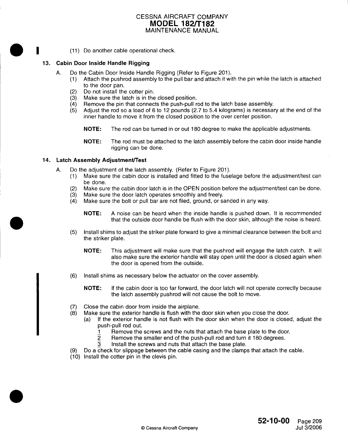
CESSNA
AIRCRAFT
COMPANY
MODEL
182/T182
MAINTENANCE
MANUAL
~|
~
(11)
Do
another
cable operational
check.
13.
Cabin
Door
Inside
Handle
Rigging
A.
Do
the
Cabin
Door
Inside Handle
Rigging
(Refer
to
Figure
201).
(1)
Attach
the
pushrod
assembly
to
the
pull
bar
and
attach
it
with
the
pin
while
the latch
is
attached
to
the
door
pan.
(2)
Do
not
install the
cotter
pin.
(3)
Make
sure
the latch
is in
the closed
position.
(4)
Remove
the
pin
that connects
the
push-pull
rod
to
the
latch
base assembly.
(5)
Adjust
the
rod
so
a
load
of
6
to
12
pounds
(2.7
to
5.4
kilograms)
is
necessary
at
the
end of
the
inner handle
to
move
it
from
the
closed position
to
the
over
center
position.
NOTE:
The
rod
can
be
turned
in
or
out
180
degree
to
make
the
applicable adjustments.
NOTE:
The
rod
must
be
attached
to
the
latch
assembly
before the
cabin
door
inside
handle
rigging
can
be
done.
14.
Latch
Assembly
Adjustment/Test
A.
Do
the
adjustment
of
the latch
assembly. (Refer
to
Figure
201).
(1)
Make
sure
the cabin
door
is
installed
and
fitted
to
the
fuselage
before
the
adjustment/test
can
be
done.
(2)
Make
sure
the
cabin
door
latch
is in
the
OPEN
position
before
the
adjustment/test
can
be
done.
(3)
Make
sure
the
door
latch
operates
smoothly
and
freely.
(4)
Make sure
the
bolt or pull
bar are
not
filed,
ground, or sanded
in
any
way.
NOTE:
A
noise can
be
heard
when
the
inside
handle
is
pushed
down.
It is
recommended
that
the
outside
door handle
be
flush
with
the door
skin,
although
the noise
is
heard.
(5)
Install
shims to
adjust
the striker
plate
forward
to
give
a
minimal
clearance
between
the
bolt
and
the
striker
plate.
NOTE:
This
adjustment
will
make
sure
that the pushrod
will
engage
the latch
catch.
It
will
also
make
sure
the
exterior
handle
will
stay
open
until
the
door
is
closed
again
when
the
door
is
opened
from the
outside.
(6)
Install
shims
as
necessary
below
the
actuator
on
the
cover
assembly.
NOTE:
If
the
cabin door
is
too
far
forward,
the
door
latch will
not
operate
correctly because
the
latch
assembly
pushrod
will
not
cause
the bolt to
move.
(7)
Close
the
cabin door
from
inside
the
airplane.
(8)
Make
sure
the
exterior
handle
is
flush
with
the
door skin
when you
close
the
door.
(a) If
the
exterior
handle
is
not
flush
with
the
door
skin
when the
door
is
closed, adjust
the
push-pull
rod
out.
1
Remove the screws
and the
nuts
that
attach
the
base
plate to
the
door.
2
Remove
the smaller
end of
the
push-pull
rod
and
turn
it
180
degrees.
3
Install
the
screws
and
nuts
that
attach
the
base
plate.
(9)
Do
a
check for slippage
between
the
cable
casing
and the
clamps
that attach
the
cable.
(10)
Install
the
cotter
pin
in
the
clevis
pin.
52-10-00
Page
209
©
Cessna Aircraft
Companv
Jul
3/2006
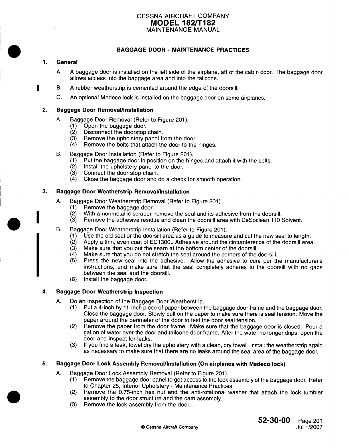
CESSNA
AIRCRAFT
COMPANY
MODEL
182/Ti
82
MAINTENANCE
MANUAL
BAGGAGE
DOOR
-
MAINTENANCE PRACTICES
1.General
A. A
baggage door
is
installed
on
the left
side
of
the
airplane,
aft
of
the
cabin
door.
The
baggage
door
allows
access
into
the
baggage
area
and
into
the
tailcone.
3
B.
A
rubber
weatherstrip
is
cemented
around
the
edge
of
the
doorsill.
C.
An
optional
Medeco
lock
is
installed
on
the
baggage
door
on
some
airplanes.
2.
Baggage
Door
Removal/installation
A.
Baggage
Door
Removal
(Refer
to
Figure
201).
(1)
Open
the
baggage
door.
(2)
Disconnect
the
doorstop
chain.
(3)
Remove the
upholstery
panel from the
door.
(4)
Remove the
bolts
that
attach
the
door
to
the hinges.
B.
Baggage Door
Installation
(Refer
to
Figure
201).
(1)
Put
the
baggage door
in
position
on
the
hinges
and
attach
it
with
the
bolts.
(2)
Install
the
upholstery
panel
to
the
door.
(3)
Connect
the
door stop
chain.
(4)
Close
the
baggage
door
and
do
a
check
for
smooth
operation.
3.
Baggage Door
Weatherstrip Removal/installation
A.
Baggage
Door
Weatherstrip
Removal
(Refer
to
Figure
201).
(1)
Remove the
baggage
door.
(2)
With
a
nonmetallic
scraper,
remove
the
seal
and
its
adhesive
from
the
doorsill.
I ~ ~(3)
Remove
the
adhesive
residue
and
clean the
doorsill
area
with
DeSocleanl110Solvent.
B.
Baggage
Door
Weatherstrip Installation
(Refer
to
Figure
201).
(1)
Use
the
old
seal
or
the
doorsill area
as
a
guide
to
measure
and
cut
the
new
seal
to
length.
(2)
Apply
a
thin, even coat
of
EC1300L
Adhesive
around
the
circumference
of
the
doorsill
area.
(3)
Make
sure
that
you put
the
seam
at
the
bottom
center
of
the
doorsill.
(4)
Make sure
that
you
do
not
stretch
the
seal
around the corners
of
the
doorsill.
(5)
Press
the
new
seal
into
the
adhesive.
Allow
the
adhesive
to
cure
per
the
manufacturer's
instructions,
and
make
sure
that
the
seal
completely
adheres
to
the
doorsill
with
no
gaps
between
the
seal
and the
doorsill.
(6)
Install the baggage
door.
4.
Baggage
Door
Weatherstrip Inspection
A.
Do
an
Inspection
of
the
Baggage
Door
Weatherstrip.
(1)
Put
a
4-inch
by
1
1-inch piece
of
paper
between
the
baggage
door
frame
and
the
baggage
door.
Close
the
baggage
door.
Slowly
pull
on
the paper
to
make sure
there
is
seal
tension.
Move the
paper
around
the
perimeter
of
the
door
to
test
the
door
seal
tension.
(2)
Remove the paper
from the
door
frame. Make sure
that
the
baggage
door
is
closed.
Pour
a
gallon
of
water
over
the
door
and
tailcone
door
frame.
After the water
no
longer
drips,
open the
door
and
inspect
for
leaks.
(3) If
you
find
a
leak,
towel
dry the
upholstery
with
a
clean,
dry
towel.
Install the
weatherstrip
again
as
necessary
to
make
sure
that
there
are
no
leaks around
the
seal
area of
the
baggage
door.
5.
Baggage Door
Lock
Assembly
Remnoval/Installation
(On
airplanes
with
Medeco
lock)
A.
Baggage
Door
Lock
Assembly
Removal
(Refer
to
Figure
201).
(1)
Remove
the
baggage
door
panel
to
get
access
to
the
lock
assembly
of
the
baggage
door.
Refer
to
Chapter
25,
Interior Upholstery
-
Maintenance
Practices.
(2)
Remove
the
0.75-inch
hex
nut
and the
anti-rotational
washer
that
attach
the
lock
tumbler
assembly
to
the
door
structure
and
the
cam assembly.
(3)
Remove the
lock
assembly
from
the
door.
52-30-00
Page
201
©
Cessna Aircraft
Company
Jul 1/2007
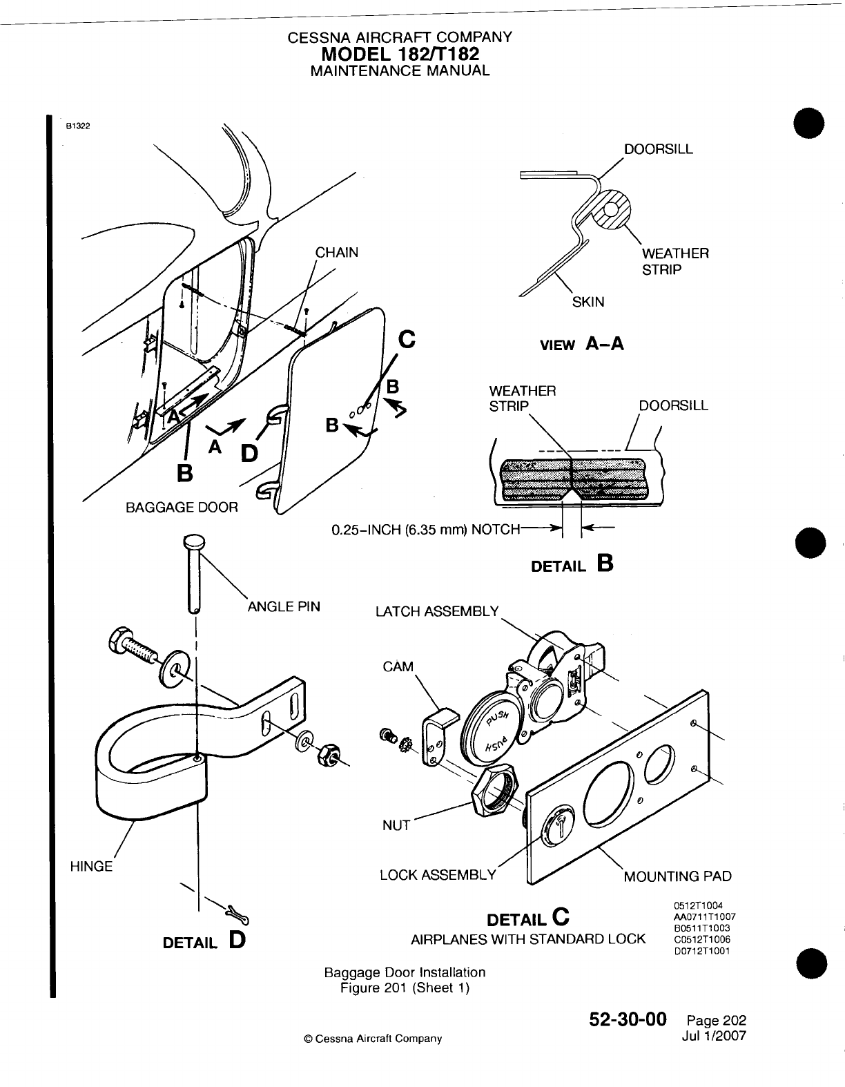
CESSNA AIRCRAFT
COMPANY
MODEL
182/Ti182
MAINTENANCE
MANUAL
B13
E-:R
SKIN
bp
viEw
A-A
WEATH
ER
STRIP
DOORSILL
C
I
I
n
9.r-INCH
(A-9. mm)
NOlT(H-1l~
~
DETAIL
B
LATCH
ASSEMBLY
HIN
DETAIL
D
DETAIL
C
AIRPLANES
WITH
STANDARD
LOCK
Baggage
Door
Installation
Figure
201
(Sheet
1)
©
Cessna Aircraft
Company
52-30-00
Page
202
Jul 1/2007
PIN
051
2T1
004
AA0711T1
007
B051
1T1
003
C0512T1
006
D0712T1 001
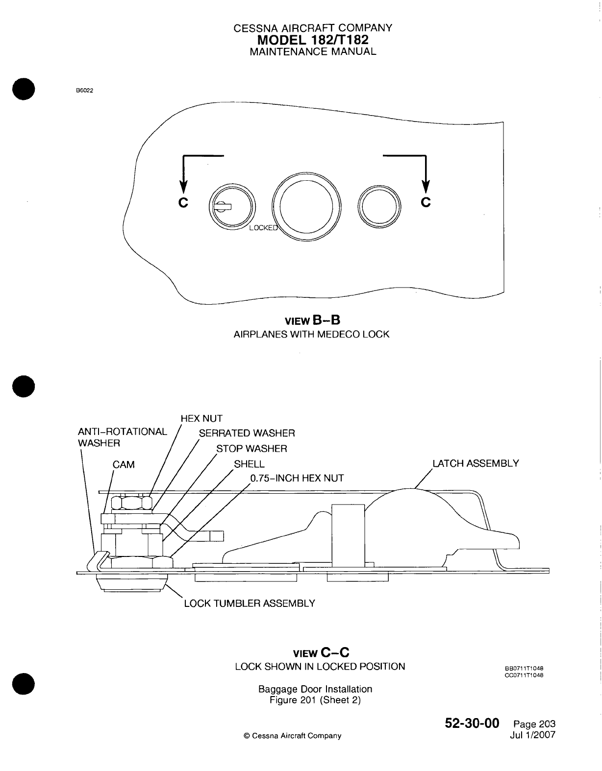
CESSNA AIRCRAFT
COMPANY
MODEL
182/Ti
82
MAINTENANCE
MANUAL
66022
VIEW
B-B
AIRPLANES
WITH
MEDECO LOCK
HEX
NUT
LOCK
TUMBLER
ASSEMBLY
VIEW
C-C
LOCK SHOWN
IN
LOCKED
POSITION
Baggage
Door
Installation
Figure
201
(Sheet
2)
©
Cessna Aircraft Company
B6B071
1T1
048
G0071
1T1
048
52-30-00
Page 203
Jul
1
/2007
CESSNA AIRCRAFT
COMPANY
MODEL
182/182
MAINTENANCE
MANUAL
B.
Baggage
Door
Lock
Assembly
Installation
(Refer
to
Figure
201).
(1)
Put
the
baggage
door
lock
assembly
in
position
on
the
baggage
door.
(2)
Install
the
0.75-inch
hex
nut
and
the
anti-rotational
washer
that attach
the
lock tumbler
assembly
to
the
door
structure
and
the
cam
assembly.
Make
sure
that
the
anti-rotational
washer
is
installed
under the
0.75-inch
hex
nut.
(3)
Torque the nut.
(4)
Bend
the
applicable
tab
on
the
anti-rotational washer
against the
flat
part
of
the nut.
(5)
Install
the
baggage
door
panel
to
the
baggage
door. Refer
to
Chapter
25,
Interior
Upholstery
-
Maintenance
Practices.
6.
Baggage
Door
Lock
Cam
Assembly
Removal/installation
(On
airplanes
with
Medeco
lock)
A.
Baggage
Door Lock
Cam
Assembly
Removal
(Refer
to
Figure
201).
(1)
Remove
the
baggage
door
panel
to
get
access
to
the baggage door
lock
assembly.
Refer
to
Chapter
25,
Interior
Upholstery
-
Maintenance
Practices.
(2)
Remove
the
hex
nut
and
the
serrated
washer
that
attach
the
cam
assembly
to the
baggage
door
lock.
(3)
Remove
the cam
assembly.
B.
Baggage
Door
Lock
Cam
Assembly
Installation
(Refer
to
Figure
201).
(1)
Put
the
cam
assembly
in
position.
(2)
Install
the
hex
nut
and
the
serrated
washer
that attach
the
cam
assembly
to
the
baggage
door
lock.
Install
the
hex
nut
with
Loctite
242.
(3)
Install
the
baggage
door
panel
to
the
baggage
door.
Refer
to
Chapter
25,
Interior
Upholstery
-
Maintenance Practices.
52-30-00
Page
204
©
Cessna
Aircraft
Company
Jul
1/2007

CHAPTER
STABILIZERS
CESSNA
AIRCRAFT
COMPANY
MODEL
182/T182
MAINTENANCE
MANUAL
LIST
OF
EFFECTIVE PAGES
CHAPTER-SECTION-SUBJECT
55-Title
55-List
of
Effective
Pages
55-Record
of
Temporary
Revisions
55-Table of
Contents
55-00-00
55-10-00
55-30-00
PAGE
Page
1
Pages 201-202
Pages 201-202
©
Cessna Aircraft
Company
55
-
LIST
OF
EFFECTIVE
PAGES
Page
1
of
1
Mar
1/2005
DATE
April
1/2002
April
1/2002
April
1/2002

Temporary
Revision
Number
RECORD
OF
TEMPORARY REVISIONS
Page
Number
Issue
Date
By
Date
Removed
By
CESSNA
AIRCRAFT
COMPANY
MODEL
182/T182
MAINTENANCE
MANUAL
CONTENTS
STABILIZERS
-
GENERAL
.......................................................
S
cope......................................................................
Definition
...................................................................
HORIZONTAL
STABILIZER
-
MAINTENANCE PRACTICES
.........
................
G
eneral
....................................................................
Horizontal
Stabilizer
Removal/Installation
.....................................
VERTICAL
FIN
-
MAINTENANCE
PRACTICES.....................................
G
en
eral
....................................................................
Vertical
Fin
Removal/Installation
..........................................
55-00-00
Page
1
55-00-00
Page
1
55-00-00
Page
1
55-10-00
Page
201
55-10-00
Page
201
55-10-00
Page
201
55-30-00
Page
201
55-30-00
Page
201
55-30-00
Page
201
CONTENTS
Page
1
of
1
Mar 1/2005
©
Cessna Aircraft
Company
CESSNA
AIRCRAFT
COMPANY
MODEL
182/T182
MAINTENANCE
MANUAL
STABILIZERS
-
GENERAL
Scope
A.
This
chapter
provides maintenance
information
on
the
horizontal
and
vertical
stabilizer.
Definition
A.
The section
on
horizontal
stabilizer
provides
instructions
for
removal
and
installation
of
the
horizontal
stabilizer.
B.
The
section
on
vertical
fin
provides instructions for
removal
and
installation
on
the
vertical
fin.
55-00-00
Page
1
©
Cessna
Aircraft
Company
April 1/2002
1.
2.
CESSNA
AIRCRAFT
COMPANY
MODEL
182/T182
MAINTENANCE
MANUAL
HORIZONTAL
STABILIZER
-
MAINTENANCE
PRACTICES
1.
General
A.
The
horizontal
stabilizer
is
of
metal
construction, consisting
of
ribs
and
spars
covered
with
skin.
A
formed
metal
leading edge
is
riveted
to
the
assembly
to complete
the
structure.
The
elevator
trim
tab actuator
is
contained
within the
horizontal
stabilizer.
The
underside
of
the
stabilizer contains a
covered opening
which
provides
access
to
the
actuator.
Hinges
are
located
on
the rear
spar
assembly
to
support
the
elevators.
B.
This
section
provides
removal
and
installation
instructions
for
the
horizontal
stabilizer.
2.
Horizontal
Stabilizer
Removal/Installation
A.
Remove Horizontal
Stabilizer
(Refer
to
Figure
201).
(1)
Remove elevators.
Refer
to
Chapter
27,
Elevator
Control
System
-
Maintenance
Practices.
(2)
Remove
rudder.
Refer
to
Chapter
27,
Rudder
Control System
-
Maintenance Practices.
(3)
Remove
vertical
stabilizer.
Refer
to
Vertical
Stabilizer
-
Maintenance
Practices.
(4)
Disconnect
elevator
trim
control
cables
at
clevis
and
turnbuckle
inside
tailcone.
(5)
Remove
pulleys which
route
the
aft
cables
into
horizontal
stabilizer,
and pull
cables
out
of
tailcone.
Refer
to Chapter
27,
Elevator
Trim
Control
-
Maintenance
Practices.
(6)
Remove
bolts
securing
horizontal
stabilizer
to
fuselage.
(7)
Remove horizontal stabilizer.
B.
Install
Horizontal
Stabilizer
(Refer to Figure
201).
(1)
Install
horizontal
stabilizer
to
fuselage using
bolts.
(2)
Reroute
cables
into
tailcone
and
install
pulleys.
(3)
Reconnect
elevator
trim
control
cables
at
clevis
and
turnbuckle
inside
tailcone.
(4)
Install
vertical
stabilizer.
Refer
to
Vertical
Stabilizer
-
Maintenance
Practices.
(5)
Install
rudder.
Refer
to
Chapter
27,
Rudder
Control
System
-
Maintenance
Practices.
(6)
Install
elevators.
Refer
to
Chapter
27,
Elevator
Control
System
-
Maintenance
Practices.
(7)
Rig
elevator.
Refer
to
Chapter
27,
Elevator
Control
System
-
Maintenance
Practices.
(8)
Rig rudder.
Refer
to
Chapter
27,
Rudder
Control
System
-
Maintenance
Practices.
(9)
Rig
elevator
trim.
Refer
to
Chapter
27,
Elevator
Trim
Control
-
Maintenance
Practices.
©
Cessna
Aircraft
Company
55-10-00
Page
201
April
1/2002
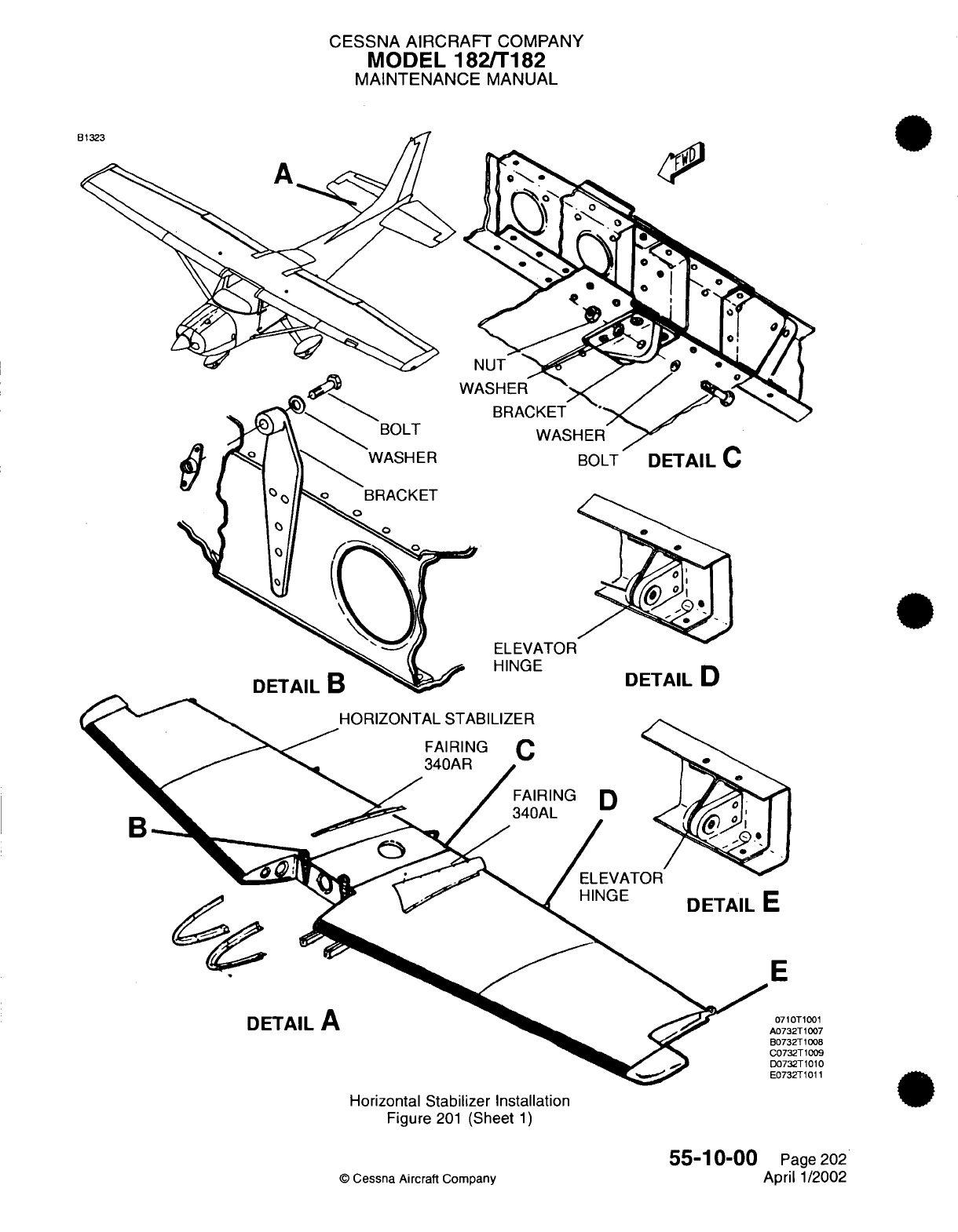
CESSNA
AIRCRAFT
COMPANY
MODEL
182/T182
MAINTENANCE
MANUAL
HINGE
DETAIL
D
OT1001
12T1007
2T
1008
32T1009
32T1010
32T1011
Horizontal
Stabilizer
Installation
Figure
201
(Sheet
1)
55-10-00
©
Cessna
Aircraft
Company
Page
202
April
1/2002
CESSNA
AIRCRAFT
COMPANY
MODEL
182/T182
MAINTENANCE
MANUAL
VERTICAL
FIN
-
MAINTENANCE
PRACTICES
1.
General
A.
The
vertical
fin
is
of
metal
construction,
consisting
of
ribs
and
spars
covered
with
aluminum skin. The
trailing
edge
of
the
fin
contains
three
hinges
used
to
attach
the
rudder.
B.
Maintenance practices
consist
of
removal
and
installation
of the
vertical
fin.
2.
Vertical
Fin
Removal/Installation
A.
Remove
Vertical
Fin
(Refer
to
Figure
201).
(1)
Remove rudder.
Refer
to
Chapter
27,
Rudder
Control System
-
Maintenance
Practices.
(2)
Remove
upper
fairing
340AL
and
340AR.
Refer
to Chapter
6,
Access/Inspection
Plates
-
Description
and
Operation.
(3)
Disconnect
all
electrical
and
navigation leads
from base
of
fin
area.
(4)
Remove
screws
attaching
dorsal
to
fin.
(5)
Disconnect
elevator
cable
from
elevator
bell
crank.
(6)
Remove hardware
attaching
fin
rear
spar
to
fuselage
fitting.
WARNING:
Carefully
note
position
of
spacers and/or
shims,
if
installed, for
reinstallation.
(7)
Remove
upper
elevator
stop
bolts.
(8)
Remove
bolts
attaching
fin
front
spar
to
fuselage
bulkhead
and remove fin
from
fuselage.
B.
Install Vertical
Fin
(Refer
to
Figure
201).
(1)
Place
fin
on
fuselage
and
secure
front
spar
of
fin
to
fuselage.
Torque
bolts
50
inch-pounds
to
70
inch
pounds
(6
to
8
N.m).
(2)
Install
upper
elevator
stop
bolts.
(3)
Attach
fin
rear
spar
to
fuselage fitting
using retained
hardware.
Torque
bolts
100
inch-pounds
to
140
inch-pounds
(11
to
16
N.m).
WARNING:
Spacers
and/or
shims
must
be
reinstalled
in
the
position
from
which
they
were
removed.
(4)
Connect
elevator
cable
to
elevator
bell
crank.
Refer
to
Chapter
27,
Elevator Control
System
-
Maintenance
Practices.
(5)
Secure
dorsal
to
fin
using
screws.
(6)
Reconnect
all
electrical
and
navigation leads.
(7)
Install
rudder.
Refer to
Chapter
27,
Rudder
Control
System
-
Maintenance
Practices.
(8)
Rig
rudder.
Refer
to
Chapter
27,
Rudder
Control
System
-
Maintenance Practices.
(9)
Rig
Elevator.
Refer to
Chapter
27,
Elevator
Control
System
-
Maintenance Practices.
(10)
Install
upper fairing 340AL
and 340AR.
Refer
to
Chapter
6,
Access/Inspection
Plates
-
Description
and
Operation.
55-30-00
Page
201
©
Cessna
Aircraft Company
April
1/2002
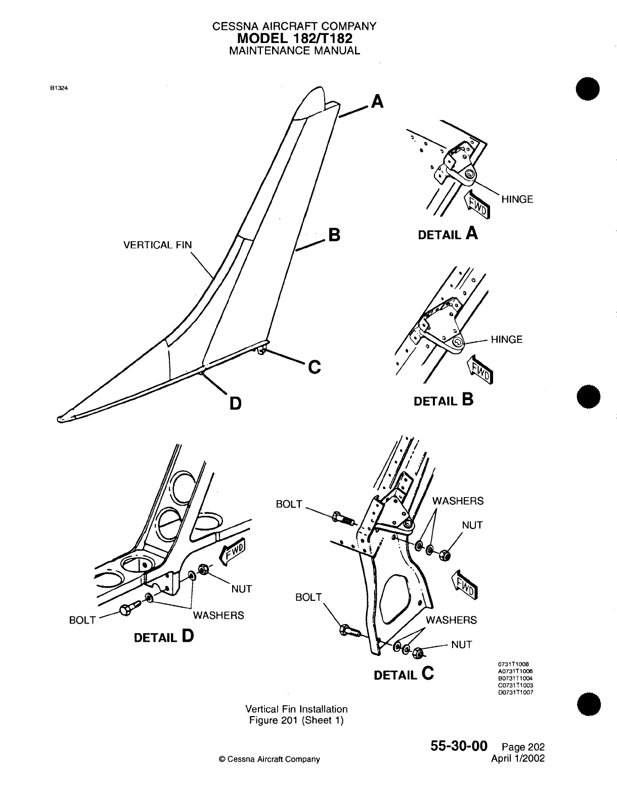
CESSNA AIRCRAFT
COMPANY
MODEL
182/T182
MAINTENANCE
MANUAL
B1
A
B
VERTICAL
FIN
HINGE
DETAIL
A
HINGE
C
DETAIL
B
BOLT
B(
DETAIL
D
Vertical
Fin
Installation
Figure
201
(Sheet
1)
©
Cessna
Aircraft
Company
D
rM/a1
-I
DUL
I
NUT
NUT
DETAIL
C
0731T1008
A0731T1006
B0731T1004
C0731T1003
D0731T1007
55-30-00
Page
202
April 1/2002
\vzz,

CHAPTER
WINDOWS

CESSNA
AIRCRAFT
COMPANY
MODEL
182/T182
MAINTENANCE
MANUAL
LIST
OF EFFECTIVE
PAGES
CHAPTER-SECTION-SUBJECT
56-Title
56-List
of
Effective Pages
56-Record
of
Temporary
Revisions
56-Table
of
Contents
56-00-00
56-00-01
56-10-00
56-20-00
56-30-00
PAGE
Pages
1-2
Pages
1-2
Pages
201-203
Pages
201-202
Pages
201-202
©
Cessna
Aircraft
Company
56
-
LIST
OF
EFFECTIVE
PAGES
Page
1
of
1
Jan
2/2006
DATE
Jan
2/2006
April
1/2002
April
1/2002
Mar
1/2005
April 1/2002
Temporary
Revision
Number
RECORD
OF
TEMPORARY REVISIONS
Page
Number
Issue
Date
By
Date
Removed
By
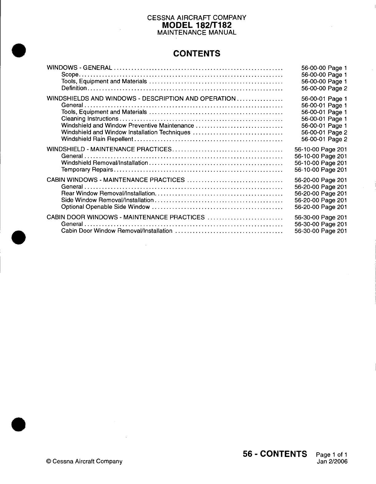
CESSNA
AIRCRAFT
COMPANY
MODEL
182/T182
MAINTENANCE
MANUAL
CONTENTS
WINDOWS
-
GENERAL
.........
............................
.....................
S
cope......................................................................
Tools,
Equipment
and
Materials
..............................................
Definition...................................................................
WINDSHIELDS
AND
WINDOWS
-
DESCRIPTION
AND
OPERATION
...............
General
....................................................................
Tools,
Equipment
and
Materials
..............................................
Cleaning Instructions
.....................................................
Windshield
and
Window
Preventive Maintenance
..............................
Windshield
and
Window Installation Techniques
...............................
Windshield
Rain
Repellent
............................
......................
WINDSHIELD
-
MAINTENANCE
PRACTICES...................................
General
...................................................................
Windshield Removal/Installation
............................................
Temporary
Repairs
..........................................................
CABIN
WINDOWS
-
MAINTENANCE PRACTICES
.................................
G
eneral....................................................................
Rear
Window
Removal/Installation............................................
Side
Window Removal/Installation
............................................
Optional
Openable
Side
Window
.............................................
CABIN
DOOR
WINDOWS
-
MAINTENANCE
PRACTICES
..........................
General
....................................................................
Cabin Door
Window
Removal/Installation
.....................................
56-00-00
Page
1
56-00-00
Page
1
56-00-00
Page
1
56-00-00
Page
2
56-00-01
Page
1
56-00-01
Page
1
56-00-01
Page
1
56-00-01
Page
1
56-00-01
Page
1
56-00-01
Page
2
56-00-01
Page
2
56-10-00
Page
201
56-10-00
Page
201
56-10-00
Page
201
56-10-00
Page
201
56-20-00
Page
201
56-20-00
Page
201
56-20-00
Page
201
56-20-00
Page 201
56-20-00
Page 201
56-30-00
Page
201
56-30-00
Page
201
56-30-00
Page 201
56
-
CONTENTS
Page
1
of
1
Jan 2/2006
©
Cessna
Aircraft Company
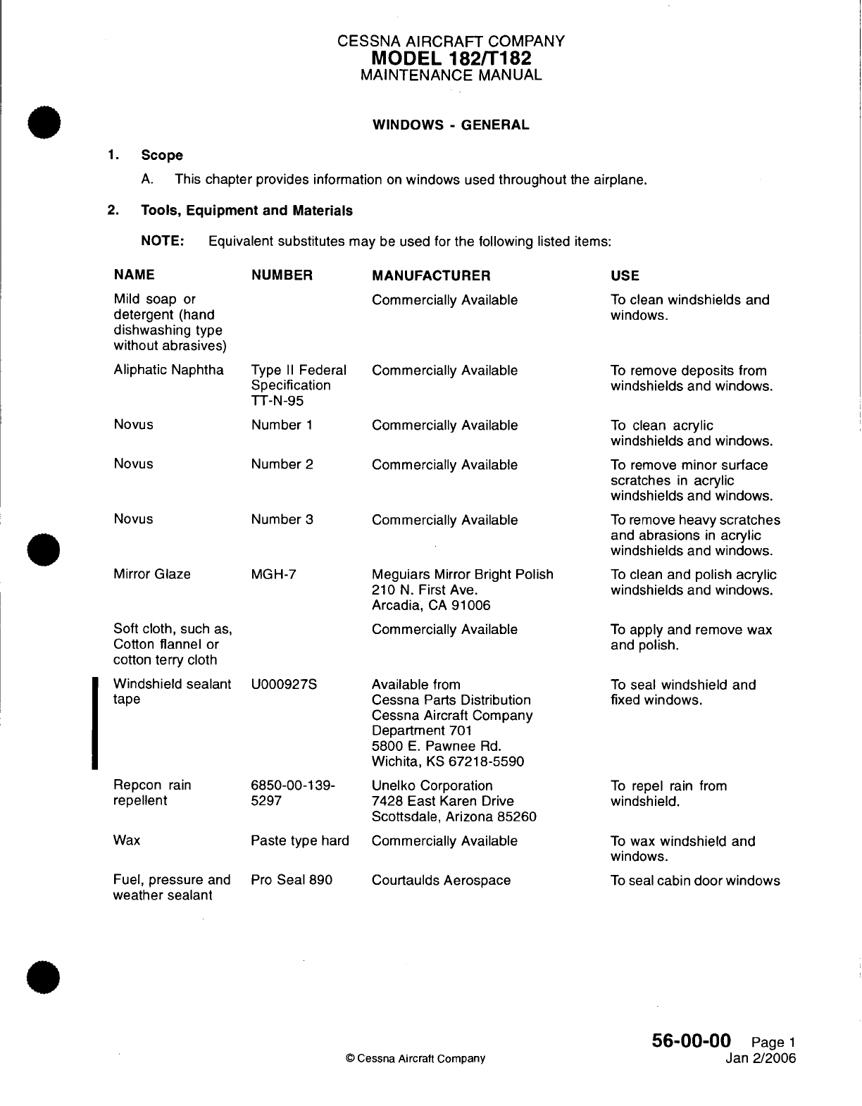
CESSNA
AIRCRAFT
COMPANY
MODEL
182/T182
MAINTENANCE
MANUAL
WINDOWS
-
GENERAL
1.
Scope
A.
This
chapter
provides
information
on
windows
used
throughout
the
airplane.
2.
Tools, Equipment
and
Materials
NOTE:
Equivalent
substitutes
may
be
used
for
the
following
listed
items:
NAME
Mild
soap
or
detergent
(hand
dishwashing
type
without
abrasives)
Aliphatic
Naphtha
Novus
NUMBER
Type
II
Federal
Specification
TT-N-95
Number
1
Novus
Number
2
Novus Number
3
Mirror
Glaze
Soft
cloth,
such
as,
Cotton
flannel
or
cotton
terry
cloth
Windshield
sealant
tape
Repcon
rain
repellent
Wax
Fuel,
pressure
and
weather
sealant
MGH-7
U000927S
6850-00-139-
5297
Paste
type
hard
Pro
Seal
890
MANUFACTURER
Commercially
Available
Commercially Available
Commercially
Available
Commercially
Available
Commercially
Available
Meguiars
Mirror
Bright
Polish
210
N.
First
Ave.
Arcadia,
CA
91006
Commercially
Available
Available
from
Cessna
Parts
Distribution
Cessna
Aircraft
Company
Department
701
5800
E.
Pawnee
Rd.
Wichita,
KS
67218-5590
Unelko Corporation
7428
East
Karen Drive
Scottsdale,
Arizona
85260
Commercially
Available
Courtaulds
Aerospace
USE
To
clean
windshields
and
windows.
To
remove
deposits
from
windshields
and
windows.
To
clean
acrylic
windshields
and
windows.
To
remove
minor
surface
scratches
in
acrylic
windshields
and
windows.
To
remove
heavy
scratches
and
abrasions
in
acrylic
windshields
and
windows.
To
clean
and
polish
acrylic
windshields
and
windows.
To
apply and remove
wax
and
polish.
To
seal
windshield
and
fixed
windows.
To
repel
rain
from
windshield.
To
wax
windshield
and
windows.
To
seal
cabin
door windows
56-00-00
Page
1
Jan
2/2006
©
Cessna
Aircraft
Company
I
CESSNA AIRCRAFT
COMPANY
MODEL
182/T182
MAINTENANCE
MANUAL
3.
Definition
A.
This
chapter
is
divided
into
sections
and
subsections
to
assist
maintenance personnel
in
locating
specific
systems
and
information.
The
following
is
a
brief
description
of
each
section.
For
locating
information within the
chapter,
refer
to
the
Table
of
Contents
at
the
beginning of
the
chapter.
(1)
The
section
on
flight
compartment windows provides
maintenance instructions
for
repair
and
replacement
of the
windshield.
(2)
The
section
on
cabin
windows
provides
maintenance
instructions
for
the cabin
side
and
cabin
rear
windows.
(3)
The
section
on
door windows
provides
maintenance
instructions
for
openable
windows
located
in
the cabin doors.
56-00-00
Page
2
©
Cessna
Aircraft
Company
Jan
2/2006
CESSNA
AIRCRAFT
COMPANY
MODEL
182/T182
MAINTENANCE
MANUAL
WINDSHIELDS
AND
WINDOWS
-
DESCRIPTION AND
OPERATION
1.
General
A.
This
section provides instructions
and
tips
for cleaning
and
installing
windshields
and
windows
used
in
the
airplane.
2.
Tools,
Equipment
and
Materials
A.
For
a
list
of
required
tools,
equipment
and
materials,
refer
to Windows
-
General.
3.
Cleaning
Instructions
CAUTION:
Windshields
and
windows
(acrylic-faced)
are
easily damaged
by
improper
handling
and
cleaning
techniques.
CAUTION:
Do
not
use
methanol,
denatured alcohol,
gasoline,
benzene,
xylene,
methyl propyl
ketone,
acetone,
carbon
tetrachloride,
lacquer
thinner,
commercial
or
household
window
cleaning
sprays
on
windshields
or
windows.
A.
Instructions
For
Cleaning.
(1)
Place
airplane
inside
hangar
or
in
shaded
area
and
allow
to
cool
from
heat of
sun's
direct
rays.
(2)
Using
clean (preferably
running) water,
flood
the
surface.
Use
bare
hands
with
no
jewelry
to
feel
and
dislodge
any
dirt
or
abrasive materials.
(3)
Using
a
mild
soap
or
detergent
(such
as
a
dishwashing
liquid)
in
water,
wash
the surface.
Again
use
only
the
bare hand
to
provide rubbing
force.
(A
clean cloth may
be
used
to
transfer
the
soap
solution
to the
surface,
but
extreme care
must
be
exercised
to
prevent
scratching the surface.)
(4)
When
contaminants
on
acrylic
windshields
and
windows
cannot
be
removed
by
a
mild
detergent,
Type
II
aliphatic
naphtha,
applied
with
a
soft
clean
cloth,
may
be
used
as
a
cleaning solvent.
Be
sure
to
frequently
refold
cloth
to
avoid
redepositing
contaminants
and/or
scratching
windshield
with
any abrasive particles.
(5)
Rinse surface
thoroughly
with
clean fresh
water
and dry
with
a
clean
cloth.
(6)
Hard
polishing
wax
should
be
applied
to
acrylic surfaces.
(The
wax
has an
index
of
refraction
nearly the
same
as
transparent
acrylic
and
will
tend
to
mask
any
shallow
scratches
on
the
windshield
surface.)
(7)
Acrylic
surfaces
may
be
polished
using
a
polish
meeting
Federal
Specification
P-P-560
applied
per the
manufacturers instructions.
NOTE:
When
applying
and
removing wax
and
polish,
use
a
clean,
soft
cloth, such
as
cotton
flannel.
4.
Windshield
and
Window
Preventive
Maintenance
NOTE:
Utilization
of the
following techniques
will
help
minimize
windshield
and
window
crazing.
A.
General
Notes
and
Techniques
For
Acrylic Windshields.
(1)
Keep
all
surfaces
of
windshields
and
windows
clean.
(2) If
desired,
wax
acrylic
surfaces.
(3)
Carefully cover
all
surfaces
during
any
painting,
powerplant cleaning
or
other procedure
that
calls
for
use
of
any
type
of
solvents
or
chemicals.
(4)
Do
not
park
or
store
airplane where
it
might
be
subjected
to
direct
contact with
or
vapors
from:
methanol, denatured
alcohol,
gasoline, benzene, xylene,
methyl propyl
ketone,
acetone, carbon
tetrachloride,
lacquer
thinner,
commercial
or
household window cleaning
sprays,
paint
strippers,
or
other
types
of
solvents.
(5)
Do
not
leave
sunvisors
up
against windshield
when
not
in
use.
The reflected
heat
from
these
items
causes
elevated temperatures
on
the
windshield.
If
solar
screens
are
installed
on the
inside
of
the
airplane,
make
sure
they
are
the
silver
appearing, reflective
type.
56-00-01
Page
1
©
Cessna Aircraft
Company
April
1/2002
CESSNA AIRCRAFT
COMPANY
MODEL
182/T182
MAINTENANCE
MANUAL
(6)
Do
not
use
a
power
drill
motor
or
other
powered
device
to
clean,
polish,
or wax
surfaces.
5.
Windshield
and
Window
Installation
Techniques
A.
Installation Techniques.
(1)
Special
drills
must
be
used
when
drilling
holes
in
acrylic.
Standard
drills
will cause
the
hole to
be
oversized,
distorted,
or
excessively
chipped.
(2)
Whenever
possible,
a
coolant,
such
as
a
plastic
drilling
wax,
should
be
used
to
lubricate
the
drill
bit.
(3)
Drilled
holes
should
be
smooth
with
a
finish
of 125
rms
(root mean
square).
(4)
The
feed
and speed
of
the
drill
is
critical.
Refer
to
Table
1
for
thickness
versus
drill
speed
information.
Table
1.
Material
Thickness
vs.
Drill
Speed
Thickness
(inches)
Thickness
(mm)
Drill
Speed (RPM)
0.062
to
0.1875
1.57
to
4.76
1500 to 4500
0.250
to
0.375
6.35
to
9.52
1500
to
2000
0.4375
11.10
1000
to
1500
0.500
12.70 500 to
1000
0.750
19.05
500
to
800
1.00
25.4
500
(5) In
addition
to
feed
and
speed
of the
drill
bit,
the
tip configuration
is of
special
importance
when
drilling through
acrylic
windows
and
windshields.
Tip
configuration
varies
with hole depth,
and
the
following
information
applies
when
drilling through acrylic:
(a)
Shallow
Holes
-
When
hole
depth
to hole
diameter
ratio
is
less
than
1.5
to
1,
the
drill
shall
have
an
included
tip
angle
of
55
degrees
to 60
degrees
and
a lip
clearance
angle
of
15
degrees
to
20
degrees.
(b)
Medium
Deep
Holes
-
When
hole
depth
to
hole
diameter
ratio
is
from
1.5
to
1
up
to
3
to
1,
the
drill shall
have
an
included
tip
angle
of
60 degrees
to
140
degrees
and
a
lip
clearance
angle
of
15
degrees to
20
degrees.
(c)
Deep
Holes
-
when
hole depth
of
hole
diameter
ratio
is
greater than
3
to
1,
the
drill
shall
have
an
included
tip
angle
of
140
degrees and
a lip
clearance
of
12
degrees to
15
degrees.
(6)
Parts
which
must have
holes drilled shall
be
backed
up
with
a
drill
fixture.
Holes
may
be
drilled
through
the
part
from one
side.
However,
less
chipping
around
holes will
occur
if
holes
are
drilled
by
drilling
the
holes
from
both
sides. This
is
accomplished
by
using
a
drill
with
an
acrylic
backup
piece
on
the opposite
side.
Remove
the
drill
from
the
hole
and
switch
the
backup
plate
and
finish
drilling
from the
opposite
side.
6.
Windshield
Rain
Repellent
A.
Repcon
is a
rain
repellent
and
surface
conditioner
that
may
be
used
to
increase
the
natural
cleaning
of
the
windshield
during
rain.
Apply
in
accordance
with
manufacturers
instructions.
56-00-01
Page
2
©
Cessna
Aircraft
Company
April 1/2002
CESSNA
AIRCRAFT
COMPANY
MODEL
182/T182
MAINTENANCE
MANUAL
WINDSHIELD
-
MAINTENANCE
PRACTICES
1.
General
A.
This section
provides instructions
for
removal
and
installation
of
the
window
as
well
as repair
techniques applicable
to
acrylic windshields
and
windows.
2.
Windshield
Removal/Installation
A.
Remove
Windshield
(Refer
to
Figure
201).
(1)
Remove wing
fairings.
(2)
Remove
air
vent
tubes.
Refer
to
Chapter
21,
Fresh
Air
Distribution
-
Maintenance Practices.
(3)
Drill
out
rivets
securing front retainer
strip.
(4)
Remove
and
tape compass
clear
of
work
area.
Do
not
disconnect
electrical
wiring.
CAUTION:
If
windshield
is
to
be
reinstalled,
be
sure
to
protect
windshield
during
removal.
(5)
Pull
windshield straight
forward,
out
of
side
and
top
retainers. Remove
top
retainer
if
necessary.
(6)
Clean
sealer
from
inner
sidewalls
and
bottom
of
retainers.
B.
Install
Windshield
(Refer
to
Figure
201).
(1) If
windshield
is
to
be
reinstalled, clean
off
old
sealer
and
felt, then
install
new felt
around
edges
of
windshield.
(2)
If
new
windshield
is
to
be
installed,
remove
protective
cover
and
clean.
(3)
Apply
new
felt
to
edges
of
windshield.
(4)
Apply windshield sealant
tape
along
the
sides
and bottom
of
felt.
Refer
to
Windows
-
General,
for
a
list
of
sealant
tape.
(5)
Position
bottom
edge
of
windshield
against deck skin.
(6)
Starting
at
upper
corner,
gradually
work
windshield
into
position.
NOTE:
Use
care
not
to
crack
windshield
when installing.
If
not
previously
removed, top
retainer
may be
removed
if
necessary.
NOTE:
Screws
and
self-locking
nuts
may
be
used
instead
of
rivets
which
fasten front
retaining
strip to
cowl
deck.
If
at least
No.
6
screws
are
used,
no
loss
of
strength
will
result.
(7)
Install
compass
(8)
Tighten
or
install
windshield
retainers
as
required.
(9)
Install
air vent
tube.
Refer
to
Chapter
21,
Fresh
Air
Distribution
-
Maintenance Practices.
(10)
Install
wing
fairings.
NOTE:
Tape
gap
between
windshield
and
leading
edge
with
cloth industrial
tape
2.5
inches
wide
on both
sides.
3.
Temporary
Repairs
A.
Temporary
repairs
to
windshields
and
windows
can
be
accomplished
using
the
following
steps. Refer
to
Figure
202
for
an
illustration
of
repair
techniques.
(1)
When
a
crack
appears,
drill
a
hole
at
end of
crack
to
prevent
further
spreading.
Hole
should
be
approximately
1/8
inch
(3.2 mm)
diameter,
depending
on
length
of
crack
and
thickness
of
material.
(2)
Temporary
repairs
to
flat
surfaces
can
be
accomplished
by
placing
a
thin
strip
of
wood
over
each
side
of
the
surface,
and
inserting
small
bolts
through
the wood
and
plastic.
A
cushion
of
sheet
rubber
or
airplane fabric
should
be
placed
between wood
and
plastic
on
both
sides.
(3) A
temporary
repair can
be
made
by
drilling
small
holes
along
both
sides
of
crack,
1/8
to
1/4
inch
(3.2 to
6.4
mm)
apart,
and
lacing
edges
together
with
soft wire.
This
type
of
repair
is
used
as
a
temporary
measure
only,
and as
soon
as
facilities
are
available,
panel
should
be
replaced.
56-10-00
Page
201
©
Cessna Aircraft Company
April
1/2002
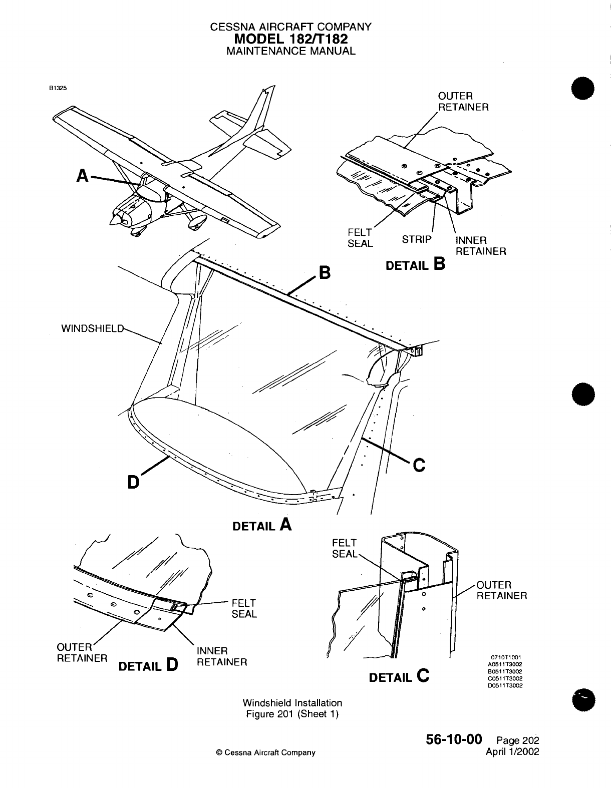
CESSNA AIRCRAFT
COMPANY
MODEL
182/T182
MAINTENANCE MANUAL
3UTER
RETAINER
INNER
RETAINER
DETAIL
A
FELT
SEAL
UU
I l-l
RETAINER
DETAIL
D
INNER
RETAINER
DETAIL
C
jOUTER
RETAINER
0710T1001
A0511T3002
B0511T3002
C0511T3002
D0511T3002
Windshield Installation
Figure
201
(Sheet
1)
©
Cessna
Aircraft
Company
56-10-00
Page
202
April
1/2002
3
f~1
I-I
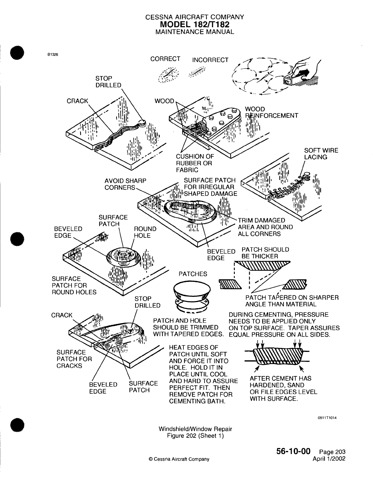
CESSNA
AIRCRAFT
COMPANY
MODEL
182/T182
MAINTENANCE
MANUAL
CORRECT INCORRECT
STOP
DRILLED
UU1
H
AND HOLE
NEE
JLD
BE
TRIMMED
ON
TAPERED
EDGES.
EQI
HEAT
EDGES OF
PATCH
UNTIL
SOFT
AND
FORCE
IT
INTO
HOLE.
HOLD
IT
IN
PLACE UNTIL
COOL
AND
HARD
TO
ASSURE
D
r-Dr
-)r"rT
r-IT
-ri
r-I
PATCH
rnlrF AI
1ni. I
rlCI
REMOVE PATCH
FOR
CEMENTING
BATH.
HINJU
UtMtN
I
INU,
IMHtI-UHt
EDS
TO
BE
APPLIED
ONLY
TOP
SURFACE.
TAPER ASSURES
JAL
PRESSURE
ON
ALL
SIDES.
/ ^
AFTER
CEMENT HAS
HARDENED,
SAND
OR
FILE
EDGES
LEVEL
WITH SURFACE.
0511T1014
WindshieldNVindow
Repair
Figure 202
(Sheet
1)
©
Cessna Aircraft
Company
56-10-00
Page
203
April
1/2002
B1326
WIRE
G
RPER
CRAC
SUF
PAT
CRA
IAL
EDGE
CESSNA
AIRCRAFT
COMPANY
MODEL
182/T182
MAINTENANCE
MANUAL
CABIN
WINDOWS
-
MAINTENANCE PRACTICES
1.
General
A.
The
airplane
has
two
side windows and
a
rear
window,
all
found
in
the
rear
cabin
area.
Maintenance
procedures
are
limited
to
the
removal and
installation
of
the
windows.
For
instructions
on
temporary
repair,
refer
to
Windshield
-
Maintenance
Practices.
2.
Rear
Window
Removal/Installation
A.
Remove
the
Rear
Window
(Refer
to
Figure
201).
(1)
Remove
the
upholstery
as
necessary
to
get access
to
the
retainer
strips
inside
the
cabin.
Refer
to
Chapter
25,
Interior
Upholstery
-
Maintenance Practices.
(2)
Remove
the
rivets as
necessary
to
remove
the
outer
retainer
strip
from
the
aft
edge
of
the
window.
(3)
To
remove
the window,
lift
the
aft
edge
and
pull
the window
aft.
If
you cannot remove
the
window
easily,
rivets
that attach
the
retainer
strips
inside
the
cabin can
also
be
removed
and
the retainer
strips
loosened
or removed.
B.
Install
the
Rear
Window
(Refer
to
Figure
201).
(1) If
the
same
window
is
being
installed
again,
remove
all
the
remaining
sealant
from the
window.
(2)
Clean
the
channels
and
retainers
to
remove
all
the remaining
sealant.
(3)
Make sure
that
the
window
fits
correctly,
and
carefully
grind
off
unwanted
plastic.
(4)
Put
a
felt
strip
around
all
the
edges
of
the window,
and
apply sealant
to
prevent leaks.
(5)
Install the
rear
window
in
the
airplane
and
attach the window
with
retainer
strips
and
rivets.
(6)
Install the upholstery.
Refer
to
Chapter
25,
Interior
Upholstery
-
Maintenance
Practices.
3.
Side Window
Removal/Installation
A.
Remove
the Side Window
(Refer
to
Figure
201).
(1)
Remove
the
upholstery
as
necessary
to
get
access
to
the
retainer
strips
inside the cabin.
Refer
to
Chapter
25,
Interior
Upholstery
-
Maintenance
Practices.
(2)
Remove
the
rivets
that attach the retainer strips
to
the
airplane.
(3)
Remove
the
window
from
the
airplane.
B.
Install
the Side
Window
(Refer
to
Figure
201).
(1) If
the
same window
is
being
installed
again, remove all
the
remaining
sealant
from
the
window.
(2)
Clean the
channels
and
retainers
to
remove all
the
remaining
sealant.
(3)
Put
a
felt
strip
around
all
the
edges
of
the
window,
and
apply sealant
to
prevent leaks.
(4)
Install
the
side window
in
the
airplane
and
attach
the
window
with
retainer
strips
and rivets.
(5)
Install
the
upholstery. Refer
to
Chapter
25,
Interior
Upholstery
-
Maintenance
Practices.
4.
Optional
Openable Side
Window
A.
Some
airplanes
have
an
optional openable
side window
found
on
the
left
side
of
the airplane
aft
of
the
pilot's
cabin
door
window.
These
windows
have
hinges
and
are
a
part
of
the
side
window.
The window
opens
to
the inside,
and
has two
latches
at
the top
and
three
hinges
at
the
bottom. The
removal
and
installation
procedure
for
the
openable
window
assembly
is
the
same
as
the
removal
and
installation
procedure
for
the standard side window.
If
the
openable
side
window
is
damaged,
all
of
the
window
assembly
must
be
replaced.
56-20-00
Page
201
©
Cessna
Aircraft
Company
Mar
1/2005
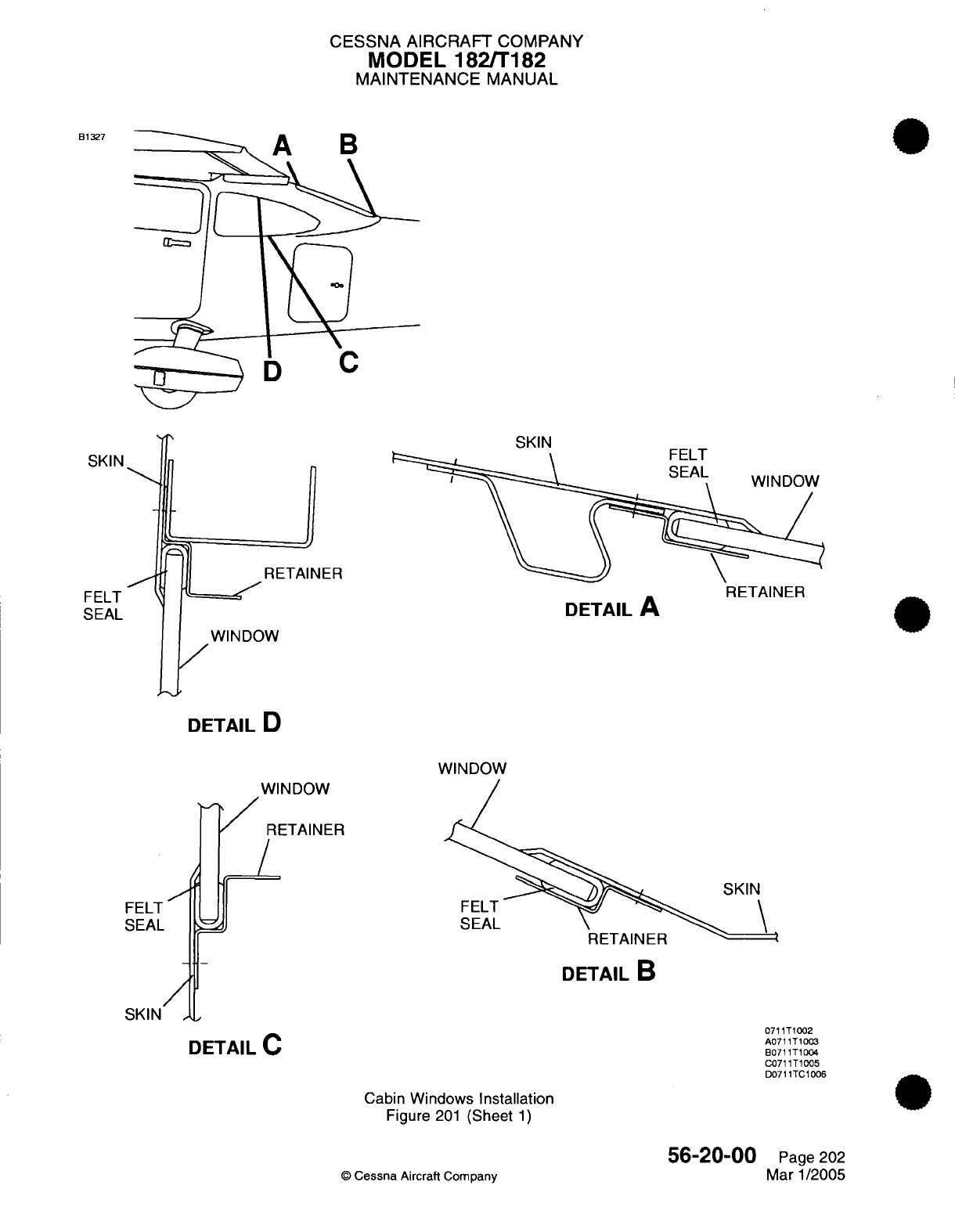
CESSNA AIRCRAFT
COMPANY
MODEL
182/T182
MAINTENANCE
MANUAL
B1327
SKIN
SKIN
IER
WINDOW
DETAIL
D
RETAINER
DETAIL
A
WINDOW
WINDOW
RETAINER
/
J
SKIN
FELT
SEAL
DETAIL
B
SKIN
,
DETAIL
C
Cabin
Windows
Installation
Figure
201
(Sheet
1)
©
Cessna
Aircraft
Company
FELT
SEAL
FELT
SEAL
0711T1002
A0711T1003
E0711T1004
C0711T1005
D0711TC1006
56-20-00
Page
202
Mar
1/2005
..
_
. _
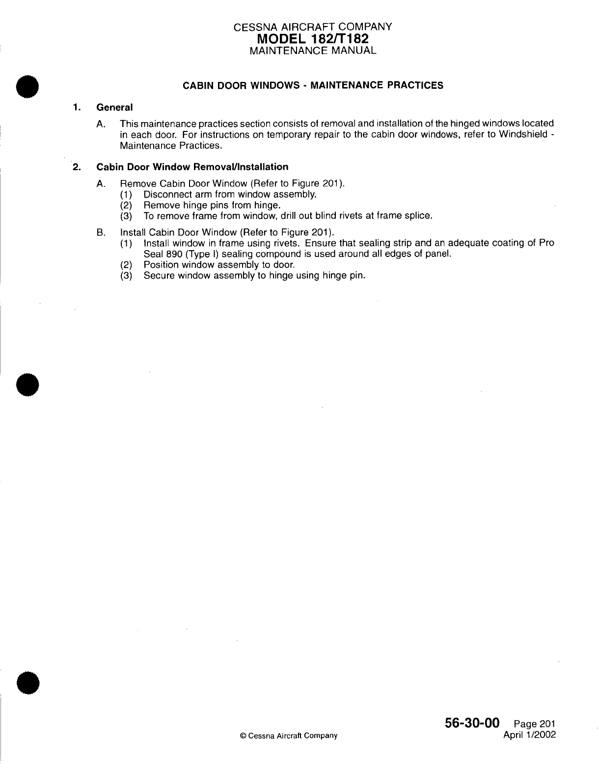
CESSNA
AIRCRAFT
COMPANY
MODEL
182/T182
MAINTENANCE
MANUAL
CABIN
DOOR
WINDOWS
-
MAINTENANCE
PRACTICES
1.
General
A.
This
maintenance
practices
section
consists
of
removal
and
installation
of
the
hinged
windows
located
in
each
door.
For
instructions
on
temporary
repair
to
the cabin
door
windows, refer
to
Windshield
-
Maintenance Practices.
2.
Cabin
Door
Window Removal/Installation
A.
Remove Cabin
Door
Window
(Refer
to
Figure
201).
(1)
Disconnect
arm
from
window
assembly.
(2)
Remove
hinge pins
from
hinge.
(3)
To
remove
frame from
window, drill
out
blind
rivets
at
frame
splice.
B.
Install Cabin
Door
Window
(Refer
to
Figure 201).
(1)
Install
window
in
frame
using
rivets. Ensure
that
sealing
strip and
an
adequate coating
of
Pro
Seal
890
(Type
I)
sealing
compound
is
used
around
all
edges
of
panel.
(2)
Position window
assembly
to door.
(3)
Secure
window
assembly
to hinge
using
hinge
pin.
56-30-00
Page
201
©
Cessna Aircraft
Company
April
1/2002
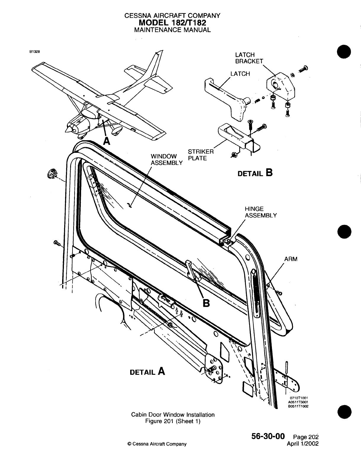
CESSNA
AIRCRAFT
COMPANY
MODEL
182/T182
MAINTENANCE
MANUAL
LATCH
BRACKET
PLATE
DETAIL
B
HINGE
ASSEMBLY
ARM
DETAIL
A
Cabin Door
Window
Installation
Figure
201
(Sheet
1)
©
Cessna
Aircraft
Company
&'
1001
T3001
T1002
56-30-00
Page
202
April
1/2002
E

CHAPTER
WINGS
CESSNA
AIRCRAFT
COMPANY
MODEL
182/T182
MAINTENANCE
MANUAL
LIST
OF
EFFECTIVE
PAGES
PAGE
CHAPTER-SECTION-SUBJECT
57-Title
57-List
of
Effective
Pages
57-Record
of
Temporary
Revisions
57-Table
of
Contents
57-00-00
57-10-00
Page
1
Pages
201-208
©
Cessna Aircraft
Company
57
-
LIST
OF
EFFECTIVE
PAGES
Page
1
of
1
Mar 1/2005
DATE
Aug
4/2003
April
1/2002

Temporary
Revision
Number
RECORD
OF
TEMPORARY
REVISIONS
Page
Number
Issue
Date
By
Date
Removed
By
CESSNA
AIRCRAFT
COMPANY
MODEL
182/T182
MAINTENANCE
MANUAL
CONTENTS
W
INGS
-
GENERAL..........
..................................................
S
co
pe......................................................................
Tools,
Equipment
and
Materials
..............................................
Definition...................................................................
WINGS
AND
WING STRUTS
-
MAINTENANCE
PRACTICES........................
Description
and
Operation
...................................................
Wing
and Strut
Removal/Installation
..........................................
Adjustment
(Correcting
Wing Heavy
Conditions)
...............................
Strut
Damage and
Repair
Criteria
............................................
Wing
Tip
Removal/Installation
...............................................
57-00-00
Page
1
57-00-00
Page
1
57-00-00
Page
1
57-00-00
Page
1
57-10-00
Page
201
57-10-00
Page
201
57-10-00
Page
201
57-10-00
Page
205
57-10-00
Page
206
57-10-00
Page
207
CONTENTS
Page
1
of
1
Mar
1/2005
©
Cessna Aircraft
Company
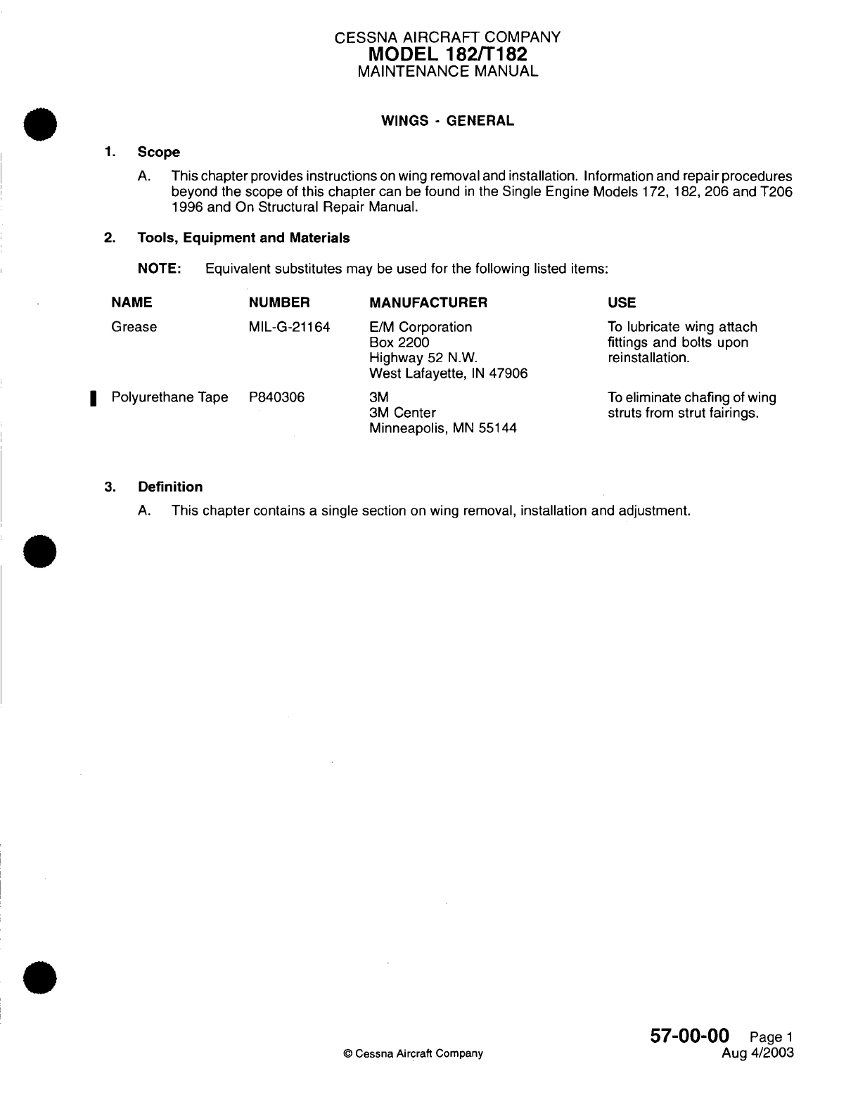
CESSNA
AIRCRAFT
COMPANY
MODEL
182/T182
MAINTENANCE
MANUAL
WINGS
-
GENERAL
1.
Scope
A.
This
chapter
provides
instructions
on
wing
removal
and
installation.
Information
and
repair
procedures
beyond
the
scope
of
this chapter
can
be
found
in
the
Single
Engine
Models
172, 182,
206
and T206
1996
and
On
Structural
Repair
Manual.
2.
Tools,
Equipment
and
Materials
NOTE:
Equivalent
substitutes
may
be
used
for
the following
listed items:
NAME
NUMBER
MANUFACTURER
USE
Grease
MIL-G-21164
I
Polyurethane
Tape
P840306
E/M
Corporation
Box
2200
Highway
52
N.W.
West
Lafayette,
IN
47906
3M
3M
Center
Minneapolis,
MN
55144
To
lubricate wing
attach
fittings
and
bolts
upon
reinstallation.
To
eliminate
chafing
of
wing
struts
from
strut
fairings.
3.
Definition
A.
This
chapter
contains
a
single section
on
wing
removal,
installation
and
adjustment.
57-00-00
Page
1
©
Cessna Aircraft
Company
Aug
4/2003
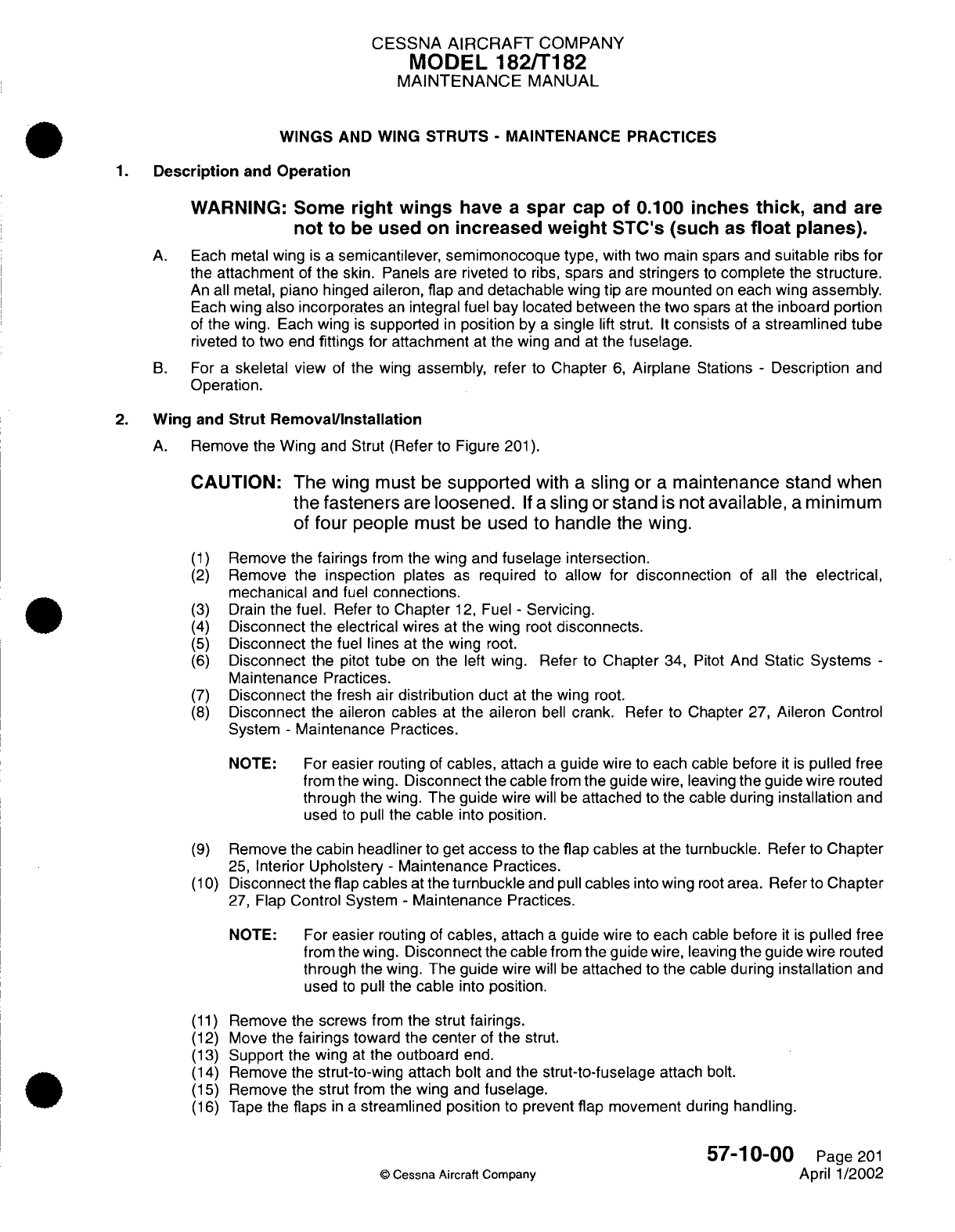
CESSNA
AIRCRAFT
COMPANY
MODEL 182/T182
MAINTENANCE
MANUAL
WINGS
AND WING
STRUTS
-
MAINTENANCE PRACTICES
1.
Description
and
Operation
WARNING:
Some
right
wings
have
a
spar
cap
of
0.100
inches
thick,
and
are
not
to
be
used
on
increased
weight
STC's
(such
as
float
planes).
A.
Each metal
wing
is
a
semicantilever, semimonocoque
type,
with
two main
spars and
suitable
ribs
for
the
attachment
of
the
skin. Panels
are
riveted
to
ribs,
spars
and
stringers
to
complete
the
structure.
An
all
metal,
piano
hinged
aileron,
flap
and
detachable wing
tip
are
mounted
on
each wing
assembly.
Each
wing
also
incorporates
an
integral
fuel
bay located
between
the
two
spars
at
the inboard
portion
of
the
wing. Each
wing
is
supported
in
position
by
a
single
lift
strut.
It
consists
of
a
streamlined
tube
riveted
to
two
end
fittings for attachment
at
the
wing
and
at
the
fuselage.
B.
For
a
skeletal
view
of
the
wing
assembly,
refer
to
Chapter
6,
Airplane
Stations
-
Description
and
Operation.
2.
Wing
and
Strut
Removal/Installation
A.
Remove
the
Wing
and
Strut
(Refer
to Figure
201).
CAUTION:
The
wing
must
be
supported
with
a
sling
or
a
maintenance
stand
when
the
fasteners
are
loosened.
If
a
sling
or
stand
is
not
available,
a
minimum
of
four
people
must
be
used
to
handle
the
wing.
(1)
Remove
the
fairings
from
the wing
and
fuselage
intersection.
(2)
Remove
the
inspection
plates
as
required to
allow
for
disconnection
of
all
the
electrical,
mechanical
and fuel
connections.
(3)
Drain
the
fuel.
Refer
to
Chapter
12,
Fuel
-
Servicing.
(4)
Disconnect
the
electrical
wires
at
the
wing
root
disconnects.
(5)
Disconnect
the
fuel
lines
at
the wing
root.
(6)
Disconnect
the
pitot
tube
on
the
left wing.
Refer
to
Chapter
34,
Pitot
And
Static
Systems
-
Maintenance
Practices.
(7)
Disconnect
the
fresh
air
distribution
duct
at
the
wing
root.
(8)
Disconnect
the
aileron
cables
at
the aileron
bell
crank.
Refer
to
Chapter
27,
Aileron Control
System
-
Maintenance
Practices.
NOTE: For
easier
routing
of
cables,
attach
a
guide
wire
to
each
cable before
it is
pulled
free
from
the
wing.
Disconnect
the
cable
from
the guide
wire,
leaving
the guide wire
routed
through the
wing.
The guide
wire
will
be
attached
to the
cable
during
installation
and
used
to
pull
the
cable
into
position.
(9)
Remove
the cabin
headliner
to get
access
to the
flap
cables
at
the
turnbuckle.
Refer
to
Chapter
25,
Interior
Upholstery
-
Maintenance
Practices.
(10)
Disconnect the
flap
cables
at
the
turnbuckle
and pull
cables
into
wing
root
area. Refer
to
Chapter
27,
Flap
Control System
-
Maintenance
Practices.
NOTE:
For
easier
routing
of
cables,
attach
a
guide
wire
to
each
cable
before
it is
pulled
free
from
the
wing.
Disconnect
the
cable
from the
guide
wire, leaving the
guide wire
routed
through
the
wing. The
guide
wire
will
be
attached
to
the
cable during
installation
and
used
to
pull
the
cable
into
position.
(11)
Remove
the screws
from
the
strut
fairings.
(12)
Move
the
fairings
toward
the center
of
the
strut.
(13)
Support
the
wing
at
the
outboard
end.
(14)
Remove
the
strut-to-wing
attach bolt
and
the
strut-to-fuselage
attach
bolt.
(15)
Remove
the
strut
from the
wing
and
fuselage.
(16)
Tape
the
flaps
in a
streamlined
position
to
prevent
flap
movement
during
handling.
57-10-00
Page
201
©
Cessna
Aircraft Company
April 1/2002
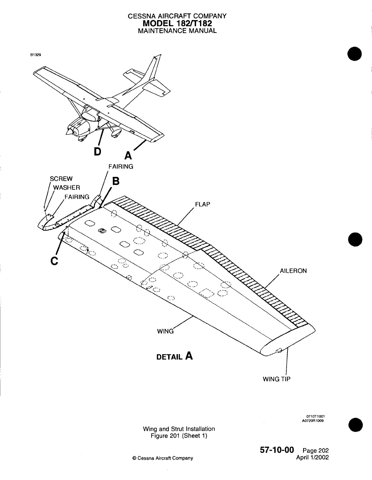
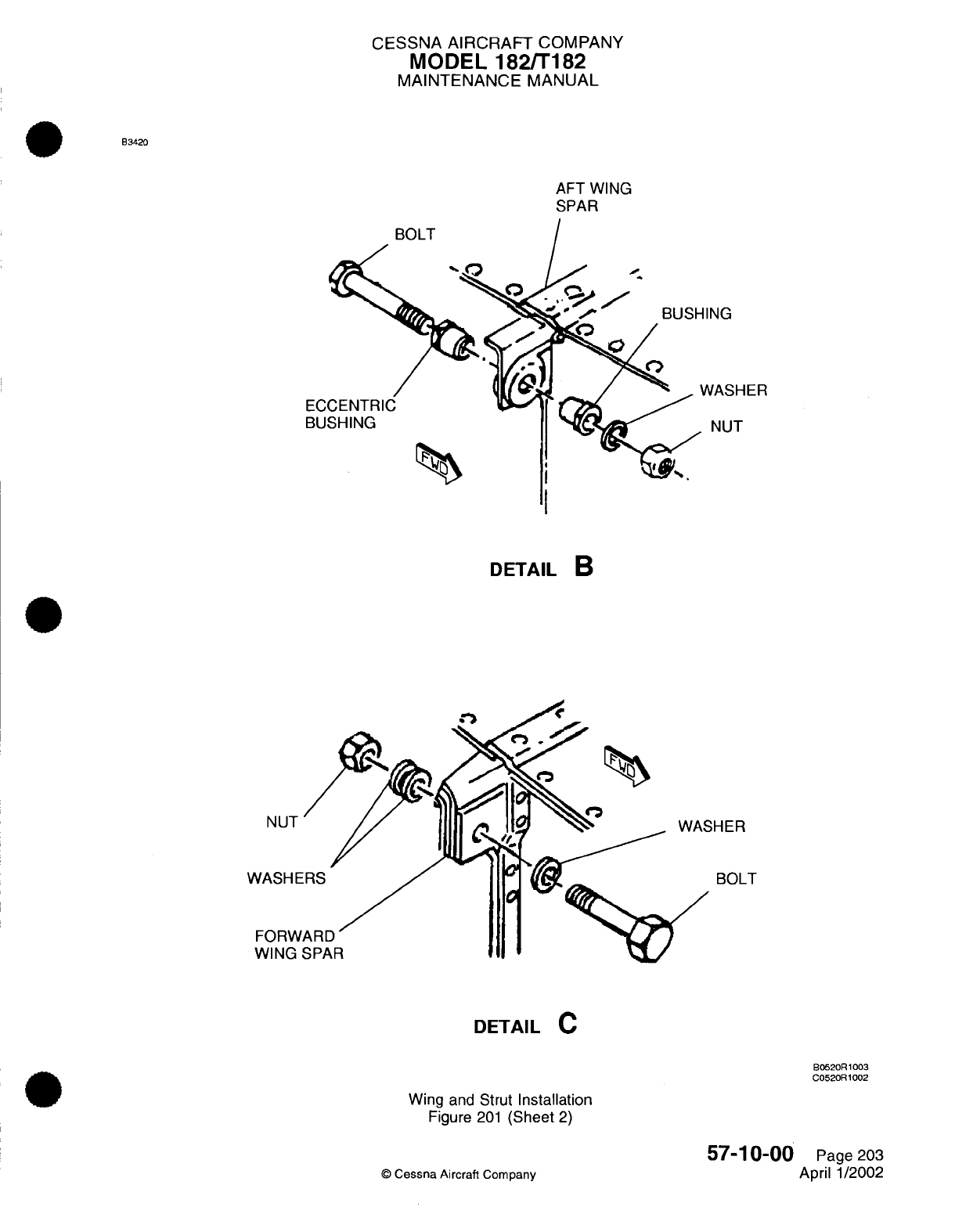
CESSNA
AIRCRAFT
COMPANY
MODEL
182/T182
MAINTENANCE
MANUAL
B3420
AFT WING
SPAR
ING
EC(
BU
<
NASHER
NUT
DETAIL
B
NUT
'HER
WASHE
FORW
WING
BOLT
DETAIL
C
B0520R1003
C0520R1002
Wing
and Strut
Installation
Figure
201
(Sheet
2)
57-10-00
©
Cessna
Aircraft
Company
Page
203
April
1/2002
I
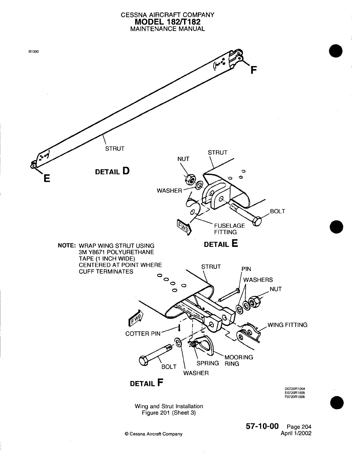
CESSNA
AIRCRAFT
COMPANY
MODEL 182/T182
MAINTENANCE
MANUAL
F
STRUT
STRUT
DETAIL
D
WASHE
BOLT
NOTE:
WRAP WING STRUT
USING
3M
Y8671
POLYURETHANE
TAPE
(1
INCH
WIDE)
rxri- T r- r-- I- A -T -flllT TAll. I f-
- --
DETAIL
E
tN I
tI-IU
A
I
r
CUFF
TERMINAT
FITTING
WASHER
DETAIL
F
Wing
and
Strut
Installation
Figure
201
(Sheet
3)
D0720R1004
E0720R1005
F0720R1006
57-10-00
©
Cessna
Aircraft Company
Page
204
April
1/2002
E
CESSNA
AIRCRAFT
COMPANY
MODEL
182/T182
MAINTENANCE
MANUAL
(17)
Mark
position
of
the
wing
attachment
eccentric bushings
in
relationship
to
the
fittings.
The
bushings
are
used to
rig
out
wing
heaviness.
NOTE:
Wings
must
be
rigged at
installation
if
bushings
are
not
marked.
(18)
Remove
the
nuts,
washers,
bushings
and
bolts
attaching
the
wing
spars to
the
fuselage.
NOTE:
It
may be
necessary
to rock
the
wings
slightly and/or
to
use
a
long
drift
punch
to
remove
attaching
bolts.
(19)
Remove
the
wing
and
lay
it
on a
padded stand.
B.
Install the Wing
and
Strut
(Refer
to
Figure
201).
CAUTION:
Do
not
lubricate
the
threads
of
the
bolts.
(1)
Lightly lubricate
the
wing
attach
bolts
and
holes
with MIL-G-21164
grease
before
installing bolts.
(2)
Hold
the
wing
in
position
and
install
the
bolts,
bushings,
washers
and
nuts
attaching the
wing
spars
to
the
fuselage
fittings.
Make
sure
eccentric
bushings
are
positioned as
marked.
(3)
Torque
the
front
wing
spar bolts
290
to
410
inch-pounds.
(4)
Torque
the rear
wing
spar
bolts
450
to
500
inch-pounds.
(5)
Install
the
0.38
inch
seal
around
strut
with
0.12
inch
gap
on
lower
surface.
(6)
Install
the
bolts,
spacers
and nuts
to
attach
the
upper
and
lower
ends
of
the
wing
strut
to
the
wing
and
fuselage
fittings.
(7)
Route the
flap
cables
using
the
guide
wires.
(8)
Connect
the
flap
cables
at the
turnbuckle above
the
headliner.
Refer
to
Chapter
27,
Flap
Control
System
-
Maintenance
Practices.
(9)
Route the
aileron
cables
using
the guide
wires.
(10)
Connect the
aileron
cable
at
the
aileron
bell
crank.
Refer
to
Chapter
27,
Aileron Control
System
-
Maintenance
Practices.
(11)
Connect the
fresh
air
distribution
at
wing root.
(12)
Connect
the
pitot
tube.
Refer
to
Chapter
34, Pitot
And
Static Systems
-
Maintenance
Practices.
(13)
Connect the
fuel
lines
at
the
wing
root.
(14)
Connect the
electrical
wires
at
the
wing
root.
(15)
Complete
a
leak
check
of
the pitot
tube. Refer
to
Chapter
34,
Pitot
And
Static
Systems
-
Maintenance
Practices.
(16)
Remove
the
tape
from the
flaps.
(17)
Rig
the
flap
system. Refer
to
Chapter
27,
Flap
Control
System
-
Maintenance
Practices.
(18)
Rig
the
aileron
system.
Refer
to
Chapter 27, Aileron
Control
System
-
Maintenance Practices.
(19)
Fuel
the
wing
bay.
Refer
to
Chapter
12,
Fuel
Servicing.
(20)
Check
the
operation
of the
fuel
quantity
system.
Refer
to
Chapter
28,
Fuel
Storage
and
Distribution
-
Maintenance
Practices.
(21)
Install the
wing
root
fairings.
(22)
Install
the cabin
headliner.
Refer
to
Chapter
25,
Interior
Upholstery
-
Maintenance
Practices.
3.
Adjustment
(Correcting
Wing
Heavy
Conditions)
NOTE:
If
considerable
control
wheel
pressure
is
required
to
keep
the
wings
level
in
normal
flight,
a
"wing
heavy"
condition exists
and can
be
corrected
by
the following
procedure.
A.
Adjustment Procedures
(Refer
to
Figure
201).
CAUTION:
The
eccentric
cams
must
be
adjusted
after
all
flight
control
systems
have
been
adjusted
and
rigged.
(1) If
necessary,
rig
the
flight
controls.
Refer
to
Chapter
27,
Flight Controls
-
General.
(2)
Remove
the
wing
fairing strip
from
the
heavy
side
of
the
airplane.
57-10-00
Page
205
©
Cessna
Aircraft
Company
April
1/2002
CESSNA
AIRCRAFT
COMPANY
MODEL
182/T182
MAINTENANCE
MANUAL
CAUTION:
Make
sure
you rotate
the
eccentric bushings
together.
If
you
rotate
just
one, you will
destroy
the alignment
between
the
off-center
bolt
holes
in
the
bushings.
A
nonalignment
of
a
bolt will
result
in
a
force
on
the
bolt
which
will
damage
the
hole
in
the wing
spar.
(3)
Loosen
the aft
wing
spar
nuts and rotate
eccentric bushings
simultaneously
until
the
bushings
are
positioned
with
the
thick
side
of
the eccentrics
up.
NOTE:
This
will
lower
the
trailing
edge
of
the
wing,
and
decrease
wing
heaviness
by
increasing
angle
of
incidence
of
the wing.
(4)
Torque
the
front
wing
spar
bolts 290 to 410
inch-pounds.
(5)
Torque
the
rear
wing
spar
bolts
450 to 500
inch-pounds.
(6)
Install
the fairing
strip.
(7)
Test
fly
the
airplane.
CAUTION: Make sure
the
eccentric bushings
are
rotated
simultaneously.
Rotating
them
separately
will
destroy
the
alignment
between
the
off-center
bolt
holes
in
the
bushings,
thus exerting
a
shearing
force
on
the
bolt,
with
possible
damage
to
the hole
in
the wing
spar.
(a) If
the
wing
heavy
condition
continues,
remove the
fairing
strip
on
the
lighter
wing, loosen
the
nut
and rotate
the eccentric bushings
simultaneously
until
the
bushings
are
positioned
with
the
thick
side
of the
eccentrics
down.
NOTE:
This
will
raise
the
trailing
edge
of
the wing,
thus increasing
wing
heaviness
to
balance heaviness
in
the
opposite
wing.
(8)
Torque
the
rear
wing
spar
bolts 450
to
500
inch-pounds.
(9)
Install
fairing strip
and
repeat
flight test.
4.
Strut
Damage
and
Repair
Criteria
CAUTION:
If
the
strut is
severely dented, cracked
or
deformed,
it
must
be
replaced.
A.
Damage
Caused by
the
Strut
Fairings.
NOTE:
The
following
procedures
are
applicable
only
to
the
specific
areas
of the
strut.
(1)
The strut
must
be
replaced
if a
groove
is
more
then
0.010
inch
in
depth
and
is
less
then
0.75
inch
from
a
rivet
center.
(2)
The
strut must
be
replaced
if
a
groove
is
more
than 0.75
inch from
a
rivet
center
and
the
groove
depth
is
more
then
0.025
inch.
(3) If
groove
depth
is
less
than
0.025
inch
and
is
more
than
0.75
inch from
a
rivet
center,
the strut
must
be
repaired.
tapering
gradually
to
the
original surface
and
burnishing
out to
a
smooth
finish.
(a)
Blend
and
smooth the surface
area
of
the groove. Make
sure
not
to
remove
any
more
material from
the
groove.
(b)
Check
the
area
using
a
dye penetrant
to make
sure
there
are
no
cracks.
(c)
Apply Alodine
and repaint
the
area.
57-10-00
Page
206
©
Cessna
Aircraft Company
April
1/2002
CESSNA
AIRCRAFT
COMPANY
MODEL
182/T182
MAINTENANCE
MANUAL
B.
Damage Caused
by
the
Cabin
Door.
NOTE:
The
following
applies
to the
wing
struts
with
grooves
worn
in
the
lower
trailing
edge.
This
type
of
damage
can
occur
with
cabin
door
usage with
a
missing
or
incorrectly
adjusted
door
stop.
A
incorrectly
adjusted
door
stop allows the
door
to
hit
against
the aft
edge
of
the
strut
at
the
lower
end.
(1)
The strut
must
be
replaced
if
a
groove
is
deeper
than
50
percent
of the
original
material
thickness.
(2)
Repair
the
strut
if
a
groove
is
less
than
50
percent
of
the
original
material
thickness.
(a)
Blend and
smooth
the surrounding
surface area
of
the
groove.
Make
sure
not to
remove
any
more
material
from
the
groove.
(b)
Check
the
area
using
a
dye
penetrant
to
make
sure
there
are
no
cracks.
(c)
Apply
Alodine
and
repaint
the
area.
(d)
Rig
the
door
to
prevent
door
from
rubbing
the
strut
tube.
5.
Wing Tip
Removal/Installation
A.
Remove
the
Wing
Tip
(Refer
to
Figure 202).
(1)
Remove
the
wing
tip.
(2)
Remove
the
strobe
light
and the navigation
light
ground
straps
to
power
supply.
(3)
Disconnect
the
navigation
lights
electrical
connector.
(4)
Disconnect
the
strobe lights electrical
connector.
(5)
Remove
wing
tip
from
wing.
B.
Install
the
Wing Tip
(Refer
to Figure 202).
(1)
Connect the strobe
lights
electrical
connector.
(2)
Connect the navigation lights electrical
connector.
(3)
Move
the
wing
tip
into
position
over
the
wing tip
rib.
Make
sure
the
existing
holes
in
the
wing
tip
align
with
the
attach
holes
in
the
wing
skin/rib
nutplates.
(4)
Make
a
curved
spacer
from
phenolic
or
aluminum
which
is
0.01
inch
to
0.03
inch
thick
and
is
1.0
inch
to
2.0 inches
in
length.
Make
sure
it
matches
the
contour
of the
leading edge.
(5)
Install the
spacer at
the
leading edge
of
the
wing
between
the
skin
and
the inside
contour
of
the
wing
tip.
(6)
Start
at
the
aft
of
the
tip
and
work forward, attach
the
wing
tip
to
wing
using
screws.
(7)
When
all
screws
are
installed,
remove
the
spacer
to
leave
a
gap
of
0.01
inch
to
0.03
inch
between
the
skin
and the
inside
contour
of
the
wing
tip.
57-10-00
Page
207
©
Cessna
Aircraft Company
April
1/2002
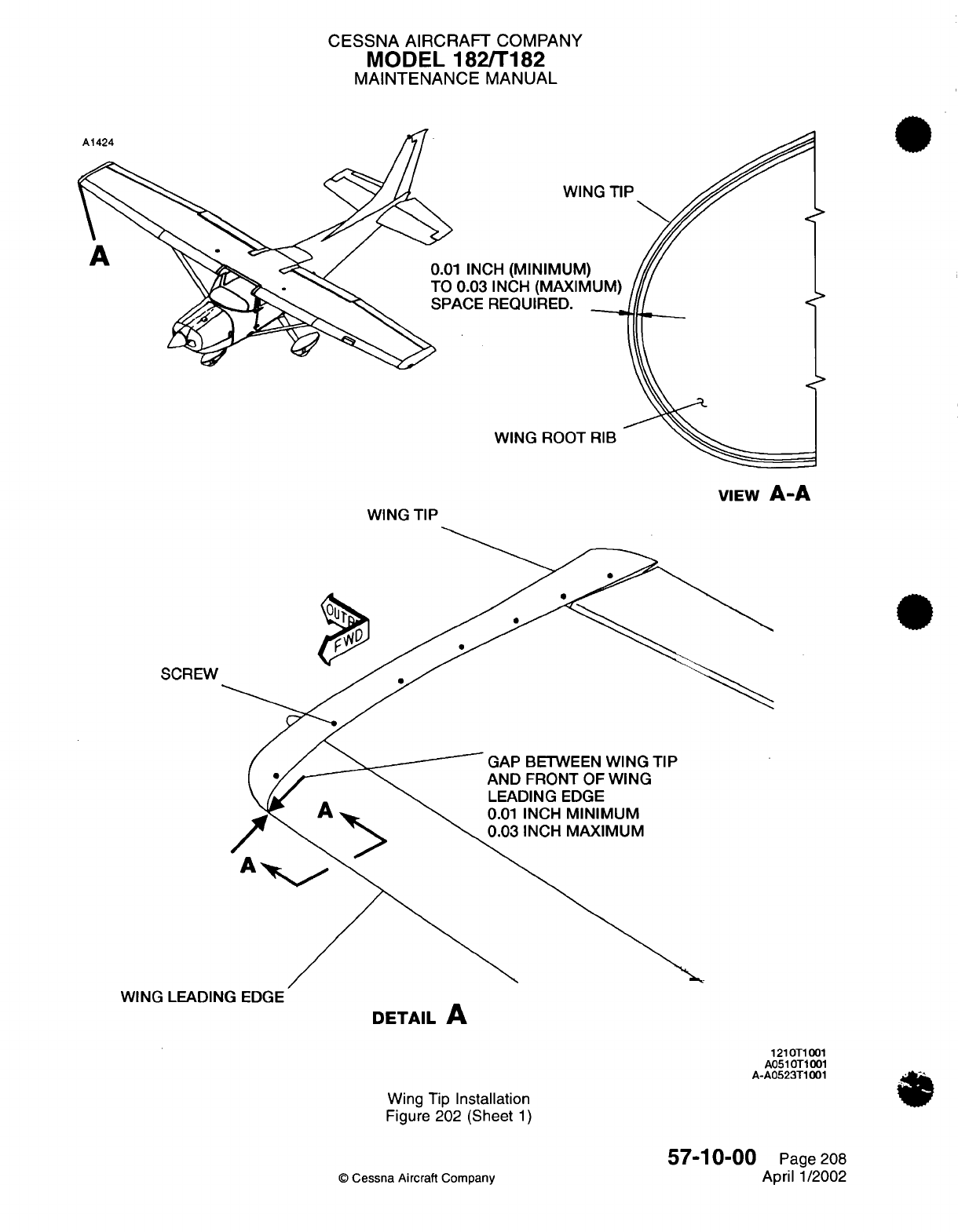
CESSNA AIRCRAFT
COMPANY
MODEL
182/T182
MAINTENANCE
MANUAL
A1424
IP
A
INCH
WING
ROOT
WING
TIP
SCREW
GAP
BETWEEN
WING
TIP
AND
FRONT
OF
WING
LEADING
EDGE
0.01
INCH
MINIMUM
0.03
INCH
MAXIMUM
WING
LEADING
EDGE
DETAIL
A
1210T1001
A0510T1001
A-A0523T1001
Wing
Tip
Installation
Figure 202
(Sheet
1)
©
Cessna
Aircraft
Company
57-10-00
Page
208
April
1/2002
VIEW
A-A

CHAPTER
PROPELLERS
CESSNA
AIRCRAFT
COMPANY
MODEL
182/Ti
82
MAINTENANCE
MANUAL
LIST
OF
EFFECTIVE
PAGES
CHAPTER-SECTION-SUBJECT
61
-Title
61
-List
of
Effective
Pages
61
-Record
of
Temporary
Revisions
61
-Table
of
Contents
61-00-00
61
-10-00
61-20-00
PAGE
Page
1
Pages
201-203
Pages 201-205
©
Cessna Aircraft
Company
61
-
LIST
OF
EFFECTIVE
PAGES
Page
1
of
1
Jul
1/2007
DATE
April
1/2002
Mar
1/2004
Jul
1/2007

Temporary
Revision
Number
RECORD
OF
TEMPORARY REVISIONS
Page
Number
Issue
Date
By
Date
Removed
By
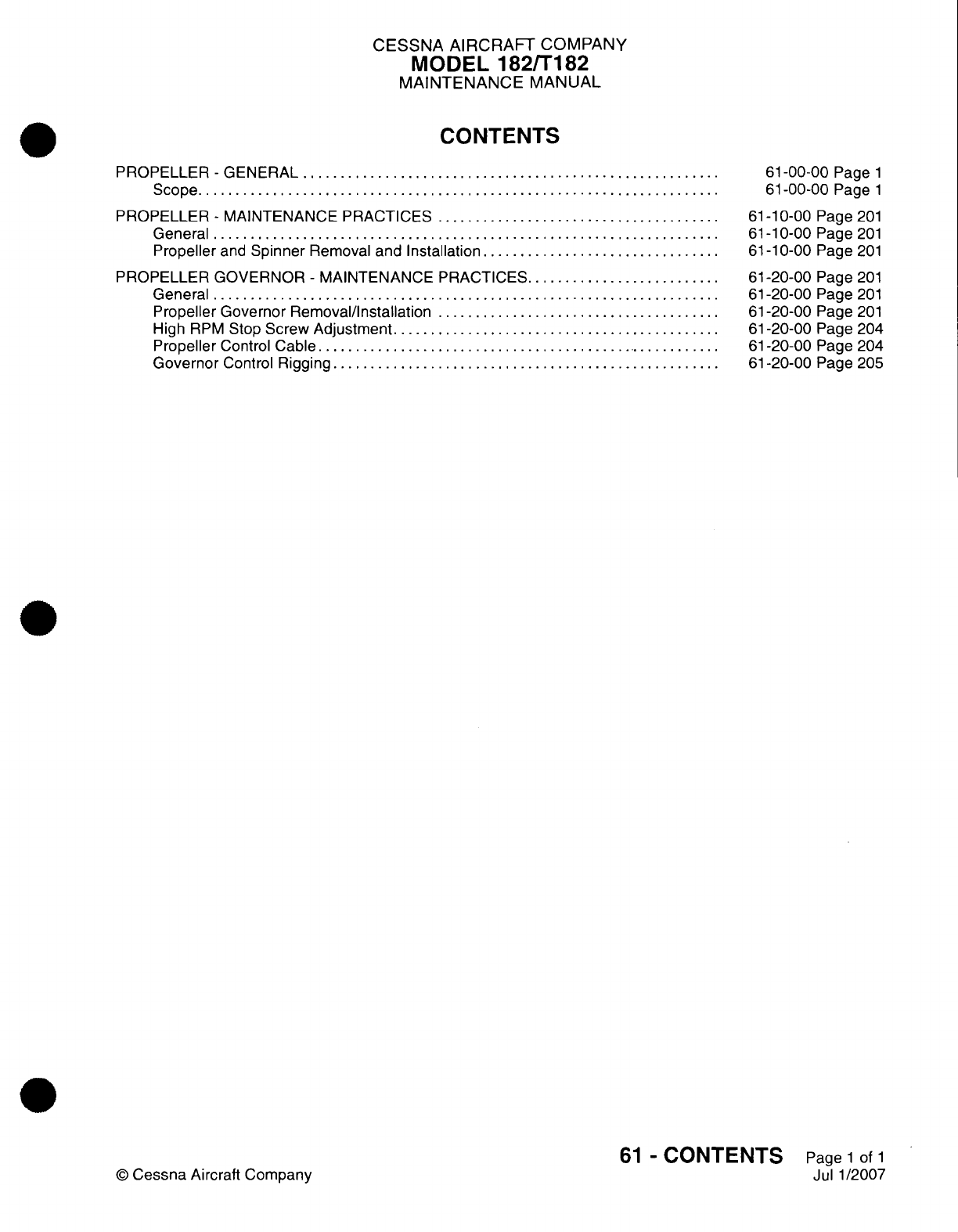
CESSNA
AIRCRAFT
COMPANY
MODEL
182/T182
MAINTENANCE
MANUAL
CONTENTS
PROPELLER
-
GENERAL.............................
Scope....................................
PROPELLER
-
MAINTENANCE
PRACTICES....................
General...................................
Propeller
and
Spinner
Removal
and
Installation.................
PROPELLER
GOVERNOR
-
MAINTENANCE
PRACTICES..............
General...................................
Propeller
Governor
Removal/installation....................
High
RPM
Stop
Screw
Adjustment.......................
Propeller
Control
Cable............................
Governor
Control
Rigging...........................
61
-00-00
Page
1
61
-00-00
Page
1
61
-10-00
Page
201
61
-1
0-00
Page
201
61
-1
0-00
Page
201
61
-20-00
Page
201
61
-20-00
Page
201
61
-20-00
Page
201
61-20-00
Page
204
61-20-00
Page
204
61-20-00
Page
205
61
-
CONTENTS
Page
1
of
1
Jul 1/2007
©
Cessna
Aircraft
Company
CESSNA
AIRCRAFT
COMPANY
MODEL
182/T182
MAINTENANCE
MANUAL
PROPELLER
-
GENERAL
1.
Scope
A.
This
chapter
contains
information
for
removal and
installation
of
the
propeller
and
propeller
governor,
and
adjustment
and
rigging
procedures
for
the
propeller
governor.
61-00-00
Page
1
©
Cessna Aircraft Company
April
1/2002
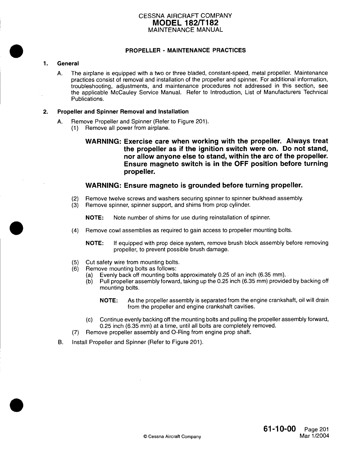
CESSNA
AIRCRAFT
COMPANY
MODEL
182/T182
MAINTENANCE
MANUAL
PROPELLER
-
MAINTENANCE PRACTICES
1.
General
A.
The
airplane
is
equipped
with
a
two
or
three
bladed,
constant-speed,
metal
propeller.
Maintenance
practices
consist
of removal
and
installation
of
the
propeller
and
spinner.
For
additional
information,
troubleshooting, adjustments,
and
maintenance
procedures
not
addressed
in
this section,
see
the applicable
McCauley
Service
Manual.
Refer
to
Introduction,
List
of
Manufacturers Technical
Publications.
2.
Propeller
and
Spinner
Removal
and
Installation
A.
Remove
Propeller
and
Spinner
(Refer
to
Figure
201).
(1)
Remove all
power from
airplane.
WARNING: Exercise
care
when
working
with the
propeller.
Always
treat
the
propeller
as
if the
ignition
switch
were
on.
Do
not
stand,
nor
allow
anyone
else
to
stand,
within
the
arc
of
the
propeller.
Ensure magneto
switch
is
in the
OFF
position
before
turning
propeller.
WARNING:
Ensure
magneto
is
grounded
before
turning propeller.
(2)
Remove
twelve
screws
and
washers
securing
spinner
to
spinner
bulkhead
assembly.
(3)
Remove
spinner,
spinner
support,
and
shims
from prop
cylinder.
NOTE:
Note
number
of
shims
for
use
during
reinstallation
of
spinner.
(4)
Remove cowl
assemblies
as
required
to
gain
access
to
propeller
mounting
bolts.
NOTE:
If
equipped
with
prop
deice system,
remove
brush
block assembly
before removing
propeller,
to
prevent
possible
brush damage.
(5)
Cut
safety
wire
from
mounting
bolts.
(6)
Remove
mounting bolts
as
follows:
(a)
Evenly
back
off
mounting
bolts
approximately
0.25
of
an
inch (6.35
mm).
(b)
Pull
propeller
assembly
forward,
taking
up
the 0.25
inch (6.35
mm)
provided by backing
off
mounting
bolts.
NOTE:
As
the
propeller
assembly
is
separated
from
the
engine
crankshaft,
oil
will drain
from
the
propeller
and
engine crankshaft
cavities.
(c)
Continue
evenly
backing
off
the
mounting
bolts
and
pulling the propeller
assembly
forward,
0.25
inch (6.35
mm)
at
a
time,
until all
bolts are
completely
removed.
(7)
Remove
propeller assembly
and
O-Ring
from engine
prop
shaft.
B.
Install
Propeller
and
Spinner
(Refer
to
Figure
201).
61-10-00
Page
201
©
Cessna
Aircraft
Company
Mar
1/2004
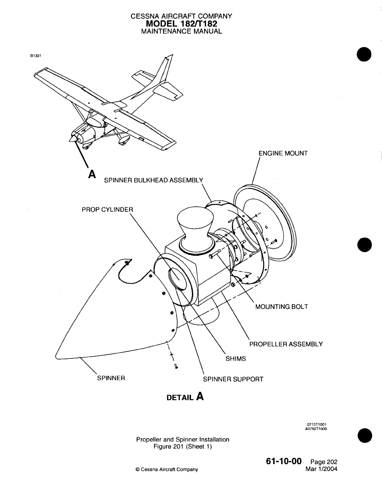
CESSNA
AIRCRAFT
COMPANY
MODEL
182/T182
MAINTENANCE
MANUAL
B
ENGINE
MOUNT
ABLY
SPINNER
SPINNER
SUPPORT
DETAIL
A
0710T1001
A0750T1003
Propeller
and
Spinner Installation
Figure
201
(Sheet
1)
O
Cessna Aircraft
Company
61-10-00
Page
202
Mar
1/2004
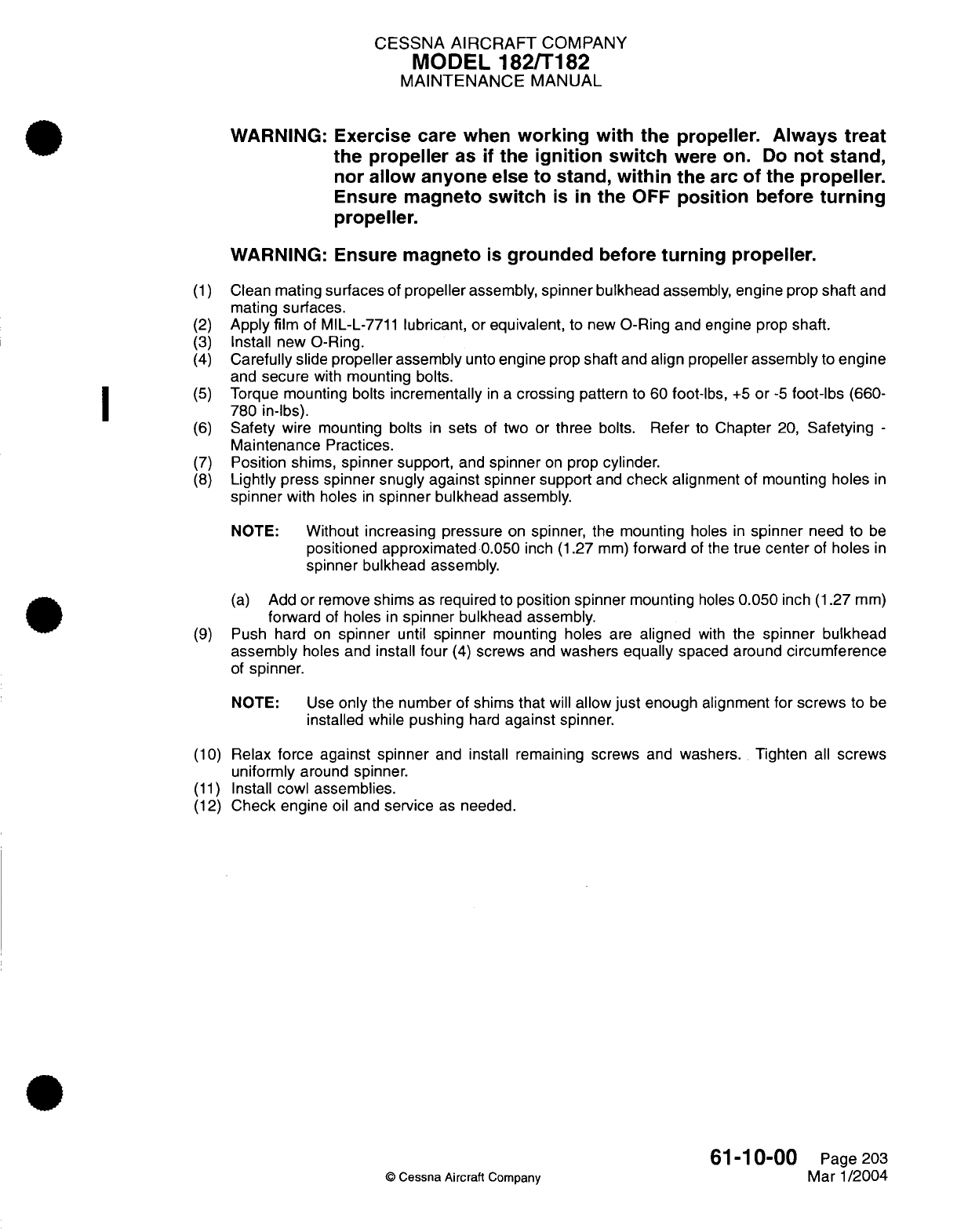
CESSNA
AIRCRAFT
COMPANY
MODEL
182/T182
MAINTENANCE
MANUAL
WARNING: Exercise
care when
working
with
the
propeller.
Always
treat
the
propeller
as
if
the
ignition
switch
were
on.
Do
not
stand,
nor
allow
anyone
else
to
stand,
within
the
arc
of
the
propeller.
Ensure magneto
switch
is
in
the
OFF
position
before
turning
propeller.
WARNING:
Ensure magneto
is
grounded
before
turning
propeller.
(1)
Clean
mating
surfaces
of
propeller
assembly,
spinner bulkhead
assembly,
engine
prop
shaft
and
mating
surfaces.
(2)
Apply
film
of MIL-L-7711
lubricant,
or
equivalent,
to new
O-Ring
and
engine prop
shaft.
(3)
Install
new
O-Ring.
(4)
Carefully
slide
propeller assembly
unto
engine
prop
shaft
and
align
propeller
assembly
to
engine
and
secure
with
mounting bolts.
(5)
Torque
mounting bolts
incrementally
in a
crossing
pattern
to 60
foot-lbs,
+5
or
-5
foot-lbs
(660-
780
in-lbs).
(6)
Safety
wire
mounting
bolts
in
sets
of
two or
three
bolts.
Refer
to
Chapter
20,
Safetying
-
Maintenance
Practices.
(7)
Position shims,
spinner
support,
and
spinner
on
prop
cylinder.
(8)
Lightly press spinner
snugly
against
spinner support
and
check
alignment
of
mounting
holes
in
spinner
with holes
in
spinner
bulkhead
assembly.
NOTE:
Without
increasing pressure
on
spinner,
the mounting
holes
in
spinner
need to
be
positioned approximated
0.050
inch (1.27
mm)
forward
of
the
true
center
of
holes
in
spinner
bulkhead
assembly.
(a)
Add
or
remove
shims as
required
to
position
spinner
mounting
holes
0.050
inch
(1.27
mm)
forward
of
holes
in
spinner
bulkhead assembly.
(9)
Push hard
on
spinner
until
spinner
mounting holes
are
aligned
with
the
spinner
bulkhead
assembly
holes and
install
four
(4)
screws
and
washers
equally
spaced
around
circumference
of
spinner.
NOTE:
Use
only
the
number
of shims
that
will
allow
just
enough alignment
for
screws
to
be
installed while
pushing
hard
against
spinner.
(10)
Relax
force
against spinner
and
install remaining
screws
and
washers. Tighten
all
screws
uniformly around
spinner.
(11)
Install
cowl
assemblies.
(12)
Check
engine
oil
and
service
as
needed.
61-10-00
Page
203
©
Cessna Aircraft
Company
Mar
1/2004
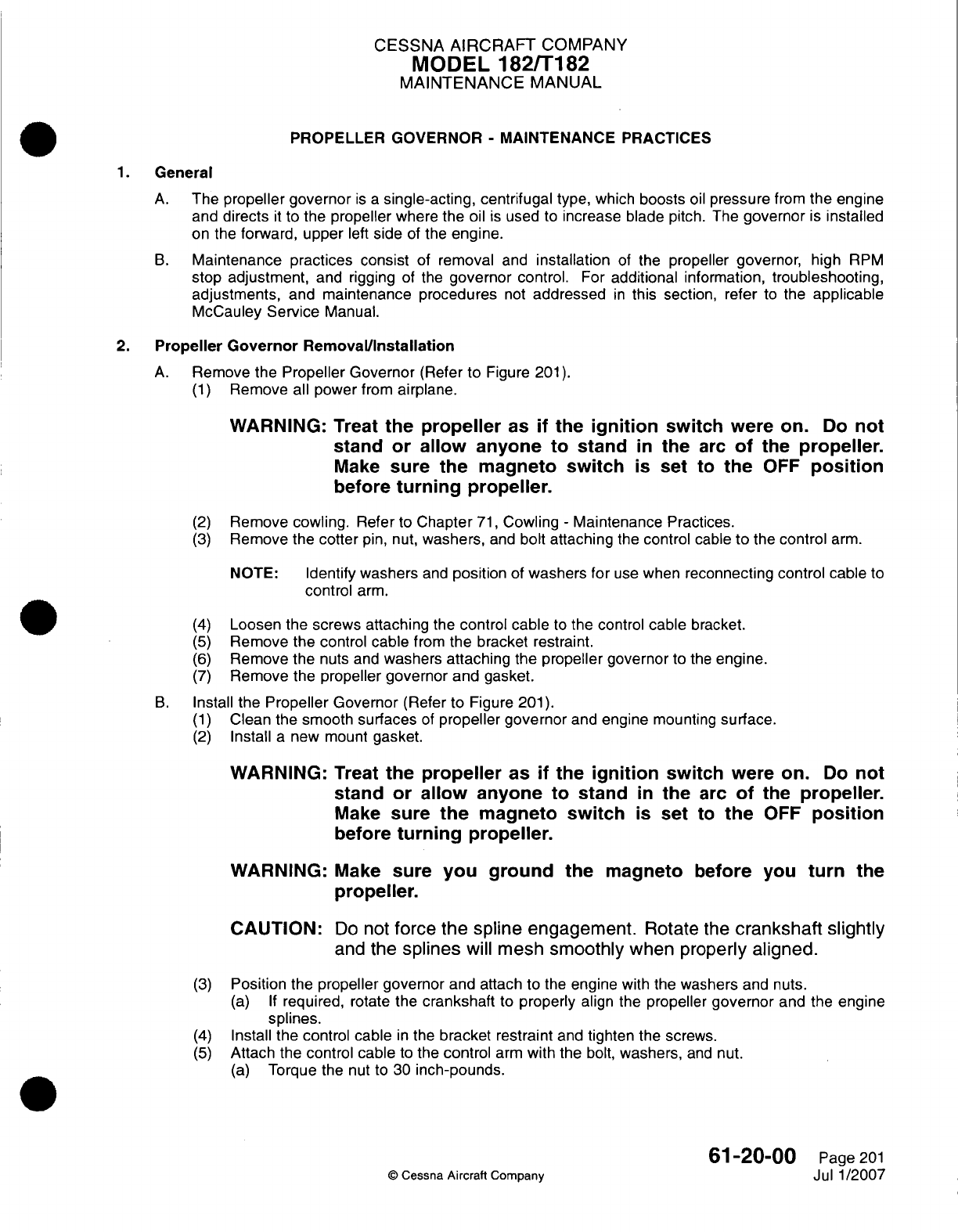
CESSNA
AIRCRAFT
COMPANY
MODEL
182/Ti
82
MAINTENANCE
MANUAL
PROPELLER
GOVERNOR
-
MAINTENANCE PRACTICES
1.
General
A.
The
propeller governor
is a
single-acting, centrifugal
type, which
boosts
oil
pressure
from
the engine
and
directs
it
to
the
propeller
where
the oil
is
used
to
increase blade
pitch.
The
governor
is
installed
on
the
forward,
upper
left
side
of
the
engine.
B.
Maintenance
practices
consist
of
removal
and
installation
of
the
propeller
governor,
high
RPM
stop
adjustment,
and rigging
of
the
governor
control.
For
additional
information,
troubleshooting,
adjustments,
and
maintenance procedures
not
addressed
in
this section, refer
to
the
applicable
McCauley Service
Manual.
2.
Propeller
Governor
Remova~l/nstallation
A.
Remove
the
Propeller
Governor
(Refer
to
Figure
201).
(1)
Remove
all
power
from
airplane.
WARNING:
Treat
the
propeller
as
if
the
ignition
switch
were
on. Do
not
stand
or
allow
anyone
to
stand
in
the
arc
of
the
propeller.
Make
sure the
magneto
switch
is
set to
the
OFF
position
before
turning
propeller.
(2)
Remove
cowling.
Refer
to
Chapter
71,
Cowling
-
Maintenance
Practices.
(3)
Remove
the
cotter
pin,
nut,
washers,
and
bolt
attaching
the
control
cable
to
the
control
arm.
NOTE:
Identify
washers
and
position
of
washers
for
use
when
reconnecting
control cable
to
control
arm.
(4)
Loosen
the
screws
attaching
the
control
cable
to
the
control
cable
bracket.
(5)
Remove
the control
cable
from
the
bracket
restraint.
(6)
Remove
the
nuts and
washers
attaching
the
propeller
governor
to the
engine.
(7)
Remove
the
propeller
governor
and
gasket.
B.
Install
the
Propeller
Governor
(Refer
to
Figure
201).
(1)
Clean the
smooth
surfaces
of
propeller governor
and
engine
mounting
surface.
(2)
Install
a
new mount
gasket.
WARNING:
Treat
the
propeller
as
if
the
ignition
switch
were on.
Do
not
stand
or
allow
anyone
to
stand
in
the
arc
of
the
propeller.
Make
sure
the
magneto
switch
is set
to
the
OFF
position
before
turning
propeller.
WARNING:
Make
sure
you ground
the
magneto
before
you
turn
the
propeller.
CAUTION:
Do
not
force
the
spline engagement.
Rotate the
crankshaft
slightly
and
the
splines
will
mesh
smoothly
when properly
aligned.
(3)
Position
the
propeller
governor
and
attach
to
the
engine
with
the
washers
and
nuts.
(a) If
required,
rotate
the
crankshaft
to
properly
align
the
propeller
governor
and
the
engine
splines.
(4)
Install
the
control cable
in
the
bracket restraint
and
tighten
the
screws.
(5)
Attach
the
control
cable
to
the
control
arm
with
the
bolt,
washers,
and
nut.
(a)
Torque
the
nut
to
30
inch-pounds.
61
-20-00
Page
201
©
Cessna
Aircraft
Company
Jul
1/2007
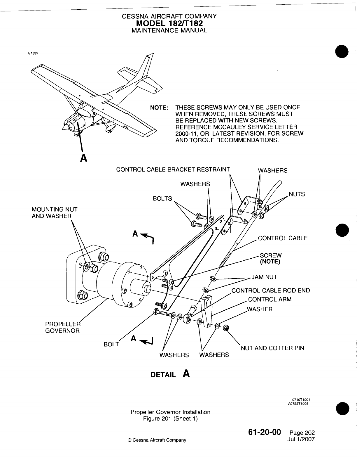
CESSNA AIRCRAFT
COMPANY
MODEL
182/Ti82
MAINTENANCE
MANUAL
ts
THESE
SCREWS
MAY
ONLY
BE
USED
ONCE.
WHEN
REMOVED,
THESE
SCREWS
MUST
BE
REPLACED
WITH
NEW
SCREWS.
REFERENCE MCCAULEY SERVICE LETTER
2000-1
1,
OR
LATEST
REVISION,
FOR
SCREW
AND
TORQUE RECOMMENDATIONS.
A
CONTROL
CABLE
BRACKET
RESTRAINT
WASHERS
1UTS
ABLE
MOL
AND
D
END
PIN
WASHERS
WASHERS
DETAIL
A
0710T1001
A0755T1
003
Propeller
Governor
Installation
Figure
201
(Sheet
1)
61-20-00
©
Cessna
Aircraft
Company
Page 202
Jul
1/2007
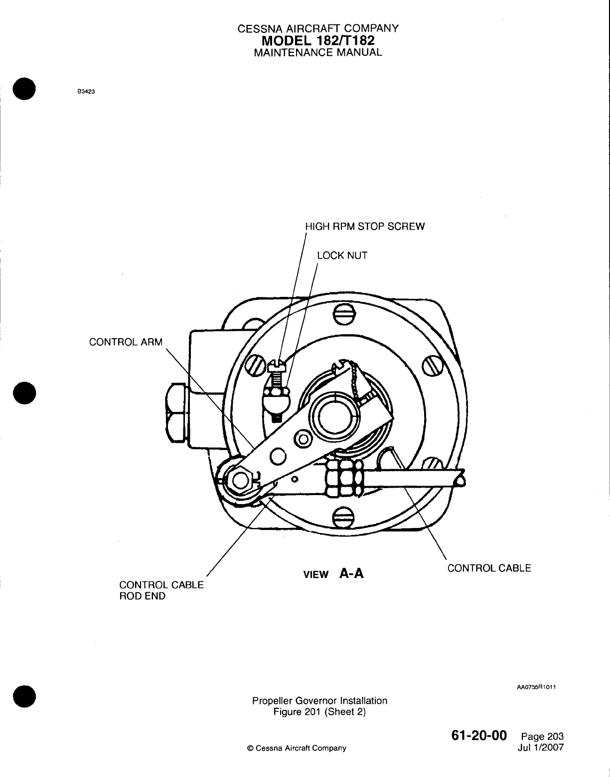
CESSNA
AIRCRAFT
COMPANY
MODEL
182/Ti182
MAINTENANCE
MANUAL
B3423
CONTROL
ARM
TROL
CABLE
CONTROL
CABLE
ROD
END
AA0755R1O1
1
Propeller Governor Installation
Figure
201
(Sheet
2)
61-20-00
©
Cessna Aircraft
Company
Page
203
Jul
1/2007
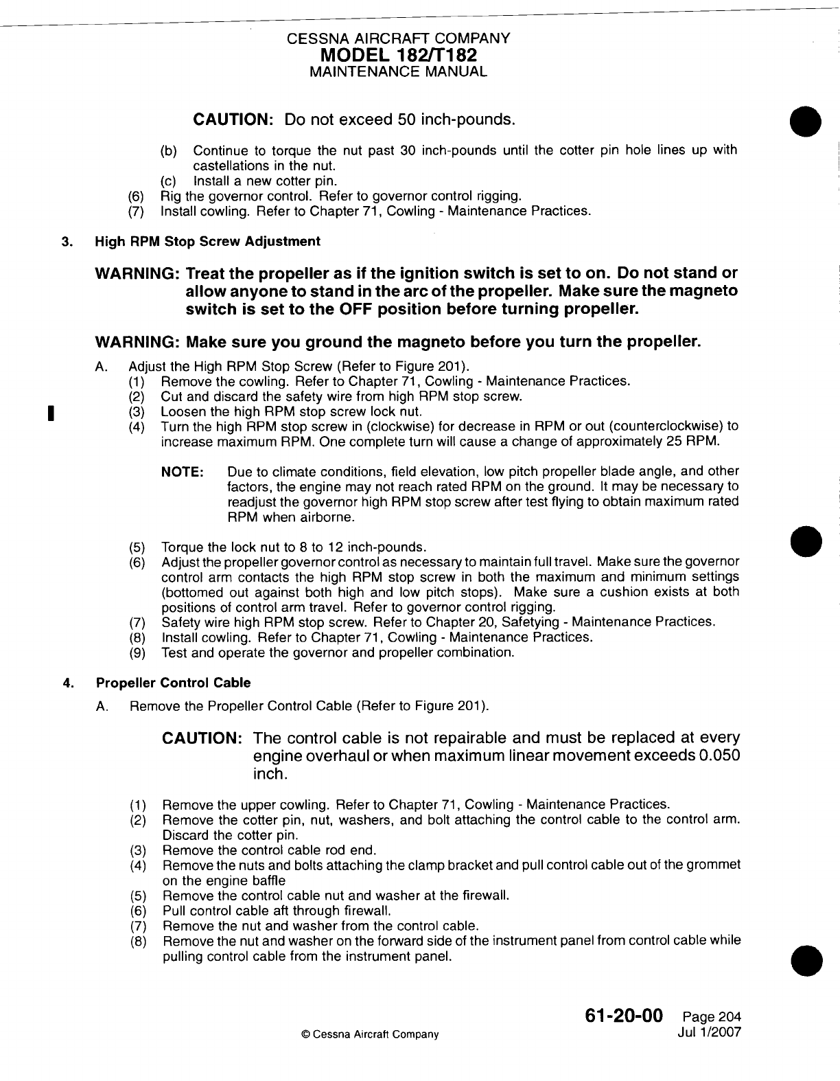
CESSNA AIRCRAFT
COMPANY
MODEL
182/Ti
82
MAINTENANCE
MANUAL
CAUTION:
Do
not
exceed
50
inch-pounds.
(b)
Continue
to
torque
the
nut
past
30
inch-pounds
until
the
cotter
pin hole
lines
up
with
castellations
in
the
nut.
(c)
Install
a
new
cotter
pin.
(6)
Rig
the
governor
control.
Refer
to
governor
control rigging.
(7)
Install
cowling.
Refer
to
Chapter
71,
Cowling
-
Maintenance Practices.
3.
High
RPM
Stop
Screw
Adjustment
WARNING:
Treat
the
propeller
as
if
the
ignition
switch
is
set
to
on.
Do
not
stand
or
allow
anyone to stand
in
the
arc
of
the
propeller.
Make
sure
the
magneto
switch
is
set
to
the
OFF
position
before
turning
propeller.
WARNING:
Make
sure you
ground
the
magneto
before you
turn
the propeller.
A.
Adjust the
High
RPM
Stop
Screw
(Refer
to
Figure
201).
(1)
Remove
the
cowling.
Refer
to
Chapter
71,
Cowling
-
Maintenance
Practices.
(2)
Cut
and
discard
the
safety
wire
from
high
RPM
stop
screw.
*
~~(3)
Loosen
the high
RPM
stop screw
lock
nut.
(4)
Turn
the
high
RPM
stop
screw
in
(clockwise)
for
decrease
in
RPM
or
out
(counterclockwise)
to
increase
maximum
RPM.
One
complete
turn
will
cause
a
change
of
approximately
25
RPM.
NOTE:
Due
to
climate
conditions,
field
elevation,
low
pitch
propeller blade
angle,
and
other
factors,
the
engine
may
not
reach
rated
RPM
on
the
ground.
It
may
be
necessary
to
readjust
the
governor
high
RPM
stop
screw
after
test
flying
to
obtain
maximum
rated
RPM
when
airborne.
(5)
Torque
the
lock
nut
to
8
to
12
inch-pounds.
(6)
Adjust
the
propeller governor
control
as
necessary
to
maintain full
travel.
Make
sure the
governor
control
arm
contacts
the
high
RPM
stop
screw
in
both
the
maximum
and
minimum
settings
(bottomed
out
against
both
high
and
low
pitch
stops).
Make sure
a
cushion
exists
at
both
positions
of
control
arm
travel.
Refer
to
governor
control
rigging.
(7)
Safety
wire
high
RPM
stop screw.
Refer
to
Chapter
20,
Safetying
-
Maintenance
Practices.
(8)
Install
cowling.
Refer
to
Chapter
71,
Cowling
-
Maintenance
Practices.
(9)
Test
and
operate
the
governor
and
propeller
combination.
4.
Propeller Control
Cable
A.
Remove
the
Propeller
Control
Cable
(Refer
to
Figure
201).
CAUTION:
The
control cable
is
not
repairable
and
must
be
replaced
at
every
engine overhaul
or
when maximum
linear movement
exceeds
0.050
inch.
(1)
Remove
the
upper
cowling. Refer
to
Chapter
71,
Cowling
-
Maintenance
Practices.
(2)
Remove
the
cotter
pin, nut,
washers,
and
bolt
attaching
the
control
cable
to
the
control
arm.
Discard the
cotter
pin.
(3)
Remove
the
control
cable
rod
end.
(4)
Remove
the
nuts
and
bolts
attaching
the
clamp
bracket
and
pull
control
cable
out
of
the
grommet
on
the
engine
baffle
(5)
Remove
the control
cable
nut
and
washer
at the
firewall.
(6)
Pull
control
cable
aft
through firewall.
(7)
Remove
the
nut
and
washer
from the
control
cable.
(8)
Remove
the
nut
and
washer
on
the
forward
side
of
the
instrument
panel from
control
cable
while
pulling
control
cable
from
the
instrument
panel.
61-20-00
Page
204
c
Cessna
Aircraft Company
Jul
1/2007
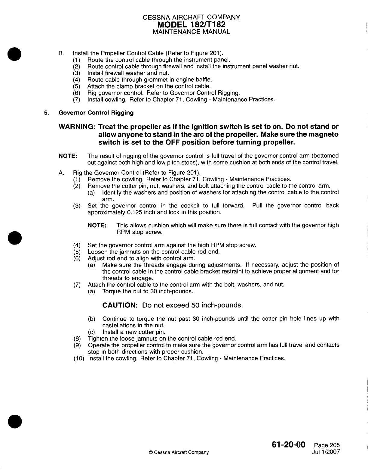
CESSNA
AIRCRAFT
COMPANY
MODEL
1821T182
MAINTENANCE
MANUAL
B.
Install the
Propeller
Control
Cable
(Refer
to
Figure
201).
(1)
Route
the
control
cable
through
the
instrument
panel.
(2)
Route
control cable
through
firewall
and
install
the
instrument
panel
washer
nut.
(3)
Install
firewall washer
and
nut.
(4)
Route cable
through
grommet
in
engine baffle.
(5)
Attach
the
clamp bracket
on
the
control cable.
(6)
Rig
governor
control.
Refer
to
Governor
Control
Rigging.
(7)
Install
cowling.
Refer
to
Chapter
71,
Cowling
-
Maintenance
Practices.
5.
Governor Control
Rigging
WARNING:
Treat
the
propeller
as
if
the
ignition
switch
is
set
to
on.
Do
not
stand
or
allow
anyone
to
stand
in
the
arc
of
the
propeller.
Make
sure
the
magneto
switch
is set
to
the
OFF
position
before
turning
propeller.
NOTE: The
result
of
rigging
of
the
governor
control
is
full
travel
of
the
governor control
arm
(bottomed
out
against
both
high
and
low
pitch
stops),
with
some
cushion
at
both
ends
of
the
control
travel.
A.
Rig
the
Governor
Control
(Refer
to
Figure
201).
(1)
Remove
the
cowling.
Refer
to
Chapter
71,
Cowling
-
Maintenance
Practices.
(2)
Remove
the
cotter
pin,
nut,
washers,
and
bolt
attaching
the
control
cable
to
the
control
arm.
(a)
Identify
the
washers
and
position
of
washers for
attaching
the
control
cable
to
the
control
arm.
(3)
Set
the
governor
control
in
the
cockpit
to
full
forward.
Pull
the
governor
control
back
approximately
0.125
inch
and
lock
in
this
position.
NOTE:
This allows cushion which
will
make
sure
there
is
full
contact
with
the
governor
high
RPM
stop
screw.
(4)
Set the
governor
control
arm
against
the
high
RPM
stop
screw.
(5)
Loosen
the
jamnuts
on
the
control cable
rod
end.
(6)
Adjust
rod
end
to
align
with
control
arm.
(a)
Make
sure
the
threads
engage
during
adjustments.
If
necessary,
adjust
the
position
of
the
control
cable
in
the
control
cable
bracket
restraint
to
achieve
proper
alignment
and
for
threads
to
engage.
(7)
Attach
the
control cable
to
the
control
arm
with
the
bolt,
washers,
and
nut.
(a)
Torque
the
nut
to
30
inch-pounds.
CAUTION:
Do
not
exceed
50
inch-pounds.
(b)
Continue
to
torque
the nut
past
30
inch-pounds
until the cotter pin
hole
lines
up
with
castellations
in
the
nut.
(c)
Install
a
new
cotter
pin.
(8)
Tighten
the
loose
jamnuts
on
the
control
cable
rod
end.
(9)
Operate
the
propeller
control
to
make
sure
the governor
control
arm
has
full
travel
and
contacts
stop
in
both
directions
with
proper
cushion.
(1 0)
Install
the
cowling.
Refer
to
Chapter
71,
Cowling
-
Maintenance
Practices.
61-20-00
Page 205
©
Cessna Aircraft Company
Jul
1/2007

CHAPTER
POWER
PL~~~~ANT
CESSNA
AIRCRAFT
COMPANY
MODEL
182/Ti
82
MAINTENANCE
MANUAL
LIST
OF
EFFECTIVE
PAGES
CHAPTER-SECTION-SUBJECT
71
-Title
71
-List
of
Effective Pages
71
-Record
of
Temporary
Revisions
71
-Table
of
Contents
©
Cessna
Aircraft
Company
71
-
LIST
OF
EFFECTIVE PAGES
Page
1
of
1
Janl1/2007
PAGE
DATE
Temporary
Revision
Number
RECORD
OF
TEMPORARY
REVISIONS
Page
Number
Issue
Date
By
Date
Removed
By
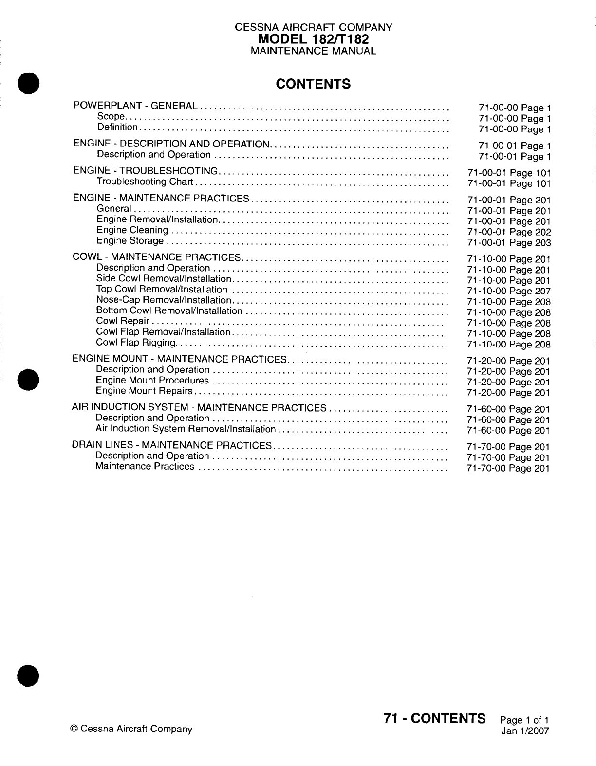
CESSNA
AIRCRAFT
COMPANY
MODEL
182/Ti
82
MAINTENANCE
MANUAL
CONTENTS
POWERPLANT
-
GENERAL............................
S
cope
.....
....... . . . . . . . .... . . . . . . . . . . .. . .
Definition
..................................
ENGINE
-
DESCRIPTION
AND OPERATION
....................
Description
and
Operation
..........................
ENGINE
-
TROUBLESHOOTING..........................
Troubleshooting
Chart
............................
ENGINE
-
MAINTENANCE PRACTICES
......................
General...................................
Engine
Removal/installation..........................
Engine
Cleaning...............................
Engine
Storage
...............................
COWL
-
MAINTENANCE
PRACTICES
.......................
Description
and
Operation
..........................
Side
Cowl
Removal/Installation
........................
Top
Cowl
Removal/Installation
........................
Nose-Cap
Removal/Installation
........................
Bottom
Cowl
Removal/Installation.......................
Cowl
Repair.................................
Cowl Flap
Removal/Installation
........................
Cowl
Flap
Rigging
..............................
ENGINE
MOUNT
-
MAINTENANCE
PRACTICES
..................
Description
and
Operation
..........................
Engine
Mount
Procedures
..........................
Engine Mount
Repairs
............................
AIR
INDUCTION SYSTEM
-
MAINTENANCE
PRACTICES..............
Description
and
Operation
..........................
Air
Induction
System
Removal/Installation
...................
DRAIN LINES
-
MAINTENANCE
PRACTICES....................
Description
and
Operation
..........................
Maintenance
Practices............................
©
Cessna Aircraft
Company
71
-00-00
Page
1
71
-00-00
Page
1
71
-00-00
Page
1
71
-00-01
Page
1
71-00-01
Page
1
71-00-01
Page
101
71
-00-01
Page
101
71-00-01
Page
201
71-00-01
Page
201
71-00-01 Page
201
71-00-01
Page
202
71-00-01
Page 203
71
-1
0-00 Page
201
71
-1
0-00
Page
201
71
-1
0-00
Page
201
71
-1
0-00
Page 207
71
-10-00
Page
208
71
-10-00
Page
208
71
-1
0-00
Page 208
71
-1
0-00
Page
208
71
-1
0-00
Page
208
71
-20-00
Page
201
71-20-00
Page
201
71-20-00
Page
201
71-20-00
Page
201
71-60-00
Page
201
71-60-00
Page
201
71
-60-00
Page
201
71-70-00
Page
201
71-70-00
Page
201
71-70-00
Page
201
71
-
CONTENTS
Page
1
of
1
Janl1/2007
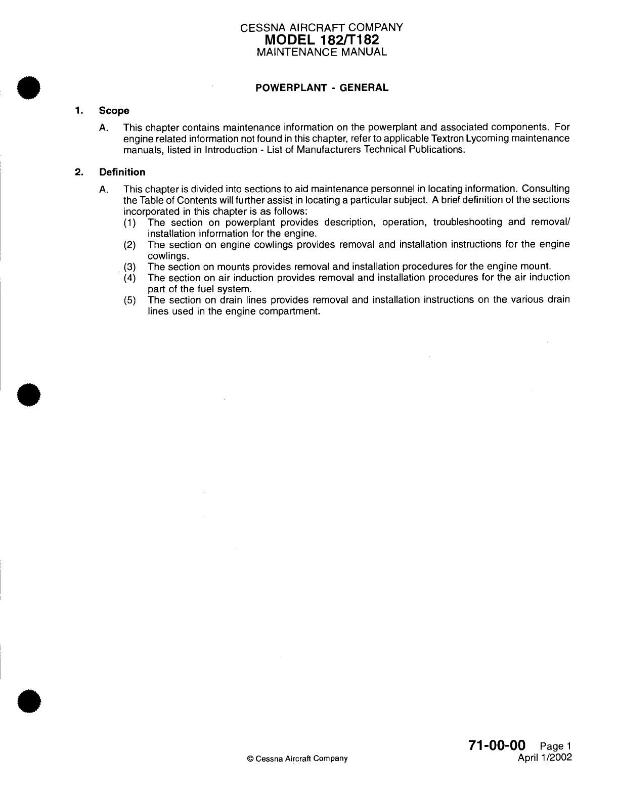
CESSNA
AIRCRAFT
COMPANY
MODEL
182/T182
MAINTENANCE
MANUAL
POWERPLANT
-
GENERAL
1.
Scope
A.
This
chapter
contains
maintenance
information
on
the
powerplant
and
associated
components.
For
engine related information
not
found
in
this
chapter,
refer
to
applicable
Textron
Lycoming
maintenance
manuals, listed
in
Introduction
-
List
of
Manufacturers
Technical
Publications.
2.
Definition
A.
This
chapter
is
divided
into
sections
to
aid
maintenance
personnel
in
locating
information.
Consulting
the
Table
of
Contents
will
further
assist
in
locating
a
particular subject.
A
brief
definition
of
the
sections
incorporated
in
this
chapter
is
as follows:
(1)
The section
on
powerplant provides
description,
operation,
troubleshooting
and
removal/
installation
information
for
the
engine.
(2)
The
section
on
engine
cowlings
provides
removal
and
installation
instructions
for
the
engine
cowlings.
(3)
The
section
on
mounts
provides
removal
and
installation procedures
for
the
engine
mount.
(4)
The
section
on
air
induction provides
removal
and
installation
procedures
for
the
air induction
part
of
the
fuel system.
(5)
The section
on
drain
lines
provides
removal
and
installation
instructions
on
the
various
drain
lines
used
in
the
engine
compartment.
71-00-00
Page
1
C
Cessna Aircraft Company
April
1/2002
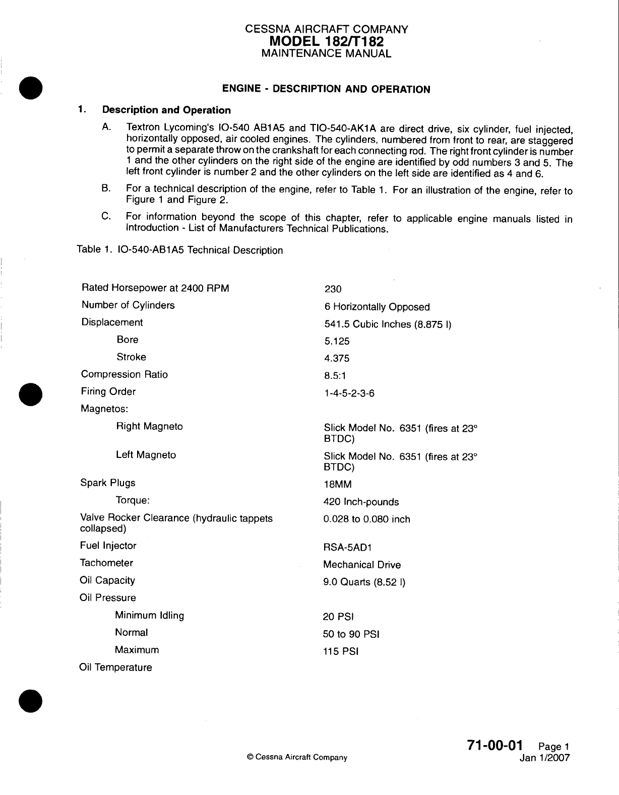
CESSNA AIRCRAFT
COMPANY
MODEL
182/1
182
MAINTENANCE
MANUAL
ENGINE
-
DESCRIPTION
AND
OPERATION
1.Description
and
Operation
A.
Textron
Lycomning's
10-540
ABlA5
and
TIO-540-AKlA
are
direct
drive,
six
cylinder,
fuel
injected,
horizontally
opposed, air cooled engines.
The
cylinders,
numbered
from front
to
rear,
are
staggered
to permit
a
separate throw
on
the
crankshaft
for
each
connecting
rod.
The
right
front
cylinder
is
number
1
and
the
other cylinders
on
the
right
side
of
the
engine
are
identified
by
odd
numbers
3
and
5.
The
left
front
cylinder
is
number
2
and the
other cylinders
on
the
left
side
are
identified
as
4
and
6.
B.
For
a
technical
description
of
the
engine,
refer
to
Table
1.
For
an
illustration
of
the
engine,
refer
to
Figure
1
and
Figure
2.
C.
For
information
beyond
the
scope
of
this chapter,
refer
to
applicable
engine manuals
listed
in
Introduction
-
List
of
Manufacturers
Technical
Publications.
Table
1.
10-540-ABl
A5
Technical Description
Rated
Horsepower
at
2400
RPM
Number
of
Cylinders
Displacement
Bore
Stroke
Compression
Ratio
Firing
Order
Magnetos:
Right
Magneto
Left Magneto
Spark
Plugs
Torque:
Valve
Rocker
Clearance
(hydraulic tappets
collapsed)
Fuel
Injector
Tachometer
Oil
Capacity
Oil
Pressure
Minimum
Idling
Normal
Maximum
Oil
Temperature
230
6
Horizontally
Opposed
541.5 Cubic Inches
(8.875
1)
5.125
4.375
8.5:1
1-4-5-2-3-6
Slick
Model
No.
6351
(fires
at
230
BTDC)
Slick
Model
No.
6351
(fires
at
230
BTDC)
18MM
420
Inch-pounds
0.028
to
0.080
inch
RSA-5AD1
Mechanical
Drive
9.0
Quarts
(8.52
1)
20
PSI
50
to
90
PSI
115
PSI
71-00-01
Page
1
Janl1/2007
©
Cessna
Aircraft
Company
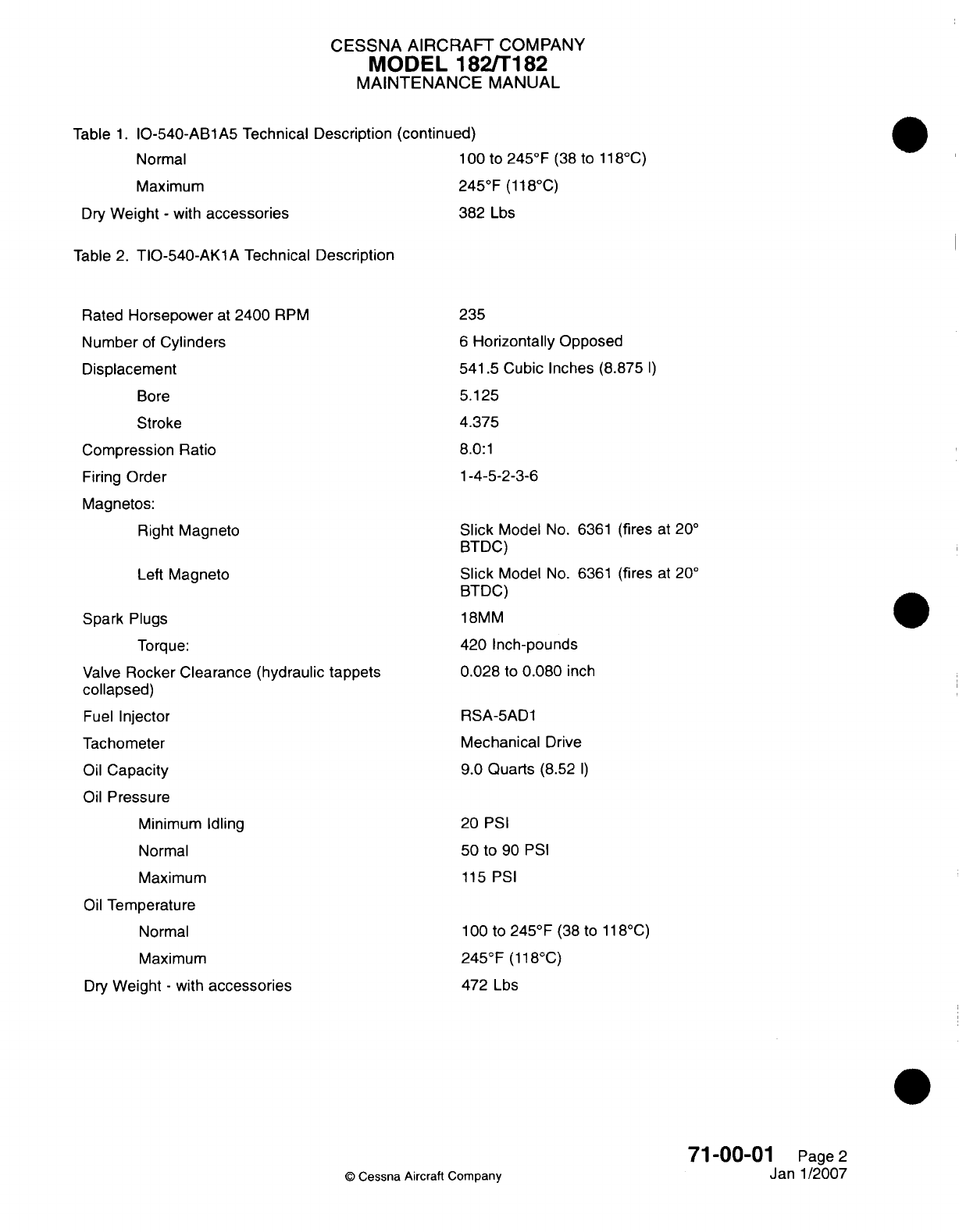
CESSNA
AIRCRAFT
COMPANY
MODEL
182/Ti182
MAINTENANCE
MANUAL
Table
1.
10-540-ABl
A5
Technical Description
(continued)
Normal
1
00
to
245
0F
(38
to
1 18
0C)
Maximum
245
0F (1
18-C)
Dry
Weight
-
with
accessories
382
Lbs
Table
2.
TIO-540-AKl1A
Technical
Description
Rated
Horsepower
at
2400
RPM
Number
of
Cylinders
Displacement
Bore
Stroke
Compression
Ratio
Firing
Order
Magnetos:
Right
Magneto
Left
Magneto
Spark
Plugs
Torque:
Valve
Rocker Clearance
(hydraulic
tappets
collapsed)
Fuel
Injector
Tachometer
Oil
Capacity
Oil
Pressure
Minimum
Idling
Normal
Maximum
Oil
Temperature
Normal
Maximum
Dry
Weight
-
with
accessories
235
6
Horizontally
Opposed
541
.5
Cubic
Inches (8.875
I)
5.125
4.375
8.0:1
1-4-5-2-3-6
Slick
Model
No.
6361
(fires
at
200
BTDC)
Slick
Model
No.
6361
(fires
at
200
BTDC)
18MM
420
Inch-pounds
0.028
to
0.080
inch
RSA-5AD1
Mechanical
Drive
9.0
Quarts
(8.52
I)
20
PSI
50
to
90
PSI
115 PSI
1
00
to
245
0F
(38
to
11
8
0C)
245-F
(118
0C)
472
Lbs
71-00-01
Page
2
Janl1/2007
©
Cessna
Aircraft
Company
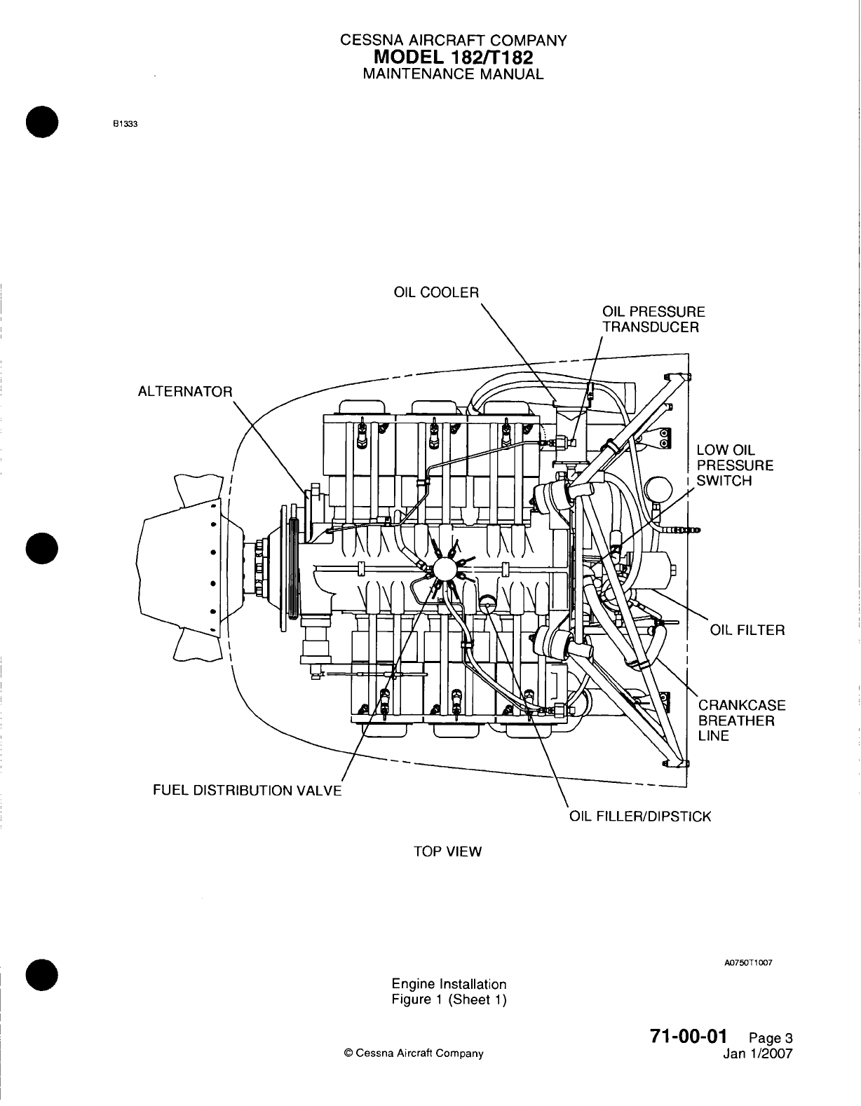
CESSNA AIRCRAFT
COMPANY
MODEL
182/Ti
82
MAINTENANCE
MANUAL
81333
OIL
COOLER
IRE
LTER
'ASE
]ER
OIL
FILLER/DIPSTICK
TOP
VIEW
A075OT1
007
Engine
Installation
Figure
1
(Sheet
1)
71-00-0
©
Cessna
Aircraft Company
1
Page
3
Janl1/2007
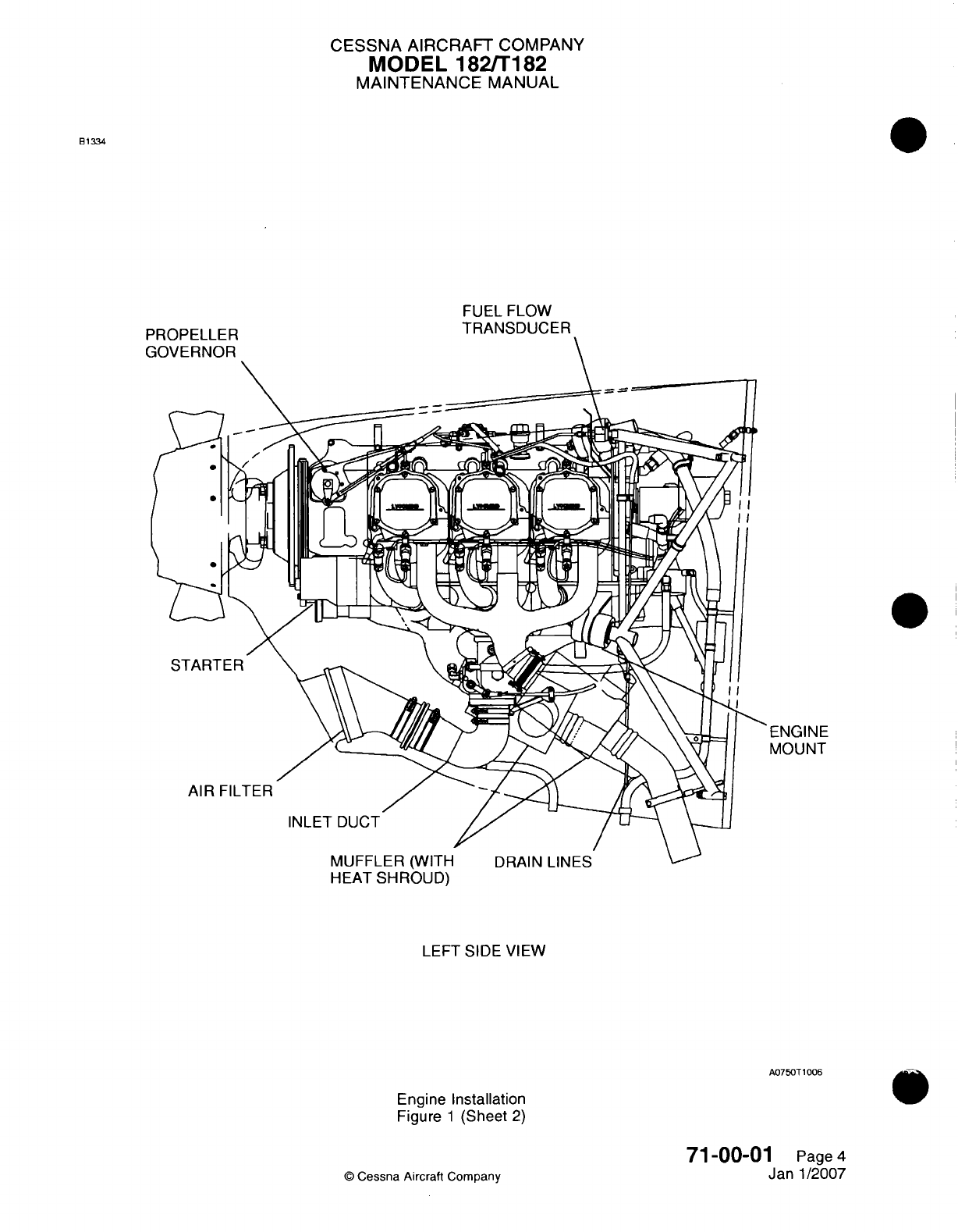
CESSNA
AIRCRAFT
COMPANY
MODEL
182/Ti
182
MAINTENANCE
MANUAL
831334
FUEL FLOW
TRANSDUCER
DnDflA2
I
120
I
ENGINE
MOUNT
HEA
T
SHROUD)
LEFT SIDE VIEW
A075OT
1006
Engine Installation
Figure
1
(Sheet
2)
71
-00-01
Page
4
Jan-1/2007
©
Cessna
Aircraft
Company
-1 .-.. ". -
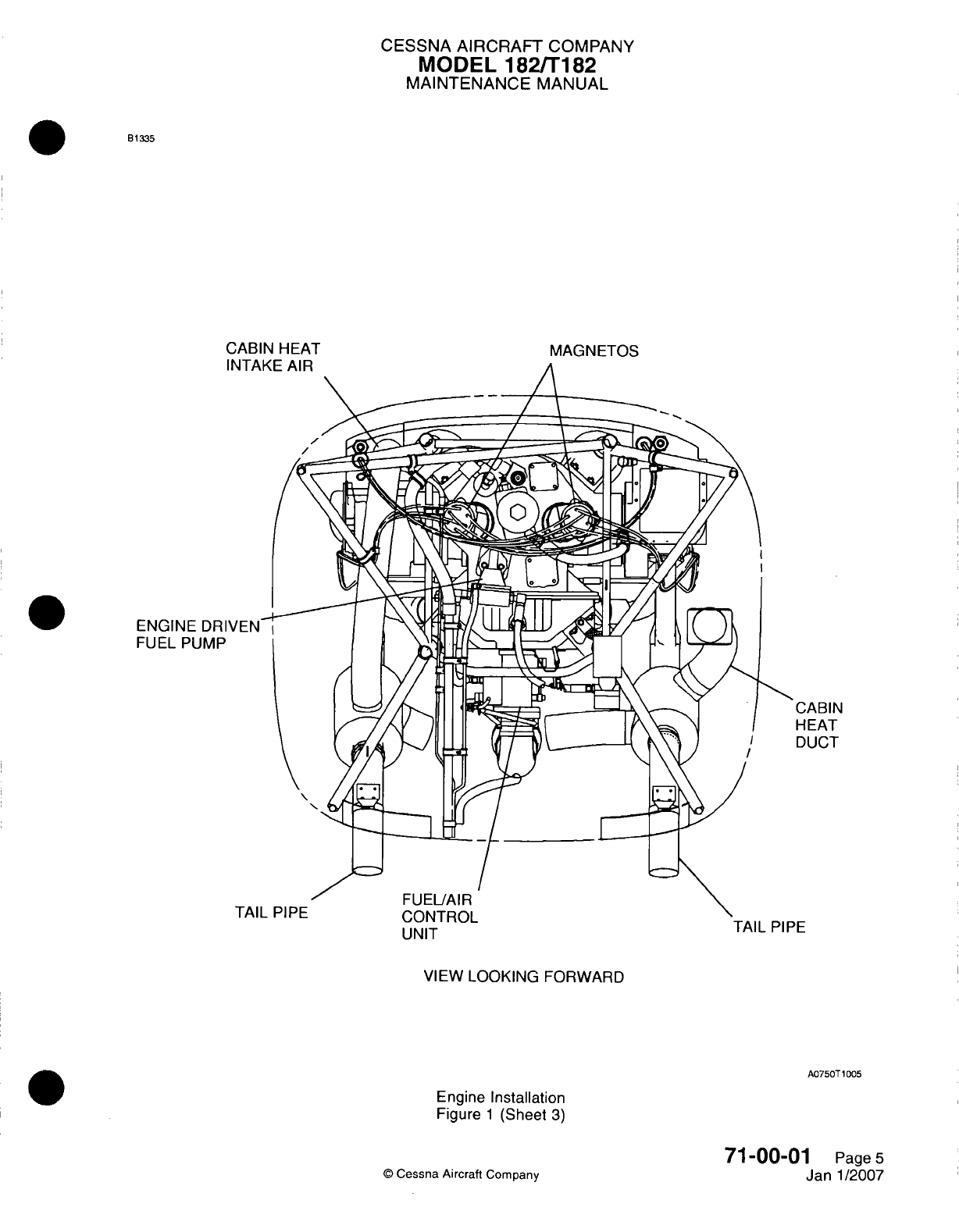
CESSNA
AIRCRAFT
COMPANY
MODEL
182/Ti182
MAINTENANCE
MANUAL
B1335
CABIN
HEAT
MAGNETOS
ENGINE
DRI
1
FUEL
PUMP
UNIT
VIEW
LOOKING
FORWARD
A0750T
1005
Engine
Installation
Figure
1
(Sheet
3)
71-00-01
Page
5
Jan-1/2007
©
Cessna
Aircraft
Company
CABIN
HEAT
DUCT
TAIL
PIPE
I
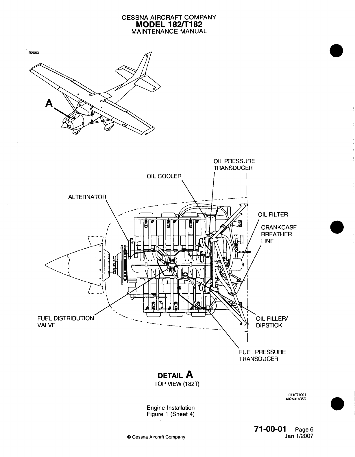
CESSNA
AIRCRAFT
COMPANY
MODEL
182/Ti
82
MAINTENANCE
MANUAL
OIL
PRESSURE
TRANSDUCER
,IL
FILTER
CRANKCASE
BREATHER
LI
NE
L
FILLER!
PSTICK
FUEL
PRESSURE
TRANSDUCER
DETAIL
A
TOP
VIEW
(11
82T)
0710T1001
A0750T635D
Engine
Installation
Figure
1
(Sheet
4)
71-00-01
Page
6
Jan
1/2007
Q
Cessna Aircraft
Company
EU
VA
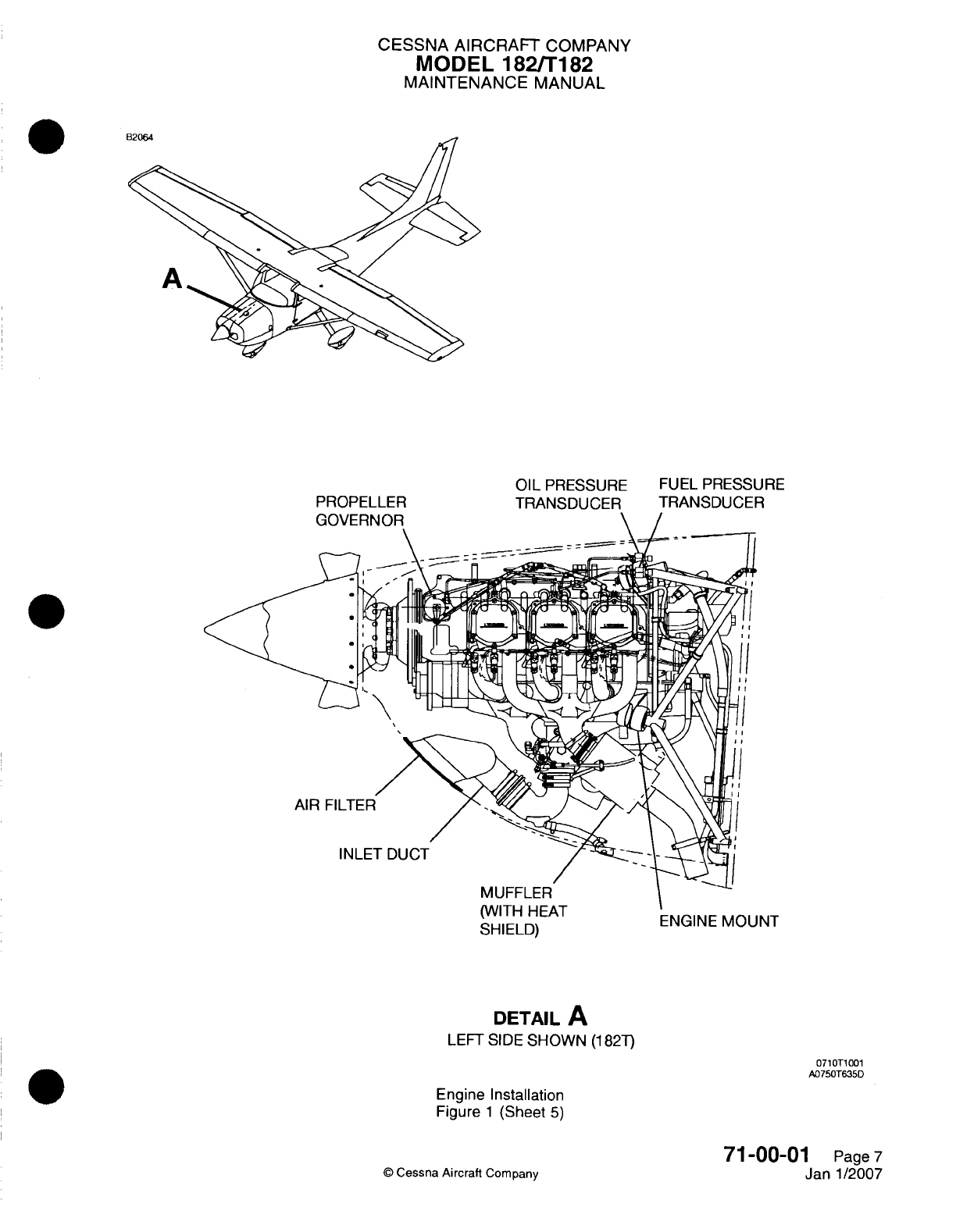
CESSNA
AIRCRAFT
COMPANY
MODEL
182/Ti82
MAINTENANCE
MANUAL
PROPELLER
OIL
PRESSURE
TRANSDUCER
FUEL
PRESSURE
TRANSDUCER
kvv
I I I I I it-/-
I
SHIELD) ENGINE
MOUNT
DETAIL
A
LEFT SIDE
SHOWN
(11
82T)
071
OTi
001
A0750T635D
Engine
Installation
Figure
1
(Sheet
5)
71-00-0
©
Cessna
Aircraft
Company
I
Pagel7
Janl1/2007
----
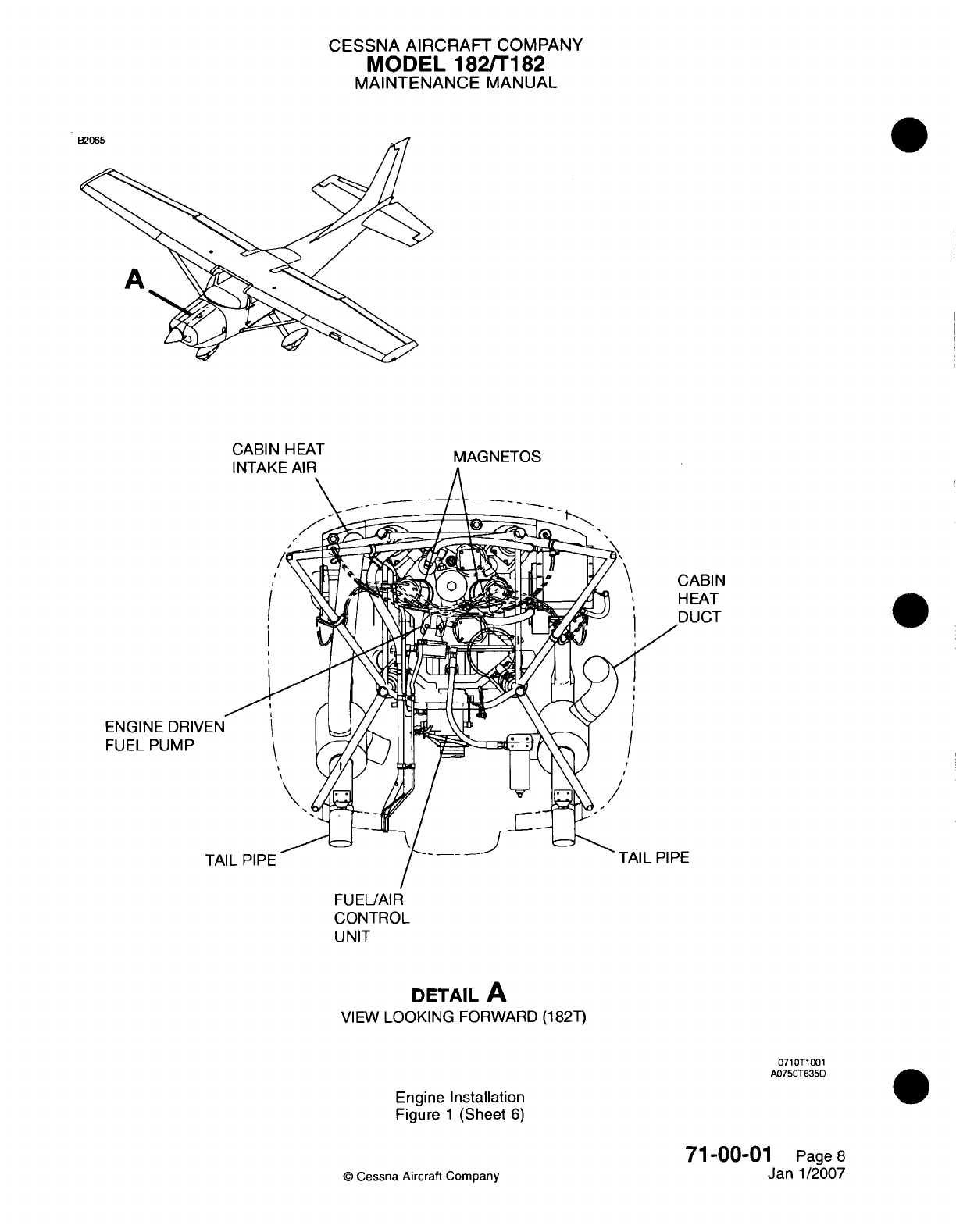
CESSNA AIRCRAFT
COMPANY
MODEL
182/Ti
182
MAINTENANCE
MANUAL
ENGINE
DRI\v
FUEL
PUMP
NBI
N
DAT
JCT
CONTROL
UNIT
DETAIL
A
VIEW
LOOKING
FORWARD (182T)
071OT1001
A0750T635D
Engine Installation
Figure
1
(Sheet
6)
71
-00-01
Page
8
Janl1/2007
0
Cessna
Aircraft
Company
-----
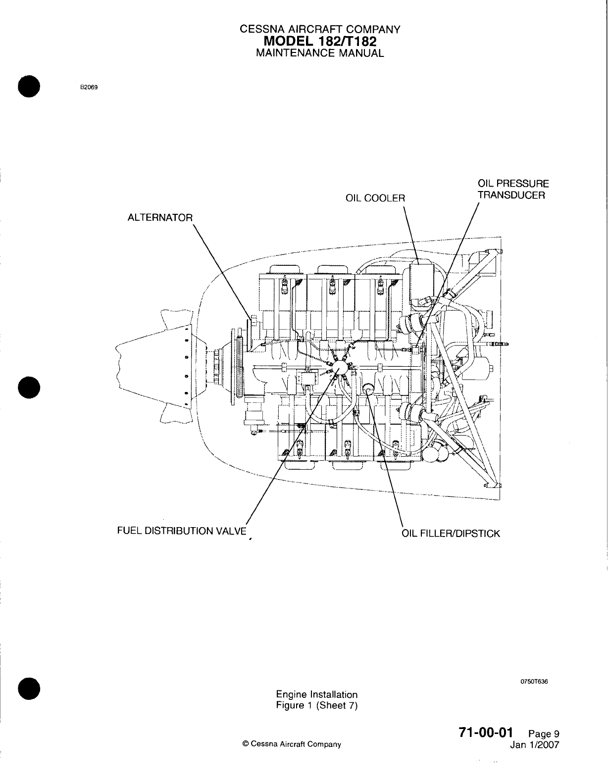
CESSNA AIRCRAFT
COMPANY
MODEL
182/Ti182
MAINTENANCE
MANUAL
B2069
OIL
COOLER
OIL
PRESSURE
TRANSDUCER
I-Uf-L
UIZ
1
HIIbU
I
ION
VALVE
OIL FILLER/DIPSTICK
07501636
Engine
Installation
Figure
1
(Sheet
7)
71-00-01
Page
9
Jan-1/2007
©
Cessna Aircraft
Company
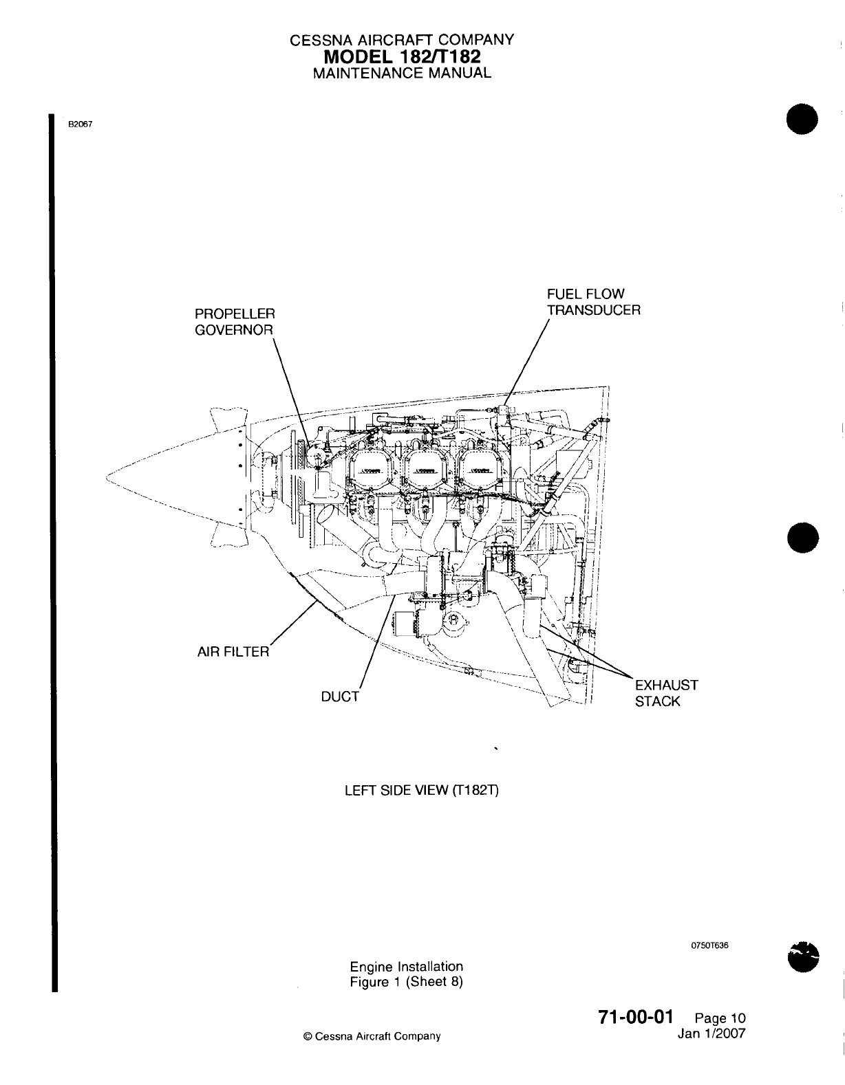
CESSNA AIRCRAFT
COMPANY
MODEL
182/Ti182
MAINTENANCE
MANUAL
B2067
FUEL
FLOW
TRANSDUCER
PPC)PFI
I
FRP
LEFT
SI
DE
VIEW
(Ti
82T)
0750T636
Engine
Installation
Figure
1
(Sheet
8)
71
-00-01
©
Cessna Aircraft
Company
EXHAUST
STACK
Page
1
0
Janl1/2007
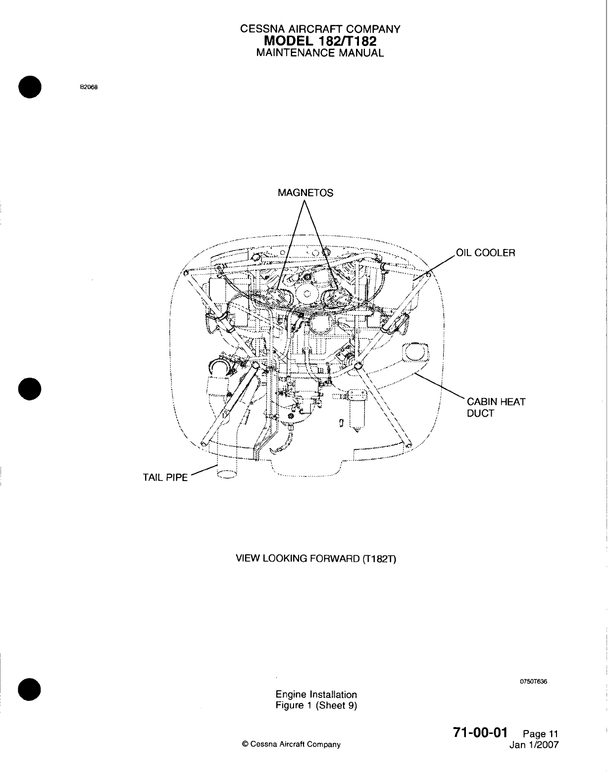
CESSNA AIRCRAFT
COMPANY
MODEL
1821T182
MAINTENANCE
MANUAL
B2068
MAGNETOS
L
COOLER
DUCT
HEAT
TAIL
PIPE
VIEW
LOOKING
FORWARD
(Ti
82T)
0750T636
Engine
Installation
Figure
1
(Sheet
9)
©
Cessna Aircraft
Company
71
-00-01
Page
11
Janl1/2007
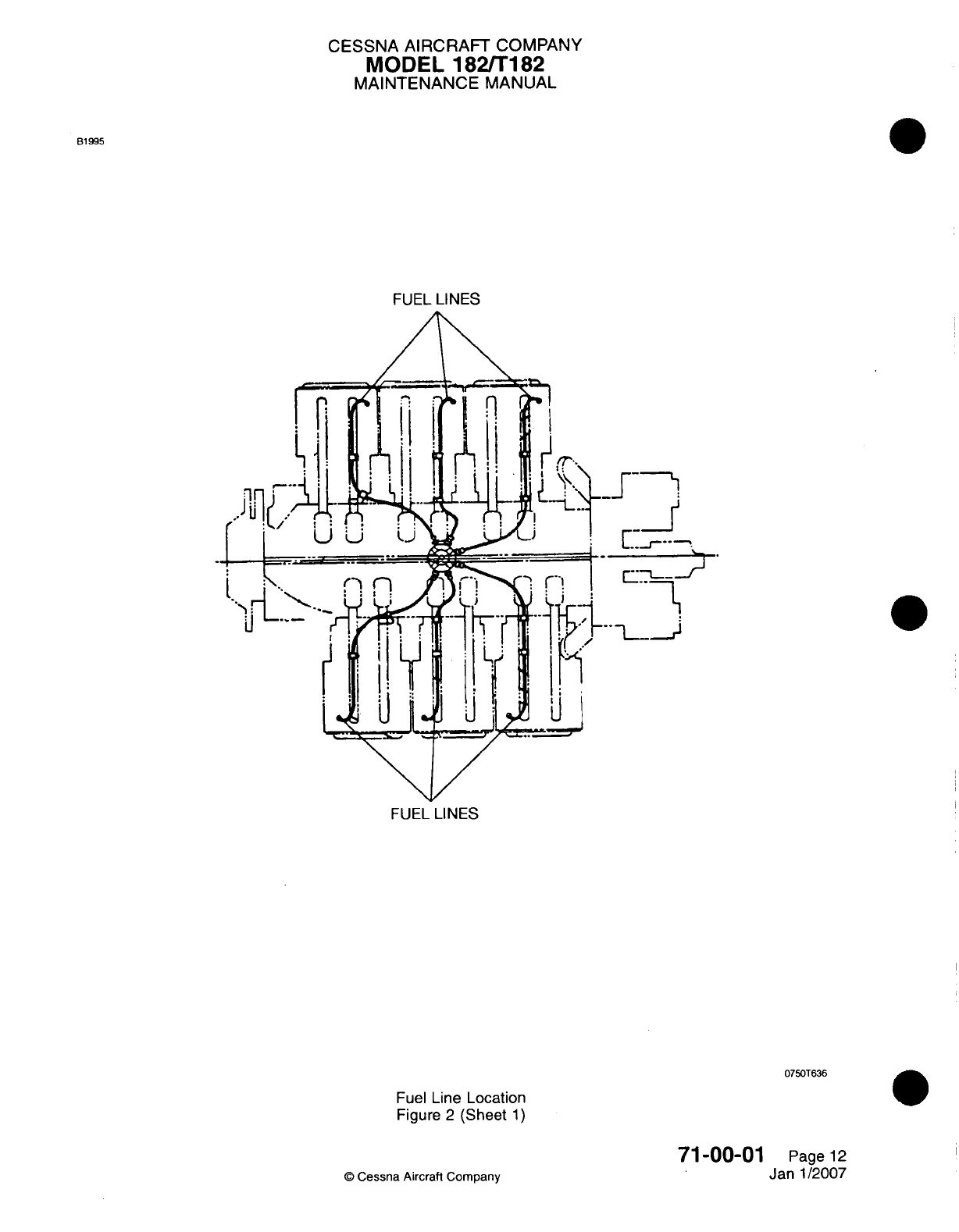
CESSNA
AIRCRAFT
COMPANY
MODEL
182/Ti182
MAINTENANCE
MANUAL
61
995
FUEL
LINES
FUEL
LINES
0750T636
Fuel
Line
Location
Figure
2
(Sheet
1)
71-00-01
©
Cessna
Aircraft Company
Page
12
Janl1/2007
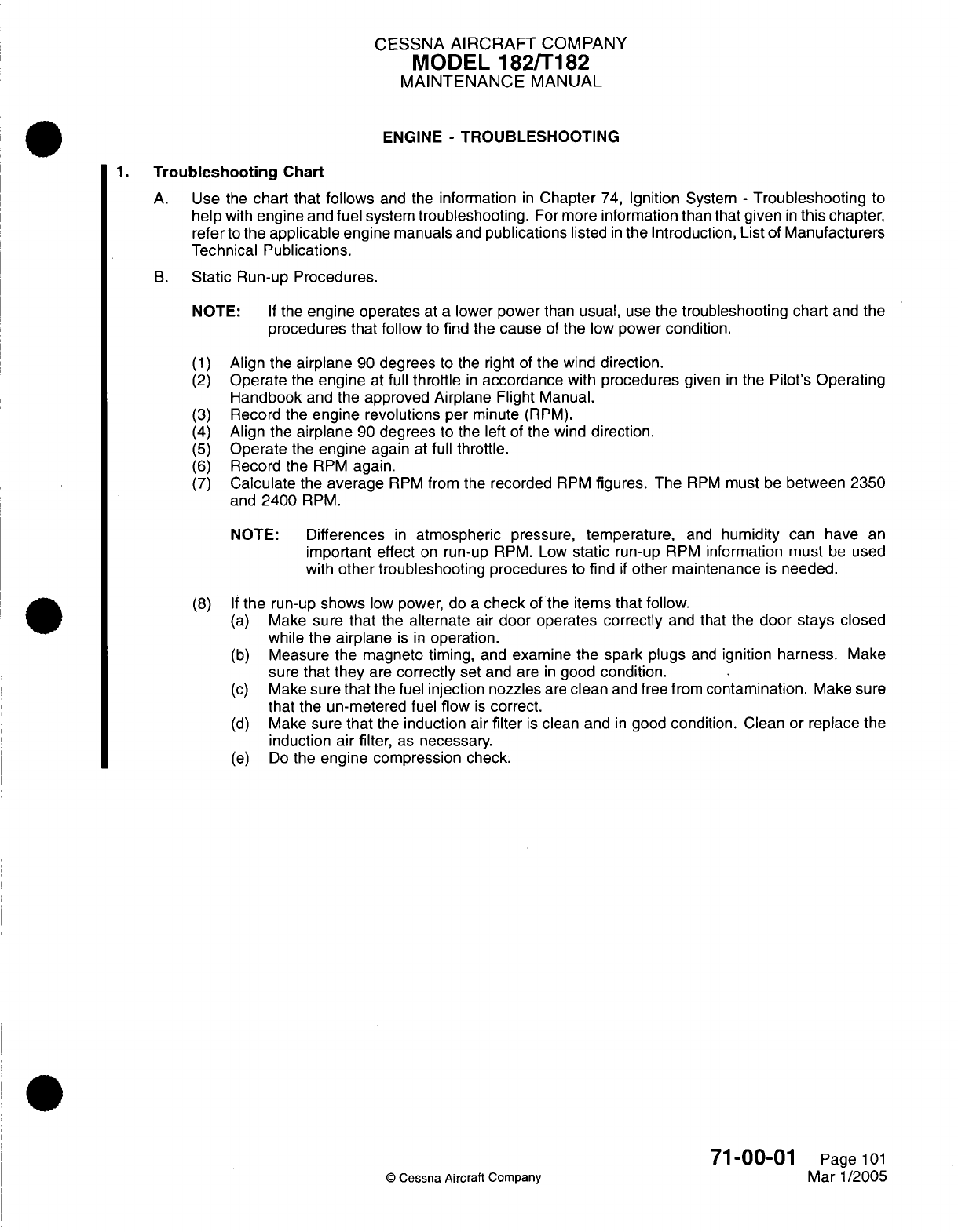
CESSNA
AIRCRAFT
COMPANY
MODEL
182/T182
MAINTENANCE
MANUAL
ENGINE
-
TROUBLESHOOTING
1.
Troubleshooting
Chart
A.
Use
the
chart
that
follows
and
the
information
in
Chapter
74,
Ignition
System
-
Troubleshooting
to
help
with
engine
and
fuel
system
troubleshooting.
For
more
information
than
that
given
in
this
chapter,
refer
to
the
applicable
engine
manuals
and
publications
listed
in
the Introduction, List
of
Manufacturers
Technical
Publications.
B.
Static
Run-up Procedures.
NOTE:
If
the
engine operates
at
a
lower power
than
usual,
use
the
troubleshooting chart
and
the
procedures
that
follow
to find the
cause
of
the
low
power condition.
(1)
Align the
airplane
90
degrees
to
the
right
of
the wind
direction.
(2)
Operate
the
engine
at
full
throttle
in
accordance
with
procedures
given
in
the
Pilot's Operating
Handbook
and
the approved Airplane Flight
Manual.
(3)
Record
the
engine
revolutions
per
minute
(RPM).
(4)
Align
the
airplane
90
degrees
to
the
left
of
the
wind
direction.
(5)
Operate
the
engine
again
at
full
throttle.
(6)
Record
the
RPM
again.
(7)
Calculate
the
average
RPM
from
the
recorded
RPM
figures.
The
RPM
must
be
between 2350
and
2400
RPM.
NOTE:
Differences
in
atmospheric
pressure,
temperature,
and
humidity
can have
an
important
effect
on
run-up
RPM.
Low
static
run-up
RPM
information must
be
used
with
other
troubleshooting
procedures
to
find
if
other
maintenance
is
needed.
(8)
If
the
run-up
shows
low
power,
do
a
check
of
the
items
that
follow.
(a)
Make
sure
that
the
alternate
air
door operates correctly
and that
the
door
stays
closed
while
the
airplane
is
in
operation.
(b)
Measure
the magneto timing,
and
examine the
spark
plugs
and
ignition
harness.
Make
sure
that
they
are
correctly
set
and
are
in
good
condition.
(c)
Make
sure that
the fuel
injection
nozzles
are
clean
and
free
from
contamination.
Make
sure
that
the
un-metered
fuel
flow
is
correct.
(d)
Make
sure that
the
induction
air
filter
is
clean
and
in
good
condition.
Clean or
replace
the
induction air
filter,
as
necessary.
(e)
Do
the
engine compression
check.
71-00-01
©
Cessna Aircraft
Company
Page
101
Mar 1/2005
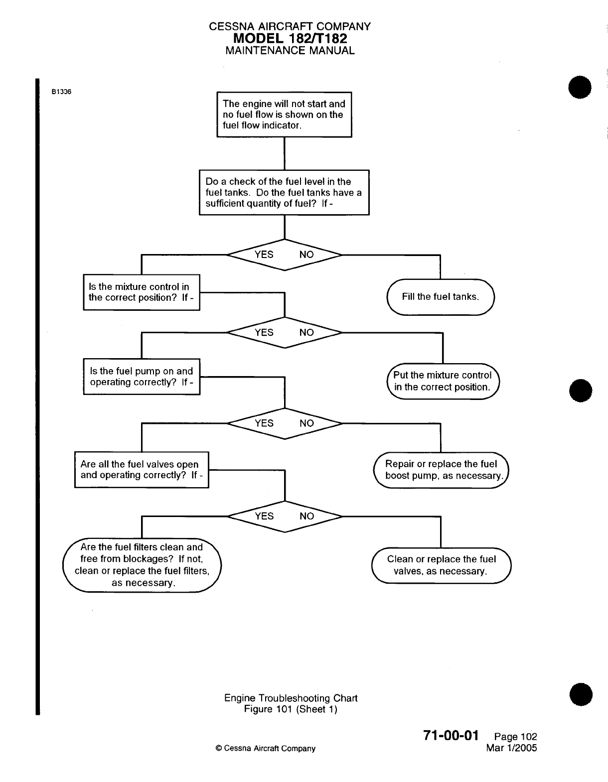
CESSNA AIRCRAFT
COMPANY
MODEL 182/T182
MAINTENANCE
MANUAL
B1336
The
engine will
not
start
and
no
fuel flow
is
shown
on
the
fuel
flow
indicator.
Do
a
check
of
the
fuel
level
in
the
fuel
tanks.
Do
the
fuel
tanks
have
a
sufficient
quantity
of
fuel?
If
-
Is
the
mixture
control
in
the
correct
position?
If
-
Is
the
fuel pump
on and
operating
correctly?
If
-
Are
all
the
fuel valves
open
and
operating
correctly?
If-
Are
the
fuel filters
clean
and
free
from
blockages?
If
not,
clean
or
replace the
fuel
filters,
as
necessary.
(Fill
the
fuel
tanks.)
Put
the
mixture
contro;
the
correct
position.
Repair
or
replace
the fuel
boost
pump,
as
necessary.
C
Clean
or
replace
the
fuel>
valves,
as
necessary.
Engine
Troubleshooting
Chart
Figure
101
(Sheet
1)
O
Cessna
Aircraft
Company
71-00-01
Page
102
Mar
1/2005
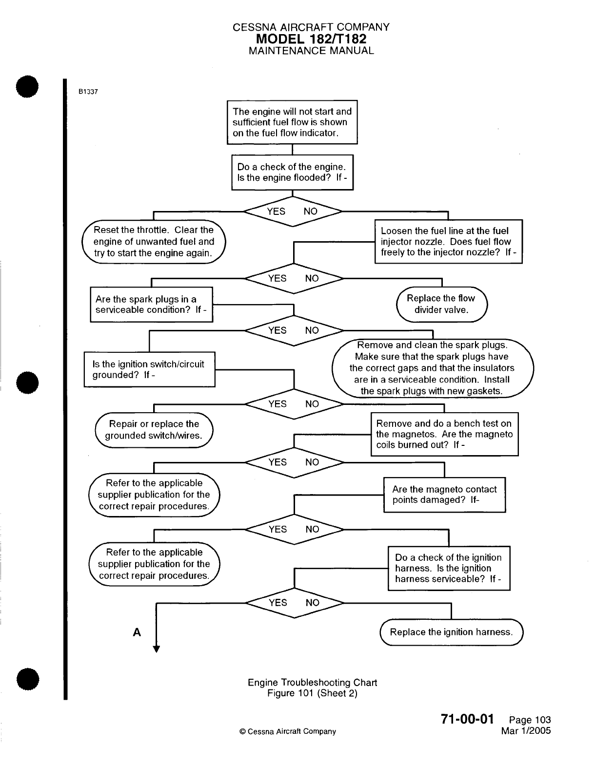
CESSNA
AIRCRAFT
COMPANY
MODEL
182/T182
MAINTENANCE
MANUAL
B1337
The engine
will
not
start
and
sufficient
fuel
flow
is
shown
on
the fuel
flow indicator.
Do
a
check of
the
engine.
Is
the engine
flooded?
If
-
<YES
N
I
Reset
the
throttle.
Clear
the
engine
of
unwanted
fuel
and
try
to
start
the
engine
again.
Are
the
spark
plugs
in
a
serviceable condition?
If
-
Is
the
ignition
switch/circuit
grounded?
If-
Repair
or
replace
the
grounded switch/wires.
Refer
to
the
applicablet
supplier
publication
for
the
correct
repair
procedures.
Refer
to
the
applicablet
supplier
publication for
the
correct
repair
procedures.
Loosen the
fuel
line
at
the
fuel
injector nozzle.
Does
fuel
flow
freely
to
the injector
nozzle?
If
-
Replace
the
flow
divider
valve.
I
Remove
and
clean
the
spark
plugs.
Make
sure
that
the spark
plugs
have
ie
correct gaps
and
that
the
insulators
are
in
a
serviceable
condition.
Install
the spark
plugs
with
new
gaskets.
I
YES
NO
A
Remove
and
do
a
bench
test
on
the
magnetos.
Are
the
magneto
coils
burned
out?
If-
Are
the
magneto
contact
points
damaged?
If-
Do
a
check
of the
ignition
harness.
Is
the ignition
harness
serviceable?
If
-
Replace
the ignition
harness.)
V
Engine
Troubleshooting
Chart
Figure
101
(Sheet
2)
©
Cessna Aircraft
Company
71-00-01
Page
103
Mar
1/2005
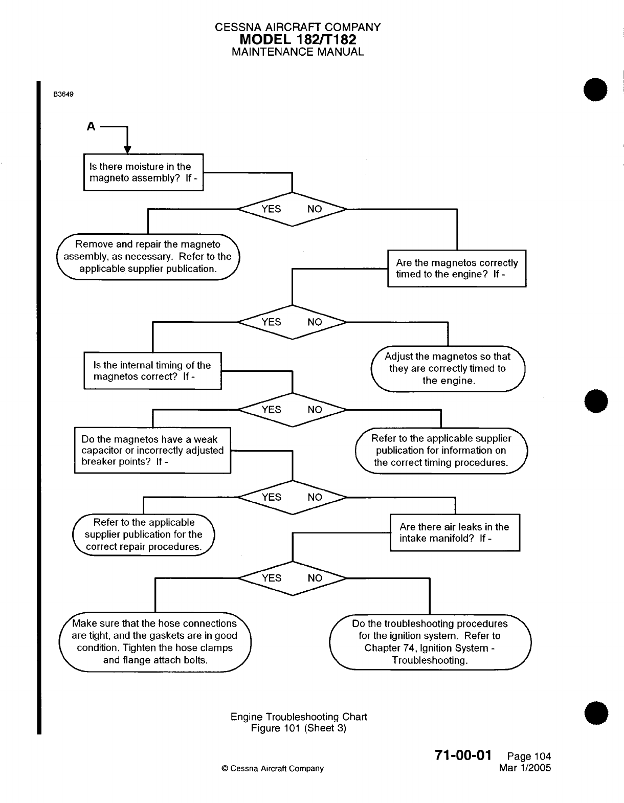
CESSNA
AIRCRAFT
COMPANY
MODEL 182/T182
MAINTENANCE
MANUAL
B3649
A
-
I
Is
there
moisture
in
the
I
magneto assembly?
If
-I
I
Remove
and
repair the
magneto
\
assembly,
as
necessary. Refer
to
the)
-nnlrhl
l
lJ t
'
iaU r n -I hli t+!inn
/
Is the
internal
timing
of
the
I Is
the
internal
timing
of
the
I
magnetos
correct?
If-
I
Do
the
magnetos
have
a
weak
1
,reervitrw
or4 :
r- r
_rr
l«,
- ..
.o-rbi
,I
I
apaLci;tL
u[ I[1
iouII
ecny
aujus>Lu
breaker
points?
If-
_ _I
Refer to the
applicable
supplier
pubiication
Tor
nme
\correct
repair
procedures
Make sure
that
the hose
connections
are
tight,
and
the
gaskets
are
in
good
condition. Tighten
the
hose
clamps
and
flange
attach bolts.
Are
the
magnetos correctly
timed
to
the engine?
If
-
Adjust
the
magnetos
so
that
they
are
correctly
timed
to
the
engine.
J
Refer
to
the
applicable
supplier
publication for
information
on
the
correct
timing
procedures.
I
Are
there
air
leaks
in
the
intake
manifold?
If-
Do
the
troubleshooting
procedures
for
the
ignition
system.
Refer
to
Chapter
74,
Ignition
System
-
Troubleshooting.
Engine
Troubleshooting Chart
Figure
101
(Sheet
3)
©
Cessna
Aircraft
Company
71-00-01
Page
104
Mar 1/2005
\_
C1VVMQL111r
OUPFAII
PULUIIC-3LIVII.
__"
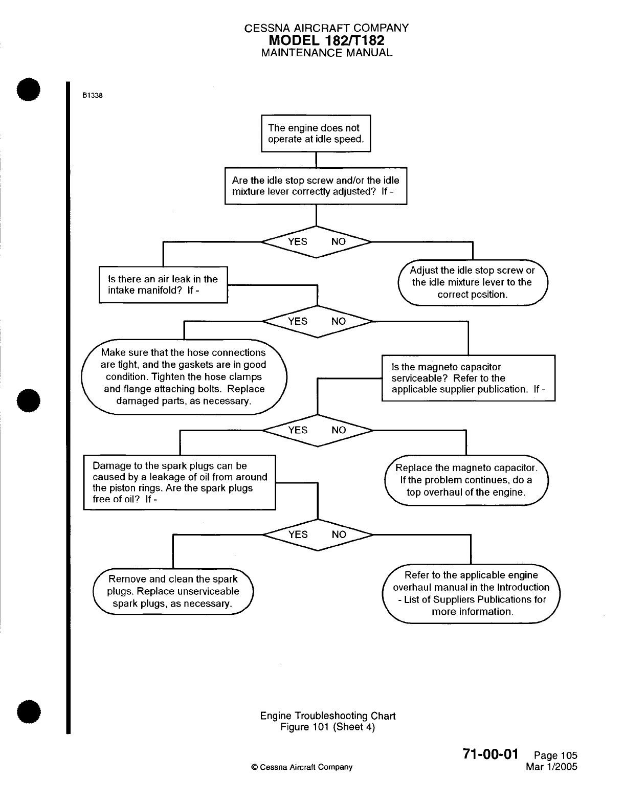
CESSNA
AIRCRAFT
COMPANY
MODEL
182/T182
MAINTENANCE
MANUAL
B1338
The
engine
does
not
operate
at
idle
speed.
Are
the
idle
stop
screw
and/or
the
idle
mixture lever
correctly
adjusted?
If
-
Is
there
an
air
leak
in
the
intake
manifold?
If
-
I
Adjust
the
idle
stop
screw
or
the
idle
mixture
lever
to
the
correct
position.
J
Make
sure
that
the hose
connecti
are
tight,
and
the
gaskets
are
in
gc
condition. Tighten
the
hose
clam
and
flange
attaching
bolts. ReplE
damaged
parts,
as
necessary.
I
Damage
to the
spark
plugs
can
be
caused
by
a
leakage
of
oil
from around
the
piston rings.
Are
the
spark plugs
free
of
oil?
If
-
Remove
and
clean
the
spark~
plugs.
Replace
unserviceable
spark
plugs,
as
necessary.
J
Is
the
magneto
capacitor
serviceable?
Refer
to
the
applicable
supplier publication.
If
-
Replace
the
magneto
capacitor.
If
the
problem
continues,
do
a
\
top
overhaul
of
the
engine.
J
Refer
to the
applicable
engine
overhaul
manual
in
the
Introduction
-
List
of
Suppliers
Publications
for
more
information.
Engine
Troubleshooting
Chart
Figure
101
(Sheet
4)
©
Cessna
Aircraft
Company
71-00-01
Page
105
Mar 1/2005
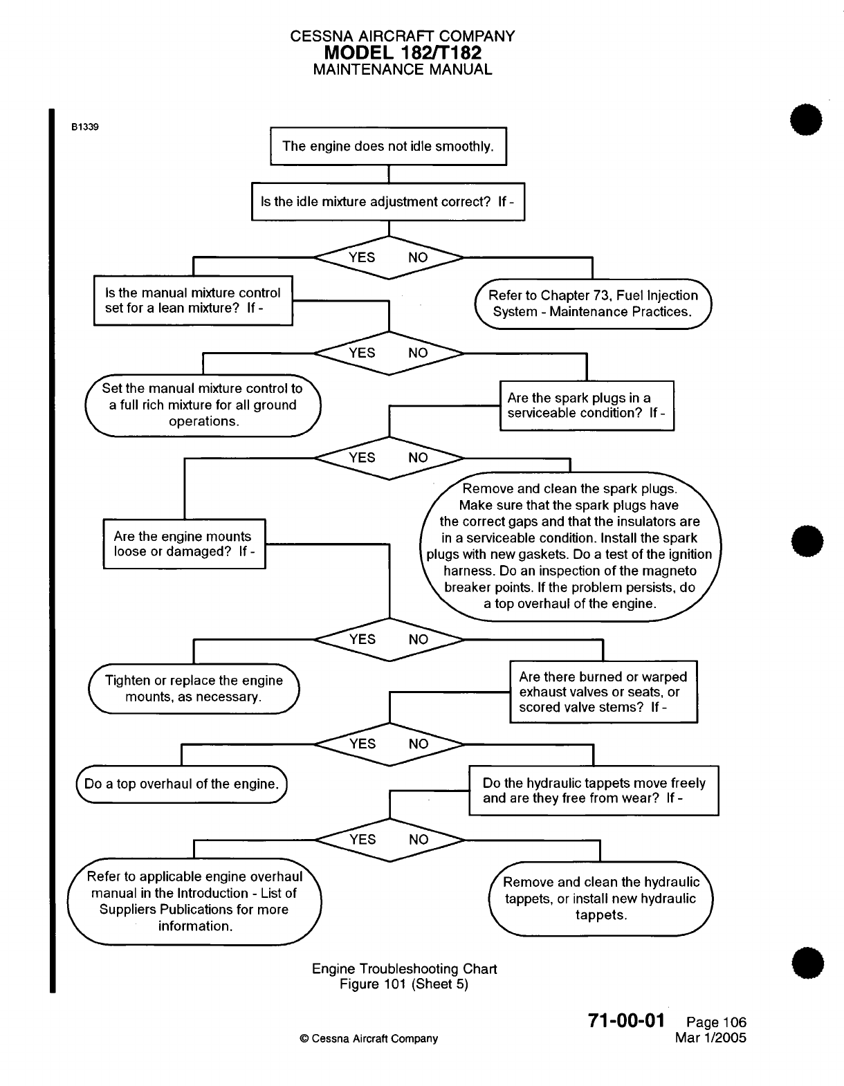
CESSNA AIRCRAFT
COMPANY
MODEL 182/T182
MAINTENANCE
MANUAL
B1339
The engine
does
not
idle
smoothly.
I
Is
th
Is
the
manual
mixture
control
set
for
a
lean
mixture?
If
-
I
et
the manual
mixture
control
to
a
full
rich
mixture
for all ground
\•
~operations.
ie
idle
mixture
adjustment
correct?
If-
I
YES
N
/Refer
to
Chapter
73,
Fuel
Injection
System
-
Maintenance
Practices.J
Are
the
spark plugs
in
a
serviceable condition?
If-
YES
NO
Are
the
engine
mounts
loose
or
damaged?
If
-
Remove
and
clean
the
spark
plugs.
Make
sure
that
the
spark
plugs
have
the
correct
gaps
and
that
the
insulators
are
in a
serviceable
condition.
Install
the
spark
plugs
with new
gaskets.
Do
a
test
of
the
ignition
harness.
Do
an
inspection
of
the magneto
\breaker
points.
If
the
problem
persists,
do
/
a
top overhaul
of
the
engine.
<YES
NO
(Tighten
or
replace
the
engine
2
mounts,
as
necessary.
J
I
(Do
a
top
overhaul
of
the
engine)
efer
to
applicable
engine overhaul
manual
in
the
Introduction
-
List
of
Suppliers
Publications
for
more
s^
~
information.
J
Are
there
burned
or
warped
exhaust valves
or
seats,
or
scored
valve
stems?
If
-
Do
the
hydraulic
tappets
move
freely
and
are
they
free
from
wear?
If
-
Remove
and
clean
the hydraulic
tappets,
or
install
new
hydraulic
p^
~
tappets.
Engine
Troubleshooting Chart
Figure
101
(Sheet
5)
©
Cessna
Aircraft
Company
71-00-01
Page
106
Mar
1/2005
_
_
c
A
I
I
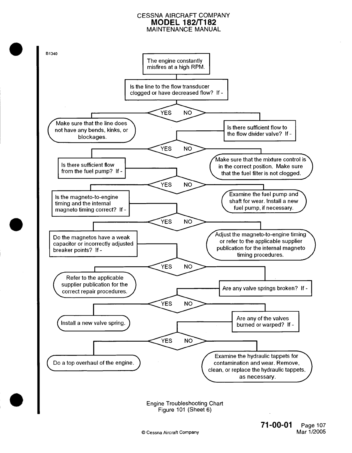
CESSNA
AIRCRAFT
COMPANY
MODEL
182/T182
MAINTENANCE
MANUAL
B1340
Is
t
do
Make
sure
that
the
line
does
not
have any
bends,
kinks,
or
blockages.
/
Is
there
sufficient
flow
from
the
fuel
pump?
If
-
I
Is
the
magneto-to-engine
timing
and
the internal
magneto
timing
correct?
If-
I
Do
the
magnetos
have
a
weak
capacitor
or
incorrectly adjusted
breaker
points?
If-
Refer
to
the
applicable
supplier
publication for
the
correct
repair
procedures.
(nstall
a
new
valve spring)
(Do
a
top overhaul
of the
engine)
The
engine
constantly
misfires at
a
high
RPM.
I
he
line
to
the
flow
transducer
gged
or have
decreased
flow?
If
-
YES
NO>
Is
there
sufficient
flow
to
the
flow
divider
valve?
If
-
I
YES
NO
MaKe
sure
tnat
me
mixture
control
is
in
the
correct
position.
Make
sure
that the
fuel
filter
is
not
clogged.
/
>
I
fExamine
the
fuel
pump
and\
shaft
for
wear.
Install
a
new
\
fuel
pump,
if
necessary.
/
'
~~~~~~~~~~~~~~~~~~~I
Adjust
the
magneto-to-engine
timing
/
or
refer
to
the
applicable
supplier
YES
N
publication
for
the
internal
magneto
)
timing procedures.
'
I
I
Are
any
valve
springs
broken?
If
-
Are
any
ofthe
valves
Are
any
of
the
valves
burned
or
warped?
If-
I
Examine
the
hydraulic
tappets
for
contamination
and
wear.
Remove,
clean,
or
replace
the hydraulic
tappets,
lec<
~as
necessary.
Engine
Troubleshooting
Chart
Figure
101
(Sheet
6)
©
Cessna Aircraft
Company
71-00-01
Page
107
Mar
1/2005
. . ..., . .
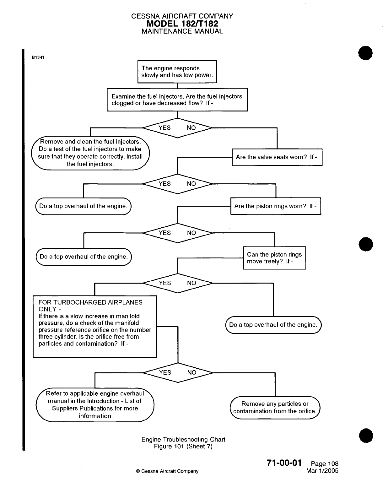
CESSNA AIRCRAFT
COMPANY
MODEL
182/T182
MAINTENANCE
MANUAL
The
engine
responds
slowly
and
has
low power.
Examine
the
fuel
injectors.
Are
the
fuel injectors
clogged
or have
decreased flow?
If
-
Remove
and
clean
the
fuel
injecto
Do
a
test
of
the
fuel
injectors
to
ma
sure
that
they operate
correctly.
Ins
the
fuel
injectors.
o
a
top
overhaul
of
the
engine)
FOR
TURBOCHARGED
AIRPLANES
ONLY
-
If
there
is
a
slow
increase
in
manifold
pressure,
do
a
check
of
the manifold
pressure reference
orifice
on
the
number
three
cylinder.
Is
the
orifice
free
from
particles
and
contamination?
If-
Are
the
valve
seats worn?
If
-
Are
the
piston
rings
worn?
If
-
Can
the
piston
rings
move
freely?
If
-
(Do
a
top
overhaul
of
the
engine)
YES
N
efer
to
applicable
engine
overhaul
manual
in
the
Introduction
-
List
of
Suppliers
Publications
for
more
information.
Remove any
particles
or
contamination from
the
orifice.
Engine
Troubleshooting
Chart
0
Figure
101
(Sheet
7)
©
Cessna Aircraft
Company
71-00-01
Page
108
Mar
1/2005
B1341
rno
Mn
ovprhnidl
of
thp.
Pnninp")
V
-
-,-I-
- ",-
I
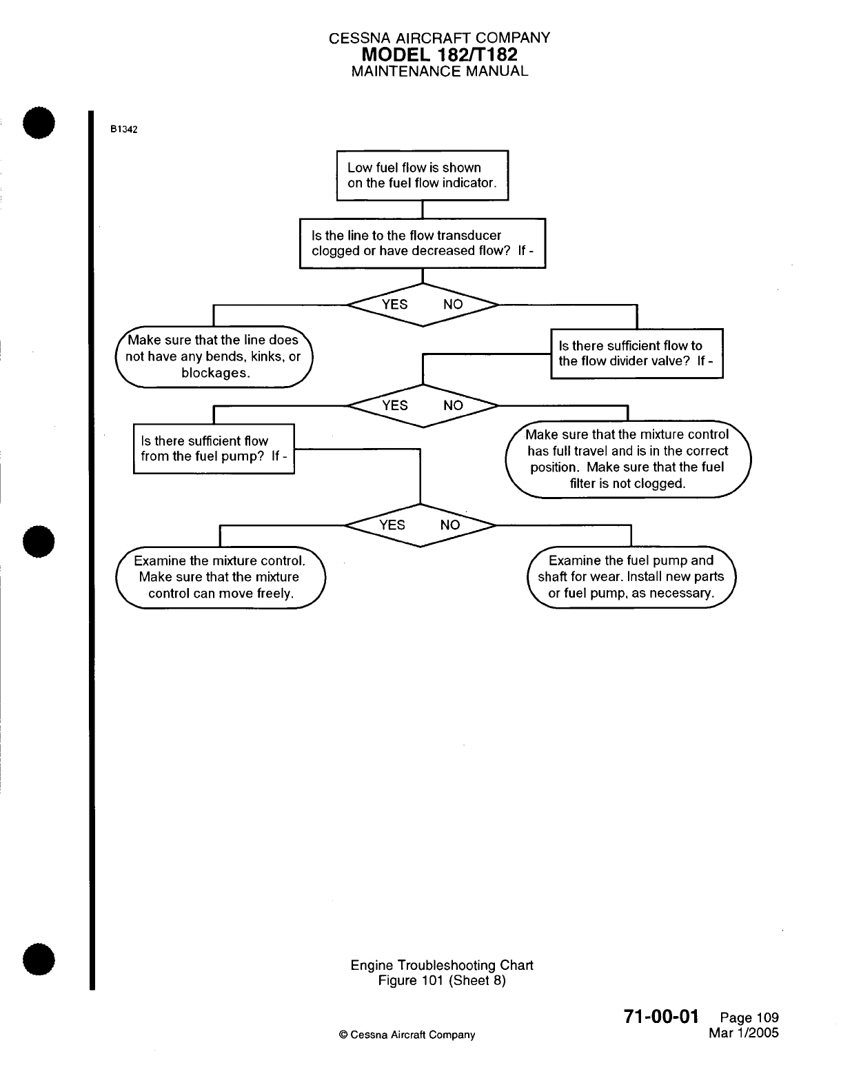
CESSNA
AIRCRAFT
COMPANY
MODEL
182/T182
MAINTENANCE
MANUAL
B1342
Low
fuel
flow
is
shown
on
the
fuel
flow
indicator.
Is
the
line to
the
flow
transducer
clogged
or have
decreased flow?
If-
YES
NO
Make
sure
that
the
line
does
not
have
any
bends,
kinks,
or
blockages.
Is
there
sufficient flow
from the
fuel
pump?
If-
xamine the
mixture
control.
Make
sure
that
the
mixture
control
can
move
freely.
J
Is
there sufficient
flow
to
the
flow
divider
valve?
If
-
I
ake
sure
that
the
mixture
control-
has
full
travel
and
is
in
the
correct
position. Make sure
that
the
fuel
filter
is
not
clogged.
Examine
the
fuel
pump
andr
shaft
for
wear.
Install
new
parts
or
fuel
pump,
as
necessary.
Engine
Troubleshooting
Chart
Figure
101
(Sheet
8)
71-00-01
©
Cessna Aircraft
Company
Page
109
Mar
1/2005
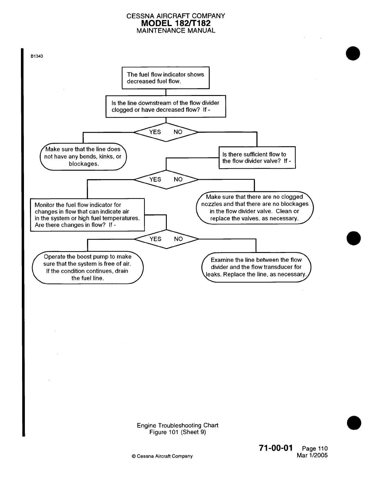
CESSNA
AIRCRAFT
COMPANY
MODEL
182/T182
MAINTENANCE
MANUAL
B1343
The
fuel
flow
indicator shows
decreased
fuel
flow.
Is
the
line
downstream
of
the
flow
divider
clogged
or
have
decreased
flow?
If
-
YES
NO
r/ake
sure
that
the
line
does
I
nat
have
an\
hanrkle inlk
r
1
Monitor
the
fuel
flow
indicator
for
changes
in
flow that
can
indicate
air
in
the
system
or
high
fuel temperatur
Are
there
changes
in
flow?
If
-
Operate
the
boost
pump
to
make
sure
that
the system
is
free
of
air.
If
the
condition
continues,
drain
the
fuel
line.
Is
there
sufficient
flow to
the
flow
divider
valve?
If
-
I
ake
sure
that there
are
no
clogged
zles
and
that there
are
no
blockages
n
the
flow
divider
valve.
Clean
or
eplace
the valves,
as
necessary.
I
Examine
the
line
between
the
flow
divider
and
the
flow
transducer
for
eaks.
Replace
the
line,
as
necessary/
i~ed~mn h
iebtentefo''
Engine
Troubleshooting
Chart
Figure
101
(Sheet
9)
71-00-01
©
Cessna
Aircraft Company
Page
110
Mar
1/2005
c
blockages.
I
I
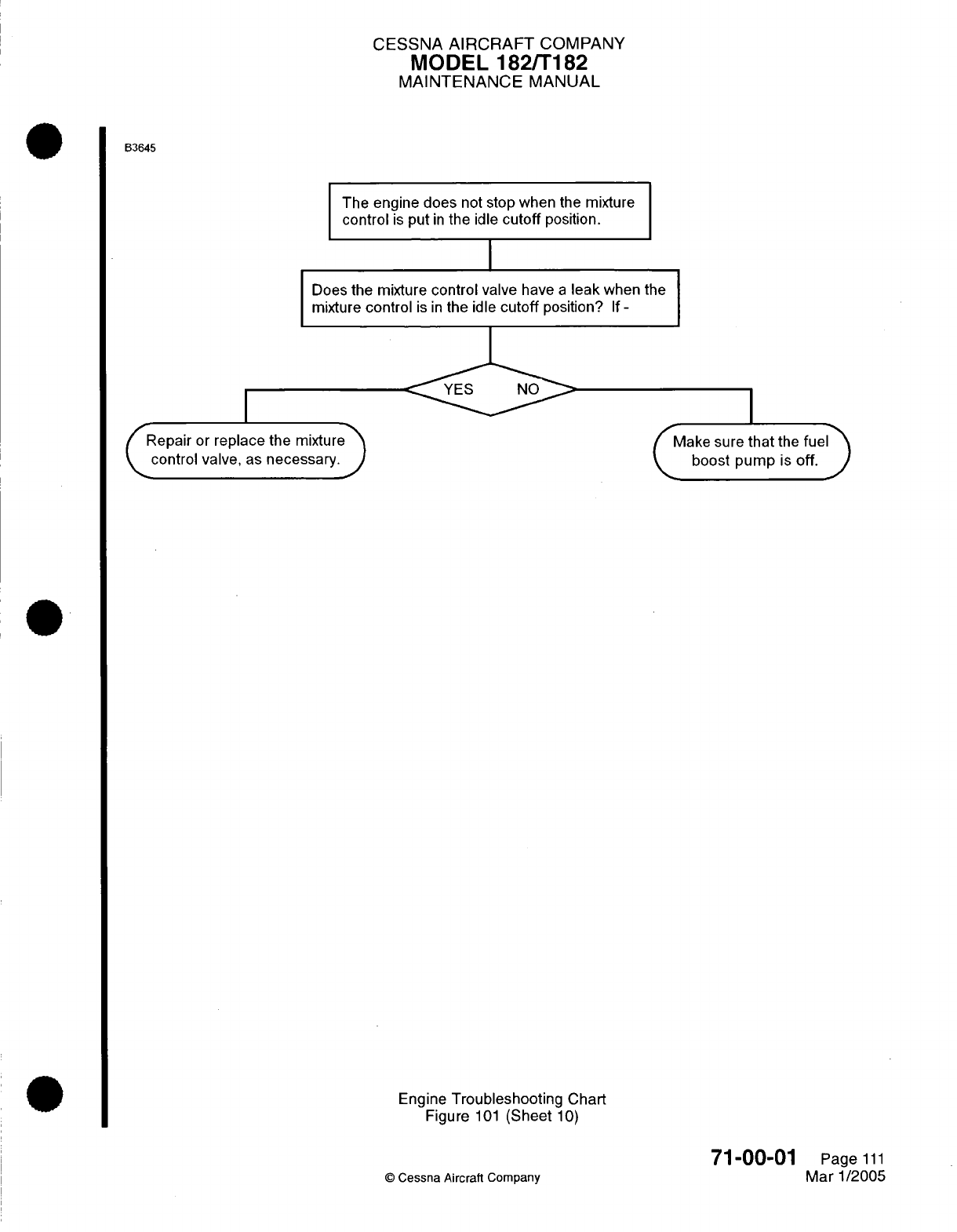
CESSNA
AIRCRAFT
COMPANY
MODEL
182/T182
MAINTENANCE
MANUAL
B3645
The engine does
not
stop
when
the
mixture
control
is
put
in
the
idle
cutoff
position.
I
Does
the
mixture
control
valve
have
a
leak
when
the
mixture
control
is
in
the
idle
cutoff
position?
If
-
CRepair
or
replace
the
mixture>
control
valve,
as
necessary.
J
I
ake
sure
that
the
fuel
Mboost
pump
is
off.
J
Engine
Troubleshooting
Chart
Figure
101
(Sheet
10)
©
Cessna Aircraft
Company
71-00-01
Page
111
Mar
1/2005
I
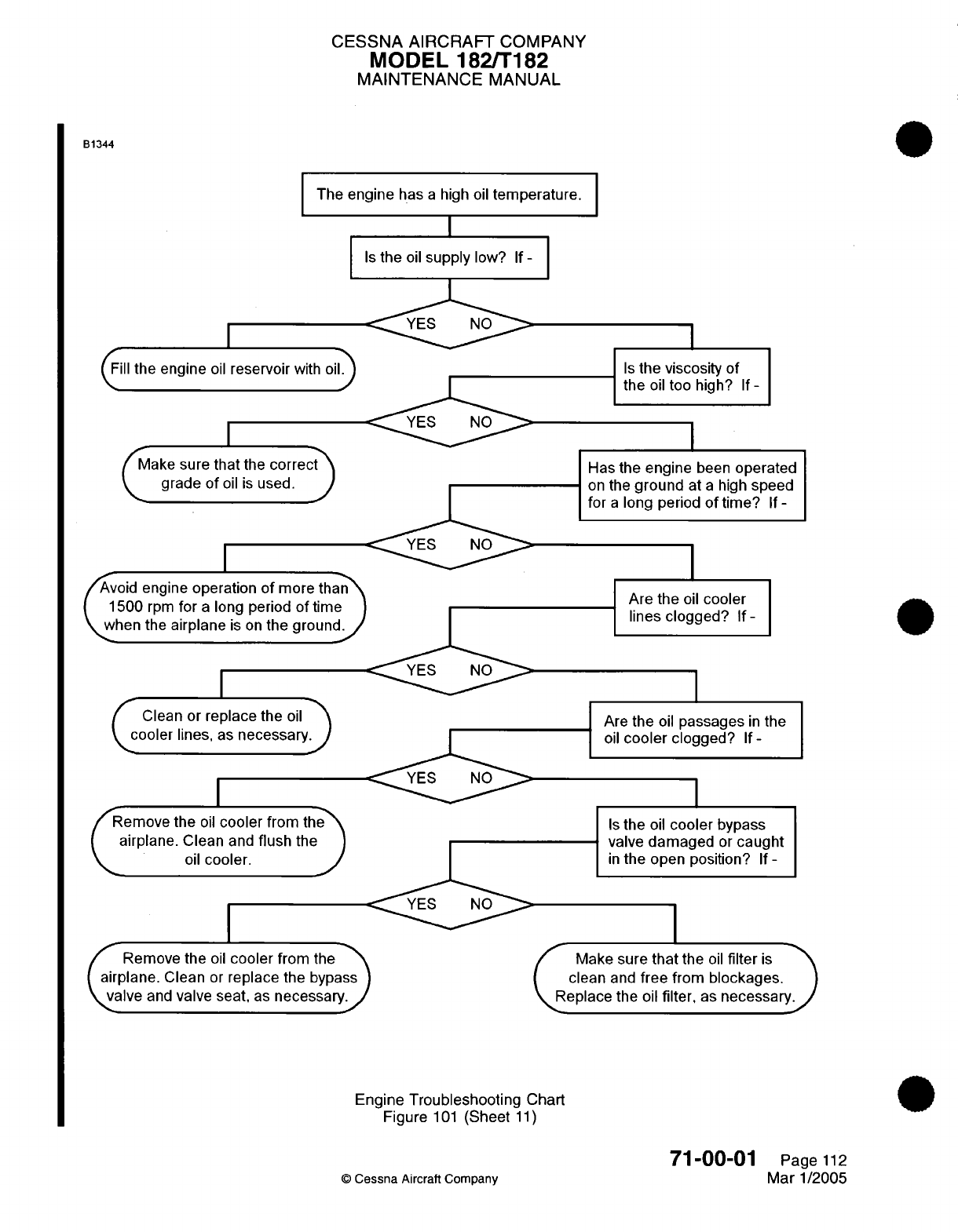
CESSNA AIRCRAFT
COMPANY
MODEL 182/T182
MAINTENANCE
MANUAL
B1344
The
engine
has
a
high
oil
temperature.
Is
the
oil
supply
low?
If
-
(
il
the
engine
oil
reservoir
with
oil
CMake
sure
that
the
correct
grade
of
oil
is
used.
I
YES
NO
void
engine
operation
of
more th
1500
rpm
for
a
long period
of tim
when the
airplane
is on
the
groun
I
Clean
or
replace
the
oil"
cooler
lines, as
necessary
emove
the
oil
cooler
from
theT
airplane.
Clean
and
flush
the
oil
cooler.
J
Remove the
oil
cooler
from
the
airplane.
Clean
or
replace
the
bypass
valve
and
valve
seat,
as
necessary.
I
Is
the viscosity
of
the
oil
too
high?
If-
Has
the
engine
been
operated
on
the
ground
at
a
high
speed
for
a
long
period
of
time?
If
-
Are
the
oil
cooler
lines
clogged?
If-
Are
the
oil
passages
in
the
oil
cooler
clogged?
If-
Is
the
oil
cooler
bypass
valve
damaged
or
caught
in
the
open position?
If
-
Make
sure
that
the
oil
filter
is
clean
and
free
from
blockages.
Replace
the
oil
filter,
as
necessary.
Engine
Troubleshooting Chart
Figure
101
(Sheet
11)
©
Cessna
Aircraft Company
71-00-01
Page
112
Mar
1/2005
I
I I
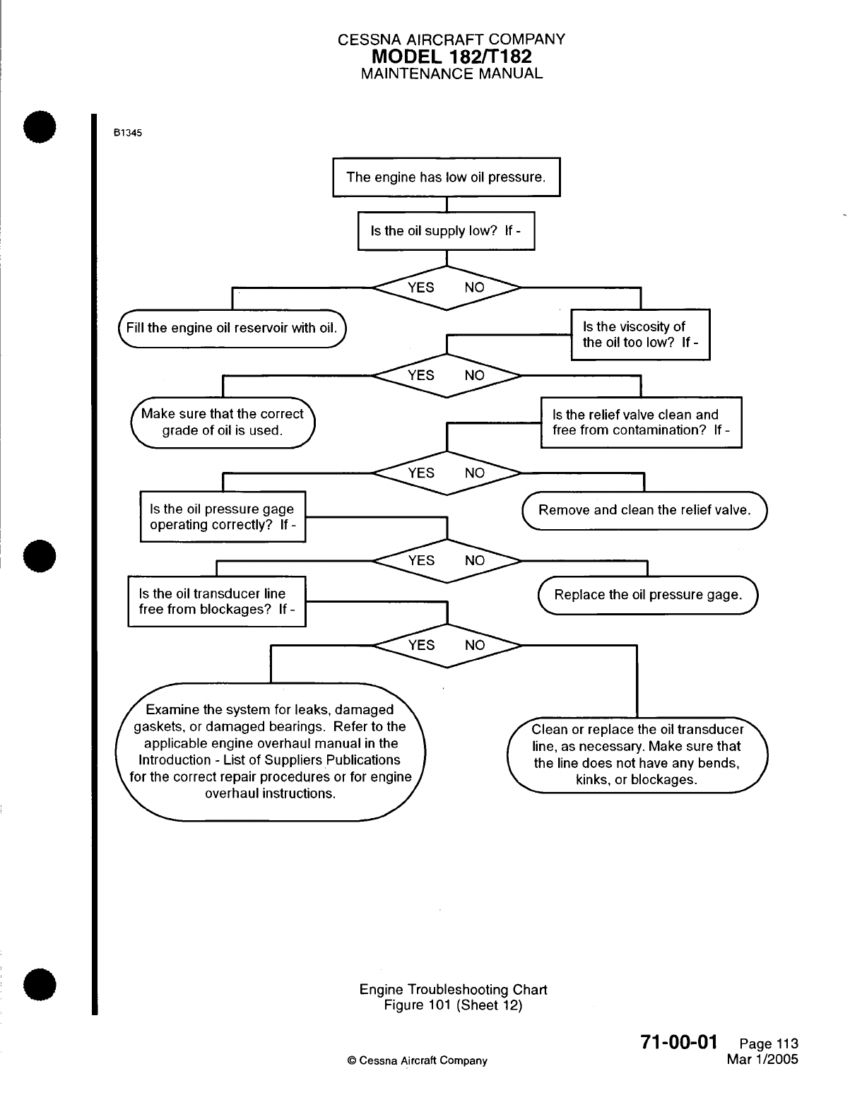
CESSNA
AIRCRAFT
COMPANY
MODEL
182/T182
MAINTENANCE
MANUAL
B1345
The engine
has
low
oil
pressure.
I
ill
the
engine
oil
reservoir
with
oi
Make sure
that
the
correct
C
grade
of
oil
is
used.
J
Is
the
oil
pressure
gage
operating
correctly?
If
-
Is
the
oil
transducer
line
free from
blockages?
If-
xamine the
system
for leaks,
damaged
gaskets,
or
damaged
bearings. Refer
to the
applicable
engine overhaul manual
in
the
Introduction
-
List
of
Suppliers Publications
for
the
correct
repair procedures
or
for engine
overhaul instructions.
Is
the
oil
supply
low?
If
-
YES
NO
YES
NO
Is
the
viscosity
of
the
oil
too
low?
If
-
Is
the
relief
valve
clean
and
free
from
contamination?
If
-
I
(
Remove
and
clean the
relief
valve.
)
I
(
Replace the
oil
pressure gage.
)
Clean
or
replace
the
oil
transducer
line,
as
necessary.
Make sure
that
the
line
does
not
have
any
bends,
kinks,
or
blockages.
Engine
Troubleshooting Chart
Figure
101
(Sheet
12)
©
Cessna
Aircraft
Company
71-00-01
Page
113
Mar
1/2005
r
I
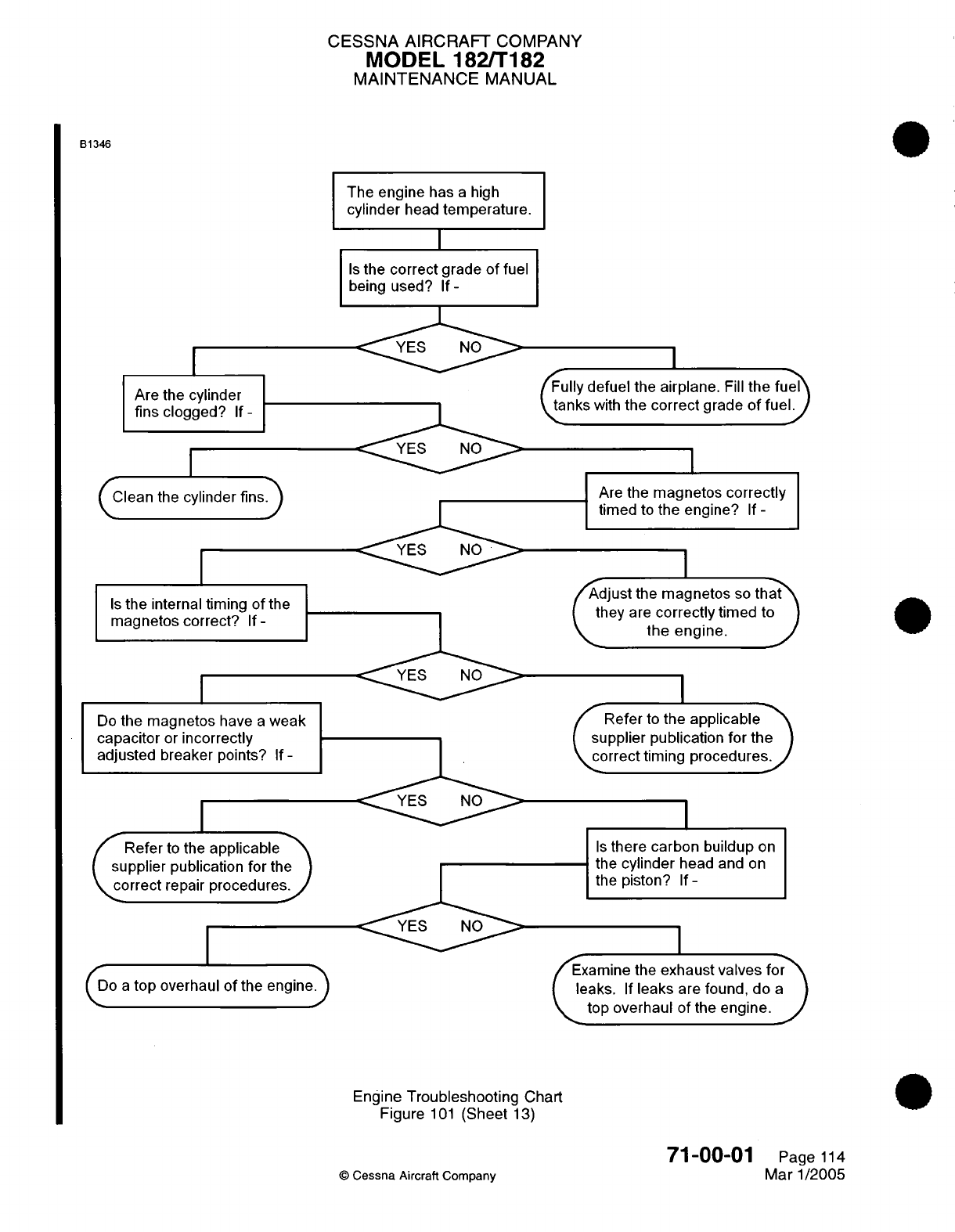
CESSNA AIRCRAFT
COMPANY
MODEL
182/T182
MAINTENANCE
MANUAL
B1346
Are
the
cylinder
fins
clogged?
If-
I
Clean the
cylinder
fins.
Is
the
internal timing
of
the
magnetos correct?
If
-
Do
the magnetos
have
a
weak
capacitor
or
incorrectly
adjusted
breaker
points?
If-
Refer
to
the
applicablet
supplier
publication
for
the
correct
repair
procedures.
The
engine
has
a
high
cylinder
head
temperature.
I
Is
the
correct
grade
of
fuel
being
used?
If-
YES
NO
YES
NO
(Do
a
top
overhaul
of
the
engine)
Fully defuel
the
airplane.
Fill
the
fue
anks
with
the
correct
grade
of
fuel.
I
Are
the
magnetos
correctly
timed
to
the engine?
If
-
I
Adjust
the
magnetos
so
that
they
are
correctly
timed
to
K,
the
engine.
Refer
to
the
applicable
supplier
publication
for
the
correct
timing
procedures.
Is
there carbon buildup
on
the
cylinder
head
and
on
the piston?
If
-
Examine
the
exhaust
valves
for
leaks.
If
leaks
are
found,
do
a
top overhaul
of
the
engine.
J
Engine
Troubleshooting
Chart
Figure
101
(Sheet
13)
©
Cessna
Aircraft
Company
71-00-01
Page
114
Mar 1/2005
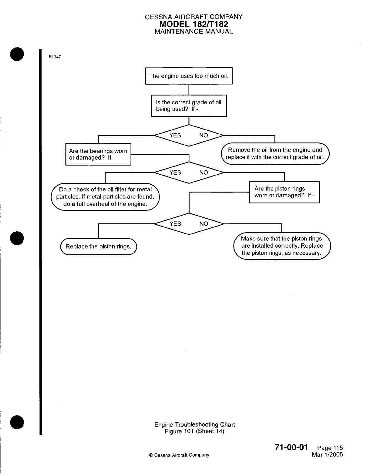
CESSNA
AIRCRAFT
COMPANY
MODEL
182/T182
MAINTENANCE
MANUAL
B1347
The
engine
uses
too
much
oil.
I
I
Is
the
correct
grade
of
oil
being
used?
If-
Are
the
bearings
worn
or
damaged?
If-
I
the
oil
from
the engine
and
with
the
correct grade
of
oil
Do
a
check
of the
oil
filter
for
met;
(particles.
If
metal
particles
are
foun
do
a
full
overhaul
of
the engine.
I
Are
the
piston
rings
worn
or
damaged?
(Replace
the piston
rings.
/Make
sure
that
the
piston
rings
are installed correctly.
Replace
the
piston
rings,
as
necessary.
Engine
Troubleshooting
Chart
Figure
101
(Sheet
14)
©
Cessna
Aircraft
Company
If-
71-00-01
Page
115
Mar
1/2005
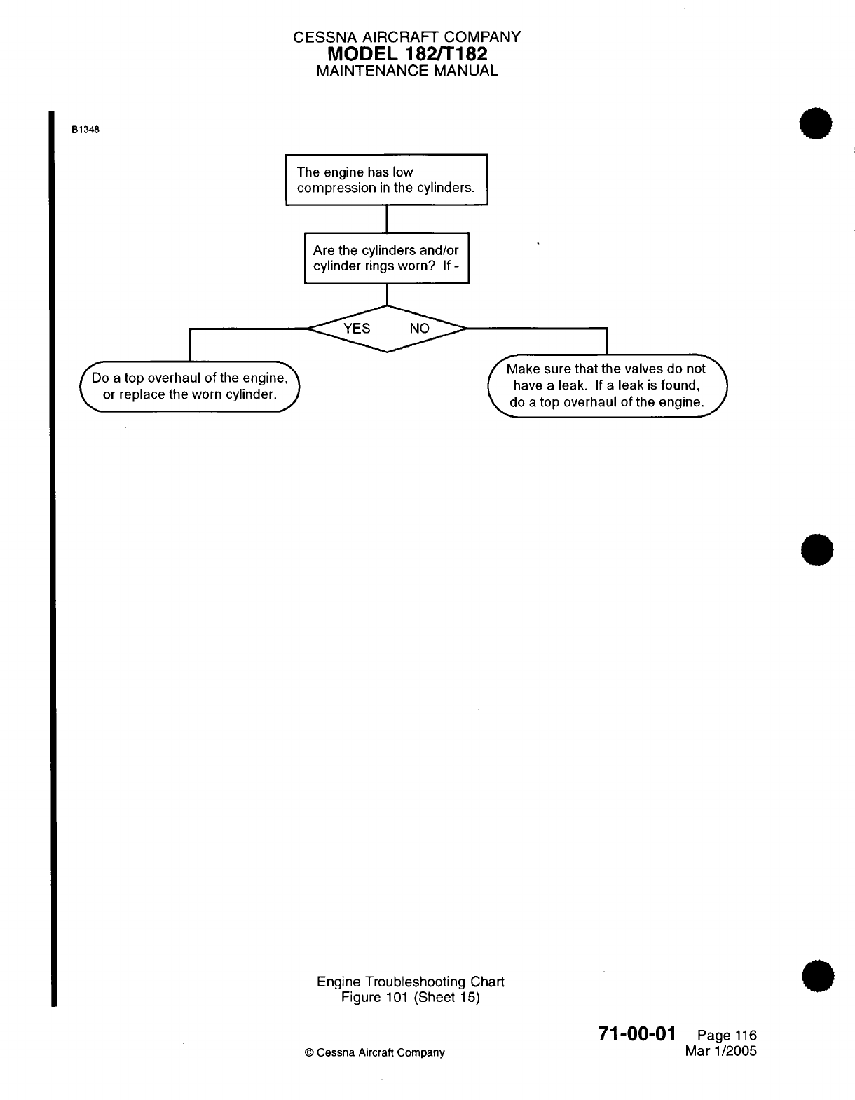
CESSNA AIRCRAFT
COMPANY
MODEL
182/T182
MAINTENANCE
MANUAL
B1348
The
engine
has
low
compression
in
the
cylinders.
I
Are the
cylinders
and/or
cylinder
rings
worn?
If
-
fo
a
top
overhaul
of
the
engine,
or
replace
the worn
cylinder.
J
ake
sure
that the
valves
do
no
have
a
leak.
If
a
leak
is
found,
\do
a
top
overhaul
of
the
engine.
Engine
Troubleshooting
Chart
Figure
101
(Sheet
15)
©
Cessna
Aircraft Company
71-00-01
Page
116
Mar
1/2005
I
CESSNA
AIRCRAFT
COMPANY
MODEL
182/T182
MAINTENANCE
MANUAL
ENGINE
-
MAINTENANCE PRACTICES
1.
General
A.
This section
gives
procedures for
the
removal and
installation
of
the
engine
and
the
engine mount
from
the
firewall.
For
more
maintenance
information,
refer
to
the
applicable
engine
publications
which
are
listed
in
the
Introduction
-
List
of
Manufacturers
Technical
Publications.
2.
Engine
Removal/Installation
A.
Remove
the
Engine
and
the
Engine Mount.
NOTE:
This procedure
shows
how you remove
the engine
and
engine
mount from the
firewall.
If
the
engine
is
removed
from
the
engine
mount
and
the
engine
mount
stays
attached
to
the
firewall,
some
of
the
steps
will
not
be
necessary.
To
disconnect
the
engine
from
the
engine
mount, remove
the
(4)
AN7
bolts
that
connect
the
(4)
shock
mounts
to
the
engine mounting
flange
and the
engine
mount tube.
(1)
Set
all
cabin
switches
to
the
OFF
position.
(2)
Set
the
fuel
shutoff
valve
to
the
OFF
position.
(3)
Remove the engine
cowl.
Refer
to
Chapter
71,
Cowling
-
Maintenance Practices.
NOTE:
Do
the
subsequent
steps
from the
right
side
of
the
airplane.
(4)
Disconnect
the
positive
and
negative battery
leads
from the
battery.
(5)
Loosen
the C-clamp
that attaches
the
flexible
duct
to the
firewall-mounted heater valve.
(6)
Remove
the
flexible
duct
from
the
heater
valve.
WARNING:
If
the
P
lead
wire
from
the
magnetos
is
disconnected,
the
electrical
ground
is
removed
from
the
magneto
circuit.
This
will
cause
hot
magnetos.
Attach
a
ground
wire
to
the
magneto
or
remove
all the
high
tension
wires
from
the
spark
plugs
before
you
turn
the
propeller.
(7)
Disconnect
the
P
lead
wires
on
the
magnetos.
(8)
Remove
the
propeller
governor.
Refer
to
Chapter
61,
Propeller Governor
-
Maintenance
Practices.
(9)
Disconnect
the
electrical connector
from
the Exhaust
Gas
Temperature
(EGT)
Probe.
(10)
Disconnect
the
fuel
outlet
line
at the
fuel
strainer.
(11)
Disconnect
the
throttle
cable
at
the
fuel/air
control
unit
and
record
the
position
of
the
washers
and
spacers
for later installation.
(12)
Disconnect
the
vacuum
hoses
at
the
firewall-mounted manifold/check
valve.
(13)
Disconnect
and put
a
label
on
the
electrical
wires
on
the
low
vacuum annunciator
switches.
NOTE:
Do
the
subsequent
steps
from the
left
side
of the
airplane.
(14)
Loosen
and
remove
the
clamps
from
the
tachometer
drive
cable
in
the
engine
area.
(15)
Disconnect
the
tachometer
drive cable
from the rear
of
the
accessory
case.
(16)
Cut
the
tie
wraps
(sta
straps)
that
attach the different
wire
bundles
to
the
engine
mount.
(17)
On
the bottom side
of the
engine,
loosen
and
remove
the
clamps that
attach
the
starter
wires
to
the
sump
area.
(18)
Remove
the
starter wires
from
the
starter.
(19)
Disconnect
the
ground strap
from the
engine
mount.
(20)
Disconnect
the
electrical
connector
from
the
fuel
flow
transducer.
(21)
Disconnect the
electrical
connector
from
the
low oil
pressure switch.
(22)
Disconnect the electrical
connector
from
the
oil
pressure transducer.
(23)
Remove
the
two
screws
on
the
rear
side
of
the
upper
right
baffles.
Remove
the
electrical
connector
from the baffles and
separate
the
baffles.
71-00-01
Page
201
©
Cessna
Aircraft
Company
Mar
1/2005
CESSNA AIRCRAFT
COMPANY
MODEL
182/T182
MAINTENANCE
MANUAL
(24)
Loosen
the
clamps
that
attach
the
battery vent
tube
to
the
drain
line
cluster.
(25)
Remove
the
vent
tube
through the
clamps.
(26)
Remove
the
bolt
and
spacer that
attach
the
drain line
cluster
to the
firewall.
(27)
Loosen
and
remove
the
ram
air
tubes
on
the
rear
side
of
the
upper
left
baffle.
(28)
Put
a
stand
under
the
tail
tie-down
to
adjust
for
a
tail
heavy
condition,
which
will
occur
when the
engine
is
removed
from
the
airframe.
(29)
Attach the hoist
to
the
lifting
strap
on
top
of the
engine.
CAUTION:
Do
not
lift
the engine higher
than
necessary.
If
you
lift
the
engine
too
high,
it
puts
a
strain
on
the attach
bolts.
(30)
Start
to
take
up
the
engine
weight
using
the
hoist.
(31)
Remove
the bolts
that
attach the engine
and
engine
mount
to the
firewall.
NOTE: Record
the
sequence
of
nuts,
washers,
and
flat
washers.
NOTE:
You
can
get
access
to the
bolt
heads
from
inside the
cockpit
to
keep
them
from
turning.
(32)
Slowly
lift
the engine
using
the
hoist
until
the engine
and
engine mount
move
free of
the
bolts.
B.
Install
the
Engine
and Engine
Mount.
(1)
Attach the engine mount
to
the
firewall. Refer
to
Engine
Mount
-
Maintenance
Practices.
(2)
Lift
the engine
into
position
with
the hoist.
(3)
Torque
the firewall
bolts
to
between
160
and
190
inch-pounds.
(4)
Remove the stand from
under
the
tail
tie-down.
(5)
Attach the
ram
air
tubes
to
the
rear
side
of
the
upper
left
baffle.
(6)
Attach
the
drain line
cluster
to
the firewall
with
a
bolt
and spacer.
(7)
Put
the battery vent
tube
through
the
drain line
clamps
and
tighten the
clamps.
(8)
Put
the wires
from
the electrical
connector
through
the
baffle
cutout
area.
(9)
Attach
the
baffle
pieces
together
with
screws.
(10)
Connect
the
electrical
connector
to
the
oil
pressure
transducer.
(11)
Connect
the
electrical
connector
to
the
low
oil
pressure
switch.
(12)
Connect
the
electrical
connector
to
the
fuel
flow
transducer.
(13)
Connect
the ground strap
to
the
engine
mount.
(14)
Connect
the
starter
wires
to
the
starter.
(15)
Connect
the
starter
wires
to
the sump
area
with
clamps.
(16)
Connect
the
different
wire
bundles
to
the engine mount
with
tie
wraps.
(17)
Connect
the
tachometer drive
cable
to
the
rear
of
the accessory
case.
(18)
Connect
the tagged
wires
to
the
low
vacuum
annunciator
switches.
(19)
Connect
the
vacuum
lines
to
the firewall-mounted manifold/check valve.
(20)
Connect
the
throttle
and
mixture
control
cables
to
the
fuel
air
control
unit.
(21)
Connect
the
fuel
outlet
line
to
the
fuel
strainer.
(22)
Connect
the
electrical
connector
to
the
EGT Probe.
(23)
Install
the
propeller
governor.
Refer
to
Chapter
61,
Propeller
Governor
-
Maintenance
Practices.
(24)
Connect
the
P
leads
to
the magnetos.
(25)
If
necessary,
connect
the high tension
wires
to the
spark
plugs.
(26)
Connect
the
flexible
duct
to
the
firewall-mounted
heater
valve.
(27)
Make sure
that
all
the controls
and
lines
are
installed
correctly
and
can
move
freely.
(28)
Make sure
that
all
fuel
fittings
are
tight
and
that
there
are
no
leaks.
(29)
Connect
the
positive
and
negative
leads
to
the
battery.
(30)
Install
the
engine
cowl. Refer
to
Chapter
71,
Cowl
-
Maintenance Practices.
3.
Engine
Cleaning
A.
Clean
the engine.
71-00-01
Page
202
©
Cessna
Aircraft
Company
Mar
1/2005
CESSNA
AIRCRAFT
COMPANY
MODEL
182/T182
MAINTENANCE
MANUAL
CAUTION:
All
openings
must
be
covered
with
caps
to
prevent
solvent
entry
into
the engine.
Cover
the
electrical
accessories
(starters,
alternators,
etc.)
before
the
cleaning
solvent
is
applied.
(1)
Clean
the
engine
using
a
Stoddard
solvent
or
equivalent
chemical.
4.
Engine
Storage
A.
If
the engine
is
removed
for
storage purposes,
refer
to
the
Lycoming
Service Letter
L180B
(or
latest
revision)
for
preservation
procedures.
71-00-01
Page
203
©
Cessna
Aircraft
Company
Mar
1/2005
CESSNA
AIRCRAFT
COMPANY
MODEL
182/T182
MAINTENANCE
MANUAL
COWL
-
MAINTENANCE PRACTICES
1.
Description
and
Operation
A.
The
engine
has
a
top
cowl,
two
side
cowls
and
a
bottom cowl.
The front
of
the
engine
has
a
top
and
bottom
or
a
left
and
right
nose-cap that
is
made
of
composite
material.
The
cowls
use
quick-release
fasteners
that
lock
into
receptacles for easy
removal
and
installation.
The
nose-caps
attach
to
each
other
with
screws.
B.
There
are
two cowl
flaps
in
the bottom
cowl.
They
help
control
the
engine
temperature
and
operate
by
a
control lever
in
the
cockpit.
2.
Side
Cowl
Removal/Installation
NOTE:
The
removal
and
installation
is
typical
for
the
left
and
right
side
cowl.
A.
Remove the Side
Cowl
(Refer
to
Figure
201).
(1)
Disconnect
the
quick-release
fasteners
around
the
edges
of the side
cowl
and
remove
the
cowl
from the
airplane.
B.
Install
the
Side
Cowl
(Refer
to
Figure
201
for
the same
cowl
you
removed
or
Figure 202
for
installation
of
a
new
side
cowl).
(1)
Install
the
same
cowl
you
removed.
(a)
Attach
the
top edge
of
the
cowl
to
the
airplane.
(b)
Attach
the forward, aft
and
bottom
edges
of
the
cowl to
the
airplane.
(2)
Install
a
new
side
cowl.
NOTE:
When
a
new
side
cowl
is
installed,
it
must
be
fitted
to the
airplane.
The
new
cowl
must
be
cut
and
adjusted for
the
correct
fit.
The
installation
for
the
left
and
right
side
of
each
new
side
cowl
is
typical.
CAUTION:
You
must
examine
the
cowl
after
you
complete
each
step
and
install
each
quick-release fastener
to make
sure
the
cowl
does
not
wrinkle
and
the
contour
of
the
cowl
will
match
the
contour
of
the
airplane.
(a)
Make
sure
the
cowl
matches
the
contour
of
the airplane
correctly
before
you
install
it.
NOTE:
The
cowl must
fit the
contour
of
the
airplane
without
force used
to
make
it
fit.
1
Hold
the
cowl
in
position
on
the
airplane
to
examine for
the
correct
contour.
2 If
the
cowl
does
not
fit
the contour
of
the
airplane,
it is
acceptable to
make
small
form
adjustments
by hand
to
help
fit
the contour.
3 If
you
cannot
form
the
cowl
by hand
to
the
correct
contour,
then
replace
the
cowl
before
you
try
to
fit
it
to
the
airplane.
(b)
Set
the
cowl
in
position
on
the
airplane
with
hole number
(1)
aligned
with
the
receptacle.
NOTE:
The
holes
for
the
quick-release
fasteners
are numbered
in
Figure
202,
Detail
A.
(c) If a
new
right
side
cowl
is
to be
installed,
material
from
the
cowl
must
be
removed
to let
the
cowl
fit
on
the
fuselage
edge
next
to
the
fuel
step
handle.
CAUTION:
Make sure
you
remove minimal
cowl
material as
necessary.
1
Make
a
mark
for
the
material
to
be
removed
from the
cowl
for
clearance
around
the
fuel
step
handle.
2
Remove the
cowl.
71-10-00
Page
201
©
Cessna
Aircraft
Company
Aug
4/2003
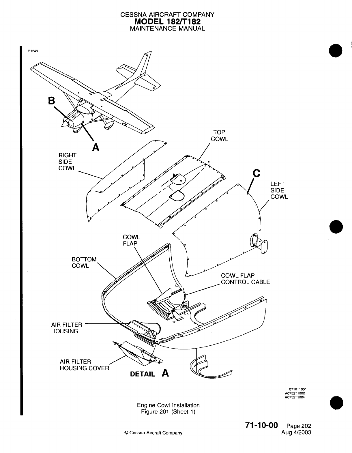
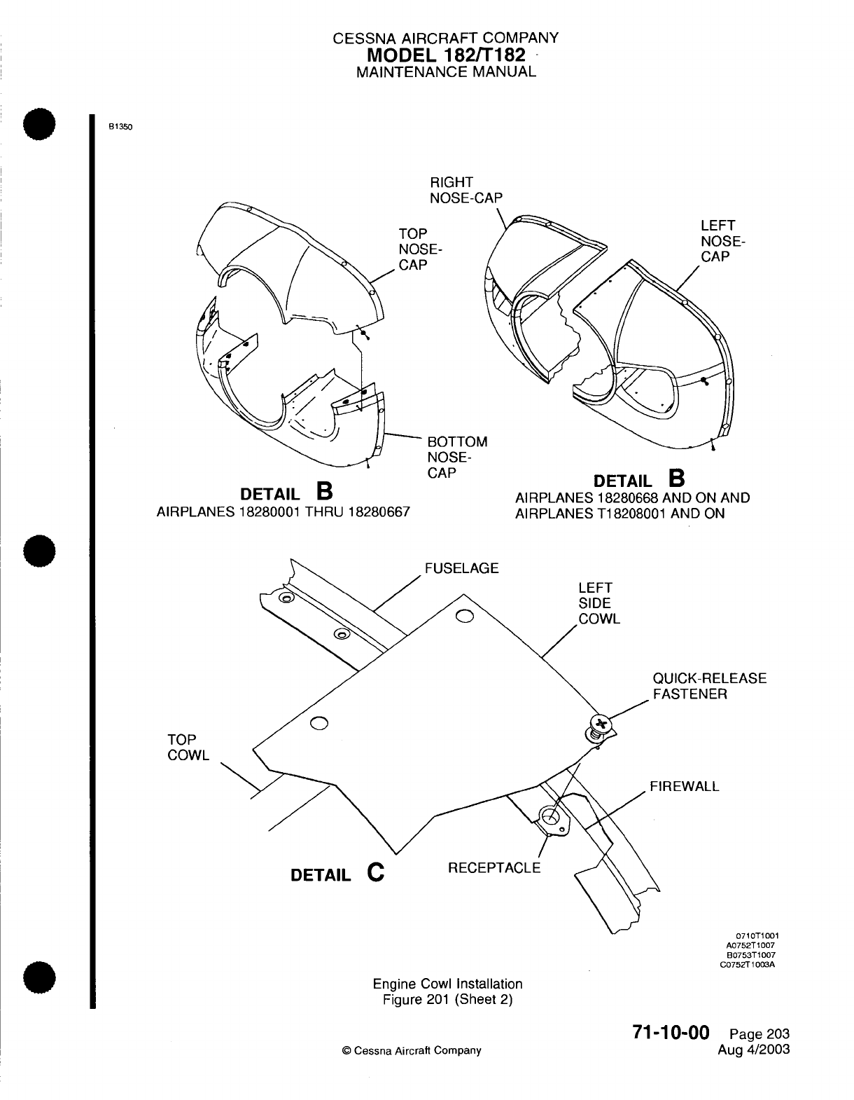
CESSNA AIRCRAFT
COMPANY
MODEL
182/T182
MAINTENANCE
MANUAL
B1350
RIGHT
NOSE-CAP
BE-
BOTTOM
NOSE-
CAP
DETAIL
B
AIRPLANES
18280001
THRU
18280667
TOP
COWL
DETAIL
B
AIRPLANES
18280668
AND ON
AND
AIRPLANES
T18208001
AND
ON
IUICK-RELEASE
ASTENER
REWALL
n7
lTno1t
n
A0752T 007
B0753T1007
C0752T1003A
Engine
Cowl
Installation
Figure
201
(Sheet
2)
Page
203
Aug
4/2003
71-10-00
©
Cessna Aircraft
Company
:)
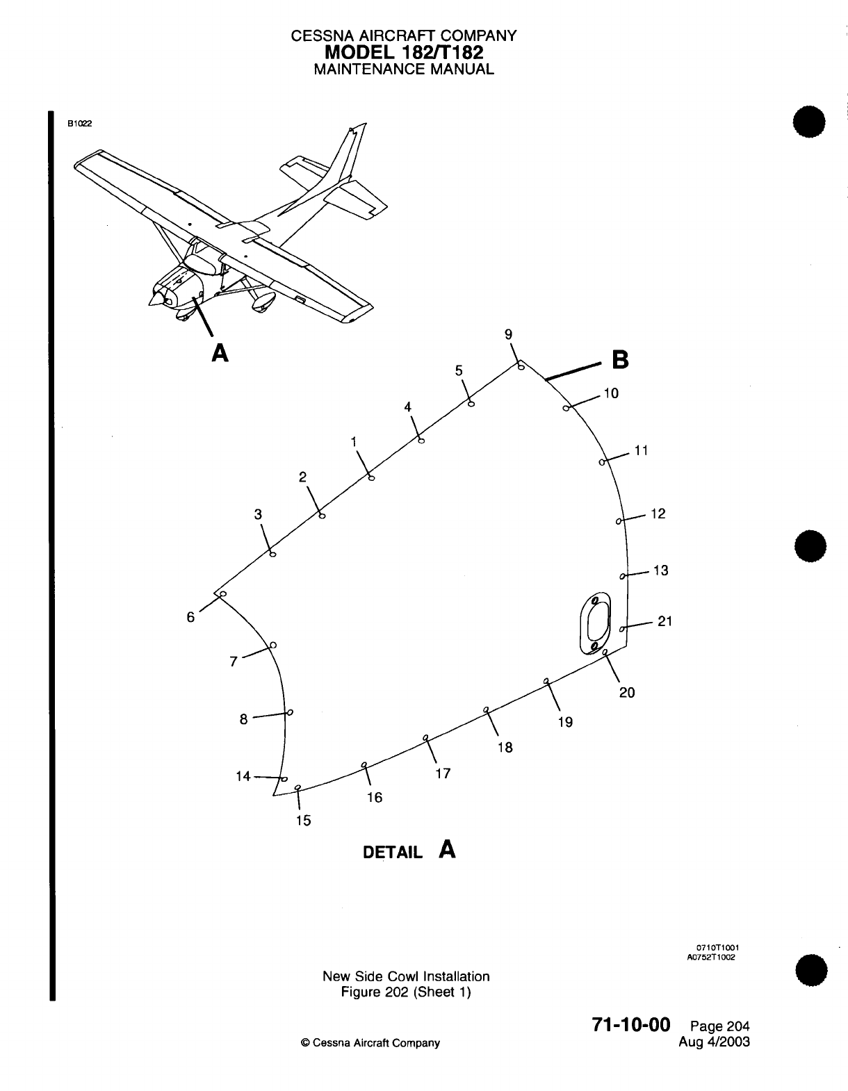
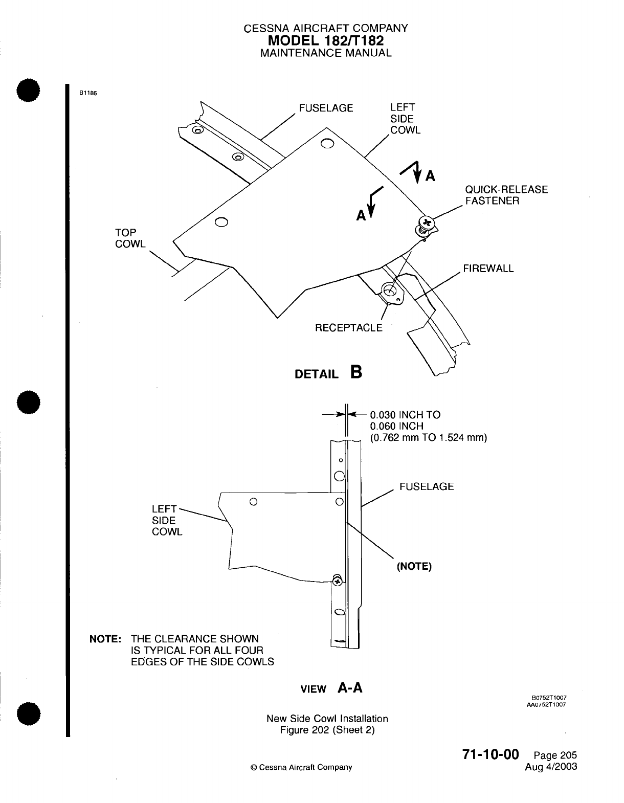
CESSNA
AIRCRAFT
COMPANY
MODEL
182/T182
MAINTENANCE
MANUAL
B1186
LUICK-RELEASE
ASTENER
REWALL
-
0.030
INCH
TO
0.060
INCH
(0.762
mm
TO
1.524
mm)
0
0
.FUSELAGE
0
(NOTE)
NOTE: THE
CLEARANCE
SHOWN
IS
TYPICAL
FOR
ALL
FOUR
EDGES
OF
THE
SIDE
COWLS
VIEW
A-A
New
Side Cowl
Installation
Figure
202
(Sheet
2)
©
Cessna Aircraft
Company
71-10-00
Page
205
Aug
4/2003
TOP
COWL
LEFT
SIDE
COWL
B0752T1007
AA0752T1007
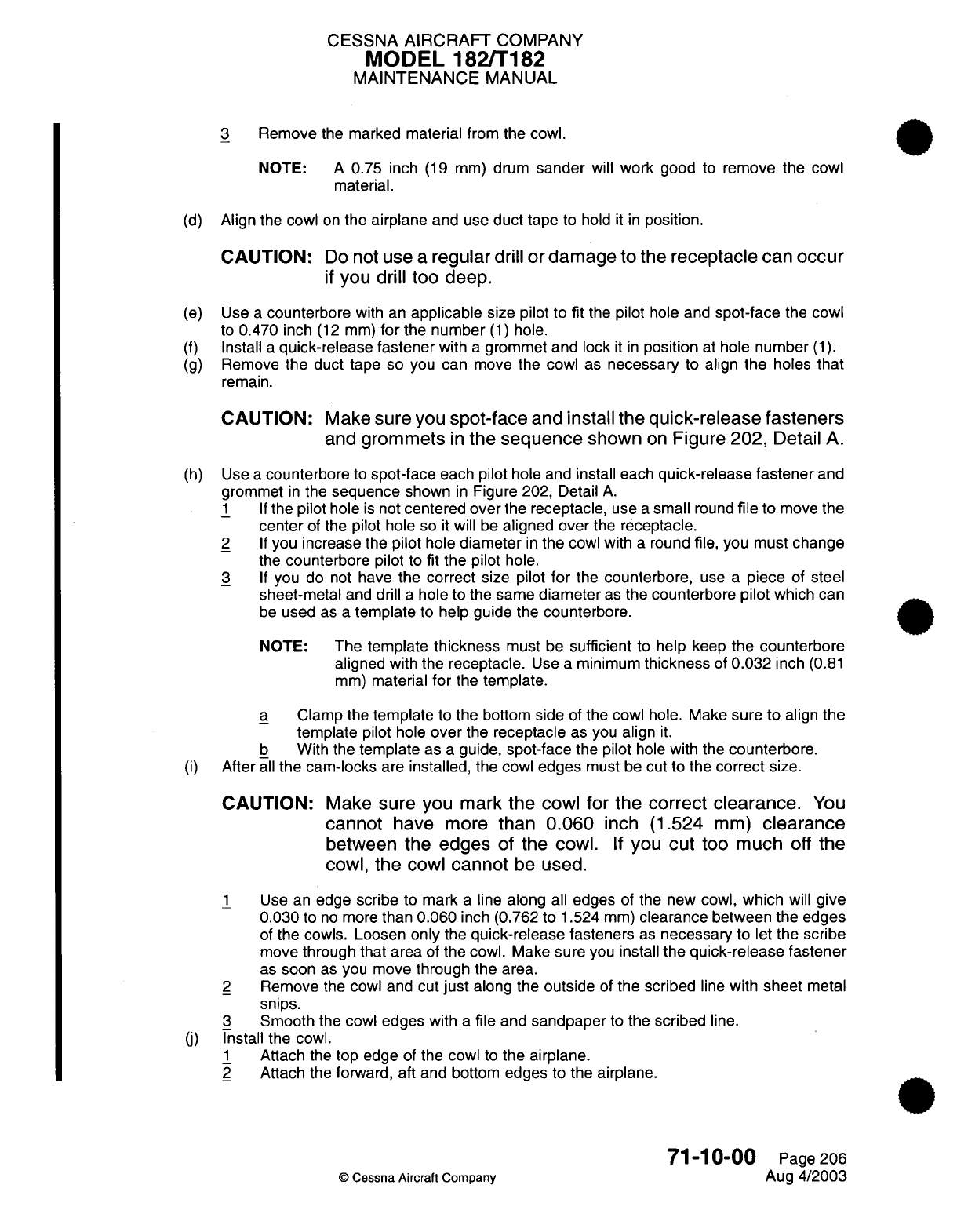
CESSNA
AIRCRAFT
COMPANY
MODEL
182/T182
MAINTENANCE
MANUAL
3
Remove
the
marked
material from the
cowl.
NOTE:
A
0.75
inch
(19
mm)
drum
sander
will
work
good
to
remove
the
cowl
material.
(d)
Align
the cowl
on
the
airplane
and
use
duct
tape
to
hold
it in
position.
CAUTION:
Do
not
use
a
regular
drill
or
damage
to
the
receptacle
can
occur
if
you
drill
too
deep.
(e)
Use
a
counterbore
with
an
applicable
size pilot to
fit
the
pilot
hole and
spot-face
the
cowl
to
0.470 inch
(12 mm)
for
the number
(1)
hole.
(f)
Install
a
quick-release fastener
with
a
grommet and
lock
it in
position
at
hole
number
(1).
(g)
Remove
the
duct tape
so
you
can
move
the
cowl
as
necessary
to
align
the
holes
that
remain.
CAUTION:
Make
sure
you
spot-face
and
install the
quick-release
fasteners
and
grommets
in
the
sequence
shown
on
Figure 202,
Detail
A.
(h)
Use
a
counterbore
to
spot-face
each pilot
hole
and
install
each
quick-release
fastener
and
grommet
in
the
sequence
shown
in
Figure
202,
Detail
A.
1 If
the
pilot
hole
is
not
centered
over
the
receptacle,
use
a
small
round
file
to
move the
center
of
the pilot
hole
so
it
will
be
aligned over
the
receptacle.
2 If
you
increase
the
pilot
hole
diameter
in
the
cowl with
a
round
file,
you
must
change
the
counterbore pilot
to
fit
the
pilot
hole.
3 If
you
do
not
have
the
correct
size
pilot
for
the
counterbore,
use
a
piece
of
steel
sheet-metal
and
drill
a
hole
to
the same
diameter
as
the
counterbore
pilot
which
can
be
used
as
a
template
to
help
guide
the counterbore.
NOTE:
The
template
thickness
must
be
sufficient
to
help keep
the
counterbore
aligned
with the
receptacle.
Use
a
minimum
thickness
of
0.032
inch
(0.81
mm)
material
for
the
template.
a
Clamp
the
template
to
the
bottom side
of
the
cowl
hole.
Make
sure
to
align
the
template
pilot
hole
over
the
receptacle
as
you
align
it.
b
With
the
template
as
a
guide,
spot-face
the
pilot
hole
with the
counterbore.
(i)
After
all
the cam-locks
are
installed,
the
cowl
edges
must be
cut
to
the
correct
size.
CAUTION:
Make
sure
you mark
the cowl
for
the
correct clearance.
You
cannot
have
more
than
0.060
inch (1.524
mm)
clearance
between the
edges
of
the
cowl.
If
you
cut
too
much
off
the
cowl,
the cowl
cannot
be
used.
1
Use
an
edge
scribe
to
mark
a
line
along
all
edges
of
the
new
cowl,
which
will
give
0.030
to
no
more
than
0.060
inch
(0.762
to
1.524
mm)
clearance
between
the
edges
of
the
cowls. Loosen
only
the
quick-release fasteners
as
necessary
to
let
the
scribe
move
through that area
of
the
cowl. Make
sure
you
install
the
quick-release
fastener
as
soon
as
you
move
through the
area.
2
Remove
the
cowl
and
cut
just
along
the
outside
of
the scribed
line
with
sheet
metal
snips.
3
Smooth the
cowl
edges
with
a
file
and
sandpaper
to
the
scribed
line.
(j)
Install
the
cowl.
1
Attach
the
top
edge
of
the
cowl
to
the
airplane.
2
Attach
the
forward, aft and bottom edges
to
the airplane.
71-10-00
©
Cessna
Aircraft Company
Page
206
Aug
4/2003
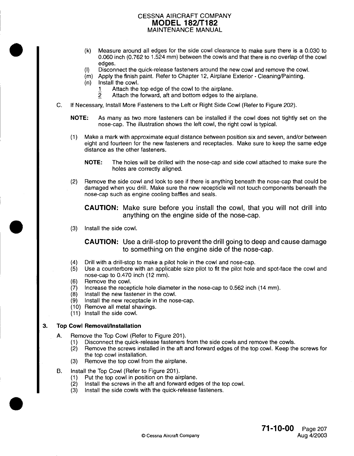
CESSNA
AIRCRAFT
COMPANY
MODEL
182/T182
MAINTENANCE
MANUAL
(k)
Measure around
all
edges
for
the
side
cowl
clearance
to
make
sure
there
is
a
0.030
to
0.060
inch
(0.762
to
1.524
mm)
between
the
cowls
and
that
there
is
no
overlap
of
the
cowl
edges.
(I)
Disconnect
the
quick-release
fasteners
around
the
new
cowl
and
remove
the
cowl.
(m)
Apply
the
finish
paint.
Refer
to
Chapter
12,
Airplane
Exterior
-
Cleaning/Painting.
(n)
Install
the
cowl.
1
Attach the top
edge
of
the
cowl
to the
airplane.
2
Attach
the
forward,
aft
and
bottom edges
to
the
airplane.
C. If
Necessary,
Install
More
Fasteners
to
the Left
or
Right
Side
Cowl
(Refer
to
Figure
202).
NOTE:
As
many
as
two
more
fasteners
can
be
installed
if
the
cowl
does
not
tightly
set
on
the
nose-cap.
The
illustration
shows the
left
cowl,
the
right
cowl
is
typical.
(1)
Make
a
mark
with
approximate
equal
distance
between position
six
and
seven,
and/or
between
eight
and
fourteen
for
the
new
fasteners
and
receptacles.
Make
sure
to
keep the
same
edge
distance
as the
other
fasteners.
NOTE:
The
holes
will
be
drilled with
the nose-cap
and
side cowl
attached
to
make
sure
the
holes
are
correctly aligned.
(2)
Remove
the side
cowl
and
look
to
see
if
there
is
anything beneath
the
nose-cap that
could
be
damaged
when
you
drill.
Make
sure
the
new
recepticle
will
not
touch
components
beneath
the
nose-cap
such
as
engine cooling
baffles
and
seals.
CAUTION:
Make
sure
before you
install the
cowl,
that
you
will
not drill
into
anything
on
the
engine
side
of
the
nose-cap.
(3)
Install
the
side
cowl.
CAUTION:
Use
a
drill-stop
to
prevent
the
drill going
to
deep
and
cause
damage
to
something
on
the
engine
side
of
the
nose-cap.
(4)
Drill
with
a
drill-stop
to
make
a
pilot
hole
in
the
cowl and
nose-cap.
(5)
Use
a
counterbore
with
an
applicable size
pilot
to
fit
the
pilot
hole
and
spot-face the
cowl
and
nose-cap
to
0.470
inch
(12
mm).
(6)
Remove
the
cowl.
(7)
Increase the
recepticle
hole
diameter
in
the
nose-cap
to
0.562
inch
(14
mm).
(8)
Install
the new
fastener
in
the
cowl.
(9)
Install
the
new
receptacle
in
the
nose-cap.
(10)
Remove
all
metal
shavings.
(11)
Install
the
side
cowl.
3.
Top
Cowl
Removal/nstallation
A.
Remove the
Top
Cowl
(Refer
to
Figure
201).
(1)
Disconnect
the
quick-release
fasteners
from
the
side cowls
and remove
the
cowls.
(2)
Remove
the
screws installed
in
the
aft
and forward
edges
of
the
top
cowl.
Keep
the
screws
for
the top
cowl
installation.
(3)
Remove
the top
cowl
from
the
airplane.
B.
Install the
Top
Cowl
(Refer
to
Figure
201).
(1)
Put
the top
cowl
in
position
on
the
airplane.
(2)
Install the
screws
in
the
aft and
forward
edges
of
the
top cowl.
(3)
Install the
side
cowls with
the
quick-release
fasteners.
71-10-00
Page
207
©
Cessna
Aircraft Company
Aug
4/2003
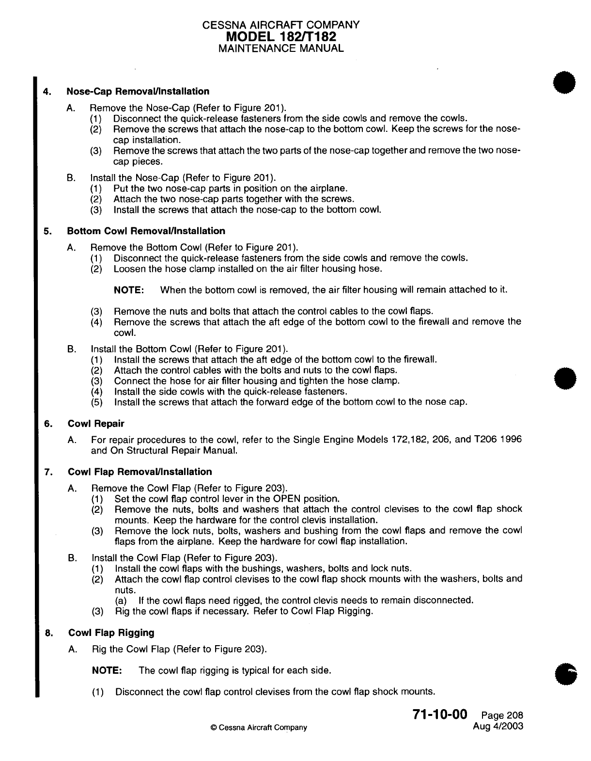
CESSNA
AIRCRAFT
COMPANY
MODEL 182/T182
MAINTENANCE
MANUAL
4.
Nose-Cap
Removal/Installation
A.
Remove
the
Nose-Cap
(Refer
to
Figure
201).
(1)
Disconnect
the quick-release fasteners
from
the
side cowls
and
remove
the
cowls.
(2)
Remove
the
screws
that
attach the
nose-cap to
the bottom
cowl.
Keep
the
screws
for
the
nose-
cap installation.
(3)
Remove
the
screws
that
attach
the
two
parts
of
the
nose-cap
together
and
remove
the
two nose-
cap
pieces.
B.
Install
the
Nose-Cap
(Refer to
Figure 201).
(1)
Put
the
two
nose-cap
parts
in
position
on
the
airplane.
(2)
Attach
the
two
nose-cap
parts
together
with
the screws.
(3)
Install the
screws
that attach
the
nose-cap
to
the bottom
cowl.
5.
Bottom
Cowl
Removal/Installation
A.
Remove
the
Bottom
Cowl
(Refer
to
Figure
201).
(1)
Disconnect
the
quick-release fasteners
from
the
side cowls
and
remove
the cowls.
(2)
Loosen
the
hose
clamp installed
on
the
air
filter
housing
hose.
NOTE:
When
the
bottom
cowl
is
removed,
the
air
filter
housing
will
remain
attached
to
it.
(3)
Remove the
nuts
and
bolts that attach
the
control
cables
to
the
cowl
flaps.
(4)
Remove
the
screws that
attach the aft
edge
of
the
bottom
cowl
to
the
firewall
and remove
the
cowl.
B.
Install
the
Bottom
Cowl
(Refer
to
Figure
201).
(1)
Install
the
screws
that attach
the aft
edge
of
the
bottom
cowl
to
the
firewall.
(2)
Attach
the
control cables
with
the
bolts
and
nuts
to the
cowl
flaps.
(3)
Connect
the
hose
for
air
filter
housing
and
tighten the
hose clamp.
(4)
Install
the
side
cowls
with
the
quick-release
fasteners.
(5)
Install the
screws
that attach
the forward
edge
of
the
bottom
cowl
to
the nose
cap.
6. Cowl
Repair
A.
For
repair
procedures
to
the
cowl, refer
to the
Single Engine
Models
172,182,
206,
and
T206
1996
and
On
Structural Repair
Manual.
7.
Cowl
Flap
Removal/Installation
A.
Remove
the
Cowl
Flap
(Refer
to
Figure
203).
(1)
Set
the
cowl
flap
control
lever
in
the
OPEN
position.
(2)
Remove
the
nuts,
bolts
and
washers
that
attach
the
control
devises
to
the
cowl
flap
shock
mounts.
Keep
the hardware
for
the
control
clevis installation.
(3)
Remove the
lock
nuts,
bolts,
washers
and
bushing
from
the
cowl
flaps
and
remove
the
cowl
flaps
from
the airplane.
Keep
the
hardware
for
cowl
flap installation.
B.
Install
the
Cowl
Flap (Refer
to Figure
203).
(1)
Install
the
cowl flaps
with the
bushings, washers,
bolts
and
lock
nuts.
(2)
Attach
the
cowl
flap
control
devises
to the
cowl
flap
shock
mounts
with
the washers,
bolts
and
nuts.
(a) If
the
cowl
flaps
need
rigged,
the
control
clevis
needs
to
remain
disconnected.
(3)
Rig
the
cowl
flaps
if
necessary. Refer
to Cowl Flap
Rigging.
8.
Cowl
Flap
Rigging
A. Rig
the
Cowl
Flap
(Refer
to
Figure
203).
NOTE:
The
cowl
flap
rigging
is
typical
for
each
side.
(1)
Disconnect
the
cowl
flap
control
devises
from
the
cowl flap
shock
mounts.
71-10-00
Page
208
©
Cessna
Aircraft Company
Aug
4/2003
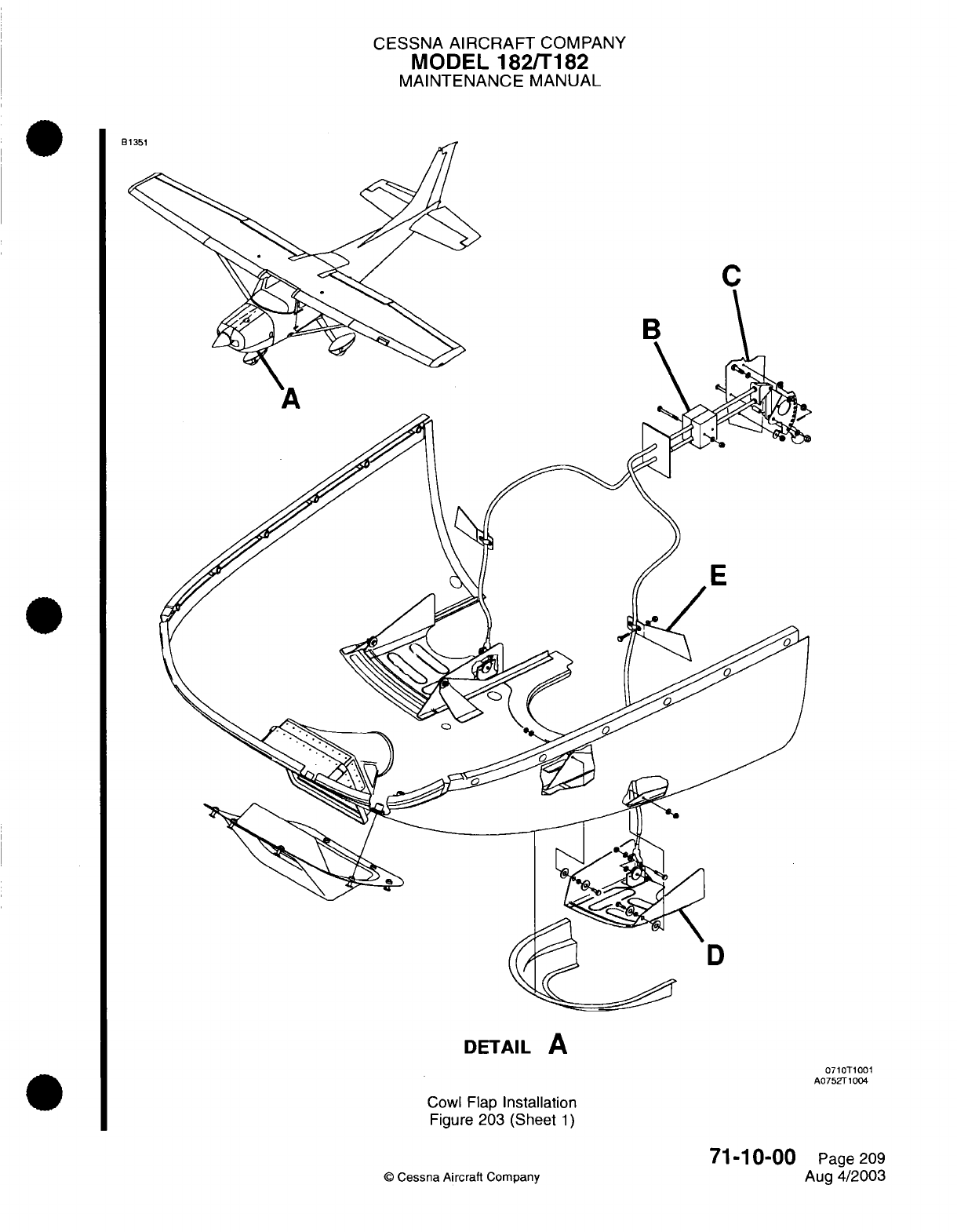
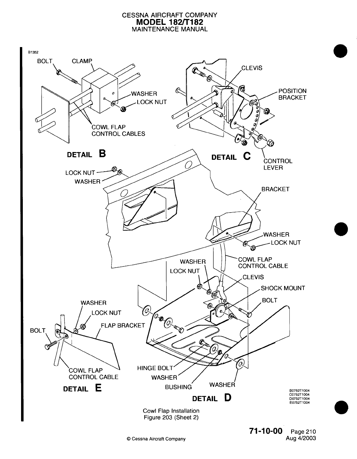
CESSNA
AIRCRAFT
COMPANY
MODEL
182/T182
MAINTENANCE
MANUAL
B1352
BOLl
UDIAIL
C
Cowl
Flap
Installation
Figure
203
(Sheet
2)
©
Cessna
Aircraft
Company
DETAIL
D
80752T1004
C0752T1004
D0752T1004
E0752T1004
71-10-00
Page
210
Aug
4/2003
LJJuo
,
111'1
CESSNA
AIRCRAFT
COMPANY
MODEL
182/T182
MAINTENANCE
MANUAL
Make
sure
that
the
flexible
controls
reach
their
internal
stops
in
each
direction.
Identify
the
controls
so that
the
full
travel
can
be
easily examined
and
maintained
while
you
complete
the
rigging
procedures.
Set
the
cowl
flap
control
lever
in
the
CLOSED
position.
(a)
If
the control
lever
cannot
be
set
in
the
closed position,
adjust
the
controls
at the
top clevis
to
position
the
control lever
in
the
bottom
hole
of
the
position
bracket.
Hold
one
cowl
flap
flat
with
the
trailing
edge of
bottom
cowl.
Set
in
position
and
adjust
the
clevis
to
align
with
the cowl
flap
mount.
Attach
the
clevis
to
the shock
mount
with
the
bolt,
washers
and
lock
nut.
NOTE: Make
sure
the
threads
are
visible
in
the
clevis inspection
holes.
Make
sure
all
the
clamps
and nuts
are
tight.
Make
sure
the
cowl
flaps fully
open
to
25
degrees
+0
or
-1
degree,
measured
with
an
inclinometer
held
against
the
cowl
flap
and
that
they
fully
close.
71-10-00
Page
211
©
Cessna
Aircraft
Company
Aug
4/2003
(2)
(3)
(4)
(5)
(6)
(7)
(8)
(9)
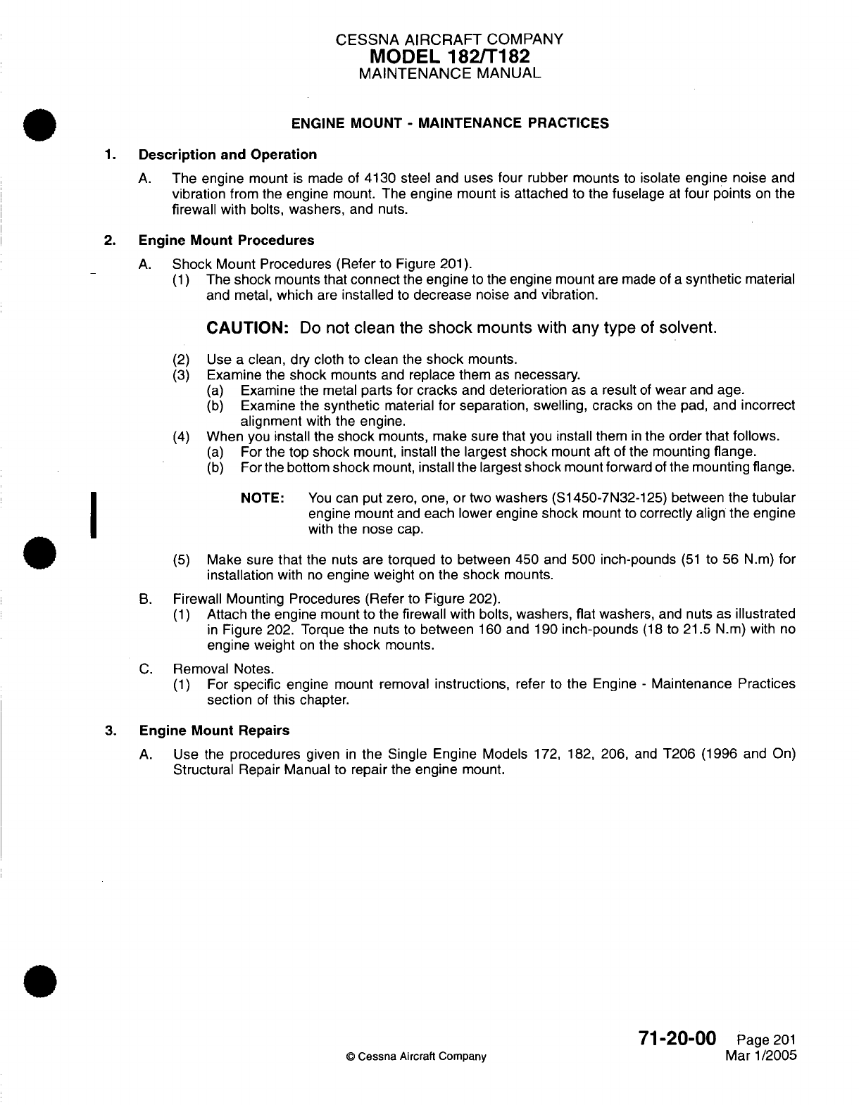
CESSNA
AIRCRAFT
COMPANY
MODEL
182/T182
MAINTENANCE
MANUAL
ENGINE
MOUNT
-
MAINTENANCE
PRACTICES
1.
Description
and
Operation
A.
The
engine
mount
is
made
of
4130 steel
and
uses four
rubber
mounts
to
isolate
engine noise
and
vibration
from the engine
mount.
The
engine
mount
is
attached
to the
fuselage
at
four
points
on
the
firewall
with
bolts,
washers,
and nuts.
2.
Engine
Mount
Procedures
A.
Shock
Mount Procedures (Refer
to Figure
201).
(1)
The
shock
mounts
that
connect
the
engine
to
the
engine mount
are
made
of
a
synthetic
material
and
metal,
which
are
installed
to
decrease
noise
and
vibration.
CAUTION:
Do
not
clean
the
shock
mounts
with
any type
of
solvent.
(2)
Use a
clean,
dry
cloth
to
clean the
shock
mounts.
(3)
Examine
the
shock
mounts
and
replace them
as
necessary.
(a)
Examine
the metal
parts
for cracks
and
deterioration
as
a
result
of
wear
and
age.
(b)
Examine
the
synthetic
material
for
separation,
swelling, cracks
on
the
pad, and
incorrect
alignment
with
the
engine.
(4)
When
you
install
the
shock
mounts, make
sure
that
you
install
them
in
the
order that follows.
(a)
For
the
top
shock
mount, install the largest
shock
mount
aft
of
the
mounting
flange.
(b)
For
the
bottom
shock
mount,
install
the largest
shock
mount
forward of
the mounting
flange.
NOTE:
You
can
put
zero, one,
or
two
washers
(S1450-7N32-125)
between
the
tubular
engine mount
and
each lower engine
shock
mount
to
correctly align
the engine
with
the
nose
cap.
(5)
Make
sure
that
the
nuts
are
torqued
to
between
450
and
500 inch-pounds
(51
to 56
N.m)
for
installation
with
no
engine
weight
on
the
shock
mounts.
B.
Firewall Mounting Procedures (Refer
to
Figure 202).
(1)
Attach the
engine
mount
to
the firewall
with
bolts, washers,
flat
washers,
and
nuts
as
illustrated
in
Figure
202.
Torque
the
nuts
to
between
160
and
190
inch-pounds
(18
to
21.5
N.m)
with
no
engine
weight
on
the
shock
mounts.
C.
Removal
Notes.
(1)
For
specific
engine
mount
removal
instructions,
refer
to
the
Engine
-
Maintenance
Practices
section
of
this
chapter.
3.
Engine Mount Repairs
A.
Use
the
procedures
given
in
the
Single
Engine
Models
172,
182,
206,
and
T206
(1996
and On)
Structural
Repair
Manual
to repair
the
engine
mount.
71-20-00
Page
201
©
Cessna
Aircraft
Company
Mar 1/2005
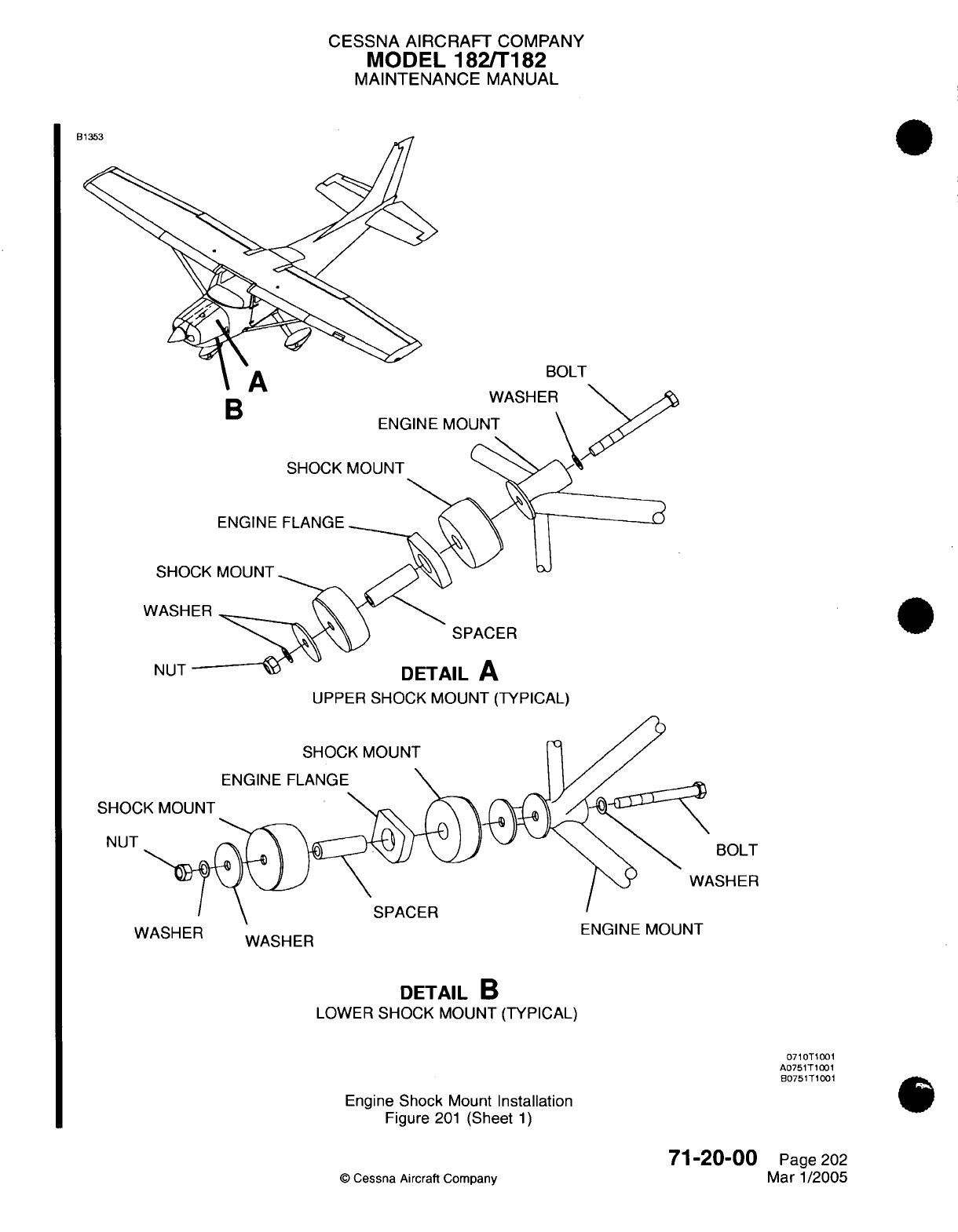
CESSNA AIRCRAFT
COMPANY
MODEL
182/T182
MAINTENANCE
MANUAL
tj
BOLT
B
SHOCK
ENGINE
FLANGE
WASH
th-
ENGINE MOUNT
\
MOUNT
SHO
WASH
SPACER
NUT
UPPER
SHOCK
MOUNT
(TYPICAL)
SHOCK MOUNT
ENGINE
FLANGE
SHOC
NUT
BOLT
\SHER
SPACER
ASHER WASHER
ENGINE
MUUN
I
WASHER
DETAIL
B
LOWER
SHOCK MOUNT
(TYPICAL)
0710T1001
A0751T1001
B0751T1001
Engine
Shock
Mount
Installation
Figure
201
(Sheet
1)
71-20-00
©
Cessna
Aircraft
Company
Page
202
Mar
1/2005
no
---
··
AI
Ar
Cs
rD
,LL-
I
-I-
N-A
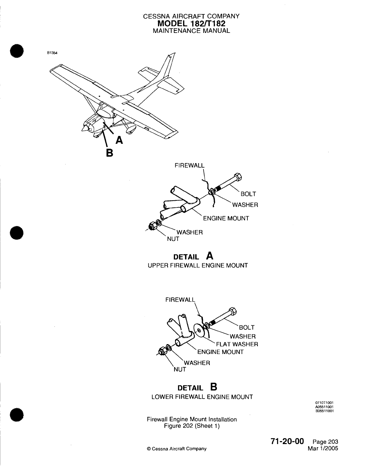
CESSNA
AIRCRAFT
COMPANY
MODEL
182/T182
MAINTENANCE
MANUAL
B
B
FIREWALL
DETAIL
A
UPPER
FIREWALL
ENGINE
MOUNT
BOLT
WASHER
DETAIL
B
LOWER
FIREWALL
ENGINE
MOUNT
Firewall
Engine
Mount
Installation
Figure
202
(Sheet
1)
©
Cessna Aircraft
Company
71-20-00
Page
203
Mar 1/2005
0710T1001
A05511
001
B05511001
..
:
I
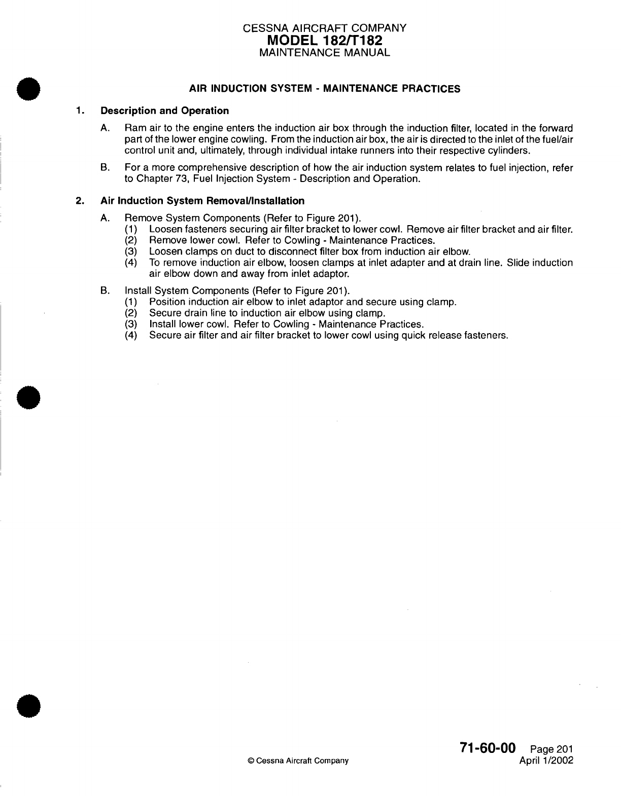
CESSNA AIRCRAFT
COMPANY
MODEL
182/T182
MAINTENANCE
MANUAL
AIR
INDUCTION
SYSTEM
-
MAINTENANCE PRACTICES
1.
Description
and
Operation
A.
Ram
air
to the
engine
enters the induction air
box
through
the
induction
filter, located
in
the
forward
part
of
the
lower engine
cowling.
From
the
induction
air
box, the
air
is
directed
to
the
inlet of
the fuel/air
control
unit
and,
ultimately,
through individual
intake
runners
into
their
respective cylinders.
B.
For
a
more
comprehensive
description
of
how
the air induction
system
relates
to
fuel
injection,
refer
to
Chapter
73, Fuel
Injection System
-
Description
and
Operation.
2.
Air
Induction
System
Removal/Installation
A.
Remove System Components
(Refer
to
Figure
201).
(1)
Loosen
fasteners
securing
air
filter
bracket
to
lower
cowl. Remove
air
filter bracket
and
air
filter.
(2)
Remove
lower
cowl.
Refer
to
Cowling
-
Maintenance
Practices.
(3)
Loosen
clamps
on
duct
to
disconnect
filter
box
from
induction
air
elbow.
(4)
To
remove
induction
air
elbow,
loosen
clamps
at
inlet
adapter
and
at drain
line.
Slide
induction
air
elbow
down
and
away
from inlet adaptor.
B.
Install
System Components (Refer
to
Figure
201).
(1)
Position
induction air elbow
to
inlet
adaptor
and
secure
using
clamp.
(2)
Secure drain
line
to
induction
air elbow
using clamp.
(3)
Install
lower
cowl.
Refer
to
Cowling
-
Maintenance Practices.
(4)
Secure
air
filter
and
air
filter
bracket
to
lower
cowl
using
quick
release fasteners.
71-60-00
Page
201
©
Cessna
Aircraft Company
April 1/2002
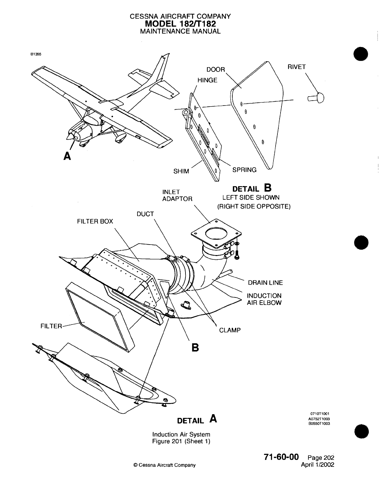
CESSNA
AIRCRAFT
COMPANY
MODEL
182/T182
MAINTENANCE
MANUAL
VET
INLET
DETAIL
B
ADAPTOR
LEFT
SIDE
SHOWN
OPPOSITE)
lAIN
LINE
)UCTION
:
ELBOW
DETAIL
A
Induction Air System
Figure
201
(Sheet
1)
71-60-00
©
Cessna
Aircraft Company
0710T1001
A0752T1003
B0550T1003
Page
202
April
1/2002
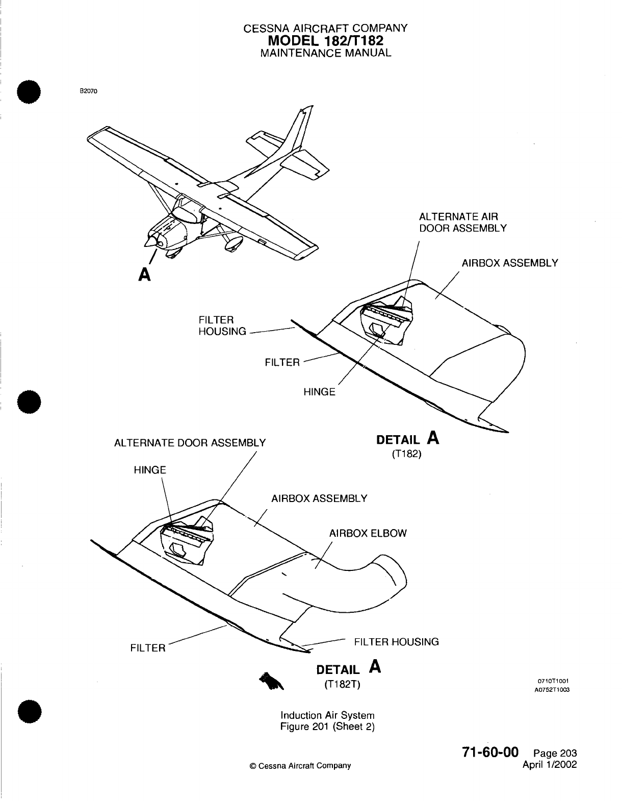
CESSNA
AIRCRAFT
COMPANY
MODEL
182/T182
MAINTENANCE
MANUAL
B2070
ALTERNATE
AIR
DOOR
ASSEMBLY
A
FILTER
HOUSING
FILTER
HINGE
ALTERNATE
DOOR
ASSEMBLY DETAIL
A
82)
HINGE
USING
FILTER
DETAIL
A
(T182T)
Induction
Air
System
Figure
201
(Sheet
2)
©
Cessna
Aircraft
Company
71-60-00
Page
203
April 1/2002
EMBLY
0710T1001
A0752T1003
I
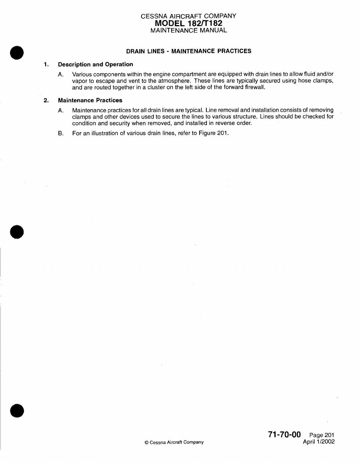
CESSNA
AIRCRAFT
COMPANY
MODEL
182/T182
MAINTENANCE
MANUAL
DRAIN
LINES
-
MAINTENANCE
PRACTICES
1.
Description
and
Operation
A.
Various
components
within
the
engine
compartment
are
equipped
with
drain lines to
allow
fluid
and/or
vapor
to
escape
and vent
to
the
atmosphere.
These
lines
are
typically
secured
using
hose
clamps,
and
are
routed
together
in a
cluster
on
the
left
side
of
the
forward
firewall.
2.
Maintenance
Practices
A.
Maintenance practices
for
all
drain lines
are
typical.
Line removal and
installation
consists
of
removing
clamps
and
other
devices
used
to
secure
the
lines
to
various
structure.
Lines
should
be
checked
for
condition
and
security
when
removed,
and
installed
in
reverse
order.
B.
For
an
illustration
of
various
drain lines, refer to Figure
201.
©
Cessna
Aircraft
Company
71-70-00
Page
201
April
1/2002
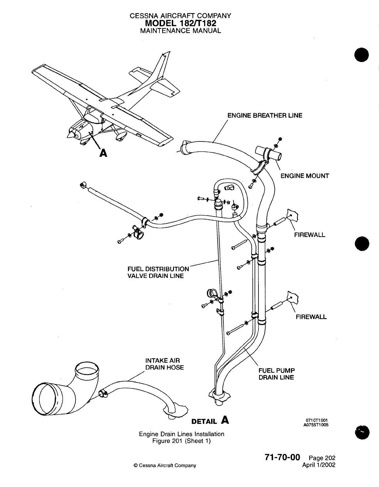
CESSNA AIRCRAFT
COMPANY
MODEL
182/T182
MAINTENANCE
MANUAL
ENGINE BREATHER
LINE
MOUNT
EWALL
VALVE
DRAIN
LINE
FIREWALL
IMTAICk
AID
EL
PUMP
AIN
LINE
DETAIL
A
Engine
Drain
Lines
Installation
Figure
201
(Sheet
1)
71-70-00
©
Cessna Aircraft
Company
071OT1001
A0755T1005
0
Page 202
April
1/2002

CHAPTER
ENGI
FUEL
CONT
INE
AN
RO
D
L
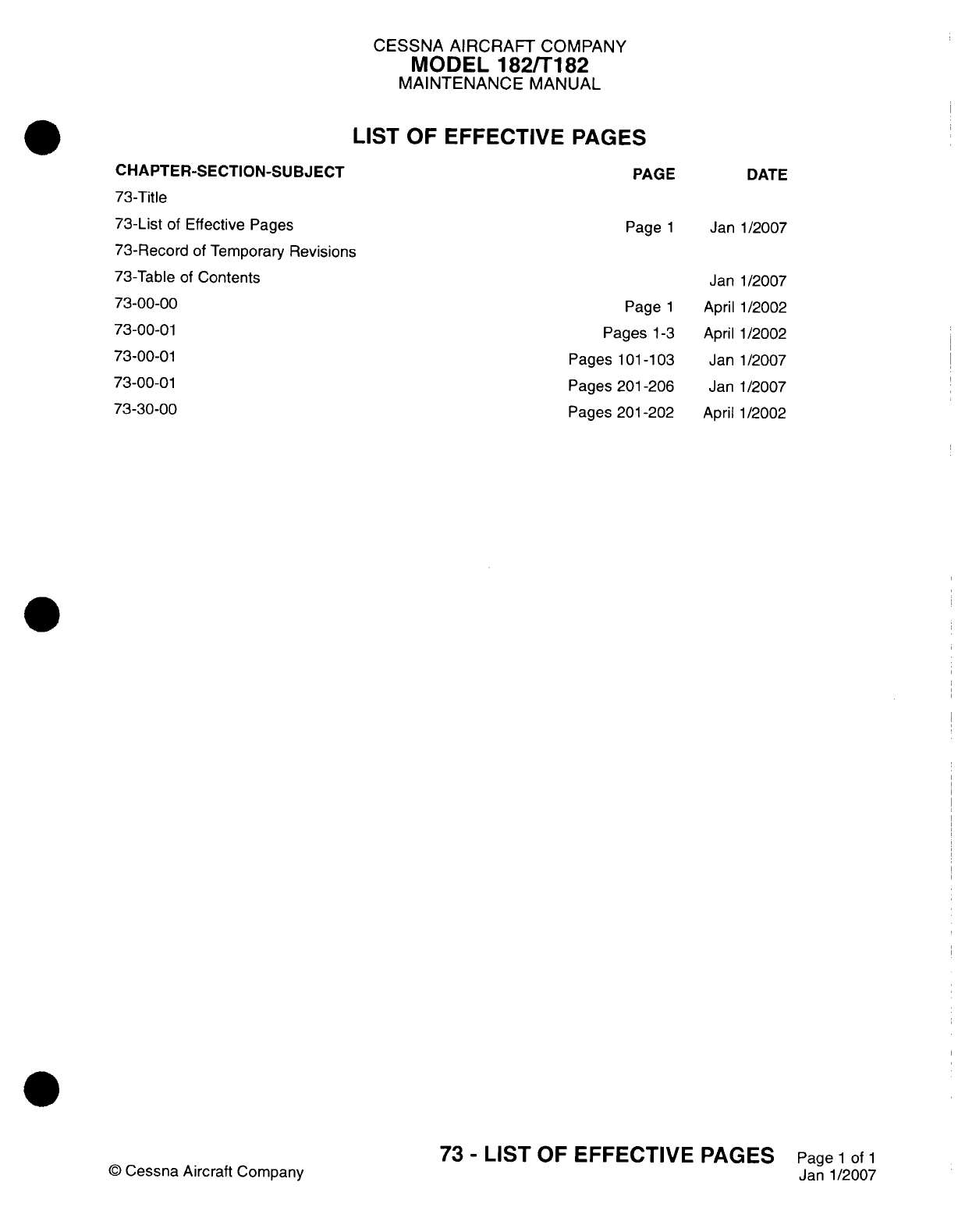
CESSNA
AIRCRAFT
COMPANY
MODEL
182/Ti
82
MAINTENANCE
MANUAL
LIST
OF
EFFECTIVE
PAGES
CHAPTER-SECTION-SUBJECT
73-Title
73-List
of Effective Pages
73-Record
of
Temporary
Revisions
73-Table
of
Contents
73-00-00
73-00-01
73-00-01
7300-01
73-30-00
PAGE
DATE
Page
1
Janl1/2007
Page
1
Pages
1-3
Pages
101
-103
Pages
201-206
Pages
201
-202
Jan
April
April
Jan
Jan
April
1/2007
1/2002
1/2002
1/2007
1/2007
1/2002
©
Cessna
Aircraft
Company
73
-
LIST
OF
EFFECTIVE
PAGES
Page
1
of
1
Janl1/2007
Temporary
Revision
Number
RECORD
OF
TEMPORARY
REVISIONS
Page
Number
Issue
Date
By
Date
Removed
By
CESSNA AIRCRAFT
COMPANY
MODEL
182/Ti
82
MAINTENANCE
MANUAL
CONTENTS
ENGINE
FUEL AND
CONTROL
-
GENERAL
....................
Scope....................................
Definition
..................................
FUEL
INJECTION SYSTEM
-
DESCRIPTION
AND
OPERATION...........
General...................................
Description
.................................
Operation..................................
FUEL
INJECTION SYSTEM
-
TROUBLESHOOTING
................
General...................................
Fuel
Injection
System
Troubleshooting.....................
FUEL
INJECTION
SYSTEM
-
MAINTENANCE
PRACTICES
.............
General...................................
Precautions.................................
Fuel/Air
Control
Unit
Removal/Installation
...................
Fuel
Distribution
Valve
Removal/installation
..................
Injection Nozzles
Removal/Installation.....................
Injection
Nozzle
Flow
Test
..........................
Idle
and
Mixture
Adjustment..........................
Injector Nozzle Cleaning
...........................
Fuel
Strainer
Cleaning
............................
Air
Throttle
Shaft
Lubrication
.........................
Engine
Driven
Fuel
Pump
Pressure
Setting
(Ti
82)
...............
FUEL
FLOW INDICATOR
-
MAINTENANCE
PRACTICES
..............
General...................................
EGT/Fuel
Flow
Gauge
Removal/installation
..................
Transducer
and
Line
Removal/Installation
...................
73-00-00
Page
1
73-00-00
Page
1
73-00-00
Page
1
73-00-0
1
Page
1
73-00-01 Page
1
73-00-0
1
Page
1
73-00-0
1
Page
1
73-00-01
Page
101
73-00-01
Page
101
73-00-01
Page
101
73-00-01
Page
201
73-00-01
Page
201
73-00-01
Page
201
73-00-01
Page
201
73-00-01
Page
201
73-00-01
Page
202
73-00-01
Page
202
73-00-01
Page
202
73-00-0
1
Page
204
73-00-01
Page
204
73-00-01
Page 205
73-00-01
Page 205
73-30-00
Page
201
73-30-00
Page
201
73-30-00
Page
201
73-30-00
Page
201
73
-
CONTENTS
Page
1
of
1
Janl1/2007
©
Cessna
Aircraft
Company
CESSNA
AIRCRAFT
COMPANY
MODEL
182/T182
MAINTENANCE
MANUAL
ENGINE
FUEL
AND
CONTROL
-
GENERAL
1.
Scope
A.
This
chapter
provides
information
on
the
fuel injection
system
used
for
the
10-540 AB1A5 engine.
Information beyond
the scope
of
this
chapter
can
be
found
in
Chapter
28,
Fuel
-
General
and
in
various
publications
which
are listed
in
Introduction
-
List
of
Manufacturers
Technical
Publications.
2.
Definition
A.
This
chapter
is
divided
into
sections
and
subsections
to assist
maintenance
personnel
in
locating
specific
systems
and information. The
following
is a
brief
description
of
each
section.
For
locating
information within
the chapter,
refer
to
the
Table
of
Contents
at
the
beginning
of the
chapter.
(1)
The
section
on
fuel injection covers procedures
used
to
troubleshoot
and
maintain
the
fuel
injection
system.
(2)
The
section
on
fuel
flow
indicator covers procedures
used
to maintain
the
indicating
portion
of
the system.
73-00-00
Page
1
©
Cessna Aircraft Company
April 1/2002
CESSNA
AIRCRAFT
COMPANY
MODEL
182/T182
MAINTENANCE
MANUAL
FUEL
INJECTION
SYSTEM
-
DESCRIPTION AND
OPERATION
1.
General
A.
This
section
covers
the
RSA
Fuel
Injection
system
used
on
the
IO-540-AB1
A5
and the
TIO-540-AK1
A
engines.
For a
schematic
of
the
fuel
injection
system,
refer
to
Figure
1.
2.
Description
A.
The
fuel
injection
system
is
a
low
pressure,
multinozzle,
continuous
flow
system
which
injects
raw
fuel
into
the engine
cylinder
heads. The
injection system
is
based
on
the
principle
of
measuring engine
air consumption
to
control
fuel
flow.
More
airflow
through
the
venturi
will
result
in
more
fuel
being
delivered
to
the
engine,
and less
airflow
through
the venturi
results
in
a
decreased
flow
of
fuel
to
engine.
B.
System
components
consist
of the
fuel/air
control
unit,
the
fuel
distribution
valve
(flow
divider),
injection
nozzles
(6
total) and
lines
used
to
connect
the
components.
A
description
of
the
components
is as
follows:
(1)
Fuel/Air
Control Unit
-
The
fuel/air
control
unit,
also
known
as
the
'servo
regulator,'
is
located
on
the
underside
of
the engine and
integrates
the
functions
of
measuring
airflow
and
controlling
fuel
flow.
The control
unit
consists
of
an
airflow
sensing
system,
a
regulator
section
and
a
fuel
metering
section.
(2)
Fuel
Distribution
Valve
-
The
fuel
distribution
valve,
also
known
as
a
'spider'
or
a
flow
divider,
is
located
on
top
of
the
engine
and
serves
to
distribute
fuel
evenly
to
the
cylinders
once
it
has
been
regulated
by
the
fuel/air
control
unit.
Also attached
to
the
fuel
distribution
valve
is
a
rigid
line
which
feeds
into
a
pressure
transducer.
This
transducer
measures
fuel
pressure
and
translates
that
reading
into
fuel
flow
at
the
cockpit
indicator.
(3)
Injection
Nozzles
-
Each
cylinder
contains
an
injection
nozzle,
also
known as
an
air
bleed nozzle
or
a
fuel
injector.
This nozzle incorporates
a
calibrated
jet
that determines,
in
conjunction
with
fuel pressure,
the
fuel
flow
entering
each
cylinder.
Fuel
entering
the
nozzle
is
discharged
through
the
jet
into
an
ambient
air
pressure
chamber
within
the
nozzle
assembly.
This nozzle
assembly
also contains
a
calibrated
opening
which
is
vented
to the
atmosphere,
and
allows
fuel
to
be
dispersed
into
the
intake
portion of the
cylinder
in
an
atomized,
cone
shaped pattern.
3.
Operation
A.
Fuel
is
stored
in
the wing
tanks
and
is
delivered
to
the
fuel
injection
system
via
a
series
of
lines,
valves
and
pumps.
From the
engine
driven
fuel
pump, fuel
enters the
fuel/air
control
unit,
passes
through
the
fuel
distribution
valve,
and
is
routed
to
individual
injection nozzles
at
each
cylinder.
NOTE:
For
a
schematic
of
the
entire
fuel
system,
refer
to
Chapter
28,
Fuel
Storage and Distribution
-
Description
and
Operation,
Figure
1.
B.
The heart
of
the
injection
system
is
the
fuel/air
control unit,
which
occupies the position
ordinarily
used
by
the carburetor
at
the
engine intake
manifold
inlet.
The
fuel/air
control
unit
is
comprised
of
an
integrated
airflow sensing
system,
a
regulator
section
and
a
fuel metering
section.
Operation
of
the
fuel
injection system
is
based
on
the
principle
of
measuring
airflow
and
using
the
airflow
signal
to
operate
a
servo
valve.
The
accurately
regulated
fuel
pressure
established
by
the
servo
valve,
when
applied across
the
fuel
control
system, makes
fuel
flow
proportional
to
airflow.
(1)
The
airflow
sensing system consists
of
a
throttle
body
which
houses
the
air throttle valve,
the
venturi,
servo valve
and
fuel
control
unit.
The
differential pressure
between
impact
air
and
the
venturi throat
pressure
is
a
measurement
of
the
velocity
of the
air
entering
the
engine.
These pressures
are
vented through drilled channels
in
the
throttle
body to
both
sides
of
an
air
diaphragm
and
create
a
force
across
the diaphragm.
A
change
in
air throttle
position or
a
change
in
engine
speed
will
change
the
air
velocity, which
in
turn
changes
the
force
across
the
air
diaphragm.
73-00-01
Page
1
©
Cessna
Aircraft Company
April
1/2002
CESSNA
AIRCRAFT
COMPANY
MODEL 182/T182
MAINTENANCE
MANUAL
(2)
The regulator section
contains
the air
diaphragm, mentioned
in
the
preceding paragraph,
and
a
fuel diaphragm.
Fuel
inlet
pressure
is
applied
to
one
side of
the
fuel
diaphragm.
The
other
side
of
the
fuel
diaphragm
is
exposed to fuel
that
has
passed
through
the
metering
jet
(metered
fuel
pressure).
The differential
pressure
across
the
fuel
diaphragm
is
referred
to as
the
fuel
metering
force.
(a)
The
air
metering
force applied
to
the air diaphragm
is
transmitted
through
the
regulator
stem
and
tends
to
move
the
ball
valve
in
the
opening direction.
The
fuel
metering
force
across
the
fuel
diaphragm acts
to
oppose
the
air
metering
force
and
tends
to
close
the
ball
valve. Because
the
air
forces
are
very
low
in
the
idle
range, a
constant
head
idle
spring
is
provided
to
maintain
an
adequate
fuel
metering force
at
low
RPM.
(b)
As
the
air
metering
force increases,
the spring
compresses
until
the
spring
retainer
touches
the
air
diaphragm
and acts as
a
solid
member.
The
constant
effort
spring produces
a
force
which
provides
a
smooth
transfer
from
idle
to
low
power
cruise
operation. Whenever
the
air metering,
fuel
metering
and
spring forces
are
balanced,
the
ball
valve
maintains
a
fixed
position.
(3)
The
fuel
metering
section
is
contained
within the
throttle
body
casting
and
consists
of
an
inlet
fuel
screen,
a
rotary idle
valve
and
a
rotary
mixture
valve.
Both
idle
speed
(closed
throttle
position)
and
idle
mixture
(relationship
between throttle
position
and
idle
valve
position)
may
be
adjusted
externally
to
meet
individual engine
requirements.
(a)
The idle
valve
is
connected
to
the
throttle
valve
by
means
of
an
external adjustable
link.
The
idle
valve controls
fuel
flow through
the
low
speed
range
of
operation
and
is
adjustable
to
obtain
good
idling
characteristics
without
affecting
fuel
metering
in
the
high
power
range.
(b)
The
mixture
control
valve
gives
full
rich
mixture
on
one
stop
and
a
progressively
leaner
mixture as
it
is
moved
toward
idle
cutoff.
The
full
rich
stop
defines
sea
level
requirements
and
the
mixture
control
provides
for
altitude
leaning.
73-00-01
Page
2
©
Cessna Aircraft
Company
April 1/2002
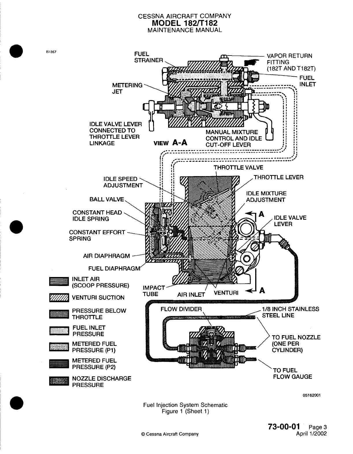
CESSNA
AIRCRAFT
COMPANY
MODEL 182/T182
MAINTENANCE
MANUAL
FUEL
VA
NE(
HL
I
URN
G
AND
T182T)
FUEL
IMI
CT
!1
:
4
I
II
II
II
II
* .4
* *4
I 4I
II
'Il
... ...
M/IIMANUAL
MI
I
VIUAIU-lt
M
YTTLE
LEVER
CONTROL
AND
IDLE
:
:
L
AGE
VIEW
A-A
AGE
VIEW
A-A
CUT-OFF
LEVER
' ,
~;,;
~ TRTL VALVE.............
_
,
(:
,
_ _
.. . .
II:
:
THROTTLE
VALVE
I.
!l
IDLE SPEED
-
ADJUSTMENT
-
VALVE
CONST___
..-
_-_
\
CONSTANT
HEAD
-
IDLE
SPRING
CONSTANT
EFFORT
-.
SPRING
AIR
DIAPHRAGM
-
FUEL
DIAPHRAGM/
INLET
AIR
(SCOOP
PRESSURE)
VENTURI SUCTION
-
PRF.CQ
IIF
RDM
I
,W
r
FLG
iW
DIVIDER
.-.
_
:FUEL
INLET
PRESSURE
METERED
FUEL
PRESSURE
(P1)
METERED
FUEL
PRESSURE
(P2)
NOZZLE
DISCHARGE
PRESSURE
1/R
INCPI
RTAIMI
F:.R
-EL
LINE
TO
FUEL
NOZZLE
(ONE
PER
CYLINDER)
-U
--
U--
IU
FUEL
FLOW
GAUGE
05162001
Fuel
Injection System Schematic
Figure
1
(Sheet
1)
73-00-01
Page
3
April
1/2002
©
Cessna
Aircraft Company
81357
IDLE
CON
THRi
LINK
BALL
...
A
........ IIIII.U....I..
.
o. U
....
I
..
IDA_% _.
I91Lr
I
MEN
MEM
T'14R-
YWU
I
-----
----
__E
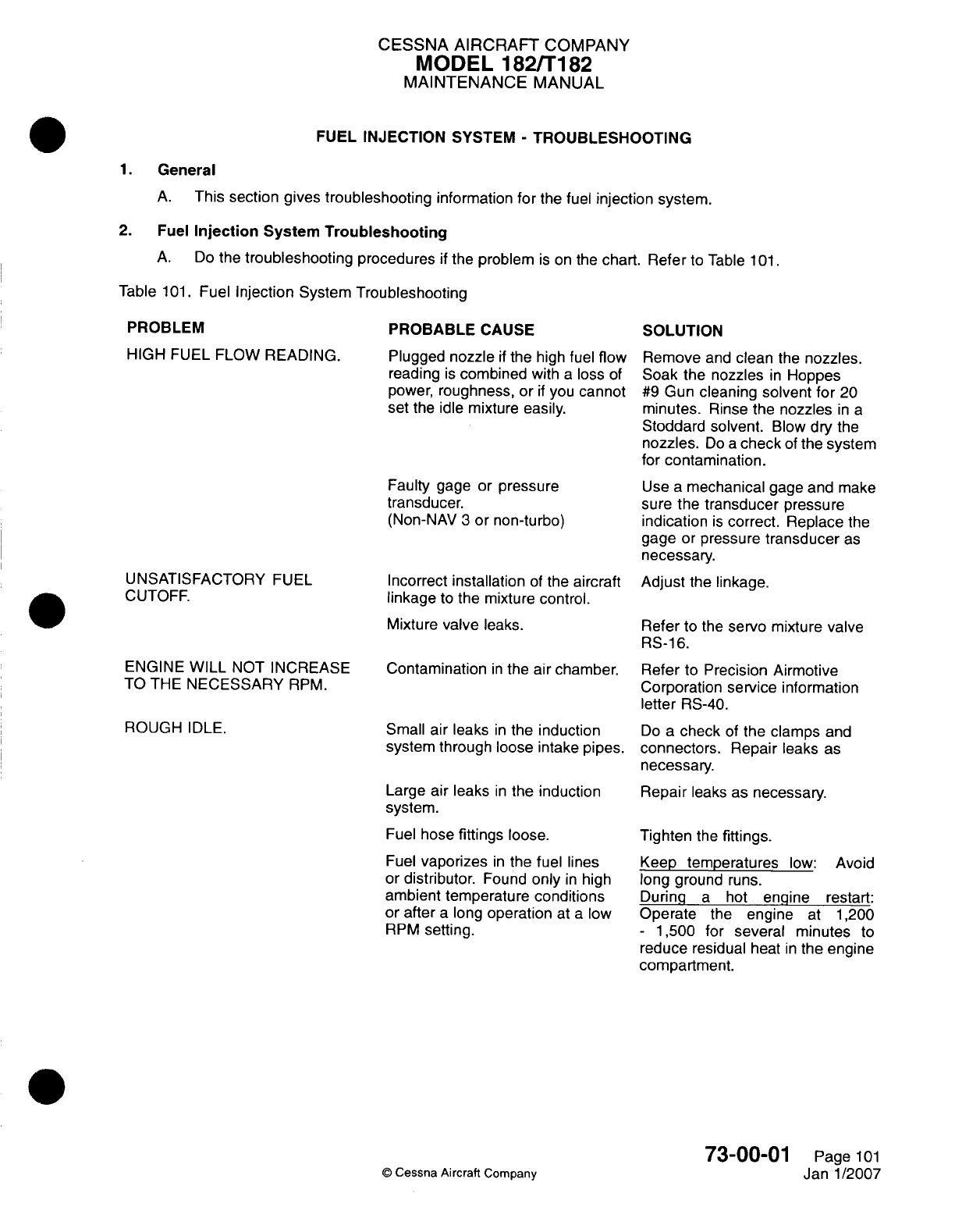
CESSNA AIRCRAFT
COMPANY
MODEL
182/T182
MAINTENANCE
MANUAL
FUEL
INJECTION
SYSTEM
-
TROUBLESHOOTING
1.
General
A.
This section gives
troubleshooting
information for
the
fuel
injection system.
2.
Fuel
Injection
System
Troubleshooting
A.
Do
the
troubleshooting
procedures
if
the
problem
is
on
the
chart.
Refer
to
Table
101
Table
101.
Fuel
Injection
System
Troubleshooting
PROBLEM
HIGH
FUEL
FLOW
READING.
PROBABLE
CAUSE
Plugged
nozzle
if
the high
fuel
flow
reading
is
combined
with
a
loss
of
power,
roughness,
or
if
you
cannot
set
the
idle
mixture
easily.
Faulty
gage
or
pressure
transducer.
(Non-NAV
3
or
non-turbo)
UNSATISFACTORY
FUEL
CUTOFF.
ENGINE
WILL
NOT
INCREASE
TO
THE
NECESSARY
RPM.
ROUGH
IDLE.
Incorrect
installation
of
the
aircraft
linkage
to
the
mixture
control.
Mixture
valve
leaks.
Contamination
in
the
air chamber.
Small air leaks
in
the
induction
system
through
loose intake
pipes.
Large
air
leaks
in
the
induction
system.
Fuel
hose
fittings
loose.
Fuel
vaporizes
in
the fuel
lines
or
distributor.
Found
only
in
high
ambient temperature
conditions
or
after
a
long
operation
at
a
low
RPM
setting.
SOLUTION
Remove
and
clean
the
nozzles.
Soak
the
nozzles
in
Hoppes
#9
Gun
cleaning solvent
for
20
minutes.
Rinse the
nozzles
in
a
Stoddard solvent.
Blow
dry
the
nozzles.
Do
a
check
of
the
system
for
contamination.
Use
a
mechanical
gage
and
make
sure
the
transducer pressure
indication
is
correct. Replace
the
gage
or
pressure
transducer
as
necessary.
Adjust
the
linkage.
Refer
to
the
servo
mixture
valve
RS-1
6.
Refer
to
Precision
Airmotive
Corporation service
information
letter
RS-40.
Do
a
check
of
the
clamps
and
connectors.
Repair
leaks
as
necessary.
Repair
leaks
as
necessary.
Tighten
the
fittings.
Keep
temperatures
low:
Avoid
long
ground
runs.
During
a
hot
engine
restart:
Operate
the
engine
at
1
,200
-
1,500
for
several
minutes
to
reduce
residual
heat
in
the
engine
compartment.
73-00-01
©
Cessna
Aircraft
Company
Page
101
Janl1/2007
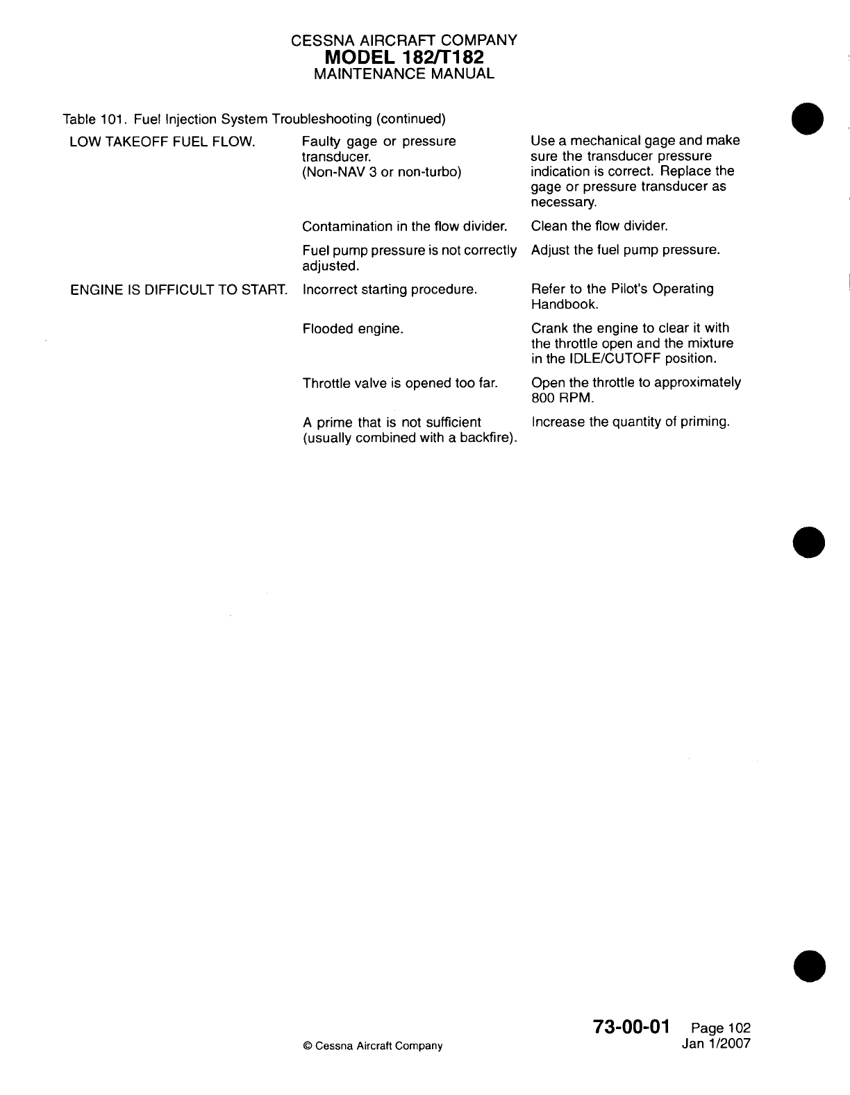
CESSNA
AIRCRAFT
COMPANY
MODEL
182/Ti82
MAINTENANCE
MANUAL
Table
101.
Fuel
Injection System
Troubleshooting
(continued)
LOW TAKEOFF
FUEL
FLOW.
Faulty
gage
or
pressure
transducer.
(Non-NAV
3
or non-turbo)
Contamination
in
the
flow
divider.
Fuel
pump
pressure
is
not
correctly
adjusted.
ENGINE
IS
DIFFICULT
TO
START.
Incorrect
starting procedure.
Flooded
engine.
Throttle
valve
is
opened too
far.
A
prime
that
is
not
sufficient
(usually
combined
with
a
backfire).
©
Cessna
Aircraft Company
Use
a
mechanical
gage and
make
sure
the transducer
pressure
indication
is
correct. Replace
the
gage
or
pressure
transducer
as
necessary.
Clean
the
flow
divider.
Adjust the
fuel
pump
pressure.
Refer
to the
Pilot's
Operating
Handbook.
Crank the
engine
to
clear
it
with
the
throttle
open
and
the
mixture
in
the
IDLE/CUTOFF
position.
Open
the
throttle
to
approximately
800
RPM.
Increase
the
quantity
of
priming.
73-0001
Page
102
Janl1/2007
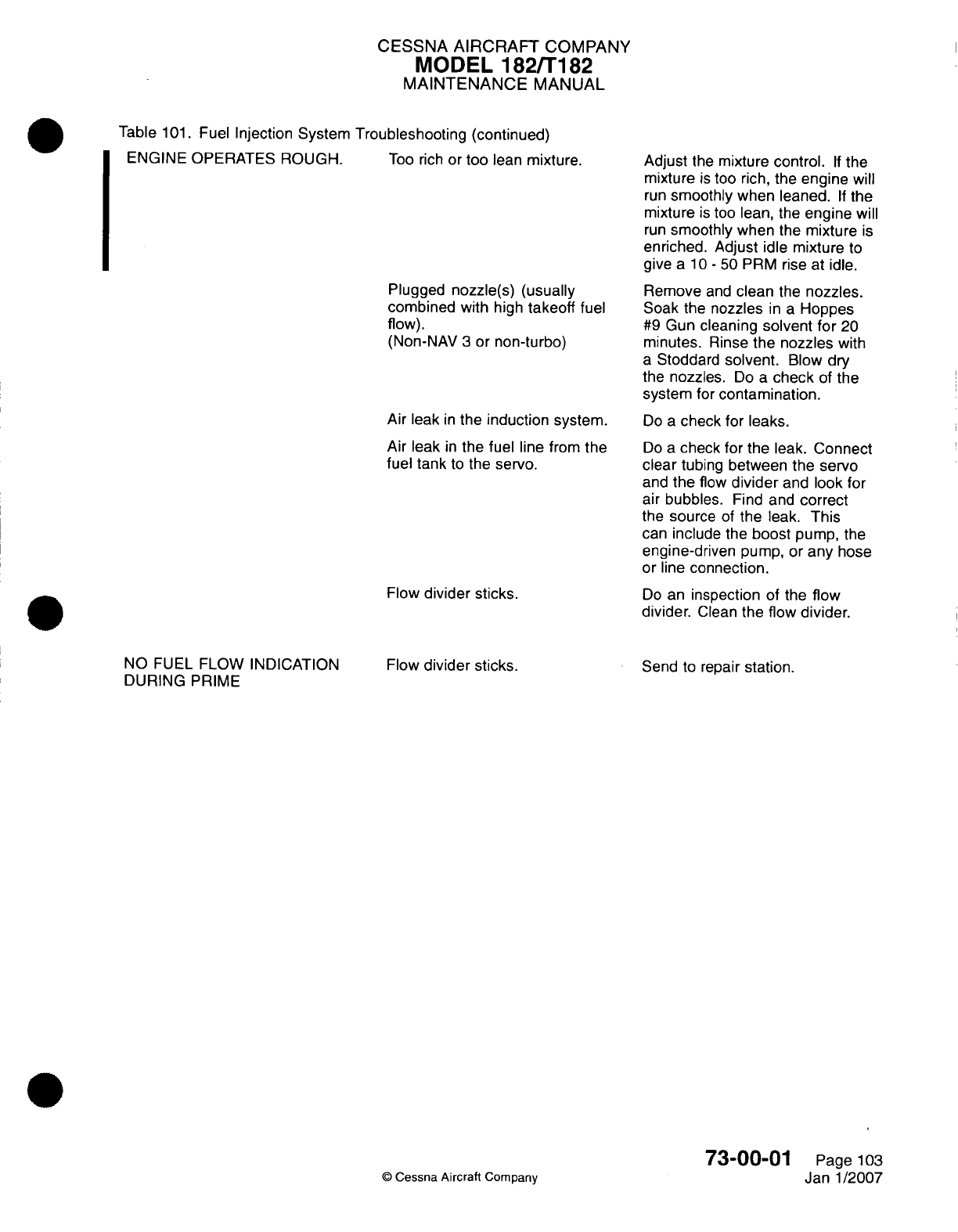
CESSNA AIRCRAFT
COMPANY
MODEL
182/Ti
82
MAINTENANCE
MANUAL
Table
101.
Fuel
Injection
System
Troubleshooting (continued)
ENGINE
OPERATES ROUGH.
Too
rich
or
too
lean
mixture.
Plugged
nozzle(s)
(usually
combined
with high
takeoff
fuel
flow).
(Non-NAV
3
or
non-turbo)
Air
leak
in
the
induction system.
Air
leak
in
the fuel
line
from
the
fuel tank
to
the
servo.
Flow
divider
sticks.
Adjust
the
mixture
control.
If
the
mixture
is
too
rich,
the
engine
will
run
smoothly when leaned.
If
the
mixture
is
too
lean, the
engine
will
run
smoothly when
the
mixture
is
enriched. Adjust
idle
mixture
to
give
a
10 -50
PRM
rise at idle.
Remove
and
clean
the
nozzles.
Soak the
nozzles
in a
Hoppes
#9
Gun
cleaning
solvent
for
20
minutes.
Rinse
the
nozzles
with
a
Stoddard
solvent.
Blow
dry
the
nozzles.
Do
a
check
of
the
system
for
contamination.
Do
a
check
for leaks.
Do
a
check
for
the
leak.
Connect
clear
tubing
between
the
servo
and
the
flow
divider
and
look
for
air
bubbles.
Find and
correct
the
source
of
the
leak.
This
can
include
the
boost
pump, the
engine-driven
pump,
or
any
hose
or
line
connection.
Do
an
inspection
of
the
flow
divider.
Glean
the
flow
divider.
NO
FUEL
FLOW
INDICATION
DURING
PRIME
Flow
divider
sticks.
Send
to
repair station.
0
Cessna
Aircraft
Company
73-00-01
Page
103
Janl1/2007
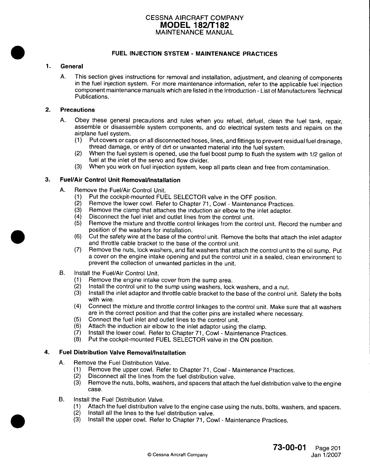
CESSNA AIRCRAFT
COMPANY
MODEL
182/Ti
82
MAINTENANCE
MANUAL
FUEL
INJECTION
SYSTEM
-
MAINTENANCE PRACTICES
1.General
A.
This
section
gives
instructions
for
removal
and
installation, adjustment,
and
cleaning
of
components
in
the
fuel
injection system.
For more
maintenance
information,
refer
to
the
applicable
fuei
injection
component maintenance
manuals
which
are
listed
in
the
Introduction
-
List
of
Manufacturers
Technical
Publications.
2.
Precautions
A.
Obey
these
general
precautions
and
rules
when
you
refuel,
defuel,
clean
the
fuel
tank,
repair,
assemble
or
disassemble
system
components,
and
do
electrical
system tests
and repairs
on
the
airplane
fuel
system.
(1)
Put
covers
or
caps
on all
disconnected
hoses, lines,
and
fittings
to
prevent residual
fuel
drainage,
thread
damage,
or
entry
of
dirt
or unwanted
material
into
the
fuel
system.
(2)
When the
fuel
system
is
opened,
use
the
fuel
boost
pump
to
flush
the
system
with
1/2
gallon
of
fuel at
the
inlet
of
the
servo
and
flow
divider.
(3)
When
you
work
on
fuel
injection
system,
keep
all
parts
clean
and
free from
contamination.
3.
Fuel/Air
Control
Unit
Removal/installation
A.
Remove
the
Fuel/Air Control
Unit.
(1)
Put the
cockpit-mounted
FUEL
SELECTOR
valve
in
the OFF
position.
(2)
Remove
the
lower
cowl.
Refer
to
Chapter
71,
Cowl
-
Maintenance
Practices.
(3)
Remove the
clamp
that
attaches
the
induction
air
elbow
to the
inlet
adaptor.
(4)
Disconnect
the
fuel
inlet
and
outlet
lines
from the
control
unit.
(5)
Remove
the
mixture
and
throttle
control
linkages
from
the
control
unit.
Record
the
number
and
position
of
the
washers
for installation.
(6)
Cut
the
safety
wire
at
the
base
of
the
control
unit.
Remove
the
bolts that
attach
the
inlet
adaptor
and
throttle
cable
bracket
to
the
base
of
the
control
unit.
(7)
Remove
the
nuts,
lock
washers,
and flat
washers that attach
the
control
unit
to
the
oil
sump.
Put
a
cover
on
the
engine
intake
opening
and
put
the
control
unit
in a
sealed, clean
environment
to
prevent
the
collection
of
unwanted
particles
in
the
unit.
B.
Install
the
Fuel/Air
Control
Unit.
(1)
Remove
the
engine
intake
cover
from
the
sump
area.
(2)
Install
the
control
unit
to
the
sump using
washers,
lock
washers,
and
a
nut.
(3)
Install
the
inlet
adaptor
and
throttle
cable
bracket
to
the
base
of
the
control unit. Safety
the
bolts
with
wire.
(4)
Connect
the
mixture
and
throttle
control
linkages
to
the
control
unit.
Make
sure
that
all
washers
are
in
the
correct
position
and
that
the
cotter
pins
are
installed
where
necessary.
(5)
Connect
the
fuel
inlet and
outlet
lines
to
the
control
unit.
(6)
Attach
the
induction
air elbow
to
the
inlet
adaptor
using
the
clamp.
(7)
Install
the
lower
cowl.
Refer
to
Chapter
71,
Cowl
-
Maintenance
Practices.
(8)
Put
the
cockpit-mounted
FUEL
SELECTOR
valve
in
the
ON
position.
4.
Fuel
Distribution
Valve
Removal/installation
A.
Remove
the
Fuel
Distribution
Valve.
(1)
Remove
the
upper
cowl.
Refer
to
Chapter
71,
Cowl
-
Maintenance
Practices.
(2)
Disconnect
all
the lines
from the
fuel
distribution valve.
(3)
Remove
the
nuts,
bolts,
washers,
and
spacers that
attach
the
fuel
distribution
valve
to
the
engine
case.
B.
Install
the
Fuel
Distribution
Valve.
(1)
Attach
the
fuel
distribution
valve
to
the
engine
case
using
the nuts, bolts,
washers,
and
spacers.
(2)
Install
all
the
lines
to
the
fuel
distribution
valve.
(3)
Install
the
upper
cowl.
Refer
to
Chapter
71,
Cowl
-
Maintenance
Practices.
73-00-01
Page
201
Q
Cessna
Aircraft
Company
Janl1/2007
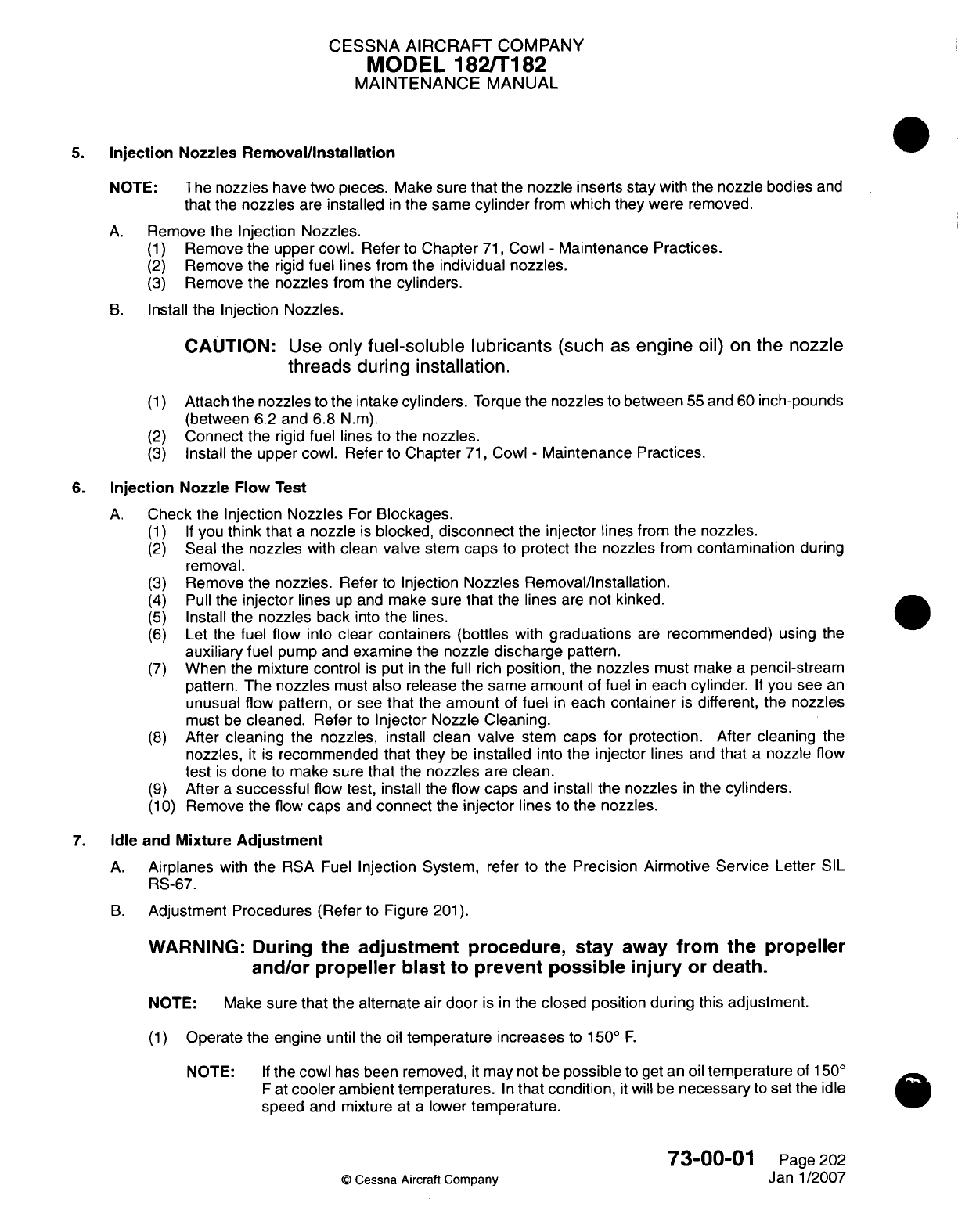
CESSNA AIRCRAFT
COMPANY
MODEL
182/Ti182
MAINTENANCE
MANUAL
5.
Injection
Nozzles RemovalVinstallation
4
NOTE:
The
nozzles
have two
pieces.
Make
sure that the
nozzle inserts
stay
with
the
nozzle
bodies
and
that
the
nozzles
are
installed
in
the
same
cylinder
from
which
they
were
removed.
A.
Remove
the
Injection
Nozzles.
(1)
Remove
the
upper
cowl.
Refer
to
Chapter
71,
Cowl
-
Maintenance Practices.
(2)
Remove
the rigid
fuel
lines from
the
individual nozzles.
(3)
Remove
the
nozzles
from
the
cylinders.
B.
Install the
Injection
Nozzles.
CAUTION:
Use
only
fuel-soluble
lubricants
(such
as
engine
oil) on
the
nozzle
threads
during
installation.
(1)
Attach
the
nozzles
to
the
intake
cylinders.
Torque
the
nozzles
to
between
55
and
60
inch-pounds
(between
6.2
and 6.8
N.m).
(2)
Connect
the
rigid
fuel lines
to
the
nozzles.
(3)
Install the
upper
cowl.
Refer
to
Chapter
71,
Cowl
-
Maintenance Practices.
6.
Injection
Nozzle
Flow
Test
A.
Check
the
Injection
Nozzles
For
Blockages.
(1) If
you
think
that
a
nozzle
is
blocked,
disconnect
the
injector
lines from the
nozzles.
(2)
Seal
the
nozzles
with
clean
valve
stem
caps
to
protect
the
nozzles
from
contamination
during
removal.
(3)
Remove
the
nozzles.
Reter
to
Injection
Nozzles
Removal/Installation.
(4)
Pull
the
injector
lines
up
and
make
sure
that
the
lines
are
not
kinked.
(5)
Install
the
nozzles back
into
the
lines.0
(6)
Let
the
fuel flow
into
clear containers
(bottles
with
graduations
are
recommended)
using
the
auxiliary
fuel
pump and
examine
the
nozzle
discharge
pattern.
(7)
When
the
mixture control
is
put
in
the
full
rich
position,
the nozzles must
make
a
pencil-stream
pattern.
The
nozzles
must
also
release
the
same amount
of
fuel
in
each
cylinder.
If
you
see
an
unusual
flow
pattern,
or see
that
the
amount
of
fuel
in
each
container
is
different,
the
nozzles
must
be
cleaned.
Refer
to
Injector
Nozzle Cleaning.
(8)
After
cleaning
the
nozzles,
install
clean
valve
stem
caps
for
protection.
After
cleaning
the
nozzles,
it
is
recommended
that
they
be
installed
into
the
injector
lines
and
that
a
nozzle
flow
test
is
done
to
make
sure
that
the
nozzles
are
clean.
(9)
After
a
successful
flow
test,
install
the
flow
caps
and
install
the
nozzles
in
the
cylinders.
(1 0)
Remove
the
flow caps
and
connect
the
injector
lines
to
the
nozzles.
7. Idle
and
Mixture
Adjustment
A.
Airplanes
with the
RSA Fuel
Injection
System, refer
to
the
Precision
Airmotive Service
Letter
SIL
RS-67.
B.
Adjustment
Procedures (Refer
to
Figure
201).
WARNING: During the
adjustment procedure, stay
away
from
the
propeller
and/or
propeller
blast
to
prevent
possible injury
or
death.
NOTE:
Make
sure
that
the
alternate
air
door
is
in
the
closed position during
this
adjustment.
(1)
Operate the
engine
until
the
oil
temperature increases
to
1500
F.
NOTE:
If
the cowl
has
been
removed,
it
may
not
be
possible
to get
an oil
temperature
of 1500
F
at
cooler
ambient
temperatures.
In
that
condition,
it
will
be
necessary
to
set
the
idle
speed
and
mixture
at
a
lower
temperature.
73-00-0
1
Page 202
©
Cessna Aircraft
Company
Janl1/2007
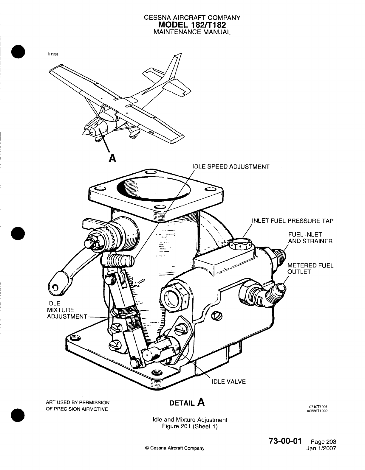
CESSNA AIRCRAFT
COMPANY
MODEL
182/Ti82
MAINTENANCE
MANUAL
IDLE
SPEED
AD.
IJTMEINT
ART
USED
BY
PERMISSION
OF
PRECISION
AlIRMOTIVE
DETAIL
A
071 OTI1001
A0556T
1002
Idle
and
Mixture
Adjustment
Figure
201
(Sheet
1)
©
Cessna
Aircraft
Company
73-00-01
Page 203
Janl1/2007
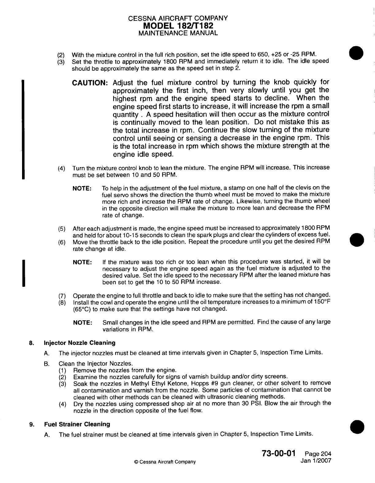
CESSNA
AIRCRAFT
COMPANY
MODEL
182/Ti
182
MAINTENANCE
MANUAL
(2)
With the
mixture control
in
the
full
rich
position,
set
the
idle
speed
to
650,
+25
or
-25
RPM.
(3)
Set
the
throttle
to
approximately
1800
RPM
and
immediately
return
it
to idle.
The
idle
speed
should
be
approximately
the same
as
the speed
set
in
step
2.
CAUTION:
Adjust the
fuel
mixture
control
by
turning
the
knob
quickly
Tor
approximately
the
first
inch,
then
very
slowly
until
you get
the
highest
rpm
and
the
engine
speed
starts
to
decline.
When
the
engine
speed
first
starts
to
increase,
it
will
increase the
rpm
a
small
quantity
.
A
speed hesitation
will
then
occur
as
the mixture
control
is
continually
moved
to
the lean
position.
Do
not
mistake
this
as
the total
increase
in
rpm.
Continue
the
slow
turning
of
the
mixture
control
until
seeing
or
sensing
a
decrease
in
the
engine
rpm.
This
is
the
total increase
in
rpm
which
shows
the
mixture
strength
at
the
engine
idle
speed.
(4)
Turn the
mixture control
knob
to
lean
the
mixture. The
engine
RPM
will
increase.
This increase
must
be
set between
10
and
50
RPM.
NOTE:
To
help
in
the
adjustment
of
the
fuel
mixture,
a
stamp
on
one half
of
the
clevis
on
the
fuel
servo
shows
the
direction
the
thumb
wheel
must
be
moved
to
make
the
mixture
more
rich
and
increase
the
RPM
rate
of
change.
Likewise,
turning
the
thumb
wheel
in
the
opposite
direction
will
make
the
mixture
to
more
lean
and
decrease
the
RPM
rate
of
change.
(5)
After each
adjustment
is
made,
the
engine
speed
must
be
increased
to
approximately
1800
RPM
and
held
for
about
10-1
5
seconds
to
clean
the
spark
plugs and
clear
the
cylinders
of
excess
fuel.
(6)
Move the
throttle
back to
the
idle
position.
Repeat
the
procedure
until
you
get
the
desired
RPM
rate
change
at idle.
NOTE:
If
the
mixture
was
too
rich
or
too
lean
when
this procedure
was
started,
it
will be
necessary
to
adjust
the
engine
speed
again
as
the
fuel
mixture
is
adjusted
to
the
desired
value.
Set
the
idle
speed
to
the
necessary
RPM
after
the leaned
mixture
has
been
set
to get
the
10
to
50
RPM
increase.
(7)
Operate the engine
to
full
throttle
and
back
to
idle
to
make
sure
that
the
setting
has not
changed.
(8)
Install
the
cowl
and
operate
the
engine
until
the
oil
temperature
increases
to
a
minimum
of
1
50'F
(65
0C)
to
make
sure
that
the
settings
have
not
changed.
NOTE: Small
changes
in
the
idle
speed
and
RPM
are
permitted.
Find
the
cause
of
any
large
variations
in
RPM.
8.
Injector
Nozzle
Cleaning
A.
The
injector nozzles
must
be
cleaned
at
time
intervals
given
in
Chapter
5,
Inspection
Time
Limits.
B.
Clean
the
Injector Nozzles.
(1)
Remove
the
nozzles
from
the
engine.
(2)
Examine
the
nozzles
carefully
for
signs
of
varnish buildup and/or
dirty
screens.
(3)
Soak
the
nozzles
in
Methyl
Ethyl
Ketone,
Hopps
#9
gun
cleaner,
or
other
solvent
to
remove
all
contamination
and
varnish
from
the
nozzle.
Some particles
of
contamination
that
cannot
be
cleaned
with
other
methods
can
be
cleaned
with
ultrasonic cleaning
methods.
(4)
Dry
the
nozzles
using
compressed
shop
air
at no
more
than
30 PSI.
Blow
the
air
through
the
nozzle
in
the
direction
opposite
of
the
fuel
flow.
9. Fuel
Strainer
Cleaning
A.
The
fuel
strainer
must
be
cleaned
at
time
intervals
given
in
Chapter
5,
Inspection
Time
Limits.
73-00-0
1
Page
204
0
Cessna
Aircraft
Comroanv
Janl1/2007
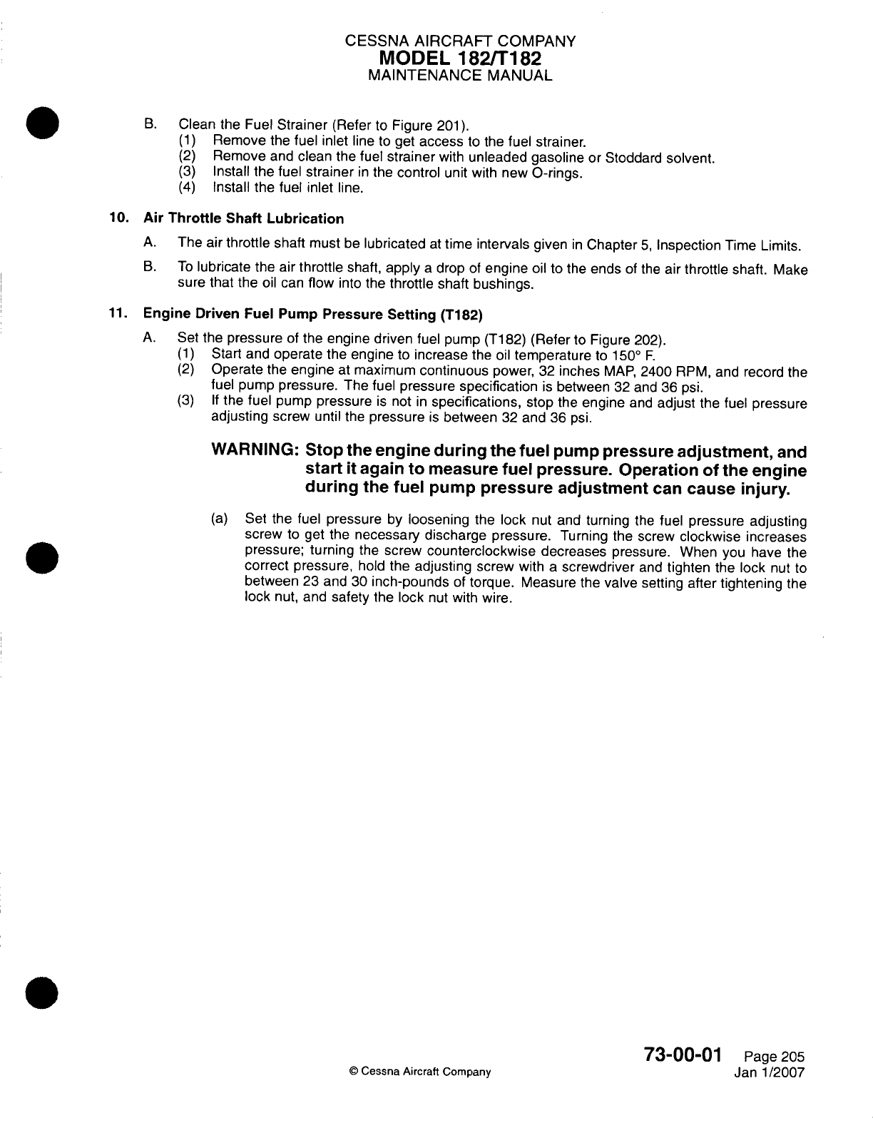
CESSNA
AIRCRAFT
COMPANY
MODEL
182/Ti182
MAINTENANCE
MANUAL
B.
Clean the
Fuel
Strainer
(Refer
to
Figure
201).
(1)
Remove
the
fuel
inlet
line
to
get
access
to
the fuel
strainer.
(2)
Remove
and
clean
the fuel
strainer
with
unleaded
gasoline
or
Stoddard
solvent.
(3)
Install
the
fuel
strainer
in
the
control
unit
with new
0-rings.
(4)
Install
the fuel
inlet
line.
10.
Air
Throttle
Shaft
Lubrication
A.
The
air
throttle shaft
must
be
lubricated
at
time
intervals
given
in
Chapter
5,
Inspection
Time
Limits.
B.
To
lubricate
the
air
throttle
shaft,
apply
a
drop
of
engine
oil
to
the
ends
of
the
air
throttle
shaft. Make
sure that
the
oil
can
flow
into the
throttle shaft bushings.
11.
Engine
Driven
Fuel
Pump
Pressure
Setting
(T182)
A.
Set
the
pressure
of
the
engine
driven
fuel
pump
(Ti
82)
(Refer
to
Figure
202).
(1)
Start and
operate
the
engine
to
increase
the
oil
temperature
to
1500
F.
(2)
Operate
the
engine
at
maximum
continuous
power,
32
inches
MAP,
2400
RPM,
and record
the
fuel
pump
pressure.
The
fuel
pressure
specification
is
between
32 and
36
psi.
(3) If
the
fuel
pump
pressure
is
not
in
specifications,
stop
the
engine
and
adjust
the fuel
pressure
adjusting
screw
until
the
pressure
is
between
32
and
36
psi.
WARNING:
Stop
the
engine
during
the
fuel
pump
pressure
adjustment,
and
start
it
again
to
measure
fuel
pressure.
Operation of
the
engine
during
the
fuel
pump
pressure adjustment
can
cause
injury.
(a)
Set
the
fuel
pressure
by
loosening
the lock
nut
and
turning
the
fuel
pressure
adjusting
screw
to
get
the
necessary discharge
pressure.
Turning
the
screw
clockwise increases
pressure;
turning
the
screw
counterclockwise
decreases
pressure.
When
you
have
the
correct
pressure,
hold
the
adjusting screw
with
a
screwdriver
and
tighten
the
lock
nut
to
between
23
and
30
inch-pounds
of
torque. Measure
the
valve
setting
after
tightening
the
lock
nut,
and
safety
the
lock
nut
with
wire.
73-00-01
Page
205
©
Cessna
Aircraft
Company
Janl1/2007
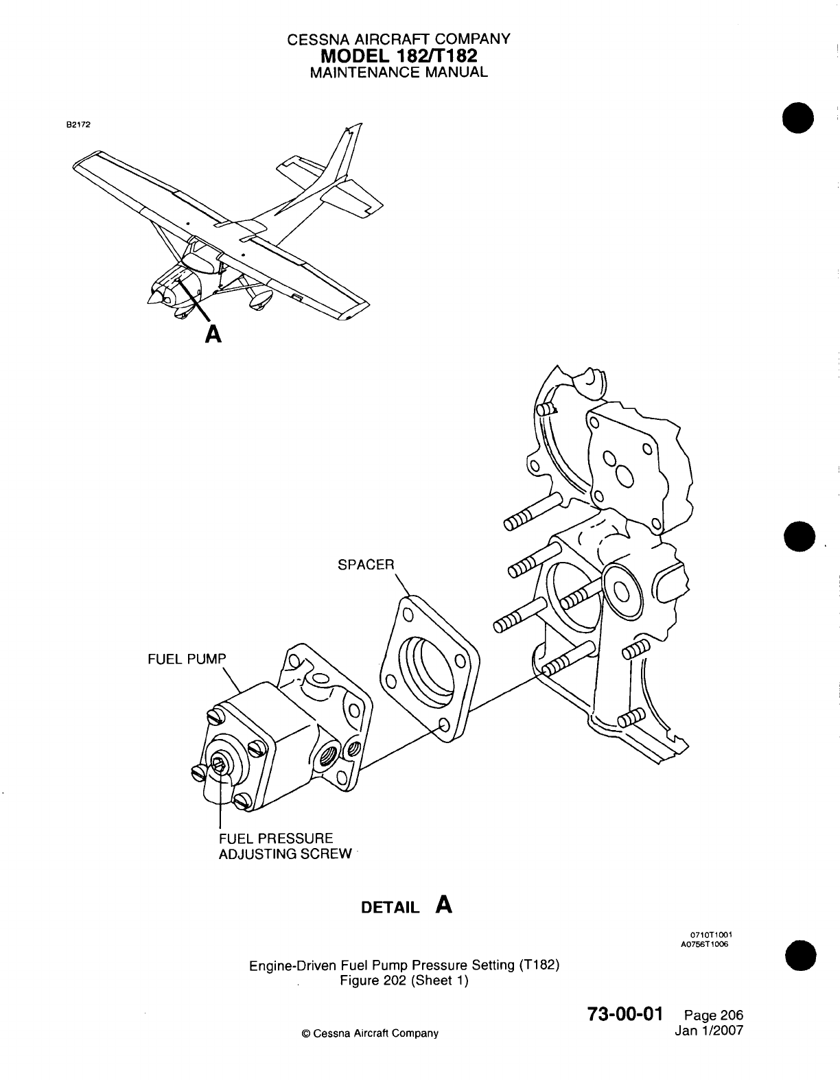
CESSNA AIRCRAFT
COMPANY
MODEL
182/1
182
MAINTENANCE
MANUAL
SPACER
FUEL
F
FUEL
PRESSURE
ADJUSTING
SCREW
DETAIL
A
071
OT1
001
A0756T
1006
Engine-Driven
Fuel
Pump
Pressure Setting
(T182)
Figure
202
(Sheet
1)
73-00-01
©
Cessna Aircraft
Company
Page
206
Janl1/2007
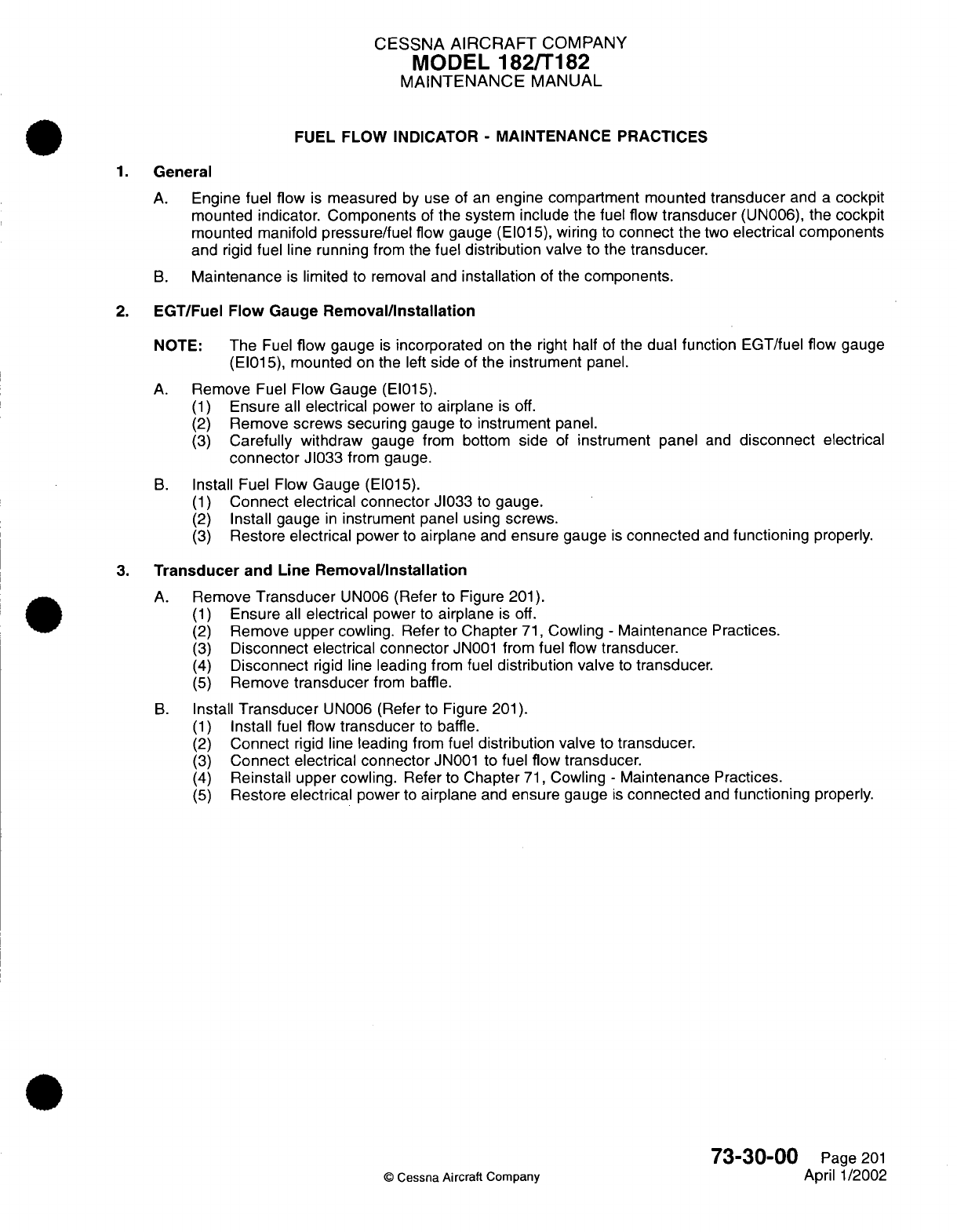
CESSNA
AIRCRAFT
COMPANY
MODEL
182/T182
MAINTENANCE
MANUAL
FUEL FLOW
INDICATOR
-
MAINTENANCE
PRACTICES
1.
General
A.
Engine
fuel flow
is
measured
by
use
of
an
engine compartment
mounted
transducer
and
a
cockpit
mounted
indicator.
Components
of
the
system
include
the
fuel
flow
transducer
(UN006),
the
cockpit
mounted manifold
pressure/fuel
flow gauge
(EI015),
wiring
to
connect the
two
electrical
components
and rigid
fuel line
running
from the
fuel
distribution
valve
to
the
transducer.
B.
Maintenance
is
limited
to removal and
installation
of
the
components.
2.
EGT/Fuel
Flow
Gauge
Removal/Installation
NOTE:
The
Fuel
flow gauge
is
incorporated
on
the
right
half
of
the
dual function
EGT/fuel
flow
gauge
(EI015),
mounted
on the
left
side
of
the instrument
panel.
A.
Remove
Fuel
Flow
Gauge
(EI015).
(1)
Ensure
all
electrical
power
to
airplane
is
off.
(2)
Remove
screws
securing
gauge
to
instrument
panel.
(3)
Carefully
withdraw
gauge
from
bottom
side
of
instrument
panel
and
disconnect
electrical
connector
J1033
from
gauge.
B.
Install
Fuel Flow
Gauge
(EI015).
(1)
Connect electrical
connector
J1033
to
gauge.
(2)
Install
gauge
in
instrument
panel
using
screws.
(3)
Restore
electrical
power
to
airplane
and
ensure
gauge
is
connected
and
functioning
properly.
3.
Transducer
and
Line
Removal/Installation
A.
Remove
Transducer
UN006
(Refer
to Figure
201).
(1)
Ensure
all
electrical
power
to
airplane
is
off.
(2)
Remove
upper
cowling.
Refer
to
Chapter
71,
Cowling
-
Maintenance Practices.
(3)
Disconnect
electrical connector
JN001
from
fuel
flow
transducer.
(4)
Disconnect
rigid
line
leading
from
fuel
distribution
valve
to
transducer.
(5)
Remove
transducer
from
baffle.
B.
Install
Transducer
UN006 (Refer
to
Figure
201).
(1)
Install
fuel
flow
transducer
to
baffle.
(2)
Connect
rigid
line
leading
from
fuel
distribution
valve
to
transducer.
(3)
Connect
electrical connector
JN001
to
fuel
flow
transducer.
(4)
Reinstall
upper
cowling.
Refer to
Chapter
71,
Cowling
-
Maintenance Practices.
(5)
Restore
electrical
power
to
airplane
and
ensure
gauge
is
connected
and
functioning
properly.
73-30-00
Page
201
©
Cessna
Aircraft Company
April
1/2002
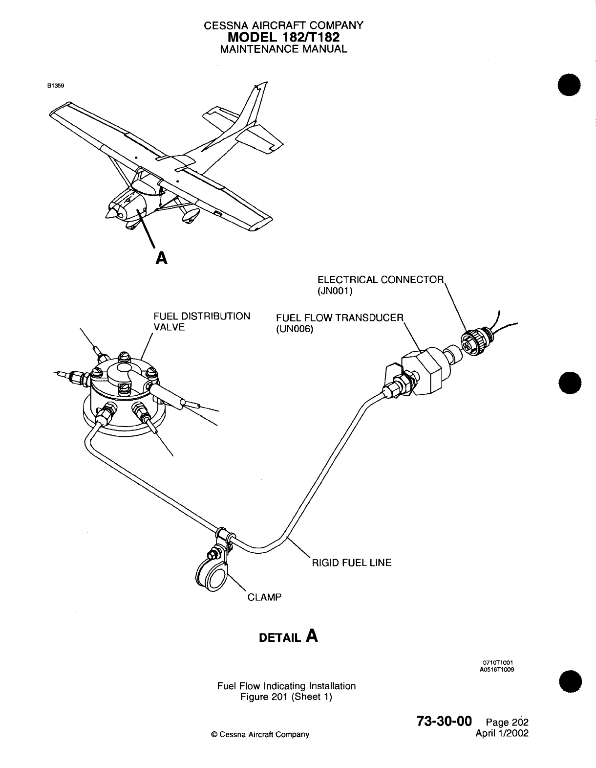
CESSNA AIRCRAFT
COMPANY
MODEL
182/T182
MAINTENANCE
MANUAL
A
FUEL
DISTRIBUTION
VALVE
ELECTRICAL
(JN001)
FUEL FLOW
TRANSDL
(UN006)
RIGID FUEL
LINE
CLAMP
DETAIL
A
0710T1001
A0516T1009
Fuel
Flow Indicating
Installation
Figure
201
(Sheet
1)
73-30-00
©
Cessna
Aircraft Company
Page
202
April
1/2002

CHAPTER
IGNITION

CESSNA AIRCRAFT
COMPANY
MODEL
182/Ti
82
MAINTENANCE
MANUAL
LIST
OF EFFECTIVE
PAGES
CHAPTER-SECTION-SUBJECT
74-Title
74-List
of
Effective Pages
74-Record
of Temporary
Revisions
74-Table
of
Contents
74-00-00
74-10-00
74-10-00
74-30-00
PAGE
Page
1
Pages
101
-1
03
Pages
201
-205
Pages
601
-602
©
Cessna
Aircraft
Company
74-
LIST
OF EFFECTIVE PAGES
Page
1
of
1
Jul
1/2007
DATE
Jul
3/2006
April
1/2002
Jul 1/2007
April
1/2002
Temporary
Revision
Number
RECORD
OF
TEMPORARY REVISIONS
Page
Number
Issue
Date
By
Date
Removed
By
CESSNA AIRCRAFT
COMPANY
MODEL
182/Ti
82
MAINTENANCE
MANUAL
CONTENTS
IGNITION SYSTEM
-
GENERAL..........................
Scope....................................
Tools,
Equipment
and
Materials........................
Definition
..................................
IGNITION SYSTEM
-
TROUBLESHOOTING
....................
General...................................
IGNITION SYSTEM
-
MAINTENANCE
PRACTICES.................
Description
and
Operation
..........................
Magneto
Removal/Installation.........................
Magneto-to-Engine
External Timing
Adjustment.................
Magneto-to-EngineTiming
Check
.......................
IGNITION SWITCH
-
INSPECTION/CHECK.....................
Description
.................................
Tools,
Equipment
and
Materials........................
ACS
Ignition
Switch Inspection
and
Lubrication.................
74-00-00
Page
1
74-00-00
Page
1
74-00-00
Page
1
74-00-00
Page
1
74-10-00
Page
101
74-10-00
Page
101
74-10-00
Page
201
74-10-00
Page
201
74-10-00
Page
201
74-10-00
Page
204
74-10-00
Page
204
74-30-00
Page
601
74-30-00
Page
601
74-30-00
Page
601
74-30-00
Page
601
74-
CONTENTS
Page
1
of
1
Jul
1/2007
©
Cessna
Aircraft
Company
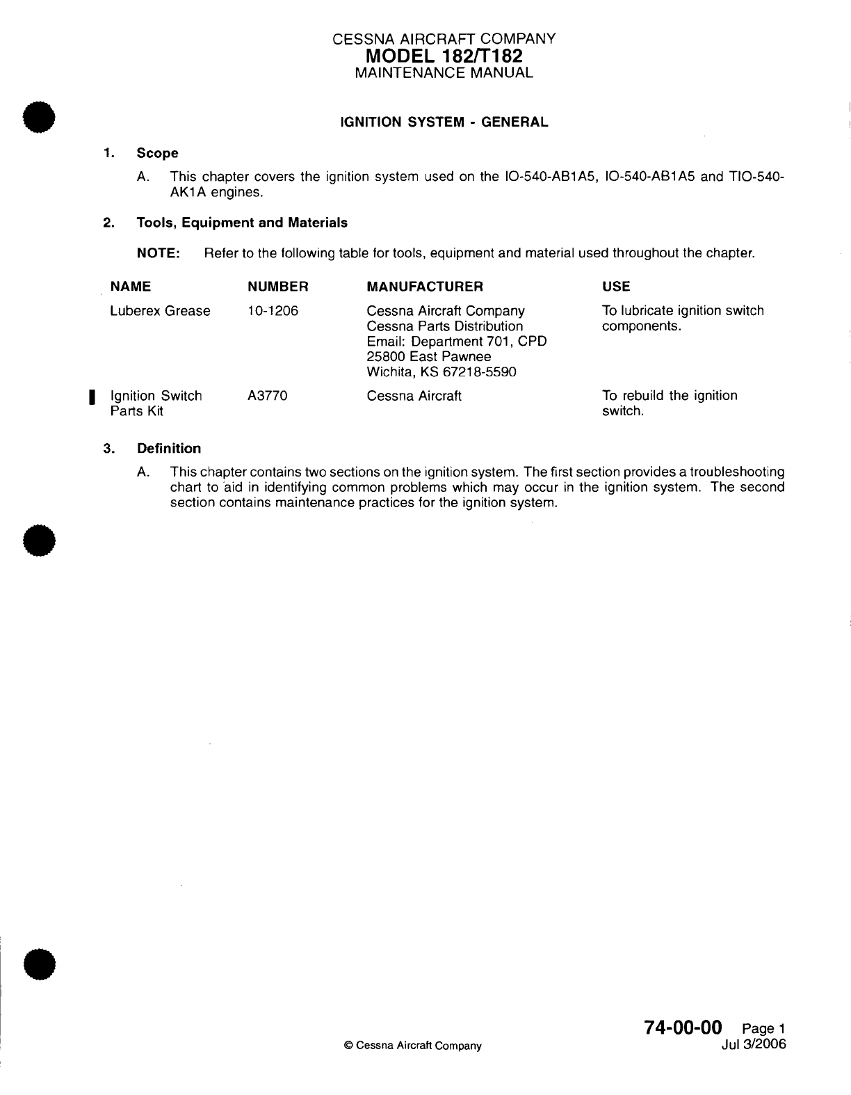
CESSNA AIRCRAFT
COMPANY
MODEL
182/T182
MAINTENANCE
MANUAL
IGNITION SYSTEM
-
GENERAL
1.
Scope
A.
This
chapter
covers
the
ignition
system
used
on
the
IO-540-AB1A5,
IO-540-AB1A5
and
TIO-540-
AK1A
engines.
2.
Tools, Equipment
and
Materials
NOTE:
Refer
to the
following
table
for tools,
equipment
and material
used
throughout
the
chapter.
NAME
Luberex
Grease
I
Ignition
Switch
Parts
Kit
NUMBER
10-1206
A3770
MANUFACTURER
Cessna
Aircraft
Company
Cessna
Parts
Distribution
Email:
Department
701,
CPD
25800
East
Pawnee
Wichita,
KS
67218-5590
Cessna
Aircraft
USE
To
lubricate
ignition
switch
components.
To
rebuild
the ignition
switch.
3.
Definition
A.
This
chapter contains
two
sections
on
the ignition system. The
first
section
provides
a
troubleshooting
chart
to
aid
in
identifying
common
problems
which
may
occur
in
the
ignition
system.
The second
section
contains
maintenance
practices
for
the
ignition
system.
74-00-00
Page
1
©
Cessna
Aircraft
Company
Jul
3/2006
CESSNA
AIRCRAFT
COMPANY
MODEL
182/T182
MAINTENANCE
MANUAL
IGNITION
SYSTEM
-
TROUBLESHOOTING
1.
General
A.
The
following
chart
has
been
provided
to
aid
maintenance
technicians
in
system
troubleshooting.
Refer
to
Figure
101.
This
chart
should
be
used
in
conjunction
with
Chapter
71,
Engine
-
Troubleshooting
to
provide
a
comprehensive
look
at
solutions
to
engine
problems.
For
information
beyond the scope
of
this
chapter,
refer to
applicable
engine
and ignition
system
manuals
and
publications
listed
in
Introduction
-
List
of
Manufacturers
Technical
Publications.
74-10-00
Page
101
©
Cessna
Aircraft Company
April
1/2002
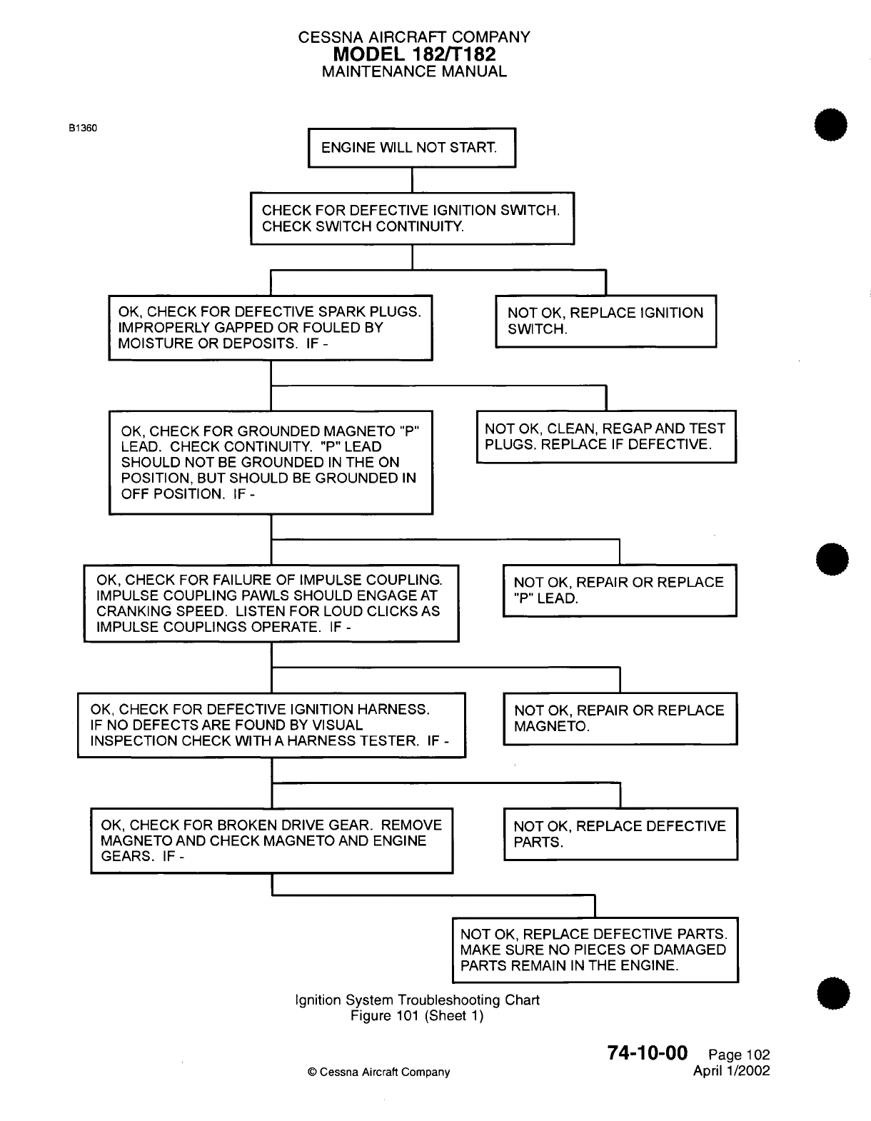
CESSNA AIRCRAFT
COMPANY
MODEL 182/T182
MAINTENANCE
MANUAL
B1360
ENGINE
WILL
NOT
START.
I
CHECK
FOR
DEFECTIVE
IGNITION
SWITCH.
CHECK
SWITCH
CONTINUITY.
I
I
OK,
CHECK FOR DEFECTIVE SPARK
PLUGS.
IMPROPERLY GAPPED OR
FOULED
BY
MOISTURE
OR
DEPOSITS.
IF
-
OK,
CHECK
FOR
GROUNDED MAGNETO
"P"
LEAD.
CHECK
CONTINUITY.
"P"
LEAD
SHOULD
NOT
BE
GROUNDED
IN
THE
ON
POSITION,
BUT
SHOULD
BE
GROUNDED
IN
OFF
POSITION.
IF-
OK,
CHECK
FOR
FAILURE
OF
IMPULSE COUPLING.
IMPULSE
COUPLING
PAWLS
SHOULD
ENGAGE
AT
CRANKING
SPEED. LISTEN
FOR
LOUD
CLICKS
AS
IMPULSE
COUPLINGS
OPERATE.
IF
-
OK,
CHECK FOR DEFECTIVE
IGNITION HARNESS.
IF
NO
DEFECTS
ARE
FOUND
BY
VISUAL
INSPECTION
CHECK
WITH
A
HARNESS TESTER.
IF
-
OK,
CHECK
FOR
BROKEN
DRIVE
GEAR.
REMOVE
MAGNETO
AND
CHECK
MAGNETO
AND ENGINE
GEARS.
IF-
I
NOT
OK,
REPLACE
IGNITION
SWITCH.
NOT
OK,
CLEAN,
REGAP
AND
TEST
PLUGS.
REPLACE
IF
DEFECTIVE.
NOT
OK, REPAIR OR
REPLACE
"P"
LEAD.
NOT OK,
REPAIR OR
REPLACE
MAGNETO.
NOT
OK,
REPLACE DEFECTIVE
PARTS.
NOT
OK,
REPLACE DEFECTIVE
PARTS.
MAKE
SURE
NO PIECES
OF
DAMAGED
PARTS
REMAIN
IN
THE
ENGINE.
Ignition
System
Troubleshooting
Chart
Figure
101
(Sheet
1)
©
Cessna
Aircraft Company
74-10-00
Page
102
April 1/2002
II
I
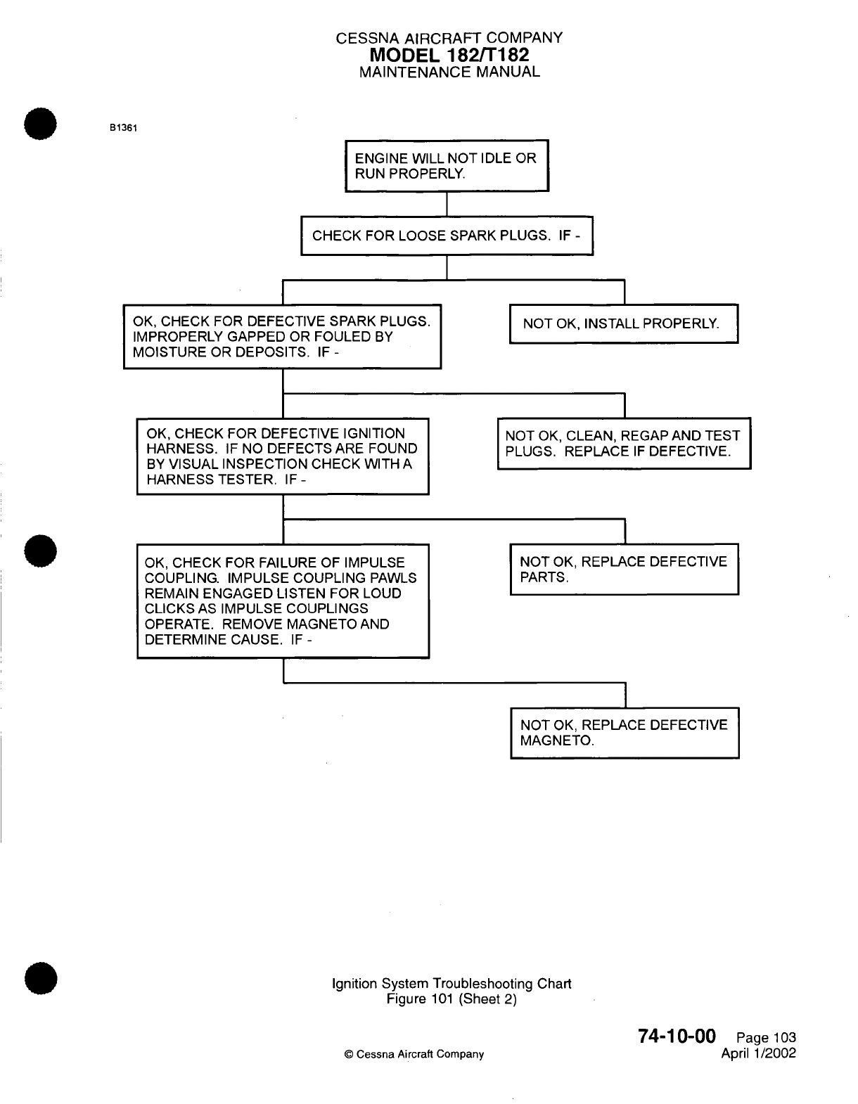
CESSNA AIRCRAFT
COMPANY
MODEL
182/T182
MAINTENANCE
MANUAL
B1361
ENGINE WILL
NOT
IDLE
OR
RUN
PROPERLY.
CHECK
FOR
LOOSE
SPARK
PLUGS.
IF
-
I
I
OK,
CHECK FOR DEFECTIVE
SPARK
PLUGS.
IMPROPERLY
GAPPED
OR
FOULED
BY
MOISTURE
OR
DEPOSITS.
IF
-
OK,
CHECK FOR DEFECTIVE
IGNITION
HARNESS.
IF
NO
DEFECTS
ARE
FOUND
BY
VISUAL INSPECTION
CHECK WITH
A
HARNESS
TESTER.
IF
-
OK,
CHECK FOR
FAILURE OF
IMPULSE
COUPLING. IMPULSE COUPLING
PAWLS
REMAIN
ENGAGED
LISTEN
FOR
LOUD
CLICKS
AS
IMPULSE
COUPLINGS
OPERATE. REMOVE
MAGNETO AND
DETERMINE
CAUSE.
IF
-
I
NOT
OK,
INSTALL
PROPERLY.
NOT
OK,
CLEAN,
REGAP
AND
TEST
PLUGS. REPLACE
IF
DEFECTIVE.
NOT
OK,
REPLACE DEFECTIVE
PARTS.
NOT
OK,
REPLACE
DEFECTIVE
MAGNETO.
Ignition System
Troubleshooting
Chart
Figure
101
(Sheet
2)
74-10-00
©
Cessna Aircraft
Company
Page
103
April 1/2002
I
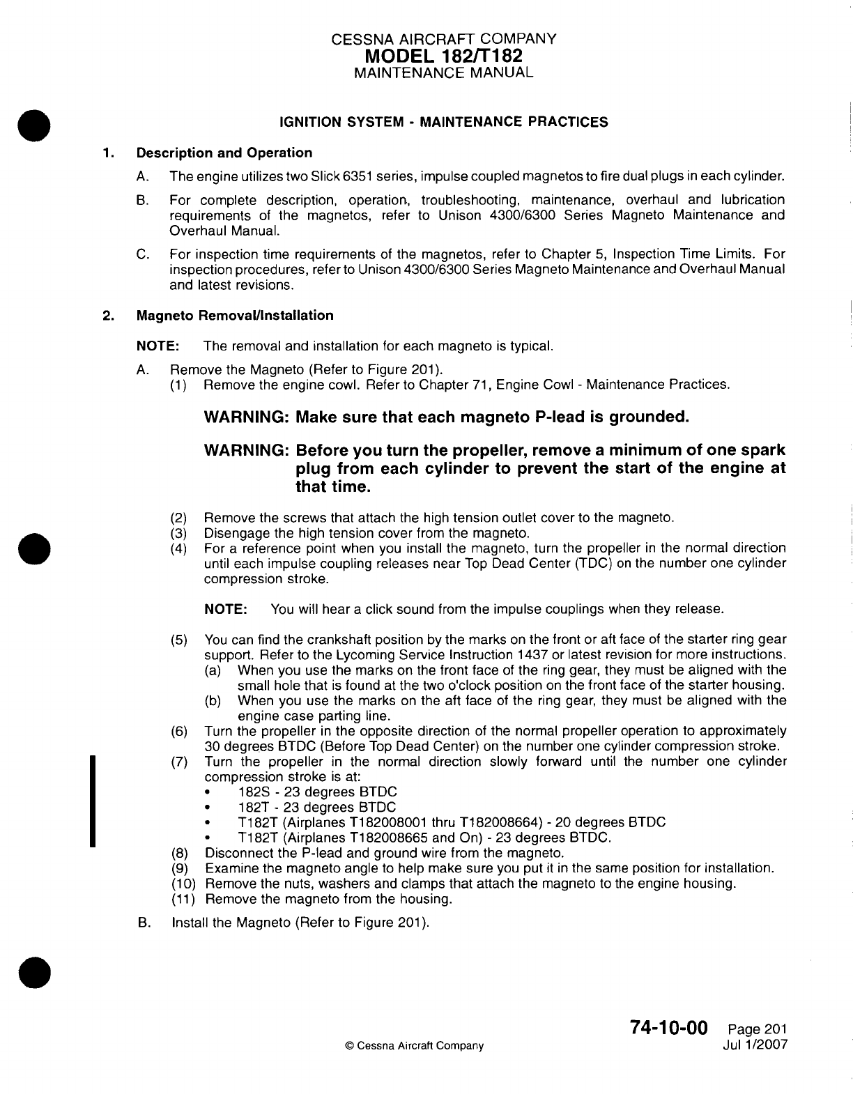
CESSNA AIRCRAFT
COMPANY
MODEL
182/T182
MAINTENANCE
MANUAL
IGNITION
SYSTEM
-
MAINTENANCE PRACTICES
1.Description
and
Operation
A.
The engine utilizes
two
Slick
6351
series, impulse
coupled
magnetos
to
fire
dual
plugs
in
each
cylinder.
B.
For
complete
description,
operation,
troubleshooting, maintenance,
overhaul
and
lubrication
requirements
of
the magnetos,
refer
to
Unison
4300/6300
Series
Magneto
Maintenance
and
Overhaul
Manual.
C.
For
inspection
time
requirements
of the
magnetos,
refer
to
Chapter
5,
Inspection
Time
Limits.
For
inspection
procedures,
refer
to
Unison
4300/6300
Series Magneto
Maintenance
and
Overhaul
Manual
and
latest revisions.
2.
Magneto
Removal/Installation
NOTE:
The removal and
installation
for
each
magneto
is
typical.
A.
Remove
the
Magneto (Refer
to
Figure
201).
(1)
Remove
the
engine
cowl. Refer
to
Chapter
71,
Engine
Cowl
-
Maintenance
Practices.
WARNING:
Make
sure
that
each
magneto
P-lead
is
grounded.
WARNING:
Before you
turn
the
propeller,
remove
a
minimum
of
one
spark
plug
from
each
cylinder
to
prevent
the
start
of
the
engine
at
that
time.
(2)
Remove the
screws
that
attach
the
high
tension
outlet
cover
to
the
magneto.
(3)
Disengage
the high
tension
cover
from
the
magneto.
(4)
For
a
reference
point
when
you
install the
magneto, turn
the
propeller
in
the
normal
direction
until
each
impulse
coupling releases
near
Top
Dead
Center
(TDC)
on
the
number
one
cylinder
compression
stroke.
NOTE:
You
will
hear
a
click sound
from
the
impulse
couplings
when
they release.
(5)
You
can
find
the
crankshaft
position
by
the
marks
on
the
front
or
aft
face
of
the
starter
ring
gear
support.
Refer
to the
Lycoming Service Instruction
1437
or
latest revision
for
more
instructions.
(a)
When
you
use
the
marks
on
the
front face
of
the
ring
gear,
they
must
be
aligned
with
the
small
hole
that
is
found
at
the two
o'clock
position
on
the
front
face
of
the
starter
housing.
(b)
When
you
use
the
marks
on
the
aft
face
of
the
ring
gear,
they
must
be
aligned
with
the
engine
case
parting
line.
(6)
Turn
the
propeller
in
the
opposite direction
of
the
normal
propeller
operation
to
approximately
30
degrees
BTDC
(Before
Top
Dead
Center)
on
the
number
one
cylinder
compression
stroke.
(7)
Turn
the
propeller
in
the
normal
direction
slowly
forward
until
the
number
one
cylinder
compression
stroke
is
at:
*
1828
-
23
degrees
BTDC
*
182T
-
23
degrees
BTDC
*
T182T
(Airplanes
Ti182008001
thru
Ti182008664)
-
20
degrees
BTDC
*
T1
82T
(Airplanes
Ti
82008665
and On)
-
23
degrees
BTDC.
(8)
Disconnect
the
P-lead
and
ground
wire
from
the
magneto.
(9)
Examine
the
magneto
angle
to
help
make sure
you put
it in
the
same
position
for installation.
(1
0)
Remove
the nuts,
washers
and
clamps
that
attach the magneto
to
the
engine
housing.
(11)
Remove
the
magneto
from the
housing.
B.
Install
the
Magneto
(Refer
to
Figure
201).
74-1
0-00
Page
201
©
Cessna
Aircraft Company
Jul
1/2007
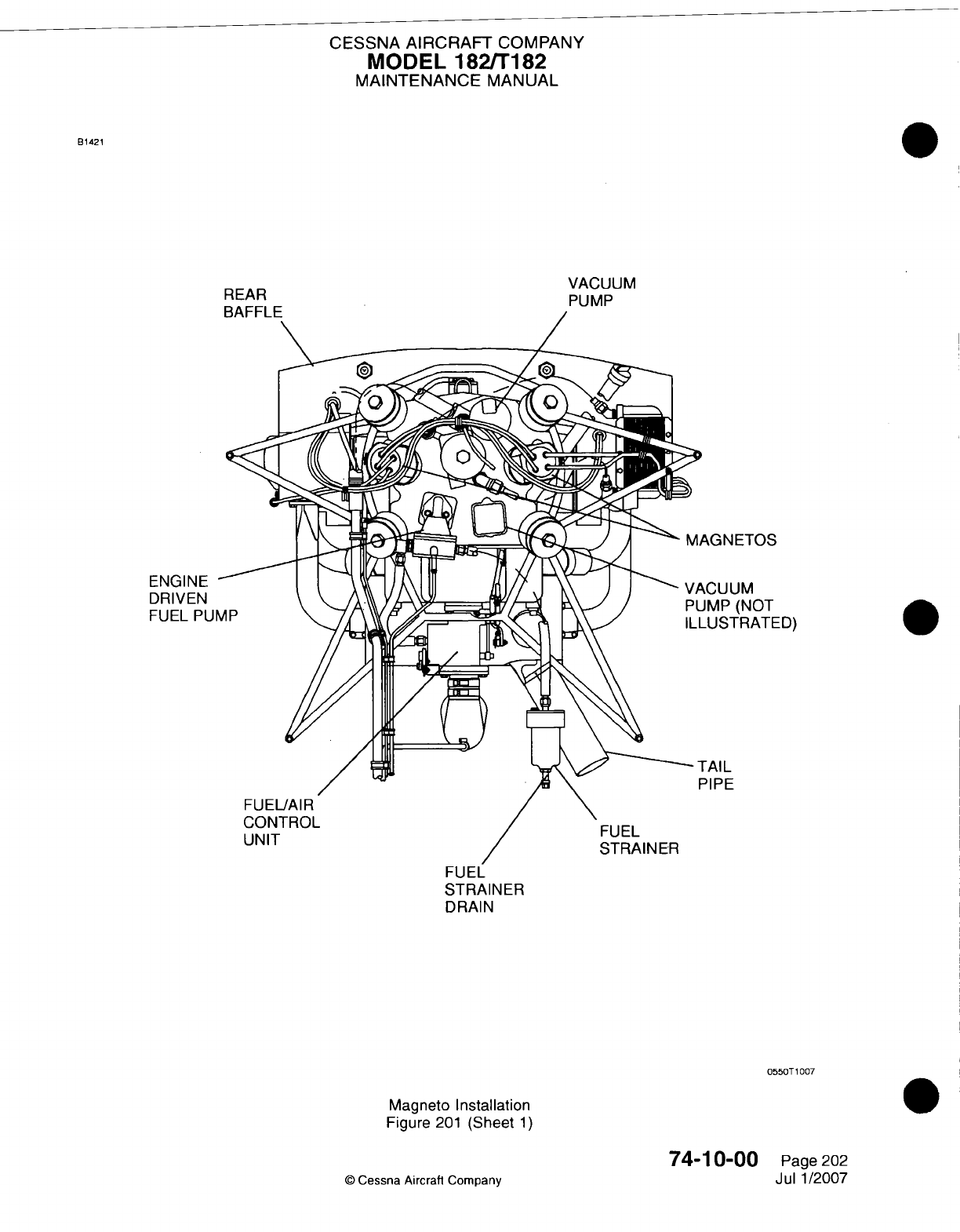
CESSNA
AIRCRAFT
COMPANY
MODEL
182/Ti
182
MAINTENANCE
MANUAL
B1421
VACUUM
REAR PUMP
AkGN
ETOS
kCUUM
JMP
(NOT
-USTRATED)
FAIL
:1lPE
STRAINER
DRAIN
055OT 1007
Magneto
Installation
Figure
201
(Sheet
1)
74-1
0-00
©
Cessna
Aircrafl
Company
Page
202
Jul
1/2007
ENGINE
DRIVEN
FUEL
PUl
CESSNA
AIRCRAFT
COMPANY
MODEL
182/Ti
82
MAINTENANCE
MANUAL
CAUTION:
Make sure
the
gasket surfaces
are
clean
to
prevent
oil
leaks.
(1)
Apply
a
small
quantity
of
silicone grease
such
as
DC4
to
each
side
of
the new
magneto
base
gasket,
which will
help
future timing
adjustments.
(2)
Make
sure
the
magneto
drive
gear
is
installed correctly,
the
is
nut
torqued
correctly
and the
cotter
pin
is
installed.
Refer
to
the
Lycoming
Service Instructions
1437
or
latest
revision
and
the
Unison
4300/6300
Magneto
Maintenance
and
Overhaul
Manual
Instructions.
CAUTION:
Make
sure
you
remove
the
T-118
timing
pin
immediately after
you
attach
the
magneto
to
the
accessory
case
and
before
the
magneto
or
propeller
is
turned.
(3)
Insert the
T-1
18
timing
pin into
the
L
timing
hole
in
the
magneto
distributor
block.
(4)
Turn
the
magneto
rotor
in
the
opposite
of
normal
direction
until
the
timing
pin
is
engaged
fully
into
the
distributor
gear.
(a) If
the
magneto
rotor
does
not
move
freely
and
the
pin
will
not
go
into
the hole
in
the
gear,
the
pin
has
hit
the
pointer
on
the
gear.
(b)
Pull the
pin
out
far
enough
to
continue
to
turn
the
magneto freely
in
the
opposite direction
of
normal
movement
until
the
pointer
has
passed
the
pin,
then
insert
the
pin.
1
Turn the
magneto
rotor
until
the
pin
engages
the
gear.
(5)
Do
a
check
of
the
crankshaft
to
make
sure
the
propeller
didn't
move
and
is
still
set
in
position
with
the
number
one
cylinder
on
the
compression
stroke
at:
*
182S
-
23
degrees
BTDC
I
*~~~
1
82T
-
23
degrees
BTDC
T1
82T
(Airplanes
Ti
82008001 thru
Ti
82008664)
-
20
degrees
BTDC
*
T1
82T (Airplanes
Ti
82008665
and On)
-
23
degrees
BTDC.
(6) If
the
propeller
as
been
turned
and
only
one
magneto
was removed,
it
will be
necessary
to
engage
the
impulse coupling
on
the
magneto
that
is
installed,
and
establish
the
crankshaft
position.
Refer
to
step
2.A.(4)
thru
2.A.(7)
before you
continue.
(7)
Do
the steps that
follow
with
the
number
one
cylinder
on
the
compression
stroke
at:
*
182S
-
23
degrees
BTDC
*
182T
-
23
degrees
BTDC
T182T
(Airplanes
Ti182008001
thru Ti182008664)
-
20
degrees
BTDC
*
T1
82T
(Airplanes
Ti
82008665
and On)
-
23
degrees
BTDC.
CAUTION:
Make sure you
remove
the
T-118
timing
pin
immediately
after
you
attach
the
magneto
to
the
accessory case
and
before
the
magneto
or
propeller
is
turned.
(a)
Install the magneto
with
the
new
base
gasket
and
the
T-1i18
timing
pin
in
position.
(b)
Engage
the
magneto
drive
gear
with
the
engine
gear,
in a
position
that
will give
a
range
of
magneto timing
adjustments
in
each
direction.
(c)
Hold
the
magneto
in
position
against
the
accessory
case
and
install
the
nuts,
flat
washers,
clamps
and new
lock washers.
(d)
Finger tighten
each
nut
by
hand.
(e)
Remove
the
timing
pin.
(8)
Before
you
continue,
you must
adjust
the
magneto
timing.
Refer
to
Magneto-to
Engine External
Timing
Adjustment.
(9)
With
the
magneto
set
in
position, first tighten each
nut
to
8
foot-pounds
(10
N.m).
(1
0)
Tighten
each
nut
from one side
to
another,
to
a
torque
of
17
foot-pounds
(23
N.m).
(ii1)
Connect
the
P-lead
to
the magneto.
(12)
Attach
a
ground
wire to
the
magneto.
(13)
Attach
the
high
tension
outlet
cover
to
the
magneto.
(14)
Tighten the P-lead
nut to
a
torque
of 13
to
15
inch-pounds
(17 to 20
N.m).
74-1
0-00
Page
203
©
Cessna
Aircraft
Company
Jul
1/2007
CESSNA
AIRCRAFT
COMPANY
MODEL
182/Ti
82
MAINTENANCE
MANUAL
CAUTION:
Make
sure
you
remove
the
T-1
18
timing
pin
before
the
magneto
or
propeller
is
turned.
i
(115)
Install
the
spark
plugs.
(116)
Install the
cowl.
Refer
to
Chapter
71,
Engine
Cowl
-
Maintenance
Practices.
(17)
Complete
a
engine
preflight operational check
of
the
ignition
system. Refer
to
the
Pilot's
Operating Handbook.
3.
Magneto-to-Engine
External
Timing
Adjustment
A.
Adjust
the
Magneto-to-Engine
Timing.
NOTE: The
Magneto-to-Engine
timing
can
be
adjusted
a
maximum total
of
0.125
inch
(3.17 mm)
movement
from the
original
factory
position,
or between
each
internal
timing
adjustment.
The external
timing
movement
of
0.1
25
inch
(3.17
mm)
approximately
equals
5
degrees
of
internal timing
change.
(1)
Before
the
first
field
adjustment
of
external timing,
the
magneto
and
accessory case
must
be
indexed
as
necessary
to
monitor
external timing
adjustments.
(a)
The
magneto must
be
removed
and
internal
timing
adjusted
in
accordance
with
Unison
4300/6300
Series
Aircraft
Magnetos Maintenance
and
Overhaul Instructions
Form
L-1363B
or
latest revision, when
the
external timing
adjustments
collect
up
to
0.125 inch
(3.17
mm)
movement
change.
(2)
Make
sure
the
ignition
is in
the OFF
position.
(3)
Remove
the
engine
cowl.
Refer
to
Chapter
71,
Engine
Cowl
-
Maintenance Practices.
(4)
Remove
a
minimum
of one
spark
plug
from
each
cylinder.
(5)
Make
sure
that
cylinder
number
one
is on
the
compression
stroke
at:
*
182S
-
23
degrees
BTDC
*
182T
-
23
degrees
BTDC
I
*
~~~T182T
(Airplanes
Ti182008001
thru
Ti182008664)
-
20
degrees
BTDC
*
T182T
(Airplanes
Ti182008665 and
On)
-
23
degrees
BTDC.
(6)
Connect
a
standard aircraft
magneto
timing
light
between
an
acceptable
engine
ground
and
the
P-lead
terminal
of
the
magneto.
NOTE:
Most
standard
aircraft magneto
timing
lights
show
open
points
with
a
Light
On
condition
and/or
a
signal
that
you
can
hear.
(7)
Loosen
the
mount
clamps
that
attach
the
magneto
to the
accessory
case
so
that the
magneto
will
turn
on
the
accessory
case.
(8)
Turn
the
ignition
switch
to
the
BOTH
position.
(a)
Look
at
the
magneto
from
the aft side
of
the engine.
1 If
the
timing
light
is
illuminated,
turn
the
magneto frame
clockwise
until
the
timing
light
shuts
off.
2
Turn
the
magneto
frame
counter-clockwise
until
the
timing
light
comes
on,
which
shows
that
the
contact breaker
points
are open.
CAUTION:
Do
not
torque
the
nuts
more
than
17
foot-pounds
(23
n-in.)
or
the
mounting
flange
can
crack.
(9)
With
the
magneto
set
in
position, first
tighten
each
nut
to
8
foot-pounds
(1
0
N.m).
(1
0)
Tighten each
nut from
one side
to
another,
to
a
torque
of
17
foot-pounds
(23
N.m).
(1 1)
Complete
a
check
of
the
magneto
timing
to
make
sure
it
has
not
changed.
Refer
to
Magneto-
to-Engine
Timing
Check.
4.
Magneto-to-EngineTiming
Check
A.
Complete
a
Check
of
the
Magneto-to-Engine
Timing
(Refer
to
Figure
201).
(1)
Make
sure the
ignition
is
in
the OFF
position.
74-1
0-00
Page
204
©
Cessna
Aircraft
Company
Jul
1/2007
CESSNA AIRCRAFT
COMPANY
MODEL
182/Ti
82
MAINTENANCE
MANUAL
(2)
Remove
the
engine
cowl. Refer
to
Chapter
71,
Engine Cowl
-
Maintenance
Practices.
(3)
Remove
a
minimum
of
one
spark
plug
from
each
cylinder.
(4)
Connect
a
standard
aircraft
magneto
timing
light
between
an
acceptable
engine
ground and the
P-lead
terminal
of
the
magneto.
NOTE:
Most
standard
aircraft
magneto
timing
light
indicate
open points with
a
Light
On
condition
and/or
an
signal
that
you
can
hear.
(5)
Turn the
ignition
switch
to
the
BOTH
position.
(6)
Turn
the
propeller
in
the normal
direction
of
movement
until each
impulse
coupling
releases
as
the
number
one
cylinder
moves
near
TDC
(Top
Dead
Center)
on
the
compression
stroke.
NOTE:
You
will
hear
a
click
sound
from
the
impulse
couplings
when
they
release.
(7)
Turn
the
propeller
in
the
opposite
direction
of
normal
propeller
operation
to
approximately
30
degrees
BTDC
(Before
Top
Dead
Center),
then
slowly
forward
to:
*
182S
-
23
degrees
BTDC
I
*~~~
182T
-
23
degrees
BTDC
T1
82T
(Airplanes
Ti
82008001
thru
Ti
82008664)
-
20
degrees
BTDC
*
Ti
82T
(Airplanes
Ti
82008665
and
On)
-
23
degrees
BTDC.
(8)
Slowly
turn the
propeller
in
the
normal
direction
of
movement
until
the
timing light
comes
on.
(9)
Examine
the
crankshaft
to
make
sure
it is in
the
correct
position.
NOTE: The
timing light
must
come
on
with
the
number
one
cylinder
on
the
compression
stroke
at:
*
182S
-
23
degrees
BTDC
*
182T
-
23
degrees
BTDC
*
T1i82T
(Airplanes
Ti
82008001
thru
Ti
82008664)
-
20
degrees
BTDC
*
T1i82T
(Airplanes
Ti
82008665
and On)
-
23
degrees
BTDC.
(1
0)
If
the
crankshaft
is
not
in
the
correct
position
you
will
have
to
make an
adjustment.
Refer
to
Magneto-to-Engine
External
Timing Adjustment.
(ii1)
Turn
the
ignition
switch
to
the
OFF
position.
(12)
Install
the
spark
plugs.
(13)
Install
the ignition
leads
on
the
spark
plugs.
(14)
Install
the
cowl.
Refer
to
Chapter
71,
Engine
Cowl
-
Maintenance
Practices.
(15)
Complete
a
engine
preflight
operational
check
of
the ignition system.
Refer
to
the
pilot's
operating handbook.
74-1
0-00
Page 205
©
Cessna Aircraft
Company
Jul
1/2007
CESSNA AIRCRAFT
COMPANY
MODEL
182/T182
MAINTENANCE
MANUAL
IGNITION
SWITCH
-
INSPECTION/CHECK
1.
Description
A.
The
following inspection
and
lubrication procedures
are
designed
for
the
ACS
brand
ignition
switch
and
should
be
accomplished
every
2000
hours.
2.
Tools,
Equipment
and Materials
A.
Refer
to
Ignition System
-
General
for
a
list
of
required
tools, equipment
and
materials.
3.
ACS
Ignition
Switch
Inspection
and
Lubrication
NOTE:
Refer
to
Figure
601
for
the
following
steps.
A.
Switch
Removal.
(1)
Disconnect
battery.
(2)
Remove
switch
assembly
from
instrument
panel
by
loosening locknut
on
the
forward
side
of
panel
and
removing
decorative
nut
on
aft
side
of
panel.
NOTE:
Wiring
need
not
be
removed
from
posts
of
switch
if
wiring
is
of
sufficient
length
to
allow
switch
assembly
to
be
moved to
a
position
where
disassembly
can
be
accomplished.
If
wiring
is
to
be
disconnected,
tag
or
mark
wires
for reinstallation.
B.
Switch
Disassembly.
(1)
Hold
switch
body
in
position
shown
in
Figure
601.
(2)
Remove
screws
and
washers.
(3)
Lift
terminal
board
assembly
from body,
being
careful
not
to
lose
springs
and
cups.
C.
Switch
Cleaning.
(1)
Clean
switch
contacts
and
the three
movable
contact
cups
using
alcohol
on
a
cotton tip swab.
D.
Switch
Inspection.
(1)
Inspect movable
contact
cups
and
switch
contacts
on
the
terminal
board
assembly
for
excessive
wear
or
corrosion
and
for
loose
contacts
or
terminals.
If
the
silver
plating
on
the
contact
cups
is
worn
through
to the
brass
material,
or
they
are
burned
or
pitted
from
arcing
or
are
corroded,
they
should
be
replaced.
If
the
contacts
on
the
contact
block
exhibit
any of
the above
conditions
or
the terminals
are
loose,
the
terminal
board
assembly
should
be
replaced.
E.
Switch
Reassembly.
(1)
Apply
a
thin
coating
of
Luberex
10-1206
lubricant
to switch contacts
and
the three
movable
contact cups.
Ensure
all
contact
areas
are
covered
with
lubricant.
(2)
Reassemble
switch
using
new
parts,
if
required.
Ensure
that
cups
and
springs
are
positioned
in
switch body
so
that
no
binding
occurs.
Secure terminal
board
assembly to
switch body
with
retained
washers
and
screws.
(3)
Mark
switch
with
a
dab
of
red
paint
on
the terminal
board
retaining
screws.
(4)
If
removed,
reconnect
wiring
to
backside
of
switch.
(5)
Install
switch
in
panel
and
secure
using
existing
hardware.
(6)
Reconnect
battery
and
perform
an
operational
check
of
the
switch.
F.
Operational
Check.
(1)
Start
engine.
Refer
to
Model
182
Pilot's
Operating
Handbook
and
FAA
Approved Airplane
Flight
Manual.
(2)
Check magnetos
for
normal
engine
RPM
drop.
(3)
Verify
that
both
magnetos
are
grounded when switch
is
in
the OFF
position.
(a)
Reduce
engine
RPM
to
idle,
and
turn switch
to
the
OFF
position. Engine
should
quit
immediately,
signifying
that
both
magnetos
have
been
grounded
through
the
ignition
switch.
(4)
After
engine
stops,
move
mixture
control
to
idle
cutoff
position.
74-30-00
Page
601
©
Cessna Aircraft
Company
April 1/2002
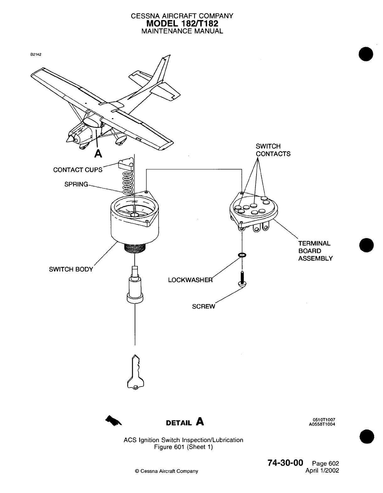
CESSNA
AIRCRAFT
COMPANY
MODEL 182/T182
MAINTENANCE
MANUAL
SWITCH
¥
SWITCH
t
SCREW
DETAIL
A
ACS
Ignition
Switch
Inspection/Lubrication
Figure
601
(Sheet
1)
051
OT1
007
A0558T1004
74-30-00
©
Cessna
Aircraft
Company
Page
602
April
1/2002
nO.As
CHAPTER
ENGINE
CONTROLS

CESSNA
AIRCRAFT
COMPANY
MODEL 182/T182
MAINTENANCE
MANUAL
LIST
OF EFFECTIVE
PAGES
CHAPTER-SECTION-SUBJECT
76-Title
76-List
of
Effective
Pages
76-Record
of Temporary
Revisions
76-Table
of
Contents
76-00-00
76-10-00
76-11-00
PAGE
Page
1
Pages
201-203
Pages
201-203
©
Cessna
Aircraft
Company
76
-
LIST
OF
EFFECTIVE
PAGES
Page
1
of
1
Jan 2/2006
DATE
April
1/2002
Jan
2/2006
Jan
2/2006
Temporary
Revision
Number
RECORD OF
TEMPORARY REVISIONS
Page
Number
Issue
Date
By
Date
Removed
By
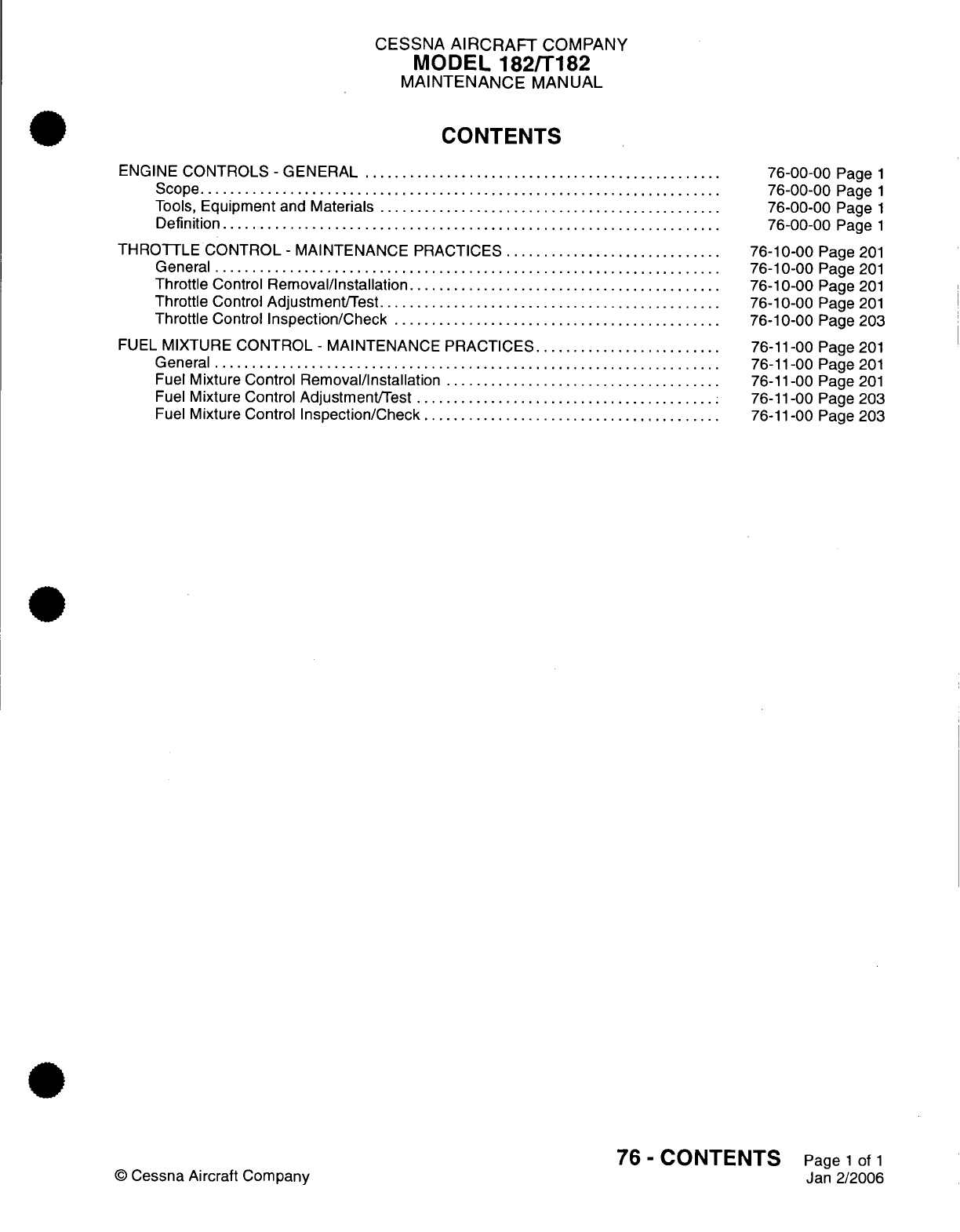
CESSNA
AIRCRAFT
COMPANY
MODEL
182/T182
MAINTENANCE
MANUAL
CONTENTS
ENGINE
CONTROLS
-
GENERAL
.........
.........
..............................
S
cope......................................................................
Tools,
Equipment
and
Materials
..............................................
Definition
...................................................................
THROTTLE
CONTROL
-
MAINTENANCE
PRACTICES
.............................
General
...................................................................
Throttle
Control
Removal/nstallation
..........................................
Throttle
Control
Adjustment/Test..............................................
Throttle
Control
Inspection/Check
............................................
FUEL
MIXTURE
CONTROL
-
MAINTENANCE
PRACTICES.........................
General
....................................................................
Fuel
Mixture Control
Removal/Installation
.....................................
Fuel
Mixture Control
Adjustment/Test
.........................................
Fuel
Mixture Control
Inspection/Check
.......................................
76-00-00
Page
1
76-00-00
Page
1
76-00-00
Page
1
76-00-00
Page
1
76-10-00
Page
201
76-10-00
Page
201
76-10-00
Page
201
76-10-00
Page
201
76-10-00
Page
203
76-11-00
Page
201
76-11-00
Page
201
76-11-00
Page
201
76-11-00
Page
203
76-11-00
Page 203
76
-
CONTENTS
Page
1
of
1
Jan
2/2006
©
Cessna
Aircraft Company
CESSNA
AIRCRAFT
COMPANY
MODEL
182/T182
MAINTENANCE
MANUAL
ENGINE
CONTROLS
-
GENERAL
1.
Scope
A.
This
chapter describes
those
controls
used
to
regulate
engine
power.
2.
Tools,
Equipment
and
Materials
NOTE:
Equivalent
substitutes
may
be
used
for
the
following
item:
NUMBER
Pro-Seal
700
MANUFACTURER
Cortaulds
Aerospace
5426
San
Fernando
Rd.
Glendale,
CA 91209
USE
Firewall
Sealing
3.
Definition
A.
This
Chapter
is
divided
into
sections
to
aid
maintenance
technicians
in
locating information.
Consulting
the
Table
of
Contents
will
further
assist
in
locating
a
particular
subject.
A
brief
description
of
the
sections
follows:
(1)
The
section
on
throttle
control
describes
the throttle handle,
cable
and
linkage.
(2)
The
section
on fuel
mixture control
describes
the
mixture
handle, cable and
linkage.
(3)
Both
sections
include removal/installation,
rigging
and
inspection
requirements.
76-00-00
Page
1
©
Cessna
Aircraft Company
April
1/2002
NAME
Sealant
CESSNA
AIRCRAFT
COMPANY
MODEL
182/T182
MAINTENANCE
MANUAL
THROTTLE CONTROL
-
MAINTENANCE
PRACTICES
1.
General
A.
The
throttle control
is
a
push-pull
type
that has
a
knurled friction
knob, which
prevents
unwanted
movement
of the
control
caused
by
vibration. The
ball
bearing
type
rod
end
on
the throttle
is
attached
to
the
engine
with
an
already-drilled
steel
AN
bolt,
castellated
nut,
and
cotter
pin.
Make
sure
that
you
do
not
use
Aluminum
AN
bolts
to attach
the
rod
end
to
the
engine.
NOTE:
Steel
AN
bolts
without
an
already-drilled
shank
are
identified
with
an
"A"
suffix (AN3-6A).
A
steel
bolt of
the
same
size,
with
the
shank
drilled for castellated
nut
and
cotter
pin,
is
identified
as
AN3-6.
Aluminum
AN
bolts
are
not
used
to
attach the
rod end
to
the
engine.
B.
When
you
adjust
the throttle control,
make
sure
that the
throttle control slides
smoothly
through
the
full
range
of
travel,
that
it
locks
tightly
with
the
friction
lock,
and
that
the
throttle
arm
operates
through
its
full
range of
travel.
Do
not
lubricate
the
throttle control.
If
the
throttle
control
does not
move
freely,
replace
it.
C.
When
you
disconnect
the
engine controls,
make
sure
that
you
monitor
the
exact
position, size,
and
number
of
parts
used.
Then
you
can
connect
the engine
controls
correctly.
2.
Throttle Control Removal/Installation
A.
Throttle
Control Removal
(Refer
to
Figure
201).
(1)
Remove
the
engine
cowl. Refer
to
Chapter
71,
Cowling
-
Removal/Installation.
(2)
Remove
the
cotter
pin,
castellated
nut,
bolt,
and
washers
that attach
the
throttle
control
rod
end
to
the
fuel/air
control
unit
throttle
arm.
Discard
the
cotter
pin.
(3)
Remove the
rod
end
and
the
jam
nut
from
the throttle control.
(4)
Remove
the
clamp
that
attaches
the
throttle
control
to
the
engine
mount.
(5)
Remove
the
throttle
control
jam
nut
and
the
lock
washer
from
the forward
side of
the
firewall.
(6) In
the
cockpit,
loosen the
throttle control
jam
nuts
and
the
lock
washers
from
the
forward
side
of
the
instrument
panel and
the
aft
side
of
the
firewall.
(7)
Carefully
pull
the
throttle
control
through
the
firewall
and
the
instrument
panel
as
you
remove
the
lock
washers
and
the
jam
nuts,
and
remove
it
from
the
airplane.
B.
Throttle Control
Installation
(Refer
to
Figure
201).
(1) In
the
cockpit, carefully
pull
the
throttle
control
through
the
instrument
panel
and
then
place
the
lock
washers
and
the
jam
nuts
over
the
throttle control.
(2)
Pull
the throttle control
through
the
firewall
and
position
the
throttle
control
in
the
instrument
panel.
(3)
Attach
the
throttle
control
to
the
instrument
panel with
the
jam
nut
and
the
lock
washer
at
the
instrument panel.
(4)
Position the
lock washer
and the
lock
nut on
the
throttle
control
on the aft
side
of
the
firewall.
(5) In
the
engine
compartment,
put
the
lock
washer
and
the
jam
nut
over
the throttle
control
and
attach
it
to
the
firewall.
(6)
Install
the
jam
nut
and
the
rod
end
on
the throttle
control.
(7)
Attach
the
throttle
control
rod end
to
the
fuel/air
control
unit
throttle
arm
with
the
bolt,
washers,
castellated
nut,
and
new
cotter
pin.
(8)
Attach
the throttle
control
to
the
engine
mount
with
the clamp.
(9)
Make
sure
that
the
routing
of the
throttle
control
is
the
same
as
when
you
removed
it.
(10)
Make
sure
that
the
throttle
control moves
freely.
(11)
Make
sure
that
no
preload
occurs
from
an
incorrectly-small
bend radius.
(12)
Adjust
the
throttle
control
as
necessary.
Refer
to
Throttle
Control
Adjustment/Test.
(13)
Install the
engine
cowl.
Refer
to
Chapter
71,
Cowling
-
Removal/Installation.
3.
Throttle Control
Adjustment/Test
A.
Throttle Control
Check
(Refer
to
Figure
201).
(1)
Pull
the
throttle
control
knob
full
out
and
make
sure
that
the
idle
stop
on
the throttle body makes
contact.
76-10-00
Page
201
©
Cessna
Aircraft
Company
Jan
2/2006
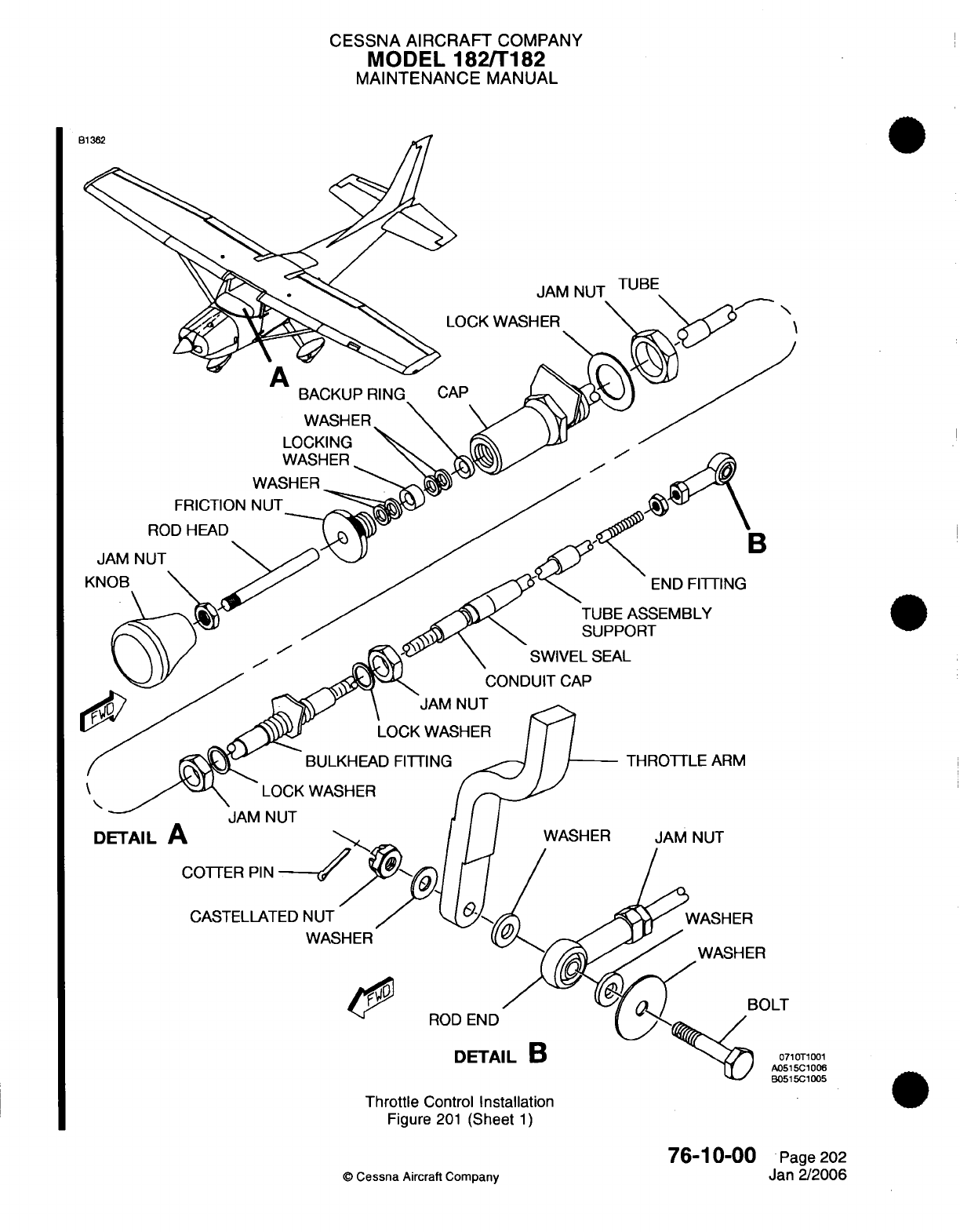
CESSNA
AIRCRAFT
COMPANY
MODEL
182/T182
MAINTENANCE
MANUAL
WASHER
WASHER
FRICTION
NUT
ROD HEAD
JAM
NUT
KNOB
\
T1001
31006
:i
005
Throttle
Control
Installation
Figure
201
(Sheet
1)
©
Cessna
Aircraft
Company
76-10-00
Page
202
Jan
2/2006
C10.0_5.__
CESSNA
AIRCRAFT
COMPANY
MODEL
182/T182
MAINTENANCE
MANUAL
(2)
Push
the
throttle
control knob
full
in
and
check
that
the
full power stop
on
the
throttle
body
makes
contact.
(3)
Do
a
check
to
make
sure
that
the
throttle
has no
less than
0.125-inch
(3.18
mm)
and
no
more
than
0.25-inch
(6.35
mm)
cushion
at
each stop.
(4)
Work
the
throttle
control
in
and
out
until
you can make
sure
that
it
moves
freely.
B.
Throttle
Control
Adjustment
(Refer
to
Figure
201).
(1)
Disconnect the throttle control
rod
end from
the throttle
arm.
(2)
Loosen
the
jam
nut
and
adjust
the
throttle control
rod
end
to
get
the
necessary
adjustment.
(3)
Tighten
the
jam
nut.
(4)
Connect
the
throttle control
rod
end
to
the
throttle
arm.
Torque
the
nut
to
30
inch
pounds
and
then
continue
to
tighten
the
nut
until
the
cotter
pin
hole
aligns
with
the
castellations
in
the
nut.
Do
not
torque
the nut to
more
than
50
inch
pounds.
(5)
Install the
cotter
pin.
4.
Throttle Control
Inspection/Check
A.
Throttle
Control
Inspection
(1)
Do
a
check
of
the
throttle
control
attachment
to
the
throttle body.
Make
sure
that
the
bolt,
castellated
nut,
cotter
pin,
rod
end,
and
rod
end jam
nut
are
correctly
attached
and
in
good
condition.
(2)
Do a
check
of
the
rod
end
witness
hole
for
proper
rod
end
engagement
with
the
throttle
control.
(3)
Make
sure
that
the throttle control moves
smoothly
through
the
full
range
of
travel.
(4)
Make
sure
that
the
throttle
control
locks
correctly
and
tightly
with
the
friction lock.
(5)
Make
sure
that
the
throttle
arm
operates
correctly
through
the
full
range
of
travel.
76-10-00
Page
203
©
Cessna
Aircraft
Company
Jan
2/2006
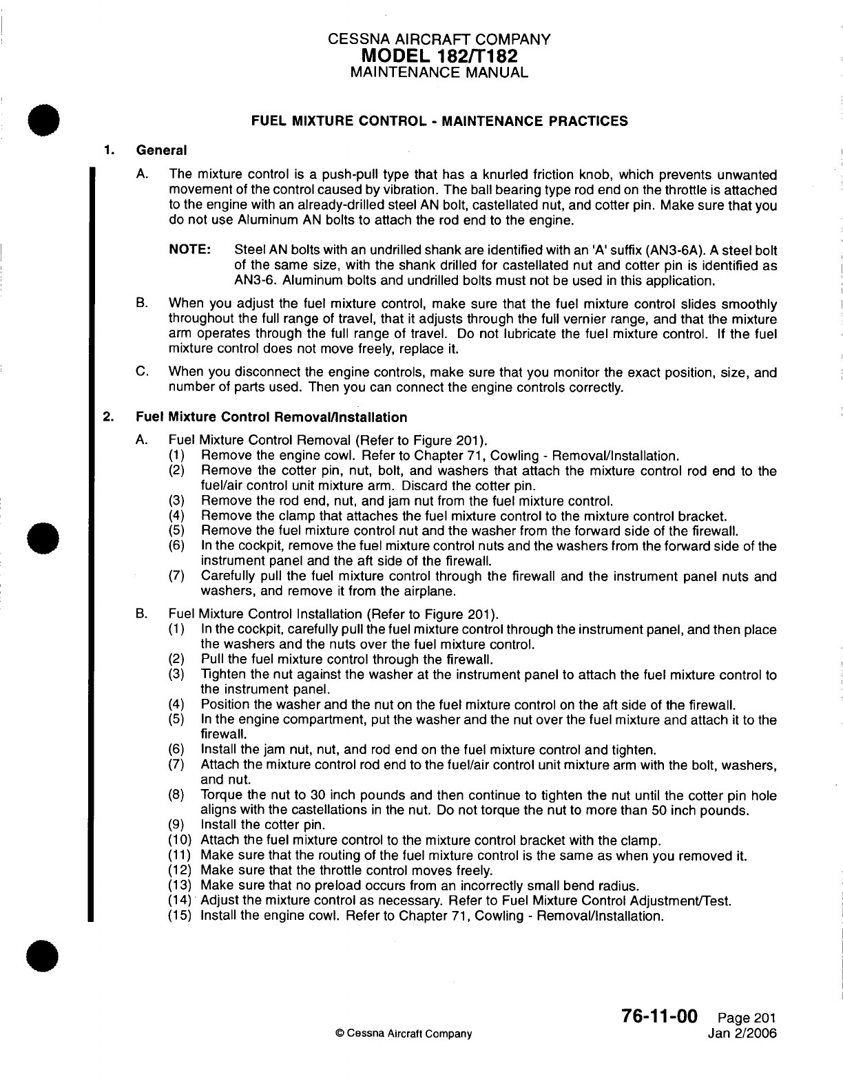
CESSNA
AIRCRAFT
COMPANY
MODEL
182/T182
MAINTENANCE
MANUAL
FUEL MIXTURE
CONTROL
-
MAINTENANCE
PRACTICES
1.
General
A.
The
mixture control
is
a
push-pull type
that
has
a
knurled
friction
knob,
which
prevents unwanted
movement
of
the control
caused
by
vibration.
The
ball
bearing
type
rod
end
on
the
throttle
is
attached
to
the
engine
with an
already-drilled
steel
AN
bolt,
castellated
nut,
and
cotter
pin.
Make
sure
that
you
do
not
use
Aluminum
AN
bolts to
attach
the
rod end
to the
engine.
NOTE:
Steel
AN
bolts
with
an
undrilled
shank
are
identified
with
an 'A'
suffix
(AN3-6A).
A
steel
bolt
of the
same
size,
with
the
shank drilled
for
castellated nut
and
cotter
pin is
identified
as
AN3-6.
Aluminum
bolts
and
undrilled
bolts
must
not
be
used
in
this
application.
B.
When
you
adjust
the
fuel
mixture
control,
make
sure
that
the
fuel
mixture
control
slides
smoothly
throughout
the
full
range
of
travel,
that
it
adjusts
through the
full
vernier
range,
and
that
the
mixture
arm
operates through
the
full
range
of
travel.
Do
not
lubricate
the
fuel
mixture
control.
If
the
fuel
mixture
control
does
not
move
freely,
replace
it.
C.
When
you
disconnect
the
engine controls,
make
sure
that
you
monitor
the
exact position,
size,
and
number
of parts
used.
Then
you
can
connect
the engine
controls
correctly.
2.
Fuel
Mixture
Control Removal/Installation
A.
Fuel
Mixture Control
Removal
(Refer
to
Figure
201).
(1)
Remove
the
engine
cowl. Refer
to
Chapter
71,
Cowling
-
Removal/Installation.
(2)
Remove
the
cotter
pin,
nut,
bolt,
and
washers
that
attach
the
mixture
control
rod
end
to the
fuel/air
control
unit
mixture
arm.
Discard
the
cotter
pin.
(3)
Remove
the
rod end,
nut,
and
jam
nut
from
the
fuel
mixture
control.
(4)
Remove
the
clamp
that
attaches
the
fuel mixture
control
to
the mixture
control
bracket.
(5)
Remove
the
fuel mixture
control
nut
and
the washer
from
the
forward side
of
the
firewall.
(6) In
the
cockpit,
remove
the
fuel
mixture
control
nuts
and
the
washers
from
the
forward side
of
the
instrument
panel
and
the aft side
of
the
firewall.
(7)
Carefully
pull
the
fuel
mixture
control through
the
firewall
and
the
instrument
panel
nuts
and
washers,
and
remove
it
from
the
airplane.
B.
Fuel
Mixture
Control
Installation
(Refer
to
Figure
201).
(1) In
the
cockpit,
carefully
pull the
fuel
mixture
control
through the
instrument
panel,
and
then
place
the
washers
and
the
nuts
over
the
fuel mixture
control.
(2)
Pull
the
fuel
mixture control
through
the firewall.
(3)
Tighten the
nut
against
the
washer
at
the
instrument
panel to
attach
the
fuel mixture
control
to
the
instrument
panel.
(4)
Position
the
washer
and
the
nut
on
the
fuel mixture
control
on
the
aft
side
of
the
firewall.
(5) In
the engine compartment,
put the
washer
and
the
nut
over
the
fuel
mixture
and
attach
it
to
the
firewall.
(6)
Install the
jam nut,
nut,
and
rod
end
on
the
fuel
mixture control and tighten.
(7)
Attach
the
mixture
control
rod end
to the
fuel/air
control
unit
mixture
arm
with
the
bolt,
washers,
and nut.
(8)
Torque
the
nut to 30
inch
pounds
and
then continue
to
tighten
the
nut
until
the
cotter
pin
hole
aligns
with
the
castellations
in
the
nut.
Do
not
torque
the
nut
to
more
than
50 inch
pounds.
(9)
Install
the
cotter
pin.
(10)
Attach
the
fuel
mixture
control
to
the
mixture
control
bracket
with
the
clamp.
(11)
Make
sure
that
the
routing
of the
fuel mixture control
is
the
same
as
when you
removed
it.
(12)
Make
sure
that
the
throttle
control moves freely.
(13)
Make
sure
that
no
preload
occurs
from
an
incorrectly
small
bend radius.
(14)
Adjust
the mixture
control
as
necessary. Refer
to
Fuel
Mixture Control
Adjustment/Test.
(15)
Install
the engine
cowl.
Refer
to
Chapter
71,
Cowling
-
Removal/Installation.
76-11-00
Page
201
©
Cessna
Aircraft
Company
Jan 2/2006
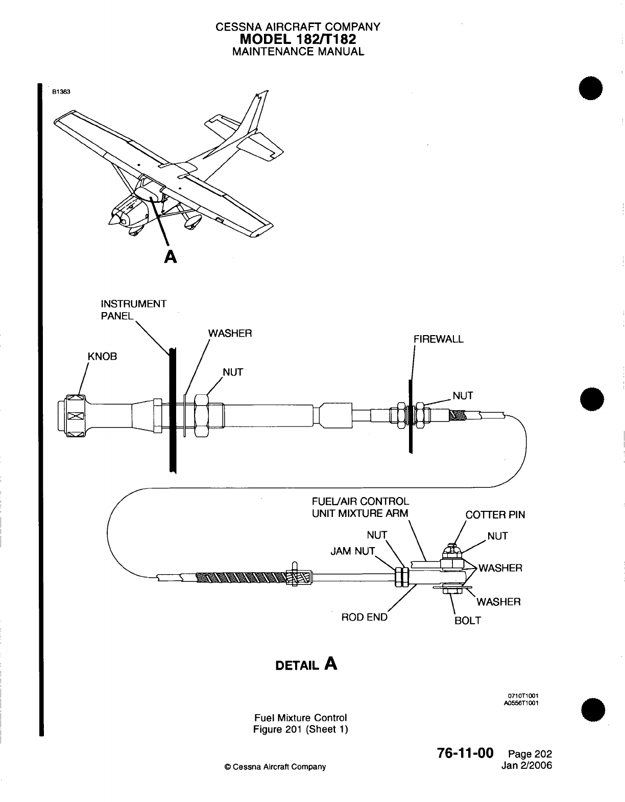
CESSNA AIRCRAFT
COMPANY
MODEL
182/T182
MAINTENANCE
MANUAL
A
INSTRUMENT
PANEL
KNOB
FUELAIR
CONTROL
UNIT
MIXTURE ARM
BOLT
DETAIL
A
0710T1001
A0556T1001
Fuel Mixture
Control
Figure
201
(Sheet
1)
76-11-00
©
Cessna
Aircraft
Company
FIREWALL
NUT
Page
202
Jan 2/2006
R
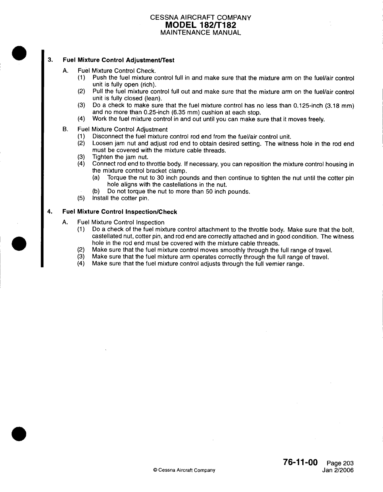
CESSNA
AIRCRAFT
COMPANY
MODEL
182/T182
MAINTENANCE
MANUAL
3.
Fuel
Mixture
Control Adjustment/Test
A.
Fuel
Mixture Control
Check.
(1)
Push
the
fuel
mixture
control
full
in
and make
sure
that
the
mixture
arm
on
the
fuel/air
control
unit
is
fully
open
(rich).
(2)
Pull
the
fuel
mixture
control full
out
and
make sure
that
the
mixture
arm
on
the
fuel/air
control
unit
is
fully
closed
(lean).
(3)
Do
a
check
to
make
sure
that
the
fuel mixture
control
has
no
less
than
0.125-inch
(3.18
mm)
and
no more
than 0.25-inch
(6.35
mm)
cushion
at
each stop.
(4)
Work the
fuel
mixture
control
in
and
out
until
you
can
make sure
that
it
moves
freely.
B.
Fuel
Mixture
Control Adjustment
(1)
Disconnect the
fuel
mixture
control
rod
end
from
the
fuel/air
control
unit.
(2)
Loosen
jam
nut and
adjust
rod
end
to
obtain
desired setting.
The
witness
hole
in
the
rod
end
must
be
covered
with
the
mixture cable
threads.
(3)
Tighten
the
jam
nut.
(4)
Connect
rod
end
to
throttle
body.
If
necessary,
you
can
reposition
the
mixture
control housing
in
the
mixture
control
bracket
clamp.
(a)
Torque
the
nut
to
30 inch
pounds
and
then
continue
to
tighten
the
nut until
the
cotter
pin
hole
aligns
with
the
castellations
in
the
nut.
(b)
Do
not
torque
the nut
to
more
than
50
inch
pounds.
(5)
Install
the
cotter
pin.
4.
Fuel
Mixture
Control Inspection/Check
A.
Fuel
Mixture
Control
Inspection
(1)
Do
a
check
of the
fuel
mixture
control attachment
to
the
throttle
body.
Make
sure
that
the
bolt,
castellated
nut,
cotter
pin,
and
rod
end
are
correctly
attached
and
in
good
condition.
The
witness
hole
in
the
rod
end
must
be
covered
with the
mixture cable
threads.
(2)
Make sure
that
the
fuel
mixture
control moves
smoothly
through
the
full range
of
travel.
(3)
Make
sure
that
the
fuel
mixture
arm
operates
correctly
through the
full
range of
travel.
(4)
Make
sure
that
the
fuel mixture
control
adjusts
through
the
full
vernier
range.
76-11-00
Page
203
©
Cessna Aircraft Company
Jan
2/2006
CHAPTER
ENGINE
INDICATING
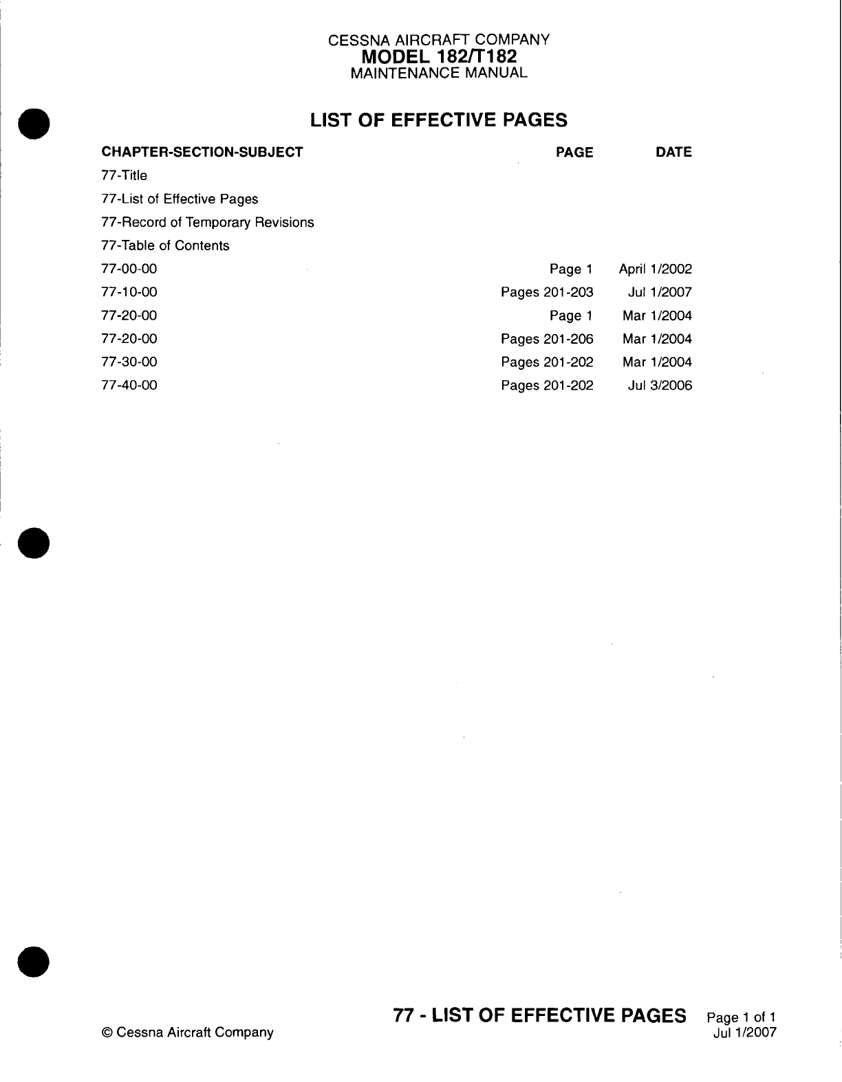
CESSNA
AIRCRAFT
COMPANY
MODEL
182/T182
MAINTENANCE
MANUAL
LIST
OF
EFFECTIVE
PAGES
CHAPTER-SECTION-SUBJECT
77-Title
77-List
of
Effective
Pages
77-Record
of
Temporary
Revisions
77-Table
of
Contents
77-00-00
77-10-00
77-20-00
77-20-00
77-30-00
77-40-00
©
Cessna Aircraft
Company
PAGE
Page
1
Pages
201-203
Page
1
Pages
201
-206
Pages
201-202
Pages
201
-202
DATE
April
1/2002
Jul
1/2007
Mar
1/2004
Mar
1/2004
Mar
1/2004
Jul
3/2006
77
-
LIST
OF
EFFECTIVE PAGES
Page
1
of
1
Jul
1/2007
Temporary
Revision
Number
RECORD
OF
TEMPORARY REVISIONS
Page
Number
Issue
Date
By
Date
Removed
By
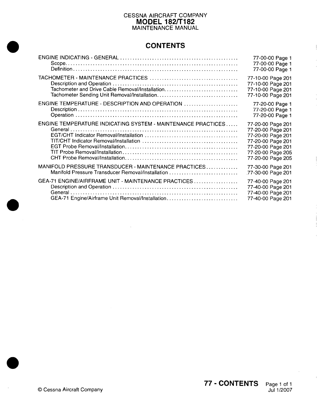
CESSNA AIRCRAFT
COMPANY
MODEL
182/Ti
82
MAINTENANCE
MANUAL
CONTENTS
ENGINE
INDICATING
-
GENERAL.........................
Scope....................................
Definition
..................................
TACHOMETER
-
MAINTENANCE
PRACTICES...................
Description
and
Operation
..........................
Tachometer
and
Drive
Cable
Removal/installation................
Tachometer
Sending
Unit
Removal/Installation
.................
ENGINE TEMPERATURE
-
DESCRIPTION
AND
OPERATION............
Description
.................................
Operation..................................
ENGINE TEMPERATURE
INDICATING
SYSTEM
-
MAINTENANCE PRACTICES.
General...................................
EGT/CHT
Indicator
Removal/Installation....................
TIT/CHT
Indicator Removal/Installation
....................
EGT
Probe
Removal/Installation........................
TIT
Probe
Removal/Installation
........................
CHT
Probe
Removal/Installation........................
MANIFOLD
PRESSURE
TRANSDUCER
-
MAINTENANCE
PRACTICES
.......
Manifold
Pressure
Transducer
Removal/installation...............
GEA-71
ENGINE/AIRFRAME
UNIT
-
MAINTENANCE
PRACTICES..........
Description
and
Operation
..........................
General...................................
G
EA-71
Engine/Airframe
Unit
Removal/Installation
...............
77-00-00
Page
1
77-00-00
Page
1
77-00-00
Page
1
77-1
0-00
Page
201
77-1
0-00
Page
201
77-1
0-00
Page
201
77-1
0-00
Page
201
77-20-00
Page
1
77-20-00
Page
1
77-20-00
Page
1
77-20-00
Page
201
77-20-00
Page
201
77-20-00
Page
201
77-20-00
Page
201
77-20-00
Page
201
77-20-00
Page
205
77-20-00
Page
205
77-30-00
Page
201
.77-30-00
Page
201
77-40-00
Page
201
77-40-00
Page
201
77-40-00
Page
201
77-40-00
Page
201
77
-
CONTENTS
Page
1
of
1
Jul
1/2007
©0
Cessna
Aircraft
Company
CESSNA
AIRCRAFT
COMPANY
MODEL
182/T182
MAINTENANCE
MANUAL
ENGINE
INDICATING
-
GENERAL
1.
Scope
A.
This
chapter tells
how
the
components
are used
to
measure
and
show
engine
output.
2.
Definition
A.
The
sections
divided
in
this
chapter
help
the
maintenance
technicians
to
find
information. Refer
the
Table
of
Contents
to
further
help
locate
the
applicable
subject.
(1)
The
section
about
the
tachometer
tells
how
the
engine
RPM
is
measured.
(2)
The
section
on
the
engine temperature system
tells
how
the engine
temperature
is
monitored
and
measured.
77-00-00
Page
1
©
Cessna
Aircraft Company
April 1/2002
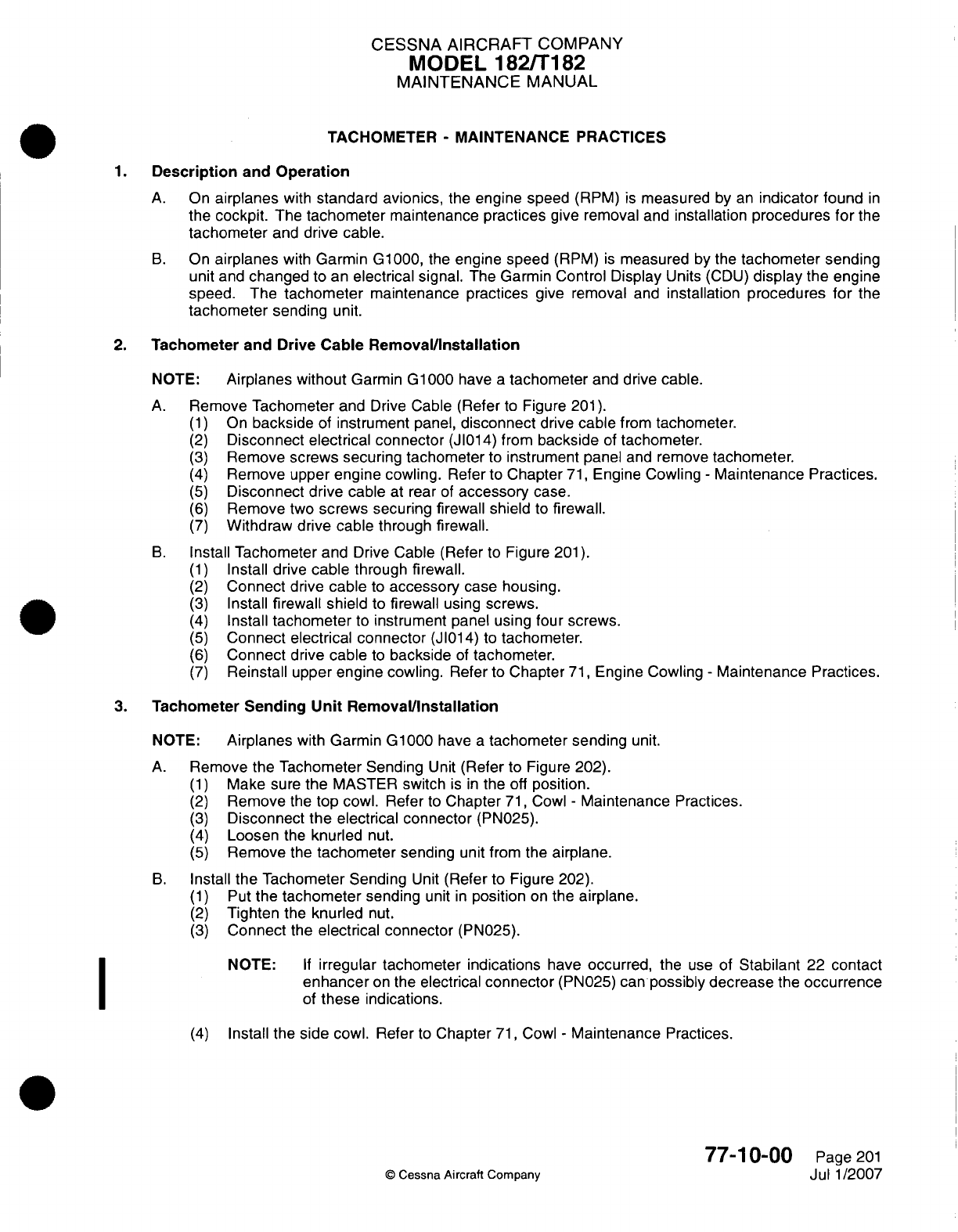
CESSNA
AIRCRAFT
COMPANY
MODEL
182/Ti
82
MAINTENANCE
MANUAL
TACHOMETER
-
MAINTENANCE PRACTICES
1.
Description
and
Operation
A.
On
airplanes
with
standard
avionics,
the
engine speed
(RPM)
is
measured
by
an
indicator
found
in
the
cockpit.
The
tachometer
maintenance
practices
give
removal
and
installation
procedures
for
the
tachometer
and
drive cable.
B.
On
airplanes
with
Garmin
G1000,
the
engine speed
(RPM)
is
measured
by the
tachometer
sending
unit
and
changed
to
an
electrical
signal.
The Garmin
Control
Display
Units
(CDU)
display
the
engine
speed. The
tachometer
maintenance practices
give
removal
and
installation procedures
for
the
tachometer
sending
unit.
2.
Tachometer
and
Drive
Cable
Removal/installation
NOTE:
Airplanes
without
Garmin
G1000
have
a
tachometer
and
drive
cable.
A.
Remove
Tachometer
and
Drive
Cable
(Refer
to
Figure 201).
(1)
On
backside
of
instrument
panel,
disconnect
drive
cable
from
tachometer.
(2)
Disconnect
electrical
connector
(J1014)
from
backside
of
tachometer.
(3)
Remove
screws securing
tachometer
to
instrument
panel
and
remove
tachometer.
(4)
Remove
upper
engine
cowling.
Refer
to
Chapter
71,
Engine
Cowling
-
Maintenance
Practices.
(5)
Disconnect drive
cable
at rear
of
accessory
case.
(6)
Remove
two
screws
securing
firewall shield
to
firewall.
(7)
Withdraw
drive
cable
through
firewall.
B.
Install
Tachometer
and
Drive
Cable
(Refer
to
Figure
201).
(1)
Install drive
cable
through
firewall.
(2)
Connect
drive
cable
to
accessory
case
housing.
(3)
Install
firewall
shield
to
firewall
using
screws.
(4)
Install
tachometer
to
instrument
panel using
four
screws.
(5)
Connect
electrical
connector
(J
101
4)
to
tachometer.
(6)
Connect
drive
cable
to
backside
of
tachometer.
(7)
Reinstall upper engine cowling.
Refer
to
Chapter
71,
Engine
Cowling
-
Maintenance
Practices.
3.
Tachometer
Sending
Unit
RemovaVlnstallation
NOTE:
Airplanes
with
Garmin
G
1000
have
a
tachometer sending
unit.
A.
Remove
the Tachometer
Sending
Unit
(Refer
to
Figure 202).
(1)
Make
sure
the
MASTER
switch
is in
the
off
position.
(2)
Remove
the
top cowl.
Refer
to
Chapter
71,
Cowl
-
Maintenance
Practices.
(3)
Disconnect
the
electrical connector
(PN025).
(4)
Loosen
the
knurled
nut.
(5)
Remove
the
tachometer
sending
unit
from the
airplane.
B.
Install
the Tachometer
Sending
Unit
(Refer
to
Figure
202).
(1)
Put
the
tachometer
sending
unit
in
position
on
the
airplane.
(2)
Tighten
the
knurled
nut.
(3)
Connect
the
electrical connector
(PN025).
NOTE:
If
irregular
tachometer
indications
have
occurred,
the
use
of
Stabilant
22
contact
enhancer
on
the
electrical
connector
(PN025)
can
possibly
decrease
the
occurrence
of
these
indications.
(4)
Install
the
side
cowl.
Refer
to
Chapter
71,
Cowl
-
Maintenance
Practices.
77-1
0-00
Page
201
©
Cessna
Aircraft Company
Jul
1
/2007
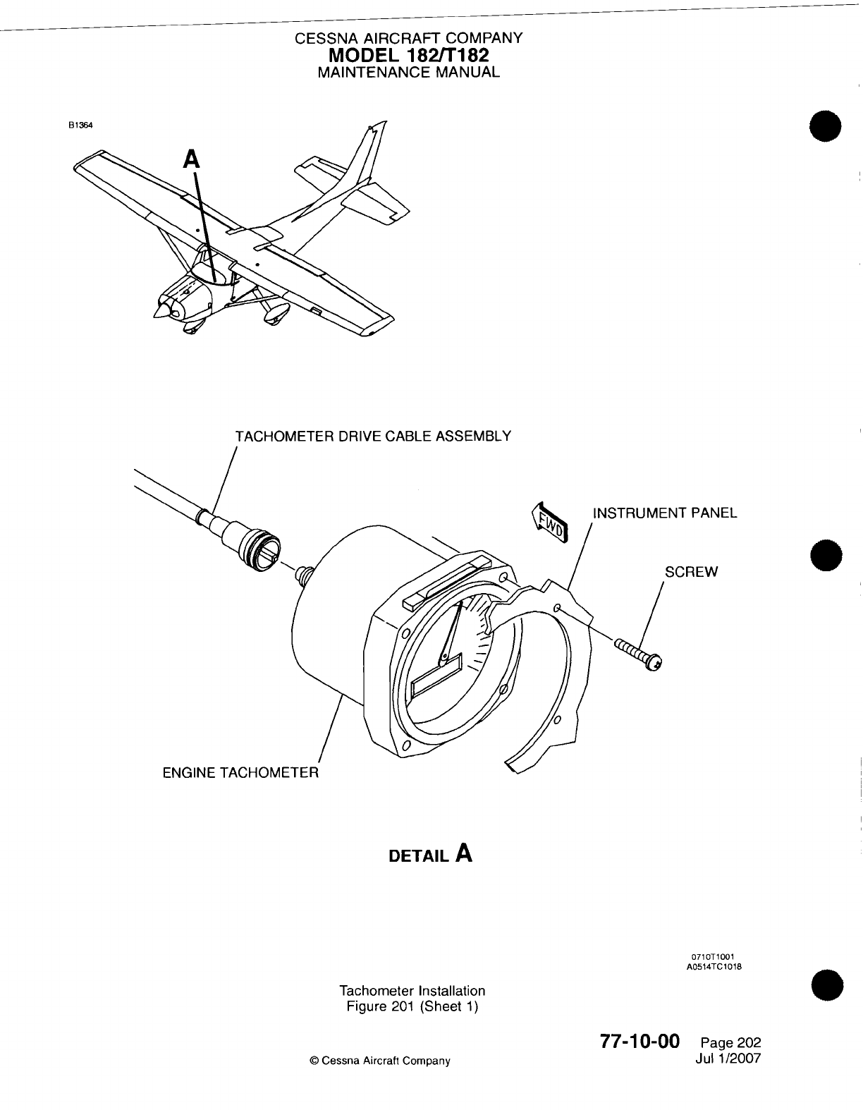
CESSNA AIRCRAFT
COMPANY
MODEL
182/Ti
182
MAINTENANCE
MANUAL
TACHOMETER
DRIVE
CABLE
ASSEMBLY
:NT
PANEL
SCREW
DETAIL
A
071 OTi1001
A05
14TC
1018
Tachometer
Installation
Figure
201
(Sheet
1)
77-1
0-00
©
Cessna
Aircraft
Company
0
Page 202
Jul
1/2007
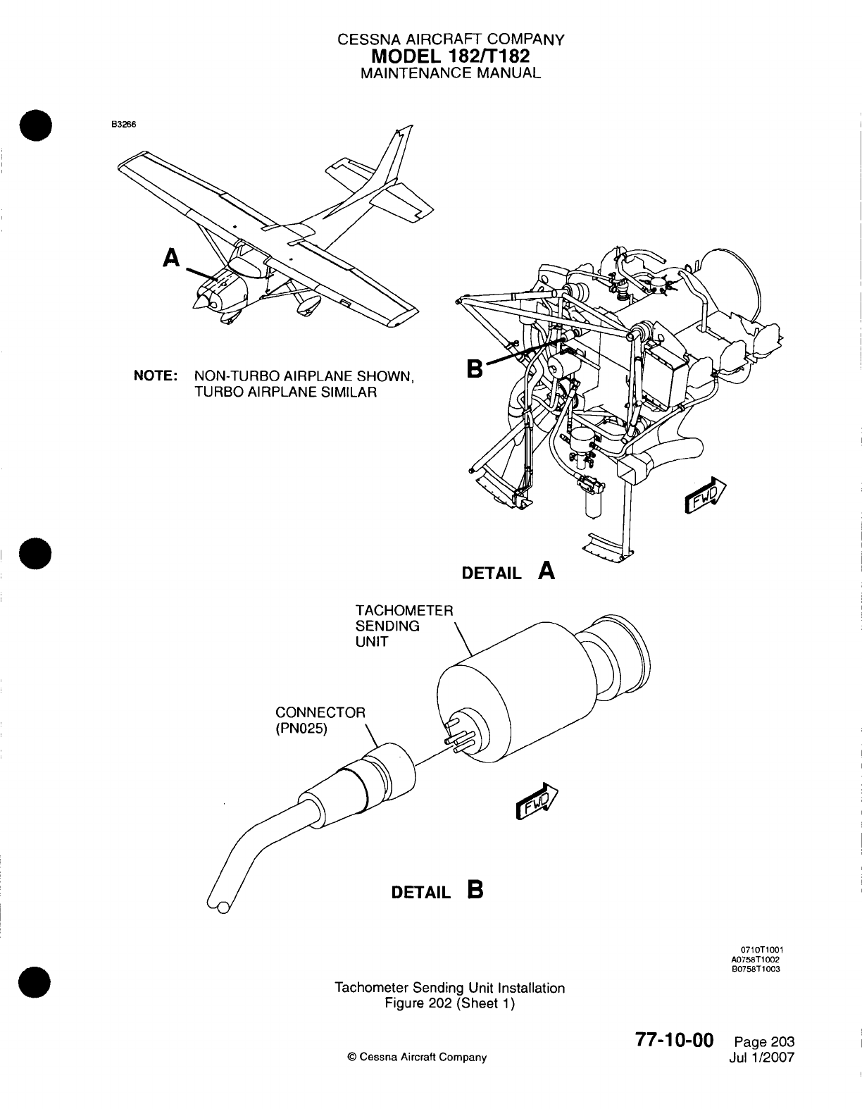
CESSNA
AIRCRAFT COMPANY
MODEL
182/Ti
82
MAINTENANCE
MANUAL
NOTE:
NON-TURBO
AIRPLANE
SHOWN,
TURBO AIRPLANE
SIMILAR
DETAIL
A
TACHOMETE
R
DETAIL
B
0710T1001
A0758T
1002
B0758T1003
Tachometer
Sending
Unit
Installation
Figure 202
(Sheet
1)
77-1
0-00
©
Cessna
Aircraft Company
Page
203
Jul
1/2007
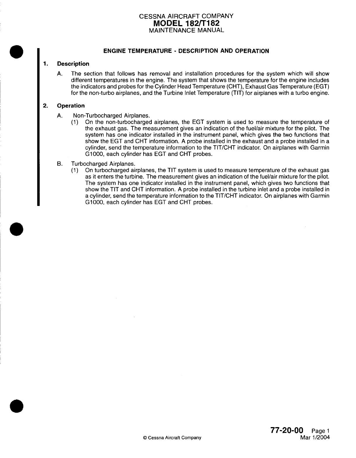
CESSNA
AIRCRAFT
COMPANY
MODEL
182/T182
MAINTENANCE
MANUAL
ENGINE
TEMPERATURE
-
DESCRIPTION AND OPERATION
1.
Description
A.
The
section
that follows
has
removal
and
installation procedures
for
the
system
which
will
show
different
temperatures
in
the
engine. The system that
shows
the
temperature
for
the
engine includes
the
indicators
and
probes
for
the Cylinder
Head
Temperature
(CHT),
Exhaust
Gas
Temperature
(EGT)
for
the
non-turbo airplanes,
and the
Turbine
Inlet Temperature
(TIT)
for
airplanes
with
a
turbo
engine.
2.
Operation
A.
Non-Turbocharged
Airplanes.
(1)
On
the non-turbocharged airplanes,
the
EGT
system
is
used
to
measure
the
temperature
of
the
exhaust
gas.
The
measurement gives
an
indication
of
the
fuel/air
mixture for
the
pilot.
The
system
has
one
indicator
installed
in
the instrument
panel,
which
gives
the
two
functions
that
show
the
EGT
and
CHT
information.
A
probe installed
in
the exhaust
and
a
probe
installed
in
a
cylinder,
send
the
temperature
information
to
the TIT/CHT indicator.
On
airplanes
with
Garmin
G1000, each
cylinder
has
EGT
and
CHT
probes.
B.
Turbocharged Airplanes.
(1)
On
turbocharged airplanes,
the
TIT
system
is
used
to
measure
temperature of
the
exhaust
gas
as
it
enters
the turbine. The measurement gives
an
indication
of
the
fuel/air mixture
for
the pilot.
The system
has
one
indicator
installed
in
the
instrument
panel,
which
gives
two
functions
that
show
the
TIT
and
CHT information.
A
probe
installed
in
the
turbine
inlet
and
a
probe
installed
in
a
cylinder,
send
the
temperature
information
to
the
TIT/CHT
indicator.
On
airplanes
with
Garmin
G1000, each
cylinder
has
EGT
and
CHT
probes.
77-20-00
Page
1
©
Cessna Aircraft Company
Mar 1/2004
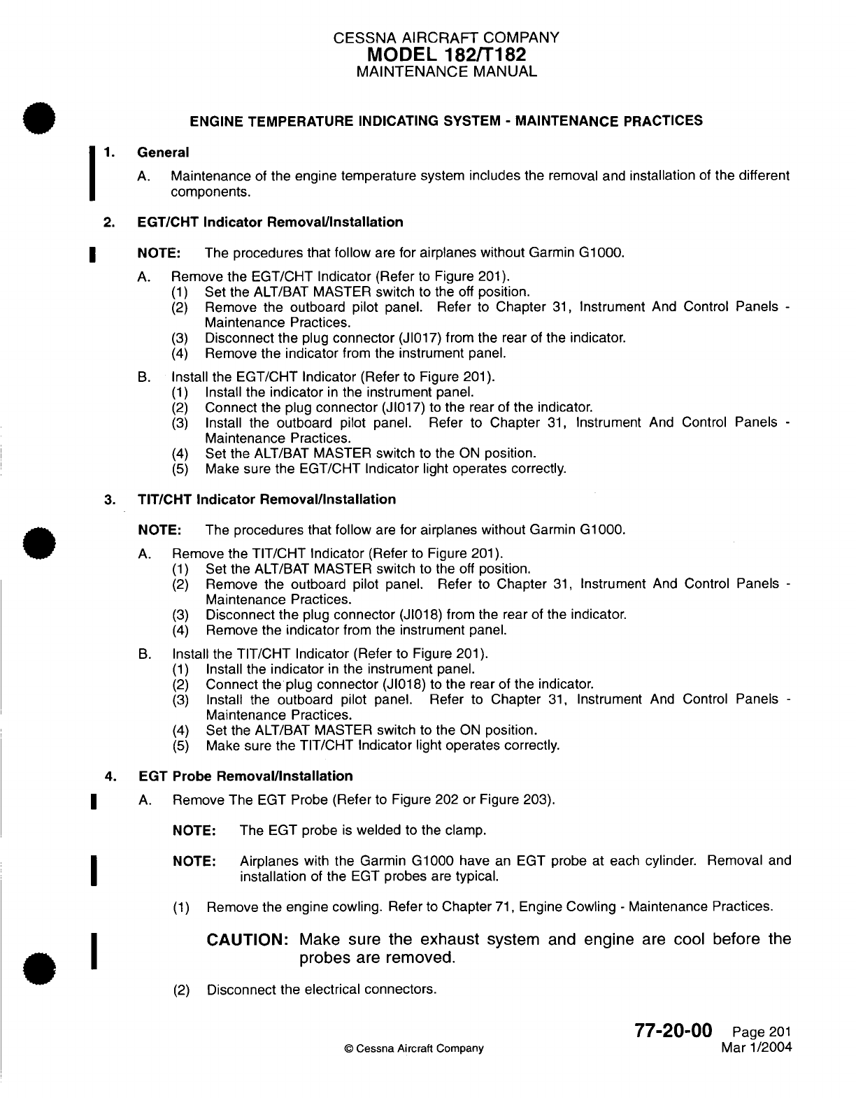
CESSNA AIRCRAFT
COMPANY
MODEL
182/T182
MAINTENANCE
MANUAL
ENGINE TEMPERATURE
INDICATING
SYSTEM
-
MAINTENANCE
PRACTICES
1.
General
A.
Maintenance
of
the engine temperature system
includes
the
removal and
installation
of
the
different
components.
2.
EGT/CHT
Indicator Removal/Installation
NOTE:
The
procedures
that
follow
are
for airplanes without
Garmin
G1000.
A.
Remove the EGT/CHT
Indicator
(Refer
to Figure
201).
(1)
Set
the ALT/BAT
MASTER
switch
to the
off
position.
(2)
Remove
the
outboard
pilot
panel. Refer
to
Chapter
31,
Instrument
And
Control
Panels
-
Maintenance
Practices.
(3)
Disconnect
the
plug
connector
(JI017) from
the
rear
of
the
indicator.
(4)
Remove
the
indicator
from the
instrument
panel.
B.
Install the EGT/CHT
Indicator
(Refer
to Figure
201).
(1)
Install
the
indicator
in
the instrument
panel.
(2)
Connect
the
plug
connector
(J1017)
to
the
rear of
the
indicator.
(3)
Install
the
outboard
pilot
panel. Refer
to
Chapter
31,
Instrument
And
Control
Panels
-
Maintenance
Practices.
(4)
Set
the
ALT/BAT
MASTER
switch
to
the
ON
position.
(5)
Make
sure
the
EGT/CHT
Indicator
light
operates
correctly.
3.
TIT/CHT
Indicator Removal/Installation
NOTE:
The
procedures
that follow
are
for
airplanes
without
Garmin
G1000.
A.
Remove
the
TIT/CHT
Indicator
(Refer
to Figure
201).
(1)
Set
the
ALT/BAT
MASTER
switch
to the
off
position.
(2)
Remove
the
outboard
pilot
panel.
Refer
to
Chapter
31,
Instrument
And
Control
Panels
-
Maintenance
Practices.
(3)
Disconnect
the
plug
connector
(J1018)
from the rear of the
indicator.
(4)
Remove
the
indicator
from the
instrument panel.
B.
Install
the
TIT/CHT
Indicator
(Refer
to Figure
201).
(1)
Install
the
indicator
in
the
instrument
panel.
(2)
Connect
the plug
connector
(J1018)
to
the
rear of
the indicator.
(3)
Install
the
outboard pilot panel.
Refer
to
Chapter
31,
Instrument
And
Control
Panels
-
Maintenance
Practices.
(4)
Set
the
ALT/BAT
MASTER
switch
to
the
ON
position.
(5)
Make
sure
the
TIT/CHT
Indicator
light
operates correctly.
4.
EGT
Probe
Removal/Installation
A.
Remove The
EGT
Probe
(Refer
to Figure
202
or
Figure
203).
NOTE:
The
EGT
probe
is
welded
to
the clamp.
NOTE:
Airplanes
with
the
Garmin
G1000
have
an
EGT
probe
at each
cylinder.
Removal
and
installation
of
the
EGT
probes
are
typical.
(1)
Remove
the
engine cowling.
Refer
to
Chapter
71,
Engine
Cowling
-
Maintenance
Practices.
CAUTION:
Make
sure
the
exhaust
system
and
engine
are
cool before
the
probes
are
removed.
(2)
Disconnect
the
electrical connectors.
77-20-00
Page
201
©
Cessna
Aircraft
Company
Mar
1/2004
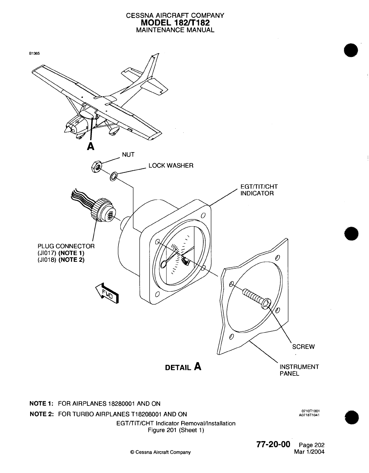
CESSNA
AIRCRAFT
COMPANY
MODEL
182/T182
MAINTENANCE
MANUAL
LOCK
WASHER
Fr'T/TIT/PT-IT
PLUG CONI
(JI017)
(NO0
(JI018)
(NO'
SCREW
DETAIL
A
NOTE
1:
FOR
AIRPLANES
18280001
AND
ON
NOTE
2:
FOR
TURBO AIRPLANES
T18208001
AND
ON
EGT/TIT/CHT
Indicator
Removal/Installation
Figure
201
(Sheet
1)
©
Cessna
Aircraft
Company
INSTRUMENT
PANEL
0710T1001
A0718T1041
77-20-00
Page 202
Mar
1/2004
"'"RK
L3
1h
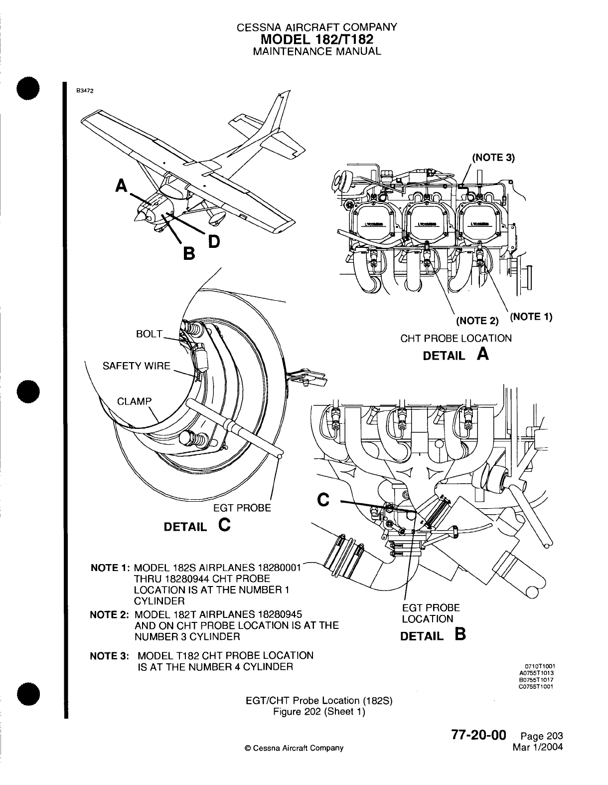
CESSNA
AIRCRAFT
COMPANY
MODEL
182/T182
MAINTENANCE
MANUAL
(NOTE
2)
Nu"-
')
CHT
PROBE
LOCATION
DETAIL
A
EGT
PROBE
DETAIL
C
NOTE
1:
MODEL
182S
AIRPLANES
18280001
THRU
18280944
CHT PROBE
LOCATION
IS
AT THE NUMBER
1
rvl
IMKln'
D
I
LI
I 1
./L
II
NOTE
2:
MODEL
182T
AIRPLANES 18280945
AND
ON
CHT
PROBE
LOCATION
IS
AT
THE
NUMBER
3
CYLINDER
EGT
PROBE
LOCATION
DETAIL
B
NOTE 3:
MODEL
T182
CHT
PROBE LOCATION
IS
AT
THE
NUMBER
4
CYLINDER
EGT/CHT
Probe
Location
(182S)
Figure
202
(Sheet
1)
©
Cessna Aircraft
Company
0710T1001
A0755T1013
B0755T1017
C0755T1001
77-20-00
Page
203
Mar
1/2004
DR...
b
^
4%\
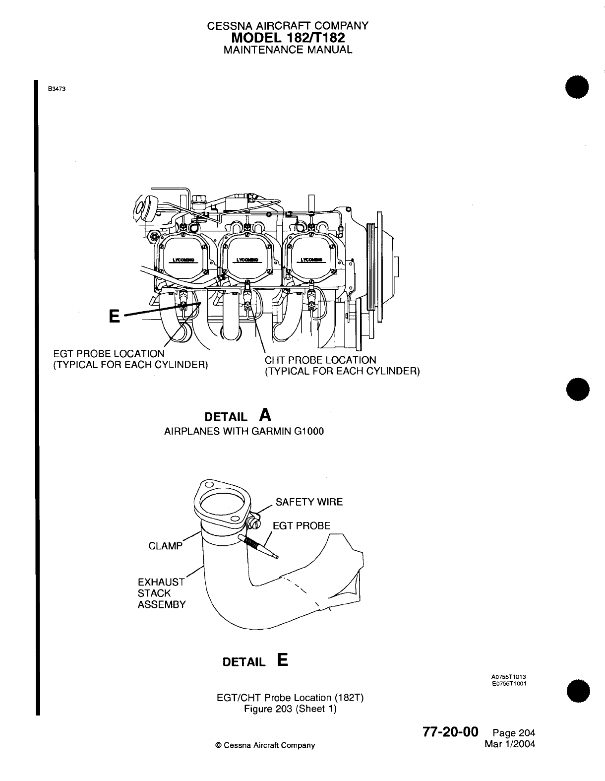
CESSNA AIRCRAFT
COMPANY
MODEL 182/T182
MAINTENANCE
MANUAL
B3473
]
J
E
EC--r
DDODC'
I
r
L(TY
I
CAL
FOR
LV-E
I
vCYI
(TYPICAL
FOR
EACH
CYLINDER)
CHT
PROBE
LOCATION
(TYPICAL
FOR EACH
CYLINDER)
DETAIL
A
AIRPLANES
WITH
GARMIN
G1000
DETAIL
E
A0755T1013
E0755T1001
EGT/CHT
Probe
Location
(182T)
Figure 203 (Sheet
1)
77-20-00
©
Cessna
Aircraft
Company
Page 204
Mar
1/2004
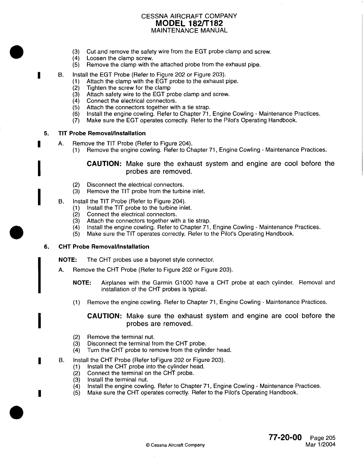
CESSNA
AIRCRAFT
COMPANY
MODEL
182/T182
MAINTENANCE
MANUAL
(3)
Cut
and
remove
the
safety
wire from
the
EGT
probe
clamp
and
screw.
(4)
Loosen
the
clamp screw.
(5)
Remove the clamp with the
attached
probe
from the
exhaust
pipe.
B.
Install
the
EGT Probe
(Refer
to
Figure 202
or
Figure 203).
(1)
Attach
the
clamp
with
the
EGT
probe to the
exhaust
pipe.
(2)
Tighten
the
screw
for
the
clamp
(3)
Attach
safety
wire to
the
EGT
probe
clamp
and
screw.
(4)
Connect
the
electrical
connectors.
(5)
Attach
the
connectors
together
with
a
tie strap.
(6)
Install
the
engine cowling. Refer
to
Chapter
71,
Engine Cowling
-
Maintenance
Practices.
(7)
Make
sure
the
EGT
operates
correctly.
Refer
to
the
Pilot's
Operating
Handbook.
5.
TIT
Probe
Removal/Installation
A.
Remove
the
TIT Probe
(Refer
to
Figure
204).
(1)
Remove
the
engine cowling.
Refer
to
Chapter
71,
Engine
Cowling
-
Maintenance
Practices.
CAUTION:
Make
sure
the
exhaust
system
and
engine
are
cool
before the
probes
are
removed.
(2)
Disconnect
the
electrical
connectors.
(3)
Remove
the
TIT probe
from
the
turbine
inlet.
B.
Install
the
TIT
Probe
(Refer
to
Figure 204).
(1)
Install
the
TIT probe
to the
turbine
inlet.
(2)
Connect
the
electrical
connectors.
(3)
Attach the
connectors together
with
a
tie
strap.
(4)
Install
the engine
cowling.
Refer
to
Chapter
71,
Engine
Cowling
-
Maintenance Practices.
(5)
Make
sure
the
TIT
operates
correctly.
Refer
to the
Pilot's
Operating Handbook.
6.
CHT Probe
Removal/Installation
NOTE:
The CHT
probes
use
a
bayonet
style connector.
A.
Remove
the
CHT Probe
(Refer
to
Figure
202
or
Figure
203).
NOTE:
Airplanes
with
the
Garmin
G1000
have
a
CHT probe
at
each
cylinder.
Removal
and
installation
of
the
CHT
probes
is
typical.
(1)
Remove
the
engine cowling.
Refer
to
Chapter
71,
Engine Cowling
-
Maintenance
Practices.
CAUTION:
Make
sure
the
exhaust
system
and
engine
are
cool
before the
probes
are
removed.
(2)
Remove the
terminal
nut.
(3)
Disconnect
the
terminal
from
the
CHT
probe.
(4)
Turn
the
CHT
probe
to
remove
from the
cylinder
head.
B.
Install
the
CHT
Probe (Refer
toFigure
202
or Figure
203).
(1)
Install the
CHT
probe
into
the
cylinder
head.
(2)
Connect
the
terminal
on
the
CHT probe.
(3)
Install
the
terminal
nut.
(4)
Install
the
engine cowling.
Refer
to
Chapter
71,
Engine Cowling
-
Maintenance
Practices.
|* ~ (5)
Make
sure
the
CHT
operates correctly.
Refer
to
the
Pilot's
Operating Handbook.
77-20-00
Page 205
©
Cessna
Aircraft Company
Mar
1/2004
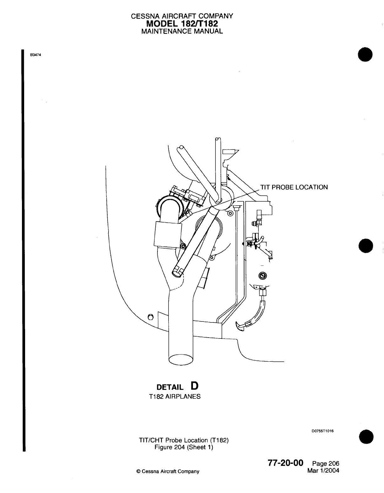
CESSNA
AIRCRAFT
COMPANY
MODEL
182/T182
MAINTENANCE
MANUAL
B3474
'ROBE
LOCATION
DETAIL
D
T182 AIRPLANES
D0755T1016
TIT/CHT
Probe
Location
(T182)
Figure
204
(Sheet
1)
77-20-00
©
Cessna
Aircraft
Company
Page
206
Mar
1/2004
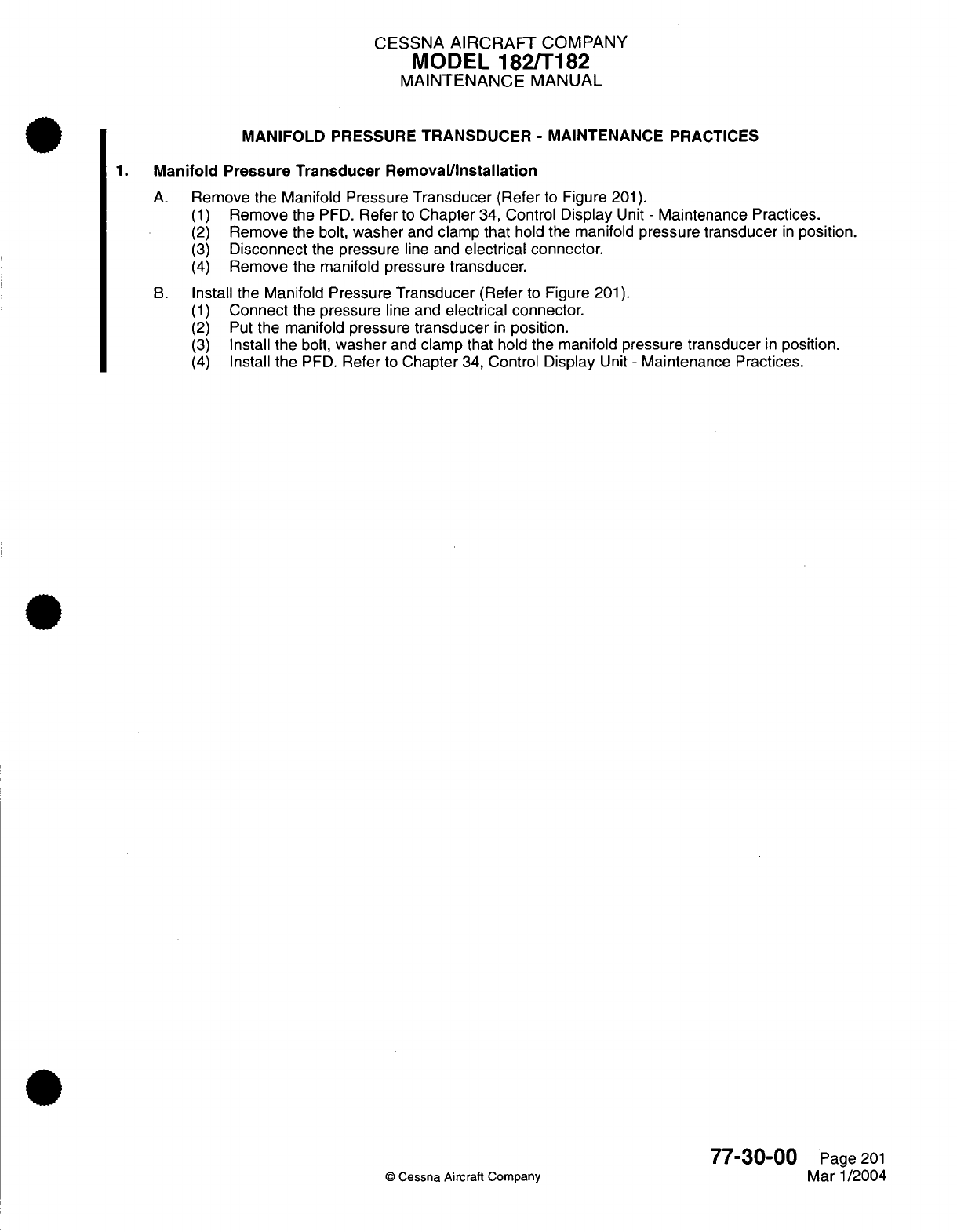
CESSNA
AIRCRAFT
COMPANY
MODEL
182/T182
MAINTENANCE
MANUAL
MANIFOLD
PRESSURE
TRANSDUCER
-
MAINTENANCE
PRACTICES
1.
Manifold
Pressure
Transducer Removal/Installation
A.
Remove
the Manifold
Pressure
Transducer
(Refer
to
Figure
201).
(1)
Remove
the
PFD.
Refer
to
Chapter
34,
Control
Display
Unit
-
Maintenance Practices.
(2)
Remove the
bolt,
washer
and
clamp
that
hold
the
manifold
pressure transducer
in
position.
(3)
Disconnect
the
pressure
line and
electrical connector.
(4)
Remove the manifold pressure
transducer.
B.
Install the Manifold Pressure
Transducer
(Refer
to
Figure
201).
(1)
Connect the
pressure
line
and
electrical
connector.
(2)
Put
the manifold
pressure
transducer
in
position.
(3)
Install the
bolt,
washer
and
clamp
that
hold
the
manifold
pressure transducer
in
position.
(4)
Install
the
PFD.
Refer
to
Chapter
34,
Control
Display
Unit
-
Maintenance Practices.
77-30-00
Page
201
©
Cessna
Aircraft
Company
Mar
1/2004
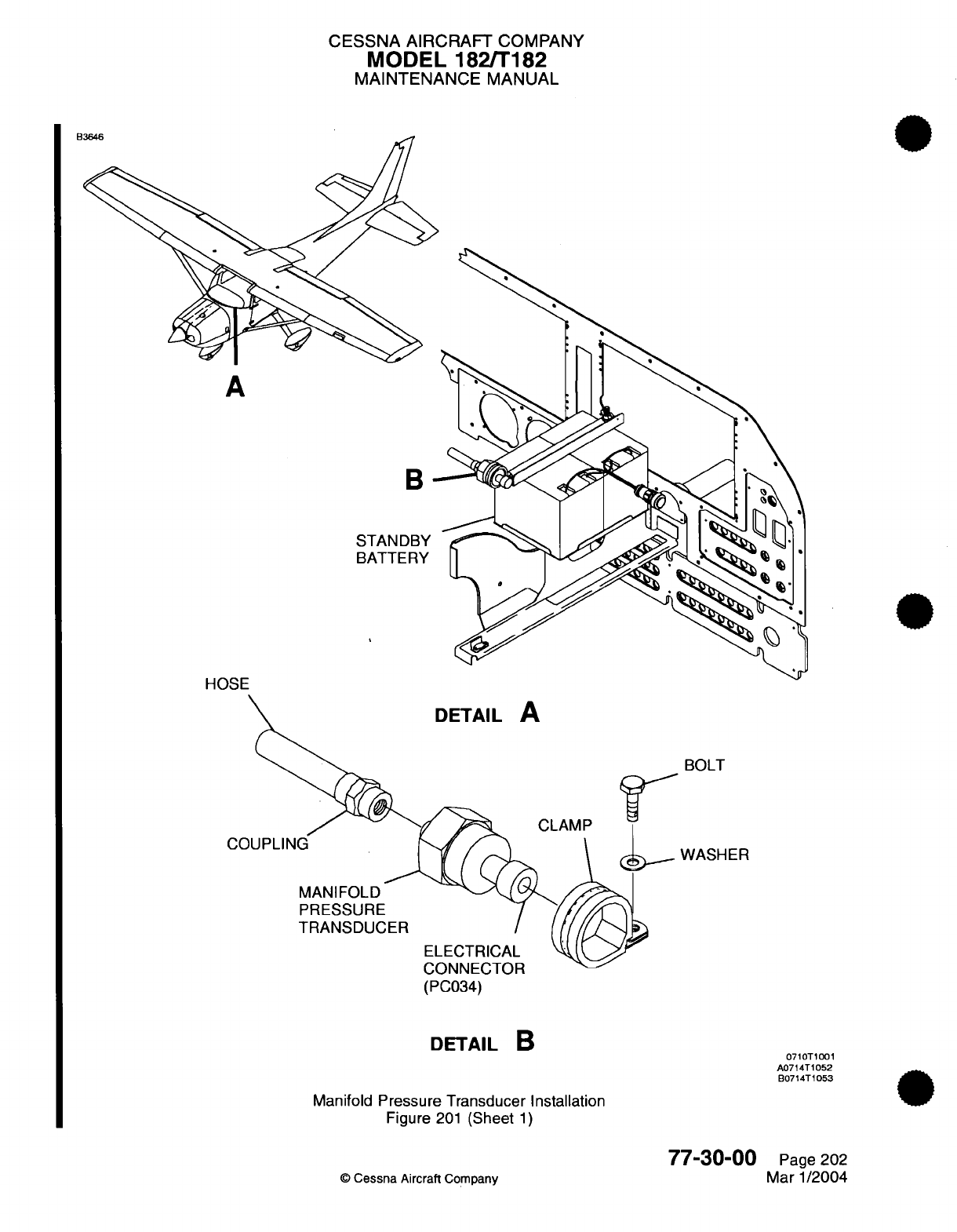
CESSNA
AIRCRAFT
COMPANY
MODEL
182/T182
MAINTENANCE
MANUAL
A
B
STANDBY
BATTERY
HOSE
DETAIL
A
/`SA
CLAMP
MANIFOLD
PRESSURE
TRANSDUCER
(PC034)
DETAIL
B
Manifold
Pressure
Transducer
Installation
Figure
201
(Sheet
1)
77-30-00
©
Cessna
Aircraft
Company
BOLT
WASHER
0710T1001
A0714T1052
B0714T1053
Page
202
Mar
1/2004
"^OAO
d
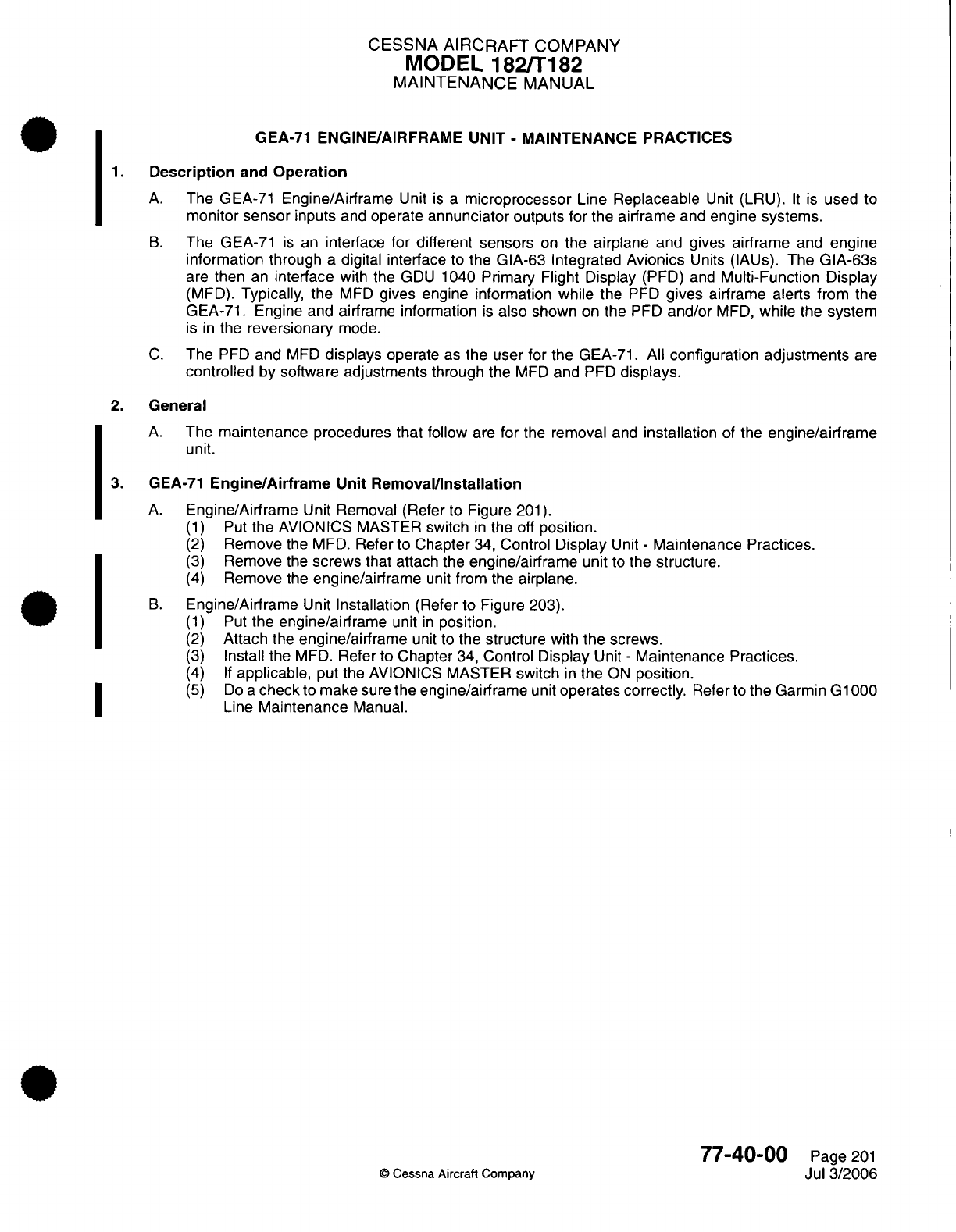
CESSNA
AIRCRAFT
COMPANY
MODEL
182/T182
MAINTENANCE
MANUAL
GEA-71
ENGINE/AIRFRAME
UNIT- MAINTENANCE PRACTICES
1.
Description
and
Operation
A.
The
GEA-71
Engine/Airframe
Unit
is a
microprocessor
Line
Replaceable
Unit
(LRU).
It
is
used
to
monitor
sensor
inputs
and
operate
annunciator
outputs for
the airframe
and
engine
systems.
B.
The
GEA-71
is
an
interface
for different sensors
on
the
airplane
and
gives
airframe
and
engine
information
through
a
digital interface
to
the
GIA-63
Integrated
Avionics
Units
(IAUs).
The
GIA-63s
are
then
an
interface
with
the
GDU
1040
Primary
Flight Display
(PFD)
and
Multi-Function
Display
(MFD).
Typically, the
MFD
gives
engine
information
while
the
PFD
gives
airframe alerts from
the
GEA-71.
Engine and
airframe information
is
also
shown
on
the
PFD
and/or
MFD,
while
the system
is
in
the
reversionary
mode.
C.
The
PFD
and
MFD
displays
operate
as
the
user
for
the
GEA-71.
All
configuration
adjustments
are
controlled
by
software
adjustments
through
the
MFD
and
PFD
displays.
2.
General
A.
The
maintenance
procedures that
follow
are
for
the
removal
and
installation
of
the
engine/airframe
unit.
3.
GEA-71
Engine/Airframe
Unit
Removal/Installation
A.
Engine/Airframe
Unit
Removal
(Refer to
Figure
201).
(1)
Put
the
AVIONICS MASTER
switch
in
the
off
position.
(2)
Remove
the
MFD.
Refer
to
Chapter
34, Control
Display
Unit
-
Maintenance Practices.
(3)
Remove
the
screws
that attach
the
engine/airframe
unit
to
the
structure.
(4)
Remove
the
engine/airframe
unit
from
the
airplane.
B.
Engine/Airframe
Unit
Installation
(Refer
to Figure 203).
(1)
Put
the
engine/airframe
unit
in
position.
(2)
Attach
the
engine/airframe
unit
to
the
structure with
the
screws.
(3)
Install
the
MFD.
Refer
to
Chapter
34,
Control
Display
Unit
-
Maintenance Practices.
(4)
If
applicable,
put the
AVIONICS
MASTER
switch
in
the
ON
position.
(5)
Do
a
check
to
make
sure
the
engine/airframe
unit
operates
correctly.
Refer to
the Garmin G1000
Line
Maintenance
Manual.
77-40-00
©
Cessna
Aircraft
Company
Page
201
Jul 3/2006
.I
I
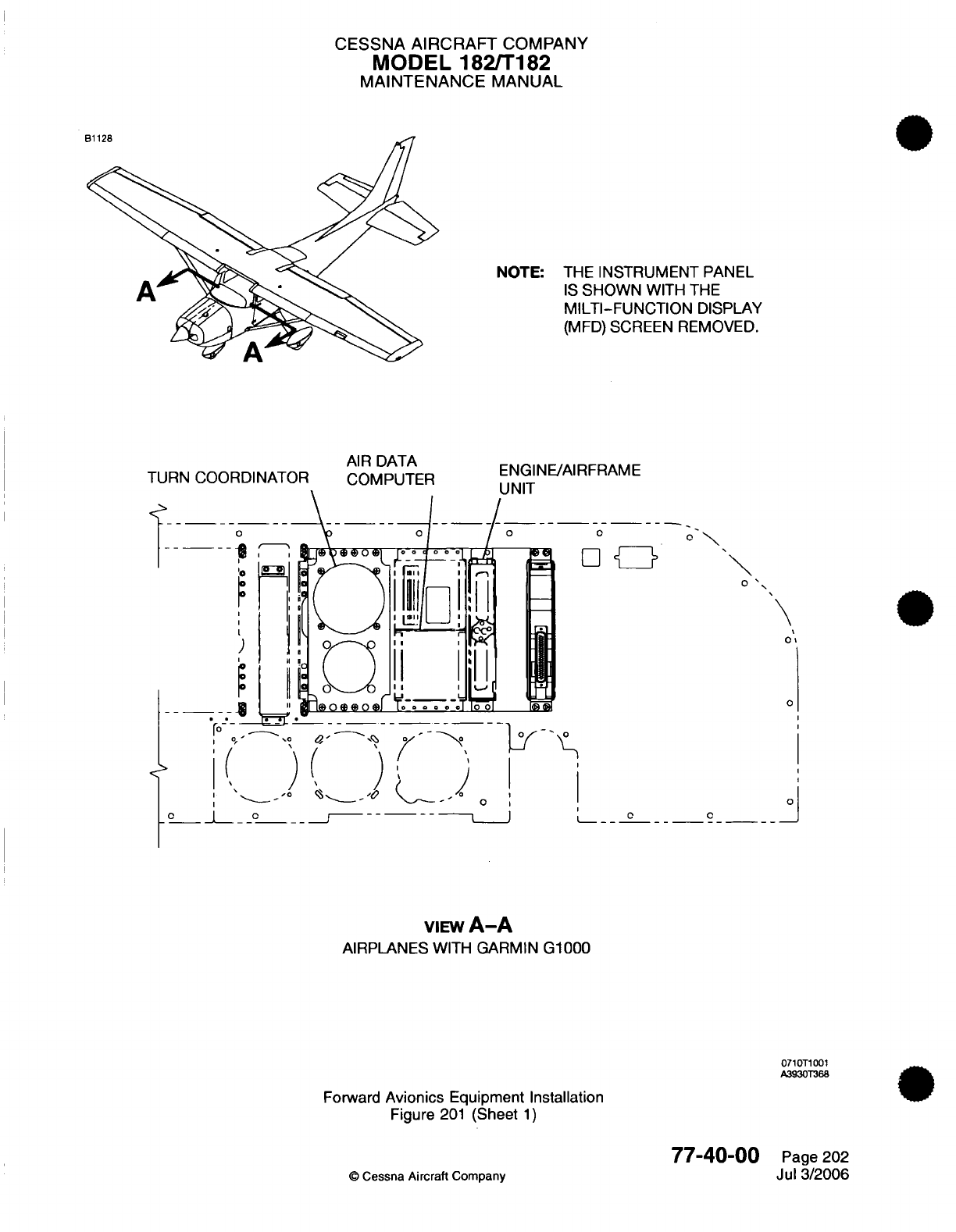
CESSNA
AIRCRAFT
COMPANY
MODEL
182/T182
MAINTENANCE
MANUAL
NOTE:
THE
INSTRUMENT
PANEL
IS
SHOWN
WITH
THE
MILTI-FUNCTION
DISPLAY
(MFD)
SCREEN REMOVED.
TURN COORDINATOR
AIR DATA
COMPUTER
ENGINE/AIRFRAME
I
IMIT
VIEW
A-A
AIRPLANES
WITH
GARMIN
G1000
0710T1001
A3930T368
Forward
Avionics
Equipment Installation
Figure
201
(Sheet
1)
77-40-00
©
Cessna
Aircraft
Company
\
Page
202
Jul
3/2006
CHAPTER
EXHAUST

CESSNA
AIRCRAIFT
COMPANY
MODEL
182/Ti182
MAINTENANCE
MANUAL
LIST
OF
EFFECTIVE PAGES
CHAPTER-SECTION-SUBJECT
78-Title
78-List
of
Effective
Pages
78-Record
of
Temporary
Revisions
78-Table
of
Contents
78-00-00
78-1
0-00
78-1
0-01
PAGE
Page
1
Pages
201
-203
Pages
201
-205
©
Cessna
Aircraft Company
78
-
LIST
OF
EFFECTIVE PAGES
Page
1
of
1
Jan
1/2007
DATE
April
1/2002
April 1/2002
Janl1/2007

Temporary
Revision
Number
RECORD
OF
TEMPORARY
REVISIONS
Page
Number
Issue
Date
By
Date
Removed
By
CESSNA AIRCRAFT
COMPANY
MODEL
182/T182
MAINTENANCE
MANUAL
CONTENTS
EXHAUST
-
GENERAL
..............................
Scope....................................
EXHAUST SYSTEM
-
MAINTENANCE
PRACTICES.................
General...................................
Description
and
Operation
..........................
Exhaust
System
Removal/installation
.....................
Exhaust
System
Inspection..........................
EXHAUST SYSTEM
(TURBOCHARGED)
-
MAINTENANCE
PRACTICES.......
General...................................
Description
and
Operation
..........................
Exhaust
Stack
Assembly
Removal/installation
.................
Heat
Shroud
Removal/Installation.......................
Exhaust System
Inspection..........................
©
Cessna
Aircraft
Company
78-00-00
Page
1
78-00-00
Page
1
78-1
0-00
Page
201
78-1
0-00
Page
201
78-10-00
Page
201
78-10-00
Page
201
78-10-00
Page
201
78-10-01 Page
201
78-10-01
Page
201
78-10-01
Page
201
78-10-01 Page
201
78-10-01 Page
201
78-10-01
Page
205
78
-
CONTENTS
Page
1
of
1
Jan-1/2007
CESSNA
AIRCRAFT
COMPANY
MODEL
182/T182
MAINTENANCE
MANUAL
EXHAUST
-
GENERAL
1.
Scope
A.
This Chapter provides
information
for
removal
and
installation
of
the
components
of
the
exhaust
system.
78-00-00
Page
1
©
Cessna
Aircraft Company
April
1/2002
CESSNA
AIRCRAFT
COMPANY
MODEL
182/T182
MAINTENANCE
MANUAL
EXHAUST
SYSTEM
-
MAINTENANCE
PRACTICES
1.
General
A.
This
section provides
instructions
for
removal,
installation,
and
inspection
of
the
exhaust system.
2.
Description
and
Operation
A.
The
exhaust
system
consists
of
two
exhaust
stacks,
two muffler
assemblies,
two
tail
pipes,
and
associated
hardware.
The
muffler
assemblies
are
equipped
with heat shrouds
to
provide
cabin
heat.
The
left
muffler shroud
is
equipped
with
an
air
intake duct
connected
to
the
upper left
engine
baffle.
A
duct
interconnects
the
left
and
right
heat
shrouds.
A
duct connected
to
the
right
heat
shroud
is
routed
to
the
cabin
heat
control
valve
on
the
firewall.
For cabin heat
installation
refer
to Chapter
21,Air
Conditioning
-
General.
3.
Exhaust
System
Removal/Installation
A.
Exhaust
System
Removal
(Refer
to Figure
201).
(1)
Remove upper
and
lower engine cowling.
(2)
Remove
clamp
from left
shroud intake
duct
and
retain.
(3)
Remove clamps
from
duct
interconnecting
the
left
and
right
heat
shrouds,
and
remove
duct
and
retain.
(4)
Remove clamp
from right heat
shroud
duct
and retain.
(5)
Remove
nuts,
washers
and
bolts
from
clamps securing
tail
pipes
to
shock
mounts
on
the firewall
and
retain
bolts
and
clamps,
discard
nuts
and
washers.
NOTE:
If
exhaust assemblies
are
to
be
removed
as
a
unit proceed
to
step
(8).
(6)
Remove
nuts,
washers,
and
bolts
from
clamps securing
tail
pipes
to
mufflers
and
retain.
Remove
tail
pipes.
(7)
Remove
cotter
pins,
nuts,
washers, bolts,
and
springs securing
mufflers
to
exhaust
stack
and
retain
bolts and
springs, discard cotter
pins,
nuts
and
washers.
Remove
mufflers.
(8)
Disconnect
electrical
lead from
EGT
thermocouple.
(9)
Remove
nuts and
washers
securing
exhaust stack
to
engine
cylinders
and
retain.
(10)
Remove
exhaust
stacks
and
gaskets.
Discard
gaskets.
B.
Exhaust
System
Installation
(Refer
to Figure
201).
(1)
Using
new
gaskets, position exhaust
stacks
on
engine
cylinders
and
install
washers
and
nuts.
(2)
Torque nuts
100
to
110
inch-
pounds
(11.3
to
12.4 N.m).
NOTE:
If
exhaust assemblies
were
removed
as
a
unit
proceed
to
step
(4).
(3)
Position
muffler
assemblies
on
exhaust stacks
and
install
springs,
bolts,
washers,
and
castellated
nuts
securing
mufflers
to
exhaust
stacks.
Install
castellated
nuts with
the
minimum
amount
of
clearance
required
for
the
cotter
pins
to
pass
through
nuts
and
bolts.
(4)
Install
tail
pipes
using
clamps,
bolts,
new
washers,
and new nuts.
(5)
Install
clamps,
bolts,
nuts,
and
washers securing
tail pipes
to
shock
mounts
on
the
firewall.
(6)
Using
clamp secure
left intake
duct
to
shroud.
(7)
Using
clamps install duct
interconnecting the
left
and right heat
shrouds.
(8)
Using
clamp secure duct
to
right heat
shroud.
(9)
Connect
electrical
lead
on
EGT
thermocouple.
(10)
Install
engine
cowlings.
4.
Exhaust
System
Inspection
A.
Exhaust
System
Inspection
and
Leak
Test.
(Refer
to
Chapter
5
-
Time
Limits/Maintenance
Checks
for
inspection
intervals).
(1)
Remove upper
and
lower
engine cowling.
(2)
Check
areas
adjacent
to
welds
and
slip
joints.
Look for
gas
deposits
in
surrounding
areas,
indicating
that
exhaust
gases
are
escaping
through
a
crack,
hole
or
around
the
slip
joints.
78-10-00
Page
201
©
Cessna Aircraft
Company
April
1/2002
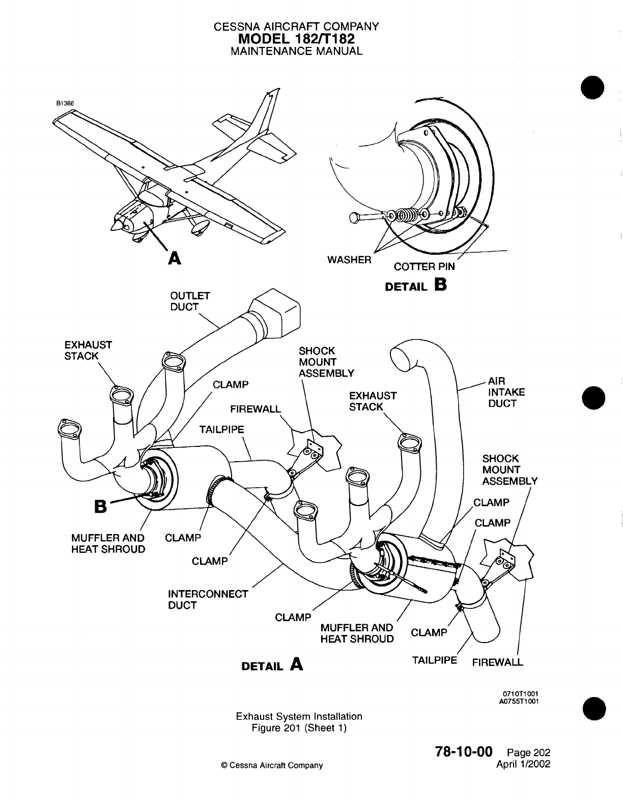
CESSNA AIRCRAFT
COMPANY
MODEL 182/T182
MAINTENANCE
MANUAL
COTTER
PIN
rETAII
R
0710T1001
A0755T1001
Exhaust System
Installation
Figure
201
(Sheet
1)
78-10-00
©
Cessna
Aircraft Company
Page
202
April
1/2002
A
I
vvr¥-oncn
CESSNA
AIRCRAFT
COMPANY
MODEL
182/T182
MAINTENANCE
MANUAL
(3)
After
visual inspection
an
air
leak
check
should
be
made on
the
system
as
follows:
(a)
Attach the pressure
side
of
an
industrial
vacuum cleaner to
the
tail
pipe
opening,
using
a
rubber
plug
to
effect
a
seal
as
required.
NOTE:
The
inside
of
vacuum
cleaner
hose
should
be
free
of
any contamination
that
might be
blown into
the
engine
exhaust
system.
(b)
With
vacuum
cleaner
operating,
all
joints
in
the
exhaust
system
may
be
leak
checked
manually
by
feel,
or
by
using
a
soap
and
water
solution
and
watching
for
bubbles.
Forming
of
bubbles
indicates
leaks;
if
bubbles
form at
the welded
joints
or show
cracks
in
the
muffler
canister,
end
plates,
or
tubes,
the
system
is
not
considered acceptable.
(c)
Repeat procedure
for
opposite exhaust.
(4)
Where
a
surface
is
not
accessible
for
a
visual
inspection,
or for
a
more
positive
test, the
following
procedure
may
be
used:
(a)
Remove
exhaust
stack
assemblies.
(b)
Remove
heat
shrouds
from
mufflers.
(c)
Use
rubber expansion
plugs
to
seal
openings.
(d)
Using
a
manometer
or
gage,
apply
approximately
1.5
PSI
(three
inches
of
mercury)
(10.3
kPa)
air
pressure while
each
stack
assembly
is
submerged
in
water.
Any
leaks
will
appear
as
bubbles
and
can
be
readily
detected.
(e)
Exhaust
stacks
found
defective
must
be
replaced
before
the
next
flight.
(5)
Install
exhaust
system
and
perform
inspection
in
step
(3).
78-10-00
Page
203
©
Cessna
Aircraft
Company
April 1/2002
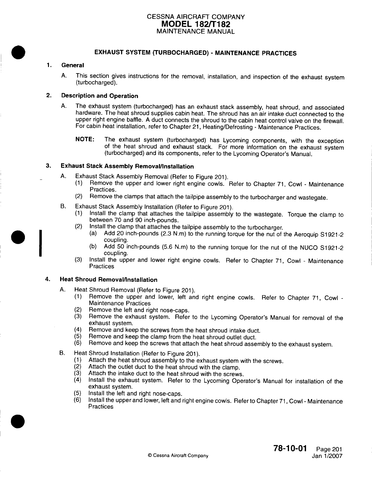
CESSNA
AIRCRAFT
COMPANY
MODEL
182/Ti182
MAINTENANCE
MANUAL
EXHAUST
SYSTEM
(TURBOCHARGED)
-
MAINTENANCE PRACTICES
1.General
A.
This section gives instructions
for
the
removal,
installation,
and
inspection
of
the
exhaust
system
(turbocharged).
2.
Description
and
Operation
A.
The
exhaust
system
(turbocharged)
has
an
exhaust
stack
assembly,
heat shroud,
and
associated
hardware.
The
heat
shroud
supplies
cabin
heat.
The
shroud
has
an
air
intake
duct
connected
to the
upper
right
engine
baffle.
A
duct
connects
the
shroud
to
the
cabin heat control
valve
on
the
firewall.
For
cabin heat
installation,
refer
to
Chapter
21,
Heating/Defrosting
-
Maintenance
Practices.
NOTE: The
exhaust
system (turbocharged)
has
Lycoming
components,
with
the
exception
of the
heat
shroud
and
exhaust
stack.
For
more
information
on
the
exhaust
system
(turbocharged)
and
its
components,
refer
to
the
Lycoming
Operator's
Manual.
3.
Exhaust
Stack
Assembly Removal/Installation
A.
Exhaust
Stack Assembly
Removal (Refer
to
Figure
201).
(1)
Remove the upper
and
lower
right
engine
cowls.
Refer
to
Chapter
71,
Cowl
-
Maintenance
Practices.
(2)
Remove
the
clamps
that
attach
the
tailpipe
assembly
to
the
turbocharger
and
wastegate.
B.
Exhaust
Stack
Assembly
Installation
(Refer
to
Figure
201).
(1)
Install the clamp
that
attaches
the
tailpipe
assembly
to
the
wastegate.
Torque the
clamp
to
between
70
and
90
inch-pounds.
(2)
Install
the
clamp that
attaches
the
tailpipe assembly
to
the
turbocharger.
(a)
Add
20
inch-pounds
(2.3
N.m)
to
the
running
torque
for
the
nut
of
the
Aeroquip
51 921-2
coupling.
I ~ ~~(b)
Add
50
inch-pounds
(5.6 N.m)
to
the
running
torque
for
the
nut
of
the
NUCO
S1921-2
coupling.
(3)
Install
the
upper
and
lower
right
engine cowls. Refer
to
Chapter
71,
Cowl
-
Maintenance
Practices
4.
Heat
Shroud
Removal/installation
A.
Heat Shroud Removal
(Refer
to
Figure
201).
(1)
Remove
the upper
and
lower,
left
and
right
engine
cowls.
Refer
to
Chapter
71,
Cowl
-
Maintenance
Practices
(2)
Remove
the
left
and
right
nose-caps.
(3)
Remove
the
exhaust
system.
Refer to
the
Lycoming
Operator's
Manual
for
removal
of
the
exhaust
system.
(4)
Remove
and
keep
the
screws
from
the
heat shroud
intake duct.
(5)
Remove
and keep
the
clamp
from
the
heat
shroud
outlet
duct.
(6)
Remove
and
keep
the
screws
that
attach
the heat
shroud
assembly
to
the
exhaust
system.
B.
Heat Shroud
Installation (Refer
to
Figure
201).
(1)
Attach
the
heat
shroud
assembly
to
the
exhaust
system
with
the
screws.
(2)
Attach
the
outlet
duct
to
the
heat
shroud
with
the clamp.
(3)
Attach
the
intake duct
to
the
heat
shroud
with
the
screws.
(4)
Install
the
exhaust
system.
Refer to
the
Lycoming
Operator's
Manual
for
installation
of
the
exhaust
system.
(5)
Install
the
left
and
right
nose-caps.
(6)
Install
the
upper
and
lower,
left
and
right
engine cowls.
Refer to
Chapter
71,
Cowl
-
Maintenance
Practices
78-1
0-01
Page
201
Janl/2007
0
Cessna
Aircraft
Company
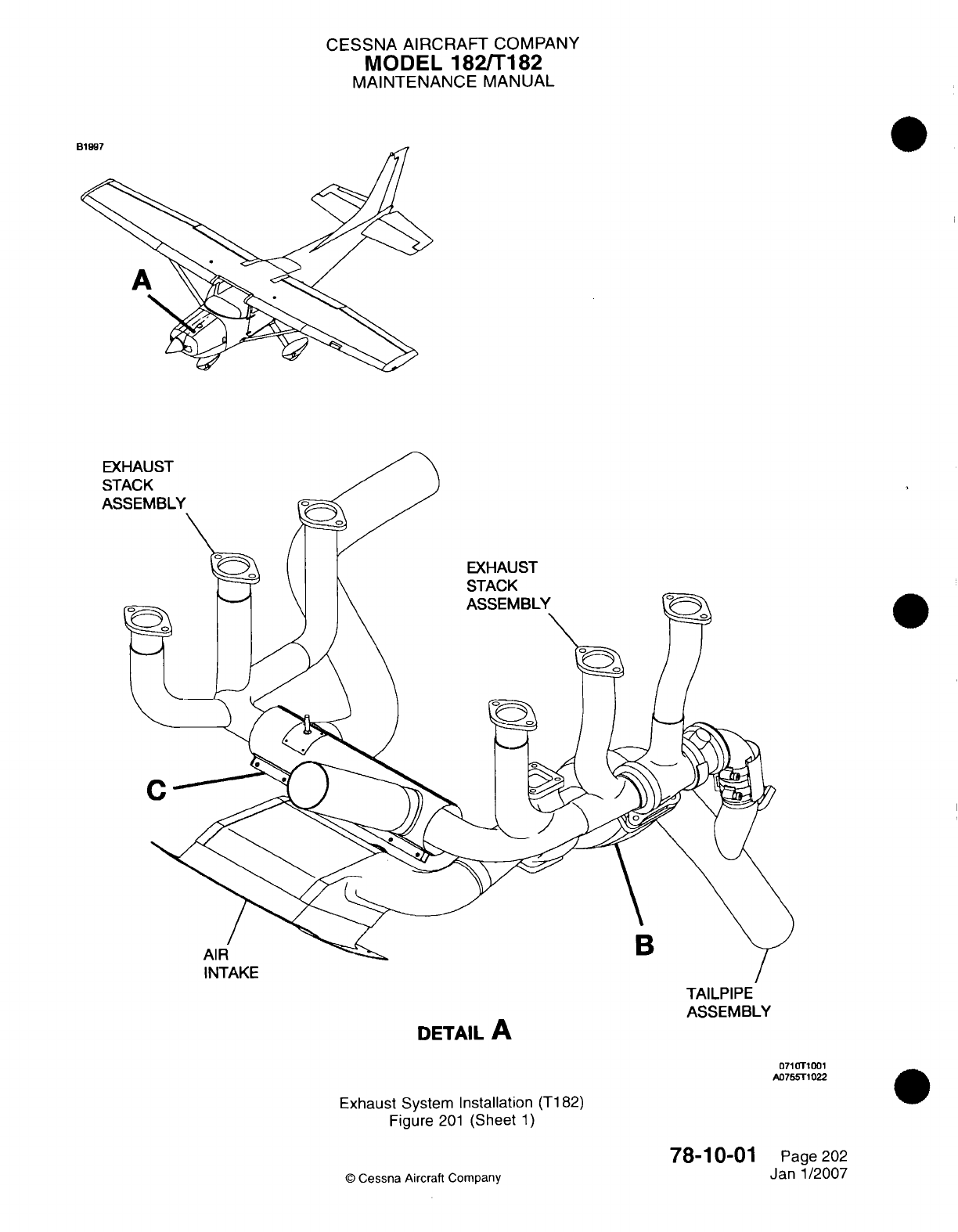
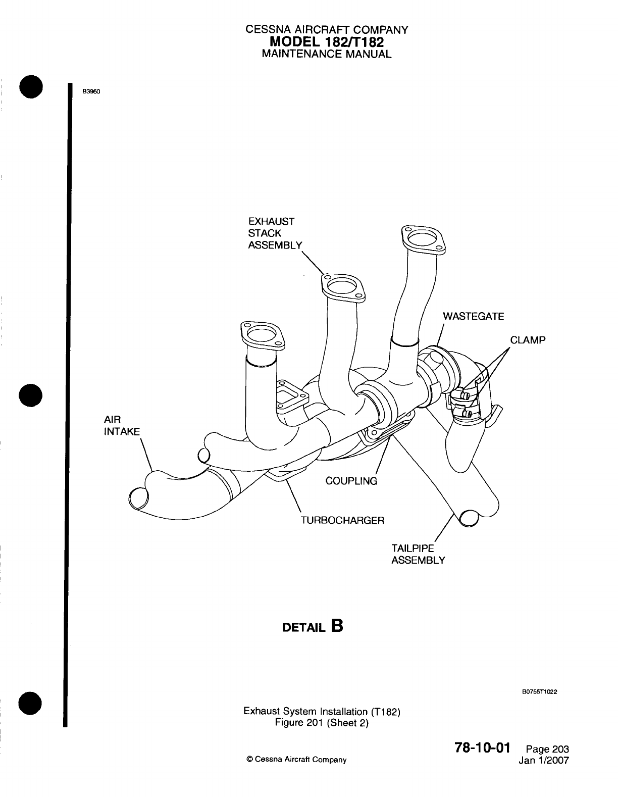
CESSNA
AIRCRAFT
COMPANY
MODEL
182/Ti
182
MAINTENANCE
MANUAL
B3960
EXHAUST
CLAM
P
AIR
INTAI
TAILPIPE
ASSEMBLY
DETAIL
B
B0755T1
022
Exhaust System
installation
(T182)
Figure
201
(Sheet
2)
Q
Cessna
Aircraft
Company
78-1 0-01
Page
203
Janl1/2007
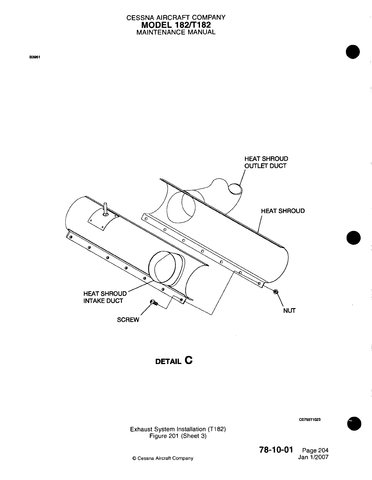
CESSNA AIRCRAFT
COMPANY
MODEL
182/Ti
82
MAINTENANCE
MANUAL
BM96
HEAT
SHROUD
OUTLET
DUCT
SCREW
DETAIL
C
C0755T1023
Exhaust
System Installation
(Ti
82)
Figure
201
(Sheet
3)
78-10-01
Q
Cessna
Aircraft
Company
Page
204
Jan
1/2007
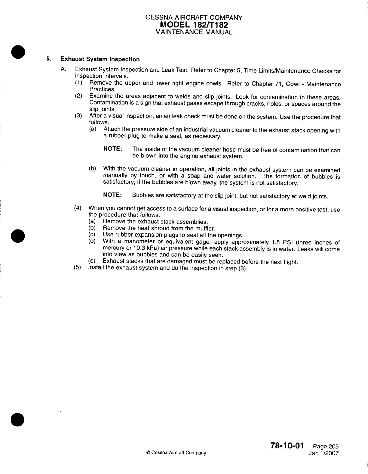
CESSNA AIRCRAFT
COMPANY
MODEL
1821182
MAINTENANCE
MANUAL
5.
Exhaust
System
Inspection
A.
Exhaust System
Inspection
and
Leak
Test.
Refer
to
Chapter
5,
Time
Limits/Maintenance
Checks
for
inspection
intervals.
(1)
Remove
the
upper
and
lower
right
engine
cowls. Refer
to
Chapter
71,
Cowl
-
Maintenance
Practices
(2)
Examine
the
areas
adjacent
to
welds
and
slip
joints.
Look
for contamination
in
these
areas.
Contamination
is a
sign
that
exhaust
gases
escape
through
cracks,
holes,
or
spaces
around
the
slip joints.
(3)
After
a
visual inspection,
an
air
leak
check
must
be
done
on
the
system.
Use
the
procedure
that
follows.
(a)
Attach the
pressure
side
of an
industrial vacuum
cleaner
to
the exhaust
stack opening
with
a
rubber
plug
to
make
a
seal,
as
necessary.
NOTE:
The inside
of
the
vacuum
cleaner
hose
must
be
free
of
contamination
that
can
be
blown
into
the
engine
exhaust
system.
(b)
With
the
vacuum
cleaner
in
operation,
all
joints
in
the
exhaust
system
can
be
examined
manually
by
touch,
or
with
a
soap
and
water
solution.
The
formation
of
bubbles
is
satisfactory;
if
the
bubbles
are
blown
away, the
system
is
not
satisfactory.
NOTE:
Bubbles
are
satisfactory
at
the slip
joint,
but
not
satisfactory
at
weld
joints.
(4)
When
you
cannot
get
access
to
a
surface
for
a
visual
inspection,
or
for
a
more
positive
test,
use
the
procedure
that
follows.
(a)
Remove
the
exhaust
stack
assemblies.
(b)
Remove
the heat shroud
from the
muffler.
(c)
Use
rubber
expansion
plugs
to
seal
all
the
openings.
(d)
With
a
manometer
or
equivalent
gage,
apply
approximately
1.5
PSI
(three
inches
of
mercury
or
10.3
kPa)
air
pressure while
each
stack assembly
is
in
water. Leaks
will
come
into
view
as
bubbles
and
can be
easily
seen.
(e)
Exhaust
stacks
that
are
damaged
must
be
replaced before
the
next
flight.
(5)
Install
the
exhaust
system
and
do
the
inspection
in
step
(3).
78-1
0-01
Page
205
©
Cessna
Aircraft
Company
Janl1/2007

CHAPTER
OIL
CESSNA
AIRCRAFT
COMPANY
MODEL
182/T182
MAINTENANCE
MANUAL
LIST
OF
EFFECTIVE
PAGES
CHAPTER-SECTION-SUBJECT
79-Title
79-List
of
Effective
Pages
79-Record
of
Temporary
Revisions
79-Table
of
Contents
79-00-00
79-20-00
79-20-10
79-30-00
79-31-00
PAGE
Page
1
Pages
201-202
Pages
201-202
Pages 201-203
Pages 201-202
©
Cessna
Aircraft
Company
79
-
LIST
OF
EFFECTIVE PAGES
Page
1
of
1
Jan
2/2006
DATE
April
1/2002
April
1/2002
Jan
2/2006
April
1/2002
April
1/2002

Temporary
Revision
Number
RECORD
OF
TEMPORARY REVISIONS
Page
Number
Issue
Date
By
Date
Removed
By
CESSNA
AIRCRAFT
COMPANY
MODEL
182/T182
MAINTENANCE
MANUAL
CONTENTS
OIL
-
GENERAL
.................................................................
S
cope......................................................................
Definition
...................................................................
OIL
COOLER
-
MAINTENANCE
PRACTICES
......................................
General
....................................................................
Oil
Cooler
Removal/Installation...............................................
AIR/OIL
SEPARATOR
ASSEMBLY
-
MAINTENANCE
PRACTICES...................
G eneral
....................................................................
Air/Oil
Separator Assembly
Removal
and
Installation
...........................
OIL
PRESSURE
INDICATORS
-
MAINTENANCE PRACTICES
......................
Description
and
Operation
...................................................
Oil
Pressure
Indicator
and
Transducer
Removal/Installation.....................
Low
Oil
Pressure
Switch
Removal/Installation
.................................
OIL TEMPERATURE
INDICATOR
-
MAINTENANCE PRACTICES
...................
Description
and
Operation
...................................................
Sending
Unit
Removal/Installation
....................
........................
Pressure
Indicator
Removal/Installation
.........
..............................
79-00-00
Page
1
79-00-00
Page
1
79-00-00
Page
1
79-20-00
Page
201
79-20-00
Page
201
79-20-00
Page
201
79-20-10
Page
201
79-20-10
Page
201
79-20-10
Page
201
79-30-00
Page
201
79-30-00
Page
201
79-30-00
Page
201
79-30-00
Page
201
79-31-00
Page
201
79-31-00
Page
201
79-31-00
Page
201
79-31-00
Page
201
79
-
CONTENTS
Page
1
of
1
Jan
2/2006
©
Cessna Aircraft
Company
CESSNA
AIRCRAFT
COMPANY
MODEL
182/T182
MAINTENANCE
MANUAL
OIL
-
GENERAL
1.
Scope
A.
This
chapter
provides maintenance
instructions for
those
components
which
distribute
oil
and
which
indicate
oil
condition.
For
information beyond
the
scope
of
this material,
refer
to
appropriate
Textron
Lycoming
Operator's
and
Overhaul
Manuals,
and to
Chapter
71,
Engine
-
Troubleshooting.
2.
Definition
A.
This
chapter
is
divided
into
sections
to
assist maintenance
personnel
in
locating
specific
information.
The
following
is
a
brief
description
of
each
section.
For
locating
information
within
the
chapter,
refer
to
the
Table of
Contents
at
the
beginning
of
the
chapter.
(1)
The
section
on
distribution provides
information
on
removal and
installation
of
the
external
oil
cooler.
(2)
The
section
on
indicating
provides
information
on
indicators, transducers
and
switches
used
to
indicate
oil
temperature
and
pressure.
79-00-00
Page
1
©
Cessna
Aircraft
Company
April 1/2002
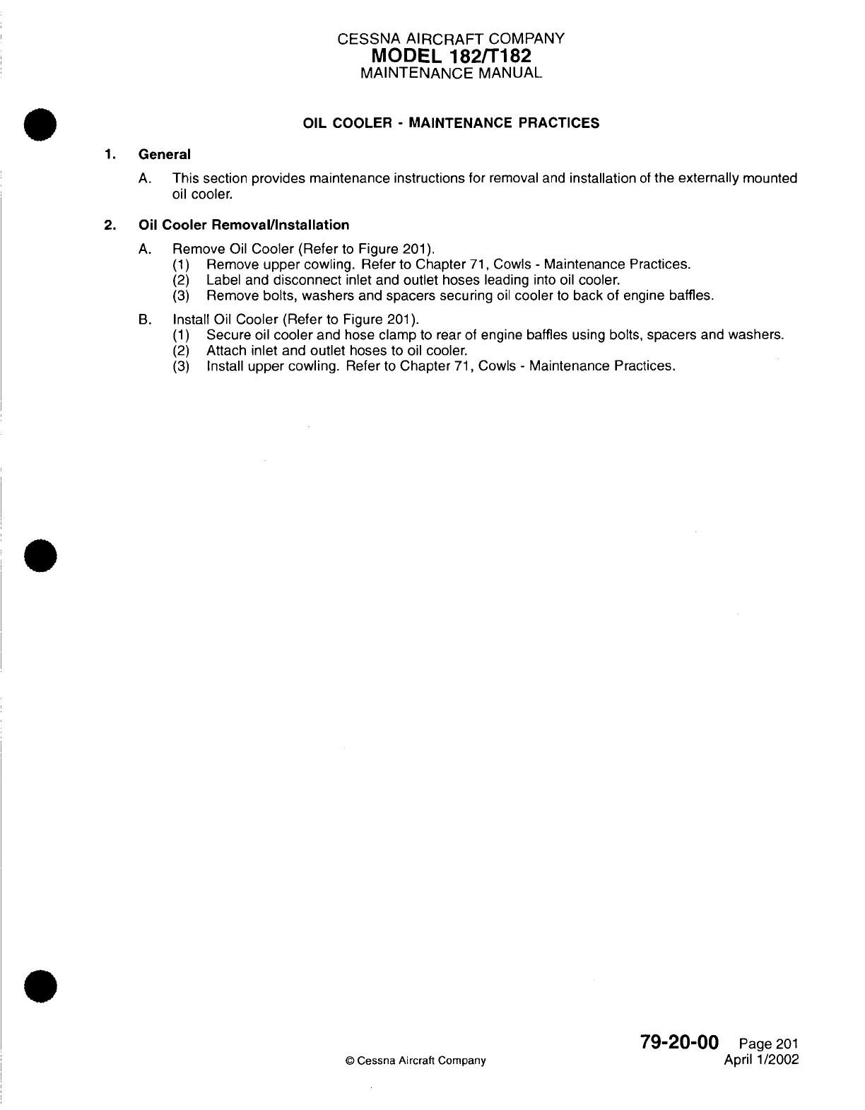
CESSNA
AIRCRAFT
COMPANY
MODEL 182/T182
MAINTENANCE
MANUAL
OIL
COOLER
-
MAINTENANCE PRACTICES
1.
General
A.
This
section
provides maintenance instructions for
removal
and
installation
of
the
externally
mounted
oil
cooler.
2.
Oil
Cooler
Removal/Installation
A.
Remove
Oil
Cooler
(Refer
to
Figure
201).
(1)
Remove
upper
cowling.
Refer
to
Chapter
71,
Cowls
-
Maintenance
Practices.
(2)
Label and
disconnect
inlet
and
outlet
hoses
leading
into oil
cooler.
(3)
Remove
bolts,
washers
and
spacers
securing
oil
cooler
to
back
of
engine
baffles.
B.
Install
Oil
Cooler
(Refer
to
Figure
201).
(1)
Secure
oil
cooler
and
hose
clamp
to
rear of
engine baffles
using
bolts,
spacers
and
washers.
(2)
Attach
inlet
and
outlet
hoses
to
oil
cooler.
(3)
Install
upper
cowling.
Refer
to
Chapter
71,
Cowls
-
Maintenance
Practices.
79-20-00
Page
201
©
Cessna Aircraft Company
April 1/2002
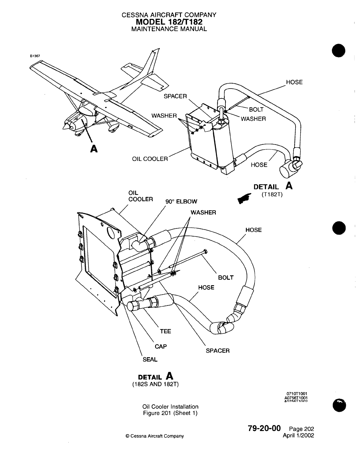
CESSNA AIRCRAFT
COMPANY
MODEL
182/T182
MAINTENANCE
MANUAL
81367
A
OIL
COOLER
DETAIL
A
OIL0
(T182T)
COOLER
90
°
ELBOW
P
SEAL
DETAIL
A
(182S
AND
182T)
Oil
Cooler Installation
Figure
201
(Sheet
1)
071
OT1001
A0756T1001
An7fT1ftn9
79-20-00
©
Cessna
Aircraft
Company
Page
202
April
1/2002
-
SE
CESSNA
AIRCRAFT
COMPANY
MODEL
182/T182
MAINTENANCE
MANUAL
AIR/OIL
SEPARATOR
ASSEMBLY
-
MAINTENANCE
PRACTICES
1.
General
A.
Turbocharged
airplanes
have
an
air/oil
separator
assembly
installed
in
the breather
system.
During
engine
operation, air
pressure
collects
in
the
crankcase
and
it
is
necessary
to
release
that pressure.
The air/oil
separator
removes
oil
from
the
air
before
it
is
released
through
the
breather
overboard
line.
After
the
air/oil
separator
removes
the
oil
from
the
air,
the
oil
is
put
back
in
the
crankcase
where
it
is
used
again.
The separator assembly
has
three
hoses.
One
connects
the
separator
to
the
crankcase
breather line, one
connects
the
separator
to the
crankcase
oil
return
line,
and
one
connects the
separator
to
the
breather overboard
line.
2.
Air/Oil
Separator
Assembly
Removal
and
Installation
A.
Air/Oil
Separator
Assembly
Removal.
Refer
to Figure
201.
(1)
Remove
the
upper
cowling
to
get
access
to
the
engine
compartment.
Refer to
Chapter
71,
Cowls
-
Maintenance Practices.
(2)
Turn
the screws
on
the
clamps
that
connect the
hoses
to
the air/oil
separator
counterclockwise
to
loosen
them.
(3)
Disconnect
the hoses
from
the
oil
breather.
(4)
Turn
the screws
on
the clamps
that
connect
the
air/oil
separator
to
the engine
baffle
counterclockwise
to
loosen
them.
(5)
Remove
the
air/oil
separator
from
the
airplane.
B.
Air/Oil
Separator Assembly
Installation.
Refer
to
Figure
201.
(1)
Put
the
air/oil
separator
in
the clamps
that
attach
it
to
the
engine
baffle.
(2)
Turn
the screws
on
the
clamps
that
connect
the
air/oil
separator
to
the
engine
clockwise
to
tighten
them.
(3)
Connect
the
hoses
to the
air/oil
separator.
(4)
Turn
the
screws
on
the
clamps
that
connect
the
hoses
to
the
air/oil separator
clockwise
to
tighten
them.
(5)
Install
the upper
cowling.
Refer
to
Chapter
71,
Cowls
-
Maintenance
Practices.
79-20-10
Page
201
©
Cessna Aircraft
Company
Jan
2/2006
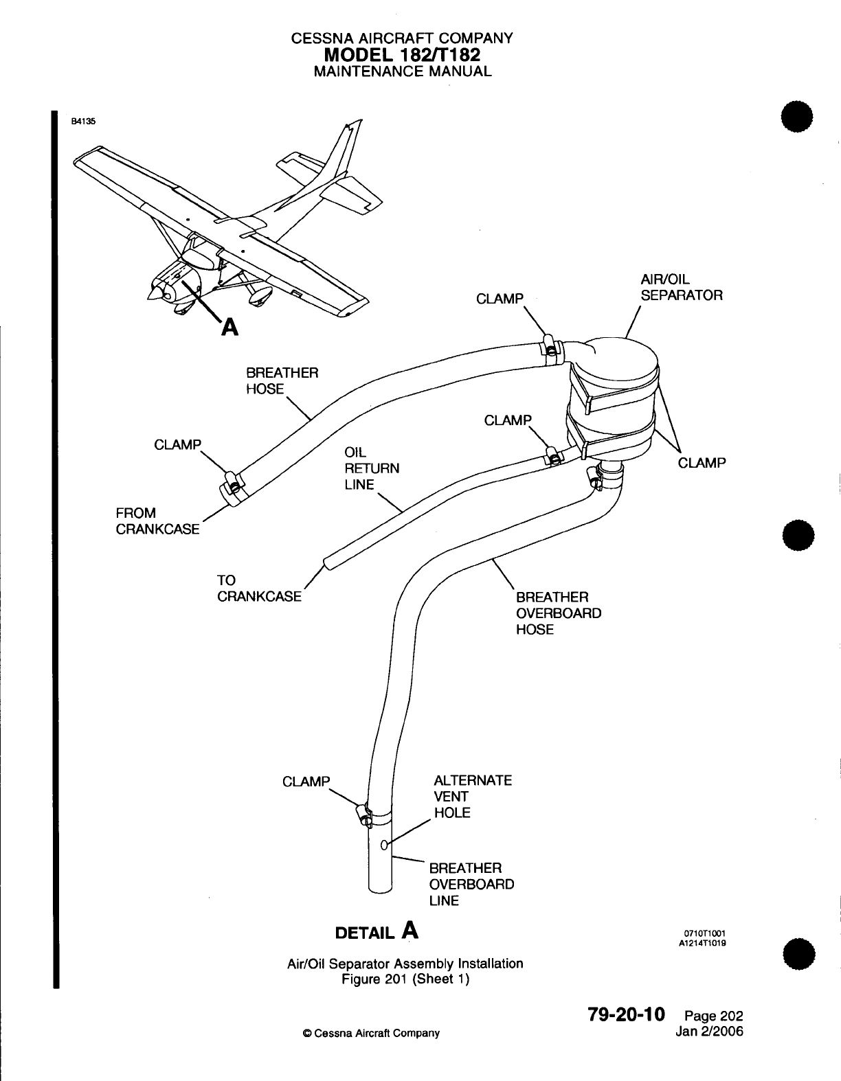
CESSNA AIRCRAFT
COMPANY
MODEL
182/1 82
MAINTENANCE
MANUAL
AIR/OIL
SEPARATOR
HOSE
CLAMI
FROM
CRANKCASE
TO
CRANKCASE
CLAMF
LINE
DETAIL
A
BREATHER
OVERBOARD
HOSE
ALTERNATE
VENT
3REATHER
3VERBOARD
0710T1 001
A1214T1019
Air/Oil
Separator
Assembly Installation
Figure
201
(Sheet
1)
Page
202
Jan
2/2006
CLAMP
'LAMP
79-20-10
C
Cessna
Aircraft Company
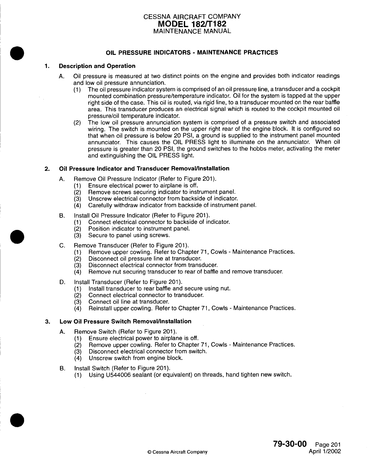
CESSNA
AIRCRAFT
COMPANY
MODEL
182/T182
MAINTENANCE
MANUAL
OIL
PRESSURE INDICATORS
-
MAINTENANCE PRACTICES
1.
Description
and
Operation
A.
Oil
pressure
is
measured
at two
distinct
points
on
the
engine
and provides
both
indicator
readings
and
low oil
pressure
annunciation.
(1)
The
oil
pressure
indicator
system
is
comprised
of
an
oil
pressure
line,
a
transducer
and
a
cockpit
mounted
combination
pressure/temperature
indicator.
Oil
for
the
system
is
tapped
at
the
upper
right
side
of
the case. This
oil
is
routed,
via
rigid
line,
to
a
transducer
mounted
on
the
rear
baffle
area.
This transducer
produces
an
electrical
signal
which
is
routed
to
the
cockpit
mounted
oil
pressure/oil temperature
indicator.
(2)
The
low
oil
pressure
annunciation
system
is
comprised
of
a
pressure
switch
and
associated
wiring. The switch
is
mounted
on
the
upper
right
rear
of
the
engine
block.
It is
configured
so
that
when
oil
pressure
is
below
20
PSI,
a
ground
is
supplied
to
the instrument
panel mounted
annunciator.
This
causes
the OIL
PRESS
light to
illuminate
on
the
annunciator.
When
oil
pressure
is
greater
than
20
PSI,
the ground
switches
to
the hobbs
meter,
activating
the
meter
and
extinguishing
the
OIL
PRESS
light.
2.
Oil
Pressure
Indicator
and
Transducer
Removal/Installation
A.
Remove
Oil
Pressure
Indicator
(Refer
to Figure
201).
(1)
Ensure
electrical
power
to
airplane
is
off.
(2)
Remove
screws
securing
indicator
to
instrument
panel.
(3)
Unscrew
electrical connector
from
backside
of
indicator.
(4)
Carefully withdraw indicator
from
backside
of
instrument
panel.
B.
Install
Oil
Pressure
Indicator
(Refer
to
Figure
201).
(1)
Connect
electrical connector
to
backside
of
indicator.
(2)
Position
indicator
to
instrument
panel.
(3)
Secure
to
panel
using screws.
C.
Remove
Transducer
(Refer
to
Figure
201).
(1)
Remove
upper cowling.
Refer
to
Chapter
71,
Cowls
-
Maintenance
Practices.
(2)
Disconnect
oil
pressure
line
at
transducer.
(3)
Disconnect
electrical
connector
from
transducer.
(4)
Remove
nut
securing
transducer
to
rear of baffle
and
remove
transducer.
D.
Install
Transducer
(Refer
to Figure
201).
(1)
Install
transducer
to
rear
baffle
and
secure
using
nut.
(2)
Connect
electrical connector
to
transducer.
(3)
Connect
oil
line
at
transducer.
(4)
Reinstall
upper
cowling.
Refer
to
Chapter
71,
Cowls
-
Maintenance
Practices.
3.
Low
Oil
Pressure
Switch
Removal/Installation
A.
Remove
Switch
(Refer to
Figure
201).
(1)
Ensure
electrical
power
to
airplane
is
off.
(2)
Remove
upper cowling.
Refer
to
Chapter
71,
Cowls
-
Maintenance
Practices.
(3)
Disconnect
electrical connector
from
switch.
(4)
Unscrew
switch
from
engine
block.
B.
Install
Switch
(Refer
to Figure
201).
(1)
Using
U544006 sealant
(or
equivalent)
on
threads,
hand
tighten
new
switch.
79-30-00
Page
201
©
Cessna
Aircraft
Company
April 1/2002
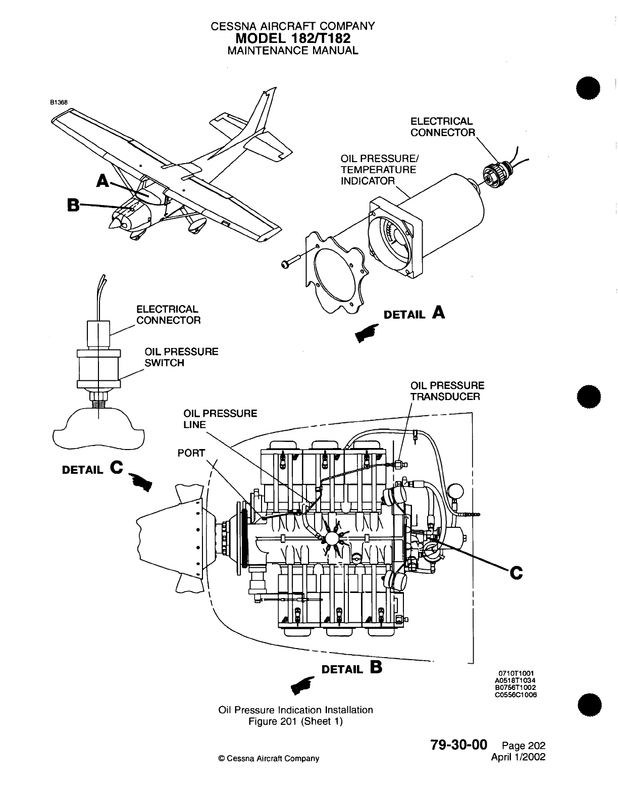
CESSNA AIRCRAFT
COMPANY
MODEL
182/T182
MAINTENANCE
MANUAL
ELECTRICAL
OIL
PRESSURE/
TEMPERATURE
INDICATOR
ECTRICAL
NNECTOR
UCIMIL
fl
'IL
PRESSURE
WITCH
OIL
PRESSURE
DETAIL
C
DETAIL
B
0710T1001
A0518T1034
B0756T1002
C0556C1006
Oil
Pressure
Indication Installation
Figure
201
(Sheet
1)
79-30-00
©
Cessna
Aircraft Company
Page
202
April 1/2002
CESSNA
AIRCRAFT
COMPANY
MODEL
182/T182
MAINTENANCE
MANUAL
CAUTION:
Do
not
use
Teflon
tape.
CAUTION:
Clean any
sealer
or
other
debris
from
the
switch
fitting before
installation.
Ensure
foreign
material
is
removed and
clear
of
the
pressure
hole
in
the
end
of
the
switch
fitting.
(2)
Use
a
7/16
inch
wrench
to
tighten switch
approximately
1
to
1
1/2
turns
(not
to
exceed
60
inch
pounds)
beyond
hand
tight.
CAUTION:
Do
not use
excessive
torque
on
plastic
switch
connection
housing
when
hand
tightening.
CAUTION:
Use
only
the
hex
fitting
to
final
tighten. Excessive
torque
will
damage
the
switch.
Do
not round
the
corners
of
the
hex
fitting.
Connect
electrical connector
to
switch.
Reinstall
upper
cowling.
Refer
to
Chapter
71,
Cowls
-
Maintenance
Practices.
79-30-00
Page
203
©
Cessna Aircraft Company
April 1/2002
(3)
(4)
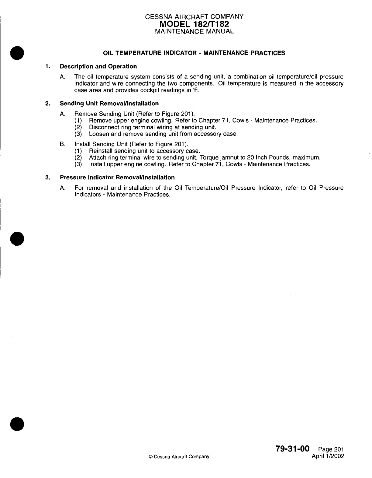
CESSNA
AIRCRAFT
COMPANY
MODEL
182/T182
MAINTENANCE
MANUAL
OIL
TEMPERATURE
INDICATOR
-
MAINTENANCE
PRACTICES
1.
Description
and
Operation
A.
The
oil
temperature
system
consists
of
a
sending
unit,
a
combination
oil
temperature/oil
pressure
indicator
and
wire
connecting
the
two
components.
Oil
temperature
is
measured
in
the
accessory
case
area
and
provides cockpit
readings
in
cF.
2.
Sending Unit
Removal/Installation
A.
Remove Sending
Unit
(Refer
to
Figure
201).
(1)
Remove
upper engine
cowling. Refer
to
Chapter
71,
Cowls
-
Maintenance
Practices.
(2)
Disconnect
ring
terminal
wiring
at
sending
unit.
(3)
Loosen
and
remove sending
unit
from
accessory
case.
B.
Install
Sending
Unit
(Refer
to
Figure
201).
(1)
Reinstall sending
unit
to
accessory
case.
(2)
Attach
ring
terminal
wire to
sending
unit. Torque
jamnut
to
20
Inch
Pounds,
maximum.
(3)
Install
upper
engine
cowling.
Refer to
Chapter
71,
Cowls
-
Maintenance Practices.
3.
Pressure
Indicator Removal/Installation
A.
For
removal and
installation
of
the
Oil
Temperature/Oil Pressure
Indicator,
refer
to
Oil
Pressure
Indicators
-
Maintenance Practices.
79-31-00
Page
201
©
Cessna Aircraft
Company
April 1/2002
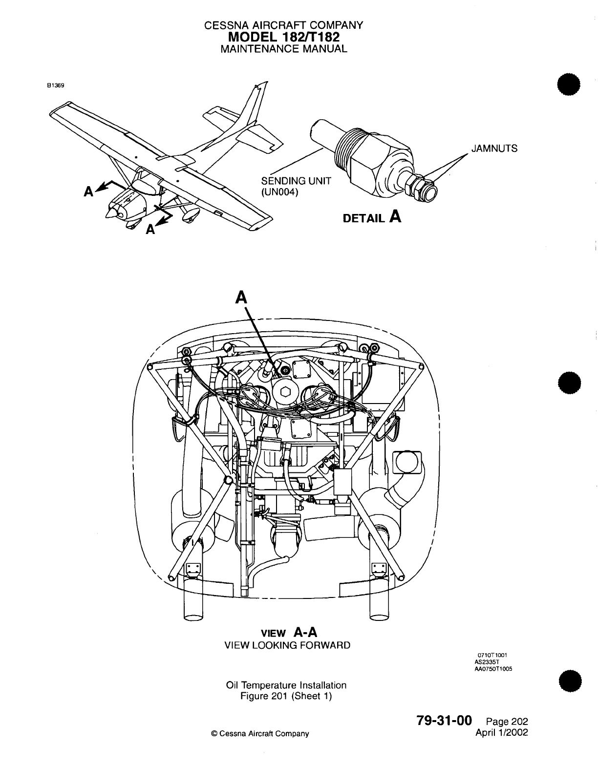
CESSNA
AIRCRAFT
COMPANY
MODEL
182/T182
MAINTENANCE
MANUAL
JAMNUTS
UNIT
DETAIL
A
A
VIEW
A-A
VIEW
LOOKING
FORWARD
0710T1001
AS2335T
AA0750T1005
Oil
Temperature
Installation
Figure
201
(Sheet
1)
©
Cessna
Aircraft
Company
79-31-00
Page
202
April
1/2002
A
E

CHAPTER
STARTING

CESSNA
AIRCRAFT
COMPANY
MODEL
182/Ti
82
MAINTENANCE
MANUAL
LIST
OF
EFFECTIVE
PAGES
CHAPTER-SECTION-SUBJECT
80-Title
80-List
of
Effective Pages
80-Record
of
Temporary
Revisions
80-Table
of
Contents
80-00-00
80-10-00
PAGE
Page
1
Pages
201
-204
©
Cessna
Aircraft Company
80
-
LIST
OF
EFFECTIVE PAGES
Page
1
of
1
Jul
1/2007
DATE
April
1/2002
Jul 1/2007
Temporary
Revision
Number
RECORD
OF
TEMPORARY
REVISIONS
Page
Number
Issue
Date
By
Date
Removed
By
CESSNA AIRCRAFT
COMPANY
MODEL
182/Ti
82
MAINTENANCE
MANUAL
CONTENTS
STARTING
-
GENERAL..............................
Scope
and
Definition.............................
STARTER
-
MAINTENANCE PRACTICES
.....................
Description
and
Operation
..........................
Starter
Removal/installation..........................
Bendix
Starter
Drive
Assembly
Cleaning/Lubrication
..............
80-00-00
Page
1
80-00-00
Page
1
80-10-00
Page
201
80-1
0-00 Page
201
80-1
0-00
Page
201
80-1
0-00
Page
201
80
-
CONTENTS
Page
1
of
1
Jul
1/2007
©
Cessna
Aircraft Company
CESSNA
AIRCRAFT
COMPANY
MODEL
182/T182
MAINTENANCE
MANUAL
STARTING
-
GENERAL
1.
Scope
and
Definition
A.
This
chapter
is
comprised
of
a
single
section
on
the
starting system. The
section
details
removal
and
installation
instructions for
the
engine
starter.
80-00-00
Page
1
©
Cessna
Aircraft
Company
April
1/2002
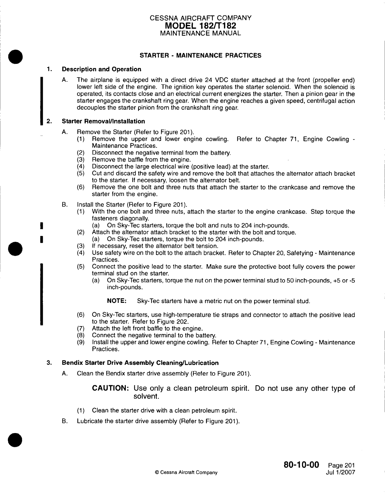
CESSNA
AIRCRAFT
COMPANY
MODEL
182/Ti182
MAINTENANCE
MANUAL
STARTER
-
MAINTENANCE PRACTICES
1.Description
and
Operation
A.
The
airplane
is
equipped
with
a
direct drive 24
VDC
starter
attached
at
the
front (propeller
end)
lower
left
side
of
the
engine. The ignition
key
operates
the
starter
solenoid. When
the
solenoid
is
operated,
its
contacts
close
and
an
electrical
current
energizes
the
starter.
Then
a
pinion
gear
in
the
starter engages
the
crankshaft
ring
gear.
When
the
engine
reaches
a
given
speed,
centrifugal action
decouples
the
starter
pinion
from
the
crankshaft
ring
gear.
2.
Starter
Removal/installation
A.
Remove
the
Starter
(Refer
to
Figure
201).
(1)
Remove the upper
and
lower
engine
cowling.
Refer
to
Chapter
71,
Engine Cowling
-
Maintenance
Practices.
(2)
Disconnect
the
negative
terminal
from the
battery.
(3)
Remove
the
baffle
from
the
engine.
(4)
Disconnect
the
large
electrical
wire
(positive
lead)
at
the
starter.
(5)
Cut
and
discard
the
safety
wire and
remove
the bolt
that
attaches
the
alternator attach
bracket
to
the starter.
If
necessary,
loosen
the
alternator
belt.
(6)
Remove
the
one
bolt
and
three
nuts
that attach
the
starter
to
the
crankcase
and
remove
the
starter
from
the
engine.
B.
Install
the
Starter
(Refer
to
Figure
201).
(1)
With the
one
bolt
and
three
nuts,
attach
the
starter
to
the
engine crankcase.
Step
torque
the
fasteners
diagonally.
*
~~~~(a)
On
Sky-Tec starters,
torque
the bolt
and
nuts
to 204
inch-pounds.
(2)
Attach
the
alternator
attach
bracket
to the
starter
with
the
bolt and
torque.
*
~~~~(a)
On
Sky-Tec
starters,
torque
the
bolt
to
204
inch-pounds.
(3) If
necessary,
reset
the
alternator
belt
tension.
(4)
Use
safety
wire
on
the bolt
to
the attach
bracket. Refer
to
Chapter
20,
Safetying
-
Maintenance
Practices.
(5)
Connect
the
positive
lead
to
the
starter. Make sure the
protective
boot
fully
covers
the
power
terminal
stud
on
the
starter.
(a)
On
Sky-Tec
starters,
torque
the
nut
on
the
power
terminal
stud
to
50
inch-pounds,
+5
or
-5
inch-pounds.
NOTE: Sky-Tec
starters
have
a
metric
nut
on
the
power
terminal
stud.
(6)
On
Sky-Tec
starters,
use
high-temperature
tie
straps
and
connector
to
attach
the
positive
lead
to
the starter. Refer
to
Figure
202.
(7)
Attach
the left
front baffle
to
the
engine.
(8)
Connect
the
negative
terminal
to
the
battery.
(9)
Install
the
upper
and
lower
engine
cowling.
Refer to
Chapter
71,
Engine
Cowling
-
Maintenance
Practices.
3.
Bendix Starter
Drive
Assembly
Cleaning/Lubrication
A.
Clean
the Bendix
starter
drive
assembly
(Refer
to
Figure
201).
CAUTION:
Use
only
a
clean
petroleum
spirit.
Do
not
use
any other
type
of
solvent.
(1)
Clean
the
starter drive
with
a
clean
petroleum
spirit.
B.
Lubricate
the
starter
drive
assembly
(Refer
to
Figure
201).
80-1
0-00
Page
201
©Cessna
Aircraft Company
Jul
1/2007
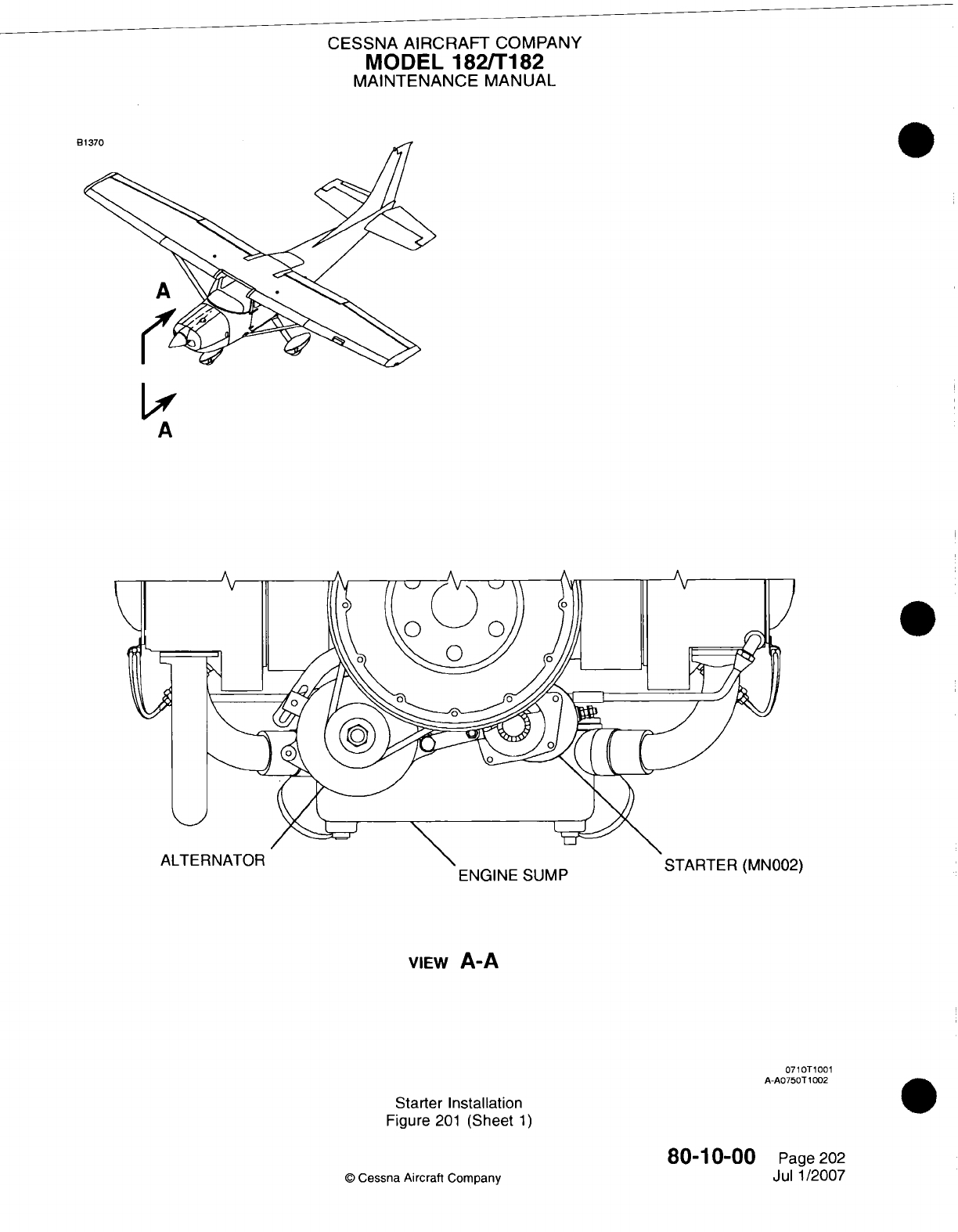
CESSNA
AIRCRAFT
COMPANY
MODEL
182/Ti182
MAINTENANCE
MANUAL
VIEw
A-A
0710T1001
A
A0750T1002
Starter
Installation
Figure
201
(Sheet
1)
80-10-00
©
Cessna Aircraft Company
Page 202
Jul 1/2007
t
oulvir-
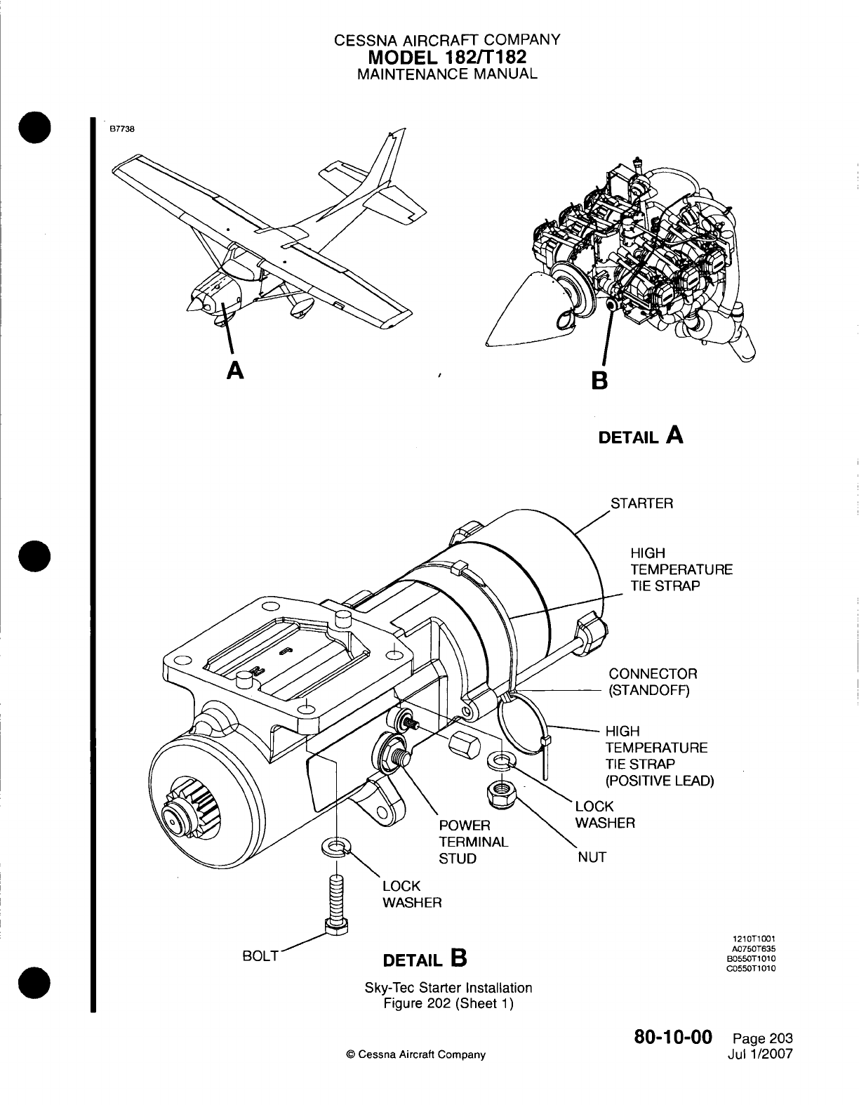
CESSNA
AIRCRAFT
COMPANY
MODEL
182/Ti
82
MAINTENANCE
MANUAL
A ~~~~~B
DETAIL
A
FU
RE
E
D)
DETAIL
0
Sky-Tec
Starter
Installation
Figure 202
(Sheet
1)
80-1
0-00
0
Cessna
Aircraft
Company
A
MUL
I
1210T1001
A0750T635
B055OT1
010
C055OT1 010
Page
203
Jul
1/2007
CESSNA
AIRCRAFT
COMPANY
MODEL
182/Ti182
MAINTENANCE
MANUAL
CAUTION:
Do
not use
grease,
oil
or
graphite lubricants.
Use
only
silicone
spray
lubricants
which
are
recommended
for correct
operation.
(1)
Lubricate
the
Bendix
starter
drive
assembly
with
a
silicone
spray such
as
Crown
Industrial
Products
silicone
spray
8034.
80-1
0-00
Page 204
©
Cessna
Aircraft
Company
Jul 1/2007
CHAPTER
TURBINES

CESSNA
AIRCRAFT
COMPANY
MODEL
182/T182
MAINTENANCE
MANUAL
LIST
OF
EFFECTIVE
PAGES
CHAPTER-SECTION-SUBJECT
81-Title
81-List
of
Effective Pages
81-Record
of
Temporary
Revisions
81-Table
of
Contents
81-00-00
81-20-00
©
Cessna
Aircraft Company
81
-
LIST
OF
EFFECTIVE
PAGES
Page
1
of
1
Mar
1/2005
PAGE
DATE
April
1/2002
April 1/2002
Page
1
Page
201
Temporary
Revision
Number
RECORD
OF
TEMPORARY REVISIONS
Page
Number
Issue
Date
By
Date
Removed
By
CESSNA
AIRCRAFT
COMPANY
MODEL
182/T182
MAINTENANCE
MANUAL
CONTENTS
TURBINES
-
GENERAL
..........................................................
S
cope......................................................................
Definition
...................................................................
TURBOCHARGER CONTROLS
-
MAINTENANCE
PRACTICES
....................
General
....................................................................
Sloped
Controller
Adjustment
....................
............................
81-00-00
Page
1
81-00-00
Page
1
81-00-00
Page
1
81-20-00
Page
201
81-20-00
Page
201
81-20-00
Page
201
CONTENTS
Page
1
of
1
Mar 1/2005
©
Cessna Aircraft
Company

CESSNA
AIRCRAFT
COMPANY
MODEL
182/T182
MAINTENANCE
MANUAL
TURBINES
-
GENERAL
1.
Scope
A.
This
chapter describes
procedures and
components
of
the turbocharger.
2.
Definition
A.
This
chapter
is
divided
into
sections
and
subsections
to
aid
maintenance
personnel
in
locating
information. Consulting
the
Table
of
Contents
will
further assist
in
locating
a
particular
subject.
A
brief definition
of the
sections
incorporated
in
this
chapter
is
as
follows.
(1)
The section
on
turbocharger
provides
procedures
and
techniques
for
the
adjustment
of
the
absolute
pressure sloped
controller
and
for
the
performance check
of
the
turbocharger
and
sloped
controller.
81-00-00
Page
1
©
Cessna
Aircraft Company
April
1/2002
CESSNA
AIRCRAFT
COMPANY
MODEL
182/T182
MAINTENANCE
MANUAL
TURBOCHARGER
CONTROLS
-
MAINTENANCE
PRACTICES
1.
General
A.
The
turbocharger
is
controlled
by
the
wastegate
assembly
and
absolute
pressure
sloped
controller.
The sloped
controller
is
designed
to
maintain
the
rated
deck
pressure
at
wide
open
throttle,
and
to
maintain
a
reduced
deck
pressure
at
part-
throttle
settings.
The
controller
senses
both deck
and
manifold
pressure
and
monitors
the
differential
between
them.
If
either
the deck pressure
or
differential pressure
rises
above
pre-determined values
for
a
given
throttle
setting,
the
controller
opens
the
exhaust
bypass
valve,
thus
lowering
compressor
speed
and
output.
A
pressure
relief
valve,
set
slightly
in
excess
of
maximum
deck
pressure,
is
installed
to
prevent
excessive overboost
in
the
event
of a
system malfunction.
2.
Sloped
Controller Adjustment
A.
Sloped
Controller Adjustments.
(1)
With
engine
oil
temperature
at
middle
of green arc
slowly
open
throttle and
note
maximum
manifold
pressure obtainable.
Do
not
exceed
32.5
inches
Hg.
(2)
Using
a
flat-bladed
screwdriver
rotate
metering
valve
seat
clockwise
to
increase
manifold
pressure
and
counterclockwise
to
decrease
manifold pressure.
Lightly
tap the
unit
after
each
adjustment
to
seat internal
parts.
Set
manifold
pressure
to
32
±0.5 inches
Hg.
NOTE:
When
adjusting
rotate
in
VERY
small
increments
as
this
is
an
extremely
sensitive
adjustment. Approximately
13
degrees
rotation
will
change
the manifold pressure
reading
about
one
inch
Hg.
(3)
Operate
engine
as
in
step
2A.(1)
to
verify
that the
controller
adjustment
provides
a
maximum
manifold
pressure
of
32
±0.5
inches
of
Hg.
(4)
After final
adjustment
the aircraft
must
be
flight
tested
to
check
results.
(5)
Repeat
this
procedure
until
desired
results
are
obtained.
81-20-00
Page
201
©
Cessna Aircraft
Company
April
1/2002
