D2068 3 13 S 182 AND T182 SERIES (1977 THRU 1986) Cessna_182_T182_1977 1986_MM_D2068 Cessna 1977 1986 MM
User Manual: Cessna_182_T182_1977-1986_MM_D2068-3-13
Open the PDF directly: View PDF ![]() .
.
Page Count: 680 [warning: Documents this large are best viewed by clicking the View PDF Link!]
- D2068-3-13 - MODELS 182 AND T182 SERIES (1977 THRU 1986)
- TEMPORARY REVISION NUMBER 3
- TEMPORARY REVISION NUMBER 2
- LIST OF EFFECTIVE PAGES
- TABLE OF CONTENTS
- CROSS REFERENCE LISTING OF POPULAR NAME VS. MODEL NUMBERS AND SERIALS
- INTRODUCTION
- SECTION 1 - GENERAL DESCRIPTION
- SECTION 2 - GROUND HANDLING, SERVICING. CLEANING, LUBRICATION AND INSPECTION
- TABLE OF CONTENTS
- GROUND HANDLING
- TOWING
- HOISTING
- JACKING
- LEVELING
- WEIGHING
- PARKING
- TIE-DOWN
- FLYABLE STORAGE (LYCOMING ENGINES)
- FLYABLE STORAGE (CONTINENTAL ENGINES)
- RETURNING AIRCRAFT TO SERVICE
- TEMPORARY STORAGE
- INSPECTION DURING STORAGE
- RETURNING AIRCRAFT TO SERVICE
- INDEFINITE STORAGE (LYCOMING ENGINES)
- INDEFINITE STORAGE (CONTINENTAL ENGINES)
- INSPECTION DURING STORAGE (LYCOMING ENGINES)
- INSPECTION DURING STORAGE (CONTINENTAL ENGINES)
- RETURNING AIRCRAFT TOSERVICE
- SERVICING
- CLEANING
- LUBRICATION
- GENERAL INSPECTION
- SECTION 3 - FUSELAGE
- TABLE OF CONTENTS
- FUSELAGE
- WINDSHIELD WINDOWS
- WINDSHIELD
- WINDOWS
- CLEANING AND WAXING
- WINDSHIELD/WINDOW INSTALLATION TECHNIQUES
- REPAIR
- SCRATCHES
- CRACKS
- CABIN DOORS
- REMOVAL/INSTALLATION
- WEATHERSTRIP
- WEDGES
- LATCHES (THRU 18267715)
- LATCHES (BEGINNING WITH 18267716)
- DESCRIPTION
- INSTALLATION, RIGGING, AND ADJUSTING
- INSTALLATION OF LOCK ASSEMBLY
- INSTALLATION OF CABLE ASSEMBLY
- RIGGING CABLE ASSEMBLY
- RIGGING OF INSIDE DOOR HANDLE
- REPLACING LOCK ASSEMBLY
- BAGGAGE DOOR
- SEATS
- PILOT AND COPILOT
- MECHANICAL LOCK CONTROL ASSEMBLY
- REAR PASSENGERS' SEAT
- AUXILIARY SEAT
- SEAT REPAIR
- CABIN UPHOLSTERY
- MATERIALS AND TOOLS
- SOUNDPROOFING
- CABIN HEADLINERS
- UPHOLSTERY SIDE PANELS
- CARPETING
- SAFETY PROVISIONS
- SEAT RAIL INSPECTION
- SECTION 4 - WINGS AND EMPENNAGE
- SECTION 5 - LANDING GEAR AND BRAKES
- TABLE OF CONTENTS
- LANDING GEAR
- DESCRIPTION
- TROUBLE SHOOTING
- MAIN LANDING GEAR
- NOSE GEAR
- BRAKE SYSTEM
- SECTION 6 - AILERON CONTROL SYSTEM
- SECTION 7 - WING FLAP CONTROL SYSTEM
- SECTION 8 - ELEVATOR CONTROL SYSTEM
- SECTION 9 - ELEVATOR TRIM TAB CONTROL SYSTEM
- SECTION 10 - RUDDER CONTROL SYSTEMS
- SECTION 11 - ENGINE (NORMALLY ASPIRATED
- TABLE OF CONTENTS
- ENGINE COWLING
- ENGINE
- STATIC RUN-UP PROCEDURES
- ENGINE OIL SYSTEM
- ENGINE FUEL SYSTEM
- INDUCTION AIR SYSTEM
- IGNITION SYSTEM
- ENGINE CONTROLS
- STARTING SYSTEM
- EXHAUST SYSTEM
- EXTREME WEATHER MAINTENANCE
- SECTION 11A - ENGINE (TURBOCHARGED)
- TABLE OF CONTENTS
- ENGINE COWLING
- ENGINE
- DESCRIPTION
- TIME BETWEEN OVERHAUL (TBO)
- OVERSPEED LIMITATIONS
- ENGINE DATA
- TROUBLE SHOOTING
- STATIC RUN-UP PROCEDURES
- REMOVAL
- CLEANING
- ACCESSORIES REMOVAL
- INSPECTION
- BUILD-UP
- INSTALLATION
- FLEXIBLE FLUID HOSES
- ENGINE BAFFLES
- DESCRIPTION
- CLEANING/INSPECTION
- REMOVAL/INSTALLATION
- REPAIR
- ENGINE MOUNT
- PAINTING
- SHOCK-MOUNT PADS
- OIL SYSTEM
- FUEL SYSTEM
- INDUCTION AIR SYSTEM
- IGNITION SYSTEM
- ENGINE CONTROLS
- STARTING SYSTEM
- EXHAUST SYSTEM
- TURBOCHARGER
- EXTREME WEATHER MAINTENANCE
- GROUND SERVICE RECEPTACLE
- SECTION 12 - FUEL SYSTEM
- SECTION 13 - PROPELLERS AND PROPELLER GOVERNORS
- SECTION 14 - UTILITY SYSTEMS
- TABLE OF CONTENTS
- UTILTY SYSTEMS
- HEATING SYSTEM
- DEFROSTER SYSTEM
- VENTILATING SYSTEM
- OXYGEN SYSTEM
- OXYGEN FILLER VALVE
- OXYGEN LINES
- OUTLET VALVE ASSEMBLIES
- OXYGEN SYSTEM FUNCTIONAL TEST
- OXYGEN GAGE
- OXYGEN MASK
- HEATED WINDSHIELD PANEL
- PROPELLER DE-ICE SYSTEM (B.F. GOODRICH 2-BLADED)
- PROPELLER DE-ICE SYSTEM (MCCAULEY 3-BLADED)
- ICE DETECTOR LIGHT
- CONTROL SURFACE STATIC DISCHARGERS
- SECTION 15 - INSTRUMENTS AND INSTRUMENT SYSTEMS
- TABLE OF CONTENTS
- INSTRUMENT AND INSTRUMENT SYSTEMS
- GENERAL
- INSTRUMENT PANEL
- PITOT AND STATIC SYSTEMS
- VACUUM SYSTEM
- STANBY VACUUM SYSTEM
- ENGINES INDICATORS
- MANIFOLD PRESSURE GAGE-182
- MANIFOLD PRESSURE FUEL PRESSURE GAGE-T182
- CYLINDER HEAD TEMPERATURE GAGE
- OIL PRESSURE GAGE
- OIL TEMPERATURE GAGE
- CARBURATOR AIR TEMPERATURE GAGE
- FUEL QUANTITY INDICATING SYSTEM
- HOURMETER
- ECONOMY MIXTURE INDICATOR
- MAGNETIC COMPASS
- STALL WARNING HORN/TRANSMITTER
- TURN COORDINATOR
- TURN-AND-SLIP INDICATOR
- ELECTRIC CLOCK
- OUTSIDE AIR TEMPERATURE GAGE
- SECTION 16 - ELECTRICAL SYSTEMS
- TABLE OF CONTENTS
- ELECTRICAL SYSTEMS
- ALTERNATOR POWER SYSTEM
- DESCRIPTION
- ALTERNATOR
- TROUBLE SHOOTING THE ALTERNATOR SYSTEM (THRU 1977 MODELS)
- TROUBLE SHOOTING ALTERNATOR SYSTEM (THRU 1978 MODELS)
- TROUBLE SHOOTING THE ALTERNATOR SYSTEM (BEGINNING WITH 1979 MODELS)
- REMOVAL/INSTALLATION
- ALTERNATOR FIELD CIRCUIT PROTECTION
- ALTERNATOR VOLTAGE REGULATOR
- ALTERNATOR CONTROL UNIT
- OVER-VOLTAGE WARNING SYSTEM
- AIRCRAFT LIGHTING SYSTEM
- LANDING/TAXI LIGHTS
- NAVIGATION LIGHTS
- FLASHING BEACON
- ANTI-COLLISION STROBE LIGHT
- OVERHEAD CONSOLE
- ELECTROLUMINESCENT PANEL LIGHTING
- INSTRUMENT POST LIGHTING
- TRANSISTORIZED LIGHT DIMMING
- MAP LIGHT
- CONTROL WHEEL MAP LIGHT
- PEDESTAL LIGHTING
- STALL WARNING SYSTEM
- PITOT STALL WARNING HEATERS
- CIGAR LIGHTER
- EMERGENCY LOCATOR TRANSMITTER (THRU 18265360)
- EMERGENCY LOCATOR TRANSMITTER (BEGINNING WITH 18265361
- ELECTRICAL LOAD ANALYSIS CHART
- SECTION 18 - STRUCTURAL REPAIR
- TABLE OF CONTENTS
- STRUCTURAL REPAIR
- REPAIR CRITERIA
- EQUIPMENT AND TOOLS
- WING/STABILIZER ANGLE-OF-INCIDENCE AND WING TWIST
- REPAIR MATERIALS
- WING
- ELEVATOR AND RUDDER
- FIN AND STABILIZER
- FUSELAGE
- BULKHEADS
- FIREWALL DAMAGE
- ENGINE MOUNT
- BAFFLES
- ENGINE COWLING
- FASTENERS
- REPAIR OF GLASS-FIBER CONSTRUCTED COMPONENTS
- CORROSION AND CORROSION CONTROL
- SECTION 19 - PAINTING
- SECTION 20 - WIRING DIAGRAMS
- TABLE OF CONTENTS
- CIRCUIT FUNCTION/SPECIFIC CIRCUIT CODE LETTERS
- 12 VOLT 182
- 24 VOLT 182
- 24 VOLT 182
Service
Manual
1977
Thru
1986
MODEL
182
&
T182
SERIES
Member
of
GAMA
FAA
APPROVAL
HAS
BEEN
OBTAINED
ON
TECHNICAL
DATA
IN
THIS
PUBLICATION
THAT
AFFECTS
AIRPLANE
TYPE
DESIGN.
REVISION
3
TO
THE
BASIC
MANUAL
INCORPORATES
TEMPORARY
REVISION
1,
DATED
3
OCTOBER.
1994.
COPYRIGHT
1996
CESSNA
AIRCRAFT COMPANY
WICHITA.
KANSAS,
USA
D2068-3-13
REVISION
3
2
JANUARY
1996
(RGI-100-5/01)
Cessna
A Textron
Company
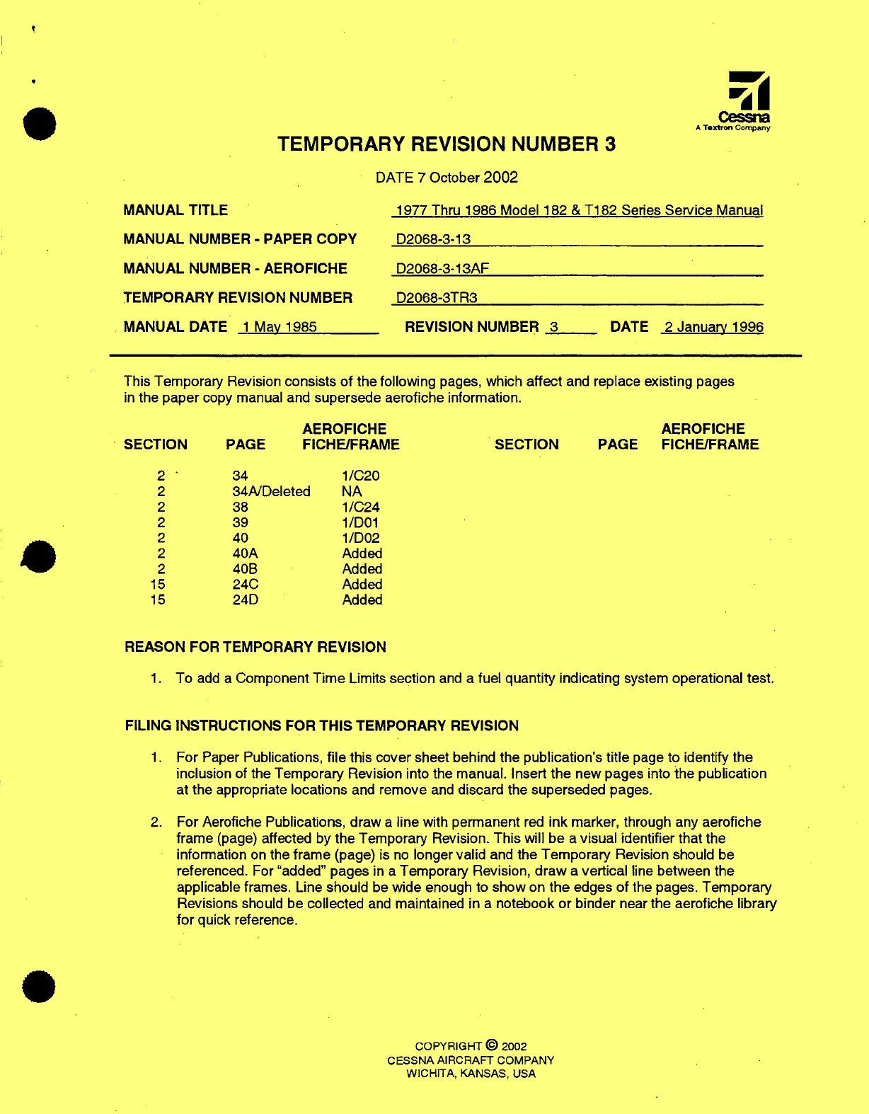
TEMPORARY
REVISION NUMBER
3
DATE
7
October
2002
MANUAL
TITLE
1977
Thru
1986
Model
182
&
T182
Series
Service
Manual
MANUAL
NUMBER
-
PAPER
COPY
D2068-3-13
MANUAL
NUMBER
-
AEROFICHE
D2068-3-13AF
TEMPORARY
REVISION
NUMBER
D2068-3TR3
MANUAL
DATE
1
May
1985
REVISION NUMBER 3
DATE
2
January
1996
This Temporary
Revision
consists
of
the following
pages,
which
affect
and
replace
existing
pages
in
the
paper
copy
manual
and
supersede aerofiche
information.
AEROFICHE AEROFICHE
SECTION
PAGE
FICHE/FRAME
SECTION
PAGE FICHE/FRAME
2
34
1/C20
2
34A/Deleted
NA
2
38
1/C24
2
39
1/D01
2
40
1/D02
2
40A
Added
2
40B
Added
15
24C
Added
15
24D
Added
REASON
FOR
TEMPORARY REVISION
1.
To
add a
Component
Time
Limits
section
and
a
fuel
quantity indicating
system
operational
test.
FILING INSTRUCTIONS
FOR
THIS
TEMPORARY
REVISION
1.
For
Paper
Publications,
file
this
cover
sheet
behind
the
publication's
title
page
to
identify
the
inclusion
of
the
Temporary
Revision
into
the
manual. Insert
the
new
pages
into
the
publication
at
the
appropriate
locations
and
remove
and
discard
the
superseded
pages.
2.
For Aerofiche
Publications,
draw
a
line
with
permanent
red
ink
marker, through
any
aerofiche
frame
(page)
affected
by
the
Temporary Revision. This
will
be
a
visual
identifier
that
the
information
on
the
frame
(page)
is
no
longer
valid
and
the Temporary
Revision
should
be
referenced.
For
"added"
pages
in a
Temporary
Revision,
draw
a
vertical
line between
the
applicable
frames.
Line
should
be
wide
enough
to
show
on
the
edges
of
the pages.
Temporary
Revisions
should
be
collected
and
maintained
in
a
notebook or binder
near
the aerofiche
library
for
quick
reference.
COPYRIGHT ©
2002
CESSNA
AIRCRAFT COMPANY
WICHITA,
KANSAS,
USA
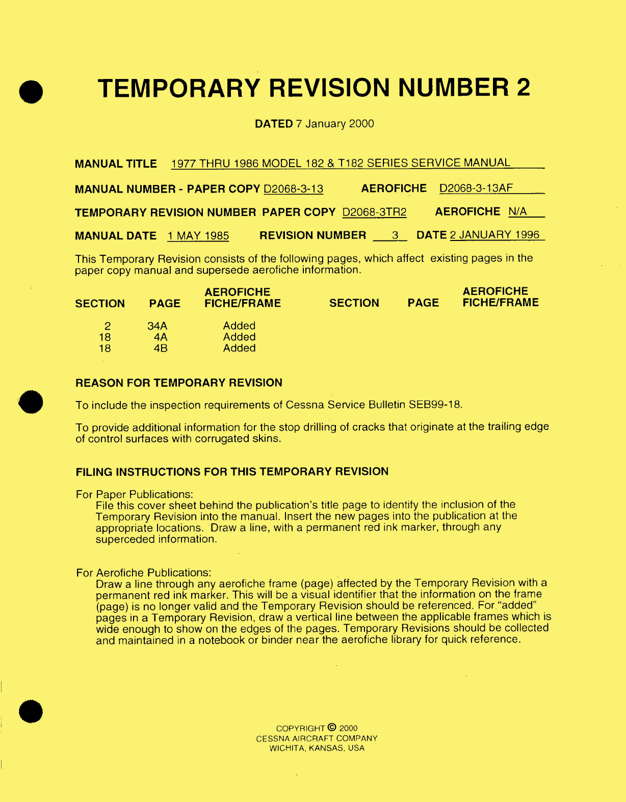
TEMPORARY
REVISION
NUMBER
2
DATED
7
January
2000
MANUAL
TITLE
1977
THRU
1986
MODEL
182 &
T182
SERIES SERVICE
MANUAL
MANUAL
NUMBER
-
PAPER COPY
D2068-3-13
AEROFICHE
D2068-3-13AF
TEMPORARY
REVISION NUMBER PAPER
COPY
D2068-3TR2
AEROFICHE
N/A
MANUAL
DATE
1
MAY
1985
REVISION NUMBER
3
DATE
2
JANUARY
1996
This Temporary
Revision
consists
of
the
following
pages, which
affect
existing
pages
in
the
paper
copy
manual
and
supersede aerofiche
information.
AEROFICHE AEROFICHE
SECTION
PAGE
FICHE/FRAME SECTION
PAGE
FICHE/FRAME
2
34A
Added
18
4A
Added
18
4B
Added
REASON
FOR
TEMPORARY
REVISION
To
include
the
inspection
requirements
of
Cessna Service
Bulletin SEB99-18.
To
provide
additional
information for
the
stop
drilling
of
cracks
that
originate
at
the
trailing
edge
of
control
surfaces
with
corrugated
skins.
FILING INSTRUCTIONS
FOR
THIS
TEMPORARY
REVISION
For
Paper
Publications:
File
this
cover
sheet behind
the
publication's
title
page
to
identify
the
inclusion
of
the
Temporary
Revision
into
the
manual. Insert
the new
pages
into
the
publication
at the
appropriate locations.
Draw
a
line,
with
a
permanent
red ink
marker,
through
any
superceded
information.
For
Aerofiche
Publications:
Draw
a
line
through any
aerofiche
frame
(page)
affected
by
the
Temporary
Revision
with
a
permanent
red
ink
marker.
This
will
be
a
visual
identifier
that
the
information
on
the
frame
(page)
is
no
longer
valid
and
the
Temporary
Revision should
be
referenced.
For "added"
pages
in
a
Temporary
Revision,
draw
a
vertical
line
between
the
applicable
frames
which
is
wide enough
to
show
on
the
edges
of
the
pages.
Temporary Revisions
should
be
collected
and
maintained
in
a
notebook
or
binder
near
the
aerofiche
library
for
quick reference.
COPYRIGHT
2000
CESSNA
AIRCRAFT
COMPANY
WICHITA, KANSAS,
USA
MODEL
182
&
T182
SERIES
SERVICE
MANUAL
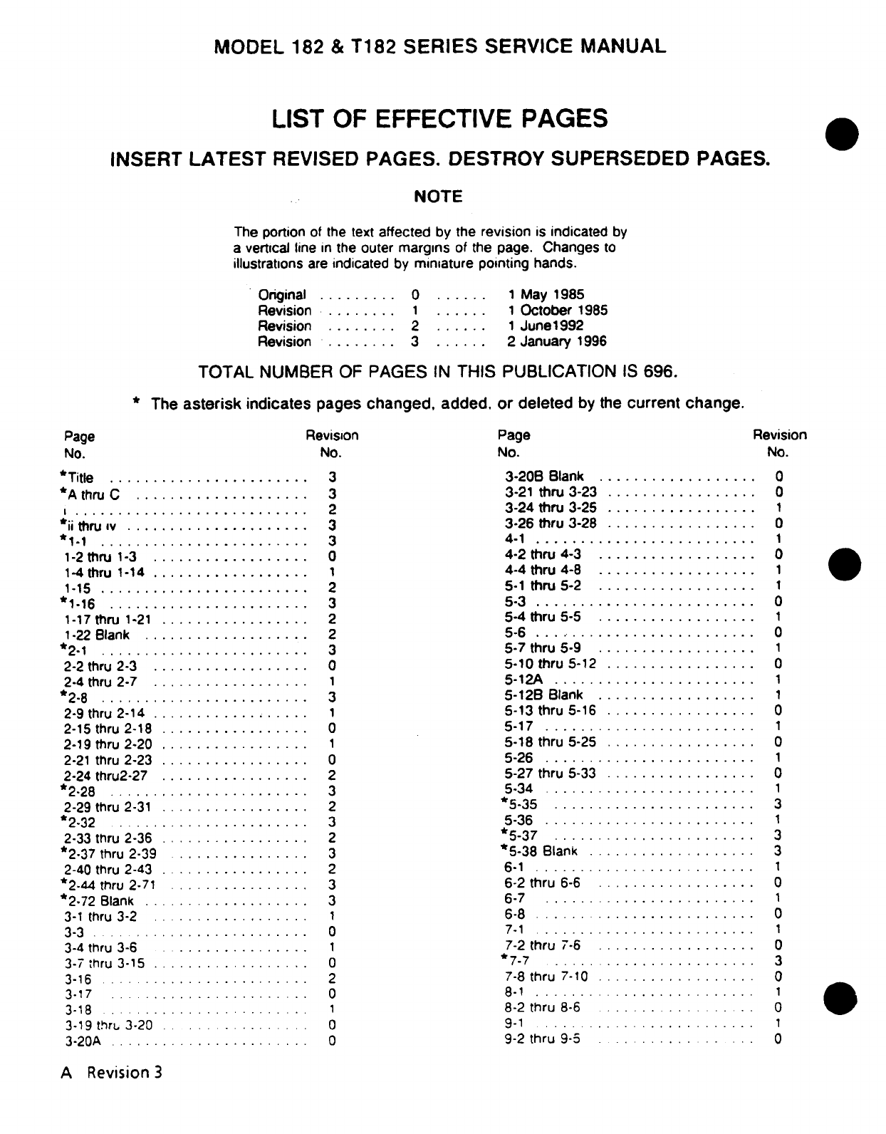
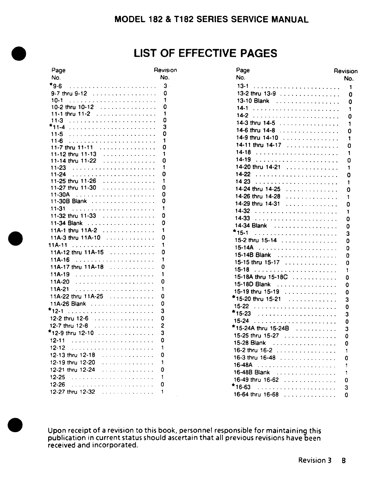
LIST
OF
EFFECTIVE
PAGES
INSERT
LATEST
REVISED
PAGES. DESTROY
SUPERSEDED
PAGES.
NOTE
The
portion
of
the
text
affected
by
the
revision
is
indicated
by
a
vertical
line
in
the
outer
margins
of
the
page.
Changes
to
illustrations
are
indicated
by
miniature pointing
hands.
Original
.........
0
...... 1
May
1985
Revision
........
1......
1 October
1985
Revision
........
2
...... 1 June1992
Revision
........
3
......
2
January
1996
TOTAL
NUMBER
OF
PAGES
IN
THIS
PUBLICATION
IS
696.
*
The
asterisk
indicates
pages
changed,
added,
or
deleted
by
the
current
change.
Page
Revision Page
Revision
No.
No.
No.
No.
*Title
.......................
3
3-20B
Blank
.................. 0
*A
thru
C
....................
3
3-21
thru
3-23
................. 0
i ........................ ...
2
3-24 thru
3-25
................. 1
*ii
thru
iv
......... ...........
3
3-26 thru
3-28
................ 0
*1-1
...................
.....
3
4-1
......................... 1
1-2
thru
1-3
.
......
..........
0
4-2
thru
4-3
.................. 0
1-4
thru
1-14
.................. 1
4-4
thru
4-8
.................. 1
1-15
........................
2
5-1
thru
5-2
.................. 1
*1-16
.......................
3
5-3
......................... 0
1-17
thru
1-21
. ................
2
5-4 thru
5-5
.................. 1
1-22
Blank
. ..................
2
5-6
......................... 0
*2-1
........................
3
5-7
thru
5-9
.................. 1
2-2
thru 2-3
..................
0
5-10
thru
5-12
................. 0
2-4 thru
2-7
........... ....... 1
5-12A
....................... 1
*2-8
........................
3
5-12B
Blank
.................. 1
2-9
thru
2-14
.................. 1
5-13
thru
5-16
................. 0
2-15
thru
2-18
.
......
.........
0
5-17
........................ 1
2-19 thru
2-20
.
......
......... 1
5-18
thru
5-25
................. 0
2-21
thru
2-23
.................
0
5-26
........................ 1
2-24
thru2-27
. ................
2
5-27
thru
5-33
................. 0
*2-28
.......................
3
5-34
........................ 1
2-29
thru
2-31
.................
2
*5-35
....................... 3
*2-32
......................
3
5-36
........................ 1
2-33
thru
2-36
.................
2
*5-37
....................... 3
*2-37
thru
2-39
.
.....
......... 3
*5-38 Blank
................... 3
2-40
thru 2-43
.................
2
6-1
......................... 1
*2-44
thru
2-71
. ...............
3
6-2
thru
6-6
.................. 0
*2-72
Blank
...... ............
3
6-7
........................ 1
3-1
thru 3-2
. ................. 1
6-8
..... .................. 0
3-3
... .....................
0
7-1
......................... 1
3-4 thru
3-6
............... 1
7-2
thru
7-6
.................. 0
3-7
thru
3-15
.
.......
0
*7-7
......................
3
3-16
.... ............... ...
2
7-8
thru
7-10
.................. 0
3.17
...
.................
..
0
8-1
.
................ ........
1
3-18
................... 1
8-2
thru
8-6
................ 0
3-19
thru
3-20
......
.........
9-1
....................... 1
3-20A
.......................
0
9-2
thru
9-5
.
......
. ... ... 0
A
Revision
3
MODEL
182
&
T182
SERIES
SERVICE
MANUAL
LIST
OF
EFFECTIVE
PAGES
Page
Revision
Page
Revision
No.
No. No.
No.
*9 -6
.................... . . .
3
13-1
..... .. . . . . ............ 1
9-7
thru
9-12
.................
0
13-2
thru
13-9
................ 0
10-1
....................... 1
13-10
Blank
............... 0
10-2
thru 10-12
...............
0
14-1
................... 1
11-1
thru
11-2
................ 1
14-2
........ 0...
11-3
. 14-3
thru
14-5
.
......
.1
*11-4
....
3
14-6 thru
14-8
................ 0
11-5
.. .. .. .. .. .. ..-.
.-
14-9
thru
14-10
............ 1
11-thru
11
.......................
11-7
thru
11-11.
.14-11
thru
14-17
.........
11-14 thru
11-22
.. . 0............................0
11-23
.......................
14-20
thru
14-21
. ............. 1
11-24
thru
11-25
thru
11-26
.............. 1
14-23
...................... 1
11-27
thru
11-30
..............
0
14-24
thru
14-25.
............. 0
11-30A
......................
14-26
thru
14-28
.............. 1
11-30B
Blank
.................
0
14-29
thru
14-31
.......... 0
11-3
1
......
....... . .
.....
.. 1
14-32
. ..
.....
... . ..
.....
.1
11-32
thru
11-33
.............. 1
14- 3
0
11-34 Blank
.................. 0...
14-34
Blank
.0
11A-1
thru
11A-2
........
.. . 1 *
15-1
........
........ ...... 3
11A-3thru
11A-0
.............
0
15-2
thru
5-14
.............. 0
11A-11
.. ...................
15-14A
thru...............0
11A-12thru
11A-15
............
15-14B
Blank
................ 0
11A-16
..................... . .
15-15
thru
15-17
......... 0...
11A-1thru
A-................. 1518
11A-19
..................... 1
15-18A
thru
15-18C
. ........ 0....
11A-20
.15-18D
11A-21
.....................
15-19
thru
15-19......
.............. 0
11A-22
thru
11A-25
............
0
*15-20
thru
15-21
............. 3
11A-26 Blank
................. 15-02
*12-1
.. .. ........
12-2
thru
12-6
............. 0
12-7
thru
12-82 ................. 2..
*15-24A
thru 15-24
.......
*12-9
thru
12-10
...............
12-11
...................... .
15-28
. ............. 0
12-12....... .
15-28
thru
12-13
thru
12-19
thru
12-20
..............
16-48A
16-18
..................... 1
12-21
thru
12-24
................
16-48B
Blank
1
12-25
12-26
..................... ....... 3
12-27 thru
12-32
.............. 1
16-64
hru
16-68
.........
Upon
receipt
of
a
revision
to
this book,
personnel
responsible
for
maintaining
this
publication
in
current
status
should
ascertain
that
all
previous
revisions have
been
received
and
incorporated.
Revision
3
B
Revision
3
B
MODEL
182
&
T182
SERIES
SERVICE
MANUAL
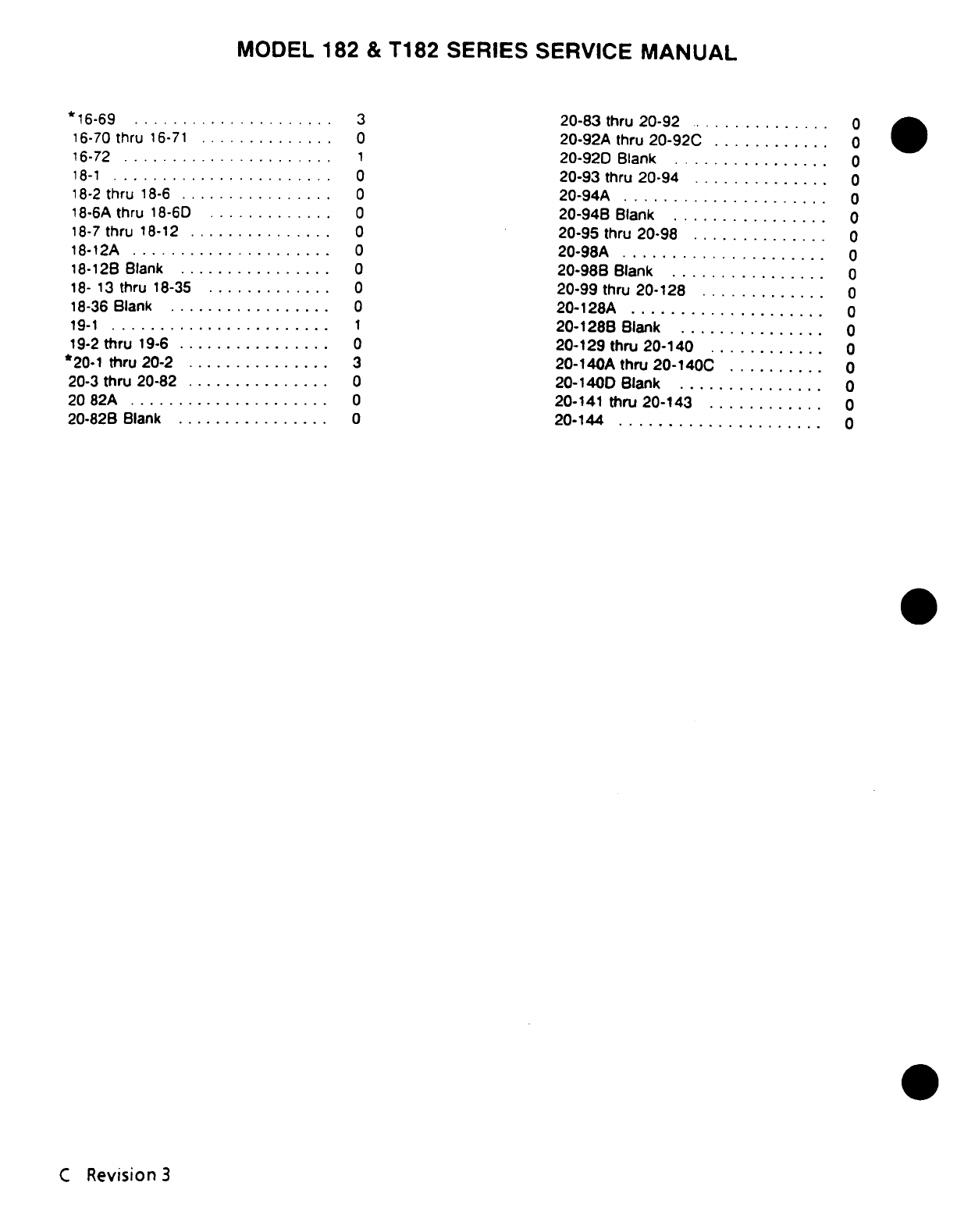
*16-69
.................. ...
3
20-83
thru
20-92
............... 0
16-70
thru
16-71
..............
0
20-92A
thru
20-92C
............ 0
16-72
...................... 1
20-92D
Blank
................ 0
18-1
.......................
0
20-93
thru
20-94
.............. 0
18-2
thru
18-6
................
0
20-94A
..................... 0
18-6A
thru
18-6D
........ ....
0
20-94B
Blank
................ 0
18-7
thru
18-12
...............
0
20-95
thru
20-98
.............. 0
18-12A
.....................
0
20-98A
..................... 0
18-12B
Blank
................
0
20-98B
Blank
................ 0
18-
13
thru
18-35
.............
0
20-99
thru
20-128
............. 0
18-36
Blank
.................
0
20-128A
................... 0
19-1
....................... 1
20-128B
Blank
............... 0
19-2
thru
19-6
................
0
20-129
thru
20-140
............ 0
*20-1
thru
20-2
...............
3
20-140A thru 20-140C
.......... 0
20-3
thru
20-82
...............
0
20-140D Blank
............... 0
20
82A
.....................
0
20-141
thru 20-143
............ 0
20-82B
Blank
................
0
20-144
..................... 0
C
Revision
3
MODEL
182
&
T182
SERIES
SERVICE
MANUAL
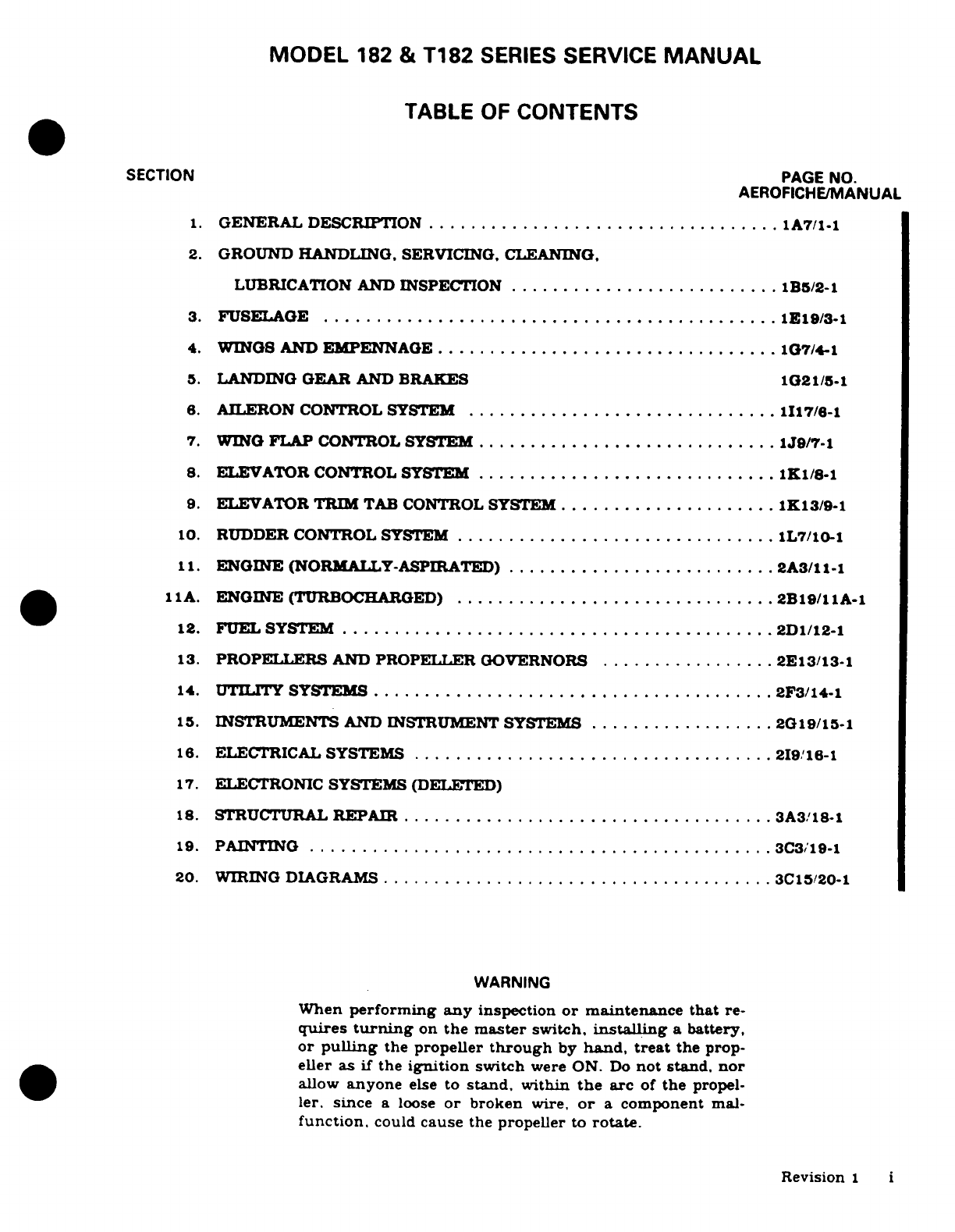
TABLE
OF
CONTENTS
SECTION
PAGE
NO.
AEROFICHE/MANUAL
1.
GENERAL
DESCRIPTION
..................................
1A7/1-1
2.
GROUND
HANDLING, SERVICING.
CLEANING.
LUBRICATION AND
INSPECTION
..........................
1Bb/2-1
3.
FUSELAGE
............................................
19/3-1
4.
WINGS AND
EMPENNAGE
.................................
1G7/4-1
5.
LANDING
GEAR
AND
BRAKES
1G21/5-1
6.
AILERON
CONTROL
SYSTEM
..............................
1I17/6-1
7.
WING
FLAP
CONTROL
SYSTEM
.............................
1J9/7-1
8.
ELEVATOR
CONTROL
SYSTEM
............................. 1K1/8-1
9.
ELEVATOR
TRIM
TAB
CONTROL
SYSTEM
.....................
1K13/9-1
10.
RUDDER
CONTROL
SYSTEM
...............................
1L7/10-1
11.
ENGINE
(NORMALLY-ASPIRATED)
..........................
2A3/11-1
11A.
ENGINE
(TURBOCHARGED)
...............................
2B19/11A-1
12.
FUEL
SYSTEM
..........................................
2D1/12-1
13.
PROPELLERS
AND
PROPELLER
GOVERNORS
.................
2E13/13-1
14.
UTILITY
SYSTEMS
.......................................
2F3/14-1
15.
INSTRUMENTS
AND
INSTRUMENT
SYSTEMS
..................
2G19/15-1
16.
ELECTRICAL
SYSTEMS
...................................
2I9/16-1
17.
ELECTRONIC SYSTEMS
(DELETED)
18.
STRUCTURAL
REPAIR
..................................
3A3/18-1
19.
PAINTING
........................ ......... .........
3C3/19-1
20.
WIRING DIAGRAMS
....................................
3C15/20-1
WARNING
When
performing
any
inspection
or
maintenance
that
re-
quires
turning
on
the
master
switch,
installing
a
battery,
or
pulling
the propeller
through
by
hand, treat
the prop-
eller
as
if
the
ignition
switch
were
ON.
Do
not
stand,
nor
allow
anyone
else
to
stand,
within
the
arc
of
the
propel-
ler.
since
a
loose
or
broken
wire,
or
a
component
mal-
function,
could
cause
the
propeller
to
rotate.
Revision
1 i
MODEL
182
&
T182
SERIES SERVICE
MANUAL
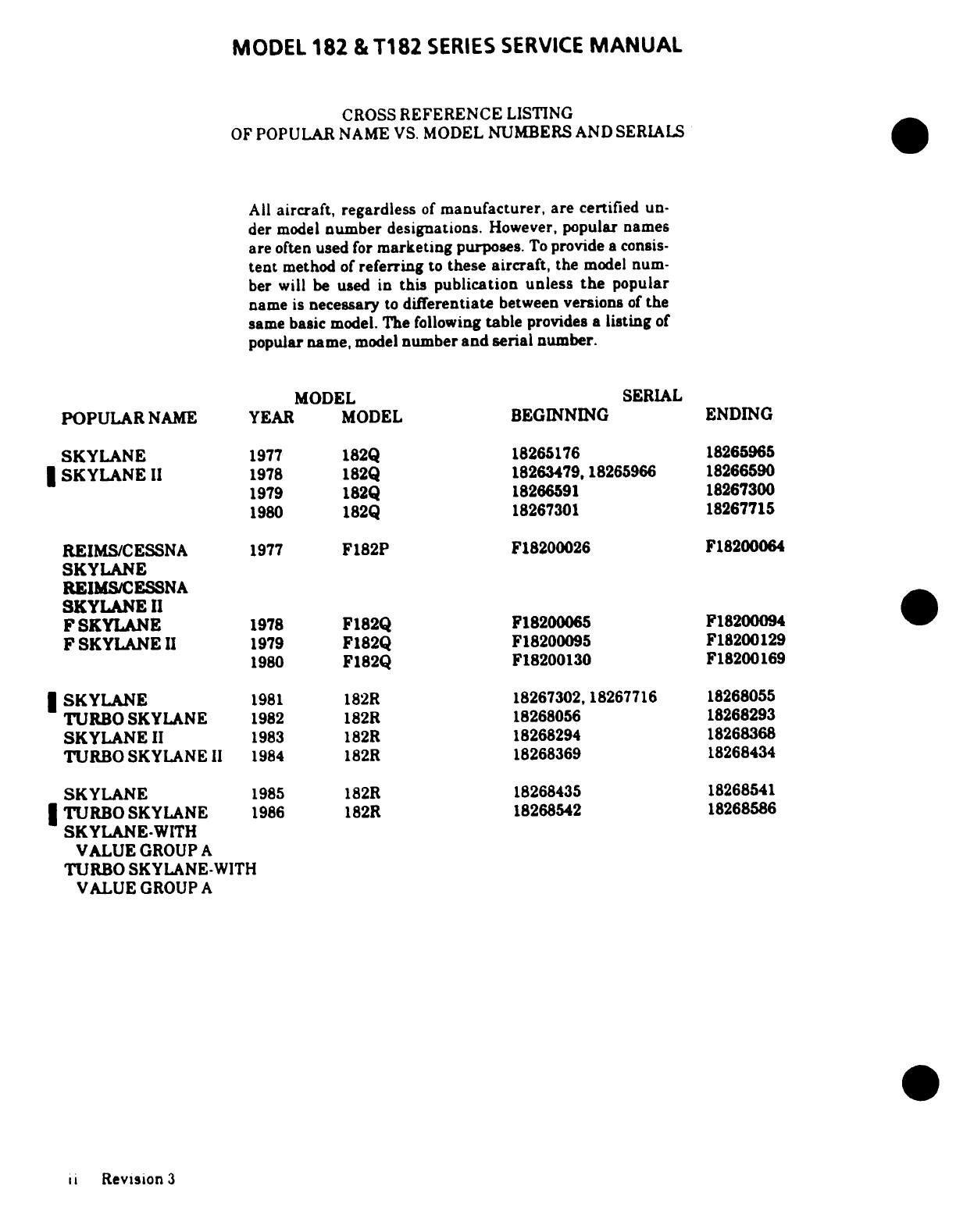
CROSS
REFERENCE
LISTING
OF
POPULAR
NAME
VS.
MODEL
NUMBERS AND
SERIALS
All
aircraft,
regardless
of
manufacturer,
are
certified
un-
der
model
number
designations.
However,
popular
names
are
often
used
for
marketing
purposes.
To
provide
a
consis-
tent
method
of
referring
to
these
aircraft,
the
model
num-
ber
will
be
used in
this
publication
unless
the
popular
name
is
necessary
to
differentiate
between
versions
of
the
same basic
model.
The
following
table
provides
a
listing
of
popular
name,
model
number
and
serial
number.
MODEL
SERIAL
POPULAR
NAME YEAR
MODEL
BEGINNING
ENDING
SKYLANE
1977
182Q
18265176 18265965
SKYLANE
II
1978
182Q
18263479,
18265966
18266590
1979
182Q
18266591
18267300
1980
182Q
18267301
18267715
REIMS/CESSNA
1977
F182P
F18200026
F18200064
SKYLANE
REIMS/CESSNA
SKYLANE
II
FSKYLANE
1978
F182Q
F18200065
F18200094
F
SKYLANE
II
1979
F182Q F18200095
F18200129
1980
F182Q F18200130 F18200169
SKYLANE
1981
182R
18267302, 18267716
18268055
TURBO
SKYLANE
1982
182R
18268056
18268293
SKYLANE
II
1983
182R
18268294
18268368
TURBO
SKYLANE
II
1984
182R
18268369 18268434
SKYLANE
1985
182R
18268435 18268541
TURBO
SKYLANE
1986
182R
18268542 18268586
SKYLANE-WITH
VALUE
GROUP
A
TURBO
SKYLANE-WITH
VALUE
GROUP
A
ii
Revision
3
MODEL
182
&T182
SERIES
SERVICE
MANUAL
This
manual
contains
factory-recommended
procedures
and
instructions
for
ground
handling,
servicing, and
maintaining
Cessna
182
Series
Models.
The
182
and
T182
Series
Models covered in
this
manual
are
identical,
except the
Model T182
is
turbocharged.
Besides
serving as
a
reference
for
the
experienced
mechanic,
this
man-
ual
also
covers
step-by-step
procedures
for
the
less
experienced. If
properly
used,
it
will
better
enable
the
me-
chanic
to
maintain
Cessna
182
Series
airplanes
and
thereby
establish
a
reputation
for
reliable
service.
This
service
manual
is
designed
for
aerofiche
presentation.
To
facilitate
the
use
of
the
aerofiche,
refer
to
the
aerofiche
header
for
basic
information.
KEEPING
CESSNA
PUBLICATIONS CURRENT
The
information
in
this
publication
is
based
on
data
available
at
the
time
of
publication and
is
updated,
supple-
mented,
and
automatically
amended
by
all
information
issued
in
Service
News
Letters,
Service
Bulletins,
Sup-
plier
Service Notices,
Publication
Changes,
Revisions,
Reissues
and
Temporary
Revisions.
All
such
amendments
become
part
of
and
are specifically
incorporated
within
this
publication.
Users
are
urged
to
keep
abreast
of
the
latest
amendments
to
this
publication
through
information
available
at
Cessna
Authorized
Service
Stations
or
through
the
Cessna
Product
Support
subscription
services.
Cessna
Service
Stations
have
also
been
supplied
with
a
group
of
supplier publications
which
provide
disassembly,
overhaul,
and
parts
breakdowns
for
some
of
the
var-
ious
supplier
equipment
items.
Suppliers
publications
are
updated,
supplemented, and
specifically
amended
by
supplier
issued revisions
and
service
information
which
may
be
reissued
by
Cessna;
thereby
automatically
amending
this
publication
and
is
communicated
to
the
field
through
Cessna's
Authorized
Service
Stations
and/or
through
Cessna's
subscription
services.
WARNING:
ALL
INSPECTION
INTERVALS,
REPLACEMENT
TIME
LIMITS, OVERHAUL TIME
OMMENDED
BY
CESSNA
ARE
SOLELY
BASED
ON
THE
USE
OF
NEW,
REMANU-
FACTURED,
OR
OVERHAULED
CESSNA
APPROVED
PARTS.
IF
PARTS
ARE
DE-
SIGNED,
MANUFACTURED,
REMANUFACTURED,
OVERHAULED,
PURCHASED,
AND/OR
APPROVED
BY
ENTITIES
OTHER
THAN CESSNA,
THEN
THE
DATA
IN
CESSNA'S
MAINTENANCE/SERVICE
MANUALS
AND
PARTS
CATALOGS
ARE
NO
LONGER
APPLICABLE
AND
THE
PURCHASER
IS
WARNED NOT
TO
RELY
ON
SUCH
DATA
FOR
NON-CESSNA
PARTS.
ALL
INSPECTION
INTERVALS, RE-
PLACEMENT
TIME
LIMITS,
OVERHAUL TIME
LIMITS, THE
METHOD
OF
INSPEC-
TION,
LIFE
LIMITS,
CYCLE
LIMITS,
ETC,
FOR
SUCH
NON-CESSNA
PARTS
MUST
BE
OBTAINED
FROM
THE
MANUFACTURER
AND/OR
SELLER
OF
SUCH
NON-
CESSNA
PARTS.
1. REVISIONS/CHANGES.
These
are
issued
to
the
Service
Stations
by
Cessna Aircraft
Company
for
this
publication
as
required,
and
include
only
pages
that
require updating.
2.
REISSUE.
Manual
is
reissued
to
Service
Stations
as required,
and
is
a
complete
manual
incorporating
all
the
latest
information
and
outstanding
revisions/changes. It
supersedes
and
replaces
previous
is-
sue(s).
REVISIONS/CHANGES
and
REISSUES
can
be
purchased
from
your
Cessna
Service
Station
or
directly
from
the
Cessna
Parts
Distribution,
(CPD
2)
Dept.
701,
Cessna
Aircraft
Company,
5800
East
Pawnee,
Wichita,
Kansas
67201.
All
supplemental
service
information
concerning
this
manual
is
supplied
to
all
appropriate
Cessna
Service
Sta-
tions
so
that
they
have
the
latest
authoritative
recommendations
for
servicing
these
Cessna
aircraft.
Therefore,
it
is
recommended
that
Cessna
owners
utilize
the
knowledge
and experience
of
the
Cessna
Service
Station
Or-
ganization.
Revision
3
iii
MODEL
182
&
T182
SERIES
SERVICE
MANUAL
CUSTOMER
CARE
SUPPLIES
AND
PUBLICATIONS
CATALOG
A
Customer
Care
Supplies
and
Publications
Catalog
is
available
from
your
Cessna
Service
Station
or
directly
from
the
Cessna
Parts
Distribution,
(CPD
2)
Dept.
701,
Cessna
Aircraft
Company,
5800
East
Pawnee,
Wichita,
Kansas
67201.
The
Supplies
and
Publications
catalog
lists
all
publications
and
Customer
Care
Supplies
avail-
able
from
Cessna
for
prior
year
models
as
well
as
new
products.
SUPPLEMENTAL
TYPE
CERTIFICATE
INSTALLATIONS
Inspection,
maintenance
and
parts
requirements
for
supplemental
type
certificate
(STC)
installations
are not
in-
cluded
in
this
manual.
When
an
STC
installation
is
incorporated
on
the
airplane,
those
portions
of
the
airplane
affected
by
the
installation
must
be
inspected
in
accordance
with
the
inspection program
published
by
the
owner
of
the
STC.
Since
STC
installations
may
change systems
interface,
operating characteristics and
component
loads or
stresses
on
adjacent
structures,
Cessna
provided
inspection
criteria
may
not
be
valid
for
airplanes
with
STC
installations.
CUSTOMER
COMMENTS ON
MANUAL
Cessna
Aircraft
Company
has
endeavored
to
furnish
you
with
an
accurate, useful,
up-to-date
manual.
This
man-
ual
can
be
improved
with
your
help.
Please
use
the
return
card,
provided
with
your manual,
to
report
any
errors,
discrepancies, and
omissions
in
this
manual
as
well
as
any
comments
you
wish
to
make.
iv
Revision
3
MODEL
182
&
T182
SERIES
SERVICE
MANUAL
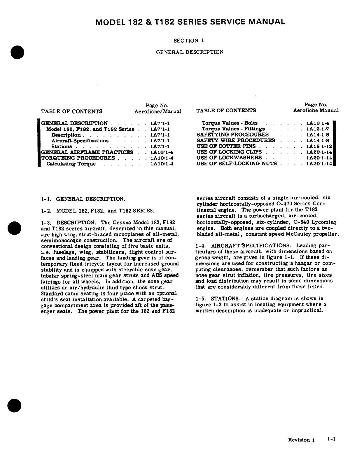
SECTION
1
GENERAL
DESCRIPTION
Page
No.
Page
No.
TABLE
OF
CONTENTS
Aerofiche/Manual
TABLE
OF
CONTENTS
Aerofiche
Manual
GENERAL
DESCRIPTION
.. ...
1A7/1-1
Torque
Values
-
Bolts
......
1A10/1-4
Model
182,
F182,
and
T182
Series
.
1A7/1-1
Torque
Values
-
Fittings
... .
1A131-7
Description.
......
..
1A7/1-1
SAFETYING
PROCEDURES
....
1A14
1-8
Aircraft
Specifications
... .
1A7/1-1
SAFETY WIRE PROCEDURES
....
.
1A14
1-8
Stations
...
.....
..
1A7/1-1
USE OF COTTER
PINS
.......
1A18
1-12
GENERAL AIRFRAME
PRACTICES
. .
1A10/1-4
USE
OF LOCKING CLIPS
.. . .
1A20,1-14
TORQUEING
PROCEDURES
.
....
1A10/1-4
USE OF LOCKWASHERS
......
1A20/1-14
Calculating Torque
.......
1A10/1-4
USE OF SELF-LOCKING
NUTS
...
1A20/1-14
1-1.
GENERAL
DESCRIPTION.
series aircraft
consists
of
a
single
air-cooled,
six
cylinder
horizontally-opposed
0-470
Series
Con-
1-2.
MODEL
182,
F182, and
T182 SERIES.
tinental
engine. The power
plant
for
the
T182
series
aircraft
is
a
turbocharged,
air-cooled,
1-3.
DESCRIPTION.
The
Cessna
Model
182,
F182
horizontally-opposed,
six-cylinder,
0-540
Lycoming
and
T182
series
aircraft,
described
in
this
manual,
engine.
Both
engines
are
coupled
directly
to
a
two-
are
high
wing,
strut-braced
monoplanes
of
all-metal,
bladed
all-metal,
constant
speed
McCauley
propeller.
semimonocoque
construction.
The
aircraft
are
of
conventional
design
consisting
of
five
basic
units,
1-4.
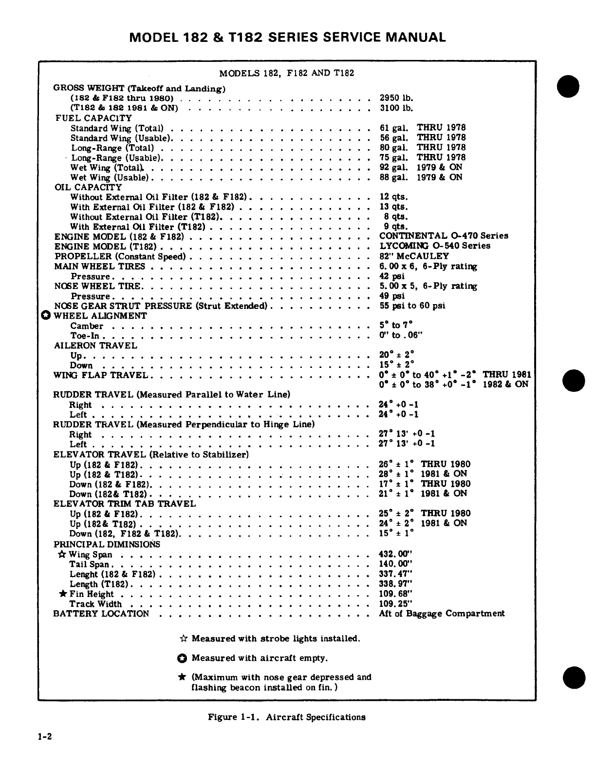
AIRCRAFT
SPECIFICATIONS. Leading
par-
i. e.
fuselage,
wing,
stabilizers,
flight
control
sur-
ticulars
of
these
aircraft,
with
dimensions
based
on
faces
and
landing
gear.
The
landing
gear
is of
con-
gross
weight,
are
given
in
figure
1-1.
If
these
di-
temporary
fixed
tricycle
layout
for
increased
ground
mensions
are
used
for
constructing
a
hangar
or
com-
stability
and
is
equipped
with
steerable
nose
gear,
puting
clearances, remember that
such
factors
as
tubular
spring-steel
main
gear
struts
and
ABS
speed
nose
gear
strut
inflation,
tire pressures,
tire
sizes
fairings
for
all
wheels.
In
addition, the
nose
gear
and
load
distribution
may
result
in
some
dimensions
utilizes
an
air/hydraulic
fluid
type
shock
strut,
that
are
considerably
different from
those
listed.
Standard cabin
seating
is
four
place
with
an
optional
child's
seat
installation
available.
A
carpeted
bag-
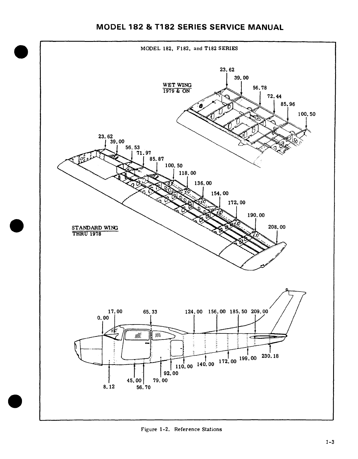
1-5.
STATIONS.
A
station
diagram
is
shown
in
gage
compartment
area
is
provided
aft
of
the
pass-
figure
1-2
to
assist
in
locating equipment where
a
enger
seats.
The
power
plant
for
the
182
and
F182
written
description
is
inadequate
or
impractical.
Revision
1 1-1
MODEL
182
&
T182
SERIES
SERVICE
MANUAL
MODELS
182,
F182
AND
T182
GROSS
WEIGHT
(Takeoff
and
Landing)
(182
&
F182
thru
1980) .. . .
....
...
......
2950
lb.
(T182 &
182
1981
&
ON)
...................
3100
lb.
FUEL
CAPACITY
Standard
Wing
(Total)
............... ....
61
gal.
THRU
1978
Standard
Wing
(Usable).
....................
56
gal.
THRU
1978
Long-Range
(Total)
......................
80
gal.
THRU
1978
Long-Range
(Usable).
..................
.
75
gal.
THRU
1978
Wet
Wing
(Total).
.......................
92
gal.
1979
&
ON
Wet
Wing
(Usable)
.......................
88
gal.
1979
&
ON
OIL
CAPACITY
Without
External
Oil
Filter
(182
&
F182).
............
12
qts.
With
External
Oil
Filter
(182
&
F182)
..............
13
qts.
Without
External
Oil
Filter
(T182).
...............
8
qts.
With
External
Oil
Filter
(T182)
.................
9
qts.
ENGINE
MODEL
(182
&
F182)
.................
CONTINENTAL
0-470
Series
ENGINE
MODEL
(T182)
...................... LYCOMING
0-540
Series
PROPELLER
(Constant
Speed)
...................
82"
McCAULEY
MAIN
WHEEL TIRES
.......................
6.00
x
6,
6-Ply
rating
Pressure
................... .......
42
psi
NOSE
WHEEL
TIRE.......................
5.00
x
5,
6-Ply
rating
Pressure
...........................
49
psi
NOSE
GEAR
STRUT
PRESSURE
(Strut
Extended)
...........
55
psi
to
60
psi
WHEEL
ALIGNMENT
Camber
..
.....
.. . . . ... . . . . .
....
... 5
°
to
7°
Toe-In
...........................
.
0"
to.
06"
AILERON
TRAVEL
Up
.....
....
. .. . . . ... . . . . .
20
° ±
2
°
Down
........................
15° ±
2
°
WING
FLAP
TRAVEL
........... .........
.
0°
to
40
°
+1° -2°
THRU 1981
0°
±
0 ° t o 3 8 ° + 0 ° - 1 °
1982
&
ON
RUDDER
TRAVEL
(Measured
Parallel
to
Water
Line)
Right . . . . ........ . . . . . . . ........ .
24
°
+0
-1
Left
............ . . . . . . ...........
24
+0
-1
RUDDER
TRAVEL
(Measured
Perpendicular
to
Hinge
Line)
Right
...........................
.
27°
13'
+0
-1
Left
.............................
27°
13' +0
-1
ELEVATOR TRAVEL
(Relative
to
Stabilizer)
Up
(182
&
F182).
.......................
26
°
±
1°
THRU
1980
Up
(182
&
T182).
.......................
28
°±
1
°
1981
&
ON
Down
(182
&
F182).
...................... 17°
±
1
°
THRU
1980
Down
(182&
T182).
......................
21
°
±
1
°
1981
&
ON
ELEVATOR
TRIM
TAB TRAVEL
Up (182
&
F182).
.......................
25
°
±
2°
THRU
1980
Up
(182&
T182)
.........................
24
°
±
2
°
1981
&
ON
Down
(182,
F182
&
T182)
.
.................
15
°
±
1
°
PRINCIPAL
DIMINSIONS
Wing Span
...........
... .
...........
432.00"
Tail
Span.
................... ........
140.
00"
Lenght
(182
&
F182)
......................
337.47"
Length
(T182)
.....
... . . ... . .. ..
.......
338.
97"
Fin
Height
.........
.. ...
.......
... .
109.68"
Track
Width
.............
.
...........
109.25"
BATTERY
LOCATION
......................
Aft of
Baggage
Compartment
Measured
with
strobe
lights
installed.
Measured
with
aircraft
empty.
(Maximum
with
nose
gear
depressed
and
flashing
beacon
installed
on
fin.
)
Figure
1-1.
Aircraft
Specifications
1-2
MODEL
182
&
T182
SERIES
SERVICE
MANUAL
MODEL
18Z,
F82,
and
T82
SERIES
23.
62
WET
WING
39.00
9785.87 1 ~85-96
,Il T9796-5r
.100
56.7850
|
17~".00
7
40
23.
62
56.53
71.9785.87
100.
s50 .
8. ~12
56.
118.70
-
Figure
1
-2.Refere
s-
-136
00
154.
00
STANDARI)
WI
172.
0
190.
00
19N7--"'
--
8
208.
00
0..00
124;
00
156:
00
185.50
209.
00
45.
A~
1
I92.00
8.12
0
79.
00
56.70
Figure
1-2.
Reference
Stations
1-3
MODEL
182
&
T182
SERIES
SERVICE
MANUAL
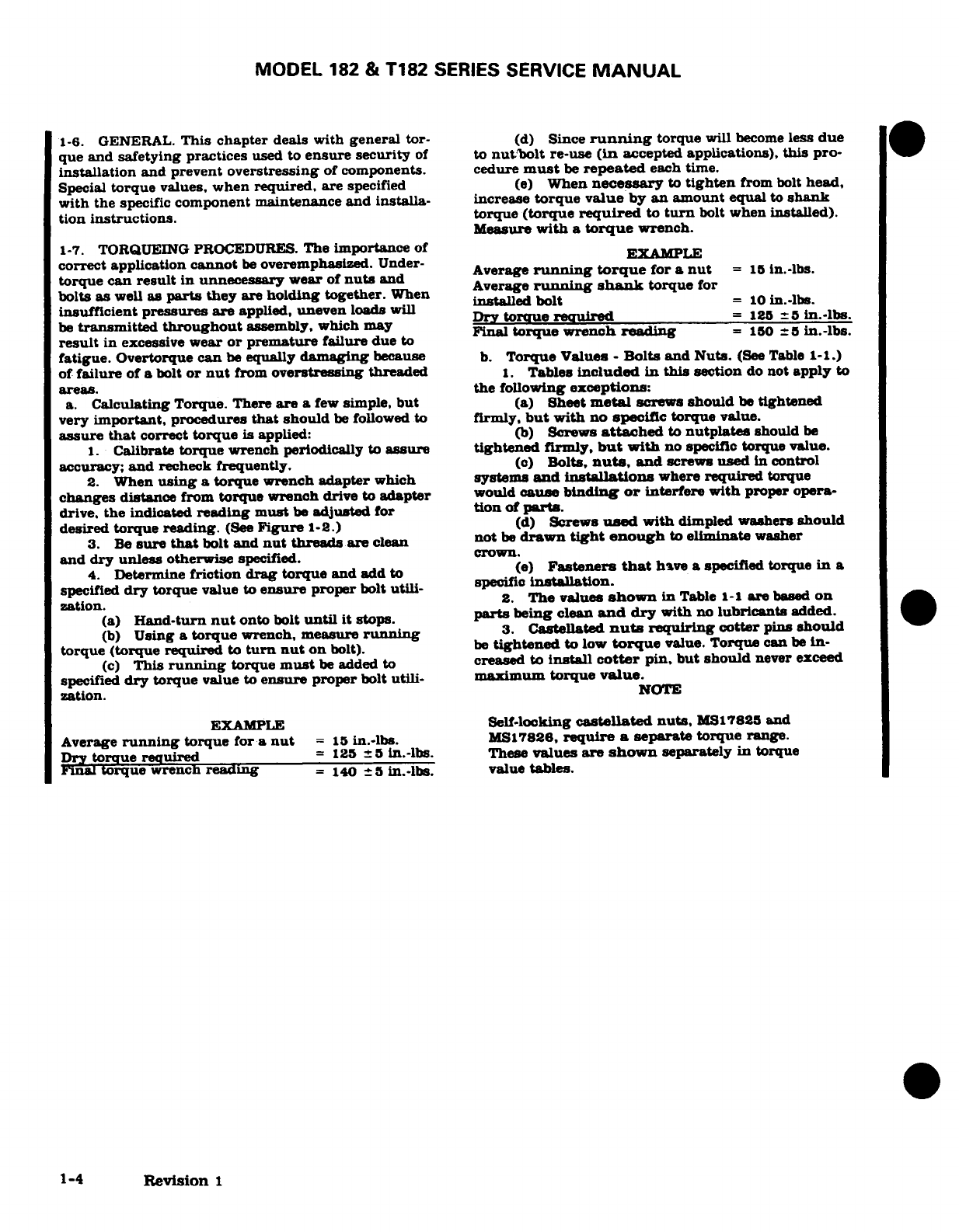
1-6.
GENERAL.
This
chapter
deals with
general
tor-
(d)
Since
running
torque
will
become
less
due
que
and
safetying
practices
used to
ensure
security
of
to
nutbolt
re-use
(in
accepted
applications),
this
pro-
installation
and prevent
overstressing
of
components. cedure
must
be
repeated
each time.
Special
torque
values,
when
required,
are
specified
(e)
When
necessary
to
tighten
from
bolt
head,
with
the
specific
component
maintenance
and
installa-
increase
torque
value
by
an
amount
equal
to
shank
tion
instructions.
torque
(torque
required
to
turn
bolt
when
installed).
Measure
with
a
torque
wrench.
1-7.
TORQUEING
PROCEDURES.
The
importance
of
correct
application
cannot
be
overemphasized.
Under-
torque can
result
in
unnecessary
wear
of
nuts
and
bolts
as
well
as
parts
they
are
holding
together.
When
Average
insufficient
pressures are
applied,
uneven
loads
will
be
transmitted
throughout
assembly,
which
may
Dry
torque
required
result
in
excessive
wear
or
premature
failure
due
to
fatigue. Overtorque
can
be
equally
damaging
because
b.
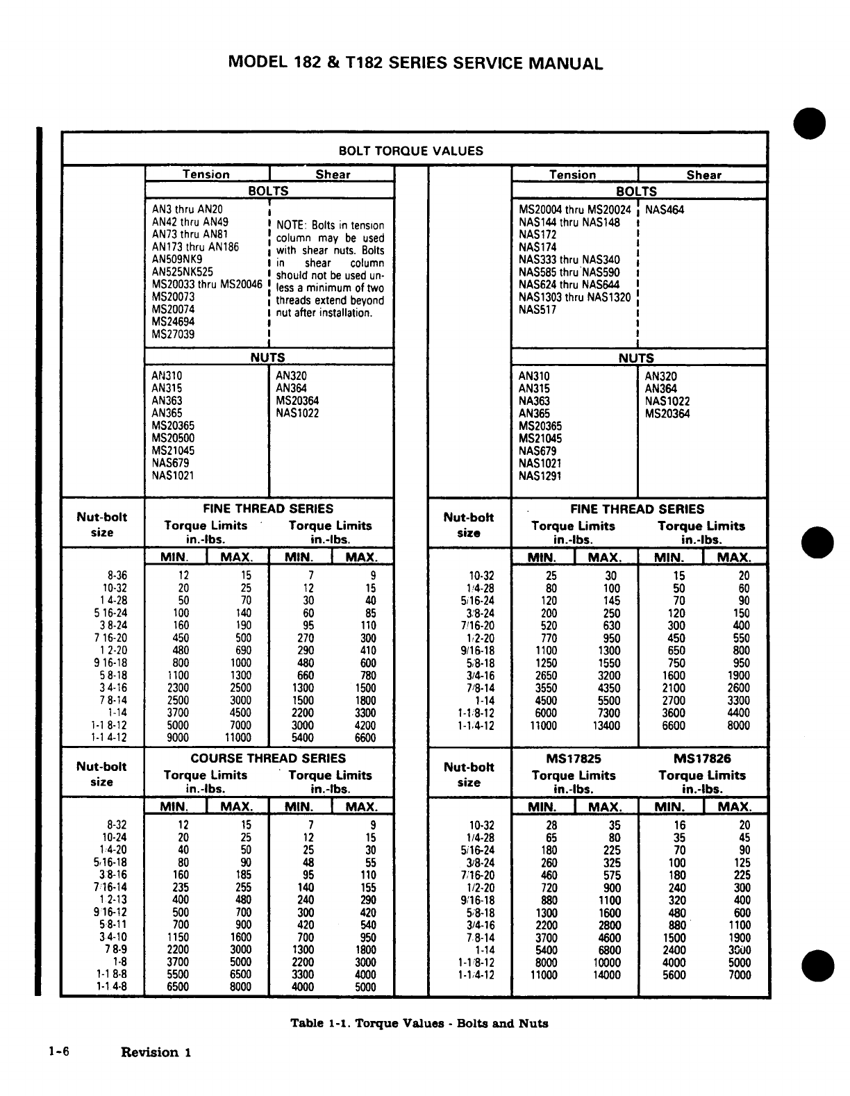
Torque
Values
-
Bolts
and Nuts.
(See
Table
1-1.)
of
failure
of
a
bolt
or
nut
from
overstressing
threaded
1.
Tables
included
in
this
section
do not
apply
to
areas.
the
following
exceptions:
a.
Calculating
Torque.
There
are
a
few
simple,
but
(a)
Sheet
metal
screws
should
be
tightened
very
important, procedures
that
should
be
followed
to
firmly,
but
with
no
specific torque
value.
assure
that
correct
torque
is
applied:
(b)
Screws
attached
to
nutplates
should
be
1.
Calibrate
torque
wrench
periodically
to
assure
tightened
firmly,
but
with
no
specific
torque
value.
accuracy;
and
recheck
frequently.
(c)
Bolts,
nuts,
and
screws
used
in
control
2.
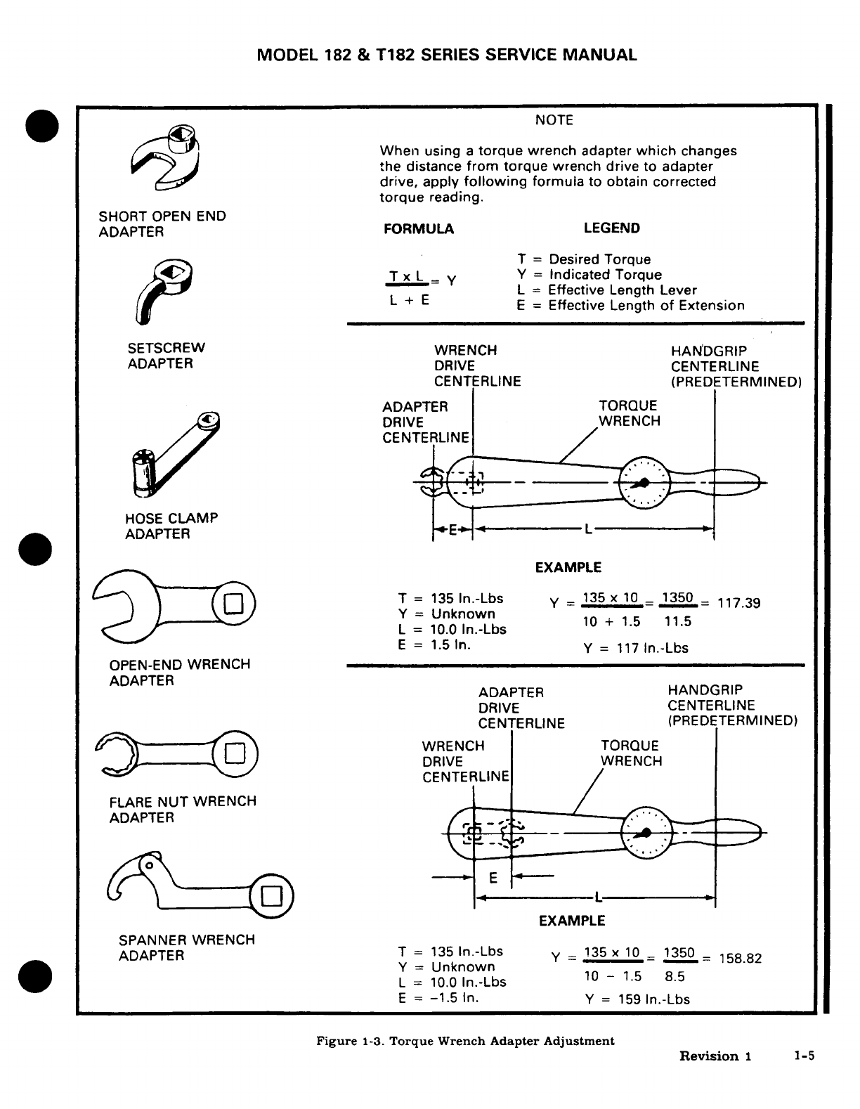
When
using
a
torque
wrench adapter
which
systems
and
installations
where
required
torque
changes
distance
from
torque
wrench
drive
to
adapter
would
cause
binding
or
interfere
with
proper
opera-
drive.
the
indicated
reading
must
be
adjusted for
tion
of
parts.
desired
torque reading.
(See
Figure
1-2.)
(d)
Screws
used
with
dimpled
washers
should
3.
Be
sure
that
bolt
and
nut
threads
are
clean
not
be
drawn
tight enough
to
eliminate
washer
and dry unless
otherwise
specified.
crown.
4.
Determine
friction
drag
torque
and
add
to
(e)
Fasteners
that
have
a
specified
torque
in
a
specified
dry
torque
value
to
ensure
proper
bolt
utili-
specific
nstallation.
zation.
2.
The
values
shown
in
Table
1-1
are
based
on
(a)
Hand-turn
nut
onto bolt
until
it
stops.
parts
being
clean
and
dry
with
no
lubricants
added.
(b)
Using
a
torque
wrench,
measure
runnin
3.
Castellated
nuts
requiring
cotter
pins
should
torque (torque required
to
turn nut
on
bolt).
be
tightened
to
low
torque
value.
Torque
can
be
in-
(c)
This
running
torque
must
be
added
to
creased
to
install
cotter
pin, but
should
never exceed
specified
dry
torque
value
to
ensure
proper
bolt
utili-
maximum
torque
value.
zation.
NOTE
EXAMPLE
Self-looking
castellated
nuts,
MS17825
and
Average
running
torque
for
a
nut
=
15
in.-lbs.
MS17826,
require
a
separate
torque
range.
Dry
torque
required
=
125
5
in.-lbs. These
values are
shown
separately
in
torque
Final
torque
wrench
reading
=
140
± 5
in.-lbs.
value
tables.
1-4
Revision
1
MODEL
182
&
T182
SERIES
SERVICE
MANUAL
NOTE
When using
a
torque
wrench
adapter
which
changes
the
distance
from torque
wrench
drive
to adapter
drive,
apply
following
formula
to obtain
corrected
torque
reading.
SHORT
OPEN
END
ADAPTER
FORMULA
LEGEND
T
=
Desired
Torque
L
+
SETSCREW
WRENCH
HANDGRIP
ADAPTER
DRIVE
CENTERLINE
CENTERLINE
(PREDETERMINED)
ADAPTER
TORQUE
CENTERLINE
HOSE
CLAMP
ADAPTER
EXAMPLE
Y
=
Unknown
10
+
1.5
11.5
E
=
1.5
In.
Y =
117
In.-Lbs
OPEN-END
WRENCH
ADAPTER
DRIVE
CENTERLINE
CENTERLINE (PREDETERMINED)
WRENCH
TORQUE
DRIVE
WRENCH
CENTERLINE
FLARE
NUT
WRENCH
ADAPTER
EXAMPLE
SPANNER
WRENCH
ADAPTER
T
=
135
In.-Lbs
y
=
135 x
10
_
1350
15882
Y
=
Unknown
L
=
10.0
In.-Lbs
10
1.5
8.5
E
=
-1.5
In.
Y
=
159
In.-Lbs
Figure
1-3.
Torque
Wrench
Adapter
Adjustment
Revision
1
1-5
MODEL
182
&
T182
SERIES
SERVICE
MANUAL
BOLT
TORQUE
VALUES
Tension
Shear
Tension
Shear
BOLTS
BOLTS
AN3
thru
AN20
MS20004
thru
MS20024
NAS464
AN42
thru
AN49
NOTE:
Bolts
in
tension
NAS144
thru
NAS148
AN73
thru
AN81
column
may
be
used
NAS172
AN173
thru
AN186
with
shear nuts.
Bolts NAS174
AN509NK9
in
shear
column
NAS333
thru
NAS340
AN525NK525
should not
be used un-
NAS585
thru
NAS590
MS20033
thru
MS20046
less
a
minimum
of two
NAS624
thru
NAS644
MS20073
threads extend
beyondNAS1303
thru
NAS1320
MS20074
nut
after
installation.
NAS517
MS24694
MS27039
NUTS
NUTS
AN310
AN320 AN310
AN320
AN315
AN364
AN315
AN364
AN363 MS20364 NA363
NAS1022
AN365
NAS1022
AN365
MS20364
MS20365
MS20365
MS20500
MS21045
MS21045 NAS679
NAS679
NAS1021
NAS1021
NAS1291
Nut-bolt
FINE
THREAD
SERIES
size
Torque
Limits
Torque
Limits
in.-lbs.
in.-lbs.
size
in.-lbs.
in.-lbs.
MIN.
MAX.
MIN.
MAX.
MIN.
I
MAX.
MIN.
MAX.
8-36
12 15
7 9
10-32
25
30 15
20
10-32
20
25
12 15
1.4-28
80
100
50
60
1
4-28
50
70
30 40
5/16-24
120
145
70
90
5
16-24
100
140
60
85
3,8-24
200
250
120
150
38-24
160
190
95
110
7/16-20
520
630
300
400
7
16-20
450
500
270
300
1/2-20
770
950
450
550
12-20
480
690
290
410
9/16-18
1100
1300
650
800
916-18
800
1000
480
600
5,8-18
1250
1550
750
950
58-18
1100 1300
660
780
3/4-16
2650
3200
1600
1900
3
4-16
2300
2500
1300
1500
7/8-14 3550
4350
2100
2600
7
8-14 2500
3000 1500
1800
1-14
4500 5500
2700
3300
1-14
3700 4500
2200
3300
1-1/8-12
6000
7300
3600
4400
1-1
8-12
5000
7000
3000
4200
1-1,4-12
11000
13400
6600
8000
1-1
4-12
9000
11000
5400
6600
Nut-bolt
Nut-bolt
size
Torque
Limits
Torque Limits
size
Torque
Limits Torque
Limits
in.-lbs.
in.-lbs.size
in.-lbs.
in.-lbs.
MIN.
I
MAX.
MIN.
I
MAX.
MIN.
I
MAX.
MIN.
MAX.
8-32
12
15
7 9
10-32
28
35
16
20
10-24 20 25
12 15
1/4-28
65
80 35
45
1/4-20
40
50
25
30
5i16-24
180
225
70
90
5,16-18
80
90
48
55
3/8-24
260
325
100
125
38-16
160
185
95
110
7,16-20
460
575
180
225
7.16-14
235
255 140
155
1/2-20
720
900 240
300
12-13
400
480 240
290
9/16-18
880
1100
320
400
9
16-12
500
700
300 420
5,8-18
1300
1600
480
600
5/8-11
700
900
420
540
3/4-16
2200
2800
880
1100
34-10
1150
1600
700
950
7
8-14
3700
4600
1500
1900
78-9
2200
3000 1300
1800
1-14 5400
6800
2400
3000
1-8
3700
5000
2200
3000
1-1/8-12 8000 10000
4000
5000
1-1
8-8
5500
6500
3300
4000
1-1/4-12
11000
14000
5600
7000
1-1
4-8
6500
8000
4000
5000
Table
1-1.
Torque Values
-
Bolts
and
Nuts
1-6
Revision
1
MODEL
182
&
T182
SERIES SERVICE
MANUAL
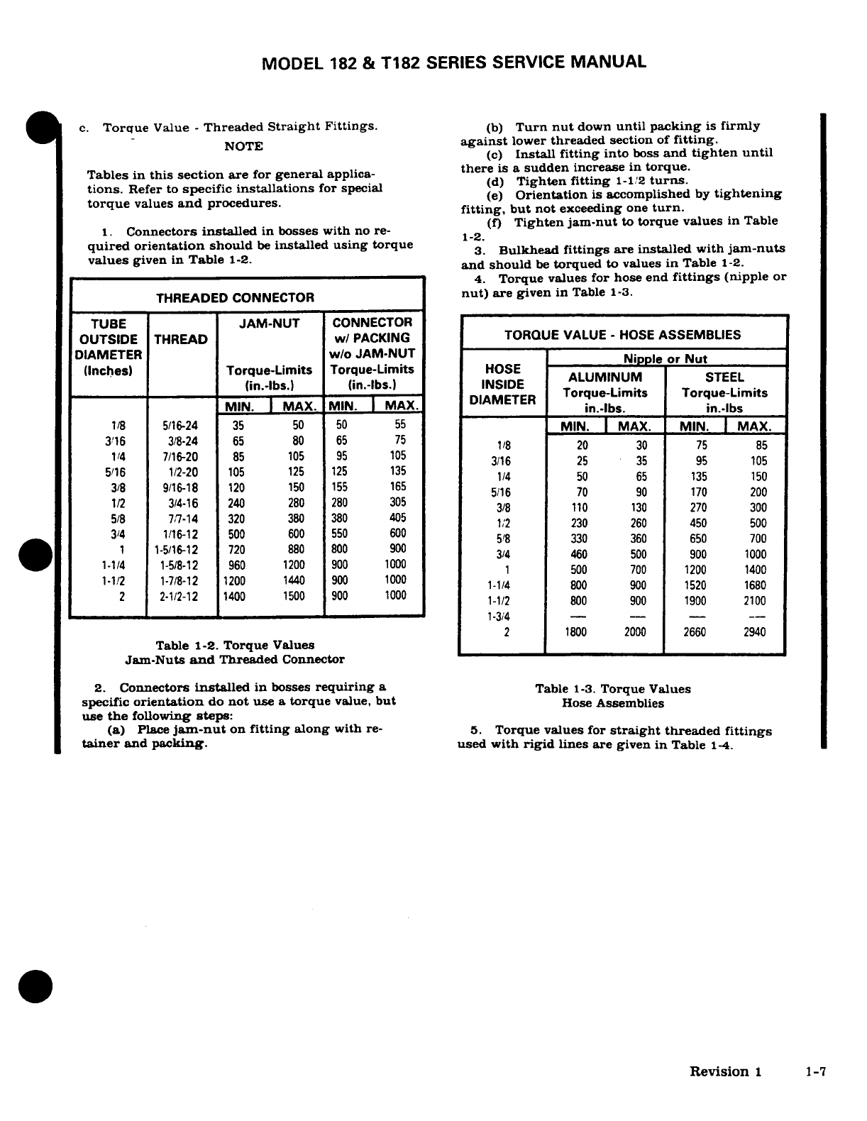
c.
Torque
Value
-
Threaded
Straight
Fittings.
(b)
Turn
nut
down
until
packing
is
firmly
NOTE
against
lower
threaded
section
of
fitting.
(c)
Install
fitting
into
boss
and
tighten
until
Tables in
this
section
are
for
general
applica-
there
is
a
sudden
increase
in
torque.
tions.
Refer
to
specific
installations
for
special
(d)
Tighten
fitting
1-1/2
turns.
torque values ad pro
ure.
(e)
Orientation
is
accomplished
by
tightening
fitting,
but
not
exceeding
one
turn.
(f)
Tighten jam-nut
to
torque
values
in
Table
1.
Connectors
installed
in
bosses
with
no
re-
quired orientation
should
be
installed
using
torque
3.
Bulkhead
fittings
are
installed
with
jam-nuts
values
given
in
Table
1-2.
and
should
be
torqued
to
values
in
Table
1-2.
4.
Torque
values
for
hose
end
fittings
(nipple
or
THREADED
CONNECTOR
nut)
are
given
in
Table
1-3.
TUBE
JAM-NUT
CONNECTOR
OUTSIDE THREAD
DIAMETER
w/o JAM-NUT
(Inches)
Torque-Limits
Torque-Limits
HOSE
ALUMINUM STEEL
1/8
5/16-24
35
50 50 55
MIN.
MAX.
MIN. MAX.
3/16
3/8-24
65 80
65
20
30
75
85
1/4
7/16-20
85
105
95
1053/16
25
35
95
105
5/16
1/2-20
105 125
125 135
1/4
50
65
135
150
3/8
9/16-18
120
150
155 165
5/16
7
90
170
200
1/2
3/4-16
240
280
280
3053/8
110
130
270
300
5/8
7,7-14
320
380 380
405
230 260
450
500
3/4
1/16-12
500 600
550 600
1
1-5/16-12
720 880 800
900
1-1/4 1-5/8-12 960
1200 900
1000
1-1/2
1-7/8-12
1200
1440 900
1000
2
2-1/2-12
1400
1500 900
1000
1-3/4
.
--
2
1800
2000
2660
2940
Table
1-2.
Torque
Values
Jam-Nuts
and
Threaded
Connector
2.
Connectors
installed
in
bosses
requiring
a
Table
1-3.
Torque
Values
specific
orientation
do
not
use
a
torque
value,
but
Hose
Assemblies
use
the
following
steps:
(a)
Place
jam-nut
on
fitting
along
with
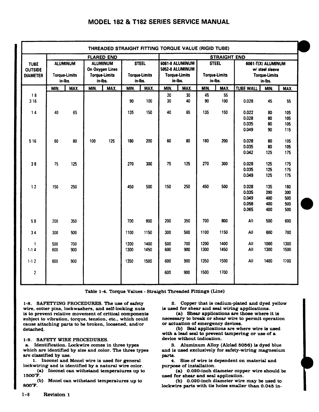
re- 5.
Torque
values
for
straight
threaded
fittings
tainer
and
packing.
used with
rigid
lines
are
given
in
Table
1-4.
Revision
1 1-7
MODEL
182
&
T182
SERIES
SERVICE
MANUAL
THREADED
STRAIGHT
FITTING
TORQUE
VALUE
(RIGID
TUBE)
FLARED
END STRAIGHT
END
TUBE
ALUMINUM
ALUMINUM
STEEL
6061-0
ALUMINUM STEEL
6061-T(X)
ALUMINUM
OUTSIDE
On
Oxygen
Lines
5052-0
ALUMINUM
w/
steel
sleeve
DIAMETER
Torque-Limits
Torque-Limits
Torque-Limits
Torque-Limits
Torque-Limits
Torque-Limits
in-lbs.
in-bs.
inlbs.
in-lbs.
in-lbs.
in-bs.
MIN.
MAX. MIN. MAX.
MIN. MAX.
MIN. MAX.
MIN.
I
MAX.
TUBE
WALL
MIN.
MAX.
18
20
30
45
55
316
90
100
30 40 90
100
0.028
45
55
14
40
65 135
150
40
65
135 150
0.022
80
105
0.028
80
105
0.035
80
105
0.049
90
115
516
60
80
100
125
180
200
60
80
180
200
0.028
80
105
0.035
80
105
0.042
125
175
38
75
125
270 300
75
125
270 300
0.028
125
175
0.035
125
175
0.049
125
175
12
150
250
450
500
150
250
450 500
0.028
135
180
0.035
200
300
0.049
400
500
0.058
400
500
0.065
400
500
58
200 350
700 800 200
350 700 800
All
500
600
34
300
500
1100 1150
300
500
1100
1150
All
600
700
1
500
700 1200
1400
500 700 1200
1400
All
1000
1300
1-1
4
600
900
1300
1450
600
900 1300
1450
All
1300
1500
1-1
2
600 900
1350
1500
600
900
1350 1500
All
1400
1700
2
600
900 1500
1700
Table
1-4.
Torque
Values
-
Straight
Threaded
Fittings
(Line)
1-8.
SAFETYING
PROCEDURES.
The
use
of
safety
2.
Copper
that
is
cadium-plated
and
dyed
yellow
wire,
cotter
pins, lockwashers,
and
self-locking
nuts
is
used
for
shear
and
seal
wiring applications.
is
to
prevent
relative movement
of
critical
components
(a)
Shear
applications
are
those
where
it
is
subject
to
vibration,
torque, tension,
etc.,
which
could
necessary
to
break
or
shear
wire
to
permit
operation
cause
attaching parts
to
be
broken,
loosened,
and/or or
actuation
of
emergency
devices.
detached.
(b)
Seal
applications are
where
wire
is
used
with
a
lead
seal
to
prevent
tampering
or
use
of
a
1-9.
SAFETY
WIRE
PROCEDURES.
device
without
indication.
a.
Identification.
Lockwire comes
in
three
types
3.
Aluminum
Alloy
(Alclad
5056)
is
dyed
blue
which
are
identified
by
size
and
color. The
three
types
and is
used
exclusively for
safety-wiring
magnesium
are classified
by
use.
parts.
1.
Inconel
and
Monel
wire
is
used
for
general
4.
Size
of wire
is
dependent on
material
and
lockwiring
and
is
identified
by
a
natural
wire
color.
purpose
of
installation.
(a)
Inconel
can
withstand
temperatures
up
to
(a)
0.020-inch
diameter
copper
wire
should
be
1500°F.
used
for
shear
and
seal
application.
(b)
Monel
can
withstand
temperatures
up
to
(b)
0.020-inch
diameter
wire
may
be
used
to
800°F.
lockwire
parts
with
tie holes
smaller
than
0.045
in-
1-8
Revision
1
MODEL
182
&
T182
SERIES
SERVICE
MANUAL
ches;
or,
on
parts
with
tie
hole
diameters
between
NOTE
0.045
and 0.062
when
spacing
between
ports
is less
than
two
inches;
or,
when
bolts
and
screws
of 0.25-
Widely
spaced
multiple
groups shall
mean
those
inch
diameter
or
less
are
closely spaced.
in
which
fasteners
are
from
four
to
six
inches
(c)
0.032-inch
minimum diameter
wire
is
used
apart.
Lockwiring
shall
not
be
used
to
secure
for
general
purpose
lockwiring. fasteners
or
fittings
which
are spaced
more
NOTE
than
six
inches
apart,
unless
tie
points
are
pro-
vided
on
adjacent
parts
to
shorten
span
of
When
using
single-wire
method
of
locking,
thelockwire
to
less
than
six
inches.
largest
wire
that
will
fit
tie
holes
should
be
5.
When
lockwiring
closely
spaced
multiple
used.
groups, the number
of
units
that
can
be
lockwired
b.
Lockwire
Installation.
There are
two
basic
forms
by
a
24-inch
length
of
wire
shall
be
the
maximum
of
lockwiring.
The
single-wire
method
has
limited
number
in
a
series.
application;
the
double-twist method
is
the
common
6.
Parts
should
be
lockwired
so
that
wire
is
method
of
lockwiring.
placed
in
tension
(pulled
on)
if
a
part
attempts
to
1.
Use
new wire
for
each
application;
do
not
try
loosen.
to
re-use
old
wire.
c.
Required
Lockwire
Installation
Applications.
2.
Single-wire
method
is
accomplished
by
pas-
1.
Bolts
and
other
fasteners
securing critical
sing
a
single
wire
through
tie
holes
and
back
with
parts
that
affect
airplane
safety
and
operation.
ends
then
twisted
together.
(See
Figure
1-4.)
(a)
In
blind-tapped
hole
applications
or
bolts
or
(a)
Single-wire method
is
used
for
shear
and
castellated
nuts
on
studs,
lockwiring
is
installed
in
seal
wiring
applications.
same
manner
as
described
for bolt
heads.
(b)
Single-wire
method
can
be
used
in
closely
(b)
Hollow
head bolts
are
safetied
in
manner
spaced,
closed
geometric
patterns.
Closely
spaced
is
prescribed
for
regular
bolts.
defined
as
spacing
two
inches
or
less
between
cen-
(c)
Drain
plugs
and
cocks
may
be
safetied
to
a
ters
of
parts.
bolt,
nut,
or
other
part
having
a
free
tie hole
in
(d)
External
snap
rings
may
be
locked
if
nec-
Screws
in
closely
spaced
geometric
patterns
essary
using
general
locking
principles
as de-
which
secure
hydraulic
or
air
seals,
hold
hy-
scribed
and
illustrated.
Internal snap
rings
should
draulic
pressure,
or
are
used
in
critical
areas
not
be
lockwired.
should
use
double-twist method
of
lockwiring.
(e)
When
locking
is
required
on
electrical
connectors which use threaded
coupling
rings,
or
3.
Lockwiring
by
the
double-twist
method
is
on
plugs
which
employ
screws
or
rings
to
fasten
really
one
wire
twisted
on
itself
several
times
and is
individual
parts
of
plug
together,
they
shall
be
accomplished
by
the
following
steps
(see
Figure
1-
lockwired
with
0.020-inch
diameter
wire
in
accor-
4)
dance
with
locking
principles as
described
and
(a)
Insert
one
end
of
wire
through
tie
holes
of
illustrated.
It
is
preferable
to
lockwire
all
electrical
bolt
head
and
firmly
loop
around
bolt
head.
connectors
individually.
Do
not lockwire
one
con-
nector
to
another
unless
it
is
necessary
to
do
so.
NOTE
(f)
Drilled
head
bolts
and
screws
need
not
be
lockwired
if
installed into
self-locking
nuts
or
in-
This
does
not
necessarily
apply
to
castellated
stalled
with
lockwashers.
Castellated
nuts
with
nuts
when
slot
is
close
to
top
of
nut.
The
wire
cotter
pins
or
lockwire
are
preferred
on
bolts
or
will
be
more
secure
if
it is
made
to
pass
along
studs
with
drilled
shanks,
but
self-locking
nuts
are
side
of
stud.
permissible
within
limitations
described
in
Para-
graph
1-13.
(b)
While
taut,
twist
strands
to
within
1/8
inch
2.
For new
design,
lockwire
shall
not
be
used
to
of
next part.
The
twisting
keeps
wire
taut
without
secure
nor shall
lockwire
be
dependent upon
frac-
overstressing
and
prevents wire
from
becoming
ture
as basis for
operation
of
emergency
devices
nicked,
kinked, or
mutilated.
such
as
handles,
switches,
and
guard-covering
(c)
Lockwiring multiple
groups
by double-
handles
that
operate
emergency
mechanisms
such
twist
method
is
accomplished
in
a
similar
manner
as
emergency
exits,
fire
extingushers,
emergency
except
twists
between
parts
are
alternated
between cabin
pressure
release,
emergency
landing
gear
clockwise
and
counterclockwise.
release,
and
the
like.
However,
where
existing
(d)
After
last
tie
hole,
wire
is
twisted three
to
structural
equipment
or
safety
of
flight
emergency
five
times
to
form
a
pigtail.
devices
requires
shear
wire
to
secure equipment
(e)
Cut
off
any
excess
wire and
bend
pigtail
while
not
in
use,
but
which
are
dependent
upon
towards
part.
shearing
or
breaking
of lockwire
for
successful
4.
When
lockwiring
widely spaced
multiple
emergency
operation
of
equipment,
particular
care
groups
by
double-twist
method,
three
units
shall
be
exercised
to
assure
that
wiring
under
these
cir-
the
maximum
number
in
a
series.
cumstances
shall
not prevent
emergency
operations
of
these
devices.
Revision
1
1-9
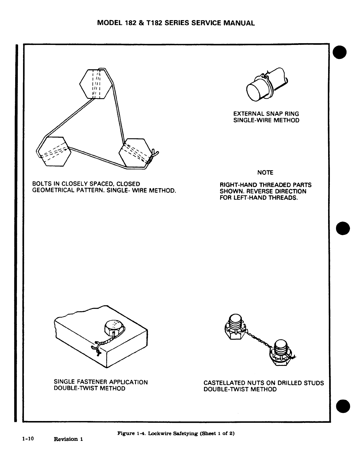
MODEL
182
&
T182
SERIES
SERVICE
MANUAL
r
rl(
I
''I
EXTERNAL
SNAP
RING
SINGLE-WIRE
METHOD
NOTE
BOLTS
IN
CLOSELY
SPACED,
CLOSED
RIGHT-HAND
THREADED
PARTS
GEOMETRICAL
PATTERN.
SINGLE-
WIRE
METHOD.
SHOWN.
REVERSE
DIRECTION
FOR
LEFT-HAND THREADS.
SINGLE
FASTENER
APPLICATION
CASTELLATED
NUTS
ON
DRILLED
STUDS
DOUBLE-TWIST METHOD
DOUBLE-TWIST METHOD
Figure
1-4.
Lockwire
Safetying
(Sheet
1
of
2)
1-10
Revision
1
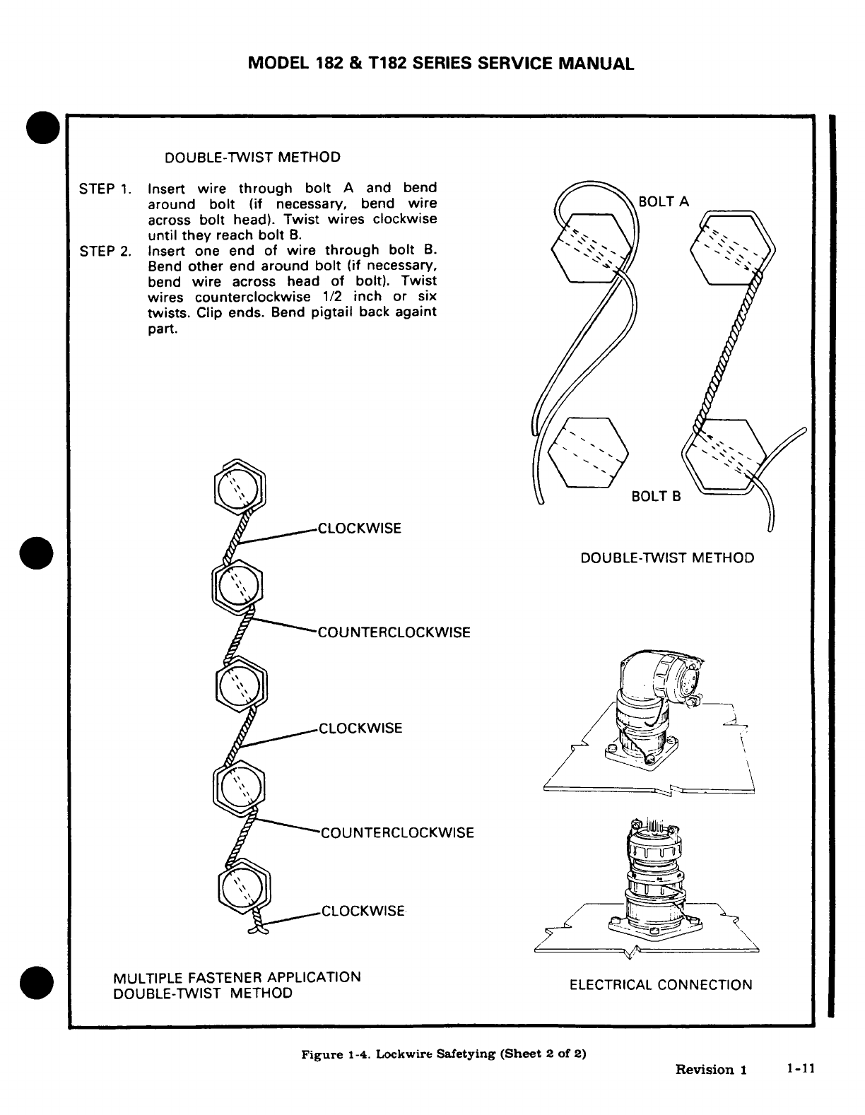
MODEL
182
&
T182
SERIES
SERVICE
MANUAL
DOUBLE-TWIST METHOD
STEP
1.
Insert
wire
through bolt
A
and
bend
around
bolt
(if
necessary, bend
wire
across
bolt
head).
Twist
wires
clockwise
STEP
2.
Insert
one
end
of
wire
through
bolt
B.
Bend
other
end
around
bolt
(if
necessary,
bend
wire
across
head
of
bolt). Twist
wires
counterclockwise
1/2
inch
or
six
twists.
Clip
ends.
Bend
pigtail
back
againt
part.
BOLT
B
CLOCKWISE
DOUBLE-TWIST
METHOD
COUNTERCLOCKWISE
CLOCKWISE
COUNTERCLOCKWISE
<
"CLOCKWISE
MULTIPLE
FASTENER
APPLICATION
DOUBLE-TWIST
METHOD
bELECTRICAL
CONNECTION
DOUBLE-TWIST METHOD
Figure
1-4.
Lockwire
Safetying
(Sheet
2
of
2)
Revision
1
1-
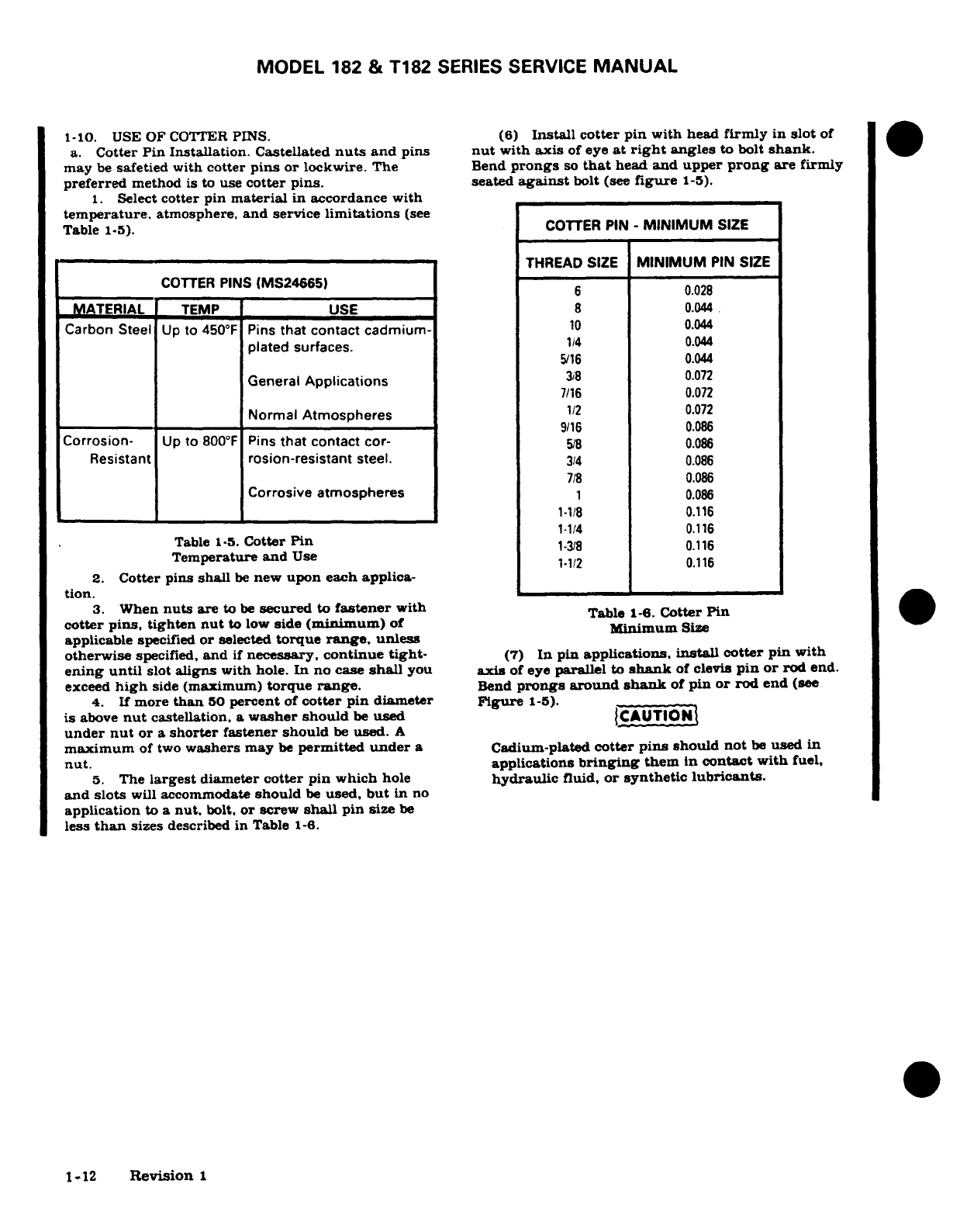
MODEL
182
&
T182
SERIES SERVICE
MANUAL
1-10.
USE
OF
COTTER
PINS.
(6)
Install cotter
pin
with
head
firmly
in
slot
of
a.
Cotter
Pin Installation.
Castellated
nuts
and
pins
nut
with
axis
of
eye
at
right
angles
to
bolt
shank.
may
be
safetied with
cotter
pins
or
lockwire.
The
Bend
prongs
so
that
head and
upper
prong
are firmly
preferred
method
is
to
use
cotter
pins.
seated
against
bolt
(see
figure
1-5).
1.
Select
cotter pin
material
in
accordance
with
temperature,
atmosphere,
and
service
limitations
(see
Table
1-5).
COTTER
PIN
-
MINIMUM
SIZE
THREAD
SIZE
MINIMUM
PIN
SIZE
COTTER
PINS
(MS24665)
0028
MATERIAL
TEMP USE
8
0.044
Carbon
Steel
Up
to
450°F
Pins
that
contact
cadmium-
10
0.044
plated
surfaces.
1/4
0.044
5/16
0.044
General
Applications
3/8
0.072
7/16
0.072
Normal
Atmospheres
1/2
0.072
9/16
0.086
Corrosion-
Up
to
800°F
Pins
that
contact
cor-
5/8
0.086
Resistant
rosion-resistant
steel.
3/4
0.086
7/8
0.086
Corrosive
atmospheres
1
0.086
1-1/8
0.116
1-1/4
0.116
Table
1-5.
Cotter
Pin
1-3/8
0.116
Temperature
and
Use
1-1/2
0.116
2.
Cotter pins
shall
be
new
upon each
applica-
tion.
3.
When
nuts
are
to
be
secured
to
fastener
with
Table
1-6.
Cotter
Pin
cotter
pins, tighten
nut
to
low
side
(minimum)
of
Minimum
Size
applicable
specified
or
selected
torque
range,
unless
otherwise
specified,
and
if
necessary,
continue
tight-
(7)
In
pin
applications,
install cotter
pin
with
ening
until
slot
aligns
with
hole.
In
no
case
shall
you
axis
of
eye
parallel
to
shank
of
clevis
pin
or
rod
end.
exceed
high
side
(maximum)
torque
range.
Bend
prongs around
shank
of
pin
or
rod
end
(see
4.
If
more
than
50
percent
of
cotter pin
diameter
Figure
1-5).
is
above
nut
castellation.
a
washer
should
be
used
under
nut
or
a
shorter
fastener
should
be
used.
A
maximum
of
two
washers
may
be
permitted
under
a
Cadium-plated
cotter
pins should not
be
used
in
nut.
applications
bringing
them
in
contact with
fuel,
5.
The
largest
diameter
cotter pin which
hole
hydraulic
fluid,
or
synthetic
lubricants.
and slots
will
accommodate
should
be
used,
but
in
no
application
to
a
nut,
bolt,
or
screw
shall
pin
size
be
less
than
sizes
described
in
Table
1-6.
1-12
Revision
1

MODEL
182
&
T182
SERIES
SERVICE
MANUAL
TO
PROVIDE
CLEARANCE
PRONG
MAY
BE
CUT
HERE
PREFERRED
METHOD ALTERNATE
METHOD
CASTELLATED
NUT
ON
BOLT
TANGENT
TO
PIN
MAXIMUM
MINIMUM
COTTER
PIN
COTTER
PIN
LENGTH LENGTH
PIN
APPLICATION
Figure
1-5.
Installation
of
Cotter
Pins
Revision
1
1-13
MODEL
182
&
T182
SERIES
SERVICE
MANUAL
1-11.
USE
OF
LOCKING
CLIPS. 5.
When
loosening
of
threaded
parts
would
not
a.
Safetying
Turnbuckles.
(See
Figure
1-6.)
endanger
safety
of
airplane or
people.
1.
Prior
to
safetying,
both
threaded
terminals
6.
When
corrosion
encouraged
by
gouging
shall
be
screwed
an
equal
distance
into
turnbuckle aluminum
or
magnesium
alloys
by
edges
of
teeth
on
body
and
shall
be
screwed
in
at
least
so
far
that
not
tooth-locked
washers
would
not
cause malfunctioning
more
than
three
threads
of
any
terminal
are
exposed
of
parts
being
fastened
together.
outside
body.
2.
After
turnbuckle
has
been
adjusted
to
its
1-13.
USE
OF
SELF-LOCKING
NUTS.
locking
position,
with
slot indicator
groove
on
termi-
a.
Restrictions.
nals
and
slot
indicator
notch
on
body
aligned,
insert
1.
Self-locking
nuts
cannot
be
used
under
cer-
end
of
locking
clip
into
terminal
and
body
(refer
to
tain
conditions.
Figure
1-6)
until
U-curved
end
of
locking
clip
is over
(a)
Used,
reworked,
or
reprocessed
nuts
hole
in
center
of
body.
should
not
be
installed
for
any
application.
(a) Press
locking
clip
into
hold
to
its
full
ex-
(b)
Do
not use
if
at
joints
in
control
systems
tent.
for
singular
attach
points.
(b)
Curved
end
of
locking
clip
will
expand
and
(c)
Do
not use
on
externally
threaded
parts
latch
in
body
slot.
that
serve
as
an
axle
of
rotation
for
another
part
(c)
To
check
proper
seating
of
locking
clip,
where
tensional (torque)
loads
can
cause
nut
to
loosen
attempt
to
remove
pressed
"U"
end
from
body hole
and/or
become
separated.
Examples
are
pulleys,
lev-
with
fingers
only.
ers,
linkages, and
cam
followers.
NOTE
NOTE
Do
not
use
tool
as
locking
clip
could
be
dis-
Self-locking
nuts
can
be
used when
threaded
torted.
parts
are
held
by
a
positive
locking
device
that
requires
shearing
or
rupture
before
torsional
3.
Locking
clips
are
for
one
time
use
only
and
loads
can
act
on
threaded
parts.
shall not
be
re-used.
4.
Both
locking
clips may
be
inserted
in
same
(d)
Do
not
use
where
a
loose
nut,
bolt,
or
hole
of
turnbuckle
body
or
in
opposite holes of
screw could
fall
or
be
drawn into
an
area
that
turnbuckle
body.
would
impede
or
damage
or
otherwise
distort
opera-
tion.
1-12.
USE
OF
LOCKWASHERS.
(e)
Do
not
use
to
attach
access
panels
and
a. Lockwashers
can
be
used
only
under
the
follow-
doors
or
to assemble components
that
are
routinely
ing
conditions. disassembled
or
removed
for
access
and
servicing.
1.
When
self-locking
feature
cannot
be
provided
(f)
In
general,
do
not
use
self-locking
nuts
in
externally
or
internally
threaded
part.
where
loss
of
bolt
affects
safety
of
flight.
2.
When
a
cotter
pin
cannot
be
used
to
prevent
2.
Bolts,
studs, or
screws,
excluding
Hi-Locks,
rotation
of
internal
threads
with
respect
to
external
must
extend
through
self-locking
nut
for
a
length
threads,
equivalent
of
two
threaded pitches.
This length
3.
When
lockwire
cannot
be
used
to
prevent
includes chamfer.
loosening
of
threaded
parts.
3.
Self-locking
nuts
which
are attached
to
struc-
4.
When
fastening
is not
used
for
fabrication
of
ture
shall
be
attached
in
a
positive
manner
to
elimi-
primary
structure.
nate
possibility
of
their
rotation or
misalignment
when
tightening
is
to
be
accomplished
by
rotating
bolts to
structure,
and
permit
replacement
of
nuts.
1-14
Revision
1
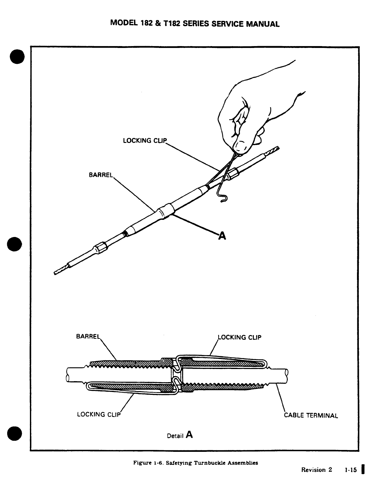
MODEL
182
&
T182
SERIES
SERVICE
MANUAL
1-14.
CONTROL
CABLE
WIRE BREAKAGE
as
shown.
While
rotating
cable,
inspect
bent
area
for
AND
CORROSION
LIMITATIONS.
broken
wires.
a.
Inspection
of
Control
Cables.
(b)
Wire
breakage
criteria
for
cables
in
1.
Control
cable
assemblies are
subject
to
a
flap,
aileron,
rudder,
and
elevator
systems
are
as
variety
of
environmental
conditions
and
forms
of
follows:
deterioration
that
ultimately
may
be
easy
to
recognize
(1)
Individual broken
wires are
acceptable
such
as
wire/strand
breakage,
or
the
not
so
readily
in
primary
and secondary
control
visible
types
of
deterioration
including
corrosion
cables
at
random
locations
when
there
and/or
distortion.
The
following
information
will
aid
are
no
more
than
six
broken
wires
in
in
detecting
these
cable
conditions.
any
given
ten-inch cable
length.
2.
Broken
Wire.
3.
Corrosion.
(a)
Examine
cables for
broken wires
by
(a)
Carefully examine
any
cable
for
passing
a
cloth along
length
of
cable.
This
will
detect
corrosion
that
has
a
broken
wire in
a
section
not
in
broken
wires,
if
cloth
snags
on
cable.
Critical
areas
for
contact
with
wear-producing
airframe
components
wire
breakage
are
those
sections
of
cable
which
pass
such
as pulleys,
fairleads,
rub
blocks,
etc.
It
may
be
through
fairleads,
across
rub
blocks,
and
around
necessary
to
remove
and
bend
cable
to
properly inspect
pulleys.
If
no
snags
are
found,
then
no
further
it
for
internal
strand
corrosion
as
this
condition
is
inspection
is
required.
If
snags
are
found
or
broken
usually not
evident
on
outer
surface
of
cable. Replace
wires
are
suspected,
then
a
more
detailed
inspection
is
cable
if
internal
corrosion
is
found.
If
a
cable
has
been
necessary
which
requires
that
the
cables
be
bent
in
a
wiped
clean
of
its
corrosion-preventive
lubricant
and
loop
to
confirm
broken
wires
(refer
to
figure
1-7).
metal-brightened,
the
cable
shall
be
examined
closely
Loosen
or
remove
cable
to
allow
it
to
be
bent
in
a
loop
for
corrosion.
1-16
Revision
3
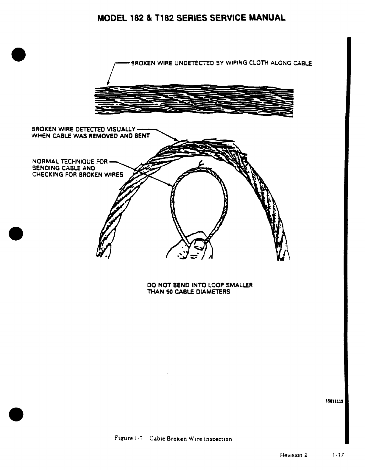
MODEL
182
&
T182
SERIES
SERVICE
MANUAL
-ROKEN
WIRE
UNDETECTED
BY
WIPING
CLOTH
ALONG
CABLE
BROKEN
WIRE
DETECTED
VISUALLY
WHEN
CABLE
WAS
REMOVED
AND
BENT
NORMAL
TECHNIQUE
FOR
BENDING
CABLE
AND
CHECKING
FOR
BROKEN
WIRES
DO
NOT
BEND
INTO
LOOP
SMALLER
THAN
50
CABLE DIAMETERS
Figure
1-7
Cable
Broken
Wire Inspection
Revision
2
1-17
MODEL
182
&
T182 SERIES
SERVICE
MANUAL
(g)
Class
IX
-
These
are
polyurethane
1-15.
ADHESIVES, CEMENTS
AND
SEALANTS
products
Store
in
original
container,
between
70°F
-
SHELF
LIFE
AND
STORAGE
and
100°F.
Urethanes
are moisture
sensitive
and
a.
General precautions should
be
taken
to
ensure
complete
1
This
section
provides
information
which
protection
from
moisture
contamination.
Container
defines
the proper
storage
and
usable
life
(shelf
life) of
must
be
tightly
closed
at
all
times.
adhesives,
cements and
sealents
which
are
used
for
(h)
Class
X
-
These
are acrylic
base
maintenance
and/or
repair
of
the
airplane.
Also,
materials.
They
require
storage
at
40°F
or per
included
in
this
section
is
the
criteria
used
for
testing instructions
on
product
container.
these
materials
after
the normal
shelf
life
has
expired,
c
Storage
of
Sealants.
to
determine
if
an
extension
to
the
shelf
life
is
possible.
1.
All
sealants
shall
be
stored
under
controlled
2.
Shelf
life
refers
to
a
specified
period
of
time
temperature
conditions.
If
open
shop
storage
becomes
usually
from
the
date
of
manufacture
(normally
necessary,
these
products shall
in
no
case
be
stored
in
stamped
or
printed
on
the
product
container)
to
the
an
area
which
will
subject
them
to
temperatures
in
expiration
date
(which
should
be
determined
using
excess
of
95°F
or
below
40°F.
Containers
shall
be
limits
specified
in
Table
1-7
or
if
applicable,
the
tightly
closed
prior
to
placing them
in
the
proper
manufacturer's
expiration
date
printed
or
stamped
on
storage
environment.
For
proper
storage
environment,
the
product
container).
The
specified
shelf
life
is
refer
to
Table
1-7
and the
following
paragraphs.
dependent
on
proper
storage
in
accordance
with the
(a)
Premixed and
frozen
sealants
shall
be
limits
specified
in
this
section
and/or the stored
at
-40°F
or
colder
and
shall
not
be
used
more
manufacturer's
instructions. than
six
weeks
after
the
date
of
mixing
even
if
all
b
Storage
Criteria
storage
is
at
-40°F
or
colder.
If
storage
temperatures
1
Storage
of
Adhesives and
Cements.
rise
above
-40°F,
but
not
warmer
than
-30F,
the
All adhesives
and
cements
shall
be
stored
under
material
may
be
stored
for
a
maximum
of
two
weeks
controlled
temperature
conditions.
If
open shop
warmer
than
-40°F
plus
time
at
-40°F
or
colder
for
a
storage
becomes
necessary, these
products
shall
in
no
combined
total
not
to
exceed
five
weeks
beyond
the
case
be
stored
in
an
area
which
will
subject
them
to
date
of
mixing.
If
storage
temperatures
rise
above
temperatures
in
excess
of
95°F
Containers
shall
be
-40F
but
are
not
warmer
than
-20°F,
the
materials
tightly
closed
prior
to
being
placing
them into
the
may
be
stored
for
a
maximum
of
one week above
-30°F
proper
storage
environment.
For
proper
storage
plus time
at
-40°F
or
colder
for
a
combined
total
not
to
environment,
refer
to
Table
1-7
and
the
following
exceed
four
weeks
beyond
the
date
of
mixing.
paragraphs.
(b)
Unmixed
sealants
shall
be
stored
at
a
(a)
Class I
-
These adhesives
are
epoxy
base
controlled
temperature
of
between
40°F
and
80°F
and
materials
and
have one
year
storage
at
room
have
a
shelf
life
of
approximately
six
months
when
temperature.
0°F
storage
will
extend
the
storage
life.
stored within
this
temperature
range.
Unmixed
Refer
to
the
product
container
instructions
for
storage
sealants
stored
at
temperatures
exceeding
80°F
shall
temperature
and
life.
be
used
within
five
weeks.
(b) Class
II, III
and
IV
-
These
adhesives
2.
All
materials
should
be
used
on
a
"first
in-
are
rubber
and
resin
base
and
are
good
for
six
months
first
out"
basis
The
adhesives,
cements
and
sealants
at
room
temperature
storage.
40°F
storage
will
extend
should
be
rotated
so
this requirement
can
be
the
storage
life
Refer
to
the
product
container
accomplished.
All
material
containers
should
be
instructions
for
limits
of
each
adhesive.
clearly
marked
with
a
"use
by"
date, consisting
of
the
(c)
Class
V. These
are
silicone
rubber
year
and
month
All
materials
not
used
by
this
date
adhesives.
If
stored
in
their
original
containers
at
a
must
be
tested
prior
to
use.
Refer
to
Testing criteria
temperature
below
80°F,
have
a
shelf
life
of
one
year
and
Table
1-7.
or as
indicated
on
the
storage container
d.
Testing
Criteria
(d)
Class
VI
These
are
solvent
bonding
I
Any
material
(adhesive,
cement
or
sealant)
solvents
They
should
be
stored
in
their
original
not
used
within
its
shelf
life
will
be
tested
and
the
containers
and
tightly
closed,
and
stored
at
40°F
results
reviewed
to
determine
if
the
material
is
usable
temperature
If
there
is
doubt about
the
material
being
usable,
it
(e)
ClassVII
-
Cyanoacrylate
base
must
be
properly
disposed
of.
Material
that
has
materials
must
he
stored
in
the
original
containers
at
exceeded
its
original
shelf
life
may
be
retested
to
40°F
or
as
specified
on
the
container
instructions
determine
if
the
material
meets
its
requirements
sensitive materials
The
shelf
life
is
two years
when
shelf
life
extended
as
specified
in
Table
1-7.
Materials
stored
at
75°F
and
50
percent relative humidity
with
shelf
life
extensions
must
be
retested
after
a
specified
period
of
time
Refer
toTable
1-7
1-18
Revision
2
MODEL
182
&
T182
SERIES
SERVICE
MANUAL
2
Testing
of
Overaged
Adhesives and
shelf
life
extension
shall
be
properly
mixed
using
the
Cements
correct
materials,
procedures
and
equipment.
3.
Overaged
premixed
frozen
sealants,
along
Sealants
which
show
conclusive evidence
of
Overaged
adhesives
and
cements are
those
separation,
discoloration
and/or
gelling
prior
to
the
that
have
exceeded
their
original
shelf
life
addition
of
a
thinner
or
curing
agent
shall
be
and
must
be
tested
prior
to
use
and/or
given
discarded.
When
in
doubt
of
the sealant
quality,
the
extended
shelf
life.
overaged
sealant
should
be
compared
with
the
same
type
of
sealant,
under
six
months
old,
which
is
known
(a)
Class
I
Epoxy
Adhesive
-
Examine
both
to
be
satisfactory.
components
to
ensure
that
they
are
still
workable.
4.
The
mixed
sealants
may
be
tested
by
placing
Check
for
gelling
and/or
contamination
Stir
a
small
amount
of
sealant
(smaple
buttons)
on
a
sheet
components
and
mix
a
small
amount
of
adhesive.
of
paper.
After
the
sample
buttons
have
cured,
they
Verify
that
adhesive
sets
up
and
hardens
should
be
cut
in
half
and examined. The
sealant
(b)
Class
II,
III
and
IV
Rubber
and
Resin
should
show
no
signs
of
spots
or
streaks
of
unmixed
Base
Adhesives
-
Open
containers
and
check
for
base compound
or
curing agent.
However,
sample
gelling
and/or contamination.
Check
for
spreading
and
buttons containing
spots,
streaks,
discoloration
and/or
drying. variations
in
uniformity
of
color
are
acceptable
if
these
(c)
Class
V
Silicone Rubber
Adhesives
-
spots,
streaks,
etc.,
are
tack free
upon
inspection.
All
Examine
adhesive
for
hardness.
If
adhesive
is
still
soft
mixed
sealant
should
be
as
void
free
as
possible.
and
can
be
spread,
it
is
acceptable.
Verify
that
5.
Contaminated
sealant,
premixed
sealant
adhesive
will
harden.
that
have
been
thawed
and
refrozen
shall
be
(d)
Class
VI
Solvent
Bonding
Solvents-
discarded.
Check
for
signs
of
apparent
contamination.
Solvents
6.
Type
1,
Class
A
sealants
should
be
checked
should
be
clean
and
clear
with
no
signs
of
cloudiness.
for
appearance,
application
time,
tack-free
time,
cure
(e)
Class
VII
Cyanoacrylic
Base
Adhesives
time,
and
adhesion.
-
Verify
that
product
is
still
liquid
with
no
visible
signs
7.
Type
I,
Class
B
sealants
should
be
checked
of
contamination.
for
appearance,
applicatiion
time,
cure
time,
tack-free
(
Class
VIII
Pressure
Sensitive
Materials
time,
and
adhesion.
In
addition,
Class
B-2
and
B-4
-
Open
containers
and
inspect
for
hardening,
gelling
sealants
should
be
checked
for
initial
flow.
amount
of
adhesive.
Verify
that
adhesive sets
up
for
appearance,
application
time,
cure
time
and
properly
adhesion.
In
addition,
Class
C
sealants
should
be
(g)
Class
X
Acrylic Adhesives-
Inspect
base
tested
to
determine
that
they
ARE
NOT
at
a
tackfree
material
to
ensure
that
it
is
still
liquid.
Mix
a
small
condition
at
the
end
of
their
rated
work
life
(squeeze
amount
of
the
components and
verify
that
it
sets
up
out
life).
properly.
9.
Type II
sealants
should
be
checked
for
3. In
general,
if
these
materials
exhibit normal
appearance,
application
time,
tack-free
time
and
cure
physical properties,
with
no
signs
of
hardening,
time.
gelling
or
contamination
and
set
up
and/or
harden
10.
Type
III
sealants
should
be
easily
thinned
properly
as
applicable, the
shelf
life may
be
extended
with
MEK,
when
difficulty
is
encountered
in
thinning
as
specified
in
Table
1-7.
the
sealant,
it
should
be
discarded
e.
Testing
of
Overaged
Sealants
11.
Type
IV
sealants
should
be
checked
for
appearance,
application
time, tack-free
time
and
cure
NOTE
time.
12.
Type
V
and
VI
sealants
should
be
checked
Overaged
sealants
are
those
that
have
for
appearance,
tack-free time
and
cure
time.
exceeded
their
original shelflife
and
13
Type
VII
sealants
should
be
checked
for
must
be
tested
prior
to
use and/or
given
appearance,
application
time,
tack-free
time
and
cure
extended
shelf
life
time
14
Type
VIII
sealants
should
be
checked
for
1.
For
identification
ofsealants
Classification,
appearance,
application
time,
tack-free
time,
cure
refer
to
Fuel,
Weather,
Pressure
and
High-
time
and
adhesion
Adhesion
to
aluminum
should
be
Temperature
Sealing
-
Maintenance
Practices.
(peel)
less
than
two-pounds
per
inch
of
width.
2
Overaged
sealants
to
be
tested
for possible
Revision
2
1-19
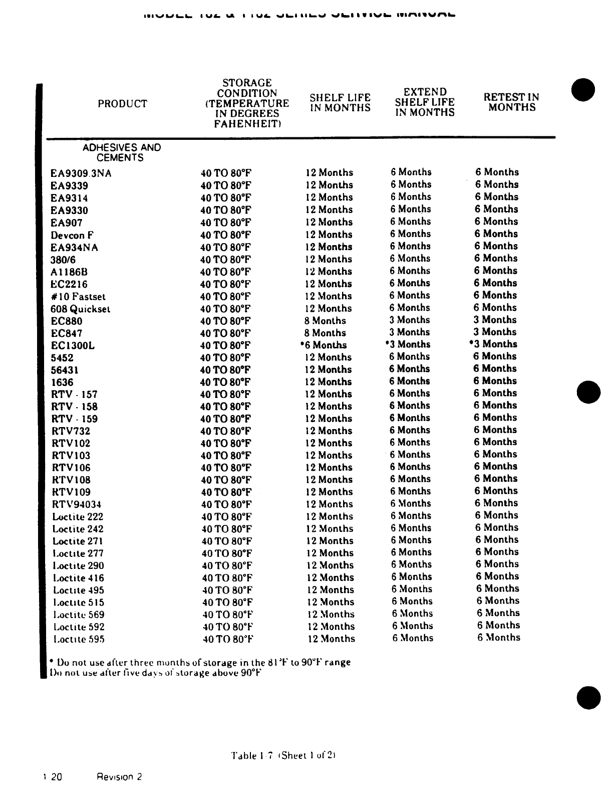
STORAGE
CONDITION
EXTEND
CONDITION
SHELF
LIFE EXTEND
RETESTIN
PRODUCT
(TEMPERATURE
IN
MONTHS
SHELF
LIFE
MONTHS
IN
DEGREES
IN
MONTHS
FAHENHEIT)
ADHESIVES
AND
CEMENTS
EA9309.3NA
40
TO 80°F
12
Months
6
Months
6
Months
EA9339
40
TO
80°F
12
Months
6
Months
6
Months
EA9314
40
TO
80°F
12
Months
6
Months 6
Months
EA9330
40 TO
80°F
12
Months
6
Months
6
Months
EA907
40
TO 80°F
12
Months
6
Months
6
Months
Devcon
F
40
TO
80°F
12
Months
6
Months
6
Months
EA934NA
40
TO
80F
12
Months
6
Months
6
Months
380/6
40
TO
80°F
12
Months
6
Months
6
Months
A1186B
40
TO
80°F
12
Months
6
Months
6
Months
EC2216
40
TO
80°F
12
Months
6
Months
6
Months
#10
Fastset
40
TO
80°F
12
Months
6
Months
6
Months
608
Quickset
40
TO
80°F
12
Months
6
Months
6
Months
EC880
40
TO
80°F
8
Months
3
Months
3
Months
EC847
40
TO
80°F
8
Months
3
Months
3
Months
EC1300L
40
TO80F
*6
Months
3
Months
3
Months
5452
40
TO
80°F
12
Months
6
Months
6
Months
56431
40
TO
80°F
12
Months
6
Months
6
Months
1636
40 TO
80°F
12
Months
6
Months
6
Months
RTV-
157
40
TO
80F
12
Months
6
Months
6
Months
RTV
158
40
TO
80°F
12
Months
6
Months
6
Months
RTV -
159
40
TO
80°F
12
Months
6
Months 6
Months
RTV732 40
TO
80°F
12
Months
6
Months
6
Months
RTV
102
40
TO 80°F
12
Months
6
Months
6
Months
RTV
103
40
TO
80°F
12
Months
6
Months
6
Months
RTV
106
40
TO 80°F
12
Months
6
Months
6
Months
RTV
108
40
TO
80°F
12
Months
6
Months 6
Months
RTV
109
40
TO
80°F
12
Months
6
Months
6
Months
RTV94034
40
TO
80°F
12
Months
6
Months
6
Months
Loctite
222 40
TO
80°F
12
Months
6
Months
6
Months
Loctite
242
40
TO
80°F
12
Months
6
Months
6
Months
Loctite
271
40
TO 80°F
12
Months
6
Months
6
Months
Loctite
277
40
TO
80°F
12
Months
6
Months
6
Months
Loctite
290
40
TO 80°F
12
Months
6
Months
6
Months
Loctite
416
40
TO
80F
12
Months
6
Months
6
Months
Loctite
495 40
TO
80°F
12
Months
6
Months
6
Months
Loctite
515
40
TO
80°F
12
Months
6
Months
6
Months
Loctite
569
40
TO
80°F
12
Months
6
Months
6
Months
Loctite
592
40
TO
80°F
12
Months
6
Months
6
Months
Loctite
595
40TO
80°F
12
Months
6
Months
6
Months
Do
not
use
after
three
months
of
storage
in
the
81°F
to
90°F
range
Do
not
use
after
five
days
of
storage
above
90°F
Table
1-7
(Sheet
1
of
2)
1-20
Revision
2
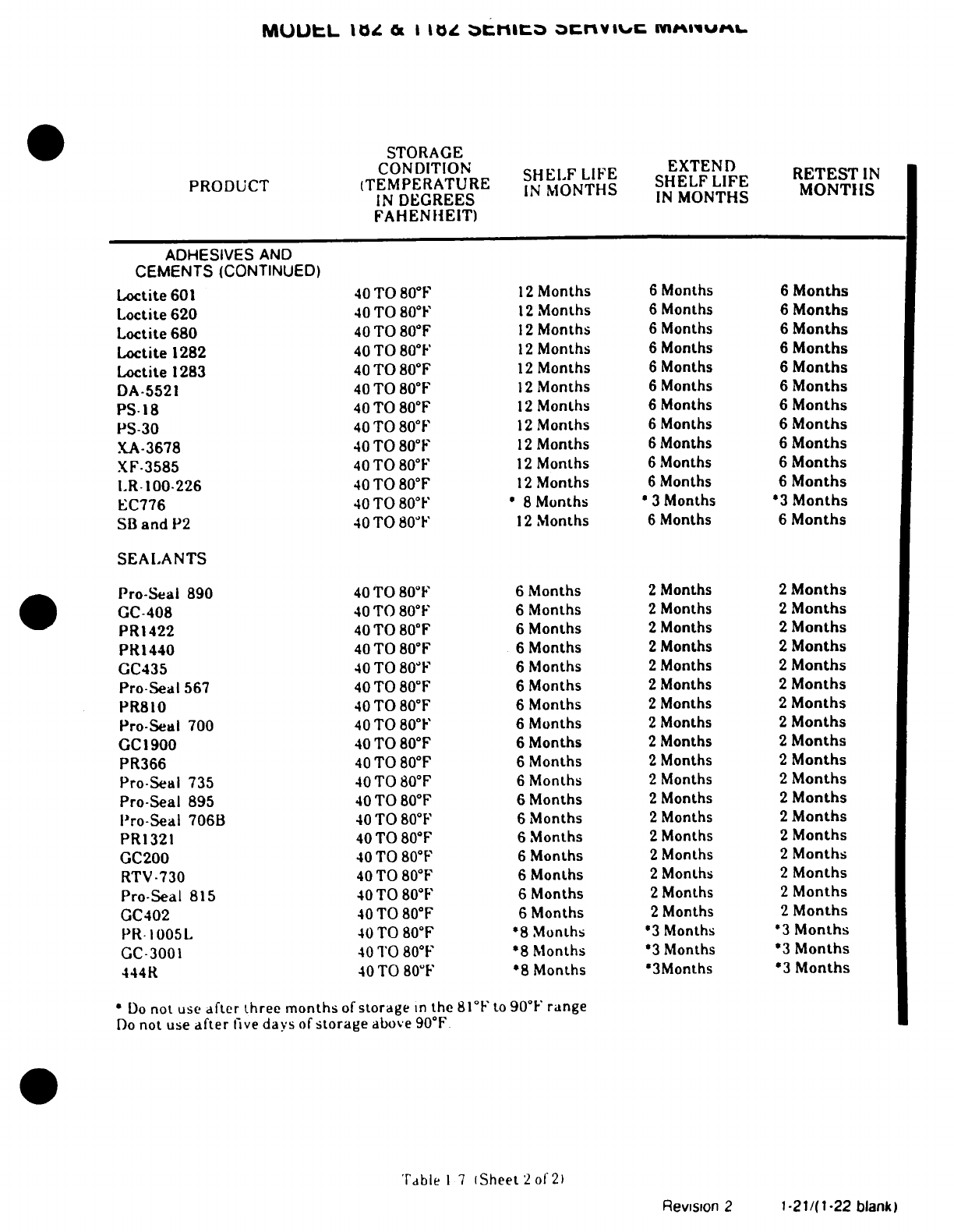
STORAGE
CONDITION
EXTEND
PRODUCT (TEMPERATURE
SN
MONTHS
SHELF
LIFE
MONTE
S
IN
DEGREES
IN
MONTHS
FAHENHEIT)
ADHESIVES
AND
CEMENTS
(CONTINUED)
Loctite
601
40
TO
80°F
12
Months
6
Months
6
Months
Loctite 620
40
TO
80°F
12
Months
6
Months
6
Months
Loctite
680
40
TO
80°F
12
Months
6
Months
6
Months
Loctite
1282
40
TO
80°F
12
Months
6
Months
6
Months
Loctite
1283
40
TO
80°F
12
Months
6
Months
6
Months
DA-5521
40
TO
80F
12
Months
6
Months 6
Months
PS
18
40
TO 80°F
12
Months
6
Months
6
Months
PS-30
40
TO 80°F
12
Months
6
Months
6
Months
XA-3678
40
TO 80°F
12
Months
6
Months
6
Months
XF-3585
40
TO
80F
12
Months
6
Months
6
Months
IR-
100-226
40
TO
80°F
12
Months
6
Months
6
Months
EC776
40
TO
80°F
*
8
Months
*
3
Months
*3
Months
SB
and
P2
40
TO
801'
12
Months
6
Months
6
Months
SEALANTS
Pro-Seal
890
40
TO
80°F
6
Months
2
Months
2
Months
GC-408
40
TO
80°F
6
Months
2
Months
2
Months
PR1422
40
TO
80F
6
Months
2
Months
2
Months
PR1440
40
TO
80F
6
Months
2
Months
2
Months
GC435
40
TO
80F
6
Months
2
Months
2
Months
Pro-Seal
567
40 TO
80°F
6
Months
2
Months
2
Months
PR810
40
TO
80°F
6
Months
2
Months
2
Months
Pro-Seal
700
40
TO
80°F
6
Months
2
Months
2
Months
GC
1900
40
TO
80°F
6
Months
2
Months
2
Months
PR366
40
TO
80OF
6
Months
2
Months
2
Months
Pro-Seal
735
40
TO
80F
6
Months
2
Months
2
Months
Pro-Seal
895
40
TO
80F
6
Months
2
Months
2
Months
Pro-Seal
706B
40
TO
80°F
6
Months
2
Months
2
Months
PR1321
40
TO
80F
6
Months
2
Months
2
Months
GC200
40
TO
80OF
6
Months
2
Months
2
Months
RTV-730
40
TO
80°F
6
Months
2
Months
2
Months
Pro-Seal
815
40TO
80°F
6
Months
2
Months
2
Months
GC402
40
TO
80OF
6
Months
2
Months
2
Months
PR-
1005L
40
TO
80F
*8
Months
*3
Months
*3
Months
GC-3001
40
TO
80°F
*8
Months
*3
Months
*3
Months
444R
40
TO
80'F
*8
Months
*3Months
*3
Months
*
Do
not
use
after
three
months
of
storage
in
the
81°F
to
90F
'
range
Do
not
use
after
five
days
of
storage
above
90°F
Table
I 7
(Sheet
2
of
2)
Revision
2
1-21/(1-22
blank)
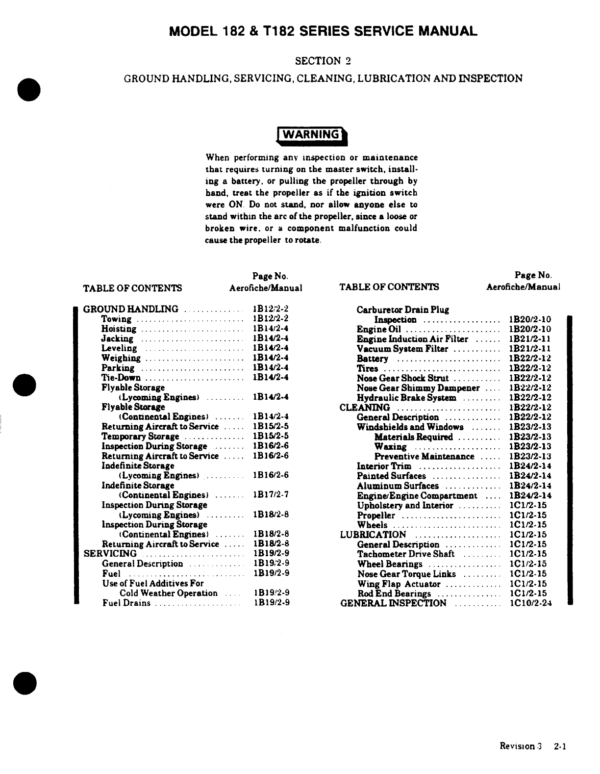
MODEL
182
&
T182
SERIES
SERVICE
MANUAL
SECTION
2
GROUND
HANDLING,
SERVICING,
CLEANING,
LUBRICATION
AND
INSPECTION
WARNING
When
performing any
inspection
or
maintenance
that
requires
turning
on
the master
switch,
install-
ing
a
battery,
or
pulling
the
propeller
through
by
hand,
treat
the
propeller
as
if
the
ignition
switch
were
ON.
Do
not
stand,
nor
allow
anyone
else
to
stand within
the
arc
of
the
propeller,
since
a
loose
or
broken
wire.
or
a
component
malfunction
could
cause
the
propeller
to
rotate.
Page
No.
Page
No.
TABLE
OF
CONTENTS
Aerofiche/Manual
TABLE
OF
CONTENTS
Aerofiche/Manual
GROUND
HANDLING
.........
.
1B12/2-2
Carburetor Drain
Plug
Towing
......................
1B12/2-2
Inspection
..................
B20/2-10
Hoisting
.......................
1B14/2-4
Engine
Oil
......................
1B20/2-10
Jacking
.......................
B14/2-4
Engine
Induction
Air
Filter
......
1B21/2-11
Leveling..... ....
1B14/2-4
Vacuum System
Filter
..........
1B21/2-11
Weighing
.......................
1B14/2-4
Battery
.
.......................
1B22/2-12
Parking
.......................
1B14/2-4
Tires
...........................
1B22/2-12
Tie-Down
....................
1B14/2-4
Nose
Gear
Shock
Strut
...........
1B22/2-12
Flyable
Storage
Nose
Gear
Shimmy
Dampener
....
B22/2-12
(Lycoming
Engines)
.........
B14/2-4
Hydraulic
Brake System
........
1B22/2-12
Flyable
Storage
CLEANING
.......................
1B22/2-12
(Continental
Engines)
.......
B14/2-4
General
Description
.............
1B22/2-12
Returning
Aircraft
to
Service
....
1B15/2-5
Windshields and
Windows
.......
1B23/2-13
Temporary Storage
..............
1B15/2-5
Materials
Required
.........
1B23/2-13
Inspection
During Storage
.......
1B16/2-6
Waxing .
...................
B23/2-13
Returning
Aircraft
to
Service
.....
1B16/2-6
Preventive
Maintenance
.....
1B23/2-13
Indefinite
Storage
Interior
Trim ................
1B24/2-14
(Lycoming
Engines)
.........
B16/2-6
Painted
Surfaces
...............
1B24/2-14
Indefinite
Storage
Aluminum
Surfaces
.............
1B24/2-14
(Continental
Engines)
.....
1B17/2-7
Engine/Engine
Compartment
....
1B24/2-14
Inspection
During
Storage
Upholstery
and
Interior
..........
1C1/2-15
(Lycoming
Engines)
.........
1B18/2-8
Propeller
.......................
1C1/2-15
Inspection
During
Storage
Wheels
.........................
1C1/2-15
(Continental
Engines)
......
1B18/2-8
LUBRICATION
....................
1C1/2-15
Returning
Aircraft
toService
.....
1B18/2-8
General
Description
............
1C112-15
SERVICING
.......................
1B19/2-9
TachometerDrive Shaft
.........
C1/2-15
General
Description
..........
1B192-9
Wheel
Bearings
.................
1C1/2-15
Fuel
....
...................
1B19/2-9
NoseGearTorqueLinks
.........
1C12-15
Use
of
Fuel Additives For
WingFlap
Actuator
............
1C1/2-15
Cold
Weather
Operation
....
1B19/2-9
Rod
End
Bearings
...............
1C1/2-15
Fuel
Drains
...................
1B19/2-9
GENERAL
INSPECTION
...........
1C10/2-24
Revision
3
2-1
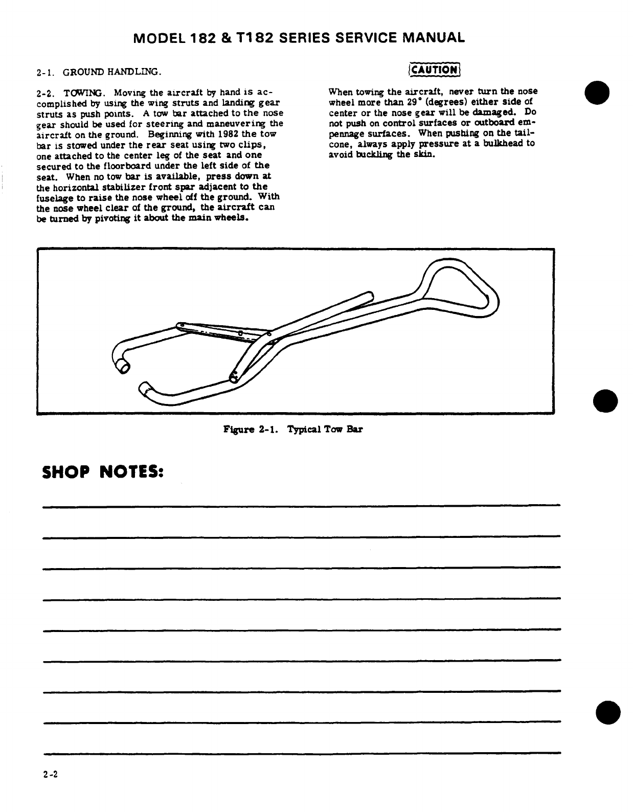
MODEL
182
&
T1
82
SERIES
SERVICE
MANUAL
2-1.
GROUND HANDLING.
2-2.
TOWING.
Moving
the
aircraft
by
hand
is
ac-
When towing
the
aircraft,
never
turn
the
nose
complished
by
using
the
wing
struts
and
landing
gear
wheel
more
than
29°
(degrees)
either
side
of
struts
as
push
points.
A
tow
bar
attached
to
the
nose
center
or
the
nose
gear
will
be
damaged.
Do
gear
should
be
used
for
steering
and
maneuvering
the
not
push
on
control
surfaces
or outboard
em-
aircraft
on
the ground.
Beginning
with
1982
the
tow
pennage
surfaces.
When
pushing on
the
tail-
bar
is
stowed
under
the
rear
seat
using
two
clips,
cone,
always
apply
pressure
at
a
bulkhead to
one
attached
to
the
center
leg
of
the
seat
and
one
avoid
buckling
the
skin.
secured
to
the
floorboard
under the
left
side
of
the
seat.
When
no
tow
bar
is
available,
press
down
at
the
horizontal
stabilizer
front
spar
adjacent
to
the
fuselage
to
raise
the
nose
wheel
off
the
ground.
With
the
nose
wheel
clear
of
the
ground,
the
aircraft
can
be
turned
by
pivoting
it
about
the
main
wheels.
Figure
2-1.
Typical
Tow
Bar
SHOP
NOTES:
2-2
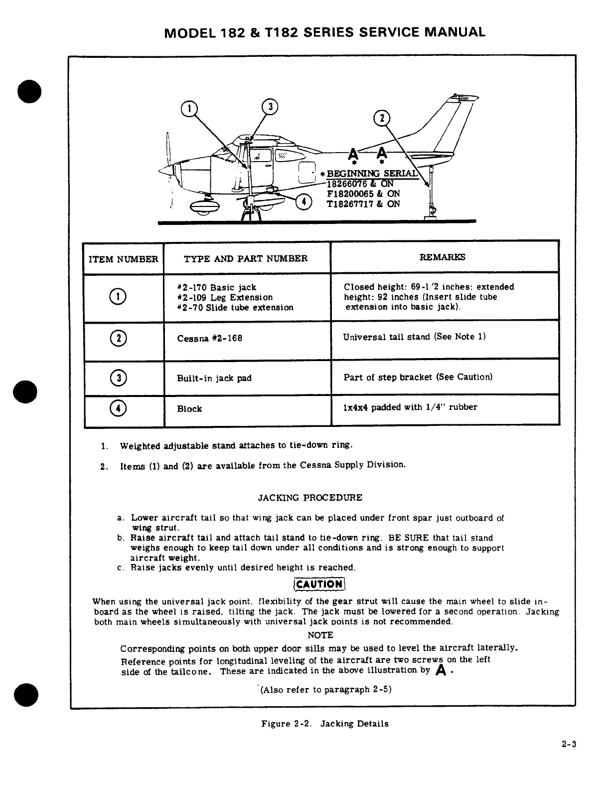
MODEL
182
&
T182
SERIES SERVICE
MANUAL
F18200065
&
ON
ITEM
NUMBER
TYPE
AND
PART
NUMBER
REMARKS
A
2-170
Basic
jack
Closed
height:
69-1
'2
inches:
extended
0QJ
#2-109
Leg
Extension
height:
92
inches
(Insert
slide
tube
<2-70
Slide tube
extension
extension
into
basic
jack).
(T)
Cessna
#2-168
Universal
tail
stand
(See
Note
1)
Q
(3)
Built-in
jack
pad
Part
of
step
bracket
(See
Caution)
G)
Block
1x4x4
padded
with
1/4" rubber
1.
Weighted
adjustable
stand
attaches
to
tie-down
ring.
2.
Items
(1)
and
(2)
are
available
from
the
Cessna
Supply
Division.
JACKING
PROCEDURE
a.
Lower
aircraft
tail
so
that
wing
jack can
be
placed
under
front
spar
just
outboard
of
wing
strut.
b.
Raise
aircraft
tail
and
attach
tail
stand
to
tie-down
ring.
BE
SURE
that
tail
stand
weighs
enough
to keep
tail
down
under
all
conditions
and
is
strong
enough
to
support
aircraft
weight.
c.
Raise
jacks
evenly
until
desired
height
is
reached.
ICAUTIONi
When
using
the
universal
jack
point.
flexibility
of
the
gear
strut
will
cause
the
main
wheel
to
slide
in-
board
as
the
wheel
is
raised,
tilting
the
jack.
The
jack
must
be
lowered
for
a
second
operation.
Jacking
both
main
wheels
simultaneously
with
universal
jack
points
is
not
recommended.
NOTE
Corresponding
points
on
both
upper
door
sills
may
be
used
to
level
the
aircraft
laterally.
Reference
points
for
longitudinal
leveling
of
the
aircraft
are
two
screws
on
the left
side
of
the
tailcone.
These
are
indicated
in
the
above
illustration
by
A
·
(Also
refer
to
paragraph
2-5)
Figure
2-2.
Jacking
Details
2-3
MODEL
182
&
T182
SERIES
SERVICE
MANUAL
2-3.
HOISTING.
The
aircraft
may
be
lifted
with
a
2-9.
FLYABLE
STORAGE.
(Airplanes
with
a
hoist
of
two-ton capacity
by
using
hoisting
rings,
Lycoming
engine).
Flyable
storage
is
defined
which
are
optional
equipment,
or
by
means
of
suit-
as
a
maxmum
of
30
days
non-operational
storage
able
slings.
The
front
sling
should
be
hooked
to
and/or
the
first
25
hours
of
intermittent
engine
each
upper
engine
mount
at
the
firewall,
and
the
aft
operation.
sling
should
be
positioned around
the
fuselage
at
the
first
bulkhead
forward
of
the
leading
edge
of
the
NOTE
stabilizer.
If
the
optional
hoisting
rings
are
used,
a
minimum
cable length
of
60
inches
for
each
cable
Lycoming
0-540 Series
aircraft
engines
is
required
to
prevent
bending
of
the
eyebolt-type
used
in
the
T182
series
aircraft
are
de-
hoisting
rings.
If
desired,
a
spreader
jig
may
be
livered
from
Cessna
with
MIL-L-6082
fabricated
to
apply
vertical
force
to the
eyebolts.
Aviation
Grade
Mineral
Oil.
This
engine
oil
should
be
used
to
replenish
the
oil
2-4.
JACKING.
See
figure
2-2
for
jacking
proced-
supply
during
the
first
25
hours
of
engine
ures.
operation
at
the
first
25
hour
oil
change
and
until
a
total
of
50
hours
have
accumu-
2-5.
LEVELING.
Corresponding
points
on
both
lated
or
oil
consumption
has
stabilized.
upper
door
sills
may
be
used
to
level
the
aircraft
Then
use
Ashless
Dispersant
Oil
conform-
laterally.
Reference
point
for
leveling
the
aircraft
ing
to
MIL-L-22851
in
accordance
with
the
longitudinally
is
the
top
of
the
tailcone
between
the
oil
chart
in
figure
2-4.
rear
window
and
the
vertical
fin. Beginning
with
Serials
18266076
&
ON,
F18200065
&
ON,
and
T182-
During the
30
day
non-operational
storage
or
the
first
67717
ON,
leveling
points
have
been
added to
the
left
25
hours
of
intermittent
engine
operation,
every
sev-
side
of
tailcone
at
Sta.
139.65
and
171.
65.
Remove
enth
day
the
propeller
shall
be
rotated
by
hand
without
NAS221-7
screws
and
install
suitable
studs
to
support
running
the
engine.
After
rotating
the
engine
five
rev-
a
level.
olutions,
stop
the
propeller
45
to
90
from
the
posi-
tion
it
was
in.
If
the
aircraft
is
stored
outside,
tie-
2-6.
WEIGHING
AIRCRAFT.
Refer
to
Pilot's
down in
accordance
with
paragraph
2-8.
In
addition,
Operating
Handbook.
the
pitot
tube,
static
air
vents,
air
vents,
openings
in
the
engine
cowling,
and
other
similar
openings
2-7.
PARKING.
Parking
precautions
depend
prin-
shall
have
protective
covers
installed
to
prevent
entry
cipally
on
local
conditions.
As
a
general
precaution,
of
foreign
material.
If
at
the
end of
thirty
(30)
days
set
parking
brake
or
chock
the
wheels
and
install
the
aircraft
will
not
be
removed
from
storage,
the engine
controls
lock.
In
sever
weather
conditions
and
high
shall
be
started
and
run.
The
preferred
method
would
wind,
tie
down
the
aircraft
as
outlined
in
paragraph
be
to
fly
the
aircraft
for
thirty
(30)
minutes,
and
up
to
2-8
i
a
hangar
is
not
available.
but
not
exceeding
normal
oil
and
cylinder
temperatures.
2-8.
TIE-DOWN. When
mooring the
aircraft
in
the
open.
head
into
the
wind
if
possible.
Secure
control
surfaces
with
the
internal
control
lock
and
set
brakes.
Excessive
ground
operation
shall
be
avoided.
Do
not
set
parking
brakes
when
they
are
NOTES
overheated
or
during
cold
weather
when
accumulated
moisture
may
freeze
them.
Preservation
date should
be
written
on
pro-
a.
Tie
ropes,
cables,
or
chains
to
the
wing
tie-
peller
tag.
down
fittings
located
at
the upper
end
of
each
wing
strut.
Secure
the
opposite
ends
of
ropes,
cables,
Maintain
complete
and
accurate
engine
pre-
or
chains
b.
Secure
a
tie-down
rope
(no
chains
or
cables)
to
vationof
the
engine
cylinders
can
be
docu-
upper
strut
of
the
nose
gear,
and
secure
opposite
end
of
rope
to
a
ground
anchor.necessary.
c.
Secure
the middle
of
a
rope
to
the
tail
tie-down
ring.
Pull
each
end
of
rope
away
at
a
45
degreeThe
airplane
is
delivered from Cessna
with
a
angle and
secure
to
ground
anchors
at
each
side
of
Corrosion Preventive
Aircraft
Engine
Oil
mix
tail.
ture.
This
engine
oil
is
a
blend
of
aviation
d.
Secure
control
lock
on
pilot
control
column.
If
grade
straight
mineral
oil
and corrosion
pre-
control
lock
is
not
available,
tie
pilot
control
wheel
ventive
compound.
This
oil
should
be
used
for
back
with
front
seat
belt.
the
first
25
hours
of
engine
operation.
In
the
e.
These
aircraft
are
equipped
with
a
spring-loaded
event
it
necessary
to
add
oil
during
the
steering
bungee
which
affords
protection
against
nor-
aviation
grade straight
mineral
oil
of
the
cor-
mal
wind
gusts.
However,
if
extremely
high
wind
gusts
are
anticipated, additional
external
locks
may
be
installed.
Flyable
storage
is
defined as
a
maximum
of
30
days
2-4 Revision
1

MODEL
182
&
T182
SERIES SERVICE
MANUAL
non-operational
storage
and
can
be
broken
down
into
a
maximum
of
90
days.
The
aircraft
is constructed
the
following
two
programs.
of
corrosion
resistant
alclad
aluminum,
which
will
a.
Program
1
-
engines or
cylinders
with
less
than
last
indefinitely
under
normal
conditions
if
kept
clean,
50
operating
hours.
however,
these
alloys
are
subject
to
oxidation.
The
1.
Propeller
pull-thru
every
five
days.
(See
first
indication
of
corrosion
on
unpainted
surfaces
is
step
c.)
in
the
form
of
white
deposits
or
spots.
On
painted
2.
Fly
airplane
every
30
days.
(See
step
d.)
surfaces,
the
paint
is
discolored
or
blistered.
Stor-
b.
Program
2
-
engines
or
cylinders
with
more
than
age
in
a
dry
hangar
is
essential
to
good
preservation
50
operating
hours
to
TBO
if
not
flown
weekly.
and
should
be
procured,
if
possible.
Varying
con-
1.
Propeller
pull-thru
every
seven
days.
(See
ditions
will
alter
the
measures
of
preservation.
but
step
c.)
under
normal
conditions
in a
dry
hangar.
and
for
2.
Fly
airplane
every 30
days.
(See
step
d.)
storage
periods
not
to
exceed
90
days.
the
following
c.
The
propeller
should
be
rotated
by
hand
without
methods
of
treatment
are
suggested.
running
the
engine.
For
four
and
six
cylinder
a.
Fill
fuel
tanks
or
bays
with
correct
grade
of
gas-
straight
drive
engines,
rotate engine
six
revolutions,
oline.
stop
propeller
45°to
90
°
from
original
position. For
b.
Clean
and wax
aircraft
throughly.
six
cylinder
geared engines, rotate
propeller
four
rev-
c.
Clean
any
oil
or
grease
from
tires
and
coat
tires
olutions
and
stop
propeller
30
°
to
60
°
from
original
with
a
tire
preservative.
Cover
tires
to
protect
position.
against
grease
and
oil.
d.
Either
block
up
fuselage
to
relieve
pressure
on
spotting the
tires.
For
maximum
safety, accomplish
engine
rota-
e. Lubricate
all
airframe items
and
seal or
cover
tion
as
follows:
all
openings
which
could
allow
moisture
and/or
dust
to
enter.
1.
Verify
magneto
switches
are
OFF.
2.
Place
throttle
in
CLOSED
position.
NOTE
3.
Place
mixture
control
in
IDLE
CUT-OFF
position.
The
aircraft
battery
serial
number
is
recorded
4.
Set
brakes
and block
airplane
wheels.
in
the
aircraft
equipment
list.
To
assure
ac-
5.
Leave
airplane
tie-downs
installed
and
curate
warranty
records,
the
battery
should
be
verify that
cabin
door
latch
is
open.
reinstalled
in
the
same
aircraft
from
which
it
6.
DO
NOT
stand
within
arc
of
propeller
was
removed.
If
the
battery
is
returned
to
blades
while
turning
propeller.
service
in
a
different
aircraft,
appropriate
d.
The
airplane
should
be
flown
for
thirty
(30)
record
changes
must
be
made
and
notification
minutes,
reaching,
but
not
exceeding,
normal
oil
sent
to
the
Cessna
Claims
Department.
and
cylinder
temperatures.
If
the aircraft
cannot
be
flown
it
should
be
represerved
in
accordance
f.
Remove
battery
and
store
in
a
cool,
dry place;
with
paragraph
2-11.
(Temporary
Storage)
or
service
battery
periodically
and
charge
as
required.
paragraph
2-14.
(Idefinite Storage).
Ground
run-
ning
is
not
an
acceptable
substitute
for
flying.
NOTE
NOTE
An
engine
treated
in
accordance
with
the fol-
If
step
2
in
each
program
cannot
be
accom-
lowing
may
be
considered
being
protected
plished
on
schedule
due
to
weather, mainte- against
normal
atmospheric
corrosion
for
a
nance,
etc.,
pull
the
propeller through
daily
period
not
to
exceed
90
days.
and
accomplish
as
soon
as
possible.
g.
Disconnect
spark
plug
leads
and
remove
upper
e.
If
airplane
is
stored
outside,
tie
it
down
in
accor-
and
lower
spark
plugs
from each
cylinder.
dance
with
paragraph
2-8.
In
addition,
the
pitot
tube,
static
air
vents,
air
vents,
openings
in
the
engine
NOTES
cowling,
and
other
similar
openings
shall
have
pro-
tective
covers
installed
to
prevent
entry
of
foreign
On 182
and
F182
Series
aircraft
equipped
material.
with
Continental
O-470
Series
aircraft
engine the
preservative
oil
must
be
2-10.
RETURNING
AIRCRAFT TO
SERVICE.
After
Lubricating
Oil
-
Contact
and
Volatile,
flyable
storage,
returning
the
aircraft
to
service
is
Corrosion
Inhibited.
MIL-L-46002,
accomplished
by
performing
a
thorough
pre-flight
Grade
1,
or
equivalent.
inspection.
At
the
end
of
the
first
25
hours
of
engine
operation,
drain
engine
oil, clean oil
pressure
screen
On
T182
Series
aircraft
equipped
with
(or
change
external
oil
filter)
and
service
engine
with
Lycoming
0-540
Series
aircraft
engine.
correct
grade
and
quantity
of
engine
oil.
See
figure
MIL-C-6529,
Type
I,
preservative
oil
2-4
and
paragraph
2-23
for
correct
grade
of
engine
must
be
used.
oil.
For
airplanes
with
a
Continental
engine,
2-11.
TEMPORARY
STORAGE.
Temporary
storage
the
preservative
oil
must
be
MIL-L-46002,
is
defined
as
aircraft
in
a
non-operational
status
for
grade
1,
at
room
temperature.
Two
preserva-
Revision
1
2-5
MODEL
182
&
T182
SERIES
SERVICE
MANUAL
tive
oils
recommended
for
use
in
Teledyne
h.
Install
spark
plugs
and
torque
to
values
specified
Continental engines
for
temporary
and
indefi-
in
Section
11
&
11A.
Connect
spark
plug
leads.
nite
storage
are
NOX
RUST
VCI-105
(Danbert
i.
Check
fuel
strainer.
Remove
and
clean
filter
Chemical
Co.,
4700
S.
Central
Avenue,
screen
if
necessary.
Check
fuel
tanks
or
bays
and
Chicago,
IL.)
and
PETROTECT
VA
(Pennsyl-
fuel
lines
for
moisture
and
sediment.
Drain
enough
vania
Refining
Company.
Butler,
PA).
fuel to
eliminate
moisture
and
sediment.
h.
Using
a
portable
pressure sprayer,
spray
pre-
j.
Perform
a
thorough
preflight
inspection,
then
servative
oil
through
the
upper
spark
plug
hole
of
start
and
warm-up
engine.
each
cylinder
with
the
piston
in
a
down
position.
Ro-
tate crankshaft
as
each
pair
of
cylinders
is
sprayed.
2-14.
INDEFINITE
STORAGE.
(Airplanes
with
a
i.
After
completing
step
"h,
"
rotate
crankshaft
so
Lycoming
engine.)
Indefinite
storage
is
defined
as
that
no
piston
is at
a
top
position.
If
the
aircraft
is
aircraft
in a
non-operational
status
for
an
indef-
to
be
stored
outside,
stop two-bladed
propeller
so
inite
period
of time.
Engines treated
in
accordance
that
blades
are
as
near
horizontal
as
possible
to
pro-
with
the
following
may
be
considered
protected
vide
maximum
clearance
with
passing
aircraft.
against
normal
atmosphere corrosion,
provided
pro-
j.
Again,
spray
each
cylinder
without
moving
the
cedures
outlined
in
paragraph
2-15
are
performed
at
crankshaft,
to
thoroughly
cover
all interior
surfaces
intervals
specified.
of
the
cylinder
above
the
piston.
a.
Operate
engine
until
oil
temperature
reaches
k.
Install
spark
plugs
and
connect
spark
plug
leads.
normal
operating range.
Drain
engine
oil
sump
in
1.
Apply
preservative
oil
to the
engine
interior
by
accordance
with
procedures
outlined
in
paragraph
spraying
approximately
two
ounces
of
the
preservative
2-23.
Close
drain
valve
or
install
drain
plug.
oil
through
the
oil
filler
tube.
b.
Fill
oil
sump
to
normal operating
capacity
with
m.
Seal
all
engine
openings
exposed
to
the
atmos-
corrosion
preventative
mixture
which
has
been
thor-
phere, using
suitable
plugs
or
non-hygroscopic tape.
oughly
mixed.
Attach
a
red
streamer
at
each
point
that
a
plug
or
tape
is
installed.
NOTE
n.
If
the
aircraft
is
to
be
stored
outside,
perform
the
procedures
outlined
in
paragraph
2-8.
In
addi-
Corrosion
preventative
mixture
consists
of
tion,
the pitot
tube,
static source
vents,
air
vents,
one
part
compound
MIL-C-6529C,
Type
I,
openings
in
the
engine
cowling, and
other
similar
mixed
with
three
parts
new
lubricating
oil
openings
should
have
protective
covers
installed
to
of
the
grade
recommended
for
service.
prevent
entry
of
foreign
material.
o.
Attach
a
warning
placard
to
the
propeller
to the
effect
that
the
propeller shall
not
be
moved
while
the
c.
Immediately
after
filling
the
oil
sump
with
a
engine
is
in
storage.
corrosion
preventative
mixture,
fly
the
aircraft
for
a
period
of
time
not
to
exceed
a
maximum
of
2-12.
INSPECTION
DURING
STORAGE.
30
minutes.
a.
Inspect
airframe
for
corrosion at
least
once
a
d.
After
flight,
with
engine
operating
at
1200
to
month.
Remove
dust
collections
as
frequently
as
1500
RPM,
and
induction
air
filter
removed, spray
possible.
Clean
and
wax
aircraft
as
required,
corrosion
preventative
mixture
into
induction
airbox,
b.
Inspect
the
interior
of
at
least
one
cylinder
at
the
rate
of
one-half
gallon
per minute.
Spray
through
the spark
plug
hole
for
corrosion at least
until
heavy
black
smoke
comes
from
exhaust
stack.
once
each
month.
Then
increase
the
spray
until
engine
is
stopped.
NOTE
Do
not
move
crankshaft
when
inspecting
in-
Spraying the
mixture
too
fast
can
cause
a
terior
of
cylinder
for
corrosion, hydrostatic
lock.
c.
If
at
the
end
of
the
90
day
period,
the
aircraft
is
e.
Do
not
rotate propeller
after
completing
step
to
be
continued in
non-operational
storage,
repeat
the
"d.
"
procedural
steps
"g"
thru
"o"
of
paragraph
2-11.
f.
Remove
all
spark
plugs
and
spray
corrosion
preventative mixture,
which
has
been
preheated
2-13.
RETURNING
AIRCRAFT
TOSERVICE.
After
(221°
to
250°F,)
into
all
spark
plug
holes
to
thor-
temporary
storage,
use the
following
procedures
to
oughly
cover
interior
surfaces
of
cylinders.
return
the
aircraft
to
service.
a.
Remove
aircraft
from
blocks.
Check
tires
for
NOTE
proper
inflation.
b.
Check
and
install
battery.
To
thoroughly
cover
all
surfaces
of
the
c.
Check
that
oil
sump
has
proper
grade
and
quantity
cylinder
interior,
move
the
nozzle
of
the
of
engine
oil.
spray
gun
from
the
top
to
the
bottom
of
d.
Service
induction
air
filter
and
remove
warning
the
cylinder.
If
by
accident
the
propeller
placard
from
propeller.
is
rotated
following
this
spraying,
re-spray
e.
Remove
materials
used
to
cover
openings.
the
cylinders
to
insure
an
unbroken
coverage
f.
Remove,
clean
and
gap
spark
plugs.
on
all
surfaces.
g.
While
spark
plugs
are
removed,
rotate
propeller
several
revolutions
to
clear
excess
rust
preventive
oil
from cylinders.
2-6 Revision
1
MODEL
182
&
T182
SERIES
SERVICE
MANUAL
g.
Install spark
plugs
or
solid
plugs
into the
lower
a.
Drain
engine
oil
and
refill
with
MIL-C-6529
Type
spark
plug
holes
and
install
dehydrator
plugs
in
the
II.
The
aircraft
should
be
flown
for
thirty
(30)
min-
upper
spark
plug
holes.
Be
sure that
dehydrator
utes,
reaching,
but not
exceeding
normal
oil
and
cyl-
plugs
are
blue
in
color when
installed. inder
temperatures.
Allow
engine
to
cool
to
ambient
h.
Cover
spark
plug
lead
terminals with
shipping
temperature.
plugs
(AN4060-1).
or
other
suitable
covers.
b.
Remove
top
spark
plug
and
spray
preservative
i.
With
throttle
in
full
open
position,
place
a
bag
oil
(Lubrication
Oil
-
Contact
and
Volatile
Corrosion
-
of
desiccant
in
the
induction
air
intake
and
seal Inhibited,
MIL-L-46002.
Grade
1)
at
room
tempera-
opening
with
moisture
resistant
paper
and
tape.
ture.
through
upper
spark
plug
hole
of
each cylinder
j.
Place
a
bag
of
desiccant
in
the
exhaust
tailpipe with
piston
in
approximately
bottom
dead
center
posi-
and
seal
openings
with
moisture
resistant
tape.
tion. Rotate
crankshaft
as
each
pair
of
opposite
cylin-
k.
Seal
cold
air
inlet
to
the
heater
muff
with
mois-
ders
is
sprayed.
Stop
crankshaft
with
no
piston
at
top
ture
resistant
tape.
dead
center.
A
pressure
pot
or
pump-up
type
garden
1.
Seal
engine
breather
tube
by
inserting
a
protex
pressure
sprayer
may
be
used.
The
spray
head
should
plug
in
the
breather
hose
and
clamping
in
place.
have
ports
around
circumference to
allow
complete
m.
Seal
all
other
engine
openings
exposed
to
at-
coverage
of
cylinder walls.
mosphere using
suitable
plugs
or
non-hygrosoopic
tape.
NOTE
NOTE
NOTE
The
preservative
oil
must
be
MIL-L-46002.
Attach
a
red
streamer
to
each
location
where
grade
1,
at
room
temperature.
Two
preserva-
plugs
or
tapes
are
installed.
Either
attach
tive
oils
recommended
for
use
in
Teledyne
red
streamers
outside
th
sealed area
with
Continental
engines
for
temporary
and
tape
or
to
the
inside
of
the
sealed
area
with
safety
wire
to prevent
wicking
of
moisture
vania
Refining
Company,
Butler.
PA).
n.
Drain
corrosion-prventive
mixture
from
en-
gine
sump
and
reinstall
drain plug
or
close
drain
To.
Respray
each
cylinder
without
rotating
crank.
move
nozzle
or
spray
gun
from
top
to
bottom
of
cyl-
inder.
The
corrosion-preventive
mixture
is
harm-
NOTE
ful
to
paint
and
should
be
wiped from
Type
II
may
be
painted
surfaces
immediately.
thoroughly
mixin
one
part
compound
MIL-
C-6529
Type
I
(Esso
RustBan
628,
Cos-
o.
Attach
a
warning
placard
on
the
throttle
control
moline
No.
1223
or
equivalent)
with
three
knob
to the
effect that
the
engine
contains
no
lubricat-
parts
new
lubricating
oil
of
the
grade
recom-
ing
oil. Placard
the
propeller
to
the
effect
that
it
mended
for
service
(all
at
room
temperature).
should
not
be
moved
while
the
engine
is
in
storage.
Single
grade
oil
is
recommended.
p.
Prepare
airframe
for
storage
as
outlined
in
paragraph
2-11
thru
step
"f".
d.
Apply
preservative to
engine
interior
by
spray-
ing
MIL-L-46002,
Grade
1
oil
(approximately
two
NOTE
ounces)
through
oil
filler
tube.
e.
Install dehydrator
plugs
MS27215-1
or-2,
in
As
an
alternate
method
of
indefinite
storage,
each
of
the
top
spark
plug
holes,
making
sure
that
the
aircraft
may
be
serviced
in
accordance
each
plug
is
blue
in
color
when
installed.
Protect
and
with
paragraph
2-11,
providing the
aircraft
support
spark
plug
leads
with
AN-4060
protectors.
is
run
up
at
maximum
intervals
of
90
days
f.
DO
NOT
rotate
propeller
after
completing
and
then
reserviced
per
paragraph
2-11.
step
e".
g.
If
engine
is
equipped
with
a
pressure
type
car-
2-14A.
INDEFINITE
STORAGE.
(Airplanes
with
a
buretor,
preserve
this
component
by
the
following
Continental
engine.)
Indefinite
storage
is
defined
as
method.
Drain
carburetor
by
removing
the
drain
and
aircraft
in a
non-operational
status
for
an
indef-
vapor vent
plugs
from
regulator
and
fuel
control
inite period
of
time.
Engines
treated
in
accordance
unit.
With
mixture
control
in
"Rich"
position,
inject
with
the
following
may
be
considered
protected
lubricating
oil,
grade
1010.
into
fuel
inlet
at
a
pres-
against
normal
atmosphere corrosion,
provided
pro-
sure
not
to
exceed
10
psi
until
oil
flows
from
vapor
cedures
outlined
in
paragraph
2-15
are
performed
at
vent
opening.
Allow
excess
oil
to
drain,
plug
inlet
and
intervals
specified.
tighten
and
safety
the
drain
and
vapor
vent
plugs.
Wire
throttle
in
open
position,
place
bags
of desiccant
in
the
intake
and
seal
opening
with
moisture
resis-
tant
paper
and
tape
or
a
cover
plate.
Revision
1
2-7
MODEL
182
&
T182
SERIES
SERVICE
MANUAL
h.
If
carburetor
is
removed
from
engine,
place a bag
engine
should
be
replaced.
of
desiccant
in
throat
of
carburetor
air
adapter.
Seal
b.
The
cylinder
bores
of
all
engines
prepared
for
adapter
with
moisture
resistant
paper
and
tape
or
a
indefinite
storage
should
be
resprayed
with
corrosion-
cover
plate.
preventive
mixture
every six
months,
or
more
fre-
i
Place
a bag
of
desiccant
in
the
exhaust
pipes
and
quently
if
bore
inspection
indicates
corrosion has
start-
seal
the
openings
with
moisture
resistant
tape.
ed
earlier
than
six months.
Replace
all
desiccant
and
j.
Seal
cold
air
inlet
to
heater
muff
with
moisture
dehydrator
plugs.
Before
spraying,
engine should
be
resistant
tape
to
exclude
moisture
and
foreign
objects
inspected
for
corrosion
as
follows:
Inspect
interior
of
at
k.
Seal
engine
breather
by
inserting
a
dehydrator
least
one
cylinder
on
engine
through
the
spark
plug
MS27215-2
plug
in
breather
hose
and
clamping
in
hole.
If
cylinder
shows
start
of
rust,
spray
cylinder
place
corrosion-preventive
oil
and
turn
prop
over
six
times,
1
Seal
all
other engine
openings
exposed
to
atmo-
then respray
all
cylinders.
Remove
at
least
one rocker
sphere.
using
suitable
plugs
or non-hygroscopic
tape.
box
cover
from
engine
and
inspect
valve
mechanism.
m.
Attach
a red
streamer
to
each
place
on
the
en-
gine
where
bags
of
desiccant
are
placed.
Either
attach
2-16.
RETURNING
AIRCRAFTTO
SERVICE.
After
red
streamers
outside
of
sealed
area
with
tape
or
to
in-
indefinite storage,
use
the
following
procedure
to
re-
side
of
sealed
area
with
safety wire
to
prevent
wicking
turn
the aircraft
to
service.
of
moisture into
sealed
area.
a.
Remove
aircraft
from
blocks.
Check
tires
for
n.
Drain
corrosion-preventive
mixture
from
engine
correct
inflation.
sump and
reinstall
drain
plug
or close
drain
valve.
b.
Check
and install
battery.
c.
Remove
all
materials
used
to
seal
and
cover
NOTE
openings.
d.
Remove
warning
placards
posted
at throttle
The
corrosion-preventive
mixture
is
and
propeller.
harmful
to
paint
and should
be wiped
e.
Remove
and
clean
engine
oil
screen,
then
re-
from
painted
surfaces
immediately,
install
and
safety.
On
aircraft
equipped
with
an
exter-
nal
oil
filter,
install
new
filter.
o.
Attach
a
warning
placard
on
the
throttle
control
f.
Remove oil
sump
drain
plug
or
open
drain
knob
to
the
effect
that
the
engine
contains
no
lubricat-
valve
and
drain
sump.
Install or
close
drain
valve
and
ing
oil.
Placard
the
propeller
to
the
effect
that
it
safety.
Service
engine with
oil
per
figure
24.
should
not
be
moved
while
the
engine
is
in
storage.
g.
Service
and
install
the
induction
air
filter.
p.
Prepare
airframe
for
storage
as
outlined
in
para-
graph
2-11.,
steps
"a."
through
"f.".
NOTE
2-15.
INSPECTION
DURING
STORAGE.
(Air-
The
corrosion-preventive
mixture
will
planes with
a
Lycoming
engine.)
Aircraft
in
indefinite mix
with
the
engine
lubricating
oil,
so
storage
shall
be
inspected
as
follows:
flushing
the
oil
system
is
not
necessary.
a.
Inspect cylinder
protex
plugs
each
seven
days.
Draining
the
oil
sump
will
remove
enough
b.
Change
protex
plugs
if
their
color
indicates
an
of
the
corrosion-preventive
mixture.
unsafe condition.
c.
If
the
protex
plugs
have
changed
color
in
one
half
WARNING
of
the
cylinders,
all
desiccant
material
in
the
engine
should
be
replaced
with
new
material.
d.
Respray
the
cylinder
interiors
with
corrosion
On
aircraft
with
a
Continental
engine,
preventive
mixture
every
six
months
and
replace des- upon
returning
the
aircraft
to service
do
iccant
and
protex
plugs.
not
use
the
corrosion-preventive
oil
refer-
enced in
paragraph
2-14.
NOTE
h.
Remove
dehydrator
plugs
and
spark
plugs
or
Before
spraying,
inspect
the
interior
of
plugs
installed
in spark
plug holes.
Rotate
propeller
one
cylinder
for
corrosion
through
the
several
revolutions
by
hand
to
clear
corrosion-
spark
plug
hole
and
remove
at
least
one
preventive
mixture
from
cylinders.
rocker
box cover
and inspect
the
valve
i.
Clean,
gap
and
install
spark
plugs
and
rotate
mechanism.
propeller
by
hand though
the
compression
strokes
of
all
the
cylinders
to
check for
possible
liquid
lock.
215A.
INSPECTION
DURING
STORAGE.
(Air- Torque
plugs
the
value
specified
in Section
11
or
11A.
planes
with
a
Continental
engine.)
Aircraft
in
indefi-
j.
Check
fuel
strainer.
Remove
and
clean
filter
nite
storage
shall
be
inspected
as
follows:
screen.
Check
fuel
cells
and
fuel
lines
for
moisture and
a.
Aircraft
prepared
for
indefinite storage
should
sediment.
Drain
enough
fuel
to
eliminate
moisture
have
cylinder dehydrator
plugs
visually
inspected
ev-
and
sediment.
ery
15
days.
The
plugs
should
be
changed
as
soon
as
k.
If
the carburetor
has
been
preserved
with
oil,
their
color
indicates
unsafe
conditions
of
storage.
If
the
drain
it
by
removing
the
drain and
vapor
vent
plugs
dehydrator
plugs
have
changed
color
in
one-half
or
from
the
regulator
and
fuel
control
unit. With
mix-
more
of
the
cylinders,
all
desiccant
material
on
the
ture
control
in
"Rich"
position,
inject
service
type
2-8
Revision
3
MODEL
182
&
T182
SERIES
SERVICE
MANUAL
gasoline
into
fuel inlet
at
a
pressure
not
to exceed
10
The
introduction
of
alcohol
or
EGME
compound
into
psi
until
all
of
the
oil
is
flushed
from
the
carburetor.
the
fuel
provides
two
distinct effects:
1)
it
absorbs
Reinstall
carburetor
plugs
and
attach
fuel
line.
the
dissolved
water from
the
gasoline
and
2)
alcohol
l.
Perform
a
thorough
preflight
inspection, then
has
a
freezing
temperature
depressant
effect.
start
and
warm up
engine.
m.
Thoroughly
clean
and test
fly aircraft.
Alcohol,
if
used,
is
to
be
blended
with the
fuel
in
a
concentration
of
1%
by
volume.
Concentrations
2-17.
SERVICING.
greater
than
1%
are
not
recommended
since
they
can
be
detrimental
to
fuel
tank
materials.
2-18.
GENERAL
DESCRIPTION.
Servicing
require-
The
manner
in which
the
alcohol
is
added to
the
fuel
ments
are
shown
in
figure
2-4.
The
following
para-
is
significant
because
alcohol
is most
effective
when
graphs
supplement
this
figure
by
adding
details
not
it
is
completely
dossolved
in
the
fuel.
To
insure
included
in
the
figure.
proper
mixing
the
following
is
recommended:
1.
For
best
results
the
alcohol
should
be
added
2-19.
FUEL. Fuel
tanks
should
be
filled
immediately
during
the
fueling
operation
by
pouring
the
alcohol
after
flight
to
lessen
condensation
in
the
tanks
and
lines.
directly
on
the
fuel
stream
issuing
from
the
fueling
Tank
capacities
are
listed
in
figure
1-1.
The
recom-
nozzle.
mended
fuel
grade
to
be
used
is
given
in
figure
2-4.
2.
An
alternate
method
that
may
be
used
is
to
gallon
capacity)
and
then
transfer
this mixture
to the
DURING
ALL
FUELING
PROCEDURES, FIRE
tank
prior
to
the
fuel
operation.
FIGHTING
EQUIPMENT
MUST
BE
AVAI-
Any
high
quality
isopropyl
alcohol
may
be
used,
LABLE.
TWO
GROUND
WIRES
FROM DIF-
such
as:
FERENT
POINTS
ON
THE
AIRPLANE
TO
Anti-icing
fluid
(MIL-F-5566) or
SEPARATE
APPROVED
GROUND
STAKES
Isopropyl
alcohol.(Federal
Spec.
TT-I-735a).
SHALL
BE
USED
TO
PREVENT
ACCIDEN-
Ethylene
glycol
monomethyl
ether
(EGME)
com-
TAL
DISCONNECTION
OF
ONE
GROUND pound
in
compliance
with
MIL-I-27686
or
Phillips
WIRE. ENSURE
THAT
FUELING
NOZZLE
PFA-55MB,
if
used,
must
be
carefully
mixed
with
IS GROUNDED
TO
THE
AIRPLANE. fuel
in
concentrations
not
to
exceed
0.15%
by
volume.
Tie-down
rings
should
be
used
as
grounding
points
for
all
grounding
wires
during
refuel-
Mixing
of
the
EGME
compound
with the
fuel
ing
procedures.
is
extremely
important
because
concentra-
tion
in
excess
of
that
recommended
(0.15
2-20.
USE
OF
FUEL
ADDITIVES
FOR
COLD
percent
by
volume
maximum)
will
result
in
WEATHER OPERATION.
Strict
adherence
to
recom-
detrimental
affects
to
the
fuel
tanks,
such
mended
preflight
draining
instructions
will
eliminate
as
deterioration
of
protective
primer
and
any
free
water
accumulations
from
the tank
sumps.
sealants
and
damage
to
O-rings
and
seals
While
small
amounts
of
water
may
still
remain
in
in
the
fuel system
and
engine
components.
solution
in
the
gasoline,
it
will
normally
be
consumed
Use
only
blending
equipment
that is
recom-
and
go
unnoticed
in
the
operation
of
the
engine.
mended
by
the
manufacturer
to
obtain
pro-
per
proportioning.
One
exception
to
this
can
be
encountered
when
oper-
ating
under
the
combined
effect
of:
1)
use
of
certain
fuels,
with
2)
high
humidity
conditions
on
the
ground
3)
followed
by
flight
at
high
altitude
and
low
tempera-
Do
not
allow
the
concentrated
EGME
com-
ture.
Under
these unusual
conditions
small
amounts
pound
to
come
in
contact
with
the
airplane
of
water
in
solution can
precipitate
from
the
fuel
finish
or
fuel
cell
as
damage
can
refult.
stream
and
freeze
in
sufficient
quantities
to
induce
partial
icing
of
the
engine
fuel
system.
Prolonged
storage
of
the
airplane
will
result
in
a
water
buildup
in
the
fuel
which
"leeches
out"
the
While
these
conditions
are
quite
rare
and
will
not
additive.
An
indication
of
this
is
when
an
excessive
normally
pose
a
problem
to
owners
and
operators,
amount
of
water
accumulates
in
the
fuel
tank
sumps.
they
do
exist
in
certain
areas
of
the
world
and
con-
The
concentration
can
be
checked
using
a
differential
sequently
must
be
dealt
with,
when
encountered.
refractometer.
It
is
imperative
that
the
technical
manual
for
the
differential
refractometer
be
followed
Therefore,
to
alleviate
the
possibility
of
fuel
icing
explicitly
when
checking
the
additive
concentration.
occurring
under
these
unusual
conditions
it is
per-
missible
to add
isopropyl
alcohol
or
ethylene
glycol
2-21.
FUEL
DRAINS.
Fuel
drains
are
located
at
monomethyl
ether
(EGME)
compound
to
the
fuel
various places
throughout
the
fuel
system.
Refer
to
supply.
See
Figure
2-3
for
Fuel
Additive
Mixing
Section
12
for
location
of
the
various
drains
in
the
sys-
Ratio.
tem.
The
strainer
drain
valve
is
an
integral
part
of
Revision
1
2-9
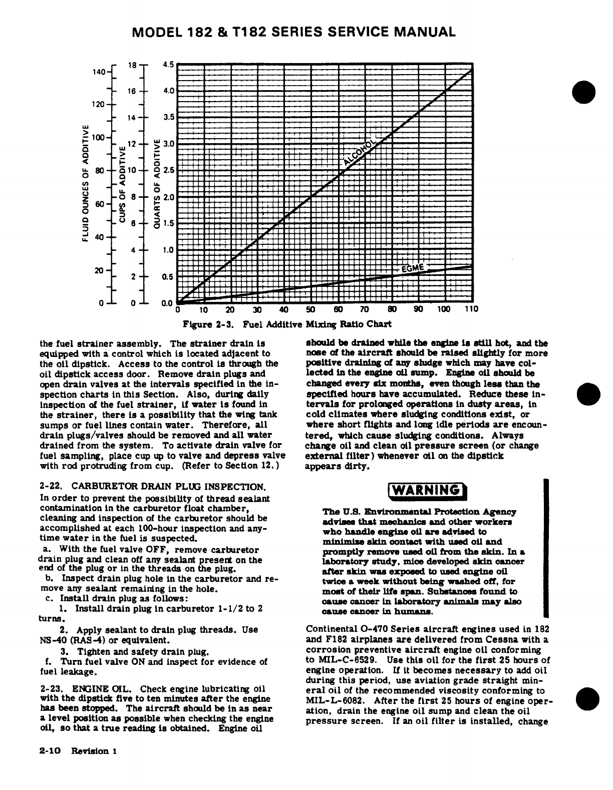
MODEL
182
&
T182
SERIES
SERVICE
MANUAL
18 4.5
140-
16
.0
120
-
,.
_
=_
>
-
4
-
.3.5
100
6
4C
1.0
20
U
0.5
0
0
8
0.0 0
10
20
30 40 50 60
70
80 90
100
110
Figure
2-3.
Fuel
Additive
Mixing
Ratio
Chart
the
fuel
strainer
assembly.
The
strainer
drain
is
should
be
drained
while
the
engine
is
still
hot,
and
the
equipped
with
a
control
which
is
located
adjacent
to
nose
of
the
aircraft
should
be
raised
slightly
for
more
the
oil
dipstick.
Access
to
the
control
is
through
the
positive
draining
of any
sludge
which
may have
col-
oil
dipstick
access
door.
Remove
drain
plugs
and
lected
in the
engine
oil ump.
Engine
oil
should
be
open
drain
valves at
the
intervals
specified
in
the
in- changed
every
six
months, even
though
less
than
the
spection
charts
in
this
Section. Also,
during
daily
specified
hours
have
accumulated.
Reduce
these
in-
inspection
of
the
fuel
strainer,
if
water
is
found
in
tervals
for
prolonged
operatons
in
dusty
areas,
in
the
strainer,
theris
a
possibility that
the
wing
tank
cold
climates
where
sludging conditions
exist,
or
sumps
or
fuel
lines
contain
water.
Therefore,
all
where
short
flights
and long
idle
periods
are
encoun-
drain
plugs/valves
should
be
removed
and
all
water
tered,
which
cause
sludging conditions.
Always
drained
from
the
system.
To
activate
drain
valve
for
change
oil
and
clean
oil
pressure
screen
(or
change
fuel
sampling,
place
cup
up
to valve
and
depress
valve
external
filter)
whenever
oil
on
the
dipstick
with
rod
protruding
from
cup.
(Refer
to
Section
12.)
appears
dirty.
2-22.
CARBURETOR
DRAIN
PLUG
INSPECTION.
IWARNINGI
In
order
to prevent
the
possibility
of
thread sealant
contamination
in
the
carburetor
float
chamber, The
U.8.
Environmental
Protection
Agency
cleaning
and
inspection
of
the
carburetor
should
be
advises
that
mechanic
and
other workers
accomplished
at
each
100-hour
inspection
and
any-
who
handl
engine
oil
are
advised
to
time
water
in
the
fuel
is
suspected.
minm
skin
contact
with
used
oil
and
a.
With
the
fuel valve
OFF,
remove
carburetor
promptly
remove
used
oil from
the skin.
In
a
drain
plug
and
clean
off
any
sealant
present
on
the
laboratory
study,
mice developed
skin
cancer
end
of
the
plug
or
in
the
threads
on
the
plug.
after
kin
was exposed
to
used
engine
oil
b.
Inspect
drain
plug
hole
in
the
carburetor
and
re-
twice
a
week
without
being
washed
off,
for
move
any
sealant
remaining
in
the
hole.
most
of
their
life
span.
Substances
found
to
c.
Install
drain
plug
as
follows:
cause cancer
in
laboratory animals may
also
1.
Install
drain
plug
in
carburetor
1-1/2
to
2
cause cancer
in
humans.
turns.
2.
Apply
sealant
to
drain
plug
threads.
Use
Continental
0-470
Series
aircraft
engines
used
in
182
NS-40
(RAS-4)
or
equivalent.
and
F182
airplanes
are
delivered
from Cessna
with
a
3.
Tighten
and
safety
drain
plug.
corrosion
preventive
aircraft
engine
oil
conforming
f.
Turn
fuel valve
ON
and
inspect
for
evidence
of
to
MIL-C-6529.
Use
this oil
for
the
first
25
hours
of
fuel leakage.
engine
operation.
If
it
becomes
necessary
to
add
oil
during
this
period,
use
aviation
grade
straight
min-
2-23.
ENGINE
OIL.
Check
engine
lubricating
oil
eral
oil
of
the
recommended
viscosity
conforming
to
with
the
dipstick
five
to
ten
minutes
after
the
engine
MIL-L-6082.
After
the
first
25
hours
of
engine
oper-
has
been
stopped.
The
aircraft
should
be
in
as
near ation,
drain
the
engine
oil
sump
and
clean
the
oil
a
level position
as
possible
when
checking
the
engine
pressure
screen.
If
an
oil
filter
is
installed,
change
oil,
so
that
a
true
reading
is
obtained.
Engine
oil
2-10
Revision
1
MODEL
182
&
T182
SERIES
SERVICE
MANUAL
filter.
Refill
oil
sump
with
recommended
quantity
NOTE
and
grade
of
ashless
dispersant
oil.
Newly
over-
hauled
engines
should
also
be
operated
on
aviation
Use
care
to
prevent
damage
to
filter
element
grade
straight
mineral
oil
conforming
to
MIL-L-6082
when
cleaning
filter
with
compressed
air.
for
the
first
25
hours.
b.
Clean
filter
by
blowing
with
compressed
air
Lycoming
0-540
Series
aircraft
engines
used
in
T182
(not
over
100
psi)
from
direction
opposite
of
normal
airplanes
are
delivered
from Cessna
with
aviation
air
flow.
Arrows
on
filter
case
indicate
direction
of
grade
straight
mineral
oil
conforming
to
MIL-L-6082.
normal
air
flow.
If
it
becomes
necessary
to
add
oil
during
the
first
25
hours
of
engine
operation
use aviation
grade
straight
mineral oil
of
the
recommended
viscosity
conforming
to
MIL-L-6082.
After
the
first
25
hours
drain
the
Do
not
use
solvent
or
cleaning fluids
to
wash
engine
oil
and
clean
the
oil
pressure
screen.
If
an
filter.
Use
only
a
water
and
household
deter-
oil
filter
is
installed,
change
filter.
Refill
oil
sump
gent
solution
when
washing
the
filter.
with
aviation
grade
straight
mineral
oil
of
the
recom-
mended
viscosity,
conforming
to
MIL-L-6082,
and
c.
After
cleaning
as
outlined
in
step
"b", the
filter
continue to
use
until
a
total
of
50
hours
of
engine
may
be
washed,
if
necessary,
in
a
solution
of
warm
operation
have
accumulated
or
oil
consumption
has
water
and
a
mild
household
detergent.
A
cold water
stabilized.
Drain
the
engine
oil
and
refill
sump
with
solution
may
be
used.
recommended
quantity
and
grade
of
ashless
dispersant
oil.
Ashless
dispersant
oil
MUST
BE USED
after
NOTE
first
50
engine
hours,
or
consumption has
stabilized.
The
same
procedure
applies
to
newly
overhauled
The
filter
assembly
may
be
cleaned
with
com-
engines.
pressed
air
a
maximum
of
30
times
or
it
may
be
washed
a
maximum
of
20
times.
A
new
An
oil
quick-drain
valve
may
be
installed
in
the
oil
filter
should
be
installed
after
using
500
hours
drain
port
of
the
oil
sump.
This
valve
provides
a
of
engine
operating
time
or
one
year,
whichever
quick
and
cleaner
method
of
draining
the
engine
oil. should
occur
first.
However,
a
new
filter
should
To
drain
the
oil,
proceed
as
follows: be
installed
at
anytime
the existing
filter
is
a.
Operate
engine
until oil
temperature
is
at
a
damaged.
A
damaged
filter
may
have
sharp
normal
operating
temperature.
or
broken
edges
in
the
filtering
panels which
b.
(With
Quick-Drain
Valve)
Attach
a hose
to
the
would
allow
unfiltered
air
to
enter
the
induc-
quick-drain
valve
in
oil
sump.
Push
up on
quick-
tion
system.
Any
filter
that
appears
doubtful,
drain
valve
until
it
locks
open,
and
allow
oil
to
drain
shall
have
a
new
filter
installed
in
its place.
through
hose
into
container.
c.
(Without
Quick-Drain
Valve)
Remove
oil
drain
d.
After
washing,
rinse
filter
with
clear water
un-
plug
from
engine
sump
and
allow
oil
to
drain
into
a
til
rinse
water
draining
from
filter
is
clear.
Allow
container.
water
to
drain
from
filter
and
dry
with
compressed
d.
After
engine
oil
has
drained,
close
quick-drain
air
(not
over
100
psi).
valve
or
install
and
safety
drain
plug.
e.
Remove
and
clean
oil
pressure
screen
or
change
NOTE
external oil
filter.
f.
Service
engine
with
correct
quantity and
viscos-
The
filtering
panels
of
the
filter
may
become
ity
of
aviation
grade
engine
oil.
distorted
when
wet,
but
they will
return
to
NOTE
their
original
shape
when
dry.
e.
Be
sure air
box
is
clean,
inspect
filter.
If
Refer
to
inspection
charts
for
intervals
for
filter
is
damaged,
install
a
new
filter
changing
oil
and
filter.
See
figure
2-4
for
f.
Install
filter
at
entrance
to
air
box
with
gasket
correct
viscosities
and
quantities
of
aviation
on
aft
face
of
filter
frame
and with
air
flow
arrows
grade
oil.
on
filter
frame
pointed
in
the
correct
direction.
2-24.
ENGINE
INDUCTION AIR
FILTER. The
in- 2-25.
VACUUM
SYSTEM
FILTER. The
vacuum
sys-
duction
air
filter
keeps
dust
and
dirt
from
entering
tem
central
air
filter
keeps
dust
and
dirt
from enter-
the
induction
system.
The
value
of
maintaining the
ing
the
vacuum-operated
instruments.
Inspect
filter
air
filter
in
a good
clean
condition
can
never
be
over-
every 100
hours
for damage.
Replace
filter
every
500
stressed.
More
engine
wear
is
caused
through
the
hours
of
operation
or
whenever
it
becomes
suffi-
use
of
a
dirty
or
damaged
air
filter
than
is
generally
ciently
clogged
to
cause
suction
gage
readings
to
believed.
The
frequency
with which
the
filter
should
drop
below
4.6
in.
Hg.
Do
not operate
the
vacuum
be
removed,
inspected,
and
cleaned
will
be
deter-
system
with
the filter
removed,
or
a
vacuum
line
mined
primarily
by
aircraft
operating
conditions.
A
disconnected
as
particles
of
dust
or
other
foreign
good
general rule
however,
is
to
remove,
inspect,
matter
may enter the
system
and
damage
the
vac-
and
clean
the filter
at
least
every
100
hours
of
engine uum-operated
instruments.
operating
time
and more
frequently
if
warranted
by
operating
condition.
Under extremely
dusty
condi-
tions, daily servicing
of
the
filter
is
recommended.
To
service
the
induction
air
filter,
proceed
as
follows:
Excessive
smoking
in
the
cabin
will
cause
a.
Remove
filter
from
aircraft.
premature
filter
clogging.
Revision
1
2-11
MODEL
182
&
T182
SERIES
SERVICE
MANUAL
2-26.
BATTERY.
Battery
servicing
involves
adding
anism within
the
hollow
piston
rod.
This
is
for
ther-
distilled
water
to
maintain
the
electrolyte
even
with
mal
expansion
and contraction
of
the
hydraulic
fluid
the
horizontal
baffle
plate
at
the
bottom
of
the
filler
in
the damper.
The
shimmy
damper
must
be
filled
holes,
checking the
battery
cable
connections,
and
completely
with
hydraulic
fluid,
free
of
en-
neutralizing
and
cleaning
off
any
spilled
electrolyte
trapped
air
with the compensating
piston
bottomed
in
or
corrosion.
Use
bicarbonate
of
soda
(baking
soda)
the
piston
rod.
Before
servicing
the
shimmy damper,
and
water
to
neutralize
electrolyte
or
corrosion.
Fol-
ascertain
that
the
compensating piston
is
bottomed
low
with
a
thorough
flushing
with
a
wire
brush,
then
in
the
piston
rod.
Service
the
shimmy
damper
at
coat
with
petroleum jelly
before
connecting.
The
bat-
least
every
50
hours
as
follows:
tery
box
also
should
be
checked
and
cleaned
if
any
a.
Remove
shimmy damper from
the
aircraft.
corrosion
is
noted.
Distilled
water,
not
acid
or
"re-
b.
While
holding the
shimmy
damper
in
a
vertical
juvenators,"
should
be
used
to
maintain
electrolyte
position
with the
filler
plug
pointed
upward,
loosen
level.
Check
the
battery
every
100
hours
(or
at
least
filler
plug
to
allow
excess
fluid
to escape.
every
90 days)
and
oftener
in
hot
weather.
See
Section
c.
Allow
the
spring
to
bottom
out
the
floating
pis-
16
for
detailed
battery
removal,
installation, and
test-
ton
inside
the
shimmy
damper
rod.
ing.
d.
When
the
fluid
stops
flowing,
insert
a
length
of
stiff
wire
through
the
air
bleed
hole
in
the
setscrew
at
the
end of
the
piston
rod
until
it
touches the
float-
2-27.
TIRES.
Maintain
tire
pressure
at the
pressure
ing
piston.
The
depth
of
insertion
should
be
3-13/16
specified
in
figure
1-1.
When
checking
tire
pressure,
inches.
examine
tires
for
wear,
cuts,
bruises,
and
slippage.
NOTE
Remove
oil,
grease,
and mud
from
tires
with
soap
and
water.
If
the
wire
insertion
is
less
than 3-13/16
inches,
the
floating
piston
is
lodged
in
the
NOTE
shaft.
If
the
wire
cannot
be
used
to
free
the
piston,
the
rod
assembly
and
piston
Recommended
tire
pressures
should
be
main-
should
be
replaced.
tained. Especially
in
cold
weather,
remember
that
any
drop
in
temperature
of
the
air
inside
e. After
determining
that
floating
piston
is
bottomed,
a
tire
causes a
corresponding
drop
in
air
pres-
move
dampener
rod
to place
piston
to
the
end
of
the
sure.
barrel
opposite
the
filler
plug.
f.
Remove
filler
plug
and
fill
shimmy
dampener
2-28.
NOSE
GEAR
SHOCK
STRUT.
The
nose
gear
with
hydraulic
fluid.
shock
strut
requires
periodic
checking
to
ensure
that
NOTE
the
strut
is
filled
with
hydraulic
fluid
and
is
inflated
to
the
correct
air
pressure.
To
service
the
nose
gear
Be
sure
that
the
shimmy
dampener
and
shock
strut,
proceed
as
follows:
hydraulic
fluid
are
at
70°
to
80°F
while
a.
Remove
valve
cap
and
release all
air.
filling
the
shimmy
dampener.
b.
Remove
valve
housing
assembly.
c.
Compress
strut
completely (stops
in
contact
g.
Install
filler
plug,
and
wash
dampener
in
clean-
with
outer
barrel
hub).
ing
solvent
and
wipe
dry
with
a
clean
cloth.
d.
Oil
level.
h.
Install
dampener
on
aircraft.
1.
Fluid
used
should
comply
with
specification
MIL-H-5606.
NOTE
2.
Fill
strut
to
bottom
of
valve
installation
hole.
3.
Maintain
oil
level
at
bottom
of
valve
installa-
Keep
shimmy
dampener,
especially
the
tion
hole.
exposed
portions
of
the
dampener piston
e.
Fully
extend
strut.
shaft,
clean
to
prevent collection
of
dust
f.
Replace valve
housing
assembly.
and
grit
which
could
cut
the
seals
in
the
g.
With
strut
fully
extended
and
nose wheel
clear
dampener
barrel.
Keep
machined
sur-
of
ground,
inflate
strut
to
55-60
psi. faces
wiped
free
of
dirt
and
dust, using
a
NOTE
draulic
fluid
(MIL-H-5606)
or
kerosene.
All
surfaces
should
be
wiped
free
of
ex-
The
nose
landing
gear
shock
strut
will
cessive
hydraulic
fluid.
normally
require
only
a
minimum amount
of
service.
Maintain the
strut
extension
2-30.
HYDRAULIC
BRAKE
SYSTEMS.
Check
brake
pressure
as
shown
in
Section
1.
Lubricate
master
cylinders
and
refill
with
hydraulic
fluid
as
landing
gear
as
shown
in
figure
2-5.
Check
specified
in
the
inspection
charts.
Bleed
the
brake
the
landing
gear
daily
for general
cleanli-
system
of
entrapped
air
whenever
there
is
a spongy
ness,
security
of
mounting,
and
for
hydrau-
response
to
the
brake
pedals.
Refer
to
Section
5
for
lic
fluid
leakage.
Keep
machined
surfaces
filling
and
bleeding
of
the
brake
systems.
wiped
free
of
dirt
and
dust, using
a
clean
lint-free
cloth
saturated
with
hydraulic
2-31.
CLEANING.
fluid
(MIL-H-5606)
or
kerosene.
All
sur-
faces
should
be
wiped
free
of
excessive
2-32.
GENERAL
DESCRIPTION.
Keeping
the
air-
hydraulic
fluid.
craft
clean
is
important.
Besides
maintaining
the
trim
appearance
of
the
aircraft,
cleaning
lessens
the
2-29. NOSE
GEAR SHIMMY DAMPER.
The
nose
possibility
of
corrosion
and
makes
inspection
and
gear
shimmy
damper
contains
a
compensating
mech-
maintenance
easier.
2-12
Revision
1
MODEL
182
&
T182
SERIES SERVICE
MANUAL
2-33.
CLEANING WINDSHIELD
AND
WINDOWS.
2-33A.
MATERIALS
REQUIRED.
NAME
MANUFACTURER
USE
Mild
soap
or
detergent
Commercially
available.
Cleaning
windshields
and
(hand dishwashing
type
windows.
without
abrasives).
Aliphatic
naphtha
Type
II
Commercially
available.
Removing
deposits
which
conforming
to
Federal
cannot
be
removed
with
mild
Specification
TT-N-95.
soap
solution
on
acryllic
windshields
and
windows.
*Polishing
wax.
Waxing
acrylic
windshields
and
windows
Turtle
Wax
(paste). Turtle
Wax,
Inc.
Chicago,
IL.
60638
Great
Reflections
E.I.
duPont
de
Nemours
Paste
Wax
and
Co.
(Inc.)
Wilmington,
DE
19898
Slip-Stream
Wax
Classic
Chemical
(paste)
Grand
Prairie,
TX
75050
Acrylic
polish
conforming
to
Cleaning
and
polishing
acrylic
Federal
Specification
windshields
and
windows.
P-P-560
such
as:
.
Permatex
plastic
cleaner
Permatex
Company,
Inc.
No.
403D
Kansas
City, KS
66115
Cotton
flannel
or
cotton
Commercially
available.
terry
cloth
material.
These
are
the
only
polishing
waxes
tested
and
approved
for
use
by
Cessna
Aircraft
Company.
denatured
alcohol,
gasoline,
benzene,
xylene,
Windshields
and
windows
are
easily
damaged
MEK,
acetone,
carbon tetrachloride,
lacquer
by
improper
handling
and
cleaning techniques.
thinners,
commercial
or
household
window
cleaning sprays.
a.
Place
airplane
inside
hangar
or
in
shaded
area
and
allow to
cool
from
heat
of
sun's
direct
rays.
2-33B.
WAXING.
b.
Using
clean
(preferably
running)
water,
flood
a. Hand
polishing
wax
should
be
applied
to
acrylic
surface.
Use
bare
hands
with
no
jewelry
to
feel
and
surfaces.
(The
wax
has
an
index
of
refraction
nearly
dislodge
any
dirt
or
abrasive
materials.
the
same
as
transparent
acrylic
and
tend
to
mask
any
c.
Using
a
mild
soap
or
detergent
(such
as
dish-
shallow
scratches
on
windshield
surface).
washing
liquid)
in
water, wash
surface.
Again
use
b.
Acrylic
surfaces
may
be
polished
using
a
polish
only
bare
hands
to
provide
rubbing
force.
(A
clean
meeting
Federal
Specification
P-P-560
applied
per
cloth
may
be
used
to
transfer
soap
solution
to
surface,
manufacturer's
instructions.
but
extreme care
must
be
exercised
to
prevent
scratching
surface.)
d.
On
acrylic
windshields
and
windows
only,
if
soils
which
cannot
be
removed
by
a
mild
detergent
re-
DO
NOT
use
rain
repellent
on
acrylic
sur-
main,
Type
II
aliphatic
naphtha
applied with
a
soft
faces.
clean
cloth
may
be
used
as
a
cleaning
solvent.
Be
sure
to
frequently
refold
cloth to
avoid
redepositing
soil NOTE
and/or
scratching
windshield with
any
abrasive
part-
When
applying
and
removing
wax
and
icles.
polish,
use
a
clean
soft
cloth.
e.
Rinse
surface
thoroughly
with
clean
fresh
water
and
dry
with
a
clean
cloth.
2-33C.
PREVENTIVE
MAINTENANCE.
DO
NOT
use
any
of
the
following
on
or
for
Utilization
of
the
following techniques
will
Revision
1
2-13
MODEL
182
&
T182
SERIES
SERVICE
MANUAL
help
minimize
windshield
and
window
craz-
cleaners,
but should
be
used
cautiously
since
some
of
them
are
strongly
alkaline.
Many good
aluminum
ing.
cleaners,
polishes
and
waxes
are
available
from
com-
a.
Keep
all
surfaces
of
windshields
and
windows
mercial
suppliers
of
aircraft
products.
clean.
b.
If
desired, wax acrylic
surfaces.
2-37.
ENGINE
AND
ENGINE
COMPARTMENT.
An
c.
DO
NOT
park
or
store
airplane
where
it
might
be
engine
and
accessories
wash
down
should
be
accom-
subjected
to
direct
contact with
or
vapors
from:
plished
during
each 100-hour
inspection
to
remove
methanol,
denatured
alcohol,
gasoline,
benzene,
oil,
grease,
salt
corrosion
or
other
residue
that
xylene,
MEK,
acetone,
carbon
tetrachloride, lacquer
might
conceal
component
defects
during inspection.
thinners,
commercial
or
household
window
cleaning
Also,
periodic
cleaning
can
be
very
effective
in
pre-
sprays, paint strippers,
or
other
types
of
solvents.
ventive
maintenance.
d.
DO
NOT
use
solar
screens
or shields
installed
on
inside
of
airplane
or
leave
sun
visors
up
against
Precautions
should
be
taken
when
working
with
clean-
windshield.
The reflected
heat
from
these
items
ing
agents
such
as
wearing
of
rubber
gloves,
an
apron
causes
elevated
temperatures
which accelerate
crazing
or
coveralls
and
a
face
shield
or
goggles.
Use
the
and
may
cause formation
of
bubbles
in
inner
ply
of
least
toxic of
available
cleaning
agents
that
will
satis-
multiple
ply windshields.
factorily
accomplish
the
work.
These
cleaning
agents
include:
(1)
Stoddard
Solvent
(Specification
P-D-680
2-34.
INTERIOR
TRIM.
The
instrument
panel,
in-
type
II),
(2)
A
water
alkaline
detergent cleaner
(MIL-
terior
plastic
trim,
and
control
knobs
need
only
be
C-25769J)
mixed,
1
part
cleaner,
2
to
3
parts
water
wiped
with
a
damp
cloth.
Oil
and
grease
on
the
con- and
8
to
12
parts
Stoddard
solvent
or
(3)
A
solvent
trol
wheels
and
control
knobs
can
be
removed
with
a
base
emulsion
cleaner
(MIL-C-4361B)
mixed
1
part
cloth
moistened
with
Stoddard
solvent.
Volatile
sol-
clearer
and
3
parts
Stoddard
vents,
mentioned
in
the
caution
note
of
paragraph
2-33,
must
never
be
used
since
they
soften
and
craze
the
plastic
trim.
Do
not
use
gasoline
or
other
highly
flammable
2-35.
PAINTED
SURFACES.
The
painted
exterior
substances
for
wash
down.
surfaces
of your
new
Cessna
have
a
durable,
long
lasting finish.
Approximately
10
days
are
required
Perform
all
cleaning
operations
in
well
ventilated
for
the
paint
to
cure
completely;
in
most
cases,
the
work
areas
and
ensure
that adequate
firefighting
and
curing
period
will
have
been
completed
prior
to
de-
safety
equipment
is
available.
Do
not smoke
or
ex-
livery
of
the
airplane.
In
the
event
that
polishing
or
pose
a
flame,
within
100
feet
of
the cleaning
area.
buffing
is
required
within
the
curing
period,
it
is
Compressed
air,
used
for
cleaning
agent,
application
recommended
that
the
work
be
done by
someone
ex-
or
drying,
should
be
regulated
to
the
lowest
practical
perienced
in handling
uncured
paint.
Any
Cessna
pressure.
Use of
a
stiff
bristle
brush
rather
than
a
Dealer
can
accomplish
this
work.
steel
brush
is
recommended
if
cleaning
agents
do
not
remove
excess
grease
and
grime
during spraying.
Generally,
the
painted
surfaces
can
be
kept
bright
by
washing with
water
and
mild
soap,
followed
by
a
rinse
A
recommended
procedure
for
cleaning
an
engine
and
with
water
and
drying
with
cloths
or
a
chamois.
accessories
is
as
follows:
Harsh
or
abrasive
soaps
or
detergents
which
cause
corrosion
or
scratches
should
never
be
used.
Remove
stubborn
oil
and
grease
with
a cloth
moistened
with
Stoddard
solvent.
Do
not
attempt
to
wash
an engine
which
is
still
hot
or
running.
Allow
the
engine
to
cool before
To
seal
any
minor
surface
chips
or
scratches
and
pro-
cleaning.
tect
against
corrosion,
the
airplane
should
be
waxed
regularly
with
a
good
automotive
wax
applied
in
accor-
a.
Remove
engine
cowling
in
accordance
with
para-
dance
with
the
manufacturer's instructions.
If
the
graph
11-3.
airplane
is
operated
in
a seacoast
or
other
salt
water
b.
Carefully
cover
the
coupling
area
between
the
environment,
it
must
be
washed
and waxed
more
fre-
vacuum
pump
and
the
engine
drive
shaft
so
that
no
quently
to
assure
adequate
protection.
Special
care
cleaning
solvent
can
reach
the
coupling
or
seal.
should
be
taken
to
seal
around
rivet
heads
and
skin
c.
Cover
the
open
end
of
the
vacuum
discharge
tube.
laps,
which
are
the
areas
most
susceptible
to
corro-
d.
Cover
the
vacuum
relief
valve
filter,
if
installed
sion.
A
heavier
coating
of
wax
on
the
leading edges
in
the
engine
compartment.
of
the
wings,
and
tail
and
on
the cowl
nose
cap
and
e.
Use
fresh
water
for
wash
down
when
the
engine
propeller
spinner
will
help
reduce
the
abrasion
en-
is
contaminated
with
salt
or
corrosive
chemicals.
A
countered
in
these
areas.
Reapplication
of
wax
will
cleaning
agent
such
as
described
previously
may
then
generally
be
necessary
after
cleaning
with
soap solu-
be
used
to
remove
oil
and
grime.
tions
or
after
chemical de-icing
operations.
2-36.
ALUMINUM
SURFACES.
The
aluminum
sur-
faces
require
a
minimum
of
care,
but
should
never
be
neglected.
The
aircraft
may
be
washed
with
clean
Care
should
be
exercised
to
not
direct
cleaning
water
to
remove
dirt
and
may be
washed
with
non-
agents
or
water
streams
at
openings
on
the
alkaline
grease
solvents
to remove
oil
and/or grease.
starter,
magnetos,
alternator
or
vacuum
pump
Household
type
detergent
soap
powders
are
effective
or
turbocharger
relief
valve.
2-14
Revision
1
MODEL
182
&
T182
SERIES SERVICE
MANUAL
f.
Thoroughly
rinse
with
clean warm
water
to
re-
2-41.
LUBRICATION.
move
all
traces
of
cleaning
agents.
Cleaning
agents
should
never
be
left
on
engine
WARNING
components
for
an
extended
period
of
time.
Failure
to
remove
them
may
cause
damage
to The
U.S.
Environmental
Protection
Agency
components
such
as
neoprene
seals
and
silicone
advises
that
mechanics
and
other
workers
fire
sleeves,
and
could
cause
additional
corro-
who
handle
engine
oil
are advised
to
promptly
remove
used
oil
from
the
skin.
In
a
g.
Completely
dry
engine
and
accessories
using
laboratory
study,
mice developed
skin
cancer
clean,
dry
compressed
air.
after
skin
was
exposed
to
used
engine
oil
h.
Remove
the
cover
over
the
coupling
area.
twice
a
week
without
being
washed
off,
for
i.
Remove
the
cover
from
the
vacuum
discharge
most
of
their
life
span.
Substances
found
to
tube.
cause
cancer
in
laboratory
animals
may
also
j.
Remove
the
cover
from
the
vacuum
relief
valve
cause
cancer in
humans.
filter,
if
installed.
k.
If
desired,
engine
cowling
may
be
washed
with
2-42.
GENERAL DESCRIPTION.
Lubrication
re-
the
same cleaning
agents,
then
rinsed
thoroughly
and
quirements
are
shown in
figure
2-5.
Before
adding
wiped
dry. After
cleaning
engine,
relubricate
all
lubricant
to
a
fitting,
wipe
fitting
free
of
dirt.
Lubri-
control
arms
and
moving
parts
as
required.
cate until
grease
appears
around
part
being
lubricated,
1.
Reinstall
engine
cowling.
and
wipe
excess
grease
from
parts.
The
following
paragraphs
supplement
figure
2-5
by
adding
details
2-43.
TACHOMETER
DRIVE
SHAFT.
Refer
to
For
maximum
safety,
check that
the
magneto
Sections
11
and
15.
switches
are
OFF,
the
throttle
is
closed,
the
mixture
control
is
in
the
idle cut-off
position,
2-44.
WHEEL
BEARINGS.
Clean
and
repack
the
and
the
airplane
is
secured
before
rotating
the
wheel
bearings
at
the
first
100-hour
inspection
and
propeller
by
hand.
Do
not stand
within
the
arc
at
each
500-hour inspection
thereafter.
If
more
of the
propeller
blades
while
turning
the
pro-
than
the
usual
number
of
take-offs
and
landings
are
peller.
made,
extensive
taxiing
is
required,
or
the
aircraft
is
operated
in
dusty
areas
or
under
seacoast
condi-
m.
Before
starting
engine,
rotate
the
propeller
by
tions,
cleaning
and
lubrication
of
the
wheel
bearings
hand
no
less
than
four complete
revolutions.
shall
be
accomplished
at
each
100-hour
inspection.
2-45.
NOSE
GEAR
TORQUE
LINKS.
Lubricate
nose
gear
torque
links
every
50
hours.
When
operating
2-38.
UPHOLSTERY
AND
INTERIOR
cleaning
pro-
from
a
dirt
strip
or
in
extremely dusty
areas,
more
longs
upholstery
fabrics
and
interior
trim.
To
clean
frequent
lubrication
of
the
torque
links
is
required.
the
interior,
proceed
as
follows:
a.
Empty
all
ash
trays
and
refuse
containers.
2-46.
WING
FLAP
ACTUATOR.
Clean
and
lubricate
b.
Brush
or
vacuum
clean
the
upholstery
and
carpet
wing
flap
actuator
jack
screw
each
100
hours
as
fol-
to
remove
dust
and
dirt.
lows:
c.
Wipe
leather
and
plastic
trim
with
a
damp
cloth.
a.
Expose
jack
screw
by
operating
flaps
to
full-
d. Soiled
upholstery
fabrics
and
carpet
may
be
down
position.
cleaned
with
a
foam-type
detergent
used
according
to
b.
Clean jack
screw
threads
with
solvent
rag
and
the
manufacturer's
instructions.
dry
with
compressed
air.
e.
Oil
spots
and
stains
may
be
cleaned
with
house-
hold
spot
removers,
used
sparingly.
Before
using
NOTE
any
solvent,
read
the
instructions
on
the
container
and
test
it
on
an
obscure
place
in
the
fabric
to
be
It
is
not
necessary
to
remove
actuator
from
cleaned. Never
saturate
the
fabric
with
volatile
sol-
aircraft
to
clean
or lubricate
threads.
vent;
it
may
damage
the
padding
and
backing
material.
f.
Scrape
sticky
material
from fabric
with
a
dull
c.
With
oil
can,
apply
light
coat
of
No.
10
weight
knife,
then
spot
clean
the
area.
non-detergent
oil
to
threads
of
jack
screw.
2-39.
PROPELLER.
The
propeller
should
be
wiped
2-47.
ROD END
BEARINGS.
Periodic
inspection
occasionally
with
an
oily
cloth
to remove
grass
and
and
lubrication
is
required
to
prevent
corrosion
of
bug
stains.
In
salt
water
areas
this
will
assist
in
the
bearing
in
the
rod end.
At
each
100-hour
inspec-
corrosion
proofing
the
propeller.
tion,
disconnect
the
control
rods
at
the
aileron
and
nose
gear
steering
bungee,
and
inspect
each
rod
end
2-40.
WHEELS.
The
wheels
should
be
washed
for
corrosion.
If
no
corrosion
is
found,
wipe
the
periodically
and
examined
for
corrosion,
chipped
surface
of
the
rod
end
balls
with
general
purpose
oil
paint,
and
cracks
or
dents
in
the wheel
halves
or
in and
rotate
ball freely
to
distribute
the
oil
over
its
the flanges
or
hubs.
If
defects
are
found
remove
and
entire
surface
and
connect
the
control
rods
to
their
repair
in
accordance
with
Section
5.
Discard
cracked
respective
units.
If
corrosion
is
detected
during
the
wheel
halves.
flanges
or
hubs
and
install
new
parts.
inspection,
install
new
rod
ends.
2-15
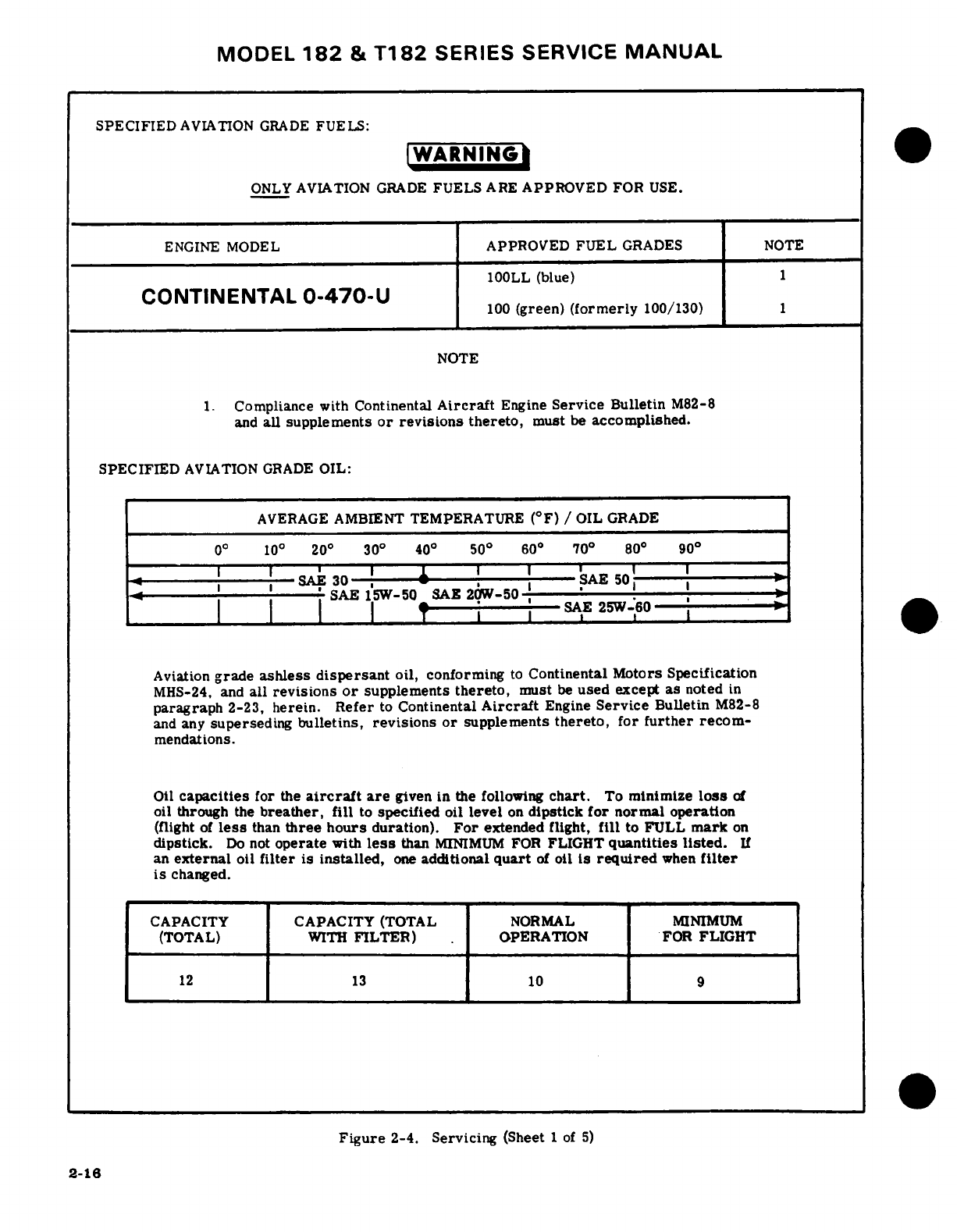
MODEL
182
&
T182
SERIES SERVICE
MANUAL
SPECIFIED
AVIATION
GRADE
FUELS:
ONLY
AVIATION
GRADE
FUELS
ARE
APPROVED
FOR
USE.
ENGINE
MODEL
APPROVED
FUEL
GRADES
NOTE
100LL
(blue)
1
CONTINENTAL
0-470-U
100
(green)
(formerly
100/130) 1
NOTE
1.
Compliance
with
Continental
Aircraft
Engine
Service Bulletin
M82-8
and
all
supplements
or
revisions
thereto,
must
be
accomplished.
SPECIFIED
AVIATION
GRADE
OIL:
AVERAGE
AMBIENT
TEMPERATURE
(°F)
/
OIL
GRADE
0
°10°
20
°
30
°
40
°
50
°
60°
70
°
80
°
90
°
Aviation
grade
ashless
dispersant
oil,
conforming
to
Continental Motors
Specification
MHS-24,
and
all
revisions
or
supplements
thereto,
must
be
used
except as
noted
in
paragraph
2-23,
herein.
Refer
to
Continental
Aircraft
Engine
Service
Bulletin
M82-8
and
any
superseding
bulletins, revisions
or
supplements
thereto,
for
further
recom-
mendations.
Oil
capacities
for
the
aircraft
are
given in the following
chart.
To
minimize
loss
of
oil
through
the
breather,
fill
to
specified
oil
level
on
dipstick
for
normal
operation
(flight
of
less
than
three
hours
duration).
For
extended
flight,
fill
to
FULL
mark
on
dipstick.
Do
not
operate
with
less
than
MINIMUM
FOR
FLIGHT
quantities
listed.
If
an
external
oil
filter
is
installed,
one
additional
quart
of
oil
is
required
when
filter
is
changed.
CAPACITY
CAPACITY
(TOTAL
NORMAL
MINIMUM
(TOTAL)
WITH
FILTER)
OPERATION
FOR
FLIGHT
12
13
10
9
Figure
2-4.
Servicing
(Sheet
1
of
5)
2-16
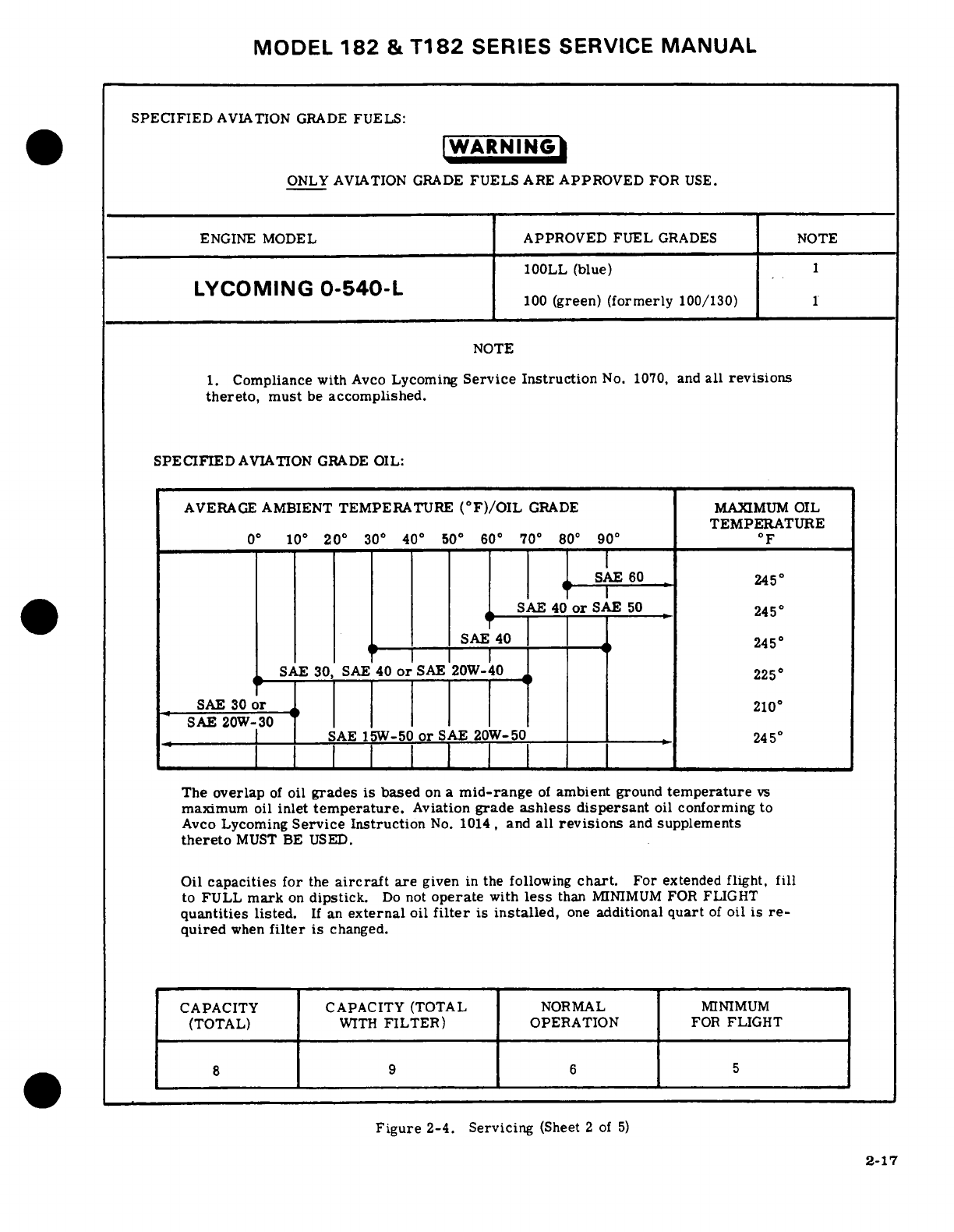
MODEL
182
&
T182
SERIES
SERVICE
MANUAL
SPECIFIED
AVIATION
GRADE
FUELS:
ONLY AVIATION
GRADE
FUELS
ARE
APPROVED
FOR
USE.
ENGINE
MODEL
APPROVED
FUEL
GRADES
NOTE
100LL
(blue)
1
LYCOMING
0-540-L
100
(green)
(formerly
100/130)
1
NOTE
1.
Compliance with
Avco
Lycoming
Service Instruction
No.
1070,
and
all
revisions
thereto,
must
be
accomplished.
SPECIFIED
AVIATION
GRADE
OIL:
AVERAGE
AMBIENT
TEMPERATURE
(°F)/OIL
GRADE MAXIMUM
OIL
TEMPERATURE
0
°
10°
20°
30°
40°
50
°
60°
70°
80
°
90°
°F
SAE
60
245
°
AE 40
or
SAE
50 245
°
SAE 30,
SAE
40
or
SAE
20W-40
225
°
SAE 30
or
210
°
SAE 20W-30
The
overlap
of
oil
grades
is
based
on
a
mid-range
of
ambient
ground
temperature
vs
maximum oil
inlet
temperature.
Aviation
grade
ashless
dispersant
oil
conforming to
Avco
Lycoming
Service
Instruction
No.
1014, and
all
revisions
and
supplements
thereto
MUST
BE
USED.
Oil
capacities
for
the
aircraft
are
given
in
the
following
chart.
For
extended
flight,
fill
to
FULL
mark
on
dipstick.
Do
not
operate
with
less
than
MINIMUM
FOR
FLIGHT
quantities
listed.
If
an
external
oil
filter
is
installed,
one
additional
quart
of
oil
is
re-
quired
when
filter
is
changed.
CAPACITY
CAPACITY
(TOTAL
NORMAL
MINIMUM
(TOTAL)
WITH
FILTER)
OPERATION
FOR
FLIGHT
8 9
6
5
Figure
2-4. Servicing
(Sheet
2
of
5)
2-17
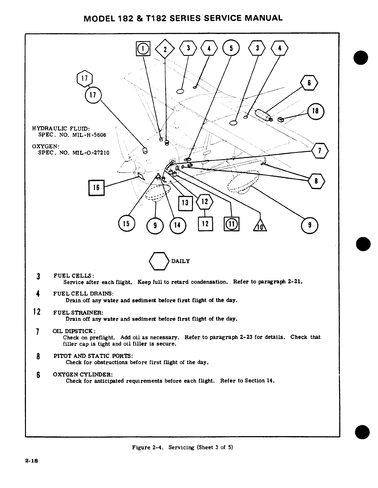
MODEL
182
&
T182
SERIES
SERVICE
MANUAL
HYDRAULIC
FLUID:
SPEC.
NO.
MIL-H-5606
\ .
/
OXYGEN:
SPEC.
NO.
MIL-0-27210
'
i
-
:
:
7'
A I
®'
"
^ ^
DAILY
3
FUEL
CELLS:
Service
after
each
flight.
Keep
full
to
retard
condensation.
Refer
to
paragraph
2-21.
4
FUEL
CELL
DRAINS:
Drain
off
any
water
and
sediment
before
first
flight
of
the
day.
12
FUEL
STRAINER:
Drain
off
any
water
and
sediment
before
first
flight
of
the
day.
7
OIL
DIPSTICK:
Check
on
preflight.
Add
oil
as
necessary. Refer
to
paragraph
2-23
for
details.
Check
that
filler
cap
is
tight
and
oil
filler
is
secure.
8
PITOT
AND
STATIC
PORTS:
Check
for
obstructions
before
first
flight
of
the
day.
6
OXYGEN
CYLINDER:
Check
for anticipated
requirements
before
each
flight.
Refer
to
Section
14.
Figure
2-4.
Servicing
(Sheet
3
of
5)
2-18
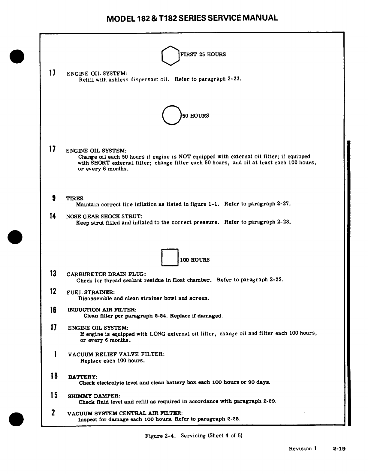
MODEL
182
&
T182
SERIES SERVICE
MANUAL
17
ENGINE
OIL
SYSTEM:
Refill
with
ashless
dispersant
oil.
Refer
to
paragraph
2-23.
17
ENGINE
OIL
SYSTEM:
Change
oil
each
50
hours
if
engine
is
NOT
equipped with
external
oil
filter;
if
equipped
with
SHORT
external
filter;
change
filter
each
50
hours,
and
oil
at
least
each
100
hours,
or
every
6
months.
9
TIRES:
Maintain
correct
tire
inflation
as
listed
in
figure
1-1.
Refer
to
paragraph
2-27.
14
NOSE
GEAR
SHOCK
STRUT:
Keep
strut
filled
and
inflated
to
the
correct pressure.
Refer
to
paragraph
2-28.
13
CARBURETOR
DRAIN
PLUG:
Check
for
thread sealant
residue
in
float
chamber.
Refer
to
paragraph
2-22.
12
FUEL
STRAINER:
Disassemble
and
clean
strainer
bowl and
screen.
16
INDUCTION
AIR
FILTER:
Clean
filter
per
paragraph
2-24.
Replace
if
damaged.
17
ENGINE
OIL
SYSTEM:
If
engine
is
equipped with
LONG
external
oil
filter,
change oil
and
filter
each
100
hours,
or
every
6
months.
1
VACUUM
RELIEF
VALVE
FILTER:
Replace
each
100
hours.
18
BATTERY:
Check
electrolyte
level
and
clean
battery
box
each
100
hours
or
90
days.
15
SHIMMY DAMPER:
Check
fluid
level
and
refill
as
required
in
accordance
with
paragraph
2-29.
2
VACUUM
SYSTEM
CENTRAL
AIR
FILTER:
Inspect
for
damage
each
100
hours.
Refer
to
paragraph
2-25.
Figure
2-4.
Servicing
(Sheet
4
of 5)
Revision
1
2-19
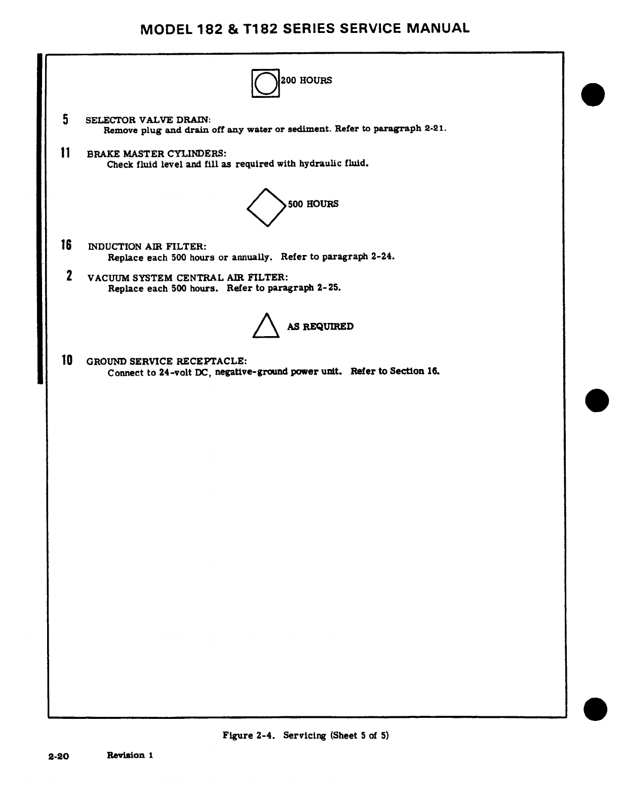
MODEL
182
&
T182
SERIES
SERVICE
MANUAL
5
SELECTOR VALVE DRAIN:
Remove
plug
and
drain
off
any
water
or
sediment.
Refer
to
paragraph
2-21.
11
BRAKE
MASTER
CYLINDERS:
Check
fluid
level
and
fill
as
required
with
hydraulic
fluid.
16
INDUCTION
AIR
FILTER:
Replace each
500
hours
or
annually.
Refer
to
paragraph
2-24.
2
VACUUM
SYSTEM
CENTRAL
AIR
FILTER:
Replace
each
500
hours.
Refer
to
paragraph
2-25.
AS
REQUIRED
10
GROUND
SERVICE
RECEPTACLE:
Connect
to
24-volt
DC,
negative-ground
power
unit.
Refer
to
Section
16.
Figure
2-4.
Servicing
(Sheet
5
of
5)
2-20
Revision
1
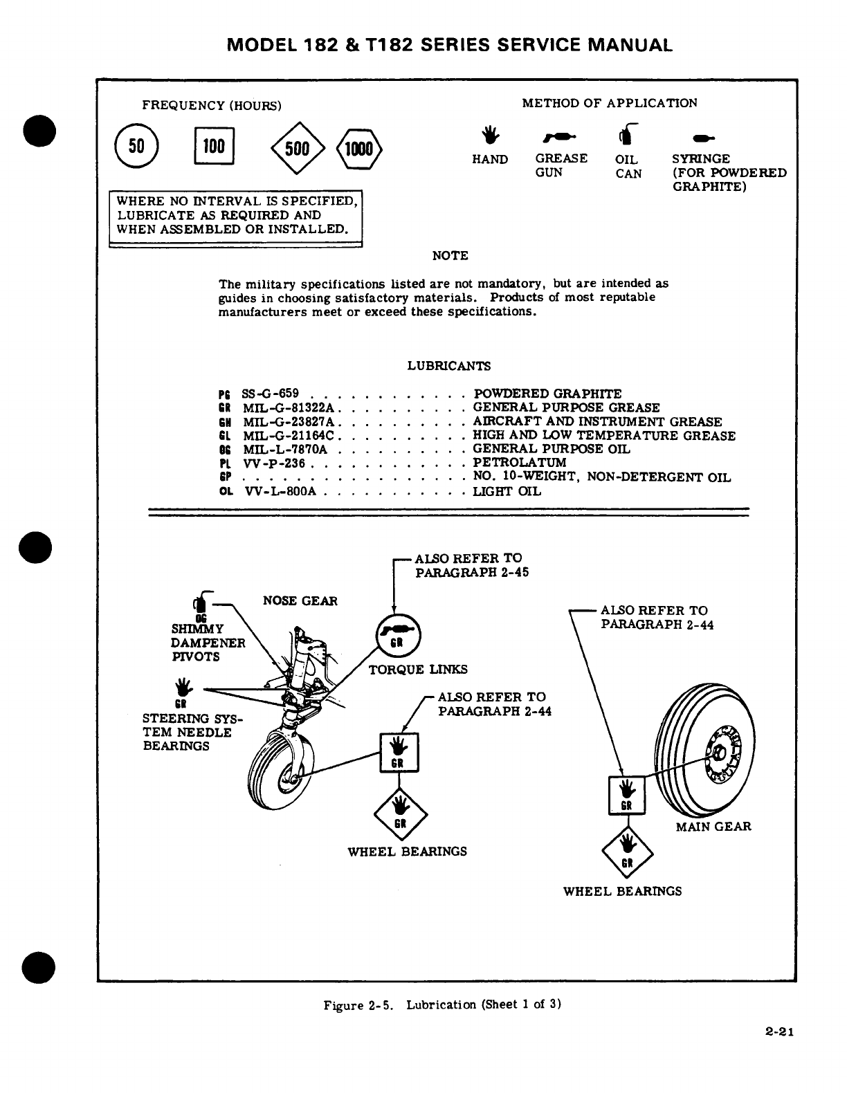
MODEL
182
&
T182
SERIES
SERVICE
MANUAL
FREQUENCY
(HOURS)
METHOD
OF
APPLICATION
.- -
GUN CAN
(FOR
POWDERED
GRAPHITE)
WHERE
NO
INTERVAL
IS
SPECIFIED,
LUBRICATE
AS
REQUIRED
AND
WHEN
ASSEMBLED
OR
INSTALLED.
NOTE
The
military
specifications
listed
are
not
mandatory,
but
are
intended
as
guides
in
choosing
satisfactory materials.
Products
of
most
reputable
manufacturers
meet
or
exceed
these
specifications.
LUBRICANTS
PG
SS-G-659
............
POWDERED
GRAPHITE
GR
MIL-G-81322A
.........
GENERAL
PURPOSE
GREASE
GH
MIL-G-23827A
..........
AIRCRAFT
AND
INSTRUMENT
GREASE
GL
MIL-G-21164C
.
........
HIGH
AND
LOW
TEMPERATURE
GREASE
OG
MIL-L-7870A
..........
GENERAL PURPOSE
OIL
PL
VV-P-236
...........
PETROLATUM
GP
...............
.NO.
10-WEIGHT,
NON-DETERGENT
OIL
OL
VV-L-800A
.........
LIGHT
OIL
ALSO
REFER
TO
PARAGRAPH
2-45
ALSO
REFER
TO
STEERING
SYS-
TEM
NEEDLE
BEARINGS
WHEEL
BEARINGS
WHEEL
BEARINGS
Figure
2-5.
Lubrication
(Sheet
1 of
3)
2-21
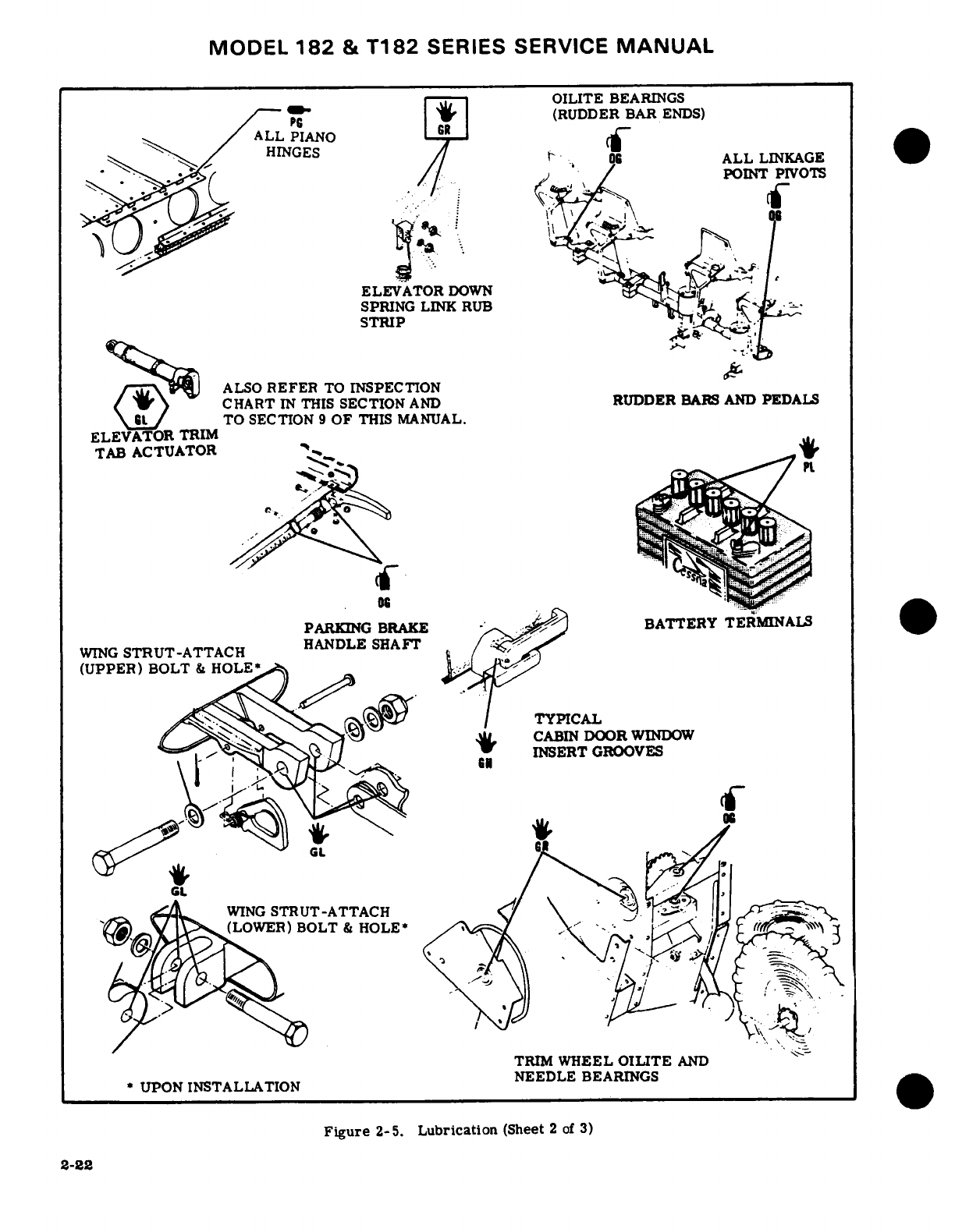
MODEL
182
&
T182
SERIES SERVICE
MANUAL
OILITE
BEARINGS
-/
ALL
PIANO
.
HINGES
--
/
-
.,
0
ALL
LINKAGE
J. ' >y~ f /
. .. /
POINT
PIVOTS
ELEVATOR
DOWN
SPRING
LINK
RUB
STRIP
K!)
ALSO
REFER
TO
INSPECTION
(Q
:
ICHART
IN THIS
SECTION
AND
RUDDER
BARS
AND
PEDALS
TO
SECTION
9
OF
THIS
MANUAL.
ELEVATOR
TRIM
TAB
ACTUATOR
"
01
PARKING
BRAKE
.3
BATTERY TERMINALS
WING
STRUT-ATTACH HANDLESHA
(UPPER)
BOLT
&
HOLE*
TYPICAL
X
L
+
CABIN
DOOR
WINDOW
G
i
INSERT
GROOVES
CL
WING
STRUT-ATTACH/
\
UPON
INSTALLATION
NEEDLE
BEARINGS
Figure
2-5. Lubrication
(Sheet
2
of
3)
2-22

MODEL
182
&
T182
SERIES SERVICE
MANUAL
CONTROL
COLUMN
BEARINGS
NEEDLE
BEARING
.
ROLLERS
HREADS
NEEDLE
BEARING'
NEEDLE
BEARINGS
ROD
END
BEARINGS
--
ALSO
REFER
TO
PARAGRAPH
2-47
AILERON
BELLCRANK
-
N D
BNNEEDLE
BEARINGS
DO NOT OIL
IF
OPERAING
*DO
NOT
OIL
IF
OPERATING
(
IN
EXTREMELY
DUSTY
CONDITIONS
NOTES
Sealed
bearings
require
no
lubrication.
Do
not
lubricate
roller
chains
or
cables
except
under
seacoast
conditions.
Wipe
with
a
clean,
dry
cloth.
Lubricate
unsealed
pulley
bearings,
rod
ends,
Oilite
bearings,
pivot
and
hinge
points,
and any
other
friction
point
obviously
needing
lubrication,
with
general
purpose
oil
every
1000
hours
or
oftener
if
required.
Paraffin
wax
rubbed
on
seat
rails
will
ease
sliding
the
seats
fore
and
aft.
Lubricate
door
latching mechanism
with
MIL-G-81322A
general
purpose
grease,
applied
sparingly
to
friction
points,
every
1000
hours
or
oftener,
if
binding
occurs.
No
lubrication
is
recommended
on
the
rotary
clutch.
Figure
2-5.
Lubrication
(Sheet
3
of 3)
2-23
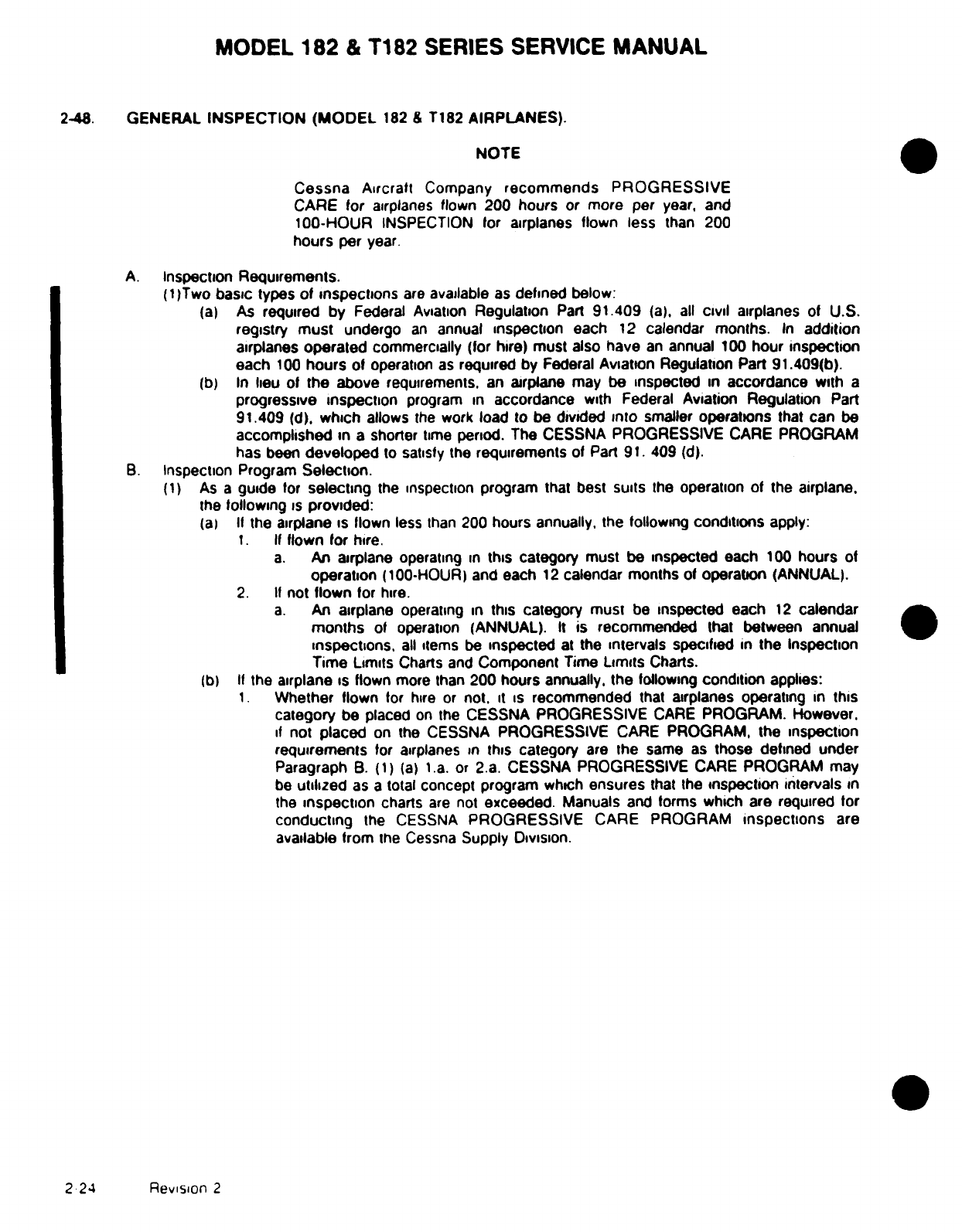
MODEL
182
&
T182
SERIES
SERVICE
MANUAL
2-48.
GENERAL
INSPECTION
(MODEL
182
&
T182
AIRPLANES).
NOTE
Cessna
Aircraft
Company
recommends
PROGRESSIVE
CARE
for
airplanes
flown
200 hours
or more per
year, and
100-HOUR
INSPECTION
for
airplanes flown
less
than
200
hours
per
year.
A.
Inspection
Requirements.
(1)Two
basic
types
of inspections
are
available
as
defined
below:
(a)
As
required
by
Federal
Aviation
Regulation
Part
91.409
(a),
all
civil
airplanes
of
U.S.
registry
must
undergo
an
annual
inspection
each
12
calendar
months.
In
addition
airplanes
operated
commercially
(for
hire) must also
have
an
annual
100
hour
inspection
each
100
hours
of
operation
as
required
by
Federal
Aviation
Regulation
Part
91.409(b).
(b)
In
lieu
of
the
above
requirements,
an
airplane
may
be
inspected
in
accordance
with
a
progressive
inspection
program
in
accordance
with
Federal
Aviation
Regulation
Part
91.409
(d).
which
allows
the
work
load
to
be
divided
into
smaller
operations
that
can
be
accomplished
in
a
shorter
time
period.
The
CESSNA
PROGRESSIVE
CARE
PROGRAM
has
been
developed
to
satisfy
the
requirements
of
Part
91.
409
(d).
B.
Inspection
Program
Selection.
(1)
As
a
guide
for
selecting
the
inspection
program
that
best
suits
the
operation of
the airplane.
the
following
is
provided:
(a)
If
the
airplane
is
flown
less
than
200
hours
annually,
the following
conditions
apply:
1. If
flown
for
hire.
a.
An
airplane
operating
in
this category
must
be
inspected
each
100
hours
of
operation
(100-HOUR)
and
each
12
calendar months
of
operation
(ANNUAL).
2.
If
not
flown
for
hire.
a.
An
airplane
operating
in
this
category
must
be
inspected each
12
calendar
months
of
operation
(ANNUAL).
It
is recommended
that
between annual
inspections,
all
items
be
inspected
at
the
intervals
specified
in
the
Inspection
Time
Limits
Charts and
Component
Time
Limits
Charts.
(b)
If
the
airplane
is
flown
more than
200
hours
annually,
the
following
condition
applies:
1.
Whether flown
for
hire
or
not.
It
is
recommended
that
airplanes operating
in
this
category
be placed
on
the
CESSNA PROGRESSIVE
CARE
PROGRAM.
However.
if
not
placed
on
the
CESSNA PROGRESSIVE
CARE
PROGRAM,
the
inspection
requirements
for
airplanes
in
this
category
are
the
same as
those
defined
under
Paragraph
B.
(1)
(a)
1.a.
or
2.a.
CESSNA PROGRESSIVE
CARE
PROGRAM
may
be
utilized
as
a
total
concept
program which
ensures
that
the
inspection
intervals
in
the
inspection
charts
are
not
exceeded.
Manuals
and
forms
which
are required
for
conducting
the
CESSNA
PROGRESSIVE
CARE
PROGRAM
inspections
are
available
from
the Cessna
Supply
Division.
2-24
Revision
2

MODEL
182
&
T182
SERIES
SERVICE
MANUAL
C.
Inspection
Charts.
NOTE
Cessna
has
prepared
these
Inspection
Charts
to
assist the
owner
or
operator
in
meeting
the
foregoing
responsibilities
and
to
meet the
intent
of
Federal
Aviation
Regulation
Part
91.409
(d).
The
Inspection
Charts
are
not
intended
to
be
all-
inclusive,
for
no
such
charts
can
replace
the
good
judgment
of
a
certified
airframe
and
powerplant
mechanic
in
performance
of
his duties.
As the
one
primarily
responsible
for
this
airworthiness
of
the
airplane,
the
owner
or
operator
should
select
only
qualified
personnel
to
maintain
the
airplane.
(1)
The
following
Inspection
Charts
(Inspection
Time
Limits,
Component
Time
Limits,
Progressive
Care
Inspection,
and
Expanded
Inspection)
show
the
recommended
intervals
at
which
items
are
to be
inspected
based
on
normal usage
under
average
environmental
conditions.
Air-
planes
operated
in
extremely
humid tropics,
or
in
exceptionally cold,
damp
climates, etc.,
may
need
more
frequent
inspections
for
wear,
corrosion,
and
lubrication.
Under
these
adverse
con-
ditions.
perform
periodic
inspections
in
compliance
with
this
chart
at
more
frequent
intervals
until
the
operator
can
set
his
own
inspection
periods
based
on
field
experience.
The
opera-
tor's inspection
intervals
shall
not
deviate
from
the
inspection time
limits
shown
in
this
manual
except
as
provided
below:
(a)
Each
inspection
interval
can
be
exceeded
by
10
hours or
can
be
performed
early
at
any
time
prior
to
the
regular
interval
as
provided
below:
1.
In
the
event
of
late
compliance
of
any
operation
scheduled,
the
next
operation
in
sequence
retains
a
due
point
from
the
time
the
late
operation
was
originally
sched-
uled.
2.
In
the
event
of
early
compliance
of
any
operation
scheduled,
that
occurs
10
hours
or
less
ahead
of
schedule,
the
next
phase
due
point
may
remain
where
originally
set.
3. In
the
event
of
early
compliance
of
any
operation
scheduled,
that
occurs
more
than
10
hours
ahead of
schedule,
the
next
phase
due
point
must
be
rescheduled
to
es-
tablish
a
new
due
point
from
the
time
of
early
accomplishment.
(2)
As
shown
in
the
charts,
there
are
items
to
be
checked
at
50
hours,
100
hours,
200
hours,
or
at
Special
of
Yearly
inspection.
Special
or
Yearly
inspection items
require
servicing
or
inspec-
tion
at
intervals
other
than
50,
100,
or
200
hours.
If
two
inspection
time
requirements
are
list-
ed
for
one
inspection
item,
one
hourly
and the
yearly, both
apply
and
whichever requirement
occurs
first determines
the
time
limit.
(a)
When
conducting
a
50-hour
inspection.
check
all
items
listed
under
EACH
50
HOURS. A
100-hour
inspection
includes
all
items
listed
under
EACH
50
HOURS and EACH
100
HOURS.
The
200-hour
inspection
includes
all
items
listed
under
EACH
50
HOURS.
EACH
100
HOURS,
and
EACH
200
HOURS.
All
of
the items
listed would
be
inspected.
serviced,
or
otherwise
performed
as
necessary
to
ensure
compliance
with
the
inspection
requirements.
(b) A
COMPLETE
AIRPLANE
INSPECTION
includes
all
50-,
100-,
and
200-hour
items
plus
those
Special
and
Yearly
Inspection
Items
which
are
due
at the
specified
time.
(c)
Component
Time
Limits
Charts should
be
checked
at
each
inspection
interval
to ensure
proper overhaul
and
replacement
requirements
are
accomplished
at
the
specified
times
Revision
2
2-25

MODEL 182
&
T182
SERIES
SERVICE
MANUAL
D
Inspection Guidelines.
(1)
The
Inspection
Charts
are to
be
used
as
a
recommended
inspection
outline.
Detailed
informa-
tion
of
systems
and
components
in
the
airplane
will
be
found
in
various
chapters
of
this
Main-
tenance
Manual
and
the
pertinent
vendor
publications.
It
is
recommended
that
reference
be
made
to
the
applicable
portion
of
this
manual
for
service instructions,
installation
instructions,
and
to
the
vendor's
data
or
publications
specifications
for
torque
values,
clearances,
settings.
tolerances,
and
other
requirements.
(2)
For
the
purpose
of this
inspection,
the
term on
condition
is
defined
as
follows:
The
neces-
sary
inspections
and/or
checks
to
determine
that
a
malfunction
or
failure
will
not
occur
prior
to
the
next
scheduled
inspection.
(3)
MOVABLE
PARTS; Inspect
for
lubrication,
servicing,
security
of
attachment.
binding,
exces-
sive
wear.
safetying,
proper
operation,
proper
adjustment,
correct
travel,
cracked
fittings,
se-
curity
of
hinges,
defective
bearngs,
cleanliness,
corrosion, deformation,
sealing,
and
tension.
(4)
FLUID
LINES
AND
HOSES:
Inspect
for
leaks,
cracks,
bulging,
collapsed,
twisted, dents,
kinks,
chafing,
proper
radius,
security,
discoloration,
bleaching,
detenoration,
and
proper
rout-
ing; rubber
hoses
for
stiffness
and
metal
lines
for
corrosion.
(5)
METAL
PARTS:
Inspect
for security
of
attachment,
cracks.
metal
distortion,
broken
spotwelds,
condition
of
paint (especially
chips
at
seams
and
around
fasteners
for
onset
of
corrosion)
and
any other
apparent
damage.
(6)
WIRING:
Inspect
for security,
chafing,
burning,
arcing,
defective
insulation,
loose
or
broken
terminals,
heat
deterioration,
and
corroded
terminals.
(7)
STRUCTURAL
FASTENERS: Inspect
for
correct
torque
in
accordance
with
applicable
torque
values. Refer
to
Bolt
Torque
Data
during
installation
or
when
visual
inspection
indicates
the
need
for
a
torque
check.
NOTE
Torque
values
listed
are not
to
be
used
for
checking
tightness
of
installed
parts
during
service.
(8)
FILTERS,
SCREENS.
AND
FLUIDS:
Inspect
for
cleanliness
and
the
need
for
replacement
at
specified
intervals.
(9)
System
check
(operation
or
function) requiring
electrical
power
must
be
performed
using
28.5
±0.25
volts
bus
voltage.
This
will
ensure
all
components
are
operating
at
their
designed
re-
quirements.
(a)
Airplane
file.
1
Miscellaneous
data.
information.
and
licenses
are
a
part
of
the
airplane
file.
Check
that
the following documents
are
up-to-date
and
in
accordance
with
current
Federal
Aviation
Regulations.
Most
of
the
items
listed
are
required
by
the
Federal
Aviation
Regulations.
Since
the
regulations
of
other
nations
may
require
other
documents
and
data.
owners
of
exported
airplanes
should
check
with
their
own
aviation
offi-
cials
to
determine
their
individual
requirements.
a.
To
be
displayed
in
the
airplane
at
all
times:
1)
Standard Airworthiness
Certificate
(FAA
Form
8100-2).
2)
Aircraft Registration
Certificate
(FAA
Form
8050-3).
3)
Aircraft
Radio
Station
License
(Federal
Communication
Commission
Form
556
if
transmitter
is
installed).
4)
Radio Telephone
Station
License
(Federal
Communication
Commission
Form
409
if
Flitefone Radio
Telephone
is
installed).
b
To
be
carried
in
the
airplane
at
all
times:
1)
Weight
and
Balance
Data
Sheets
and
associated
papers
(all
copies
of
the
Repair and
Alteration
Form.
FAA
Form
337.
are
applicable).
2)
Equipment
List
3)
Pilot's
Operating
Handbook and
FAA-Approved
Airplane
Flight
Manual.
To
be
made available
upon request:
1)
Airframe
Engine.
Propeller.
and
Avionics
Maintenance
Records.
2
.26
Revision
2
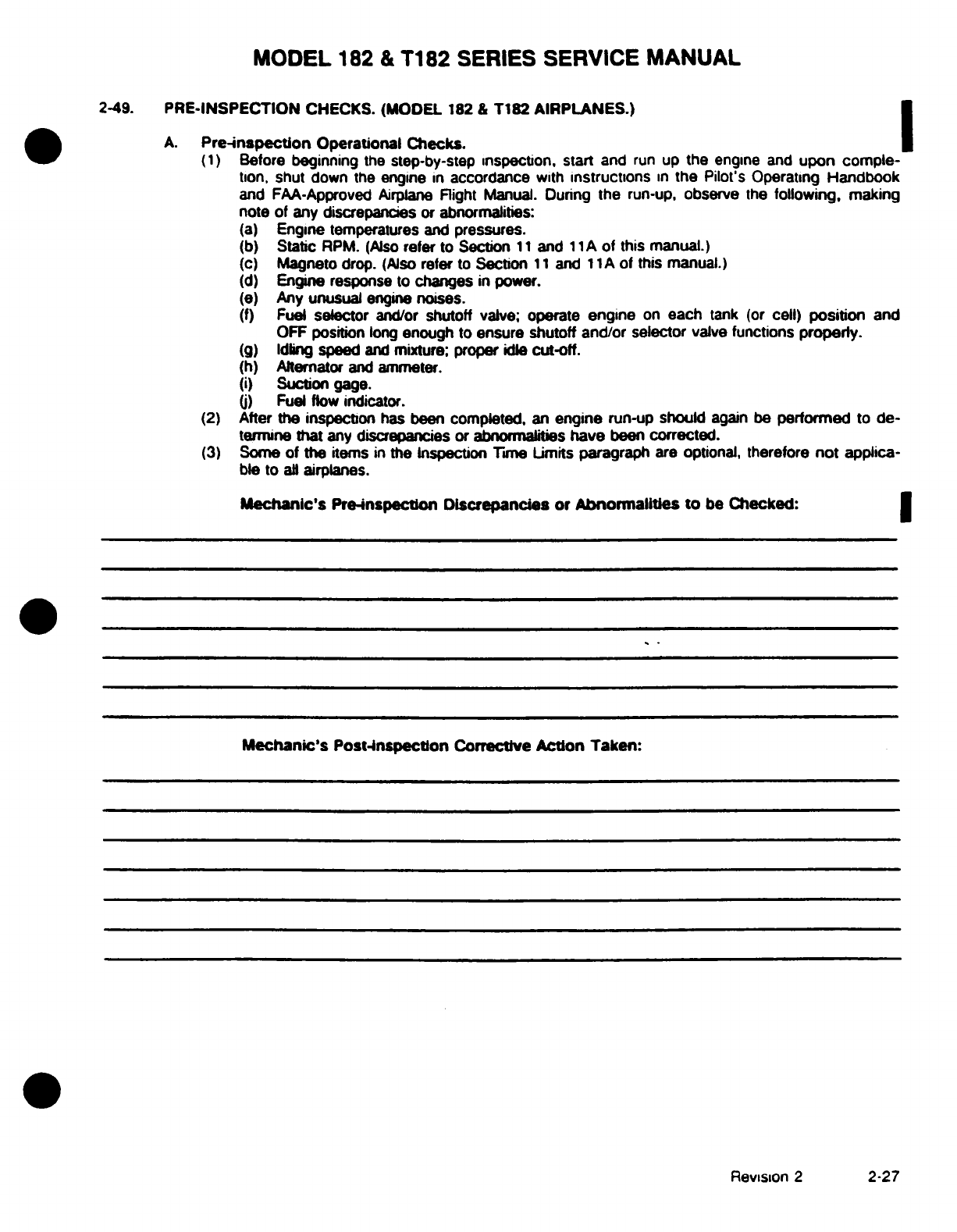
MODEL
182
&
T182
SERIES
SERVICE
MANUAL
2-49.
PRE-INSPECTION
CHECKS.
(MODEL
182
&
T182
AIRPLANES.)
(1)
Before
beginning
the
step-by-step
inspection,
start
and
run
up
the
engine
and
upon
comple-
tion,
shut
down
the engine
in
accordance
with
instructions
in
the
Pilot's Operating
Handbook
and
FAA-Approved
Airplane
Flight
Manual.
During
the
run-up,
observe
the
following,
making
note
of
any discrepancies
or
abnormalities:
(a)
Engine
temperatures
and
pressures.
(b)
Static
RPM.
(Also
refer
to
Section
11
and
11A
of
this manual.)
(c)
Magneto
drop.
(Also
refer
to
Section
11
and 11A
of
this
manual.)
(d)
Engine
response
to changes
in
power.
(e)
Any
unusual
engine
noises.
(f)
Fuel
selector
and/or
shutoff
valve; operate
engine
on
each
tank (or
cell)
position
and
OFF
position
long
enough
to ensure
shutoff and/or
selector
valve
functions
properly.
(g)
Idling
speed
and
mixture;
proper idle
cut-off.
(h)
Alternator
and
ammeter.
(i)
Suction
gage.
(j)
Fuel
flow indicator.
(2)
After
the
inspection
has
been
completed,
an
engine
run-up
should
again
be
performed
to
de-
termine
that
any
discrepancies
or
abnormalities
have
been
corrected.
(3)
Some
of
the
items
in
the
Inspection
Time
Limits
paragraph
are
optional,
therefore
not
applica-
ble
to
all
airplanes.
Mechanic's
Pre-inspection
Discrepancies
or
Abnormalities
to
be
Checked:
Mechanic's
Post-inspection
Corrective
Action
Taken:
Revision
2
2-27
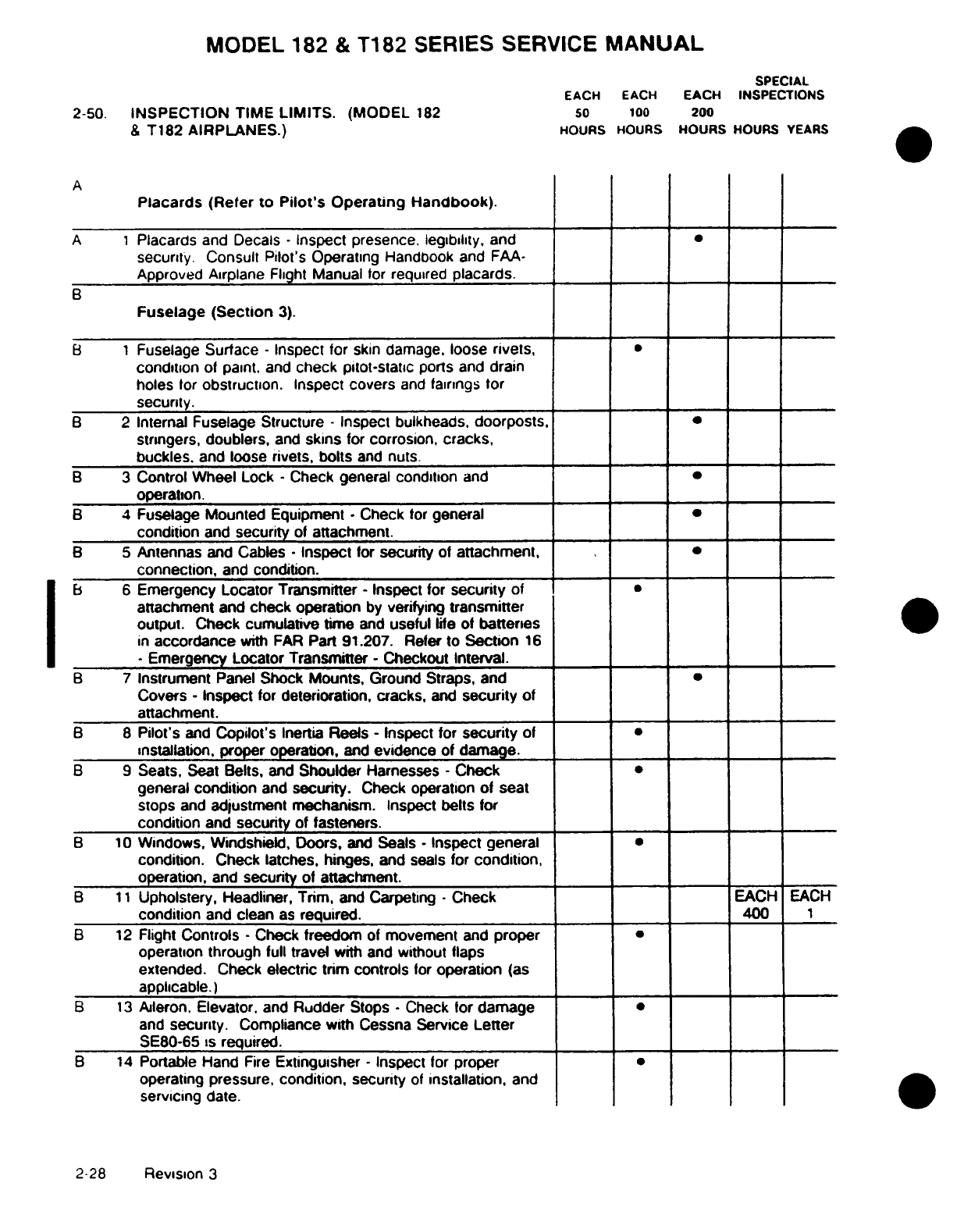
MODEL
182
&
T182 SERIES
SERVICE
MANUAL
SPECIAL
EACH
EACH
EACH
INSPECTIONS
2-50.
INSPECTION
TIME
LIMITS.
(MODEL
182
50
100
200
&
T182
AIRPLANES.)
HOURS HOURS
HOURS
HOURS
YEARS
A
Placards
(Refer
to
Pilot's
Operating
Handbook).
A
1
Placards
and
Decals
-
Inspect
presence.
legibility,
and
security.
Consult Pilot's
Operating
Handbook and
FAA-
Approved Airplane
Flight
Manual
for
required
placards.
B
Fuselage
(Section
3).
B 1
Fuselage
Surface
-
Inspect
for
skin
damage,
loose
rivets,
condition
of
paint,
and
check pilot-static
ports
and
drain
holes
for
obstruction.
Inspect
covers
and
fairings
for
security.
B
2
Internal Fuselage
Structure
-
Inspect
bulkheads,
doorposts,
stringers,
doublers,
and
skins
for
corrosion,
cracks,
buckles,
and
loose
rivets,
bolts
and
nuts.
B
3
Control Wheel Lock
-
Check
general
condition
and
operation.
B
4
Fuselage
Mounted
Equipment
-
Check
for
general
condition
and
security
of
attachment.
B
5
Antennas
and
Cables
-
Inspect
for
security
of
attachment,
connection,
and
condition.
B
6
Emergency Locator
Transmitter
-
Inspect
for
security
of
attachment
and
check
operation
by
verifying
transmitter
output. Check
cumulative
time
and
useful
life
of
batteries
in
accordance
with
FAR
Part
91.207.
Refer
to
Section
16
-
Emergency Locator
Transmitter
-
Checkout Interval.
B
7
Instrument
Panel
Shock
Mounts,
Ground Straps,
and
Covers
-
Inspect
for
deterioration,
cracks,
and
security
of
attachment.
B
8
Pilot's
and
Copilot's
Inertia
Reels
-
Inspect
for
security
of
installation, proper
operation,
and
evidence
of damage.
B
9
Seats, Seat
Belts,
and
Shoulder
Harnesses
-
Check
general
condition
and
security.
Check operation
of
seat
stops
and
adjustment
mechanism. Inspect
belts
for
condition
and
security
of
fasteners.
B
10
Windows, Windshield,
Doors,
and
Seals
-
Inspect general
condition. Check latches,
hinges,
and
seals
for
condition,
operation,
and
security
of
attachment.
B
11
Upholstery,
Headliner, Trim,
and
Carpeting
-
Check
EACH
EACH
condition
and
clean
as
required.
B 12
Flight
Controls
-
Check
freedom
of
movement
and
proper
operation through full travel with
and
without
flaps
extended.
Check
electric
trim controls
for
operation
(as
applicable.)
B
13
Aileron.
Elevator,
and
Rudder
Stops
-
Check
for
damage
and
security.
Compliance
with
Cessna
Service
Letter
SE80-65
is
required.
B
14
Portable Hand
Fire
Extinguisher
-
Inspect
for
proper
operating
pressure,
condition,
security
of
installation,
and
servicing
date.
2-28
Revision
3
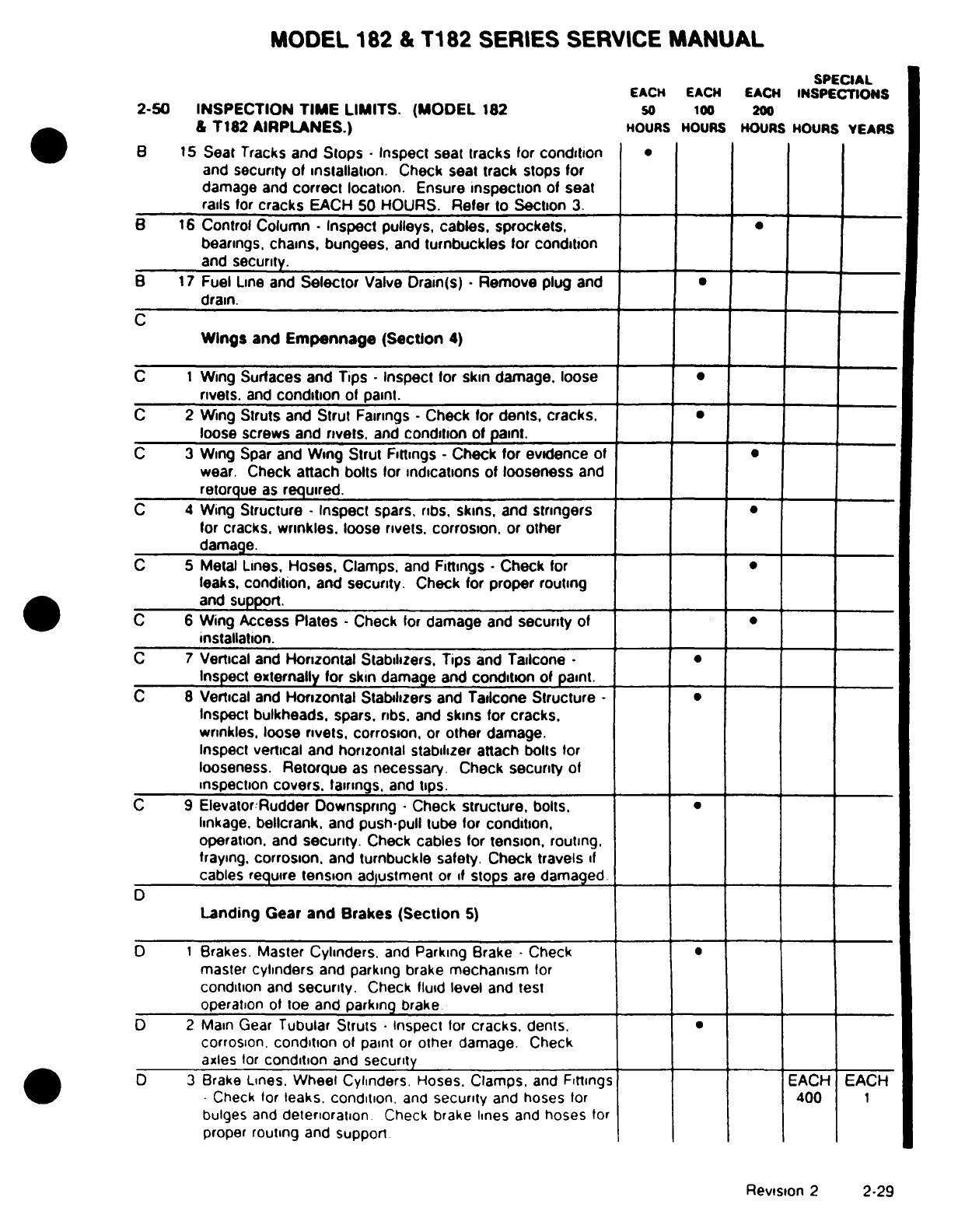
MODEL 182
&
T182
SERIES
SERVICE
MANUAL
SPECIAL
EACH EACH
EACH
INSPECTIONS
2-50
INSPECTION
TIME LIMITS.
(MODEL
182
50
100
200
&
T182
AIRPLANES.)
HOURS HOURS
HOURS
HOURS
YEARS
B
15
Seat
Tracks
and
Stops
-
Inspect
seat
tracks
for
condition
and
security
of installation.
Check
seat
track stops
for
damage
and
correct
location.
Ensure
inspection
of
seat
rails
for
cracks
EACH
50
HOURS.
Refer
to
Section
3.
B
16
Control Column
-
Inspect
pulleys,
cables, sprockets,
bearings,
chains,
bungees,
and
turnbuckles
for
condition
and
security.
B
17
Fuel
Line
and
Selector
Valve
Drain(s)
-
Remove
plug
and
drain.
C
Wings
and
Empennage
(Section
4)
C
1
Wing
Surfaces and
Tips
-
Inspect
for skin damage,
loose
rivets.
and
condition
of paint.
C
2
Wing
Struts
and Strut Fairings
-
Check
for
dents,
cracks,
loose screws and rivets,
and
condition
of paint.
C
3
Wing
Spar
and
Wing
Strut
Fittings
-
Check for
evidence
of
wear.
Check
attach bolts
for
indications
of
looseness
and
retorque
as
required.
C
4
Wing
Structure
-
Inspect
spars,
ribs,
skins,
and
stringers
for cracks,
wrinkles.
loose
rivets,
corrosion,
or
other
damage.
C
5
Metal
Lines,
Hoses,
Clamps. and
Fittings
-
Check
for
leaks,
condition,
and security. Check
for
proper
routing
and
support.
C
6
Wing
Access Plates
-
Check
for
damage
and
security
of
installation.
C
7
Vertical
and
Horizontal
Stabilizers.
Tips
and
Tailcone
-
Inspect
externally
for
skin damage
and
condition
of
paint.
C 8
Vertical
and
Horizontal
Stabilizers
and
Tailcone
Structure
-
Inspect bulkheads,
spars.
ribs.
and
skins
for
cracks,
wrinkles,
loose rivets,
corrosion,
or
other
damage.
Inspect
vertical
and
horizontal
stabilizer attach
bolts
for
looseness.
Retorque
as
necessary
Check
security
of
inspection
covers.
fairings,
and
tips.
C
9
Elevator
Rudder Downspring
-
Check
structure,
bolts.
linkage,
bellcrank,
and
push-pull
tube
for
condition,
operation,
and
security.
Check
cables
for
tension,
routing.
fraying,
corrosion,
and
turnbuckle
safety.
Check travels
if
cables
require
tension
adjustment
or
if
stops
are
damaged
D
Landing
Gear
and
Brakes
(Section
5)
D 1
Brakes.
Master
Cylinders.
and
Parking
Brake
-
Check
master
cylinders
and
parking
brake
mechanism
for
condition
and
security.
Check
fluid
level
and
test
operation
of
toe and
parking
brake
D
2
Main Gear
Tubular
Struts
.
Inspect
for
cracks.
dents.
corrosion.
condition
of
paint
or
other
damage.
Check
axles
for
condition
and
securit
D
3
Brake
Lines.
Wheel Cylinders.
Hoses.
Clamps.
and
Finings EACH
EACH
Check for
leaks. condition.
and
security
and
hoses
for
400
1
bulges
and
deterioraiion
Check brake
lines
and
hoses
for
proper
routing
and support
Revision
2
2-29
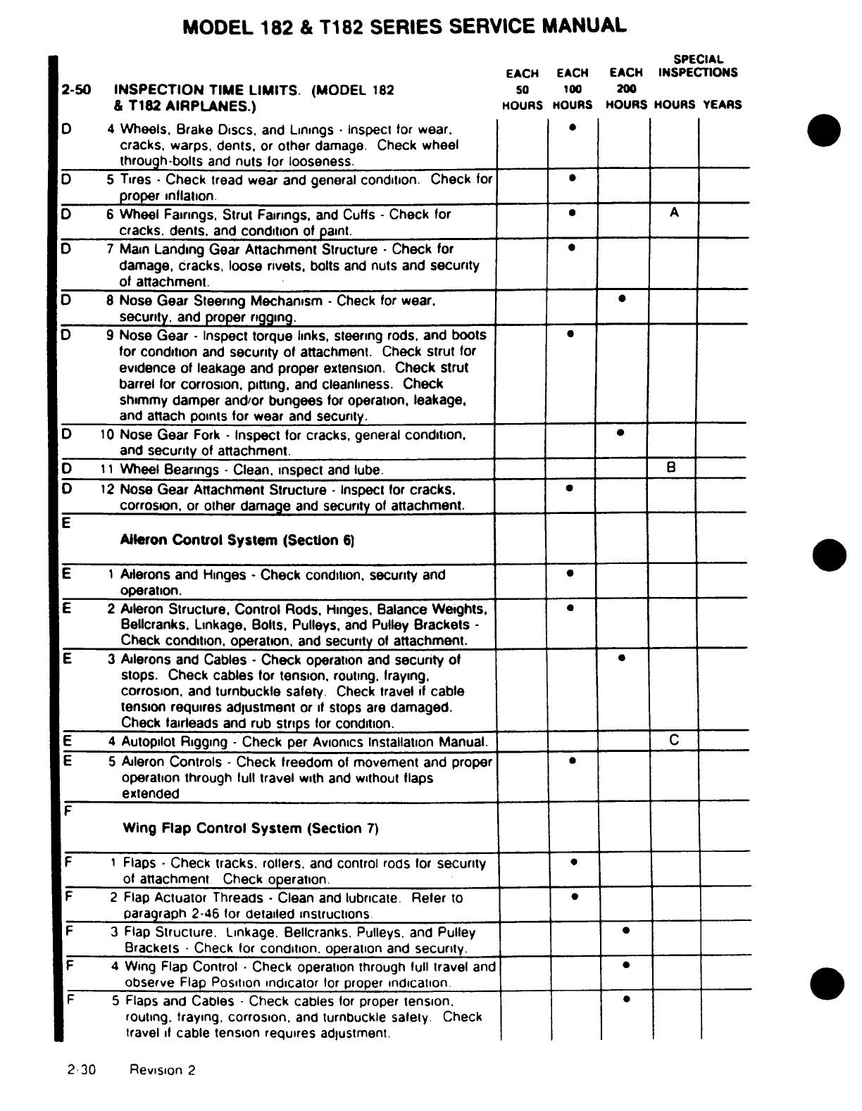
MODEL 182
&
T182
SERIES
SERVICE
MANUAL
SPECIAL
EACH
EACH
EACH INSPECTIONS
2-50 INSPECTION
TIME
LIMITS.
(MODEL
182
50
100
200
&
T182
AIRPLANES.)
HOURS
HOURS
HOURS
HOURS YEARS
D
4
Wheels.
Brake
Discs,
and
Linings
-
Inspect
for
wear.
cracks,
warps,
dents,
or
other
damage.
Check
wheel
through-bolts
and
nuts
for
looseness.
D
5
Tires
-
Check
tread wear and general
condition. Check
for
proper
inflation.
D
6
Wheel
Fairings,
Strut
Fairings,
and
Cuffs
-
Check
for
A
cracks,
dents,
and
condition
of
paint.
D
7
Main
Landing
Gear
Attachment
Structure
-
Check
for
damage,
cracks,
loose
rivets,
bolts
and
nuts and
security
of
attachment.
D
8
Nose Gear Steering
Mechanism
-
Check
for
wear,
security,
and
proper
rigging.
D
9
Nose
Gear
-
Inspect
torque
links,
steering
rods,
and
boots
for
condition
and
security
of
attachment. Check
strut
for
evidence
of
leakage
and
proper
extension.
Check
strut
barrel
for
corrosion,
piing,
and
cleanliness. Check
shimmy
damper
and/or
bungees
for operation,
leakage,
and
attach points
for
wear
and
security.
D
10
Nose
Gear
Fork
-
Inspect
for
cracks,
general
condition.,
and
security
of
attachment.
D
11
Wheel
Bearings
-
Clean,
inspect
and
lube.
B
D
12
Nose Gear Attachment
Structure
-
Inspect
for
cracks,
corrosion,
or
other
damage
and
security
of
attachment.
E
Aileron
Control
System
(Section
6)
E
1
Ailerons
and
Hinges
-
Check
condition,
security
and
operation.
E
2
Aileron
Structure,
Control
Rods.
Hinges,
Balance
Weights,
Bellcranks.
Linkage,
Bolts,
Pulleys,
and
Pulley
Brackets
-
Check
condition,
operation,
and
security
of
attachment.
E 3
Ailerons
and
Cables
-
Check
operation
and
security
of
stops.
Check cables
for
tension,
routing,
fraying,
corrosion,
and
turnbuckle
safety.
Check
travel
if
cable
tension
requires
adjustment
or
it
stops
are
damaged.
Check
fairleads
and
rub
strips
for
condition.
E
4
Autopilot
Rigging
-
Check
per
Avionics
Installation
Manual.
C
E
5
Aileron
Controls
-
Check freedom
of
movement
and
proper
operation
through
full
travel
with
and
without
flaps
extended
F
Wing
Flap
Control System
(Section
7)
F 1
Flaps
-
Check
tracks,
rollers,
and
control rods
for
security
of
attachment
Check
operation
F 2
Flap
Actuator
Threads
-
Clean
and
lubricate
Refer
to
paragraph
2-46
for
detailed
instructions
F 3
Flap
Structure.
Linkage.
Bellcranks.
Pulleys.
and
Pulley
Brackets
-
Check
for
condition.
operation
and
security.
F
4
Wing
Flap
Control
Check
operation through
full
travel
and
observe
Flap
Position
indicator
for proper
indication.
F
5
Flaps
and Cables
-
Check
cables
for
proper
tension.
routing,
fraying,
corrosion,
and
turnbuckle
safely
Check
travel
if
cable
tension
requires
adjustment.
2
30
Revision
2
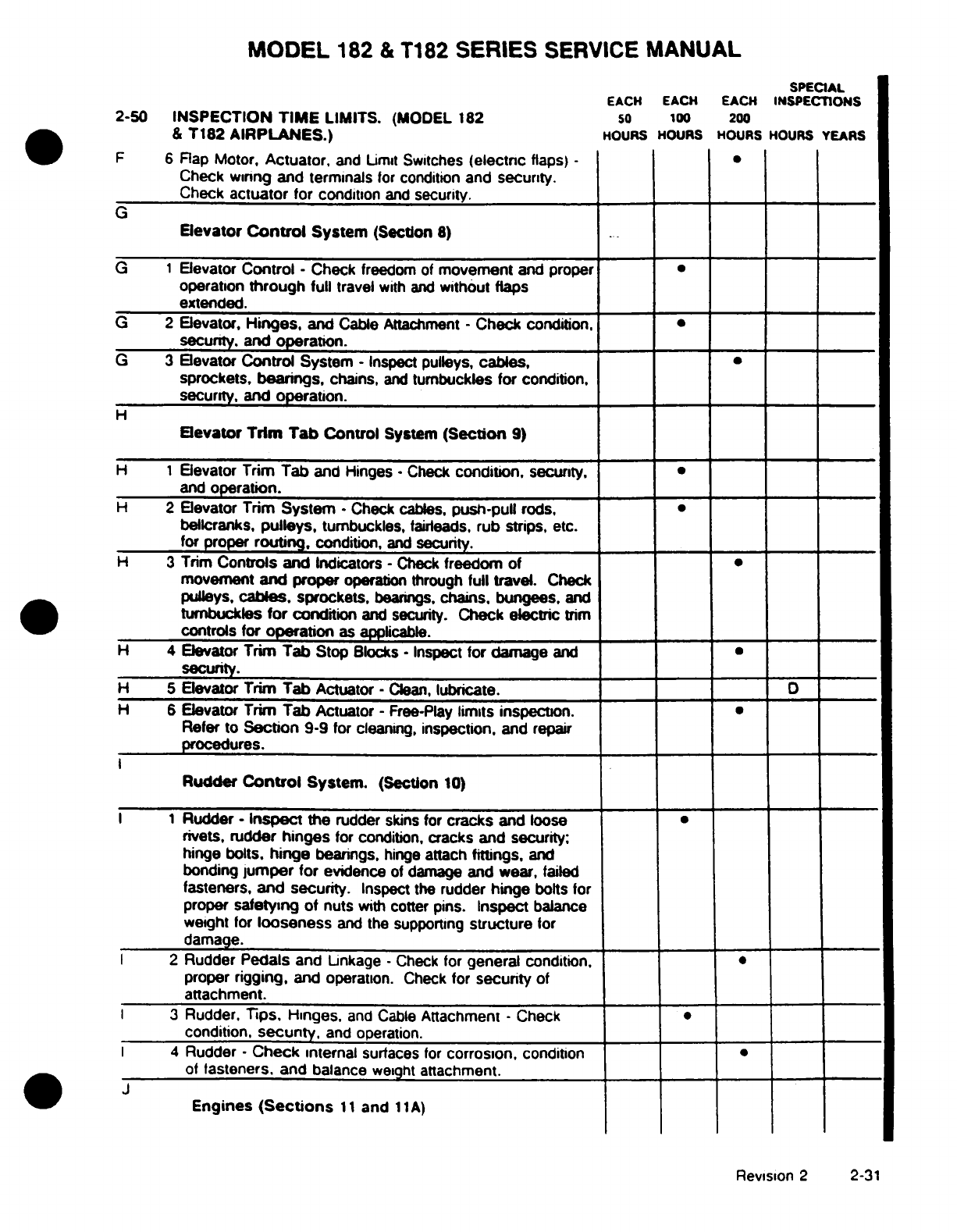
MODEL
182
&
T182
SERIES
SERVICE
MANUAL
SPECIAL
EACH EACH
EACH
INSPECTIONS
2-50
INSPECTION
TIME
LIMITS.
(MODEL
182
50
100
200
&
T182
AIRPLANES.)
HOURS
HOURS HOURS
HOURS
YEARS
F
6
Flap
Motor,
Actuator,
and
Limit
Switches
(electric
flaps)
-
Check
wiring
and terminals
for
condition
and
security.
Check
actuator
for
condition
and
security.
G
Elevator
Control
System
(Section
8)
G
1
Elevator
Control
-
Check
freedom
of
movement
and
proper
operation
through
full
travel
with
and
without
flaps
extended.
G
2
Elevator,
Hinges,
and
Cable
Attachment
- Check
condition,
security.
and operation.
G
3
Elevator
Control
System
-
Inspect
pulleys,
cables,
sprockets,
bearings,
chains,
and
tumbuckles
for condition,
security,
and
operation.
H
Elevator
Trim
Tab
Control
System
(Section
9)
H
1
Elevator
Trim
Tab
and
Hinges
-
Check
condition,
security,
and
operation.
H
2
Elevator
Trim
System
-
Check
cables,
push-pull
rods,
bellcranks,
pulleys,
turnbuckles,
fairleads,
rub
strips,
etc.
for
proper
routing,
condition,
and
security.
H
3
Trim
Controls
and
Indicators
-
Check
freedom
of
movement
and
proper
operation through
full
travel.
Check
pulleys,
cables,
sprockets,
bearings,
chains,
bungees,
and
turnbuckles
for
condition
and
security.
Check
electric
trim
controls
for
operation
as
applicable.
H
4
Elevator
Trim Tab
Stop
Blocks
-
Inspect
for
damage
and
security.
H
5
Elevator
Trim
Tab
Actuator
-
Clean,
lubricate.
D
H
6
Elevator
Trim
Tab
Actuator
-
Free-Play
limits inspection.
Refer
to
Section
9-9
for
cleaning,
inspection,
and
repair
procedures.
Rudder
Control
System.
(Section
10)
1
Rudder
-
Inspect
the
rudder
skins
for
cracks
and
loose
rivets,
rudder
hinges
for
condition,
cracks
and
security;
hinge
bolts,
hinge
bearings,
hinge
attach
fittings,
and
bonding
jumper
for
evidence
of
damage
and wear,
failed
fasteners,
and
security.
Inspect
the
rudder
hinge
bolts
for
proper
safetying
of
nuts
with cotter
pins.
Inspect
balance
weight
for
looseness
and
the
supporting
structure
for
damage.
2
Rudder
Pedals
and
Linkage
-
Check
for
general
condition,
proper
rigging,
and
operation.
Check
for
security
of
attachment.
3
Rudder,
Tips.
Hinges,
and Cable
Attachment
-
Check
condition,
secunty,
and operation.
4
Rudder
-
Check
internal
surfaces
for
corrosion,
condition
of
fasteners.
and
balance
weight
attachment.
J
Engines
(Sections
11
and
11A)
Revision
2
2-31
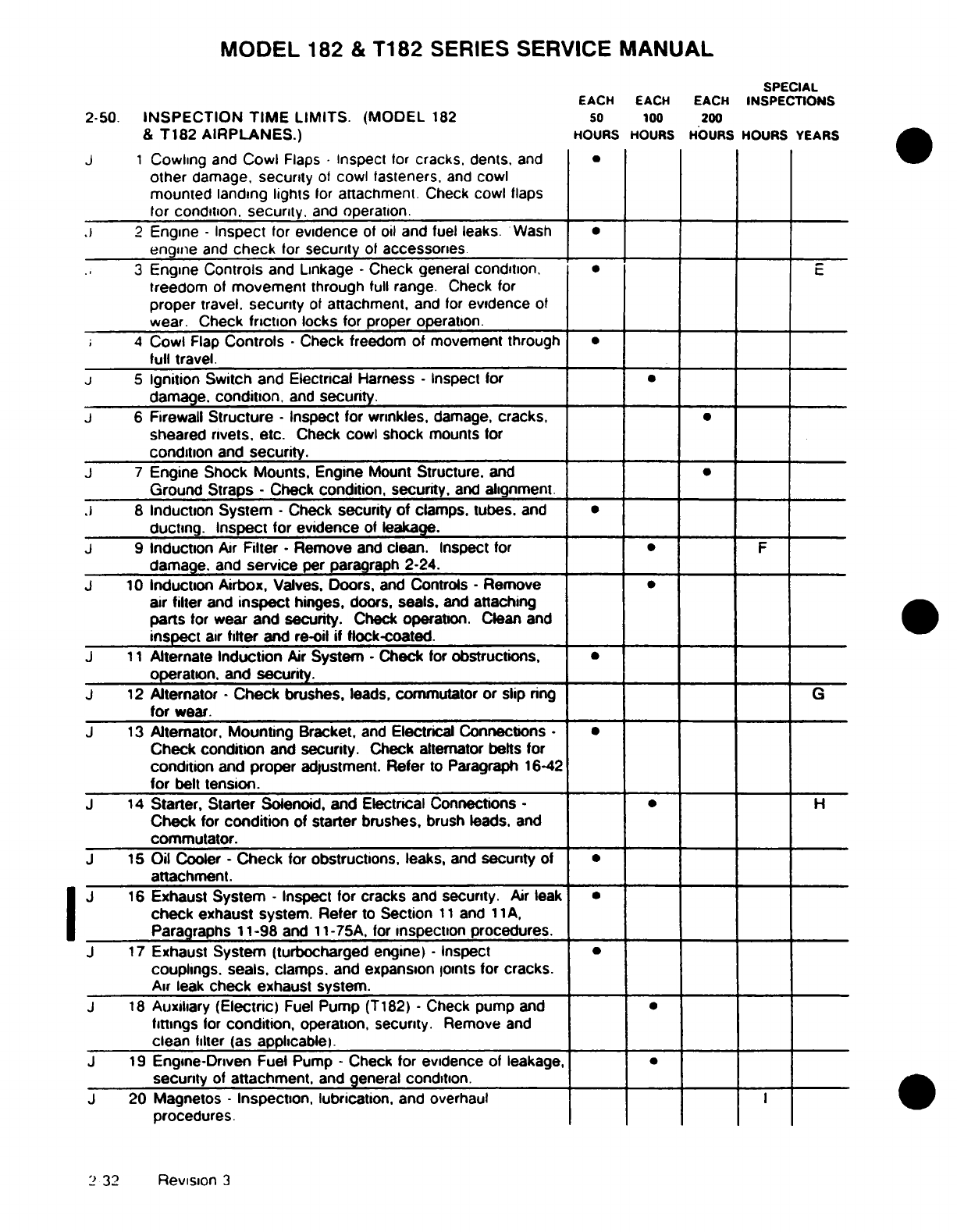
MODEL
182
&
T182
SERIES
SERVICE
MANUAL
SPECIAL
EACH
EACH
EACH
INSPECTIONS
2-50.
INSPECTION TIME
LIMITS.
(MODEL
182
50
100
200
&
T182
AIRPLANES.)
HOURS
HOURS
HOURS
HOURS
YEARS
J
1
Cowling
and
Cowl
Flaps
-
Inspect
for
cracks,
dents,
and
other
damage,
security
of
cowl
fasteners,
and
cowl
mounted
landing lights
for
attachment.
Check
cowl
flaps
for
condition,
security.
and
operation.
,.
2
Engine
-
Inspect
for
evidence
of
oil
and
fuel leaks.
Wash
engine
and
check
for
security
of
accessories
3
Engine
Controls
and
Linkage
-
Check general
condition.
E
freedom
of
movement
through
full
range.
Check
for
proper
travel.
security
of
attachment,
and for
evidence
of
wear.
Check
friction
locks
for
proper
operation.
4
Cowl
Flap
Controls.
Check freedom
of
movement
through
full
travel.
J
5
Ignition
Switch
and
Electrical
Harness
-
Inspect for
damage.
condition,
and
security.
J
6
Firewall
Structure
-
Inspect for wrinkles,
damage,
cracks,
sheared rivets, etc.
Check
cowl shock
mounts
for
condition
and
security.
J
7
Engine Shock
Mounts,
Engine
Mount
Structure,
and
Ground Straps
-
Check
condition,
security,
and
alignment.
.,
8
Induction
System -
Check
security
of
clamps,
tubes.
and
ducting.
Inspect
for
evidence
of
leakage.
J
9
Induction
Air
Filter
-
Remove
and
clean.
Inspect
for
F
damage.
and
service
per
paragraph
2-24.
J
10
Induction
Airbox,
Valves.
Doors,
and
Controls
-
Remove
air
filter
and
inspect
hinges,
doors,
seals,
and
attaching
parts
for
wear
and
security.
Check
operation.
Clean
and
inspect
air
filter
and re-oil
if
flock-coated.
J
11
Alternate
Induction
Air
System
-
Check
for
obstructions,
operation.
and
security.
J
12
Alternator
- Check
brushes,
leads,
commutator
or
slip
ring
G
for
wear.
J
13
Alternator,
Mounting
Bracket,
and
Electrical
Connections
-
Check
condition
and
security.
Check
alternator
belts
for
condition
and
proper
adjustment. Refer
to Paragraph
16-42
for
belt
tension.
J
14
Starter, Starter
Solenoid, and Electrical Connections
-H
Check
for
condition
of
starter
brushes,
brush leads,
and
commutator.
J
15
Oil
Cooler
- Check
for
obstructions,
leaks,
and
security
of
attachment.
J 16
Exhaust
System
-
Inspect
for
cracks
and
security.
Air
leak
check
exhaust system.
Refer
to
Section
11
and
11A,
Paragraphs
11-98
and 11-75A, for
inspection
procedures.
J
17
Exhaust
System
(turbocharged
engine)
-
Inspect
couplings.
seals,
clamps, and
expansion
joints
for
cracks.
Air leak
check
exhaust system.
J
18
Auxiliary
(Electric)
Fuel
Pump
(T182)
-
Check pump
and
fittings
for
condition,
operation,
security. Remove
and
clean
filter
(as
applicable).
J 19
Engine-Driven
Fuel Pump
-
Check
for
evidence
of
leakage,
security
of
attachment,
and
general
condition.
J
20 Magnetos
-
Inspection,
lubrication.
and
overhaul
procedures.
2-32
Revision
3
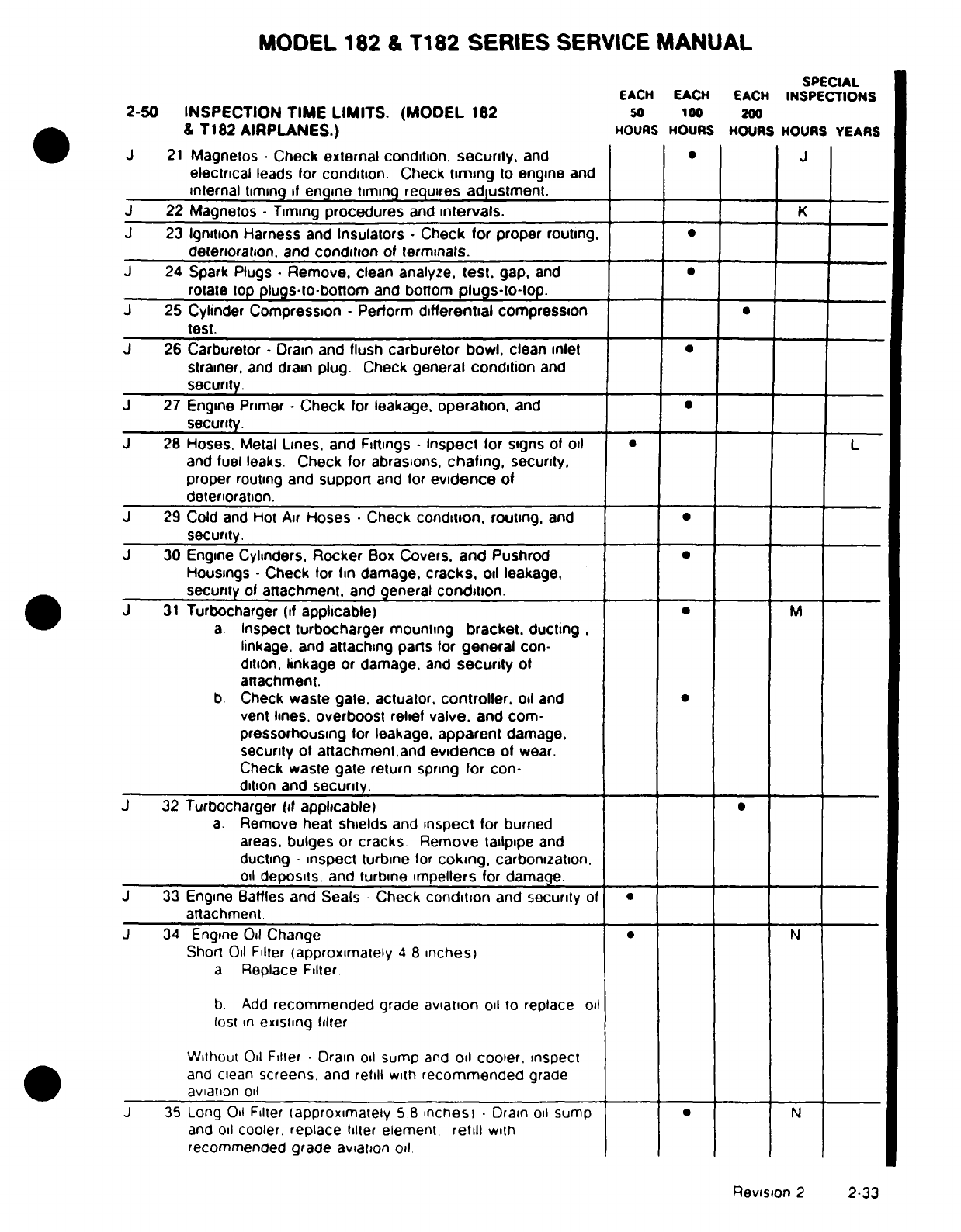
MODEL
182
&
T182
SERIES
SERVICE
MANUAL
SPECIAL
EACH
EACH
EACH
INSPECTIONS
2-50 INSPECTION
TIME
LIMITS.
(MODEL
182
50
100
200
&
T182 AIRPLANES.)
HOURS
HOURS HOURS
HOURS
YEARS
J
21
Magnetos
-
Check external
condition,
security,
and
J
electrical
leads for
condition.
Check
timing
to
engine
and
internal
timing
if
engine
timing
requires
adjustment.
J
22
Magnetos
-
Timing
procedures
and
intervals.
K
J
23
Ignition Harness
and
Insulators
-
Check
for
proper
routing,
deterioration.
and
condition
of
terminals.
J
24
Spark
Plugs
-
Remove,
clean
analyze,
test.
gap,
and
rotate
top
plugs-to-bottom
and
bottom
plugs-to-top.
J
25
Cylinder
Compression
-
Perform
differential
compression
test.
J 26
Carburetor
-
Drain
and
flush
carburetor bowl.
clean inlet
strainer,
and
drain plug.
Check
general
condition
and
security.
J
27
Engine Primer
-
Check
for
leakage,
operation,
and
security.
J
28
Hoses.
Metal
Lines,
and
Fittings
-
Inspect
for signs
of
oil
L
and
fuel
leaks.
Check
for
abrasions,
chafing,
security,
proper
routing and
support
and
for
evidence
of
deterioration.
J
29
Cold
and
Hot
Air
Hoses
·
Check
condition.
routing,
and
security.
J
30
Engine
Cylinders.
Rocker
Box
Covers.
and
Pushrod
·
Housings
-
Check
for
fin
damage.
cracks,
oil leakage,
security
of
attachment.
and
general
condition.
J
31
Turbocharger
(if
applicable)
M
a.
Inspect
turbocharger
mounting
bracket.
ducting,
linkage.
and
attaching
parts
for
general
con-
dition,
linkage
or
damage.
and
security
of
attachment.
b.
Check
waste gate, actuator,
controller,
oil
and
·
vent
lines.
overboost
relief
valve,
and com-
pressorhousing
for
leakage.
apparent
damage.
security
of
attachment.and
evidence
of
wear.
Check
waste gate
return spring
for
con-
dition and
security.
J 32
Turbocharger
(if
applicable)
a.
Remove
heat
shields
and
inspect
for
burned
areas,
bulges
or
cracks
Remove tailpipe
and
ducting
- inspect
turbine
for
coking,
carbonization.
oil
deposits.
and
turbine
impellers
for
damage
J
33
Engine
Baffles
and
Seals
-
Check
condition
and
security
of
attachment
J
34
Engine
Oil
Change
N
Short
Oil
Filter
(approximately
4
8
inches)
a
Replace
Filter.
b
Add
recommended
grade
aviation
oil
to
replace
oil
lost
in
existing
filter
Without
Oil
Filter
-
Drain
oil
sump
and
oil
cooler.
Inspect
and
clean
screens,
and refill
with
recommended
grade
aviation
oil
J
35
Long
Oil
Filter
(approximately
5 8
inches)
Drain
oil
sump
N
and
oil
cooler,
replace
filler
element,
refill
with
recommended
grade
aviation
oil.
Revision
2
2-33
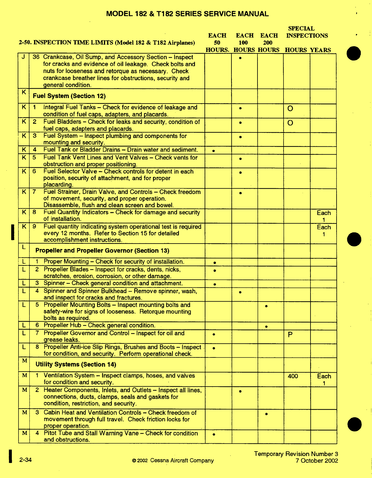
MODEL
182
&
T182
SERIES
SERVICE MANUAL
SPECIAL
EACH
EACH
EACH
INSPECTIONS
2-50.
INSPECTION TIME
LIMITS
(Model
182
&
T182
Airplanes)
50
100
200
HOURS.
HOURS
HOURS
HOURS YEARS
J
36
Crankcase,
Oil
Sump,
and
Accessory Section
-
Inspect
for
cracks
and
evidence
of
oil leakage. Check
bolts
and
nuts
for
looseness
and
retorque
as
necessary.
Check
crankcase
breather
lines
for
obstructions,
security
and
general
condition.
K
Fuel
System
(Section
12)
K
1
Integral
Fuel
Tanks
-
Check
for
evidence
of
leakage
and
• O
condition
of
fuel
caps, adapters,
and
placards.
K
2
Fuel
Bladders
-
Check
for
leaks
and
security, condition
of • O
fuel
caps,
adapters and
placards.
K
3
Fuel
System
-
Inspect
plumbing
and
components
for
mounting
and
security.
K
4
Fuel
Tank
or
Bladder Drains
-
Drain
water
and
sediment.
•
K
5
Fuel
Tank
Vent
Lines
and
Vent
Valves -
Check
vents for
Obstruction
and
proper
positioning.
K
6
Fuel
Selector
Valve
-
Check controls
for detent
in
each
position, security
of
attachment,
and
for
proper
placarding.
K
7
Fuel
Strainer,
Drain
Valve,
and
Controls
-
Check
freedom
of
movement, security,
and
proper
operation.
Disassemble,
flush
and
clean
screen
and
bowel.
K
8 Fuel
Quantity
Indicators
- Check
for
damage
and
security
Each
of
installation.
1
K
9 Fuel
quantity
indicating
system
operational
test
is
required
Each
every
12
months.
Refer
to
Section
15
for
detailed
1
accomplishment instructions.
L
Propeller
and
Propeller
Governor
(Section
13)
L
1
Proper
Mounting
-
Check
for security
of
installation.
L 2
Propeller
Blades
-
Inspect
for
cracks,
dents,
nicks,
scratches,
erosion,
corrosion,
or
other damage.
L
3
Spinner
-
Check
general
condition
and
attachment.
L 4
Spinner
and
Spinner
Bulkhead
-
Remove
spinner,
wash,
and
inspect
for
cracks
and
fractures.
L
5
Propeller
Mounting
Bolts
-
Inspect
mounting
bolts
and
safety-wire
for
signs
of
looseness.
Retorque mounting
bolts
as
required.
L 6
Propeller
Hub
-
Check general
condition.
L
7
Propeller Governor
and
Control
-
Inspect
for
oil
and
•
p
grease
leaks.
L
8
Propeller
Anti-ice
Slip Rings,
Brushes and Boots
-
Inspect
.
for
condition,
and
security.
Perform
operational check.
M
Utility
Systems (Section
14)
M
1 Ventilation
System
-
Inspect
clamps,
hoses,
and
valves
400
Each
for
condition
and
security.
1
M
2
Heater
Components,
Inlets,
and
Outlets
-
Inspect all
lines,
connections,
ducts,
clamps,
seals
and
gaskets
for
condition,
restriction,
and
security.
M
3
Cabin
Heat
and
Ventilation
Controls
-
Check
freedom
of
movement
through
full
travel.
Check
friction
locks
for
proper
operation.
M
4
Pitot
Tube
and
Stall
Warning
Vane
-
Check for condition
•
and
obstructions.
Temporary
Revision
Number
3
2-34
©
2002
Cessna Aircraft
Company
7
October
2002
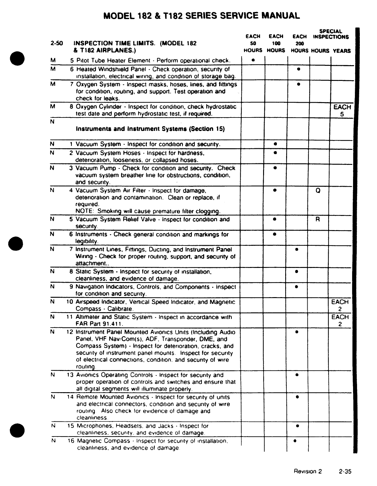
MODEL
182
&
T182 SERIES
SERVICE
MANUAL
SPECIAL
EACH EACH
EACH
INSPECTIONS
2-50
INSPECTION TIME
LIMITS.
(MODEL
182
50
100 200
&
T182
AIRPLANES.)
HOURS
HOURS
HOURS
HOURS
YEARS
M 6
Heated
Windshield
Panel
-
Check operation,
security
of
installation,
electrical
wiring,
and
condition
of
storage
bag.
M
7
Oxygen
System
-
Inspect
masks,
hoses,
lines,
and
fittings
for
condition,
routing,
and
support.
Test
operation
and
check
for
leaks.
M 8
Oxygen
Cylinder
-
Inspect
for
condition,
check hydrostatic
EACH
test
date and
perform
hydrostatic
test.
if
required.
5
N
Instruments
and
Instrument
Systems
(Section
15)
N
1
Vacuum
System
-
Inspect
for
condition
and
security.
N
2
Vacuum
System
Hoses
-
Inspect
for
hardness,
deterioration,
looseness,
or
collapsed
hoses.
N
3
Vacuum Pump
-
Check
for
condition
and
security. Check
vacuum
system
breather
line
for
obstructions,
condition,
and
security.
N
4
Vacuum
System
Air
Filter
-
Inspect
for damage,
Q
deterioration
and
contamination.
Clean
or
replace,
if
required.
NOTE:
Smoking
will
cause
premature
filter
clogging.
N 5
Vacuum
System Relief
Valve
-
Inspect
for
condition
and
R
security.
N
6
Instruments
.
Check
general
condition
and
markings
for
legibility.
N
7
Instrument
Lines,
Fittings,
Ducting,
and
Instrument
Panel
Wiring
-
Check
for
proper
routing,
support, and
security
of
attachment..
N
8
Static
System
-
Inspect
for
security
of
installation,
cleanliness,
and
evidence
of
damage.
N
9
Navigation
Indicators,
Controls,
and
Components
-
Inspect
for
condition
and
security.
N
10
Airspeed
Indicator.
Vertical
Speed
Indicator,
and
Magnetic
EACH
Compass
-
Calibrate.
2
N
11
Altimeter
and
Static
System
-
Inspect
in
accordance
with
EACH
FAR
Part
91.411.
2
N
12
Instrument
Panel
Mounted
Avionics
Units
(Including
Audio
Panel.
VHF
Nav/Com(s),
ADF.
Transponder,
DME,
and
Compass
System)
-
Inspect
for
deterioration,
cracks,
and
security
of
instrument
panel
mounts. Inspect
for
security
of
electrical
connections,
condition.
and
security
of
wire
routing.
N
13
Avionics Operating
Controls
.
Inspect
for
security
and
proper
operation
of
controls
and
switches
and
ensure
that
all
digital
segments
will
illuminate
properly.
N
14
Remote
Mounted
Avionics
-
Inspect
for
security
of
units
and
electrical
connectors.
condition
and
security
of
wire
routing
Also
check
for
evidence
of
damage
and
cleanliness
N
15
Microphones.
Headsets,
and
Jacks
-
Inspect
for
N 16
Magnetic
Compass
-
Inspect
for
security
of installation.
cleanliness,
and
evidence
of
damage
Revision
2
2-35
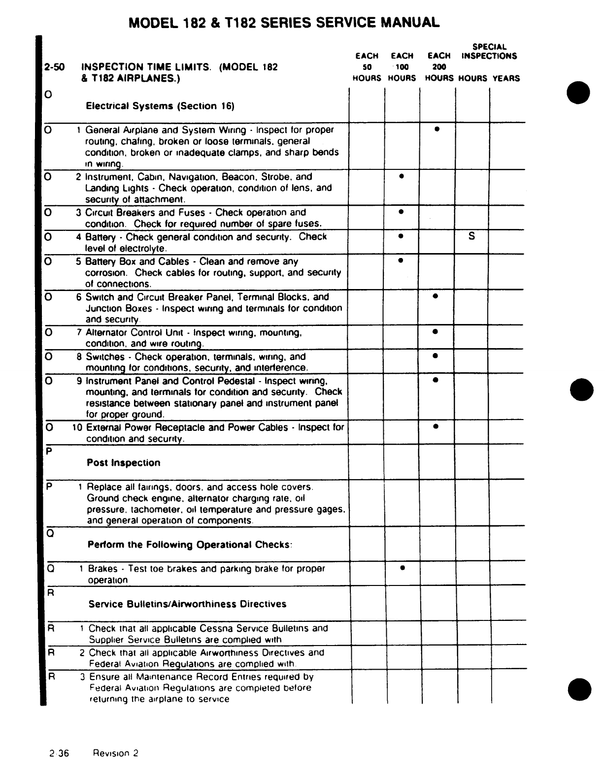
MODEL 182
&
T182
SERIES
SERVICE
MANUAL
SPECIAL
EACH
EACH
EACH
INSPECTIONS
2-50
INSPECTION
TIME
LIMITS.
(MODEL
182
50
100
200
&
T182
AIRPLANES.)
HOURS
HOURS
HOURS HOURS YEARS
Electrical Systems
(Section
16)
O
1
General Airplane and
System
Wiring
-
Inspect
for
proper
routing,
chafing,
broken
or
loose
terminals,
general
condition,
broken
or
inadequate
clamps,
and
sharp
bends
in
wiring.
O
2
Instrument.
Cabin.
Navigation,
Beacon. Strobe.
and
Landing
Lights
-
Check
operation,
condition
of
lens,
and
security
of
attachment.
O
3
Circuit
Breakers and
Fuses
-
Check operation
and
condition.
Check
for required
number
of
spare
fuses.
O
4
Battery
-
Check
general
condition
and
security.
Check
* S
level
of
electrolyte.
O
5
Battery
Box and
Cables
-
Clean
and
remove
any
corrosion. Check
cables
for
routing,
support,
and security
of
connections.
O
6
Switch
and
Circuit
Breaker
Panel.
Terminal
Blocks,
and
Junction
Boxes
-
Inspect
wiring
and
terminals
for
condition
and
security
O
7
Alternator Control Unit
-
Inspect
wiring,
mounting,
condition,
and
wire
routing.
8
Switches
-
Check
operation.
terminals,
wiring,
and
mounting
for
conditions,
security,
and
interference.
O
9
Instrument
Panel
and
Control
Pedestal
-
Inspect
wiring.
mounting,
and
terminals
for
condition
and
security.
Check
resistance
between
stationary
panel
and
instrument
panel
for
proper
ground.
O
10
External
Power
Receptacle
and
Power Cables
-
Inspect
for
condition
and
security.
P
Post
Inspection
P
1
Replace
all
fairings,
doors,
and
access
hole
covers.
Ground
check engine,
alternator charging
rate.
oil
pressure,
tachometer,
oil
temperature
and
pressure
gages.
and
general
operation
of
components.
Q
Perform
the
Following
Operational
Checks:
Q
1
Brakes
-
Test
toe
brakes
and parking
brake
for
proper
operation
R
Service
Bulletins/Airworthiness
Directives
R
1
Check
that
all
applicable
Cessna
Service
Bulletins
and
Supplier
Service
Bulletins
are
complied
with
R
2
Check
that
all
applicable
Airworthiness Directives
and
Federal
Aviation
Regulations
are
complied
with
R
3
Ensure
all
Maintenance Record
Entries
required
by
Federal
Aviation
Regulations
are
completed
before
returning
the
airplane
to
service
2-36
Revision
2

MODEL
182
&
T182 SERIES
SERVICE
MANUAL
Special
Inspections
Legends:
A.
If
the
airplane
is
flown
from
surfaces
with
mud,
snow,
or
ice,
the main
gear
speed
fairings should
be
checked
that
there
is no
accumulation
which
could
prevent normal
wheel
rotation.
B.
First
100
hours
and
each
500
hours
thereafter.
More
often
if
operated
under
prevailing
wet
or
dusty
con-
ditions.
C.
Each
600 hours
or
1
year,
whichever
comes
first.
D.
Lubrication
of
the
actuator
is
required
each
1000
hours
or
3
years,
whichever
comes
first.
See
figure
2-5
for
grease specification.
E.
Lubricate
each
100
hours
(except
in
extreme
dusty conditions).
These
controls
are
not
repairable
and
should
be
replaced
every
1500
hours
or
whenever
maximum
linear
movement
exceeds
0.050
inch.
F.
Clean
filter
per Paragraph
2-24. Replace
paper
filter
at
least
each
500
hours.
G.
Inspect
each
500
hours.
H.
For
Prestolite
starter
only,
inspect
the
commutator
and
brushes
each
1500
hours.
I.
After
500
hours
of
operation,
perform
the
following
checks:
1.
Inspect
contact
points for
condition
and
adjust
or
replace as required.
2.
Inspect carbon
brush,
high-tension
lead,
and
distributor
block
for
condition
and
clean
or
replace
as
re-
quired.
3.
Inspect impulse
coupling
and pawls
for
condition
and
replace
as
required.
Use
light
pressure
only,
do
not
force
pin (or
drill
bit)
when
checking pawls.
4.
Inspect bearings
and
lubricate,
replace
bearings,
if
required.
5.
Lubricate
contact
point
cam.
6.
Completely overhaul,
or
replace
existing
magneto
with
a
new
or
rebuilt
exchange
magneto,
at
every
engine
overhaul.
7.
Overhaul
and
Maintenance
Manual,
Publication
No.
1037C1-13,
covering
Model
4200/6200
series
magnetos,
is
available from
Cessna
Supply
Division.
J.
Compliance
with
Bendix
Service
Bulletin
599D
or
latest revision
is
required.
K.
AT
the
first
25
hours,
first
50
hours,
first
100
hours,
and
thereafter
at
each
100
hours,
the
contact
breaker
point compartment
and
magneto-to-engine
timing
should be
inspected
and
checked.
If
magneto-to-engine
timing
is
correct
within
plus
zero
degrees
to
minus
two
degrees,
internal
timing need
not
be
checked.
If
timing
is
out
of
tolerance,
remove
magneto
and
set
internal
timing,
then
install
and
time
to
the
engine.
Re-
fer
to
Section
11
or
11A
and
the
magneto
manufacturers
service
instructions
for
magneto
timing
proce-
dures.
L.
Replace
engine
compartment
rubber
hoses
(Cessna installed
only)
every
five
years
or
at
engine
overhaul,
whichever
occurs
first.
This
does
not
include
drain hoses.
Hoses
which
are
beyond
these
limits
and
are
in
a
serviceable condition,
must be
placed
on
order
immediately
and then be
replaced
within
120
days
after
receiving
the
new
hose(s)
from
Cessna. Replace
drain
hoses on
condition.
Engine
flexible
hoses
(Conti-
nental
or
Lycoming
installed)
(Refer
to
Continental
or
Lycoming Maintenance
Manual
and
Continental
or
Lycoming
Engine
Service
Bulletins).
M.
Replace
turbocharger
oil
line
check
valves
every
1000
hours. (Refer to
Cessna
Single
Engine
Service
Bulletin
SEB92-7.)
N.
Continental
engine
(182):
Add
straight
grade
mineral
oil
if
required. After
25
hours,
drain
and
refill
with
ashless
dispersant
oil.
Lycomng
engine
(T182): Add
straight
grade
mineral
oil
if
required.
After
25
hours.
drain
and
refill with
straight grade
mineral
oil
until
a
total
of
50
hours
have
accumulated
or
oil
consumption
stabilizes,
then
change
to
ashless
dispersant
oil.
Continental
and
Lycoming
engines:
After
initial
break-in
(25
or
50
hours).
If
NOT
equipped
with
an
external
filter,
change
oil
and
clean screens
each
50
hours.
If
equipped
with
SMALL external
filter,
change
filter
each
50
hours
and
oil
each
100
hours.
It
equipped
with
LARGE external
filter,
change
oil
and filter
each
100
hours.
In
all
cases,
change
oil
at
least
each
6
months
regardless
of
accumulated
hours.
O.
Each 1000
hours.
P.
If
leakage
is
evident,
refer
to
McCauley
Service
Manual.
Q.
Replace
every
500 hours.
R.
Replace
filter
each
100
hours.
S.
Check
electrolyte
level
and
clean
battery
box
each
100
hours
or
90
days.
Revision
3
2-37

MODEL 182
&
T182
SERIES
SERVICE
MANUAL
2-51.
COMPONENT
TIME
LIMITS
1.
General
A.
Most
components
listed
throughout
Section
2 should
be
inspected
as
detailed
elsewhere
in
this section
and
repaired,
overhauled or
replaced
as
required. Some
components, however, have
a
time
or life
limit,
and
must
be
overhauled or
replaced
on
or
before
the
specified
time
limit.
NOTE:
The
terms
overhaul
and
replacement
as
used
within this section
are
defined
as
follows:
Overhaul -
Item
may be
overhauled
as
defined
in
FAR 43.2
or
it
can
be
replaced.
Replacement
-
Item
must
be
replaced
with
a
new
item
or
a
serviceable
item
that
is within
its
service
life
and
time
limits
or
has
been
rebuilt
as
defined
in FAR
43.2.
B.
This section
provides
a
list
of
items which
must
be
overhauled or replaced
at
specific time
limits.
Table
1
lists
those
items
which Cessna
has
mandated
must be
overhauled
or
replaced
at
specific
time
limits. Table
2
lists
component time
limits
which
have
been
established
by
a
supplier
to
Cessna
for
the
supplier's
product.
C. In
addition
to
these
time
limits,
the
components
listed herein
are
also
inspected
at
regular
time
intervals
set
forth
in
the Inspection
Charts,
and
may require
overhaul/replacement
before
the
time
limit
is
reached
based
on
service
usage
and
inspection
results.
2.
Cessna-Established
Replacement
Time
Limits
A. The
following
component
time
limits
have
been
established
by
Cessna
Aircraft
Company.
Table
1:
Cessna-Established
Replacement
Time
Limits
COMPONENT
REPLACEMENT
TIME
OVERHAUL
Restraint
Assembly
Pilot,
Copilot,
and
Passenger
Seats
Trim Tab
Actuator
Vacuum
System
Filter
Vacuum
System
Hoses
Pitot
and
Static
System Hoses
Vacuum
Relief/Regulator
Valve
Filter
(If Installed)
Engine
Compartment Flexible
Fluid
Carrying
Teflon
Hoses
(Cessna-
Installed)
Except
Drain
Hoses
(Drain
hoses
are
replaced
on
condition)
Engine
Air
Filter
1,000
hours
or
3
years,
whichever
occurs
first
500
hours
10
years
10
years
500 hours
10
years
or
engine
overhaul,
whichever occurs
first
.
(Note
1)
500 hours
or 36
months,
whichever
occurs
first
(Note
9)
©
2002
Cessna
Aircraft
Company
Temporary
Revision
Number
3
7
October
2002
10
years
NO
YES
NO
NO
NO
NO
NO
NO
2-38

MODEL 182
&
T182
SERIES
SERVICE
MANUAL
REPLACEMENT
OVERHAUL
TIME
Engine
Mixture,
Throttle,
and
Propeller Controls
Check
Valve (Turbocharger
Oil
Line
Check
Valve)
Oxygen
Bottle
-
Lightweight
Steel
(ICC-3HT,
DOT-3HT)
Oxygen
Bottle
-Composite
(DOT-E8162)
Engine
Driven
Dry
Vacuum
Pump
Drive
Coupling
(Not
lubricated
with
engine
oil)
Engine
Driven
Dry
Vacuum
Pump
(Not
lubricated
with
engine
oil)
Standby
Dry
Vacuum
Pump
At
engine TBO
NO
Every
1,000
hours
of
operation
(Note
1
0)
Every 24
years
or
4380
cycles,
whichever occurs
first
Every
15
years
6
Years
or
at
vacuum
pump
replacement,
whichever
occurs
first
500
hours
(Note
10)
500
hours or
10
years,
whichever
occurs
first
(Note
10)
Supplier-Established Replacement
Time
Limits
A.
The
following component
time
limits
have
been
established
by
specific
suppliers
and
are
reproduced
as
follows:
Table
2:
Supplier-Established
Replacement Time
Limits
COMPONENT
REPLACEMENT
OVERHAUL
TIME
ELT
Battery
Note
3
NO
Vacuum
Manifold
Note 4
NO
Magnetos
Note
5
YES
Engine
Note
6
YES
Engine
Flexible
Hoses
Note
2
NO
(Lycoming
and
TCM
Installed)
Auxiliary
Electric
Fuel
Pump
Propeller
Note
7
Note
8
YES
YES
Temporary Revision Number
3
7
October
2002
©
2002
Cessna
Aircraft
Company
COMPONENT
NO
NO
NO
NO
NO
NO
2-39
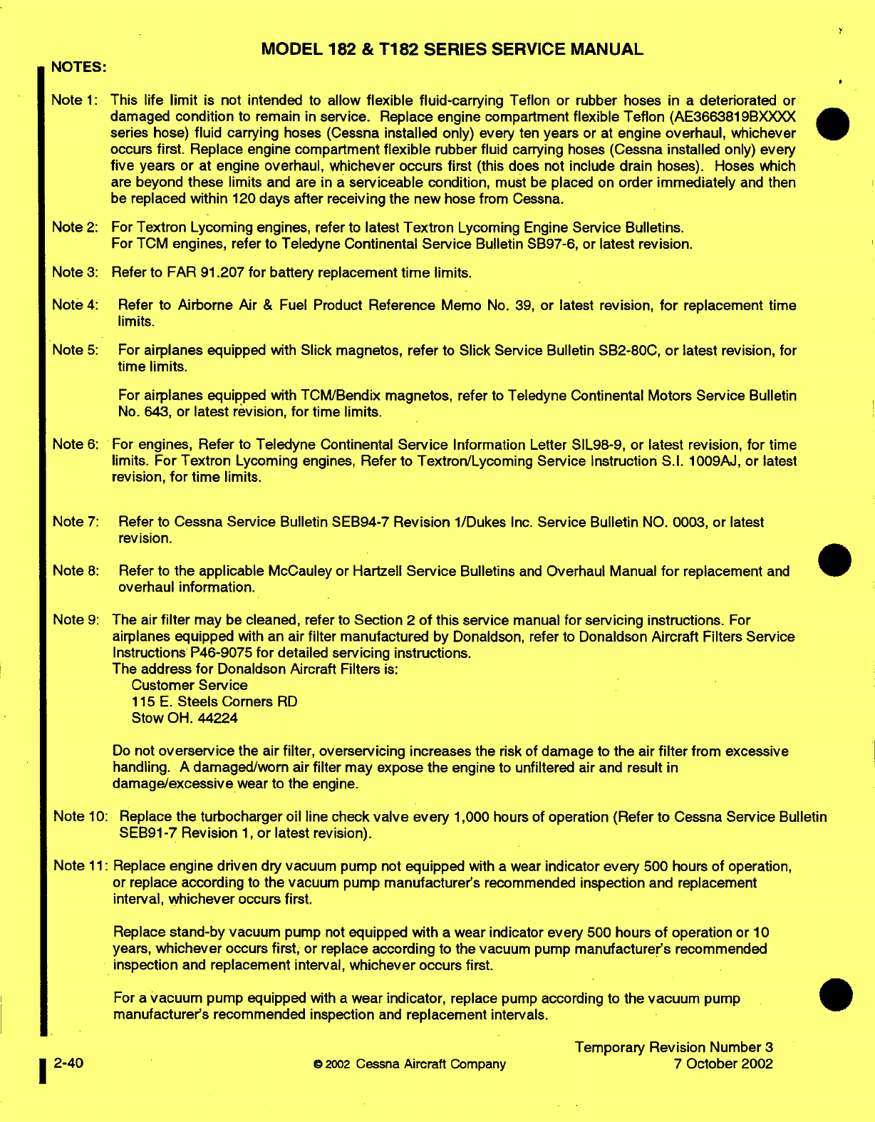
MODEL
182
&
T182
SERIES
SERVICE
MANUAL
NOTES :
Note
1:
This
life
limit
is
not
intended
to
allow
flexible
fluid-carrying
Teflon
or
rubber hoses in
a
deteriorated
or
damaged
condition
to
remain
in
service.
Replace
engine
compartment
flexible
Teflon
(AE3663819BXXXX
series
hose)
fluid
carrying
hoses
(Cessna
installed only)
every
ten
years
or
at
engine
overhaul,
whichever
occurs
first.
Replace engine
compartment
flexible
rubber fluid carrying
hoses
(Cessna
installed
only) every
five
years
or
at
engine
overhaul, whichever
occurs
first
(this
does
not include
drain
hoses).
Hoses
which
are
beyond
these limits
and are
in
a
serviceable
condition,
must be
placed on
order
immediately
and
then
be
replaced
within
120
days after
receiving
the
new
hose
from
Cessna.
Note
2:
For
Textron Lycoming
engines,
refer
to
latest
Textron
Lycoming
Engine
Service Bulletins.
For
TCM
engines, refer
to
Teledyne
Continental
Service
Bulletin
SB97-6,
or
latest
revision.
Note
3:
Refer to
FAR
91.207
for
battery
replacement
time
limits.
Note
4:
Refer
to
Airborne
Air
&
Fuel
Product
Reference
Memo
No.
39,
or
latest
revision,
for
replacement time
limits.
Note
5:
For
airplanes
equipped with
Slick
magnetos,
refer
to
Slick
Service
Bulletin
SB2-80C,
or
latest
revision,
for
time
limits.
For
airplanes
equipped
with
TCM/Bendix
magnetos,
refer
to
Teledyne
Continental
Motors
Service
Bulletin
No.
643,
or
latest
revision,
for
time limits.
Note
6:
For
engines,
Refer
to
Teledyne
Continental
Service
Information
Letter
SIL98-9,
or
latest revision,
for
time
limits.
For
Textron Lycoming
engines,
Refer
to Textron/Lycoming
Service
Instruction
S.I.
1009AJ,
or
latest
revision,
for
time limits.
Note
7:
Refer
to Cessna
Service
Bulletin
SEB94-7
Revision
1/Dukes
Inc.
Service
Bulletin
NO.
0003,
or
latest
revision.
Note
8:
Refer
to
the
applicable
McCauley
or
Hartzell
Service
Bulletins
and
Overhaul
Manual
for
replacement
and
overhaul information.
Note
9:
The
air
filter
may
be
cleaned,
refer
to
Section
2
of
this
service
manual
for
servicing
instructions.
For
airplanes
equipped
with
an
air
filter
manufactured by
Donaldson,
refer
to Donaldson
Aircraft
Filters
Service
Instructions P46-9075
for
detailed
servicing instructions.
The
address
for
Donaldson
Aircraft
Filters
is:
Customer
Service
115
E.
Steels
Corners
RD
Stow
OH.
44224
Do
not
overservice
the
air
filter,
overservicing
increases the
risk
of
damage
to
the
air
filter
from
excessive
handling.
A
damaged/worn air
filter
may
expose
the
engine
to
unfiltered air
and
result
in
damage/excessive
wear
to
the
engine.
Note
10:
Replace
the turbocharger
oil
line
check
valve
every
1,000
hours
of
operation
(Refer
to
Cessna
Service
Bulletin
SEB91-7
Revision
1,
or
latest
revision).
Note
11:
Replace
engine driven dry
vacuum pump
not
equipped
with
a
wear
indicator
every
500
hours
of
operation,
or replace according
to
the vacuum
pump
manufacturer's
recommended
inspection
and
replacement
interval,
whichever
occurs first.
Replace
stand-by
vacuum
pump
not
equipped
with
a
wear
indicator
every
500
hours
of
operation
or
10
years,
whichever
occurs
first,
or
replace
according
to
the
vacuum
pump
manufacturer's
recommended
inspection
and
replacement
interval,
whichever
occurs
first.
For
a
vacuum
pump
equipped
with
a
wear
indicator,
replace
pump
according
to
the
vacuum
pump
manufacturer's
recommended
inspection
and
replacement
intervals.
Temporary
Revision
Number
3
2-40
©
2002
Cessna
Aircraft
Company
7
October
2002
NOTES:

MODEL
182
&
T182
SERIES
SERVICE
MANUAL
2-53.
PROGRESSIVE
CARE
PROGRAM.
(MODEL
182
&
T182
AIRPLANES)
A.
Progressive inspection
Program.
(1)
Purpose
and
Use.
(a)
As
detailed
in
Federal
Aviation
Regulation
Part
91.409.
paragraph
(d),
airplane
operators
that
desire
to
use
a
Progressive
Inspection
Program
must
be
inspected
in
an
accordance
with
an
authorized
progressive inspection
program.
This
chapter
presents
the current
progressive
inspection program
for
the
Cessna
Model 182
&
T182,
recommended
by
the Cessna
Aircraft
Company.
B.
Introduction.
(1)
Following
is the
recommended
Progressive
Care Program
for
Model
182
&
T182
airplanes.
(2)
This
program
is
divided
into
four
separate operations
which
are
to
be
accomplished
initially
after 50
hours
of
operation
and
each
50
hours of
operation thereafter.
Additional special
requirements
indicated
as
Special
Inspection,
which are
required
at
other intervals
are
specified
separately.
(3)
Recommended
progressive care inspection
may
be
accomplished
by
one
of
the
following.
NOTE
Some
100 HOUR
items are
covered
in
Operations
1
and 3,
also
some
200
HOUR
items
are
covered
in
Operations
1,
2, 3,
and
4.
These
items
are
placed
here
for convenience
and
expediency
of
the
total
inspection.
After
the
first
completion of
all
four
Operations,
these
items
will
be
at
the
proper
intervals.
(a)
NEW DELIVERED
AIRCRAFT
-
A
new
delivered aircraft
must
have
less
than
50
hours
total
time
in
service
and
enough
calendar time
remaining
since
the
issuance
date
of
the original Airworthiness
Certificate
to
allow
the owner/operator
to
complete
a
cycle
of
all
four
Operations
before
the
first
annual
inspection
becomes due.
Operation
1
will
be due
at
50
hours
time
in
service.
Operation
2
will
be
due
at
100
hours.
Operation
3
will
be
due
at
150
hours
and
Operation
4
will
be
due
at
200
hours.
There
are
additional
inspection
requirements
for
new
aircraft
at
the
FIRST
50
HOUR
inspection point.
In
addition
to
performing Operation
1,
the
FIRST
50
HOUR
ITEMS
listed
in
the inspection
Time
Limits
Charts
in
2-59
must
also
be
performed.
After
these
FIRST
50
HOUR
items
have
been
accomplished,
they
have
permanent inspection
time limits
which
are
covered
in
the
Operations
Schedules.
(b)
ALL
OTHER
AIRCRAFT
-
To
quality other
aircraft
which
have
more
than
50
hours
time
in
service
for
the
Progressive Inspection
Program,
conduct
a
COMPLETE
AIRPLANE INSPECTION.
Operation
1
will
become
due
50 hours
from
the
time
the
COMPLETE
AIRPLANE
INSPECTION was
accomplished.
(4)
Performance
of
the
inspections
as
listed
herein
at
the
specified
points
will assure
compliance
with
the
Inspection
Time
Limits
detailed
in
2-59.
Special
inspections
shall
be
complied
with
at
prescribed
intervals
and/or
intervals
coinciding
with
operations
1
through
4
as
outlined
in
2-52.
(5)
An
operator
may
elect
to
perform
the
recommended
inspections
on a
schedule
other than
that
specified.
Any
inspection
schedule
requiring
the
various
inspection
items
detailed
in
this
chapter
be performed
at
a
frequency
equal
to
that
specified
herein
or
more
frequently
is
acceptable.
Any inspection
item
performed
at
a
time
period
in
excess
of
that
specified
herein
must
be
approved by
the
appropriate
regulating
agency.
(6)
As
defined
in
Federal
Aviation
Regulations
Part
91.409
(d),
the
frequency
and
detail
of
the Progressive
Inspection
Program
shall
provide for
the
complete
inspection
of
the airplane
within
each
12-calendar
months.
If
the
airplane
is
approaching
the
end
of
a
12-calendar
month
period,
but
the complete
cycle
of
4
operations
has
not
been
accomplished,
it
will
be
necessary
to
complete
the remaining
operations,
regardless
of
airplane
hours
before
the
end
of
the
12-calendar
month
period.
If
the
Progressive
inspection
Program
is
to
be
discontinued,
an
annual
inspection
becomes
due
at
the
time
when
any
item
reaches
a
maximum
of
12-
calendar
months
from
the last
time
it
was
inspected
under
the
Progressive
Inspection
Program.
Refer
to
Federal
Aviation
Regulation Part
91.409
(d)
for
detailed
information.
Temporary Revision
Number
3
7
October
2002
©
2002
Cessna
Aircraft
Company
2-40A

MODEL
182
&
T182
SERIES
SERVICE
MANUAL
(THIS
PAGE
INTENTIONALLY
LEFT
BLANK)
©
2002
Cessna
Aircraft
Company
Temporary
Revision
Number
3
7
October
2002
2-40B
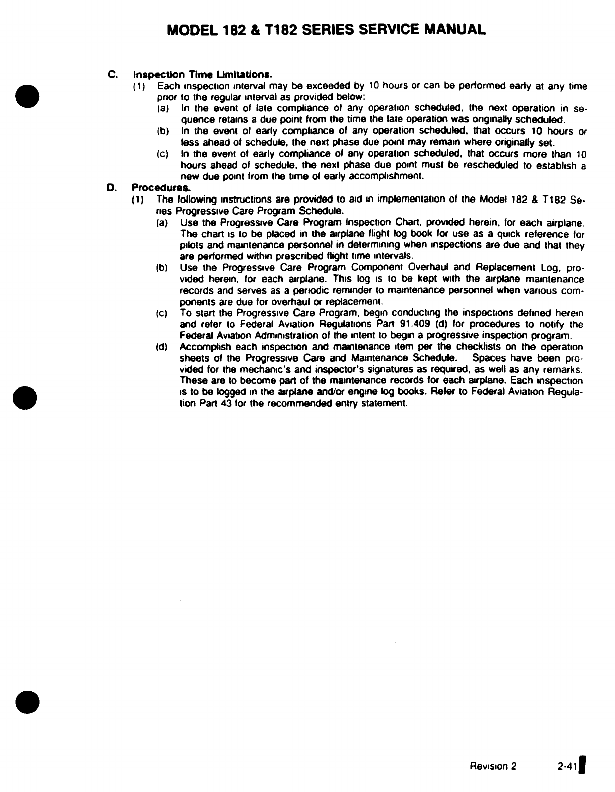
MODEL
182
&
T182
SERIES
SERVICE
MANUAL
C.
Inspection
Time
Limitations.
(1)
Each
inspection
interval
may be
exceeded
by
10
hours
or
can
be
performed early
at
any
time
prior to
the regular
interval
as
provided
below:
(a)
In
the event
of
late
compliance
of
any
operation
scheduled, the
next
operation
in
se-
quence
retains
a
due
point
from
the
time
the
late
operation
was
originally
scheduled.
(b)
In
the event
of
early
compliance
of
any
operation
scheduled,
that
occurs
10
hours
or
less
ahead
of
schedule,
the
next
phase
due
point
may
remain
where
originally
set.
(c)
In
the
event of
early
compliance
of
any
operation scheduled,
that
occurs more
than
10
hours
ahead
of
schedule,
the
next phase
due
point
must
be
rescheduled
to
establish
a
new
due
point from
the
time
of
early
accomplishment.
D.
Procedures.
(1)
The
following instructions
are
provided
to
aid
in
implementation
of
the
Model
182
&
T182
Se-
ries
Progressive
Care
Program
Schedule.
(a)
Use
the
Progressive
Care Program
Inspection
Chart.
provided
herein,
for
each
airplane.
The
chart
is
to be
placed
in
the
airplane
flight
log
book
for
use
as
a
quick
reference
for
pilots
and
maintenance
personnel
in
determining
when
inspections
are
due
and
that
they
are
performed within
prescribed
flight
time
intervals.
(b)
Use
the
Progressive
Care
Program
Component Overhaul
and
Replacement
Log,
pro-
vided
herein,
for
each
airplane.
This
log
is
to
be
kept
with the airplane
maintenance
records
and
serves
as
a
periodic
reminder
to
maintenance
personnel
when
various
com-
ponents
are
due
for
overhaul
or
replacement.
(c)
To
start
the
Progressive
Care Program,
begin
conducting
the
inspections
defined
herein
and
refer
to
Federal
Aviation
Regulations
Part
91.409
(d)
for
procedures
to notify
the
Federal
Aviation
Administration of
the
intent
to
begin
a
progressive inspection program.
(d)
Accomplish
each
inspection
and
maintenance
item
per
the
checklists
on
the
operation
sheets
of
the
Progressive
Care
and
Maintenance
Schedule. Spaces
have
been
pro-
vided
for
the
mechanic's
and
inspector's
signatures
as
required, as well
as
any
remarks.
These
are
to
become
part
of
the
maintenance
records
for
each
airplane.
Each
inspection
is
to
be logged
in
the
airplane
and/or
engine
log
books.
Refer
to
Federal
Aviation
Regula-
tion
Part
43
for
the
recommended entry
statement.
Revision
2
2-41
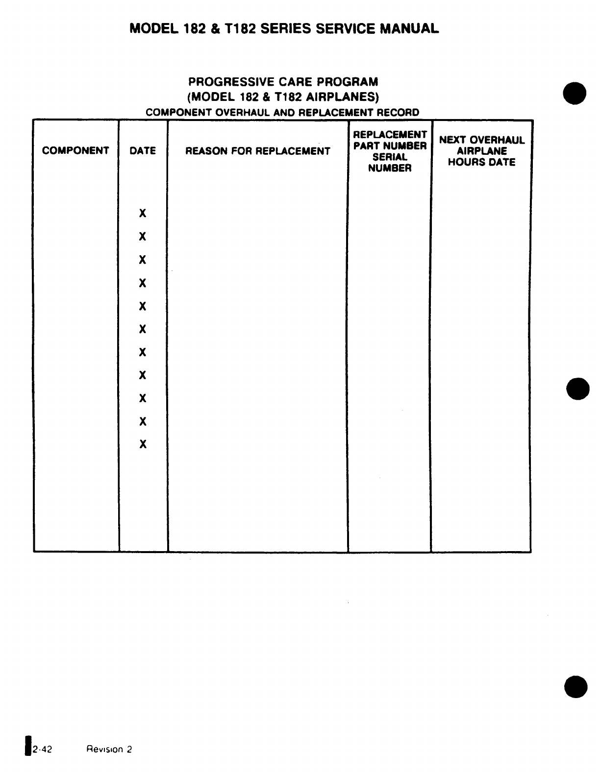
MODEL
182
&
T182
SERIES
SERVICE
MANUAL
PROGRESSIVE
CARE PROGRAM
(MODEL
182
&
T182
AIRPLANES)
COMPONENT
OVERHAUL
AND REPLACEMENT
RECORD
REPLACEMENT NEXT OVERHAUL
COMPONENT
DATE
REASON
FOR
REPLACEMENT
PART NUMBER
AIRPLANE
SERIAL
NUMBER
HOURS
DATE
NUMBER
X
X
X
X
X
X
X
X
X
X
X
2-42
Revision 2
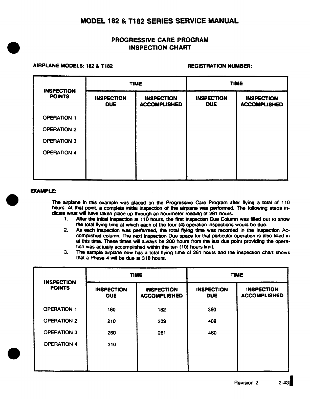
MODEL
182
&
T182
SERIES
SERVICE
MANUAL
PROGRESSIVE
CARE
PROGRAM
INSPECTION
CHART
AIRPLANE
MODELS:
182
&
T182 REGISTRATION
NUMBER:
TIME
TIME
INSPECTION
POINTS
INSPECTION
INSPECTION
INSPECTION
INSPECTION
DUE
ACCOMPLISHED
DUE
ACCOMPLISHED
OPERATION
1
OPERATION
2
OPERATION
3
OPERATION
4
EXAMPLE:
The
airplane
in
this
example was
placed
on
the
Progressive
Care
Program
after
flying
a
total of
110
hours.
At that
point,
a
complete
initial inspection
of
the
airplane
was
performed.
The
following
steps
in-
dicate
what
will
have
taken
place
up
through
an
hourmeter
reading
of
261
hours.
1.
After
the
initial inspection
at
110
hours,
the
first
Inspection
Due Column
was
filled
out
to
show
the total
flying
time
at
which
each
of
the
four
(4)
operation
inspections would
be
due.
2.
As
each
inspection
was
performed.
the
total
flying
time
was recorded
in
the
Inspection
Ac-
complished
column. The
next
Inspection
Due
space
for
that
particular
operation is
also
filled
in
at
this
time.
These
times
will
always
be
200
hours
from the
last due
point providing the
opera-
tion was
actually accomplished
within
the ten
(10)
hours
limit.
3.
The
sample airplane
now
has
a
total
flying time of
261
hours
and the
inspection chart
shows
that
a
Phase
4
will be
due
at
310
hours.
TIME
TIME
INSPECTION
POINTS
INSPECTION
INSPECTION
INSPECTION
INSPECTION
DUE
ACCOMPLISHED
DUE
ACCOMPLISHED
OPERATION
1
160
162
360
OPERATION
2
210
209
409
OPERATION
3
260
261
460
OPERATION
4
310
Revision
2
2-43
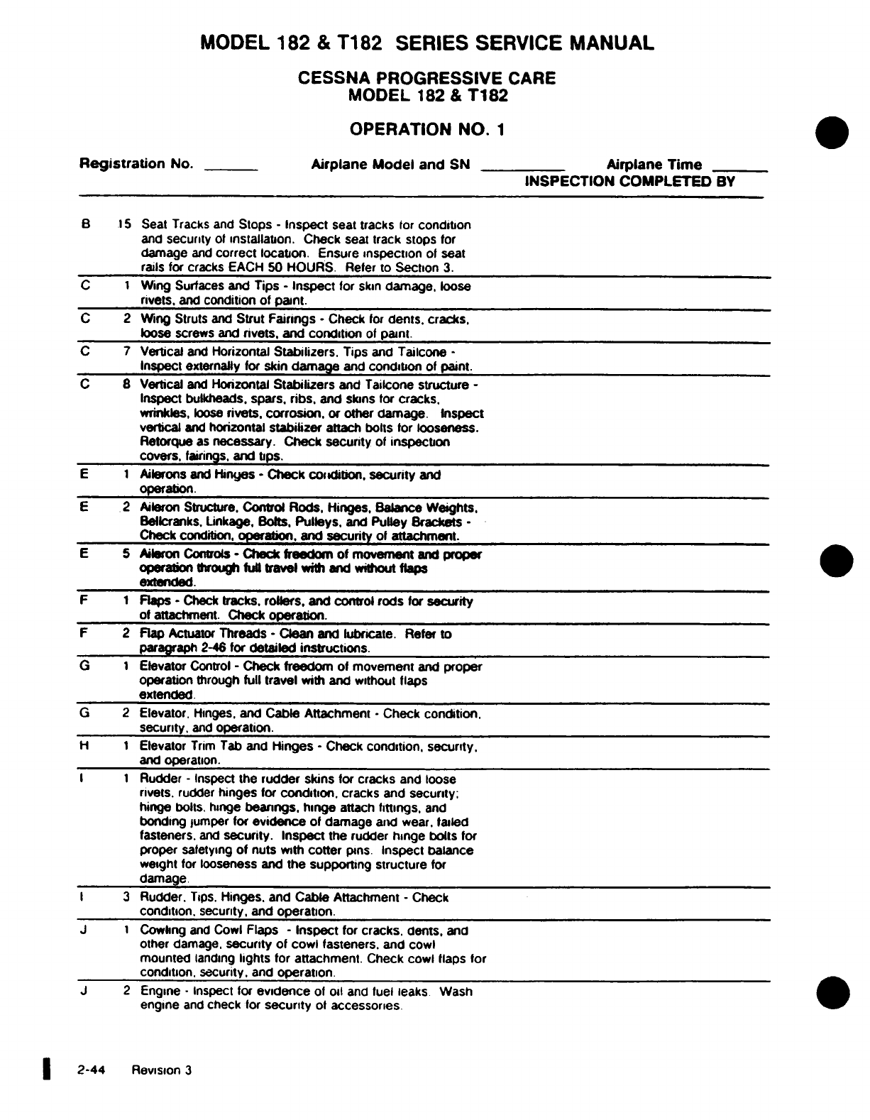
MODEL
182
&
T182
SERIES
SERVICE
MANUAL
CESSNA
PROGRESSIVE
CARE
MODEL
182
&
T182
OPERATION
NO.
1
Registration
No.
Airplane Model
and
SN Airplane
Time
INSPECTION COMPLETED
BY
B
15
Seat
Tracks
and
Stops - Inspect
seat
tracks
for
condition
and
security
of
installation.
Check
seat
track
stops
for
damage
and
correct
location.
Ensure
inspection
of
seat
rails
for
cracks
EACH
50
HOURS.
Refer to
Section
3.
C
1
Wing
Surfaces
and
Tips
-
Inspect
for
skin
damage,
loose
rivets,
and
condition
of
paint.
C
2
Wing
Struts
and
Strut
Fairings
-
Check
for
dents. cracks,
loose
screws and
rivets,
and
condition
of
paint.
C
7
Vertical
and
Horizontal
Stabilizers.
Tips
and
Tailcone
-
Inspect
externally
for
skin damage
and
condition
of paint.
C
8
Vertical
and
Horizontal
Stabilizers
and
Tailcone
structure
-
Inspect
bulkheads, spars,
ribs,
and skins
for
cracks.
wrinkles,
loose
rivets, corrosion,
or
other
damage.
Inspect
vertical
and
horizontal
stabilizer
attach
bolts
for
looseness.
Retorque
as
necessary. Check
security
of
inspection
covers,
fairings,
and
tips.
E
1
Ailerons
and
Hinges
-
Check
condition,
security
and
operation.
E
2
Aileron
Structure.
Control
Rods,
Hinges, Balance
Weights,
Bellcranks.
Linkage,
Bolts.
Pulleys,
and
Pulley
Brackets
-
Check
condition,
operation,
and
security
of
attachment.
E
5
Aileron
Controls
-
Check
freedom
of
movement
and
proper
operation
through
full
travel
with
and
without
flaps
extended.
F
1
Flaps
-
Check
tracks,
rollers,
and
control
rods
for
security
of
attachment.
Check
operation.
F
2
Flap
Actuator
Threads
-
Clean
and
lubricate.
Refer
to
paragraph
2-46
for
detailed
instructions.
G
1
Elevator
Control
-
Check freedom
of
movement
and
proper
operation
through
full
travel with
and without
flaps
extended.
G
2
Elevator.
Hinges,
and
Cable
Attachment
-
Check
condition,
security.
and
operation.
H
1
Elevator
Trim
Tab
and
Hinges
-
Check
condition,
security.
and
operation.
I 1
Rudder
-
Inspect
the
rudder
skins
for
cracks
and loose
rivets,
rudder
hinges
for
condition,
cracks
and
security;
hinge
bolts,
hinge
bearings,
hinge
attach
fittings,
and
bonding
jumper
for
evidence
of
damage
and
wear,
failed
fasteners.
and
security.
Inspect
the
rudder
hinge bolts for
proper
safetying
of
nuts with
cotter
pins.
Inspect
balance
weight
for
looseness and
the supporting
structure
for
damage.
I
3
Rudder.
Tips.
Hinges,
and
Cable
Attachment
-
Check
condition.
security, and
operation.
J
1
Cowling
and
Cowl
Flaps
-
Inspect
for
cracks.
dents,
and
other
damage,
security
of
cowl
fasteners.
and
cowl
mounted
landing
lights
for
attachment.
Check
cowl
flaps
for
condition,
security.
and
operation.
J
2
Engine
-
Inspect
for
evidence
of
oil
and
fuel leaks Wash
engine
and
check for
security
of
accessories.
2-44
Revision
3
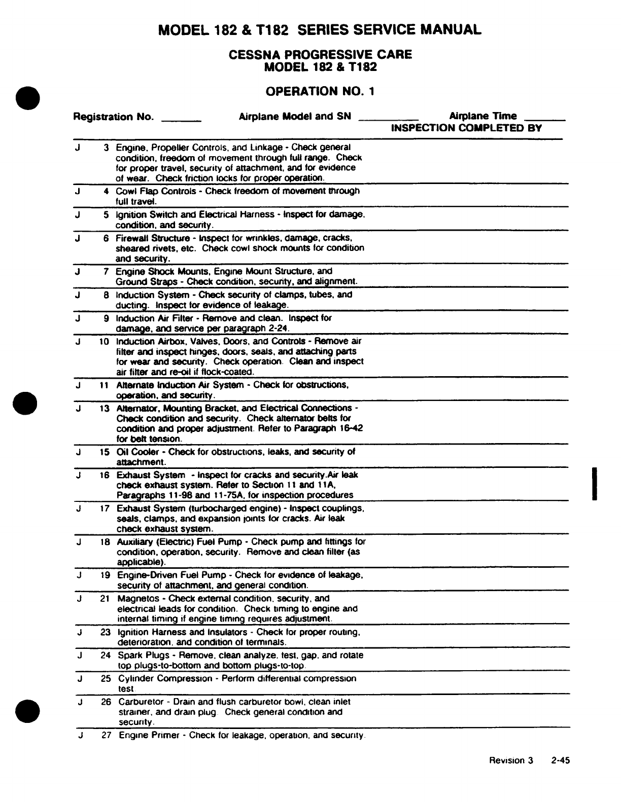
MODEL
182
&
T182
SERIES
SERVICE
MANUAL
CESSNA
PROGRESSIVE
CARE
MODEL
182
&
T182
OPERATION
NO.
1
Registration
No.
Airplane
Model
and
SN
_
Airplane
Time
INSPECTION COMPLETED BY
J
3
Engine. Propeller
Controls,
and
Linkage
-
Check
general
condition,
freedom
of
movement through
full
range. Check
for
proper travel,
security
of
attachment,
and
for
evidence
of
wear.
Check
friction
locks
for
proper
operation.
J
4
Cowl
Flap Controls
-
Check
freedom
of
movement through
full
travel.
J
5
Ignition
Switch
and
Electrical Harness
-
Inspect
for damage,
condition,
and
security.
J
6
Firewall
Structure
-
Inspect
for
wrinkles,
damage,
cracks.
sheared
rivets, etc.
Check
cowl
shock
mounts
for
condition
and
security.
J
7
Engine Shock
Mounts,
Engine
Mount
Structure,
and
Ground
Straps
-
Check
condition,
security,
and
alignment.
J
8
Induction
System
-
Check
security
of
clamps, tubes,
and
ducting.
Inspect
for
evidence
of
leakage.
J
9
Induction
Air
Filter
-
Remove
and
clean.
Inspect
for
damage,
and
service
per
paragraph 2-24.
J
10
Induction
Airbox,
Valves,
Doors,
and Controls
-
Remove
air
filter
and
inspect
hinges.
doors, seals,
and
attaching
parts
for wear
and
security.
Check
operation.
Clean
and
inspect
air
filter
and
re-oil
if
flock-coated.
J
11
Alternate
Induction
Air
System
-
Check
for
obstructions,
operation,
and
security.
J
13
Alternator,
Mounting
Bracket,
and
Electrical
Connections
-
Check
condition
and
security.
Check
alternator
belts
for
condition
and proper
adjustment.
Refer
to Paragraph
1642
for
belt
tension.
J
15
Oil
Cooler
-
Check
for
obstructions,
leaks,
and
security
of
attachment.
J
16
Exhaust
System
-
Inspect
for
cracks
and
security.Air
leak
check
exhaust system.
Refer
to
Section
11
and
11A,
Paragraphs
11-98
and
11-75A.
for inspection
procedures
J
17
Exhaust
System
(turbocharged
engine)
-
Inspect
couplings,
seals,
clamps,
and
expansion
joints
for cracks.
Air
leak
check
exhaust
system.
J
18
Auxiliary (Electric)
Fuel Pump
-
Check pump
and
fittings
for
condition,
operation,
security.
Remove
and
clean
filler
(as
applicable).
J
19
Engine-Driven
Fuel
Pump
-
Check
for
evidence
of leakage,
security
of attachment,
and
general
condition.
J
21
Magnetos
-
Check external
condition.
security,
and
electrical
leads
for
condition.
Check
timing
to
engine
and
internal
timing
if
engine
timing requires
adjustment.
J
23
Ignition
Harness
and
Insulators
-
Check
for
proper
routing.
deterioration,
and
condition
of
terminals.
J 24
Spark
Plugs
-
Remove,
clean
analyze,
test, gap.
and
rotate
top
plugs-to-bottom
and bottom
plugs-to-top.
J
25
Cylinder
Compression
-
Perform
differential compression
test
J 26
Carburetor
-
Drain
and
flush
carburetor
bowl.
clean
inlet
strainer,
and
drain plug
Check
general
condition
and
security.
J
27
Engine Primer
-
Check
for
leakage, operation,
and
security.
Revision
3
2-45
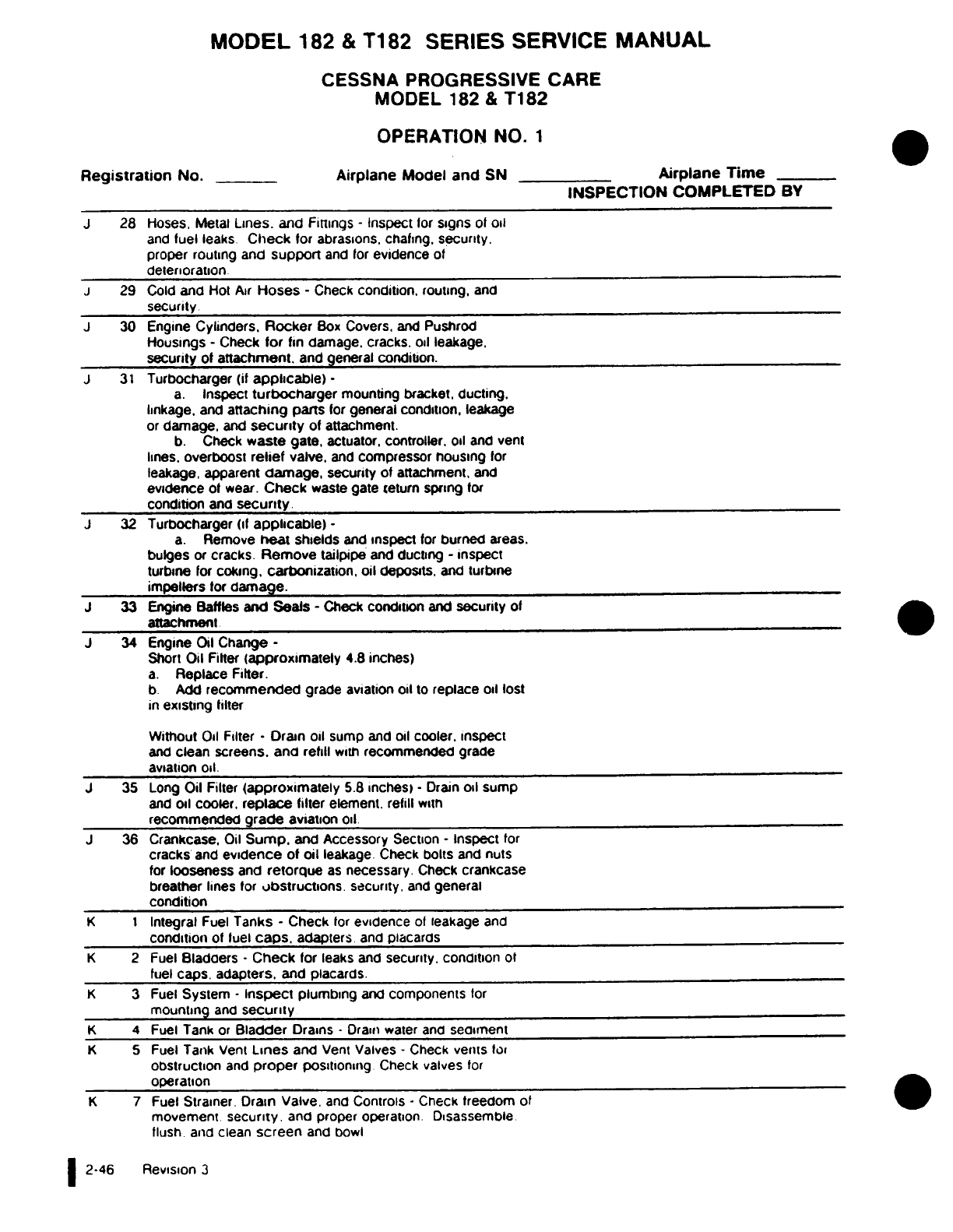
MODEL
182
&
T182
SERIES
SERVICE
MANUAL
CESSNA PROGRESSIVE
CARE
MODEL
182
&
T182
OPERATION
NO.
1
Registration
No.
Airplane
Model and SN
Airplane
Time
INSPECTION
COMPLETED
BY
J 28
Hoses.
Metal
Lines.
and
Fittings
-
Inspect
for
signs
of
oil
and
fuel
leaks
Check
for
abrasions,
chafing.
security.
proper
routing
and
support
and
for
evidence
of
deterioration
J
29
Cold
and
Hot
Air
Hoses
-
Check
condition,
routing,
and
security
J
30
Engine
Cylinders.
Rocker
Box
Covers, and
Pushrod
Housings
-
Check
for
fin
damage,
cracks,
oil
leakage.
security
of
attachment.
and
general
condition.
J
31
Turbocharger
(if
applicable)
-
a.
Inspect
turbocharger
mounting bracket,
ducting.
linkage,
and
attaching
parts
for
general
condition, leakage
or
damage.
and
security
of
attachment.
b. Check
waste
gate,
actuator,
controller.
oil
and
vent
lines.
overboost
relief
valve,
and
compressor
housing
for
leakage,
apparent
damage,
security
of
attachment,
and
evidence
of
wear.
Check
waste
gate
return
spring
for
condition
and
security.
J
32
Turbocharger
(if
applicable)
-
a.
Remove
heat
shields
and
inspect
for
burned
areas.
bulges
or
cracks.
Remove
tailpipe
and
ducting
-
inspect
turbine
for
coking.
carbonization.
oil deposits,
and
turbine
impellers
for
damage.
J
33
Engine
Baffles
and
Seals
-
Check
condition
and
security
of
attachment
J
34
Engine Oil
Change
-
Short
Oil
Filter
(approximately
4.8
inches)
a.
Replace Filter.
b
Add
recommended
grade
aviation
oil
to
replace
oil
lost
in
existing
filter
Without
Oil
Filter
-
Drain
oil
sump
and
oil
cooler,
inspect
and
clean
screens.
and refill
with
recommended
grade
aviation
oil.
J
35
Long
Oil
Filter
(approximately
5.8
inches)
-
Drain
oil
sump
and
oil
cooler,
replace
filter
element.
refill
with
recommended
grade
aviation
oil.
J
36
Crankcase,
Oil
Sump.
and Accessory
Section
-
Inspect
for
cracks
and
evidence
of
oil
leakage. Check
bolts
and
nuts
for
looseness
and
retorque
as
necessary.
Check
crankcase
breather
lines
for
obstructions.
security.
and
general
condition
K 1
Integral
Fuel
Tanks
-
Check
for
evidence
of
leakage
and
condition
of fuel
caps.
adapters
and
placards
K
2
Fuel
Bladders
-
Check
for
leaks
and
security,
condition
of
fuel
caps.
adapters,
and
placards.
K
3
Fuel
System
-
Inspect
plumbing
and
components
for
mounting
and
security
K
4
Fuel
Tank
or
Bladder
Drains
-
Drain
water
and
sediment
K
5
Fuel
Tank
Vent
Lines
and
Vent
Valves
-
Check
vents
for
obstruction
and
proper
positioning
Check
valves
for
operation
K
7
Fuel
Strainer.
Drain Valve,
and
Controls
-
Check
freedom
of
movement
security,
and
proper
operation.
Disassemble
flush.
and clean
screen
and
bowl
2-46 Revision
3

MODEL 182
&
T182
SERIES
SERVICE
MANUAL
CESSNA PROGRESSIVE CARE
MODEL
182
&
T182
OPERATION
NO.
1
Registration
No.
Airplane
Model
and
SN
Airplane
Time
INSPECTION COMPLETED BY
L
1 Propeller
Mounting
-
Check
for
security
of
installation.
L
2
Propeller
Blades
-
Inspect
for
cracks, dents,
nicks,
scratches,
erosion.
corrosion.
or
other damage.
L
3
Spinner
-
Check
general
condition
and
attachment.
L
4
Spinner
and
Spinner
Bulkhead
-
Remove spinner,
wash.
and
inspect
for
cracks
and fractures.
L
5
Propeller
Mounting
Bolts
-
Inspect
mounting bolts
and
safety-wire
for
signs
of
looseness. Retorque
mounting
bolts
as
required.
L
6 Propeller
Hub
-
Check
general
condition.
L
7
Propeller
Governor
and
Control
-
Inspect
for
oil
and
grease
leaks.
L
8 Propeller
Anti-ice
Slip
Rings.
Brushes, and
Boots
-
Inspect
for
condition,
and
security.
Perform
operational
check.
M
2
Heater Components. Inlets,
and
Outlets
-
Inspect
all
lines.
connections, ducts,
clamps,
seals.
and
gaskets
for
condition.
restriction,
and
security.
M
4
Pitot
Tube and
Stall Warning
Vane
-
Check
for
condition
and obstructions.
M
5
Pitot
Tube
Heater
Element
-
Perform
operational
check.
N
3
Vacuum
Pump
-
Check
for
condition
and
security.
Check
vacuum system
breather
line
for
obstructions, condition,
and security.
O
4
Battery
-
Check
general condition
and
security.
Check
level
of
electrolyte.
O 5
Battery
Box
and
Cables
-
Clean
and
remove
any
corrosion.
Check
cables
for
routing,
support. and
security
of
connections.
O
7
Alternator
Control
Unit
-
Inspect
wiring,
mounting,
condition.
and
wire
routing.
O
10
External
Power
Receptacle
and Power
Cables
-
Inspect
for
condition
and
security.
Revision
3
2-47
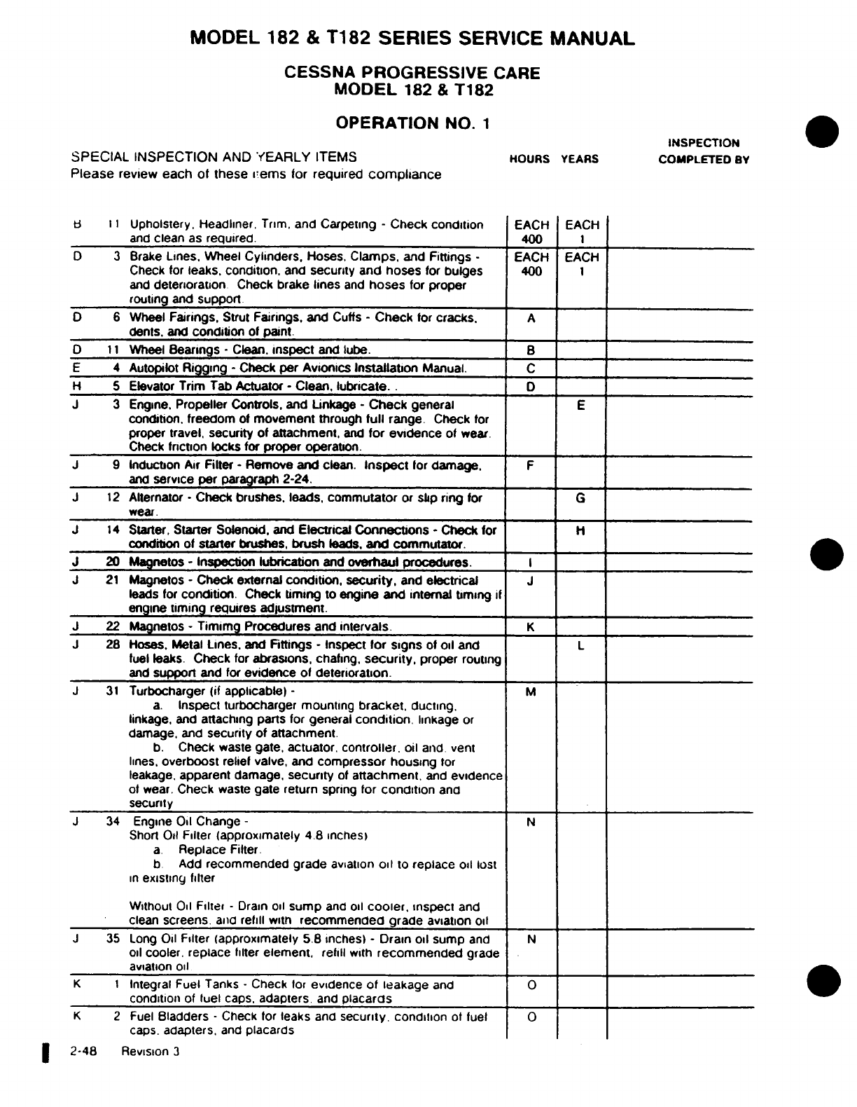
MODEL
182
&
T182
SERIES
SERVICE
MANUAL
CESSNA
PROGRESSIVE
CARE
MODEL
182
&
T182
OPERATION
NO.
1
INSPECTION
SPECIAL INSPECTION
AND
YEARLY
ITEMS
HOURS
YEARS
COMPLETED
BY
Please
review
each
of
these
items
for
required
compliance
B
I
Upholstery.
Headliner.
Trim,
and
Carpeting
-
Check
condition
EACH
EACH
and
clean
as
required.
400
1
D
3
Brake
Lines. Wheel
Cylinders.
Hoses,
Clamps,
and
Fittings
-
EACH
EACH
Check
for
leaks, condition,
and
security
and hoses
for
bulges
400
1
and
deterioration
Check
brake
lines
and
hoses
for
proper
routing and
support
D
6
Wheel
Fairings,
Strut
Fairings,
and
Cuffs
-
Check
for
cracks.
A
dents,
and
condition
of
paint.
D
11
Wheel
Bearings
-
Clean,
inspect
and lube.
B
E
4
Autopilot
Rigging
-
Check
per Avionics
Installation
Manual.
C
H
5
Elevator
Trim
Tab
Actuator
-
Clean,
lubricate..
D
J
3
Engine.
Propeller
Controls,
and
Linkage
-
Check
general
E
condition, freedom
of
movement
through
full
range. Check
for
proper
travel,
security
of attachment,
and
for
evidence
of
wear.
Check
friction
locks
for
proper
operation.
J
9
Induction
Air
Filter
-
Remove
and
clean.
Inspect
for
damage.
F
and
service per
paragraph
2-24.
J
12
Alternator
-
Check brushes,
leads,
commutator
or
slip
ring
for
G
wear.
J
14
Starter.
Starter Solenoid,
and
Electrical
Connections
-
Check
for
H
condition
of
starter
brushes,
brush
leads, and
commutator.
J
20
Magnetos
-
Inspection
lubrication
and
overhaul
procedures.
I
J
21
Magnetos
-
Check
external
condition,
security,
and
electrical
J
leads for
condition.
Check
timing
to
engine
and
internal
timing
if
engine
timing
requires
adjustment.
J
22
Magnetos
-
Timimg Procedures and
intervals.
K
J
28 Hoses,
Metal
Lines,
and
Fittings
-
Inspect
for
signs
of
oil
and
L
fuel leaks.
Check
for abrasions, chafing.
security,
proper
routing
and
support
and
for
evidence
of
deterioration.
J
31
Turbocharger
(if
applicable)
-M
a. Inspect
turbocharger
mounting
bracket,
ducting.
linkage, and
attaching
parts
for
general
condition.
linkage
or
damage,
and
security
of
attachment.
b.
Check
waste
gate,
actuator,
controller,
oil
and.
vent
lines,
overboost
relief
valve,
and
compressor housing
for
leakage.
apparent
damage,
security
of
attachment.
and
evidence
of
wear.
Check
waste
gate
return
spring
for
condition
and
security
J
34
Engine
Oil
Change
-N
Short Oil
Filter (approximately 4.8
inches)
a.
Replace
Filter.
b
Add
recommended
grade
aviation
oil
to
replace oil
lost
in
existing
filter
Without
Oil
Filter
-
Drain
oil
sump
and
oil
cooler,
inspect
and
clean
screens.
and
refill with
recommended grade
aviation
oil
J
35
Long
Oil
Filter
(approximately 5.8 inches)
-
Drain
oil
sump
and
N
oil
cooler,
replace
filter
element,
refill
with
recommended
grade
aviation
oil
K 1
Integral
Fuel Tanks
-
Check
for
evidence
of leakage
and
O
condition
of fuel
caps.
adapters.
and
placards
K
2
Fuel
Bladders
-
Check for
leaks
and
security,
condition
of
fuel
O
caps.
adapters,
and
placards
2-48
Revision
3
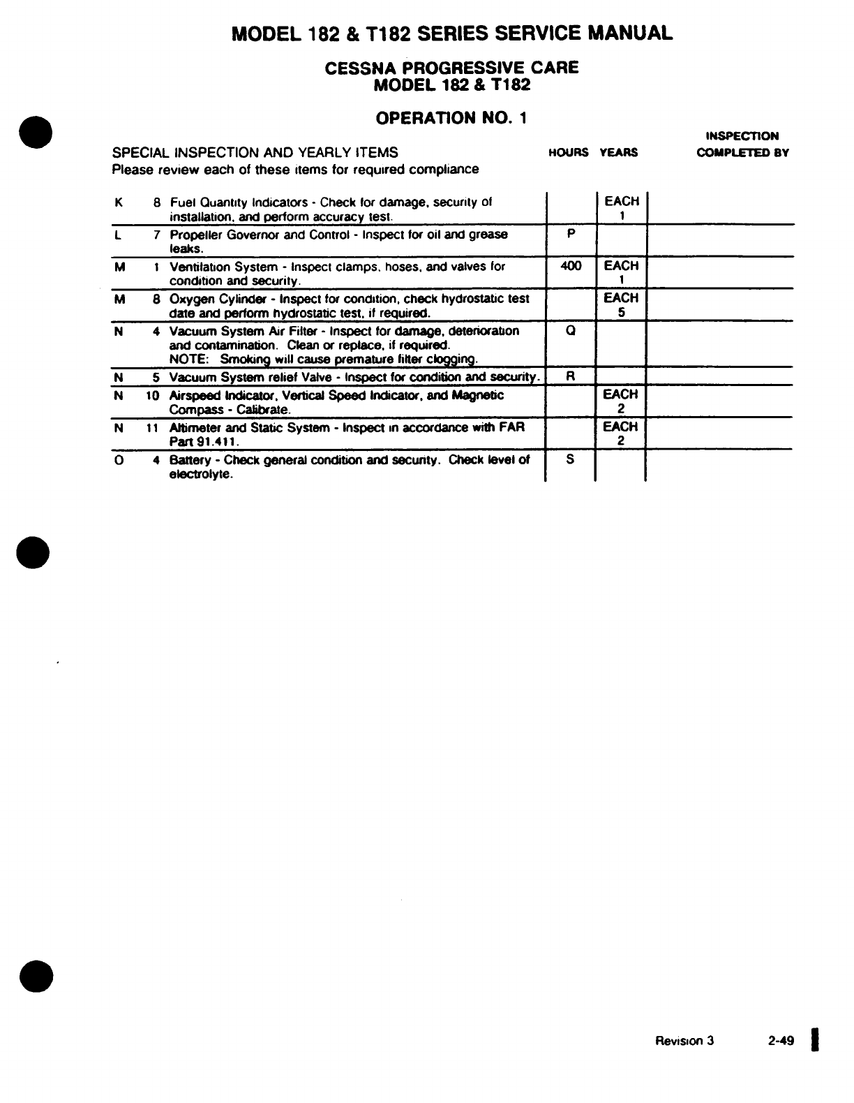
MODEL
182
&
T182
SERIES
SERVICE
MANUAL
CESSNA
PROGRESSIVE
CARE
MODEL
182
&
T182
OPERATION
NO.
1
INSPECTION
SPECIAL
INSPECTION AND
YEARLY
ITEMS
HOURS
YEARS
COMPLETED
BY
Please
review
each
of
these
items
for
required
compliance
K
8
Fuel
Quantity
Indicators
-
Check
for
damage,
security
of
EACH
installation,
and
perform accuracy
test.
1
L
7
Propeller
Governor
and
Control
-
Inspect
for
oil
and
grease
P
leaks.
M
1
Ventilation
System
-
Inspect
clamps,
hoses, and
valves
for
400
EACH
condition
and
security.
1
M
8
Oxygen
Cylinder
-
Inspect
for
condition,
check
hydrostatic
test
EACH
date
and perform
hydrostatic
test,
if
required.
5
N
4
Vacuum System
Air
Filter
-
Inspect
for
damage, deterioration
Q
and
contamination.
Clean
or
replace,
if
required.
NOTE:
Smoking
will
cause
premature filter
clogging.
N
5
Vacuum
System
relief
Valve
-
Inspect
for
condition
and
security.
R
N
10
Airspeed Indicator.
Vertical
Speed Indicator,
and
Magnetic
EACH
Compass
-
Calibrate.
2
N
11
Altimeter
and
Static System
-
Inspect
in
accordance
with
FAR
EACH
Part
91.411.
2
O
4
Battery
-
Check
general
condition
and
security.
Check
level
of
S
electrolyte.
Revision
3
2-49
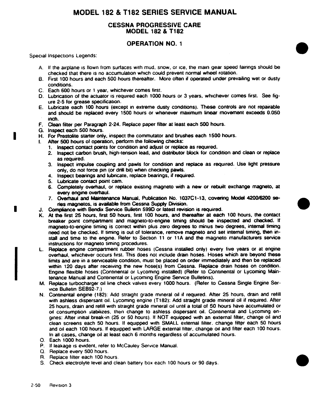
MODEL
182
&
T182 SERIES
SERVICE
MANUAL
CESSNA
PROGRESSIVE
CARE
MODEL
182
&
T182
OPERATION
NO.
1
Special
Inspections
Legends:
A.
If
the
airplane
is
flown
from
surfaces
with
mud,
snow,
or
ice,
the main
gear
speed
fairings
should
be
checked
that
there
is no
accumulation
which
could
prevent
normal
wheel
rotation.
B.
First
100
hours
and
each
500
hours
thereafter.
More
often
if
operated under
prevailing
wet
or
dusty
conditions.
C.
Each
600
hours
or
1
year,
whichever
comes first.
D.
Lubrication
of
the
actuator
is
required
each
1000
hours
or
3
years,
whichever
comes
first.
See
fig-
ure
2-5
for
grease
specification.
E.
Lubricate
each
100
hours
(except
in
extreme
dusty
conditions).
These
controls
are
not
repairable
and
should
be
replaced
every
1500
hours
or
whenever
maximum
linear
movement
exceeds 0.050
inch.
F.
Clean
filter per
Paragraph
2-24.
Replace
paper
filter
at
least
each 500
hours.
G.
Inspect
each
500
hours.
H.
For
Prestolite
starter
only,
inspect
the
commutator
and
brushes
each 1500
hours.
I.
After
500
hours
of
operation,
perform
the
following
checks:
1.
Inspect
contact
points
for
condition
and
adjust or
replace
as
required.
2.
Inspect
carbon
brush, high-tension
lead,
and
distributor
block for
condition
and
clean
or
replace
as
required.
3.
Inspect impulse
coupling
and pawls
for
condition
and
replace
as
required.
Use
light
pressure
only,
do
not
force
pin
(or
drill
bit)
when
checking
pawls.
4.
Inspect
bearings
and
lubricate,
replace
bearings,
if required.
5.
Lubricate
contact
point cam.
6.
Completely
overhaul,
or
replace
existing magneto
with
a
new
or
rebuilt
exchange
magneto, at
every
engine
overhaul.
7.
Overhaul
and
Maintenance
Manual,
Publication
No.
1037C1-13,
covering
Model
4200/6200
se-
ries
magnetos,
is
available
from
Cessna
Supply Division.
J. Compliance
with
Bendix
Service
Bulletin
599D
or
latest
revision
is
required.
K.
At
the
first
25
hours,
first
50
hours,
first
100
hours,
and
thereafter
at
each
100
hours,
the
contact
breaker
point
compartment
and
magneto-to-engine
timing
should
be
inspected
and
checked.
If
magneto-to-engine
timing
is
correct
within
plus
zero
degrees
to
minus
two
degrees,
internal
timing
need
not
be
checked.
If
timing
is out
of
tolerance,
remove magneto
and
set
internal
timing,
then
in-
stall
and
time
to the
engine.
Refer
to
Section
11
or
11A
and
the
magneto
manufacturers
service
instructions for
magneto
timing
procedures.
L.
Replace
engine
compartment
rubber
hoses
(Cessna
installed only)
every
five
years
or
at
engine
overhaul,
whichever occurs first.
This
does
not
include
drain
hoses.
Hoses
which
are beyond
these
limits
and
are
in
a
serviceable condition,
must
be
placed
on
order
immediately
and
then
be
replaced
within
120
days
after
receiving
the new
hose(s)
from
Cessna.
Replace
drain
hoses
on
condition.
Engine
flexible
hoses
(Continental
or
Lycoming installed) (Refer
to
Continental
or
Lycoming
Main-
tenance
Manual
and
Continental
or
Lycoming
Engine
Service
Bulletins).
M.
Replace
turbocharger
oil
line
check
valves
every
1000
hours. (Refer
to
Cessna
Single
Engine
Ser-
vice
Bulletin
SEB92-7.)
N.
Continental
engine
(182):
Add
straight
grade
mineral
oil
if
required.
After
25
hours,
drain
and
refill
with
ashless
dispersant
oil.
Lycoming engine
(T182):
Add
straight
grade
mineral
oil
if
required.
After
25
hours,
drain
and
refill
with
straight
grade mineral
oil
until
a
total
of
50
hours
have
accumulated
or
oil
consumption
stabilizes,
then
change
to
ashless
dispersant oil.
Continental
and
Lycoming
en-
gines:
After initial
break-in
(25
or 50
hours).
If
NOT equipped
with
an
external
filter,
change
oil
and
clean
screens
each
50
hours.
If
equipped with SMALL
external
filter. change
filter
each
50
hours
and
oil
each
100 hours.
If
equipped
with
LARGE
external
filter,
change oil
and filter each
100
hours.
In
all
cases,
change
oil
at
least
each
6
months
regardless
of
accumulated
hours.
O.
Each 1000
hours.
P.
If
leakage
is
evident,
refer
to
McCauley
Service
Manual.
Q.
Replace
every
500
hours.
R.
Replace
filter
each
100
hours
S.
Check
electrolyte
level and
clean
battery
box
each
100
hours
or
90
days.
2-50 Revision
3
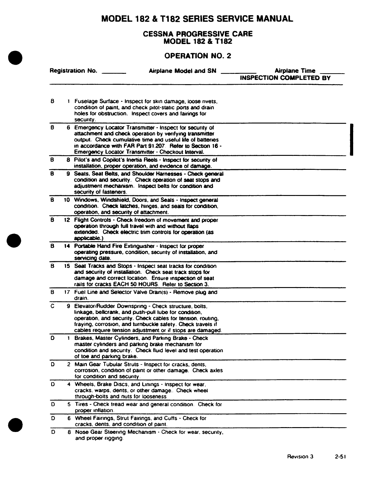
MODEL
182
&
T182
SERIES
SERVICE
MANUAL
CESSNA PROGRESSIVE
CARE
MODEL
182
&
T182
OPERATION NO.
2
Registration
No.
Airplane
Model and
SN
Airplane
Time
INSPECTION COMPLETED BY
B 1
Fuselage Surface
-
Inspect
for
skin
damage,
loose
rivets,
condition
of
paint.
and
check
pitot-static
ports
and
drain
holes
for
obstruction.
Inspect
covers
and
fairings
for
security.
B
6
Emergency Locator
Transmitter
-
Inspect
for
security
of
attachment
and
check
operation
by
verifying
transmitter
output.
Check
cumulative
time
and
useful
life
of
batteries
in
accordance
with
FAR
Part
91.207
Refer
to
Section
16
-
Emergency Locator
Transmitter
-
Checkout
Interval.
B
8
Pilot's
and
Copilot's
Inertia
Reels
-
Inspect
for
security
of
installation.
proper
operation,
and
evidence
of
damage.
B
9
Seats.
Seat
Belts,
and
Shoulder
Harnesses
-
Check
general
condition
and
security.
Check
operation
of
seat
stops
and
adjustment mechanism.
Inspect
belts
for
condition
and
security
of
fasteners.
B
10
Windows.
Windshield.
Doors,
and
Seals
-
Inspect
general
condition.
Check
latches,
hinges,
and
seals
for
condition.
operaton,
and
security of
attachment.
B
12
Flight
Controls
-
Check
freedom
of
movement
and
proper
operation through
full
travel
with
and
without flaps
extended.
Check
electric
trim controls
for
operation (as
applicable.)
B
14
Portable
Hand
Fire Extinguisher
-
Inspect
for
proper
operating pressure,
condition,
security
of
installation,
and
servicing
date.
B
15
Seat
Tracks
and
Stops
-
Inspect
seat
tracks
for
condition
and
security
of
installation.
Check
seat track stops
for
damage
and
correct
location.
Ensure
inspection
of
seat
rails
for
cracks
EACH
50
HOURS.
Refer to
Section
3.
B
17
Fuel
Line
and
Selector
Valve
Drain(s)
-
Remove
plug
and
drain.
C
9
Elevator/Rudder Downspring
-
Check
structure,
bolts.
linkage, bellcrank.
and
push-pull
tube
for
condition.
operation,
and
security.
Check cables
for
tension,
routing,
fraying, corrosion,
and turnbuckle safety.
Check
travels
if
cables
require
tension
adjustment
or
if
stops
are
damaged.
D 1
Brakes. Master
Cylinders,
and
Parking Brake
-
Check
master
cylinders
and
parking
brake
mechanism
for
condition
and
security.
Check fluid
level
and test
operation
of toe
and
parking
brake.
D 2
Main
Gear
Tubular
Struts
-
Inspect
for
cracks,
dents,
corrosion,
condition
of
paint
or
other
damage.
Check
axles
for
condition
and
security.
D
4
Wheels.
Brake
Discs,
and
Linings
-
Inspect
for
wear.
cracks.
warps,
dents.
or
other
damage.
Check
wheel
through-bolts
and
nuts
for
looseness
D 5
Tires
-
Check
tread
wear
and
general
condition
Check
for
proper
inflation
D 6
Wheel
Fairings,
Strut Fairings,
and
Cuffs
-
Check
for
cracks,
dents,
and
condition
of
paint.
D
8
Nose
Gear
Steering
Mechanism
-
Check
for
wear.
security.
and
proper
rigging
Revision
3
2-51
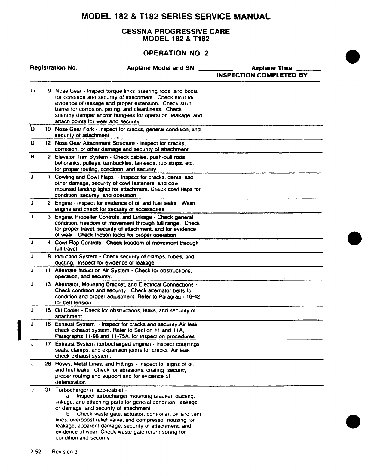
MODEL
182
&
T182
SERIES
SERVICE
MANUAL
CESSNA
PROGRESSIVE
CARE
MODEL
182
&
T182
OPERATION
NO.
2
Registration
No.
Airplane
Model
and
SN
Airplane
Time
INSPECTION COMPLETED
BY
D
9
Nose
Gear
-
Inspect
torque
links.
steering
rods,
and
boots
for
condition
and
security
of
attachment.
Check
strut
for
evidence
of
leakage and
proper extension.
Check
strut
barrel
for
corrosion,
pitting,
and
cleanliness
Check
shimmy damper
and.or
bungees
for
operation.
leakage,
and
attach
points
for
wear
and
security
D
10
Nose
Gear
Fork
-
Inspect
for
cracks.
general
condition,
and
security
of
attachment.
D
12
Nose
Gear
Attachment
Structure
-
Inspect
for
cracks.
corrosion,
or
other
damage
and
security
of
attachment.
H
2
Elevator
Trim
System
-
Check
cables.
push-pull
rods.
bellcranks. pulleys,
turnbuckles.
fairleads.
rub
strips,
etc.
for
proper routing,
condition,
and
security.
J
I
Cowling
and
Cowl
Flaps
-
Inspect
for
cracks,
dents.
and
other
damage,
security
of cowl fasteners
and
cowl
mounted
landing
lights
for
attachment.
Check
cowl
flaps
for
condition, security,
and
operation.
J
2
Engine
-
Inspect
for
evidence
of
oil
and
fuel leaks.
Wash
engine
and
check
for
security
of
accessories.
J
3
Engine,
Propeller Controls.
and
Linkage
-
Check
general
condition,
freedom of
movement
through
full range
Check
for
proper travel.
security
of
attachment,
and
for
evidence
of
wear.
Check
friction
locks
for
proper
operation.
J
4
Cowl
Flap Controls
-
Check
freedom
of
movement
through
full
travel.
J
8
Induction System
-
Check
security
of
clamps, tubes,
and
ducting.
Inspect
for
evidence
of
leakage.
J
Alternate
Induction
Air
System
-
Check for
obstructions.
operation.
and
security.
J
13
Alternator. Mounting
Bracket,
and
Electrical
Connections
-
Check
condition
and
security.
Check alternator
belts
for
condition
and
proper
adjustment
Refer
to
Paragraph
16-42
for
belt
tension.
J
15
Oil
Cooler
-
Check
for
obstructions,
leaks. and
security
of
attachment
J
16
Exhaust
System
-
Inspect
for
cracks
and
security.Air
leak
check
exhaust
system.
Refer to
Section
11
and
11A,
Paragraphs
11-98 and
11-75A.
for
inspection procedures
J
17
Exhaust
System
(turbocharged
engine)
-
Inspect
couplings.
seals,
clamps,
and
expansion joints
for
cracks
Air
leak
check
exhaust
system.
J
28
Hoses, Metal Lines,
and
Fittings
-
Inspect
for
signs of
oil
and fuel leaks
Check for
abrasions.
chafing
secuity.
proper
routing
and
support
and
for
evidence
of
deterioration
J
31
Turbocharger
(if
applicable)
-
a
Inspect
turbocharger
mounting
linkage,
and
attaching parts
for
general
condition.
leakage
or
damage
and
security
of
attachment
b
Check
waste
gate. actuator.
controller,
oil
and
vent
lines, overboost
relief
valve.
and
compressor
housing
for
leakage,
apparent damage,
security
of
attachment.
and
evidence
of
wear
Check
waste
gate return
spring
for
condition and
security
2-52
Revision
3
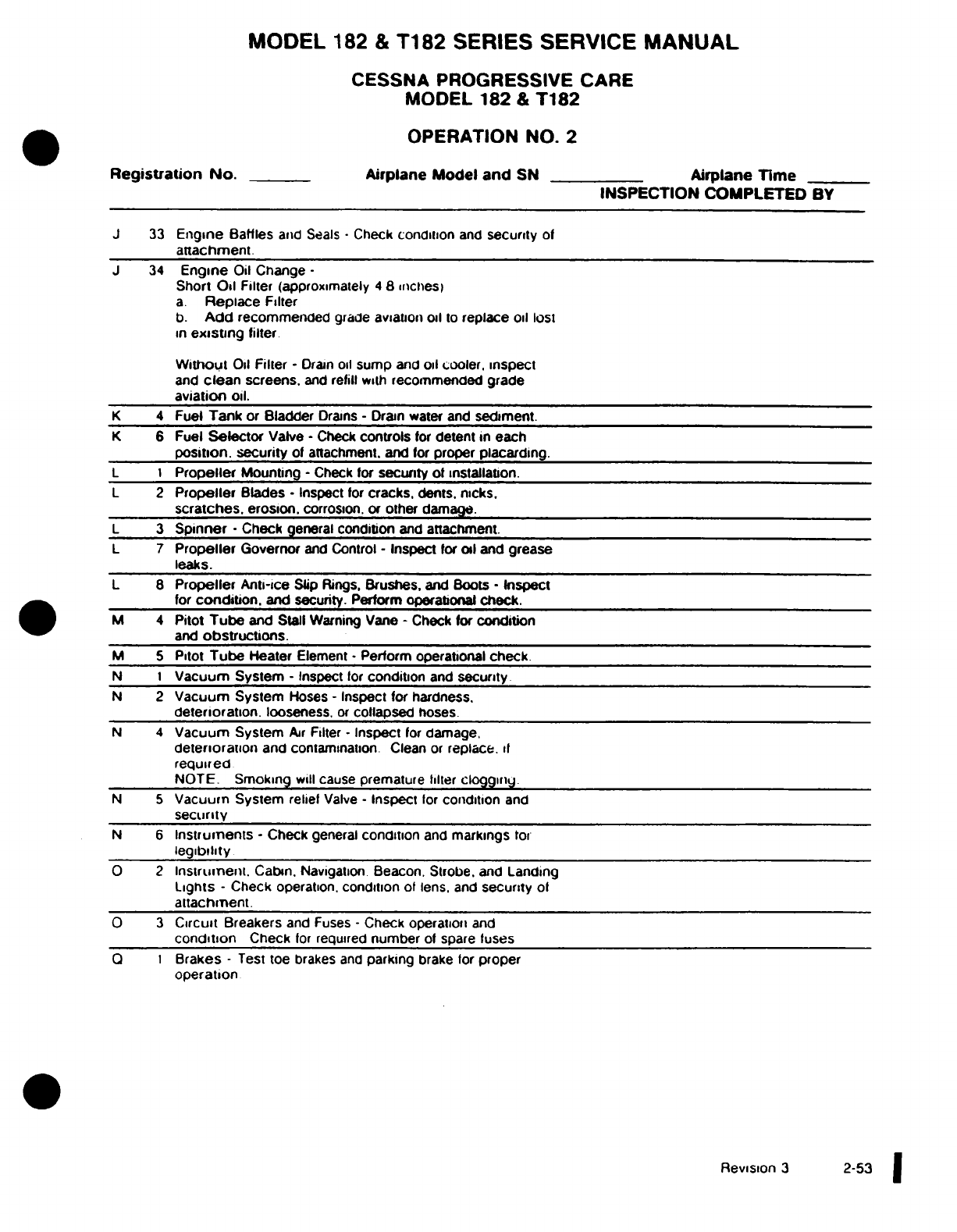
MODEL
182
&
T182
SERIES
SERVICE
MANUAL
CESSNA
PROGRESSIVE
CARE
MODEL 182
&
T182
OPERATION NO.
2
Registration
No.
Airplane Model and SN
Airplane
Time
INSPECTION COMPLETED
BY
J
33
Engine
Baffles
and
Seals
-
Check
condition
and
security
of
attachment.
J
34
Engine
Oil
Change
-
Short
Oil
Filter
(approximately
4 8
inches)
a.
Replace
Filter
b.
Add
recommended
grade
aviation
oil
to
replace
oil
lost
in
existing
filter
Without
Oil
Filter
-
Drain
oil
sump
and
oil
cooler,
inspect
and
clean screens.
and
refill
with
recommended grade
aviation
oil.
K
4
Fuel
Tank
or
Bladder
Drains
-
Drain
water
and
sediment.
K
6
Fuel
Selector
Valve
-
Check
controls
for
detent
in
each
position.
security
of
attachment.
and
for
proper
placarding.
L
1
Propeller
Mounting
-
Check
for
security
of
installation.
L
2
Propeller
Blades -
Inspect
for
cracks, dents.
nicks.
scratches,
erosion.
corrosion.
or
other
damage.
L
3
Spinner
-
Check
general
condition
and
attachment.
L 7
Propeller
Governor
and
Control
-
Inspect
for
oil
and
grease
leaks.
L
8
Propeller
Anti-ice
Slip
Rings.
Brushes,
and
Boots
-
Inspect
for
condition,
and
security.
Perform
operational
check.
M
4
Pitot
Tube
and
Stall
Warning
Vane
-
Check
for
condition
and
obstructions.
M
5
Pitot
Tube
Heater
Element
-
Perform operational
check.
N
1
Vacuum
System
-
Inspect
for
condition
and
security
N
2
Vacuum
System
Hoses
-
Inspect
for
hardness.
deterioration.
looseness.
or
collapsed
hoses.
N
4
Vacuum
System
Air
Filter
-
Inspect
for
damage.
deterioration and
contamination
Clean
or
replace.
If
required
NOTE.
Smoking
will
cause
premature
filter
clogginy.
N
5
Vacuum
System
relief
Valve
-
Inspect
for
condition
and
security
N
6
Instruments
-
Check
general condition
and
markings
for
legibility
O
2
Instrument.
Cabin.
Navigation
Beacon.
Strobe,
and
Landing
Lights
-
Check
operation.
condition
of
lens,
and
security
of
attachment.
O
3
Circuit
Breakers
and
Fuses
-
Check
operation and
condition
Check
for
required
number
of
spare
fuses
Q
1
Brakes
-
Test
toe
brakes
and
parking
brake
for
proper
operation
Revision
3
2-53
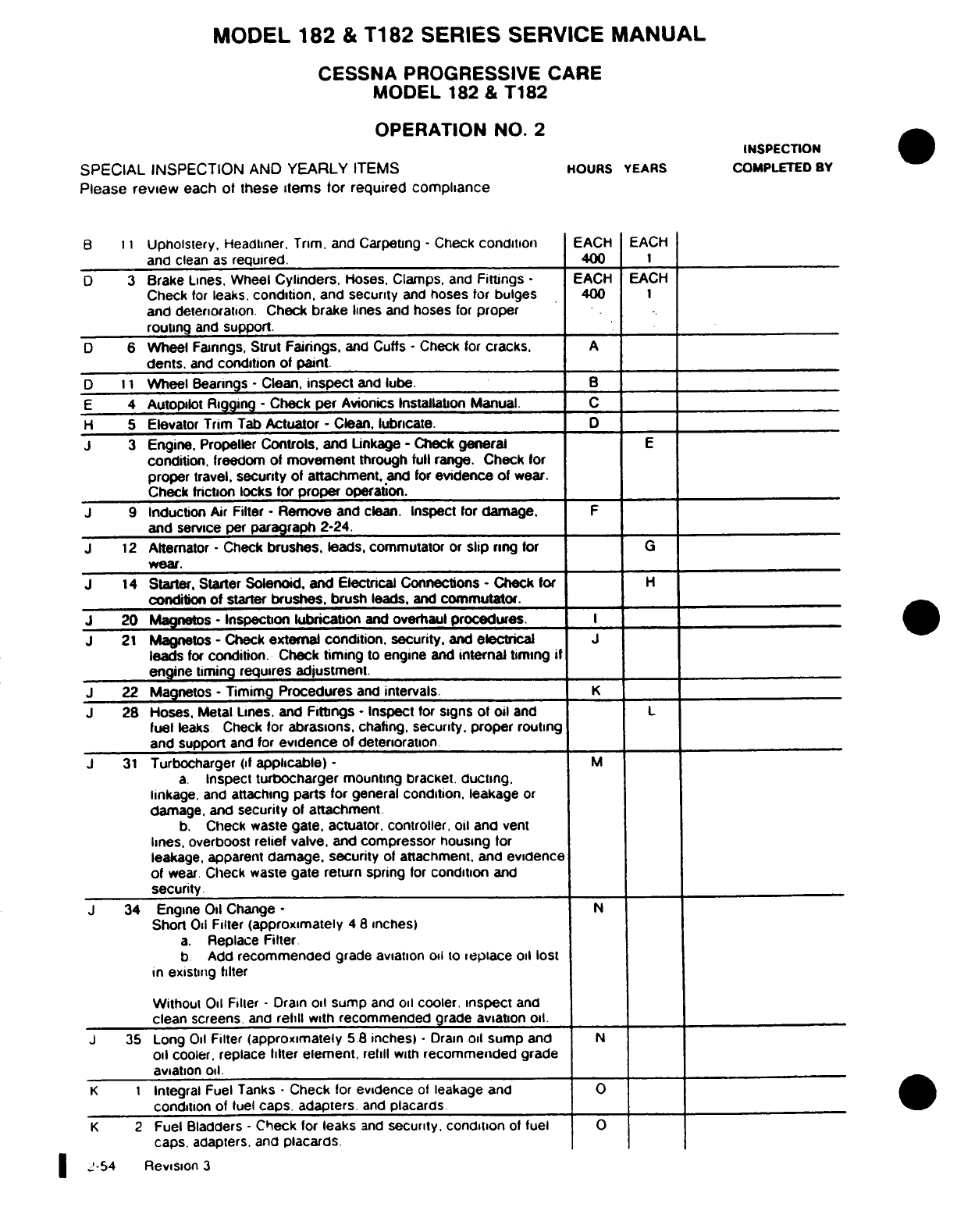
MODEL
182
&
T182
SERIES
SERVICE
MANUAL
CESSNA
PROGRESSIVE
CARE
MODEL
182
&
T182
OPERATION
NO.
2
INSPECTION
SPECIAL
INSPECTION
AND
YEARLY
ITEMS
HOURS
YEARS
COMPLETED
BY
Please
review
each of
these
items
for
required
compliance
B
11
Upholstery,
Headliner.
Trim,
and
Carpeting
-
Check
condition
EACH
EACH
and
clean
as
required.
400
1
D
3
Brake
Lines,
Wheel
Cylinders.
Hoses.
Clamps, and
Fittings
EACH
EACH
Check
for
leaks.
condition,
and security
and
hoses
for
bulges
400
1
and
deterioration.
Check brake
lines
and
hoses
for
proper
routing
and
support.
D
6
Wheel
Fairings,
Strut
Fairings,
and Cuffs
-
Check for
cracks.
A
dents,
and
condition of
paint.
D
11
Wheel
Bearings
-
Clean,
inspect
and
lube.
B
E
4
Autopilot Rigging
-
Check per
Avionics
Installation
Manual.
C
H
5
Elevator Trim
Tab
Actuator
-
Clean.
lubricate.
D
J
3
Engine. Propeller
Controls, and
Linkage
-
Check
general
E
condition,
freedom
of movement
through
full
range.
Check
for
proper
travel,
security
of
attachment,
and
for
evidence
of
wear.
Check
friction
locks for
proper
operation.
J
9
Induction
Air
Filter
-
Remove
and clean.
Inspect
for
damage.
F
and
service
per
paragraph 2-24.
J
12
Alternator
-
Check
brushes,
leads, commutator
or
slip
ring
for
G
wear.
J
14
Starter, Starter
Solenoid, and
Electrical
Connections
-
Check
for
H
condition
of
starter
brushes,
brush
leads,
and
commutator.
J
20
Magnetos
-
Inspection
lubrication
and
overhaul
procedures.
J
21
Magnetos
-
Check
external
condition,
security,
and
electrical
J
leads
for
condition.
Check
timing
to
engine
and
internal
timing
if
engine
timing
requires
adjustment.
J
22
Magnetos
-
Timimg
Procedures
and
intervals.
K
J
28
Hoses,
Metal
Lines.
and
Fittings
-
Inspect
for
signs
of
oil
and
L
fuel
leaks Check
for abrasions,
chafing,
security.
proper
routing
and
support
and
for
evidence
of
deterioration.
J
31
Turbocharger
(if
applicable)
-M
a.
Inspect
turbocharger
mounting bracket.
ducting.
linkage,
and
attaching parts
for
general
condition,
leakage
or
damage,
and
security
of
attachment
b.
Check waste
gate,
actuator,
controller,
oil
and
vent
lines,
overboost
relief
valve,
and
compressor housing
for
leakage,
apparent
damage,
security
of
attachment, and
evidence
of
wear
Check
waste
gate
return spring
for
condition
and
security
J
34
Engine Oil
Change
- N
Short
Oil
Filter
(approximately
4
8
inches)
a.
Replace
Filter
b
Add
recommended
grade
aviation
oil
to
replace
oil
lost
in
existing filter
Without
Oil
Filter
-
Drain
oil
sump
and
oil
cooler.
inspect
and
clean
screens.
and
refill
with recommended
grade aviation
oil.
J
35
Long
Oil
Filter
(approximately
5.8
inches)
-
Drain
oil
sump and
N
oil
cooler,
replace
filter
element,
refill
with
recommended grade
aviation
oil.
K
1
Integral
Fuel
Tanks
-
Check
for
evidence
of
leakage and
O
condition
of
fuel
caps.
adapters.
and
placards
K
2
Fuel
Bladders
-
Check
for
leaks
and
security, condition
of
fuel
O
caps.
adapters,
and
placards.
2-54
Revision
3
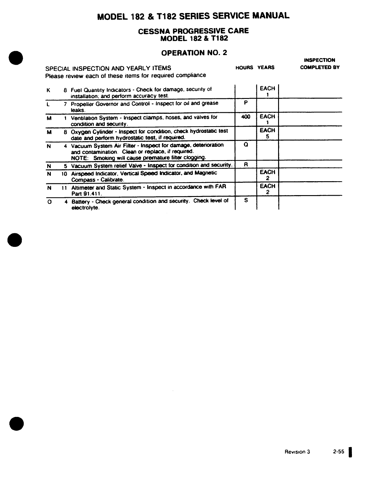
MODEL
182
&
T182
SERIES SERVICE
MANUAL
CESSNA
PROGRESSIVE
CARE
MODEL
182
&
T182
OPERATION
NO.
2
INSPECTION
SPECIAL
INSPECTION
AND
YEARLY
ITEMS
HOURS
YEARS COMPLETED
BY
Please
review
each
of
these
items
for
required
compliance
K
8
Fuel
Quantity
Indicators
-
Check
for
damage, security
of
EACH
installation,
and
perform
accuracy
test.
1
L
7
Propeller
Governor
and
Control
- Inspect
for
oil
and
grease
P
leaks.
M
1
Ventilation
System
-
Inspect
clamps,
hoses,
and
valves
for
400
EACH
condition
and
security.
1
M
8
Oxygen
Cylinder
-
Inspect
for
condition,
check
hydrostatic
test
EACH
date
and
perform
hydrostatic
test.
if
required.
5
N
4
Vacuum System
Air
Filter
-
Inspect
for
damage,
deterioration
Q
and
contamination.
Clean
or
replace,
if
required.
NOTE: Smoking
will
cause
premature
filter
clogging.
N
5
Vacuum
System
relief
Valve
-
Inspect
for
condition
and
security.
R
N
10
Airspeed
Indicator.
Vertical
Speed
Indicator.
and
Magnetic
EACH
Compass
-
Calibrate.
2
N
11
Altimeter
and
Static System
-
Inspect
in
accordance
with FAR
EACH
Part
91.411.
2
O
4
Battery
-
Check
general
condition
and security.
Check
level
of
S
electrolyte.
Revision
3
2-55
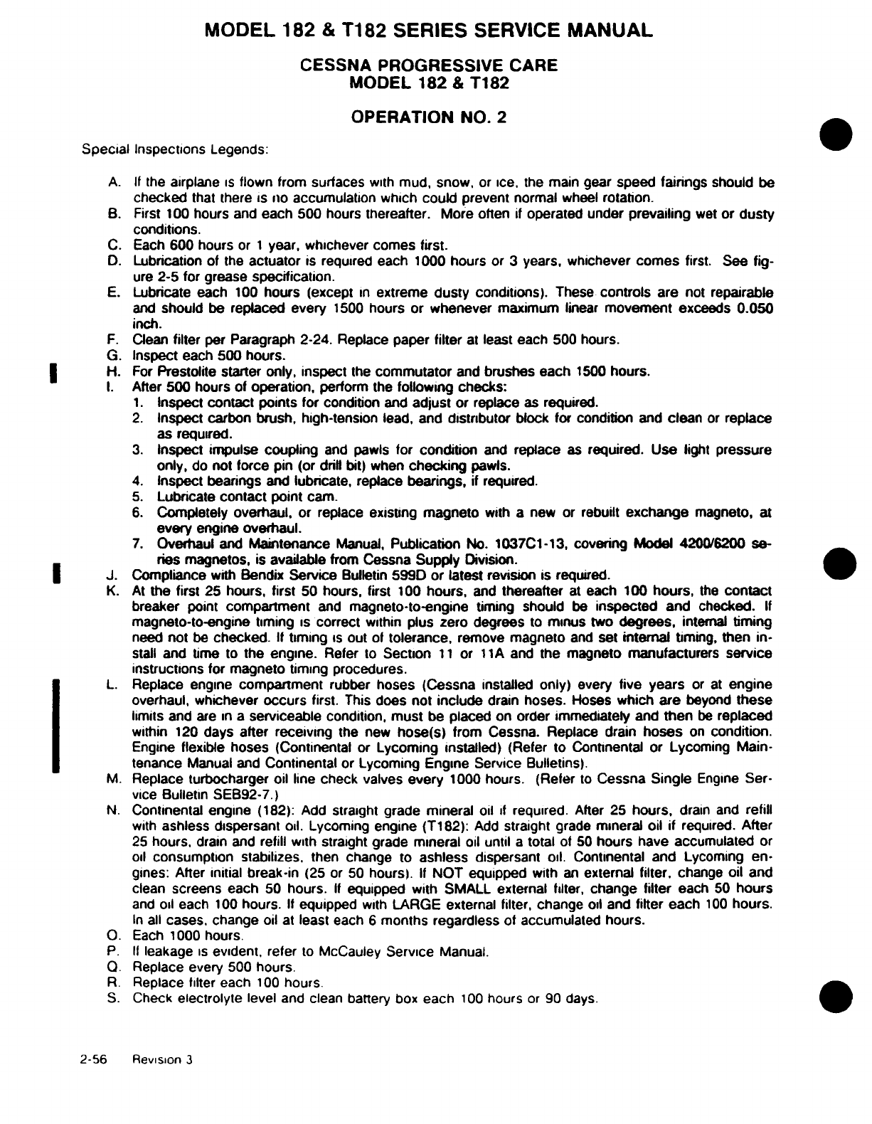
MODEL
182
&
T182
SERIES
SERVICE
MANUAL
CESSNA
PROGRESSIVE CARE
MODEL
182
&
T182
OPERATION
NO.
2
Special
Inspections Legends:
A.
If
the
airplane
is
flown
from
surfaces
with
mud,
snow,
or
ice.
the main
gear
speed
fairings
should
be
checked
that
there
is
no
accumulation which
could
prevent
normal
wheel
rotation.
B.
First
100
hours
and
each
500
hours
thereafter.
More
often
if
operated under
prevailing
wet
or
dusty
conditions.
C.
Each
600
hours
or
1
year,
whichever
comes
first.
D.
Lubrication of
the
actuator
is
required
each
1000
hours
or
3
years,
whichever
comes
first.
See
fig-
ure
2-5
for
grease
specification.
E.
Lubricate each
100
hours
(except
in
extreme
dusty
conditions).
These
controls
are
not
repairable
and
should
be
replaced
every
1500
hours
or whenever
maximum
linear
movement
exceeds
0.050
inch.
F.
Clean
filter
per Paragraph
2-24.
Replace
paper
filter
at
least each
500
hours.
G.
Inspect
each
500 hours.
H.
For
Prestolite starter only,
inspect
the
commutator
and
brushes
each
1500
hours.
I.
After
500
hours
of
operation,
perform
the
following
checks:
1.
Inspect
contact points
for
condition
and
adjust
or
replace
as
required.
2.
Inspect carbon
brush,
high-tension
lead,
and
distributor
block
for
condition
and
clean
or
replace
as required.
3.
Inspect
impulse
coupling
and pawls
for
condition
and
replace
as
required. Use
light
pressure
only,
do
not
force
pin
(or
drill bit)
when
checking
pawls.
4.
Inspect bearings
and
lubricate, replace
bearings,
if
required.
5.
Lubricate
contact
point
cam.
6.
Completely
overhaul,
or replace
existing
magneto
with
a
new or
rebuilt
exchange
magneto,
at
every
engine
overhaul.
7.
Overhaul
and
Maintenance
Manual,
Publication
No.
1037C1-13,
covering Model 4200/6200
se-
ries
magnetos,
is
available
from Cessna
Supply
Division.
J.
Compliance
with Bendix
Service
Bulletin
599D
or
latest
revision
is
required.
K.
At
the
first
25
hours,
first
50
hours,
first
100
hours,
and
thereafter
at
each
100
hours,
the
contact
breaker point
compartment
and
magneto-to-engine
timing
should
be
inspected
and checked.
If
magneto-to-engine timing
is
correct
within
plus
zero
degrees
to
minus
two
degrees,
internal
timing
need
not
be
checked.
If
timing
is
out
of
tolerance,
remove
magneto
and
set
internal
timing,
then
in-
stall
and
time
to
the
engine.
Refer
to
Section
11
or
11A
and
the
magneto
manufacturers
service
instructions
for
magneto
timing
procedures.
L.
Replace
engine
compartment
rubber
hoses (Cessna
installed
only)
every
five years
or
at
engine
overhaul,
whichever
occurs
first.
This
does
not
include
drain
hoses.
Hoses
which
are
beyond
these
limits
and
are
in a
serviceable
condition,
must
be
placed
on
order immediately and
then
be
replaced
within
120
days
after
receiving
the
new
hose(s)
from
Cessna.
Replace
drain
hoses
on
condition.
Engine
flexible
hoses
(Continental
or
Lycoming
installed) (Refer
to
Continental
or
Lycoming Main-
tenance
Manual
and
Continental
or
Lycoming Engine
Service
Bulletins).
M.
Replace turbocharger oil
line
check
valves
every
1000
hours.
(Refer
to
Cessna
Single
Engine
Ser-
vice
Bulletin
SEB92-7.)
N.
Continental engine
(182): Add
straight
grade
mineral
oil
if
required.
After
25
hours,
drain and
refill
with
ashless
dispersant
oil.
Lycoming
engine
(T182):
Add
straight
grade
mineral oil if
required.
After
25
hours,
drain
and
refill with
straight
grade
mineral
oil
until
a
total
of
50
hours
have accumulated
or
oil
consumption
stabilizes,
then
change
to
ashless
dispersant oil.
Continental
and
Lycoming
en-
gines: After initial
break-in
(25
or
50
hours).
If
NOT
equipped
with
an
external
filter,
change
oil
and
clean
screens
each
50
hours.
If
equipped with
SMALL
external
filter,
change
filter
each
50
hours
and
oil each
100
hours.
It
equipped
with
LARGE
external
filter, change
oil
and
filter
each
100
hours.
In
all
cases,
change
oil
at
least
each
6
months
regardless
of accumulated
hours.
O.
Each
1000
hours.
P.
If
leakage
is
evident,
refer
to
McCauley
Service
Manual.
Q.
Replace every
500
hours.
R.
Replace filter
each
100
hours.
S.
Check
electrolyte
level
and clean
battery
box
each
100
hours
or 90
days.
2-56
Revision
3
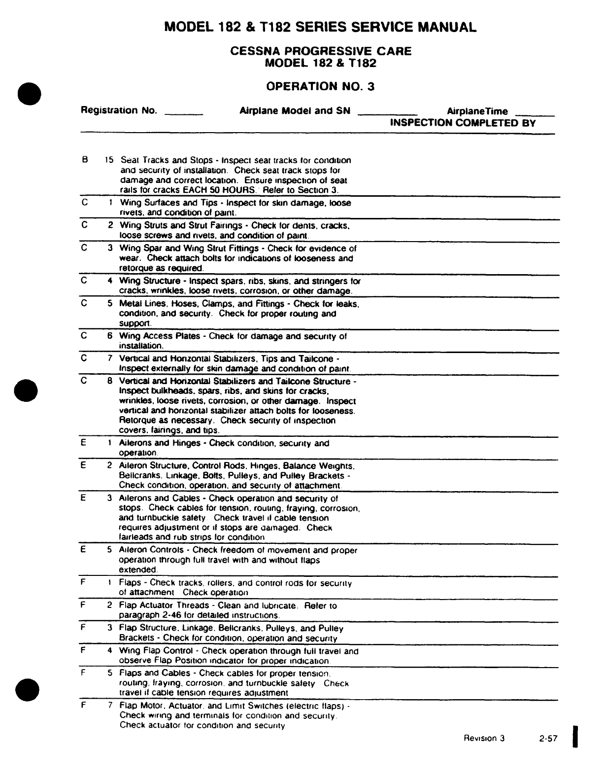
MODEL
182
&
T182
SERIES SERVICE
MANUAL
CESSNA
PROGRESSIVE
CARE
MODEL
182
&
T182
OPERATION
NO.
3
Registration
No.
Airplane
Model
and SN
Airplane
Time
INSPECTION
COMPLETED
BY
B
15
Seat Tracks
and Stops
-
Inspect
seat
tracks
for
condition
and
security of
installation.
Check
seat
track
stops
for
damage
and
correct
location.
Ensure
inspection
of seat
rails
for
cracks
EACH
50
HOURS.
Refer
to
Section
3.
C 1
Wing
Surfaces
and
Tips
-
Inspect
for
skin
damage,
loose
rivets,
and
condition
of
paint.
C 2
Wing
Struts
and
Strut
Fairings
-
Check for
dents, cracks.
loose
screws
and
rivets, and
condition
of
paint.
C 3
Wing
Spar
and
Wing
Strut
Fittings
-
Check
for
evidence
of
wear.
Check
attach bolts
for indications
of looseness
and
retorque
as
required.
C 4
Wing
Structure
-
Inspect
spars.
ribs,
skins,
and
stringers
for
cracks,
wrinkles,
loose rivets,
corrosion,
or
other damage.
C 5
Metal
Lines,
Hoses.
Clamps,
and
Fittings
-
Check
for
leaks.
condition.
and security.
Check
for
proper
routing
and
support.
C
6
Wing
Access
Plates
-
Check for damage
and
security
of
installation.
C
7
Vertical
and
Horizontal
Stabilizers.
Tips
and
Tailcone
-
Inspect
externally
for
skin
damage
and
condition
of
paint
C
8
Vertical
and
Horizontal
Stabilizers
and
Tailcone Structure
-
Inspect
bulkheads.
spars,
ribs.
and
skins
for
cracks.
wrinkles,
loose
rivets,
corrosion,
or
other
damage. Inspect
vertical
and
horizontal stabilizer
attach
bolts
for
looseness.
Retorque
as necessary. Check security
of
inspection
covers,
fairings.
and
tips.
E 1
Ailerons
and
Hinges
-
Check
condition.
security
and
operation
E 2
Aileron
Structure.
Control
Rods.
Hinges.
Balance
Weights.
Bellcranks. Linkage.
Bolts.
Pulleys,
and
Pulley Brackets
-
Check
condition,
operation. and
security
of
attachment
E
3
Ailerons
and Cables
-
Check operation
and security
of
stops.
Check
cables
for
tension.
routing,
fraying,
corrosion.
and
turnbuckle
safety
Check travel
if
cable
tension
requires adjustment
or
if
stops
are
damaged.
Check
fairleads
and
rub
strips
for
condition
E 5
Aileron
Controls
-
Check
freedom
of
movement
and
proper
operation
through
full
travel
with
and
without
flaps
extended.
F 1
Flaps
-
Check
tracks. rollers,
and
control
rods
for
security
of
attachment
Check
operation
F 2
Flap
Actuator Threads
-
Clean and
lubricate. Refer
to
paragraph
2-46
for
detailed
instructions.
F 3
Flap
Structure.
Linkage.
Bellcranks.
Pulleys,
and
Pulley
Brackets
-
Check
for
condition.
operation and
security
F 4
Wing
Flap
Control
-
Check
operation
through
full
travel
and
observe
Flap Position
indicator
for
proper
indication
F 5
Flaps
and
Cables
-
Check
cables
for
proper
tension.
routing,
fraying.
corrosion.
and
turnbuckle
safety
Check
travel
if
cable
tension
requires
adjustment
F 7
Flap
Motor.
Actuator.
and
Limit
Switches
(electric
flaps)
-
Check wiring
and
terminals
for
condition
and
security.
Check actuator
for
condition
and security
Revision
3
2-57
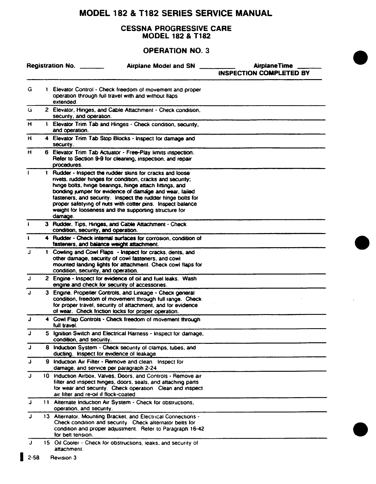
MODEL
182
&
T182
SERIES SERVICE
MANUAL
CESSNA
PROGRESSIVE
CARE
MODEL
182
&
T182
OPERATION
NO.
3
Registration
No.
Airplane
Model
and
SN
AirplaneTime
INSPECTION
COMPLETED
BY
G 1
Elevator
Control
-
Check
freedom
of
movement
and
proper
operation
through
full
travel
with
and
without
flaps
extended.
G
2
Elevator.
Hinges,
and
Cable Attachment
-
Check
condition.
security. and
operation.
H 1
Elevator
Trim
Tab
and
Hinges
-
Check
condition,
security.
and
operation.
H
4
Elevator
Trim
Tab Stop
Blocks
-
Inspect
for damage
and
security.
H
6
Elevator
Trim
Tab
Actuator
-
Free-Play
limits
inspection.
Refer to
Section
9-9
for
cleaning,
inspection,
and
repair
procedures.
Rudder
-
Inspect
the
rudder
skins
for
cracks
and
loose
rivets, rudder
hinges
for
condition. cracks
and
security;
hinge
bolts,
hinge bearings, hinge
attach
fittings,
and
bonding
jumper for
evidence
of
damage
and
wear,
failed
fasteners,
and
security. Inspect
the
rudder
hinge
bolts
for
proper
safetying
of
nuts
with
cotter
pins.
Inspect
balance
weight
for
looseness and
the supporting
structure for
damage.
3
Rudder.
Tips.
Hinges,
and
Cable
Attachment
-
Check
condition,
security,
and
operation.
I
4
Rudder
-
Check
internal
surfaces for
corrosion,
condition
of
fasteners,
and balance
weight
attachment.
J
1
Cowling and
Cowl
Faps
-
Inspect
for
cracks,
dents,
and
other
damage,
security
of
cowl fasteners.
and
cowl
mounted
landing
lights
for
attachment.
Check
cowl
flaps
for
condition,
security,
and
operation.
J
2
Engine
-
Inspect
for
evidence
of
oil
and
fuel
leaks.
Wash
engine
and
check
for
security
of
accessories.
J
3
Engine.
Propeller
Controls.
and
Linkage
-
Check
general
condition, freedom
of
movement
through
full
range.
Check
for proper
travel, security of
attachment,
and
for
evidence
of
wear.
Check
friction
locks
for
proper
operation.
J
4
Cowl
Flap
Controls
-
Check freedom
of
movement through
full
travel.
J
5
Ignition
Switch
and
Electrical
Harness
-
Inspect
for
damage,
condition,
and
security.
J
8
Induction
System
-
Check
security
of
clamps,
tubes,
and
ducting. Inspect
for
evidence
of
leakage
J
9
Induction
Air
Filter
-
Remove
and clean.
Inspect
for
damage,
and
service per
paragraph 2-24
J
10
Induction Airbox.
Valves.
Doors, and
Controls
-
Remove
air
filter
and
inspect
hinges,
doors.
seals.
and attaching
pans
for
wear
and
security.
Check operation
Clean
and
inspect
air
filter and
re-oil
if
flock-coated
J
11
Alternate
Induction
Air
System
-
Check for
obstructions,
operation.
and
security.
J
13
Alternator.
Mounting
Bracket.
and
Electrical
Connections
-
Check
condition
and
security
Check
alternator
belts
for
condition
and proper
adjustment.
Refer
to
Paragraph
16-42
for
belt
tension.
J
15
Oil
Cooler
-
Check
for
obstructions,
leaks.
and
security
of
attachment.
2-58 Revision
3
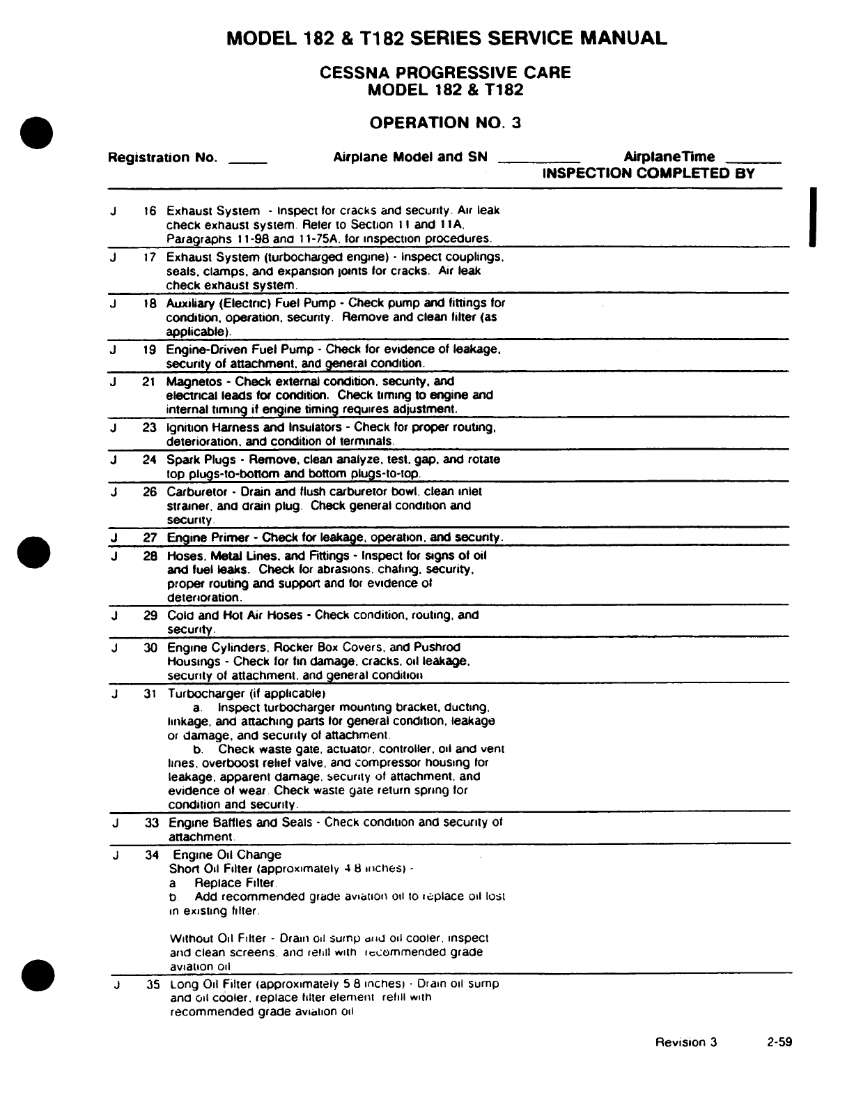
MODEL
182
&
T182
SERIES SERVICE
MANUAL
CESSNA
PROGRESSIVE
CARE
MODEL
182
&
T182
OPERATION
NO.
3
Registration
No.
Airplane
Model
and
SN
AirplaneTime
INSPECTION
COMPLETED
BY
J
16
Exhaust
System
-
Inspect
for
cracks
and
security.
Air
leak
check
exhaust
system.
Refer
to
Section
II
and 11A.
Paragraphs
11-98
and
1-75A.
for
inspection
procedures.
J
17
Exhaust
System
(turbocharged
engine)
-
Inspect
couplings.
seals.
clamps,
and expansion
joints
for
cracks.
Air leak
check
exhaust system.
J
18
Auxiliary
(Electric)
Fuel
Pump
-
Check pump
and
fittings
for
condition.
operation.
security.
Remove
and
clean
filter
(as
applicable).
J
19
Engine-Driven
Fuel
Pump
-
Check
for
evidence
of
leakage.
security
of
attachment,
and
general
condition.
J
21
Magnetos
-
Check
external
condition. security,
and
electrical
leads
for
condition.
Check
timing
to
engine
and
internal
timing if
engine
timing
requires
adjustment.
J
23
Ignition
Harness
and
Insulators
-
Check
for
proper routing.
deterioration,
and
condition
of
terminals.
J 24
Spark
Plugs
-
Remove,
clean
analyze,
test.
gap.
and rotate
top
plugs-to-bottom
and
bottom
plugs-to-top.
J
26
Carburetor
-
Drain
and
flush
carburetor
bowl.
clean
inlet
strainer.
and
drain
plug.
Check
general
condition
and
security
J
27
Engine Primer
-
Check
for
leakage,
operation. and
security.
J
28
Hoses. Metal
Lines.
and
Fittings
-
Inspect
for
signs
of
oil
and
fuel leaks.
Check
for
abrasions.
chafing.
security.
proper routing
and support
and
for
evidence of
deterioration.
J
29
Cold
and
Hot
Air
Hoses
-
Check
condition.
routing,
and
security.
J
30
Engine
Cylinders.
Rocker
Box
Covers,
and
Pushrod
Housings
-
Check
for
fin
damage.
cracks,
oil
leakage.
security
of
attachment.
and
general
condition
J
31
Turbocharger
(if
applicable)
a.
Inspect
turbocharger mounting
bracket.
ducting.
linkage,
and
attaching
parts
for
general
condition,
leakage
or
damage,
and
security
of
attachment
b.
Check
waste
gate,
actuator,
controller,
oil
and
vent
lines.
overboost
relief
valve,
and
compressor housing
for
leakage.
apparent
damage,
security of
attachment.
and
evidence
of wear
Check
waste
gate
return
spring
for
condition
and
security.
J
33
Engine
Baffles
and
Seals
-
Check
condition
and
security
of
attachment
J
34
Engine
Oil
Change
Short
Oil
Filter
(approximately
4
8
inches)
-
a
Replace
Filter
b
Add
recommended
grade
aviation
oil
to
replace
oil
lost
in
existing
filter.
Without
Oil
Filter
-
Drain oil
sump
and
oil
cooler.
Inspect
and
clean
screens.
and
refill
with
recommended
grade
aviation
oil
J
35
Long
Oil
Filter
(approximately
5
8
inches)
-
Drain
oil
sump
and
oil cooler.
replace
filter
element
refill
with
recommended
grade
aviation
oil
Revision
3
2-59
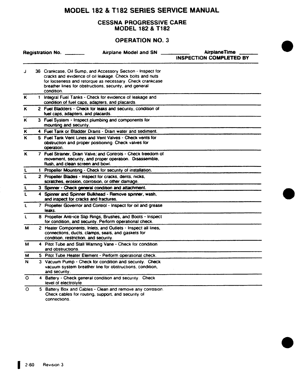
MODEL
182
&
T182
SERIES
SERVICE
MANUAL
CESSNA
PROGRESSIVE
CARE
MODEL
182
&
T182
OPERATION
NO.
3
Registration
No.
Airplane Model and
SN
Airplane
Time
INSPECTION
COMPLETED
BY
J
36
Crankcase.
Oil
Sump.
and
Accessory
Section
-
Inspect
for
cracks
and
evidence
of
oil
leakage.
Check
bolts
and
nuts
for
looseness
and retorque
as
necessary.
Check
crankcase
breather
lines
for obstructions,
security,
and
general
condition.
K
1 Integral
Fuel
Tanks
-
Check
for
evidence
of
leakage
and
condition
of
fuel
caps,
adapters,
and
placards.
K
2
Fuel
Bladders
-
Check
for leaks
and
security, condition
of
fuel
caps,
adapters,
and
placards.
K
3
Fuel
System
-
Inspect
plumbing
and
components
for
mounting
and
security.
K
4
Fuel
Tank
or
Bladder
Drains
-
Drain
water and
sediment.
K
5
Fuel
Tank
Vent
Lines and
Vent
Valves
-
Check
vents
for
obstruction
and
proper
positioning.
Check
valves for
operation.
K
7
Fuel
Strainer.
Drain Valve, and
Controls
-
Check freedom
of
movement,
security,
and
proper
operation.
Disassemble,
flush,
and
clean
screen
and
bowl.
L
1
Propeller
Mounting
-
Check for
security
of
installation.
L 2
Propeller
Blades
-
Inspect
for
cracks,
dents.
nicks.
scratches,
erosion,
corrosion,
or
other damage.
L 3
Spinner
-
Check
general condition
and
attachment.
L 4
Spinner
and
Spinner
Bulkhead
-
Remove spinner,
wash,
and
inspect
for
cracks
and
fractures.
L
7
Propeller
Governor
and
Control
-
Inspect
for
oil
and
grease
leaks.
L
8
Propeller
Anti-ice
Slip
Rings,
Brushes, and
Boots
-
Inspect
for
condition,
and
security.
Perform
operational check.
M
2
Heater
Components,
Inlets,
and
Outlets
-
Inspect all lines,
connections,
ducts,
clamps,
seals, and
gaskets
for
condition.
restriction,
and
security.
M
4
Pitot
Tube
and
Stall
Warning
Vane
-
Check
for
condition
and
obstructions.
M
5
Pitot Tube
Heater Element
-
Perform
operational check.
N
3
Vacuum
Pump
-
Check
for
condition
and
security.
Check
vacuum
system
breather
line
for
obstructions,
condition.
and
security.
O
4
Battery
- Check
general
condition
and
security.
Check
level
of
electrolyte
O
5
Battery
Box
and Cables
-
Clean
and
remove
any
corrosion
Check
cables
for
routing.
support.
and
security
of
connections.
2-60
Revision
3
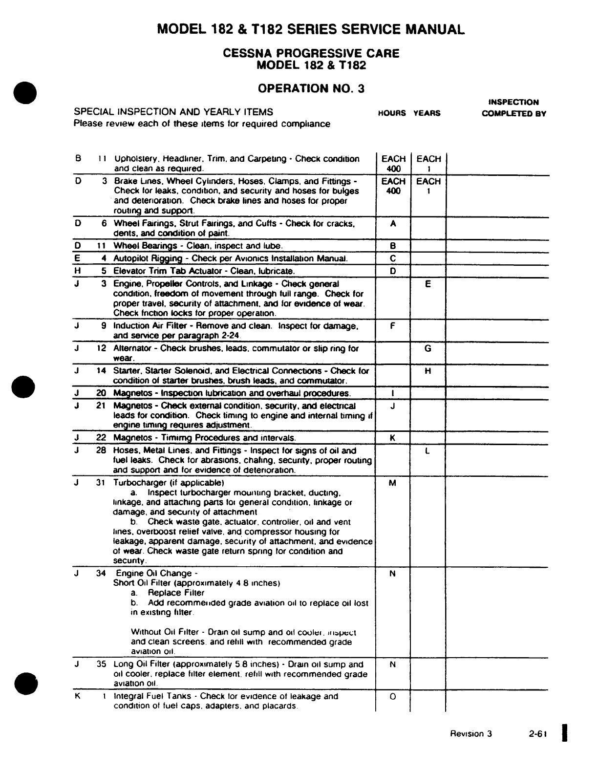
MODEL
182
&
T182
SERIES
SERVICE
MANUAL
CESSNA
PROGRESSIVE
CARE
MODEL
182
&
T182
OPERATION
NO.
3
INSPECTION
SPECIAL INSPECTION
AND
YEARLY ITEMS
HOURS
YEARS
COMPLETED
BY
Please
review
each of
these
items
for
required
compliance
B
II
Upholstery.
Headliner.
Trim,
and Carpeting
-
Check
condition
EACH
EACH
and
clean
as
required.
400
1
D
3
Brake
Lines.
Wheel
Cylinders.
Hoses,
Clamps,
and
Fittings
-
EACH
EACH
Check
for
leaks, condition.
and
security
and
hoses
for
bulges
400
1
and
deterioration.
Check
brake
lines
and hoses
for
proper
routing
and
support.
D
6
Wheel
Fairings.
Strut
Fairings.
and
Cuffs
-
Check
for
cracks.
A
dents,
and
condition
of paint.
D
11
Wheel
Bearings
-
Clean,
inspect
and
lube.
B
E
4
Autopilot
Rigging
-
Check
per
Avionics
Installation
Manual.
C
H
5
Elevator
Trim
Tab
Actuator
-
Clean.
lubricate.
D
J
3
Engine.
Propeller
Controls,
and
Linkage
-
Check
general
E
condition,
freedom
of
movement
through
full
range. Check for
proper
travel,
security
of
attachment,
and
for
evidence
of wear.
Check
friction
locks
for
proper
operation.
J
9
Induction
Air
Filter
-
Remove
and
clean.
Inspect
for
damage.
F
and
service
per
paragraph
2-24
J
12
Alternator
-
Check brushes,
leads.
commutator
or
slip
ring
for
G
wear.
J
14
Starter.
Starter
Solenoid.
and
Electrical
Connections
-
Check
for
H
condition
of
starter
brushes,
brush
leads, and
commutator.
J
20
Magnetos
-
Inspection
lubrication
and
overhaul
procedures.
I
J
21
Magnetos
-
Check external
condition,
security,
and
electrical
J
leads
for
condition.
Check
timing
to
engine
and
internal
timing
if
engine timing
requires
adjustment.
J
22
Magnetos
-
Timimg
Procedures and
intervals.
K
J
28
Hoses.
Metal
Lines,
and
Fittings
-
Inspect
for
signs
of
oil
and
L
fuel
leaks.
Check
for
abrasions,
chafing.
security, proper routing
and
support
and
for
evidence
of
deterioration.
J
31
Turbocharger
(if applicable)
M
a.
Inspect turbocharger mounting bracket.
ductng.
linkage,
and
attaching
parts
for
general
condition,
linkage
or
damage, and
security
of attachment
b.
Check
waste
gate,
actuator.
controller,
oil
and
vent
lines,
overboost
relief
valve,
and
compressor
housing
for
leakage,
apparent
damage.
security
of
attachment,
and
evidence
of
wear.
Check
waste
gate
return
spring
for
condition
and
security.
J
34
Engine
Oil
Change
-N
Short
Oil
Filter (approximately
4
8
inches)
a.
Replace Filter
b.
Add
recommended
grade
aviation oil
to
replace
oil
lost
in
existing
filter.
Without
Oil
Filter
-
Drain
oil
sump
and
oil
cooler.
and
clean
screens.
and
refill
with
recommended
grade
aviation oil.
J 35
Long Oil
Filter
(approximately
58
inches)
-
Drain
oil
sump
and
N
oil
cooler.
replace
filter
element.
refill
with
recommended grade
aviation
oil.
K 1
Integral
Fuel
Tanks
-
Check
for
evidence
of
leakage and
O
condition
of
fuel
caps.
adapters.
and
placards
Revision
3
2-61
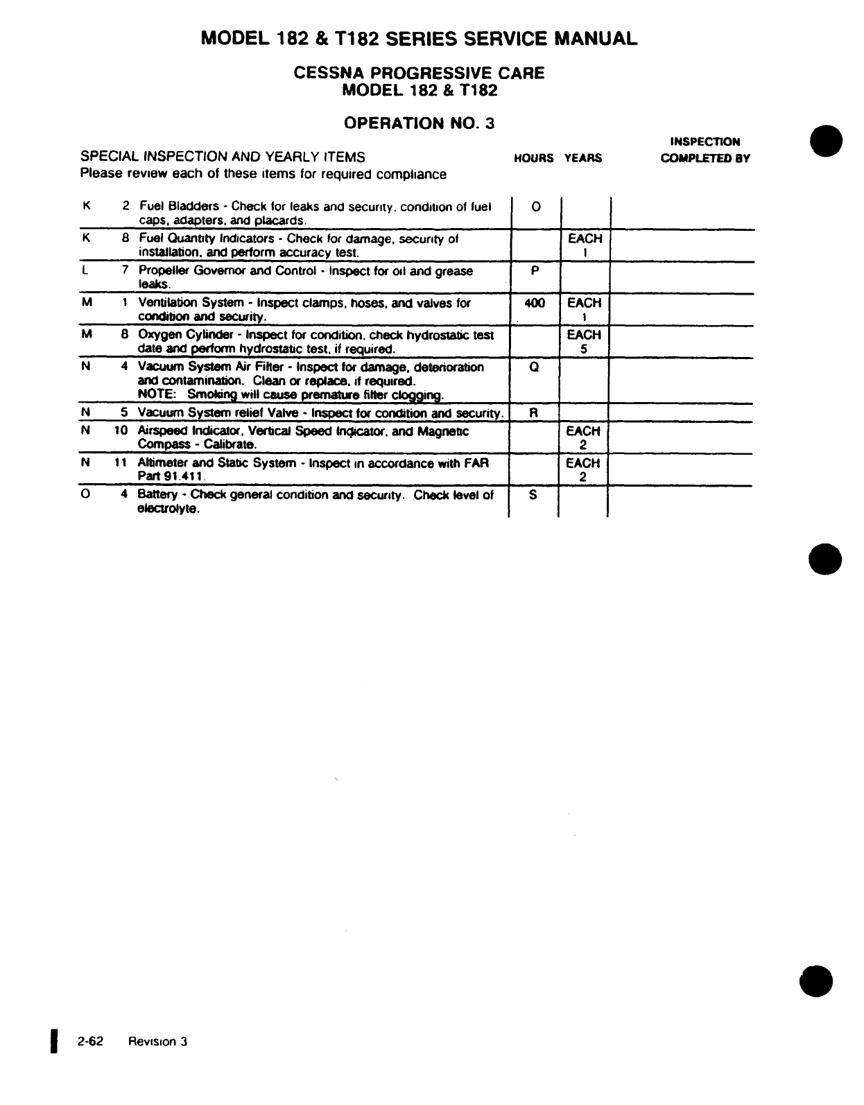
MODEL 182
&
T182 SERIES
SERVICE
MANUAL
CESSNA
PROGRESSIVE
CARE
MODEL
182
&
T182
OPERATION
NO.
3
INSPECTION
SPECIAL
INSPECTION
AND
YEARLY
ITEMS
HOURS YEARS
COMPLETED
BY
Please
review each
of these items
for required
compliance
K
2
Fuel
Bladders -
Check
for
leaks and
security, condition
of
fuel
O
caps,
adapters,
and
placards.
K 8
Fuel
Quantity
Indicators
-
Check
for
damage,
security
of
EACH
installation,
and
perform
accuracy
test.
L
7
Propeller
Governor
and
Control
-
Inspect
for
oil
and
grease
P
leaks.
M
1
Ventilation
System
-
Inspect clamps,
hoses,
and
valves
for 400
EACH
condition
and
security.
I
M
8 Oxygen
Cylinder
-
Inspect
for
condition. check hydrostatic
test
EACH
date
and
perform
hydrostatic
test.
if
required.
5
N
4
Vacuum
System
Air
Filter
-
Inspect
for
damage,
deterioration
Q
and
contamination.
Clean or
replace,
if
required.
NOTE:
Smoking
will
cause
premature
filter
clogging.
N
5
Vacuum
System
relief
Valve
-
Inspect
for
condition
and
security.
R
N
10
Airspeed Indicator.
Vertical Speed Indicator,
and
Magnetic
EACH
Compass
-
Calibrate.
2
N
11
Altimeter
and
Static
System
-
Inspect
in
accordance
with
FAR
EACH
Part 91.411.
2
O
4
Battery
-
Check
general
condition
and
security.
Check
level of
S
electrolyte.
2-62
Revision
3
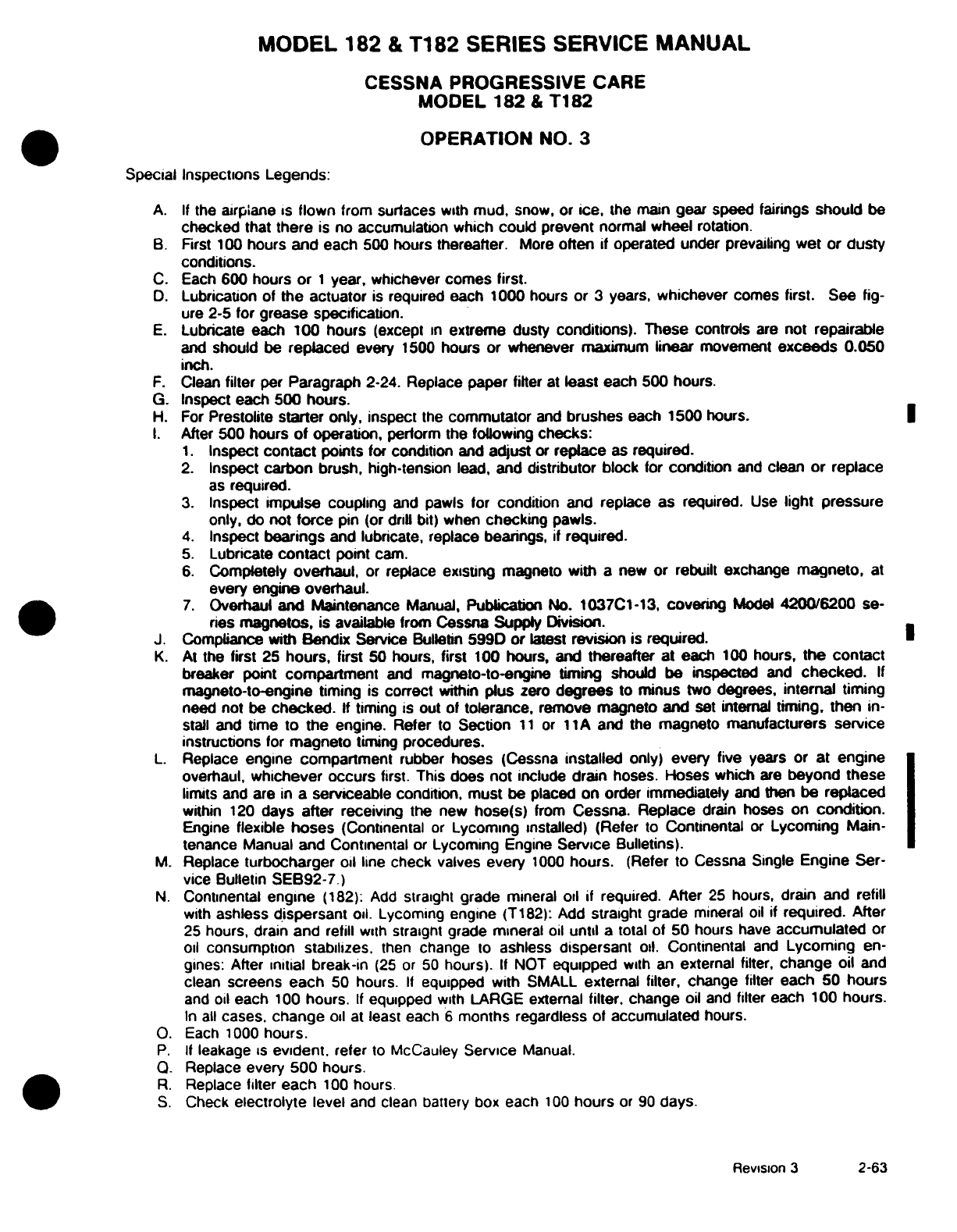
MODEL
182
&
T182
SERIES
SERVICE
MANUAL
CESSNA PROGRESSIVE CARE
MODEL
182
&
T182
OPERATION
NO.
3
Special Inspections
Legends:
A.
If
the
airplane
is
flown
from
surfaces
with
mud,
snow,
or
ice,
the
main
gear speed
fairings
should
be
checked
that
there
is
no accumulation
which
could
prevent
normal
wheel
rotation.
B.
First
100
hours
and each
500
hours
thereafter.
More
often
if
operated
under prevailing
wet
or
dusty
conditions.
C.
Each
600
hours
or 1
year,
whichever
comes
first.
D.
Lubrication
of
the actuator
is
required
each
1000 hours
or
3
years,
whichever
comes
first.
See fig-
ure
2-5
for
grease
specification.
E.
Lubricate each
100
hours
(except
in
extreme
dusty
conditions).
These
controls
are
not repairable
and
should
be
replaced
every
1500
hours
or
whenever maximum
linear
movement
exceeds
0.050
inch.
F.
Clean
filter
per
Paragraph
2-24.
Replace
paper
filter
at
least
each
500
hours.
G.
Inspect each
500
hours.
H.
For
Prestolite
starter
only,
inspect
the
commutator
and
brushes
each
1500
hours.
I.
After
500
hours
of
operation,
perform
the
following
checks:
1.
Inspect
contact
points
for
condition
and
adjust
or
replace
as
required.
2.
Inspect
carbon
brush,
high-tension
lead,
and
distributor block
for
condition
and
clean
or replace
as
required.
3.
Inspect
impulse
coupling
and pawls
for
condition
and
replace as required.
Use
light pressure
only, do
not
force
pin
(or
drill
bit)
when
checking
pawls.
4.
Inspect
bearings
and
lubricate, replace bearings,
if
required.
5.
Lubricate
contact
point
cam.
6.
Completely
overhaul,
or
replace
existing
magneto
with
a new
or
rebuilt
exchange
magneto,
at
every
engine overhaul.
7.
Overhaul
and
Maintenance
Manual,
Publication
No.
1037C1-13,
covering
Model
4200/6200
se-
ries
magnetos,
is
available from
Cessna
Supply Division.
J.
Compliance with
Bendix
Service
Bulletin
599D
or
latest
revision
is
required.
K.
At
the
first
25
hours, first
50
hours,
first
100
hours, and
thereafter
at each
100
hours,
the
contact
breaker
point
compartment
and
magneto-to-engine
timing
should
be
inspected
and
checked.
If
magneto-to-engine
timing
is
correct
within
plus
zero
degrees
to
minus
two
degrees,
internal timing
need
not be
checked.
If
timing is
out
of
tolerance,
remove
magneto
and
set internal
timing, then
in-
stall and
time
to
the
engine.
Refer
to
Section
11
or 11A
and the
magneto
manufacturers
service
instructions
for
magneto
timing
procedures.
L.
Replace
engine compartment
rubber
hoses
(Cessna
installed
only)
every
five
years
or
at
engine
overhaul,
whichever
occurs
first.
This
does not
include
drain
hoses.
Hoses which
are
beyond these
limits
and
are
in
a
serviceable
condition,
must
be placed
on
order immediately
and
then
be
replaced
within
120
days
after
receiving
the
new
hose(s)
from
Cessna.
Replace
drain hoses
on
condition.
Engine
flexible
hoses
(Continental
or
Lycoming
installed) (Refer
to
Continental
or
Lycoming
Main-
tenance
Manual
and
Continental
or
Lycoming
Engine
Service
Bulletins).
M.
Replace
turbocharger
oil line
check
valves
every
1000
hours.
(Refer
to
Cessna Single
Engine
Ser-
vice
Bulletin
SEB92-7.)
N.
Continental
engine
(182): Add
straight
grade
mineral
oil
if
required. After
25
hours,
drain
and
refill
with
ashless
dispersant
oil.
Lycoming
engine
(T182):
Add
straight grade
mineral
oil
if
required.
After
25
hours,
drain
and
refill
with
straight
grade
mineral
oil
until
a total of
50
hours
have
accumulated
or
oil
consumption
stabilizes,
then
change
to
ashless
dispersant
oil.
Continental
and
Lycoming
en-
gines:
After
initial
break-in
(25 or
50
hours).
If
NOT
equipped
with
an
external filter,
change
oil
and
clean
screens
each
50
hours.
If
equipped
with
SMALL
external
filter,
change
filter
each
50
hours
and
oil
each
100
hours.
If
equipped
with
LARGE external
filter,
change
oil
and
filter
each
100
hours.
In
all
cases,
change
oil
at
least
each
6
months
regardless
of
accumulated
hours.
O.
Each 1000
hours.
P.
If
leakage
is
evident.
refer
to
McCauley
Service
Manual.
Q.
Replace
every 500
hours.
R.
Replace
filter
each
100
hours.
S.
Check
electrolyte
level
and clean battery
box
each
100
hours
or
90
days.
Revision
3
2-63
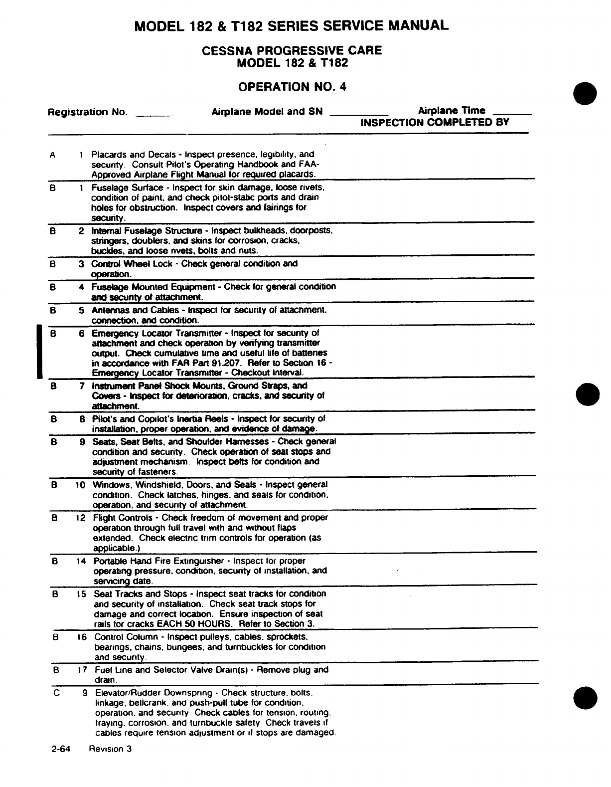
MODEL
182
&
T182
SERIES
SERVICE
MANUAL
CESSNA
PROGRESSIVE
CARE
MODEL
182
&
T182
OPERATION
NO.
4
Registration
No.
Airplane
Model
and
SN
Airplane
Time
INSPECTION
COMPLETED
BY
A 1
Placards
and Decals
-
Inspect presence,
legibility,
and
security.
Consult
Pilot's
Operating
Handbook
and FAA-
Approved
Airplane Flight
Manual
for
required
placards.
B
1
Fuselage
Surface
-
Inspect
for
skin
damage,
loose
rivets.
condition
of
paint.
and
check
pitot-static
ports
and
drain
holes
for
obstruction.
Inspect covers
and
fairings
for
security.
B
2
Internal
Fuselage
Structure
-
Inspect
bulkheads,
doorposts.
stringers,
doublers,
and
skins
for
corrosion, cracks,
buckles,
and loose rivets,
bolts
and
nuts.
B
3
Control
Wheel
Lock
-
Check general
condition
and
operation.
B
4
Fuselage
Mounted Equipment
-
Check
for
general
condition
and
security
of
attachment.
B
5
Antennas
and
Cables
-
Inspect
for
security
of
attachment.
connection,
and
condition.
B
6
Emergency
Locator Transmitter
-
Inspect
for
security
of
attachment
and
check
operation
by
verifying
transmitter
output.
Check
cumulative
time
and useful
life
of
batteries
in
accordance
with
FAR
Part 91.207.
Refer
to
Section
16
-
Emergency Locator
Transmitter
-
Checkout
Interval.
B 7
Instument
Panel
Shock
Mounts,
Ground
Straps,
and
Covers
-
Inspect for
deterioration,
cracks,
and
security
of
attachment.
B
8
Pilot's
and
Copilot's
Inertia
Reels
-
Inspect
for security
of
installation, proper
operation.
and
evidence
of
damage.
B
9
Seats.
Seat
Belts,
and
Shoulder
Harnesses
-
Check
general
condition
and
security.
Check
operation
of
seat
stops
and
adjustment
mechanism Inspect
belts
for
condition
and
security of
fasteners.
B
10
Windows.
Windshield.
Doors,
and Seals
-
Inspect
general
condition.
Check
latches, hinges.
and
seals
for
condition.
operation.
and
security
of
attachment.
B 12
Flight Controls
-
Check freedom
of
movement
and
proper
operation through
full
travel
with
and
without
flaps
extended.
Check
electric
trim
controls
for
operation
(as
applicable.)
B
14
Portable Hand
Fire
Extinguisher
-
Inspect
for
proper
operating
pressure.
condition, security
of
installation,
and
servicing
date.
B 15
Seat
Tracks
and
Stops
-
Inspect
seat
tracks
for
condition
and
security
of
installation.
Check
seat
track
stops
for
damage
and
correct
location.
Ensure
inspection of
seat
rails
for
cracks
EACH
50
HOURS.
Refer
to
Section
3.
B
16
Control
Column
-
Inspect
pulleys,
cables.
sprockets.
bearings,
chains.
bungees.
and
turnbuckles
for
condition
and
security.
B
17
Fuel
Line
and
Selector
Valve
Drain(s)
-
Remove
plug
and
drain.
C
9
Elevator/Rudder
Downspring
-
Check structure,
bolts.
linkage,
bellcrank.
and
push-pull
tube
for condition,
operation.
and
security
Check
cables
for
tension,
routing.
fraying.
corrosion,
and
turnbuckle
safety
Check
travels if
cables
require
tension adjustment
or
if
stops
are
damaged
2-64
Revision
3

MODEL
182
&
T182
SERIES
SERVICE
MANUAL
CESSNA
PROGRESSIVE
CARE
MODEL
182
&
T182
OPERATION
NO.
4
Registration
No.
Airplane Model
and
SN
Airplane
Time
INSPECTION COMPLETED
BY
D 1
Brakes.
Master
Cylinders.
and
Parking
Brake
-
Check
master
cylinders
and parking
brake
mechanism
for
condition
and
security.
Check
fluid
level
and
test
operation
of toe and
parking
brake.
D
2
Main
Gear
Tubular
Struts
-
Inspect
for
cracks,
dents.
corrosion,
condition
of
paint
or
other damage. Check
axles
for
condition
and
security
D
4
Wheels.
Brake
Discs,
and
Linings
-
Inspect
for
wear.
cracks,
warps,
dents,
or
other
damage.
Check
wheel
through-bolts
and
nuts
for
looseness.
D
5
Tires
-
Check
tread
wear
and
general condition.
Check
for
proper
inflation.
D
6
Wheel Fairings, Strut
Fairings,
and
Cuffs
-
Check
for
cracks,
dents,
and
condition
of
paint.
D
7
Main
landing
Gear
Attachment
Structure
-
Check
for
damage.
cracks, loose
rivets,
bolts
and nuts
and
security
of
attachment.
D
9 Nose
Gear
-
Inspect
torque
links,
steering
rods,
and
boots
for
condition
and
security
of
attachment.
Check strut
for
evidence
of
leakage
and
proper
extension.
Check
strut
barrel for
corrosion,
pitting,
and
cleanliness.
Check
shimmy damper and/or
bungees
for
operation,
leakage,
and
attach
points
for
wear
and
security.
D
12
Nose Gear
Attachment Structure
-
Inspect
for
cracks,
corrosion,
or other
damage
and
security
of
attachment.
G
3
Elevator
Control
System
-
Inspect
pulleys,
cables.
sprockets,
bearings,
chains,
and
turnbuckles
for
condition.
security,
and
operation.
H
2
Elevator
Trim
System
-
Check
cables, push-pull
rods.
bellcranks.
pulleys,
turnbuckles.
fairleads.
rub strips,
etc.
for
proper routing.
condition.
and
security.
H
3
Trim
Controls
and
Indicators
-
Check freedom
of
movement
and
proper
operation through
full
travel.
Check
pulleys.
cables.
sprockets. bearings,
chains.
bungees.
and
turnbuckles
for
condition
and
security.
Check
electric
trim
controls
for
operation
as
applicable.
2
Rudder
Pedals
and
Linkage
-
Check for
general
condition.
proper
rigging,
and
operation.
Check
for
security
of
attachment.
J
I
Cowling
and
Cowl
Flaps
-
Inspect
for
cracks, dents,
and
other
damage,
security
of
cowl fasteners,
and
cowl
mounted
landing
lights
for
attachment.
Check
cowl
flaps
for
condition,
security,
and
operation.
J
2
Engine
-
Inspect
for
evidence
of
oil
and fuel
leaks
Wash
engine and
check
for
security of
accessories
J
3
Engine,
Propeller
Controls,
and
Linkage
-
Check general
condition,
freedom
of
movement through
full
range.
Check
for
proper
travel.
security
of
attachment,
and
for
evidence
of
wear
Check
friction
locks
for
proper
operation
J
4
Cowl
Flap
Controls
-
Check
freedom
of
movement
through
full travel.
J
8
Induction
System
-
Check
security
ot
clamps,
tubes,
and
ducting Inspect
for
evidence
of
leakage.
J
11
Alternate
Induction
Air
System
-
Check
for
obstructions.
operation
and
security
Revision
3
2-65
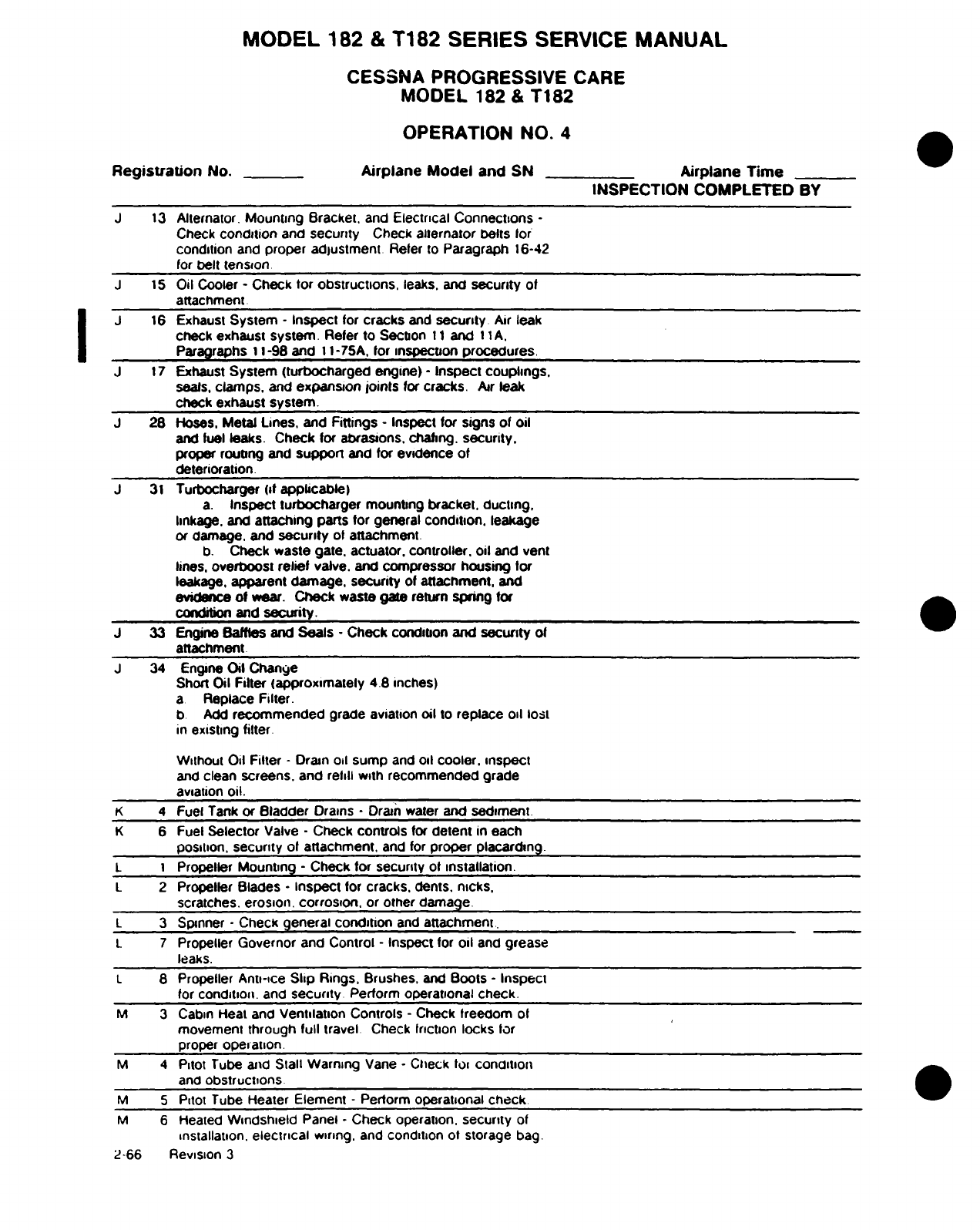
MODEL
182
&
T182 SERIES
SERVICE
MANUAL
CESSNA PROGRESSIVE
CARE
MODEL
182
&
T182
OPERATION
NO.
4
Registration
No.
Airplane
Model
and
SN
Airplane
Time
INSPECTION
COMPLETED
BY
J
13
Alternator.
Mounting
Bracket,
and
Electrical
Connections
-
Check
condition
and
security Check
alternator
belts
for
condition
and
proper
adjustment
Refer
to
Paragraph
16-42
for
belt
tension
J
15
Oil Cooler
-
Check
for
obstructions,
leaks.
and
security
of
attachment
J
16
Exhaust
System
-
Inspect
for
cracks
and
security
Air
leak
check
exhaust system.
Refer
to Section
11
and
11A.
Paragraphs
11-98
and 11-75A,
for
inspection
procedures.
J
17
Exhaust
System
(turbocharged
engine)
-
Inspect
couplings,
seals,
clamps,
and
expansion
joints
for
cracks.
Air leak
check
exhaust
system.
J
28
Hoses.
Metal
Lines,
and
Fittings
-
Inspect
for
signs
of
oil
and fuel
leaks.
Check
for
abrasions.
chafing.
security,
proper
routing
and
support
and
for evidence
of
deterioration
J
31
Turbocharger
(if applicable)
a.
Inspect
turbocharger
mounting
bracket,
ducting,
linkage,
and
attaching
parts
for
general
condition,
leakage
or damage,
and
security
of
attachment
b.
Check waste
gate.
actuator, controller.
oil
and vent
lines,
overboost
relief
valve,
and
compressor
housing
for
leakage,
apparent damage,
security
of
attachment,
and
evidence
of
wear.
Check
waste
gate
return
spring
for
condition
and
security.
J
33
Engine
Baffles
and
Seals
-
Check
condition
and
security
of
attachment
J 34
Engine
Oil
Change
Short
Oil
Filter
(approximately
4.8
inches)
a
Replace
Filter.
b
Add
recommended
grade
aviation
oil
to
replace
oil
lost
in
existing
filter
Without
Oil Filter
-
Drain
oil
sump
and
oil cooler.
inspect
and
clean
screens.
and
refill
with
recommended
grade
aviation
oil.
K
4
Fuel
Tank
or
Bladder
Drains
-
Drain water
and
sediment.
K
6
Fuel
Selector
Valve
-
Check
controls
for
detent
in
each
position,
security
of
attachment,
and
for
proper
placarding.
L 1
Propeller
Mounting
-
Check for
security
of
installation.
L
2
Propeller
Blades
-
Inspect
for
cracks,
dents,
nicks.
scratches.
erosion,
corrosion.
or other damage.
L
3
Spinner
-
Check
general
condition
and
attachment.
L 7
Propeller
Governor and Control
-
Inspect
for
oil
and
grease
leaks.
L
8
Propeller
Anti-ice
Slip
Rings,
Brushes,
and
Boots
-
Inspect
for
condition, and
security
Perform
operational
check.
M 3
Cabin
Heal
and
Ventilation
Controls
-
Check
freedom
of
movement
through
full
travel
Check
friction
locks
for
proper
operation.
M
4
Pitot
Tube
and
Stall
Warning
Vane
-
Check
for
condition
and
obstructions
M
5
Pitot Tube
Heater
Element
-
Perform
operational
check
M
6
Heated
Windshield
Panel
-
Check operation,
security
of
installation,
electrical
wiring,
and
condition
of
storage
bag.
2-66
Revision
3
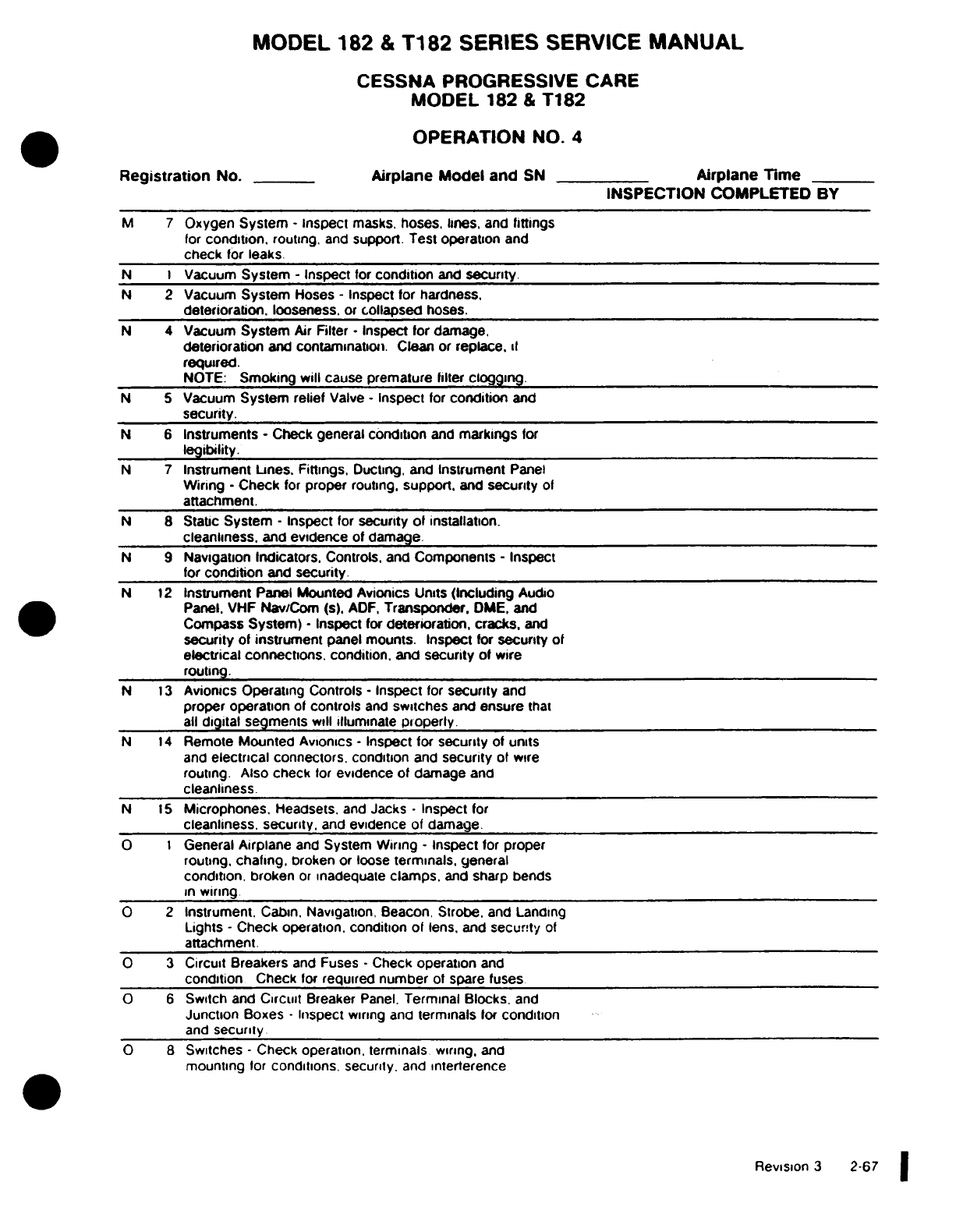
MODEL
182
&
T182
SERIES SERVICE
MANUAL
CESSNA PROGRESSIVE
CARE
MODEL
182
&
T182
OPERATION
NO.
4
Registration
No.
Airplane Model
and SN
Airplane Time
INSPECTION
COMPLETED
BY
M
7
Oxygen
System
-
Inspect
masks,
hoses,
lines,
and
fittings
for
condition.
routing.
and support.
Test
operation
and
check
for
leaks.
N
I
Vacuum
System
-
Inspect
for
condition
and
security.
N
2
Vacuum
System
Hoses
-
Inspect
for hardness.
deterioration.
looseness,
or
collapsed
hoses.
N
4
Vacuum
System
Air
Filter
-
Inspect for damage,
deterioration
and
contamination.
Clean
or
replace,
if
required.
NOTE:
Smoking will
cause premature filter
clogging.
N
5
Vacuum
System relief
Valve
-
Inspect
for
condition
and
security.
N
6
Instruments
-
Check
general
condition
and
markings
for
legibility.
N
7
Instrument Lines.
Fittings.
Ducting.
and
Instrument
Panel
Wiring
-
Check
for
proper
routing,
support.
and
security
of
attachment.
N
8
Static
System
-
Inspect
for
security
of
installation.
cleanliness.
and
evidence
of
damage.
N
9
Navigation
Indicators.
Controls, and
Components
-
Inspect
for
condition
and
security.
N
12
Instrument
Panel
Mounted Avionics
Units
(Including
Audio
Panel.
VHF
Nav/Com(s).
ADF,
Transponder.
DME.
and
Compass
System)
-
Inspect
for
deterioration,
cracks,
and
security
of
instrument
panel mounts. Inspect
for
security
of
electrical connections.
condition. and
security
of wire
routing.
N
13
Avionics Operating
Controls
-
Inspect
for
security
and
proper
operation
of
controls
and
switches
and
ensure
that
all
digital
segments
will
illuminate
properly.
N
14
Remote
Mounted Avionics
-
Inspect
for
security
of
units
and
electrical
connectors,
condition
and
security
of wire
routing. Also
check
for
evidence
of
damage
and
cleanliness.
N
15
Microphones.
Headsets.
and
Jacks -
Inspect
for
cleanliness.
security,
and
evidence
of
damage.
O
1
General
Airplane
and
System
Wiring
-
Inspect
for
proper
routing,
chafing,
broken
or
loose
terminals,
general
condition.
broken
or
inadequate
clamps,
and
sharp
bends
in
wiring
O
2
Instrument.
Cabin.
Navigation.
Beacon.
Strobe,
and
Landing
Lights
-
Check
operation,
condition
of
lens. and
security
of
attachment.
O
3
Circuit
Breakers
and
Fuses
-
Check operation and
condition
Check
for
required
number
of
spare
fuses
O
6
Switch and
Circuit
Breaker
Panel.
Terminal
Blocks,
and
Junction
Boxes
-
Inspect
wiring
and
terminals
for
condition
and
security
O
8
Switches
-
Check
operation.
terminals
wiring,
and
mounting
for
conditions.
security.
and
interterence
Revision
3
2-67
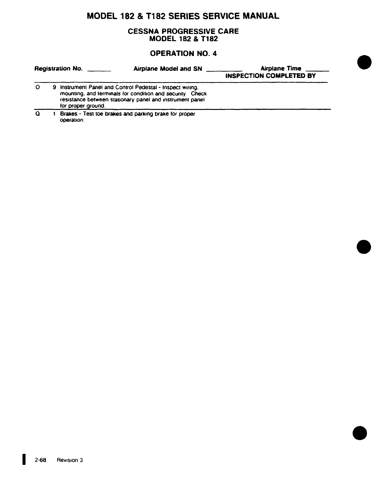
MODEL
182
&
T182
SERIES
SERVICE
MANUAL
CESSNA PROGRESSIVE CARE
MODEL
182
&
T182
OPERATION
NO.
4
Registration
No.
Airplane Model
and
SN Airplane
Time
INSPECTION COMPLETED
BY
O
9
Instrument
Panel
and Control
Pedestal
-
Inspect wiring.
mounting,
and
terminals
for
condition
and
security
Check
resistance
between
stationary panel
and
instrument
panel
for
proper
ground.
Q
1
Brakes
-
Test toe
brakes
and
parking
brake
for
proper
operation.
2-68
Revision
3

MODEL 182
&
T182
SERIES SERVICE
MANUAL
CESSNA
PROGRESSIVE
CARE
MODEL
182
&
T182
OPERATION
NO.
4
INSPECTION
SPECIAL
INSPECTION
AND YEARLY
ITEMS
HOURS YEARS
COMPLETED
BY
Please
review
each
of
these
items
for
required
compliance
I Upholstery. Headliner,
Trim, and
Carpeting
-
Check
condition
EACH EACH
and
clean
as
required.
400
1
D
3
Brake
Lines.
Wheel
Cylinders.
Hoses.
Clamps.
and
Fittings
-
EACH
EACH
Check
for
leaks,
condition.
and
security
and
hoses
for
bulges
400
1
and
deterioration. Check
brake
lines
and
hoses
for
proper
routing
and
support.
D
6
Wheel
Fairings,
Strut
Fairings,
and
Cuffs
-
Check for
cracks.
A
dents,
and
condition
of
paint.
D
11
Wheel
Bearings
-
Clean,
inspect
and
lube.
B
E
4
Autopilot Rigging
-
Check
per
Avionics
Installation
Manual.
C
H
5
Elevator
Trim
Tab
Actuator
-
Clean.
lubricate.
D
J
3
Engine.
Propeller Controls,
and
Linkage
-
Check
general
E
condition,
freedom
of
movement through
full
range.
Check
for
proper
travel,
security
of
attachment,
and
for
evidence
of
wear.
Check friction
locks
for
proper
operation.
J
9
Induction
Air
Filter
-Remove
and
clean.
Inspect
for
damage.
F
and
service
per
paragraph
2-24
J
12
Alternator
-
Check
brushes,
leads.
commutator
or
slip
ring
for
G
wear.
J
14
Starter, Starter
Solenoid,
and
Electrical
Connections
-
Check
for
H
condition
of starter
brushes.
brush
leads,
and
commutator.
J 20
Magnetos
-
Inspection lubrication and
overhaul
procedures.
J
21
Magnetos
-
Check external
condition,
security.
and
electrical
J
leads
for
condition.
Check
timing
to
engine
and
internal
timing
if
engine
timing requires adjustment
J
22
Magnetos
- Timing
Procedures
and
intervals.
K
J
28
Hoses. Metal
Lines,
and
Fittings
-
Inspect
for signs
of
oil
and
L
fuel
leaks.
Check
for
abrasions,
chafing.
security, proper
routing
and
support
and
for
evidence
of
deterioration.
J
31
Turbocharger
(if
applicable)
M
a.
Inspect
turbocharger mounting
bracket.
ducting.
linkage,
and
attaching
parts
for
general condition,
leakage
or
damage,
and
security
of
attachment
b.
Check
waste
gate.
actuator.
controller,
oil
and
vent
lines.
overboost
relief
valve,
and
compressor
housing for
leakage. apparent damage.
security
of
attachment,
and
evidence
of
wear.
Check waste gate return
spring
for
condition
and
security
J
34
Engine
Oil
Change
-N
Short Oil Filter
(approximately
4
8
inches)
a.
Replace
Filter
b.
Add
recommended
grade
aviation oil
to
replace oil
lost
in
existing
filter.
Without
Oil
Filter
-
Drain
oil
sump
and
oil
cooler.
inspect
and
clean screens,
and
refill with recommended
grade
aviation
oil.
J
35
Long
Oil
Filter
(approximately
58
inches)
-
Drain
oil
sump
and
N
oil
cooler, replace filter element,
refill
with
recommended grade
aviation
oil.
K
Integral
Fuel
Tanks
-
Check
for
evidence
of
leakage
and
0
condition
of
fuel
caps.
adapters.
and
placards
Revision
3
2-69

MODEL
182
&
T182
SERIES
SERVICE
MANUAL
CESSNA
PROGRESSIVE
CARE
MODEL
182
&
T182
OPERATION
NO.
4
INSPECTION
SPECIAL INSPECTION
AND
YEARLY
ITEMS
HOURS YEARS
COMPLETED
BY
Please
review
each
of
these
items
for
required
compliance
K
2
Fuel
Bladders
-
Check
for
leaks and
security.
condition
of
fuel
O
caps.
adapters.
and
placards.
K
8 Fuel
Quantity
Indicators
-
Check
for
damage.
security
of
EACH
installation,
and
perform
accuracy
test.
1
L
7
Propeller
Governor
and
Control
-
Inspect
for
oil
and
grease
P
leaks.
M
1
Ventilation
System
-
Inspect
clamps,
hoses.
and
valves
for
400
EACH
condition
and
security.
1
M
8
Oxygen
Cylinder
-
Inspect
for
condition,
check
hydrostatic
test
EACH
date
and
perform
hydrostatic
test,
if
required.
5
N
4
Vacuum
System
Air
Filter
-
Inspect
for
damage
deterioration
Q
and
contamination.
Clean
or
replace,
if
required.
NOTE:
Smoking
will
cause
premature
filter
clogging.
N
5
Vacuum
System
relief
Valve
-
Inspect
for
condition
and
security.
R
N
10
Airspeed
Indicator.
Vertical
Speed
indicator,
and
Magnetic
EACH
Compass-
Calibrate.
2
N
11
Altimeter
and
Static
System
-
Inspect
in
accordance
with
FAR
EACH
Part
91.411.
2
O
4
Battery
-
Check
general
condition
and
security.
Check
level
of
S
electrolyte.
2-70
Revision
3
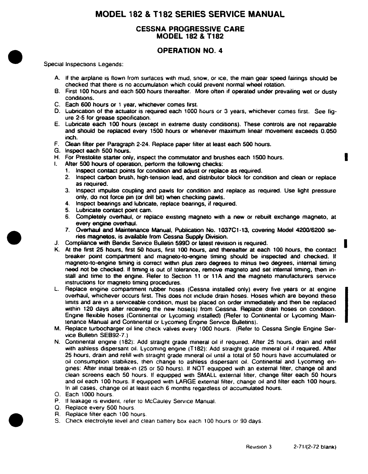
MODEL
182
&
T182
SERIES SERVICE
MANUAL
CESSNA
PROGRESSIVE
CARE
MODEL
182
&
T182
OPERATION
NO.
4
Special
Inspections
Legends:
A.
If
the
airplane
is flown
from
surfaces
with
mud,
snow,
or
ice.
the
main
gear speed
fairings
should
be
checked that
there
is
no
accumulation
which
could prevent
normal wheel rotation.
B.
First
100
hours
and each
500
hours
thereafter.
More
often
if
operated
under
prevailing
wet
or
dusty
conditions.
C.
Each
600
hours
or
1
year,
whichever
comes first.
D.
Lubrication
of
the
actuator
is
required
each
1000
hours
or
3
years,
whichever
comes
first.
See fig-
ure
2-5
for
grease
specification.
E.
Lubricate
each
100
hours
(except
in
extreme
dusty
conditions).
These
controls
are
not
repairable
and
should be replaced
every
1500
hours or
whenever maximum linear
movement
exceeds
0.050
inch.
F.
Clean
filter per
Paragraph
2-24.
Replace
paper
filter
at
least
each
500
hours.
G.
Inspect
each
500
hours.
H.
For
Prestolite
starter
only,
inspect
the commutator
and
brushes
each
1500
hours.
I.
After
500
hours
of
operation, perform
the following
checks:
1.
Inspect
contact
points
for
condition
and
adjust
or
replace
as required.
2.
Inspect
carbon
brush,
high-tension
lead,
and
distributor block
for
condition
and
clean or
replace
as
required.
3.
Inspect
impulse
coupling
and
pawls
for
condition
and
replace
as
required.
Use
light
pressure
only,
do
not force
pin
(or
drill
bit)
when
checking
pawls.
4.
Inspect
bearings
and
lubricate, replace
bearings,
if
required.
5.
Lubricate
contact
point
cam.
6.
Completely
overhaul,
or
replace existing
magneto
with
a new
or
rebuilt
exchange
magneto,
at
every
engine
overhaul.
7.
Overhaul
and
Maintenance
Manual,
Publication
No.
1037C1-13,
covering
Model
4200/6200
se-
ries
magnetos,
is
available
from
Cessna
Supply
Division.
J.
Compliance
with
Bendix
Service Bulletin
599D
or
latest
revision
is
required.
K.
At
the
first
25
hours,
first
50
hours,
first
100
hours,
and
thereafter
at
each
100
hours,
the
contact
breaker
point
compartment
and
magneto-to-engine timing
should
be
inspected
and
checked.
If
magneto-to-engine
timing
is
correct
within
plus
zero
degrees
to
minus
two
degrees,
internal
timing
need
not be
checked.
If
timing
is
out
of
tolerance,
remove magneto
and
set
internal
timing,
then
in-
stall
and
time
to
the
engine. Refer
to
Section
11
or 11A
and
the
magneto
manufacturers
service
instructions
for
magneto
timing
procedures.
L.
Replace
engine
compartment
rubber
hoses (Cessna
installed
only)
every
five
years
or
at
engine
overhaul,
whichever
occurs first.
This does
not
include drain hoses.
Hoses
which
are
beyond
these
limits
and
are
in
a
serviceable
condition,
must
be
placed
on
order immediately
and
then
be
replaced
within
120
days
after
receiving
the new
hose(s)
from
Cessna.
Replace
drain
hoses
on
condition.
Engine
flexible
hoses
(Continental
or Lycoming
installed) (Refer
to
Continental
or
Lycoming
Main-
tenance Manual
and
Continental
or
Lycoming
Engine
Service
Bulletins).
M.
Replace
turbocharger
oil
line
check
valves every
1000
hours.
(Refer
to
Cessna Single Engine Ser-
vice
Bulletin
SEB92-7.)
N.
Continental
engine
(182):
Add
straight
grade mineral
oil
it
required. After
25
hours, drain
and
refill
with
ashless dispersant
oil.
Lycoming
engine
(T182):
Add
straight
grade
mineral
oil
if
required.
After
25
hours,
drain
and
refill
with
straight
grade
mineral oil
until
a
total
of
50
hours
have
accumulated
or
oil
consumption
stabilizes.
then
change
to
ashless
dispersant
oil.
Continental
and
Lycoming
en-
gines: After
initial
break-in
(25
or
50
hours).
If
NOT
equipped
with
an
external filter,
change
oil
and
clean
screens
each
50
hours.
If
equipped
with
SMALL
external
filter,
change
filter
each
50
hours
and
oil
each
100
hours.
If
equipped
with LARGE
external
filter,
change oil
and
filter each
100
hours.
In
all
cases,
change
oil
at
least
each
6
months
regardless
of
accumulated
hours.
O.
Each
1000
hours.
P.
If
leakage
is
evident.
refer
to
McCauley
Service
Manual.
Q.
Replace
every
500
hours.
R.
Replace filter
each
100
hours.
S.
Check
electrolyte
level
and
clean
battery
box
each
100
hours
or
90
days.
Revision
3
2-71/(2-72
blank)
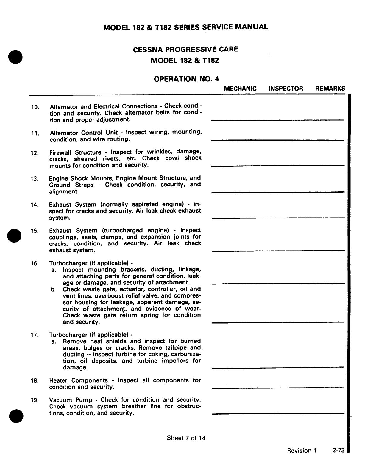
MODEL
182
&
T182
SERIES
SERVICE
MANUAL
CESSNA
PROGRESSIVE
CARE
MODEL
182
&
T182
OPERATION
NO.
4
MECHANIC
INSPECTOR
REMARKS
10.
Alternator
and
Electrical
Connections
- Check
condi-
tion
and
security.
Check
alternator
belts
for
condi-
tion
and
proper
adjustment.
11.
Alternator
Control
Unit
-
Inspect
wiring,
mounting,
condition,
and
wire
routing.
12.
Firewall
Structure
-
Inspect
for
wrinkles,
damage,
cracks,
sheared
rivets,
etc.
Check
cowl
shock
mounts
for
condition
and
security.
13.
Engine
Shock
Mounts,
Engine
Mount
Structure,
and
Ground
Straps
- Check
condition,
security,
and
alignment.
14.
Exhaust
System
(normally
aspirated
engine)
-
In-
spect
for
cracks
and
security.
Air
leak
check
exhaust
system.
15.
Exhaust
System
(turbocharged engine)
-
Inspect
couplings,
seals,
clamps,
and
expansion
joints for
cracks,
condition,
and
security.
Air
leak check
exhaust
system.
16.
Turbocharger
(if
applicable)
-
a.
Inspect
mounting
brackets,
ducting,
linkage,
and
attaching
parts
for
general
condition,
leak-
age
or
damage,
and
security
of
attachment.
b.
Check
waste
gate,
actuator,
controller,
oil
and
vent
lines,
overboost
relief
valve,
and
compres-
sor
housing
for
leakage,
apparent
damage,
se-
curity
of
attachment,
and
evidence
of
wear.
Check
waste
gate
return
spring
for
condition
and
security.
17.
Turbocharger
(if
applicable)
-
a.
Remove
heat
shields
and
inspect
for
burned
areas,
bulges or
cracks.
Remove
tailpipe
and
ducting
--
inspect
turbine
for
coking,
carboniza-
tion,
oil deposits,
and
turbine
impellers
for
damage.
18.
Heater
Components
-
Inspect
all
components
for
condition
and
security.
19.
Vacuum
Pump
-
Check
for
condition
and
security.
Check
vacuum
system
breather line
for
obstruc-
tions,
condition,
and
security.
Sheet
7
of
14
Revision
1
2-73
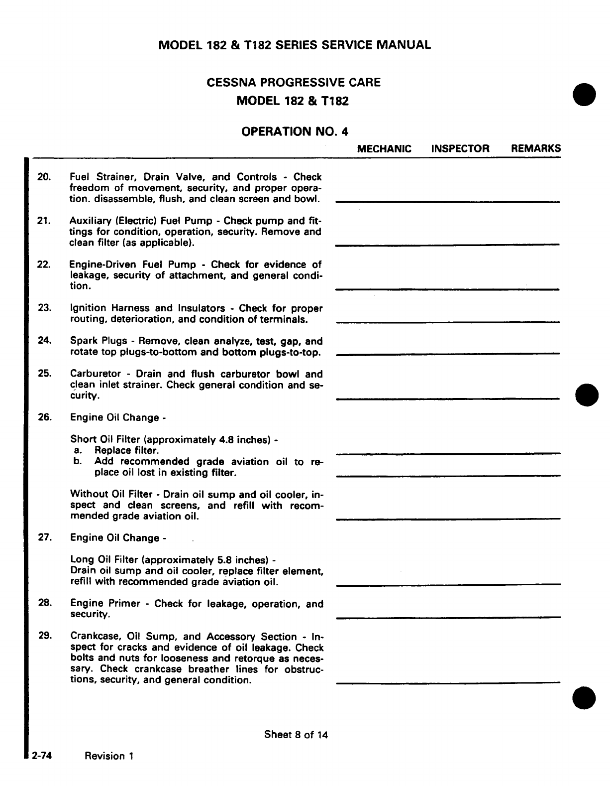
MODEL
182
&
T182
SERIES
SERVICE
MANUAL
CESSNA
PROGRESSIVE
CARE
MODEL
182
&
T182
OPERATION
NO.
4
MECHANIC INSPECTOR REMARKS
20.
Fuel
Strainer,
Drain
Valve,
and Controls
-
Check
freedom
of
movement,
security,
and
proper
opera-
tion.
disassemble,
flush,
and
clean
screen
and
bowl.
21.
Auxiliary
(Electric)
Fuel
Pump
-
Check
pump
and
fit-
tings
for
condition,
operation,
security.
Remove
and
clean
filter
(as
applicable).
22.
Engine-Driven
Fuel
Pump
- Check
for
evidence
of
leakage,
security
of
attachment,
and
general
condi-
tion.
23.
Ignition
Harness
and
Insulators
-
Check
for
proper
routing, deterioration,
and
condition
of
terminals.
24.
Spark
Plugs
-
Remove, clean
analyze,
test,
gap,
and
rotate
top
plugs-to-bottom
and
bottom
plugs-to-top.
25.
Carburetor
-
Drain
and
flush
carburetor
bowl
and
clean
inlet
strainer.
Check
general
condition
and
se-
curity.
26.
Engine
Oil
Change -
Short
Oil
Filter
(approximately
4.8
inches) -
a.
Replace
filter.
b.
Add
recommended
grade
aviation
oil
to
re-
place
oil lost
in
existing
filter.
Without
Oil
Filter
-
Drain
oil sump
and
oil cooler,
in-
spect
and
clean screens,
and
refill
with
recom-
mended grade
aviation
oil.
27.
Engine
Oil
Change
-
Long
Oil
Filter
(approximately
5.8
inches)
-
Drain
oil
sump
and
oil
cooler,
replace
filter
element,
refill
with
recommended grade
aviation
oil.
28.
Engine
Primer
-
Check
for
leakage,
operation,
and
security.
29.
Crankcase,
Oil
Sump,
and
Accessory
Section
-
In-
spect
for
cracks and
evidence
of
oil
leakage.
Check
bolts
and
nuts
for
looseness and
retorque
as
neces-
sary.
Check
crankcase
breather
lines
for
obstruc-
tions,
security,
and general
condition.
Sheet
8
of
14
2-74
Revision
1
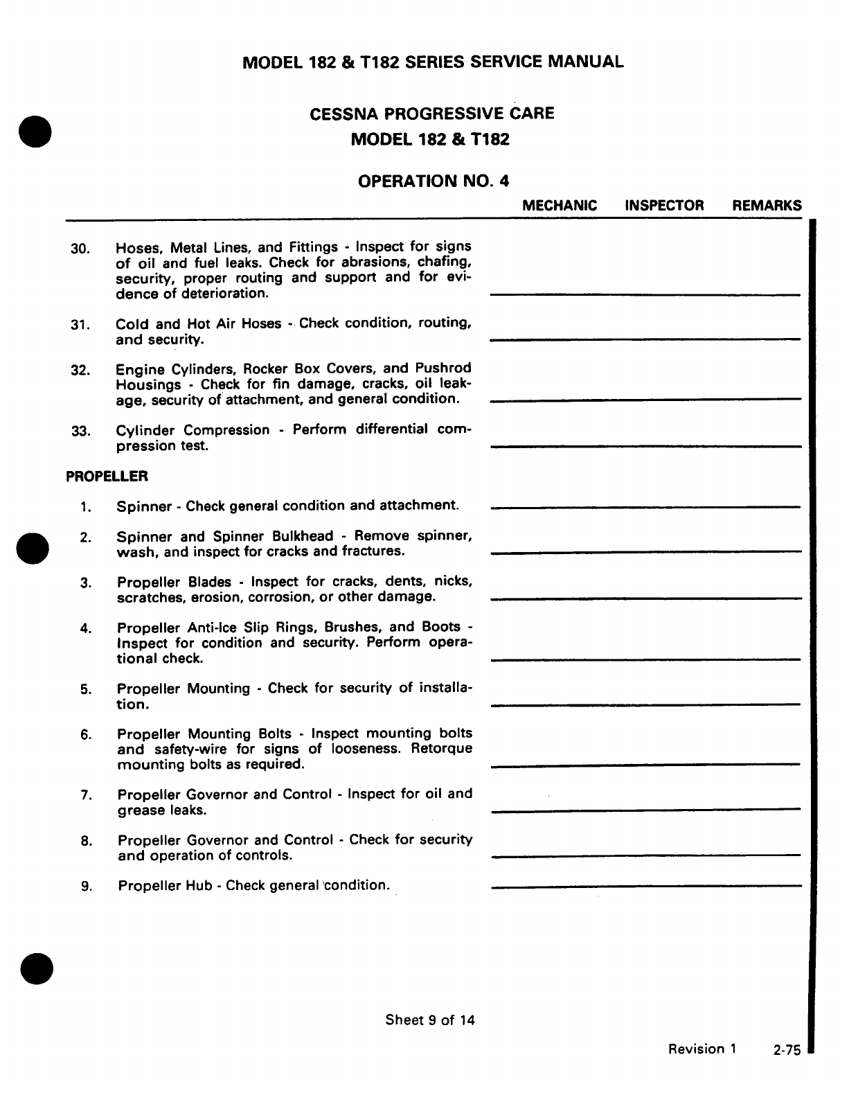
MODEL
182
&
T182
SERIES
SERVICE
MANUAL
CESSNA
PROGRESSIVE
CARE
MODEL
182
&
T182
OPERATION
NO.
4
MECHANIC
INSPECTOR
REMARKS
30.
Hoses,
Metal
Lines,
and
Fittings
-
Inspect
for
signs
of
oil
and
fuel
leaks.
Check
for
abrasions,
chafing,
security,
proper
routing
and
support
and
for
evi-
dence
of
deterioration.
31.
Cold
and
Hot
Air
Hoses
-
Check
condition,
routing,
and
security.
32.
Engine
Cylinders,
Rocker
Box
Covers,
and
Pushrod
Housings
-
Check
for
fin
damage,
cracks,
oil
leak-
age,
security
of
attachment,
and
general
condition.
33.
Cylinder
Compression
-
Perform
differential
com-
pression
test.
PROPELLER
1.
Spinner
-
Check
general
condition
and
attachment.
2.
Spinner
and
Spinner
Bulkhead
-
Remove
spinner,
wash,
and
inspect
for
cracks
and
fractures.
3.
Propeller
Blades
-
Inspect
for
cracks,
dents,
nicks,
scratches,
erosion,
corrosion,
or other
damage.
4.
Propeller
Anti-Ice Slip
Rings, Brushes,
and
Boots
-
Inspect
for
condition
and
security.
Perform
opera-
tional
check.
5.
Propeller
Mounting
-
Check
for
security
of
installa-
tion.
6.
Propeller
Mounting
Bolts
-
Inspect
mounting
bolts
and
safety-wire
for
signs
of
looseness.
Retorque
mounting
bolts
as
required.
7.
Propeller
Governor
and
Control
-
Inspect
for
oil
and
grease
leaks.
8.
Propeller
Governor
and
Control
-
Check
for
security
and
operation
of
controls.
9.
Propeller
Hub
-
Check
general
condition.
Sheet
9
of
14
Revision
1
2-75
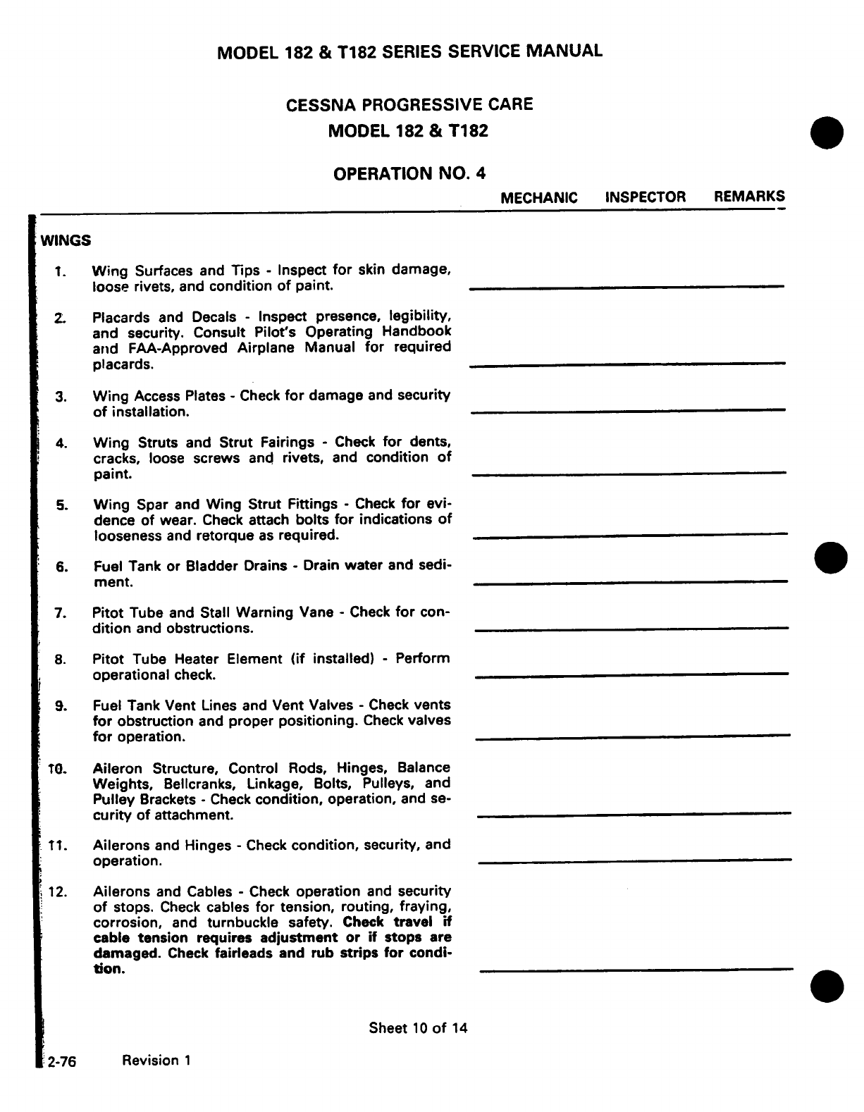
MODEL
182
&
T182
SERIES
SERVICE
MANUAL
CESSNA
PROGRESSIVE
CARE
MODEL
182
&
T182
OPERATION
NO.
4
MECHANIC
INSPECTOR
REMARKS
WINGS
1.
Wing
Surfaces and
Tips
-
Inspect
for
skin
damage,
loose
rivets,
and
condition
of
paint.
2.
Placards
and Decals -
Inspect
presence,
legibility,
and
security. Consult
Pilot's
Operating
Handbook
and
FAA-Approved
Airplane
Manual
for
required
placards.
3.
Wing
Access
Plates -
Check
for
damage
and
security
of
installation.
4.
Wing
Struts
and
Strut
Fairings
-
Check
for
dents,
cracks,
loose
screws
and
rivets,
and
condition
of
paint.
5.
Wing
Spar and
Wing
Strut
Fittings
-
Check
for
evi-
dence
of
wear.
Check
attach
bolts
for
indications
of
looseness
and
retorque
as
required.
6.
Fuel
Tank
or
Bladder
Drains
-
Drain
water
and
sedi-
ment.
7.
Pitot
Tube
and
Stall
Warning
Vane
-
Check
for
con-
dition
and
obstructions.
8.
Pitot
Tube
Heater
Element
(if
installed)
-
Perform
operational
check.
9.
Fuel
Tank
Vent
Lines
and
Vent
Valves
-
Check
vents
for
obstruction
and
proper
positioning.
Check
valves
for
operation.
10.
Aileron
Structure,
Control
Rods,
Hinges,
Balance
Weights,
Bellcranks,
Linkage,
Bolts,
Pulleys,
and
Pulley
Brackets
-
Check
condition,
operation,
and
se-
curity
of
attachment.
11.
Ailerons
and
Hinges
-
Check
condition,
security,
and
operation.
12.
Ailerons
and Cables -
Check
operation
and
security
of
stops.
Check
cables
for
tension, routing,
fraying,
corrosion,
and
turnbuckle
safety.
Check
travel
if
cable
tension
requires
adjustment
or
if
stops
are
damaged.
Check
fairleads
and
rub
strips
for
condi-
tion.
Sheet
10
of
14
2-76
Revision
1
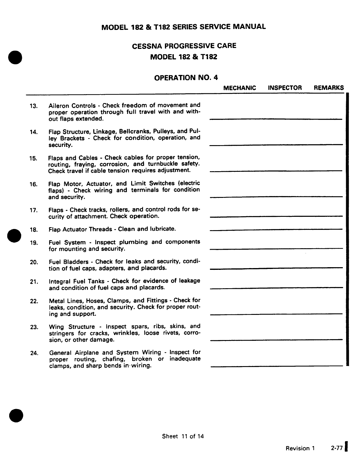
MODEL
182
&
T182
SERIES
SERVICE
MANUAL
CESSNA
PROGRESSIVE
CARE
MODEL
182
&
T182
OPERATION
NO.
4
MECHANIC
INSPECTOR
REMARKS
13.
Aileron
Controls
- Check
freedom
of
movement
and
proper
operation
through
full
travel
with
and
with-
out flaps
extended.
14.
Flap
Structure,
Linkage,
Bellcranks,
Pulleys,
and
Pul-
ley
Brackets
- Check
for
condition,
operation,
and
security.
15.
Flaps
and
Cables
-
Check
cables
for
proper
tension,
routing, fraying, corrosion,
and
turnbuckle
safety.
Check
travel
if
cable
tension
requires
adjustment.
16.
Flap
Motor,
Actuator,
and
Limit
Switches
(electric
flaps)
-
Check
wiring
and
terminals
for condition
and
security.
17.
Flaps
-
Check
tracks,
rollers,
and
control
rods
for
se-
curity
of
attachment.
Check
operation.
18.
Flap
Actuator
Threads
-
Clean
and
lubricate.
19.
Fuel
System
-
Inspect
plumbing
and
components
for
mounting
and
security.
20.
Fuel
Bladders
- Check
for
leaks
and
security,
condi-
tion
of
fuel
caps,
adapters,
and
placards.
21.
Integral
Fuel
Tanks
- Check
for
evidence
of
leakage
and
condition
of
fuel
caps
and
placards.
22.
Metal
Lines,
Hoses,
Clamps,
and
Fittings
-
Check
for
leaks,
condition,
and
security.
Check
for
proper rout-
ing
and
support.
23.
Wing
Structure
-
Inspect
spars,
ribs,
skins,
and
stringers
for
cracks,
wrinkles,
loose rivets, corro-
sion,
or
other
damage.
24.
General
Airplane
and
System
Wiring
-
Inspect
for
proper
routing,
chafing, broken
or
inadequate
clamps,
and
sharp
bends
in
wiring.
Sheet
11
of
14
Revision
1
2-77
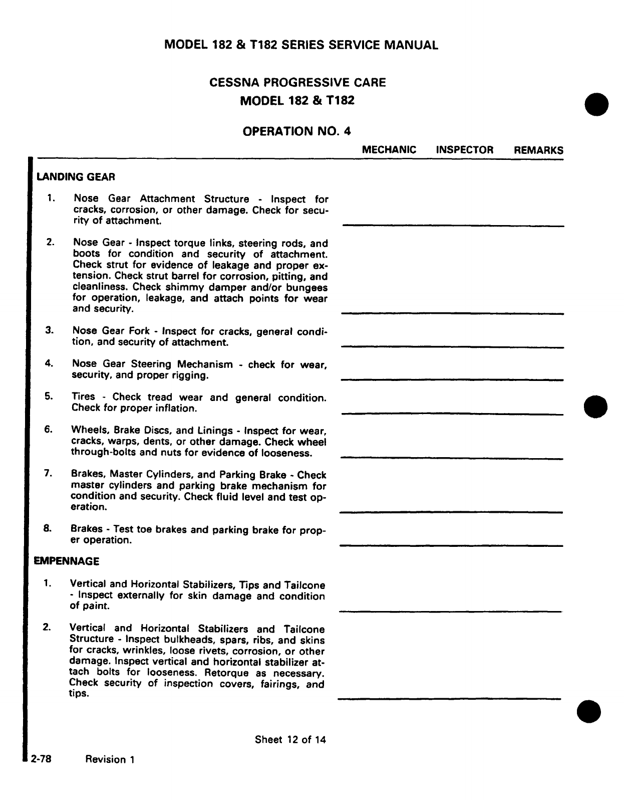
MODEL
182
&
T182
SERIES SERVICE
MANUAL
CESSNA
PROGRESSIVE
CARE
MODEL
182
&
T182
OPERATION
NO.
4
MECHANIC INSPECTOR
REMARKS
LANDING
GEAR
1.
Nose
Gear
Attachment
Structure
-
Inspect
for
cracks,
corrosion,
or
other
damage.
Check
for
secu-
rity
of
attachment.
2.
Nose
Gear
-
Inspect
torque
links,
steering rods,
and
boots
for condition
and
security
of
attachment.
Check
strut
for
evidence
of
leakage
and
proper
ex-
tension.
Check
strut
barrel
for
corrosion,
pitting,
and
cleanliness.
Check
shimmy
damper
and/or
bungees
for
operation,
leakage,
and
attach
points
for
wear
and
security.
3.
Nose
Gear
Fork
-
Inspect
for
cracks,
general
condi-
tion,
and
security
of
attachment.
4.
Nose
Gear
Steering
Mechanism
-check
for
wear,
security,
and
proper
rigging.
5.
Tires
-
Check
tread
wear
and
general
condition.
Check
for
proper
inflation.
6.
Wheels,
Brake
Discs,
and
Linings
-
Inspect
for
wear,
cracks,
warps,
dents,
or
other
damage.
Check
wheel
through-bolts
and
nuts
for
evidence
of
looseness.
7.
Brakes,
Master
Cylinders,
and
Parking
Brake
-
Check
master
cylinders
and
parking
brake
mechanism
for
condition
and
security.
Check
fluid
level and
test
op-
eration.
8.
Brakes
- Test
toe
brakes
and
parking
brake
for
prop-
er
operation.
EMPENNAGE
1.
Vertical
and
Horizontal
Stabilizers,
Tips
and
Tailcone
-
Inspect
externally
for
skin
damage
and
condition
of
paint.
2.
Vertical
and
Horizontal
Stabilizers
and
Tailcone
Structure
-
Inspect
bulkheads,
spars,
ribs,
and
skins
for
cracks,
wrinkles,
loose
rivets,
corrosion,
or other
damage.
Inspect
vertical
and
horizontal stabilizer
at-
tach
bolts
for
looseness.
Retorque
as
necessary.
Check
security
of
inspection
covers,
fairings,
and
tips.
Sheet
12
of
14
2-78
Revision
1
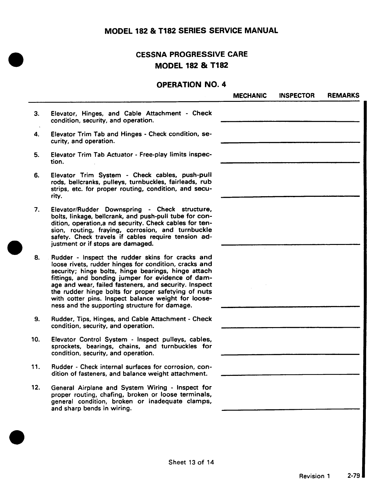
MODEL
182
&
T182
SERIES
SERVICE
MANUAL
MODEL
182
&
T182
OPERATION
NO.
4
MECHANIC
INSPECTOR
REMARKS
3.
Elevator,
Hinges, and
Cable
Attachment
-
Check
condition,
security,
and
operation.
4.
Elevator
Trim
Tab
and
Hinges
-
Check
condition,
se-
curity,
and
operation.
5.
Elevator
Trim
Tab
Actuator
-
Free-play
limits
inspec-
tion.
6.
Elevator Trim System
- Check
cables,
push-pull
rods,
bellcranks,
pulleys,
turnbuckles,
fairleads,
rub
strips, etc.
for proper
routing,
condition,
and
secu-
rity.
7.
Elevator/Rudder
Downspring
- Check
structure,
bolts,
linkage,
bellcrank,
and
push-pull
tube
for
con-
dition,
operation,a
nd
security.
Check
cables
for
ten-
sion,
routing, fraying, corrosion,
and
turnbuckle
safety.
Check
travels
if
cables
require
tension
ad-
8.
Rudder
-
Inspect
the rudder
skins
for
cracks
and
loose
rivets,
rudder
hinges
for
condition,
cracks
and
security;
hinge
bolts,
hinge
bearings,
hinge
attach
fittings,
and
bonding
jumper
for
evidence
of
dam-
age
and
wear,
failed
fasteners,
and
security.
Inspect
the
rudder
hinge
bolts
for
proper
safetying
of
nuts
with
cotter
pins.
Inspect
balance
weight
for
loose-
ness
and
the
supporting structure
for
damage.
9.
Rudder,
Tips,
Hinges,
and
Cable
Attachment
-
Check
condition,
security,
and
operation.
10.
Elevator
Control
System
-
Inspect
pulleys,
cables,
sprockets,
bearings,
chains,
and
turnbuckles
for
condition,
security,
and
operation.
11.
Rudder
-
Check
internal
surfaces
for
corrosion,
con-
dition
of
fasteners,
and
balance
weight
attachment.
12.
General
Airplane
and
System
Wiring
-
Inspect
for
proper
routing, chafing,
broken
or
loose
terminals,
general
condition,
broken
or
inadequate
clamps,
and
sharp
bends in
wiring.
Sheet
13
of 14
Revision
1
2-79
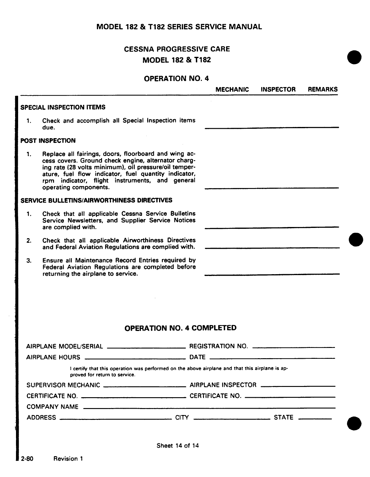
MODEL
182
&
T182
SERIES
SERVICE
MANUAL
CESSNA
PROGRESSIVE
CARE
MODEL
182
&
T182
OPERATION
NO.
4
MECHANIC
INSPECTOR REMARKS
SPECIAL
INSPECTION
ITEMS
1.
Check
and
accomplish
all
Special
Inspection
items
due.
POST INSPECTION
1.
Replace
all
fairings,
doors,
floorboard
and
wing
ac-
cess
covers.
Ground
check
engine,
alternator
charg-
ing
rate
(28
volts
minimum),
oil
pressure/oil
temper-
ature,
fuel
flow
indicator,
fuel
quantity indicator,
rpm
indicator,
flight
instruments,
and
general
operating
components.
SERVICE
BULLETINS/AIRWORTHINESS
DIRECTIVES
1.
Check
that
all
applicable
Cessna
Service
Bulletins
Service
Newsletters,
and
Supplier
Service
Notices
are
complied
with.
2.
Check
that
all
applicable
Airworthiness
Directives
and
Federal
Aviation
Regulations
are
complied
with.
3.
Ensure
all
Maintenance
Record
Entries
required
by
Federal
Aviation
Regulations
are
completed
before
returning
the
airplane
to
service.
OPERATION
NO.
4
COMPLETED
AIRPLANE
MODEL/SERIAL REGISTRATION
NO.
AIRPLANE
HOURS
DATE
I
certify
that this
operation
was
performed
on
the
above
airplane
and
that
this
airplane
is
ap-
proved
for
return
to
service.
SUPERVISOR
MECHANIC AIRPLANE
INSPECTOR
CERTIFICATE NO. CERTIFICATE
NO.
COMPANY
NAME
ADDRESS
CITY
STATE
Sheet
14
of
14
2-80
Revision
1
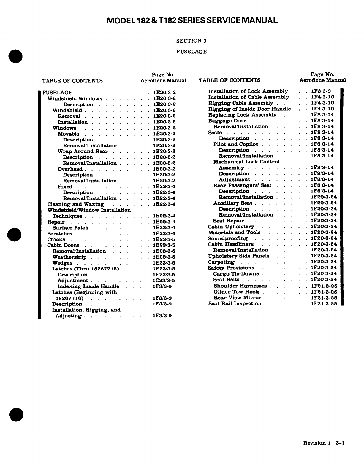
MODEL
182
&
T182
SERIES
SERVICE
MANUAL
SECTION
3
FUSELAGE
Page
No.
Page
No.
TABLE
OF
CONTENTS
Aerofiche
Manual
TABLE
OF
CONTENTS
Aerofiche.
Manual
FUSELAGE
.. . .. .. .. .
1E20.3-2
Installation
of
Lock
Assembly
. .
1F3
3-9
Windshield
Windows
.......
1E203-2
Installation
of
Cable
Assembly
.. .
1F4
3-10
Description
........
1E20/3-2
Rigging
Cable
Assembly
.....
1F4
3-10
Windshield.
.. ... ....
E20/3-2
Rigging
of
Inside
Door
Handle
.
1F4
3-10
Removal
....... . . .
1E20/3-2
Replacing
Lock
Assembly
....
1F8
3-14
Installation
. .. ... ..
1E20/3-2
Baggage
Door
. . . .
1F83-14
Windows
.
.........
1E20/3-2
Removal/Installation
.
....
1F8.3-14
Movable
.........
.
1E20/3-2
Seats
... .
1F8/3-14
Description
........
1E20/3-2
Description
........
F
3-14
Removal/Installation
. ...
1E20/3-2
Pilot and
Copilot
....
.
1F8/3-14
Wrap-Around
Rear
..... .
1E20/3-2
Description
.
.......
1F83-14
Description
........
1E20/3-2
Removal/Installation
.....
1F8/3-14
Removal/Installation
....
1E20/3-2
Mechanical
Lock
Control
Overhead
....
..
....
1E20/3-2
Assembly
.........
1F8/3-14
Description
........
1E20/3-2
Description
.
......
1F8/3-14
Removal/Installation
....
1E20/3-2
Adjustment
.....
F8/3-14
Fixed
...........
1E22/3-4
Rear
Passengers'
Seat
.....
1F83-14
Description
........
1E22/3-4
Description
.
.......
F8/3-14
Removal/Installation
.....
1E22/3-4
Removal/Installation
.....
1F20/3-24
Cleaning
and
Waxing
......
1E22/3-4
Auxiliary
Seat
. .. ... . 1F20/3-24
Windshield/Window
Installation Description
..
....
. 1F20/3-24
Techniques
..........
1E22/3-4
Removal/Installation
.....
1F20/3-24
Repair
............
1E22/3-4
Seat
Repair
..
.....
.1F20/3-24
Surface
Patch
... .. .. .
1E22/3-4
Cabin
Upholstery
.......
1F20/3-24
Scratches.
.
........
1E22/3-4
Materials
and
Tools
......
1F20/3-24
Cracks
............
1E23/3-5
Soundproofing
.
.....
.1F20/3-24
Cabin
Doors
..........
E23/3-5
Cabin
Headliners
.....
. 1F20/3-24
Removal/Installation
....
.1E23/3-5
Removal/Installation
.....
1F20/3-24
Weatherstrip
....
.....
1E23/3-5
Upholstery
Side
Panels
.....
1F20/3-24
Wedges
.......
1E23/3-5
Carpeting
....
.1F20/3-24
Latches
(Thru
18267715)
. . .
1E23/3-5
Safety
Provisions
.......
1F20
3-24
Description
..
.....
.1E23/3-5
Cargo
Tie-Downs
.......
1F20
3-24
Adjustment
....
....
1C23/3-5
Seat
Belts
.........
1F20/3-24
Indexing
Inside Handle
..
1F3/3-9
Shoulder Harnesses
.... .
1F21/3-25
Latches
(Beginning
with
Glider
Tow-Hook .... .. 1F21/3-25
18267716)
.......
..
F3/3-9
Rear
View
Mirror
......
1F21/3-25
Description
. .. . . . . ..
F3/3-9
Seat
Rail Inspection
.. . . . .
F21'3-25
Installation.
Rigging, and
Adjusting
......
...
1F3/3-9
Revision
1
3-1
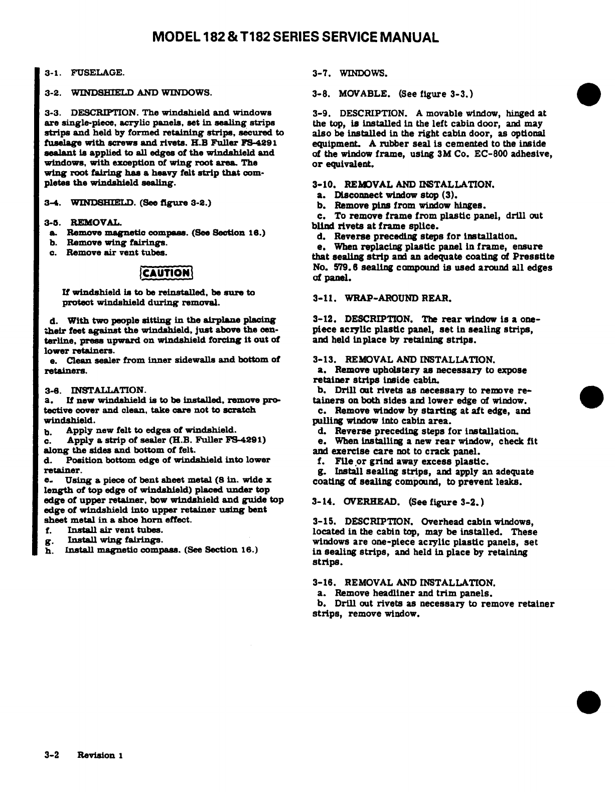
MODEL
182
&
T182
SERIES
SERVICE
MANUAL
3-1.
FUSELAGE.
3-7.
WINDOWS.
3-2.
WINDSHIELD
AND
WINDOWS.
3-8.
MOVABLE.
(See
figure
3-3.)
3-3.
DESCRIPTION.
The
windshield
and
windows
3-9.
DESCRIPTION.
A
movable
window,
hinged
at
are
single-piece,
acrylic panels,
set
in
sealing
strips
the
top,
is installed
in
the
left
cabin
door,
and
may
strips
and
held
by
formed
retaining
strips,
secured
to
also
be
installed
in
the
right
cabin
door,
as
optional
fuselage
with
screws
and
rivets.
H.B
Fuller
FS-4291
equipment.
A
rubber
seal
is
cemented
to
the
inside
sealant
is
applied
to all
edges
of
the
windshield
and
of
the
window
frame,
using
3M
Co.
EC-800
adhesive,
windows,
with
exception
of
wing
root
area.
The
or
equivalent.
wing
root
fairing
has
a
heavy
felt
strip that
com-
pletes
the
windshield
sealing.
3-10.
REMOVAL
AND
INSTALLATION.
a.
Disconnect
window
stop
(3).
3-4.
WINDSHIELD.
(See
figure
3-2.)
b.
Remove
pins from
window
hinges.
c.
To
remove
frame
from
plastic
panel,
drill
out
3-5.
REMOVAL.
blind
rivets
at
frame
splice.
a.
Remove
magnetic
compass.
(See
Section
16.)
d.
Reverse
preceding
steps
for
installation.
b.
Remove
wing
that
sealing
strip
and
an
adequate
coating
of
Presstite
If
windshield is
to
be
reinstalled,
be
sure
to
protect
windshield
during
removal.
d.
With
two
people
sitting
in
the
airplane
placing
3-12.
DESCRIPTION.
The
rear
window
is
a
one-
their
feet
against
the
windshield,
just
above
the
cen-
piece acrylic
plastic
panel,
set
in
sealing
strips,
terline, press
upward
on windshield
forcing
it
out
of and
held
inplace
by
retaining
strips.
lower
retainers.
e.
Clean
sealer
from
inner
sidewalls
and
bottom
of
3-13.
REMOVAL
AND
INSTALLATION.
retainers.
a.
Remove
upholstery
as
necessary
to
expose
retainer
strips
inside
cabin.
3-6.
INSTALLATION.
b.
Drill
out
rivets
as
necessary
to
remove
re-
a.
If
new
windshield is
to
be
installed.
remove
pro-
tainers
on
both
sides
and
lower
edge
of
window.
tective
cover
and
clean,
take
care
not
to
scratch
c.
Remove
window
by
starting
at
aft
edge,
and
windshield.
pulling
window
into
cabin
area.
b.
Apply
new
felt
to
edges
of
windshield.
d.
Reverse preceding
steps
for
installation.
c.
Apply
a
strip
of
sealer
(H.B.
Fuller
FS-4291)
e.
When
installing
a
new
rear
window,
check
fit
along the
sides and
bottom of felt.
and
exercise
care
not
to
crack
panel.
d.
Position
bottom edge
of
windshield
into
lower
f.
File
or
grind
away
excess
plastic.
retainer.
g.
Install
sealing
strips,
and
apply
an
adequate
e.
Using
a
piece
of
bent
sheet
metal
(8
in.
wide
x
coating
of
sealing
compound,
to
prevent
leaks.
length
of
top
edge
of
windshield)
placed
under
top
edge
of
upper
retainer.
bow
windshield
and
guide
top
3-14.
OVERHEAD.
(See
figure
3-2.)
edge
of windshield
into upper
retainer
using
bent
sheet
metal
in
a shoe
horn
effect.
3-15.
DESCRIPTION.
Overhead
cabin
windows,
f. Install
air
vent tubes.
located
in
the
cabin
top, may
be
installed.
These
g.
Install
wing
fairings.
windows
are
one-piece
acrylic
plastic
panels,
set
h.
Install
magnetic
compass.
(See
Section
16.)
in sealing
strips,
and
held
in
place
by
retaining
strips.
3-16.
REMOVAL
AND
INSTALLATION.
a.
Remove
headliner
and
trim
panels.
b.
Drill
out
rivets
as
necessary
to remove
retainer
strips,
remove
window.
3-2
Revision
1

MODEL
182
&
T182
SERIES
SERVICE
MANUAL
CORRECT
,/.
,.
-;:.
'-
INCORRECT
STOP
DRILLED
X
\WOOD.
WO
CRACK__
^
|l
; SF
REINFORCEMENT
TRIM
DAMAGED
AREA
-
,.ll'.
!
CORNERS-
iI J,,
-,
' '.
'-
BEVELED
EDGEGE^
II' I
,
IRREGULAR
SHAPED
SDAMAGERP
SURFACE
PATCH-_.
/
--
ROUND
HOLE
^ANPATCH SHOULD
BE
SURFACE
P
H
FR
ROUND
HORLES
PATCH
SURFACE
PATCH
OR
ROUND
HOLES
BEVE
-D
EDGE
I
IN
PLACEU
PATCH
TAPERED
ON
SHARPER
ANGLE
THAN
STOP*~~
*«-MATERIAL.
STOP
BEVELED
EDGE--DRILLED
PATCH
AND HOLE DURING
CEMENTING,
PRESSURE
SHOULD
BE
TRIMMED
NEED
BE
APPLIED
ONLY
ON
TOP
-C R
'FhN
cfi>I
}
WITH
TAPERED
EDGES. SURFACE.
TAPER
ASSURES
EQUAL
,CR
ACKEFC
I-
PRESSURE
ON
ALL
SIDES
-
s^^^'^ n'-FCE
PATCH
HEAT
EDGES
OF
<.:
-~;ll!,
,
o- e-
PATCH
UNTIL
SCRFACE
PATCH
FOR
CRACKS
SOFT
AND
FORCE
IT
INTO
HOLE.
HOLD
IT
IN
PLACE
UNTIL
COOL
AND
HARD
TO
ASSURE
PERFECT
FIT.
AFTER
CEMENT
HAS
HARDENED.
THEN REMOVE PATCH
SAND
OR
FILE
EDGES
LEVEL
FOR
CEMENTING
BATH.
WITH
SURFACE
Figure
3-1.
Repair
of
Windshield
and
Windows
3-3
MODEL
182
&
T182
SERIES
SERVICE
MANUAL
c.
Reverse
preceding
steps
for
installation.
the
drill
shall
have
an
included
tip
angle
of
d.
When
installing
new
window,
check
fit
and
exer-
60
degrees
to
140
degrees
and
a
lip clearance
cise
care
not
to
crack
panel.
angle
of
15
degrees
to
20
degrees.
e.
File
or
grind
away
excess
plastic.
f.
Apply
felt
strips
and
apply an
adequate
coating
Deep
holes
-
when
hole
depth
to hole
diameter
of
sealing
compound,
to
prevent leaks.
ratio
is
greater
than
3.0
to
1,
the
drill
shall
have an
included
tip
angle
of
140
degrees
and
3-17.
FIXED.
(See
figure 3-2.)
a lip
clearance
of
12
degrees
to
15
degrees.
3-18.
DESCRIPTION.
Fixed
windows
are
mounted
Parts
which
must
have
holes
drilled
shall
be backed
in
sealing
strips
and
sealing
compound,
and
are
held
up
with
a
drill
fixture.
Holes
may
be
drilled
through
in
place
by
various
retainer
strips.
the
part
from
one
side.
However,
less
chipping
around
holes will
occur
if
holes
are
drilled
by
drill-
3-19.
REMOVAL
AND
INSTALLATION.
ing
the
holes
from
both
sides.
This
is
accomplished
a.
Remove
upholstery
and
trim
panels
as
necessary.
by
using
a
drill
with
an
acrylic
backup
piece
on
the
b.
Drill
out
rivets
securing
retainers;
remove
opposite
side.
Remove the
drill
from
the
hole
and
window.
switch
the
backup
plate
and
finish
drilling
from the
c.
Reverse
preceding
steps for
installation.
opposite
side.
d.
When
installing
new
window,
check
fit
and
exer-
cise
care
not
to
crack
panel. 3-22. REPAIR.
Replace
extensively
damaged
trans-
e.
File
or
grind
away
excess
plastic. parent
plastic,
rather
than
repair
whenever
possible,
f.
Apply
felt
strips
and
apply
an
adequate
coating
since
even
a
carefully
patched
part
is
not
the
equal
of
sealing
compound,
to
prevent leaks.
of
a
new
section,
either
optically
or
structurally.
At
the
first
sign
of
crack
development,
drill
a
small
hole
3-20.
CLEANING
AND
WAXING.
(Refer
to
Section
2.)
at
the
extreme
end
of
the
crack,
as
shown
in
figure
3-1.
This
serves
to
localize
the
cracks
and
also
to
3-21.
WINDSHIELD
AND
WINDOW
INSTALLATION
preventfurther
splitting
by
distributing
the
strain
TECHNIQUES:
over
a
large
area.
If
the
cracks
are
small,
stopping
them with
drilled
holes
will
usually
suffice
until
re-
Special
drills
must
be
used
when
drilling
holes
in
placement
or
more
permanent
repairs
can
be
made.
acrylic.
Standard
drills
will cause
the
hole
to
be
The
following
repairs
are
permissible;
however,
they
oversized,
distorted,
or
excessively
chipped.
are
not
to
be
located
in
the
pilot's
line
of
vision
dur-
ing
landing
or
normal
flight.
Whenever possible,
a
coolant
such
as
a
plastic
drill-
a.
SURFACE
PATCH.
If
a
surface
patch
is
to
be
ing
wax
should
be
used
to
lubricate
the
drill
bit.
Installed,
trim
away
the
damaged
area
and
round
all
Cessna
recommends
"Reliance"
drill
wax
or
Johnson
corners.
Cut a
piece
of
plastic
of
sufficient
size
to
No.
140
Stick
Wax.
cover
the
damaged
area,
and
extend
at
least
3/4-inch
on
each
side
of
the
crack
or
hole.
Bevel
the edges,
Drilled
holes
should
be
smooth
with
a
finish
of
as
shown
in
figure
3-1.
If
the
section
to
be
repaired
125
rhr.
is
curved,
shape
the
patch
to
the
same
contour
by
heating
it
in
an
oil
bath
at
a
temperature
of
248°F
to
The
feed
and
speed
of
the
drill
is
critical.
The
fol-
302°F.,
or
it
may
be
heated
on
a
hot
plate
until
soft.
lowing
chart
indicates
drill
speed
for
various
thick-
Boiling
water
should
not
be
used
for
heating.
Coat
nesses
of
acrylic.
the
patch
evenly with
plastic
solvent
adhesive
and
place
immediately
over
the
hole.
Maintain
a
uniform
Material
Thickness
Drill
Speed
pressure
of
from
5
to
10
psi
on
the
patch
for
a
mini-
1/16" to
3/16"
1500
to
4500
rpm
mum
of
three
hours.
Allow
the
patch
to
dry
24
to 36
1/4"
to
3/8"
1500
to
2000
rpm
hours
before
sanding
or
polishing
is
attempted.
7/16"
1000
to
1500
rpm
b.
PLUG
PATCH.
In
using
inserted
patches
to
1/2"
500
to
1000
rpm
repair
holes in
plastic
structures,
trim
the
holes
to
3/4"
500
to
800
rpm
a
perfect
circle
or
oval,
and
bevel
the
edges
slightly.
1"
500
rpm
Make
the
patch
slightly
thicker
than the
material
being
repaired,
and
similarly,
bevel
the
edges.
Install
Specifications
for
the
twist
drill
used
to
drill
acrylic
patches in
accordance
with
procedures
illustrated
in
is
as
follows:
figure
3-1.
Heat
the
plug
until
soft
and
press
into
the
hole
without
cement,
and
allow
to
cool
in
order
to
NOTES
make
a
perfect
fit.
Remove
the
plug,
coat
the
edges
with
adhesive,
and
then
reinsert
into
the
hole.
Main-
Shallow
holes
-
when
hole
depth
to
hole
diam-
tain
a
firm,
light
pressure
until
the
cement
has
set,
eter
ratio
is
less
than
1.
5
to 1,
the
drill
shall
then
sand
or
file
the
edges
level
with
the
surface;
have
an
included
tip
angle
of
55
degrees
to
60
buff
and
polish
to
a
clear
finish.
degrees
and
a
lip
clearance
angle
of
15
degrees
to
20
degrees.
3-23.
SCRATCHES.
Scratches
on
clear
plastic
surfaces
can
be
removed
by
hand-sanding
operations,
Medium
deep
holes
-
when
hole
depth to
hole
followed
by
buffing
and
polishing,
if
the
following
diameter
ratio
is
from
1. 5 to 1
up
to
3
to
1,
steps
are
followed
carefully.
3-4
Revision
1
MODEL
182
&
T182
SERIES SERVICE
MANUAL
a.
Wrap
a
piece
of
No.
320
(or
finer)
sandpaper
or
each
side
of
surface,
and
inserting
small
bolts
abrasive
cloth
around
a
rubber
pad
or
a
wooden
through
wood
and
plastic.
A
cushion
of
sheet
rubber
block.
Rub
surface
around
scratch
with
a
circular
or
aircraft
fabric
should
be
placed
between
wood
and
motion,
keeping
abrasive
constantly
wet
with
clean
plastic
on
both
sides.
water
to
prevent
scratching
surface
further.
Use
minimum
pressure
and
cover
an
area
large
enough
3-25.
CABIN DOORS.
(See
figure
3-3.)
to
prevent formation
of
"bull's
eyes"
or
other
optical
distortions.
3-26.
REMOVAL
AND
INSTALLATION.
Removal
of
hinge
pins, attaching hinges
and
door
stops.
If
per-
Do
not
use
a
coarse
grade
of
abrasive.
manent
hinge
pins
are
removed,
they
may
be
replaced
Number
320
is
of
maximum
coarseness,
with
clevis
pins,
secured
with
cotter
pins,
or
new
hinge
pins
may
be
installed
by
inserting
pin
through
b.
Continue
sanding
operation,
using
progressively
both
hinge
halves,
and chucking
a
rivet
set
in
a
hand
finer
grade
abrasives
until
scratches
disappear.
drill,
hold one end
of
pin
and
form
a
head
on
opposite
c.
When
scratches
have
been
removed,
wash
area
end.
Reverse
pin
and
repeat
process.
When
fitting
a
thoroughly
with
clean
water
to
remove
all
gritty
new
door
that
is
not
bonded,
some trimming
of
door
particles.
The
entire
sanded
area
will
be
clouded
skin
at
edges,
and
some
reforming
with
a
soft
mallet
with
minute
scratches,
which
must
be
removed
to
may
be
necessary
to achieve
a
good
fit.
Reforming
restore
transparency.
of
bonded
door
flange
by
striking
with
a
soft
mallet,
d.
Apply
fresh
tallow
or
buffing
compound
to a
etc.
is
NOT
permissible,
due
to
possible
damage
to
motor-driven
buffing
wheel.
Hold
wheel
against
bonded
areas.
plastic
surface,
moving
it
constantly
over
damaged
area
until
cloudy
appearance
disappears.
A
2000- 3-27.
CABIN
DOOR
WEATHERSTRIP.
A
hollow,
foot-per-minute
surface
speed
is
recommended
to
fluted-type,
rubber
weatherstrip
is
cemented
around
prevent
overheating
and
distortion.
(Example:
750
all
edges
of
the
cabin
door.
When
replacing
weather-
rpm
polishing
machine
with a
10-inch
buffing
bonnet.)
strip,
ensure
that
contact
surfaces
are
clean
and
dry.
Cut
new
weatherstrip
to
length
using
old
weatherstrip
NOTE
as
a
guide.
Cut
small
notch
in
butt
ends
of
new
wea-
therstrip
to
allow
for
drainage.
Position
splice
with
Polishing
can
be
accomplished
by
hand,
but
notch
at door
low
point
and
apply
a
thin,
even
coat
of
will
require
a
considerably
longer
period
of
EC-1300L
adhesive
(3-M
Company)
or
equivalent
to
time
to
attain
the
same
result
as
produced
both
surfaces.
Allow
to
dry
until
tacky
before
press-
by
a
buffing
wheel.
ing
into
place
on
door.
Do
not
stretch
weatherstrip
around
door
corners.
e.
When
buffing
is
finished,
wash
area
thoroughly,
and
dry
with a
soft, flannel
cloth.
Allow
surface
to
3-28.
WEDGES.
Thru
18267715,
wedges
are
instal-
cool,
and
inspect
area,
to
determine
if
full
trans-
led
at
the upper
forward
edge
of
the
door
to
aid
in
pre-
parency
has
been
restored.
Apply
a
thin
coat
of
venting
air
leaks
at
this
point.
Several
attaching
holes
hard
wax,
and
polish
surface
lightly
with
a
clean
are
located
in
the
wedges.
Holes
giving
best
results
flannel
cloth.
should
be
selected.
NOTE
3-29.
DOOR
LATCHES.
(Thru
18267715.)
(See
figure
3-4.)
Rubbing
plastic
surface
with
a
dry
cloth
will
build
up
an
electrostatic
charge
3-30.
DESCRIPTION.
The
cabin
door
latch
is
a push-
which
attracts
dirt
particles,
and may
pull
bolt
type,
utilizing
a
rotary
clutch
for
positive
eventually
cause
scratching
of
surface.
bolt
engagement.
As
the
door
is
closed,
teeth
on
un-
After
wax
has
hardened,
dissipate
this
derside
of
bolt
engage
teeth
on
clutch.
The
clutch
charge
by
rubbing
surface
with
a
slightly
gear
rotates
in one
direction
only
and
holds
door
un-
damp
chamois cloth. This
will
also
re-
til
handle
is
moved
to
LOCK
position,
driving
bolt
move
dust
particles
which
have
collected
into
slot.
while
wax
is
hardening.
3-31.
ADJUSTMENT.
Vertical
adjustment
of
the
ro-
f.
Minute
hairline
scratches
can
often be
removed
tary
clutch
is
afforded
by
slotted
holes
which
ensures
by
rubbing
with
commercial
automobile
body
cleaner,
sufficient
gear-to-bolt
engagement,
and
proper
align-
or
fine-grade
rubbing
compound.
Apply
with
a
soft,
ment.
The
extension
or
retraction
of
the bolt
(2)
is
clean,
dry cloth
or
imitation
chamois.
controlled
by
adjusting
bolts
(10)
in
the
slotted
holes.
Loosen
screws
sufficiently
to
move
latch
base
forward
3-24.
CRACKS.
(See
figure
3-1.)
on
the
door to
retract
bolt,
and
aft
to
extend
bolt.
a.
When
a
crack
appears,
drill
a
hole
at
end
of
crack
to
prevent
further
spreading.
Hole
should
be
approximately
1/8-inch
in
diameter,
depending
on
length
of
crack
and
thickness
of
material.
b.
Temporary
repairs
to
flat
surfaces
can
be
accomplished
by
placing
a
thin
strip
of
wood
over
Revision
1
3-5
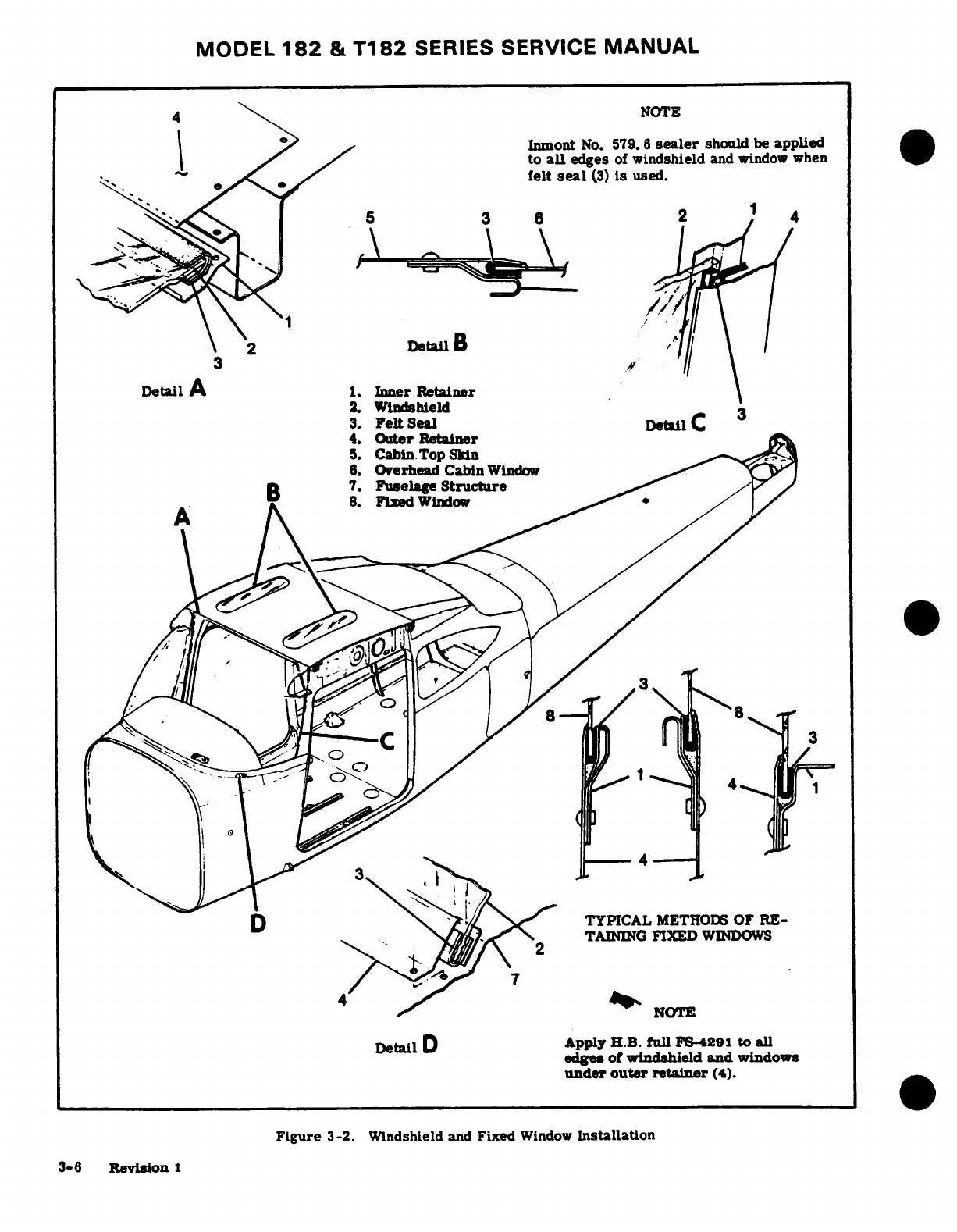
MODEL
182
&
T182
SERIES
SERVICE
MANUAL
4
^\
NOTE
Inmont
No.
579.6
sealer
should
be
applied
tI/~ ^^~~~ /
~
to
all
edges
of
windshield
and
window
when
"^
~,~
/. »^felt
seal
(3)
is
used.
5 3
6
2
4
11 are
32
DetailB
Detail
A
1.
Inner
Retainer
2.
Windshield
3.
Pelt
Seal
Detl
C
4.
Outer
Retainer
5. Cabin.
Top
Skin
6.
Overhead Cabin
Window
B
7.
Fuselage
Structure
A
"Q
7
\ 2 ..........
TAINING
FIXED
WINDOWS
'2
/^~~
NOTE
3-6
Revision
1
I~~~~de
ofwnsil
n
idw
3-6
Revision
I

MODEL
182
&
T182
SERIES
SERVICE
MANUAL
2
B
8
Detail
D
13
Beginning
with
Detail
C
1978
Models
6
10
Detail
A
*
THRU
18267715
C
1.
Window
Seal
//
y
2.
Weatherstrip
A
3.
Window
Stop
re
3-
4.
Spring
3
e
Figure
3-4
5.
Wedge
4
6.
Window
Hinge
7. Cabin
Door
8. Door
Jamb
9.
Window
Frame
10.
Window
\
11.
Washer
14
12.
Nut
.\ 15
13.
Lock
Assembly
Detail
14.
Latch
Handle
Detail
15.
Striker
Plate
Thru
1977
Models
16.
Screw
0
17.
Spacer
18.
Stop
Guide
16
19.
Stop
Arm
20.
Pin
21.
Stop
Hinge
E
17
22.
Stop
Spring
-=-
-_
_
23.
Door
Outer
Skin
F
etail
E
F 18
NOTES
A
\
Openable
window
may
be
installed
in
RH
cabin
door.
19
Forming
of
the
door
flanges
by
striking
with
soft
-'
mallet,
etc.
is
NOT
permissible,
since
damage
20
~ .
to
bonded
areas
may
occur.
23
Trim
cutout
in
inner
pan
if
necessary
to
maintain
23
.10
inch
minum
clearance
with
door
stop
arm.
\
Spray
cabin
door
and
window
seals
with
MS-122
(Miller-Stephenson
Chem
Corp)
or
equivalent.
Do
not
overspray;
confine to
seals.
As
required
(Typ
Lubricate
surface
of
spring
(22)
in
contact
with
for
good
seal
etire
entire
spacers
(17)
with
Hi/Lo-Temp
grease
(MIL-G-21164C)
perimeter)
After tightening
screw
(16),
spacers
(17)
should
turn
freely.
View
F- F
Figure
3-3.
Cabin
Door
3-7

MODEL
182
&
T182
SERIES
SERVICE
MANUAL
10
7
NOTE
Thru
1825253,
a
Service
Gi l
5
f
Letter
and
Service
Kits
.^'^(^S~i''''.^^ /
4
SK206-16
and
SK206-17
are
available
from
the
·[r ';io < Oi \ |
Cessna Service
Parts
]|
//
4 *
'\ I 0
3
Center
for installing
the
board.
This
modification
2
enables
the
door
to
be
ini-
00,//011 ^^^ >^// ^
<~
,tially
easier
to
close.
1
Also,
the
cabin
doors
re-
main
closed
on
the
ground
l ^ 'i>^^' L^S
^^^^~t^ ^j
~during
gusty
wind
condi-
tions.
./
19
, f
Detail
A
2
es
Rotary
clutch
components
are
matched
upon
assembly.
The
clutch
mechanism,
if
defec-
tive,
should
be
replaced
as a
22
unit.
17
Y
E A^ ^
6;71
2726
24
15
r 'Sy ~16^
i
2j7f
ROTARY
CLUTCH
18
16
1.
Top
Bolt
Guide
10.
Bolt
Adjust
Screw
20.
Outside
Handle
2.
Bolt
11.
Pull Bar
21.
Pin
3.
Side
Bolt
Guide
12.
Spring
22.
Mounting
Structure
4.
Base
Bolt
Guide
13.
Pin
23. Shim
5.
Latch
Base
Plate
14.
Inside
Handle
24.
Rotary
Clutch
6.
Abrasive Pad
15.
Spacer
25.
Guide
7.
Lockplate
16.
Plate
Assembly
26.
Door
Post
8.
Bracket
17.
Support
27.
Cover
9.
Spring
18.
Shaft
Assembly
28.
Handle
Adjust
Screw
19.
Bolt
Push
Rod
Figure
3-4. Door
Latch
and
Rotary
Clutch
(Thru
18267715)
3-8

MODEL
182
&
T182
SERIES
SERVICE
MANUAL
on
the
rear
doorpost.
Pushing
the
exterior
handle
flush
with
the
fuselage
skin.
The
push
rod
assembly,
attached
to
the latch
bolt/pull
bar
assembly,
moves
guide
in
the
door
into
the
upper
aft door
sill
receptacle.
Close
door
carefully
after
adjustment
and
The
interior
door
handle
has
now
moved
from
approxi-
check
clearance
between
bolt
and
door
jamb mately
15 °
aft
of
vertical
to
approximately
45
°
forward
and
clutch
engagement.
of
vertical.
Pushing
the
interior
handle
to
the
horizon-
tal
position,
flush
with
the arm
rest,
will
overcenter
3-32.
INDEXING INSIDE
HANDLE.
(Thru
18267715.)
the
door
latch,
securing
the
door
for
flight.
The
ca-
(See
figure 3-4.)
When
inside
door
handle
is
removed,
bin
door
latch
assembly
also
incorporates
a
locking
reinstall
in
relation
to
position
of
bolt
(2),
which
is
arm
and
locking
pin,
used
with
a
key
lock
to
secure
spring-loaded
to
CLOSE
position.
Index
inside
handle
the
aircraft
after
use.
With
the
cabin
door
closed,
in
accordance
with
the
following
procedures.
and
the
exterior
latch
handle
flush,
actuating
the
a.
Temporarily
install
handle
(14)
on
shaft
assem-
key
lock
drives
the
locking
pin
into
the
exterior
latch
bly
(18)
approximately
vertical.
handle, locking
the
aircraft.
It
is
important
to
note
b.
Move
handle
(14)
back
and
forth
until
handle cen-
that
since the
cabin
door latch assembly
and
the
ters
in
spring-loaded position.
interior
handle
fase
plate
assembly
are
directly
con-
c.
Without
rotating
shaft
assembly
(18),
remove
nected
by
the
push
rod
assembly,
that
any
amount
of
handle
and
install
door
upholstery
panel
with
door
force
applied
t
o
the
outside
handle
is
subsequently
handle
OPEN-CLOSE
placard
in
place.
applied
to
the
inside
handle.
If
the
push
rod
assembly
d.
Ensure
CLOSE
index
is
at
top.
is
not
properly adjusted,
it
is
possible
to
lock
one's
e.
Install
handle
(14)
to
align
with
CLOSE
index
on
self
out
of
the
aircraft
by applying
too much
force
to
placard.
the
exterior
handle
when
closing
the
cabin
door.
f.
Ensure
bolt
(2)
clears
doorpost
and
teeth
engage
Therefore,
it
is
important
to
adhere
to
all
of
the
clutch
gear
when
handle
(14)
is
in
CLOSE
position.
rigging
and
adjustment
specifications
pertaining
to
The
inside
door
handle
fits
into
the
arm
rest
when
it
the
preload
forces
of
the
interior
door
handle.
Refer
is
moved
to the
locked
position.
Install
the
handle
on
to the
rigging
and
adjusting
procedures
in
the
follow-
the
serated
shaft so
that
the
forward
end
on
the
handle
ing
paragraphs.
is 8 °
15'
above
the
centerline
of
the
handle
shaft
when
in
the
locked
position.
A
small
amount
of
adjustment
3-35.
INSTALLATION,
RIGGING
AND
ADJUSTMENT
can
be
accomplished
by
loosening
the
shaft
mounting
PROCEDURES.
(Beginning
with
18267716.) (See
bolts,
and
moving
screw
(28)
in
the
slot
to
raise
or
figure
3-5.
)
lower
forward
end
of
the
handle.
3-36.
INSTALLATION
OF
LOCK
ASSEMBLY
ON
3-33.
DOOR
LATCHES.
(Beginning with
18267716.) LATCH
ASSEMBLY.
(Beginning
with
18267716
and
(See
figure 3-5.)
T18267717.)
(See
figure
3-5.)
a.
Assemble
locking
arm
(2)
with
pin
assembly
(5)
3-34.
DESCRIPTION.
The
cabin
door
latch
consists
by
placing
one
washer
(4) on
each
side
of
locking
of
a
two-piece
nylon
latch
base,
exterior
handle,
arm
(2).
Swage
pin
(5)
so
that
there
is
a
minimal
spring-loaded
latch
bolt/pull-bar
assembly,
and
a
amount
of
looseness
between
parts.
Cut
excessive
spring-loaded
catch/trigger
pin
assembly.
The
in-
material
from
pin
(5).
terior
handle
base plate
assembly
is
directly
connec-
b.
Place
pin
(5)
in
1/8-inch
hole
of
base
assembly
ted to
the
cabin
door latch
by
means
of
an
adjustable
(22).
push
rod assembly.
This
push
rod
assembly
has
two
c.
Align
.
099-inch
hole
of
locking
arm
(2)
with
clamps
attached,
180
°
apart
on
the
main
rod.
These
.094-inch
hole
in
latch
base
(22)
and
install
pin.
clamps
are
used
to
operate
a
cable
assembly
that
d.
Assemble
cam
assembly
(24)
to
locking
arm
drives
a
cable pin
from
the upper
aft
end
of
the
cabin
(2).
Cam
should
be
on
latch
side
of
locking
arm.
door
into
the
aft
upper
door
sill,
When
the
cabin
door
Use
3
washers
(25)
between
cam
and
locking
arm.
is
open,
the
door latch
exterior
handle
should
be ex-
tended
(out),
held
in
this
position
by
means
of
the
3-37.
INSTALLATION
OF
LOCK
ASSEMBLY.
spring-loaded
latch
catch
engaged
with
the latch
bolt (Beginning
with
18267716.)
(See
figure
3-5.
)
through
the
beveled
hole in
the
bolt.
The push
rod
assembly
will
be
moved
forward,
and
the
attached
NOTE
cable
assembly
will
be
retracted
from
the
upper
door
sill
with
the
cable
pin
recessed
in
the
pin
guide,
lo-
Install
with
in
position
cated
in
the
upper aft
corner
of
the
door.
The
interior
Install
with
latch
in
CLOSE
position.
handle,
being
directly
connected
by
means
of
the
push
rod,
will
be
moved
approximately
15°
aft
of
the
a.
Install
latch
assembly
between
door
pan
and
door
rod,
will
be
moved
approximately
15°
aft
of
the
vertical
position.
Closing
the
cabin
door
drives
the
trigger
pin
over
the
nylon
actuator
attached
to
the
b.
Cable
assembly
should
be
forward
of
latch
base
cover
plate, located
on
the
rear
doorpost.
As
the
attach
plate
and
inboardof
latch
base
cup.
trigger
pin
is
driven
forward,
it
disengages
the
latch
c.
Extend
latch
handle
through
cutout
in
door
catch
from
the latch
bolt.
The
extended
extension
This
will
pull latch
bolt
back
far
enough
to
allow
springs,
attached
to
the
latch
handle
and
bolt/pull
bar
latch
to
fall
into
place.
assembly,
compress,
pulling
the
latch handle
in,
and
d.
Push
latch
assembly
aft
so
that
bolt
(12)
and
push
assembly, compress,
pulling
the latch
handle
in,
and
respective
holes.
driving
the
latch
bolt
over
the
latch
striker,
located
rod
(13)
extend through
the
respective
holes.
3-9
MODEL
182
&
T182
SERIES SERVICE
MANUAL
e.
Trip
push rod
(13)
so
that
bolt
(12)
is
fully
ex-
a.
With
latch
secured
to
door
pan,
attach
push
rod
tended
and
handle
(20)
is flush.
assembly
(44)
to
pull
bar
(7)
and
secure
with
pin
(8).
f.
Secure
latch
to
door
pan
with
four
NAS
220-5
screws
through base
assembly
(22)
and
two AN525-
NOTE
10R6
screws
through
aft flange
of
door
pan.
g.
Ensure
door skin
fits
properly
around latch
Do
not
install
cotter
pin
(9).
assembly,
then
drill
eleven
.128-inch holes
to
align
with
latch
base.
b.
Ensure
that
latch
is
in
CLOSED
position.
c. By
removing
pin
(8)
that
connects
push
rod
to
NOTE
latch
base assembly,
rotate rod
in
or
out
(180
°
)
for
adjustment.
Adjust
rod so
that
it
takes
a
load
of
6
Do
not
oversize
holes
in
the
latch
base
and
pounds
to
12
pounds
at
the
end
of
the
inner
handle
to
do
not
rivet
base
to
skin
at
this
time.
move
it
from
closed position
to
overcenter
position.
3-38.
INSTALLATION
OF
CABLE
ASSEMBLY.
NOTE
(Beginning
with
18267716.)
(See
figure
3-5.)
a.
On
pin
end of
cable
assembly
(32),
attach
clamp
Rod
must
be
attached
to latch
assembly
(33)
and
nut
(31),
one-inch from
end of
casing,
as
before
rigging
can
be
accomplished.
shown
in
detail
A.
b.
Insert
pin
end of
cable
between
door
pan
and d.
For
fine
adjustment for
overcentering
latch
as-
door skin
at
aft
end
of
door.
Push
pin
end
of
cable sembly,
proceed
as
follows:
to
top
of
door.
1.
Cabin
door
must
be
installed
and
completely
c.
Remove
plug
button
(26)
and
align
pin
on
cable
fitted
to fuselage.
with
pin
guide
(28).
and
insert
pin
through
guide.
2.
Cabin
door latch
must
be
in OPEN
position.
Access
is
gained
through
.
875-inch
hole
(30).
Latch
must
operate
smoothly
and
freely.
d.
Align
clamp
on
cable
casing
with
hole
located
3.
Adjust
striker
plate
(52)
forward
by
installing
one-inch
below .
875-inch
hole,
and
install
screw.
shims
(53)
as required,
so
that
there
is
a
minimal
e.
Check
operation
of
cable.
If
sluggish
operation
clearance
between
latch
bolt
(12)
and
striker
(52).
of
cable
is
encountered,
add
S1450-2A4-062
washers
(34)
as
required
to
facilitate smoother
cable
opera-
NOTE
tion.
This
adjustment
will
ensure
that
when
the
3-39.
RIGGING
CABLE
ASSEMBLY.
(Beginning
door
is
opened
from
the
outside,
the
bolt
with
18267716.)
(See
figure
3-5.)
will
engage the
latch
catch,
and the
exterior
a.
Pull
excess
slack
out
of
cable
(32).
Attach
handle
will
stay
open
until the
door
is
closed
clamp
(33)
and
nut
(31)
to
cable
so
that
it
aligns
with
again.
.
193-inch
hole
in
door
pan,
and
attach.
(Refer
to
paragraph
3-31,
step
"d".)
NOTE
NOTE
If
cabin
door
is
located
too
far
forward
such
that
the
door
latch
will
not
operate,
this
will
Make
sure
latch
is
in
OPEN
position
before
not
allow
latch
assembly
push
rod
(13)
to
ride
proceeding.
up
on
actuator
(47)
and
trigger
the
latch
bolt
(12).
Install
shims
(48)
as required
beneath
b.
Cut
casing
of
cable
assembly
approximately
actuator
(47),
located
on
cover
assembly
(49).
2-inches
from
clamp
bolt
(43)
on
push
rod
assembly
(44)
4.
Close
cabin
door
from
inside
the
aircraft.
When
c.
Insert
core
of
cable through
clamp
bolt
(43).
latch
is
overcentered,
the
exterior
handle should pull
d.
Pull
core
through
clamp
bolt
so
that
pin
(29)
flush.
If
it
does
not
pull
flush,
the
connecting
push
rod
extends
approximately
1/8-inch
from
door
pan
from
the
door
latch
to
the
inside
handle
assembly
should
contour.
be
adjusted
"out" (lengthened).
e.
Cut
core
approximately one-inch forward
of
push
rod
clamp
bolt
(43).
NOTE
f.
Secure
two
nuts
to
push
rod
clamp
bolt.
g.
Operate
latch
several
times
to
ensure
that
latch
When
making
this
adjustment
on
the
over-
works
freely.
If
latch
binds up
and
will
not
work
centering
of
the latch,
it
may
be
noticed
freely,
remove
cable
core
from
clamp
bolt
(43)
and
that
there
is
a
sharp,
loud
canning noise
operate
latch.
If
cable
operates
easily
without
cable
when
the
inside
handle
is
pushed
down.
attachment,
check
cable
for
possible adjustments
to
It
is
preferred
that
the
outside
door
handle
facilitate
ease
of
operation.
be
flush,
even
if
the canning
noise
is
h.
After
cable
operates
freely,
install
cover
assem
noticeable.
bly
(42)
and
recheck
cable
for
operation.
5.
When
adjusting
push
rod,
it
may
need
only
be
adjusted
1/2
turn.
To
accomplish
this,
base
plate
3-40.
RIGGING
INSIDE
DOOR
HANDLE.
(Beginning
(45)
should
be
removed.
with
18267716.)
(See
figure
3-5.)
6.
To
make
1/2
turn
adjustment, remove
smaller
3-10
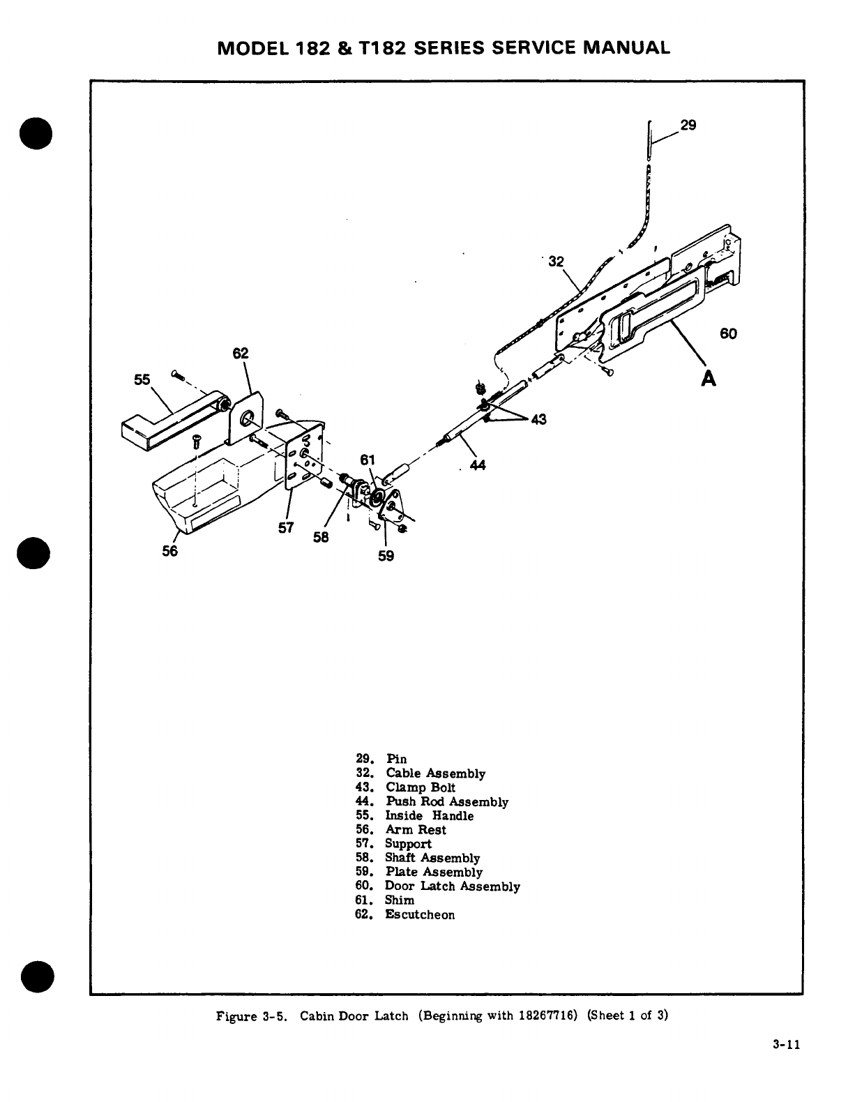
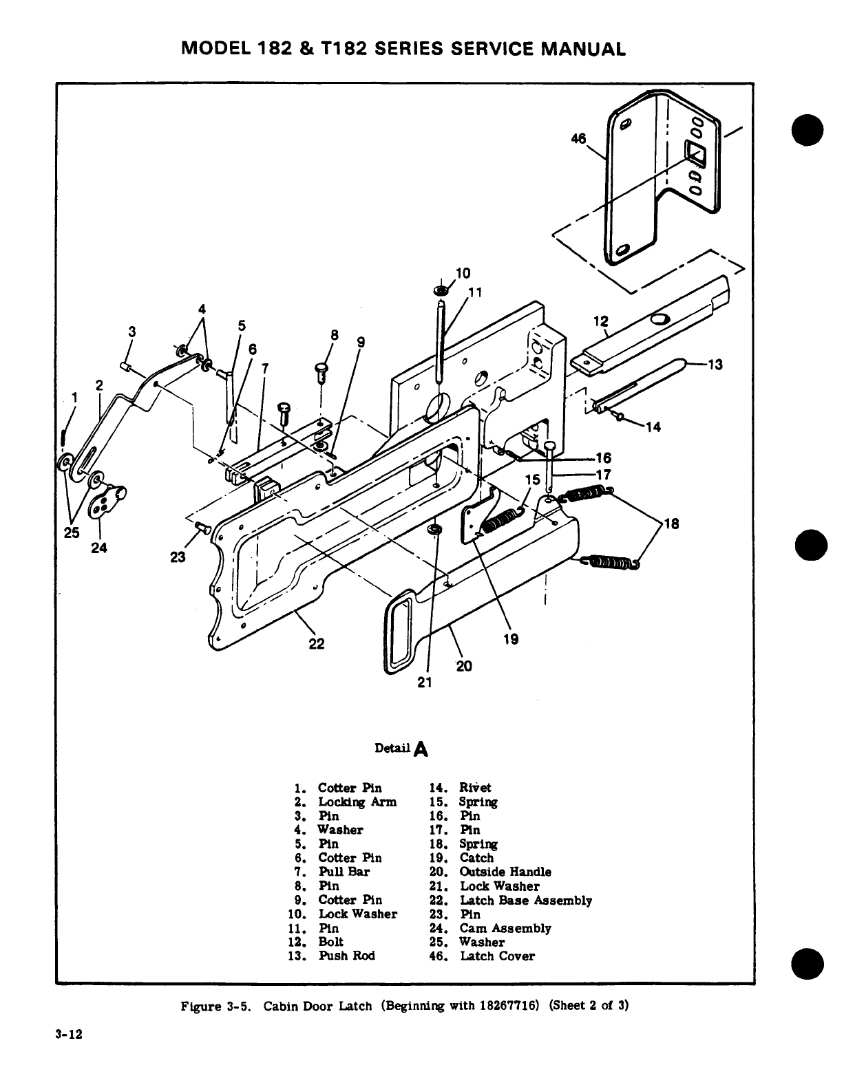
MODEL
182
&
T182
SERIES
SERVICE
MANUAL
46
2,1
10
6
9
12
2 1
.
24
1.
Cotter
Pin
14.
Rivet
2. Locking
Arm
15.
Spring
7.
Pull
Bar
20.
Outside
Handle
8. Pin
21.
Lock
Washer
Detail
A
9.
Cotter
Pin
14.
Latch
Base
Assembly
2.
Lock
Washer
23.
Sprin
3.
Pin
24.
Cam
Assembly
.
BoltWasher
17.
Washer
5.
Pin
18.
Spring
6.
Push
C
otter
Pin
19.
atch
Cover
7.
PuUlBar
20.
Outside
Handle
8.
Pin
21.
Lock
Washer
9.
Cotter
Pin
22.
Latch
Base
Assembly
10.
Lock
Washer
23.
Pin
11.
Pin
24.
Cam
Assembly
12.
Bolt
25.
Washer
13.
Push
Rod
46.
Latch
Cover
Figure
3-5.
Cabin
Door
Latch
(Beginning
with
18267716)
(Sheet
2
of
3)
3-12
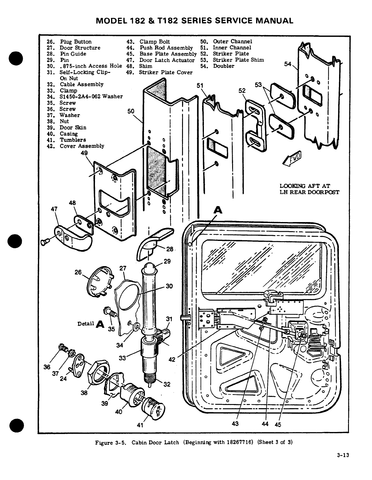
MODEL
182
&
T182
SERIES
SERVICE
MANUAL
26.
Plug Button
43.
Clamp Bolt
50.
Outer
Channel
27.
Door
Structure
44.
Push
Rod
Assembly
51.
Inner
Channel
28.
Pin
Guide
45.
Base
Plate
Assembly
52.
Striker
Plate
29.
Pin
47.
Door
Latch
Actuator
53.
Striker
Plate
Shim
30.
.875-inch Access
Hole
48.
Shim
54.
Doubler
54
31.
Self-Locking
Clip-
49.
Striker
Plate
Cover
On Nut
32.
Cable
Assembly
51
53
33.
Clamp
52
34.
S1450-2A4-062
Washer
35.
Screw
36.
Screw
50
37.
Washer
38.
Nut
40.
Casing
41.
Tumblers
42.
Cover
Assembly
49
49- < jl
*
|
| i |LOOKING
AFT
AT
Is I . I
|
^LH
REAR DOORPOST
48
0|
47
8 1 I
A
*^
^281 .
ft
l &
29
30
I
-
/
Detail
A
34
j
6 41~ 433
42
4
24
39
40
41
43
44
45
Figure
3-5.
Cabin Door
Latch
(Beginning
with
18267716)
(Sheet
3
of
3)
3-13
MODEL
182
&
T182
SERIES
SERVICE
MANUAL
end
of
push
rod
(44)
and
turn
it
over
(180°).
Then
re-
way
front
seats
for
the
pilot
and
copilot,
and
a
split-
install
base
plate
assembly
(45).
backed fixed
seat
for
the
rear
passengers.
A
child's
7.
When
closing
cabin
door
from
the
outside,
by
seat,
if
installed,
is
located
at
the
aft
cabin
bulkhead
using
a
large, sharp
force
on
the
outside
handle,
it
behind
the
rear
seat.
is
possible
to
overcenter
the
inside
handle,
thus
lock-
ing
one's
self
out.
To
prevent this
from
occuring,
3-46.
PILOT
AND
COPILOT.
when
adjusting
the
push
rod
in
step
"4",
adjust
push
rod
so
there
is
a
sufficient
force
(6
to
12
pounds)
3-47.
DESCRIPTION.
The
four-way
seats
may
be
against
the inside
handle
to
prevent it
from overcen-
moved
forward
or
aft,
and
the
seat
back
angle
is
infi-
tering
when
closing
the
door
from
the
outside.
nitely
adjustable.
The
six-way
seats
may
be
moved
8.
Do
not
file,
grind
or
sand
any
portion
of
bolt
forward or
aft,
and
are
adjustable
for
height
and
seat
(12).
back
angle.
9.
Recheck
clamps
that
secure
cable.
There
must
not
be any
slippage
between
cable
casing
and
3-48.
REMOVAL
AND
INSTALLATION.
clamp.
a.
Remove
seat
stops from
rails.
10.
After
overcenter
adjustment
has
been
made,
b.
Disengage
seat
belts
by
slipping
buckle
ends
install
cotter
pin
(9)
in
clevis
pin
(8).
through
seat
belt
retainer.
e.
Rivet
latch
base
(22)
to
door
skin
with
c.
With
vertical
adjust
seats installed,
remove
MS20426A4-3
rivets.
cabin
vent/carpet retainer.
f.
Attach
lock
assembly
casing
(40)
to
door
skin
(39) d.
Crank
vertical
adjust
seats
to
their
maximum
with
nut
(38)
provided. height.
g.
Install
tumblers
(41)
and
attach
cam
(24)
to
tum-
e.
Slide
seat
forward
to
disengage
front
rollers
blers
with
screw
and
lockwasher
(36)
and
(37)
from
seat
rails.
provided.
f.
Slide
seat
aft
to
disengage
rear
rollers
from
seat
rails.
NOTE
g.
Lift
seat
out.
h.
Reverse
preceding
steps
for
installation.
En-
After
installing
cam
(24),
seal
over.head
of
sure
all
seat
stops
are
properly
installed.
screw
(36)
and
washer
(37)
with
RTV-102
(white)
or
RTV-103
(black)
silicone
rubber
sealant
(General
Electric,
Waterford,
NY.)
It
is
extremely
important
that
pilot's
seat
h.
Operate
lock
several
times
to
ensure
that
all
com-
stops
are
installed,
since
acceleration,
ponents function
properly.
and
deceleration
could
possibly
permit
seat
to
become disengaged
from
seat rails
NOTE
and
create
a
hazardous
situation,
especially
during
take-off
and
landing.
Steps
"f",
"g"
and
"h"
apply
to
LH
door
only.
3-49.
MECHANICAL
LOCK
CONTROL
ASSEMBLY.
3-41.
REPLACING
LOCK
ASSEMBLY. (See
figure
3-7,
Sheets
1
and
4.
)
a.
Remove
lock
cylinder
from
new
housing.
b.
Insert
original
key
into
new
cylinder
and
file
off
3-50.
DESCRIPTION.
A
mechanical
lock
control
any
protruding
tumblers
flush
with
cylinder.
Without
assembly
is
installed
on
pilot
and
copilot
seats
and
removing
key, check
that
cylinder
rotates
freely
in
on
the
rear
seat
assembly
beginning
with
18267301,
housing.
F18200130
and
T18267716.
The
front
seat
lock
con-
c.
Install
lock
assembly
in
door
and
check
lock
trol
is
longer
than
the
rear
seat
lock
control.
The
operation
with
door
open.
lock
control
assembly
facilitates
seat
reclining
ad-
d.
Destroy
new
key
and
disregard
code
number
on
justment.
When
the
control
is
activated,
an
internal
cylinder. spring
is
released,
enabling
the
occupant
to
recline
the
seat
to
the
desired
angle.
When
the
control
is
3-42.
BAGGAGE
DOOR.
(See
figure
3-6.)
released,
the
internal
spring
expands,
locking
the
seat
in
the
desired
reclined
position.
When
the
3-43.
REMOVAL
AND
INSTALLATION.
(See
figure
control
is
reactivated,
the
seat
returns
to
the
origi-
3-6.)
nal
vertical
position.
a. Disconnect
door-stop
chain
(13).
b.
Remove
inside door
handle,
if
installed.
3-51.
ADJUSTMENT. (See
figure
3-7, Sheets
1
and
c.
Remove
screws
securing upholstery
panel
and
4.
)
Rotate
adjusting
nut
(2)
to
adjust
control
wire
(4)
remove
panel.
output
stroke
after
seat
is
installed.
d.
Remove
bolts
securing
door to
hinges,
or
re-
move
clevis
pins
securing
hinges
to
brackets.
3-52.
REAR
PASSENGERS'
SEAT.
e.
Reverse
preceding
steps
for
reinstallation.
3-53
.
3-53.
DESCRIPTION. The
rear
passengers'
seat
3-44.
SEATS.
(See
figure
3-7.)
consists
of
a
fixed,
one-piece
seat
bottom
with
infinitely adjustable seat
backs.
3-45.
DESCRIPTION.
The
seating
arrangements
consist
of
two
individually
adjustable
four-way
or
six-
3-14
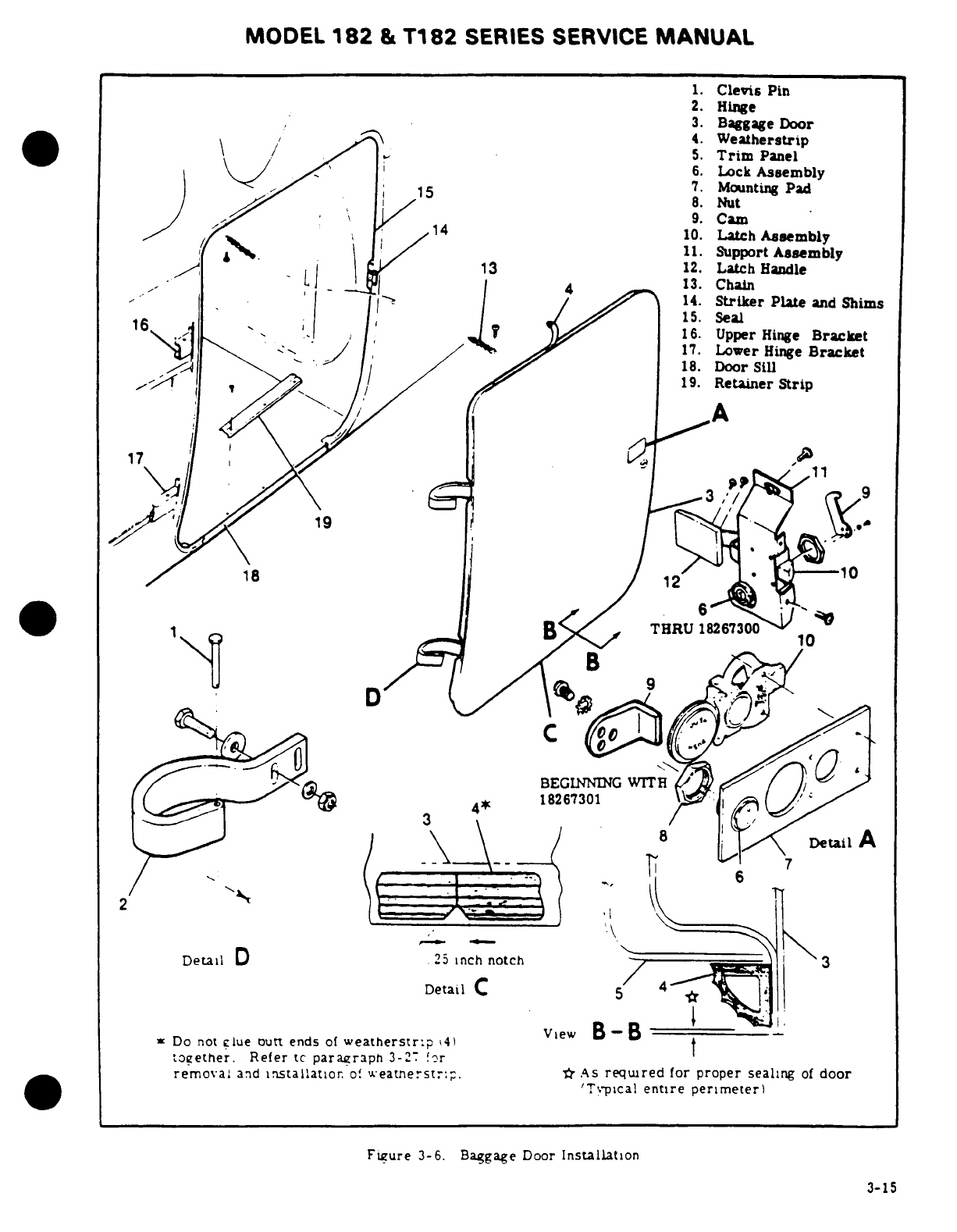
MODEL
182
&
T182
SERIES
SERVICE
MANUAL
1.
Clevis
Pin
2.
Hinge
3.
Baggage
Door
5.
Trim
Panel
8.
Nut
14
10.
Latch
Assembly
14.
Striker
Plate
and
Shims
16\
l .-
,
' '
'
|
I
16. Upper
Hinge
Bracket
17.
Lower
Hinge
Bracket
.A \/ ~ ~
/18.
Door
Sll
17I
, ~. // ~~/^19.
RetainerStrip
17
*"~ 1/^y ^ T" ""~~~~10
An9
B9^^
i/o;/
2/ _'_ l-cl ; \ = "
3
4
Detail
D
25
inch
notch
-
1e 3
DetailC
5
4
a
Do
not
clue
outt
ends
of
weatherstr:p
k4)
t
together.
Refer
tc
paragraph
3-2T
for
removal
and
installatior.
of
weatnerstr:p.
*
As
required
for
proper
sealing
of
door
'Typical
entire
perimeter)
Figure
3-6.
Baggage Door
Installation
3-15
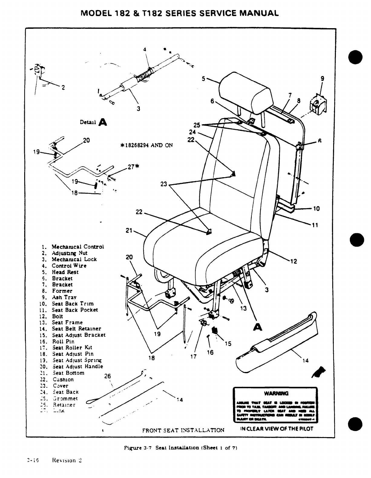
MODEL
182
&
T182
SERIES
SERVICE
MANUAL
3
Detil
A 25
242
^^1<
3.,*18268294
AND
ON
)
<^^^-7*
//S //, -27
\199, 23
01
-
23
18
-
-'
,
22
~~21 / \
1
1
~~~~~11
1.
Mechanical
Control
/
2.
Adjusting
Nut
3.
Mechanical
Lock
201
4.
Control
Wire
5.
Head
Rest
6.
Bracket
'\
7.
Bracket
8.
Former
3
9.
Ash
Trav
10.
Seat
Back
Trim
11.
Seat
Back
Pocket
' 13
12.
Bolt
13.
Seat
Frame
14.
Seat
Belt
Retainer
15.
Seat
Adlust
Bracket
\
19
16.
Roll
Pin
17.
Seat
Roller
Kit
18.
Seat
Adlust Pin
16
13.
Seat
Adlust
Spring
r 14
20.
Seat
Ad)ust
Handle
21.
Seat Bottom
22.
Cu;shion
23.
Cover
'
-
//
24.
Seat
BaciK
WARNING
:'.
3rommet
I/e
.4
*
a
m
2'6. aeti-.er ...... I~.
_.'
.
m LAW
etm emaTm
FRONT
S
I
eN
CLEAR
VIo
EW
O
THE
PILOT
FRONT
SEAT
INSTALLATION
N
CLEAR
VIEW
OF
THE
PILOT
Figure
3-7
Seat
Inltallation
(Sheet
1
of
7)
2-i6
Revision
2

MODEL
182
&
T182
SERIES
SERVICE
MANUAL
11.
Seat
Belt
Pocket
.
27
*
18268294
AND ON
14.
Seat
Belt
Retainer
18.
Seat Adjust
Pin
19.
Seat
Adjust
Spring
21.
Seat
Bottom
24.
Seat
Back
26.
Vertical
Adjustment
Handle
27.
Fore/Aft
Adjustment
Handle
28.
Articulating
Adjustment
Handle
29.
Adjustment
Screw
30.
Bellcrank
31.
Trim
24
32.
Spacer
30
33.
Channel
34.
Torque
Tube
35.
Seat
Structure
29
36.
Roller
37.
Link
28
27
19
Detail A
3
14
26
INFINITELY
ADJUSTABLE
FRONT
SEAT
INSTALLATION
36
Figure
3-7.
Seat
Installation
(Sheet
2
of
7)
3-17
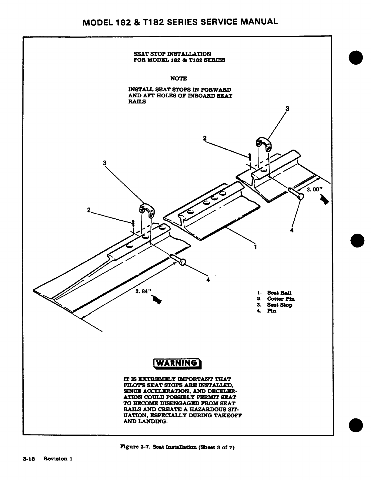
MODEL
182
&
T182
SERIES
SERVICE
MANUAL
SEAT
STOP
INSTALLATION
FOR
MODEL
182
& T182
SERIES
NOTE
INSTALL
SEAT STOPS
IN
FORWARD
AND
AFT
HOLES
OF
INBOARD
SEAT
RAILS
2
2.
Cotter
Pin
3.
Seat
Stop
4.
Pin
IT
IS
EXTREMELY
IMPORTANT THAT
PILOT'S
SEAT
STOPS
ARE
INSTALLED,
SINCE
ACCELERATION,
AND
DECELER-
ATION
COULD
POSSIBLY
PERMIT
SEAT
TO
BECOME
DISENGAGED
FROM
SEAT
RAILS
AND CREATE
A
HAZARDOUS
SIT-
UATION,
ESPECIALLY
DURING
TAKEOFF
AND
LANDING.
Figure
3-7.
Seat
Instllation
(Sheet
3
of
7)
3-18
Revision
1
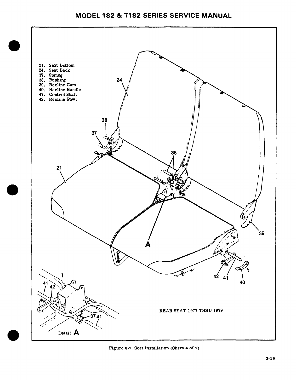
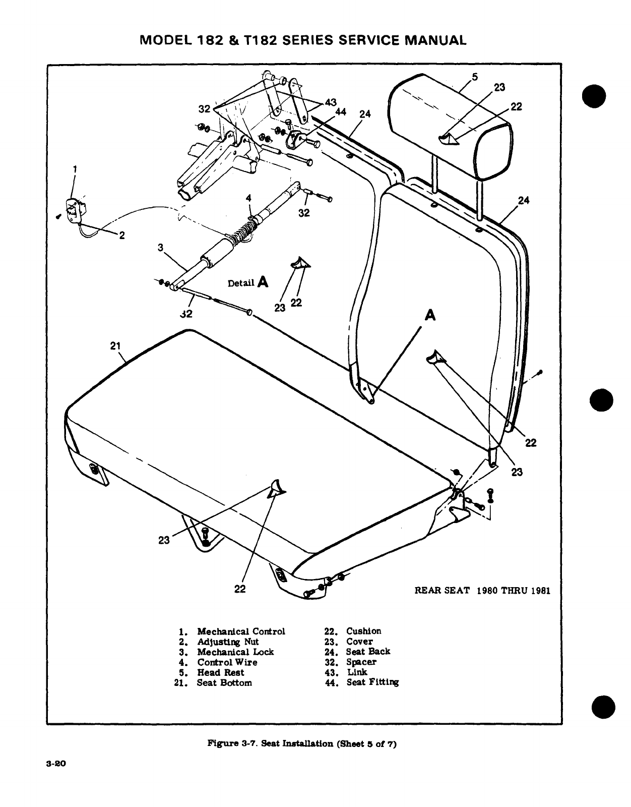
MODEL
182
&
T182
SERIES SERVICE
MANUAL
23
43
22
4
<
2~~~~~~22
33
23
;f
23 /~ A |23
22
REAR
SEAT
1980
THRU
1981
1.
Mechanical
Control
22.
Cushion
2.
Adjusting
Nut
23.
Cover
3.
Mechanical
Lock
24.
Seat
Back
4.
Control
Wire
32.
Spacer
5.
Head
Rest
43.
Link
21.
Seat
Bottom
44.
Seat
Fitting
Figure
3-7.
Seat
Installation
(Sheet
S
of
7)
3-20
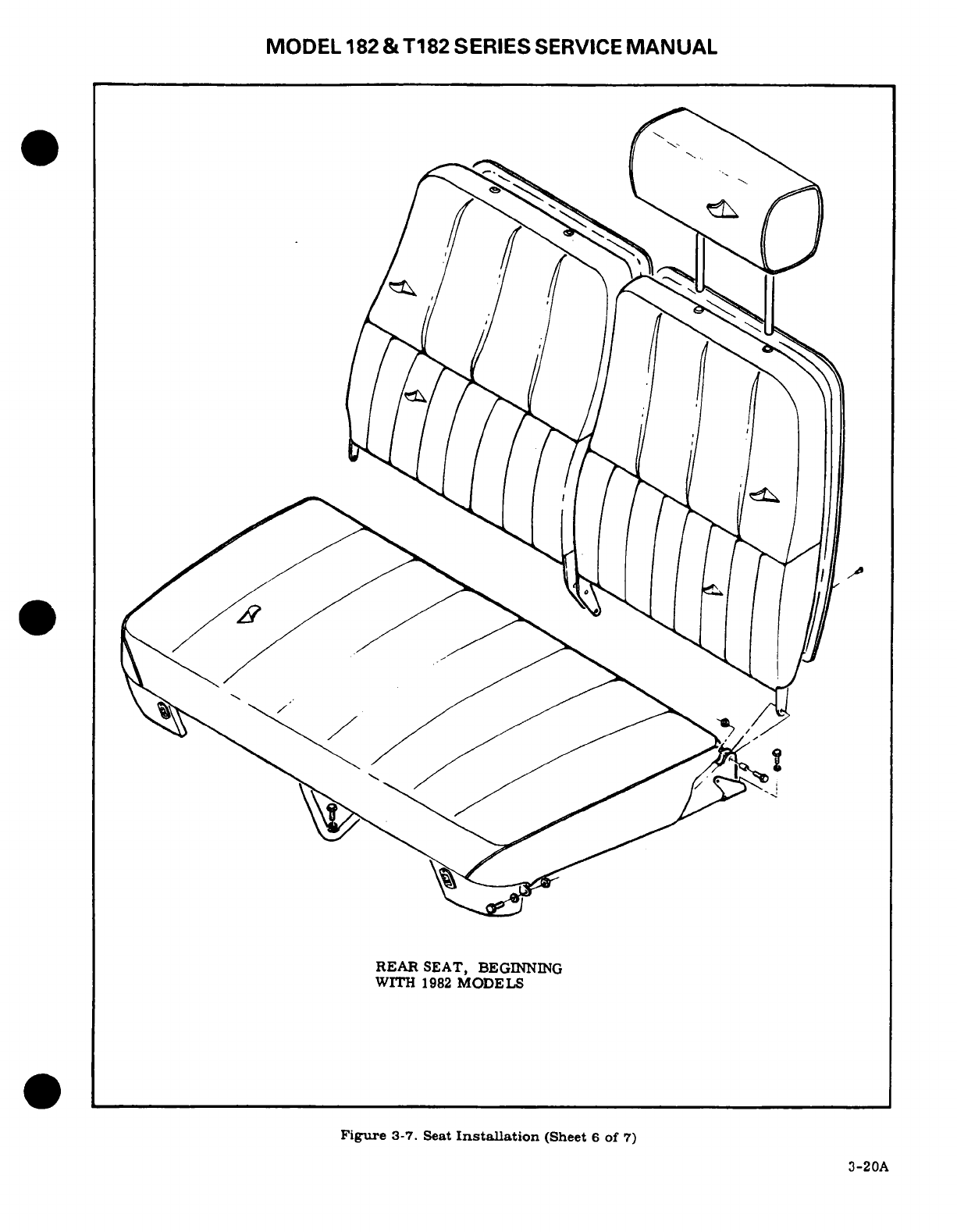
MODEL
182
&
T182
SERIES
SERVICE
MANUAL
REAR SEAT,
BEGINNING
WITH
1982
MODELS
Figure
3-7.
Seat
Installation
(Sheet
6
of
7)
3-20A
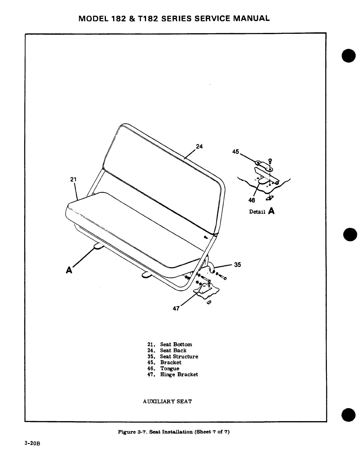
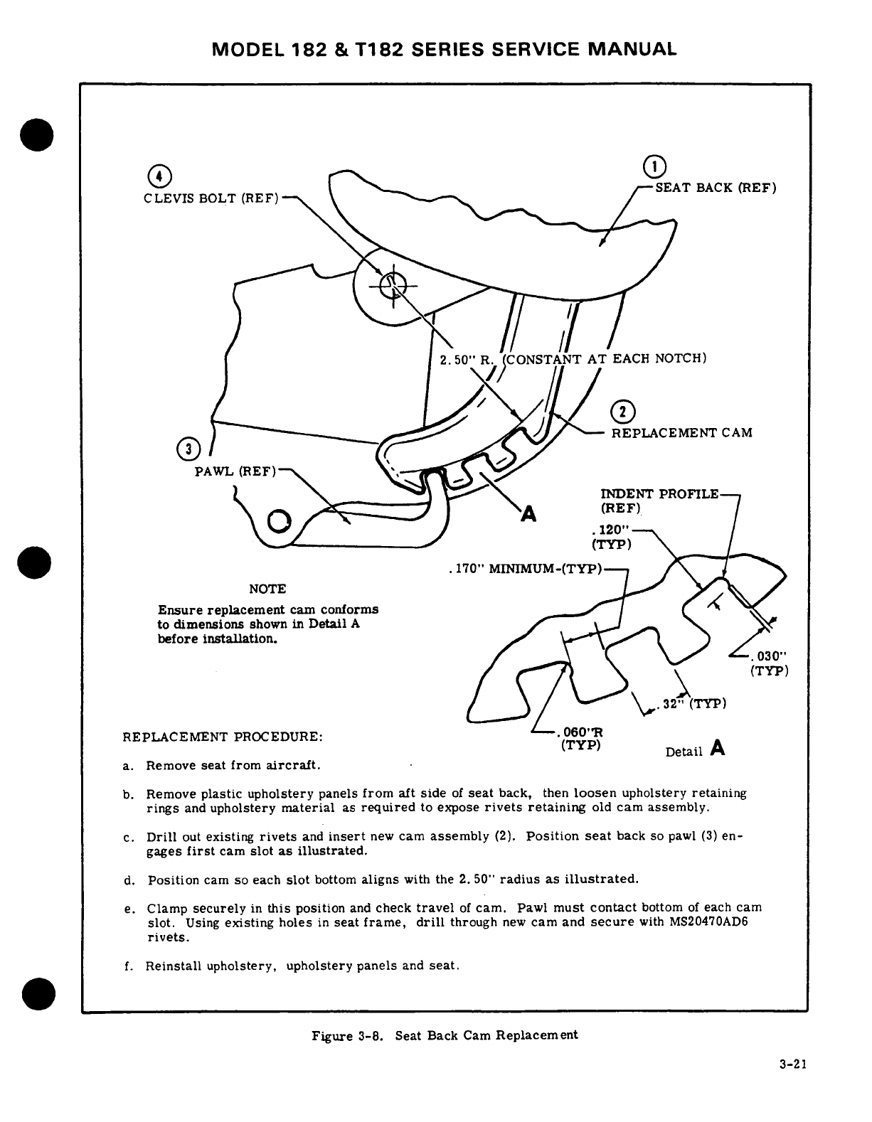
MODEL
182
&
T182
SERIES
SERVICE
MANUAL
CLEVIS
BOLT
(REF)
PAWL
(REF)
INDENT
PROFILE
(TYP)
.
170"
MINIMUM-(TYP)
NOTE
Ensure
replacement
cam
conforms
to
dimensions
shown
in
Detail
A
before
installation.
REPLACEMENT
PROCEDURE:
(TYP)
Detail
A
a.
Remove
seat
from
aircraft.
b.
Remove
plastic
upholstery
panels
from
aft
side
of
seat
back,
then
loosen
upholstery
retaining
rings
and
upholstery
material
as
required
to
expose
rivets
retaining
old
cam assembly.
c.
Drill
out
existing
rivets
and
insert
new
cam
assembly
(2).
Position
seat
back
so
pawl
(3)
en-
gages
first
cam
slot
as
illustrated.
d.
Position
cam
so
each
slot
bottom
aligns
with the
2.
50"
radius
as
illustrated.
e.
Clamp
securely
in
this
position
and
check
travel
of
cam.
Pawl
must
contact
bottom
of
each
cam
slot.
Using
existing
holes
in
seat frame,
drill
through
new
cam
and
secure
with
MS20470AD6
rivets.
f.
Reinstall
upholstery, upholstery
panels
and
seat.
Figure
3-8.
Seat Back
Cam
Replacement
3-21
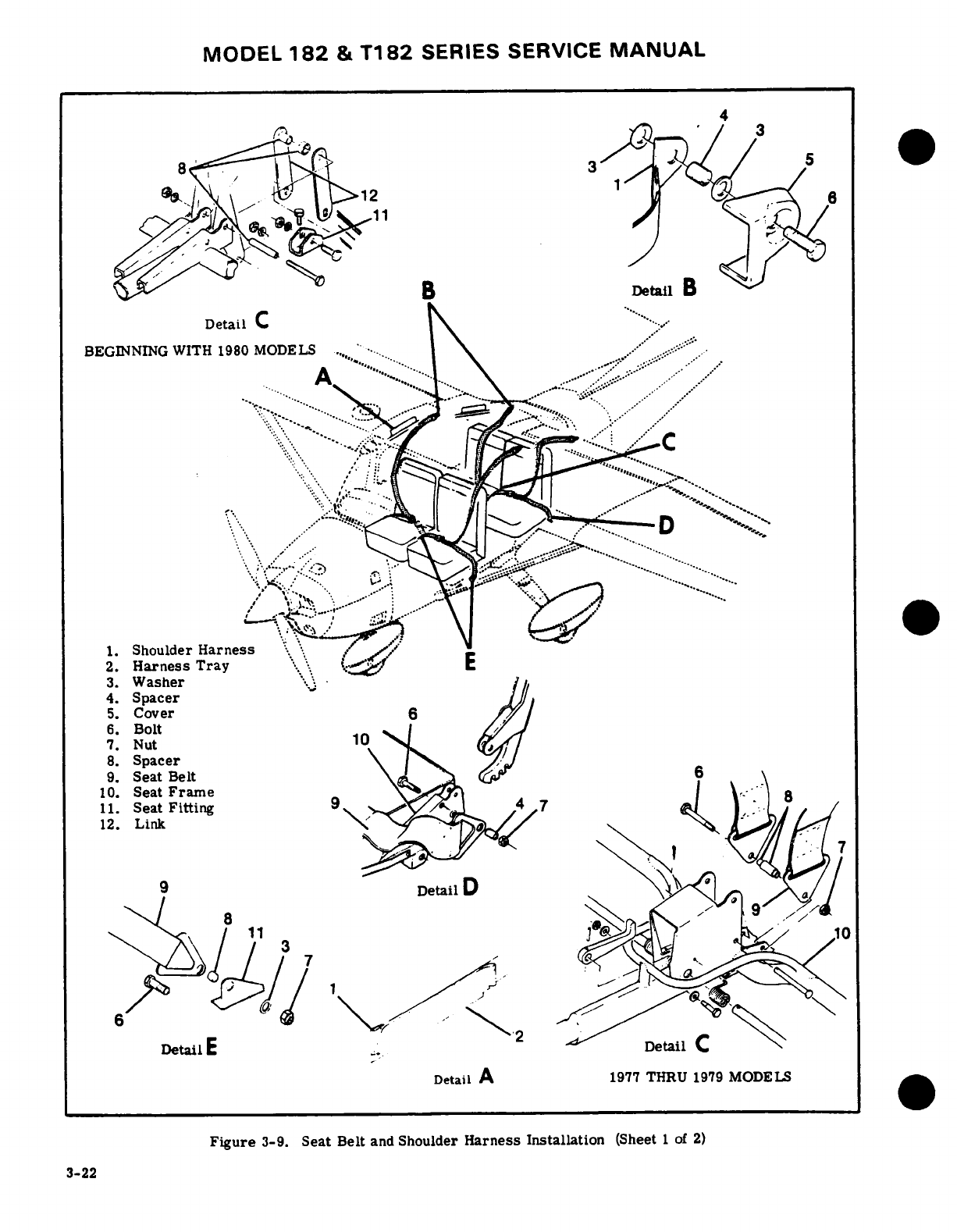
MODEL
182
&
T182
SERIES SERVICE
MANUAL
4
^^^ ^^<: 2
11
B
Detail
B
Detail
C\
BEGINNING WITH 1980 MODELS
..
.
o
...
....-
'., 5.\
1.
Shoulder
Harness
...
2.
Harness
Tray
E
3.
Washer
*.^
'^
4.
Spacer
//YJ
5.
Cover
6.
Bolt
7.
Nut
10
8.
Spacer
9.
Seat
Belt
\
6
\
10.
Seat
Frame
X
11.
Seat
Fitting
9
Am
4 7
8
/
7 7
^/9
Detail
D
1
;.;'
.. ...
10
.
^ ^/'v-^
2
1
Detail
E
.. .
Detail
C
Detail
A
1977
THRU
1979
MODELS
Figure
3-9.
Seat
Belt
and
Shoulder
Harness
Installation
(Sheet 1
of
2)
3-22
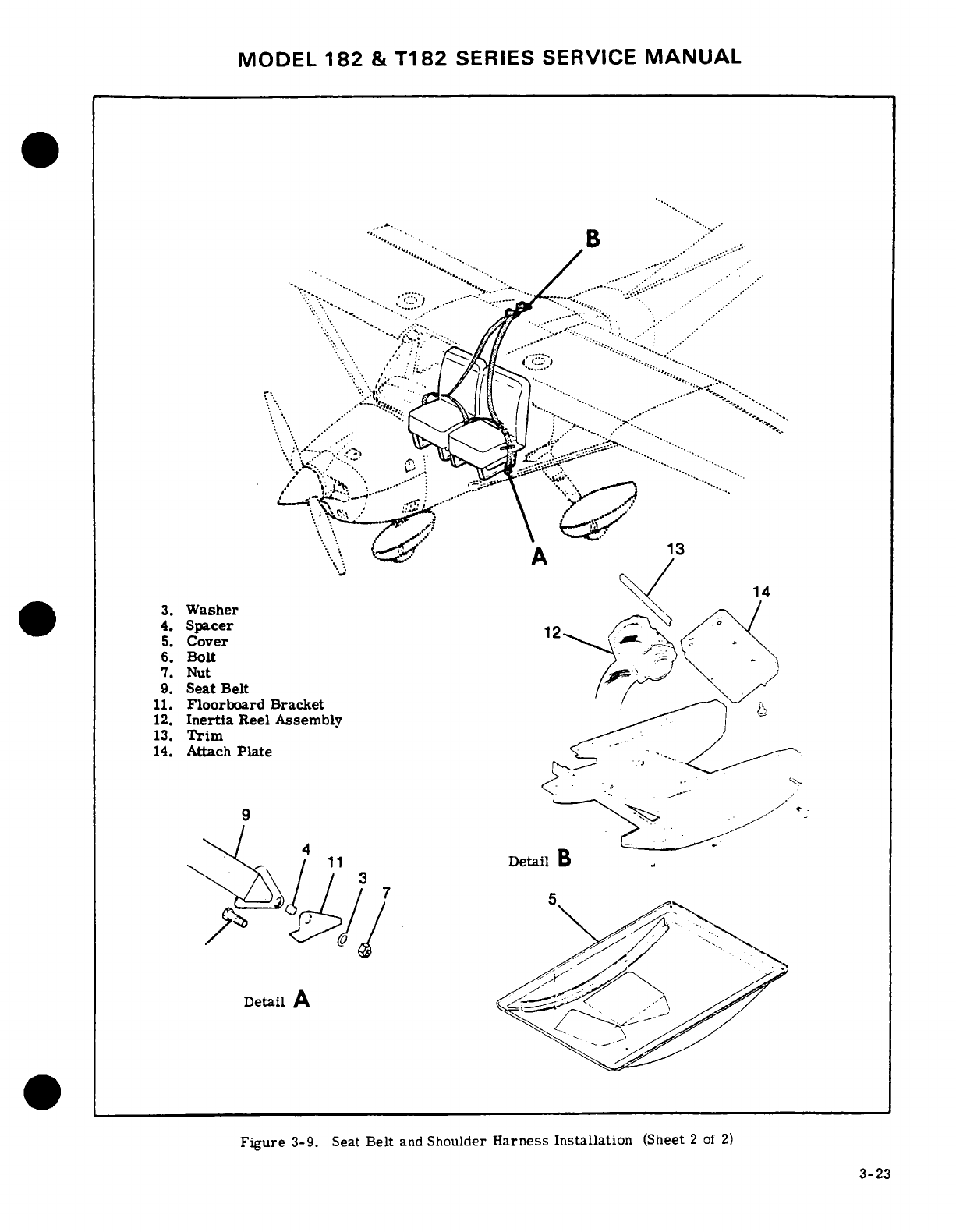
MODEL
182
&
T182
SERIES
SERVICE
MANUAL
Ct.'' '.' S 004.
f13
.::...
,,, \'
.
.A
13
14
3.
Washer
\ /
4.
Spacer
12
5.
Cover
12
6.
Bolt
-
'
7.
Nut
9.
Seat
Belt
/
11.
Floorboard
Bracket
12.
Inertia
Reel
Assembly
13.
Trim
14.
Attach
Plate
'
11
BDetail
B
Detail
A
Figure
3-9.
Seat
Belt
and
Shoulder
Harness
Installation
(Sheet 2
of
2)
3-23
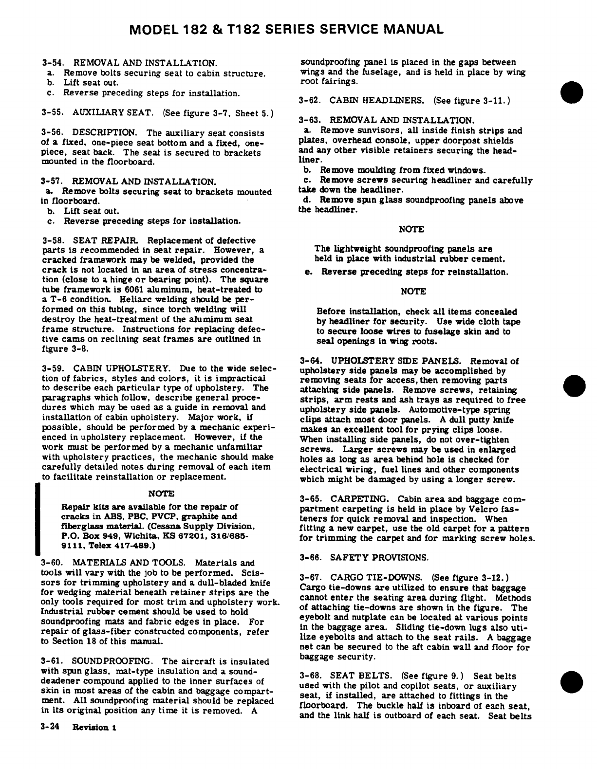
MODEL
182
&
T182
SERIES
SERVICE
MANUAL
3-54.
REMOVAL
AND
INSTALLATION.
soundproofing
panel
is
placed in
the
gaps
between
a.
Remove
bolts
securing
seat
to
cabin
structure.
wings
and
the
fuselage,
and
is
held
in
place
by
wing
b.
Lift
seat
out.
root
fairings.
c.
Reverse
preceding
steps
for
installation.
3-62.
CABIN
HEADLINERS.
(See
figure
3-11.)
3-55.
AUXILIARY
SEAT. (See
figure
3-7,
Sheet
5.)
-
3-63.
REMOVAL
AND
INSTALLATION.
3-56.
DESCRIPTION.
The
auxiliary
seat
consists
a.
Remove
sunvisors,
all
inside finish
strips
and
of
a
fixed,
one-piece
seat
bottom
and
a
fixed,
one-
plates,
overhead
console,
upper
doorpost
shields
piece,
seat
back.
The
seat is
secured
to
brackets
and
any
other
visible
retainers
securing
the
head-
mounted
in
the
floorboard.
liner.
b.
Remove
moulding
from
fixed
windows.
3-57.
REMOVAL
AND
INSTALLATION.
c.
Remove
screws
securing
headliner
and
carefully
a.
Remove
bolts
securing
seat
to
brackets
mounted
take
down
the
headliner.
in
floorboard.
d.
Remove
spun
glass
soundproofing
panels
above
b.
Lift
seat
out.
the
headliner.
c.
Reverse
preceding
steps
for
installation.
NOTE
3-58.
SEAT
REPAIR.
Replacement
of
defective
parts
is
recommended
in
seat
repair.
However,
a
The
lightweight
soundproofing
panels
are
cracked
framework
may
be
welded,
provided
the held
in
place with
industrial
rubber
cement.
crack
is
not
located
in an
area
of
stress
concentra-
e.
Reverse
preceding
steps
for
reinstallation.
tion
(close
to
a
hinge
or
bearing
point).
The
square
tube
framework is
6061
aluminum,
heat-treated
to
NOTE
a
T-6
condition.
Heliarc
welding
should
be
per-
formed
on
this
tubing,
since
torch
welding
will Before
installation,
check
all
items
concealed
destroy
the
heat-treatment
of
the
aluminum
seat
by
headliner
for
security.
Use
wide
cloth
tape
frame structure.
Instructions
for
replacing
defec-
to
secure
loose
wires
to
fuselage
skin
and
to
tive
cams
on
reclining
seat
frames
are
outlined
in
seal
openings
in
wing
roots.
figure
3-8.
3-64.
UPHOLSTERY
SIDE
PANELS.
Removal
of
3-59.
CABIN
UPHOLSTERY.
Due to
the
wide
selec- upholstery
side
panels
may be
accomplished
by
tion
of
fabrics,
styles
and
colors,
it
is
impractical
removing
seats
for
access,
then
removing
parts
to
describe
each
particular
type
of
upholstery.
The
attaching
side
panels.
Remove
screws,
retaining
paragraphs
which
follow,
describe
general
proce-
strips,
arm
rests
and
ash
trays
as
required
to
free
dures
which
may
be
used
as
a
guide in
removal
and
upholstery
side panels.
Automotive-type
spring
installation
of
cabin
upholstery.
Major
work,
if
clips
attach
most
door
panels.
A
dull
putty
knife
possible,
should
be
performed
by
a
mechanic
experi-
makes
an
excellent
tool
for
prying
clips
loose.
enced
in
upholstery
replacement.
However,
if the
When
installing
side
panels,
do
not
over-tighten
work must
be
performed
by
a
mechanic
unfamiliar
screws.
Larger
screws
may
be
used
in
enlarged
with
upholstery
practices,
the
mechanic
should
make
holes
as
long
as
area
behind
hole
is
checked
for
carefully
detailed notes during
removal
of
each
item
electrical
wiring,
fuel
lines
and
other
components
to
facilitate reinstallation or
replacement.
which
might
be
damaged
by
using
a
longer
screw.
NOTE
Repair
kits
are
available
for
the
repair
of
partment
carpeting
is
held
in
place
by
Velcro
fas-
cracks
in
ABS,
PBC,
PVCP,
graphite
and
teners
for
quick
removal
and
inspection.
When
fiberglass material.
(Cessna
Supply
Division,
fitting
a
new
carpet,
use
the
old
carpet
for
a
pattern
P.O.
Box
949,
Wichita,
KS
67201, 316/685-
for
trimming
the
carpet
and
for
marking
screw
holes.
9111,
Telex
417-489.)
3-66.
SAFETY
PROVISIONS.
3-60.
MATERIALS
AND
TOOLS.
Materials
and
3-66
SAFETY
PROVISIONS.
tools
will
vary
with the
job
to
be
performed. Scis-
3-67.
CARGO
TIE-DOWNS.
(See
figure
3-12.)
sors
for
trimming
upholstery
and
a
dull-bladed
knife
Cargo tie-downs
are
utilized
to
ensure
that
baggage
for
wedging
material
beneath
retainer
strips
are
the
cannot
enter
the
seating
area
during
flight.
Methods
only
tools
required
for
most
trim
and
upholstery
work.
of
attaching
the
seating
area
during
flight.
Methods
soundproofing
mats
and
fabric
edges
in
place.
For
in
the
baggage
area.
Sliding
tie-down
lugs
also
uti-
repair
of
glass-fiber
constructed
components,
refer
lize
eyebolts
and
attach
to
the
seat
rails.
A
baggage
to
Section
18
of
this
manual.
net
can
be
secured
to
the
aft
cabin wall
and
floor
for
3-61.
SOUNDPROOFING.
The
aircraft
is
insulated
baggage
security.
with
spun
glass,
mat-type
insulation
and
a
sound-
3-68.
SEAT
BELTS.
(See
figure
9.)
Seat belts
deadener
compound
applied
to
the
inner
surfaces
of
used
with
the
pilot
and
copilot
seats,
or
auxiliary
skin
in
most
areas
of
the
cabin
and
baggage
compart-
seat,
if
installed, are
attached
to
fittings
in
the
ment.
All
soundproofing
material
should
be
replaced
floorboard.
The
buckle
half
is
inboard
of
each
seat,
in
its
original
position
any
time
it
is
removed.
A
and
the
link
half
is
outboard
of
each
seat.
Seat
belts
3-24
Revision
1
MODEL
182
&
T182
SERIES SERVICE
MANUAL
1.
Headliner
2.
Retainer
5
3.
Skylight
Moulding
4.
Tiara
5.
Aft
Upper
Window
Moulding
6.
Coat
Hook
4
Figure
3-10.
Cabin
Headliner
Installation
for
the
rear
seat
are
attached
to
the
seat
frame,
with
console,
marked
PILOT
and
COPILOT,
to
attach
the
link
halves
on
the
left
and
right sides
of
the
seat
points
inboard
of
the
two
front
seats.
A
separate
bottom,
and
the
buckles
at
the
center
of
the
seat seat
belt
and
buckle
is
located
outboard
of
the
seats.
bottom.
Inertia
reels
allow
complete
freedom
of
body
move-
ment.
However,
in
the
event
of
sudden
deceleration,
NOTE
they
will
lock
automatically
and
protect
the
occupants.
A
special
seat
belt
shortener
Service
Kit
is
3-70. GLIDER
TOW-HOOK.
A
glider
tow-hook,
now
available
which
repositions
the
belt
buck-
mounted
in
place
of
the
tail
tie-down
ring
is
available
le/shoulder
harness
connection.
Repositioning
through
18265965
and
F18200064.
of
the
buckle
is
recommended to
prevent
inad-
vertent
loosening
of
the
seat
belt.
(Refer
to
Service
Information Letter
SE82-43.)
3-71.
REAR
VIEW MIRROR.
(See
figure
3-14.)
A
rear
view
mirror
may
be
installed
on
the
cowl deck
3-69.
SHOULDER HARNESSES.
(See
figure
3-10.)
above
the
instrument
panel
on
aircraft
thru
18266591.
Integrated
seat belt/shoulder
harnesses
with
inertia
reels
may
be
installed
in
the
pilot
and
copilot
posi-
3-72.
SEAT
RAIL
INSPECTION.
A
special
inspec-
tions.
The
seat
belt/shoulder harness
installations
tion
of
seat
rails
should
be
conducted
each
50
hours.
extend
from
inertia
reels
located
in
the
overhead
See
figure
3-14
for inspection
procedures.
Revision
1
3-25
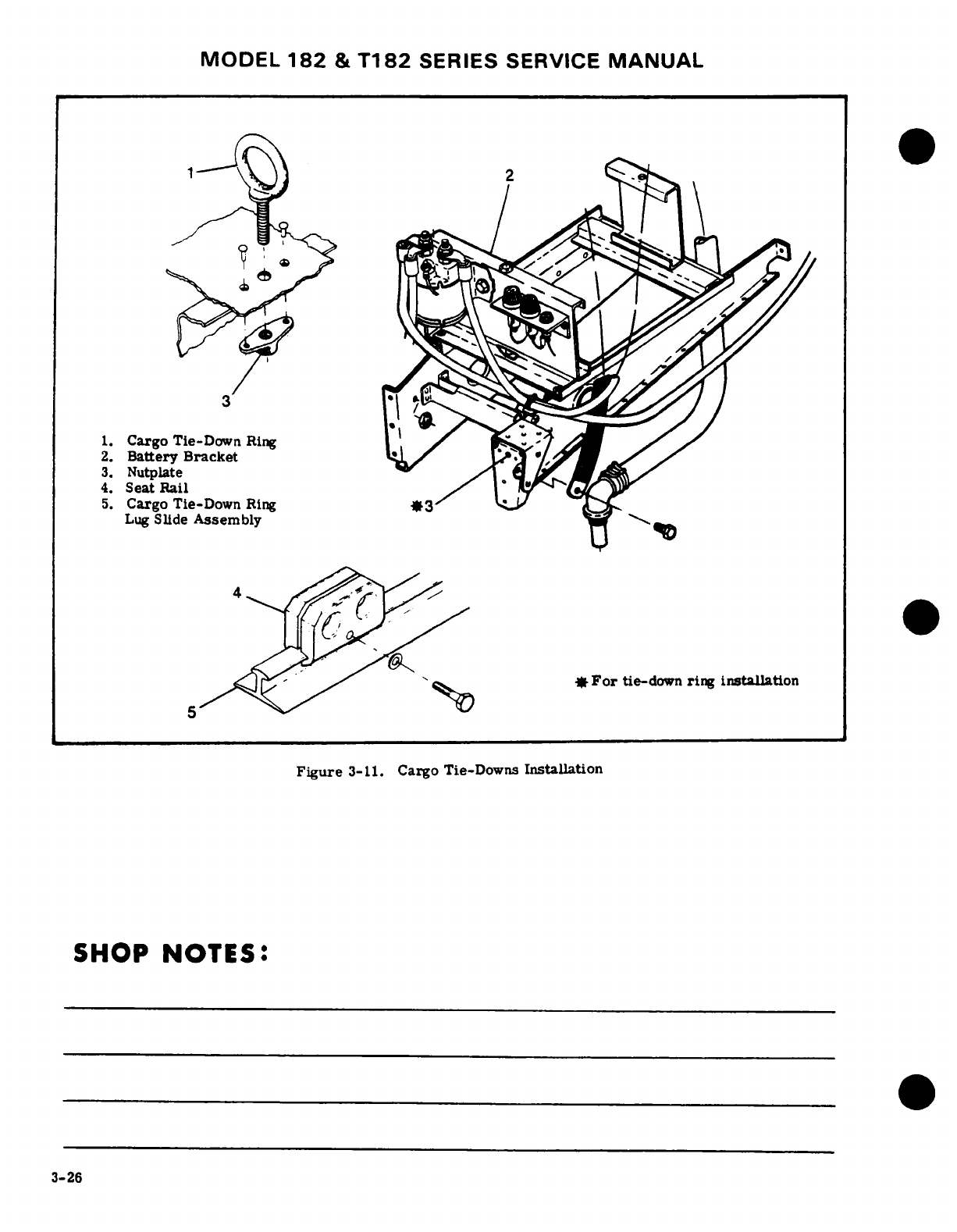
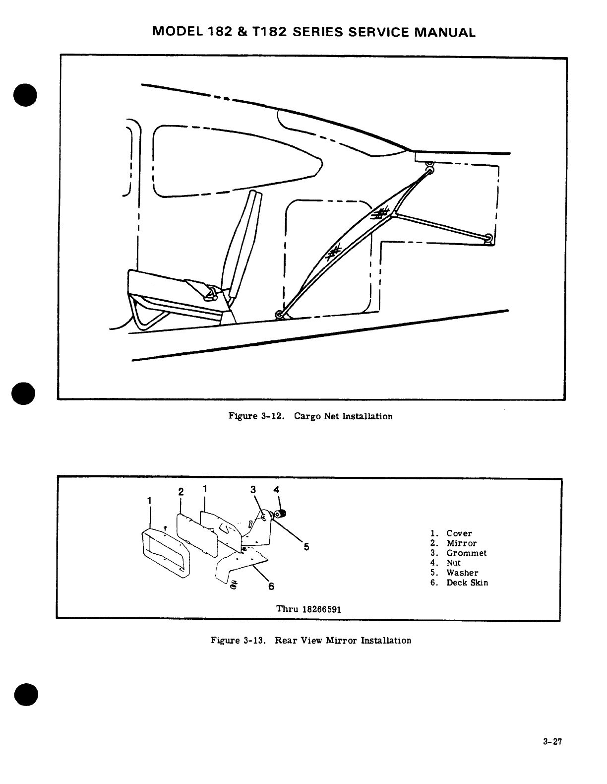
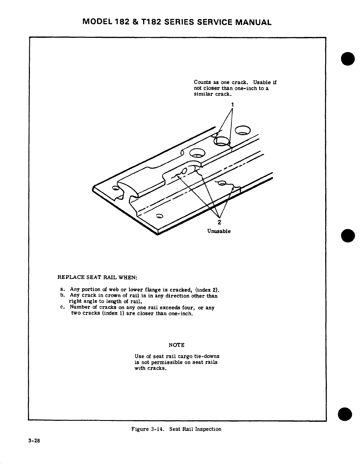
MODEL
182
&
T182
SERIES
SERVICE
MANUAL
Counts
as
one
crack.
Usable
if
not
closer
than one-inch
to
a
similar
crack.
Unusable
REPLACE
SEAT
RAIL
WHEN:
a.
Any
portion
of
web
or
lower
flange
is
cracked,
(index
2).
b.
Any
crack
in
crown
of
rail
is
in
any
direction
other
than
right
angle
to
length
of
rail.
c.
Number
of
cracks
on
any one
rail
exceeds four,
or
any
two
cracks
(index
1)
are
closer
than
one-inch.
NOTE
Use
of
seat
rail
cargo
tie-downs
is
not
permissible
on
seat rails
with
cracks.
Figure
3-14.
Seat
Rail
Inspection
3-28
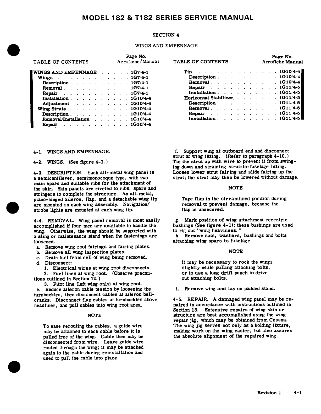
MODEL
182
&
T182
SERIES
SERVICE
MANUAL
SECTION
4
WINGS AND
EMPENNAGE
Page
No.
Page
No.
TABLE
OF CONTENTS
Aerofiche/Manual
TABLE
OF
CONTENTS
Aerofiche
Manual
WINGS AND
EMPENNAGE.
.
....
1G7/4-1
Fin
.............
1G10/4-4
Wings
............
1G7/4-1
Description
.
........
1G10,4-4
Description
......
...
1G7/4-1
Removal
.
........
..
1G10/4-4
Removal .
..........
1G7/4-1
Repair
. .
.... ....
1G11/4-5
Repair
.........
.
1G7/4-1
Installation
........
.
1G114-5
Installation
.
.....
...
1G10/4-4
Horizontal
Stabilizer
.......
1G11/4-5
Adjustment
.........
1G10/4-4
Description
.
.....
..
1G11/4-5
Wing Struts
..........
1G10/4-4
Removal
..........
1G11/4-5
Description.
.........
1G10/4-4
Repair
. .
......
..
1G
114-5
Removal/Installation
......
1G10/4-4
Installation
.
.......
.
1G11/4-5
Repair
..
.....
...
10/4-4
4-1.
WINGS
AND
EMPENNAGE.
f.
Support
wing
at outboard
end
and
disconnect
strut
at
wing
fitting.
(Refer
to
paragraph
4-10.)
4-2.
WINGS.
(See
figure
4-1.)
Tie
the
strut
up
with
wire
to
prevent it
from
swing-
ing down
and
straining
strut-to-fuselage
fitting.
4-3.
DESCRIPTION.
Each
all-metal
wing
panel
is
Loosen
lower
strut fairing
and
slide
fairing
up
the
a
semicantilever,
semimonocoque
type,
with
two
strut;
the
strut
may
then
be
lowered
without
damage.
main
spars
and
suitable
ribs
for
the
attachment
of
the
skin.
Skin
panels
are
riveted
to
ribs,
spars
and
NOTE
stringers
to
complete
the
structure.
An
all-metal,
piano-hinged
aileron,
flap,
and
a
detachable
wing
tip
Tape
flap
in
the
streamlined
position
during
are
mounted
on
each
wing
assembly.
Navigation/
removal
to
prevent
damage, because
the
strobe
lights
are
mounted
at each
wing
tip.
flap
is
unsecured.
4-4.
REMOVAL. Wing
panel
removal is
most
easily
g.
Mark
position
of
wing
attachment
eccentric
accomplished
if
four
men
are
available
to
handle the
bushings
(See
figure
4-1);
these
bushings
are
used
wing.
Otherwise,
the
wing
should
be
supported
with
to
rig
out
"wing
heaviness.
"
a
sling
or
maintenance stand
when
the
fastenings
are
h.
Remove nuts,
washers,
bushings
and
bolts
loosened.
attaching
wing
spars
to
fuselage.
a.
Remove
wing
root
fairings
and
fairing
plates.
b.
Remove
all
wing
inspection
plates.
NOTE
c.
Drain
fuel
from
cell
of wing
being
removed.
d.
Disconnect:
It
may
be
necessary
to
rock
the
wings
1.
Electrical
wires
at
wing
root
disconnects.
slightly
while
pulling
attaching
bolts,
2.
Fuel
lines
at
wing
root.
(Observe
precau-
or
to
use
a
long
drift
punch
to
drive
tions
outlined
in
Section
12.
)
out
attaching
bolts.
3.
Pitot
line
(left
wing
only)
at
wing
root.
e.
Reduce
aileron
cable
tension
by
loosening
the
i.
Remove
wing
and
lay
on
padded
stand.
turnbuckles,
then
disconnect
cables
at
aileron bell-
cranks.
Disconnect flap
cables
at
turnbuckles
above
4-5.
REPAIR.
A
damaged
wing
panel
may
be
re-
headliner,
and
pull cables
into
wing
root
area.
paired
in
accordance with
instructions
outlined
in
Section
18.
Extensive
repairs
of
wing
skin
or
NOTE
structure
are
best
accomplished
using
the
wing
repair
jig,
which
may
be
obtained
from
Cessna.
To
ease
rerouting
the
cables,
a
guide
wire
The
wing
jig
serves
not
only
as
a
holding
fixture,
may
be
attached
to
each
cable
before it
is
making
work
on
the
wing
easier,
but
also
assures
pulled
free
of
the
wing.
Cable
then
may
be
the
absolute alignment
of
the
repaired
wing.
disconnected
from
wire. Leave
guide
wire
routed through
the
wing;
it
may
be
attached
again
to
the
cable
during
reinstallation
and
used
to
pull
the
cable
into
place.
Revision
1
4-1
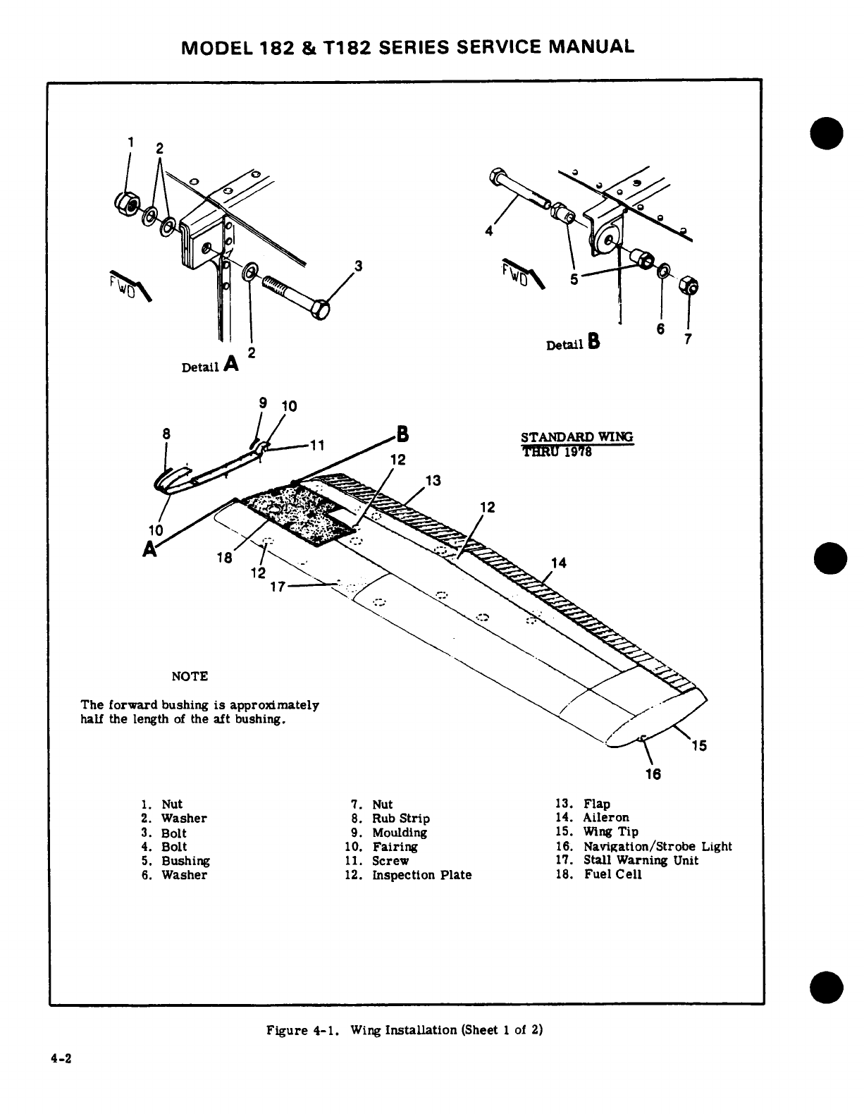
MODEL
182
&
T182
SERIES SERVICE
MANUAL
Detail
B
Detail
A
9
10
8
THRU
1978
13
12
18
12
NOTE
The
forward
bushing
is
approximately
half
the
length
of
the
aft
bushing.
16
1.
Nut
7.
Nut
13.
Flap
2.
Washer
8.
Rub
Strip
14.
Aileron
3.
Bolt
9.
Moulding
15.
Wing
Tip
4.
Bolt
10.
Fairing
16.
Navigation/Strobe
Light
5.
Bushing
11.
Screw
17.
Stall
Warning
Unit
6.
Washer
12.
Inspection
Plate
18.
Fuel
Cell
Figure
4-1.
Wing
Installation
(Sheet
1
of
2)
4-2
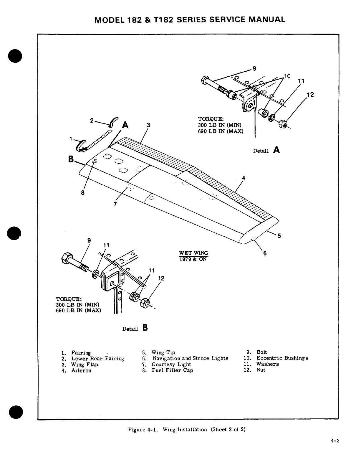
MODEL
182
&
T182
SERIES
SERVICE
MANUAL
12
3
300
LB
IN
(MIN)
TORQUE:
300
LB
IN
(MIN)
690
LB
IN
(MAX)
Detail
B
1.
Fairing
5.
Wing
Tip
9.
Bolt
2.
Lower
Rear
Fairing
6.
Navigation
and
Strobe
Lights
10.
Eccentric
Bushings
3.
Wing
Flap
7.
Courtesy
Light
11.
Washers
4.
Aileron
8.
Fuel
Filler
Cap
12. Nut
Figure
4-1.
Wing
Installation
(Sheet
2
of
2)
4-3
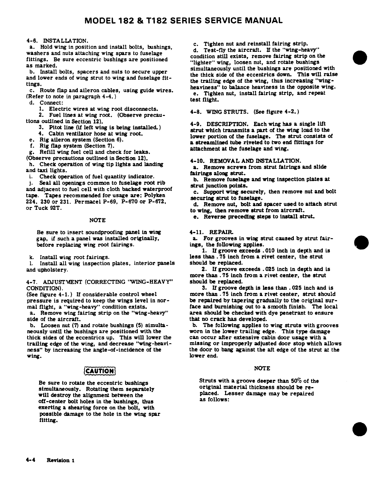
MODEL
182
&
T182
SERIES
SERVICE
MANUAL
4-6.
INSTALLATION.
c.
Tighten
nut
and
reinstall
fairing
strip.
a.
Hold
wing
in
position
and
install
bolts,
bushings,
d
Test-fly
the
aircraft.
If
the
"wing-heavy"
washers
and
nuts
attaching
wing
spars
to
fuselage
condition
still
exists,
remove
fairing
strip
on
the
fittings.
Be
sure
eccentric
bushings
are
positioned
"lighter"
wing,
loosen
nut,
and
rotate
bushings
as
marked.
simultaneously
until
the
bushings
are
positioned
with
b.
Install
bolts,
spacers
and
nuts
to
secure
upper
the
thick
side
of
the
eccentrics
down.
This
will
raise
and
lower
ends
of
wing
strut
to
wing
and fuselage
fit-
the
trailing
edge
of
the
wing,
thus
increasing
"wing-
1.
Electric
wires
at
wing
root
disconnects.
4-8.
WING
STRUTS.
(See
figure
4-2
)
2.
Fuel
lines
at
wing
root.
(Observe
tions
outined
in
Section
12).
4-9.
DESCRIPTION.
Each
wing
has
a
single
lift
3.
Pitot
line
(if
left
wing
is
being
installed.)
strut
which
transmits
a
part
of
the
wing
load
to
the
4.
Cabin
ventilator
hose
at
wing
root
lower
portion
of
te
fuselage.
The
strut
consists
of
.
Rig
aileron
system
(Section
6). a
streamlined
tube
riveted
to
two
end
fittings
for
f.
Rig
flap
system
(Section
7).
attachment
at
the
fuselage
and
wing.
g.
Refill
wing
fuel
cell
and
check
for
leaks.
(Observe precautions
outlined
in
Section
12).
4-10.
REMOVAL
AND
INSTALLATION.
h.
Check
operation
of
wing
tip lights
and
landing
a.
Remove
screws
from
strut
fairings
and
slide
and
taxi
lights.
fairings
along
strut.
i.
Check
operation
of
fuel
quantity
indicator.
Remove
fuselage
and
wing
inspection
plates
at
j.
Seal
all
openings
common
to
fuselage
root
rib strut
junction
points
f.
Rig
flap system
(Section
7).
and
adjacent
to
fuel
cell
with
cloth
backed
waterproof
securely,
then
remove
nut
and
bolt
tape
Tapes
recommended
for
usage
are;
Polyken
securing
strut
to
fuselage.
224,
230
or
231.
Permacel
P-69,
P-670
or
P-672,
d.
Remove
nut, bolt
and
spacer
used
to
attach
strut
or
Tuck
92T.
to
wing,
then
remove
strut
from
aircraft.
e.
Reverse preceding steps
to
install
strut.
Be
sure
to
insert
soundproofing
panel
in
wing
4-11.
REPAIR
before replacing
wing
root
fairings.
ings,
the
following
applies.
1.
If
groove
exceeds
.
010
inch
in
depth
and
is
k.
Install
wing
root
fairings.less
than
.75
inch
from
a
rivet
center,
the
strut
1.
Install
all
wing
inspection
plates,
interior
panels
should
be
replaced.
and
upholstery.
2.
If
groove
exceeds
.025
inch
in
depth
and
is
more
than .75
inch
from
a
rivet
center,
the
strut
4-7.
ADJUSTMENT (CORRECTING
"WING-HEAVY"
should
be
replaced.
CONDITION).
3.
If
groove
depth
is
less
than
.
025
inch
and
is
(See
figure
4-1.)
If
considerable
control
wheel
more
than
.75
inch
from
a
rivet
center,
strut
should
pressure
is
required
to keep the
wings
level
in
nor-
be
repaired
by
tapering
gradually
to
the
original
sur-
mal
flight,
a
"wing-heavy"
condition
exists.
face
and
burnishing
out
to
a smooth
finish.
The
local
a.
Remove
wing
fairing
strip
on
the
"wing-heavy"
area
should
be
checked
with
dye
penetrant
to
ensure
side
of
the
aircraft.
that
no
crack
has
developed.
b.
Loosen
nut
(7)
and
rotate
bushings
(5)
simulta-
b.
The
following
applies
to
wing
struts
with
grooves
neously
until
the
bushings
are
positioned
with
theworn
in
the
lower
trailing
edge.
This
type damage
thick
sides
of
the
eccentrics
up.
This
will
lower
the
can
occur
after
extensive
cabin
door
usage
with
a
trailing
edge
of
the
wing
and
decrease in
ness"
by
increasing
the
angle-of-incidence
of
the
the
door
to
bang
against
the aft
edge
of
the
strut
at
the
wing.
lower
end.
Be
sure
to
rotate
the
eccentric
bushings
Struts
with
a
groove
deeper
than
5
of
the
simultaneously.
Rotating
them
separatelyoriginal
material
thickness
should
be
re-
will
destroy
the
alignment
between
theplaced.
Lesser
damage
may
be
repaired
off-center
bolt
holes
in the
bushings, thus
as
follows:
exerting
a
shearing
force
on
the
bolt,
with
possible
damage
to
the hole
in
the
wing
spar
fitting.
4-4
Revision
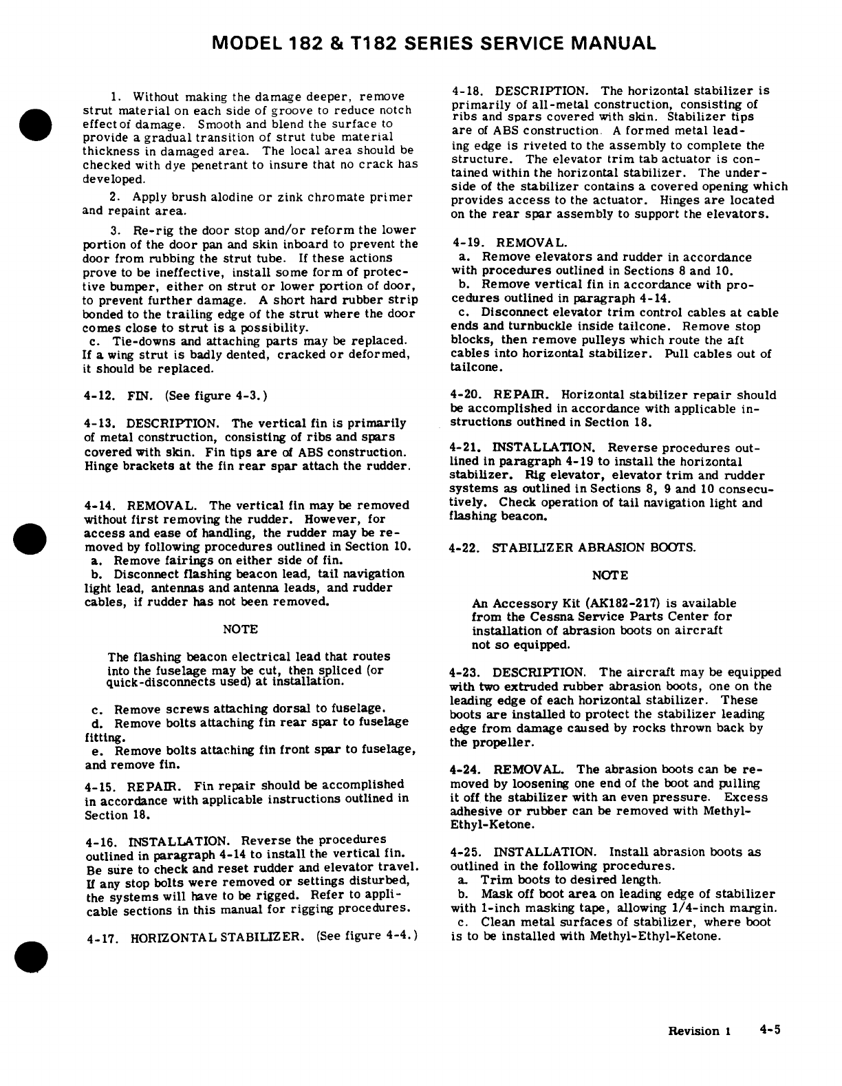
MODEL
182
&
T182
SERIES
SERVICE
MANUAL
1.
Without
making
the
damage
deeper,
remove
4-18.
DESCRIPTION. The
horizontal
stabilizer
is
strut
material
on
each
side
of
groove
to
reduce
notch
primarily
of
all-metal
construction, consisting
of
ribs
and
spars
covered
with
skin.
Stabilizer
tips
effect
of
damage.
Smooth and
blend the
surface
to
are
of
ABS
construction.
A
formed
metal
lead-
provide
a
gradual
transition
of
strut
tube
material
thickness
in
damaged
area.
The
local
area
should
be ing
edge
is
riveted
to
the
assembly
to
complete
the
checked
with
dye
penetrant
to
insure
that
no
crack
has
structure.
The
elevator
trim
tabactuator
s
con-
developed,
tained
within
the
horizontal
stabilizer.
The
under-
side
of
the
stabilizer
contains
a
covered
opening
which
2.
Apply
brush
alodine
or
zink
chromate
primer
provides
access
to
the
actuator.
Hinges
are
located
and
repaint
area.
on
the
rear
spar
assembly
to
support
the
elevators.
3.
Re-rig
the
door stop
and/or
reform
the
lower
portion
of
the
door
pan
and
skin
inboard
to
prevent
the
4-19.
REMOVAL.
door
from
rubbing
the
strut
tube.
If
these
actions
a.
Remove
elevators
and
rudder
in
accordance
prove
to be
ineffective,
install
some
form
of
protec-
with
procedures
outlined
in
Sections
8
and
10.
tive
bumper,
either
on
strut or
lower
portion
of
door,
b.
Remove
vertical
fin
in
accordance
with
pro-
to
prevent
further
damage.
A
short
hard
rubber
strip
cedures
outlined
in
paragraph
4-14.
bonded
to
the
trailing
edge
of
the
strut
where
the
door
c.
Disconnect
elevator
trim
control
cables
at
cable
comes close
to
strut
is
a
possibility.
ends
and
turnbuckle inside
tailcone.
Remove
stop
c.
Tie-downs
and
attaching
parts
may
be
replaced.
blocks,
then
remove pulleys
which
route
the
aft
If
a
wing
strut
is
badly dented,
cracked
or
deformed,
cables
into
horizontal
stabilizer.
Pull
cables
out
of
it
should
be
replaced.
tailcone.
4-12.
FIN.
(See
figure
4-3.)
4-20.
REPAIR.
Horizontal
stabilizer
repair
should
be
accomplished
in
accordance
with
applicable
in-
4-13.
DESCRIPTION. The
vertical
fin
is
primarily structions
outlined
in
Section
18.
of
metal
construction,
consisting
of
ribs
and
spars
covered
with
skin.
Fin tips
are
of
ABS
construction.
4-21
INSTALLATION.
Reverse
procedures
out-
Hinge
brackets
at
the fin
rear
spar
attach
the
rudder,
lined
in
paragraph
4-19
to
install
the
horizontal
stabilizer.
Rig
elevator,
elevator
trim
and
rudder
systems
as
outlined
in
Sections
8,
9
and
10
consecu-
4-14.
REMOVAL.
The
vertical
fin
may
be
removed tively.
Check
operation
of
tail
navigation
light
and
without
first
removing
the
rudder.
However,
for
flashing beacon.
access
and
ease
of
handling,
the
rudder
may
be
re-
moved
by
following
procedures
outlined
in
Section
10.
4-22.
STABILIZER
ABRASION
BOOTS.
a.
Remove
fairings
on
either
side
of
fin.
b.
Disconnect
flashing
beacon
lead,
tail
navigation
NOTE
light
lead,
antennas
and
antenna
leads,
and
rudder
cables,
if
rudder
has
not
been
removed.
An
Accessory
Kit
(AK182-217)
is
available
from
the
Cessna
Service
Parts
Center
for
NOTE
installation
of
abrasion
boots
on
aircraft
not
so
equipped.
The
flashing
beacon
electrical
lead
that routes
into
the
fuselage
may
be
cut,
then
spliced
(or 4-23.
DESCRIPTION.
The
aircraft
may
be
equipped
quick-disconnects
used)
at
installation.
with
two
extruded
rubber
abrasion
boots,
one
on
the
leading
edge
of
each
horizontal
stabilizer.
These
c.
Remove
screws
attaching
dorsal
to
fuselage.
boots
are
installed
to
protect
the
stabilizer
leading
d.
Remove
bolts
attaching
fin
rear
spar
to
fuselage
edge
from
damage
caused
by
rocks
thrown
back
by
e.
Remove
bolts
attaching
fin
front
spar
to
fuselage,
the
propeller.
and
remove fin.
4-24.
REMOVAL.
The
abrasion
boots can
be
re-
4-15.
REPAIR.
Fin
repair
should
be
accomplished
moved
by
loosening
one
end
of
the
boot
and
pulling
in
accordance
with
applicable
instructions
outlined
in
it
off
the
stabilizer
with
an even
pressure.
Excess
Section
18.
adhesive
or
rubber
can
be
removed
with
Methyl-
Ethyl-Ketone.
4-16.
INSTALLATION.
Reverse
the
procedures
outlined
in
paragraph
4-14
to
install
the
vertical
fin.
4-25.
INSTALLATION.
Install
abrasion
boots as
Be
sure
to
check
and
reset
rudder
and
elevator
travel.
outlined
in
the
following
procedures.
If
any
stop
bolts
were
removed
or
settings disturbed,
a
Trim
boots
to
desired
length.
the
systems
will
have
to
be
rigged.
Refer
to
appli-
b.
Mask
off
boot
area
on
leading
edge
of
stabilizer
cable
sections
in
this
manual
for
rigging
procedures.
with
1-inch
masking
tape,
allowing
1/4-inch
margin.
c.
Clean
metal
surfaces
of
stabilizer,
where
boot
4-17.
HORIZONTAL
STABILIZER.
(See
figure
4-4.)
is
to
be
installed
with
Methyl-Ethyl-Ketone.
Revision
1
4-5
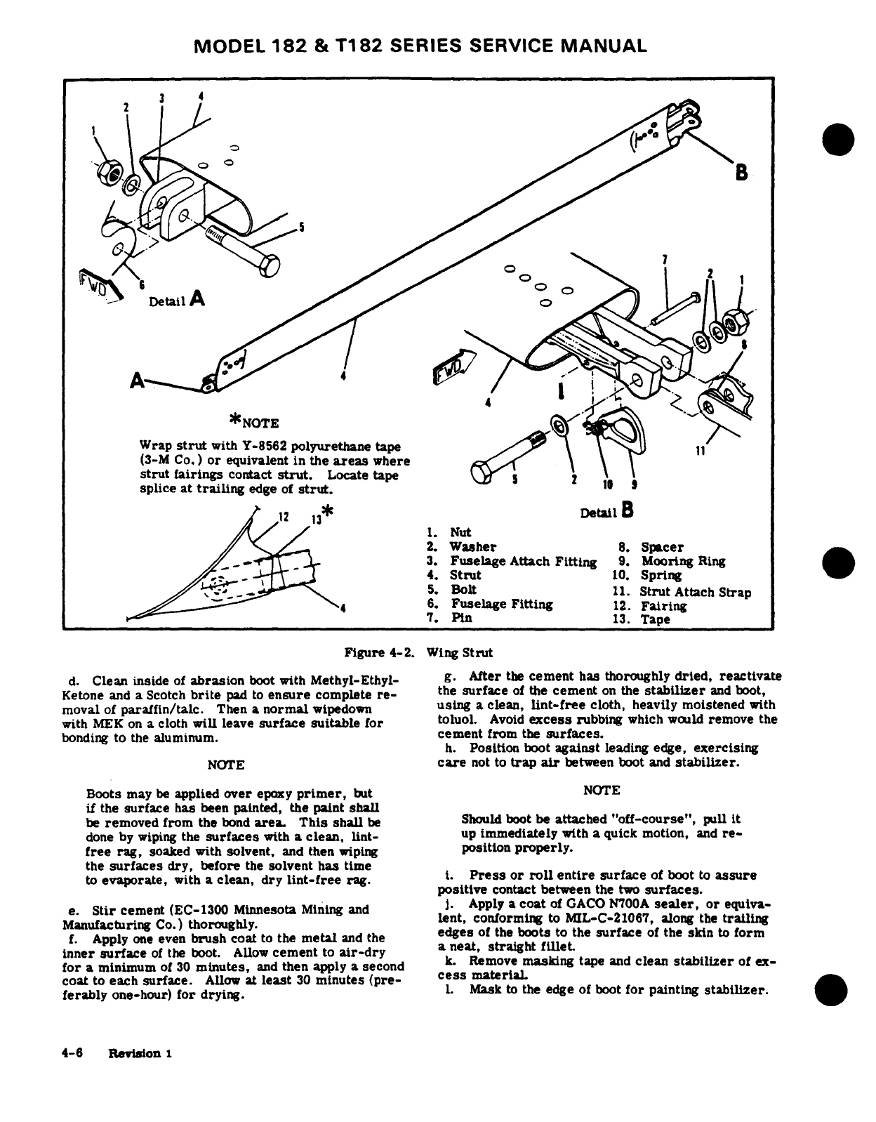
MODEL
182
&
T182
SERIES
SERVICE
MANUAL
splice
at
trailing
edge
of
strut.
1.
Nut
3.
Fuselage
Attach
Fitting
9.
Mooring
Ring
4.
Strut
10.
Spring
Figure
4-2.
Wing
Strut
d.
Clean
inside
of
abrasion
boot
with
Methyl-Ethyl-
g.
After
the
cement
has
thoroughly
dried,
reactivate
Ketone
and
a
Scotch
brite
pad
to
ensure
complete
re-
the
surface
of
the
cement
on
the
stabilizer
and
boot,
moval
of
paraffin/talc.
Then
a
normal
wipedown
using
a
clean,
lint-free
cloth, heavily moistened
with
with
MEK on
a
cloth
will
leave
surface
suitable
for
toluol.
Avoid
excess
rubbing
which
would
remove
the
bonding
to
the
aluminum.
cement
from
the
surfaces.
h.
Position
boot
against
leading edge,
exercising
NOTE
care
not to
trap
air
between
boot and
stabilizer.
Boots
may
be
applied
over
epoxy
primer,
but
NOTE
if
the
surface
has
been
painted,
the paint
shall
be
removed
from the
bond
area.
This
shall
be
Should boot
be
attached
"off-course",
pull
it
done
by wiping
the
surfaces
with
a
clean,
lint-
up
immediately
with
a
quick motion,
and
re-
free
rag,
soaked
with
solvent,
and
then
wiping
position
properly.
the
to
evaporate,
with
a
clean,
dry
lint-free
rag.
Press
or
roll
entire
surface
of
boot
to
assure
positive
contact
between
the
two
surfaces.
e.
Stir
cement
(EC-1300 Minnesota
Mining
and
j.
Apply
a
coat
of
GACO N700A
sealer,
or
equiva-
Manufacturing
Co.)
thoroughly.
lent,
conforming
to
MIL-C-21067,
along
the
trailing
f.
Apply
one
even
brush coat
to
the
metal
and
the
inner
surface
of
the
boot.
Allow
cement
to
air-dry
a
neat,
for
a
minimum
of
30
minutes,
and
then
a
coat
to
each surface.
Allow
at
least
30
minutes
(pre-
cess
material
ferably
one-hour)
for
drying.
1.
Mask
to
the edge
of
boot
for
painting
stabilizer.
4-6
Revision
1
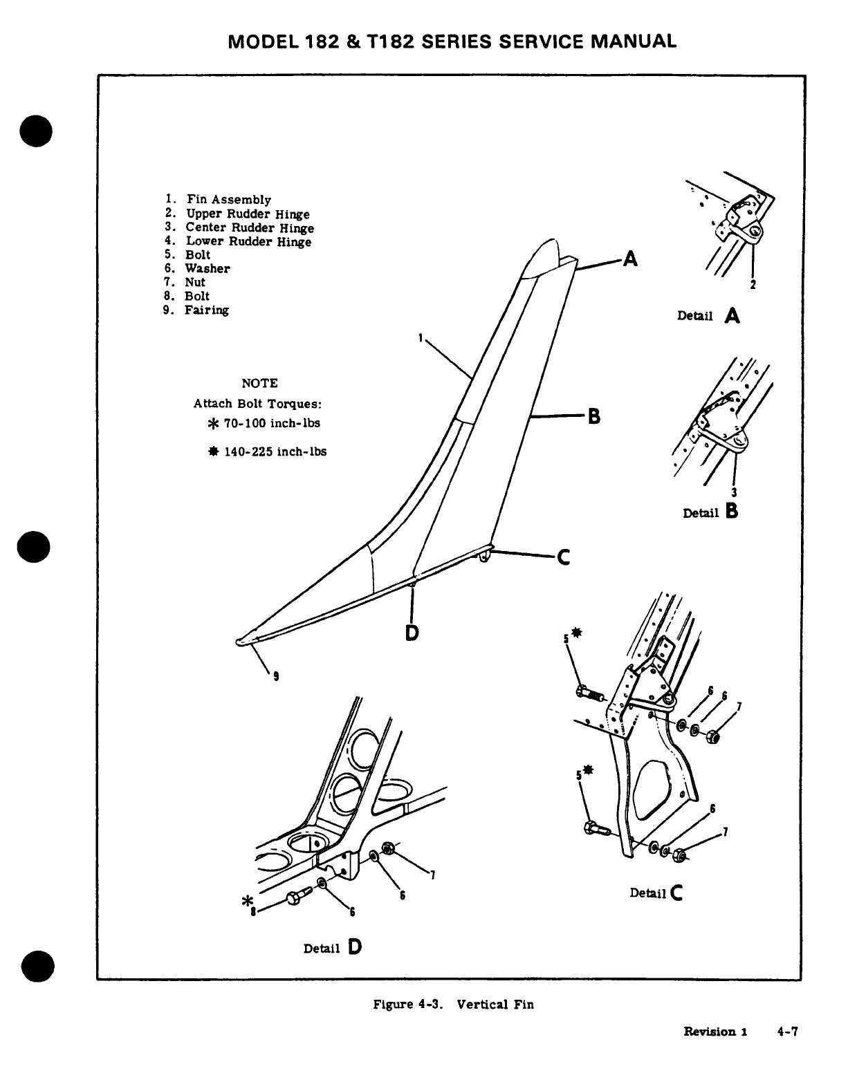
MODEL
182
&
T182
SERIES SERVICE
MANUAL
1.
Fin
Assembly
2.
Upper
Rudder
Hinge
3.
Center
Rudder
Hinge
4.
Lower
Rudder
Hinge
5.
Bolt
6.
Washer
7.
Nut
2
8.
Bolt
9.
Fairing
Detail
A
NOTE
Attach
Bolt
Torques:
70-100
inch-lbs
140-225
inch-lbs
Detail
B
$5
¢ .'/7\/7
S^^^\ 6
Detail
C
Detail
D
Figure
4-3.
Vertical
Fin
Revision
1
4-7
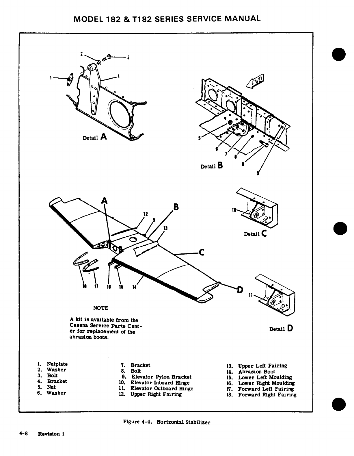
MODEL
182
&
T182
SERIES SERVICE
MANUAL
2
Detail
Detail
B
NOTE
A
kit
is
available
from
the
Cessna
Service
Parts
Cent-
er
for
replacement
of
the
Detail
D
abrasion
boots.
1.
Nutplate
7.
Bracket
13.
Upper
Left
Fairing
2.
Washer
8.
Bolt
14.
Abrasion
Boot
3.
Bolt
9.
Elevator
Pylon
Bracket
15.
Lower Left
Moulding
4.
Bracket
10.
Elevator
Inboard
Hinge
16.
Lower
Right
Moulding
5.
Nut
11.
Elevator
Outboard
Hinge
17.
Forward
Left
Fairing
6.
Washer
12.
Upper
Right
Fairing
18.
Forward
Right
Fairing
Figure
4-4.
Horizontal
Stabilizer
4-8
Revision
1
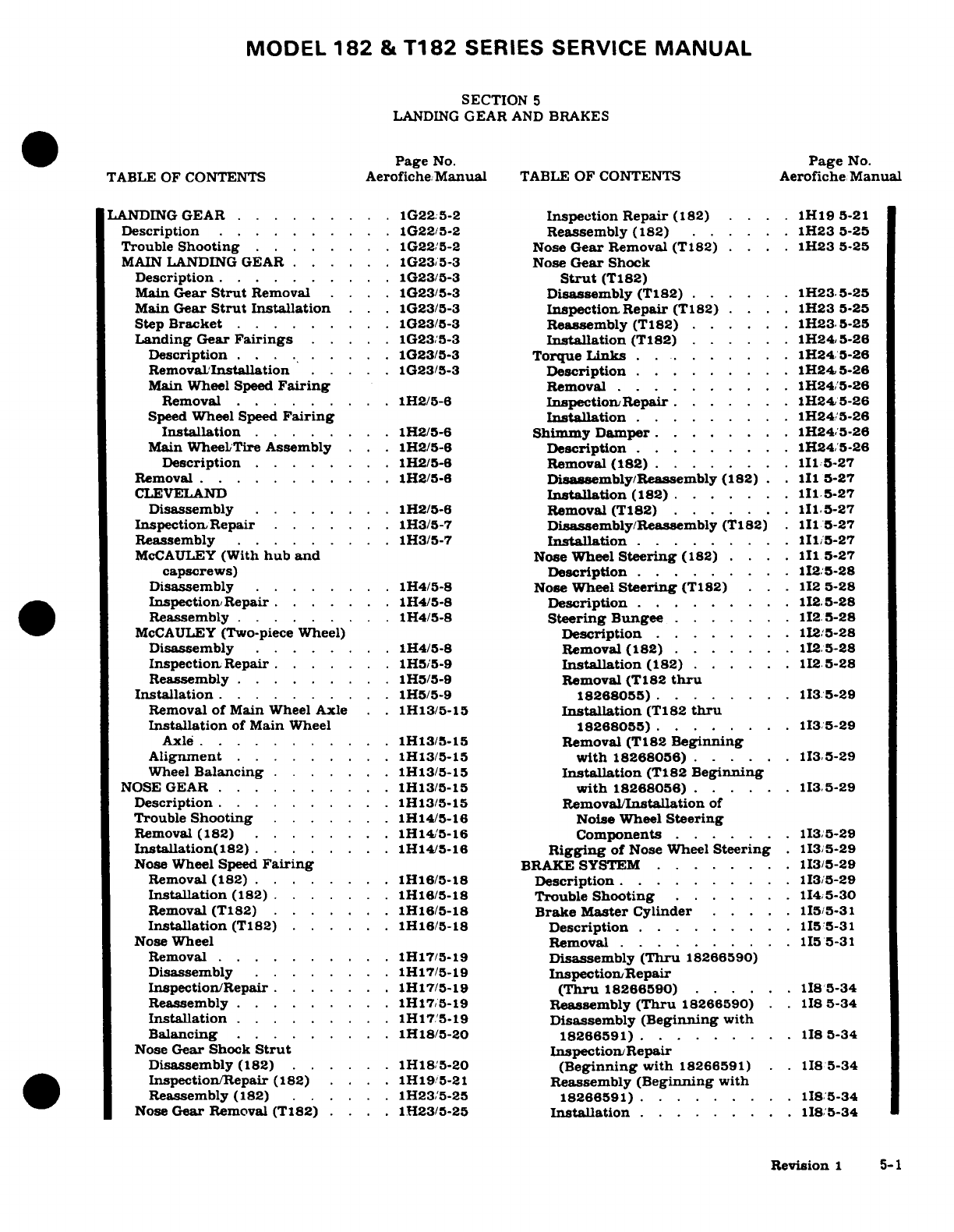
MODEL
182
&
T182
SERIES
SERVICE
MANUAL
SECTION
5
LANDING
GEAR
AND
BRAKES
TABLE
OF
CONTENTS
Aerofiche/Manual
TABLE
OF
CONTENTS
Aerofiche
Manual
LANDING
GEAR
. . . . . .. . .
1G22.5-2
Inspection
Repair
(182) . ...
1H19
5-21
Description
.
........
1G22/5-2
Reassembly
(182)
.....
1H23 5-25
Trouble
Shooting
........
1G22/5-2
Nose
Gear
Removal
(T182) ... . 1H23
5-25
MAIN
LANDING GEAR
.....
1G23/5-3
Nose
Gear
Shock
Description
.......
.. .
1G23/5-3
Strut
(T182)
Main
Gear
Strut
Removal
...
1G23/5-3
Disassembly
(T182)
......
1H23/5-25
Main
Gear
Strut
Installation
. .
1G23/5-3
Inspection
Repair
(T182)
...
1H23 5-25
Step
Bracket
.........
1G23/5-3
Reassembly
(T182).
.....
1H23.5-25
Landing
Gear
Fairings
... .
1G23/5-3
Installation
(T182)
......
1H24/5-26
Description
.......
..
1G23/5-3
Torque
Link
. .
........
1H24/5-26
Removal/Installation
....
1G23/5-3
Description
. .
......
.
1H24
5-26
Main Wheel
Speed
Fairing
Removal
..........
1H24,5-26
Removal
.........
1H2/5-6
Inspection Repair
......
1H245-26
Speed
Wheel
Speed
Fairing
Installation
......
1H24/5-26
Installation
........
Main
Wheel/Tire
Assembly
. .
.1H2/5-6
Description
.........
1H24/5-26
Description
........
1H12/5-6
Removal
(182)
........
1I15-27
Removal
. . . . .
.....
1H2/5-6
Disassembly/Reassembly
(182)
. .
1I1/5-27
CLEVELAND
Installation
(182)
.......
Disassembly
........
1H2/5-6
Removal
(T182)
.......
111.5-27
InspectionRepair
.......
1H3/5-7
Disassembly/Reassembly
(T182)
.
Reassembly
.
.....
. .
McCAULEY
(With
hub
and
Nose
Wheel
Steering
(182)
. ...
capscrews)
Description
. .
......
.
Disassembly
........
1H4/5-8
Nose
Wheel
Steering
(T182) . ..
112
5-28
Inspection,Repair
......
1H4/5-8
Description
.
.....
..
1125-28
Reassembly
.........
1H4/5-8
Steering
Bungee
.......
112
5-28
McCAULEY
(Two-piece
Wheel)
Description
.....
..
1I2/5-28
Disassembly
........
1H4/5-8
Removal
(182)
.......
1I2/5-28
Inspection,
Repair
.
.....
.
1H5/5-9
Installation
(182)
. ... .
112
5-28
Reassembly
. . .. . . . . .
1H5/5-9
Removal
(T182
thru
Installation
. . . . . . ...
1H5/5-9
18268055)
. . . . . . .
1135-29
Removal
of
Main
Wheel
Axle ..
1H13/5-15
Installation
(T182
thru
Installation
of
Main
Wheel
18268055)
... . ...
1I3/5-29
Axle
. ...... .. .
1H13/5-15
Removal
(T182
Beginning
Alignment
.
.......
1H13/5-15
with
18268056)
....
..
113,5-29
Wheel
Balancing
.. .
....
1H13/5-15
Installation
(T182
Beginning
NOSE GEAR
.........
H13/5-15
with
18268056)
......
113,5-29
Description
. . . .. . ..
1H13/5-15
Removal/Installation
of
Trouble
Shooting
. .. . . ..
H14/5-16
Noise
Wheel
Steering
Removal
(182)
.
.......
1H14/5-16
Components
.......
113.5-29
Installation(182)
. .
....
1H14/5-16
Rigging
of
Nose Wheel
Steering
.
1I3/5-29
Nose Wheel Speed
Fairing
BRAKE SYSTEM
.. ...
1I3/5-29
Removal
(182)
.
......
1H16/5-18
Description.
......
1I3/5-29
Installation
(182)
. . . .. .
1H16/5-18
Trouble
Shooting
.......
1I4/5-30
Removal
(T182)
. . .. .1H16/5-18
Brake
Master
Cylinder
.....
1I5/5-31
Installation
(T182)
......
1H16/5-18
Description
.
......
..
1I5/5-31
Nose Wheel
Removal
..........
115
5-31
Removal
..........
17/5-19
Disassembly
(Thru
18266590)
Disassembly
........
1H17/5-19
Inspection/Repair
Inspection/Repair
......
1H17/5-19
(Thru
18266590)
......
1I8/5-34
Reassembly
.........
1H17,5-19
Reassembly
(Thru
18266590)
.
118
5-34
Installation
..... . . . .
1H17/5-19
Disassembly
(Beginning
with
Balancing
.........
1H18/5-20
18266591)
.........
.
118
5-34
Nose
Gear
Shock
Strut
Inspection/Repair
Disassembly
(182)
... . . .
1H185-20
(Beginning
with
18266591) . .
18
5-34
Inspection/Repair
(182) . . .. 1H195-21
Reassembly
(Beginning
with
Reassembly
(182)
......
1H23/5-25
18266591)
.........
1I8/5-34
Nose
Gear
Removal
(T182)
.. .
1H123/5-25
Installation
.........
118,5-34
Revision
1
5-1
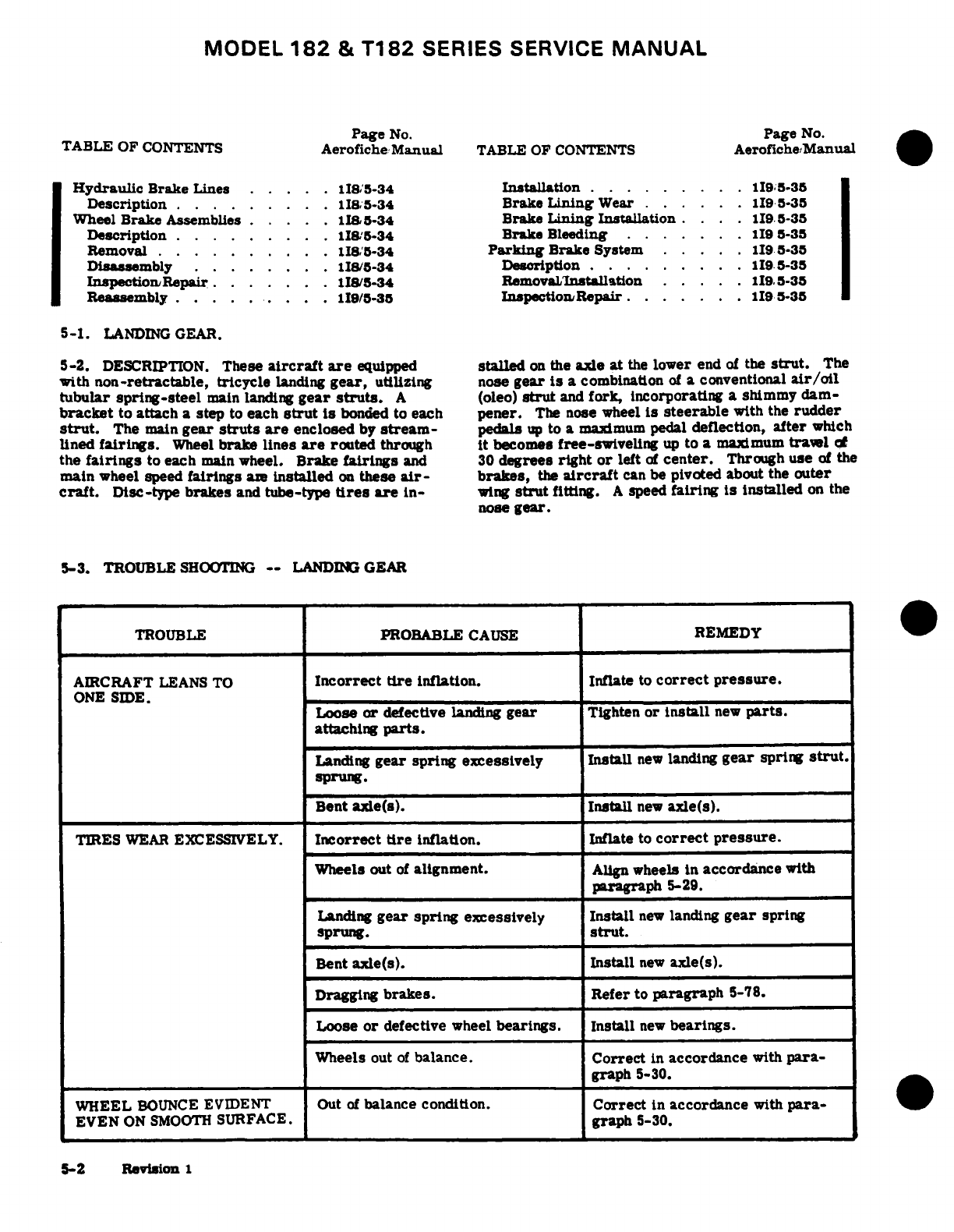
MODEL
182
&
T182
SERIES
SERVICE
MANUAL
Page
No.
Page
No.
TABLE
OF
CONTENTS
Aerofiche/Manual
TABLE
OF
CONTENTS
Aerofiche/Manual
Hydraulic
Brake
Lines
.....
1I8/5-34
Installation
.........
1I9/5-35
Description
.........
1I8/5-34
Brake
Lining
Wear
.... . 1I9/5-35
Wheel
Brake
Assemblies
..... 1I8/5-34
Brake
Lining
Installation
.. . .
1I9/5-35
Description
.
.......
1I8/5-34
Brake Bleeding
. ... ..
1I9/5-35
Removal
...... ... .1I8/5-34
Parking
Brake
System
... ..
1I9/5-35
Disassembly
........
118.5-34
Description
.........
1I9/5-35
Inspection/Repair
.... .
1I8/5-34
Removal/Installation
.....
1I9/5-35
Reassembly
........ .
119/5-35
Inspection/Repair.
..... .
119
5-35
5-1.
LANDING
GEAR.
5-2.
DESCRIPTION.
These
aircraft are
equipped
stalled
on
the
axle
at
the
lower
end
of
the
strut.
The
with
non-retractable,
tricycle
landing
gear,
utilizing
nose
gear
is
a
combination
of
a
conventional
air/oil
tubular
spring-steel
main
landing
gear
struts.
A
(oleo)
strut
and
fork,
incorporating
a
shimmy
dam-
bracket
to
attach
a
step
to
each
strut is
bonded
to each
pener.
The
nose
wheel
is
steerable
with
the
rudder
strut.
The
main
gear
struts
are
enclosed
by
stream-
pedals
up
to
a
maximum
pedal
deflection,
after
which
lined
fairings.
Wheel
brake
lines
are
routed
through
it
becomes
free-swiveling
up
to
a
maximum
travel
of
the
fairings
to
each
main
wheel.
Brake
fairings
and
30
degrees
right
or
left
of
center.
Through
use
of
the
main
wheel
speed
fairings
am
installed
on
these
air-
brakes,
the
aircraft
can
be
pivoted
about the
outer
craft.
Disc-type
brakes
and
tube-type
tires
are
in-
wing
strut
fitting.
A
speed
fairing
is
installed
on
the
nose
gear.
5-3.
TROUBLE
SHOOTING
--
LANDING
GEAR
TROUBLE
PROBABLE
CAUSE
REMEDY
AIRCRAFT
LEANS TO
Incorrect
tire
inflation.
Inflate
to
correct pressure.
ONE SIDE.
Loose
or
defective
landing
gear
Tighten
or
install
new
parts.
attaching
parts.
Landing
gear
spring
excessively
Install
new
landing
gear
spring
strut.
sprung.
Bent
axle(s).
Install
new
axle(s).
TIRES
WEAR
EXCESSIVELY.
Incorrect
tire
inflation.
Inflate
to
correct pressure.
Wheels
out
of
alignment.
Align
wheels
in
accordance
with
paragraph
5-29.
Landing
gear spring
excessively
Install
new
landing
gear
spring
sprung.
strut.
Bent
axle(s).
Install
new
axle(s).
Dragging
brakes.
Refer
to
paragraph
5-78.
Loose
or
defective
wheel
bearings.
Install
new
bearings.
Wheels
out
of
balance.
Correct
in
accordance
with
para-
graph
5-30.
WHEEL
BOUNCE
EVIDENT
Out
of
balance
condition.
Correct
in
accordance
with
para-
EVEN
ON
SMOOTH
SURFACE.
graph
5-30.
5-2
Revision
1
MODEL
182
&
T182
SERIES
SERVICE
MANUAL
5-4.
MAIN
LANDING
GEAR.
j.
Reinstall
carpet
and
seats.
k.
Check
wheel
alignment.
5-5.
DESCRIPTION.
The
tubular,
spring-steel
main
landing
gear
struts
are
attached
to
the
aircraft
at
in-
5-8.
STEP
BRACKET. (See
figure
5-3.)
board
and
outboard forgings,
located
in
the
belly
of
the
aircraft.
A
bracket
is
bonded
to
each
strut
for
NOTE
attachment
of
a
step.
Hydraulic
brake lines
are
routed
down
the
main
gear
struts.
The
axles,
main
The
step
bracket
is
secured
to
the
landing
wheels
and
brake
assemblies
are
installed
at
the
lo-
gear
spring
strut
with EA9303,
or
a
similar
wer
end
of
each
strut.
epoxy
base
adhesive.
5-6.
MAIN
GEAR
STRUT
REMOVAL. (See
figure
a.
Mark
position
of
the
bracket
so
that
the
new
step
5-1.)
bracket
will
be
installed
in
approximately
the
same
position
on
the
strut.
NOTE
b.
Remove
all
traces
of
the
original
bracket
and
ad-
hesive
as
well
as
any
rust,
paint
or
scale
with
a
wire
This
procedure
removes
the
landing
gear
as
brush
and
coarse
sandpaper.
a
complete
assembly.
Refer
to
applicable
c.
Leave
surfaces
slightly
roughened
or
abraded,
paragraph
for
removal
of
individual
parts.
but
deep
scratches
or
nicks
should
be
avoided.
d.
Clean
surfaces
to
be
bonded
together
thoroughly.
a.
Remove
floorboard
access
covers
over
inboard
If
a
solvent
is
used,
remove
all
traces
of
the solvent
and
outboard
landing
gear
forgings
(24)
and
(26).
with a
clean,
dry
cloth.
It
is
important
that
the
bon-
b.
Hoist
or
jack
aircraft
in
accordance
with
pro-
ding
surfaces
be
clean
and
dry.
cedures
outlined
in Section
2
of
this
manual.
e.
Check fit
of
step
bracket
on
the
strut.
A
small
c.
Remove
screws
from
fuselage
fairing
and
slide
gap
is
permissible
between
bracket
and
strut.
down
strut
fairing
for
access
to
brake
line.
f.
Mix
adhesive
(EA9309)
in
accordance
with
manu-
d.
Remove
brake
bleeder
screw
and
drain
hydrau-
facturer's
directions.
lic
fluid
from
brake
on
gear
being
removed.
g.
Spread
a
coat
of
adhesive
on
bonding
surfaces,
e.
Disconnect
brake
line
at
fuselage
fitting.
and
place
step
bracket
in
position
on
strut.
Clamp
f.
Remove
snap
ring
(1)
from
strut-attaching
pin
bracket to
ensure
a
good
tight
fit.
(2).
h.
Form
a
small
fillet
of
the
adhesive
at
all
edges
g.
Remove
plug
button
(25)
from
belly
of
aircraft
of
the
bonded
surfaces.
Remove
excess
adhesive
below
gear
forging.
with
lacquer
thinner.
h.
Using
a
punch,
drive
attaching
pin
(2)
upward
i.
Allow
the
adhesive
to
cure
thoroughly
according
out
of
inboard
forging
(26).
to the
manufacturer's
recommendations before
flex-
i.
Pull
strut
outboard
of
forgings
(24)
and
(26).
ing
the
strut
or
applying
loads
to
the
step.
j.
Paint
the
strut
and
step
bracket
after
curing
NOTE
is
completed.
To
replace
bushing
from
outboard
forging
(24),
5-9.
LANDING
GEAR
FAIRINGS.
(See
figure
5-1.)
remove
retaining
ring
at
inboard
end and
slide
bushing
outboard
from
forging. (Refer
5-10.
DESCRIPTION.
The
aircraft
is
equipped
with
to
Section
view
A-A.
)
fuselage
fairings,
attached
to the
fuselage
and
the
tu-
bular
strut
fairings
with
screws.
The
tubular
strut
5-7.
MAIN
GEAR
STRUT
INSTALLATION.
(See
fairings
cover
the
tubular
landing
gear
struts.
and
figure
5-1.)
attach
to
the
fuselage
fairings
at
the
upper
end
and
to
cover
plates
at
the
lower
end.
The
cover
plates
at-
NOTE
tach
to
the
tubular
strut
fairings
at
the
upper
end
and
are
clamped
to
the
tubular
struts
at
the
lower
end.
The
following
procedure
installs
the
landing
Brake
fairings
are
installed
at
the lower
end
of
the
gear as
a
complete
assembly.
Refer
to
tubular
strut
fairings
and
are
attached to
the
wheel
applicable
paragraphs
for
installation
of
speed
fairings
by
screws
around
their outer
peri-
individual
components.
meters.
The
speed
fairings
are
installed
over
the
wheels
and
are
attached
to
mounting
plates.
attached
a.
Install
parts
removed
from
strut.
to
the
axles.
The
wheel
fairings
are
equipped
with
b.
Clean
and
polish
machined
surface
on
upper
end
adjustable
scrapers.
installed
in
the
lower
aft
part
of
strut.
Prime
fitting
(10)
per
note.
if
required.
of
the
fairings.
directly
behind
the
wheels.
c.
Apply
Universal
Oil
DYNAPLEX
21C
REGULAR
to
unpainted
area
on
upper
end
of
strut.
5-11.
REMOVAL
AND
INSTALLATION
OF
MAIN
d.
Slide
strut
through
bushing into
inboard
forging
GEAR FAIRINGS.
(See
figure
5-1.)
and
align
attaching
pin
holes.
a.
To
remove
brake
fairing, proceed
as
follows:
e.
Install
attaching
pin
and
snap
ring.
1.
Remove
screws
from
perimeter
of
fairing.
f.
Install
access
plates
and
plug
button.
2.
Remove
screws
from
nutplates
holding
two
g.
Remove
caps
or
plugs
and
connect
brake
line.
halves
of
fairing
together: remove
two
fairing
halves.
h.
Fill
and
bleed
brake
system
in
accordance
with
3.
Reverse
the
preceding
steps
to
install
brake
applicable
paragraph.
fairing.
i.
Install
fuselage
fairing.
b.
To
remove
cover plates.
proceed
as
follows:
5-3
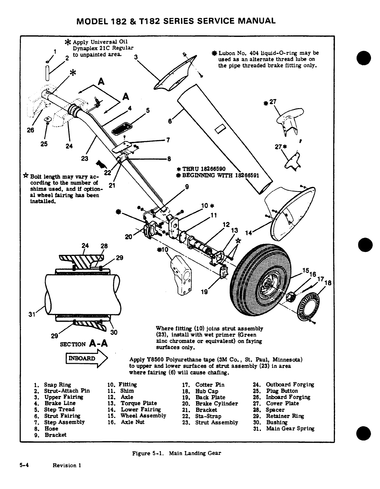
MODEL
182
&
T182
SERIES
SERVICE
MANUAL
Apply
Universal
Oil
Dynaplex
21C
Regular
the pipe
threaded
brake
fitting
only.
A
26
25
24
27*
Bolt
length
may
vary
ac-
cording
to
the
number
of
21
shims used,
and
if
option-
al
wheel
fairing
has been
installed.
12
14
24
28
31
Where
fitting
(10)
joins
strut
assembly
29 30
(23),
install
with
wet
primer
(Green
SECTION
A-A
zinc
chromate
or
equivalent)
on
faying
SECTION
A-A
surfaces
only.
INBOARD
Apply
Y8560
Polyurethane
tape
(3M
Co.,
St.
Paul,
Minnesota)
where
fairing
(6)
will
cause
chafing.
1.
Snap
Ring
10.
Fitting
17.
Cotter
Pin
24.
Outboard
Forging
2.
Strut-Attach
Pin
11.
Shim
18.
Hub
Cap
25.
Plug
Button
3.
Upper
Fairing
12.
Axle
19.
Back
Plate
26.
Inboard
Forging
4.
Brake
Line
13.
Torque
Plate
20.
Brake
Cylinder
27.
Cover
Plate
5.
Step
Tread
14.
Lower
Fairing
21.
Bracket
28.
Spacer
6.
Strut
Fairing
15.
Wheel
Assembly
22.
Sta-Strap
29.
Retainer
Ring
7.
Step
Assembly
16.
Axle
Nut
23.
Strut
Assembly
30.
Bushing
8.
Hose
31.
Main
Gear
Spring
9.
Bracket
Figure
5-1.
Main
Landing
Gear
5-4
Revision
1
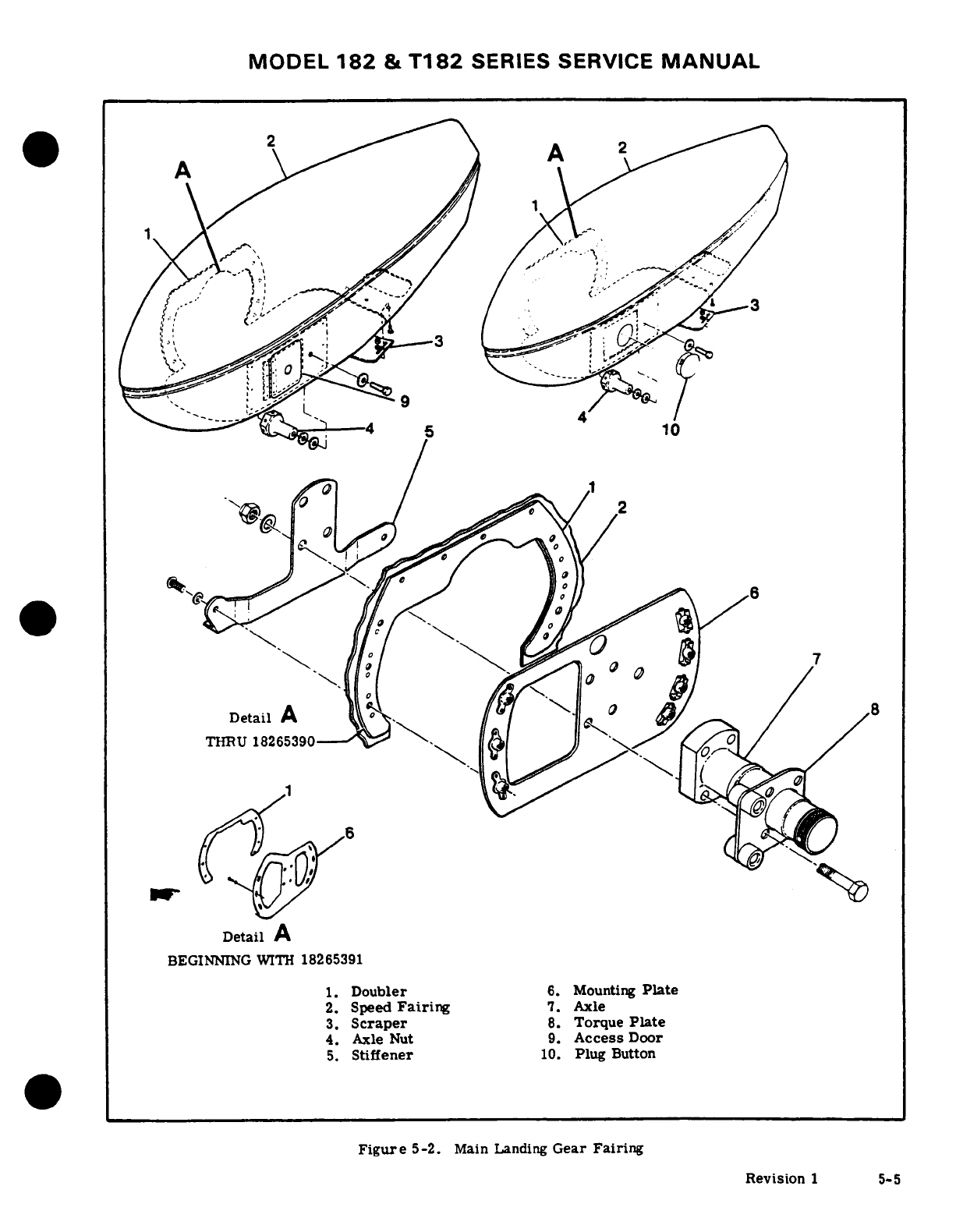
MODEL
182
&
T182
SERIES
SERVICE
MANUAL
1.
Remove
three
screws
attaching
fairings
to
tu-
stalling
screws
in
nutplates
holding
two
halves
of
bular
strut
fairing.
brake
fairing
together,
then
installing
screws
around
2.
Remove bolt
and nut
attaching
clamp
to
tubu-
perimeter
of
fairing.
lar
spring-strut.
e.
After
installation,
check
scraper-to-tire
clear-
3.
Spring clamp
open
to
slide
over
tubular
gear
ance
for
a
minimum
of
0.25-inch
to
a
maximum
of
strut;
remove
cover
plate.
0.50-inch.
Elongated
holes
are provided
in
the
4.
Reverse
the
preceding
steps
to
install
cover
scraper
for
clearance
adjustments.
plates.
c.
To
remove
fuselage
fairing, proceed
as
follows:
1.
Remove
screws
attaching
fairing
to
fuselage.
2.
Remove
screws
at splice
in
fairing.
Always check
scraper-to-tire
clearance
after
3.
Work
fairing
off
strut
fairing. installing
speed
fairing,
whenever
a
tire
has
4.
Reverse
the
preceding
steps
to
install
fuse-
been
changed,
and
whenever
scraper
adjust-
lage
fairing.
ment
has been
disturbed.
If
the
aircraft
is
d.
To
remove
tubular
gear
strut
fairing,
proceed
flown
from
surfaces
with
mud,
snow,
or
ice,
as
follows:
the
speed
fairing
should
be
checked
to
make
1.
Remove
brake
fairing
as
outlined
in
step
"a".
sure
there
is
no
accumulation
which
could
2.
Remove
cover
plate
as
outlined
in
step
"b".
prevent
normal
wheel
rotation.
Wipe
fuel
and
3.
Remove
fuselage
fairing
as
outlined
in
step
oil
from
speed
fairings
to
prevent
stains
and
"c".
deterioration.
4.
Remove
screws
from nutplates
on
tubular
gear
strut
fairing.
5-14.
MAIN
WHEEL
AND
TIRE
ASSEMBLY.
5.
Spring
fairing over
tubular
gear
strut.
(See
figure
5-4.)
6.
Reverse
the
preceding
steps
to
install
tubu-
lar
gear
strut
fairing.
5-15.
DESCRIPTION.
The
aircraft
may
be
equipped
with
either
Cleveland
or
McCauley two
piece
wheel
5-12.
MAIN
WHEEL
SPEED
FAIRING REMOVAL.
and
tire
assemblies, or,
McCauley
three
piece (with
(See
figure
5-2.)
hub
and
capscrews)
wheel
and
tire
assemblies.
Sep-
a.
Remove
wheel
brake
fairing
(item
14,
figure
5-1),
arate
disassembly,
inspection
and
reassembly
instruc-
by
removing
screws
around
perimeter
of
fairing,
then tions
are
provided
for
each
type.
by
removing
screws
from
nutplates
holding
two
halves
of
brake
fairing
together.
5-16.
REMOVAL.
b.
Remove
screws
attaching
stiffener
(5)
and
inboard
side
of
wheel
speed
fairing
(2)
to
mounting
plate
(6), NOTE
which
is
attached
to
the
axle.
c.
Remove
bolt
securing
outboard
side
of
fairing
to It
is
not
necessary
to
remove
the
main
wheel
axle
nut.
to
reline
the
brakes
or
remove
brake
parts,
d.
Loosen
scraper,
if
necessary,
and
work
speed other
than
the
brake
disc
of
the
torque
plate.
fairing from
wheel.
a.
Using
an
individual
jack
pad,
jack
the
wheel
as
5-13.
MAIN
WHEEL
SPEED
FAIRING INSTALLA-
outlined
in
Section
2.
TION.
(See
figure
5-2.)
b.
Remove
hub
cap.
a.
Work
speed
fairing
down
over
wheel.
c.
Remove
cotter
pin
and
axle
nut.
b.
Install
bolt
securing
outboard
side
of
fairing
to
d.
Remove
bolts
and
washers
attaching
back
plate
axle
nut.
to
brake
assembly
and
remove back
plate.
c.
Install screws
attaching
stiffener
(5)
and
inboard
e.
Pull
wheel
assembly
from
axle.
side
of
wheel
speed
fairing
(2)
to
mounting
plate
(6),
which
is
attached
to
the
axle.
5-17.
DISASSEMBLY
OF CLEVELAND
MAIN
WHEEL
d.
Install
brake
fairing
(item
14,
figure
5-1),
by
in-
AND
TIRE
ASSEMBLY.
(See
figure
5-4.)
a.
Deflate
tire
and
tube
and
break
tire
beads
loose
at
wheel
flanges.
5-6

MODEL
182
&
T182
SERIES
SERVICE
MANUAL
NOTE
After
installation
of screw
(6),
cement
entire
forward
half
of
step
tread
(5)
to
step
(7)
with
EC1300
or
equivalent.
(Refer
to shaded
area.)
1.
Step
SupportAssembly
4.
Brake
Line
6.
Screw
2.
Sta-Strap
5.
Step
Tread
7.
Step
3.
Spring
Strut
8.
Hose
Figure
5-3.
Step
Installation
mate
and
painted
with
aluminum
lacquer.
Avoid
damaging wheel
flanges
when
breaking
c.
Inspect
brake
discs
in
accordance
with
proce-
tire
beads
loose.
A
scratch,
gouge
or
nick
dures
outlined
in
paragraph
5-95.
may
cause
wheel
failure.
d.
Bearing
cups
and
cones
must
be
inspected
care-
fully
for
damage
and
discoloration.
After
cleaning.
b.
Remove
thru-bolts
and
separate
wheel
halves,
pack
bearing
cone
with clean
aircraft
wheel
bearing
removing
tire,
tube
and
brake
disc.
grease
before installation
in
the
wheel
half.
c.
Remove
grease
seal
rings,
felts
and
bearing
cones
from
wheel
halves.
5-19.
REASSEMBLY
OF
CLEVELAND
MAIN
WHEEL
NOTE
AND
TIRE
ASSEMBLY.
(See
figure
5-4.)
a.
Insert
thru-bolts
through
brake
disc
and position
Bearing
cups
are
a
press
fit
in
the wheel
brake
disc
in
the
inner
wheel
half,
using
the
thru-
halves
and
should
not
be
removed
unless
new
bolts
to
guide
the
disc.
Assure
that
brake disc
is
bearing
cups
are
to
be
installed.
To
remove
seated
in
wheel
half.
bearing
cup,
heat
wheel half
in
boiling
water
b.
Insert
tube
in
tire,
aligning
index
marks
on
tire
for
15
minutes.
Using
an
arbor
press,
if
and
tube.
available,
press
out
the
bearing
cup
and
c.
Position
tire
and
tube
with
inflation
valve
press
in
new
cup
while wheel
is
still
hot.
through
hole
in
outboard
wheel
half.
Place
inner
wheel
half
in
position
with
thru-bolts
in
outboard
5-18.
INSPECTION
AND
REPAIR OF
CLEVELAND
wheel
half.
Apply
light
force
to
bring
wheel
halves
MAIN
WHEEL
AND
TIRE
ASSEMBLY.
(See
figure
together
and
assemble
a
washer
and
nut
on
thru-bolts.
5-4.)
Tighten
thru-bolts
evenly
to
a
torque
of
90
lb in.
a.
Clean
all
metal
parts
and
grease
seal
felts
in
cleaning
solvent
and
dry
thoroughly.
b.
Inspect
wheel
halves
for
cracks.
Cracked
wheel
halves
must
be
rejected
and
new
parts
installed.
Uneven
or
improper
torque
of
thru-bolt
Sand
out
nicks,
gouges
and
corroded
areas.
When
nuts
may
cause
failure
of
bolts
with
re-
the
protective
coating
has
been
removed,
the
area
sultant
wheel
failure.
Revision
1 5-7
MODEL
182
&
T182
SERIES SERVICE
MANUAL
d.
Clean
and
repack
wheel
bearing
cones
with
clean
a.
Place
wheel
hub in
tire
and
tube
with
tube
infla-
aircraft
wheel
bearing
grease.
tion
stem
in
cutout of wheel
hub.
e.
Assemble
bearing
cones,
grease
seal
felts
and
b.
Place
spacer
and
wheel
flange
on
inboard
side
of
rings
into wheel
halves.
wheel
hub
(opposite
of tube
inflation
stem),
then
place
f.
Inflate
tire
to
seat
tire
beads,
then
adjust
pres-
washer under
head
of
each
capscrew
and
start
cap-
sure
to
amount
specified
in
figure
1-1.
screws
into
wheel
hub
threads.
c.
Place
spacer
and
wheel
flange
on
other
side
and
5-20.
DISASSEMBLY
OF
McCAULEY
MAIN
WHEEL
align
valve
stem
in
cutout
in
wheel
flange.
AND
TIRE
ASSEMBLY.
(With
hub
and
capscrews.)
d.
Place washer
under
head
of
each
capscrew
and
(See
figure
5-4.)
start
capscrews
into
wheel
hub
threads.
a.
Remove
valve
core
and
deflate
tire
and
tube.
Break
tire
beads
loose
from
wheel
flanges.
WARNING
Injury
can
result
from
attempting
to
remove
seated
on
flange
of wheel
hub.
Uneven
or
wheel
flanges
with
the
tire
and
tube
inflated
improper
torque
of
capscrews
can
cause
Avoid
damaging
wheel flanges
when
breaking
failure
of
capscrews,
with
resultant
wheel
tire
beads
loose.
A
scratch
gouge
or
nick
failure.
in
wheel flanges
could
cause
wheel
failure.
e.
Tighten
capscrews
evenly
and
torque
to
a
value
b.
Remove
capscrews
and
washers.
of
190-200
lb
in.
c.
Separate
wheel
flanges
from
wheel
hub.
Retain
f.
Clean
and
pack
bearing
cones
with
clean
aircraft
spacers
between
wheel
flanges
and
wheel
hub.
wheel
bearing
grease.
(Refer
to
Section 2
for
grease
d.
Remove wheel
hub
from
tire
and
tube.
type.)
e.
Remove
retainer
rings,
grease
seal
retainers,
g.
Assemble bearing
cones,
grease
seal
felts
and
retainers
into
wheel
hub.
grease
seal
felts
and
bearing
cones
from
wheel
hub.
retainers
into
wheel
hub.
NOTE
The
bearing
cups
are
a
press
fit
in
the
wheel
Grease
seal
retainer
hub
and
should
not
be
removed
unless
a
new
seal
retainers
(inboard)
(12)
are
not
inter-
part is to be
part
is
to
be
installed.
To
remove
the
bear-
ing
cup,
heat
wheel
hub
in
boiling
water
for
are
30
minutes,
or
in
an oven
not
to
exceed
121°C
Grease
seal
retainer
(outboard)
(2),
grease
(250 F).
Using
an
arbor
press,
if
available,
seal
felt
(outboard)
(3)
and
grease
seal
re-
press
out
bearing
cup
and
press
in
new
bear-
tainer
(outboard)
(4)
are
to
be
assembled
in
ing
cup
while wheel
hub
is
still
hot.
5-21.
INSPECTION
AND
REPAIR
OF
McCAULEY h.
Inflate
tire
to
seat
tire
beads,
then
adjust
to
cor-
WHEEL
AND
TIRE
ASSEMBLY.
(With
hub
and
rect tire
pressure
specified
in
figure
1-1.
capscrews.)
(See
figure
5-4.)
a.
Clean
all
metal
parts,
grease
seal
felts
and 5-23.
DISASSEMBLY
OF
McCAULEY
MAIN
WHEEL
spacers
in
cleaning
solvent
and
dry
thoroughly.
AND
TIRE
ASSEMBLY.
(Two-Piece
Wheel.)
b.
Inspect
wheel
flanges
and
wheel
hub
for
cracks.
a.
Completely
deflate
tire
and tube
and
break
loose
Discard
cracked
wheel
flanges
or
hub and
install
new
tire
beads.
Extreme
care
must
be
exercised
to
pre-
parts.
Sand
out
nicks,
gouges
and
corroded
areas.
vent
tire
tool damage when
removing
tire
from
wheel
When
protective
coating
has
been
removed,
clean
the
halves
(6).
area
thoroughly;
prime
with
zinc
chromate,
and
paint
with
aluminum
lacquer.
c.
Inspect brake
discs
in
accordance
with
proce-
dures
outlined
in
paragraph
5-95.
d.
Carefully
inspect
bearing cones
and
cups
for
damage
and
discoloration.
After
cleaning,
pack
bear-
ing
cones
with
clean
aircraft
wheel
bearing
grease
(refer
to
Section
2)
before
installing
in
wheel
hub.
c.
Remove
thru-bolts(24)
and
washers
(25).
d.
Separate
and
remove
wheel
halves
(6)
from
tire
5-22.
REASSEMBLY
OF
McCAULEY
MAIN
WHEEL
and
tube.
AND
TIRE
ASSEMBLY.
(With
hub
and
capscrews.)
e.
Remove
retaining rings
(1),
grease seal
retain-
ers
(2)
grease
seal
felts
(3),
grease
seal
retainers
(4)
and
bearing
cones
(5)
from
both
wheel
halves
(6).
5-8 Revision
1
MODEL
182
&
T182
SERIES SERVICE
MANUAL
NOTE
5-25.
REASSEMBLY
OF
McCAULEY
MAIN
WHEEL
AND
TIRE
ASSEMBLY.)
(Two-Piece
Wheel.)
Bearing
cups
(races)
(27)
are
a
press
fit
in
a.
Assemble
bearing
cone
(5),
grease
seal
retainer
wheel
halves
(6),
and
should
not
be
removed
(4),
grease
seal
felt
(3),
grease seal
retainer
(2)
and
unless
a
new
part
is
to
be
installed.
To
re-
retaining
ring
(1)
into
each
wheel
half
(6).
move
bearing
cups,
heat
wheel
half
in
boiling
b.
Insert
tube
in
tire,
aligning
index
marks
on
tire
water for
30
minutes,
or
in
an
oven,
not
to
and
tube.
excees
121°C
(250°F). Using
an
arbor press,
c.
Place
wheel
half
(6)
into
tire
and
tube
(side
if
available,
press
out
bearing
cup
and
press
opposite
valve
stem),
aligning
base
of
valve
stem
in
a
new
bearing
cup
while
wheel half
is
still
in
valve
slot.
With
washer
(25)
under
head
of
thru-
hot.
bolt
(24),
insert
bolt
through
wheel
half
(6).
d.
Place
wheel
half
(6)
into
other
side
of
tire
and
5-24.
INSPECTION
AND
REPAIR
OF
McCAULEY
tube,
aligning
valve
stem
in
valve
slot.
WHEEL
AND
TIRE
ASSEMBLY.
(Two-Piece
Wheel.)
e.
Insert
washers
(9)
and
nuts
(10)
on
thru-bolts
a.
Clean
all
metal
parts
and
grease
seal felts
in
(24),
and
pre-torque
to
10-15
lb.
in.
Stoddard
solvent
or
equivalent,
and
dry
thoroughly.
NOTE
Uneven
or
improper
torque
of
the
nuts
A
soft
bristle
brush
may
be
used
to
remove
can
cause
failure
of the
bolts
with
re-
hardened
grease,
dust
or
dirt.
sultant
wheel
failure.
b.
Inspect
wheel
halves
(6)
for
cracks
or
damage.
f.
Prior
to
torquing
nuts
(10),
inflate
tube
with
c.
Inspect
bearing
cones
(5),
cups
(27),
retaining
approximately
10-15
psi
air
pressure
to
seat
tire.
rings
(1),
grease
seal
retainers
(2),
grease
seal
felts
(3)
and
grease
seal
retainers
(4)
for
wear
or.
damage.
d.
Inspect
thru-bolts
(24)
and
nuts
(10)
for
cracks
in
threads
or
cracks
in
radius
under bolt
head.
e.
Replace
cracked
or
damaged
wheel
half
(6).
e.
Replace
cracked
or
damaged
wheel
half
(6).
h.
Inflate
tire
to
correct pressure
specified
in
f.
Replace
damaged
retainer
rings
(1)
and
seals
figure
1-1
of
this
manual.
(2),
(3)
and
(4).
g.
Replace
worn
or
damaged
bearing
cups
(27)
and
5-26.
INSTALLATION
OF
MAIN
WHEEL
cones
(5).
a.
Place
wheel
assembly
on
axle.
h.
Replace
any
worn
or
cracked
thru-bolts
(24)
or
b.
Install
axle nut
and
tighten
axle
nut
until
a
slight
nuts
(10).
bearing
drag
is
obvious
when
the
wheel
is
rotated.
i.
Inspect
brake
discs
in
accordance
with
proce-
Back
off
axle
nut
to
nearest
castellation
and
install
dures
outlined
in
paragraph
5-95.
cotter
pin.
j.
Remove
any
corrosion
or
small
nicks.
c.
Place
brake back
plate
in
position
and
secure
k.
Repair
reworked
areas
of
wheel
by
cleaning
with
bolts
and
washers.
thoroughly,
then
applying one
coat
of
clear
lacquer
d.
Install
speed
fairing
as
outlined
in
paragraph
paint. 5-13.
1.
Pack
bearings
with
grease
specified
in
Section
2
e.
Remove
jack
and
jack
pad.
of
this
manual.
SHOP
NOTES:
Revision
1
5-9
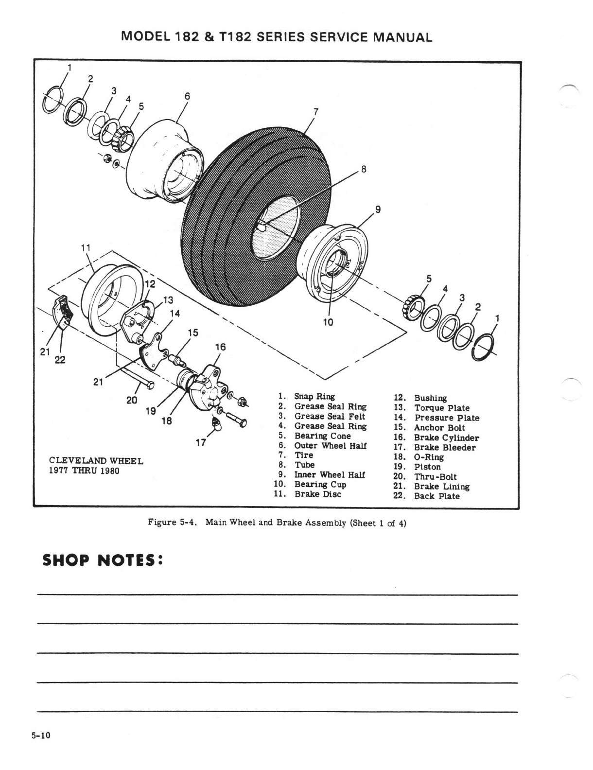
MODEL
182
&
T182
SERIES
SERVICE
MANUAL
1.
Snap
Ring
12.
Bushing
17
6.
Outer
Wheel
Half
17.
Brake
Bleeder
7.
Tire
18.
O-Ring
CLEVELAND
WHEEL
8.
Tube
19.
Piston
1977
THRU
1980
9.
Inner
Wheel
Half
20.
Thru-Bolt
10.
Bearing
Cup
21.
Brake
Lining
11.
Brake
Disc
22.
Back
Plate
Figure
5-4. Main Wheel
and
Brake
Assembly
(Sheet
1
of
4)
SHOP
NOTES:
5-10
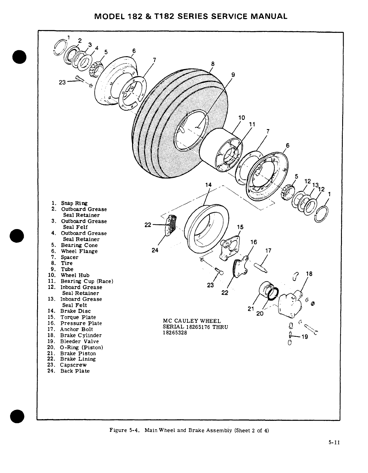
MODEL
182
&
T182
SERIES
SERVICE
MANUAL
1.
Snap
Ring
2.
Outboard
Grease
Seal
Retainer
3.
Outboard
Grease
Seal
Felf
15
4.
Outboard
Grease
Seal
Retainer
16
5.
Bearing
Cone
6.
Wheel
Flange
24
7.
Spacer
8.
Tire
9.
Tube
10.
Wheel
Hub
? 18
11.
Bearing
Cup
(Race)
12.
Inboard
Grease
Seal
Retainer
22
13.
Inboard
Grease
/
Seal
Felt
2
14.
Brake
Disc
20
15.
Torque
Plate
MC
CAULEY WHEEL
16.
Pressure
Plate
SERIAL
18265176
THRU
17.
Anchor
Bolt
18265328
n
18.
Brake
Cylinder
182619
19.
Bleeder
Valve 0
20.
O-Ring
(Piston)
21.
Brake
Piston
22.
Brake
Lining
23.
Capscrew
24.
Back
Plate
Figure
5-4.
Main
Wheel
and
Brake
Assembly
(Sheet
2
of
4)
5-11
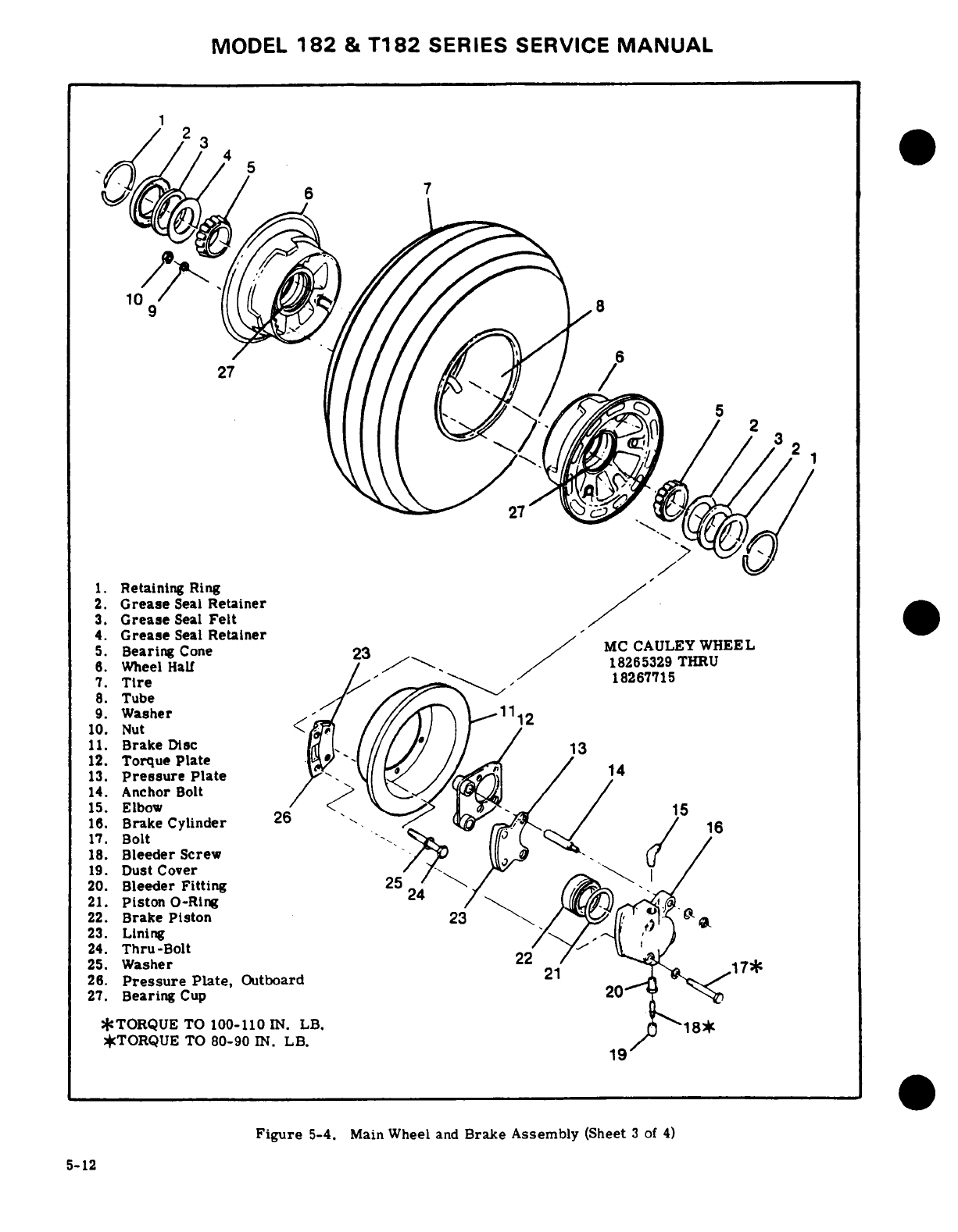
MODEL
182
&
T182
SERIES
SERVICE
MANUAL
10
1
2
2
11. Brak
Dlc
l/ / //
27
1.
Retaining
Ring
2.
Grease
Seal
Retainer
3.
Grease
Seal
Felt
4.
Grease
Seal
Retainer
5.
Bearing
Cone
23
MC
CAULEY
WHEEL
6.
Wheel
Half
'
18265329
THRU
7.
Tire
18267715
8.
Tube
9.
Washer
1112
10. Nut
11.
Brake
Disc
13
12.
Torque
Plate
13.
Pressure
Plate
14Out
14.
Anchor
Bolt
15E
.
Elbow
15
1
.
a
Brake
Cylinder
263
of
5-12
17.
Bolt
Bo
l
/
18.
Bleeder
Screw
19.
Dust
Cover
20.
Bleeder
Fitting
25
21
Piston
0-Ring
4
22.
Brake
Piston
23
23.
Lining
24.
Thru-Bolt
25.
Washer 22
17*
26.
Pressure
Plate,
Outboard
21
1
27.
Bearing
Cup
20
* TORQUE
TO
100-110
IN.
LB.
18*
*TORQUE
TO
80-90
IN.
LB.
19
Figure
5-4.
Main
Wheel
and
Brake
Assembly
(Sheet
3
of
4)
5-12
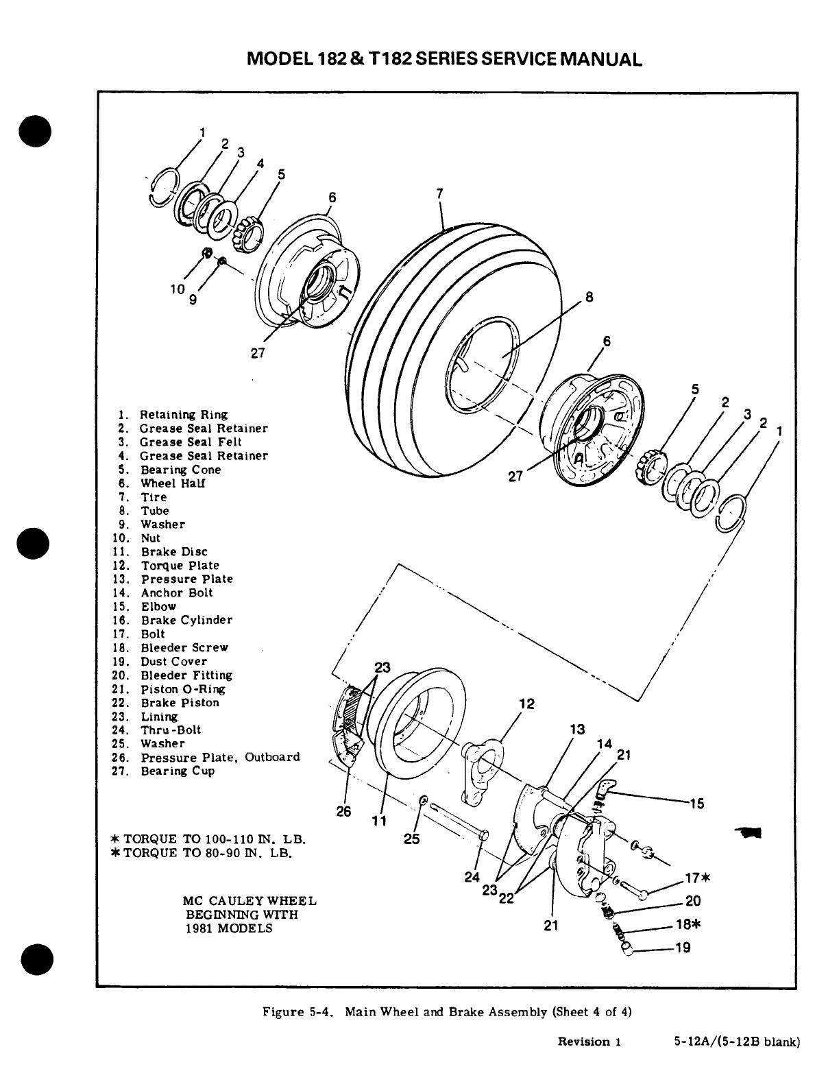
MODEL
182
&
T182
SERIES
SERVICE
MANUAL
1.
Retaining
Ring
2.
Grease
Seal
Retainer
3.
Grease
Seal
Felt
4.
Grease
Seal
Retainer
5.
Bearing
Cone
27
6.
Wheel
Half
7.
Tire
8.
Tube
9.
Washer
10.
Nut
11.
Brake
Disc
12.
Torque
Plate
13.
Pressure
Plate
14.
Anchor Bolt
15.
Elbow
16.
Brake
Cylinder
17.
Bolt
18.
Bleeder
Screw
19.
Dust
Cover
20.
Bleeder
Fitting
21.
Piston
O-Ring
22.
Brake
Piston
23.
Lining
24.
Thru-Bolt
13
25.
Washer
14
26.
Pressure
Plate,
Outboard
21
27.
Bearing
Cup
*TORQUE
TO
100-110 IN.
LB.
*TORQUE
TO
80-90
IN.
LB.
24
MC
CAULEY
WHEEL
BEGINNING
WITH
1981
MODELS 21
Figure
5-4.
Main
Wheel
and
Brake
Assembly
(Sheet
4
of
4)
Revision
1
5-12A/(5-12B
blank)
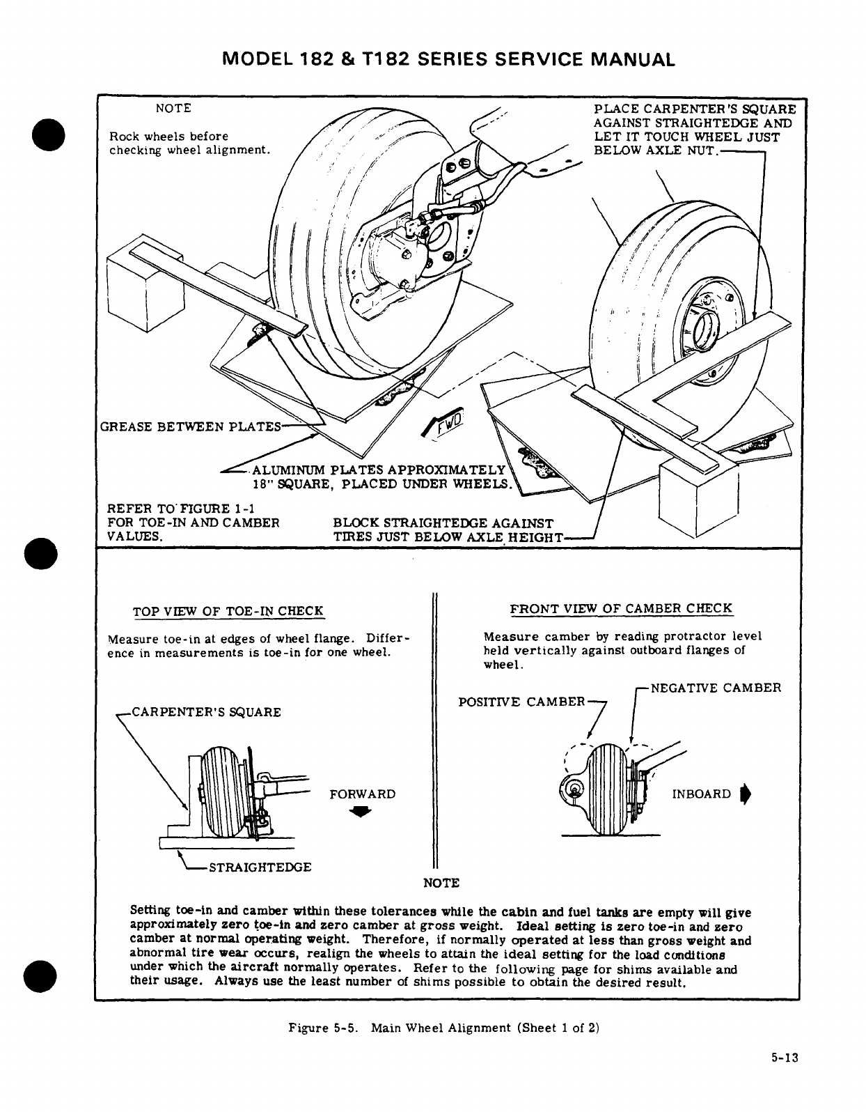
MODEL
182
&
T182
SERIES
SERVICE
MANUAL
NOTE
PLACE
CARPENTER'S
SQUARE
Rock
wheels
before
/ ' LET
IT
TOUCH
WHEEL
JUST
checking
wheel
alignment.
/BELOW
AXLE
NUT.
GREASE
BETWEEN
PLATES
ALUMINUM
PLATES
APPROXIMATELY
18"
SQUARE,
PLACED
UNDER
WHEELS
REFER
TO'FIGURE
1-1
FOR
TOE-IN
AND
CAMBER
BLOCK STRAIGHTEDGE
AGAINST
/
.^
VALUES.
TIRES
JUST
BELOW AXLE
HEIGHT--
TOP
VIEW
OF
TOE-IN
CHECK
FRONT
VIEW
OF
CAMBER
CHECK
Measure
toe-in
at
edges
of
wheel flange.
Differ-
Measure
camber
by
reading
protractor
level
ence
in
measurements
is
toe-in
for
one
wheel.
held
vertically
against
outboard
flanges
of
wheel.
NEGATIVE
CAMBER
POSITIVE
CAMBER-7
CARPENTER'S
SQUARE
P
FORWARD
INBOARD
>-STRAIGHTEDGE
NOTE
Setting
toe-in
and
camber
within
these
tolerances
while the
cabin
and
fuel
tanks
are
empty
will
give
approximately
zero
toe-in
and
zero
camber
at
gross
weight.
Ideal
setting
is
zero
toe-in
and
zero
camber
at normal
operating
weight.
Therefore,
if
normally
operated
at
less
than
gross
weight
and
abnormal
tire
wear
occurs,
realign
the
wheels
to
attain
the
ideal
setting
for
the
load
conditions
under
which
the
aircraft
normally
operates.
Refer
to
the
following
page
for
shims
available
and
their
usage.
Always
use
the
least
number
of
shims
possible
to
obtain
the
desired
result.
Figure
5-5.
Main
Wheel
Alignment
(Sheet
1 of
2)
5-13
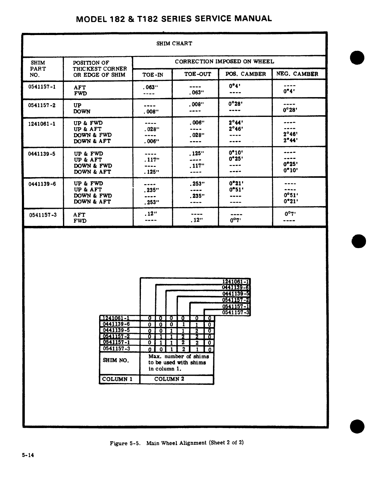
MODEL
182
&
T182
SERIES SERVICE
MANUAL
SHIM
CHART
SHIM
POSITION
OF
CORRECTION
IMPOSED
ON
WHEEL
PART
THICKEST
CORNER
NO.
OR
EDGE OF
SHIM
TOE-IN
TOE-OUT
POS.
CAMBER
NEG.
CAMBER
0541157-1
AFT
.063"
----
0'4'
--
FWD
.--
.063"
----
0
4'
0541157-2
UP
..
.008"
0°
28'
---
DOWN
.
008"
--- --
0028'
1241061-1
UP
&
FWD
---
.006"
2044
'---
UP
& AFT
.028"
--
2046
'--
DOWN
&
FWD ----
.028"
----
2°46'
DOWN
& AFT
.006"
----
--
2'44'
0441139-5
UP
&
FWD ----
.125"
0010'
---
UP
&
AFT
.117"
----
0`25'
DOWN
&
FWD
----
.117"
----
025'
DOWN
&
AFT
.125"
--- --
0010
0441139-6
UP
&
FWD
----
.253"
0-21'
---
UP
&
AFT
.235"
----
0-51' --
DOWN
&
FWD
---
.235"
----
0°51
'
DOWN
& AFT
.253"
---- ----
0°21'
0541157-3
AFT
.12"
-- - ---
_ 007
'
FWD
----
.12" 007
'
---
1241061-
0441139-6
05411
-
0457-
0441139-6
0
0
0
1
1 0
0441139-5
-
1 1 I
2
1
"
1157-1
0
1 1
2 2
0
0541157-3
0
0
1
2
1
Max.
number
of
shims
SHIM
NO.
to
be
used
with
shims
in column
1.
COLUMN
1
COLUMN
2
Figure
5-5.
Main
Wheel
Alignment
(Sheet
2
of
2)
5-14
MODEL
182
&
T182
SERIES
SERVICE
MANUAL
wheel
alignment
is
obtained
through
the
use
of
tapered
Always
check
scraper-to-tire
clearance
after
shims
between
the flange
of
the axle
and
spring-strut.
installing
speed
fairings,
whenever
a
tire
has See
figure 5-5
for
procedures
to
follow
in
wheel
been
changed,
and
whenever
scraper
adjust-
alignment.
Wheel
shims
and
the
correction
imposed
ment
has
been
disturbed.
If
the
aircraft
is
on
the
wheel
by
the
shims
are
listed
in
the
illustra-
flown
from
surfaces
with
mud,
snow,
or
ice,
tion.
the
fairing
should
be
checked to
make
sure
there
is
no
accumulation
which
could
prevent
NOTE
normal
wheel
rotation.
Refer
to
paragraph
5-13
for
correct
scraper-to-tire
clearance.
Failure
to
obtain
acceptable
wheel
alignment
through
the
use
of
the
shims
indicate
a
de-
5-27.
REMOVAL
OF
MAIN
WHEEL
AXLE.
formed
main
gear
spring-strut
or
strut
at-
a.
Remove
speed
fairing
in
accordance
with
para-
taching
bulkhead
out
of
alignment.
graph
5-12.
b.
Remove
wheel
in
accordance
with
paragraph
5-16.
5-30.
WHEEL
BALANCING.
Since
uneven
tire
wear
c.
Disconnect,
drain,
and
plug
or
cap
hydraulic
is
usually
the cause
of
wheel
unbalance,
replacing
the
brake
lire
at
the
wheel
brake cylinder.
tire
will
probably
correct
this
condition.
Tire
and
d.
Remove
nuts,
washers
and
bolts
securing
axle,
tube
manufacturing
tolerances
permit
a
specified
a-
brake
components
and
speed
fairing
mounting
plate
to
mount
of
static
unbalance.
The
light-weight
point
of
strut-attach
fitting.
the
tire
is
marked
with
a
red
dot
on
the
tire
sidewall
and
the
heavy-weight
point
of
the
tube
is
marked
with
NOTE
a
contrasting
color
line
(usually
near
the
inflation
valve
stem).
When
installing
a
new
tire,
place
these
When
removing
axle
from
strut-attach
fitting,
marks
adjacent
to
each
other.
If
a
wheel
becomes
note
number
and
position
of
wheel
alignment
unbalanced
during
service,
it
may
be
statically
bal-
shims
between
axle
and
attach
fitting.
Mark anced.
Wheel
balancing
equipment
is
available
from
shims
or
tape
together
carefully
so
they
can
the
Cessna
Supply
Division.
be
installed
in
exactly
the
same position
to
ensure
wheel
alignment
is
not
disturbed.
5-31.
NOSE
GEAR.
(See
figures
5-6
and
5-10.)
5-28.
INSTALLATION
OF
MAIN
WHEEL
AXLE.
5-32. DESCRIPTION.
Basically,
the
nose
gear
is
.
a.
Secure axle
and
brake
components
to
strut-attach
comprised
of a
steerable
nose
wheel,
mounted
in a
fitting,
assuring
that
wheel
alignment
shims
and
speed
fork,
attached
to an
air/oil
(oleo
shock
strut.
On
fairing
mounting
plate
are
installed
in
their
original
the
Model
182.
the
shock
strut
is
attached
to
the
positions.
firwall
with
upper
and
lower
strut
fittings.
On
the
b.
Install
wheel
assembly
on
axle
in
accordance
Model
T182.
the
steering
bellcrank is
attached
to
a
with
paragraph
5-26.
bracket
on
the
firewall.
the
trunnion
is
attached
to
c.
Connect
hydraulic
brake
line
to
wheel
brake
cy-
brackets
in
the
wheel
tunnel
area.
and
the
drag
link
linder.
is
attached
to
a
forged
fitting
in
the
aft
tunnel
at
d.
Fill
and
bleed
affected
brake
system
in
accor-
Station
17.
0.
dance
with
applicable
paragraph
in
this
Section.
e.
Install
speed
fairing
in
accordance
with
para-
graph
5-13.
SHOP
NOTES:
5-15
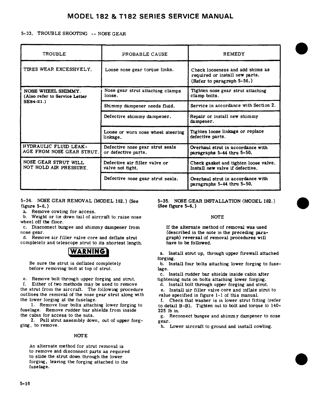
MODEL
182
&
T182
SERIES
SERVICE
MANUAL
5-33.
TROUBLE
SHOOTING
--
NOSE
GEAR
TROUBLE
PROBABLE
CAUSE
REMEDY
TIRES
WEAR
EXCESSIVELY.
Loose
nose
gear
torque
links.
Check
looseness
and
add
shims
as
required
or
install
new
parts.
(Refer
to
paragraph
5-56.)
NOSE
WHEEL
SHIMMY.
Nose
gear
strut
attaching
clamps
Tighten
nose
gear
strut
attaching
(Also
refer
to
Service
Letter
loose.
clamp
bolts.
SE84-21.)
Shimmy
dampener needs
fluid.
Service
in
accordance
with
Section
2.
Defective
shimmy
dampener.
Repair or
install
new
shimmy
dampener.
Loose
or
worn
nose wheel
steering
Tighten
loose
linkage
or
replace
linkage.
defective
parts.
HYDRAULIC
FLUID
LEAK-
Defective
nose
gear
strut
seals
Overhaul
strut
in
accordance
with
AGE
FROM
NOSE
GEAR
STRUT.
or
defective
parts.
paragraphs
5-44
thru
5-50.
NOSE
GEAR
STRUT WILL
Defective
air
filler
valve
or
Check
gasket
and
tighten
loose
valve.
NOT HOLD
AIR
PRESSURE.
valve
not
tight.
Install-new
valve
if
defective.
Defective
nose
gear
strut
seals.
Overhaul
strut
in
accordance
with
paragraphs
5-44
thru
5-50.
5-34.
NOSE
GEAR
REMOVAL (MODEL
182.)
(See
5-35.
NOSE
GEAR INSTALLATION
(MODEL
182.)
figure
5-6.
)
(See
figure
5-6. )
a
Remove
cowling
for
access.
b.
Weight
or
tie
down
tail
of
aircraft
to
raise
nose
NOTE
wheel
off
the
floor.
c.
Disconnect
bungee
and
shimmy
dampener
from
If
the
alternate
method
of
removal
was
used
nose
gear.
(described
in
the note
in
the
preceding
para-
d.
Remove
air
filler
valve
core
and
deflate
strut
graph)
reversal
of
removal
procedures
will
completely
and
telescope
strut
to
its
shortest
length.
have
to
be
followed.
forging.
Be
sure
the
strut
is
deflated
completely
b.
Install
four
bolts
attaching
lower
forging to
fuse-
before
removing bolt
at top
of
strut.
lage.
c.
Install
rudder
bar
shields
inside
cabin
after
e.
Remove
bolt
through upper
forging
and
strut.
tightening
nuts
on
bolts
attaching
lower
forging.
f.
Either
of
two
methods
may
be
used
to
remove
d.
Install
bolt
through
upper
forging
and
strut.
the
strut
from
the
aircraft.
The following
procedure
e.
Install
air
filler
valve
core
and
inflate
strut
to
outlines
the
removal
of
the
nose
gear
strut
along
with
value
specified
in
figure
1-1 of
this
manual.
the
lower
forging
at
the
fuselage.
f.
Check
that
washer
is
in
lower
strut
fitting
(refer
1.
Remove
four
bolts
attaching lower forging
to
to
detail
B-B). Tighten
nut
to
bolt
and
torque
to
140-
fuselage.
Remove
rudder
bar
shields
from inside
225
lb
in.
the
cabin
for
access
to
the
nuts.
g.
Reconnect
bungee
and
shimmy
dampener
to
nose
2.
Pull
strut
assembly
down,
out
of
upper
forg-
gear.
ging,
to
remove.
h.
Lower
aircraft
to
ground
and
install
cowling.
NOTE
An
alternate
method
for
strut
removal
is
to
remove
and
disconnect
parts
as
required
to
slide
the
strut
down
through
the
lower
forging,
leaving
the forging
attached
to
the
fuselage.
5-16
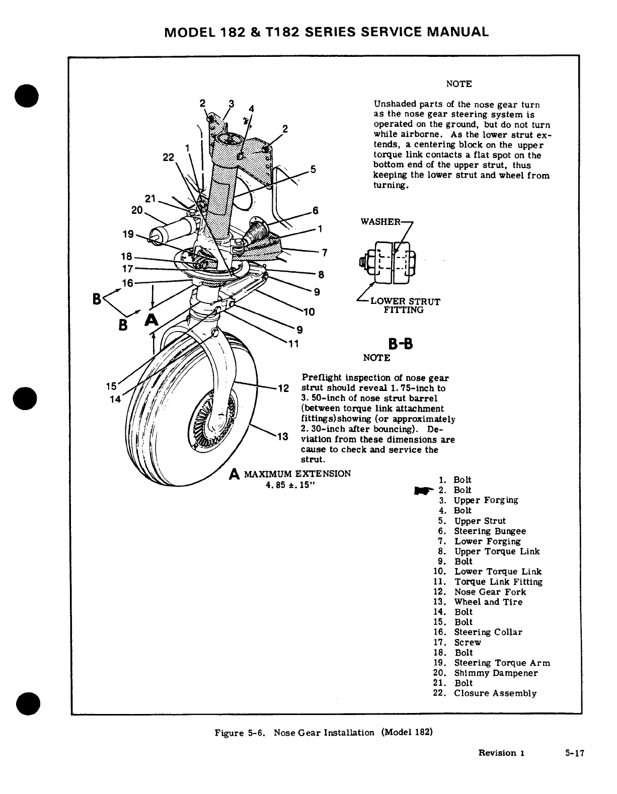
MODEL
182
&
T182
SERIES SERVICE
MANUAL
NOTE
as
the
nose
gear
steering
system
is
/1 I^^^I^^tends,
a
centering
block
on
the
upper
~~~22
1~~....
\
llltorque
link
contacts
a
flat
spot
on
the
\ \ , t ^ \
5
bottom
end
of
the
upper
strut,
thus
21 Ckeeping the
lower
strut
and
wheel
from
turning.
21
20-0
FITTING
11^i ~ B-B
NOTE
Preflight
inspection
of
nose
gear
15
12
strut
should
reveal
1.75-inch
to
14
ID//h
/
/
a^
1
/3.
50-inch
of
nose
strut
barrel
:l."/ /t^ -. /
(between
torque
link
attachment
7ll
0H/*~
Xliil
^fittings)showing
(or
approximately
2.
30-inch
after
bouncing).
De-
13
viation
from
these
dimensions
are
cause
to
check
and
service
the
strut.
A
MAXIMUM
EXTENSION
1. Bolt
1.
Bolt
4.85 -15"
I 2. Bolt
3.
Upper
Forging
4.
Bolt
5.
Upper
Strut
6.
Steering
Bungee
7.
Lower
Forging
8.
Upper
Torque
Link
9.
Bolt
10.
Lower
Torque
Link
11.
Torque
Link
Fitting
12.
Nose
Gear
Fork
13.
Wheel
and
Tire
14.
Bolt
15.
Bolt
16.
Steering Collar
17.
Screw
18.
Bolt
19.
Steering
Torque
Arm
20.
Shimmy
Dampener
21.
Bolt
22.
Closure
Assembly
Figure
5-6.
Nose
Gear
Installation
(Model
182)
Revision
1
5-17
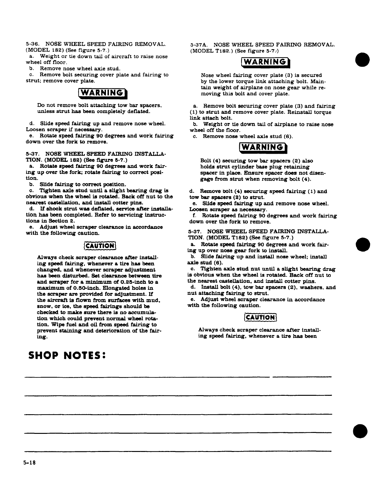
5-36.
NOSE
WHEEL
SPEED
FAIRING
REMOVAL.
5-37A.
NOSE
WHEEL SPEED
FAIRING
REMOVAL.
(MODEL
182)
(See
figure
5-7.) (MODEL
T182.)
(See
figure
5-7..)
a.
Weight or
tie
down
tail
of
aircraft
to
raise
nose
wheel
off
floor.
b.
Remove
nose
wheel
axle
stud.
c.
Remove
bolt
securing
cover
plate
and
fairing
to
Nose
wheel
fairing
cover
plate
(3)
is
secured
strut;
remove
cover
plate.
by
the
lower
torque
link
attaching
bolt.
Main-
tain
weight
of
airplane
on
nose
gear
while
re-
Do
not
remove
bolt
attaching
tow
bar
spacers,
a.
Remove
bolt
securing
cover
plate
(3)
and
fairing
unless
strut
has
been
completely
deflated.
(1)
to
strut
and
remove
cover
plate.
Reinstall torque
link attach
bolt.
d.
Slide speed
fairing
up
and
remove
nose
wheel.
b.
Weight
or
tie
down
tail of
airplane
to
raise
nose
Loosen
scraper
if
necessary.
wheel
off
the
floor.
e.
Rotate speed
fairing
90
degrees
and
work
fairing
c.
Remove
nose
wheel
axle
stud
(6).
down
over
the
fork
to
remove.
5-37.
NOSE
WHEEL
SPEED
FAIRING
INSTALLA-
TION.
(MODEL
182) (See
figure
5-7.)
Bolt
(4)
securing
tow
bar
spacers
(2)
also
a. Rotate
speed
fairing
90
degrees
and
work
fair-
holds
strut
cylinder
base
plug
retaining
ing
up
over
the
fork;
rotate
fairing
to
correct
posi-
spacer
in
place.
Ensure
spacer
does
not disen-
tion.
gage from
strut
when
removing
bolt
(4).
b.
Slide
fairing
to
correct
position.
c.
Tighten
axle
stud
until
a
slight
bearing
drag
is
d.
Remove
bolt
(4)
securing
speed
fairing
(1)
and
obvious
when
the
wheel is
rotated.
Back
off
nut
to
the
tow
bar
spacers
(2)
to
strut.
nearest
castellation,
and
install
cotter pins.
e.
Slide
speed
fairing
up
and
remove
nose
wheel.
d.
If
shock
strut
was
deflated,
service
after installa-
Loosen
scraper
as necessary.
tion has
been
completed. Refer
to
servicing
instruc-
f.
Rotate speed
fairing
90
degrees
and
work
fairing
tions
in
Section
2.
down
over
the fork
to
remove.
e.
Adjust
wheel
scraper
clearance
in accordance
with
the
following
caution.
5-37.
NOSE
WHEEL
SPEED FAIRING
INSTALLA-
TION.
(MODEL
T182)
(See
figure
5-7.)
ing
up
over
nose
gear fork
to
install.
Always
check
scraper
clearance
after install-
b.
Slide
fairing
up
and
install
nose
wheel;
install
ing
speed
fairing,
whenever
a
tire
has
been
axle
stud
(6).
changed,
and
whenever
scraper
adjustment
c.
Tighten
axle
stud
nut
until
a
slight
bearing
drag
has
been
disturbed.
Set
clearance
between
tire
is
obvious
when
the
wheel
is
rotated.
Back
off
nut
to
and
scraper
for
a
minimum
of
0.25-inch
to
a
the nearest
castellation,
and
install
cotter
pins.
maximum
of
0.50-inch.
Elongated
holes
in
d.
Install
bolt
(4),
tow
bar
spacers
(2),
washers, and
the scraper are
provided
for
adjustment.
If
nut
attaching
fairing
to
strut.
the
aircraft
is
flown
from
surfaces
with mud,
e.
Adjust
wheel
scraper
clearance
in
accordance
snow,
or
ice,
the
speed
fairings
should
be
with
the
following
caution.
checked to
make
sure
there
is
no
accumula-
tion
which could
prevent normal
wheel
rota-
tion.
Wipe
fuel
and
oil
from
speed
fairing
to
prevent
staining
and
deterioration
of
the
fair-
Always
check
scraper
clearance
after
install-
ing.
ing
speed
fairing,
whenever
a
tire
has
been
SHOP
NOTES:
5-18
MODEL
182
&
T182
SERIES SERVICE
MANUAL
NOTE
changed, and
whenever
scraper
adjustment
has
been
disturbed.
Set
clearance
between
tire
and
scraper
for
a
minimum
of
0.25-inch
to
a
A
soft
bristle
brush
may
be
used
remove
maximum
of
0.50-inch.
Elongated
holes
are
hardened
grease,
dust
or
dirt.
provided
in
the
scraper
for
adjustment.
If
the
airplane
is
flown
from
surfaces with mud,
snow,
or
ice,
the
speed
fairing
should
be
c.
Inspect bearing
cones
(9),
cups
(7).
retaining
checked
to
make
sure
there
is
no
accumula-
rings
(1)
and
seals
(2
and
3).
for
wear
or
damage.
tion
which
could
prevent
normal
wheel
rota-
d.
Inspect
thru-bolts
(8)
and
nuts
(4)
for
cracks
in
tion.
Wipe
fuel
and
oil
from
speed
fairing
to
threads
or
cracks
in
radius.
prevent
stains
and
deterioration.
e.
Replace
cracked
or
damaged wheel
half
(6).
f.
Replace
damaged
retaining
rings
(1)
and
seals
f.
Lower
nose
of
airplane
to
floor.
(2
and
3).
g.
Install
cover
plate
and
bolt
attaching
cover plate
g.
Replace
any
worn
or
cracked
thru-bolts
(8)
or
to
strut.
nuts
(4).
h.
Replace
worn
or
damaged
bearing
cups
(7)
or
cones
(9).
5-38.
NOSE
WHEEL
REMOVAL.
(See
figure
5-6.)
i.
Remove
any
corrosion
or
small
nicks.
a.
Weight
or
tie
down
tail
of
aircraft
to
raise
the
j.
Repair
reworked
areas
of
wheel
by
cleaning
nose
wheel
off
the
floor.
thoroughly,
then applying
one
coat
of
clear
lacquer
b.
Remove
axle
stud.
paint.
c.
Pull
nose wheel
assembly
from fork
and
remove
k.
Pack
bearings
with
grease
specified
in
Section 2
axle
tube
from
nose
wheel.
of
this
manual.
NOTE
5-41.
NOSE
WHEEL
REASSEMBLY.
(See
figure
5-8.)
It
may
be
necessary
to
loosen
nose
wheel
a.
Assemble
bearing
cone
(9),
grease
seal
retainer
fairing
scraper
to
remove
nose
wheel
(2),
felt
grease
seal
(3),
grease seal
retainer
(2)
and
retaining
ring
(1)
into
both
wheel
halves
(6).
5-39.
NOSE
WHEEL
DISASSEMBLY.
(See
figure
b.
Insert
tube
in
tire,
aligning
index
marks
on
tire
5-8.)
and
tube.
c.
Place
wheel
half
(6)
into
tire
and
tube
(side
op-
posite
valve
stem),
aligning
base
of
valve
stem
in
valve
slot.
With
washer
(5)
under
head
of
thru-bolt
Serious
injury
can
result
from
attempt-
(8),
insert
bolt
through
wheel
half
(6).
ing
to
separate
wheel
halves
with
tire
and
d.
Place
wheel
half
(6)
into
other
side
of
tire
and
tube
inflated.
tube.
aligning
valve
stem
in
valve
slot.
e.
Install
washers
(5)
and
nuts
(4)
on
thru-bolts
(8)
a.
Completely deflate
tire
and
tube
and
break
loose
and
pre-torque
to
10-50
lb.
in.
tire
beads.
Extreme
care
must
be
exercised
to
pre-
vent
tire
tool damage
when
removing
tire
from
wheel
halves
(6).
b.
Remove
nuts
(4)
and
washers
(5).
Uneven
or
improper
torque
of
the
nuts
can
c.
Remove
thru-bolts
(8)
and
washers
(5).
cause
failure
of
the
bolts
with
resultant
d.
Separate
and
remove
wheel
halves
(6)
from
tire
wheel
failure.
and tube.
e.
Remove
retaining
ring
(1).
grease seal
retainer
f.
Prior
to
torquing
nuts
(4).
inflate
tube
with
ap-
(2).
felt
grease seal
(3),
grease
retainer
(2)
and
bear-
proximately
10-15
psi
air
pressure
to
seat
tire.
ing
cone
(9)
from
each wheel
half
(6).
NOTE Do
not
use
impact
wrenches
on
thru-bolts
Bearing cups
(races)
(7)
are
a
press
fit
in
or
nuts.
wheel
half
(6)
and
should
not
be
removed
unless
a
new
part
is
to
be
installed.
To
g.
Dry
torque
all
nuts
(4)
evenly
to
the
torque
value
remove
bearing
cups.
heat
wheel
half
in
specified
in
the
figure.
boiling
water for
30
minutes.
or
in
an oven.
h.
Inflate
tire
to
correct
pressure
specified
in
fig-
not to
exceed
121°C
(250°F).
Using
an
ure
1-1 of
this
manual.
arbor
press,
if
available,
press
out
bearing
cup
and
press
in
a
new
bearing
cup
while 5-42.
NOSE
WHEEL
INSTALLATION.
(See
figure
wheel
half
is
still
hot.
5-6. )
a-
Install
axle
tube
in
nose wheel.
5-40.
NOSE
WHEEL INSPECTION
AND
REPAIR.
b.
Install
nose
wheel
assembly
in
fork
and
install
(See
figure
5-8.)
nose
wheel
axle
stud.
a.
Clean
all metal
parts
and
felt
grease
seals
in
c.
Tighten
axle stud
nut
until
a
slight
bearing
drag
Stoddard
solvent
or
equivalent.
and
dry
thoroughly.
is
obvious
when
the
wheel
is
rotated.
Back
nut
off
to
5-19
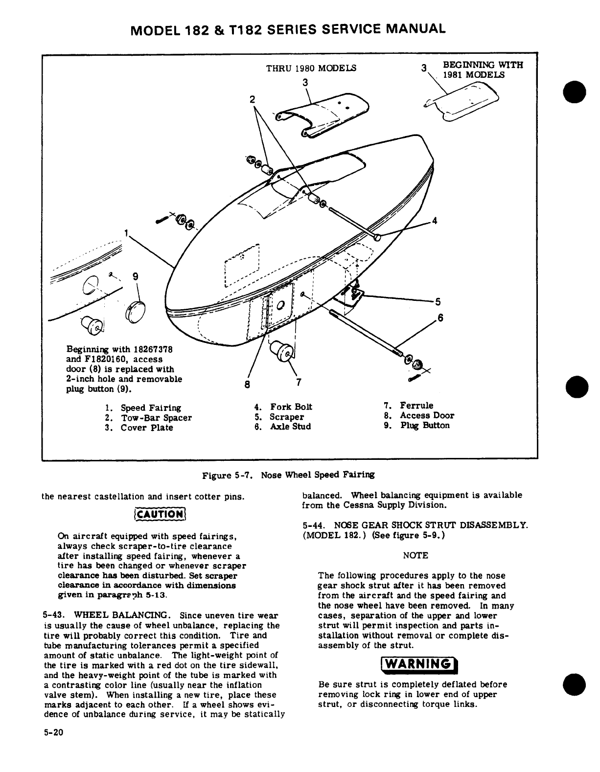
MODEL
182
&
T182
SERIES
SERVICE
MANUAL
THRU 1980 MODELS
3
BEGINNING
WITH
Beginning with
18267378
and
F1820160,
access
door
(8)
is
replaced
with
2-inch
hole
and
removable
plug
button
(9).
1.
Speed
Fairing
4.
Fork
Bolt
7.
Ferrule
2.
Tow-Bar
Spacer
5.
Scraper
8.
Access
Door
3.
Cover
Plate
6.
Axle
Stud
9.
Plug
Button
Figure
5-7.
Nose
Wheel Speed
Fairing
the
nearest
castellation
and
insert cotter
pins.
balanced.
Wheel
balancing
equipment
is
available
CAUTION
5-44.
NOSE
GEAR
SHOCK
STRUT
DISASSEMBLY.
On
aircraft
equipped
with
speed
fairings,
(MODEL
182.)
(See
figure
5-9.)
always
check
scraper-to-tire
clearance
after
installing speed
fairing,
whenever
a
NOTE
tire
has
been
changed
or
whenever
scraper
clearance
has
been
disturbed.
Set
scraper
The
following
procedures
apply
to
the
nose
clearance
in
accordance
with
dimensions
gear
shock
strut
after
it
has been
removed
given
in
paragraph
5-13.
from
the
aircraft
and
the
speed
fairing
and
the
nose
wheel
have
been
removed.
In
many
5-43.
WHEEL
BALANCING.
Since
uneven
tire
wear
cases,
separation
of
the
upper
and
lower
is
usually
the
cause
of
wheel unbalance,
replacing
the
strut
will
permit
inspection
and
parts
in-
tire
will
probably
correct
this
condition.
Tire
and
stallation
without
removal
or
complete
dis-
tube
manufacturing
tolerances
permit
a
specified
assembly
of
the
strut.
amount
of
static
unbalance.
The
light-weight
point
of
the
tire
is
marked
with
a
red
dot
on
the
tire
sidewall,
and
the
heavy-weight
point
of
the
tube
is
marked
with
a
contrasting
color
line
(usually
near
the
inflation
Be
sure
strut
is
completely
deflated
before
valve
stem).
When
installing
a
new
tire,
place
these removing
lock
ring
in
lower end
of
upper
marks
adjacent
to
each
other.
If
a
wheel shows
evi-
strut,
or
disconnecting
torque
links.
dence
of
unbalance during
service,
it
may
be
statically
5-20
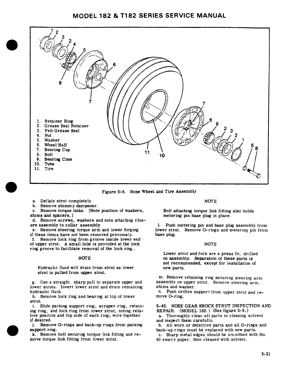
MODEL
182
&
T182
SERIES
SERVICE
MANUAL
9
1.
Retainer
Ring
2.
Grease
Seal
Retainer
3.
Felt
Grease
Seal
4.
Nut
5.
Washer
6.
Wheel
Half
7.
Bearing
Cup
8.
Bolt
10
9.
Bearing
Cone
10.
Tube
11.
Tire
Figure
5-8.
Nose Wheel
and
Tire
Assembly
a.
Deflate
strut
completely.
NOTE
b.
Remove
shimmy
dampener.
c.
Remove
torque
links.
(Note
position
of
washers,
Bolt
attaching
torque
link
fitting
also
holds
shims
and
spacers.)
metering
pin
base
plug
in
place.
d.
Remove
screws,
washers
and
nuts
attaching
clos-
ure
assembly
to
collar
assembly
1.
Push
metering
pin
and
base
plug
assembly
from
e.
Remove
steering
torque
arm
and
lower
forging
lower
strut.
Remove
O-rings
and
metering
pin
from
if
these
items
have
not been
removed previously.
base
plug.
f.
Remove
lock ring
from
groove
inside
lower
end
of
upper
strut.
A
small
hole
is
provided
at
the
lock
NOTE
ring
groove
to
facilitate
removal
of
the
lock
ring. Lower
strut
and
fork are
a
press
fit,
drilled
NOTE
on
assembly.
Separation
of
these
parts
is
not
recommended,
except
for
installation
of
Hydraulic
fluid
will
drain
from
strut
as
lower
new
parts.
strut
is
pulled
from
upper
strut.
m.
Remove
retaining
ring
securing
steering
arm
g.
Use
a
straight.
sharp
pull
to
separate
upper
and
assembly
on
upper
strut.
Remove
steering
arm.
lower
struts.
Invert
lower
strut
and
drain
remaining
shims
and
washer.
hydraulic
fluid.
n.
Push
orifice
support
from
upper
strut
and
re-
h.
Remove
lock
ring
and
bearing
at top
of
lower
move
O-ring.
strut.
i.
Slide
packing
support ring,
scraper
ring,
retain-
5-45.
NOSE
GEAR
SHOCK
STRUT
INSPECTION
AND
ing
ring,
and
lock
ring
from
lower
strut,
noting
rela-
REPAIR.
(MODEL
182.)
(See
figure 5-9.)
tive
position
and
top
side
of
each
ring;
wire
together
a.
Thoroughly
clean
all
parts
in
cleaning
solvent
if
desired.
and
inspect
them
carefully.
j.
Remove
O-rings
and
back-up
rings
from
packing
b.
All
worn
or
defective
parts
and
all
O-rings
and
support
ring.
back-up
rings
must
be
replaced
with
new
parts.
k.
Remove
bolt
securing
torque
link
fitting
and
re-
c.
Sharp
metal
edges
should
be
smoothed
with
No.
move
torque
link
fitting
from lower
strut.
40
emery
paper.
then
cleaned
with
solvent.
5-21
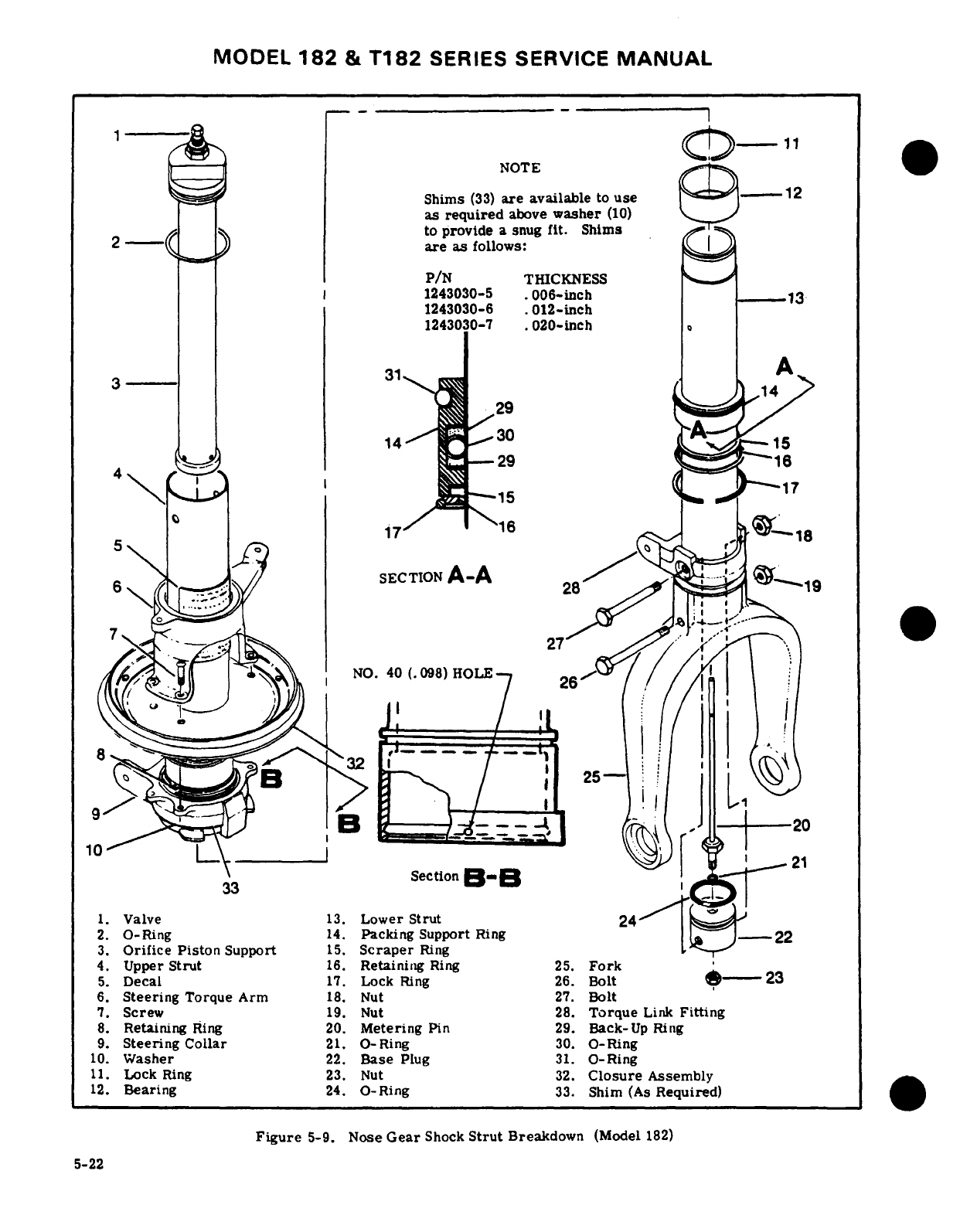
MODEL
182
&
T182
SERIES
SERVICE
MANUAL
Shims
(33)
are
available
to
use
- 12
as
required
above
washer
(10)
2vf ~ -- < \~ ~to
provide
a
snug
fit.
Shims
2
are
as
follows:
P/N
THICKNESS
1243030-5
.006-inch
13
1243030-6
.012-inch
1243030-7
.020-inch
3
31
A
~~3 ~~~~~~14
29
16
4X~~ ~
~~~~~
<~15<
17
5
NO.
17
16
Qr
7
i
SECTION
A-A
Sp
or
R9
o5.
40
Ring
26.
BOt
2
i
L j
, --
-»2
'--
-
°
10
21'
33
Section
B-B
21
7.
Valve
13.
Lower
Strut
24Link
2.
R-Ring
14.
Packing
2Support
Ring
Rg2
3.
Orifice
Piston
Support
15.
Scraper
Ring
4.
UpperStrut
16.
Retaininng25.
Forki
5.
Decal
17.
Lock
Ring
26.
. Bolt
o
e
23
6.
Steering
Torque
Arm
18.
Nut
27.
Bolt
7.
Screw
19.
Nut
28.
Torque
Link
Fitting
8.
Retaining
Ring
20.
Metering
Pin
29.
Back-Up
Ring
9.
Steering
Collar
21.
O-Ring
30.
O-Ring
10.
Washer
22.
Base
Plug
31.
O-Ring
11.
Lock
Ring
23.
Nut
32.
Closure
Assembly
12.
Bearing
24.
O-Ring
33.
Shim
(As
Required)
Figure
5-9.
Nose
Gear
Shock
Strut
Breakdown
(Model
182)
5-22
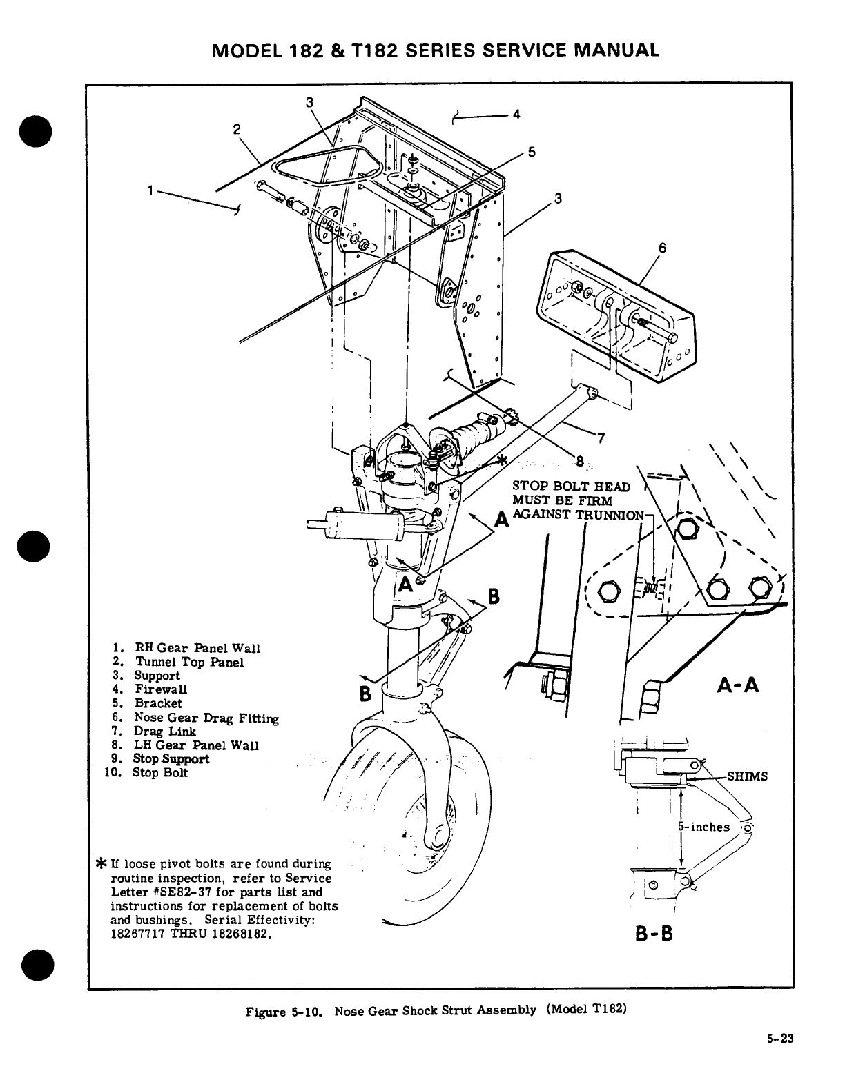
MODEL
182
&
T182
SERIES SERVICE
MANUAL
2
STOP
BOLT
HEAD
_ a .^ ev/
MUST
BE
FIRM
\ I \ \ \
r= 3;!
*f
/
Y
A
AGAINST
TRUNNION
\ok
Q
\
2.k->B I-
1.
RH
Gear
Panel
Wall
/ // .
2.
Tunnel
Top
Panel
3. Support
4.
Firewall
5.
BracketI
6.
Nose
Gear
Drag
Fitting
7.
Drag
Link
8.
LH
Gear Panel
Wall
9.
Stop
Support
10.
Stop
Bolt/
HIMS
i-
I
}'
/
5-inches
,
~ - 4
*
If
loose
pivot
bolts
are
found
during
routine
inspection,
refer
to
Service
Letter
#SE82-37
for
parts list
and
/ I
instructions
for
replacement
of
bolts
and
bushings.
Serial
Effectivity:
18267717
THRU
18268182.
B-B
Figure
5-10.
Nose
Gear
Shock
Strut
Assembly
(Model T182)
5-23
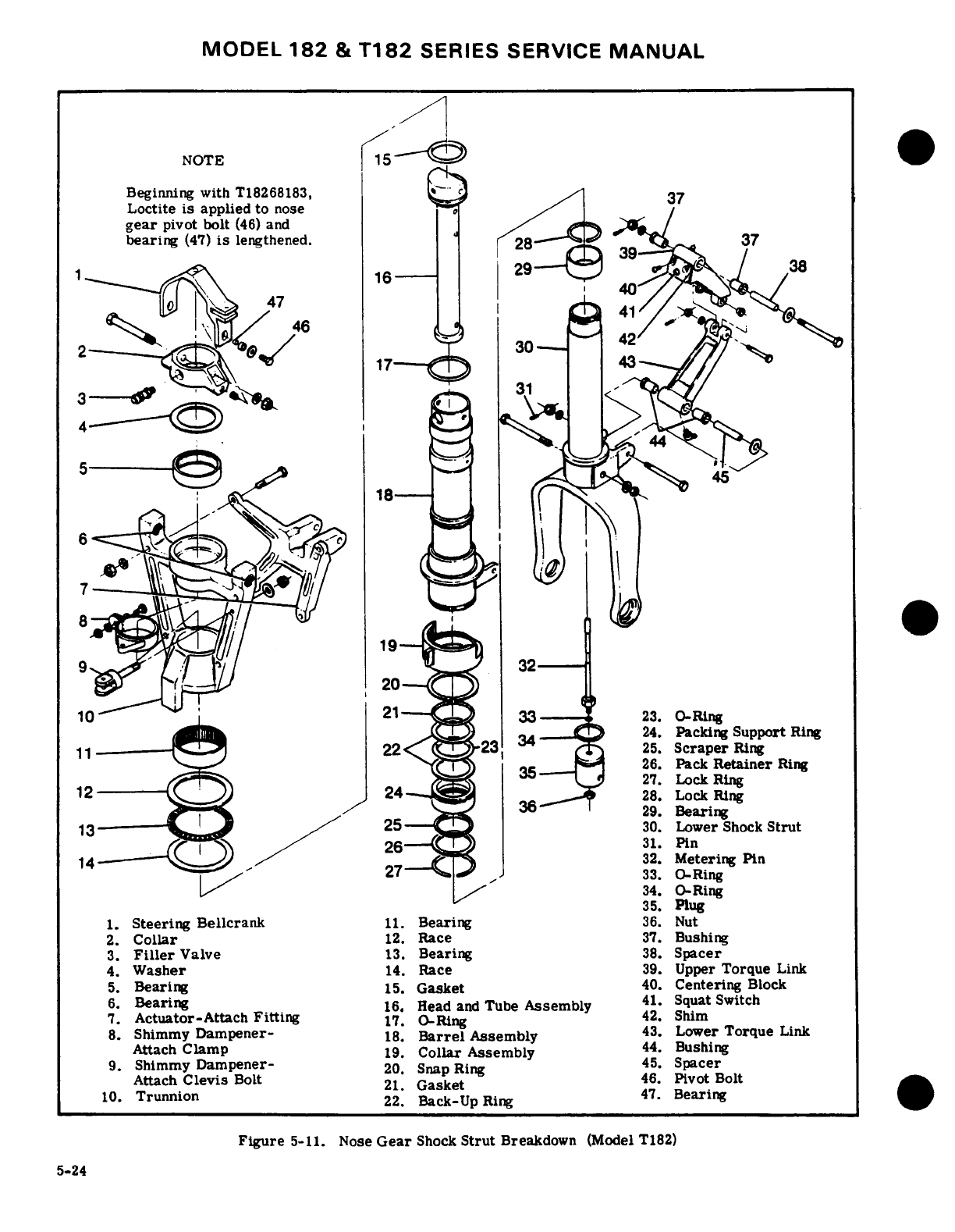
MODEL
182
&
T182
SERIES
SERVICE
MANUAL
NOTE
Beginning
with
T18268183,
37
Loctite
is
applied
to
nose
gear
pivot
bolt
(46)
and
bearing
(47)
is
lengthened.
37
27.
Lock
Ring
35.
Plug
1.
Steering
Bellcrank
11.
Bearing
36.
Nut
2.
Collar
12.
Race
37.
Bushing
3.
Filler
Valve
13.
Bearing
38.
Spacer
4.
Washer
14.
Race
39.
Upper
Torque
Link
5.
Bearing
15.
Gasket
40.
Centering
Block
6.
Bearing
16.
Head and
Tube
Assembly
41.
Squat Switch
7.
Actuator-Attach
Fitting
17.
O-Rng
42.
8.
Shimmy
Dampener-
18.
Barrel
Assembly
43.
Lower
Torque
Link
Attach Clamp19.
Collar
Assembly
4.
Bushing
9.
Shimmy
Dampener -
20.
Snap
Ring
45.
Spacer
Attach
Clevis
Bolt
21.
Gasket
46.
Attach
Clevis
Bolt
21.
Gasket
46.
Pivot
Bolt
10.
Trunnion22.
Back-Up
Ring
47.
Bearing
Figure
5-11.
Nose
Gear
Shock
Strut
Breakdown
(Model
T182)
5-24
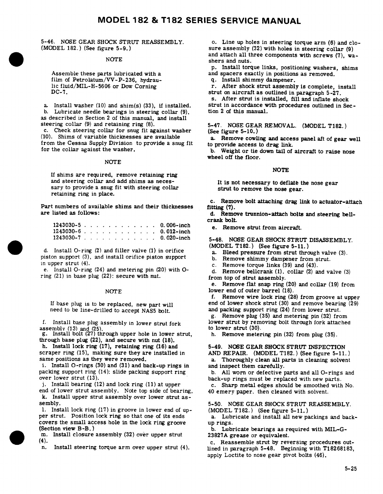
MODEL
182
&
T182
SERIES SERVICE
MANUAL
5-46.
NOSE
GEAR
SHOCK
STRUT REASSEMBLY.
o.
Line
up
holes
in
steering
torque
arm
(6)
and
clo-
(MODEL 182.) (See
figure
5-9.)
sure assembly
(32)
with holes
in
steering
collar
(9)
NOTE
shers
and
nuts.
p.
Install
torque
links,
positioning
washers,
shims
Assemble
these
parts
lubricated
with a and
spacers
exactly
in
positions
as
removed.
film
of
Petrolatum/VV-P-236,
hydrau-
q.
Install
shimmy
dampener.
lic
fluid/MIL-H-5606
or
Dow
Corning
r.
After
shock
strut
assembly
is
complete,
install
DC-7.
strut
on
aircraft
as
outlined
in
paragraph
5-27.
s.
After
strut
is
installed,
fill
and
inflate
shock
a.
Install washer
(10)
and
shim(s)
(33),
if
installed.
strut
in
accordance
with
procedures
outlined
in
Sec-
b.
Lubricate
needle
bearings
in
steering
collar
(9),
tion
2
of
this
manual.
as
described
in
Section
2
of
this
manual,
and
install
steering
collar
(9)
and
retaining
ring
(8).
5-47.
NOSE
GEAR
REMOVAL.
(MODEL
T182.)
c.
Check
steering collar
for
snug
fit
against
washer
(See
figure
5-10.)
(10).
Shims
of
variable
thicknesses
are
available
a.
Remove
cowling
and
access
panel
aft
of
gear
well
from
the
Cessna
Supply
Division to provide
a
snug
fit
to
provide
access
to
drag
link.
for
the
collar
against
the
washer.
b.
Weight
or
tie
down
tail
of
aircraft
to
raise
nose
wheel
off
the
floor.
NOTE
NOTE
If
shims
are
required,
remove
retaining
ring
and
steering
collar
and
add
shims
as
neces-
It
is
not
necessary
to
deflate
the nose
gear
sary
to
provide
a
snug
fit
with
steering collar
strut
to
remove
the
nose
gear.
retaining
ring
in
place.
c.
Remove
bolt
attaching
drag
link
to
actuator-attach
Part
numbers
of
available
shims
and
their
thicknesses
fitting
(7).
are
listed
as
follows:
d.
Remove
trunnion-attach
bolts
and
steering
bell-
crank
bolt
1243030-5
......
.. . . . .. .
0.
006-inch
e.
Remove
strut
from
aircraft.
1243030-6
............
0.
012-inch
1243030-7
.. .. . . .
.....
0.
020-inch
5-48.
NOSE
GEAR
SHOCK
STRUT
DISASSEMBLY.
d.
Install
O-ring
(2)
and
filler
valve
(1)
in
orifice
a
Bleed
pressure
from
strut
through
valve
(3).
piston
support
(3),
and
install
orifice
piston
support
b.
Remove
shimmy
dampener
from
strut.
in
upper
strut
(4).
c.
Remove
torque
links
(39)
and
(43).
e.
Install
O-ring
(24)
and
metering
pin
(20)
with O-
d.
Remove
bellcrank
(1).
collar
(2)
and
valve
(3)
ring
(21)
in
base
plug (22):
secure
with
nut.
from
top
of
strut
assembly.
e.
Remove
flat
snap
ring
(20)
and
collar
(19)
from
NOTE
lower
end of
outer
barrel
(18).
f.
Remove
wire lock ring
(28)
from
groove
at
upper
If
base
plug
is
to
be
replaced,
new
part
will
end
of
lower
shock
strut
(30)
and
remove
bearing
(29)
need
to
be
line-drilled
to
accept
NAS5
bolt.
and
packing
support
ring
(24)
from
lower
strut.
g.
Remove
plug
(35)
and
metering
pin
(32)
from
f.
Install
base
plug
assembly
in
lower
strut
fork lower
strut
by
removing
bolt
through
fork
attached
assembly
(13)
and
(25).
to
lower
strut
(30).
g.
Install
bolt
(27)
through
upper
hole in
lower
strut,
h.
Remove
metering
pin
(32)
from
plug (35).
through
base
plug
(22),
and
secure
with
nut
(18).
h.
Install
lock
ring
(17),
retaining
ring
(16)
and
5-49.
NOSE
GEAR
SHOCK
STRUT
INSPECTION
scraper
ring
(15),
making
sure
they
are
installed
in
AND
REPAIR.
(MODEL
T182.)
(See
figure
5-11.)
same
positions as
they
were
removed.
a.
Thoroughly
clean
all parts
in
cleaning
solvent
i.
Install
O-rings
(30)
and
(31)
and
back-up
rings
in and
inspect
them
carefully.
packing
support
ring
(14):
slide
packing
support
ring
b.
All
worn
or
defective
parts
and
all
O-rings
and
over
lower
strut
(13).
back-up
rings
must
be
replaced
with
new
parts.
j.
Install
bearing
(12)
and
lock
ring
(11)
at
upper
c.
Sharp
metal
edges
should
be
smoothed
with
No.
end
of
lower
strut
assembly.
Note
top
side
of
bearing,
40
emery
paper.
then
cleaned
with
solvent.
k.
Install
upper
strut
assembly
over
lower
strut
as-
sembly.
5-50.
NOSE
GEAR
SHOCK
STRUT REASSEMBLY.
1.
Install
lock
ring
(17)
in
groove
in
lower
end
of
up-
(MODEL
T182.)
(See
figure
5-11.)
per
strut.
Position
lock
ring
so
that
one
of
its
ends
a.
Lubricate
and
install
all
new
packings
and back-
covers
the
small access
hole
in the
lock
ring
groove
up
rings.
(Section
view
B-B.)
b.
Lubricate bearings
as
required
with
MIL-G-
m.
Install
closure
assembly
(32)
over
upper
strut
23827A
grease
or
equivalent.
(4).
c.
Reassemble
strut
by
reversing procedures
out-
n.
Install
steering
torque
arm
over upper
strut
(4).
lined
in
paragraph
5-48.
Beginning
with T18268183,
apply
Loctite
to
nose
gear
pivot
bolts
(46).
5-25
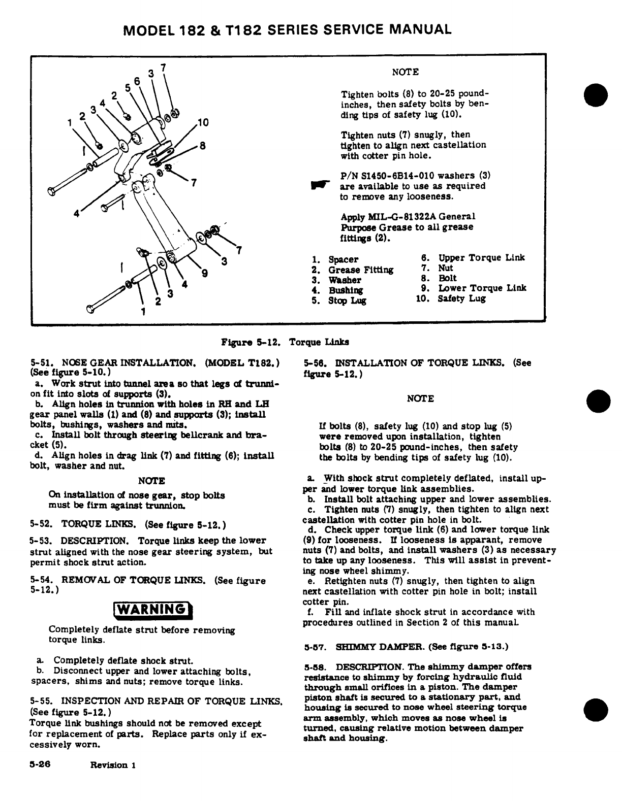
MODEL
182
&
T182
SERIES
SERVICE
MANUAL
2
\ \ \
Tighten
bolts
(8) to 20-25
pound-
4
3
4'
\ \ \
\
Y\t
l
(0inches,
then
safety
bolts
by
ben-
1
2
\\ -^
\yci
®
10
ding
tips
of
safety
lug
(10).
Tighten
nuts
(7)
snugly,
then
(M
,-8
tighten
to
align
next
castellation
·J^y~// </~7 ^!with
cotter
pin
hole.
// y^-.Y ^ 7
~P/N
S1450-6B14-010
washers
(3)
7 /^ -" J¢L- *\
I'
sare
available
to
use
as
required
to
remove
any
looseness.
~\4 .\
\
Apply
MIL-G-81322A
General
Purpose
Grease
to
all
grease
fittings
(2).
3
1.
Spacer
6.
Upper
Torque
Link
> X\ \
9
2.
Grease
Fitting
7.
Nut
r \ \
4
3.
Washer
8.
Bolt
} \ \
3
4.
Bushing
9.
Lower
Torque
Link
r\ •2
5.
Stop
Lug
10.
Safety
Lug
Figure
5-12. Torque
Links
5-51.
NOSE
GEAR
INSTALLATION.
(MODEL
T182.)
5-56.
INSTALLATION
OF
TORQUE
LINKS.
(See
(See
figure
5-10.)
figure
5-12.)
a.
Work
strut
into
tunnel
area
so
that
legs
of
trunni-
on
fit
into
slots
of
supports
(3).
b.
Align
holes
in
trunnion
with
holes
in
RH
and
L
NOTE
gear
panel
walls
(1)
and
(8)
and
supports
(3);
install
bolts,
bushings,
washers
and
nuts.
If
bolts
(8),
safety
lug
(10)
and
stop
lug
(5)
c.
Install
bolt through
steering
bellcrank
and
bra-
were removed
upon
installation,
tighten
cket
(5).
bolts
(8)
to
20-25
pound-inches, then
safety
d.
Align
holes
in
drag
link
(7)
and
fitting
(6);
install
the
bolts
by
bending
tips
of
safety
lug
(10).
bolt,
washer
and
nut.
NOTE
a.
With
shock
strut
completely deflated,
install
up-
On
installation
of
nose
gear,
stop bolts per
and
lower
torque
link
assemblies.
b.
Install
bolt
attaching upper
and
lower
assemblies.
c.
Tighten
nuts
(7)
snugly,
then
tighten
to
align
next
5-52.
TORQUE
LINKS.
(See
figure
5-12.)
castellation
with
cotter
pin
hole
in
bolt.
d.
Check upper
torque
link
(6)
and
lower
torque link
5-53.
DESCRIPTION.
Torque links
keep
the
lower
(9)
for
looseness.
If
looseness
is
apparant,
remove
strut
aligned
with
the
nose
gear steering system,
but
nuts
(7)
and
bolts,
and
install
washers
(3)
as necessary
permit
shock
strut
action. to take
up
any
looseness.
This
will
assist
in
prevent-
ing
nose
wheel
shimmy.
5-54.
REMOVAL
OF
TORQUE
LINKS.
(See
figure
e.
Retighten
nuts
(7)
snugly,
then
tighten
to
align
5-12.)
next
castellation
with
cotter
pin
hole
in
bolt;
install
[WARNING'
cotter
pin.
f.
Fill
and
inflate
shock
strut
in
accordance
with
Com
y d e s t
b
e
r
ving
procedures
outlined
in
Section
2
of
this
manual
Completely
deflate
strut
before
removing
torque
links.
5-57.
SHIMMY
DAMPER.
(See
figure
5-13.)
a.
Completely
deflate
shock
strut.
b.
Disconnect
upper
and
lower
attaching bolts,
5-58.
DESCRITION.
The
shimmy
damper
offers
spacers,
shims
and
nuts;
remove
torque
links.
resistance
to
shimmy
by
forcing
hydraulic
fluid
through
small orifices
in
a
piston.
The damper
5-55.
INSPECTION
AND
REPAIR
OF
TORQUE
LINKS.
piston
shaft
is
secured
to
a
stationary
part,
and
(See
figure
5-12.)
housing
is
secured
to
nose
wheel
steering
torque
arm
assembly,
which
moves
as
nose
wheel
is
Torque
link
bushings should
not
be
removed
except
am
a
sembly,
which
moe
as
nos
wheel
is
for
replacement
of
parts.
Replace
parts
only
if
ex-
turned,
causing relativ
motion
between damper
cessively
worn.
shaft
and
housing.
cessivey
worn.evision
1
5-26
Revision
1
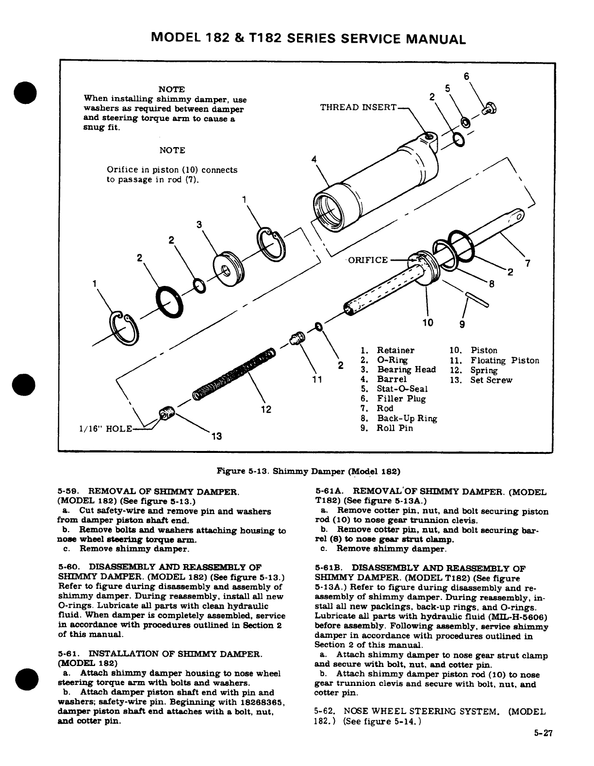
MODEL
182
&
T182
SERIES
SERVICE
MANUAL
6
When
installing
shimmy
damper, use
washers
as
required
between
damper
THREADINSERT
and
steering
torque
arm
to
cause
a
snug
fit.
NOTE
Orifice
in
piston
(10)
connects
to
passage
in rod
(7).
,
p ^ \ \
1.
Retainer
10.
Piston
/"
^ \
'q
2.
O-Ring
11.
Floating
Piston
2-\
3.
Bearing
Head
12.
Spring
\
11
4.
Barrel
13.
Set
Screw
5.
Stat-O-Seal
\v
,,
\ ~
6.
Filler
Plug
12
7.
Rod
8.
Back-Up
Ring
1/16"
HOLE
9.
Roll
Pin
13
Figure
5-13.
Shimmy Damper
(Model
182)
5-59.
REMOVAL
OF
SHIMMY DAMPER.
5-61A.
REMOVAL'OF
SHIMMY
DAMPER.
(MODEL
(MODEL
182) (See
figure
5-13.)
T182)
(See
figure
5-13A.)
a.
Cut
safety-wire
and
remove
pin
and
washers
a.
Remove
cotter
pin,
nut,
and
bolt
securing
piston
from
damper
piston shaft
end.
rod
(10)
to nose
gear
trunnion
clevis.
b.
Remove
bolts
and
washers
attaching
housing
to
b.
Remove
cotter
pin,
nut,
and
bolt
securing
bar-
nose
wheel
steering
torque
arm.
rel
(8)
to
nose
gear
strut
clamp.
c.
Remove
shimmy
damper.
c.
Remove
shimmy
damper.
5-60.
DISASSEMBLY
AND
REASSEMBLY
OF
5-61B. DISASSEMBLY AND
REASSEMBLY
OF
SHIMMY
DAMPER.
(MODEL
182)
(See
figure
5-13.)
SHIMMY
DAMPER.
(MODEL
T182)
(See
figure
Refer
to
figure
during
disassembly
and
assembly
of
5-13A.)
Refer
to
figure
during
disassembly
and
re-
shimmy
damper.
During
reassembly, install
all
new
assembly
of
shimmy
damper.
During
reassembly,
in-
O-rings. Lubricate
all
parts
with
clean
hydraulic
stall
all
new
packings,
back-up
rings,
and
O-rings.
fluid.
When
damper
is
completely
assembled, service
Lubricate all
parts
with
hydraulic
fluid
(MIL-H-5606)
in
accordance
with
procedures
outlined in
Section
2
before
assembly.
Following
assembly,
service
shimmy
of
this
manual.
damper
in
accordance
with
procedures
outlined
in
Section
2
of
this
manual.
5-61.
INSTALLATION
OF
SHIMMY
DAMPER.
a.
Attach
shimmy
damper
to
nose
gear
strut
clamp
(MODEL 182)
and secure
with
bolt,
nut,
and
cotter
pin.
a.
Attach
shimmy
damper
housing
to
nose
wheel
b.
Attach
shimmy
damper
piston
rod
(10)
to
nose
steering
torque arm
with
bolts
and washers.
gear
trunnion
clevis
and
secure
with
bolt,
nut,
and
b.
Attach
damper
piston
shaft
end
with
pin and
cotter
pin.
washers;
safety-wire
pin. Beginning
with
18268365,
damper piston
shaft
end
attaches
with
a
bolt,
nut,
5-62.
NOSE
WHEEL
STEERING
SYSTEM.
(MODEL
and
cotter pin.
182.)
(See
figure
5-14. )5-27
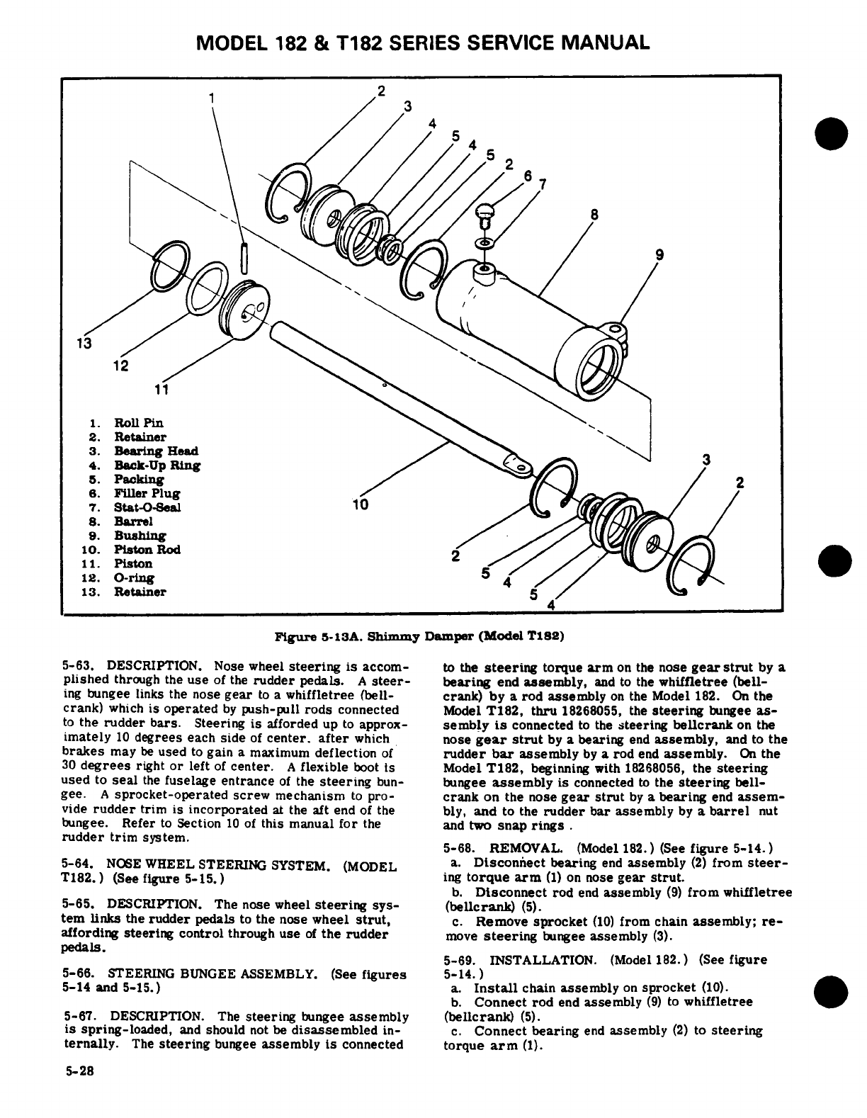
MODEL
182
&
T182
SERIES
SERVICE
MANUAL
3
5
4
12
1.
Roll
Pin
,
2.
Retainer
3.
Bearing
Head
4.
Back-Up
Ring
3
5.
Packing
2
6.
Filler
Plug
7.
Stat-O-eal
10
8.
Barrel
9. Bushing
10.
Piston
Rod
11.
Piston
12.
O-ring
5
13.
Retainer
Figure
5-13A.
Shimmy
Damper
(Model T182)
5-63.
DESCRIPTION. Nose
wheel
steering
is
accom-
to
the
steering
torque
arm
on
the
nose
gear
strut
by
a
plished
through the
use
of
the
rudder
pedals.
A
steer-
bearing
end
assembly,
and
to
the
whiffletree
(bell-
ing
bungee
links
the
nose
gear
to
a
whiffletree
(bell-
crank)
by
a
rod
assembly
on
the
Model
182.
On
the
crank)
which
is
operated
by
push-pull
rods
connected
Model
T182,
thru
18268055,
the
steering
bungee
as-
to
the
rudder
bars.
Steering
is
afforded
up
to
approx-
sembly
is
connected
to
the
steering
bellcrank
on
the
imately
10
degrees
each
side
of
center.
after
which
nose
gear
strut
by
a
bearing
end
assembly,
and
to
the
brakes
may
be
used
to
gain
a
maximum
deflection
of
rudder
bar
assembly
by
a
rod
end
assembly.
On
the
30
degrees
right
or
left
of
center.
A
flexible
boot
is
Model
T182,
beginning
with
18268056,
the
steering
used
to
seal
the
fuselage
entrance
of
the
steering
bun-
bungee
assembly
is
connected
to
the
steering
bell-
gee.
A
sprocket-operated
screw
mechanism
to
pro-
crank
on
the
nose
gear
strut
by
a
bearing
end
assem-
vide
rudder
trim
is
incorporated
at
the
aft
end
of the
bly,
and
to
the
rudder
bar
assembly
by
a
barrel
nut
bungee.
Refer
to
Section
10
of
this
manual
for
the
and
two
snap
rings.
rudder
trim
system.
5-68.
REMOVAL.
(Model
182.)
(See
figure
5-14.)
5-64.
NOSE
WHEEL STEERING
SYSTEM.
(MODEL
a.
Disconnect
bearing
end
assembly
(2)
from
steer-
T182.) (See
figure 5-15.)
ing
torque
arm
(1)
on
nose
gear
strut.
b.
Disconnect
rod
end
assembly
(9)
from
whiffletree
5-65.
DESCRIPTION.
The
nose
wheel
steering
sys-
(bellcrank)
(5).
ter
links
the
rudder
pedals
to
the
nose
wheel
strut,
c.
Remove
sprocket
(10)
from
chain
assembly;
re-
affording
steering
control
through
use
of
the
rudder
move
steering
bungee
assembly
(3).
pedals.
5-69.
INSTALLATION.
(Model
182.)
(See
figure
5-66.
STEERING
BUNGEE
ASSEMBLY.
(See
figures
5-14.)
5-14
and
5-15.)
a.
Install
chain
assembly
on
sprocket
(10).
b.
Connect
rod
end
assembly
(9)
to
whiffletree
5-67.
DESCRIPTION.
The
steering
bungee
assembly
(bellcrank)
(5).
is
spring-loaded,
and
should
not
be
disassembled
in-
c.
Connect bearing
end
assembly
(2)
to
steering
ternally.
The
steering
bungee
assembly is
connected
torque
arm
(1).
5-28
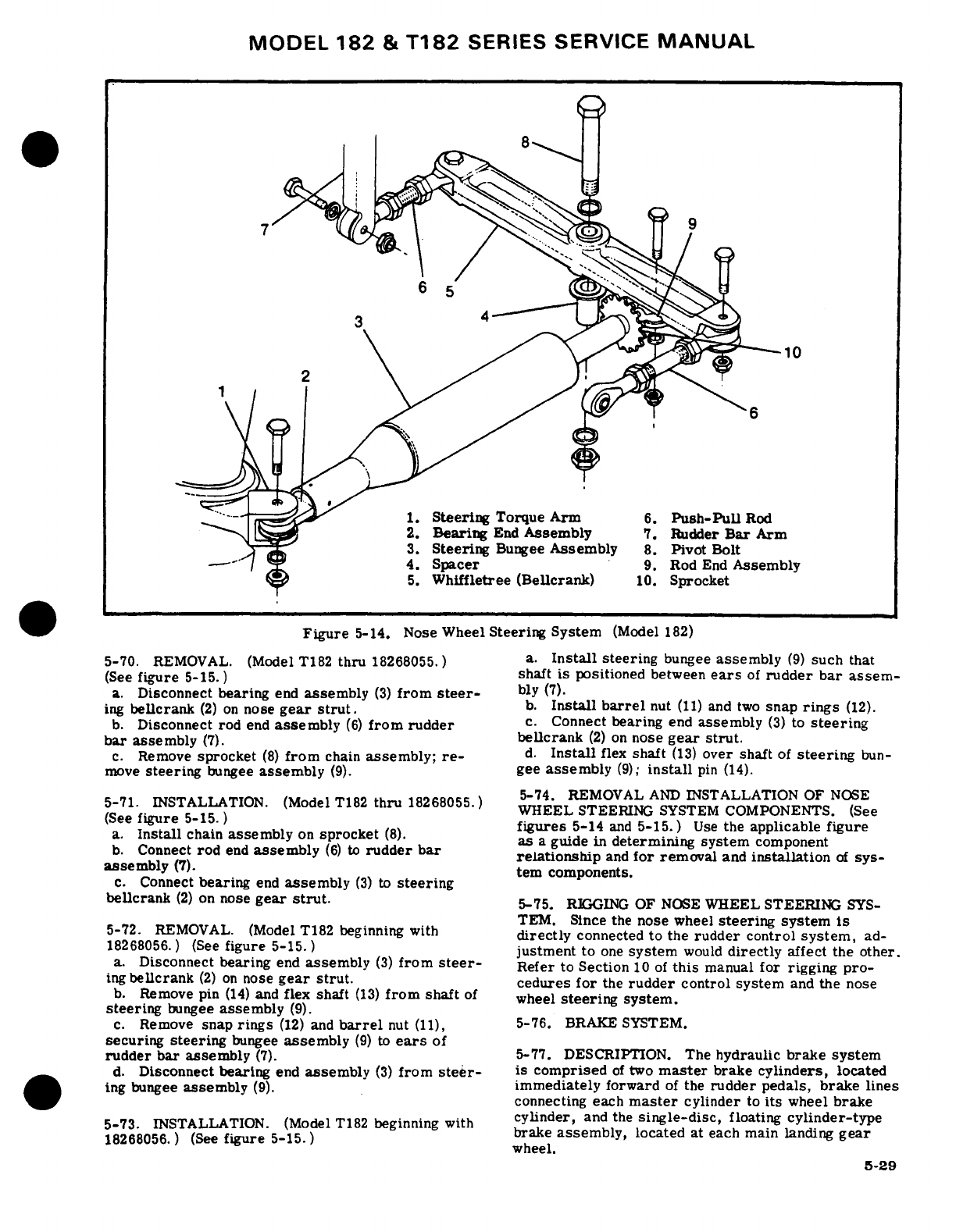
MODEL
182
&
T182
SERIES SERVICE
MANUAL
2.
Bearing
End
Assembly
7.
Rudder
Bar
Arm
3.
Steering
Bungee
Assembly
8.
Pivot
Bolt
Figure
5-14.
Nose
Wheel
Steering
System
(Model
182)
5-70.
REMOVAL.
(Model
T182
thru
18268055.)
a.
Install
steering
bungee
assembly
(9)
such
that
(See
figure
5-15.
)
shaft
is
positioned
between
ears
of
rudder
bar
assem-
a.
Disconnect
bearing
end
assembly
(3)
from
steer-
bly
(7).
ing
bellcrank
(2)
on
nose
gear
strut.
b.
Install
barrel
nut
(11)
and
two
snap
rings
(12).
b.
Disconnect
rod
end
assembly
(6)
from rudder
c.
Connect
bearing
end
assembly
(3)
to
steering
bar
assembly
(7).
bellcrank
(2)
on
nose
gear
strut.
c.
Remove
sprocket
(8)
from
chain
assembly;
re-
d.
Install
flex
shaft
(13)
over shaft
of
steering
bun-
move
steering
bungee
assembly
(9).
gee
assembly
(9);
install
pin
(14).
5-71.
INSTALLATION.
(Model
T182
thru
18268055.)
REMOVAL
AND
INSTALLATION
OF
NOSE
(See figure 5-15. )
WHEEL
STEERING
SYSTEM
COMPONENTS.
(See
Install
chain
assembly
on
sprocket
(8).
)figures
5-14
and
5-15.
)
Use
the
applicable
figure
a.
Install
chain
assembly
on
sprocket
(8).
as
a
guide
in
determining
system
component
b.
Connect
rod
end
assembly
(6)on
rudder
bar
as
a
guide in
determining
system
component
b.
Connect
rod
end
assembly
(6)
to
rudder
bar
relationship
and
for
removal
and
installation
of
sys-
assembly
(7).
ter
components.
c.
Connect
bearing
end
assembly
(3)
to
steering
bellcrank
(2)
on
nose
gear
strut.
5-75.
RIGGING
OF
NOSE
WHEEL STEERING
SYS-
TEM.
Since
the
nose
wheel
steering
system
is
5-72.
REMOVAL.
(Model T182
beginning with
directly
connected
to
the
rudder
control
system,
ad-
18268056.
)
(See
figure
5-15.
)
justment
to
one
system
would
directly
affect
the other.
a.
Disconnect
bearing
end
assembly
(3)
from
steer-
Refer
to
Section
10
of
this
manual
for
rigging
pro-
ing
bellcrank
(2)
on
nose
gear
strut.
cedures
for
the
rudder
control
system
and
the
nose
b.
Remove pin
(14)
and
flex shaft
(13)
from
shaft
of
wheel
steering
system.
steering
bungee
assembly
(9).
c.
Remove
snap
rings
(12)
and
barrel
nut
(11),
5-76.
BRAKE
SYSTEM.
securing
steering
bungee
assembly
(9)
to
ears
of
rudder
bar assembly
(7).
5-77.
DESCRIPTION.
The
hydraulic
brake
system
d.
Disconnect
bearing
end
assembly
(3)
from
steer-
is
comprised
of
two
master
brake
cylinders,
located
ing bungee
assembly
(9).
immediately
forward
of
the
rudder
pedals,
brake
lines
5-73.
INSTALLATION.
(Model
T182
beginning
with
cylinder,
and
the
single-disc,
floating
cylinder-type
18268056.
)
(See
figure
5-15.)
brake
assembly,
located
at
each
main
landing
gear
wheel.
5-29
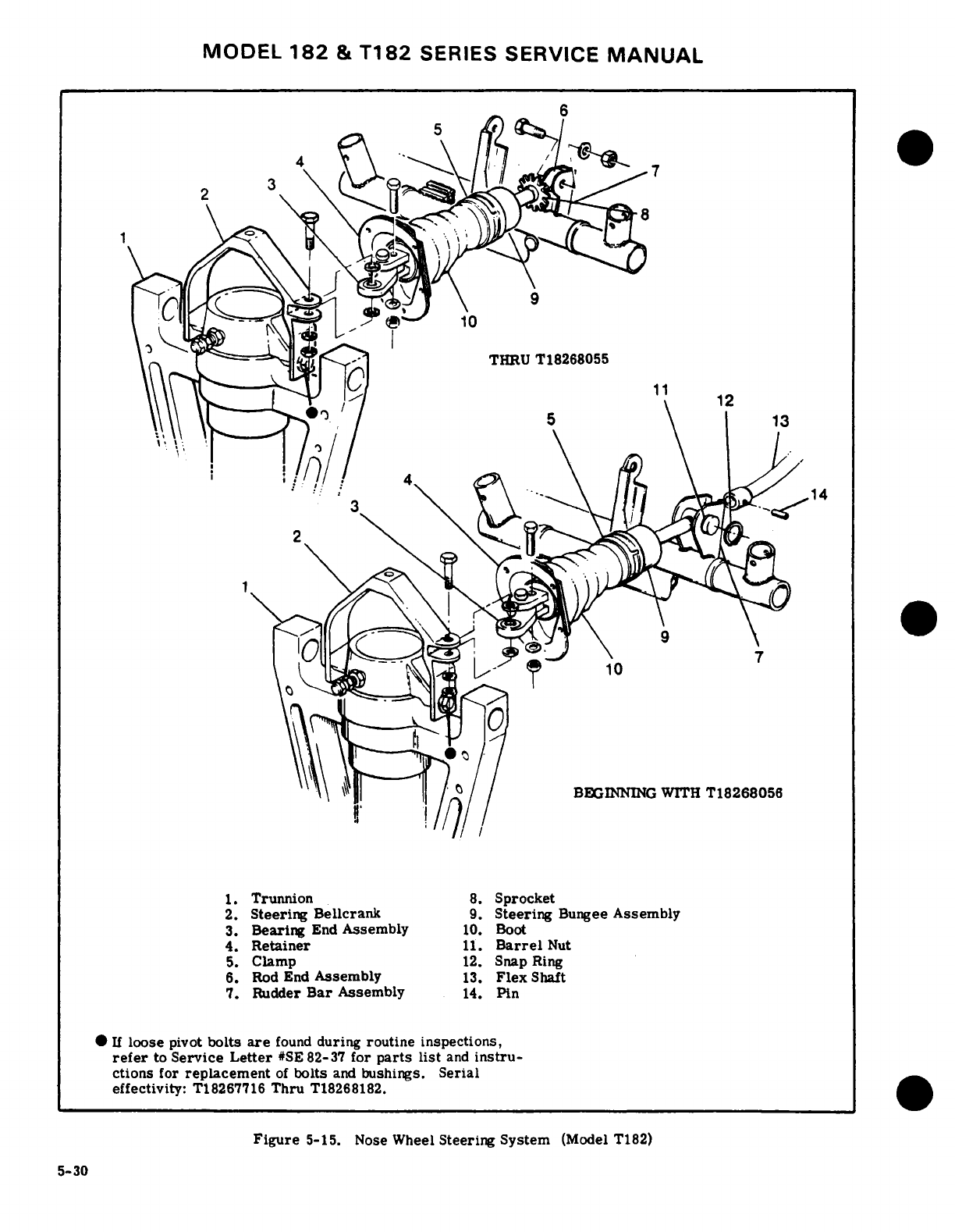
MODEL
182
&
T182
SERIES
SERVICE
MANUAL
4 7
-
10
THRU
T18268055
5.Cam-2.Sa
1R
5
13
,i
^11" \
/ /
BEGINNING WITH
T18268056
6.
Rod
End
Assembly
14.
Flex
Shaft
effectivity:
T18267716
Thru
T18268182.
1.
Trunnion
8.
Sprocket
Figure
5-152.
Steering
Bellcrank
9.Nose
Wheel
Steering System
(Model T182)
5-30
3.
Bearing
End
Assembly
10.
Boot
4.
Retainer
11.
Barrel
Nut
5.
Clamp
12.
SnapRing
6.
Rod
End
Assembly
13.
Flex
Shaft
7.
Rudder
Bar
Assembly
14.
Pin
If
loose
pivot
bolts
are
found
during
routine inspections,
refer
to
Service
Letter
#SE
82-37
for
parts
list
and
instru-
ctions
for
replacement
of
bolts
and
bushings.
Serial
effectivity:
T18267716
Thru
T18268182.
Figure
5-15.
Nose
Wheel
Steering System
(Model
T182)
5-30
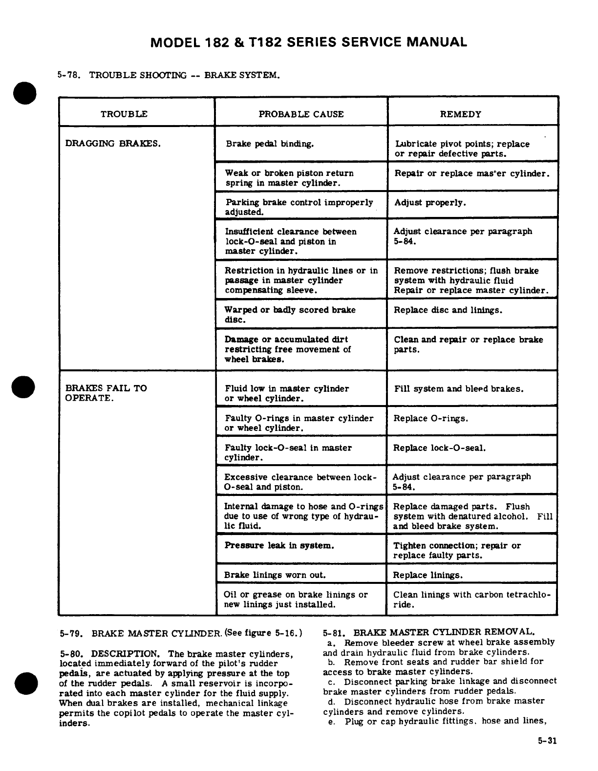
MODEL
182
&
T182
SERIES
SERVICE
MANUAL
5-78.
TROUBLE
SHOOTING
--
BRAKE
SYSTEM.
TROUBLE
PROBABLE
CAUSE
REMEDY
DRAGGING
BRAKES.
Brake
pedal
binding.
Lubricate
pivot
points;
replace
or repair
defective
parts.
Weak
or
broken
piston
return
Repair
or
replace
master
cylinder.
spring
in
master
cylinder.
Parking
brake
control
improperly
Adjust
properly.
adjusted.
Insufficient
clearance
between
Adjust
clearance
per
paragraph
lock-O-seal
and
piston
in
5-84.
master
cylinder.
Restriction
in
hydraulic
lines
or
in Remove
restrictions;
flush
brake
passage
in
master
cylinder
system
with
hydraulic
fluid
compensating
sleeve.
Repair
or
replace
master
cylinder.
Warped
or
badly
scored
brake
Replace disc and
linings.
disc.
Damage
or
accumulated
dirt
Clean
and
repair
or
replace brake
restricting
free
movement
of
parts.
wheel
brakes.
BRAKES
FAIL
TO
Fluid
low in
master
cylinder
Fill
system
and
bleed
brakes.
OPERATE.
or
wheel
cylinder.
Faulty
O-rings
in
master
cylinder
Replace
O-rings.
or
wheel
cylinder.
Faulty
lock-O-seal
in
master
Replace
lock-O-seal.
cylinder.
Excessive
clearance
between
lock-
Adjust
clearance
per
paragraph
O-seal
and
piston.
5-84.
Internal
damage
to
hose and
O-rings
Replace
damaged
parts. Flush
due
to
use
of
wrong
type
of
hydrau-
system
with
denatured
alcohol.
Fill
lic
fluid.
and bleed
brake
system.
Pressure
leak
in
system.
Tighten
connection;
repair
or
replace
faulty
parts.
Brake
linings
worn
out.
Replace
linings.
Oil
or
grease
on
brake
linings
or
Clean
linings
with carbon
tetrachlo-
new
linings
just
installed.
ride.
5-79.
BRAKE
MASTER
CYLINDER.
(See
figure
5-16.)
5-81.
BRAKE MASTER CYLINDER REMOVAL.
a.
Remove
bleeder screw
at
wheel
brake
assembly
5-80.
DESCRIPTION.
The
brake
master
cylinders,
and
drain hydraulic
fluid
from
brake
cylinders.
located
immediately
forward
of
the
pilot's
rudder
b.
Remove
front
seats
and
rudder
bar
shield
for
pedals,
are
actuated
by
applying
pressure
at
the top
access
to
brake
master
cylinders.
of
the
rudder
pedals.
A
small
reservoir
is
incorpo-
c.
Disconnect
parking
brake
linkage
and
disconnect
rated
into
each
master
cylinder
for
the
fluid supply.
brake
master
cylinders
from
rudder
pedals.
When
dual
brakes are
installed,
mechanical
linkage
d.
Disconnect hydraulic
hose
from
brake
master
permits
the
copilot
pedals
to
operate
the
master
cyl-
cylinders
and
remove
cylinders.
inders.
e.
Plug
or
cap
hydraulic
fittings,
hose
and
lines,
5-31
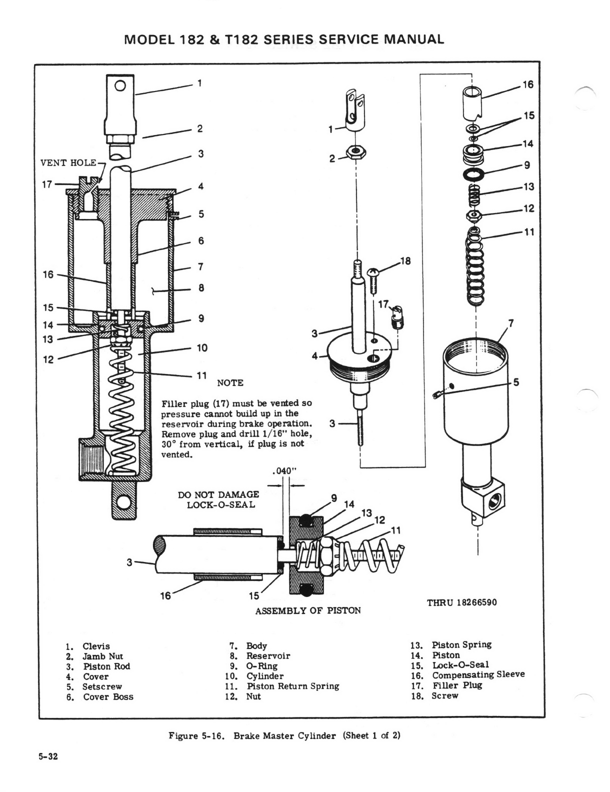
MODEL
182
&
T182
SERIES
SERVICE
MANUAL
15
1
VENT
HOLE-
17
4
13
12
11
16
15
14
13
10
4
11
NOTE
Filler
plug
(17)
must
be
vented
so
pressure
cannot
build
up
in
the
reservoir
during
brake
operation.
3
Remove
plug
and
drill
1/16"
hole,
30
°
from
vertical,
if
plug
is
not
vented.
DO
NOT
DAMAGE
LOCK-O-SEAL
16
15
THRU
18266590
ASSEMBLY
OF
PISTON
1.
Clevis
7.
Body
13.
Piston
Spring
2.
Jamb
Nut
8.
Reservoir
14.
Piston
3.
Piston
Rod
9.
O-Ring
15.
Lock-O-Seal
4.
Cover
10.
Cylinder
16.
Compensating
Sleeve
5.
Setscrew
11.
Piston
Return
Spring
17.
Filler
Plug
6.
Cover
Boss
12.
Nut
18.
Screw
Figure
5-16.
Brake
Master
Cylinder
(Sheet
1
of
2)
5-32
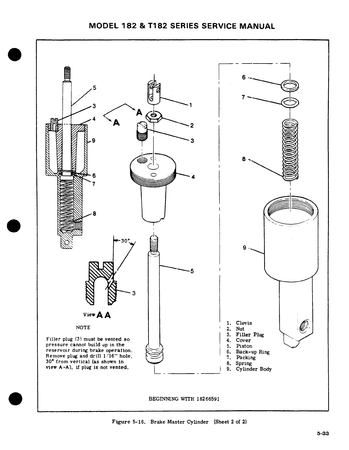
MODEL
182
&
T182
SERIES
SERVICE
MANUAL
4 <A
9 T3
9.
8 /
300
viewA
A
1.
Clevis
NOTE
2.
Nut
Filler
plug
(3)
must
be
vented
so
4.
Cover
pressure
cannot build
up
in
the
5.
Piston
reservoir
during
brake
operation.
6.
Back-up
Ring
Remove
plug
and
drill
1'16"
hole,
7.
Packing
30'
from
vertical
(as
shown
in
8.
Spring
view A-A),
if
plug
is
not
vented.
L
1
9.
Cylinder
Body
BEGINNING
WITH
18266591
Figure
5-16.
Brake
Master
Cylinder
(Sheet
2
of
2)
5-33
MODEL
182
&
T182
SERIES SERVICE
MANUAL
5-82.
DISASSEMBLY.
(Thru
18266590.)
(See
figure
place
packing
and
back-up
ring.
Filler
plug
(3)
must
5-16.)
be
vented
so
pressure
cannot build
up
during
brake
a.
Unscrew
clevis
(1)
and
jamb
nut
(2).
operation.
Remove
plug and
drill
1/16-inch
hole 30°
b.
Remove
screw
(18)
and
washer
(19).
from
vertical,
if
plug
is
not
vented.
See
view
A-A
c.
Remove
filler
plug
(17)
and
setscrew
(5).
for
location
of
vent
hole.
d.
Unscrew cover
(4)
and
remove
up
over
piston
rod
(3).
5-87.
REASSEMBLY.
(Beginning
with
18266591.)
e.
Remove
piston
rod
(3)
and
compensating
sleeve
(See
figure 5-16.)
(16).
a.
Install
spring
(8)
into
cylinder
body
(9).
f.
Slide
sleeve
(16)
up
over
rod
(3).
b.
Install
back-up
ring
(6)
and
packing
(7)
in
groove
g.
Unscrew
nut
(12)
from
threads
of
piston
rod
(3). of
piston
(5).
h.
Remove
spring
(13)
and
O-ring
(9)
from piston
c.
Install
piston
(5)
in
cylinder
body
(9).
(14).
d.
Install
cover
(4)
over
piston
(5)
and
screw cover
i.
Remove
Lock-O-Seal
(15).
nto
cylinder
body
(9).
e.
Install
nut
(2)
and
clevis
(1).
5-83.
INSPECTION
AND
REPAIR.
(Thru
18266590.)
f.
Install
filler
plug
(3),
making
sure
vent
hole
is
(See
figure
5-16.)
Repair
is
limited
to
installation
of
open.
new
parts,
cleaning and
adjusting.
Refer
to
assem-
bly
paragraph
for
adjustment
5-88.
Use
clean
BRAKE
MASTER
CYLINDER
INSTALLATION.
fluid
(MIL-H-5606)
as
a
lubricant
during
reassembly
a.
Connect
hydraulic
hoses
to
brake
master
cylin-
of
the
cylinders.
Inspect
Lock-O-Seal
(Parker
Sealders
and
install
cylinders.
Co.
P/N
800-001-6)
and
replace
if
damaged.
Replace
b
Connect
brake
master
cylinders
to
rudder
pedals
all
O-rings.
Filler
plug
(17)
must
be
vented
so
pres-
and
connect
parking brake
linkage.
sure
cannot build
up
during
brake
operation.
Remove
c.
Install
rudder bar
shield
and
install
front
seats.
plug
and
drill
1/16-inch
hole,
30°
from
vertical,
if
d.
Install
bleeder screw
at
wheel
brake
assembly
plug
is
not
vented.
and
fill
and
bleed brake
system
in
accordance
with
applicable
paragraph
in
this
Section.
5-84.
REASSEMBLY.
(Thru
18266590.)
(See
figure
5-16.)
5-89.
HYDRAULIC BRAKE
LINES.
a.
Install
Lock-O-Seal
(15)
at
bottom
of
piston
rod
(3).5-90.
DESCRIPTION.
The
brake
lines
are
of
rigid
b.
Install
O-ring
(9)
in
groove in
piston
(14);
insert
tubing,
except
for
flexible
hose
used
at
the
brake
piston spring
(13)
into
piston,
and
slide
assembly
up
mater
cylinders.
A
separate
line
is
used
to
connect
on
bottom
threaded
portion
of
piston
rod
(3).
each
brake
master
cylinder
to
its corresponding
c.
Run nut
(12)
up
threads
to
spring
(13).
Tighten
wheel
brake
cylinder.
nut
(12)
enough
to
obtain
0.040±0.005-inch
clearance
between top
of
piston
and
bottom
of
Lock-O-Seal,
as
shown
in the
illustration.
d.
Install
piston
return
spring
(11)
into
cylinder
5-92.
DESCRIPTION
Th
wheel
brake
assemblies
(10)
portion
of body
(7).
(10)
portion
of
body
(7).5-92.
DESCRIPTION.
The wheel
brake
assemblies
e.
Install
piston
rod
(3)
end
through
spring
(11).
employ
a
floating
brake
assembly
and
a
disc
which
is
f.
Slide compensating
sleeve
(16)
over
rod
(3).attached to
the
main
wheel.
g.
Install
cover
(4),
washer
(19)
and
screw
(18).
h.
Install
jamb
nut
(2)
and
clevis
(1).
5-93.
REMOVAL
OF
WHEEL
BRAKE.
(See
figure
i.
Install
filler
plug
(17),
making
sure
vent
hole
is
5-4.)
Wheel
brake
assemblies
can
be
removed
by
open.
disconnecting
the
brake
line
(drain
fluid
when
discon-
j.
Install
setscrew
(5).
necting
line)
and
removing
the
brake
back plate. The
brake disc
is
removed
after
the
wheel
is removed
and
5-85.
DISASSEMBLY.
(Beginning
with
18266591.)
disassembled.
To
remove
the
torque
plate. remove
(See
figure
5-16.)
wheel
and
axle.
a.
Unscrew
clevis
(1)
and
jamb
nut
(2).
.
Reove
filler
plug
(
ure
5-4
for
a
breakdwon
of
wheel
brake
parts.
This
NOTE
figure
may
be
used as
a
guide
for
disassembling
the
A
special
tool,
brake master
cylinder
wrench
wheel
brakes.
No.
34-101
is available
from
the
Cessna
Sup-
ply
Division
to
accomplish
the
following step.
5-95.
INSPECTION
AND
REPAIR OF
WHEEL
BRAKE.
a.
Clean
all
parts
except
brake
linings
and
O-rings
c.
Unscrew cover
(4)
and
remove
up
over
piston
(5).
in
dry
cleaning
solvent
and
dry
thoroughly.
d.
Remove
piston
(5)
and
spring
(8).
b.
Install
all
new
O-rings.
If
O-ring
reuse
is
neces-
e.
Remove
packing
(7)
and
back-up
ring
(8)
from
sary,
wipe with
a
clean
cloth
saturated
in
hydraulic
piston
(5).
fluid
and
inspect for
damage.
5-86.
INSPECTION
AND
REPAIR,
(Beginning
with
NOTE
18266591.)
(See
figure
5-16.)
Repair is
limited
to
installation
of
new
parts
and Thorough
cleaning
is important.
Dirt
and
cleaning.
Use
clean
hydraulic
fluid
(MIL-H-5606)
as
chips
are
the
greatest
single
cause
of
mal-
a
lubricant
during
reassembly
of
the cylinder.
Re-
functions
in
the
hydraulic
brake
system.
5-34
Revision
1
MODEL
182
&T182
SERIES
SERVICE
MANUAL
c.
Check
brake
lining
for
deterioration
and
maxi-
back
plate
and pressure
plate
in
the same
manner.
mum
permissible
wear. Refer
to
applicable
para-
graph
for
maximum
wear
limit.)
NOTE
d.
Inspect
brake
cylinder
bore
for
scoring.
A
scored
cylinder
will
leak
or
cause
rapid
O-ring wear.
Install
A
rivet
setting
kit.
Part
No.
199-1,
is
a new
brake
cylinder
if
the
bore
is
scored.
available
from
Cessna
Parts Distribution
e.
If
the
anchor
bolts
on
the
brake
assembly are
(CPD
2).
This
kit
consists
of
an
anvil
and
nicked
or
gouged,
they
shall
be
sanded
smooth
to
punch
prevent
binding
with
the
pressure
plate
or torque
plate.
When
new
anchor bolts
are
to
be
installed,
d.
Clamp
the
flat
side
of
the
anvil
in
a
vise.
press
out
old
bolts
and
install
new
bolts
with
a soft
e.
Align
new
lining
on
back
plate
and
place
brake
mallet.
rivet
in
hole
with
rivet
head
in
the
lining.
Place
the
f.
Inspect brake
discs.
Sand
smooth
small
nicks
head
against
the
anvil.
and
scratches.
If
excessively
warped or
scored,
the
f.
Center
rivet setting
punch
on
lips
of
rivet.
While
brake
discs
should
be
replaced
with
new
parts.
The
holding
back
plate
down
firmly
against
lining,
hit
chart
in
figure
5-18
lists
wheel
assemblies and
cor-
punch
with
hammer
to
set
rivet.
Repeat blows
on
responding
brake
discs.
The
original
thickness
and
punch
until
lining
is
firmly
against
back
plate.
the
minimum
allowable
thickness
of
each
disc
are
g.
Realign
the
lining
on
the
back
plate
and
install
shown.
Replace
the
disc
if the
thickness is
below
the
and
set
rivets in
the
remaining
holes.
allowable
minimum
dimension.
h.
Install
a
new
lining
on
pressure
plate
in
the
same
manner.
5-96.
REASSEMBLY OF
WHEEL
BRAKE.
(See
i.
Position pressure
plate
on
anchor
bolts
and
place
figure
5-4.)
cylinder
in
position
so
that
anchor bolts
slide
into
the
torque
plate.
NOTE
j.
Install
back
plate
with
bolts
and
washers.
Lubricate
parts
with
clean
hydraulic
fluid
5-100. BLEEDING
BRAKE
SYSTEM.
during
brake
assembly.
NOTE
a.
Use
figure
5-4
as
a
guide
during
reassembly.
Bleeding
with
a
clean
hydraulic
pressure
5-97.
INSTALLATION
OF
WHEEL
BRAKE.
source
connected
to
the
wheel
cylinder
is
a.
Place
brake
assembly
in
position
with
pressure recommended.
plate
in
place.
a.
Remove
brake master
cylinder
filler
plug
and
NOTE
screw
flexible
hose
with appropriate
fitting into the
filler
hole
at
the
top of
the
brake
master
cylinder.
If
torque plate
was
removed,
install
as
the
b.
Immerse
opposite
end
of
flexible
hose
into
a
con-
axle
is
installed,
or
install
on
axle.
If
the
tainer
with
enough
hydraulic
fluid
to
cover
end
of
the
brake
disc
was removed,
install
as
wheel
hose.
is
assembled.
c.
Connect
a
clean
hydraulic
pressure
source,
such
as
a
hydraulic
hand
pump
or
Hydro-Fill
unit
to
the
5-98.
CHECKING
BRAKE
LINING
WEAR.
New
bleeder
valve
in
the
wheel
cylinder.
brake lining
should
be
installed
when
the
existing
lin-
d.
As
fluid
is
pumped
into
the
system,
observe
the
ing
has
worn to
a
thickness
of
3/32-inch.
A
3/32-inch
immersed
end
of
the
hose
at
the
master
brake
cylinder
thick
strip
of
material
held
adjacent
to
each
lining
can
for evidence
of
air
bubbles
being
forced
from
the
brake
be
used
to
determine
amount
of
wear.
The shank
end
system.
When
bubbling
has
ceased,
remove
bleeder
of
a
drill
bit
of
the
correct
size
can
also
be
used
to
deter-
source
from
wheel
cylinder
and
tighten
the
bleeder
mine wear
of
brake
linings
valve.
5-99.
INSTALLATION
OF
BRAKE LINING.
See
5-101
BRAKE
LINING
BURN-IN.
The
brake
pads
figure
5-4.)
are
equipped with
either
a
non-asbestos
organic
lining
a.
Remove bolts
securing
back
plate,
and
remove
or
an
iron
based
metallic lining.
These
materials
must
back
plate.
be
properly
conditioned
(glazed)
in
order
to
provide
b.
Pull
brake
cylinder
out
of
torque
plate
and
slide
maximum
performance
and
service
life.
This
is
accom-
pressure
plate
off
anchor
bolts.
plished
by
a
brake
burn-in
c.
Place back
plate
on
a
table
with
lining
side
down
a.
Non-asbestos
organic
lining.
flat.
Center
a 9/64-inch
(or
slightly smaller)
punch in
1.
Taxi
airplane
for
1500
feet
with
engine
at
the
rolled
nvet,
and
hit
the
punch
sharply
with
a
ham-
1700
RPM
applying
brake pedal
force
as
needed
mer
Punch
out
all
rivets
securing
the
linings
to
the
to
develop
a
5
to
9
knots
taxi
speed.
Revision
3
5-35
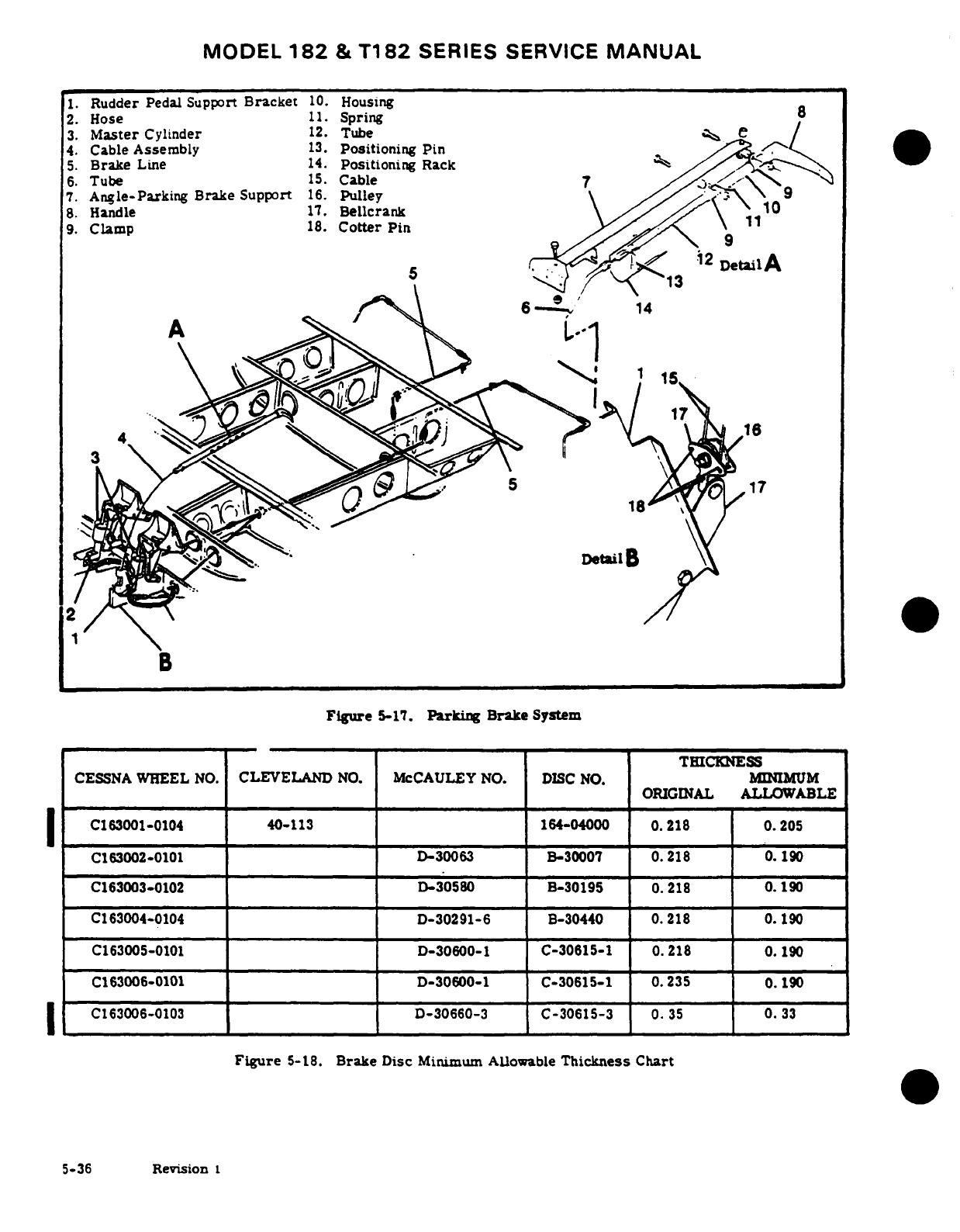
MODEL
182
&
T182
SERIES
SERVICE
MANUAL
1.
Rudder
Pedal
Support
Bracket
10.
Housing
2.
Hose
11.
Spring 8
3.
Master
Cylinder
12.
Tube
4.
Cable
Assembly
13.
Positioning Pin
.-
5.
Brake
Line
14.
Positioning
Rack
6.
Tube
15.
Cable
7.
Angle-Parking
Brake
Support
16.
Pulley
8.
Handle
17.
Bellcrank
9.
Clamp
18.
Cotter
Pin
.
5^~~~ '^i^
12
DetailA
13
46~ 16
1
"
,5,17
i
%i
F re
5-17.
PkiDe
Brake
System
B
Figure
5-17.
Parking Brake
System
THICKNESS
CESSNA
WHEEL
NO.
CLEVELAND
NO.
McCAULEY
NO.
DISC
NO. MINIMUM
ORIGINAL
ALLOWABLE
C163001-0104
40-113
164-04000
0.218
0.205
C163002-0101
D-30063
B-30007
0.218
0. 190
C163003-0102
D-30580
B-30195
0.218
0.190
C163004-0104
D-30291-6
B-30440
0.218
0.190
C163005-0101
D-30600-1 C-30615-1
0.218
0. 190
C163006-0101
D-30600-1
C-30615-1
0.235
0. 190
C163006-0103
D-30660-3
C-30615-3
0.35
0.33
Figure
5-18.
Brake
Disc
Minimum
Allowable
Thickness
Chart
5-36
Revision
I
MODEL
182
&
T182
SERIES
SERVICE
MANUAL
2.
Allow
brakes
to
cool
for
10
to
15
minutes
cylinder
piston
rods
and
the
handle
ratchet
locks
the
3.
Apply
brakes
and
check
to
see
if
a
high
throt-
handle
in
this
position
until
the
handle
is
turned and
tie
static run
up
may
be
held
with
normal
pedal
released.
force.
If
so,
burn-in
is
completed.
4.
If
static
run
up
cannot
be
held.
repeat
steps
1
5.104.
REMOVAL
AND
INSTALLATION.
(See
through
3
as
needed
to
successfully
hold.
figure
5-17.)
See
the
figure
for
relative
location
of
b.
Iron based
metallic
lining.
system
components.
The
illustration
may
be
used
as
a
1. Perform
two
consecutive
full
stop
braking
ap-
guide
during
removal
and
installation
of
components.
plications
from
30
to
35
knots.
Do
not
allow
the
brake
discs
to
cool
substantially
between
stops. 5-105.
INSPECTION
AND
REPAIR
OF
SYSTEM
COMPONENTS.
Inspect
lines
for
leaks,
cracks,
dents,
5-102.
PARKING
BRAKE
SYSTEM
(See
figure
chafing,
improper
radius,
security,
corrosion,
deterio-
5-17.)
ration,
obstructions
and
foreign
matter.
Check
brake
master
cylinders
and
repair
as
outlined
in
applicable
5-103.
DESCRIPTION. The
parking brake
system
paragraph
in
this
Section. Check
parking
brake
han-
consists
of
a
handle
and
ratchet
mechanism,
connected
dle
and
ratchet
for
proper
operation
and
release.
Re-
by a
cable
to
linkage
at
the
brake
master
cylinders.
place
worn
or
damaged
parts.
Pulling
out
on
the
handle depresses
both
brake
master
Revision
3
5-37/(5-38
Blank)
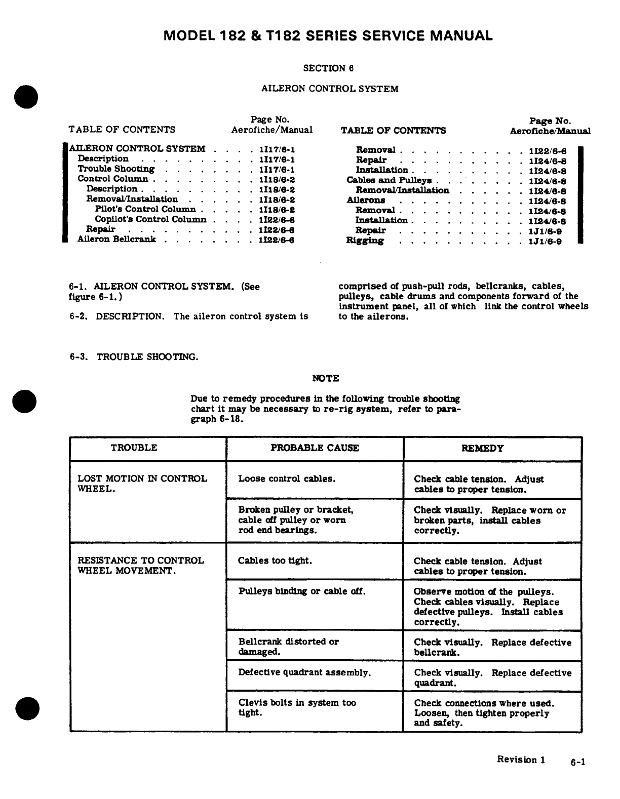
MODEL
182
&
T182
SERIES
SERVICE
MANUAL
SECTION
6
AILERON
CONTROL
SYSTEM
Page
No.
Page
No.
TABLE OF
CONTENTS
Aerofiche/Manual
TABLE
OF
CONTENTS
Aerofiche/Manual
AILERON CONTROL
SYSTEM
....
1117/6-1
Removal
...........
1I22/6-6
Description
..........
1I17/6-1
Repair
...........
1124/6-8
Trouble
Shooting
........
1I17/6-1
Installation
..........
1124/6-8
Control
Column
.
.......
.
1I18/6-2
Cables
and
Pulleys
..
......
1I24/6-8
Description.
.........
.
1I18/6-2
Removal/Installation
......
1I24/6-8
Removal/Installation
......
1118/6-2
Ailerons
........... 1I24/6-8
Pilot's
Control
Column
.....
1I18/6-2
Removal
...........
1I24/6-8
Copilot's
Control
Column
.. ..
1I22/6-6
Installation
..........
1I24/6-8
Repair
...........
1122/6-6
Repair
...........
1J1/6-9
Aileron
Bellcrank
.
....
.1I22/6-6
Rigging
.
..........
1J1/6-9
6-1.
AILERON CONTROL SYSTEM.
(See
comprised
of
push-pull rods,
bellcranks,
cables,
figure
6-1.)
pulleys,
cable
drums
and
components
forward
of
the
instrument
panel,
all
of
which
link
the
control
wheels
6-2.
DESCRIPTION.
The
aileron
control
system
is
to the
ailerons.
6-3.
TROUBLE
SHOOTING.
NOTE
Due
to
remedy
procedures
in
the
following
trouble
shooting
chart
it
may
be
necessary
to
re-rig
system,
refer
to
para-
graph
6-18.
TROUBLE
PROBABLE
CAUSE
REMEDY
LOST
MOTION
IN
CONTROL
Loose control
cables.
Check cable
tension.
Adjust
WHEEL.
cables
to
proper
tension.
Broken
pulley
or
bracket,
Check
visually.
Replace
worn
or
cable
off
pulley
or
worn
broken
parts,
install
cables
rod
end
bearings.
correctly.
RESISTANCE
TO
CONTROL
Cables
too
tight.
Check cable
tension.
Adjust
WHEEL MOVEMENT.
cables
to
proper
tension.
Pulleys
binding
or
cable
off.
Observe
motion
of
the
pulleys.
Check
cables
visually.
Replace
defective
pulleys.
Install
cables
correctly.
Bellcrank
distorted
or
Check
visually.
Replace
defective
damaged.
bellcrank.
Defective
quadrant
assembly.
Check
visually.
Replace
defective
quadrant.
Clevis
bolts
in
system
too
Check
connections
where
used.
tight.
Loosen,
then
tighten
properly
and
safety.
Revision
1
6-1

MODEL
182
&
T182
SERIES
SERVICE
MANUAL
6-3.
TROUBLE
SHOOTING
(Cont).
TROUBLE PROBABLE
CAUSE
REMEDY
CONTROL
WHEELS
NOT
Improper
adjustment
of
Refer
to
paragraph
6-18.
LEVEL
WITH
AILERONS
cables.
NEUTRAL.
Improper
adjustment
of
Adjust
push-pull
rods
to
obtain
aileron
push-pull
rods.
proper
alignment.
DUAL
CONTROL
WHEELS
Cables
improperly
adjusted.
Refer
to
paragraph
6-18.
NOT
COORDINATED.
INCORRECT
AILERON
Push-pull
rods
not
adjusted
Refer
to
paragraph
6-18.
TRAVEL.
properly.
Incorrect
adjustment
of
travel
Refer
to
paragraph
6-18.
stop
bolts.
6-4.
CONTROL
COLUMN.
(See
figure
6-2.)
adapter
(35)
to
control
wheel
tube
assembly
(13)
and
remove
control
wheel
assembly.
6-5.
DESCRIPTION.
Rotation
of
the
control
wheel
2.
Disconnect
electrical
wiring
to
map
light
and
rotates
four
bearing
roller
assemblies
(3)
on
the
end
mike
switch
at
connector
(39)
if
installed.
Slide
of
the
control
wheel
tube
(13),
which
in
turn,
rotates
cover
(1) off
control
wheel tube
assembly
(13).
a
square
control
tube
assembly
(15)
inside
and
ex-
3.
Remove
decorative
cover
from instrument
tending
from
the
control
wheel tube
(13).
Attached
panel.
to
this
square
tube
(15)
is
a
quadrant
(24)
which
oper-
4.
Remove
screw securing
adjustable
glide
plug
ates
the
aileron
system.
This
same
arrangement
is
(14)
to
control
tube
assembly
(15)
and
remove
plug
provided
for
both
control
wheels.
Synchronization
of
and
glide
assembly.
the
control
wheels
is
obtained
by
the
interconnect
5.
Disconnect
push-pull
tube
(16)
at
sleeve
weld
cable
(29),
turnbuckle
(30)
and
adjustment
terminals
assembly
(5).
(27).
The
forward
end
of
the
square
control
tube
(15)
6.
Remove
screws
securing support
plate
(10)
at
is
mounted in
a
bearing
block
(21)
on
firewall
(31)
and
instrument
panel.
does
not
move
fore-and-aft,
but
rotates
with
the
con-
trol
wheel.
The
four
bearing
roller
assemblies
(3)
NOTE
on
the
end
of
the
control
wheel
tube
reduce
friction
as
the
control
wheel
is
moved
fore-and-aft
for
ele-
To
ease removal
of
control
wheel
tube
assem-
vator
system
operation.
A
sleeve
weld
assembly
(5),
bly
(13),
snap
ring
(9)
may
be
removed
from
containing
bearings
which
permit
the
control
wheel
its
locking
groove
to
allow
sleeve
weld
assem-
tube
to
rotate
within
it, is
secured
to
the
control
bly
(5)
additional
movement.
wheel
tube
by a
sleeve
and
retaining
ring
in
such
a
manner
it
moves
fore-and-aft
with
the
control
wheel
7.
Using
care,
pull
control
wheel
tube
assembly
tube.
This
movement
allows
the
push-pull
tube
(16)
(13)
aft
and
work
assembly
out
through
instrument
attached
to
the
sleeve
weld
assembly
(5)
to operate
panel.
an
elevator
arm
assembly
(18),
to
which
one
elevator
cable
(20)
is
attached.
A
torque
tube
(19)
connects
NOTE
this
arm
assembly
(18)
to
the
one
on
the
opposite
end
of
the
torque
tube
(19),
to
which
the
other
elevator
If
removal
of
control
tube
assembly
(15)
or
cable
is
attached.
When
dual
controls
are
installed,
quadrant
(24)
is
necessary,
proceed
to
step
the
copilot's
control
wheel
is
linked to
the
aileron
and
8.
elevator
control
systems
in
the same
manner
as
the
pilot's
control
wheel.
8.
Remove
safety
wire
and
relieve
direct
cable
tension
at
turnbuckles
(index
8,
figure
6-1).
6-6.
REMOVAL
AND
INSTALLATION.
(See
figure
6-2.)
9.
Remove
safety wire
and
relieve
interconnect
a.
PILOT'S
CONTROL
COLUMN.
cable
tension
at
turnbuckle
(30).
1.
Slide
cover
(1)
toward
instrument
panel
to
10.
Remove
safety
wire
and
remove
roll
pin
(28)
expose
adapter
(35).
Remove
screws
securing
through
quadrant
(24)
and
control
tube
assembly
(15).
6-2
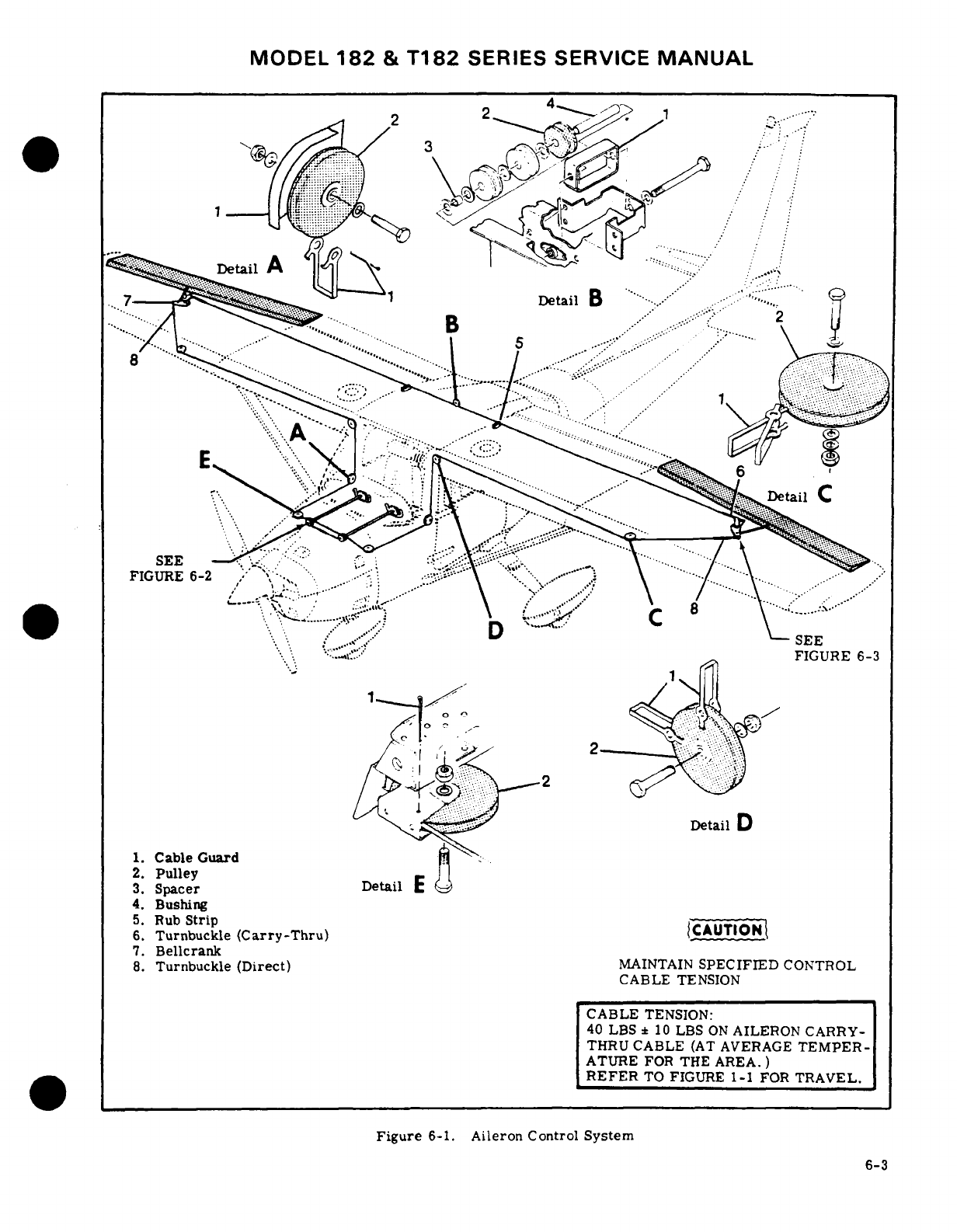
MODEL
182
&
T182
SERIES SERVICE
MANUAL
2_
2
A
.
FIGURE 6-2 .
..... .. ;.
.
I"°''^
v^
*
'
''
<\
/
..-
* 8
< ....
'~' ."'..-"?".'
-
FIGURE
6-3
1.
Cable
Guard
2.
Pulley
A
E
3..
Spacer
Detail
C
4.
Bushing
6.
Turnbuckle
(Carry-Thru)
iCAUTIONt
7.
Bellcrank
8.
Turnbuckle
(Direct)
MAINTAIN
SPECIFIED
CONTROL
CABLE
TENSION
CABLE
TENSION:
40
LBS
±
10
LBS
ON
AILERON CARRY-
THRU
CABLE
(AT
AVERAGE
TEMPER-
ATURE
FOR
THE
AREA.)
REFER
TO
FIGURE
1-1
FOR
TRAVEL.
Figure
6-1.
Aileron
Control
System
6-3
2
<2
4.
Bushing
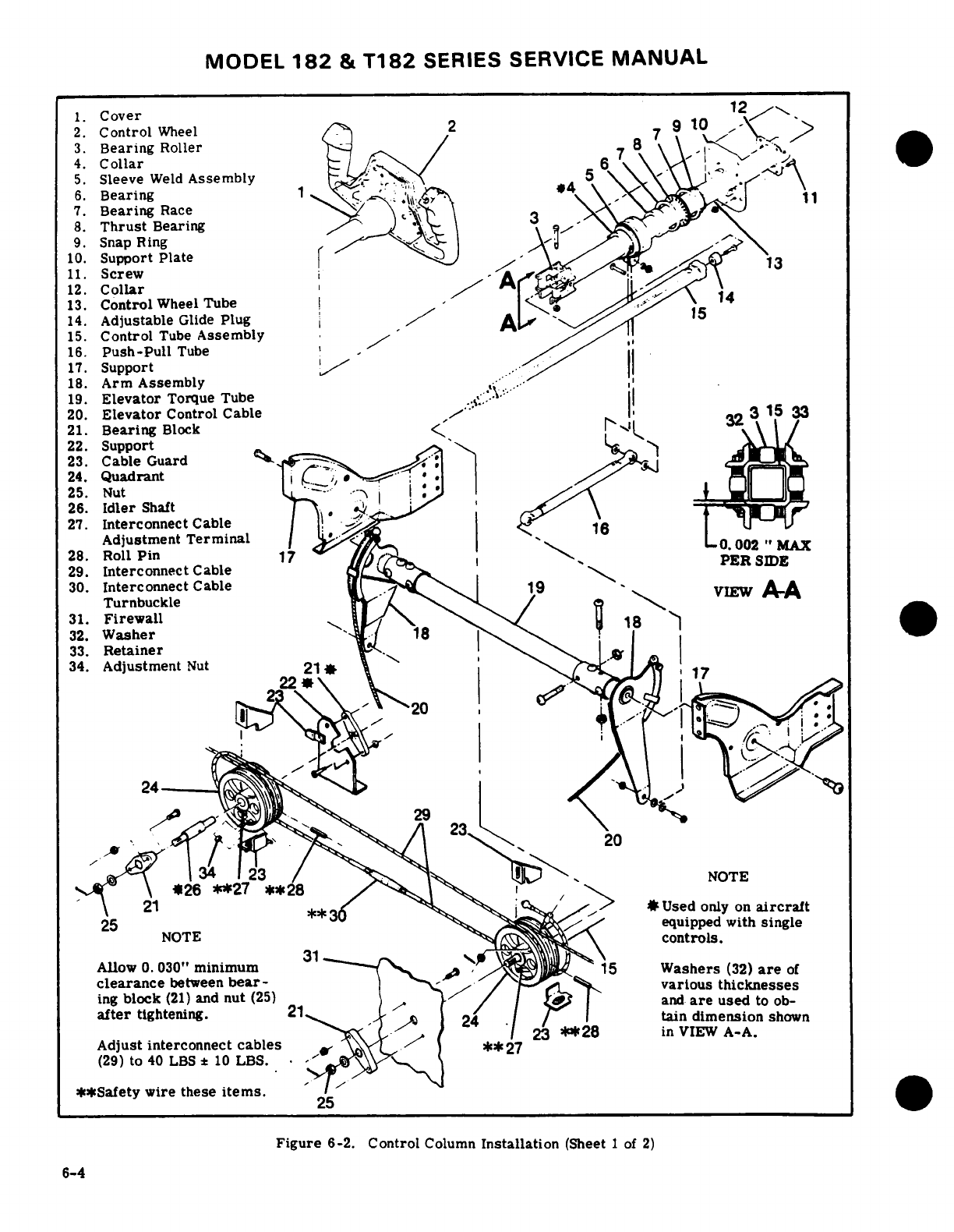
MODEL
182
&
T182
SERIES
SERVICE
MANUAL
1.
Cover
1 2
/ .
2.
Control
Wheel
2
9
10
-\
3.
Bearing
Roller
8
5.
Sleeve
Weld
Assembly
5
6.
Bearing
1 >4
7.
Bearing
Race
11
8.
Thrust
Bearing
3
9.
Snap
Ring
10.
Support
Plate
11.
Screw
13
12.
Collar
A
13.
Control
Wheel Tube
14
14.
Adjustable
Glide
Plug
1
15.
Control
Tube
Assembly
16.
Push-Pull
Tube
,
17.
Support
18.
Arm Assembly
19.
Elevator
Torque
Tube
.-
20.
Elevator
Control Cable
3
15
21.
Bearing
Block
32
22.
Support
23.
Cable
Guard -
|
-i
^
i-
24.
Quadrant
<J
~
;
25.
Nut
.
j
26.
Idler
Shaft
,
27.
Interconnect
Cable!
Adjustment
Terminal
16
28.
Roll
Pin
17
A
0.002
"MAX
29.
Interconnect
Cable
PER
SIDE
30.
Interconnect
Cable
1 AA
Turnbuckle
VIEW
A-A
31.
Firewall
32.
Washer
"
18
18
33.
Retainer
34.
Adjustment
Nut
21
22_\
'J
17
2^^^^^^S^ ^'^^
22
i/,2
24
20
29
0^ ^ «26 4**2723»*28 /^^Y,
NOTE
x
2
S~C
r~**
3/
^/
- F
Used
only
on
aircraft
25
NOTE
equipped
with
single
controls.
Allow
0.
030"
minimum
_
\
15
Washers
(32)
are
of
clearance
between
bear-
5
Washers
(32)
are
of
ing
block
(21)
and
nut
(25)
various thicknesses
after
tightening.
21
and
are
used
to
ob-
.Ad isght .e ni
24
2
/ I
tain
dimension
shown
Adjust
interconnect
cables
23
**28
in
VIEW
A-A.
(29)
to
40
LBS
*
10
LBS.
27
**Safety
wire these
items.
25
Figure
6-2.
Control
Column
Installation
(Sheet
1
of
2)
6-4
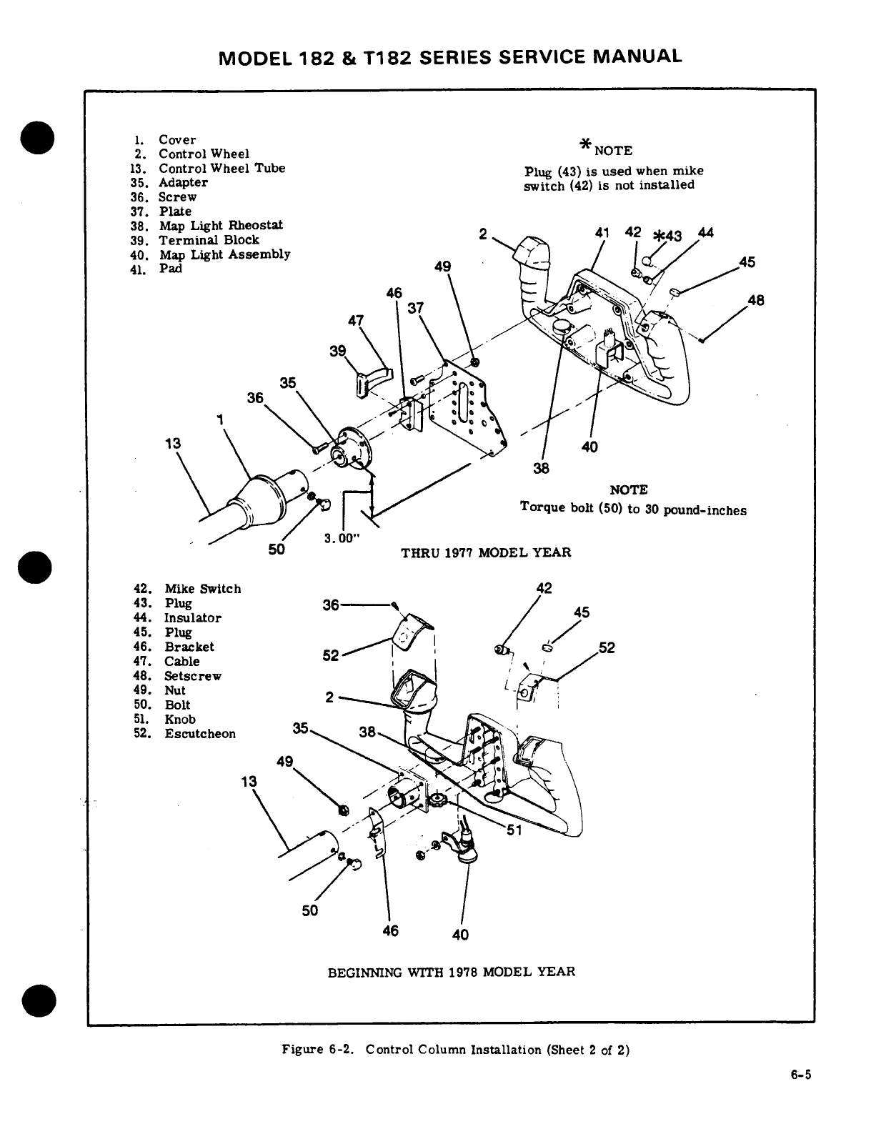
MODEL
182
&
T182
SERIES
SERVICE
MANUAL
1.
Cover
2.
Control
Wheel
NOTE
13.
Control
Wheel
Tube Plug
(43)
is
used
when
mike
35.
Adapter
switch
(42)
is
not
installed
36.
Screw
37.
Plate
38.
Map
Light
Rheostat
39.
Terminal
Block
2
41
42
*43
44
40.
Map
Light
Assembly
/
/
41.
Pad
49
45
4637
48
35
36
13
40
NOTE
Torque
bolt
(50)
to
30
pound-inches
3.00"
50
THRU
1977
MODEL
YEAR
42.
Mike
Switch
42
43.
Plug
36-- /
44.
Insulator
/ /
45
45.
Plug
46.
Bracket
47.
Cable
52
48.
Setscrew
49.
NEutchen
50.
Bolt
2
51.
Knob
52.
Escutcheon
38
49
13
50
46
40
BEGINNING
WITH
1978
MODEL
YEAR
Figure
6-2.
Control
Column
Installation
(Sheet
2
of
2)
6-5
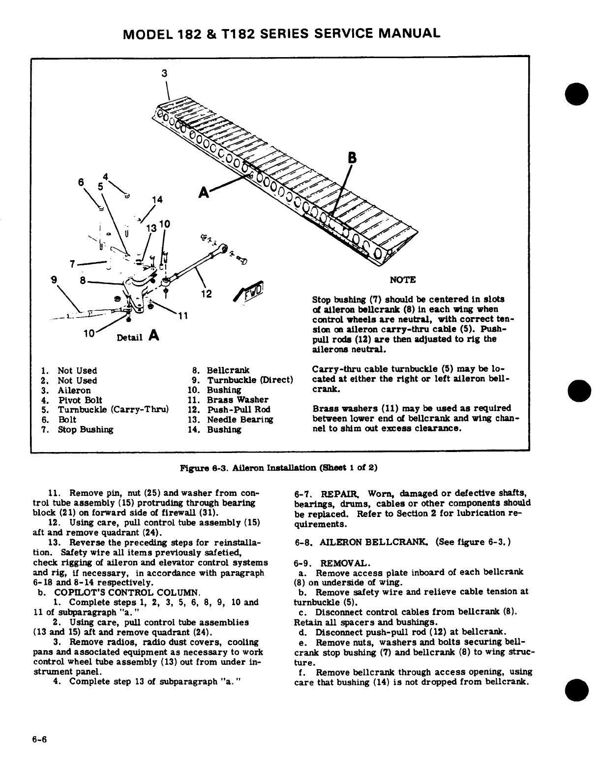
MODEL
182
&
T182
SERIES
SERVICE
MANUAL
3
9
a ~\ °® H ~ ^~1-~^
Stop
bushing
(7)
should
be
centered
in
slots
11
>-i e@
.
of
aileron bellcrank
(8)
in
each
wing
when
... ~L-- ,
1
"
control
wheels
are
neutral,
with
correct
ten-
10
.. ^
a
A
sion
on
aileron
carry-thru
cable
(5).
Push-
1v
Detail
A
pull
rods
(12)
are
then
adjusted to
rig
the
ailerons neutral.
1.
Not
Used
8.
Bellcrank
Carry-thru
cable turnbuckle
(5)
may
be
lo-
2.
Not
Used
9.
Turnbuckle
(Direct)
cated
at either
the
right
or
left
aileron
bell-
3.
Aileron
10.
Bushing
crank.
4.
Pivot
Bolt
11.
Brass
Washer
5.
Turnbuckle
(Carry-Thru)
12.
Push-Pull
Rod
Brass
washers
(11)
may
be
used
as
required
6.
Bolt
13.
Needle Bearing between
lower
end
of
bellcrank
and
wing chan-
7.
Stop
Bushing
14.
Bushing
nel
to
shim
out
excess clearance.
Figure
6-3.
Aileron
Installation
(Sheet
1
of
2)
11.
Remove
pin, nut
(25)
and
washer from
con-
6-7.
REPAIR.
Worn,
damaged
or
defective
shafts,
trol
tube
assembly
(15)
protruding
through
bearing
bearings,
drums,
cables
or
other
components
should
block
(21) on
forward
side
of
firewall
(31).
be
replaced.
Refer
to
Section
2
for
lubrication
re-
12.
Using
care,
pull
control
tube
assembly
(15)
quirements.
aft
and
remove quadrant
(24).
13.
Reverse
the
preceding steps
for
reinstalla-
6-8.
AILERON
BELLCRANK.
(See
figure
6-3.)
tion.
Safety
wire
all
items
previously
safetied,
check
rigging
of
aileron
and
elevator
control
systems
6-9.
REMOVAL.
and
rig,
if
necessary,
in
accordance
with
paragraph
a. Remove
access
plate
inboard
of
each
bellcrank
6-18
and
8-14
respectively.
(8)
on
underside
of
wing.
b.
COPILOT'S
CONTROL
COLUMN.
b.
Remove
safety
wire
and
relieve
cable
tension
at
1.
Complete
steps
1,
2,
3, 5,
6,
8, 9,
10
and
turnbuckle
(5).
11
of
subparagraph
"a.
"
c.
Disconnect
control
cables
from bellcrank
(8).
2.
Using
care,
pull
control
tube
assemblies
Retain
all
spacers
and
bushings.
(13
and
15)
aft
and
remove
quadrant
(24).
d.
Disconnect
push-pull
rod
(12)
at bellcrank.
3.
Remove
radios,
radio
dust
covers,
cooling
e.
Remove
nuts,
washers
and
bolts
securing
bell-
pans
and
associated
equipment
as
necessary
to
work
crank
stop
bushing
(7)
and
bellcrank
(8)
to
wing
struc-
control
wheel tube
assembly
(13)
out
from
under
in-
ture.
strument
panel.
f.
Remove
bellcrank
through
access
opening,
using
4.
Complete
step
13
of
subparagraph
"a.
"
care
that
bushing
(14)
is
not
dropped
from
bellcrank.
6-6
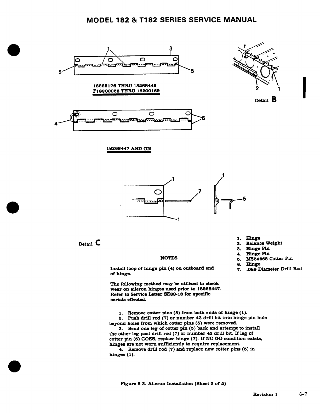
MODEL
182
&
T182
SERIES
SERVICE
MANUAL
18265176
THRU
18268446
F18200026
THRU
18200169
Detail
B
18268447
AND
ON
1.
Hinge
Detail
C
2.
Balance Weight
3.
Hinge
Pin
4.
Hinge
Pin
NOTES
5.
MS24665
Cotter
Pin
6.
Hinge
Install
loop of
hinge
pin
(4)
on
outboard
end
7.
.089
Diameter
Drill
Rod
of
hinge.
The following
method
may
be
utilized
to
check
wear
on
aileron
hinges
used
prior
to
18268447.
Refer
to
Service
Letter
SE83-18
for
specific
serials
effected.
1.
Remove
cotter
pins
(5)
from
both
ends
of
hinge
(1).
2.
Push drill
rod
(7)
or
number
43
drill
bit
into
hinge
pin
hole
beyond holes
from
which cotter
pins
(5)
were
removed.
3.
Bend
one
leg
of
cotter pin
(5)
back
and
attempt
to
install
the
other
leg
past
drill
rod
(7)
or
number
43
drill
bit.
If
leg
of
cotter pin
(5)
GOES,
replace
hinge
(7).
If
NO GO
condition
exists,
hinges
are not
worn sufficiently
to
require
replacement.
4. Remove
drill
rod
(7)
and
replace
new
cotter
pins
(5)
in
hinges
(1).
Figure
6-3.
Aileron
Installation
(Sheet
2
of
2)
Revision
1
6-7
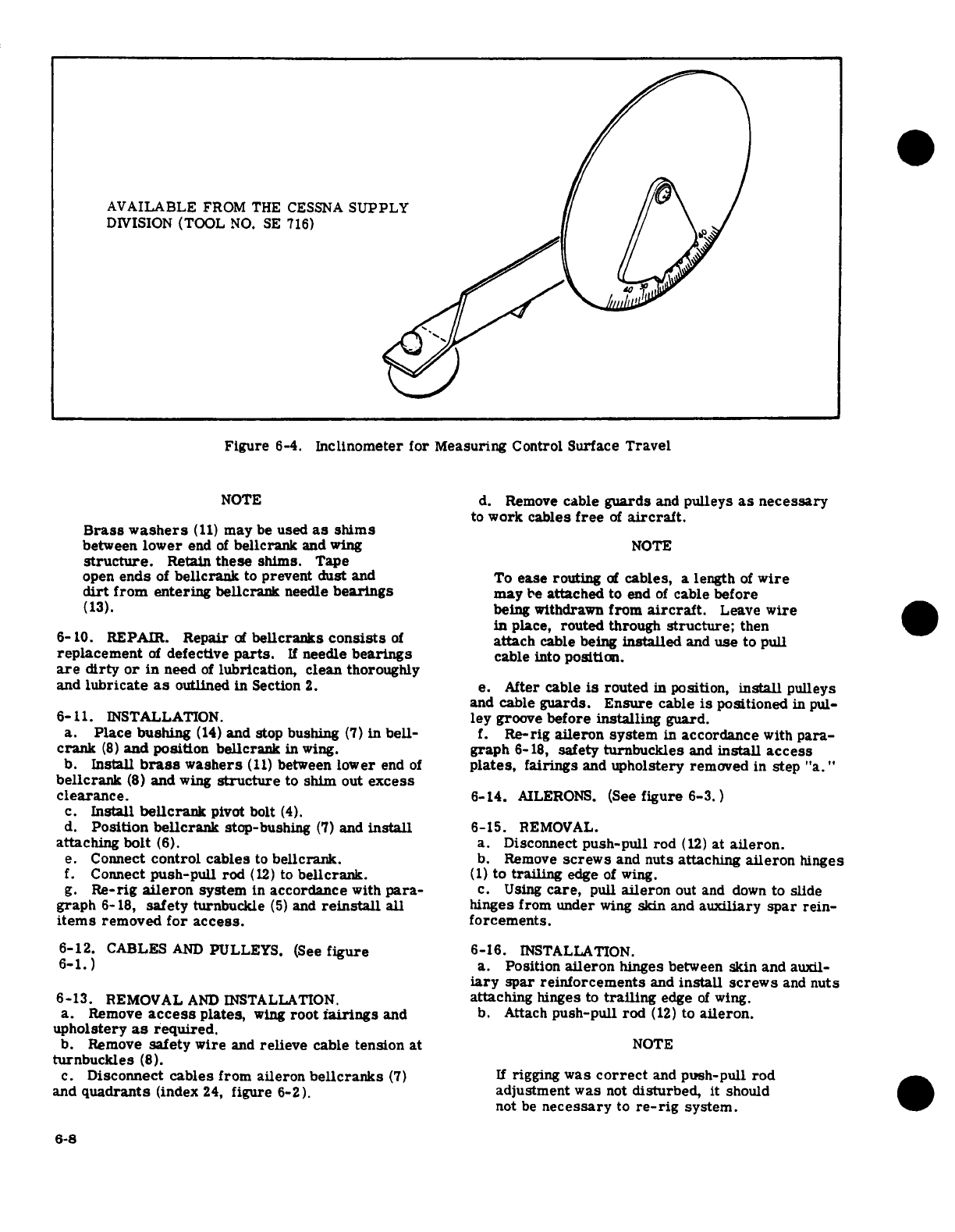
AVAILABLE
FROM
THE CESSNA
SUPPLY
DIVISION
(TOOL
NO.
SE
716)
Figure
6-4.
Inclinometer
for
Measuring
Control Surface
Travel
NOTE
d.
Remove
cable
guards
and
pulleys
as
necessary
to
work
cables
free
of
aircraft.
Brass
washers
(11)
may
be
used
as
shims
between
lower
end
of
bellcrank
and
wing
NOTE
structure.
Retain
these
shims.
Tape
open
ends
of
bellcrank
to
prevent
dust
and
To
ease routing
of
cables,
a
length
of
wire
dirt
from
entering
bellcrank
needle
bearings
may
be
attached
to
end
of
cable
before
(13).
being
withdrawn
from
aircraft.
Leave
wire
in
place,
routed
through
structure;
then
6-10.
REPAIR.
Repair
of
bellcranks
consists
of
attach
cable
being
installed
and
use
to
pull
replacement
of
defective
parts.
If
needle
bearings
cable
into
position.
are
dirty
or
in
need
of
lubrication,
clean
thoroughly
and
lubricate
as
outlined
in Section
2.
e.
After cable
is
routed
in
position,
install
pulleys
and
cable
guards.
Ensure
cable
is
positioned
in pul-
6-11.
INSTALLATION.
ley
groove
before
installing
guard.
a.
Place bushing
(14)
and
stop
bushing
(7)
in
bell-
f.
Re-rig
aileron
system
in
accordance
with
para-
crank
(8)
and
position
bellcrank
in
wing.
graph
6-18,
safety
turnbuckles
and
install
access
b.
Install
brass
washers
(11)
between
lower
end
of
plates,
fairings
and
upholstery
removed
in
step "a."
bellcrank
(8)
and
wing
structure
to
shim
out
excess
clearance.
6-14.
AILERONS.
(See
figure
6-3.)
c.
Install
bellcrank
pivot
bolt
(4).
d.
Position
bellcrank
stop-bushing
(7)
and
install
6-15.
REMOVAL.
attaching
bolt
(6).
a.
Disconnect
push-pull
rod
(12)
at
aileron.
e.
Connect
control
cables
to
bellcrank.
b.
Remove
screws
and
nuts
attaching
aileron
hinges
f.
Connect
push-pull
rod
(12)
to
bellcrank.
(1)
to
trailing
edge
of
wing.
g.
Re-rig
aileron
system
in
accordance
with
para-
c.
Using
care,
pull
aileron
out
and
down
to
slide
graph
6-18,
safety
turnbuckle
(5)
and
reinstall
all
hinges
from
under
wing
skin
and
auxiliary
spar
rein-
items
removed
for
access.
forcements.
6-12.
CABLES
AND
PULLEYS.
(See
figure
6-16.
INSTALLATION.
6-1.)
a.
Position
aileron
hinges
between
skin
and
auxil-
iary
spar
reinforcements
and
install
screws
and
nuts
6-13.
REMOVAL
AND
INSTALLATION.
attaching
hinges
to
trailing
edge
of
wing.
a.
Remove
access
plates,
wing
root
fairings
and
b.
Attach
push-pull
rod
(12)
to
aileron.
upholstery
as
required.
b.
Remove
safety
wire
and
relieve
cable
tension at
NOTE
turnbuckles
(8).
c.
Disconnect
cables
from
aileron
bellcranks
(7)
If
rigging
was
correct
and
push-pull rod
and
quadrants
(index
24,
figure
6-2).
adjustment
was
not
disturbed,
it
should
not
be
necessary
to
re-rig
system.
6-8
MODEL
182
&
T182
SERIES
SERVICE
MANUAL
c.
Check
aileron
travel
and
alignment,
re-rig
if
nec-
slots
with 40±10
pounds
tension
on
carry-thru
cable.
essary,
in
accordance
with
paragraph
6-18.
Disregard
tension
on
direct
cables.
f.
Adjust
push-pull
rods
(index
12,
figure
6-3)
at
6-17.
REPAIR.
Aileron
repair
may be
accomplished
each
aileron
until
ailerons
are
neutral
with
reference
in
accordance
with
instructions
outlined
in Section
18.
to
trailing
edge
of
wing
flaps.
Be
sure
wing
flaps
Before
installation, ensure
balance
weights
and
hinges
are
full
UP
when
making
this
adjustment.
are
securely attached.
g.
With
ailerons
in
neutral
position
(streamlined),
mount
an
inclinometer
on
trailing
edge
of
one
aileron
6-18.
RIGGING.
(See
figure
6-1.)
and
set
to 0
°
.
(Refer
to
figure
6-4
for
inclinometer.)
a.
Remove
safety
wire
and
relieve
cable
tension
at
h.
Remove
bar
from
control
wheels
and
check de-
turnbuckles
(6
and
8).
gree
of
travel
as
specified
in
figure
1-1. If
travel
is
b.
Disconnect
push-pull
rods
at
bellcranks
(7).
not
within
specified
limits, readjust
push-pull
rods
c.
Adjust
interconnect
cable
turnbuckle
(index
30,
and
cables
as
necessary.
figure
6-2)
and
adjustment
terminals
(index
27,
fig-
i.
Ensure
all
turnbuckles
are
safetied,
all
cables
ure
6-2) to
remove
cable
slack,
acquire
proper
ten-
and
cable
guards
are
properly installed,
all
jam
nuts
sion
(40
±
10
pounds)
and
position
control
wheels
are
tight
and
replace
all
items
removed
for
access.
level
(synchronized).
d.
Tape
a
bar
across
both
control
wheels
to
hold
them
in
neutral
position.
e.
Adjust
direct
cable
turnbuckles
(8)
and
carry-
Be
sure
ailerons
move
in
the
correct
direction
thru
cable
turnbuckle
(6)
so
bellcrank
stop-bushings
when
operated
by
the
control
wheel.
(index
7,
figure
6-3)
are
centered
in
both
bellcrank
SHOP
NOTES:
6-9/(6-10
blank)
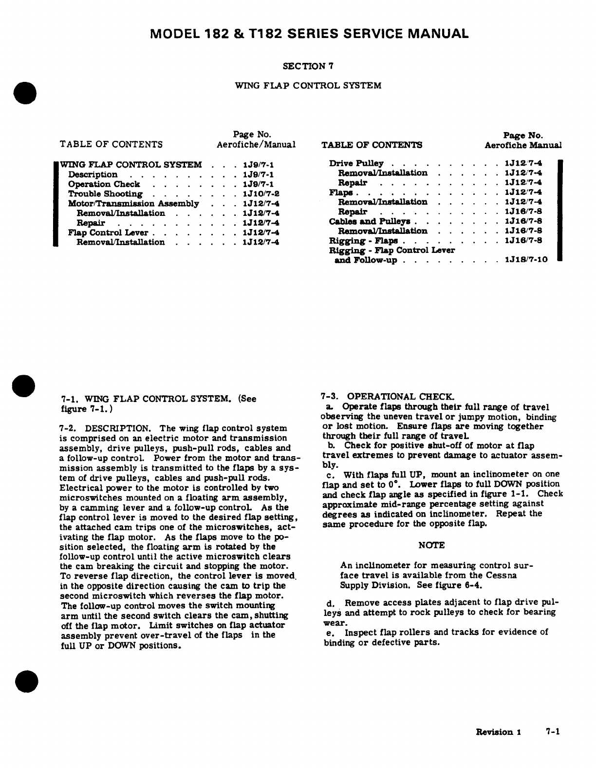
MODEL
182
&
T182
SERIES
SERVICE
MANUAL
SECTION
7
WING
FLAP
CONTROL
SYSTEM
Page
No.
Page
No.
TABLE
OF
CONTENTS
Aerofiche/Manual
TABLE
OF
CONTENTS
Aerofiche
Manual
WING
FLAP
CONTROL SYSTEM
. . .
1J9/7-1
Drive
Pulley
..........
1J12.7-4
Description
..
......
.
1J9/7-1
Removal/Installation
......
1J12/7-4
Operation
Check
........
1J9/7-1
Repair
...........
1J12/7-4
Trouble
Shooting
........
1J10/7-2 Flaps
...........
.
1J12/7-4
Motor/Transmission
Assembly
...
J12/7-4
Removal/Installation
......
J12/7-4
Removal/Installation
......
1J12/7-4
Repair
........... 1J16/7-8
Repair
...........
1J12/7-4
Cables
and
Pulleys.
.......
.
1J16/7-8
Flap
Control
Lever
. ... .
1J12/7-4
Removal/Installation
.. . .
1J16/7-8
Remova/Installation
......
12/7-4
Rigging
-
Flaps
.........
1J16/7-8
Rigging
-
Flap
Control
Lever
and
Follow-up
........
.
1J18/7-10
7-1.
WING
FLAP
CONTROL
SYSTEM.
(See
7-3
OPERATIONAL CHECK
figure
7-1.)
a.
Operate
flaps through
their
full range
of
travel
observing
the
uneven
travel
or
jumpy
motion,
binding
7-2.
DESCRIPTION.
The
wing
flap
control
system
or
lost
motion.
Ensure
flaps
are
moving
together
is
comprised
on an
electric
motor
and
transmission
through
their
full
range
of
travel
assembly,
drive
pulleys,
push-pull
rods,
cables
and
b.
Check
for
positive
shut-off
of
motor
at
flap
a
follow-up
control.
Power
from
the
motor
and
trans-
travel
extremes
to
prevent
damage
to
actuator
assem-
mission
assembly
is
transmitted
to
the
flaps
by
a
sys-
bly.
tem
of
drive
pulleys,
cables
and
push-pull
rods.
c.
With
flaps
full
UP,
mount
an
inclinometer
on one
Electrical
power
to
the
motor
is
controlled
by
two
flap
and
set
to
0°.
Lower
flaps
to
full
DOWN
position
microswitches
mounted
on
a
floating
arm
assembly,
and
check
flap
angle
as
specified
in
figure
1-1.
Check
by
a
camming
lever
and
a
follow-up
control
As
the
approximate
mid-range
percentage
setting
against
flap
control
lever
is
moved to
the
desired
flap
setting,
degrees
as
indicated
on
inclinometer.
Repeat
the
the
attached
cam
trips
one
of
the
microswitches,
act-
same
procedure
for
the
opposite
flap.
ivating
the
flap
motor.
As
the
flaps
move
to
the
po-
sition
selected,
the
floating
arm
is
rotated
by
the
NOTE
follow-up
control
until
the
active
microswitch
clears
the
cam
breaking
the
circuit
and
stopping
the
motor.
An
inclinometer
for
measuring
control
sur-
To
reverse
flap
direction,
the
control
lever
is
moved,
face
travel
is
available
from
the
Cessna
in
the
opposite
direction
causing
the
cam
to
trip
the
Supply
Division.
See
figure
6-4.
second
microswitch
which
reverses
the
flap
motor.
The
follow-up
control
moves
the
switch
mounting
d.
Remove
access
plates
adjacent
to
flap
drive
pul-
arm
until
the
second
switch
clears
the
cam,
shutting
leys
and
attempt
to
rock
pulleys
to
check
for
bearing
off
the
flap
motor.
Limit
switches
on
flap
actuator
wear.
assembly
prevent
over-travel
of
the
flaps
in
the
e.
Inspect
flap
rollers
and
tracks
for evidence
of
full
UP
or
DOWN
positions.
binding
or
defective
parts.
Revision
1
7-1
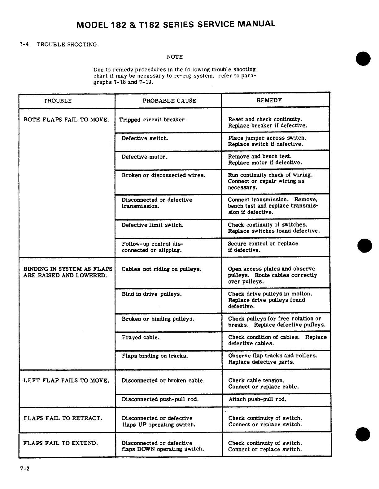
MODEL
182
&
T182
SERIES SERVICE
MANUAL
7-4.
TROUBLE
SHOOTING.
NOTE
Due
to
remedy
procedures
in
the
following
trouble
shooting
chart
it
may
be
necessary
to
re-rig
system,
refer
to
para-
graphs
7-18
and
7-19.
TROUBLE
PROBABLE
CAUSE REMEDY
BOTH
FLAPS
FAIL TO
MOVE.
Tripped
circuit
breaker.
Reset
and
check
continuity.
Replace
breaker
if
defective.
Defective switch.
Place
jumper
across
switch.
Replace
switch
if
defective.
Defective
motor.
Remove
and
bench
test.
Replace
motor
if
defective.
Broken
or
disconnected
wires.
Run
continuity
check
of
wiring.
Connect
or
repair
wiring
as
necessary.
Disconnected
or
defective
Connect
transmission.
Remove,
transmission,
bench
test
and
replace
transmis-
sion
if
defective.
Defective
limit
switch.
Check
continuity
of
switches.
Replace
switches
found
defective.
Follow-up
control
dis-
Secure
control
or
replace
connected
or
slipping.
if
defective.
BINDING IN
SYSTEM
AS
FLAPS
Cables
not
riding
on
pulleys.
Open
access
plates
and
observe
ARE RAISED
AND
LOWERED.
pulleys.
Route
cables
correctly
over
pulleys.
Bind
in
drive
pulleys.
Check
drive
pulleys
in
motion.
Replace
drive
pulleys
found
defective.
Broken
or
binding
pulleys.
Check
pulleys for
free
rotation
or
breaks.
Replace
defective
pulleys.
Frayed
cable.
Check
condition
of
cables.
Replace
defective
cables.
Flaps
binding
on
tracks.
Observe
flap
tracks
and
rollers.
Replace
defective
parts.
LEFT
FLAP
FAILS TO
MOVE.
Disconnected
or
broken
cable.
Check
cable
tension.
Connect
or replace
cable.
Disconnected
push-pull
rod.
Attach
push-pull
rod.
FLAPS
FAIL
TO
RETRACT.
Disconnected
or
defective
Check
continuity
of
switch.
flaps
UP
operating switch.
Connect
or
replace
switch.
FLAPS FAIL
TO
EXTEND.
Disconnected
or
defective
Check
continuity
of
switch.
flaps
DOWN
operating
switch.
Connect
or
replace
switch.
7-2
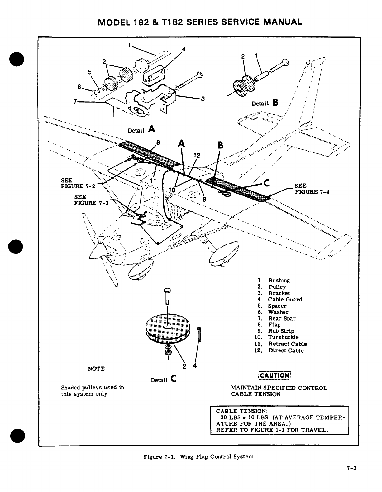
MODEL
182
&
T182
SERIES
SERVICE
MANUAL
2
1
2
/
7
3
De3l
B
Detail
Detal
B.........
'^ *--....··---·-··/. l
.
......
....
6"*- ..... Detail
A..racke
*'' »s~~~~~:-. .*' ""**-
^*-.;
^y
'
'-*.^*yy-
1'"'
"**i">»"\
--
*"";
""""*-.
""*-.:~ ~ ~ ~
~ ~
~~
. ' .
SEE
FIUEFIGURE
7-4
SEE
FIGURE
7-3
1.
Bushing
'*-
2.
Pulley
3.
Bracket
|
4.
Cable
Guard
.^nl I -D e4iln
7.
Rear
SpGar
9.
Rub
Strip
10.
Turnbuckle
11.
Retract
Cable
f
\
12.
Direct
Cable
NOTE
2
4
Detail
C
ICAT---
'
Shaded
pulleys
used
in
MAINTAIN
SPECIFIED
CONTROL
this system
only. CABLE
TENSION
CABLE
TENSION:
30
LBS
±
10
LBS
(AT
AVERAGE
TEMPER-
ATURE
FOR
THE
AREA.)
REFER
TO FIGURE
1-1
FOR
TRAVEL.
Figure
7-1.
Wing
Flap Control
System
7-3
,~ ~~~~~~~~~~2
ietal
...
',-:'
n..
..
:.-":
.. ... ...
........... ~ 4
. ' . ..
:'.·::
... .
.-..
....... : ................. ,~ .....
:.:?".....
......
'........::...
'"--.il
' " .
::.
..
o.4l
" " " .
ShddplesseE
'..
' .., ,
AI
'....IE
,'~,::,...'
...
".':9~'~:.
-.
i
sy
"'e
' '"
'-.
CA.L
":.'.T... -i...~~:':>-,.................
...
~. ~
~
~~~~~~AL
---
4,,'
.-
.~.;~.
..... '-.:::...
..
-~~~~~~~~~3
..
:
... .-.
:-..!.
.-
:..
!VRG
.: ..... ..... -,,
-..
\ .: .... ..... 7-~.~-%;;.HE
ARE. ..,, ..
,....·... .%-.
· ,.
:
.. ..
~~EFE
,...
/-.R
.-
;..
o:o.:OR-'
:,VE.
-.
....
,'"~"'~
'
gur
....
~. ¢~
~
,,~~;,,:.
.....
,oto
_.--
....
.....
.
,'
%':--
".
.....
%
i
.'~?,~'~
";.~ ~-.
..
''.=
...
....
.
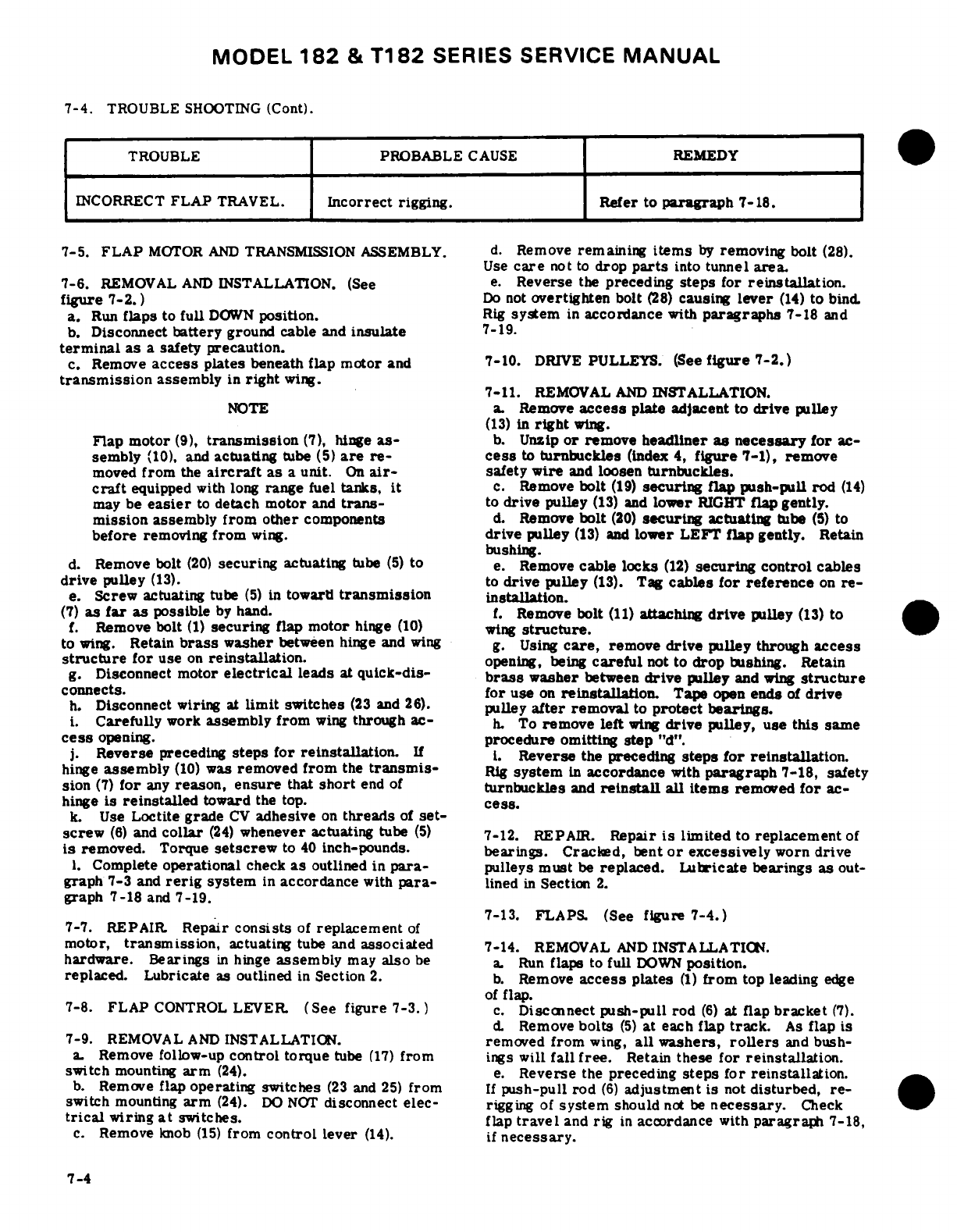
MODEL
182
&
T182
SERIES
SERVICE
MANUAL
7-4.
TROUBLE
SHOOTING
(Cont).
TROUBLE
PROBABLE
CAUSE
REMEDY
INCORRECT
FLAP
TRAVEL.
Incorrect
rigging.
Refer to
paragraph
7-18.
7-5.
FLAP
MOTOR
AND
TRANSMISSION
ASSEMBLY.
d.
Remove
remaining
items
by
removing
bolt
(28).
Use
care
not
to
drop
parts
into
tunnel
area.
7-6.
REMOVAL
AND
INSTALLATION. (See
e.
Reverse
the
preceding
steps
for
reinstallation.
figure
7-2.)
Do
not
overtighten
bolt
(28)
causing
lever
(14)
to
bind.
a.
Run
flaps
to
full
DOWN
position.
Rig
system
in
accordance
with
paragraphs
7-18
and
b.
Disconnect
battery
ground cable
and
insulate
7-19.
terminal
as
a
safety
precaution.
c.
Remove
access
plates
beneath
flap
motor
and
7-10.
DRIVE
PULLEYS.
(See
figure
7-2.)
transmission
assembly
in
right
wing.
7-11.
REMOVAL
AND
INSTALLATION.
NOTE
a.
Remove
access
plate adjacent
to
drive
pulley
(13)
in
right
wing.
Flap
motor
(9),
transmission
(7),
hinge
as-
b.
Unzip
or
remove
headliner
as
necessary
for
ac-
sembly
(10),
and
actuating
tube
(5)
are
re- cess
to
turnbuckles
(index
4,
figure
7-1),
remove
moved
from
the
aircraft
as
a
unit.
On
air-
safety
wire
and
loosen
turnbuckles.
craft
equipped
with long
range
fuel
tanks,
it
c.
Remove
bolt
(19)
securing
flap
push-pull
rod
(14)
may
be
easier
to
detach
motor
and
trans-
to
drive
pulley
(13)
and
lower
RIGHT
flap
gently.
mission
assembly from
other
components
d.
Remove
bolt
(20)
securing
actuating
tube
(5)
to
before
removing
from
wing.
drive
pulley
(13)
and
lower LEFT
flap
gently. Retain
bushing.
d.
Remove
bolt
(20)
securing
actuating
tube
(5)
to
e.
Remove
cable
locks
(12)
securing control
cables
drive
pulley
(13).
to
drive
pulley
(13).
Tag
cables
for reference
on
re-
e.
Screw
actuating
tube
(5)
in
toward
transmission
installation.
(7)
as
far
as
possible
by
hand.
f.
Remove
bolt
(11)
attaching
drive
pulley
(13)
to
f.
Remove bolt
(1)
securing
flap
motor
hinge
(10) wing
structure.
to
wing.
Retain
brass
washer
between
hinge and
wing g.
Using
care,
remove
drive
pulley
through
access
structure
for
use
on
reinstallation.
opening, being
careful
not to
drop
bushing.
Retain
g.
Disconnect
motor
electrical
leads at
quick-dis-
brass
washer
between
drive
pulley
and
wing
structure
connects.
for
use
on
reinstallation.
Tape
open
ends
of
drive
h.
Disconnect
wiring
at
limit
switches
(23
and
26).
pulley
after
removal
to
protect
bearings.
i.
Carefully
work
assembly
from
wing
through
ac- h.
To
remove
left
wing
drive
pulley,
use
this
same
cess
opening.
procedure
omitting
step
"d".
j.
Reverse
preceding
steps
for
reinstallation.
If
i.
Reverse
the
preceding
steps for
reinstallation.
hinge
assembly
(10)
was
removed
from
the
transmis-
Rig
system
in
accordance
with
paragraph
7-18,
safety
sion
(7)
for
any
reason, ensure
that
short
end
of
turnbuckles
and
reinstall
all
items
removed
for
ac-
hinge
is
reinstalled
toward
the top.
cess.
k.
Use
Loctite
grade
CV
adhesive
on
threads
of
set-
screw
(6)
and
collar
(24)
whenever actuating
tube
(5)
7-12.
REPAIR.
Repair
is
limited to replacement
of
is
removed.
Torque
setscrew
to
40
inch-pounds.
bearings. Cracked,
bent
or
excessively
worn
drive
1.
Complete
operational
check
as
outlined in
para-
pulleys
must
be
replaced. Lubricate bearings
as
out-
graph
7-3
and
rerig
system
in
accordance
with
para-
lined
in
Section
2.
graph 7-18
and
7-19.
7-13.
FLAPS. (See
figure
7-4.)
7-7.
REPAIR
Repair
consists
of
replacement
of
motor,
transmission,
actuating
tube
and
associated
7-14.
REMOVAL
AND
INSTALLATION.
hardware.
Bearings
in
hinge
assembly
may
also
be
a.
Run
flaps
to
full
DOWN
position.
replaced.
Lubricate
as
outlined
in
Section
2.
b.
Remove
access
plates
(1)
from
top leading
edge
of
flap.
7-8.
FLAP
CONTROL
LEVER
(See
figure
7-3.)
c.
Disconnect
push-pull
rod
(6)
at flap
bracket
(7).
d.
Remove
bolts
(5)
at
each
flap
track.
As
flap
is
7-9.
REMOVAL
AND
INSTALLATION.
removed
from
wing,
all
washers,
rollers
and
bush-
a.
Remove
follow-up
control
torque
tube
(17)
from
ings
will
fall free.
Retain
these
for
reinstallation.
switch
mounting
arm
(24).
e.
Reverse
the
preceding
steps
for reinstallation.
b.
Remove
flap
operating switches
(23
and
25)
from
If
push-pull rod
(6)
adjustment
is
not
disturbed,
re-
switch
mounting
arm
(24).
DO
NOT
disconnect
elec-
rigging
of
system
should
not
be
necessary.
Check
trical
wiring
at
switches.
flap
travel
and
rig
in
accordance
with
paragraph
7-18,
c.
Remove
knob
(15)
from
control
lever
(14).
if
necessary.
7-4
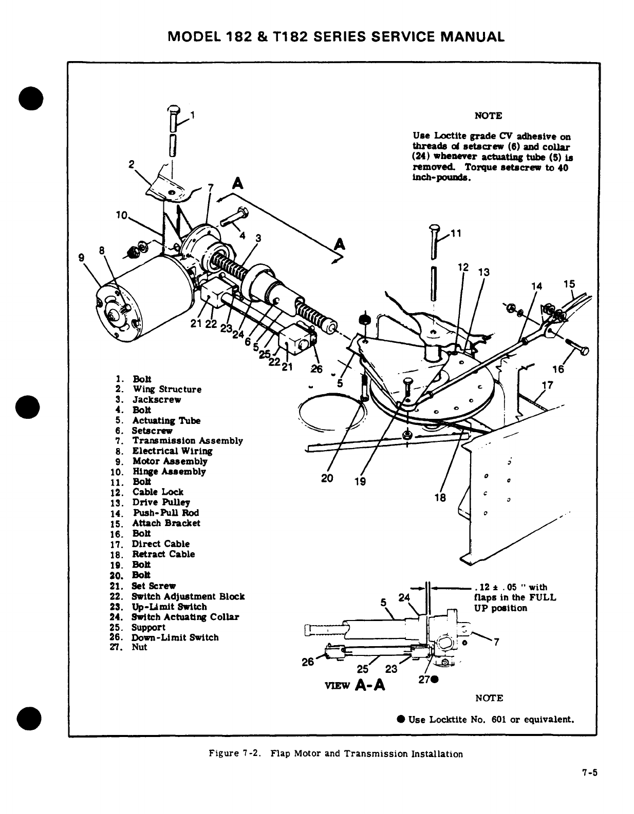
MODEL
182
&
T182
SERIES
SERVICE
MANUAL
Use
Loctite
grade
CV
adhesive
on
threads of
setscrew
(6)
and
collar
(24)
whenever
actuating
tube
(5)
is
2
2.
Wing
Structure
3.
Jackscrew
5.
Jackscrew
4.
Bolt
5.
Actuating
Tube
6.
Setscrew f /
7.
Transmission
Assembly
..
8.
Electrical
Wiring
9.
Motor
Assembly
11.
Bolt
12.
Cable
Lock
13.
Drive
Pulley
14.
Push-Pull
Rod
.
15.
Attach
Bracket
16.
Bolt
17.
Direct
Cable
18.
Retract
Cable
19.
Bolt
20.
Bolt
21.
Set
Screw
22.
Switch
Adjustment
Block
23.
Up-Limit
Switch
UP
position
24.
Switch
Actuating
Collar
25.
Support
-
26.
Down-Limit
Switch
27.
Nut
NOTE
Use
Locktite
No.
601
or equivalent.
Figure
7-2.
Flap
Motor
and
Transmission
Installation
7-5
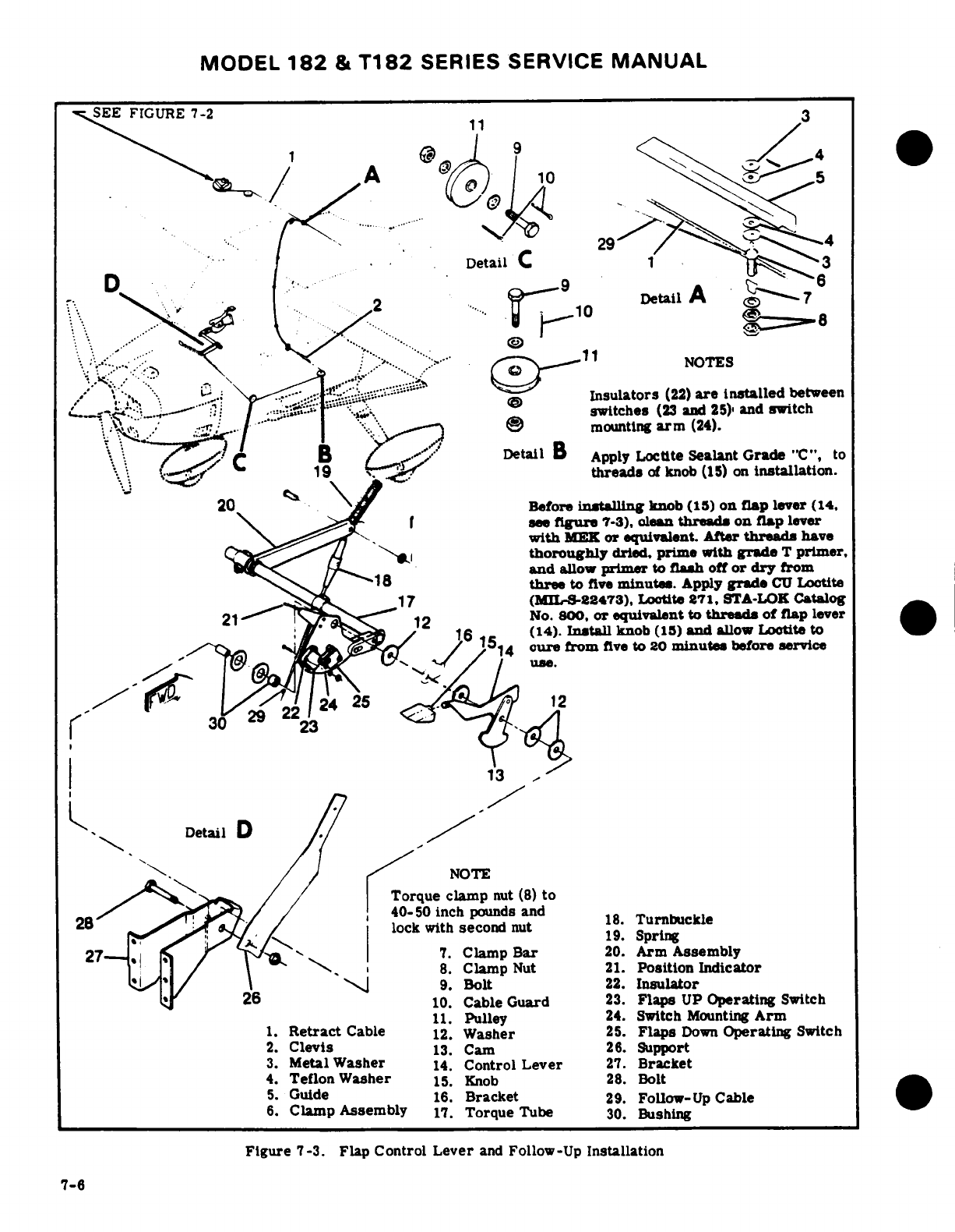
MODEL
182
&
T182
SERIES
SERVICE
MANUAL
SEE
FIGURE
7-2
". " ..
Detail
C 1
A
D
2
Detail
A
6
/V--. , .
1
:?
i,..
>""
rV
-11
NOTES
j ;;\. i>S-,: \
..
;-
;;:.-
H
^ 7
Insulators
(22)
are
installed
between
^. -- :; „.d--- . :
/
^3!
*~-"s
.n
switches
(23
and
25),
and
switch
-..-
*";S.M." f''"
''**-''*^^^}
.
mounting
arm
(24).
B*:.
/- .,Detail
B
Apply
Loctite
Sealant
Grade
"C",
to
'19
threads
of
knob
(15)
on
installation.
20
Before
installing
knob
(15)
on
flap
lever
(14,
\ _r t
bsee
figure
7-3),
olean
threads
on
flap
lever
with
MEK
or
equivalent. After
threads
have
thoroughly
dried,
prime
with
grade
T
primer,
18< \1 a
~
and
allow
primer
to
flash
off
or
dry
from
^^s/y 18 'three
to
five
minutes.
Apply
grade
CU
Loctite
_I4
17
(MIL-S-22473),
Lootite
871,
STA-LOK
Catalog
21
-'" I ' mS^
^
12
0
No.
800.
or
equivalent
to
threads
of
flap
lever
16
e
(14).
Install
knob
(15)
and
allow
Lootito
to
/ C */
/154
cure
from
five
to
20
minutes
before
service
30
29
2224
25
<3 l
' r
13
L
Detail
D
NOTE
Torque clamp
nut
(8)
to
O2~B""
^^
*>»^Sit
j
/40-50
inch
pounds
and
18
Turbuckle
lock
with
second
nut
19.
Spring
\^
^^
'i^U</\
19.
Sprlng
27
7.
Clamp
Bar
20.
Arm
Assembly
/ \ \
8.
Clamp
Nut
21.
Position
Indicator
./ I
9.
Bolt
22.
Insulator
·
-
26
10.
Cable
Guard
23.
Flaps
UP
Operating
Switch
11.
Pulley
24.
Switch
Mounting
Arm
1.
Retract
Cable
12.
Washer
25.
Flaps
Down
Operating
Switch
2.
Clevis
13.
Cam
26.
Support
3.
Metal
Washer
14.
Control
Lever
27.
Bracket
4.
Teflon
Washer
15.
Knob
28.
Bolt
5.
Guide
16.
Bracket
29.
Follow-Up
Cable
6.
Clamp Assembly
17.
Torque
Tube
30.
Bushing
Figure
7-3.
Flap
Control
Lever
and
Follow-Up
Installation
7-6
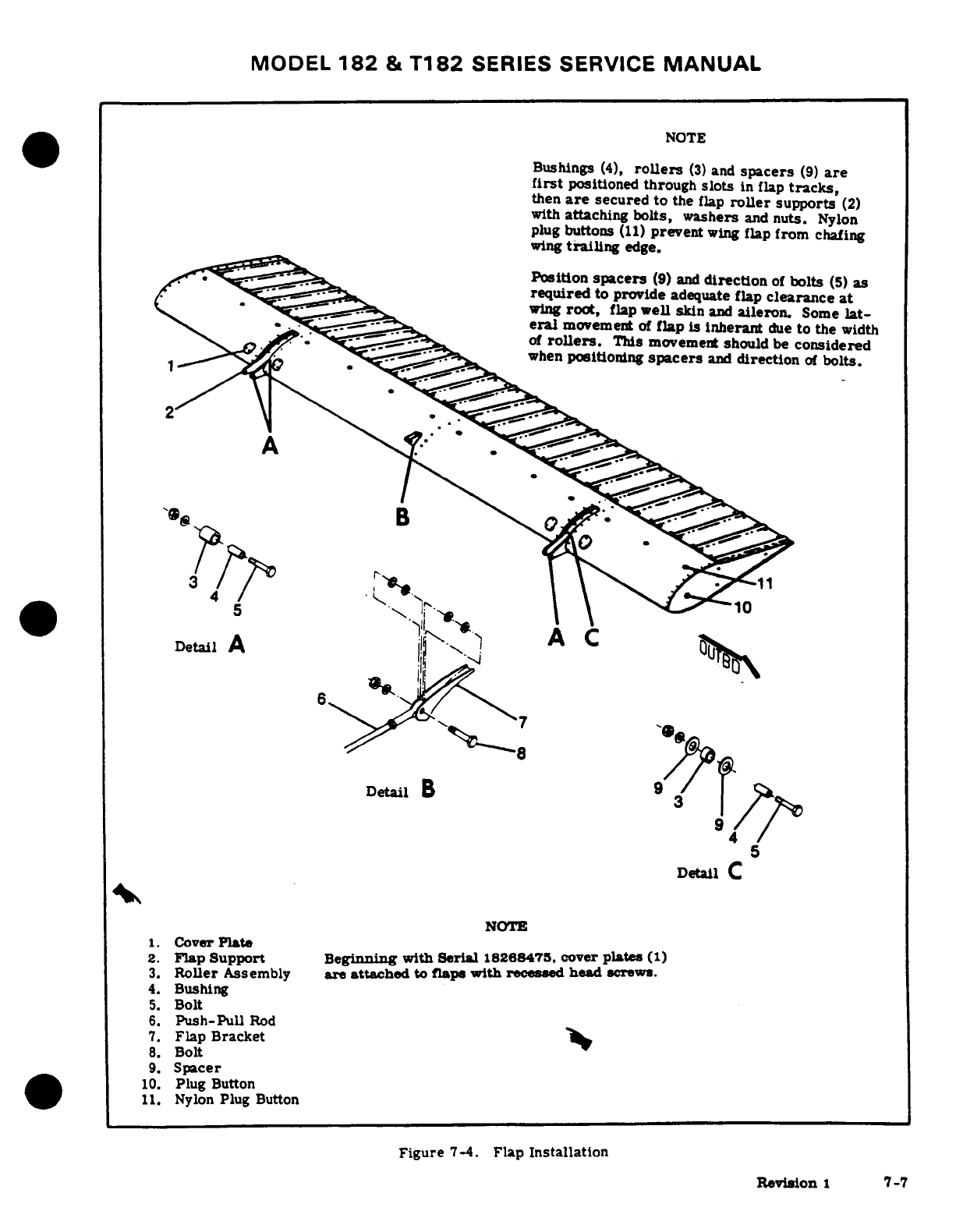
MODEL
182
&
T182
SERIES SERVICE
MANUAL
NOTE
Bushings
(4),
rollers
(3)
and
spacers
(9)
are
first
positioned
through
slots
in
flap
tracks,
then
are
secured to
the
flap
roller
supports
(2)
with
attaching bolts, washers
and
nuts.
Nylon
plug
buttons
(11)
prevent
wing
flap
from
chafing
wing
trailing
edge.
Position
spacers
(9)
and
direction
of
bolts
(5)
as
required
to
provide
adequate
flap
clearance
at
wing
root,
flap
well
skin
and
aileron.
Some
lat-
eral
movement
of
flap
is
inherant
due
to the
width
of
rollers.
This movement
should
be
considered
when
positioning
spacers
and
direction
of
bolts.
Detail
A
6
Detail
B
Detail
C
NOTE
1.
Cover
Plate
2.
Flap
Support Beginning
with Serial
18268475,
cover
plates
(1)
3.
Roller
Assembly
are
attached
to
flaps with
recessed
head
screws.
4.
Bushing
5.
Bolt
6.
Push-Pull
Rod
7.
Flap
Bracket
8.
Bolt
9.
Spacer
10.
Plug
Button
11.
Nylon
Plug
Button
Figure
7-4.
Flap
Installation
Revision
1
7-7

MODEL
182
&
T182
SERIES
SERVICE
MANUAL
DRIVE
PULLEY
FWD
TRANSMISSION
DRIVE
PULLEY
RUB
STRIP-
RUB
STRIP
ACTUATING
TUBE
-
PUSH-PULL
ROD
TURNBUCKLE
PUSH-PULL
ROD
TO
LEFT
TO
RIGHT
WING
FLAP
VIEWED
FROM
ABOVE
WING
FLAP
Figure
7-5.
Flap
System
Schematic
7-15.
REPAIR.
Flap
repair
may
be
accomplished
in
7-18.
RIGGING-FLAPS.
(See
figure
7-2.)
accordance
with
instructions
outlined
in
Section
18.
a.
Unzip
or
remove
headliner
as
necessary
for
ac-
cess
to
turnbuckles
(index
10,
figure
7-1).
7-16.
CABLES
AND
PULLEYS.
(See
b.
Remove
safety
wire, relieve
cable
tension,
dis-
figure
7-1.)
connect
turnbuckles
and
carefully
lower LEFT
flap.
c.
Disconnect
push-pull rods
(14)
at
drive
pulleys
7-17.
REMOVAL
AND
INSTALLATION.
(13)
in
both wings and
lower
RIGHT
flap
gently.
a.
Remove
access
plates,
fairings,
headliner
and
d.
Disconnect
actuating
tube
(5)
from drive
pulley
upholstery
as
necessary
for
access.
(13).
b.
If
retract
cable
(11)
is
to
be
removed,
disconnect
follow-up
cable
at
clamp
(index
6,
figure
7-3).
NOTE
c.
Remove
safety
wire,
relieve
cable
tension,
dis-
connect
turnbuckles
(6)
and
carefully
lower LEFT
If
control
cables
are
not
connected
to
left
flap.
and
right
drive
pulleys,
actuating
tube
(5)
d.
Disconnect
cables
at
drive
pulleys.
remove
and
push-pull
rods
(14)
must
be
discon-
cable
guards
and
pulleys
as
necessary
to
work
cables
nected
before
installing
cables.
If
drive
free
of
aircraft.
pulleys
(13)
are
not
installed.
attach
control
cables before
installing
drive
pulleys
in
the
wings
as
illustrated
in
figure
7-5.
NOTE
e.
The
3/32 inch
retract
cable
connects
to
the
for-
To
ease
routing
of
cables,
a
length
of
wire
ward side
of
the
right drive
pulley
and
to
the
aft
side
may
be
attached
to
the
end of
cable
being
of
the
left
drive
pulley.
The
1/8
inch
direct
cable
withdrawn
from
the
aircraft.
Leave
wire
connects
to
the
aft
side
of
the
right
drive
pulley and
in
place,
routed
through
structure;
then
to
the
forward side
of
the
left
drive
pulley.
attach
the
cable
being
installed
and
use
f.
Adjust
both
push-pull
rods
(14)
to
8.
83±.
12
wire
to
pull
cable
into
posi
ion.
inches
between
centers
of
rod
end
bearings,
and
then
tighten
locknuts
on
both ends.
Connect
push-pull
e.
Reverse
the
preceding
steps
for
reinstallation.
rods
to
flaps
and
drive
pulleys.
f.
After
cables
are
routed
in
position,
install
pul-
leys
and
cable
guards.
Ensure cables
are
positioned
NOTE
in
pulley
grooves
before
installing
guards.
g.
Re-rig
flap
system
in
accordance
with
paragraph
Temporarily
connect
cables
at
turnbuckles
7-18
and
safety
turnbuckles.
(index
10,
figure
7-1)
and
test
flaps
by
hand
h.
Re-rig
follow-up
system
in
accordance
with
para-
to
ensure
both
flaps
extend and
retract
to-
graph
7-19
and
reinstall
all
items
removed
in
step gether.
If
they
will
not,
the
cables
are
in-
"a".
7-8

MODEL
182
&
T182
SERIES SERVICE
MANUAL
correctly
attached
to
the
drive
pulleys.
En-
k.
With
right flap
in
full
UP
position,
loosen
set-
sure
that
the
right
drive
pulley
rotates
clock-
screw
(21)
and
slide
UP -
limit
switch
(23)
and ad-
wise,
when
viewed
from
below,
as
the
flaps
justment
block
(22)
assembly
on
support
(25)
to
acti-
are
extended.
Tag
cables
for
reference
and
vate
switch
(23).
When
switch
(23)
is
activated,
power
disconnect
turnbuckles
again.
is
interrupted
to
flap motor
(9)
during
normal
opera-
tion. After
switch
(23)
is
properly
adjusted, tighten
g.
Screw
actuating
tube
(5)
IN
toward
transmission setscrew
(21).
(7)
by
hand
to.
12±.05
inches
between
switch actu-
1.
Move
right
flap
to
full
DOWN
position,
loosen
ating
collar
(24)
and
transmission
as
illustrated
in
setscrew
(21) on
DOWN
-
limit
switch
(26),
and
move
VIEW
A-A.
Loosen
setscrew
(6)
securing
actuating
switch
(26) on
support
(25)
until
switch
(26)
activates
tube
(5)
to
switch
actuating
collar
(24),
hold
actuating
Adjust
this
switch
action
to
correspond
with
maximum
collar
to
maintain
.
12±.
05",
hold
RIGHT
flap
in
the
flap
extension
as
specified
in
figure
1-1.
After
switch
full
UP
position
and
adjust
actuating
tube
(5)
IN
or
is
properly
adjusted,
tighten
setscrew
(21).
OUT
as
necessary
to
align
with
attachment
hole
in
m.
Run RIGHT
flap
to
full
UP
position,
manually
drive
pulley
(13).
Tighten
setscrew
(6)
in
accordance
hold
LEFT
flap
full
UP
and
connect
control
cables
at
with
procedures
outlined
in
the
following
note
and
turnbuckles
(index
10,
figure
7-1).
Remove
reference
secure
tube
to
drive
pulley
with bolt
(20).
tags
previously
installed
in
step
"f"
as
turnbuckles
are
connected.
NOTE
n. With
flaps
full
UP,
adjust
turnbuckles
to obtain
30±10
pounds
tension
on
cables. Adjust
retract
cable
Apply
Loctite
grade
CV
sealant
to
threads
of
first.
setscrew
(6)
and
torque
to
40
inch-pounds.
NOTE
If
actuating
tube
(5)
is
too
long
to
allow
attachment
to
drive
pulley
after
completion
of
step
"g",
proceed
to
Ensure
cables
are
positioned in
pulley
grooves
step
"h".
and
cable
ends
are
positioned
correctly
at
drive
h.
Disconnect
push-pull
rod
(14)
at
drive
pulley
(13),
pulleys
before
tightening
turnbuckles.
then
connect actuating
tube
(5)
to
drive
pulley.
i.
Manually
hold
RIGHT
flap
in
full
UP
position
and
o.
Disconnect
push-pull
rod
at
left
drive
pulley.
readjust
push-pull
rod
(14)
to
align
with
attachment
Run
motor
to
extend
flaps
approximately
20
°
and
hole
in
drive
pulley.
Connect
push-pull
rod
and
tight-
check
tension
on
each
flap
cable.
If
necessary,
re-
en
locknuts.
adjust
turnbuckles
to
maintain
30±10
pounds
tension
NOTE
p.
Fully
retract
right
flap.
Manually
hold
left
flap
in
full
up
position
and
readjust
push-pull
rod to
align
The
right
flap
and
actuator
must
be
correctly
with
attaching
hole
in
drive
pulley.
Connect
push-pull
rigged
before
cables
and
left
flap
can be
rig-
rod
and
tighten
locknuts.
ged.
q.
After
completion
of
steps
"a" thru
"p",
operate
flaps
and
check
for
positive shut-off
of
flap
motor
j.
Mount
an
inclinometer
on
trailing
edge
of
RIGHT
through
several
cycles.
Check
for specified flap
flap.
travel
with
inclinometer
mounted
on
each
flap
sepa-
rately.
NOTE
NOTE
An
inclinometer
for
measuring
control
sur-
face
travel
is available
from
the
Cessna
Since
the
flap
rollers
may
not
bottom
in the
Supply
Division.
See
figure
6-4.
flap
tracks
with
flaps
fully
extended,
some
free
play
may
be noticed
in
this
position.
SHOP
NOTES:
7-9
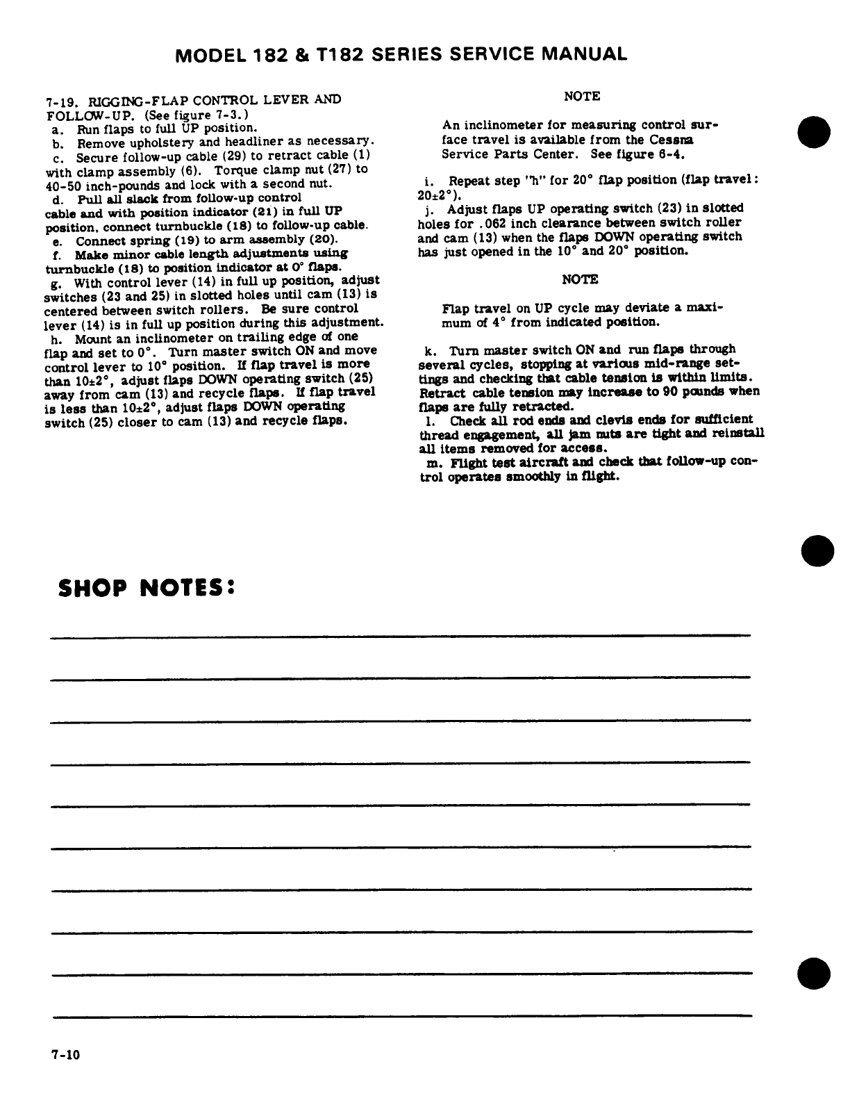
MODEL
182
&
T182
SERIES SERVICE
MANUAL
7-19.
RIGGING-FLAP
CONTROL
LEVER
AND
NOTE
FOLLOW-UP.
(See
figure
7-3.)
a.
Run
flaps
to
full
UP
position.
An
inclinometer
for
measuring control
sur-
b.
Remove
upholstery
and
headliner
as
necessary.
face
travel
is
available
from
the
Cessna
c.
Secure
follow-up
cable
(29)
to
retract
cable
(1)
Service
Parts
Center.
See
figure
6-4.
with
clamp
assembly
(6).
Torque clamp
nut
(27)
to
40-50
inch-pounds
and
lock
with
a second
nut.
i. Repeat
step
"h"
for
20°
flap
position
(flap
travel:
d.
Pull
all
slack
from
follow-up
control
20±2°).
cable
and with
position
indicator
(21)
in
full
UP
j.
Adjust
flaps
UP
operating
switch
(23)
in
slotted
position, connect
turnbuckle
(18)
to
follow-up
cable.
holes
for
.062
inch
clearance
between
switch
roller
e.
Connect
spring
(19)
to
arm
assembly
(20).
and
cam
(13)
when the
flaps
DOWN
operating
switch
f.
Make
minor
cable
length
adjustments
using
has
just
opened
in
the
10
°
and
20
°
position.
turnbuckle
(18)
to
position
indicator
at
0°
flaps.
g.
With
control
lever
(14)
in
full
up
position,
adjust
NOTE
switches
(23
and
25)
in
slotted
holes
until
cam
(13)
is
centered
between
switch
rollers.
Be
sure
control
Flap
travel
on
UP
cycle
may
deviate
a
maxi-
lever
(14)
is
in
full
up
position
during
this
adjustment.
mum
of
4°
from
indicated
position.
h.
Mount
an
inclinometer
on
trailing
edge
of
one
flap
and
set
to
0°.
Turn
master
switch
ON
and
move
k.
Turn
master
switch
ON
and
run
flaps
through
control
lever
to
10
°
position.
If
flap
travel
is
more
several
cycles,
stopping
at
various
mid-range
set-
than
10±2
°,
adjust
flaps
DOWN
operating
switch
(25)
tings
and
checking
that
cable
tension
is
within
limits.
away
from
cam
(13)
and
recycle flaps.
If
flap
travel
Retract
cable
tension
may
increase
to
90
pounds
when
is
less
than
10±2
°,
adjust
flaps
DOWN
operating
flaps
are
fully
retracted.
switch
(25)
closer
to
cam
(13)
and
recycle
flaps.
1.
Check
all
rod
ends
and
clevis
ends
for
sufficient
thread
engagement,
all
jam
nuts
are
tight
and
reinstall
all
items
removed
for
access.
m.
Flight
test aircraft
and check
that
follow-up
con-
trol
operates
smoothly
in
flight.
SHOP
NOTES:
7-10
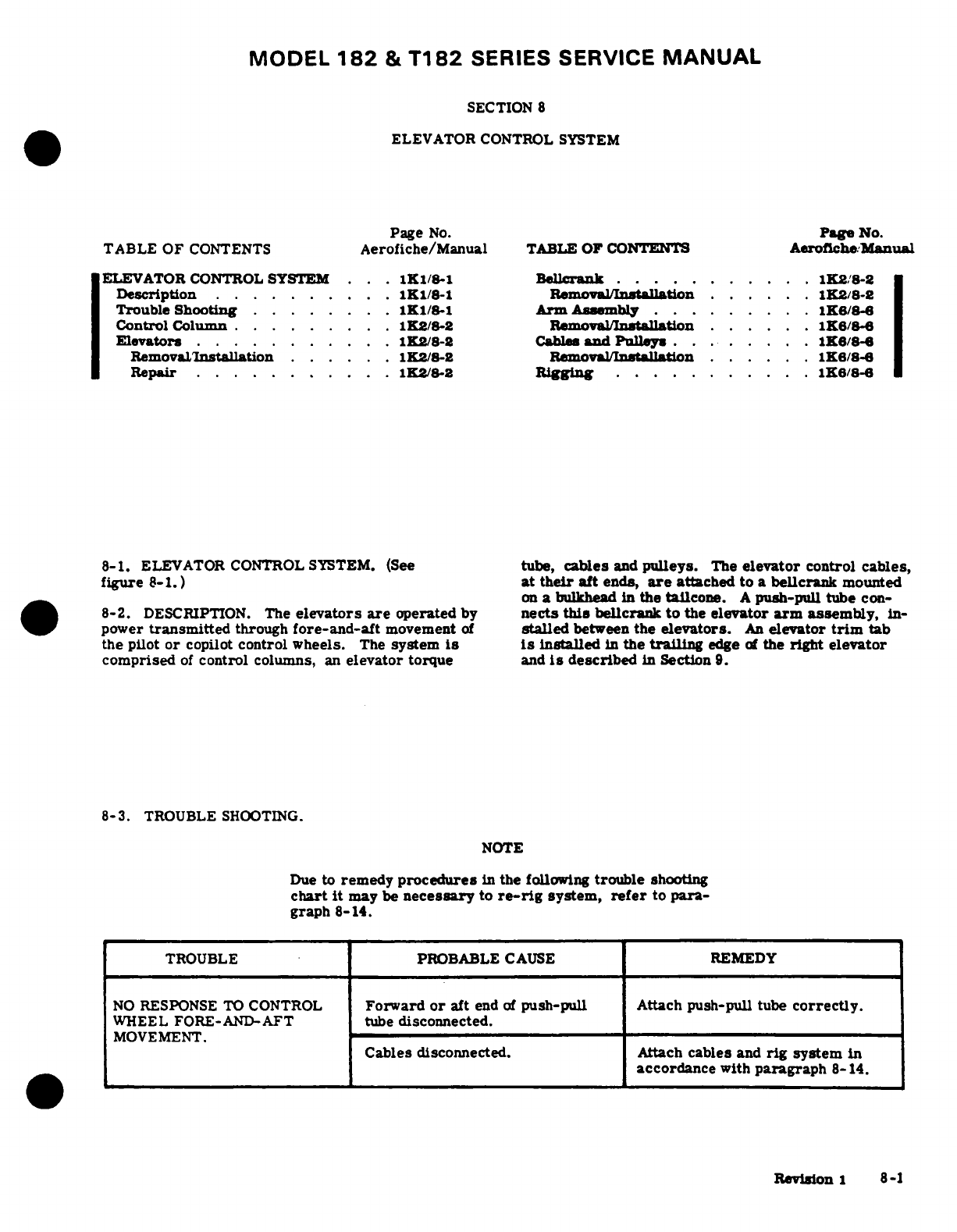
MODEL
182
&
T182
SERIES
SERVICE
MANUAL
SECTION
8
ELEVATOR
CONTROL
SYSTEM
Page
No.
Page
No.
TABLE
OF
CONTENTS
Aerofiche/Manual
TABLE
OF
CONTENTS
Aerofiche/Manual
ELEVATOR
CONTROL SYSTEM
..
1K1/8-1
Bellcrank
...........
1K2/8-2
Description
..........
1K1/8-1
Removal/Installation
......
1K2/8-2
Trouble
Shooting
........
1K1/8-1
Arm
Assembly
.........
1K6/8-6
Control Column
.
........
1K2/8-2
Removal/Installation
......
1K6/8-6
Elevators
.. .
....
.
1K2/8-2
Cables
and
Pulleys
.. . . ..
1K6/8-
RemovaLInstallation
......
1K2/8-2
Removal
Installtion
Repair
..........
1K2/8-2
Rigging
...........
1K/8
8-1.
ELEVATOR
CONTROL SYSTEM.
(See
tube,
cables
and
pulleys.
The
elevator
control
cables,
figure
8-1.)
at
their
aft
ends,
are
attached to
a
bellcrank
mounted
on
a
bulkhead in
the
tailcone.
A
push-pull
tube
con-
8-2.
DESCRIPTION.
The
elevators
are
operated
by
nects
this
bellcrank
to
the
elevator
arm
assembly,
in-
power
transmitted
through
fore-and-aft
movement
of
stalled
between
the
elevators.
An
elevator
trim
tab
the
pilot
or
copilot
control
wheels.
The
system
is is
installed
in
the
trailing
edge
of
the
right elevator
comprised
of
control
columns,
an
elevator
torque
and
is
described
in
Section
9.
8-3.
TROUBLE
SHOOTING.
NOTE
Due
to
remedy
procedures
in
the
following
trouble
shooting
chart
it
may be
necessary
to
re-rig
system,
refer
to
para-
graph
8-14.
TROUBLE PROBABLE
CAUSE
REMEDY
NO
RESPONSE
TO
CONTROL
Forward
or
aft
end
of
push-pull
Attach
push-pull
tube
correctly.
WHEEL
FORE-AND-AFT
tube
disconnected.
MOVEMENT.
Cables disconnected.
Attach
cables
and
rig
system
in
accordance
with
paragraph
8-14.
Revision
1
8-1
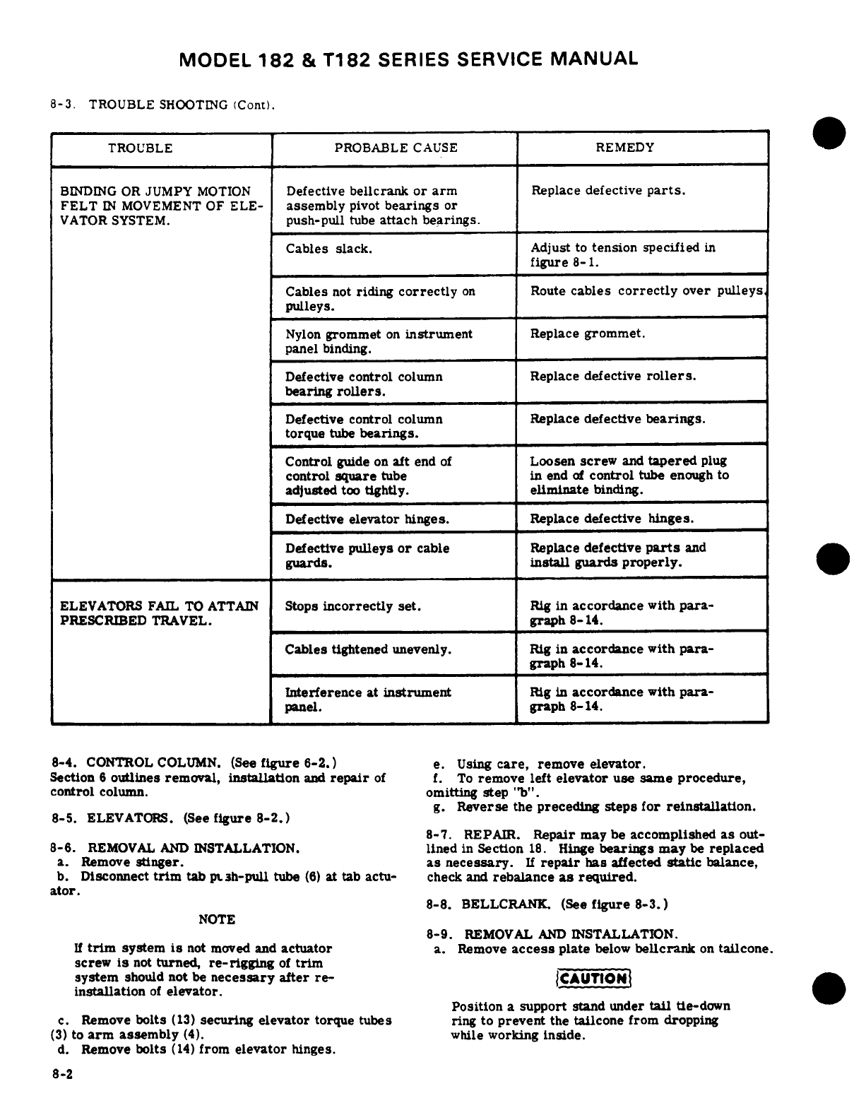
MODEL
182
&
T182
SERIES
SERVICE
MANUAL
8-3.
TROUBLE
SHOOTING
(Cont).
TROUBLE
PROBABLE
CAUSE
REMEDY
BINDING
OR
JUMPY
MOTION
Defective
bellcrank
or arm
Replace
defective
parts.
FELT
IN
MOVEMENT
OF
ELE-
assembly
pivot
bearings
or
VATOR SYSTEM.
push-pull
tube
attach
bearings.
Cables slack.
Adjust
to
tension specified
in
figure
8-1.
Cables
not
riding
correctly
on
Route
cables
correctly
over pulleys
pulleys.
Nylon
grommet
on
instrument
Replace
grommet.
panel
binding.
Defective
control
column
Replace
defective
rollers.
bearing
rollers.
Defective
control
column
Replace
defective
bearings.
torque
tube
bearings.
Control
guide
on
aft
end
of
Loosen
screw
and
tapered
plug
control
square
tube
in
end
of
control
tube
enough
to
adjusted
too
tightly.
eliminate
binding.
Defective
elevator
hinges.
Replace
defective
hinges.
Defective
pulleys
or
cable Replace
defective
parts
and
guards.
install
guards
properly.
ELEVATORS
FAIL
TO
ATTAIN
Stops
incorrectly
set.
Rig
in
accordance
with
para-
PRESCRIBED
TRAVEL.
graph
8-14.
Cables
tightened
unevenly.
Rig
in
accordance
with
para-
graph 8-14.
Interference
at
instrument
Rig
in
accordance
with
para-
panel.
graph
8-14.
8-4.
CONTROL
COLUMN.
(See
figure
6-2.)
e.
Using
care,
remove
elevator.
Section
6
outlines
removal,
installation
and
repair
of
f.
To
remove left
elevator
use
same
procedure,
control
column.
omitting
step
"b".
8-5.
ELEVATORS.
(See
figure
8-2.)
8-7.
REPAIR.
Repair
may
be
accomplished
as
out-
8-6.
REMOVAL
AND
INSTALLATION.
lined
in
Section
18.
Hinge
bearings
may
be
replaced
a.
Remove
stinger.
as
necessary.
If
repair
has
affected
static
balance,
b.
Disconnect
trim
tab
push-pull
tube
(6)
at
tab
actu-
check and
rebalance
as
required.
ator.
8-8.
BELLCRANK.
(See
figure 8-3.)
NOTE
8-9.
REMOVAL
AND
INSTALLATION.
If
trim
system
is
not
moved
and
actuator
a.
Remove
access
plate
below
bellcrank
on
tailcone.
screw
is
not
turned,
re-rigging
of
trim
system
should
not
be
necessary after
re-
installation
of
elevator.
Position
a
support
stand
under
tail
tie-down
c.
Remove
bolts
(13)
securing
elevator
torque tubes
ring
to
prevent
the
tailcone
from dropping
(3)
to
arm
assembly
(4).
while
working
inside.
d.
Remove
bolts
(14)
from
elevator
hinges.
8-2
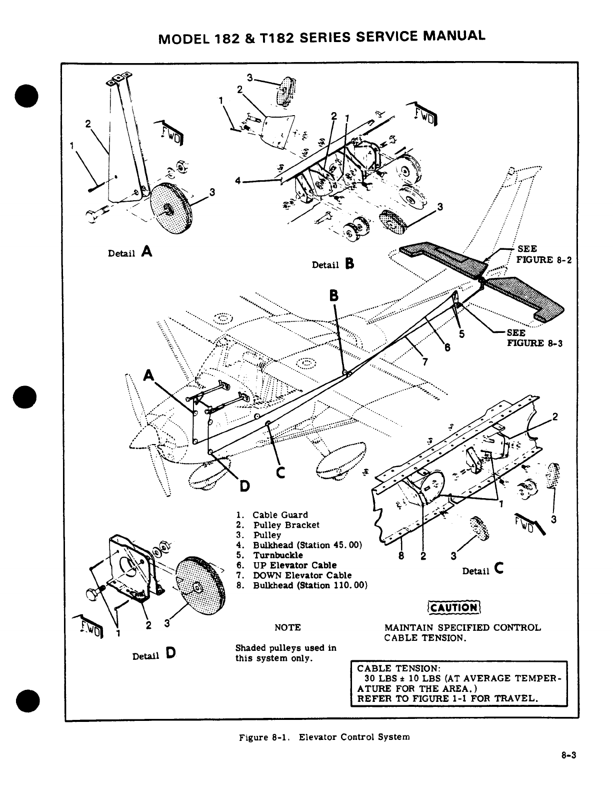
MODEL
182
&
T182
SERIES
SERVICE
MANUAL
1
.Detail
B
***.....FIGURE
8-2
'<D
-'
< 1 V TPj"'- -
6-
UP
Elevator
Cable
D
1
7.
DOWN
Elevator
Cable
Detaild
.'W^N^
>i
X^^N^
8.
Bulkhead
(Station
110.00)
\T.
/'°"CAUTION:
r&l 1
2 3
NOTE
MAINTAIN
SPECIFIED
CONTROL
CABLE
TENSION.
DelD Shaded
pulleys
used
in
Detail
D
this
system
only.
CABLE
TENSION:
30
LBS
*
10
LBS
(AT
AVERAGE
TEMPER-
ATURE
FOR
THE
AREA.)
REFER
TO
FIGURE
1-1
FOR
TRAVEL.
Figure
8-1.
Elevator Control
System
8-3
.,"..~~~~~~~~~AL '":IO.
"
'..
·
ealDSae uly sdi
...
£..!,.~. ~m
only
..
~ ~ ~C
BL
TESO::..., ·.
..
~.:~~~3 :': :
;..?"ATAERGETMP
'TR O TEAE....
t~~~~EE
OFGR
~..~-'" ....
'
V...
......
igre8-.
El:'to
Coto
~
::::::::~
~:- ?: ;i: .....?
::::?:.
..........
~~8-
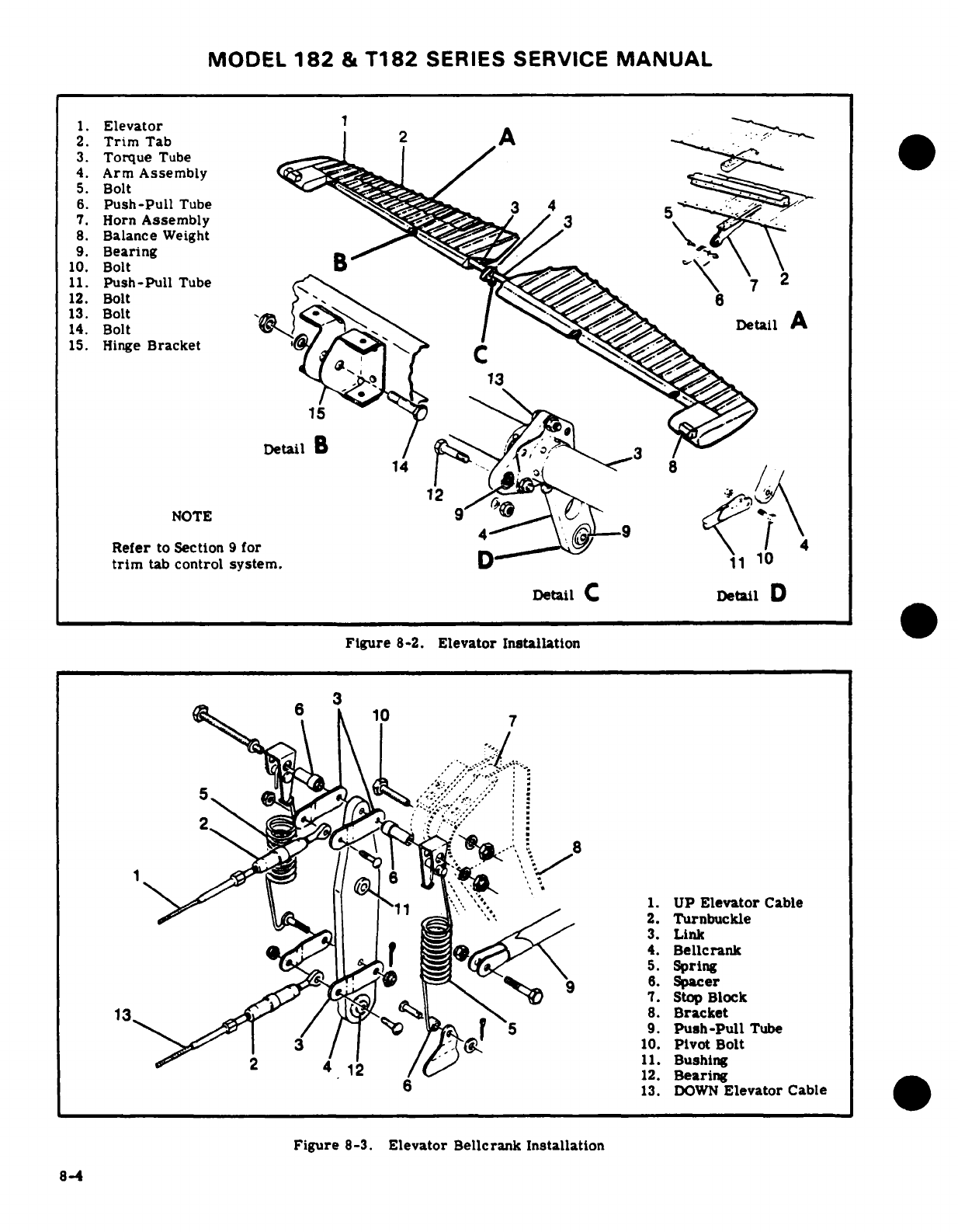
MODEL
182
&
T182
SERIES
SERVICE
MANUAL
1.
Elevator
2.
Trim
Tab
2
A
3.
Torque
Tube
4.
Arm
Assembly
5. Bolt
6.
Push-Pull
Tube
3
7.
Horn
Assembly
8.
Balance
Weight
9.
Bearing
10.
Bolt
11.
Push-Pull
Tube
12.
Bolt
13.
Bolt
14.
Bolt
Detail
A
15.
Hinge
Bracket
Detail
B
14
8
12
NOTE
9
Refer
to
Section
9
for
trim
tab
control
system.
11
Detail
C
Detail
D
Figure
8-2.
Elevator
Installation
1.
UP
Elevator
Cable
13 'ss^,3~ ~ .^'^S
5
~
9.
Push-Pull
Tube
6I
3
/
/
r
}o
o
10.
Pivot
Bolt
4
2 1
2
/t
'11.
Bushing
~~~~~~~4 12 /{12.
Bearing
~~~~~6 ~13.
DOWN
Elevator
Cable
Figure
8-3.
Elevator Bellcrank
Installation
8-4
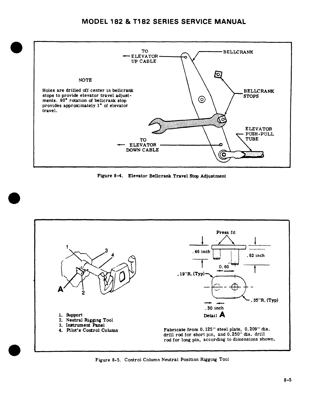
MODEL
182
&
T182
SERIES
SERVICE
MANUAL
E
LEVATOR
UP
CABLE
NOTE
Holes
are
drilled
off
center
in
bellcrank
BELLCRANK
stops
to
provide
elevator
travel
adjust-
STOPS
ments.
90°
rotation
of
bellcrank stop
provides
approximately
1°
of
elevator
travel.
TO
-- ELEVATOR
DOWN
CABLE
Figure
8-4.
Elevator
Bellcrank
Travel
Stop
Adjustment
Press
fit
3
.46
inch
.30
inch
1.
Support
Detail
A
2.
Neutral
Rigging Tool
3.
Instrument
Panel
4.
Pilot's
Control
Column
Fabricate
from
0.
125"
steel
plate,
0.209"
dia.
drill
rod
for
short
pin,
and
0.250"
dia.
drill
rod
for
long
pin,
according
to
dimensions
shown.
Figure
8-5.
Control
Column
Neutral
Position
Rigging
Tool
8-5
MODEL-
182
&
T182
SERIES SERVICE
MANUAL
b.
Remove
safety wire,
relieve
cable
tension
at
place, routed
through
structure;
then
at-
turnbuckles
(2)
and
disconnect
turnbuckle
eyes
at
tach
the
cable
being
installed
and
pull
cable
bellcrank links
(3).
into
position.
c.
Disconnect
elevator
down-springs
(5)
at
bell-
f.
After
cable
is
routed
in
position,
install
pulleys
crank
(4).
and
cable
guards.
Ensure
cable
is
positioned
in
d.
Disconnect
push-pull
tube
(9)
at
bellcrank
(4).
pulley
groove
before
installing
guards.
e.
Remove pivot
bolt
(10)
attaching
bellcrank
(4)
g.
Re-rig
system
in
accordance
with
paragraph
to
brackets
(8).
Remove
bellcrank.
8-14,
safety
turnbuckles
and
reinstall
all
items
f.
Reverse
the
preceding
steps
for
reinstallation.
removed
in
step
"a".
Rig
system
in
accordance
with
paragraph
8-14,
safety
turnbuckles
and
reinstall
all
items
removed
8-14.
RIGGING.
(See
figure
8-3.)
for
access.
8-10.
ARM
ASSEMBLY.
(See
figure
8-2.)
Position
a
support
stand
under
tail
tie-down
8-11.
REMOVAL
AND
INSTALLATION.
ring
to
prevent
the
tailcone
from
dropping
a.
Remove
stinger.
while
working
inside.
b.
Remove
bolt
(10)
securing
push-pull
tube
(11)
to
arm
assembly
(4).
a.
Streamline
elevators,
mount
an
inclinometer
on
c.
Remove
bolts
(13)
attaching
elevator
torque
tubes
one
elevator
and
set
to
0°.
(3)
to
arm
assembly
(4).
d.
Remove pivot
bolt
(12)
securing
arm
assembly
NOTE
(4)
and
slide
assembly
from
between
elevator
torque
tubes.
An
inclinometer
for
measuring control
sur-
e.
Reverse
the
preceding
steps
for
reinstallation
face
travel
is
available
from
the
Cessna
and
reinstall
all
items
removed
for
access.
Supply
Division.
See
figure
6-4.
8-12.
CABLES
AND
PULLEYS.
(See
figure
b.
Lock
control
column
in
neutral
position per
8-1.)
figure
8-5.
c.
Adjust
bellcrank
stop
blocks
(7)
at
brackets
(8)
8-13.
REMOVAL
AND
INSTALLATION.
to
degree
of
travel
specified
in
figure
1-1.
Position
a
support
stand under
tail
tie-down
The
bellcrank
stop
blocks
(7)
are
four-sided
ring
to
prevent
the
tailcone
from
dropping
bushings,
drilled
off-center
so
they
may
be
while
working
inside.
rotated
to
any
one
of
four
positions
to
attain
correct
elevator
travel.
Each
90-degree
ro-
a.
Remove
seats,
upholstery
and
access
plates
as
tation
of
the
stop, changes
the
elevator
travel
necessary.
approximately
one
degree.
b.
Remove
safety
wire
and
relieve
cable
tension
at
turnbuckles
(5).
d.
Adjust
turnbuckles
(2)
equally to
tension
specified
c.
Disconnect
cables
at
control
column
arm
assem-
in
figure
8-3
blies
(index
18,
figure
6-2).
e.
Check
sponge
at
control
column
in
both
UP
and
d.
Disconnect
cables
at
bellcrank
links
(index
3,
DOWN
positions
and
if
necessary,
readjust turn-
figure 8-3).
buckles
(2)
to
prevent
the
control
column
from
hitting
e.
Remove
cable
guards
and
pulleys
as
necessary
the
instrument
panel
or
firewall.
to
work
cables
free
of
aircraft.
f.
Safety
turnbuckles
and
reinstall
all
items
re-
NOTE
moved
for
access.
NOTE
To
ease
routing
of
cables,
a
length
of
wire
may
be
attached
to
the
end
of
cable being
Be
sure
elevators
move
in
the
correct
direc-
withdrawn
from
aircraft.
Leave
wire
in
tion
when
operated
by
the
control
wheel.
SHOP
NOTES:
8-6
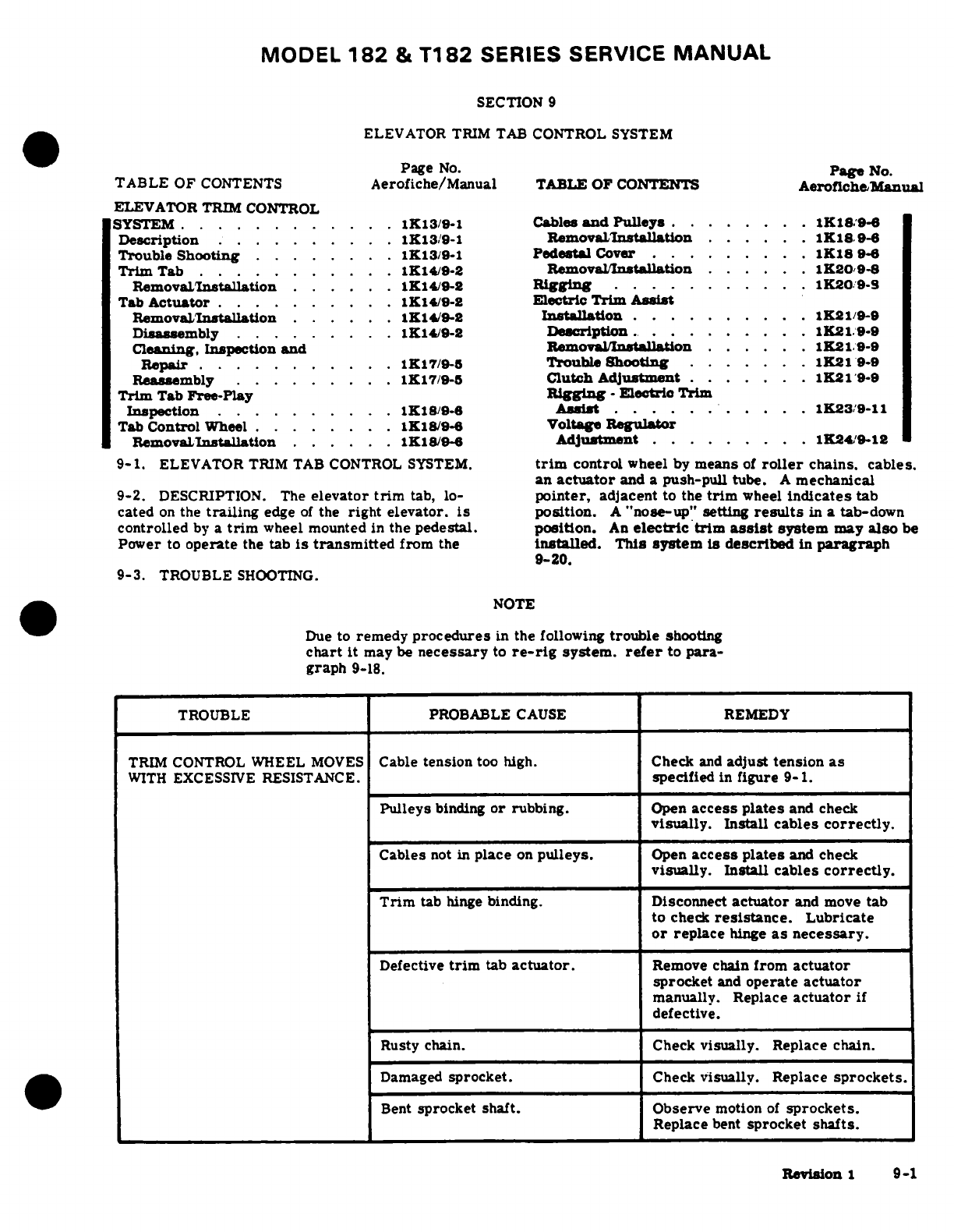
MODEL
182
&
T182
SERIES
SERVICE
MANUAL
SECTION
9
ELEVATOR
TRIM
TAB
CONTROL
SYSTEM
Page
No.
Page
No.
TABLE
OF
CONTENTS
Aerofiche/Manual
TABLE
OF
CONTENTS
Aerofiche/Manual
ELEVATOR
TRIM
CONTROL
SYSTEM
............
1K13/9-1
Cables
and
Pulleys
... ...
1K18/9-6
Description
..........
1K13/9-1
Removal/Installation
......
1K18/9-6
Trouble
Shooting
........
1K13/9-1
Pedestal
Cover .
........
1K18
9-6
Trim
Tab
.........
.
1K14/9-2
Remova/Installation
......
1K20,9-8
Removal/Installation
..
....
K14/9-2
Rigging
...........
1K20/9-8
Tab
Actuator
..........
1K14/9-2
Electric
Trim Assist
Removal/Installation
......
1K14/9-2
Installation
..........
1K21/9-9
Disassembly
.........
1K14/9-2
Description
..........
1K21.9-9
Cleaning,
Inspection
and
Removal/Installation
......
1K21/9-9
Repair
...........
1K17/9-5
Trouble
Shooting
.......
1K21/9-9
Reassembly
.........
1K17/9-5
Clutch
Adjustment
.......
1K21/9-9
Trim
Tab
Free-Play
Rigging
-
Electric
Trim
Inspection
..........
1K18/9-6
Assist
.
........
.
1K23/9-11
Tab
Control
Wheel
........
.
1K18/9-6
Voltage
Regulator
Removal/Installation
.....
.
1K18/9-6
Adjustment
.........
1K249-12
9-1.
ELEVATOR
TRIM
TAB
CONTROL
SYSTEM.
trim
control
wheel
by
means
of
roller
chains, cables.
an
actuator
and
a
push-pull
tube.
A
mechanical
9-2.
DESCRIPTION. The
elevator
trim
tab, lo-
pointer,
adjacent
to
the
trim
wheel
indicates
tab
cated
on
the
trailing
edge
of
the
right elevator.
is
position.
A
"nose-up"
setting
results
in
a
tab-down
controlled
by
a
trim
wheel
mounted in
the
pedestal.
position.
An
electric
trim
assist
system
may
also
be
Power
to
operate
the
tab
is
transmitted
from
the
installed.
This
system
is
described
in
paragraph
9-20.
9-3.
TROUBLE
SHOOTING.
NOTE
Due
to
remedy
procedures
in
the
following
trouble
shooting
chart
it
may be
necessary
to
re-rig
system.
refer
to
para-
graph
9-18.
TROUBLE PROBABLE
CAUSE
REMEDY
TRIM CONTROL
WHEEL
MOVES
Cable
tension
too
high.
Check
and
adjust
tension
as
WITH
EXCESSIVE RESISTANCE.
specified
in
figure
9-1.
Pulleys
binding
or
rubbing.
Open
access plates
and
check
visually.
Install
cables
correctly.
Cables
not
in
place
on
pulleys.
Open
access plates
and check
visually. Install cables
correctly.
Trim
tab
hinge
binding.
Disconnect
actuator
and
move
tab
to
check
resistance.
Lubricate
or
replace
hinge
as
necessary.
Defective
trim
tab
actuator.
Remove
chain
from
actuator
sprocket
and
operate
actuator
manually.
Replace
actuator
if
defective.
Rusty
chain. Check
visually.
Replace chain.
Damaged
sprocket.
Check
visually.
Replace
sprockets.
Bent
sprocket
shaft.
Observe
motion
of
sprockets.
Replace
bent
sprocket
shafts.
Revision
1
9-1
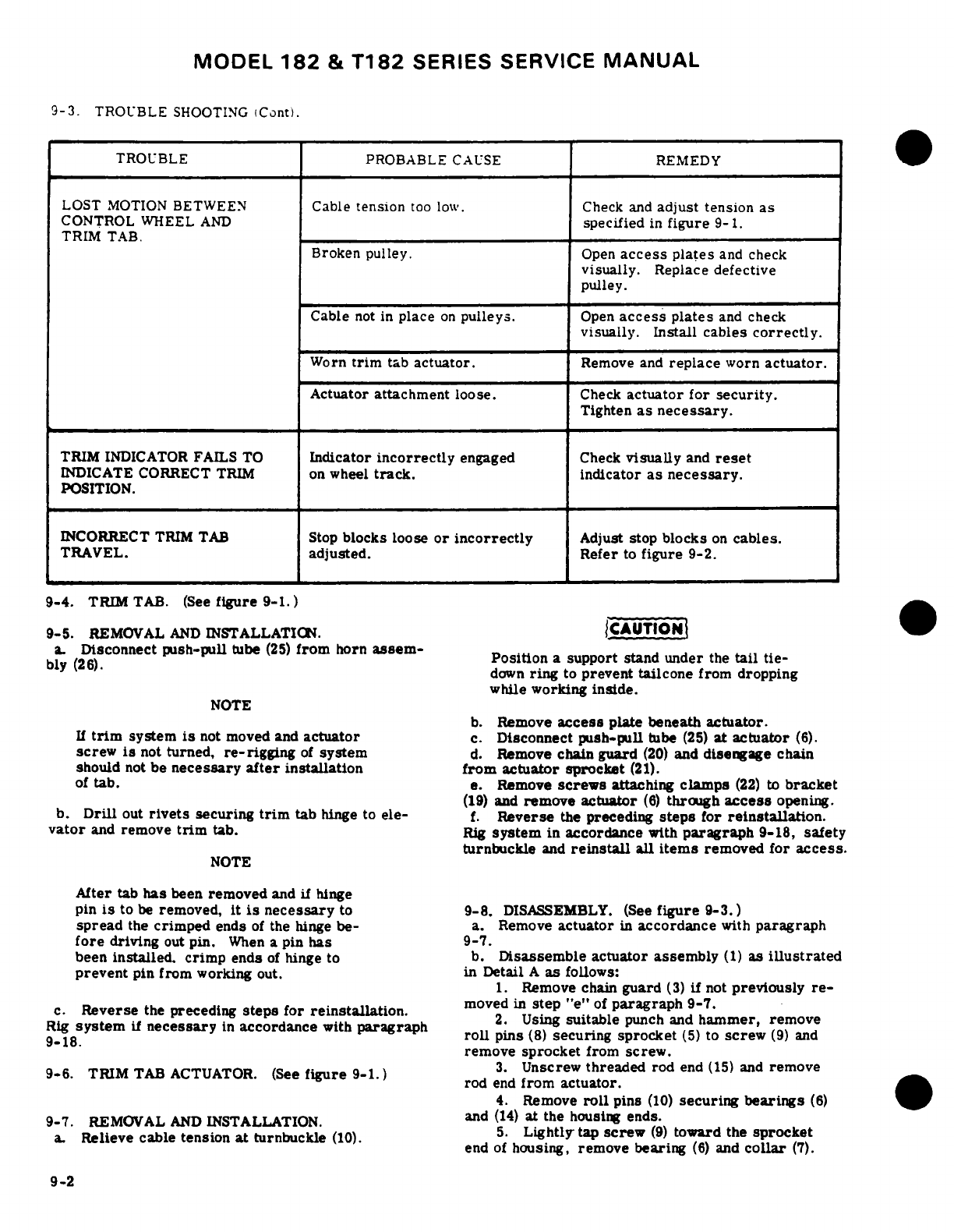
MODEL
182
&
T182
SERIES SERVICE
MANUAL
9-3.
TROUBLE
SHOOTING (Cont).
TROUBLE
PROBABLE
CAUSE
REMEDY
LOST
MOTION
BETWEEN
Cable
tension
too
low.
Check
and
adjust
tension
as
CONTROL
WHEEL
AND
specified
in
figure
9-1.
TRIM
TAB.
Broken pulley.
Open
access
plates
and
check
visually.
Replace defective
pulley.
Cable
not
in
place
on
pulleys.
Open
access
plates
and
check
visually.
Install
cables
correctly.
Worn
trim
tab
actuator.
Remove
and
replace
worn
actuator.
Actuator
attachment
loose.
Check
actuator for
security.
Tighten
as necessary.
TRIM
INDICATOR
FAILS
TO
Indicator
incorrectly
engaged
Check
visually
and
reset
INDICATE
CORRECT
TRIM
on
wheel
track.
indicator
as
necessary.
POSITION.
INCORRECT
TRIM
TAB
Stop
blocks loose
or
incorrectly
Adjust stop
blocks
on
cables.
TRAVEL.
adjusted.
Refer
to
figure
9-2.
9-4.
TRIM
TAB. (See
figure
9-1.)
9-5.
REMOVAL
AND
INSTALLATION.
a.
Disconnect
push-pull
tube
(25)
from
horn
assem-
bly
(26).
Position
a
support stand
under
the
tail
tie-
down
ring
to
prevent
tailcone
from
dropping
while
working
inside.
NOTE
b.
Remove
access
plate
beneath
actuator.
If
trim
system
is
not
moved
and
actuator
c.
Disconnect
push-pull
tube
(25)
at
actuator
(6).
screw
is
not
turned,
re-rigging
of
system
d.
Remove
chain
guard
(20)
and
disengage
chain
should
not
be
necessary
after
installation from actuator sprocket
(21).
of
tab.
e.
Remove
screws
attaching
clamps
(22)
to
bracket
(19)
and
remove
actuator
(6)
through
access
opening.
b.
Drill
out
rivets
securing
trim
tab
hinge
to
ele-
f.
Reverse
the
preceding
steps
for
reinstallation.
vator
and
remove
trim
tab.
Rig
system
in
accordance
with
paragraph
9-18,
safety
turnbuckle
and
reinstall
all items
removed
for
access.
NOTE
After
tab
has
been
removed
and
if
hinge
pin
is
to
be
removed,
it is
necessary
to
9-8.
DISASSEMBLY.
(See
figure
9-3.)
spread
the
crimped
ends
of
the hinge
be-
a.
Remove
actuator
in
accordance
with
paragraph
fore
driving
out
pin.
When
a
pin
has 9-7.
been
installed.
crimp
ends
of
hinge
to
b.
Disassemble actuator assembly
(1)
as
illustrated
prevent
pin
from
working
out.
in
Detail
A
as
follows:
1.
Remove
chain
guard
(3)
if
not
previously
re-
c.
Reverse
the
preceding
steps
for
reinstallation.
moved
in
step
"e"
of
paragraph
9-7.
Rig
system
if
necessary
in
accordance
with
paragraph
2.
Using
sutable
punch
and
hammer,
remove
remove
sprocket
from
screw.
9-6.
TRIM
TAB
ACTUATOR.
(See
figure
9-1.)
3.
Unscrew
threaded
rod
end
(15)
and
remove
rod
end
from
actuator.
4.
Remove
roll
pins
(10)
securing bearings
(6)
9-7.
REMOVAL
AND
INSTALLATION.
and
(14)
at
the
housing
ends.
a.
Relieve cable tension
at
turnbuckle
(10).
5.
Lightly tap
screw
(9)
toward
the
sprocket
end
of
housing,
remove bearing
(6)
and
collar
(7).
9-2
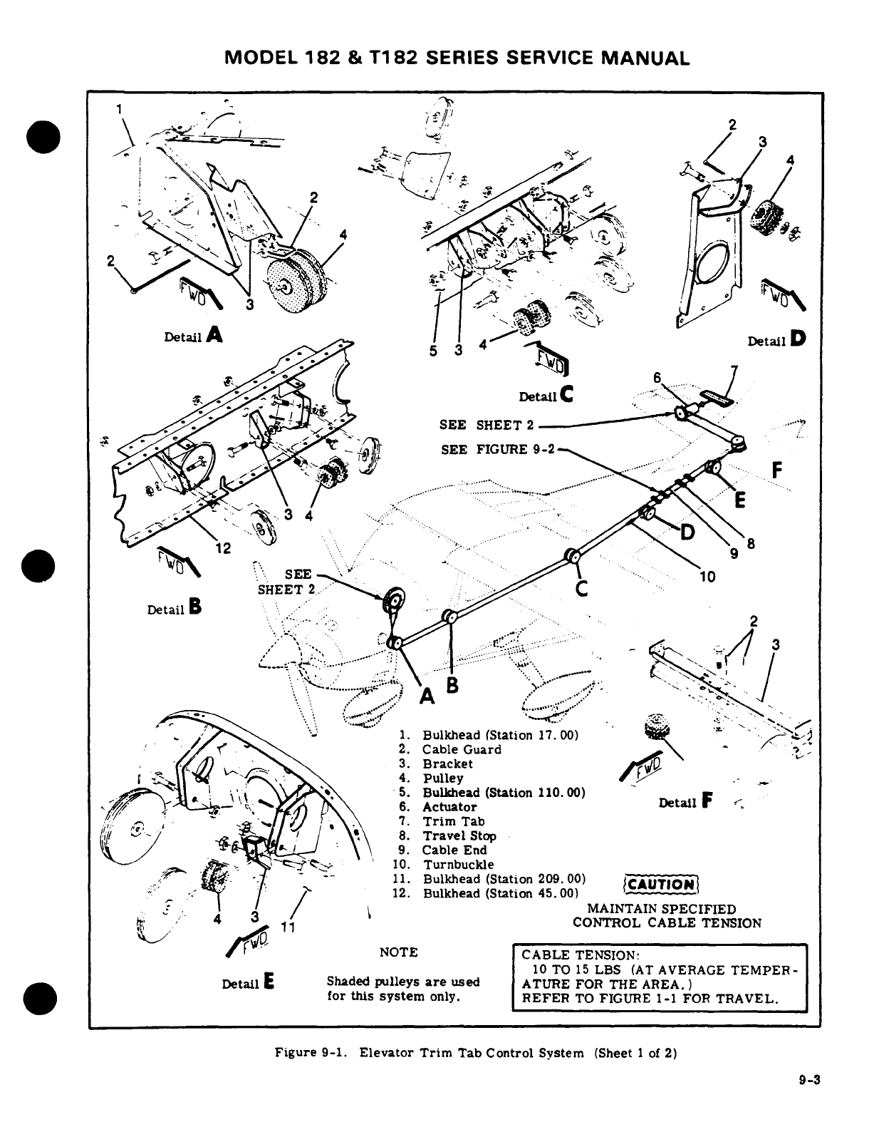
MODEL
182
&
T182
SERIES
SERVICE
MANUAL
_ _ _ _ _ _
3
-?.
--
^It.4:
'
/
"
8
,--E
T2.
....
%...
:,
........
..
......
'
..
*\ \
/
/2
S\10
S
-'.
....
.
....
S1.
Bulkhead
(Station
1R
0)
3
((. \ 3
Bracket.
..
.5.
Bulchea
(Sta
io
II
-,I
C
^. \\.92.
Cable
End
S4EET
32l0.
Turnbuckle
\¥--7^^
A"
/
......
**:
,?
*'
>
s
'
12
--
"11.
Bulkhead
(Station
21.
00)
r
..
SHE.......
.
.
: "/2'
Cable
Guard'
"
'
·
,-"
-
4
-'
.- ' " ' · 2
y-;' , ,.
iBulkhead
(Station
110.00)
1'
8.
Travel
Stop
:
4
<
011
CONTROL
CABLE
TENSION
NOTE
CABLE
TENSION:
10
TO
15
LBS
(AT
AVERAGE
TEMPER-
Detail
E
Shaded
pulleys
are
used
ATURE
FOR
THE
AREA.)
for
this
system
only.
REFER
TO
FIGURE
1-1
FOR
TRAVEL.
Figure
9-1.
Elevator
Trim
Tab
Control
System
(Sheet I
of
2)
9-3
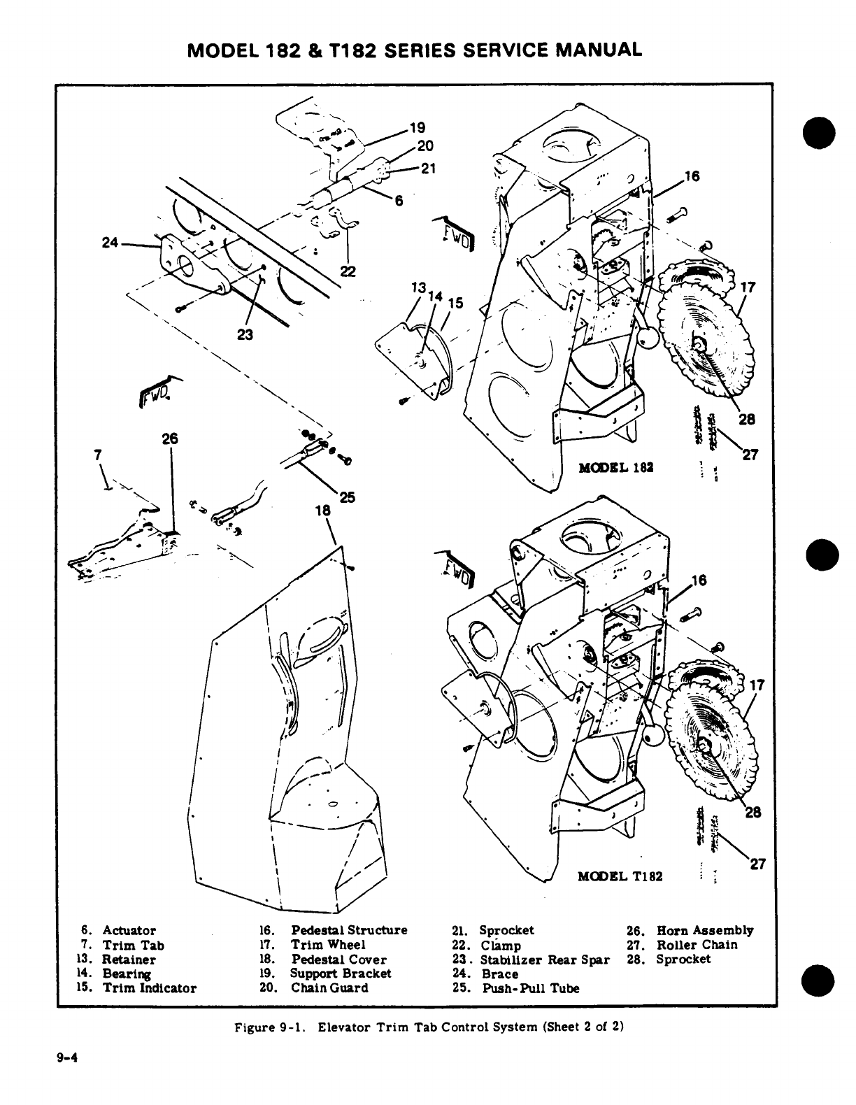
MODEL
182
&
T182
SERIES
SERVICE
MANUAL
-
24
26
7
dy^\ I2
\4 9j t*
>
x \t~ ai) i iMODEL182
18
170A
*
No
6.
Actuator
16.
Pedestal
Structure
21.
Sprocket
26.
Horn
sembly
7.
Trim
Tab
17.
Trim
Wheel
22.
Clmp
27.
Roller
Chain
13.
Retainer
18.
Pedestal
Cover
23.
Stabilizer
Rear
Spar
28.
Sprocket
14.
Bearing
19.
Support
Bracket
24.
Brace
15.
Trim
Indicator
20.
ChainGuard
25.
Push-Pull
Tube
Figure 9-1.
Elevator
Trim
Tab
Control
System
(Sheet
2
of
2)
9-4
9-4

MODEL
182
&
T182
SERIES
SERVICE
MANUAL
,
FWD
a
1.
With
elevators
in
neutral.
set
trim
tab
to
neutral
(streamlined).
2.
Position
stop
blocks
(2
and
3)
against
cable
ends
and
secure
to
cable
A.
3.
Place
inclinometer
on
trim
tab
and
lower
to
degree
specified
in
figure
1-1.
4.
Position
stop
block
(4)
against
stop
block
(3)
and
secure
to cable
B.
5.
Raise
trim
tab
to
specified
degree. place
stop
block
(1)
against
stop
block
(2)
and
secure
to
cable
B.
Figure
9-2.
Elevator
Trim
Tab
Travel
Stop
Adjustment
6.
Lightly
tap
screw
(9)
in
the
opposite
direc-
NOTE
tion
from
sprocket
end,
remove bearing
(14),
O-ring
(13)
and
collar
(7).
Relative
linear
movement between
Internal
7.
It
is
not
necessary
to
remove
retaining rings
threaded
screw
(9)
and
bearing
(14)
should
^^ ( ~~~~~~11
L~).
~be
0.004
to
0.010
inch
at room
temperature.
99.
CLEANING,
INSPECTION
AND
REPAIR.
e.
Examine
threaded
rod end
(15)
and
screw
(9)
(See
figure 9-3.)
for
damaged
threads
or
dirt
paricles
that
may
a.
DC
NOT
remove
bearing
(16)
from
threaded
rod
impair
smootb
operation.
end
(15)
unless
replacement
of
bearing
is
necessary.
f.
Check
sprocket
(5)
for
broken,
chipped
and.
or
b.
Clean
all
component
parts,
except
bearing
(16),
worn
teeth.
by
washing
in
Soddard
solvent
or
equivalent.
Do
not
g.
Check
bearing
(16)
for
smoothness
of
operation.
clean
sealed
bearing
(16).
h.
DO
NOT
attempt to
repair
damaged
or
worn
c.
Inspect
all
component
parts
for
obvious
indica-
parts
of
the
actuator
assembly.
Discard all
defec-
tions
of
damage
such
as
stripped
threads,
cracks,
tive
items
and
install
new
parts
during
reassembly.
deep
nicks
and
dents.
d.
Check
bearings
(6
and
14),
screw
(9)
and
thread-
ed
rod
end
(15)
for
excessive
wear
and
scoring.
Dimensions
of
the
parts
are
as
follows:
BEARING
(6)
9-10.
REASSEMBLY. (See
figure
9-3.)
INSIDE
IIAMETER
0.373"
MIN.
a.
XwaIfsicard
the
following
items
and
install
INSIDE
DIAMETER
0.
374"
MAX.
new
parts
during
reassembly.
BEARING
(14)
1.
Bearings
(6
and
14)
INSIDE
DIAMETER
2.
Roll
Pins
(8
and
10)
SMALL
HOLE
0.248"
MIN.
3.
O-Ring
(13)
SMALL
HOLE
0.249"
MAX.
4.
Nuts
(2).
LARGE
HOLE
0.
373"
MIN.
b.
During
reassembly,
lubricate
collars
(7),
screw
LARGE
HOLE
0.374"
MAX.
(9)
and
threaded
rod
end
(15)
in
accordance
with
Section
2.
THREADED
ROD
END
(15) c.
Press
sprocket
(5)
into
the
end of
screw
(9),
OUTSIDE
DIAMETER
align
roll
pin
holes
and
install
new
roll
pins
(8).
(SHANK)
0.245"
MIN.
d.
Slip
bearing
(6)
and
collar
(7)
on
screw
(9)
and
0.246"
MAX.
slide
them
down
against
sprocket
(5).
e.
Insert
screw
(9),
with
assembled
parts,
into
SCREW
(9)
housing
(12)
until
bearing
(6)
is
flush
with
the
end
of
OUTSIDE
DIAMETER
0.369"
MIN.
housing.
0.
370"
MAX.
9-5
MODEL
182
&T182
SERIES
SERVICE
MANUAL
NOTE
When
inserting
screw
(9)
into
housing
(12)
Position
a
support
stand under the
tail
locate
the
sprocket
(5)
at
the
end
of
housing tie-down
ring
to
prevent tailcone
from
which
is
farther
away
from
the
groove
for
dropping
while
working
inside.
retaining
ring
(11).
b.
Remove
pedestal
cover
(18)
in
accordance
with
The
bearings
(6
and
14)
are
not
pre-drilled
paragraph
9-16.
and
must
be
drilled
on
assembly.
The
roll
c.
Remove
screws
attaching
control
wheel
retainer
pins
(10)
are
3/32
inch
in
diameter,
there-
(13)
to
left
side
of
pedestal
structure
(16).
fore,
requiring
a
3/32
(0.094)
inch
drill.
d. Remove
retainer
(13)
and
indicator
(15),
using
care
not
to
drop
trim
wheel
(17).
f.
Withbearing(6)
flushwithend
ofhousing(12),
e.
Disengage
roller
chin
(27) from
sprocket
(28)
carefully
drill
hearing
so
the drill
will emerge
from
the
and
trim
wheel
(17).
hole
on
the
opposite
side
of
housing
(12).
DO
NOT
ENLARGE
HOLES IN
HOUSING.
NOTE
g.
Pres
new
roll
pins
(10)
into
pin
holes.
h.
Insert
collar
(7),
new O-ring
(13)
and
bearing
Removal
of
the
sprocket
(7)
from
control
(14)
into
opposite
end
of
housing
12).
wheel
shaft
is
not recommended except
for
i.
Complete
steps
and
"g"
for
bearing
(14).
replacement
of
part.
j.
If a
new
bearing
(16)
is
required, a
new
bearing
may
be
pressed
into
the
b.
Be
sure
force
bears
f
Reverse
the
preceding
steps
for
reinstallation.
against
the
outer
race of
bearing. Rig
system
in
accordance
with
paragrph
9-18.
safety
k.
Screw
the
threaded
rod
end
(15)
into
screw
(9).
turnbuckle
and
reinstall
all
items
removed
for
access.
l.
Install
retaining
rings
(11),ifthey
were
re-
moved.
9-14.
CABLES
AND
PULLEYS.
(See
figure
9-1.)
m.
Test
actuator
assembly
by
rotating
sprocket
(5)
with
fingers
while
holding
threaded
rod end
(15).
The
9-15.
REMOVAL
AND
INSTALLATION.
threaded
rod
end
should
travel
in
and
out
smoothly
a.
Remove
seats,
upholstery,
pedestal
cover
and
with
no
indication
of
binding.
access
plates
as
necessary.
Reinstall
acuator
assembly
in
9-11.
TRIM
TAB
FREE-PLAY
INSPECTION.
Position
a
support
stand
under the
tail
a.
Place
elevator
and
trim
tab
in
neutral
position
tie-down
ring
to
prevent
tailcone
from
and
secure elevator
from
movement.
dropping
while
working
inside.
b.
Determine
m
imum
amount
of allowable
free-
play
using
procedures
shown
in
figure
9-2A.
b.
Remove
travel
stop
blocks
(8)
from control
c.
Using
moderate
hand pressure (up
and
down),
cables.
measure
free-ply
at
trailing
edge
of
trim
tab.
c.
Disconnect
control
cables
at
turnbuckles(10)
d.
If
trim
tab freeplay
is
less
than
maximum
al-
and
at
cable
ends
(9).
lowable,
the
system
is within
prescribed
limits.
d.
Remove
cable
guards
and
pulleys
as
necessary
to
e.
If
trim
tab
free-play is
more
than
maximum
al-
work
cables
free
of
aircraft
Disengage
roller
chains
lowable.
check
the
following
items
for
looseness
while
from
sprocket to
ease
cable
removal.
moving
trim
tab
up
and
down.
1.
Check
push-pull
tube
to
trim
tab
horn
as-
NOTE
sembly
attachment
for looseness.
2.
Check
push-pull
tube
to
actuator
assembly
To
ease
routing
ofcables,
a
length
of
wire
threaded
rod
end
attachment
for
looseness
may
be
attched
to
end
of
the
cable
before
3.
Check
actuator
assembly
threaded
rod
end
being
withdrawn
from
aircraft
Leave
for
looseness
in
the
actuator
assembly
with
push-pull
wire
in
place,
routed
through
structure;
tube
disconnected.
then
attach
the
cable
being
installed
and
f.
If
looene
is
apparent
while
checking
steps
e-1
pull
cable into
position.
and
e-2,
repair
by
installing
new
parts.
g.
If
looseness
is
apparent
while
checking
step
e-3.
e.
After
cable
is
routed
in
position,
install
pulleys
refer
to
paragraphs
9-6
through
9-10.
Recheck
trim
and
cable
guards.
Ensure
cable
is positioned
in
pulley
tab
free-play.
groove
before
installing
guards.
Ensure roller
chains
are
positioned
correctly
over
sprockets.
9-12.
TRIM
TAB CONTROL
WHEEL.
(See
figure
f.
Re-rig
system
in accordance
with
paragraph
9-1.)
9-18,
safety
turnbuckle
and
reinstall
all
items
re-
moved
in
step
a".
9-13
REMOVAL
AND
INSTALLATION.
a.
Relieve
cable
tension
at
turnbuckle
(10)
9-16.
PEDESTAL
COVER.
(Seefigure
9-1.)
9-6
Revision
3
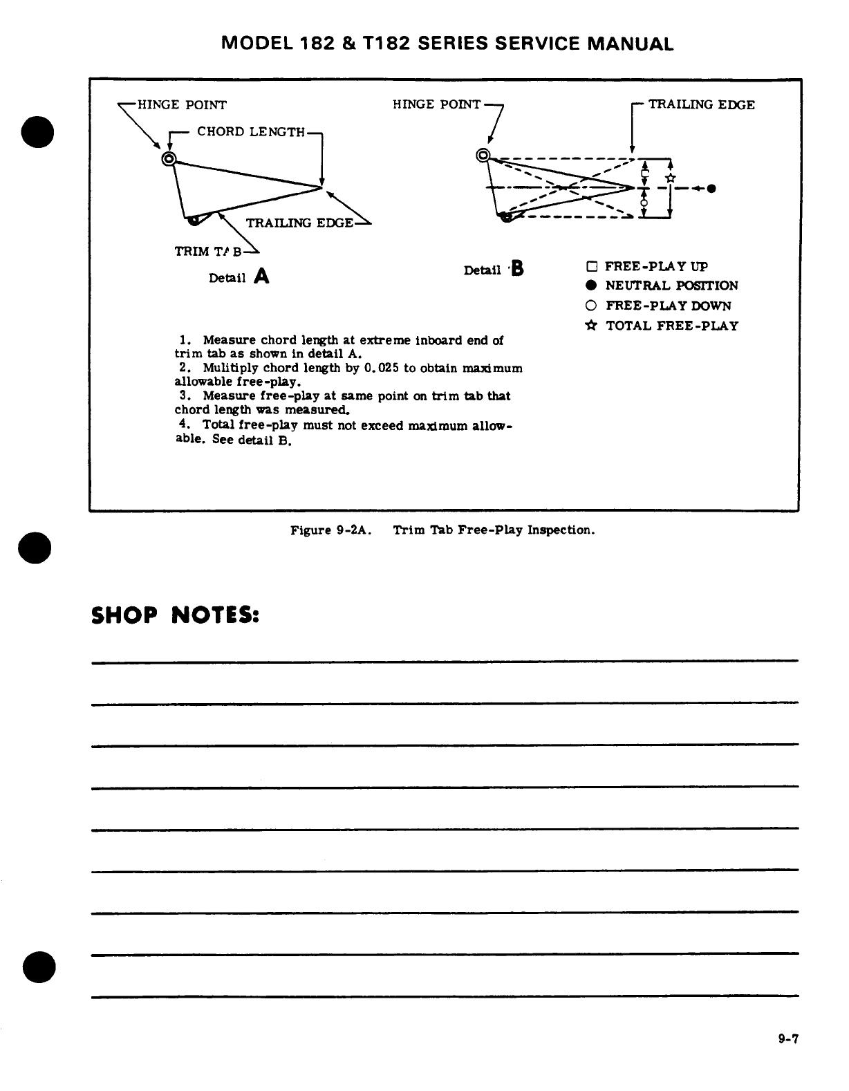
MODEL
182
&
T182
SERIES
SERVICE
MANUAL
HINGE
POINT
HINGE
POINT -TRAILING EDGE
CHORD
LENGTH
TRIM
TAB
Detail
A
Detail
B
FREE-PLAY
UP
NEUTRAL POSITION
FREE-PLAY
DOWN
TOTAL
FREE-PLAY
1.
Measure
chord
length
at extreme
inboard
end
of
trim
tab
as
shown
in
detail
A.
2.
Mulitiply
chord
length
by
0.025
to
obtain
maximum
allowable
free-play.
3.
Measure
free-play
at
same
point
on
trim
tab
that
chord
length
was
measured.
4.
Total
free-play
must
not
exceed
maximum
allow-
able.
See
detail
B.
Figure
9-2A.
Trim
Tab
Free-Play
Inspection.
SHOP
NOTES:
9-7

MODEL
182
&
T182
SERIES
SERVICE
MANUAL
NOTE
Used
with
electric
trim
assist
installation
-w 1
\
11
,
16
'«
A
=
^
< \. \
15
8\
z
A
d
z
"
I \\ 14
1.
Actuator
Assembly
2.
Nut
10
7
3.
Chain
Guard
4.
Screw
12
5.
Sprocket
6.
Bearing
7.
Collar
8.
Pin
9.
Screw
8
8
4`\
10.
pin
rg
\\ \
7 3
UffW
\8'
11.
Retaining
Ring
i \ \
6
\ \
»
A
12.
Housing
~\ ~~\ \ \ ~
f
~>^ \f0
7
13.
O-Ring
4\\ \4
5
14.
Bearing
Detail
A
\3
/
/
15.
Threaded
Rod
End
2
2
16.
Bearing
Figure
9-3.
Elevator
Trim
Tab
Actuator
Assembly
9-17.
REMOVAL
AND
INSTALLATION.
e.
Rotate
trim
control
wheel
(17)
full
forward
(nose
a.
Remove fuel
selector
valve
handle
and
placard.
down).
Ensure
pointer
(15)
does
not
restrict
wheel
b.
Remove
mike
and
remove
mike mounting
bracket.
movement.
If
necessary,
reposition pointer
using
a
c.
Remove
cowl
flap
control
knob.
thin
screwdriver
to
pry
trailing
leg
of
pointer
out
of
d.
Disconnect
electrical
wiring
to
pedestal lights,
groove.
e.
Remove
screws
securing
pedestal
cover
to
structure
and
remove
cover.
NOTE
f.
Reverse
the
preceding
steps
for
reinstallation.
Full
forward
(nose
down)
position
of
trim
9-18.
RIGGING.
(See
figure
9-1.)
wheel
is
where
further
movement
is
pre-
vented
by
the
chain
or
cable
ends
contact-
I
CA»UTION|H
ing
sprockets or
pulleys.
Position
a
support
stand
under
the
tail
tie-
down
ring
to
prevent
tailcone
from
dropping
while
working
inside.
f.
With
elevator
and
trim
tab
both
in
neutral
(streamlined),
mount
an
inclinometer
on
tab
and
set
a.
Remove
rear
baggage
compartment
wall
and
ac-
to 0°.
Disregard
counterweight
areas
of
elevators
cess
plates
as necessary.
when
streamlining.
These
areas
are
contoured so
b.
Loosen
travel
stop blocks
(8)
on
trim
tab
cables.
they
will
be
approximately
30
down
at cruising
speed.
c.
Disconnect
push-pull
tube
(25)
from
actuator
(6).
d.
Check
cable
tension
and
readjust
turnbuckle
(10)
NOTE
if
necessary.
An
inclinometer
for
measuring
control
sur-
NOTE
face
travel
is
available
from
the
Cessna
Supply
Division.
See
figure
6-4.
If
chains
and/or
cables
are
being
installed,
permit
actuator
screw
to
rotate freely
as
g.
Rotate
actuator
screw
in
or
out
as
required
to
chains
and
cables
are
connected. Adjust
place
trim
tab
up with
a
maximum
of
2°
overtravel,
cable
tension
and
safety
turnbuckle
(10).
with
actuator
screw
connected
to
push-pull
tube
(25).
9-8
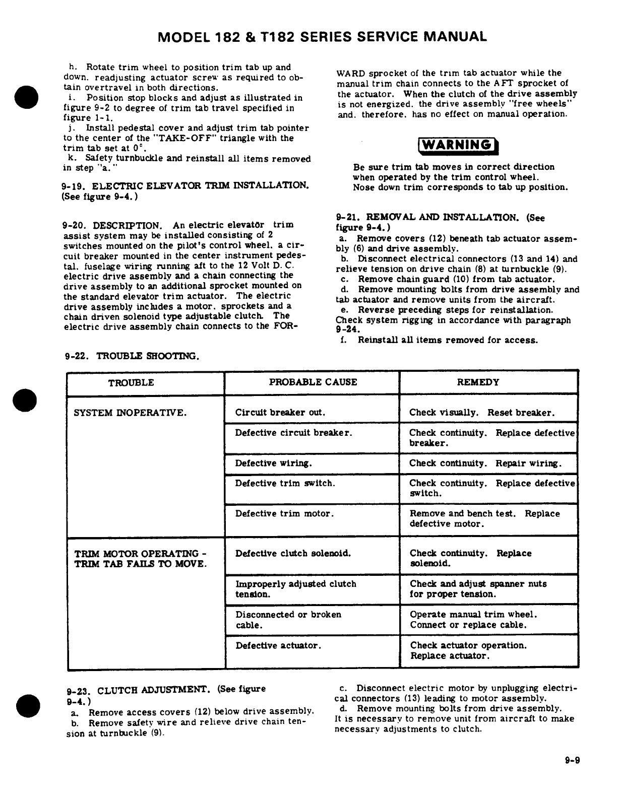
MODEL
182
&
T182
SERIES
SERVICE
MANUAL
h.
Rotate
trim
wheel
to
position
trim
tab
up
and
down.
readjusting
actuator
screw as
required
to
ob-
WARD
sprocket
of
the
trim
tab
actuator
while
the
tain
overtravel
in both
directions.
manual
trim
chain
connects
to
the
AFT
sprocket
of
i.
Position
stop
blocks
and
adjust
as
illustrated
in the
actuator.
When
the
clutch
of
the
drive
assembly
figure
9-2
to
degree
of
trim
tab
travel
specified
in
is
not
energized.
the
drive
assembly
free
wheels"
figure
1-1.
and.
therefore.
has
no
effect
on
manual
operation.
j.
Install
pedestal
cover
and
adjust
trim
tab
pointer
to
the
center
of
the
"TAKE-OFF"
triangle
with
the
trim
tab
set
at
0°.
k.
Safety
turnbuckle
and
reinstall
all
items
removed
in
step
"a."
Be
sure trim
tab moves
in
correct
direction
when
operated
by
the
trim
control
wheel.
9-19.
ELECTRIC
ELEVATOR
TRIM
INSTALLATION.
Nose
down
trim
corresponds
to tab
up
position.
(See
figure
9-4.)
9-21.
REMOVAL
AND
INSTALLATION.
(See
9-20.
DESCRIPTION.
An
electric
elevator
trim
figure
9-4.)
assist
system
may
be
installed
consisting
of
2
a.
Remove
covers
(12)
beneath
tab
actuator
assem-
switches
mounted
on
the
pilot's
control
wheel.
a
cir-
bly
(6)
and
drive
assembly.
cuit
breaker
mounted
in
the
center
instrument
pedes-
b.
Disconnect
electrical
connectors
(13
and
14)
and
tal.
fuselage
wiring
running
aft
to
the
12
Volt
D. C.
relieve
tension
on
drive
chain
(8)
at turnbuckle
(9).
electric
drive
assembly
and
a
chain
connecting
the
c.
Remove
chain
guard
(10)
from
tab
actuator.
drive
assembly
to
an
additional sprocket
mounted
on
d.
Remove
mounting
bolts
from drive
assembly
and
the
standard
elevator
trim
actuator.
The
electric
actuator
and
remove
units
from
the
aircraft.
drive assembly
includes
a
motor.
sprockets
and
a
e.
Reverse
preceding
steps for
reinstallation.
chain
driven
solenoid
type
adjustable
clutch.
The
Check
system
rigging
in
accordance
with
paragraph
electric
drive
assembly
chain
connects
to
the
FOR-
9-24.
f.
Reinstall
all
items
removed
for
access.
9-22.
TROUBLE
SHOOTING.
TROUBLE
PROBABLE
CAUSE
REMEDY
SYSTEM
INOPERATIVE.
Circuit
breaker
out.
Check
visually.
Reset
breaker.
Defective
circuit
breaker.
Check
continuity. Replace
defective
breaker.
Defective
wiring.
Check
continuity.
Repair
wiring.
Defective
trim
switch.
Check
continuity.
Replace defective
switch.
Defective
trim
motor.
Remove
and
bench
test.
Replace
defective motor.
TRIM
MOTOR
OPERATING
-
Defective
clutch solenoid.
Check
continuity.
Replace
TRIM
TAB
FAILS TO
MOVE.
solenoid.
Improperly adjusted
clutch
Check
and
adjust
spanner
nuts
tension.
for
proper
tension.
Disconnected
or
broken
Operate
manual
trim
wheel.
cable.
Connect
or
replace
cable.
Defective
actuator.
Check
actuator
operation.
Replace
actuator.
9-23.
CLUTCH
ADJUSTMENT.
(See
figure
c.
Disconnect
electric
motor
by
unplugging
electri-
a.
Remove
access
covers
(12)
below
drive
assembly.
d.
Remove
mounting
bolts
from
drive
assembly.
b.
Remove
safety
wire
and
relieve
drive
chain
ten-
It
is
necessary
to
remove
unit
from
aircraft
to
make
sion
at
turnbuckle
(9).
necessary
adjustments
to
clutch.
9-9
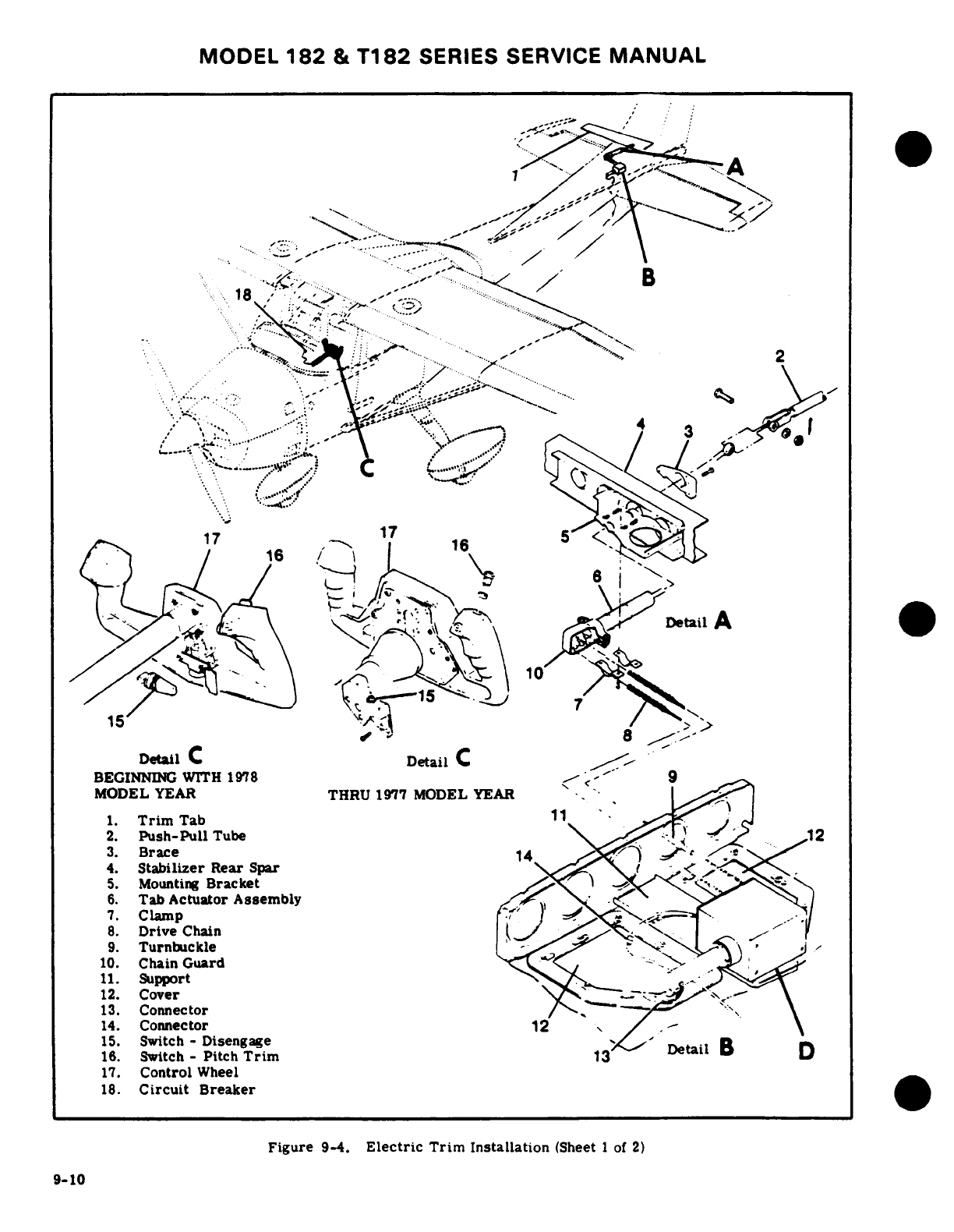
MODEL
182
&
T182
SERIES SERVICE
MANUAL
18
''
*...- "'
'
B
L..
.......
;--^\, ....
BEG~INN
.-.
WITH**
.**' .1
7
-'
MODEL
Y
7
1-9
M
E
-\
.3 .-.
, y .. Br ac 14
6
..
.....
3.
Brive
Cai
c
,..
4
.
/- -
17.
Coe41 /
C
16
149.
Turnnect
kle
/ ...
..
\
1..
Sup
-
Pi
Trim
Tab
'-..
D
D
18.
CMircuit
Breaker
F
ure
.
El
ric Trim
Installation
(Shet
.
of
9-10
D10
ail.
C
,a ,
'Dt
ai
-,
-, -
1
-
17....
..
B
E
G
IN NI
/
19
7
416~I~·. Sabilc
ze
ric rmDetail A
18.
Coiruit
Breaketr
'
6. TbctTrim
Tab
s
1
,
7.
Clamp
8.
Drive
Chain
9.
Turnbuckle
10.
Chain
Guard
11.
Support
12.
Cover
14.
Connector
12
15.
Switch
-
Disengage
-
B
16.
SSwitch
-
Pitch
Trim
13
17.
Control
Wheel
18.
Circuit
Breaker
Figure
9-4.
Electric Trim
Installation
(Sheet
1
of
2)
9-10
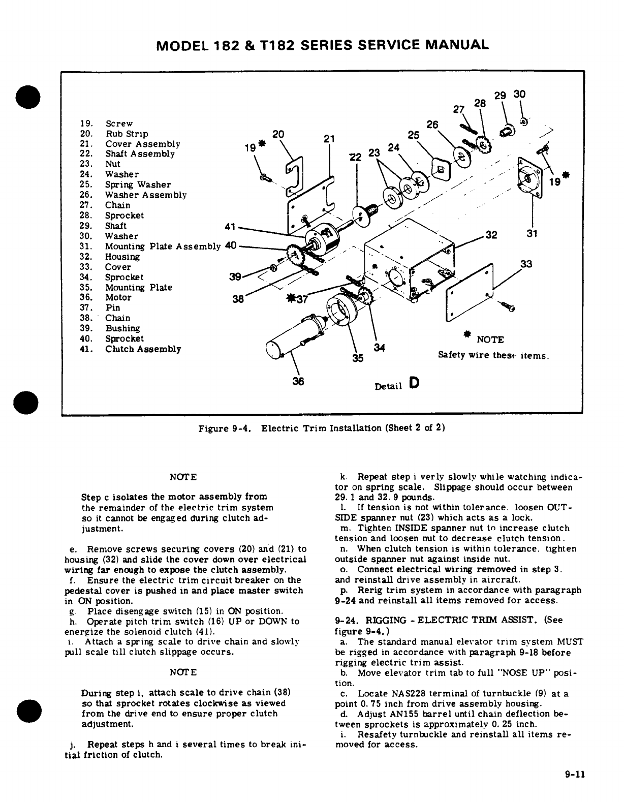
MODEL
182
&
T182
SERIES
SERVICE
MANUAL
29
30
19.
Screw
20.
Rub
Strip
20 25
21.
Cover
Assembly
19*
24
22.
Shaft
Assembly
23
24.
Washer
25.
Spring
Washer
-
26.
Washer
Assembly
27.
Chain
28.
Sprocket
29.
Shaft
41
30.
Washer
32
31
31.
Mounting
Plate
Assembly
40
32.
Housing
33.
Cover
^
33
35.
Mounting
Plate
36.
Motor
38
37.
Pin
38.
Chain
39.
Bushing
40.
Sprocket
NOTE
41.
Clutch
Assembly
\ 34
41.
Clutch35
ASafety
wire
thest items.
36
Detail
D
Figure
9-4.
Electric
Trim
Installation
(Sheet
2
of
2)
NOTE
k.
Repeat
step
i
verly
slowly
while
watching
indica-
tor
on
spring
scale.
Slippage
should
occur
between
Step
c
isolates
the
motor assembly
from
29.
1
and
32.
9
pounds.
the
remainder
of
the
electric trim
system
1.
If
tension is
not
within
tolerance,
loosen
OUT-
so
it
cannot
be
engaged
during
clutch
ad-
SIDE
spanner
nut
(23)
which
acts
as
a
lock.
justment.
m.
Tighten
INSIDE
spanner
nut
to
increase
clutch
tension
and
loosen
nut
to
decrease
clutch
tension.
e.
Remove
screws
securing
covers
(20)
and
(21)
to
n.
When
clutch
tension
is
within
tolerance.
tighten
housing
(32)
and
slide
the
cover
down
over
electrical
outside
spanner
nut
against
inside
nut.
wiring
far
enough
to
expose
the clutch
assembly.
o.
Connect
electrical
wiring
removed
in
step
3.
f.
Ensure
the
electric
trim
circuit
breaker
on
the
and
reinstall
drive
assembly
in
aircraft.
pedestal
cover
is
pushed
in
and
place
master
switch
p.
Rerig
trim
system
in
accordance
with
paragraph
in
ON
position.
9-24
and
reinstall
all
items
removed
for
access.
g.
Place
disengage
switch
(15)
in
ON
position.
h.
Operate
pitch
trim
switch
(16)
UP
or
DOWN
to
9-24.
RIGGING
-
ELECTRIC
TRIM
ASSIST.
(See
energize
the
solenoid
clutch
(41).
figure
9-4.)
i. Attach
a
spring
scale
to
drive
chain
and
slowly
a.
The
standard
manual
elevator
trim
system
MUST
pull
scale
till
clutch
slippage
occurs.
be
rigged
in
accordance
with
paragraph
9-18
before
rigging
electric
trim
assist.
NOTE
b.
Move
elevator
trim
tab
to
full
"NOSE
UP"
posi-
tion.
During
step
i,
attach
scale
to
drive
chain
(38)
c.
Locate
NAS228
terminal
of
turnbuckle
(9)
at
a
so
that
sprocket
rotates
clockwise
as
viewed
point
0.
75
inch
from
drive assembly
housing.
from
the
drive
end
to
ensure proper
clutch
d.
Adjust
AN155
barrel
until
chain deflection
be-
adjustment.
tween
sprockets
is
approximately
0. 25
inch.
i.
Resafety
turnbuckle
and
reinstall
all
items re-
j.
Repeat
steps
h
and
i
several
times
to
break
ini-
moved
for
access.
tial
friction
of
clutch.
9-11
MODEL
182
&
T182
SERIES
SERVICE
MANUAL
9-25.
VOLTAGE REGULATOR ADJUSTMENT.
(24V
sembly
power
leads.
Be
sure
to connect
RED
to
RED
ELECTRICAL
SYSTEM)
(See
figure
9-4.)
and
BLACK
to
BLACK when
reconnecting
leads.
a.
Remove
access
cover
(39).
h.
Check
to
see
if
full
"NOSE
UP"
to
full
"NOSE
b.
Connect
an
external
power
source
of
27.
5
volts
DOWN"
and
full
"NOSE
DOWN"
to
full
"NOSE
UP"
dc
continuous
to
the
aircraft
electrical
system,
or
if
cycle
time
is
41±3
seconds.
an
external
power
supply
is
not
available,
run
the
air-
craft
engine
at
approximately
1000
RPM
to
maintain
the
normal
operating
aircraft
voltage.
c.
Disconnect
the
electrical
power
leads
to the
The
trim
motor
should
be
allowed
to
cool
motor
by
unplugging
the
connectors
installed
in
the between
voltage
regulator
adjustments
for
RED
and
BLACK
wire
leading
to
the
motor
assembly.
approximately
5
minutes
if
several
actua-
d.
Connect
one
lead
of
a
dc
voltmeter
capable
of
tions
of
the
motor
becomes
necessary
dur-
measuring
the
aircraft
voltage
to
either
the
RED
or
ing
adjustment.
BLACK
wire
leading
to
the
motor
and
the
other
volt-
meter
lead
to
a
good
aircraft
ground.
i.
Readjust
voltage
regulator
as required
to
obtain
e.
Operate
the
electric
trim
switch
to the
Nose
UP
41±3
seconds
cycle
time.
and
Nose
DOWN
positions
and
check
voltage
present
at
the
RED
and
BLACK
wires.
NOTE
f.
Adjust
CTR
1
and
CTR
2
adjustment
screws
on
the
voltage
regulator
counterclockwise
(CCW),
then
If
trim
tab
travel
time
exceeds
44
seconds,
slowly
turn
adjustment
screws
clockwise
(CW)
until
lubricate
and
"free
up"
elevator
trim sys-
a
13.
5
volt
output
is
obtained
for
both
(RED
and
tem
as
required
per
section
2.
BLACK)
leads.
g.
Remove
voltmeter
and
reconnect
the
motor
as-
j.
Check
trim
system
for proper
operation
and
re-
install
all
items
removed
for
access.
SHOP
NOTES:
9-12
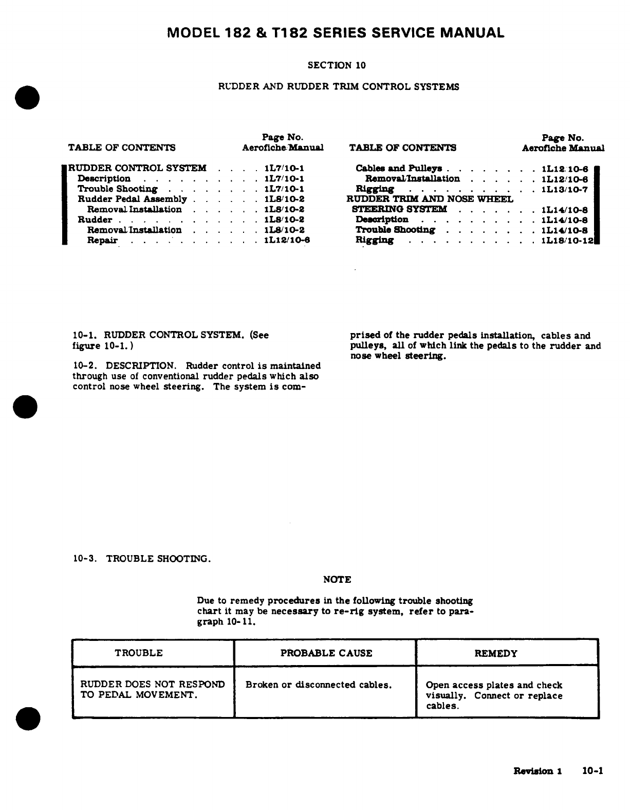
MODEL
182
&
T182
SERIES
SERVICE
MANUAL
SECTION
10
RUDDER
AND
RUDDER
TRIM CONTROL
SYSTEMS
Page
No.
Page
No.
TABLE
OF
CONTENTS
Aerofiche.Manual
TABLE
OF
CONTENTS
Aerofiche
Manual
RUDDER
CONTROL
SYSTEM
. . .
1L7/10-1
Cables
and
Pulleys
.
.......
1L1210-
Description
..........
L7/10-1
Removal/Installation
......
L1210-6
Trouble
Shooting
........
1L7/10-1
Rigging
...........
1L13/10-7
Rudder
Pedal Assembly
. .
....
1L8/10-2
RUDDER
TRIM
AND
NOSE
WHEEL
Removal
Installation
......
1L8/10-2 STEERING
SYSTEM
.......
1L14/10-8
Rudder
..
........
..
L810-2
Description
..........
1L14/10-8
Removal
Installation
.....
1L8/10-2
Trouble
Shooting.
.
....
.
1L14/10-8
Repair
.
.
...
....
. .
L12/10-6
Rigging
...........
1L18/10-12
10-1.
RUDDER
CONTROL
SYSTEM.
(See
prised
of
the
rudder
pedals
installation,
cables
and
figure
10-1.)
pulleys,
all
of
which
link
the
pedals
to
the
rudder
and
nose
wheel
steering.
10-2.
DESCRIPTION.
Rudder
control
is
maintained
through
use
of
conventional
rudder
pedals
which
also
control
nose
wheel
steering.
The
system
is
com-
10-3.
TROUBLE
SHOOTING.
NOTE
Due
to
remedy
procedures
in
the
following
trouble
shooting
chart
it
may
be
necessary
to
re-rig
system,
refer
to
para-
graph
10-11.
TROUBLE PROBABLE
CAUSE
REMEDY
RUDDER
DOES
NOT
RESPOND
Broken
or
disconnected
cables.
Open
access
plates
and
check
TO
PEDAL
MOVEMENT.
visually.
Connect
or
replace
Revision
1
10-1
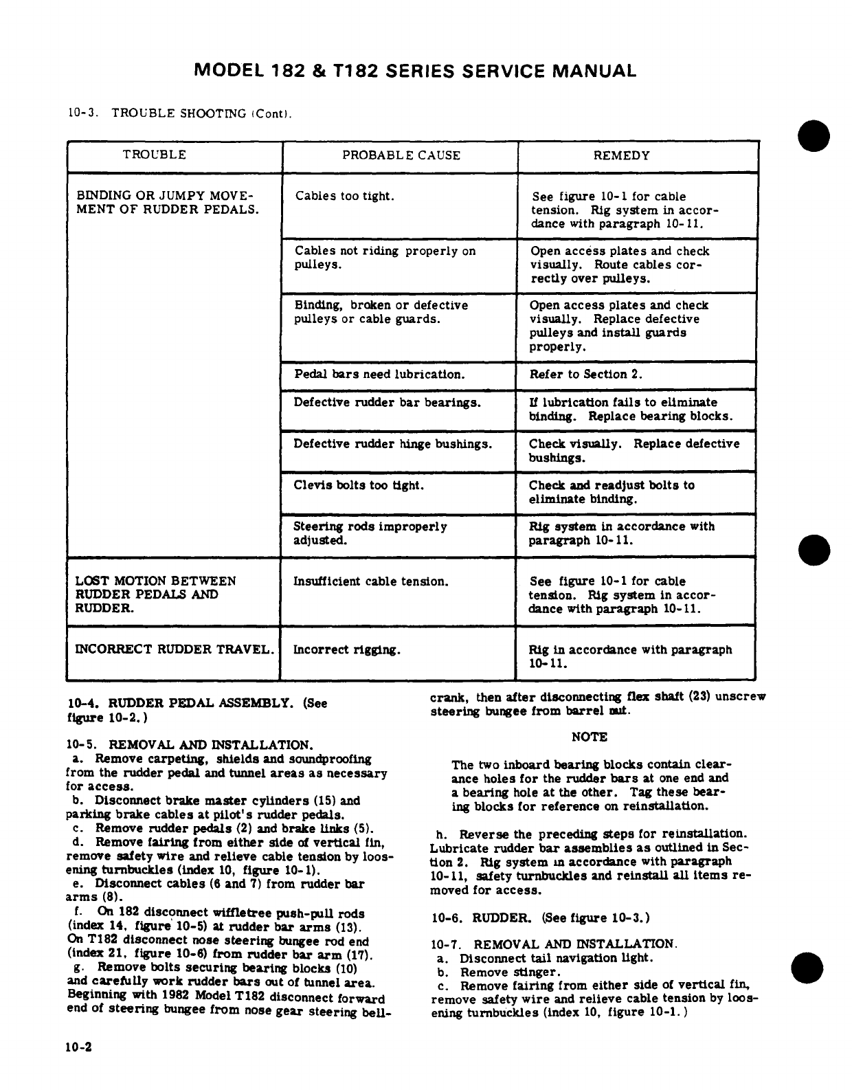
MODEL
182
&
T182
SERIES SERVICE
MANUAL
10-3.
TROUBLE
SHOOTING
(Cont).
TROUBLE
PROBABLE
CAUSE
REMEDY
BINDING
OR
JUMPY
MOVE-
Cables
too
tight.
See
figure
10-1
for
cable
MENT
OF
RUDDER PEDALS.
tension.
Rig
system
in
accor-
dance
with
paragraph
10-
11.
Cables
not
riding
properly
on
Open
access
plates
and
check
pulleys,
visually.
Route
cables
cor-
rectly
over
pulleys.
Binding,
broken
or
defective
Open
access
plates
and check
pulleys
or
cable
guards.
visually.
Replace
defective
pulleys
and
install
guards
properly.
Pedal
bars
need
lubrication.
Refer
to
Section
2.
Defective
rudder
bar
bearings.
If
lubrication
fails
to
eliminate
binding.
Replace
bearing
blocks.
Defective
rudder
hinge
bushings.
Check
visually.
Replace defective
bushings.
Clevis bolts
too
tight.
Check
and
readjust
bolts
to
eliminate
binding.
Steering
rods improperly
Rig
system
in
accordance
with
adjusted.
paragraph
10-11.
LOST
MOTION
BETWEEN
Insufficient
cable
tension.
See
figure
10-1
for
cable
RUDDER
PEDALS
AND
tension.
Rig
system
in
accor-
RUDDER.
dance
with
paragraph
10-11.
INCORRECT
RUDDER
TRAVEL.
Incorrect
rigging.
Rig
in
accordance
with
paragraph
10-11.
10-4.
RUDDER
PEDAL
ASSEMBLY.
(See
crank,
then
after
disconnecting
flex
shaft
(23)
unscrew
figure
10-2.)
steering
bungee
from
barrel
nut.
NOTE
10-5.
REMOVAL
AND
INSTALLATION.
a.
Remove
carpeting,
shields
and
soundproofing
The
two
inboard
bearing blocks
contain
clear-
from the
rudder
pedal
and
tunnel
areas
as
necessary
ance
holes
for
the
rudder
bars
at
one
end
and
for
access.
,
b.
Disconnect
brake
master
cylinders
(15)
and
ing
blocks
for
reference
on
reinstallation.
parking
brake
cables
at
pilot's
rudder
pedals.
c.
Remove
rudder
pedals
(2)
and
brake
links
(5).
h.
Reverse
the
preceding
steps
for
reinstallation.
d.
Remove
fairing
from
either
side
of
vertical
fin,
Lubricate
rudder
bar
assemblies
as
outlined in
Sec-
remove
safety
wire
and
relieve
cable
tension
by
loos-
tion
2.
Rig
system
in
accordance
with
paragraph
ening
turnbuckles
(index
10,
figure
10-1). 10-11,
safety
turnbuckles
and
reinstall all items re-
e.
Disconnect
cables
(6
and
7)
from
rudder
bar
moved
for
access.
moved
for
access.
arms
(8).
f.
On
182
disconnect
wiffletree push-pull
rods
10-6.
RUDDER.
(See
figure
10-3.)
(index
14,
figure
10-5)
at
rudder
bar
arms
(13).
On
T182
disconnect
nose
steering
bungee
rod
end 10-7.
REMOVAL
AND
INSTALLATION.
(index
21,
figure
10-6)
from
rudder
bar
arm
(17).
a.
Disconnect
tail
navigation
light.
g.
Remove
bolts
securing
bearing
blocks
(10)
b
Remove
stinger.
and
carefully
work
rudder
bars
out
of
tunnel
area.
c.
Remove
fairing
from
either
side
of
vertical
fin,
Beginning
with
1982
Model
T182
disconnect
forward
remove
safety
wire
and
relieve
cable
tension
by
loos-
end
of
steering
bungee
from
nose
gear
steering bell-
ening
turnbuckles
(index
10,
figure
10-1.)
10-2
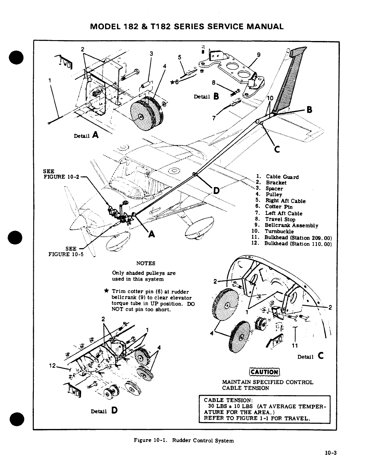
MODEL
182
&
T182
SERIES
SERVICE
MANUAL
FIGURE
10-2
,'.-*
J
"""
Cablek
Guard
a '""
-
i
*'
8
D-3.
Spacer
d^
.,1D
\ ""^-^y^
>4.
Pulley
5.
Right
Aft
Cable
6.
Cotter
Pin
7.
Left Aft
Cable
A;/ \. "'R.
^SSGE
\ ;,,,^" ;
,.
.,.";
, .
8.
Travel
Stop
,
-
..
.'..
.....
***:;
7i
.'
A,..>
.·
.
*;·
9.
Bellcrank
Assembly
.\ !^
-'*
^o .'. -...
*
\t. o*.'
j..,
.
,,
O10.
Turnbuckle
!^
..
o
..
o-....
....
... .
.;....^:-':.-
11.
Bulkhead
(Station
209.00)
SEE A,^~~ ,~ „~..~
~12.
Bulkhead
(Station
110.
00)
SEE
'"'' ?'""'."
FIGURE
10-5
.
NOTES
Only
shaded
pulleys
are
/
used
in
this
system
2
*
Trim
cotter
pin
(6)
at
rudder
.n
L
bellcrank
(9)
to
clear
elevator
-
:
' '
;
'
torque
tube
in
UP
position.
DO
/
NOT
cut
pin
too
short.
1 -;'
t
2
DetailC
^;1 2 (al
iCAUTION
:: ......- ....
..
MAINTAIN
SPECIFIED
CONTROL
,
< -(^
'
CABLE
TENSION
CABLE
TENSION:
30 LBS
*
10
LBS
(AT
AVERAGE
TEMPER-
Detail
D
ATURE
FOR
THE
AREA.)
REFER
TO
FIGURE 1-1
FOR
TRAVEL.
Figure
10-1.
Rudder
Control
System
10-3
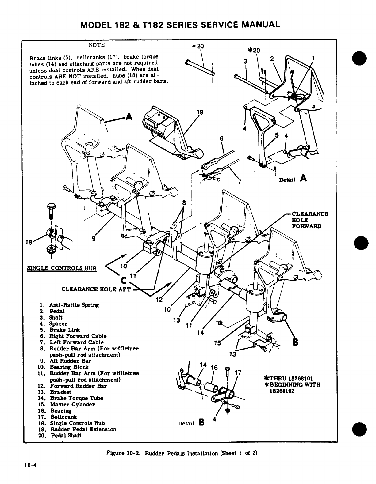
MODEL
182
&
T182
SERIES
SERVICE
MANUAL
NOTE
*20
Brake
links
(5),
bellcranks
(17).
brake
torque
2
1
tubes
(14)
and
attaching
parts
are
not
required
unless
dual
controls
ARE
installed.
When
dual
controls
ARE
NOT
installed,
hubs
(18)
are
at-
tached
to
each
end
of
forward
and
aft
rudder
bars.
SINGLE CONTROLS
HUB
CLEARANCE
HUB
CLEARANCE
HOLE
AFT
1.
Anti-Rattle
Spring
2.
Pedal
3.
Shaft
4.
Spacer
5.
Brake
Link
6.
Right
Forward
Cable
7.
Left
Forward
Cable 15
8.
Rudder
Bar
Arm
(For
wiffletree
-
push-pull
rod
attachment)
13
9. Aft
Rudder
Bar
10.
Bearing
Block
11.
Rudder
Bar
Arm
(For
wiffletree
push-pull
rod
attachment)
*THRU
18268101
12.
Forward
Rudder
Bar
13.
Bracket
18268102
14.
Brake
Torque
Tube
15.
Master
Cylinder
16.
Bearing
17.
Bellcrank
4
18.
Single
Controls
Hub
Detail
B
19.
Rudder
Pedal
Extension
20.
Pedal
Shaft
Figure
10-2.
Rudder
Pedals
Installation
(Sheet
1
of
2)
10-4
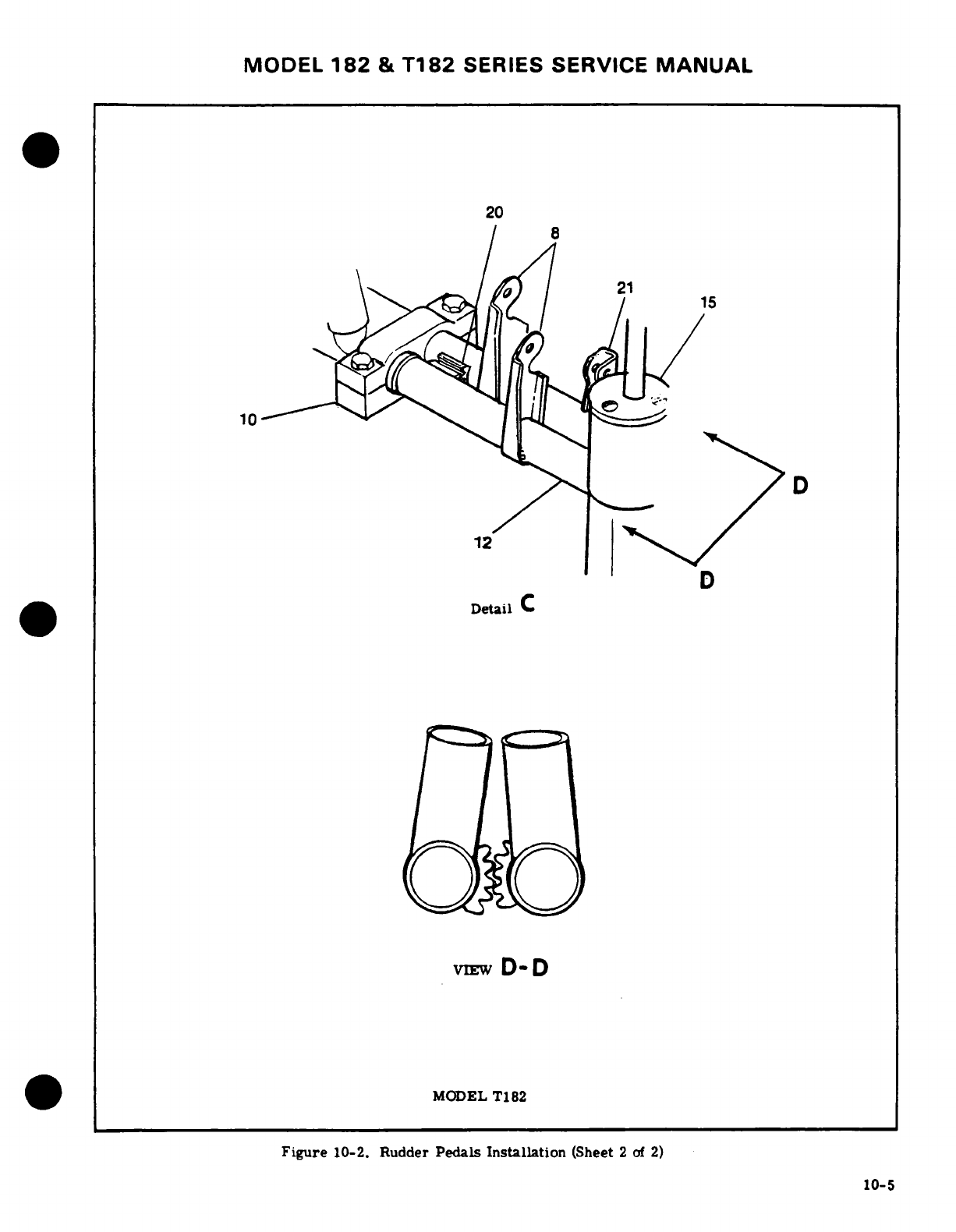
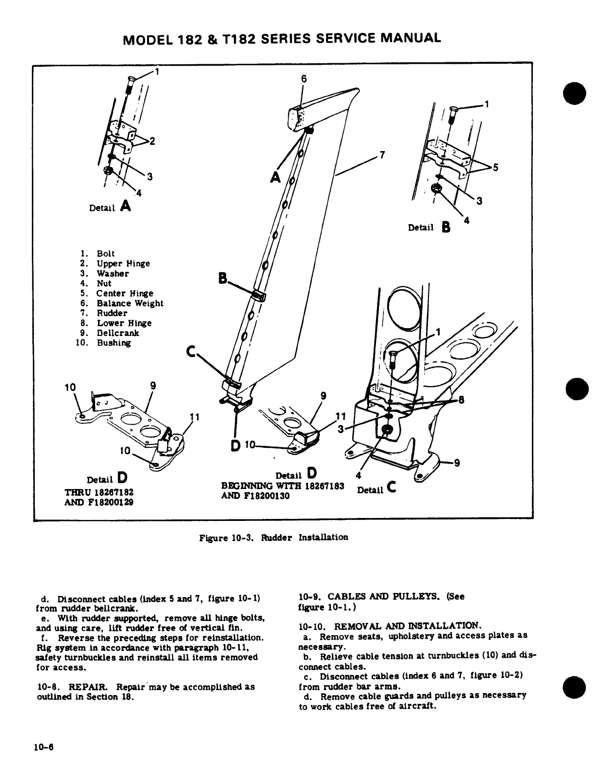
MODEL
182
&
T182
SERIES
SERVICE
MANUAL
A
Detail
A
Detail
B
1.
Bolt
2.
Upper
Hinge
3.
Washer
4.
Nut
5.
Center
Hinge
6.
Balance
Weight
7.
Rudder
8.
Lower
Hinge
9.
Bellcrank
10.
Bushing
C
/
10
DetailD
DetailD
THRU
18267182
BEGINNING
WITH 18267183
Detail
C
AND
F18200129
AND
F18200130
Figure
10-3.
Rudder
Installation
d.
Disconnect
cables
(index
5
and
7,
figure
10-1)
10-9.
CABLES
AND
PULLEYS.
(See
from
rudder
bellcrank.
figure
10-1.)
e.
With
rudder
supported, remove
all
hinge
bolts,
and
using
care,
lift
rudder
free
of
vertical
fin.
10-10.
REMOVAL
AND
INSTALLATION.
f.
Reverse
the
preceding
steps
for
reinstallation.
a.
Remove
seats,
upholstery
and
access
plates
as
Rig
system
in
accordance
with
paragraph
10-11,
necessary.
safety
turnbuckles
and
reinstall
all
items
removed
b.
Relieve cable
tension
at
turnbuckles
(10)
and
dis-
for
access.
connect
cables.
c.
Disconnect
cables
(index
6
and
7,
figure
10-2)
10-8.
REPAIR.
Repair
may
be
accomplished
as
from
rudder
bar
arms.
outlined
in
Section
18.
d.
Remove
cable
guards
and
pulleys
as
necessary
to
work
cables
free
of
aircraft.
10-6
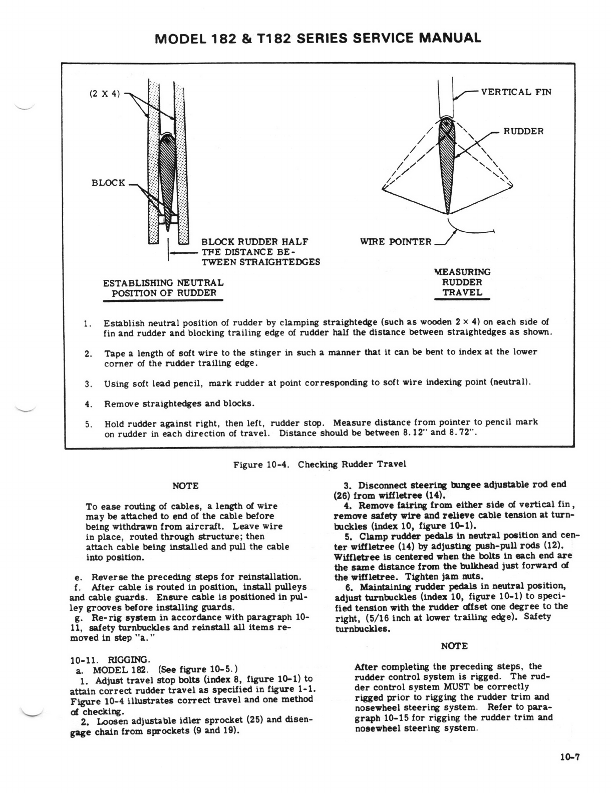
MODEL
182
&
T182
SERIES
SERVICE
MANUAL
(2
X
4)
VERTICAL
FIN
BLOCK
BLOCK RUDDER
HALF
WIRE
POINTER
THE
DISTANCE
BE-
TWEEN
STRAIGHTEDGES
MEASURING
ESTABLISHING
NEUTRAL
RUDDER
POSITION
OF
RUDDER
TRAVEL
1.
Establish
neutral
position
of
rudder
by
clamping
straightedge
(such
as
wooden
2
x
4)
on
each
side
of
fin
and
rudder
and blocking
trailing
edge
of
rudder
half
the
distance
between
straightedges
as
shown.
2.
Tape
a
length
of
soft
wire
to the
stinger
in
such
a
manner
that
it
can be
bent
to
index
at
the
lower
corner
of
the
rudder
trailing
edge.
3.
Using
soft
lead
pencil,
mark
rudder
at
point
corresponding
to
soft
wire
indexing
point
(neutral).
4.
Remove
straightedges
and
blocks.
5.
Hold
rudder
against
right,
then
left,
rudder
stop.
Measure
distance
from pointer
to
pencil
mark
on
rudder
in
each
direction
of
travel.
Distance
should
be
between
8.12"
and
8.
72".
Figure
10-4.
Checking
Rudder
Travel
NOTE
3.
Disconnect
steering
bungee
adjustable
rod
end
(26)
from wiffletree
(14).
To
ease
routing
of
cables,
a
length
of
wire
4.
Remove
fairing from
either
side
of
vertical
fin,
may
be
attached
to
end
of
the
cable
before
remove
safety
wire
and
relieve
cable
tension
at
turn-
being withdrawn
from
aircraft.
Leave
wire
buckles
(index
10,
figure
10-1).
in
place,
routed through
structure;
then
5.
Clamp
rudder
pedals
in
neutral
position
and
cen-
attach
cable being
installed
and
pull the cable
ter
wiffletree
(14)
by
adjusting
push-pull
rods
(12).
into
position.
Wiffletree
is
centered
when
the
bolts
in
each
end
are
the
same
distance from the
bulkhead
just
forward
of
e.
Reverse
the
preceding
steps for reinstallation.
the
wiffletree.
Tighten
jam
nuts.
f.
After
cable
is
routed
in
position,
install
pulleys
6.
Maintaining
rudder
pedals in
neutral
position,
and
cable
guards.
Ensure
cable
is
positioned in
pul-
adjust
turnbuckles
(index
10,
figure
10-1)
to
speci-
ley
grooves
before
installing guards.
fied
tension
with
the
rudder
offset
one
degree
to
the
g.
Re-rig
system
in
accordance
with
paragraph
10-
right,
(5/16
inch
at
lower
trailing
edge).
Safety
11,
safety
turnbuckles
and
reinstall
all
items
re-
turnbuckles.
moved
in
step
"a."
NOTE
10-11.
RIGGING.
a.
MODEL
182.
(See
figure
10-5.)
After
completing the
preceding
steps,
the
1.
Adjust
travel
stop
bolts
(index
8,
figure
10-1)
to
rudder
control
system
is
rigged.
The
rud-
attain
correct
rudder
travel
as
specified
in
figure
1-1.
der
control system
MUST
be
correctly
Figure
10-4
illustrates
correct
travel
and
one
method
rigged
prior
to
rigging
the
rudder
trim
and
of
checking. nosewheel
steering system.
Refer
to
para-
2.
Loosen
adjustable
idler
sprocket
(25)
and
disen- graph
10-15
for
rigging
the
rudder
trim
and
gage chain
from
sprockets
(9
and
19).
nosewheel
steering
system.
10-7
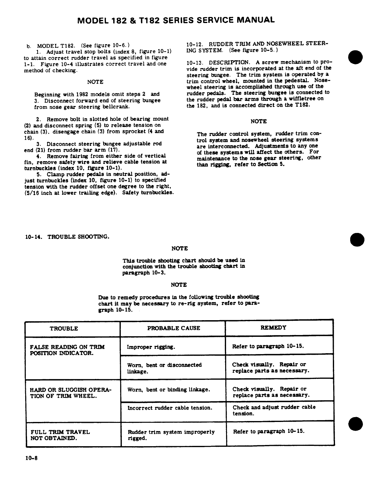
MODEL
182
&
T182
SERIES SERVICE
MANUAL
b.
MODEL
T182.
(See
figure
10-6.)
10-12.
RUDDER
TRIM
AND
NOSEWHEEL
STEER-
1.
Adjust
travel
stop
bolts
(index
8,
figure
10-1)
ING
SYSTEM.
(See
figure
10-5.)
to
attain
correct
rudder
travel
as specified
in
figure
1-1.
Figure
10-4
illustrates
correct
travel
and
one
10-13.
DESCRIPTION.
A
screw
mechanism
to
pro-
method
of
checking.
vide
rudder
trim
is
incorporated
at the aft
end
of
the
steering
bungee.
The
trim
system
is
operated
by
a
NOTE
trim
control
wheel,
mounted in the
pedestal.
Nose-
wheel
steering
is
accomplished
through
use
of
the
Beginning
with
1982
models omit
steps
2
and
rudder
pedals.
The
steering
bungee
is
connected
to
3.
Disconnect
forward
end
of
steering
bungee
the
rudder
pedal
bar
arms
through
a
wiffletree
on
from
nose
gear
steering
bellcrank.
the
182,
and
is
connected
direct
on
the
T182.
2.
Remove
bolt
in
slotted
hole
of
bearing
mount
NOTE
(2)
and
disconnect spring
(5)
to
release
tension
on
chain
(3).
disengage
chain
(3)
from
sprocket
(4
and
16).
The
rudder control
system,
rudder
trim
con-
3.
Disconnect
steering
bungee
adjustable
rod
end
(21)
from
rudder
bar
arm
(17).
are
interconnected. Adjustments
to
any
one
4.
Remove
fairing
from
either
side
of
vertical
fin,
remove
safety wire
and
relieve
cable
tension
at
than
rigging,
refer
to
Section
5.
turnbuckles
(index
10,
figure
10-1).
5.
Clamp
rudder
pedals
in
neutral
position,
ad-
just
turnbuckles
(index
10,
figure
10-1)
to
specified
tension
with
the
rudder
offset
one
degree
to
the
right,
(5/16
inch
at
lower
trailing
edge).
Safety
turnbuckles.
10-14.
TROUBLE
SHOOTING.
NOTE
This
trouble
shooting
chart
should
be
used
in
conjunction
with
the
trouble
shooting
chart
in
paragraph
10-3.
NOTE
Due
to
remedy
procedures
in
the
following
trouble
shooting
chart
it
may
be
necessary
to
re-rig
system,
refer
to
para-
graph
10-15.
TROUBLE
PROBABLE
CAUSE
REMEDY
FALSE
READING
ON
TRIM
Improper
rigging.
Refer
to
paragraph
10-15.
POSITION
INDICATOR.
Worn,
bent
or
disconnected
Check
visually.
Repair
or
linkage.
replace
parts
as
necessary.
HARD
OR
SLUGGISH
OPERA-
Worn,
bent
or
binding
linkage.
Check
visually.
Repair
or
TION
OF
TRIM
WHEEL.
replace
parts as
necessary.
Incorrect rudder
cable
tension.
Check
and
adjust
rudder
cable
tension.
FULL
TRIM
TRAVEL
Rudder
trim
system
improperly
Refer
to
paragraph
10-15.
NOT
OBTAINED.
rigged.
10-8
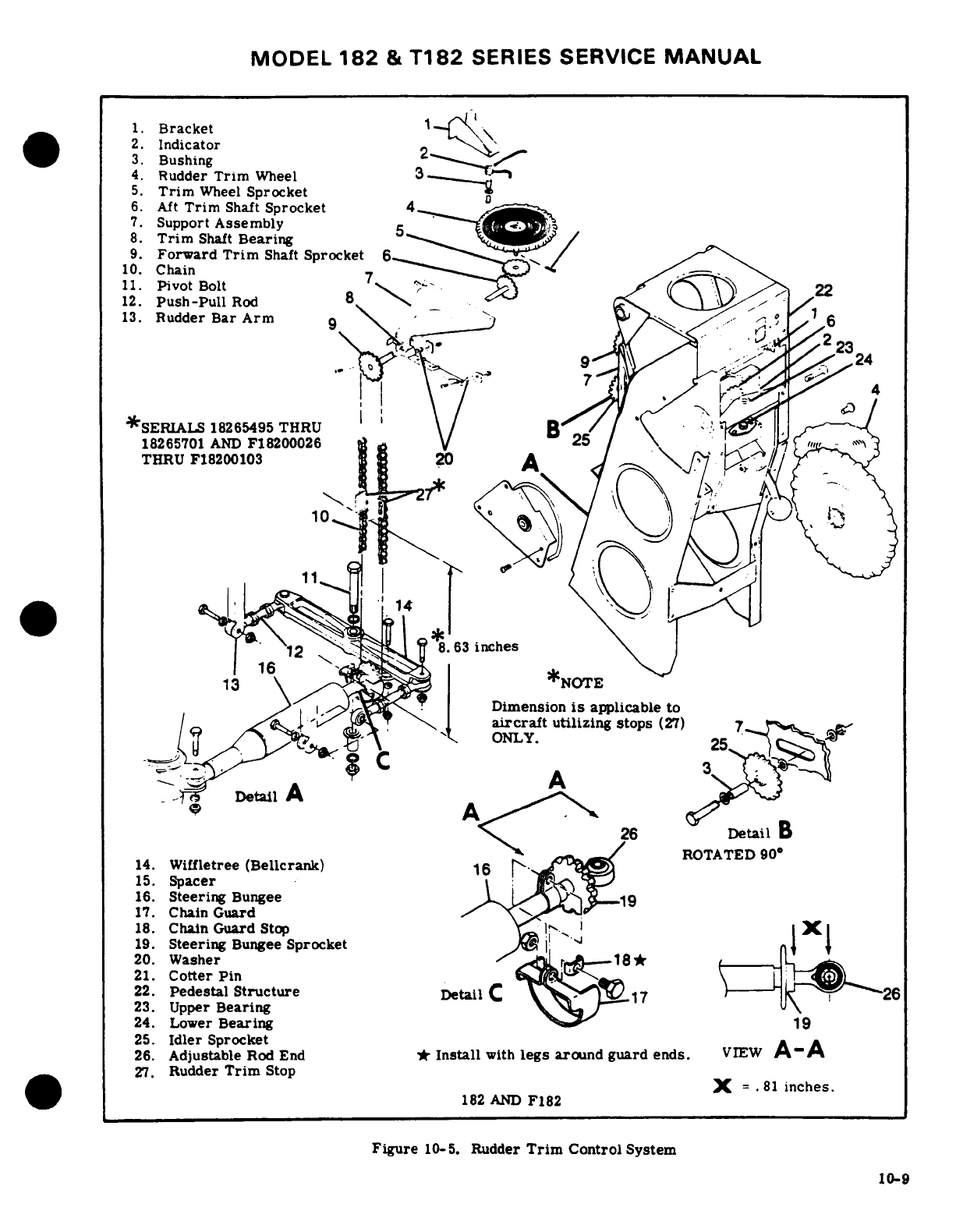
MODEL
182
&
T182
SERIES SERVICE
MANUAL
1.
Bracket
2.
Indicator
2
3.
Bushing
2-
4.
Rudder
Trim
Wheel
3
5.
Trim
Wheel
Sprocket
6.
Aft
Trim
Shaft
Sprocket
4
7.
Support
Assembly
5
8.
Trim
Shaft
Bearing
9.
Forward
Trim
Shaft
Sprocket
6
10.
Chain
11.
Pivot
Bolt
\
22
12.
Push-Pull
Rod
8
/
13.
Rudder
Bar Arm
6
...
4..%
/2234
4
*SERIALS
18265495
THRU
B
/
' ' '
18265701
AND
F18200026 /
THRU
F18200103
A
20
A
13
\ /^^
NOTE
{
I )
Dimension
is
applicable
to
aircraft
utilizing
stops
(27)
7
ONLY.
25
--
$V^
A
3
v A1 4
'A
26
Detail
B
ROTATED
900
14.
Wiffletree
(Bellcrank)
16
ROTATED
90
15.
Spacer
16.
Steering
Bungee 19
17.
Chain
Guard
18.
Chain
Guard
Stop
I
19.
Steering
Bungee
Sprocket
20.
Washer
A
-18*
h
-
21.
Cotter
Pin
\
22.
Pedestal
Structure
Detail
C
\ 1 17
23.
Upper
Bearing
v 1 6
24.
Lower
Bearing
19
25.
Idler
Sprocket
W
AA
26.
Adjustable
Rod
End
*
Install
with
legs
around
guard
ends.
VIEW
A-A
27.
Rudder
Trim
Stop
182
AND
F182 X =
.81
inches.
Figure
10-5.
Rudder
Trim
Control System
10-9
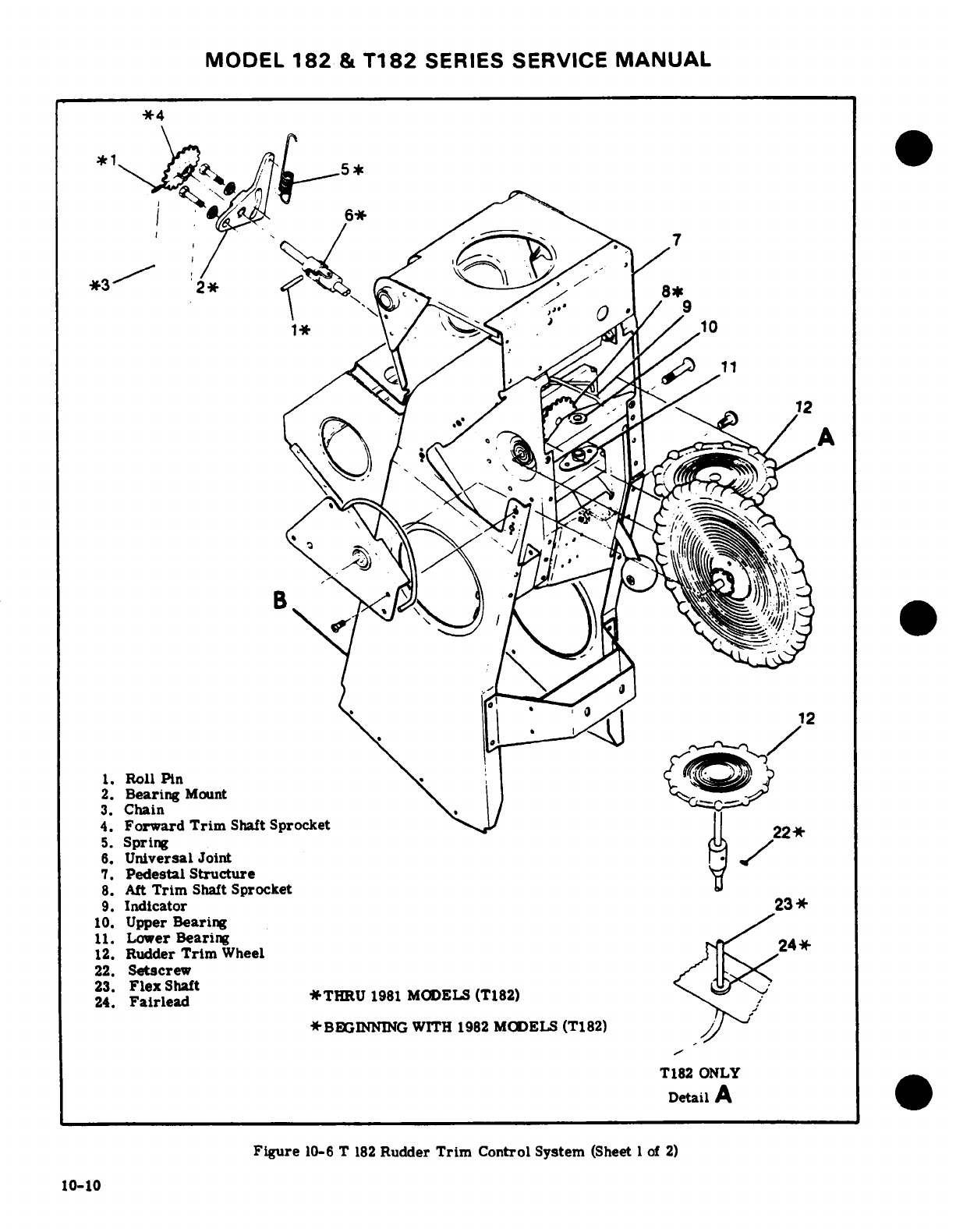
MODEL
182
&
T182
SERIES
SERVICE
MANUAL
*4
B
1.
Roll
Pin
0
2.
Bearing
Mount
4.
Forward
Trim
Shaft
Sprocket
22*
5.
Spring
6.
Universal Joint
F
7.
Pedestal
Structure
8.
Aft
Trim
Shaft
Sprocket
9.
Indicator
23*
10.
Upper
Bearing
/
11.
Lower
Bearing
12.
Rudder
Trim
Wheel
s
24*
22.
Setscrew
|
24.
Fairlead
*THRU
1981
MODELS
(T182)
*BEGINNING
WITH 1982
MODELS
(T182)
/
J
T182
ONLY
Detail
A
Figure
10-6
T
182
Rudder
Trim
Control
System
(Sheet
I
of
2)
10-10
I0-10
tcre
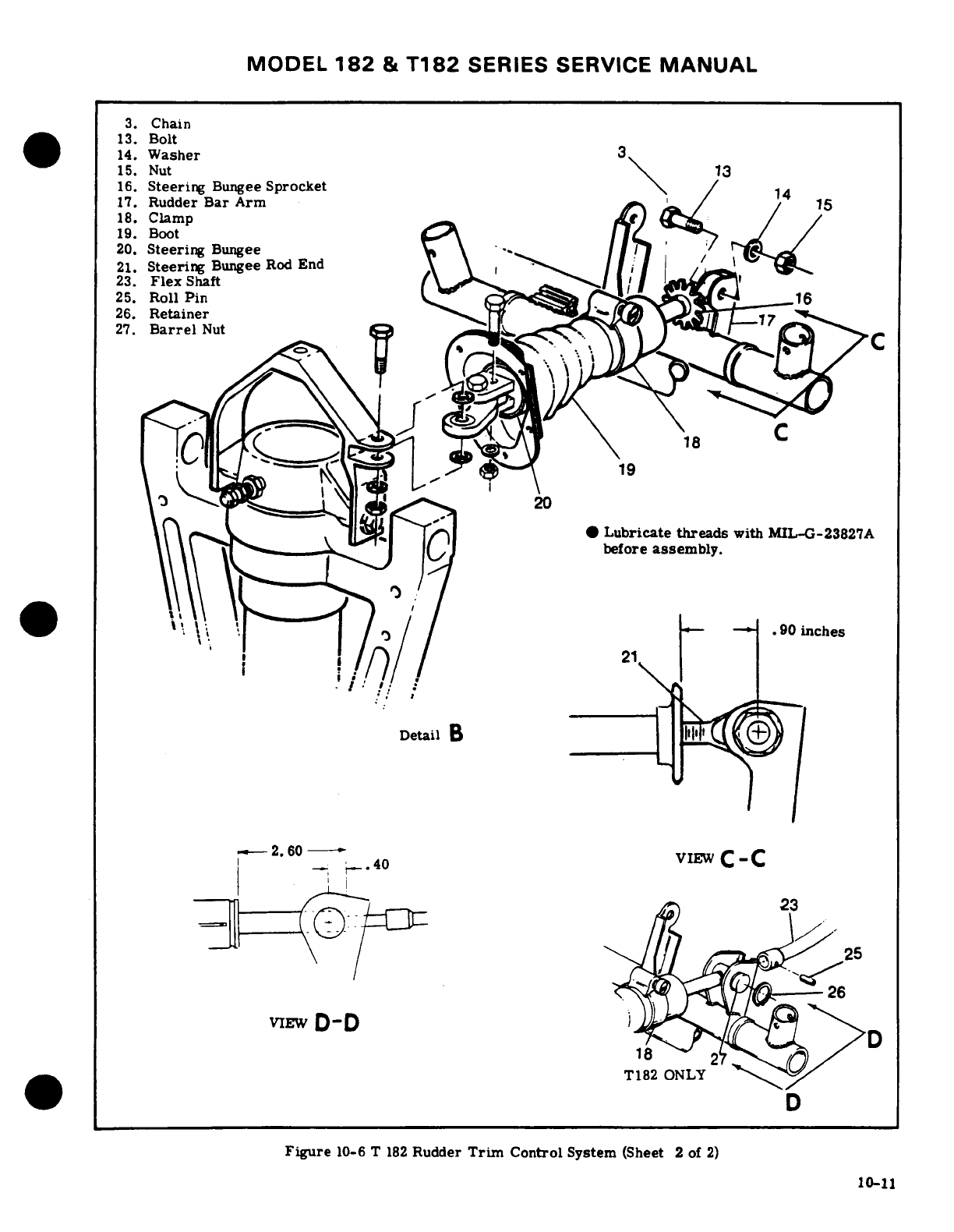
MODEL
182
&
T182
SERIES SERVICE
MANUAL
3.
Chain
13.
Bolt
14.
Washer
3
15.
Nut
13
16.
Steering
Bungee
Sprocket
14
17.
Rudder
Bar
Arm
15
18.
Clamp
19.
Boot
20.
Steering
Bungee
21.
Steering
Bungee
Rod
End
23.
Flex
Shaft
25.
Roll
Pin
16
26.
Retainer
27.
Barrel
Nut
20
Lubricate
threads
with MIL-G-23827A
before
assembly.
*l\\
\,
/
i
/
l', \ iI\\ '.,( I -~1*
.'90
inches
'
i i ~
21
Detail
B
-
2.60-
VIEW
C-C
_
__-.
40
VIEW
D-D
T182
ONLY
/
D
Figure
10-6
T
182
Rudder
Trim
Control
System
(Sheet
2
of
2)
10-11
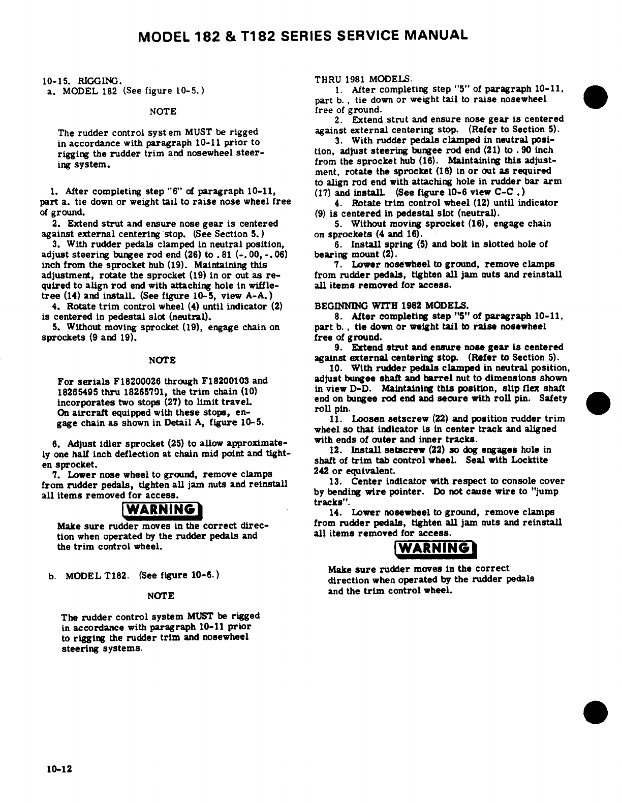
MODEL
182
&
T182
SERIES
SERVICE
MANUAL
10-15.
RIGGING.
THRU
1981
MODELS.
a.
MODEL
182
(See
figure
10-5.)
1.
After
completing
step
"5"
of
paragraph
10-11,
part
b.,
tie
down
or
weight
tail
to
raise
nosewheel
NOTE
free
of
ground.
2.
Extend
strut
and
ensure
nose
gear
is
centered
The
rudder
control
system
MUST
be
rigged
against
external
centering
stop. (Refer
to
Section
5).
in
accordance
with
paragraph
10-11
prior
to
3.
With
rudder
pedals
clamped
in
neutral
posi-
rigging the
rudder
trim
and
nosewheel
steer-
tion,
adjust
steering
bungee
rod
end
(21)
to
.
90
inch
ing
system.
from
the
sprocket
hub
(16).
Maintaining
this adjust-
ment,
rotate
the
sprocket
(16)
in
or
out
as
required
to
align
rod
end
with
attaching
hole
in
rudder bar
arm
1.
After
completing
step
"6"
of
paragraph
10-11,
(17)
and
install
(See
figure
10-6
view
C-C
.)
part
a.
tie
down
or
weight
tail
to
raise
nose
wheel
free
4.
Rotate
trim
control
wheel
(12)
until
indicator
of
ground.
(9)
is
centered
in
pedestal
slot
(neutral).
2.
Extend
strut
and
ensure
nose
gear
is
centered
5.
Without
moving
sprocket
(16),
engage
chain
against
external
centering
stop.
(See
Section
5.)
on
sprockets
(4
and
16).
3.
With
rudder
pedals
clamped
in
neutral
position,
6.
Install
spring
(5)
and
bolt
in
slotted
hole
of
adjust
steering
bungee
rod
end
(26)
to
.81
(+.
00,
-.
06)
bearing
mount
(2).
inch
from
the
sprocket
hub
(19).
Maintaining
this
7.
Lower nosewheel
to
ground,
remove clamps
adjustment,
rotate
the
sprocket
(19)
in
or
out
as
re-
from
rudder
pedals,
tighten
all
jam
nuts
and
reinstall
quired
to
align
rod
end
with
attaching
hole
in
wiffle-
all
items
removed
for
access.
tree
(14)
and
install.
(See
figure
10-5,
view
A-A.)
4.
Rotate
trim
control
wheel
(4)
until indicator
(2)
BEGINNING
WITH
1982
MODELS.
is
centered
in
pedestal
slot
(neutral).
8.
After
completing
step
"5"
of
paragraph
10-11,
5.
Without moving
sprocket
(19),
engage
chain
on
part
b.,
tie
down
or
weight
tail
to
raise
nosewheel
sprockets
(9
and
19).
free
of
ground.
9.
Extend
strut
and
ensure
nose
gear
is
centered
NOTE
against
external
centering
stop.
(Refer
to
Section
5).
10.
With
rudder
pedals clamped
in
neutral
position,
For
serials
F18200026
through
F18200103 and
adjust
bungee
shaft
and
barrel
nut
to
dimensions
shown
18265495
thru
18265701,
the
trim
chain
(10)
in
view
D-D.
Maintaining
this
position,
slip
flex
shaft
incorporates
two
stops
(27)
to
limit
travel.
end
on
bungee
rod
end
and
secure
with
roll
pin.
Safety
On
aircraft
equipped
with
these
stops,
en-
roll
pin.
gage
chain
as
shown
in
Detail
A,
figure
10-5.
11.
Loosen
setscrew
(22)
and
position
rudder
trim
wheel
so
that indicator
is
in
center
track
and
aligned
6.
Adjust
idler
sprocket
(25)
to
allow
approximate-
with
ends
of
outer
and
inner
tracks.
ly
one
half
inch
deflection
at
chain
mid
point
and
tight-
12.
Install setscrew
(22)
so
dog
engages
hole
in
en
sprocket.
shaft
of
trim
tab
control
wheel.
Seal
with
Locktite
7.
Lower
nose
wheel
to ground,
remove
clamps
242
or
equivalent.
from
rudder
pedals,
tighten
all
jam
nuts
and
reinstall
13.
Center
indicator
with
respect
to
console cover
all
items
removed
for
access.
by
bending
wire
pointer.
Do
not
cause wire
to
"jump
tracks".
Make
sure
rudder
moves
in
the
correct
direc-
from
rudder
pedals,
tighten
all
jam nuts
and
reinstall
tion
when
operated
by
the
rudder
pedals
and
all
items
removed
for
access.
the
trim
control
wheel.
NOTE
and
the
trim
control
wheel.
The
rudder
control
system
MUST
be
rigged
in
accordance
with
paragraph
10-11
prior
to
rigging
the
rudder
trim
and
nosewheel
steering
systems.
10-12
MODEL
182
&
T182
SERIES SERVICE
MANUAL
SECTION
11
ENGINE
(NORMALLY
ASPIRATED)
WARNING
When
performing
any
inspection
or
maintenance
that
re-
quires
turning
on
the
master
switch,
installing
a
battery,
or
pulling
the
propeller
through
by
hand,
treat
the
propel-
ler
as
if
the
ignition
switch
were
ON.
Do
not
stand, nor
allow
anyone
else
to
stand,
within
the
arc
of
the
propeller,
since
a
loose
or
broken
wire,
or
a
component
malfunction,
could
cause
the
propeller
to
rotate.
Page
No.
Page
No.
TABLE
OF
CONTENTS
Aerofiche/Manual
TABLE
OF
CONTENTS
Aerofiche/Manual
ENGINE
COWLING
........
2A4/11-2
Filter
Adapter
.........
2A21/11-19
Description
.
.........
2A4/11-2
Removal
...........
2A2111-19
Removal/Installation
.......
2A4/11-2
Disassembly,Inspection
Cleaning/Inspection
.......
2A5/11-3
and
Reassembly
.
......
2A21/11-19
Repair
............
2A5/11-3
Installation.
.........
2A21
11-19
Cowl
Flaps
. . . . . ... 2A5/11-3
Full-Flow
Oil
Filter
(18267716
Description.
........
2A5/11-3
&
ON)
............
2A22/11-20
Removal/Installation
......
2A5/11-3
Desription.
.........
2A22/11-20
Rigging
.
........
2A5/11-3
ENGINE
.. . . . ... ...
2A5/11-3
Filter
Adapter
.........
2A22/11-20
Description
........
.
2A5/11-3
Removal
.....
. ... .
2A22/11-20
Engine
Data
..........
2A6/11-4
Disassembly,
Inspection
Time
Between
Overhaul
(TBO)
. ..
2A7/11-5
and
Reassembly
.......
2A22/11-20
Overspeed
Limitations
... . . .2A7/11-5
Installation.
.......
.
.2A24/11-22
Trouble
Shooting
........
2A9/11-7
Oil
Cooler
...........
2A24/11-22
Static
Run-Up
Procedures
......
2A12/11-10
Description
.
.......
.
2A24/11-22
Removal
.........
.
2A12/11-10
ENGINE
FUEL
SYTEM
......
2A24/11-22
Cleaning
.
.. .
2A14/11-12
Description
.
.......
2A24/11-22
Accessories
Removal
......
.
2A14/11-12
Carburetor
..........
2A24/11-22
Inspection
..........
2A14/11-12
Removal/Installation
....
. 2A24/11-22
Build-Up
.
.......
.
2A14/11-12 Idle
Speed
and
Mixture
Installation
.........
2A14/11-12
Adjustments
........
2A24/11-22
Flexible
Fluid
Hoses
. . ... .
2A15/11-13
INDUCTION
AIR
SYSTEM
.....
2B1/11-23
Leak
Test
.......
..
2A15/11-13
Description
..........
2B1/11-23
Replacement
.........
2A15/11-13 Airbo
.
...........
2B1/11-23
Engine
Baffles
.........
2A15/11-13
Removal/Installation
......
B1/11-23
Description
.........
2A1/11-13
Cleaning/Inspection
.....
.
2B1/11-23
Cleaning/Inspection
......
2A15/11-13
Installation
of
Inlet
Ducts
....
2B1/11-23
Removal/Installation
......
2A16/11-14
Induction
Air
Filter
.......
2B1/11-23
Repair
.........
.
2A16/11-14
Description
........
.
2B1/11-23
Engine
Mount
........
.
2A16/11-14
Removal/Instllation
......
2B1/11-23
Description
.........
2A16/11-14
Cleaning/Inspetion
......
2B1/11-23
Removal/Instllation
......
2A16/11-14
IGNITION
SYSTEM
........
2B311-23
Repair
...........
2A16/11-14
Description
..........
2B3/11-23
Painting
.....
... .
2A16/11-14
TroubleShooting
........
2B3/11-24
Engine
Shock-Mount
Pads
.....
2A16/11-14
Magneto
...........
2B3/11-25
ENGINE OIL
SYSTEM
.......
2A16/11-16
Description
..........
2B3/11-25
Description
..........
2A16/11-14
Removal
.
..........
2B3/11-25
Trouble
Shooting
........
2A17/11-15
Internal
Timing
......
.
2B3/11-25
Full-Flow
Oil
Filter
(thru
Installation
and
Timing-
18267715)
..........
2A19/11-17
to-Engine
..........
2B3.11-25
Description
..........
2A19/11-17
Maintenance
.
......
..
2B4/11-26
Removal/Installation
......
2A19/11-17
Magneto
Check.
.........
2B6/11-28
Spark
Plugs
..........
2B6/11-28
Revision
1
11-1
MODEL
182
&
T182
SERIES
SERVICE
MANUAL
Page
No.
Page
No.
TABLE
OF
CONTENTS
Aerofiche/Manual
TABLE
OF
CONTENTS
Aerofiche
Manual
ENGINE
CONTROLS
.......
2B
11-28
EXHAUST
SYSTEM
........
2B9
11-30A
Description
..........
1B6
11-28
Description
. . .
.....
2B9
11-30A
Rigging
...
.....
.
2B6
11-28
Economy
Mixture
Indicator
Throttle
Control
........
2B6/11-28
(EGT)
..........
. .
2B11
11-31
Mixture
Control
.......
.
2B7
11-29
Removal/Installation
.......
2B11
11-31
Carburetor
Heat Control
.....
2B7/11-29
Inspection
.........
.
2B11
11-31
Propeller
Control
.......
2B7/11-29
EXTREME
WEATHER
STARTING
SYSTEM
........
2B7/11-29
MAINTENANCE
.........
2B13
11-33
Description
.
.........
2B8/11-30
Cold
Weather
.
.......
..
2B1311-33
Trouble
Shooting
.....
.
2B8/11-30 Hot
Weather
..
........
2B1311-33
Primary
Maintenance
......
2B9/11-30A
Seacoast
and
Humid Areas
.....
2B13
11-33
Starter
Motor
.........
2B9/11-30A
Ground
Service
Receptacle
.....
2B13
11-33
Removal/nstallation
. ... .
2B9/11-30A
11-1.
ENGINE
COWLING.
11-3.
REMOVAL
AND
INSTALLATION.
a.
Disconnect
cowl
flap
control
clevises
at
cowl
11-2.
DESCRIPTION.
The
engine cowling
is
divided
flaps.
into
two
major
removable
segments.
The
upper
cowl-
b.
Remove
screws
securing
upper
and
lower
cowl-
ing
segment
has
two
access
doors,
one
at
the
upper
ing
segments
together
at
the
nose
cap.
front
provides
access
to
the
oil
filler
neck
and one
at
c.
Release
the
quick-release
fasteners
attaching
the left
aft
side provides
access
to
the
oil
dipstick
the
cowling
to the fuselage
and
at
the
parting surfaces
and
remote
strainer
drain
control.
Controllable
cowl
of
the
upper
and
lower
segments.
flaps
are
attached
to
the
trailing
edge
of
the
lower
d.
Disconnect
the landing
and taxi
light
wires
at
cowl
segment to aid in controlling the
engine
temper-
the
quick-disconnects.
ature.
Screws fasten
the
upper
and
lower segments
e.
Disconnect
air
induction
duct
on
lower
cowl
seg-
together
at
the
nose
cap.
Quick-release
fasteners
ment
at
airbox
and
carefully
remove
cowling.
are
used
along
the
parting
surfaces
and
the
aft
end,
f.
Reverse
the
preceding
steps
for
reinstallation
allowing
the
removal
of
either
segment
individually.
Ensure
the baffle
seals
are
turned
in
the
correct
Cowl-mounted
landing
and
taxi
lights
are
mounted
in
direction
to
confine
and
direct
air
flow
around
the
the
lower
cowling
nose
cap.
The cowling
attaches
to
engine.
The
vertically installed
seals
must
fold
for-
shock mounts,
which
in
turn,
are
fastened
to
the
fuse-
ward
and
the
side
seals
must
fold
upwards.
Check
lage.
cowl
flap
rigging
and
re-rig,
if
necessary,
in
accor-
dance
with
paragraph
11-9.
11-2
Revision
1
MODEL
182
&
T182
SERIES
SERVICE
MANUAL
11-4.
CLEANING
AND
INSPECTION.
Wipe
the
in-
c.
Place
cowl
flap
control
lever
(11)
in
the
CLOSED
ner
surfaces
of
the
cowling
segments
with
a
clean
position.
If
the control
lever
cannot
be
placed
in the
cloth
saturated
with
cleanin solvent
(Stoddard
or
closed position,
loosen
clamp
(3)
at
upper
end
of con-
equivalent).
If
the
inside surface
of
the
cowling
is
trols
and
slip
housings
in
clamp
or
adjust
controls at
coated
heavily
with
oil
or
dirt,
allow solvent
to
soak
upper
clevis
(10)
to
position
control
lever in
bottom
until
foreign
material
can
be
removed.
Wash
painted
hole
of
position
bracket
(9).
surfaces
of
the
cowling
with
a
solution
of
mild
soap
d.
With
the
control
lever
in
CLOSED
position,
hold
and
water
and
rinse
thoroughly.
After
washing,
a
one
cowl
flap
closed,
streamlined
with
trailing
edge
coat
of
wax
may
be
applied
to the
painted
surfaces
to
of
lower
cowl.
Loosen
jam nut
and
adjust
clevis
(6)
prolong
paint
life.
After
cleaning,
inspect
cowling
on
the
control
to
bold
cowl
flap
in
this
position
and
for
dents, cracks,
loose
rivets
and
spot
welds.
Re-
install
bolt.
pair
all
defects
to
prevent spread
of
damage.
NOTE
11-5.
REPAIR.
If
cowling
sins
are
extensively
damaged,
new
complete
sections
of
the
cowling
If
the lower
control
clevis
(6)
cannot
be
ad-
should
be
installed.
Standard
insert-type
patches
justed
far
enough
to streamline
flap and
may
be
used
for
repair
if
repair
parts
are
formed
still
maximum
sufficient
thread
engagement,
to
fit
contour
of
cowling.
Small
cracks
may
be
stop-
loosen
the
lower
control
housing
clam
(4)
drilled
and
small
dents
straightened
if
they
are
re-
and
slide
housing
in
clamp
as
necessary.
inforced
on
the
inner
surface
with
a
doubler
of
the
Be
sure
threads
are
visible
in
clevis
inspec-
forcement
angles
should
be
replaced
with
new
parts.
Due
to
their
small
size,
new
reinforcement
angles
e.
Repeat
the preceding
step
for
the
opposite
cowl
are
easier
to
install
than
to
repair
the
damaged
part.
flap.
f.
When
cowl
flaps
are lowered
they
should
be
open
11-6.
COWL
FLAPS.
13°
+3° -1°
measured
with
an
inclinometer
held
against
the
cowl
flap.
11-7.
DESCRPTION.
Cowl
flaps
are
provided
to
g.
Check
that
ll
clamps
and
jam
nuts
are
tight.
aid
in
controlling
engine
temperature.
Two
cowl
flaps,
operated
by
a
single control
in
the
cabin,
are
11-10.
ENGINE.
located at
the
aft
edge
of
the
lower
cowl
segment.
11-11.
DESCRIPTION.
An
air
cooled,
wet-sump,
11-8.
REMOVAL
AND
INSTALLATIN. (Refer
to
six-cylinder,
horizontally-opposed,
direct-drive,
figure
11-1.)
a.
Place
cowl
flap
control
lever
(11)
in the
OPEN
a
constant-speed
propeller
is
used to
power
the
air-
position.
craft.
The
cylinders,
numbered
from
rear
to
front
b.
Disconnect
cowl
flap control
clevises
(6)
from
are
staggered
to
permit
a
separate
throw
on
the
cowl
flap shock-mounts
(7).
crankshaft
for
each
connecting
rod.
The
right
rear
c.
Remove
safety
wire
securing
hinge
pins
to
cowl
cylinder
is
number
1
and
cylinders
on
the
right
side
flaps,
pull
pins
from
hinges
and
remove
flaps.
are
identified
by
odd
numbers
1, 3
and
5.
The
left
d.
Reverse
the
preceding
steps
for
reinstalltion.
rear
cylinder
is number
2
and
the
cylinders
on
the
Rig cowl
flaps, if
necessary,
in accordance
with
left
side
are
identified
as
numbers
2,
4
and
6.
Re-
paragraph
11-9.
fer
to
paragraph
11-12
for
engine
data.
For
repair
and
overhaul
of
the
engine,
accessories
and
propeller,
11-9.
RIGGING.
(Refer
to
figure
11-1.)
refer
to
the
appropriate
publications
issued
by
their
a. Disconnect
cowl
flap
control
clevises
(6)
from
manufacturer's.
These
publications
are
available
cowl
flap shock-mounts
(7).
from
the
Cessna
Supply
Division.
b.
Check
to
make
sure
that
the
flexible
controls
reach
their
internal
tops in
each
direction.
Mark
controls
so
that
full
travel
can
be
readily
checked
and
maintained
during
the
remaining
rigging
pro-
cedures.
11-3
MODEL
182
&
T182
SERIES
SERVICE
MANUAL
11-12
ENGINE
DATA
Aircraft
Series
182
SKYLANE Series
MODEL
(Continental)
0-470-U
Rated
Horsepower
at
RPM
230
at
2400
Number
of Cylinders
6
Horizontally-Opposed
Displacement
470
Cubic
Inches
Bore
5.00
Inches
Stroke
4.00
Inches
Compression
Ratio
8.6:1
Magnetos
Slick
No.
662
Ending
with
18267300
Slick
No.
6210
Beginning
with
18267301
Right
Magneto
Fires
24 BTC.
Lower
Left,
Upper
Right
Fires
24
BTC,
Upper
Left,
Left
Magneto
Lower
Right
Firing Order
1-6-3-2-5-4
Spark
Plugs
18
mm (Refer
to
Continental
Service
Bulletin
M77-10
for
factory
approved
spark
plugs
and
required gap.)
Torque
330±30
inch-lbs.
Carburetor
(Marvel-Schebler)
MA4-5
Tachometer
Mechnical
Drive
Oil
Sump
Capacity
12
US.
Quarts
With
External
Filter
13
U.S.
Quarts
Oil
Pressure
(PSI)
Normal
30-60
Minimum
Idling
10
Maximum
(Cold
Oil
Starting)
100
Connection
Location
Between
No.
2
and
No.
4
Cyl.
Oil
Temperature
Normal
Operating
Within
Green
Arc
Maximum Red
Line
(240°F)
Probe
Location Below
Oil Cooler
Cylinder
Head
Temperature
Normal
Operating
Within
Green
Arc
Maximum
Red
Line
(460°F)
Probe
Location
Lower
side
of
Number
3
Cylinder
thru
18267715
Lower side of
Number
5
Cylinder
18267716
thru
18268160
Lower side
of
Number
3
Cylinder
18268161
and
On
Economy
Mixture
Indicator
(EGT)
Probe
Location
Right
Hand
Exhaust
Collector
Direction
of
Crankshaft
Rotation
(Viewed
from
Rear)
Clockwise
Dry
Weight-With
Accessories
438
lbs.
(Weight
is
approximate
and
will
vary
with
optional
accessories
installed.)
114
Revision
3
MODEL
182
&
T182
SERIES
SERVICE
MANUAL
11-13.
TIME
BETWEEN
OVERHAUL
(TBO).
Tele-
11-14.
OVERSPEED
LIMITATIONS.
The
engine
dyne
Continental Motors
recommends
engine
overhaul
must
not
be
operated
above
specified
maximum
con-
at
1500
hours
operating
time
for
the
0-470
series
en-
tinuous
RPM.
However,
should
inadvertant
over-
gines.
Refer
to
Continental
Aircraft
Engine
Service
speed occur,
refer
to
Continental
Aircraft
Engine
Bulletin
M80-22.
and
to
any
superseding
bulletins,
Service
Bulletin
M75-16,
and
to
any
superseding
revisions or
supplements
thereto,
for
further
recom- bulletins,
revisions
or
supplements
thereto,
for
mendations.
At
the
time
of
overhaul,
engine
acces-
further
recommendations.
sories
should
be
overhauled.
Refer
to
Section
13
for
propeller
and
governor overhaul periods.
SHOP
NOTES:
11-5
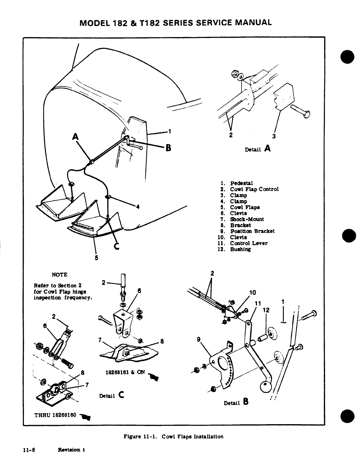
MODEL
182
&
T182
SERIES
SERVICE
MANUAL
,J%
.2
3
\in ^^B
,
Detail
A
1.
Pedestal
2.
Cowl
Flap
Control
3.
Clamp
4.
Clamp
5.
Cowl
Flaps
6.
Clevis
7.
Shock-Mount
8.
Bracket
9.
Positlon
Bracket
10.
Clevis
11.
Control
Lever
12.
Bushing
5
NOTE
2
Refer
to
Section
2
2
for
Cowl
Flap
hinge
,
6
10
inspection
frequency.
2
8
1
y~f 7 ^^^^. B
9
^*^ p^
//
I ^
8
18268161
&
ON
$I~7
0<^^
~
Detail
C
Detail
B
THRU 18268160
-
Figure
11-1.
Cowl
Flaps
Installation
11-6 Revision
1
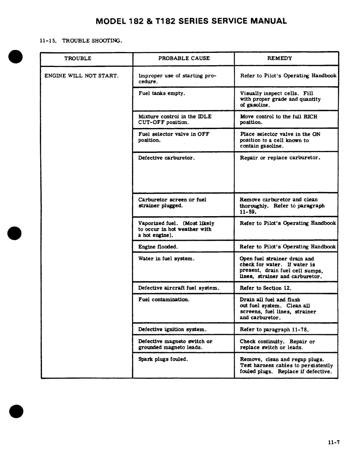
MODEL
182
&
T182
SERIES SERVICE
MANUAL
11-15.
TROUBLE
SHOOTING.
TROUBLE PROBABLE
CAUSE
REMEDY
ENGINE WILL
NOT
START.
Improper
use
of
starting
pro-
Refer
to
Pilot's
Operating
Handbook
cedure.
Fuel
tanks
empty.
Visually
inspect
cells. Fill
with
proper
grade
and
quantity
of
gasoline.
Mixture
control
in
the
IDLE
Move
control
to
the
full
RICH
CUT-OFF
position.
position.
Fuel
selector
valve in
OFF
Place
selector
valve
in
the
ON
position.
position
to
a
cell
known
to
contain gasoline.
Defective
carburetor.
Repair
or
replace
carburetor.
Carburetor screen
or
fuel
Remove
carburetor
and
clean
strainer
plugged.
thoroughly.
Refer
to
paragraph
11-59.
Vaporized
fuel.
(Most
likely
Refer
to
Pilot's
Operating
Handbook
to
occur
in
hot
weather
with
a
hot
engine).
Engine
flooded.
Refer
to
Pilot's
Operating
Handbook
Water
in
fuel
system.
Open
fuel
strainer
drain
and
check
for
water.
If
water
is
present,
drain
fuel
cell
sumps,
lines, strainer
and
carburetor.
Defective
aircraft
fuel
system.
Refer
to
Section
12.
Fuel
contamination.
Drain
all
fuel
and
flush
out
fuel
system.
Clean
all
screens,
fuel
lines,
strainer
and
carburetor.
Defective
ignition
system.
Refer
to
paragraph
11-78.
Defective magneto
switch
or
Check
continuity.
Repair
or
grounded magneto
leads.
replace
switch
or
leads.
Spark
plugs
fouled.
Remove,
clean and
regap
plugs.
Test
harness cables
to
persistently
fouled plugs.
Replace
if
defective.
11-7
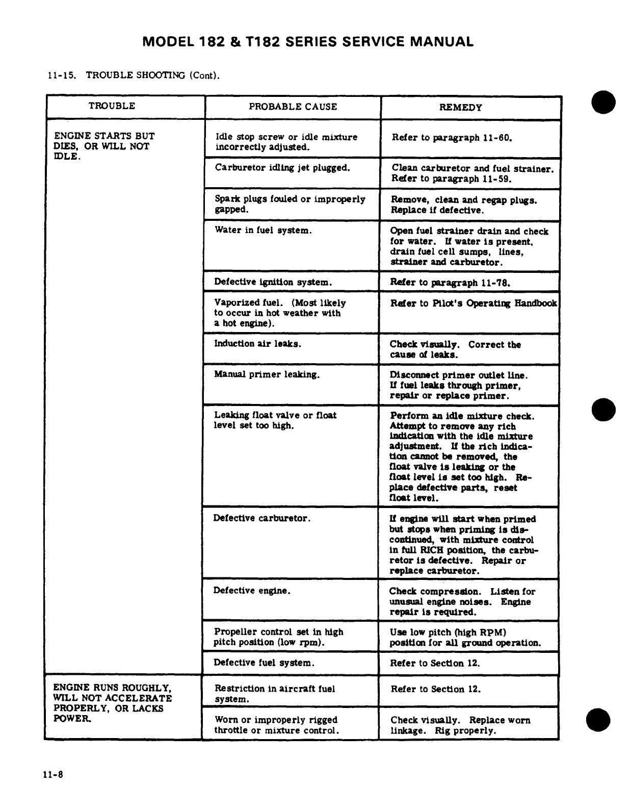
MODEL
182
&
T182
SERIES
SERVICE
MANUAL
11-15.
TROUBLE
SHOOTING
(Cont).
TROUBLE PROBABLE
CAUSE
REMEDY
ENGINE
STARTS
BUT
Idle
stop
screw
or
idle
mixture
Refer
to
paragraph
11-60.
DIES,
OR
WILL
NOT
incorrectly
adjusted.
IDLE.
Carburetor
idling
jet
plugged.
Clean
carburetor
and
fuel
strainer.
Refer
to
paragraph
11-59.
Spark
plugs
fouled
or
improperly
Remove,
clean
and
regap plugs.
gapped.
Replace if
defective.
Water
in
fuel
system.
Open
fuel
strainer
drain
and
check
for
water.
If
water
is
present,
drain
fuel
cell
sumps,
lines,
strainer
and
carburetor.
Defective
ignition
system.
Refer
to
paragraph
11-78.
Vaporized
fuel. (Most
likely
Refer
to
Pilot's
Operating
Handbook
to
occur
in
hot
weather
with
a
hot
engine).
Induction
air
leaks.
Check
visually.
Correct
the
cause
of
leaks.
Manual
primer
leaking.
Disconnect
primer
outlet
line.
If
fuel
leaks
through
primer,
repair
or
replace
primer.
Leaking
float
valve
or
float
Perform
an
idle
mixture
check.
level
set
too
high.
Attempt
to
remove
any
rich
indication
with
the
idle
mixture
adjustment.
If
the
rich
indica-
tion
cannot be
removed, the
float
valve
is
leaking
or
the
float
level
is
set
too high.
Re-
place
defective
parts,
reset
float
level.
Defective
carburetor.
If
engine
will
start
when
primed
but
stops
when
priming
is
dis-
continued,
with
mixture control
in
full
RICH
position,
the
carbu-
retor
is
defective.
Repair
or
replace
carburetor.
Defective engine.
Check
compression. Listen
for
unusual
engine
noises.
Engine
repair
is
required.
Propeller
control
set
in
high
Use
low
pitch
(high RPM)
pitch
position
(low
rpm).
position
for
all
ground
operation.
Defective
fuel
system.
Refer
to
Section
12.
ENGINE
RUNS
ROUGHLY,
Restriction
in
aircraft
fuel
Refer
to
Section
12.
WILL
NOT
ACCELERATE
system.
PROPERLY,
OR
LACKS
POWER.
Worn
or
improperly
rigged
Check
visually.
Replace
worn
throttle
or
mixture
control.
linkage.
Rig
properly.
11-8
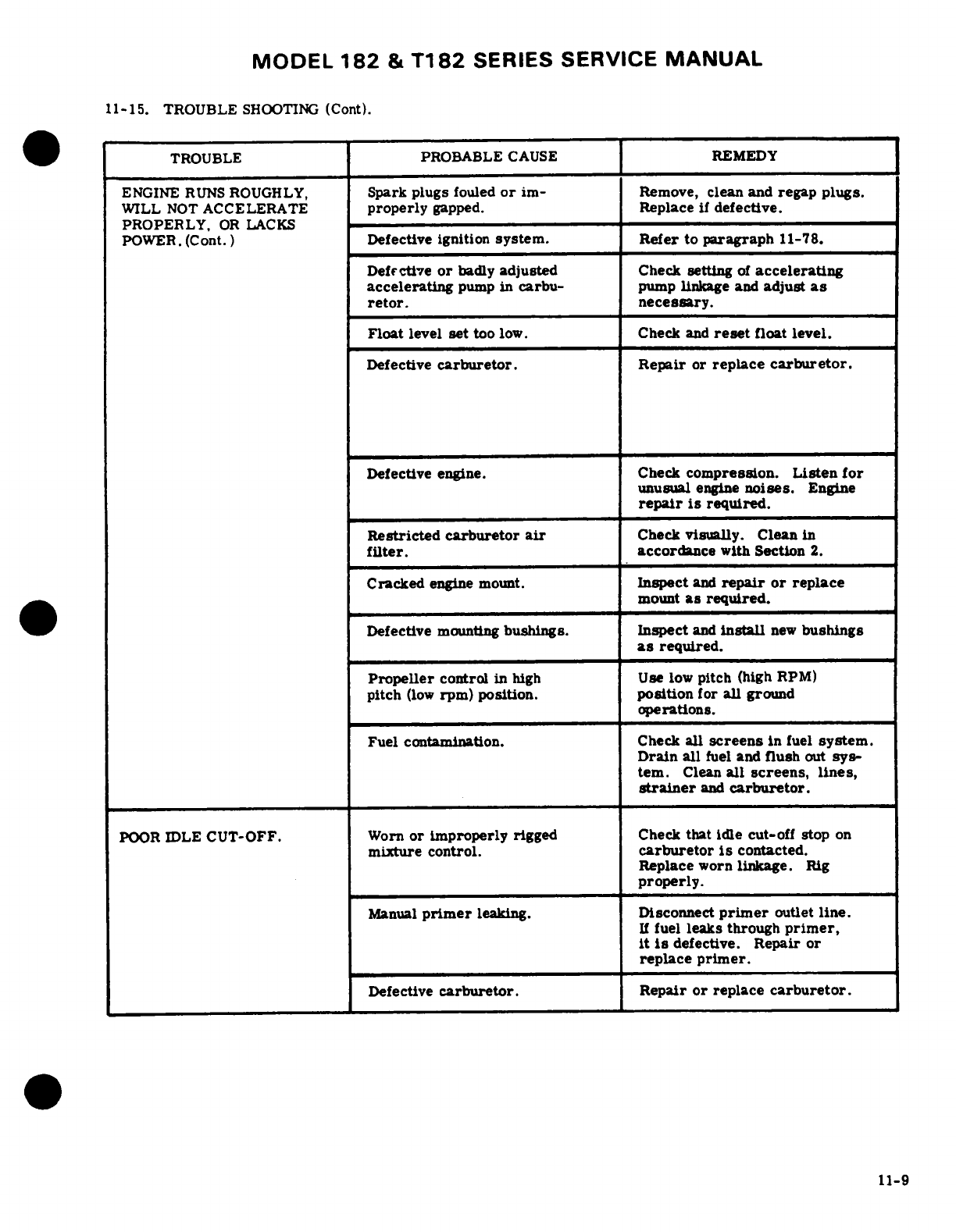
MODEL
182
&
T182
SERIES
SERVICE
MANUAL
11-15.
TROUBLE
SHOOTING
(Cont).
TROUBLE
PROBABLE
CAUSE
REMEDY
ENGINE
RUNS
ROUGHLY,
Spark
plugs
fouled
or
im- Remove,
clean and
regap
plugs.
WILL
NOT
ACCELERATE
properly
gapped.
Replace
if
defective.
PROPERLY,
OR
LACKS
POWER.
(Cont.)
Defective ignition
system.
Refer
to
paragraph
11-78.
Defective
or
badly
adjusted
Check
setting
of
accelerating
accelerating
pump
in
carbu-
pump
linkage and
adjust as
retor.
necessary.
Float
level
set
too
low.
Check
and
reset
float
level.
Defective
carburetor.
Repair
or
replace
carburetor.
Defective
engine.
Check
compression.
Listen
for
unusual
engine
noises.
Engine
repair
is
required.
Restricted
carburetor
air
Check
visually.
Clean
in
filter.
accordance
with
Section
2.
Cracked
engine
mount.
Inspect
and
repair
or
replace
mount
as
required.
Defective
mounting
bushings.
Inspect
and
install
new
bushings
as
required.
Propeller
control
in
high
Use
low
pitch
(high
RPM)
pitch
(low
rpm)
position.
position
for
all
ground
operations.
Fuel
contamination.
Check
all
screens
in
fuel
system.
Drain
all
fuel
and
flush
out
sys-
tem.
Clean
all
screens,
lines,
strainer
and
carburetor.
POOR
IDLE
CUT-OFF.
Worn
or
improperly
rigged
Check
that idle
cut-off
stop
on
mixture control.
carburetor
is
contacted.
Replace
worn
linkage.
Rig
properly.
Manual
primer
leaking.
Disconnect
primer
outlet
line.
If
fuel
leaks
through
primer,
it
is
defective.
Repair
or
replace
primer.
Defective
carburetor.
Repair
or
replace
carburetor.
11-9
MODEL
182
&
T182
SERIES
SERVICE
MANUAL
11-16.
STATIC
RUN-UP
PROCEDURES.
In
a
power
loss.
case
of
suspected
low
engine power,
a
static
RPM
3.
Check
magneto
timing,
spark
plugs
and
run-up
should be conducted
as
follows:
ignition
harness
for
settings
and
condition.
a.
Run
up
engine,
using
take-off
power
and
mix-
4.
Check
condition
of
induction
air
filter.
Clean
ture
settings,
with
the
aircraft
facing
90
°
right
and
if
required.
then
left
to
the
wind
direction.
5.
Perform
an
engine
compression
check.
Refer
b.
Record
the
RPM
obtained
in
each
run-up
posi-
to
engine
manufacturer's
service
manual.
tion.
NOTE
11-17.
REMOVAL.
If
an
engine
is
to
be
placed
in
storage
or
returned
to
the
manufacturer
for
over-
Daily
changes
in
atmospheric
pressure,
haul,
proper
preparatory
steps
should be
taken
for
temperature
and
humidity will
have
a
corrosion
prevention
prior
to
beginning
the
removal
slight
effect
on
static
run-up.
procedure.
Refer
to
Section
2
for
storage
prepara-
tion.
The following
engine
removal
procedure
is
c.
Average
the
results
of
the
RPM
obtained,
it
based
upon
the
engine
being
removed
from
the
air-
should
be
within
50
RPM
of
2380 RPM.
craft
with
the
engine
mount
attached
to
the
firewall.
d.
If
the
average
results
of
the
RPM
obtained
are
lower
than
stated
above,
the
following
recommended
NOTE
checks
may
be
performed
to
determine
a
possible
deficiency. Tag
each
item
when
disconnected
to
aid
in
1. Check
governor
control
for
proper
rigging.
identifying
wires,
hoses,
lines
and
control
It
should
be
determined
that
the
governor
control
linkages
when
engine
is
reinstalled.
Like-
arm travels
to
the
high
RPM
stop
on
the
governor
and
wise,
shop
notes
made
during
removal
will
that
the
high
RPM
stop
screw
is
adjusted properly.
often
clarify
reinstallation.
Protect
open-
(Refer
to
Section
13
for
procedures.
)
ings,
exposed
as
a
result
of
removing
or
disconnecting
units,
against entry
of
foreign
NOTE
material
by
installing
covers
or
sealing
with
tape.
If
verification
of
governor
operation
is
necessary,
the
governor
may
be
removed
a.
Place
all
cabin
switches
in
the
OFF
position.
from
the
engine
and
a
flat
plate
installed
b.
Place
fuel
selector
valve
in
the
OFF
position.
over
the
engine
pad.
Run
up
engine to
c.
Remove
engine
cowling
in
accordance
with
para-
determine
that
governor
was
adjusted graph
11-3.
properly.
d.
Disconnect
battery
cables
and
insulate
terminals
as
a
safety
precaution.
2.
Check
carburetor
heat
control
for
proper
e.
Drain
fuel
strainer
and
lines
with
strainer
drain
rigging.
If
partially
open
it
would
cause
a
slight
control.
SHOP NOTES:
11-10
MODEL
182
&
T182
SERIES
SERVICE
MANUAL
NOTE n.
Disconnect
wires
and
cables
as
follows:
1.
Disconnect
tachometer
drive
shaft
at
adapter.
During the
following
procedures,
remove
any
clamps
or
lacings
which
secure
con-
trols,
wires,
hoses
or
lines
to
the
engine,
engine
mount
or
attached
brackets,
so
When
disconnecting
starter
cable
do
not
they
will
not
interfere
with
engine
removal.
permit
starter
terminal
bolt to
rotate.
Some
of
the
items
listed
can
be
disconnected
Rotation
of
the
bolt
could
break
the
con-
at
more
than
one
place.
It
may
be
desirable
ductor
between
bolt
and
field
coils
caus-
to
disconnect
some
of
these
items
at
other
ing
the
starter
to
be inoperative.
than
the
places
indicated.
The
reason
for
engine
removal
should
be the
governing
fac-
2.
Disconnect
starter
electrical
cable
at
starter.
tor
in deciding
at
which point
to
disconnect
3.
Disconnect
cylinder
head
temperature
wire
at
them.
Omit
any
of
the
items
which
are
not
probe.
present
on
a
particular
engine
installation.
4.
Disconnect
carburetor
air
temperature
wires
at
quick-disconnects.
f.
Drain
the
engine
oil
sump
and
oil
cooler.
5.
Disconnect
electrical
wires
and
wire
shield-
g.
Disconnect
magneto
primary
lead
wires
at
ing
ground
at
alternator.
magnetos.
6.
Disconnect exhaust
gas
temperature
wires
at
wires
or
cables
to
engine
and
pull
wires
and
cables
The
magnetos
are
in
a
SWITCH
ON
condition
aft
to
clear
engine.
when
the
switch
wires
are
disconnected.
o.
Disconnect
lines
and
hoses
as
follows:
Ground
the
magneto
points
or
remove the
high
1.
Disconnect
vacuum
hose
at
vacuum
pump.
tension
wires
from
the
magnetos
or
spark
2.
Disconnect
oil
breather
and
vacuum
system
plugs
to
prevent
accidental
firing.
oil
separator
vent
lines
where
secured
to
the
engine.
h.
Remove
the
spinner
and
propeller
in
accordance
with
Section
13.
Cover
exposed
end of
crankshaft
flange
and
propeller
flange
to
prevent
entry
of
foreign
Residual
fuel
and
oil
draining
from
discon-
material.
nected
lines
and
hoses
constitutes
a
fire
i.
Disconnect
throttle
and
mixture
controls
at
car-
hazard.
Use
caution
to
prevent
accumula-
buretor.
Remove
clamps
attaching
controls
to
engine
tion
of
such
fuel
and
oil
when
lines
or
hoses
and
pull
controls
aft
clear
of
engine.
Use
care to
are
disconnected.
avoid
bending
controls
too
sharply.
Note
EXACT
po-
sition,
size
and
number
of
attaching
washers
and
3.
Disconnect
oil
temperature
bulb below
cooler.
spacers
for
reference
on
reinstallation.
4.
Disconnect
primer
line
at firewall
fitting.
j.
Disconnect
propeller
governor
control
at
gover-
5.
Disconnect
fuel
supply
hose
at
fuel
strainer.
nor.
Note
EXACT
position,
size
and
number
of
at-
6.
Disconnect
oil
pressure
line at
firewall
taching
washers
for
reference
on
reinstallation.
Re-
fitting.
move
clamps attaching
control
to
engine
and
pull
con-
7.
Disconnect
manifold
pressure
line
at
firewall.
trol
aft
clear
of
engine.
p.
Carefully
check
the
engine
again
to
ensure
ALL
k.
Disconnect
all
hot
and cold
air
flexible
ducts
hoses,
lines, wires,
cables,
clamps
and
lacings
are
and
remove. disconnected or removed
which
would
interfere
with
1.
Remove
exhaust
system
in
accordance
with
para-
the
engine
removal.
Ensure
all
wires,
cables
and
graph
11-97.
engine
controls
have
been
pulled
aft
to
clear
the
en-
m.
Disconnect
carburetor
heat
control from
arm
on
gine.
airbox.
Remove
clamps
and
pull
control
clear
of
engine.
SHOP
NOTES:
11-11
MODEL
182
&
T182
SERIES
SERVICE
MANUAL
Place
a
suitable
stand
under
tail
tie-down
Avoid
excessive
flexing
and
sharp
bends
ring
before
removing
engine.
The
loss
of
when
examining
hoses
for
stiffness.
engine weight will
cause
the
aircraft
to
be
tail
heavy.
e.
Refer
to
Section
2
for
replacement
intervals
for
flexible
fluid
carrying
hoses
in
the engine
compart-
q.
Attach
a
hoist
to
the
lifting
lug
at
the
top
center
ment.
of
the engine
crankcase.
Lift
engine
just
enough
to
f.
For major
engine
repairs,
refer
to
the
engine
relieve
the
weight
from
the engine
mount
pads.
manufacturer's
overhaul
and
repair
manual.
r. Remove
bolts
attaching
engine
to engine
mount
pads
and
slowly
hoist
engine
and
pull
it
forward.
11-21.
BUILD-UP.
Engine
build-up
consists
of
in-
Checking
for
any
items
which
would
interfere
with
stallation
of
parts,
accessories
and
components to
the
engine
removal.
Balance
the
engine
by hand
and
the
basic
engine
to
build
up
an
engine
unit
ready
for
carefully
guide
the
disconnected
parts
out
as
the
en-
installation
on
the
aircraft.
All
safety
wire,
lock-
gine
is
removed.
washers,
nuts,
gaskets
and
rubber
connections should
s.
Remove
engine
shock-mount
pads
and
bonding
be
new
parts.
straps.
11-22.
INSTALLATION.
Before
installing
the
engine
11-18.
CLEANING.
Clean
engine
in accordance
on
the
aircraft,
install
any
items
which
were
removed
with
instructions
in
Section
2.
from
the
engine
or
aircraft
after
the
engine
was
re-
moved.
11-19.
ACCESSORIES REMOVAL.
Removal
of
en-
gine
accessories
for
overhaul
or
for
engine
replace-
NOTE
ment involves
stripping
the
engine
of
parts,
acces-
sories
and
components
to
reduce
it
to the
bare
engine. Remove
all
protective
covers,
plugs,
caps
During
the removal
process,
removed
items
should
and
identification
tags
as
each item
is
con-
be
examined
carefully
and
defective
parts
should
be nected
or
installed.
Omit
any
items
not
tagged
for
repair
or
replacement
with
new
compo-
present
on
a
particular
engine
installation.
nents.
a.
Hoist
the
engine
to
a
point
near
the
engine
mount.
NOTE
b.
Install
engine
shock-mount
pads
and
bonding
straps
as
illustrated
in
figure
11-2.
Items
easily
confused with
similar
items
c.
Carefully
lower
engine
slowly into
place
on
the
should
be
tagged
to
provide
a
means
of
engine
mount.
Route
controls,
lines,
hoses
and
identification
when
being
installed
on
a
wires
in
place
as
the
engine
is
positioned
on
the
en-
new
engine.
All
openings
exposed by
the
gine
mount
pads.
removal
of
an
item
should
be
closed by
installing
a
suitable
cover
or
cap
over
NOTE
the
opening.
This
will
prevent
entry
of
foreign
material.
If
suitable
covers
are
Be
sure
engine
shock-mount
pads,
spacers
not
available,
tape
may
be
used
to
cover
and
washers
are
in
place
as
the
engine
is
the openings.
lowered
into
position.
11-20.
INSPECTION.
For
specific items
to
be
in-
d.
Install
engine-to-mount
bolts,
then remove
the
spected,
refer
to
the
engine
manufacturer's
manual.
hoist
and
support stand
placed
under
tail
tie-down
a.
Visually
inspect
the engine
for
loose nuts,
bolts,
fitting.
Torque
bolts
to
450-500
lb-in.
cracks
and
fin
damage.
e.
Route
throttle,
mixture
and
propeller
controls
b.
Inspect
baffles,
baffle
seals
and
brackets
for
to
their
respective
units and connect.
Secure
con-
cracks,
deterioration
and
breakage.
trols
in
position
with
clamps.
c.
Inspect
all
hoses
for
internal
swelling,
chafing
f.
Route
carburetor
heat
control
to
airbox
and con-
through
protective
plies,
cuts,
breaks,
stiffness,
nect.
Secure
control
in
position
with
clamps.
damaged
threads
and
loose
connections.
Excessive
heat
on
hoses
will
cause
them
to become
brittle
and
NOTE
easily
broken.
Hoses
and
lines
are
most
likely
to
crack
or
break
near
the
end
fittings
and
support
Throughout
the
aircraft
fuel
system,
from
the
points.
fuel
cells
to
the
carburator,
use
NS-40
(RAS-4)
d.
Inspect
for
color
bleaching
of
the
end
fittings
or
(Snap-On-Tools
Corp.,
Kenosha,
Wisconsin),
severe
discoloration
of
the
hoses.
11-12
Revision
1
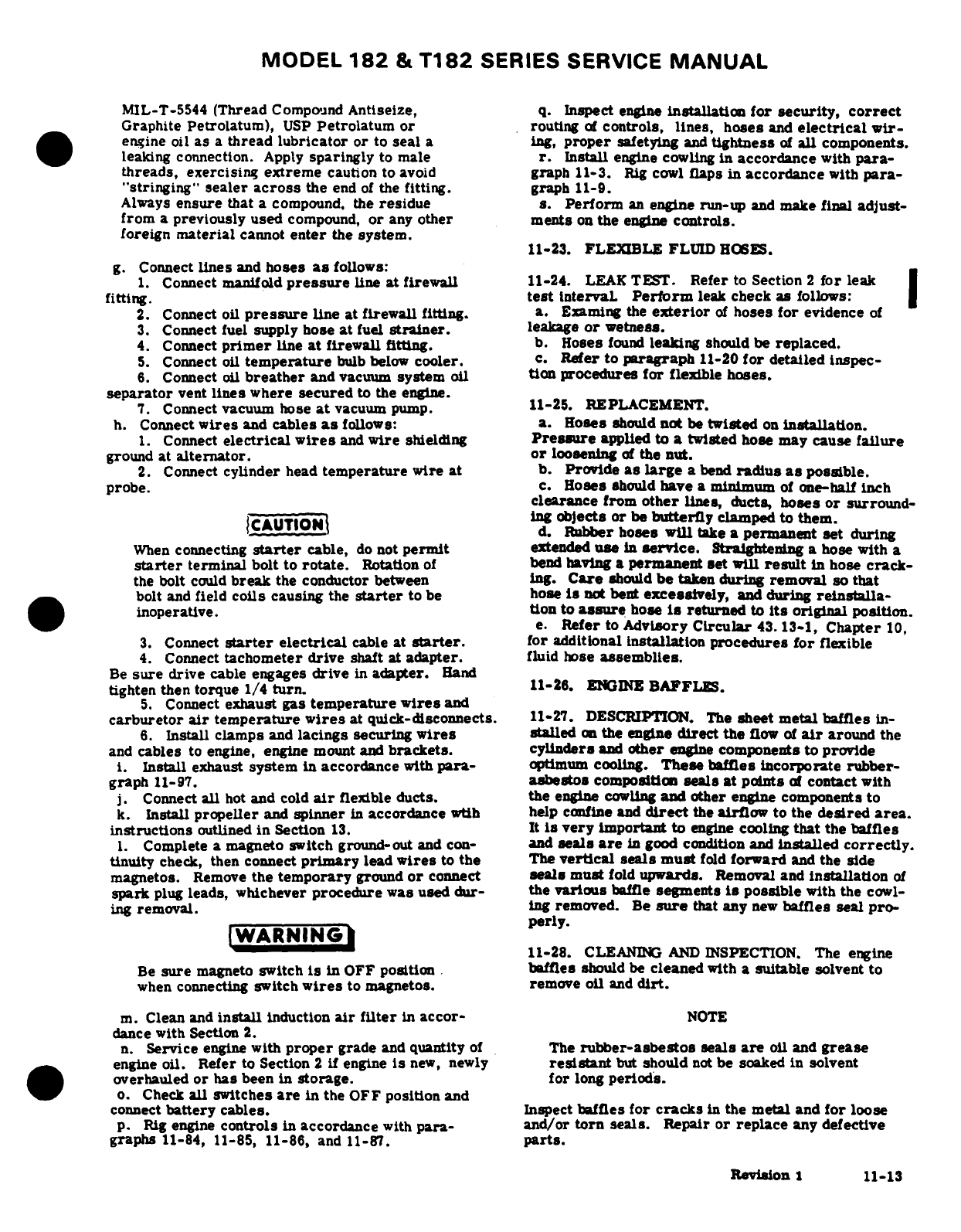
MODEL
182
&
T182
SERIES
SERVICE
MANUAL
MIL-T-5544
(Thread
Compound
Antiseize,
q.
Inspect
engine
installation
for
security,
correct
Graphite
Petrolatum),
USP
Petrolatum
or
routing
of
controls,
lines,
hoses
and
electrical
wir-
engine oil
as
a
thread
lubricator
or
to
seal
a
ing,
proper
safetying
and
tightness
of
all
components.
leaking
connection.
Apply
sparingly
to male
r.
Install
engine cowling
in
accordance
with
para-
threads,
exercising
extreme
caution
to
avoid
graph
11-3.
Rig
cowl
flaps in
accordance
with
para-
"stringing"
sealer
across
the
end
of
the
fitting.
graph
11-9.
Always
ensure
that
a
compound,
the
residue
s.
Perform
an
engine
run-up
and
make
final
adjust-
from
a
previously used
compound,
or
any
other
ments
on
the
engine
controls.
foreign
material
cannot
enter
the
system.
11-23.
FLEXIBLE
FLUID
HOSES.
g.
Connect
lines
and
hoses
as
follows:
1.
Connect
manifold
pressure
line
at
firewall
11-24.
LEAK
TEST.
Refer
to
Section
2
for
leak
fitting.
test
interval.
Perform
leak
check
as
follows:
2.
Connect
oil
pressure
line
at
firewall
fitting.
a.
Examing
the
exterior
of
hoses
for
evidence
of
3.
Connect
fuel
supply
hose
at
fuel
strainer.
leakage
or
wetness.
4.
Connect
primer
line
at
firewall
fitting.
b.
Hoses
found
leaking
should
be
replaced.
5.
Connect
oil
temperature
bulb
below
cooler.
c.
Refer
to
paragraph
11-20
for
detailed
inspec-
6.
Connect
oil
breather
and
vacuum
system
oil
tion
procedures for
flexible
hoses.
separator
vent
lines
where
secured
to
the
engine.
7.
Connect
vacuum hose
at
vacuum
pump.
11-25. REPLACEMENT.
h.
Connect
wires
and
cables
as
follows:
a.
Hoses
should
not
be
twisted
on
installation.
1.
Connect
electrical
wires
and
wire
shielding
Pressure
applied
to
a
twisted
hose
may
cause
failure
ground
at
alternator.
or
loosening
of
the
nut.
2.
Connect
cylinder
head
temperature
wire
at
b.
Provide
as
large
a
bend
radius
as
possible.
probe.
c.
Hoses
should
have
a
minimum
of
one-half
inch
clearance
from
other
lines, ducts,
hoses
or
surround-
When
connecting
starter
cable,
do
not
permit
extended
use
in
service.
Straightening
a
hose with
a
starter
terminal bolt
to
rotate.
Rotation
of
bend having
a permanent
set
will
result
in
hose
crack-
the
bolt
could
break
the
conductor
between
ing.
Care
should
be
taken
during removal
so
that
bolt
and
field
coils
causing
the
starter
to
be
hose
is
not
bent
excessively,
and
during
reinstalla-
inoperative.
tion
to
assure
hose
is
returned
to
its
original
position.
e.
Refer
to
Advisory
Circular
43.13-1,
Chapter
10,
3.
Connect
starter
electrical
cable
at
starter.
for
additional
installation
procedures
for
flexible
4.
Connect
tachometer drive
shaft
at
adapter.
fluid
hose
assemblies.
Be
sure
drive
cable engages
drive
in
adapter.
Hand
tighten then
torque
1/4
turn.
11-26.
ENGINE
BAFFLES.
5.
Connect
exhaust
gas
temperature
wires
and
carburetor
air
temperature
wires
at
quick-disconnects.
11-27. DESCRIPTION. The
sheet
metal
baffles
in-
6.
Install
clamps
and
lacings
securing
wires
stalled
on
the
engine
direct
the
flow
of
air
around the
and
cables
to
engine,
engine
mount
and
brackets.
cylinders
and
other
engine
components
to provide
i.
Install
exhaust
system
in
accordance
with
para-
optimum cooling.
These
baffles
incorporate
rubber-
graph
11-97.
asbestos
composition
seals
at
points
of
contact
with
j.
Connect
all
hot
and
cold
air
flexible
ducts. the
engine
cowling
and
other
engine components
to
k.
Install
propeller
and
spinner
in
accordance
with
help
confine and
direct
the
airflow
to
the
desired
area.
instructions
outlined
in
Section
13.
It
is
very
important
to
engine
cooling
that
the
baffles
1.
Complete
a
magneto
switch ground-out
and
con-
and
seals
are
in
good
condition
and
installed
correctly.
tinuity
check,
then
connect
primary
lead
wires
to
the
The
vertical
seals
must
fold
forward
and
the
side
magnetos.
Remove
the
temporary
ground
or
connect
seals
must
fold
upwards.
Removal and
installation
of
spark
plug
leads,
whichever
procedure
was
used
dur-
the
various
baffle
segments
is
possible
with
the
cowl-
ing
removal.
ing
removed.
Be
sure
that
any
new
baffles seal
pro-
perly.
Be
sure
magneto
switch
is
in
OFF
position
baffles
should
be
cleaned
with
a
suitable
solvent
to
when
connecting
switch
wires
to magnetos. remove
oil
and
dirt.
m. Clean
and
install
induction
air
filter
in
accor-
NOTE
dance
with Section
2.
n.
Service
engine
with
proper
grade
and
quantity
of
The
rubber-asbestos
seals
are
oil
and
grease
engine
oil.
Refer
to
Section
2
if
engine
is
new,
newly
resistant
but
should
not
be
soaked
in solvent
overhauled
or
has
been
in
storage.
for
long
periods.
o.
Check
all
switches
are
in
the
OFF position
and
connect
battery
cables.
Inspect
baffles
for
cracks
in
the metal
and
for
loose
p.
Rig
engine
controls
in
accordance
with
para-
and/or
torn seals.
Repair
or replace
any
defective
graphs
11-84,
11-85,
11-86,
and
11-87.
parts.
Revision
1
11-13
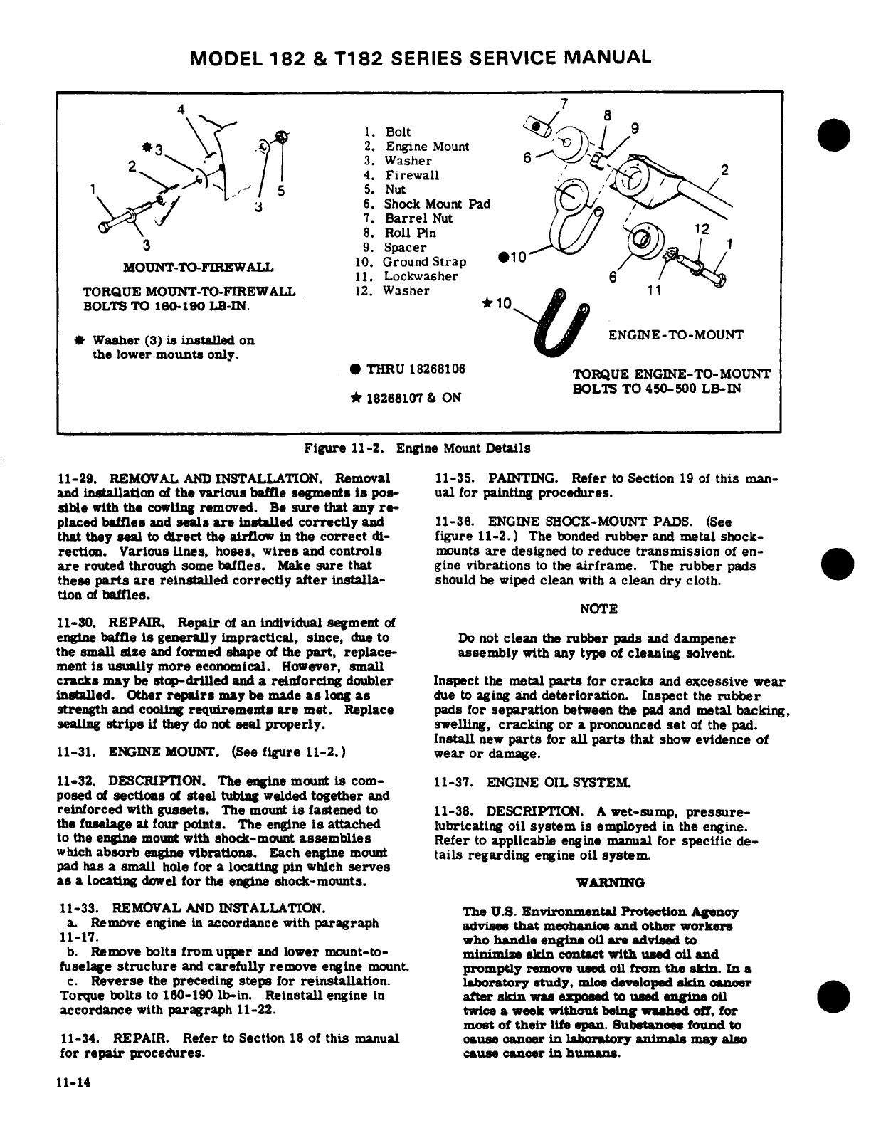
MODEL
182
&
T182
SERIES
SERVICE
MANUAL
*3
\ * 2.
Engine
Mount
' I
2
^ 1 1 3.
Washer
6
/
I
4.
Firewall
/
1 >"
'
l
/
I
,5.
Nut/
3\
"/
3
6.
Shock
Mount
Pad
7.
Barrel
Nut
8.
Roll
Pin
12
3
9.
Spacer
MOUNT-TO-FIREWALL
10.
Ground
Strap
*10
11.
Lockwasher
6
TORQUE
MOUNT-TO-FIREWALL
12.
Washer
11
BOLTS
TO
160-190
LB-IN.
*10
·
Washer
(3)
is
installed
on
NGINE-TO-MOUNT
the
lower
mounts
only.
*
THRU 18268106 TORQUE
ENGINE-TO-MOUNT
18268107
&
ON
BOLTS
TO
450-500 LB-IN
*
18268107
&
ON
Figure
11-2. Engine
Mount
Details
11-29.
REMOVAL
AND
INSTALLATION.
Removal
11-35.
PAINTING.
Refer
to
Section
19
of
this
man-
and
installation
of
the
various
baffle
segments
is
pos- ual for
painting
procedures.
sible
with
the
cowling
removed.
Be
sure
that
any
re-
placed
baffles
and
seals are
installed
correctly
and
11-36.
ENGINE SHOCK-MOUNT
PADS.
(See
that
they
seal
to
direct
the
airflow
in
the
correct
di-
figure
11-2.) The
bonded
rubber
and
metal
shock-
rection. Various
lines,
hoses,
wires
and
controls
mounts
are
designed
to
reduce
transmission
of
en-
are
routed
through
some
baffles.
Make
sure
that
gine
vibrations
to
the
airframe.
The
rubber
pads
these
parts
are
reinstalled
correctly
after
installa-
should
be
wiped
clean
with
a
clean
dry
cloth.
tion
of
baffles.
NOTE
11-30. REPAIR.
Repair
of
an
individual
segment
of
engine
baffle
is
generally
impractical,
since,
due
to
Do
not
clean
the
rubber
pads
and
dampener
the
small
size
and
formed
shape
of
the
part,
replace-
assembly
with
any
type
of
cleaning
solvent.
ment
is
usually
more
economical.
However,
small
cracks
may
be
stop-drilled
and
a
reinforcing
doubler
Inspect
the
metal
parts
for
cracks
and
excessive
wear
installed.
Other
repairs
may
be
made
as
long
as
due
to
aging
and
deterioration.
Inspect
the
rubber
strength
and
cooling
requirements
are
met.
Replace pads
for
separation
between
the
pad
and
metal
backing,
sealing
strips
if
they
do
not
seal
properly.
swelling,
cracking
or
a
pronounced
set
of
the
pad.
Install
new
parts
for
all
parts
that
show
evidence
of
11-31.
ENGINE
MOUNT.
(See
figure
11-2.)
wear
or
damage.
11-32.
DESCRIPTION.
The
engine
mount
is
com-
11-37.
ENGINE
OIL
SYSTEM.
posed
of
sections
of
steel
tubing welded
together
and
reinforced
with
gussets.
The
mount
is
fastened
to
11-38.
DESCRIPTION.
A
wet-sump,
pressure-
the
fuselage
at
four points.
The
engine is
attached
lubricating
oil
system
is
employed
in
the engine.
to
the engine
mount
with
shock-mount
assemblies
Refer
to
applicable
engine
manual
for specific
de-
which
absorb
engine
vibrations.
Each
engine mount
tails
regarding
engine
oil
system.
pad
has
a
small
hole
for
a
locating
pin
which
serves
as
a
locating
dowel
for
the engine
shock-mounts.
WARNING
11-33.
REMOVAL
AND
INSTALLATION.
The
U.S.
Environmental Protection
Agency
a.
Remove engine
in
accordance
with
paragraph
advises
that
mechanics
and
other
workers
11-17.
who
handle
engine
oil
are
advised
to
b.
Remove
bolts
from
upper
and
lower
mount-to-
miniTnmz
skin
contact
with
used
oil
and
fuselage
structure
and
carefully
remove
engine
mount.
promptly
remove
used
oil
from
the skin.
In
a
c.
Reverse
the
preceding
steps
for
reinstallation.
laboratory
study.
mice
developed
skin
cancer
Torque
bolts
to
160-190
Ib-in.
Reinstall
engine
in
after
skin
was
exposed
to
used
engine
oil
accordance
with
paragraph
11-22.
twice
a
week
without
being washed
off,
for
most
of
their
life
span.
Substance
found
to
11-34.
REPAIR.
Refer
to
Section
18
of
this
manual
cause
cancer
in
laboratory animals
may also
for
repair
procedures.
cause
cancer
in
humans.
11-14

MODEL
182
&
T182
SERIES SERVICE
MANUAL
11-39.
TROUBLE
SHOOTING.
TROUBLE
PROBABLE
CAUSE
REMEDY
NO
OIL
PRESSURE.
No
oil
in
sump.
Check
with
dipstick.
Fill
sump
with
proper
grade and
quantity
of
oil.
Refer
to
Section
2.
Oil
pressure
line
broken,
Inspect
pressure
lines.
Replace
disconnected
or
pinched.
or
connect
lines
as
required.
Oil pump
defective.
Remove
and
inspect.
Examine
engine.
Metal
particles
from
damaged
pump
may
have
entered
engine
oil
passages.
Defective oil
pressure
gage.
Check
with
a
known
good
gage.
If
second
reading
is
normal,
replace
gage.
Oil
congealed
in
gage
line.
Disconnect
line
at
engine
and gage;
flush
with
kerosene.
Pre-fill
with
kerosene
and
install.
Relief
valve defective.
Remove
and
check
for
dirty
or
de-
fective
parts.
Clean
and
install;
replace
valve
if
defective.
LOW
OIL PRESSURE.
Low
oil
supply. Check
with
dipstick.
Fill
sump
with
proper
grade
and
quantity
of
oil.
Refer
to
Section
2.
Low
viscosity
oil.
Drain
sump and
refill
with
proper
grade
and
quantity
of
oil.
Oil
pressure
relief
valve
spring
Remove
and
inspect
spring.
weak
or
broken.
Replace
weak
or
broken
spring.
Defective
oil
pump.
Check
oil
temperature
and
oil
level.
If
temperature
is
higher
than
normal
and oil
level
is
correct,
internal
failure
is
evident.
Remove
and
inspect.
Examine
engine. Metal
particles
from
damaged
pump
may
have
entered
oil
passages.
Secondary
result
of
high
oil
Observe
oil
temperature
gage for
temperature.
high
indication. Determine
and
correct
reason
for
high
oil
tem-
perature.
Dirty
oil
screens.
Remove
and
clean
oil
screens.
11-15
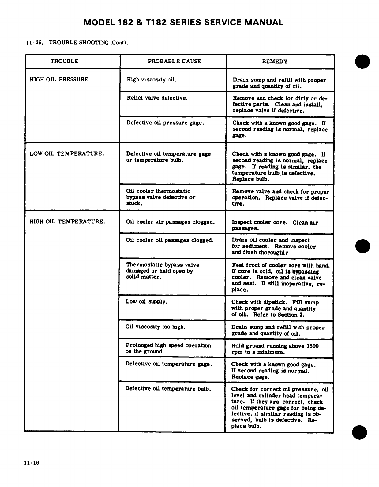
MODEL
182
&
T182
SERIES SERVICE
MANUAL
11-39.
TROUBLE
SHOOTING
(Cont).
TROUBLE
PROBABLE
CAUSE
REMEDY
HIGH
OIL
PRESSURE.
High
viscosity
oil.
Drain
sump
and
refill
with
proper
grade
and
quantity
of
oil.
Relief
valve
defective.
Remove
and
check
for
dirty or
de-
fective
parts.
Clean
and
install;
replace
valve
if
defective.
Defective oil
pressure
gage.
Check with
a
known
good
gage.
If
second
reading
is
normal,
replace
gage.
LOW
OIL
TEMPERATURE.
Defective
oil
temperature
gage
Check with
a
known
good
gage.
If
or
temperature
bulb.
second
reading
is
normal,
replace
gage.
If
reading
is
similar,
the
temperature
bulb
is
defective.
Replace
bulb.
Oil
cooler
thermostatic
Remove valve
and
check
for
proper
bypass
valve
defective
or
operation.
Replace
valve
if
defec-
stuck.
tive.
HIGH
OIL
TEMPERATURE. Oil
cooler
air
passages
clogged.
Inspect
cooler
core.
Clean
air
passages.
Oil
cooler
oil
passages
clogged.
Drain
oil cooler
and
inspect
for
sediment.
Remove
cooler
and
flush
thoroughly.
Thermostatic
bypass
valve
Feel
front
of
cooler
core
with
hand.
damaged
or
held
open
by
If
core
is cold,
oil
is
bypassing
solid
matter.
cooler.
Remove
and
clean
valve
and
seat.
If
still
inoperative,
re-
place.
Low
oil
supply.
Check
with
dipstick.
Fill
sump
with
proper
grade
and
quantity
of
oil.
Refer to
Section
2.
Oil
viscosity
too
high.
Drain
sump
and
refill
with
proper
grade
and
quantity
of
oil.
Prolonged
high
speed
operation
Hold
ground
running
above
1500
on
the
ground.
rpm
to
a
minimum.
Defective oil
temperature
gage.
Check
with
a
known
good
gage.
If
second
reading
is
normal.
Replace
gage.
Defective
oil
temperature
bulb.
Check
for
correct
oil
pressure,
oil
level
and
cylinder
head
tempera-
ture.
If
they
are
correct,
check
oil
temperature
gage
for
being
de-
fective;
if
similar
reading
is
ob-
served,
bulb
is
defective.
Re-
place
bulb.
11-16
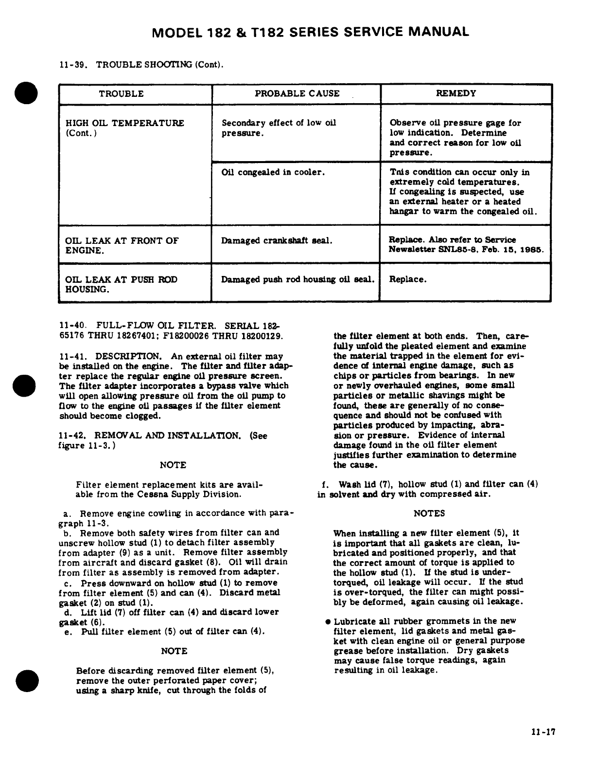
MODEL
182
&
T182
SERIES SERVICE
MANUAL
11-39.
TROUBLE
SHOOTING
(Cont).
HIGH
OIL
TEMPERATURE
Secondary
effect
of
low
oil
Observe
oil
pressure
gage for
(Cont.)
pressure.
low
indication.
Determine
and
correct
reason
for
low
oil
pressure.
Oil
congealed
in
cooler.
Tnis
condition
can
occur
only
in
extremely
cold
temperatures.
If
congealing
is
suspected,
use
an
external
heater
or
a
heated
hangar to
warm
the
congealed oil.
OIL
LEAK AT FRONT
OF
Damaged
crankshaft
seal.
Replace.
Also
refer
to
Service
ENGINE.
Newsletter
SNL85-8,
Feb.
15,
1985.
OIL
LEAK
AT
PUSH ROD
Damaged push
rod housing
oil
seal.
Replace.
HOUSING.
11-40.
FULL-FLOW
OIL
FILTER.
SERIAL
182-
65176
THRU
18267401;
F18200026
THRU
18200129.
the
filter
element
at
both
ends.
Then,
care-
fully
unfold
the
pleated
element
and
examine
11-41.
DESCRIPTION.
An
external
oil
filter
may
the
material
trapped
in
the
element
for
evi-
be
installed
on
the
engine.
The
filter
and
filter
adap- dence
of
internal
engine
damage,
such
as
ter
replace
the
regular
engine
oil
pressure
screen.
chips
or particles
from bearings.
In
new
The
filter
adapter
incorporates
a
bypass
valve
which
or
newly
overhauled
engines, some
small
will
open
allowing
pressure
oil
from
the
oil
pump
to
particles
or
metallic
shavings might
be
flow
to the
engine oil
passages
if
the
filter
element
found,
these
are
generally
of
no
conse-
should
become clogged.
quence
and
should
not
be
confused with
particles
produced
by
impacting,
abra-
11-42.
REMOVAL
AND
INSTALLATION.
(See
sion
or
pressure.
Evidence
of
internal
figure
11-3.)
damage
found
in
the
oil
filter
element
justifies
further
examination
to
determine
NOTE
the
cause.
Filter
element
replacement
kits
are
avail-
f. Wash
lid
(7),
hollow
stud
(1)
and
filter
can
(4)
able
from
the
Cessna
Supply
Division.
in
solvent
and
dry
with
compressed
air.
a.
Remove
engine
cowling
in
accordance
with
para-
NOTES
graph
11-3.
b.
Remove
both
safety
wires
from
filter
can
and
When
installing
a
new
filter
element
(5),
it
unscrew
hollow
stud
(1)
to detach
filter
assembly
is
important
that
all
gaskets
are
clean,
lu-
from
adapter
(9)
as
a
unit.
Remove
filter
assembly
bricated
and
positioned
properly,
and
that
from
aircraft
and
discard
gasket
(8).
Oil
will
drain
the
correct
amount
of
torque
is
applied
to
from
filter
as assembly
is
removed
from
adapter.
the
hollow
stud
(1).
If
the
stud
is
under-
c.
Press
downward
on
hollow
stud
(1)
to
remove
torqued,
oil
leakage
will occur.
If
the
stud
from
filter
element
(5)
and
can
(4).
Discard
metal
is
over-torqued, the
filter
can
might
possi-
gasket
(2)
on
stud
(1).
bly
be
deformed,
again
causing oil
leakage.
d.
Lift lid
(7)
off
filter
can
(4)
and
discard
lower
gasket
(6).
Lubricate all
rubber
grommets
in
the
new
e.
Pull
filter
element
(5)
out
of
filter
can
(4).
filter
element,
lid
gaskets
and
metal
gas-
ket
with
clean
engine
oil
or
general
purpose
NOTE
grease
before
installation.
Dry
gaskets
may
cause
false
torque
readings,
again
Before
discarding
removed
filter
element
(5),
resulting
in
oil
leakage.
remove
the
outer
perforated
paper
cover;
using
a
sharp
knife, cut
through
the
folds
of
11-17
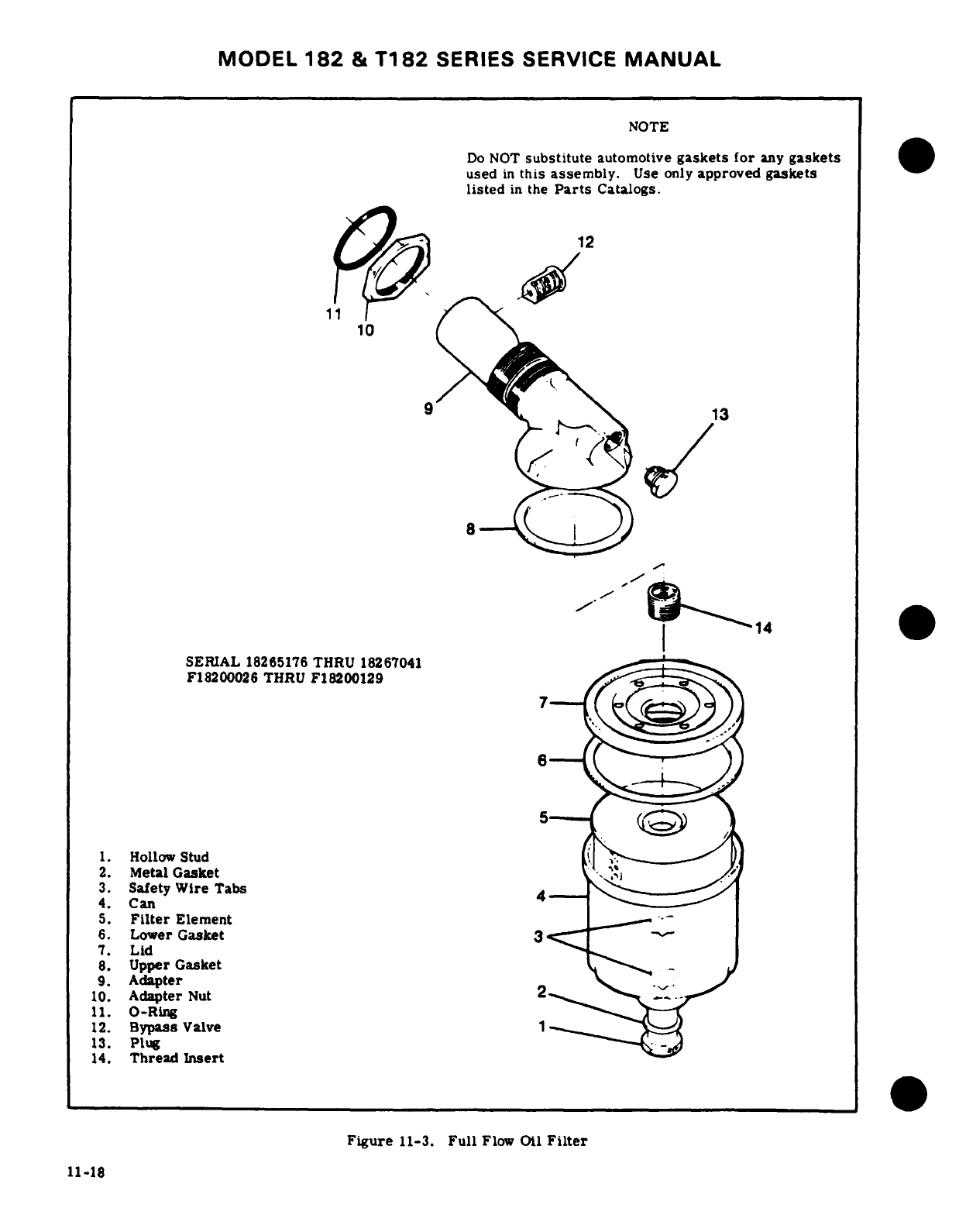
MODEL
182
&
T182
SERIES
SERVICE
MANUAL
NOTE
Do
NOT
substitute
automotive
gaskets for
any
gaskets
used
in
this
assembly.
Use
only
approved
gaskets
listed
in
the
Parts
Catalogs.
12
11
10
9
f~
13
'
^14
SERIAL
18265176
THRU
18267041
F18200026
THRU
Fl8200129
1.
Hollow
Stud
2.
Metal
Gasket
3.
Safety
Wire Tabs
4
4.
Can
5.
Filter
Element
6.
Lower
Gasket
3
7.
Lid
8.
Upper
Gasket
9.
Adapter
10.
Adapter
Nut
11.
O-Ring
12.
Bypass
Valve
13.
Plug
14.
Thread
Insert
Figure
11-3.
Full
Flow
Oil
Filter
11-18
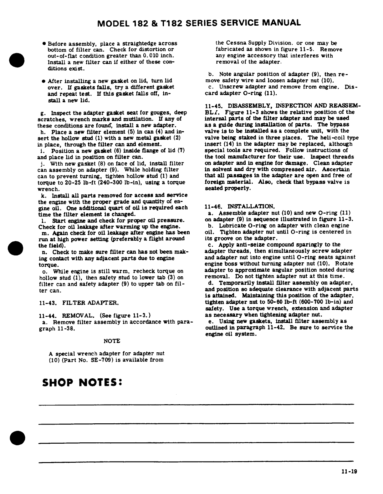
MODEL
182
&
T182
SERIES
SERVICE
MANUAL
Before
assembly,
place
a
straightedge
across
the
Cessna
Supply
Division.
or
one
may
be
bottom
of
filter
can.
Check
for
distortion
or
fabricated
as
shown
in
figure
11-5.
Remove
out-of-flat
condition
greater
than
0.
010
inch.
any
engine
accessory
that
interferes
with
Install
a
new
filter
can
if
either
of
these
con-
removal
of
the
adapter.
ditions
exist.
b.
Note
angular
position
of
adapter
(9),
then
re-
After
installing
a new
gasket
on
lid,
turn
lid
move
safety
wire
and
loosen
adapter
nut
(10).
over.
If
gaskets
falls,
try
a
different gasket
c.
Unscrew
adapter
and
remove from
engine.
Dis-
and
repeat
test.
If
this
gasket
falls
off,
in-
card
adapter
O-ring
(11).
stall
a
new
lid.
11-45.
DISASSEMBLY,
INSPECTION
AND
REASSEM-
g.
Inspect
the
adapter
gasket
seat
for
gouges,
deep
BLI.
Figure
11-3
shows
the
relative
position
of
the
scratches,
wrench
marks
and
mutilation.
If
any
of
internal
parts
of
the
filter
adapter
and
may
be
used
these
conditions
are
found,
install
a
new
adapter.
as
a
guide
during
installation
of
parts.
The
bypass
h.
Place
a
new
filter
element
(5)
in
can
(4)
and
in-
valve
is
to
be
installed
as
a
complete
unit,
with
the
sert
the
hollow
stud
(1)
with
a
new
metal
gasket
(2)
valve
being
staked
in
three
places.
The
heli-coil
type
in
place,
through
the
filter
can
and
element.
insert
(14)
in the
adapter
may be
replaced,
although
i.
Position
a
new
gasket
(6)
inside
flange
of
lid
(7)
special
tools
are
required.
Follow
instructions
of
and
place
lid
in
position
on
filter
can.
the
tool
manufacturer for
their
use.
Inspect
threads
j.
With
new
gasket
(8)
on
face
of
lid,
install
filter
on
adapter
and
in
engine
for
damage.
Clean adapter
can
assembly
on
adapter
(9).
While
holding
filter
in
solvent
and
dry
with
compressed
air.
Ascertain
can
to
prevent
turning,
tighten
hollow
stud
(1)
and
that
all
passages
in
the
adapter
are
open
and
free
of
torque
to
20-25
lb-ft
(240-300
lb-in),
using
a
torque
foreign
material.
Also,
check
that
bypass
valve
is
wrench.
seated
properly.
k.
Install
all
parts
removed
for
access
and
service
the
engine
with
the
proper
grade
and
quantity
of
en-
gine
oil.
One
additional
quart
of
oil
is
required
each
11-46.
INSTALLATION.
time
the
filter
element
is
changed.
a.
Assemble
adapter
nut
(10)
and
new
O-ring
(11)
l.
Start
engine and
check
for
proper
oil
pressure.
on
adapter
(9)
in
sequence
illustrated
in
figure
11-3.
Check
for
oil
leakage
after
warming
up
the engine.
b.
Lubricate O-ring
on
adapter
with
clean
engine
m.
Again
check
for
oil
leakage
after
engine
has
been
oil.
Tighten
adapter
nut
until
O-ring
is
centered
in
run
at
high
power
setting
(preferably
a
flight around
its
groove
on
the
adapter.
the
field).
c.
Apply
anti-seize
compound
sparingly
to
the
n. Check
to
make
sure
filter
can
has
not
been
mak-
adapter
threads,
then
simultaneously
screw
adapter
ing
contact
with
any
adjacent
parts
due
to
engine and
adapter
nut
into
engine
until
O-ring
seats
against
torque.
engine
boss
without
turning
adapter
nut
(10).
Rotate
o.
While
engine
is
still
warm,
recheck torque
on
adapter
to
approximate
angular
position
noted
during
hollow
stud
(1),
then
safety
stud
to
lower tab
(3)
on
removal.
Do
not
tighten
adapter
nut
at
this
time.
filter
can
and
safety
adapter
(9)
to
upper
tab
on
fil-
d.
Temporarily
install
filter
assembly
on
adapter,
ter
can.
and
position
so
adequate
clearance
with
adjacent
parts
is
attained.
Maintaining
this
position
of
the
adapter,
11-43.
FILTER
ADAPTER.
tighten
adapter
nut
to
50-60
lb-ft
(600-700
lb-in)
and
safety.
Use
a
torque
wrench,
extension
and
adapter
11-44.
REMOVAL.
(See
figure
11-3.)
as
necessary
when
tightening
adapter
nut.
a.
Remove
filter
assembly
in
accordance
with
para-
e.
Using
new
gaskets,
install
filter
assembly
as
graph
11-38.
outlined in
paragraph
11-42.
Be
sure
to
service
the
engine
oil
system.
NOTE
A
special
wrench
adapter
for
adapter
nut
(10)
(Part
No.
SE-709)
is
available
from
SHOP
NOTES:
11-19
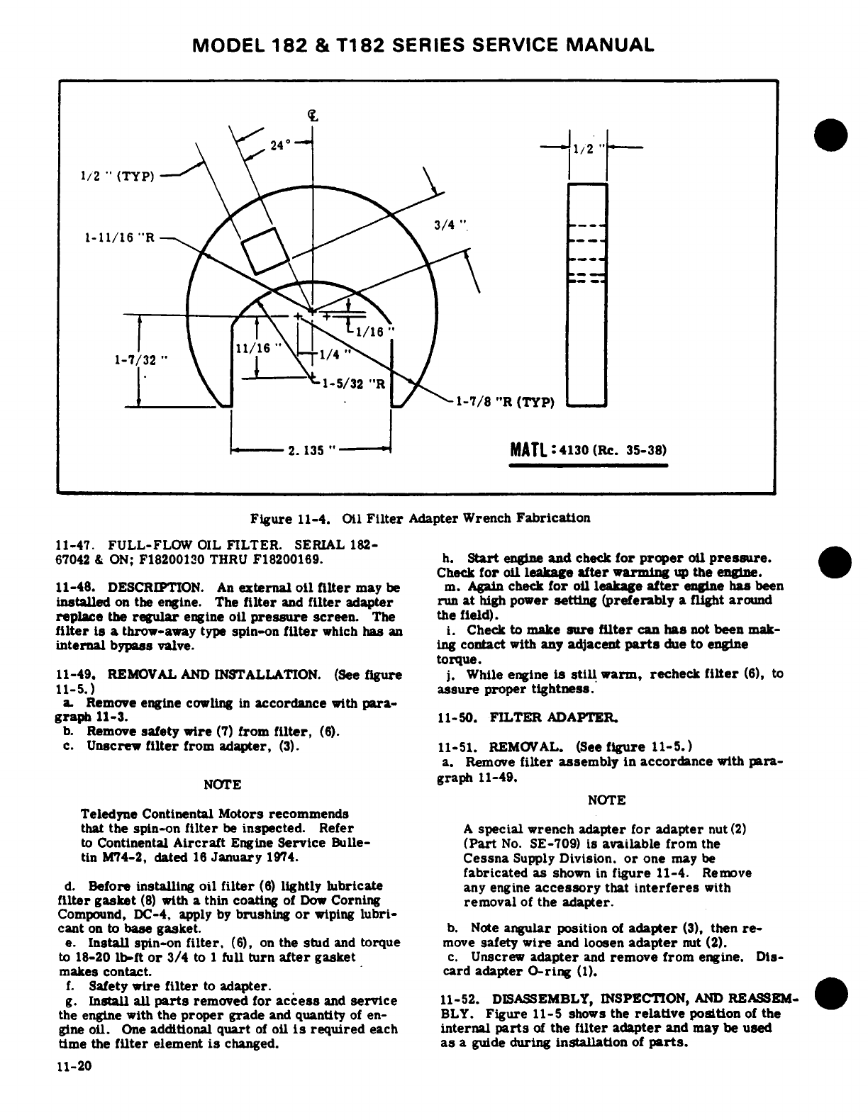
MODEL
182
&
T182
SERIES
SERVICE
MANUAL
1/2
"
(TYP)
1-11/16
"R
1-7/8
"R
(TYP)
·-
L
2.
135
-"
MATL:
4130
(Rc.
35-38)
Figure
11-4.
Oil
Filter
Adapter
Wrench
Fabrication
11-47.
FULL-FLOW
OIL
FILTER.
SERIAL
182-
67042
&
ON;
F18200130
THRU
F18200169.
h.
Start
engine
and
check
for
proper
oil
pressure.
Check
for
oil
leakage
after
warming
up
the
engine.
11-48.
DESCRIPTION.
An
external
oil
filter
may
be
m.
Again
check
for
oil
leakage
after
engine
has
been
installed
on
the
engine. The
filter
and
filter
adapter
run
at
high
power
setting
(preferably
a
flight
around
replace
the
regular
engine
oil
pressure
screen.
The
the
field).
filter
is
a
throw-away
type
spin-on
filter
which
has
an
i.
Check
to
make
sure
filter
can
has
not
been
mak-
internal
bypass
valve.
ing
contact
with
any
adjacent
parts
due
to
engine
torque.
11-49.
REMOVAL
AND
INSTALLATION.
(See
figure
j.
While
engine
is
still
warm,
recheck
filter
(6),
to
11-5.)
assure
proper
tightness.
a.
Remove
engine
cowling
in
accordance
with
para-
graph
11-3. 11-50.
FILTER
ADAPTER.
b.
Remove
safety wire
(7)
from
filter,
(6).
c.
Unscrew
filter
from
adapter,
(3).
11-51.
REMOVAL.
(See
figure
11-5.)
a.
Remove
filter
assembly
in accordance
with
para-
NOTE
graph
11-49.
NOTE
Teledyne
Continental
Motors recommends
that
the
spin-on
filter
be
inspected.
Refer
A
special
wrench
adapter
for
adapter
nut
(2)
to
Continental
Aircraft
Engine
Service
Bulle-
(Part
No.
SE-709)
is
available
from
the
tin
M74-2,
dated
16
January
1974.
Cessna
Supply
Division.
or
one
may
be
fabricated
as
shown
in
figure
11-4.
Remove
d.
Before
installing
oil
filter
(6)
lightly
lubricate
any
engine
accessory
that
interferes
with
filter
gasket
(8)
with
a
thin
coating
of
Dow
Corning
removal
of
the
adapter.
Compound,
DC-4,
apply
by
brushing
or
wiping
lubri-
cant
on
to
base
gasket.
b.
Note
angular position
of
adapter
(3),
then
re-
e.
Install
spin-on
filter,
(6),
on
the
stud
and
torque
move
safety
wire
and
loosen
adapter
nut
(2).
to 18-20
lb-ft
or
3/4
to 1
full
turn
after
gasket
c.
Unscrew
adapter
and
remove from
engine.
Dis-
makes
contact. card
adapter O-ring
(1).
f.
Safety
wire
filter
to
adapter.
g.
Install
all
parts
removed
for
access
and
service
11-52.
DISASSEMBLY,
INSPECTION,
AND
REASSEM-
the engine with
the
proper
grade
and
quantity
of
en-
BLY.
Figure
11-5
shows
the
relative
position
of
the
gine
oil.
One
additional
quart
of
oil
is
required
each
internal
parts
of
the
filter
adapter
and
may be
used
time
the
filter
element
is
changed.
as
a
guide
during
installation
of
parts.
11-20
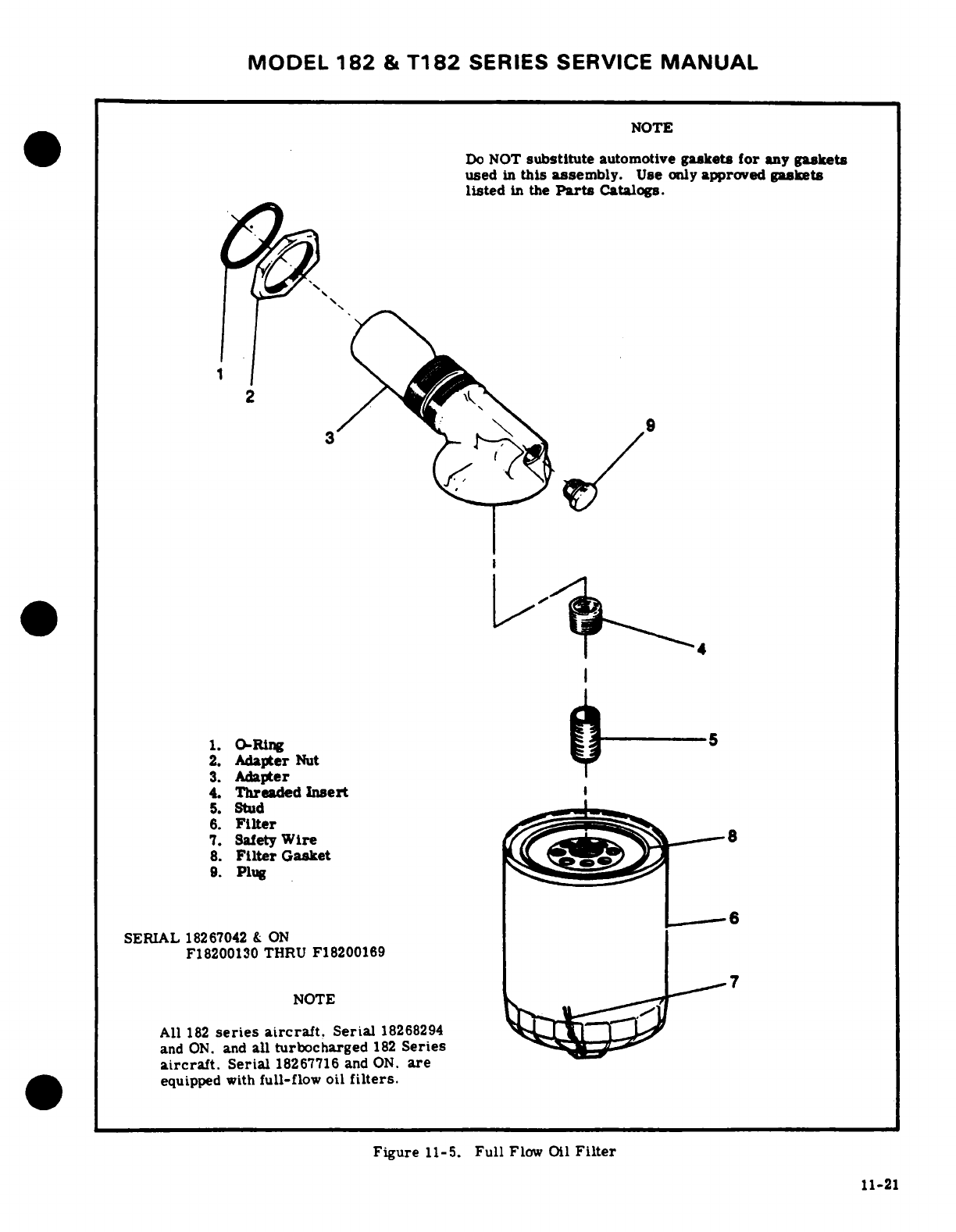
MODEL
182
&
T182
SERIES SERVICE
MANUAL
NOTE
Do
NOT
substitute
automotive
gaskets
for
any
gaskets
used
in
this assembly.
Use
only
approved
gaskets
listed
in
the
Parts
Catalogs.
2
1.
O-Ring
2.
Adapter
Nut
3.
Adapter
4.
Threaded
Insert
5.
Stud
6.
Filter
7.
Safety
Wire
8.
Filter
Gasket
9.
Plug
SERIAL
18267042
&
ON
F18200130
THRU
F18200169
7
NOTE
All
182
series aircraft.
Serial
18268294
and
ON.
and
all
turbocharged
182
Series
aircraft.
Serial
18267716 and
ON.
are
equipped
with
full-flow
oil
filters.
Figure
11-5.
Full
Flow Oil
Filter
11-21
MODEL
182
&
T182
SERIES
SERVICE
MANUAL
The
heli-coil
type
insert
(4)
in
the
adapter
may
be
11-58.
CARBURETOR.
replaced,
although
special
tools
are
required.
Follow
instructions
of
the
tool
manufacturer for
11-59.
REMOVAL
AND
INSTALLATION.
their
use.
Inspect
threads
on
adapter
and
in
engine
a.
Place
fuel
selector
valve
in
the
OFF
position.
for
damage.
Clean
adapter
in
solvent
and
dry
with
b.
Remove
engine
cowling
in
accordance
with
para-
compressed
air.
Ascertain
that
all
passages
in
the
graph
11-3.
adapter
are
open and
free
of
foreign
matter.
c.
Drain
fuel
from
strainer
and
lines
with
strainer
drain
control.
11-53.
INSTALLATION.
d.
Remove
airbox
in
accordance
with
paragraph
a.
Assemble
adapter
nut
(2)
and
new
O-ring
(1)
11-64.
on
adapter
(3)
in
sequence
illustrated
in
figure
e.
Disconnect
throttle
and
mixture
controls
at
11-3.
carburetor.
Note
EXACT
position,
size
and
number
b.
Lubricate
O-ring
on
adapter
with
clean
engine
of
attaching
washers
and
spacers
for
reference
on
oil.
Tighten
adapter
nut
until
O-ring
is
centered
reinstallation.
in
its
groove
on
the
adapter.
f.
Disconnect and
cap
or
plug
fuel
line
at
carbure-
c.
Apply
anti-seize
compound
sparingly
to
the
tor.
adapter
threads,
then
simultaneously
screw
adapter
g.
Remove
safety wire,
nuts
and
washers
attaching
and
adapter
nut
into
engine
until
O-ring
seats
against
carburetor
to
intake
manifold
and
remove
carburetor
engine
boss
without
turning
adapter
nut
(2).
Rotate
and
mounting
gasket.
adapter
to
approximate angular
position
noted
during
h.
Reverse
the
preceding
steps
for
reinstallation.
removal.
Do
not
tighten
adapter
nut
at
this
time.
Use
new
gaskets
when
installing
carburetor.
Rig
d.
Temporarily
install
filter
assembly
on
adapter,
controls
in
accordance
with
paragraphs
11-84,
11-85,
and
position
so
adequate
clearance
with
adjacent
and
11-86. (Check
carburetor
throttle
arm
to
idle
stop
parts
is
attained.
Maintaining
this
position
of
the
arm
attachment
for
security
and
proper
safetying
at
adapter,
tighten
adapter
nut
to
600
to
700
in-lb
and
each
normal
engine
inspection
in
accordance
with
fig-
safety.
Use
a
torque
wrench,
extension
and
adapter
ure
11-7.)
as
necessary
when
tightening
adapter
nut.
e.
Install
filter
assembly
as
outlined
in
paragraph
11-60.
IDLE
SPEED
AND
MIXTURE
ADJUSTMENTS.
11-49.
Be
sure
to
service
the
engine
oil
system.
Idle
speed
and
mixture
adjustment
should
be
accom-
plished
after
the
engine
has
been
warmed
up.
Since
idle
RPM
may
be affected
by
idle
mixture
adjustment,
it
may
be
necessary
to
readjust
idle
RPM
after
set-
11-54.
OIL
COOLER.
ting
the
idle
mixture
correctly.
a.
Set
the
throttle
stop
screw (idle
RPM)
to
obtain
11-55.
DESCRIPTION.
A
non-congealing oil
cooler
600±25
RPM,
with
throttle
control
pulled full
out
may be
installed
on
the
aircraft.
The
cooler
is
against
idle
stop.
mounted
on
the
right
forward
side
of
the
engine
crank-
case
directly
in
front
of
number
five
cylinder
and
has
NOTE
no
external oil
lines.
Ram
air
passes
through
the
oil
cooler
and
is
discharged
into
the
engine
compartment.
Engine
idle
speed
may
vary
among
different
Oil
circulating
through the
engine
is
allowed
to
circu-
engines.
An
engine
should
idle
smoothly,
late
continuously through
warm-up
passages
to
pre-
without
excessive
vibration
and
the
idle
speed
vent
the
oil
from
congealing
when
operating
in
low
should be
high
enough
to maintain
idling
oil
temperatures.
On
the
standard
and
non-congealing
pressure
and
to
preclude any
possibility
of
oil
coolers,
as
the
oil
increases
to
a
certain
tempera-
engine
stoppage
in
flight
when
the
throttle
is
ture,
the
thermostat
valve
closes,
causing
the
oil
to
closed.
be
routed
to
all
of
the
cooler
passages
for
cooling.
Oil
returning
to
the
engine
from
the
cooler
is
routed
b.
Advance
throttle
to
increase
engine
speed
to
through
the
internally
drilled
oil
passages.
approximately
1000
RPM
c.
Pull
mixture
control
knob
slowly
and
steadily
11-56.
ENGINE
FUEL
SYSTEM.
toward the
idle cut-off
position,
observing
tacho-
meter,
then
return
control
full
IN
(RICH)
position
11-57.
DESCRIPTION.
The engine
is
equipped
with
before
engine
stops.
a
carburetor
mounted
at
the
lower
side
of
the
engine.
d.
Adjust
mixture
adjusting
screw
at
upper
end
of
The
carburetor
is
of
the
plain-tube
fixed-jet
type
and
carburetor
intake
throat
to
obtain
a
slight
and
has
such
features
as
an
enclosed
accelerating
pump
mentary
gain
of
25
RPM
maximum
at
1000
RPM
en-
mechanism, simplified
fuel
passages
to
prevent
vapor
gine
speed
as
mixture
control
is
moved
from
full
IN
locking,
idle
cut-off
to
prevent
starting
of
the
engine
(RICH)
toward
idle
cut-off position.
Return
control
accidentally
and
manual
mixture
control
for
leaning.
to
full
IN
(RICH)
to
prevent
engine
stoppage.
For
overhaul
and
repair
of
the
carburetor,
refer
to
e.
If
mixture
is
set
too
LEAN,
engine
speed
will
the
manufacturer's
overhaul
and
repair
manual. drop
immediately,
thus
requiring
a
richer
mixture.
11-22
MODEL
182
&
T182
SERIES
SERVICE
MANUAL
Turn
adjusting
screw
OUT
(counterclockwise)
for
a
box.
Inspect
gaskets
and
install
new
gaskets,
if dam-
richer
mixture.
aged.
Check
manually-operated
air
door
for
ease
of
f.
If
mixture
is
set
too
RICH,
engine
speed
will
operation
and
proper
rigging.
increase
above
25
RPM.
thus
requiring
a
leaner
mixture.
Turn adjusting
screw
IN
(clockwise)
for
11-65A.
INSTALLATION
OF
INLET
DUCTS.
When
a
leaner
mixture.
cutting
duct
assembly
to
length,
the
support
wire
should
be
out
back
far
enough
to bend
back
(mini-
NOTE
mum
bend
radius
1.8
inch)
under
the
clamp
and
pro-
trude
1/4
inch.
Do
not
break
the
bond
between
wire
After
each
adjustment
to
the
idle
mixture,
and
fabric.
Before
tightening
clamps,
make
sure
there
run
engine
up
to
approximately
2000
RPM
is
no
twist
or
torque on
hose.
If
hose
is
wrapped
to
clear
engine
of
excess
fuel
to
obtain
a with
MIL-Y-1140
cord
in
place
of
wire
support, the
correct
idle
speed.
same
installation
procedure
applies
except;
MIL.Y-
1140
has
no
minumum
bend
radius
requirement.
11-61.
INDUCTION
AIR
SYSTEM.
The
minimum
installed
bend
radius
for
wire
11-62.
DESCRIPTION.
Ram
air
enters
the
induc-
supported
hose
in
the
plane
of
bend
is
as
tion
air
system
through
a
filter
at
the
front
of
the
follows:
lower
cowling
and
is
ducted
to the
airbox
at
the
car-
1.
Neoprene, one-ply
hose
-1/4
diameter
of
the
buretor.
From
the
induction
airbox
the
filtered
air
maximum
hose
dimension.
is
directed
to
the
inlet
of
the
carburetor,
mounted
2.
Neoprene,
two-ply
hose
and
silicone,
one-ply
on
the lower
side
of
the
engine,
through
the
carbure-
hose
-1/3
diameter
of
the
maximum
hose
dimension.
tor,
where fuel
is
mixed with
the
air,
to
the
intake
4.
Silicone,
two-ply
hose
-
1/2
diameter
of
the
manifold.
From
the
intake
manifold,
the
fuel-air
maximum
hose
dimension.
mixture
is
distributed
to
each
cylinder
by
separate
intake
pipes.
The
intake
pipes
are
attached
to
the
11-66.
INDUCTION
AIR
FILTER.
manifold
with
hoses
and
clamps
and
to
the
cylinder
with
a
four
bolt
flange
sealed
with
a
gasket.
A
butter-
11-67.
DESCRIPTION.
An
induction
air
filter,
fly
valve,
located
in
the
airbox,
may be
operated
mounted
at
the
induction
air
inlet
on
the
front
of
the
manually
from the cabin
to
permit
the
selection
of
lower
cowling,
removes
dust
particles
from
the
ram
either
cold
or
heated
air.
When
the
induction
air
door
air
entering
the
engine.
is
closed,
heated
air
is
drawn
from
a
shroud
on
the
left
exhaust
stack
assembly.
11-68.
REMOVAL
AND
INSTALLATION.
a.
Remove
screws
securing
filter
cover,
release
11-63.
AIRBOX.
the
quick-release fasteners
securing
the
filter
assem-
bly
and
lift
filter
out
of
nose
cap.
11-64.
REMOVAL
AND
INSTALLATION.
b.
Reverse
the
preceding
steps
for
reinstallation.
a.
Remove
engine
cowling
in
accordance
with
para-
graph
11-3.
b.
Disconnect flexible
duct
from
left
side
of
airbox. inspect
filter
in
accordance
with
instructions
in
c.
Disconnect
boot
from
forward
end
of
airbox.
Section
2.
d.
Disconnect
carburetor
heat
control
at
arm
on
NOTE
right
side
of
airbox
and
remove
clamp
securing
con-
e.
Remove
mounting
bolt safety
wire,
remove
bolts
filter
gasket
becomes
loose,
and
gasket
and
carefully
remove
airbox.
bond
with
EC-1300L
or
equivalent.
f.
Reverse
the
preceding
steps
for
reinstallation.
Rig
carburetor
heat
control
in
accordance
with
para-
11-70.
IGNITION
SYSTEM.
graph
11-86.
11-71.
DESCRIPTION.
The
ignition
system
is
com-
11-65.
CLEANING
AND
INSPECTION.
Clean
metal
prised
of
two
magnetos,
two
spark
plugs
in
each
cyl-
parts
of
the
induction
air
box
with
Stoddard
solvent
inder,
an
ignition
wiring
harness,
an
ignition
switch
or
equivalent.
Inspect
for
cracks,
dents, loose
mounted
on
the
instrument
panel
and
required
wiring
rivets,
etc.
Minor
cracks
may
be
stop-drilled.
In
between
the ignition
switch
and
magnetos.
case
of
continued
or
severe
cracking,
replace
air
SHOP
NOTES:
Revision
1
11-23

MODEL
182
&
T182
SERIES
SERVICE
MANUAL
11-72.
TROUBLE
SHOOTING.
TROUBLE PROBABLE
CAUSE
REMEDY
ENGINE
FAILS
TO
START.
Defective
ignition
switch. Check switch
continuity.
Replace
if
defective.
Spark
plugs
defective,
improperly
Clean, regap
and
test
plugs.
gapped
or
fouled
by
moisture or
Replace
if
defective.
deposits.
Defective
ignition
harness.
If
no
defects
are
found
by
a
visual
inspection,
check
with
a
harness
tester.
Re-
place
defective
parts.
Magneto
"P"
lead
grounded.
Check
continuity.
"P"
lead
should
not
be
grounded in the
ON
position,
but
should
be
grounded in
OFF position.
Repair
or
replace
"P"
lead.
Failure
of
impulse
coupling.
Impulse
coupling
pawls
should
engage
at
cranking
speeds.
Listen
for
loud
clicks
as
impulse
couplings
operate.
Remove
magnetos
and
determine
cause.
Replace
defective
magneto.
Defective
magneto.
Refer
to
paragraph
11-78.
Broken
drive
gear.
Remove
magneto
and check
mag-
neto
and
engine
gears.
Replace
defective
parts.
Make
sure
no
pieces
of
damaged
parts
remain
in
engine
or
engine
disassembly
will
be
required.
ENGINE
WILL
NOT
Spark
plugs defective,
im-
Clean,
regap
and
test
plugs.
IDLE
OR
RUN
PROPERLY.
properly
gapped
or
fouled
Replace
if
defective.
by
moisture
or
deposits.
Defective ignition
harness.
If
no
defects
are
found
by
a
visual
inspection,
check
with
a
harness
tester.
Replace
defective
parts.
Defective
magneto.
Refer
to
paragraph
11-78.
Impulse
coupling
pawls
Listen
for
loud
clicks
as
impulse
remain
engaged.
coupling
operates.
Remove
magneto and
determine
cause.
Replace
defective
magneto.
Spark
plugs loose.
Check
and
install
properly.
11-24
MODEL
182
&
T182
SERIES SERVICE
MANUAL
11-73.
MAGNETOS.
NOTE
11-74.
DESCRIPTION.
The
magnetos
contain
a
con-
As
the
magneto
is
removed
from
its
mount-
ventional
two-pole
rotating
magnet
(rotor),
mounted
ing,
be
sure
that
the
drive
coupling
rubber
in
ball
bearings.
Driven
by
the
engine
through an
bushing
and
retainer
do
not
become
dislodged
impulse
coupling
at
one
end,
the
rotor
shaft
operates
from the
gear
hub
and
fall
into
the
engine.
the
breaker
points
at
the
other
end
of
the
shaft.
The
nylon
rotor
gear
drives
a
nylon
distributor
gear
which
11-76.
INTERNAL
TIMING.
transfers
high
tension
current
from
the
wedge-mount-
a.
Whenever
the
gear
on
the
rotor
shaft
or
the
cam
ed
coil
to
the
proper
outlet
in
the
distributor
block.
(which
also
serves as
the key
for
the
gear) has
been
A
coaxial
capacitor
is
mounted in
the
distributor
block
removed,
be
sure
that
the
gear
and
cam
are
installed
housing
to
serve
as
the
condenser
as
well
as
a
radio
so
the
timing
mark
on
the
gear
aligns
with
the
"O"
noise
suppressor.
Both
nylon
gears
are
provided
etched
on
the
rotor
shaft
with
timing
marks
for
clockwise
or
counterclockwise
b.
When
replacing
breaker
assembly
or
adjusting
rotation.
The
distributor
gear
and
distributor
block
contact
breaker
points,
place
a
timing pin
(or
0.
093
have
timing
marks,
visible
through
the
air
vent holes,
inch
6-penny nail)
through
the timing
hole
in
the
bot-
for
timing
to
the
engine.
A
timing
hole
is
provided
tom
of
the
magneto
next
to
the
flange
and
into the
in
the bottom
of
the
magneto
adjacent
to
the
magneto
mating
hole
in
the
rotor
shaft.
Adjusting
contact
flange.
A
timing
pin
or
6-penny nail
can
be
inserted
breaker
points
so
they
are
just
starting
to
open
in
through
this
timing
hole
into the
mating
hole
in
the
this
position
will
give
the
correct
point
setting.
rotor
shaft
to
lock
the magneto
approximately
in
the
Temporarily
assemble
the
magneto
halves
and
cap-
proper firing
position.
The
breaker
assembly
is
acitor
slip
terminal
and
use
a
timing light
to
check
accessible
only
after
removing
the
screws
fastening
that
the
timing
marks,
visible
through the
ventilation
the
magneto
halves
together
and
disconnecting
the
plug
holes
are
approximately
aligned.
capacitor
slip
terminal.
Do
not
separate
magneto
halves
while
it
is installed
on
the
engine
or
internal
NOTE
timing
may
be
disturbed.
The
sideof
the
magneto
with
the
manu-
11-75.
REMOVAL.
facturer's
insignia
has
a
red
timing
mark
a.
Remove
engine
cowling
in
accordance
with
para-
and
the
side
opposite
to the
insignia
has
graph
11-3.
a
black
timing
mark
viewed
through
the
b.
Tag
for
identification
and
remove
high
tension
vent plug
holes.
The
distributor
gear
wires
from
the
magneto
being
removed. also
has
a
red
timing
mark
and
a
black
on
the
engine.
Do
not
place
red
and
black
The
magneto
is
in
a
SWITCH
ON
condition
lines
together
on
the
same
side.
when
the
switch
wire
is
disconnected.
Re-
move
the high
tension
wires
from
magneto
c.
Whenever
the
large distributor
gear
and
rotor
or disconnect
spark
plug
leads
from
the
gear
have been
disengaged,
they
must
be
engaged
spark
plugs
to
prevent
accidental
firing.
with
their
timing
marks
aligned
for
correct
rotation.
Align
the timing
mark
on
the
rotor
gear
with
the
c.
Disconnect
switch
wire
from
condenser
terminal
"RH"
on
the
distributor
gear.
Care
must
be
taken
to
at
magneto.
Tag
wire
for
identification
so
it
may
be
keep
these
two
gears
meshed
in
this
position
until
installed
correctly.
the magneto
halves
are
assembled.
d.
Rotate
propeller
in
direction
of
normal
rotation
until
No.
1
cylinder
is
coming
up
on
its
compression
11-77.
INSTALLATION
AND
TIMING
TO
ENGINE.
stroke.
The
magneto
MUST
be
installed
with
its
timing
marks
correctly
aligned,
with
the
number
one
cylin-
NOTE
der
on
its
compression
stroke
and
with
number
one
piston
at
its
advanced
firing
position.
Refer
to
para-
To
facilitate
the
installation
of
a
replacement
graph
11-12
for
the
advanced
firing
position
of
num-
magneto,
it
is
good
practice
to
position
the
ber
one
piston.
crankshaft
at
the
advanced
firing
angle
for
No.
1
cylinder
during
step
"d."
Any
standard
timing
device
or
method
can
be
used,
or
if
the
magneto
being removed
is
correctly
timed
to
the
engine,
the
crankshaft
can
be
rotated to
a
The magneto
is
grounded
through
the
ignition
position
at
which
the
breaker
points
will
be
switch,
therefore,
any
time
the
switch
just
opening
to
fire
No.
1
cylinder.
(primary)
wire
is
disconnected
from
the
magneto,
the
magneto
is
in
a
switch
ON
or
e.
Remove
magneto
retainer
clamps,
nuts
and
HOT
condition.
Before
turning
the
propeller
washers
and
pull
magneto
from
crankcase
mounting by
hand,
remove the
high
tension
wires
from
pad.
the
magneto
or
disconnect
all
spark
plug
leads
to
prevent
accidental
firing
of
the
engine.
Revision
1
1-25
MODEL
182
&
T182
SERIES SERVICE
MANUAL
To
locate
the
compression stroke
of
number
one cy-
c.
Connect
a
timing
light
to
the
capacitor
terminal
linder,
remove
the
lower spark plugs
from
each
cy-
at
the
front
of
the
magneto
and
to
a
good
ground.
Under
except
number
one
cylinder.
Remove
the
top
d.
Turn
propeller
back a
few
degrees
(opposite
of
plug
from number
one
cylinder.
Place
thumb
of
one
normal
rotation)
to
close
the
contact
points.
hand
over
the
number
one
cylinder
spark
plug
hole
and
rotate
the
crankshaft
in
the
direction
of
normal
NOTE
rotation
until the
compression
stroke
is
indicated
by
positive
pressure
inside
the
cylinder
lifting
the
thumb
Do
not
turn
the
propeller
back
far
enough
to
off
the
spark
plug hole.
After
the
compression stroke
engage
the impulse
coupling
or
the
propeller
is
obtained,
locate
number
one
piston
at
its
advanced
will
have
to
be
turned
in
normal
direction
of
firing
position.
Locating
the
advanced
firing
position
rotation
until
the
impulse
coupling
releases,
of
number
one
cylinder
may
be
obtained
by
use
of
a
then
backed
up
to
slightly
before
the
firing
timing
disc
and
pointer,
Timrite,
protractor
and
position.
piston
locating
gage
or
external
engine
timing
marks
alignment. e.
Slowly
advance
the
propeller
in
the
normal
direc-
tion
of
rotation
until
the
timing
light
indicates
the
con-
NOTE
tact
points
breaking.
Magneto
mounting
clamps
may
be
loosened
so
that
the
magneto
may be
shifted
to
External
engine
timing
marks
are
located
on
break
the
points
at
the
correct
firing
position.
a
bracket
attached
to
the
starter
adapter,
f.
Tighten magneto
mounting
nuts
and
recheck
with
a
timing
mark
on
the
alternator
drive
timing.
pulley
as
the
reference
point.
g.
Repeat
steps
"a"
through
"f"
for
the
other
mag-
neto.
In
all
cases,
it
must
be definitely
determined
that
the
h.
After
both
magnetos
have
been
timed,
check
syn-
number
one
cylinder
is
at
the
correct
firing
position
chronization
of
both
magnetos.
Magnetos
must
fire
and
on
the
compression
stroke,
when
the
crankshaft
at
the
same
time.
is
turned
in
its
normal
direction
of
rotation. After
i.
Remove
timing
devices
from
magneto
and
engine.
the
engine
has
been
placed in
the
correct
firing
posi-
j.
Connect
spark
plug
leads
to
their
correct
mag-
tion,
install
and
time
the
magneto
to
the engine
in the
neto
outlets.
following
manner.
NOTE
NOTE
The
No.
1
magneto
outlet
is
the
one
closest
Install
the
magneto
drive
coupling
retainer
to
the
ventilation
plug
on
the
side
of
the
and
rubber
bushings
into
the
magneto
drive
magneto having
the
manufacturer's
insignia.
gear
hub
slot.
Insert
the
two
rubber
bush-
The
magneto
fires
at
each
successive
outlet
ings
into
the
retainer
with
the
chamfered
in
clockwise
direction.
Connect
No.
1
mag-
edges
facing toward
the
front
of
the
engine.
neto
outlet
to
No.
1
cylinder.spark
plug
lead,
No.
2
outlet
to
the
next
cylinder
to
fire,
etc.
a.
Turn the
magneto shaft
until
the
timing
marks
Engine
firing
order
is
listed
in
paragraph
visible
through the
ventilation
plug
holes
are
aligned
11-12.
(red-to-red
or
black-to-black)
and
insert
a
timing
pin
(or
0.
093
inch
6-penny
nail)
through the
timing
hole
in
the
bottom
of
the
magneto
next
to
the
flange
k.
Connect
toggle
switch
(primary)
lead
to
the
ca-
and into
the
mating
hole
in
the
rotor
shaft.
This
pacitor
terminal
on
the
magneto.
locks
the magneto
approximately
in
the
firing
posi-
tion
while
installing
on
the
engine.
NOTE
NOTE
Magneto
(primary)
lead
nut
torque range
is
13-15
in.
-lbs.
Exceeding
this
torque range
If
the
magneto
drive
gear was
disengaged
could
result
in
possible condenser
damage.
during
magneto
removal,
hold
the
magneto
in
the
horizontal
position
it
will
occupy
1.
Inspect
magneto
installation
and
install
engine
when
installed,
make
certain
that
the
drive
cowling
in
accordance
with
paragraph
11-3.
gear
coupling
slot
is
aligned
with
the
mag-
neto
coupling
lugs.
If
it
is
not
aligned,
pull
the
magneto
drive
gear
out
of
mesh
with
its
11-78.
MAINTENANCE.
Refer
to
Section
2
for
in-
drive
gear
and
rotate
it
to
the
aligned angle,
spection
intervals
for
the
breaker
compartment.
Re-
then push
it
back
into
mesh.
DO
NOT
WITH-
fer
to
Section
2
for
intervals
for
checking
magneto-
DRAW
THE
MAGNETO
DRIVE
GEAR
FROM
to-engine
timing.
If
timing
is
24
(plus
0,
minus
2),
ITS OIL
SEAL.
b.
After
magneto
gasket
in
place,
position
the
magneto
on
the
engine
and
secure,
then
remove
the
timing
pin
from
the
magneto.
Be
sure
to
remove
this
pin
before
turning
the
propeller.
11-26
Revision
1
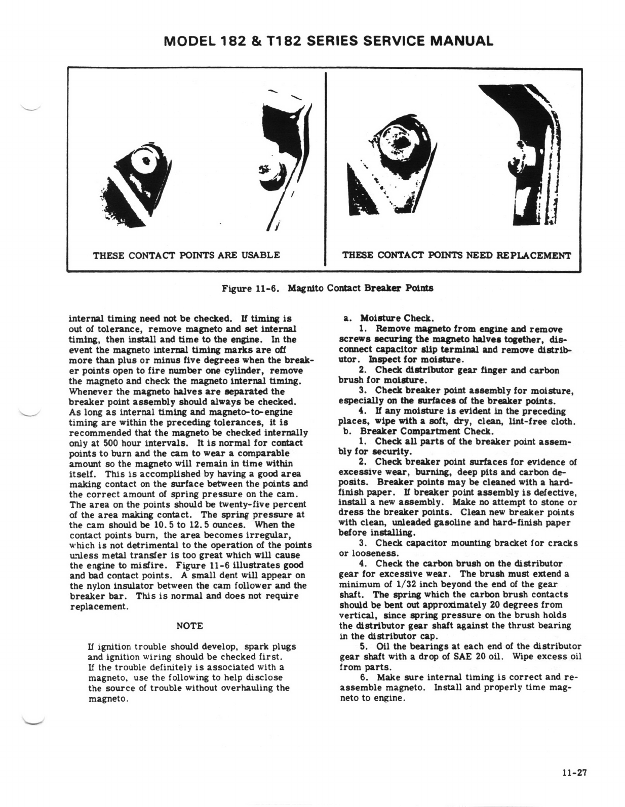
MODEL
182
&
T182
SERIES SERVICE
MANUAL
THESE
CONTACT
POINTS
ARE
USABLE THESE
CONTACT POINTS
NEED
REPLACEMENT
Figure
11-6.
Magnito
Contact
Breaker
Points
internal
timing
need
not
be
checked.
If
timing
is
a.
Moisture
Check.
out
of
tolerance,
remove
magneto
and
set
internal
1.
Remove
magneto
from
engine
and
remove
timing,
then
install
and
time
to the
engine.
In
the
screws
securing
the
magneto
halves together,
dis-
event
the
magneto
internal
timing
marks
are
off
connect
capacitor
slip
terminal
and
remove
distrib-
more
than
plus
or
minus
five
degrees
when
the
break-
utor.
Inspect
for
moisture.
er
points
open
to
fire
number
one
cylinder, remove
2.
Check
distributor
gear
finger
and
carbon
the
magneto
and
check
the
magneto
internal
timing.
brush
for
moisture.
Whenever
the
magneto
halves
are
separated
the
3.
Check
breaker
point
assembly for
moisture,
breaker
point
assembly
should
always
be
checked.
especially
on
the
surfaces
of
the
breaker
points.
As
long
as
internal
timing
and
magneto-to-engine
4.
If
any
moisture
is
evident
in
the
preceding
timing
are
within
the
preceding
tolerances,
it
is
places,
wipe with
a
soft,
dry,
clean,
lint-free
cloth.
recommended
that
the
magneto
be
checked
internally
b.
Breaker
Compartment
Check.
only
at
500
hour
intervals.
It is
normal
for
contact
1.
Check
all
parts
of
the
breaker
point
assem-
points
to
burn
and
the
cam
to
wear
a
comparable
bly
for security.
amount
so
the magneto
will
remain
in
time
within
2.
Check
breaker
point
surfaces
for
evidence
of
itself.
This
is
accomplished
by
having
a
good
area
excessive
wear,
burning,
deep
pits
and
carbon
de-
making
contact
on
the
surface
between
the
points
and
posits.
Breaker
points
may be
cleaned
with
a
hard-
the
correct
amount
of
spring
pressure
on
the
cam.
finish
paper.
If
breaker
point
assembly
is
defective,
The
area
on
the
points
should be
twenty-five
percent
install
a
new
assembly.
Make
no
attempt
to
stone
or
of
the
area
making
contact.
The
spring
pressure
at
dress
the
breaker
points.
Clean
new
breaker
points
the
cam
should
be
10.
5
to
12.
5
ounces.
When
the
with
clean,
unleaded
gasoline
and
hard-finish
paper
contact
points
burn,
the
area
becomes
irregular,
before installing.
which
is not
detrimental
to
the
operation
of
the
points
3.
Check
capacitor
mounting
bracket
for
cracks
unless
metal
transfer
is
too
great
which
will
cause or
looseness.
the
engine to
misfire.
Figure
11-6
illustrates
good
4.
Check
the
carbon
brush
on
the
distributor
and bad
contact
points.
A
small
dent will
appear
on
gear
for
excessive
wear.
The
brush
must
extend
a
the
nylon
insulator
between
the
cam
follower
and the
minimum
of
1/32
inch
beyond
the
end
of
the
gear
breaker bar.
This
is
normal
and
does
not
require
shaft.
The
spring
which
the
carbon
brush
contacts
replacement.
should be
bent
out
approximately
20
degrees
from
vertical,
since spring
pressure
on
the
brush
holds
NOTE
the
distributor
gear
shaft
against
the
thrust
bearing
in
the
distributor
cap.
If
ignition
trouble
should develop,
spark
plugs
5.
Oil
the
bearings
at
each
end
of
the
distributor
and
ignition
wiring
should
be
checked
first.
gear
shaft
with
a
drop
of SAE
20
oil.
Wipe
excess
oil
If
the
trouble definitely
is
associated
with a
from
parts.
magneto,
use
the
following
to help
disclose
6.
Make
sure
internal
timing
is
correct
and
re-
the
source
of
trouble
without
overhauling the
assemble
magneto.
Install
and
properly
time
mag-
magneto.
neto
to
engine.
11-27
MODEL
182
&
T182
SERIES
SERVICE
MANUAL
11-79.
MAGNETO
CHECK.
Advanced
timing
set- lower
spark
plugs
in
upper
portion
of
cylin-
tings
in some
cases,
is
the
result
of
the
erroneous
ders
and
install
upper
spark
plugs
in
lower
practice
of
bumping
magnetos
up
in
timing
in
order
portion
of
cylinders.
Since
deterioration
of
to
reduce
RPM
drop
on
single ignition.
NEVER
AD-
lower
spark
plugs
is
usually
more
rapid
than
VANCE TIMING
BEYOND
SPECIFICATIONS
IN
OR-
that
of
the
upper
spark
plugs,
rotating
helps
DER
TO REDUCE RPM
DROP.
Too
much
impor- prolong
spark
plug
life.
tance
is
being
attached
to
RPM
drop
on
single
ignition.
RPM
drop
on
single
ignition
is
a
natural
character-
11-81.
ENGINE
CONTROLS.
istic
of
dual
ignition
design.
The
purpose
of
the
fol-
lowing
magneto
check
is
to
determine
that
all
cyl-
11-82.
DESCRIPTION. The
throttle,
mixture,
pro-
inders
are
firing.
If
all
cylinders
are
not
firing,
the
peller
and
carburetor
heat
controls
are
of
the
push-
engine
will
run
extremely
rough
and
cause
for
investi-
pull
type. The
propeller
and
mixture
controls
are
gation will
be
quite
apparent.
The
amount
of
RPM
equipped
to
lock
in
any
position
desired.
To
move
drop
is
not
necessarily
significant
and
will
be
influ-
the
control,
the
spring-loaded
button,
located
in
the
enced
by
ambient
air
temperature,
humidity,
airport
end
of
the
control
knob,
must
be
depressed.
When
altitude,
etc.
In
fact,
absence
of
RPM
drop
should
the
button
is
released,
the
control
is
locked.
The
be
cause
for suspicion
that
the magneto
timing
has
propeller
and
mixture
controls
also
have
a
vernier
been
bumped
up
and
is
set
in
advance
of
the
setting
adjustment.
Turning
the
control
knob
in
either
direc-
specified.
Magneto
checks
should
be
performed
on
a tion
will
change
the
control
setting.
The
vernier
is
comparative
basis
between
individual
right
and
left
primarily
for
precision
control
setting.
The
throttle
magneto
performance.
control
has neither
a
locking
button
nor
a
vernier
ad-
a.
Start
and
run
engine
until the
oil
and
cylinder
justment,
but
contains
a
knurled
friction
knob
which
head
temperature
is
in the
normal
operating
range.
is
rotated
for
more or
less
friction
as
desired.
The
b.
Place
the
propeller
control
in
the
full
low
pitch
friction
knob
prevents
vibration
induced
"creeping"
of
(high
rpm)
position.
the
control.
The
carburetor
heat
control
has
no
lock-
c.
Advance engine
speed
to
1700
RPM.
ing
device.
d.
Turn
the
ignition
switch
to the
"R"
position
and
note
the
RPM
drop,
then
return
the
switch
to
NOTE
"BOTH"
position
to
clear
the
opposite
set
of
plugs.
e.
Turn
the
switch
to
the
"L"
position
and
note
the
Some
controls
have
intricate
parts
that
will
rpm drop,
then
return
the switch
to the
"BOTH"
fall
out
and
possibly
be
lost
if
the
control
is
position.
pulled
from
the
housing
while
it
is
discon-
f.
The
rpm
drop
should
not
exceed
150
RPM
on
nected.
either
magneto
or
show
greater
than
50
RPM
differ-
ential
between magnetos.
A
smooth
RPM
drop-off
11-83.
RIGGING.
When
adjusting
any engine
control,
past
normal
is
usually a
sign
of
a
too
lean
or
too
it
is
important
to check
that
the
control
slides
smooth-
rich
mixture.
A
sharp
rpm
drop-off
past
normal
ly
throughout
its
full
travel, that
it
locks securely
if
is
usually
a sign
of
a
fouled
plug,
a defective
harness
equipped with
a
locking device
and
the
arm
or
lever
lead
or
a
magneto
out
of
time.
If
there
is
doubt
con-
which
it operates
moves
through
its
full
arc
of
travel.
cerning
operation
of
the ignition
system,
RPM
checks
at
a
leaner
mixture
setting
or at
higher
engine
speeds
will
usually
confirm whether a deficiency
exists.
Some
engine
controls
have
a
small
retaining
NOTE
ring
brazed
(or
attached
with
epoxy
resin)
near
the
threaded
end
(engine
end)
of
the
con-
An
absence
of
RPM
drop
may
be
an
indication
trol.
The
purpose
of
these retaining
rings
is
of
faulty
grounding
of
one
side
of
the
ignition
to
prevent
inadvertent
withdrawal
of
and
pos-
system,
a
disconnected
ground
lead
at
mag-
sible
damage
to
the
knob
end
of
the
controls
neto
or
possibly
the magneto
timing
is
set
while
jam
nuts
and
rod
ends
are
removed.
too
far
in
advance.
Whenever engine
controls
are
being
discon-
11-80.
SPARK
PLUGS.
Two
spark
plugs
are
in- nected,
pay
particular
attention to
the
EXACT
stalled
in
each
cylinder
and
screw
into
hellcoil
type
position,
size
and
number
of
attaching washers
thread
inserts.
The
spark plugs
are
shielded
to
pre-
and
spacers.
Be
sure
to
install
attaching
parts
vent
spark
plug
noise
in
the
radios
and have
an
inter-
as
noted
when
connecting
controls.
nal
resistor
to
provide
longer
terminal
life.
Spark
plug
service
life will
vary
with
operating
conditions.
11-84. THROTTLE
CONTROL.
A
spark
plug
that
is kept
clean
and
properly
gapped
will
give
better
and
longer
service
than
one
that
is
NOTE
allowed
to
collect
lead
deposits
and
is
improperly
gapped.
Before
rigging
throttle control
shown
in
fig-
ure
11-7,
check
that
staked
connection
(7)
NOTE
between
rigid
conduit
(6)
and
flexible
conduit
(5)
is
secure.
If
any
indication
of
looseness,
Refer
to
Section
2
for
inspection
intervals.
(total
linear
movement
exceeds
.
050 in.) or
Remove,
clean,
inspect
and
regap
all
spark
breakage is apparent,
replace
the
throttle
plugs
at
these
intervals.
At
this
time,
install
control
before
continuing
with
the
rigging
procedure.
11-28
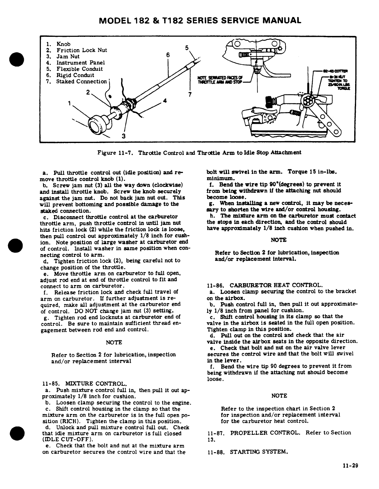
MODEL
182
&
T182
SERIES
SERVICE
MANUAL
1.
Knob
2.
Friction
Lock
Nut
3.
Jam
Nut
6
4.
Instrument
Panel
5.
Flexible
Conduit
6.
Rigid
Conduit
7.
Staked
Connection
^S1 iO
m
3
Figure
11-7.
Throttle
Control
and
Throttle
Arm
to
Idle
Stop Attachment
a.
Pull
throttle
control
out
(idle
position)
and
re-
bolt
will
swivel
in
the
arm.
Torque
15
in-lbs.
move
throttle
control
knob
(1).
minimum.
b.
Screw jam
nut
(3)
all
the
way
down
(clockwise)
f.
Bend
the
wire
tip
90°(degrees) to
prevent
it
and
install
throttle
knob.
Screw
the
knob
securely from
being
withdrawn
if
the
attaching
nut
should
against
the
jam
nut.
Do
not
back jam
nut
out.
This
become
loose.
will
prevent
bottoming
and
possible
damage
to
the
g.
When
installing
a
new
control,
it
may be
neces-
staked
connection.
sary
to
shorten
the wire
and/or
control
housing.
c.
Disconnect
throttle
control
at
the
carburetor
h.
The
mixture
arm
on
the
carburetor
must
contact
throttle arm,
push
throttle
control
in
until
jam
nut
the
stops
in
each
direction,
and
the
control
should
hits
friction
lock
(2)
while
the
friction
lock
is
loose,
have
approximately
1/8
inch
cushion
when
pushed
in.
then
pull
control
out
approximately
1/8 inch
for
cush-
ion.
Note
position
of
large
washer
at
carburetor
end
NOTE
of
control. Install
washer
in
same
position
when con-
necting
control
to
arm.
Refer
to
Section
2
for
lubrication,
inspection
d.
Tighten
friction
lock
(2),
being
careful
not
to
and/or
replacement
interval.
change
position
of
the
throttle.
e.
Move
throttle arm
on
carburetor
to
full
open,
adjust
rod
end
at
end
of
throttle
control
to
fit
and
connect
to
arm
on
carburetor.
11-86.
CARBURETOR
HEAT
CONTROL.
f.
Release
friction
lock
and
check
full
travel
of
a. Loosen
clamp
securing
the
control
to
the
bracket
arm
on
carburetor.
If
further
adjustment
is
re-
on
the
airbox.
quired,
make
all
adjustment at
the
carburetor
end
b.
Push control
full
in,
then
pull
it
out
approximate-
of
control.
DO NOT
change
jam
nut
(3)
setting.
ly
1/8
inch from
panel
for
cushion.
g.
Tighten
rod
end
locknuts
at
carburetor
end
of
c.
Shift
control
housing
in
its
clamp
so
that
the
control.
Be
sure
to
maintain
sufficient
thread
en-
valve
in
the
airbox
is
seated
in
the
full
open
position.
gagement
between
rod
end
and
control.
Tighten
clamp
in
this
position.
d.
Pull
out
on
the
control
and
check
that
the
air
NOTE
valve
inside
the
airbox seats
in
the
opposite
direction.
e.
Check
that
bolt
and
nut
on
the
air
valve
lever
Refer
to
Section
2
for lubrication,
inspection
secures
the
control
wire
and
that
the
bolt will
swivel
and/or
replacement
interval
in
the
lever.
f.
Bend
the
wire
tip
90
degrees
to
prevent
it
from
being
withdrawn
if the
attaching
nut
should become
loose.
11-85.
MIXTURE
CONTROL.
a.
Push
mixture
control
full
in,
then pull
it
out
ap-
proximately
1/8
inch
for
cushion.
NOTE
b.
Loosen
clamp
securing
the
control
to
the
engine.
c.
Shift
control
housing in
the
clamp
so
that
the
Refer
to
the
inspection
chart
in
Section
2
mixture
arm
on
the
carburetor
is
in
the full
open
po-
for
inspection
and/or
replacement
interval
sition
(RICH).
Tighten the clamp
in
this
position.
for
the
carburetor
heat
control.
d.
Unlock
and
pull
mixture
control
full
out.
Check
that
idle
mixture
arm
on
carburetor
is
full
closed
11-87.
PROPELLER
CONTROL.
Refer
to
Section
(IDLE
CUT-OFF).
13.
e.
Check
that the
bolt
and
nut
at
the
mixture
arm
on
carburetor
secures
the
control
wire
and
that
the
11-88.
STARTING SYSTEM.
11-29
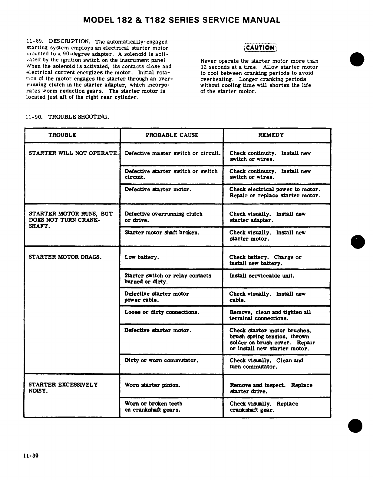
MODEL
182
&
T182
SERIES
SERVICE
MANUAL
11-89.
DESCRIPTION. The
automatically-engaged
starting
system
employs
an
electrical
starter
motor
mounted
to
a
90-degree
adapter.
A
solenoid
is
acti-
vated
by
the
ignition
switch
on
the
instrument
panel Never
operate
the
starter
motor
more
than
When
the
solenoid
is
activated,
its
contacts
close
and
12
seconds
at
a
time.
Allow
starter
motor
electrical
current
energizes
the
motor. Initial
rota-
to cool
between
cranking
periods
to
avoid
tion
of
the
motor
engages
the
starter
through
an
over- overheating.
Longer
cranking
periods
running
clutch
in
the
starter
adapter,
which
incorpo-
without
cooling
time
will
shorten
the
life
rates
worm
reduction
gears.
The
starter
motor
is of
the
starter
motor.
located
just
aft
of
the
right
rear
cylinder.
11-90.
TROUBLE
SHOOTING.
TROUBLE
PROBABLE
CAUSE
REMEDY
STARTER
WILL
NOT
OPERATE.
Defective
master
switch
or
circuit.
Check
continuity.
Install
new
switch
or
wires.
Defective
starter
switch
or
switch
Check
continuity.
Install
new
circuit.
switch or
wires.
Defective
starter
motor.
Check
electrical
power
to
motor.
Repair
or
replace
starter
motor.
STARTER
MOTOR
RUNS,
BUT
Defective
overrunning
clutch
Check
visually.
Install
new
DOES
NOT
TURN
CRANK-
or
drive.
starter
adapter.
SHAFT.
Starter
motor
shaft
broken.
Check
visually.
Install
new
starter
motor.
STARTER
MOTOR
DRAGS.
Low
battery.
Check
battery.
Charge
or
install
new
battery.
Starter
switch
or
relay
contacts Install
serviceable
unit.
burned
or
dirty.
Defective
starter
motor
Check
visually.
Install
new
power cable. cable.
Loose
or
dirty
connections.
Remove,
clean
and
tighten
all
terminal
connections.
Defective
starter
motor.
Check
starter
motor
brushes,
brush spring
tension,
thrown
solder
on
brush
cover.
Repair
or
install
new
starter
motor.
Dirty or
worn
commutator.
Check
visually.
Clean
and
turn
commutator.
STARTER
EXCESSIVELY
Worn
starter
pinion.
Remove
and
inspect.
Replace
NOISY.
starter
drive.
Worn
or
broken
teeth
Check
visually.
Replace
on
crankshaft
gears.
crankshaft
gear.
11-30
MODEL
182
&
T182
SERIES
SERVICE
MANUAL
11-91.
PRIMARY
MAINTEINANCE.
The
starting
circuit
should
be
inspected at
regular
intervals,
the
frequency
of
which
should
be
determined
by
the
When
disconnecting
starter
electrical
cable,
amount
of
service
and
conditions under
which the
do
not
permit
terminal
bolt to
rotate.
Ro-
equipment
is
operated.
Inspect
the
battery
and
wir-
tation
of
the
bolt
could
break
the conductor
ing.
Check
battery for
fully
charged
condition,
pro-
between
bolt and
field
coils
causing
the
per electrolyte
level
with
approved
water
and
termi-
starter
to
be
inoperative.
nals
for
cleanliness.
Inspect
wiring
to
be
sure
that
all
connections
are
clean
and
tight
and
that
the
wiring
b.
Disconnect
battery
cables
and
insulate
as
a
insulation
is
sound.
Check
that
the
brushes
slide safety
precaution.
freely
in
their
holders
and
make
full
contact
on
the
c.
Discornect
electrical
cable
at
starter
motor.
commutator.
When
brushes
are
worn
to one-half
of
d.
Remove
nuts
and
washers
securing
motor
to
their
original
length,
install
new
brushes
(compare
starter
adapter
and
remove
motor.
Refer
to
engine
brushes
with
new
brushes).
Check
the
commutator
manufacturer's
overhaul
manual
for adapter
removal.
for
uneven
wear,
excessive
glazing
or
evidence
of
e.
Reverse
the
preceding
steps
for
reinstallation.
excessive
arcing.
If
the
commutator
is
only
slightly
Install
a
new
O-ring
seal
on
motor,
then
install
motor.
dirty,
glazed
or
discolored,
it
may
be
cleaned
with
a
Be
sure
motor drive
engages
with
the
adapter
drive
strip
of
No. 00
or
No.
000
sandpaper.
If
the
commu-
when
installing.
tator
is
rough
or
worn,
it
should
be
turned
in
a
lathe
and
the
mica
undercut.
Inspect
the
armature
shaft
11-94.
EXHAUST
SYSTEM.
for
rough
bearing
surfaces.
New
brushes
should
be
properly
seated
when
installing
by
wrapping
a
strip
11-95.
DESCRIPTION.
The
exhaust
system
consists
of
No.
00
sandpaper around
the
commutator
(with
of
two
exhaust stack
assemblies,
for
the
left
and
right
sanding
side
out)
1-1/4
to
1-1/2
times
maximum.
bank
of
cylinders.
Each cylinder
has
a
riser
pipe
at-
Drop
brushes
on
sandpaper
covered
commutator
and
tached
to
the
exhaust
port.
The
three
risers
at
each
turn
armature
slowly
in
the
direction
of
normal
ro-
bank
of
cylinders
are
joined
together
into
a
collector
tation.
Clean
sanding
dust
from
motor
after
sanding
pipe
forming
an
exhaust
stack
assembly.
The
center
operations.
riser
on
each
bank
is
detachable,
but
the
front
and
aft
risers
are
welded
to the
collector
pipe.
Each
exhaust
11-92.
STARTER
MOTOR.
stack
assembly
connects
to
the
muffler
beneath
the
engine.
The
muffler
is
enclosed
in
a
shroud
which
11-93.
REMOVAL
AND
INSTALLATION.
captures
exhaust
heat
which
is
used
to
heat
the
cabin.
a.
Remove
engine cowling
in
accordance
with
para-
graph
11-3.
11-30A/(11-30B
blank)
MODEL
182
&
T182
SERIES SERVICE
MANUAL
The
tailpipe
is
welded
to
the muffler.
A
shroud
is
tions,
inspection
is
important
and
should
be
accom-
attached
to
the
left
exhaust
stack to
provide
heated
plished every
50
hours
of
operation.
Also.
a
thor-
air
for
the
carburetor
heat
source.
ough
inspection
of
the
engine
exhaust
system
should
11-96.
ECONOMY
MIXTURE
INDICATOR
(EGT)
be
made
to
detect
cracks
causing
leaks
which
could
Refer
to Section
15.
result
in
loss
of
engine
power. To
inspect
the
engine
11-97.
REMOVAL
AND
INSTALLATION.
(Refer
to
exhaust
system,
proceed
as
follows:
figure
11-8.)
a.
Remove
engine
cowling
as
required
so
that
ALL
a.
Remove engine
cowling
in
accordance
with
para- surfaces
of
the
exhaust
assemblies
can
be
visually
graph
11-3.
inspected.
b.
Disconnect
ducts
from
heater
shroud
on
muffler
assembly.
NOTE
c.
Disconnect
duct
from
shroud
on
left
exhaust
stack assembly.
Especially
check
the
areas
adjacent
to
welds
and
slip
joints.
Look
for
gas
deposits
in
sur-
NOTE
rounding
areas,
indicating
that
exhaust
gases
are
escaping
through
a
crack
or
hole
or
around
If
the
aircraft
is equipped
with
a
carburetor
the
slip
joints.
heat
shroud
modification kit,
SK182-78, the
shroud
is
attached
to
the
engine
mounts
and
b.
After
visual
inspection,
an
air
leak
check
should
must
be
removed
before
removing the
ex-
be made
on
the
exhaust
system
as
follows:
haust
system
from the
engine.
Effected
1.
Attach
the
pressure
side
of
an
industrial
Serials
include:
18265176
thru
18268320
and
vacuum
cleaner
to
the tailpipe
opening,
using
a
rub-
F18200026
thru
F18200169.
ber
plug
to
effect
a
seal
as
required.
d.
Remove
nuts,
bolts
and
clamps
attaching stack
NOTE
assemblies
to
the
muffler.
e.
Loosen
nuts
attaching
exhaust
stacks
to
the
The
inside
of
vacuum
cleaner
hose should
be
cylinders
and
remove
muffler
assembly.
free
of
any
contamination
that
might be
blown
f.
Remove
nuts attaching
exhaust
stack
assemblies
into
the engine
exhaust
system.
to
the
cylinders
and
remove
exhaust
stacks
and
gas-
kets.
2.
With
vacuum
cleaner
operating,
all
joints
g.
Reverse
the
preceding
steps
for
reinstallation.
in
the
exhaust
system
may
be
checked manually
by
Install
a
new
gasket
between
each
riser
and
its
mount-
feel,
or
by
using
a
soap
and
water
solution
and
ing
pad
on
each
cylinder,
regardless
of
apparent
cond-
watching
for
bubbles.
Forming
of
bubbles
is
con-
ition
of
those
removed. Torque exhaust
stack
nuts
at
sidered
acceptable,
if
bubbles
are
blown
away
cylinders
to
100-110
in-lbs.
system
is
not
considered
acceptable.
c.
Where
a
surface
is not
accessible
for
a
visual
11-98.
INSPECTION.
Since
exhaust
systems
of
this
inspection,
or
for
a
more
positive
test,
the
following
type
are
subject
to
burning,
cracking
and
general
de-
procedure
is
recommended.
terioration
from
alternate
thermal
stresses
and
vibra-
Revision
1 11-31
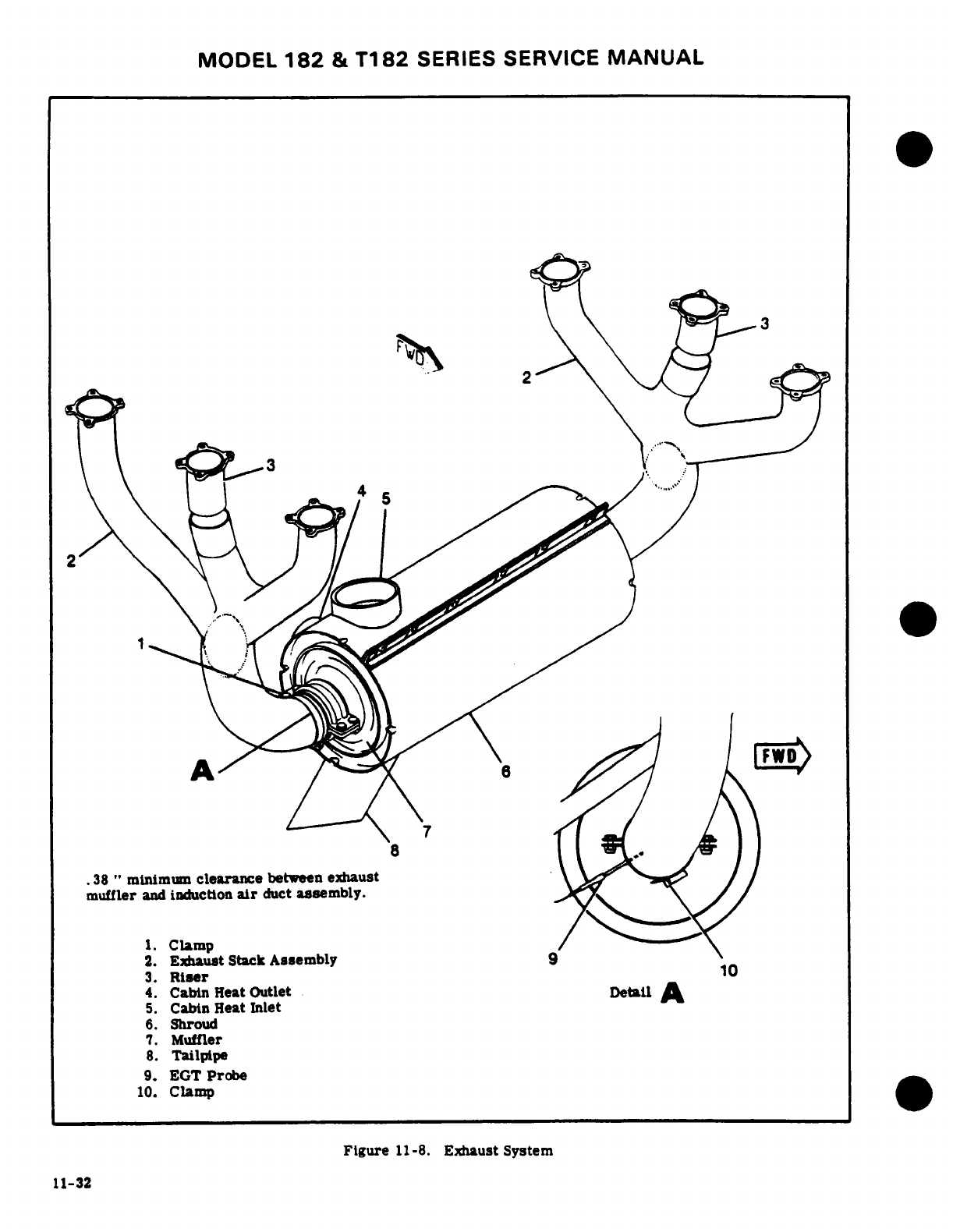
MODEL
182
&
T182
SERIES SERVICE
MANUAL
1.
Remove
exhaust
stack
assemblies.
the
cylinders
and
oil.
After
the
engine
compartment
2.
Use
rubber
expansion
plugs
to
seal
openings.
has
been
pre-heated,
inspect
all
engine
drain
and
3.
Using
a
manometer
or
gage,
apply
approxi-
vent
lines
for
presence
of
ice.
After
this
procedure
mately
1-1/2
psi
(3
inches
of
mercury)
air
pressure
has
been complied with,
pull
propeller
through
sev-
while
each
stack
assembly
is
submerged
in
water.
eral
revolutions
by
hand
before
attempting
to
start
Any
leaks
will
appear
as
bubbles
and can
be
readily the
engine.
detected.
4. It
is
recommended that
exhaust
stacks
found
defective
be
replaced
before
the
next
flight.
d.
After
installation
of
exhaust
system
components
Due
to
the
desludging
effect
of
the
diluted
perform
the
inspection
in
step
"b"
of
this
paragraph
oil, engine
operation
should
be
observed
to
ascertain
that
system
is
acceptable.
closely
during
the
initial
warm-up
of
the
engine.
Engines
that
have
considerable
11-99.
EXTREME
WEATHER
MAINTENANCE.
amount
of
operational hours
accumulated
since
their
last
dilution
period
may be
11-100.
COLD
WEATHER.
Cold
weather
starting
seriously
affected
by
the
dilution
process.
will
be
made
easier
by
the
installation
of
an
engine
This
will
be
caused
by the
diluted
oil
dis-
primer
system
and
a
ground
service
receptacle.
The lodging
sludge
and
carbon
deposits
within
primer
system
is
manually
operated from
the
cabin.
the
engine.
This
residue
will
collect
in
the
Fuel
is
supplied
by
a
line
from
the
fuel
strainer
to
oil
sump
and
possibly
clog
the
screened
the
plunger. Operating
the
primer
forces
fuel
to
the
inlet
to
the
oil
sump.
Small
deposits
may
engine.
With
an
external
power
receptacle
installed,
actually
enter
the
oil
sump
and
be
trapped
an
external
power
source
may
be
connected
to
assist
by
the
main
oil
filter
screen.
Partial
or
in
cold
weather
starting.
Refer
to
Section
16
for use
complete
loss
of
engine
lubrication
may
of
the
external
power
receptacle.
result
from
either
condition.
If
these
con-
ditions
are
anticipated
after
oil
dilution,
The
following
may
also
be
used
to
assist
engine
start-
the
engine
should
be
run
for
several
min-
ing
in
extreme
cold
weather.
After
the
last
flight
of
utes
at
normal
operating
temperatures
and
the
day,
drain
the
engine oil
into
a
clean
container so
then
stopped
and
inspected
for
evidence
of
the
oil can
be
preheated.
Cover
the
engine
to prevent
sludge and
carbon
deposits
in the
oil sump
ice
or
snow
from
collecting
inside
the
cowling.
When
of
oil
condition
can
be
preparing
the
aircraft
for
flight
or
engine
runup
after
the
oil
prior
to
each
engine
oil
change.
This
these
conditions
have
been
followed,
preheat
the
drain-
sludge and
carbon
deposits.
11-101.
HOT
WEATHER.
Refer
to
Pilot's
Operating
Do
not
heat the
oil
above
121°C
(250°F).
A
Handbook.
flash
fire
may
result.
Before
pulling
the
propeller
through,
ascertain
that
the mag-
11-102.
SEACOAST
AND
HUMID
AREAS.
In
salt
neto
switch
is
in
the
OFF position
to
prevent
water
areas
special
care
should
be
taken
to
keep
accidental
firing
of
the
engine.
the
engine,
accessories
and
airframe
clean
to
pre-
vent
oxidation.
In
humid
areas,
fuel
and
oil
should
After
preheating
the
engine
oil,
gasoline
may
be
be
checked
frequently
and
drained
of
condensation
mixed
with
the heated
oil
in
a
ratio
of 1
part
gasoline
to prevent
corrosion.
to
12
parts
engine
oil before
pouring
into
the
engine
oil
sump.
If
the
free
air
temperature
is
below
minus
11-103.
GROUND
SERVICE
RECEPTACLE.
Refer
29°C
(-20°),
the
engine
compartment
should
be
pre-
to
Section
16.
heated
by
a
ground
heater.
Pre-heating
the
engine
compartment
is
accomplished
by
inducing
heated
air
up
through
the
engine
cowl
flaps;
thus
heating
up
both
SHOP
NOTES:
11-33/(11-34
blank)
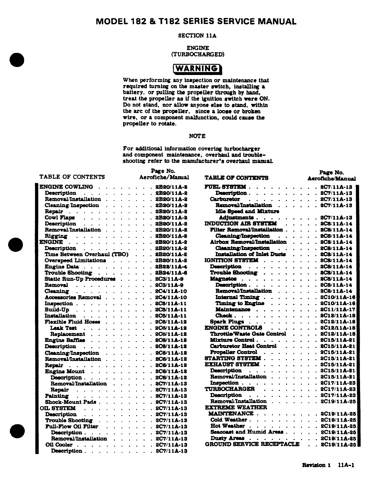
MODEL
182
&
T182
SERIES
SERVICE
MANUAL
SECTION
11A
ENGINE
(TURBOCHARGED)
When
performing
any
inspection
or
maintenance
that
required
turning
on
the
master
switch,
installing
a
battery, or
pulling
the
propeller
through
by
hand,
treat
the
propeller as
if
the
ignition
switch
were
ON.
Do
not
stand,
nor
allow
anyone
else
to
stand,
within
the
arc
of
the
propeller,
since a
loose
or
broken
wire,
or
a
component
malfunction,
could
cause
the
propeller
to
rotate.
NOTE
For
additional information
covering
turbocharger
and
component
maintenance,
overhaul
and
trouble-
shooting
refer
to
the
manufacturer's
overhaul
manual
Page
No.
Page
No.
TABLE
OF
CONTENTS
Aerofiche/Manual
TABLE
OF
CONTENTS
Aerofiche/Manual
ENGINE
COWLING
........ 2B20/11A-2
FUEL
SYSTEM.
.........
2C7/11A-13
Descri
Remova/Installation
.......
2B20/11A-2
Carburetor
..........
2C7/11A-13
Cleaning/Inspection
.......
2B20/11A-2
Removal/Installation
... .
.2C7/11A-13
Repair
...........
2B20/11A-
Idle
Speed
and
Mixture
Cowl
Flaps
..........
B20/11A-2
Adjustments
.
.....
. 2C7/11A-13
Description
...
.......
2B20/11A-
INDUCTION
AIR
SYSTEM
.....
2C8/11A-14
Removal/Installation
......
.
2B20/11A-2
Filter
Removal/Installation
. .. .
2C8/11A-14
Rigging
.........
. .
2B2/11A-
Cleaning/Inspection
......
2C8/11A-14
ENGINE
............
.
2B20/11A-2
Airbox Removal/Installation
. . .
.2C811A-14
Description.. .......
.
2B20/11A-2
Cleaning/Inspection
......
2C8/11A-14
Time
Between
Overhaul
(TBO)
. . 2B20/11A-2
Installation
of
Inlet
Duct
....
2C8/11A-14
Overspeed
Limitations
......
2B20/11A-2
IGNITION
SYSTEM
.
......
.
2C8/11A-14
Engine
Data
.......
.
2B22/11A-4
Description
..........
2C8/11A-14
Trouble
hooting
........
2B24/11A-6
Trouble
Shooting
.......
.
2C8/11A-14
Static
Run-Up
Procedures
....
.
2C3/11A-9 Magneto
..
........
.
2C8/11A-14
Removal
...........
2C/11A-9
Description.
..
.....
.
2C8/11A-14
Cleaning
...........
2C4/11A-10
Removal/Installation
....
.
.2C8/11A-14
Accessories
Removal
.
.....
.
2C4/11A-10
Internal
Timing
........
2C10/11A-16
Inspection
.........
.
2C5/11A-11
Timing
to
Engine
.......
2C10/11A-16
Build-Up
.........
.
2C5/11A-11
Maintenance
........
2C11/11A-17
Installation
.......
..
2C5/11A-11
Check
....... ....
C12/11A-18
Flexible
Fluid
Hoses
.......
2C6/11A-12
Spark
Plug
..........
2C12/11A-18
Leak
Test
.... .....
2C6/11A-12
ENGINE
CONTROLS
......
.2C12/11A-18
Replacement
.........
2C/11A-12
Throttle/Waste
Gte
Control
....
. C12/11A-18
Engine
Baffles
.........
2C6/11A-12
Mixture
Control
.
.......
.2C15/11A-21
Description
..... .......
2C6/11A-12
Carburetor
Heat
Control
.....
2C15/11A-21
Cleaning/Inspection
.......
2C6/11A-12
Propeller
Control
.
......
2C11/11A-21
Remova/Installation
.......
2C6/11A-12
STARTING
SYSTEM
........
2C15/11A-21
Repair
.
...........
2C6/11A-12
EXHAUST
SYSTEM
........
2C15/11A-21
Engine
Mount
.........
.
2C6/11A-12
Description
..........
2C15/11A-21
Description.
.........
2C6/11A-12
Removal/Installation
.......
2C15/1A-21
Removal/Installation
......
2C7/11A-13
Inspection
...........
2C17/11A-23
Repair
.........
.
2C7/11A-13
TURBOCHARGER
........
2C17/11A-23
Painting
...........
2C7/11A-13
Description
..........
2C17/11A-23
Shock-Mount
Pads
........
2C7/11A-13
Removal/Installation
......
.
2C19/11A-25
OIL
SYSTEM
..........
2C7/11A-13
EXTREME
WEATHER
Description
..........
2C7/11A-13
MAINTENANCE
.........
2C19/11A-25
Trouble
Shooting
........
2C7/11A-13
Cold
Weather
..........
2C19/11A-25
Full-Flow
Oil
Filter
.......
2C7/11A-13
Hot
Weather
..........
2C19/11A-25
Description.
........
. 2C7/11A-13
Seacoast
and
Humid
Areas
.
....
2C19/11A-25
Removal/Installation
......
2C7/11A-13
Dusty
Areas
......
....
2C19/11A-25
Oil
Cooler
.........
. 2C7/11A-13
GROUND SERVICE
RECEPTACLE
..
2C19/11A-25
Description
.........
2C7/11A-13
Revision
1
11A-1
MODEL
182
&
T182
SERIES
SERVICE
MANUAL
11A-1.
ENGINE
COWLING.
d.
Reverse
the
preceding
steps
for
reinstallation.
Rig
cowl
flaps,
if
necessary.
in
accordance
with
11A-2.
DESCRIPTION.
The engine
cowling
is
divid-
paragraph
11A-9.
ed
into
major
removable
segments.
The
upper
RH
segment
has
an
oil
dipstick
and
remote
fuel
strainer
11A-9.
RIGGING.
(See
figure
11A-1.)
drain
control
access
door.
The
upper
center
cowl
a.
Disconnect
cowl
flap
control
clevises
(6)
from
skin
has
the
oil
filler
neck
access
door,
and
the
cowl
flap
shock-mounts
(7).
lower
LH
panel
contains
the
turbocharger
access
b. Check
to
make
shure
that
flexible
controls reach
door. Controllable
cowl
flaps
are integral
with
the
their
internal
stops
in
each
direction.
Mark
controls
lower
trailing
edge
of
cowl
skin.
They
are
hinged
at
so
that
full
travel
can
be
readily
checked and main-
the
front
edge,
and
controlled
manually
to
maintain tained
during
remaining
rigging
procedures.
efficient
engine
operating
temperature.
The
upper
c.
Place
cowl
flap control
lever
(11)
in
CLOSED
pos-
center
and
lower
cowl
segments
are
screw
fastened
ition.
If
the
control
lever
cannot
be
placed
in
closed
at
the
nose
cap,
but
RH
and
LH
segments
use
quick
position,
adjust controls
at
upper
clevis
(10)
to
position
release
fasteners
all
around
for easy
access.
Land-
control
lever
in
bottom
hole
of
position
bracket
(9).
ing
and
taxi
lights
are
mounted
in
the
nose
cap
lower
d.
With
control lever
in
CLOSED
position,
hold
one
cowling.
cowl
flap
closed,
streamlined
with
trailing
edge
of
lower
cowl.
Loosen
jam
nut
and
adjust
clevis
(6)
on
the
con-
11A-3.
REMOVAL
AND
INSTALLATION.
trol
to
hold
cowl
flap in
this
position.
Retighten jam
a.
Remove
screws
securing
upper
center
and
lower
nut
and
install
bolt
through
clevis
and
shock-mount.
cowling
segments
to
the
nose
cap.
b.
Release
the
quick-release
fasteners
attaching
NOTE
the
cowling
to
the
fuselage
and
at
the
parting
surfaces
of
the
center
and
lower
segments.
Be
shure
threads
are
visible
in
clevis
inspec-
c.
Disconnect
the landing
and
taxi
light
wires
at
the
tion
holes.
quick-disconnects
and
carefully
remove
cowling.
d.
Reverse
the
preceding
steps for
reinstallation.
e.
Repeat
preceding
step
for
the
opposit
cowl
flap.
Ensure
the
baffle
seals
are
turned
in
the
correct
f.
Check
that
all
clamps
and
jam
nuts
are
tight.
direction
to confine
and
direct
air
flow
around
the
g. Check
for
ease
of
operation.
engine.
The
vertical
installed
seals
must
fold
for-
ward
and
the
side
seals
must
fold
upwards.
11A-10.
ENGINE.
11A-4.
CLEANING
AND
INSPECTION.
Wipe
the
11A-11. DESCRIPTION.
An
air
cooled,
wet-sump,
inner
surfaces
of
the
cowling
segments
with
a
clean
six-cylinder,
horizontally-opposed,
direct-drive,
cloth
saturated
with
cleaning
solvent
(Stoddard
or
carbureted,
Turbocharged
Avco
Lycoming
0-540-
equivalent).
If
the
inside
surface
of
the
cowling
is
L3C5D
engine,
driving
a
constant-speed
propeller,
coated
heavily
with
oil
or
dirt,
allow
solvent
to
soak
is
used
to
power the
aircraft
The
cylinders,
num-
until
foreign
material
can
be
removed.
Wash
painted
bered
from front
to
rear,
are
staggered
to
permit
a
surfaces
of
the
cowling
with
a
solution
of
mild
soap
separate
throw
on
the
crankshaft
for each
connecting
and
water
and
rinse
thoroughly.
After
washing,
a
rod.
The
right
front
cylinder
is
number
1
and
cylin-
coat
of
wax
may
be
applied
to
the
painted
surfaces
to
ders
on
the
right
side
are
identified
by
odd
numbers
prolong
paint
life.
After
cleaning,
inspect
cowling
1,
3
and
5.
The
left
front cylinder
is
number
2
and
for
dents,
cracks,
loose
rivets
and
spot
welds.
Re-
the
cylinders
on
the
left
side
are
identified
as
number
pair
all
defects
to
prevent
spread
of
damage.
2,
4
and
6.
Refer
to
paragraph
11A-12
for
engine
data.
For
repair
and
overhaul
of
the
engine
turbo-
11A-5.
REPAIR.
(Refer
to
Section
17.)
charger,
accessories
and
propeller,
refer
to
the
appropriate
publications
issued
by
their
manufacturers.
11A-6.
COWL
FLAPS.
These
publications
are
available from
the
Cessna
Supply
Division.
11A-7.
DESCRIPTION. Cowl
flaps
are
provided
to
aid
in
controlling
engine
temperature.
Two
cowl
11A-12.
TIME
BETWEEN
OVERHAUL
(TBO). Avco
flaps,
operated
by
a
single
control
in
the
cabin,
are
Lycoming
recommends
engine
overhaul
at
2000
hours
located
at
the
aft
edge
of
the lower
cowl
segment.
operating time
for
the
0-540-L3C5D
series
engines.
Refer
to
Avco
Lycoming
Service
Instruction
1009,
NOTE
and
to
any
superseding
Instructions,
revisions
or
supplements
thereto,
for
further
recommendations.
Refer
to Section
2
for
cowl
flap
hinge
inspec-
At
the
time
of
overhaul,
engine
accessories
should be
tion frequency.
overhauled.
Refer
to
Section
13
for
propeller
and
governor
overhaul
periods.
11A-8.
REMOVAL
AND
INSTALLATION.
(Refer
to
figure
11A-1.)
11A-13.
OVERSPEED
LIMITATIONS.
The
engine
a.
Place
cowl
flap
control
lever
(11)
in
the
OPEN
must
not
be
operated
above
specified
maximum
con-
position.
tinuous
RPM.
However,
should
inadvertent
overspeed
b.
Disconnect
cowl
flap
control
clevises
(6)
from
occur,
refer
to Avco
Lycoming
Service
Bulletin
369F,
cowl
flap
shock-mounts
(7).
and
to
any
superseding bulletins,
revisions
or
supple-
c.
Remove
safety
wire
securing
hinge
pins
to
cowl
ments
thereto,
for
further
recommendations.
flaps,
pull pins
and
remove
flaps.
11A-2
Revision
1
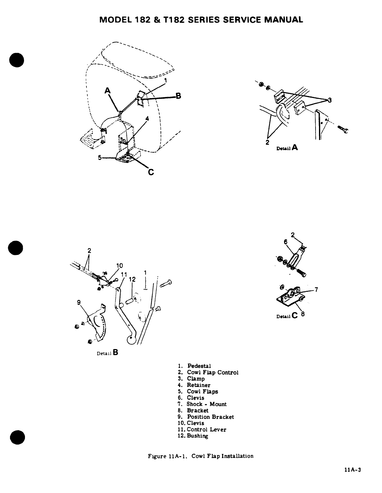
MODEL
182
&
T182
SERIES SERVICE
MANUAL
A"
'
-"
>-,'-
D
eta
il
A
\ \
Detail
B
3.
Clamp
2
10
12
e aDetaiC
8
Detail
B
1.
Pedestal
2.
Cowl
Flap
Control
3.
Clamp
4.
Retainer
5.
Cowl
Flaps
6.
Clevis
7.
Shock
-
Mount
8.
Bracket
9.
Position
Bracket
10.
Clevis
11.
Control
Lever
12.
Bushing
Figure
11A-1. Cowl
Flap
Installation
11A-3
MODEL
182
&
T182
SERIES
SERVICE
MANUAL
11A-14.
ENGINE
DATA.
AIRCRAFT
Series
T182
SKYLANE
MODEL
(Lycoming)
0-540-L3C5D
Rated
Horsepower
at
RPM 235
at
2400
to
20,000 Feet
Number
of
Cylinders
6
Horizontally-Opposed
Displacement
541.
5
Cubic Inches
Bore
5.
125
Inches
Stroke
4.375
Inches
Compression
Ratio
8.
5:1
Magnetos
Bendix D6LN-2031
Right
Magneto
Fires
23
°
BTC,
Upper Left, Lower Right
Left
Magneto
Fires
23
°BTC,
Lower Left,
Upper
Right
Firing
Order
1-4-5-2-3-6
Spark
Plugs
18mm
(Refer
to
Avco
Lycoming
Service
Instruction
No.
1042
for
factory
approved
spark
plugs
and
required
gap.)
Torque
330
±
30
LB-IN.
Carburetor
(Marvel-Schebler)
HA-6
Tachometer
Mechanical
Drive
Oil
Sump
Capacity
8
U.
S.
Quarts
With
External
Filter
9
U.
S.
Quarts
Oil
Pressure
(PSI)
Normal
60-90
Minimum
Idling
25
Maximum
(Cold
Oil
Starting)
100
Oil
Temperature
Normal
Operating
160
°
F
-
245
°F
Maximum
Red Line
(245°F)
Probe
Location
Accessory
Housing
Cylinder
Head
Temperature
Normal
Operating
200
°
F
-
500
°F
Maximum Red
Line
(500 F)
Probe
Location
Lower
Side
of
Number
5
Cylinder
Economy
Mixture
Indicator
(EGT)
Probe
Location
Left
Hand
Exhaust Collector
Direction
of
Crankshaft
Rotation
(Viewed
from
Rear)
Clockwise
Dry
Weight-With
Accessories
430
LB
(Weight
is
approximate
and
will
vary
with
optional
accessories
installed.)
11A-4
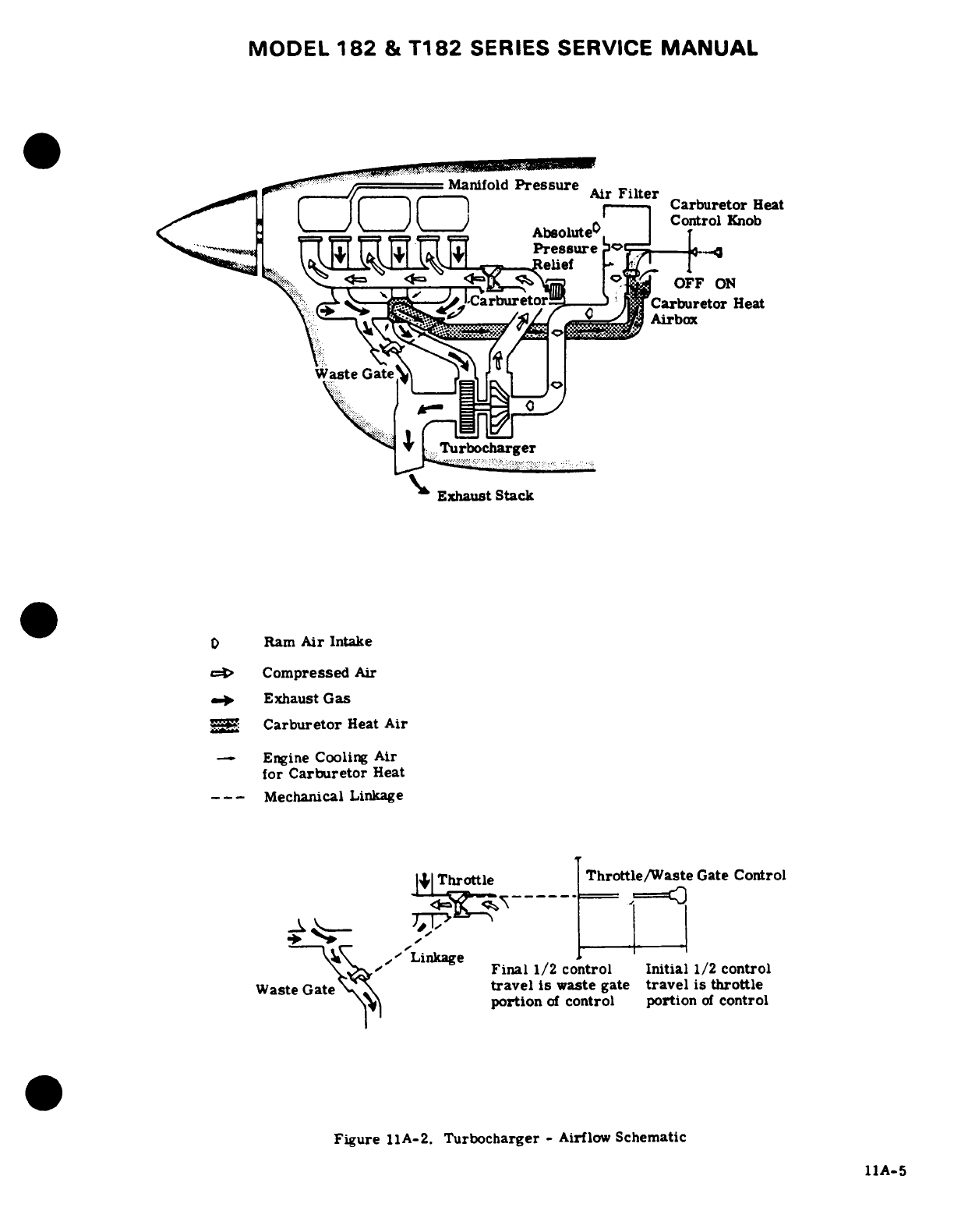
MODEL
182
&
T182
SERIES
SERVICE
MANUAL
Carburetor
Heat
.
Airbox
Waste
Gate
Exhaust
Stack
Ram
Air
Intake
Compressed
Air
Exhaust
Gas
Carburetor
Heat
Air
-Engine
Cooling
Air
for
Carburetor
Heat
---
-
Mechanical
Linkage
Throttle
Throttle/Waste
Gate
Control
------
Linkage
Final
1/2
control
Initial
1/2
control
Waste
Gate
travel
is
waste
gate
travel
is
throttle
Waste
Figure
11A-2.
Turbocharger
-
Airflow
Schematic
11A-5
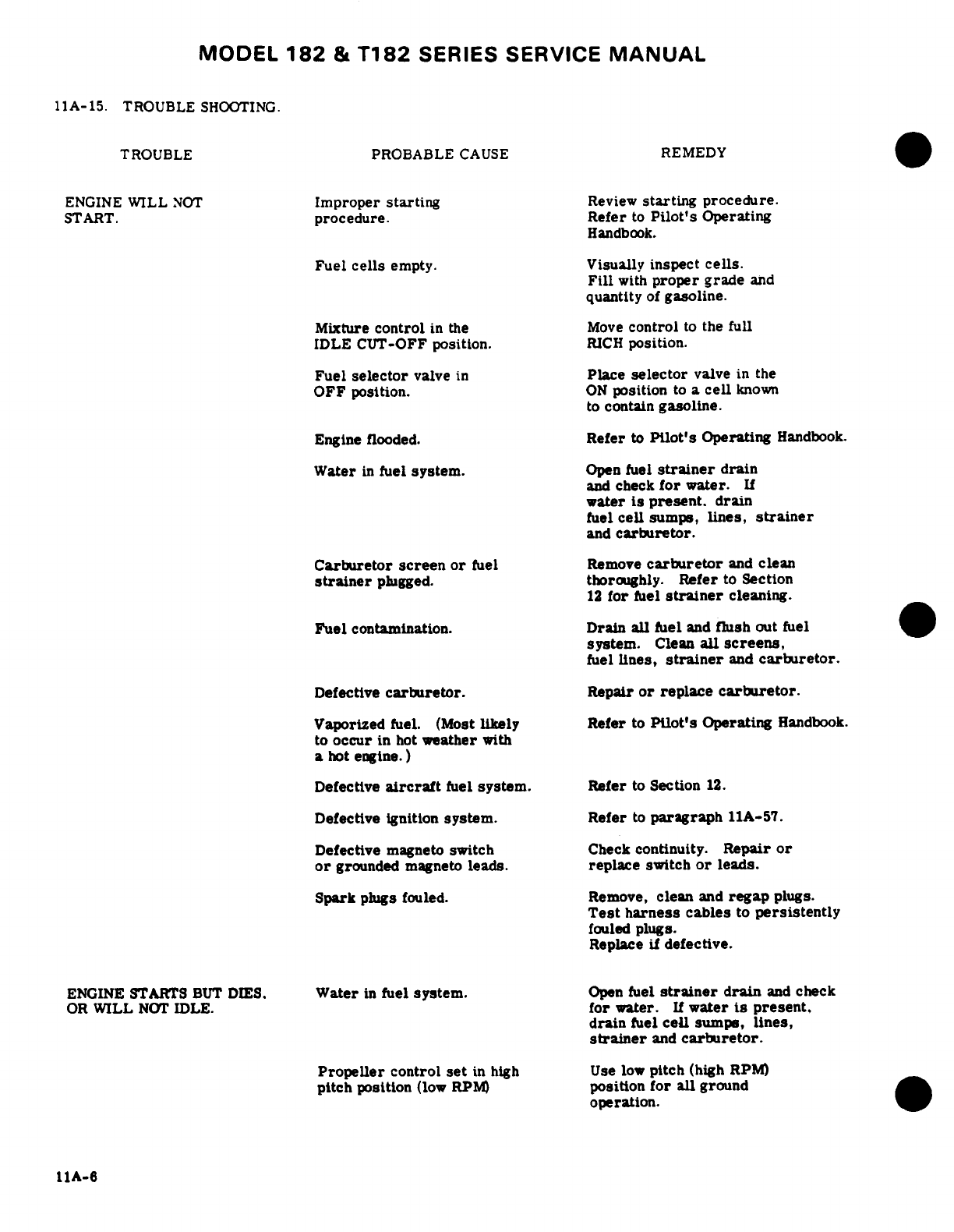
MODEL
182
&
T182
SERIES SERVICE
MANUAL
11A-15.
TROUBLE
SHOOTING.
TROUBLE
PROBABLE
CAUSE
REMEDY
ENGINE
WILL
NOT
Improper
starting
Review
starting
procedure.
START.
procedure.
Refer
to
Pilot's
Operating
Handbook.
Fuel
cells
empty.
Visually
inspect
cells.
Fill
with
proper
grade
and
quantity
of
gasoline.
Mixture
control
in
the
Move
control
to
the
full
IDLE
CUT-OFF
position.
RICH
position.
Fuel
selector
valve
in
Place
selector
valve
in the
OFF
position.
ON
position
to
a
cell
known
to
contain
gasoline.
Engine
flooded.
Refer
to
Pilot's
Operating
Handbook.
Water
in
fuel
system.
Open
fuel
strainer
drain
and
check
for
water.
If
water
is present.
drain
fuel
cell
sumps,
lines,
strainer
and
carburetor.
Carburetor
screen
or
fuel
Remove
carburetor
and
clean
strainer
plugged.
thoroughly.
Refer
to
Section
12
for
fuel
strainer
cleaning.
Fuel
contamination.
Drain
all
fuel
and
flush
out
fuel
system.
Clean
all screens,
fuel
lines,
strainer
and
carburetor.
Defective
carburetor.
Repair
or
replace
carburetor.
Vaporized
fuel.
(Most
likely
Refer
to
Pilot's
Operating
Handbook.
to
occur
in
hot
weather
with
a
hot engine.)
Defective
aircraft
fuel
system.
Refer
to
Section
12.
Defective ignition
system.
Refer
to
paragraph
11A-57.
Defective
magneto
switch
Check
continuity.
Repair
or
or
grounded
magneto
leads.
replace
switch
or
leads.
Spark
plugs
fouled. Remove,
clean
and
regap
plugs.
Test
harness
cables
to
persistently
fouled
plugs.
Replace if
defective.
ENGINE
STARTS
BUT
DIES.
Water
in
fuel
system.
Open
fuel
strainer
drain
and
check
OR
WILL
NOT
IDLE.
for
water.
If
water
is
present.
drain
fuel
cell
sumps,
lines,
strainer
and
carburetor.
Propeller
control
set
in
high
Use
low
pitch
(high
RPM)
pitch
position
(low
RPM)
position
for all
ground
operation.
11A-6
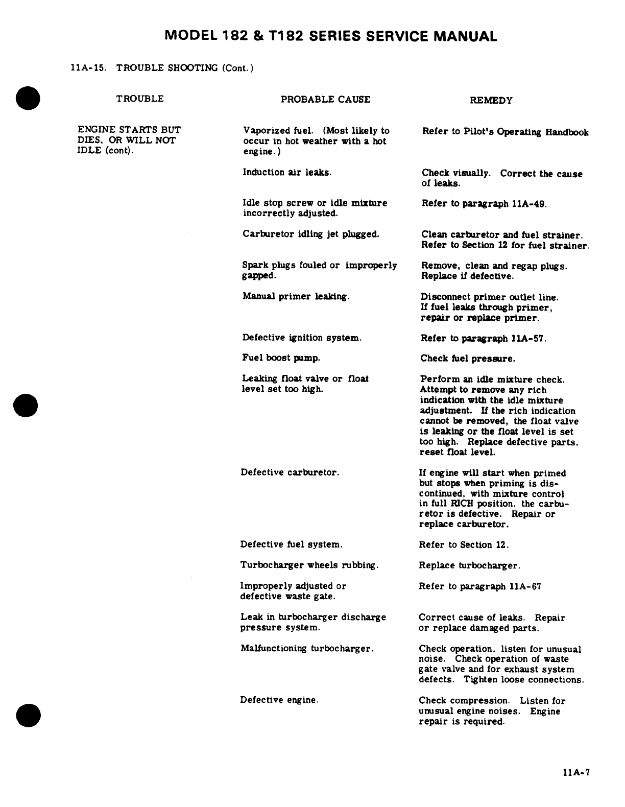
MODEL
182
&
T182
SERIES
SERVICE
MANUAL
11A-15.
TROUBLE
SHOOTING
(Cont.)
TROUBLE PROBABLE
CAUSE
REMEDY
ENGINE
STARTS
BUT
Vaporized
fuel.
(Most
likely
to
Refer
to
Pilot's
Operating
Handbook
DIES.
OR
WILL
NOT
occur
in
hot
weather
with
a
hot
IDLE
(cont).
engine.)
Induction
air
leaks.
Check
visually.
Correct
the
cause
of
leaks.
Idle
stop
screw
or
idle
mixture
Refer
to
paragraph
11A-49.
incorrectly
adjusted.
Carburetor
idling
jet
plugged.
Clean
carburetor
and
fuel
strainer.
Refer
to
Section
12
for
fuel
strainer.
Spark
plugs
fouled
or
improperly
Remove,
clean
and
regap
plugs.
gapped.
Replace
if
defective.
Manual
primer
leaking.
Disconnect
primer
outlet
line.
If
fuel
leaks
through
primer,
repair
or
replace
primer.
Defective
ignition
system.
Refer
to
paragraph
11A-57.
Fuel
boost
pump.
Check
fuel
pressure.
Leaking
float
valve
or
float
Perform
an
idle
mixture
check.
level
set
too
high.
Attempt
to
remove
any
rich
indication
with
the idle
mixture
adjustment.
If the
rich
indication
cannot
be
removed,
the
float
valve
is
leaking
or
the
float
level
is set
too
high.
Replace
defective
parts.
reset
float
level.
Defective
carburetor.
If engine will
start
when
primed
but
stops
when
priming
is
dis-
continued,
with
mixture
control
in
full
RICH
position.
the
carbu-
retor
is
defective.
Repair
or
replace
carburetor.
Defective
fuel
system.
Refer
to
Section
12.
Turbocharger
wheels
rubbing.
Replace
turbocharger.
Improperly
adjusted
or
Refer
to
paragraph
11A-67
defective
waste
gate.
Leak
in
turbocharger discharge
Correct
cause
of
leaks.
Repair
pressure
system.
or
replace
damaged
parts.
Malfunctioning
turbocharger.
Check
operation.
listen
for
unusual
noise.
Check
operation
of
waste
gate
valve
and
for
exhaust
system
defects.
Tighten loose
connections.
Defective
engine.
Check
compression. Listen
for
unusual
engine
noises.
Engine
repair
is
required.
11A-7
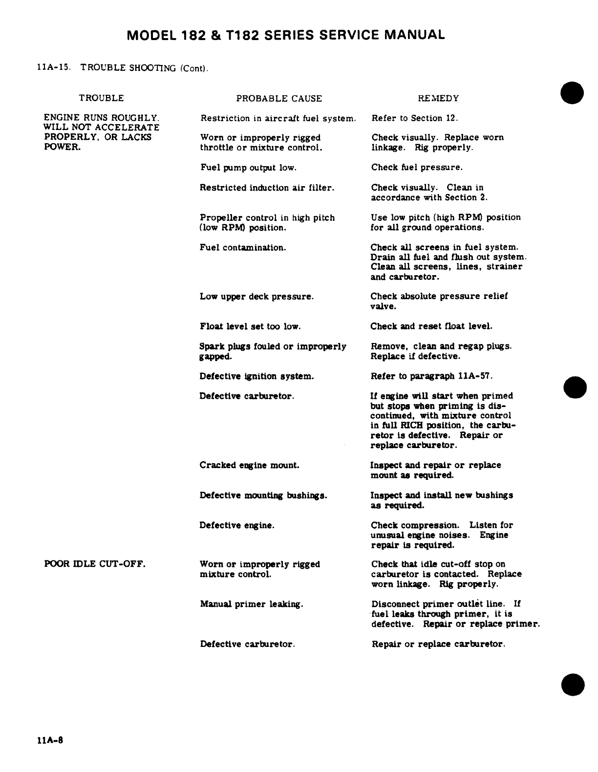
MODEL
182
&
T182
SERIES
SERVICE
MANUAL
11A-15.
TROUBLE
SHOOTING
(Cont).
TROUBLE PROBABLE
CAUSE
REMEDY
ENGINE
RUNS
ROUGHLY.
Restriction
in
aircraft
fuel
system.
Refer
to
Section
12.
WILL
NOT
ACCELERATE
PROPERLY,
OR LACKS
Worn
or improperly
rigged
Check
visually.
Replace
worn
POWER.
throttle
or
mixture
control.
linkage.
Rig
properly.
Fuel
pump
output
low.
Check
fuel
pressure.
Restricted
induction
air
filter.
Check
visually.
Clean
in
accordance
with
Section
2.
Propeller
control
in high
pitch
Use
low
pitch
(high
RPM)
position
(low
RPM)
position.
for
all
ground
operations.
Fuel
contamination.
Check
all
screens
in
fuel
system.
Drain all
fuel
and
flush
out
system.
Clean
all
screens,
lines,
strainer
and
carburetor.
Low
upper
deck
pressure.
Check
absolute
pressure
relief
valve.
Float
level
set
too
low.
Check
and
reset
float
level.
Spark
plugs
fouled
or
improperly
Remove,
clean
and
regap
plugs.
gapped.
Replace
if
defective.
Defective
ignition
system.
Refer
to
paragraph
11A-57.
Defective
carburetor.
If
engine will
start
when
primed
but
stops
when
priming
is
dis-
continued,
with
mixture
control
in
full
RICH
position,
the
carbu-
retor
is
defective.
Repair
or
replace
carburetor.
Cracked
engine mount.
Inspect
and
repair or
replace
mount
as
required.
Defective
mounting
bushings.
Inspect
and
install
new
bushings
as
required.
Defective
engine.
Check
compression. Listen
for
unusual
engine
noises.
Engine
repair
is
required.
POOR
IDLE
CUT-OFF.
Worn
or
improperly
rigged
Check
that
idle
cut-off
stop
on
mixture
control.
carburetor is
contacted.
Replace
worn
linkage.
Rig
properly.
Manual
primer
leaking.
Disconnect
primer
outlet
line.
If
fuel leaks
through
primer,
it
is
defective.
Repair
or
replace
primer.
Defective
carburetor.
Repair
or
replace
carburetor.
11A-8
MODEL
182
&
T182
SERIES
SERVICE
MANUAL
11A-15.
TROUBLE
SHOOTING
(Cont).
ENGINE
LACKS
POWER.
Carburetor
heat
on.
Check control
REDUCTION
IN
MAXIMUM
MANIFOLD
PRESSURE.
Improperly
adjusted
waste
gate.
Refer
to
paragraph
11A-67.
Loose
or
damaged
exhaust
Inspect
entire
exhaust
system.
system.
Refer
to
paragraph
11A-72.
Malfunctioning
turbocharger.
Check
for unusual
noise
in
turbo-
charger.
If
malfunction
is
sus-
pected,
remove
exhaust
and/or
air
inlet
connections
and
check
turbine
and
compressor
wheels
for
damaged
blades.
Check
shaft
bearing.
Replace
turbo-
charger
if
damage
is
noted.
Leak
in
induction
system.
Check
visually.
Correct
the
cause
of
leaks.
11A-16.
STATIC
RUN-UP
PROCEDURES. If
low
pad.
Run
up
engine
to
determine
that governor
engine
RPM
is
encountered,
or
suspected.
a
static
was
adjusted
properly.
run-up
should
be
conducted
according
to
the
follow-
ing
procedures.
4.
Check
magneto
timing,
spark
plugs,
and
a.
Run
engine.
using
takeoff
power
and
mixture
ignition
harness
for
settings
and
condition.
settings.
first
with
airplane
facing
90
°
right
to
pre-
5.
Perform
an
engine
compression
check.
vailing
wind.
and
second
with
airplane
facing
90°
left
Refer
to
engine
manufacturer's service
manual
to
prevailing
wind
direction. for
procedures
and
requirements.
b.
Record
the
maximum
RPM
obtained
in
each
instance.
for
analysis.
11A-17. REMOVAL.
If
an
engine
is
to be
placed
in
storage
or returned
to the
manufacturer
for overhaul.
NOTE
proper
preparatory steps
should
be
taken
for
corro-
sion prevention
prior
to
beginning
the
removal
pro-
Daily
changes
in
atmospheric
pressure.
tem-
cedure. Refer
to
Section
2
for
storage preparation.
perature.
and
humidity
will
have a
slight
The
following
engine
removal
procedure
is based
affect
on
static
run-up.
upon
the
engine
being
removed
from
the
aircraft
with
the
engine
mount
attached
to
the
firewall.
c.
Average
the
results
of
the
RPM
readings.
The
average
should
be
within
50
RPM
of
2350
RPM.
NOTE
d.
If
the
average
reading
is
lower
than
minimum
limit,
the
following
checks
may
be
performed
to
Tag
each
item
when
disconnected
to
aid
in
determine
probable
discrepancy.
identifying
wires.
hoses,
lines
and
control
1.
Check
condition
of
induction
air
filter;
clean
linkages
when
engine
is
reinstalled.
Like-
if
required.
wise.
shop
notes
made
during
removal
will
2.
Check
carburetor
heat
control
for
proper
often
clarify reinstallation.
Protect
openings.
adjustment.
If
it
is
partially
open.
it
would
cause
exposed
as
a
result
or
removing
or
discon-
RPM
drop (slight
power
loss).
necting
units.
against
entry
of
foreign
mate-
3.
Check
governor
control for
proper
rigging.
rial
by
installing
covers or
sealing
with
tape.
The
control
arm
should
be
limited
by
high
RPM
stop
on
governor
and
the
high
RPM
stop
screw
adjusted
so
a.
Attach
a
tail stand
of
suitable capacity.
the
above
average
RPM
is
within
tolerance. Refer
b.
Place
all
cabin
switches
in
the
OFF
position.
to
Section
13
for
adjustment
procedures.
c.
Place
fuel
selector
valve
in
the
OFF
position.
d.
Remove engine
cowling
in
accordance
with
NOTE
paragraph
11A-3.
If
verification
of
governor
operation is neces-
as
a
safety
precaution.
sary.
the
governor
may
be
removed
from
the
f.
Drain
fuel
strainer
and
lines
with
strainer
drain
engine.
and
a
flat
plate
installed
over
mount
control.
11A-9
MODEL
182
&
T182
SERIES
SERVICE
MANUAL
NOTE
6.
Exhaust
gas
temperature
wire
at
quick-
disconnect.
During
the
following
procedures.
remove
any
7.
Remove
all
clamps
and
lacings
attaching
clamps
or
lacings
which
secure controls.
wires or
cables
to
engine,
and
pull
wires
and
cables
wires,
hoses
or
lines
to
the
engine.
engine
aft
to
clear
engine.
mount
or
attached
brackets.
so they
will
not
p.
Disconnect
lines
and
hoses
as
follows:
interfere
with
engine
removal.
Some
of
the
1.
Vacuum
hose
at vacuum
pump.
items
listed
can
be
disconnected
at
more
2.
Oil
breather
vent
lines
where
secured
to
the
than
one
place.
It
may
be
desirable
to
dis-
engine.
connect
some
of
these
items
at
other
than
WARNING
the
places
indicated.
The
reason for
engine
removal
should
be
the
governing
factor
in
removal should
be the
governing
factor
in
Residual fuel
and
oil
draining
from
discon-
deciding
at
which
point
to
disconnect
them.Residual
fuel
and
hoses
Omitany
of
the
items
which
are
not
presentes
on
a
particular
engine
installation.
of
such
fuel
and
oil
when
lines
or
hoses
are
g.
Drain
the
engine
oil
sump and
oil
cooler.
disconnected.
h.
Disconnect
magneto
primary
lead
wires
at
6.
Oil
pressure
line
at
engine
fitting.
The
magnetos
are
in
a
SWITCH
ON
condition
7.
Manifold
pressure
line at
engine.
when
the
switch
wires are
disconnected.
q.
Carefully
check
the
engine
again
to
ensure
ALL
Ground
the
magneto
points
or
remove
the
hoses,
lines,
wires,
cables, clamps
and
lacings
high
tension
wires
from
the
magnetos
or
which
would
interfere
with
the
engine
removal
are
spark
plugs
to
prevent
accidental
firing,
disconnected
or
removed.
Ensure
all
wires.
cables
and
engine
controls
have
been
pulled
aft
to
clear
the
i.
Remove
the
spinner
and
propeller
in
accordance
engine.
with
Section
13.
Cover
exposed
end
of
crankshaft
flange
and
propeller
flange
to
prevent
entry
of
foreign
material.
Place
suitable
stand
under
tail
tie-down
ring
j.
Disconnect
throttle
and
mixture
controls
at
car-
before
removing
engine.
The
loss
of
engine
buretor.
Remove
clamps
attaching
controls
to
engine
weight
will
cause
the
aircraft
to
be
tail
heavy.
and
pull
controls
aft
clear
of
engine.
Use
care
to
avoid bending
controls
too
sharply.
Note
EXACT
r.
Attach
a
hoist
to
the
lifting
lug
at
the
top
center
position,
size
and
number
of
attaching
washers
and
of
the
engine
crankcase.
Lift
engine
just
enough
to
spacers
for
reference
on
reinstallation.
relieve
the
weight
from
the
engine
mount
pads.
k.
Disconnect
propeller
governor
control
at
gover-
s.
Remove
bolts
attaching
engine
to
engine
mount
nor.
Note
EXACT
position,
size
and
number
of
pads
and
slowly
hoist
engine
and
pull
it
forward.
attaching
washers for reference
on
reinstallation.
Check
for
any
items
which
would
interfere
with
the
Remove
clamps
attaching
control
to
engine
and
pull
engine
removal
Balance
the engine
by
hand
and
control
aft
clear
of
engine.
carefully
guide
the
disconnected
parts
out
as
the
1.
Disconnect
all
hot
and
cold
air
flexible ducts
and
engine
is
removed.
remove.
t.
Remove engine
shock-mount
pads
and bonding
m.
Remove
exhaust
system
in
accordance
with
para-
straps.
graph
11A-69.
n.
Disconnect
carburetor
heat
control
from
arm
on
11A-18.
CLEANING.
Refer
to
Section
2.
airbox.
Remove
clamps
and
pull
control
clear
of
engine.
11A-19.
ACCESSORIES REMOVAL.
Removal
of
o.
Disconnect
wires
and
cables
as
follows:
engine
accessories
for
overhaul
or
for
engine
re-
1.
Tachometer
drive
shaft
at
adapter.
placement
involves
stripping
parts, accessories
and
components
from
the
engine
to
reduce
it
to
the
removed
should
be
tagged
for
repair
or
replacement
When
disconnecting
starter
cable
do
not
as
required.
permit
starter
terminal
bolt
to
rotate.
Rotation
of
the
bolt
could
break
the
con-
NOTE
ductor
between
bolt
and
field
coils
causing
the
starter
to
be
inoperative.
Items easily
confused
with
similar
items
should
be
tagged
to
provide
a
means
of
2.
Starter
electrical
cable
at
starter.
identification
when
being
installed
on
a
3.
Cylinder
head
temperature wire
at
probe.
new
engine. All
openings
exposed
by
the
4.
Carburetor
air
temperature
wires
at
quick-
removal
of
an
item
should
be
closed
by
disconnects.
installing
a
suitable
cover,
cap
or
tape
5.
Electrical
wires
and
wire
shielding
ground at
over
the
opening.
This
will
prevent
entry
alternator.
of
foreign
material.
11A-10
MODEL
182
&
T182
SERIES
SERVICE
MANUAL
11A-20.
INSPECTION.
For
specific
items
to be
NOTE
inspected,
refer
to
the
engine
manufacturer's
manual.
a.
Visually
inspect
the
engine
for
loose
nuts,
bolts,
The
manufacturer
recommends
that
NS-40
cracks
and
fin
damage.
(RAS-4)
(Snap-On-Tools
Corp.,
Kenosha.
b.
Inspect
baffles,
baffle
seals
and
brackets
for
Wisc.),
MIL-T-5544
(Thread
Compound
cracks,
deterioration
and
breakage.
Antiseize,
Graphite
Petrolatum).
USP
c.
Inspect
all
hoses
for internal
swelling.
chafing
Petrolatum
or
engine
oil
be
used
as
a
through
protective
plys,
cuts,
breaks, stiffness, thread
lubricant
and
to
seal
fittings.
Ap-
damaged
threads
and
loose
connections.
Excessive
ply
sparingly
to
male
threads
omitting
heat
on
hoses
will cause
them
to
become
brittle
and
first
two
threads
on
the
fitting.
Use
care
easily
broken.
Hoses
and
lines
are
most
likely
to
so
lubricant
does
not
string
across
the
crack or
break
near
the
end
fittings
and
support
opening.
Be
sure
area
is
clean
to
prevent
points.
fuel
contamination.
d.
Inspect
for
color
bleaching
of
the
end
fittings
or
severe
discoloration
of
the
hoses.
g.
Connect
lines
and
hoses
as
follows:
1.
Manifold
pressure
line
at
engine
fitting.
NOTE
2.
Oil
pressure
line
at engine
fitting.
3.
Fuel
supply
hose
at
fuel
strainer.
Avoid
excessive
flexing
and
sharp
bends
when
4
Primer
line
at
engine
fitting.
examining
hoses
for
stiffness.
5.
Oil
temperature
bulb.
6.
Oil
breather
vent
line
where
secured
to
the
e.
Refer
to
Section
2
for
replacement
intervals
for
.
flexible
fluid
carrying
hoses
in the
engine
compart-
ment.
f.
For major
engine
repairs, refer
to
the engine
.
Electrical
wires
and
wire
shielding
ground
at
manufacturer'
manufacturer's
overhaul
and
repair
manual.
alternator.
.
11A-21.
BUILD-UP.
Engine
build-up
consists
of
(Do
not
exceed
4
lb-in
torque.)
installation
of
parts, accessories
and
components
to
the
basic
engine
to
build up
an
engine
unit
ready
for installation
on
the
aircraft.
All
safety wire,
lockwashers,
nuts,
gaskets
and
rubber
connections
When
connecting
starter
cable,
do
not
permit
should
be new
parts.
starter
terminal
bolt
to
rotate.
Rotation
of
11A-22.
INSTALLATION.
Before
installing the
starter
to
be
engine
on
the
aircraft,
install
any
items
which
were
removed
from
the
engine
or
aircraft
after
the engine
was
removed.
3.
Starter electrical
cable
at
starter.
drive
cable
engages
drive
in
adapter. Torque
housing
Remove
all
protective
covers,
plugs,
caps
attach
nut
to
100
lb-in.
and
identification
tags as
each
item
is
con-
5.
Exhaust
gas
temperature
wire
and
carburetor
nected
or
installed.
Omit
any
items
not
air
temperature
wires
at quick-disconnects.
present
on
a
particular
engine
installation.
6.
Install
clamps
and
lacings
securing
wires
and
cables
to
engine,
engine
mount
and
brackets.
a. Hoist
the
engine
to
a
point
near
the
engine
mount.
i.
Install
exhaust
system
in
accordance
with
para-
b.
Install
engine
shock-mount
pads
as
illustrated
in
graph
11A-74.
figure
11A-3.
j.
Connect
all
hot
and
cold
air
flexible
ducts.
c.
Carefully
lower
engine slowly
into
place
on
the
k.
Install
propeller
and
spinner
in
accordance
with
engine
mount.
Route
controls,
lines,
hoses
and
wires instructions
outlined
in
Section
13.
in
place
as
the
engine
is
positioned
on
the engine
mount
1.
Complete
a
magneto
switch
ground-out
and
conti-
pads.
nuity
check,
then
connect
primary
lead
wires
to
the
magnetos.
Remove
the
temporary
ground
or
connect
NOTE
spark
plug
leads,
whichever
procedure
was
used
dur-
ing
removal
Be
sure
engine
shock-mount
pads,
spacers
and
washers
are
in
place
as
the
engine is
lowered
into
position.
Be
sure
magneto
switch
is
in
OFF
position
d.
Install
engine-to-mount
bolts,
torque
bolts
to when
connecting switch
wires
to
magnetos.
450-500
lb-in.
then
remove
the
hoist
and
support
stand
placed
under
tail
tie-down fitting.
m.
Clean
and
install
induction
air
filter
in
accor-
e.
Route
throttle,
mixture
and
propeller
controls
dance
with
Section
2.
to
their
respective
units
and
connect.
Secure
con-
n.
Service
engine
with
proper
grade
and
quantity
trols
in
position
with
clamps.
of
engine
oil.
Refer
to
Section
2
if
engine
is
new,
f.
Route
carburetor
heat
control
to
airbox
and con-
newly
overhauled
or
has
been
in
storage.
nect.
Secure
control
in
position
with
clamps.
Revision
11A-11
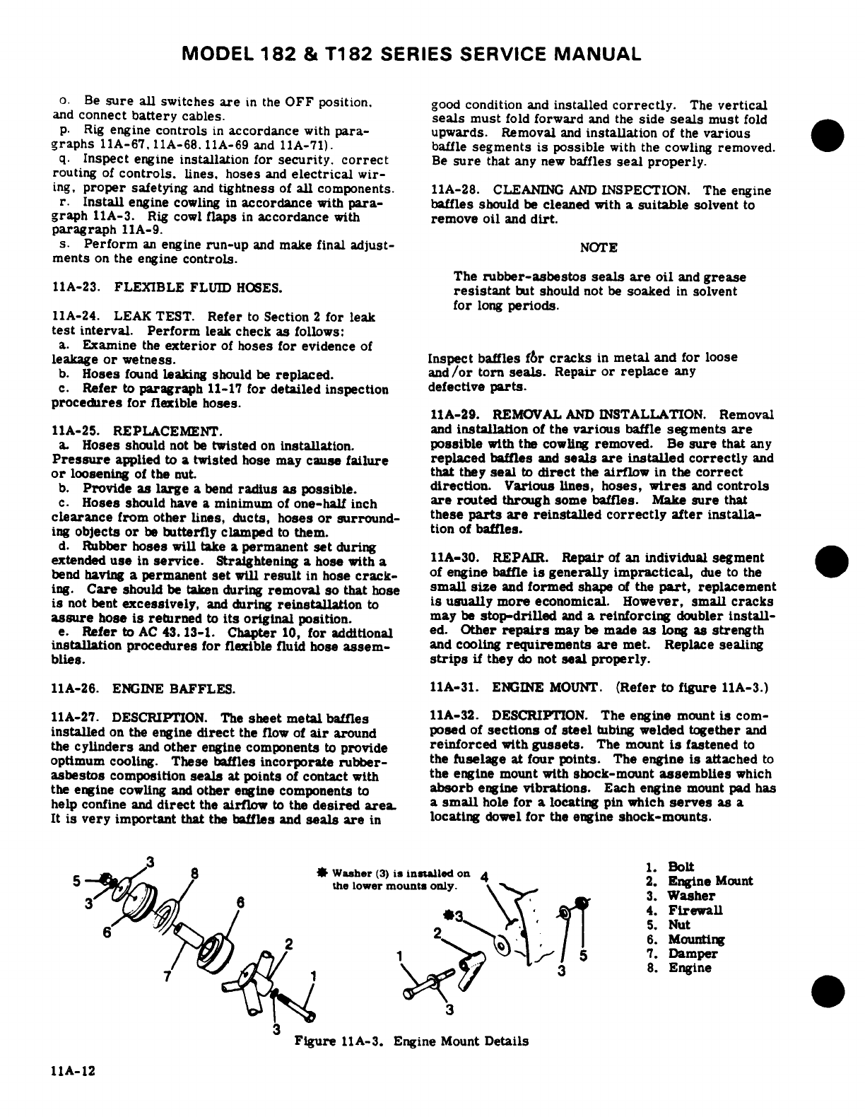
MODEL
182
&
T182
SERIES
SERVICE
MANUAL
o.
Be
sure
all
switches
are
in
the
OFF
position,
good
condition
and
installed
correctly.
The
vertical
and
connect
battery
cables.
seals
must
fold
forward
and
the
side
seals
must
fold
p.
Rig
engine
controls
in
accordance
with
para-
upwards.
Removal
and
installation
of
the
various
graphs
11A-67.
11A-68.11A-69
and
11A-71).
baffle
segments
is possible
with
the
cowling
removed.
q.
Inspect
engine
installation
for
security.
correct
Be
sure
that
any
new
baffles
seal properly.
routing
of
controls.
lines,
hoses
and
electrical
wir-
ing,
proper
safetying
and
tightness
of
all
components.
11A-28.
CLEANING
AND
INSPECTION. The
engine
r.
Install
engine
cowling
in
accordance
with
para-
baffles
should
be
cleaned
with
a
suitable
solvent
to
graph
11A-3.
Rig
cowl
flaps
in
accordance
with
remove
oil
and
dirt.
paragraph
11A-9.
s.
Perform
an
engine
run-up
and
make
final
adjust-
NOTE
ments
on
the
engine
controls.
The
rubber-asbestos
seals
are
oil
and
grease
11A-23.
FLEXIBLE
FLUID
HOSES.
resistant
but
should
not
be
soaked
in
solvent
for
long
periods.
11A-24.
LEAK
TEST.
Refer
to
Section
2
for
leak
test
interval.
Perform
leak
check
as
follows:
a.
Examine
the
exterior
of
hoses for
evidence
of
leakage
or
wetness.
Inspect
baffles
for
cracks
in
metal
and
for
loose
b.
Hoses
found
leaking
should
be
replaced.
and/or
torn
seals.
Repair
or
replace
any
c.
Refer
to
paragraph
11-17
for
detailed
inspection
defective
parts.
procedures
for
flexible
hoses.
11A-29.
REMOVAL
AND
INSTALLATION.
Removal
11A-25.
REPLACEMENT.
and
installation
of
the
various
baffle
segments
are
a. Hoses
should
not
be
twisted
on
installation.
possible
with
the
cowling
removed.
Be
sure
that
any
Pressure
applied
to
a
twisted
hose
may
cause
failure
replaced
baffles
and
seals are installed
correctly
and
or
loosening
of
the
nut.
that
they
seal
to
direct
the
airflow
in
the
correct
b.
Provide
as
large
a
bend
radius
as
possible.
direction.
Various
lines,
hoses,
wires
and
controls
c.
Hoses
should
have
a
minimum
of
one-half
inch
are
routed
through
some
baffles.
Make
sure
that
clearance
from other
lines,
ducts,
hoses
or
surround- these
parts
are
reinstalled
correctly
after
installa-
ing
objects
or
be
butterfly clamped
to
them.
tion
of
baffles.
d.
Rubber
hoses
will
take
a
permanent
set
during
extended
use
in
service.
Straightening
a
hose
with
a
11A-30.
REPAIR.
Repair
of
an
individual
segment
bend
having
a
permanent
set
will
result
in
hose
crack-
of
engine
baffle
is
generally
impractical,
due to
the
ing.
Care
should
be
taken
during
removal
so
that
hose
small
size
and
formed
shape
of
the
part,
replacement
is
not
bent
excessively,
and
during
reinstallation
to
is
usually
more
economical. However,
small cracks
assure
hose
is
returned
to
its
original
position.
may
be
stop-drilled
and
a reinforcing
doubler
install-
e.
Refer
to
AC
43.13-1. Chapter
10,
for
additional
ed.
Other
repairs
may
be
made
as
long
as
strength
installation
procedures
for
flexible
fluid
hose
assem-
and cooling
requirements are
met.
Replace
sealing
blies.
strips
if
they
do
not
seal
properly.
11A-26.
ENGINE
BAFFLES.
11A-31.
ENGINE
MOUNT.
(Refer
to
figure
11A-3.)
11A-27.
DESCRIPTION.
The
sheet metal
baffles
11A-32. DESCRIPTION.
The
engine
mount
is
com-
installed
on
the
engine
direct
the
flow
of
air
around
posed
of
sections
of
steel
tubing
welded
together
and
the
cylinders
and
other
engine
components
to
provide
reinforced
with
gussets.
The mount
is
fastened
to
optimum
cooling.
These
baffles
incorporate rubber-
the
fuselage
at
four
points. The
engine
is
attached
to
asbestos
composition
seals
at
points
of
contact
with
the engine
mount
with
shock-mount
assemblies
which
the engine
cowling
and
other
engine
components
to
absorb
engine
vibrations.
Each
engine
mount
pad
has
help
confine
and
direct
the
airflow
to
the
desired
area.
a
small
hole
for
a
locating
pin
which
serves
as
a
It
is
very
important
that
the
baffles
and
seals
are
in
locating
dowel
for
the
engine
shock-mounts.
1. Bolt
5.
Nut
3
Figure
11A-3.
Engine
Mount
Details
11A-12
MODEL
182
&
T182
SERIES
SERVICE
MANUAL
11A-33.
REMOVAL
AND
INSTALLATION.
e.
Install
spin-on
filter
and
torque
to
18-20
lb-ft
a.
Remove engine
in
accordance
with
paragraph
or
3/4
to
1
full
turn
after
gasket
makes
contact.
11A-17.
f.
Safety
wire
filter.
b.
Remove
bolts
from
upper
and
lower
mount-to-
fuselage
structure
and
carefully
remove
engine mount.
11A-43.
OIL
COOLER.
c.
Reverse
the
preceding
steps
for
reinstallation.
Reinstall
engine
in
accordance
with
paragraph
11A-22.
11A-44.
DESCRIPTION.
The
external
oil
cooler
is
NOTE
mounted
on
the
right
aft
engine
baffle.
Flexible
hoses
carry
the
oil
to
and
from
the
cooler.
Ram
air
passes
through
the
cooler
coil
and
is
discharged
into
Torque
engine-to-mount bolts
to
450-500
lb-in.
the
engine
compartment.
At
each
engine
oil
change,
Torque
mount-to-firewall
bolts
to
160-190
lb-in.
drain
the
oil
cooler. Refer
to
Section
2
for
servicing
instructions.
11A-34.
REPAIR.
(Refer
to
Section
17.)
11A-35.
PAINTING.
(Refer
to
Section
18.)
11A-45.
ENGINE
FUEL
SYSTEM.
11A-36.
ENGINE
SHOCK-MOUNT
PADS.
(Refer
a
carburetor
mounted
on
the
lower
aft
end
of
the en-
figure
11A-3.) The
bonded
rubber
and
metal
shock
a
figure
11A-3.
)
The
bonded
rubber
and
metal
shock- gine.
The
carburetor
has
a
manual
altitude
mixture
mounts
are
designed
to
reduce
transmission
of
engine
cont.
The
carburetor
has
and
vibrations
to
the
airframe.
The
rubber
pads should
be
wiped
clean
with
a
clean
dry
cloth.
refer
to the
manufacturer's
overhaul
and
repair
be
wiped
clean
with
a
clean
dry
cloth,
manual.
manual.
11A-37.
ENGINE
OIL SYSTEM.
11A-47.
CARBURETOR.
11A-38.
DESCRIPTION.
A
wet-sump,
pressure-
11A-48.
REMOVAL
AND
INSTALLATION.
lubricating
oil
supply
is
employed
in
the
engine. The
a.
Place
fuel
selector
valve
in
the
OFF position.
engine
is
equipped
with
an
external
replaceable
oil
b.
Remove
engine
cowling
in
accordance
with
filter
and
a
noncongealing
oil
cooler.
paragraph
11A-3.
The
U.S.
Environmental
Protection
Agency
d.
Disconnect
throttle
and
mixture
controls
at
the
advises
that
mechanics
and
other
workers
carburetor.
Note
EXACT
position,
size
and
number
who
handle
engine
oil
are
advised
to
of
attaching
washers
and
spacers
for
reference
on
minimize
skin
contact
with
used
oil
and
reinstallation.
promptly
remove
used
oil
from
the
skin.
In
a
e.
Disconnect
and
cap
or
plug
fuel
line
at
carbure-
laboratory
study,
mice developed
skin
cancer
tor.
after
skin
was
exposed
to
used
engine
oil
f.
Remove
safety
wire.
nuts
and
washers
attaching
twice
a
week
without
being
washed
off,
for
carburetor
to
engine.
and
remove
carburetor
and
most
of
their
life
span.
Substances
found
to
mounting
gasket.
cause
cancer
in
laboratory animals
may
also
g.
For
overhaul
and
cleaning
procedures
refer
to
cause
cancer
in
humans.
the
manufacturer's
overhaul
and
repair
manual.
h.
Reverse
the
preceding
steps
for
reinstallation,
11A-39.
TROUBLE
SHOOTING.
(Refer
to
Section
11.)
using
new
gaskets.
Rig
throttle/waste
gate
and
mix-
ture
controls
in
accordance
with
paragraphs
11A-67
11A-40.
FULL-FLOW
OIL
FILTER.
and
11A-68.
11A-41. DESCRIPTION.
An
external
replaceable
11A-49.
IDLE
SPEED
AND
MIXTURE
ADJUST-
oil
filter
is
standard
equipment
on
this
engine. The
MENTS.
Idle
speed
and
mixture
adjustment
should
filter
is
a throw-away
spin-on
filter
which
has
an
be
accomplished
after
the
engine
has
been
warmed
internal
bypass
valve. up.
Since
idle
RPM
may
be
affected
by
idle
mixture
adjustment.
it
may
be
necessary
to
readjust
idle
RPM
11A-42.
REMOVAL
AND
INSTALLATION.
after
setting
the
idle
mixture
correctly.
a.
Set
the
throttle
stop
screw
(idle
RPM)
to
obtain
NOTE 600±25
RPM.
wit
h
throttle
control
pulled
full
out
against
idle
stop.
Replacement
filters
are
available
from
the
Cessna
Supply
Division.
NOTE
a.
Remove
cowling
in
accordance
with
paragraph
Engine
idle
speed
may
vary
among
different
11A-3.
engines.
An
engine
should
idle
smoothly.
b.
Remove
safety
wire
from
filter.
without
excessive
vibration
and
the
idle
speed
c.
Unscrew
filter
from adapter.
should
be
high
enough
to
maintain
idling
oil
d.
Before
installing
oil
filter
apply
a
thin
coating
pressure
and
to
preclude
any
possibility
of
of
Dow
Corning
Compound. DC-4.
on
the
base
gasket
engine
stoppage
in
flight
when
the
throttle
is
by
brushing
or
wiping.
closed.
11A-13
MODEL
182
&
T182
SERIES SERVICE
MANUAL
b.
Advance
throttle
to
increase
engine
speed
to
b.
Disconnect flexible
compressor
inlet
(upper)
approximately
1000
RPM.
duct at
airbox.
c.
Pull
mixture control
knob
slowly
and
steadily
c.
Disconnect
flexible
carburetor
heat
(lower)
duct
toward
the
idle
cut-off
position,
observing
tachometer,
from
airbox.
then
return
control
full
IN
(RICH)
position
before en-
d.
Disconnect
carburetor
heat
control
wire
from
gine
stops.
control
arm
on
airbox.
and
remove
clamp.
d.
Adjust
mixture
adjusting
screw
at
upper
end
of
e.
Remove
clamp
attaching
air
filter
box
to
airbox.
carburetor
intake
throat
to
obtain
a
slight
and
mo-
f.
Remove
screw
attaching
upper
airbox
support
to
mentary
gain
of
25
RPM
maximum
at
1000
RPM
firewall
stiffener.
engine
speed
as
mixture control
is
moved
from
full
g.
Remove
four
screws
attaching
airbox
to
firewall
IN
(RICH)
toward
idle
cut-off position.
Return
con-
and
remove
airbox.
retaining
washers
for
installation.
trol
to
full
IN
(RICH)
to
prevent
engine
stoppage.
h.
Reverse
the
preceding
steps
for
reinstallation.
e.
If
mixture
is
set
too
LEAN,
engine
speed
will
Rig
carburetor
heat
control
according
to
paragraph
drop
immediately,
thus
requiring
a
richer
mixture.
11A-69.
Turn
adjusting
screw
OUT
(counterclockwise)
for
a
richer
mixture.
11A-54.
CLEANING
AND
INSPECTION.
Clean
metal
f.
If
mixture
is
set
too
RICH.
engine speed
will
parts
of
the
induction
airbox
with
Stoddard
solvent
or
increase
above
25
RPM,
thus
requiring
a
leaner
equivalent.
Inspect
for
cracks,
dents,
loose
rivets.
mixture.
Turn
adjusting
screw
IN
(clockwise)
for
a
etc.
Minor
cracks
may
be
stop-drilled.
In
case
of
leaner
mixture.
continued
or
severe
cracking,
replace
airbox.
In-
spect
gaskets
and
install
new
gaskets,
if
damaged.
NOTE
Check
manually-operated
air
door
for
ease
of
oper-
ation
and
proper
rigging.
After each
adjustment
to
the
idle
mixture,
run
engine
up
to
approximately
2000
RPM
11A-54A.
INSTALLATION
OF
INLET
DUCTS.
When
to
clear
engine
of
excess
fuel
to
obtain
a
cutting duct
assembly
to
length,
the
support
wire
correct
idle
speed.
should
be
cut
back
far
enough
to
bend
back
(mini-
mum
bend
radius
1,8
inch)
under
the
clamp
and
pro-
trude
1/4
inch.
Do
not
break
the
bond between
wire
11A-50.
INDUCTION
AIR
SYSTEM.
Ram
air
enters
and
fabric
Before
tightening
clamp,
make
sure
ther-
the
induction
air
system
through
an intake
port
and
a
is
no
twist
or
torque
on
hose.
If
hose
is
wrapped
filter
on
the
aft
left
side
of
the cowling.
It
is
ducted
with
MIL-Y-1140
cord
in
place
of
wire
support,
the
to
the
airbox,
and
onward
to
the
turbocharger
com-
same
installation
procedures
applies
except;
MIL-Y-
pressor
section,
located
under
and
to
the
left
of
1140
has
no
miumum
bend
radius
requirement.
engine.
After
compression,
the
air
is
forced
through
The
minimum
installed
bend
radius
for
wire
the
carburetor,
where
fuel
is
intermixed
and
then
to
the
intake
manifold
through
the
throttle
valve.
The
supported
hose
in
the
plane
bend is
as
mixture
is
distributed
to
each
cylinder
as
demanded
Neoprene, one-ply hose
-1/4
diameter
of
the
1.
Neoprene,
one-ply
hose
-1/4
diameter
of
the
through
separate
intake pipes.
A
butterfly
valve,
maximum
how
dimension.
located
in
the
airbox
may
be
operated
manually
from
.
Neoprene
two-ply how
and
silicone, one-ply
the
cockpit
to
permit
selection
of
carburetor
heated
hose-1/3
diameter
of
the
minimum
hose
dimension.
air,
which in
this
application
is
also
alternate
air
4.
Silicone,
two-ply
hose
-
1/2
diameter
of
the
selection.
When
carburetor
heat
is
selected,
heated
maximum
hose
dimension.
air
is
drawn
from
a
shroud
on
the
left
exhaust
stack
assembly.
11A-55.
IGNITION
SYSTEM.
11A-56.
DESCRIPTION.
The
ignition
system
is
com-
11A-57.
FILTER
REMOVAL
AND
INSTALLATION.
prised
of
dual
magnetos,
two
spark
plugs
in
each
a.
Remove
upper
left
cowling
according
to
paragraph
cylinder,
an
ignition wiring
harness,
an
ignition switch
11A-3.
mounted
on
the
instrument
panel
and
required
wiring
b.
Release
the
four
quick-release
fasteners
securing
between
the
ignition
switch
and
magnetos.
the
filter
assembly
to
the
airbox.
c.
Reverse
the
preceding
steps
for installation.
11A-57.
TROUBLE
SHOOTING.
(Refer
to
Section
11.)
11A-52.
CLEANING
AND
INSPECTION.
Clean
and
11A-58.
MAGNETOS.
inspect
filter
in
accordance
with
instructions
in
Section
2.
11A-59.
DESCRIPTION.
The Bendix
D-2000
series
magneto
consists
of
two
electrically
independent
NOTE
ignition
circuits.
The magneto
uses
an
impulse
coupling to
provide
reliable
ignition
at
engine
crank-
If
filter
gasket
becomes
loose,
bond
with
ing
speed.
Suppression
of
breaker
contact
point
EC-1300L
or
equivalent.
arcing
is
accomplished
by
feed-thru
type
capacitors
mounted
in
the
magneto
cover
which
forms
a
part
of
11A-53.
AIRBOX
REMOVAL
AND
INSTALLATION.
the
magneto
harness
assembly.
a.
Remove
upper left
cowl
in
accordance
with
para-
graph
11A-3.
11A-60.
REMOVAL
AND
INSTALLATION.
11A-14
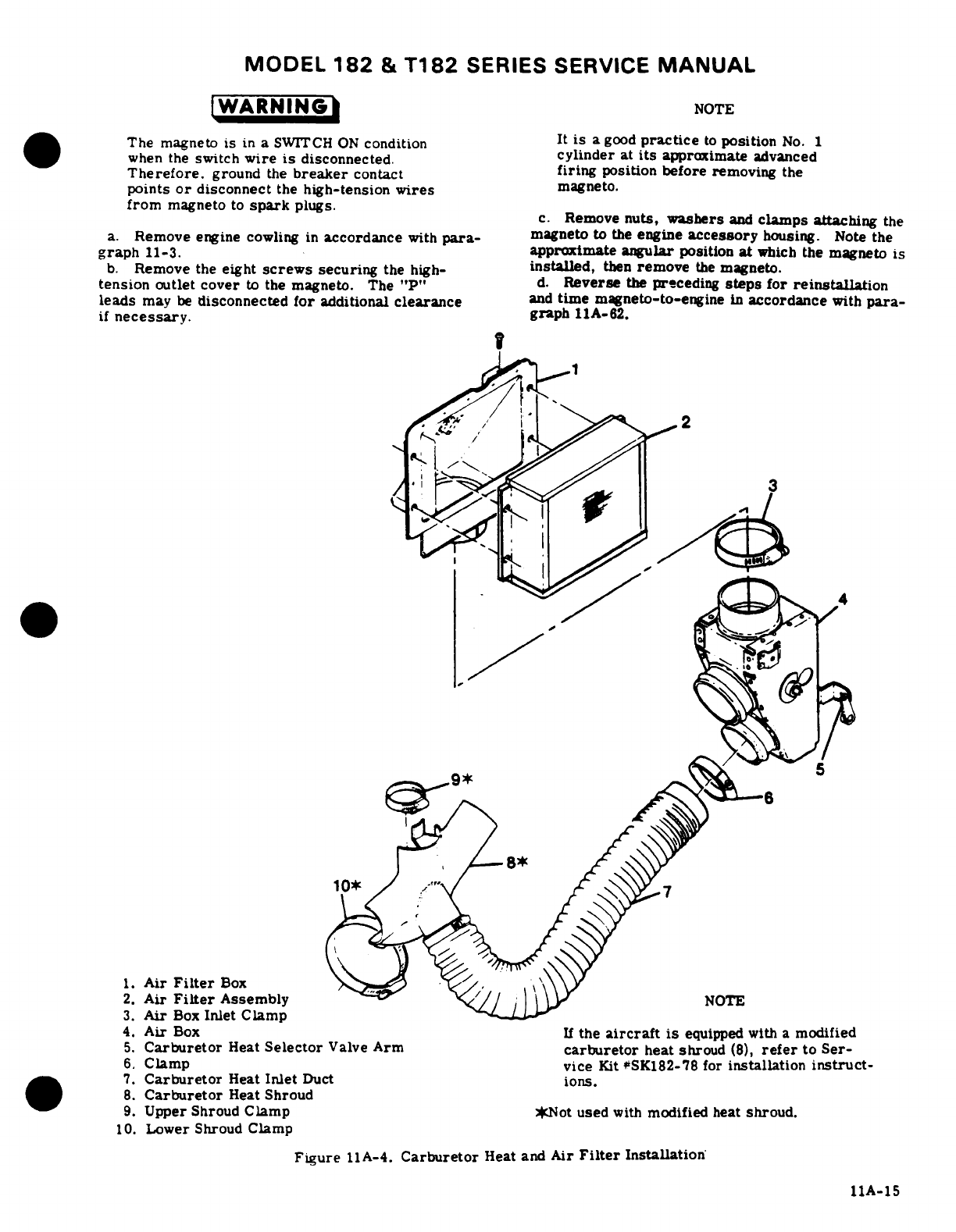
MODEL
182
&
T182
SERIES
SERVICE
MANUAL
The
magneto
is
in
a
SWITCH
ON
condition
It
is
a
good
practice
to
position
No.
1
when
the
switch
wire
is
disconnected.
cylinder
at
its
approximate
advanced
Therefore.
ground
the
breaker
contact
firing
position before
removing
the
points
or
disconnect
the
high-tension
wires
magneto.
from
magneto
to
spark
plugs.
c.
Remove
nuts,
washers
and
clamps
attaching
the
a.
Remove
engine
cowling
in
accordance
with
para-
magneto
to
the
engine
accessory
housing.
Note
the
graph
11-3.
approximate angular
position
at
which
the
magneto
is
b.
Remove
the
eight
screws
securing
the high-
installed,
then
remove
the
magneto.
tension outlet
cover
to
the
magneto.
The
"P"
d.
Reverse
the
preceding
steps
for
reinstallation
leads
may
be
disconnected
for
additional
clearance
and
time
magneto-to-engine
in
accordance
with
para-
if
necessary.
graph
11A-62.
1.
Air
Filter
Box
2.
Air
Filter
Assembly
NOTE
3.
Air
Box
Inlet Clamp
4.
Air
Box
If
the
aircraft
is
equipped with
a
modified
5.
Carburetor
Heat
Selector
Valve
Arm
carburetor
heat
shroud
(8),
refer
to Ser-
6.
Clamp
vice
Kit
#SK182-78
for
installation
instruct-
7.
Carburetor
Heat
Inlet
Duct
ions.
8.
Carburetor
Heat
Shroud
9.
Upper
Shroud
Clamp
Not
used
with
modified
heat
shroud.
10.
Lower Shroud
Clamp
Figure
11A-4.
Carburetor
Heat
and
Air
Filter
Installation
11A-15
MODEL
182
&
T182
SERIES
SERVICE
MANUAL
11A-61.
INTERNAL
TIMING.
(MAGNETO
RE-
h.
While holding the
rotor
shaft.
loosen
the
screw
MOVED
FROM
ENGINE.)
securing
breaker
contact
cam
to
rotor
shaft
and
back
screw
out
approximately
half
way.
Place
the
end
of
NOTE
a
broad
bladed
screwdriver
between
the
bottom
of
the
cam
and housing.
Strike
the
screwdriver
handle with
A
magneto,
correctly
timed
internally,
will a
sharp
downward
blow
to
"pop"
the
cam
loose
from
have
the
red
painted
tooth
of
the
large
dis- taper
of
shaft.
tributor
gears
approximately
centered
in
the
1.
Rotate
cam
until
breaker
contact
cam
followers
timing
windows,
the L
("E"
gap)
mark
on
the
are
on
the
high
point
of
cam
lobes.
Adjust
breaker
rotor
shaft
in
alignment
with
the
pointer
and
points
to
obtain
a
clearance
of
0.
016±0.
004
inch
on
both
sets
of
breaker
contacts
opening,
all
at
LEFT
and
RIGHT
contacts
respectively.
Tighten
the
same
time.
breaker
contact
securing
screws
to
20-25
lb-in.
j.
Repeat
step
"c.
"
a.
Remove
breaker
contact
point
assembly
cover,
k.
While
holding
rotor
shaft
in
this
EXACT
position,
if
installed,
by
removing
the
cover
screws,
pulling
rotate
the
breaker
contact cam
in
the
opposite
direc-
cover
directly
aft
away
from
housing
and
disconnecting
tion
of
rotation
a
few
degrees
BEYOND
where
the
both
capacitor
leads
from
breaker
contact
assemblies.
breaker
contacts
close,
then
rotate
cam
in
the
normal
b.
Remove
timing
inspection
hole
plugs
from
mag-
direction
of
rotation
until
the
breaker
contacts
just
neto.
begin
to
open.
Point
opening
should
be
determined
c.
Slowly
turn
the
rotor
shaft
until
the
red
painted
by
the
use
of
a
timing
light
(Bendix
Part
No.
11-9110
tooth
of
the
large
distributor
gear
for
each side
is
or
equivalent)
approximately
centered
in
the
inspection
windows
L
While
holding
cam
in
this
EXACT
POSITION,
with
the
L
("E"
gap)
mark
on
the
rotor
aligned
with
push
cam
on
rotor
shaft
as far
as
possible
with
the
the
pointer.
Lock
the
rotor
in
this
EXACT
position
fingers.
Tighten
cam
securing
screw
thereby
draw-
using
Bendix
Rotor
Holding
Tool,
Part
No.
11-8465
ing
the
cam
down
evenly
and
tightly.
Torque
cam
or
equivalent.
securing screw
to
16-20
lb-in.
NOTE
NOTE
Position
the
11-8465
Rotor
Holding
Tool
on
Extreme
care
must
be
exercised
in
this
oper-
drive
end
of
rotor
shaft
in
the
4
o'clock
ation.
If
cam
adjustment
is
changed
in
the
position
so
that
any
shaft
deflection
caused
slightest
degree,
the
timing
of
the
magneto
by
clamping
action
will
be
in
a
plane
parallel
will
be
thrown
off.
Do
not
drive
cam
on
rotor
to
the
breaker
contacts.
shaft
with
a
mallet
or other
instrument.
d.
Connect
the
timing
light
(Bendix
Part
No. 11-
9110
or
equivalent)
black
lead
to
any
unpainted
sur-
m.
Recheck timing
to
make
sure
both
sets
of
breaker
face
of
the
magneto. Connect
the
red
lead
to
the
left
contacts
begin
to
open
within
the
width
of
the
L
("E"
breaker
contact
terminal
and
the
green
lead
to
the
gap)
mark
and
that
the
contact
point
clearance
is
in
right
breaker
contact
terminal.
accordance
with
dimensions
in
step
"g".
e.
Carefully
adjust
the
LEFT
breaker
contacts
to
just
begin to
open
(light
will
go
out)
with the
timing
NOTE
pointer
within
the
width
of
the
L
("E"
gap)
mark.
f.
Repeat
step
"e"
for
the
RIGHT
breaker
contacts.
When
reinstaling
the
inspection hole
plugs,
g.
Loosen the
rotor
holding
tool
and
turn
rotor
make
sure
the
ventilated
plugs
are
installed
shaft
in
normal
direction
of
rotation
until
cam
follow-
in the
ends
of
the
magneto.
Torque
plugs
to
ers
of
contact
assemblies
are
on
the
high
point
of
cam
12-15
lb-in.
lobes.
Contact
point
clearance
should
be
0.
016±0.002
inch and
0.016±0.
004
inch
on
LEFT
and
RIGHT
con-
11A-62. MAGNETO-TO-ENGINE-TIMING.
The
tacts
respectively.
If
dimensions
do
not
fall
within
magneto
must
be
installed
with
its
timing marks
limits,
readjust
contact
points
and
recheck
to
be
sure carefully
aligned,
with
number
one
cylinder
on
its
the
points
just
begin
to
open when
the timing
pointer
compression
stroke
and
with
the
number
one
position
is
within
the
width
of
the
L
("E" gap)
mark.
of
number
one
piston.
To
locate
the
compression
stroke
of
the number
one
cylinder, remove
the
lower
NOTES
spark
plug
from
number
2,
3,
4,
5,
and
6
cylinders.
Remove
the
upper
spark
plug
from number
1
cylinder.
Wire
feeler
gages
are
recommended
when
Place
the
thumb
of
one
hand
over
the
spark
plug
hole
checking
contact
point
clearance.
of
number
one
cylinder
and
rotate crankshaft
in
the
direction
of
normal
rotation
until
the
compression
No
attempt
should
be
made
to
stone
or
dress
stroke
is
indicated
by
positive
pressure
inside
the
contact
points.
cylinder
lifting
the
thumb
off
the
spark
plug
hole.
After
the
compression
stroke
is
attained, locate
If
the
above
conditions
are
met
and
within
number
one
piston
at
its
advanced
firing
position.
the
tolerance,
the
magneto
is
timed
inter-
Locating
the
advanced
firing
position
of
number
one
nally
and
ready
for
installation.
If
the
piston
may
be
obtained
by
rotating
the
crankshaft
above
conditions
are
not
within
tolerance,
opposite
to
its
normal
direction
of
rotation
until
it
is
proceed
to
step
"h".
approximately
30
degrees
before
top
dead
center
11A-16
Revision
1
MODEL
182
&
T182
SERIES
SERVICE
MANUAL
(BTC)
on
the
compression
stroke
of
number
one
h.
Attach
the
red
lead
of
the
timing
light
(Bendix
cylinder.
Rotate
crankshaft
in
a
normal direction
Part
No.
11-9110
or
equivalent)
to
the
left
switch
to
align
the
timing
mark
on
the
front
face
of
the
lead
adapter,
the
green
lead
of
the
timing
light
to
starter
ring
gear
support
with
the
drilled
hole
in
the the
right
switch
lead
adapter
and
the
black
lead
of
starter,
making
sure
the
final
motion
of
the
ring
gear
the
timing
light
to
the
magneto
housing
(common
is
in
the
direction
of
normal
rotation.
ground).
NOTE
NOTE
An
accurate
top
center
indicator
which
screws
An
internal
timing
tolerance
is
allowed
when
into
a
spark
plug
mounting
hole,
and
a
pendu-
adjusting
the
two
main
breakers.
Therefore,
lum
pointer
mounted
on
a
360-degree
timing
one
of
the
main
breakers
may
open
slightly
disc
may
also
be
used
to
locate
the
advanced
before
the
other.
Magneto-to-engine
timing
firing
position.
The
timing
disc
should
be
should
be
accomplished
using
the
first
main
adapted
to
fit
over
the
end
of
the
propeller
breaker
to
open
as
the
reference
point
when
spinner
in
such
a
manner
that it
may
be
ro-
the
engine
is
in
the
firing
position
for
No.
1
tated
as
necessary.
In
all
cases,
it
must
be
cylinder.
This will
ensure
that
ignition
definitely
determined
that
the
number
one
created
by
either
spark
plug
will
not
occur
cylinder
is
at
the
correct
firing
position
and
prior
to
the
desired
engine
firing
point.
on
the
compression
stroke
when
the engine
is
turned
in
its
normal direction
of
rotation.
i.
Turn
the
entire
magneto
in
direction
of
rotor
rotation,
right-hand
rotation
to
right
and
left-hand
After
the engine has
been
placed
in
the
correct
firing
rotation
to
left,
until
one
of
the timing
lights
just
position,
install
the
magneto
to
the
engine
in
the
fol- goes
off.
Then
tighten
the
magneto
mounting
clamps
lowing
manner:
evenly
in
this
position.
a.
Remove the
timing
window
plug
from
the
most
k.
Back
the
engine up
approximately
10°
and
then
convenient
side
of
the magneto
housing,
carefully
"bump"
the
engine
forward
while
observing
b.
Remove
the
rotor
viewing
location
plug
from
the
the timing
lights.
top
center
of
the
housing.
1.
At
the
No.
1
cylinder
firing
position,
one
of
the
c.
Turn
the
rotating
magnet
drive
shaft
in
the
nor-
timing
lights
should
go
off.
Continue
turning
the
en-
mal
direction
of
magneto
rotation until
the
red
painted
gine
in
its
normal
direction
of
rotation until
the
other
tooth
of
the
large
distributor
gear
is
centered
in
the
timing
light
goes
off.
This
should
be
not
more
than
timing
hole
(hole
at
each
side
of
magneto).
3
engine
degrees
later
than
the
first
light.
If
not,
d.
Also
observe
at
this
time
that
the
built
in
pointer
repeat
steps
"i"
thru
"k"
until
these
conditions
are
just
ahead
of
the
rotor
viewing
window
aligns
with
the
obtained.
L
"E"
gap)
mark
on
the
rotor.
m.
Make
sure
the
magneto
clamps
are
tightened
e.
Install
the
magneto-to-engine
gasket
on
the mag-
securely,
recheck
timing
once
more
and
remove
neto
flange.
timing
equipment.
n.
Reinstall
inspection
plugs and
torque
plugs to
12-15
lb-in.
Do
not
attach
harness
spark
plug
leads
to
the 11A-63.
MAINTENANCE. At
the
first
25-hour
in-
spark
plugs
until
all
magneto-to-engine
timing
spection.
first
50-hour inspection,
first
100-hour
procedures are
completed
and
the
switch
leads
inspection
and
thereafter
at
each 100-hour inspection,
("P"
leads)
are
connected.
the
contact
breaker
point
compartment
and
magneto-
to-engine
timing
should
be
inspected
and
checked.
f.
Remove
the
engine-to-magneto
drive
gear train
If
magneto-to-engine
timing
is
correct
within
plus
backlash
by
turning magneto
drive
opposite
to
normal
zero
and
minus
two
degree.
internal
timing
need
not
rotation as
far
as
possible.
be
checked.
If
timing
is
out
of
tolerance.
remove
g.
With the
No.
1
cylinder
at
its
correct
firing posi-
magneto
and
set internal
timing
(paragraph
11-62).
tion
and
on
the
compression stroke.
hold
the magneto
then
install
and
time
to engine.
as
close
to
its
No.
1
firing
position
as
possible
(red
tooth
in
center
of window
and
pointer over
L
("E"
gap)
NOTE
mark
on
rotor
and
install
magneto
to
the
engine.
Loosely tighten
magneto
in
position.
If
engine
operating
troubles
develop
which
appear
to
be
caused
by
the
ignition
system,
NOTE
it
is
advisable
to
check
the
spark
plugs
and
ignition
harness
first
before
working
on
the
To
facilitate
connection
of
a
timing light
to
magnetos.
If
the
trouble
appears
definitely
the
switch
lead
("P"
lead)
terminals,
short
associated
with
a
magneto.
the
following
adapter
leads
may
be
fabricated.
These
can
may
be
used
to
help
disclose
the
source
of
be
made
by
using
two
switch
lead
terminals
trouble
without
overhauling
the
magneto.
and
two
short
pieces
of
insulated
wire.
In-
stall
the
fabricated adapter
leads
in
the
switch
lead
outlet
terminals
of
the
cover.
11A-17
MODEL
182
&
T182
SERIES
SERVICE
MANUAL
a.
Moisture
check.
"BOTH"
position
to
clear
the
opposite
set
of
plugs.
1. Remove
contact
breaker
point
assembly
cover
d.
Turn
the
switch
to
the
"L"
position
and
note
the
and
inspect cover,
cables
and
capacitor
for
moisture
RPM
drop,
then
return
the
switch
to
the
"BOTH"
in
the
area.
position.
2.
Inspect
distributor
block
high
tension
outlets
e.
The
RPM
drop
should
not
exceed
175
RPM
on
for
moisture. either
magneto
setting
or
show
greater
than
50
RPM
3.
If
any
moisture
is
evident,
lightly
wipe
with
differential
between
magneto
settings.
A
smooth
a
soft,
dry,
clean,
lint-free
cloth.
RPM
drop-off past
normal
is
usually
a
sign
of
a
too
lean
or
too
rich
mixture.
A
sharp
RPM
drop-off
defective
harness
lead
or
a
magneto
out
of
time.
If
Do
not
use
gasoline
or
any
other
solvent,
as
there
is
doubt
concerning
operation
of
the
ignition
these
will
remove
the
wax
coating
on
some
system,
RPM
checks at
a
leaner
mixture
setting
or
parts
and
cause
an
electrical
leak.
at
higher
engine
speeds
will
usually confirm
whether
a deficiency
exists.
b.
Breaker
contact
compartment
check.
1.
Check
all
parts
of
the
contact
breaker assem-
NOTE
bly
for
security.
Check
distributor
block
high-tension
outlet
springs
for
evidence
of
spark
erosion
and
pro-
An
absence
of
RPM
drop
may
be
an
indication
per
height.
The
end
of
spring
should
not
be
more
than
of
faulty
grounding
of
one
side
of
the
ignition
0.
422
inch
from
top
of
tower.
system,
a
disconnected
ground
lead at
magneto
2.
Check
breaker
contact
assembly
points
for or
possibly
the
magneto
timing
is set
too
far
in
excessive
wear,
burning,
deep
pits
and
carbon
de- advance.
posits. Breaker
points
may
be
cleaned
with
a hard
finish
paper.
If
breaker
points
are
found
defective,
11A-65.
SPARK
PLUGS.
Two
18-mm
spark
plugs
install
a
new
assembly.
Make
no
attempts
to
stone
are
installed
in
each
cylinder
and
screw
into
helicoil
or
dress
breaker
points.
Clean
new
breaker
points
type
thread
inserts.
The
spark
plugs
are
shielded
to
with
clean
unleaded
gasoline
and
hard finish
paper
prevent
spark
plug
noise
in
the
radios
and
have
an
before
installing.
internal
resistor
to
provide
longer
terminal
life.
3.
Check
condition
of
the
cam
follower
felt.
Spark
plug
life
will
vary
with
operating
conditions.
Squeeze
felt
between thumb
and
finger.
If
fingers
are
A
spark
plug
that
is
kept
clean
and
properly
gapped
not
moistened
with
oil,
re-oil
using
2
or
3
drops
of
will
give
better
and
longer
service
than
one
that
is
lubricant
(Bendix
Part
No.
10-86527
or
equivalent),
allowed
to
collect
lead
deposits
and
is
improperly
Allow
approximately
30
minutes
for
felt
to
absorb
the
gapped.
lubricant.
Blot
off
excess
lubricant
with
a
clean,
NOTE
lint-free
cloth.
Too much
lubricant
could foul
breaker
points
and
cause
excessive
burning.
Refer
to
Section
2
for
inspection
interval.
4.
Check
capacitors
for
looseness
in
the
magneto
Refer
to
Section
2
for
inspection
interval.
cover
of
the
harness
assembly
and
for
any
physical
damage. If
equipment
is
available,
check
the
capaci- plugs at each
inspection.
Install
lower
tors
for leakage,
series
resistance
and
capacitance.
and
install
upper
spark
plugs
in
lower
portion
The
capacitance
should
be
0.
34
to
0.41
microfarads.
of
cylinders.
Since
deterioration
of
lower
spark
plugs
is
usually
more
rapid
than
that
NOTE
of
the
upper
spark
plugs,
rotating
helps
pro-
long
spark
plug
life.
Spring
in
capacitor
outlet
may
cause
an
indi-
11A-66.
ENGINE CONTROLS
cation
of
a
short
to
ground
if
an
adapter
lead
is
not
used.
11A-67.
THROTTLE
AND
WASTE
GATE CONTROL
(See
figure
11A-5).
c.
If
the
trouble
has
not
been
corrected after
accom-
(See
figure
plishing
the
moisture
and
breaker
contact
compart-
ment
check,
check
magneto-to-engine
timing
in
accor-
on
throttle
shaft
(4)
tighten
finger tight,
then
install
dance
with
paragraph
11A-62.
If
timing
is
incorrect,
spring
pin
(33)
making
certain
it
does
not
protrude
remove
magneto
and
adjust
internal
timing
in
accor-
beyond
the
edge
of
the
extension
dance with
paragraph
11A-61.
b.
Assemble
bolt
(5)
through
levers
(8,
14
and
17)
in
d.
Reinstall
magneto
and
time
to engine
in
accor-
the
exact
order
as
shown
in
figure
11A-5,
and
screw
dance
with
paragraph
11A-62.
throttle
control
rod
end
(20)
on
bolt
(5)
with
lock
nut.
e.
If
the
trouble
has
not
been
corrected,
magneto
NOTE
overhaul
or
replacement
is
indicated.
Make
sure
nylon
washers
are
on
retainer
and
11A-64.
MAGNETO CHECK.
not
between
AN960
washers
and
retainers.
a.
Start
and
run
engine
until
the
oil
and
cylinder
head
temperatures
are
in
the
normal
operating
ranges.
c.
Be
sure
that
washers
(26),
cam
(24)
and
castellated
b.
Advance
engine
speed
to 1700
RPM.
nut
(23)
are
properly
installed.
c.
Turn
the
ignition switch
to
the
"R"
position
and
d.
Install throttle
arm
bolt
(9)
through
lever
(8)
and
note
the
RPM
drop,
then
return
the
switch
to
the
throttle
arm
(3).
11A-18
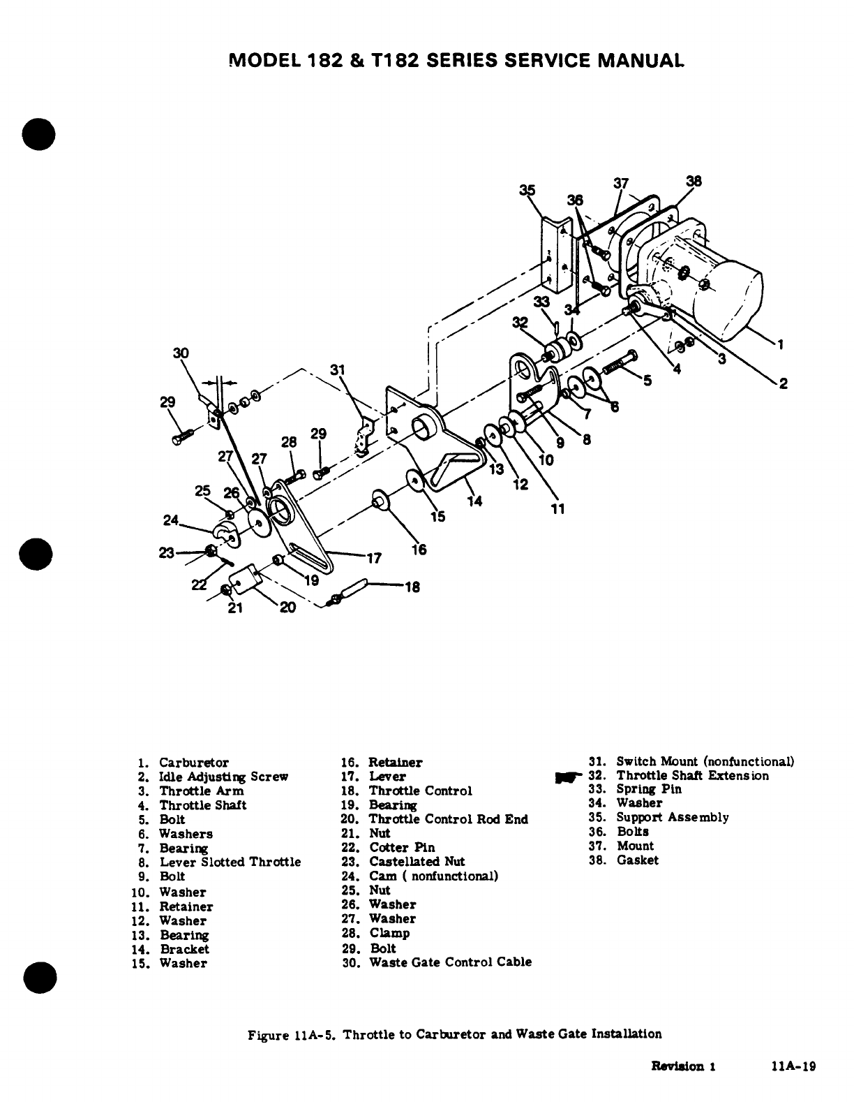
MODEL
182
&
T182
SERIES SERVICE
MANUAL
30
2
1424
23
17
1.
Carburetor
16.
Retainer
31.
Switch
Mount
(nonfunctional)
2.
Idle
Adjusting
Screw
17.
Lever
_
32.
Throttle
Shaft
Extension
3.
Throttle
Arm
18.
Throttle
Control
33.
Spring
Pin
4.
Throttle
Shaft
19.
Bearing
34.
Washer
5.
Bolt
20.
Throttle
Control
Rod
End
35.
Support
Assembly
6.
Washers
21.
Nut
36.
Bolts
7.
Bearing
22.
Cotter Pin
37.
Mount
8.
Lever Slotted
Throttle
23.
Castellated
Nut
38.
Gasket
9.
Bolt
24.
Cam
(nonfunctional)
10.
Washer
25.
Nut
11.
Retainer
26.
Washer
12.
Washer
27.
Washer
13.
Bearing
28.
Clamp
14.
Bracket
29.
Bolt
15.
Washer
30.
Waste
Gate
Control
Cable
Figure
11A-5.
Throttle
to
Carburetor
and
Waste
Gate
Installation
Revision
1
1lA-19
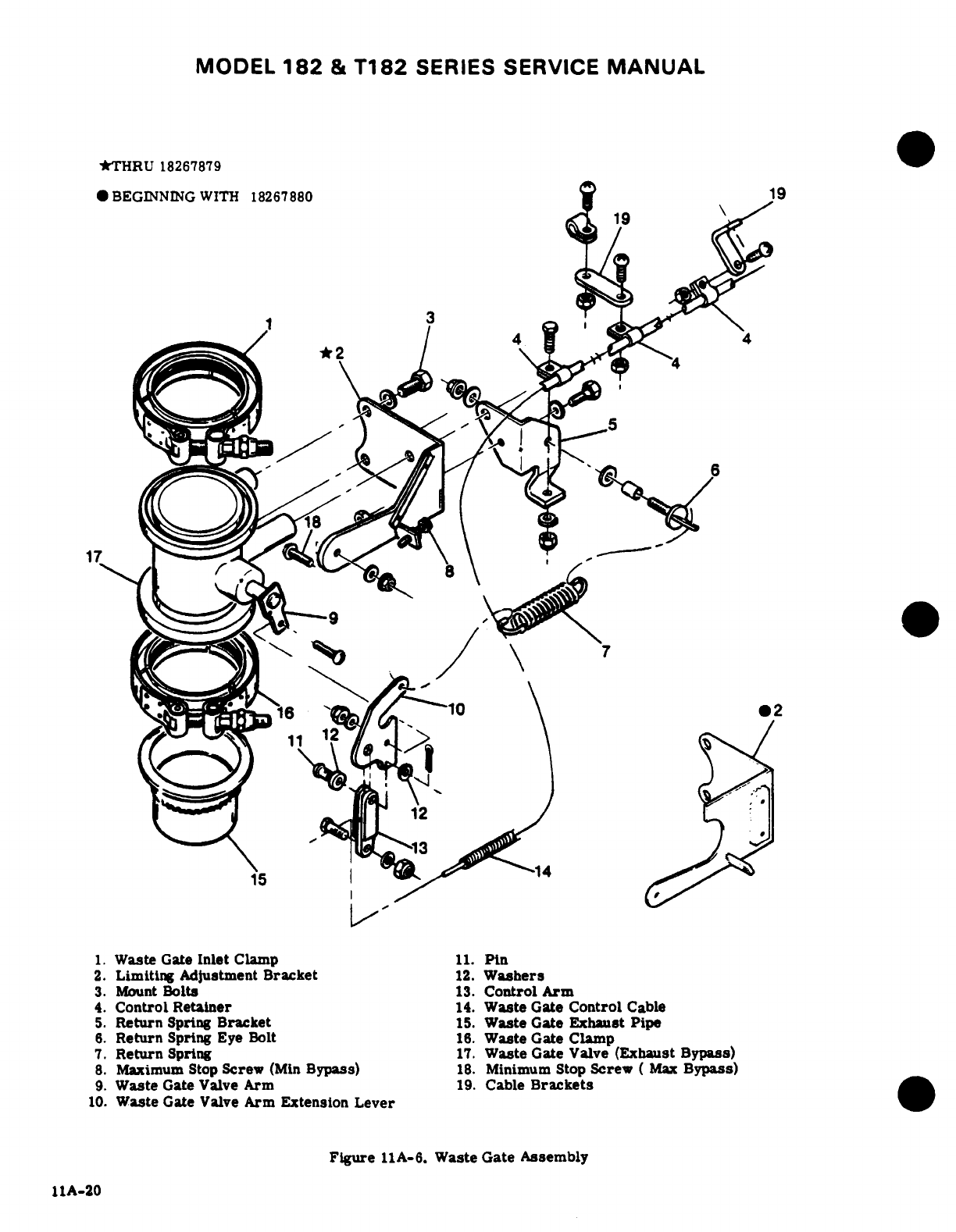
MODEL
182
&
T182
SERIES SERVICE
MANUAL
*THRU
18267879
BEGINNING
WITH
18267880
19
19
5
*I
17
10
02
.
Waste
Gate
Inlet
Clamp
1.
1.
Waste
Gate
Inlet
Clamp
11.
Pin
2.
Limiting
Adjustment
Bracket
12.
Washers
3.
Mount
Bolts
13.
Control
Arm
4.
Control
Retainer
14.
Waste
Gate
Control
Cable
5.
Return
Spring
Bracket
15.
Waste Gate
Exhaust
Pipe
6.
Return
Spring
Eye
Bolt
16.
Waste Gate
Clamp
7.
Return
Spring
17.
Waste
Gate
Valve
(Exhaust
Bypass)
8.
Maximum
Stop
Screw
(Min
Bypass)
18.
Minimum
Stop
Screw
(
Max
Bypass)
9.
Waste
Gate
Valve
Arm
19.
Cable
Brackets
10.
Waste
Gate
Valve
Arm
Extension
Lever
Figure
11A-6.
Waste
Gate
Assembly
11A-20
MODEL
182
&
T182
SERIES
SERVICE
MANUAL
e.
Assemble support
(35)
and
mount
(37)
using
bolts
NOTE
(36),
do
not
tighten
until
entire
unit
is
assembled
and
freedom
of
movement
is
assured.
Refer
to
the
inspection
chart
in
Section
2
f.
Install
switch
bracket
(31).
for
inspection,
lubrication
and/or
replace-
ment
interval
for
the
mixture
control.
NOTE
11A-69.
CARBURETOR
HEAT
CONTROL.
Lubricate
waste
gate
control
cable
(30)
a.
Loosen
clamp securing
the
control
to
the
bracket
with molybdenum
disulfide
(MIL-M-7866)
on
engine.
suspended
in
petroleum
distilate.
b.
Push
control
full
in, then
pull
it
out
approximately
1/8
inch
from
panel
for
cushion.
g.
Install
waste
gate
control
(30)
with
bolts
(28
and
29).
c.
Shift
control
housing
in
its
clamp
so
that
the
valve
h.
See
figure
11A-6.
Waste
gate control
arm
(10)
in
the
airbox
is
seated
in
the
full
open
position.
Tight-
must
be
against
minimum
stop
screw
adjustment
(8)
en
clamp
in
this
position.
and
wire
must
not
be
bent.
Ensure
0.
072"
clearence
d.
Pull
out
on
the
control
and
check
that
the
air
valve
exists
between
butterfly
valve
and
throat
while
arm
inside
the
airbox
seats
in
the
opposite
direction.
rests
against
the
adjustable
stop.
e.
Check
that
bolt
and
nut
on
the
air
valve
lever
i.
Install
throttle
control
(18)
so
approximatley
1/8"
secures
the
control wire
and
that
the
bolt
will
swivel
cushion
exists
at
each
end
of
travel
of
the
cockpit
in
the
lever.
throttle
control
f.
Bend
the
wire
tip
90
degrees
to
prevent
it
from
being
withdrawn
if
the
attaching
nut
should
become
NOTE
loose.
Slots
are
provided
to
allow
free
movement
NOTE
alignment
tighten
bolts
in
proper
sequence
to
prevent
binding.
If
after
complete
assembly
Refer
to
the
inspection
chart
in
Section
2
for
the
return
spring
will
not
return
the
arm
inspection,
lubrication
and/or
replacement
readjustment
is
necessary.
interval
for
the
carburetor
heat
control.
j.
After
free
movement
is
obtained,
follow
the
follow-
11A-70.
PROPELLER
CONTROL.
(Refer
to
Section
ing
bolt
tightening
sequence.
13.)
1.
Tighten
throttle
arm
bolt
(9),torque
20-30
in-lbs.
11A-71.
STARTING
SYSTEM
(Refer
to
Section
11.)
2.
Throttle
rod
bolt
(5)
tighten
as
soon
as
all
levers-72
EXHAUST
SYSTEM.
(8,
14
and
17),
washers
(6,
10,
12
and
15),
bearings
(7,13
and
19)
and
retainers
(
11
and
16)
are
11A-73. DESCRIPTION.
The
exhaust
system
con-
installed.
sists
of
a
single
pipe
for
each
cylinder,
two
short
3.
Tighten
castellated
nut
(23)
and
install
cotter
pin
stacks,
a
crossover
tube,
a
Y
connector
the
turbine
(22)
after throttle
rod
bolt.
(22) after throttle
rod
bolt.
section
of
the
turbocharger,
a
waste
gate,
and
a
4.
Tighten
stationary
lever
bolts
(29)
before
support
single
exhaust
outlet.
The
single
pipes
collect
ex
mount
bolts.
haust
gases
from
each
respective
cylinder,
and
route
5.
Tighten
support
mount
bolts
(36)
only
after
adjust-
it
to
the
two
stacks,
one
for
the
set
of
odd
numbered
ment
is
complete
and
free
movement
is
assured.
cylinders
and one
for
the
set
of
even
numbered
cylin-
ders.
The
left
bank,
even
numbered,
exhaust
gases
11A-68.
MIXTURE
CONTROL.
are
used
to
drive
the
turbine
wheel
of
the
turbocharger,
a.
Push
mixture
control full
in,
then
pull
it
out
which
in
turn
drives
the
compressor
wheel.
The
right
approximately 1/8
inch
for
cushion.
bank,
odd
numbered,
exhaust
is
routed
through
the
b.
Loosen
clamp
securing
the
control
to
the engine,
crossover
around
the
front
of
the
engine
to
the
Y
con-
c.
Shift
control
housing
in
the
clamp
so
that
the
nection,
which
directs
exhaust
to
the
waste
gate.
All
mixture arm
on
the
carburetor
is
in the
full
open
excess
exhaust
gases
bypass
the
turbine
wheel
of
the
position
(RICH).
Tighten
the
clamp
in
this
position.
turbocharger
through
the
waste
gate.
Manual
linkage
d.
Unlock
and
pull
mixture
control
full
out.
Check
connects
the
waste
gate
valve
to
the
carburetor
throt-
that
idle
mixture
arm
on
carburetor
is
full
closed
tle
linkage.
As
the
throttle
is
moved
toward
the
open
(IDLE
CUT-OFF).
position,
the
waste
gate
is
operated
mechanically.
e.
Check
that
the
bolt
and nut
at
the
mixture
arm
on
carburetor
secures
the
control
wire
and
that
the
11A-74.
REMOVAL
AND
INSTALLATION.
(See
figure
bolt will
swivel
in
the
arm.
11A-7.
)
f.
Bend
the
wire
tip
90
degrees
to
prevent it
from
a.
Remove engine
cowling
in
accordance
with
para-
being withdrawn
if the
attaching
nut
should
become
graph
11A-3.
loose.
b.
Disconnect ducts from
heater
shroud
on
muffler
g. When
installing
a
new
control,
it
may
be
neces-
assembly.
sary
to
shorten
the
wire
and/or
control
housing.
c.
Disconnect
duct
from
shroud
on
left
exhaust
h.
The
mixture
arm
on
the
carburetor
must
contact
stack
assembly.
the
stops
in
each
direction,
and
the
control
should
d.
Remove
nuts,
bolts
and
clamps
attaching
stack
have
approximately
1/8
inch
cushion
when
pushed
in.
assemblies
to the
turbocharger.
Revision
1
11A-21
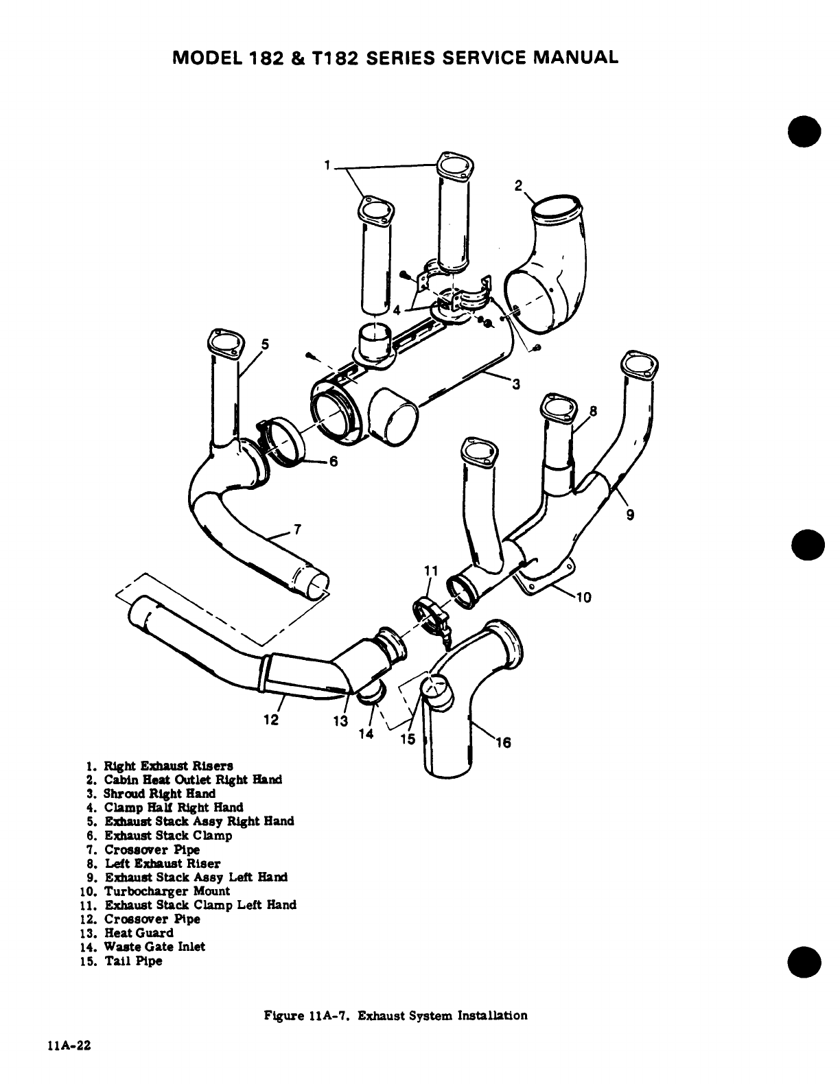
MODEL
182
&
T182
SERIES
SERVICE
MANUAL
4
14
15
56
1.
Right
Exhaust
Risers
2.
Cabin
Heat
Outlet Right
Hand
3.
Shroud
Right
Hand
4.
Clamp
Half Right
Hand
5.
Exhaust
Stack
Assy
Right
Hand
6.
Exhaust
Stack
Clamp
7.
Crossover
Pipe
8.
Left Exhaust
Riser
9.
Exhaust
Stack
Assy
Left
Hand
10.
Turbocharger
Mount
11.
Exhaust
Stack Clamp
Left
Hand
12.
Crossover
Pipe
13.
Heat
Guard
14.
Waste
Gate
Inlet
15.
Tail
Pipe
Figure
11A-7.
Exhaust System
Installation
1 A-22
MODEL
182
&
T182
SERIES
SERVICE
MANUAL
e.
Remove
nuts attaching
exhaust
stack
assemblies
11A-76.
TURBOCHARGER
(See
figure
11A-8.)
to
the
cylinders
and
remove
exhaust
stacks
and
gas-
kets.
NOTE
f.
Reverse
the
preceding
steps
for
reinstallation.
Install
a new
gasket
between
each
riser
and
its
mount-
For
additional
information covering
turbo-
ing
pad
on
each
cylinder,
regardless
of
apparent
cond-
charger
and
component
maintenance,
over-
ition
of
those
removed. Torque
exhaust
stack
nuts
at
haul
and
trouble
shooting
refer
to
the
cylinders
to
100-110
in-lbs.
Manufacturer's
Overhaul
Manual.
11A-77.
DESCRIPTION.
The
turbocharger
is
an
11A-75. INSPECTION.
Since
exhaust
systems
of
exhaust
gas-driven
compressor,
or
air
pump,
which
this
type
are
subject
to
burning.
cracking
and
general
provides
high
velocity
air
to
the
engine
intake
mani-
deterioration
from
alternate
temperature extremes
fold.
The
turbocharger
is
composed
of
a turbine
and
vibrations,
inspection is
important
and
must
be
wheel,
compressor
wheel,
turbine
housing
and
com-
accomplished
every
50
hours
of
operation.
To
inspect
pressor
housing.
The
turbine,
compressor
wheel
the
engine
exhaust
system,
proceed
as
follows:
and
interconnecting
drive
shaft
comprise
one
com-
a.
Remove
engine
cowling
as required
so
that
ALL
plete
assembly
and
are
the only
moving
parts
in
the
surfaces
of
the
exhaust
assemblies
can
be
visually
turbocharger.
Turbocharger bearings
are
lubricated
inspected.
with
filtered
oil
supplied from
the
engine
oil
system.
Engine
exhaust gas
enters
the
turbine
housing
to
drive
NOTE
the
turbine
wheel.
The turbine
wheel,
in
turn,
drives
the
compressor
wheel,
producing
a
high
velocity
of
Especially
check the
areas
adjacent
to
welds
air
in
the engine
induction
system.
Exhaust
gas
is
and
slip joints.
Look
for gas deposits
in
sur-
then
dumped
overboard
through
the
exhaust
outlet
of
rounding
areas.
indicating
that
exhaust
gases
the
turbine
housing
and
exhaust
tailpipe.
Ram
air
is
are
escaping
through
a
crack
or
hole
or
around drawn
into
the
compressor
through
the
induction
air
the
slip
joints.
filter
and
is
forced
out
of
the
compressor
housing
through
the
carburetor,
to
intake manifold
This
high
b.
After
visual
inspection,
an
air
leak
check
should
velocity
air
enters
the
carburetor
where
fuel
is
added,
be
made
on
the
exhaust
system
as
follows:
and
flow
is
limited
by
the
throttle
valve
setting.
Dur-
1.
Attach
the
pressure
side
of
an
industrial
vac-
ing
the
transient
interval
from
low
to
high
RPM,
the
uum
cleaner
to
the
tailpipe
opening,
using a
rubber
absolute
pressure
relief
valve
functions
to
limit
maxi-
plug
to
effect
a
seal
as
required.
mum
pressure
available
to
the
carburetor
by
releasing
surplus
to
engine
compartment
atmosphere.
It
also
NOTE
presets
a
maximum available
manifold
pressure.
Actual available
manifold
pressure
is
regulated
by
the
The
inside
of
vacuum
cleaner
hose
should
be
turbocharger
speed,
controlled
by
the
wastegate
by-
free
of
any
contamination
that
might
be
blown
pass
action
or
directly
by the
operator.
into
the
engine
exhaust
system.
2.
With
vacuum
cleaner
operating.
all
joints
in
the
exhaust
system
may
be
checked manually
by
feel,
or
by
using
a
soap
and
water
solution
and
watching
This
turbocharged
engine
installation
is
for
bubbles.
Forming
of
bubbles
is
considered accept-
equipped
with
an
overboost
control
valve
able;
if
bubbles
are
blown
away,
system
is
not
con-
c.
Where
a
surface
is
not
accessible
for a
visual
inspection,
or
for
a
more
positive
test,
the
following
Consequently,
it is necessary
that
the
procedure
is
recommended.
Consequently,
it is
necessary
that
the
1. Remove
exhaust
stack
assemblies.
pressure.
particularly
during
takeoff.
2.
Use
rubber
expansion
plugs
to
seal
openings.
pressre
particularly
duringtakeoff.
3. Using
a
manometer
or
gage,
apply
approxi-
climb
and
power
chanes
in
flight
mately
1-1/2
psi
(3
inches
of
mercury)
air pressure
The
slight
overboosting
of
manifold
pressure
while
each
stack assembly
is
submerged
in
water.
beyond
established
maximums
which
is
occa-
beyond
established
maximums
which
is
occa-
Any
leaks
will
appear
as
bubbles
and can
be
readily
detected.
4.
It
is
recommended
that exhaust
stacks
found
or
during
a
power
change
in
flight
is
not
con-
defective
be
replaced
before
the
next
flight.
sidered
detrimental
to
the
engine
as
long
as
d.
After
installation
of
exhaust
system
components
it
does
not
exceed
2
inches
and
is momentary.
perform
the
inspection
in
step
"b"
of
this paragraph
to
ascertain
that
system
is
acceptable.
OVERBOOST
EXCEEDING
2
INCHES
beyond
established
maximum
is
excessive
and
can
result
in
engine
damage.
Refer
to
Lycoming
Service
Bulletin
No.
369F
and
all
revisions
or
supplements
thereto.
11A-23
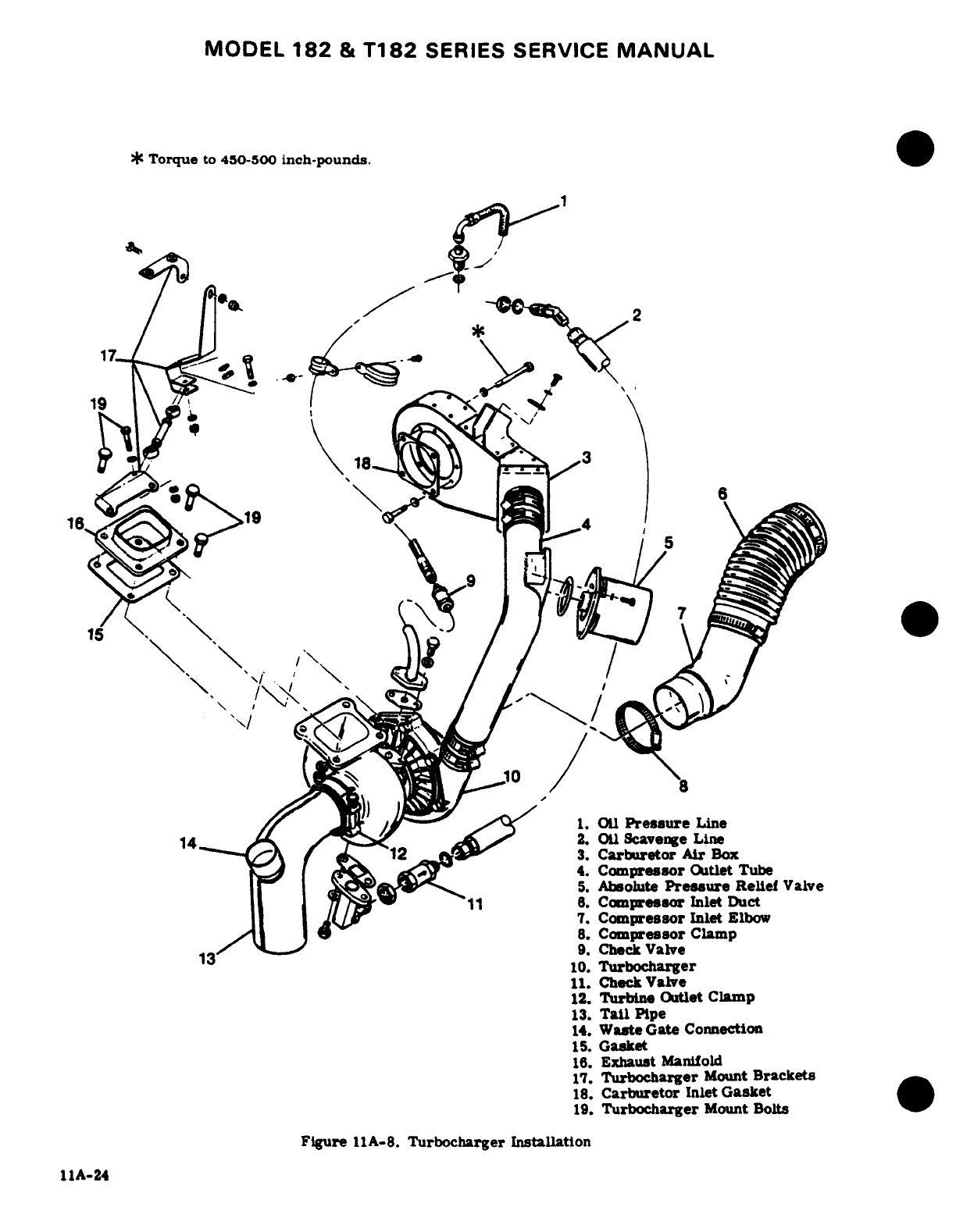
MODEL
182
&
T182
SERIES
SERVICE
MANUAL
*
Torque
to
450-500
inch-pounds.
17
' 1
19
-s
6
*i-
40
18
/3
1
1.
lou
Pressure
Line
14
_ ,
2.
011i
Scavenge
Line
-~ i i < (^
12
,^JaY^
3.
Carburetor
Air
Box
4.
Compressor
Outlet
Tube
lI _ B~A
S
^
5.
Absolute
Pressure
Relief
Valve
lI He lr11
8.
Compressor
Inlet
Duct
7.
Compressor
Inlet Elbow
8.
Compressor
Clamp
,~~~~13/^~ _^~1
9.
Check
Valve
10.
Turbocharger
11.
Check
Valve
12.
Turbine
Outlet Clamp
13.
Taill
Pipe
14.
Waste
Gate
Connection
15.
Gasket
16.
Exhaust
Manifold
17.
Turbocharger
Mount
Brackets
18.
Carburetor
Inlet
Gasket
19.
Turbocharger
Mount
Bolts
Figure
11A-8.
Turbocharger Installation
11A-24
MODEL
182
&
T182
SERIES
SERVICE
MANUAL
11A-78.
REMOVAL
AND
INSTALLATION
(See
sump.
If
the
free
air
temperature
is
below
minus
figure
11A-8.)
20°C (-20
F),
the engine
compartment
should
be
pre-
a.
Remove engine
cowling
as required.
heated
by
a
ground
heater.
Pre-heating
the
engine
b.
Remove
waste
gate
to
tailpipe
clamp
at
(14).
compartment
is
accomplished
by
inducing
heated
air
c.
Loosen
clamp
(12)
at
turbine
exhaust
outlet
and
up
through
the
cowl
flap
openings;
thus
heating
both
work
tailpipe
(13)
from
turbine
outlet,
and
cover
the
oil
and
the
cylinders. After
the
engine
compart-
to
prevent entrance
of
foreign
material.
ment
has
been
preheated,
inspect
all
engine
drain
and
d.
Loosen
clamps
(8)
and
remove
air
inlet,
elbow
vent
lines
for
presence
of
ice.
After
this procedure
(7)
and
duct
(6)
from
turbocharger
compressor
sec-
has
been
complied
with,
pull
propeller
through
sev-
tion
(10).
and
cover
both
parts
to
prevent
damage.
eral
revolutions
by
hand before
attempting
to
start
e.
Disconnect
oil
pressure
(1)
and
scavenge
lines
the
engine.
(2)
from
turbocharger
(10),
plug
and
cap
all
openings.
Remove
all
clamps
and
ties
as necessary.
f.
Remove
four
bolts
(19)
attaching
turbine
to
LH
exhaust
manifold
(16).
g.
Carefully
remove
turbocharger
from
engine
com-
partment.
at
aft
LH
side
near
the
firewall.
Due
to
the desludging
effect
of
the
diluted oil,
h.
Reverse
the
preceding
steps
for
reinstallation.
engine
operation
should
be
observed
closely
Always
use
a
new
gasket
between
turbocharger
and
during
the
initial
warm-up
of
the
engine.
En-
exhaust
manifold.
gines that
have
considerable
amount
of
oper-
ational
hours
accumulated
since
their
last
NOTE
dilution
period
may
be
seriously
affected
by
the
dilution
process.
This will
be
caused
by
Install
all
hardware
in
exact removal
sequence.
the
diluted
oil
dislodging
sludge
and
carbon
deposits
within
the
engine.
This
residue
will
i.
Refer
to
paragraph
11A-67
for
waste
gate
control
collect
in
the
oil
sump
and
possibly
clog
the
linkage
installation
and
adjustment.
screened
inlet
to
the
oil
sump.
Small
deposits
may
actually
enter
the
oil
sump
and
be
trapped
by
the
main oil
filter
screen.
Partial
or
complete
loss
of
engine
lubrication
may
result
from
either
condition.
If
these
conditions
are
11A-79.
ECONOMY
MIXTURE
INDICATOR
(EGT).
anticipated
after
oil
dilution,
the
engine should
(Refer
to
Section
15.)
be
run
for
several
minutes
at
normal
operating
temperatures
and
then
stopped
and
inspected
11A-80.
EXTREME
WEATHER
MAINTENANCE.
for
evidence
of
sludge
and
carbon
deposits
in
the
oil
sump
and
oil
filter
screen.
Future
11A-81. COLD
WEATHER.
Cold
weather
starting
occurrence
of
this
condition
can
be
prevented
is
made
easier
by
the
use
of
the
engine
primer
sys-
by
diluting
the
oil
prior
to
each
engine
oil
tem
and
installation
of
a ground
service receptacle.
change.
This
will
also prevent
the
accumu-
Operating
the
primer
forces
fuel
to
the
engine.
With
lation
of
the
sludge
and
carbon
deposits.
an
external
power
receptacle
installed,
an
external
power
source
may
be
connected
to
assist
in
cold
11A-82.
HOT
WEATHER.
Refer
to
Pilot's
Oper-
weather
starting.
Refer
to
Section
16
for
use
of
the
ating
Handbook.
external
power
receptacle.
11A-83.
SEACOAST
AND
HUMID
AREAS.
In
salt
The
following
may
also
be
used
to
assist
engine
start-
water
areas
special
care
should
be
taken
to
ing
in
extreme
cold
weather.
After
the
last
flight
of
the
engine
accessories
and
airframe
clean
to
pre-
the
day.
drain
the
engine
oil
into
a
clean
container
so vent oxidation.
In
humid
areas
fuel
and
oil
should
the
oil
can
be
preheated.
Cover
the
engine
to
prevent
be
checked
frequently
and
condensation
drained
to
ice
or
snow
from
collecting
inside
the
cowling.
When
prevent corrosion.
preparing
the
aircraft
for
flight
or
engine
runup
after
these
conditions
have
been followed,
preheat
the
drain-
11A-84.
DUSTY
AREAS.
Dust
induced
into
the
intake
ed
engine
oil.
cause
of
early
engine
wear.
When
operating
in
high
as
outlined
in
Section
2.
Also
change
engine
oil
and
Do
not
heat
the
oil
above
121°C
(250 F).
or
lubricate
airframe
items
more often
than
specified.
a flash
fire
may
result.
Before
pulling
the
propeller
through.
ascertain
that
the
magneto
11A-85.
GROUND
SERVICE
RECEPTACLE.
Refer
switch
is
in
the
OFF position.
or
that
primary
to
Section
16.
lead
is grounded
to
prevent
accidental
firing
of
the
engine.
After
preheating
the
engine
oil.
gasoline
may
be mix-
ed
with
the
heated
oil
in
a
ratio
of 1
part
gasoline
to
12
parts
engine
oil
before
pouring
into the
engine
oil
11A-25/(11A-26
blank)

MODEL
182
&
T182
SERIES
SERVICE
MANUAL
SECTION
12
FUEL
SYSTEM
Page
No.
Page
No.
TABLE
OF
CONTENTS
Aerofiche/Manual
TABLE
OF
CONTENTS
Aerofiche/Manual
FUELSYSTEM
.....................
2D1/12-1
Removal/Installation
........... 2D17/12-17
Description
......................
2D1/1-12
Di
embly
................... 2D17/12-17
Precautions
.....................
2D112-1
Cleaning
Inspection
Troubleshooting
..................
2D2/12-2
and
Repair
..............
2D17/12-17
Fuel Cells
........................
2D11/1211
Reassembly .
.............
1812-18
Description
....................
2D11/1211
Fuel
Strainer
....................
2D18/12-18
General
Precautions
...........
2D11/12-11 Description ...................
2D1812-18
Removal
......................
2D11/1211
Removal/Installation
..........
2D1812-18
Repair
........................
2D11/12-11
Dissembly/Assembly
.........
2D18/12-18
Installation
...................
2D11/12-11
Priming System
..................
2D23/12-23
Filler
Caps
.......................
2D11/12.11
Description
....................
2D23/12-23
Description
................
....
................
2D11/12-12
Filler
Cap-Metal
...............
2D12/12.11
Auxiliary
Electric
Fuel
Inspecti
..................
2D12/12-12
Pump(T182)
..................
2D2312-23
Cleaning
...................
2D12/12-12
Reassembly
.................
2D13/12.13
Cleaning
LSE
Fuel
Priming
System
(T182
Opt
.......
2D23/12-23
Filler
Caps
.................
2D14/12-14
Filler
Cap-Red
Plastic
..........
2D15/12-15
Inspection...
..................
2D15/12.15
Description
......................
Cleaning
...................
2D15/12-15
Leak
Classification
...............
2D23/12-23
Leak
Testing
Metal
or
Sealant
.........................
2D24/2-24
Red
Plastic
Caps
...........
2D15/12-15
Fuel
Quantity
Transmitter
........
Fuel
Vents
.......................
2D16/12-16
.................
-
Adjustment
...................
2D16/12-16
Fuel
Selector
Valve
...............
2D17/2.17
Fuel
Quantity
Transmitter
.......
12-1.
FUEL
SYSTEM.
12-3.
al
precautions
and
rules
during
fueling,
defueling,
12-2.
DESCRIPTION.
A
rubberied
bladder-type
tank
or integral
fuel
bay
purging,
repairing
assembly
fuel
(cell)
tank,
or
and
integral
fuel
tank
is located
in
or
diassembly
of
system
the inboard
bay
of
each
ing.
When
the
fuel
system
is
system
checks
and
repairs
on
the
airplane
fuel system:
in
operation,
depending
upon
the
aircraft'
configura-
tion,
gravity,
an
electric
or engine-driven
fuel
pump,
draws
the
fuel
from
the
tanks
through
the
tank
strain-
er,
a
selector
valve,
fuel
strainer,
electric
or
engine
driven
fuel
pump
to
the
carburetor.
In
the
1977
During
all
fueling procedures
fire
fight-
through
1978
Models,
system
ventilation
is
provided
ing
equipment
must
be
available.
Attach
by
vented
fuel
cap
and
a
vent
line
and
check
valve
ex-
a
round
wire
from
approved
ground
tends
from
the
left
wing
tank
and
emerges
through the
stakes
to
the
mooring
eyebolt
on
L and
lower
wing
with
1979 Models,
a
vent
line
and
check valve
is
also
and
RH
wings.
Ground
fuel
nozzle
to
air-
used
on
the
right
wing
tank.
The
forward
fuel
lines
plane
during
fueling
operations.
from
the
right
and
left
tanks
are
also
utilied
as
vapor
return
line
and
are
teed
into
a
tank
crossover
vent
a.
Plugs
or
cap
should
be
placed
on
all
discon-
line
connected to
the
right
and
left
vent
lines.
The
fuel
nected
hoses,
lines
and
fittings
to prevent
reid-
strainer
has
a
quick-drain valve
on
the
bottom
of
the
ual
fuel
drainage,
thread
damage, or
entry
of
dirt
bowl
and
is
used
to remove
water and
sediment
from
or
foreign
material
into
fuel system.
I
the
system.
Fuel sump
drain
valves
(one
in
each
tank)
re
located
in
the
bottom,
inboard
end
of
each
fuel
tank
and are provided
for
draining
trapped
water
and
sedi-
ment.
Integral
fuel
tank
equipped
aircraft
18265176
and
On, incorporating
SK182-100
have
four
additional
quick-drain
valve
installed in
each
fuel
bay.
Revision
3
12-1
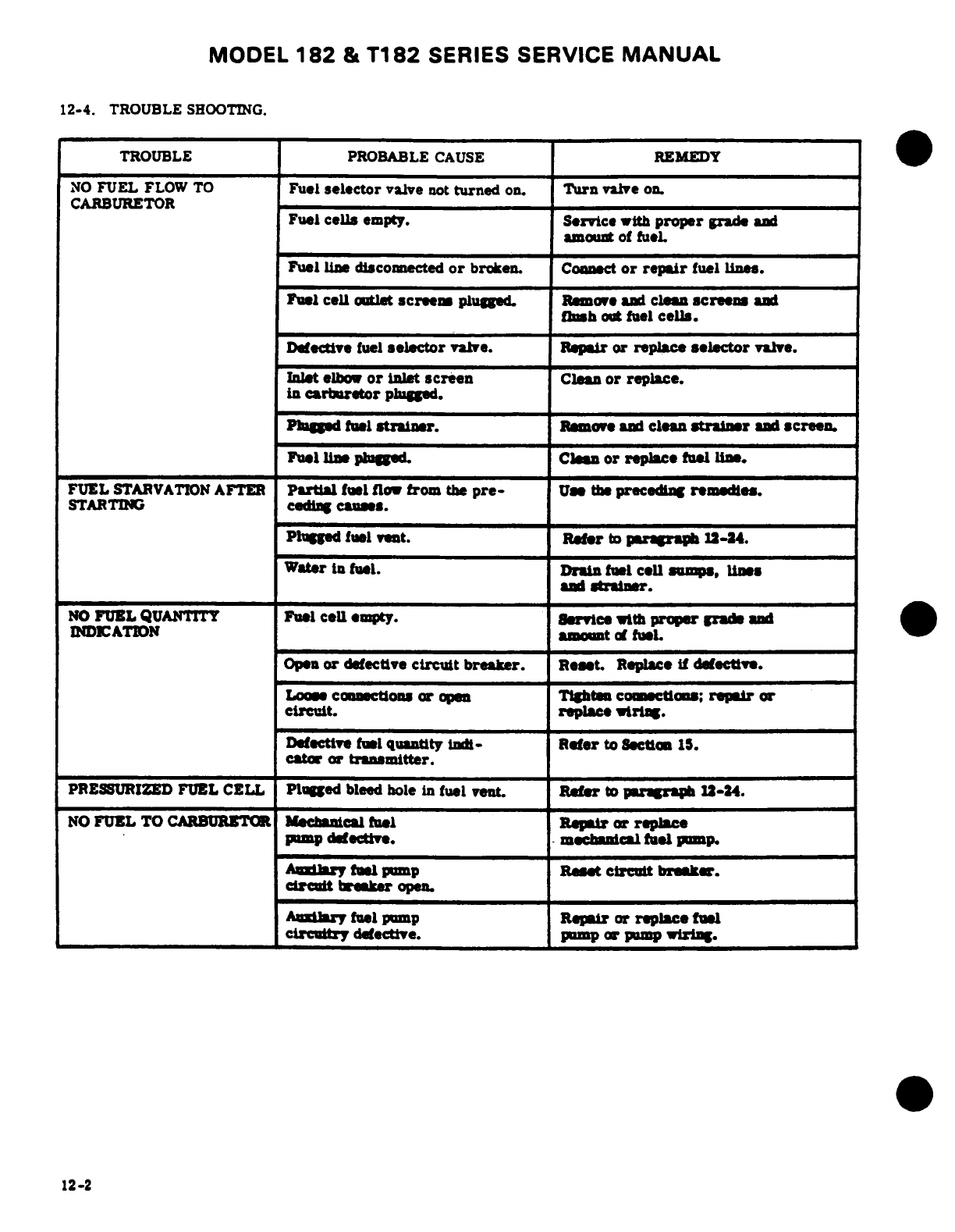
MODEL
182
&
T182
SERIES SERVICE
MANUAL
12-4.
TROUBLE
SHOOTING.
TROUBLE
PROBABLE
CAUSE
REMEDY
NO
FUEL
FLOW
TO
Fuel
selector
valve
not
turned
on.
Turn
valve
on.
CARBURETOR
Fuel
cells
empty.
Service
with
proper
grade
and
amount
of
fuel.
Fuel
line
disconnected
or
broken.
Connect
or repair
fuel
lines.
Fuel cell
outlet
screen
plugged. Remove
and
clean
screens
and
flush
out
fuel
cells.
Defective
fuel
selector
valve.
Repair
or
replace
selector
valve.
Inlet
elbow
or
inlet
screen
Clean
or
replace.
in
carburetor
plugged.
Plugged
fuel
strainer.
Remove
and
clean
strainr
and
screen.
Fuel
line
plugged.
Clean
or
replace
fuel line.
FUEL
STARVATION
AFTER
Partial fuel
flow
from
the
pre-
Use
the
preceding
remedies.
STARTING
ceding
causes.
Pluged
fuel
vent.
Refer
to
paragraph 12-24.
Water
in
fuel.
Drain
fuel
cell
sumps,
lines
and
strainer.
NO
FUEL
QUANTITY
Fuel
cell
empty.
Service
with
proper
grade
and
INDICATION
amount
of
fuel.
Open
or
defective
circuit breaker.
Reset.
Replace
if
defective.
Loose
connections
or
open
Tighten
connection;
repair
or
circuit.
replace
wiring.
Defective
fuel quantity
indi-
Refer
to
Section
15.
cator
or transmitter.
PRESSURIZED
FUEL
CELL
Plugged
bleed
hole
in
fuel vent. Refer to
paragraph
12-24.
NO
FUEL
TO
CARBURETOR
Mechanical
fuel
Repair
or
replace
pump
defective.
mechanical fuel
pump.
circuit
breaker
open.
circuitry
defective. pump
or
pump
wiring.
12-2
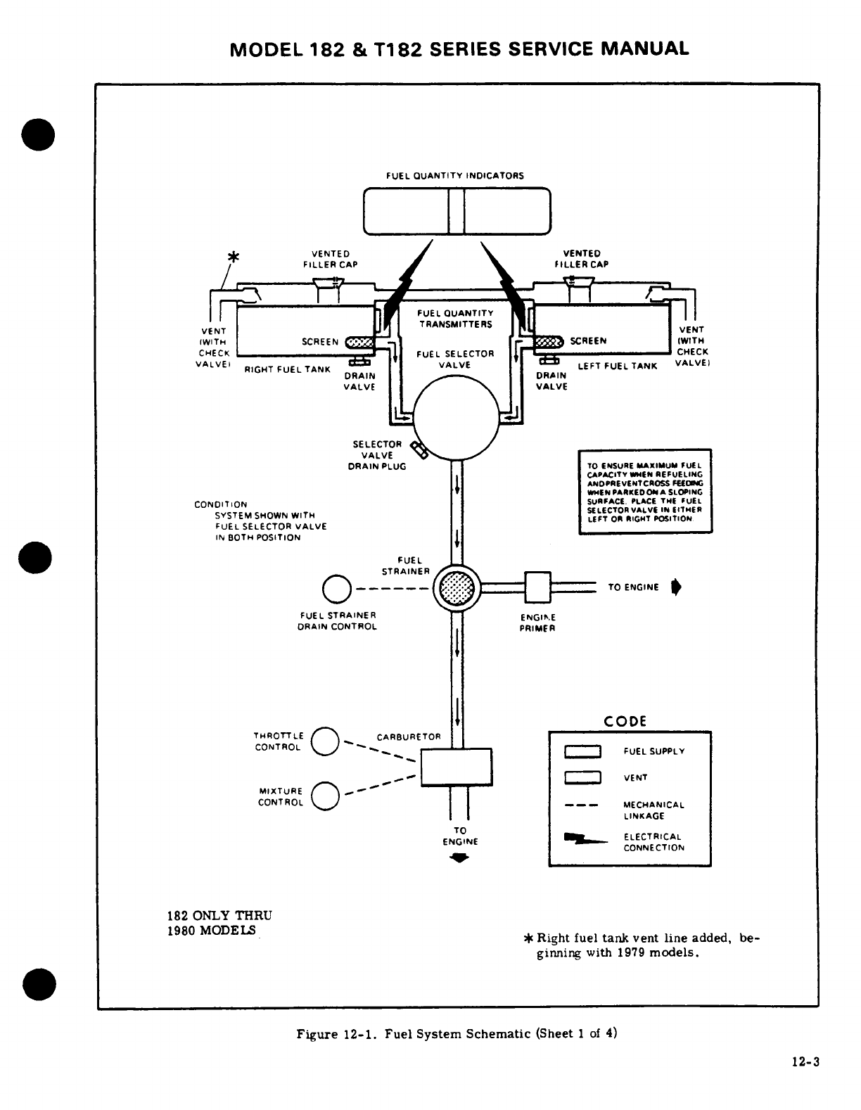
MODEL
182
&
T182
SERIES
SERVICE
MANUAL
FUEL QUANTITY
INDICATORS
i i1
1
FILLER
CAP
FILLER
CAP
IWITH
SCREEN
T2 __
SCREEN
IWITH
CHECK
1 FUEL
SELECTOR
I
" -
CHECK
VALVEI
RGHT
FUEL
TANK
DRAIN
VALVE
D
LEFT FUEL
TANK
VALVE)
DRAIN
DRAIN
VALVE
VALVE
SELECTOR
VALVE
DRAIN
PLUG TO
ENSURE
MAXIMUM
FUEL
CAPACITY
WHEN
REFUELING
ANDPREVENTCROSS
FEEING
WHEN
PARKEDON
A
SLOPING
CONDITION
SURFACE.
PLACE THE FUEL
SYSTEM
SHOWN
WITH
SELECTOR
VALVE
IN
EITHER
SYSTEM
SHOWN
WI~h
LEFT
OR RIGHT
POSITION
FUEL SELECTOR
VALVE
IN
BOTH
POSITION
FUEL
STRAINER
y
t--
cii
-----
^:'
-
L
--
TO
ENGINE
I
FUEL
STRAINER
ENGI.E
DRAIN CONTROL
PRIMER
CODE
THROTTLE
CARBURETOR
CONTROL
O
CONTROL
-0"'- ^^
- -
I
i
FUEL SUPPLY
~- L
I-
1
VENT
MIXTURE
(ENT
_
CONTROL
\- ___
MECHANICAL
LINKAGE
TO
ETNGINE
|
ELECTRICAL
ENGNE
-
CONNECTION
182
ONLY
THRU
1980
MODELS
*
Right
fuel
tank
vent
line
added,
be-
ginning
with
1979
models.
Figure
12-1.
Fuel
System
Schematic
(Sheet
1
of
4)
12-3
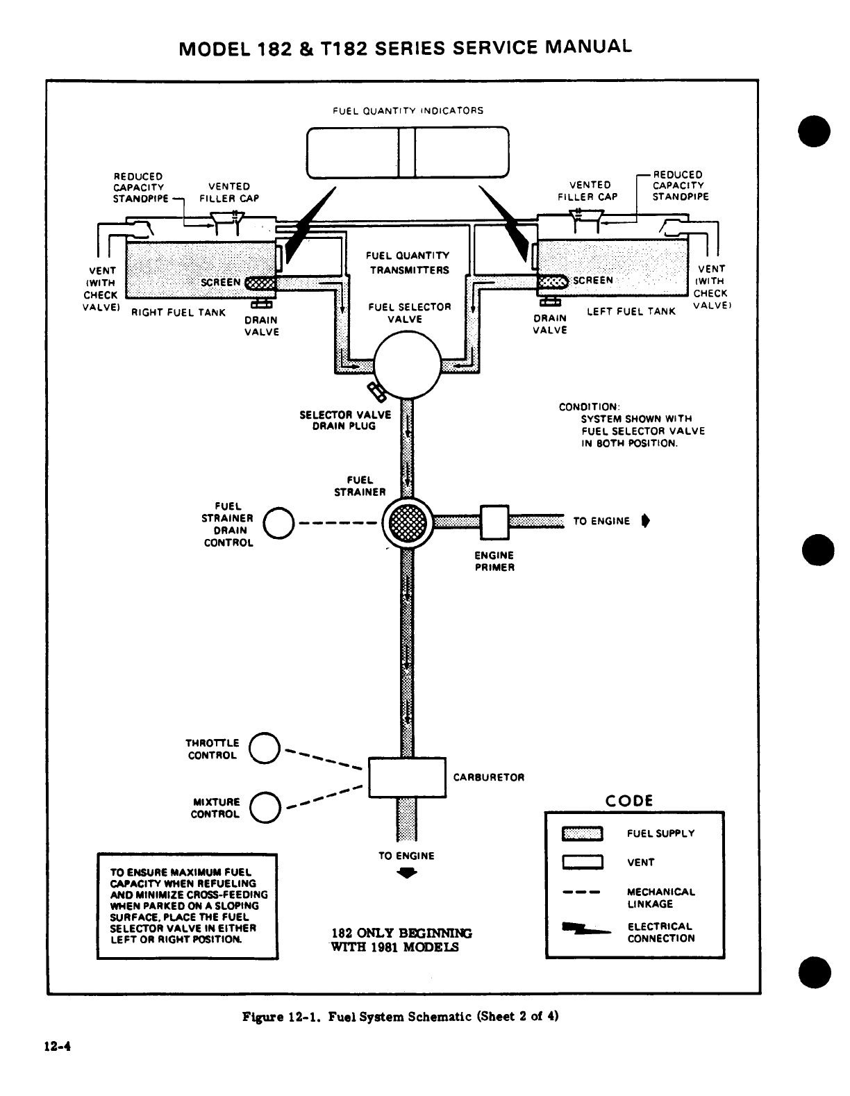
MODEL
182
&
T182
SERIES
SERVICE
MANUAL
FUEL
QUANTITY
INDICATORS
REDUCED
*
]
-
-REDUCED
CAPACITY VENTED
,
VENTED CAPACITY
STANDPIPE-i
FILLER
CAP
y
E
FILLER
CAP
STANDPIPE
I I
-
::;:
i::;:
fi;;: i : I;:f; : : ial:i:i;.
..
;:
i..
FUEL
QUANTITY
..
.... .,.^^:^
i'
:
:::;,0';
i .:
I I
:
VENT
^
^
W
K
'.
\ ______..........
......
TRANSMITTERS
-
~_
.
::
]:i::Ij:::
.':.::
*
::-:{::::
VENT
(WITH
:l..........
i..l..
SC
e'[ -:
":::c--:
,'-
:^-
l
'
ISCREEN
: : :
N
WITH
CHECI
K 1::::l
:-::::
-
::-
:
**
1
**'-**
:^ ^^^-
'.
----
:
"_ -------
. --
I:::
: ::
CHECK
V~ALVE)
FUEL
FUEL
SELECTOR
VALVE
VALV
RIGHT FUEL
TANK
LEFT
FUEL
TANK
DRAIN
VALVE
!
::/'
DRAIN
VALVE
:VALVE
CON:
OLCONDITION:
SELECTOR
VALVE
SYSTEM
SHOWN
WITH
DRAIN
PLUG
^gFUEL
SELECTOR
VALVE
:i.i
IN
BOTH POSITION.
FUEL
STRAINER
FUEL
STRAINER
0E
CONTR^N0
---- "---~ (^^Wli~iir^Pialj:~;:
TO
ENGINE
%
CONTROL
--
F
[~i: CPT
WENGINE
PRIMER
THROTTLE
O
CONTROL
SS
'".E,.
,M
N
CARBURETOR
MIXTURE
_
-
:--1:1
CODE
CONTROL
\
FUEL
SUPPLY
TO
ENGINE
I I
VENT
TO
ENSURE
MAXIMUM
FUEL
CAPACITY
WHEN
REFUELING
AND
MINIMIZE
CROSS-FEEDING
--
MECHANICAL
WHEN
PARKED
ON
A
SLOPING
LINKAGE
SURFACE.
PLACE
THE
FUEL
SELECTOR
VALVE
IN
EITHER
182
ONLY
B]GIMNG
E'r
ELECTRICAL
LEFT
OR
RIGHT
POSITION.
MOD
CONNECTION
WTlr
1981
MODELS
Figure
12-1.
Fuel
System
Schematic
(Sheet
2
of
4)
12-4
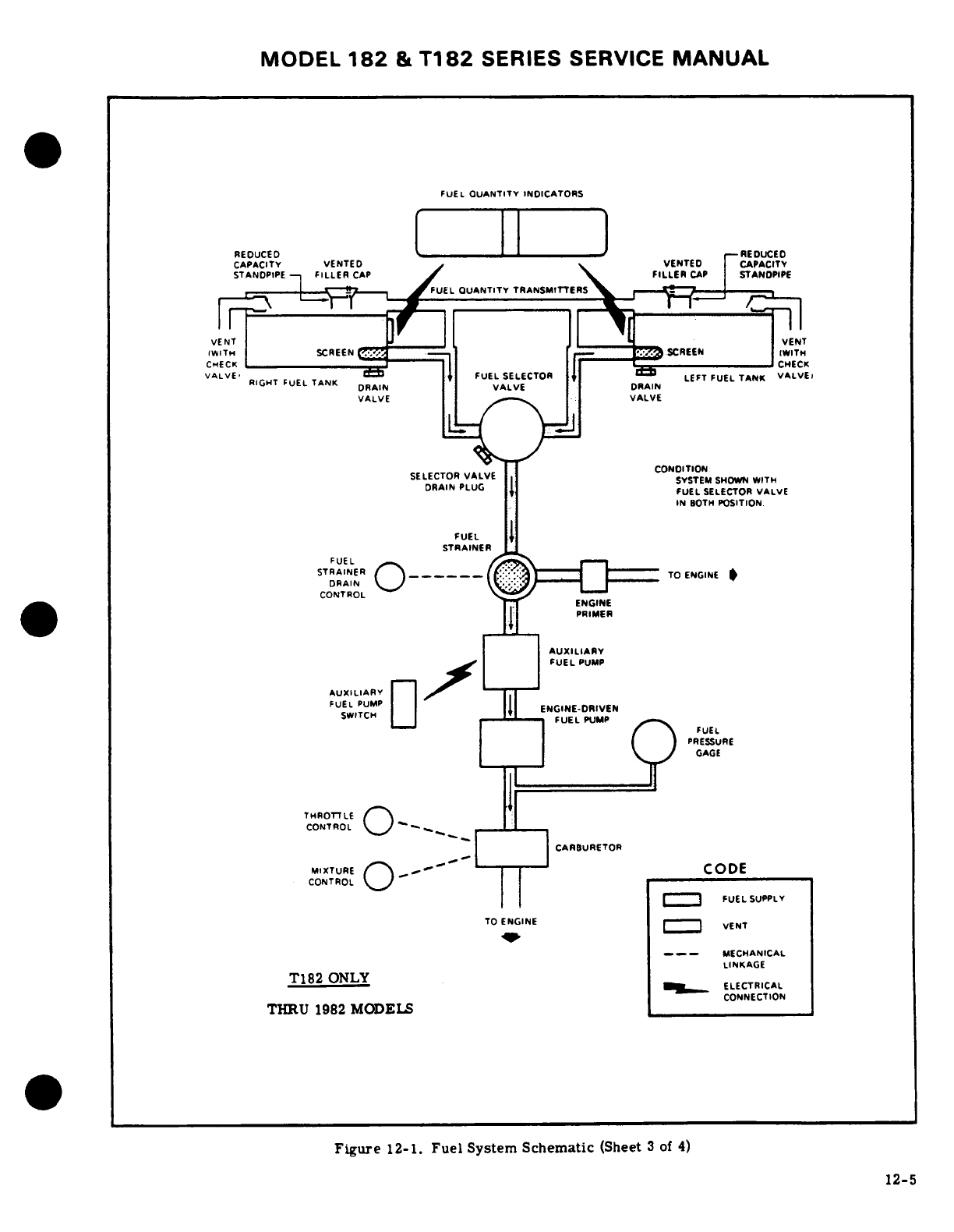
MODEL
182
&
T182
SERIES
SERVICE
MANUAL
FUEL
QUANTITY
INDICATORS
REDUCED
CAPACITY
VENTED VENTED CAPACITY
STANDPIPE
VALVE
CONDITION:
SELECTOR
VALVE
SYSTEM
SHOWN
WITH
IN
BOTH
POSITION
FUEL
STRAINER
DRAIN
CONTROL
ENGINE
PRIMER
AUXILIARY
FUEL
PUMP
AUXILIARY
FUEL
PUMP
FUEL
PRESSURE
GAGE
THROTTLE
CONTROL
MIXTURE
-
.CODE
CONTROL
---
TO
ENGINE
---
MECHANICAL
LINKAGE
T182
ONLY
CONNECTION
THRU
1982
MODELS
Figure
12-1.
Fuel
System
Schematic
(Sheet
3
of
4)
12-5
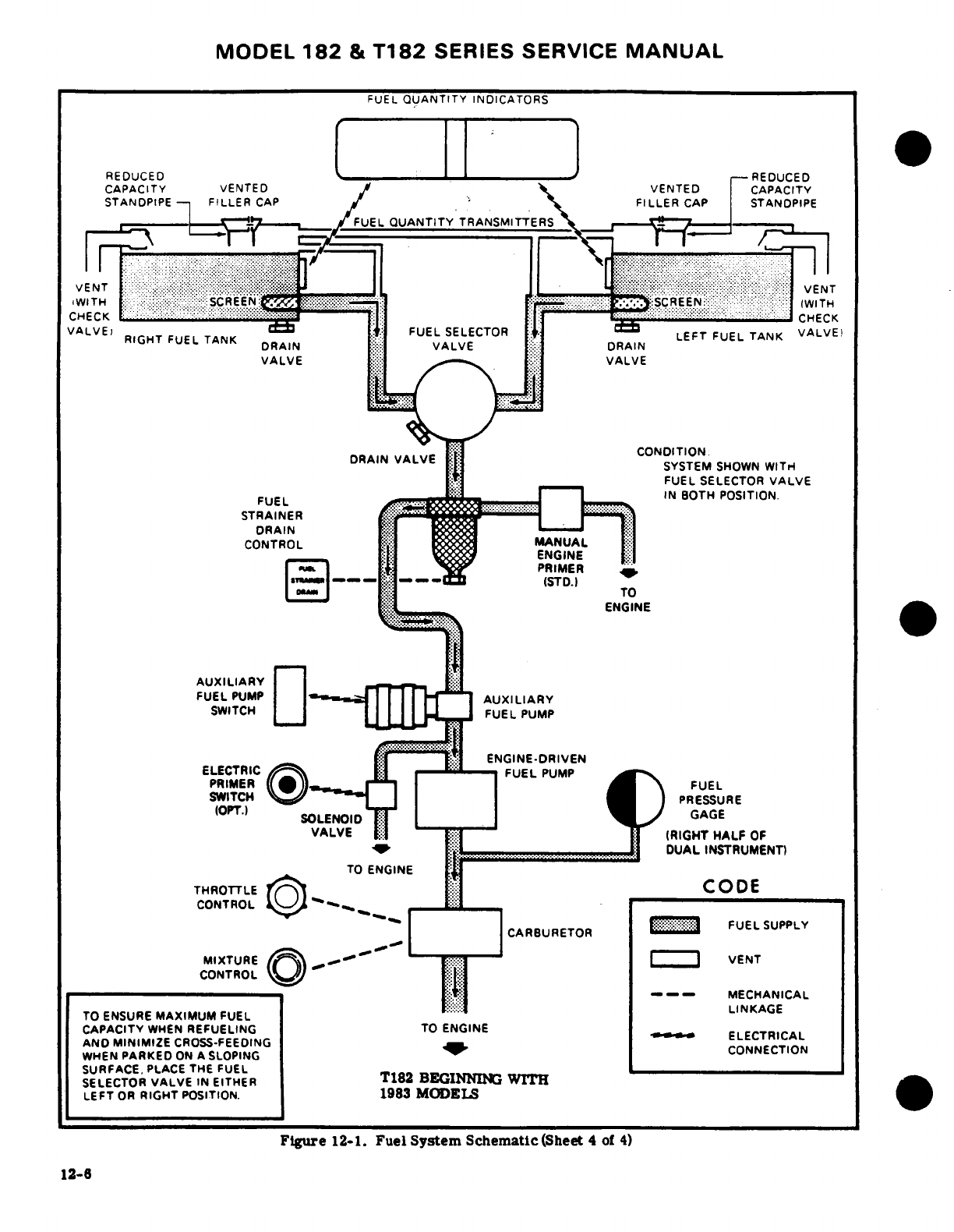
MODEL
182
&
T182
SERIES SERVICE
MANUAL
FUEL
QUANTITY
INDICATORS
REDUCED
r
-REDUCED
CAPACITY
STANDPIPE
-
FILLER
CAP
,
FUEL
QUANTITY
TRANSMITTERS
-r.
.
T
.. . .
~~~~CHECK :::: ::.: :
..
""""""--
--
:;~~~~~~ -1
..
~
:. :
.-
~-- ~..-- : .fi^
.
.... ;..:-
.:
:-:.:-.:.I
CHECK
RVALVE
RGHT
FUEL
TANK
DRI
:
FUEL
SELECTOR
.
,LEFT
FUEL
TANK VALVE!
Mj~i
iiiutL iiaMK ~DRAIN
::
VALVE
§iiii
DRAIN
VALVE
..
:.
VALVE
RIGHT
FUEL
TANK
VAE
L
IKU~~ ~
CONDITION:
DRAIN
VALVE
SYSTEM
SHOWN
WITH
!UEL PUPFUEL
SELECTOR
VALVE
SWIT~FUEL CHI IIN
BOTH
POSITION.
STRAINER
DRAIN
CONTROL
: ^
MANUAL
I
ENGINE
SWIC
P
E
SU
EPRIMER
OPT.) GAGEO__(STD.)
ENGINE
AUXILIARY
'
FUEL
PUMP
AUXILIARY
SWITCH
FUEL
PUMP
ELECTRIC
FUEL
PUMP
PRIMER
( )
rC
FUEL
SWITCH
_ -|
|
| |
PRESSURE
IOPTS.)
SOLENOIDM
U
FE
LI
KGAGE
VALVE
i
i
T
(RIGHT HALF
OF
~
, . ...
..... .:...
.
.DUAL
INSTRUMENT)
TO
ENGINE
THROTTLE
S
CODE
CONTROL
-C
SU_ RCCARBURETOR
PC
FUEL
SUPPLY
MIXTURE
Q _
- -- I
I
VENT
CONTROL
\0
/ (
MECHANICAL
LINKAGE
TO ENSURE
MAXIMUM
FUEL
LINKAGE
CAPACITY
WHEN
REFUELING
TO
ENGINE
AND
MINIMIZE
CROSS-FEEDING
CONNECTION
WHEN
PARKED
ON
A
SLOPING
CNNCTN
SURFACE.
PLACE
THE
FUEL
SELECTOR
VALVE
IN
EITHER
T182
BEGINNING
WITH
LEFT
OR
RIGHT
POSITION.
1983
MODELS
Figure
12-1.
Fuel System Schematic
(Sheet
4
of
4)
12-6
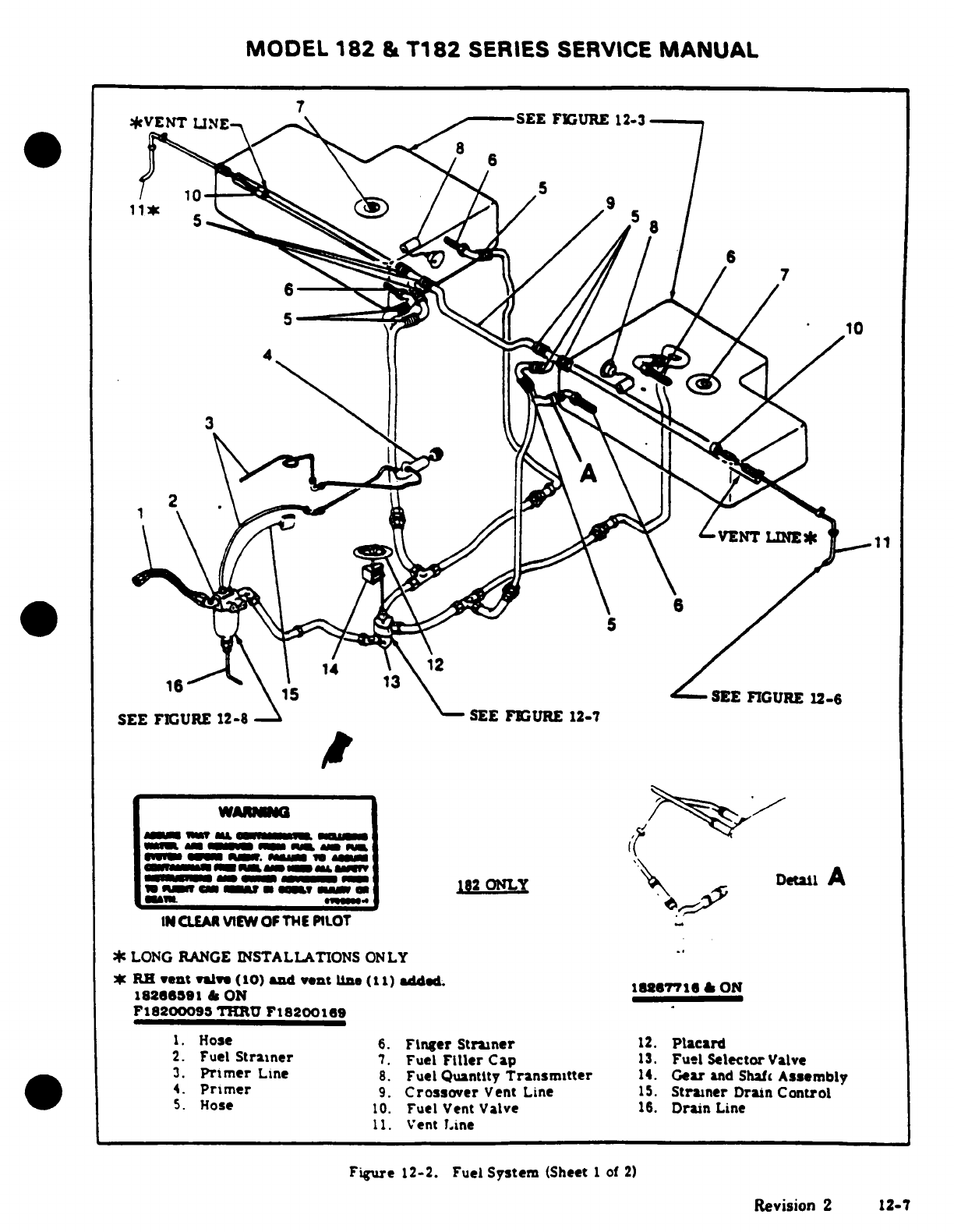
MODEL
182
&
T182
SERIES
SERVICE
MANUAL
SEE
FIGURE
12-8
IN
CLEAR
VIEW
OF
THE
PILOT
*
LONG
RANGE
INSTALLATIONS ONLY
*C
RH
vent
valve
(10)
nd
vent
dlne
(l1)
"ddad.
wiTle
h
ON
18266391
&
ON
F
F18200095
TKRM
F18200169
1.
Hose
6.
Finger
Strainer
12.
Placard
2.
Fuel
Strainer
7.
Fuel
Filler
Cap
13.
Fuel Selector
Valve
3.
Primer
Line
8.
Fuel Quantity
Transmitter
14.
Gear
and
Shaft
Assembly
4.
Primer
9.
Crossover
Vent Line
15.
Strainer
Drain
Control
5.
Hose
10.
Fuel
Vent
Valve
16.
Drain
Line
11.
Vent
Line
Figure
12-2.
Fuel
System
(Sheet
1
of
2)
Revision
2
12-7

SEE
FIGURE
12-12
SEE
E E|'^S~f^^'^'^ \^
/SEE
FIGURE
12-6
9
7
~~~~SEE
FIGURE
12-7 m---
-
I
11
12m
SEE
FIGURE
12-8
SEE
FIGURE
1
SE
FIGURE
12-7
mmm
um-
-
/
I t~uRo m
mo
at
,
T182
ONLY
IN
CLEAR
VEW
OF
THE
PILOT
1.
Fuel
FlUer
Cap
7.
Fuel
Selector
Valve
2.
Fuel
Quantity
Tranmitter
8.
Drai Line
3.
Crossover
Vent
Line
9.
Fuel
Stminer
4.
Hose
10.
Auziliary Electric
Fuel
Pump
5.
Placard
11.
Vent
Line
6.
Gear
and
Shaft
Assembly
12.
Fuel
Vent
Valve
Ftgure
12-2.
Fuel
System
(Sheet
2
of
2)
12-8
Revision
2
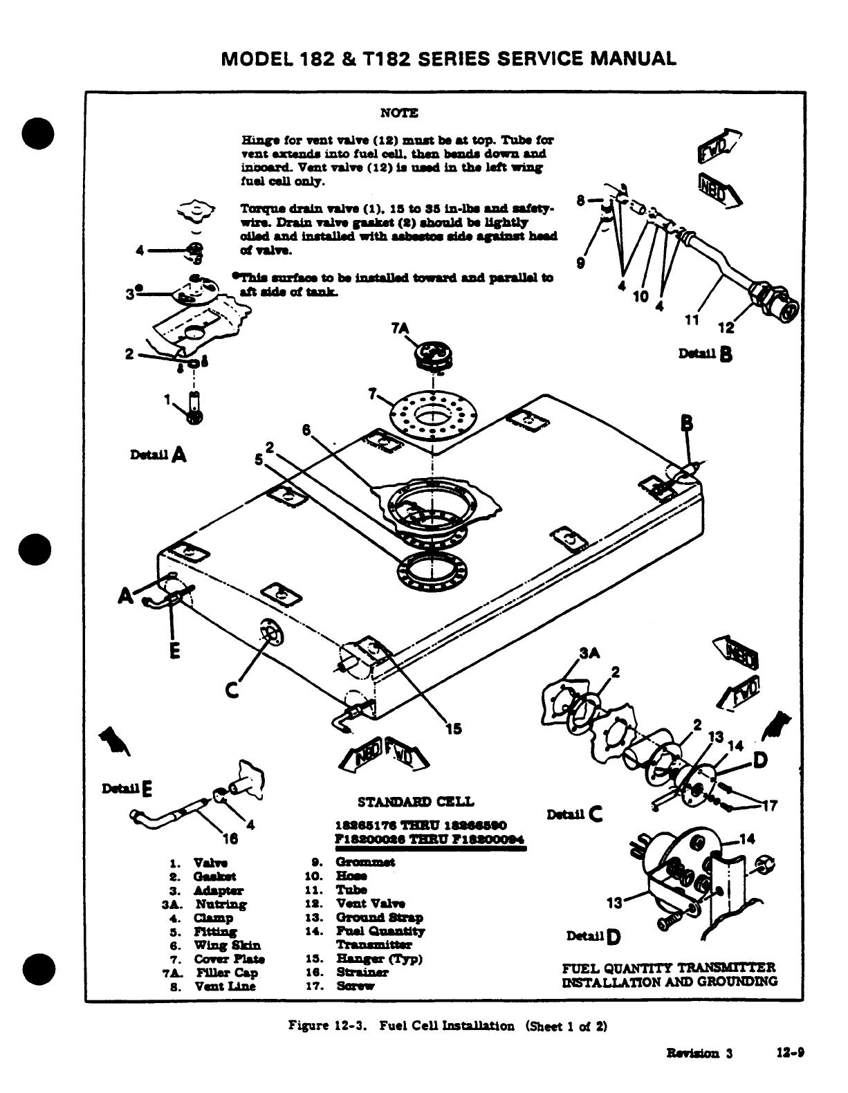
MODEL
182
&
T182
SERIES SERVICE
MANUAL
NOTE
Hinge
for
vent
valve
(12)
must
be
at
top.
Tube
for
vent
extends
into
fuel
cell,then
bend
down
and
inboard.
Vent
valve
(12)
is
used
in
the
left wing
fuel
cell
only.
Torque
drain
valve
(1),
15
to
3
in-lbs
and
safety-
wire.
Drain
valve
gasket
(2)
should
be
lightly
oiled
and
installed
with
side
against
heed
4----
of
valve.
,
3-
4
136176
TMU
1863660
E
L
I
^y'.
STAM
UBD
CELL
_ \
,4
1aB8i7C SBBu
a
1*
C
r
16
mF1
zoom
TU P
1ooe
^ &-14
1.Valve
.
r9ea
t
2.
GQakt
10.
BHow
3.
Adapter
11.
Tub
3A.
Nutring
12.
Vent
Valve3
13
4.
Clamp
13.
Ground
Strap
5.
tting
14.
Pul
Quantity
Detai
n
6. Winfg 6in
Transmitter
7.
Cover
Plate
15.
Hanger
(TCp)
7k.
FllerS
Cp
16.
S3ins
FEL
QUANTITT
TRAMI
ER
8.
Vent Line
17.
Srew
SITALLATION
AND
GROUNDING
Figre
12-3.
Fuel
Cell
Installaton
(Sheet
1
of
2)
Revion
3
12-9
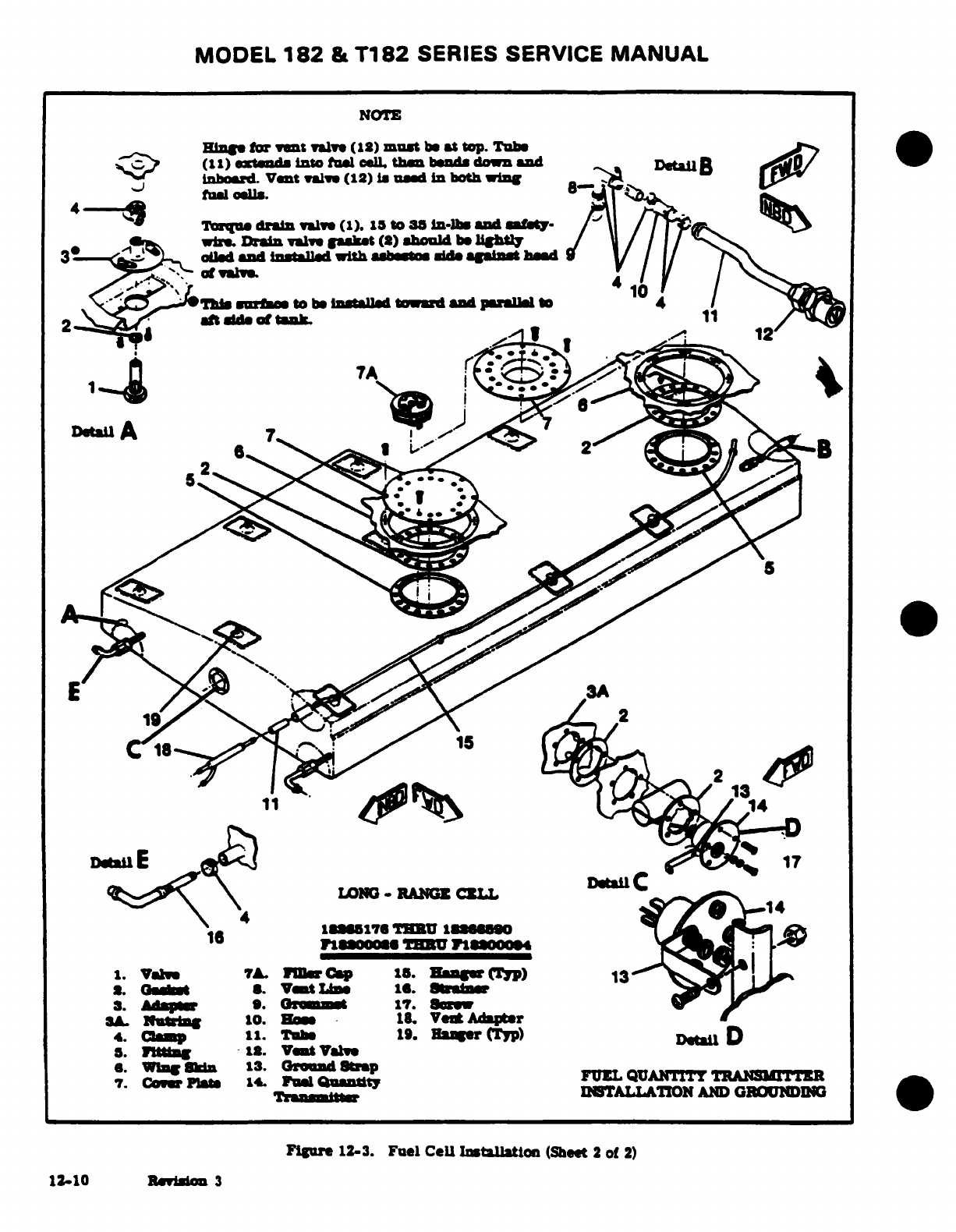
MODEL
182
&
T182
SERIES
SERVICE
MANUAL
NOTE
(I1)
(
xtnds
into
tul
cll.
then
bed,
down
and
Dea
inboard.
Vent
valv
(12)
I
uaed
in
both winf
ronzru
dvin
eve
(I).
13
to
a
iln.ab
lad
af-
-
-wr^
Drin
r
lve
ruskt
(2)
houd
be
lightly
3
.-
<~
oil
and
,idtaled
with
a
b
to
ide
iut
he/d
C
6
2/
|
,.
1*
7A
f^^L
^
^
104
*
14
l6
las1smu6 TH^U
n
seamo
16
n!poooM
n oooF
THU
11m
1. vw
mCp
1.
HnaawClyp)
13
a.
d
S.
V.UM
1.
Usiner
3A.
Nultoug
10.
HRm
18.
Vest
AdJater
4.
Cmp
11.
Tube
19.
H
r
(Trp)
tun
D
a.
rfntff
1l.
Vt
Valve
6.
Wing
,in
13.
Ground
SapULQUATIT
AM
7.
covr
P
1f Ct
F
Q
Svu7.
sl
*
to!
DBTALLAT1ON
AND
GROUMDI
Figure
12-3.
Fuel
Cel
Installation
(Sheet
2
of
2)
12-10
Revisou
3
MODEL
182
&
T182
SERIES
SERVICE
MANUAL
12-5.
FUEL
CELLS. 12-9.
FUEL
CELL
REPAIR.
12-6.
DESCRIPTION.
Rubberized,
bladder-type
NOTE
fuel
cells
are
installed
in
the
inboard
bay
of
each
wing
panel. These
cells
are secured
by
fasteners
to
For
fuel
cell
repair
information,
refer
prevent
collapse
of
the
flexible
cells.
to
Cessna
Service
News
Letter
dated
August
28,
1970.
For
minor
repair,
a
12-7.
GENERAL
PRECAUTIONS.
When
storing,
fuel
cell
repair
kit
is
available
from
inspecting
or
handling
rubberized,
bladder-type
fuel
Goodyear,
complete
with
required
cells,
the
following
precautions
should
be
observed:
materials
and
instructions.
a.
Fold
cells
as
smoothly
and
lightly
as
possible
with
a
minimum
number
of
folds.
Place
protective
12-10.
FUELCELLINSTALLATION.
Beforeinstal-
12-10.
FUEL
CELL
INSTALLATION.
Before
instal-
wadding
between
folds.
lation
fuel
cell
compartment must
be
thoroughly
b.
Wrap
cell
in
moisture-proof
paper
and
place
in
a
suitable
container.
Do
not
crowd
cell
in
container.
clean
and
devoid
of
sharp
obects.
protrusions.
and
Use
wadding
to
prevent
movement.
c.
Stack
boxed
cells
to
allow
access
to
oldest
cell
a.
Inspect compartment
to
ensure
that
it is
clean
first.
Do
not
allow
stacks
to
crush
bottom
boxes. an
safe.
Leave
cells
in
boxes
until
used.
b.
Be
sure
that
rubberized
cell
is warm
enough
to
d.
Storage
area
must
be
cool,
+30°F
to
85
°
,
and
be
flexible
for
working
through
filler
neck.
free
of
exposure
to
sunlight,
dirt
and
damage.
c.
Place cell
in
compartment,
develope
to
full
size.
e.
Used
cells
must
be
cleaned
with
soap
and
warm
water
prior
to
storage.
Dry and
package
as
outlined
are
used.
in
the
preceding
steps
in
the
preceding
steps.
f.
Do
not
carry
cells
by
fittings.
Maintain
original
stall
nylon
vent
tube
inside cell,
inserting
tube
cell
contours
or
folds
when
refolding
for
boxing.
through
four hangers
in
top
of
cell.
If
a
replacement
cell
is
being
installed,
use
nylon
vent
tube
removed
12-8.
FUEL
CELL
REMOVAL.
from
old
cell
and/or
order
tube
from
applicable
a.
Drain
fuel from
applicable
cell.
Parts
Catalog.
e.
When
tightening
screw-type
clamps
on
the
standard
NOTE
fuel
cell
(BTC-39
construction),
apply
a
maximum
torque
of
20
inch-pounds
to
clamp
screws.
On
the
ex-
Prior
to
removal
of
cell,
drain
fuel,
purge
tended
range
fuel
cell
(BTC-67
construction),
apply
with
fresh
air,
and swab
out
to
remove
all
a
maximum
torque
of
30-35
inch-pounds
to
clamp
traces
of
fuel.
screws.
A
light
application
of
#10
engine
oil
to metal
tube
aids
installation
into
nipple
fittings.
b.
Remove
wing
root
fairings
and
disconnect
fuel
f.
When
installing
filler
adapter,
cover
plate
and
lines
at
wing
root.
fuel
quantity
transmitter
to
the
wing
and
fuel
cell,
c.
Remove
clamps
from
forward
and
aft
fuel
cell
tighten attaching
screw
evenly.
The
sealing
or
com-
bosses
at
wing
root
and
carefully
work
fuel
strainers
pression
surfaces
must
be
assembled
when
abso-
and
lines
from cell
bosses.
lutely
dry
(NO
SEALING
PASTE
IS
TO
BE
USED).
d.
Disconnect
electrical
lead
and
ground
strap
from
g.
After
installation
has
been
completed, cell
should
fuel
quantity
transmitter
and
carefully
work
trans-
be
inspected
for
final
fit
within
compartment,
making
mitter
from
fuel
cell
and
wing
rib.
certain
that
cell
is
extended
out
to
the
structure
and
e.
Remove
screws
attaching
drain
adapter
to
lower
no
corners
are
folded
in.
surface
of
wing.
h.
The
final inspection,
prior
to
closing
the
cell,
f.
Remove
clamps
attaching
crossover
vent
line
to should
be
a
close
check
to
insure
that
cell
is
free
of
fuel
cells
and
work
vent
line out
of
cell
being
removed. foreign
matter
such
as
lint,
dust,
oil
or
any
installa-
In
aircraft
equipped
with
long-range
cells,
remove
tion
equipment.
If
a
cell
is
not
thoroughly
clean,
it
vent
extension
tube
from
inside
cell.
Vent
extension
should
be cleaned
with
a
lint-free
cloth, soaked
in
tube
is
attached
to
the
crossover
vent
bars
on
the
water,
alcohol
or
kerosene.
NO
OTHER
SOLVENT
cell.
SHALL
BE
USED.
g.
Remove fuel
filler
adapter
and
gaskets
by
re-
moving
screws
attaching
adapter
to
wing
and
fuel
12-11
FUEL
FILLER
CAPS.
cell.
On
aircraft
equipped
with
long-range
cells,
remove cover
plate
and
gaskets,
and
remove
nylon
vent
tube
from inside
cell
may
be
constructed
of
either metal
of
red
plastic.
h.
Working
through
filler
neck
opening
loosen
Both
cap
assemblies
incorporate
a
vent
safety
valve
snap
fasteners.
Tilt
snap
fasteners
slightly
when
respective
fuel
tanks.
It
is
important
that
both
type
pulling
cell
free,
to
prevent
tearing
rubber.
pulling
cell
free,
to
prevent
tearing
rubber.
caps
to
be
cleaned
on
as
required
basis,
if
proper
i.
Collapse
and
carefully
fold
cell
for
removal, filler
cap
sealing
is
to
be
maintained.
Beginning
then
work
cell
out
of
fuel
bay
through
filler
opening
with
18268434
flushtype
filler
caps
are
replaced
by
in
upper
wing
surface.
Use
care
when
removing
to
LSE
type caps.
prevent
damage
to
cell.
j.
Unfold
cell
and
remove
fittings,
snap
fasteners
and fuel
sump
drain
adapter.
12-11
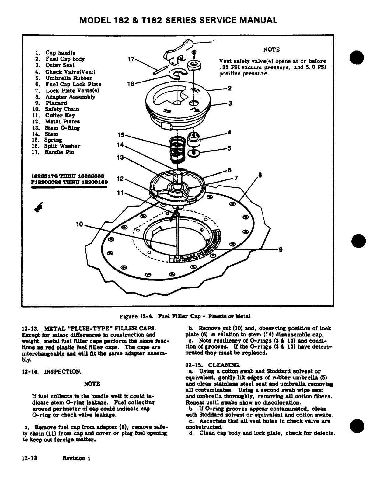
MODEL
182
&
T182
SERIES SERVICE
MANUAL
1.
Cap
handle
NOTE
2.
Fuel
Cap
body
3.
Outer
Seal
4.
Check
Valve(Vent)
positive
pressure.
5.
Umbrella
Rubber
6.
Fuel
Cap Lock
Plate
16
7.
Lock
Plate
Vents(4)
8.
Adapter
Assembly
9.
Placard
3
10.
Safety
Chain
11.
Cotter
Key
12.
Metal
Plates
13.
Stem
O-Ring
14.
Stem
15
15.
Spring
16.
Split
Washer
14
17.
Handle
Pin
18265176
THRU
18268368
F18200026 THRU
18200169
Figure
12-4.
Fuel
Filler
Cap
-
Plastic
or
Metal
12-13.
METAL
"FLUSH-TYPE"
FILLER
CAPS.
b.
Remove
nut
(10)
and,
observing
position
of
lock
Except
for
minor
differences
in
construction
and
plate
(6)
in
relation
to
stem
(14)
disassemble
cap.
weight,
metal
fuel
filler
caps
perform
the
same
func-
c. Note
resiliency
of
O-rings
(3
&
13)
and
condi-
tions as
red
plastic
fuel
filler
caps.
The
caps
are
tion
of
grooves.
If
the
O-rings
(3
&
13)
have
deteri-
interchangeable
and
will
fit
the
same
adapter
assem-
orated
they
must
be
replaced.
bly.
12-15.
CLEANING.
12-14.
INSPECTION.
a.
Using
a
cotton swab
and
Stoddard
solvent
or
equivalent, gently lift
edges
of
rubber
umbrella
(5)
NOTE
and
clean
stainless
steel
seat
and
umbrella
removing
all
contaminates.
Using
a
second swab
wipe
seat
If
fuel
collects
in
the
handle
well
it
could
in-
and
umbrella
thoroughly,
removing
all
cotton
fibers.
dicate
stem
O-ring
leakage.
Fuel collecting
Repeat
until
swabs
show
no
discoloration.
around
perimeter
of
cap
could
indicate
cap
b.
If
O-ring
grooves appear contaminated,
clean
O-ring
or
check
valve
leakage.
with
Stoddard
solvent
or
equivalent
and
cotton
swabs.
c.
Ascertain that
all
vent
holes
in
check
valve
are
a.
Remove
fuel
cap
from
adapter
(8),
remove
safe-
unobstructed.
ty
chain
(11)
from
cap
and
cover
or
plug
fuel
opening d.
Clean
cap
body
and
lock
plate,
check
for
defects.
to
keep
out
foreign
matter.
12-12
Revision
1
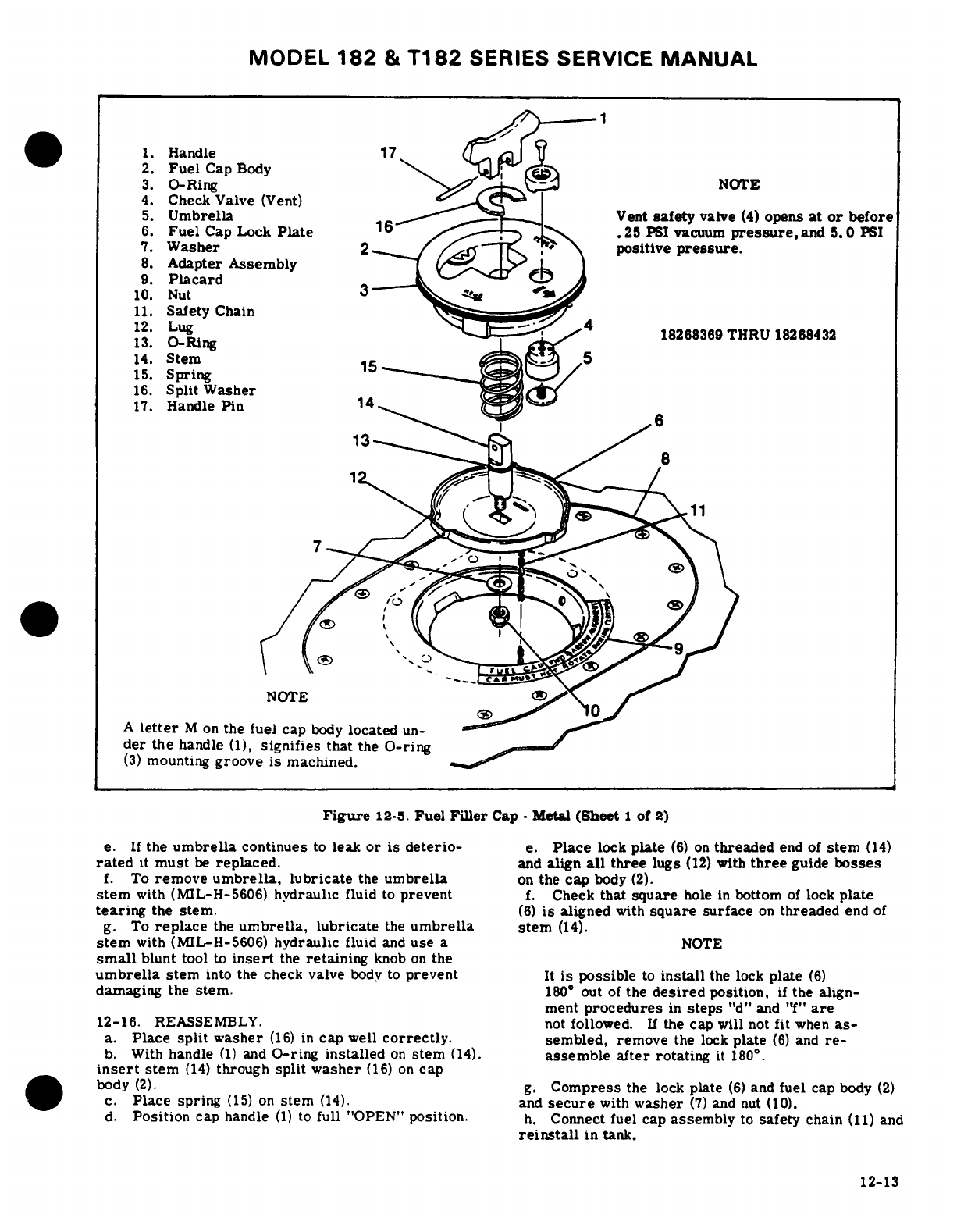
MODEL
182
&
T182
SERIES SERVICE
MANUAL
1. Handle
2.
Fuel
Cap
Body
3.
O-Ring
NOTE
4.
Check Valve
(Vent)
5.
Umbrella
Vent
safety
valve
(4)
opens
at
or
before
6.
Fuel
Cap
Lock
Plate
16
.25
PSI
vacuum
pressure,
and
5.
0
PSI
7.
Washer
2
positive
pressure.
8.
Adapter Assembly
9.
Placard
10.
Nut
3
11.
Safety
Chain
12.
Lug
13.
O-Ring
14.
Stem
15.
Spring
16.
Split
Washer
17.
Handle
Pin
14
6
13
NOTE
A
letter
M
on
the fuel
cap
body
located
un-
der
the
handle
(1),
signifies
that
the
O-ring
(3)
mounting
groove
is
machined.
Figure
12-5.
Fuel
Filler
Cap
- Metal
(Sheet
1
of
2)
e.
If
the
umbrella
continues
to
leak
or
is
deterio-
e.
Place
lock
plate
(6)
on
threaded
end of
stem
(14)
rated
it
must
be
replaced.
and
align
all
three
lugs
(12)
with
three
guide
bosses
f.
To
remove
umbrella,
lubricate
the
umbrella
on
the
cap
body
(2).
stem
with
(MIL-H-5606)
hydraulic
fluid
to
prevent
f.
Check
that
square
hole
in
bottom
of
lock
plate
tearing
the
stem.
(6)
is
aligned
with
square
surface
on
threaded
end
of
g.
To
replace
the
umbrella,
lubricate
the
umbrella
stem
(14).
stem
with
(MIL-H-5606)
hydraulic
fluid
and
use
a
NOTE
small
blunt
tool
to
insert
the
retaining
knob
on
the
umbrella
stem
into
the
check
valve
body
to
prevent
It
is
possible
to
install
the
lock
plate
(6)
damaging
the
stem.
180°
out
of
the
desired
position,
if
the
align-
ment
procedures
in
steps
"d"
and
"f"
are
12-16.
REASSEMBLY.
not
followed.
If
the
cap
will
not
fit
when
as-
a.
Place
split
washer
(16)
in
cap
well
correctly.
sembled,
remove
the
lock
plate
(6)
and
re-
b.
With
handle
(1)
and
O-ring installed
on
stem
(14).
assemble
after
rotating
it
180°.
insert
stem
(14)
through
split
washer
(16) on
cap
body
(2).
g.
Compress
the
lock
plate
(6)
and
fuel
cap
body
(2)
c.
Place
spring
(15)
on
stem
(14).
and
secure
with
washer
(7)
and nut
(10).
d.
Position
cap
handle (1)
to
full
"OPEN"
position.
h.
Connect
fuel
cap
assembly
to
safety
chain
(11)
and
reinstall
in
tank.
12-13
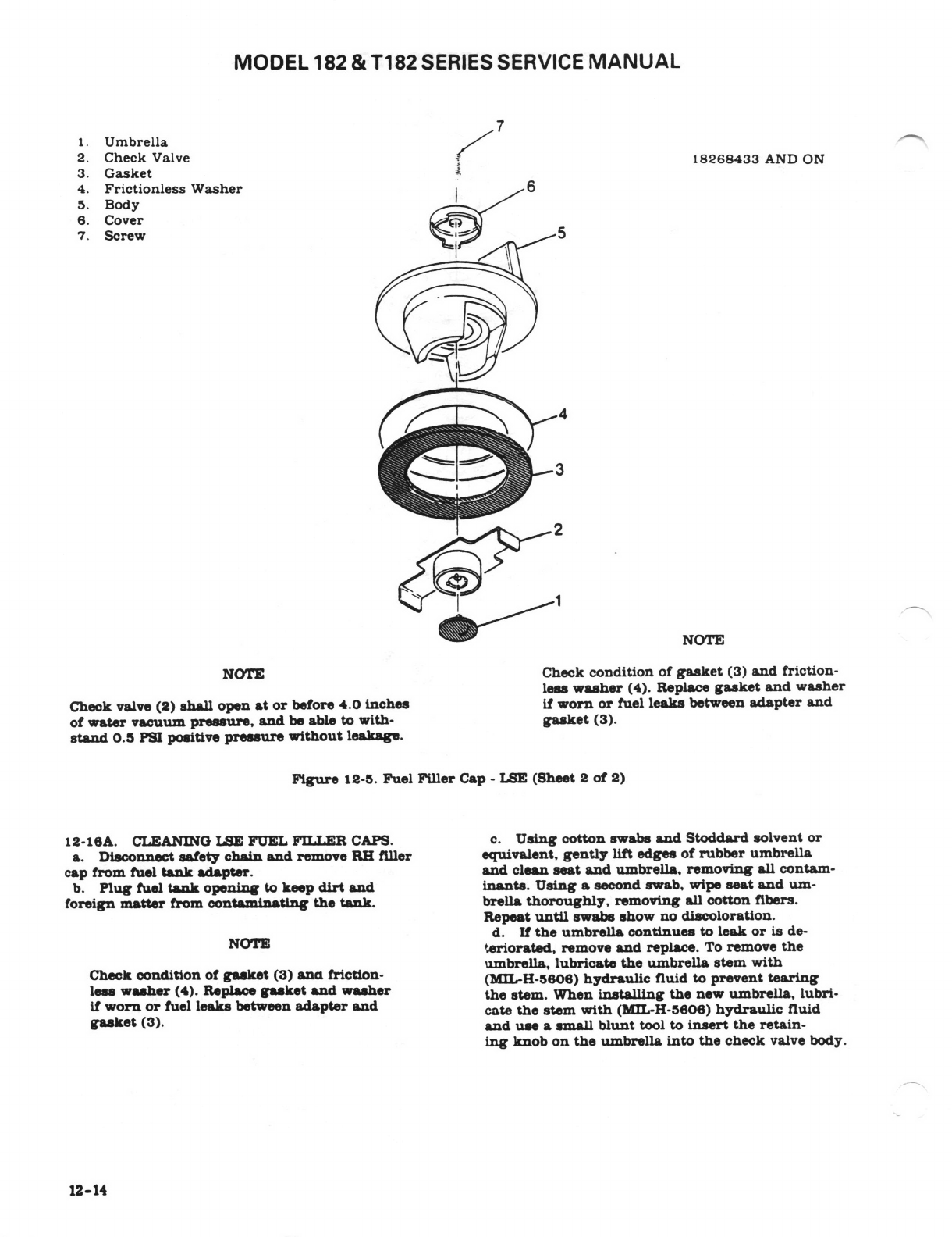
MODEL
182
&
T182
SERIES SERVICE
MANUAL
7
1.
Umbrella
2.
Check
Valve
18268433
AND
ON
3.
Gasket
4.
Frictionless
Washer
5.
Body
6.
Cover
7.
Screw
4
NOTE
NOTE
Check
condition
of
gasket
(3)
and
friction-
less
washer
(4). Replace
gasket and
washer
Check
valve
(2)
shall
open
at
or
before
4.0
inches
if
worn or
fuel
leaks
between
adapter
and
of
water
vacuum
pressure,
and
be
able
to with-
gasket
(3).
stand
0.5
PSI
positive
pressure
without
leakage.
Figure
12-5.
Fuel
Filler
Cap
-
LSE
(Sheet
2
of
2)
12-16A.
CLEANING LSE
FUEL
FILLER
CAPS.
c.
Using
cotton
swabs
and
Stoddard
solvent
or
a.
Disconnect
safety
chain and
remove
RH
filler
equivalent,
gently
lift
edges
of
rubber
umbrella
cap
from
fuel
tank
adapter.
and
clean
seat
and
umbrella, removing
all
contam-
b.
Plug
fuel
tank
opening
to
keep
dirt
and
inants.
Using
a
second
swab,
wipe
seat and
um-
foreign
matter
from
ontaminating
the
tank.
brella
thoroughly,
removing
all
cotton
fibers.
Repeat
until
swabs
show
no
discoloration.
d.
If
the
umbrella
continues
to
leak
or is
de-
umbrella,
lubricate
the
umbrella
stem with
Check
condition
of
gasket
(3)
and
friction-
(MIL-H-5606)
hydraulic
fluid
to
prevent
tearing
less
washer
(4).
Replace
gasket and
washer
the
stem.
When
installing
the
new
umbrella,
lubri-
if
worn
or
fuel
leaks
between
adapter
and
cate
the
stem
with
(MIL-H-5606)
hydraulic
fluid
ing
knob
on
the
umbrella
into the
check
valve body.
12-14
MODEL
182
&
T182
SERIES
SERVICE
MANUAL
12-17.
RED
PLASTIC
"FLUSH-TYPE"
FILLER
washer
under
the
cap
handle
will
increase
CAPS.
A
red plastic
"Flush-Type"
vented
filler
cap
te
effort
required
to
upcap
the
fuel
tank.
may
be
used.
Extra care
is
required
when
reinstall-
ing
plastic
filler
caps
in
the
fuel
filler
adapter
assem-
a.
Install
spring
(15)
on
stem
(14).
bly.
An
improperly installed
filler
cap
could
cause
b.
Install
fuel
cap
body
(2)
on
stem
(14).
a
loss
of
fuel
from
the
tanks during
flight.
c.
Check
that
three
metal
plates
(12)
on
top
rim
of
lock
plate
(6)
are
aligned
with
three
guide
bosses
on
12-18.
INSPECTION.
fuel
cap
body
(2).
NOTE
If
fuel
collects
in
the
handle
well
it
could
in-
It
is
possible
to
install
the
handle
pin
in the
dicate
stem
O-ring
leakage.
Fuel
collecting
pin
hole
180°
out
of
the
desired
position,
if
around
perimeter
of
cap
could
indicate
cap
the
alignment
procedure
in
step
"c"
is
not
outer seal or
check
valve leakage.
followed.
If
the
handle
(1) is
not
installed
properly
the
FWD
arrow
on
the
cap
will
not
a.
Remove
fuel
cap
from
adapter
(8),
remove
safe-
align
with
the
arrow
on
the
placard
(9)
when
ty
chain
(10)
from
cap
and
cover
or
plug
fuel
opening
the cap
is
reinstalled.
to keep
out
foreign
matter.
b.
Rotate
cap
handle
(1)
to
the
"OPEN"
position,
d.
Compress
cap
body
(2)
and
lock
plate
(6),
install
compress
cap
body
(2)
and
lock
plate
(6)
to
expose
split
washer(s)
(16)
as
required.
the
.125
inch
diameter
handle
pin
(17).
e.
Install
cap
handle
(1)
on
stem
(14)
so
that
the
c.
Using
a
small
wire
push
out
the
handle
pin
(17).
handle
(1)
will
be
in
the
open
position.
d.
Note
resilience
of
O-ring
(13)
and
outer
seal
(3)
f.
Insert
handle
pin
(17)
through
handle
(1)
and
and
condition
of
grooves.
If
the
O-ring
(13)
or
the
stem
(14).
outer
seal
(3)
have
deteriorated
they
must
be
replaced.
g.
Connect
fuel
cap
assembly
to
safety
chain
(10)
e.
Note
condition
of
tabs
on
lock
plate
(6)
for
signs
and
reinstall
fuel
cap.
Make
certain
that
the
arrow
of
abnormal wear,
if
such
wear
is
evident
replace
on
the
fuel
cap
body
(2)
and
the
arrow
on
the
placard
the
complete
cap
assembly.
(9)
align.
12-19.
CLEANING.
12-20A.
LEAK
TESTING
METAL
OR
RED
PLASTIC
a. Using a
cotton
swab
and
Stoddard
solvent
or
FILLER
CAPS.
equivalent,
gently
lift
edges
of
rubber
umbrella
(5)
and
clean
stainless
steel
seat
and
umbrella
removing
The
following
procedure
may
be
used
to
detect
fuel
all
contaminates.
Using
a second
swab
wipe
seat
and
filler
cap
leakage.
umbrella
thoroughly,
removing
all
cotton
fibers.
a.
Service
the
aircraft
with
approved
fuel
filling
Repeat
until
swabs
show
no
discoloration.
each
bay.
b.
If
O-ring
or
outer
seal grooves appear
contami-
b.
Place
the
fuel
selector
in
the
OFF
position.
nated.
clean
with
Stoddard
solvent
or
equivalent
and
c.
Plug
one
of
the
fuel
bay
vent
lines
(where
it
cotton
swabs.
protrudes
beneath the
wing)
with
a
small
rubber
c.
Ascertain
that
all
vent
holes
in
check
valve
are
plug
or
tape.
unobstructed.
d.
Connect
a
rubber
hose
to
the
other
vent.
Then
d.
Clean
cap
body
and
lock
plate.
check
for
defects.
tee
into
this
hose
a
pressure
measuring
device,
such
e.
If
the
umbrella
continues
to
leak
or
is
deterio-
as
a
water
manometer,
manifold
pressure
gage
or
rated
it
must
be
replaced.
airspeed
indicator.
f.
To
remove
umbrella,
lubricate
the
umbrella
e.
Blow
into
the
open
end
of
the
hose.
The
pressure
stem
with
(MIL-H-5606)
hydraulic
fluid
to
prevent
must
not
exceed
.7
psi
which
equals
20
inches
of
water
tearing
the
stem.
on
a
water manometer, or
1.
43
inches
Hg
on
a
mani-
g.
To
replace
umbrella.
lubricate
the
umbrella
fold
pressure
gage,
or
174
Kts
on
an
airspeed
indica-
stem
with
(MIL-H-5606)
hydraulic
fluid
and
use
a
tor.
small
blunt
tool
to
insert
the
retaining
knob
on
the
umbrella
stem
into the
check
valve
body
to
prevent
damaging
the
stem.
Do
not
inhale
fuel
vapor
while
blowing
into
12-20.
REASSEMBLY.
the
rubber
hose.
NOTE
f.
It
may take
several
applications
of
pressure
to
to
bring
the
bay
to
the
desired
pressure
level.
If
fuel
was
observed
leaking
around
the
cap
periphery
prior
to
disassembly
and
the
leak-
age
was
not
due to
a
bad
O-ring
or
outer
seal
an
additional
split
washer
(16)
may
be
added
Do
not
apply
regulated
or
unregulated
air
for
a
total
of two,
prior
to
reassemblying
pressure
from
an
air
compressor
to
the
cap.
To
make
sure
that
these
washers are
fuelvent.
Over
inflation
and
major
struc-
not
installed
upside
down,
check
to
see
that
tural
damage
will
occur
if
more
than
.7
edges
of
the
split
parallel
the
respective
psi
is
applied.
sides
of
the
cap
well. The
addition
of
a
12-15
MODEL
182
&
T182
SERIES
SERVICE
MANUAL
g.
Pinch
or
close
the
rubber
hose
to
sustain
pres-
sure
in
the
fuel
bay.
tube
to
retain
pressure
within
the
cell.
Loosen.
but
h.
Apply
a
soap solution
to
the
fuel
filler
caps
and
do
not
remove
filler
cap
on
opposite
wing
to
check
inspect
for
leakage
around
the
rubber
seal
to
filler
cell
crossover
line.
If
pressure
escapes
from
filler
neck
junction,
the
fuel
cap
vent.
and
the
fuel cap
cap,
crossover
line
is
open.
Remove
rubber
tube
handle
stem.
Load
the
cap
sideways
in
all directions
from
end of
vent
line
beneath
the
wing
after
comple-
by
pressing
on
the
fuel
cap vent housing
by
hand.
tion
of
check.
NOTE
NOTE
No
leakage
is
permissible.
If
leaks
are
Remember
that
a
plugged
vent
line
or
bleed
present, replace
the
cap
with
a
new
unit
hole
can
cause
either
fuel
starvation
or
the
or
repair
in
accordance
with
Cessna
pressurization
of
cells
by
fuel
expansion.
Service
Information
Letter
SE
80-59
Supplement
#1
dated
June
23
1980.-
f.
Any
fuel
vent
found
plugged
or
restricted
must
be
corrected
prior
to
returning
aircraft
to
service.
Care
must
be
exercised
in
removing
the
fuel
filler
caps
until
the
system
has
been
The
fuel
vent
line
protruding
beneath
the
depressurized.
wing
near
the
wing
strut
must
be
correctly
aligned
to
avoid
possible
icing
of
the
vent
i.
After
replacement
or
repair
of
either
fuel
filler
tube.
Dimensions
are
shown
in
figure
6.
cap,
repeat
the
inspection.
j.
Remove
the
rubber
hose,
unplug
or
remove
the
12-24A.
ADJUSTMENT.
On
aircraft
serials
182-
tape
from
the
other
fuel vent,
and
place
the
fuel
66591
and
on,
uneven
fuel
flow
from
the
integral
fuel
selector
in
the
desired
position.
bays,
when
the
aircraft
fuel
selector
valve
is
posi-
tioned
to
feed
from
both
fuel
bays.
can
be
caused
by
12-21.
FUEL
QUANTITYTRANSMITTERS.
Refer
unequal
pressures
in
the
fuel
venting
system.
When
to
Section
15
for
a
detailed
description,
operation,
uneven
fuel
flow
is
observed,
the venting
system
may
and
maintenance
procedure.
be
checked
and
unequal
pressures
in
the
system
cor-
rected
by
using
the
following
procedures:
12-22.
FUEL
VENTS.
NOTE
12-23.
DESCRIPTION.
A
vent
line
is
installed
in
the outboard
end of
each
fuel
bay
and
extends
over- The following
procedure
should
be
accom-
board
through
the
lower
wing
skin.
The
inboard
end
plished
during
a
sequence
of
routine
flight
of
the
vent line
extends
into
the
fuel
cell.
then
operations.
Special
flights
for
the
sole
bends
down
and
inboard.
A
vent
valve
is
install-
purpose
of
checking
and
adjusting
fuel
ed
on
the
inboard
end
of
the
vent
line
inside
the
fuel
tank
feed
rates
are
not
recommended.
cell,
and
a crossover
line
connects
the
cells
together.
On
aircraft
equipped
with
long-range
cells,
a
nylon
a.
Inspect
the
venting
system
to
insure
the
lines
vent
tube
is
attached
to the
crossover
line at
the
in-
are
open,
connections
secure
and
that
the
system
board
end
of
each
cell.
This
vent
tube
extends
into
is
functioning
properly.
the
fuel
cell,
and
is
suspended
by
four
hangers
in
the
b.
Park
the
aircraft
on
level
ground
and
select
the
top
of
the
cell.
'both'
position
on
the
fuel
selector.
Leave
the
air-
craft
parked
until
the
tank
levels
are
equal
or
fill
12-24.
CHECKING.
Fuel vents
can become
plugged
both
tanks.
as
evidenced
by
field
experience,
and
can
cause
fuel
c.
With
the
fuel
selector
in
the
'both' position, take
starvation
of
the
engine.
If
the
bleed
hole
in
the
vent
off
and
climb
to
an
altitude
where
the
air
is smooth.
valve
becomes
plugged, then
over
pressurization
can
d.
Trim
the
aircraft
for
straight
and
level
flight.
occur
due
to
normal
temperature
variation. This
Make
sure
the
aircraft
is
free
of
any
'yaw'
by
trim-
would
usually
occur
then
the
airplane
engine
is
not
ming
the
rudder
to
center
the
ball
of
the
turn
coordi-
operating.
The
following
procedure
should
be
used
nator.
Cruise
at
the
top
of
the
green
band on
mani-
to
check
the fuel vent
and
bleed
system.
fold
pressure
for
a
period
of
at
least
one
hour.
a.
Attach
a
rubber
tube
to
the end
of
vent
line be-
e.
At
the
end
of
the
hour
and
while
still
in
straight
neath
the
wing.
and
level flight,
take
note
of
the
fuel
tank
levels
as
b.
Plug
vent
on
opposite
wing
from
one being
tested.
indicated
on
the fuel
gauge.
c.
Slightly
pressurize
the
cell,
if
air
can
enter
the
f.
If
the
fuel
tank
levels
are
greater
than
5
gallons
cell,
the
vent
line
is
open.
apart,
land the
aircraft
and
perform
the
following
d.
After
cell
is
slightly
pressurized, insert
end
of
procedure:
rubber
tube into
a
container
of
water
and watch
for
a
1.
Bend
the
underwing
vent
of
the
tank
which
continuous
stream
of
bubbles,
which
indicates
the
had
the
highest
level outboard
1/4".
bleed
hole
in
valve
assembly
is
open and
relieving
2.
Bend
the
underwing
vent
of
the
tank
which
pressure.
had
the
lowest
level
inboard
1/4",
providing
the vent
e.
After completion
of
step
"c",
blow
into
tube
is
not
squarely
behind
the
strut.
Repeat
the
first
again
to
slightly
pressurize
the
cell.
Crimp
rubber
five
steps.
12-16
MODEL
182
&
T182
SERIES SERVICE
MANUAL
At
least
one
of
the vent
tubes
should
remain
12-28.
DISASSEMBLY.
(See
figure
12-7.)
behind the
strut
to
insure
that
icing cannot
a.
Remove
fuel
selector
valve
in
accordance
with
block
both
vents.
paragraph
12-27.
b.
Remove
screws
(1)
securing
cover
(2)
to
valve
g.
No
adjustment
need
be
performed
when
satis-
body
(7)
and
carefully
remove
cover.
Discard
0-
factory
equalization
of
fuel
tank feeding
is
obtained.
rings
(23)
and
(6),
but
retain
ball
(3)
and
spring
(4)
for reinstallation.
12-25.
FUEL
SELECTOR
VALVE.
(See
figure
c.
Slowly
withdraw
rotor
(5)
from
valve
body.
12-7.)
12-26.
DESCRIPTION.
A
four-position
selector
NOTE
valve
is
located
under
the
floorboard
aft
and
left
of
the
pedestal.
The
selector
valve
positions
are
Removal
of
rotor
(5)
will allow
seal
(8),
O-
labeled:
LEFT,
BOTH
ON, RIGHT,
and
OFF.
Valve
ring
(9),
washer
(10)
and
spring
(11)
(one
repair
is
limited
to
replacement
of
component
parts
each
installed
in
both
inlet
ports)
to
spring
(see
figure
12-7).
Serial
18265176
thru
18268055;
free.
controls
consist
of:
handle, gear
assembly,
drive
shaft,
and
attaching
parts.
Serial
18288056
thru
d.
Remove
washer
(24),
plug
(13)
and
O-ring
(12).
18268434;
controls
consist
of
handle,
shaft,
and
attaching
parts.
Beginning
with
18268435
controls
12-29.
CLEANING,
INSPECTION
AND
REPAIR.
consist
of:
handle
,
shaft,
roll
pin,
spring,
collar
and
attaching
parts.
The
handle
must
be
pushed
NOTE
down
to
allow
the
roll
pin
to
clear
a lock
ring
slot
before
rotating shaft
through
the
four
oper- Repair
of
damaged
or
worn
parts
of
the
ating
positions.
selector
valve
assembly
is
NOT
authorized
and
therefore,
is
limited
to
replacement
of
12-27.
REMOVAL
AND
INSTALLATION.
(See
fig-
component
parts
only.
component
parts
only.
ure
12-7. )
a.
Drain
all
fuel
from
wing
tanks,
fuel
strainer,
a.
Clean
disassembled parts
by
washing
in
Stoddard
lines
and
selector
valve,
observing
precautions
out-
solvent
or
equivalent
Blow
parts
dry
using
clean
lined
in
paragraph
12-3.
compressed
air.
b.
Remove
selector
valve
handle
(15)
and
pedestal
b.
Inspect
all
parts
for
obvious
wear
or
damage
as
cover.
follows:
c.
Peel
back
carpet
as required
to
gain
access
to
Check
detent
holes
in
cover
(2)
for
excessive
inspection
plates
aft
of
pedestal
structure.
wear
and
examine
bearing
surfaces
with
rotor
(5).
d.
Disconnect
drive
shaft
assembly
(18)
at
selector
2.
Inspect
shaft
and
bearing
surfaces
of
rotor
valve
(21).
(5)
for
removal
of
black
anodized
finish
indicating
e.
Disconnect
and
cap
inlet
and
outlet
fuel
lines
to
wear.
Check
for
nternal
corrosion
of
drilled
pas-
valve.
sages
f.
Remove
screws
attaching
valve
to
mounting
3.
Examine valve
body
(7)
for wear.
cracks.
bracket
(19)
and
withdraw
valve,
distortion
and
internal
corrosion.
Any
damage
to
g.
Reverse
preceding
steps
for installation.
Ser-
thread
surfaces
at
inlet
and
outlet
ports
or
cover
at-
vice
aircraft
in
accordance
with
Section
2,
turn
fuel
tach
screw
holes
is
cause for
rejection.
selector
valve
to
ON
position
and
check
for
leaks.
SHOP
NOTES:
12-17
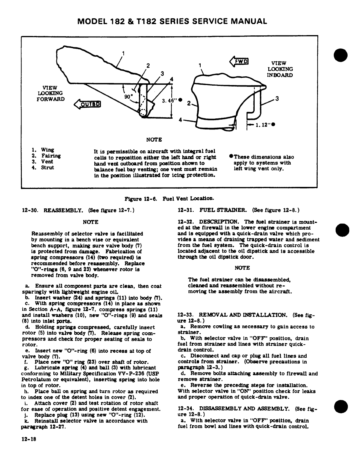
MODEL
182
&
T182
SERIES SERVICE
MANUAL
LOOKING
VIEW
LOOKING
NOTE
1.
Wing
It is
permissible
on
aircraft
with
integral
fuel
2.
Fairing
cells
to
reposition
either
the
left
hand
or
right
These
dimensions
also
3. Vent
hand
vent
outboard
from
position
shown
to
apply
to
systems
with
4.
Strut
balance
fuel
bay
venting;
one
vent
must
remain
left
wing
vent
only.
in
the position
illustrated
for
icing
protection.
Figure
12-6.
Fuel
Vent
Location.
12-30.
REASSEMBLY.
(See
figure
12-7.) 12-31.
FUEL
STRAINER.
(See
figure
12-8.)
NOTE
12-32. DESCRIPTION.
The
fuel
strainer
is
mount-
ed
at
the
firewall
in the
lower
engine
compartment
Reassembly
of
selector
valve
is
facilitated
and
is
equipped
with
a
quick-drain
valve
which
pro-
by
mounting
in
a
bench
vise
or
equivalent
vides
a
means
of
draining
trapped
water
and
sediment
bench
support,
making
sure
valve
body
(7)
from
the
fuel
system.
The
quick-drain
control
is
is
protected
from
damage.
Fabrication
of
located adjacent
to
the
oil
dipstick
and
is
accessible
spring
compressors
(14)
(two
required)
is
through
the
oil dipstick
door.
recommended
before
reassembly.
Replace
"O"-rings
(6, 9
and
23)
whenever
rotor
is
NOTE
removed
from
valve
body.
The
fuel
strainer
can
be
disassembled,
a.
Ensure
all
component
parts
are
clean,
then
coat cleaned
and
reassembled
without
re-
sparingly
with
lightweight
engine
oil.
moving
the
assembly
from
the
aircraft.
b.
Insert
washer
(24)
and
springs
(11)
into
body
(7).
c.
With
spring
compressors
(14)
in
place
as
shown
in
Section
A-A,
figure
12-7,
compress springs
(11)
and
install
washers
(10),
new
"O"-rings
(9)
and
seals
12-33.
REMOVAL
AND
INSTALLATION.
(See
fig-
(8)
into
inlet
ports.
ure
12-8.)
d.
Holding
springs
compressed,
carefully
insert
a.
Remove
cowling
as necessary
to
gain
access
to
rotor
(5)
into valve
body
(7).
Release spring
com-
strainer.
pressors
and
check
for
proper
seating
of
seals
to
b.
With
selector
valve
in
"OFF"
position,
drain
rotor.
fuel
from
strainer
and
lines
with
strainer
quick-
e.
Insert
new
"O"-ring
(6)
into
recess
at
top
of
drain
control.
valve
body
(7).
c.
Disconnect
and
cap
or
plug
all
fuel
lines
and
f.
Place
new
"O"
ring
(23)
over
shaft
of
rotor.
controls
from
strainer.
(Observe
precautions
in
g.
Lubricate
spring
(4)
and
ball
(3)
with
lubricant
paragraph
12-3.)
conforming
to
Military
Specification
VV-P-236
(USP
d.
Remove
bolts
attaching
assembly
to
firewall and
Petrolatum
or
equivalent),
inserting
spring
into
hole
remove
strainer.
in
top
of
rotor.
e.
Reverse
the
preceding
steps
for
installation.
h.
Place
ball
on
spring
and
turn
rotor
as
required
With
selector
valve
in
"ON"
position
check
for
leaks
to index
one
of
the
detent
holes
in
cover
(2).
and
proper
operation
of
quick-drain
valve.
i.
Attach
cover
(2)
and
test
rotation
of
rotor
shaft
for
ease
of
operation
and
positive
detent
engagement.
12-34.
DISSASSEMBLY
AND
ASSEMBLY.
(See
fig-
j.
Replace
plug
(13)
using
new
"O"-ring
(12).
ure
12-8.
)
k.
Reinstall
selector
valve
in
accordance
with
a.
With
selector
valve
in
"OFF"
position,
drain
paragraph
12-27.
fuel
from
bowl
and
lines
with
quick-drain
control.
12-18
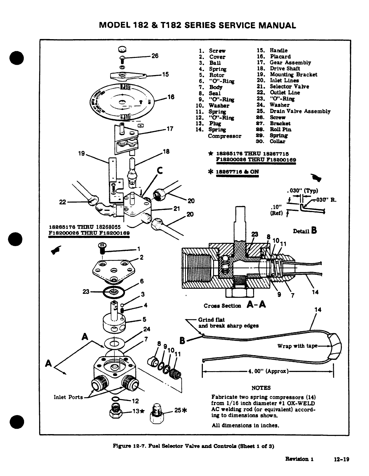
MODEL
182
&
T182
SERIES
SERVICE
MANUAL
t
<--26
2.
Cover
16.
Placard
7I*y T
3.
Ball
17.
Gear
Assembly
4.
Spring
18.
Drive
Shaft
· 1
5---15
5.
Rotor
19.
Mounting
Bracket
6.
"O'-Ring
20.
Inlet
Lines
7.
Body
21.
Selector
Valve
0/~.~P^ \ ..
8.
Seal
22.
Outlet
Line
f- _
,
s
r
6
9.
"1Y'-1Rng
23.
"O"-Ring
\,k ^ --- '-/ J10.
Washer
24.
Washer
ar,,_+ _~.j~
~
11.
Spring
25.
Drain
Valve
Assembly
12.
"O"-Rlng 26.
Screw
- D ~ I3
13.
Plug
27.
Bracket
.>
17
14.
Spring
88.
Roll
Pin
{-Ssf ^
~
Compressor
29.
Spring
30.
Collar
19_
18
*
18288176
THRU
18267715
_7"--T r ^F18200026 T
F18200189
} A C
,~*
18287716
& ON
i;;\ r Ef
//^
^
.030"
(Typ)
22---\^ .200 ll|t
03(0
R.
__a ,<
-21
_
.10"
L /-20
(Ref)
Fl8200026
THRU
F18200169
23Detal
I---
I
oee,#~~~~~~~~~
;
1011
6
23
3
9 7
14
f
>21-4
Cross
Section
A-A
[.)
L.J
°
5
~--Grind
flat
/
I 24"S'^f ~
9^
^and
break
sharp
edges
91011y^^ 8
9
Wrap with
tape
NOTES
Inlet
Ports
0-12
Fabricate
two
spring
compressors
(14)
i ^z:
1 2
from
1/16
inch
diameter
#1
OX-WELD
j_13*r
.l _
25*
AC
welding
rod
(or
equivalent)
accord-
-*~_.Y /24
d
reing
to dimensions
shown.
All
dimensions
in
inches.
Figure
12-7.
Fuel
Selector
Valve
and
Controls
(Sheet
1
of
3)
Revision
1
12-19
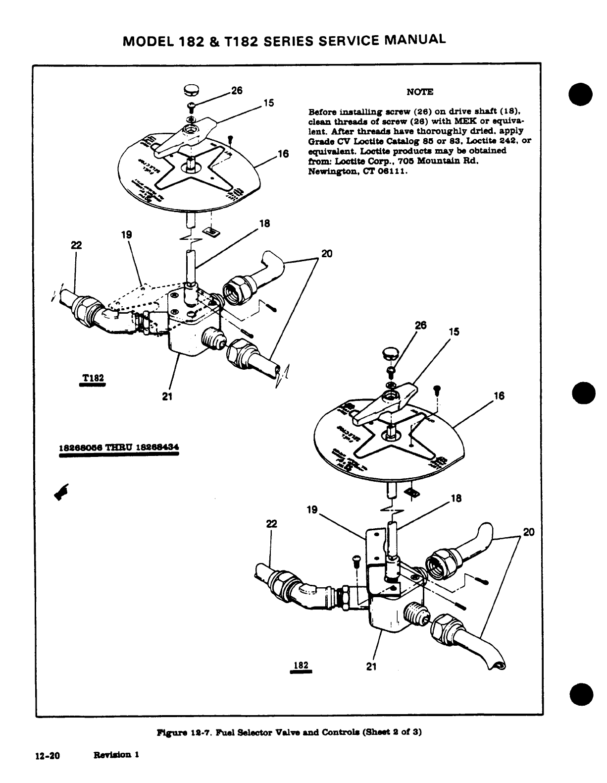
MODEL
182
&
T182
SERIES
SERVICE
MANUAL
2
-26 1NOTE
15
'~~~*
^^Before
installing
screw
(26)
on
drive
shaft
(18),
•b^
'
~
~~
~clean
threads
of
screw
(26)
with
MEK
or
equiva-
lent.
After
threads
have
thoroughly
dried,
apply
Grade
CV
Loctite
Catalog
85
or
83.
Loctite
242,
or
16
equivalent.
Loctite
products
may
be
obtained
from:
Lootite
Corp.,
705
Mountain
Rd.
I4 9 >
'*'-*/
'-
-<Newington,
CT
06111.
19
<
21
r 16
22
-2
~~~~~~20
182688086
THBU
182684
3
~182 218
L0
Figure
18-7.
Fuel
Selector
Valve
and
Controls
(Sheet
2
of 3)
12-20
Revision
1
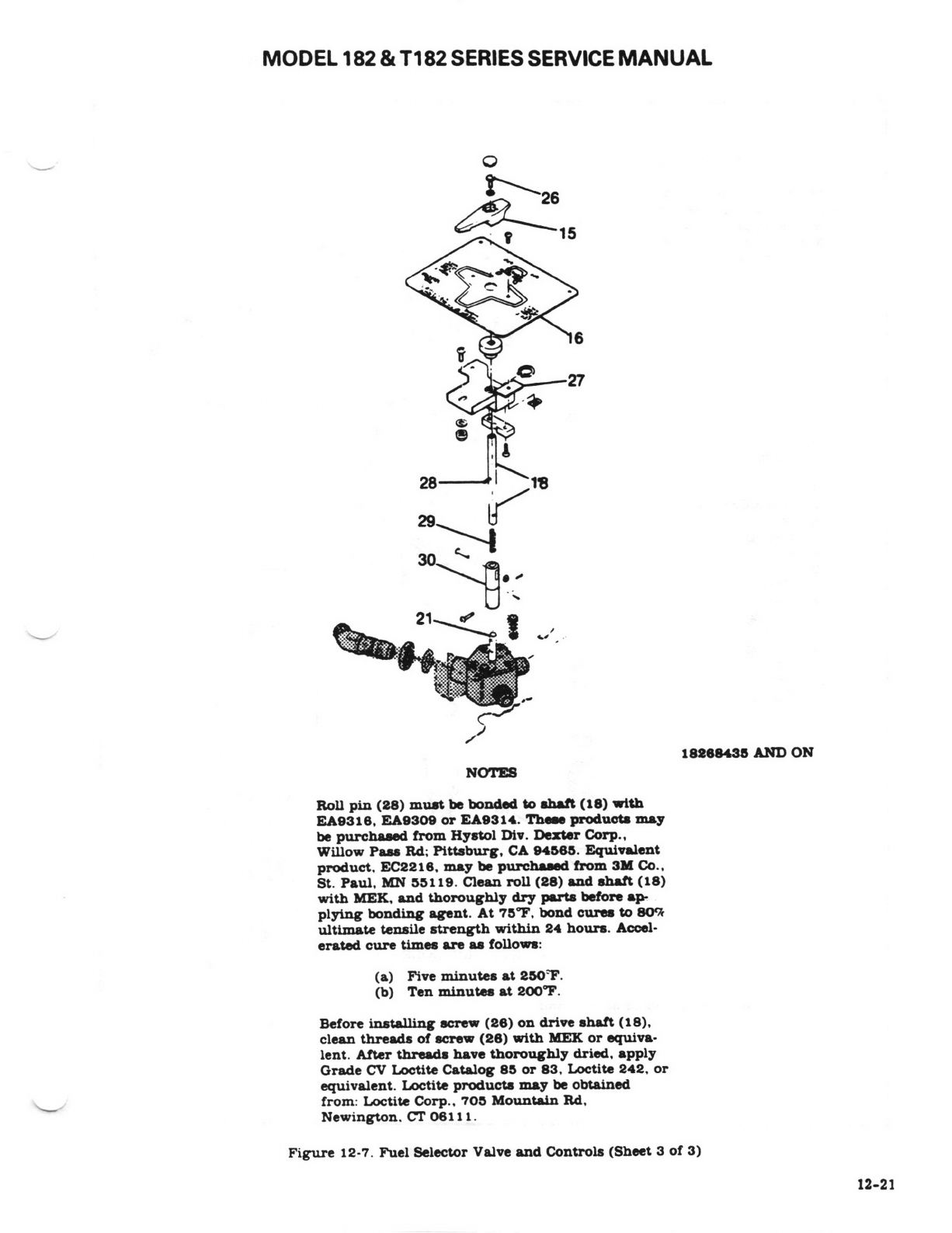
MODEL
182
&
T182
SERIES
SERVICE
MANUAL
15
6
28
NOTES
Roll
pin
(28)
must
be
bonded
to
shaft
(18)
with
EA9316,
EA9309
or
EA9314.
These
products
may
be
purchased
from Hystol
Div.
Dexter
Corp.,
Willow
Pass
Rd;
Pittsburg,
CA
94565.
Equivalent
product.
EC2216,
may
be
purchased
from
3M
Co..
St.
Paul,
MN
55119.
Clean
roll
(28)
and
shaft
(18)
with
MEK,
and
thoroughly dry
parts
before
ap-
plying
bonding
agent.
At
75°F,
bond
cures
to
80%
ultimate
tensile
strength
within
24
hours.
Accel-
erated
cure
times
are
as
follows:
(a)
Five
minutes
at
250°F
(b)
Ten
minutes
at
200°F.
Before
installing
screw
(26)
on
drive
shaft
(18),
clean
threads
of
screw
(26)
with
MEK
or
equiva-
lent.
After
threads
have
thoroughly
dried,
apply
Grade
CV
Loctite
Catalog
85
or
83,
Loctite 242,
or
equivalent.
Loctite
products
may
be
obtained
from:
Loctite
Corp.,
705
Mountain
Rd,
Newington.
CT
06111.
Figure
12-7.
Fuel
Selector
Valve
and
Controls
(Sheet
3
of
3)
12-21
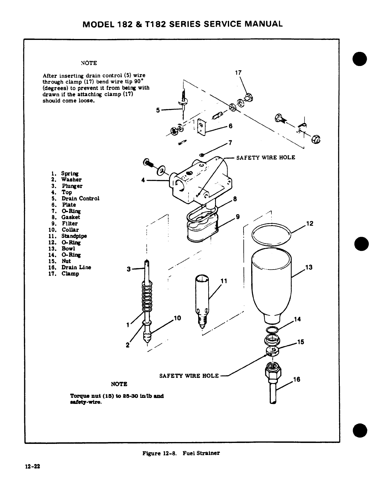
MODEL
182
&
T182
SERIES
SERVICE
MANUAL
NOTE
After
inserting drain
control
(5)
wire
17
through
clamp
(17)
bend
wire tip
90
°
(degrees)
to
prevent
it
from
being
with
drawn
if
the
attaching
clamp
(17)
should
come
loose.
2.
Washer
1.
Spring
3.
Plunger
5.
Drain
Control
6.
Plate
7.
O-Ring
8.
Gasket
9.
Filter
12
10.
Collar
11.
Standpipe
12.
O-Ring
13.
Bowl
14.
-Ring
15.
Nut
16.
Drain
Line
17.
Clamp
2 15
SAFETY
WIRE
HOLE
NOTE
Torque
nut
(15)
to
25-30
in/lb
and
safety-wre.
Figure
12-8.
Fuel
Strainer
12-22
MODEL
182
&
T182
SERIES
SERVICE
MANUAL
b.
Remove
drain
tube,
safety
wire,
nut
and
wash-
c.
Remove
fuel
lines
from
pump,
observing
precautions
er
at
bottom
of
filter
bowl
and
remove
bowl.
cautions
in
paragraph
12-3.
c.
Carefully
unscrew standpipe
and
remove.
d.
Disconnect
wire
at
connector.
d.
Remove
filter
screen
and
gasket.
Wash
filter
e.
Remove
two
mount
bolts,
retaining hardware
for
screen
and
bowl
with
solvent
(Federal
Specification
installation.
P-S-661,
or
equivalent)
and
dry
with
compressed
air.
f.
Reverse
preceding
steps
for
installation,
and
check
e.
Using
a
new
gasket
between
filter
screen
and
check
pump
operation
when
repair
is
completed.
top
assembly,
install
screen
and
standpipe. Tighten
standpipe
only
finger
tight.
12-40A.
PRIMING
SYSTEM
(T182
OPTIONAL).
f.
Using
all
new
O-rings,
install
bowl.
Note
that
step-washer
at
bottom
of
bowl
is
installed
so
that
12-40B.
DESCRIPTION.
The
optional
electric
pri-
step seats
against
O-ring.
Connect
drain
tube.
mer
consists
of
a
solenoid valve,
switch,
circuit
g.
With
selector
valve
in
"ON"
position,
check
for
breaker,
and
necessary
plumbing.
The
solenoid
leaks
and
proper
operation
of
quick-drain
valve.
valve
is
mounted
on
a
tee
attached
to
the
outlet
side
h.
Safety
wire
bottom
nut
to
top
assembly.
Wire
of
the
auxiliary
fuel
pump.
A
line
to
the
engine
driven
must
have
right
hand
wrap,
at
least
45
degrees.
pump
is
attached
to
the
other
side
of
the
tee.
The
primer
functions
in
conjunction
with
the
auxiliary
12-35.
PRIMING
SYSTEM.
electric
fuel
pump.
With
the
auxiliary
electric
fuel
pump
on,
and
the
primer
switch
depressed,
the
12-36.
DESCRIPTION.
The
priming
system
is
solenoid
valve
opens
allowing
fuel
to
flow
to
the
comprised
of
a
plunger-type
manually-operated
cylinders.
primer,
which
draws
fuel
from
the
strainer
and
forces
it
through
a
tee
fitting
to
the
aft
end
of
each
12-41.
INTEGRAL
FUEL
BAY.
intake
manifold. Injecting
the
fuel
into
each
mani-
fold
primes
both
banks
of
cylinders.
12-41A.
DESCRIPTION.
Beginning
Serial
18266591.
The
integral
fuel
bay
is
a
sealed
12-37.
REMOVAL
AND
INSTALLATION.
portion
of
the
inboard
wing
structure
between
a.
With
selector
valve
in
"OFF"
position,
drain the
front
and
rear
wing spars,
extending
ap-
fuel
from
strainer
and
lines
with
quick-drain
control.
proximately
five
feet
into
each
wing.
This
b.
Disconnect
and cap
or
plug
all
fuel
lines
at
type
construction
reduces
overall
weight
as
primer
(Observe
precautions
in
paragraph
12-3.) well
as
increasing
the
strength
of
the
wing.
c.
Unscrew
knurled
nut
and
remove
plunger
from
pump
body.
12-42.
FUEL
LEAK CLASSIFICATION.
Fuel
d.
Remove
pump
body
from
instrument
panel.
leaks
which
do
not
constitute
a
night
hazard
are
stains,
seeps
and
heavy
seeps
NOT
in
an
enclosed
NOTE
area.
However,
they
should
be
repaired
when
the
aircraft
is
grounded
for
other
maintenance.
Fuel
Visually
inspect
primer
lines
for
crushed,
leaks
which
constitute a
fight
hazard
are
running
kinked
or
broken
condition.
Ensure
proper
leaks
in
any
area,
seeps,
heavy
seeps,
or
stains
in
clamping
to
prevent
fatigue
due
to
vibration
an
enclosed
area,
such
as
the
wing
leading
edge,
the
and
chafing.
sections
of
wing
inboard
and
outboard
of
the fuel
bay
and
the
area
between
the
rear
fuel
spar
and the
main
e.
Prior
to
installing
a
primer,
check
for
proper
spar.
These
leaks
must
be
repaired
before
that
bay
pumping
action
and
positive
fuel
shut-off
in
the
is
used
for
another flight.
The
wet
or
stained
spot
pumping
action
and
positive
fuel
shut-off
in
the
locked
position.
on
the
wing
in
the
area
of
the
bay
is
an
indication
of
f.
Reverse
the
preceding
steps
for
installation.
the
intensity
of
the
leak.
Fuel
leak
classifications
With
selector
valve
in
"BOTH"
position,
check
for
are
shown
in
figure
12-10.
leaks
and
proper
pumping
action.
NOTE
12-38.
AUXILIARY
ELECTRIC
FUEL
PUMP
-
T182.
Stains
and
seeps
that
are
not
considered
a
flight
hazard
must
be
inspected
after
each
12-39.
DESCRIPTION.
On
turbocharged
aircraft
an
night
to
insure
that
they
have not
grown
in
auxiliary
electric
fuel
pump
is
used
to
ensure
adequate
intensity
to
the
point
of
causing
a
flight
fuel
flow.
See
figure
12-9.
hazard.
12-40.
REMOVAL
AND
INSTALLATION.
a.
Place
fuel
selector
valve
in
OFF
position.
b.
Make
sure
that Master
Switch
and
Auxiliary
Fuel
Pump
Switch
are
OFF.
12-23
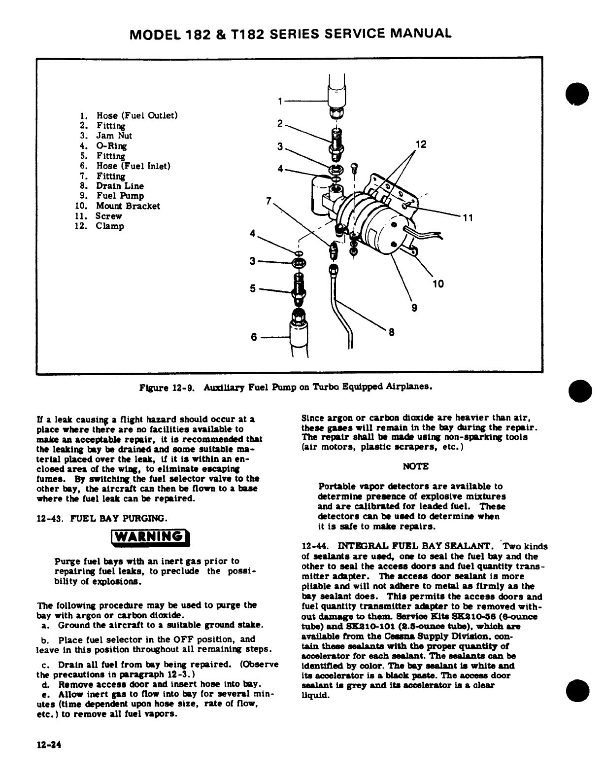
MODEL
182
&
T182
SERIES
SERVICE
MANUAL
1.
Hose
(Fuel
Outlet)
2.
Fitting
2
3.
Jam
Nut
4.
O-Ring
3
12
5.
Fitting
6.
Hose
(Fuel
Inlet)
7.
Fitting
8.
Drain
Line
9.
Fuel
Pump
10.
Mount
Bracket
11.
Screw
12.
Clamp
6
Figure
12-9.
Auxiliary
Fuel
Pump
on
Turbo
Equipped
Airplanes.
If
a
leak
causing
a
flight
hazard
should
occur
at
a
Since
argon
or
carbon
dioxide
are
heavier
than
air,
place
where
there
are
no
facilities
available
to
these
gases
will
remain
in
the
bay
during
the
repair.
make
an
acceptable
repair,
it
is
recommended
that
The
repair
shall
be
made
using
non-sparking
tools
the
leaking
bay be
drained
and
some
suitable
ma-
(air
motors,
plastic
scrapers,
etc.)
terial
placed over
the
leak,
if
it
is
within
an
en-
closed
area
of
the
wing,
to
eliminate
escaping
NOTE
fumes.
By
switching the
fuel
selector
valve
to
the
other
bay,
the
aircraft
can
then
be flown
to
a
base
Portable
vapor
detectors
are
available
to
where
the
fuel
leak
can
be
repaired.
determine
presence
of
explosive
mixtures
and
are
calibrated
for
leaded
fuel.
These
12-43.
FUEL
BAY
PURGING.
detectors
can
be
used
to
determine
when
it
is
safe
to make
repairs.
12-44.
INTEGRAL
FUEL
BAY
SEALANT. Two
kinds
of
sealants
are
used,
one
to
seal
the fuel
bay
and
the
Purge
fuel
bays
with
an
inert
gas
prior
to
repairing
fuel
leaks,
to
preclude
the
possi-
other
to
seal
the
access
doors
and
fuel
quantity
trans-
repairing
fuel
leaks,
to
preclude
the
possi-
bility
of
explosions.
pliable and
will
not
adhere
to metal
as
firmly
as
the
bay
sealant
does.
This
permits
the
access
doors
and
The
following
procedure
may
be
used
to purge
the
fuel
quantity
transmitter
adapter
to
be
removed
with-
bay
with
argon
or
carbon
dioxide.
out
damage to
them.
Service
Kits
SK210-56
(6-ounce
a.
Ground
the
aircraft
to
a
suitable
ground
stake.
tube)
and
SK210-101
(2.5-ounce
tube),
which
re
b.
Place
fuel
selector
in
the
OFF position,
and
available
from
the
Cessna
Supply
Division,
con-
leave
in
this
position
throughout
all
remaining
steps.
tain
these
sealants
with
the
proper
quantity
of
accelerator for
each sealant. The
sealants
can
be
c.
Drain
all
fuel
from
bay
being
repaired.
(Observe
identified
by
color.
The bay
sealant
is
white
and
the
precautions
in
paragraph
12-3.)
its
accelerator
is
a
black
paste.
The
access
door
d.
Remove
access
door
and
insert
hose
into bay.
sealant
is
grey
and
its
accelerator
is a
clear
e.
Allow
inert
gas
to
flow
into
bay
for
several
min-
liquid.
utes
(time
dependent
upon
hose
size,
rate
of
flow,
etc.)
to
remove
all
fuel
vapors.
12-24
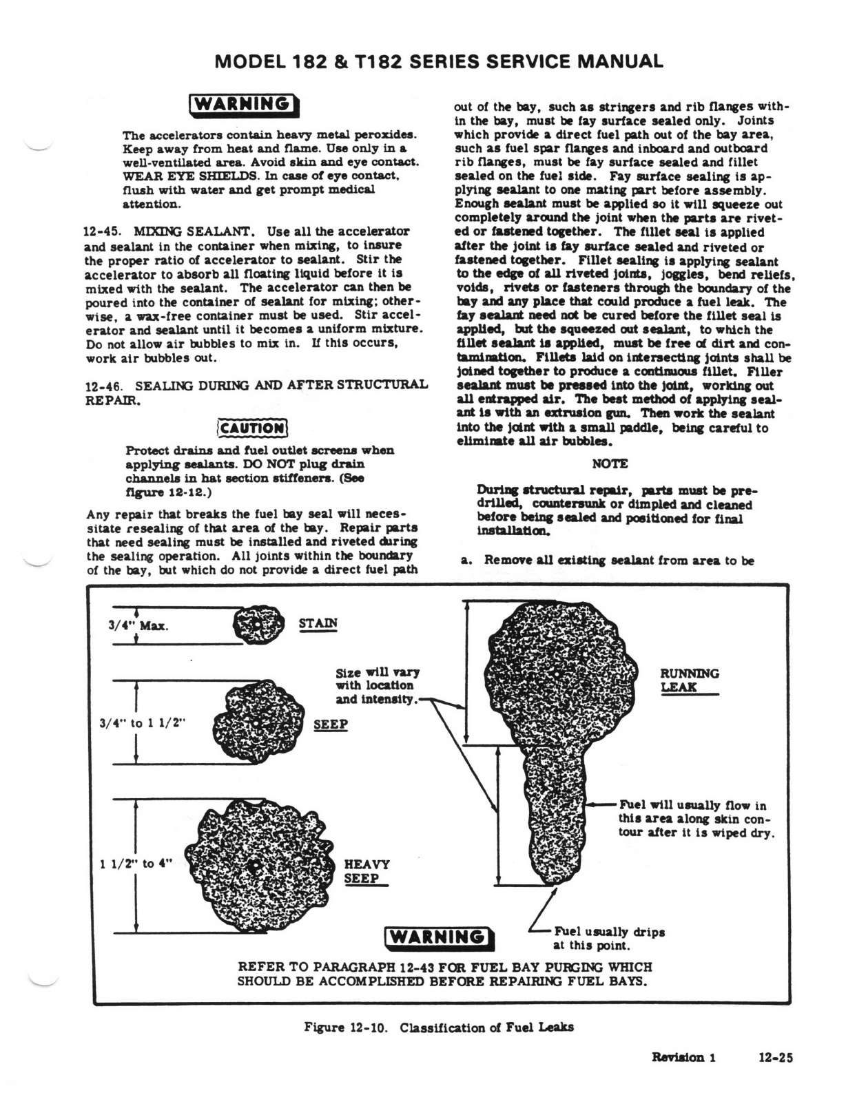
MODEL
182
&
T182
SERIES
SERVICE
MANUAL
in
the
bay,
must
be
fay
surface
sealed
only.
Joints
The
accelerators
contain
heavy metal
peroxides.
which
provide
a
direct
fuel
path
out
of
the
bay
area,
Keep
away
from
heat
and
flame.
Use
only
in
a
such
as
fuel
spar
flanges
and
inboard and
outboard
well-ventilated
area.
Avoid
skin
and
eye
contact.
rib
flanges, must
be fay
surface
sealed
and
fillet
WEAR
EYE
SHIELDS.
In
case
of
eye
contact.
sealed
on
the
fuel
side.
Fay
surface
sealing
is
ap-
flush
with water
and
get prompt
medical
plying
sealant
to
one
mating
part
before
assembly.
attention.
Enough
sealant
must
be
applied so
it
will
squeeze
out
completely around the joint
when
the
parts
are
rivet-
12-45.
MIXING
SEALANT.
Use
all
the
accelerator
ed
or
fastened together.
The
fillet
seal
is
applied
and
sealant
in
the
container
when
mixing,
to
insure
after
the
joint
is
fay
surface
sealed
and
riveted
or
the
proper
ratio
of
accelerator
to
sealant. Stir
the
fastened together.
Fillet
sealing
is
applying
sealant
accelerator
to
absorb all
floating
liquid
before
it
is
to
the
edge
of
all
riveted
oints,
joggles,
bend
reliefs,
mixed
with
the
sealant.
The
accelerator
can
then
be
voids,
rivets
or
fasteners
through
the
boundary
of
the
poured
into the
container
of
sealant
for
mixing;
other-
bay and
any
place
that
could
produce
a
fuel
leak.
The
wise,
a
wax-free
container
must
be
used.
Stir
accel-
fay
sealant
need
not
be
cured before
the
fillet
seal
is
erator
and
sealant until
it
becomes
a
uniform
mixture.
applied,
but
the
squeezed
out
sealant,
to
which
the
Do
not
allow
air
bubbles
to
mix
in.
If
this occurs,
fillet
sealant
s
applied,
must
be
free
of
dirt
and con-
work
air
bubbles
out.
tamintion.
Fillets
laid
on
intersecting
joints
shall
be
joined
together
to
produce
a
continuous
fillet.
Filler
12-46.
SEALING
DURING AND
AFTER
STRUCTURAL
sealant
must
be
pressed
into
the
joint,
working
out
REPAIR.
all
entrapped
air.
The
best
method
of
applying
seal-
ant
is
with
an
extruion
gun.
Then
work
the
sealant
eliminate
all
air
bubbles.
Protect
drains
and
fuel
outlet screens
when
applying sealants.
DO
NOT
plug
drain
NOTE
channels
in
hat
section
stiffeners.
(See
figure
12-12.) During
structural repair,
parts
must
be
pre-
drilled,
countersunk
or
dimpled
and
cleaned
Any
repair
that
breaks
the
fuel
bay
seal
will
neces-
before
being
seale
and
positioned
for
final
sitate
resealing
of
that
area
of
the
bay.
Repair
parts
installation
that
need
sealing
must
be
installed
and
riveted
during
the
sealing
operation.
All
joints
within
the
boundary
a.
Remove
all
existing sealant
from
area
to
be
of
the
bay,
but
which
do
not
provide a
direct
fuel
path
3/4"
Max.
STAIN
Size
will
vary
RUNNING
with
location
LEAK
and
intensity.
3/4"
to 1
1/2"
SEEP
Fuel
will
usually
flow
in
this
area
along
skin
con-
WARNING
Fuel
usually
drps
REFER
TO
PARAGRAPH
12-43
FOR
FUEL
BAY
PURGING WHICH
SHOULD
BE
ACCOMPLISHED
BEFORE
REPAIRING
FUEL
BAYS.
Figure
12-10.
Classification
of
Fuel
Leaks
Revision
1 12-25

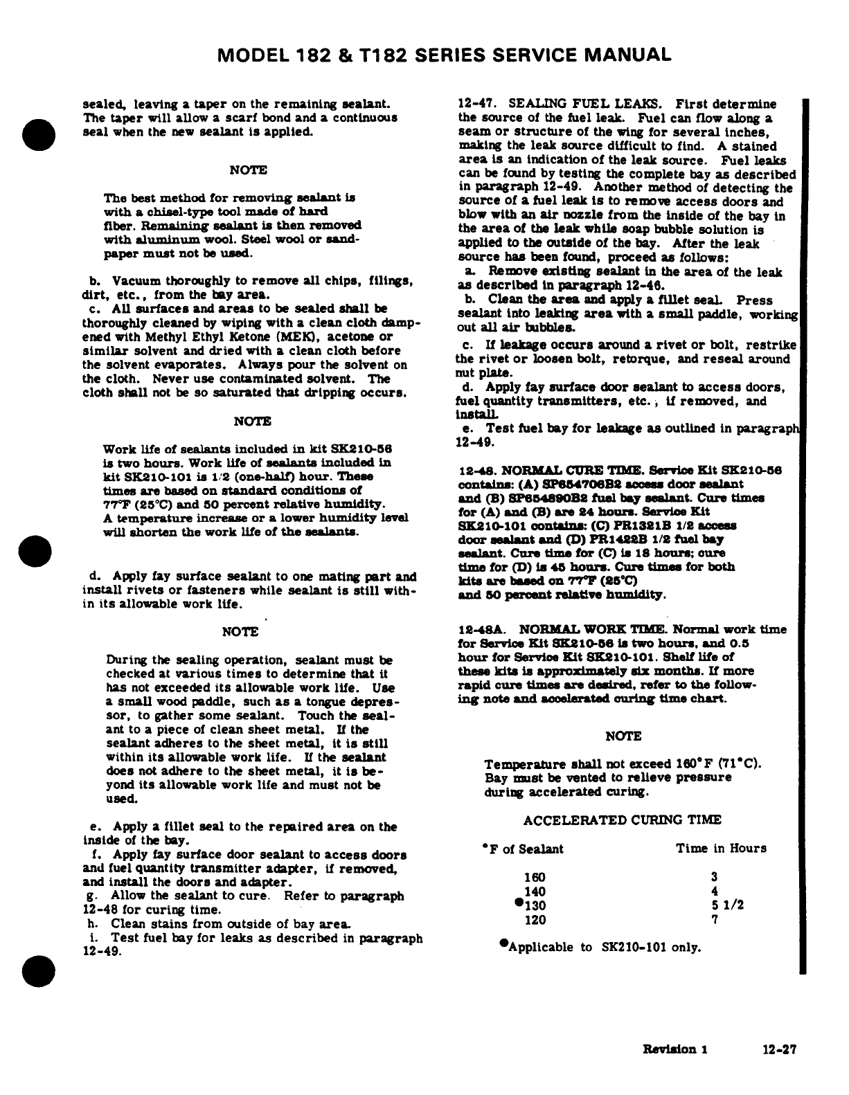
MODEL
182
&
T182
SERIES SERVICE
MANUAL
sealed,
leaving a
taper
on
the
remaining
sealant.
12-47.
SEALING
FUEL
LEAKS.
First
determine
The
taper
will
allow
a
scarf
bond
and
a
continuous
the
source
of
the
fuel
leak.
Fuel
can
flow
along
a
seal
when
the
new
sealant
is
applied.
seam
or
structure
of
the
wing
for
several
inches,
making
the
leak
source
difficult
to
find.
A
stained
area
is
an
indication
of
the
leak
source.
Fuel
leaks
NOTE
can
be
found
by
testing
the
complete
bay
as described
in
paragraph
12-49.
Another
method
of
detecting
the
The
best
method
for removing
sealant
is
source
of
a
fuel
leak
is
to
remove
access
doors
and
with
a
chisel-type tool made
of
hard
blow
with
an
air
nozzle
from
the
inside
of
the
bay
in
fiber.
Remaining
sealant
is
then
removed
the
area
of
the
leak
while
soap
bubble
solution
is
with
aluminum
wool.
Steel
wool
or
sand-
applied
to
the
outside
of
the bay.
After
the
leak
paper
must
not
be
used.
source
has
been
found,
proceed
as
follows:
a.
Remove
existing
sealant
in
the
area
of
the
leak
b.
Vacuum
thoroughly
to
remove
all
chips,
filings,
as
described
in
paragraph
12-46.
dirt,
etc.,
from
the
bay
area.
b.
Clean
the
area
and
apply
a
fillet
seal.
Press
c.
All
surfaces
and
areas
to
be
sealed
shall
be
sealant
into
leaking
area
with
a
small
paddle,
working
thoroughly
cleaned
by
wiping
with
a
clean
cloth
damp-
out
all
air
bubbles.
ened
with
Methyl
Ethyl
Ketone
(MEK),
acetone
or
similar
solvent
and
dried
with
a
clean
cloth
before
c.
If leakage
occurs
around
a
rivet
or
bolt,
restrike
the solvent
evaporates.
Always
pour
the
solvent
on
the
rivet
or
loosen
bolt,
retorque,
and
reseal
around
the
cloth.
Never
use
contaminated solvent.
The nut
plate.
the cloth. Never
use
contaminated
solvent.
The
d.
Apply
fay
surface
door
sealant
to
access
doors,
cloth
shall
not
be
so
saturated
that
dripping
occurs.
fuel
fuel
quantity
transmitters,
etc.,
if
removed,
and
e.
Test
fuel
bay
for
leakage
as
outlined
in
paragrap
12-49.
Work
life
of
sealants
included
in
kit
SK210-56
12-49.
is
two
hours.
Work
life
of
sealant
included
in
12-48.
NORMAL,
CURE
TIME. Service
Kit
SK210-56
kit
SK210-101
is
1/2
(one-half)
hour.
These
12-48.
NORMAL
CURE
TIME.
Service
Kit
SK210-56
times
are
based
on
standard
conditions
of
contained:
(A)
SP654706B2
access
door
sealant
77°F
(25°C)
and
50
percent
relative
humidity.
A
temperature
increase
or
a lower
humidity
level
will
shorten
the
work
life
of
the
d.
Apply
fay
surface
sealant
to
one
mating
part
and
kits
are
based
on
77°F
(25°C)
install
rivets
or
fasteners
while
sealant
is
still
with-
and
50
percent
relative
humidity
in
its
allowable
work
life.
NOTE
12-48A.
NORMAL
WORK
TIME.
Normal
work
time
for
Service
Kit
SK210-56
is
two
hours,
and
0.5
During
the
sealing
operation,
sealant
must
be
hour
for
Service
Kit
SK210-101.
Shelf
life
of
checked
at
various
times
to
determine
that
it
these
kits
is
approximately
six
months.
If
more
has
not
exceeded
its
allowable work
life.
Use
rapid
cure times
are
desired,
refer
to
the
follow-
a
small
wood
paddle,
such
as
a
tongue
depres-
ing
note
and
accelerated
curing
time
chart.
sor,
to
gather
some
sealant.
Touch
the
seal-
ant
to
a
piece
of
clean
sheet
metal.
If
the
NOTE
sealant
adheres
to
the
sheet
metal,
it
is
still
within
its
allowable work
life.
If
the
sealant Temperature
shall
not
exceed
160°F
(71°C).
does
not
adhere
to
the
sheet
metal,
it is
be- Bay
must
be
vented
to
relieve
pressure
yond
its
allowable
work
life
and
must
not
be
during
accelerated
curing.
used.
e.
Apply
a
fillet
seal
to
the
repaired
area
on
the
ACCELERATED
CURING
TIME
inside
of
the
bay.
f. Apply
fay
surface
door
sealant
to
access
doors
F
of Sealant
Time
in
Hours
and
fuel
quantity
transmitter
adapter,
if
removed,
and
install
the
doors
and
adapter.
140
4
g.
Allow
the
sealant
to
cure. Refer
to
paragraph
140
4
12-48
for
curing
time.
130
5
1/2
h.
Clean
stains
from
outside
of
bay
area.
120
7
i.
Test
fuel
bay
for
leaks
as
described
in
paragraph
Applicable
to
SK210-101
only.
12-49.
12-49.
Revision
1
12-27
MODEL
182
&
T182
SERIES
SERVICE
MANUAL
12-48B.
INTEGRAL FUEL
BAY
QUICK-REPAIR
NOTE
SEALANT.
GC-435
is
a
quick-repair
synthetic
rubber
sealant
for
use
in
fuel
bays when
it
is
necessary
Work
life
of
GC-435
is
approximately
to
refill
bays
as
soon
as
the
repair
has
been
made.
(15)
minutes.
Shelf
life is
at
least
The
sealant
is
a
two-part,
medium-viscosity,
poly-
(6)
months
when
stored
in
an
area
sulfide liquid
polymer
and
is
formulated
for
ap-
where the
ambient
temperatures
are
plication
by
brush
or
extrusion.
GC-435
may
be
80
°
(26°C)
or
lower.
purchased
from:
Goal
Chemical
Sealants
Corp.,
3137
East
26th Street,
Los
Angeles,
CA
90023.
12-49.
TESTING
INTEGRAL
FUEL
BAY.
a.
Remove
vent
line
from
vent
fitting
and
cap
fitting.
12-48C. SURFACE
PREPARATION.
To
ensure
max-
b.
Disconnect
fuel
lines
from
bay.
imum
adhesion
of
GC-435,
integral
bay
surfaces
c.
To
one
of
the
bay
fittings,
attach
a
water
manom-
should
be
free
of
oil,
grease,
wax,
dirt,
etc.
eter
capable
of
measuring
twenty
inches
of
water.
Pour
cleaning
solvent
onto
the
cloth
and
wipe
d.
To
the
other
bay
fitting,
connect
a
well
regulated
the
surface.
Then
use
a
clean,
dry
cloth
to
wipe
supply
of
air
(1/2
PSI
MAXIMUM,
or
13.
8
INCHES
of
the
solvent
from
the
surface
prior
to
its
evap-
water). Nitrogen
may
be
used
where
the
bay
might
oration.
Be
sure the
surface
to
be sealed
is
be
exposed
to
temperature
changes
while
testing.
clean
and
dry.
Observe
all
e.
Make
sure
filler
cap
is installed
and
sealed.
warnings
and
cautions
covering
preparation
and
application
of sealants as
noted
in
this
section
and
the
instructions
included
with
GC-435
sealant.
12-48D.
MIXING
SEALANT.
GC-435
comes
in
pr-
measured
and
proportioned
kits
ready
for
use.
The
base
compound
is
cream-colored,
and
the
catalyst is
black.
If the
entire
kit
is
not
needed,
the
GC-435
may
be
proportioned
by
com-
bining
(10)
parts
of
the
bee
compound
(cream-
colored),
with
(1)
part
of
the
catalyst
(black)
by
weight.
Use
an
mix the
base
and
catalyst
until a
homogeneous
blend
of
color
and appearane
is
accomplished
12-28
Revision
1
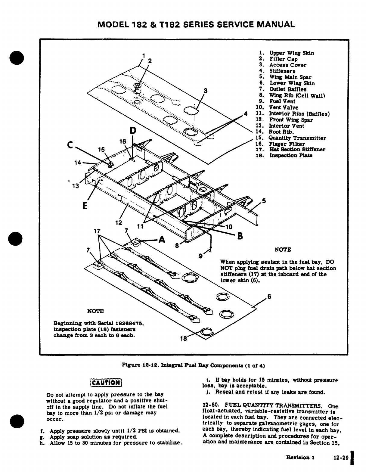
MODEL
182
&
T182
SERIES
SERVICE
MANUAL
*-~1
1'
t
~1.
Upper
Wing
Skin
I/
2
2.
Filler
Cap
2,J ^^~
/
~3.
Access
Cover
4.
Stiffeners
5.
Wing
Main
Spar
.~"*- (j. '"4~ %
-.6
6.
Lower
Wing
Skin
/*'*C - ''-- \s
3
7.
Outlet
Baffles
wj\ ''--.t ^-q f -\ /
8.
Wing
Rib
(Cell
Wall)
\'^ '-'--_ '-;' '.-:
."y.,
,,
9.
Fuel
Vent
\ '.. '"::;. ""-- <
10.
Vent
Valve
4
11.
Interior
Ribs
(Bafles)
<:A :I^. '".C -
1
12.
Front
Wing
Spar
\'"^ ."1
J, _ \
13.
Interior
Vent
D
I:_~ /.s^
14.
Root
Rib.
|ft \y
^^s.
'
k;
;-.,-<--
^15.
Quantity
Transmitter
C \ 9s16_/ .
Finger
Filter
C15K
17.
Hat
Section
Stiffener
^^.
^^<^e-at
Ax^-.
\s^
When
applying
sealant
in
the
fuel
bay,
DO
(
Gus$?
t^\^
^
<
^
~>^
\^
NOT
plug
fuel
drain
path
below
hat
section
Beginning
with
Serial
18288475,
\ /
~~~~~~~~~i.
inspection
plate (18)
fasteners
lat
12
17
7
7chag fom
3 each
NOTE
'.'
A
i.
"'.>
loss,
bay
is
acceptable.
Do
not
attempt
to apply
pressure
to
the
bay
i.
Reseal
and
retest
if
a
leaks
are
found.
without
a
good
regulator
and
a
positive
shut-
off in thesplie ontinlth ul1-0When applyinsu sealant
iin the
fuel bay,TERS.
One
bay
to
more
than
1/2
psi
or
damage
may
float-actuated,
variable-resistive
transmitter
is
y tomooccur eha 2sodmae
a
located
in
eachp
fuel
drain
path
below
hat
s
connected
onc-
trically
to
separate
galvanometric gages,
one
for
r
skin
(6).
Apply
pressure
slowly
untl
1/2
PSI
is
obtained
each
tereby
ndicl
82level
n
each
bay.
Apply
soap
solution
as
requition
and
procedur
fteor oper
change
from
3
each
to
6
each.
Figure
12-12.
Integrai
Fuel
Bay
Components
(1
of
4)
h. Allow
15
to
30
minutes
form
pressure
to
stabilize.
aton
and
mintenance
are
contained in
Secton
15.
losRevson, bay
is
accep
ble29
J.
Reseal
and
retest
if
any
leaks
are
found.
without
a
good
regulator
and
a
positive
shut-
off
in
the
supply
line.
Do
not
inflate
the
fuel
12-50.
FUEL
QUANITY
TRANSMITTERS.
One
bay
to
more
than
1/2
psi
or
damage
mary
float-actuated,
variable-resistive
transmitter
is
occur.
located
in
each
fuel
bay.
They
are
connected
elec-
trically
to
separate
galvanometric gages,
one for
f.
Apply
pressure
slowly
until
1/2
PSI
is
obtained.
each
bay,
thereby
indicating
fuel level
in
each
bay.
g.
Apply
soap
solution
as
required.
A
complete
description
and
procedures
for
oper-
h. Allow
15
to
30
minutes
for
pressure
to
stabilize.
ation and
maintenance
are
contained
in
Section
15.
Revision
I
12-29

MODEL
182
&
T182
SERIES
SERVICE
MANUAL
NOTE
Torque
drain
valve
(1),
15
to
35
inch-pounds.
Drain
valve
gasket
(16)
should
be
lightly
oiled
nd
in-
Safety-wire
drain
valve
(1).
16
1. Drain
Valve
2.
Valve
Assembly
4.
Gasket
5.
Washer
6.
Nut
8.
Grommet
9.
Clamp
11.
Screw
12.
Finger
Strainer
13.
Clamp
14.
Fitting
16.
Gasket
17.
Fuel
Sampler
Cup
NOTE
Beginning
with
1979
models,
items
thru
11
13
14
13
12
Detail
E
When
tightening
screw
clamp
(13),
13
do
not
exceed
8-10
in-lbs.
15
Figure
12-12.
Integral
Fuel
Bay
Components
(2
of
4)
12-30
Revsion
1
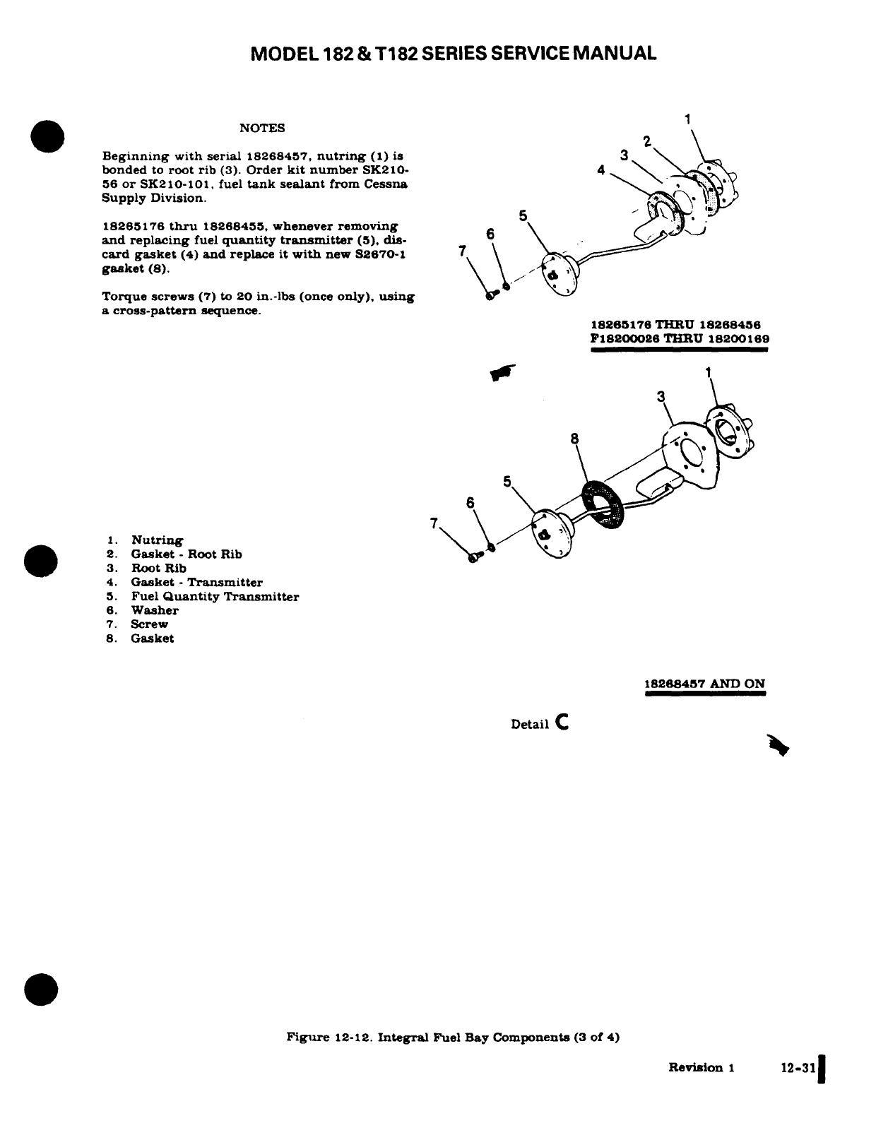
MODEL
182
&
T182
SERIES
SERVICE
MANUAL
NOTES
Beginning
with serial
18268457,
nutring
(1)
is 3
bonded
to
root
rib
(3).
Order
kit
number
SK210-
4
56
or
SK210-101,
fuel
tank
sealant
from
Cessna
Supply
Division.
18265176
thru
18268455.
whenever removing
and
replacing
fuel
quantity
transmitter
(5),
dis-
card
gasket
(4)
and
replace
it
with
new S2670-1
gasket
(8).
Torque
screws
(7)
to
20
in.-lbs
(once
only),
using
a
cross-pattern
sequence.
18265176
THRU
18268456
F18200026
THRU
18200169
1.
Nutring
2.
Gasket
- Root
Rib
3.
Root
Rib
4.
Gasket
-
Transmitter
5.
Fuel
Quantity
Transmitter
6.
Washer
7.
Screw
8.
Gasket
18268457
AND
ON
Detail
C
Figure
12-12.
Integral
Fuel
Bay
Components
(3
of
4)
Revision
1
12-31
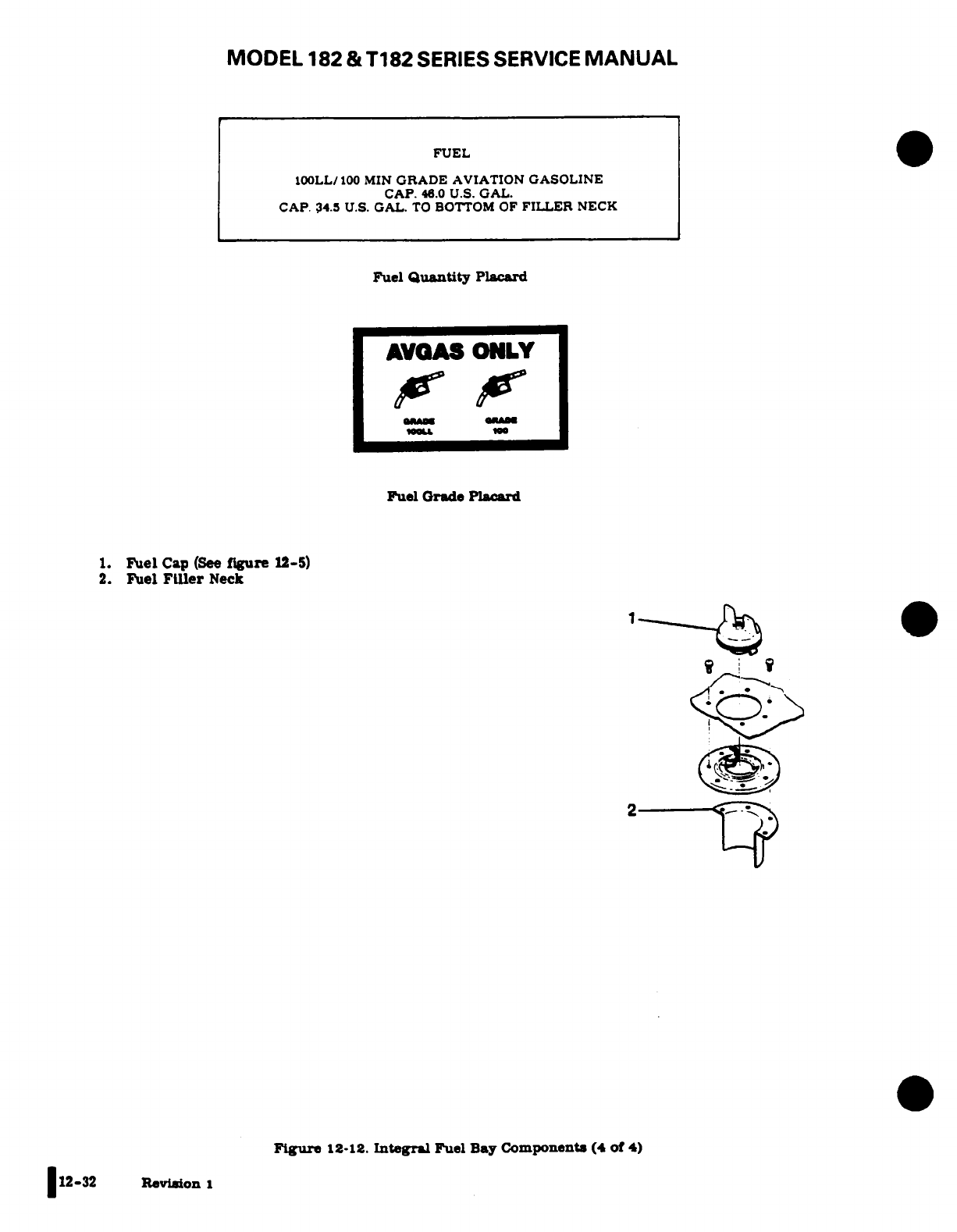
MODEL
182
&
T182
SERIES SERVICE
MANUAL
FUEL
100LL/
100
MIN
GRADE AVIATION
GASOLINE
CAP.
46.0
U.S.
GAL.
CAP.
34.5
U.S.
GAL.
TO
BOTTOM
OF
FILLER
NECK
Fuel
Quantity
Placard
AVGAS
ONLY
Fuel
Grade
Placard
1.
Fuel
Cap
(See
figure
12-5)
2.
Fuel
Filler
Neck
Figure
12-12.
Integral
Fuel
Bay
Components
(4 of 4)
12-32
Revision
1
MODEL
182
&
T182
SERIES
SERVICE
MANUAL
SECTION
13
When
performing
any
inspection
or
mainte-
nance
that
requires
turning
on
the
master
switch,
installing
a
battery,
or
pulling
the
propeller
through
by
hand,
treat
the
propel-
ler
as
if
the
ignition
switch
were
ON.
Do
not
stand,
nor
allow
anyone
else
to
stand,
within
the
arc
of
the
propeller,
since
a
loose
or
broken
wire,
or
a
component
mal-
function, could
cause
the
propeller
to
rotate.
Page
No.
TABLE
OF
CONTENTS
Aerofiche/Manual
PROPELLER
......
.. .
2E13/13-1
GOVERNOR
...........
2E19/13-7
Description
..........
2E13/13-1
Description
..........
2E19/13-7
Repair
............
2E13/13-1
Trouble Shooting
........
2E19/13-7
Trouble
Shooting
........
2E14/13-2 Removal
.
....
... ..
2E19/13-7
Removal
- 182 &
F182
. ... .
2E15/13-3
Installation
..........
2E19/13-7
Installation
-
182
&
F182
.....
2E15/13-3
High
RPM
Stop
Adjustment
. . . .
2E20/13-8
Removal
-
T182
.........
2E15/13-3
Rigging
Prop
Governor
Control
. . .
2E20/13-8
Installation
-
T182
........
2E15/13-3
Time Between
Overhaul
(TBO)
..
2E21/13-9
Time Between
Overhaul
(TBO) . .
2E19/13-7
13-1. PROPELLER.
speed
is
decreased,
the
engine
RPM
will
try
to
de-
crease.
The
governor
senses this
and
allows
the
13-2.
DESCRIPTION.
The
aircraft
is
equipped
with
oil
to
drain
from
the
forward side
of
the
piston.
an
all-metal,
constant-speed,
governor-regulated
Spring
tension
and
centrifugal
twisting
moment
will
propeller.
The
constant-speed
propeller
is
single-
move
the
blades
to
a
lower pitch
to maintain
the
acting,
in
which engine
oil
pressure,
boosted
and
selected
engine
speed. Figure
13-1,
illustrates
the
regulated
by
the
governor
is
used
to
obtain
the
cor- different
propellers
used
on
the
aircraft.
Refer
to
rect
blade
pitch
for
the
engine
load.
Engine
lubrica-
applicable
vendor
publications
for
further
information.
ting
oil
is
supplied
to
the power
piston
in
the propel-
ler
hub
through the
crankshaft.
The
amount and
pres-
13-3.
REPAIR.
Metal
propeller
repair
first
involves
sure
of
the
oil supplied
is
controlled
by
the
engine-
evaluating
the
damage
and
determining
whether
the
driven
governor.
An
increase
or
decrease
in
throttle
repair
will
be
a
major
or
minor
one.
Federal
Avia-
setting
or
a
change in
aircraft
attitude
will
affect
the
tion Regulations,
Part
43
(FAR 43),
and
Federal
balance
which
maintains
a
given
RPM.
If
the
throttle
Aviation
Agency,
Advisory
Circular
No.
43.13
(FAA
is
opened
further
or
if
aircraft
speed
is
increased,
AC
No.
43.13),
define
major
and
minor
repairs,
al-
engine
RPM
will
try
to
increase.
The
governor
terations
and
who
may
accomplish
them.
When
mak-
senses
this
and
directs
oil
pressure
to
the
forward
ing
repairs
or
alterations
to
a
propeller
FAR
43,
side
of
the
piston.
The
blades
will
be
moved
to
a
FAA
AC No.
43.13
and the
propeller
manufacturer's
higher
pitch
and engine
speed will
remain
constant.
instructions
must
be
observed.
Conversely,
if
the
throttle
opening
or
the
aircraft
13-1
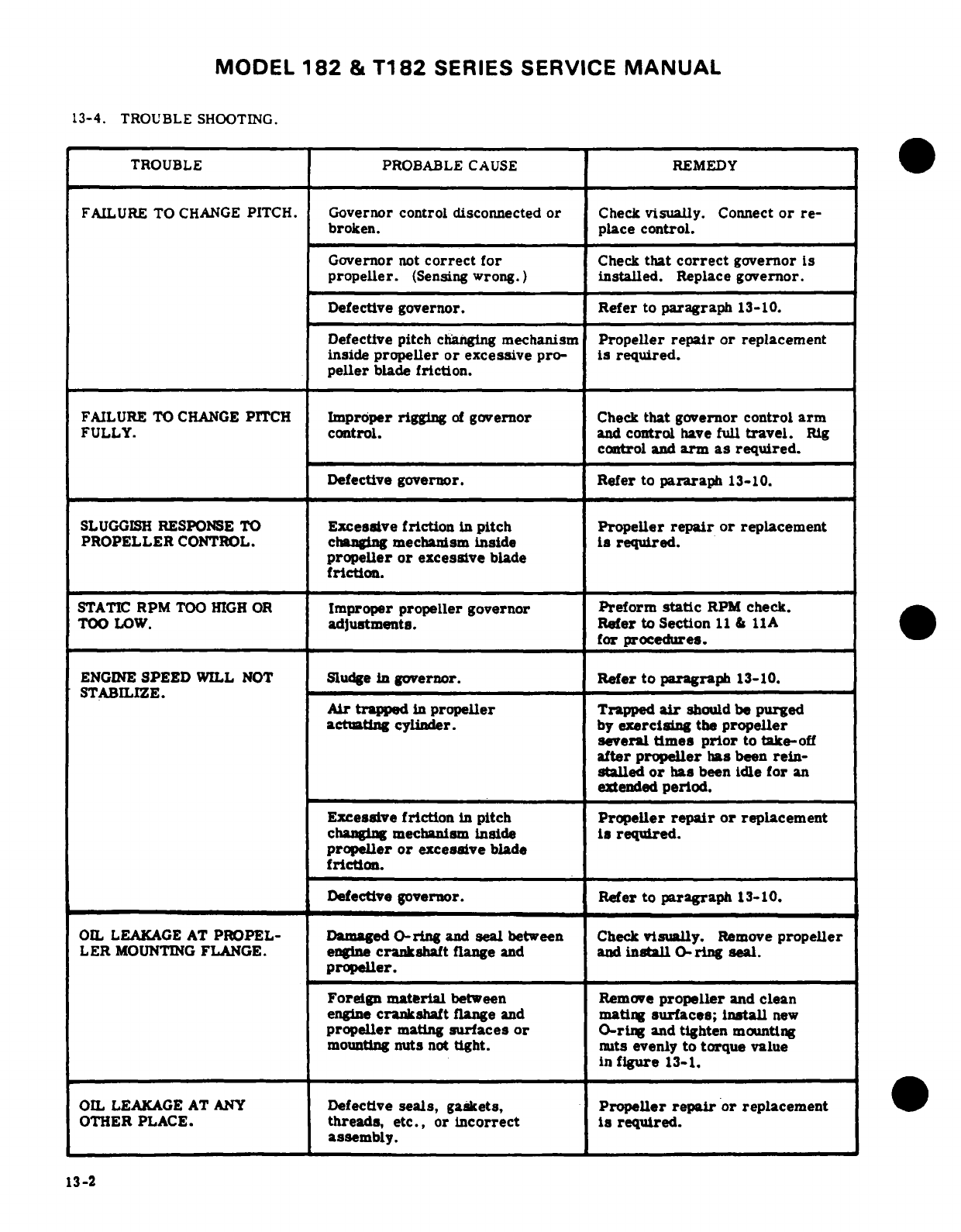
MODEL
182
&
T182
SERIES
SERVICE
MANUAL
13-4. TROUBLE
SHOOTING.
TROUBLE PROBABLE
CAUSE
REMEDY
FAILURE TO
CHANGE
PITCH.
Governor
control disconnected
or
Check
visually.
Connect
or
re-
broken. place
control.
Governor
not
correct
for
Check
that
correct
governor
is
propeller.
(Sensing
wrong.)
installed.
Replace
governor.
Defective
governor.
Refer
to
paragraph
13-10.
Defective
pitch
changing
mechanism
Propeller
repair
or
replacement
inside
propeller
or
excessive
pro-
is
required.
peller
blade
friction.
FAILURE
TO
CHANGE
PITCH
Improper
rigging
of
governor
Check
that governor control
arm
FULLY.
control.
and
control
have
full
travel.
Rig
control
and
arm
as
required.
Defective
governor.
Refer
to
pararaph
13-10.
SLUGGISH
RESPONSE
TO
Excessive
friction
in
pitch
Propeller
repair
or
replacement
PROPELLER
CONTROL.
changing
mechanism
inside
is
required.
propeller
or
excessive
blade
friction.
STATIC
RPM
TOO
HIGH OR
Improper
propeller
governor
Preform
static
RPM
check.
TOO
LOW.
adjustments.
Refer
to
Section
11
&
11A
for
procedures.
ENGINE
SPEED
WILL
NOT
Sludge
in
governor.
Refer
to
paragraph
13-10.
STABILIZE.
Air trapped
in
propeller
Trapped
air
should
be
purged
actuating
cylinder.
by
exercising
the
propeller
several
times
prior
to
take-off
after
propeller
has
been
rein-
stalled
or
has
been
idle
for
an
extended
period.
Excessive
friction
in
pitch
Propeller
repair
or
replacement
changing
mechanism
inside
is
required.
propeller or
excessive
blade
friction.
Defective
governor.
Refer
to
paragraph
13-10.
OIL
LEAKAGE
AT
PROPEL-
Damaged O-ring
and
seal
between
Check
visually.
Remove
propeller
LER
MOUNTING
FLANGE.
engine
crankshaft
flange
and
and
install
O-ring
seal.
propeller.
Foreign
material
between
Remove
propeller
and
clean
engine
crankshaft
flange
and
mating
surfaces;
install
new
propeller
mating
surfaces
or
O-ring
and
tighten
mounting
mounting
nuts
not
tight. nuts
evenly
to torque
value
in
figure
13-1.
OIL
LEAKAGE AT
ANY
Defective
seals,
gaskets,
Propeller
repair
or
replacement
OTHER
PLACE.
threads,
etc.,
or
incorrect
is
required.
assembly.
13-2
MODEL
182
&
T182
SERIES
SERVICE
MANUAL
13-5.
REMOVAL-182
&
F182.
(See
Figure
13-1.)
e.
Install
propeller
attaching
nuts
(14)
and
work
propeller
aft
as
far
as
possible,
then
tighten
nuts
f.
Install
spacers
(3)
and
spinner
support
(2)
on
propeller
cylinder
(4).
If
spacers
(3)
are
not
cen-
tered
mechanically
(piloted)
visually
center
and
hold
Be
sure
magneto
is
grounded
before turning
them
until spinner support
(2)
is
forced
firmly
in
propeller.
place.
g.
Hold
spinner
(1)
snug
against
spinner
support
(2)
a.
Remove
spinner
(1),
spinner support
(2)
and
and
check
alignment
of
holes
in
spinner
(1)
with
holes
spacers
(3).
Retain
spacers.
in
spinner
bulkhead
(12).
Add
or
remove
spacers
(3)
b.
Remove
cowling
as
required
for
access
to
from the
propeller
cylinder
(4)
until
holes
are
within
mounting
nuts
(14).
.050
of
alignment.
c.
Loosen
all
mounting
nuts
(14)
approximately
h.
Push hard
on
spinner
(1)
to
align
holes
and
in-
1/4
inch
and
pull
propeller
(6)
forward
until
stopped
stall
screws
and
washers
(if
required)
in
3
or
more
by
nuts.
equal
spaces
around
the
spinner
bulkhead
(12).
Relax
pressure
on
the
spinner
and
install
the
remaining
NOTE
screws
and
washers
(if
required)
in
the spinner.
i.
Tighten
all screws
uniformly
around
the
spinner.
As
the
propeller
(6)
is
separated
from
the
engine
crankshaft
flange,
oil
will
drain
13-7.
REMOVAL-T182.
(See
Figure
13-1.)
from
the
propeller
and
engine
cavities.
d.
Remove
all
propeller
mounting
nuts
(14)
and
pull
propeller
forward
to
remove
from
engine
crank-
Be
sure
magneto
is
grounded
before
turning
shaft
(11).
propeller.
e.
If
desired,
the
spinner
bulkhead
(12)
can
be
re-
moved
by
removing
screws
and
nuts attaching lugs
a.
Remove
spinner
(1).
(13)
to
bulkhead.
Note
direction
of
lugs
(13)
and
lug
b.
Remove
safety
wire,
back
off
bolts
attaching
attaching
screws.
propeller
to
engine
crankshaft
about
1/4
inch,
pull
propeller
forward.
13-6.
INSTALLATION-182
&
F182.
propeller
(2)
can
be
pulled
forward
(approx-
imately 1/4
inch
eack
time)
until
all
bolts
Be
sure
magneto
is
grounded
before
turningaged
from
engine
crankshaft
propeller,
flange.
As
the
propeller
is
seperated
from
the
engine
crankshaft,
oil
will
drain from
a.
If
the
spinner
bulkhead
(12)
was
removed,
posi- the
propeller
and
engine
crankshaft
cavities.
tion
bulkhead
so
the
propeller
blades
will
emerge
from
the
spinner
(1)
with
ample
clearance
and
in-
c.
If
necessary,
the
aft spinner
bulkhead
(3)
can
be
stall
spinner
bulkhead
attaching
lugs
and
screws.
removed
by
removing
screws
(4),
washers
(5),
and
nuts
(6)
attaching
bulkhead
to
the
propeller.
Then
Avoid
scraping
metal
from
bore
of
spinner
bulkhead
and
wedging
scrapings
between
13-8.
INSTALLATION-T182. (See
Figure
13-1.)
engine
flange
and
propeller. Trim
the
in-
side
diameter
of
the
bulkhead
as
necessary
when
installing
a
new
spinner
bulkhead.
Be
sure
magneto
is
grounded
before turning
b.
Clean
propeller
hub
cavity
and
mating
surfaces
the
propeller.
of
propeller
and
crankshaft.
c.
Lightly
lubricate
a
new
O-ring
(9)
and
the
crank-
a.
If
aft
spinner
bulkhead
was
removed.
Reinstall.
shaft pilot
with
clean
engine
oil
and
install
the
O-ring
b.
If
starter
ring
gear
support
was
removed,
clean
in
the
propeller
hub.
mating
surfaces
of
support
assembly
and
engine
d.
Align
propeller
mounting
studs
and dowel
pins
crankshaft
flange.
with
proper
holes
in
engine
crankshaft
flange
and c.
Place
alternator
drive
belt
in
pully
groove
of
slide
propeller
carefully
over
crankshaft pilot
until
starter
ring
gear
support.
Fit
starter
ring
gear
over
mating
surfaces
of
propeller
and
crankshaft
flange
propeller
flange
bushings
on
crankshaft.
are
approximately
1/4
inch
apart.
13-3
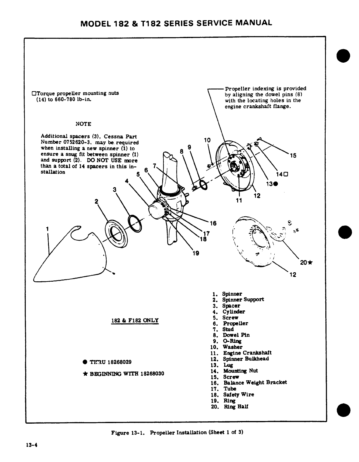
MODEL
182
&
T182
SERIES
SERVICE
MANUAL
Propeller
indexing
is
provided
Torque
propeller
mounting
nuts
by
aligning
the
dowel
pins
(8)
(14)
to 660-780
lb-in.
with
the
locating holes
in the
engine
crankshaft
flange.
NOTE
Additional
spacers
(3).
Cessna
Part
10
Number
0752620-3.
may
be.
required
when
installing
a
new
spinner
(1)
to
ensure
a
snug
fit
between
spinner
(1)
and
support
(2). DO
NOT
USE
more
than
a total
of
14
spacers
in
this
in-
7
stallation
17
'
~19
1
-/
j
^\/
20*
12
1.
Spinner
2.
Spinner
Support
3.
Spacer
4.
Cylinder
5.
Screw
182
&
F182
ONLY
6.
Ppeller
7.
Stud
8.
Dowel
Pin
9.
0-Ring
10.
Washer
11.
Engine
Crankshaft
* ~ TfIU 18268029
^12.
Spinner
Bulkhead
*
THTIU
18268029 1 3
Lug
13.
Lug
BEGINNING
WTH
18268030
1.
ing
Nut
15.
Screw
16.
Balance
Weight
Bracket
17.
Tube
18.
Safety
Wire
19.
Ring
20.
Ring
Half
Figure
13-1.
Propeller
Installation
(Sheet
1
of
3)
13-4
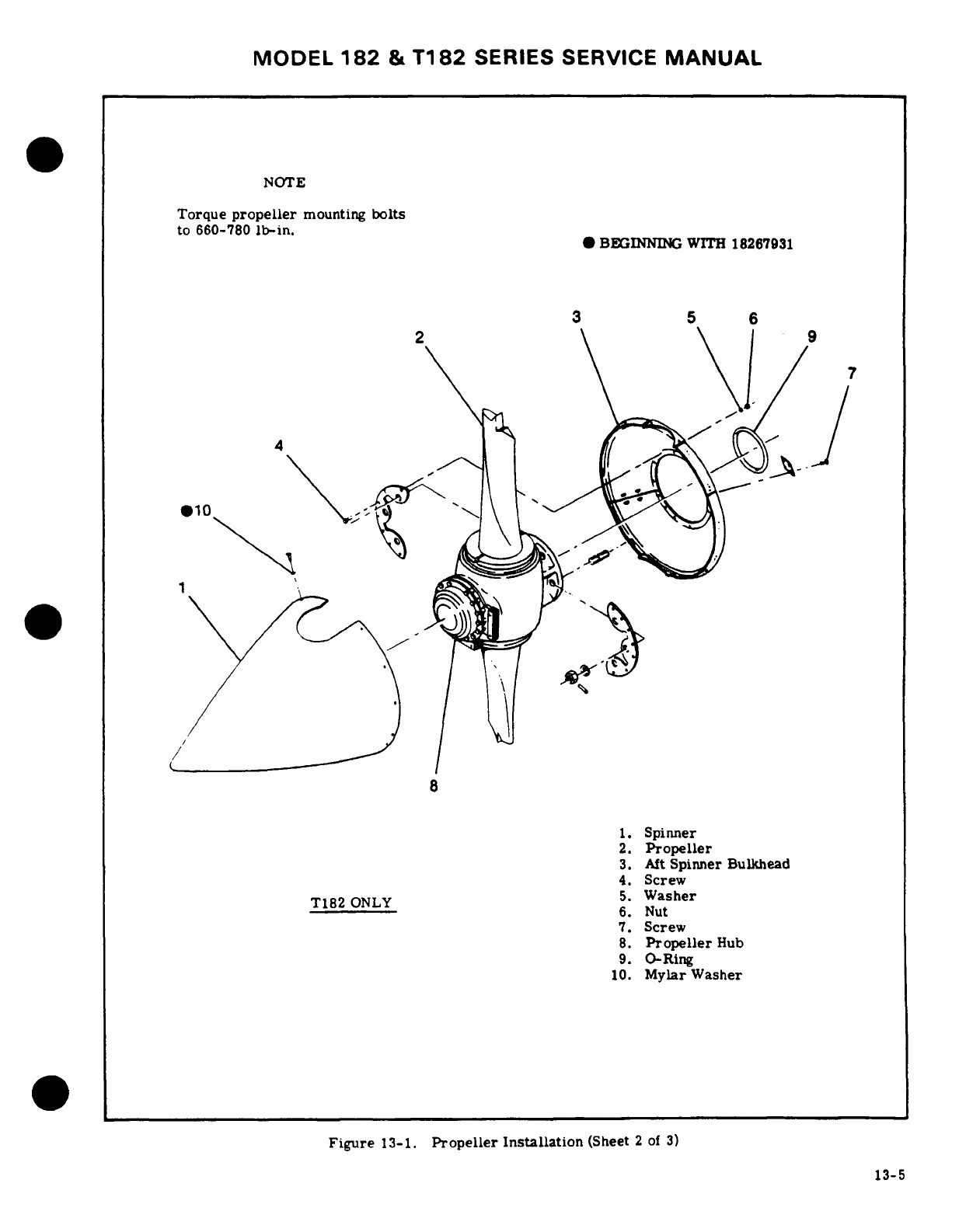
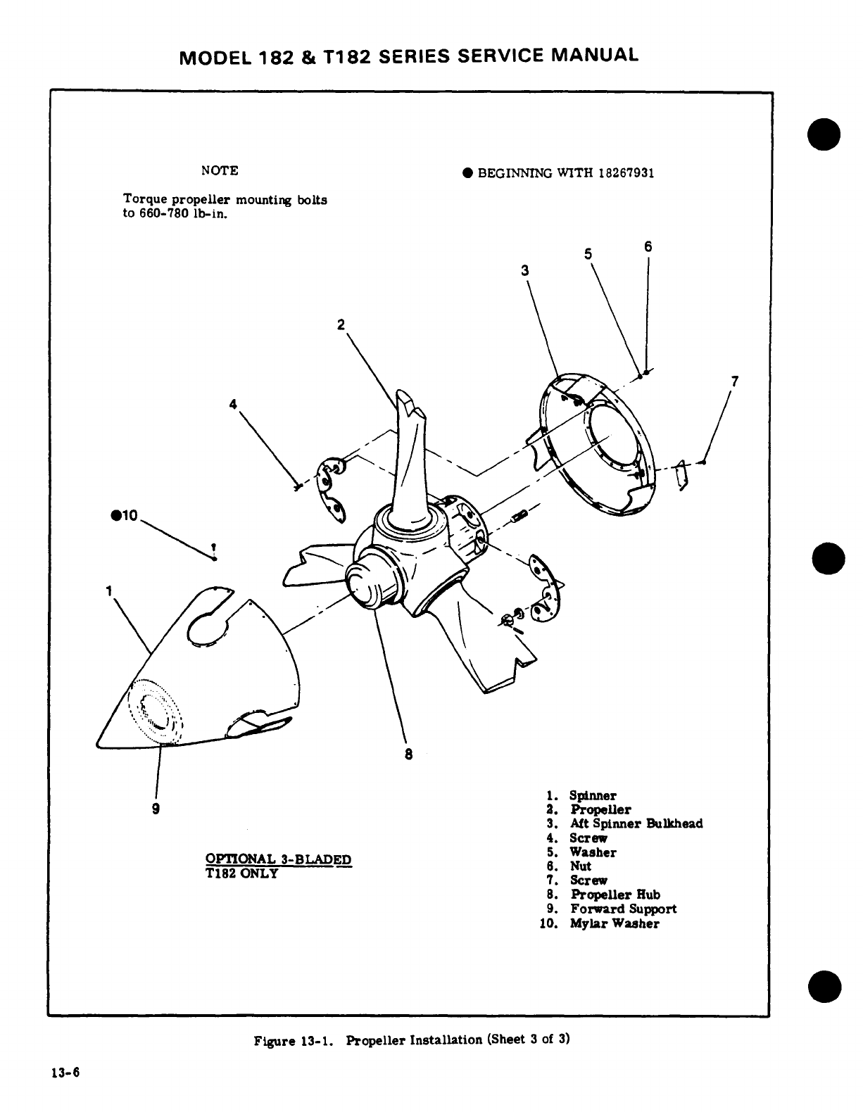
MODEL
182
&
T182
SERIES SERVICE
MANUAL
NOTE BEGINNING WITH
18267931
Torque
propeller
mounting
bolts
to 660-780
lb-in.
5
6
1.
Spinner
3.
Aft
Spinner
Bulkhead
4.
Screw
OPTIONAL
3-BLADED
5.
Washer
T182
ONLY
6.
Nut
7.
Screw
8.
Propeller
Hub
9.
Forward
Support
10.
Mylar
Washer
Figure
13-1.
Propeller
Installation
(Sheet
3
of
3)
13-6
MODEL
182
&
T182
SERIES SERVICE
MANUAL
NOTE
increase
or
decrease
blade
pitch.
The
propellers
used
on
these
aircraft
require
Make
sure
bushing
hole
in
ring
gear
support, governors
which
"sense"
in
a
certain
man-
marked
"O",
is
assembled
adjacent
to
"O"
ner.
"Sensing"
is
determined
by
the
type
mark
on
crankshaft
flange
bushing.
The
pilot
valve
installed
inside
the
governor.
starter
ring
gear
must
be
located
correctly
Since
the
basic
governor
may
be
set
to
to
assure
proper
alignment
of
the
timing
"sense"
oppositely,
it is
important
to
mark
on
the
ring
gear.
ascertain
that
the
governor
is
correct
for
the
propeller
being
used.
d.
Clean
propeller
hub
cavity
and
mating
surfaces
of
propeller
hub
and
ring
gear
support.
13-12.
TROUBLE
SHOOTING.
When
trouble
shoot-
e.
On
the
standard
2
bladed
propeller,
lightly
ing
the
propeller-governor
combination,
it is
recom-
lubricate
new
O-ring
(9)
and
crankshaft
pilot
with
mended
that
a
governor
known
to
be
in
good
condition
clean
engine
oil,
and
install
O-ring
in the
propeller
be
installed
to
check
whether
the
propeller
or
the
hub.
governor
is
at
fault.
Removal and
replacement,
rig-
f.
Align
propeller
mounting
bolts
with
proper
holes
ging,
high-speed
stop
adjustment,
desludging
and
re-
in
engine
crankshaft
flange,
and
slide
propeller
care-
placement
of
the
governor
mounting
gasket
are
not
fully
over
crankshaft
pilot until
bolts
can
be
started
major
repairs
and
may
be
accomplished
in
the
field.
in
crankshaft
flange bushing.
Position
propeller
Repairs
to
propeller
governors
are
classed
as
pro-
blades
to
extend
thru
aft
spinner
bulkhead with
ample
peller
major
repairs
in
Federal
Aviation
Regulations,
clearance.
which
also
define
who
may
accomplish
such
repairs.
g.
Tighten
bolts
evenly,
and
work
propeller
aft
on
crankshaft
flange.
Torque
bolts
per
figure
13-1. 13-13.
REMOVAL.
h.
Install
.040
inch
diameter
corrosion
resistant
safety
wire
through
bolts
in
pairs.
i.
Adjust
alternator
drive
belt
tension
as
outlined
in
Section
16.
j.
Install
spinner
(1),
using
spacers
as
required.
NOTE
Be
sure
magneto
is
grounded
before
turning
propeller
When
replacing
optional
three
bladed
propeller
assembly
(2),
apply
Y8560
Polyurethane
Film
a.
Remove
cowling
and
engine
baffles
as
required
(3M
Company),
a
minimum
of
one
wrap
on
for
access
to
governor.
propeller
hub
(8),
then
as required
to
obtain
b.
Disconnect
governor
control
from
governor.
a
snug
fit
of
forward support
(9)
to
propeller
hub
(8).
NOTE
Note
EXACT
position
of
all
washers
so
that
13-9.
TIME
BETWEEN
OVERHAUL
(TBO).
Pro-
washers
may
be
installed
in
the
same
posi-
peller
overhaul
shall
coincide
with
engine
overhaul,
tion
on
reinstallation.
but
shall
not
exceed
limits
specified
in McCauley
Service
Bulletin
137
and
all
other
revisions
and
c.
Remove
nuts
and
washers securing
governor
to
supplements
thereto.
Refer
to Sections
11
&
11A
engine
and pull
governor
from
mounting
studs.
for
engine
overhaul
periods.
d.
Remove
gasket from
between
governor
and
en-
gine
mounting pad.
13-10.
GOVERNOR.
13-14.
INSTALLATION.
13-11.
DESCRIPTION.
The
propeller
governor
is
a
single-acting,
centrifugal
type,
which
boosts
oil
pres-
sure
from
the
engine and
directs
it
to
the
propeller
where
the
oil
is
used
to
increase
blade
pitch.
A
single-acting
governor
uses
oil
pressure
to
effect
a
pitch
change
in
one
direction
only; a
pitch
change
in
the opposite
direction
results
from
a
combination
of
Be
sure
magneto
is
grounded
before
turning
centrifugal
twisting
moment
of
rotating blades
and
propeller
compressed springs.
Oil
pressure
is
boosted
in
the
governor
by a
gear
type
oil
pump.
A
pilot
valve,
fly
a.
Wipe
governor
and
engine
mounting
pad
clean.
weight
and
speeder spring
act together
to
open
and
b.
Install
a new
gasket
on
the
mounting
studs.
In-
close
governor
oil
passages
as
required
to
maintain
stall
gasket
with
raised
surface
of
the
gasket
screen
a
constant
engine
speed.
toward
the
governor.
c.
Position
governor
on
mounting
studs,
aligning
NOTE
governor drive
splines
with
splines
in
the
engine
and
install
mounting
nuts
and
washers.
Do
not
force
Outward
physical
appearance
of
specific spline
engagement.
Rotate
engine
crankshaft
slightly
governors
is
the
same,
but
internal
parts
and
splines
will
engage
smoothly
when
properly
determine
whether
it
uses
oil
pressure
to
aligned.
13-7
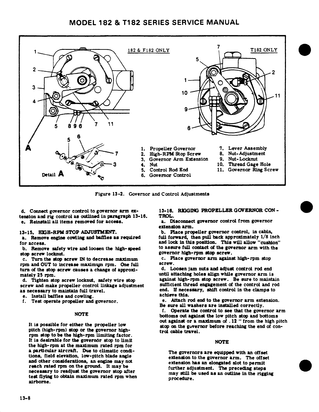
MODEL
182
&
T182
SERIES SERVICE
MANUAL
2
A
K |- H
/,
7
2.
High-RPM
Stop
Screw
8.
Nut-Adjustment
3.
Governor
Arm
Extension
9.
Nut-Locknut
&
-3
4.
Nut
10.
Thread
Gage
Hole
A -
'S
, f ~5.
Control
Rod
End
11.
Governor
Ring
Screw
Detail
Aa
6.
Governor
Control
Figure
13-2.
Governor
and
Control
Adjustments
d.
Connect
governor
control
to
governor
arm
ex-
13-18.
RIGGING
PROPELLER
GOVERNOR
CON
-
tension
and
rig
control
as
outlined
in paragraph
13-16.
TROL.
e.
Reinstall
all
items
removed
for
access,
a. Disconnect
governor
control
from
governor
extension
arm.
13-15.
HIGH-RPM
STOP
ADJUSTMENT.
b.
Place
propeller
governor
control,
in cabin,
a.
Remove
engine cowling and
baffles
as
required
full
forward,
then pull
back
approximately
1/8
inch
for
access.
and
lock
in
this
position.
This
will
allow
"cushion"
b.
Remove
safety
wire
and
loosen the
high-speed
to
assure
full contact
of
the
governor
arm
with
the
stop
screw
locknut.
governor
high-rpm
stop
screw.
c.
Turn
the
stop
screw
IN
to
decrease
maximum
c.
Place
governor arm
against
high-rpm
stop
rpm
and
OUT
to
increase
maximupm
rpm.
One
full
screw.
turn
of
the
stop
screw
causes
a
change
of
approxi-
d.
Loosen
jam
nuts
and
adjust
control
rod
end
mately
25
rpm.
until
attaching
holes
align
while
governor
arm
is
d.
Tighten
stop
screw
locknut,
safety
wire
stop
against high-rpm
stop
screw.
Be
sure
to
maintain
screw
and make
propeller
control
linkage
adjustment sufficient
thread
engagement
of
the
control
and
rod
as
necessary
to
maintain full
travel.
end.
If
necessary,
shift control
in
the
clamps
to
e.
Install
baffles
and
cowling.
achieve
this.
f.
Test
operate
propeller
and
governor.
e.
Attach
rod
end
to
the
governor
arm
extension.
Be
sure
all
washers
are
installed
correctly.
f.
Operate
the control
to
see
that
the
governor
arm
NOTE
bottoms
out
against
the
low
pitch
stop
and
bottoms
out
against
or
a
maximum
of
.12
"
from
the
high
pitch
It
is
possible
for
either
the
propeller
low
Itch (igsh
o
r
the
gop
er
low
stop
on
the
governor
before reaching
the
end
of
con-
pitch
(high-rpm)
stop
or
the
governor
high-
trol
cable
travel.
rpm
stop
to
be
the
high-rpm limiting
factor.
It is
desirable
for
the
govern6r
stop
to
limit
NOTE
the high-rpm
at
the maximum
rated
rpm
for
a
particular
aircraft.
Due
to
climatic
condi-
The
governors
are
equipped with
an
offset
tions,
field elevation,
low-pitch
blade
angle
extension
to
the
governor
arm.
The offset
and
other considerations,
an
engine may
not
extension
has
an
elongated
slot
to
permit
reach
rated
rpm
on
the
ground.
It
may
be
further
adjustment.
The
preceding
steps
necessary
to
readjust
the
governor
stop
after
may
still
be
used
as
an
outline
in
the
rigging
test
flying
to
obtain
maximum
rated
rpm
when
procedure.
airborne.
13-8
MODEL
182
&
T182
SERIES
SERVICE
MANUAL
13-17.
TIME
BETWEEN
OVERHAUL (TBO).
Pro-
peller
governor
overhaul
shall
coincide with
engine
overhaul.
Refer
to
sections
11
and
11A
for
engine
time
between
overhaul
(TBO)
periods.
The
gover-
nor
overhaul
manual
is available
from
the
Cessna
Supply
Division.
13-9/(13-10
blank)
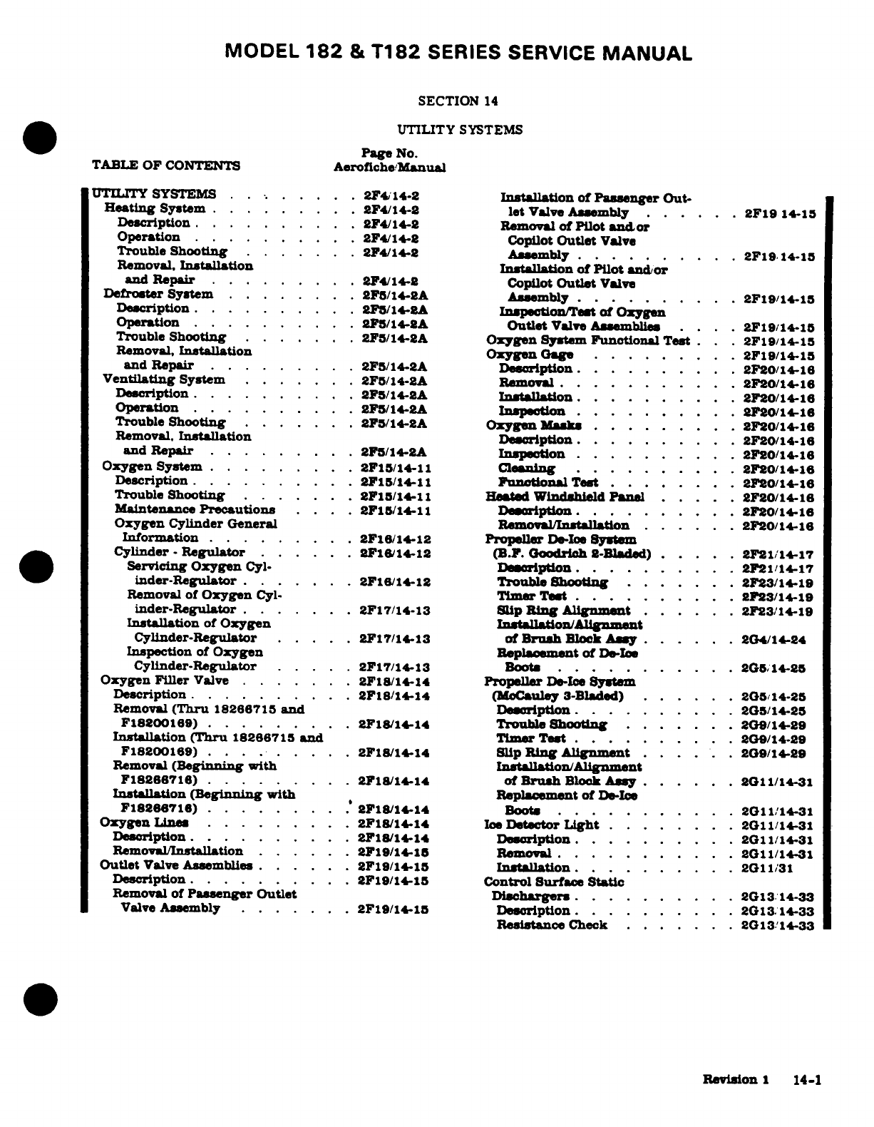
MODEL
182
&
T182
SERIES
SERVICE
MANUAL
SECTION
14
UTILITY
SYSTEMS
Page
No.
TABLE
OF
CONTENTS
Aerofiche/Manual
UTILTY
SYSTEMS
. . ... ..
2F4/14-2
Installation
of
Passenger
Out-
Heating
System
.........
2F4/14-2
let
Valve
Assembly
......
2F19
14-15
Description
..........
2F4/14-2
Removal
of
Pilot
and/or
Operation
........
.
2F4/14-2 Copilot
Outlet
Valve
Trouble
Shooting
.......
2F414-2
Assembly
..........
2F19
14-15
Removal.
Installation Installation
of Pilot
and/or
and
Repair
.........
2F4/14-
Copilot
Outlet
Valve
Defroster
System
........
2F5/14-A
Assembly
..........
2F19/14-15
Description
..........
2F5/14-A
Inspection/Test
of
Oxygen
Operation
..........
2F5/14-A
Outlet
Valve
Assmblies
. . .
2F19/14-15
Trouble
Shooting
.......
2F5/14-2A
Oxygen
System
Functional Test
..
2F19/14-15
Removal,
Installation
Oxygen
Gage
.........
2F19/14-15
and
Repair
.
........
2F/14-2A
Description.
.........
2F20/14-16
Ventilating
System
.......
2F5/14-2A
Removal
..........
2F20/14-16
Description
........
...
2F/14-A
Installation
..........
2F20/14-16
Operation
..........
2F5/142A
Inspection
..........
2F20/14-16
Trouble
Shooting
.......
2F5/14-2A
Oxygen
ask
.........
2F20/14-16
Removal.
Installation
Description
..........
2F20/14-16
and
Repair
.........
2F5/14-2A
Inspection
..........
2F20/14-16
Oxygen System
.........
2F15/14-11
Cleaning
........
.
2F20/14-16
Description
..... ....
2F15/14-11
Functonal
Test
.......
.
2F20/14-16
Trouble
Shooting
.......
2F15/14-11
Heated Windshield
Panel
.....
2F20/14-16
Maintenance
Precautions
....
2F15/14-11
Description.
.........
2F20/14-16
Oxygen
Cylinder General
Removal/Installation
....
.
2F20/14-1
Information
.
......
.
2F16/14-12
Propeller
De-Ice
System
Cylinder
-
Regulator
. . .
2F16/14-12
(B.F.
Goodrich 2-Bladed)
.....
2F21/14-17
Servicing
Oxygen
Cyl-
Description
..........
2F21/14-17
inder-Regulator
.......
2F16/14-12
Trouble
Shooting
.......
2F23/14-19
Removal
of
Oxygen
Cyl-
Timer Test
..........
2F23/14-19
inder-Regulator
......
2F17/14-13 Slip
Ring
Alignment
......
2F23/14-19
Installation
of
Oxygen
Installation/Alignment
Cylinder-Regulator
.....
2F17/14-13
of
Brush
Block
Assy
......
24/14-24
Inspection
of
Oxygen
Replacement
of
De-Ice
Cylinder-Regulator
.....
2F17/14-13
Boots
...........
2G5/14-25
Oxygen
Filler
Valve
....
. .
2F18/14-14
Propeller
De-Ice
System
Description
.
........
2F18/14-14
(MCauley
3-Bladed)
......
2G5/14-25
Removal
(Thru
18266715
and
Description
..........
2G5/14-25
F18200169)
.........
2F18/14-14
Trouble
Shooting
.......
29/14-29
Installation
(Thru
18266715
and
Timer Test
..........
2G9/14-29
F18200169)
.........
2F18/14-14
Slip
Ring
Alignment
......
2G9/14-29
Removal
(Beginning with
Installation/Alignment
F18266716)
.........
2F18/14-14
of Brush
Block
Assy
......
211/14-31
Installation
(Beginning with
Replacement
of
De-Ice
F18266718)
.........
2F18/14-14
Boots
...........
2G1114-31
Oxygen
Lines
.... .....
2F18/1414
Ice
Detector
Light
........
2G11/14-31
Description.
.......
..
2F18/14-14
Description.
.........
2G11/14-31
Removal/Installation
......
2F19/14-1
Removal
...........
2G11/14-31
Outlet
Valve
Assemblies
......
2F19/14-15
Intallation
.........
21131
Description
.........
2F19/14-15
Control Surface
Static
Removal
of
Passenger
Outlet
Dischargers
.........
2G13/14-33
Valve
Assembly
.......
2F19/14-15
Description.
.........
2G13.14-33
Resistance
Check
.......
2G13.14-33
Revision
1
14-1
MODEL
182
&
T182
SERIES SERVICE
MANUAL
14-1.
UTILITY
SYSTEMS.
muffler.
In
most
cases,
valves or
controls
can
be
freed
by
proper
lubrication.
Damaged
or
broken
14-2.
HEATING
SYSTEM.
(See
figure
14-1.)
parts
must
be
repaired
or
replaced.
When
checking
controls, ensure
valves
respond freely
to
control
14-3.
DESCRIPTION.
The
heating
system
is
com-
movement.
that
they
move
in
the
correct
direction.
prised
of
the heat
exchange
section
of
the
exhaust
that
they move
through
their
full range
of
travel
and
muffler,
a
shut-off
valve,
mounted
on
the
right
for-
seal
properly.
Check
that
hose
are
properly
secured
ward
side
of
the
firewall,
a
push-pull
control
on
the and
replace
hose
that
are
burned, frayed
or
crush-
instrument
panel,
outlets
and
flexible
ducting
con-
ed.
If
fumes
are
detected
in
the
cabin,
a
thorough
necting
the
system,
inspection
of
the
exhaust
system
should
be
accom-
plished.
Refer
to
applicable
paragraph
in
Section
11
14-4.
OPERATION.
Ram
air
is
ducted
through
for
this
inspection.
Since
any
holes
or
cracks
may
engine baffle
inlets
and
heat
exchange
section
of
the
permit
exhaust
umes
to
enter
thecabin,
replacement
exhaust
muffler, to
the
shut-off
valve
at
the
firewall.
of
defective
parts
is
imperative
because
fumes
consti-
The
heated
air
flows
from
the
shut-off
valve
into
a
tute
an
extreme
danger.
Seal
any
gaps
in
heater
ducts
across
the
firewall
with
Pro-Seal
=700
(Coast
duct
across
the aft
side
of
the
firewall,
where
it
is
Pro-Seal
Co.,
Los
Angeles.
California)
compound
distributed
into
the
cabin.
The
shut-off
valve,
oper-
or
equivalent
compound.
ated
by
a
push-pull
control
labeled
"CABIN HEAT.
located
on
the
instrument
panel,
regulates
the vol-
14-6.
REMOVAL,
INSTALLATION
AND
REPAIR.
ume
of
heated
air
entering
the
system.
Pulling
the
Figure
14-1
may
be
used
as
a
guide
during
removal,
control
full
out
supplies
maximum
flow
and
pushing
installation
and
repair
of
heating
system
components.
control
in
gradually
decreases
flow,
shutting
off
flow
Burned,
frayed
or
crushed
hose
must
be
replaced
completely
when
the
control
is
pushed
full
in.
with
new
hose,
cut
to
length
and
installed
in
the
orig-
inal
routing.
Trim
hose
winding
shorter
than
the
14-5.
TROUBLE
SHOOTING.
Most
of
the
operation-
hose
to
allow
clamps
to
be
fitted.
Defective
air
al
troubles
in
the heating
and
defrosting
systems
are
valves
must
be
repaired
or
replaced.
Check
for
caused
by
sticking
or
binding
valves
and
their
con-
proper operation
of
valves
and
their
controls
after
trols,
damaged
air
ducting
or
defects
in
the
exhaust
repair
or
replacement.
14-2

MODEL
182
&
T182
SERIES
SERVICE
MANUAL
14-7.
DEFROSTING
SYSTEM.
(See
figure
14-1.)
wings.
Each
plenum
chamber
is
equipped
with
a
valve
which
meters
the
incoming
cabin
ventilation
14-8.
DESCRIPTION.
The
defrosting
system
is
air.
This provides
a
chamber
for
expansion
of
cabin
comprised
of
a
duct
across
the
aft
side
of
the
fire-
air
which
greatly
reduces
inlet
air
noise.
Filters
wall.
a
defroster
outlet
and
shut-off
valve
assembly
at
the
air
inlets
are primarily
noise
reduction
filters.
mounted
on
the
left
side
of
the
cowl
deck
immediately
Forward
cabin
ventilation
is
provided
by
a
fresh
air-
aft
of
the
windshield,
a
shut-off
valve
control
on
the
scoop door
mounted
on
the
right
side
of
the
fuselage,
instrument
panel
and
flexible
ducting
connecting
the
just
forward
of
the
copilot
seat.
The
scoop
door
is
system.
operated
by
a control
in
the
instrument
panel
marked
"CABIN
AIR."
Fresh air
from
the
scoop
door
is
14-9.
OPERATION.
Air
from
the
duct
across
the
aft
side
of
the
firewall
flows
through
a
flexible
duct
where
it
is
distributed
into
the cabin.
As
long
as
to
the
defroster
outlet.
The
temperature
and
volume
the
"CABIN
HEAT"
of
this
air
is
controlled
by
the
settings
of
the
heater
from
the
scoop
will
flow
through
the
duct
into
the
14-10.
TROUBLE
SHOOTING.
Since
the
defrosting
cabin.
As
the
system,
refer
to
paragraph
14-5
for
trouble
shooting
the
fresh
air
from
the
scoop
and
be
distributed
into
the
defrosting
system.
the cabin.
Either
one,
or
both
of
the
controls
may
14-11.
REMOVAL.
INSTALLATION
AND
REPAIR.
be
set
at
any
position from
full
open
to
full
closed.
Figure
14-1
may
be
used
as
a
guide
during
removal,
14-15.
TROUBLE
SHOOTING.
Most
of
the
opera-
installation
and
repair
of
defrosting
system
com-
ponents.
Cut
hose
to
length
and
install
in the
origi-
nal
routing.
Trim
hose winding
shorter
than
the
hose
control.
Check
the
airscoop
filter
elements
in
the
to
allow
clamps
to
be
fitted.
A
defective
defroster
wing
leading edges
for
obstructions.
The
elements
outlet
must
be
repaired
or
replaced.
may
be
removed
and
cleaned
or
replaced.
Since
air
passing
through
the
filters
is
emitted
into the
cabin,
14-12.
VENTILATING
SYSTEM.
(See
figure
14-2.)
do
not
use
a
cleaning solution
which
would
contam-
inate
the
air.
The
filters
may
be
removed
to
in-
14-13.
DESCRIPTION. The
ventilating
system
is
crease
air
flow.
However,
their
removal
will
cause
comprised
of
two
airscoops
mounted
in
the
inboard a
slight
increase
in
noise
level.
leading
edge
of
each
wing.
a
manually-adjustable
ventilator
installed
on
each
side
of
the
cabin
near
the
14-16.
REMOVAL,
INSTALLATION
AND
REPAIR.
upper
corners
of
the
windshield,
two
plenum
cham-
Figure
14-2
may
be
used
as
a
guide
during
removal,
bers
mounted
in
the
rear
cabin
wing
root
areas,
a
installation
and
repair
of
the
ventilating
system
coM-
fresh
airscoop
door
on
the
right
side
of
the
fuselage ponents.
A
defective
ventilator or
scoop
must
be
re-
just
forward
of
the
copilot's
seat,
a
control
knob
on
paired
or replaced.
Check
for
proper
operation
of
the
instrument
panel and
flexible
ducting
connecting
ventilating
controls
after
installation
or
repair.
the
system.
14-14.
OPERATION.
Air
received
from scoops
mounted
in
the
inboard
leading edges
of
the
wing
is
ducted
to
adjustable
ventilators
mounted
on
each
side
of
the
cabin
near
the
upper
corners
of
the
windshield.
Rear
seat
ventilation
is
provided
by
plenum
chambers
mounted
in
the
left
and
right
rear
cabin
wing
root
areas.
These
plenum
chambers
receive
ram
air
from
the
airscoops
in
the
inboard
leading
edges
of
the
14-2A/(14-2B
blank)
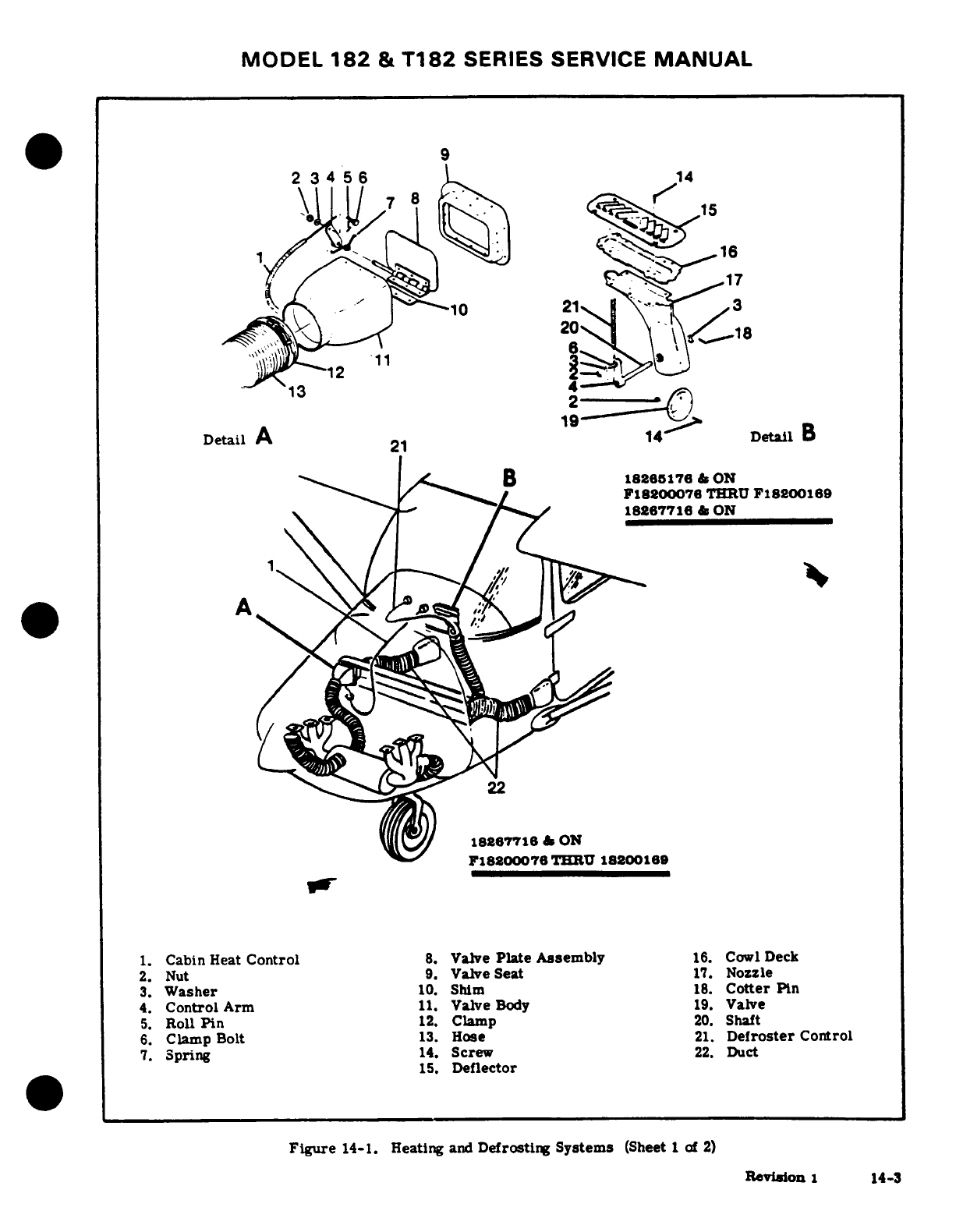
MODEL
182
&
T182
SERIES
SERVICE
MANUAL
23456
14
V/1
15
17
10
21
20
g>X6tg1 8
Detail
A
2
14
Detail
B
B
18265176
&
ON
F18200076
THRU
F18200169
18267716
&
ON
~~~~~*
A
^i.
18267716
&
ON
F18200076
THRU
18200169
1.
Cabin
Heat
Control
8.
Valve
Plate
Assembly
16.
Cowl
Deck
2.
Nut
9.
Valve
Seat
17.
Nozzle
3.
Washer
10.
Shim
18.
Cotter
Pin
4.
Control
Arm
11.
Valve
Body
19.
Valve
5.
Roll
Pin
12.
Clamp
20.
Shaft
6.
Clamp
Bolt
13.
Hose
21.
Defroster
Control
7.
Spring
14.
Screw
22.
Duct
15.
Deflector
Figure
14-1.
Heating
and
Defrosting
Systems
(Sheet
1
of
2)
Revision
1
14-3
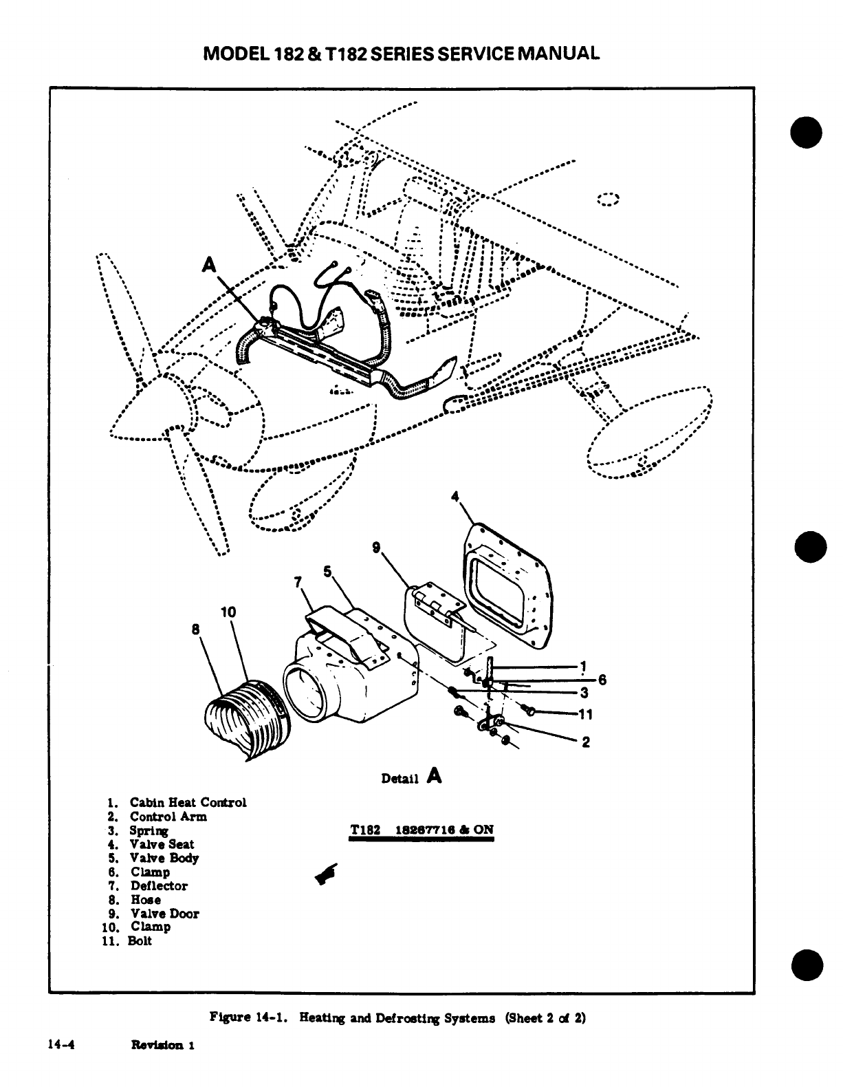
MODEL
182
&
T182
SERIES
SERVICE
MANUAL
.,,.......
~~*3.
Spring
T182
1
827716
.
ON
4, l
.*
*... Valve Sea·
6.
.:Clamp 8. .Hose... ' ..
''9\_/..
Valve
Door.
..
' '
'"14
.,
_ ......-.--
4
Re
-
a'
.0 0
..
0
a'
;0..,
:4 .
v
Sca
...-
,..
I: :.:
10 .,-'a-
..
:·ii-....0
10.\
75
..
3.
SprHing
T182
Sstes
& e
ON
14
8.
H
ose
10.
Clamp
11.
Bolt
Figure
14-1.
Heating
and
Defrostin
Systems
(Sheet
2
c
2.)
14-4 Revialon
1
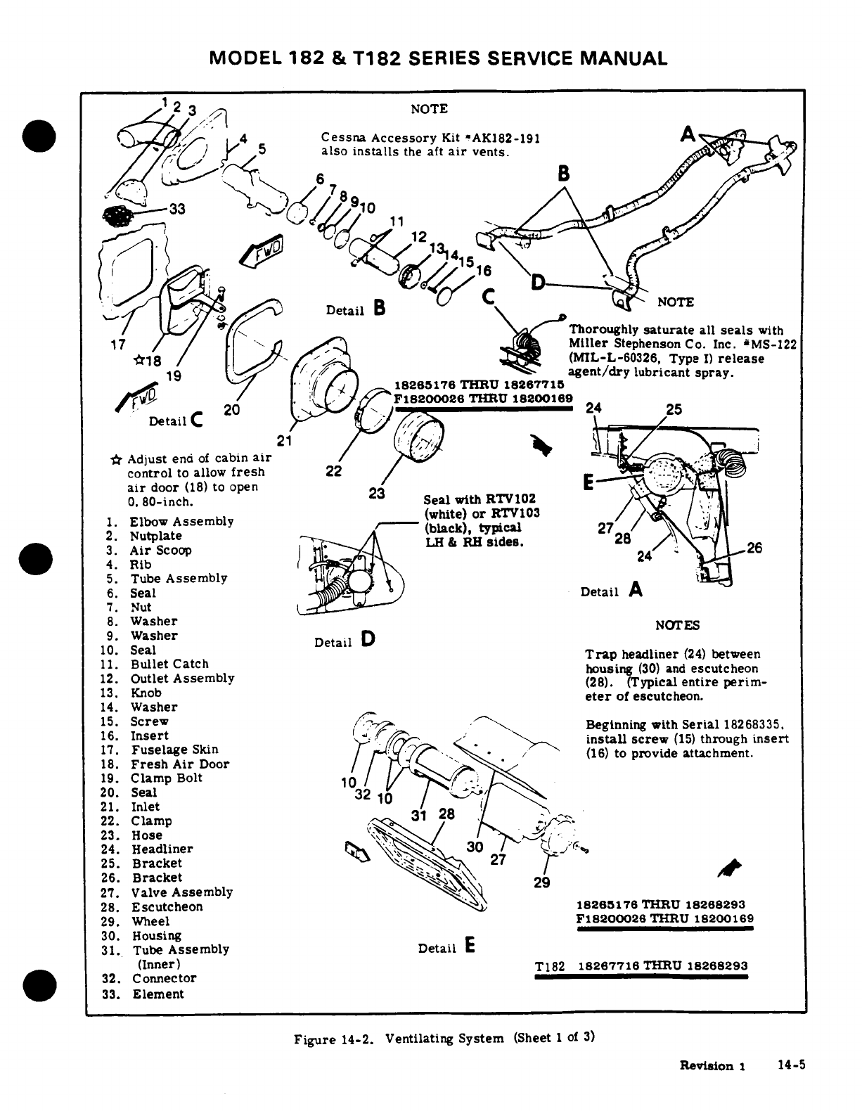
MODEL
182
&
T182
SERIES
SERVICE
MANUAL
4
Cessna Accessory
Kit
*AK182-191
G-/
/
5~X6
B
33 '
/8910
212
_'^|^^
A
v i
Detail
B
NOTE
Thoroughly
saturate
all
seals
with
17
/
f
H
Miller
Stephenson
Co.
Inc.
'MS-122
*18
/
l|_
((MIL-L-60326,
Type
I)
release
19
\
agent/dry
lubricant spray.
/
18265176
THRU
18267715
> lf_
/
*
'Ll
Go
F18200026
THRU
18200169
.
~~20 at24
25
Detail
C
21
-
Adjust
end
of
cabin
air
/
control
to
allow
fresh
22
air
door
(18)
to
open
23
KE
0.
80-inch.
Seal
with
RTV102
1.
Elbow
Assembly
(white)
or
RTV103
~2. Nutplate
(black),
typical
27
3.
Nutple
So
LH
&
RH
sides.
26
4.
Rib
24
5.
Tube
Assembly
6.
Seal
Detail
A
7.
Nut
8.
Washer
NOTES
9.
Washer
Detail
D
10.
Seal
Trap
headliner
(24)
between
11.
Bullet
Catch
housing
(30) and
escutcheon
12.
Outlet
Assembly
(28).
(Typical
entire
perim-
13.
Knob
eter
of
escutcheon.
14.
Washer
15.
Screw
Beginning
with
Serial
18268335.
16.
Insert
( -
install
screw
(15)
through
insert
17.
Fuselage
Skin
/ .,
(16)
to
provide
attachment.
18.
Fresh
Air
Door
/
19.
Clamp
Bolt
10
20.
Seal
32
10
21.
Inlet
/
22.
Clamp
31
2/
23.
Hose
, / > .
24.
Headliner
30
/
25.
Bracket
'
<
3
27
26.
Bracket
29
27.
Valve
Assembly
29
28.
Escutcheon
18265176
THRU
18268293
29. Wheel
F18200026
THRU
18200169
30.
Housing -N
31. Tube
Assembly Detail
E
(Inner)
T182
18267716
THRU
18268293
32.
Connector
33.
Element
Figure
14-2.
Ventilating
System
(Sheet 1
of
3)
Revision
1
14-5
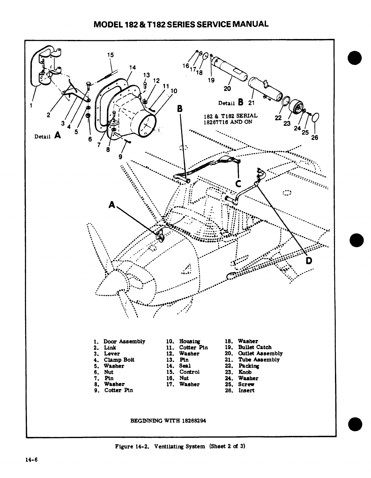
MODEL
182
&
T182
SERIES
SERVICE
MANUAL
5^-^ 15
Detail
A
A
1 7
18.
Wa 2
ser
36
--
12
W
*ase
.
26
13
C p1.2 T Ae18
W r*
1
SDetail
.'
"
15
C'nr-- .
..
.....
7
·*
....
n
l.
.Nu
2.4Wse
8. W Washe
25
''.
Screw
,:
....
,
;;
, *"
-:'.
~..,..
*.
.3 C n18267716
AND
...
4
'
\\
/.*·I.,
**2.
4
6 26
1.
r
Door
Assembiy
*0.
Hosn
1 8
... .
Wh
2.-
Link
11
Cotr
1.Bult ach,.\
9
~22~
3. Lever
12.
Washer
20.
t
emb-y
4
.
Clap
Bl
1
.
Pn
21.
Tbe
A.se
mbly
6
"
"':
"".-.
Nut"
1-
-
2. .Kn
94.'.
Cotte
Pi.n
n 2.
Ins
e
., ,:-..
,--*"
..c
7
.
Pin-16 N2:'ah
.
.ahr
A1.
Washer
2.
or
4.........olt
13.
Pn
21.
,ube
Assembly
1.
DoorAssembly
10.
Housing
18.
Washer
8.
Washer
17.
Washer
25.
Screw
9.
Cotter
Pin
26.
Insert
BEGINNING
WITH
18268294
Figure
14-2.
Ventilating
System
(Sheet
2
of
3)
14-6
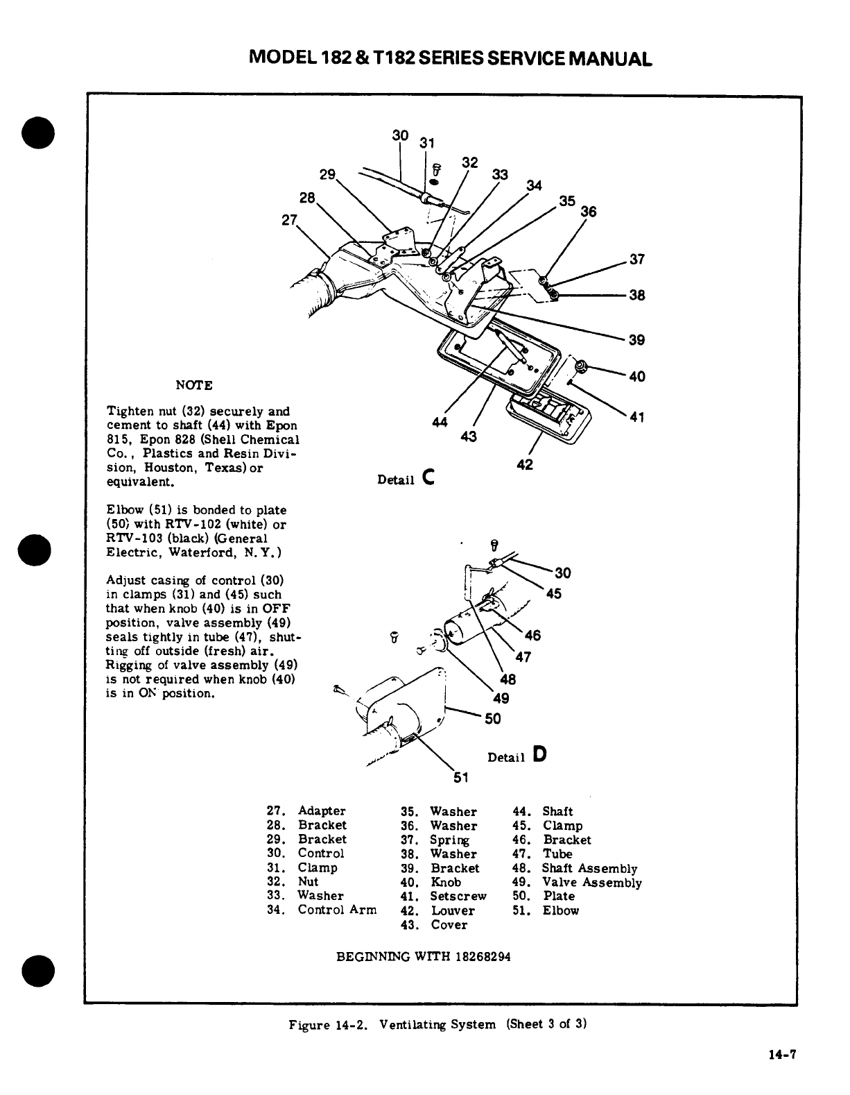
MODEL
182
&
T182
SERIES SERVICE
MANUAL
30
31
29
/
33
34
28
35
828 (Shell
Chemical
43
/
27
:"3
equivalent. Detail
3
'". ~/
~40
NOTE
Tighten
nut
(32)
securely
and
t
cement
to
shaft
(44)
with
Epon
44
815,
Epon
828
(Shell
Chemical
.
Co.,
Plastics
and
Resin
Divi-/
sion,
Houston,
Texas)
or
(
equivalent.
Detail
C
Elbow
(51)
is
bonded
to
plate
(50)
with
RTV-102 (white)
or
RTV-103
(black)
(General
Electric,
Waterford, N.Y.)
Adjust
casing
of
control
(30)
in
clamps
(31)
and
(45)
such
4
that
when
knob
(40)
is
in
OFF
24<
position,
valve
assembly
(49)
46
seals
tightly
in
tube
(47),
shut-
'
tine
off
outside
(fresh)
air.
47
Rigging
of
valve
assembly
(49)
is
not
required
when knob
(40)
8
\
48
is
in
ON
position.
<'49
\^.^'/
50
^,,' \
Detail
D
51
27.
Adapter
35.
Washer
44.
Shaft
28.
Bracket
36.
Washer
45.
Clamp
29.
Bracket
37.
Spring
46.
Bracket
30.
Control
38.
Washer
47.
Tube
31.
Clamp
39.
Bracket
48.
Shaft
Assembly
32.
Nut 40.
Knob
49.
Valve
Assembly
33.
Washer
41.
Setscrew
50.
Plate
34.
Control
Arm
42.
Louver
51.
Elbow
43.
Cover
BEGINNING
WITH
18268294
Figure
14-2.
Ventilating
System
(Sheet 3
of
3)
14-7
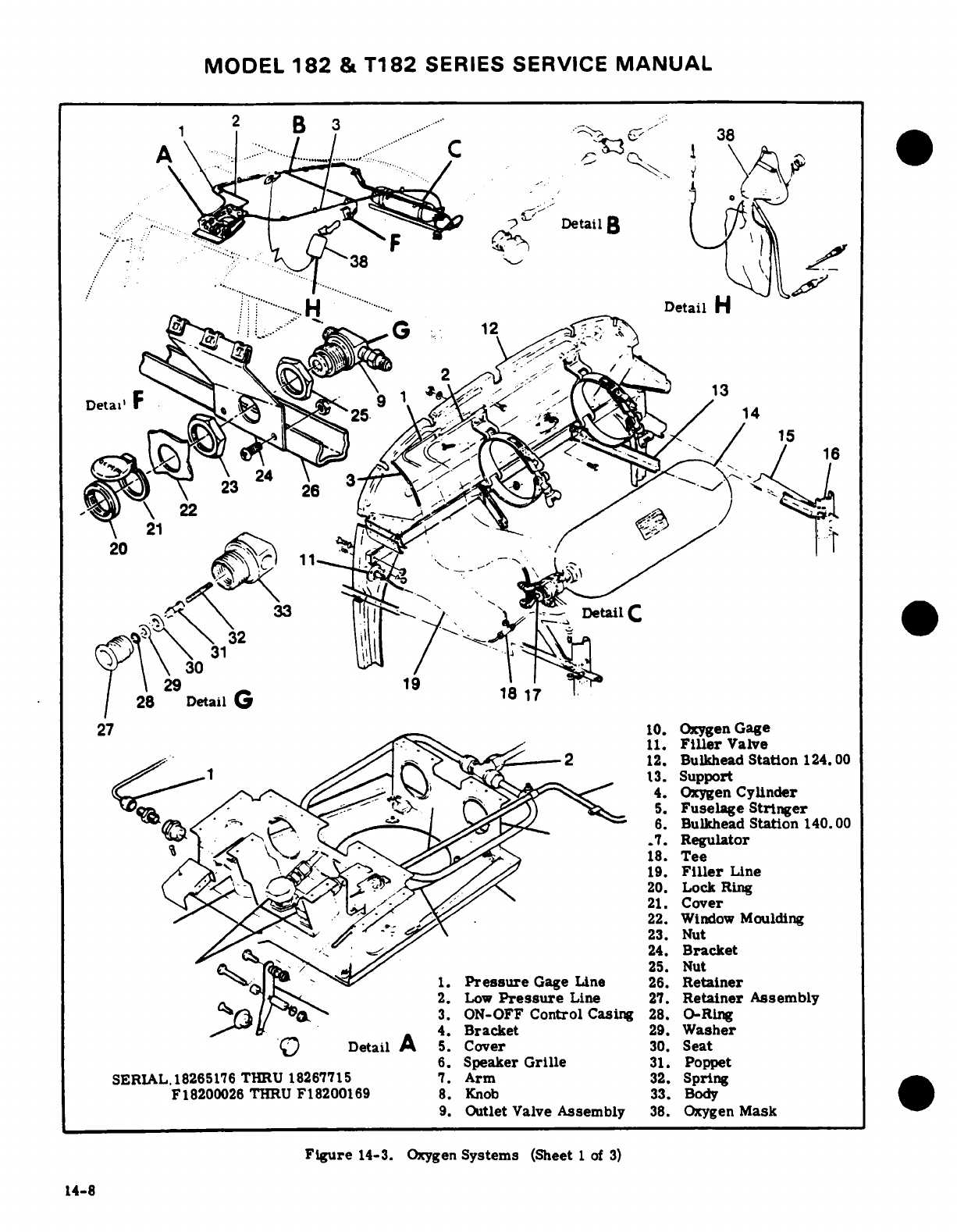
MODEL
182
&
T182
SERIES SERVICE
MANUAL
1 ;
-:'-
B
3
.. ......**....
.**
.,,
^,
38
/ 28 Detail 18
17
'27
10.
Ox'ygen
Gage.
1^ S2
12.
Bulkhead
Station
124.00
(-
^ 53' 1uppo'3
^r2^^ ^^
ss /^' ' c ' .^
S?^^
^
4.
Oxygen
Cylinder
Wo&
/*
C'---^'
>-
1.r^^"))
s~s_
5.
Fuselage
Stringer
_- ^N, ^ 2.
Low
Pressure
Line27. Regulator
/^^V
l^^>^>fc
NS
^^ ^
1.
Filler
Line
CrO^A /"
'20.
Lock
Ring
2
1425.
Nut
'^J^^
-'*'sslh'
1.
Pressure
Gage Line
26.
Retainer
" " / 14
OO
Control
Casing
28.
0Rng
^~~lf
4.
Bracket
29.
Washer
2
Detail
A
5.
Cover
30
Seat
6.
Speaker
Grille
31.
Poppet
SER~IAL. 18265176
THRU
18267715
72.
Buhead
Spring
tation
124.00
F18200026
THRU
F18200169
8.
Knob
33.
Body
13.
Support
9.
Outlet
Valve
Assembly
38.
Oxygen
MaskCylinder
Figure
14-3.
O5.ygen
Systems
(Sheet
1
of
3)
~~~~~~~~14-8~~6.
Bulkhead
ion
140.
-7.
Regulator
18.
Tee
19.
Filler
Line
20.
Lock
Ring
21.
Cover
22.
Window
Moulding
23. Nut
Pressure
Gage Line
26.
Retainer
2.
Low
Pressure
Line
27.
Retainer
Assembly
3.
ON-OFF
Control Casing
28.
O-RiR
y
-sa
~
4.
Bracket
29.
Washer
'(~
Detail
A
5.
Cover
30.
Seat
6.
Speaker
Grille
31.
Poppet
SERIAL.18265176
THRU
18267715
7.
Arm
32.
Spring
F18200026
THRU
F18200169
8.
Knob
33.
Body
9.
Outlet
Valve
Assembly
38.
Oxygen
Mask
Figure
14-3.
Oxygen
Systems
(Sheet
I
of
3)
14-8
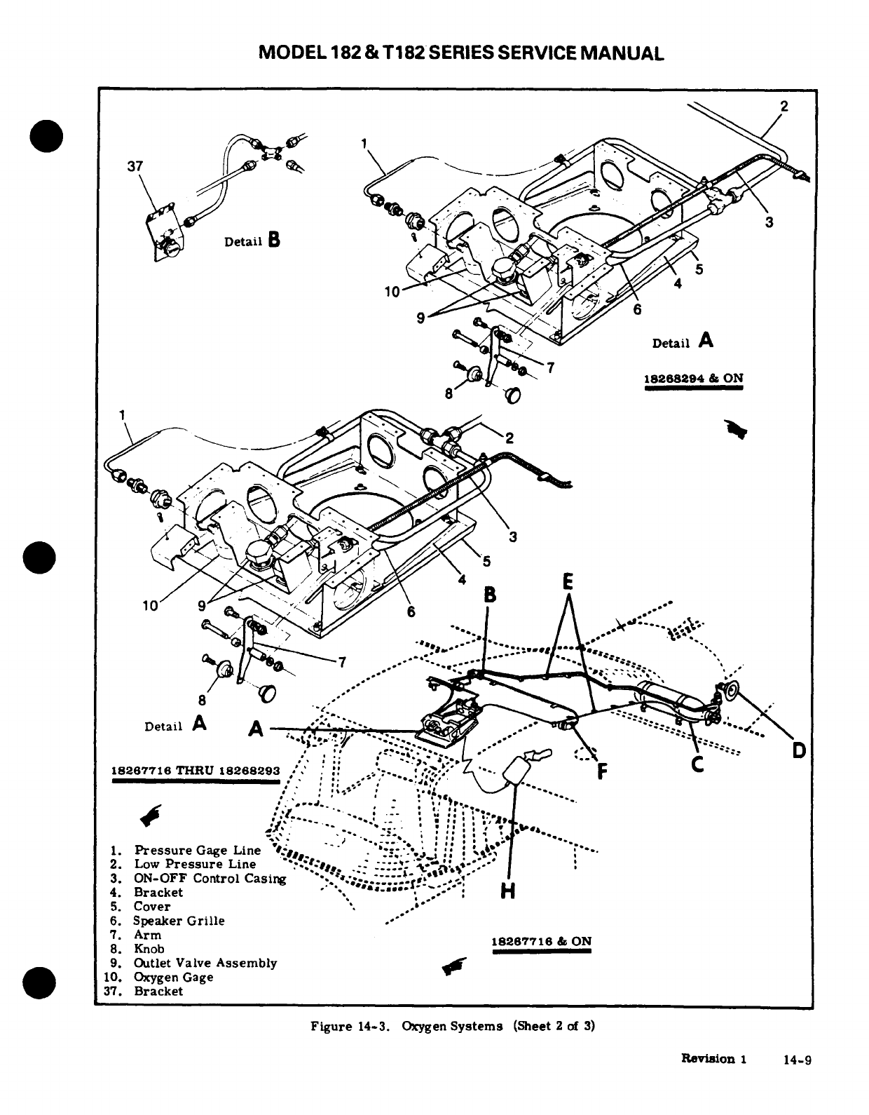
MODEL
182
&
T182
SERIES SERVICE
MANUAL
Detail
B
Detail
A
7
18268294
&
ON
Detai
A
i
Aj~y ^
^
18267716
THRU
18268293
.'
2 '..
''
<
F
_
...
:
,'1
,. *,
~:;;,,:,X.1'W
......
'
1.
Pressure
Gage
Line
'
.';
'*J ?,,
e
s
'*
2.
Low
Pressure
Line
'":* ' : -' - .-'
3.
ON-OFF
Control
Casing
'".
i::;: '"":i,
..
,'
4.
Bracket
.
oa
.':.-
H
5.
Cover
' .*'
6.
Speaker
Grille
7.
Arm
18267716
&
ON
8.
Knob
9.
Outlet
Valve
Assembly
10.
Oxygen
Gage
37.
Bracket
Figure
14-3.
Oxygen
Systems
(Sheet
2
of
3)
Revision
1
14-9
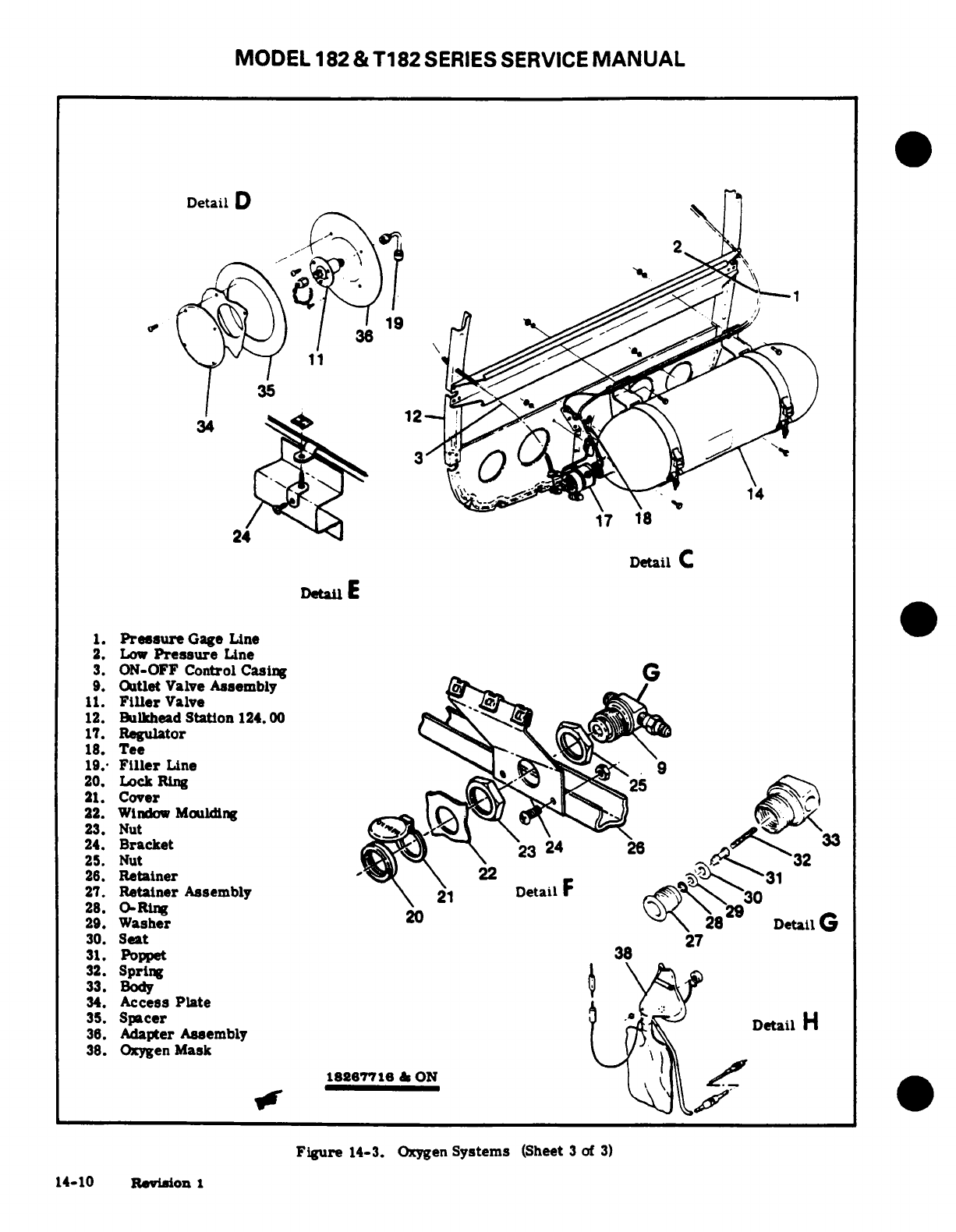
MODEL
182
&
T182
SERIES SERVICE
MANUAL
DetailD
2
'U.
11
35
34
24~' 14
Detail
C
1.
Pressure
Gage Line
2.
Low
Pressure
Line
3.
ON-OFF
Control
Casing
G
9.
Outlet
Valve
Assembly
11.
Filler
Valve
12.
Bulkhead
Station
124.00
17.
Regulator
18.
Tee
19.-
Filler
Line
-t25 9
20.
Lock
Ring
21.
Cover
22.
Window
Moulding
23.
Nut
24.
Bracket 23 24
26
25.
Nut
26.
Retainer
d \
22
31
27.
Retainer
Assembly
21
Detail
r
30
28.
0-Ring
29.
Washer
28
Detail
G
30.
Seat
27
31.
Poppet
38
32.
Spring
33.
Body
34.
Access
Plate
35.
Spacer
i
DetailH
36.
Adapter Assembly
7
38.
Oxygen
Mask
1
\
18267716
a
ON
Figure
14-3.
Oxygen
Systems
(Sheet
3
of
3)
14-10
Revision
1
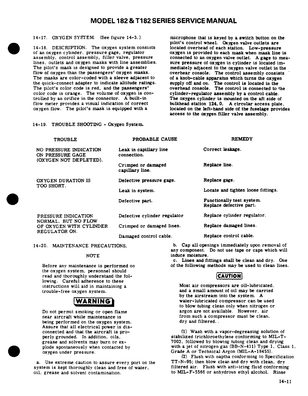
MODEL
182
&
T182
SERIES SERVICE
MANUAL
14-17.
OXYGEN
SYSTEM.
(See
figure
14-3.)
microphone
that
is
keyed
by
a
switch
button
on
the
pilot's
control
wheel.
Oxygen
valve
outlets
are
14-18.
DESCRIPTION. The
oxygen
system consists
located
overhead
of
each
station.
Low-pressure
of
an
oxygen
cylinder.
pressure
gage,
regulator
oxygen
is
provided
to each
mask
when
mask
line
is
assembly.
control assembly,
filler
valve,
pressure
connected
to
an
oxygen
valve
outlet.
A
gage
to
mea-
lines. outlets
and
oxygen
masks
with
line
assemblies,
sure
pressure
of
oxygen
in
cylinder
is
located
im-
The
pilot's
mask
is
designed
to
provide
a
greater
mediately
adjacent
to
the
oxygen
valve
outlet
in the
flow
of
oxygen
than
the
passengers'
oxygen
masks.
overhear
console.
The
control
assembly
consists
The
masks
are
color-coded
with
a
sleeve
adjacent
to
of a
knob-cable
apparatus
which
turns
the
oxygen
the
quick-connect
adapter
to
indicate altitude
ratings.
supply
off
and
on.
The
control
is
located
in
the
The
pilot's
color
code
is
red,
and
the
passengers'
overhead
console.
The
control
is
connected
to
the
color
code
is
orange.
The
volume
of
oxygen
is
con-
cylinder-regulator
assembly
by
a
control
cable.
trolled
by
an
orifice
in
the
connector.
A
built-in
The
oxygen
cylinder
is
mounted
on
the
aft
side
of
flow
meter
provides
a
visual
indication
of
correct
bulkhead
station
124.
0.
A
circular
access
plate.
oxygen
flow.
The
pilot's
mask
is
equipped
with
a located
on
the
left-hand
side
of
the
fuselage
provides
access
to the oxygen
filler
valve
assembly.
14-19.
TROUBLE
SHOOTING
-
Oxygen
System.
TROUBLE
PROBABLE
CAUSE
REMEDY
NO
PRESSURE
INDICATION
Leak
in
capillary
line
Correct
leakage.
ON
PRESSURE
GAGE
connection.
(OXYGEN
NOT
DEPLETED).
Crimped
or
damaged
Replace
line.
capillary
line.
OXYGEN
DURATION
IS
Defective
pressure
gage.
Replace
gage.
TOO
SHORT.
Leak
in
system.
Locate
and
tighten
loose
fittings.
Replace
defective
part.
PRESSURE
INDICATION
Defective
cylinder
regulator
Replace cylinder
regulator.
NORMAL.
BUT
NO
FLOW
OF
OXYGEN
WITH
CYLINDER
Crimped
or
damaged
lines.
Replace
damaged
lines.
REGULATOR
ON.
Damaged
control
cable.
Replace
control cable.
14-20.
MAINTENANCE
PRECAUTIONS.
b.
Cap
all
openings
immediately
upon
removal
of
any
component.
Do
not
use
tape
or
caps
which
will
NOTE
induce
moisture.
c.
Lines
and
fittings
shall
be
clean
and
dry.
One
Before
any
maintenance
is
performed
on
of
the
following
methods
may be
used
to
clean
lines.
the
oxygen
system,
personnel
should
read
and
thoroughly
understand
the
fol-
lowing.
Careful adherence
to
these
instructions
will
aid
in
maintaining
a Most
air
compressors
are
oil-lubricated.
trouble-free
oxygen
system.
and
a
small
amount
of
oil
may
be
carried
by
the
airstream
into
the
system.
A
to
blow
tubing
clean
only
when
nitrogen
or
Do
not
permit
smoking
or
open
flame
argon
are
not
available.
However.
air
near
aircraft
while
maintenance
is
from
such
a
compressor
must
be
clean.
being
performed
on
the oxygen
system.
dry
and
filtered..
Assure
that
all
electrical
power
is
dis-
connected
and
that
the
aircraft
is
pro-
(1)
Wash
with
a
vapor-degreasing
solution
of
perly
grounded.
In
addition.
oils.
stabilized
trichloroethylene
conforming
to
MIL-T-
grease
and
solvents
may
burn
or
ex-
7003.
followed
by
blowing
tubing
clean
and
drying
plode
spontaneously
when
contacted
by
with
a
jet
of
nitrogen gas
(BB-N-411)
Type
1.
Class
1.
oxygen
under
pressure.
Grade
A
or
Technical
Argon
(MIL-A-18455).
(2)
Flush
with
naptha
conforming
to
Specification
a.
Use
extreme
caution
to
assure
every
port
on
the
TT-N-95;
then
blow
clean
and
dry
with
clean,
dry
system
is
kept
thoroughly
clean
and
free
of
water,
filtered
air.
Flush
with
anti-icing
fluid
conforming
oil,
grease
and
solvent
contamination.
to
MIL-F-5566
or
anhydrous
ethyl alcohol.
Rinse
14-11
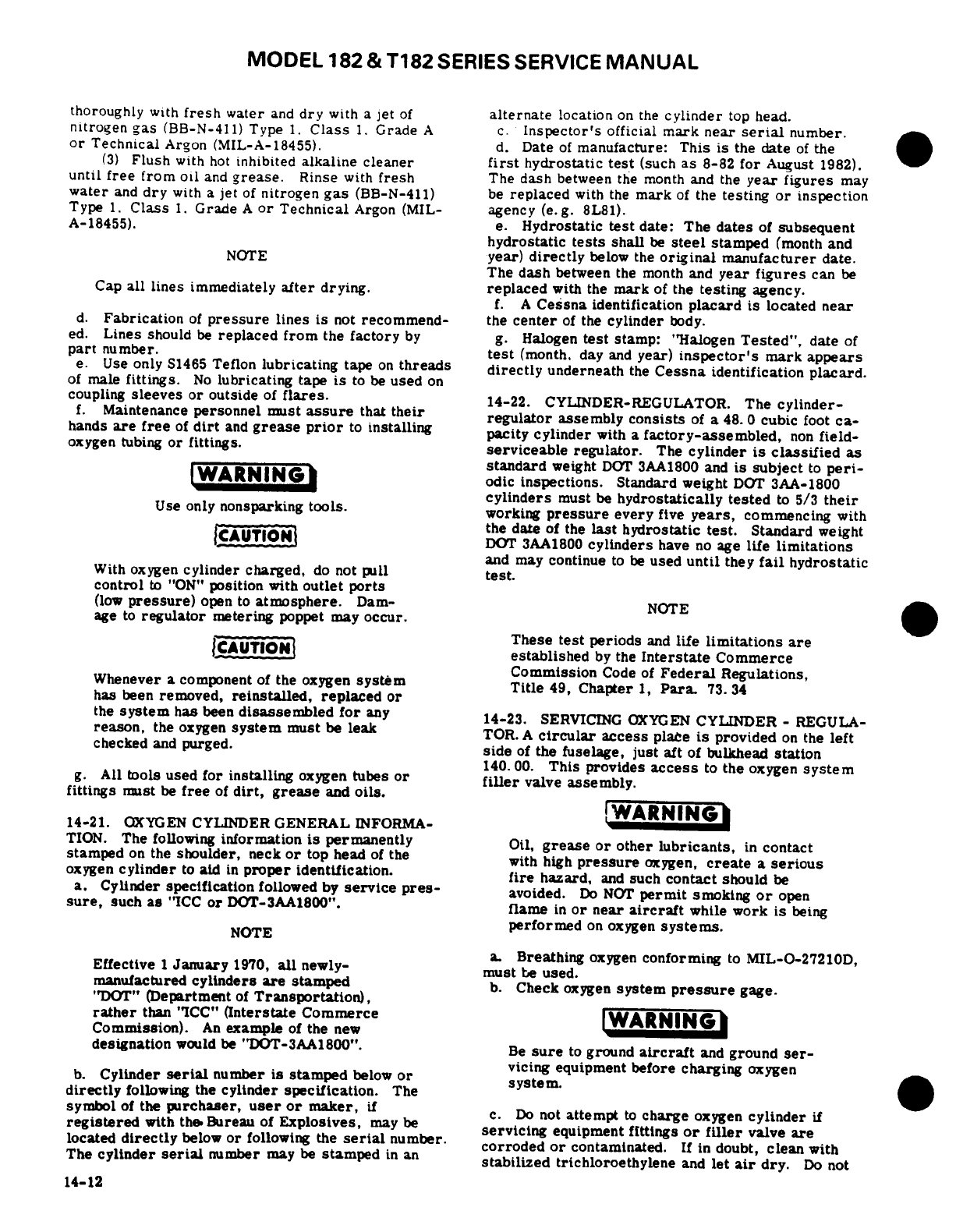
MODEL
182
&
T182
SERIES
SERVICE
MANUAL
thoroughly
with
fresh
water
and
dry
with
a
jet
of
alternate
location
on
the
cylinder
top
head.
nitrogen
gas
(BB-N-411)
Type
1.
Class
1.
Grade
A
c.
Inspector's
official
mark
near
serial
number.
or
Technical
Argon (MIL-A-18455).
d.
Date
of
manufacture:
This
is
the
date
of
the
(3)
Flush
with
hot
inhibited
alkaline cleaner
first
hydrostatic
test
(such
as
8-82
for
August
1982).
until
free
from
oil
and
grease.
Rinse
with
fresh
The
dash
between
the
month
and
the
year
figures
may
water
and
dry
with
a
jet
of
nitrogen
gas
(BB-N-411)
be
replaced
with
the
mark
of
the
testing
or
inspection
Type
1.
Class
1.
Grade
A
or
Technical
Argon
(MIL-
agency
(e.g.
8L81).
A-18455).
e.
Hydrostatic
test
date: The
dates
of
subsequent
hydrostatic
tests
shall
be
steel
stamped
(month
and
NOTE
year)
directly
below
the
original
manufacturer
date.
The
dash
between
the month
and
year
figures
can
be
Cap
all
lines
immediately
after
drying,
replaced
with
the
mark
of
the
testing
agency.
f.
A
Cessna
identification
placard
is
located
near
d.
Fabrication
of
pressure
lines is
not
recommend-
the
center
of
the
cylinder
body.
ed.
Lines
should
be
replaced from
the
factory
by g.
Halogen
test
stamp:
"Halogen
Tested",
date
of
part
number.
test
(month,
day
and
year)
inspector's
mark
appears
e.
Use
only
S1465
Teflon
lubricating
tape
on
threads directly
underneath
the
Cessna
identification
placard.
of
male
fittings.
No
lubricating
tape
is
to be
used
on
coupling
sleeves
or
outside
of
flares.
14-22.
CYLINDER-REGULATOR.
The
cylinder-
f.
Maintenance
personnel
must
assure
that
their regulator
assembly
consists
of
a
48.
0
cubic
foot
ca-
hands
are free
of
dirt
and
grease
prior
to
installing pacity
cylinder
with
a
factory-assembled,
non
field-
oxygen
tubing
or
fittings.
serviceable
regulator.
The
cylinder
is
classified
as
cylinders
must
be
hydrostatically
tested
to
5/3
their
Use
only
nonsparking
tools.
working
pressure
every
five
years,
commencing
with
and
may
continue
to
be
used
until
they
fail
hydrostatic
With
oxygen
cylinder charged,
do
not
pull
test.
control
to "ON"
position
with
outlet
ports
(low
pressure)
open
to
atmosphere.
Dam-
NOTE
age
to
regulator
metering
poppet may
occur.
Commission
Code
of
Federal
Regulations,
Whenever
a
component
of
the
oxygen
system
Title
49,
Chapter
1,
Para
73.
34
has been
removed,
reinstalled,
replaced
or
the
system
has
been
disassembled
for
any
14-23.
SERVICING
OXYGEN
CYLINDER -
REGULA-
reason,
the
oxygen
system
must
be
leak
TOR.
A
circular
access
place
is
provided
on
the
left
checked
and
purged.
side
of
the
fuselage,
just
aft
of
bulkhead
station
140.
00.
This
provides
access
to
the
oxygen
system
g.
All
tools
used
for installing
oxygen
tubes
or
filler
valve
assembly.
fittings
must
be
free
of
dirt,
grease
and
oils.
14-21.
OXYGEN
CYLINDER
GENERAL
INFORMA-
TION.
The
following
information
is
permanently
Oil,
grease
or
other
lubricants,
in
contact
stamped
on
the
shoulder,
neck
or
top
head
of
the
with
high
pressure
oxygen,
create
a
serious
oxygen
cylinder
to
aid
in
proper
identification.
fire
hazard,
and
such
contact
should
be
a.
Cylinder
specification
followed
by
service
pres-
avoided.
Do
NOT
permit
smoking
or
open
sure,
such
as
"ICC
or
DOT-3AA1800".
flame
in
or near
aircraft
while
work
is
being
NOTE
a.
Breathing
oxygen
conforming
to
MIL-O-27210D,
Effective
1
January
1970,
all
newly-
must
be
used.
manufactured
cylinders
are
stamped
b.
Check
oxygen
system
pressure
gage.
"DOT"
(Department
of
Transportation),
rather
than
"ICC"
(Interstate
Commerce
Commission).
An
example
of
the
new
designation
would
be
"DOT-3AA1800".
Be
sure
to
ground
aircraft
and
ground
ser-
vicing equipment
before
charging
oxygen
b.
Cylinder
serial
number
is
stamped
below or
directly
following
the
cylinder
specification.
The
symbol
of
the
purchaser,
user
or
maker,
if
c. Do
not
attempt
to
charge
oxygen
cylinder
if
registered
with
the.
Bureau
of
Explosives,
may be
servicing
equipment
fittngs
or
filler
valve
are
located
directly
below
or
following
the
serial
number.
corroded
or
contaminated.
If
in
doubt,
clean
with
The
cylinder
serial
number
may
be
stamped
in
an
stabilized
trichloroethylene
and
let
air
dry.
Do
not
14-12
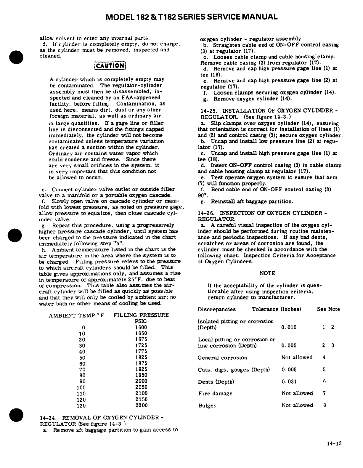
MODEL
182
&
T182
SERIES SERVICE
MANUAL
allow
solvent
to
enter
any
internal
parts.
oxygen
cylinder
-
regulator
assembly.
d.
If
cylinder
is
completely
empty,
do
not
charge,
b.
Straighten
cable
end
of
ON-OFF
control
casing
as
the
cylinder
must
be
removed,
inspected
and
(3)
at
regulator
(17).
cleaned.
c.
Loosen cable
clamp
and
cable
housing
clamp.
tee
(18).
A
cylinder
which
is
completely
empty
may
e.
Remove
and
cap
high
pressure
gage line
(2)
at
be
contaminated.
The
regulator-cylinder
regulator
(17).
assembly
must
then
be
disassembled,
in-
f.
Loosen
clamps
securing
oxygen
cylinder
(14).
spected
and
cleaned
by
an
FAA-approved
g.
Remove
oxygen
cylinder
(14).
facility,
before
filling
.
Contamination, as
used
here.
means
dirt,
dust
or
any
other
14-25.
INSTALLATION
OF
OXYGEN
CYLINDER
-
foreign
material, as
well
as
ordinary
air
REGULATOR.
(See
figure
14-3.)
in
large quantities.
If
a
gage
line
or
filler
a.
Slip
clamps
over
oxygen
cylinder
(14),
ensuring
line
is disconnected
and
the
fittings
capped
that
orientation
is
correct
for
installation
of
lines
(1)
immediately,
the
cylinder
will
not
become
and
(2)
and
control
casing
(3);
secure
oxygen
cylinder.
contaminated
unless temperature
variation
b.
Uncap
and
install
low
pressure
line
(2)
at
regu-
has
created
a
suction
within
the
cylinder.
lator
(17).
Ordinary
air
contains
water
vapor
which
c.
Uncap and
install
high
pressure
gage line
(1)
at
could
condense
and
freeze.
Since
there
tee
(18).
are
very
small
orifices
in
the
system,
it
d.
Insert
ON-OFF
control
casing
(3)
in
cable
clamp
is
very important
that
this
condition
not
and
cable
housing
clamp
at
regulator
(17).
be
allowed
to
occur.
e.
Test
operate
oxygen
system
to
ensure
that
arm
(7)
will
function
properly.
e.
Connect
cylinder
valve
outlet or outside
filler
f.
Bend
cable
end of
ON-OFF
control
casing
(3)
valve
to
a
manifold
or
a
portable
oxygen
cascade.
90
° .
f.
Slowly
open
valve
on
cascade
cylinder
or
mani-
g.
Reinstall
aft baggage
partition.
fold
with
lowest
pressure,
as
noted
on
pressure
gage,
allow
pressure
to
equalize,
then
close
cascade
cyl-
14-26.
INSPECTION
OF
OXYGEN
CYLINDER
-
inder
valve.
REGULATOR.
g.
Repeat
this procedure,
using
a
progressively
a.
A
careful
visual
inspection
of
the
oxygen
cyl-
higher
pressure
cascade
cylinder,
until
system
has
inder
should
be
performed
during
routine
mainten-
been
charged
to
the
pressure
indicated
in
the
chart
ance
and
periodic inspections.
If
any bad
dents,
immediately
following
step
"h".
scratches
or
areas
of
corrosion
are
found,
the
h.
Ambient
temperature
listed
in
the
chart
is
the
cylinder
must
be
checked
in
accordance
with
the
air
temperature
in
the
area
where
the
system
is
to
following
chart:
Inspection
Criteria
for
Acceptance
be
charged. Filling
pressure
refers
to
the
pressure
of
Oxygen
Cylinders.
to
which
aircraft
cylinders
should
be
filled.
This
table
gives
approximations
only,
and
assumes
a
rise
NOTE
in
temperature
of
approximately
25°F.
due
to
heat
of
compression. This
table
also
assumes
the
air-
If
the
acceptability
of
the
cylinder
is
ques-
craft
cylinder
will
be
filled as
quickly
as
possible
tionable
after
using
inspection
criteria.
and
that
they
will
only
be
cooled
by
ambient
air;
no
return
cylinder
to
manufacturer.
water
bath
or other
means
of
cooling
be
used.
Discrepancies
Tolerance
(Inches)
See
Note
AMBIENT
TEMP
°F
FILLING
PRESSURE
PSIG
Isolated
pitting
or corrosion
0
1600
(Depth)
0.010
1
2
10
1650
20
1675
Local
pitting
or
corrosion
or
30
1725
line
corrosion
(Depth)
0.005
2
3
40
1775
50
1825
General
corrosion
Not
allowed
4
60
1875
70
1925
Cuts. digs,
gouges
(Depth)
0.005
5
80
1950
90
2000
Dents
(Depth)
0.
031
6
100
2050
110
2100
Fire
damage
Not
allowed
7
120
2150
130
2200
Bulges
Not
allowed
8
14-24.
REMOVAL
OF
OXYGEN
CYLINDER
-
REGULATOR
(See
figure
14-3.)
a.
Remove aft baggage
partition
to
gain
access
to
14-13
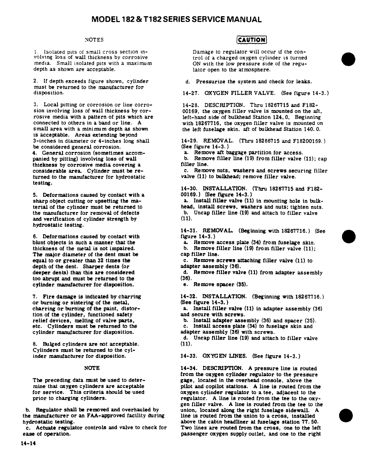
MODEL
182
&
T182
SERIES
SERVICE
MANUAL
1.
Isolated
pits
of
small
cross
section
in-
Damage
to
regulator
will
occur
if the
con-
volving
loss
of
wall
thickness
by
corrosive
trol
of
a
charged
oxygen
cylinder is
turned
media.
Small isolated pits
with
a
maximum
ON
with
the
low
pressure
side
of
the
regu-
depth
as
shown
are
acceptable.
lator
open
to
the
atmosphere.
2.
If
depth
exceeds
figure
shown,
cylinder
d.
Pressurize
the
system
and
check
for
leaks.
must
be
returned
to
the
manufacturer
for
disposition.
14-27.
OXYGEN
FILLER
VALVE.
(See
figure
14-3.)
3.
Local
pitting
or
corrosion
or
line
corro-
14-28.
DESCRIPTION.
Thru
18267715 and
F182-
sion
involving
loss
of
wall
thickness
by
cor-
00169,
the oxygen
filler
valve
is
mounted
on
the
aft,
rosive
media
with
a
pattern
of
pits
which
are
left-hand side
of
bulkhead
Station
124.
0.
Beginning
connected
to
others
in
a
band
or
line.
A
with
18267716,
the
oxygen
filler
valve
is
mounted
on
small
area
with a
minimum depth
as
shown
the
left
fuselage
skin.
aft
of
bulkhead
Station
140.
0.
is acceptable.
Areas
extending
beyond
3-inches
in
diameter
or
4-inches
long
shall
14-29.
REMOVAL.
(Thru
18266715
and
F18200169.)
be
considered
general
corrosion.
(See
figure
14-3. )
4.
General
corrosion
(sometimes
accom-
a.
Remove
aft
baggage
partition
for
access.
panied
by
pitting)
involving
loss
of
wall
b.
Remove
filler
line
(19)
from
filler
valve
(11);
cap
thickness
by
corrosive
media covering
a
filler
line.
considerable
area.
Cylinder must
be
re-
c.
Remove
nuts,
washers
and
screws
securing
filler
turned
to
the
manufacturer for
hydrostatic
valve
(11)
to
bulkhead;
remove
filler
valve.
testing.
14-30.
INSTALLATION.
(Thru
18267715
and
F182-
5.
Deformations
caused
by
contact
with
a
00169.)
(See
figure
14-3.)
sharp
object
cutting
or
upsetting
the ma-
a.
Install
filler
valve
(11)
in
mounting
hole in
bulk-
terial
of
the
cylinder
must
be
returned
to
head,
install screws,
washers
and
nuts;
tighten
nuts.
the
manufacturer
for removal
of
defects
b.
Uncap
filler
line
(19)
and
attach
to
filler
valve
and
verification
of
cylinder
strength
by
(11).
hydrostatic
testing.
14-31.
REMOVAL.
(Beginning
with
18267716.)
(See
6.
Deformations
caused
by
contact
with
figure
14-3.)
blunt
objects
in
such
a
manner
that
the
a.
Remove
access
plate
(34)
from
fuselage skin.
thickness
of
the
metal is
not
impaired.
b.
Remove
filler
line
(19)
from
filler
valve
(11);
The
major
diameter
of
the
dent
must
be
cap
filler
line.
equal
to
or
greater
than
32
times
the
c.
Remove
screws
attaching
filler
valve
(11)
to
depth
of
the dent.
Sharper
dents
(or
adapter
assembly
(36).
deeper
dents)
than
this
are
considered
d.
Remove
filler
valve
(11)
from
adapter
assembly
too
abrupt
and
must
be
returned
to
the
(36).
cylinder
manufacturer for
disposition.
e.
Remove
spacer
(35).
7.
Fire
damage
is
indicated
by
charring
14-32.
INSTALLATION.
(Beginning
with
18267716.)
or
burning
or
sintering
of
the
metal,
(See
figure
14-3.
)
charring
or
burning
of
the
paint,
distor-
a.
Install
filler
valve
(11)
in
adapter
assembly
(36)
tion
of
the
cylinder,
functioned
safety
and
secure
with
screws.
relief
devices,
melting
of
valve
parts,
b.
Install
adapter
assembly
(36)
and
spacer
(35).
etc.
Cylinders
must
be
returned
to
the
c.
Install
access
plate
(34)
to
fuselage
skin
and
cylinder
manufacturer for disposition.
adapter
assembly
(36)
with
screws.
d.
Uncap
filler
line
(19)
and
attach
to
filler
valve
8.
Bulged
cylinders
are
not
acceptable.
(11).
Cylinders
must
be
returned
to
the
cyl-
inder
manufacturer
for disposition.
14-33.
OXYGEN
LINES.
(See
figure
14-3.)
NOTE
14-34.
DESCRIPTION.
A
pressure
line
is
routed
from
the
oxygen
cylinder
regulator
to
the
pressure
The
preceding
data
must
be
used
to
deter-
gage,
located
in
the
overhead
console,
above
the
mine
that
oxygen
cylinders
are
acceptable pilot
and
copilot
stations.
A
line
is
routed
from
the
for
service.
This
criteria
should
be
used
oxygen
cylinder regulator
to
a
tee,
adjacent
to the
prior
to
charging
cylinders.
regulator.
A
line
is
routed
from
the
tee
to
the
oxy-
gen
filler
valve.
A
line
is
routed
from
the
tee
to the
b.
Regulator
shall
be
removed
and
overhauled
by
union,
located
along
the
right
fuselage
sidewall.
A
the
manufacturer
or
an
FAA-approved
facility
during
line
is
routed
from
the
union
to
a
cross,
installed
hydrostatic
testing.
above the
cabin
headliner
at
fuselage
station 77.50.
c.
Actuate
regulator controls
and
valve
to
check
for
Two
lines
are
routed
from
the
cross,
one
to
the
left
ease
of
operation.
passenger
oxygen
supply
outlet,
and
one to
the
right
14-14
MODEL
182
&
T182
SERIES
SERVICE
MANUAL
passenger
oxygen
outlet
valve
assembly.
A
line
is 14-40.
REMOVAL
OF
PILOT
AND/OR
COPILOT
routed
from
the
cross
to
a
tee,
located
at
the aft
end
OUTLET
VALVE
ASSEMBLY.
(See
figure
14-3.)
of
the
overhead
console.
Two
lines
are
routed
from
the tee.
one
to
the
pilot's
oxygen
outlet
valve
assem-
NOTE
bly.
and
one
to
the
copilot's
oxygen
outlet
valve
assembly,
both
installed
in
the
overhead
console.
Ensure
oxygen
control
is
OFF.
14-35.
REMOVAL
AND
INSTALLATION.
(See
a.
Remove
overhead
console.
figure
14-3.)
Assure
that
the
oxygen
control
is
b.
Disconnect
oxygen
line
at
rear
of
outlet
valve
off.
Access
to
the
various
lines
is
gained
by
re-
assembly;
cap
oxygen
line.
moving
the cabin
headliner
and/or
appropriate
c.
Remove
nut
(25).
upholstery
side
panels,
depending
on
line
location.
d.
Remove
outlet
valve
assembly.
Removal
and
installation
procedures
for
cabin
head-
liner
and
upholstery
side
panels
are
outlined
in
14-41.
INSTALLATION OF
PILOT
AND/OR
Section
3
of
this
manual.
Lines
are
secured
by
COPILOT
OUTLET
VALVE
ASSEMBLY.
(See
clamps
and/or
nylon
ties.
Whenever
ties
are
re-
figure
14-3.)
moved,
replace
with
new
ties.
a.
Install
outlet
valve
assembly
in
mounting hole
of
bracket
(37).
NOTE
b.
Install
and
tighten
nut
(25).
c.
Uncap
and
install
oxygen
line
at
rear
of
outlet
Observe
all
cautions, warnings,
precautions
valve
assembly.
and
procedures
outlined
in
paragraph
14-20
d.
Turn
oxygen
control
ON
and
test
connection
for
when
removing
or
installing
oxygen
lines, leaks.
e.
Install
overhead
console.
14-36.
OUTLET
VALVE
ASSEMBLIES. (See
figure
14-3.)
14-42.
INSPECTION/TEST
OF
OXYGEN
OUTLET
VALVE
ASSEMBLIES.
14-37.
DESCRIPTION.
The
pilot
and
copilot
outlet
a.
Assure
that
oxygen
system
is
fully
charged.
valve
assemblies
are
mounted
in
the
overhead
con-
b.
Insert
an
oxygen
outlet
adapter,
connected
to
a
sole.
Passenger
outlet
valve
assemblies are
mounted
pressure
gage,
into the
oxygen
outlet
valve.
overhead
and
outboard
of
each
passenger
station.
c.
Test
retainer
assembly
(27)/adapter
junction
for
leaks
with
fluid
leak
detector.
No
bubbles
are
per-
4-38.
REMOVAL
OF
PASSENGER
OUTLET
VALVE
mitted.
ASSEMBLY.
(See
figure
14-3.)
d.
After
completion
of
leak
tests,
fully
charge
oxygen
system as
outlined
in
paragraph
14-23.
NOTE
14-43.
OXYGEN
SYSTEM
FUNCTIONAL
TEST.
Ensure
oxygen
control
is
OFF.
NOTE
a.
Remove lock
ring
(20)
and
cover
(21).
b.
Remove
window
moulding
(22).
Whenever
the
oxygen
system regulator
c.
Remove
cabin
headliner
as
outlined
in
Section
3
(cylinder-regulator
assembly)
has
been
of
this
manual.
replaced
or
overhauled.
perform
a
flow
d.
Remove
nut
(23).
test
to
determine
that
system
functions
e.
Remove
bracket
(24).
properly.
f.
Disconnect
oxygen
line
from
outlet
valve
assem-
bly.
and
cap
line.
a.
Fully
charge
the
oxygen
system
as
outlined
in
g.
Remove
nut
(25).
paragraph
14.23.
h.
Remove
outlet
valve
assembly.
b.
Install
an
oxygen
outlet
adapter
into
a
pressure
gage
(calibrated
in
one
pound
increments
from
0
to
14-39.
INSTALLATION
OF
PASSENGER
OUTLET
100
PSIG)
and
insert
adapter
into
pilot's
oxygen
out-
VALVE
ASSEMBLY.
(See
figure
14-3.)
let
valve
assembly.
a.
Install
nut
(25) on
threads
of
outlet
valve
assem-
c.
Turn
oxygen
system
ON.
Pressure
should
be
bly.
and
install
outlet
valve
assembly
in
mounting
70±10
PSIG. If
pressure
does
not
fall
within
these
hole
of
retainer
(26):
tighten
nut
(25).
tolerance,,
replace
cylinder-regulator
and
repeat
b.
Uncap
and
connect
oxygen
line
to
outlet
valve
test.
assembly.
d.
Recharge
oxygen
system
as
required
as
outlined
c.
Install
bracket
(24).
in
paragraph
14-23.
d.
Install
and
tighten
nut
(23).
e.
Turn
oxygen
control
ON
and
test
connection
for
14-44.
OXYGEN
GAGE.
(See
figure
14-3.)
leaks.
f.
Install
cabin
headliner as
outlined
in
Section
3
14-45.
DESCRIPTION.
The
oxygen
gage
is
located
of
this
manual.
on
the
right-hand
side
of
the
overhead
console.
The
g.
Install
window
moulding. oxygen
gage is
calibrated
from
0
to
2000
PSI.
h.
Install
cover
(21)
and
lock
ring
(20).
14-15
MODEL
182
&
T182
SERIES
SERVICE
MANUAL
14-46.
REMOVAL.
(See
figure
14-.
)
cabin
oxygen
receptacle
with
ease
and
will
not
leak.
e.
If
a
mask
assembly
is
defective
(leaks.
does
NOTE
not
allow
breathing
or
contains
a
defective
micro-
phone),
it
is
advisable
to
return
the
mask
assembly
The
system
does
not
have
to
be
discharged
to
the
manufacturer
or
an
FAA-approved
repair
sta-
before
removing
high
pressure
lines
as
tion.
there
is
a
check
valve
in
the
regulator
to
f.
Replace
hose
if
it
shows
evidence
of
deteriora-
shut
off
the
flow
of
oxygen
when
a
connec-
tion.
tion
is
broken.
Ensure the
system
is
OFF.
14-52.
CLEANING.
a.
Remove
aft baggage
partition
for
access
to
a.
Clean
and
disinfect
mask
assemblies
after
use
oxygen
cylinder-regulator
assembly.
with
rubbing alcohol,
as
appropriate.
b.
Disconnect
pressure
gage
line
(1)
at tee
(18).
b.
If
installed,
remove
microphone
from
mask.
c.
Remove
overhead console
for
access
to
pressure
gage
(10).
d.
Disconnect
pressure
gage
line
(1)
from
pressure
gage
(10);
remove
pressure
gage
by
unscrewing
bezel
Do
not
allow rubbing
alcohol
to
enter
micro-
and
removing
clear
lens.
phone
or
electrical
connections.
14-47.
INSTALLATION. (See
figure
14-3.)
c.
Apply
rubbing
alcohol
to
mask
with
a cotton
a.
Install
pressure
gage
(10)
in
overhead console,
swab
or
the
equivalent,
as
required,
to
remove
install clear
lens
and
screw
bezel
on
pressure
gage
contamination.
threads,
attaching
pressure
gage
to
overhead console.
d.
If
used,
install
microphone.
b.
Connect
pressure
gage
line
(1)
to
pressure
gage
(10).
14-53.
FUNCTIONAL
TEST.
c.
Connect
pressure
gage
line
(1)
to
tee
(18).
d.
Turn
oxygen
control
ON
and
test
for
leaks.
NOTE
e.
Install
aft
baggage
partition.
f.
Install
overhead
console. Each
mask
should
be
periodically tested
to
ensure
its
correct
functioning.
NOTE
a.
Turn
oxygen
control
ON.
Pressure
gage
is
not
repairable
and
must
be
b.
Insert
oxygen
mask
adapter
into
its
outlet
valve
tested
by
the
manufacturer
every
3000
flight
assembly.
hours
or
three
years,
whichever
comes
first.
c.
Observe
that
the
flowmeter
shows
a
proper
flow
of
oxygen
(indicator
shows
green
only.)
14-48.
INSPECTION.
The
only
inspection
possible
d.
Return
mask
to
storage.
is
to
observe
indicated
pressure
rise
as
the
system
e.
Recharge
oxygen
system
as
outlined
in
para-
is
charged
and
decrease
as
oxygen
is
bled
off.
graph
14-23.
14-49.
OXYGEN
MASKS.
14-54.
HEATED
WINDSHIELD
PANEL.
(See
figure
14-5.)
14-50.
DESCRIPTION.
One
pilot's
mask
and
three
passengers'
masks
are
provided
with
the
aircraft.
14-55.
DESCRIPTION.
The
panel
is
constructed
of
The
pilot's
mask
has
a
built-in
microphone
and
also
two
sheets
of
plate
glass
covering
a
layer
of
vinyl.
provides
a
greater
flow
of
oxygen.
The
masks
are
Imbedded
in
the vinyl
is
a
fine
resistance
wire
which
of
the
constant-flow
type,
with
a
metering
orifice
in
provides
the
heat
for
windshield
anti-icing.
The
panel
the
quick-connect adapter.
A
flowmeter
built
into
is
installed
in
two
brackets.
The
outboard
bracket
the line,
approximately
six-inches from
the
connec-
(10)
is
mounted
on
the
cowl
deck
skin
immediately
for-
tor,
provides
a
visual
indication
of
proper
oxygen
ward
of
the
lower
left
windshield
retainer,
and
the
flow, showing
red
when
no
flow
is
taking
place,
red
inboard
bracket
(5)
is
mounted in
the
lower
windshield
and
green
with
a
partial
flow, and
green
with
full
retainer.
The
upper
end
of
the
panel
is
supported
by
flow.
The
masks
are
color-coded
by
a
sleeve
adja-
a
rubber
bumper
(12)
which
holds
panel
off
the
wind-
cent
to
the
quick-connect
adapter; red
for
pilot,
shield.
The lower
end
of
the
panel
pivots
in
mounting
22,000
to
30,000
foot
altitude
rating,
and
orange for
brackets,
providing
easy
cleaning
between
panel
and
passenger,
14,000
to
22,000
foot
rating.
windshield.
Power
to
the
heated
panel
is
provided
through
an
electrical
plug
located
in
cover
assembly
14-51.
INSPECTION.
(13)
mounted
to
the
left
of
outboard
mounting
bracket
a.
Check
oxygen
masks
for
cracks
and
rough
face
(10).
An
ON-OFF
switch
and
a
circuit
breaker
labeled
seals.
W/S
A-ICE
are
installed
in
the
switch panel.
b.
Flex
mask
hose
gently
over
its
entirety
and
check
for
evidence
of
deterioration
or
dirt.
14-56.
REMOVAL
AND
INSTALLATION.
(See
figure
c.
Examine mask
and
hose
storage compartment
14-5.)
Panel
removal
is
accomplished
by
disconnect-
for
cleanliness
and
general
condition.
ing
connector
(11)
inside
cover
(13)
and
moving
spring-
d.
Observe
that
each
mask
breathing
tube
end
is
loaded
handles
(8)
in
tube
(9)
toward
center
of
panel,
free
of
nicks,
and
that
the tube
end
will
slip
into the
14-16
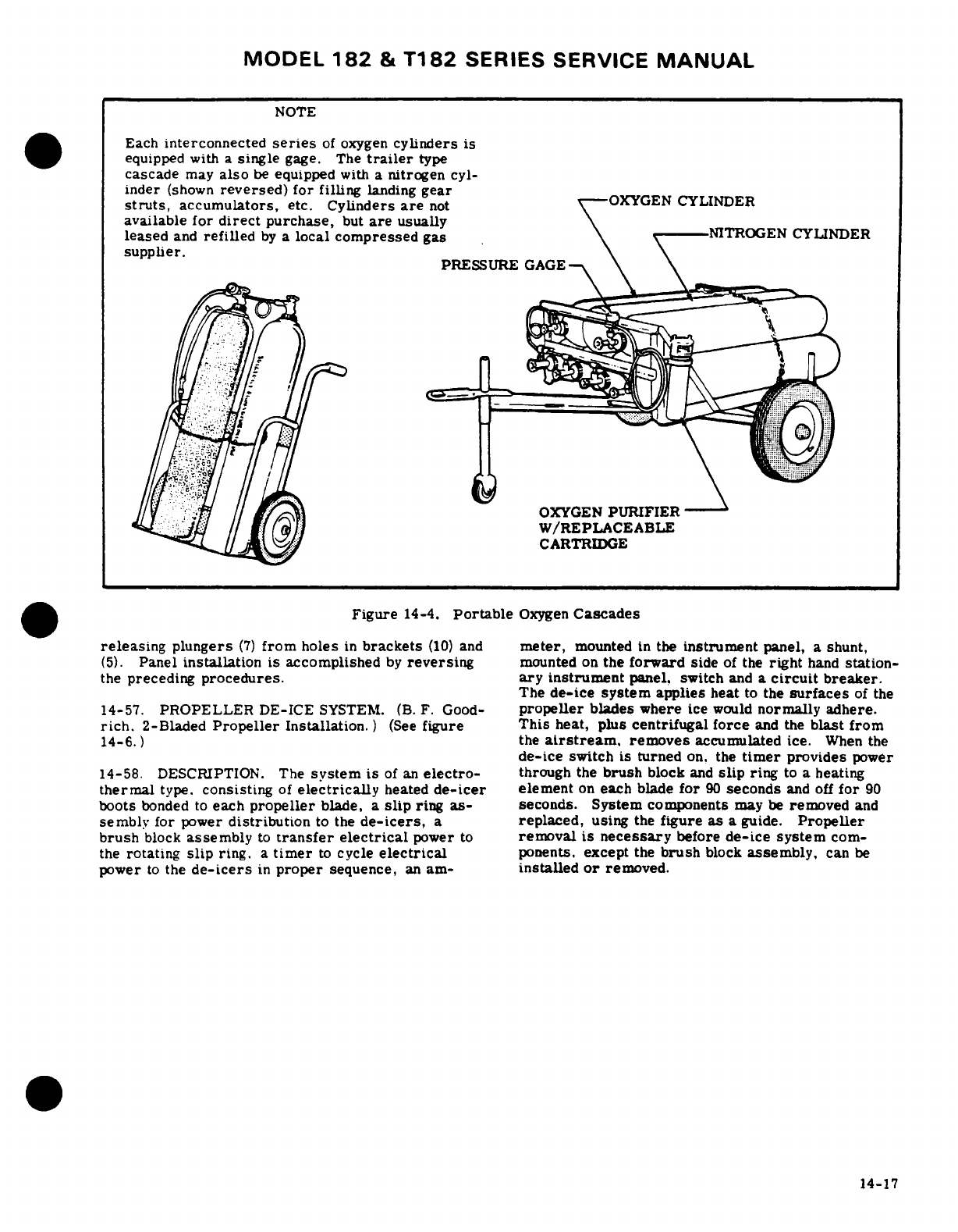
MODEL
182
&
T182
SERIES
SERVICE
MANUAL
NOTE
Each
interconnected
series
of
oxygen
cylinders
is
equipped
with
a
single
gage. The
trailer
type
cascade
may
also
be
equipped
with
a
nitrogen
cyl-
inder
(shown
reversed)
for
filling
landing
gear
struts,
accumulators,
etc.
Cylinders
are
not
available
for
direct
purchase,
but
are
usually
leased
and
refilled
by
a
local compressed
gas
supplier.
PRESSURE
GAGE
OXYGEN
PURIFIER
W/REPLACEABLE
CARTRIDGE
Figure
14-4.
Portable
Oxygen
Cascades
releasing
plungers
(7)
from
holes
in
brackets
(10)
and
meter,
mounted
in the
instrument
panel,
a
shunt,
(5).
Panel
installation
is accomplished
by
reversing
mounted
on
the
forward
side
of
the
right
hand
station-
the
preceding
procedures.
ary
instrument
panel,
switch
and
a
circuit
breaker.
The
de-ice
system
applies
heat
to
the
surfaces
of
the
14-57.
PROPELLER
DE-ICE
SYSTEM.
(B.
F. Good-
propeller
blades
where
ice
would
normally adhere.
rich.
2-Bladed
Propeller
Installation.
)
(See
figure
This
heat, plus
centrifugal force
and
the
blast from
14-6.)
the
airstream,
removes
accumulated
ice.
When
the
de-ice
switch
is
turned
on.
the
timer
provides
power
14-58.
DESCRIPTION.
The
system
is
of
an
electro-
through
the
brush
block
and
slip
ring
to
a heating
thermal
type.
consisting
of
electrically
heated
de-icer
element
on
each
blade
for
90
seconds
and off
for
90
boots
bonded
to
each
propeller
blade,
a
slip
ring
as-
seconds.
System
components
may
be
removed
and
sembly
for
power
distribution
to
the
de-icers,
a
replaced,
using
the
figure
as
a
guide.
Propeller
brush
block
assembly
to
transfer
electrical
power
to
removal
is
necessary
before
de-ice
system
com-
the
rotating
slip
ring.
a
timer
to
cycle
electrical
ponents.
except
the
brush
block
assembly,
can
be
power
to
the
de-icers
in
proper
sequence,
an
am-
installed
or
removed.
14-17
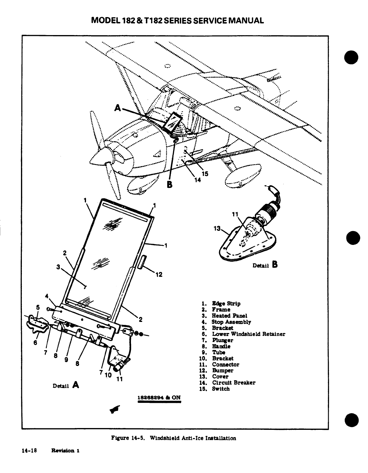
MODEL
182
&
T182
SERIES
SERVICE
MANUAL
e
%.
..
'**%, o-O
.. *-
..
.*.".
""~'''I""'..
.
%.o....,;".....
.°
X~.
...,
;, >
...
.
*
.
V
'.
;-.....
"""*"';:-..
'
.;'..:>
.....
Y\ 1/l, 1 ^. le
Strip
(· 2
3
Heated,
n
*.
_' Gil
*.
:a o*°' °
,:b,
8,
/
| bi**' BD a
14
( .'
11
'\' :':;"
-9
"..'~-~,7.:".
Heated
Panelr
eeS'oe
°
.-
o 12
-
*.*4.
Stop
Assembly
S^82?8 8jL5. Bracket
Figure 14-5.Win
e6.
Lower
Windshield
Retainer
14-18/-WT^
T
~~~~~7.
Pluiger
8.
Handle
*'7** *': " " _;-9.
Tube
8
9
/
/l.-z^^
10.
Bracket
8
/ T^^r11.
Connector
12.
Bumper
10o...
13.
Cover
Detail A
14.
Circuit
Breaker
Detail
A
15.
Switch
18268294
&
ON
Figure
14-5.
Windshield
Anti-Ice
Installation
14-18
Revision
1
14-18
Revision
I
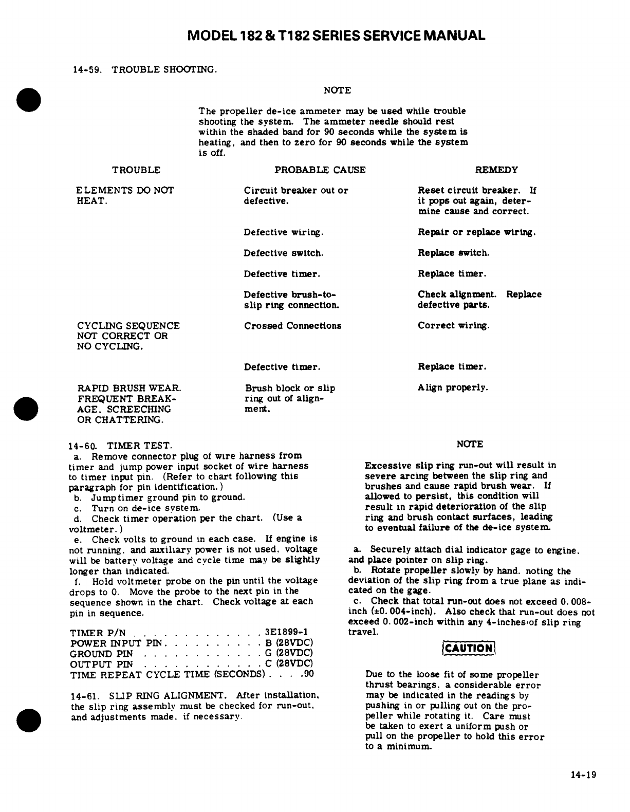
MODEL
182
&
T182
SERIES SERVICE
MANUAL
14-59.
TROUBLE
SHOOTING.
NOTE
The
propeller de-ice
ammeter
may be
used
while
trouble
shooting
the
system.
The
ammeter
needle
should
rest
within
the
shaded
band
for
90
seconds
while
the
system
is
heating,
and
then
to
zero
for
90
seconds
while
the
system
is
off.
TROUBLE
PROBABLE
CAUSE
REMEDY
ELEMENTS
DO
NOT
Circuit breaker
out
or
Reset
circuit breaker.
If
HEAT.
defective,
it
pops
out
again,
deter-
mine
cause
and
correct.
Defective wiring.
Repair
or
replace
wiring.
Defective
switch.
Replace
switch.
Defective
timer.
Replace
timer.
Defective
brush-to-
Check
alignment.
Replace
slip
ring
connection.
defective
parts.
CYCLING
SEQUENCE
Crossed
Connections
Correct
wiring.
NOT
CORRECT
OR
NO
CYCLING.
Defective
timer.
Replace
timer.
RAPID
BRUSH
WEAR.
Brush
block
or
slip
Align
properly.
FREQUENT
BREAK-
ring
out
of
align-
AGE.
SCREECHING
ment.
OR
CHATTERING.
14-60.
TIMER
TEST.
NOTE
a.
Remove
connector
plug
of
wire
harness
from
timer
and
jump
power
input
socket
of
wire
harness
Excessive
slip
ring run-out
will
result
in
to
timer
input
pin.
(Refer
to
chart
following
this
severe
arcing
between
the
slip
ring
and
paragraph
for
pin
identification.)
brushes
and
cause
rapid
brush
wear.
If
b.
Jumptimer
ground
pin
to
ground. allowed
to
persist,
this
condition
will
c.
Turn
on
de-ice
system.
result
in
rapid
deterioration
of
the
slip
d.
Check
timer
operation per
the
chart.
(Use
a
ring
and
brush
contact
surfaces,
leading
voltmeter.
)
to
eventual
failure
of
the
de-ice
system.
e.
Check
volts
to
ground
in
each
case.
If
engine
is
not
running,
and
auxiliary
power
is
not
used.
voltage
a.
Securely
attach
dial
indicator
gage
to
engine.
will
be
battery
voltage
and
cycle
time
may
be
slightly
and
place
pointer
on
slip
ring.
longer
than
indicated.
b.
Rotate
propeller
slowly
by
hand.
noting
the
f.
Hold
voltmeter
probe
on
the pin
until
the
voltage
deviation
of
the
slip
ring
from
a
true
plane
as
indi-
drops
to
0.
Move
the
probe
to
the
next
pin
in
the
cated
on
the
gage.
sequence
shown
in
the
chart.
Check
voltage
at
each
c.
Check
that
total run-out
does
not
exceed
0.
008-
pin
in
sequence.
inch
(±0.
004-inch).
Also
check
that
run-out
does
not
exceed
0.
002-inch
within
any
4-inches
of
slip
ring
TIMER
P/N
.............
3E1899-1
travel.
POWER
INPUT
PIN
........ .
B
(28VDC)
....
GROUND
PIN
....
(28VDC)..
OUTPUT
PIN
............ C
(28VDC)
TIME
REPEAT
CYCLE
TIME
(SECONDS)
...
.90
Due
to
the
loose
fit
of
some
propeller
thrust
bearings,
a
considerable
error
14-61.
SLIP
RING
ALIGNMENT.
After
installation,
may
be
indicated
in
the
readings
by
the
slip
ring
assembly
must
be
checked
for
run-out,
pushing
in
or
pulling
out
on
the
pro-
and
adjustments
made.
if
necessary.
peller
while
rotating
it.
Care
must
be
taken
to
exert
a
uniform
push
or
pull
on
the
propeller
to
hold
this
error
to
a
minimum.
14-19
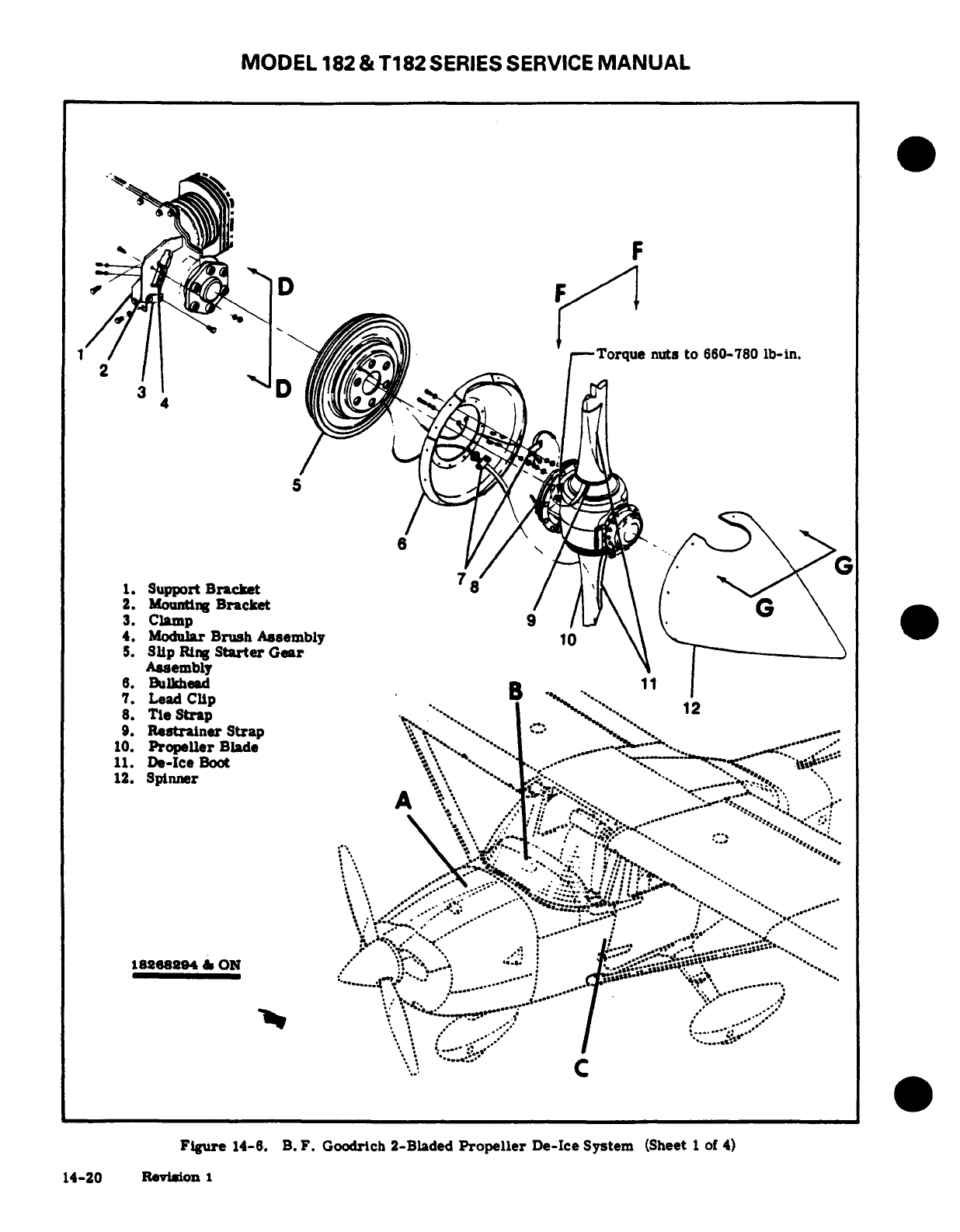
MODEL
182
&
T182
SERIES
SERVICE
MANUAL
F
D
1
2
3
Torque
nuts
to
660-780
lb-in.
32
D
G
1.
Support Bracket
8
2.
Mounting
Bracket
G
3.
Clamp
9
4.
Modular
Brush
Assembly
10
5.
Slip
Ring
Starter
Gear
Assembly
6.
Bulkhead
11
7.
Lead
Clip
8.
Tie
Strap
**.
I
i
..
12
9.
Restrainer
Strap
, ".
.
10.
Propeller
Blade.
I
11.
De-Ice
Boot
.
.
......
.
.
12.
Spinner
-.
-.
B. F. h 2
d
Pro
r
D
e
..
S
m
(
t
..
**14-20
Revisi'on I"'...o
' ..
.....
/'_'.:::::"»:.'.,,'
*....
FIgure
14-6.
B.
F. Goodrich 2-Bladed
Propeller
De-Ice System
(Sheet
1
of
4)
14-20
RevisIon
1
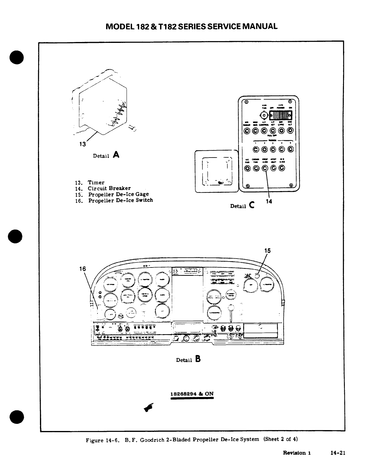
MODEL
182
&
T182
SERIES
SERVICE
MANUAL
13
Detail
A
.
a a
,^
Il i I
=
«.§
...
13.
Timer
14.
Circuit
Breaker
,
15.
Propeller
De-Ice
Gage
16.
Propeller
De-Ice
Switch
14
Detail
C
15
16
'' ,
r-i
--
|=
-
----l
" -l
......
' .
_
.
__________g
'"
^
*"
l
'"'?____
-
~
-.
,
:,
v__
_ -
?-
_
_
Detail
B
18268294
&
ON
Figure
14-6.
B.
F.
Goodrich
2-Bladed
Propeller
De-Ice
System
(Sheet
2
of
4)
Revision
1
14-21
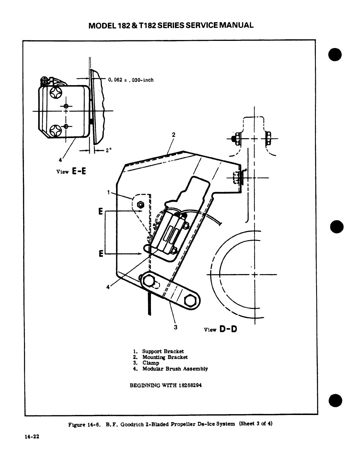
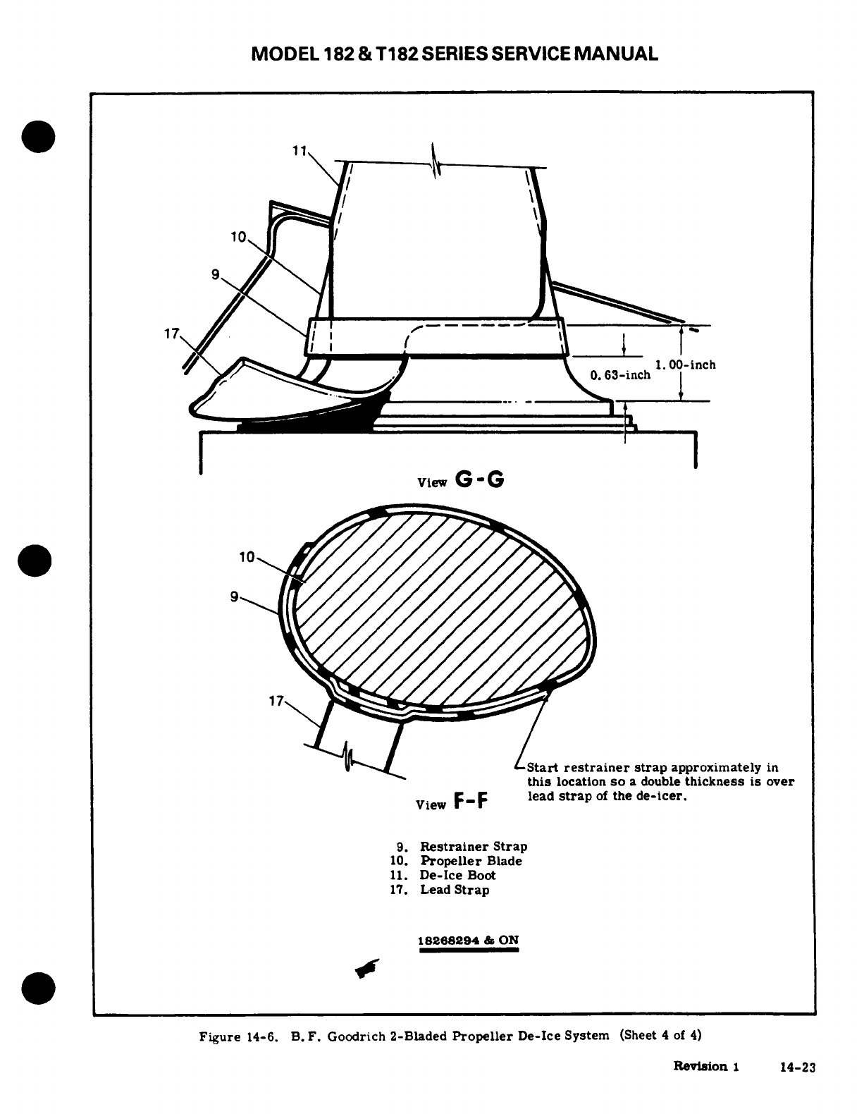
MODEL
182
&
T182
SERIES
SERVICE
MANUAL
View
G G
Start
restrainer
strap
approximately
in
this
location
so
a
double
thickness
is over
View
F-F
lead
strap
of
the
de-icer.
9.
Restrainer
Strap
10.
Propeller
Blade
11.
De-Ice
Boot
17.
Lead
Strap
18268294
&
ON
Figure
14-6.
B.
F.
Goodrich
2-Bladed
Propeller
De-Ice
System
(Sheet
4
of
4)
Revision
1
14-23
MODEL
182
&
T182
SERIES
SERVICE
MANUAL
d.
If
slip
ring
run-out
is
within
limits
specified
in
be
slow enough
to
allow
the
solvent
to
undercut
the
step
"c".
no
corrective
action is
required.
A
small
cement
so
that
parts
will
not
be
damaged.
To
in-
amount
of
run-out
may
be
corrected
by
varying
the
stall
a
propeller
anti-ice
boot.
proceed
as
follows:
torque
of
the
attachment
bolts
within
the
limits
speci-
a.
Clean
the
metal
to
be
bonded with
Methyl Ethyl
fied
by
the
propeller
manufacturer.
Ketone,
(MEK).
For
final
cleaning,
wipe
the
sol-
vent
film
off
quickly
with
a
clean,
dry
cloth
before
14-62.
INSTALLATION
AND
ALIGNMENT
OF
BRUSH
it
has
time
to
dry.
BLOCK
ASSEMBLY.
(See
figures
14-8
and
14-9.)
b.
Prepare
a
pattern
the
size
of
the
boot,
including
three
inches
of
the boot
strap.
Draw
a
centerline
NOTE
(lengthwise) through
the
pattern.
c.
Draw
a
line
on
the
centerline
of
the
leading
edge
Installation
of
the
brush
block should
be
of
the
blade.
Position
the
pattern
centerline
over
the
deferred,
when
possible,
until
after
the
leading
edge
centerline.
Position
pattern
so bottom
slip
ring,
propeller,
and
related
compo-
of
boot
is
1/2"below
spinner
cutout.
Draw
a
line
on
nents
are
installed.
However,
the
brush
the
propeller
hub on
each
side
of
the
pattern
boot
block
assembly
may
be
replaced
without
strap
where
it
crosses
the
hub.
Check
boot
strap
removing
the
propeller.
To
avoid
break-
position
by
fitting
restraining
strap
on
the
hub
and
age
when
installing
the
brush
block
as-
comparing
its
position
with
the
marked
position
of
sembly,
keep
brushes
retracted
in
brush
the
strap.
block
until
slip
ring
and
propeller
assem-
d.
Mask
off an
area
1/2"
from
each
side
and
outer
blies
have
been
installed.
end
of
the
pattern,
and
remove
the
pattern.
Make
sure
that
slip
ring
run-out
has
been
Apply
cement
at room
temperature
(65°-75°F).
corrected
before attempting
to
align
For
best
results,
allow
to
air
dry
for
a
mini-
brushes
on
slip
ring.
mum
of one
hour
at
50°F
or
above
when
rela-
tive
humidity
is
less
than
75%.
If
the
humidity
a.
In
order
to
get
smooth,
efficient
and
quiet
trans-
is
75%
and
90%,
allow
additional
drying
time.
fer
of
electric
power
from
the
brushes
to
the
slip
ring,
Do
not
apply
cement
if
relative
humidity
is
brush
alignment
must
be
checked
and
adjusted,
if
higher
than
90%
or
if
the
temperature
is
below
necessary
to
meet
the
following
requirements.
50°F.
Allow
12
hours
cement
curing
time
1.
Projection
must
be
such that
the
distance
before
starting
engine.
Allow
24
hours
cement
between
the
brush
block
and
the
slip
ring
is
0.
062
curing
time
before
operating
the
de-icers.
(±0.
030-inch).
2.
The
brushes
must
be
lined
up
with
the
slip
e.
Mix
EC-1300L
cement
(Minnesota
Mining
&
Mfg.
ring
so
that
the
entire
face
of
each
brush
is
in
con-
Co.)
thoroughly.
Surfaces
shall
be
65°F
prior
to
tact
with
the
slip
ring
throughout
the
full
360°
of
slip
applying
cement.
During
periods
of
high
humidity,
ring
rotation.
care
shall
be
taken
to
prevent
moisture
condensation
3.
The
brushes
must
contact
the
slip
ring
at
an
due
to
the
cooling
effect
of
the evaporating
solvent.
angle
of
approximately
2°
from
perpendicular
to
the
This
can
be
done
by
warming
the
area
with
a heat
gun
slip
ring
surface,
measured
toward
the
direction
of
or
heat
lamp.
Apply
one
even
brush
coat
of
EC-1300L
rotation
of
the
slip
ring. cement
to
the
cleaned metal
surface.
Allow
to
air
b.
Brush
projection
can
normally
be
adjusted
by
dry for
a
minimum
of
one
hour
and
then
apply
a
sec-
loosening
hardware
attaching
the
brush
block
and ond
even
brush
coat
of
EC-1300L
cement.
holding
the
brushes
in
the
desired
location
while
f.
Moisten
a
cloth
with
Methyl
Ethyl
Ketone
and
retightening
the
hardware.
Slotted
holes
are
pro-
clean
the
unglazed
back
surface
of
the
boot,
changing
vided.
cloths
frequently
to
avoid
contamination
of
the
cleaned
c.
One
method
for
face
alignment
is
described
in
area.
step
"b".
Another
is
to
use
shims
between
brush
g.
Apply
one
even
coat
of
EC-1300L
cement
to
back
block
and
bracket
Laminated
metal
shims
are
gen-
surface
of
boot.
It
is
not
necessary
to
cement
more
erally
provided.
Layers
of
metal
.003"
are
used
to
than
1/2"
of
the
boot
strap.
make
up
shims
which
are
approximately
0.
20"
thick
h.
Using
a
silver-colored
pencil, mark
a
centerline
overall.
Shims
may
be
fabricated
locally.
along
the
leading
edge
of
the
propeller
blade
and
a
d.
Loosen
mounting
bolts
and
twist
block
while
corresponding
centerline
on
the
cemented
side
of
the
tightening
to
attain proper angular
adjustment.
boot.
i.
Reactivate
the
surface
of
the
cement
using
a
Avoid
excessive
rubbing
of
cement,
which
would
re-
Use
care
not
to
disturb
other
adjustments
move
the
cement.
when
adjusting
angular alignment.
j.
Position
the
boot
centerline
on
the
propeller
leading
edge,
starting
at
the
hub
end
of
the
position
14-63.
REPLACEMENT
OF
DE-ICE
BOOTS.
To
marked.
Make
sure
that
boot
strap
will
fall
in
the
remove
or
loosen
installed
de-ice
boots,
use
toluol
position marked.
Tack
the boot
centerline
to
the
to
soften
the
"cement
line".
Apply
a
minimum leading edge
of
the
propeller
blade.
If
the
boot
is
amount
of
this
solvent
to
the
cement
line
as
tension
allowed
to
get
off-center,
pull
up
with
a
quick
motion
is
applied
to
peel
back
the boot.
Removal
should
and
replace
properly.
Roll
firmly
along
centerline
14-24
MODEL
182
&
T182
SERIES SERVICE
MANUAL
with
a
rubber
roller.
assembly
for
power
distribution
to
the
propeller
de-
k.
Gradually
tilting
the
roller,
work
the
boot
care-
icers,
a
brush
block
assembly
to
transfer
electrical
fully
over
either
side
of
the
blade
contour
to
avoid
power
to
the
rotating
slip
ring,
a
timer
to
cycle
trapping
air
in
pockets.
electric
power
to
the
de-icers
in
proper
sequence,
1. Rolling
outward
from
the
centerline
to
the
edges
an
ammeter,
mounted
in
the
instrument
panel,
a
tends
to
form
wrinkles,
work
them
out
smoothly
and
shunt,
a
switch
and
a
circuit
breaker.
The
de-ice
carefully
with
fingers.
system
applies
heat
to
the
surfaces
of
the
propeller
m.
Apply
one
even
coat
of
EC-539
(Minnesota
Mining
blades
where
ice
would
normally
adhere.
This
heat,
&
Mfg.
Co.
). mixed
per
manufacturer's instructions,
plus
centrifugal
force
and
the
blast
from
the
airstream.
around
the
edges
of
the
installed
boot.
removes
accumulated
ice.
Each
de-icer
has
two
sep-
n.
Remove
masking
tape
from
the
propeller
and
arate
electrothermal
heating
elements,
an
inboard
clean
the
surface
of
the
propeller
by
wiping
with
a
section
and
an
outboard
section.
When
the
switch
is
clean
cloth dampened
with
toluol.
turned
on,
the
timer
provides
power
through
the
brush
o.
Install
restrainer
strap
as
shown
in
detail
in
block
and
slip
ring
to
outboard
elements
for approxi-
figure
14-6,
sheet
4.
Start
strap
approximately
in
mately
30
seconds,
reducing ice
and
adhesion
in
these
location
shown
in
detail
so
a
double
thickness
is
areas.
Then
the
timer
switches
power
to
inboard
over
lead
strap
of
the
de-icer.
The
lead
strap
must
heating
elements
for approximately
30
seconds.
It
not
be
twisted
more
than
one
turn
(180°)
in
lining
then
returns
to
the
outer
elements
and
continues
up
the
respective
leads.
Trim
restrainer
strap
so
cycling
action.
This
outboard-inboard
sequence
is
it
will
end
approximately
as
shown
in
the
detail.
very important
since
the
loosened
ice,
through
centri-
p.
Secure
electrical
leads
of
restrainer
strap
with
fugal
force
moves
outboard.
Heating
may
begin
at
screws, washers
and
sleeves.
any
phase
in
the
cycle,
depending
on
timer
position
when
the
switch
was
turned
off
from
previous use.
14-64.
PROPELLER
DE-ICE
SYSTEM.
(McCauley,
Ground checkout
of
the
systems
is
permitted
when
3-Bladed
Propeller
Installation.)
(See
figure
14-7.) the
engine
is
not
running.
System
components
may
be
removed
and
replaced,
using
the
figure
as
a
guide.
14-65.
DESCRIPTION.
The
system
is
of an
elec-
Propeller
removal
is
necessary
before
de-ice
com-
trothermal
type.
consisting
of
electrically
heated ponents,
except
brush
block
assembly,
can
be
in-
de-icers
bonded
to
each
propeller
blade,
a
slip
ring
stalled
or
removed.
14-25
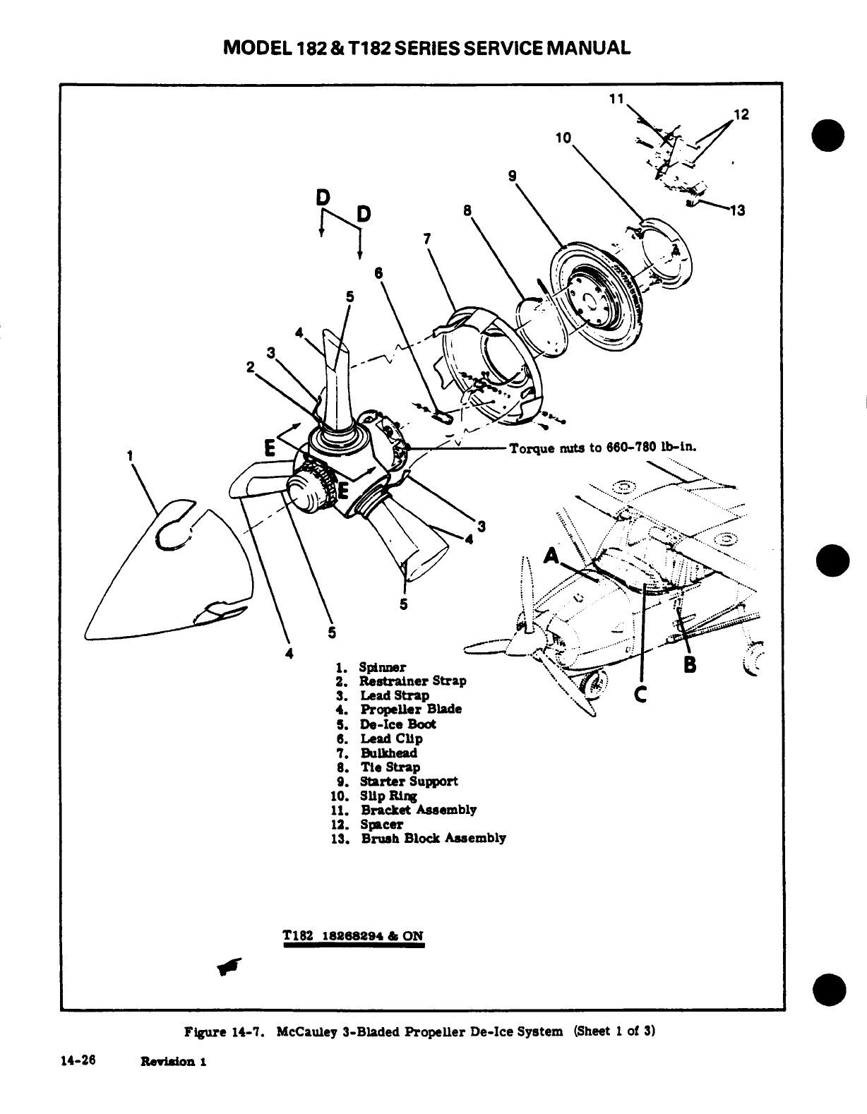
MODEL
182
&
T182
SERIES SERVICE
MANUAL
11
10
1.
Spinner
3.
Lead
Strap
4.
Propeller
Blade
5.
De-Ice
Boot
6.
Lead
Clip
7.
Bulkhead
8.
Tie
Strap
9.
Starter
Support
10.
Slip
11.
Bracket
Assembly
13.
Brush
Block
Assembly
14-26
R
3.
Lead
Strap
4.
Propeller
Blade
5.
De-Ice
Boot
6.
Lead
Clip
7.
Bulkhead
8.
Tie
Strap
9.
Starter
Support
10.
Slip
Ring
11.
Bracket
Assembly
12.
Spacer
13.
Brush
Block
Assembly
T182
18268294
&
ON
Figure
14-7.
McCauley
3-Bladed
Propeller
De-Ice
System
(Sheet
1
of
3)
14-26
Revision
1
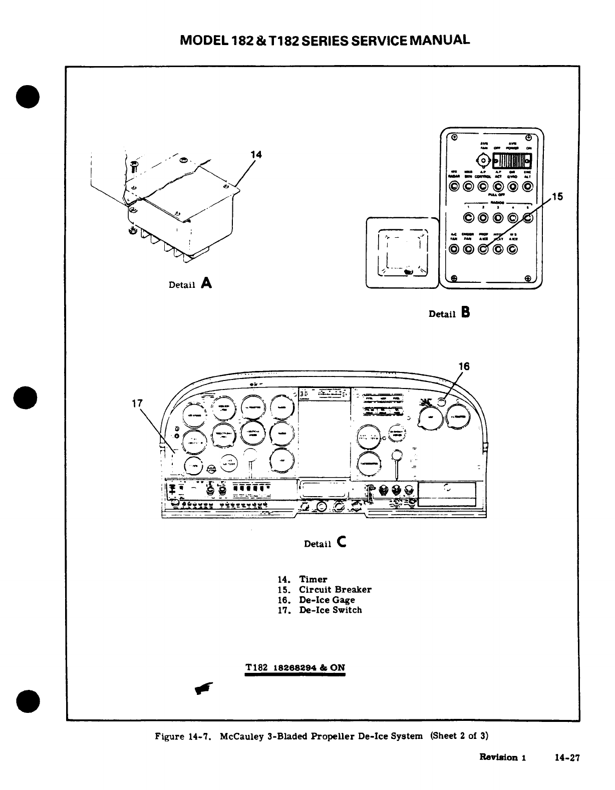
MODEL
182
&
T182
SERIES
SERVICE
MANUAL
_
.'
t§§tX
______
^'"___
*15-
v
F
0
K!• ,;
i' @©
Detail
A l -- *', i'
Detai~Detail
B
.16
17.
De-Ice
Switch
,I.?
-...
=..-
.
;?
_
-
:=,,I
.. I
Detail
C
14.
Timer
15.
Circuit
Breaker
16.
De-ice
Gage
17.
De-Ice
Switch
T182
18268294
&
ON
Figure
14-7.
McCauley
3-Bladed
Propeller
De-Ice
System
(Sheet
2
of
3)
Revision
1
14-27
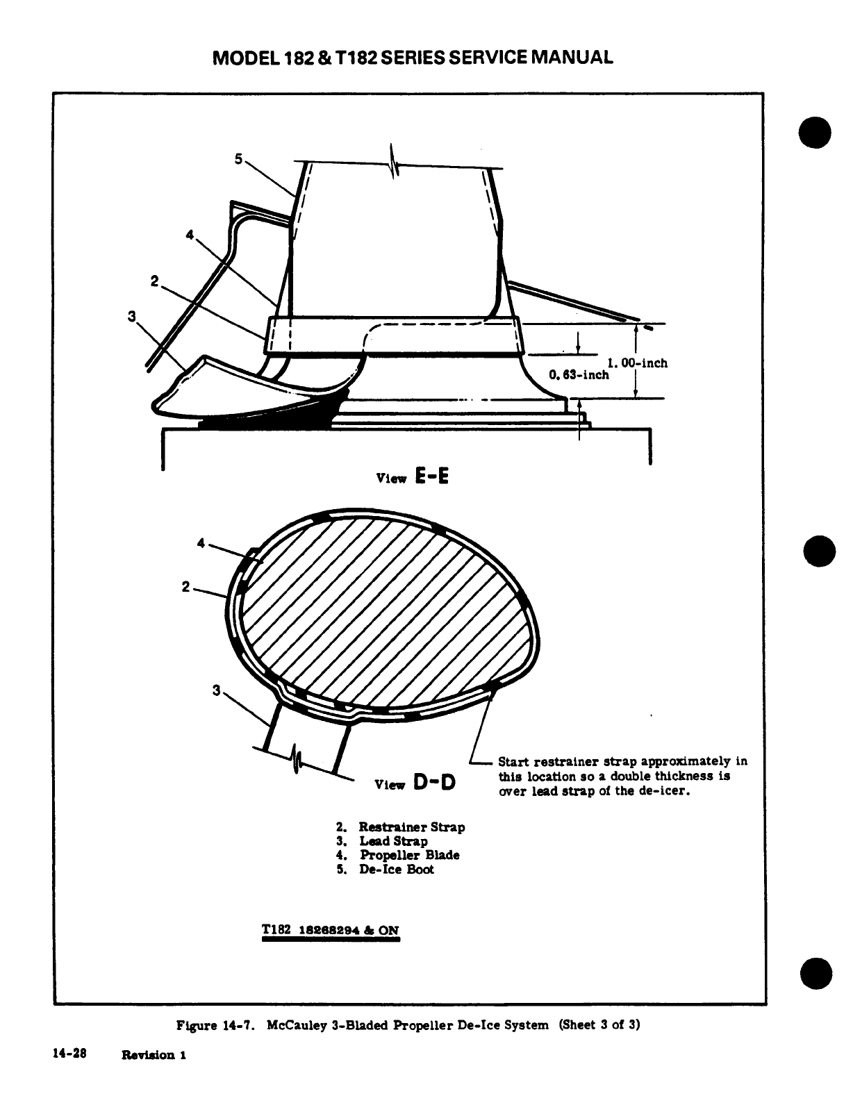
MODEL
182
&
T182
SERIES
SERVICE
MANUAL
4/
3i-o
k-- 1
*
2
C\
0.63-inch
view
E-E
Start
restrainer
strap
approximately
in
ieV
D-D
this
location
so
a
double
thickness
is
DView
over lead
strap
of
the
de-icer.
2.
Restrainer
Strap
3.
Lead
Strap
4.
Propeller
Blade
5.
De-Ice
Boot
T182
18268294
&
ON
Figure
14-7.
McCauley
3-Bladed
Propeller
De-Ice
System
(Sheet
3
of
3)
14-28
Revision
I
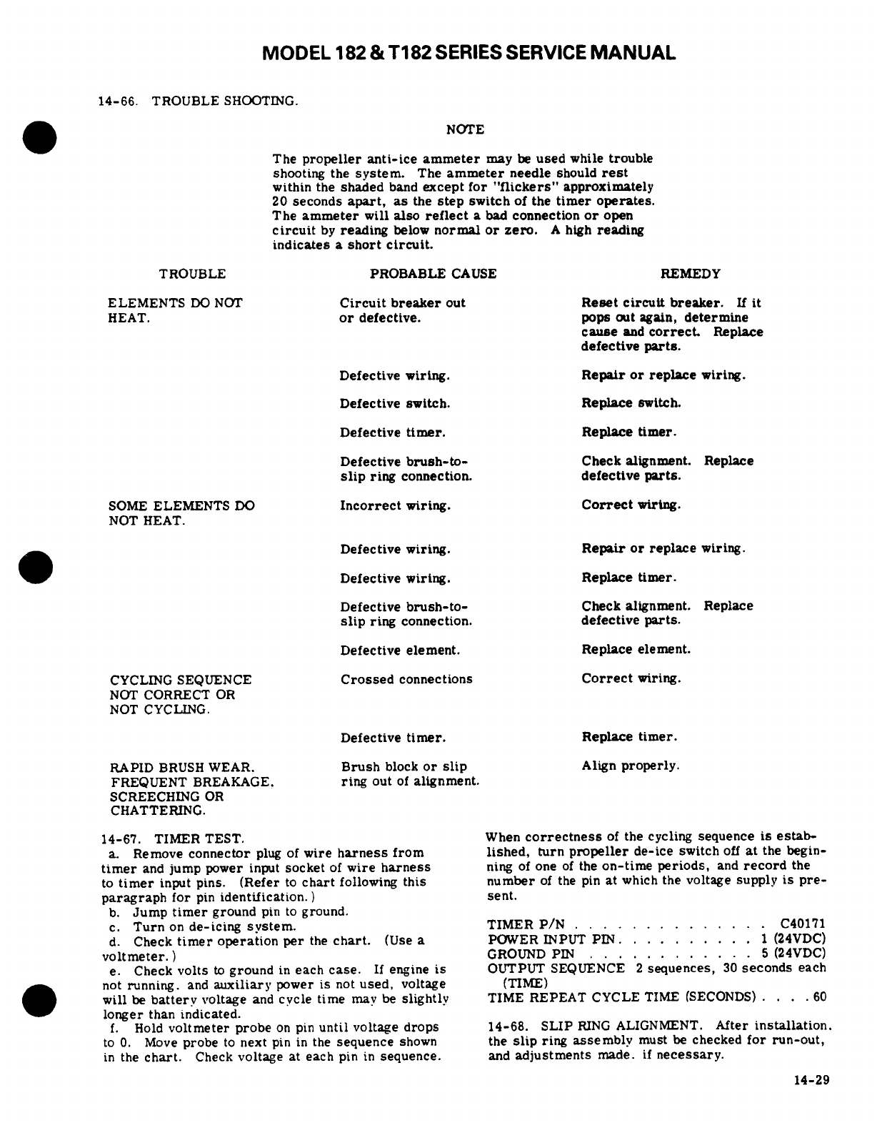
MODEL
182
&
T182
SERIES SERVICE
MANUAL
14-66.
TROUBLE
SHOOTING.
NOTE
The
propeller
anti-ice
ammeter
may
be
used
while
trouble
shooting
the
system.
The
ammeter
needle
should
rest
within the
shaded
band
except
for
"flickers"
approximately
20
seconds
apart,
as
the
step
switch
of
the
timer
operates.
The
ammeter
will
also
reflect
a
bad
connection
or
open
circuit
by
reading
below
normal
or
zero.
A
high
reading
indicates
a
short
circuit.
TROUBLE
PROBABLE
CAUSE
REMEDY
ELEMENTS
DO
NOT
Circuit
breaker
out
Reset circuit
breaker.
If
it
HEAT.
or
defective,
pops
out
again,
determine
cause
and
correct.
Replace
defective
parts.
Defective wiring.
Repair
or
replace
wiring.
Defective
switch.
Replace
switch.
Defective
timer.
Replace
timer.
Defective
brush-to-
Check alignment.
Replace
slip
ring
connection.
defective
parts.
SOME
ELEMENTS
DO
Incorrect
wiring.
Correct
wiring.
NOT HEAT.
Defective
wiring.
Repair
or
replace
wiring.
Defective wiring.
Replace
timer.
Defective
brush-to-
Check
alignment.
Replace
slip
ring
connection.
defective
parts.
Defective element.
Replace element.
CYCLING
SEQUENCE
Crossed
connections
Correct
wiring.
NOT
CORRECT
OR
NOT
CYCLING.
Defective
timer.
Replace
timer.
RAPID
BRUSH
WEAR.
Brush
block
or
slip
Align
properly.
FREQUENT
BREAKAGE.
ring
out
of
alignment.
SCREECHING
OR
CHATTERING.
14-67.
TIMER
TEST.
When
correctness
of
the cycling
sequence
is
estab-
a.
Remove
connector
plug
of
wire
harness
from
lished,
turn
propeller
de-ice
switch
off
at
the
begin-
timer
and
jump
power
input
socket
of
wire
harness
ning
of
one
of
the
on-time
periods,
and
record
the
to
timer
input
pins.
(Refer
to
chart
following
this
number
of
the
pin
at
which
the
voltage
supply
is
pre-
paragraph
for
pin
identification.)
sent.
b.
Jump
timer
ground
pin
to
ground.
c.
Turn
on
de-icing
system.
TIMER
P/N
..............
C40171
d.
Check
timer
operation per
the
chart.
(Use
a
POWER INPUT
PIN
.......... 1
(24VDC)
voltmeter.)
GROUND
PIN
..........
.
5
(24VDC)
e.
Check
volts
to
ground
in
each
case.
If
engine
is
OUTPUT
SEQUENCE
2
sequences,
30
seconds
each
not
running.
and
auxiliary
power
is
not
used,
voltage
(TIME)
will
be
battery
voltage
and
cycle time
may
be
slightly
TIME
REPEAT
CYCLE
TIME
(SECONDS)
..
..
60
longer
than
indicated.
f.
Hold
voltmeter
probe
on
pin
until
voltage
drops
14-68.
SLIP
RING
ALIGNMENT.
After
installation.
to
0.
Move
probe
to
next
pin
in
the
sequence
shown
the
slip
ring
assembly
must
be
checked
for run-out,
in
the
chart.
Check
voltage
at
each
pin
in
sequence.
and
adjustments
made.
if
necessary.
14-29
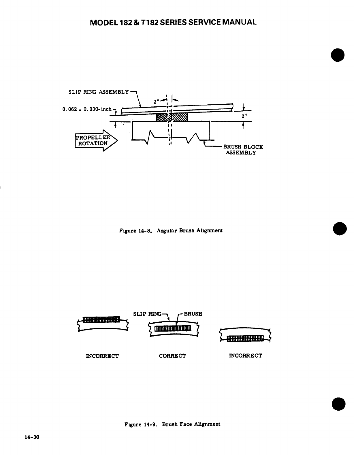
MODEL
182
&
T182
SERIES
SERVICE
MANUAL
SLIP
RING
ASSEMBLY
0.
062
t
0.
030-inch
1
28
PELLERS
ROTATION
}
I t
BRUSH
BLOCK
ASSEMBLY
Figure
14-8. Angular
Brush
Alignment
SLIP
ING
BRUSH
INCORRECT CORRECT
INCORRECT
Figure
14-9.
Brush Face
Alignment
14-30
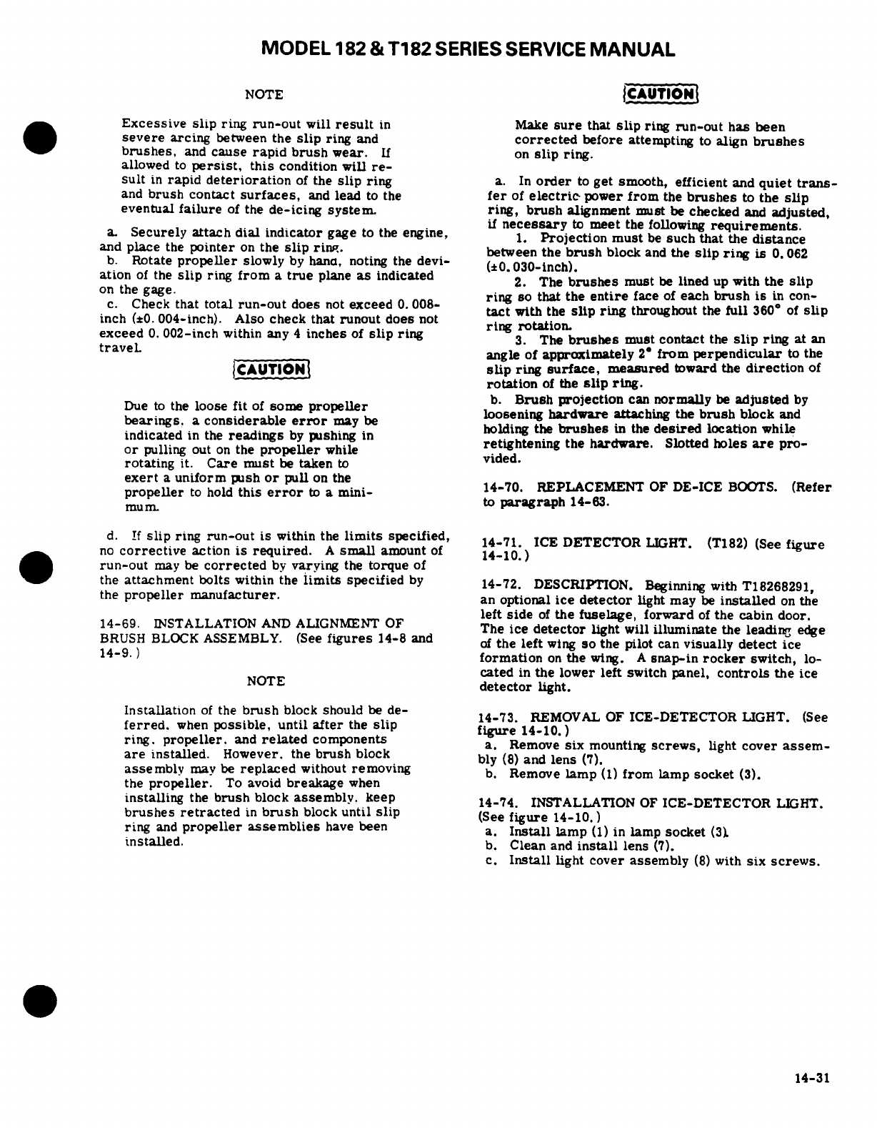
MODEL
182
&
T182
SERIES SERVICE
MANUAL
NOTE
Excessive
slip
ring
run-out
will
result
in
Make
sure
that
slip
ring
run-out
has
been
severe
arcing
between
the
slip
ring
and
corrected
before
attempting
to
align
brushes
brushes,
and
cause
rapid
brush
wear.
If
on
slip
ring.
allowed
to
persist,
this
condition
will
re-
sult
in
rapid
deterioration
of
the
slip
ring
a.
In
order
to
get
smooth,
efficient
and
quiet
trans-
and
brush
contact
surfaces,
and
lead
to
the
fer
of
electric
power
from
the
brushes
to
the
slip
eventual
failure
of
the
de-icing
system.
ring,
brush
alignment
must
be
checked
and
adjusted,
if
necessary
to
meet
the
following
requirements.
a.
Securely
attach
dial
indicator
gage
to
the
engine,
1.
Projection
must
be
such
that
the
distance
and
place
the
pointer
on
the
slip
ring.
between
the
brush
block
and
the
slip ring
is
0.062
b.
Rotate
propeller
slowly
by
hand,
noting the
devi-
(±0.030-inch).
ation
of
the
slip
ring
from
a
true
plane
as
indicated
2.
The
brushes
must
be
lined
up
with
the
slip
on
the gage.
ring
so
that
the
entire
face
of
each
brush
is
in
con-
c.
Check
that
total
run-out
does
not
exceed
0.
008-
tact
with the
slip
ring
throughout
the
full
360°
of
slip
inch
(±0.
004-inch).
Also
check
that
runout
does
not
ring
rotation.
exceed
0.
002-inch
within
any
4
inches
of
slip
ring
3.
The
brushes
must
contact
the
slip
ring
at
an
travel.
rotation
of
the
slip
ring.
b.
Brush
projection
can
normally
be
adjusted
by
Due
to
the
loose
fit
of
some
propeller
loosening
hardware
attaching the
brush
block
and
bearings,
a
considerable
error
may
be
holding
the
brushes
in
the
desired
location while
indicated
in
the
readings
by
pushing
in
retightening
the
hardware.
Slotted
holes
are
pro-
or
pulling
out
on
the
propeller
while
vided
rotating
it.
Care
must
be
taken
to
exert
a
uniform
push
or
pull
on
the
14-70.
REPLACEMENT
OF
DE-ICE
BOOTS.
(Refer
propeller
to
hold
this
error
to
a
mini-
to
paragraph
14-63.
mum.
d.
If
slip
ring
run-out
is
within
the
limits
specified,
14-71.
ICE
DETECTOR
LIGHT.
(T182)
(See
figure
no
corrective
action
is
required.
A
small
amount
of
14-10.)
run-out
may
be
corrected
by
varying
the
torque
of
the
attachment
bolts
within
the
limits
specified
by
14-72.
DESCRIPTION. Beginning with T18268291,
the
propeller
manufacturer.
an
optional
ice
detector
light may
be
installed
on
the
left
side
of
the
fuselage,
forward
of
the
cabin
door.
14-69.
INSTALLATION
AND
ALIGNMENT
OF
The
ice
detector
light
will illuminate
the
leading
edge
BRUSH
BLOCK
ASSEMBLY.
(See
figures
14-8
and
of
the
left
wing
so the
pilot
can
visually
detect
ice
14-9.
)
formation
on
the
wing.
A
snap-in
rocker
switch,
lo-
cated
in
the
lower
left
switch
panel,
controls
the
ice
NOTE
detector
light.
Installation
of
the
brush
block
should
be
de-
14-73.
REMOVAL OF
ICE-DETECTOR
LIGHT.
(See
ferred.
when
possible,
until
after
the
slip
figure
14-10.)
ring.
propeller.
and
related
components
a.
Remove
six
mounting
screws,
light
cover
assem-
are
installed.
However,
the
brush
block
bly
(8)
and
lens
(7).
assembly
may
be
replaced
without
removing
b.
Remove
lamp
(1)
from
lamp
socket
(3).
the
propeller.
To
avoid
breakage
when
installing
the
brush
block
assembly.
keep
14-74.
INSTALLATION
OF
ICE-DETECTOR
LIGHT.
brushes
retracted
in
brush
block
until slip
(See
figure
14-10.)
ring
and
propeller
assemblies
have
been
a.
Install
lamp
(1)
in
lamp
socket
(3)
installed.
b.
Clean
and
install
lens
(7).
c.
Install
light cover
assembly
(8)
with
six screws.
14-31

MODEL
182
&
T182
SERIES
SERVICE
MANUAL
14-75.
CONTROL
SURFACE
DISCHARGERS.
may
be
purchased
from
the
following
source:
James
G.
Biddle
Co
14-76.
DESCRIPTION.
Wick
type
static
dischargers
Plymouth
Meeting,
Pa.,
19462
may
be
installed
on
the
trailing
edge
surfaces
of
the
ailerons.
elevators
and
rudder
of
the
aircraft.
One
Perform
the
following
resistance
checks:
type
discharger
is
fabricated
with
the
wick
and
the
1.
If
the
wick
and
base
of
the
static discharger
base
combined
into
an
integral
unit;
in
the
other
type,
are
combined,
the
resistance
from
the
base
of
the
the
wick
is
attached
to
the
base
by
a
threaded
fitting,
discharger
to
a
good
aircraft
ground should
check
2.
5
and
may
be
replaced
without
removing the
base
from
milliohms
maximum.
the
aircraft.
The
installation
of
static
dischargers
2.
If
the
wick
can
be
separated
from
the
base,
reduces
the
build-up
of
static electricity
on
the
air-
the
resistance
from
the
base
to
the
airframe
should
frame
as
a
consequence
of
flying
through
haze,
dust,
check
1.
0
ohm
maximum.
In
the
preceding
steps,
rain,
snow
or
ice
crystals.
In
some
cases,
if
dis-
establish
a
good
ground
before
proceeding to
step
3.
chargers
are
not
installed.
or
not
functioning
as
a
3.
Connect
the
EARTH
terminal
of
the
megohm-
result
of
age
or
repeated
exposure
to
static
electricity,
meter
to
the
base
of
the
discharger
and
check
the
static
build-up
can
result
in
the
loss
of
usable
radio
resistance
at
the
tip
of
the
wick.
The
resistance
signals
on
all
communication
and
navigation
equip-
should check
1.
0
to
100.
0
megohms.
This
check
ment.
Whenever
static
dischargers
are
installed,
re-
applies
to
either
type
of
static
discharger.
If
the
placed,
and
at
regular intervals
during
their
service
resistance
of
the
wick
checks
less
than
1.
0
or
more
life,
resistance
checks
should
be
performed
to
deter-
than
100.
0
megohms,
the
wick should
be
replaced.
mine
their
effectiveness
in
reducing
static
build-up.
14-77.
RESISTANCE CHECK.
Since
static
discharg-
ers
lose
their
effectiveness
with
age
and
exposure
to
DO
NOT
BEND
the
wick
during
this
check
static
electricity,
they
should
be
checked
with
a
500
since
wicks
have
a higher
resistance
if
to
1000
volt
capacity megohmmeter
every
500
hours
bent.
or
annually,
whichever
occurs
first.
Megohmmeters
14-33/(14-34
blank)
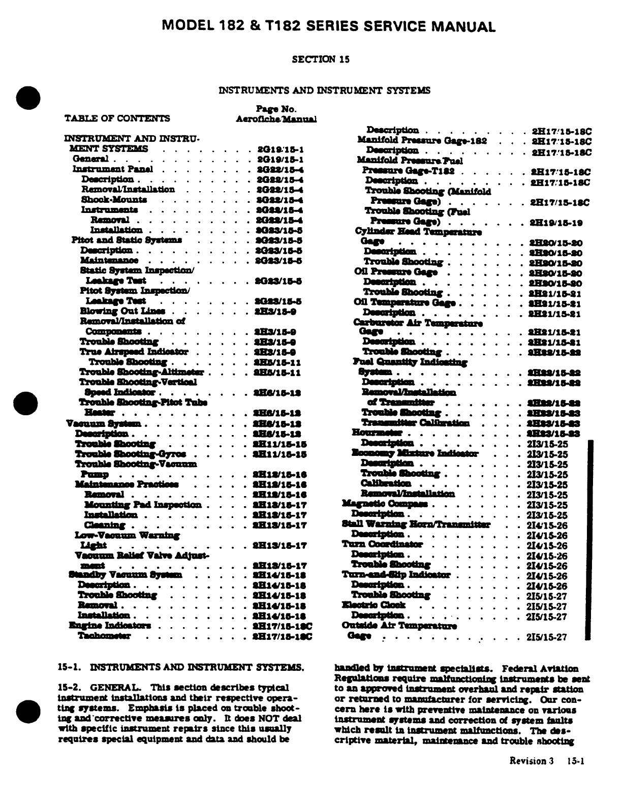
MODEL
182
&
T182
SERIES
SERVICE
MANUAL
SECTION
15
INSTRUMENTS
AND
INSTRUMENT
SYSTEMS
Page
No.
TABLE OF
CONTENTS
Aerofiche/Manual Description
....... ..
2H17/15-18C
Instrument
Panel.
....
....
Description
..........
Shock-Mounts
........
In
Removal
.... ....
Blowing
Out
Lines
.......
Trouble
Shooting
.......
.
T
sewun
... .
1..1-1
Trs
m
.
...
2..1543
Dim
0on.
.. 1...
.2.. o
.r.h.
.re
.
5.
1
m ... a
hr
booan.
....
..
...
as/1..-1
o
llb .
........
213115-25
Trble
_4
.
.. ..
11/15-15
neem
, . ..
. .
2135-25
pTrPblM
.
...... 1....
Hi/i1-
euMo
..
.....
21315-25
MaaTm
nf.p
P
m
.. ...
aH
s11t-1l
6n
T
.....
21315-25
_m 211 a
. . /.
.. cramo .......
....
213/15-25
· , lmp ........... il....
ls.
tlsle
TGEN
-_boisnf
.......
213r15-25
.
o-
e
- -- ... ...
HS/D18
G
l...
*.H13/1617.....
213/15-25
Coula
..
In.Potio-
.
.
251/15-17
M851-6
6
.
..
21315-25
.212/16-17
DmeradriH.
H
21315-25
Mo up.33...
12ia-/l67
WarnngD . .
.aTr
...
21415-26
LJg
... 1..
.. 1..
.
E113/1-17
T ur
ia ...... 21415-26
Voun ffi
Vae
Ad*jst-
DmoriP
* * * * * .
214/15-26
. . . . ..
/1-17
Trobls
*..
.. .
214/15-26
s,,iI
..... .s14li
DeSci
po
wm.
.......... .
214/15-26
SrtdIib~ ......
...
Vl Tu....
TomBta
.......
2415.26
TMsU
l
HoIng
.
.b14/15-
18
TooblelBo
.........
215/15-27
1ul ........... EH14/1-1 ...
...........
215/15-27
In
ballaio
..........
14/11-16
D
.... . . ..
215/15-27
bgmeu
IndiMtor
......
217/15-1C
Outde
Air
Tempertu1
Tahometr
......
.17/1-1C
oe* .. .........
2515-27
15-1.
ISTRUENTS
AND
INSTRUMENT
SYSTEMS.
handled
by
Itrument
spectalists.
Federal
Aviation
Rulation
require
mnlfsaclo
truments
be
sent
15-2.
GENERAL.
This
section
describes
typical
to
an
approved
lnstrumnt
overhal
nd
repair
tation
instrument
Intallattons
and
their
respective
opera-
or
returned
to
manuacturer
for
servicing.
Our
con-
ting
systems.
Emphsis
is
placed
on
trouble
shoot-
cern
here
is
with
preventive
maintenace
on
various
tng
and'corrective
meaures
only.
It
does
NOT
deal
nstrument
systems
and
correction
of
system
falts
with
specific
instrment
repairs
since
this
usually
which
result
s
instrument
malfunctions.
The
des-
requires
special
equipment and
dta
and
should
be
crtptive
material,
maintenance
and trouble
shooting
Revision
3
1351
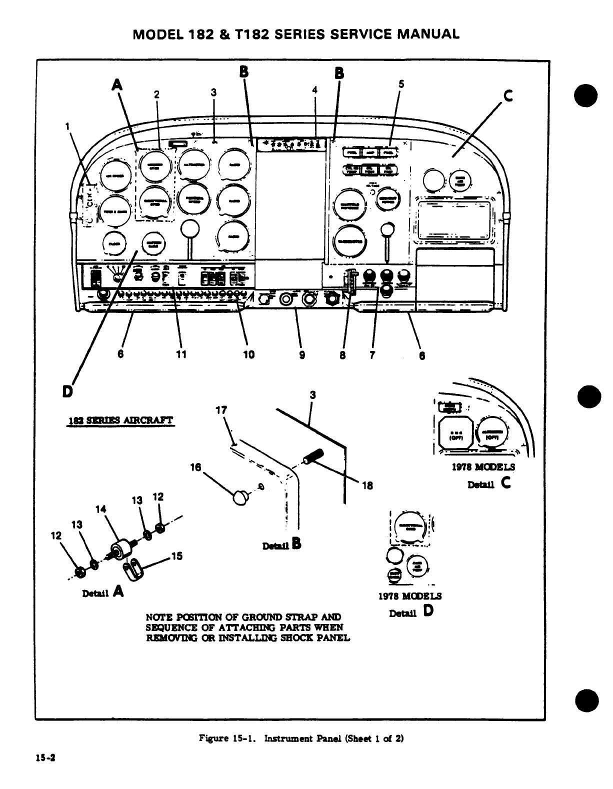
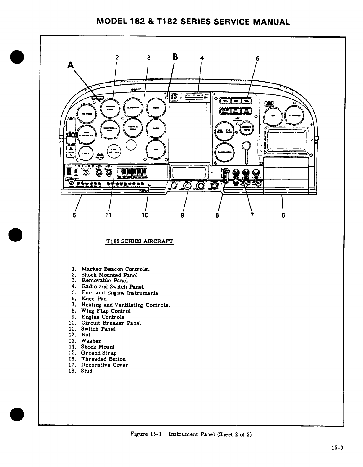
MODEL
182
&
T182
SERIES
SERVICE
MANUAL
2 3
B
4
.' ).
a
,
--------
.l
·=
/-
e
/
z I
'
6
11
10
9
8
7
6
T182
SERIES AIRCRAFT
1.
Marker
Beacon
Controls.
2.
Shock
Mounted
Panel
3.
Removable Panel
4.
Radio
and
Switch
Panel
5.
Fuel
and Engine
Instruments
6.
Knee
Pad
7.
Heating
and
Ventilating
Controls.
8.
Wing
Flap
Control
9.
Engine
Controls
10.
Circuit
Breaker
Panel
11.
Switch
Panel
12.
Nut
13.
Washer
14.
Shock
Mount
15.
Ground
Strap
16.
Threaded
Button
17.
Decorative
Cover
18.
Stud
Figure
15-1.
Instrument
Panel
(Sheet
2
of
2)
15-3

MODEL
182
&
T182
SERIES
SERVICE
MANUAL
information
in
this section
is
intended
to
help
the
5.
To
install
shock-mounted
panel,
place
panel
mechanic
determine
malfunctions
and
correct
them,
over
shock
mount
studs.
Be
sure
the
ground
strap
is
up
to
the
defective
instrument
itself,
at
which point
installed
in
the
proper
position.
if
removed.
then in-
an
instrument
technician
should
be
called
in.
Some
stall
nuts
and
washers.
instruments,
such
as
fuel quantity
and
oil
pressure
6.
Install
gyros,
uncap and
install
plumbing. Refer
gages,
are
so
simple
and
inexpensive,
repairs
usu-
to note in
paragraph
15-9.
ally
will
be
more
costly
than
a
new
instrument.
On
7.
Install
decorative
cover.
the
other
hand,
aneroid
and
gyro
instruments
usu-
ally
are
well
worth
repairing.
The
words
"replace
15-6.
SHOCK-MOUNTS.
Service
life
of
shock-
instrument"
in
the
text,
therefore,
should
be
taken
mounted
instruments
is
directly
related
to
adequate
only in
the
sense
of
physical
replacement
in
aircraft,
shock-mounting
of
the
panel.
If
removel
of
shock-
Whether
replacement
is
to
be
with
a
new
instrument,
mounted
panel
is
necessary,
check
mounts
for
de-
an
exchange
one,
or
original instrument
is
to
be
terioration
and
replace
as
necessary.
repaired
must
be
decided
on
basis
of
individual
cir-
cumstances.
15-7.
INSTRUMENTS.
(See
Figure
15-1.)
15-3,
INSTRUMENT
PANEL.
(See
Figure
15-1.)
15-8.
REMOVAL.
Most
instruments
are
secured
to
the
panel
with
screws
inserted
through
the
panel
15-4. DESCRIPTION.
The
instrument
panel
assem-
face,
under
the
decorative
cover.
To
remove
an
bly
consists
of
a
stationary
panel,
a
removable
flight
instrument,
remove
decorative
cover,
disconnect
instrument
panel
and
a
shock-mounted panel.
The
wiring
or
plumbing
to
instrument,
remove
mounting
stationary
panel, containing
fuel
and engine
instru-
screws
and
take
instrument
out
from
behind,
or
in
mants
is
secured
to
the
engine mount
stringers
and
a
some
cases,
from
front
of
panel.
Instrument
clusters
forward fuselage
bulkhead.
The
removable
panel,
are
installed
as
units
and
are
secured
by
a
screw
at
containing
flight
instruments
such
as
airspeed,
verti-
each
end.
A
cluster
must
be
removed
from
panel
to
cal
speed
and
altimiter
is
secured
to the
stationary
replace
an
individual
gage.
In
all
cases
when
an
in-
panel
with
screws.
The
shock-mounted panel,
con-
strument
is
removed, disconnected
lines
or
wires
taining
major
flight
instruments
such
as
the
horizon-
should
be
protected.
Cap
open
lines
and
cover
pres-
tal
and
directional
gyros
is
secured
to
the
removable
sure
connections on
instrument
to
prevent
thread
panel
with
rubber
shock-mounted
assemblies.
Most damage and
entrance
of
foreign
matter.
Wire
ter-
of
the
instruments
are
screw
mounted
on
the panel. minals
should
be
insulated
or
tied
up
to
prevent
ac-
cidental
grounding
or
short-circuiting.
15-5.
REMOVAL
AND
INSTALLATION.
a. FLIGHT
INSTRUMENT
PANEL 15-9.
INSTALLATION.
Generally,
installation
pro-
1.
Unscrew
threaded
buttons
and
remove
decorative
cedure
is
the
reverse
of
removal
procedure.
Ensure
cover.
Disconnect
post
light wiring
if
installed.
mounting
screw
nuts
are
tightened
firmly,
but
do
not
2.
Tag
and
disconnect
plumbing
and
wiring.
Cap
over-tighten,
particularly
on
instruments
having
plumbing.
plastic
cases.
The
same
rule
applies
to
connecting
3.
Remove
screws
securing
flight
instrument
panel
plumbing
and
wiring.
to
stationary
panel
and
pull
straight
back
to
remove.
4.
To
install,
place
panel
in
position
and
install
NOTE
screws.
5.
Install
flight
instruments
in
panel.
All
instruments
(gages
and
indicators),
re-
6.
Uncap
plumbing
and
connect
plumbing
also
wiring.
quiring
a
thread
seal
or
lubricant,
shall
be
Do
not
over-tighten
connections.
Refer
to
note
in
installed
using
teflon
tape
on
male
fittings
paragraph
15-9. only.
This
tape
is
available
through
the
b.
SHOCK-MOUNTED
PANEL
Cessna
Supply
Division.
NOTE
When
replacing
an
electrical
gage
in
an
instrument
cluster
assembly,
avoid
bending
pointer
or
dial plate.
Due
to
the
difficulty
encountered
when
remov-
Distortion
of
dial
or
back
plate
could
change
the
cali-
ing
the
shock-mounted panel
with
the
gyros
bration
of
gages.
installed,
it
is
recommended
that
the
direc-
tional
gyro
be
disconnected
and
removed
prior
15-10.
PITOT
AND
STATIC
SYSTEMS.
to
re
-noval
of
the shock-mounted panel.
15-11.
DESCRIPTION.
The
pitot
system
conveys
1.
Unscrew
threaded
buttons
and
remove
decorative ram
air
pressure
to
the
airspeed
indicator.
The
cover.
Disconnect
post
light
wiring
if
installed.
static
system
vents
vertical
speed
indicator,
alti-
2.
Tag,
disconnect
and
cap
gyro
plumbing.
meter
and
airspeed
indicator
to
atmospheric
pres-
3.
Remove
directional
gyro
mounting
screws
and
sure
through
plastic
tubing
connected
to
static
ports.
remove
gyro from
panel.
A
static
line
sump
is
installed
at
each
source
button
4.
Remove
shock-mount.
nuts
and
washers
then
to
collect
condensation
in
static
system.
A
pitot
tube
work
panel
out
from
behind
flight
instrument
panel.
heater
may
be
installed.
The
heating
element
is
con-
The
horizon
gyro
may
also
be
removed
from
panel
trolled
by
a switch
at
the
instrument
panel
and
power-
if
desired.
15-4
MODEL
182
&
T182
SERIES
SERVICE
MANUAL
ed
by
the
electrical
system.
A
static
pressure
alter-
NOTE
nate
source
valve
may
be
installed
in
the
static
sys-
tem
for
use
when
the
external
static
source
is
mal-
If
leakage
rate
exceeds
the
maximum
allowable,
functioning.
This
valve
also
permits
draining
first
tighten
all
connections, then
repeat
leak-
condensate from
the
static
lines. Refer
to
Pilots
age
test.
If
leakage
rate
still
exceeds
the
maxi-
Operating
Handbook
for
flight
operation
using
alter-
mum
allowable,
use
following
procedure.
nate
static
source
pressure.
The
encoding
altimeter
supplies
an
altimeter
reading
to
the
optional
300
or
i.
Disconnect
static pressure
lines from
airspeed
400
transponder
for
signal
transmission.
The
stand-
indicator
and
vertical
speed
indicator.
Use
suitable
by
altimeter
is
connected
to
the
static
system
by
a
fittings
to
connect
lines
together
so
altimeter
is
the
tube
to
the
vertical
speed
indicator.
The
static
tube
only
instrument
still
connected
into
static
pressure
installation
will
vary
when
an
alternate
static
source
system.
is
installed.
j.
Repeat
leakage
test
to
check
whether
static
pres-
sure
system or
the
bypassed
instruments
are
cause
of
15-12.
MAINTENANCE.
Proper
maintenance
of
leakage.
If
instruments are
at
fault,
they
must
be
pitot
and
static system
is
essential
for
proper
opera-
repaired
by
an
"appropriately
rated repair
station"
tion
of
altimeter, vertical
speed and
airspeed
indi-
or
replaced.
If
static pressure
system
is
at
fault,
cators.
Leaks,
moisture
and
obstructions
in
pitot
use
following
procedure
to
locate
leakage.
system
will
result
in
false
airspeed
indications,
k.
Attach
a
source
of
positive
pressure
to
static
while
static system
malfunctions
will
affect
readings
source
opening.
Figure
15-4
shows
one
method
of
of
all
three
instruments.
Under
instrument
flight
obtaining
positive
pressure.
conditions,
these
instrument
errors
could
be
hazar-
dous.
Cleanliness
and
security
are
the
principal
rules
for
system
maintenance.
The
pitot
tube
and
static
ports
MUST
be
kept
clean
and
unobstructed.
Do
not
apply
positive
pressure
with
airspeed
indicator
or
vertical
speed
indicator
connect-
15-13.
STATIC
PRESSURE
SYSTEM
INSPECTION
ed
to
static
pressure
system.
AND
LEAKAGE
TEST.
The
following
procedure
outlines
inspection
and
testing
of
static
pressure
1.
Slowly
apply
positive
pressure
until
altimeter
system,
assuming
altimeter
has
been
tested
and
in-
indicates
a
500-foot
decrease
in
altitude
and
main-
spected
in
accordance
with
current
Federal
Aviation
tain this
altimeter
indication
while
checking
for
leaks.
Regulations.
Coat line
connections
and
static
source
flange
with
a.
Ensure
static
system
is
free
from
entrapped
LEAK-TEC
or
a
solution
of
mild
soap
and
water,
moisture
and
restrictions.
watching
for
bubbles
to
locate
leaks.
b.
Ensure
no
alterations
or
deformations
of
air-
m.
Tighten
leaking connections.
Repair
or
replace
frame
surface
have
been
made
which would
affect
parts
found
defective.
the
relationship
between
air
pressure
in
static
pres-
n.
Reconnect
airspeed
and
vertical
speed
indicators
sure
system
and
true
ambient
static
air
pressure
for
into
static
pressure
system
and
repeat
leakage
test
any
flight
configuration.
per
steps
"c"
thru
"h".
c.
Seal
one
static
source
port
with
pressure
sensi-
tive
tape.
This
seal
must
be
air
tight.
15-14.
PITOT
SYSTEM
INSPECTION
AND
LEAKAGE
d.
Close
static
pressure
alternate
source
valve,
TEST.
To
check
pitot system
for
leaks,
place
a
piece
if
installed.
of
tape over
small
hole
in
lower
aft
end
of
pitot
tube,
e.
Attach
a
source
of
suction
to
the
remaining
static
fasten
a
piece
of
rubber
or
plastic
tubing
over
pitot
pressure
source
opening.
Figure
15-5
shows
one
tube,
close
opposite
end
of
tubing
and
slowly
roll
up
method
of
obtaining
suction.
tube
until
airspeed
indicator
registers
in
cruise
range.
f.
Slowly
apply
suction
until
altimeter
indicates
a
Secure
tube
and
after
a
few
minutes
recheck
airspeed
1000-foot
increase
in
altitude.
indicator.
Any
leakage
will have
reduced
the
pres-
pressure
is
reduced
gradually.
Otherwise
instru-
When
applying
or
releasing
suction,
do
not
ment
may
be
damaged.
If
test
reveals
a
leak
in
sys-
exceed
range
of
vertical
speed
indicator
or
tem,
check
all
connections for
tightness.
airspeed
indicator.
15-15.
BLOWING
OUT
LINES.
Although
the
pitot
g.
Cut
off
suction
source
to
maintain
a
"closed"
system
is
designed
to
drain
down
to
pitot
tube
open-
system
for
one
minute.
Leakage
shall
not
exceed
ing,
condensation
may
collect
at
other
points
in
sys-
100
feet
of
altitude
loss
as
indicated
on
altimeter.
tem
and
produce
a
partial
obstruction.
To
clear
the
h.
If
leakage
rate
is
within
tolerance,
slowly
re-
line,
disconnect
it
at
airspeed
indicator.
Using
low
lease
suction
source
and
remove
tape
from
static
pressure air,
blow
from
indicator
end
of
line
toward
port.
the
pitot
tube.
15-5
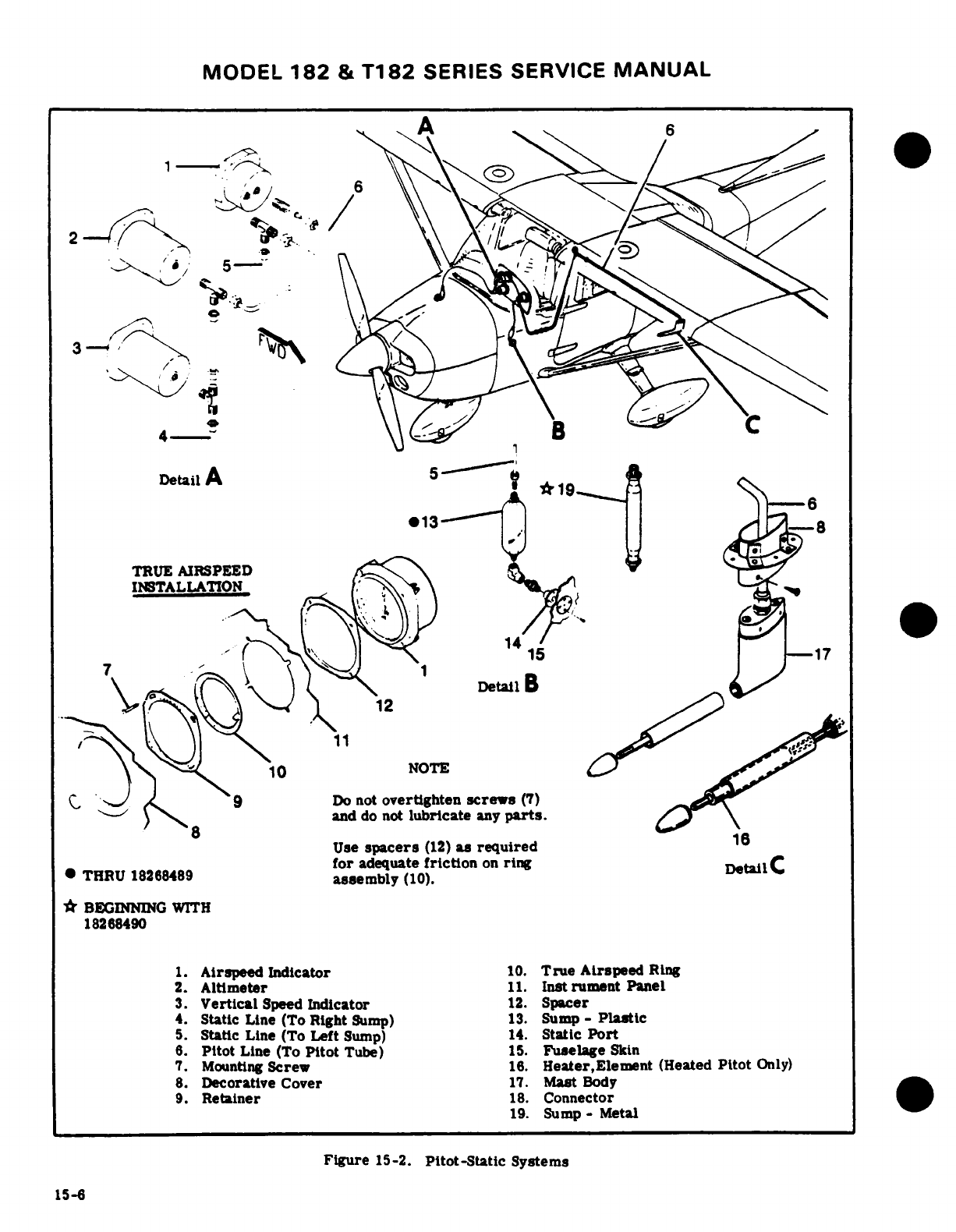
MODEL
182
&
T182
SERIES
SERVICE
MANUAL
A
1
-1
2'~~~~~~o-
et ftto
o
TRUE
AIRSPEED
na )
T A
7/Q
5
4
--
17
.
ertic al
SpeedInicator.Spa
^N
"---^
10
NOTE
/, ,' r
^^
~~~C '^
9
Do
not
overtighten
scre
s
(7)
P at
.
S) \8 t
and
do
not
lubricate
any
parts.
Pr \
Use
spacers
(12)
as
required
1
*
BEGINNING WITH
18268490
1.
Airspe
1. re
(eed
Indicator
10.
True
Airspeed
Ring
2.
Altimeter
11.
Instrument
Panel
.
Vertical
Speed
ndcator
1.
Spacer
4.
Static
Line
(To Right
Sump)
13.
Sump -
Plastic
5.
Static
Line
(To
Left
Sump)
14.
Static
Port
6.
Pttot
Line
(To
Pitot
Tube)
15.
Fuselage
Skin
7.
Mounting
Screw
16.
HeaterElement
(Heated
Pitot
Only)
8.
Decorative Cover
17.
Mast
Body
9.
Retainer
18.
Connector
I
19.
Sump
-
Metal
Figure
15-2.
Pitot-Static
Systems
15-6
15-8
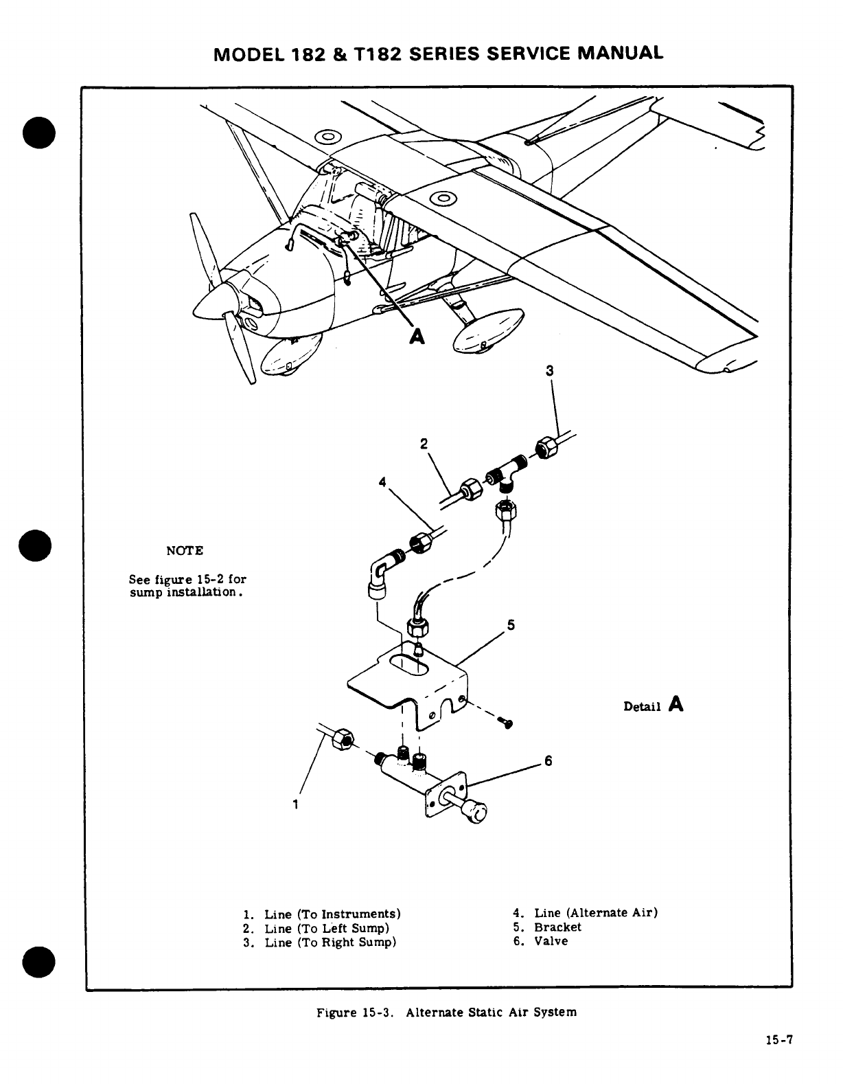
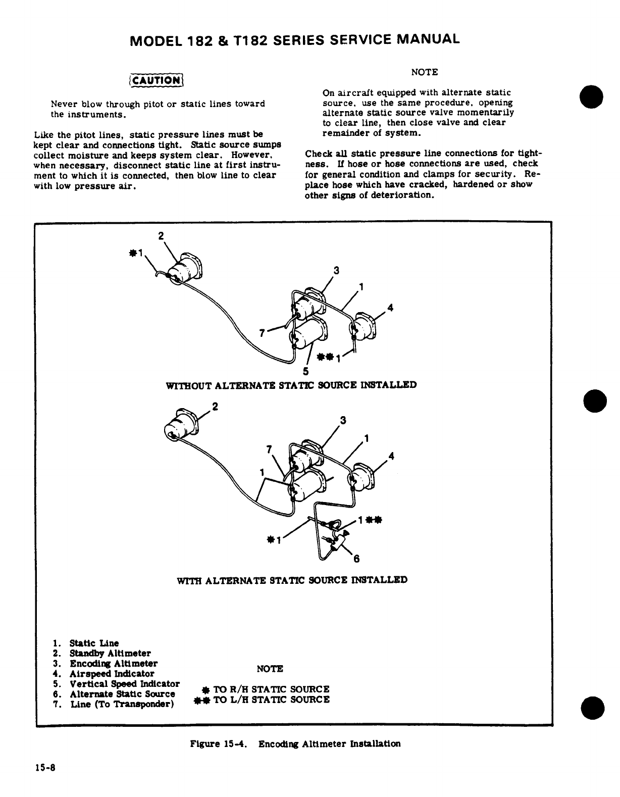
MODEL
182
&
T182
SERIES SERVICE
MANUAL
On
aircraft
equipped
with
alternate
static
Never
blow
through
pitot
or
static
lines
toward
source,
use
the
same
procedure,
opening
the
instruments.
alternate
static
source
valve
momentarily
to
clear
line, then
close
valve
and
clear
Like
the
pitot
lines,
static
pressure
lines
must
be
remainder
of
system.
kept
clear
and
connections
tight.
Static
source
sumps
collect moisture
and
keeps
system
clear.
However.
Check
all
static
pressure
line connections for
tight-
when
necessary,
disconnect
static
line
at
first
instru-
ness.
If
hose
or
hose connections
are
used,
check
ment
to
which
it
is
connected,
then
blow
line
to
clear
for
general
condition
and
clamps
for
security.
Re-
with
low
pressure
air.
place
hose
which have
cracked, hardened
or
show
other
signs
of
deterioration.
2
5
WITHOUT
ALTERNATE
STATIC
SOURCE
INSTALLED
2
WITH
ALTERNATE
STATIC
SOURCE
INSTALLED
1.
Static
Line
2.
Standby
Altimeter
3.
Encoding
Altimeter
4.
Airspeed
Indicator
NOTE
5.
Vertical
Speed
Indicator
STATIC
6.
Alternate
Static
Source
*
TO
R/H
STATIC
SOURCE
7.
Line
(To
Transponder)
**
TO
L/H
STATIC
SOURCE
Figure
15-4.
Encoding
Altimeter
Installation
15-8
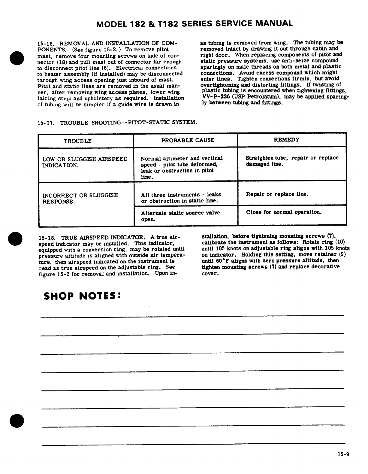
MODEL
182
&
T182
SERIES
SERVICE
MANUAL
15-16.
REMOVAL
AND
INSTALLATION
OF COM-
as
tubing
is
removed
from
wing.
The
tubing
may
be
PONENTS.
(See
figure
15-2.)
To
remove
pitot
removed
intact
by
drawing
it
out
through
cabin and
mast,
remove
four
mounting
screws
on
side
of
con-
right
door.
When
replacing
components
of
pitot
and
nector
(18)
and
pull
mast
out
of
connector
far
enough
static
pressure
systems,
use
anti-seize
compound
to
disconnect
pitot
line
(6).
Electrical
connections
sparingly
on
male
threads
on
both
metal
and
plastic
to
heater
assembly
(if
installed)
may
be
disconnected connections.
Avoid
excess
compound
which
might
through
wing
access
opening
just
inboard
of
mast.
enter
lines.
Tighten
connections
firmly,
but
avoid
Pitot
and
static
lines
are
removed
in
the
usual
man-
overtightening
and
distorting
fittings.
If
twisting
of
ner,
after
removing
wing
access
plates,
lower
wing
plastic
tubing
is
encountered
when
tightening
fittings,
fairing
strip
and
upholstery
as
required.
Installation
VV-P-236
(USP
Petrolatum),
may
be
applied
sparing-
of
tubing will
be
simpler
if
a guide
wire
is
drawn
in
ly
between
tubing and
fittings.
15-17.
TROUBLE
SHOOTING--PITOT-STATIC
SYSTEM.
TROUBLE PROBABLE
CAUSE
REMEDY
LOW
OR
SLUGGISH
AIRSPEED
Normal
altimeter
and
vertical
Straighten
tube,
repair
or
replace
INDICATION.
speed
-
pitot
tube
deformed,
damaged
line.
leak
or obstruction
in
pitot
line.
INCORRECT
OR
SLUGGISH
All
three instruments
-
leaks Repair
or
replace
line.
RESPONSE.
or
obstruction
in
static
line.
Alternate
static
source
valve
Close
for
normal
operation.
open.
15-18.
TRUE
AIRSPEED
INDICATOR.
A
true
air-
stallation,
before
tightening
mounting
screws
(7),
speed
indicator
may
be
installed.
This
indicator,
calibrate
the
instrument
as
follows:
Rotate
ring
(10)
equipped
with
a
conversion
ring,
may
be
rotated
until until
105
knots
on
adjustable
ring
aligns
with
105
knots
pressure
altitude
is
aligned
with
outside
air
tempera-
on
indicator.
Holding
this
setting,
move
retainer
(9)
ture,
then
airspeed
indicated
on
the
instrument
is
until
60°F
aligns
with
zero
pressure
altitude,
then
read
as
true
airspeed
on
the
adjustable
ring.
See
tighten
mounting
screws
(7)
and
replace
decorative
figure
15-2
for
removal
and
installation.
Upon
in-
cover.
SHOP
NOTES:
15-9
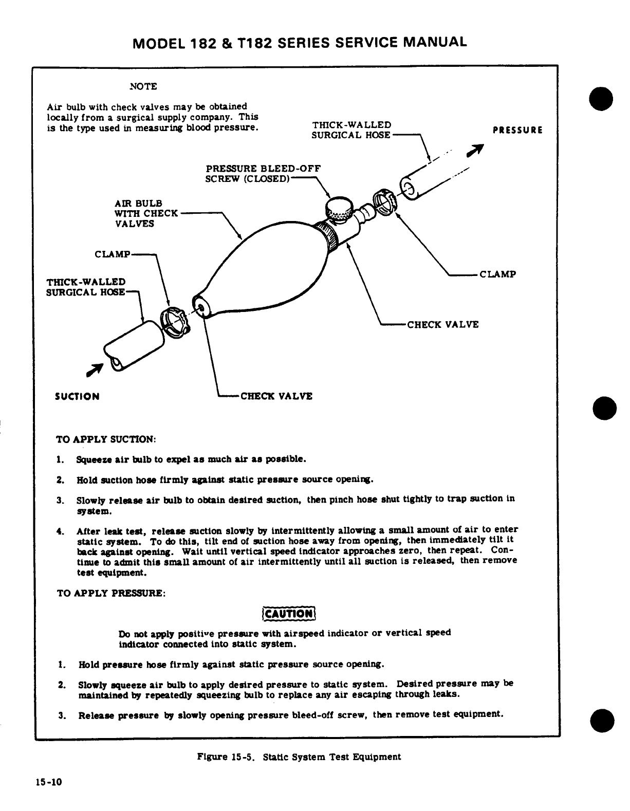
MODEL
182
&
T182
SERIES
SERVICE
MANUAL
NOTE
Air
bulb
with
check
valves
may
be
obtained
locally from
a
surgical
supply company.
This
is
the type
used
in
measuring
blood
pressure.
THICK-WALLED
PRESSURE
SURGICAL
HOSE
PRESSURE
BLEED-OFF
SCREW (CLOSED)-
AIR
BULB
WITH
CHECK
VALVES
CLAMP
THICK-WALLED
SURGICAL
HOSE
CHECK
VALVE
SUCTION
CHECK
VALVE
TO
APPLY
SUCTION:
1.
Squeeze
air
bulb
to
expel
as
much
air
as
possible.
2.
Hold
suction hose
firmly
against static
pressure
source
opening.
3.
Slowly
release
air
bulb
to
obtain
desired
suction, then
pinch
hose
shut
tightly
to
trap
suction
in
system.
4.
After
leak
test,
release
suction
slowly
by
intermittently
allowing
a small
amount
of
air
to
enter
static
system.
To
do
this, tilt
end
of
suction
hose
away
from
opening,
then
immediately
tilt
it
back
against
opening.
Wait
until
vertical
speed
indicator
approaches
zero,
then
repeat.
Con-
tinue
to
admit
this
small
amount
of
air
intermittently
until
all
suction
is
released,
then
remove
test
equipment.
TO
APPLY
PRESSURE:
Do
not
apply
positive
pressure
with
airspeed
indicator
or
vertical
speed
indicator
connected
into
static
system.
1.
Hold
pressure
hose
firmly
against static
pressure
source
opening.
2.
Slowly
squeeze
air
bulb
to
apply
desired
pressure
to
static
system. Desired
pressure
may
be
maintained
by
repeatedly
squeezing
bulb
to
replace
any
air
escaping
through
leaks.
3.
Release
pressure
by
slowly opening
pressure
bleed-off
screw,
then
remove
test
equipment.
Figure
15-5.
Static
System
Test
Equipment
15-10
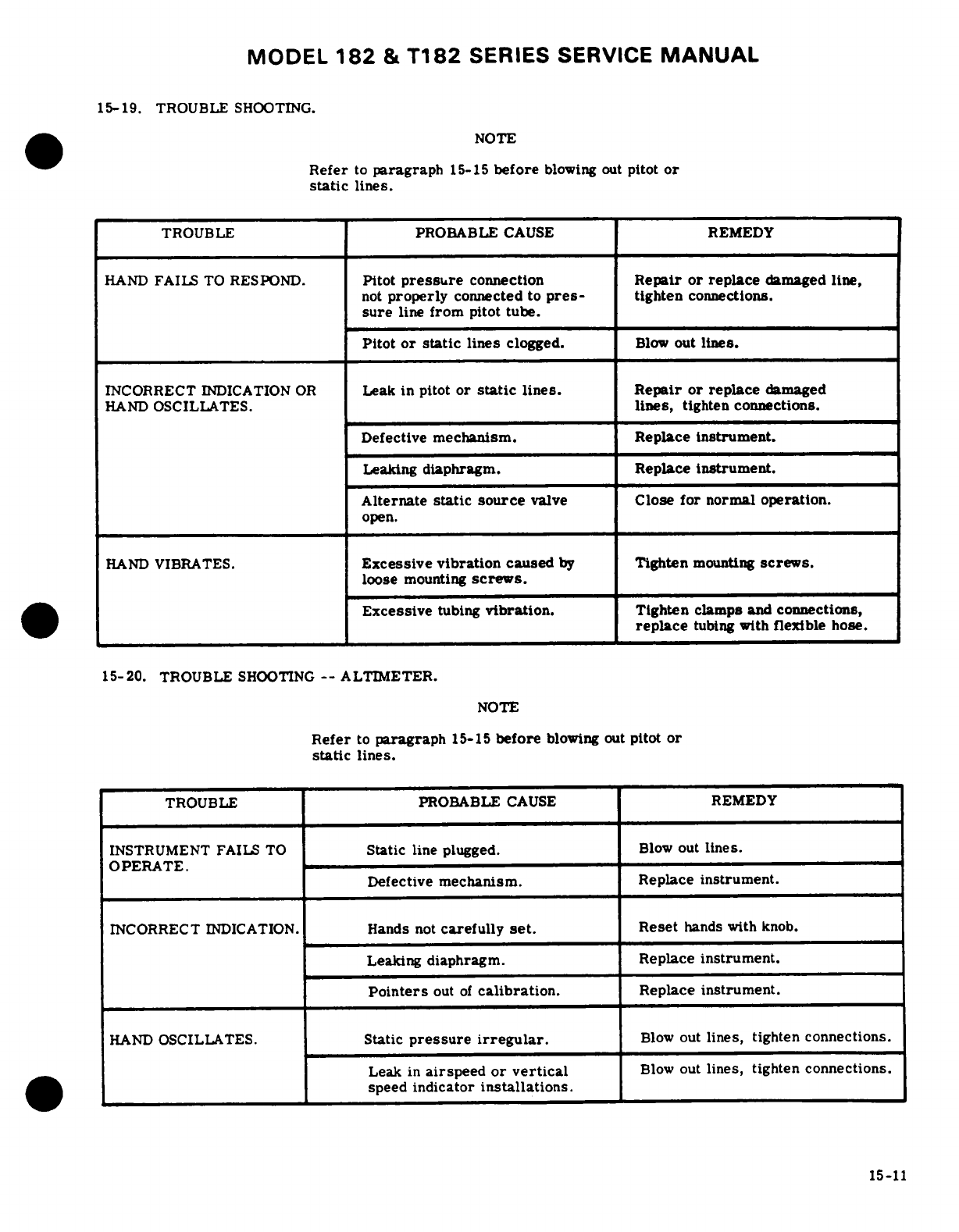
MODEL
182
&
T182
SERIES
SERVICE
MANUAL
15-19.
TROUBLE
SHOOTING.
NOTE
Refer
to
paragraph
15-15
before
blowing
out
pitot
or
static
lines.
TROUBLE PROBABLE
CAUSE
REMEDY
HAND
FAILS
TO
RESPOND.
Pitot
pressure
connection
Repair
or
replace
damaged
line,
not
properly
connected
to
pres-
tighten
connections.
sure
line
from
pitot
tube.
Pitot
or static
lines
clogged.
Blow
out
lines.
INCORRECT
INDICATION
OR
Leak
in
pitot
or
static
lines. Repair
or
replace
damaged
HAND
OSCILLATES.
lines,
tighten
connections.
Defective
mechanism.
Replace
instrument.
Leaking
diaphragm. Replace
instrument.
Alternate
static
source
valve
Close for normal
operation.
open.
HAND
VIBRATES.
Excessive
vibration
caused
by
Tighten
mounting
screws.
loose
mounting
screws.
Excessive
tubing
vibration.
Tighten
clamps
and
connections,
replace
tubing
with
flexible
hose.
15-20.
TROUBLE
SHOOTING
--
ALTIMETER.
NOTE
Refer
to
paragraph
15-15
before
blowing
out
pitot
or
static
lines.
TROUBLE PROBABLE
CAUSE
REMEDY
INSTRUMENT
FAILS
TO
Static
line
plugged.
Blow
out
lines.
OPERATE.
Defective
mechanism.
Replace
instrument.
INCORRECT
INDICATION.
Hands
not
carefully
set.
Reset
hands
with
knob.
Leaking
diaphragm.
Replace
instrument.
Pointers
out
of
calibration.
Replace
instrument.
HAND
OSCILLATES.
Static
pressure
irregular.
Blow
out
lines,
tighten
connections.
Leak
in
airspeed
or
vertical
Blow
out
lines,
tighten
connections.
speed
indicator
installations.
15-11
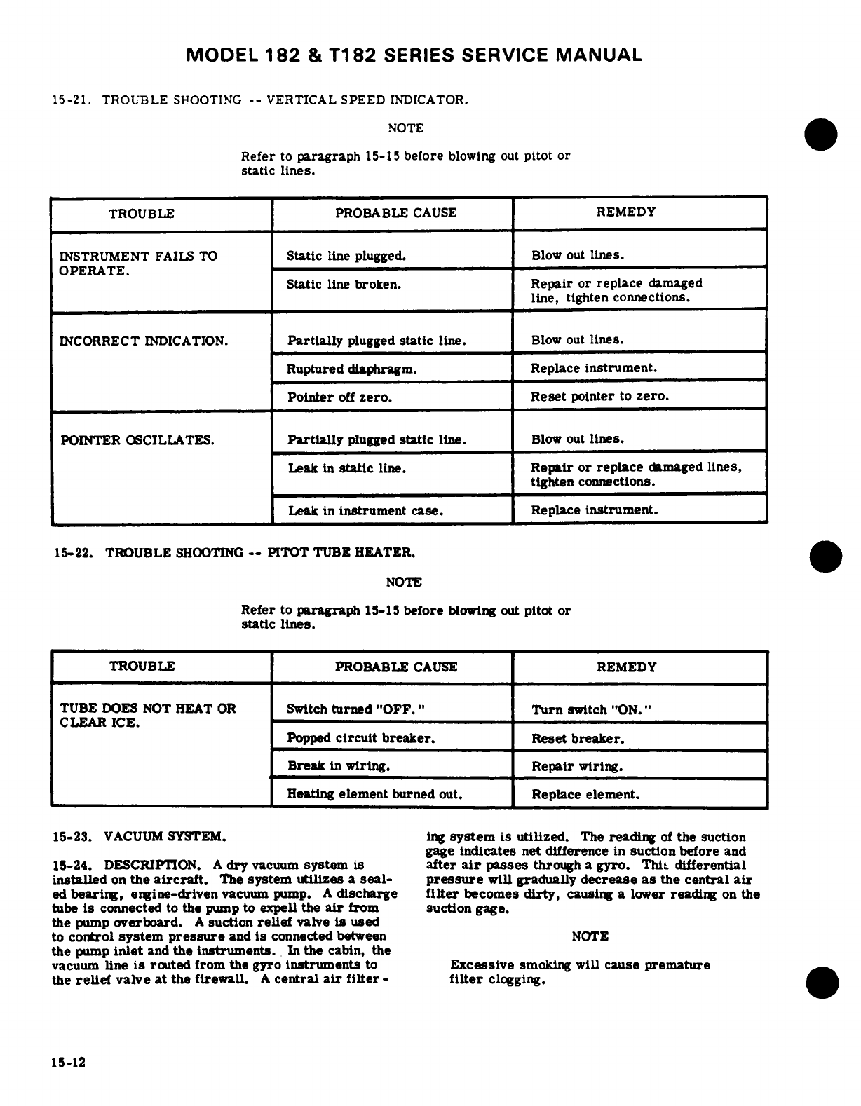
MODEL
182
&
T182
SERIES
SERVICE
MANUAL
15-21.
TROUBLE
SHOOTING
--
VERTICAL
SPEED
INDICATOR.
NOTE
Refer
to
paragraph
15-15
before
blowing
out
pitot
or
static
lines.
TROUBLE
PROBABLE
CAUSE
REMEDY
INSTRUMENT
FAILS
TO
Static
line
plugged.
Blow
out
lines.
OPERATE.
Static
line
broken.
Repair
or
replace
damaged
line,
tighten
connections.
INCORRECT
INDICATION.
Partially
plugged
static
line.
Blow
out
lines.
Ruptured
diaphragm.
Replace
instrument.
Pointer
off
zero.
Reset
pointer
to
zero.
POINTER OSCILLATES.
Partially
plugged
static
line.
Blow
out
lines.
Leak
in
static
line.
Repair or
replace
damaged
lines,
tighten
connections.
Leak
in
instrument
case.
Replace
instrument.
15-22. TROUBLE
SHOOTING
--
PITOT
TUBE
HEATER.
NOTE
Refer
to
paragraph
15-15
before
blowing
out
pitot
or
static lines.
TROUBLE PROBABLE
CAUSE
REMEDY
TUBE
DOES
NOT HEAT
OR
Switch
turned
"OFF."
Turn
switch
"ON."
CLEAR
ICE. Popped
circuit
breaker.
Reset
breaker.
Break
in
wiring.
Repair
wiring.
Heating
element
burned
out.
Replace
element.
15-23.
VACUUM
SYSTEM.
ing
system
is utilized.
The
reading
of
the
suction
gage
indicates
net
difference
in
suction
before
and
15-24.
DESCRIPTION.
A
dry
vacuum
system
is
after
air
passes
through
a
gyro.
This
differential
installed
on
the
aircraft.
The
system
utilizes
a
seal-
pressure
will
gradually
decrease
as
the
central
air
ed
bearing,
engine-driven
vacuum
pump.
A
discharge
filter
becomes
dirty,
causing
a
lower
reading
on
the
tube
is
connected
to
the
pump
to
expell
the
air
from
suction
gage.
the
pump
overboard.
A
suction
relief
valve
is
used
to
control
system
pressure
and
is
connected
between
NOTE
the
pump
inlet
and
the
instruments.
In
the
cabin,
the
vacuum
line
is
routed
from the gyro
instruments
to
Excessive
smoking
will
cause
premature
the
relief
valve
at
the
firewall.
A
central
air
filter-
filter
clogging.
15-12
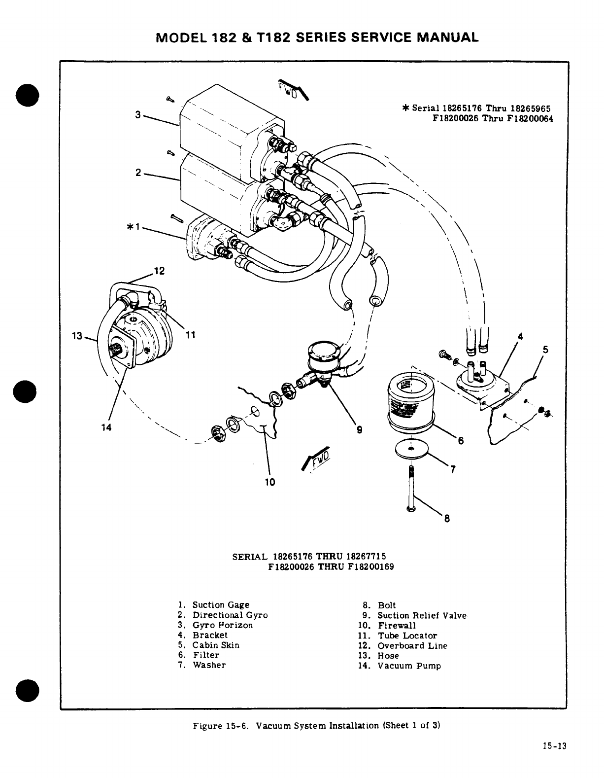
MODEL
182
&
T182
SERIES SERVICE
MANUAL
7
10
SERIAL
18265176 THRU
18267715
F18200026
THRU
F18200169
1.
Suction
Gage
8.
Bolt
2.
Directional
Gyro
9.
Suction
Relief
Valve
3.
Gyro
Horizon
10.
Firewall
4.
Bracket
11.
Tube
Locator
5.
Cabin
Skin
12.
Overboard
Line
6.
Filter
13.
Hose
7.
Washer
14.
Vacuum
Pump
Figure
15-6.
Vacuum
System
Installation
(Sheet
1
of
3)
15-13
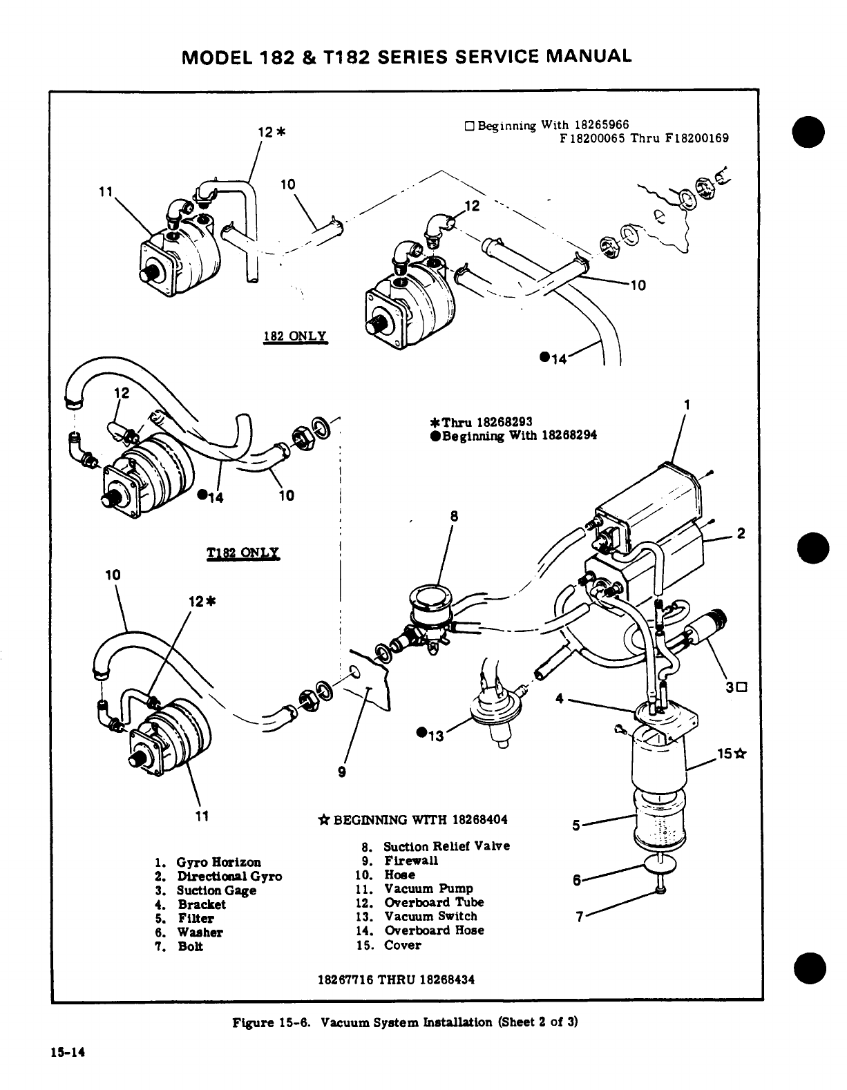
MODEL
182
&
T182
SERIES SERVICE
MANUAL
12*
Beginning
With
18265966
F18200065
Thru
F18200169
182
ONLY
*Thru
18268293
T
10
12*
11
BEGINNING
WITH
18268404
8.
Suction
Relief
Valve
1.
Gyro
Horizon
9.
Firewall
2.
Directional
Gyro
10.
Hose
3.
Suction Gage
11.
Vacuum
Pump
4.
Bracket
12.
Overboard
Tube
5.
Filter
13.
Vacuum
Switch
7
6.
Washer
14.
Overboard
Hose
7.
Bolt
15.
Cover
18267716
THRU
18268434
Figure
15-6.
Vacuum
System Installation
(Sheet
2
of
3)
15-14
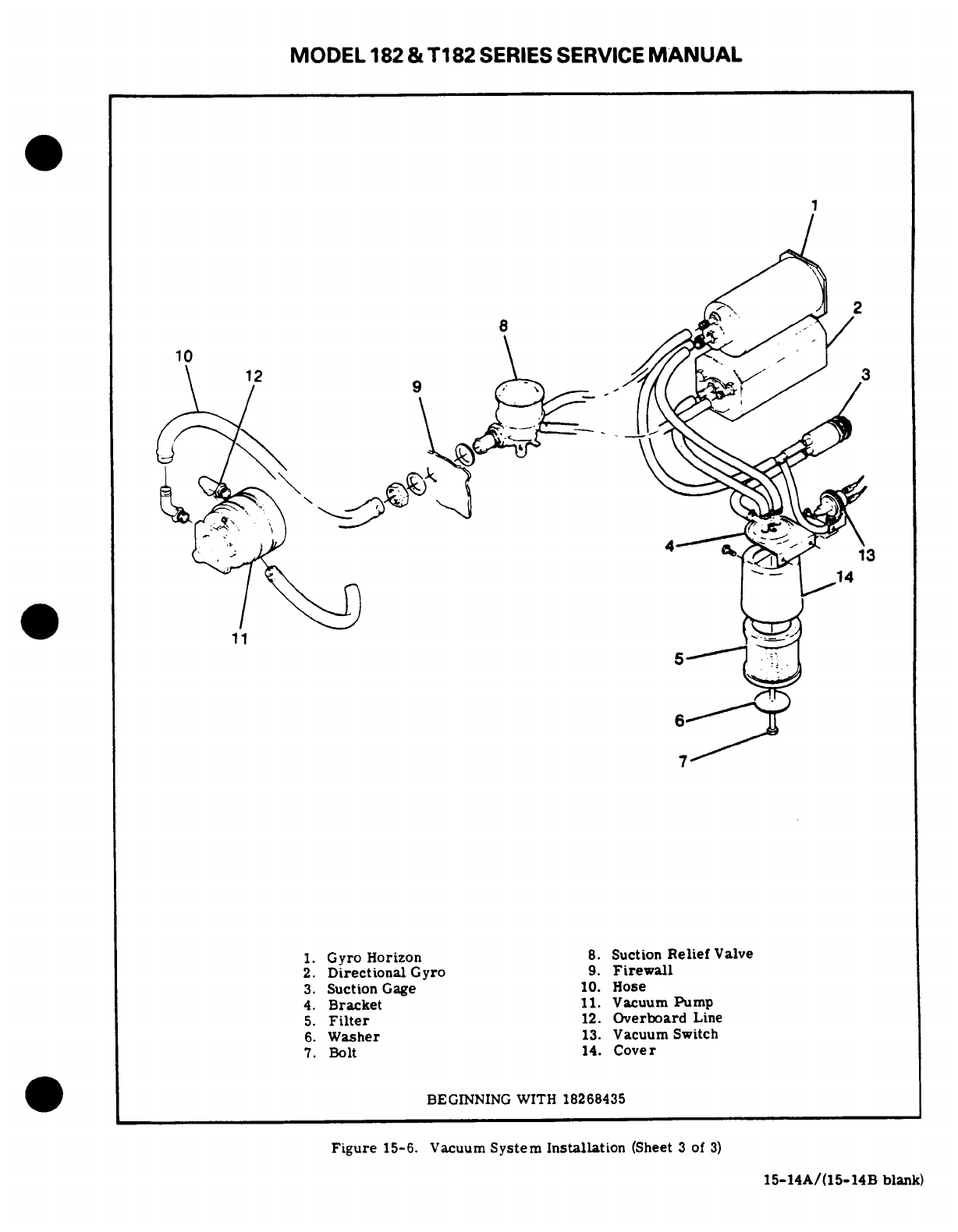
MODEL
182
&
T182
SERIES SERVICE
MANUAL
13
14
0^^ 11
1.
Gyro Horizon
8.
Suction
Relief
Valve
2.
Directional
Gyro
9.
Firewall
3.
Suction
Gage
10.
Hose
4.
Bracket
11.
Vacuum
Pump
5.
Filter
12.
Overboard
Line
6.
Washer
13.
Vacuum
Switch
7.
Bolt
14.
Cover
BEGINNING WITH
18268435
Figure
15-6.
Vacuum
System
Installation
(Sheet
3
of
3)
15-14A/(15-14B
blank)
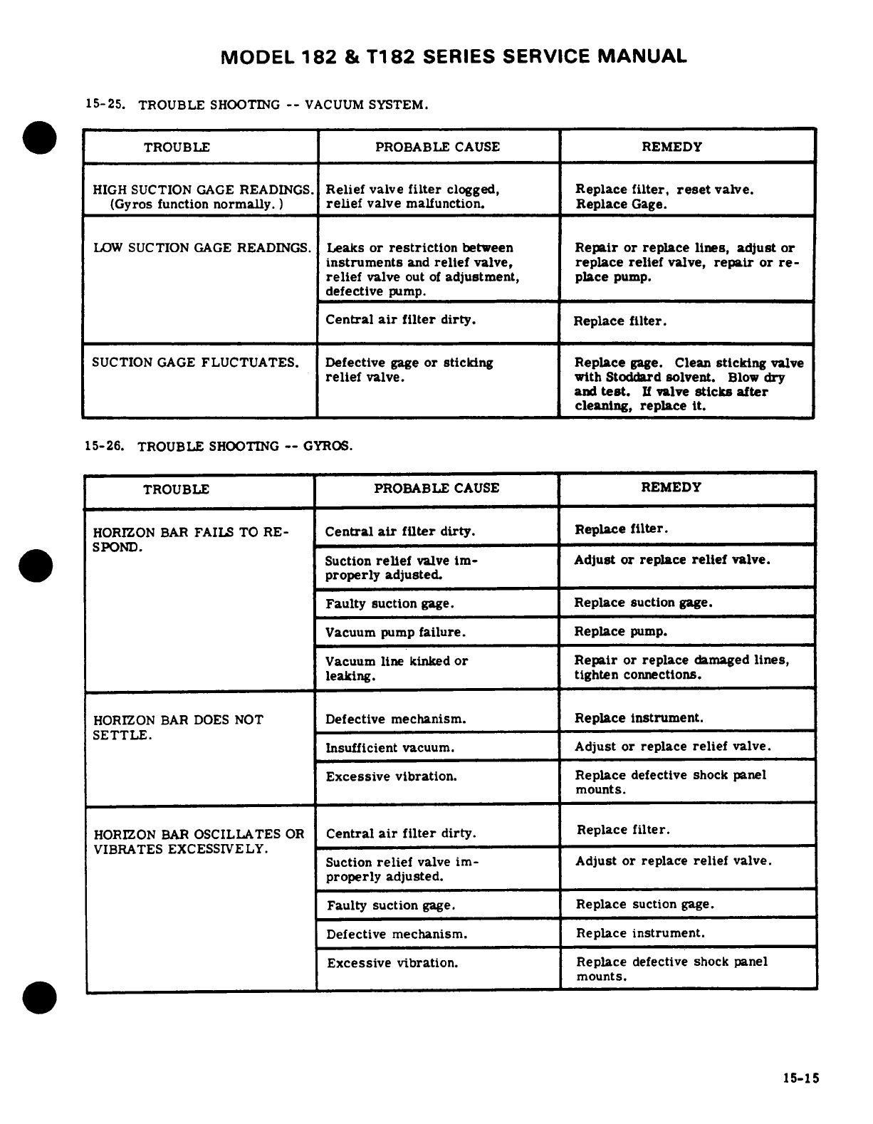
MODEL
182
&
T182
SERIES
SERVICE
MANUAL
15-25.
TROUBLE
SHOOTING
--
VACUUM
SYSTEM.
TROUBLE
PROBABLE
CAUSE
REMEDY
HIGH
SUCTION
GAGE
READINGS.
Relief
valve
filter
clogged,
Replace
filter,
reset
valve.
(Gyros function
normally.
)
relief
valve malfunction.
Replace
Gage.
LOW
SUCTION
GAGE
READINGS.
Leaks
or
restriction
between
Repair
or
replace
lines,
adjust
or
instruments
and
relief
valve,
replace
relief
valve,
repair
or
re-
relief
valve
out
of
adjustment,
place
pump.
defective
pump.
Central
air
filter
dirty.
Replace
filter.
SUCTION
GAGE
FLUCTUATES.
Defective
gage
or
sticking
Replace
gage.
Clean
sticking
valve
relief
valve.
with
Stoddard
solvent.
Blow
dry
and
test.
If
valve
sticks after
cleaning,
replace
it.
15-26.
TROUBLE
SHOOTING
--
GYROS.
TROUBLE PROBABLE
CAUSE
REMEDY
HORIZON
BAR
FAILS
TO
RE-
Central
air
filter
dirty.
Replace
filter.
SPOND.
Suction
relief
valve
im-
Adjust
or
replace
relief
valve.
properly
adjusted.
Faulty
suction
gage.
Replace
suction
gage.
Vacuum
pump
failure.
Replace
pump.
Vacuum
line
kinked
or Repair or
replace
damaged
lines,
leaking.
tighten
connections.
HORIZON
BAR
DOES
NOT
Defective
mechanism. Replace
instrument.
SETTLE.
Insufficient
vacuum.
Adjust
or
replace
relief
valve.
Excessive
vibration.
Replace
defective
shock
panel
mounts.
HORIZON
BAR
OSCILLATES
OR
Central
air
filter
dirty.
Replace
filter.
VIBRATES
EXCESSIVELY.
Suction
relief
valve
im-
Adjust
or
replace
relief
valve.
properly
adjusted.
Faulty
suction
gage.
Replace
suction
gage.
Defective
mechanism.
Replace
instrument.
Excessive
vibration.
Replace
defective
shock panel
mounts.
15-15
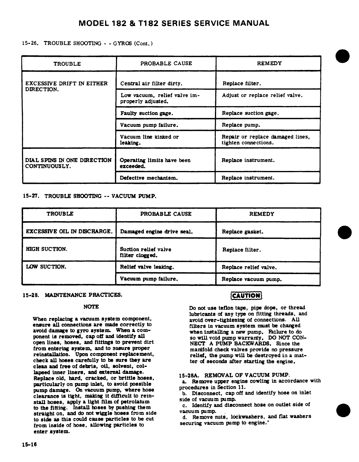
MODEL
182
&
T182
SERIES
SERVICE
MANUAL
15-26.
TROUBLE
SHOOTING
- -
GYROS
(Cont.)
TROUBLE
PROBABLE
CAUSE
REMEDY
EXCESSIVE
DRIFT
IN
EITHER
Central
air
filter
dirty.
Replace
filter.
DIRECTION.
Low
vacuum,
relief
valve im-
Adjust
or
replace
relief
valve.
properly
adjusted.
Faulty
suction
gage.
Replace
suction
gage.
Vacuum
pump
failure.
Replace
pump.
Vacuum
line
kinked
or
Repair
or replace
damaged
lines,
leaking.
tighten
connections.
DIAL SPINS
IN
ONE
DIRECTION
Operating
limits
have
been
Replace
instrument.
CONTINUOUSLY.
exceeded.
Defective
mechanism.
Replace
instrument.
15-27.
TROUBLE
SHOOTING
--
VACUUM
PUMP.
TROUBLE PROBABLE
CAUSE
REMEDY
EXCESSIVE OIL
IN
DISCHARGE.
Damaged
engine
drive
seal.
Replace
gasket.
HIGH
SUCTION.
Suction
relief
valve
Replace
filter.
filter
clogged.
LOW
SUCTION.
Relief
valve leaking. Replace
relief
valve.
Vacuum
pump
failure.
Replace
vacuum
pump.
15-28.
MAINTENANCE
PRACTICES.
NOTE
Do
not
use
teflon
tape,
pipe
dope,
or
thread
lubricants
of
any
type
on
fitting
threads,
and
When
replacing
a
vacuum
system
component,
avoid
over-tightening
of
connections.
All
ensure
all
connections
are
made
correctly
to
filters
in
vacuum
system
must
be
changed
avoid
damage
to
gyro
system.
When
a
com-
when
installing
a
new
pump.
Failure
to
do
ponent
is
removed,
cap
off
and
identify
all
so
will
void
pump
warranty.
DO
NOT
CON-
open
lines,
hoses,
and
fittings
to
prevent
dirt
NECT
A
PUMP
BACKWARDS.
Since
the
from
entering
system,
and
to
ensure
proper
manifold
check
valves
provide
no
pressure
reinstallation.
Upon
component
replacement,
relief,
the
pump
will
be
destroyed
in
a
mat-
check
all
hoses
carefully
to
be
sure
they
are
ter
of
seconds
after
starting
the
engine.
clean
and
free
of
debris, oil,
solvent,
col-
lapsed
inner
liners,
and
external
damage.
Replace
old,
hard,
cracked,
or
brittle
hoses,
15-28A.
REMOVAL
OF
VACUUM
PUMP.
Replace
old,
hard, cracked,
to avoid
possible
a.
Remove
upper
engine
cowling
in
accordance
with
particularly
on
pump
inlet,
to
avoid
possible
pump
damage.
On
vacuum
pump,
where
hose
procedures
in
Section
11.
clearance
is
tight,
making
it
difficult
to
rein-
stall
hoses,
apply
a
light
film
of
petrolatum
side
of
vacuum
pump.
to
the fitting.
Install
hoses
by
pushing
them
c.
Identify
and
disconnect
hose
on
outlet
side
of
straight
on, and
do not
wiggle
hoses from
side
vacuum
pump.
to
side
as
this
could
cause
particles
to
be
cut
d.
Remove
nuts,
lockwashers,
and
flat
washers
from
inside
of
hose,
allowing
particles
to
securing
vacuum
pump
to
engine.
enter
system.
15-16
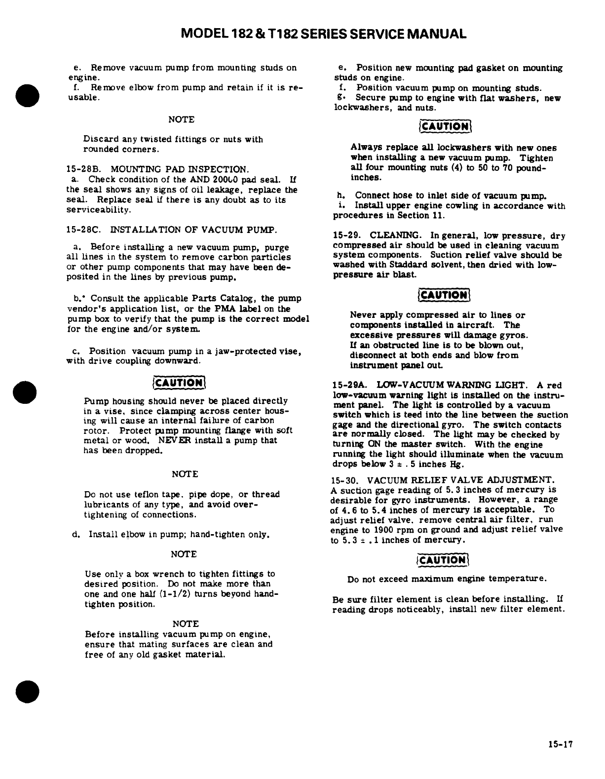
MODEL
182
&
T182
SERIES
SERVICE
MANUAL
e.
Remove
vacuum
pump
from
mounting
studs
on
e.
Position
new
mounting
pad
gasket
on
mounting
engine.
studs
on
engine.
f.
Remove
elbow
from
pump
and
retain
if
it
is
re-
f.
Position
vacuum
pump
on
mounting
studs.
usable.
g.
Secure
pump
to
engine
with
flat
washers,
new
lockwashers,
and
nuts.
Discard
any
twisted
fittings
or
nuts
with
rounded
corners.
Always
replace
all
lockwashers
with
new
ones
when
installing
a
new
vacuum
pump.
Tighten
15-28B.
MOUNTING
PAD
INSPECTION.
all
four
mounting
nuts
(4)
to
50
to
70
pound-
a.
Check
condition
of
the
AND
200,0
pad
seal.
If
inches.
the
seal
shows
any
signs
of
oil
leakage,
replace
the.
seal.
Replace
seal
if
there
is
any
doubt
as
to
its
h.
Connect
hose
to
inlet side
of
vacuum
pump.
serviceability.
procedures
in
Section
11.
15-28C.
INSTALLATION
OF
VACUUM
PUMP.
15-29.
CLEANING.
In
general,
low
pressure,
dry
a.
Before
installing
a
new
vacuum
pump,
purge
compressed
air
should
be
used
in
cleaning
vacuum
all
lines
in
the
system
to
remove
carbon
particles
system
components.
Suction
relief
valve should
be
or
other
pump
components
that
may
have
been
de-
washed
with
Staddard
solvent,
then
dried
with
low-
posited
in the
lines
by
previous
pump.
pressure
air
blast.
b.
Consult
the
applicable
Parts
Catalog, the
pump
vendor's
application
list,
or
the
PMA
label
on
the
pump
box
to
verify
that
the
pump
is
the
correct
model
Never
apply
compressed
air
to
lines
or
for
the engine
and/or
system.
components
installed
in
aircraft.
The
excessive
pressures
will
damage
gyros.
If
an
obstructed
line
is
to
be
blown
out,
c.
Position
vacuum
pump
in
a
jaw-protected vise,
disconnect
at
both
ends
and
blow
from
with
drive
coupling
downward.
instrument
panel
out
instrument
panel
out.
low-vacuum
warning
light
is
installed
on
the
instru-
Pump
housing
should
never
be
placed
directly
ment
panel.
The
light
is controlled
by
a
vacuum
in
a
vise,
since clamping
across
center
hous-
switch
which
is
teed
into
the
line
between
the
suction
ing
will cause
an
internal
failure
of
carbon
gage
and
the
directional
gyro.
The
switch
contacts
rotor.
Protect
pump mounting
flange
with
soft
are
normally
closed.
The
light
may
be
checked
by
metal
or
wood.
NEVER
install
a
pump
that
turning
ON
the
master
switch.
With
the
engine
has
been
dropped.
running
the light should
illuminate
when
the
vacuum
drops
below
3
±.
5
inches
Hg.
NOTE
15-30.
VACUUM
RELIEF
VALVE
ADJUSTMENT.
Do
not
use
teflon
tape.
pipe
dope,
or
thread
A
suction
gage
reading
of
5. 3
inches
of
mercury
is
lubricants
of
any
type,
and
avoid
over-
tightening
of
connections.
adjust
relief
valve.
remove
central
air
filter,
run
d.
Install
elbow in
pump;
hand-tighten
only,
engine
to
1900
rpm
on
ground
and
adjust
relief
valve
to
5.
3
±
.
1
inches
of
mercury.
NOTE
Use
only a
box
wrench
to
tighten
fittings
to
Do
not
exceed maximum
engine
temperature.
Do
not
exceed
maximum
engine
temperature.
desired
position.
Do
not
make
more
than
one
and
one
half
(1-1/2)
turns
beyond
hand-
tighteand posit half
NOTE
Before installing
vacuum
pump
on
engine,
ensure
that
mating
surfaces
are
clean
and
free
of
any
old
gasket
material.
15-17
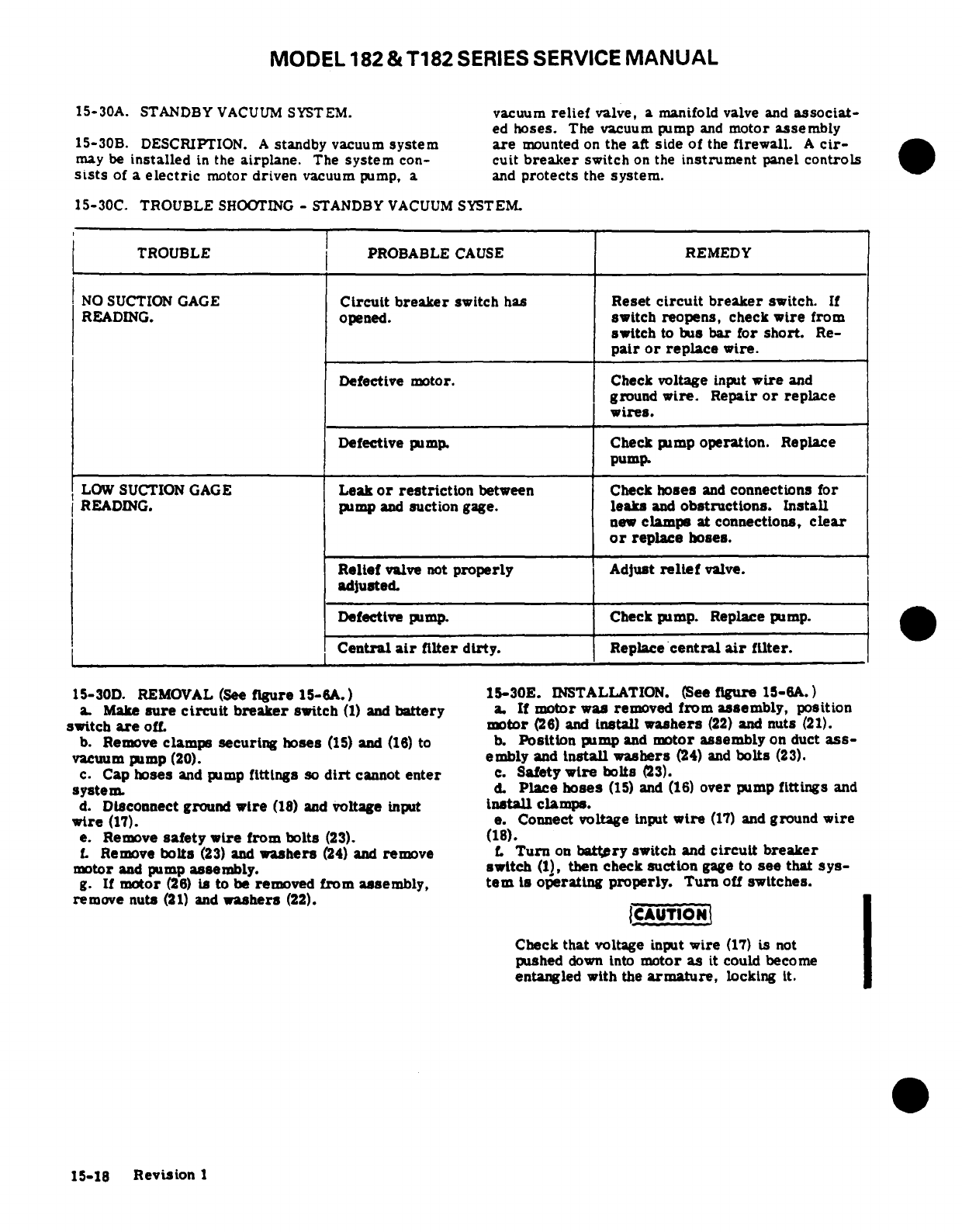
MODEL
182
&
T182
SERIES
SERVICE
MANUAL
15-30A.
STANDBY
VACUUM
SYSTEM.
vacuum
relief
valve,
a
manifold
valve
and
associat-
ed
hoses.
The vacuum
pump
and
motor
assembly
15-30B.
DESCRIPTION.
A
standby vacuum
system
are
mounted
on
the
aft
side
of
the
firewall.
A
cir-
may
be
installed
in
the
airplane.
The
system
con-
cuit
breaker
switch
on
the
instrument
panel
controls
sists
of
a
electric
motor
driven
vacuum
pump,
a
and
protects
the
system.
15-30C.
TROUBLE
SHOOTING
-
STANDBY
VACUUM
SYSTEM.
TROUBLE
PROBABLE
CAUSE
REMEDY
NO
SUCTION GAGE
Circuit
breaker
switch
has
Reset
circuit breaker
switch.
If
READING.
opened.
switch
reopens,
check
wire
from
switch
to
bus
bar
for short.
Re-
pair
or
replace
wire.
Defective
motor.
Check
voltage
input
wire
and
ground
wire. Repair
or
replace
wires.
Defective
pump.
Check
pump
operation.
Replace
pump.
LOW
SUCTION GAGE
Leak
or
restriction
between
Check
hoses
and
connections
for
READING.
pump
and
suction
gage.
leaks
and
obstructions.
Install
new
clamps at
connections,
clear
or
replace
hoses.
Relief
valve
not
properly
Adjust
relief
valve.
adjusted.
Defective
pump.
Check
pump.
Replace
pump.
Central
air
filter
dirty.
Replace
central
air
filter.
15-30D.
REMOVAL
(See
figure
15-6A.)
15-30E.
INSTALLATION.
(See
figure
15-6A.)
a.
Make
sure
circuit
breaker
switch
(1)
and
battery
a.
If
motor
was
removed
from assembly,
position
switch
are
off.
motor
(26) and
install
washers
(22)
and
nuts
(21).
b.
Remove
clamps securing hoses
(15)
and
(16)
to
b.
Position
pump
and
motor
assembly
on duct
ass-
vacuum
pump
(20).
embly
and
install
washers
(24)
and
bolts
(23).
c.
Cap
hoses
and pump
fittings
so
dirt
cannot
enter
c.
Safety
wire
bolts
(23).
system.
d.
Place
hoses
(15)
and
(16)
over
pump
fittings
and
d.
Disconnect
ground
wire
(18)
and
voltage
input
install
clamps.
wire
(17).
e.
Connect
voltage
input
wire
(17)
and
ground
wire
e.
Remove
safety
wire
from
bolts
(23).
(18).
f.
Remove
bolts
(23)
and
washers
(24)
and
remove
f.
Turn
on
battery
switch
and
circuit
breaker
motor
and pump
assembly.
switch
(1),
then
check
suction
gage
to
see
that
sys-
g.
If
motor
(26)
is to
be
removed
from assembly,
tem
is
operating properly. Turn
off
switches.
remove
nuts
(21)
and
washers
(22).
Check
that
voltage
input
wire
(17)
is
not
pushed
down
into
motor
as
it
could
become
entangled
with
the
armature,
locking
it.
15-18
Revision
1
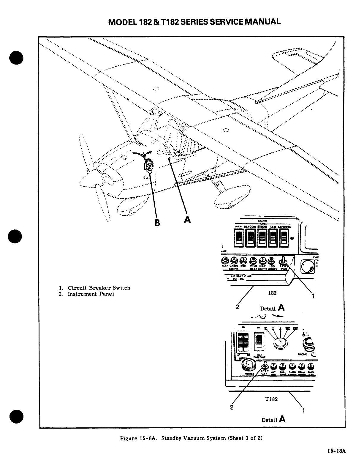
MODEL
182
&
T182
SERIES SERVICE
MANUAL
,,
eee ~.
o-q-'
oooO 'O
-
·-
F: NOT
:
! .- ·
*
... .. * ¾
o.
.do.c.
t W.
o·o
- .. . .
o o .*·
a....
1.
Circuit
Breaker
Switch / \
'°l&.~~~~~~~~~~~~ ."....
i
.
2. Instrument Panel
/
182
1
2
Detail
A
A* ____
Fi
e
15
.
Stany
Vacm
Stm (
t
of
Figure
15-6A.
Standby
Vacuum
System
(Sheet
1 o15f
.·.·····r-
.·~~~~~~~~~~~~~~~~~~~~o
-: ~ ~
~ ~ ~ ~ ~ ~ ~
·
w~o,,o
..
u
.
.
.' . . .
:
..
?
- - .
. ... .'...-' :.-..: ...
..
'~
'- '
o~ o °
,
·
'. .
15-18A
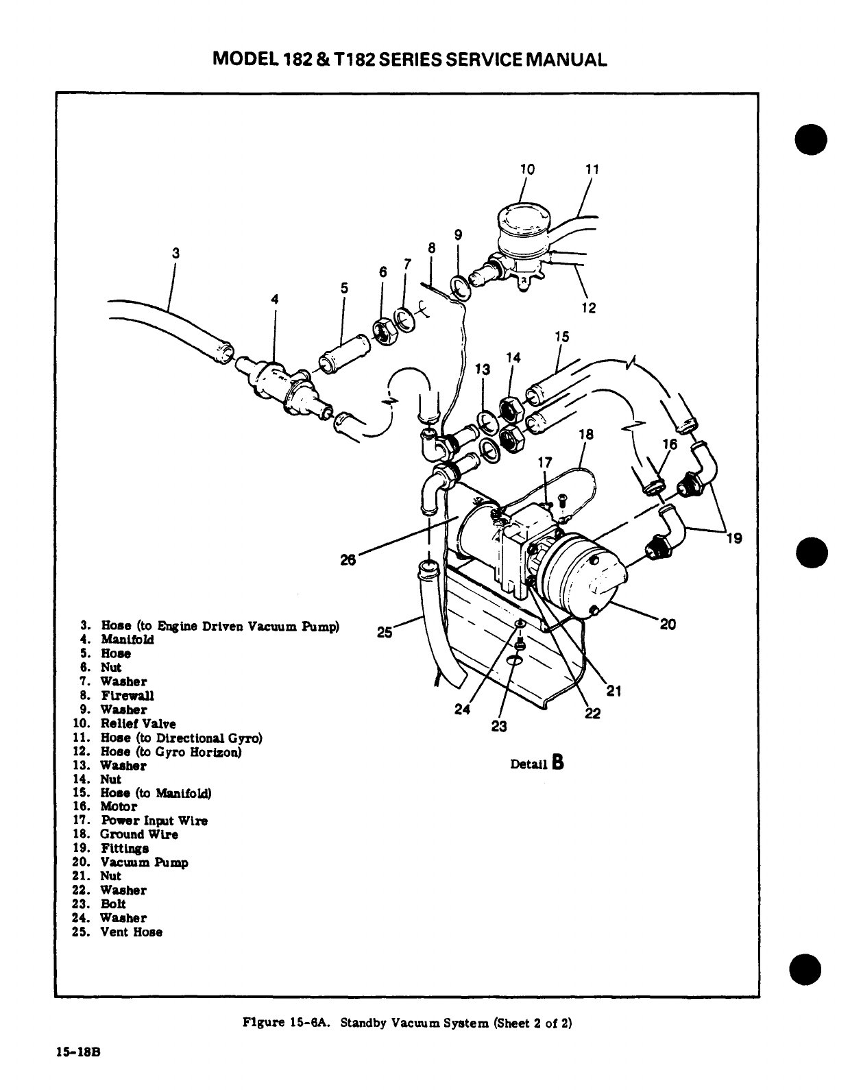
MODEL
182
&
T182
SERIES SERVICE
MANUAL
10
11
I19
388
5
26/le
3.
Hose
(to
Engine
Driven
Vacuum Pump)
25
\
4.
Manifold
5.
Hose
6.
Nut
7.
Washer
8.
Firewall
9.
Washer
24
22
10.
Relief
Valve
23
11.
Hose
(to
Directional
Gyro)
12.
Hose
(to
Gyro
Horizon)
et
B
13.
Washer
Detail
14.
Nut
15.
Hose
(to
Manifold)
16.
Motor
17.
Power
Input
Wire
18.
Ground
Wire
19.
Fittings
20.
Vacuum
Pump
21. Nut
22.
Washer
23.
Bolt
24.
Washer
25.
Vent
Hose
Flgure
15-6A. Standby
Vacuum
System
(Sheet
2
of
2)
15-18B
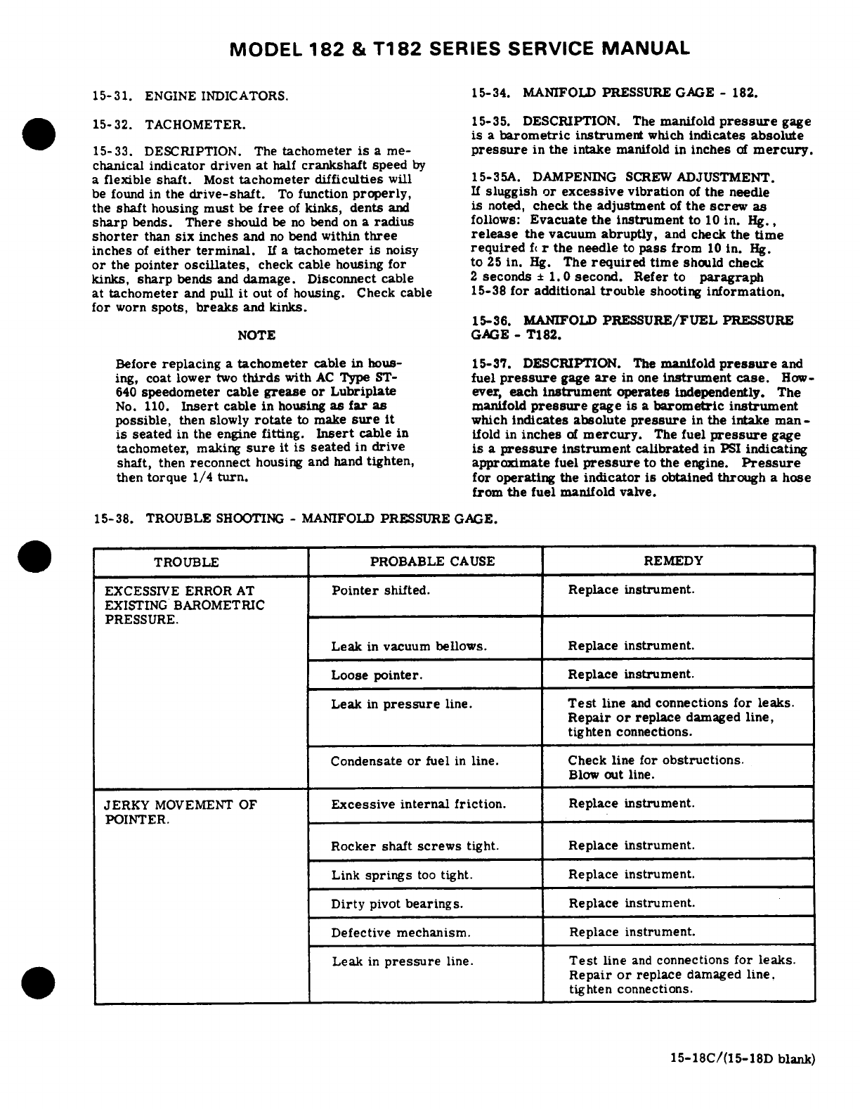
MODEL
182
&
T182
SERIES
SERVICE
MANUAL
15-31.
ENGINE
INDICATORS.
15-34.
MANIFOLD
PRESSURE
GAGE
-
182.
15-32.
TACHOMETER.
15-35.
DESCRIPTION.
The
manifold
pressure
gage
is
a
barometric
instrument
which
indicates
absolute
15-33.
DESCRIPTION.
The
tachometer
is
a
me-
pressure
in
the intake
manifold
in
inches
of
mercury.
chanical
indicator driven
at
half
crankshaft
speed
by
a
flexible
shaft.
Most
tachometer difficulties
will
15-35A.
DAMPENING
SCREW
ADJUSTMENT.
be
found
in
the
drive-shaft.
To
function
properly,
If
sluggish
or
excessive
vibration
of
the
needle
the
shaft
housing
must
be
free
of
kinks,
dents
and
is
noted,
check
the adjustment
of
the
screw
as
sharp
bends.
There
should
be
no
bend on
a
radius
follows:
Evacuate
the instrument
to
10
in.
Hg.,
shorter
than
six
inches
and
no
bend
within
three
release
the
vacuum
abruptly,
and check
the
time
inches
of
either terminal.
If
a
tachometer
is
noisy
required
for
the needle
to
pass
from
10
in.
Hg.
or
the
pointer
oscillates,
check
cable housing
for
to
25
in.
Hg.
The
required
time
should check
kinks,
sharp
bends
and
damage.
Disconnect
cable
2
seconds
±
1.0
second.
Refer
to
paragraph
at
tachometer
and
pull
it
out
of
housing. Check cable
15-38
for
additional
trouble
shooting
information.
for
worn
spots,
breaks
and
kinks.
15-36.
MANIFOLD
PRESSURE/FUEL
PRESSURE
NOTE
GAGE
-
T182.
Before
replacing
a
tachometer
cable in
hous-
15-37. DESCRIPTION.
The
manifold
pressure
and
ing,
coat
lower
two
thirds
with
AC
Type
ST-
fuel
pressure
gage
are
in
one
instrument case.
How-
640
speedometer
cable
grease
or
Lubriplate
ever,
each
instrument
operates
independently.
The
No.
110.
Insert
cable
in
housing
as far
as
manifold
pressure
gage is
a
barometric
instrument
possible,
then slowly
rotate
to
make
sure
it
which
indicates absolute
pressure
in
the
intake
man-
is
seated
in the
engine
fitting.
Insert
cable
in
ifold
in
inches
of
mercury.
The
fuel
pressure
gage
tachometer,
making
sure
it
is
seated
in
drive
is
a
pressure
instrument
calibrated
in
PSI
indicating
shaft,
then
reconnect
housing
and
hand
tighten,
approximate
fuel
pressure
to
the
engine.
Pressure
then
torque
1/4
turn.
for
operating
the
indicator
is
obtained
through
a hose
from
the
fuel
manifold
valve.
15-38.
TROUBLE
SHOOTING
-
MANIFOLD
PRESSURE
GAGE.
TROUBLE
PROBABLE
CAUSE
REMEDY
EXCESSIVE ERROR
AT
Pointer
shifted. Replace
instrument.
EXISTING
BAROMETRIC
PRESSURE.
Leak
in
vacuum
bellows.
Replace
instrument.
Loose
pointer.
Replace
instrument.
Leak
in
pressure
line.
Test
line
and
connections
for
leaks.
Repair
or
replace
damaged
line,
tighten
connections.
Condensate
or
fuel
in
line.
Check
line
for
obstructions.
Blow
out
line.
JERKY
MOVEMENT
OF
Excessive
internal
friction.
Replace
instrument.
POINTER.
Rocker
shaft
screws
tight.
Replace
instrument.
Link
springs
too
tight.
Replace
instrument.
Dirty
pivot
bearings.
Replace
instrument.
Defective
mechanism.
Replace
instrument.
Leak
in
pressure
line.
Test
line
and
connections
for
leaks.
Repair
or
replace
damaged
line.
tighten
connections.
15-18C/(15-18D
blank)
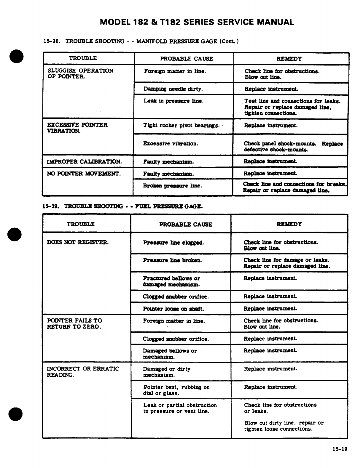
MODEL
182
&
T182
SERIES SERVICE
MANUAL
15-38.
TROUBLE
SHOOTING
--
MANIFOLD
PRESSURE
GAGE
(Cont.)
TROUBLE
PROBABLE
CAUSE
REMEDY
SLUGGISH
OPERATION
Foreign
matter
in
line. Check
line
for
obstructions.
OF
POINTER.
Blow
out
line.
Damping
needle
dirty.
Replace
instrument.
Leak
in
pressure
line.
Test
line
and
connections
for
leaks.
Repair
or
replace
damaged
line,
tighten
connections.
EXCESSIVE
POINTER
Tight
rocker
pivot
bearings.
Replace
instrument.
VIBRATION.
Excessive
vibration.
Check panel
shock-mounts.
Replace
defective
shock-mounts.
IMPROPER
CALIBRATION.
Faulty
mechanism.
Replace
instrument
NO
POINTER
MOVEMENT.
Faulty
mechanism. Replace
instrument
Broken
pressure
line.
Check
line
and
connections
for
breaks
Repair
or
replace
damaged
line.
15-39.
TROUBLE
SHOOTING
-- FUEL
PRESSURE
GAGE.
TROUBLE PROBABLE
CAUSE
REMEDY
DOES
NOT
REGISTER
Pressure
line
clogged.
Check
line
for
obstructions.
Blow
out
line.
Pressure
line
broken. Check
line
for
damage
or
leaks.
Repair
or
replace
damaged
line.
Fractured
bellows
or
Replace
instrument.
damaged
mechanism.
Clogged
snubber
orifice.
Replace
instrument.
Pointer
loose
on
shaft.
Replace
instrument.
POINTER
FAILS
TO
Foreign
matter
in
line.
Check
line
for
obstructions.
RETURN
TO
ZERO.
Blow
out
line.
Clogged
snubber
orifice.
Replace
instrument
Damaged
bellows
or
Replace
instrument
mechanism.
INCORRECT
OR
ERRATIC
Damaged
or
dirty
Replace
instrument.
READING.
mechanism.
Pointer
bent, rubbing
on
Replace
instrument
dial
or
glass.
Leak
or
partial
obstruction
Check
line
for
obstructions
in
pressure
or
vent
line.
or
leaks.
Blow
out
dirty
line,
repair
or
tighten
loose
connections.
15-19
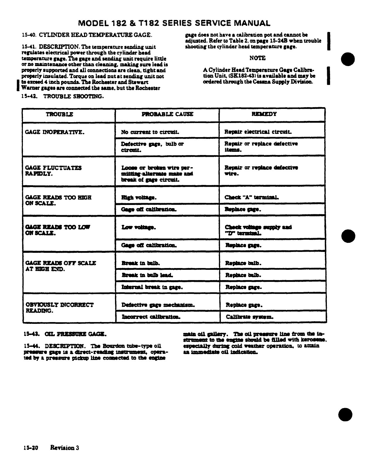
MODEL
182
&
T182
SERIES
SERVICE
MANUAL
15-40.
CYLINDER
HEAD
TEMPERATURE GAGE.
gage
does
not
have
a
calibration
pot and
cannot
be
adjusted.
Refer
to
Table
2.
on
page
15-24B
when trouble
15-41.
DESCRIPTION.
The
temperature
sending
unit
shooting
the
cylinder
head
temperature
gage.
regulates electrical
power
through
the
cylinder
head
temperature
gage.
The
gage
and
sending
unit
require
little
NOTE
or no
maintenanc
other
than
cleaning,
making
sure
lead
is
properly
supported
and
all
connections
re
clean,
tight
and
A
Cylinder
Head
Temperature
Gage
Calibra-
properly
insulated.
Torque
on
lead
nut
at
sending
unit
not
tion
Unit.
(SK182-43)
is
available
and
may
be
to
exceed
4
inch
pounds
The Rochester
and
Stewart
ordered
through
the
Cessna
Supply
Division.
Warner
gages
are
connected
the
same.
but
the
Rochester
15-42
TROUBLE
SHOOTING.
TROUBLE
PROBABLE
CAUSE
REMEDY
GAGE
INOPERATIVE.
No
current
to
circuit
Repair
electrical
circuit.
Defective
gage,
bulb
or
Repair
or
replace
defective
circut.
items.
GAGE
FLUCTUATES
Loose
or
broken
wire
per-
Repair
or
replace
defective
RAPIDLY.
break
of
gage
circuit.
GAGE
READS
TOO
HIGH
ON
SCALE.
GAGE
READS
TOO
LOW
LOW
voltage.
Check
ON
Gap
off
calibration.
GAGE
READS
OFF
SCALE
AT
READING.
15-43
15-44.
DESCRIPTION.
The Bourdon
tube-type
oil
especially
during
cold
weather
operation,
to
pressure
ted
by
pressure
pickup
line
connected
to
the engine
15-20
Revision
3
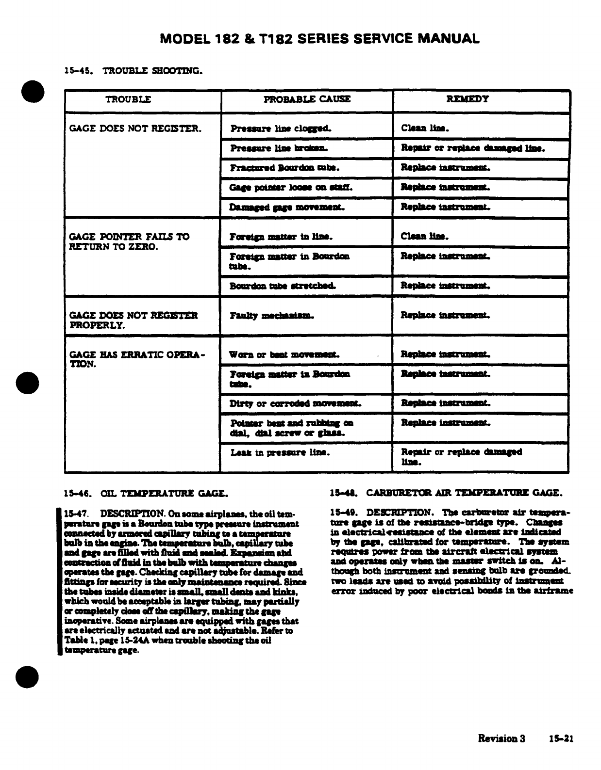
MODEL
182
&
T182
SERIES
SERVICE
MANUAL
15-45.
TROUBLE
SHOOTING.
TROUBLE
PROBABLE
CAUSE
REMEDY
GAGE
DOES
NOT
REGISTER.
Pressure
line cloged.
Clear
line.
pressure
line
broken.
Repair
or
replace
Fractured
Bourdon
Gage
po
GAGE
POINTER FAILS
TO
Foreign
RETURN
TO
ZERO.
Foreign
GAGE
DOES
NOT
REGISTER F
PROPERLY.
GAGE
HAS
ERRATIC
OPERA-
Worn
or
bent
D
Pointer
b
dil,
dtl
screw
or
glass
Luk
In
pressre
lia.
Repair
or
replace
deage
UM.
15-46.
OIL
TEPERATURE
GAGE.
15-48
CARBURETO
A
T
EATURE
GAGE.
15-47.
DESCRIPTION. On
so
airplane,
the
oil
tm-
15-49.
DESRmPTION.
Tho arbotr
nir
tempera-
pwmtune
ga
is
a
Boudno
tube
ype
presure instrusent
tar
age
is
of
the
reitance-brld
type.
Cbange
conaected
by
armoed
apilly
tubing
to
a
tempeatr
in
lectr
icle lfSci
of
the
elemeat
d
irdtcated
bulb
in
th
engine.
The
temermeblb,
apiU
ry
tube
by
the
gt,
calibratd
for
tmpertare.
Tbe
sym
ad
gag
ar
filld
with
f
-lid
nd
mald.
zpmimn
aMd
requir
powr
from
the
aircraft
lectrical
sy
olatetioofflitd
in
tbe
bulb
withhtawrs
u andprn
d
oprat
y
w
inthe
asnr
switch
mon.
Al-
peraes
the
ge.
Checkng
capillrytube
for
damrg
and
thogh
both
inatrumet
and
sening
blob
re
prondd.
fitting
for
ecurity is
the
on
ly
ainta
quired.
Bie
to
lads
aroe
d
to
u
md
poibillty
of
lntynoot
the
tubs
inside
dimetir
sual
sl dts
and
kinks
error
induced
by
poor
electrical
bond
in
the
airframe
which
would
be
acceptable
in
larr
tubing.
may
peilly
r
copletely
dom
o
the
capillar,
making
the
la
inopertive.
Some
airplans
a
equipped
with
gage
that
are
electrically
ctuated
and
re
not
adjutabl.
RBfr
to
Table
1,
pae
15-24A
when
trouble
shting
the
oil
teperature
gage.
Revision
3
1-21
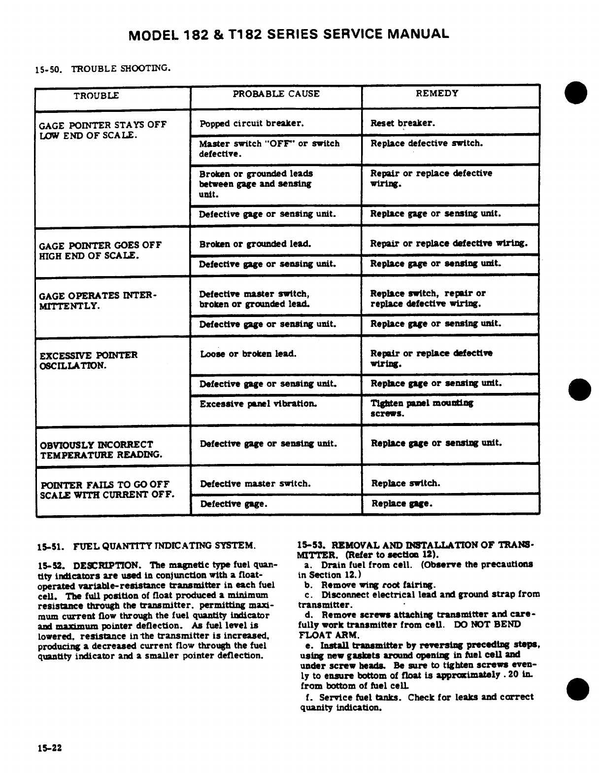
MODEL
182
&
T182
SERIES
SERVICE
MANUAL
15-50.
TROUBLE
SHOOTING.
TROUBLE PROBABLE
CAUSE
REMEDY
GAGE
POINTER
STAYS
OFF
Popped
circuit
breaker.
Reset
breaker.
LOW
END
OF
SCALE.
Master
switch
"OFF"
or
switch Replace
defective switch.
defective.
Broken
or
grounded
leads
Repair
or
replace
defective
between
gage
and
sensing
wiring.
unit.
Defective
gage
or
sensing
unit.
Replace
gage
or
sensing
unit.
GAGE
POINTER
GOES
OFF
Broken
or
grounded
lead.
Repair
or
replace
defective
wiring.
HIGH
END
OF
SCALE.
Defective
gage
or
sensing
unit.
Replace
gage
or
sensing
unit.
GAGE
OPERATES
INTER-
Defective
master
switch,
Replace
switch,
repair
or
MITTENTLY.
broken
or
grounded
lead.
replace
defective wiring.
Defective
gage
or
sensing
unit.
Replace
gage
or
sensing unit.
EXCESSIVE
POINTER
Loose
or
broken
lead. Repair
or
replace
defective
OSCILLATION.
wiring.
Defective
gage
or
sensing
unit.
Replace
gage
or
sensing unit.
Excessive
panel
vibration.
Tighten
panel
mounting
screws.
OBVIOUSLY
INCORRECT
Defective
gage
or
sensing
unit.
Replace
gage
or
sensing
unit.
TEMPERATURE
READING.
POINTER FAILS TO
GO
OFF
Defective
master
switch.
Replace
switch.
SCALE
WITH
CURRENT
OFF.
Defective
gage.
Replace
gage.
15-51.
FUEL
QUANTITY INDICATING
SYSTEM.
15-53.
REMOVAL
AND
INSTALLATION
OF
TRANS-
MITTER.
(Refer
to section
12).
15-52.
DESCRIPTION.
The
magnetic
type
fuel
quan-
a.
Drain
fuel
from
cell.
(Observe
the
precautions
tity
indicators
are
used
in
conjunction
with
a
float-
in
Section
12.)
operated
variable-resistance
transmitter
in each
fuel
b.
Remove
wing
root
fairing.
cell.
The
full
position
of
float
produced
a
minimum
c.
Disconnect
electrical
lead
and ground
strap
from
resistance
through
the
transmitter,
permitting
maxi-
transmitter.
mum
current
flow
through the
fuel
quantity
indicator
d.
Remove
screws
attaching
transmitter
and
care-
and
maximum
pointer
deflection.
As
fuel
level
is
fully
work
transmitter
from
cell.
DO
NOT
BEND
lowered,
resistance
in
the
transmitter
is
increased,
FLOAT
ARM.
producing
a
decreased
current
flow
through
the
fuel
e.
Install
transmitter
by
reversing
preceding
steps,
quantity
indicator
and
a
smaller
pointer
deflection,
using
new
gaskets
around
opening in
fuel
cell
and
under
screw
heads.
Be
sure
to
tighten
screws
even-
ly to
ensure
bottom
of
float
is
approximately
.
20
in.
from
bottom
of
fuel
cell.
f.
Service
fuel
tanks.
Check
for
leaks
and
correct
quanity
indication.
15-22
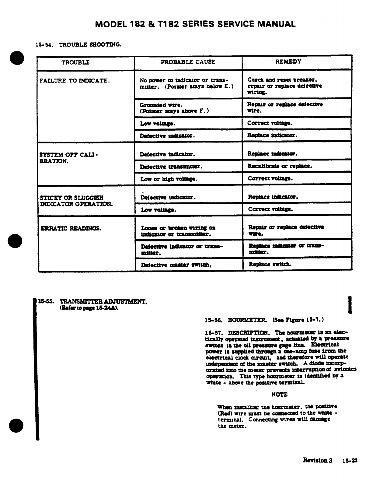
MODEL
182
&
T182
SERIES
SERVICE
MANUAL
15-54.
TROUBLE
SHOOTING.
TROUBLE
PROBABLE
CAUSE
REMEDY
FAILURE
TO
INDICATE.
No
power
to
Indicator
or
trans-
Check and
reset
breaker.
mitter.
(Pointer
says
below
E.)
repair
or
replace
wiring.
Grounded
wire.
Repair
or
replace
defective
(Poi
Low
voltage.
Correct
voltage.
Defective
indicator.
Replace
indicator.
SYSTEM
OFF
CALI-
Defective
indicator.
Replace
indicator.
BRATION.
Defective
Low
or
high
voltage.
Correct
voltage.
STICKY
OR
SLUGGISH
Defective
indicator.
INDICATOR OPERATION.
Low
voltage.
Correct
ERRATIC
READINGS.
Defective
Defective
master
switch.
Replace
switch
15-55.
(Refer
to
page
15-24A).
15-56.
HOrU
TER.
(See
Fiure
15-7.)
15-57.
DESCRPTIO.
The
hrmetar
is
ma
e1ec-
ticaly
operated
asnnment,
aced
by
a
pessre
switch
in
the
ol
presure
gage
lne
Electcal
pwer
is
spplied
throgh
a
ne-amp
fuse
from
the
electrical
clock
circt,
and
therefore
will operate
independm
of
the
masr swtch.
A
diode
Incorp-
orated
Ito
the
meter
preents
iorerrpaaf
avionics
operaton
This type
hormaer
i
isidntified
by
a
white
* above
the
positive
terminal
NOTE
When
insal._
the
hoarmter.
the
positve
(Red)
wire
must
be
connected
to
the
white
-
terminal.
Connectng
wires
will
damage
the
meter.
Revisio
3
15-23
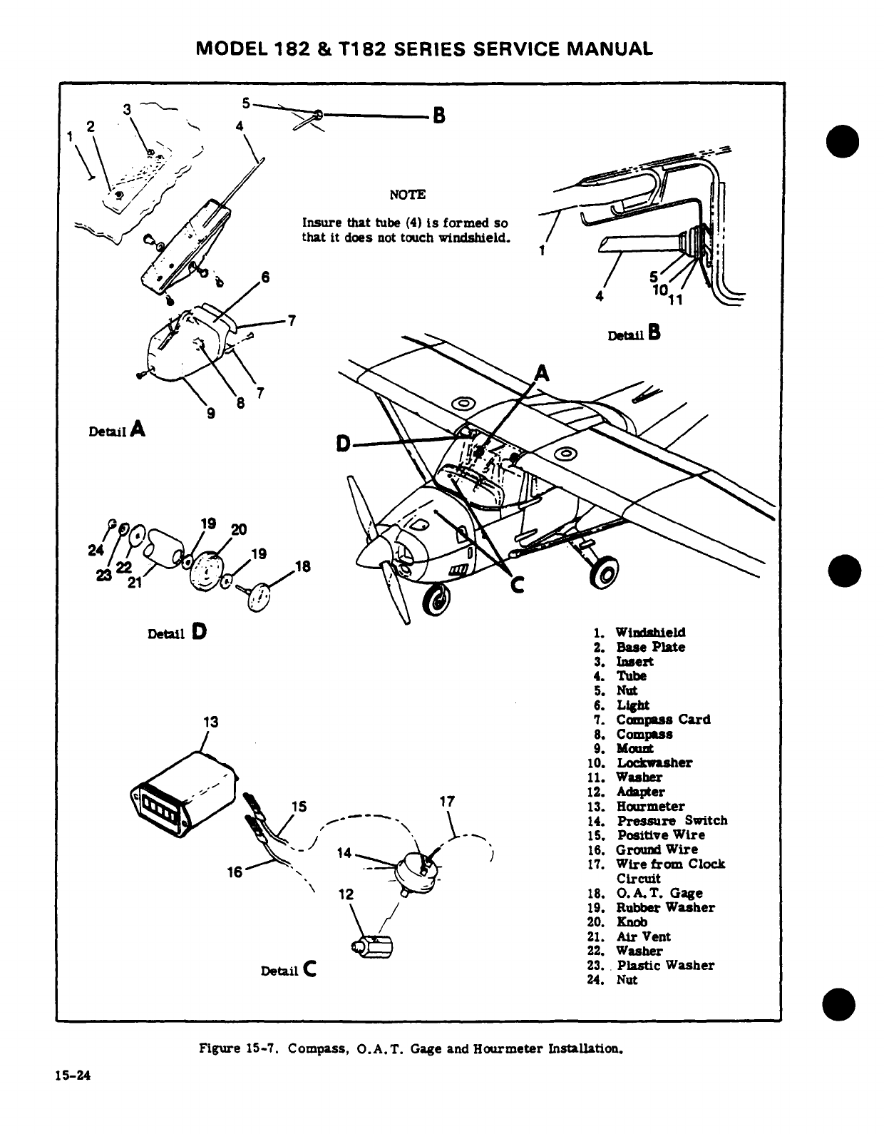
MODEL
182
&
T182
SERIES
SERVICE
MANUAL
3
~
-
5_--__
Insure
that
tube
(4)
is
formed
so
= -^'
&.«/*«?/
that
it
does
not
touch
windshield.
6
7
ADeta
D+
9~~A
\ 7
7
Detail
A
19
20
2322
--
',
S'
Detail
D 1.
Windshield
2.
Base
Plate
3.
Insert
4.
Tube
5.
Nut
6.
Light
13
7.
Compass
Card
8.
Compass
9.
Mount
10.
Lockwasher
11.
Washer
12.
Adapter
15
17
13.
Hourmeter
14.
Pressure
Switch
W
S A'\ , /
>-
15.
Positive
Wire
a'*
14
;
6.
Ground
Wire
1 ^--^*,
'^>/<B^- '
17.
Wire
from
Clock
16
De
,
oi
CCircuit
\
12
18.
O.A.T.
Gage
15-\ / 419.
Rubber
Washer
20.
Knob
21.
Air
Vent
22.
Washer
Detail
C
23..
Plastic
Washer
24.
Nut
Figure
15-7.
Compass,
O.A.T.
Gage
and
Hourmeter
Installation.
15-24
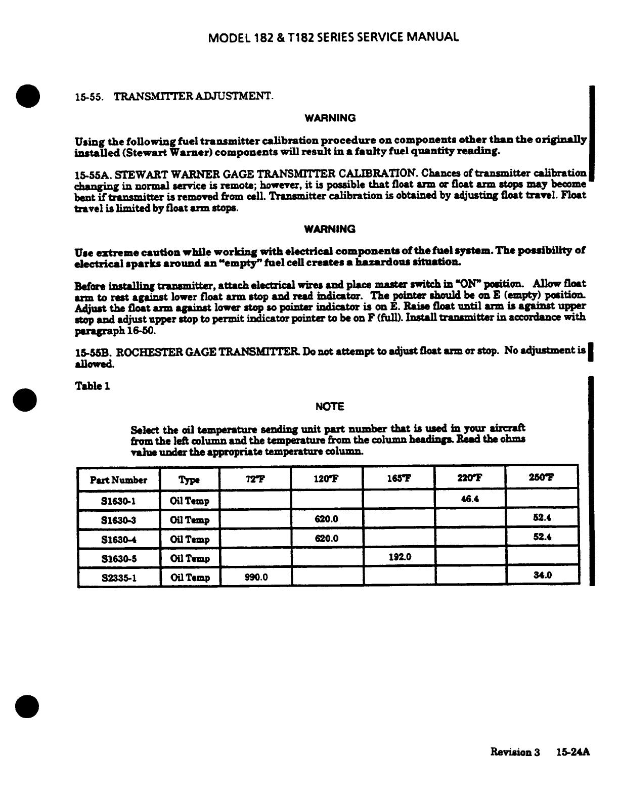
MODEL
182
&
T182
SERIES
SERVICE
MANUAL
15-55.
TRANSMITTER ADJUSTMENT.
WARNING
Using
the
following
fuel
transmitter
calibration
procedure
on
components
other
than
the
originally
installed
(Stewart
Warner) components
will
result
in
a
faulty
fuel
quantity
reading.
15-55A. STEWART
WARNER
GAGE
TRANSMITTER
CALIBRATION.
Chances
of
transmitter
calibration
changing
in
normal
service
is remote;
however,
it
is
possible
that
float
arm
or float
arm
stops
may
become
bent
if
transmitter
is
removed
from
cell.
Transmitter
calibration
is
obtained by
adjusting
float
travel.
Float
travel
is limited
by
float
arm
stops.
WARNING
Use
extreme
caution
while
working with
electrical
components
of
the
fuel
system.
The
possibility
of
electrical
sparks
around
an
"empty" fuel
cell
creates
a
hazardous situation.
Before
installing
transmitter, attach
electrical
wires
and
place
master
switch
in
"ON"
position.
Allow float
arm to
rest
against
lower
float
arm
stop
and
read
indicator.
The
pointer
should be
on
E
(empty)
position.
Adjust
the
float
arm
against
lower
stop so
pointer
indicator
is
on
E.
Raise
flat
until
arm
is
against
upper
stop
and
adjust
upper
stop
to
permit
indicator pointer
to
be
on
F
(full).
Install
transmitter in
accordance
with
paragraph
16-50.
15-55B.
ROCHESTER
GAGE
TRANSMITTER.
Do
not
attempt
to
adjust
float
arm
or
stop.
No
adjustment
is
allowed.
Table
1
NOTE
Select
the
oil
temperature
sending
unit
part
number
that
is used
in
your
aircraft
from
the
left
column
and
the
temperature
from
the
column
headings.
Read
the
ohms
value
under
the
appropriate
temperature
column
Part
Number
Type
72°F
120°F
165°F
220°F
250°F
S1630-1 Oil
Temp
46.4
S1630-3
Oil
Temp
620.0
52.4
S1630-4
Oil
Temp
620.0
52.4
S1630-5
Oil Temp 192.0
S2335-1
Oil Temp
990.0
34.0
Revision
3
15-24A
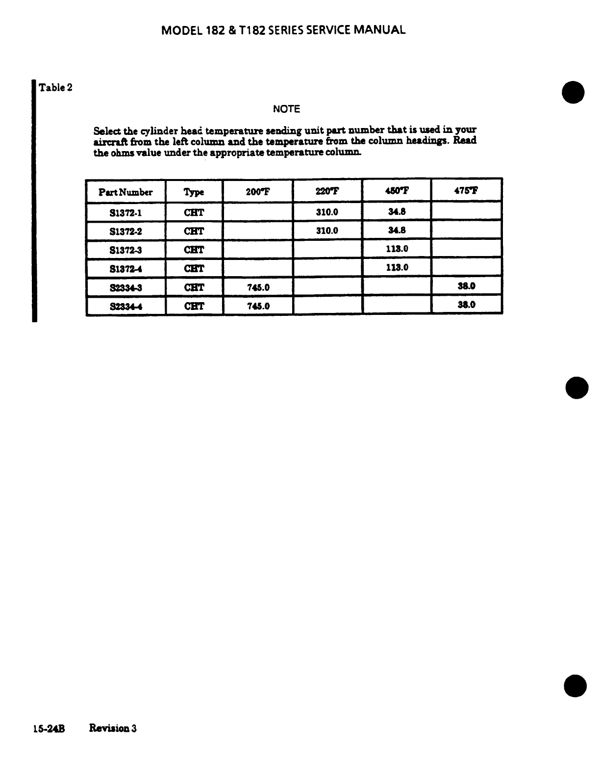
MODEL
182
&
T182
SERIES
SERVICE
MANUAL
Table
2
NOTE
Select
the
cylinder
head
temperature
sending
unit part
number
that
is
used
in
your
aircraft
from
the
left
column
and
the
temperature
from
the
column
headings.
Read
the
ohms
value
under
the
appropriate
temperature
column.
Part
Number
Type
200°F
220°F
450°F
475°F
S1372-1
CHT
310.0
34.8
S1372-2
CHT
310.0
34.8
S1372-3
CHT
113.0
S1372-4
CHT
113.0
82334-3
CHT
745.0
38.0
S2334-4
CHT
745.0
38.0
15-24B
Revision
3
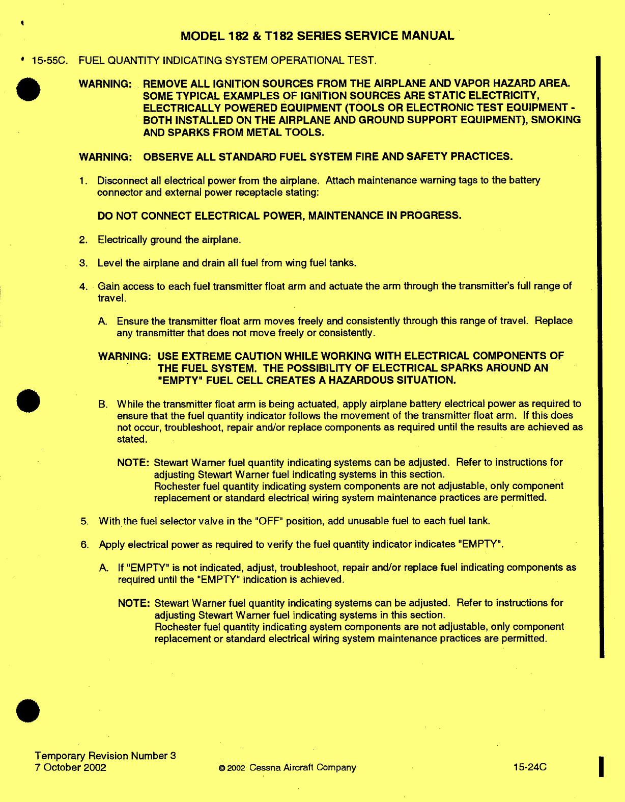
MODEL
182
&
T182
SERIES SERVICE
MANUAL
15-55C.
FUEL
QUANTITY
INDICATING
SYSTEM
OPERATIONAL
TEST.
WARNING:
REMOVE
ALL
IGNITION
SOURCES
FROM
THE
AIRPLANE
AND
VAPOR HAZARD
AREA.
SOME
TYPICAL
EXAMPLES
OF
IGNITION
SOURCES ARE
STATIC ELECTRICITY,
ELECTRICALLY
POWERED
EQUIPMENT
(TOOLS
OR
ELECTRONIC
TEST
EQUIPMENT
-
BOTH
INSTALLED
ON
THE
AIRPLANE
AND
GROUND
SUPPORT
EQUIPMENT),
SMOKING
AND
SPARKS
FROM
METAL
TOOLS.
WARNING:
OBSERVE
ALL
STANDARD
FUEL
SYSTEM
FIRE
AND
SAFETY
PRACTICES.
1.
Disconnect
all
electrical
power
from
the airplane.
Attach
maintenance
warning
tags
to
the
battery
connector
and
external power
receptacle stating:
DO
NOT CONNECT
ELECTRICAL
POWER,
MAINTENANCE
IN
PROGRESS.
2.
Electrically
ground
the
airplane.
3.
Level
the
airplane
and
drain
all fuel
from wing
fuel tanks.
4.
Gain
access
to
each
fuel transmitter
float
arm
and
actuate the
arm
through
the transmitter's
full
range
of
travel.
A.
Ensure
the
transmitter
float
arm
moves
freely
and
consistently
through
this
range
of
travel.
Replace
any
transmitter
that
does
not
move
freely
or
consistently.
WARNING:
USE
EXTREME
CAUTION
WHILE
WORKING
WITH
ELECTRICAL
COMPONENTS OF
THE
FUEL
SYSTEM. THE
POSSIBILITY
OF
ELECTRICAL
SPARKS
AROUND
AN
"EMPTY"
FUEL
CELL
CREATES
A
HAZARDOUS
SITUATION.
B.
While
the
transmitter
float
arm is
being actuated,
apply
airplane
battery
electrical
power
as
required
to
ensure
that
the
fuel
quantity indicator
follows
the
movement
of
the
transmitter
float
arm.
If
this does
not
occur,
troubleshoot,
repair
and/or replace
components
as
required
until
the
results
are
achieved
as
stated.
NOTE: Stewart
Warner
fuel
quantity indicating
systems
can
be
adjusted.
Refer
to
instructions
for
adjusting
Stewart
Warner
fuel
indicating
systems
in
this section.
Rochester fuel
quantity indicating
system
components
are
not
adjustable,
only
component
replacement or
standard
electrical
wiring
system
maintenance
practices
are
permitted.
5.
With
the fuel
selector
valve
in
the
"OFF"
position,
add
unusable
fuel to
each
fuel
tank.
6.
Apply electrical
power
as
required
to
verify the
fuel
quantity
indicator
indicates
"EMPTY".
A.
If
"EMPTY"
is
not
indicated, adjust,
troubleshoot,
repair
and/or
replace
fuel
indicating
components
as
required until
the
"EMPTY"
indication
is
achieved.
NOTE:
Stewart
Warner
fuel
quantity
indicating
systems
can
be
adjusted. Refer
to
instructions
for
adjusting
Stewart
Warner
fuel
indicating
systems
in
this
section.
Rochester fuel
quantity
indicating
system
components
are
not
adjustable, only component
replacement or
standard
electrical
wiring
system
maintenance
practices
are
permitted.
Temporary
Revision
Number
3
7
October
2002
©
2002
Cessna
Aircraft
Company
15-24C
MODEL 182
&
T182
SERIES
SERVICE
MANUAL
7.
Fill
tanks
to
capacity,
apply
electrical
power
as
required
and
verify
that
the
fuel
quantity
indicators
indicate
"FULL".
A.
If
"FULL"
is
not
indicated,
adjust,
troubleshoot, repair
and/or replace
fuel
indicating
components
as
required until
the
"FULL"
indication
is
achieved.
NOTE:
Stewart
Warner
fuel
quantity indicating
systems
can
be
adjusted. Refer to
instructions
for
adjusting
Stewart
Warner fuel indicating
systems
in
this section.
Rochester fuel
quantity indicating
system
components
are
not
adjustable,
only component
replacement
or
standard
electrical
wiring system
maintenance practices
are
permitted.
8.
Install
any
items
and/or equipment
removed
to
accomplish
this
procedure,
remove
maintenance
warning
tags
and
connect the
airplane battery.
Temporary
Revision
Number
3
©
2002
Cessna Aircraft
Company
7
October
2002
15-24D
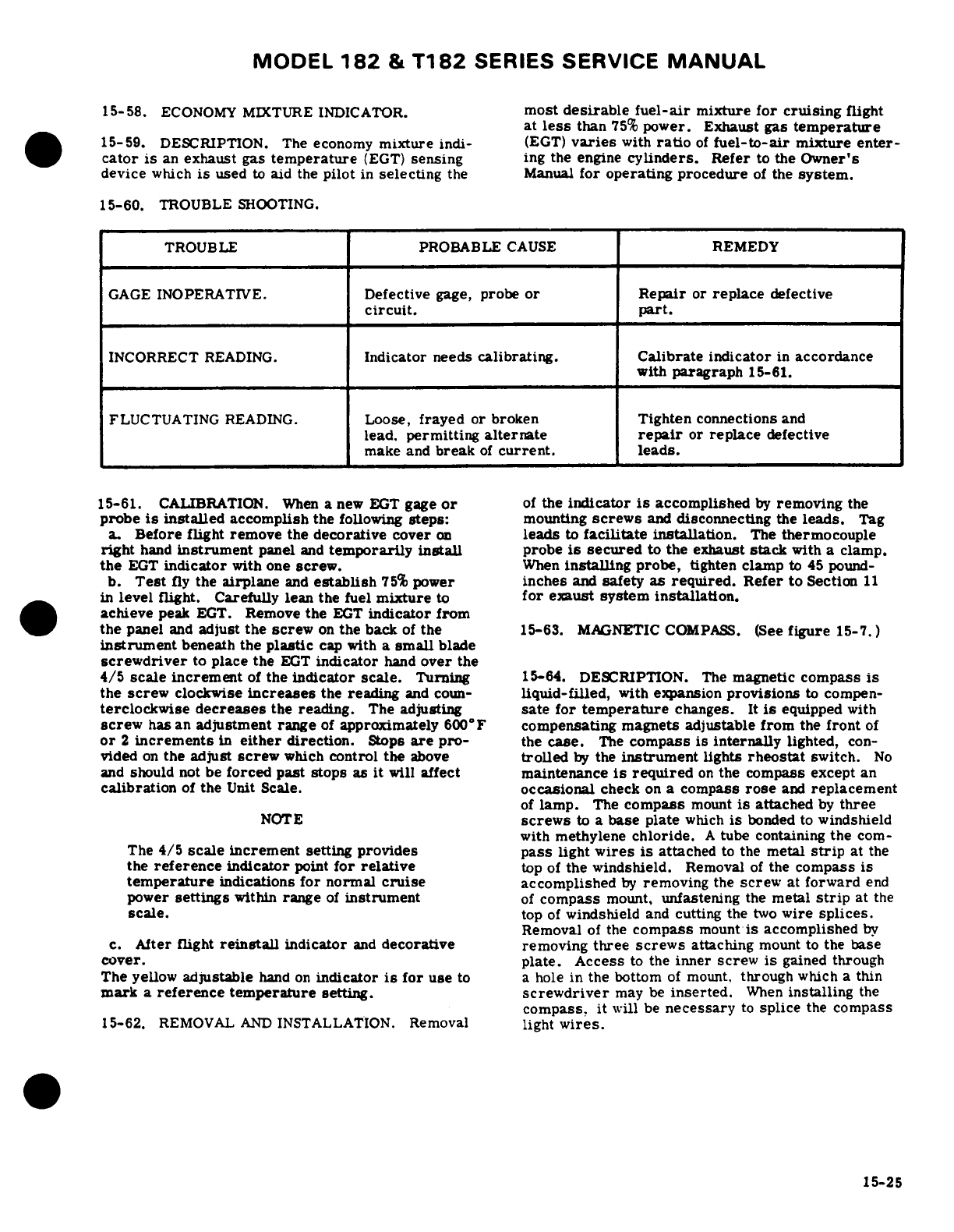
MODEL
182
&
T182
SERIES SERVICE
MANUAL
15-58.
ECONOMY
MIXTURE
INDICATOR.
most
desirable
fuel-air
mixture
for
cruising
flight
at
less
than
75%
power.
Exhaust
gas
temperature
15-59.
DESCRIPTION.
The
economy
mixture
indi-
(EGT)
varies
with
ratio
of
fuel-to-air
mixture
enter-
cator
is
an
exhaust
gas
temperature
(EGT)
sensing
ing
the engine
cylinders.
Refer
to
the
Owner's
device
which
is
used
to
aid
the
pilot
in
selecting
the Manual
for operating procedure
of
the
system.
15-60.
TROUBLE
SHOOTING.
TROUBLE PROBABLE
CAUSE
REMEDY
GAGE
INOPERATIVE.
Defective
gage,
probe
or Repair
or
replace
defective
circuit. part.
INCORRECT
READING.
Indicator
needs
calibrating.
Calibrate
indicator
in
accordance
with
paragraph
15-61.
FLUCTUATING
READING.
Loose,
frayed
or
broken
Tighten
connections
and
lead.
permitting
alternate
repair
or
replace
defective
make
and
break
of
current.
leads.
15-61.
CALIBRATION.
When
a
new
EGT
gage
or
of
the
indicator
is
accomplished
by
removing
the
probe
is
installed
accomplish
the
following
steps:
mounting
screws
and
disconnecting
the
leads.
Tag
a.
Before flight remove
the
decorative
cover
on
leads
to
facilitate
installation.
The
thermocouple
right
hand
instrument
panel
and
temporarily
install
probe
is
secured
to
the
exhaust
stack
with
a clamp.
the
EGT
indicator
with one
screw.
When
installing
probe,
tighten
clamp
to
45
pound-
b.
Test
fly
the
airplane
and
establish
75%
power
inches
and
safety as
required.
Refer
to
Section
11
in
level
flight.
Carefully
lean
the fuel
mixture
to
for
exaust
system
installation.
achieve
peak
EGT.
Remove
the
EGT
indicator
from
the
panel
and
adjust
the
screw
on
the
back
of
the
15-63.
MAGNETIC
COMPASS.
(See
figure
15-7.)
instrument
beneath the
plastic
cap
with
a
small
blade
screwdriver
to
place
the
EGT
indicator
hand
over
the
4/5
scale
increment
of
the
indicator
scale.
Turning
15-64.
DESCRIPTION.
The
magnetic
compass
is
the
screw
clockwise
increases
the
reading
and
coun-
liquid-filled,
with
expansion
provisions
to
compen-
terclockwise
decreases
the reading.
The
adjusting
sate
for
temperature
changes.
It
is
equipped
with
screw
has
an
adjustment
range
of
approximately
600°F
compensating magnets
adjustable from
the
front
of
or
2
increments
in
either
direction.
Stops
are
pro-
the
case.
The
compass
is
internally
lighted,
con-
vided
on
the
adjust
screw
which
control the
above
trolled
by
the
instrument
lights
rheostat
switch.
No
and
should
not
be
forced
past
stops as
it
will
affect
maintenance
is
required
on
the
compass except
an
calibration
of
the
Unit
Scale.
occasional
check
on
a
compass
rose
and
replacement
of
lamp.
The
compass
mount
is
attached
by
three
NOTE
screws
to
a
base
plate
which
is
bonded
to
windshield
with
methylene
chloride.
A
tube
containing
the
com-
The
4/5
scale
increment
setting
provides
pass
light
wires
is
attached
to
the
metal
strip
at
the
the
reference
indicator
point
for
relative
top
of
the windshield.
Removal
of
the
compass
is
temperature
indications
for normal
cruise
accomplished
by
removing
the
screw
at
forward
end
power
settings
within
range
of
instrument
of
compass
mount,
unfastening
the
metal
strip
at
the
scale.
top
of
windshield
and
cutting
the
two
wire
splices.
Removal
of
the
compass
mount
is
accomplished
by
c.
After
flight
reinstall
indicator
and
decorative
removing
three
screws
attaching
mount
to
the base
cover.
plate.
Access
to
the
inner
screw
is
gained
through
The
yellow
adjustable
hand
on
indicator
is
for
use
to
a
hole
in
the
bottom
of
mount,
through
which
a
thin
mark
a
reference temperature
setting.
screwdriver
may
be
inserted.
When
installing
the
compass,
it
will
be
necessary
to
splice
the
compass
15-62.
REMOVAL
AND
INSTALLATION.
Removal
light
wires.
15-25
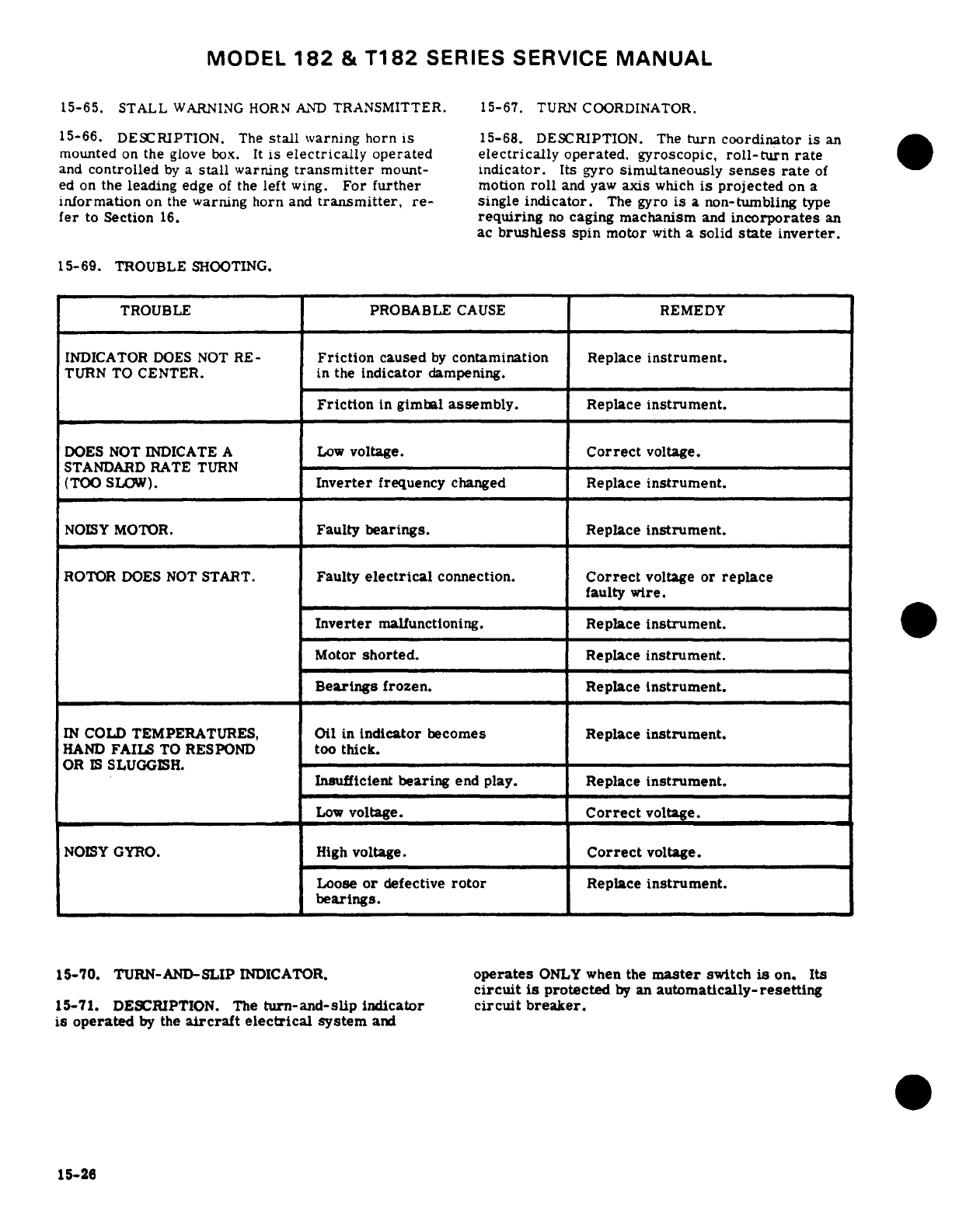
MODEL
182
&
T182
SERIES SERVICE
MANUAL
15-65. STALL
WARNING
HORN
AND
TRANSMITTER.
15-67.
TURN
COORDINATOR.
15-66.
DESCRIPTION.
The
stall
warning
horn
is
15-68.
DESCRIPTION.
The
turn
coordinator
is
an
mounted
on
the
glove
box.
It
is
electrically
operated
electrically
operated,
gyroscopic,
roll-turn
rate
and
controlled
by
a
stall
warning
transmitter
mount-
indicator.
Its
gyro
simultaneously
senses
rate
of
ed
on
the
leading
edge
of
the
left
wing.
For
further
motion
roll
and
yaw
axis
which
is
projected
on
a
information
on
the
warning horn
and
transmitter,
re-
single
indicator.
The
gyro
is
a
non-tumbling
type
fer
to
Section
16.
requiring
no
caging machanism
and
incorporates
an
ac
brushless
spin motor
with
a
solid
state
inverter.
15-69.
TROUBLE
SHOOTING.
TROUBLE
PROBABLE
CAUSE
REMEDY
INDICATOR
DOES NOT
RE-
Friction
caused
by
contamination
Replace
instrument.
TURN
TO
CENTER.
in
the
indicator
dampening.
Friction
in
gimbal
assembly.
Replace
instrument.
DOES
NOT INDICATE
A
Low
voltage.
Correct
voltage.
STANDARD
RATE
TURN
(TOO
SLOW).
Inverter
frequency
changed
Replace
instrument.
NOISY
MOTOR.
Faulty
bearings.
Replace
instrument.
ROTOR
DOES NOT
START.
Faulty
electrical
connection.
Correct
voltage
or
replace
faulty
wire.
Inverter
malfunctioning.
Replace
instrument.
Motor
shorted.
Replace
instrument.
Bearings
frozen.
Replace
instrument.
IN
COLD
TEMPERATURES,
Oil
in
indicator
becomes
Replace
instrument.
HAND
FAILS
TO
RESPOND
too
thick.
OR
IS
SLUGGISH.
Insufficient
bearing
end play.
Replace
instrument.
Low
voltage.
Correct
voltage.
NOISY
GYRO.
High
voltage.
Correct
voltage.
Loose
or
defective
rotor
Replace
instrument.
bearings.
15-70.
TURN-AND-SLIP
INDICATOR.
operates
ONLY
when
the
master
switch
is
on. Its
circuit
is
protected
by
an
automatically-resetting
15-71.
DESCRIPTION. The
turn-and-slip
indicator
circuit breaker.
is
operated
by
the
aircraft
electrical
system
and
15-26
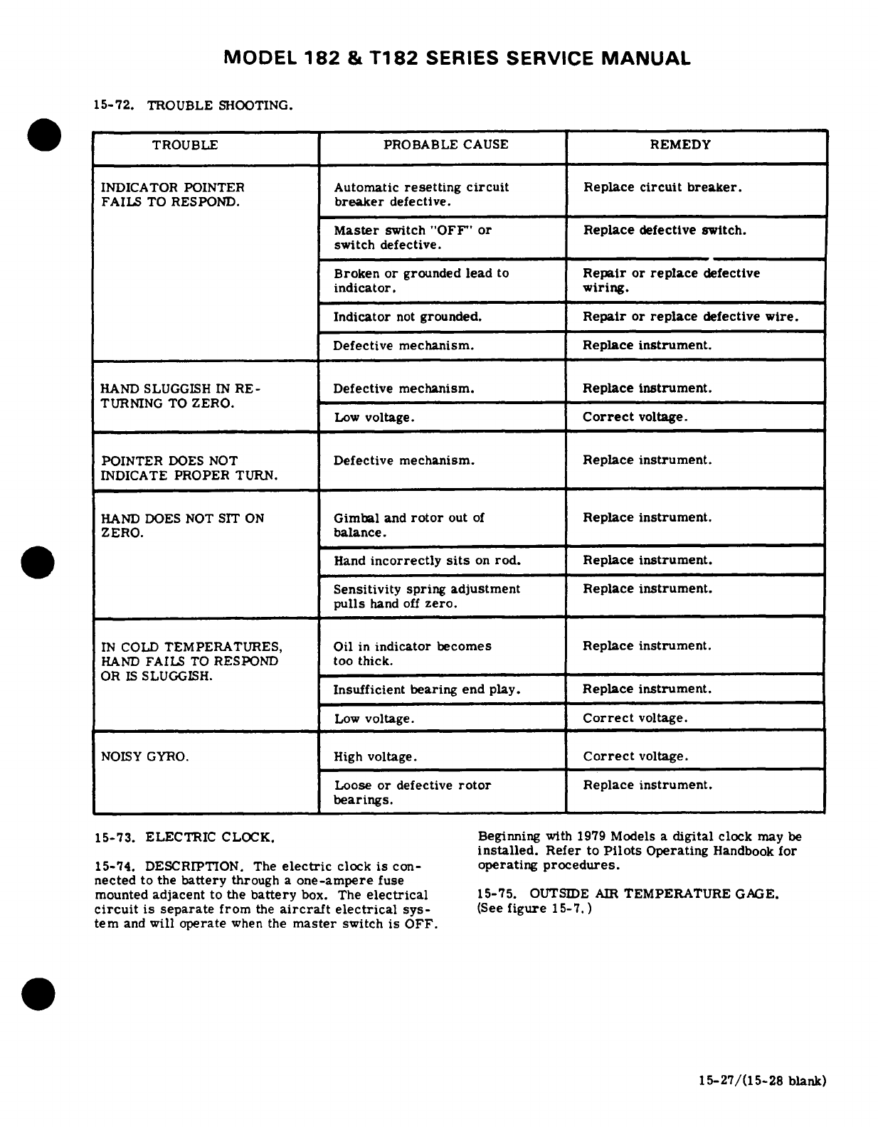
MODEL
182
&
T182
SERIES
SERVICE
MANUAL
15-72.
TROUBLE
SHOOTING.
TROUBLE PROBABLE
CAUSE
REMEDY
INDICATOR
POINTER
Automatic
resetting
circuit
Replace
circuit
breaker.
FAILS
TO
RESPOND.
breaker
defective.
Master
switch
"OFF"
or
Replace
defective switch.
switch
defective.
Broken
or
grounded
lead
to
Repair
or
replace
defective
indicator.
wiring.
Indicator
not
grounded.
Repair
or
replace
defective
wire.
Defective
mechanism. Replace
instrument.
HAND
SLUGGISH
IN
RE-
Defective
mechanism. Replace
instrument.
TURNING
TO
ZERO.
Low
voltage.
Correct
voltage.
POINTER
DOES
NOT
Defective mechanism.
Replace
instrument.
INDICATE
PROPER
TURN.
HAND
DOES
NOT
SIT
ON
Gimbal
and
rotor
out
of
Replace
instrument.
ZERO.
balance.
Hand
incorrectly
sits
on
rod.
Replace
instrument.
Sensitivity
spring adjustment
Replace
instrument.
pulls
hand
off
zero.
IN
COLD
TEMPERATURES,
Oil
in
indicator
becomes Replace
instrument.
HAND
FAILS
TO
RESPOND
too
thick.
OR
IS
SLUGGISH.
Insufficient bearing
end
play.
Replace
instrument.
Low
voltage.
Correct
voltage.
NOISY GYRO.
High
voltage.
Correct
voltage.
Loose
or
defective
rotor
Replace
instrument.
bearings.
15-73.
ELECTRIC
CLOCK.
Beginning
with
1979
Models a
digital
clock
may
be
installed.
Refer
to
Pilots
Operating
Handbook
for
15-74.
DESCRIPTION.
The
electric
clock
is
con-
operating
procedures.
nected
to
the
battery
through
a
one-ampere
fuse
mounted
adjacent
to
the
battery
box.
The
electrical
15-75.
OUTSIDE
AIR
TEMPERATURE
GAGE.
circuit
is
separate
from
the
aircraft
electrical
sys-
(See
figure
15-7.)
tern
and
will
operate
when
the
master
switch
is
OFF.
15-27/(15-28
blank)
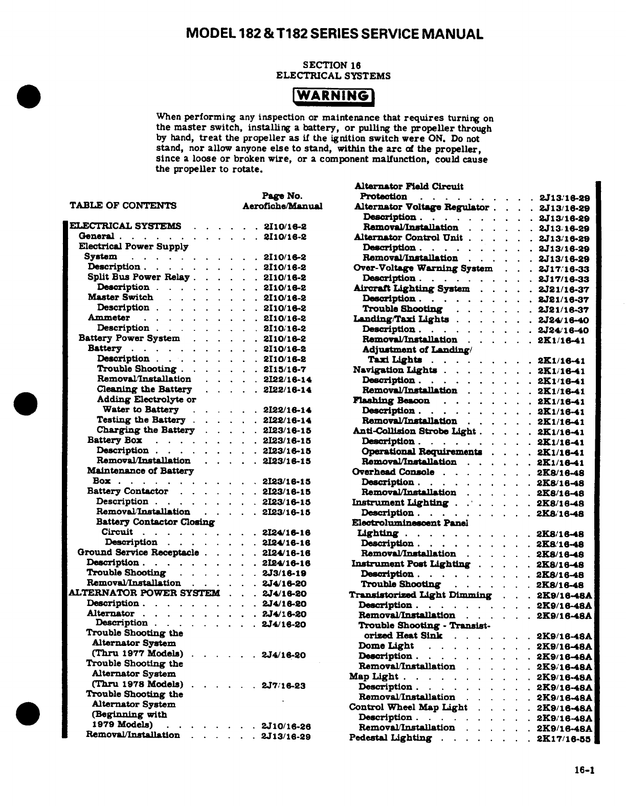
MODEL
182
&T182
SERIES SERVICE
MANUAL
SECTION
16
ELECTRICAL
SYSTEMS
When
performing
any
inspection
or maintenance that
requires
turning
on
the
master
switch,
installing
a
battery,
or
pulling
the
propeller
through
by
hand,
treat
the
propeller
as
if
the ignition
switch
were
ON.
Do
not
stand, nor
allow
anyone
else
to
stand,
within
the
arc
of
the
propeller,
since
a
loose
or
broken
wire,
or
a
component
malfunction,
could
cause
the
propeller
to
rotate.
Alternator
Field Circuit
Page
No.
Protection
..........
2J13/16-29
TABLE
OF
CONTENTS
Aerofiche/Manual
Alternator
Voltage
Regulator
....
2J13/16-29
Description
..... .....
2J13/16-29
ELECTRICAL SYSTEMS
......
2I10/16-2
Removal/Installation
.....
2J1316-29
General
. ... .
.2110/16-2
Alternator
Control
Unit
......
2J13/16-29
Electrical Power
Supply
Description
.
.........
2J13/16-29
System
...........
2110/16-2
Removal/Installation
......
2J13/16-29
Description
..........
2110/16-2
Over-Voltage
Warning
System
...
2J1716-33
Split Bus
Power
Relay
.
.....
2I10/16-2
Description
.........
2J17/16-33
Description
.
........
2I10/16-2
Aircraft
Lighting
System
.....
2J21/16-37
Master Switch
......
.
2I10/16-2
Description
........
.
2J21/16-37
Description
.........
2110/16-2
Trouble
Shooting
.
......
2J21/16-37
Ammeter
.
.......
2110/16-2
Landing/Taxi
Lights
. .
.....
2J24/16-40
Description.
.......
.
2110/16-2
Description
.
....
... .
2J24/16-40
Battery
Power
System
......
2110/16-2
Removal/Installation
......
2K1/16-41
Battery
.........
.
2110/16-2
Adjustment
of Landing/
Description
. .
.......
2I10/16-2
Taxi
Lights
....... .....
2K1/16-41
Trouble
Shooting
.. ... .
2I15/16-7
Navigation
Lights
.....
..
2K116-41
Removal/Installation
.....
2I22/16-14
Description
........
.
2K1/16-41
Cleaning
the
Battery
.....
2I22/16-14
Removal/Installation
......
2K1/16-41
Adding Electrolyte
or
Flashing
Beacon
........
2K1/16-41
Water
to
Battery
. ... . 2122/16-14
Description
..........
2K1/16-41
Testing
the Battery
... .
2I22/16-14
Removal/Installation
......
2K1/16-41
Charging
the
Battery
.....
2I23/16-15
Anti-Collision
Strobe
Light
.....
2K1/16-41
Battery
Box
....
.. . .
2I23/16-15
Description
..
....
..
2K1/16-41
Description
.........
2I23/16-15
Operational
Requirements
....
2K1/16-41
Removal/Installation
.
....
2I23/16-1
Removal/Installation
......
2K1/16-41
Maintenance
of
Battery
Overhead
Console
.
.......
2K8/16-48
Box
.......
.. .
2123/16-15
Description
......
...
2K8/16-48
Battery
Contactor
......
.
2I23/16-15
Removal/Installation
. ... .
2K8/16-48
Description
.........
2I23/16-15
Instrument Lighting
.
.....
2K8/16-48
Removal/Installation
.....
2I23/16-1
Description
..........
2K8/16-48
Battery Contactor
Closing
Electroluminescent
Panel
Circuit
..........
2I24/16-16
Lighting
.........
.
2K8/16-48
Description
.
.......
2124/16-16
Description
..........
2K8/16-48
Ground
Service
Receptacle
.....
2I24/16-16
Removal/Installation
......
2K8/16-48
Description
..........
2124/16-16
Instrument
Post
Lighting
.....
2K8/16-48
Trouble
Shooting
.
.....
2J3/16-19
Description
..........
2K8/16-48
Removal/Installation
.. . ...
2J4/16-20
Trouble
Shooting
.
......
2K8/16-48
ALTERNATOR
POWER
SYSTEM
.
2J4/16-20
Transistorized
Light
Dimming
.. .
2K9/16-48A
Description
..........
2J4/16-20
Description
..........
2K9/16-48A
Alternator
.
.......
..
2J4/16-20
Removal/Installation
... . .
2K9/16-48A
Description
........
.
2J4/16-20
Trouble
Shooting
-
Transist-
Trouble
Shooting
the orized
Heat
Sink
.......
2K9/16-48A
Alternator
System
Dome
Light
.. . ... . .
2K9/16-48A
(Thru
1977
Models)
.
....
2J4/16-20
Description
...
......
2K9/16-48A
Trouble
Shooting
the
Removal/Installation
......
2K9/16-48A
Alternator
System
Map
Light
.......
. ..
2K9/16-48A
(Thru
1978
Models)
.
......
2J716-23
Description
..
.......
2K9/16-48A
Trouble
Shooting the
Removal/Installation
.. .. .
2K9/16-48A
Alternator
System
Control
Wheel
Map
Light
.....
29/16-48A
(Beginning
with
Description
.. .
.....
.
2K9/16-48A
1979
Models)
........
2J10/16-26
Removal/Installation
......
2K9/16-48A
Removal/Installation
.....
.
2J13/16-29
Pedestal
Lighting
.......
.
2K17/16-55
16-1
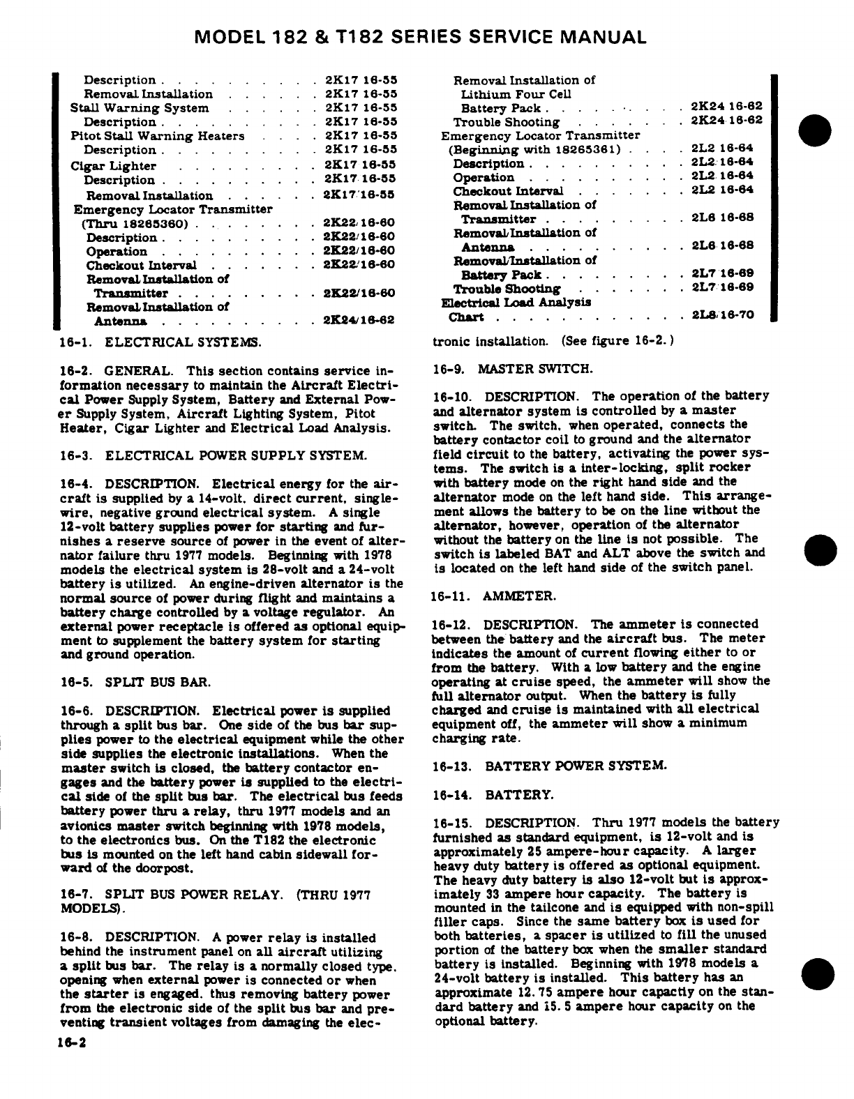
MODEL
182
&
T182
SERIES
SERVICE
MANUAL
Description
...
......
2K17
16-55
Removal
Installation
of
Removal
Installation
.... .
2K17
16-55
Lithium
Four
Cell
Stall
Warning
System
.
.....
2K17
16-55
Battery
Pack
.... .
2K24
16-62
Description
.
.......
.
2K17
16-55
Trouble
Shooting
. ...
2K24
16-62
Pitot
Stall
Warning
Heaters
.. .
2K17
16-55
Emergency
Locator
Transmitter
Description
.
........
2K17
16-55
(Beginning
with
18265361)
....
2L2
16-64
Cigar
Lighter
. ..... ... 2K17
16-55
Description.
....... .
2L2.
16-64
Description
. . . ...
2K17
16-55
Operation
.
.........
2L2
16-64
Removal
Installation
. ....
2K17
16-55
Checkout
Interval
... . .
2L2
16-64
Emergency
Locator
Transmitter
Removal
Installation
of
(Thru
18265360)
.......
.
2K22,16-60
Transmitter
.........
2L6
16-68
Description
. . . . . . .
2K2216-60
Removal/Installation
of
Operation
........
.
2K22/16-60
Anten
..
........
2L6
16-68
Checkout
Interval
.. . . ...
2K2216-60
Removal/Installation
of
Removal/Installation
of
Battery Pack
....
. ...
2L7
16-69
Transmitter
.......
..
2K22/16-60 Trouble
Shooting
....
. ..
2L7
16-69
Removal/Installation
of
Electrical
Load
Analysis
Antenna
..........
2K24/16-2
Chart
............
2L8
16-70
16-1.
ELECTRICAL
SYSTEMS.
tronic installation.
(See
figure
16-2.)
16-2.
GENERAL.
This
section contains
service
in-
16-9.
MASTER
SWITCH.
formation
necessary
to
maintain
the
Aircraft
Electri-
cal
Power
Supply
System,
Battery
and
External
Pow-
16-10.
DESCRIPTION.
The
operation
of
the
battery
er
Supply
System,
Aircraft
Lighting
System,
Pitot
and
alternator
system
is
controlled
by
a
master
Heater,
Cigar
Lighter
and
Electrical
Load
Analysis.
switch.
The
switch,
when
operated,
connects
the
battery
contactor
coil
to
ground
and
the
alternator
16-3. ELECTRICAL
POWER
SUPPLY
SYSTEM.
field
circuit
to
the
battery,
activating
the
power
sys-
tems.
The
switch
is
a
inter-locking,
split
rocker
16-4.
DESCRIPTION.
Electrical
energy
for
the
air-
with
battery
mode
on
the
right
hand
side
and
the
craft
is
supplied
by
a
14-volt.
direct
current,
single-
alternator
mode
on
the
left
hand
side.
This
arrange-
wire,
negative ground
electrical
system.
A
single
ment allows
the
battery
to
be on
the
line
without
the
12-volt
battery
supplies
power
for
starting
and
fur-
alternator,
however,
operation
of
the
alternator
nishes
a
reserve
source
of
power
in
the
event
of
alter-
without
the
battery
on
the
line
is
not
possible.
The
nator
failure
thru
1977
models.
Beginning
with
1978
switch
is
labeled
BAT
and
ALT
above
the
switch
and
models
the
electrical
system
is
28-volt
and
a
24-volt
is
located
on
the left
hand
side
of
the
switch
panel.
battery
is
utilized.
An
engine-driven
alternator
is
the
normal
source
of
power
during
flight
and
maintains
a
16-11.
AMMETER.
battery
charge
controlled
by
a
voltage
regulator.
An
external
power
receptacle
is
offered
as
optional
equip-
16-12.
DESCRIPTION.
The
ammeter
is
connected
ment
to
supplement
the
battery system
for
starting
between
the
battery
and
the
aircraft
bus.
The
meter
and
ground
operation.
indicates
the amount
of
current
flowing
either
to
or
from
the
battery.
With
a
low
battery
and
the
engine
16-5.
SPLIT
BUS
BAR.
operating
at
cruise
speed,
the
ammeter
will
show the
full
alternator
output.
When
the
battery
is
fully
16-6.
DESCRIPTION.
Electrical
power
is
supplied
charged
and
cruise
is
maintained
with
all
electrical
through
a
split
bus
bar.
One
side
of
the
bus
bar
sup- equipment
off,
the
ammeter
will
show
a
minimum
plies
power
to
the
electrical
equipment
while
the
other
charging
rate.
side
supplies
the
electronic
installations.
When
the
master
switch
is
closed,
the
battery
contactor
en-
16-13.
BATTERY
POWER
SYSTEM.
gages
and
the
battery
power
is
supplied
to
the
electri-
cal
side
of
the
split
bus
bar.
The
electrical
bus
feeds
16-14.
BATTERY.
battery
power
thru
a
relay,
thru
1977
models
and an
avionics
master
switch
beginning
with
1978
models,
16-15.
DESCRIPTION.
Thru
1977
models
the
battery
to the
electronics
bus.
On
the
T182
the
electronic
furnished as standard
equipment,
is
12-volt
and
is
bus
is
mounted
on
the
left
hand
cabin
sidewall
for-
approximately
25
ampere-hour
capacity.
A
larger
ward
of
the
doorpost.
heavy
duty
battery
is
offered
as
optional
equipment.
The
heavy
duty
battery
is
also
12-volt
but
is
approx-
16-7.
SPLIT
BUS
POWER
RELAY.
(THRU
1977
imately
33
ampere
hour
capacity.
The
battery
is
MODELS).
mounted
in
the
tailcone
and
is
equipped
with
non-spill
filler
caps.
Since
the
same
battery
box
is
used
for
16-8.
DESCRIPTION.
A
power
relay
is
installed
both
batteries,
a
spacer
is
utilized
to
fill
the unused
behind
the
instrument
panel
on
all
aircraft
utilizing
portion
of
the
battery
box
when
the
smaller
standard
a
split
bus
bar.
The
relay
is
a
normally closed
type.
battery
is
installed.
Beginning
with
1978
models
a
opening
when
external
power
is
connected
or
when
24-volt
battery
is
installed.
This
battery
has
an
the
starter
is
engaged.
thus
removing
battery
power
approximate
12.
75
ampere
hour
capactiy
on
the
stan-
from
the
electronic
side
of
the
split
bus
bar
and
pre-
dard
battery
and
15.
5
ampere
hour
capacity
on
the
venting
transient
voltages from
damaging
the
elec-
optional
battery.
16-2
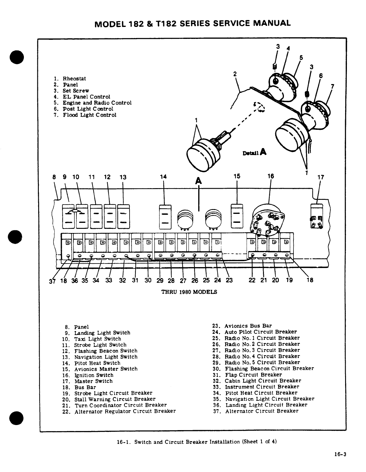
MODEL
182
&
T182
SERIES
SERVICE
MANUAL
2
6
1.
Rheostat
2.
Panel
3.
Set
Screw
/
4.
EL Panel
Control
5.
Engine and
Radio
Control
6.
Post
Light
Control
/
7.
Flood
Light
Control
DeailA
M
8
9
10
11
12
13
14 15
16 17
\t \
__
_
A
-
o o
o
®
a
mp_
g
o o
8
o
f ~ ~
[i
0
c
o /
3
18
36
35
34 33
32
31
30
2928
27
26
25
24
23
22
21
20
19
18
THRU
1980
MODELS
8.
Panel
23.
Avionics
Bus
Bar
9.
Landing
Light
Switch
24.
Auto
Pilot Circuit
Breaker
10.
Taxi
Light
Switch
25.
Radio
No. 1
Circuit
Breaker
11.
Strobe
Light
Switch
26.
Radio
No.
2
Circuit
Breaker
12.
Flashing
Beacon
Switch
27.
Radio
No.
3
Circuit
Breaker
13.
Navigation
Light
Switch
28.
Radio
No.
4
Circuit
Breaker
14.
Pitot
Heat
Switch
29.
Radio
No.
5
Circuit
Breaker
15.
Avionics
Master
Switch
30.
Flashing
Beacon
Circuit
Breaker
16.
Ignition
Switch
31.
Flap
Circuit
Breaker
17.
Master
Switch
32.
Cabin
Light
Circuit
Breaker
18.
Bus
Bar
33.
Instrument
Circuit
Breaker
19.
Strobe
Light
Circuit
Breaker
34.
Pitot
Heat
Circuit
Breaker
20.
Stall Warning
Circuit
Breaker
35.
Navigation Light
Circuit
Breaker
21.
Turn
Coordinator
Circuit Breaker
36.
Landing
Light
Circuit Breaker
22.
Alternator
Regulator
Circuit
Breaker
37.
Alternator Circuit
Breaker
16-1.
Switch
and
Circuit
Breaker
Installation
(Sheet
1
of
4)
16-3

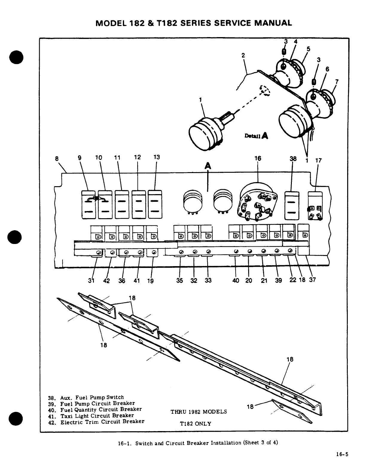
MODEL
182
&
T182
SERIES SERVICE
MANUAL
8
9
10
11
12
13
16
LS
lllLI
ie
3
42
36
41
19
35
32
33 40
20
21
39
22
18
37
38.
Aux.
Fuel
Pump
Switch
39.
Fuel
Pump
Circuit
Breaker
40.
Fuel
Quantity
Circuit
Breaker
THRU
1982
MODELS
41.
Taxi
Light
Circuit
Breaker
42.
Electric
Trim
Circuit
Breaker
T182
ONLY
16-1.
Switch
and
Circuit
Breaker
Installation
(Sheet
3
of
4)
16-5
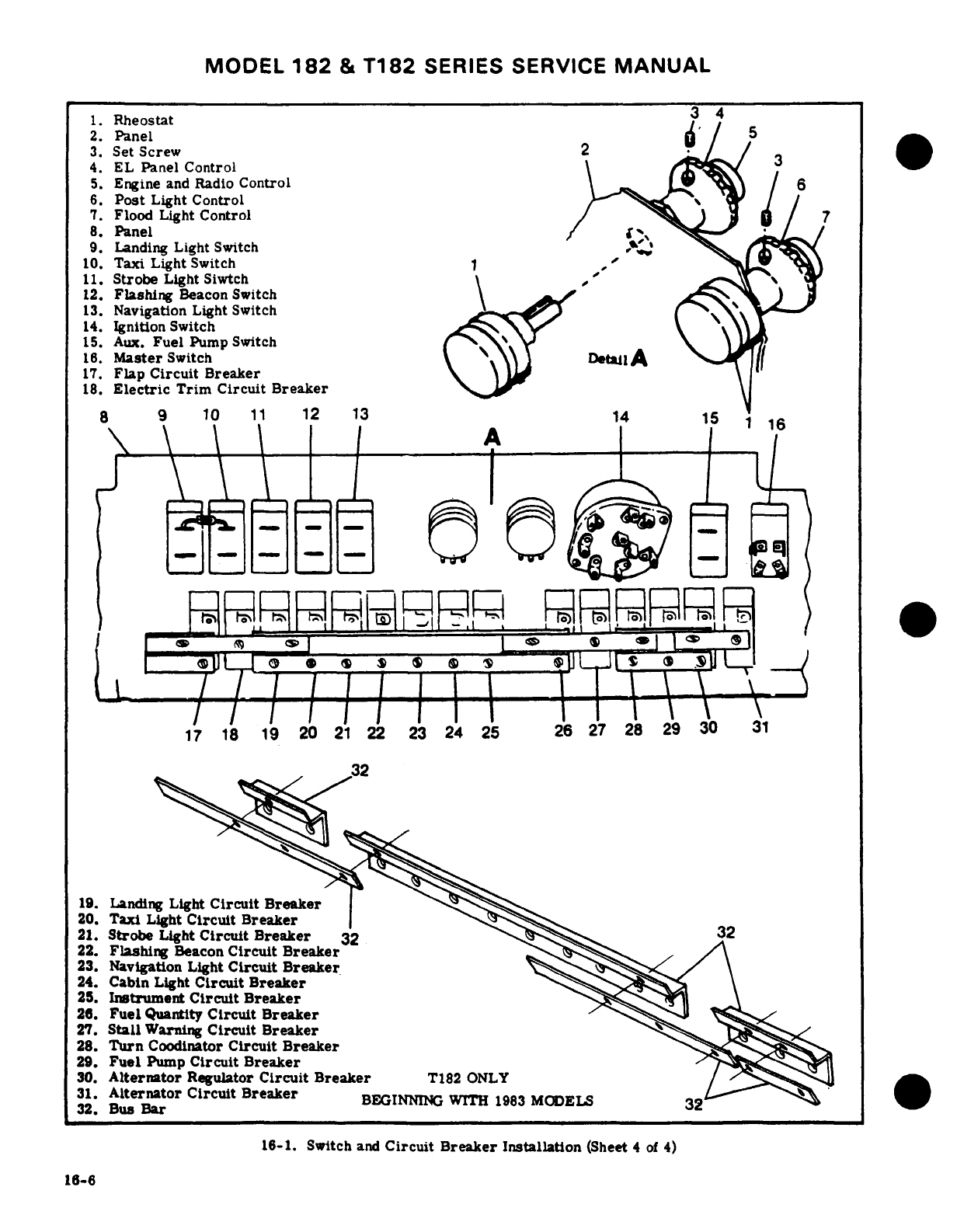
MODEL
182
&
T182
SERIES
SERVICE
MANUAL
1.
Rheostat
3
4
2.
Panel
/
5
3.
Set
Screw
2
/
4.
EL
Panel
Control
3
5.
Engine
and
Radio
Control
\ /
6.
Post
Light
Control
, ; '% y / /
7.
Flood
Light
Control
/ /
8.
Panel
/
9.
Landing
Light
Switch
A
10.
Taxi
Light
Switch 1 ·
'
'
11.
Strobe
Light
Siwtch '
12.
Flashing
Beacon Switch
\
13.
Navigation
Light
Switch
\
14.
Ignition
Switch
\
15.
Aux.
Fuel
Pump
Switch V \
16.
Master
Switch Det
A
^
17.
Flap
Circuit
Breaker
\
18.
Electric
Trim Circuit
Breaker
8
9
1
1
1
2
13
14
15
1
---
I
d
1\::J
t 37
R
FFF
,
\
.
R
'
I
'
I S |
·
_.~'1 I O
TEI
<sULJ
lao *s
s
a
s>
e
isfJL
9ng'
a
s'U
U IL
17
18
19
20
21
22
23
24 25
26 27
28
29
30
31
32
19.
Landing
Light
Circuit Breaker
20.
Taxi
Light
Circuit
Breaker
21.
Strobe
Light
Circuit
Breaker
32
32
22.
Flashing
Beacon
Circuit
Breaker
23.
Navigation
Light
Circuit
Breaker
24.
Cabin
Light
Circuit
Breaker
\
25.
Instrument
Circuit
Breaker
26.
Fuel
Quantity
Circuit Breaker
27.
Stall
Warning
Circuit
Breaker
28.
Turn
Coodinator
Circuit
Breaker
29.
Fuel
Pump
Circuit
Breaker
30.
Alternator
Regulator
Circuit
Breaker
T182
ONLY
31.
Alternator
Circuit
Breaker
BEGINN WITH
1983
MODELS
32.
Bus
Bar
BEINNG
H 1983
MODELS
32
16-1. Switch
and
Circuit
Breaker
Installation
(Sheet
4 of
4)
16-6
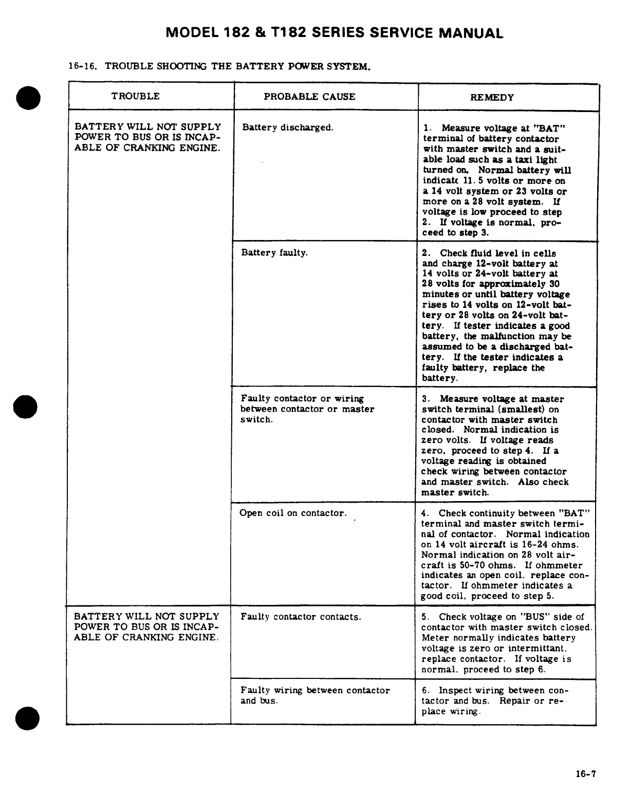
MODEL
182
&
T182
SERIES
SERVICE
MANUAL
16-16.
TROUBLE
SHOOTING
THE
BATTERY
POWER
SYSTEM.
TROUBLE
PROBABLE
CAUSE
REMEDY
BATTERY
WILL
NOT
SUPPLY
Battery
discharged.
1.
Measure
voltage
at
"BAT"
POWER
TO
BUS
OR
IS
INCAP-
terminal
of
battery
contactor
ABLE
OF
CRANKING
ENGINE.
with
master
switch
and
a
suit-
able
load
such
as
a
taxi
light
turned
on.
Normal
battery
will
indicate
11.
5
volts
or
more
on
a
14
volt
system
or
23
volts
or
more
on
a
28
volt
system.
If
voltage
is
low
proceed
to
step
2.
If
voltage
is
normal,
pro-
ceed
to
step
3.
Battery
faulty.
2.
Check
fluid
level
in
cells
and
charge 12-volt
battery
at
14
volts
or
24-volt
battery
at
28
volts
for
approximately
30
minutes
or
until
battery
voltage
rises
to
14
volts
on
12-volt
bat-
tery or
28
volts
on
24-volt
bat-
tery.
If
tester
indicates
a
good
battery,
the
malfunction
may
be
assumed
to
be
a
discharged
bat-
tery.
If
the
tester
indicates
a
faulty battery,
replace
the
battery.
Faulty
contactor
or
wiring
3.
Measure
voltage at
master
between
contactor
or
master
switch
terminal
(smallest)
on
switch.
contactor
with
master
switch
closed.
Normal
indication
is
zero
volts.
If
voltage
reads
zero,
proceed
to
step
4.
If
a
voltage
reading
is
obtained
check
wiring
between
contactor
and
master
switch.
Also
check
master
switch.
Open
coil
on
contactor.
4.
Check
continuity
between
"BAT"
terminal
and
master
switch
termi-
nal
of
contactor. Normal
indication
on
14
volt
aircraft
is
16-24
ohms.
Normal
indication
on
28
volt
air-
craft
is
50-70
ohms.
If
ohmmeter
indicates
an
open
coil.
replace
con-
tactor.
If
ohmmeter
indicates
a
good
coil,
proceed
to
step
5.
BATTERY WILL
NOT
SUPPLY
Faulty
contactor
contacts.
5.
Check
voltage
on
"BUS"
side
of
POWER
TO
BUS
OR
IS
INCAP-
contactor
with
master
switch
closed.
ABLE
OF
CRANKING
ENGINE.
Meter
normally
indicates
battery
voltage
is
zero
or
intermittant.
replace
contactor.
If
voltage
is
normal.
proceed
to
step
6.
Faulty
wiring
between
contactor
6.
Inspect
wiring
between
con-
and
bus.
tactor
and
bus.
Repair
or
re-
place
wiring.
16-7
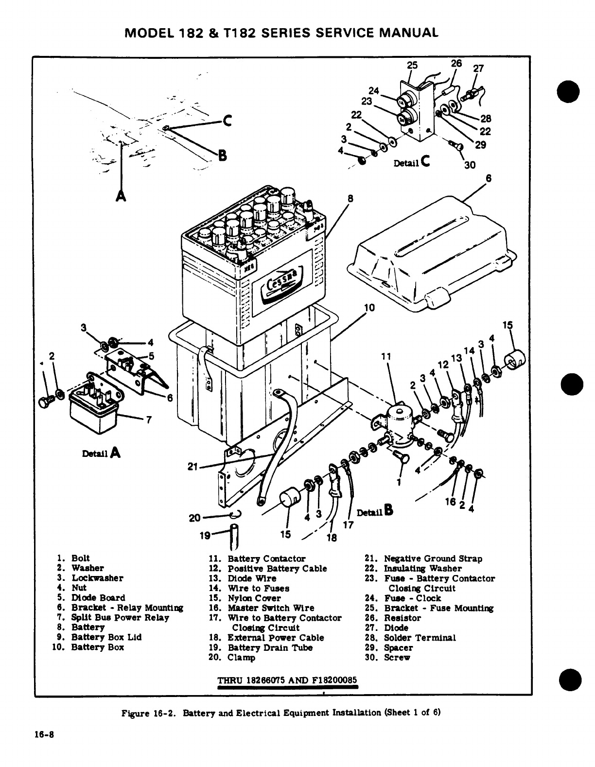
MODEL
182
&
T182
SERIES
SERVICE
MANUAL
25
26
24
6
123
\y wJ~y\
Tf
a ^ 211
19
1 1
5
/'
1.
Bolt
11.
Battery
Contactor
21.
Negative
Ground
Strap
2.
Washer
12.
Positive Battery
Cable
22.
Insulating
Washer
3.
Lockwasher
13.
Diode
Wire
23.
Fuse
-
Battery
Contactor
4.
Nut
14.
Wire
to
Fuses
Closing
Circuit
5.
Diode
Board
15.
Nylon
Cover
24.
Fuse
-
Clock
6.
Bracket
-
Relay
Mounting
16.
Master
Switch
Wire
25.
Bracket
-
Fuse
Mounting
7.
Split
Bus
Power
Relay
17.
Wire
to
Battery
Contactor
26.
Resistor
8.
Battery
Closing
Circuit
27.
Diode
9.
Battery
Box
Lid
18.
External
Power
Cable
28.
Solder
Terminal
10.
Battery
Box
19.
Battery
Drain
Tube
29.
Spacer
20.
Clamp
30.
Screw
THRU
18266075
AND
F18200085
Figure
16-2.
Battery
and
Electrical
Equipment
Installation
(Sheet
1
of
6)
16-8
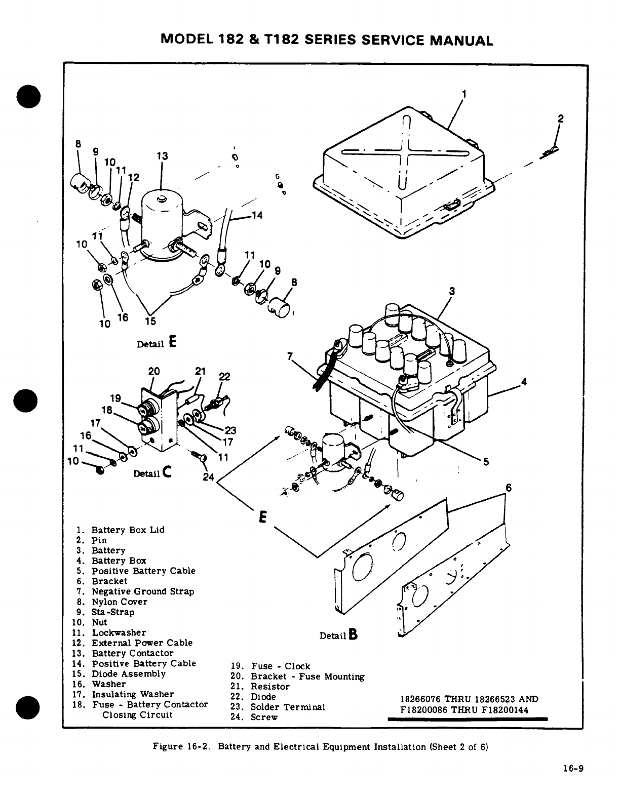
MODEL
182
&
T182
SERIES
SERVICE
MANUAL
)l
2
8
9_
-
14
'
e
c
.- - ~ /
~
14
1
0
1
De1il5
E
6
:
1O-^^
5
0
0^ 11/^
^
&^/ I ; 5
rDetail
E
1
Battery
Box
Lid
21
*4
1
61
7
4.
Battery
Box
J /
I /
/
- y
5.
Positive
Battery
Cable
10.
Nut
/
15.
Diode
Assembly
20
Bracket
-
Fuse
Mounting
16.
Lasher
21
Resistor
13.
Battery
Contactor
17.
Insulating Washer
22.
Diode
18266076
THRU
18266523
AND
18.
Fuse
-
Battery
Contactor
23.
Solder
Terminal
F18200086
THRU
F18200144
Closing
Circuit
24.
Screw
Figure
16-2.
Battery
and
Electrical
Equipment
Installation
(Sheet 2
of
6)
16-9
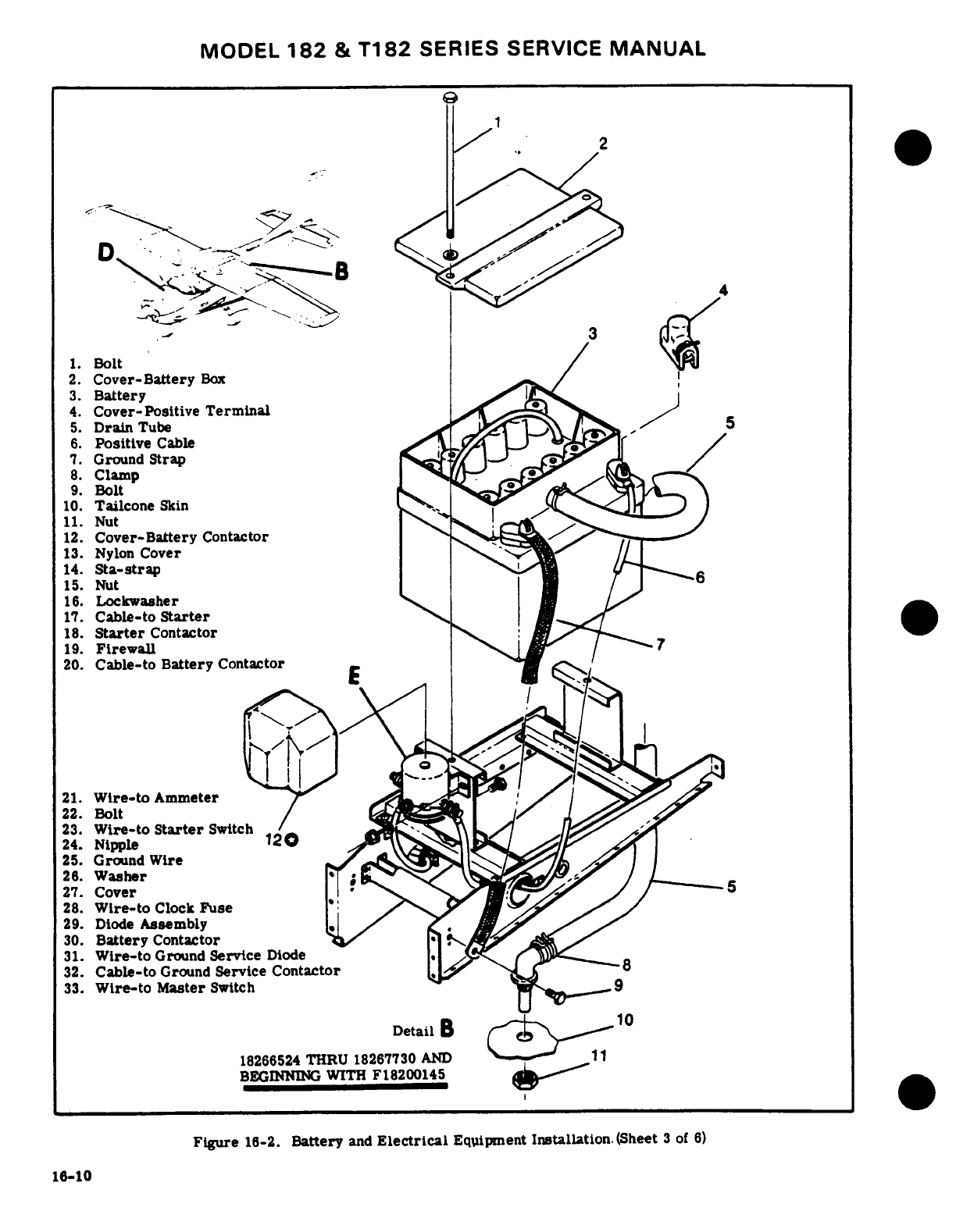
MODEL
182
&
T182
SERIES
SERVICE
MANUAL
1.
Bolt
2.
Cover-Battery
Box
3.
Battery
4.
Cover-Positive Terminal
5.
Drain
Tube
6.
Positive
Cable
7.
Ground
Strap
8.
Clamp
9.
Bolt
10.
Tailcone
Skin
11.
Nut
12.
Cover-Battery
Contactor
13.
Nylon
Cover
14.
Sta-strap
15.
Nut
16.
Lockwasher
17.
Cable-to
Starter
18.
Starter
Contactor
19.
Firewall
20.
Cable-to Battery
Contactor
21.
Wire-to
Ammeter
22.
Bolt
23.
Wire-to
Starter
Switch
24.
Nipple
25.
Ground
Wire
26.
Washer
27.
Cover
28.
Wire-to
Clock
Fuse
29.
Diode
Assembly
30.
Battery
Contactor
31.
Wire-to
Ground
Service
Diode
32.
Cable-to
Ground
Service
Contactor
-
33.
Wire-to
Master
Switch
Detail
B
18266524
THRU
18267730
AND
BEGINNING
WITH
F18200145
Figure
16-2.
Battery
and
Electrical
Equipment
Installation.
(Sheet
3
of
6)
16-10
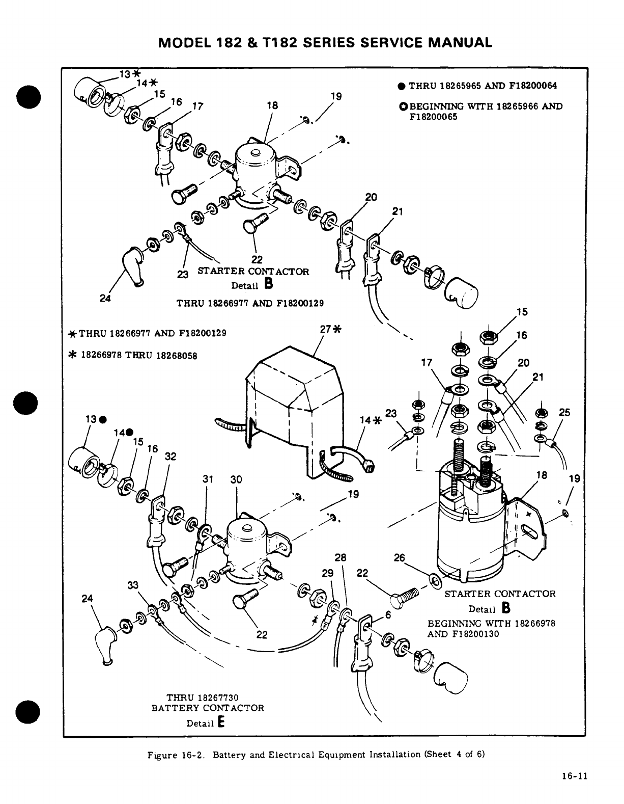
MODEL
182
&
T182
SERIES
SERVICE
MANUAL
13*
13 ~
14*''
THRU
18265965
AND
F18200064
(^@^
^15
17 19
-- v1
~
16
18
OBEGINNING
WITH
18265966
AND
W§/S'
L n /
LF18200065
TR
18266978
THRD
182687 20
21
.29 22 ^*a
THRU 1826
2
7
STARTER
CONTACTOR
Detail
B
24
THRU 18266977
AND
F18200129
(*THRU
18266977
AND
F18200129
27*
16
*
18266978
THRU
18268058
0
17/
c S. -\ \ ^ dL/ ~~21
13
s
^KI23 r>' 1
25
34 2
22 26
-
STARTER
CONTACTOR
14
Figure
1Battery
and
Electrical
Equipment
Installation
(Sheet
4
of
6
16-11
16-11
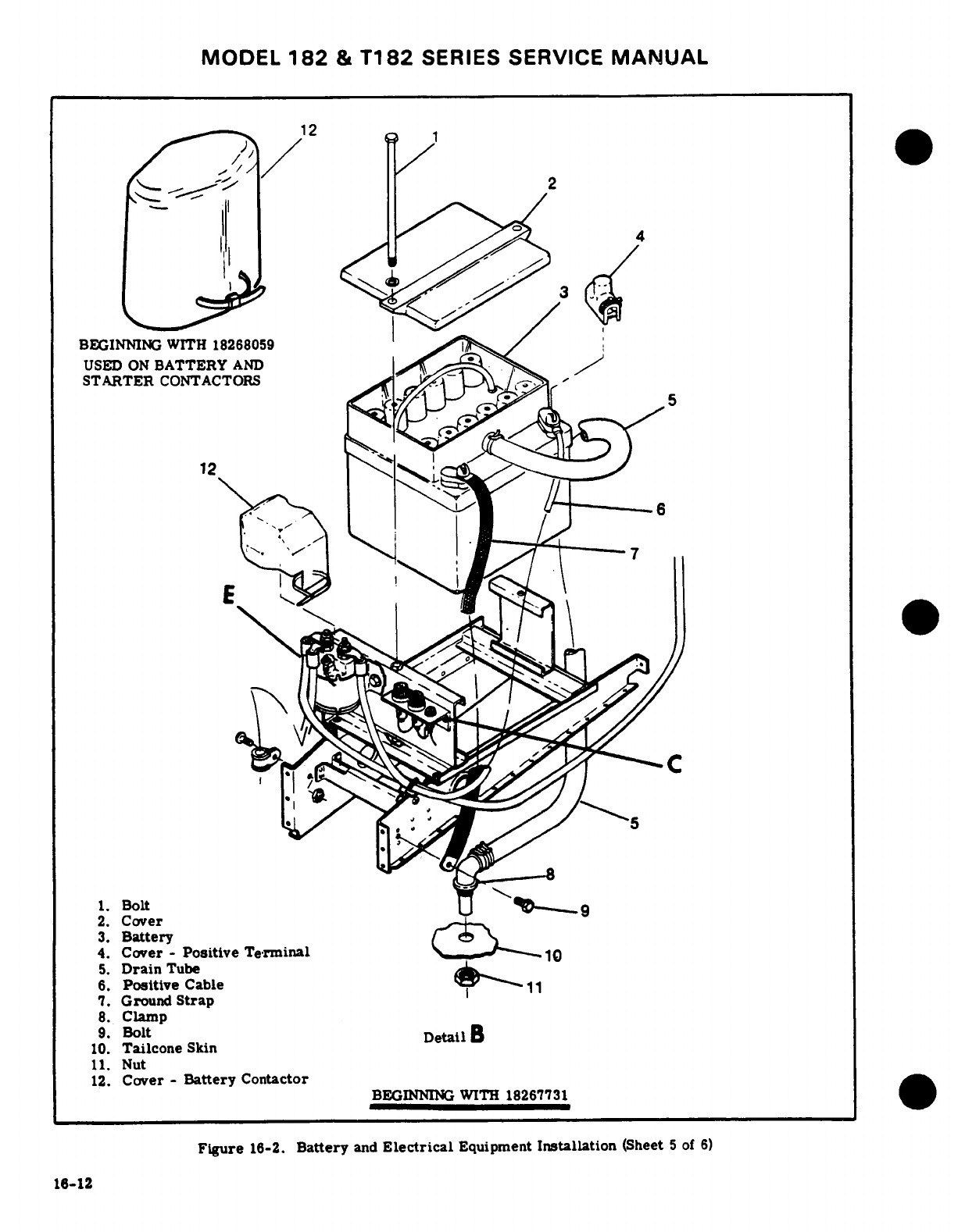
MODEL
182
&
T182
SERIES
SERVICE
MANUAL
12
//
-I
BEGINNING WITH 18268059
USED ON
BATTERY
AND
STARTER
CONTACTORS
12
1. Bolt
2.
Cover
9
3.
Battery
4.
Cover
-
Positive
Te-rminal
10
5.
Drain
Tube
6.
Positive
Cable
7.
Ground
Strap
8.
Clamp
9.
Bolt
Detail
B
10.
TailconeSkin
11.
Nut
12.
Cover
-
Battery
Contactor
BEGINNING
WITH
18267731
Figure
16-2.
Battery
and
Electrical
Equipment
Installation
(Sheet 5
of
6)
16-12
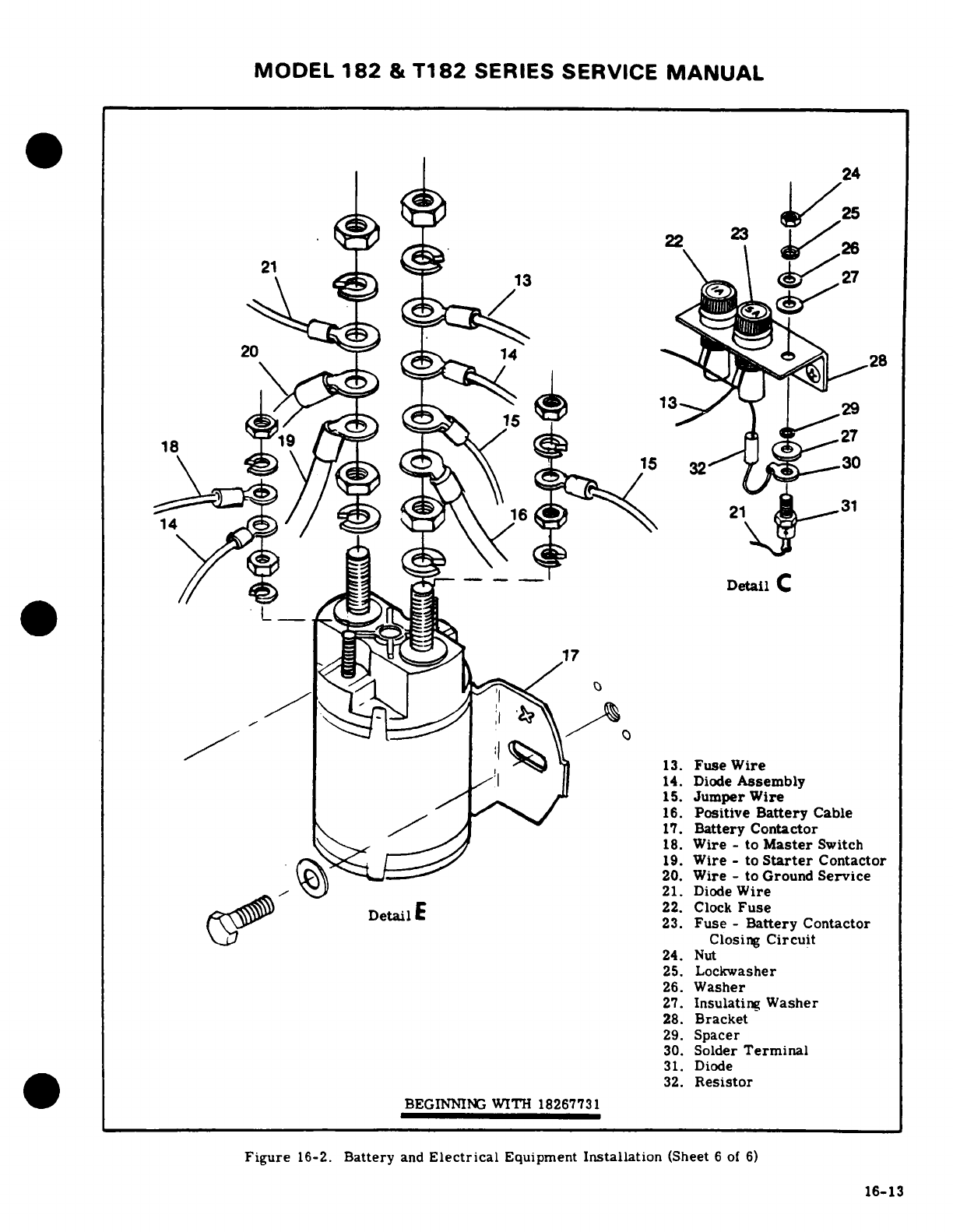
MODEL
182
&
T182
SERIES SERVICE
MANUAL
24
22
23
64<2
21
13
27
1
15.
Jumpe
18
19
16.
Positive
Battery
Cable
Detail
C
13.
Fuse
Wire
14.
Diode
Assembly
15.
Jumper
Wire
16.
Positive
Battery
Cable
17.
Battery
Contactor
18.
Wire
-
to
Master
Switch
19.
Wire
-
to
Starter
Contactor
20.
Wire
-
to Ground
Service
,^~~~~~~~ \~ ~21.
Diode
Wire
<
_Detail
22.
Clock
Fuse
RSw
Detail
C
23.
Fuse
-
Battery
Contactor
C~~~\^~~~~~~~~l~~ DClosing
Circuit
24.
Nut
25.
Lockwasher
26.
Washer
27.
Insulating Washer
28.
Bracket
29.
Spacer
30.
Solder
Terminal
31.
Diode
32.
Resistor
BEGINNING
WITH
18267731
Figure
16-2.
Battery
and
Electrical
Equipment
Installation
(Sheet
6
of
6)
16-13
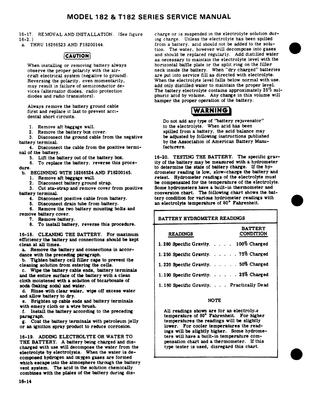
MODEL
182
&
T182
SERIES
SERVICE
MANUAL
16-17.
REMOVAL
AND
INSTALLATION.
(See
figure
charge or
is
suspended
in
the
electrolyte
solution
dur-
16-2.)
ing
charge.
Unless
the
electrolyte
has
been
spilled
a.
THRU
18266523
AND
F18200144.
from
a
battery.
acid
should
not
be
added
to the
solu-
tion.
The
water,
however
will
decompose
into
gases
as necessary
to
maintain
the
electrolyte
level
with
the
When
installing
or
removing
battery
always
horizontal
baffle
plate
or
the
split
ring
on
the
filler
observe
the
proper
polarity
with
the
air-
neck
inside
the
battery.
When
"dry
charged"
batteries
craft electrical
system
(negative
to
ground).
are
put
into
service
fill
as
directed
with
electrolyte.
Reversing
the
polarity.
even
momentarily,
When
the
electrolyte
level
falls
below
normal
with
use.
may
result
in
failure
of
semiconductor
de-
add
only
distilled
water
to
maintain the
proper
level.
vices
(alternator
diodes,
radio
protection
The
battery
electrolyte
contains
approximately
25%
sul-
diodes
and
radio
transistors).
phuric
acid
by
volume.
Any
change
in
this
volume
will
hamper
the
proper
operation
of
the
battery.
Always
remove
the
battery
ground
cable
first
and
replace
it
last
to
prevent
acci-
dental
short
circuits.
Do
not
add
any
type
of
"battery
rejuvenator"
1.
Remove aft
baggage
wall.
to
the
electrolyte.
When
acid
has
been
2.
Remove
the
battery
box
cover.
spilled
from
a
battery,
the
acid balance
may
3.
Disconnect
the
ground
cable
from
the
negative
be
adjusted
by
following
instructions
published
battery
terminal.
by
the
Association
of
American
Battery
Manu-
4.
Disconnect
the
cable
from
the
positive
termi-
facturers.
nal
of
the
battery.
5.
Lift
the
battery
out
of
the
battery
box.
16-20.
TESTING THE
BATTERY.
The
specific
grav-
6.
To
replace
the
battery.
reverse
this proce-
ity
of
the
battery
may
be
measured
with
a
hydrometer
dure.
to
determine
the
state
of
battery
charge.
If
the
hy-
b.
BEGINNING
WITH
18266524
AND
F18200145.
drometer
reading
is
low,
slow-charge
the
battery
and
1.
Remove
aft
baggage
wall
retest.
Hydrometer
readings
of
the
electrolyte
must
2.
Disconnect
battery
ground
strap.
be
compensated
for
the
temperature
of
the
electrolyte.
3.
Cut
sta-strap
and
remove
cover
from
positive
Some
hydrometers
have
a
built-in
thermometer
and
battery
terminal,
conversion
chart.
The
following
chart
shows
the
bat-
4.
Disconnect
positive
cable
from
battery.
tery
condition
for various
hydrometer readings
with
5.
Disconnect
drain
tube
from
battery.
an
electrolyte
temperature
of
80
°
Fahrenheit.
6.
Remove
the
two
battery
mounting
bolts
and
remove
battery
cover.
7.
Remove
battery.
BATTERY
HYDROMETER
READINGS
8.
To
install
battery,
reverse
this
procedure.
BATTERY
16-18.
CLEANING
THE
BATTERY.
For
maximum
READINGS
CONDITION
efficiency
the
battery
and
connections
should
be
kept
clean
at
all
times.
1.280 Specific
Gravity
....
100%
Charged
a.
Remove
the
battery
and
connections
in
accor-
dance
with
the
preceding
paragraph.
1.250 Specific
Gravity.
.....
75%
Charged
b.
Tighten
battery cell
filler
caps
to
prevent
the
cleaning
solution
from
entering
the
cells.
1.220 Specific
Gravity.
.....
50%
Charged
c.
Wipe
the
battery
cable
ends,
battery
terminals
and
the
entire
surface
of
the
battery
with
a
clean
1.
190
Specific
Gravity.
.....
25%
Charged
cloth
moistened
with
a
solution
of
bicarbonate
of
soda
(baking
soda)
and
water.
1.160
Specific
Gravity.
Practically
Dead
d.
Rinse
with
clear
water,
wipe
off
excess
water
and
allow
battery
to
dry.
e.
Brighten
up
cable
ends
and
battery terminals
NOTE
with
emery
cloth
or
a
wire
brush.
f.
Install
the
battery
according
to
the
preceding
All
readings
shown
are
for
an
electrolyte
paragraph. temperature
of
80°
Fahrenheit.
For
higher
g.
Coat
the
battery
terminals
with
petroleum
jelly
temperatures
the
readings
will
be
slightly
or
an
ignition
spray
product
to
reduce
corrosion.
lower.
For
cooler
temperatures
the
read-
ings
will
be
slightly
higher.
Some
hydrome-
16-19.
ADDING
ELECTROLYTE
OR
WATER
TO
ters
will
have
a
built-in
temperature
com-
THE
BATTERY.
A
battery
being
charged
and
dis-
pensation
chart
and
a
thermometer.
If
this
charged
with
use
will decompose
the
water from
the
type
tester
is
used,
disregard
this
chart.
electrolyte
by
electrolysis.
When
the
water
is
de-
composed
hydrogen
and
oxygen
gases
are
formed
which
escape
into
the
atmosphere
through
the
battery
vent
system.
The
acid
in
the
solution
chemically
combines
with
the
plates
of
the
battery
during
dis-
16-14
MODEL
182
&
T182
SERIES SERVICE
MANUAL
16-21.
CHARGING
THE
BATTERY.
When
the
bat-
tery
is
to be
charged,
the
level
of
the
electrolyte
should
be
checked
and
adjusted
by
adding
distilled
water
to
cover
the
tops
of
the
internal battery plates.
Do
not
allow
acid
deposits
to
come
in
contact
Remove
the
battery
from
the
aircraft
and
place
in
a
with
skin
or
clothing.
Serious
acid
burns
may
well
ventilated
area
for
charging.
result
unless
the
affected
area
is
washed
im-
mediately
with
soap
and
water.
Clothing
will
When
a
battery
is
being
charged,
hydrogen
Inspect
the
cleaned
box
and
cover
for
physical
damage
and
oxygen
gases
are
generated.
Accumula-
and
for
areas
lacking
proper
acid proofing.
A
badly
tion
of
these
gases
can
create
a
hazardous
damaged
or
corroded
box
should
be
replaced.
If
the
explosive
condition.
Always
keep
sparks
box
or
lid
require
acid
proofing,
paint
the
area
with
and
open
flame
away
from
the
battery.
acid
proof paint
Part
No.
CES1054-529,
available
from
the
Cessna
Service
Parts
Center.
Allow
unrestricted
ventilation
of
the
battery
area
during
charging.
16-26.
BATTERY
CONTACTOR.
The
main
points
of
consideration
during
a
battery
16-27.
DESCRIPTION.
Thru
18266523
and
F18200144
charge
are
excessive
battery temperature
and
vio-
the
battery
contactor
is
bolted
to
the
side
of
the bat-
lent
gassing.
Test
the
battery
with
a
hydrometer
tery
box.
Beginning
with
18266524
and F18200145
the
to
determine
the
amount
of
charge.
Decrease
the
contactor
is
bolted
to
a
bracket
adjacent
to
the
battery.
charging
rate
or
stop
charging
temporarily
if the
The
contactor
is
a plunger
type
contactor
which is
battery
temperature
exceeds
125°F.
actuated
by
turning
the
master
switch
on.
When
the
master
switch
is
off,
the
battery
is
disconnected
from
16-22.
BATTERY
BOX.
(THRU 18266523
AND
the
electrical
system.
A
silicon
diode
is
used
to
F18200144).
eliminate
spiking
of
transistorized
radio
equipment
The
large
terminal
of
the
diode
connects
to
the
battery
16-23.
DESCRIPTION.
The
battery
is
completely
terminal
of
the
battery
contactor.
The
small
terminal
enclosed
in
an
acid
resistant
plastic
box
which
is
of
the
diode
and
the
master
switch
wire
connect
to
the
riveted
to
mounting
brackets
in
the
tailcone.
The
coil
terminal
of
the
battery
contactor.
(See
figure
box
has
a
vent
tube
which
protrudes
through the
16-2.)
bottom
of
the
aircraft
allowing
battery gases
and
spilled
electrolyte
to
escape.
16-28.
REMOVAL
AND
INSTALLATION.
(See
figure
16-2.)
16-24.
REMOVAL
AND
INSTALLATION.
(See
figure
a.
THRU 18266523
AND
F18200144.
16-2.)
The
battery
box
is
riveted
to
the mounting
1.
Remove
the
battery
box
cover
and
disconnect
brackets
in
the
tailcone.
The
rivets
must
be
drilled
the
ground
cable
from
the
negative
battery
terminal
out
to
remove
the
box.
and
pull
cable
clear
of
battery
box.
2.
Remove
the
nut.
lockwasher
and
the
two
plain
16-25.
MAINTENANCE
OF
BATTERY
BOX.
The
washers
securing
the
battery
cables
to
the
battery
battery
box
should
be
inspected
and
cleaned
periodi-
contactor.
cally.
The
box
and
cover
should
be
cleaned
with
a
3.
Remove
the
nut.
lockwasher
and
the
two
plain
strong
solution
of
bicarbonate
of
soda
(baking
soda)
washers
securing
the
wire
which
is
routed
to
the
and
water.
Hard
deposits
may
be
removed
with
a
master
switch.
wire
brush.
When
all
corrosive
deposits
have
been
4.
Remove
the
silicon
diode
which
is
connected
removed
from
the
box.
flush
it
thoroughly
with
clean
to
the
battery
terminal
and
the
coil
terminal.
water.
5.
Remove
the
bolt. washer
and
nut
securing
each
16-15
MODEL
182
&
T182
SERIES
SERVICE
MANUAL
side
of the
battery
contactor
to
the
battery
box.
The
NOTE
contactor
will
now
be
free
for removal.
6.
To
replace
the
contactor.
reverse
this proce-
Maintenance
of
the
electronic
installation
dure.
cannot
be
performed
when
using
external
b.
BEGINNING
WITH
18266524
AND
F18200145.
power.
Application
of
external
power
1.
Remove baggage wall.
opens
the
relay
supplying
voltage
to
the
2.
Disconnect
ground
strap
from
negative
termi-
electronic
bus.
For
lengthy
ground
test-
nal
of
the
battery.
ing
of
electronic
systems,
connect
a
well
3.
Cut
sta-straps
and
remove
cover
from
con-
regulated
and
filtered
power supply
directly
tactor.
to
the
battery
side
of
the
battery
contactor.
4.
Remove
nut
and
washers securing,
positive
Adjust
the
supply
for
14-volts
and
close
the
cable.
diode
assembly
and
wire
to
fuse.
Tag
wires
master
switch.
for
reinstallation.
5.
Remove
nut
and
washers securing,
wire
to
NOTE
starter
contactor.
wire
to
ground
service
and
wire
to
diode.
Tag
wires
for
reinstallation.
When
using
ground
power
to
start
the
air-
6.
Remove
bolts
and
washers
securing
contac-
craft.
close
the
master
switch before
re-
tor
to
bracket
and
remove
contactor.
moving the
ground
power
plug.
This
will
7.
To
install
contactor
reverse
this
procedure, ensure
closure
of
the
battery
contactor
using
new
sta-straps
on
cover.
and
excitation
of
the
alternator
field.
16-29.
BATTERY
CONTACTOR
CLOSING
CIRCUIT.
16-30.
DESCRIPTION.
This
circuit
consists
of
a
Failure
to
observe
polarity
when
connecting
5-amp
fuse.
a
resistor
and
a
diode
mounted
on
a
an
external
power
source
directly
to
the
bat-
bracket
on
the
side
of
the
battery
box.
This
serves
tery
or
directly
to
the
battery
side
of
the
bat-
to
shunt
a
small
charge
around
the
battery
contactor
tery
contactor,
will
damage
the
diodes
in
the
so
that
ground
power
may
be
used
to
close
the
con-
alternator
and
other semiconductor
devices
tactor.
in
the
aircraft.
16-31.
GROUND
SERVICE
RECEPTACLE.
16-32.
DESCRIPTION.
A
ground
service
receptacle
External
power
receptacle
must
be
functionally
is
offered
as
optional
equipment
to
permit
use
of
ex-
checked
after
wiring,
or
after
replacement
of
ternal
power
for
cold
weather
starting or
when
per-
components
of
the
external
power
or
split
bus
forming lengthy
electrical
maintenance.
A
reverse
systems. Incorrect
wiring
or
malfunctioned
polarity
protection
system
is
utilized
whereby ground
components
can
cause
immediate
engagement
power
must
pass
through
an
external
power
contactor
of
starter
when
ground
service
plug
is
inserted.
to
be
connected
to
the bus.
A
silicon
junction
diode
Also
refer
to
Cessna
Single-Engine
Service
is
connected
in
series
with
the
coil
on
the
external
Letter,
SE77-1 (Supplement
#1)
Dated
May
2,
power
contactor
so
that
if
the
ground
power
source
is
1977.
inadvertently
connected
with
a
reverse
polarity,
the
external
power
contactor
will
not
close.
This
feature
protects
the
diodes
in the
alternator,
and
other
semi-
conductor
devices, used
in
the
aircraft
from possible
reverse
polarity
damage.
16-16
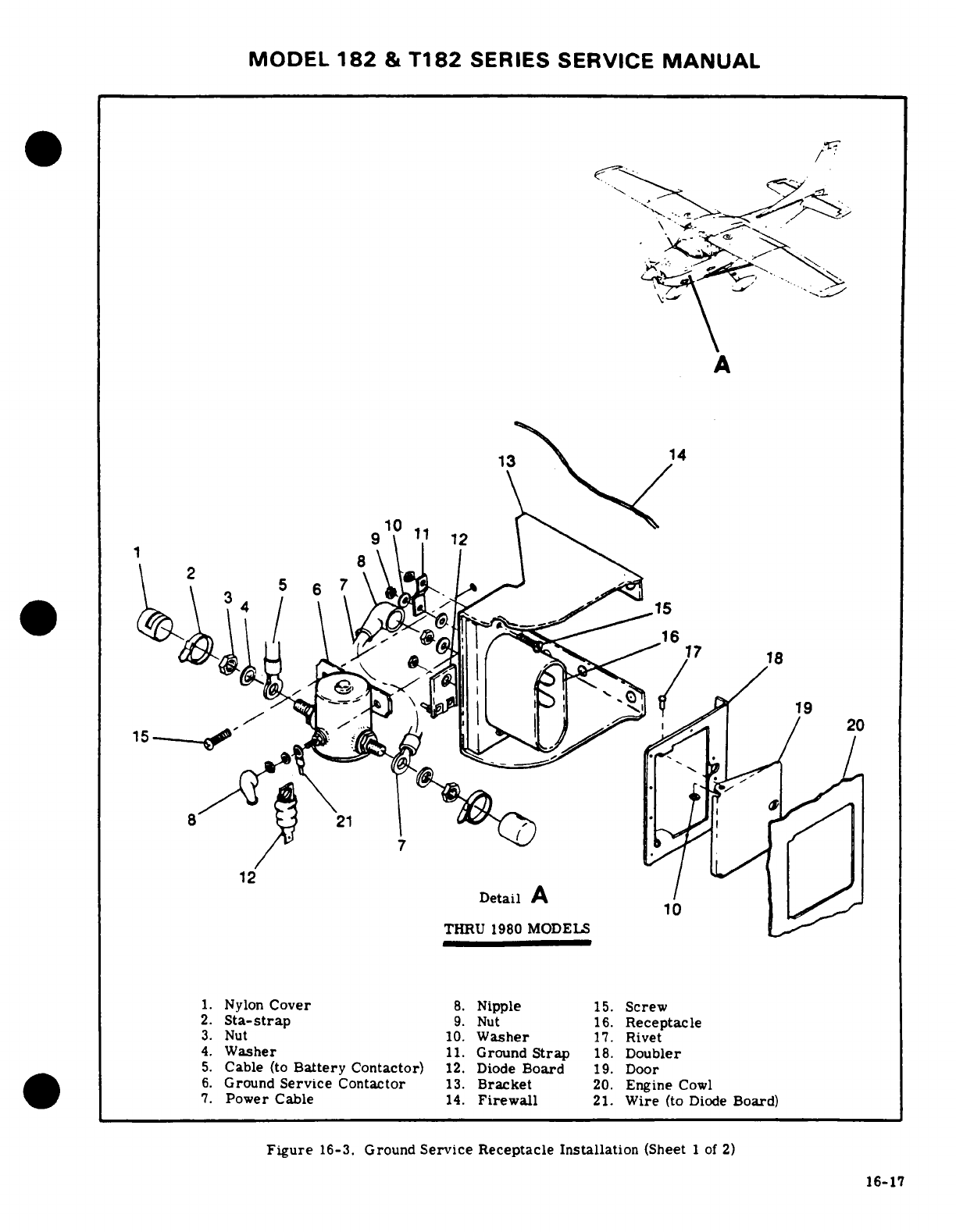
MODEL
182
&
T182
SERIES SERVICE
MANUAL
913
1
14
10
1. 19
1
8
21
2. Sta-trap 9
Nut
16.
Receptacle
7.
Po
r
C
e
1.
Firewll
1.
Wre1
Figure
16-3.
Ground
Service
Receptacle
Installation
(Sheet
1
of
2)
3.7
Nut 1 Washer
7.
R
i vet~
16-17
5Cal(tBatrCottr)1Doe12
Bar
19
Do 6.12~
GuSreta
o Detail A
10
THRU
1980
MODELS
1.
Nylon
Cover
8.
Nipple
15.
Screw
2.
Sta-strap
9.
Nut
16.
Receptacle
3.
Nut
10.
Washer
17.
Rivet
4.
Washer
11.
Ground
Strap
18.
Doubler
5.
Cable
(to
Battery
Contactor)
12.
Diode
Board
19. Door
6.
Ground
Service
Contactor
13.
Bracket
20.
Engine
Cowl
7.
Power
Cable
14.
Firewall
21.
Wire (to
Diode
Board)
Figure
16-3.
Ground
Service
Receptacle
Installation
(Sheet
1
of
2)
16-17
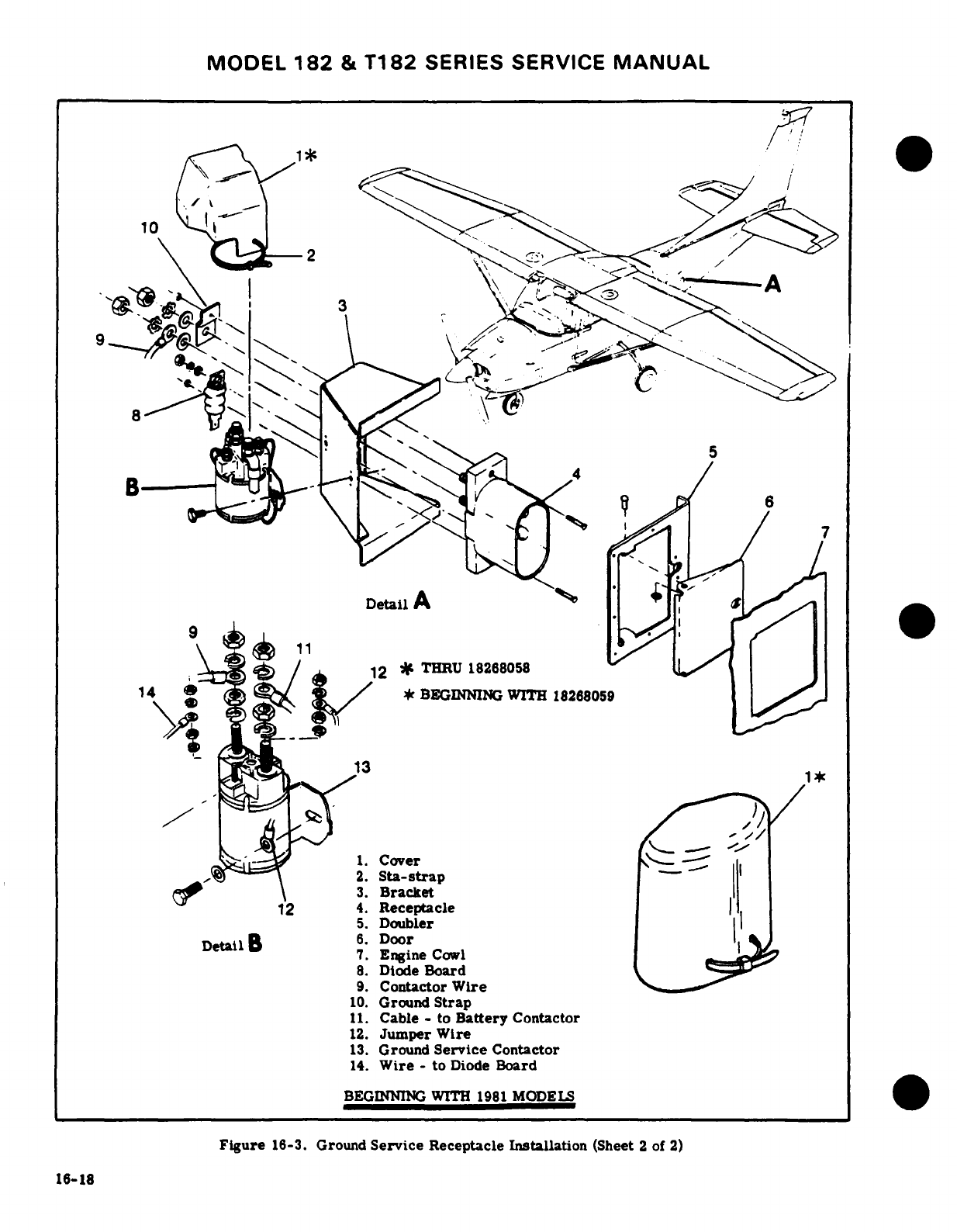
MODEL
182
&
T182
SERIES
SERVICE
MANUAL
10
A~
~
/
~k
12
'
THW
'18268058
-
*14 @ t W
*
BEGINNING WITH
18268059
13
1.
Cover
2.
Sta-strap
-
3.
Bracket
K-'
12
4.
Receptacle
5.
Doubler
|
Detail
B
6
Door
7.
Engine
Cowl
8.
Diode
Board
9.
Contactor
Wire
10.
Ground
Strap
11.
Cable
- to
Battery
Contactor
12.
Jumper
Wire
13.
Ground
Service
Contactor
14.
Wire
-
to
Diode
Board
BEGINNING WITH
1981
MODELS
Figure
16-3.
Ground
Service
Receptacle
Installation
(Sheet
2
of
2)
16-18
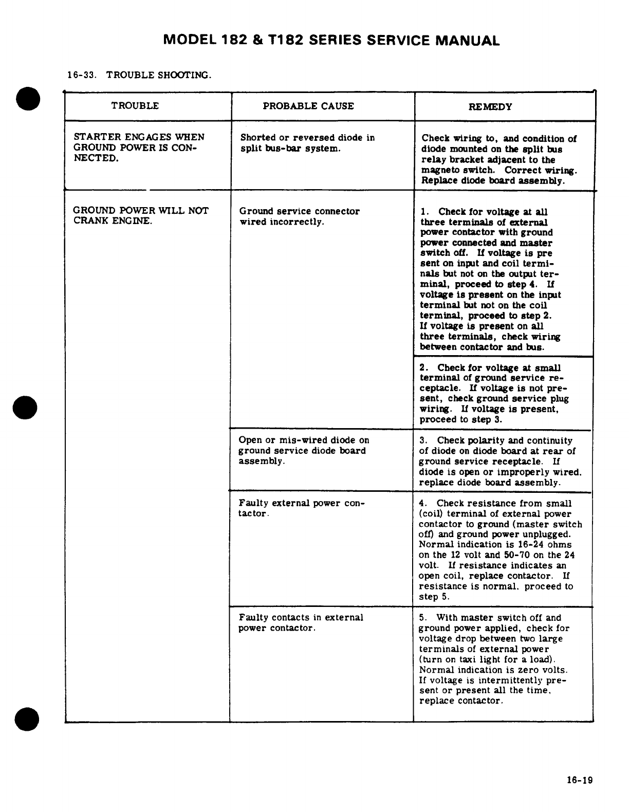
MODEL
182
&
T182
SERIES
SERVICE
MANUAL
16-33.
TROUBLE
SHOOTING.
TROUBLE
PROBABLE
CAUSE
REMEDY
STARTER
ENGAGES
WHEN
Shorted
or
reversed
diode
in
Check
wiring
to,
and
condition
of
GROUND
POWER
IS
CON-
split
bus-bar
system.
diode
mounted
on
the
split
bus
NECTED.
relay
bracket
adjacent
to the
magneto
switch.
Correct
wiring.
Replace
diode
board
assembly.
GROUND
POWER
WILL
NOT
Ground
service
connector
1.
Check
for
voltage
at
all
CRANK
ENGINE.
wired
incorrectly.
three
terminals
of
external
power
contactor
with
ground
power
connected
and
master
switch
off.
If
voltage
is
pre
sent
on input
and
coil
termi-
nals
but
not
on
the output
ter-
minal,
proceed
to
step
4.
If
voltage
is
present
on
the
input
terminal
but
not
on
the
coil
terminal,
proceed
to
step
2.
If
voltage
is
present
on
all
three
terminals,
check
wiring
between
contactor
and
bus.
2.
Check
for
voltage
at
small
terminal
of
ground
service
re-
ceptacle.
If
voltage
is
not
pre-
sent,
check
ground
service
plug
wiring.
If
voltage
is
present,
proceed
to
step
3.
Open
or
mis-wired
diode
on
3.
Check
polarity
and
continuity
ground
service
diode
board
of
diode
on
diode
board
at
rear
of
assembly.
ground
service receptacle.
If
diode
is
open
or
improperly
wired.
replace
diode
board
assembly.
Faulty
external
power
con-
4.
Check
resistance
from
small
tactor.
(coil)
terminal
of
external
power
contactor
to
ground
(master
switch
off)
and
ground
power
unplugged.
Normal
indication
is
16-24
ohms
on
the
12
volt
and
50-70
on
the
24
volt.
If
resistance
indicates
an
open
coil,
replace
contactor.
If
resistance
is
normal.
proceed
to
step
5.
Faulty contacts
in
external
5.
With
master
switch
off and
power
contactor.
ground
power
applied, check
for
voltage
drop
between
two
large
terminals
of
external
power
(turn
on
taxi
light
for
a
load).
Normal
indication
is
zero
volts.
If
voltage
is
intermittently
pre-
sent
or
present
all
the
time,
replace
contactor.
16-19
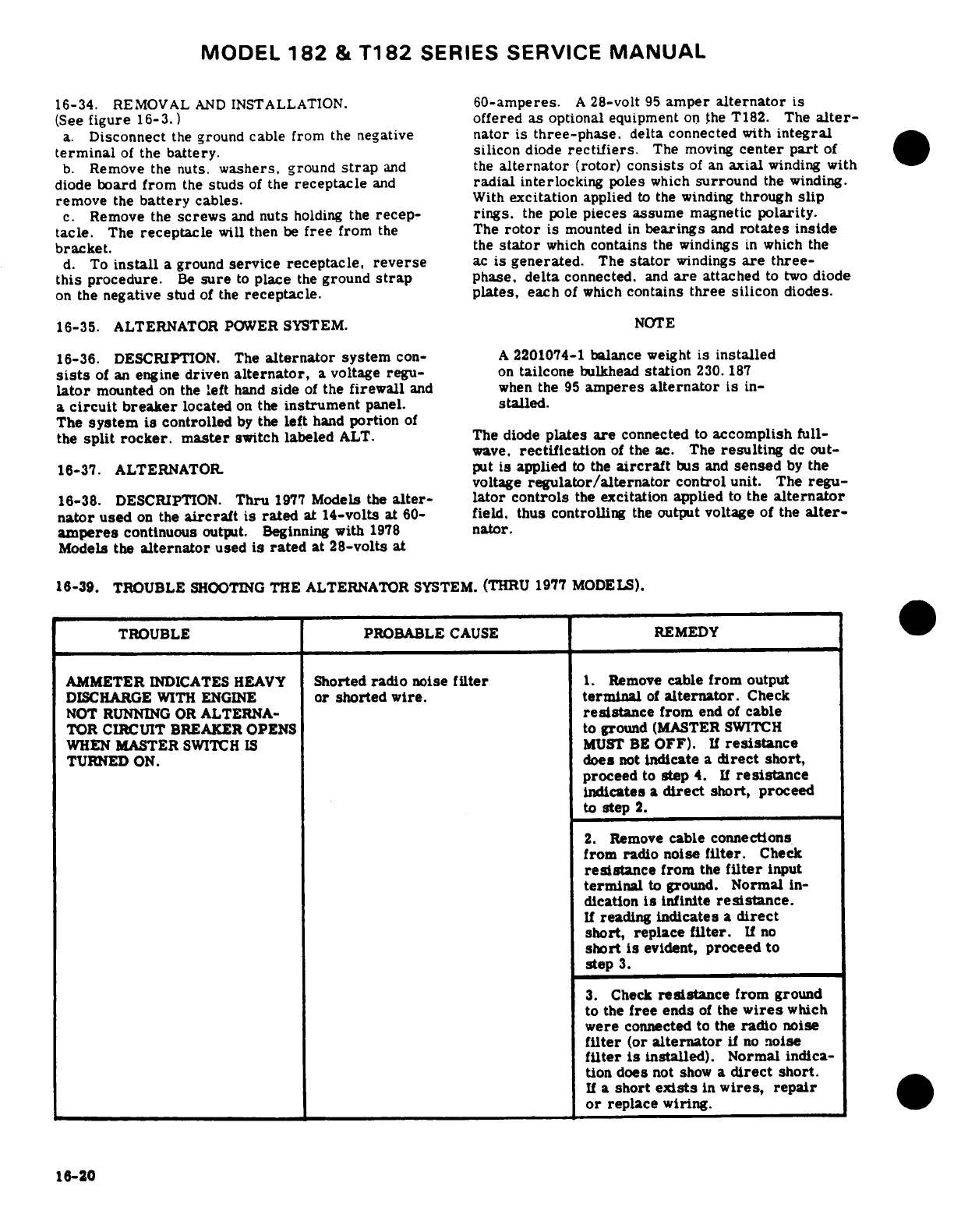
MODEL
182
&
T182
SERIES
SERVICE
MANUAL
16-34.
REMOVAL
AND
INSTALLATION.
60-amperes.
A
28-volt
95
amper
alternator
is
(See
figure
16-3.)
offered
as
optional
equipment
on
the T182.
The
alter-
a.
Disconnect
the
ground
cable
from
the
negative
nator
is
three-phase.
delta
connected
with
integral
terminal
of
the
battery.
silicon
diode
rectifiers.
The
moving
center
part
of
b.
Remove
the
nuts.
washers,
ground
strap
and
the
alternator
(rotor)
consists
of
an
axial
winding
with
diode
board
from
the
studs
of
the
receptacle
and
radial
interlocking poles
which
surround
the
winding.
remove
the
battery
cables.
With
excitation
applied
to
the winding
through
slip
c.
Remove
the
screws
and
nuts
holding the
recep-
rings.
the pole
pieces
assume
magnetic
polarity.
tacle.
The
receptacle
will
then
be
free
from
the
The
rotor
is
mounted
in
bearings
and
rotates
inside
bracket.
the
stator
which
contains
the
windings
in
which the
d.
To
install
a
ground
service
receptacle,
reverse
ac
is
generated.
The
stator
windings
are
three-
this
procedure.
Be
sure
to
place
the
ground
strap
phase,
delta
connected.
and
are
attached
to
two
diode
on
the
negative
stud
of the
receptacle. plates,
each
of
which
contains
three
silicon
diodes.
16-35.
ALTERNATOR
POWER
SYSTEM.
NOTE
16-36.
DESCRIPTION.
The
alternator
system
con-
A
2201074-1
balance
weight
is
installed
sists
of
an
engine
driven
alternator,
a
voltage
regu-
on
tailcone
bulkhead
station
230.
187
lator
mounted
on
the
left
hand
side
of
the
firewall
and when
the
95
amperes
alternator
is
in-
a
circuit
breaker
located
on
the
instrument
panel,
stalled.
The
system
is
controlled
by
the
left
hand
portion
of
the
split
rocker.
master
switch labeled
ALT.
The
diode
plates
are
connected
to
accomplish
full-
wave.
rectification
of
the
ac.
The
resulting
dc
out-
16-37.
ALTERNATOR.
put
is
applied
to
the
aircraft
bus
and
sensed
by
the
voltage
regulator/alternator
control
unit.
The
regu-
16-38.
DESCRIPTION.
Thru
1977
Models
the
alter-
lator controls
the
excitation
applied
to
the
alternator
nator
used
on
the
aircraft
is
rated
at
14-volts
at
60-
field,
thus controlling
the
output
voltage
of
the
alter-
amperes
continuous
output. Beginning
with
1978
nator.
Models the
alternator
used
is
rated
at
28-volts
at
16-39.
TROUBLE
SHOOTING
THE ALTERNATOR
SYSTEM.
(THRU
1977 MODELS).
TROUBLE PROBABLE
CAUSE
REMEDY
AMMETER
INDICATES
HEAVY
Shorted
radio
noise
filter
1.
Remove
cable
from
output
DISCHARGE
WITH ENGINE
or shorted wire.
terminal
of
alternator.
Check
NOT
RUNNING
OR
ALTERNA-
resistance
from
end
of
cable
TOR
CIRCUIT
BREAKER
OPENS
to
ground
(MASTER
SWITCH
WHEN
MASTER
SWITCH
IS
MUST
BE
OFF).
If
resistance
TURNED
ON.
does
not
indicate
a
direct
short,
proceed
to
step
4.
If
resistance
indicates
a
direct
short, proceed
to
step
2.
2.
Remove
cable
connections
from radio noise
filter.
Check
resistance
from
the
filter
input
terminal
to
ground.
Normal
in-
dication
is
infinite
resistance.
If
reading
indicates
a
direct
short,
replace
filter.
If
no
short
is
evident,
proceed
to
step
3.
3.
Check
resistance
from
ground
to
the
free
ends
of
the
wires
which
were
connected
to
the
radio
noise
filter
(or
alternator
if
no
noise
filter
is
installed).
Normal
indica-
tion
does
not
show
a
direct
short.
If
a
short
exists
in
wires,
repair
or
replace
wiring.
16-20
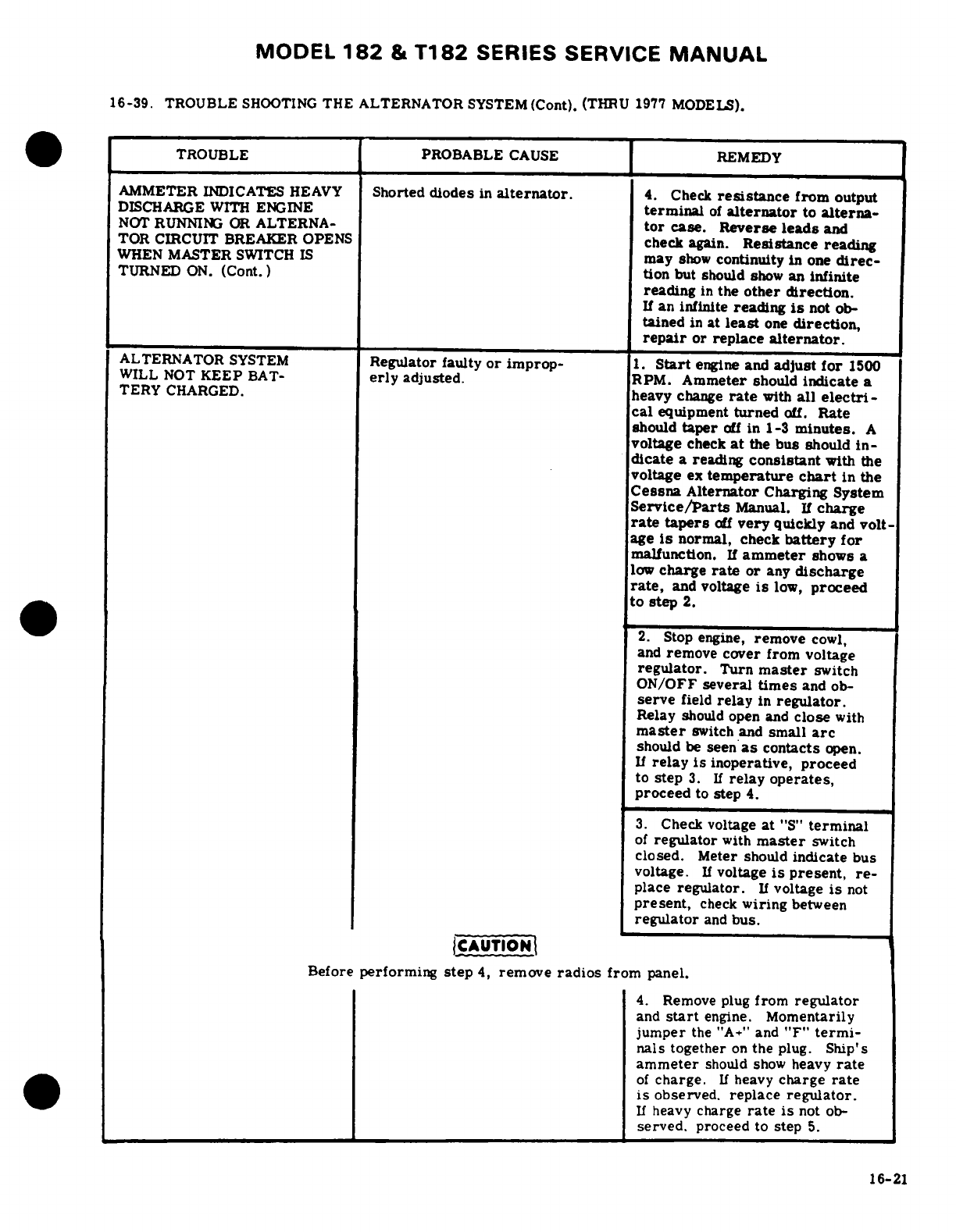
MODEL
182
&
T182
SERIES SERVICE
MANUAL
16-39.
TROUBLE
SHOOTING
THE ALTERNATOR
SYSTEM
(Cont).
(THRU
1977
MODELS).
TROUBLE PROBABLE
CAUSE
REMEDY
AMMETER
INDICATES
HEAVY
Shorted
diodes
in
alternator.
4.
Check
resistance
from
output
DISCHARGE
WITH
ENGINE
terminal
of
alternator
to
alterna-
NOT
RUNNING
OR
ALTERNA-
tor
case.
Reverse
leads
and
TOR
CIRCUIT
BREAKER
OPENS
check
again.
Resistance
reading
WHEN
MASTER
SWITCH
IS
may
show
continuity in
one
direc-
TURNED
ON.
(Cont.)
tion
but should
show
an
infinite
reading
in
the
other direction.
If
an infinite
reading
is
not
ob-
tained
in
at
least
one
direction,
repair
or
replace
alternator.
ALTERNATOR
SYSTEM
Regulator faulty
or
improp-
1.
Start
engine
and
adjust
for
1500
WILL
NOT
KEEP
BAT-
erly
adjusted.
RPM.
Ammeter
should
indicate
a
TERY
CHARGED.
heavy
change
rate
with
all
electri-
cal
equipment
turned
off.
Rate
should
taper
off
in
1-3
minutes.
A
voltage
check
at
the
bus
should
in-
dicate
a
reading
consistant
with the
voltage
ex
temperature
chart
in
the
Cessna
Alternator
Charging
System
Service/Parts
Manual.
If
charge
rate
tapers
off
very
quickly
and
volt-
age
is
normal,
check
battery
for
malfunction.
If
ammeter
shows
a
low
charge
rate
or
any
discharge
rate,
and
voltage
is
low,
proceed
to
step
2.
2.
Stop
engine,
remove
cowl,
and
remove
cover
from
voltage
regulator.
Turn
master
switch
ON/OFF
several
times
and
ob-
serve
field
relay
in
regulator.
Relay
should
open
and
close
with
master
switch
and
small
arc
should
be
seen
as
contacts
open.
If
relay
is
inoperative,
proceed
to
step
3.
If
relay
operates,
proceed
to
step
4.
3.
Check
voltage
at
"S"
terminal
of
regulator
with
master
switch
closed.
Meter should
indicate
bus
voltage.
If
voltage
is
present,
re-
place
regulator.
If
voltage
is
not
present,
check
wiring
between
regulator
and
bus.
Before
performing
step
4,
remove
radios
from panel.
4.
Remove plug
from
regulator
and
start
engine.
Momentarily
jumper
the
"A+"
and
"F"
termi-
nals
together
on
the
plug.
Ship's
ammeter
should
show
heavy
rate
of
charge.
If
heavy
charge
rate
is
observed,
replace
regulator.
If
heavy
charge
rate
is
not
ob-
served.
proceed
to
step
5.
16-21
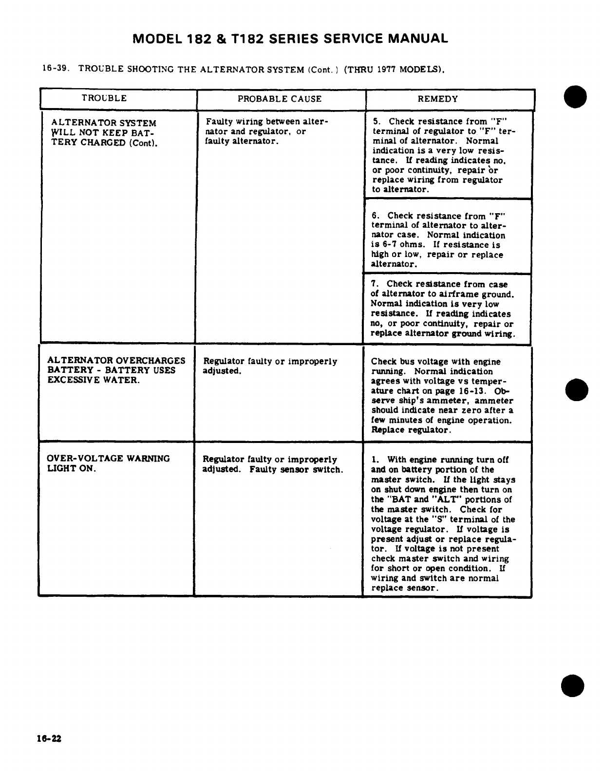
MODEL
182
&
T182
SERIES
SERVICE
MANUAL
16-39.
TROUBLE
SHOOTING
THE ALTERNATOR
SYSTEM
(Cont.)
(THRU
1977
MODELS).
TROUBLE
PROBABLE
CAUSE
REMEDY
ALTERNATOR
SYSTEM
Faulty
wiring
between
alter-
5.
Check
resistance
from
"F"
WILL
NOT
KEEP
BAT-
nator
and
regulator,
or
terminal
of
regulator
to
"F"
ter-
TERY
CHARGED
(Cont).
faulty
alternator.
minal
of
alternator.
Normal
indication
is
a
very
low
resis-
tance.
If
reading
indicates
no.
or
poor
continuity,
repair
or
replace
wiring from
regulator
to
alternator.
6.
Check
resistance
from
"F"
terminal
of
alternator
to
alter-
nator
case.
Normal
indication
is
6-7
ohms.
If
resistance
is
high
or
low,
repair
or
replace
alternator.
7.
Check
resistance
from case
of
alternator
to
airframe
ground.
Normal
indication
is
very
low
resistance.
If
reading
indicates
no,
or
poor
continuity,
repair
or
replace
alternator
ground wiring.
ALTERNATOR
OVERCHARGES
Regulator
faulty
or
improperly
Check
bus
voltage
with
engine
BATTERY
-
BATTERY
USES
adjusted.
running.
Normal
indication
EXCESSIVE
WATER.
agrees
with
voltage
vs
temper-
ature chart
on
page
16-13.
Ob-
serve
ship's
ammeter,
ammeter
should
indicate
near
zero
after
a
few
minutes
of
engine
operation.
Replace
regulator.
OVER-VOLTAGE
WARNING
Regulator
faulty
or
improperly
1.
With
engine
running
turn
off
LIGHT
ON.
adjusted.
Faulty
sensor
switch.
and
on
battery portion
of
the
master
switch.
If
the light
stays
on
shut
down
engine
then
turn
on
the
"BAT
and
"ALT"
portions
of
the
master
switch.
Check
for
voltage
at
the
"S"
terminal
of
the
voltage
regulator.
If
voltage
is
present
adjust
or
replace
regula-
tor.
If
voltage
is
not
present
check
master
switch
and
wiring
for
short or
open
condition.
If
wiring
and
switch
are
normal
replace
sensor.
16-22
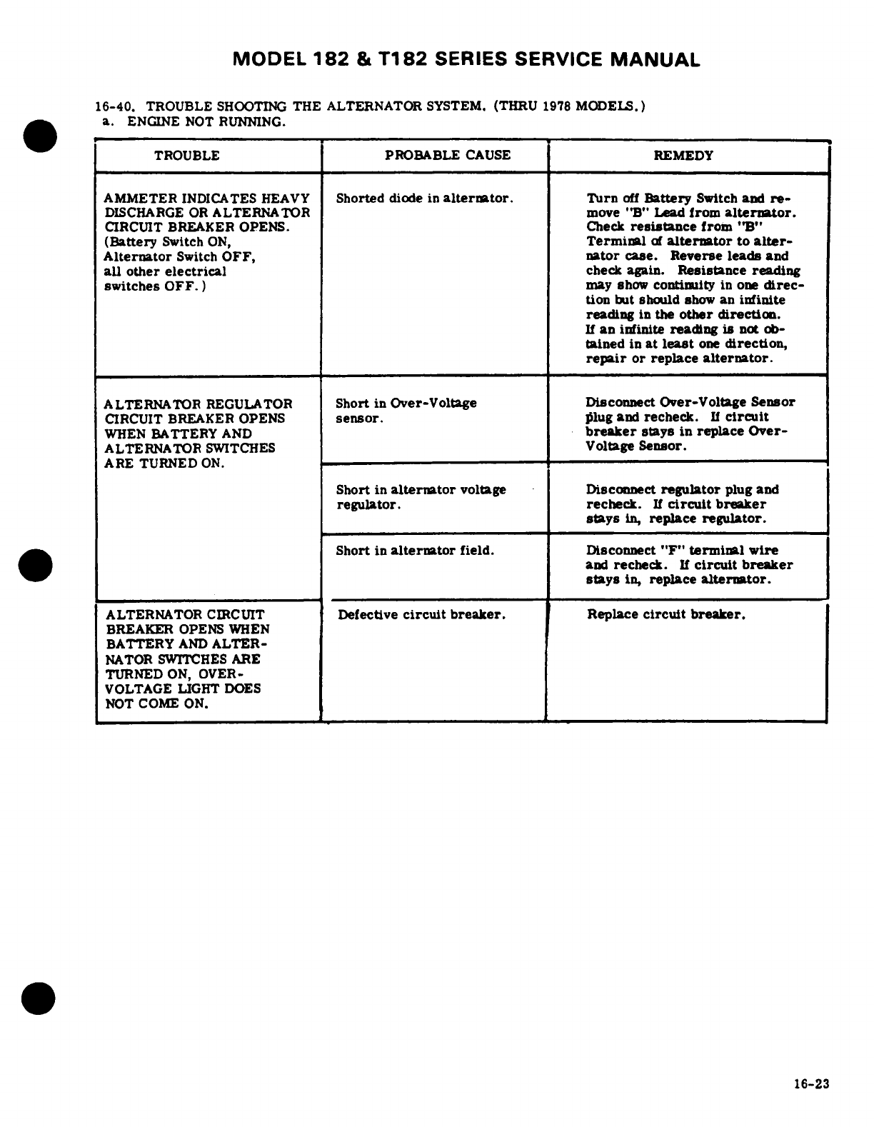
MODEL
182
&
T182
SERIES
SERVICE
MANUAL
16-40.
TROUBLE
SHOOTING
THE ALTERNATOR
SYSTEM.
(THRU
1978
MODELS.)
a.
ENGINE
NOT
RUNNING.
TROUBLE
PROBABLE
CAUSE
REMEDY
AMMETER
INDICATES
HEAVY
Shorted
diode
in
alternator.
Turn
off
Battery
Switch
and
re-
DISCHARGE
OR
ALTERNATOR move
"B"
Lead
from
alternator.
CIRCUIT
BREAKER
OPENS.
Check
resistance
from
"B"
(Battery
Switch
ON,
Terminal
of
alternator
to
alter-
Alternator
Switch
OFF,
nator
case.
Reverse
leads
and
all
other
electrical
check
again.
Resistance
reading
switches
OFF.)
may
show
continuity
in
one
direc-
tion
but
should
show
an
infinite
reading
in
the
other direction.
If
an
infinite
reading
is
not ob-
tained
in
at
least
one
direction,
repair
or replace
alternator.
ALTERNATOR
REGULATOR
Short
in
Over-Voltage
Disconnect
Over-Voltage Sensor
CIRCUIT
BREAKER
OPENS
sensor.
plug
and
recheck.
If
circuit
WHEN
BATTERY
AND
breaker
stays
in
replace Over-
ALTERNATOR
SWITCHES
Voltage
Sensor.
ARE
TURNED
ON.
Short in
alternator
voltage
Disconnect
regulator
plug
and
regulator.
recheck.
If
circuit
breaker
stays
in,
replace
regulator.
Short
in
alternator
field.
Disconnect
"F"
terminal
wire
and
recheck.
If
circuit
breaker
stays
in,
replace
alternator.
ALTERNATOR CIRCUIT
Defective
circuit breaker.
Replace
circuit
breaker.
BREAKER
OPENS
WHEN
BATTERY
AND
ALTER-
NATOR
SWITCHES
ARE
TURNED
ON,
OVER-
VOLTAGE
LIGHT
DOES
NOT COME
ON.
16-23
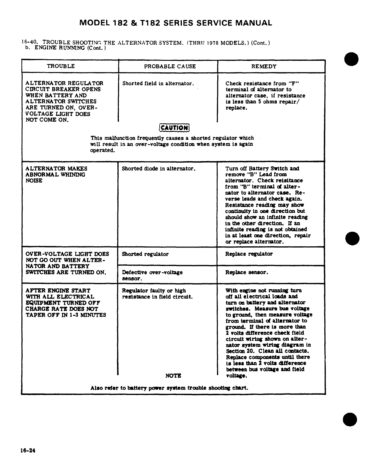
MODEL
182
&
T182
SERIES SERVICE
MANUAL
16-40.
TROUBLE
SHOOTING.
THE
ALTERNATOR
SYSTEM. (THRU
1978
MODELS.)
(Cont.)
b.
ENGINE
RUNNING
(Cont.)
TROUBLE
PROBABLE
CAUSE
REMEDY
ALTERNATOR
REGULATOR
Shorted
field
in
alternator.
Check
resistance
from
"F"
CIRCUIT
BREAKER
OPENS
terminal
of
alternator
to
WHEN
BATTERY
AND
alternator
case,
if
resistance
ALTERNATOR
SWITCHES
is
less
than
5
ohms
repair/
ARE
TURNED
ON,
OVER-
replace.
VOLTAGE LIGHT
DOES
NOT
COME
ON.
This
malfunction
frequently
causes
a
shorted
regulator
which
will
result
in
an
over-voltage
condition
when
system
is
again
operated.
ALTERNATOR
MAKES
Shorted
diode
in
alternator.
Turn
off
Battery
Switch
and
ABNORMAL
WHINING
remove
"B"
Lead
from
NOISE
alternator.
Check
reisitance
from
"B"
terminal
of
alter-
nator
to
alternator
case.
Re-
verse
leads
and
check
again.
Resistance reading
may
show
continuity
in
one
direction
but
should
show
an
infinite
reading
in
the
other
direction.
If
an
infinite
reading
is
not
obtained
in
at
least
one
direction,
repair
or
replace
alternator.
OVER-VOLTAGE
LIGHT
DOES
Shorted
regulator
Replace
regulator
NOT
GO
OUT
WHEN
ALTER-
NATOR
AND
BATTERY
SWITCHES
ARE
TURNED
ON.
Defective
over-voltage
Replace
sensor.
sensor.
AFTER
ENGINE
START
Regulator
faulty
or
high
With
engine not
running
turn
WITH
ALL
ELECTRICAL
resistance
in
field
circuit.
off
all
electrical
loads
and
EQUIPMENT
TURNED
OFF
turn
on
battery
and
alternator
CHARGE
RATE
DOES
NOT
switches.
Measure
bue voltage
TAPER
OFF
IN
1-3
MINUTES
to
ground,
then
measure
voltage
from
terminal
of
alternator
to
ground.
If
there
is
more
than
2
volts
difference
check
field
circuit
wiring
shown
on
alter-
nator system
wiring
diagram
in
Section
20.
Clean
all
contacts.
Replace
components
until
there
is
less
than
2
volts
difference
between
bus
voltage
and
field
NOTE
voltage.
Also
refer
to
battery
power
system
trouble
shooting
chart.
16-24
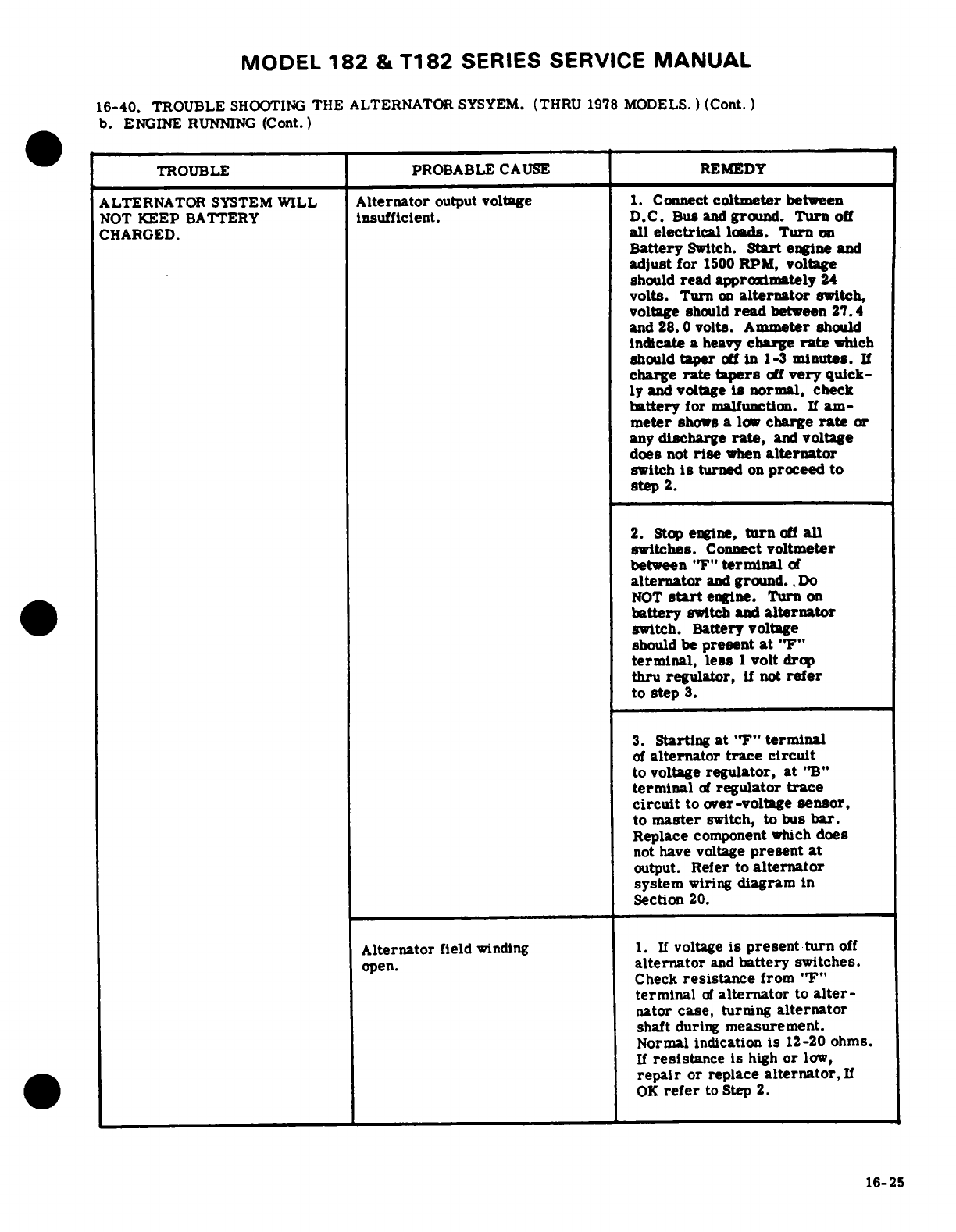
MODEL
182
&
T182
SERIES SERVICE
MANUAL
16-40,
TROUBLE
SHOOTING
THE
ALTERNATOR
SYSYEM.
(THRU
1978
MODELS.
)
(Cont.)
b.
ENGINE
RUNNING
(Cont.)
TROUBLE PROBABLE
CAUSE
REMEDY
ALTERNATOR
SYSTEM
WILL
Alternator
output
voltage
1.
Connect
coltmeter
between
NOT
KEEP
BATTERY
insufficient.
D.C.
Bus
and
ground.
Turn
off
CHARGED.
all
electrical
loads.
Turn
on
Battery
Switch.
Start
engine
and
adjust
for
1500
RPM,
voltage
should
read
approximately
24
volts.
Turn
on
alternator
switch,
voltage
should
read
between
27.4
and
28.0
volts.
Ammeter
should
indicate
a
heavy
charge
rate
which
should
taper
off
in
1-3
minutes.
If
charge
rate
tapers
off
very
quick-
ly
and voltage
is
normal,
check
battery
for
malfunction.
If
am-
meter
shows
a
low
charge
rate
or
any
discharge
rate,
and
voltage
does
not
rise
when
alternator
switch
is
turned
on
proceed
to
step
2.
2.
Stop
engine,
turn
off
all
switches.
Connect
voltmeter
between
"F"
terminal
of
alternator
and
ground..
Do
NOT
start
engine.
Turn
on
battery
switch
and
alternator
switch.
Battery
voltage
should be
present
at
"F"
terminal,
less
1
volt
drop
thru regulator,
if
not
refer
to
step
3.
3.
Starting
at
"F"
terminal
of
alternator
trace
circuit
to
voltage
regulator,
at
"B"
terminal
of
regulator
trace
circuit
to
over-voltage
sensor,
to
master
switch,
to
bus
bar.
Replace
component
which
does
not
have
voltage
present
at
output.
Refer
to
alternator
system
wiring
diagram
in
Section
20.
Alternator
field
winding
1.
If
voltage
is
present
turn
off
open.
alternator
and
battery
switches.
Check
resistance
from
"F"
terminal
of
alternator
to
alter-
nator
case,
turning
alternator
shaft
during
measurement.
Normal indication
is
12-20
ohms.
If
resistance
is
high
or
low,
repair
or
replace
alternator,
If
OK
refer
to
Step
2.
16-25
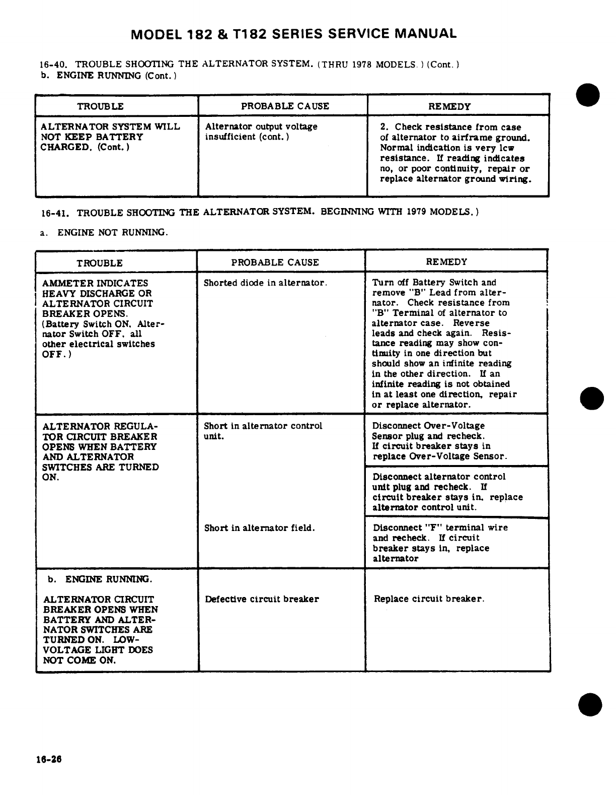
MODEL
182
&
T182
SERIES
SERVICE
MANUAL
16-40.
TROUBLE
SHOOTING
THE
ALTERNATOR
SYSTEM. (THRU
1978
MODELS.
)
(Cont.)
b.
ENGINE
RUNNING
(Cont.)
TROUBLE PROBABLE
CAUSE
REMEDY
ALTERNATOR
SYSTEM
WILL
Alternator
output
voltage
2.
Check
resistance
from
case
NOT
KEEP
BATTERY
insufficient
(cont.)
of
alternator
to
airframe
ground.
CHARGED.
(Cont.)
Normal
indication
is
very
low
resistance.
If
reading
indicates
no,
or
poor
continuity,
repair
or
replace
alternator
ground
wiring.
16-41.
TROUBLE
SHOOTING
THE
ALTERNATOR
SYSTEM.
BEGINNING
WITH 1979
MODELS.)
a.
ENGINE
NOT RUNNING.
TROUBLE PROBABLE
CAUSE
REMEDY
AMMETER
INDICATES
Shorted
diode
in
alternator.
Turn
off
Battery
Switch
and
HEAVY
DISCHARGE
OR
remove
"B"
Lead
from
alter-
ALTERNATOR
CIRCUIT
nator.
Check
resistance
from
BREAKER
OPENS.
"B"
Terminal
of
alternator
to
(Battery
Switch
ON.
Alter-
alternator
case.
Reverse
nator
Switch
OFF.
all
leads
and
check
again.
Resis-
other
electrical
switches
tance reading
may show
con-
OFF.)
tinuity
in
one
direction
but
should
show
an
infinite
reading
in
the
other
direction.
If
an
infinite reading
is
not
obtained
in
at
least
one
direction, repair
or
replace
alternator.
ALTERNATOR
REGULA-
Short
in
alternator
control
Disconnect
Over-Voltage
TOR
CIRCUIT
BREAKER
unit.
Sensor
plug
and
recheck.
OPENS
WHEN
BATTERY
If
circuit breaker
stays
in
AND
ALTERNATOR
replace
Over-Voltage
Sensor.
SWITCHES
ARE
TURNED
ON.
Disconnect
alternator
control
unit
plug
and
recheck.
If
circuit
breaker
stays
in.
replace
alternator
control
unit.
Short
in
alternator
field. Disconnect
"F"
terminal
wire
and
recheck.
If
circuit
breaker
stays
in,
replace
alternator
b.
ENGINE
RUNNING.
ALTERNATOR
CIRCUIT
Defective
circuit
breaker
Replace
circuit
breaker.
BREAKER
OPENS
WHEN
BATTERY
AND
ALTER-
NATOR
SWITCHES
ARE
TURNED
ON.
LOW-
VOLTAGE
LIGHT
DOES
NOT
COME
ON.
16-26
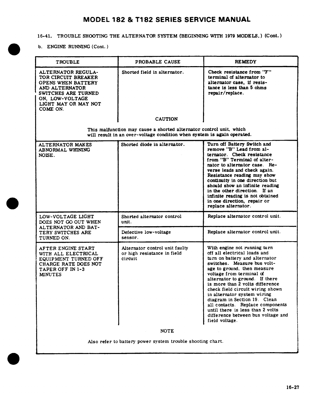
MODEL
182
&
T182
SERIES
SERVICE
MANUAL
16-41.
TROUBLE
SHOOTING
THE ALTERNATOR
SYSTEM
(BEGINNING
WITH
1979
MODELS.)
(Cont.)
b. ENGINE
RUNNING
(Cont.)
TROUBLE PROBABLE
CAUSE
REMEDY
ALTERNATOR
REGULA-
Shorted
field
in
alternator.
Check
resistance
from
"F"
TOR
CIRCUIT BREAKER
terminal
of
alternator
to
OPENS
WHEN
BATTERY
alternator
case,
if
resis-
AND
ALTERNATOR
tance
is
less
than
5
ohms
SWITCHES
ARE
TURNED
repair/replace.
ON,
LOW-VOLTAGE
LIGHT
MAY
OR
MAY
NOT
COME
ON.
CAUTION
This malfunction
may
cause
a
shorted
alternator
control
unit,
which
will
result
in
an
over-voltage
condition
when
system
is
again
operated.
ALTERNATOR
MAKES
Shorted
diode in
alternator.
Turn
off
Battery
Switch
and
ABNORMAL
WHINING
remove
"B"
Lead
from
al-
NOISE.
ternator.
Check
resistance
from
"B"
Terminal
of
alter-
nator
to
alternator
case.
Re-
verse
leads
and
check
again.
Resistance
reading
may
show
continuity
in
one
direction
but
should
show
an
infinite
reading
in
the
other
direction.
If
an
infinite
reading
is
not
obtained
in
one
direction,
repair
or
replace
alternator.
LOW-VOLTAGE LIGHT
Shorted
alternator
control
Replace
alternator
control
unit.
DOES
NOT
GO
OUT
WHEN
unit.
ALTERNATOR
AND
BAT-
TERY
SWITCHES ARE
Defective
low-voltage Replace
alternator
control
unit.
TURNED
ON.
sensor.
AFTER
ENGINE
START
Alternator
control
unit
faulty
With
engine not
running
turn
WITH
ALL
ELECTRICAL
or
high
resistance
in
field
off
all
electrical
loads
and
EQUIPMENT
TURNED
OFF
circuit
turn
on
battery
and
alternator
CHARGE
RATE
DOES
NOT
switches.
Measure
bus
volt-
TAPER
OFF
IN
1-3
age
to
ground.
then
measure
MINUTES
voltage
from
terminal
of
alternator
to
ground.
If
there
is
more
than
2
volts difference
check
field
circuit
wiring
shown
in
alternator
system
wiring
diagram
in
Section
19.
Clean
all
contacts.
Replace components
until
there
is
less
than
2
volts
difference
between
bus
voltage
and
field
voltage.
NOTE
Also
refer
to
battery
power
system trouble
shooting
chart.
16-27
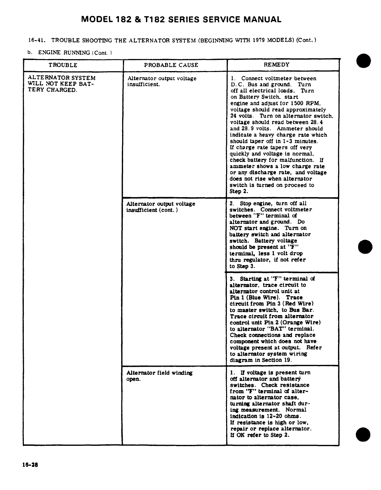
MODEL
182
&
T182
SERIES SERVICE
MANUAL
16-41.
TROUBLE
SHOOTING
THE
ALTERNATOR
SYSTEM
(BEGINNING
WITH
1979
MODELS)
(Cont.)
b.
ENGINE
RUNNING
(Cont.
)
TROUBLE
PROBABLE
CAUSE
REMEDY
ALTERNATOR
SYSTEM
Alternator
output
voltage
1.
Connect
voltmeter
between
WILL
NOT
KEEP
BAT-
insufficient.
D.C.
Bus and
ground.
Turn
TERY
CHARGED.
off
all
electrical
loads.
Turn
on
Battery
Switch.
start
engine
and
adjust
for
1500
RPM.
voltage
should
read
approximately
24
volts.
Turn
on
alternator
switch.
voltage
should
read
between
28.4
and
28.9
volts.
Ammeter
should
indicate
a
heavy
charge
rate
which
should
taper
off
in
1-3
minutes.
If
charge
rate
tapers
off
very
quickly
and
voltage
is
normal.
check
battery
for
malfunction.
If
ammeter
shows
a
low
charge
rate
or
any
discharge
rate,
and
voltage
does
not
rise
when
alternator
switch
is
turned
on
proceed
to
Step
2.
Alternator
output
voltage
2.
Stop
engine,
turn
off
all
insufficient
(cont.)
switches.
Connect
voltmeter
between "F"
terminal
of
alternator
and
ground.
Do
NOT
start
engine.
Turn
on
battery
switch
and
alternator
switch.
Battery
voltage
should
be
present
at
"F"
terminal,
less
1
volt
drop
thru
regulator,
if
not
refer
to
Step
3.
3.
Starting
at
"F"
terminal
of
alternator,
trace
circuit
to
alternator
control
unit
at
Pin
1
(Blue
Wire).
Trace
circuit
from
Pin
3
(Red
Wire)
to
master
switch,
to
Bus
Bar.
Trace
circuit
from
alternator
control
unit
Pin
2
(Orange
Wire)
to
alternator
"BAT"
terminal.
Check
connections
and
replace
component
which
does
not have
voltage
present
at
output.
Refer
to
alternator
system
wiring
diagram
in
Section
19.
Alternator
field
winding
1.
If
voltage
is
present
turn
open.
off
alternator
and
battery
switches.
Check
resistance
from
"F"
terminal
of
alter-
nator
to
alternator
case,
turning
alternator
shaft
dur-
ing
measurement.
Normal
indication
is
12-20
ohms.
If
resistance
is
high
or
low,
repair
or
replace
alternator.
If
OK
refer
to
Step
2.
16-28
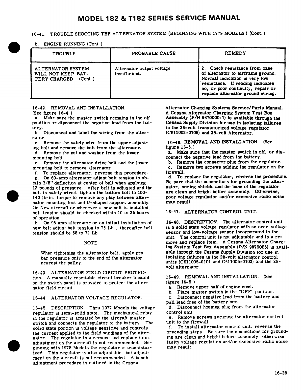
MODEL
182
&
T182
SERIES SERVICE
MANUAL
16-41.
TROUBLE
SHOOTING
THE
ALTERNATOR
SYSTEM
(BEGINNING WITH 1979
MODELS)
(Cont.)
.
b.
ENGINE
RUNNING
(Cont.)
TROUBLE PROBABLE
CAUSE
REMEDY
ALTERNATOR
SYSTEM
Alternator
output
voltage
2.
Check
resistance
from
case
WILL
NOT
KEEP
BAT-
insufficient,
of
alternator
to
airframe
ground.
TERY
CHARGED.
(Cont.)
Normal
indication
is
very
low
resistance.
If
reading
indicates
no,
or
poor
continuity,
repair
or
replace
alternator
ground
wiring.
16-42.
REMOVAL
AND
INSTALLATION.
Alternator
Charging
Systems
Service/Parts
Manual.
(See
figure
16-4.
)
A
Cessna
Alternator
Charging System
Test
Box
a.
Make
sure
the
master
switch
remains
in
the
off
Assembly
(P/N
9870000-1)
is
available
through
the
position
or
disconnect
the
negative
lead
from
the
bat-
Cessna
Supply
Division
for
use
in
isolating
failures
tery.
in
the
28-volt
transistorized
voltage
regulator
b.
Disconnect
and
label
the
wiring
from
the
alter-
(C611002-0105)
and
28-volt
Alternator.
nator.
c.
Remove
the
safety
wire
from
the
upper
adjust-
16-46.
REMOVAL
AND
INSTALLATION.
(See
ing
bolt
and
remove
the
bolt
from
the
alternator.
figure
16-5.)
d.
Remove
the
nut
and
washer
from
the
lower
a.
Make
sure
that
the
master
switch
is
off,
or
dis-
mounting bolt.
connect
the
negative lead
from
the
battery.
e.
Remove
the
alternator
drive
belt
and
the
lower
b.
Remove
the
connector
plug
from
the
regulator.
mounting
bolt
to
remove
alternator.
c.
Remove
two
screws
holding
the
regulator
on
the
f.
To
replace
alternator,
reverse
this
procedure.
firewall.
g.
On
60-amp
alternator
adjust
belt
tension
to
ob-
d.
To
replace
the
regulator,
reverse
the
procedure.
tain
3/8"
deflection at
center
of
belt
when
applying
Be
sure
that
the
connections
for
grounding
the
alter-
12
pounds
of
pressure.
After belt
is
adjusted
and
the
nator,
wiring
shields
and
the
base
of
the
regulator
bolt is
safety
wired.
tighten
the
bottom
bolt
to
100-
are
clean
and
bright
before
assembly. Otherwise,
140
lb-in.
torque
to
remove
any
play
between
alter-
poor voltage
regulation
and/or
excessive
radio
noise
nator
mounting
foot
and
U-shaped
support assembly.
may
result.
On
New
aircraft
or
whenever
a
new
belt
is
installed,
belt
tension
should
be
checked
within
10
to
25
hours
16-47.
ALTERNATOR
CONTROL
UNIT.
of
operation.
h.
On
95
amp
alternator
or
on
initial
installation
of
16-48.
DESCRIPTION.
The
alternator
control
unit
new
belt
adjust
belt
tension
to
75
Lb.,
thereafter
belt
is
a
solid
state
voltage
regulator
with
an
over-voltage
tension
should
be
58
to
72
Lb.
sensor
and
low-voltage
sensor
incorporated
in
the
unit.
The
control
unit
is
not
adjustable
and
is
a
re-
NOTE
move
and
replace
item.
A
Cessna
Alternator
Charg-
ing
System
Test
Box
Assembly (P/N
9870005)
is
avail-
When
tightening
the
alternator
belt,
apply
pry able
through
the
Cessna
Supply
Division
for
use
in
bar
pressure
only
to
the
end
of
the
alternator
isolating
failures
in
the
28-volt
alternator
control
nearest
the
pulley.
units
(C611005-0101
and
C611005-0102) and
the
28-
volt
alternator.
16-43.
ALTERNATOR
FIELD
CIRCUIT
PROTEC-
tion.
A
manually
resettable circuit
breaker
located 16-49.
REMOVAL
AND
INSTALLATION.
(See
on
the
switch
panel
is
provided
to
protect
the
alter-
figure
16-5.)
nator
field
circuit.
a.
Remove
upper
half
of
engine
cowl.
b.
Place
master
switch
in
the
"OFF" position.
16-44.
ALTERNATOR
VOLTAGE REGULATOR.
c.
Disconnect negative
lead
from
the
battery
and
pull lead
free
of
the
battery
box.
16-45.
DESCRIPTION.
Thru
1977
Models
the
voltage
d.
Disconnect
housing
plug
from
the
alternator
regulator
is
semi-solid
state.
The
mechanical
relay control
unit.
in
the
regulator
is
actuated
by
the
aircraft
master
e.
Remove
screws
securing
the
alternator
control
switch
and
connects
the
regulator
to
the
battery.
The
unit
to
the
firewall.
solid
state
portion
is
voltage
sensitive
and
controls
f.
To
install
alternator
control
unit.
reverse
the
the
current
applied
to
the
field
windings
of
the
alter-
preceding
steps.
Be
sure
the
connections
for
ground-
nator.
The
regulator
is
a
remove
and
replace
item.
ing
are
clean
and
bright
before
assembly.
otherwise
adjustment
on
the
aircraft
is
not
recommended.
Be-
faulty
voltage
regulation
and/or excessive
radio
noise
ginning
with
1978
Models
the
regulator
is
transistor-
may
result.
ized.
This
regulator
is
also
adjustable.
but
adjust-
ment
on
the
aircraft
is
not
recommended.
A
bench
adjustment
procedure
is
outlined
in
the
Cessna
16-29
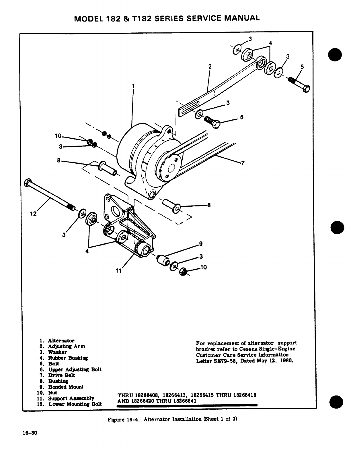
MODEL
182
&
T182
SERIES
SERVICE
MANUAL
3
2
1.
Alternator
2.
Adjusting Arm
For replacement
of
alternator
support
3.
Washer
bracket
refer
to
Cessna
Single-Engine
4.
Rubber
Bushing
Customer
Care
Service
Information
5.
Bolt
Letter
SE79-58,
Dated
May
12,
1980.
6.
Upper Adjusting
Bolt
7.
Drive
Belt
8.
Bushing
9.
Bonded
Mount
10.
Nut
11.
Support
Asembly
THRU
18266408, 18266413,
18266415 THRU 18266418
12.
Figure
16-4.
Alternator
Installation
(Sheet
1
of
3)
16-30
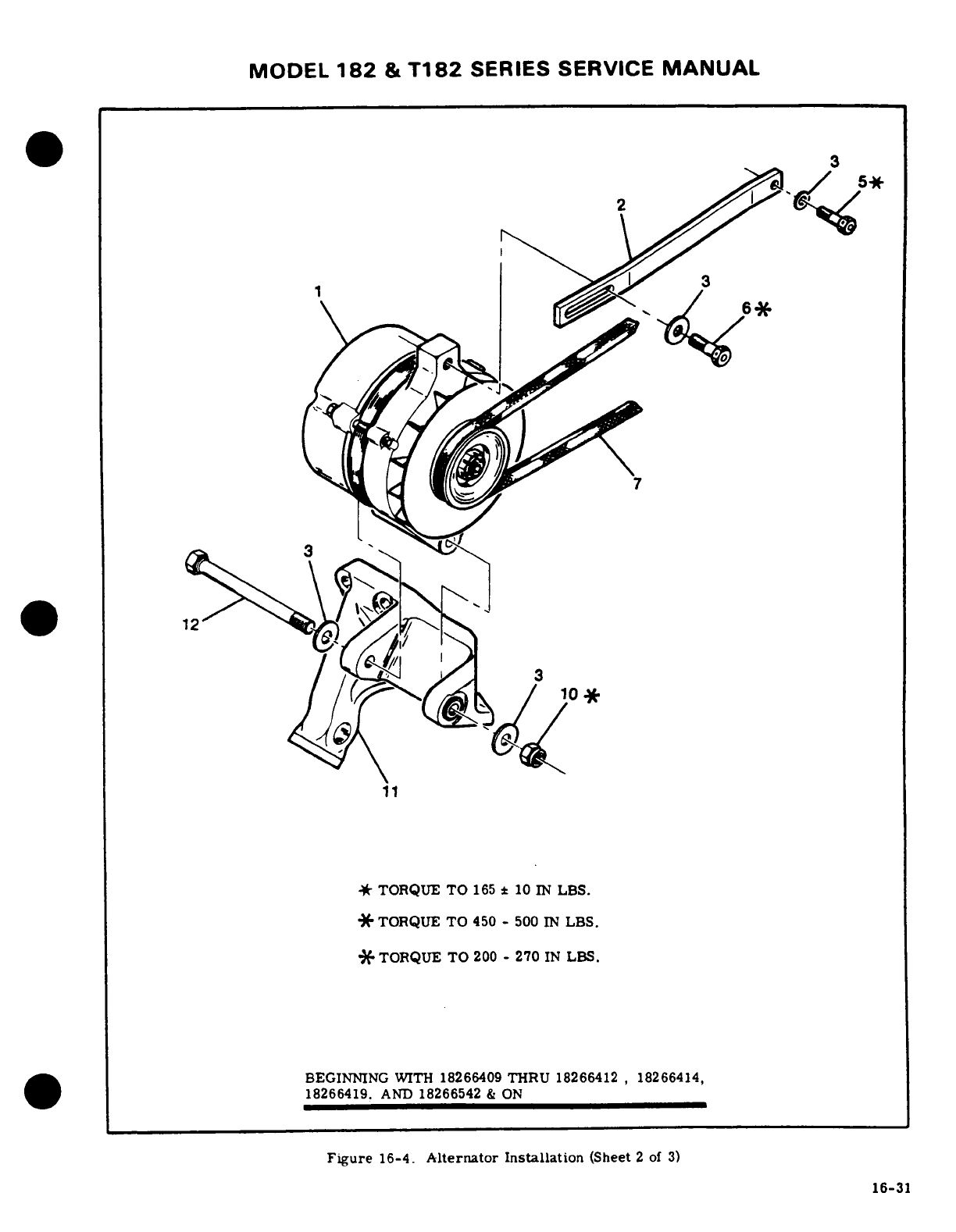
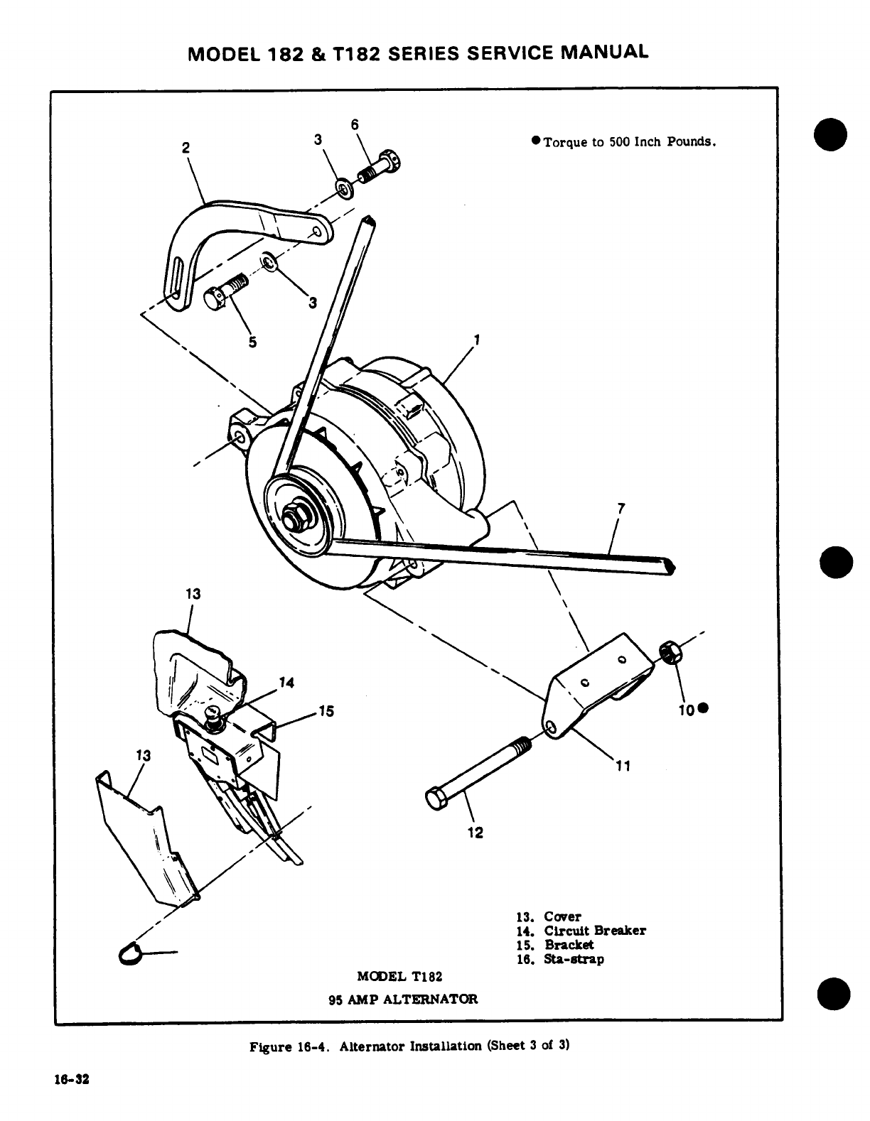
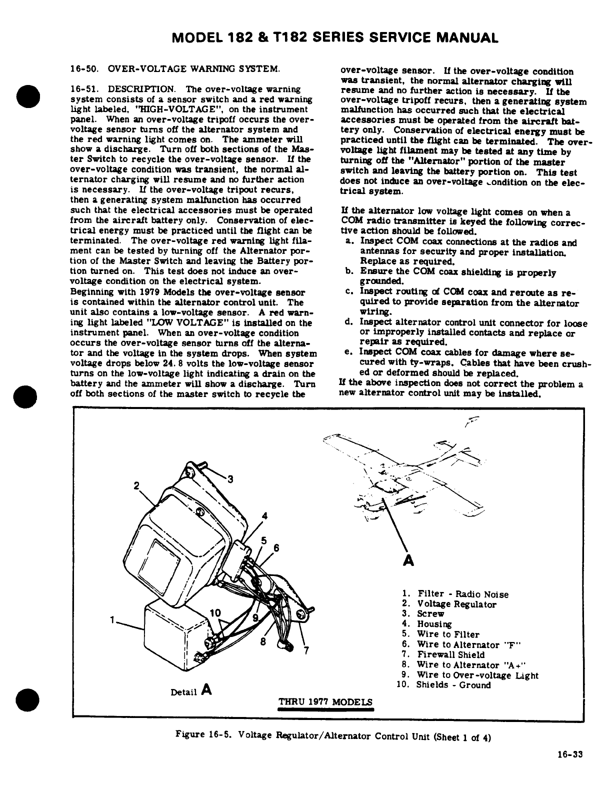
MODEL
182
&
T182
SERIES SERVICE
MANUAL
16-50.
OVER-VOLTAGE
WARNING
SYSTEM.
over-voltage
sensor.
If
the
over-voltage
condition
was
transient,
the
normal
alternator
charging
will
16-51.
DESCRIPTION. The
over-voltage
warning
resume
and
no
further
action
is
necessary.
If
the
system
consists
of
a
sensor
switch
and
a
red
warning
over-voltage
tripoff
recurs,
then
a
generating system
light labeled,
"HIGH-VOLTAGE",
on
the
instrument
malfunction
has
occurred
such
that
the
electrical
panel.
When an
over-voltage
tripoff
occurs
the
over-
accessories
must
be
operated
from
the
aircraft
bat-
voltage
sensor
turns
off
the
alternator
system
and
tery
only.
Conservation
of
electrical
energy
must
be
the
red
warning light
comes
on.
The
ammeter
will
practiced
until
the
flight
can
be
terminated.
The
over-
show
a
discharge.
Turn
off
both
sections
of
the Mas-
voltage
light
filament
may
be
tested
at
any
time
by
ter
Switch to
recycle
the
over-voltage
sensor.
If
the
turning
off
the
"Alternator"
portion
of
the
master
over-voltage
condition
was
transient,
the
normal
al-
switch
and
leaving
the
battery
portion
on.
This
test
ternator
charging
will
resume
and
no
further
action
does
not
induce
an
over-voltage
condition
on
the
elec-
is
necessary.
If
the
over-voltage
tripout
recurs,
trical
system.
then
a
generating
system
malfunction
has
occurred
such
that
the
electrical accessories
must
be
operated
If
the
alternator
low
voltage
light
comes
on
when
a
from
the
aircraft
battery
only.
Conservation
of
elec-
COM
radio
transmitter
is
keyed the
following
correc-
trical
energy must
be
practiced
until
the
flight
can
be
tive
action
should
be
followed.
terminated.
The
over-voltage red
warning
light
fila-
a.
Inspect
COM
coax
connections
at
the
radios
and
ment
can
be
tested
by
turning
off
the
Alternator por-
antennas
for
security
and
proper
installation.
tion
of
the
Master
Switch
and
leaving the
Battery
por-
Replace
as required.
tion
turned
on.
This
test
does
not
induce an
over-
b.
Ensure
the
COM
coax
shielding
is
properly
voltage
condition
on
the
electrical
system.
grounded.
Beginning
with
1979
Models the
over-voltage
sensor
c.
Inspect
routing
of
COM
coax
and
reroute
as
re-
is
contained
within
the
alternator
control
unit.
The
quired
to
provide
separation
from
the
alternator
unit
also
contains
a
low-voltage
sensor.
A
red
warn-
wiring.
ing
light
labeled
"LOW
VOLTAGE"
is
installed
on
the
d.
Inspect
alternator
control
unit
connector
for
loose
instrument
panel.
When
an
over-voltage
condition
or
improperly
installed
contacts
and
replace
or
occurs
the
over-voltage
sensor
turns
off
the
alterna-
repair
as required.
tor
and
the
voltage
in
the
system drops.
When
system
e.
Inspect
COM
coax cables
for
damage
where
se-
voltage
drops
below
24.
8
volts
the
low-voltage
sensor
cured
with
ty-wraps.
Cables
that
have
been
crush-
turns
on
the
low-voltage
light indicating
a
drain
on
the ed
or
deformed
should
be
replaced.
battery
and
the
ammeter
will
show
a
discharge. Turn
If
the
above
inspection
does
not
correct
the
problem
a
off
both
sections
of
the
master
switch
to
recycle
the
new
alternator
control
unit
may
be
installed.
2.
Voltage
Regulator
3.
Screw
4.
Housing
8.
Wire
to
Alternator
"A+"
9.
Wire
to
Over-voltage
Light
Detail
A
THRU
1977
MODELS
Figure
16-5.
Voltage
Regulator/Alternator
Control
Unit
(Sheet
1 of
4)
16-33
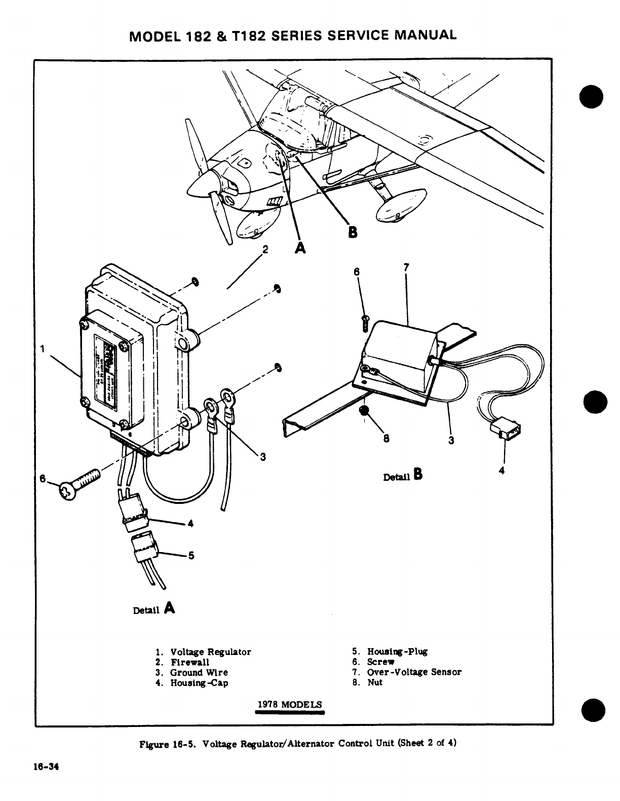
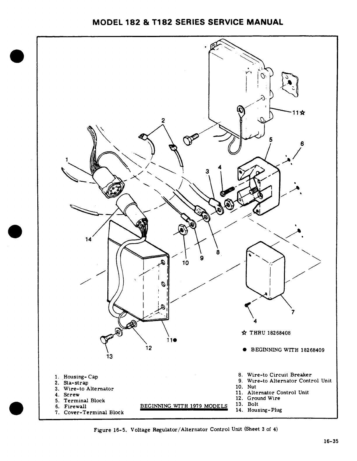
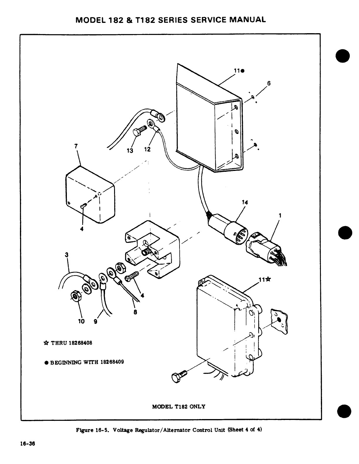
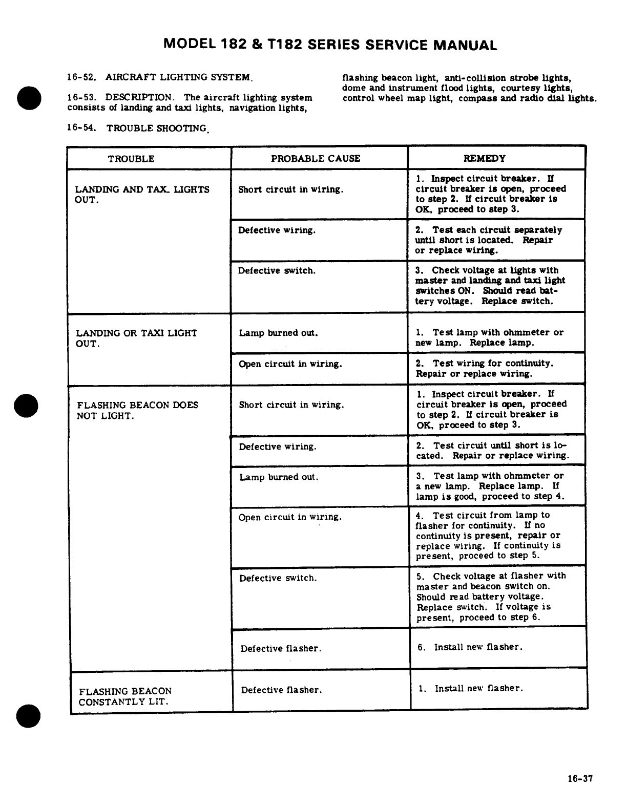
MODEL
182
&
T182
SERIES SERVICE
MANUAL
16-52.
AIRCRAFT
LIGHTING
SYSTEM
flashing
beacon
light,
anti-collision strobe
lights,
dome
and
instrument
flood
lights,
courtesy
lights,
16-53.
DESCRIPTION. The
aircraft
lighting
system
control
wheel map
light,
compass
and
radio
dial
lights
consists
of
landing
and
taxi
lights,
navigation
lights,
16-54.
TROUBLE
SHOOTING
TROUBLE
PROBABLE
CAUSE
REMEDY
1.
Inspect
circuit
breaker.
If
LANDING
AND
TAX
LIGHTS
Short
circuit
in
wiring.
circuit
breaker
is
open,
proceed
OUT.
to
step
2.
If
circuit
breaker
is
OK,
proceed
to
step
3.
Defective
wiring.
2.
Test
each
circuit
separately
until
short
is
located.
Repair
or
replace
wiring.
Defective
switch.
3.
Check
voltage
at
lights
with
master
and
landing
and
taxi
light
switches
ON.
Should
read bat-
tery
voltage.
Replace
switch.
LANDING
OR TAXI
LIGHT
Lamp
burned
out.
1.
Test
lamp
with
ohmmeter
or
OUT.
new
lamp.
Replace
lamp.
Open
circuit
in
wiring.
2.
Test
wiring
for
continuity.
Repair
or
replace wiring.
1.
Inspect
circuit
breaker.
If
FLASHING
BEACON DOES
Short
circuit
in
wiring.
circuit
breaker
is
open,
proceed
NOT LIGHT.
to
step
2.
If
circuit
breaker
is
OK,
proceed
to
step
3.
Defective
wiring.
2.
Test
circuit
until
short
is
lo-
cated.
Repair
or replace
wiring.
Lamp
burned
out.
3.
Test
lamp
with
ohmmeter
or
a
new
lamp.
Replace
lamp.
If
lamp
is
good,
proceed
to
step
4.
Open
circuit
in
wiring.
4.
Test
circuit
from
lamp
to
flasher
for
continuity.
If
no
continuity
is
present,
repair
or
replace
wiring.
If
continuity
is
present,
proceed
to
step
5.
Defective switch.
5.
Check voltage at
flasher
with
master
and
beacon switch
on.
Should
read
battery
voltage.
Replace
switch.
If
voltage
is
present,
proceed to
step
6.
Defective
flasher.
6.
Install
new
flasher.
FLASHING
BEACON
Defective
flasher.
1.
Install
new
flasher.
CONSTANTLY LIT.
16-37
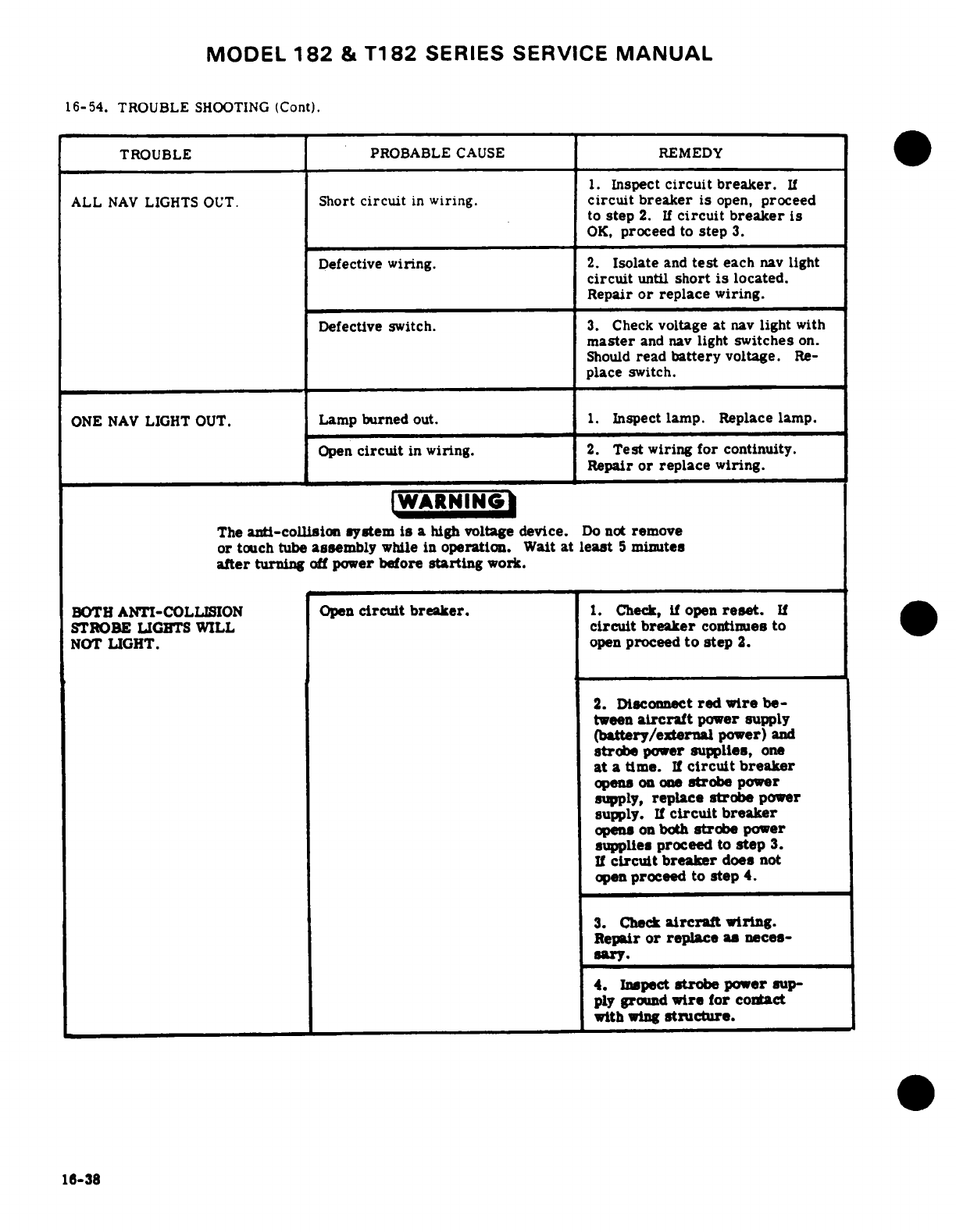
MODEL
182
&
T182
SERIES
SERVICE
MANUAL
16-54.
TROUBLE
SHOOTING
(Cont).
TROUBLE
PROBABLE
CAUSE
REMEDY
1.
Inspect
circuit
breaker.
If
ALL
NAV
LIGHTS
OUT.
Short
circuit
in
wiring,
circuit
breaker
is
open,
proceed
to
step
2.
If
circuit breaker
is
OK,
proceed
to
step
3.
Defective
wiring.
2.
Isolate
and
test
each
nav
light
circuit
until
short
is
located.
Repair
or
replace
wiring.
Defective
switch.
3.
Check
voltage
at
nav
light
with
master
and nav
light
switches
on.
Should
read
battery
voltage.
Re-
place
switch.
ONE
NAV
LIGHT
OUT.
Lamp
burned
out.
1.
Inspect
lamp.
Replace lamp.
Open
circuit
in
wiring.
2.
Test
wiring
for
continuity.
Repair
or
replace
wiring.
The
anti-collision system
is
a
high
voltage device.
Do
not
remove
or
touch
tube
assembly
while in
operation.
Wait
at
least
5
minutes
after
turning
off
power
before
starting
work.
BOTH
ANTI-COLLISION
Open
circuit
breaker.
1.
Check,
if
open
reset.
If
STROBE
LIGHTS
WILL
circuit
breaker
continues
to
NOT
LIGHT.
open
proceed
to
step
2.
2.
Disconnect
red
wire
be-
tween
aircraft
power
supply
(battery/external
power)
and
strobe
power
supplies,
one
at a
time.
If
circuit
breaker
opens
on
one
strobe
power
supply,
replace
strobe
power
supply.
If
circuit
breaker
opens
on
both
strobe
power
supplies
proceed
to
step
3.
If
circuit breaker
does
not
open
proceed
to
step
4.
3.
Check
aircraft
wiring.
Repair
or
replace
as
neces-
sary.
4.
Inspect
strobe
power
sup-
ply
ground
wire
for
contact
with
wing
structure.
16-38
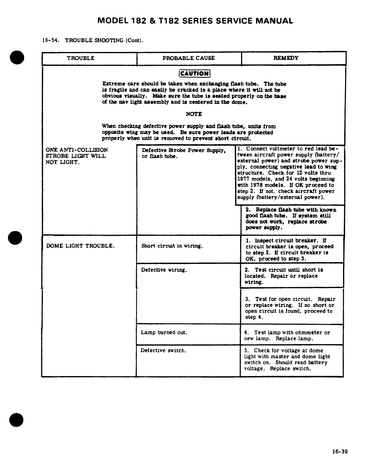
MODEL
182
&
T182
SERIES SERVICE
MANUAL
16-54.
TROUBLE
SHOOTING
(Cont).
Extreme
care
should
be
taken
when
exchanging
flash
tube.
The
tube
is
fragile
and
can
easily
be
cracked
in
a
place
where
it
will
not
be
obvious
visually.
Make
sure
the
tube
is
seated
properly
on
the
base
of
the
nav
light
assembly
and
is
centered
in
the
dome.
NOTE
When
checking
defective power
supply
and
flash
tube,
units
from
opposite
wing
may
be
used.
Be
sure
power
leads
are
protected
properly
when
unit
is
removed
to
prevent
short circuit.
ONE
ANTI-COLLISION
Defective
Strobe
Power
Supply,
1.
Connect
voltmeter
to
red
lead be-
STROBE
LIGHT
WILL
or
flash
tube.
tween
aircraft
power supply
(battery/
NOT
LIGHT.
external
power)
and
strobe
power
sup-
ply,
connecting
negative
lead
to
wing
structure.
Check
for
12
volts
thru
1977
models,
and
24
volts
beginning
with
1978
models.
If
OK
proceed
to
step
2.
If
not.
check
aircraft
power
supply
(battery/external
power).
2.
Replace
flash
tube
with
known
good
flash
tube.
If
system
still
does
not
work,
replace
strobe
power
supply.
1.
Inspect
circuit
breaker.
If
DOME
LIGHT
TROUBLE.
Short
circuit
in
wiring.
circuit
breaker
is
open,
proceed
to
step
2.
If
circuit
breaker
is
OK,
proceed
to
step
3.
Defective
wiring.
2.
Test
circuit
until
short
is
located.
Repair
or
replace
wiring.
3.
Test
for
open
circuit.
Repair
or
replace
wiring.
If
no
short
or
open
circuit
is
found,
proceed
to
step
4.
Lamp
burned
out.
4.
Test
lamp
with
ohmmeter
or
new
lamp.
Replace
lamp.
Defective
switch.
5.
Check
for
voltage
at
dome
light
with
master
and
dome
light
switch
on.
Should
read
battery
voltage.
Replace
switch.
16-39
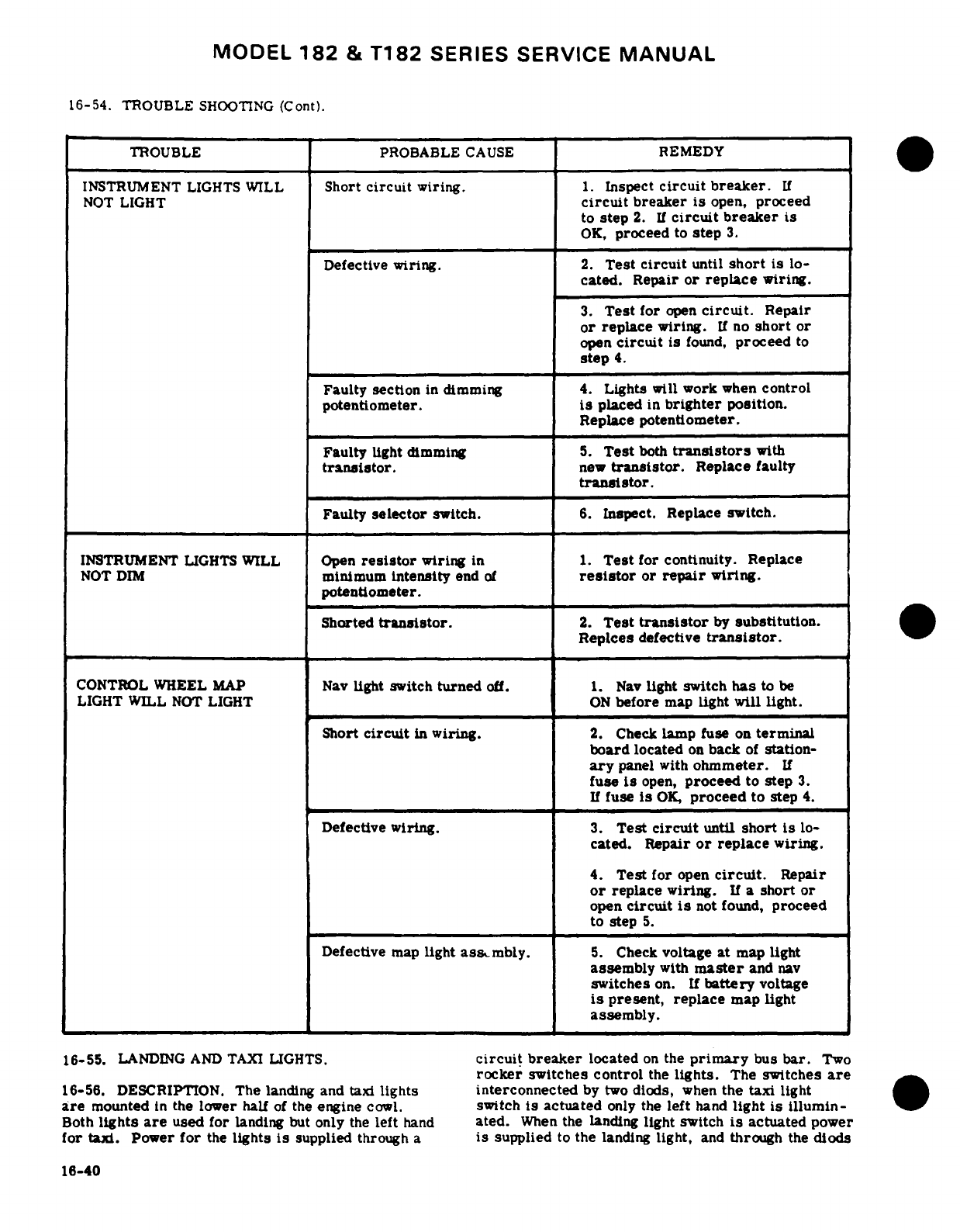
MODEL
182
&
T182
SERIES
SERVICE
MANUAL
16-54.
TROUBLE
SHOOTING
(Cont).
TROUBLE
PROBABLE
CAUSE
REMEDY
INSTRUMENT
LIGHTS
WILL
Short
circuit
wiring.
1.
Inspect
circuit
breaker.
If
NOT
LIGHT
circuit
breaker
is
open,
proceed
to
step
2.
If
circuit breaker
is
OK,
proceed
to
step
3.
Defective wiring.
2.
Test
circuit
until
short
is
lo-
cated. Repair
or
replace
wiring.
3.
Test
for
open
circuit.
Repair
or
replace
wiring.
If
no
short
or
open
circuit
is
found,
proceed
to
step
4.
Faulty
section
in
dimming
4.
Lights
will
work
when
control
potentiometer.
is
placed
in
brighter
position.
Replace
potentiometer.
Faulty
light dimming
5.
Test
both
transistors
with
transistor.
new
transistor.
Replace
faulty
transistor.
Faulty
selector
switch.
6.
Inspect. Replace
switch.
INSTRUMENT
LIGHTS
WILL
Open
resistor
wiring
in
1.
Test
for continuity.
Replace
NOT
DIM
minimum
intensity
end
of
resistor
or
repair
wiring.
potentiometer.
Shorted
transistor.
2.
Test
transistor
by
substitution.
Replaces
defective
transistor.
CONTROL WHEEL
MAP Nav
light switch
turned
off. 1.
Nav
light
switch
has
to
be
LIGHT WILL
NOT
LIGHT
ON
before
map
light
will light.
Short
circuit
in
wiring.
2.
Check
lamp
fuse
on
terminal
board
located
on
back
of
station-
ary
panel
with
ohmmeter.
If
fuse
is
open,
proceed
to
step
3.
If
fuse
is
OK,
proceed
to
step
4.
Defective
wiring.
3.
Test
circuit
until
short
is
lo-
cated. Repair
or
replace
wiring.
4.
Test
for
open
circuit.
Repair
or
replace
wiring.
If
a
short
or
open
circuit
is
not
found,
proceed
to
step
5.
Defective
map
light
assembly.
5.
Check
voltage
at
map
light
assembly
with
master
and
nav
switches
on.
If
battery
voltage
is
present,
replace
map
light
assembly.
16-55.
LANDING
AND
TAXI
LIGHTS.
circuit
breaker
located
on
the
primary
bus
bar.
Two
rocker
switches
control
the
lights.
The
switches
are
16-56.
DESCRIPTION.
The
landing
and
taxi
lights
interconnected
by
two
diods,
when
the
taxi
light
are
mounted
in
the
lower
half
of
the
engine
cowl.
switch
is
actuated
only
the
left
hand
light
is
illumin-
Both
lights
are
used
for
landing
but
only
the
left
hand
ated.
When
the
landing
light
switch
is
actuated
power
for
taxi.
Power
for
the
lights
is
supplied
through
a
is
supplied
to
the
landing
light,
and
through
the
diods
16-40
MODEL
182
&
T182
SERIES
SERVICE
MANUAL
around
the
taxi
light
switch
to
the
taxi
light
so
both 16-61.
REMOVAL
AND
INSTALLATION.
For
re-
lights
are
illuminated.
moval and
installation
of
the
navigation
lights
see
figure
16-7.
16-57.
REMOVAL
AND
INSTALLATION.
(See
figure
16-6.)
16-62.
FLASHING
BEACON.
a.
Remove
the
lower
cowl and
disconnect
wires
from
the
landing
and
taxi
lights.
16-63.
DESCRIPTION.
The
flashing
beacon
light
is
b.
Remove
screws
(8)
securing
lamp
assembly
to
attached
to
the
vertical
fin
tip.
The
flashing
beacon
support
(2)
and
remove
lamp
assembly.
Note
number
is
an
iodine-vapor
lamp
electrically
switched
by
a
and
position
of
washers
between
plate
(3)
and
support
solid-state
flasher
assembly.
The
flasher
assembly
(2)
for
reinstallation.
is
located
in
the
vertical
fin
under
the
fin
tip.
Switch-
c.
Remove
screws
(7)
securing
bracket
(6)
to
plate
ing
frequency
of
the
flasher
assembly
operates
the
(3)
and
remove
lamp
(5)
and
gasket
(4).
lamp
at
approximately
45
flashes
per
minute.
A
1.5
d.
To
install
,
place
lamp
(5)
in
bracket
(6)
and
ohm
resistor
is
installed
to
provide
a
dummy
load
to
install
gasket
(4)
and
plate
(3)
using
screws
(7).
eliminate
a
"pulsing"
effect
on
the
cabin
lighting
and
ammeter.
NOTE
16-64.
REMOVAL
AND
INSTALLATION.
For
re-
Aminimum
of
one
gasket
(4)
and
a
max- moval and
installation
of
the
flashing
beacon
light
imum
of
two
gaskets
may
be
used
to
see
figure
16-8.
secure
lamp
(5)
between
bracket
(6)
and
plate
(3).
16-65.
ANTI-COLLISION
STROBE
LIGHTS.
e.
Using
screws
(8)
secure
lamp
assembly
to
16-66.
DESCRIPTION.
A
white
strobe
light
is
in-
support
(2)
installing
washers,
in
the
proper
position,
stalled
on
each
wing
tip.
These
lights
are
vibration
removed
in
step
(b.).
resistant
and
operate
on
the
principle
of
a
capacitor
discharge
into
a xenon
tube,
producing
an
extremely
NOTE
high
intensity
flash.
Energy
is
supplied
to
the
strobe
lights from
power
supplies
mounted
on
each
wing
tip
A
maximum
of
two
washers
may
be
used
rib.
between
support
(2)
and
plate
(3)
for
ad-
justment.
16-67.
OPERATIONAL
REQUIREMENTS.
(THRU
1977
MODELS).
f.
Connect
wires
to
lamps
and
install
cowl.
g.
Check
lights
for
operation.
The
capacitors
in
the
strobe
light
power
16-58.
ADJUSTMENT OF
LANDING
AND
TAXI
supplies
must
be
reformed
if
not
used
for
LIGHT.
(See
figure
16-6.)
Adjustment
of
the
a
period
of
six
(6)
months.
The
following
landing
and
taxi
lights
is
pre-set
at
the
factory.
If
procedure
must
be
used.
further
asjustment
is
desired
proceed
as
follows:
a.
Remove
the
lower
engine
cowland
disconnect
Connect
the
power
supply,
red
wire
to
plus,
black
to
wires
from
the
landing
and
taxi
lights.
ground
to
6
volt
DC
source.
Do
Not
connect
strobe
b.
Remove
screws
(8)
securing
lamp
assembly
to
tube.
Turn
on
6
volt
supply.
Note
current
draw
after
support
(2).
one
minute.
If
less
than
1
ampere,
continue
opera-
c.
Add
or
remove
washers
between
lamp
assembly
tion
for
24
hours.
Turn
off DC
power
source.
Then
and
support
(2).
connect
to
the
proper
voltage,
12
volt.
Connect
tube
to
output
of
strobe
power
supply
and allow
to operate,
NOTE
flashing,
for
15
minutes.
Remove
strobe
tube.
Op-
erating
power
supply
at
12
volts,
note
the
current
A
maximum
of
two
washers
may be
used
drain
after
one
minute.
If
less
than
0.
5
amperes,
between
support
(2)
and
plate
(3)
for
ad-
operate
for
6
hours.
If
current
draw
is
greater
than
justment.
0.
5
amperes, reject
the
unit.
d.
Using
screws
(8)
secure
lamp
assembly
to
16-68.
REMOVAL
AND
INSTALLATION. (See
support
(2).
figure
16-7
as
a
guide
for
removal
and
installation
e,
Connect
wires
to
lamps
and
install
cowl.
of
the
anti-collision
strobe
light
components.
f.
Check
lights
for
operation
and
direction.
16-59.
NAVIGATION
LIGHTS.
16-60.
DESCRIPTION.
The
navigation
lights
are
This
anti-collision
system
is
a
high
volt-
installed
on
each
wing
tip
and
the
stinger.
The
lights
age
device.
Do
not
remove
or
touch
tube
are
controled
by
a
switch
located
on
the
instrument
assembly
while
in
operation.
Wait
at
least
panel.
5
minutes
after
turning
off
power
before
starting
work.
16-41
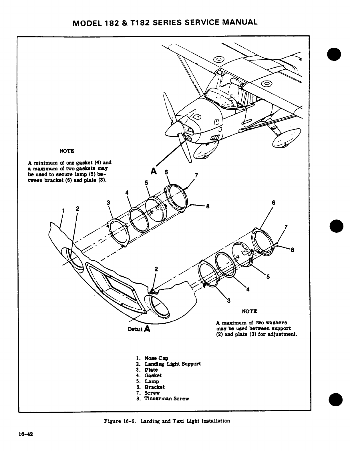
MODEL
182
&
T182
SERIES
SERVICE
MANUAL
NOTE
A
minimum
of
one
gasket
(4)
and
a
maximum
of
two
gaskets
may
be
used to
secure
lamp
(5)
be-
tween
bracket
(6)
and
plate
(3).
A
maximum
of
two
washers
Detail
A
may
be
used
between
support
(2)
and
plate
(3)
for
adjustment.
1.
Nose
Cap
2.
Landing
Light
Support
3.
Plate
4.
Gasket
5.
Lamp
6.
Bracket
7.
Screw
8.
Tinnerman
Screw
Figure
16-6.
Landing and
Taxi
Light
Installation
16-42
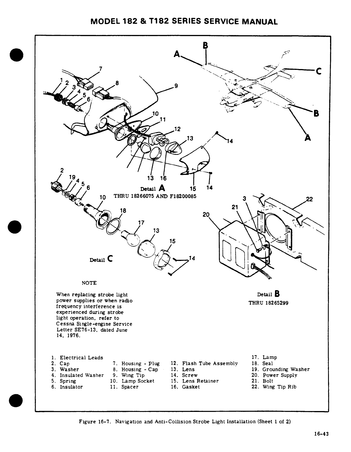
MODEL
182
&
T182
SERIES
SERVICE
MANUAL
B
10
6
Detail
A
15
14
NOTE
When
replacing
strobe
light
Detail
B
power
supplies
or
when
radio
THRU
18265299
frequency
interference
is
experienced
during
strobe
light operation,
refer
to
Cessna
Single-engine
Service
Letter
SE76-13.
dated June
14,
1976.
1.
Electrical
Leads
17.
Lamp
2.
Cap
7.
Housing
-
Plug
12.
Flash
Tube
Assembly
18.
Seal
3.
Washer
8.
Housing
-
Cap
13.
Lens
19.
Grounding
Washer
4.
Insulated
Washer
9.
Wing
Tip
14.
Screw
20.
Power
Supply
5.
Spring
10.
Lamp
Socket
15.
Lens
Retainer
21.
Bolt
6.
Insulator
11.
Spacer
16.
Gasket
22.
Wing
Tip
Rib
Figure
16-7.
Navigation
and
Anti-Collision
Strobe
Light
Installation
(Sheet
1
of
2)
16-43
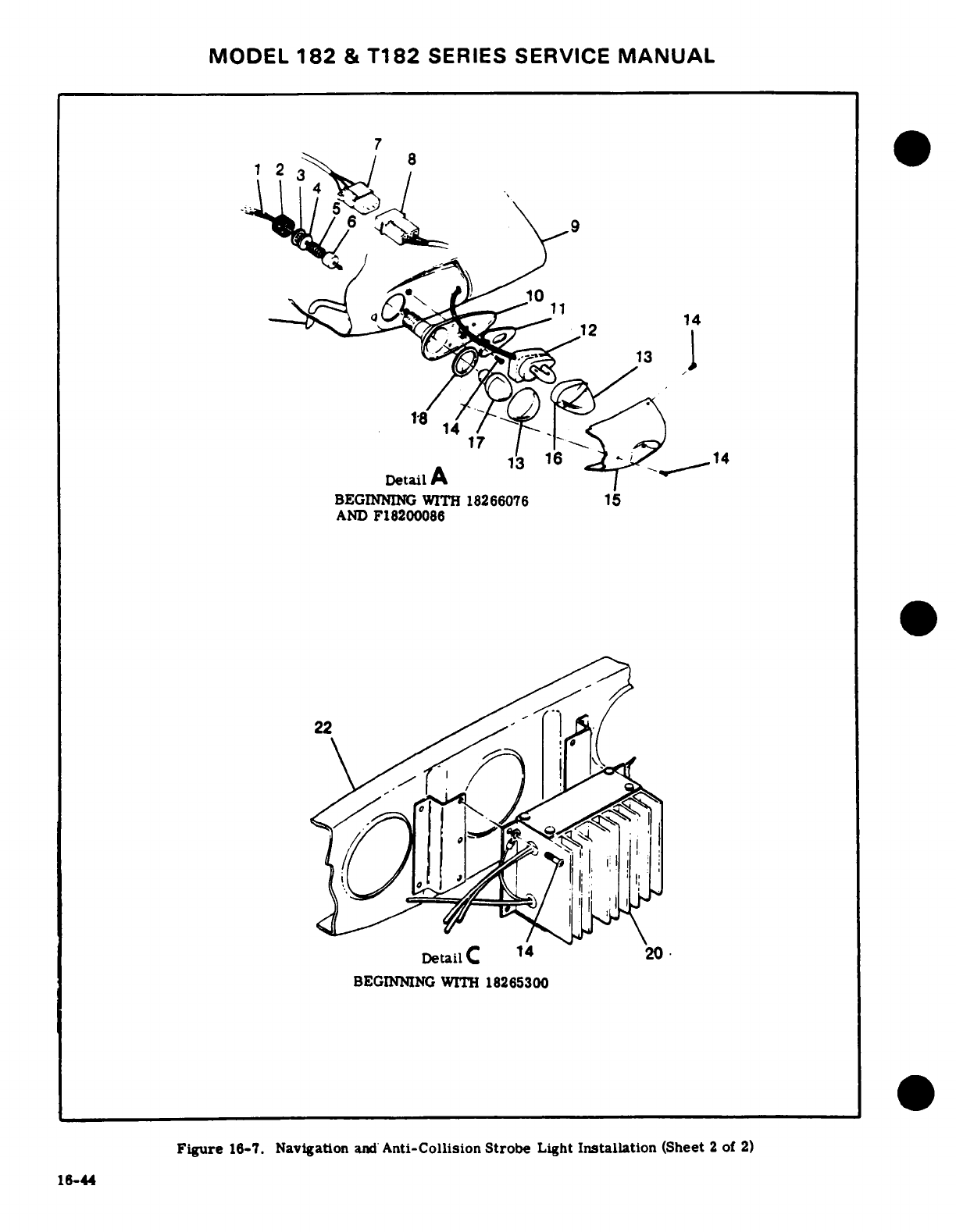
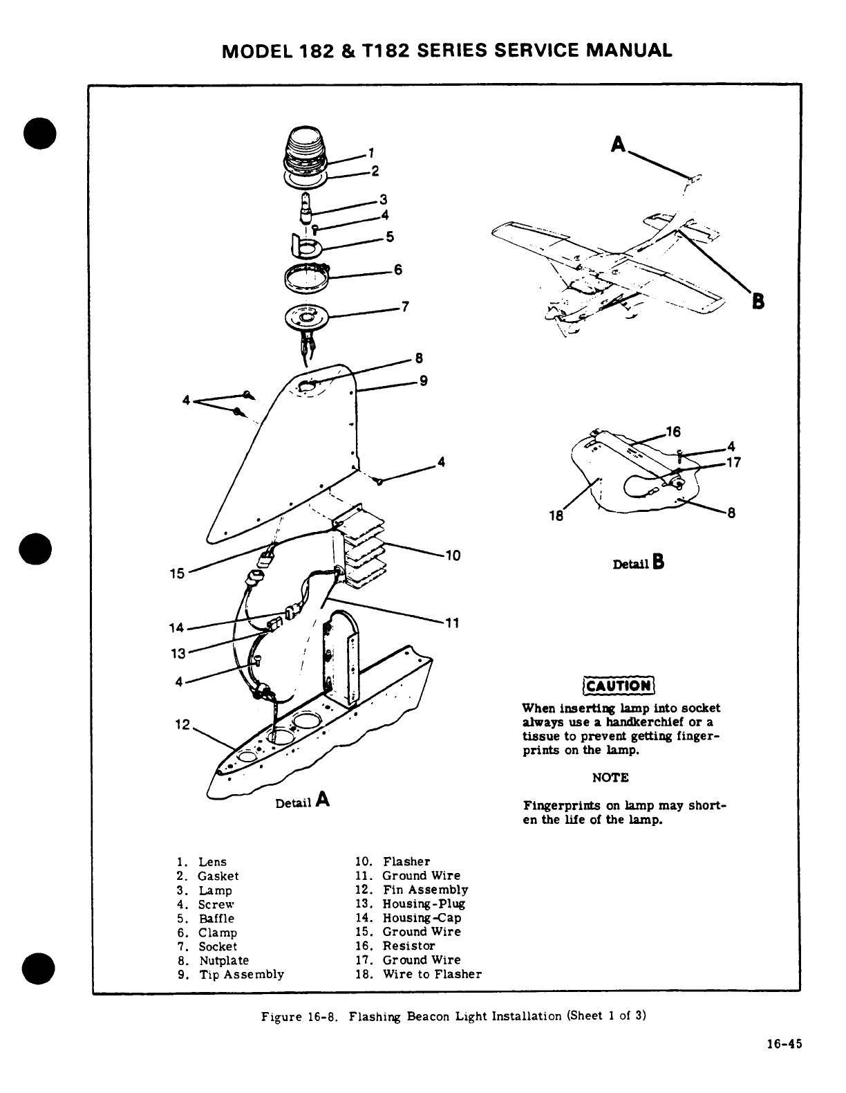
MODEL
182
&
T182
SERIES SERVICE
MANUAL
4
/
/
CAUTION
When
inserting
lamp
into
socket
12
-''j^^^ '
V
/ >always
use
a
handkerchief
or
a
tissue
to prevent
getting
finger-
'.;
J. /e
prints
on
the
lamp.
*~r^-
^y^^~
~~NOTE
Detail
A
Fingerprints
on
lamp may
short-
en
the life
of
the
lamp.
1.
Lens
10.
Flasher
2.
Gasket
11.
Ground
Wire
3.
Lamp
12.
Fin
Assembly
4.
Screw
13.
Housing-Plug
5.
Baffle
14.
Housing-Cap
6.
Clamp
15.
Ground Wire
7.
Socket
16.
Resistor
8.
Nutplate
17.
Ground
Wire
9.
Tip
Assembly
18.
Wire
to
Flasher
Figure
16-8.
Flashing
Beacon
Light
Installation
(Sheet
1
of
3)
16-45
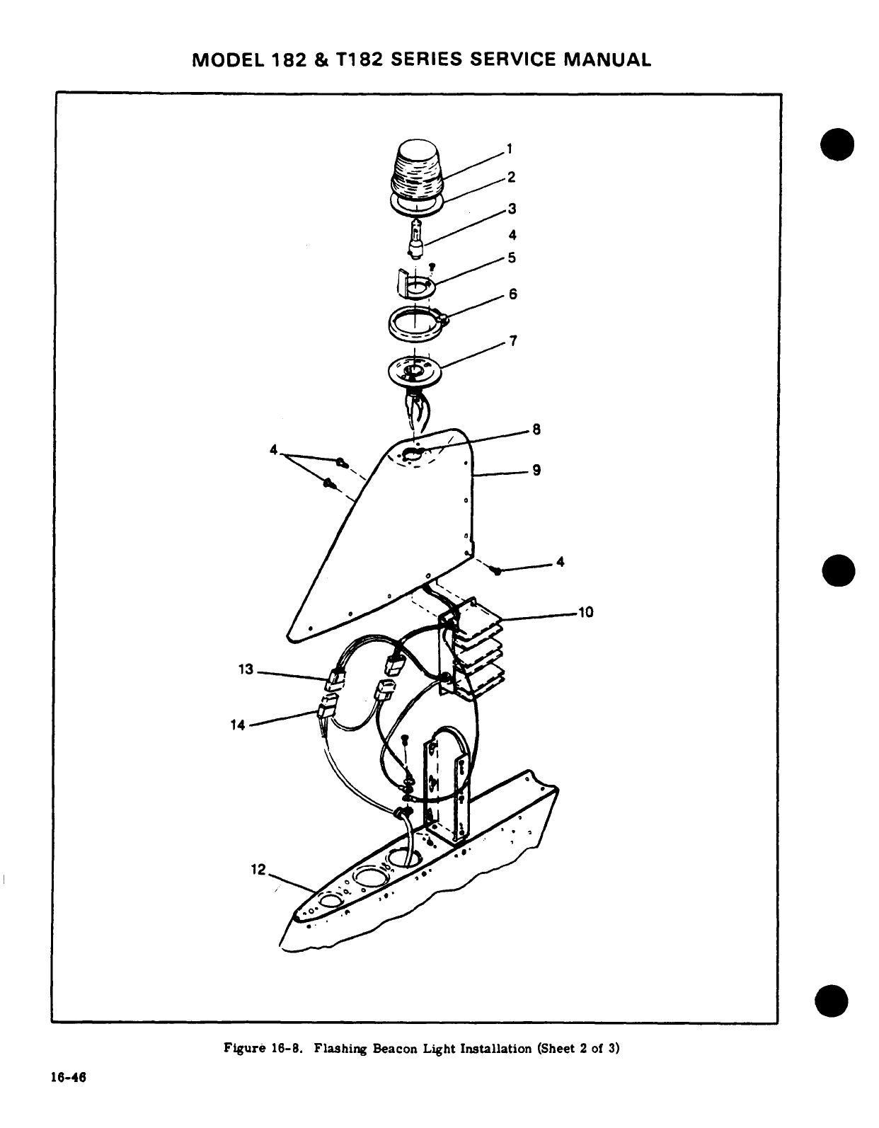
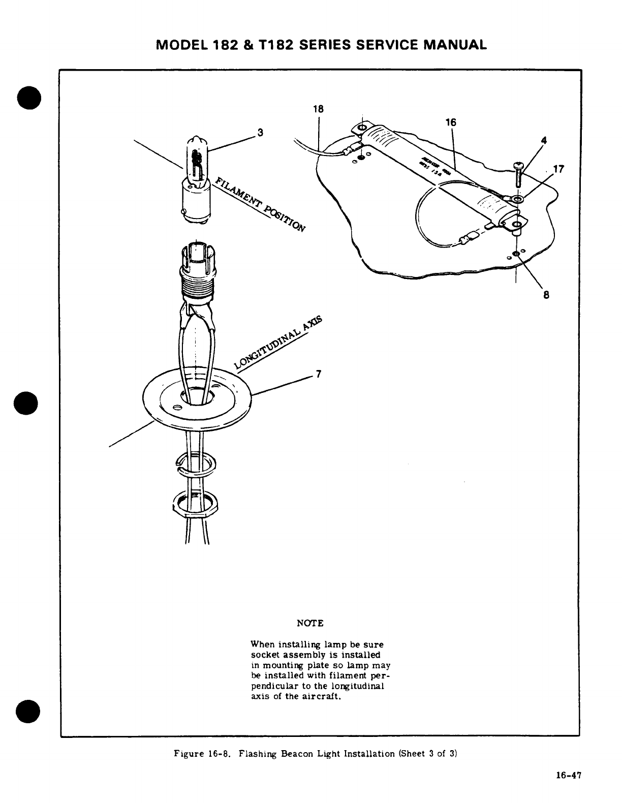
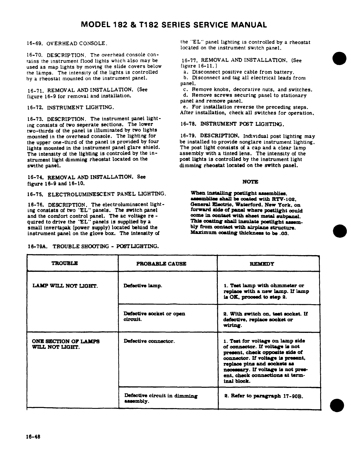
MODEL
182
&
T182
SERIES
SERVICE
MANUAL
16-69.
OVERHEAD
CONSOLE.
the
"EL"
panel
lighting
is
controlled
by
a
rheostat
located
on
the
instrument
switch
panel.
16-70.
DESCRIPTION.
The
overhead console
con-
tains
the
instrument
flood
lights
which
also
may
be
16-77.
REMOVAL
AND
INSTALLATION.
(See
used
as
map
lights
by
moving
the
slide
covers
below
figure
16-11.
)
the
lamps.
The
intensity
of
the
lights
is
controlled
a.
Disconnect
positive cable
from
battery.
by
a
rheostat
mounted
on
the
instrument
panel.
b.
Disconnect
and
tag
all
electrical
leads from
panel.
16-71.
REMOVAL
AND
INSTALLATION.
(See
c.
Remove
knobs,
decorative
nuts, and
switches.
figure
16-9
for
removal
and
installation.
d.
Remove
screws
securing
panel
to
stationary
panel
and
remove
panel.
16-72.
INSTRUMENT
LIGHTING.
e.
For installation
reverse
the
preceding
steps.
After
installation,
check
all
switches
for
operation,
16-73.
DESCRIPTION.
The
instrument
panel
light-
ing
consists
of
two
seperate
sections.
The
lower
16-78.
INSTRUMENT
POST
LIGHTING.
two-thirds
of
the
panel
is
illuminated
by two
lights
mounted
in
the
overhead
console.
The
lighting
for
16-79.
DESCRIPTION.
Individual
post
lighting
may
the
upper
one-third
of
the
panel
is
provided
by
four
be
installed
to
provide
nonglare
instrument
lighting.
lights
mounted
in
the
instrument
panel
glare
shield.
The
post
light
consists
of
a
cap
and
a
clear
lamp
The
intensity
of
the
lighting
is
controled
by
the
in-
assembly
with
a tinted
lens.
The
intensity
of
the
strument
light
dimming
rheostat
located
on
the
post lights
is
controlled
by
the
instrument
light
swithc panel. dimming
rheostat
located
on
the
switch
panel.
16-74.
REMOVAL
AND
INSTALLATION. See
figure
16-9
and
16-10.
NOTE
16-75.
ELECTROLUMINESCENT PANEL
LIGHTING.
When
installing
postlight
assemblies
assemblies
shall
be
coated
with
RTV-102,
16-76.
DESCRIPTION.
The
electroluminscent
light-
General Electric,
Waterford,
New
York.
on
ing
consists
of
two
"EL"
panels.
The
switch
panel
forward
side of
panel where
postlight
could
and
the
comfort control
panel.
The
ac
voltage
re
-
come
in
contact
with
sheet
metal
subpanel.
quired
to
drive
the "EL"
panels
is
supplied
by
a
This
coating
shall
insulate
postlight
assem-
small
invertapak
(power
supply)
located
behind
the
bly
from
contact
with
airplane
structure.
instrument
panel
on
the
glove
box.
The
intensity
of
Maximum
coating
thickness
to
be
.03.
16-79A.
TROUBLE
SHOOTING
-
POSTLIGHTING.
TROUBLE
PROBABLE
CAUSE
REMEDY
LAMP
WILL
NOT
LIGHT.
Defective
lamp.
1.
Test
lamp
with ohmmeter
or
replace
with
a
new
lamp.
is
OK,
roceed
to
step
2.
Defective
socket
or
open
2.
With
switch
on,
test
socket.
If
circuit.
defective,
replace
socket
or
wiring.
ONE SECTION
OF
LAMPS
Defective
connector.
1.
Test
for
voltage
on
lamp
side
WILL
NOT LIGHT.
of
onnector.
If
voltage
is
not
present,
check
opposite
side
of
connector.
If
voltage
is
present,
replace
pins
and
sockets
as
necessary. If
voltage
is
not pres-
ent.
check
connections
at
term-
inal
block.
Defective
circuit
in
dimming
2.
Refer
to
paragrph
17-90B.
assembly.
16-48
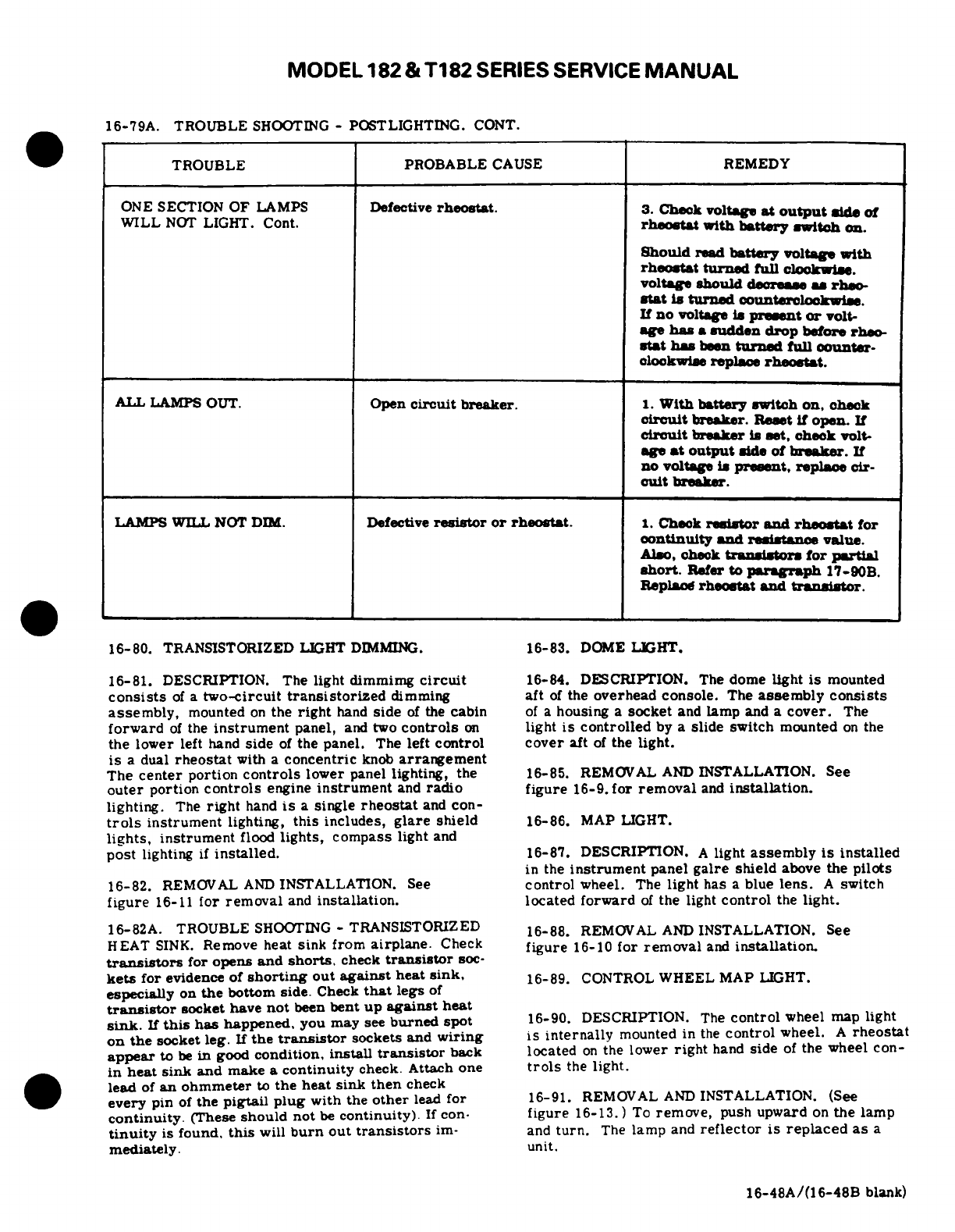
MODEL
182
&
T182
SERIES
SERVICE
MANUAL
16-79A.
TROUBLE
SHOOTING
-
POSTLIGHTING.
CONT.
ONE
SECTION
OF
LAMPS
Defective
rheostat.
3.
Check
voltage
at
output
side
of
WILL
NOT
LIGHT.
Cont.
rheostat
with
battery
switch on.
Should
read
battery
voltage
with
rheostat
turned
full
clockwise.
voltage
should
decrease
as
rheo-
stat
is
turned
counterclockwise.
If
no
voltage
is
present
or
volt-
age
has
a
sudden drop
before
rheo-
stat
has
been
turned
full
counter-
clockwise
replace
rheostat.
ALL LAMPS
OUT.
Open
circuit
breaker.
1.
With
battery
switch on,
check
circuit
breaker.
Reset
if
open.
If
circuit
breaker
is
set,
check volt-
age
at
output
side
of
breaker.
If
no
voltage
is
present,
replace
cir-
cuit
breaker.
LAMPS
WILL
NOT
DIM.
Defective
resistor
or rheostat.
1.
Check
resistor
and
rheostat
for
continuity
and
resistance
value.
Also,
check
transistors
for
partial
short.
Refer
to
paragraph
17-90B.
Replace
rheostat and
transistor.
16-80.
TRANSISTORIZED
LIGHT
DIMMING.
16-83.
DOME
LIGHT.
16-81.
DESCRIPTION.
The
light
dimming
circuit
16-84. DESCRIPTION.
The
dome
light
is
mounted
consists
of
a
two-circuit
transistorized
dimming
aft
of
the
overhead console.
The
assembly consists
assembly,
mounted
on
the
right
hand
side
of
the
cabin
of
a
housing
a
socket
and
lamp
and a
cover.
The
forward
of
the
instrument
panel,
and two
controls
on
light
is
controlled
by a
slide
switch
mounted
on
the
the
lower
left
hand
side
of
the
panel.
The
left
control cover
aft
of
the
light.
is
a
dual
rheostat
with
a
concentric
knob
arrangement
The
center
portion
controls
lower
panel
lighting,
the
16-85.
REMOVAL
AND
INSTALLATION. See
outer
portion
controls
engine
instrument
and
radio
figure
16-9.
for
removal
and
installation.
lighting.
The
right
hand
is
a
single
rheostat
and
con-
trols
instrument
lighting,
this
includes,
glare
shield
16-86.
MAP LIGHT.
lights,
instrument
flood
lights,
compass
light
and
post
lighting
if
installed.
16-87. DESCRIPTION.
A
light
assembly
is
installed
in
the
instrument
panel
galre
shield
above
the
pilots
16-82.
REMOVAL
AND
INSTALLATION.
See
control
wheel.
The
light
has
a
blue
lens.
A
switch
figure
16-11
for
removal
and
installation.
located forward
of
the
light
control
the
light.
16-82A.
TROUBLE
SHOOTING
-
TRANSISTORIZED
16-88.
REMOVAL
AND
INSTALLATION.
See
HEAT
SINK.
Remove heat
sink from
airplane.
Check
figure
16-10
for
removal
and
installation.
transistors
for
opens
and
shorts,
check
transistor
soc-
kets
for
evidence of
shorting
out
against
heat
sink,
16-89.
CONTROL
WHEEL
MAP
LIGHT.
especially
on
the
bottom
side.
Check
that
legs
of
transistor
socket
have
not
been
bent
up
against
heat
sink.
If
this
has
happened,
you
may
see
burned
spot
16-90.
DESCRIPTION.
The
control
wheel
map
light
on
the
socket
leg.
If
the
transistor
sockets and
wiring
is
internally
mounted in
the
control
wheel.
A
rheostat
appear
to
be
in
good
condition,
install
transistor
back
located
on
the
lower
right
hand
side
of
the
wheel
con-
in
heat
sink
and
make
a
continuity
check.
Attach
one
trols
the
light.
lead
of
an
ohmmeter
to
the heat
sink then
check
every
pin
of
the
pigtail
plug
with
the
other
lead
for
16-91.
REMOVAL
AND
INSTALLATION.
(See
continuity.
(These
should
not
be
continuity).
If
con-
figure
16-13.)
To
remove,
push
upward
on
the
lamp
tinuity
is
found,
this
will
burn
out
transistors
im-
and
turn.
The
lamp
and
reflector
is
replaced
as
a
mediately,
unit.
16-48A/(16-48B
blank)
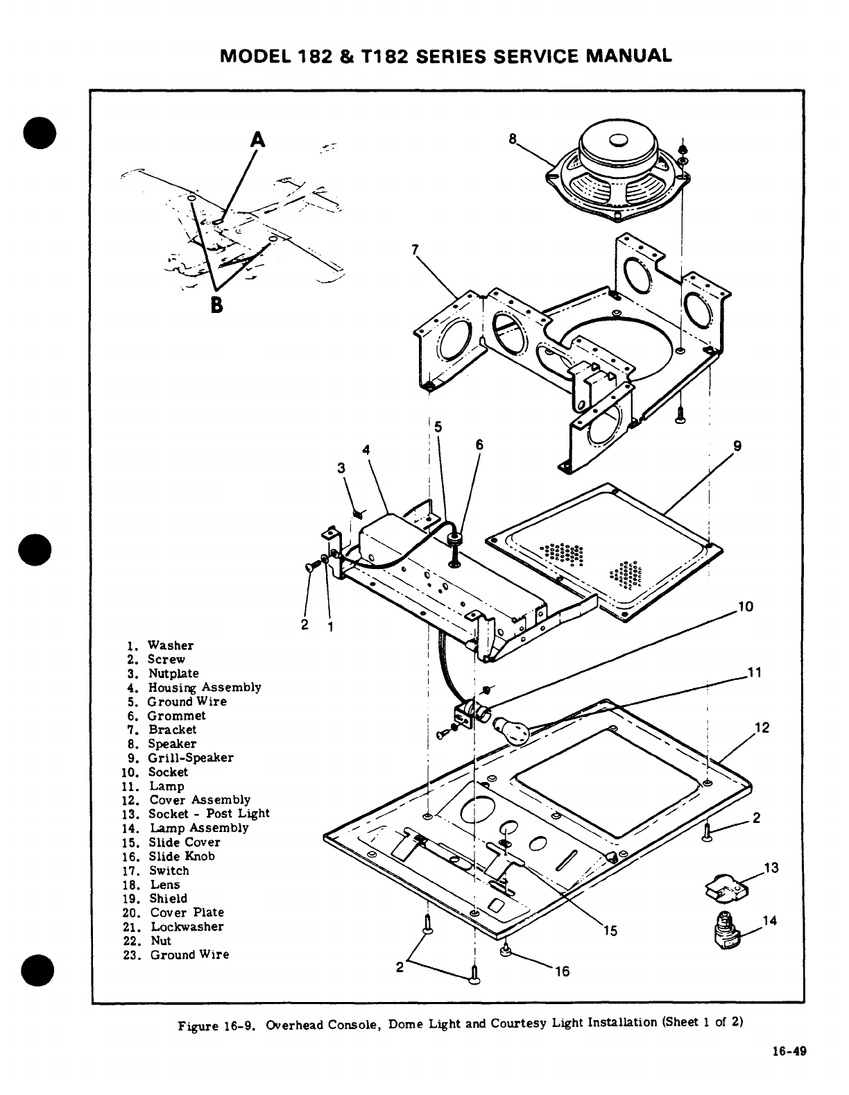
MODEL
182
&
T182
SERIES SERVICE
MANUAL
*
A
.
: 8,
2
/
10
1.
Washer
2.
Screw
3.
Nutplate
11
4. Housing
Assembly
5.
Ground
Wire
6.
Grommet
7.
Bracket
12
8.
Speaker
9.
Grill-Speaker
10.
Socket
11.
Lamp
12.
Cover
Assembly
/
13.
Socket
-
Post
Light
2
14.
Lamp
Assembly
15.
Slide
Cover.
16.
Slide
Knob
17.
Switch
13
18.
Lens
19.
ShieldK
20.
Cover
Plate
21.
Lockwasher
15
22. Nut
23.
Ground
Wire
2
¢
-16
Figure
16-9.
Overhead
Console,
Dome
Light
and
Courtesy
Light
Installation
(Sheet
1
of
2)
16-49
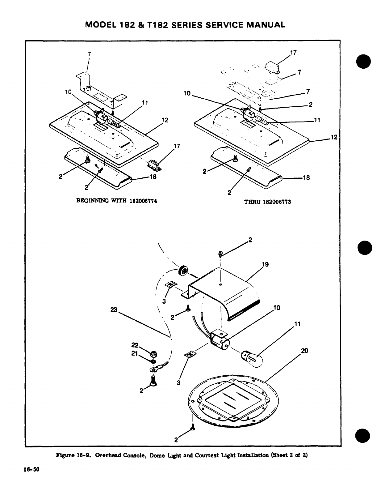
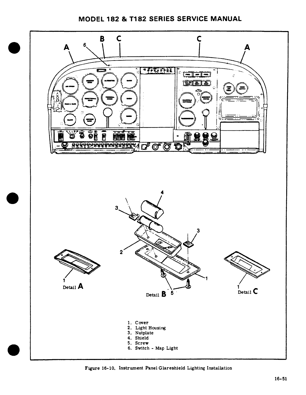
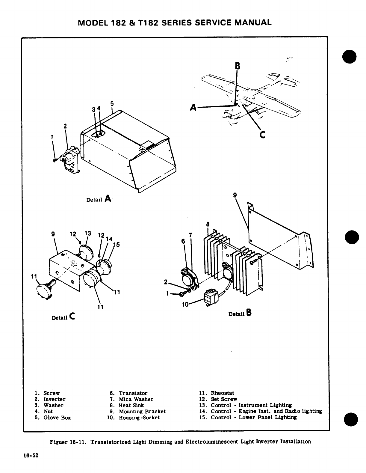
MODEL
182
&
T182
SERIES
SERVICE
MANUAL
11
Detail
C
1.
Screw
6.
Transistor
11.
Rheostat
2.
Inverter
7.
Mica
Washer
12.
Set
Screw
3.
Washer
8.
Heat
Sink
13.
Control
-
Instrument
Lighting
4.
Nut
9.
Mounting
Bracket
14.
Control
- Engine
Inst.
and Radio
lighting
5.
Glove
Box
10.
Housing-Socket
15.
Control
-
Lower
Panel
Lighting
Figuer
16-11.
Transistorized
Light
Dimming
and
Electroluminescent
Light
Inverter
Installation
16-52
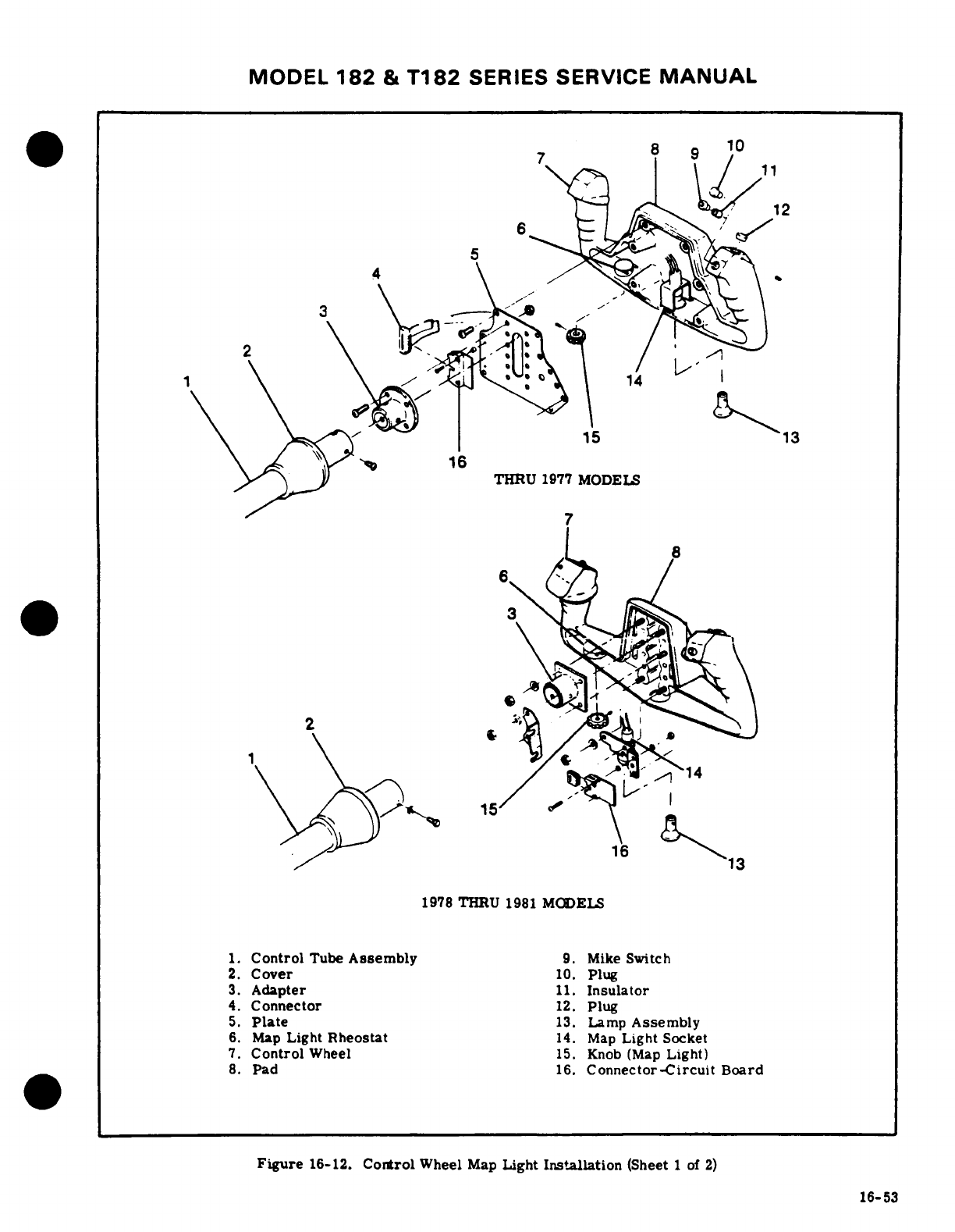
MODEL
182
&
T182
SERIES SERVICE
MANUAL
4.
Connector
12,
P
g12
3
7.
15
13
16
THRU
1977
MODELS
2\
' "'
1 14
15
13
1978
THRU
1981
MODELS
1.
Control
Tube
Assembly
9.
Mike
Switch
2.
Cover
10.
Plug
3.
Adapter
11.
Insulator
4.
Connector
12.
Plug
5.
Plate
13.
Lamp
Assembly
6.
Map
Light
Rheostat
14.
Map
Light
Socket
7.
Control
Wheel
15.
Knob (Map
Light)
8.
Pad
16.
Connector-Circuit
Board
Figure
16-12.
Control
Wheel
Map
Light
Installation
(Sheet 1
of
2)
16-53
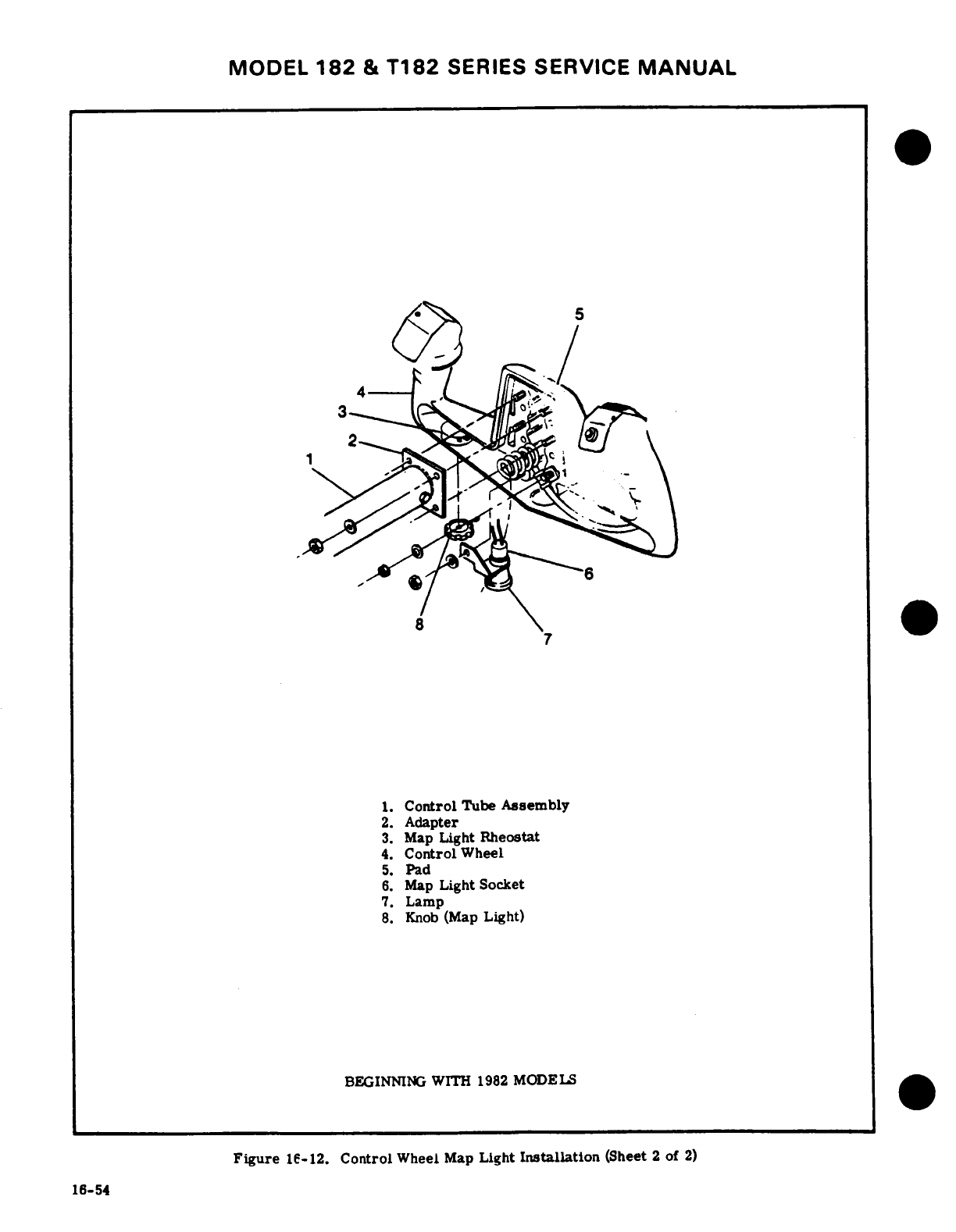
MODEL
182
&
T182
SERIES
SERVICE
MANUAL
16-92.
PEDESTAL
LIGHTING.
16-97.
PITOT
AND
STALL
WARNING
HEATERS.
16-93.
DESCRIPTION.
The
pedestal
lighting
con-
16-98.
DESCRIPTION.
Electrical
heater
units
are
sists
of
two
lights.
One on
the
upper
poriotn
of
the
incorporated
in
some
pitot
tubes
and
stall
warning
pedestal
for
lighting
of
the
trim
wheels
and
the
cowl
switch
units.
The
heaters
offset the
possibility
of
flap
control.
One
on
the lower
portion
for
lighting
ice
formations
on
the
pitot
tube and
stall
warning
of
the
fuel
selector.
Light
dimming
is
controled
by
actuator
switch.
The
heaters
are
integrally
mounted
the
transistorized
light
dimming
circuit.
in
the
pitot
tube and
the
stall
warning
actuator
switch.
Both
heaters
are
operated
by
the pitot
heat
switch.
16-94.
REMOVAL
AND
INSTALLATION.
For
removal
and
installation
of
the
lamps
see
figure
16-13.
16-99.
CIGAR
LIGHTER.
16-95.
STALL
WARNING
SYSTEM.
16-100.
DESCRIPTION.
The
cigar
lighter
(located
on
the
instrument
panel)
is
equipped
with
a
thermal-
16-96.
DESCRIPTION.
The
stall
warning
circuit
is
actuated
circuit
breaker
which
is
attached to the
rear
comprised
of
a
warning
horn
and an
actuating
switch
of
the
cigar lighter.
The
circuit
breaker
will
open
if
The
switch
is
installed
in
the
leading
edge
of
the
left
the
lighter
becomes
jammed
in
the
socket
or
held
in
wing
and
is
actuated
by
airflow
over the
surface
of
position
too
long.
The
circuit
breaker
may
be
reset
the
wing.
The
switch will
close
as
a
stall
condition
by
inserting
a
small
probe
into
the
.078
diameter
is
approached,
actuating
the
warning
horn
which
is
hole
in
the
back
of
the
circuit
breaker
and
pushing
mounted
on
the
glove
box.
The
stall
warning
unit
lightly until
a
click
is
heard.
should
actuate the
stall
warning
horn
approximately
five to
ten
miles
per
hour
above
the
airplane
stall
speed.
Install
the
lip
of
the warning
unit approxi-
mately
one-sixteenth
of
an
inch
below
the
centerline
Make
sure
the
master
switch
is
"OFF" before
of
the
wing
skin
cutout.
Test
fly
the
aircraft
to
inserting
probe into
the
circuit
breaker
on
determine
if
the
unit
actuates
the
warning
horn
at
the
cigar
lighter
to
reset.
desired
speed.
If
the
unit
actuates
the warning
horn
at
a
speed
in
excess
of
ten
miles
per
hour
above
stall
16-101.
REMOVAL
AND
INSTALLATION.
(See
speed, loosen
the
mounting
screws
and
move
the
unit
figure
16-15.)
down.
If
the
unit
actuates
the
horn
five
miles
per
a.
Ensure
that
the
master
switch
is
"OFF."
hour
below
stall
speed,
loosen
the
mounting
screws
b.
Remove
cigar
lighter
element.
and
move
the
unit
up.
c.
Disconnect
wire
on
back
of
lighter.
d.
Remove
shell
that
screws
on
socket
back
of
panel.
e.
The
socket
will
then
be
free for
removal.
f. To
install
a
cigar
lighter,
reverse
this pro-
cedure.
SHOP NOTES:
16-55
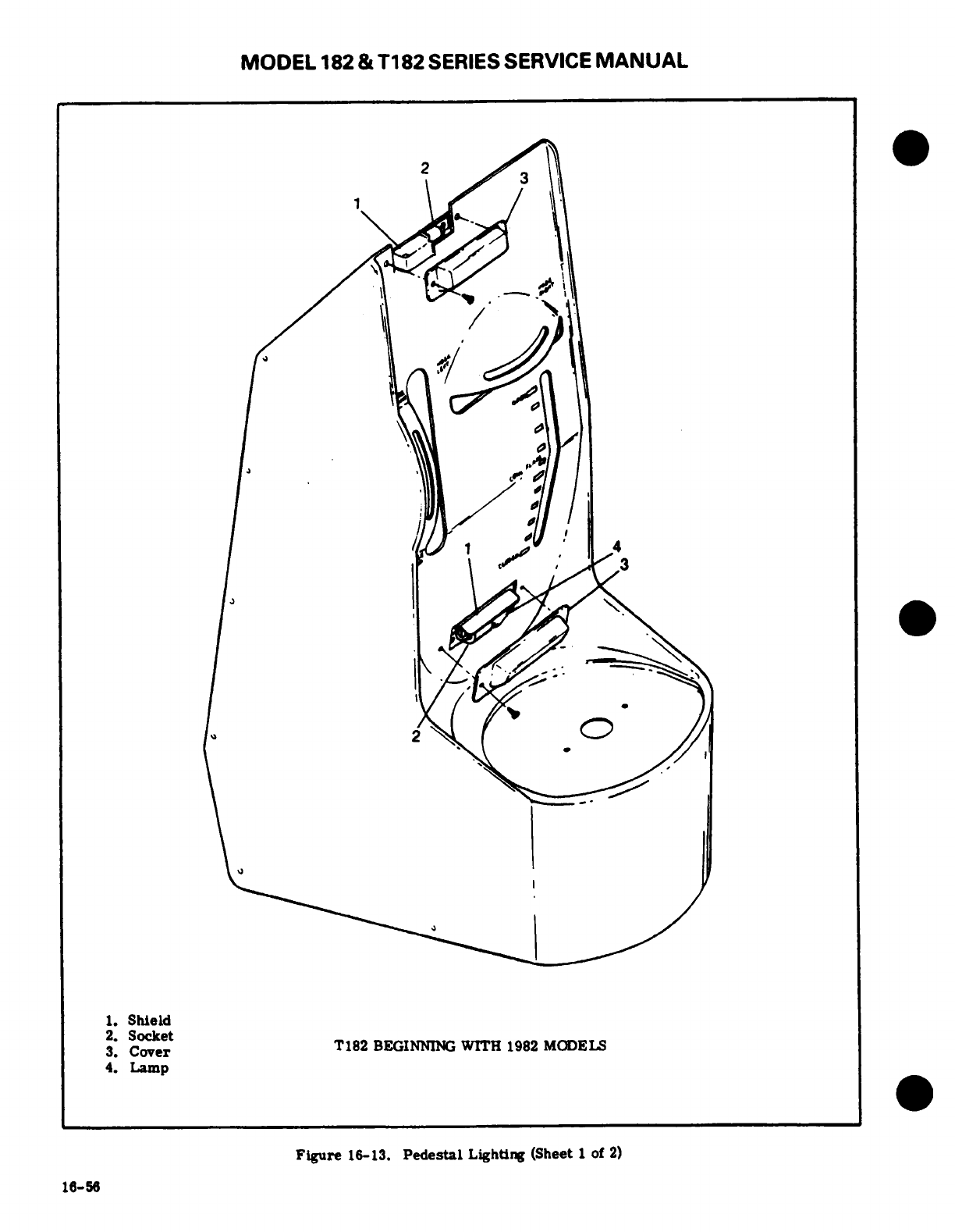
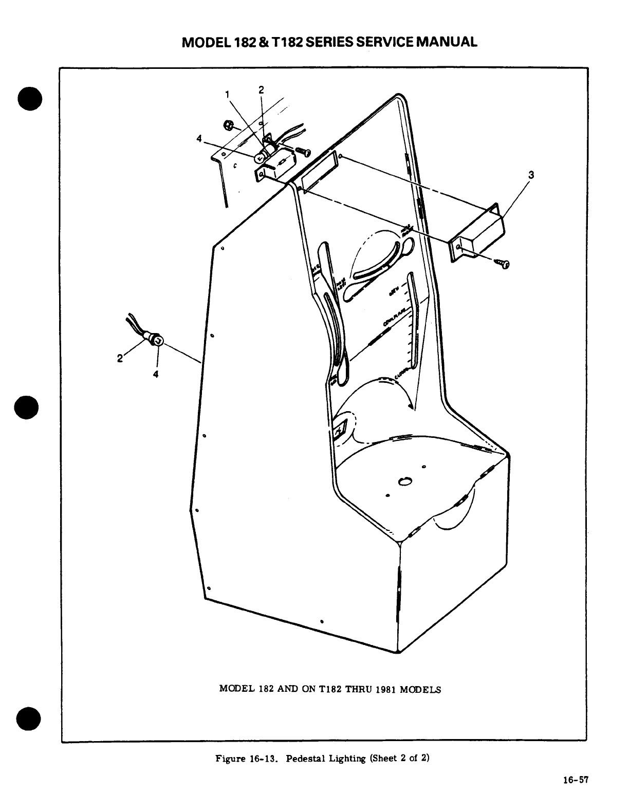
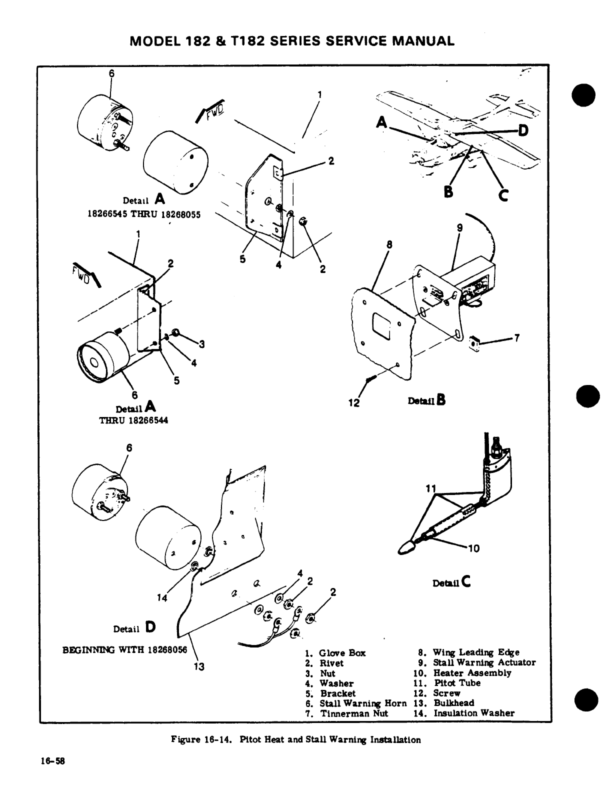
MODEL
182
&
T182
SERIES
SERVICE
MANUAL
2
DetailA
18266545 THRU
18268055
DetilA
THRU
18266544
10
DetailD
BEGINNING
WITH
18268056
1.
Glove
Box
8.
Wing
Leading
Edge
13
2.
Rivet
9.
Stall
Warning
Actuator
3.
Nut
10.
Heater Assembly
4.
Washer
11.
Pitot
Tube
5.
Bracket
12.
Screw
6.
Stall
Warning
Horn
13.
Bulkhead
7.
Tinnerman
Nut
14.
Insulation Washer
Figure
16-14.
Pitot
Heat
and
Stall
Warning
Installation
16-58
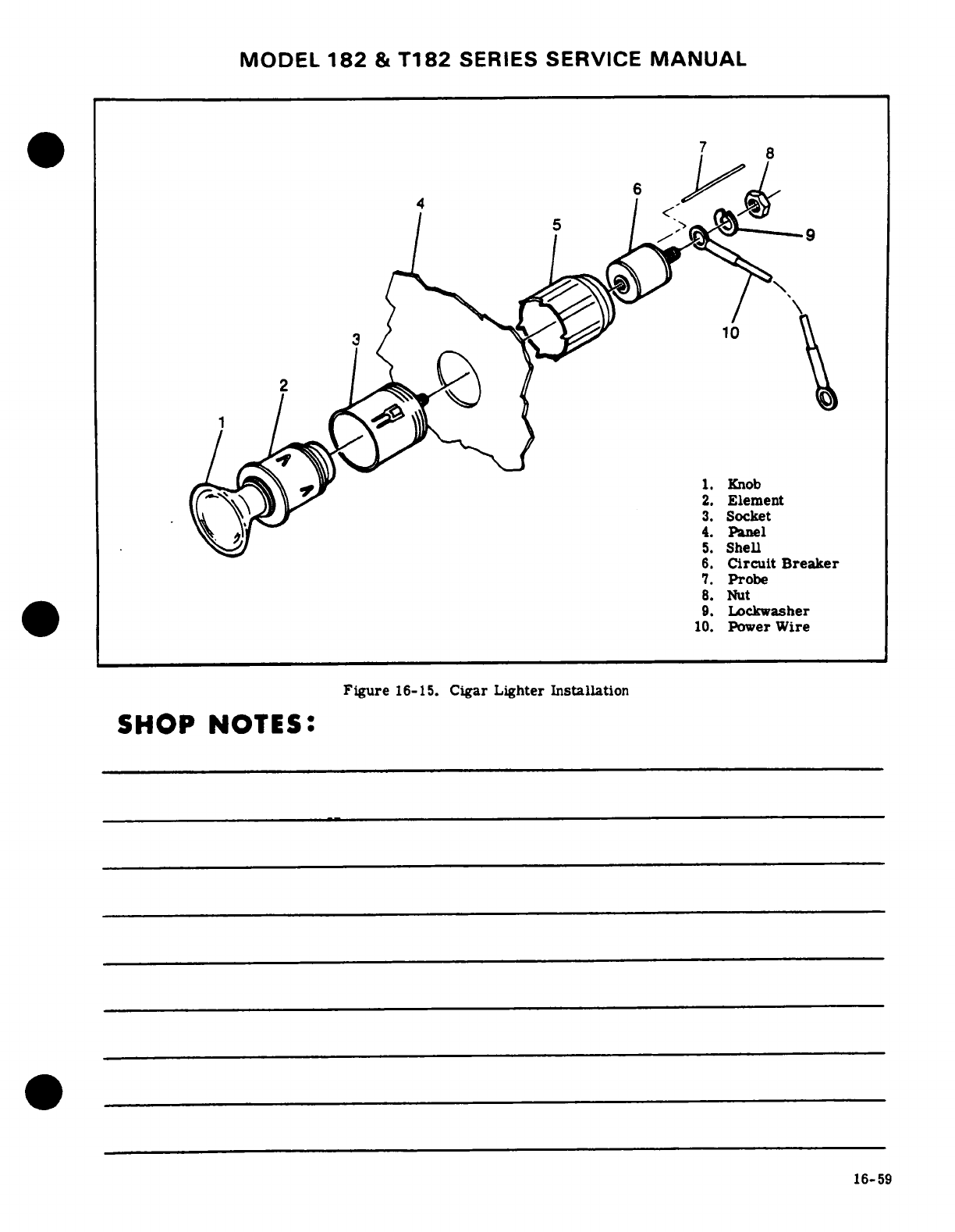
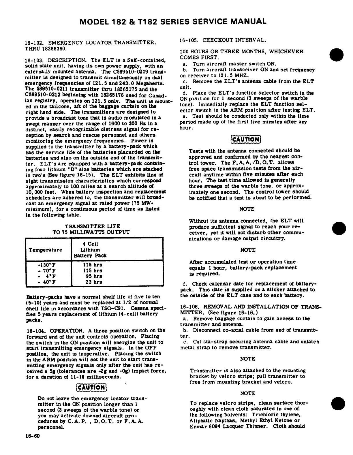
MODEL
182
&
T182
SERIES
SERVICE
MANUAL
16-102.
EMERGENCY LOCATOR
TRANSMITTER.
16-105.
CHECKOUT
INTERVAL.
THRU
18265360.
100
HOURS
OR
THREE
MONTHS,
WHICHEVER
16-103.
DESCRIPTION.
The
ELT is
a
Self-contained,
COMES
FIRST.
solid
state
unit,
having
its
own
power
supply,
with
an
a.
Turn
aircraft
master
switch
ON.
externally
mounted
antenna.
The
C589510-0209
trans-
b.
Turn
aircraft
transceiver
ON
and
set
frequency
mitter
is
designed
to
transmit
simultaneously
on
dual
on
receiver
to
121.
5
MHZ.
emergency
frequencies
of
121.
5
and
243.0
Megahertz.
c.
Remove
the
ELT's
antenna
cable
from
the
ELT
The
589510-0211
transmitter
thru
18265175
and
the
unit.
C589510-0212 beginning
with
18265176
used
for
Canad-
d.
Place
the
ELT's
function
selector
switch
in
the
ian
registry,
operates
on
121.
5
only.
The unit
is
mount-
ON
position
for
1
second
(3
sweeps
of
the
warble
ed
in
the
tailcone,
aft
of
the
baggage
curtain
on
the
tone).
Immediatly
replace
the ELT
function
sel-
right
hand
side.
The
transmitters
are
designed to
ector
switch
in
the
ARM
position
after
testing
ELT.
provide
a
broadcast
tone
that
is
audio
modulated
in
a
e.
Test
should
be
conducted
only
within
the
time
swept
manner
over
the
range
of
1600
to
300
Hz
in
a
period
made
up
of
the
first
five
minutes
after
any
distinct,
easily
recognizable
distress
signal for
re-
hour.
ception
by
search
and
rescue
personnel
and
others
monitoring
the
emergency
frequencies.
Power
is
supplied
to
the
transmitter
by
a
battery-pack
which
has
the
service
life
of
the
batteries
placarded
on
the
Tests
with
the
antenna
connected should
be
batteries
and
also
on
the
outside
end
of
the
transmit-
approved
and
confirmed
by
the
nearest
con-
ter.
ELT's
are
equipped with
a
battery-pack
contain-
trol
tower.
The
F.A.A./D.
O.T.
allows
ing
four
lithium
"D"
size
batteries
which
are
stacked
free
space
transmission
tests
from
the
air-
in
two's
(See
figure
16-15).
The
ELT
exhibits
line
of
craft
anytime
within five
minutes
after
each
sight
transmission
characteristics
which
correspond
hour. The
test
time
allowed
is
generally
approximately
to
100
miles at
a
search
altitude
of
three
sweeps
of
the
warble
tone,
or
approx-
10,
000
feet.
When
battery
inspection
and
replacement
imately
one
second.
The
control
tower
should
schedules
are
adhered
to,
the
transmitter
will
broad-
be
notified
that
a
test
is
about
to
be
performed.
cast
an
emergency
signal
at
rated
power
(75
MW-
minimum),
for
a
continuous
period
of
time
as listed
NOTE
in the
following
table.
Without
its
antenna connected,
the
ELT
will
TRANSMITTER
LIFE
produce
sufficient
signal
to
reach
your
re-
TO
75
MILLIWATTS
OUTPUT
ceiver,
yet
it
will
not
disturb
other
commu-
Temperature
Lithium
NOTE
Battery
Pack
+130°F
115
hrs
After
accumulated
test
or
operation
time
+
70°F
115
hrs
equals
1
hour,
battery-pack
replacement
-
4°F
95
hrs
is
required.
-
40°F
23
hrs
f.
Check
calendar
date
for
replacement
of
battery-
pack.
This
date
is
supplied
on
a
sticker
attached
to
Battery-packs
have
a
normal
shelf
life
of
five
to
ten the
outside
of
the
ELT
case
and
to
each
battery.
(5-10)
years
and
must
be
replaced
at
1/2
of
normal
shelf
life
in
accordance
with
TSO-C91.
Cessna speci-
16-106.
REMOVAL
AND
INSTALLATION OF
TRANS-
fies
5
years
replacement
of
lithium
(4-cell)
battery
MITTER.
(See
figure
16-16.)
packs. a.
Remove
baggage
curtain
to
gain
access
to
the
transmitter
and
antenna.
16-104.
OPERATION.
A
three
position
switch
on
the
b.
Disconnect
co-axial
cable
from
end
of
transmit-
forward
end
of
the
unit
controls
operation.
Placing
ter.
the switch
in
the
ON
position
will
energize
the
unit to
c.
Cut
sta-strap
securing
antenna
cable
and
unlatch
start
transmitting
emergency
signals.
In
the
OFF
metal
strap
to
remove
transmitter.
position,
the unit
is
inoperative. Placing
the
switch
in
the
ARM
position
will
set
the
unit
to
start
trans-
NOTE
mitting
emergency
signals
only
after
the
unit
has
re-
ceived
a
5g
(tolerances
are
+2g
and
-0g)
impact
force,
Transmitter
is
also
attached
to the
mounting
for
a
duration
of
11-16
milliseconds.
bracket
by
velcro
strips;
pull
transmitter
to
free
from
mounting
bracket
and
velcro.
NOTE
Do
not
leave
the
emergency
locator
trans-
mitter
in
the
ON
position
longer than
1
To
replace
velcro
strips,
clean
surface
thor-
second
(3
sweeps
of
the
warble
tone)
or
oughly
with
clean
cloth
saturated
in
one
of
you
may
activate
downed
aircraft
pro-
the
following
solvents:
Trichloric
thylene,
cedures
by
C.
A.
P.
,
D.O.T.
or
F.A.A.
Aliphatic
Napthas,
Methyl
Ethyl
Ketone
or
personnel.
Enmar
6094
Lacquer
Thinner.
Cloth
should
16-60
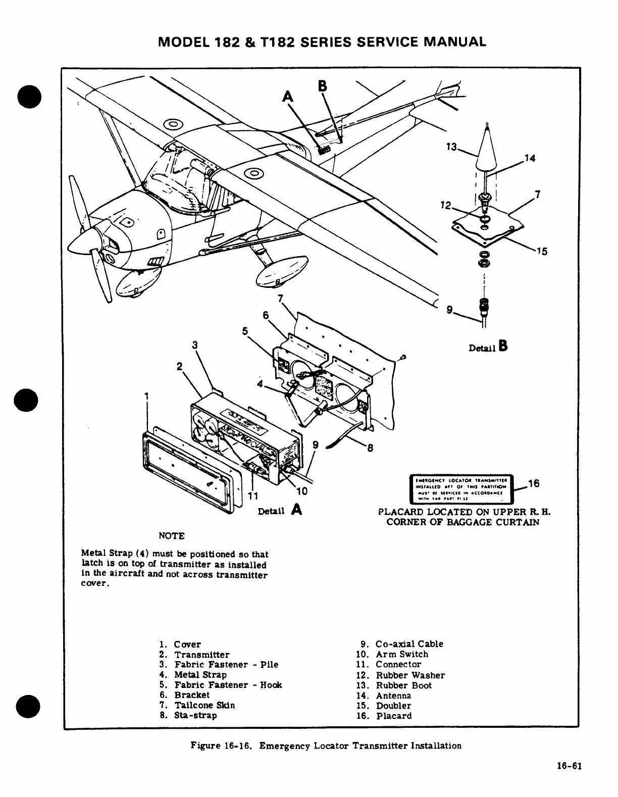
MODEL
182
&
T182
SERIES SERVICE
MANUAL
7
> ii 1X
l Strp () mst
DetailB
in the aircraft locoross
transmitter
1.
Cover
9.
Co-axal
|Cable
I
O
2. Transmitter 10.
Arm
Switch
3. F c
Detail
A
PLACAR
LOCATED
ON
UPER
R.
H.
CORNER
OF
BAGGAGE
CURTAIN
NOTE
Metal
Strap
(4)
must
be
positioned
so
that
latch
is
on
top
of
transmitter
as
installed
in
the
aircraft
and
not
across
transmitter
cover.
1.
Cover
9.
Co-axial
Cable
2.
Transmitter
10.
Arm
Switch
3.
Fabric
Fastener
-
Pile
11.
Connector
4.
Metal
Strap
12.
Rubber
Washer
5.
Fabric
Fastener
-
Hook
13.
Rubber
Boot
6.
Bracket
14.
Antenna
7.
Tailcone
Skin
15.
Doubler
8.
Sta-strap
16.
Placard
Figure
16-16.
Emergency Locator
Transmitter
Installation
16-61
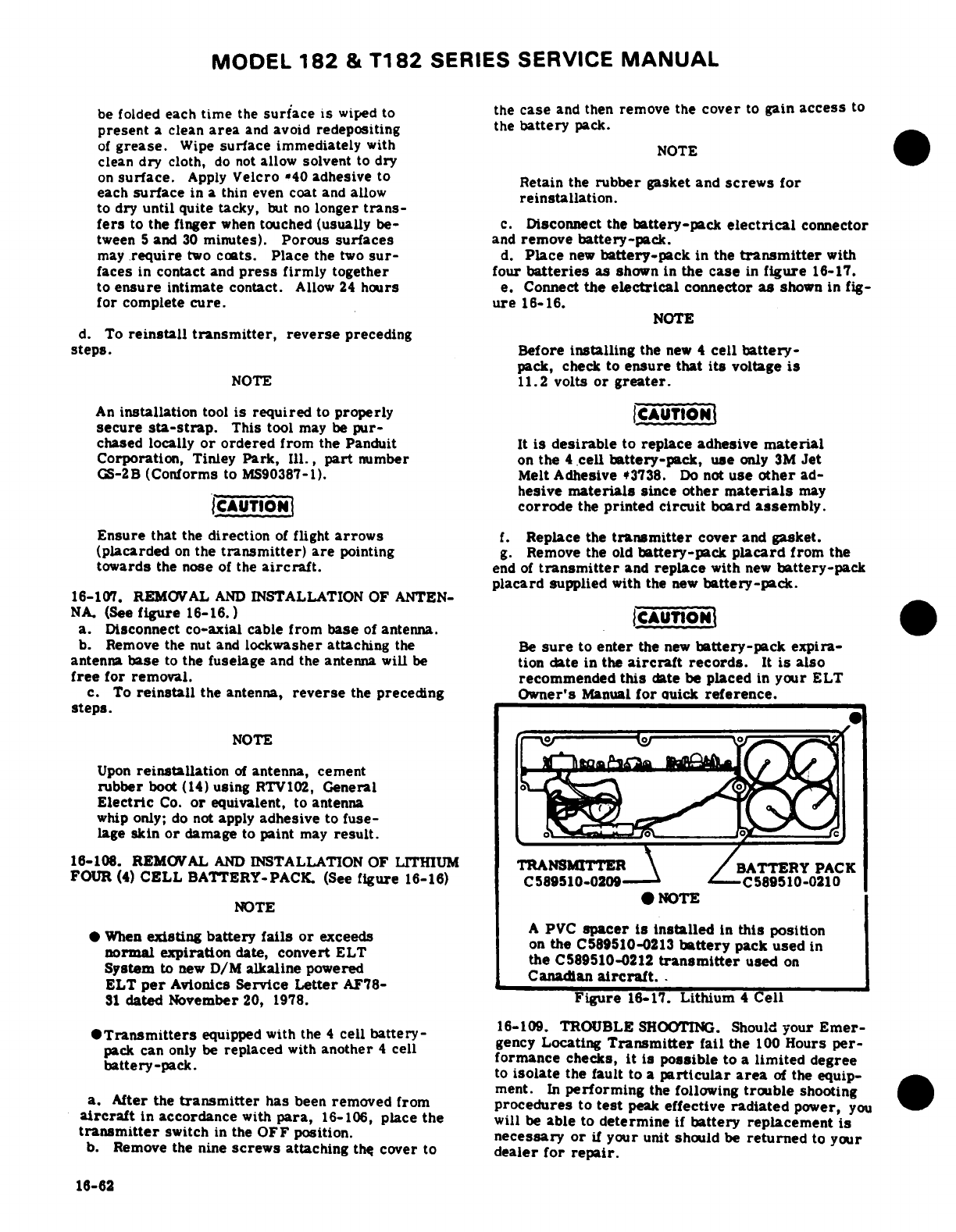
MODEL
182
&
T182
SERIES
SERVICE
MANUAL
be
folded each
time
the
surface
is
wiped
to the
case
and then
remove
the
cover
to
gain
access
to
present
a
clean
area
and
avoid
redepositing
the
battery
pack.
of
grease.
Wipe
surface
immediately
with
NOTE
clean
dry
cloth,
do
not
allow
solvent
to
dry
on
surface.
Apply
Velcro
.40
adhesive
to
Retain the
rubber
gasket
and
screws
for
each
surface
in
a
thin
even
coat
and allow
reinstallation
to
dry
until
quite
tacky,
but
no
longer
trans-
fers
to
the
finger
when
touched
(usually
be-
c.
Disconnect
the
battery-pack
electrical
connector
tween
5
and
30
minutes).
Porous
surfaces
and
remove
battery-pack.
may
require
two
coats.
Place
the
two
sur-
d.
Place
new
battery-pack
in
the
transmitter
with
faces
in
contact
and
press
firmly
together
four
batteries
as
shown
in
the
case
in
figure
16-17.
to
ensure
intimate
contact.
Allow
24
hours
e.
Connect
the
electrical
connector
as
shown in
fig-
for
complete
cure.
ure
16-16.
NOTE
d.
To
reinstall
transmitter,
reverse
preceding
steps.
Before
installing
the
new
4
cell
battery-
pack, check
to
ensure
that
its
voltage
is
NOTE
11.2
volts
or
greater.
An
installation
tool
is
required
to
properly
secure
sta-strap.
This
tool
may
be
pur-
chased
locally
or
ordered
from
the
Panduit
It
is
desirable
to
replace
adhesive
material
Corporation,
Tinley
Park,
Ill.,
part
number
on
the
4
cell
battery-pack,
use
only
3M
Jet
GS-2B
(Conforms
to
MS90387-1).
Melt
Adhesive
3738.
Do
not
use
other
ad-
hesive
materials
since
other
materials
may
Ensure
that
the
direction
of
flight
arrows
f.
Replace
the
transmitter
cover
and
gasket.
(placarded
on
the
transmitter)
are
pointing
g.
Remove the
old
battery-pack
placard
from
the
towards
the
nose
of
the
aircraft.
end
of
transmitter
and
replace
with
new
battery-pack
placard
supplied
with
the
new
battery-pack.
16-107.
REMOVAL
AND
INSTALLATION OF ANTEN-
NA.
(See
figure
16-16.
)
a.
Disconnect
co-axial
cable
from
base
of
antenna.
- --
b.
Remove
the
nut
and
lockwasher attaching
the
Be
sure
to
enter
the
new
battery-pack
expira-
antenna
base
to
the
fuselage
and
the
antenna will
be
tion
date
in
the
aircraft
records.
It
is
also
free
for
removal. recommended
this
date
be
placed
in
your
ELT
c.
To
reinstall
the
antenna,
reverse
the
preceding
Owner's
Manual
for
ouick
reference.
steps.
NOTE
Upon
reinstallation
of
antenna,
cement
rubber
boot
(14)
using
RTV102,
General
Electric
Co.
or
equivalent,
to
antenna
whip
only;
do
not
apply
adhesive
to
fuse-
lage
skin
or
damage
to
paint
may
result.
16-108.
REMOVAL
AND
INSTALLATION
OF
LITHIUMTRANSMITTER
BATTERY
PACK
FOUR
(4)
CELL
BATTERY-PACK.
(See
figure
16-16) C589510-0209
NOTE
A
PVC
spacer
is
installed
In
this
position
When
existing
battery
fails
or
exceeds
normal
expiration
date,
convert
ELT
System
to
new
D/M
alkaline
powered
ELT
per
Avionics
Service
Letter
AF78-
31
dated
November
20,
1978.
Figure
16-17.
Lithium
4
Cell
Transmitters
equipped
with
the
4
cell
battery-
16-109.
TROUBLE
SHOOTING.
Should
your
Emer-
pack
can
only
be
replaced
with
another
4
cell gency
Locating
Transmitter
fail
the
100
Hours
per-
battery-pack.
formance
checks,
it
is
possible to
a
limited
degree
ment.
In
performing
the
following
trouble
shooting
a.
After
the
transmitter
has
been
removed
from
procedures
to
test
peak
effective
radiated
power,
you
aircraft
in
accordance
with
para,
16-106,
place
the
will
be
able
to
determine
if
battery
replacement
is
transmitter
switch
in
the
OFF
position.
necessary
or
if
your
unit
should
be
returned
to
your
b.
Remove
the
nine
screws
attaching
the
cover
to
dealer for
repair.
16-62
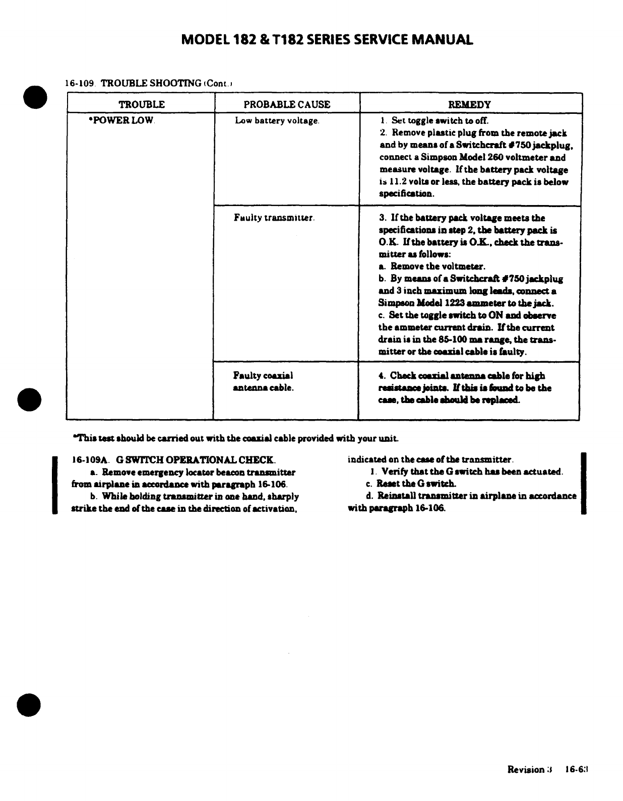
MODEL
182
&T182
SERIES
SERVICE
MANUAL
16-109
TROUBLE
SHOOTING
(Cont)
TROUBLE
PROBABLE
CAUSE
REMEDY
*POWER
LOW
Low
battery
voltage.
1.
Set
toggle
switch
to
off.
2.
Remove
plastic
plug
from
the
remotejack
and
by
means
of
a Switchcraft
750
jackplug,
connect
a
Simpson
Model
260
voltmeter
and
measure
voltage.
If
the
battery
pack
voltage
is
11.2
volts
or
less,
the
battery
pack
is
below
specification.
Faulty
transmitter
3.
If
the
battery
pack
voltage
meets
the
specifications
in
step
2,
the
battery
pack
is
O.K.
If
the
battery
is
O.K.
check
the
trans-
mitter
as
follows:
a.
Remove
the
voltmeter.
b.
By
means of
a
Switchcraft
#750jackplug
and
3
inch
maximum
long
leads,
connect
a
Simpson
Model
1223
ammeter
to
thejack.
c.
Set
the
toggle
switch
to
ON
and
observe
the
ammeter
current
drain.
If
the
current
drain
is
in
the
85-100
ma
range,
the
trans-
mitter
or
the
coaxial
cable
is
faulty.
Faulty
coaxial
4.
Check
coaxial
antenna
cable
for
high
antenna
cable.
resistance
joints.
If
this
is
found
to
be
the
case,
the
cable should
be
replaced
This test
should
be
carried
out
with
the
coaxial cable
provided
with
your
unit.
16-109A.
G
SWITCH
OPERATIONAL CHECK.
indicated
on
the
case
of
the
transmitter.
a.
Remove
emergency
locator
beacon
transmitter
1.
Verify
that the
G
switch
has
been
actuated.
from
airplane
in
accordance
with
paragraph
16-106.
c.
Reset
the
G
switch.
b.
While
holding
transmitter
in
one
hand, sharply
d.
Reinstall
transmitter
in
airplane
in
accordance
strike
the
end
of
the
case
in
the
direction
of
activation,
with
paragraph
16-106
Revision
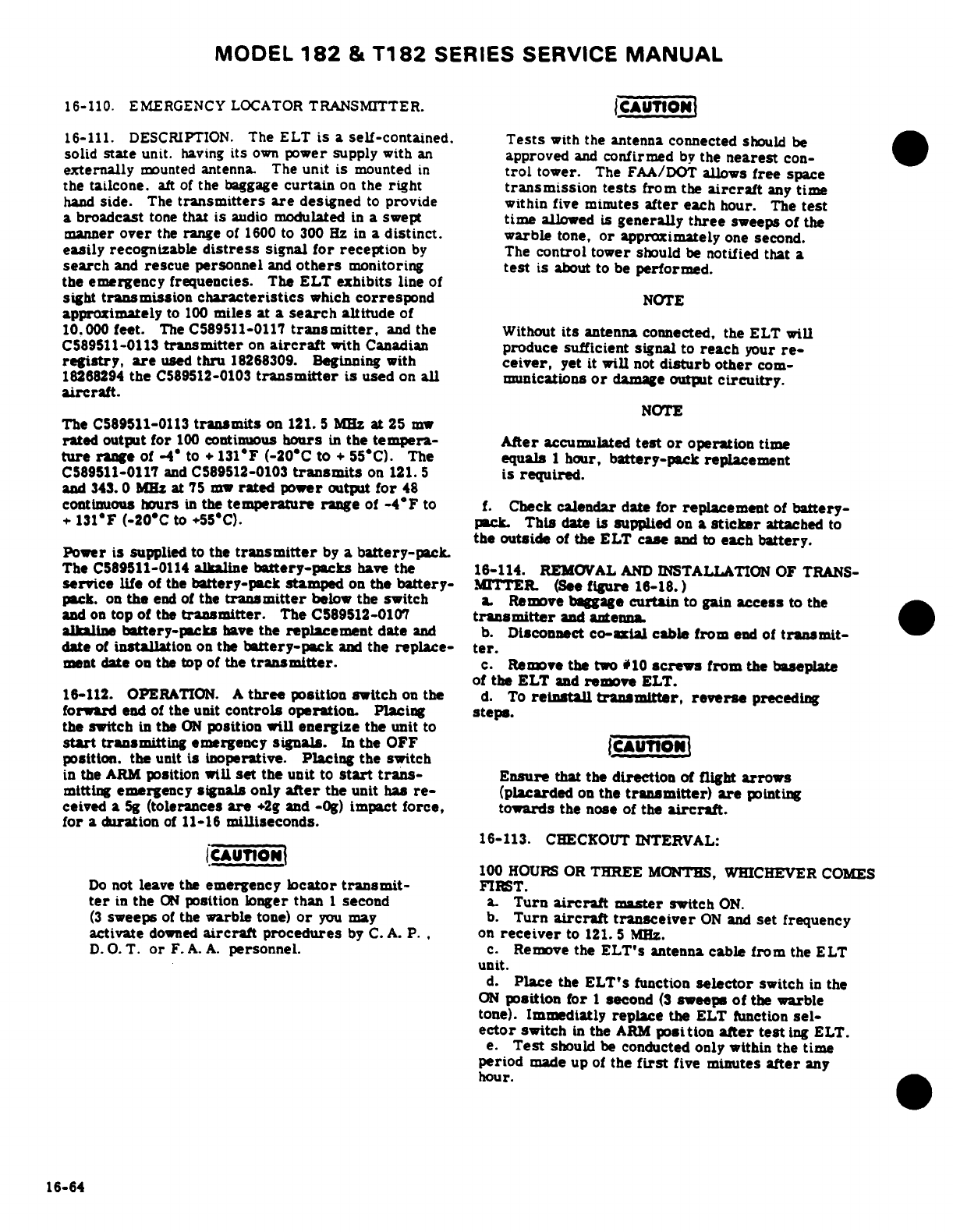
MODEL
182
&
T182
SERIES
SERVICE
MANUAL
16-110.
EMERGENCY
LOCATOR
TRANSMITTER.
CAUTION
16-111.
DESCRIPTION.
The
ELT
is
a
self-contained.
Tests
with
the
antenna
connected
should
be
solid
state
unit.
having
its
own
power
supply
with
an
approved
and
confirmed
by
the
nearest
con-
externally
mounted
antenna.
The
unit
is
mounted
in
trol
tower.
The FAA/DOT
allows
free
space
the
tailcone.
aft
of
the
baggage
curtain
on
the
right
transmission
tests
from
the
aircraft
any
time
hand
side.
The
transmitters
are
designed
to
provide
within five
minutes
after
each
hour.
The
test
a
broadcast
tone
that
is
audio
modulated
in
a
swept
time
allowed
is
generally
three
sweeps
of
the
manner
over
the
range
of
1600
to
300
Hz
in
a
distinct.
warble
tone,
or
approximately
one
second.
easily
recognizable
distress
signal
for
reception
by
The
control
tower
should
be
notified
that
a
search
and
rescue
personnel
and
others
monitoring
test
is
about
to
be
performed.
the
emergency
frequencies.
The
ELT
exhibits
line
of
sight
transmission
characteristics
which
correspond
NOTE
approximately
to
100
miles
at
a
search
altitude
of
10.000
feet.
The
C589511-0117
transmitter,
and
the
Without
its
antenna
connected,
the
ELT
will
C589511-0113
transmitter
on
aircraft
with
Canadian
produce
sufficient
signal
to
reach
your
re-
registry,
are
used
thru
18268309.
Beginning
with
ceiver,
yet
it
will
not
disturb
other
com-
18268294
the
C589512-0103
transmitter
is
used
on
all
munications
or
damage
output
circuitry.
aircraft.
NOTE
The
C589511-0113
transmits
on
121.
5
MHz
at
25
mw
rated
output
for
100
continuous
hours
in
the
tempera-
After
accumulated
test
or
operation
time
ture
range
of -4°
to
+
131°F
(-20-C
to
+ 55-C).
The
equals
1
hour,
battery-pack
replacement
C589511-0117
and
C589512-0103
transmits
on
121.
5
is
required.
and
343.
0
MHz
at
75
mw
rated
power
output
for
48
continuous
hours
in
the
temperature
range
of
-4°F
to
f.
Check
calendar
date
for replacement
of
battery-
+
131°F
(-20°C
to
+55°C).
pack.
This
date
is
supplied
on
a
sticker
attached
to
the
outside
of
the ELT
case
and to
each
battery.
Power
is
supplied
to
the
transmitter
by
a
battery-pack.
The
C589511-0114
alkaline
battery-packs
have
the
16-114.
REMOVAL
AND
INSTALLATION
OF
TRANS-
service
life
of
the
battery-pack
stamped
on
the
battery-
MITTER
(See
figure
16-18.)
pack.
on
the
end
of
the
transmitter
below
the switch
a.
Remove
baggage
curtain
to
gain
access
to
the
and
on
top
of
the
transmitter.
The
C589512-0107
transmitter
and
antenna.
alkaline
bttery-packs
have
the
replacement
date
and b.
Disconnect
co-axial
cable
from
end
of
transmit-
date
of
installation
on
the
battery-pack
and
the
replace-
ter.
ment
date
on
the
top
of
the
transmitter.
c.
Remove
the
two
#10
screws
from
the
baseplate
of
the
ELT
and
remove
ELT.
16-112.
OPERATION.
A
three
position switch
on
the
d.
To
reinstall transmitter, reverse
preceding
forward
end
of
the
unit
controls operation.
Placing
steps.
the
switch
in
the
ON
position will
energize
the
unit
to
start
transmitting
emergency
signals.
In
the
OFF
position.
the
unit
is
inoperative.
Placing the
switch
in
the
ARM
position
will
set
the
unit
to
start trans-
Ensure
that
the
direction
of
flight
arrows
mitting
emergency
signals
only
after
the
unit
has
re-
(placarded
on
the
transmitter) are
pointing
ceived
a
5g
(tolerances
are
+2g
and
-0g)
impact
force, towards
the
nose
of
the
aircraft.
for
a
duration
of
11-16
milliseconds.
16-113.
CHECKOUT
INTERVAL:
- ---- - -
100
HOURS
OR
THREE
MONTHS,
WHICHEVER COMES
Do
not
leave the
emergency
locator
transmit-
FIRST.
ter
in
the
ON
position
longer than
1
second a.
Turn
aircraft
master
switch
ON.
(3
sweeps
of
the
warble
tone)
or
you
may
b.
Turn
aircraft transceiver
ON
and
set
frequency
activate
downed
aircraft
procedures
by
C.
A.
P.
,
on
receiver
to
121.
5
MHz.
D.
O.
T.
or
F.
A. A.
personnel.
c.
Remove
the
ELT's
antenna
cable
from
the
ELT
unit.
d.
Place
the
ELT's
function
selector
switch
in
the
ON
position
for
1
second
(3
sweeps of
the
warble
tone).
Immediatly
replace
the
ELT function
sel-
ector
switch
in
the
ARM
position
after
test
ing
ELT.
e.
Test
should
be
conducted only
within
the
time
period
made
up
of
the
first
five
minutes
after
any
hour.
16-64
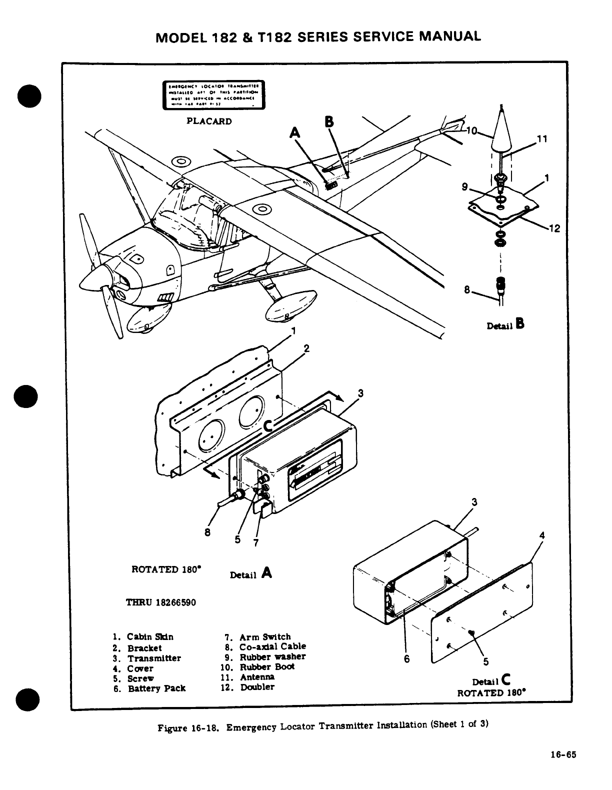
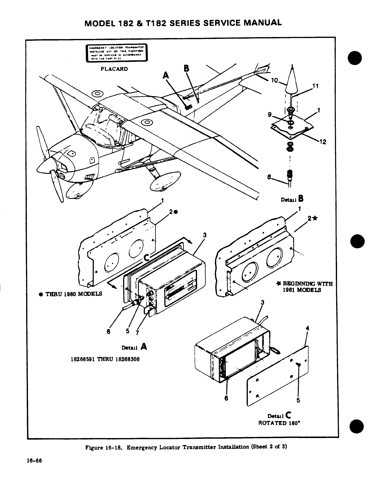
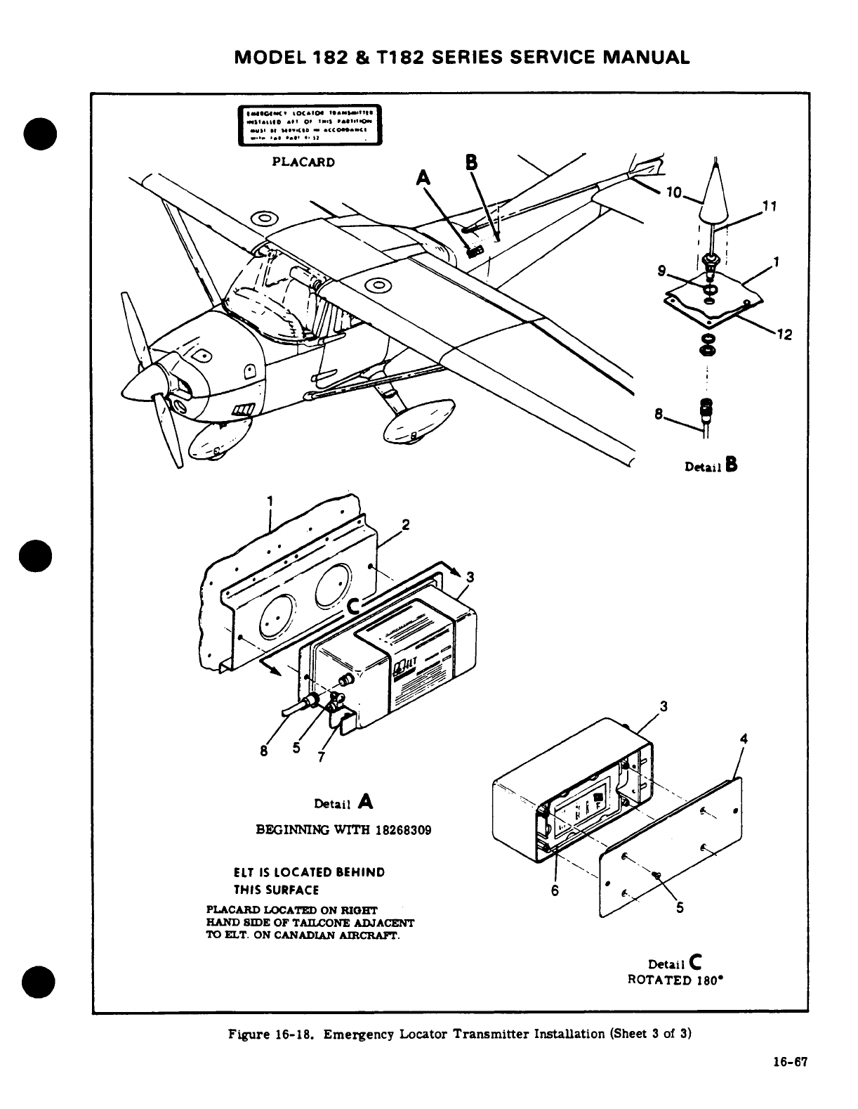
MODEL
182
&
T182
SERIES
SERVICE
MANUAL
*..
"m,..o:-o,";,i:..ti-
I
PLACARD
B
11
Detail
B
S~~oxDti
Detail
AWITH
182
BEGINNING
WITH
18268309
>
ELT
IS
LOCATED
BEHIND
THIS
SURFACE
6
PLACARD
LOCATED
ON
RIGHT
5
HAND
8IDE
OF
TAILCONE
ADJACENT
TO
ELT. ON
CANADIAN
AIRCRAFT.
Detail C
ROTATED
180'
Figure
16-18.
Emergency Locator
Transmitter
Installation
(Sheet
3
of
3)
16-67
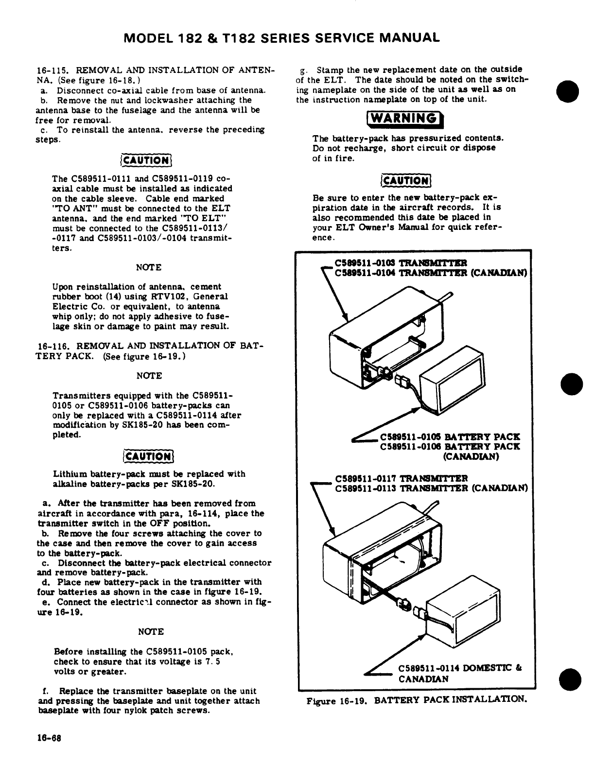
MODEL
182
&
T182
SERIES
SERVICE
MANUAL
16-115.
REMOVAL
AND
INSTALLATION
OF
ANTEN-
g.
Stamp
the
new
replacement
date
on
the
outside
NA.
(See
figure
16-18.)
of
the
ELT.
The
date
should
be noted
on
the
switch-
a.
Disconnect
co-axial
cable
from
base
of
antenna.
ing
nameplate
on
the
side
of
the
unit
as
well
as
on
b.
Remove
the
nut
and
lockwasher
attaching
the the
instruction
nameplate
on
top
of
the
unit.
antenna
base
to the
fuselage
and
the
antenna
will
be
free
for
removal.
c.
To
reinstall
the
antenna.
reverse
the
preceding
steps.
The
battery-pack
has
pressurized
contents.
Do
not
recharge,
short
circuit or
dispose
of
in
fire.
The
C589511-0111
and
C589511-0119
co-
axial
cable
must
be
installed
as
indicated---
on
the
cable
sleeve.
Cable
end
marked
Be
sure
to
enter
the
new
battery-pack
ex-
"TO
ANT"
must
be
connected
to
the
ELT
piration
date
in
the
aircraft
records.
It
is
antenna,
and
the
end
marked
"TO
ELT"
also
recommended
this
date
be
placed
in
must
be
connected
to
the
C589511-0113/
your
ELT
Owner's
Manual
for
quick
refer-
-0117
and
C589511-0103/-0104
transmit-
ence.
ters.
NOTE
Upon
reinstallation
of
antenna,
cement
rubber
boot
(14)
using
RTV102,
General
Electric
Co.
or
equivalent,
to
antenna
whip
only;
do
not
apply
adhesive
to
fuse-
lage
skin
or
damage
to
paint
may
result.
16-116.
REMOVAL
AND
INSTALLATION
OF
BAT-
TERY
PACK.
(See
figure
16-19.)
NOTE
Transmitters
equipped
with
the
C589511-
0105
or
C589511-0106
battery-packs
can
only
be
replaced
with
a
C589511-0114
after
modification
by
SK185-20
has
been
com-
pleted.
C58511-0105
BATTERY
PACK
C589511-0106
BATTERY
PACK
i
CAUTION
(CANADIAN)
Lithium
battery-pack
must
be
replaced
with
C589511-117
TRANSM
ER
alkaline
battery-packs
per
SK185-20.
C589S110113
TRANSMTTER
(CANADIN)
a.
After
the
transmitter
has
been
removed
from
aircraft
in
accordance
with
para,
16-114,
place
the
transmitter
switch
in
the
OFF
position.
b.
Remove
the
four
screws
attaching
the
cover
to
the
case
and
then
remove
the
cover
to
gain
access
to
the
battery-pack.
c.
Disconnect
the
battery-pack
electrical
connector
and
remove
battery-pack.
d.
Place
new
battery-pack
in
the
transmitter
with
four
batteries
as
shown
in
the
case
in
figure
16-19.
e.
Connect
the
electrical
connector
as
shown
in
fig-
ure
16-19.
NOTE
Before
installing
the
C589511-0105
pack,
check
to
ensure
that
its
voltage
is
7.
5
volts
or
greater.
C589511-0114
DOMESTIC
&
CANADIAN
f.
Replace
the
transmitter
baseplate
on
the
unit
_v
and
pressing
the
baseplate
and
unit
together
attach
Figure
16-19.
BATTERY
PACK
INSTALLATION.
baseplate
with
four
nylok
patch
screws.
16-68
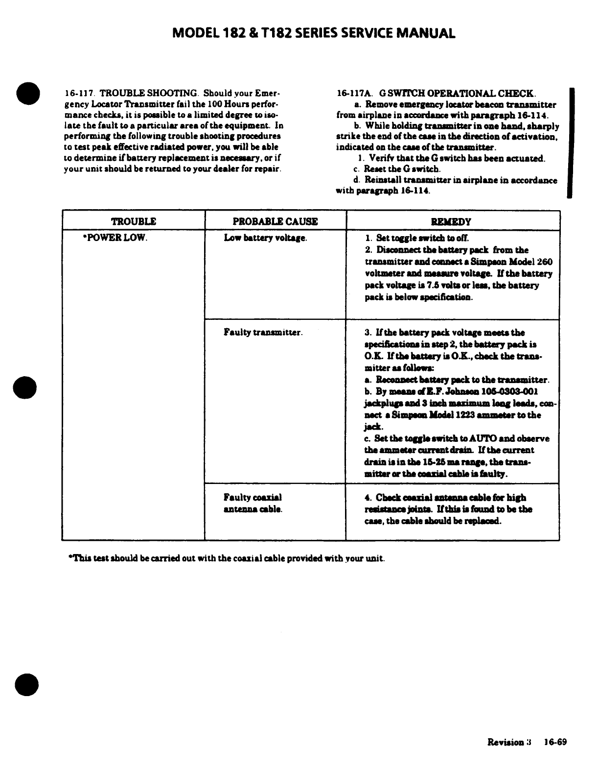
MODEL
182
&
T182
SERIES
SERVICE
MANUAL
gency
Locator
Transmitter
fail
the
100
Hours
perfor-
a. Remove
emergency
locator
beacon
transmitter
mance
checks,
it
is
possible
to
a
limited
degree
to
iso-
from
airplane
in
accordance
with
paragraph
16-114.
late
the
fault
to
a
particular
area
of
the
equipment.
In
b.
While
holding
transmitter in
one
hand,
sharply
performing
the
following
trouble
shooting
procedures
strike
the
end
of
the case
in
the
direction
of
activation,
to
test
peak
effective
radiated
power,
you
will
be
able
indicated
on
the
case
of
the
transmitter.
to
determine
if
battery
replacement
is
necessary,
or
if
1.
Verify
that
the
G
switch
has
been
actuated.
your
unit
should
be
returned
to your
dealer
for
repair.
c.
Reset
the
G
switch.
d.
Reinstall
transmitter
in
airplane
in
accordance
with
paragraph
16-114.
TROUBLE
PROBABLE
CAUSE
REMEDY
*POWER
LOW. Low
battery
voltage.
1.
Set
toggle
switch
to
off.
2.
Disconnect
the
battery
pack
from
the
transmitter
and
connect
a
Simpson
Model
260
voltmeter
and
measure
voltage.
If
the
battery
pack
voltage
is
7.5
volts
or less,
the
battery
pack
is
below
specification.
Faulty
transmitter.
3.
Ifthe
battery
pack
voltage
meets
the
specifictions
in
step
2,
the
battery
pack
is
O.K.
If
the
battery
is
O.K.,
check
the
trans
mitter
as
follow
a.
Reconnect
battery
pck
to
the
transmitter.
b.
By
means
of
E.F.
Johnson
105-0303-001
jackplugs
and
3
inch
maximum
long
leads,
con-
nect
a
Sim
jack.
c.
Set
the
toggle
switch to AUTO
and
observe
the
ammeter
current
drain.
If
thecurrent
drain
is
in
the
16-2
ma
range,
the
trans-
mitter
or
thecoaxial
cable
is
faulty.
Faulty
coaxial
4.
Check
coaxial
antenna
cable
for
high
antenna
cable.
reins
case,
the
cable should
be
replaced.
*This
test
should
be
carried
out
with
the
coaxial
cable
provided
with
your
unit.
Revision
3
16-69

MODEL
182
&
T182
SERIES
SERVICE
MANUAL
ELECTRICAL
LOAD
ANALYSIS
CHART
STANDARD
EQUIPMENT
(RUNNING
LOAD)
AMPS
REQD
1977
1978
1979 1980
1981
1982
1983
Instrument
(Engine).............
0.2
0.
2
0.2
0.2 0.2
0.2
Instrument
Lights
.. . . ... .....
0.7
07
0.7 0.7 0.7
1.0
a.
EL
Panel
... .. ..... .
0.04
0.7
0.7
0.7
0.7
0.7
0.7
b.
Cluster
................
0.32
c.
Console*
...............
2.08
d.
Compass
. . . . . . . .......
.08
e.
Pedestal
.. .. . .. . . . .. ...
0.16
Position
Lights
..............
5.
6
2.5
2.
5
2.5
2.
5
2.5
2.5
Battery
Contactor
.............
0.
6
0.5
0.5
0.5
0.
5
0.
5
0.
5
Fuel
Quantity
Indicators
.. .......
0.
10
0.10
0.
10
0.
10
0.
10
Cylinder
Head
Temprature
Indicators
. ...
0.05 0.05
0.
05
0.
05
0.
05
Turn
Coordinator
.... ... .....
0.8
0.3
0.3
0.3
0.3
0.
3
0.
3
Clock
................... t t t t t t t
OPTIONAL
EQUIPMENT (Running
Load)
Turn
and
Bank
Indicator
..........
0.2 0.2 0.2
0.2
Heated
Pitot
and
Stall
Warning
.......
10.0
5.
8 5.
8
5.8
5.
8
5.
8
5.
8
Strobe
Lights
...
.......
4.0
3.0
3.0
3.0
3.0
3.0
3.0
Carburetor
Air
Temp
...........
0.03
0.03
0.03
0.03
0.03
Cessna
200A
Navomatic
(Type
AF-295B)
...
2.5
2.
2. 2.
2.
2.5 .
.5
5
2.5
Cessna
300
ADF
(Type
R-546E)
.......
1.0
1.0
1.0
1.0
1.0
1.0
1.0
Cessna
300 Nav
Cor
(360
Channel-
Type
RT-308C)
.......
...... 1. 5
Cessna
300
Nav
Corn
(720
Channel-
Type
RT-328T)
.............
1.
5
Cessna
300
Transponder
(Type
RT-359A)
.. .
1.0
2.0 2.0 2.0
2.0 2.0
2.0
Cessna
00A
Nawomitlc
(Type
AF-395A) . . .
2.5 2.5
2.5
2.
5
2. 5
2.5
2.5
With
Unsavd
HS
(IG-832C)
.......
2. 8
2.8
2.
8
2.8
2.8
Cesa
300
Nav
Com
(Type
RT-385A) .....
1.0 1.0
1.
1.0
1.0
.
1.0
2.3S
2.
3
2.
3
2.3*
2.3S
2.3*
Cessna
400
Nav
Com (Type
RT-485A)
.....
1
.6
1.6
1.6
1.6
1.6
1.
6
4.0*
4
4.0
4.0
4.0* 4.0
4.0*
Cessna
400
ADF
(Type
RT-485A)
. ... 1.
6*
1.
6*
.
6*
1.
6*
1. 6*
1.6*
4.0*
40*
4.0
4
.0* 4.0
4.0
Cessna
400
ADF
(Type R-446A)
.......
6
1 1.3 1.6 1.
1.6
1.
1.6
1.6
Cessna
Glideslope
(Type
R-443B)
......
0.5
0.5
.5
0.5 0.5
0.
5
0.5
Cessna
400
Transponder
(Type
RT-459A)
. .
2.0 2.0
2.
0
2.
0
2. 0
2.0
2.0
Cessna
400
Marker
Beacon
(Type
R-402A).
..
.10
0.1
0.1
0.1
O. 1 O. 1
0.1
Cessna
400
DME
(Type
478A)
........
2.5
2.5
2.5
2.5
2.5
2.5
Cessna
400
RNAV
(Type
RN-476A)
......
0.5
0.5
0.
5
0.
5
0.
5
0.5
Sunair
SSB
Transceiver
(Type
ASB-125 ...
5.0
2.5*
2.5*
2.5*
2.5* 2.5* 2.5*
7.5*
7.5*
7.5*
7.5* 7.5* 7.5*
Flashing
Beacon
..............
7.0
6.
.0
6.0
6.0
6.0
6.0
68.
Narco
190
DME
..............
2.9
2.9
2.9
2.9
2.9
Pantronics
PT10-A
HF
Transceiver
.....
1.5 1.0*
1.
0*
1.0*
9.0' 9.0*
9.0*
Post
Lights'
................
1.52
0.6
0.
6
0.8
0.6 0.6
0.8
Mkr
Ben
EL
Panel
.............
0.02
Bendix
Marker
Beacon
(Type
GM-247A)....
.10
0.1
0.
1
Blind
Encoder
...........
...
.10
0.1
0.1
0.1
0.1
0.1
0.1
Cessna
Encoding
Altimeter
(Type
EA-401A) . .
.07
0.1
0.
1
0.1
0.1
0.1
Foster
RNAV
511
.............. .
1.0
1.0
1.0
Stereo
-
AM/FM
Cassette
. .........
1.0
1
1.0 1.
1.0
Interphone
System
............. 1 t t t
RNAV
ANS
351
...............
0.65
0.65
0.65
Avionics
Cooling
Fan
............
1.0
0
.
DME
-
451
. . . . .... ......
.2
1.
2
16-70
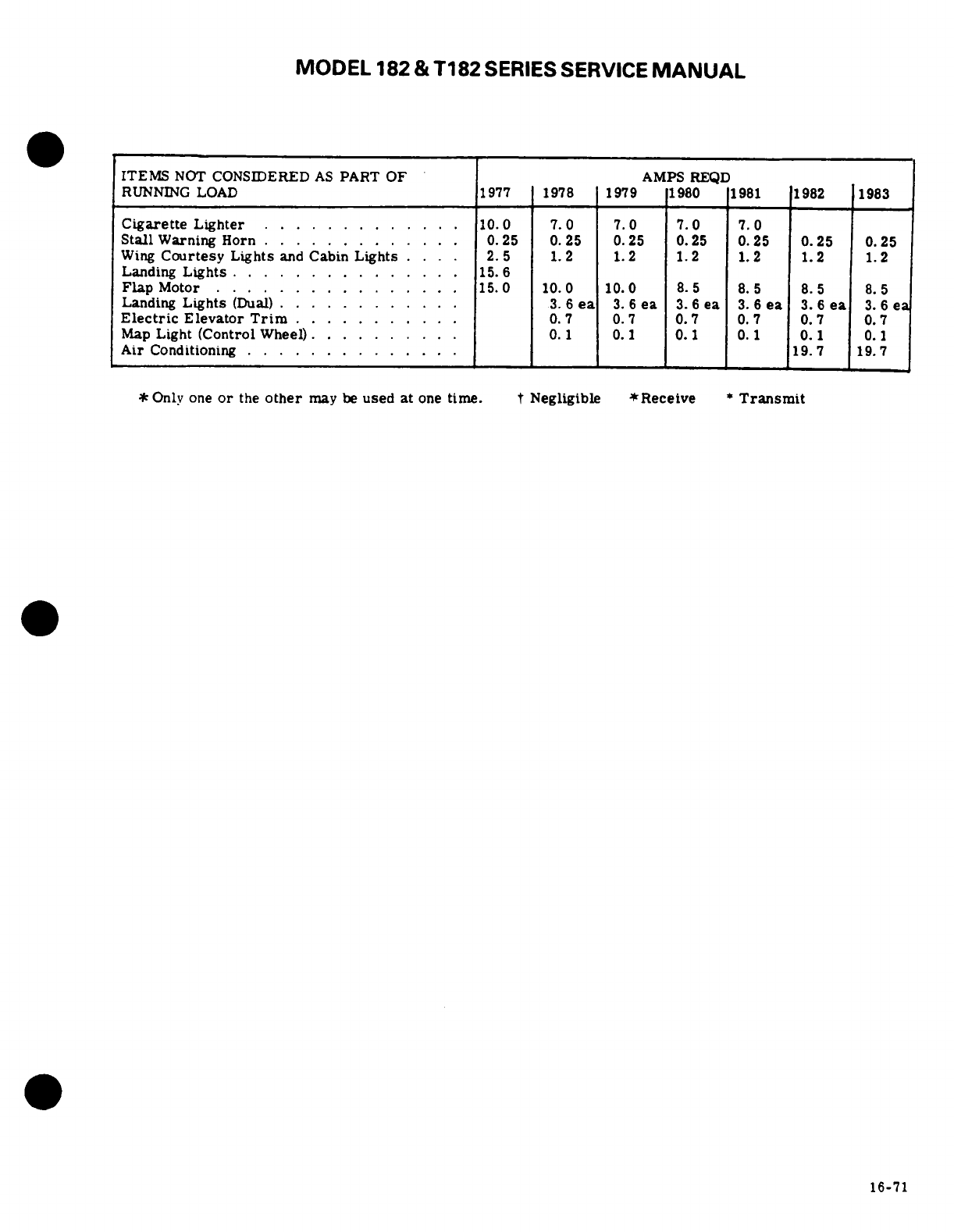
MODEL
182
&
T182
SERIES
SERVICE
MANUAL
ITEMS
NOT
CONSIDERED
AS
PART
OF
AMPS
REQD
RUNNING
LOAD
1977 1978
1979
1980
1981
1982
1983
Cigarette
Lighter
.. .
........
10.0
7.0 7.0 7.0
7.0
Stall
Warning
Horn
.. .
........
0.25
0.25
0.25 0.25
0.25
0.25
0.25
Wing
Courtesy
Lights
and
Cabin
Lights
...
5
1.2
1.
2
1.2
1.2
1.2
1.2
Landing
Lights
... . ...... . .. . .
15.
6
Flap
Motor
................
15.0
10.0
10.0
8.
5
8.5
8.5
8.5
Landing
Lights
(Dual)
. ... ..
ea.. 3.
6
ea
3.
6
ea
3.
6
ea
3.6
ea
3.6
ea
Electric
Elevator
Trim
...........
0.
7
0.7
0.7
0.7
0.
7
0.
7
Map
Light
(Control
Wheel)
.. ... ...
0.1 0.1
0.1 0.1
0.1
0.1
Air
Conditioning
..............
19.7
19.7
*
Only
one
or
the
other
may
be
used
at
one
time.
t
Negligible
*Receive
*
Transmit
16-71
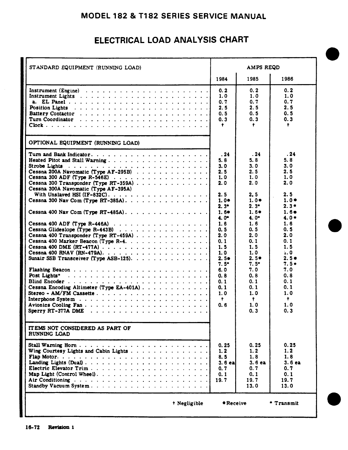
MODEL
182
&
T182
SERIES SERVICE
MANUAL
ELECTRICAL
LOAD
ANALYSIS
CHART
STANDARD
EQUIPMENT
(RUNNING
LOAD)
AMPS REQD
1984
1985 1986
Instrument
(Engine)
.....................
0.
2
0.2
0.
2
Instrument
Lights
......................
1.0
1.0
1.0
a.
EL
Panel
.............................. ....
0.7 0.7
0.7
Position
Lights
........................
.5
2.
5
2.
5
Battery
Contactor
............ ..... .....
0.
5
0.
5
0.5
Turn
Coordinator
.......................
0.
3
0.
3
0.
3
Clock
......................... ....
t t
t
OPTIONAL
EQUIPMENT
(RUNNING
LOAD)
Turn
and
Bank
Indicator.
....................
.24 .24
.24
Heated
Pitot
and
Stall
Warning
..................
5.
8
5.
8
5.
8
Strobe
Lights
.. .. . . . . . .. .. . .. . . . . .. . . .
3.0
3.0
3.0
Cessna
200A
Navomatic (Type
AF-295B)
...........
. ..
2.5
2.
5
Cessna
300
ADF
(Type
R-546E)
...............
..
1.0 1.0
1.
0
Cessna
300
Transponder
(Type
RT-359A)
.............
2.0 2.0
2.
0
Cessna
300A
Navomatic (Type
AF-395A)
With
Unslaved
HSI
(IF-832C)
.................
2.
25
2.
5 2.
5
Cessna
300
Nav
Corn
(Type
RT-385A)
.......
........
1.
0
1.
0 1.0
2.3* 2.3*
2.3*
Cessna
400
Nav
Com
(Type
RT-485A).
.............. 1.
6
1.
6
1.
6
4.0*
4.0*
4.0*
Cessna
400
ADF
(Type
R-446A)
.................
1.6
1.
6
1.
6
Cessna
Glideslope
(Type
R-443B)
...............
0.
5
0.
5
0.
5
Cessna
400
Transponder
(Type
RT-459A)
.............
2.0
2.0
2.
0
Cessna
400
Marker
Beacon
(Type
R-4.
...............
0.1
0.
1
0.1
Cessna
400 DME
(RT-477A)
...................
.
15
1.
5 1.
5
Cessna
400
RNAV
(RN-479A).
...................
1.0
1.0
1.
0
Sunair
SSB
Transceiver
(Type
ASB-125).
..............
2.5
2. 5 2.
5
7.5*
7
.5
5
Flashing
Beacon
......... ...... .........
6.0
7.0
7.0
Post
Lights*
.........................
0
.
8
0.8
Blind
Encoder
........................
.
01
0.
1
0.1
Cessna
Encoding
Altimeter
(Type
EA-401A)
............
0.1 0.1
0.1
Stereo
-
AM/FM
Cassette
....................
1.0
1.0
1.0
Interphone
System
....................... t t t
Avionics
Cooling
Fan
..................... .
0.6
1.0
1.0
Sperry
RT-377A
DME
.....................
0.3
0.
3
ITEMS
NOT
CONSIDERED
AS
PART
OF
RUNNING
LOAD
Stall
Warning
Horn
.......................
0.25 0.25
0.25
Wing
Courtesy
Lights
and
Cabin
Lights
.............. 1.2 1.2
Flap
Motor. .. ... . .
...................
8.5
1.8
1.8
Landing
Lights
(Dual)
.....................
. .
3.6
ea
3.
6
ea
3.6
ea
Electric
Elevator
Trim
.....................
0.
7
0.
7
0.
7
Map
Light
(Control
Wheel)
....................
0.
1
0.
1
0.1
Air
Conditioning ... . .. . . .. . . . .. . . . . . . . ..
19.7
19.7
19.7
Standby
Vacuum
System.
.................
...
13.0
13.0
t
Negligible *Receive
·
Transmit
16-72
Revision
I
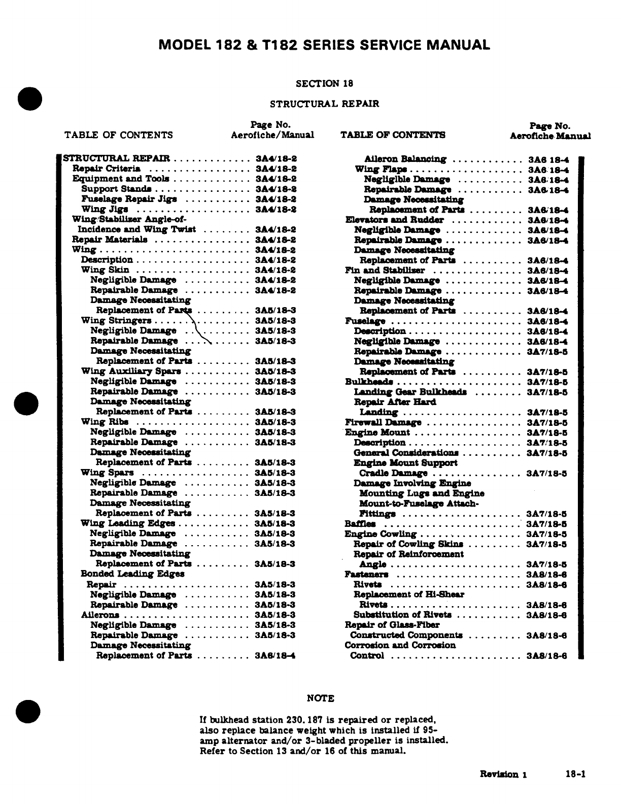
MODEL
182
&
T182
SERIES
SERVICE
MANUAL
SECTION
18
STRUCTURAL
REPAIR
Page
No.
Page
No.
TABLE
OF
CONTENTS
Aerofiche/Manual
TABLE
OF
CONTENTS
Aerofiche
Manual
STRUCTURAL
REPAIR
.............
3A4/18-2
Aileron
Balancing
............
3A6
18-4
Repair
Criteria
.................
3A4/18-2
Wing
Flap
.
.............
3A6
18-4
Equipment
and
Tools
.............
3A4/18-2
Negliglible
Damage
...........
3A6/18-4
Support
Stands
................
3A4/18-2
Repairable
Damage
...........
3A6/18-4
Fuselage
Repair
Jigs
...........
3A4/18-2
Damage Necessitating
Wing
Jigs
...................
3A418-2
Replacement
of
Parts
.........
3A18-4
Wing/Stabilizer
Angle-of-
Elevator
and
Rudder
............
3A6/18-4
Incidence
and
Wing Twist
........
3A418-2
Negligible Damage
.............
3A6/18-4
Repair
Materials
...............
3A4/18-2
Repairable Damage
.............
3A6/18-4
Wing
.......... .........
3A4/18-2
Damage
Necessitating
Description
...................
3A4/18-2
Replacement
of
Parts
..........
3A6/18-4
Wing
Skin
...................
3A4/18-2
Fin
and
Stabilizer
...............
3A6/18-4
Negligible
Damage
...........
3A4/18-2
Negligible Damage
.............
3A6/18-4
Repairable
Damage
...........
3A4/18-2
Repairable Damage
.............
3A6/18-4
Necessitating
Damage
Replacement
of
P
Wing
Stringers
...... ........
3A5/18-3
Fuselage
......................
3A6/18-4
Negligible Damage
..
........
3A5/18-3
Description
...................
3A6/18-4
Repairable
Damage
....
......
3A5/18-3
Negligible
Damage.............
3A/18-4
Damage
Necessitating
Repairable
Damage
.............
3A7/18-5
Replacement
of
Parts
.........
3A5/18-3
Damage
Necessitating
Wing
Auxiliary
Spars
...........
3A/18-3
Negligible Damage
..........
3A5/18-3
Bulkheads
........ .............
3A7/18-5
Repairable Damage
...........
3A5/18-3
Landing
Gear
Bulkheads
........
3A7/18-5
Damage
Necessitating Repair
After
Hard
Replacement
of
Part
...........
3A5/18-3
Landing ....................
3A7/18-5
Wing
Ribs
.......
............
3A5/18-3
Firewall
Damage
................
3A7/18-5
Negligible Damage
...........
3A5/18-3
Engine
Mount
..................
3A7/18-5
Repairable Damage
...........
3A5/18-3
Description
...................
3A7/18-5
Damage
Necesitating
General
Considerations
..........
3A7/18-5
Replacement
of
Parts
........
3A5/18-3
Engine
Mount
Support
Wing
Spars
.................
3A5/18-3
Cradle
Damage
...............
3A7/18-5
Negligible Damage
...........
3A5/18-3
Damage Involving
ngne
Repairable
Damage
...........
3A5/18-3
Mounting
Lug
and
Engine
Damage
Necessitating
Mount-to-Fuselage
Attach-
Replacement
of
Parts
.........
3A5/18-3
Fittings
....................
3A7/18-5
Wing Landing
Edges
.
...........
3A5/18-3
Baffles
.......................
3A7/18-5
Negligible
Damage
...........
3A5/18-3
Engine
Cowling
.................
3A7/18-5
Repairable Damage
...........
3A5/18-3
Repair
of
Cowling
Skins
.........
3A7/18-5
Damage
Necessitating
Repair
of
Reinforcement
Replacement
of
Parts
.........
3A5/18-3
Angle
......................
3A7/18-5
Bonded
Leading
Edges
Fasteners
.....................
3A8/18
Repair
.....................
3A5/18-3
Rivets
...................
.
3A8/18-6
Negligible Damage
...........
3A5/18-3
Replacement
of
Hi-Shear
Repairable
Damage
...........
3A5/18-3
Rivets....................
3A8/18-6
Ailerons
.....
............
3A5/18-3
Substitution
of
Rivets
...........
3A8/18-6
Negligible
Damage
...........
3A5/18-3
Repair
of
Glass-Fiber
Repairable Damage
...........
3A5/18-3
Constructed
Components
.........
3A8/18-6
Damage
Necessitating
Corrosion and
Corrosion
Replacement
of
Parts
.........
3A6/18-4
Control
......................
3A8/18-
NOTE
If
bulkhead
station
230.187
is
repaired
or
replaced,
also
replace
balance
weight
which
is
installed
if
95-
amp
alternator
and/or
3-bladed
propeller
is
installed.
Refer
to
Section
13
and/or
16
of
this
manual.
Revision
1
18-1
MODEL
182
&
T182
SERIES
SERVICE
MANUAL
18-1.
STRUCTURAL
REPAIR.
18-9.
REPAIR
MATERIALS.
Thickness
of
a mate-
rial
on
which a
repair
is
to
be
made
can
easily
be
de-
18-2.
REPAIR
CRITERIA. Although
this section
termined
by
measuring
with
a
micrometer.
In
gen-
outlines
repair
permissible
on
structure
of
the
air-
eral,
material
used
in
Cessna
aircraft
covered
in
craft,
the
decision
of
whether
to
repair
or
replace
a
this
manual
is
made
from
2024
aluminum
alloy,
heat
major
unit
of
structure
will
be
influenced
by
such
treated
to
a
-T3,
-T4,
or
-T42
condition.
If
the
type
factors
as
time
and
labor
available,
and by
a
com-
of
material
cannot
readily
be
determined,
2024-T3
parison
of
labor
costs
with
the
price
of
replacement
may
be
used
in making
repairs,
since
the
strength
assemblies.
Past
experience
indicates
that
replace-
of
-T3
is
greater
than
-T4
or
-T42
(-T4 and
-T42
ment,
in
many
cases,
is
less
costly
than
major
re-
may
be
used
interchangeably,
but they
may
not
be
pair.
Certainly,
when
the
aircraft
must
be
restored
substituted
for
-T3).
When
necessary
to
form
a
part
to
its
airworthy
condition
in
a
limited
length
of
time.
with a
smaller
bend
radius
than
the
standard
cold
replacement
is
preferable.
Restoration
of
a
damaged
bending
radius
for
2024-T4,
use
2024-0
and
heat
aircraft
to
its
original
design
strength,
shape,
and
treat
to
2024-T42
after
forming.
The
repair
mate-
alignment
involves
careful
evaluation
of
the damage,
rial
used
in
making
a
repair
must
equal
the
gauge
of
followed
by
exacting
workmanship
in
performing
the the
material
being
replaced
unless
otherwise
noted.
repairs.
This
section
suggests
the
extent
of
struc-
It
is
often
practical
to
cut
repair
pieces
from
service
tural
repair
practicable
on
the
aircraft,
and
supple-
parts
listed
in
the
Parts
Catalog.
A
few
components
ments
Federal
Aviation
Regulation,
Part
43.
Con-
(empennage
tips,
for
example)
are
fabricated
from
suit
the
factory
when
in
doubt
about
a
repair
not
thermo-formed
plastic
or
glass-fiber
constructed
specifically
mentioned
here.
material.
18-3.
EQUIPMENT
AND
TOOLS.
18-10.
WING.
18-4.
SUPPORT
STANDS.
Padded,
reinforced
saw-
18-11.
DESCRIPTION.
The
wing
assemblies
are
a
horse
or
tripod
type
support
stands,
sturdy
enough
to
semicantilever
type
employing
semimoncoque
type
support
any
assembly
placed
upon
them,
must
be
of
structure.
Basically,
the
internal
structure
con-
used
to
store
a
removed
wing
or
tailcone.
Plans
for
sists
of
built-up front
and
rear
spar
assemblies,
a
local
fabrication
of
support stands
are
contained
in
formed
auxiliary
spar
assembly
and
formed
sheet
figure
18-1. The
fuselage
assembly,
from
the
tail-
metal
nose,
intermediate,
and
trailing
edge
ribs.
cane
to
the
firewall,
must
NOT be
supported
from
Stressed
skin,
riveted
to
the
rib
and
spar
structures,
the
underside,
since
the
skin
bulkheads
are
not
de-
completes
the
rigid
structure.
Access
openings
signed
for
this
purpose.
Adapt
support stands
to
(hand
holes
with
removable
cover
plates)
are
located
fasten
to the
wing
attach
points
or
landing
gear
attach
in the
underside
of
the
wing
between
the
wing
root
points
when
supporting a fuselage.
and
tip
section.
These
openings
afford
access
to
aileron bellcranks,
flap
bellcranks,
electrical
wiring,
18-5.
FUSELAGE
REPAIR
JIGS.
Whenever
a
repair
strut
attach
fittings,
control
cables
and
pulleys,
and
is
to
be
made which
could
affect
structural
alignment,
control disconnect
points.
suitable
jigs
must
be
used
to
assure
correct
align-
ment
of
major
attach
points,
such
as
fuselage,
fire-
18-12.
WING
SKIN.
wall,
wing
and landing
gear.
These fuselage
repair
jigs
are
obtainable
from
the
factory.
18-13.
NEGLIGIBLE
DAMAGE.
Any
smooth
dents
in
the
wing
skin
that
are
free from
cracks, abrasions
18-6.
WING
JIGS.
These
jigs
serve
as
a
holding fix-
and
sharp
corners,
which
are
not
stress
wrinkles
and
ture
during
extensive
repair
of
a
damaged
wing,
and
do
not
interfere
with
any
internal
structure
or
mech-
locates
the
root
rib,
leading
edge
and
tip rib
of
the
anism,
may
be
considered
as
negligible damage.
In
wing.
These
jigs
are
also
obtainable
from
the
factory.
areas
of low
stress
intensity,
cracks,
deep
scratches,
or
deep,
sharp
dents,
which
after
trimming
or
stop-
18-7.
WING
TWIST
AND
STABILIZER
ANGLE-OF-
drilling
can
be
enclosed
by
a
two-inch
circle,
can
be
INCIDENCE.
considered
negligible
if
the
damaged
area
is
at
least
one
diameter
of
the
enclosing
circle
away
from
all
18-8.
Wing
twist
(washout)
and
horizontal
stabilizer
existing
rivet
lines
and
material
edges.
Stop
drilling
angle-of-incidence
are
shown
below.
Stabilizers
do
is
considered
a
temporary
repair
and
a
permanent
not
have
twist.
Wings have
no
twist
from
the
root
to
repair
must
be
made
as
soon
as
practicable.
the
lift
strut
station.
All
twist
in
the
wing
panel
occurs
between
this
station
and
the
tip rib.
See
figure
18-14. REPAIRABLE
DAMAGE.
Figure
18-4
out-
18-2
for
wing
twist
measurement. lines
typical
repair
to
be
employed
in
patching skin.
Before
installing
a
patch,
trim
the
damaged
area
to
half
inch
radius
at
each
corner,
and
de-burr.
The
Twist
(Washout)
3
°
sides
of
the
hole
should
lie
span-wise
or chord-wise.
A
circular
patch
may
also
be
used.
If
the
patch
is
STABILIZER
Angle
of
Incidence
-3
°
30'
patch
type
of
repair;
if
in
an
area
where
flush
rivets
18-2
MODEL
182
&
T182
SERIES
SERVICE
MANUAL
are
not
used,
make
an
overlapping
type
of
repair.
which
wing
spars
encounter,
very
little
damage can
Where optimum
appearance
and
airflow
are
desired,
be
considered
negligible.
All
cracks,
stress
wrink-
the
flush
patch
may
be
used.
Careful
workmanship
les,
deep
scratches,
and
sharp dents
must
be
re-
will
eliminate
gaps
at
butt-joints;
however,
an
epoxy
paired.
Smooth
dents,
light
scratches
and
abrasions
type
filler
may
be
used
at
such
joints.
may
be
considered
negligible.
18-15.
DAMAGE
NECESSITATING
REPLACEMENT
18-30.
REPAIRABLE
DAMAGE.
Figure
18-7,
illus-
OF
PARTS.
If
a
skin
is
badly
damaged,
repair
must
trates
typical
spar
repairs.
It
is
often
practical
to
be
made
by
replacing
an
entire
skin
panel,
from
one
cut
repair
pieces
from
service
parts
listed
in
the
structural
member
to the
next.
Repair
seams
must
Parts
Catalog.
Service
Kits
are
available
for
cer-
be
made
to
lie
along
structural
members
and
each
tain
types
of
spar
repairs.
seam
must
be
made
exactly the same
in
regard
to
rivet
size,
spacing
and
pattern
as
the
manufactured
18-31.
DAMAGE
NECESSITATING
REPLACEMENT
seams
at
the
edges
of
the
original
sheet.
If
the
manu-
OF
PARTS.
Damage
so
extensive
that
repair
is
not
factured
seams
are
different,
the
stronger
must
be
practicable
requires
replacement
of
a
complete
wing
copied.
If
the
repair
ends
at
a
structural
member
spar.
Also
refer
to
paragraph
18-2.
where
no
seam
is
used,
enough
repair
panel
must
be
used
to
allow an
extra
row
of
staggered
rivets,
with
18-32.
WING
LEADING
EDGES.
sufficient
edge
margin,
to
be
installed.
18-33.
NEGLIGIBLE
DAMAGE.
Refer
to
paragraph
18-16.
WING
STRINGERS.
18-13.
18-17.
NEGLIGIBLE
DAMAGE.
Refer
to
paragraph
18-34.
REPAIRABLE
DAMAGE.
Wing
skin
repairs,
18-13.
outlined
in
paragraph
18-14,
may
be
used
to
repair
leading
edge
skins,
although
the
flush-type
patches
18-18.
REPAIRABLE
DAMAGE.
Figure
18-5
out-
should
be
used.
To
facilitate
repair,
extra
access
lines
a
typical
wing
stringer
repair.
Two
such
re-
holes
may
be installed
in
locations
noted in
figure
pairs
may
be
used
to
splice
a
new
section
of
stringer
18-13.
If
the damage
would
require
a
repair
which
material
in
position,
without
the
filler
material,
could
not
be
made
between
adjacent
ribs,
refer
to
the
following
paragraph.
18-19.
DAMAGE
NECESSITATING
REPLACEMENT
.
OF
PARTS.
If
a
stringer
is
so
badly damaged
that
18-35.
DAMAGE
NECESSITATING
REPLACEMENT
more
than
one
section must
be
spliced,
replacement
OF
PARTS.
Where
extreme
damage
has
occurred,
is
recommended.
complete leading
edge
skin
panels
should
be
replaced.
Extra
access
holes
may
be
installed.
See
figure
18-20.
WING
AUXILIARY
SPARS.
18-13
for
procedures.
18-21.
NEGLIGIBLE
DAMAGE.
Refer
to
paragraph
18-36.
BONDED LEADING
EDGES
REPAIR.
18-13.
18-37.
NEGLIGIBLE
DAMAGE.
Refer to
paragraph
18-22.
REPAIRABLE
DAMAGE.
Figure
18-8
illus-
18-13.
trates
a
typical
auxiliary
spar
repair.
18-38.
REPAIRABLE
DAMAGE.
(See
figure
18-11.)
18-23.
DAMAGE
NECESSITATING
REPLACEMENT Cut out
damaged
area
as
shown,
to
the
edge
of
un-
OF
PARTS.
If
damage
to
an
auxiliary
spar
would
damaged
ribs.
Using a
corresponding
section
from
require
a
repair
which
could
not
be made
between
a
new
leading
edge
skin,
overlap
ribs
and
secure
to
adjacent
ribs,
the
auxiliary
spar
must
be
replaced.
wing,
using
rivet
pattern
shown
in
the
figure.
18-24.
WING
RIBS.
18-39.
AILERONS.
18-25.
NEGLIGIBLE
DAMAGE.
Refer
to
paragraph
18-40.
NEGLIGIBLE
DAMAGE.
Refer to
paragraph
18-13.
18-13.
18-26.
REPAIRABLE
DAMAGE.
Figure
18-6
illus-
18-41.
REPAIRABLE
DAMAGE.
The
repair
shown
trates
a
typical
wing
rib
repair.
in
figure
18-9
may
be
used
to
repair
damage
to
ailer-
on
leading
edge
skins.
Figure
18-4
may
be
used
as
a
18-27.
DAMAGE
NECESSITATING
REPLACEMENT guide
to
repair
damage
to
flat
surface
between
corru-
OF
PARTS.
Leading
and
trailing
edge
ribs
that
are
gations.
when
damaged
area
includes
corrugations,
extensively
damaged
can
be
replaced.
However,
due
see
figure
18-12.
It
is
recommended
that
material
to
the
necessity
of
unfastening
an
excessive
amount
of
used for
repair
be
cut
from
spare
parts
of
the
same
skin
in
order
to
replace
the
rib,
they
should
be
re-
gauge
and
corresponding
spacing. Following
repair,
paired
if
practicable.
Center
ribs,
between
the front
the
aileron
must
be
balanced.
Refer
to
paragraph
and
rear
spar
should
always
be
repaired
if
practicable.
18-43
for
balancing.
If
damage
would
require
a
repair
which
could
not
be
made
between
adjacent
ribs,
18-28.
WING
SPARS.
refer
to
paragraph
18-42.
18-29.
NEGLIGIBLE
DAMAGE.
Due
to
the
stress
18-3
MODEL
182
&
T182
SERIES
SERVICE
MANUAL
18-42.
DAMAGE
NECESSITATING
REPLACEMENT
elevators
and
rudder
must
be
balanced.
A
flight
OF
PARTS.
If
the
damage
would
require
a
repair
control
surface
balancing
fixture
kit
is
available
which could
not
be
made
between
adjacent
ribs,
com-
(P/N
5180002-1).
See
figure
18-3
for
procedures
plete
skin
panels must
be
replaced.
Ribs
and
spars
pertaining
to
the
use
of
this
kit.
may
be
repaired,
but
replacement
is
generally
pre-
ferable.
Where
extensive
damage
has
occurred,
re-
18-53.
FIN
AND
STABILIZER.
placement
of
the
aileron
assembly
is
recommended.
18-54.
NEGLIGIBLE
DAMAGE.
Refer
to
paragraph
After
repair
and/or
replacement,
balance
aileron
18-13
in
accordance
with
paragraph
18-43
and
figure
18-3.
18-55.
REPAIRABLE
DAMAGE.
Skin
patches
illus-
18-43
AILERON
BALANCING.
Following
repair. trated
in
figure
18-4
may
be
used
to
repair
skin
dam-
replacement or
painting,
the
aileron
must
be
balanced.
age.
Access
to
the
dorsal
area
of
the fin
may
be
A
flight
control
surface
balancing
fixture
kit is
avail-
gained
by
removing the
horizontal closing
rib
at
the
able
(P/N5180002-1).
See
figure
18-3
for
procedures
bottom
of
the
fin.
Access
to
the
internal
fin
structure
pertaining
to
the
use
of
this
kit.
is
best
gained
by
removing
skin
attaching
rivets
on
one
side
of
the
rear
spar
and
ribs,
and
springing
back
18-44.
WING
FLAPS
the
skin.
Access
to the
stabilizer
structure
may
be
gained
by
removing
skin
attaching
rivets
on
one
side
18-45.
NEGLIGIBLE
DAMAGE.
Refer
to
paragraph
of
the
rear
spar
and
ribs,
and
springing
back the
skin.
18-13.
If
the
damaged
area
would
require
a
repair
which
could
not
be
made
between
adjacent
ribs, or
a
repair
18-46.
REPAIRABLE
DAMAGE.
Flap
repairs
should
would
be
located
in
an
area
with
compound
curves,
be
similar
to
aileron
repairs
discussed
in
paragraph
see
the
following
paragraph.
18-41.
A
flap
leading
edge
repair
is
shown in
figure
18-10.
18-56.
DAMAGE
NECESSITATING
REPLACEMENT
OF
PARTS.
If
the
damaged
area
would
require
a
18-47.
DAMAGE
NECESSITATING
REPLACEMENT
repair
which
could
not
be
made between
adjacent
ribs,
OF
PARTS.
Flap
repairs
which
require
replacement
or
the
repair
would
be
located in
an
area
with
com-
of
parts
should be
similar
to
aileron
repairs
dis-
pound
curves,
complete
skin
panels
must
be
replaced.
cussed
in
paragraph
18-42.
Since
the flap
is
not
con-
Ribs
and
spars
may
be
repaired,
but
replacement
is
sidered
a
movable
control
surface,
no
balancing
is
generally
preferable.
Where
damage
is
extensive,
required.
replacement
of
the
entire assembly
is
recommended.
18-48.
ELEVATORS
AND
RUDDER.
18-57.
FUSELAGE.
18-49. NEGLIGIBLE
DAMAGE.
Refer to
paragraph
18-58.
DESCRIPTION.
The
fuselage
is
of
semi-
18-13.
The
exception
to
negligible damage
on
the
monocoque
construction,
consisting
of
formed
bulk-
elevator
surfaces
is
the
front
spar,
where
a
crack
heads,
longitudinal
stringer,
reinforcing
channels,
appearing in
the
web
at
the
hinge
fittings
or
in
the
and
skin
panels.
structure
which
supports
the
overhanding
balance
weight
is
not
considered
negligible.
Cracks
in
the
18-59. NEGLIGIBLE
DAMAGE.
Refer
to
paragraph
overhanging
tip
rib,
in the
area
at
the
front
spar
18-13.
Mild
corrosion
appearing
upon
alclad
sur-
intersection
with
the
web
of
the
rib, also
cannot
be
faces
does
not
necessarily
indicate incipient
failure
considered
negligible.
of
the
base
metal.
However,
corrosion
of
all
types
must
be
carefully
considered,
and
approved
reme-
18-50. REPAIRABLE
DAMAGE.
Skin
patches
illus-
dial
action taken.
Small
cans
appear
in
the
skin
trated
in
figure
18-4
may
be
used
to
repair
skin
dam-
structure
of
all
metal
aircraft.
It
is
strongly
rec-
age
between
corrugations.
For
skin
damage
which
ommended however,
that
wrinkles
which
appear
to
includes
corrugations,
see figure
18-12. Follow-
have
originated
from
other
sources,
or
which
do
ing
repair,
the
elevator/rudder
must
be
balanced.
not
follow the
general
appearance
of
the
remainder
See
figure
18-3
for
balancing
procedures.
If
damage
of
the
skin
panels,
be
thoroughly
investigated.
requires
a
repair
which
could
not
be
made
between
Except
in
the
landing
gear
bulkhead
areas,
wrinkles
adjacent
ribs,
see paragraph
18-51.
occurring
over
stringers
which
disappear
when
the
rivet pattern
is
removed,
may
be
considered
negligi-
18-51.
DAMAGE
NECESSITATING
REPLACEMENT
ble.
However,
the
stringer
rivet
holes
may
not
OF
PARTS.
If
the
damaged
area
would
require
a
re-
align
perfectly
with
the
skin
holes
because
of
a
per-
pair
which
could
not
be
made between
adjacent
ribs,
manent
"set"
in
the
stringer.
If
this
is
apparent,
complete
skin
panels
must
be
replaced.
Ribs
and
replacement
of
the
stringer
will
usually
restore
the
spars
may
be
repaired,
but
replacement
is
generally
original
strength
characteristics
of
the
area.
preferable.
Where
extensive
damage
has occurred,
replacement
of
the
entire
assembly
is
recommended.
NOTE
After
repair
and/or
replacement,
balance
elevators
Wrinkles
occurring
in
the
skin
of
the
main
and
rudder
in
accordance
with
paragraph
18-52
and
landing
gear
bulkhead
areas
must
not
be
figure
18-3.
considered
negligible.
The
skin
panel
must
be
opened
sufficiently
to
permit
a
thorough
18-52.
ELEVATOR
AND
RUDDER
BALANCING.
examination
of
the
lower
portion
of
the
land-
Following
repair,
replacement
or
painting,
the
ing
gear
bulkhead
and
its
tie-in structure.
18-4
MODEL
182
&
T182
SERIES
SERVICE
MANUAL
18-40A.
CRACKS
IN
CORRUGATED AILERON SKINS
(Continued
from page
18-3)
1.
It
is
permissible
to
stop drill
crack(s)
that originate
at
the
trailing
edge
of
the
control
surface provided
the
crack
is
not
more
than
2
inches
in
length.
2.
Stop
drill
crack
using
a
#30
(.128 inch)
drill.
3.
A
crack
may
only
be
stop
drilled
once.
NOTE:
A
crack that
passes
through
a
trailing
edge
rivet and
does
not
extend
to
the
trailing
edge
of
the
skin may
be
stop
drilled
at
both
ends
of
the crack.
4.
Any
control
surface that
has
a
crack
that
progresses
past
a
stop
drilled
hole
shall
be
repaired. Refer
to
paragraphs
18-40,
-41,
and -42
as
applicable
for
repair information.
5.
A
control surface that
has
any
of
the
following conditions
shall
have
a
repair
made as
soon
as practicable:
A.
A
crack
that
is
longer
than
2
inches.
B.
A
crack
that
does
not
originate
from
the
trailing
edge or
a
trailing
edge rivet.
C.
Cracks
in
more
than
six trailing
edge rivet
locations
per
skin.
Refer
to
paragraphs
18-40,
-41,
and
-42
as
applicable for
repair information.
6.
Affected
control
surfaces with
corrugated
skins
and
having
a
stop drilled
crack
that
does
not
extend
past
the stop
drilled hole,
may
remain
in
service
without additional
repair.
Temporary
Revision
Number
2
18-4A
7
January
2000

MODEL
182
&
T182 SERIES
SERVICE
MANUAL
18-45A.
CRACKS
IN
CORRUGATED
FLAP
SKINS
(Continued
from page
18-4)
1. It
is
permissible
to
stop drill
crack(s) that
originate
at
the trailing
edge
of
the control
surface
provided
the
crack
is
not
more than
2
inches
in
length.
2.
Stop
dri
3.
A
crack
r
-, only
be
stop drilled once.
NOTE:
A
crack
that passes
through
a
trailing
edge
rivet
and
does
not
extend
to
the trailing
edge
of
the
skin
may
be
stop drilled
at both
ends
of
the crack.
4.
Any
control
surface
that
has
a
crack
that
progresses
past
a
stop
drilled
hole shall
be
repaired.
Refer
to
paragraphs
18-45,
-46,
and
-47
as
applicable
for
repair
information.
5.
A
control
surface
that
has
any
of
the
following
conditions
shall
have
a
repair
made
as
soon
as
practicable:
A. A
crack that
is
longer
than
2
inches.
B.
A
cr,.
C.
Cracks
in
more
than
six
trailing
edge
rivet
locations
per
skin.
Refer to
paragraphs
18-45,
-46,
and -47
as
applicable for
repair information.
6.
Affected
control surfaces
with
corrugated skins and
having
a
stop
drilled crack
that
does
not
extend
past
the
stop
drilled
hole,
may
remain
in
service
without
additional
repair.
18-49A.
CRACKS
IN
CORRUGATED
ELEVATOR
SKINS
(Continued
from page
18-4)
1. It
is
permissible
to stop
drill
crack(s)
that
originate
at
the trailing
edge
of
the control
surface
provided
the
crack
is
not
more than
2
inches
in
length.
2.
Stop drill
crack
using
a
#30
(.128
inch)
drill.
3. A
crack
may
only
be
stop
drilled
once.
NOTE:
A
crack
that
passes
through
a
trailing
edge
rivet
and
does
not
extend
to
the
trailing
edge of
the
skin
may
be
stop
drilled
at
both ends
of
the
crack.
4.
Any
control
surface
that
has
a
crack that
progresses
past
a
stop drilled
hole
shall
be
repaired.
Refer
to
paragraphs
18-49,
-50,
and
-51
as
applicable
for
repair information.
5. A
control
surface
that
has
any
of
the following
conditions
shall have
a
repair
made
as
soon
as
practicable:
A.
A
crack that
is
longer
than
2
inches.
B.
A
crack
that
does
not
originate
from
the
trailing
edge or
a
trailing
edge
rivet.
C.
Cracks
in
more
than
six trailing
edge
rivet
locations
per
skin.
Refer
to
paragraphs
18-49,
-50,
and
-51
as
applicable for
repair
inform
6.
Affected
control
surfaces
with
corrugated
skins and
having
a
stop drilled
crack
that
does
not
extend
past
the
stop
drilled
hole, may
remain
in
service without
additional
repair.
18-4B
Temporary
Revision Number
2
7
January
2000
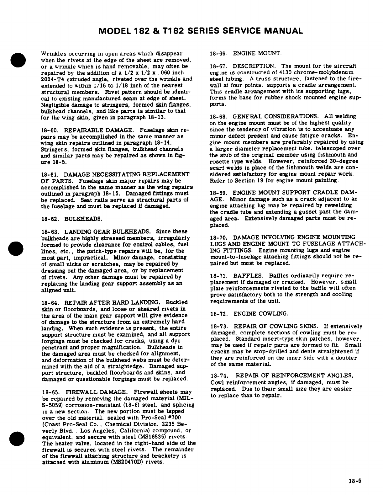
MODEL
182
&
T182
SERIES SERVICE
MANUAL
Wrinkles
occurring
in open
areas
which
disappear
18-66.
ENGINE MOUNT.
when
the
rivets
at
the edge
of
the
sheet
are
removed,
or
a
wrinkle
which
is
hand
removable,
may often
be
18-67. DESCRIPTION.
The
mount
for
the
aircraft
repaired
by
the
addition
of
a
1/2
x
1/2
x
.060
inch
engine
is constructed
of 4130
chrome-molybdenum
2024-T4
extruded
angle,
riveted
over the
wrinkle
and
steel
tubing.
A
truss
structure,
fastened
to
the
fire-
extended
to
within
1/16
to
1/18
inch
of
the
nearest
wall
at
four
points.
supports
a
cradle
arrangement.
structural
members.
Rivet
pattern
should
be
identi-
This
cradle
arrangement
with
its
supporting
lugs,
cal
to
existing manufactured seam
at
edge
of
sheet.
forms
the
base
for
rubber
shock
mounted
engine
sup-
Negligible
damage
to
stringers,
formed
skin
flanges,
ports.
bulkhead
channels,
and
like
parts
is
similar
to
that
for
the wing
skin,
given
in
paragraph
18-13.
18-68.
GENERAL
CONSIDERATIONS.
All
welding
on
the engine
mount
must
be
of
the highest
quality
18-60.
REPAIRABLE
DAMAGE.
Fuselage
skin
re-
since
the
tendency
of
vibration
is to
accentuate
any
pairs
may
be
accomplished
in
the
same
manner
as
minor
defect
present
and
cause
fatigue
cracks.
En-
wing
skin
repairs
outlined
in
paragraph
18-14.
gine
mount
members
are
preferably
repaired
by
using
Stringers,
formed
skin
flanges,
bulkhead
channels
a
larger
diameter
replacement
tube.
telescoped
over
and
similar
parts
may
be
repaired
as
shown
in
fig- the
stub
of
the
original
member
using fishmouth
and
ure
18-5.
rosette
type
welds.
However,
reinforced 30-degree
scarf
welds
in
place
of
the
fishmouth welds
are
con-
18-61.
DAMAGE
NECESSITATING
REPLACEMENT
sidered
satisfactory
for
engine
mount
repair
work.
OF
PARTS.
Fuselage
skin
major
repairs
may
be
Refer
to
Section
19
for
engine
mount
painting.
accomplished
in
the
same manner
as
the
wing
repairs
outlined
in
paragraph
18-15.
Damaged
fittings
must
18-69.
ENGINE
MOUNT
SUPPORT
CRADLE
DAM-
be
replaced.
Seat
rails
serve
as
structural
parts
of AGE.
Minor
damage
such
as
a
crack
adjacent
to
an
the
fuselage
and
must
be
replaced
if
damaged.
engine
attaching
lug
may
be
repaired
by
rewelding
the
cradle
tube
and
extending
a
gusset
past
the dam-
18-62.
BULKHEADS.
aged
area.
Extensively
damaged
parts
must
be
re-
placed.
18-63.
LANDING
GEAR
BULKHEADS.
Since
these
bulkheads
are
highly
stressed
members,
irregularly
18-70.
DAMAGE INVOLVING
ENGINE
MOUNTING
formed
to
provide
clearance
for
control
cables,
fuel
LUGS
AND
ENGINE
MOUNT
TO
FUSELAGE
ATTACH-
lines,
etc.,
the
patch-type
repairs
will
be,
for
the
ING
FITTINGS.
Engine
mounting
lugs
and
engine
most
part,
impractical.
Minor
damage,
consisting mount-to-fuselage
attaching
fittings
should
not
be
re-
of
small
nicks
or
scratches,
may
be
repaired
by
paired
but
must
be
replaced.
dressing
out
the
damaged
area,
or
by
replacement
of
rivets.
Any
other
damage
must
be
repaired
by
18-71.
BAFFLES.
Baffles
ordinarily
require
re-
replacing
the
landing
gear
support
assembly
as
an
placement
if
damaged
or
cracked.
However.
small
aligned
unit.
plate
reinforcements
riveted
to
the
baffle
will
often
prove
satisfactory
both
to
the
strength
and
cooling
18-64. REPAIR
AFTER
HARD
LANDING.
Buckled
requirements
of
the
unit.
skin
or
floorboards,
and
loose
or
sheared
rivets
in
the
area
of
the main
gear
support
will
give
evidence
18-72.
ENGINE
COWLING.
of
damage
to
the
structure
from
an
extremely
hard
landing.
When
such
evidence
is
present,
the
entire
18-73.
REPAIR
OF
COWLING
SKINS.
If
extensively
support
structure
must
be
examined,
and
all
support
damaged.
complete
sections
of
cowling
must
be
re-
forgings
must
be
checked
for
cracks,
using
a
dye
placed.
Standard
insert-type
skin
patches,
however,
penetrant
and
proper
magnification.
Bulkheads
in may
be
used
if
repair
parts
are
formed
to
fit.
Small
the
damaged
area
must
be
checked
for
alignment,
cracks
may
be
stop-drilled
and
dents
straightened
if
and
deformation
of
the
bulkhead webs
must
be
deter-
they
are
reinforced
on
the
inner
side
with
a
doubler
mined
with
the
aid
of
a
straightedge.
Damaged sup-
of
the
same
material.
port structure,
buckled
floorboards
and
skins,
and
18-74
RPA
OF REINFORCEMENT
ANGLES
damaged
or
questionable
forgings
must
be
replaced.
Cowl
reinforcement
angles,
if
damaged,
must
be
18-65.
FIREWALL
DAMAGE.
Firewall
sheets
may
replaced.
Due
to
their
small
size
they
are
easier
be
repaired
by
removing
the
damaged
material
(MIL-
to
replace
than
to
repair.
S-5059)
corrosion-resistant
(18-8)
steel.
and
splicing
in
a
new
section.
The
new
portion
must
be
lapped
over
the
old
material,
sealed
with
Pro-Seal
#700
(Coast
Pro-Seal
Co.,
Chemical
Division,
2235
Be-
verly
Blvd..
Los
Angeles.
California)
compound,
or
equivalent,
and
secure
with
steel
(MS16535)
rivets.
The
heater
valve,
located
in
the
right-hand
side
of
the
firewall
is secured
with
steel
rivets.
The
remainder
of
the
firewall
attaching
structure
and
bracketry
is
attached
with
aluminum
(MS20470D)
rivets.
18-5
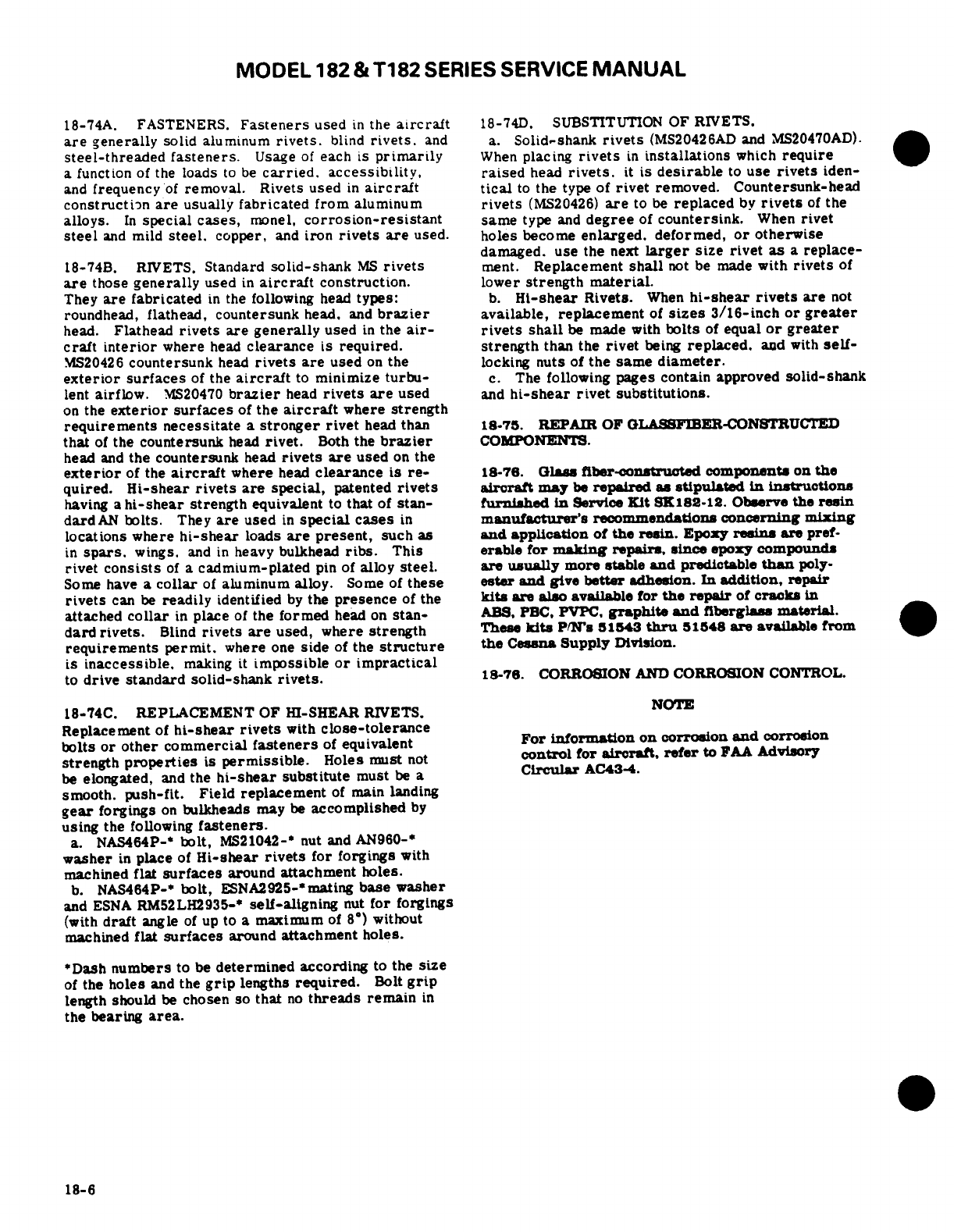
MODEL
182
&
T182
SERIES
SERVICE
MANUAL
18-74A. FASTENERS.
Fasteners
used
in
the
aircraft
18-74D.
SUBSTITUTION
OF RIVETS.
are
generally
solid
aluminum
rivets,
blind
rivets,
and
a.
Solid-shank
rivets
(MS20426AD
and
MS20470AD).
steel-threaded
fasteners.
Usage
of
each
is
primarily
When
placing
rivets
in
installations
which
require
a
function
of the
loads
to
be
carried.
accessibility, raised
head
rivets.
it
is
desirable
to
use
rivets
iden-
and
frequency
of
removal.
Rivets used
in
aircraft
tical
to
the
type of
rivet
removed.
Countersunk-head
construction
are
usually
fabricated from
aluminum
rivets
(MS20426)
are
to
be
replaced
by
rivets
of
the
alloys.
In
special
cases,
monel,
corrosion-resistant
same
type
and
degree
of
countersink.
When
rivet
steel
and
mild
steel.
copper,
and
iron
rivets
are
used.
holes
become
enlarged.
deformed,
or
otherwise
damaged.
use
the
next
larger
size
rivet
as
a
replace-
18-74B. RIVETS.
Standard
solid-shank
MS
rivets
ment.
Replacement
shall
not
be
made
with
rivets
of
are
those
generally
used
in
aircraft
construction.
lower
strength
material.
They
are
fabricated
in
the
following
head
types:
b.
Hi-shear
Rivets.
When
hi-shear
rivets
are
not
roundhead,
flathead,
countersunk
head.
and
brazier
available,
replacement
of
sizes
3/16-inch or
greater
head.
Flathead
rivets
are generally
used
in
the
air-
rivets
shall
be
made
with
bolts
of
equal
or
greater
craft
interior
where
head
clearance
is
required.
strength
than
the
rivet
being
replaced.
and
with
self-
MS20426
countersunk
head
rivets
are
used
on
the
locking
nuts
of
the
same
diameter.
exterior
surfaces
of
the
aircraft
to
minimize
turbu-
c.
The
following
pages contain
approved
solid-shank
lent
airflow.
MS20470
brazier
head
rivets
are
used
and
hi-shear
rivet
substitutions.
on
the
exterior
surfaces
of
the
aircraft
where
strength
requirements
necessitate
a
stronger
rivet
head
than 18-75.
REPAIR
OF
GLASSFIBER-CONSTRUCTED
that
of
the
countersunk
head
rivet.
Both
the
brazier
COMPONENTS.
head
and
the countersunk
head
rivets
are
used
on
the
exterior
of
the
aircraft
where
head
clearance
is
re-
18-76.
Glass
fiber-constructed
components
on
the
quired.
Hi-shear
rivets
are
special,
patented
rivets
aircraft
may
be
repaired
as
stipulated
in
instructions
having
a
hi-shear
strength
equivalent
to
that
of
stan-
furnished
in
Service
Kit
SK182-12.
Observe
the
resin
dardAN
bolts.
They
are
used
in
special cases
in
manufacturer's
recommendations
concerning
mixing
locations
where
hi-shear
loads
are
present,
such
as
and
application of
the
resin.
Epoxy
resins
are
pref-
in
spars.
wings.
and
in
heavy
bulkhead
ribs.
This
erable
for
making
repairs,
since
epoxy
compounds
rivet
consists
of
a
cadmium-plated
pin
of
alloy
steel.
are
usually
more
stable
and
predictable
than
poly-
Some
have
a
collar
of
aluminum
alloy.
Some
of
these
ester
and
give
better
adhesion.
In
addition,
repair
rivets
can
be
readily
identified
by
the
presence
of
the
kits
are
also
available
for
the repair
of
cracks
in
attached
collar
in
place
of
the
formed
head
on
stan-
ABS,
PBC,
PVPC,
graphite
and
fiberglass material.
dard
rivets.
Blind
rivets
are
used, where
strength
These
kits
P/N's
51543
thru
51548
are
available
from
requirements
permit.
where
one
side
of
the
structure
the
Cessna
Supply
Division.
is
inaccessible,
making
it
impossible
or
impractical
to
drive
standard
solid-shank
rivets.
18-76.
CORROSION
AND
CORROSION
CONTROL.
18-74C.
REPLACEMENT
OF
HI-SHEAR
RIVETS.
NOTE
Replacement
of
hi-shear
rivets
with
close-tolerance
bolts
or
other
commercial
fasteners
of
equivalent
For
information
on
corrosion
and
corrosion
strength
properties
is
permissible.
Holes
must
not
control
for
aircraft refer
to
FAA
Advisory
be
elongated,
and
the
hi-shear
substitute
must
be
a
Circular
AC43-4.
smooth.
push-fit.
Field
replacement
of
main
landing
gear
forgings
on
bulkheads
may
be
accomplished
by
using
the
following
fasteners.
a.
NAS464P-*
bolt,
MS21042-*
nut
and
AN960-*
washer
in
place
of
Hi-shear
rivets
for forgings
with
machined
flat
surfaces
around
attachment
holes.
b.
NAS464P-*
bolt,
ESNA2925-*mating
base
washer
and
ESNA
RM52LH2935-*
self-aligning
nut
for
forgings
(with
draft
angle
of
up
to
a
maximum
of
8°)
without
machined
flat
surfaces
around
attachment
holes.
*Dash
numbers
to
be
determined
according
to
the
size
of
the
holes
and
the
grip
lengths
required.
Bolt
grip
length
should
be
chosen
so
that
no
threads
remain
in
the
bearing
area.
18-6
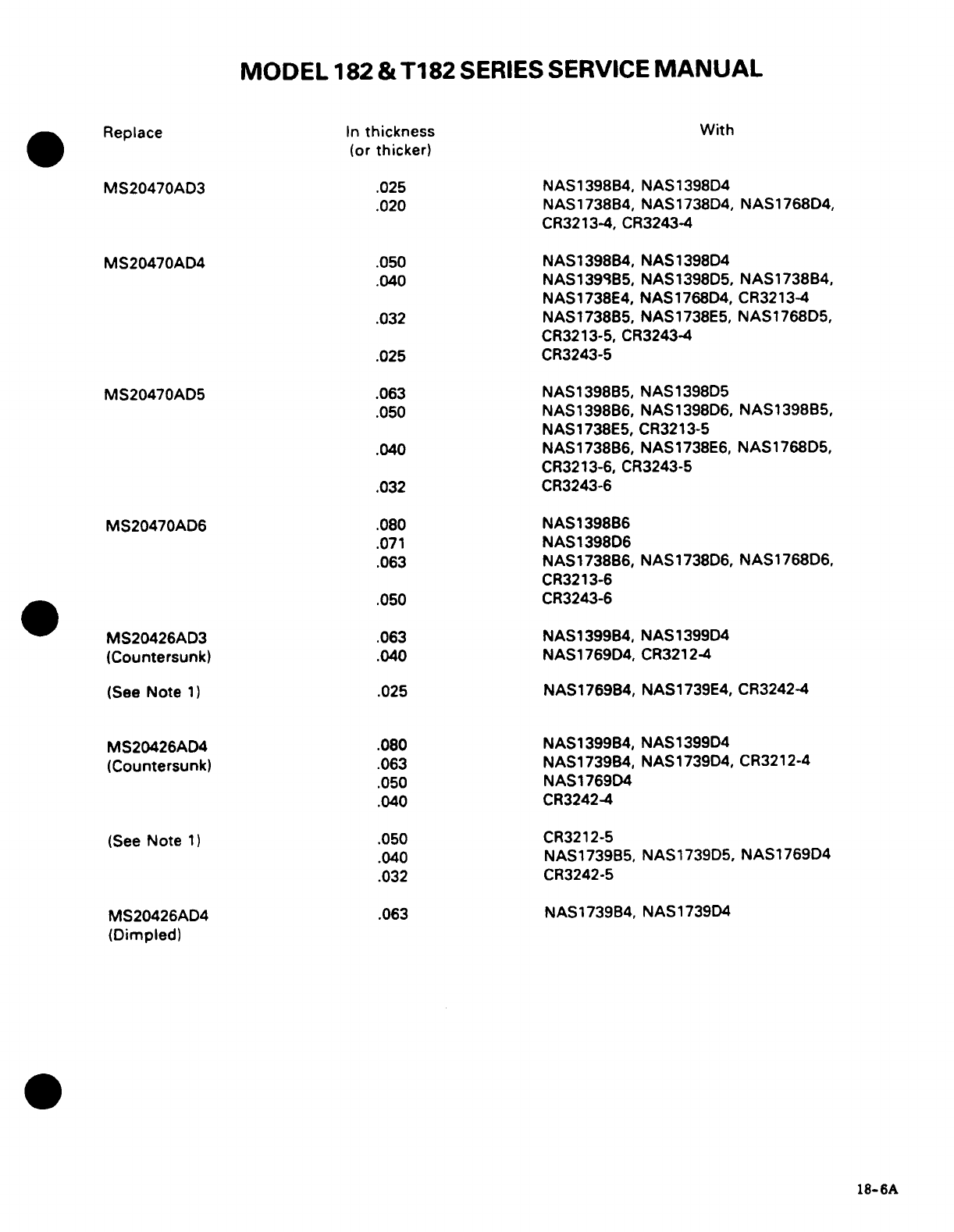
MODEL
182
&
T182
SERIES
SERVICE
MANUAL
Replace
In
thickness
With
(or
thicker)
MS20470AD3
.025
NAS1398B4,
NAS1398D4
.020
NAS1738B4, NAS1738D4,
NAS1768D4,
CR3213-4, CR3243-4
MS20470AD4
.050
NAS1398B4,
NAS1398D4
.040
NAS1398B5, NAS1398D5,
NAS1738B4,
NAS1738E4,
NAS1768D4,
CR3213-4
.032
NAS1738B5,
NAS1738E5,
NAS1768D5,
CR3213-5,
CR3243-4
.025
CR3243-5
MS20470AD5
.063
NAS1398B5, NAS1398D5
.050
NAS1398B6, NAS1398D6,
NAS1398B5,
NAS1738E5,
CR3213-5
.040
NAS1738B6,
NAS1738E6,
NAS1768D5,
CR3213-6, CR3243-5
.032
CR3243-6
MS20470AD6
.080
NAS1398B6
.071
NAS1398D6
.063
NAS1738B6, NAS1738D6,
NAS1768D6,
CR3213-6
.050
CR3243-6
MS20426AD3
.063
NAS1399B4,
NAS1399D4
(Countersunk)
.040 NAS1769D4,
CR3212-4
(See
Note
1)
.025
NAS1769B4,
NAS1739E4,
CR3242-4
MS20426AD4
.080
NAS1399B4,
NAS1399D4
(Countersunk)
.063
NAS1739B4, NAS1739D4,
CR3212-4
.050
NAS1769D4
.040
CR3242-4
(See
Note
1)
.050
CR3212-5
.040
NAS1739B5, NAS1739D5,
NAS1769D4
.032
CR3242-5
MS20426AD4
.063
NAS1739B4,
NAS1739D4
(Dimpled)
18-6A
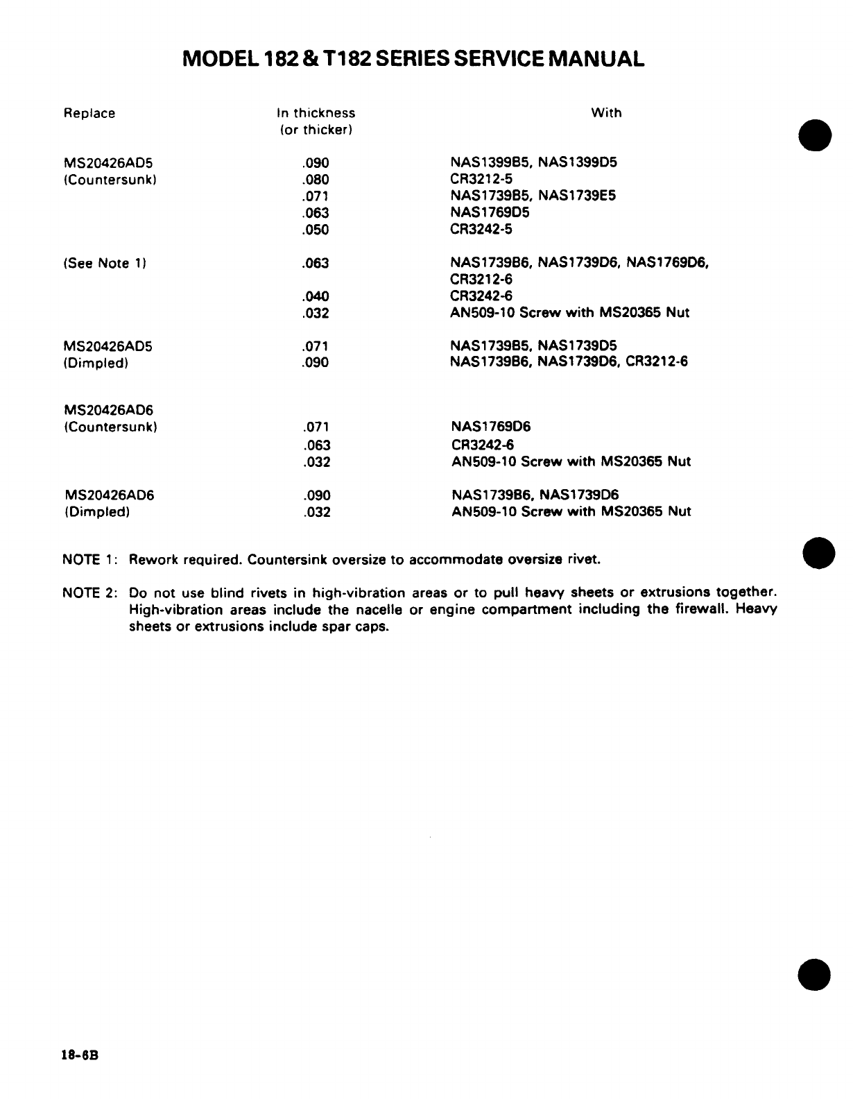
MODEL
182
&
T182
SERIES
SERVICE
MANUAL
Replace
In
thickness With
(or thicker)
MS20426AD5
.090
NAS1399B5, NAS1399D5
(Countersunk)
.080
CR3212-5
.071
NAS1739B5,
NAS1739E5
.063 NAS1769D5
.050
CR3242-5
(See
Note
1)
.063
NAS1739B6, NAS1739D6,
NAS1769D6,
CR3212-6
.040
CR3242-6
.032
AN509-10
Screw
with
MS20365
Nut
MS20426AD5
.071
NAS1739B5, NAS1739D5
(Dimpled)
.090
NAS1739B6, NAS1739D6,
CR3212-6
MS20426AD6
(Countersunk)
.071
NAS1769D6
.063
CR3242-6
.032
AN509-10
Screw
with
MS20365
Nut
MS20426AD6
.090
NAS1739B6, NAS1739D6
(Dimpled)
.032
AN509-10
Screw
with
MS20365
Nut
NOTE
1:
Rework
required.
Countersink
oversize
to
accommodate
oversize
rivet.
NOTE 2:
Do
not
use
blind
rivets
in
high-vibration
areas
or
to
pull
heavy
sheets
or
extrusions
together.
High-vibration
areas
include
the
nacelle
or engine
compartment
including
the
firewall.
Heavy
sheets
or
extrusions
include
spar
caps.
18-6B

MODEL
182
&
T182
SERIES
SERVICE
MANUAL
REPLACE
DIAMETER
WITH
Fastener
Collar
Fastener
Collar
NAS178
NAS179
(See
Note
1)
NAS1054
NAS179,
NAS528
(See
Note
1)
NAS14XX
NAS1080C,
NAS1080E,
NAS1080G
(See
Note
1)
NAS529
NAS524A
(See
Notes
1
and
2)
NAS1446
NAS1080C,
NAS1080A6
(See
Note
1)
NAS7034
NAS1080K
(See
Note
1)
NAS464
AN364, MS20364,
MS21042
o
NAS1103
NAS1303
o
NAS6203
o
AN173
AN305, MS20305,
MS21044,
MS21045
NAS1054 NAS179, NAS528 NAS14XX
NAS1080C,
NAS1080E
NAS529
NAS524A
(See
Note
2)
NAS1446
NAS1080C,
NAS1080A6
NAS7034
NAS1080K
NAS464
AN364,
MS20304,
MS21042
o
NAS1103
NAS1305
NAS6203
NAS14XX
NAS1080C
NAS529
NAS524A
NAS1080E
NAS1446
NAS1080C,
NAS1080A6
NAS1080G
NAS7034
NAS1080K
o
NAS464
AN364,
MS20364,
MS21042
NAS1103
NAS1303
o
NAS6203
NAS529 NAS524A
(See
Note
3)
NAS1446
NAS1080C,
NAS1080A6
NOTE
1:
See
appropriate
tables
for
nominal
diameters
available.
NOTE
2:
Available
in
oversize
for
repair
of
elongated
holes.
Ream
holes
to
provide
a
.001
inch
interference
fit.
NOTE 3:
NAS1446
oversize
only
permitted
as
a
replacement
for
NAS529.
Steel
shank
fastener
designed
for
drive-on
collars.
Steel
shank
fastener designed
for
squeeze-on
collars.
Installation
requires
sufficient
space
for
the
tool
and
extended
shank
of
the
fastener.
Threaded
fastener.
18-6C
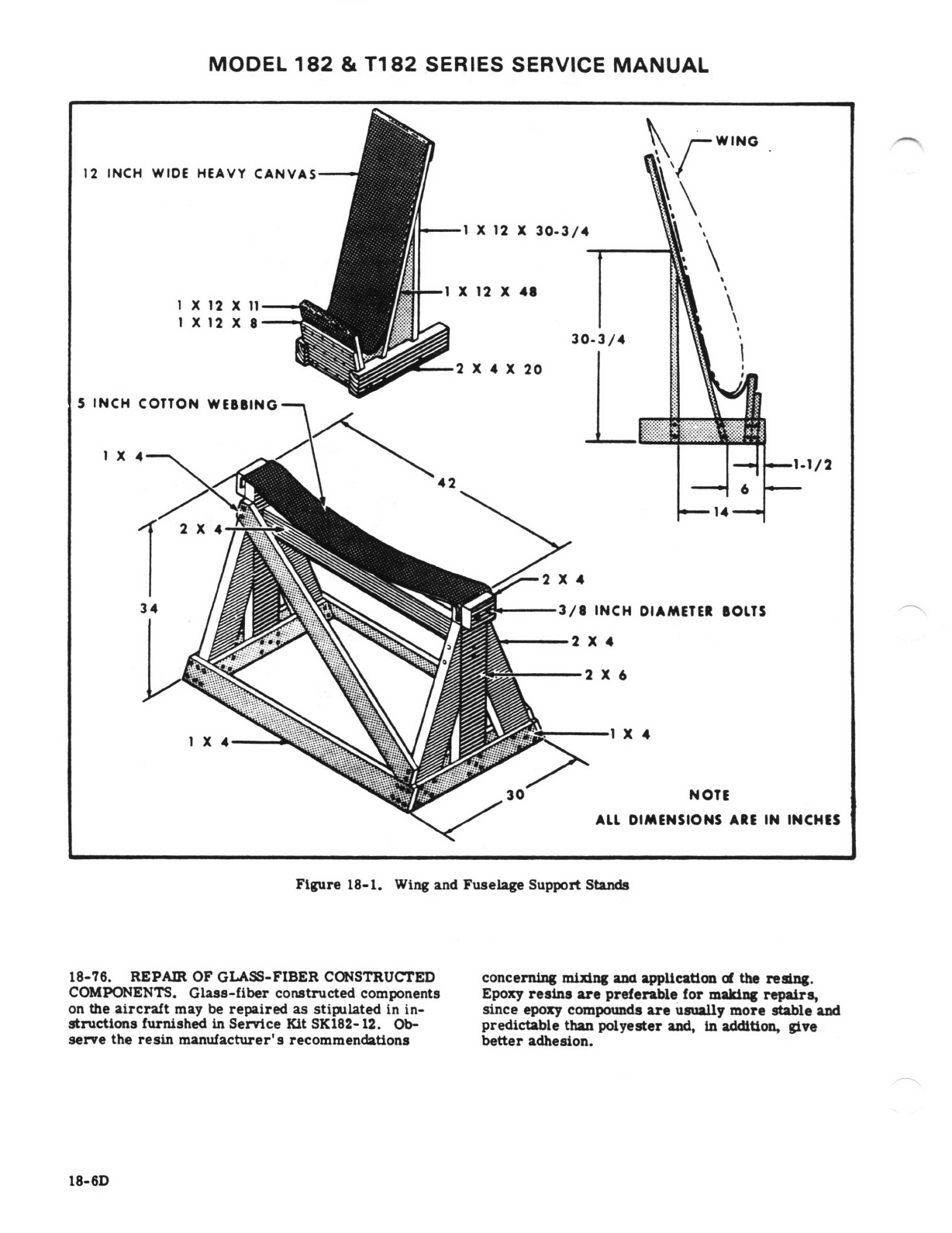
MODEL
182
&
T182
SERIES SERVICE
MANUAL
12
INCH
WIDE
HEAVY
CANVAS
30-3/4
2
X
4
X
20
5
INCH
COTTON
WEBBING
42
14
34
----
3/8
INCH
DIAMETER
BOLTS
2
X
6
30
NOTE
ALL
DIMENSIONS
ARE
IN
INCHES
Figure
18-1.
Wing
and
Fuselage
Support
Stands
18-76.
REPAIR
OF
GLASS-FIBER
CONSTRUCTED
concerning
mixing
and
application
of
the
resing.
COMPONENTS.
Glass-fiber
constructed
components
Epoxy
resins
are
preferable for
making
repairs,
on
the
aircraft
may
be
repaired
as
stipulated
in
in-
since
epoxy
compounds
are
usually more
stable
and
structions
furnished
in
Service
Kit SK182-12.
Ob-
predictable
than
polyester
and,
in
addition,
give
serve
the
resin
manufacturer's
recommendations
better
adhesion.
18-6D
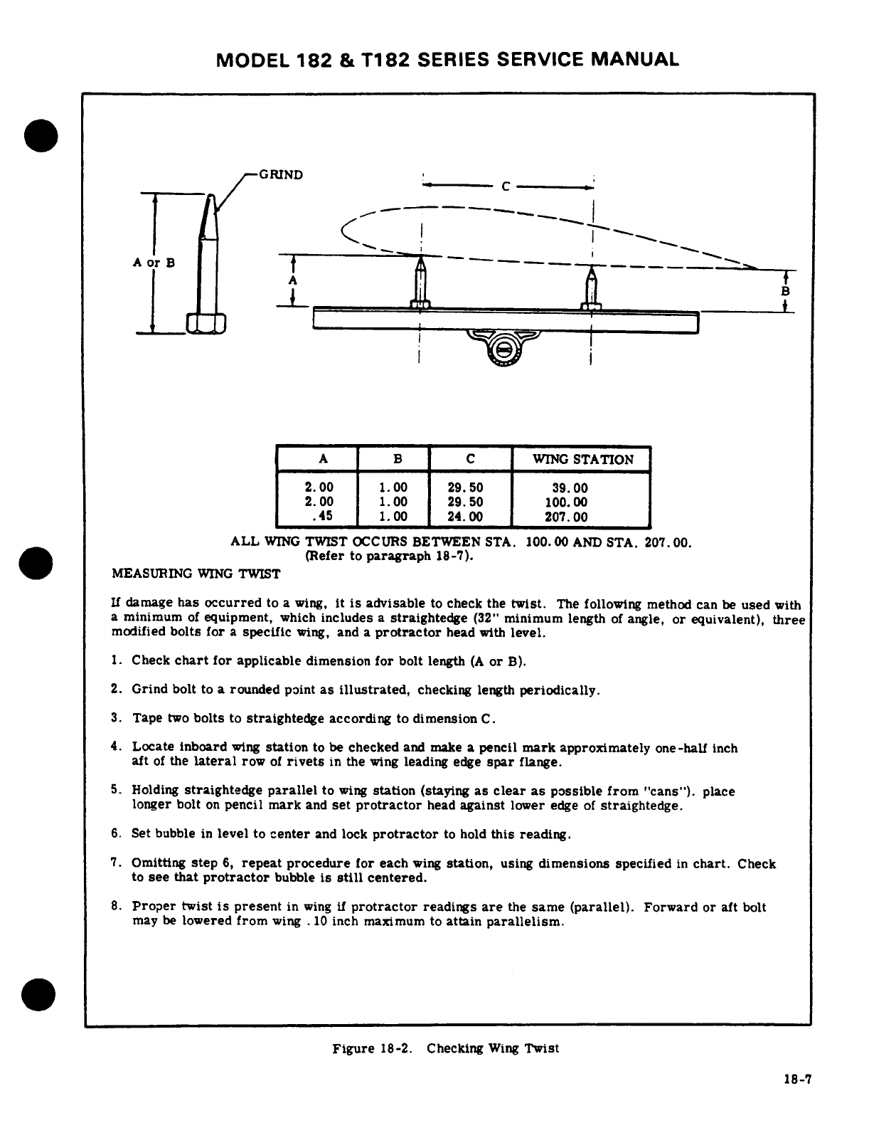
MODEL
182
&
T182
SERIES
SERVICE
MANUAL
-
---
A
or
B
:_ L_
A
B
C
WING
STATION
2.00
1.00 29.50
39.00
2.00
1.00
29.50
100.00
.45
1.00
24.00 207.00
ALL
WING
TWIST
OCCURS
BETWEEN
STA.
100.00
AND
STA.
207.00.
(Refer
to
paragraph
18-7).
MEASURING
WING
TWIST
If
damage
has
occurred
to
a
wing,
it
is
advisable
to
check the
twist.
The
following
method
can
be
used
with
a
minimum
of
equipment,
which
includes
a
straightedge
(32"
minimum
length
of
angle,
or
equivalent),
three
modified
bolts
for
a
specific
wing,
and
a
protractor
head
with
level.
1.
Check
chart
for
applicable
dimension for bolt
length
(A
or
B).
2.
Grind
bolt
to
a
rounded
point
as
illustrated,
checking
length
periodically.
3.
Tape
two
bolts
to
straightedge
according
to
dimension
C.
4.
Locate
inboard
wing
station
to
be
checked
and
make
a
pencil
mark
approximately
one-half
inch
aft
of
the
lateral
row
of
rivets
in
the
wing
leading
edge
spar
flange.
5.
Holding
straightedge
parallel
to
wing
station
(staying
as
clear as
possible
from
"cans").
place
longer
bolt
on
pencil
mark
and
set
protractor
head
against
lower
edge
of
straightedge.
6.
Set
bubble
in
level
to
center
and
lock
protractor
to
hold
this
reading.
7.
Omitting
step
6,
repeat
procedure
for
each
wing
station,
using
dimensions
specified
in
chart.
Check
to
see that
protractor
bubble
is
still
centered.
8.
Proper
twist
is
present
in
wing
if
protractor
readings
are
the
same
(parallel).
Forward
or
aft
bolt
may
be
lowered
from
wing
.
10
inch
maximum
to
attain
parallelism.
Figure
18-2.
Checking
Wing
Twist
18-7
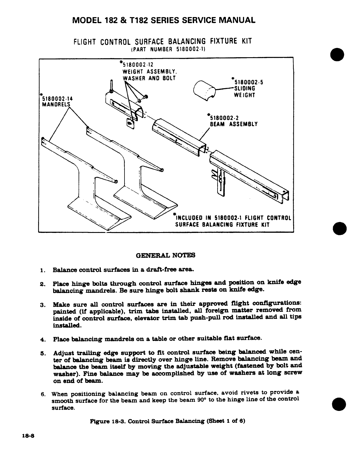
MODEL
182
&
T182
SERIES SERVICE
MANUAL
FLIGHT CONTROL
SURFACE
BALANCING
FIXTURE
KIT
(PART
NUMBER
5180002.1)
*5180002
-12
WEIGHT
ASSEMBLY.
WASHER
AND
BOLT
*518000214
MANDRELS
BEAM
ASSEMBLY
INCLUDED
IN
5180002-1
FLIGHT
CONTROL
SURFACE
BALANCING
FIXTURE
KIT
GENERAL NOTES
1.
Balance
control
surfaces in
a
draft-free
area.
2.
Place
hinge
bolts
through
control
surface
hinges
and
position
on
knife
edge
balancing
mandrels.
Be
sure hinge
bolt
shank
rests
on
knife
edge.
3.
Make
sure
all
control
surfaces
are
in
their
approved
flight
configurations:
painted
(if
applicable),
trim
tabs installed,
all
foreign
matter
removed
from
inside
of
control surface,
elevator
trim
tab
push-pull
rod
installed and
all
tips
installed.
4.
Place
balancing
mandrels
on
a
table
or
other
suitable
flat
surface.
5.
Adjust
trailing
edge
support
to
fit control
surface
being
balanced while
cen-
ter
of
balancing
beam
is directly
over
hinge
line.
Remove
balancing
beam
and
balance
the
beam
itself
by
moving
the
adjustable
weight (fastened
by
bolt
and
washer). Fine
balance
may
be
accomplished
by
use
of
washers
at
long
screw
on
end
of
beam.
6.
When
positioning balancing
beam
on
control
surface,
avoid
rivets
to
provide
a
smooth
surface
for
the beam
and
keep
the
beam
90°
to
the
hinge line
of
the
control
surface.
Figure
18-3.
Control
Surface
Balancing
(Sheet
1
of
6)
18-8
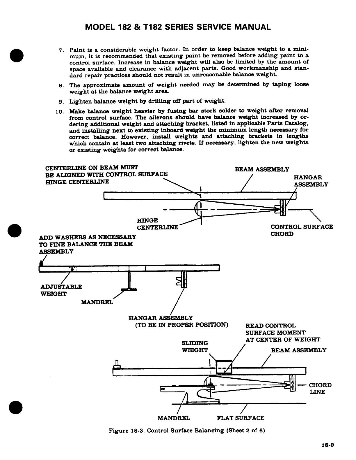
MODEL
182
&
T182
SERIES
SERVICE
MANUAL
7.
Paint
is
a
considerable
weight
factor.
In
order
to
keep
balance
weight
to a
mini-
mum,
it
is
recommended
that
existing
paint
be
removed
before
adding
paint
to
a
control
surface.
Increase
in
balance
weight
will
also
be
limited
by
the
amount
of
space
available
and
clearance
with
adjacent
parts.
Good
workmanship
and
stan-
dard repair
practices should
not
result
in
unreasonable
balance
weight.
8.
The
approximate
amount
of
weight
needed may
be
determined
by
taping
loose
weight
at
the
balance
weight
area.
9.
Lighten
balance
weight
by
drilling
off
part
of
weight.
10.
Make
balance
weight
heavier
by
fusing
bar
stock solder
to
weight
after
removal
from
control
surface.
The
ailerons
should
have
balance
weight
increased
by
or-
dering
additional weight and
attaching
bracket,
listed
in
applicable
Parts
Catalog,
and
installing
next
to
existing
inboard
weight
the
minimum
length necessary
for
correct
balance.
However,
install
weights
and
attaching
brackets
in
lengths
which
contain
at
least
two
attaching
rivets.
If
necessary,
lighten
the
new
weights
or
existing weights
for
correct
balance.
CENTERLINE
ON BEAM
MUST
BEAM
ASSEMBLY
BE ALIGNED
WITH CONTROL
SURFACE HANGAR
ADD
WASHERS
AS
NECESSARY
CHORD
TO
FINE
BALANCE
THE
BEAM
ASSEMBLY
ADJUSTABLE
WEIGHT
MANDREL
HANGAR ASSEMBLY
(TO
BE
IN
PROPER
POSITION)
READ
CONTROL
SURFACE
MOMENT
SLIDING
AT
CENTER
OF
WEIGHT
WEIGHT
LINE
MANDREL FLAT
SURFACE
Figure
18-3.
Control
Surface
Balancing
(Sheet
2
of
6)
18-9
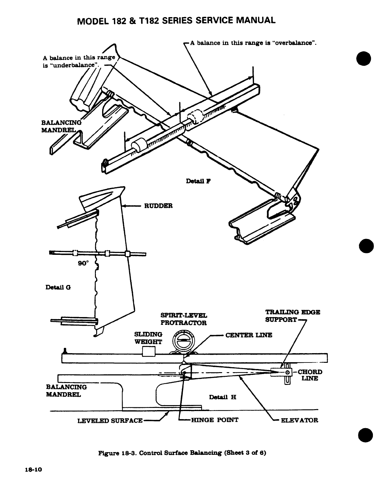
MODEL
182
&
T182
SERIES
SERVICE
MANUAL
A
balance
in
this
range
is
"overbalance".
A
balance
in
this
range
is
"underbalance".
BALANCING
MANDREL
Detail
F
RUDDER
90°
Detail
G
LESPIET-LEVEL
TRAILINO
EDGE
18 SU0PROTRACTOR
PPORT
J
SLIDING
CENTER
LINE
/
I---------------- =- -i -
CHORD
LINE
BALANCING
MANDREL
D
H
\
LEVELED
SURFACE
---
HINGE
POINT
\-ELEVATOR
Figure
18-3.
Control
Surface
Balancing
(Sheet
3
of
6)
18-10
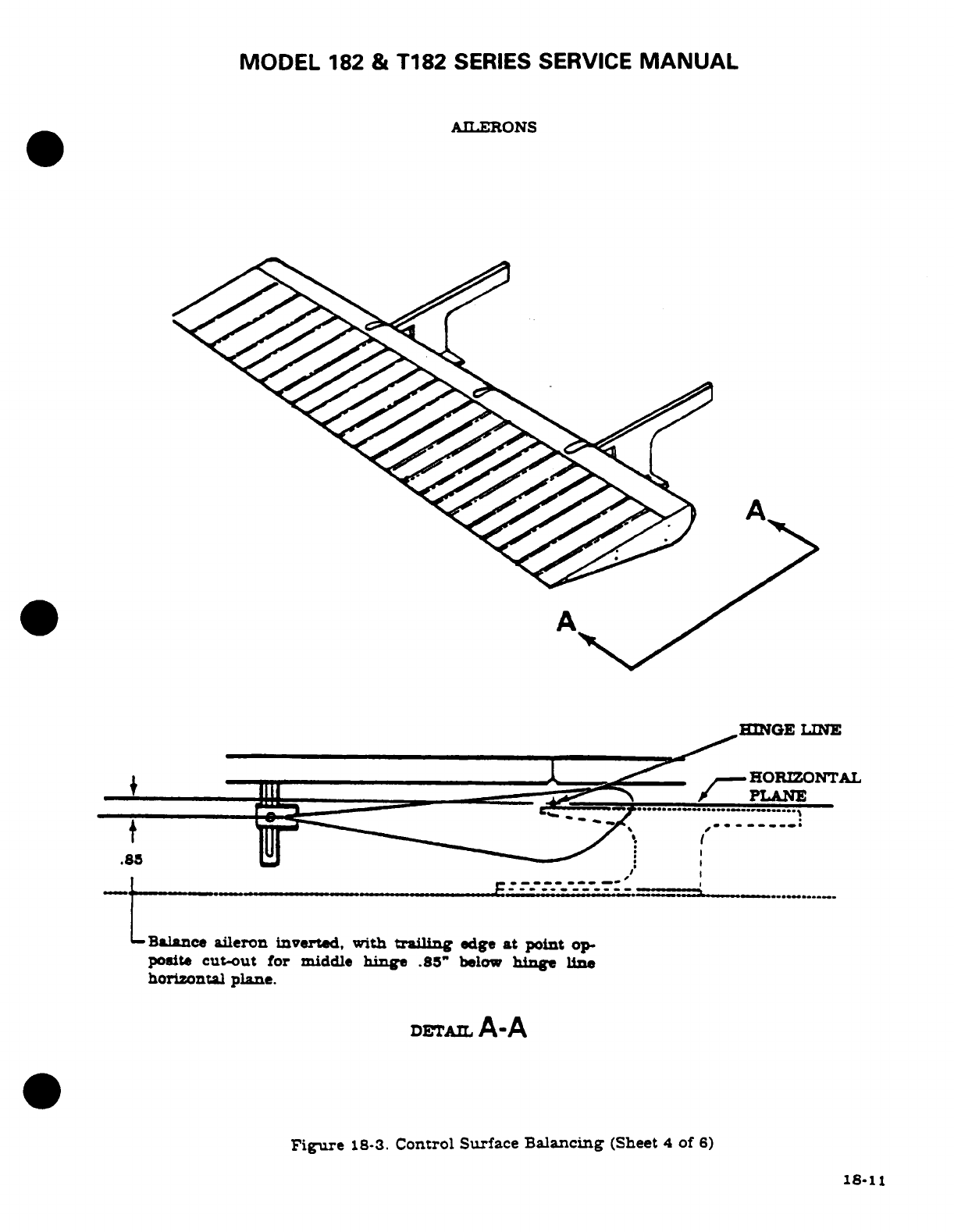
MODEL
182
&
T182
SERIES SERVICE
MANUAL
AILERONS
1ORIZONTAL
=/
PLANE
-
aance
aileron
i.nverted,
with
trailing
edge
at
point
op.
-Balance
aileron inverted,
with
trailing
edge
at point
op-
posite
cut-out
for
middle
hinge
.85"
below
hinge
line
horizontal
plane.
DETAL
A-A
Figure
18-3.
Control Surface
Balancing
(Sheet
4
of
6)
18-11
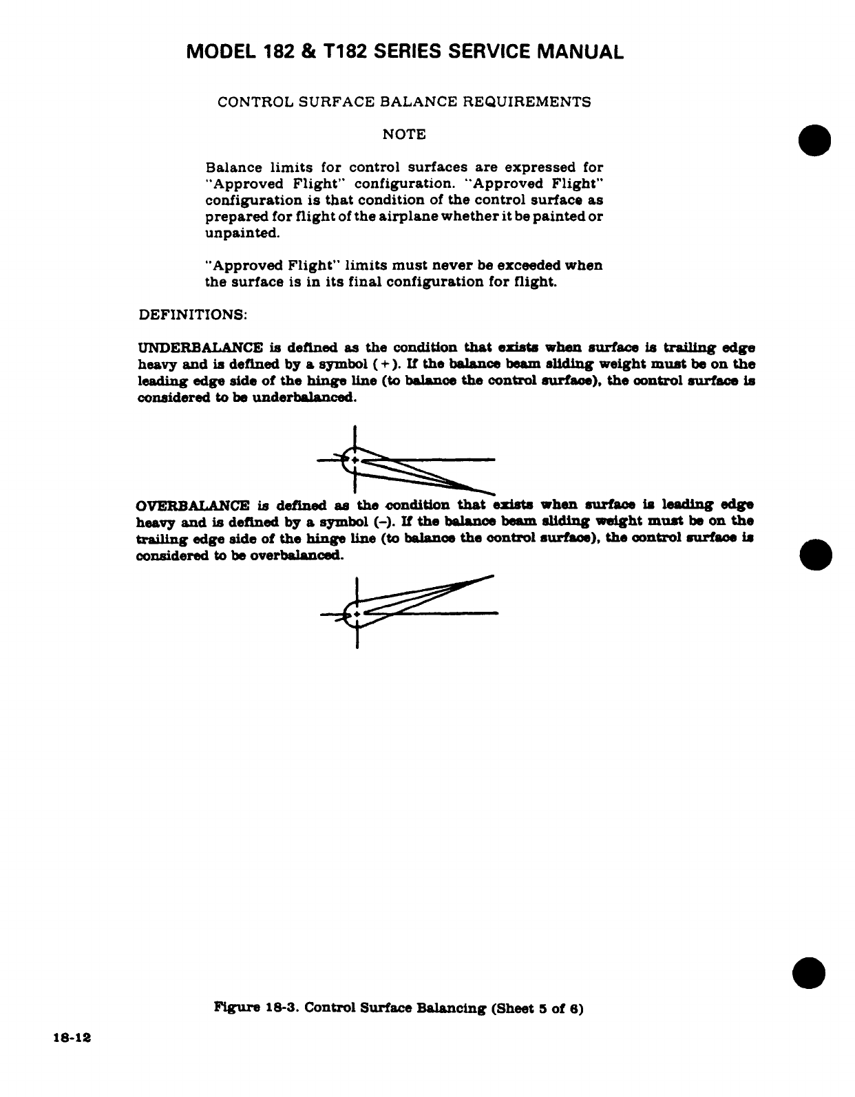
MODEL
182
&
T182
SERIES
SERVICE
MANUAL
CONTROL
SURFACE
BALANCE
REQUIREMENTS
NOTE
Balance
limits
for
control
surfaces
are
expressed
for
"Approved
Flight"
configuration.
"Approved
Flight"
configuration
is
that
condition
of
the
control
surface
as
prepared
for
flight
of
the
airplane
whether
it
be
painted
or
unpainted.
"Approved
Flight"
limits
must
never
be
exceeded
when
the
surface
is in
its
final
configuration
for
flight.
DEFINITIONS:
UNDERBALANCE
is defined
as the
condition
that
exists
when
surface
is
trailing
edge
heavy
and
is
defined
by
a
symbol
(+).
If
the
balance
beam
sliding
weight
must
be
on
the
leading
edge side of
the
hinge
line
(to
balance
the
control surface),
the control surface
is
considered
to
be
underbalanced.
OVERBALANCE
is defined
as
the
condition
that
exists
when
surface
is
leading
edge
heavy
and
is
defined
by
a
symbol
(-).
If
the
balance
beam
sliding
weight
must
be
on
the
trailing
edge side
of
the hinge
line (to
balance
the control
surface),
the
control
surface
is
considered
to
be
overbalanced.
Figure
18-3.
Control
Surface
Balancing
(Sheet
5
of
6)
18-12
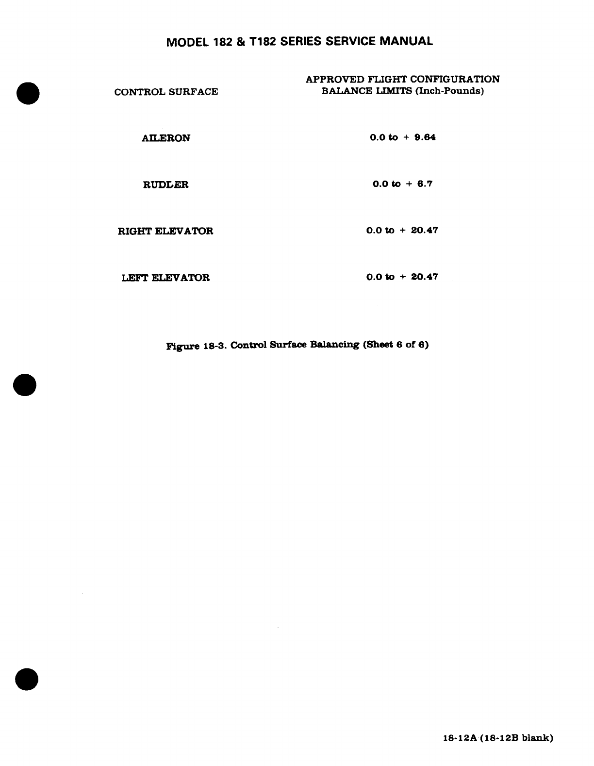
MODEL
182
&
T182
SERIES
SERVICE
MANUAL
APPROVED
FLIGHT
CONFIGURATION
CONTROL
SURFACE
BALANCE LIMITS
(Inch-Pounds)
AILERON
0.0
to
+
9.64
RUDDER
0.0
to
+
6.7
RIGHT ELEVATOR
0.0
to
+
20.47
LEFT
ELEVATOR
0.0
to
+
20.47
Figure
18-3.
Control
Surface
Balancing
(Sheet
6
of
6)
18-12A
(18-12B
blank)
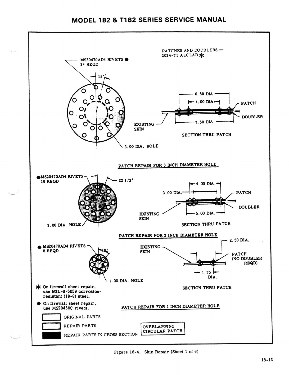
MODEL
182
&
T182
SERIES
SERVICE
MANUAL
PATCHES
AND
DOUBLERS
-
2024-T3
ALC
LAD
MS20470AD4
RIVETS
15-`
\O
^ 'fit'
EXISTING
7.50DIA.
SKIN
N^\O J< >v~
y\SECTION
THRU
PATCH
3.00DIA.
HOLE
PATCH
REPAIR
FOR
3
INCH
DIAMETER
HOLE
*MS20470AD4
RIVETS
16
REQD
/
221/2'
-4.00
DIA.1
3. j0
DIA.-'
PATCH
/YISTN .-
,-._ RDOUBLER
EXISTING
-
5.00
DIA.
SKIN
2.00
DIA.
HOLE/
SECTION
THRU
PATCH
PATCH
REPAIR
FOR
2
INCH
DIAMETER
HOLE
2.
50
DIA.
*
MS20470AD4
RIVETS
EXISTING
8
REQD
S\IN
PATCH
-
i1.75
-
-
DIA.
1.00
DIA.
HOLE
C
On
firewall sheet
repair,
SECTION
THRU
PATCH
use
MIL-S-5059
corrosion-
resistant
(18-8)
steel.
*
On
firewall
sheet
repair,
use
MS20450C
rivets.
PATCH
REPAIR
FOR
1
INCH
DIAMETER
HOLE
]
|
ORIGINAL PARTS
|1
REPAIR
PARTS
OVERLAPPING
REPAIR
PARTS IN
CROSS
SECTION
CIRCULAR PATCH
Figure
18-4.
Skin
Repair
(Sheet
1
of
6)
18-13
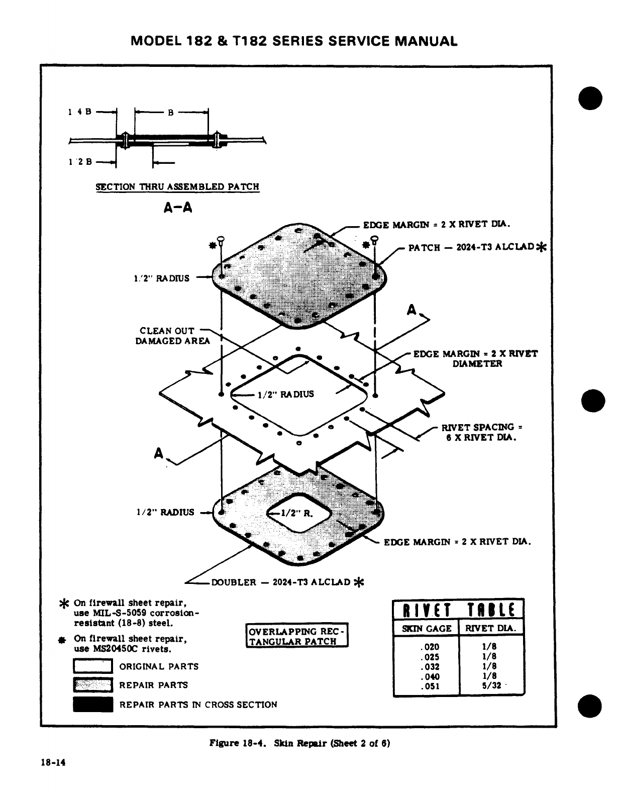
MODEL
182
&
T182
SERIES
SERVICE
MANUAL
1
4B
--
B
- B
1
'2
B
SECTION
THRU
ASSEMBLED
PATCH
A-A
EDGE
MARGIN
=
2
X
RIVET
DIA.
0i
.!i*
:
+.
:...:^
.-
: 1
.
_
.
.
j:;: :i: i.
.. ..
PATCH
-
2024-T3
ALCLAD*
CLEAN
OUT
DAMAGED
.AREA
.. .
EDGE
MARGIN
=
2
X
RIVET
·
^ *^^-^
l<* ^JDIAMETER
RIVET
SPACING
=
1/2"
RADIUS
-.
....
....
::
I.
/
R.
..
i-
lil
I
_''EDGE
MARGIN
-
2
X
RIVET
DIA.
DOUBLER
-
2024-T3
ALCLAD
*
*
On
firewaKll
sheet
repair,
use
MIL-S-5059
corrosion-
RIlVET
R
T
S
L
N
DOAAVERLAPPING
REC-
SKIN
GAGE
RIVET
DIA.
*
On
firewall
sheet
repair,
TANGUAR
PATCH
.020
1/
use
MS20450C
rivets.
.T
_---.·
.025
1/8
ORIGINAL PARTS
.032
I1/8
1/2"m i 1/2"~i
.I
.040 1/8
[!!:: :1
REPAIR
PARTS
.051
5/32
-|
REPAIR
PARTS
IN
CROSS
SECTION
Figure
18-4.
Skin
Repair
(Sheet
2
of
)
18-14
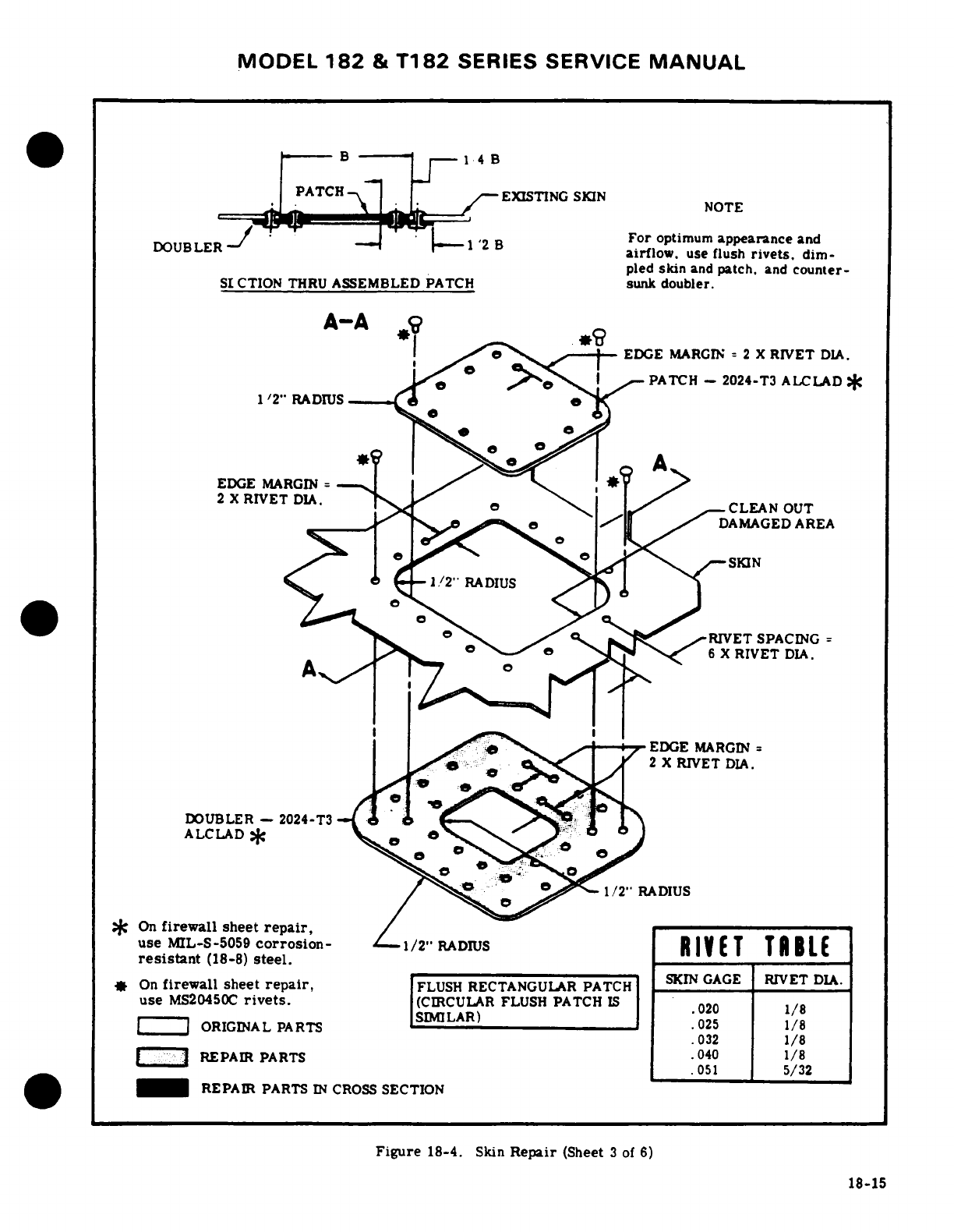
MODEL
182
&
T182
SERIES
SERVICE
MANUAL
----
B
-i4B
PATCH
I m
-
EXISTING
SKIN
NOTE
nnD -nr-^ '--
L_.C1'2
B
_,For
optimum
appearance
and
DOUBLER-
1 i2
B
airflow.
use
flush
rivets,
dim-
pled
skin
and
patch,
and
counter-
SI
CTION
THRU
ASSEMBLED
PATCH
sunk
doubler.
A-A
.?
.
!0
,o
r e
'
-j
~EDGE
MARGIN
= 2
X
RIVET
DIA.
J__
e~I
,
PATCH
-
2024-T3
ALCLAD
*
1
/2
RADIUS B
i
*y ^Ss
A
EDGE
MARGIN
=
,
A
2 X
RIVET
DIA.
.
CLEAN
OUT
"_ IS
0l
DAMAGED
AREA
1/2"
RADIUS
RIVET
SPACING
=
AoS^ e°- eX
6
X
RIVET
DIA.
A,
,
/
_--~
-
EDGE
MARGIN
=
^^»'
tC'^'C
'
2
X
RIVET
DIA.
DOUBLER
-
2024-T3
ALCLAD
*
: 0
O
/
O'
v^
1//
2
RADIUS
*
On
firewall sheet
repair,
use
MIL-S-5059
corrosion-
-1/2"
RADIUS
RIVET
T
LE
resistant
(18-8)
steel.
*
On
firewall
sheet
repair,
FLUSH
RECTANGULAR
PATCH
SKIN
GAGE
RIVET
DIA.
use
MS20450C
rivets.
(CIRCULAR
FLUSH
PATCH
IS
.020
1/8
I ORIGINAL PARTS
SIMLAR)
.025
1/8
.032
1/8
Ji::
3
REPAIR
PARTS
.040
1/8
.051
5/32
REPAIR
PARTS
IN
CROSS
SECTION
Figure
18-4. Skin
Repair
(Sheet
3
of
6)
18-15
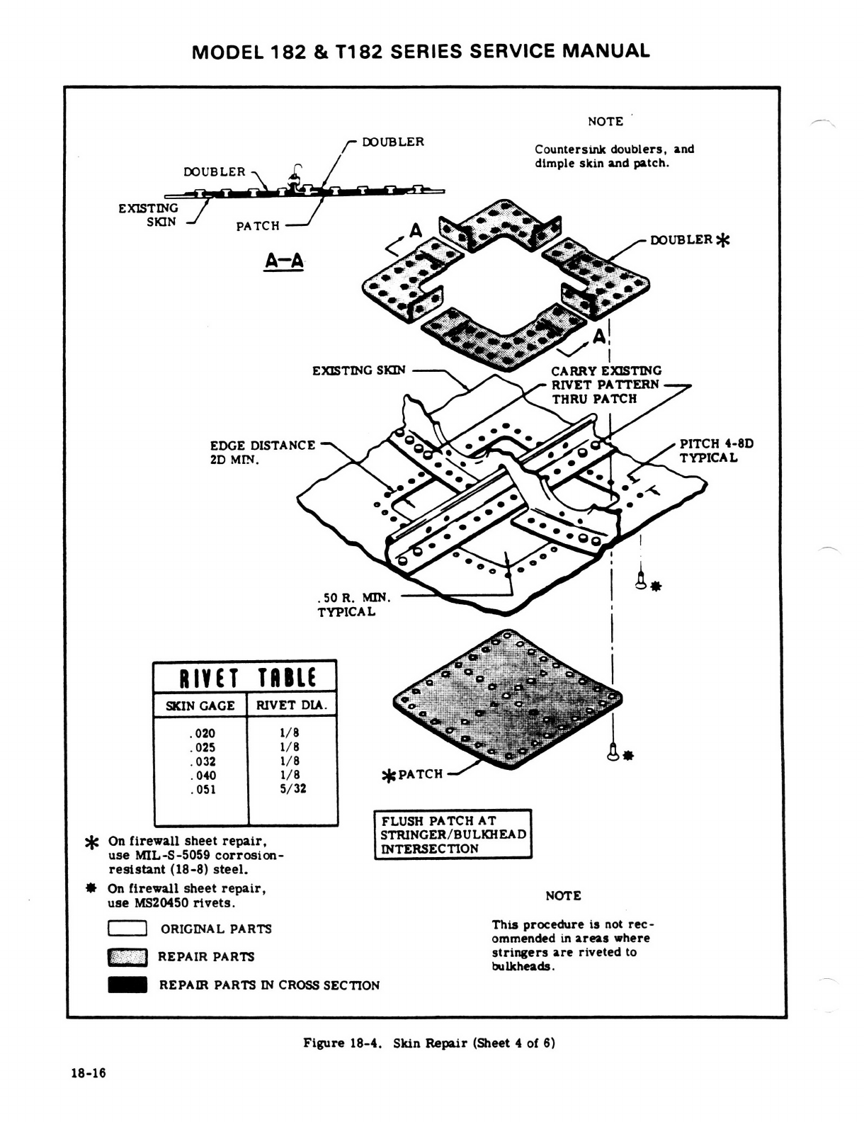
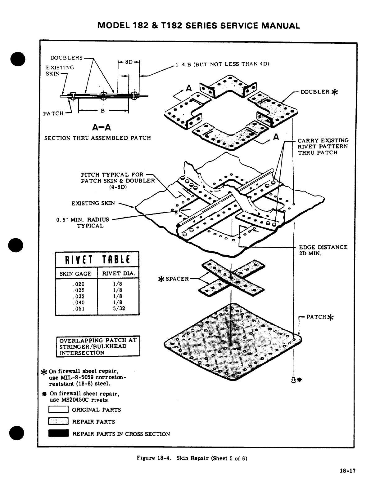
MODEL
182
&
T182
SERIES
SERVICE
MANUAL
DOUBLERS
XSKIN
/
/_
Ai_14BL..
-
DOUBLER
*
PATCHT4
A-A
SECTION
THRU
ASSEMBLED
PATCH
CARRY
EXISTING
RIVET
PATTERN
THRU
PATCH
PITCH
TYPICAL
FOR
-i
PATCH
SKIN
&
DOUBLER\
(4-8D)
/0
_
EXISTING
SKIN
0.
5"
MIN.
RADIUS
TYPICAL
_~S^ I r
EDGE
DISTANCE
------- ^2D
MIN.
RIVET
TRBLE
M
SKIN
GAGE
RIVET
DIA.
.020
1/8
A
.025
1/8
.032
1/8
.040
1/8
.051
5/32
L'--?
..
LJ-
<
k
~~~PATCH*
OVERLAPPING PATCH
AT
STRINGER/BULKHEAD
!
.
.. L
INTERSECTION
I
*
On
firewall
sheet
repair,
use
MIL-S-5059
corrosion-
I
resistant
(18-8)
steel.
*
On
firewall
sheet
repair,
use
MS20450C
rivets
ORIGINAL
PARTS
':
:
I
REPAIR
PARTS
REPAIR PARTS
IN
CROSS
SECTION
Figure
18-4.
Skin
Repair
(Sheet
5
of
6)
18-17
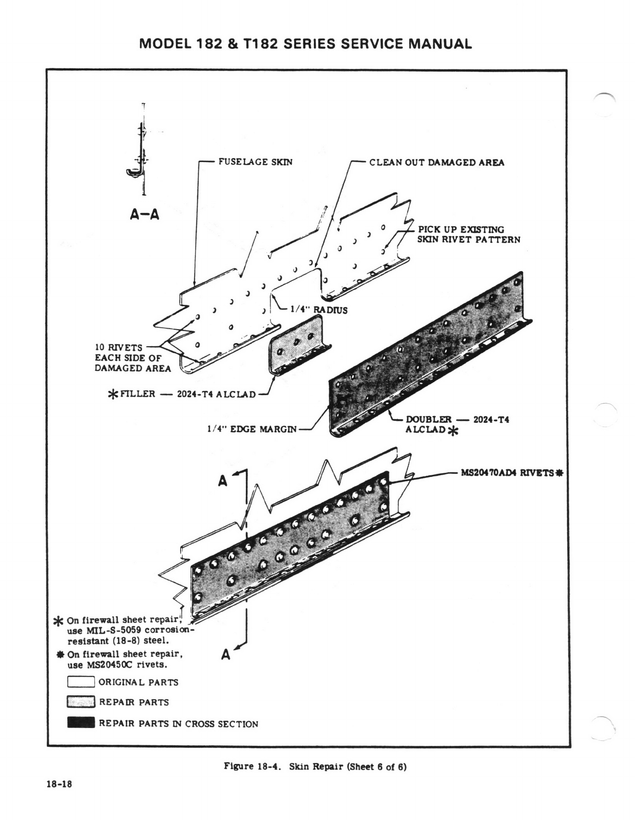
MODEL
182
&
T182
SERIES
SERVICE
MANUAL
/
^
/
v
~)
//
SKIN
RIVET
PATTERN
1/4"
EDGE
MARGIN
^
ALCLAD*
^
r\1^^
_^l
Za*
^^-"MS20470AD4
R.IVTS4
On
firewall
sheet
repair'
use
MIL-S-5059
corrosion-
resistant
(18-8)
steel.
*
On
firewall sheet
repair,
A
use
MS20450C
rivets.
ORIGINAL
PARTS
|:
-.
1
REPAIR
PARTS
_
REPAIR
PARTS
IN
CROSS
SECTION
Figure
18-4.
Skin
Repair
(Sheet
6
of
6)
18-18
~~ On firewa11 sheet repair,
,1~
~
~
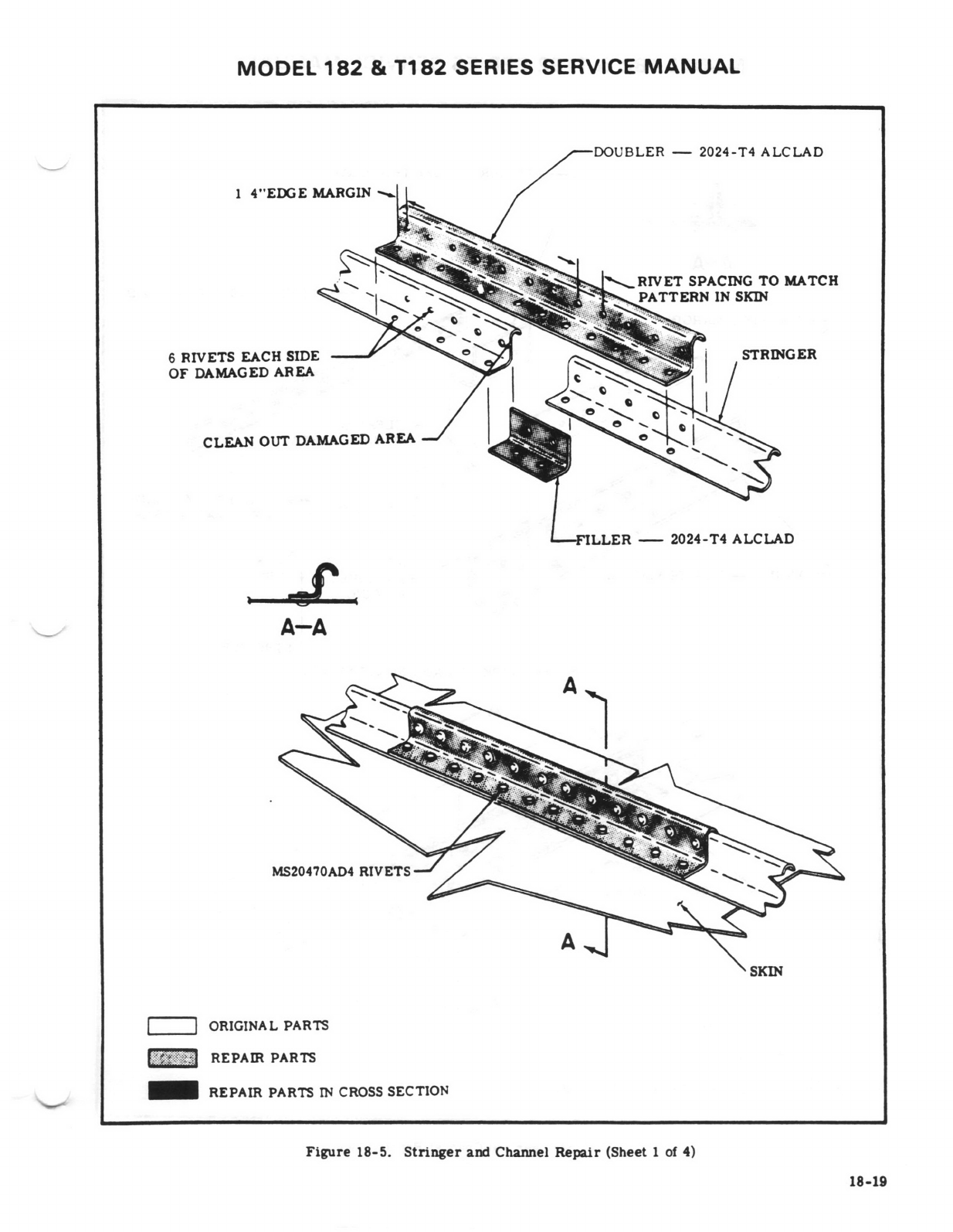
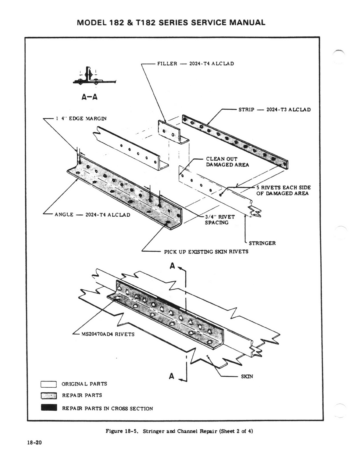
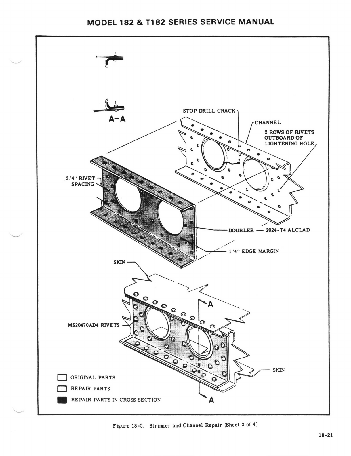
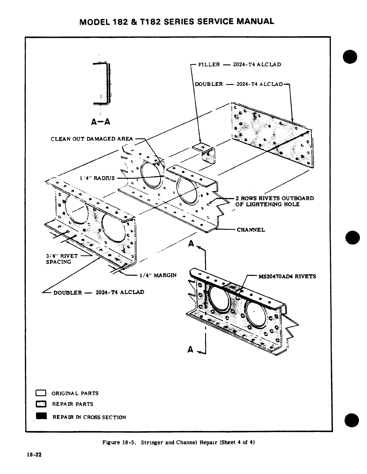
MODEL
182
&
T182
SERIES
SERVICE
MANUAL
FILLER -2024-T4
ALCLAD
DOUBLER
-
2024-T4
ALCLAD
A-A
CLEAN
OUT
DAMAGED
AREA
<: 1
.
'4"
RADIUS
T--..\-.
./
{·~':
>
*''
»-~.-"-~
'< -/.~^.
y,"
^--^CL^//
<?e e-
2
ROWS
RIVETS
OUTBOARD
» ^Y- : '>, \ t'^^
v
tC
OF
LIGHTENING HOLE
DOUBLER
-
2024-T4
ALCLAD
,'C-^^
:
.- ' « -
CHANNEL
3/4"
RIVET
T-^^s,
,|
,-
SPACING
/
/
|
/^
--
1/4"
MARGIN
*Oe'
MS20470AD4
RIVETS
DOUBLER
-
2024-T4
ALCLAD
i
A
II ORIGINAL PARTS
'.
REPAIR
PARTS
REPAIR
IN
CROSS
SECTION
Figure
18-5.
Stringer
and
Channel
Repair
(Sheet
4
of
4)
18-22
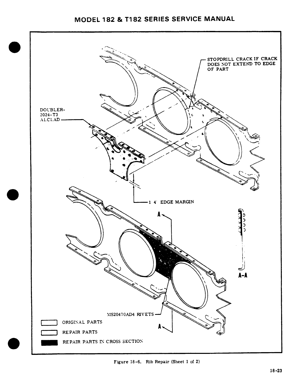
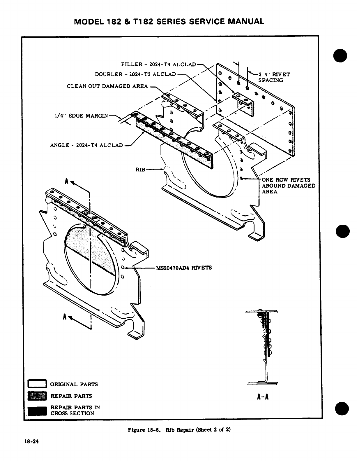
MODEL
182
&
T182
SERIES
SERVICE
MANUAL
FILLER-
2024-T4
ALCLAD
DOUBLER
-
2024-T3
ALCLAD
3 4"
RIVET
Q/
S. ®
SPACING
CLEAN
OUT
DAMAGED
AREA
1/4"
EDGE
MARGIN--
-
s
-
al
ANGLE-
2024-T4
ALCLAD
r
A
_
1<
|
°
*
}'--^
-ONE
ROW
RIVETS
AROUND
DAMAGED
4s\
<
)
C
M5204A-D--
MS20470AD4
RIVETS
I
|
ORIGINAL PARTS
REPAIR
PARTS
A-A
REPAIR
PARTS
IN
CROSS
SECTION
Figure
18-6.
Rib
Repair
(Sheet
2
of
2)
18-24
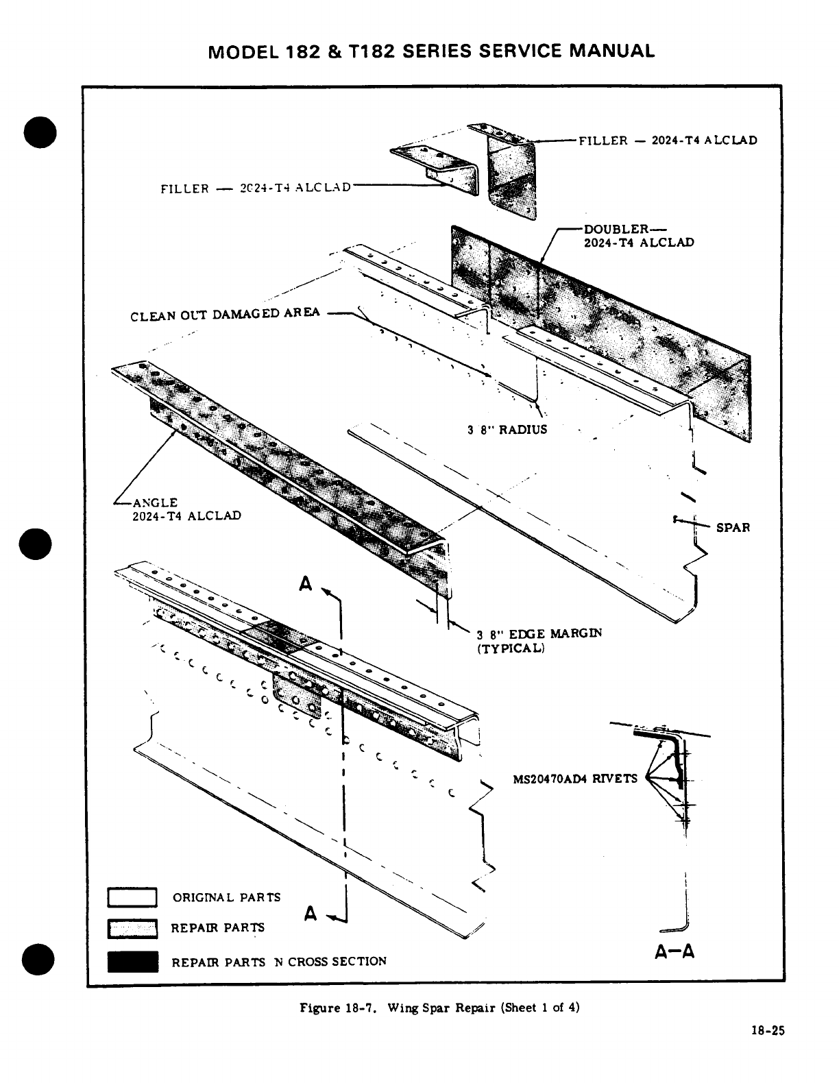
MODEL
182
&
T182
SERIES SERVICE
MANUAL
FILLER
-
2024-T4
ALCLAD
FILLER
-
2C24-T4
ALCLAD
^. ~.-' y^ *Si2024-T4
ALCLAD
CLEAN
OUT
DAMAGED
AREA
2024-T4
ALCLAD'""
.. "' "
ANGLEA~ \^S.^~~~~
>~t-
SPAR
2o2,
.
^^^^^
.
. . . .
^^
3
8"
EDGE
MARGIN
MS20470AD4
RIVETS
I
|
ORIGINAL
PARTS
|
'
: \
:REPAIR
PARTS
REPAIR
PARTS
N
CROSS
SECTION
A-A
Figure
18-7.
Wing
Spar Repair
(Sheet
1
of
4)
18-25
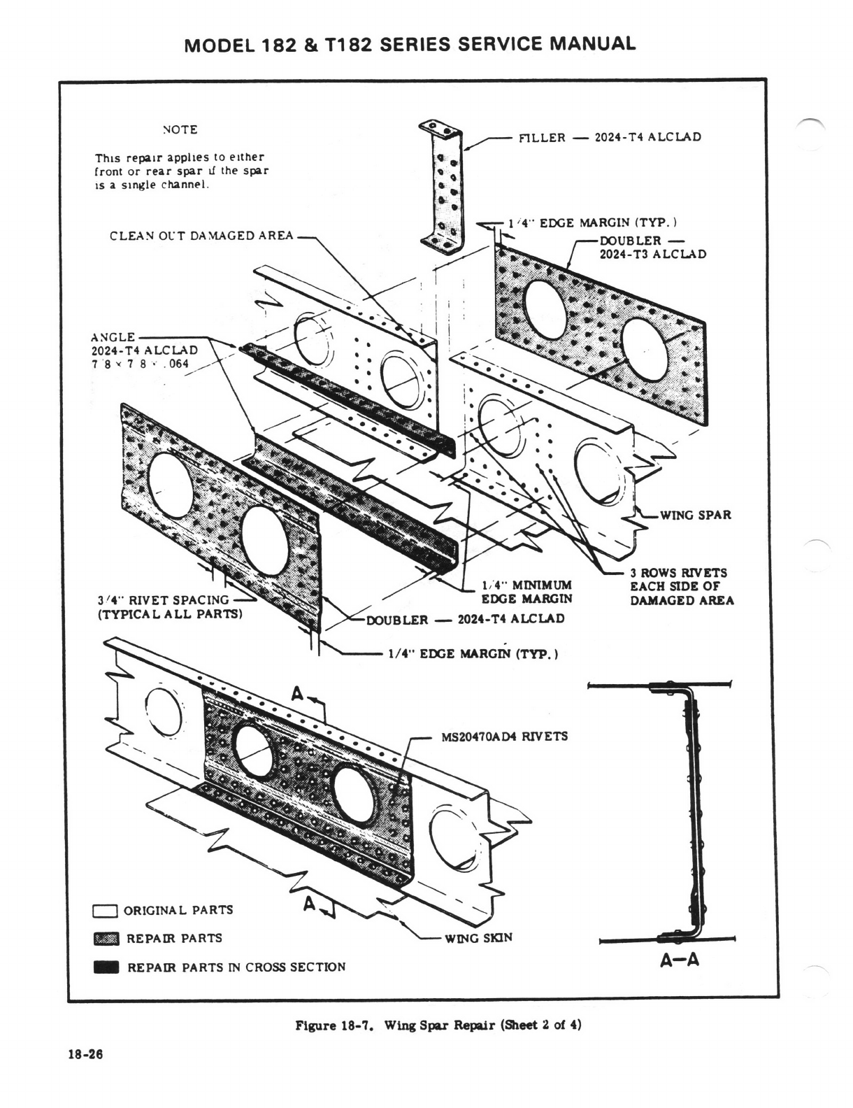
MODEL
182
&
T182
SERIES
SERVICE
MANUAL
NOTE
FILLER
-
2024-T4
ALCLAD
This
repair
applies
to
either
front
or
rear
spar
if
the
spar
is
a
single
channel.
1/4"
EDGE
MARGIN
(TYP.)
CLEAN
OUT
DAMAGED
AREA
.
DOUBLER
WING
SPAR
3/4"
RIVET
SPACING
(TYPICAL
ALL
PARTS)
1/4"
EDGE
MARGIN
(TYP.
)
-
REPAIR
PARTS
--
WING
SKIN
REPAIR
PARTS
IN
CROSS
SECTION
Figure 18-7.
Wing
Spar Repair
(Sheet
2
of
4)
18-26
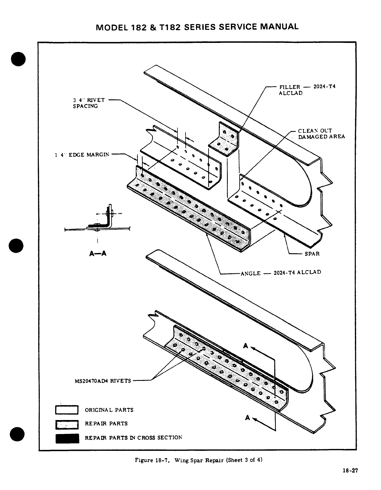
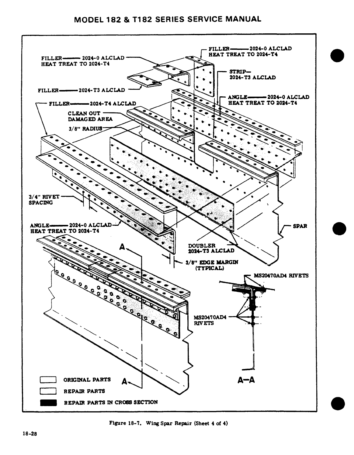
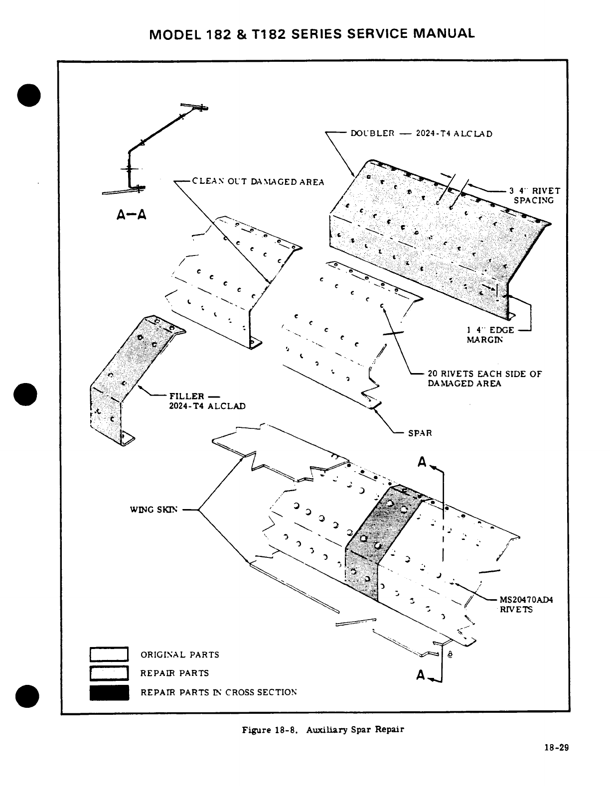
MODEL
182
&
T182
SERIES SERVICE
MANUAL
DOUBLER
-
2024-T4
ALCLAD
C
LEAN
OUT
DAMAGED
AREA
/.
'
s
/ "
"-..
~.'
'
=~.f^.'
,.
'"--.-
.-
3
4'
RIVET
A.=A
-A (.··.c.....
::...'*:.:.-':'7.'
.:':".·.
-
.·.
/'^ISI®^ j^^
''--
e
>
r R G
EARGIN
/^K~'l^ ~^ ^
''
.20
RIVETS
EACH
SIDE
OF
*^K ^
FILLER-
\ >
DAMAGED
AREA
> <
,
\ \
SPAR
WING
SKIN
X
A
>
/
c"^^
"^
-
^
C/
MS20470AD4
| |
ORIGINAL
PARTS
C<e>
\
,
REPAIR
PARTS
A
_"
/20
REPAIR
PARTS
EA
CROSS
SECTION
Figure
18-8.
Auxiliary
Spar
Repair 18-29
0!:
~FILLER
--
2024-T4
ALCLAD
A
-~
RIVETS
r'==
IREPAIR
PARTS
A
REPAIR
PARTS
IN
CROSS
SECTION
Figure
18-8.
Auxiliary Spar
Repair
18-29
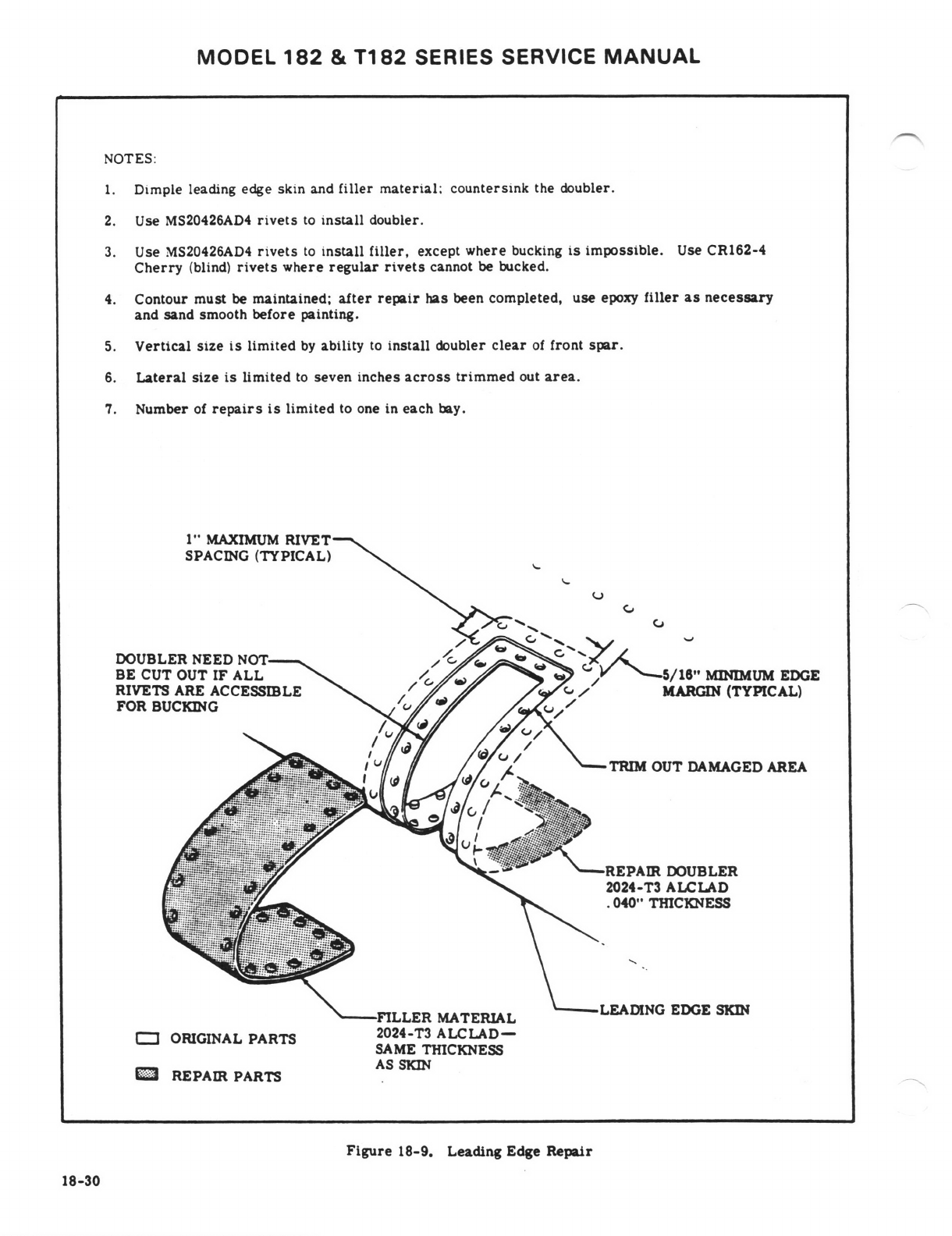
MODEL
182
&
T182
SERIES
SERVICE
MANUAL
NOTES:
1.
Dimple leading
edge
skin
and
filler
material;
countersink
the
doubler.
2.
Use
MS20426AD4
rivets
to
install
doubler.
3.
Use
MS20426AD4
rivets
to
install
filler,
except
where
bucking
is
impossible.
Use
CR162-4
Cherry
(blind)
rivets
where
regular
rivets
cannot
be
bucked.
4.
Contour
must
be
maintained;
after repair
has
been
completed, use
epoxy
filler
as
necessary
and
sand smooth
before
painting.
5.
Vertical
size
is
limited
by
ability
to
install
doubler
clear
of
front
spar.
6.
Lateral
size
is
limited
to
seven
inches
across
trimmed
out
area.
7.
Number
of
repairs
is
limited
to
one
in
each
bay.
1"
MAXIMUM
RIVET
SPACING
(TYPICAL)
DOUBLER
NEED
NOT
BE
CUT
OUT
IF
ALL
5/16"
MINIMUM
EDGE
RIVETS
ARE
ACCESSIBLE
MARGIN
(TYPICAL)
FOR
BUCKING
.040"
THICKNESS
FILLER
MATERIAL
AS
SKIN
REPAIR
PARTS
Figure
18-9.
Leading
Edge
Repair
18-30
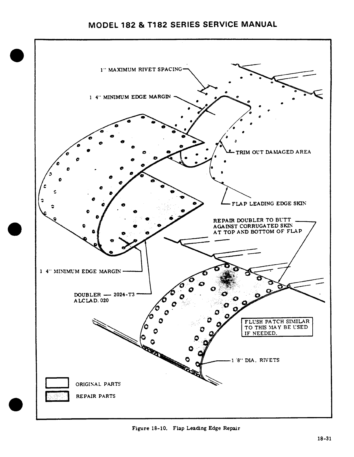
MODEL
182
&
T182
SERIES
SERVICE
MANUAL
MAXIMUM
RIVET
SPACING
,.
1
4"
MINIMUM
EDGE
MARGIN
0 0
/
e ^* L
FLAP
LEADING
EDGE
SKIN
; a
/
.
J
REPAIR
DOUBLER
TO
BUTT
-B "^ t 1a
#
°*~
~
AGAINST
CORRUGATED
SKIN
rS o%
*
e
^
1
^.
AT
TOP
AND
BOTTOM
OF FLAP
1
4"
MINIMUM
EDGE
MARGIN
----
DOUBLER
-
2024-T3
ALCLAD.
020
·
O
., 7
s
'
O
^s
O
X; ,:0
D
FLUSH PATCH
SIMILAR
S.O
/
7
0TO
THIS
MAY
BE
USED
IF
NEEDED.
OR_
2^
IGINAL1 '8"
DIA.
RIVETS
_|
ORIGINAL
PARTS
REPAIR
PARTS
Figure
18-10.
Flap
Leading
Edge
Repair
18-31
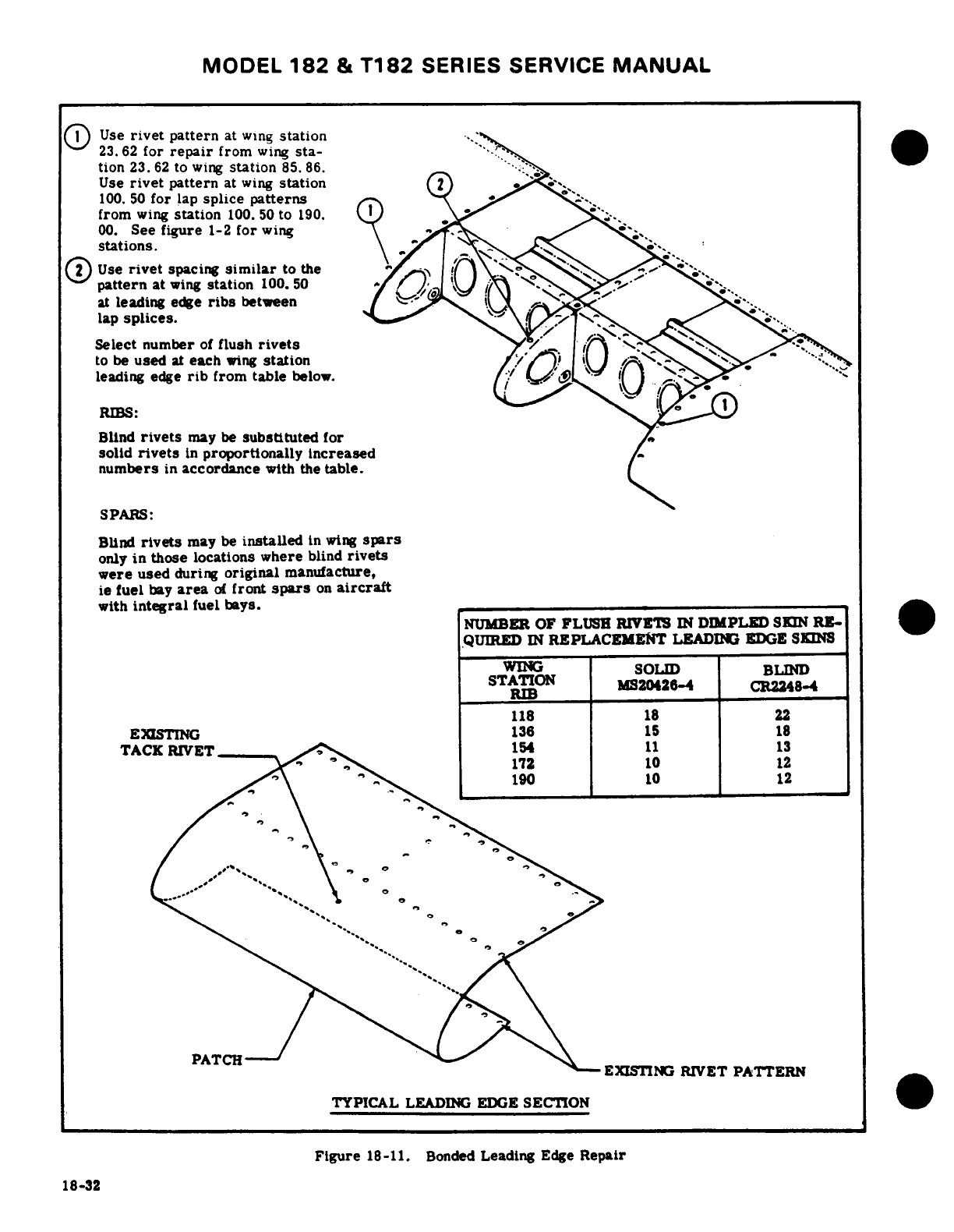
MODEL
182
&
T182
SERIES
SERVICE
MANUAL
Use
rivet
pattern
at
wing
station
23.62
for
repair
from
wing
sta-
tion
23.
62
to
wing
station
85. 86.
Use
rivet
pattern
at
wing
station
100.
50
for
lap
splice
patterns
, .
from
wing
station
100.
50
to
190.
00.
See
figure
1-2
for
wing
stations.
Use
rivet
spacing
similar
to
the
pattern
at
wing
station
100.
50
at
leading
edge
ribs
between
lap
splices.
Select number
of
flush
rivets
to
be
used
at
each
wing
station
leading
edge
rib
from
table
below.
RIBS:
Blind
rivets
may
be
substituted
for
solid
rivets
in
proportionally
increased
numbers
in
accordance
with
the
table.
SPARS:
Blind
rivets
may
be
installed
in
wing
spars
only
in
those
locations
where
blind
rivets
were
used
during
original
manufacture,
ie
fuel
bay
area
of
front
spars
on
aircraft
with
integral
fuel
bays.
NUMBER
OF
FLUSH RIVETS
IN
DIMPLED
SKIN
RE-
QUIRED
IN
REPLACEMENT
LEADING
EDGE
SKINS
STATION
MS20426-4
CR2248-4
RIB
118
18
22
EXISTING
136
15
18
TACK
RIVET
154
11
13
190
10
12
PATCH
EXISTING
RIVET
PATTERN
TYPICAL
LEADING
EDGE
SECTION
Figure
18-11.
Bonded
Leading
Edge
Repair
18-32
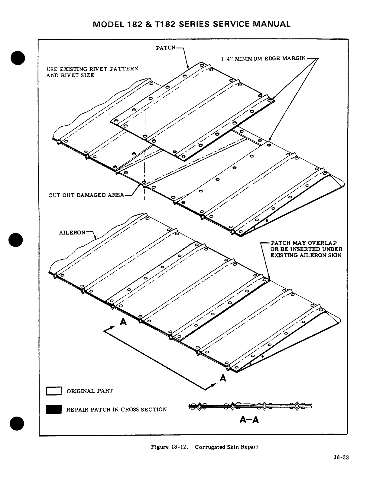
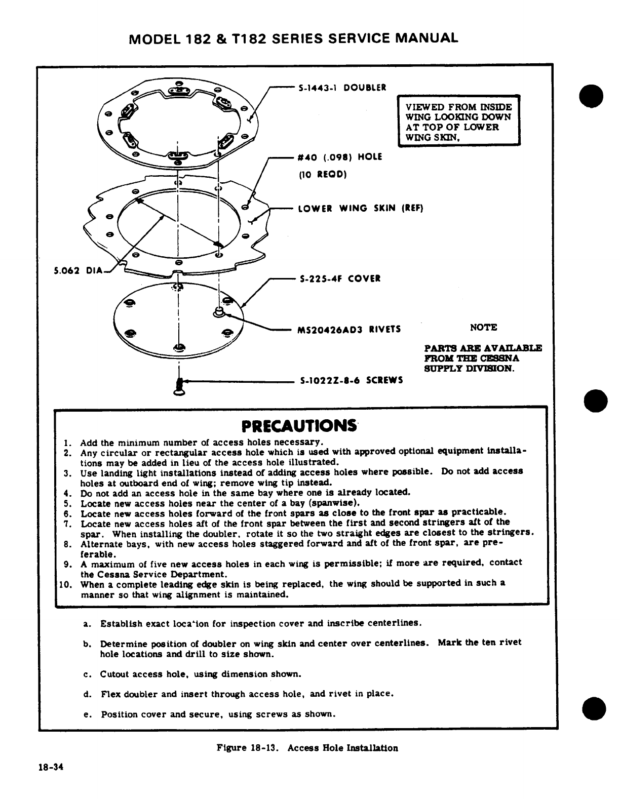
MODEL
182
&
T182
SERIES
SERVICE
MANUAL
WING
LOOKING
DOWN
AT
TOP
OF
LOWER
(10
REOD)
LOWER
WING
SKIN
(REF)
5.062
DIA-
S-225-4F
COVER
\,A | 4- ~
MS20426AD3
RIVETS
NOTE
PARTS
ARE
AVAILABLE
FROM
THE
CESSNA
SUPPLY
DIVISION.
S-1022Z-8-6
SCREWS
PRECAUTIONS
1.
Add
the
minimum
number
of
access
holes
necessary.
2.
Any
circular
or
rectangular
access
hole
which
is
used
with
approved
optional
equipment
installa-
tions
may
be
added
in
lieu
of
the
access
hole
illustrated.
3.
Use landing
light
installations
instead
of
adding
access
holes
where
possible.
Do
not
add
access
holes
at
outboard
end
of
wing;
remove
wing
tip
instead.
4.
Do
not
add
an
access
hole
in
the
same
bay
where
one
is
already
located.
5.
Locate
new
access
holes
near
the
center
of
a
bay
(spanwise).
6.
Locate
new
access
holes
forward
of
the
front
spars
as
close
to
the
front
spar
as
practicable.
7.
Locate
new
access
holes
aft
of
the
front
spar
between
the
first
and
second
stringers
aft
of
the
spar.
When
installing
the
doubler,
rotate
it
so
the
two
straight
edges
are
closest
to
the
stringers.
8.
Alternate
bays,
with
new
access
holes
staggered
forward
and
aft
of
the
front
spar, are
pre-
ferable.
9.
A
maximum
of
five
new
access
holes
in
each
wing
is
permissible;
if
more
are
required,
contact
the
Cessna
Service
Department.
10.
When
a
complete
leading
edge
skin is
being
replaced,
the
wing
should
be
supported
in
such
a
manner
so that
wing
alignment
is
maintained.
a.
Establish
exact
loca'ton
for
inspection
cover
and
inscribe centerlines.
b.
Determine
position
of
doubler
on
wing
skin
and
center
over
centerlines.
Mark
the
ten
rivet
hole
locations
and
drill
to
size
shown.
c.
Cutout
access
hole,
using
dimension
shown.
d.
Flex doubler
and
insert
through
access
hole,
and
rivet
in
place.
e.
Position cover
and
secure,
using
screws
as
shown.
Figure
18-13.
Access
Hole
Installation
18-34
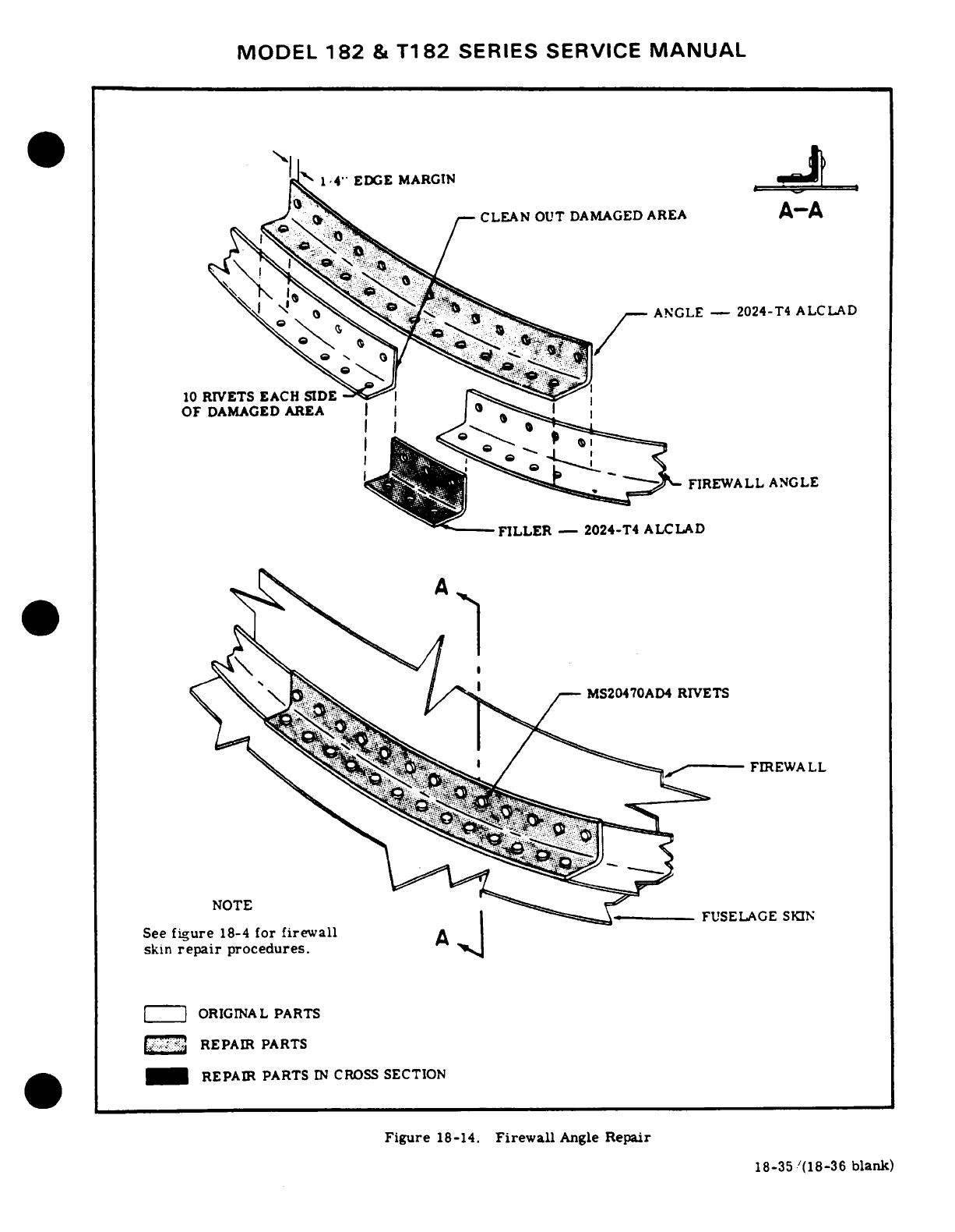
MODEL
182
&
T182
SERIES
SERVICE
MANUAL
-
CLEAN
OUT DAMAGED
AREA
A-A
ANGLE
-
2024-T4
ALCLAD
10
RIVETS
EACH
SIDE
I
OF
DAMAGED
AREA
I I
'
[
FIREWALL
ANGLE
FILLER
-
2024-T4
ALCLAD
MS20470AD4
RIVETS
FIREWALL
NOTE
·
..--
,._FUSELAGE
SKIN
See
figure
18-4
for
firewall
A
skin
repair
procedures.
| |
ORIGINAL
PARTS
4,"' iREPAIR
PARTS
REPAIR
PARTS
IN
CROSS
SECTION
Figure
18-14.
Firewall
Angle
Repair
18-35
'(18-36
blank)
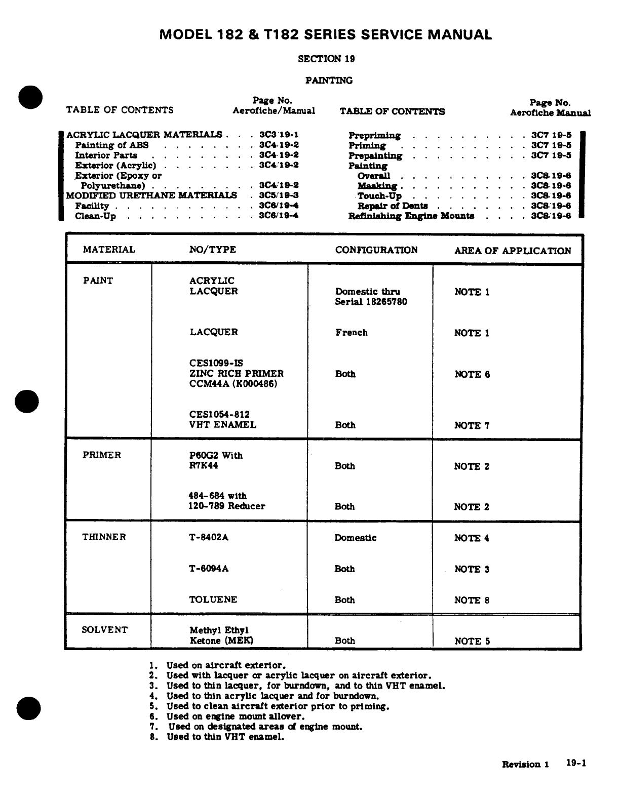
MODEL
182
&
T182
SERIES SERVICE
MANUAL
SECTION
19
PAINTING
Page
No.
Page
No.
TABLE
OF
CONTENTS
Aerofiche/Manual
TABLE
OF
CONTENTS
Aerofiche
Manual
ACRYLIC
LACQUER
MATERIALS.
.
3C3 19-1
Prepriming
..........
3C7
19-5
Painting
of
ABS
........
3C4,19-2
Priming
....... ..
3C7
19-5
Interior
Parts
..
.....
3C4
19-2
Prepainting
..........
3C7
19-5
Exterior
(Acrylic)
........
3C4,19-2
Painting
Exterior
(Epoxy
or
Overall
...........
3C8/19-6
Polyurethane)
.........
3C4/19-2
Masking
.. .......
3C8/19-6
MODIFIED
URETHANE
MATERIALS
. 3C5/19-3
Touch-Up
.. ..... .
3C8
19-6
Facility
............
3C/19-4
Repair of
Dents
........
3C8/19-6
Clean-Up
........
3C6/19-4
Refinishing
Engine
Mounts
....
3C8/19-6
MATERIAL
NO/TYPE
CONFIGURATION
AREA
OF
APPLICATION
PAINT
ACRYLIC
LACQUER
Domestic
thru
NOTE
1
Serial
18265780
LACQUER
French
NOTE
1
CES1099-IS
ZINC
RICH
PRIMER
Both
NOTE
6
CCM44A (K000486)
CES1054-812
VHT
ENAMEL
Both
NOTE
7
PRIMER
P60G2
With
R7K44
Both
NOTE
2
484-684 with
120-789
Reducer
Both
NOTE
2
THINNER
T-8402A
Domestic
NOTE
4
T-6094A
Both
NOTE
3
TOLUENE
Both
NOTE
8
SOLVENT
Methyl
Ethyl
Ketone
(MEK)
Both
NOTE
5
1.
Used
on
aircraft
exterior.
2.
Used
with
lacquer
or
acrylic
lacquer
on
aircraft
exterior.
3.
Used to
thin
lacquer,
for
burndown,
and
to
thin
VHT
enamel.
4.
Used
to
thin
acrylic
lacquer
and
for
burndown.
5.
Used
to
clean
aircraft
exterior
prior
to
priming.
6.
Used
on
engine
mount
allover.
7.
Used
on
designated
areas
of
engine mount.
8.
Used
to thin
VHT
enamel.
Revision
1
19-1
MODEL
182
&
T182
SERIES
SERVICE
MANUAL
When
stripping
paint
from
aircraft,
do
not
allow
stripper
to
contact
ABS
parts.
Strong
solvents,
Xylol,
Toluol,
or
Lacquer
Thinner
should not
be
used.
ABS
parts
are
to
be
cleaned
with
Naptha
or
soap
and
water, dried,
and
topcoated
without
priming.
19-1.
PAINTING
OF
FORMED
ABS
PLASTIC
PARTS.
for
the
topcoat.
Paint must
be
thinned
with
appro-
The
following
procedures
outline
some
basic
steps priate
acrylic
thinner
and
applied
as a
wet
coat
to
which
are
useful
during
touchup
or
painting
of
formed
ensure
adhesion.
ABS
plastic
parts.
b.
Touch
up
of
previously
painted
parts.
1.
Lightly
scuff
sand
to
remove
scratches
and
19-2.
INTERIOR PARTS
(finish
coat
of
lacquer).
improve
adhesion.
a.
Painting
of
spare
parts.
2.
Ensure a
clean
surface
by
wiping
with
Naphtha
1.
Ensure
a
clean
surface
by
wiping
with Naphtha
to
remove
surface
contamination.
to
remove
surface
contamination.
Do
not
use
strong
solvents
such
as
Xylol,
Do
not
use strong
solvents
such
as
Xylol,
Toluol
or
lacquer thinner
since
prolonged
Toluol
or
lacquer thinner
since
prolonged
exposure
can
soften
or embrittle
ABS.
exposure
can soften
or
embrittle
ABS.
3.
Apply
a
compatible
primer
-
surfacer
and
2.
After
the
part
is
thoroughly
dry it is
ready
sealer.
for
the
lacquer
topcoat.
Paint
must
be
thinned
with
4.
After
the
part
is
thoroughly
dry
it
is
ready
lacquer
thinner
and
applied
as a
wet
coat
to
ensure
for
the
topcoat.
Paint
must
be
thinned
and
applied
adhesion.
as a
wet
coat
to
ensure
adhesion.
b.
Touch up
of
previously
painted
parts.
1.
Light
sanding
is
acceptable to
remove
NOTE
scratches
and
repair
the
surface
but
care
must
be
exercised
to
maintain
the
surface
texture
or
grain.
Acrylic
topcoats
can
be
successfully
spotted
in.
2.
Ensure
a
clean
surface
by
wiping
with
Naphtha
to
remove
surface
contamination.
19-4.
EXTERIOR
PARTS
(Epoxy
or
Polyurethane
topcoat).
parts.
Do
not
use
strong
solvents
such
as
Xylol,
1.
Lightly
scuff
sand
to
remove
scratches
and
Toluol
or
lacquer
thinner
since
prolonged improve adhesion.
exposure
can
soften
or embrittle
ABS.
2.
Ensure
a
clean
surface
by
wiping
with Naphtha
to
remove
surface
contamination.
3.
After
the
part
is
thoroughly
dry
it
is
ready
for
the
lacquer
topcoat.
Paint
must
be
thinned
with
lacquer thinner
and
applied
as
a
wet
coat
to
ensure
adhesion.
Do
not
use
strong
solvents
such
as
Xylol,
Toluol
or
lacquer
thinner
since
prolonged
NOTE
exposure
can soften
or
embrittle
ABS.
Lacquer
paints
can
be
successfully
spotted
in.
3.
Apply
a
primer
compatible
with
Epoxy
or
Polyurethane
topcoat
19-3.
EXTERIOR
PARTS
(acrylic
topcoat).
4.
After
the
part
is
thoroughly
dry
it is
ready
a.
Painting
of
spare
parts.
for
the
topcoat.
1.
Lightly
scuff
sand
to
remove
scratches
and
improve
adhesion.
NOTE
2.
Ensure
a
clean
surface
by
wiping with
Naptha
to
remove
surface
contamination.
Epoxy
or
Polyurethane topcoats
cannot
be
successfully
spotted
in -
finish
should
be
as
skin
laps
or
stripe
lines.
Do
not
use
strong solvents
such
as
Xylol,
Toluol
or
lacquer thinner
since
prolonged
When
painting
interior
and
exterior
polycarbonate
exposure
can
soften
or
embrittle
ABS.
parts,
or
where
the
part
material
is
questionable,
a
"barrier
primer"
should
be
applied
prior
to
the
3.
After
the
part
is
thoroughly
dry
it
is
ready
enamel,
lacquer,
epoxy
or
polyurethane
topcoat
19-2
MODEL
182
&
T182
SERIES SERVICE
MANUAL
NOTE
Enflex
III
is
standard
on
serials
18265781
thru
18265784,
18265786
thru
18265806, 18265808,
18265809, 18265815,
and
18265817.
ENMAR
MODIFIED
URETHANE
MATERIAL
NO/TYPE
AREA
OF
APPLICATION
PAINT
ENFLEX
III
ENAMEL
Standard
Exterior.
and
Stripe
Only
configuration
ENFLEX
III
ADDUCT
Catalyst
for
Enflex
III
Enamel
ACCELERATOR
URETHANE
ACCELERATOR
Used
to
speed
curing
on
stripes
120-975
PRIMER
WASH
PRIMER
484-684
Used
to
prime
aircraft
for
Enflex
III
topcoat
REDUCER
120-789
Used
to
thin
484-684
THINNER
Jet
Glo
Used
to thin
Enflex
III
86T-
10399
(110-655)
110-805
Used
to
thin
Enflex
III
RETARDER
110-996
Used
to
slow
curing
time
NOTE
Imron
is
standard
on
serials
18265785,
18265807,
18265810
thru
18265814,
18265816,
and
18265818.
IMRON
MODIFIED
URETHANE
MATERIAL
NO/TYPE
AREA
OF
APPLICATION
PAINT
IMRON
ENAMEL
Used
as
corrosion
proof
topcoat
IMRON
192S
Activator
Catalyst
for
Imron
Enamel
PRIMER
WASH
PRIMER
P60G2
Used
to
prime
aircraft
for
Imron Enamel
REDUCER/
IMRON
Y8485S
Reducer
Used
to
thin
Imron
Enamel
THINNER
Catalyst
Reducer
R7K44
Used
to
reduce
P60G2
NOTE
Do
not
paint pitot
tube,
gas
caps,
or
aileron
gap
seals.
Also
do
not
paint antenna
covers
which
were
not
painted
at
the
factory.
NOTE
This
section contains
standard
factory
materials
listing
and
area
of
application.
For
paint
number
and
color,
refer
to
Aircraft Trim
Plate
and
Parts
Catalog.
In
all
cases
determine
the
type
of
paint
on
the
aircraft
as
some
types
of
paint
are
not
com-
patible.
Materials
may be
obtained
from
Cessna
Service
Parts
Center.
19-3
MODEL
182
&
T182
SERIES SERVICE
MANUAL
MATERIAL
NO/TYPE
AREA
OF
APPLICATION
STRIPPER
Strypeeze
Stripper
Used
to
strip
primer
overspray
CLEANER
DX
440
Wax
and
Grease
Remover
Used
to
clean
aircraft
exterior
Imperial Cleaner
Used to
remove
grease,
bug
stains,
etc.
Klad
Polish
Used
to
clean
aluminum
finish
808
Polishing
Compound
Used
to
rub
out
overspray
SOLVENT
(MEK)
Methyl
Ethyl
Ketone
Used
to
tack
aircraft
prior
to topcoat
CLOTH
HEX
Wiping
Cloth Used
with
solvent
to
clean
aircraft
exterior
FILLER
White
Streak
Used
to
fill
small
dents
MASKING
Class
A
Solvent
Proof
Paper
Used
to
mask
areas
not
to
be
painted
Tape
Y218
Used
for
masking
small
areas
Tape
Y231
Used
for
masking
small
areas
19-5.
FACILITY.
Painting
facilities
must
include
all
plexiglass
surfaces,
because
cuts
and
scratches
the
ability
to
maintain
environmental
control;
tem-
may
contribute
to
crazing
and
failure
of
plexiglass
perature
at
65°
F.,
and
a
positive
pressure
inside
to
windows.
preclude
the
possibility
of
foreign
material
damage.
c.
Methyl
Ethyl
Ketone
(MEK)
solvent
should
be
All
paint
equipment
must
be
clean,
and
accurate
used
for
final
cleaning
of
airplanes
prior
to
painting.
measuring
containers
available
for
mixing
protective
The
wiping
cloths
shall
be
contaminat
and
lint
free
coatings.
Modified
Urethane
has
a
pot
life
of
four
to
HEX.
Saturate
cloth
in
the
solvent
and
wring
out
so
eight
hours,
depending
on
ambient
temperature
and
it
does
not
drip.
Wipe
the
airplane
surface
with
the
relative
humidity.
Use
of
approved
respirators
while
solvent
saturated
cloth
in
one
hand,
and
immediately
painting
is
a
must, for
personal
safety.
All
solvent
dry
with
a
clean cloth
in
the
other
hand.
It
is
im-
containers
should
be
grounded
to
prevent
static
build-
portant
to
wipe
dry
solvent
before
it evaporates.
up.
Catalyst
materials
are
toxic,
therefore,
breath-
ing
fumes
or
allowing
contact
with
skin
can
cause
When
an
airplane
has
paint
or
zinc
chromate
over-
serious irritation.
Material
stock
should
be
rotated
spray
on
the
exterior,
stripper
may
be
used
to
re-
to
allow
use
of
older
materials
first,
because
its
use-
move
the
overspray.
The
stripper
may
be
applied
ful
life
is
limited.
All
supplies
should
be
stored
in
by
brush
and
will
require
a
few
minutes
to
soften
the
an
area
where
temperature
is
higher
than
50°
F.,
but
overspray.
Heavy
coatings
may
require
more
than
lower
than
90
F.
Storage
at 90°F
is
allowable
for
no
one
application
of
the
stripper.
Use
extreme care
more
than
sixty
days
providing
it
is
returned
to
room
to
prevent
stripper
from
running
into
faying
surfaces
temperature
for
mixing
and
use.
on
corrosion
proofed
airplanes.
After
removal
of
the
overspray,
clean
the
airplane
with Methyl
Ethyl
Modified
urethane
paint
requires
a
minimum
of
seven
Ketone
(MEK)
solvent
in
the
prescribed
manner.
days
to
cure
under
normal
conditions,
if
humidity
and
temperature
is
lower,
curing
time
will
be
extended
a
NOTE
maximum
of
14
days.
During
the
curing period,
in-
discriminate
use
of
masking
tape,
abrasive
polishes,
It
is
imperative
that
clean
solvent
be
used
in
or
cleaners
can
cause
damage to
finish.
Desirable
cleaning
airplanes.
Dispose
of
contaminated
curing
temperature
for
modified
urethane
is
60°F.
solvent
immediately.
Fresh
solvent should
for
a
resulting
satisfactory
finish,
be
used
on
each
airplane.
19-6.
CLEAN
UP.
a.
Inspect
airplane for
any
surface
defects,
such as
dents
or
unsatisfactory
previous
repairs,
and
correct
Use
explosion proof
containers
for
storing
according
to
paragraph
19-13.
wash
solvents
and
other
flammable
materials.
b.
Wipe
excess
sealer
from
around
windows and
skin
laps
with
Form
Tech
AC
aircraft
window
cleaning
solvent.
Mask
windows,
ABS
parts,
and
any
other
areas
not
to
be
primed,
with
3M
tape
and
Class
A
Solvent
Proof Paper. Care
must
be
exercised
to
avoid
cuts,
scratches
or
gouges
by
metal
objects
to
19-4
MODEL
182
&
T182
SERIES
SERVICE
MANUAL
19-7.
PREPRIMING.
19-8.
PRIMING.
a.
Apply
primer
in
one
wet
even
coat. Dry
film
thickness
to
be
.
0003
to
.
0005
inches.
Do
not
top-
NOTE
coat
until
sufficiently
cured.
When
scratching
with
firm
pressure
of the
fingernail
does
not
penetrate
Enflex
III
is
standard
on
serials
18265781
thru
the
coating,
the
primer
is
cured.
Primer
should
be
18265784,
18265786
thru
18265806,
18265808,
topcoated
within
four
hours
after
application.
18265809, 18265815,
and
18265817.
a.
Above
serialized
aircraft
have
Enmar
Wash
19-9.
PREPAINTING.
primer
EX-ER-7,
Enflex
III
Enamel
for
overall
color
and
stripes,
which
has been
replaced
with
NOTE
484-684.
b.
Mix
one
to
one,
484-684
primer
with
120-
Enflex
III
is
standard
on
serials
18265781
thru
789Reducer
by
volume.
Mix
in
stainless
steel
or
18265784,
18265786
thru
18265806,
18265808,
lined
containers
only.
After
mixing, allow
pri-
18265809,
18265815
and
18265817.
mer
to
set
for
30
minutes
before
spraying.
Pot
life
of
the
mixed
primer
is
six
(6)
hours.
All
mixed
material
should
be
discarded
if
not
used
a.
On
above
serialized aircraft,
mix
the
required
within
this
time.
Pot
pressure
during
spraying
amount
of
Enflex
III
with
Enflex
III
Adduct
in
a
4
to
1
should
be
approximately
10
±
1
psi.
Air
pres- ratio
by
volume.
Mix
thoroughly,
and
allow
to
stand
sure
should
be
30
to
40
psi
at
the
gun.
Blow
for
approximately
30
minutes before
spraying.
loose
contanimant
of
the
aircraft
with
clean
dry
Enflex
III
can
be
thinned
with
Jet
Glo
thinner
86T-
air.
Check
all
tapes to
make
sure
it
adheres
10399
(110-655)
to
obtain
spraying
viscosity,
which
properly.
Cover
the flap
tracks,
nose
gear
should
be
checked
after
four
hours
and
adjusted
if
strut
tube, wheels,
and
shimmy
dampener
rod
necessary.
ends.
ABS
parts
and
other
preprimed
parts
do
not
receive
wash
primer.
NOTE
NOTE
Imron
is
standard
on
serials
18265785,
18265807,
Imron
is
standard
on
serials
18265785, 18265807,
18265810
thru
18265814, 18265816,
and
18265818.
.
18265810
thru
18265814, 18265816,
and
18265818.
c.
Corrosion
proofed
and
standard
aircraft
will
b.
On
standard
aircraft,
mix
the
required
amount
of
receive
Sherwin
Williams
Primer
P60G2,
DuPont
Imron
with
Imron
192S
Activator in
a
3
to
1
ratio
by
Imron
Enamel
for
over
all
color,
and
for
stripes.
d.
Mix
1
part
P60G2
primer
with
1
1/2
parts
volume.
Mix
thoroughly,
and
begin
spraying
im-
R7K44
catalyst
reducer,
by
volume.
Mix
in
stain-
mediately, because
there
is
no
induction
time
re-
less steel
or
lined
containers
only.
Alter
mixing
quirement.
Imron
can be
thinned
to
spraying
less steel or
allow
primer
to
set
for
30
minutes
before
spraying.
viscosity
with
Y8485S
Imron
Reducer.
Viscosity
should
be
checked
and
adjusted
after
four
hours
if
Pot
life
of
the
mixed
primer
is
six
(6)
hours,
all
should
be
checked
and
adjusted
after
four
hours
if
mixed
materials
should be
discarded
if
not
used
necessary.
within
that
time
limit.
Pot
pressure
during
spraying
painter
should
wear
an
approved
respirator,
which
should
be
should
be
40
to
50
psi
at
the
gun.
Blow
loose
con-
taminant
off
the
airplane
with
clean,
dry
air.
Chec
contain
some
isocyanate,
which
may
cause
ir-
all
tapes
to
make
sure
they
adhere
properly.
Cover
ritation
to
the
respiratory
tract
or
an
allergic
reac-
the
flap
tracks,
nose
gear
strut
tube,
wheels,
and
ritation
to
the
respiratory
tract
or
an
allergic
reac-
the
flap
tracks,
nose
gear
strut
tube,
wheels,
and
tion.
Individuals
may
become
sensitized
to
isocya-
shimmy dampener rod
ends.
ABS
parts
and
other
preprimed parts
do
not
receive
wash
primer.
d.
The
pot
life
of
the
mixre
s
approximately
6-8
should
be
40
to
50
psi.
AIRCRAFT
SHOULD
BE
GROUNDED
PRIOR
e.
Scuff
sand
the
primer
only
where
runs
or
dirt
TO
PAINTING
TO
PREVENT
STATIC
ELEC-
particles
are
evident.
Minor
roughness
or
grit
may
TRICITY
BUILD-UP
AND
DISCHARGE.
be
removed
by
rubbing the
surface
with
brown
Kraft
19-5
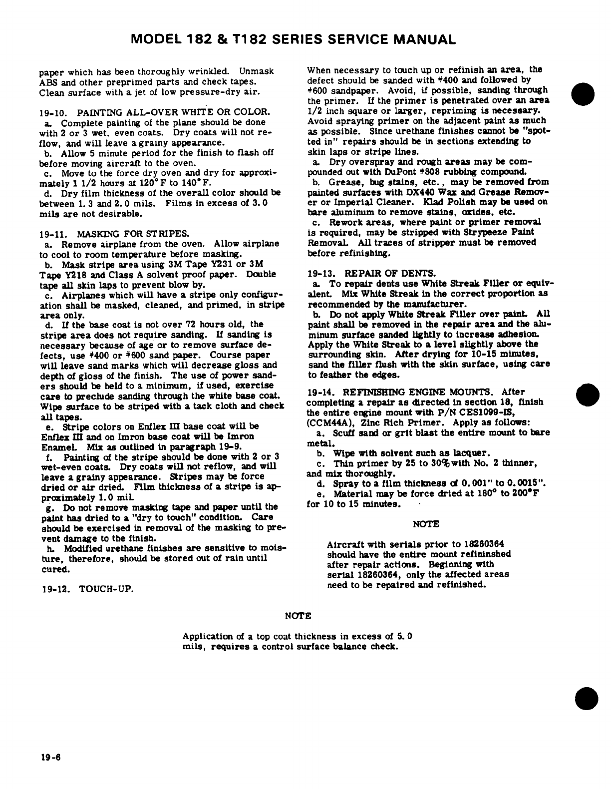
MODEL
182
&
T182
SERIES SERVICE
MANUAL
paper
which
has
been
thoroughly
wrinkled.
Unmask
When
necessary
to
touch
up
or
refinish
an
area,
the
ABS
and
other
preprimed
parts
and
check
tapes.
defect
should
be
sanded
with
#400
and followed
by
Clean
surface
with
a
jet
of
low
pressure-dry
air.
#600
sandpaper.
Avoid,
if
possible,
sanding
through
the
primer.
If
the
primer
is
penetrated
over
an
area
19-10.
PAINTING
ALL-OVER
WHITE
OR
COLOR.
1/2
inch
square
or
larger,
repriming
is necessary.
a.
Complete
painting
of
the
plane
should
be
done
Avoid
spraying
primer
on
the
adjacent
paint
as
much
with
2
or
3
wet,
even
coats.
Dry
coats
will
not
re-
as
possible.
Since
urethane
finishes
cannot
be
"spot-
flow, and
will
leave
a
grainy
appearance.
ted
in"
repairs
should
be in
sections
extending
to
b.
Allow
5 minute
period
for
the
finish
to
flash
off
skin
laps
or
stripe
lines.
before
moving
aircraft
to
the
oven.
a.
Dry
overspray
and
rough
areas
may
be
com-
c.
Move
to
the
force
dry
oven and
dry
for
approxi-
pounded out
with
DuPont
#808
rubbing
compound.
mately
1
1/2
hours
at
120°F
to
140
F.
b.
Grease,
bug
stains,
etc.,
may
be
removed
from
d.
Dry
film
thickness
of
the
overall
color
should
be
painted
surfaces
with
DX440
Wax
and
Grease
Remov-
between
1. 3
and
2. 0
mils.
Films
in
excess
of
3.0
er
or
Imperial
Cleaner.
Klad
Polish
may
be
used
on
mils
are
not
desirable.
bare
aluminum
to
remove
stains,
oxides,
etc.
c.
Rework
areas,
where
paint
or
primer
removal
19-11.
MASKING
FOR
STRIPES.
is required,
may
be
stripped
with
Strypeeze Paint
a.
Remove
airplane
from
the oven.
Allow
airplane
Removal
All
traces
of
stripper
must
be
removed
to
cool
to
room
temperature
before
masking.
before
refinishing.
b.
Mask
stripe
area
using
3M
Tape
Y231
or
3M
Tape
Y218
and
Class
A
solvent proof
paper.
Double
19-13. REPAIR
OF
DENTS.
tape
all
skin laps
to
prevent
blow
by.
a.
To
repair
dents
use
White
Streak
Filler
or
equiv-
c.
Airplanes
which
will
have
a
stripe
only
configur- alent.
Mix
White
Streak
in
the
correct
proportion
as
ation
shall
be
masked,
cleaned,
and
primed,
in
stripe
recommended
by
the
manufacturer.
area
only.
b.
Do
not
apply
White
Streak
Filler
over
paint.
All
d.
If
the
base
coat
is
not
over
72
hours
old,
the
paint
shall
be
removed
in
the
repair
area
and
the
alu-
stripe
area
does
not
require
sanding.
If
sanding
is
minum
surface
sanded
lightly to
increase
adhesion.
necessary
because
of
age
or
to
remove
surface
de-
Apply
the
White
Streak
to
a level slightly
above
the
fects,
use
#400
or
#600
sand
paper.
Course paper surrounding
skin.
After
drying
for
10-15
minutes,
will
leave sand
marks
which
will
decrease gloss
and
sand
the
filler
flush
with
the
skin
surface,
using
care
depth
of
gloss
of
the
finish.
The
use
of
power
sand-
to
feather
the
edges.
ers
should
be
held
to
a
minimum,
if
used,
exercise
care
to
preclude
sanding
through
the
white
base
coat.
19-14.
REFINISHING
ENGINE
MOUNTS.
After
Wipe
surface
to be
striped
with
a
tack
cloth
and
check
completing a
repair
as
directed
in
section
18,
finish
all
tapes.
the
entire
engine
mount
with
P/N
CES1099-IS,
e.
Stripe
colors
on
Enflex
III
base
coat
will
be
(CCM44A),
Zinc
Rich
Primer.
Apply
as
follows:
Enflex
III
and
on
Imron
base
coat
will
be
Imron
a.
Scuff
sand
or
grit
blast
the
entire
mount
to
bare
Enamel.
Mix
as
outlined
in
paragraph
19-9.
metal.
f.
Painting
of
the
stripe
should
be
done
with
2
or
3
b.
Wipe
with
solvent
such
as
lacquer.
wet-even
coats.
Dry
coats
will
not
reflow,
and
will
c.
Thin
primer
by
25
to
30%with
No.
2
thinner,
leave
a
grainy
appearance.
Stripes
may
be
force
and
mix
thoroughly.
dried
or
air
dried.
Film
thickness
of
a
stripe is
ap-
d.
Spray
to
a
film thickness
of 0.001"
to 0.0015".
proximately
1.0
mil.
e.
Material
may
be
force
dried
at
180
°
to
200°F
g.
Do
not
remove
masking
tape
and
paper
until
the
for
10
to
15
minutes.
paint
has
dried
to
a
"dry
to
touch"
condition.
Care
should
be
exercised
in
removal
of
the
masking
to
pre-
NOTE
vent
damage
to
the
finish.
h.
Modified
urethane
finishes
are
sensitive
to
mois-
Aircraft
with
serials
prior
to
18260364
ture, therefore,
should
be
stored
out
of
rain
until
should
have
the
entire
mount
refininshed
cured.
after
repair
actions.
Beginning
with
serial
18260364,
only
the
affected
areas
19-12.
TOUCH-UP.
need to
be
repaired
and
refinished.
NOTE
Application
of
a
top
coat
thickness
in
excess
of
5.
0
mils,
requires
a
control
surface
balance
check.
19-6
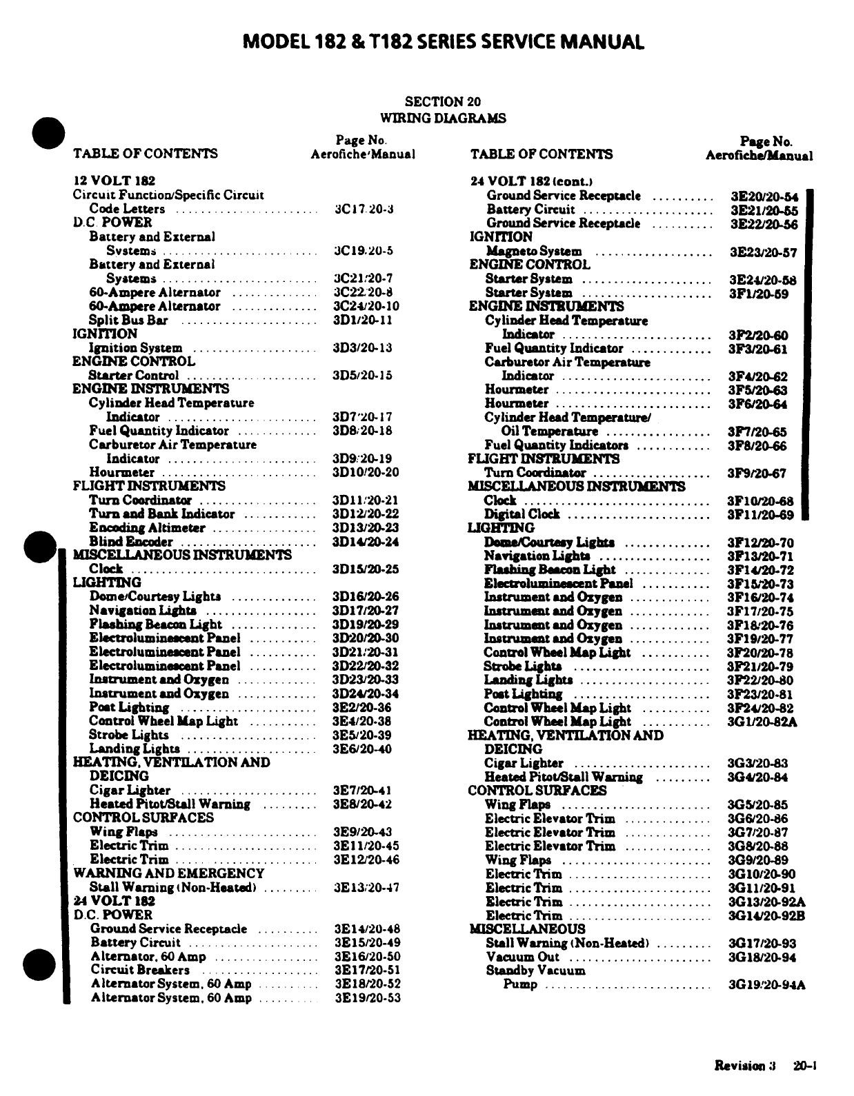
MODEL
182
&T182
SERIES
SERVICE
MANUAL
SECTION
20
WIRING
DIAGRAMS
Page
No.
Page
No.
TABLE
OF
CONTENTS Aerofiche/Manual
TABLE
OF
CONTENTS
Aerofiche/Manual
12
VOLT
182
24
VOLT
182
(cont.)
Circuit
Function/Specific
Circuit
Ground
Service
Receptacle
.........
3E20/20-54
Code
Letters
. ..............
3C
17
20-3
Battery
Circuit
.
..............
3E21/20-55
D.C
POWER
Ground
Service Receptacle
.........
3E22/20-56
Battery
and
External
IGNITION
Svstem
.......................
3C19.20-5
MagnetoSystem
.
.............
3E23/20-57
Battery
and
External
ENGINE
CONTROL
Systems
.........................
3C21:20-7
StarterSystem
.
.............
3E24/20-58
60-Ampere
Alternator
..............
3C2220-
Starter
System
.....................
3F1/20-59
60-Ampere
Alternator
..............
3C24/20-10
ENGINE
INSTUMENTS
Split
Bus
Bar
......................
3D1/20-11
Cylinder
Head
Temperature
IGNITION
Indicator
.
.............
3F2/20-60
Ignition
System
....................
3D3/20-13
Fuel
Quantity
Indicator
..........
3F3/20-61
ENGINE
CONTROL
Carburetor
Air Temperature
Starter
Control ...................
3D5/20-15
Indicator
. ...............
3F4/2062
ENGINE
INSTRUMENTS
Hourmeter
.
................
3F5/20-63
Cylinder
Head
Temperature
Hourmeter
.
........................
3F6/20-64
Indicator
......................
3D7/20-17
Cylinder
Head
Temperature/
Fuel
Quantity
Indicator
............
3D8/20-18
Oil
Temperatre
.................
3F7/20-65
Carburetor
Air
Temperature
Fuel
Quantity
Indicators
............
3F8/20-66
Indicator
.......................
3D9.20-19
FLIGHT
INSTRU
ENTS
Hourmeter
.........................
3D10/20-20
Turn
Coordinator
................... 3F9/20-67
FLIGHT
INSTRUMENTS
MISCELLANEOUS INSTRUMENTS
Turn
Coordinator
.................
3D11/20-21
Clock
....................
3F10/20-68
Turn
and
Bank
Indicator
............
3D12/20-22
Digital
Clock
.......................
3F11/20-69
Encoding
Altimeter
.................
3D13/20-23
LIGHTING
Blind
Encoder ......................
3D14/20-24
Dome
Lights
...........
3F12/20-70
MISCELLANEOUS
INSTRUMENTS
NavigationLights
.............
3F13/20-71
Clock
.............................
3D1520-25
Flhing
BeaconLight
..............
3F14/20-72
LIGHTING Electroluminescent
Panel
...........
3F15/20-73
Dome/Courtesy
Lights
..............
3D16/20-26
Instrument
and
Oxygen
.............
3F16/20-74
Navigation
Lights
.............
3D17/20-27
Instrument
and
Oxygen
.............
3F17/20-75
Flashing
Beacon
Light
..............
3D19/20-29
Instrument
and Oxygen
.............
3F18/20-76
Electroluminescent
Panel
...........
3D20/20-30
Instrument
and
Oygen
.............
3F19/20-77
Electroluminescent
Panel
..........
3D21/20-31
Control
Wheel
Map
Light
..........
3F2020-78
Electroluminescent Panel
...........
3D22/20-32
Strobe
Lights
...................... 3F21/20-79
Insrument
and
Oxygen ............
3D2320-33
Landing Lights
.....................
3F22/20-0
Instrument
and
Oxygen
.............
3D24/20-34
Post Lighting
...................... 3F23/20-81
Post
Lighting
. ..............
3E2/20-36
Control
Wheel
Map
Light
...........
3F24/20-82
Control
Wheel
Map
Light
...........
3E4/20-38
Control
Wheel
Map
Light
...........
3G1/20-82A
Strobe
Lights
...............
3E5/20-39 HEATING.
VENTILATION
AND
Landing
Lights
. .............
3E6/20-40
DEICING
HEATING,
VENTILATION
AND
Cigar Lighter
...............
3G3/20-83
DEICING
Heated
Pitot/Stall Warning
.........
3G4/20-84
Cigar
Lighter
.....................
3E7/20-41
CONTROL
SURFACES
Heated
Pitot/Stall Warning
.........
3E8/20-42
Wing
Flaps
. ...............
3G5/20-85
CONTROL SURFACES
Electric
Elevator
Trim
.............
3G6/20-86
Wing
Flaps
........................
3E9/20-43
Electric Elevator
Trim
...........
3G7/20-87
ElectricTrim
.......................
3E11/20-45
Electric
Elevator
Trim
...........
3G8/20-88
Electric
Trim
.....................
3E12/20-46
Wing
Flaps
.....
..................
3G9/20-89
WARNING
AND
EMERGENCY
Electric Trim
.......................
3G10/20-90
Stall
Warning
(Non-Heated)
.........
3E13/20-47
Electric Trim
.
..............
3G11/20-91
24
VOLT
182
Electric Trim
.......................
3G13/20-92A
D.C.
POWER
Electric Trim
................
3G14/20-92B
Ground
Service
Receptacle
..........
3E14/20-48 MISCELLANEOUS
Battery
Circuit
.....................
3E15/20-49
Stall
Warning
(Non-Heated)
.........
3G17/20-93
Alternator.
60
Amp ................
3E16/20-50
Vacuum
Out
.
..............
3G18/20-94
Circuit
Breakers
..................
3E17/20-51
Standby
Vacuum
AlternatorSystem,
60
Amp
..........
3E18/20-52
Pump
...........................
3G19,20-94A
Alternator
System.
60
Amp
.....
3E19/20-53
Revision
3
20-1
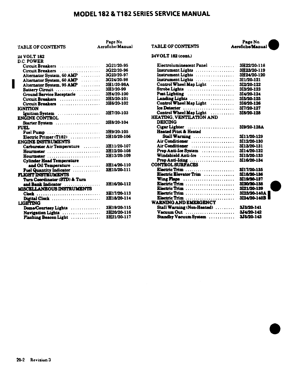
MODEL
182
&
T182
SERIES
SERVICE
MANUAL
Page
No.
Page
No.
TABLE
OF
CONTENTS
Aerofiche/Manual
TABLE OF
CONTENTS
Aerofiche/Manual
24
VOLT
182
24VOLT
182
(cont.)
D.C.
POWER
Circuit
Breakers
.............
3G21/20-95
Electroluminescent
Panel
...........
3H22/20-118
Circuit
Breakers
................
3G22/20-96
Instrument
Lights
.................
323/20-119
Alternator
System.
60 AMP
........
3G23/20-97
Instrument
Lights .................
3H24/20-120
Alternator
System,
60
AMP
......
3G24/20-98
Instrument
Lights ..................
31120-121
Alternator
System.
95
AMP
.........
3H/20-98A
Control Wheel
Map
Light
...........
3I2/20122
Battery
Circuit
...........
3H3/20-99
Strobe Lights
......................
3I3/20-123
Ground
Service
Receptacle
.........
3H420100
Pt
Lighting
......................
31420124
Circuit
Breakers
...................
3H5/20-101
Landing Lights
.................. .3I5/20-125
Circuit
Breakers
..................
3H6/20-102
Control Wheel
Map
Light
...........
31620-126
IGNITION
Ice
Ignition
System
..................
3H7/20-103
Control
Weel
Map
Light
...........
3I8/20-128
ENGINE CONTROL
HEATING.
VENTILATION
AND
Starter
System
....................
3H8/20-104
DEICING
FUEL
Cigar Lighter
...................... 31920-128A
Fuel
Pump
......................
3H9/20-105
Heated
Pitot
&
Heated
Electric
Primer
(T182)
..............
3H10/20-106
StallWarning
...................
3111/20129
ENGINE
INSTRUMENTS
Air
Conditioner
....................
3112/20-130
Carburetor Air
Temperature
........
3H11/20-107
Air Conditioner
....................
3113/20-131
Hourmeter
.......................
3H12/20-108
Prop
Anti-Ice
System
...............
311420132
Hourmeter
.........................
3H13/20-109
Windshield
Anti-Ice
................
3I15/20-133
Cylinder
Head
Temperature
Prop
Anti-Icing
.....................
3I16/20-134
and
Oil
Temperature
.............
3H14/20110
CONTROL SURFACES
Fuel
Quantity
Indicator
.............
3H15/20111
Electric
Trim
.......................
3I17/20-135
FLIGHT
INSTRUMENT
Turn
Coordinator
(STD)
&
Turn
Wing
........................
nd
Bank
dicator
...............
Clock
..............................
317/20113 ElectriTrim
.......................
323
140A
Digital
Clock
....................
3H18/20-114
Electric
Trim
......................
3I24/20-140B
LIGHTING
WARNING
AND
EMERGENCY
Dome/Courtesy
Lights
..............
3H19/20-115
Stall
Warning
(Non-Heated)
.........
3J3/20-141
Navigation
Lights
..................
3H20/20-116
Vacuum
Out
.......................
3J4/20142
Flashing
Beacon
Light
.............
3H21/20117
Standby
Vacuum
System
............
3F5/20143
20-2
Revision 3

MODEL
182
&
T182
SERIES SERVICE
MANUAL
CIRCUIT
FUNCTION
AND
SPECIFIC
CIRCUIT
CODE
LETTERS
A
-
Armament
LB
-
Instrument
B
-
Photographic
LC
-
Landing
C
-
Control
Surface
LD
-
Navigation
CA
-
Automatic
Pilot
LE -
Taxi
CC
-
Wing
Flaps
LF
-
Rotating
Beacon
CD
-
Elevator
Trim
LG
-
Radio
D
-
Instrument
(Other
Than
Flight
or
Engine
LH
-
De-ice
Instrument)
LJ
-
Fuel Selector
DA
-
Ammeter
M
-
Miscellaneous
DB
-
Flap
Position
Indicator
MA
-
Cowl
Flaps
DC
-
Clock
MB
-
Electrically
Operated Seats
DD
-
Voltmeter
MC
-
Smoke
Generator
DE
-
Outside
Air
Temperature
MD
-
Spray
Equipment
DF
-
Flight
Hour
Meter
ME
-
Cabin
Pressurization
Equipment
E
-
Engine
Instrument
MF
- Chem
02
-
Indicator
EA
-
Carburetor
Air
Temperature
P
-
D. C.
Power
EB
-
Fuel
Quantity
Gage
and
Transmitter
PA
-
Battery Circuit
EC
-
Cylinder
Head
Temperature
PB
-
Generator
Circuits
ED
- Oil
Pressure
PC
-
External
Power
Source
EE
-
Oil
Temperature
Q
-
Fuel
and
Oil
EF
-
Fuel
Pressure
QA
-
Auxilliary
Fuel
Pump
EG
-
Tachometer
QB
- Oil
Dilution
EH
-
Torque
Indicator
QC
- Engine
Primer
EJ
-
Instrument
Cluster
QD
- Main
Fuel
Pumps
F
-
Flight
Instrument
QE
-
Fuel
Valves
FA
- Bank
and
Turn
R
-
Radio
(Navigation
and
Communication)
FB
-
Pitot
Static
Tube
Heater
and
Stall
Warning
RA
-
Instrument
Landing
Heater
RB
- Command
FC
-
Stall
Warning
RC
-
Radio
Direction
Finding
FD
- Speed
Control
System
RD
-
VHF
FE
-
Indicator
Lights
RE
-
Homing
G
-
Landing
Gear
RF
-
Marker
Beacon
GA
-
Actuator
RG
-
Navigation
GB
-
Retraction
RH
-
High
Frequency
GC
-
Warning
Device
(Horn)
RJ
-
Interphone
GD
-
Light
Switches
RK
-
UHF
GE
-
Indicator
Lights
RL
-
Low
Frequency
H
-
Heating, Ventilating
and
De-Icing
RM-
Frequency
Modulation
HA
-
Anti-icing
RP
-
Audio
System
and
Audio
Amplifier
HB
-
Cabin
Heater
RR
-
Distance
Measuring
Equipment
(DME)
HC
-
Cigar
Lighter
RS
-
Airborne
Public
Address
System
HD
-
De-ice
S
-
Radar
HE
-
Air
Conditioners
U
-
Miscellaneous
Electronic
J
-
Ignition
UA
-
Identification
-
Friend
or
Foe
JA - Magneto
W
-
Warning
and
Emergency
K
-
Engine
Control
WA
-
Flare
Release
KA
-
Starter
Control
WB
-
Chip
Detector
KB
-
Propeller
Synchronizer
WC
-
Fire
Detection
System
L
-
Lighting
X-
A.C.
Power
LA
-
Cabin
20-3
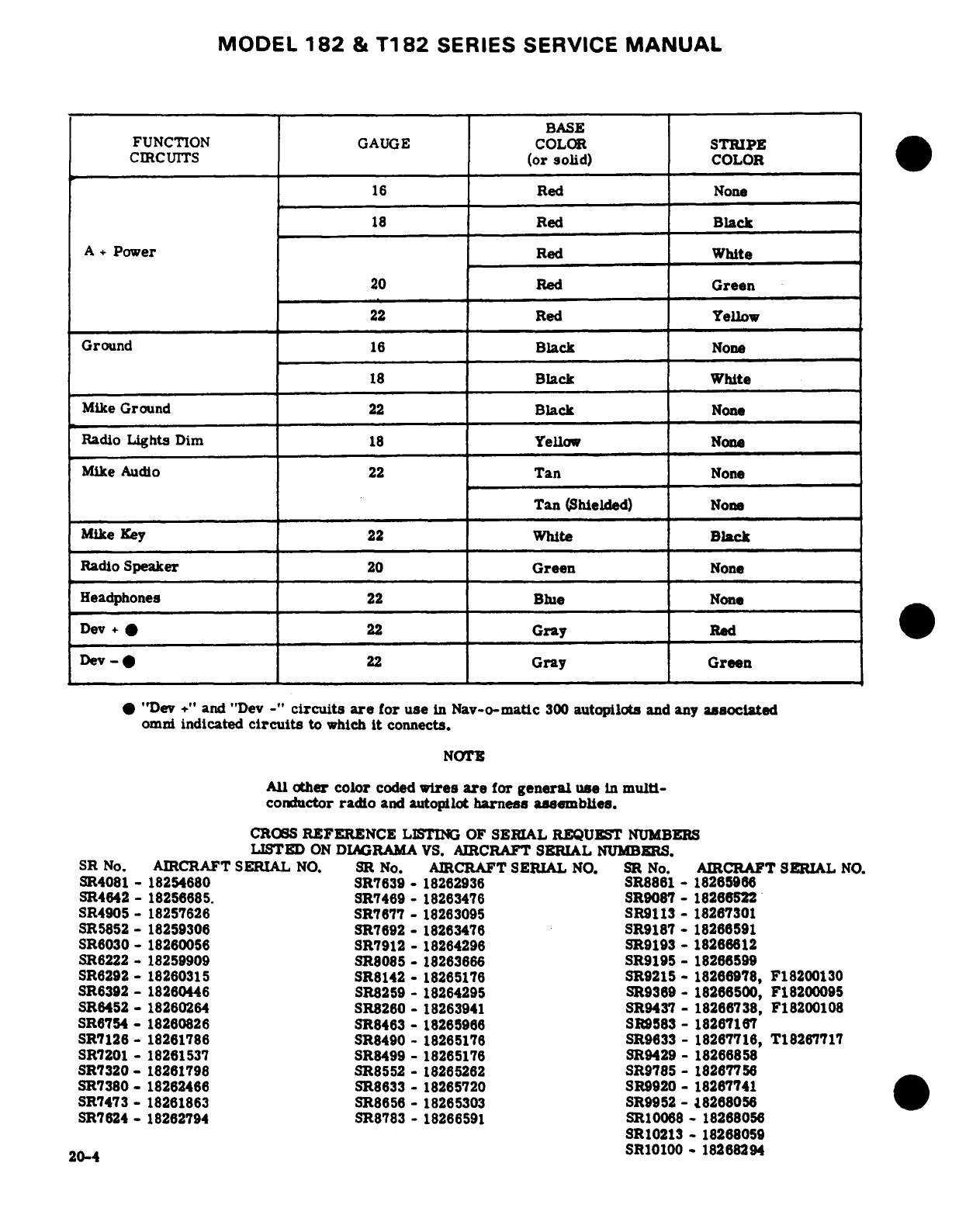
MODEL
182
&
T182
SERIES
SERVICE
MANUAL
BASE
FUNCTION
GAUGE
COLOR
STRIPE
CIRCUITS
(or
solid)
COLOR
16
Red
None
18
Red
Black
A
+
Power
Red
White
20
Red
Green
22
Red
Yellow
Ground
16
Black
None
18
Black
White
Mike
Ground
22
Black
None
Radio
Lights
Dim
18
Yellow
None
Mike Audio
22
Tan
None
Tan
(Shielded)
None
Mike
Key
22
White
Black
Radio
Speaker
20
Green
None
Headphones
22
Blue
None
Dev
+
22
Gray
Red
Dev
-
22
Gray
Green
"Dev
+"
and
"Dev
-"
circuits
are
for
use
in
Nav-o-matic
300
autopilots
and
any
associated
omni
indicated
circuits
to
which
it
connects.
NOTE
All
other
color
coded
wires
are
for
general
use
in
multi-
conductor
radio
and
autopilot
harness
assemblies.
CROSS
REFERENCE
LISTING
OF
SERIAL
REQUEST
NUMBERS
LISTED
ON
DIAGRAMA
VS.
AIRCRAFT
SERIAL
NUMBERS.
SR
No.
AIRCRAFT SERIAL
NO.
SR
No.
AIRCRAFT
SERIAL
NO.
SR
No.
AIRCRAFT
SERIAL
NO.
SR4081
-
18254680
SR7639
-
18262936
SR8861
-
18265966
SR4642
-
18256685.
SR7469
-
18263476
SR9087- 18266522
SR4905
-
18257626 SR7677
-
18263095
SR9113
-
18267301
SR5852- 18259306
SR7692-
18263476
SR9187- 18266591
SR6030-
18260056
SR7912
-
18264296 SR9193
-
18266612
SR6222
-
18259909
SR8085-
18263666
SR9195-
18266599
SR6292-
18260315
SR8142
-
18265176
SR9215
-
18266978,
F18200130
SR6392-
18260446
SR8259-
18264295 SR9369
-
18266500,
F18200095
SR6452
-
18260264
SR8260
-
18263941
SR9437
-
18266738,
F18200108
SR6754
-
18260826
SR8463
-
18265966
SR9583
-
18267167
SR7126
-
18261786
SR8490-
18265176
SR9633-
18267716,
T18267717
SR7201
-
18261537
SR8499-
18265176 SR9429-
18266858
SR7320-
18261798
SR8552
-
18265262
SR9785- 18267756
SR7380-
18262466 SR8633
-
18265720
SR9920-
18267741
SR7473
-
18261863
SR8656
-
18265303
SR9952-
18268056
SR7624
-
18262794
SR8783
-
18266591
SR10068
-
18268056
SR10213
-
18268059
20-4
SR110100-
18268294
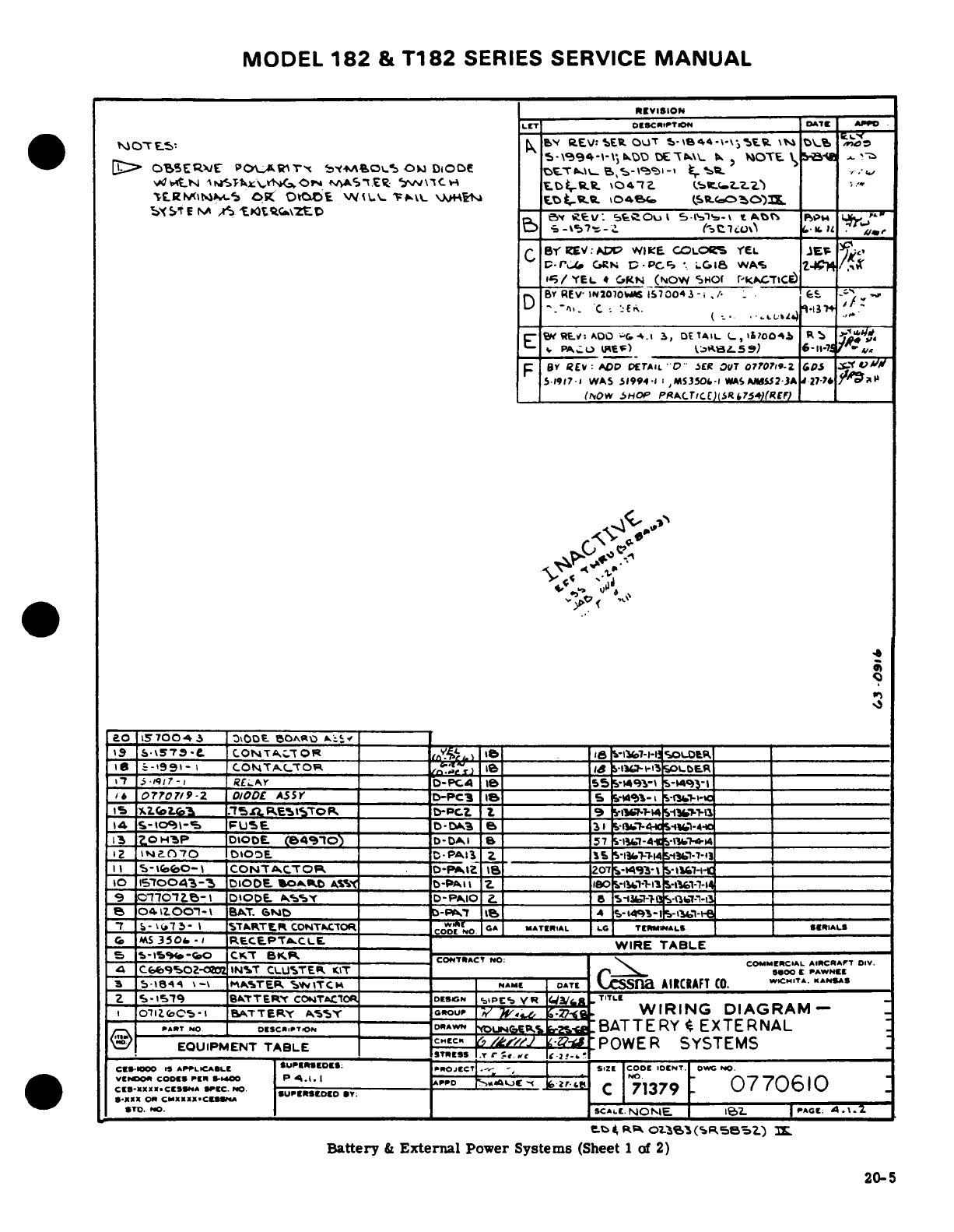
MODEL
182
&
T182
SERIES
SERVICE
MANUAL
EMIVISION_
,_
LETI
DEoSCRIPTION
DATE
APP
NmOTES
L
WY
RLEV:
SE-t
Ou'T
.
\844-^-\C-L
',EzL
\.Is
io.
,
t
s-\9;94-r-,;
'
Dnd
eTE\\-
k
%OTE
v
5-a-
[>
OBSWEgtE
POtRni
re
5ez1M4oi.
OM
DIOoD
aE.\T
»e>-°-19<1
-
eaFl
, .
'DN_
ELn4L Cs- ____ (NOW
5HO
C
\0472
TICE
:._
__
5YSS
E
Mi
IvS
t14t5it
Zr
zt
_
oaf;
ctv:
:,srZoa6
9
bf
tQout
ft6
I-f.
IBY -_V5t-_ IN2
M
C. 1a
'
1
.
t.
.
r
BREV:A0
A
Iw I E
COLOS
EIL
RJEF
Y
t;
D Cp RNThi
C-PCrc
M itl18
WAS
27-/4X
_- 1/
YEL
*
rtKN
(NuOW
SHOt
PYWCTICE)
D
Br
REV
IN2010WV
IS70043-i
/*
_
-
ftC
_Co
U V
C
'
Er
*L~)
·"'
r.
E
BY
RE:
<00
(*o.I
1,
DETAIL
L,167004.
RPi
3#Z
.-
PA;O
-
EIF)
s3a59_)
66-1
-7' =4.
F
By
RV
: ADo
DETAIL.
*
O
5ER
3UT
07T0719-2
6IDS
S-<
Sl1B17-1
WAS
1994-1
,
5S350
-i WSAS
AM52
JA
27-7*
/-4i'
*
__
(W
(hOW
SHOP
PRLTCE)(SR4)(RE)
_____
3
.*
4
20Lo
(57004a
7
IODE
..
O-
.
____'1
t
.-
____/ 1___
i9
S\S7-e.
COLNTDAcTOR
___ __ ___7--____ i1_____ _____
eI
_-9SI
-
I
CONTA(_..TO
.R
IS.'
tha.
,e
1
_-t_ _-%lSO-1,t_
I7 i
197
-,
-RELAY
____
D-PC4
IS ____ IS
4-l
-II ____-1-t-49-
I 607'707/9 -2 DOD0O
:
ASSr
D-PC3
______ ____________
5-t-
Is
-1204
.-
.1SRE.'S-TOR ___
_
D-PC.Z
-l
____
9-I
t1-t-(
14
iS-CIo9-b
IFU
SE
D-
DA3
________
I
--
____
'
O3P
DIODE.
(869410
_
b-DAI
s
_
57
-i-4
*_
'2
Z
N?()70
DIODE
v-_PA.3
I' z 5_
_
1. p
-1
_
_
II IS-:I60-I
CON
TACTOR
D___.
-PoIZ
l
207
-t49-1 _____--
10
1570043-3
DIODE.
SOO^P
AS
____
-PAII
Z
ISO
51
-1-11 5-I1-1-
9
C0770Z.ZB-
DIODE.
AYf
D-PAIO
________
a
-
1-fl--
L
e
04IZ.OO-1-\
BAT.
6NCD
___
-P
I
___t 4
i5--49-
-11-
7T 5
-
\L7-
\
S"
RTtR.
CONTCTOR
____ cW
o
Gor
A
ATERIAL
LG
TtRNINALS
SR
IALS
C
blS
350
-
_ _ REcEPTCLE__-
-WIRE
TABLE
S
S-s159-fo
CKT
BSK.
___k__
_
CONTRACT
NO
M
COMMERCIAL
AIRCRiAT
DIV.
4 Cb9O-C0
INST
CLUSTE
.
KI.T
soo
t PAt^WNEE
s
5-1e49
\-\
MASTER
SvITCk
I NAME
DTE
AIRCRAFT
CO.
CHTA.
KANSAS
Z
¶S-I1T9
ANTTERY
CONTC10___
DESICN
5IIPEC$
YR
TITLE
0711ZCO5-1
BATTERY
ASSY
G
coup
..
;-
,
WIRING
DIAGRAM-
PART
No
DESC|lPTON
DRAWN
v
RS
BATT
E
RY
EXTERNAL
".
EQUIPMENT
TABLE
CHC
POWER
SYSTEMS
iST tER r- ?E .¢ ?
-2!-
CES-i00
IS
APPLICALE
SUPE
OJECT
S-
:
S+ZE
ICODE
IDENT.
DWG
NO.
VE-NOR
CODES
PER
5--.D
P
4.o.'1
PP
Io
"
*^. 'o^r^
I~-E ±
',
k.~3.,
.
0770610
:
CIXXXXCSSNA
SPC.
O.
SUPERSEDED
C
71379
07706
S-RXX
On
CMXEXXCElISNA
|TO.
NO.
scAe:
NOL_ SC I PAGc:
A.i\.
1
>4
R» oL~eE
(sR5a
,Z)
3
Battery
&
External
Power
Systems
(Sheet
1
of
2)
20-5
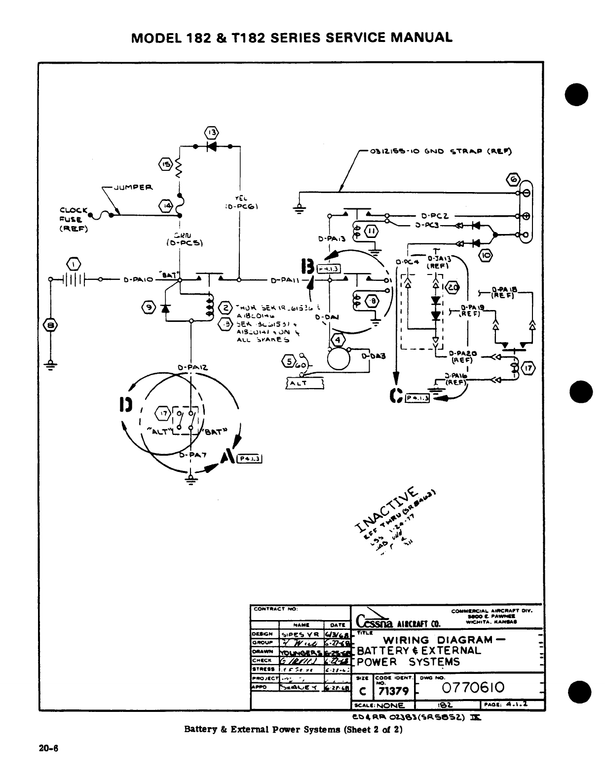
MODEL
182
&
T182
SERIES
SERVICE
MANUAL
@
|~*1~^ *~
i-0o
lblS^-1O
6NO
czTR^P
(Mt)
YE
JUMPE!
P.
|
CLOCK
~g
:0-PCL
\ ®-. ,_:
I-
f
/
: -.-..------
CLOCK
,I
'-
P Ct
/
~
I
L
_
_1
_YJ
I
'i
£5 \ \- ·
I-
IT^g-^F 1-- -c
IAJ
,
11ro? I|
0-,
V1
PA1~~~~~.1PW
COW,
:',,
;-V n
T
WIRING
DIAGRAM
O.A.,
~~,. _
E:BATTERY
4
EXTERNAL
1/C"C -2
/ '
r~"':POWER
SYSTEMS
^ D
P.
_- ,
C
73
07-706 10
SL:
NON
I
L
I PAE
4.(1
C
lkRk
OU
wIZASIBtZ)
ML
Battery
&
External
Power
Systems
(Sheet
2
of
2)
2~~0-f6f
4>:^
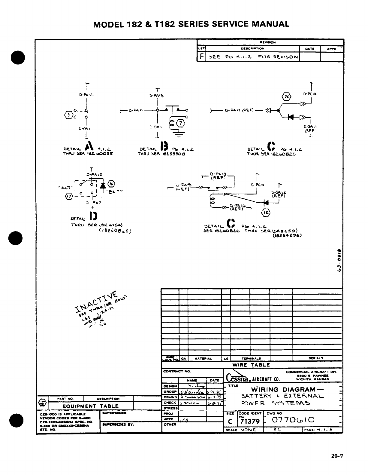
MODEL
182
&
T182
SERIES
SERVICE
MANUAL
DEML=P~IZl 1)-
%R
r
_i o L "e^T"
tREF}
~ _-irz
^--l- (RE F
)
IRe F
DETaIL
}
Tuev
sie
(Sb
6754)
DET,
|^ C P:-k II.
Z-
-k
/82zoBL2Sj-.
S
?l.a.OBthfa
TU St(>B59)
O(le26*296)
(,6244
""' -I I;I I
I
I
I
'r't
,
~.AJ
MATEIAL. LO
TMtAINALS
SERIA.L
WIRE
TABLE
CONTRACT
O:
COMMERCIAL AIRCRAFT
DIV.
D-CeSPAna__AIREAZ -D
>500
C.
PAWNH-
NAME
DATY
C
aI.IAC
AFT
CO.
WICHrTA.
KANSAS
EIROUPM TABLE
______
S
_TTL
WIRING DIAGRAM-
I-|
PART
|
oDmcTO
DRAWN
R|
_a^o-11-75_
IATTER
L
EXTEPNAL
VXNDOOW
CODES
MM
154t
0
"-
NO
,: 'O /'CO
r-XXXxC NA
C
m*PI
C.
NO.
,
-'
I
C
71379
-
7
70 cO
-
$-F
CoM
CMXXXX-CC-NA
SUPERSEDD
by
OTHER
.
No.
SCALE:
NON
|
PAGE
-.
20-7
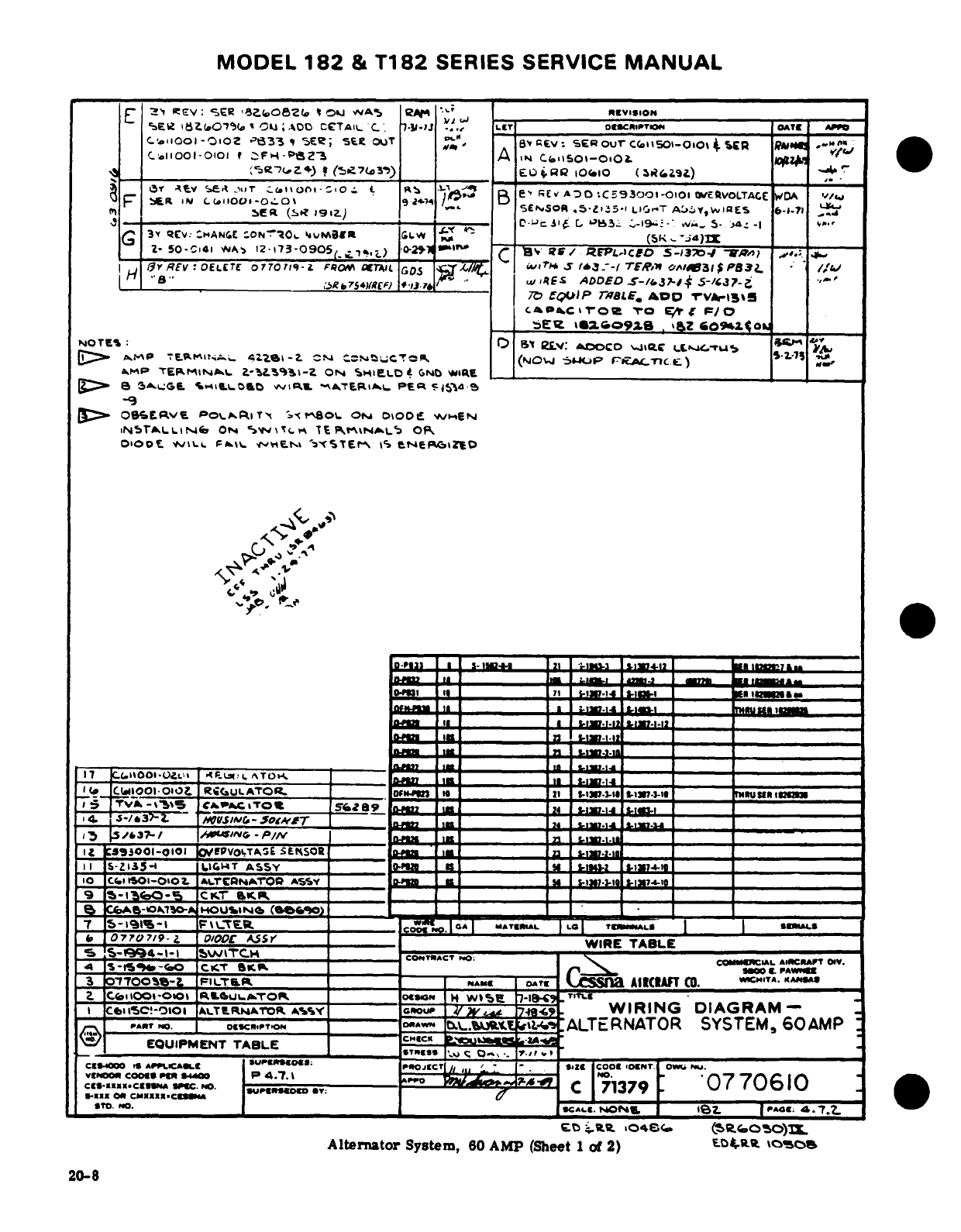
MODEL
182
&
T182
SERIES
SERVICE
MANUAL
E
R2
mev:
sE
se
O
'cOB'z
t oj
wA
4
^
-
RE*IvN*
_VIIO
5%Ft
18Z?.0b9O
0J;
.AO
CCTACL.. C. -,73J '.; DESCRLeTP ORlCIPNTDA
OA?(
A
C_
i
00
o
i-
o
io
Pt335
e
5eT'
seZ
OU-T
E
6
v:
sERourcrInSOI-oOIS
ER
RA
N'
"
C.11oOOI-OI0101
If
FH-pe
Z
A
C,.
o1501-
L
a_______ >Z_
)
_ __ _7__)_
EOcaoRQIOco (aIca9L)
-
:5ax(r
Z
~t(3~
7(0
3$)
1
I
I
(Eoca
10f.10
(_
_ _
._
R
"v
RSE
0-T0,
1
-
o.Is
E
..
.
'
R
E
AD
C5933001I-0,01
WO
tVOLTAGE
DA
*/w
FCR (R--
?
9912J)
/
SENSOA
.5-
.~t15-1
LIG,-T
AS_,lvY,wIES
6-1-71
^.
e3
- --
*--------------- -C-c l
·- ,
&BS.a.
*,-19.;.--'
,'. 5- 4 -I
,,,
.,
G
3Y
CV:
^HANGE
oN-'"o0.
uar
CVMI
_
-
,'
2-
50-Cio
i
*^*>
12-i73-09O5(
,7z
-)
o0-291
WNW
C S5
QS7
JfPLEFCeO
S-1370oj
-V
t
;I3
I
_"
s"_____ ______
_Rb74_RF)
·
.3.7G Y -Egs
ADDEO
S -3J-/ 8jR5-/c7 ei
-
I'3YREV.'DELCrE
IT ori/z &,o,
OTA7L
GD
0
0,9-
..
i '$',1
TE
w
,~i~Bi$_
/83
7'
E7
Q(JP
78Lf.tE
ADO
TrvAr-5s
0abCTcroe
ro
t
g
FP/O
_ EE 2zo9e
.
'Z
o9,
Z oo__
G
NOTTE1:
1
"
L
E.v:
LOOCO
>i \
C
L-.c0.-u
P;
'
AD
Ez <MP
.EP^nl?,~
«,I
-sl-Z
CM
_SMLICt'-e (fOw ruOP
frTAInTLC£)
l
"
w7
,AMP
TEP.MIt^NA.
a-M&\ -Za
ON
SMIe.LD
GN
bE _Wl __
8
5AL;.G6
S-itLOaD
vviI.
-AlTEfRIt.
PER
CS^<-
l
-9
(^
OSERvE
POL\..RIT-
i-f11o»
O 0 0
DIODC
/6mEN
ilN1r.,LLINt
ON
SW\s"t.
TERt^IT^'ALS
OR
OOlt
*.I.N
L
FI^\:.
vweKlt
'(TSTEf
Is
ENefCl>Z'ED
4$.D-P3
I
---i
0-1q
"T [ II 71 ,.1
_
-
lll4-1
ll«IIN
7. M&
a
~o
S
,UN
-J
.-- ,.
a l
-. .
1
---
fi,....
_t_ C/
-
lo·0
OtOZRitoULAloB O-Fw---- t C... I.;I
.I
...
H
_______ll
P
,r jn
&-
a
_ _1_ _-1-1
5
ITV--r. C^-I.^CITO--iTl 5l8l
J
---.-
.,q l 4
S.-/UL.g37t
-VS~--
0[;;;A
JII_
-
--
3 SUSI3JN/ 8u.^___ a- Z Z lP/i
M-: J.
,
-
I
AIMOO-3001-001
RPVCAEULAOR
AO
S
Z
S-tlSO1
_- _..-3-1
S
T-215-(
LICW.T
ASSY
T OL=_
A
UL
1131
_____________
10
(CfC1-tOIO.0L
lCNqATO
ASSY9 |_
A
-.
5L* __ __ -O______
__a_
9
15-
63C7-
I-* -e
- - -
1
7eQ-c5
CTOUltsNO
G_ __(Go _____
7
IS-9lS-I
FF\TCE.
______ GA
-
1
I
ATERLI LO |C
107707/9-L
i
ooo
Assr
1--WIRE
TABLE
5 1-
-94--l
WTC.C
CT
.|^ .^r
.
3 lO7TTO^--
iLB-f.____
_----a0-*5g
AlUCItIfT
77 t es r
CO.
4CH7T1. t«**«l«
Z
ICC17OOI-
OtlO
IJATO. _______ CI
H
W5 718_
TI
jS-/1,3O-C.
'-
__
i cfcu1c-oioi
6,TNTO
-S
Gou
"
j
WIRING
DIAGRAM-
7^'
t
««T^.
I
o~~wllrRlo.R
*
ru S
5I~,ft
^:A~CLT
RNATOR
SYSTEM,
60
A.MP
/
EQUIPMENT
TABLE
TABLE
C4EooO
-
c .t
/
-IICI
-
I
l
ICOO
IONTI.
O
Nu.
vorr oo€r CrOlS
PANIIoo
P
4.7.
~CO.
C.\
.
o
C.ii-c.C.'..
SPC
-----
k.TkoN
'K|
C
|
71379
07 70610AGA
PAR
No
O
MP
Alternator
System,
60
AMP
(Sheet 1
of 2)
:
Ero^
vOo
20-8
2O-8
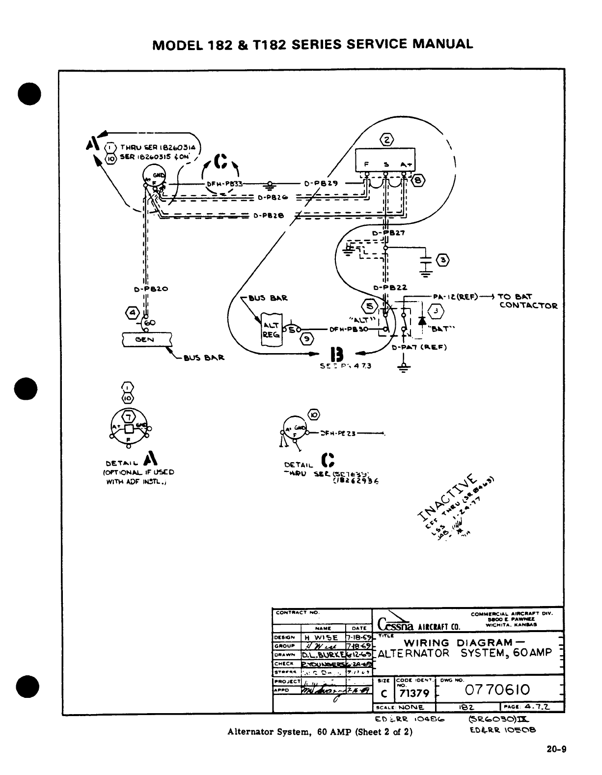
MODEL
182
&
T182
SERIES
SERVICE
MANUAL
L,6iii(
' /
-
L
_
-
2
_
''
0--ao--j^ ------
0-P6-9
-
A "Wi
I
^^^
^
bus
ill
i
I
G uS'
/--
\
* ,
;2
D-PB1O
/
\^^
D-PBZK
|
1
T /LCUS &»&% I-il(F)--
TO
BTAIL
WITHi
ADF
w45TL.%
!4.l
&,4)
°CONTIR"CT "O
.-
E
-
C oize
O
5O
C.
PAWNEE
NAME
DATE
CO-Pa
ARCIAFT
CO.
WICHITA
KANTSA
DESiN
^
WI
-
TITLC
SR.
C[CS
'
r
S
.
7,
1
0ET*..^.
A\ DWTRlI D
R
(OPT0^1_D
IF
-ALD ERAO
SYSTCEM,60AMP
AP =,TS*
C
71
379
:
0770610
wI
SCL
o Ne
.
I- L.
IISAGZE:
-,4
,7.
-- --
1~
~^r
~Lcna
AHOAF
o.
W(
°4ZQ
03)M
Alternator
System,
60
AMP
(Sheet
2
of
2)YSTEM, o
AMP
20-9
20-9
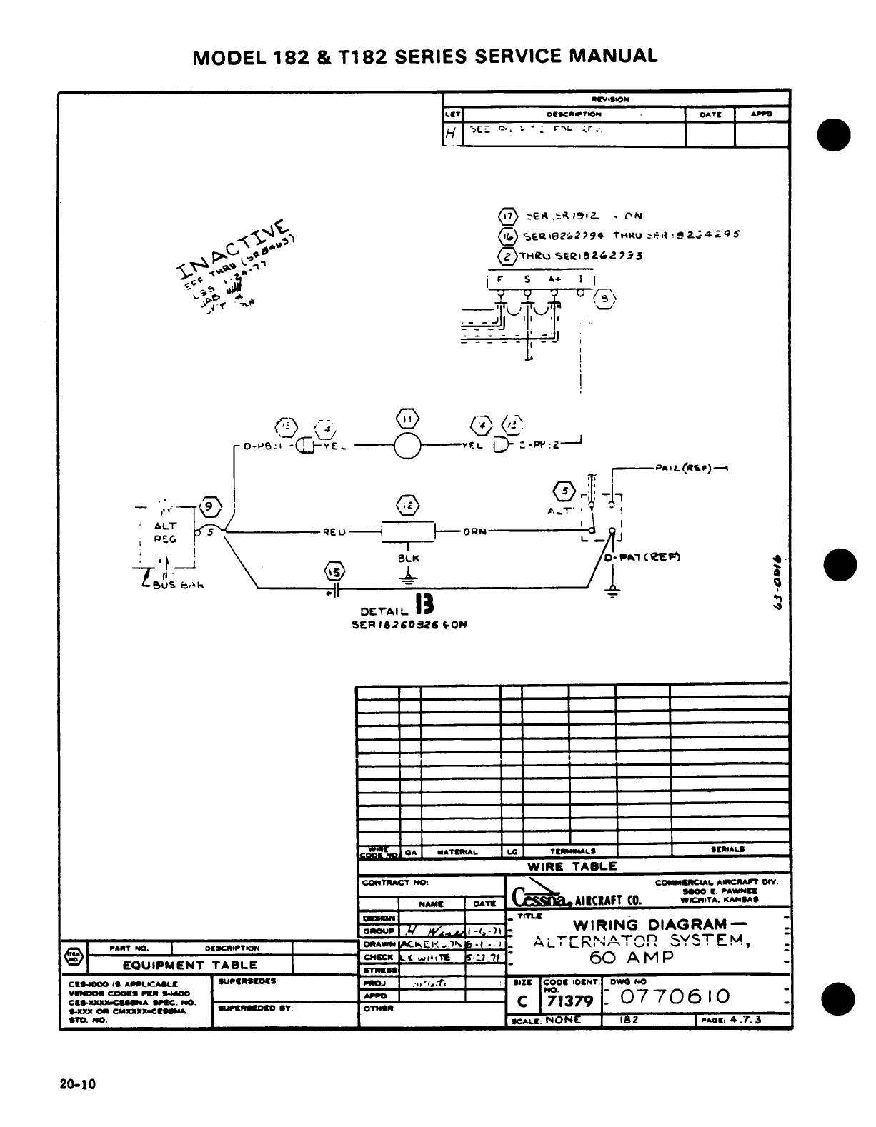
MODEL
182
&
T182
SERIES SERVICE
MANUAL
H
:'
o
-
r'
.
;
.'.
( )
A.-E
.
1
91L.
-
ON
-BZ
)
Gez.27;?94
THKU
EFl
RZ; -,9S
0
J2THRU
SEeIrIBa2
73
c Icg
F
S
+ I
I
_*r
-
_:
-"
'1
1
--
^J
A
_t
9~'
*
'7'L..
n '~./~~~~~~~~~~~**
_ ".--,&ttN
,
P¢C--
i
-eus NCOUIAL
AI
CRA
,T
._
DErAIW
1 :
'F
SEPI
I26036
tON
PART^
A*
aTI
L
ILG
L
I .I f
AL _ S
-^.ll*
WIRE TABLE
i
CONTNACT
NO:
COtCIAL
AlCrnFrT
om.
,oo
PAWNlIE
--
|
NAM
|oAr Lssa.iAIICIA
FT
CO.
Wo.
W
rA. *AS
carG
V
.ITr
WIRING
DIAGRAM-
-
.
|
AT
No. I
oSCm.?.
O
I~A,¢....
.
I<'CrNATO-
SYSTEM,
J
EQUIPMENT
TABLE
cH-
--
f-:a
L
'
60
AM
P
Cv-t,
XXXXc.A
OPC.
N0. C
7379
-
0770610
I-XXX
ON
CMXXXX-C-IMA
UIK/iR'4OO
LY:
OTNI[R
S«TD.
NO.
CX_
SCALE;
NONE
182
|
PAo:
4.7.3
20-10
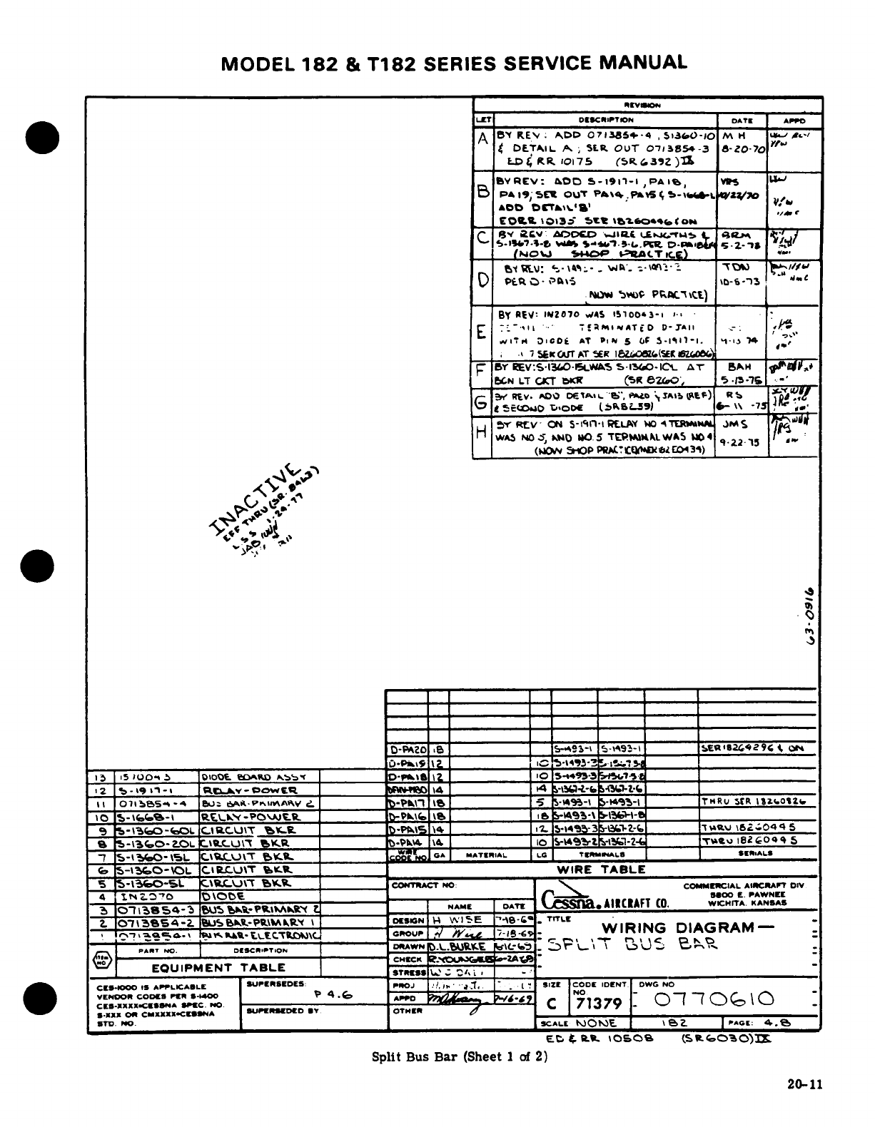
MODEL
182
&
T182
SERIES
SERVICE
MANUAL
REVISION
LET
0DESCrIPTIOON DATE
APPO
A
BY
REvI;
ADD
0713854-4
,
Si..30--o
M,
H
,.
DETAIL
A ;
SLR
OUT
071)354-3
8-ZO-70
LD
4
R.
10175
(SR
C
3SZ
)1
BvREV:
&OD
5-1911-I1PAl,
WS
1I
'
PA19;
SEt
OUr
P&\.;p:.5-,-
.
r
o
h
AOb
OCTlr.
'a'
.
EOtIL.
iOa3S
,t
Steo'.*-CA-
o
,
BY
REV:
R
I1,.
-
1l2070
v
dAS l'100*'-1 I.,
.
PLFR
r D
. .
si
\-6n3
*H '',C
N_:LOt
O
,ObCWw
5vbP P(Ct..l7)
BY
REVt:
INZ070
WOAS
ELSo0*3-A1
* ,
r -'l
- ,
ia l«TcD
D-TJlI
=:
;,
MI'M
io CO
AT
<v
S
Ot
5-1^11-l.
1-1'
w4 7'
'
F
sBYRvs
1V.Si0^-
sLwC
sO-ICt- r A
BAH
CFPOff
ifCN
LT
Clt
&*cg
(R
eao,
5^
-75
._
_
w
REV.
»00
Df
tAn.O".
e*o
/
AIlI
tF))
RS
5l{/
G
L
se«uo
t>-oe
(
tkBL5_9)
»
\\
-75
Q"*
*
_
9r
RCV
ON
s-lsnR
t
QLAY
tTlib
JM^s
%-##
l
WA5
NO0,
WOD
0.5
TER-UMKLWAVS
U
4
2
'
1
I
_ (MD"tv
5HOP
PBRACTlCq(01iaD03i)
q'
2
,a
i'I
3
D-I^20
_
5
-1ASI-1
-
uEst26I-q29c
t oi.
'-P2AO
5
SII_ 5_9- ER_ '_
'S
i-
_S_)-oI
I
..
L
_______
NM
'o
»") _
5e I____
..
b,
,
1"'
Z0
5-Oe6-%
-
.)-«.k
-PO.R _. 'l_________ 1
-
-______
___'__4
__ __
9
-M3C60-60L
ClQCOUIT
KBI. ___2_. \I 1____ i> 61t-_
_
\S044
5
_
S-%3-.2O-OL
-tLUCU\v
lKR
% .-
P. \4
10
_5-W9r_
_-_1_-2-___
TJ
82
044
S5
-7
_-Sf(O-%SL
Ct.CLUVAT
B9L
_A cM
ATERIAL
LC
TWERMILS
SERIALS
_ 5--O-\OL
Cl.RC.U\T
eK.
_______ _WIRE
TABLE
S
O5-3
.0-5SL
.\CU
1e.L
CONTRACT
no
:
COMMERCIAL
AINCRAPT
DIV
4 INC ______ Ob
c.
PAWNEE
3
07i-3554-b3
VBS MtAS ---- tE
NAME
_DAT_
CSia.AllCLAFT
CO.
WICHITA
.KANSAS
'
01\-854-2. Be
-p___PtK
.Y
I
DES
N
.4
.lSE
e-. -iR
DIAGT
*7>C~4..
an
.-
C.TUC
/
C
/
-
I--I
-6V-
WIRING
DIAGRAM-
DRAWN
rbL..
.VL7
L-
6-:5
" -
NO.I
DISCR.PTION
.DAWN
L-
U L-L T I' \_
EQUIPMENT
TABLE
[
STRES-i
-
C5-1000
IS
APPLICALE
SUPERSEDES:
OJ
[
SIZE CODE
IDENT
DWG
NO
VENOOR
CODES
PEIR-400
-
R
DD
.
AP
C
71379
CgS
CXXXE.
SPC"C 71379O
-
!S-XIXX
CM
XXXX.CESNA
UPERIED
*Y
OTHIER
TD.
NO.
|
SCALE
*
')
OIE.
9
PAGE:
4.
e
EG
r tL 050& (S
L"C030)IE
Split
Bus
Bar
(Sheet
1
of
2)
20-11
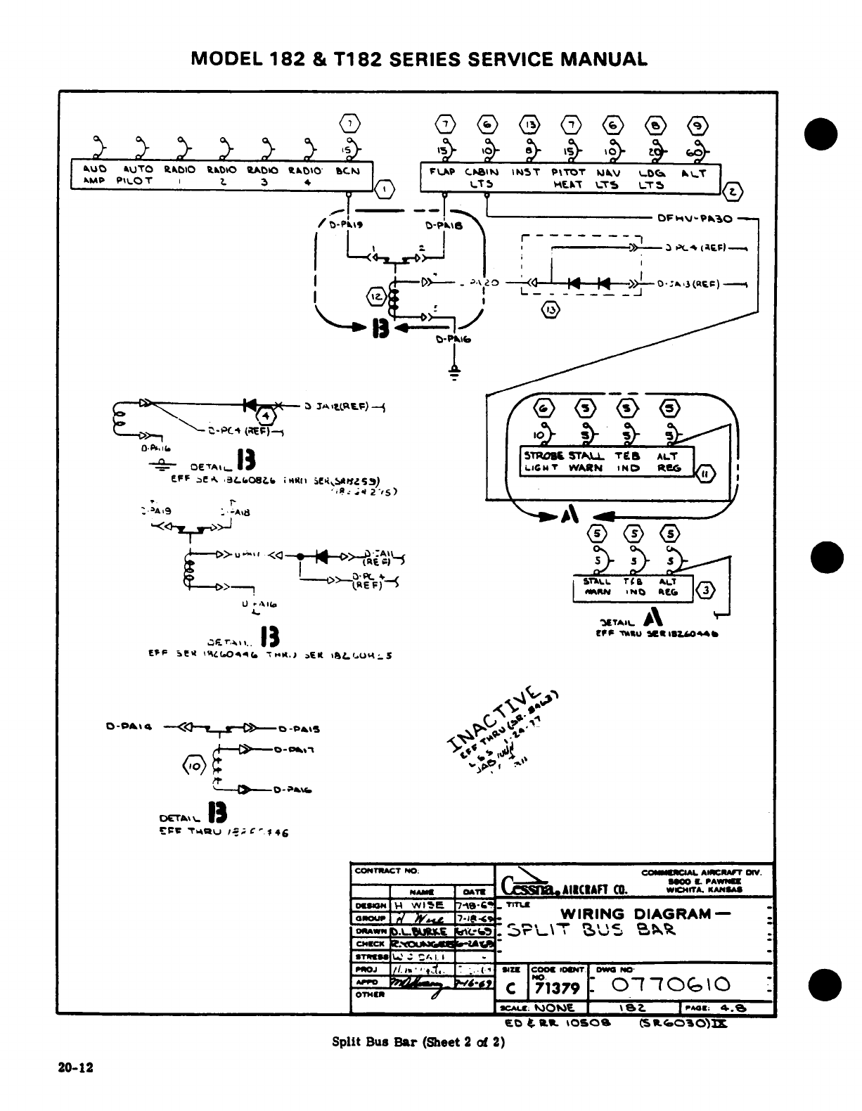
MODEL
182
&
T182
SERIES
SERVICE
MANUAL
G
<
®
@
G
®
D ® ®e
N>~ >
> > I >
->
t5>
*0
>
1>
\°>
t
I
bUO
IUTO
st)bIO
IOtvO
"OlO
20koo
bCN
FUP
-1BIM
\1ST
P\TOAT
WOV
»
k K\T
MUP
PiLOT
I Z.
3 4
1
T
'T
HEWT
LTS
L
TS
D
., -
,1
-
O3i)
--
P
--
i
1L ®.RT.:..;
®
O.P&,1
STR---O
Ao4 -M »
o-;*4.(«e)
-- \
L
t t-P1f a
b,
»
14
"a
-s-Ct (GEF)) 0
'
_
®
O·
l
*
|t
STROBISTL.
Tb
A
I
_
oE-TA
1
;
iICt
WARN
IND
R
£EFF
z
,3{1· .l>
i
,R.,t2I)) _
,
_
t
: ,-rr. r.
13
l
^
-
» "-F
«l
-vai»
A C F
CO.^
5
MVIA KN
--
-EF)'
MMMI
iNO
IC I"
aSSIGN R wIE
'WIRIG
DT^ As-
rFF BusF Bas
r
salt
2
046*
,-.
S
Split
Bus
Bsr
(Sheet
2
of
2)
20-12
-CO
ACT
F0
CON
.
AMC
T
ON.
--
ms
I
R
essnaIRIAc«n
CO.
wexot:A.
I*MI
ag
V
I.
-1
:I
W
IRING
DIAGRAM
-
1IOJ
S/I.=»oo,.^. I-
.. , (
OU »i«Cooc IOT
wO
APM
C
71379
0770G10
Split
Bus
Bar
(Sheet
2
of
2)
20-12
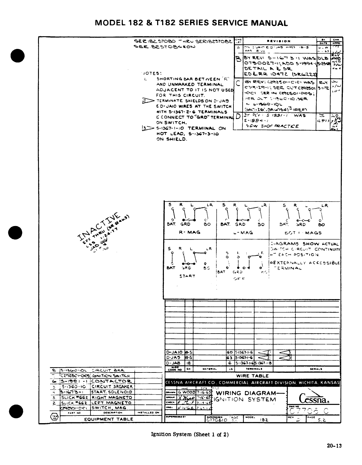
MODEL
182
&
T182
SERIES
SERVICE
MANUAL
=>EZ
IS?-570oeO
-t*EVr
toerz. a_____o_____ DSE.\g
e-,.r
::.it..
'~ ::.,-o
t0
.. .-
"-. :.-.f,, c
D--.,S
:
.
it
,
re-S
'.w
_
'i-;
*-r
FZ
,7 C>""L 0h) B
C
--
ES
------- <
-5
v ,,,. B. _ a~a' s _ ,,,,
.. ,
*:J
S
BY
Rt-
S
-
\
> 3
-\
WK5t<e7
JO-I."5'lOt
.
TL-
WA-l.
*-
7"
JOTES:
E 1,
0
T.T
POt-. (...T..?J
I.
SHORTrlNG
1AR
BET
'EE
N
R
-_
AND
UNMARKED
TERMINAL
.C
e- o -cc
,
/kDJACENT
TO
IT
IS
NOT
USED
Ct
-
FOR
T7Hi5
CIRCUIT.
-cec
Ct
-O
>
TERMINATE
SHIELDS ON
-
JA9
-E
T
-t-'-C
E
D-JA10
WIRES
AT
T7E
SWITCm
lITH
S-IC7- 2-6
TERMINALS
'.*C '.-v
_
I
CONNECT
TO
"GRO"
TERMIN
D
Y
L
99
WAS
L)
0
ON
SWITCH.
_
[>S
-1537-1-10
TERMINAL
ON
L
V 5.O'CFCE
,
HOT
LEAD,
S-1347--O10
ON
SHIELD.
S
R
L
L. 5
R
L
-_R
S
R
LRF
S
R
L
LR
.
TCa
C:RC
,:
CON
INUITY
BAT
.
\
' ' -
EXT_,Lf
CC-CLN
BIT
AR
CvU
N
I.
I
BA
AT.RD RD
R
MG
.-
MAG
T
i
MAGF5
D-JAIO
11S_51
160
S15-137-- I-
C
-
-T).Sc.I-0e51l\T2
S*.c _ _-,
WIRE
TA
,.LE.
C_
iS-
Lk9
1
-
I ICO.T
&-
P
0'
o v-
0
.
S-13GO-IG
!CIRCUIT
BRT
AKER
_!--
T
_S-1(
W3-l
START.
SOLENOID
-_ WOO_
716_C_5
WIRING
DIAGRAM-
SLICK
"GCZ
RIGHT
MAGNCTO
I GNIT
ION
SYSTES
M
(Essna
a
SLICK
(.C
LCv-T
MAGNCTO
2n
-
C.ZFtN-CtCi
SWITCH
.
MAG
,_-
__7
1'
'.t.,
7
.,,
_
· ·
r
.
o O.·C-IC*'O V.
NSVUo
_" _
..
v
, -
:c_ _ G
EQCUIPMENT
TABLE
07'° |a I °°
..
c»_
r
C
Ignition System
(Sheet
1 of
2)
20-13
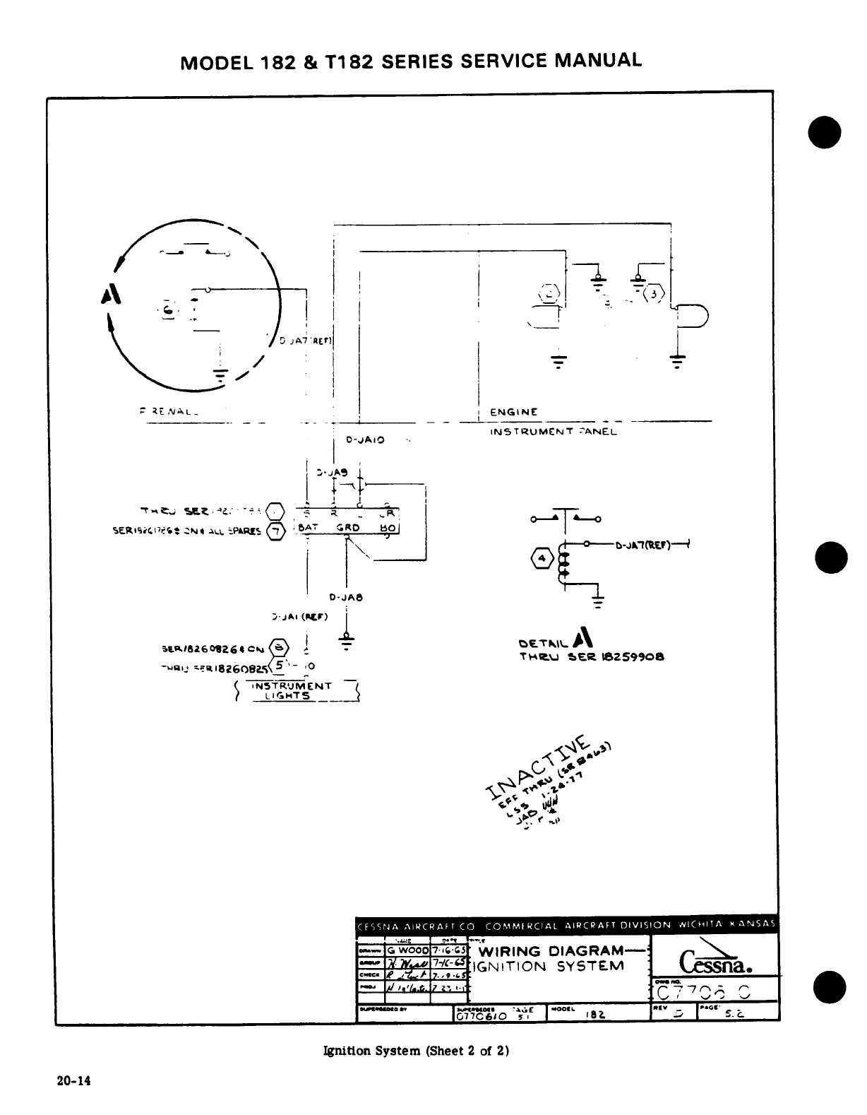
MODEL
182
&
T182
SERIES
SERVICE
MANUAL
-
....
D-JA8
; i--
-T x^;
y
e Z:
-.
^.
." - -
.QQ
-
:-4-
u
-O
D-JA8
1
;-J<,
(lry)
i
stPf8260"26C bc
4
;
A
3TM
/-, *~
T~~THEU
»EW
18259908
-ua,
e.
1826t83(s
5
\- 'o
(
NSTRUMENT
LIGHTS
__'
G
w
oo-0
WIRING
DIAGRAM-
.,
7Z-/
-
IGNITION
SYSTEM
Cessna.
.. _
i.
.Z ," C, ,I
.o
7C 6; 05
'
|/
;.v
.6 .7
-7
rr.
.-
^
-
C_________________________
077C610
vi IiBz
Ignition
System
(Sheet
2
of
2)
20-14
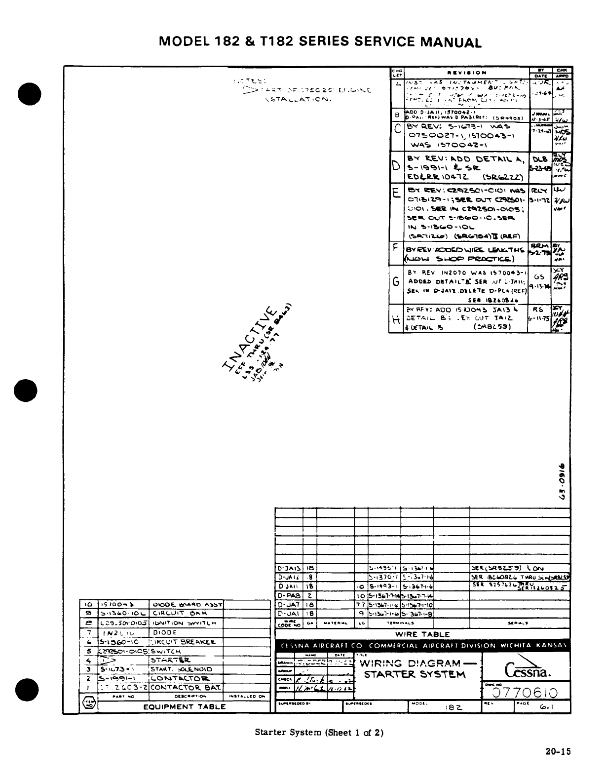
MODEL
182
&
T182
SERIES SERVICE
MANUAL
., .. . ..
-,I.ON ~l _~
L-.
..
S fI.
"J1MCA..
-3
7
.-
DD
7
:
7
-
a
OO
-"
^^^y
\SsT
.CA,.
* ' --.
£.;
i"T
.
ii C:
rn.
Et
k
\0491-\
Z.
.
I.z)
·
Dti F,\O4PL
(
311~'
q05)
E 1-
v
X&
-
~'.
%..
E
rv : I _
'
&
~iIE'G.
I.GdY'T.
_
orPEV
ISN2O
CWASR
t7\
OS4
-I
F
8steC>v:DD~rowI I E'rtU' v83
_ _ _
v_
_
I 1927002
W-S
157004-
__,_
^G
ADDED
DtlL-Q
5ER
Jr E.
g
S;
C
S.t
'w
-JAC'.
.DOLETE
qoD-P9¢_(E_:)
__A'
L/ 7O b 2i9FV 0 NITION
T,,VV1T(
S
R5--S
\ g t., -
;
;
.t
.
L'-
T
T
wIL
5-;
z7~ I N I2
WIRE
T
RA
B
D__
_ _ _ _ _ _ '--- '------N
2A
G
Ro
A
M
-szE.O t-e
.
\7
-
_
A
T.
sNB.<». Z -__
__o_
:" z c So 67
0
sL7NIT10
'7wllt r,
coos
-o'
.
CO»>~,C' l
O
O
eV' .J
'" "
.7I
EQUIPMENT
TABLET
TAB
.
.-,,
z~,,~
.
B
.,OO:
Starter System
(Sheet
1
of
2) ~ r
-
Ov MT 0 *E |
,
r
7|20-15
A
...
s~jDI~o~o S
,
VITIOIU'3WI
n I
K
C- O E-,.
6.;.
-...
c.J-
,I
C. I
1
-"-757
O
I
O
E
_
_N2C,~
DEOUIPMENT
TABL
...
E
(b.
I
|
5 ~ ~
~ ~ ~ ~ ~ ~ ~
" .,
^i------------------------
i--
jj?;~TI0 I O!SSCh^RM-
sTa.^CN\
~15r9~-\;
ONTaCoaI
SAR.'
/SCM
'-fa
*
~ _
~3ZCNATR
BTI3761
·
~·u o~o·
· ·
rr··ol·
lo~r. r~o4
~~3 ,,,,.,.
.~~~~~~
..
,...,,.,~~~~~
EOUIPMENT TABLE ist 6. 1~~~~~~~~~~~~~~~~~~~~~~~~~~~~~~~~~~~~~~~~~~~~~~~~~:
Starter System (Sheet
1
of
2)
20-1
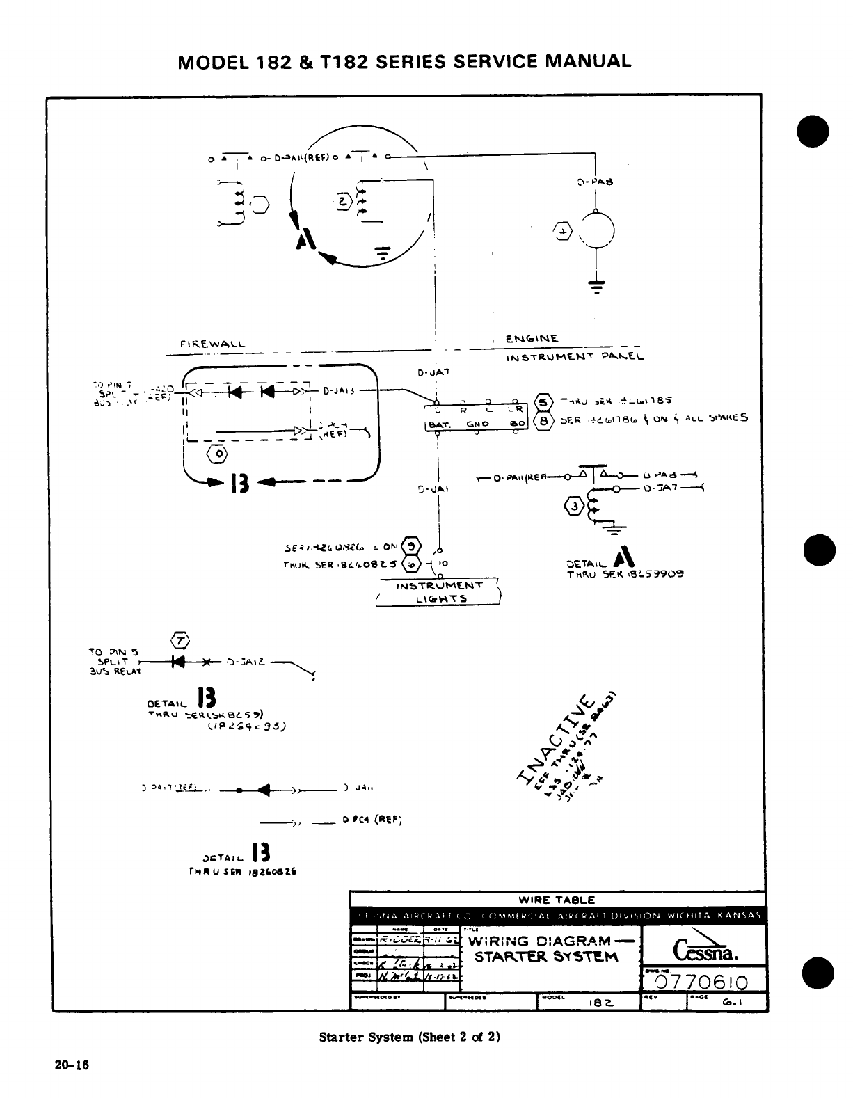
MODEL
182
&
T182
SERIES SERVICE
MANUAL
0
*
-D-
i-Ar.L(
Fo
. . I
L
---
--
--
I
-< 4. -JI
FITFE.WA,\_
L
.
ENG\
Ne
_______ _ _
ISTRMt-F."T
LPAI
ls,,..
JrO
^f;
-
J
D-JA1
s~3
- -'
~: ~
1~7
-~
-
_-1v~l
I <I
o
6< (U.1-PL AlMT
-
13
'~
--- -
J',.t
.
T
I(
O--,A7
"tO P·ki "5n
®Lb~7 9~ Iolv
i
net
C
UII SER
8.OLt
K
WIRE
1
ETABL.
-----
/o
--
THIRU
SFRA i
RA59909
INSSTRUMtNT
O
.
ETAH1 IT
I
XT
^'
^U
*
RV S
sr
C
S
^
)
-AX
j ,,,.
.~
_,
,
.WIRE
TABLE
C
(6EF
Starter
System
(Sheet
2
of
2)
20-16
201B8
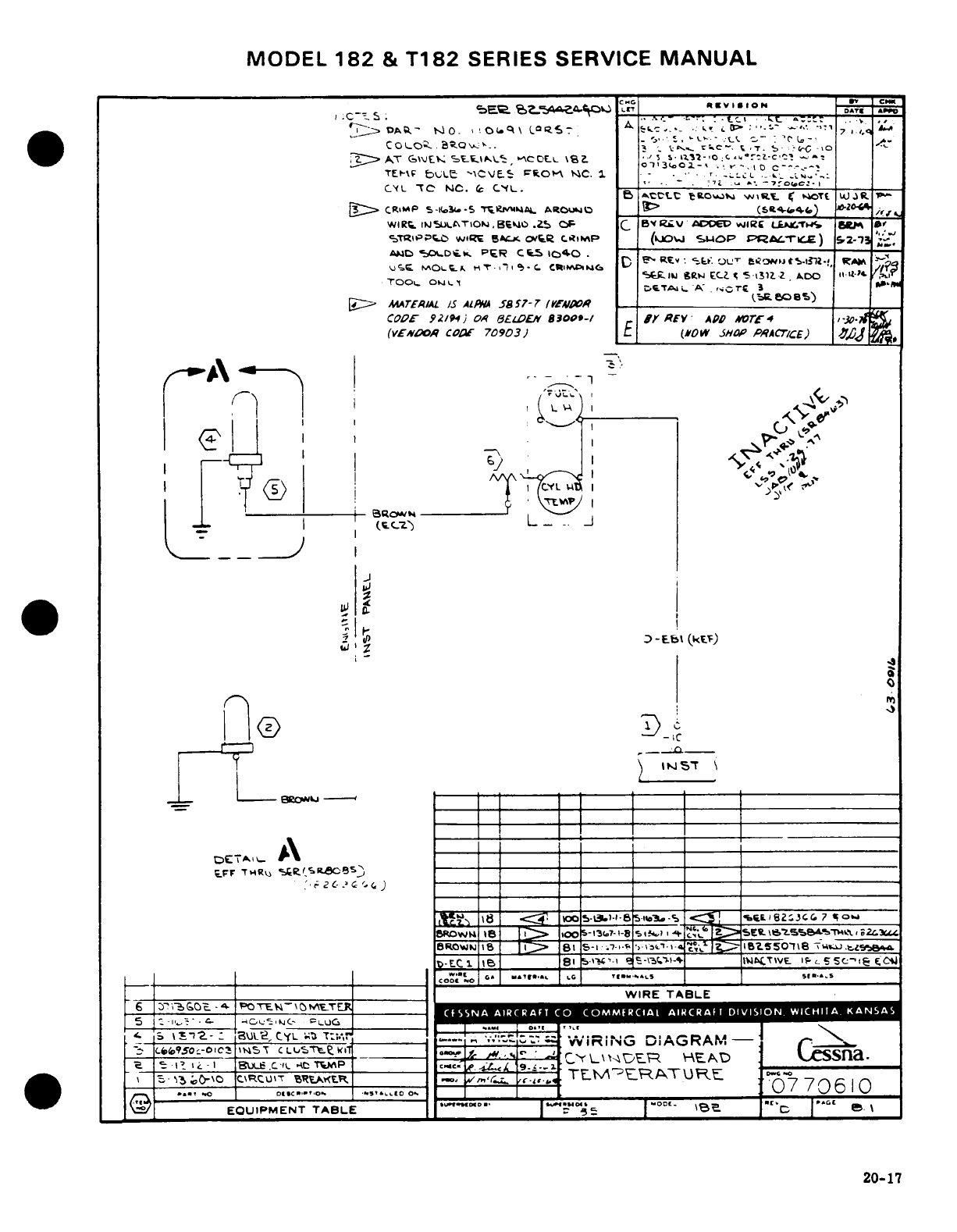
MODEL
182
&
T182
SERIES
SERVICE
MANUAL
DA-
9, -\
t
.
5
^
t
, ,
LO
, '-
G
,.'.
1ioN
7
C7
m5
i
C
c-
.
.-
' --
T.
t
k
.L
,
T
C
-
A p°
/
L
C,',A
_
'B%.Q
-,: ._.
'-53"-
,._^
c'
.-
^\
.t
.
^. :
,;*,,
..
TEF-S
bLtE
CVE.-6
=kOK
MC.
'
k
.
_.
-.
, .
CY'L
TC
NC.
.
CY
-7.
I
.
I B tCC
t-OwhM
WIRiW
t(O
%
IUJR
1iR»
rF
CRIMP
S-lK.3-5
TrkIIR ARw4Ou _ 9>C
(St4Sp4.)
-20A
a,
WIR-
I|JSWAT|OMB6ClD
.25
OF
C
BY
V
ID
a
W
IRC
L-fcrw
aM
f
bTqIPpMOL.
Wi?
..
-c.
CIMPA
_ (woi
SuOP
s
'RArT
rE)
5- ''.:
AMD
5O.D.
.
PcR
C
C5
1040
._
u5E
M00k.
eT*n1
9-C
CR,^,^ D
b
R
c
S''
^** O
CT
al5Yv^s-
,.!
,
r
.
bktKu
Im
6 rr E<-
5
t lS Z A5DDO l
"
"*'*
Li>
kMTERAML
/S
AlPM
5S57-7
IW/V _ 8)
--
_
CODE
92/14
R
i
ELDENB
8300*-/
If
REV
AP
rTE'4
,-*j
-
I I
I
(vE3
OOR
C09{
70903
E
(MOW
H0f
-wAC1CE)
w
C-4x -I
-.
i
-J1n ! ; 'Q
__
^~~
!
0
z
)-Etb
(
IEF)
: z
-
.
-
,~,
"
.... I-
~o
~ T: ::-9"
'
::-i]
_
_
Oi I
=
8 1:.' *1-4 ~i I,
Bna.
'.1
'
'
12.60
-I L_
*l'~r I7
-I BLC _R Tr.MP
_______
\
TrM.PATURT_
0
_
I-
BeSo
..
,t-
---
3
--- -- -
DEOTUIPMENT
TABLE
'_
...
iNoT o Lcl,~o '~'~<
1
o
'7
20-17
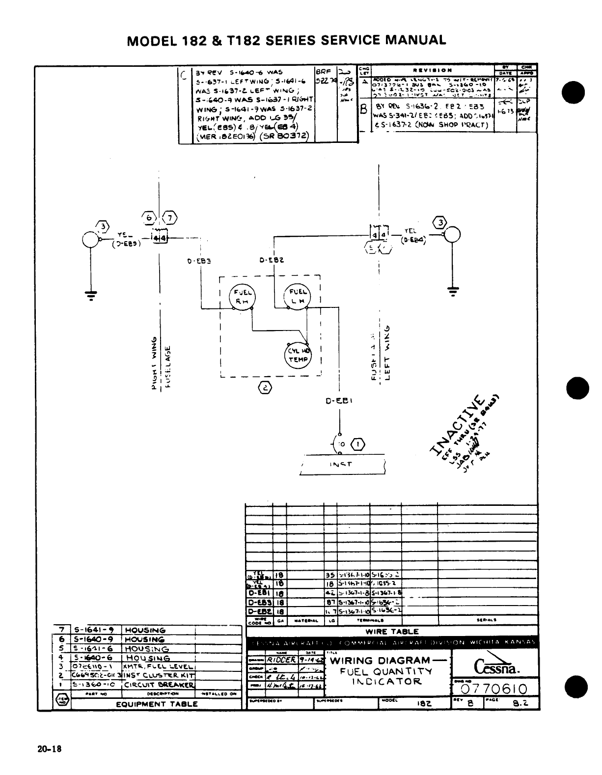
MODEL
182
&
T182
SERIES
SERVICE
MANUAL
(
3,
"ev
S-,IC4O-6
S
BRP
-
RviON .ay.
CO.
'
I-',637-1
£F- iG 5.41-4
-52
?137Z-
.. .
5--~lO-«tf
!-.-'
IN.A
S-1i37-L
LEF;'
,~Gr ;
WIN
"
'
-' ' -.
s2-.
6.-"c-.c ^ - -
.'-
i F
o7,3,~i?-d
BJ
m ./c. t..
O
-,
.s0- » 1WAS
S-Io37
-I NGT__/
.
WING;
S-1641-9
WAS
5-15637-2
B
Q 5-1t
S
3-2
e
I E
a
w
Rl(.rTWINc.,
&OO
1S
o
5/
WAS
S-341-1/
E:
E5;
4
'00
W
Y..L'e85)
.,/vaEB4) _
S-16i37-Z
CNO
SHOP
I'QLAT)
_M
ER
I2EOl6%)
(5R
80372)__
IDI \LW~~~~
r
i t
r
- -
-
--
7
0 -E.B3
WIRING
DIAGRAM-r
[ -~.' v~' ."--G," 1V
L
>
"
3I.$t,'LL
.-
~
Krr'
FUE
QUANTtT'f
-s
-1l 3 ?47
i
-
I I I
!
I
-
1 _ QUIPMENT
T
I
D-E20t0-E8
_ _ _
CO-D;IO
(
,
GA.
.-
6
5
-
640-9
'
tHC!SIo
G
3 _'elo-lloJ
Xm
'E
sWIRING
DIAGRAM-
\
ts." c^'-cI,
35sr
UB. rI
T
- ---
I=7
,,.,.,
FUEL
QIJANTTY
Yna.
I
^-»3feO-C~pq>RcuTaRE^%CR
________
!=~ rf.^ IN.CiCA70R.
_ ^al _ _
EQUIPMENT
TABLE.L 0..
I
.OD
8
|l
et
20-18

MODEL
182
&
T182
SERIES
SERVICE
MANUAL
,I--"
_ _50223-1
b &<
Q.
S-1B-LX ea,^
?1
-
i7
tWr
O\Z23-\O; Dsle~ C.t s?~
S
c
r'27\0(-\
o
C
WA'sQ)\4P e,
L^qE._,
Cc.bo0Z
-o°c%3
wKS
0
1
7'
OOZ
-
1,
DF-LBW
_(B'c
wj.v C-re w.
~i~~~~~ r
6
ei.v:
c/9«B-Qo9-c
eL<
JRi
1
/
o
CCet95Cl-ObO
7-7-70
.w
r/- ~ ~i~ \-/DE _ .e <M
«C"e>
ow
(
bwPP
«*,()
_»
~~~~I I
.
e~BI
RlLiU 00
D
M53051-4A
LSS
/T)S7 ~~ I
!~~~~
I1
~
;~
CLAMP
5
,3 -I-3 WAk
S-31-
\ t-M1
v^ \ ___________ ^.
(________
ttOX
SOP
s P"
CE)
_
t_--!
A
.
C
,/
7''o
Il
I-i
'
DA
!3
LL-LZ
I--
-----
--
D-I
T
I
\
i FuV\
I
r
) -
At
lALe5
T
'.MF,
Z 0o-EBK~t-fr)
*i
i
Z ! u)
~ ~
=-~i
'-
1'
'F-I'
(Plc
4-
EU
INST
/
'__ __
LIGHTS2
'C
I
-II
-
I| I I
'
tG-EA
IS
c__ i -_____ ______
I_
.---
SPEUC |E _
WIRE
TAA
BLE
0-EW.
16 ___-____ lo·l*-C,
aC~Llc-E
<LE_ _R_
_
E
:Z :20-19.
9D
.
18
--
_
*^
W
IRING
DIAGRAM\ _ ___
_
Fc
____-IJ :h+______
-
a
,
_D_-__._
CAARIi
C LC A
\R
L ________I
.
|
H>3i3
-fc \
E
L.
!rb
A
,P
_D.
,
·
.
,t
«tlr t
.
T
«
«
,,i:;
CPT)
xri7
ri
k&\ f
E
DUIPMENT
TABL
\FZ
W E IB.3
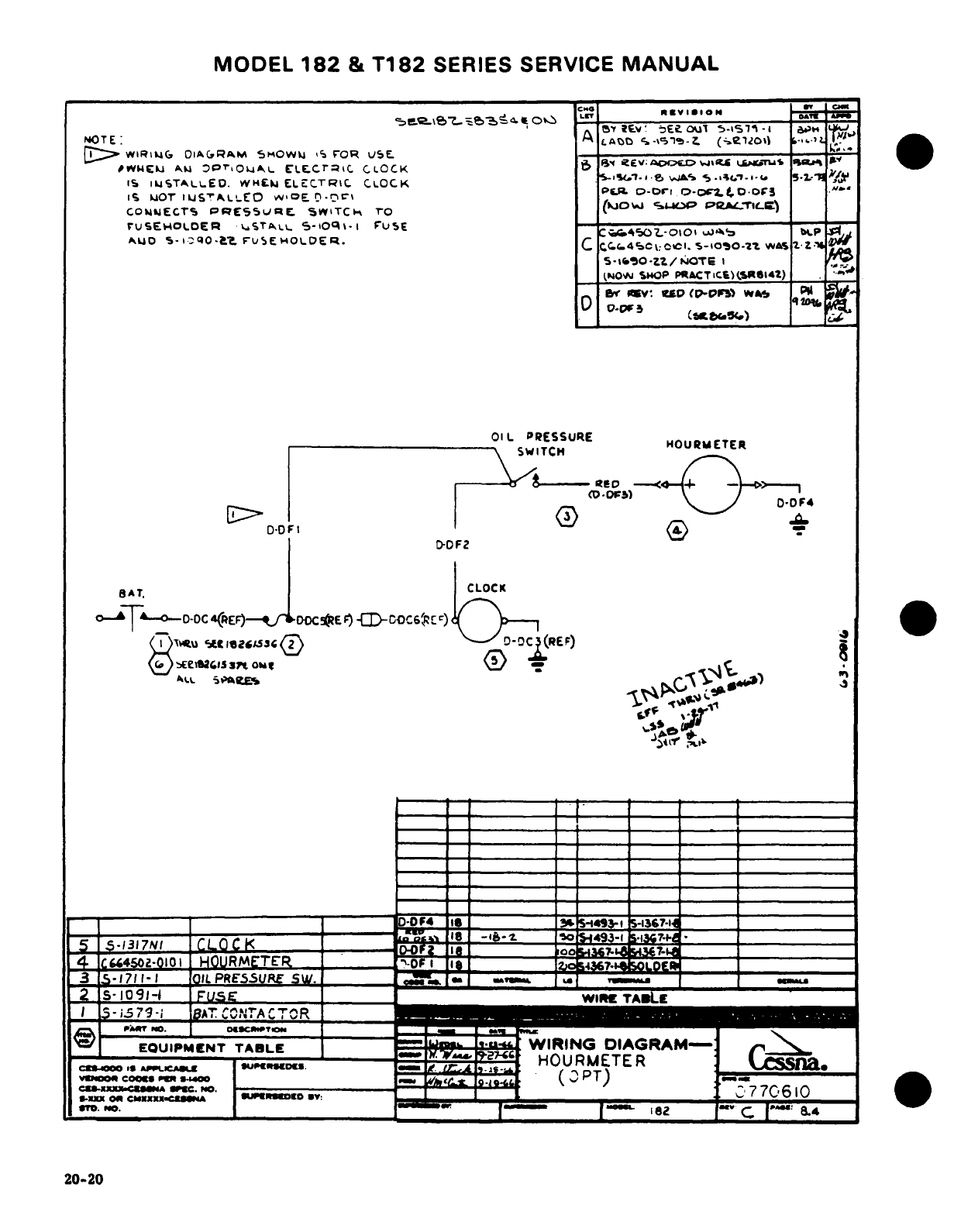
MODEL
182
&
T182
SERIES
SERVICE
MANUAL
'0
B,
.-
loC.
NOTE
.A
'5
i't
B
F-v
~[j.>
WIRM.G
OIAGRAM
SMOWL
;
rOR
USE.
A
_r0
-
WEEuJ
AU
PTiOLrAL
ELECTr,
CLOCK
l
EeV:A
\
IS
IUST^LLED.
WHEI
ELECTRlC
CLOCK
II
5
*>
.-
5-
2.-T
IS
UIOT
IUSTALLEO
E
WIO.E
-.
n-\
I I
0-
o-DDoc.
O
""
CoMuECts
PRCESSvC
S'WITCIT
ro
JOW
SUO
PA.C)
ruSEMOLOER
v
.ST»L.
S-iO
-l
FU5E
-
C---o----4502---0
1 W-
b.-
-.
uO
S
-*qO
.
FdS^EOLOER.
c
:OR_-Oi
^. SI O»OP
.
.AL40~~
c~
CCr-45cACt-oCI.
5-105o0-22
WS
LZ
Z
S-lciO--z/OtE
,
I^
I(NOJ
SO4P
PRACTtCE)(
S142)
_
_
_ ef WtLV' D ("PS)
lAS
b
O
_
4)20%
OIL
PRESSURE
SWITCH
HOURMETER
Rev--C
-<-
-
D<DOF5)
|
DF4
D-DFI
F
<A)
.4
D-~OFI~
.F2
^^ 3
I-DFD
AT5-.3 I7 _____
I-
-ia*Lfci_______CLOCK
T D-CEQUIPNT
TABLE
S
WIRG
D
,IAGRAM-
Rr)
3cE~wracs
sm,
m
0_-2 0__I __-____ .~p~u. DC. OD
F4
to
.s
5
cX
O1
CMXXXXCU
MM t
*
C
L
C ^_
_
6
-
1
31
CLQ
R
-
3
5
71M_-1o
O.IL
PRE5UR-
SW.\y
I___
___---___"1_____4
20-20
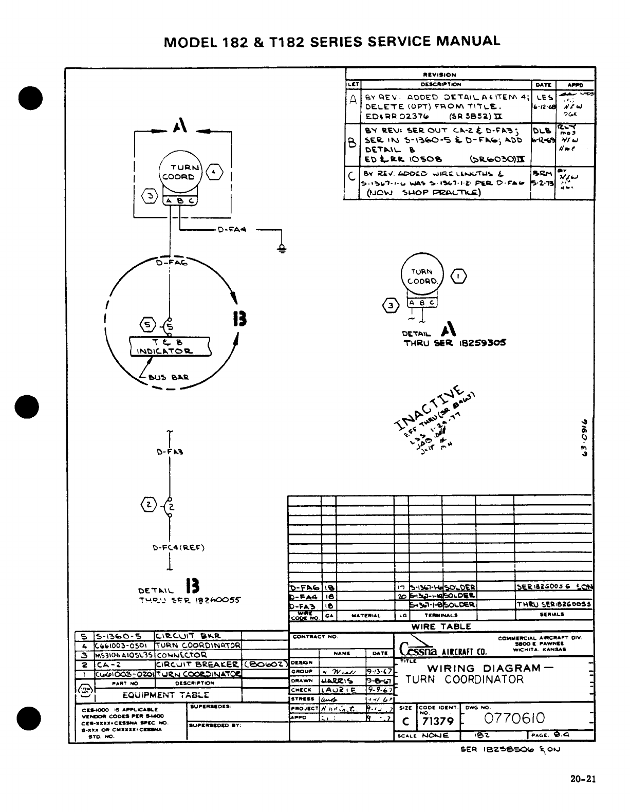
MODEL
182
&
T182
SERIES
SERVICE
MANUAL
REVISION
LET DESCRIPTION
DATER
APPO
yA
,qEV.
ADDED
iETDAI.
A
.
ITEN
4,;
E
.r
DELETE
(OPT)
FROCN
TITE%.
-126
0
IV/s
EDoRR
0237(
(SR
5852)
o
C,'
\.N
.tE\J-:
SE
OUT
C/k-.
D-Ftk;
,
t.L%
_
E.
.
IF4
S-\:r0-S c t
-Fk.;
kbt
6>-U.-H
v/J
/
/TU _^ Et>E
tRtR
\050I
(5Q
o
.050)3
I (cOORt)
)
<P)
I
C
8By
21i:
DDCLt w1s '-i -S t OS
Kr
/
v5
/
.%4,7
-I- -t >I. .S
-
ISOO
-
iI
-
FXt
PO
r
s-Z-i
'
2- ^^
*0·
|T\ @ ~-| 2
(uJOW
SUOP
PeccT)
5
o
-
-D
-
¢4
13
\ E
T
It sb'
THRU
SIR.
8259305
INts,
\
/
bUS
lPbb
_j
_
T «3
s
C>-F(K4(B
R=[F)
-_
~
Iuq~r I9_!205
_ D-
-'
'^""--'-FA3 16_e
_
bj t_5__
1
5-ETQU
i6»15260o5a
C GOO
o
CA MATERIAL
LG
TERMINALS SERIALS
________________________________ _______________WIA
TABLE___________________
WIRE
TABLE
S
S-
f\3Ce0-
5
.\.CUX\
)IT
B».gQ
_______
CONTRACT
NO:
COMMERCIAL
AIRCRAFT
DIV.
6
C10-050
TURN C.OOR)\NoTTOR
s lOO E0
PAWNEE
3
3I0b30>oto5
CO
tCTOR
Q
NAME
IDATE
Lssra
AIRCRAFT
CO.
WICHITA
KANSAS
2
AC-z
CIRCUIT
BREArE
oOI0.)
DESICN
-
TITLE
C
C1003-0
B T
BA'T-Og.
7
GROUP
.c
7
-
-e--
W
IRING
DIAGRAM-
PART
NO.
DESCRITION
RAWN
TUgs
.
-,tt
TURN
COORDINATOR
__....-
....- _... _-----
cHE*cx
LA=i2C E
9--6
EQUIPMENT
ABLE
_
STRESS
,
____
ICES-100D
IS
ALICASLE
SUPERSEDES:
IROJECT
1
I
-< 19 J. SIZE
CODE
IDNT.
DWO
O.
VENDOR
COOES PER
NOP
ICES-XXXI.CSSA
SPEC.
NO.
ISUPEREOO
LI
C
-
0770610
I
SI -XXX
OR
CMXXXX-CISE
A
UPE
D
S:
C
7137I
STD.
NO. ___
SCALE
MOis
E I Z |
PAGE
0*.
SEa
ISZ'55s
C
10o0J
20-21
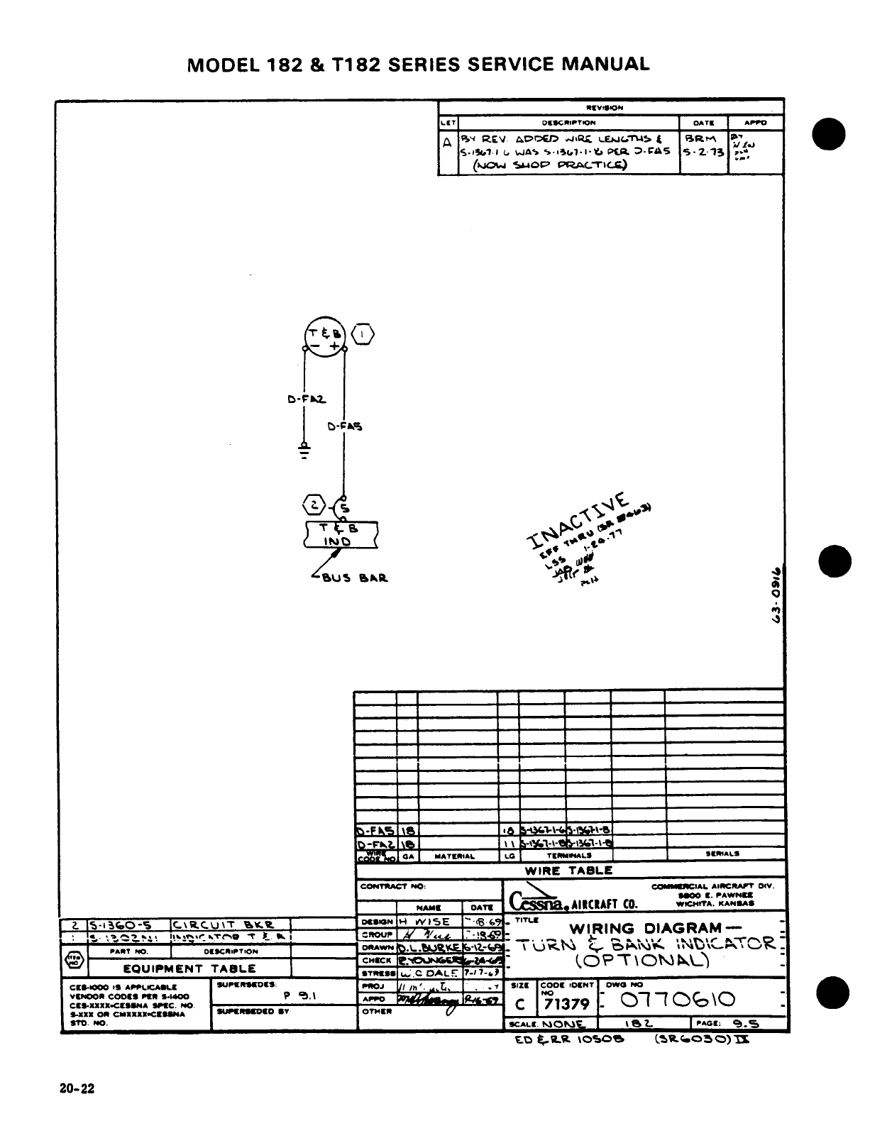
MODEL
182
&
T182
SERIES SERVICE
MANUAL
REVISIN
111_
09CR1T1-N
0ATI APPO
I
SAY
R.EV
&Opr
D
Ji£
L.Ej(
*'T B
L
FRR-Y
P"
B
.l-l I
A2
A-l« 1-l^, -tP
Pi
3-CAS
5-Z
5
2
r-
(wjow
swOp
PRACLC
`)
8AI
a-
m
I HAL
_LQo~~'
r
E K
.
r
_ _ _ _
_
COCIT4CT
No:
cMMERCIA.L
AICRAFT
Ov.
SW
.
PAWN
_____
0A
IRRAT
O.
WIHIAIKCRAF TN COS.
Z......460-.
,
.C...
T
,_ 4l"
v
'
I
¥
g'T.
? .:,
=
WIRING
DIAGRAM--
-.-
rrg
"0:
L
IAL1AIIY I C W OIV,
EOQUIPMENT
TABLE
CTC
.i
DAL
T \ O-
-Q
CS-O*O
o
IS
APPLICASLx
SUrcEos:
ROJ
/I /1
.n
' . .
IZZ
COOE
DONT
OWo
NOO
VNO
C001ES
cER pa4o
4
P
,
A
NO
-
CES-XXXCSNA
SPO
EC.NOlrrfS*Y AO _
C
71379
-
S-IISS ORI
CMX.CESItMA
SUPERSrDED
3
OTHER
AI
STO.
O.
20-22
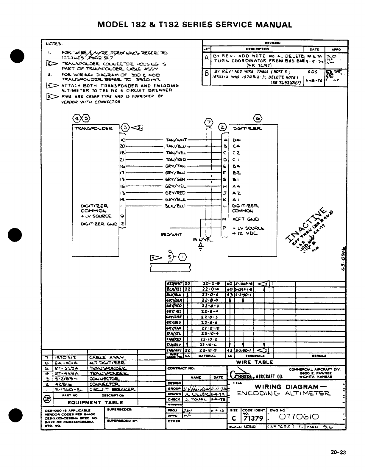
MODEL
182
&
T182
SERIES SERVICE
MANUAL
uOTLS:
____
viSON
LET
OESCRIPTION
DATE
APPO
^^^ i. I
I
-*-*-- -- -
b2, I .Zd'/lI 7
..
a~.'
~A
B'
REV:
ADD NOTE
NO
4.;
DELETE
MEA E
=
T ,L
_T^P,
X^ ^ O^
5
*TURN
COORDIN^TO
FROM
BUS
BM
3-5-
7,
4,'
>x:
-'@
@^
E.'
''
Fi
'Sl
15
_
(SR
7&9Z)
3.
c
o.
-
wIPe,
DIAw&I
OF
I 1.
'COO
1I?03Z
WAS
1570312-3;
DELETE
NOTE
I
PARTOF
~RALSCPCJTER
I.A913 (SQ.
.92AAEf.
.7A
E
ATTACH
BOTH
TRANSPONDER
AND
ENLODING
ALTIMETER
TO
THE
NO
4
CIRCUIT
BREAIIER
:>
PINS
ARE
CRIMP
TYPE
ANP
IS FURNISHED
BY
VENDOR
WITH
CONNECTOR
_
--
TAV,-/WHT
A
D4
2--
.
TAJ/.BL)
.-
B
C
4
18
-
TA/VIE.
---
C
C
L
Z.
TAMJ/RED
D
D
CI
Ie
--
OER/TAM
, .,4.
17
/BL
-------- F
L
19-
G/.--
/
-----
15----
GeY/.Y-EL..
A
4
I
-
eVY/RiED
_ 3 A
.
14--------
6E/lX.
----
-LK
KI
A
I
DIGITI.E:
R.
IIBLc/a
---
L.
DClHTIIER.
COCMM
OWJ
CiOMMOb
J
t
LV
SOUeCE
9 t
FT
D
&
Of(.l~ll£R. C~
H
ACF'T
GoJD
I.DEA./HT
-
7IVDCi. vLV
'
*lt ..- B'\
J
,
I
_-
1P
D
-
___
____
_
i ___ >
'_
REiW,
to
2
o-
20I~2
s-.,jmr-,
X/EL
22
22-0-4
60
I7
Ia ~ 2 -0-
43
IS-2190-1
/M _
22--0S
4iv,._____
BLX/B>l
_
22--.
J
o
1
0_
r__
22-8-a
I I=
;RY/
~
22-8-
_____
tY,
i _~
_
22
a-5-
mr/tu
-
_
22-a-T
·
__ __
_-
7
1 S70'5
A
|CA&
J
______
A
COMMAC
MATIRIAL
LC
TINAL
IA
A
FT
C.
W
.
KNSS2-10-
~
---
-T/W I2
22-10-) 43
JS'l90-I
O __
2.
.z'al'
COJ If
DESIGN
TITlE
~~~ |S0_----
rAI^IC
A~lS^
-------
Bj~ia
°
MA?
llAL
It
-IKM
IWI
RIN
G
D
IAG
RA
M
-l«
I -cO.-t,
.T
AL.O
_______
WIRE
TABLE-
S
IT(-'^5A
AUOEcr N: A\
COACIAL
AIRCAFT
DIV.
I
IS-\bO--S
L
ICIRLI.T
BB.AE.R
---
a.ou
# ' ./,//-/?.7_ , -
WIRING
DIAGRAM-
I
,.,T
NO.
o'. D .C ~R--
AWN
-,L. >- .F._ 1^9-7',.
^ ^
*--~~"--*
------ "---
~~~~
------
~~)--
-----
--
^ ^
CHECK
J. "(00
l. II-A-"
, :
EQUIPMENT
TABLE
r!
.
C914000
IS* APPLICALU
UPwrE l
D1:
L°OJ
Wn1,
/
i
Silz
CODE IDSNT.
DWG
NO
CIA-XXXXCESN^A
O P.
I.
UOIE
P c 7139
D
0 770(l
XUx onR
CXXXX.CE-SSNA
4IIoPERIEDD
*Y:
OTHER
T O OO. O
___
CALE:
IUOW
(S79Z ':.I
PAGE.-
«c.
20-23
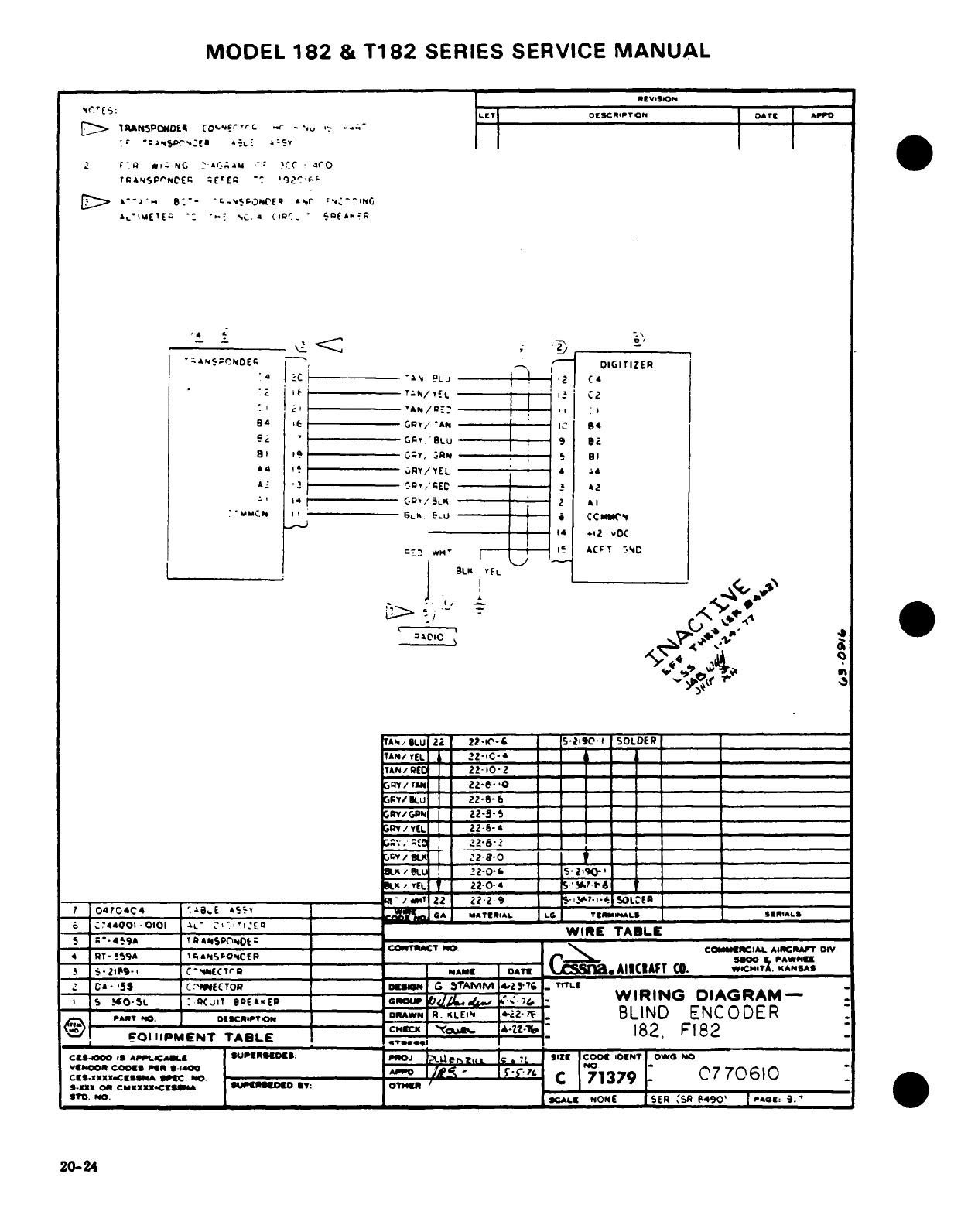
MODEL
182
&
T182
SERIES SERVICE
MANUAL
REVISION
ES:
*LET
OESCR'PTTON
DATl
APo
t
ANoSPON
C0t.'
-
r
-
'C,
, .
*,NG_'- C.
.
.A
-
C('
:
4C0
;
c'.a
*,i
NG
r:r.Au
-: !C
-
r
O
TCASSP*'lCEK
;:E'fR
'
92'
I^r
D
-
'f--"4
8:'- -'-
co'
o
l
a
C'
r
C'.;--ING
AL'iuETc
"
'-: ;c. 4 (IrO
'
CE
Al,;E
'4 1'<:
-
| N
NS;rNOENDE;
_L
-
DIGITIZER
a
cC
'AN
*
LJ
t
!
2
c'
:ai
ifr
--
T-:N/rE.
ii ;2
'
m 2
at
'~A/:.' l
'
|
|
8
i
GRsA
; 84
----- G
'.S
BLU
--- /
9
Si
8
9
1 ;.-RY,
::RN
'
El
.4
,'
8RY/
EL
*4
4
Al;
.
-lC-Y EC
*
KE
»Z
-1
14
C1 CPD/
LK
2
Al
-uCHN 11 ------ 65.
ELU
--- ---
CMMC'4
-------
- '-
4
-*2
vOC
6 ; »-, | ----
-- --
ACFT
:.SC
SLK
YfL
' ^c-e
s,
' . |
AN
ELI
22-C-4
rTAN/ RE I
_
22-
0-2
_ _
.
_
_
R'/TAN I
22-6-0
_ _
_ __
T/sU
22-9-6
11
________
GOYszl
"
_ _22-8-6 _ _ ________
,/GPN
22
i--
_
r;YSELI I 2-6-___
22-6-6
/2-8-0
4LK/LI
I~
22-0-'
S2i90-
K ELf
T1
22-0-4 | 34t-T __
-
-
q
22
|
222
9
| -i2-'Y
-
9
SOLCEr4
I
04704C4
IaAE
45
_____GI
MATEAL
|
Tt
TUNALS
SE
IALSr
6
C7.44001
-0101
A'AA
'<=;6'«oo-o.O
:- .:"
-
'|E
J
" -
..
WIRE
TABLE
5
|'
«49»
Tra
*SPO4ot:
|
----
'
^-4- ----- -----
--
RAN
---
___'N ^^--
_________-
~COITACT
MM
COMMOCKIAL
AIRCRAFT
DIV
4
RT-
!59
TAANS4oS4CEAR
II NAl AT
A F
\
0O0
PAWNUE
3
S-21Fp9-l
C
";
%CTB
K
0
AICAT CO.
WITI
KANSAS
*
-
C-
'S
C.ECTP
01til
G.
5TAMM
4,23T-
.
TrTLE
I
S
10-5L
:
I¢UIT
ePEoER
,oi C9IU.o
,.'.
-
WIRING
DIAGRAM-
PArT^
N.
-S»clr.T
-
ODAWN
R.
KLEI
'i2-
X
BLIND
ENCODER
VQ...PMIENT
TABLE
182,
Fl82
CI-1000
ICS AL
CA
SUPI-DS. IOJ
LhZIe
SIZE:
COOIOIENT
OWO
NO
vCNOOI=
cos
P
-1400
-
C770610
Cas-rXXx.cKiA
Sc.
IO.
C-
I
71379
I
S-xxx
0o C AMXXX
A
OTH
_
0.
POO.
-
4
SCL E
SER
-SA
2490'
i
P^a:
J.4
20-24
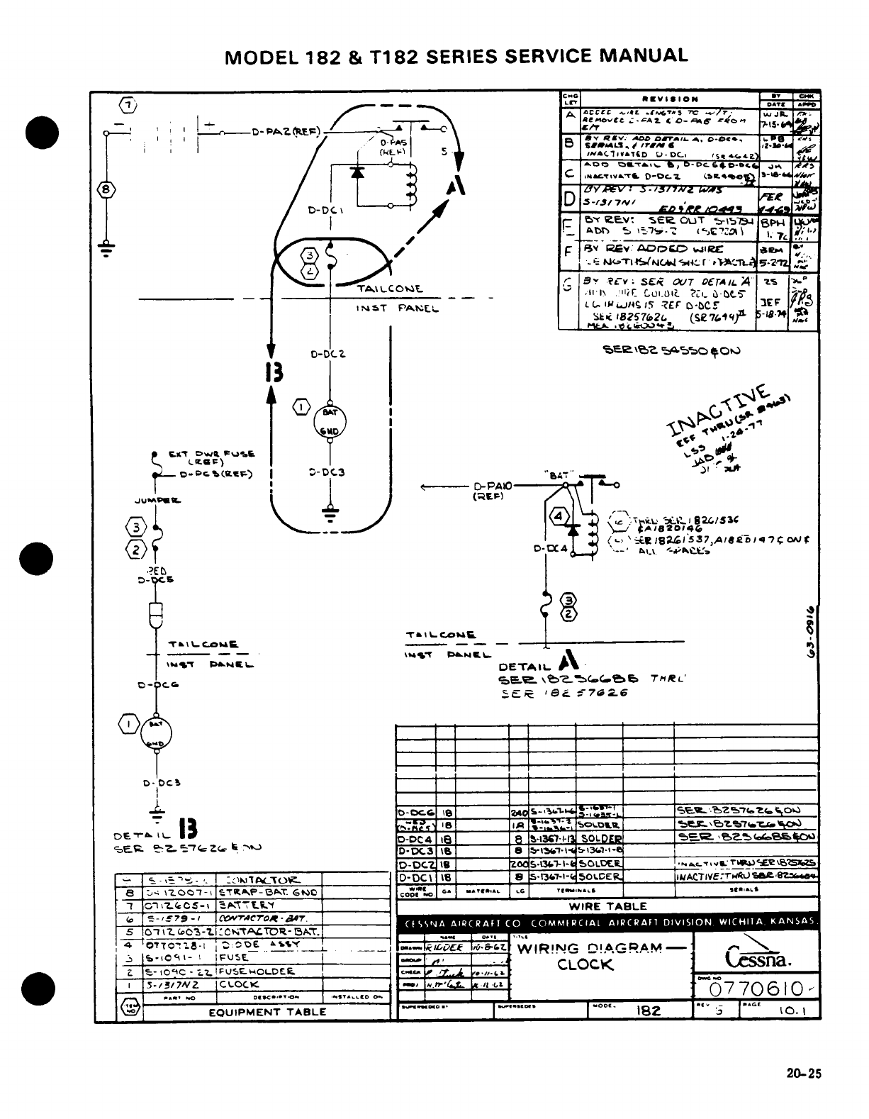
MODEL
182
&
T182
SERIES
SERVICE
MANUAL
--
o--1- \n~
i~l
CIWrCe
-s~t
-
O-PFf
Muorz
-
)---
' ,
i q I
--, ---
D-
I:).~,,~
.
"/-'
----- r-AT
^
-OX
__)^__________-15-f
)
'St
lu CPpcvr *c)ob4r.
jw0
4,
IS' i -I'
~
~ ~ ~ ~ ~ ~ ~
_
ST-
C
iV/
I
* i
|i _ D -,pA~~ h E ;5
D
Aivj
«o*
..
-
0_o3.,; !,'U
w
/
(-1, I '
/
_ 4tci
.np
E3
:,
,c4,
O'M
t^
I
/
/
r- 6
'
e
&~v'
SER
OUT
SI-\S7
BPt
OU
L .JU^
,
APU- Uv^n
5
\179-
T'a'..,>\
I: (;l*.,
/
IF 'Y
ry"
roso IlRc: ae.
.'
_________- _
__
TWUCOst
'_^ ,„C ,,;r.
oI
'SL
?
-M-S-
q
'*
O r _
.Ev;
$
7
0£T4//.
P"...
ImsT
PAKIEL
L
L(. IN
WSc,/S
.7EF
D-OCr
3F
S- =cl>.
8257(-2L
w
f
7:-uc
5-1.
-1S_
13
1
t2-Dc0(tF)
-C3
BAC
-Ut'p
.
I _I (_tF)
_
___
I'
It
|DCi
---
_
" --- --
1
r____t_
-.. .
.TS=e.
\aZ,-D-Die>
T
-s--L. aER IC 6-
::F
76^Z
6
0(
-
ti
Z-3- i
,.
D,-.
DC
I I'I._'O.S._
1 -_ _-
,_I
I
,%--to'roz&-c
j':.E
Z-
,OC
-,
S __t____
..
___.. tEe
0
6...e
G-hl
C0S-
15tEQUI
ME
IT
WIRE
TA
BLE
--- fo 0-7a-La see
\B'L~~~~~~GBB
L20-25
4
OT-S
-
;
S
_
__
I
.
.e
et
WIRING
i!A^AM-- ^\
z
i
--
lo>
c
-c _ _L -sV
-LDE
I
.
,
s1
CLOCK
U7
na
a
.
|
|
|5
-
0
6
1"
o
Z
|
CUO
tC
0
. .
8
+^^^^^^
0
7^6
| I\^ _______~
EQUIPMENT
TABLE
I ~
--
I
|.
20-25

MODEL
182
&
T182
SERIES SERVICE
MANUAL
REV*SbON
LET
OSCR«IPTION
OATE
I AF
A
Y
:cv:
aLeTf
-iAi;r U071
'.-O; _0
·
^
;
ACC
-..
t A ;
t-LAL'
WA
C
-LA1
T-
7i*r
M
(--t 7t)7 __
BY
REV;
$S-lmO-b
WAvS5-S657-1
.LEF
BRF
-a
WING;
5-164I-6
WAS
5-1637-2
LrPT
5-Zl"'
4I/L
WING;
3-l640-9VWAS
-J637-l
R
IG
.
HT
WING; 5-1641-9
WAS
S-1637-Z
tIGHT
W116
G6RN(LAfC)4
6RM(LZ)
WAS
GRN,
ADO
LI li/beN
4I2q6;N
(m\R
iaa.sot)
(SR
___7
0i
JS
KOO
O1~ 01.
CoU
,S-1,
M-LA'5
1< NcuGP
3
,
D
1 11110
.PA
Nf
.
iG DEINITS
L
rG WIRI-16
D
D-UAZS
1H __o _
sa
____
__________
u4 , _to _
soIa.
S-I-
____
__
(-LA2
Sa _______
135
s-,S5-t
^_____
____________
10 S-ART____ __|6_I DRLAWZ 1
-
Ua-E-
-
Y
LIGHTS
I
5-1641
9-9
HOUSING_-
5CKT
_______
0LAa f
______ S-. S.B ___ __ ______
-
10
s-6640-9
MOUSING-
PI
___
DLAZ
_____
s-t
OO___________
_
-S-1640-6
=O
=JING-PIN
-
7
MS5584 'Z
LAMPQ
-7
of MATTRIAL LO I
TtRMINALGS
E
RIALS
C 51S1 ZM T _________
WIRE
TABLE
_SS
t
---
I4u^I
------ -------
CONTRACT
NO;------
SIZ-----CEN--
cO
54CP#
-
OU
51.
_
< \_
COMMERIAL
AIICRIAT
OIV.
3
3SI-lI
L.^MP
NAM€
OATS
(
a
AICAFT
CO.
WICOITA.
KANSA
L s
-
I
a
*-
I s
> iw
*_ 7ssin
_
ITL
E
0S-i5o-ioL
CYT avt
cHOUr
,
? -7
WIRING
DIAGRAM-N
~^
"T
NS.
OOCI^tN
__OuAWN
_ _ _
L__ D_
OOME
_
COURTESY LIGHTS_
IXTD.
NO.
I
|CALE
E |
\
.
|
ONG I I.OI
.1
-b'---r-IR TA0BE
OWO NO
ENOrmcooEsPERS~hdOO
ClP 11.: CS
Ai
-CI~
0I70610
______________________
_____________________
SCALE.
.PAW
(S-rAO).
(
82a4 G
C)
20-26
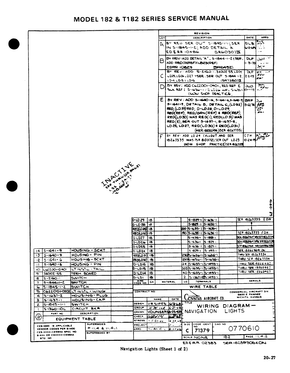
MODEL
182
&
T182
SERIES
SERVICE
MANUAL
REVISION
LET
OISCRIPTION
DATI
AIPD
S^
VV\:
!bSER
oRu
O- \-5-l->q,589
Ov.6,
^
8\s
3-\84=-l-L; kOD DETT\^ > **,,;
_
tDanR
1048f (tRfO>03)r
.K
B
E
PeV:
AD)D
cETA'L
A"A.
s-'844--ii-Zi
,
ILP
U
'
ADO
RtD3)tRtLF)Cle3QEF)
I.7
-.
E)
B'¢
R"V:
A4D
..
S-iO,-6,
$64I.-6,$-I0-9
BRF
<
,..
~REV; i-,c.-
I
..
--. , '.
,-S
..
.y,
_
k%_ REP___
(*JJ
S
;.-
Pg«
T>C
_
E
B-4
RC
v;
ADO
S- 1i-f,
S-1
-
1-6,5-IM5-9,
BRF
7
S-1641-9,
D TAl46
B,
DTAIL
-C,(LOZ)
5-&-
/
RED,(LD339)RED,
0-L2,
D-DOz9,
O"
ReD(RIEF),
RFED/GRN(R6F)
4
wo(ftF),
f--
RED(LDos)
WAS
RED('),
RCD\LD
31)
W5
Rfo(t),SER
OUT
5-16S7-l,9-l637-2,
__
_ __________
(MERl92E0D9t)&ER
F6Zi)
__E
_
F
By
REV-
ADO
LO
24
(ALLOUT
A
SEA
CTH
^*i,
IZS333
WAS
(SR
8037):SER
OUT
L025
10-Z4-
/
_
NOW
SHOP
PRACTICE)SERI
B13D
*^
*»'
0
[29
IB
_3335i_
I s-e s
,-i
s-,-
_
1_
3
5
1ON
D-LD,
8e I p-Is-I
S-,l361-
|_ I-
RED(L_18
M_
O
5-14635-1
1S- __1
_
RE I
18
A
Ino
|S
(951IA 6--I
5
1
5ER
1L823335
t
ON
'
LD27
I"-'S
_-=_
5
5
93
1
r
_
..
Z.24b4TIfR43
D-LDtr
_
*I3S
/./ Is
129-,I
KI9S3A1fYI3
~~_G,~~~~~
.
tD-LDtS
is
=_
sf636-I
S5
B~-I I
EESM.4WA
WIUERETALE
14
S-1641-9
IHOU51
tI
SCc-T
.
-L.Dl4
815
__
,
S
IZ_.I
S
.93-1
AIRAT
C4
.*
13
5-1640-9
HLj51NG-
PIN
RF__ C(__
iv3g
10
2_ l
5--
Z-6
__
TRU5__
P
18(3534
I
-54-
G
P
HOU
C!___
-
X_
KT
W
-lI S-e6l
ITIfRU
SEP
8
3334
II
s-1640-6
OU5NG
-
PIN
_
D-I1.
%l
24
5-163'-l
j49u
5e-o-
iG'_
_______
,0
LcZZ0OI-401
L.r
I ki"7
-
-,
7*1_ L
D-LI15
5L I305
s-O6MS-
15-1493'-\
_
I__ tU
SE
IB/2C
C
9
34002-55
TER.
E0a&D
t-LD
e
4 0
5-1635-l0 Is-Ires -1
s-14
l-U 5Ie23a
a
SZIc0-_
SWbCI
-Lbl
lB
__
_ 2 l5-11Wi
-w49
__I
7
IS5-lt4lIZ IWITCn
OCS
A ITEIRL
LG T1ERMISIAL SC
NOAAL5
6 S
-I845,
-l I
SWITC9
.
_ _
WIRE
TABLE
S
C6Z2)OOzO2m
L
ICNRTL
NO
\
J
co
SO
COMERCIAL
A
RCRAFT
CDIV
3
51
Do- I
MOL
IjINr-
CAP
N
AME
DATE _L __
AIRCRAFT
CO.
WCT
_
ASAS
Z
S-
IP4S
-I-
I-Cw i
%V
I SmDESiGN
V ItPEb
TITLE
I S-i3o-0L
CIRCu'T
5okt
GROUP
16-t-.
WIRING DIAGRAM-
PART NCO.
DOCRIPTON
_
DRAWN
oIouN6zseR
--
NAVIGATION
LIGHTS
EQUIPMENT
TABLE
C.
D//
STRESS
I-
;
'$e
, 2
CES
rIO
IS
APPLCAL
SUPERS
PROJ
i
IOD
D C
N.
VENDORCOOKSPER-O· P.4 .4.
PP
C
71379
CES-XXXI.CESSNA
SPEC
SUPERSEDE
.
1 c 077061
S-X1X OR
CMXXX.CESSfAC
STD
SO
|
|
SCALt:,,
1 BF
_
82
PACGO I. 1 .4.
Navigation
Lights
(Sheet
1
of
2)
20-27
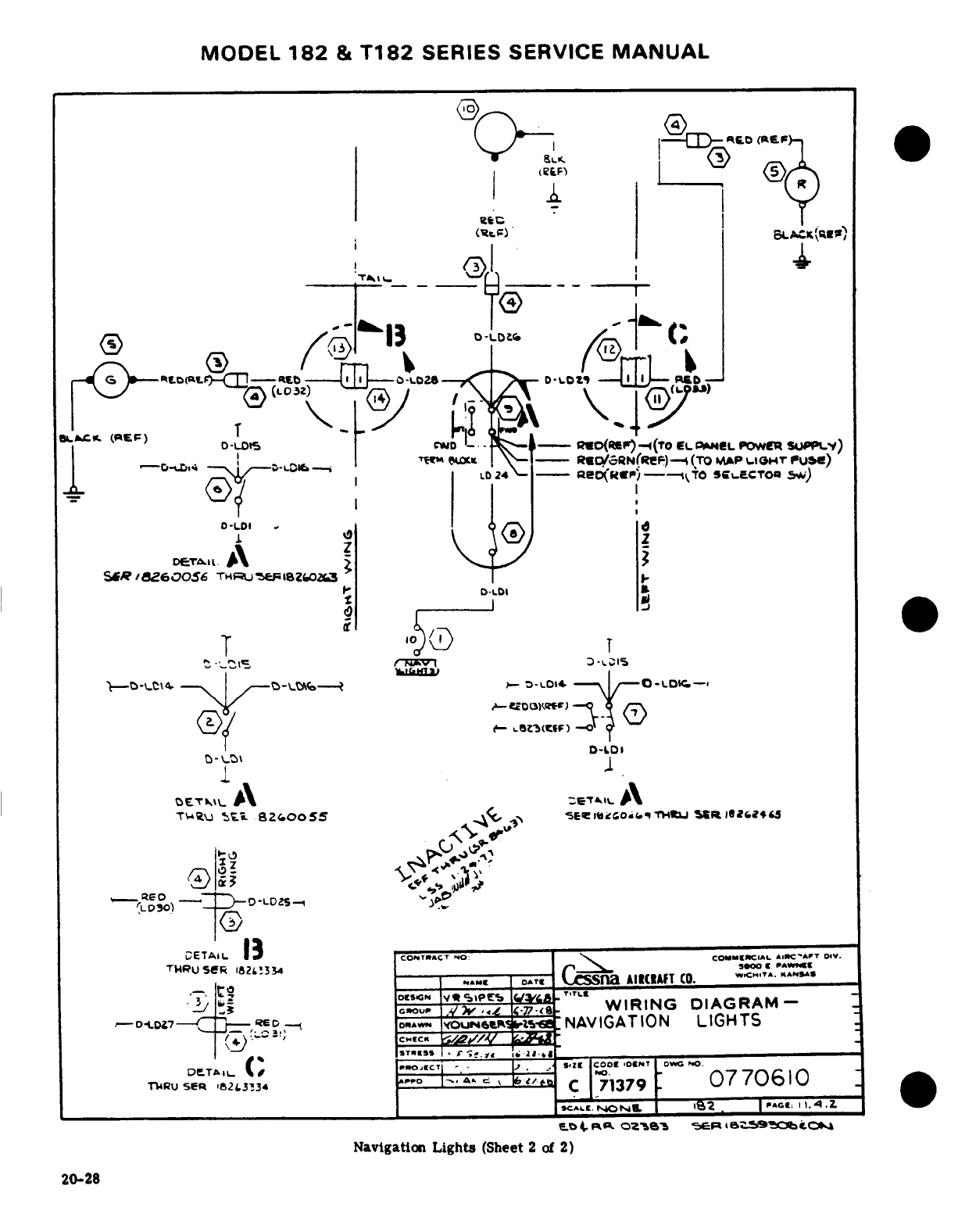
MODEL
182
&
T182
SERIES
SERVICE
MANUAL
-TG%4
'
Lh -RO, TC
'°'
,
.~
z
L.
OD-LD
iV)
\
I
__ I
e
'
~~tl~i04 QI
--
'-¶3o SCAcToQ--
5C)
^^"-'""
^D ^*
ReqtWlrj
-leiO sr,?-T
v^ "
(DC.
.
Lt
,
;
.
--
L8I
J
A
I
.-
L
.
193°!
D
LDI OI
N
I
^COQ)W)00^*
40 0
C>-»-Q>
0-^ 1
________
SIPE0
T
O1TKP WU
GR0)--P'
WIRING
DIAGRAM--
-D TI-13 ONAWN
YOt%
-NAVIGATION
LIGHTS
ThRu
SE'r
82 co3S34 5
S
C001
O-0F.T
WIG
NO.
__________1____;___3_______________________
iSCAL
N4ONL
PAGt
i.
-q.4
.},i. 2GNavtgation Lights
(Sheet
2
of
2). 1
20-28
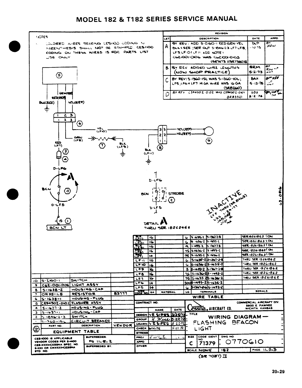
MODEL
182
&
T182
SERIES
SERVICE
MANUAL
REvISION
^^-
LIT
________________!~LETOESCIWPTON
OATZ
AP"
'
-OEC
AisES
!SEtrpir
'
ESO
iEDltso
E
_r
EV
.
-DD
S-ZI
60-1
r-EDGZN
YEL
cPT-
-,
-
J.E
i-e
ESES
.t(L-.L
"sOr
3E
!
TCaE.S
CESI
OO
A
eLse
*5e
e
cUT
s-e4.-Z-
i.7
e.FB,
.
W
Vf
CODOIXC
Qc
TI-
.
WIP&S
IS r=O
PAETS
LIST
LFLP!O
IC
It
AOC
A
rE
I
_se
COsLIY
jo3aO
WAM
Csf.W
c<"lXl0#C
_
____<g(Stw&
)(--AtTaeo)g
w_
B.
R
cv
&00ar
.jR..L
er.
SR
all
!
C
BY
tREv:5-r56-015L
WAS
--
IS-1,o
H Lw
f
_ -_ LCS,F.LF7 I
CA*
14
WA«S
1&>,
S
13
-7
.'
|I _I_____
(sw.
__(5Keazo) I /
9
Sr
RFv
iC594o50?Zo
:oZ
WAS
CS450.-OZ
VLI
.?Ds
'
_
r
i
.
a
l--
2,I?--
2
scw _-.
YE.:
|
(LF)
^ ¢
V^w^
I
I
2 2
I
'
r,
*ic^_ c·1n)~
<32~ <1) i i)
rS®
_o
\1
I
!
-Z
D
-Lr6
01 9-
.LFS
i-Lrf' S
I S
-
E
T5
^T.A
KANAS
T14'v
,
J
I.. ._
__
_'.
,
S.
KYST t:
5's1
-2B
¥
I
e
IiiCI3
'
.
T A __ S *E-2 '5I
_______
HIrt ;St--
"S8
^I __________ K ______
i.,t.i
l
li2C.btlO
oci.
14
_________
-6
i4XS-W
z
S
»-t
5u
s
teA8
I3<
C
'
C G2_ ST
OlX c.t
S-lic-
t 5' LPK
jd
__)B__O_
LV
S\ -_- o
-
L 1+ ________
__.
S_-Z .,L
-
1 '6_2_
l8
2O
LCt
Or Ii IU fi
_C_-_Z _s*3S-_ _ _
-___u a_
_IBZIZ_
_.»9
K
4 O--ez C__ Tl
tu
'et
608S2r_
CLrS-1OO IS
9
140lr 2 AII~LICA tJ[1 S6 6
s
---
_---------- "^
"
-
-- ""
i utw
lfc_
_________ _5 5-l-3Ef »-»«-; 1__L_ 2
w
BCt iSt2
_
O 5-?2LG o-l U5IJTCI-
1
F1
_
P_ 5_-1_
3S-
-,esn
5-
T
AuA
SEIA
1
Z 18
CST
2
9
c3Ztoolloo T.»t
ASS
-- ---
I___
_
8 5-13R-Z
U
sOU1WIIGI-CGP
ILFS
II+
7 095-1.S RrS'&TOR_ i l f cg
l
'""*' Lc T5
CXIILS
__
1
S
I"'II
c
S-
l38-1
I
U
ous"NT
-
PLU
WIRE
TABLE
VNO50oOl
-
COS0Z tU
ASSY
R
COT*CT
NO;
COICIAL ARCAr DIV.
4
S-
i67-2
lIY\OUS
*
u"Ca
___-
%
Q_ II
N.-
r E
.. rA...
3
5-I
-
i-- CPN--
E
I
D^T
Isn.
AIRAFT
(O.
WCHITA.
KANSAS
CX
F
-
Kc-O-
E U4[;
SP
R Sr41M11-
CS
6
-
r
sw
>
'
-_XX _CB a W IRING DIAGRAM
-
PA-tT
N'.
I-\DlCa.l
VtUoOR
Z
lV-si.p
4-
PLAS4!NG
BFACON
{21
EOUIPMENT
TABLE
|
-
LCI- 72_
_1____
n_|
L
iG4PA
Cl$OO-
18
APPLICAwL
sUIrLa8
;s
PSOJ
lll.t.
S.
,
C0
I0oNl
ID|N
tW o
_O
vemOOa
cOD1
<K
*1D
pI ui
I
I.
rapt
"
r T7
AeD
\I
O
C"u-XXXXKSNAl
c
NO
POO
.
X*|o1
-
C
71379
-
0-70 1
O-
**XXX
Of
Cmxxxx-cff--<A sJP»IOBOa
m*Y
OTMEM
T
NO.
NI.
C
: | OC
UC
1| 2
PAGE:
1.5.>
(sC
'77o)
.
20-29
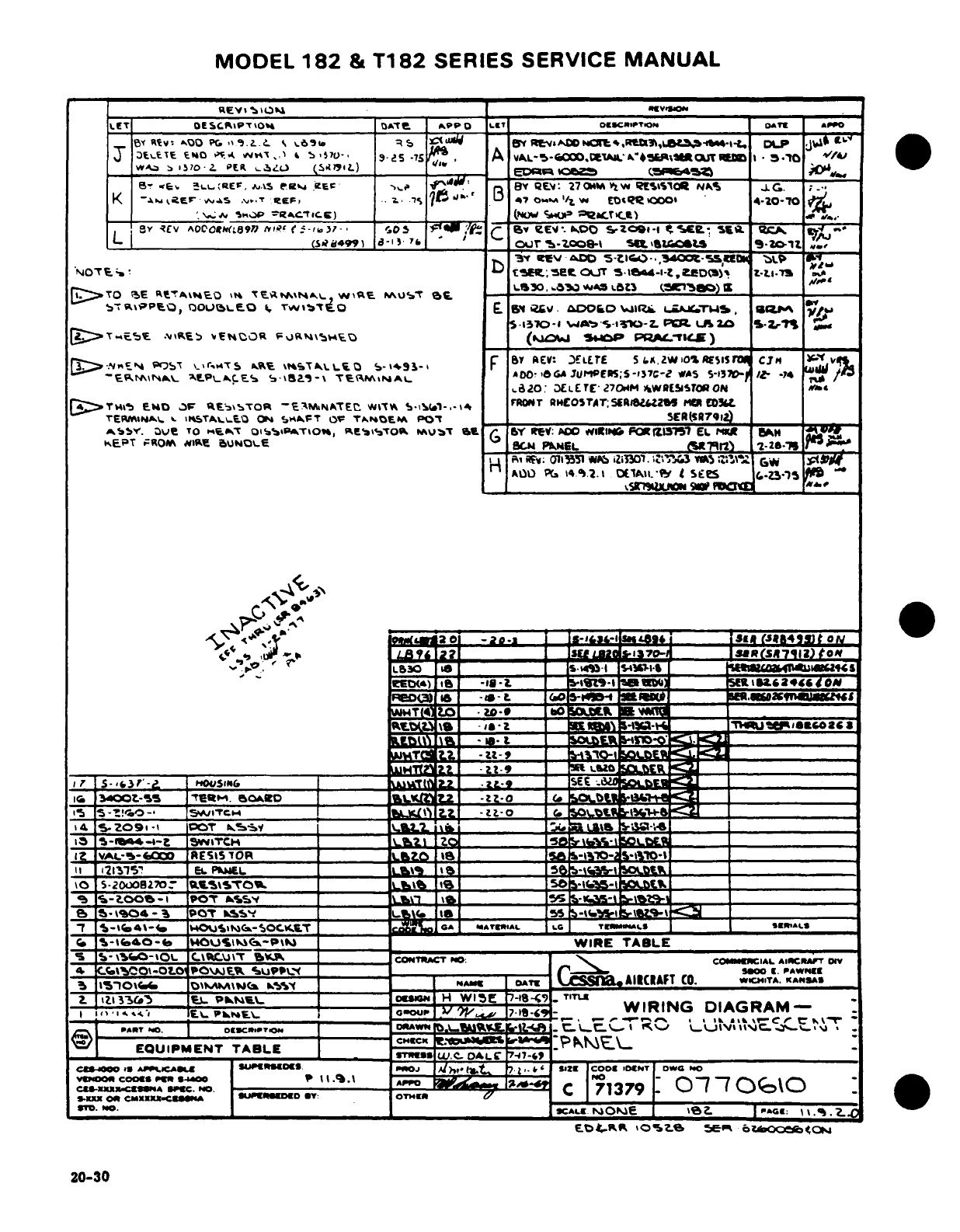
MODEL
182
&
T182
SERIES
SERVICE
MANUAL
LET
OESCR
iPTO&
oAr
e.
APPO
,LTr
ocaCripr N
OAT
APPO
tYf
R*v
,O PGC
..
i..L.5 :
.v
io ti, i
D
I BLP t l.'
J'
3.EATE
tO
9.&
vv
.
*
'
57-
o-
s-
S
-75
'
A
vAL..-"-_sO.__C:A
.'4 1~.*
tt C I~E
o
,
/
WAZ)
>
1570
)
PER
lt
N
(S·
-9/L)
_
,w
A
:,i,"o-z.
p.
-.-
o .i.')
'""
_
EDqm.
27-za
(.atWr=,aaI3:
IiNN
,-,r<
.i,-:,..e.
.
A..S
P.,
iEC
",E,.
"d~?ldd:
BY
QE.':
27(W4M
»w
BCWISralC
N ,J.G.-
K
ee
r
as
.
eep
,.
i=Is
.
1-
4
7
o.uw
1V
EOstQ
i
4-20-710
_i
*
s3
--
^,cTiCC)
_____ (Mow Pt2it) C
.,.
L Y
^Ev
OOORWl89»
IftI
J
^
53-.
.OS
r,, /Ct
-
Bv
-Ev-.
".OO
S-ZeCv-l
.tS"-L-9s7
$.
7c-l
%
"
3V
AD-
S-,,CI-.
3
-,5,,.
*s%.(
-,
"I^N~,OThu-t.,- T.' t:e*.;-set9
OUT
s
ao
-i-t
,zDC
i-.'-
S
^*
D>
TO
r5E
RtA\4EO
\H
TE*\MNAoL WIRE
FIOUT
rt.
-
L030.-&
A"
aa--)
_
A9PAPEDO,
OOUL)EEO
I,
TWIlbTEO
5E
BQv
L
ooo o&EDWIr
Lw4i-Q-r.
SQJ.
yWr
1570-e
PaMs -'1o-l t.
LP2
S-71
-r
[2^>T
rSt»
.klREb
*FtC;DR
F4PILvjMEb _ (''»l
Ss.oP
PRA^LIL)
n>
.NE.s
POS*
TS
uT \nt ^5TrL.O s-z9
F
ByEV:
XLErE
5
.
A.
2W1O.RESIS
CMJA7
II
'^-EAY^Lt
xPu~^CES
^SB-\5-\
TtV.iNAL
A*D!
18GA
JuMPERs;S-137C-
2As
S-I37-
-1
4
mo
ao20:
DECLTE'
2704M
)wREItSTOR
ON
A,
.
>Trmtl
EMoT
OF
RE,5TOR
-EAMW^TEc
W
%C Si \l-i.t-
FRO"T BrCOSTAT:SlftTR4
29f
Mf
rUEO3L
TEHMNMA.
,.
IlSTASLt-E
ON
C>zLAfT
OF
TXNOEA
PO
_
_
5EA(SRT7i)t
h.lr.
sue
TO
04E>T
OISBAT\O,
RCe\STO
MAUT &e
S
SBY
eV:
AhO iIXp
FOQIIS57
E.L
MN
at
KEPT
PrRO
m
aunoe
M
Ptk4EL
tn
G
2
--
,
e.O
H
Ai;
iiK,:
0
'5n tb
iZin.
i;:''.a3
VAs
r. fw'.'
W
PG0
P
1t4092.1
DEIA.I.-P
i' SE
lel4t~
2
-
o-
is.-e,1
Ss-&1
J11t
9hI
Y,(
... -
.o...,
L
*'
'e
__. _,
__
:__-__,L_
_s__.i__
i Q
34005ts
!4.
MCIt=
___
__-__ _iOe
BaT
W)
i 1 I 4--.1'il
L.
tzeo _. -ft U__
_ Z_ _ _i _ _ _.
a
IL
VALb-1-[
mEtS
OR
I-zt2O
ia G
17'Lst \2
z-9L _E
____ at
R
_________
co
5-20cz27o.-5
.tE.
l'
___T.
.
lt_ « -2o _
_-------l
%a 5- -2- 9swTC00 Hi Pr L_
,
I
b-.c*..
1-b1'
I". i l
-
_ v-^--,o% aS _____ A
-O.
iiao
TILaAL
LimG
s
T
_-Io-I_
.
_ I___
9 S2.t-zo-1 POT s H w___ ___ __ t-s-
ea
,I
>
4.-
3 PT
MlY P_ .tS
1165h-a- WLC-- I
r
rk
a%
\Oc
0
7
S->fas-«,
USING-SOt<S
T
|-__-_ Hta> |c- cO« IL A.
tTC« I.» b^.
_-O-EQUIPMEN_
OUtAS
-Ps_
WIRE
TABLE
S
5-\^<'->OL
C.t.jn"
v
l _
COH'T
CT
NO:
--
c-'o..
i*IAIAl
*
ollrr
r
3 S4o-
.
>./C
-o-
.3¥A |,,<
,
"'a
aNE
__C
AIICRAFT
C 0.
w_.TA.
PWN!AS
Z
'
.... ;
CootsPa
,1.C.1 o," i', //,AS
A
,
No
_
. 1*.<;
tuPso
.____O&
c v > E
7-.8-
.
l
WIRING
DIAGRAM-
<
-
-EQUIPMENT
TABLE
.___
.mcr
w
:OL
4
cm-ooo i»*X
AmL*6S
P°J
I4)-o« 1
.
(.' |iZX
COo
OCNYT
o w
NO0
co
C^ s. .A0I
P
I I
..
71379
00
S-[XX
O
CMXXIK
I.C
NA
*SU
D!DY:
OTI I
.
50.
'D.
I I
C
j-
k
N
io*e
|
\BZ
I
Ce:
\C.
.Z&
A
~~~~~~~~~~~~~6 t_
20-30>
20-30
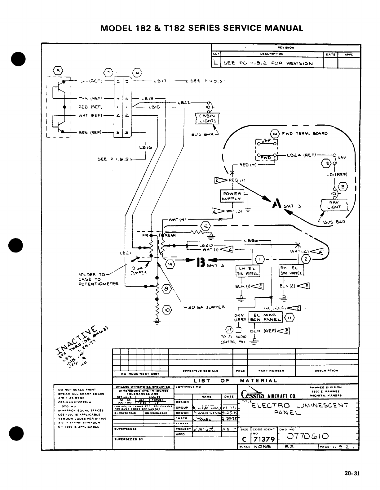
MODEL
182
&
T182
SERIES SERVICE
MANUAL
LEIT
DESCRIPTION
I
e*
PD
L
SEE
P
..
FOR
cEV%',ON
_®
0,© S
--
EE
P
~.~.5.,
I--
RE;)
4
. -
LB\9
-
.ED
(REF)
\ \
'L--
18
-
I
VNT
UREF)---
L 2---- AM
-
L
*
'_
_
B---\RI
(REF)
-
-3 u FunVO
TERM.
bOARD
LB6X
) ) /
r l
\
SEE
Pr1.9.
5
// /
l L4 (RF)P
NAV
q 0I
r
L~4
"
LRI(ZEF)
P0
gE I
QI
5OLeR
TO
--
,
;A zPPL cI jL
a-
t--
NA
I
t
-
A
O-I- A\
T
b
'
C-
/
-2 0 [£>wi.^)L
-
PE R v
.
%-l
20 G0 3LY
)PAPER
UNPOTLESS TOTRWI
SPECID
CONTRACT
NO
DIV
000,
.A
*
0 ~'
DO
NOT
SCALE
SPAST
D-ENICCOES
SrE
IN
S OUPINHESE
CSTDO
IS AOP CLIS
ABC sEL
C..
1
-oup
tl_ _
RC) J
C,
_
7
IS APPLICABLE
_^.0
DRAWN
_WAN
BOf
5asP7
PA
N|
E
vErDORf
CODfE<S
PS
S-I
00
(CEOCKKL
P_
L
5
1000
IS
APPLICABLE
|SUPESDES
!A/
/
:-.
CO
7 D
I
IIO
--
-I--
- -
-CT[
SCI[ILS
PAG! PAL T NUMBE
Z
DESC
AI
TIO
Z
20-31
NO
RNQD'NEXT
AS»Y
____________ __LIST
OF
MATERIAL
00
NOT 5CAHL "IiNT
DIM[NIION$
AR(
tN
INNCHlB- ~
i00
C PAWNEE
CI[~-IXXt CI[BSN
»«»C
O ,o i .o]
0
i,
D«IIWN
TITL7
VINDOn
COORS
r<,
S-IJo0
J
CHICK
^ ^Q>«Y4 }
2S-7?"r"
>...D, .---
--
C
171379
-
20-31
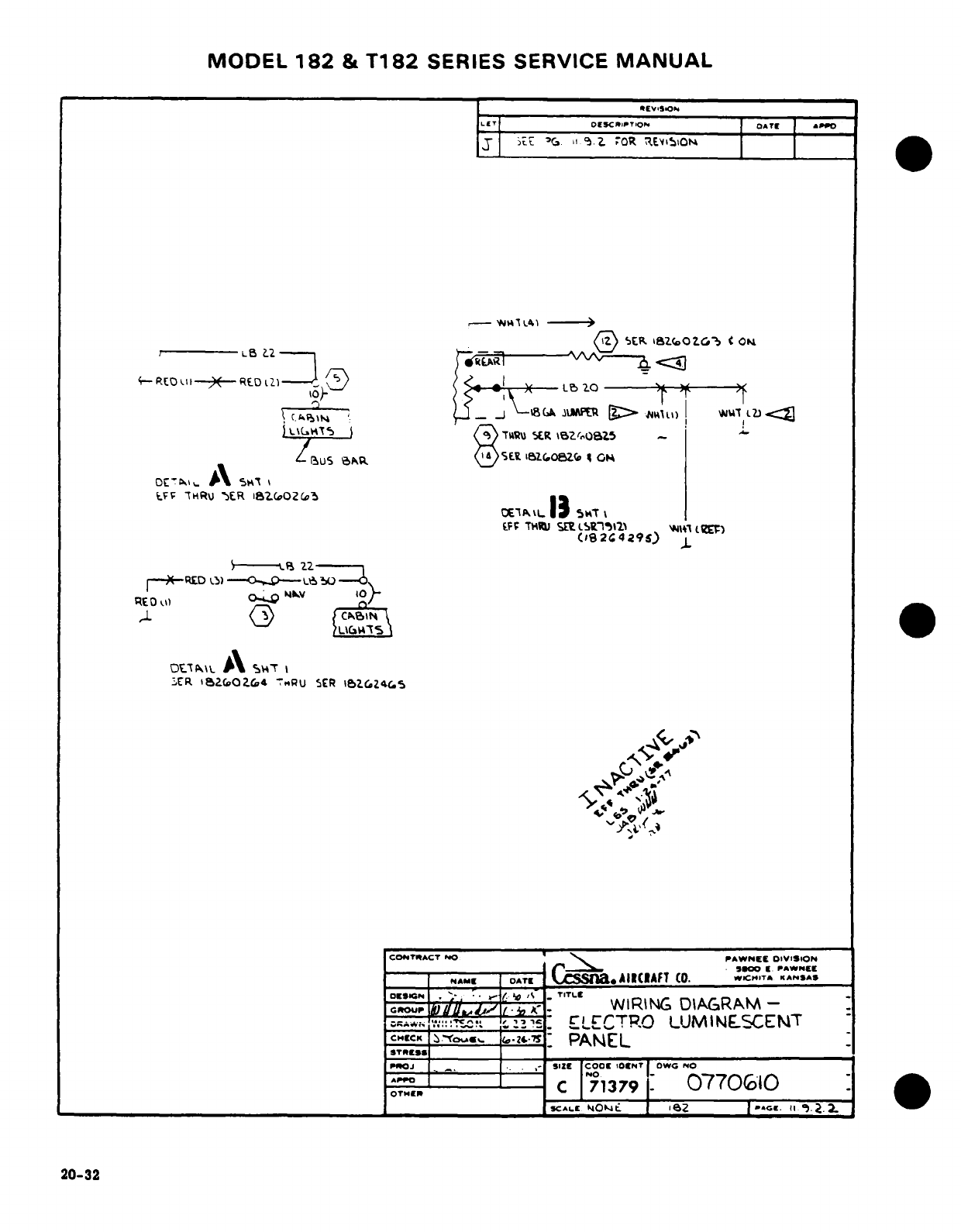
MODEL
182
&
T182
SERIES
SERVICE
MANUAL
REViS.ON
1Z T
OIC»I»TIO'.
oPT
O
J iE
'G
11
'2.
OR
iRE'oSiOM
·--
m
-W«U
----
)
.Q
511~.
az(eo0..C'
'
O4.
,-^0^-^ Rt~i2S, *B: JZ
O
-
G
0
rT-
L\ f
L
2
*
ck
.. )
is (A_$.
,
mm
-
S
Nlc,
.
l)
[
WI
L :2)
g
L i.^1)
)
TaU
SER
EBZRoaz
-
OC'Mi-
-\ 5^t
-
E(.~~FF wF1RH~Zu
-ER
1piktozSRS
*Ao
:
'TRvU
5ER
SZV02(.ol
OEZ5
5%
0;r
THft
SUE
LSR15)
Win
ll(E Lz
>aNvL
1
5^X
1
9
2C
4a9S)
_
z---LQ 22----
j--
RID -5)
Z--.. L
-
RED
O
kv
i
o
Q
I- KI~)
Nk
C~tiO
0D7
R\\
A\
S"T
5XR
iLZCOZo4
-TiU
5ER
IBZ.CGZ4(.G5
CONTRACT
NO
'
PAWNEE
IVISION
I
.
~1300
I.
PAWNEE
NAME
S
Sia
AI»CIAFT
C(O.
WICHITA
KANSAS
°K
i 6 A!:'
-
WIRING
DIAGRAM
-
.___S_
i: r:
ELECT1RO
LUMINESCCENT
cHcK
fi
(.--
'
PANEL
_OJ A.___
.
_-
SIZE
COOX
IOiNT
OWG
NO
^Jo
I-
c
71379
00
.
SCALE MOln
,ez
I^4GN I
.2.
20-32
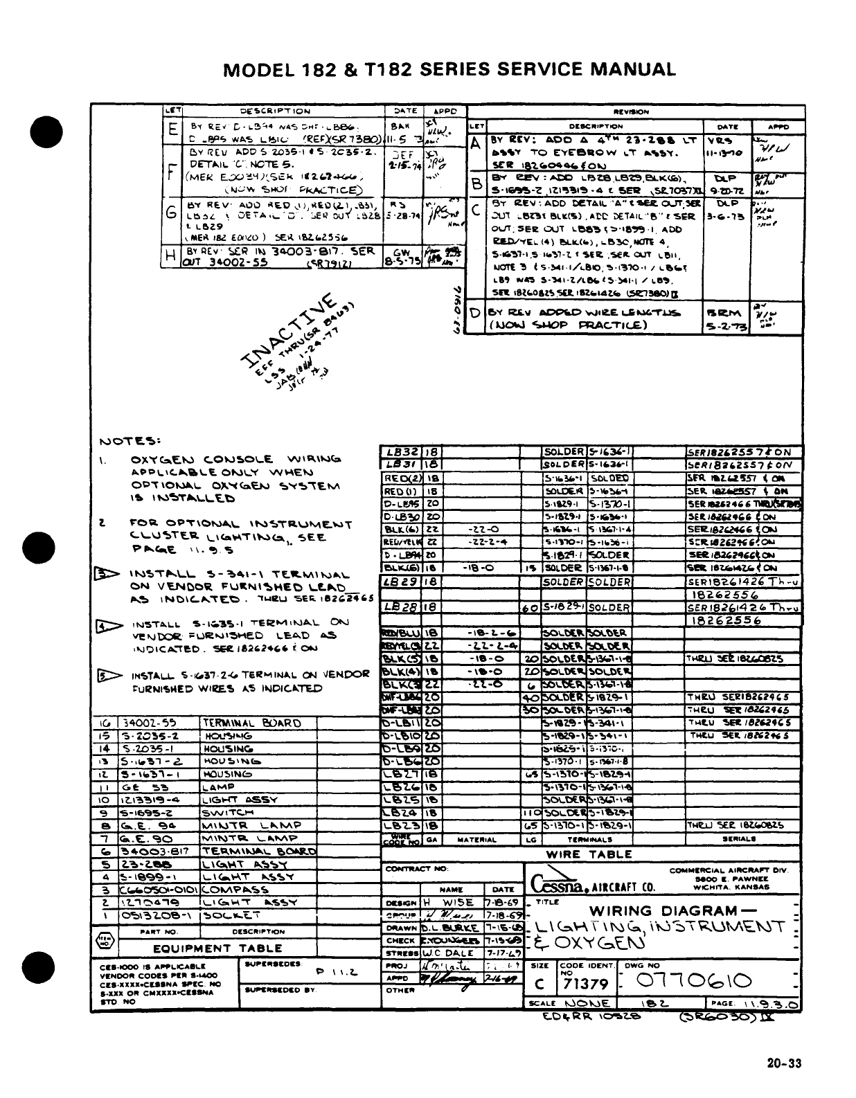
MODEL
182
&
T182
SERIES
SERVICE
MANUAL
LET
DoESCRB r
IO N
10
DATE
&PPC
ESvnION
E Yf
,
E
C.
L
!4
r
-F
r lB
.
BAH
^. L[ET
DESCRIPTION DATE APD
_ F _S
wA5
Le6Llc
!g£EFXSR73a0)
11-5
A
BY
eCV:
&0.
A
4
&T
23-Z»6
vT
v
a
IY
REV
ADD
S
20!5-1
S
2C3SZ2.
*
E
&
V^'r
TO
EYECSOW
.T
%Y.
ll-Io 0
/
r
DETAIL
'C".
I.CTE
5.
-1./f7
4>' _
Srt
EfO
F
(ME6
E)"',SLK k1cs
B
B
ee
V:ACD
LFBZLBT5Z.,BLK.
),
CLP
_
juw
_ S^ s rCoTiCES _ S SG-Z
t
ZICls^
tE SEr
*,SI.'703y7:
9,t
.7Z
d'Y
REV
AO
O
W rr LD O .LI. \
S
IK e', JA 5E
rZE:
ADD
DeTAtL
'A"
t&r
,CT5t
DLP
,,
G L
U
EA.
.
e i sZ- 1 1
e
BLK(
)
.
,c
DETAIL'B"
I
SR
3-C-ST
mu
t
L5Z9
O%_'
Ot.SEE
OUT
LbSb-I5WI 4ADD
.MER
182
Eallo
)
SE
ZS.L25.
_ Ei
L(4)
BL
),.
C
NOT
4
aD/YEL(
/)
5bLYf-),653',
4
H B
FREV
'Sz.
IM
340003-890.
SIER
GV4
5-4w-1.5
1s-s.-t
I sit
se
OUT
51.11
H
OJT
34002-55
e-
-
*7
SE
-
<.
5
4. 1B
-.
1370-, I/ L
b
uL
W5S
S->4-Z/.ltBoSMI -I
/
L1B.
/^~~~~ ?
SX
I9ZtfcOit5Bt
ISZ(l.t«
(
_S3a0)
<4 0 D C) Y
r
^L0
LE
L.L E V
KtM YAISV
,9
>
*
3_
(U&J
P&OP
RACriC.)
-
?
.
% .',
.
LB3L
18
___ I
/SOLDER
s- l_341
,.
JI.je2szSs f7
ON
.
.S
.FC
*,
\Als
A\. OX'C.t~
COK.)SO.E
W
.
w.
L[32118|
I
ISOLDERIS-17365
I
IeR182si2SS7
t
ON
Ro
EE2
ISi I
I
ISOW
1&.
SO
=D
|111
---
L&LIsX7
0
a.
,IPL.\C.,L..
OSL.Y
WtE
,
_
_
REDO(,Z
laB
s-_
.
%S~D
5-
-s-
.
Is.L.S5'7
,
OtN
"OO'=A0i
0C-
5
S
t
iREDi(I)
18
__Sl__OAR
-'S
5E>.
IbziES57
abN
IS
%0Th.lj
OD-LEe
Zo
=
-
__IZg9
1'-1
3X-I
SERI__
2i4C
~6
m
2.
VO
0P0T\0..)
\'STRUMCL-T
BLL(IZ)
-ZZ-Z-.
.i-r'I
5
--
SEt^J8CaC6
O_
P$
'
<_
-ET.
2\$-Z
* .
5
-*
L-)
0.
Iq-
I
b-2.-1-5 ~t-
|
See
LDEE IC
2C<C
1>
tST-\, -341-\ T.M\A II
)
1_6
-IB-o0
I IS
ISLDER
5-1
L-1- ___-B
i8s214o.-a
ON VoR
-ut6
__
LB29
I
50LDE
ER
LDE
SERI
1426
T
A-
IND\CNED.
.
TErUR) CE G AB2626f
-----
C24S=_=
182162556
tLB28
18
_
.
6Z0
s-ssER
SOLDERI
S__
RI___26T
iu
ID>
HST-L
SS-1_35-1-
TReiM oj _ _ _ _
___I
15_26g556
vekjDIOC
_lSPH-ED
LEASID
VS
RJ
\6
l
«
_ __ _
AS.t is
__5___
_
II
oYOICr-cTD
.
5*E
l_2C2*4Ct i
Oa
eL2 <
-Z.L-
L-4
Et ________
\8f
-eS-0
_201
SOL.OC
5 bE\W<
t1f
Et
i8Ut6s
>
INTAL.-
S.3.7-2-(x
TERMINAL
ON
VENDOR
^
-\b_0
-
'O
__SL
rURNISHED
WILRES
5
IVJICtkTED
sY
Z 2 _
(
______
____W-
I
b _
99l>B'-
I
TOU
SEBRIB2it;r5
IG
I
400Z-55'
TER4I\.AL
O.R.-
|-
S-..\
LO'
.
Z5->9-.._
s--
urtu
WIRIG /IZCS
I5 12-j5-2
HON'<LG
I ___ b-LlO
Lo
-5-9-\I5 *b4--I
TI4tU
Set
IBC82S
14
S-2zo3-1
H
OUSINC______
A
--
-;
o_____
'1
S-i.%-1
-
oAvs-s1 I *IoZ.
D
AL
S-
370_l
s-ni7__-_
Gt
.I5
LAMP
_ _____b _I 5 1-\z3- i
-
_
10
igIl-4 LIG»-lt
GSS'
_____ Ol.
!*
______ ____
9
15-I,69s-z
SSITC-
I
L____
L
Is IOI o E-'- ____- _ ___I_
a
I.
94
AIM\TR
S__P _I_
_
\\ ____' (5
n-\3(10-\
-l
t.9-\1
I'A-J TE
e
IOkU50Z
-7
CI..E.
SO
NA \P
I
tA%
cc
GA'O
MATERIAL
L
TIRINALS
SEI
I
RIALS
3*)00Q3-ai7
4TFEO\3».U
SOI?_ _ _
WIRE
TABLE
4
-1
199-\
|-\
YAkT
SS0
-
oo
.O
PAWNEE
C.0-\
Cloor-SO
______
NAME DATE
T CO.
WICHITA
KANSAS
Z. '\
7t1 'A
l
C-tAWI
ISN 1__C___
OESIGN
tI
WISE
7-Y-69
TITLE
»
OSCM3OB-\
ISO_-K
-t
!^....
_ _4/__
17-18-69
WIRING
DIAGRAM-
|--
-,.T
.
O-
-
icnT8o
--
----
KN |£IC.B>C
|l-\G-«
_\
(jD\\
\hv\
ta
z
i
\
'K
*-\
R
t\E
\MsT
~
EOUIPMENT
TABLE
D
B
-
-
|:
j
STRESS
C7-I7-
__
B
CE-OOO
IS
APPLICASLE
SUPEECDEO
S
P*OJ
I
'
: i II
l
SIZE
ICOOE IDENT.|
DWG
NO
-XXX"
OR
CM
XXXX.CISSNA
xUPWirOCDcO
B*
OTHER
N C
171379
|-_7 \
I
STO N o _____
----
i^^^ __ ^
9>t-
|
GE. \\..
R
C
f 0_
20-33
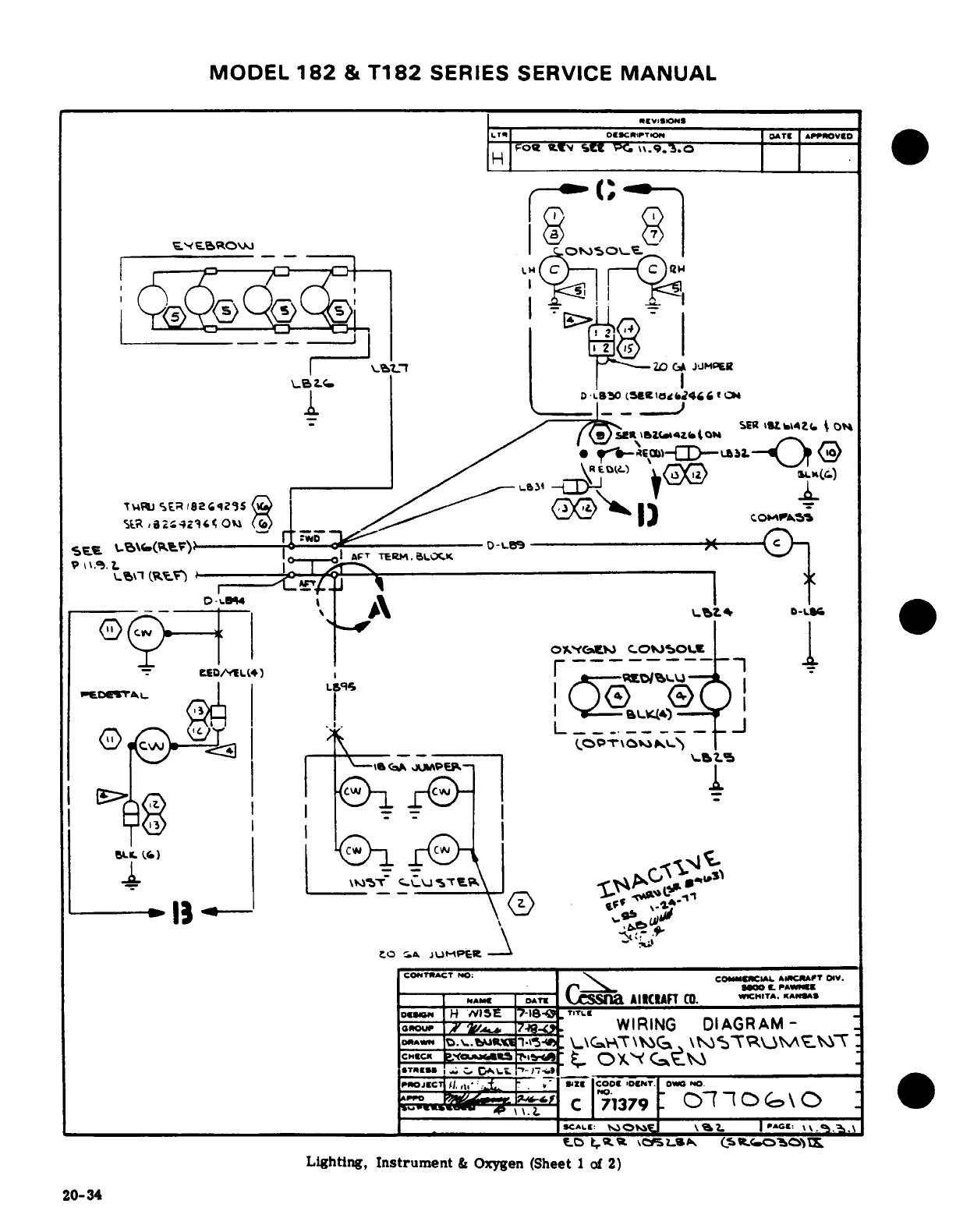
MODEL
182
&
T182
SERIES
SERVICE
MANUAL
LT-
0
*OESClhPTION
OATI
A| OVA
S
OP
H
'FoQ
Q
ste
-
\\.9.3.0
PWE.RO _ R_)
I
|D
-LBSO
(SE
liad246
&
6
1
_
7-
SER ,%St
b,4_.; tOK
C'AJ
IL
I O lkeqt C\q ~So IL PAWNEoE
5 Ew ,aDrO 1\5(re r. D-LB9
D('1b~4
\s-' Wt~WR
1
DDL
AEC
Lighting
Instren &OxygenOXY£ C(e
of 50
2)
20- 34o >t\\oMkJ\
pl 71^
1
CODE---
4E
T 0PEFIC
1
I
(-
; Yt> I I
I
"
O A I L 14 _ kB^ C S CIX
Lihtn,
nCONTrmCT
N:
&COxCgLe (hAeT O
V.
20/ ~ ~ ~ ~0-341tr
-
<woo r__-
--
H
f)c IAj
==- \^Ts
____ (.oen ^ n
IB
D
v
Hw# E
WWIRING
DIAGRAM
-_
Y m~wuixi 1 :
\GHT\M6
\'
iRUMEN
\ D. .tu
\
_
37O,\:-l'
CCOTL:
N O- \tL
I
^ICI:
\ W
.
Lighting,
Instrument
&
Oxygen
(Sheet
1
f
2)
20-34
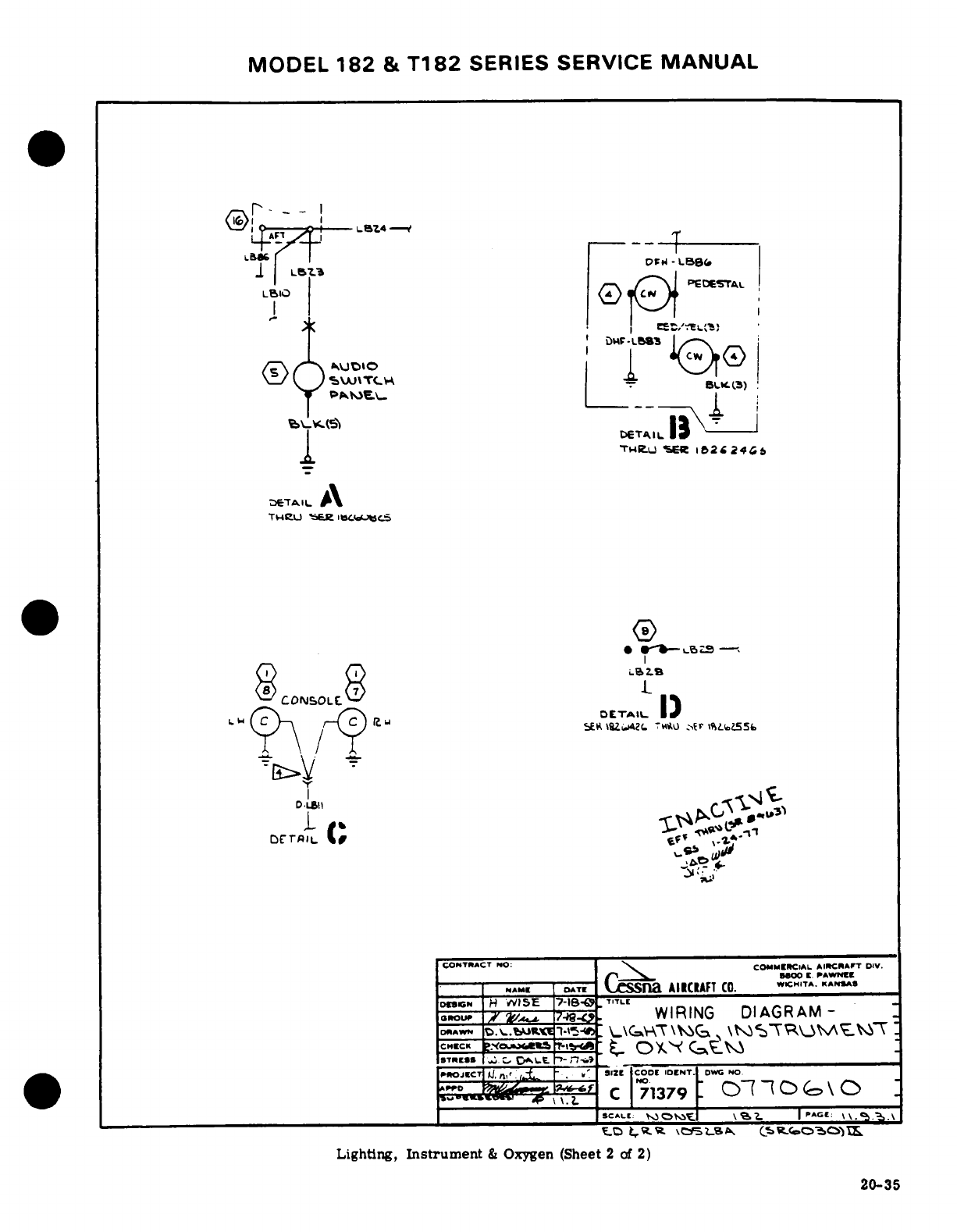
MODEL
182
&
T182
SERIES
SERVICE
MANUAL
,,~~~~~~~~~~~~~DH- i LB©(
1
LS
L -SL3 Dt
-
LO |-
®.) ,.C o
,
I D^'
D14F-LbS3
CDETAkD
L
SL
.L
CONSOL[
8
d
E'1 THT
:fe
.
I
2C
2
'.
C
6 NTADIL C\
AI0 0 7-0TITLBZE
<OAw> 7sv
WIRING
DIAGRAM
--
SCALE:
|P
'S../^0\~ l^^
,
r
Ra-S4ZC.
f-H~O
Z
Isr
>\.
..
55c.
DLAI1
J'C
T k':
Lighting,
Instrument
&
Oxygen
(Sheet
2
of
2)
2035
CONTrACT
NO:N.
COMMERCIAL
*AlCIRCRT
D1V.
NAME
-
DATE
'..L
ssfla
AICIAFT
CO.
WICH*TA'" A"NA
H
WvISE
7
TITL-
*vx^-TIt/^.rT^Q.
WIRING
DIAGRAM-
Lighting,
Instrument
&
Oxygen
(Sheet
2
of
2)
20-35
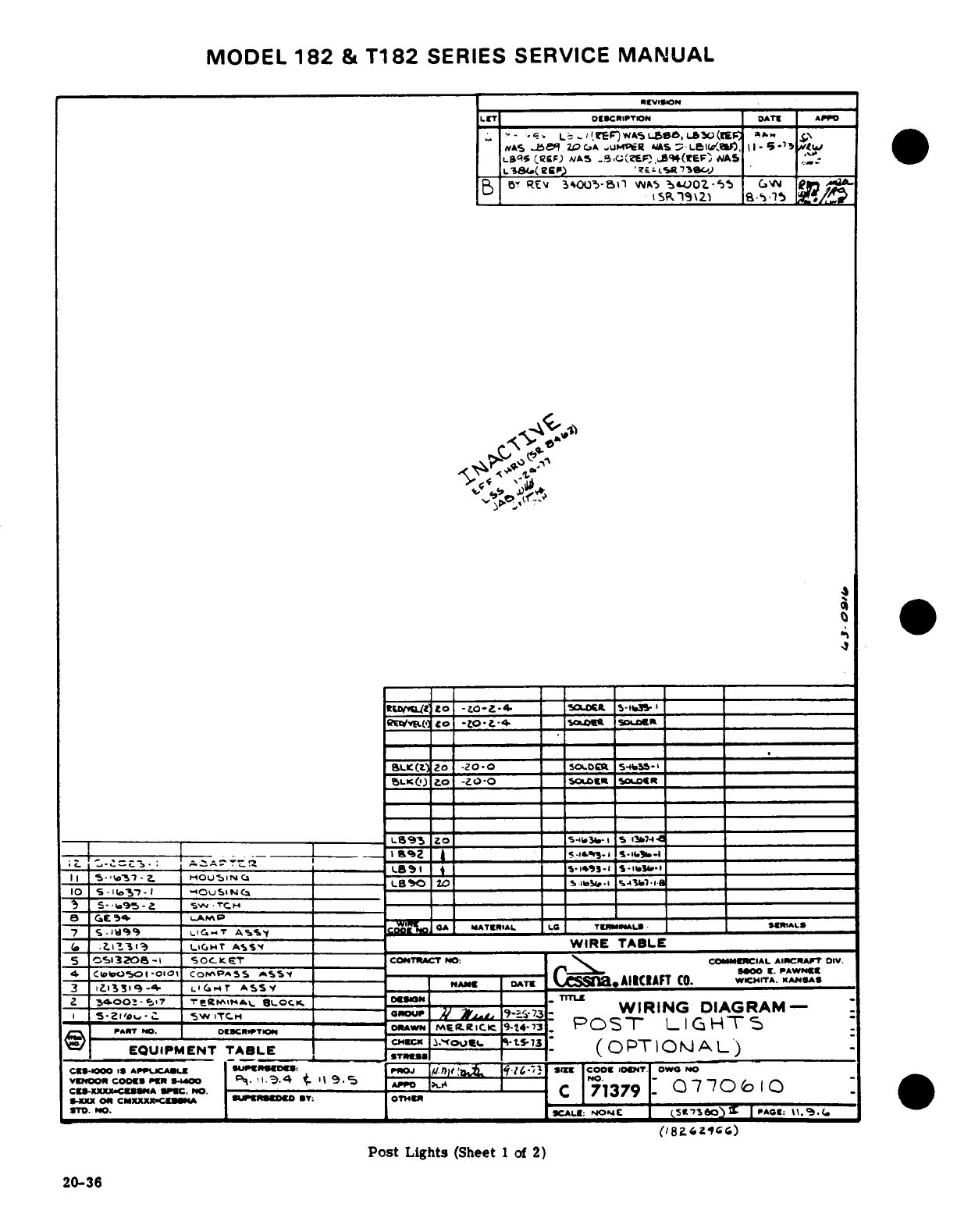
MODEL
182
&
T182
SERIES
SERVICE
MANUAL
REVISION
LT ODESCRIPTIO DAT A^Po
H"
-s
'
z
CA
uMIE R MAS
<; Lei,)(
,
I I
-5-'A
0
-B
OC
(F)
NAS
05.OF
9.
I..
4(CEF
NAS
P5
B-
p.
o 33-8ai5 0-5 o GJ
2C) O0
_
_ -Z O 3SR0 5\ZD a_
__
s__
_/_
_i
L
t.o
I S-.3b-Z'
-a
LB9
Zo
lb= S i
-W
_____ S__
I
~I s-,.----- /1 T" ,-^
/«3-ou1
t 11
I
--
'-i-3. i-
-- --
=5 '
l _~'"'
I
gt
1 =
5===5
10
SIl37-
f
--
OuSiNCa
-
10 S*-lM-a S'
*TCMH
--
-
-
_-
LF
9C7 _S i|--
[-
7 S
*199
.LIG.T
AS--
MAT
GEAM "IL
TEMM
ALS
(0 .zi!i
LIGHT
A«lS'I ___ ___-_
__
WIRE TABLE
5
t513ZO20
-I
SOC_-ET
___ CONTT
NO:
_
CoIAL
AIRCArcr
OIV.
4. C'"507
-0101 COMPASS
^SS'
-1-0_0
.
PAWN€€
3 IZ331C)-4 ~ LIG4T ASST _
"NAM
OAT1
AIRCRAF
CO w"IT. KrANS
Z
oo
-
C,.e7
TeCrtitAI
BSLOC.
--
o«»o
_
T
r
TnL|
--
_
3S4.00
3-?
'
TCH
-----
J
,.
.ROU.
WIRING
DIAGRAM-
PAT
O. o
DCRTrONk
O"WH
MlE`lC
9-24-73_
POST
L
I
G
HT
S
EQUIPMENT
TABLE
.
^
:
(OPT
ON1AL')
cE-Sooo
I
APPLICAULE
SUP«»S
:
nEfl; S4-i sz3
jcooK
IoIT
owo
NO
VENDOR
COOS
P
--
P400 I
P... i °'
---
APPO
IN -
G
CMu-XXXX-CuNA
SC
O.
--
.
I
C
71379
Q
0770
b
10
G-XXX
OR
CMIXX3X-
IMA
SUalEdOO
*Y:
OTHE
I
ITPO
O. S
SCALE:
-
NOE
(ST3 |
PAGE:
1\.9.
W
Post
Lights (Sheet
1
of
2)
20-36
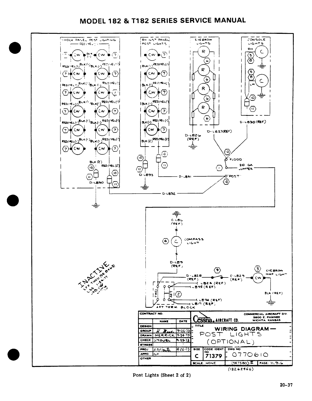
MODEL
182
&
T182
SERIES
SERVICE
MANUAL
('3OC.r D
PCVT
R5
T.aI | [e-3
DATIl_ :
ErCAROv
0On50LE
JI"/'X
-
L--·E,,----,
!
PC5'T
LI"C"
.
LIG,-TS
I/,l'tS
PC5
I
G
M r
|8
(·k i,
)
BLK
I |K( JL^ ty
-
RED/
K
ICuI.J5LK 1-'
BL
RED
I
I
IlSL
I<
I T
.
BLK(D
)
.L.,BL,
;MD/ALQ^
0
^^- (eC
F
tT
'^L ^^ BLIt,)^'^^
I
so
CD
,
-
.; ^
r-
*
v - -B2,
WeIt{
)
a^w^^! ^^eU(~) L^. 0^
C
BL 1
I
sT ^X-e
9 (4
BF)
BP
/'r
I B..- -¢I
<
(
Rr
SRe
FoL)
| |'
-
1.D-L
/
Ct
o.
Ia.
D.^BQO IUGH
j
__
DRAWN
-MEWIt.K.
9-2473
_POST7
L
I
CIGHT
S
CH CK
YOuv% 9tS73- (O.
PTt
73
Po.J
>,
S-..z-,13 SIZE- IODE
T.
DWC.NO
AP.
.o
o...~
Q77Obi
2OTH-
C
71379
-
77O
I
CAL
OE _
.PAGE:
A,,..
ID-~~~~B~~~~O~('
a
I
Post
Lights
(Sheet
2
of
2)
20-37
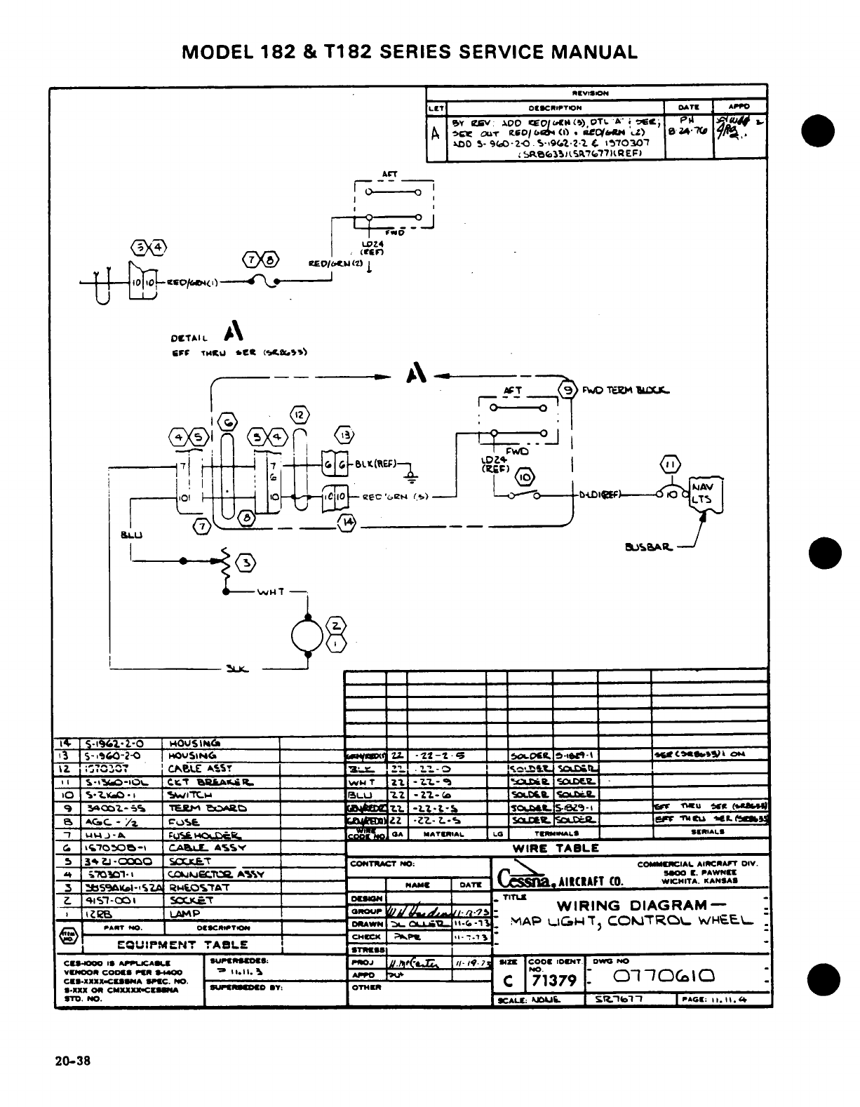
MODEL
182
&
T182
SERIES
SERVICE
MANUAL
REVISION
LET
OECRIPTTON
D
ATE
APPO
oy WEV:
ADO
tcC
o
ecI
O-) ,TLD. A'
i*
, -- .
A
c
oC
OUT
°o/l
«
( .
)y
J)
|
24B7(
a
I
DO
5-
9(c-Z--0.
.
C
S
IZ
57030'
I
A
_ _____ S SR1G3
1L
7%R77/(o
EF)
I
R
ACT
I
i
T?
i4L
LPZ4
DCTAIL
A
I
I
---
_I, 1\4 7,--.
®
<
-_- _
)
-S-60-21-0
HOUSIN.
____
.
a CE ____
.
WIRE
TABL
s
j-(:DO~O
cCr.K.-T
CO_____ CT_ No: COI:MOMMeNCIAa
oiv.
~wso%'tA-rZ
S._^
--
-r~--N
^ATE
....
AIICIAFT
CO.
WICITA.
KANSA.
0
VQ
I 1 _L (i
1(a__
_
ILE
I
w AoIbo. __MAoEI L----P^
WIRING
DIAGRAM-
PARNo.___ _ _S _E
_
VENO+ 1R
5-14bK
IN I
PlERm
;>t
_I
,
,.-A.
.P
CE.-
IAP^AE
SP.E
3_.
*
-----
C
_ET
D^^^I TO
SiEXE
'
CMXX2
M CPROHERK
AWL
-AGT
C
t170.NO-.
_
CL
A
WIREEUIP
TABLE
C
,*
-38
-
CAle
.
»uJ[ i W C€8: C.OMMRI~
II- I. ?
CRA°T
DIV.
VCMO9 n COOZRCmm A1 1Y UOO C.
PAWN
f
cI-xxxl-IszA QP0C
.
|-
-
"NA |
DCnr
AIRICIFT
CO.
WICHlIT.
KANSAS
~ZPB
415 l
MP
Diz 1 1-
nns
WIRING DIAGRAM-
PART
NO.
OascKWTae
I
DRAWNl
%%
<t.(.-J.
MAP
uGc4
7,
COhk1R.Q
WHSF-
T
CZ4D10
10
uPPCAu
|
surtr.
rOff
I4t lIv l1
3
SIZXE|
COOT
IDEOT|
DWO
ron
voarSrXXXcGuMrASPEC
14o
U0.
DC
71379
*IXXX
On
CMXXX,,CXImIA
UPB-lDRD
*'I:
OTHEI
11'T.
NO.
1
CAU;:
/iCo,
.
sr-LI
o' -? P I CPAG:
I i.
oI.
<
20-38
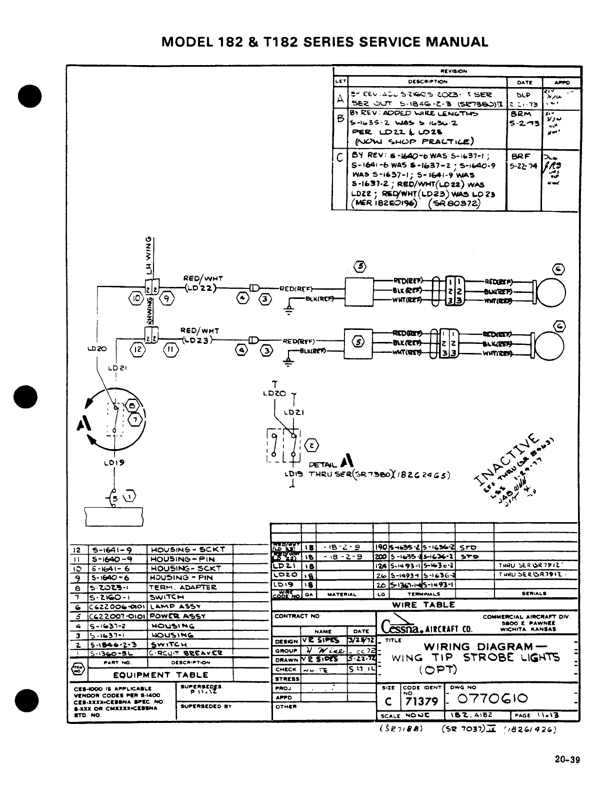
MODEL
182
&
T182
SERIES
SERVICE
MANUAL
REVISION
LET
DESCRIPTION
DATEr
APP
b
A
,
E
C.Ev
.
,_ 5-ZiC S
?O.3-:
tC E P SE E
L
t
_
^y~~~~~~~~~se
o s
rr
O
-\eg.-e-3 5SeB)Xe
_
R,3
.'-'
sB
IEV
ADPED
Vl.r%
L.EMc.-rn-»t
&P p-
R.
L..DL2.-
i4. U i
LIS
(NJOW
5-MO>
RP
PRAC'TILe)
C
B1
REV:
S-I6O-bWAS
5-i.37-1;
BPF
5-1641-6
WAS
S-1637-Z ; 5-140-9
5-Z- 74
I/f
WAS
S-1657-1;
5-1641-9
WAS
S-1637-Z2;
ReD/WTCT(LD2Z)
WAS
.
r.
LDOZ;
R0EWNHT(LD23)
WAS
L.D
2
-
(MER
I82E0196)
(SRo037a)
30
3
LI)
5
0
I j =
eD/WHT
-
-D-WFF)
0
I[~I~ LD
,
LDZ
--
L
19
I
-
LE
'
, .
9czzoo(,.<~o L"-A.
&SSr
WIRE
TABLE
..
Cr.Z
~O'7-10!
POWE"L
AuY CONTRACT
NO_
COMMEIHRASRy
82<
)
AIRCRA< r
DIV.
i
c.,%zculT
GROUP
W.
lhei-.Lz
-
cr
7
WIRING
DIAGRAM
12
5-1641-9
OU
NI6-MCKT
T ABL E Z
'B9
S l
TRESS
5--Z
sro
C-
5-1640-9
IOUSINP:-PIN 1U
-
RB
-
Z-
ZOO 5-I
-
S-ICODE
--
DENT
WG
1No
EO
5
-141-
6
U5
SNG-
SCKT
ll 5
S.^93-1
5-°3
07 Z _____ER Tu
79
iZ-
9
S-1640-6
4.OU51N
&-PIN
I---- Z(s_
I____-I4493
S1
1
93
L-
-
______
TU^RU
EH^7
8
S-Z.O;M-
TERPI.
ADAPTI
-
\9
16
2 3S-93-l__________________
C7S- Z.x
0-
-
SwI.T
WI C*
MATRIAL
.LG
TE
INALS
Sr I^-
G
CC2ZOOCiO'
MP
ASS5'
WIRE
TABLE__
3 C.
200.7IOI
POWER
ASY _____
CONTRACT
NO
|N
COMMERCIAL AIRCRAFT
DIV
C
S-I(.V1-Z
IW&OU5St4C
I______ T
NAME
-
-
5500
.
(AWNE_
2
5-49. -3
Z
U5WTC
H
DCSIGN
X
SI9C5
Z/
z
_
TITLE
S-I.^O-5.
QRCAWT
__ ^
GROUP
^-
WIRING
DIAGRAM-
O
PART
NC
DESCRIPT-ON
D-rAWN
I'I3 L5-V
-
WING
T P
STR
OBE
LUSNTS
EQUIPMENT
TABLE
-
C--1-
0
IS
7(P__)
CEC-OOO
IS
APPLICAmL
SUPECRSED*5
PROJ
|
.
r
SIZE
CODE
IDENT
DWG
NO
-XXX
Of
CMXXXX-CKISCNA
SUPCRSEDED
mY OTHER
71379
0
rTD.
NO
SCALE
NO0C
\
2..PI
4152
PAGE:
\.\-\
(Se
-7/
IB)
(Se
'7037):L
fe826/»20-396
20-39
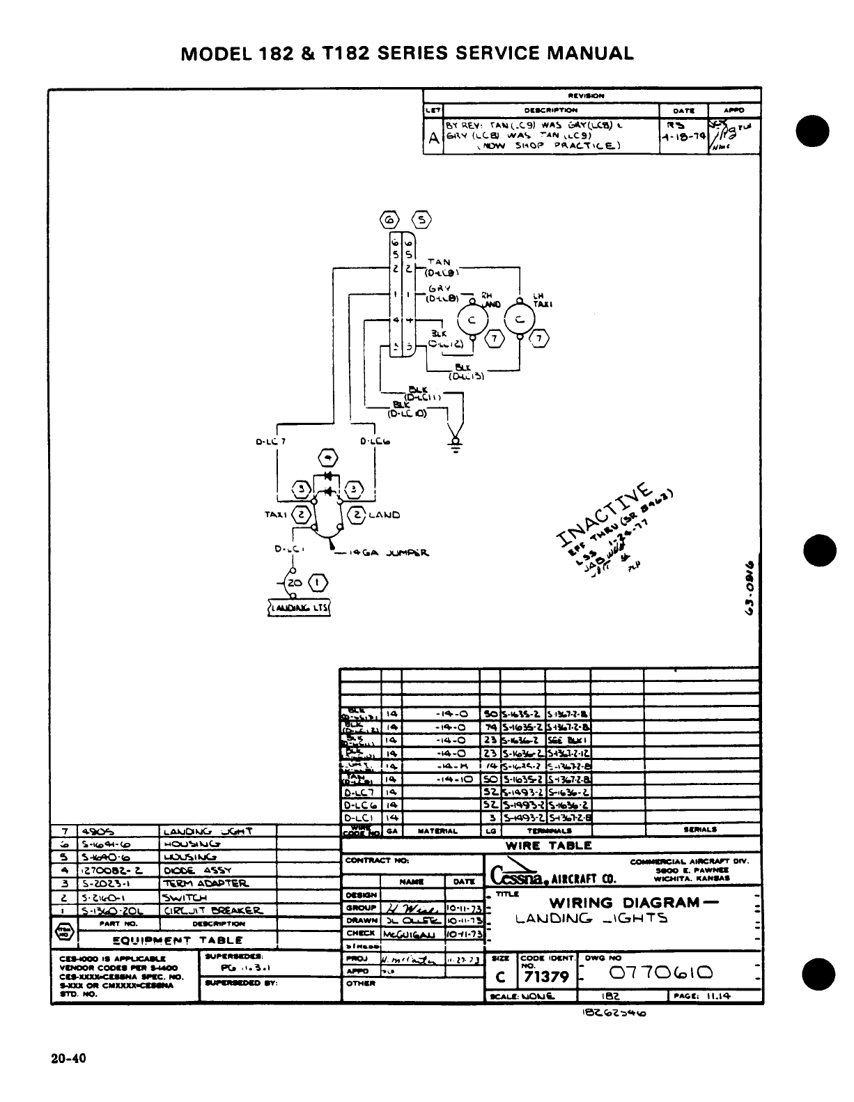
MODEL
182
&
T182
SERIES SERVICE
MANUAL
mIVIsON
1
..
DEUCIPTrIOh
DOAT AP
O
A
REV,
(Ua(..
WA
.
AN
I.C c9) t-1
7A-
'L
C9
IW
)w
'OP
A.tAcT'.\e)
ILF-
A
5
5
N--
i i
-
(O-- 91
IU
LL
(D4.
.I
(
4
-iX4
O-LC
?
D-LC4.
®D-,C
-II-II
MAPiSR
A
.
C
14.
-'4-0
Z
ZSpIL1-L
5I7-
D
A
_ _ _ _ _ _
_
5
S
I __
;
14
-14-0 il S-Itoit
54_
_-. ___. _
,_
_. _ _. _ _
m-C i
.
_. _.t,_2,
c_.¢/'l 5
-
_
_ _ _
i i
!
__-__-
i
7CC$0-XXU"-LCI
7M P C. PO-.,,qT-.
Al--
4 l
.-
l(o
A4-(
O
_______
1
I
____
__
_LI
I- S CAPOOT
.A
-
al-D
.
WIRING DIAGRAMG--
:
2040 '
(-,i- 7
4,,~,,o
o.
c
cl..7D
D
,-
L.
|
t
a
j5l
_
_|r_
A_
v
U1
40 .I0l
CIO OV
S-
>JQ _ICH _S0 _
p_
¢IIut-aXXu
.!
III,.W.,!:.
o.
Cu
|
71379
07 70 6
10
S-XX.
Or
CM1
-
-l 5
: O7THI
__~ l_ _____________ SZ
-CALE
OIQ
-
II82
PAoC.
I1'i4:
20-40
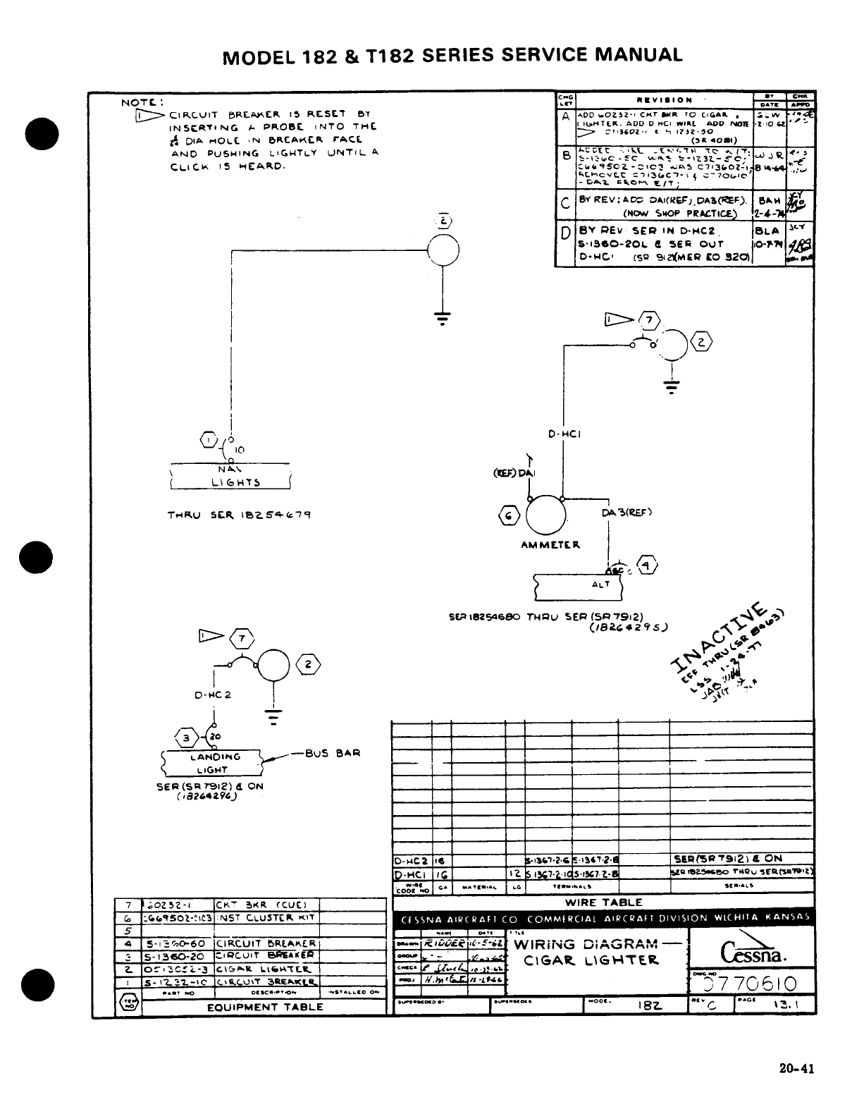
MODEL
182
&
T182
SERIES
SERVICE
MANUAL
NOTE.:
c-
VIg*o.
-
^.S'
C.
D|
CIRCUIT
BRE.ACrt
15 RC.SET
e.
A
ADD
>.OZ3Z
-
,
CKT
h
R
r
OC.GA»
,AK
.
INSERcTI
NG
/-
PRO5B
INTO
TIHC
I
ILHTLR.
ADD
D MC,
WIRL
A.DD O
..-
0
' ''
O N,,sNO
-o:,-,
C
,
32--0
.
DIA
HOLC
'N
BRCAlKE.R
rACL
(_ >
40
)
17
AND
PUSHING
LIGWTL.Y
ULNTIL.
A B ct
'
t _,l
--
^
-r
7
C-
Z.
C
I
C
Z
.n'~
5C-Z3?.-4-
,.
Z-
dglD.
CLICK
I
HCEAK.D.
tC*
'SO
-
^c
,.rL
c
7"3
-'l
*4.'.
'-nvLMCVC.C
=^l((
c-70
1CC
-
o^t
kero\
t1
BY
REV;AD;
DOI(KF)DA(<EF).
B>
G
.-'
__,
(NOv,
SlOP
PRACTICE.)
2.-4-'
t)D
BY
REV
SER
IN
D-H
CZ
BLA
L
-
(_____________________
\
S-13O0-20L
S
5ER
OUTr
lio-
*%
I -.
C
oc-.
(S
9ia(mtr
co
320°
5.p
ALTA}
~TH~U ISER
18.54680
lT4_S
SF-
(5P
792)
D'5(,
F
AMMETEIR
n,,,
~(/~X
*
I
I'
L
IGHT
o-. -'BU5~ '-Q
9
5ER
(siR
"9a,?)
.
ON _
_
(l
a_42.4
___ ___.
Dc- C = 5--2C
2-
5
912)
O.
' N
7
LIOZ5Z-1 JCKT
3tR
(Cut)
_ _
WIRE
TA
BLE
G
LUTK502-
12l
NST
C
UuSTEIR
FItI
5 [ I {·. I
I.
..
4 S-
G-
60
CIRCUIT
5REAk^ER
-
Iic iiir- ¢
WlRiNG
Dl-RAI.-
An
25-13-A60-20
j'QCUT
9BEA(ER
s-I2
-It a\
ON
_tL_ __
._
,
7
70
rb
I
0
EOUIPMENT
TABLE
_- IO
18Z.
C
20-41
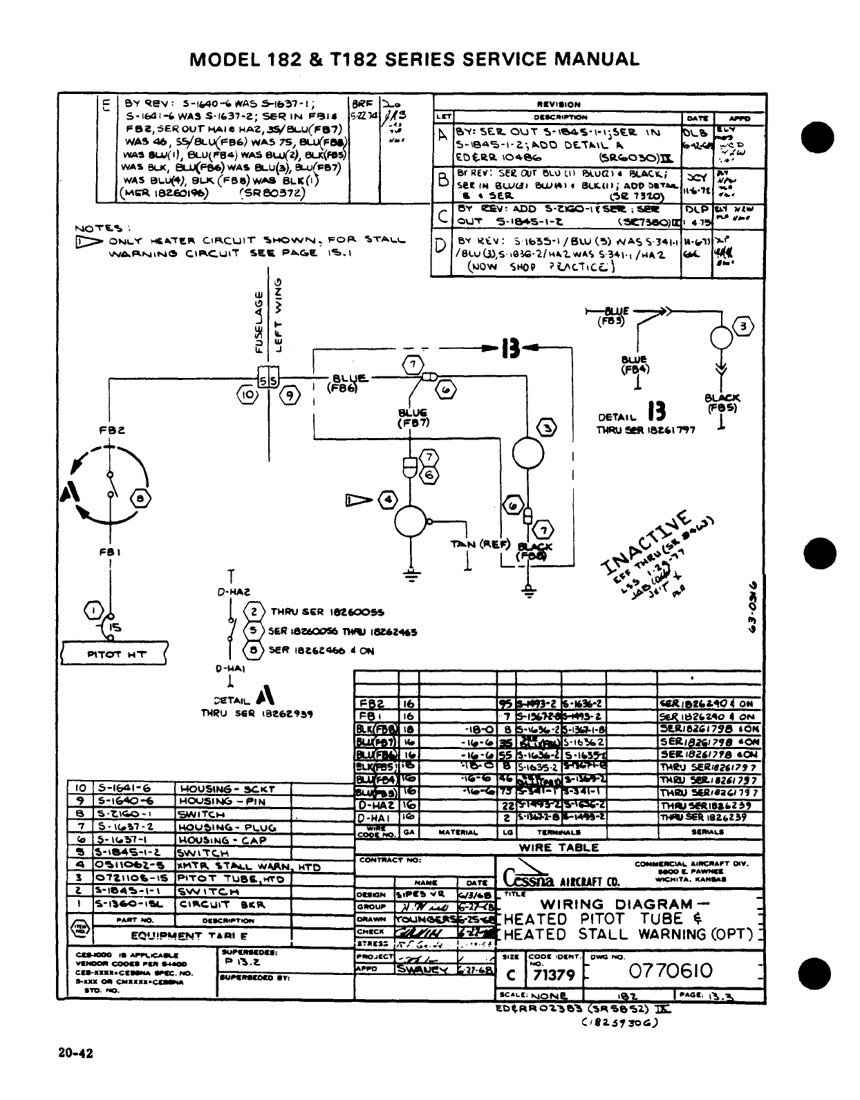
MODEL
182
&
T182
SERIES SERVICE
MANUAL
5
BY
Rev:
S-lit40-WYAS6IA5s
7-1;
eFRP
-L6
RE
VISION
S-i6l-6
WAS
S-1637-Z;
SeR
IN FI I LE1TS
DLiCRIToN
ATE
F
2,5ER
OUr
HAI
e
AZ,
3S/BBLU(F57)
/
3yt
SERL
OUT
S
-\t;4.StR>
\M
5N B--
C
WAS
46,
5/8eLU(Fe6)
WA5
7S,
BLU(F)
i-'
S-\845--
;O
\
'.
WAS
Sw(l),
eLU(FB4)
WAS
BLJ(2),
eL(Ps)
SSzD
4
olKZOe
V
R)<OO)B
T
WAS
BLK,
BeLU(F)
WAS
SLU(3),
LBW(F7)
_
BREY:
See
O4UT
LU
LI)
Pua)
a
iLACZ;
zv
0
WAS
BLu(.),
9LK(F5B)WAS
BLKI()
B
set
IN
BUV3)
BWA>
*
84A11;
AOD
I
ONlT mACTE
CIlCUIT
ON
FOR
'TAU
D
BY
I
tv:
I
obS5-l
/
BU(5)
WAS
341.
I-
'3
V
(WOW
SHOP
?LACTiCC
T
(9
>
|u
Z
(F55W
SLUG-TA
I
Lo..,
13
THRQ
56R
1Z(,E60055,
,
5ER
,8Z6
TUM
IZ6A24
-11 (F=
=
II!
T6
H'ZTIRu
W 7
|
01-tO-
Sl
I TH-AI
_
U
SER
005R
12Z39
7
-y
157
-
Z
4OVG-
PLfUCA
QA
I
ATEAIP
I TalAJ
A
5)
)SER
ieZ676006
TtR.
6a262465
,
PITo
HI
SeR
IaeE,<466
d
ON
(S
S__- _57
-1_ _OUSI_
-
CAP
_ _
WIRE
TABLE
4
?
ZoSI-46 S- rro'
ITP
~~
-
--
T
AC
.
ORA AICRAFT
CO
.
CV.
Z-~~
-T-RU
s6R
l-
;elP I6 I ONSi
_'_
o'
TITLE
-I
-cI'-1
CU
c
GR;
OUP
WIRING
DIAGRAM-
, PAlRT <0. DESC.
RIPTION
0,_ ,,
j-out4
-:-HEATED
PITOT
TUBE
4
,EQU.!PME.CFT
T'RI
F
S.2RES
z
HEATED
STALL
WARNING
(OPT)
CEOO I APPLCAE SPRSD;tfPTJ _asC
SIZE
CODE.
OT.
NO.
VEjrBAORt
-><-(<55
sOCSaPc-tEA 5-ndOC 5
/ O
CI---I
---
R---- -4
OPEC..
NO.
*r:
g-JPO 1$,,- m 27P HC
|
71379
0770610
'
·
5N<!o;.
_ _ _ _ _
___.
-
-STO.
NO
CI
|SCALE.
NsO I
2.
PAG|
E
^
:
EteRRO-b'S-
(0CseSssl)
=
-4-S_
WIAE.
TABI.E
20-42mUCI
PIG:
AI#UFI
CO.
o.
30G)
20-42
20-42
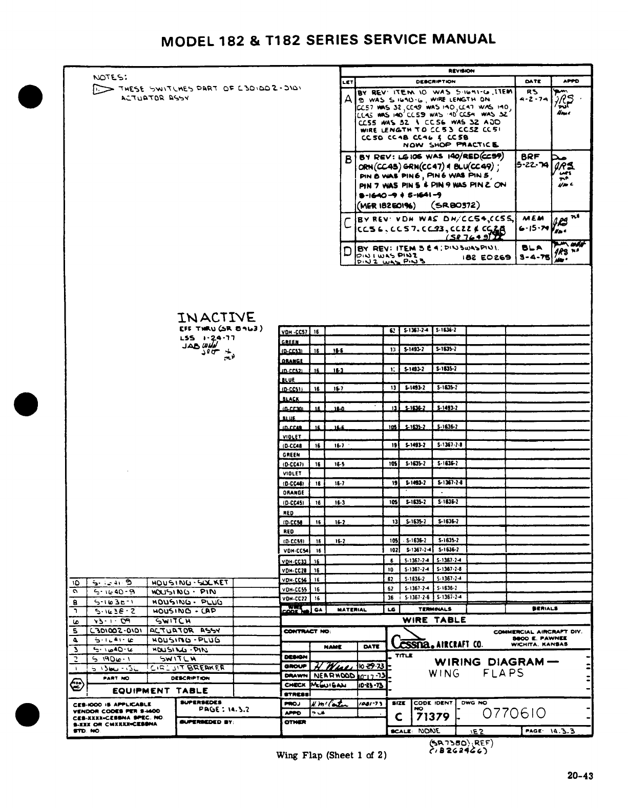
MODEL
182
&
T182
SERIES
SERVICE
MANUAL
__I".ZT ~ ~
~ ~
~ ~ ~ RO ____ CZs_ _REvimo_
C: D 7AE rs\
tE
D
0i
L
-LET
DLCRIP1TIO
N
DATE
APID
tkc>
7UE«T
-
^LOM 0 LO^
-
A-
BY
RfV
IeI^
'o
wAe
lf-*l1E R\ I---
l ^I;7^~UfTOO pc~ ~A
g
WAS
ISO
10O-
.
WIlE
LENCTW
ON
-2-74
C57
MS
32
CCt9
WA^
1O
C
.l
Wra
10,
LLAS
lAS
140
CC53 WA
b
AbCC SC
WAI
3Z
CCSS
WA^
52
.
CCS6
W'A
S
Z
ADO
wIRE
LENGTH
TO
CC53
CCSZ
CCS
CCSO
CC4A
Cc-X.
CCSB
NOWI
S.HOP
PRAC.TCI.
B
Bf
REV:
Lsios
wAS
1i40/tEO(C99)
BIF
ORN(CC4)
6RN(CC47)
<
eLU(CC49);
E7-Zz-q
g1?
PIN
9
vWS
PIN6,
PIN6
WAS
PIUN,
S.s
PN
7
WAS
PINS
PIN
9
WAS
PIN.
ON
<
*-1640-4
t-
141-9
(MER
182601%)
(sR90372)
C
BY
REV
vDO
WVA
D
N/CCCS4,CCSS,
MEL
A
cC.5
C.
LC.S-7.
CC-3,CCZt.
CCa
c-57
B.
_SR'
7,
4g91
Doe
EV:
ITEP
3
e
:
DLlMPeo
\
SLA
_ -,,,, wX2
,
e
EOZ69
9-%.
P,.S4- :'
IN
ACTIVE
EC;
TA.u
(C
.
515L.3)
VOD
-CC57 16 C2
5-13672-4
S-1636-2
LSS
ICT4I _
-
_
_
E»(
Q
-2*U >.n
.
lv.H 16 13 T2
S-1493-2 S-1635-2
__ _
__
v1;
1-1413
ID.LCC5 16 16-7 1 S-1493-2
S-135-2
__a
6---
-
_ __________________
l(D-CCSI 16 16- 131 S-1635-2 S -13S-2
j"D-CUI16
16-7- 1 S-I 12 -1431
-2_
Wo--Rc-a-
1-
.IL
-3 _
--
16-21
S
I-1C.2
ID-CC48 16 16.- 19 S-1463-2 S-1367-1
-
GREEN
_
Dl-CC4l 16 16-S 10S
S-136l-2
S-1636-2
VIOLET
iCC4
s
1C 16-7 19 5 -13m -2
S-1373-24
VH
_ _ 6 13ORANGE
367-4
1287
24
(D-CC451 16 1S-3 10
S-135-2
S-1&36.2
VD-CC28 16
1
1367-
5-136
7 2S
-
_____-
(D-CC9
i 1V 16 16- 1__
S-163-2
S-.1635-2
VOH-CCS4 16 ____10 S-1367-2-4 S-1636-2
VDH-CC33 16 6
S-136
367-2-4 S
.1387.24
VOH-CB
__
___16
l°
S-1367-2-4
S-1367.2-8
IO~
;,. k
,.
S
°>--
MOucN
-^ULA
ET
|I-------6 62 S-1636.2
5!.367-2--
c |
2
-
I
L-
40
-
Ot
10toul-31m
a
5 \ PN vDH-CCSS 16 62
s-1367-24
S-1636-2
---
| S- I
D3
^
--
| --------
al-mu
U
VOH-CC22
16 3636
S-1367.2.6
5136-2-4
T~
~lte-
Z
l4OUU5SiNO
-
TP
;
ATERIAL
LC
TCRMI
ALS
*ERIALS
o v' I
C-
O_
CiTC.
w
_ ___
WIRE
TABLE
5
LM\OOZ_-0\__D<
_7
UNO5
g _______
0
COwT ACT
NO:
.
COMMERCIAL
AIRCRArr
DIV.
,
:,-
fI.
C
A
O
U%
-:PLUC
800
r.
PAWNEC
-^ Z- -- ,,A---- U..-~
_
G"ATE
AIRCRAFT
C0.
WICHITA
.KANSAS
3
IC
t
-
\ ID40
I
099SN
TI
LE
PART-. :,'~%.\.
I,
D
XESCRIPT,'.__
__-_,
-
WIRING
DIAGRAM-
I-^T^-I DE CArOTe-- mAW-
N
0
4E^ODion-1.
WING
F
LAPS
!
EQUIPMENT
TABLE
CI
1
CEXIIOOC
.I
A-PPLCALL
PwR.SCES
0
IAO_
h
1,-,,
1
SIZE
ICODO
IDENT
DWG
NO
,,NDO,
CooC.C
PR
.-
4oo
PAGci:
,4,
.
.2
A
CDXX
*OR
CM.XXXXCSSNA
?
my
|D
C
71
79
0
706Y10
(ICA'f 1)
REF)
_O
No______
S_____________CA:LE M
-
2
|O
PAGE
\A.'
.L
Wing
Flap
(Sheet
1
of
2)
c,8Za2;4)
20-43
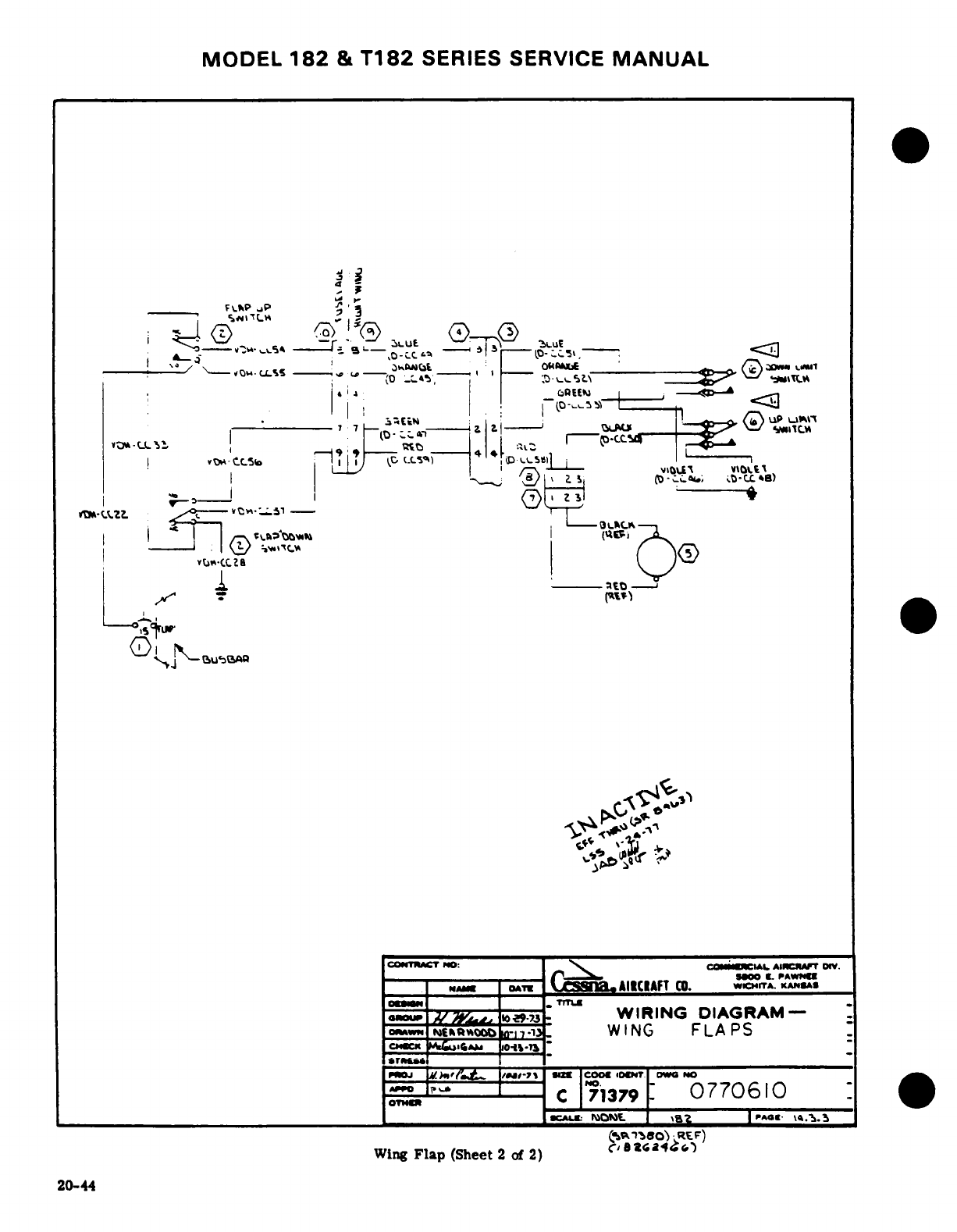
MODEL
182
&
T182
SERIES
SERVICE
MANUAL
v-L
/
L <i-1SS
~
„
,,,
J
LS
Q=
'
0-¢
--
L_.¶.ZL.
-
Z
-
CO* iL I 4zIL( <
(--o
t;:t-u^
! ,
.;,L
4_\
.[-^
b
,
-
Gu
s'
rt 2 C2|.1 (..
T(j
_ Q--
'0
1~-~~~NM Ot
AICAFT
CO.
wcHr,.
KAN
I/^O
-
XOW) (A
N
1.
C
0770610
ONScTSS
T
NO:
--
$AnniL
-N-rr
DIV.
--
T
-^N°
-
I
s r
.
s a
,UC.=: cor3^F
offem"
Tr
_=C
*cmwm
I
aPAI~.
o4.C.
A5
^ I = C
71379
0770610
(,
rwso)
RE
F)
Wing
Flap
(Sheet
2
of
2)
)
20-44
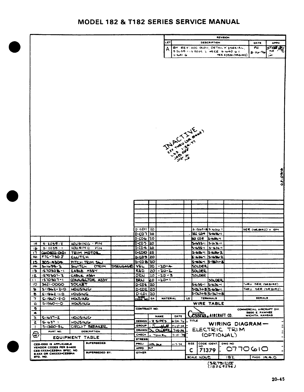
MODEL
182
&
T182
SERIES SERVICE
MANUAL
REVISON
LET
____.'
2
ODESCRIPTION
DATE
AP
"~
A
e
zEV:&Do
OLIID
pETi
te
9
.i$>U-
-
PaE'r-
uso
it i
7P
4
4
D
GD,,
l
20
_ _ _
S156 1t -i5 I
K,.
I L6t (agmZ)
*
ON
D-COO
|It
*
t
I
Il
*:
I__
D-CDO'
I- -L;.:O
~-.
Is
6
-2O
-
WODI5
NL
PItN
_
D-CDS
.
0
i.
S
D-CD,-
5-
20'
-
I
IOU*IN
C:
P1
NCD L = 5A5-I -S-I'6-t
Ct
C|;iOl0Z-01io
TeIM
MIOTOL
CDD
-
LOa
1
$-k-l
Sc-_L_.
Io
FTC--750
CL
UtTCk
O-CSI
ZO
;IIM SI-KI'..
Ji
!
rCIP\T6.l
TRim
SWj
0-CDVS
1O
= S-b
-I
*I@7t-^ __
_I
S_.-J
%L SW
ITCu.
TItM
DSiLU6.&
-
VC
L
20
_--
t
5'7050-
I-t
CAlbP
ASS'¢
RP.ED
ZO
-2l.o-.. _
_.EL
IL
157O01.
IL
CAbLA. Yam' _i; _ _____
__
IS0YO5-I
aOjULLtI1 A&5v
I
BJ
20
-Io- J\x
L
__
10
3421
-oo0000
SCtET
"
CDi
20
j =_ _
,-I
I j -1
*IEu
omet (lblIZ)
_
1-I9t.L
-Z-O
1u
$lCu
r
_______
I
ZO
=
2 hoF lZ
lbF
r1
_ _
tIIJRU
IbEt
I
Rb
t4
O
-1
9VZ-1-O
W5OUCJJO
____
D-CDI
20
7 ;-
19g0
-z-,O
O
I
CIC,
GA
M
ATERIAL
LG
TE
I*ALS
SERIALS
6
S-19(0-1-0
Ol0
I
Ca
_
_
WIRE
TABLE
5I_
CONTRACT
NO
:
COMMlERCIAL
AFIRCRACT
DIV.
~ff I 0
.
PAWN
I f
I
ea.wa.I-2.
o
iUU
|
t'tNAME
DATE
LC.A
.AIlCRAFT
CO.
WICHITA.
KANSAS
Z c5.3I I
w0051c
DESIGN
1-'
TITLE
I
5--s.05L
CIl.C,
iT eA;;
.
_
GROUP
WIRING
DIAGRAM-
PART
N0.
DECRIPTON
DRAWN1
ELECTi.IC
TRI
M
EOUIPMIENT
TA3LE
S
o
CHECK
..
?..
(OPTIOK.AL)
CESIOOO
IS
APLIC
DLU SUP'CII
CDI":
OJS Kll 1OmED
-
I ')4 I
ZE
CODE
IDENT.
DWG
NO
VENDOR
CODES
PE
440
APPO
U
NO
C7_ _7 _ _-
CCS.-XXXXC9SCA
OPc. P |UT |
C
71379
-
CT. *o.
SCALE:
hJO/
I.. 14D
I
|
PAGE:
14-.4.0
0(82C0425
)
20-45
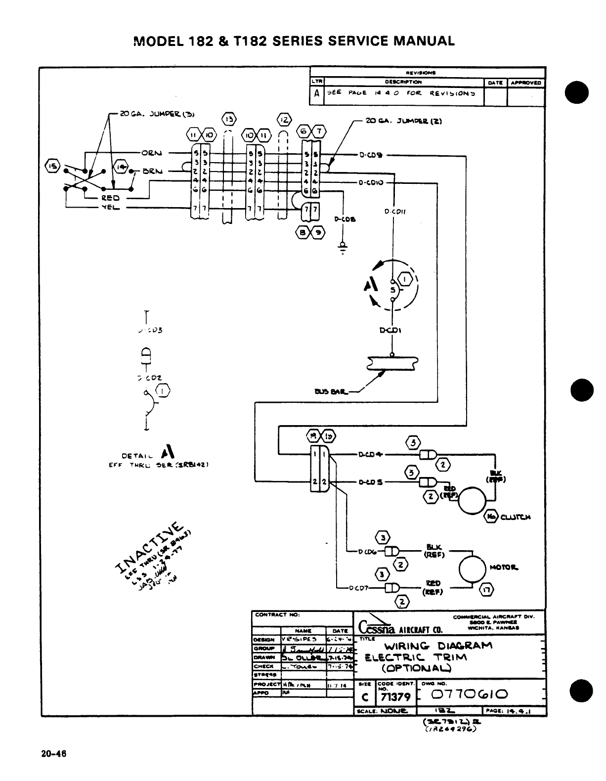
MODEL
182
&
T182
SERIES
SERVICE
MANUAL
LTRI
ODCRPTO
I OATE
APMOV60'o
A
I PE
PAt
id
4 3
FOrt
iEvIIO
N3
i-20
a. @UMPE. 0
20
G.
3uM
xt(2
r -f- -ow-
- - -
»
- -
oeL.
>
a-¢
C
T
I
7 1-
ZED
ETAir
-
I'
D.C
D-0
EFrF
TrtL 5
IStR542)
~, A, "Z
2 '05 (o-»)
CONTRACT
O
COMRCIA
AIRCRAFT
IV
M~r ~OX1 IL
PAW
rAE
LC
T a AIIUFT
C.
WICHITA.
IIANAS
V<H [ve_
PEBS
B
C
.-
^
TITLf
-- .
WIRINC.
IA"AM
CPrEC TM L.
tf s 4/
(OP61
?AL
) |
c
-
sI
z
*2ECODE
1
T
WC
[
N
sC~ul;
mok1021
C#LZ
11C
4
0-6(M 'St -I
20-46<0
oC^4~
Q
L.^-,
-^
Y~___ ____
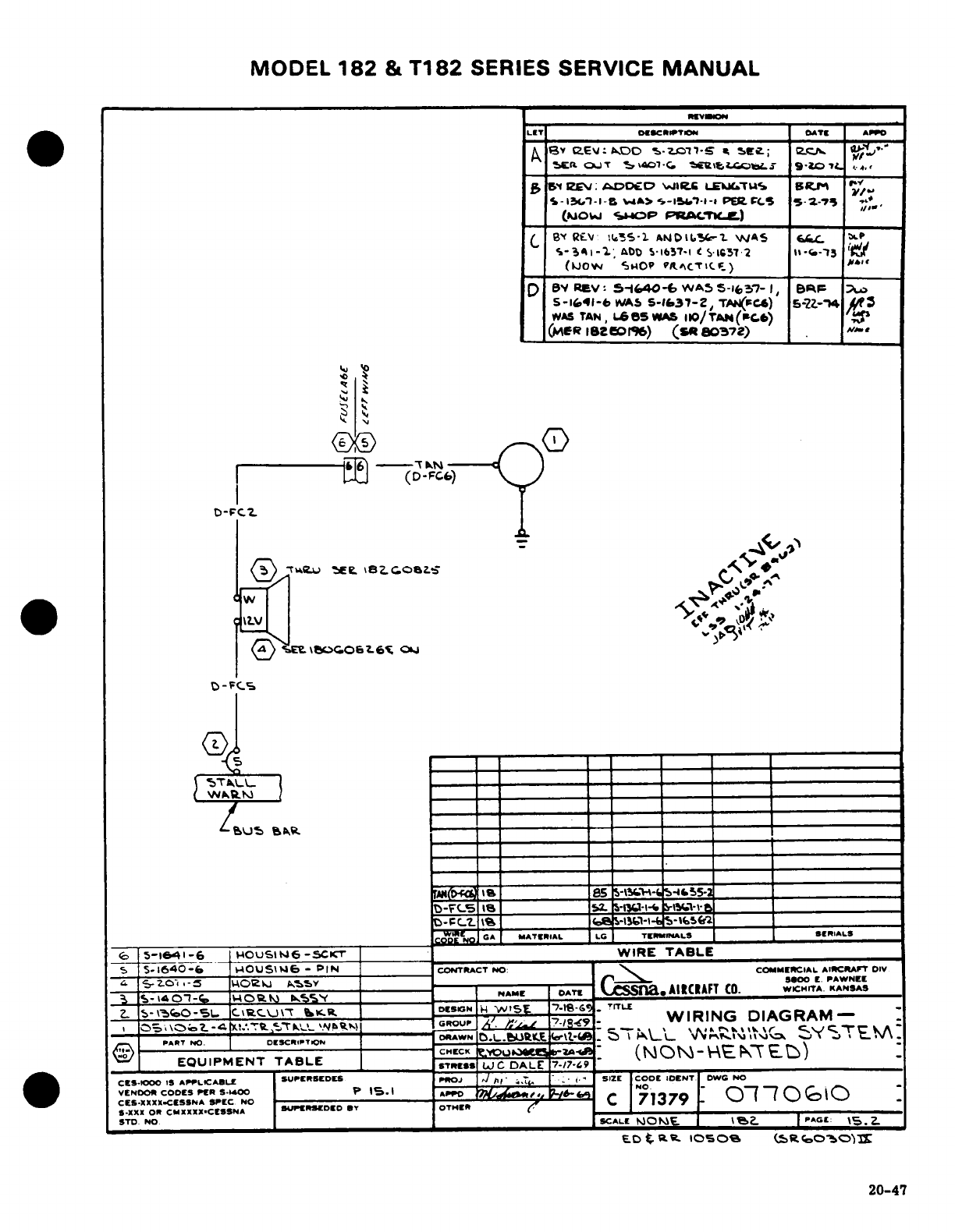
MODEL
182
&
T182
SERIES SERVICE
MANUAL
*LI
_OCPTIOe COATE A-PO
3
(
ZEFe;-Do
S-
OI-S
,
stee;
ZCAu
h.
'S'
C
Tl: C~
Tz
'-^L-, l 2-0 It
, .
f>
BEV:
AD2Dt3l wl6
LE_.TuS
8Cst
r.v
S-I
"l-1-
I W >
A
-1,, ,7l--
PER
FCS
S
2.-75
'.-
(wOW
CCO
F PRtCK
-C.)
W/-
6'
REt.\r
's::-2.
ANhiL6-L'
WAS
.sC I
5P
-34l-l.
DDo
5-1637-1
I
S-IG3572
H-
id
(lJOw
S'mOP
sfM"Ct-iCT-)
v*"
C
D
By
REV:
5-1640-6
t 3A5
5-W167-
1, B,
X
S-1641-6
VAS
S-1637-2,
TA(PCA)
s-2t-
4
RS
WAS
TAN,
L6
5
WAS
I/
TAN
C(.)
'P
(Mef
iseolr) (s
eo37)
.
eo
Q~uMTERIA -A
§ SIA
D-Fc2.
'S
'PW
|
/5> \tC ^b~o67-65
I©i)Y~~b16~~ ~ iL)
0
-
FE5--
lB
5Ta 1 =
.
=
=
Z<
)A
Jcc.A-.
-8-.
S.
16-40
6O
IOuS -
PIN
NO: COEL
T.
DIV
*
CODE~.
.So
1
"
.
NNI
0
.
PAWN
S D-XSGO-5L
CdUvX
CES.S
-5E
1 -r -BOTHER
(sLE
__
~*\~7**-4
:~T~c~~r
~p
GROUP
74
...
-'L~
(7.13CRUWIRING
DIAGRAM-
RSI-K)OO
1I
APPLICABLE
SUPERSEDESP0ro I_
-
t_
SIZE
_COE
DENT
DWG
NO
VENDOR CODIES PE: S.400
P
eI
I-
-
APPO
-i
-71 55-7 2-
0
C
CES-XXXX.CESSNANO CA
AtL
9
T
71379
RA
SXXx
O
-1XXXX-6
C
uSSNA urD
I
WIRE
OTERTABL
So.
N5.1640-
CT
NO
:CONMEMCIL
AInC
DIV
20-47
20-47
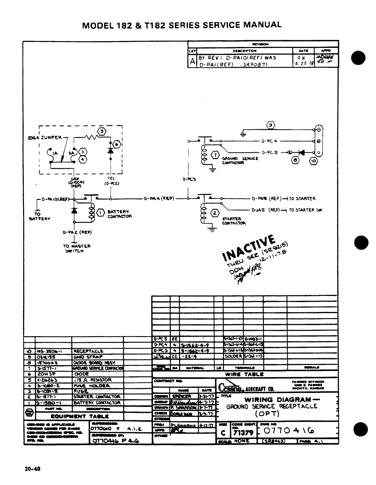
MODEL
182
&
T182
SERIES
SERVICE
MANUAL
L
_
OeslCmrITINo
OATU
A
A
BY
REV:
O-PAIO(REF)
WA5
s
D-PAI(REF)
.5R9087)
4-ZS
r-""---D (-u.--)
M6A
JUMPElR
-_
,PR
/
I 1\
o-
| T
_-o------
-pC4
c-----
4
iA I1 AY
/
M^ 7
---
OUN
SEIWCE(°
toCl4)
((O-F-)
-0-f\OWV(REF--
I
-
0-P.(RV-I)
1-T-
|
-&-
PA
(REF)-'TO S-TA-TtR
8 0
01001.
I
0---aS
(EF)-
TO
STARTER
ObATEVP S00
WIRE
CONTALEZ
5
0-P-
(
s)
W
TO
iS tma
E
m IaIm\
Mq.
dl.wa
I
to I
ms-
3sob-
I
L
I 1 I cx
'
= occ
^?
.
^i-=-o
£^»I
.
owl
N
___
l,.I_ _ ____
o
P
Isf
_
__
_
_
9
OSISS
6MO
STmIP __
e
_ (.o...
i'|t
-21-4
_0 '7€
5i'3
\ _
_
1
5-157-1
m ID
Yl
ta
C-lO
; _
*
_
T
20-48
3
O
_ 5-i1
->
bTTEmY
cOMTCO^k UO
.
WIRING DIAGRAM-
_o" N. I rnscil
l-p
GROUND
SERVICE
FEEPTACLE
E
KQUIPMEINT
TAM
EL---
-
2.
: ____
(OPT)
__
)_
9~
an
I.\.i _
C
1379t
0770 4 \C
_
C_
-1044ia P
4.C
L
*
NatE
m
OIU.^3.
I-
%.
20-48
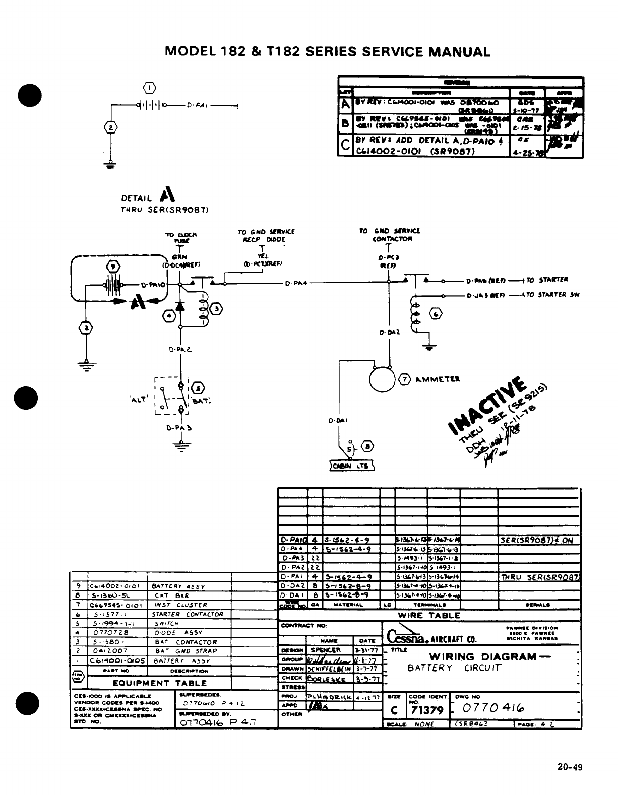
MODEL
182
&
T182
SERIES
SERVICE
MANUAL
)*
,1,t,~I
lo__,
A""
7:cs
R:Cb4oooiC
s
oRsooEo
&o
---
|
<[
)
*»
i»»»t
tA»»M-
ei
IMT
e-
e--
PMrF
|
ey
REV
S
ADD
DETAIL
A,D-PAIO
4
as
DETAIL
LA
TURU
SER(SR9087)
·
cu.K
Tro
&DNO
StRvw
C
TO
CNOD
sVCtC
F'SEACP DEOE0
CONTACoTo
T
T
T
~-- -------- ^
eK
G
y'.
D-»
PC
3
2.
I'T
D-O
r---l
()
(DDC4PEF)
(D-
pCM
&I
EM
C |1|1| o~eT
0
PA4
D-^ oln
bTo
STA(Eit
^©O®<~~~~~~~~~~~~~~~ o
FO-JA5mF)
.~.-TO
Ti~tER
SW
' .
I '1
'?
r---l
AMMLTlU
0-
oVI;^0
OAZ
kmk~Ih
4ETLR
-"
? 4~&,(~9S1S-
'MAL
L5_
-
JD
l
-
'Eoo
777;'8 IPg
4
1
ER9
0-PA
4
,-'s2t-4-9 _
i-W-J13
3
_-
1
D-PA3
Zl
__ __
-0493-i
i37-i-a
D
PAZ
____ __
5I
3·7
1
S1493-1
_
D-
PAI
5l a4-s-4-9 _ 5-i3T743
S-I34R
7HRU
SER(SR9087
9
Co4002-o0101
8ArTcR
ASSY
D-DAZ
5-154--9
-137-4
i
_____
ls____ ___l
~
S-3tO-SL
CKT
BKR
-DAi
_8 5i34iW4- _______________
?7
~CZ'HS-
001
INST
CLUSTER
--
DA
MATEIAL
L
T
C
_M*ALS
-
RALS
5-1577-1
STARTR
COnTACTO
________WIRE
TABLE
5
5
1994-
I-I
5ynrc
CONrIACT
PO:|
PAWNEE
DIVSBION
*
0770728
DroDE
A's
|
--
C.^ A
IIIC
IAFT
A
~
580
-o-
BAr
CONTACTOR
"A'
AT
'S
.s
AIRCIA*
CO..A--
2
04,
2007
BAT
GOD
TrRAP
o|EN
SWIRI NG3-3'7
I
rTrL
C
coi4OOI-C
OS
ATTER
A,55s
0*
--
WIRING
DIAGRAM-
RT
o DCNIPTIO
AWN
H
IFfEi.fIN
3-7-77
BATTERY
CIRCU
IT
CiECEI
L'b
EQUIPMENT
TABLE
TRE
LE
-
_____
C S-DOO IC
AAPPoLICAS
| *uPrEcRDTr. P0ro ?L.>aItk1
4.
-l*1 *m COolDC
.
IT
owC*
N
VENOOR
CODC
-o
o
0D
.D 7
70,o0
PA
J. 1 2
-U.
0
770
41(o
S-XXX
01
CMXXXXICERKSRA
ULIEIOD
aY;
OTHER
-
rTD
NO.1
0o1"041I
P
4.1
___:
NONE
(Ie4A3
r"PAEO:
4.
20-49
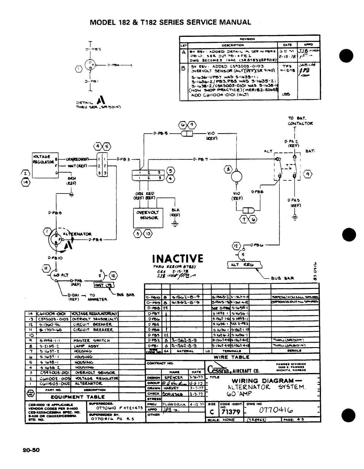
MODEL
182
&
T182
SERIES
SERVICE
MANUAL
T
ILr
DEI
oCIPTION
DATE
A1
^l 3
"
-"S"
*Toes
~
BA
ST
Y 3WTS.
' .
D
E
=)
P»; ^,
56
9 JJB
0
pb
.0,
514
st5w-
78
/l
.6l)
P
. . .
O '~)r-NL oDWC
BSEComeS
IN
.
(sR6783l9/014)
___
0Q
)
3----°-'---,
.
B
tE5
.
AtDOtD
C593003-0103
-Tr
S
.
A
.
\J^T D-W~eA~vevOLT
5eNOR
O(ALTP
sRE9,r
*
t-l-
I
-/g
I S&- <B*~3*b-
/P» S-n«3B-i~
w'5 <
-1 s
33-;
>-
>a
S-
./P35.-L/
P
.PoSP
9w5
5-\435-2.,;
L~~ 9I~l~-
I'-.3-2S/C
S00O3-I0l
'A w
S
-1l.M-
1-LI~~ (NmOa P
oPRfCTIce)(ewe162-Eos
-
_
t00 _
C(\1004-0101
(PA-'
L
T'lA,
W.
0
TO
A&T.
(^(7)
COhT&.cTOC
0-Pb-PT,
Vio--
(EF)
-
P&
Z
<,4Yi2 (e)
'
F
--
»<MT(» F>-- Z Z
--
/
____
-(
I
EF)
---
OLTF
| _
D
ALT
B
\AT.
<3L
1-------
l w t 8 ,@ t----
-
»J^-
YJ.
C,-
E
I
F
I(r
F^ r
d (D
P9
0-F54l^ ^ ;.,..- ~
~ ~ ~ ~ ~ ~ ~
~~~O
PA
-;olo
INACTIVE
K
\A QI
r
(«a
_
=
\-//-QQ(
o
r-
d,5
-s-71
--
~ ~
~ T-Pg T* -a-_ _ __k-
SSu
6
m.
_
0-GMAt
--
_
TO
uS- _____ _
-o
-
R
O-PC,&
ta
_
D-Po
Sa-I,-l
14
C<11004-OLO
OWLAL
P
Tt.U9ESO.WLAA
D
-
_
_
I
14q
IH ____b-
C3
5C'45305-0103
oiol
OVERHLT
m.
mhT)L
D
'
_ __
__I_
1- SeI
_r_-_
it
IO5-7O
CAlW
b
4S
B
KEC
D-F6
Im
-
I `
,
I
6
01
1t
'.ts(aO-4.
CIKCUIT
2CEA.E,. L oI<»!-I
u
5
t"S -IP
II
.I"O'I-.
CID/Uir
f.f.&EEg..
-pq!*
,
I
_ 1 i ______
|,
5q44-t-l
HtSEtt
aWlCA
D
DP2
_6
S-5l.-B-9 -_
b-14
S- 7-t
*
u-
-- )
8
S-Ztl5-
LJ4HP
A6&' I
o-Pi
b
S-i662-6-
3
;
IN.T-4
44%.1j-4-l ____ iau_4_
A
4'l
'7 5'- tI(7- [It
OUbm
a Ao
MATERIIAL
LG
TEAINAL
IJ
SERIALS
(a
15
1751-
I OUIM"G _
_WIRE
TABLE
5
$
I8-1
l
I-
CONTACT
NO,.«0
4
i
NO:
4
I11' t
"
iO.lJ
1¢ I l AWN1l
~)
C'y:'.5'010
1
o~Vl
I V.IEOLT .lcl,
A
|I DNATME AIRCIA CO.
DWICI,-A., K.ANSA
t
CiW10t
5
X0·
i
oLTAk&.
efAULTO
O
N
SPE
CR
3-7
-
-R
TITWL
c
C,.lI0o-01o2
A.eL'WNTOK.
'OOU
.
1-.7
.-
WIRING
DIAGRAM-
-
^A PA'T eWDfC.~ w
--
OMAWN
i AI
AlYV
3-7-77
_.
ALTERNTOR
6Y6TEM
EQUIPMENT
TABLE
(O'°
P_
cESiCoS «> ES ;
|, pLptR
4-
n
SIZE
Icoo« IDA-NT.
owo
NO
CvuXXXocoKUA
0PO.
No.
C
71379
-
'00
Ibm
~
onCo!v'~vCIxsNA
my
I
:
TD.
NO.
07704.1/
PG
4. u
acA:
ON6E
|
te):| IPAGT
4
5
20-50
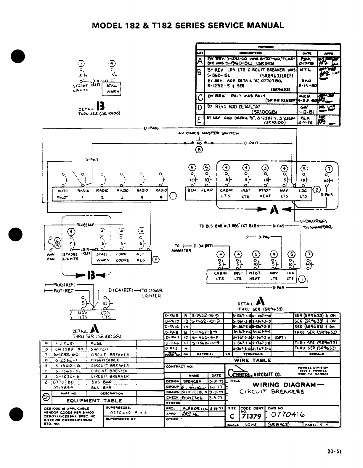
MODEL
182
&
T182
SERIES
SERVICE
MANUAL
LET
DuClPTIO
I
BT$
"-'
"A
eRV'
o
,-n-8
.'Be:
')
,
0-.L;
(ait
91
g-ir
orC~ _;, Q~
B
7Y
RtV
LD6
LTS
CIRCUIT
BREAKER
WAS
N'l
5;
5A
-
5-13W0-15L
(SRS6JU)CIEF)
Li
0-LDI4-.
Br
REV:
ADO
DETAIL
'A,
0710'180,
RAO
bT;SrO
(LLU)
TA
S-IZ3Z-5
k
SEL
3-14-8
UfCuTS
WARN
___________________________(sea'__)6
BYC
RE
V,'
PAII
WAS
Pr 1)
MM
DLtraL
13
D
B'
RE.V:
D
OCtA,
IL$A'
vW-
'
Tsev
_
(
101.o00o)
1_
(k,(XO)
1-2-
8
-
E
ItW
L:
ADo
Ot..
,S-sl-I,
5-,
..
T K
) L
j
_________(J,
ro01o0)
2-9-f
c
E,.
D
-PAI6
AVIONICS,
MNSTIK
SWITC.
I------------------------*
--
*-A
D
-
PAI7
0 0 0
0
0 0 0 0
0
0
)\
-
)
-
Io
\ 10)-O
l
)-°0)-
s)-
I4
)
i
tO)-
0
'
Wo10
Qa«\C
RADIO
R.ADIO RADIO
RADIO
OC.
FLAP
CABIN
,s-r
PITOr
NAV
L0D
<
2
DILOT
2.
3
r4 a 0 L
LTS
LTS
E*AT
LTS
LT3
0-P^S
I
RDl)«Sf
-.
_
TD
BUS
86R
ALI
f6'
CKT
---- -PA5 90f
g
0
1 i) T
O
.P
A
,9
® z
,
,'O. C.
S'
f
5
.S,
5
-
TO
i--
D-DAI(R
F
AM
STROE
(REF)
srAu
ruR,
R
AIT
(
f_
L16HTS
WARN
COORD
REl
2 O 0 O O
0
S
5_
5
_
10)
5)
o
-~ »V ^-
/
LTS
LTS
MEAT
LTS
LTS
(3
P----,(REF)
F
--
PAM
(REFI
--
D-
C4(REF)
-TO
ClGAR
0 0 o
LiGN'HR
05
0
LIGwTEP
DETAIL
- --
Q
--
Q
--
CA/ ^--, L______
______THRU
SER
(sqbc33)
LTS
LI E0-6
IPAI5
1
S-
1552-8-~)
S-136
-4- -I
-l7'-4-1
SER
(SR933)
OD
D-PAl?
101
I
-tO56\0-9 -137-3--3
-
-I-3-
ISER
(5R9S)b33
ON
A
|D-PAI6
164
_
|______
1I-Z-I
3-13I.2
-8I
____SEK (533 ON
1IF_ L
A
D-XPJ 8
-
a
ilZ-5-'9
,-i
|
J,,L1-U-
3
_-4?-___
THRU
SER
(SgR
33)"
T4RU
R
St[R\O00
)
pD-PA7
I O
S--lcO--9
I-
if-3-7-.3.,73b-3'6
(OF
T')
q
4
S-'~5,5-
| FVSi
I
ID-PA
I
IO|5
-
_S2-0
-9
51347-3'
,34735
|-
-i
THRU
5ER
(5sR%33)
8
CM
3589
40
.
SWITCH.
D-LPAS
4
_____3- __i *3-ZS.I72- _
THRU
SER
(SR%33)
S7 S-IZ3.-60O
CIRCUIT
BREAFKER
GA McATERIAL LGO
TEMNALS
-
IA
6 -Z5.-(
,
FUS£HOLDL
t. I
WIRE
TABLE
5
,5
13.0
-IOL
.
CIRCUIr
BRA^ER
CONTCT
NO:
\PANEE
DIVISION
4
5-
3(.o-0
CIRCUIT
BREAKER
so
IOO e
PAWNEi
3
5-.;z3z-
5
CIRCUIT BREAKER
I
I
NAME
I
DATE
L
n.AIRCRAFT
CO.
WIC"T^.
KASAS
IZ
0770780
BSU
BAR
DESN
I SFPNC.EPR
13-3--l
TrrTL
| O
1
654
BUS
BA.
GROUPS
.:.
.
WIRING
DIAGRAM-
IPART NO. |
DSCRIPTION
|*DRAWNI
SCHIFFEL8EIN
3.7
7.
CH\RCUIT
BRE.AK.RS
EQUIPMENT
TABLE
I
I
CNECK
ILEKL.
3-7
-77
CES-IOOO
IS
APPLICABLE
SUPIERSDES.
P.OJ
ILI;I0.I.j
--
7T
SIZE
CODT
IDcnT.
DWG
NO
CtS-XXXX.CESSNA
SPEC.
NO.
r
/
71379
I.XXX
O
CMXXXXCESLSNA
UPCRSECDD
SY.
OTHR
I
STDo
NO.
N|I^
|I^ I__
SCALE
NONE
I
R.se3)
PAGE:
4.
4
20-51
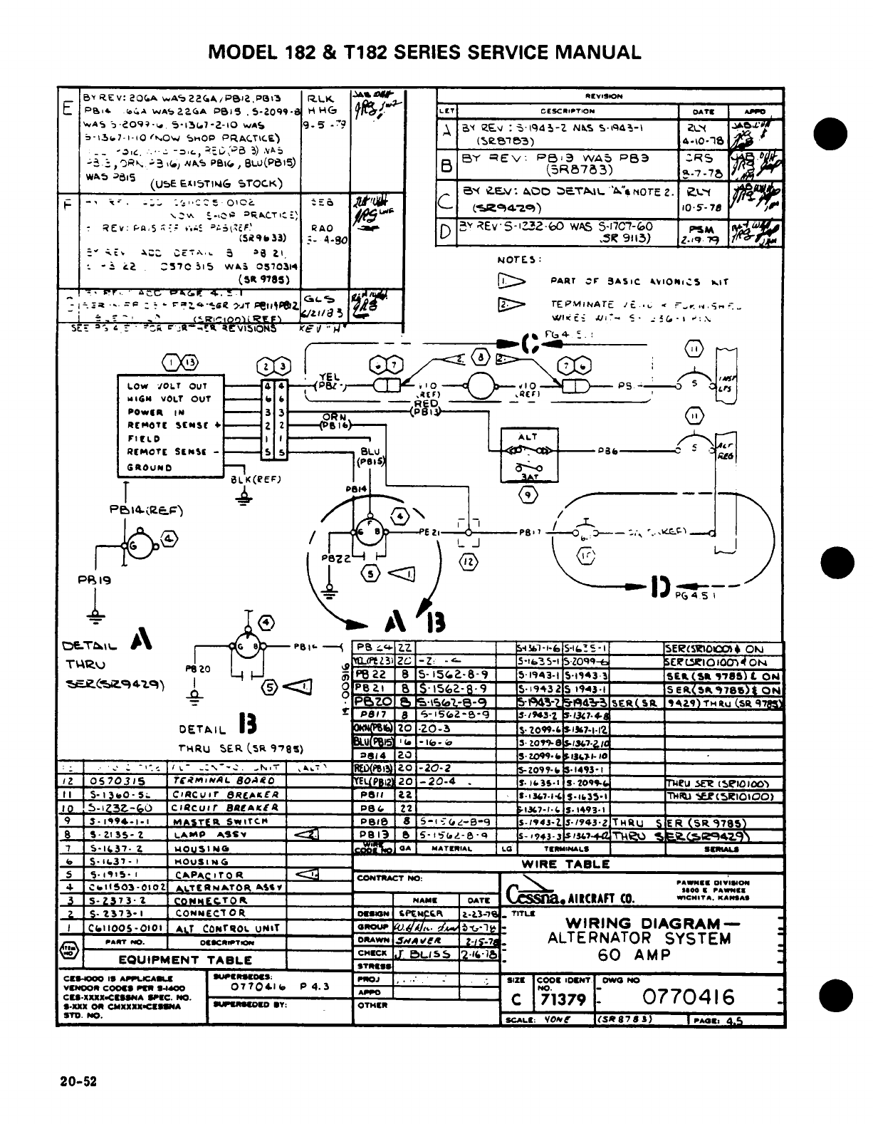
MODEL
182
&
T182
SERIES
SERVICE
MANUAL
B_
Y
REV:
20G.A
-A
22A AP/Pai.P3I
RPLK
(ZL 9
-L
_
RvION
WAS-
09-
5
.7-2-
W'
9-S-?
:
1iq4-Z
NWAS
9-l
,
b-l3i.7-1l-iOe'NOW
bHMOP
PRACTICE)
(St^s
3) 4-Ia
ss
I-:
-7
A
-.
I
, )
A3MA(P8,BL(P85)
By
BY REv:
P513
wA5
PB3
:
WA,
5
Dd'is
'PB
(BR5783)
_S7-7
W__
w 3
(USE
EAS5TIG,
STOCK)
a8
eZv:
-c.
AOTJL
'Anore
2.
·
t
,
h"--
'
-:
.4Po
....
c
3)
__ __
-
REv:
P
a,5
.
;-'
**E
i;,F'
rAO
rD rF
REv
5-127ZfoO
WAS
5-17C7-&0
F^F
l
S
(Sib133)
5.
4-.o
_____
9113)
Z'.,q
79
*-F*
-
A
a a
VI,
NOTE5:
:--
Z
37C
515
w-A
0570314
O_ __(5R
9785)
D
95
PAT
3F
3ASiC
VI10Ol;S
lTr
-
-
_a
=C1_
* *
F
r
Q>'kst
>JT
PtIt6Z
s-C .7
[>
rEPMiNATh
E
y£.w
< i_
.. _
" ·
i =- _
F
.
.F (eg.-.or ltgcF
--
-S-
/
e--
'
c6
c*
f-
0OA
OaR 3g 7
c)
85
)
5EE
ns-4,
-s:
cj
u,?
ee^C\/1l,~N5,
fe.zt/
'n
_
.
a'
.:e^PS
I0 -r-IZ--- ~
cl-cu-- BA
1
LOOL
OUT
-----
--
-
Z
-I t--PS-
5
O
r
HIM
VOLT_
OUT
---- I
--- '
POw2.
IN
-33 3____(Pl__
_
REtO
J(NSt
SN _ 2
Z
2----(P5T
1N
FItLD
---
I I 1
--
-- ,
ALT
_
REIOTE
SLAMP
--
SE
5
BLe. P a -,, 5 CS
,
G
ROj i
IiND
OAItOIPA
EDIS
N
T .
N
P__
-
ORAW)
--\ -
/
A
S
EQUIPMEN
TABLE
___S________.ill
S-X
ESUaa
SE
C. O lPs
N5-
-
-
l-
*seX .4,
O o
<>0
O
T.OR
f
.1270
~r4,re,
(ALTERATOIRTE
P9
\ ;
P1945
c~.,,oos-opo,[
.;r
IT
A
TVI[N1
C-
iN- ;4
6
PBI
PB4. Z1 SOO=
5 O-k
TURZU
P120
I-Z:
@
C
F 6LaZ3)
2ZL
_Z_50991 >5-4
1010m
Iq~~
P
O
22
8
S-
15428-9
1943-1
-1143
31
(SOL
97a5)
t
014
cSZ94z95
1 O 3 8 PB21 a S-
1S6-8
9
=
a-,25
1943.s
1943
1
|S
E(s78S)tON
_-~~~~~~ 1
F70 5O
S-1ts(-5-_9
_
R9S
4r3|SER(5R.
IS)THRu
(S
97859
IU
r"p!an!_
sB-Ys:
Tz-ERa9
=/
3-'
37-.3
DETAIL
I»
20
-ZO-3
=
I 0
(
=6-l-l
__
rTRU
SER
('SR
978)
mas
2C-4..G-0
_
23)SS--
:
-
-
*^
-
'''.<
'
'.'
-:'.'--.
IR
» l(l 2ZO -20-
2
_
s2099
S-1
14
-
I2
05703)5 rfm.NAL
BOARD
2o
'E^PBIZ
20
-20-4
.
_
-
.l36-1 s
2099J_6
TWJ
eu -11" 11 0)
11
S-13b0-5
|
CiRCV
ir
8R
f^ER
|
Pi31
22z
13
5-
7-1
-135
-1 _ TF
g(III010oo)
10
5-Z3Z-6
IcvcO
iCuir
BaCA$Cf
_I Pse
22
_
,l307-l-4
.1493-1
|
9
S
-
1994.1.1
MASTER
SWITC
1
Peae
8
5-1
--
a-9
s-943-2
5-/943
2
THRU
S
ER
(54R78SS)
8
5-zi5-Z
ILA^MP
ASSi
<
19
IC
-
3
1S-iSf4-8-
9
1
-193-1
ac1zS'
7 |S-l'I37- Z
OuSlt
O
I_____
SS
M I
LG
I MIATRIA L S
C
I
Muu
(
i
S-1-37-1
M
HOusING
-
_
WIRE
TABLE
5
5S
1115-
I
-,
CKPACi
r
o
-R
COINTRACT
NO:
\
PAWNEE
Dol,^
CI11S03-01OZ
ALTERNATOR
Sf
1
.. ... .
rI
.*.
ee
^1r
3
S-
2
3
7
3
CO
Co
CTORl | ET lNAME
DATE
I
CSSna.
A
IUCIAFT CO.
WCHITA.
KANA
Z
S-
Z'373'-1
ICOwNECVOR
_
DESIGN
SR
€.«N
Zt.3-3-71
TITU
T
Ciiosoo
ALT
C*gRiOL
UImT
GROUP
-
WIRING
DIAGRAM-
PAR
NTO. O€C1*IT^~
wDN
5 It
V
-ei.
ALTERNATOR
SYSTEM
EQUIPMENT
TABLE
C
J 2
S60
AMP
cc
1. ALooo
r
CAI"
,
r.I
.RJ
I .
-
.,
IZE
COODE
IDgT
Dwo NO
vEoNO
coDcS
r*4
40oo
07704.1k
P
4.3
|.--
-
NO._
_
CUS-XXXXCR^SA
PEC.PO.
.
------
D
BY:
OTHER-'
C
71370
0770 416
T.XXX
Of
CNXXXX-CO-A
| D
D
Df:
OTHIH
L
l
I
TTD.
NO.
S
CALE:
V0fe
(S*»87a)
IA
.
|
4.
20-52
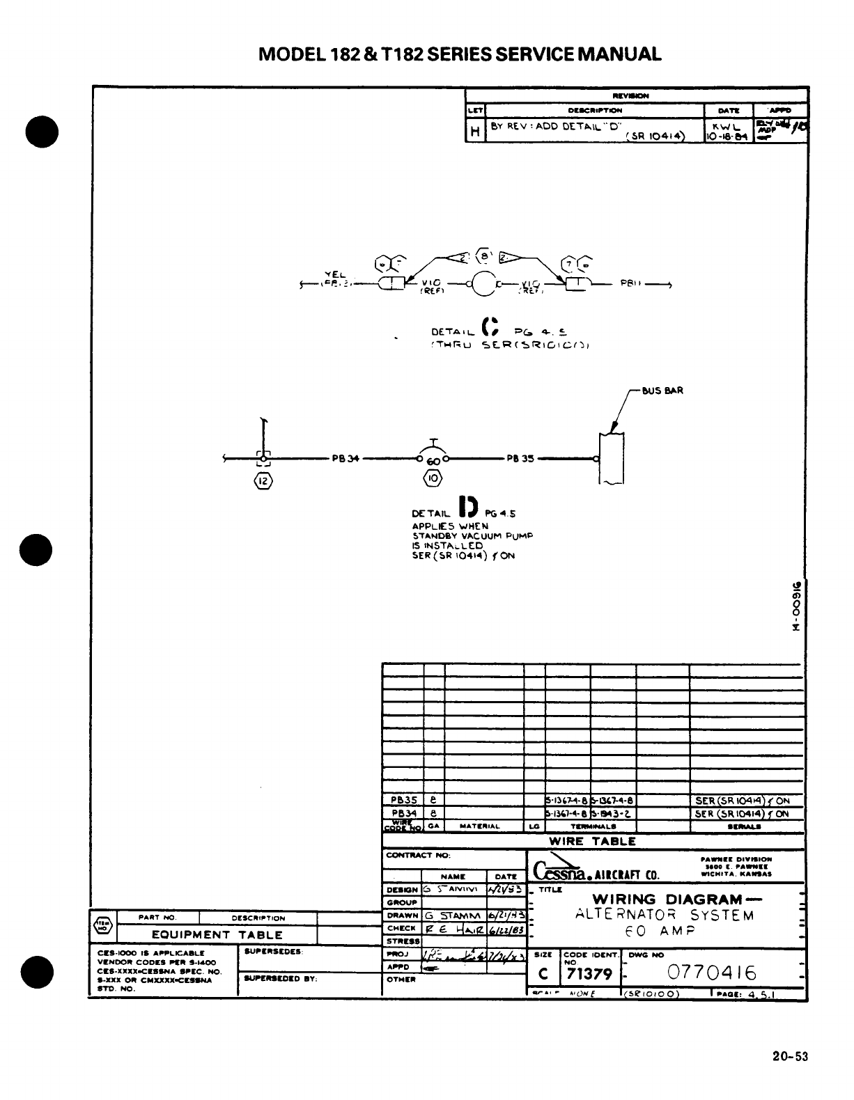
MODEL
182
&
T182
SERIES
SERVICE
MANUAL
REIVIION
viOp
PLIT
DOP0TION
DATI
AD3
£O 14'1 fON104145110e-M
I
AfELD
Ci,
C C-
C
DETA
U
(
PL
--
'TiTRu
5iE.R(SRIGICr'
I
bUS
BAR
P------- 34--
--
O°,
-
0-
-
PS
35-
DETAIL
1)
PG4.S
APPLIE5
WHEN
STANDBY
VACUUM
PUMP
IS
tNSTALLED
SER
(SR
10414)
f
ON
I
DErSIGN
--
A IIIVWV
AA
il Tf2z
.
PD635
e
_ 7 >
-13_7___6"B~
SER(5R
T1041
ON
|
PBM
e
________
sQ^-4e
sB-
L
r____
5ER(5sR
10414)
S
ON
oC?^A0G
MANRA
CA
MTEANATOIL LSYSTEM
E____UIPMENT
TABLWIRE
TABLEM
CONT^ACT Noo PEER
-
DI.O
NO
CA?!
_______________________________» ____00 __C.
_
|
N*MV
|ATI
CtssEa.
AHOAFT
CO.
«MT
K »A»E
DErSON
6
5~AIVHI
Vh i
-
TITrrL
'_c___*gROUP __----
WIRING
DIAGRAM-
PART
O.
|
DESCIpTION
DORAWN G
STAMI
j/ZJ
ALTE
PNATOP
SYSTEM
EOUIPMENT
TABLECHECK
-
.
^Iu/6I
EO
AMP
CCI-1o00
IS
APPLICABLE
PI
O /-- .P1OJ7/ l IZ
CODE
IOENT.
DWG
NO
VENDOR
CODES
PER
S-1400
AO--
SE
NO
CES-XXXX.CESSNA
SPEC.
NO.
PD
7137
0
7 7
0
I
S-XXX
OR
CMXXXX-CESSNA
SUPERSEDID
BY:
OTHER
_
7
7
STO.
NO.
'
-.
,-
'0~
(Si?
o
)
IPACE:
D 1(SOIOO5 )~ I&C·IE:
4
2053
20-53
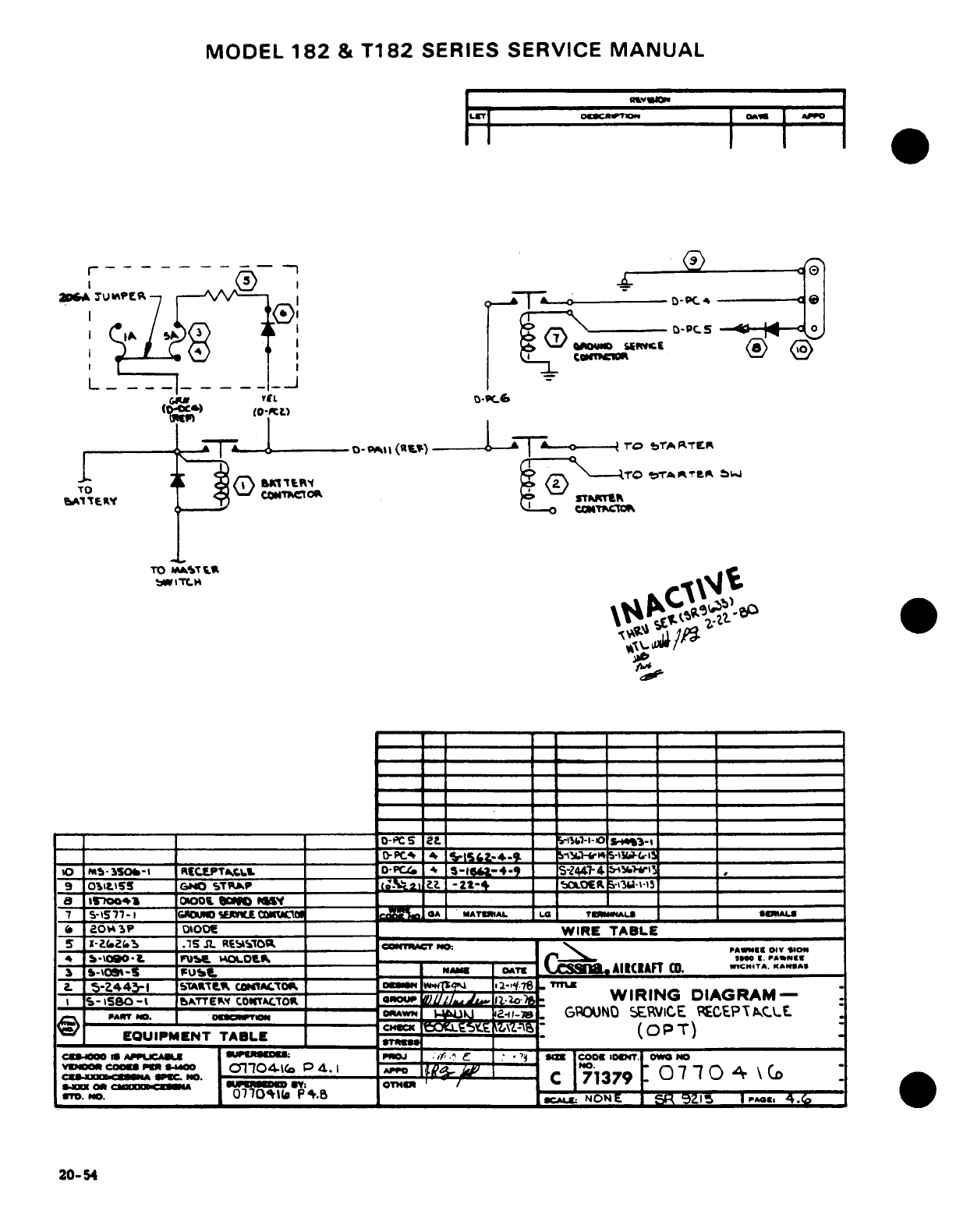
MODEL
182
&
T182
SERIES
SERVICE
MANUAL
I
IA
;
i
&
o
--
pcss
0
#tC«r
b,
T®R
'
/^
1
_t' }-F-"-----
--- ""
L _
-
-I-
_ _
-
_-J
»
42
)
rfLt
o-
6
-
(«^
(-O.K)
__ _ __
i_ 0
_o-___
_ _l(_-)
-
TO
rAWRE
TABE
WTOf
;
~
E
CONTW
P e
WO
NTw
TO
AI CAT
6.
, .
D_
PC--
--
_
_______'__
_____________
__*_______ ml
.
o-i-- WRN DIAGR A M
-
:.-i
10
,S-350ob-
R'CtPTCsA.t
_____.
D-PC-
4 4
-16-4- E I
S-Z444.
P^l
'
9
q\\tL\5s
CM0
5iTm~p
__2L____
__
-22 _- _
-COEP
S a--4
m-
ri
1-1
_
DIS2.ISSS
GMP%
STP.AP
-
'
-
a
>rioo0a
S0oot
DIOD
E
y______ _ __
_ ___
7
5-S
T77- i
QaWO
EVAI
na
_______ YSo Ga
mATMAL
4
TIA
-
_
_"6
D0IO
P
S
:
'
'
OOE _
WIRE
TAB.
LE
^7 i
.\ooo
,
Mt
M.
.K
_
.
07i"
Soo"
0-5I4P
2"'
-3- S-\l-S
FUibe.
AI___
CAFT
Co.
C.T.
KANSAS
Z
s-Z445-l
wAtTx
COC
M CTOA
ON
Datu.m
i2-f-e
_
Smz
I_
-1is8o-
1BATTERN
COMXCATO
_
a
n--I
_
WIRING
DIAGRAM-
Q
^PAT
NO.
I
o
o-- !2ol- ,r
'm£
GOU)NO
SERVICE
_CEPTCLLoEt
w EQUIPMENT
TABLE
(OPT)
cI
oon_
,^
c
-7
A
IPPCA-
s
u
MM.O CODO OT.I
n
no
all
1
mX
T
;Po =1 c
71
379
07
o
704
\Q
:
0.o-no.
4
Q770o1»o
P*.B
W
-
NONE
S .
9
l-i. 4SR
Z I
20-54
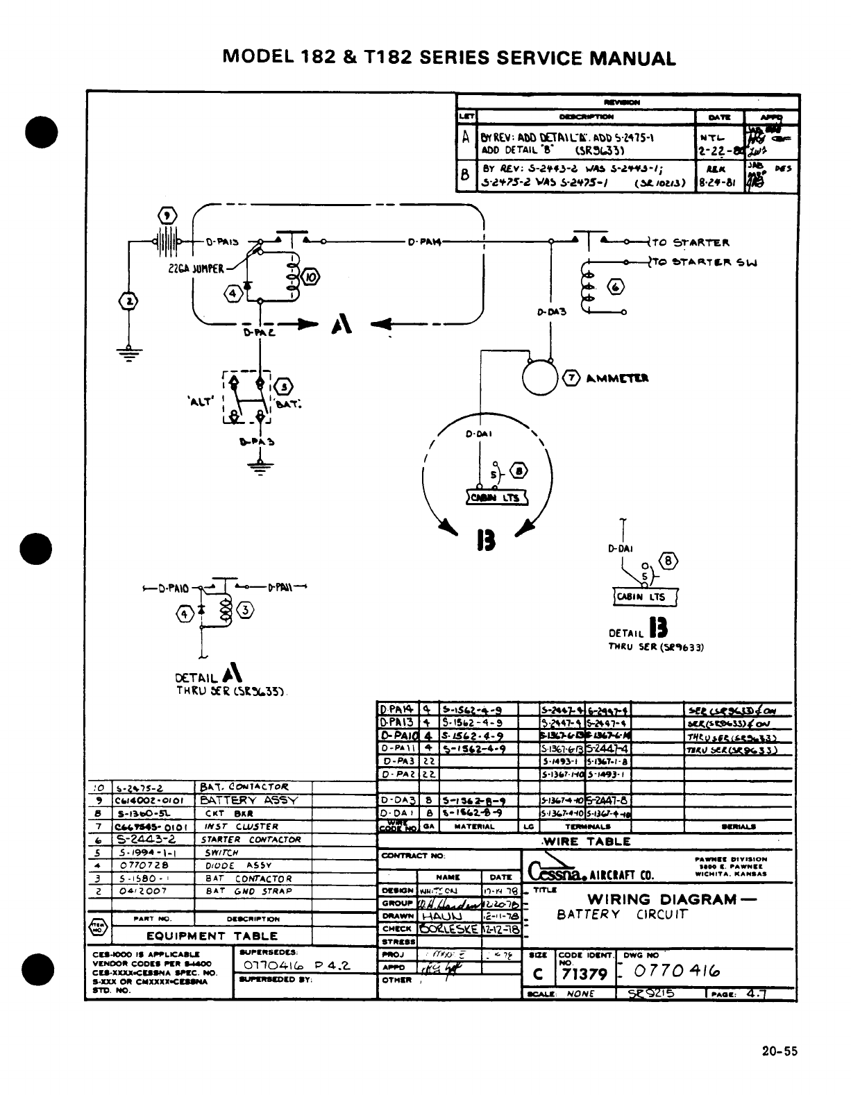
MODEL
182
&
T182
SERIES
SERVICE
MANUAL
*ooT
*----------------------__I---,
,^'
A
B'rREv:
aOID
EM\L'L'.
l
S
U75-\
Nc
r
ADD
DETAIL'
*'
R3(3'j)
1
2-
-t
BY
r
v:
.5-a23--L&
AS-Aw-l; U Jm
w,5
_
s-2*75-2
vW5
-2S15-1
(.-Aoti)
80-o1
y
EiRllr
-
I
30°-h ITARTLr
SW
1 1-
- -
^
A
.-
A
I
-
,I
_
13r"-
0
---
i
T
DETAIL
19
THRU
SER
(RSe133)
DEThIL
A
THRU E IC
S4
-S
DPAK^.$
.5-.-.9
--.
7- f-4
SE
WW9lt
D-
PAI
4 S-S1 I2-N s __.>ST
Mv
SI ATI
LC_ A
TIM._^
O
-PA
\
I
4
S-#5S2-4-9
=tT167____
Tk
XK
sz:
E-PA3
Z_
S.14_3-I
SI
5-187-1-
______
o
D-PA
i
____2_ z=lirH
5-1493-
___
O
-.
Z*.-2 T-z
ARE
COTACTO
___
9
Cfl.14002-OlOI
EATTERY
ASSY
-A3 s8
-132-g-9
_-130-4I-74
2
___________
*
s-i3WO-SL
CKT
BK
0-
DA
6 -2-9
5-137-4-0
5-I3j-t____________________
7
C.4/S4S-
OlOt
IN5r
CLUSTER
;
A
MATtERIAL
LC TERMINALS
0JIA
_,
S-Z-445-
5TA^RTER
COrACTro.R
WIRE
TABLE
s
5
-s: 1 -4
-
I
--
^^
| S__w__rcH
COiNTRACT
tN'tO: PAWNEEC
D
ISION
4
0770728
_
DIOOE
ASSY
-S10
C.
^PAWNI
.
5
-1580-'
BAT
CONACTOR
N
AME
DAT
C.
WCHTA.
K
Z
042Z007
BAT
CGNO
5TRAP
OESIN
IR,%Cl
)-rq
-71
T
EITU
WINSA
K
------
-____O_
B5T
Gh
*SOGROUP
j _ T
WIRING
DIAGRAM-
,,
-^PART NO. -D«CRIITON--
tDAWN
Q
-1,-~
BATTrERY
CIRCUIT
-
EQUIPMENT
TABLE
-
ST--St.
.S
,_____-.l
CES-OO r
APPLICABLE
SUPERSEDE
PROJ
f-
«?.
*_
a
SCODE
IOCET.
DWG
NO
VENDOR
CODES
P€E
U.6d0O
941,00
O'o1-104
'
4
.-
I
77
-
_
I(Mo
Cu-XXXX-C.SuN.A
,
C
o.
·.
-
01
4
Ar
!
C
71379
0
770
41(o
S-XXX
OR
CMXXXX.CEsWNA
S
PEREED
*Y:
OTHER
,'
I
l
YD0. Not. MSO._
--
«CALE:
NONE
|
Z'Z15
I AGE:
4
A7
20-55
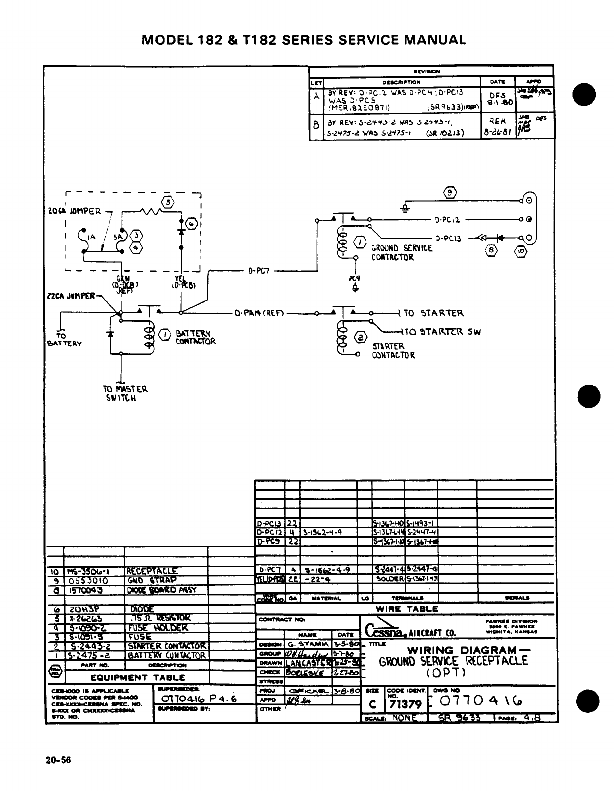
MODEL
182
&
T182
SERIES
SERVICE
MANUAL
LLT
ococrLIRIPTION
OA|' A
|
BY
REV'
O-PC.1
WAS
D-PCLi4-.PC
3
DFS
WAS
3-PC
5
a-\0
-,o
'M
-R,
.O;
7I)
SR
q
b33)(
B
Yr
REY:
5-Z#-<-
wAS
S-R+E-A, R£
r
S5-2,5-Z
Vwn
5.2i75-1
(t
/OJ3n)
8-
l
-81
ZOCO "On
PER.
--c
f! ~ ,-P.3
'
-- '<
PC
:
.
i
I
i
O-O
COIXTACTOR
'-
/
s
-(
BC)
(C)
|TO
ZnCA
JiBPnR
--
------
Q.PkF.(.(REF)
O
'T
o
TO
STARTER
TO
Q
C^ATTE
r
TO
TARKTER
SW
^
,l'TtlvPL
^ ^
W
TO
MiSTEO
5U
\TL
O-PC13
122
_
137-HC
S-
1
43-1
D-PC
12
S-154.l-4
-
_
S-131.-41'
S-24L7-
_
i___22_______ 5_______________
t________
_-9________
S1--1-I
_.
____________
I0
P'~'35(d'l
7RECEPTACLE
.1C16Qq46-9
9~
O55
3010
6No
--
_ ~
L
pt.i
-
22-
%_.R
S-1-
5_____
a
1570043
D0oe
m
P^t __ _ r______ _____
= cI~iOO4~
~
D.."e
maw
A
MATIrLAL
I.G
?aLR*
-
3IMI
(a
ZOuwP
OtODE
WIRE
TABLE
T
-21,Z
.15
A
5
EfQTlU
-.-
COENTRCT
NO:
A..
olvWo."
-5
r
TFUSE
IOLDEK
CIO2-AIIF"T
CO.
.
PAE
^^WS"s
4T
5-2435-
ST1ER CoT
o
RI
G.
IS-
'5-90
TL
__
^-47S
--
*BATnm
Cuw_ aCouTO
-ig J:
WIRING
DIAGRAM
,
S-2475
-2
SATTEVV
OWITOR
-
dll2.
,,w,,
=A
PArT
NO.
o__noT_
_ ___
DAWN
CAB
W
GOUMO
$LRVKCE
RECEPTNCLE
EQUIP
MENT
TABLE
ICA
_
(OPT
4-=
.O7 a
CMXX
«mom
BY.
OTHM
C
71379
W-%oe _
..
WIIN.DAGAM
c2o-Aoo
UA
,,.
s'rc3--.
GRCOCE
loE T. oe
NC
VC
.. ,.
.=mm,
,°,,,0104t P4.6,O 1. C
I71379
077O4\(
35.
No.
I ;
tONE
SI 9653
I
,PA
4,8
20-56
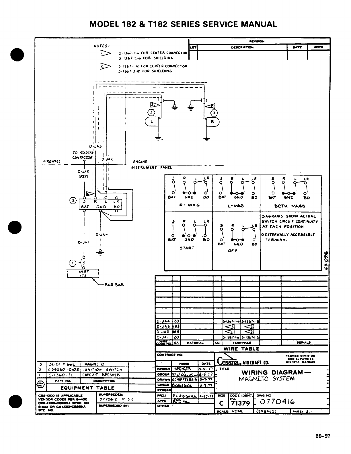
MODEL
182
&
T182
SERIES
SERVICE
MANUAL
NOTrS:
uLrl
IC»IPIo
AT9
A-
O
;[: .1^
)
?
-
I-
(fO--.
FOR
CENTER
CONECTOR
|
5S-13-7.Z-4. FOR
.SIELOIN6
0Z^>
5-3c7
-i-l0
FOR
CNTER
COMSECTOn
.'
13&?-I-iO
FOR
C[NTER
CONNECTOR
5-IA.7-3-10
FOR
SHIELDING
…-----T---
---
K-,-
_ 44
1;,
r
I
r
CW~D-rCTOIP
JA3I
To
srBARTf
fiRE
LL J T 6NtNE
]i
,
IN5TRlMENT
PANEL
0-JAS
l0 !rr I
I
IREF)
L
L
Ls
L
I-\
" " " "
BAT.
GIMO
so
BAT
GPO
so
6kT
G)
BO0
sL
5
R
L
IL
BAT
GND
so
R-
MAC
L-M
bOT4
MktS
1OACRAMS
SmOW
ACTUAL
5R L
SWITCH
CIRCUIT
conrri
TYr
(~)I4
%~-pdI L
Lit
AT
E;Cm
PoItriom
D-JA4
ioll »0 .EXTERN[ \
OEIfKMALLY
ACCESSISLE
|BAAT pmN0
BO
0
l-
0
-
0
TERMINAL
¢-JAI J
SAT
G,0o
s0
INST
ST
'"---BuA BA8,
,
-
O-JA4
ZO
S-I•31-(-
S-13
7-lfl
0-JAI
gO
________-__
?-
5 1 7._7. i-____________
.tSSS,
GA
MATRNiAL
LG
TERMINALU
111Al «UJ.
WIRE
TABLE
cON'm*AC
NO:
I. iWN,
DIVI
ON.
S000
IrIt
PAWNIE
)
.LICA
b(bp
MAGNETO
NAME
DATt
eSSnaIRCAFT
CO.
WICHITA.
KANSAS
Z
C29Z-OI-0
10 5 IOaNITON
SWITCH
eN
SR
I-' TT
5-.3.O-L
CIRCUIT
cREu
P<fr ;u 4,< I.7. 7// .C-
.
WIRING
DIAGRAM-
PAR,»T NO.I
oascwyfo
M-
AWN
SCHIFFELBEIN
3-7-77
M
AQETO
5Y5TEM
EQUIPMENT
TABLE
C-4OOO
I
APPUCALu
IuF-tclD;:
PIIOJ
PLAPULaK.O
4'n17
SBIZE
COoE
IDENT.
oWe
NO
V9KNDO«
COCIO PgCo
840
0
7701,10
r
S.Z
.
A
r'L "AG
-
NO
N7O.
CEU-XXX-ClMJIA
SP1'M:.
NO-.
"'0
C
'71379
077041
SKxxx
Ocnm
CNXXX--MA
sUa-m
BY;
OTNft
^*
"
5TN.
o
CAIJE:
NONE
O(L4f.3)
| PAEO9
S.I
20-
57
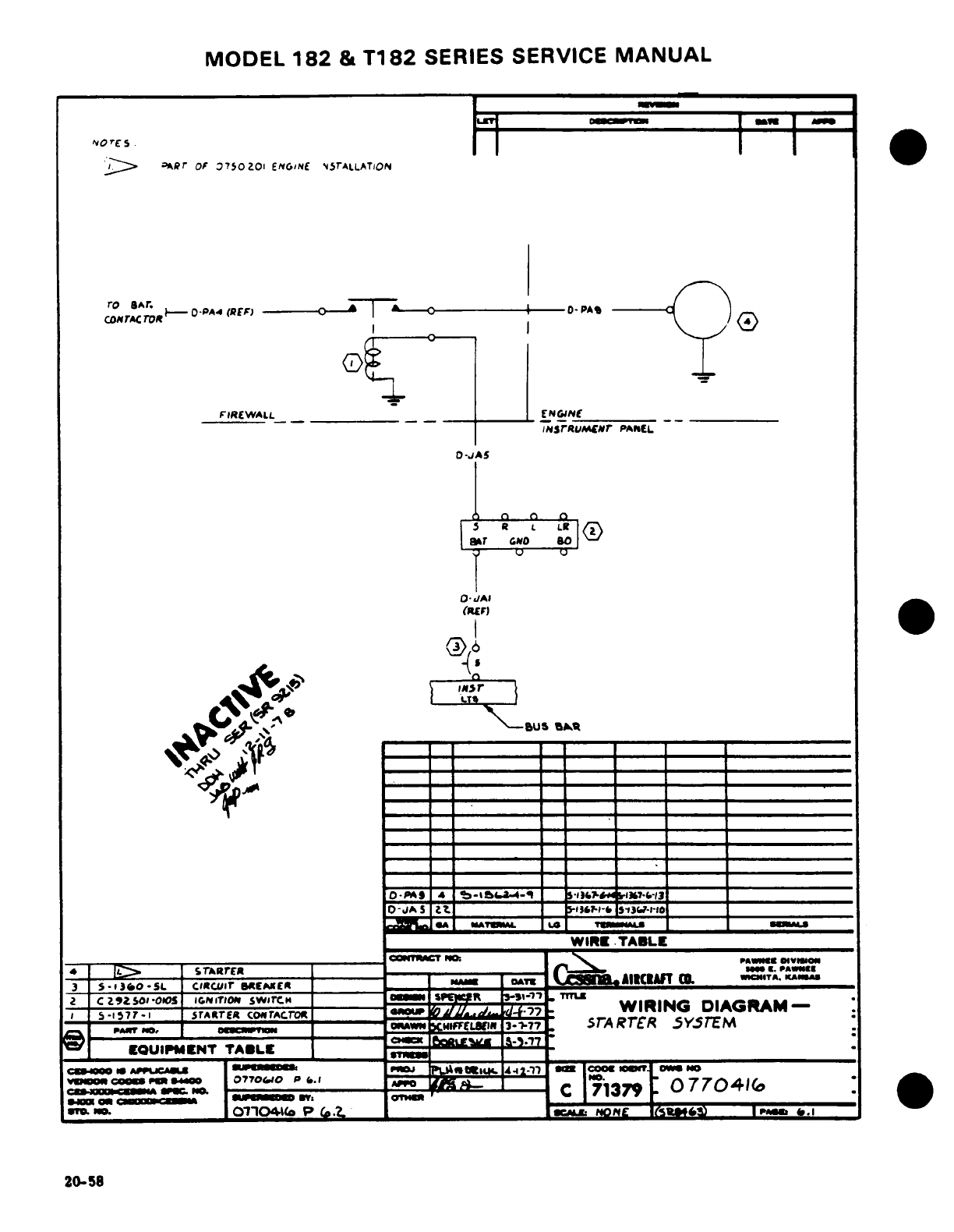
MODEL
182
&
T182
SERIES
SERVICE
MANUAL
-
'/>
O
ro
-
rr
OF
3750Z1O
ENmNE6
STALLATION
I~
I
ro
aAr.
Al I
0
O-PA
COX
rAC
raft
DPkE
FIREWALL
_ _ _____
insrRuMCrr
PANrEL
0-JA5
( - --
n in
5
B L
LI
arT
GNO
sO
0-
AI
(RErI
5
'-
0-.
l
4
b-i
b.-4-i
3pL.
i&7.4.-13
O-JAS
Zt
&
_
B
S1-
1
-_l-___'__.?-_
A t u iA6L _IA _1in I II
S
__ __
_WIRE
-TABLE
comuncr
"Do=.
woms
oll"Nr
2
C Z
.
50'
005
IGNITION
SWITCH
omNI
R
l
-,
rTI
5
c5-^7cro7-I
STttEA
CON
/TAC.O4
WIRING
DIAGRAM-
P
Ar
A.
e
Oru
iFFLVTI
1-77
SrA
RrER
.SY5TEM
EQUIPMENT
TABLE
57
c_________
U N
6.AP P____
g
O.o
no
p
c-ioos
*
AFPLICA
____
S
m
s 4.n
*
5
coos
mSuir.
o_ NO
I0,~S0. 1Me;.
C
7379
07704137
WM
Mo 0'5o 04 P
.
·
NE IS.?, I
e
.li
20-58
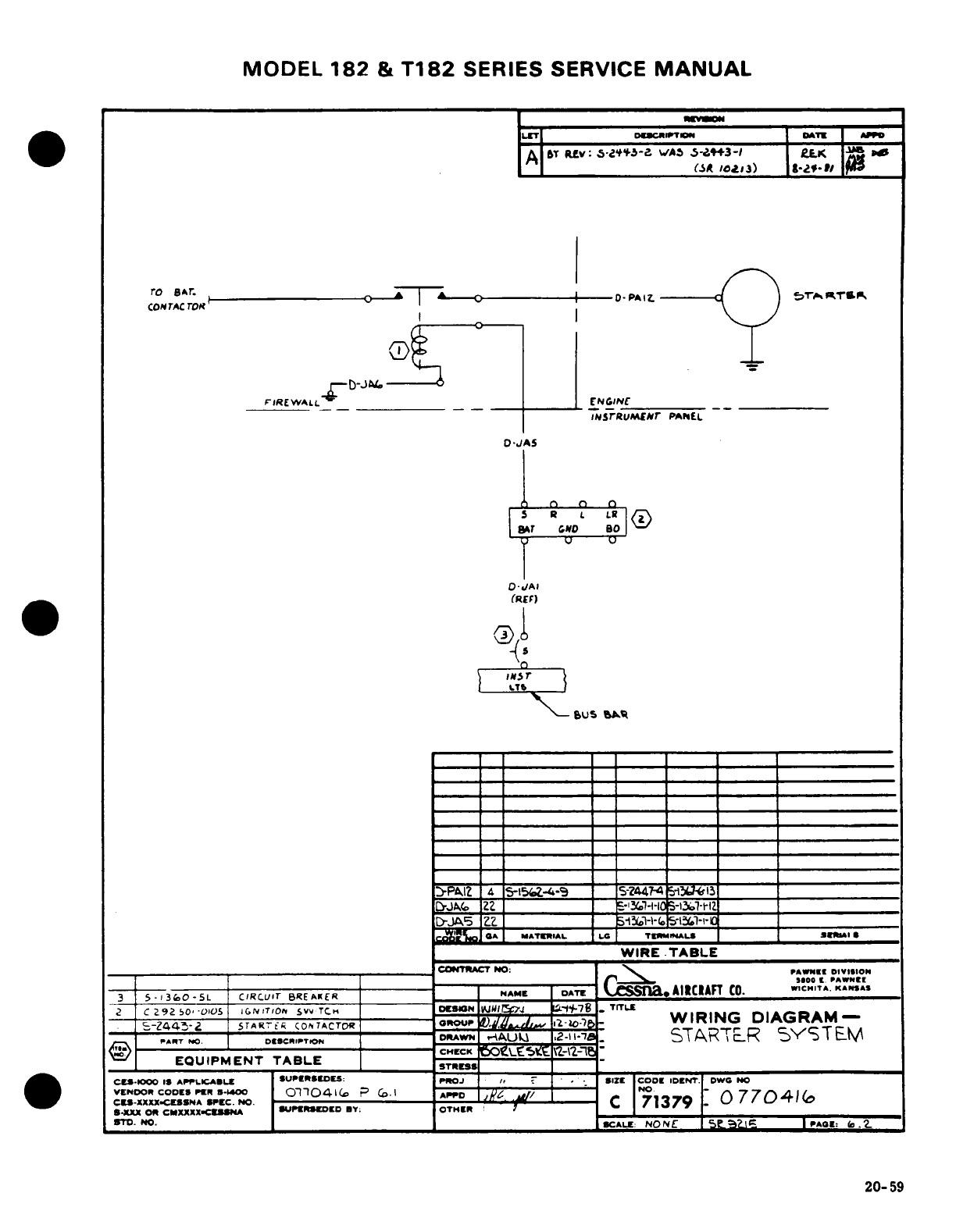
MODEL
182
&
T182
SERIES
SERVICE
MANUAL
*iTg'r
i~s~s~llllr
iOVI
DAION
A
T
REC
v:
5-ZtA-
AS
.5-1++3-1
E,
.K
ro
sAr.
-
-0-PPAIL
-
}
sr
TPRT
CON
TAC
roR
FIREWALI
LEN INE
INSTRRuMECr
PANEL
D-JAS
5
R
L
LR
AT
uN
BO
'0-dAl
0
JAI
(REn)
I
_
bUS
B56k
WIRE
.TABLE
_CONCTRS NO:;
PAWI
rE
DIVISION
froo
L PAWNNIIt
3 5
-130
-5L
CIRCUIT
BREAKER
AM
DT
tASa.AIICIA
CO.
WICHITA.
KAN
2
C
92
50'
-o05
IGNITION
Svv
TCH
DSn
76
TITLNG
IAGRAM
.-.
S-Z44o o5-.,
-,o
2ouw
U~
-"-"
STA,
RTOTT
GROTUP
_
-^7PR
NO.
DSCRIPTION
DRAWN
Uk
.2-l-f
,
STARI'cR
SYSTEM
EQUIPMENT
TABLE
s-
REs
CS-KIOOO
IS
APPLICABLE
SUPERSDES:
PROJ
I/ r
-
SIZE
CODE
IDENT.
DWG
NO
VENDOR
CODES
PrK
B-OO
0-1104c
4
S
.
APPD
.
-
7 7
0
4
CUS-XXXX-CESSMA
SPEC.
NO.
7137704
»8XXX
OR
CMXXXX.CUN4A
SUPERSEDED
BY:
OrTHER
aro.
No.
______,___: _ON_________E _____
...
~
-i
LN
g
2L*omr:
Na
.
2.
20-59
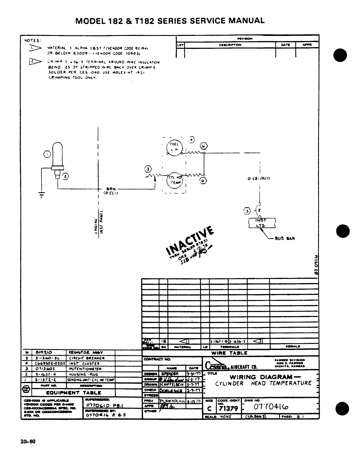
MODEL
182
&
T182
SERIES
SERVICE
MANUAL
NO
rE
:
I
*VIaON
>
'AArERAL
s
ALPH
55' 7
(vENOOR
CODE
9Z1
41
LT
DSPTON
DT
3R
ELOFN
a3009'
i
(
EOOR.
CDOE
10903,
D'
:,I M " I> .5 :)-'5
rFRMINAL
?
AROUNC VeIKr
INSULATION
dCNO
25
OF
STRIPPED
WlRE
BACN
OVER
CRIMP
t
SOLOER
PER
CE5
,040.
.5E
MOLEIX
19tl.
CRtliPINo
rOOL
ONLY.
0
I ; I
-'
N Y \
L<
M 0p
OkaI
(RtC)
_
O
-(0-c_
_
I
SStBUU
S
(O
8tlo
rEroTlt
AY
_
.
WIRE
TABLE
5
5--30--
SL
cORcur*
J
)S- r
DI
4
C(.952OZOOZ
;vYSr
CLISrEt
so"
a
.P
1
al"a
0
Z
S
-
4JI3
-
4 WuyC
---
Sw5
SPWKR
-k3-5t-
Tr
i 5-
1 2
iENDING
-ir-
CL
NOTM
LIPI WIRING DIAGRAM-
PvT
r O.
DT
lRf SWIf
KNIFnELB/"IN
3__
J7
CYLINDER
HEAID
TEMPERATURE
EQ
6Uo
ICPMENT
TAB
_____
WE
TABL
e
snilAr
CLU
TeEr
.
--
I
CoE ODITM OwO
No
^ ^SS?- orsS-- 1 I O
C
71379
____________________.
-
EC£.jA:
NONE
-
L w9 3 IP a I---I
20-60
NmE
Oifm
ARCAmTCO
WSCIT.m
le
O~~~eJ~~~oa
~~~~~urE~~~~r~~oM~~~~rr~~~
________
-
-~~~~v~~m~n
Z S-I~~~J?-4
~~
ousiNG-~~6
0uN
S~~~,mGmR
,.m. mmm
s-/u(.J~
,
Ouus,,v
-
CAE~.NEPAE
2s-,3tt60$~L,:
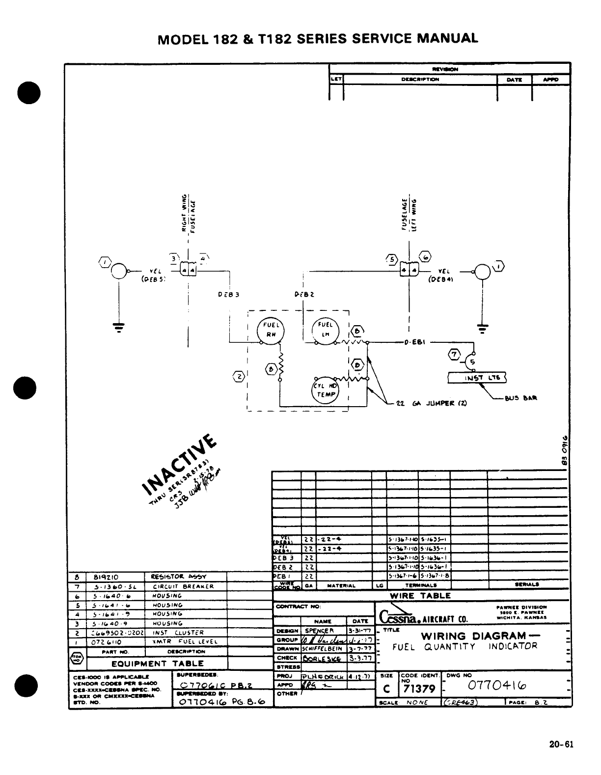
MODEL
182
&
T182
SERIES
SERVICE
MANUAL
LET
DESCRIPTION| DCAT AD
I'
DE£85.
(
3
(4B
ZI
_-'
]; '-I-
C._84
-1
t
I
6
JU4
<v
0
3
2Z1~'
'_
_
_____.
. --
-_ ',,.WIR
T
M',
2t -22-4 _ *I »-3_________ cs-
)E.8
3
2t. ____________
s-3.7-H
a
-
_____ __13-
2
______________________________
5
-5--
s
___________-__
i-i-i 5-i- ______
______________--
alqziO210
EI*TOI
E
i
.
5i-i37-
i-S 37-i________________
7
.-
13
b0
'5s
CIRCUIT
BCRAKER
WE s CA
MATERIAL
XLC
nAL
1AL
-
S
-
5X0-
ifo <1 xoi/smt;__________ __WIRE
TABLE
5 S
*
4, I.
HOUSINC
COT
D.
4
CONTRACT
NO:
S
-
4, 9
OvSING
«
IVWION
3
.5 ~I
40
9
OUSNN
__NAME ^DATr esna.AIICAFT
co.
"ECHITA.
"K
2
:O..9502
O:20;
INST CLUSTER
DESI.N
SPE/cER
3-31-r"
.
TITU
i
z072
c(0
io
'ITR
FUEL
LEVEL
.
GROUPwW
,
I
-)
WIRING
DIAGRAM
PART
^.
C
DRAWN.:H SCl
IFF-LBSEIN
3--7?
.
FUEL
QUANTITY
INDICATOR
EQUIPMENT
TABLE
STRES
.17
CLES-OOO
19
AIPPLICAL
UPERIEDI
POJ
SPUPEl- F ttt 14 17i7
SIZE
CODE
IDENT.
DWG
NO
VENDOR
COOC
S-M
OO
P.
, .
NO
.
,7.-
XIS-x
O
CNXXXX,-CCsA
,,WND ZT OR C
13
79
si
T
.
oNo. Y0:OIC0
P6
I o
_______ _
CALE
NOE
71379
-3)
PACE:
20-61
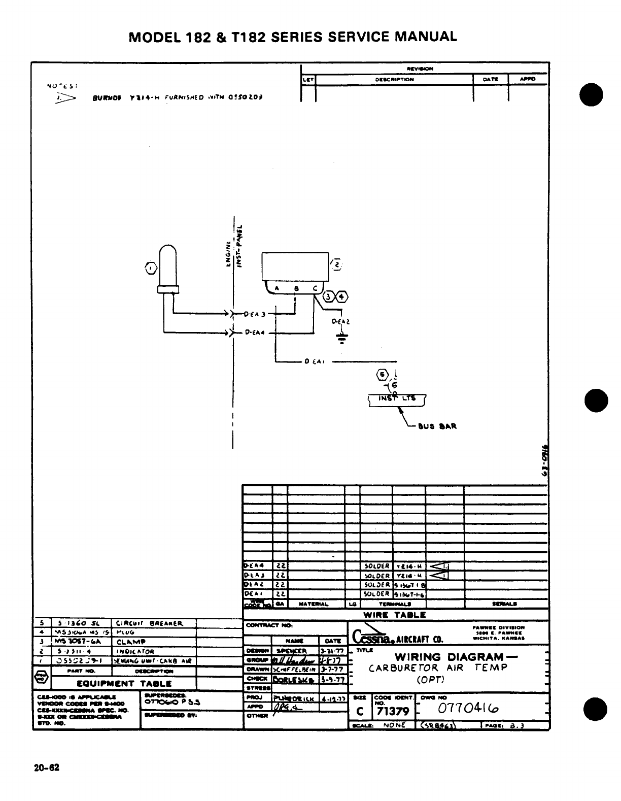
MODEL
182
&
T182
SERIES
SERVICE
MANUAL
LIVT
OI
SCnPTION DATr
&IO
'O
fAI:
I~ ~ ~
~!--OU
bu
klk
------.-O--A _
-
_-
I0A4
2Z
_
-OLDER
--
-14-I
)t-
A
2- 2
f 7
OLDER
S1
·
O
AZ L =
50LOE
R
I
e
5W1-
s
5 5 140So. 5 Ci~twr
O KER,
C
T -.
WIRE TABLE
s_
530wSM7-(.k
CLAMPMp
1
1
Cme
ANCIAFT
CO.
w
iCITAt.
KA"
l AS
2 .S
-1
l
11.
Ol(ro-R
SP1 3-1-
rLT
,_
055
'Zr:-
;
ut
u
.Es.r-C,,s^
,e
jo ,,--.Ai
k.
hI
R
WIRING
DIAGRAM-_
Pain"o.
I
oa IC
WnTev,,rr"
,.,
3--
?
_
CARBURETOR
AIR
TEMP
EQUIWPMENT
TABLE
_
s7
,-,
,
: (T_______pR
CASIO
.I AM
P
JICA1. I
4,
I1
U___
C
01 0G
P
iniT
O
^TIII-co."
r-
na<.
077041o-
4=
EC-uIP0lnmE-
C
71379
07704-1
__________
Q^
NXXINCMft
UPPB T*OT11 ~
**__________________
UCL
NT41
/PA
211 ._,0-
.
62ONE
sL
\
O 3
20-62
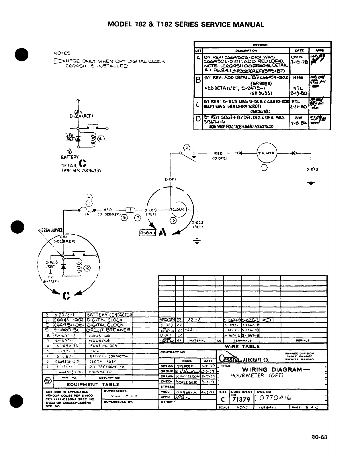
MODEL
182
&
T182
SERIES
SERVICE
MANUAL
*JOTES:
T
-Ic
D
D
,A
6^
Rev1
tcfciA
-o'ob 0 A1= WCM< ~.
·
1_>
EQC
OMLY
WHEI
OPI:T
DIfGITAL
CLOCK
CCa4.oL-oloi
,ADD
RED(O<),
7-1-78
Oc
Sdii *£
.BTAiaLLED
2
NOTE
1, CSQ
I
Ora;#qiS o
rAIL
A
·
RP.8^4.l
RC:DXREF;)Ci[87)
.
B
Y
REV.
ADD
DETAIL'54
CI4ib4502
HH6
w
Ab
DETAIL'C,
5-24-5-- #9
L
(SR
(,5)
.
-q-o
BY REV
O-
t
0-
UO-
KS
0-MN
(
1
TL
T
C
uVAu5
&6IIIJ0D(01n
z-27-n
<
so
GRN
(1__363')
D-aC4(REF)
D
BY
REV:
S(I7-l-8/DFt.Of2.DF
Wk(S
i< lfAV
T_ U
^W.\--
75E..
o-'
CTN
__
5_P
_PPTEUt_52__
_O___
TO
E-D 4F
TO
RED
8 1TTE
RY
(D-DFZI
DETC
IL
(C
o
TKRU
5ER
ISR9333)
D
D-Df3
D-OF
Di---iTAL^»-
LO
D,
-O.-
-0
-1.1.-
..-
7.
f.J
c 5 1- (.-X.IlClE)CI ORF
\2
- ..
,C3?
\
(EF) t
I
\ T
O;--
/
--_
_AL
·
o
-2475-
I
AT
'
aEY CONrTACTUR r~~
C E45
-ao2
DIlTAL
CLOCK
OED(N4ZL
-2Z
___-
-?-
IC Co51 1-010
DI(GIThALCLOCK
AD-OF
Z___ __ S i ____ ____
:
S--35OL
oCIRCUIT
EREAKER
-
2- =
493
5/.37-B-w
8
s-I,'-z -C0651G _
DDF,
2 _____ 'i,3W
1-
S-i7 __ _____
'7
%-6f31-
1__
HC(
v
siNG
_ __ IcO"l C*A
MATERIAL.
LG
TIRIN
ALS
SERALS
E S
109o02t fuSE
HOLDCR
WIRE
TABLE
---
Sj
-
-O--
--
-
A--v-SE
C ONt**ACOT
N
'
PAWNM
DIVIS10O
4 AS I'
Ar f
A ONTN^CiC 5r 0
oo
PAWN9I1
3
Ie.56-
t
s
rl
rCLOCK^
sy
: NAMEr
DATE
L
AI
CO.
HCIFT C
.
:°CTA
IS":AS'
-
C i
17,/.,
/
PR(5CiSIRE
r,
ESO
s
Ft
^
E-S1- _ TI9TLL
,3-o.o.
5 100,
HOUVMr
TE
G
ROUPJ
^ L
77
_
WIRING
DIAGRAM-
P RaT
NO
ODE5CRIPTION
DRAWN
SCHIFFCL&EIN
3--7
_
HOUR
METER
(OPT)
)
~EQUIPMENT
TABLEC TE
SS
C£S5 PIS 15
APLCAL
*
IUPCRSEDED J A
T
E
R
I
C
71379
o
7704G
T
Dw
CES.XXXX.CESSNA
SPEC.
NO.
----
.^ C 71379
_
0
7
0-
4
S.XXX
OR
CMXXXXX.CESSNA
SUPlSEDED
BY.
OTHCR
STO.
NO.
SCALE:
NOEI
'sr
r0 4
e PAGI :
4
20-63
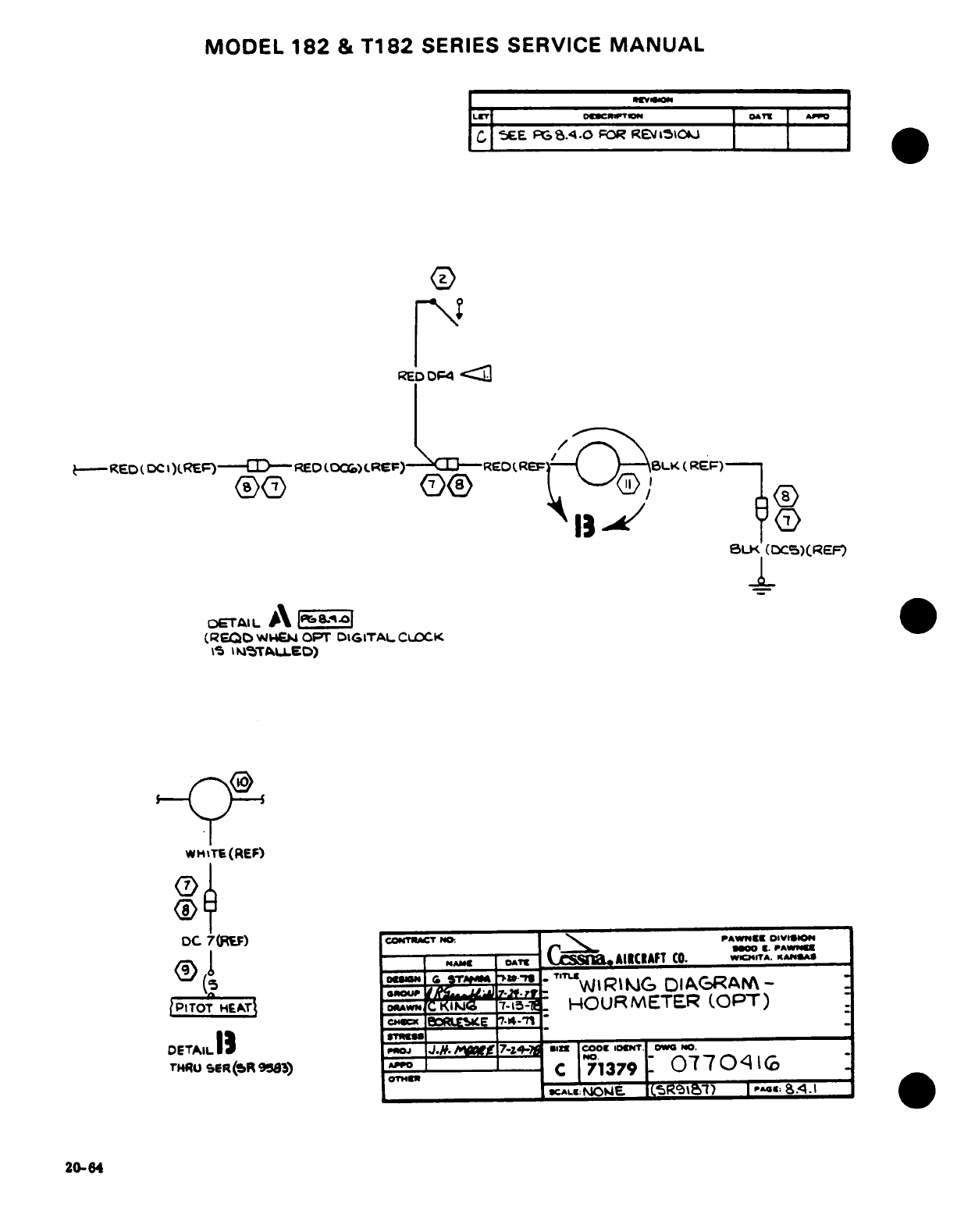
MODEL
182
&
T182
SERIES SERVICE
MANUAL
ILrr
OeCaemrhpM
I
oY
Jj
C
5EE
P8a.4.0
FOR
REViJOI
-
RED
r-P4
---
ED(
DC
I
)RE)--
CD-
REO
(ODC)LRREFP)
-<,
RE)
LK
(REF
<
8
D®
\
K~(L
1BL tORF)jl
iBLK
(:c5)(ReF.
OETAIL
A\
1'ol1
(REQD
WHEJ4
OPT
DIGITAL
CLOCK
\15
MbTALLEO)
WH'TE
(REF)
(i
DC
7(R
..
)
caOTmAC
no:
.
PAWN\
DiVSON
0D
1
N- _
!
tAMEC LOAIT
ACSAFT
CO.
WIcirT.
KAAS
(nm
,
a sir
-,. W ,IRi
CG
DIAG.RA
-
fPITOT
HE\
KT
ow
KIN1
'
7-1-1
IHOUR
METER
(OPT)
DETAIL1
3J
J.#.
/lf 7-L.-: *1IZ
coo-
10CNr.
owG.
r"RU eR(R 9M)
C
1
71379
07
7
0 1
G
OTWM
_____
________
A_____
05
5EV
2__0__ ____
«cALn:NJoWJE.
E
C
5 Ro Et I)
I
P"
a.q.
20-64
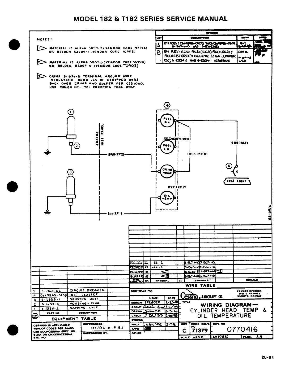
MODEL
182
&
T182
SERIES
SERVICE
MANUAL
NOTE
S: *TA ms
:Uc_ Sp1X _ f
1 011 "I
U
MATERIIL
15
ALPHA
5S57-7
(VENDOR
CODE
9ZI94)
-
-0
*
S--E--q
__
OR
BELCEN
63009-1(VENDOR
COOE
70903)
l
b"
REV:ADO
RE(EC),RB(SaZ)
CMK
REDIEF)
DELETE
ZAs
GAX
d.8-1
kATERIAL
15
ALPHA
S^S-
5((VENDOOR
CODE
92194)
_
W
6lq4) (SM)
I
OR
BCLDEN
6300-b
(V
aMDOR COOD
09O03)
[~>
CRIMP
s-l(,3,L-S
TICRMI
4AL
AIROUND
WIRe
INSULATrON,
BENO
.ZS
OF
STRlPPED
WIRE
BACK
OvER
CRIMP
AMO
SOLDCR
PER
C[SIO4O,
uSE
MOLLX
mT-
19Zl
CRIMPING
TOOL ONLY
-0-
0
r
|
II
'
I S:«
IE
(
MQ
La
r
ISn
_i IR2
8EDl ;EEZ)
==4
C1$45-OO
-ST
CLsr'
CLULI)r
,Cr
E
(Z oSs$- 4G 5OU
-Z-Z
.
P-'L- oi SPrEiCER _____
_______
T
---- C2.rIRC uIT
17;
GROLAKER
- .
4_ __W IRINGDWIRE TABLEG
RAM
5
S-13tO-SL
__CIC____
____R _
_________
WATRO
C
NO;NEE
OIVIUIOW
4 C.S4- O
INS
^C LUSTr( ------ _
_ __ _L.A
FT
CO.
-.
am
".
C
I
5
stii33~->2;
xousi~f-P~ua
__.
5V
U,-
GROUP
~WIRING DIAGRAM-
PART
"D
sIDEnr'W
DRAWN
a-C .2-
.15-7
_
CYLINDER
HEAD
TEMP
&
A-CNK
JbL.I
S
2--I01
OIL
TEMPERATURE
EOUIPMENT
TABLE
_
JSS
L
TEMP
URE
C-,m000
-
AoIn
PIC.
MI[ sUt
.
fIO:
J
j.g.
fooeC0
3--7
_
COOC
IT.1
DW
NO
v
cR CO.oo" P
o
o
07704l1
o
P
A.l
8.1
7
0770416
I-xx
oft
S-
C]:
P_
N
TrD. X0. I=
.
ON.
-
C 71379
,*
20-65
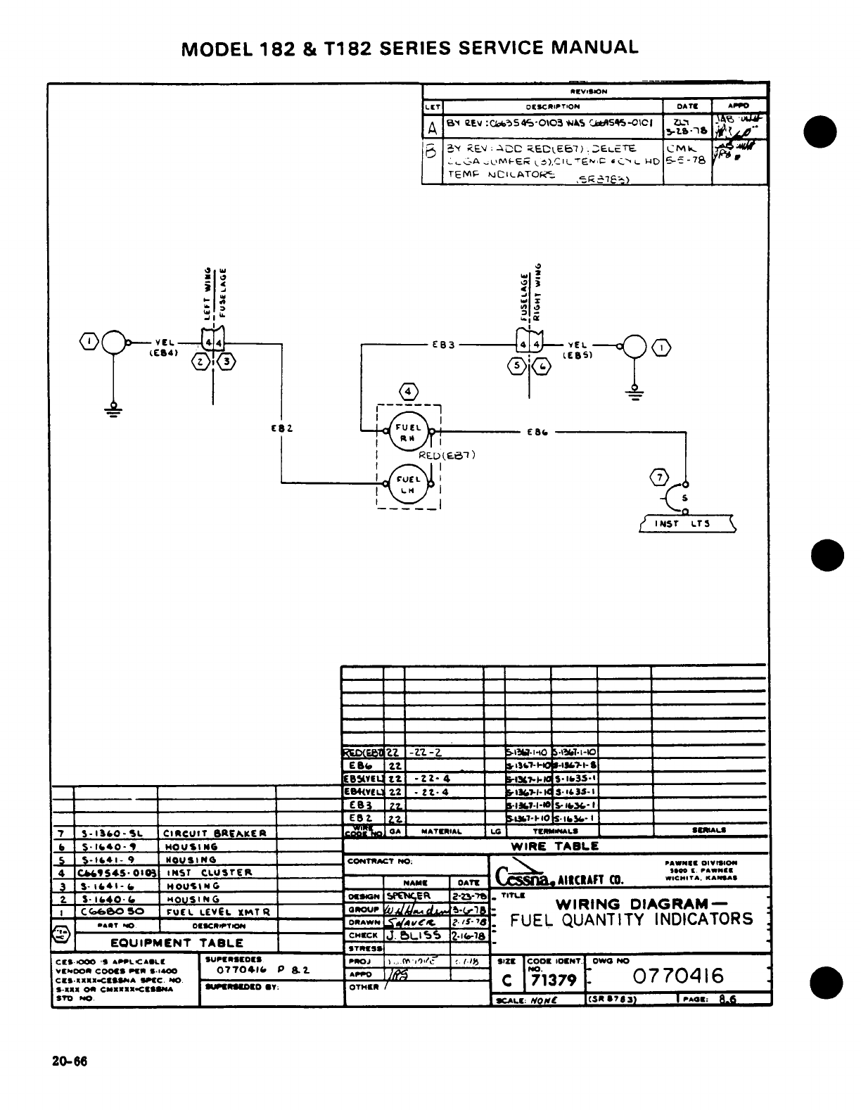
MODEL
182
&
T182
SERIES
SERVICE
MANUAL
LI.T
DOESCIPTIrON
DATE
APWO
4~
B
PEtv
:Cs354-oos5
&
S
"S45-01C
I
'ZL
_ _Z
<E£:
.CC
a
eECDE67)
:£-EET
CMS
.,
-A
I_
'
-tE
-
L
"
,),I
LTNEC:
c6 i L D I- -78
TEMP
XJCICATO
1c^)
w.!-
a
!
z2
I
VELI
EB3
VEL
E
S4)
Q
(E
I
C
REDEL Ien)
/
I,5T
L'
T
C
£
11 11
-ZZ-2
i. *$OU-_I-______
$~
t__S-__[ 8 (.4,
B
:rjY- I htt
-
-2-4
-
l35_____________-1
________
________________
________
EB4VEL
2
.
Zt-4
_
.3
Jl
________________
"^ ___________ ________________
________
£Bi
£.3.
________
__
I-UfiT-1.I.S-
lc~fc-
I
____:
_______________
_ 22_
E.
__
-_. _ =
-t-I-1O
S
-I
i-I
X
S-4
N~bO
2t E.
7_FUELUATlYs
I IC
AT
OS-l
7
-lbI3o-SL
CIfRCUIT
EREAKER
s____ cFoGA
MATERIA.L
LO
T__RIA
_ : *ta
b I~-
EO-
U
MOUSINGT
WIRE
TABLE
8
S-IX
l-
9
HOUSING
CONTRACT
N0:
PAWNEi
oI1ISNo
STIO
t
1
oo
r
,-
I
cSC^
N
o-meoc
7 701
c»*no.
PA
a0".
^
4
C2.0S4S-OI
INSr _Lu__t
S
X
4.6
(40
U
L~
R
OOUS
WIRING
DIAGRAM-
I
C.G:SOSO
FUEL
LEIEL
XMTR
GROUP
.,/-.. ~-.-
QUNTIT
I
N DA
...-.
o
oRAT.,,O,
o-,
u.
Z.,
,,5,-.
FUEL
QUANTITY INDICATORS
CHECK
J.
BLI.
'2-i.-l8
EQUIPMENT TABLE
STRE
-
CES-.OO
'!
AP»L-CAUL
I
SUPERSEDES
PnOJ
)I. Yi..'/
'
: I'/
)sIZE
COO
IOIENT.
OWO
NO
vrEooR
CooSP*IE
o
?o
,
07704
P8.2.
P-,-
..
07 704 '16
S-Is
00
ClMdIK.CESINA
C--
- --
D-- r
71379
-
I"
lo
S
»>
00
C«>1X<ItU
MA
I M--1qlH
lO
*I:
OTHEr
STO
"o.
SCAE.
LIOM
OC
tSR
5173)
PaE:=
8-6
20-66
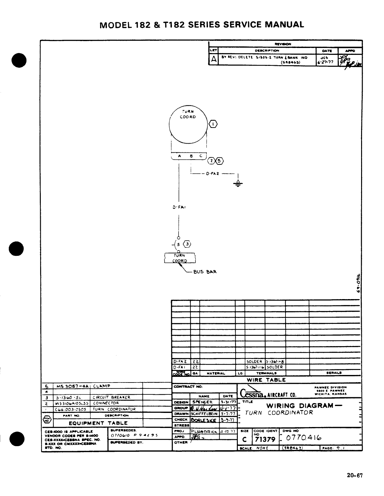
MODEL
182
&
T182
SERIES
SERVICE
MANUAL
*A
A
t' rl:
DELETE
I,60-.
.
'TURN
46ANK
IO
JC
T
UR*N
C.OORD
/-
li
-
I3
D-
FAI
r
I
COORD
I
/,
D-fAZ
11
2
SO
LDER
3W.5-i
(. .
D-FrA
I
2?-
S
1367T-r-
5OLOE R
_______
GA
MATERIAL LG
TERMINALS
S
ERIALS
WIRE
TABLE
5
M5
3057-4A
CL
K
MP
COITACT
NO;
PAWNII
DIVISION
,4
_______
Ceoo S00 PAWNL
E
.3
-13bO
*.L
cl.IRCuiT
BREAAER
NACME
DATE
sia
CIAFT
.
WICHITA.
IASA
Z
'iS310.A105L35
CONNECTOR
ODEIN
SP'E
ER
-31-7
.
TITLE
C.,.0O3
'505S
TURN
COORDINATu
ouPr
S..^/
-.-.
WIRING
DIAGRAM-
PART
040.
o9SCH.pT*"
c-ECK
ZORLEIVRE
1:~r&
PART
NO
DSCKROPT.
T
-
DAWP
4N"IFFL[IN1-77 7.
URN
COORDINATOR
EQUIPMENT
TABLE
STRESS
L
_
CES4OOO
I
AIPLICAILE
SUPERSEDES.
PIOJ
PLUIoRI(.K
.i
-12
'77
51ZE
CODE
IDENT.
DWG
NO
VINDOOR
COODES
Cr
S-MlOO
0710110
P
9
s
95
NO
-
C.
-Nx
aCsorN
SX
XX-CC
A
UIID
BY
C
71379
07' 70 41
c
rTO.
NO.
S CALE.:
NONE
(S3Re4!
|
PAGE:
o.
I
20-67

MODEL
182
&
T182
SERIES SERVICE
MANUAL
EIVISIC" ____
Nh1 e>
07____
T
E
a: >X.
_ 0CA
»1TOON
_____OATZ APPO
f--- _ .RiA
8YREV:
D-PAIO(REF)
WAS
D-PAJ
s
,A°rT o
owEe
7,rE .MT BC LOCeL
c
r
D
A
(REF)
(SR9087)
4-ZS-7
TO
aAI-~'" "r--E.eit
Ikj,
'
_
o
.
OC<.
T^'ic--
(
0' jt
cJ-, ehNj
OA"GQ
-
-rgo
JjiT iL.
etumicr
bY
eEV:
ADD
OTE(i
D-0c
s-;
e ^4
B
ADD
DETA-"L'A'
SEj,
Cc*
-o.
(
--
7
(r.
I
/AJ^~
c<.soa,-o
o,
/
_
_( q91
95)(
ICE___
G
BY
REVU
AOODD
EDTL-".
RED(OC9)
NTL
c
xtDOB)
< 5
Lt5-1
2-2S-O
*s
.
t
A V
/
&
o-oc8)
I
_
,e13
D
/
IC
·
» ^ K^ 0
*
O
CJ
D-PA;
\
(Rt
EF)
0:~ \ _. ----_
D
oc-5¥--C3
OCTAIL.
13
? 1 _ _-2 _- _ _
61
-36-1
'Y.
_7_
_ _ _3)
_
T2
Z-5
6OLDE
R S»167f(
it 0 W9-^3S)
r
_
_z_z
*
5- -I
S
N
s
(T
s 9.3)
7 |
i4SfrooI
CLOC
ssw A
T
ATL A I) iALS AL
5 j 5 3L
2T
MO
N
r
'-1
NO
ln N
I
T
II"^9o
ISION
4 0770aZ
&
St _00i T0£
aW.P^A=
S
Z.-
3
'1090-
a?-
FUSE
HOLDER
Mff~m
speNOcEPI
3-l17 TITALGRAM
-
3
5-4-?g
l
~ rTt. cOTAtCorr I /.o,
I
zzl
-2-z1si^ I
IS
' "
s
L I /___
S
-0
IZ
FUS
OOE o
WIRING
DIAGRAM-
-
t
0
wv^So W oa
-SCi3e-, FEI
LOCH
3EQUIPMiENT
tLW
TABL
O
LBLEX
E
:7_
cam-amO@
APVUC#AULE
sJ
PL
N
c v1 a-oio n
_w
.
_
p
-
___~>N«
^^T
AC
IAFT
) .
-"*
""
-
SM!P'.
NO.
I SC AU2R
2-; __ l3___IO.
1
T20 _
68
NO
20-68
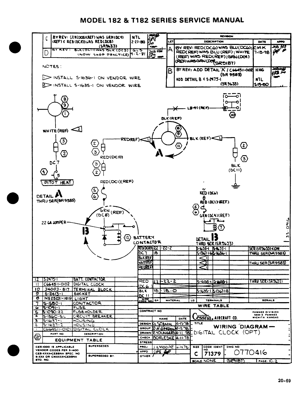
MODEL
182
&
T182
SERIES
SERVICE
MANUAL
C
BYV
RCV:
tClDRJEr)UWA$C
G6N(i.i)
NIL
ev
mon
(ItEFr
REb(bCIO)WK
R.EOLIB
)
2-Z1-1BQ
.ljI^O DM__AT
I
PP
> _
ct
5
(DrlI]
5
5 C COC3) L
fm
A
sY
REV:
RE
(DC,)w
A
BWLUDC))
CM
W
O
e-
W
5
1^
5
_
L
)A
o
A.
RED(REr-)W
BA5lU
(REF)
j
14
T
15-11B
8
V
kN-O%
50P
Pc=CE>
N
-I3 t(RE.
WA
REDtREFC);CRkC(Oq)
NOTE,
·:
~NOT
E~~S:
B
~BY
REV:
ADD
DETAIL'A'/CI
C4511
H6
NG
(5R
9586
f
0INST4ALL
S-163(o-1I
ON
VEMIOR.
WIZEO
AO
DETAIL
B
S-475-1
NIL
>
INSTALL
5-fo35-l
ON
JMEMDORZ
WlE.
_R .,c33)
NH»TE
(REF!)
<H
/
RSLC
1(?>
<-\
1-----WDAttF)<^ -{
)---}B
(EEXSLK(IE
3-)
RED(DCO)
DC7
®O
BLK
l) T
<R
(DCF)
PITOT
IHEAT
RED(DCI)(REF)
1
DETAIL
A\
8
o
THRU
SER(5R9583)
T
o
itDCl)cEF
(oc8)
E(DLU)(REF)
22
6GA JM1PRR
-
i
-
-B1-E1Y
SDETAIL
13
N IS:-S?..LONTCT^rO
Ti
HT
SER(SR1J(.3)
~\
/RE
rZZ-ZD I-
.s-l
S3SZ sI
I.33)<ON~
\
/
C
1
&e
I |S-13«7 Fe -'l 5
SER(6956a
DL
I tW11
___________T^
E-13Q
1-
~ <K~Tr
_~_________
_HR SER(SR95
5- ~2475-1
TT.
COTACTOR
RED t--
TU
SE(SR3___
C6645I11-010oo2
DIGIT-L
CLOCK
R
_;_
S
10
34003-817
TERMINAL
BLOCK
-
c
lb
ti (Cl
_
e
MS25z231-le19
LIGHT
Gr Gc
MATR^L
*
LOTEtRMI INALS S^
IALS
17 S-O\ COkT~fZ TOR_ _ __
WIRE
TABLE
5 5-1O90-ZZ
FuSE&HODETg.
________
CONTRACT
NO
PAWNEE
DIVISION
w-1;~
-
(AT-'-..--.,^L~)800
PAWNEE
3
5-1\36C-L
ZZCZCT\T
3^E4-Er
*NAME
DATCE Ce eC
aeAIIRCAFT
CO.
WC.A
KANSAS
.
s 7-
HccUSINCC-
DESIGN
M
4CL-8..TITLE
C~Lc
s45-oIcI
GT
c..CC
--
GWROUP
'
WIRING
DIAGRAM-
PAT
P
D.CIPT.oN
D.R
oUAWN5
1
DIeG
TA.L
CLOCK
(OPT)
C[S.)OOO IS
~CIIQ
A
¢,,-B*
S U P RERSEDES
-7~
EQUIPMENT
TABLE
ORLEE
-1I
:
COD
CES-00X)
IS
APPLICABLE
SUPERSEDES PROJ
m 1\0
'>C-
|4*
t4
SIZE
|CODE
ID[NT.
DWC
NO
VENDOR
CODES
PER
S-1400
-
NO
-
7
C
41
CES-XXXX.CESSNA
SPEC.
NO
APP07
4
S-XXX
OR
CMXXXX.CESSNA
*UPERSEDD
BY
OTHER
F
3
S
N.
n.P
E
20-69
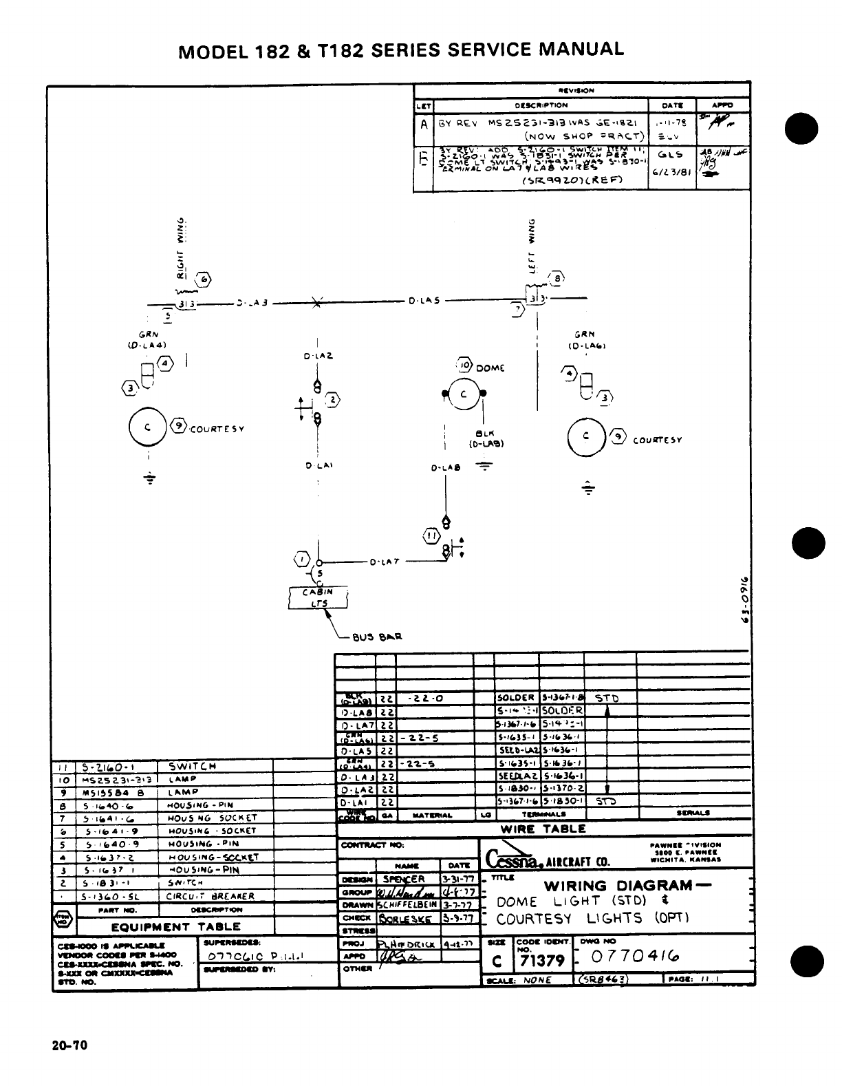
MODEL
182
&
T182
SERIES
SERVICE
MANUAL
lEYVISiON
LET
OISCRIPTION
DATE
API
O
IA
Y
I EV
MSZS
I-313
-
vrs
>E--iZ
I ,-l -7 cI ^i
(NowV
S14OP
SACT)
-..
l
I:,
(i5 3
W.zIo
C...
(O-L,,S
~~(z~~~~~~D-LA4) [ l' C(- LAXe
TSY
¢<i>COURTLSY r?
g.461
(D-
IS
D
LA
DALA
_
_
.3
C
ABIN
Lrs
e1
-z
-O
SOLDER
5-1347-1
_
ST
r_
0-LLAS4) I l (_
5
'.
0 -L'
Si
0-LA7
Z
3
5-1
D:LAZ
0-LA
ZS
Z
,
S-Ut-LA
S
143-
-'
_
I5-?_1l-
t=I
|wITCIH
___2
-2
L-S
S
5,.35
.3
1 _ _-
0
SZS 3'3I
LAMP
? SELe
l
S"
.3I
"
9
M515584
-
LAMP
t.-o
TLA
3Z
?_ S L30
5
'370't-
3
5
-1(.40
-4.
HOU.ING
-
PIN
"D-"
0LAI
Z.
t
°
_
,30-,
0-1
_
I
?
p
*
7
5
(,Al
-
.
WOV5
NC.
SOCKCET
a m
AAL
LA
TEI°AL
S-IDALS
5
16
4
1-9
MOUS,-NSOCKET
_WIRE
TABLE
S 5, (.40 '9
1M0IN&
-PIN
CAXOTRP PAWNER
"VISION
~14 3?-
NOV
ING-
T
·
oo
C.
PAWNEE
{¥i
~3 S7~ I(- 3_~
-OUS..-PIN
_I
nDATX
AIICRAFT
CO.
wsCrrT.
ANSAS
o-Lla
-
6:o@ K.
PAWN
| ~.EQUIPMENT
TABLE
IC...._
ODURT7F.SY
LIGH1TS
(OPFT)
c4C0OOD
1S
APPuCAU.
I
suPaRSEE
PROJ
mISIE
CODE
DENT.
OWO
No
COD"
Pot
4
44M
0-7
I
c(,I
C
C-
roPPO
NO.
C
07
TCS-ZZZ.CS-
I SWITCC
NO
EPER1EDE
ST
OTHER
&-. i-*fc- __ ___
_
I~~9 -- -
'~c~.~,c
____._.
0-LA
____
_ S-iaJo" 5-
S
I40
OD.-il
*O.
|ON
'O
h!S.
PAGE
7i74)
4
l
I
I
20-70
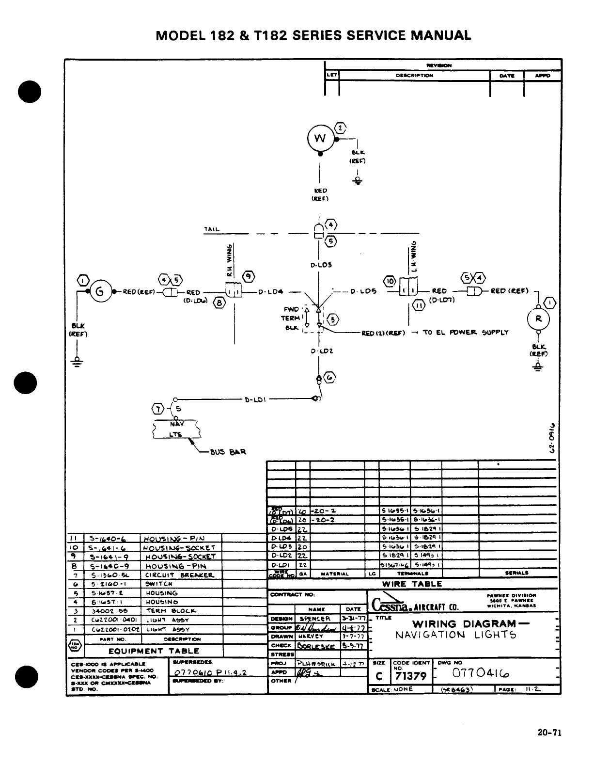
MODEL
182
&
T182
SERIES
SERVICE
MANUAL
-I
I
IET
DESCRIPTION
6DATE
(91K
t(ED)
lAIL
r ____
·
w :.e
D-LOS
R6
EW(tEF)-jRetED ---- IL--L04D
-
.--- DLOE
-..--
E-- 0 E(E)
-1
v-- (D·LD®
(
x
I'
(DLO)
0
(IEpr)
---
rD(OCt)()
-
'TO
EL
POw6.
K
5UfLY
?
|1~~~~~~~~~~~~~
D-
ED
?
(Zte)
I
I
i
®
Oo-
b-L2D
-%-
L_
^-6us
Lra 32
O-E[~
-
2.
--
0-
3.
'6 I~
S
,-9
5-_K,{,
'
"~,',
Zo
-30-2 _
-
1i56-1I ________
_D- rI______________
__ 1 I_______
II IS-I.40-.
HOu)SILG
-
PI
D-LD IP4
ZL
,
___w ,__
162
I1
10
S5-.(141-.
HCOl)k-5.Cit.T D__
LOD
20
______
13
5-'e.al
I
_
S--1I4-
9
HOSA1'46-
SOCKT
____ DLDt
ZL
____ __
6
6i 1
514i
8 5-)i4C-9
HOUS0*I6
-PlN
____ DI 1tt
51.
-
l
1^i
-
7
5. IfO Cr5
CIRCUIT
BES~:E.R
GA M
ATERNIAL
LG
TERMINALS
I I *SAL
(
s5 tloo-i
SVITCu
WIRE
TABLE
I_
5.14S7-
t
HUOU5ING.
CONTCACT
NO:
PAWNSE
DIVISION
4
6-Ii.ST-
l
.OUIN4b
lO_
.o
t
PAWNEE
3
34.o00Zt
E
M
SLOLK.
NAME
DATE
sna.AIRCRAFT
CO.
WICHITA,
KANSAS
2
C-..2001.0401
LIUWT
&AYY
ceSImN
{pfNCER
r
.'
-'-
TITE
I
CI.2t'OOtI
0401
-
iLAU _
D^.N
AStNEFV (1-t7.T
WIRING
DIAGRAM-
.ART
NO.
DTSCI..T.IN
U,
_----
u'-
ev
-
N AVIG
ATIO
N
LIGHT
\IE ~ -"--
-------
~~~~~)--~r
CHICK
QBC:LC&
e
% --
'
EQUIPMENT
TABLE
ST
IS
7
CEL-IOO
IS
AiPLCABSL
ICUPERIDU:
lOJ
?Lfrt.T.
,
K
1.-127T
*IZ
I
CODE
IDNT.
DWG NO
oI.
077041
C
CS-XXXXCNA
.SEC.
NO.
C0--
7
1
379
7701
s-XXX
CO
CMXXXX-CrSUNA
;H
SD
IY:
OTHER
/
)
arm.
NO.
K
I
»CAL
E:
oN£
(LIftfe3'
I
«C:
II
~. ZND~o~.
SC~LE
I4~OFE
~~(I~$K4(.3I
P1AGE,: I.20-
20-71

MODEL
182
&
T182
SERIES
SERVICE
MANUAL
_tvIo"N
I----
LI?
oIrScplTO
[
APOI
SL_
I
Jt
EF
)
I IL
RE
(EL
) _
tO.
Lf5)
SL
1
2
1
.
_.
0-LFZ
c
L/.0ool
-olOz
LiUT
O
LVL
-
_S1 IF
^
I '
I
"S ° ' i °'
L
cIcuT.
EK. EWIRE
TABLE
5
CN
:
I(&
5
1 F L
1O00614I
$0
sa.
P-Weff
_
s
,o,- I
I
o"
I
"'
I
HAW
~cssr,
a
.IAIRcRT
CO.
ICHITA.
KA"AS
t C, 6A6.
w--- tib
0
r
-N
I %Kff ----
R
13--r7
|
--
Tr--_
cEI,-40% ao~t
FR #PY *l _1Ll-_ I
icol
-
WIRING
DIAGRAM-___
____________
rT
o__________
7
"
L
5
I n
B
E
AXO______N
I'll .ou,.,,.______..______ c .:=l.:
',r. Co_'' ___________
v
CCI
l
001*0>oOE
IMENT
YTABLE t IG
H-
/L ,-1-
-
____|__
-
(oPT)
0
'-72
C.2
UOLIto,
D0P
l _________ »
i
4-l
q4
6il
I
on
C.
Csu'O
OTHQ
C
713TO7.O P S
SmI
c
1t01104AL
L1
T
AL
SA
C.
bIs.o*Ic.L
cIe.CwT
sEe...
___________
IWIRE
TABLE
_5_ _____S O__________
____ _-----
CONTACT
NO:
-----
oIIoSIN
-
__
hIC.3?-i
IAU«>I6
EgR
3-yl-V7
.
ITL
c.T4Go1
t PL«
UER.
«AIb -----
EuPE
SQC
H-
WIRING
DIAGRAM-
n
.no.
No. A
LE
-
m I
3)-?71ZS
FLA
S
ING
BEACON
20
EQUIMENT
TABLE
cn
a72t
LIGHT
COP)
CEU-x2acEumSA
S
.
NO
0
o"rvo..3 TI,
C
71379
mu.
*
O.
I
_ _ _ __
9
LS:
_ _ _ _ _ _ga_ _3JI_ _0«,
I.»
20-72

MODEL
182
&
T182
SERIES
SERVICE
MANUAL
JUO EB NrSmnm
DTc
e
eE7T>iEC IEE I9L
leE
Mobr
eE LET*_i'_ O»^TL
w_
tOLETTwL
DLKSCRIPTION
A
A
"TRI'PPE[D
COOLeLEC
*
'rwITTED
B
REV: TERM
WAS
.5367-1-
I-
DLP
A
NOTE
2
i
ADD
DETAIL
A,LBA2
Z-W-l9I
./W
~>
'TERMlNArTE
\JENDOR
FURNISKED
WII.NIT
5-1'e--B6
SER
($S.8tSEC
F(SR9ll3)
[£> -TMI
ENC
OF
ReiTiE
L.
TEHCINTEC
*U
iItT
.,
-A
B
WALS
1_64 5tR^E9z) 2/eiA
1EReMl.jAL.
IklT.iLLE
OwN
-.
AF'T
OF
TANOEM
POT
BIruv:
LbA?
VS
L9585,
ALO(C.<V)
AR
v
&A'-
DUE
TC,
HEAT
DOP,-IPL&TIO4,
RIrT
MUr
WAS
RA(L&W.);ADD
TAIL
C
6E
KEPT
F--H
1
RWIE
BONDLE
5s)
y2-Il
r--
D-833----
--
D-L63+
r r--1FWP
TERM
CLOCX
DETAIL
13
DETAIL
(i
I
FW
TE
1LOC
THRu
5.R
(.R995
2
)
THRv
SE£(.R97t5)
I
. I
LW
O
D
-LD2l(PE)
-
TO
DIMMINGS
S-Y
S-
-
t
T
r
.
^ ^D- LC^.L
DID
I)
IPOt
-
\
PWE
4
0-
L
iRE'F
("
IEF)E
0-^B :
S
S---O^:s:^
-L
B
-.
^*- 1D- 3
-
-5LK
(LBA
2)
Bu
e
\
/U JUMIPEP. W
(
TBRj
K(LB42)
-------------
P)
*
OLDEE
TO
(REe 5;
J
CAS'E
'TO
POTENTIOHETEIL
BLK<
(RE
F)
_s7^
| ^JORN
AUD
CONT
PNL
-
---------
.-
8---/r,,aC6)
To
RADIO
LTS
DIM
L.H
FEL
/~W
I:~
t4E
L
DETAIL
\
| ____
THRU
SER
(SR9III)
IReP?})
E~,.I'6A
Z2
____
5-IBIZ-I
s5-7O.i
_ |_____
5ER
EC.tq5sz)oON
L^i47
2z
_______ |-I70-1
OLER
RER 5.'5
2.'
ON
LK(Lb42
1z.
-22
_-0
85969-6
5-136.
1-8
SER(SR9113)
C
ON
_____ ______~ _____ _____ f-l8 _________ otR
t?
so
a-.i
CQ
__________
I
2470003
AUDIO
CONTROL
PNL
.o..63
Z.
____ _
5-i37-1
O
TuRU
bt.
C5bOq
5Z)
Io0
714
I
CONNETO.
-
_-_3
=SEE C,,3 85- _____
q
,.
ZI(lO
I
5Nt1C
D-i..7
___ _
5-3'"-?.
S-X _______-
L. 'Iit 135
EL
PANEL.
.
o
-
2
-&..-
=
St-o18-1
5.-1
Tw"
u
5Et(5R99SZ.)
T 0'13 '_7 7
EL
PSiEL
| CA
MA
TZl»iA
LG
TERMINALS
SElIALS
-.
070?44L
~>Nl00
CJNTE.L
NPWL _WIRE
TABLE
4 -AOO~
'%
HMIWJkL
OA&.
-
O
-
S_
__^00_
-se____
T b
CONTRACT
.NO
PAWNEE
DIVISION
4
CL,5l)OI
010
1
EYE
SUPPL
I. 00 E. PAWNEE
5
5
1;5V.*C
c
L
Cl.CUIT
gE&.E|EZ
NAME
D|ATE
CsSna.AIRCRAFT
CO.
WCH.,
KA.ANSAS
2
VAL
e
G00
KE^'
.
______
ONI
S.~PEtCER
_3 i-G'
.
TITLE
'
tZ.'~i
±-t
PUT'
A,,
Y
CROUP
7/7,
Ztl
i
-_ '."
WIRING
DIAGRAM-
P-ARRT
N
OSNC-T
-
----
D-^AW
^vIY 13-7-77:_
ELECTRC
LUNIMKESCEK'T
EQUIPMENT
TABLE
L PSTRESSr
(OPT)
-
1- 7
1
CEI
s1000
S
APPLICAiL
(
UPERSEDES
OJ
I-LIlTl>iT
4-2-))
SIZE
CODE
IDENT
DG
NO
E-,.xc,
*
A
.
P
.-
I
CES.XXXX.CBSPNA
OPEC
NO.
I
A
C
R713
79
0- 0+
I
7-0 1
(D
*IXXX
0R
CMXXXXCECNA
M7ED
*T:
OTH
1
s'0.
"N.
|
|__ SCA^LE NON~C
1r
3
'
'.
4
I
PAGE:
11
4
20-73

MODEL
182
&
T182
SERIES
SERVICE
MANUAL
REVISION
OT£E'>
ELET
DESCRIPTION
OATE
APeO
I
.EN
:;,-OLE
wielNO,
.PQLILlYbLE
ONLY
A
B
REV
ADO
DETAIL
A P
.iil.
.I
C
-'
A
F.LF.'
LE
7
$-Ib3')-1-2)/PE.bs'AL
..
T
1'
78
N
UC
.
-P"Sr~L,,
'wxYFl-EN
-,¥-,TEM
3
I'
N5TALLE'C
4UEN ZPTisL
_X-E.N
r-YeTEM
1e
.N'TLLEC
5-;_'..5ti-7
AS
-3
(S-i9<4)(EF)Sba3)
'___ ___
.;4N5TALL
'
.-
i, TEEH.MIWAL
ON
1ENDOR.
B
a
tZJ
:C
AS4-C4lO5
*A
Cjb9%
5-OiO0
jl
-J
uL-Ni-,uED
-_EAO
AS
INDICATEC
_ I-Z-
'
j>
INbTALL
§l i5,f-,- 7
TEIMINAL
ON
VENPOL
C
B'
REV:
ADD
Le31,NOTE
5Zq31-
CNIK
-MK
FUKNIMb4ED
Nl2
AS
INOICATED
M
_ 5SZ51.i1i I7) 7-
1-s-e
tu-- vo5POT IS
PMLT
OF
2011
3
DUAL
F1T
6y
BY
REV
22
GZuCAPE-,'
) w
^
'(
3
)
U
SS
-A
wMHI
OPTIONAL
E.L
LIOHTIN(.
1 I
IN'TrLLED
D[
BY
SEV
7Z3)
(5Re7.3'1EF1))
..
^R^EQD
ONLY
L'vC ;
EN
PT
0DIGTAL
CLXCK
BY
REV:ADD
DETAIL
A
Rt
SE-R,
HH
C65 STALLE9545-107
(SR9437)
9-25
F
BY
REV-:
ADD
RED(L842)t
BLLB
43),
RED
PM
.w
F(LB44)
aLn(ReF).WwT(lEF)
MERZ
IOW£
*
HHG
RED/WHT(L
d
3)
WA5
RED(LB
4,5-I-,
3 -I
2
-
1-7
WA
5
OLDER/LIa-IG
-B17,
'-.K(L..l-)
5,
LaBO
(NOW
SHOP PRPC(-TICt)
4
3EzSI
-22-0
1SOLDER
S-1.5-I
22
-
22-
0
S-1655-1
SOLDER
D-La41
2
_
__-__->-_
_ <__
O-LBI
Z2_ S-
IS9-1
IS-d.7-1-
_____
RasflwuJia945I
D-LB
.
__ _
S-lb3S?
SU
_
D-LeS
u. _ _
-1-__S3-l
SOL
b-
L%4
2Z
___S-1-3S-l
OiOtR
___
__~__~_______
___________->.!3 9_________S-L39- I
S-13S
1____________
27
C669545-0107
INST
CLUSTER
D-Lai __ _
S-182S-1
5-__35-_
24
CC954S-0(103
IMnS CLVSTER I
,
I
._
_
1_01
s
I'D
'____I
It
S-tOS-1
O-7DL.
PT
ASSTI
_
*e__ _
L-6s.'
s
q
i _____
___B__S
2.t
S-lo-
OuSiNt
_______ PLBZ _
S
s-
144
1
_____
ZI S-l
I.
-9
HOUSIN
______
0o
s1570301
i_
I
oIWA1
AS0-S _ _
l D0-L
s-zz-
1
s-___o_
Is
I sz
LA
___ LP
I
_
_
_
'
i
s-lIl-
_
______________
Ib s'
IS\O
SL
CUII
Kt
.
__ _
-
SI
1
I36-1 lb
tOPT)
______________
T0
Si 24C2J
TO.
____
_
_ _ _
5-1636-|i,
&lo _____ (OP__T)
i
S6 104-Z
PO
r0
AUn'
____ D116_ _ ._ I
I
I
ez
5
s-b1
5
K.4*0-
_
OU
_to _1
la\
I S-13701___ ___
14
S
1S41
Ca
1JoIu
I
__5_1
9
_ _
-.
Z-L lS I
S'OLOE
_
ISTOLe.
0IMMImb
al
r' ____
_
_ -22-*=
SO
iEt
S-1370-
______ ______________-
It
0Il5s6b4
6
MIMltAluIe
LAP
_______ pl
-22-2
-
513701
E
1.
69
II
OstO0
SOCKET
o e
-
2-0
_
1370-1
i
1-1-4
0
-ZO
OUI
-22-
L
_____ ______________
A
5
s5
L
UOU1 4_ _ _ ___
S
C(,.C0W010-I0t
COM',^
kty ; Z
-ZZ-
2*
_-
eOL
.
___DEt ____w
cl
5i~
I
HOU'iN
j
_A_______
o^
ATIAL
IL
tMIALU
IS
IIALS
,
1,.51
t
UOUINi
______
mWIRE
TABLE
1s
1
__________________
s ONTs
NO
.
I C
PAWNER
DIVIS
ON
4
3400S
1
ICtKMIN&-L
BLOCK
-
1S
C. P-AWNE
_
S
'>4
L~LUt7
AARY
~ -_
MNIC
OTK .-
AIICIA
CO.
W"'T*"
KA""SA
t
1i704Tq
LIlMuT
^oYo mas
I
StEtR
3-_-_7
TIT1
I
5
3
q
LIL'T
&,
__Y_
L3 o
L
O
WIRING
DIAGRAM-
PANT
*-
.
OSSCrIPN
-
-
ODORAWN
&auvev
3-7-7
INSTRUMENT
:
OXYGEN
E_
UIPMIENlT
TABU
.OLE IE.L.S n
LIGHTS
Coeu-x
mN
*
MOe.
--
ss _L I
-
LIGHT__
____ _ ___o
CO-0MO
.
AP.
OLICA
UCoWP:
,OI 4f-
I)
SI I CO10z
0I0.
Oo
vapmo
e01MI1
no On3
C. I
0
o11.9.3-0
-«-^-
NO.
coca
3.0^-
07
7 0
4770 41 %
04=
cmxxwcoomeV:C
171379
am.
No.
I
_
I INC
_'_
I
a
N
P ,AGE . I4.0
20-74
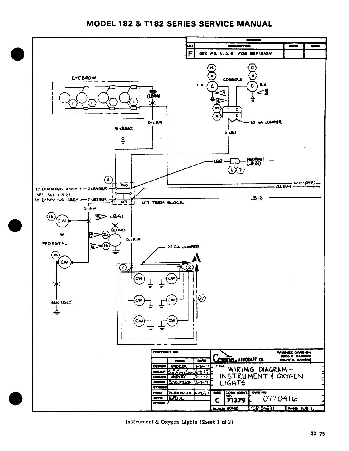
MODEL
182
&
T182
SERIES SERVICE
MANUAL
F
src
Pe.
11.5.0
FORa
RVISlOod
_____________________________
____
_______________,,.so
oI
,
EYE
BROW
co 0
!
-S
LJ
a.n
(
L t14.IL
_
.
D
-Lbq
S
s
-tO
(A
AUMPO-
BL7ld)
(~ TLB
-
--
\i\
{SE:E SKT
1>.S.?.--
I
-
_"
.
FrT
TE
.M
LO(C.
ID-L6161
Instu
,
22
6A
JU
MPER
-WI'ING
DlkG2A-7M-
'.**VUY
3-7-77
IN6TUMENT
.
OXYGEN
c-___=-
LIGHT6
Pow(L~l^
I
© |
J"®^
* ®
Instrument
&
Oxygen
Lights
(Sheet
1
of 2)
20-75
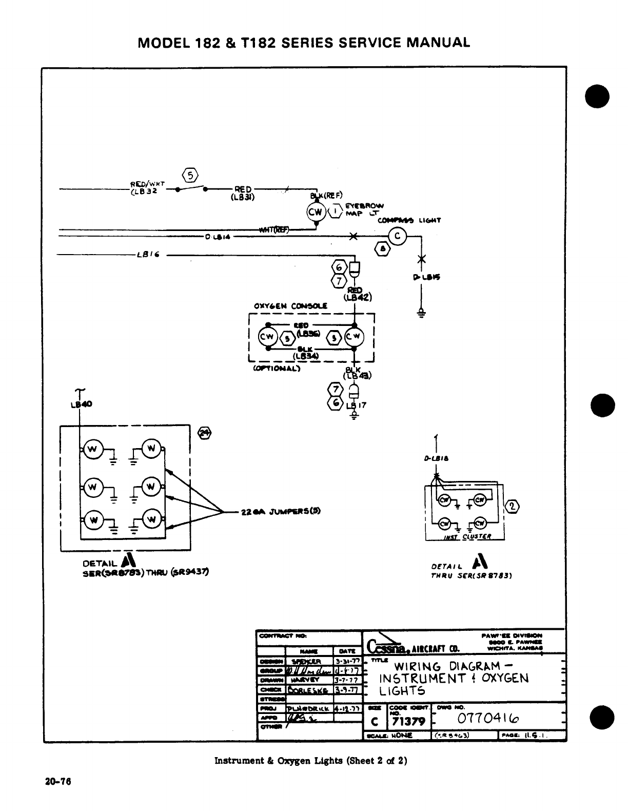
MODEL
182
&
T182
SERIES SERVICE
MANUAL
(LB3)D/2
(Las)
(FM
F)
LCW)V(f./
P
LC,
r
1 l4i
~OW
'41WO
CO5OWWLl"
LIS
1
I L@
I~i-tL
(LB
r
O
e & el(e
(o
rTloCA7
.
I _
^-N
"^--~22&A
JUMPSCRSM5
OETAIL
DErAILA
SKR(%aR7a)TMh«
(SR9437?)
rNU
5M(3SRS783)
mean
OAlE
CC
AIUCRAF
CIL WOW
a
Hlar---bCP*LR
J^:^
mM
WIRING
DIXGRAM
Dowigm
3-7-
7
7
INSTRUMENT
4
0)YGEN
o
SSCM
LE= ^
-T?
*
L
IG
H
T
6
POMJ
am^>r~r
rr^ 'sr
^gp"
p"Low
"D
'o.
Appe
Z
C
71379
Q
77o4t
Instrument
&
Oxygen
Lights (Sheet
2
of
2)
20-76
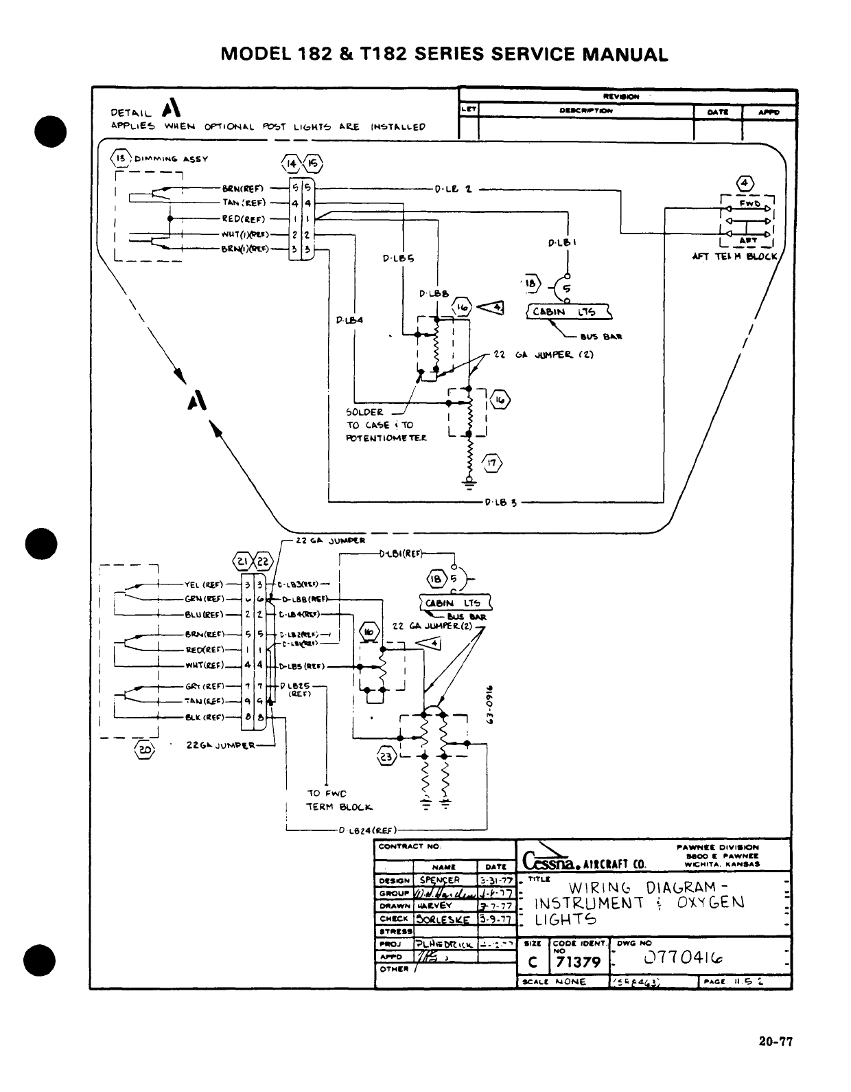
MODEL
182
&
T182
SERIES SERVICE
MANUAL
OETML
;\
AIL
T
PLE
D3 T ~
AT
|
A
,PPLIE'
W
EHN
OPTION&L
PFIOT
Ll-HT6
-.
E
I1TN'&TkLLEO
Dlnml-
»SSY
/5i\
r--
-
I -B
--
6en<REFt
--
9I
-L
t
_
I- T ;F)
-_- 4 4
,
rFwt
I;
--
i
RED(i-EF)
,
-
\9 L ~_ ~_ __
betl~~~-5
<~P-L&
$
AFT
TEOM
UOCK
0165^ r^^ ^
r
1
1
\ I \I D
1
.f1X
?. /LI
-
_\ a u--
A
(--,E) (REK
/L
'O
FOT
E
IOMeTEL
-
__.
LI)
Z4 tIPL
,EF
/)
Z2
R
Bz
j 0m
-I
I I BtLU XEF)-Z
2
_
W
C-L
-
L_
Z
jI "
N
I MMDI C.
;
*
r.
&K-
*--
(R--) 164 ----------
^^ft i- iZ
26
Jt
J»LPR
YdaiE^
--
i
L
)-
FWC5
1~~~~~t~~~~------
t-
Z
DESON
SPP-iER -H-3')---
i
T-uE
GROUP
P -6 (E- WI
M(
DI
A-LRAM
C
ORAWN1
1_A
IN
CMECK
L
I
LI
GHT
P:
J
I o:-
SIZE
C-o ca
IDEN
.
"WG
NO
"
I-APP-I
-
I I
4
1
7
1
3
OTHER
4
7
I--
I|NTU
CT I--
SCALE
A)ONE
/R4 I
PAE
11
C,
.
20-77
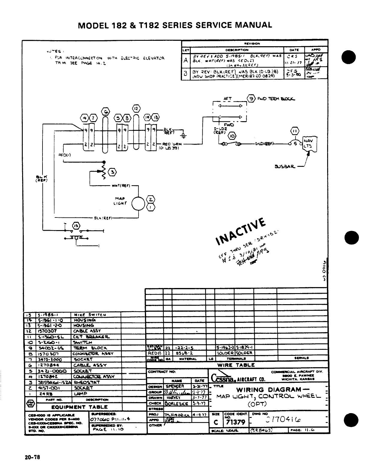
MODEL
182
&
T182
SERIES SERVICE
MANUAL
REVISION
,;-~6S*
L
ITr ________ OEUCN9IPI __ONI
OAT
APPOI
.
FDR
INTEACLCNNECTri0
'NH
N E
IC-
EL.EVATOR
SV
QC
v
ADD
5.
19'5-
1S
BLk
et-
WAS
:s -A5
TRkM
ETE Pi6 14A
P
'
A
aL..<
waricg)
wAs
;0
o
ED
)
-7
3
3Y
2EV:
LKKREF1
.AxS
eLK
(0-L3:-)
FS
_
NO\
rtiOP
R*ACTi:E)(MERl8tO
a0801q)
5--
ACT
5
FWD
TEYWi
%IKM
------
2),_ -__,-
t~, Z-> J.;l
L
(N
RTL
'----- tr
~(Ra)
o
-
9L W 'T(R'E F) 7-1
28~~~~~~~~~~~~~~~0
1V S-1
-I
-2-0
Ko
LI5&
-
I-C
%
ir
L-
-.
I
I
B I57C ^01
CO
-;VOW..
~*~Y
______
RE4I')
f2d3
6lb%2
SOLDER
SOLOR
-
__1
34L
C
C
Av C L
AIVCRAFV
01
S, 15198S- 1C 5*reCC
5.
_A__IX
l__
_-l____ _1-0
-___S___
______
__ _dfi_ _ IOPT
A3
S-_9GI
-_Z0
ouStI-
I2Z
1TB70307
AB>LE
C5SL
= =-
'l
Se^*»TfO-5L
CPT
SIZ
.-
9 1g4COOZ-i S T·
M
a OC s g s
-
1 1 7-S _"'
S
l~3-3
S
-1
--
v---
EB 157C -o
o
CS___ Y 0RED)77
11
P85 t
-
1 _LOE 70
LDNO
_
C
3a73*3e
OC~tlT__
t
^i
T C
LO
T
17 _m *>
-
mC71379
Sib.
on
O.
x-
1 1
I-
-
I
i27o8*
CAB
S5
___________________WIRE TABLE_____
I-
170at
CJ
.
o
AA
trA
(.
8A
W
I
23
0 ^Saf7 -5al
REO
A-t __A
I
OAT
I Vj|
ICSCIAnFT
CO.
WMTA7.
KA<A
Z-
241RB
~
LAMP
-
-I-- tr i
1,>3'"1
77
-i-)
WIRING
DIAGRAM-
'^
rrrT
o.--
oSUrCIWT
OI
0
*AWNI
aEY
13-7+771~
MAP
UGCMT]
COITRC^-
WHI£EL
@
ECQUIPMENT
TABLE
^ 6Sa_1L
(O
PT)
vMoO
coop1
40
0770&IC
T
= =.4-
o
-
-77n-
cxxxi
,,,^-A
*HC.
NO.
.
_--- 3 -I-
71379
.i .
4
,^00
o-
mIuiiin
i
rEi»
*YP-WDBO
*
OTMCR
'Ls W T 1C^
-
1.E,
f
*
___
^
20-78
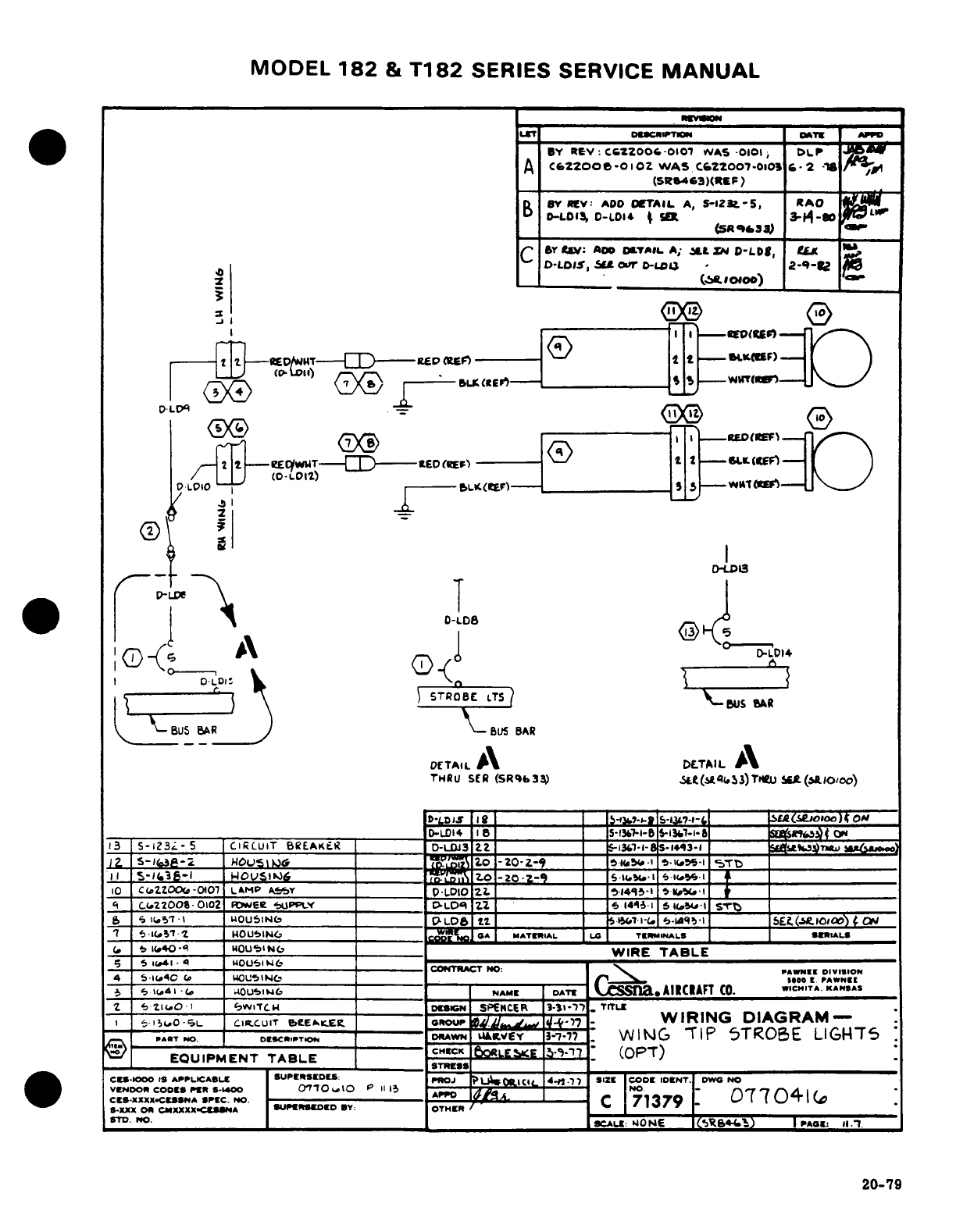
MODEL
182
&
T182
SERIES
SERVICE
MANUAL
*L»T
_____________
OE»CIPTIOM
_________ I __ MTE
A
D
BY
REV:
C6Z00G-010'1
'nAG
0101,
)
I.P
41NW
A
C622006-010Z
WAS
CG22007-010
C-
2
1
r
,
(SR5463)(REF
)
BY
RV:
ADD
OCTAIL
A,
S-IZI3-
5,
RAO
D-LDIm,
D-LDIC Y\; 3(^-S wLw
C-LDR
M3-14
-m
(Sm"633)
r Ir t: AOO
DI.TAL
A;
aiL
.x
D-LD8,
D
/
1A
D-LDIS,
-
*rr
0-LODI
-
2-U
q
IID:T-V
_
2_ t ______jji jiI)
D
D LD'--- 1
-W
C
-
DM
L
(REF)--
LOL
(0.
L
X
6
)
i-
IL-(_5_
<«-3
f
I
I
r~
LV
T
D
*
I
\
0-108
C<
L,
A
01
I
D-LDI,
,
-LDI
t|\
'
\ i
STROBE
LTS
1
BUS
BA
g
uSBAR \>"
BUS
BAR
DETAIL
DETAILA
THRU
SER
(SR»b3.33)
Sit(T4i±
,3)Tl«U
SA(SAIOoo)
D-LDJI
I I tS-l-
S
5-1i.37-l-t
is(e.LIODOo)
OH
____________ D____________________
-LDI
18
_
5-1347-I-B
-131.-B S-i1-8 asw% 0w
13
S-1Z3,-
5
CIRCUIT
BREAKIt
___
D-LDJ3
2
=
l 1-lS - l
5-143-1
eS1m. o]
12
s-j-
ou
_______
-*s
I'mZo.
-202--9
.__
4-I
I-ClS
_-l Tb___
II
S-1.48-I
HOvSwI
__6
_zo__
2.0
2-z o z- _ I
S
I____14 -l_____
10
Co.ZZOOc
-0017
LA.MP
AV
Y
Y o__ LDIO
I.L
5__145-1
'I5.AlA
cl
C.2z008
0102
FWE lt
.UPPLY
___-LD
Z
L7. s
14'-
I
s(l
T
54.-I
S-.~'r
&
$»371
1
UOUlN4
_____.
P-LDO
tZ
I
_I
SI.-1. -t.9i __ 5b(^le.0ob )C
CA
·
IC1·T
H
OU1IN(.
____cM
GA
MATERIAL
LI
TERMINALS
S
ERALS
,6
5(040
-^ UOUo
C
N___
____
WIRE
TABLE
1-- -1a4IA
-
w0u-im(,
______
LICO9TRACT
NO:
PAWNKE
DIVISION
4
5-1i~4C
Co
W0U1IN.
NT000
.
PAWNi
l
45
i,41
'C-
(
AoulFeim
|
NAME
DATE
RAIRCRAFT
CO.
WICIT.
KANSAS
2.1
'ZlcO0 I
WITCH
I_____
EIGN
SPEICER
3-31-)
.
TITLE
i-
13L..o--L
CIR-CUIT
e
E.k.-E
GRO
UP-
T
-.
WIRING
DIAGRAM-
PAR.T ro.
oE...pTIN
-
DRAWN
U"VEY
3-7-7
W
\ING
'
TIP
5TRO&E
LIGHTS
EQUIPMENT
TABLE
SCc
IoaLEE
13-9-
(OPT)
CES-1000
IS
APPLICABLc
SUPESCDES:
POJ
o Lk
Ili
1,.
t
3
4
1n.
SIZEI
CODD
IDENT.
DWG
NO
VENDOR
CODES
PER
S-14OO I
c'TO,.lO
P11
1
NO
.
AI
CES-XXXX.CISSNA
SPEC.
NO.
AP
'
C
171379-
1
t041(
S-XXX
01
CMXXXXCZSISNA
SUPECIDED
BY:
OTHER
STO.
NO O.
SCAL:
.ONE
1(5r*
4-6(.)
PACG:
#1
.
20-79
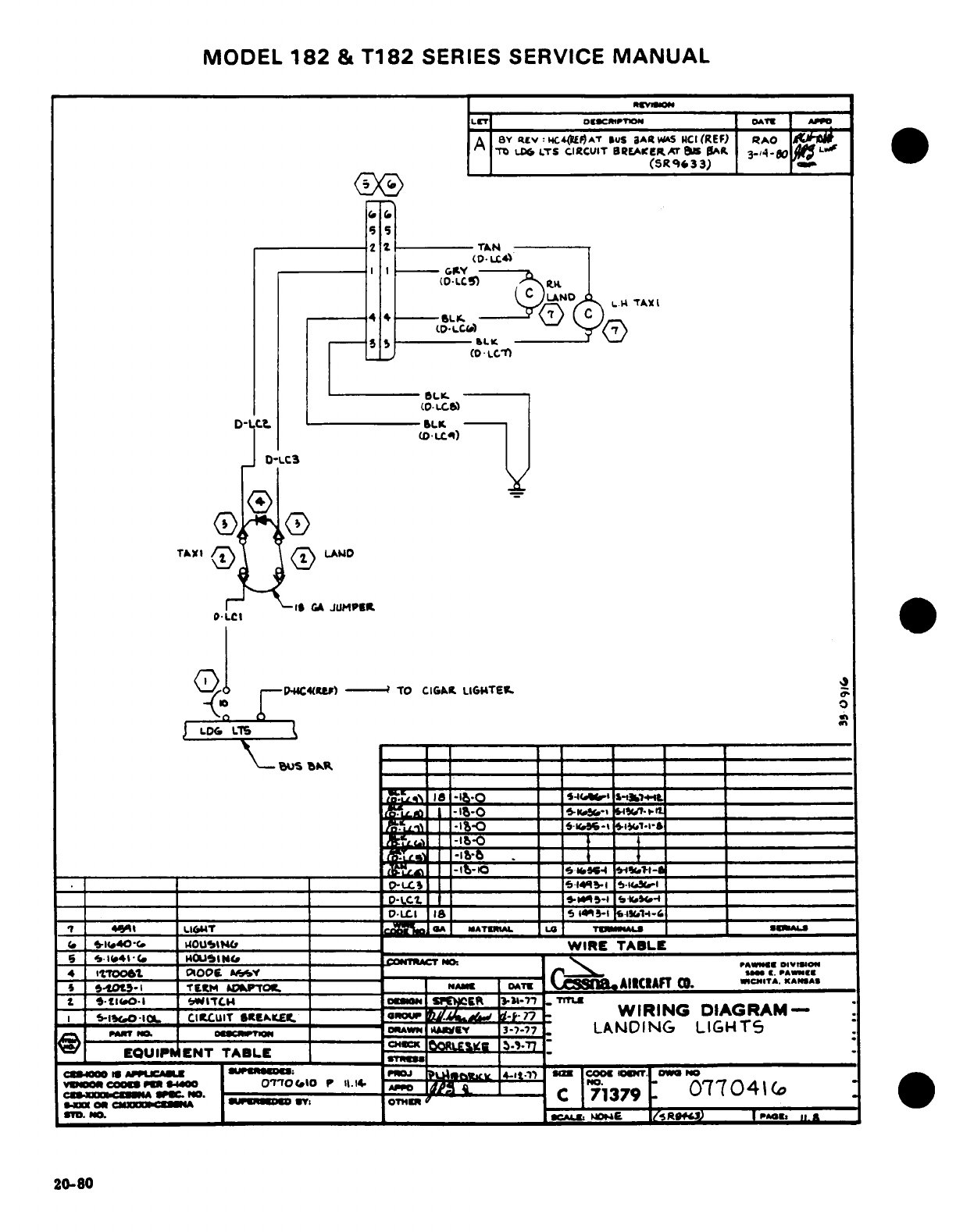
MODEL
182
&
T182
SERIES
SERVICE
MANUAL
LrT
ODIImCmPTION
IOAII
APPO
A
T
Y
Rcv
:HC4(*FAT
SUS
3A«W5
MCI|REF)
RAO
r
A
DTO
LD6
ITS
CIRCUIT
BREACER
Ara
0T i-
3
M4
S
0
L
(SRq33)
$ 5
(0-
LC4:
I G.ILY
C
2AND
L1 TAXI
(DLC0)
t(O
LC-
___ ---------- L
5&LK
(
O.
LCqr)
J
0-LC3
I
GA
JUMP!It
O'LCI
q 4I-0C4it") _----_
TO
CIG&It
LIG1TEL.
.
10
i
3
.LOC
LT5
T"
7
*
.L~
·
I
_I_-Ob
J--
M
.S
5
Sb-
111041
(a
----,
IwlSO.NT-T
N,.
PA
DIO
4
2t^
aoC Ct oIt1- bpi_ _I___CPA__
2 § 21@0
~ ~ ~ ~
DLC
1
.
1
C
R
WITC
1_
IL.-
-I
4c-l
L-
CICUIT
E-
-
a
*
ATu
La L--7
WIRING
DIAGRAM
PAT
NI. RC- O
3-7-7
LANDING
LIGHTS
-
IOU.EQUIP
WENT IR
TABLE
T
LE______
I -IO-I UCICuIT
'
*O.'E.
PI
1..a.
W
I
RIN.G
DIAGRAM
-
4
n~i9Te.
"
a".-
,'
A
wm
,lE'(
13-7-77
.
LANDING
LIGHT5
EQUIPI
ENT
TABLE
0N
acn-
|_
OT",
|8
C
713790
20-80
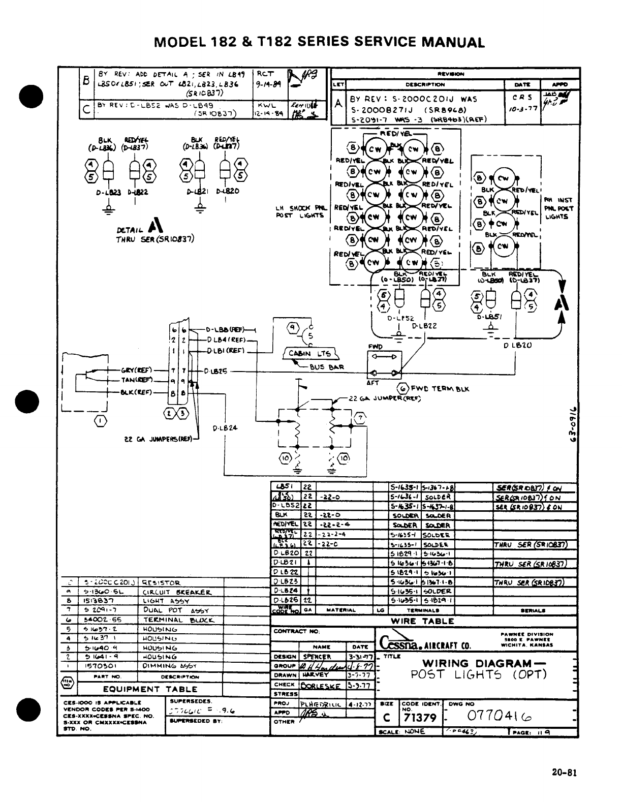
MODEL
182
&
T182
SERIES
SERVICE
MANUAL
BY REV:
ADb
DETAIL
4
;
SER
IN
L847
RCCT
O
_ RVN
B
L&SOfL85
;ER
C T
tiZI,L823
iB3<
9-l^-
L
DESCRIPTION
D
*T«
AI DP
at
R
wv:I-L852
*
(5R
0' .^Z-7 ,,A%
5-
.2000B27,J
(SR89.4)
/0-J-
?7
S-Z
201-1
'wkS
-3
(WBs4b3)(PIEF)
5806K
4
8 8 BLM R 8
DD/w~YE
t-
CO/
16I--I -
(P..LI3w
(Dda3i')
POLS3T
((cl)
|
(AW>
c-_
:(C'I
...
I E( XCw I
C
-
oIv.
KSI REDIEL/ BLL
RCDI-U
0.2 Z
5_-D-
L)
r FD
-)-
-4--
LH
SHOK
PHIL
bEO)KL
M
C/
C9l
LtS PP FPO|T
4 _
3Y(1 T -D
L
U
WII
At I |, (lOi)-- Ie
""-/-
t
2 cFiN
-
O
KE LI
ETAIL
A\
I
t«Ye
IRE/LDIL R FETL
rmR
sER(5,RIO83
7)
I oJ 2cw
-<gi.<j P4 __
L6S.122
|~. |
5-
$-t
.S->-.3*7,-~-)
.SE'S#$,CDa.?)
f
-
L52
5-35
FWD
0
L
S
L
--
>i 5Z ~ -I--'L T U .R
--
:R 183'AFT
FVt T~-
'7)
p
L8--- _-- P
------- -----I
- --
0
*
Z3il-'~
|
CIKUT
(-EY |1 5-1C :-1
, p
5&
..
,~S
'"rI
TEK.IN~.L
DL/I
r_
.
_ WIRE
TABLE
I
D-LBS2
__ _SZ
S
$
Ko5?="t.
|.
,l I.S c I _ CO2ONTRA
-
nt
NO:_
4
5
I.{~'3'
I
~01J51N(~
OOLK E PAWNEE
7 ,~ moa, i- q iOu
s~&
C~SG
$FR0
L.
Z2
i I l'e
_ ,S~o~5oII OI4
N
o,,~ou,
a/-4/
/-B-/. /5.-./~.J
WISERING
DIAGRAM-
VL1S
I=
s-|s-i
P05'3fT
LI-
NRHT (S
OPT)
~'vl~oC
SL
CiR.LUIT
ScKEAK.E-
0-L54
5
11,31I
-2-0______ _____lISLl)
E
Q
MUIPMENTANL _
WIRE
TABLE
|
-
CES-IOOO IS AU'k,
|
_ _
'RACT
NO
PAWNEE
DIVISION
*
O
RT
N DSRDRWPtS.XXX
ORN
CXXXXmCE
_DA|
D
SYC T79
TI
EOUIPMENT
TABLE
C
WLKZECKI-U7
|___- STD2
~~
I__ = _ft-STRESS
CES-100O IS
APPLICABLE-
1B
SUPERSEDES.
P'ROJ
1Pr?)i
ILk
4-122l
SZ
COEDN OW
NO
5.5
i OS-OR~
CX SENCESSNAE ;2;4IL APNO
C
'i1379
0 7
4
CS~XXX
.
OR1C3 0
SNA
SPE. Ci NO_ PLUPERSEDED
BY: OTHER
I
$T0
NO. SCALE:
wDWE
"0
14_______
__PAGE:S_ C
C
NB».0
4 ~ ~ ~
~
~ ~
~ ~ ~
~ ~
~~L
G
li 1
OL'O ________^__ r
"ox
AN
~ L 1__-Jn ~ _
NN
o~
Lsn~nATco
"' ''*
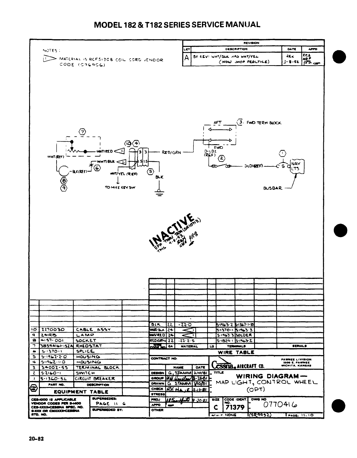
MODEL
182
&T182
SERIES
SERVICE
MANUAL
RWISION
NOTE5):
o______
Do0SCRIPTIQON | o
|
MA47RI-
'L
RCF'ICg
CC
ENDOC
A
Br
w?/L. av
wHT/AL
~
vA3
WNT/rE-
mop
CODE
(.C
q
(.
C)
PALi..)
j-g2
wLJ
aFT
_(J
FOrE
mEC BWOCK
Oj
!
<-^i
~~,_
0
-3-
WTIKED<3
3
c9
_REO/GRN
D--
0-L
mTI--E)
--
-
-Ef
(,
F)
0
I
--
rTsL
-fl
5
.Y---J
AV
(8>
1t
v
*~WIREI
T
BL
E
8
*T~OMiKEKY
iWo
Bu'sBAR-
\61
=3 1 ZZ "203 "~L BIK" I _
-
"
0_
'
"" '
" "
"A
1
.7
...
..
_..
-
ID
Z100_____/0
CAI
ASty
Z4
-<1
=
5-1VO-1
*
________
q IL.R____ LAMP _____
V
S-i3L
5
____1_LE
a
I-
1
-
oo
'
SOCK.T
to__
2
-Z-
2- S
-
s-ieq-
lsb___r
___ ___
_
"SS
Al-fIi.1-
Z
QHE 0
S5TAT
_______
A
M*TL
ILO
TSAuL
_
UALS
i '
-
1-70-1
SPLI
C.
_ _ _
WIRE
TABLE
5 '2S14
t
I- -0 WOUSINC__ AW___ L,.
-
5
-
----
\-
--
0
------- C
TI
C
Y
N O
:
9
0
"
C
.
Pi A tl v
r
O
'
!34o00Z-SS
I
t1MIrNAL
BLOC
~
-
NN LtAN
DATY
SSa*
AICIAFT
CO.
WICNITA.
KANSAS
I ^.
"
"'--
L-
K-5K-E..
MAP
LGlHT,
COIROQ
W-EE-
-~
EQUIPMENT
TABLE
HEs
(OPT)
C-OOO
iS
A|uALE sR nj g
u-7-S/
Siz
CODE
I0MT.
0WO
NO
woscOOW
.
SOe|-
NO
P
°
-
-
C
71379
t
07704Q
3-4
OR
OLVSIERA DsVec. : :1y-
oZr
NTD.
DO.
-. -
NON
(S
qq5Z)
o
.
20-82
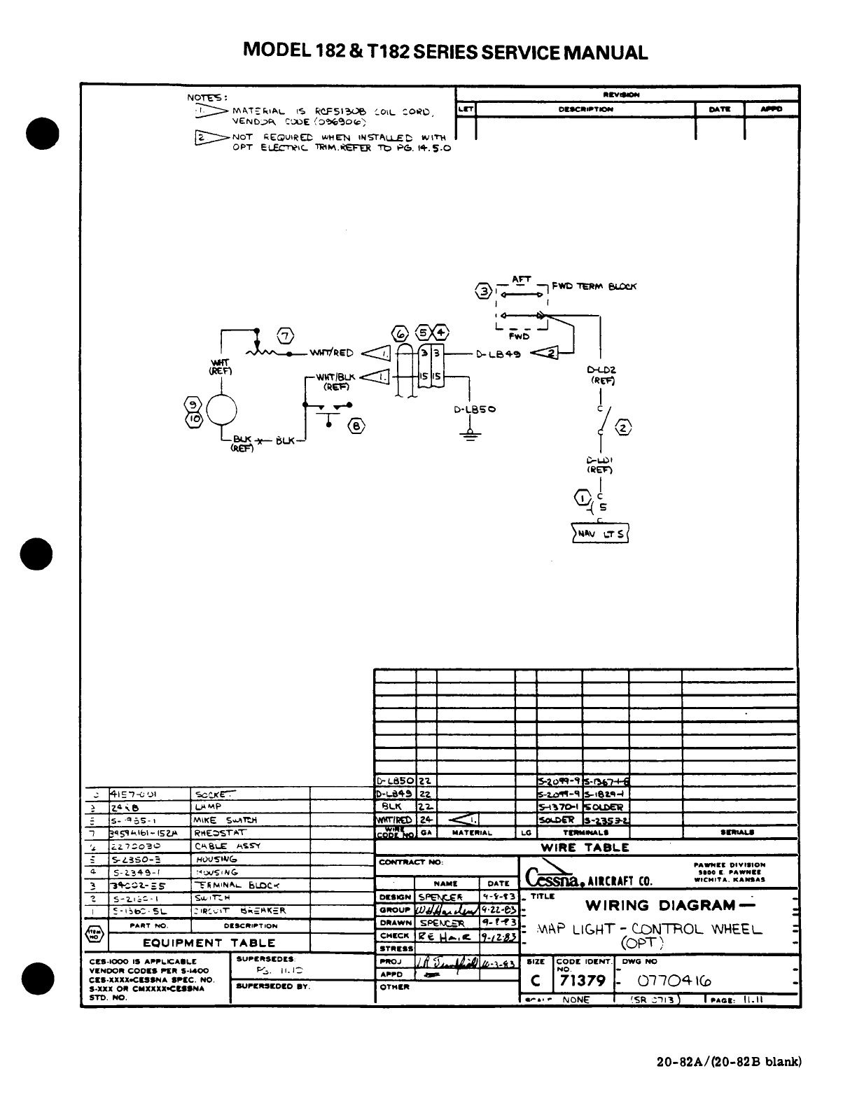
MODEL
182
&
T182
SERIES
SERVICE
MANUAL
NOTE4:
lr____
M\T-kAL
IS
RCF51
COIL
OO
LOT
OCIT,
DAT
O
VEND>P,,
C'-)E
OSO
90c
[NOT
EOQUIREC
WHEN
IN1STALLEC[
Wr'
OPT
ELECTi'L
TRIM.itEFR
Tt-
P.
14..5.0
ArT
-AT- 1FWOFw D
TM
BLOCK
(<^-REll
x-
-wwr/.J
--,
r
T
(REF)
m
bLD(
__ )uf
LTSt
___^ _____________________ ________
[>-La50
C1"
f S-Zo_0_ _
S-__-7_
_Z.<A6_____P___
P_________
____
___2-9i7&-1
SOt-
_______________
S- :: =-
I
M-E
S
-2.S
____________________
-7
q 1,* ble- 15 I
RtE::STAT
C
l
cA
MATERIAL
LG
TE
MtlALS
*E1
»
zi
7_o03o
C^LE
^ss____Y
WIRE
TABLE
-')
i350-5 HO')SI(~ __V
_ _
'
CO'TICAACWT
NO:
PAN
r
L
ODIVIIION
4
S-2.34S-1
-
'^VSlNG
r
I
K PAWNS
3~4-Ns.l- _I 5uLDC.
-'
I
|
'T
NSS Al--
-
_
=
CO.
C
CNAME
DATE
Na.IcF.KAN
-
S-Z
..-
S
ES
:N
.PE.c.l 1-_-_3_ T ITL ElA
2
S~Wl _~
-
I
Ss
IT-
H
DESIGN
5
91
-13
TITLE
-i~t
-:SL .s:T
:z;-A---R
R--
OUP
,Iu
-zz-e-
WIRING
DIAGRAM-
DRAwN
SPEC.-=-R
4-1r3
PART
NO.
DEScRIPTIpoN
N SAP
LIGHT
-
CJDNTROL
WHEEL
1Q ~5 _~~CHECK
Ve
LA,'c
-
(OPT)
EQUIPMENT
TABLE
(pTIVI
'
_
CES-IOOO
I
APPLICABLE SUPERSEDES:
IPOJ
/SIZE CODE
IDENT.
DWG
NO
CvCNDOII CoODCr NS
rxS4OD
1
V,
1.1-
No
VENDOR
CODES
PER
S-MO
.
ID
.
C
71379-
(7
704
NOI(
CE.XXXX.C<ESSNA
pIEC.
NO.
W
S.XX
X
On CMXXXXCfISN
A
ISUPELEDED
BY
OTHER
STD.
N0.
_____|______'
I
NONE
'SR
71'3
II PE:t
1I.11P
20-82A/(20-82B
blank)
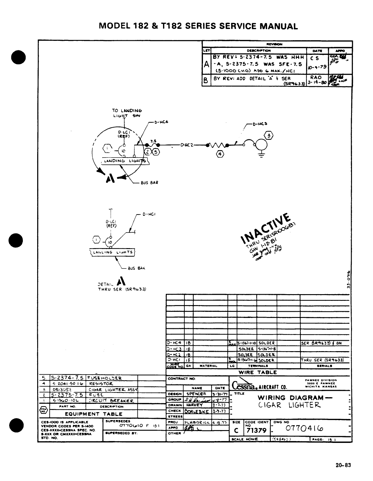
MODEL
182
&
T182
SERIES
SERVICE
MANUAL
REVISION
*IT ______DESCRIPTION
p
I
BY
REV:
S-Z374-7.5
WAS
AH
1^4
C
A
-A,
S-2375-7.5
WAS
SFC-7.5
)-.,-79
t(S-\OOO
c.G) b
,
MXW./HCI
B
BY REV:
ADD
DETAIL
'A' I
SER
RAO
Wf
TO
LAWDIM6
LIC,4T
SW
-LCI
(it R F)
3
?.)
\,
L&W01146
LI(2W
\s~~
\yt
/
A
us
BA
DETAI,
A
THRU
SER
(SRe,33)
D-HC4
15
,AAU
SL-3b-l-10
SOLDER
SER
(SR
e33)
(
ON
-3 J6
___________.
-SOLEL.
.S-13-B____
0- C !L
S
CLt
SOLDE.
________
:-uCI
I _____ _
5
l'1-i-, _.LDE __ THRU
SER
(SR9b33)
NODNO
GA
MATERIAL
LG
TERMINALS
SERIALS
_____________________WIRE
TABLE
5 5-2374-
7.5
US C lVSCLE.R
CONTRACT NO:
\
P,.WN
DoIV,,ON
4,2O4 T5S-I- REEISTOI DRAW
NAME
DATE
C
Sa.AIRCAFT
CO.
WICHITA
KANSAS
Z
5-
_~75-
7. 5
cuSL
DESIGN
SPEW-ER
TLTLE
2 SI.. 0 iL
:I.CUIT
e9E.KER.
o1ouIC__ O ROUP..,, f-3-T
WIRING DIAGRAM-:
PART
NO.
DESCRIPTION
DRAWN
"VEY
--
;;
CIGAR
LIGHTE
R
EQUIPMENT
TABLE
STRESS
E
-9-71_
CES-1000
IS
APPLICABLE SUPERSEDES PROJ
;LAbOitlClL
4
Il.1)
SIZE CODE
IDENT.
DW
NO
VENDOR
CODES
PER
s-4o00
o
70
P. li
1O, 07o
-
I
1
CES-XXXX.CESNA
SPEC.
NO.
'
C 71379
S-XXX
OR
CMXXXX.CESSNA
CSEEDED BY:
OTHER
7
5TD.
NO.
SCALE
:OWe
'O'
i
)I) PAGE: I
1
20-83
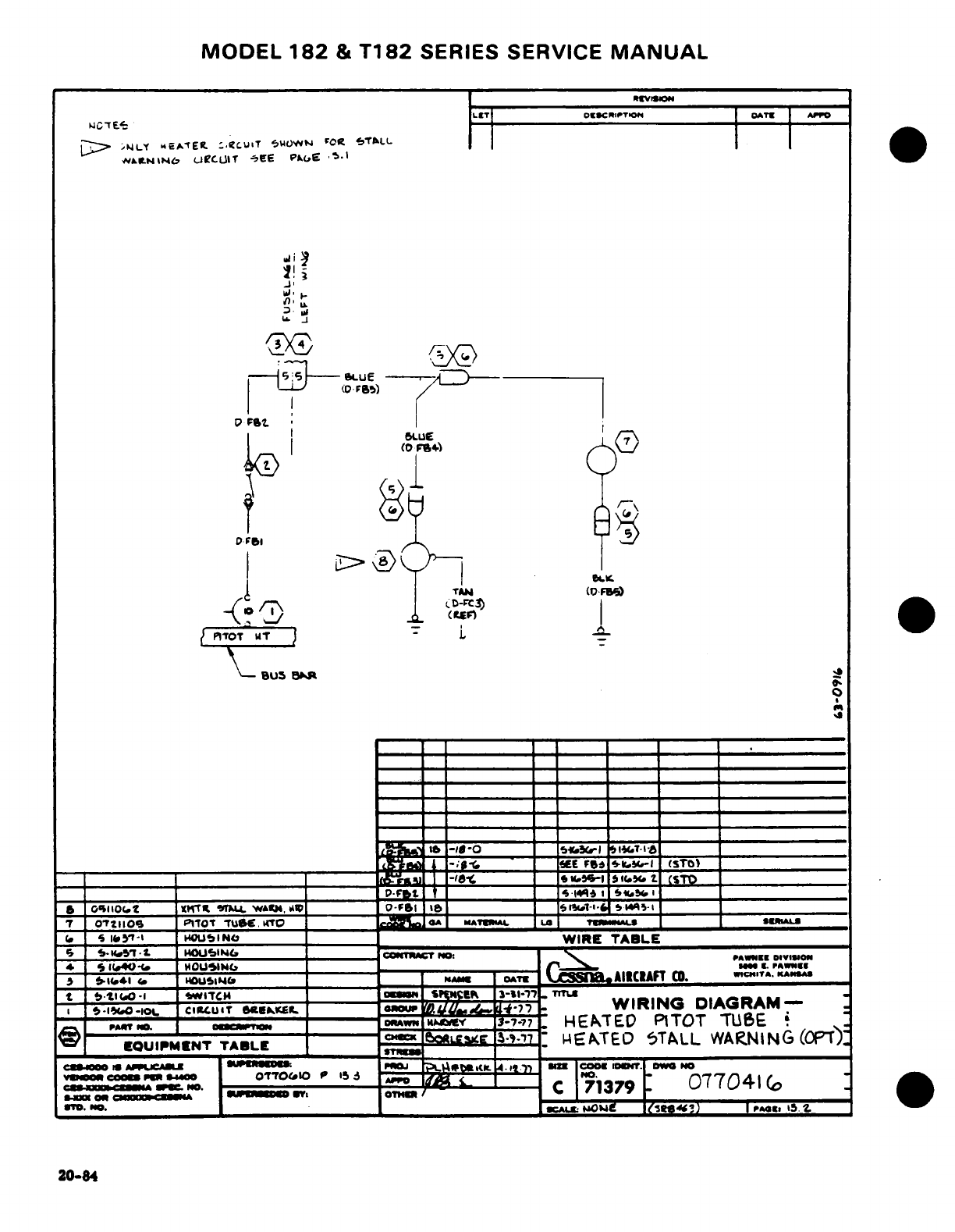
MODEL
182
&
T182
SERIES
SERVICE
MANUAL
w EsLITIO I
OlCr IRTION
O
D
MLY
"EATER
:,ICUiT
SuOWN
FOR
'T'LL
.W
fi'&UWLN»N
ULACUIT
-_rEE
P^(
*'
vii
D(D FF
)
..
FBI
\
BUS
*
O.
-
1 9
-
0 ~
I t.
S 6a-wiE
.
IF
_ _ _ _ _ _ _ _ _ _ _ _ _ _
_
ow0 51-1 N_ I
WIRE
TABLE
___
lb-__________
____________________
GWThiEI
NO:
PAWNER
DIVII1QN
4. *40
_ _ _ __________[_____IN4
Be" C. PAlUki
6. 1 4i
weue
,
.Ih. O,
AIlCEAFT
CO.
WICHITA.
KAN&A"
t
®
_
_
d~-T.
Itdl~
'l tqIICH 11111
sn
1:[tp.
v
rIs-~,.~
.
Tn
. ,
.I
e-~(-IOL
CIRCUIT EGIaKIuKI.
-
4/#.ac.p
WIRING DIAGRAM-
PAR .. .I 1--.
HE/TED
PITO
T
TUBIE
EQUIPMENT
T»ABLE
'
uEATED
5TALL
WA
ErNIN (sFT)
I _ 'W:
--
S..
li4
n
t
.,
=
coi
[l'rn.
No
o
,so. GS.1I~,o l.WC _10 I.
-
L n
5
=,,m
"D.
C 71077041C(o
S..IXX
_____,_ ______I__A
C______
7
137
9¶
\
iS
2.
20.
No.
-I4
"OuWE-l847I
r-8I A.
:
20-84
20-84
*
mftne
__ __
__
A«
OT
\CSaAC~TCO
nm«
*«
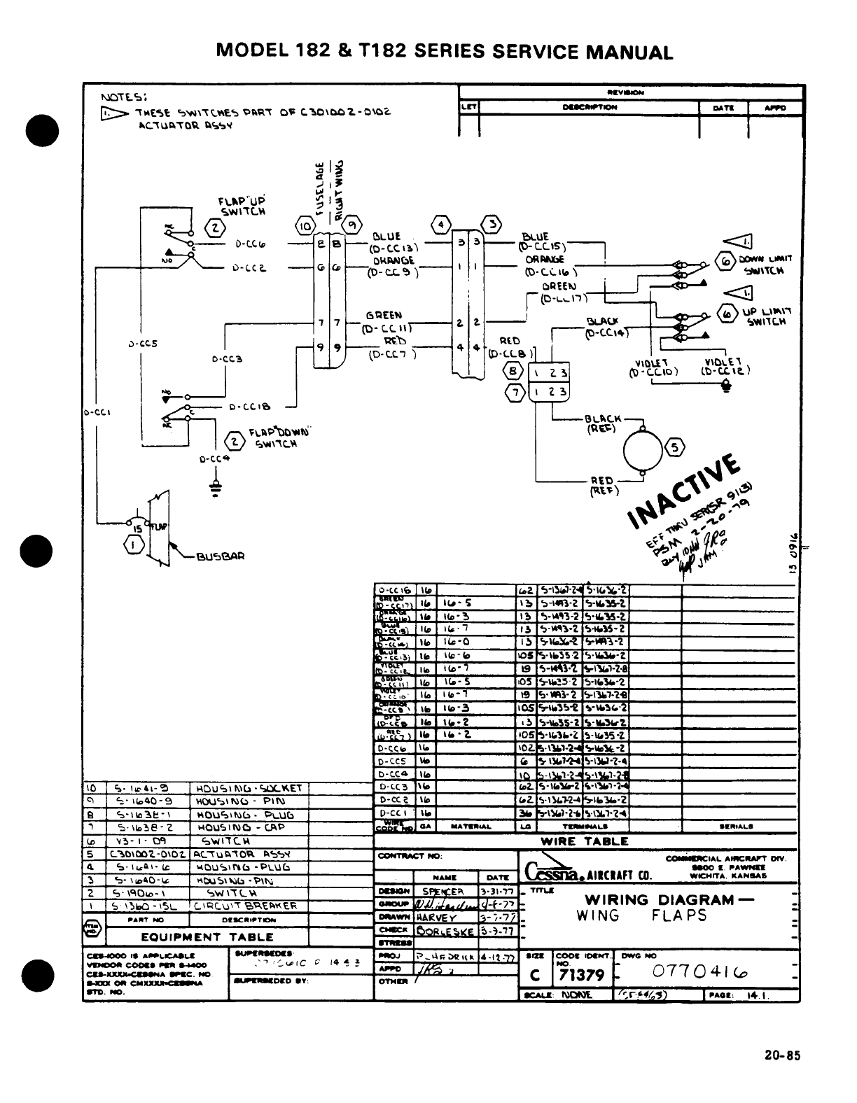
MODEL
182
&
T182
SERIES
SERVICE
MANUAL
II
I
jOAT jAP
D
7mES-,
Or-
L%0%°Z-0
-
L'rsl
0c a
o
CATS
1'
ShP"UP:
13
CLUi
BLUE
O-LCte
---
&8 (X-LC.CA
-LS^
--
^-*
J
('
5l\5&' I S) -nr
p
-
C.5)
)-LC_
L
co-6_ C_
.
@Q :,s,
%
,
Q
(
urpEEI u-
,° '__' I!
~1
1 ~,',z
r---77
(
L1_
E
C>
-CC
.
IRc--
RLEID
.
J
-
C"- sS (ID
-
tRL)
Lb-LL\;
0-
ttSUAbQ
30
>
t
b
t- ?
.-.
.t
l
t2. 5
3
5-
(.05- FZ____
D-C.
lb LOS
*lA.W2
'\b. 10
S _______________
"Cn~~ Ila
-cc'
Lb
\o- 5
lIi 5a
\
RS
Itb
l
_
1S
'liwH--
I21 S\-2-2 _____________
p15
b
Ib-2
3
e
'-Z OS
I
-
-7 1 P
1__ 1' _____A_
__AL
-6- C.C
(_(
._
WIRE
TABLE_____
4W
C,. S.4I-i U'LV.-E --------
0-C3
h
b_________
6o2.
'--
1.6
E
'r%
-
cooo s ^ i~
^U'-CT-
Clto |4-<I
'.
*m
|COIDC______
IDKL_3_ b_--2_-_
5
_'3c^DO'Z-ODC
0_TGu'tO9
~
______
Io
.
NO:
COCIAL
AmCRAPT
mYv
_______
:-
c---NAME
|AIR
CR.*CAFT
CO. w
.06001¢^PNE
Z
DEcic
S
I~b
l
33
IV
(
-IT
S-1t
41
__
'C-
4--'~7oULz%
N*
OCT
P
N>
s
W
.
T^U
WI
RING
DIAGRAM-
(
--
^ ^bQ-^L CPLU^^I
-
I=S. MoZl IEEE
D-Cc
1C 16
? NTo | OM .PTu
-
OIN vAEyP S-E.7I
WING
FLAPS
-
EIU EPME NTWIRE TABLE
'E
S-dOC
N
APiPLC
E
p
)
vuS
I COD-P\%
N
DAE ICANT
F7
Co. WNWGC.
KANSAS
Z
C.-
\o,,OES
K
N
O 71379C
s"FT
T-
7
I
OHwc
IE
1
(
!I
0770
4I
(
CE1NEo.
C3
A
w_ wO
J
C^___ r4
71
cO.
NO.
IC
Z
xN O:
9
1 S'*IPAGE2:
14,.
I.
20-85

MODEL
182
&
T182
SERIES
SERVICE
MANUAL
MOTES:
*cvmp_
LIT
Dl»Cn»T10
D TI uDAV AP"
I.
WHL
MIKER
KEY
15
REQD
NITH
EECTRIC
r
,
S
S-K6/CDlo
2
TRIM
;REFEZR
TO
3:201<q4
COR
WIRINM.
CF:
EE.CTRIC TRIM
A
,IMTCE4
I
-,,COTRO- 5-^EEL
'
w
S-4 BI--/CO.tC.
-
>_
IJ5TALL
5-071l-l
TUBPluG
COER
C01ln
CDl8
WiRE
IOTE. t
b
tT-i.'
B"
B:FORE
,i
kTSTALLU
N-M
TERM IKJAL
(t'O40.
COP
PtCTIC)
CS
(5_9j ll C'
ADD
NOTE
35
RG i<.
Z.
I
7-
3-8
>
C61l
1C03
-0101
1RnIA
RE6ULATCR
W'TM
MCO
"IV _Ra9)
OR
LATER
WILL
BE
RE6Q
AT
5ER
SRLabo9)
f'
J
ae
v
: st
Our
c17,
COi4
t
S-13io-S;
2AO
Iv C'
Cm
A
R ADESC.IAM
NLL
PARSER
IN
CDIO8.
CDI
*0 5-1232S
R33)
3-
-eo0
O
BE
A
SUFFIX
70
THE
YEMCCR
PART
L)MBEER q
,
BY
REVY
BLK(REIV)
WAS
BLKDO-CDB
3FSC
,Aw
C
(
CNOI
SHOP
DRACTICE
MHCR
181-EO
O082q
8-
5-0
[
t
,
>A
ERIAiiL
Is
tcrsisO COIb
COlD
vewoOt
C _
Yl
TV:
A^bo
MOTE
40
,
DETAIL
C
O,.
C
--
CODC
ocqqoc.
eutQUIrML
T
ITELMS
i
TlRU
LS,5.3o
3/10a 1
)
-
gi
U c o
I
l
CO0D;
SeIAL.
OuT
-,
((o,
RLO(U
-
rZLGCAJUh
.
P() I
o0NBR
(4
l£q5L)
E
C
BY
VIN
LWAwS
PuN8/5-'l
-)LO
I 5
*@
"
\\
/7\
L
E-L
O
C
a-i~fc?.-Z.-Q_____c»,
2..'
/'
a
/sB
1
aI'-
-20R>
<=8
INACTIVE
i.r 1'^ _ bTHRU
tALs61-0100)
CLID()
J
eEK
3-0-f
%
MAP
LICGH
__T_ 9
WNTfDIT1
C;
I
TSOLDER
5-1qb
3 StM
(5gaIS
21s0E
OlE^g?-^-ET& I4.
-
D
-E-
(
\
.C O-» tX<«L»U
)
m
J
t~
__
I
| I _ _____
*
(s>K«lfstqs2)
»O
'
-QEOIRED
2s
~J _
SOLDER
Ssf3-5O s3 5_____t 50Z^
|
AC.T4_ _ __C___20_ ,;I-I0- 13
1-1-
-13
SER(SR9L33)l
ON
(atQUl«tD
wIT1
mP 1 tTMAP
)
La* a 1P.Pi
2 a
83
8-1_
_ so__l___ _____ Y( tVR*qb!b
WIT-H,0--------8O5(6ZZ
5
*8-3
_
t-3
I-utL
T-WIU
tR
(S5FS)
L
B
S-I-l0l-It
J-PLCL _____
Cti)
A = S-',
SEI9'3-
THIU
SER
(SR%33)
2n
13q
3&s5qL/-'5-2A
WILOS
i-. RaD
A
Z2
8958-
Z =
O5LI.
O.lR
T4iufu
5Ct
(sRAqSL)
z(.
Z4R.E,
LAMP
Riltl
8
s
gS8-2
0.o0
_____o
25
5-la5a-1I
SWITrCH-MIKIE
K.rY
.K)
_
I
8s6B-1'0
_ St
sCo.0
_
249
S-iZ3
2-z.
CIRCUIT
RtEAER.
_____
i(8
I
WI)
_ _
8
0
.e
0o _ O€ 5o
TIU
St
(5Rqq
5sZI
L3z
2Z70030
CArLE.
A5Y
_'
-22-
O1^-
51^7-.1-_
Z.L
I-9.Z-
10
wOUSIb 1_
-22-4
_
s5M -il
_'"_
.
21
IS-Iqtb-I-O
HOUSING
-
_T_
-20 -____ _
S.-
20
S-IZ32-5
CIRCUIT
SItEANR
________
__
_ st3-_
SU
CD4_
.
19
2
I4.0243^
M'A
PouT
MATL _
.1
2-5
a.-i _ALM
tI
S-lbi1-2-0
0u,
a_
__
_
ITr
-191I-1-0
JIs40i s _
2-
=
_s.-1
36-e
_
rT0307
CAbL
______
; ~ -I
R
-
b
L5
S_ 137030t
cco&io
^t
AS
S
*-22.3
-
______________
_4
3541-0000
oaCw*To
t XWa1
20
-2
S2.03l
Sio- _______=-_
13
1z70e4
CALs
c 120 513-l I_________
1
2
3
43-3000
coiM"4qR
UL
OC
2.
s_ -f-t Sis-I
I_
1t70T91
Co.€ECTO
A _____s > ______S-
S_
___2____-
s0
Tol0-0o
awTItI
_ -C«
_=
Si3_ Sll
__
to
9
5-2050-1
S3IwI
-cc4
Z
= ^ l T_______ITRU
SER
(SR9.33
e
S-13.0-SL
C,.%RAt1
1^1
&w.
_____
=-
20
S
_____o
«.-»
a
7
C
e«oo502
-obo
i 0
lA
l-aT0I
_
MATIMIAL
Lo_ LaTI I
T
o_ SE^
ALS
.
584137-I
40"UCJ58141
WIRE
TABLE
5 5
I
-b3
l-x
mOus
m CCT
NO;
_ |
-
rPAWNW R
DIVISION
4
TC5a20
CLUTCW
|
|OT
A
lC0A-
-
t.
I
"9«
S,, os -o40- Ho4
,.
AT,
oum CcssOAIRRAFT
Co.
"CHITA.
KANSAS
2
st,4.
HOIUS4h6
O°lcsaEf
13-3w-7n
TITL
I
Cio005--0101
TltA
(S.t
,
I _-_RO-,WI
WIRING
DIAGRAM-
PA
-Nr.
Ocmcpro
_-_ O IRt^
13-7-771_
ELECT.R\C
E.LEVATOi
'TR\M
r
EQUIPMENT
TABLE
-
"c ReLEr
|
|(OPT)
CeIIOO
if AP1114LICA«LE Sl»-»WO; mj p
,
1 |7T)
OM
COOca lcrfT.
o
vnc°o^.S^
0
's8
'
mero
op1
Ic
9
0i37
l
:
0t7704aINT
So
XONI COOR0 p TI oTt lao
.m.
NO.
IC
14.40
.4-.
I
SCASL:
|pa.
I
E,14.O
20-86

MODEL
182
&
T182
SERIES
SERVICE
MANUAL
LET
C
IPTIOl
bATE
|
O
E
E
ZE
P..Z.OPR
TREVISOOj
REOCREF)
(-- n (LREF)
O- Rl
(LREp)
IGUA
-/<
BLU
(REF)-
03\
C I
-"
-=r=)
31,~-
.
:' _YEL
(REF)
I--
RED(DCD
3
ORC
D-CD(o)
---
BLUW
O-CDiR)--EC
REF)-
6^
C)
(OCD
S
)
,_ _ 6
D-CD5)
I~O-
--
-
_
-- - -
R
»lCD<Di
)-
-B»<(tREF)
_*
*
_r_
_
)
__
I
|--.-.
-
4'
--
f
(
°D-C
D..
---
:-- I
2
ORN
.^Ay4~~~~~°
'1'13*
--
t
I
PE-l
a
CO-TACT
NO
O
PAWNiEE
DIVISiON
i
_N
O
'
__
;TITLE
c-^ ^
-.
r
r
^
*
^ ^ ^lltt
<^
!
STRSN
_______ IAltD
CO.
r.
!i 6>A
JUPER
Wi \R(C l _
--
2
---
-CDl
(
-on/
' *Io
AI
_71379
c
-
O"F
-
I
CL
NOIE
O
-
Electric
Elevator
Trim
(OPT)
(Sheet
1
of
2)
20-87
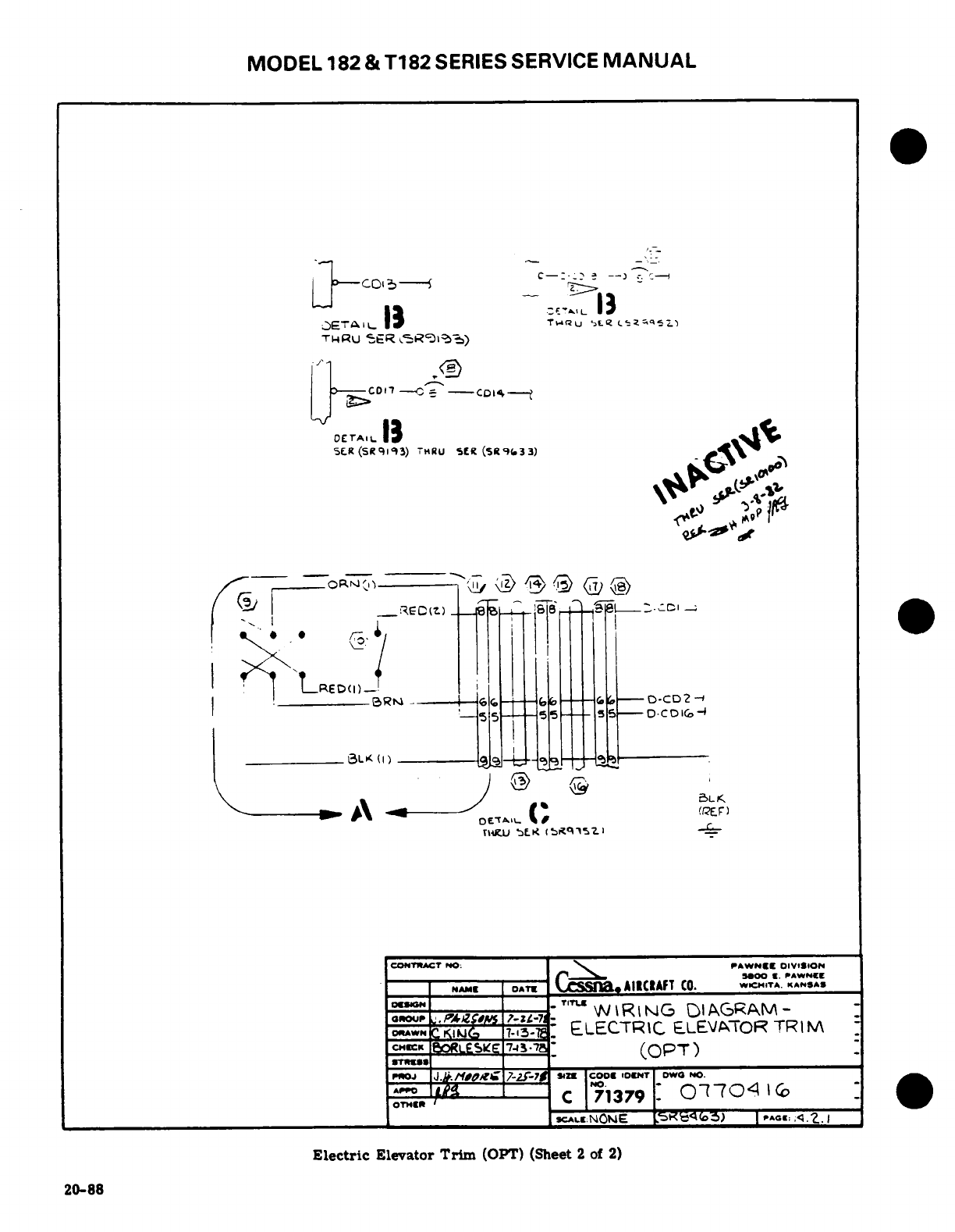
MODEL
182
&
T182
SERIES
SERVICE
MANUAL
--
.
_i_ |9~
h)i, j._
.
z.)
rIe
1}
TrDu
?.)
tZ:'S5,
TH-RU
-ERq i19 1
3-)
CDi-co
7
C!O
-.
-DIAW
DNETAILAFT CO.
w
4
R
NOJ
I
714.
/u
coo
-E
WON
R(S13) CRU
t1
(
s
5
D-
C3 o
,, ,
'QP
,r-
"^
I
CC__NTACT
_ _ _ _
PAWN__LA
DlW5|0hZ
ow 0A1AZS
~"-;-#.i
ELECTRIC
ELE\JA'OR
TR
I l
SttWt
LEZG
'-'
Z.,.G (OPT)
OT,,,,
'I
c
71379
07-{70
1
(o
Ica~s
N<*.4E
c». 1
/903)
|
^*
;<
2.1
Electric
Elevator
Trim
(OPT)
(Sheet
2
of 2)
20-88
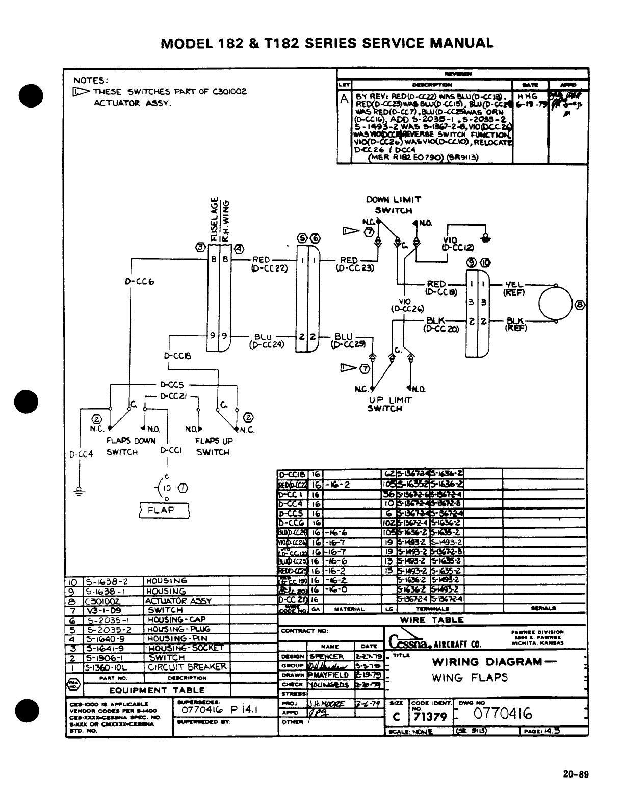
MODEL
182
&
T182
SERIES
SERVICE
MANUAL
NOTES:
_
-
[
'
THESE
SWITCHES
PART
OF
C30100Z
BY
REV.
RED(PD2)
BLU(D
1
.
ACTUATOR
ASSY.
A
Y REVDtRED(D-Cu2) WClAS
nD-CC
.
n
wSRED(D-CC7)
.BLU(D-CC2)wAs
ORW
p
(D-CCI)
ADD
5-2035-1
,S-20JS-Z
S- 149..-Z
W.kS
-13-24,o 3r Cz2
WASVtOxlREE
SWITCH
PUICTIO,
MVIOC-C35)
wkAVIO(O-CCto),
RELOC
D-CC2
6
J
DCC4
_
(E
R
R
I82
EO
790)
(SR91l3)
uJ
DOWN
LIMIT
.
Z
SWITCH
<~---
®
---
(D-CC
8
-RED
I
RED-
CD--
IS
(-CC22)
D-C
3)
D-CC6
---
RED-
I I
-EL
(D-cc
)
(REF)
°C)
33
()
(D-CC28
BLK
Z K
Blu
--
L
' .
|--
9
9
-.
BLu
--
Z
2-
BLU
-- )
(D-CC
24)
(p-CCz-
.
D-CC5
-LC.'
J,
-
C-
O-CC21
-C
UP
LIMIT
SWITCH
N.C.
NO. NO.
N.C.
FLAPS
DOWN
FLAPS
UP
D-CC4
SWITCH
D-CCI
SWITCr
I, L6-,o
_T)
g~g
iefez
rgi__
__
1io
Q
16
-16b-
-C_____
-
________
16
FLAP
g
R_5__16___
16
-
7_
-
-
Ta
__
16
__ I
19
S-ZO
-
SIF32-1
1
JU~o-C
iG-I-/
f _____15"l-Z_-35-Z ____
I
-r16-7
119
4-93
-2
-
a 16
-16-6
13
1
5--2 ______
l
H-5Gr16
-16-2
1U 5B
5-15-2
_
_
10
5-16038-I
HOUSING .c IC
(
-I-2O
I
-63-
Z
-1 -Z__
9
5-1638
-I
HCOLSIG
__ _ _
6|< i,
-16-0
|Srf Z 5-2 |
|
a
C30100LZ
ACTUATO
A-5Y
I
DCC
21
16
___
_
7
V3-1-D9
SWITCH
FA____ I
MATERIAL
LG
TE-MINALS
gUAL
6
5-2035-1
HOUSING-CAP
1
WIRE
TABLE
5
5-
2035-2
HOUS
ING-
r
PLUG
_COT A
O:
r voN
4 5-( 4
0'9
HOUSING-PIN
O
L
.
PAr^WE
3
5t-I&4
-9
HOUSIN--
SOCKET
INAME D-ATE C
.ACIA
CO. WICII"A.
KANSA
z
5-1906-
SWITCH
_____N So
P
.P
t--19
Tm
I
5-o1360-1L
CIRCUIT
BRAERK__
OOu.
.O 1,,,
WIRING
DIAGRAM-
PARlT
NO.
DECRIPTON
--
o-ftAwN
MAYFIELD
-
I
-
WING
FLAPS
&*)
E----------------------
-------
CMICK
?l.k.N.
..
-.
-K
'7
EQUIPMENT
TABLE
CCK
sm8
CA-1OO
o1
APWLAL
SUIPESDE*:
OJ t-7f. »CO= _oDE
wT.
wo
no
v
"ooDcot
cam
uos P077041( P
14.1
*O-P
m.e
-
CXXXI-s
O
c.AL
*
,l.
71379
07704
1
6
4XO
Ca XXXf
X
A
-CI[IaB
my;
OTl.
[
I
TDOI.
o.
______________t
)
Fi
PAOE
14.3
20-89

MODEL
182
&
T182
SERIES
SERVICE
MANUAL
REVISION
.Ll
.
OtCR
IPTIONf_
.
TKI
AmPo
A
SY
RLV"
-00
NOTEL
Zf
J8 Z, 0_ cioloo,
5-s-
la
NOTES
:
D:
IA'TERAL
\S
RCF
5130C
COIL
CO.D,
VL.NOOt
CODL
(091G)
INSTALL
5-1071
ruBING cWOVA
CDIl
wIQE.
_IFOOL
,,i5rsT:u-.
rget^iN^LA.
_ IS I.. =NkT:
/"INI I
.
i
-9
_
j
20
-20-
-
.
-
-
&-1.481-3
w
_iTC.
q
4'443052.57
TRIm
AC1uAor 0____
_
B
-&46-%I
COMuXC.TOR
___3-3___ ____________
|-232|-a
C19R=1
MECA
AG
MATLaAL
_
TEp4AIL
SpAL"
6
S-I2i-z-O
1
HOUSING
WIRE
TABLE
5 &*IL-I-O
HOJSIN
COC
P A
DIVISO
_4
-_70030
CAS:LE
AUy
CIi__.-
C
AI"CCOAF S- CAO
.
4Z0 0a223 r
AlAn
SAUY
aA
--
IC.
______
23 i4
COouoECTOR
-R._
KLEIN
.--
I'G
1
7205P4
SwIT
-c
aeD
PoiMbi
WIRING
DIAGRAM
-^.r
NO.
_ ,,.a
R
.
KLLN
t-2
ELECTRIC
TRIM
(0or)
EQUIPMENT
TABLE
=U-COD
"
P.MA
r
G
O
c NOo.
-
4
S
vroo~ cor rh _ ~ao P6,o
4
s-
t_.2.
1
,
Ci3
79 _
0770
1
+ 1
-4K
o :M oa
CO
up.
Y OTH71379
Ns'_ro. o
,
_______
0
1
/4.4.0
20-90
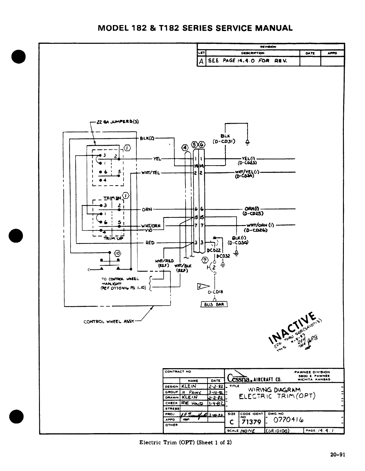
MODEL
182
&
T182
SERIES
SERVICE
MANUAL
*LETJ
_
DIECRIPT
KM
DATE
APPO
A
SEE
PAGE
14.4.0
FOR
ReV.
22GA
Jumptb(3)
|I I
*---',BLK
_
J_-
.... (C-
8...
BLK
11
5
r-- ^o
I I
(-co'
WUT/YEL--
2-
W-- S-(-)
64
,
I I56 I___,.,.,.ol-caas)
_
TRI.
»((D
IO-t, f! o
|
.--
_---,
I
,
5--WTR-
-
757--------OT
---
*l I~ t I----^
-
I--l-
v:l1
0
-- )
I
(-co.c)
L,-I u
I.
T_
IM
UP
_ 8I(
-
O-0
4-4i> I.
1.10)M
M
-
l
l
CONTROL
WI4EL
AW
STS
(
o-cois
~coMTrOaL wu~ee.CNRC ASNONT
CONTRACT
NO
PAWNEE
DIVISION
-
5^I
.600
E.oc
PAWNEE
.
NAME
DATE
[
.tSSna.AI1C»AFT
CO.
WICHITA
KANSAS
DESIGN
KLEIN
2-2-
TITLE
GROUP
/A
PAINE
3-o
u
-
WIR\NG
DIAGRAM
DRAWN
Le
tIN
T
-2-T
ELECTRIC
TRIr
(OPT)
CHECK
RgE
HkcK0
116
STRESS
PROJ
RSa..
5pJ.rL
j
SIZE
CODE
IDENT
DWC
NO
A:PD- 1
7NO1379
0770416
OTHECR
C
71379
I74
SCALE
NoE
(SR
10i00)
PAGC.
/4.4.
Electric
Trim
(OPT)
(Sheet
1
of
2)
20-91
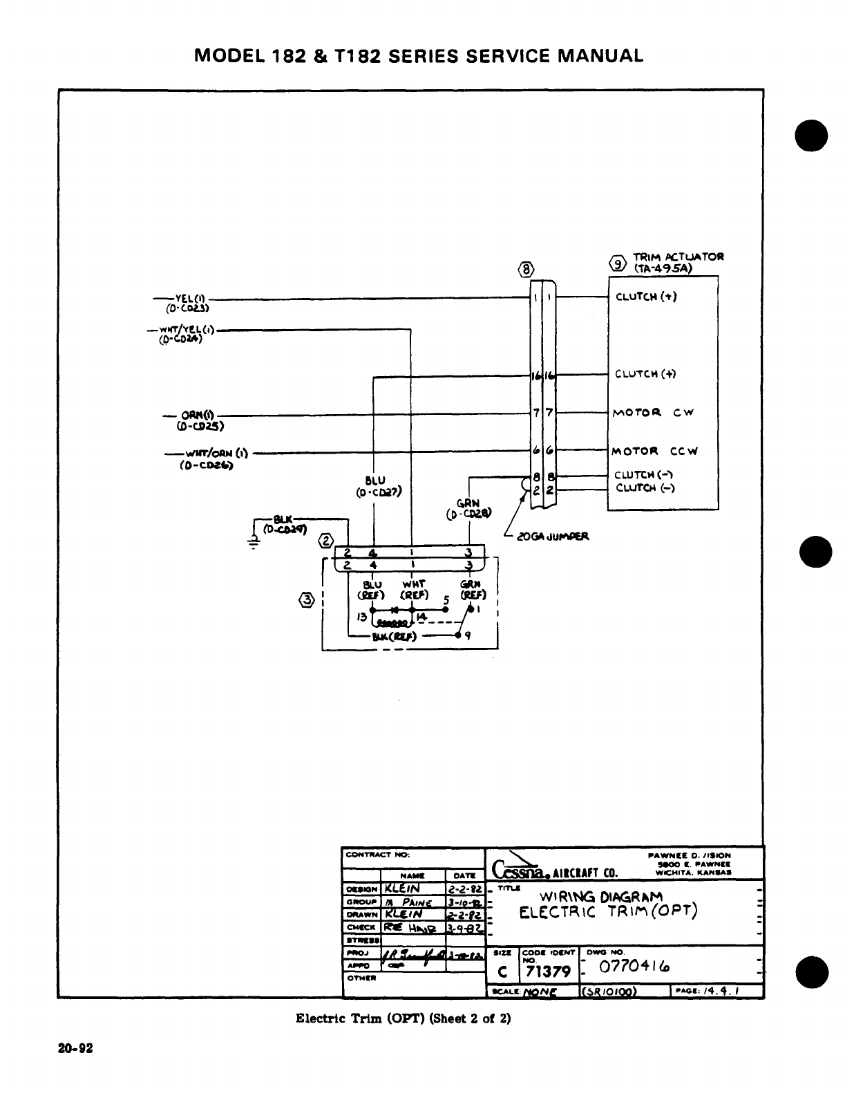
MODEL
182
&
T182
SERIES
SERVICE
MANUAL
TPlM
CTUATOR
(TA-495A)
-Y.L(l)
CLUTCH
(4)
.---- 1
'CLUTCH
(+)
-OR----I-
-----
) --
7o7---
foroR
Cw
(D-c~kS)
_--wKT/OoR
(I)
---
6
M
------
NOTOR
CC
W
(0-CD2.)
bLU
,
88
CLUTC
4(-'1
(o-
cDa)
(2
-
CLUTC
(-)
rt2
4
W
X
J
B L
SLK-----
_
.
oarr)) G
uD
CO~fiT~t
.
PAWNE
E O
.
1ISIN
o
KEA-A C
^
ltfTt.
WCITA.
KOANEA
NAlIEAFT
__0. _
C.
PAWNEE_!
NA
ME
CAT
Ca SFZCE
O
WCOE
fDENT1
DW'G
NO
oO
.v..
C
71379
077041e
*
I
S
'N- Sa
-
/4.4.
oR
G
RP I A
)
5
(ftWDI
lectrc
im
(OPTR)
(Sheet
2
oTR
O
2)
20-92
-
r^'
NO.
37 0770414-
OTHER
C
171379
NCAH:
EONE
(SR
10100)
I
PACE:
/4.4.
i
Electric
Trim
(OPT)
(Sheet
2
of
2)
20-92
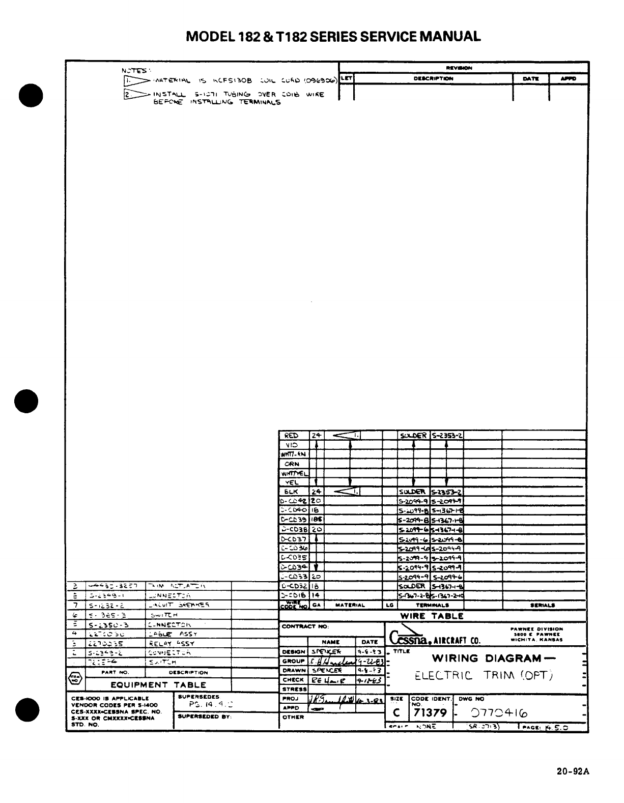
MODEL
182
&
T182
SERIES
SERVICE
MANUAL
N
.>AlkTekl*i
l>
1
%CFSIlOB
-OiL
_UL
'l01bC
)
LET>
DESCRIPTIO
N
TL
| D |F
*(
Z^S_
INST^U_
,-1i:ll
T6BIN<J
3'ER
;Ole uWIKE
ND
|Z4 | | | S__
R
s____-
iwrtn.T^M*
_I_
_ _ _ _ _______
ORN
w
HT
_3
L
6LK
Z4-
-
_ SD
'
S-
3--Z
D- c z 2o
5-zoiq-
s-Og'
____
=-
Cb 410
S
S-3
_ S-___
-"
II
___
_____________
'-C±36
I
_
s-2o-
S-t3s7-_-______
-
cO3b
ro
S
.a1-I
-s-
$-( _"___
oC3-=t
______ Sr» S-Zoq
-q
.
___-____
_-
C-'O32
_ _ _____ S-_____ _ _s-_ol4____
.G
''
S
20..o _ '-1
S
-o:T
-
_________
-'
7-
-.
'--i-C ______NJ
T'' S-cb
1
'
--
,
4
--
I-i
.-
NNJ:T_|_____,; ____
DI6
14
___________ S--i
S-13
_______
7
S
_'wl g ____
_
c_ No
*
tlAL
__LG
T________»
____
»_*_
"~7
S~°
.-
"~--
,
'
_
vT E,-v^ _ IR
IGA
MATERIAL
LG
TERMIALS
SERIALS
c
~
3s-±
srTtc,
WIRE
TABLE
_ 5- cS
-
_T^_________ _________i CONCT
NO:
PAWNEE
DIVISION
*4
_._'~ _C_____ __ _
\SST
-
_
'
r
100
C PAWNXK
_~. .,-;-~ ,5
EL
R
u
.
SS
Y
H _
NAME DATE
ss
aAA
IICIAFT
CO.
WICHITA
K"ANSAS
5
;.-
,o-L
7I.Jc.- f r
DESIGN
PPsr
sc-
s-t-3
,
TITLE
--.
,:-:
'_, tr/Gr..ou.
c
--
WIRING
DIAGRAM-
_
PART
NO.
DESCRIPTION
DRAWN
'S {ec1
q-
-TRM
O
---
2---
.
, ,
,..I'-- __ _.: TLEQTRI
M
TRi OPT'
EQUIPMENT
TABLE
STES
-
CCS-10OO
Is
APPLICABLE
SUPERSEDES
PRJ
v
lX
.
SIZE
CODt
IDENT.
DWG
NO
VENDOR
CODES
PER
5P.1400
P
.
A.
(
1 No
CES-XXX.CESSNA
SPEC.
NO.
-------- 3.- C 71379
S-
X
OR
CMXXXX
OR
CE
A
SUPEIED
BY
OTHER
STD.
No.
P
AGE:
CI
.
20-92A
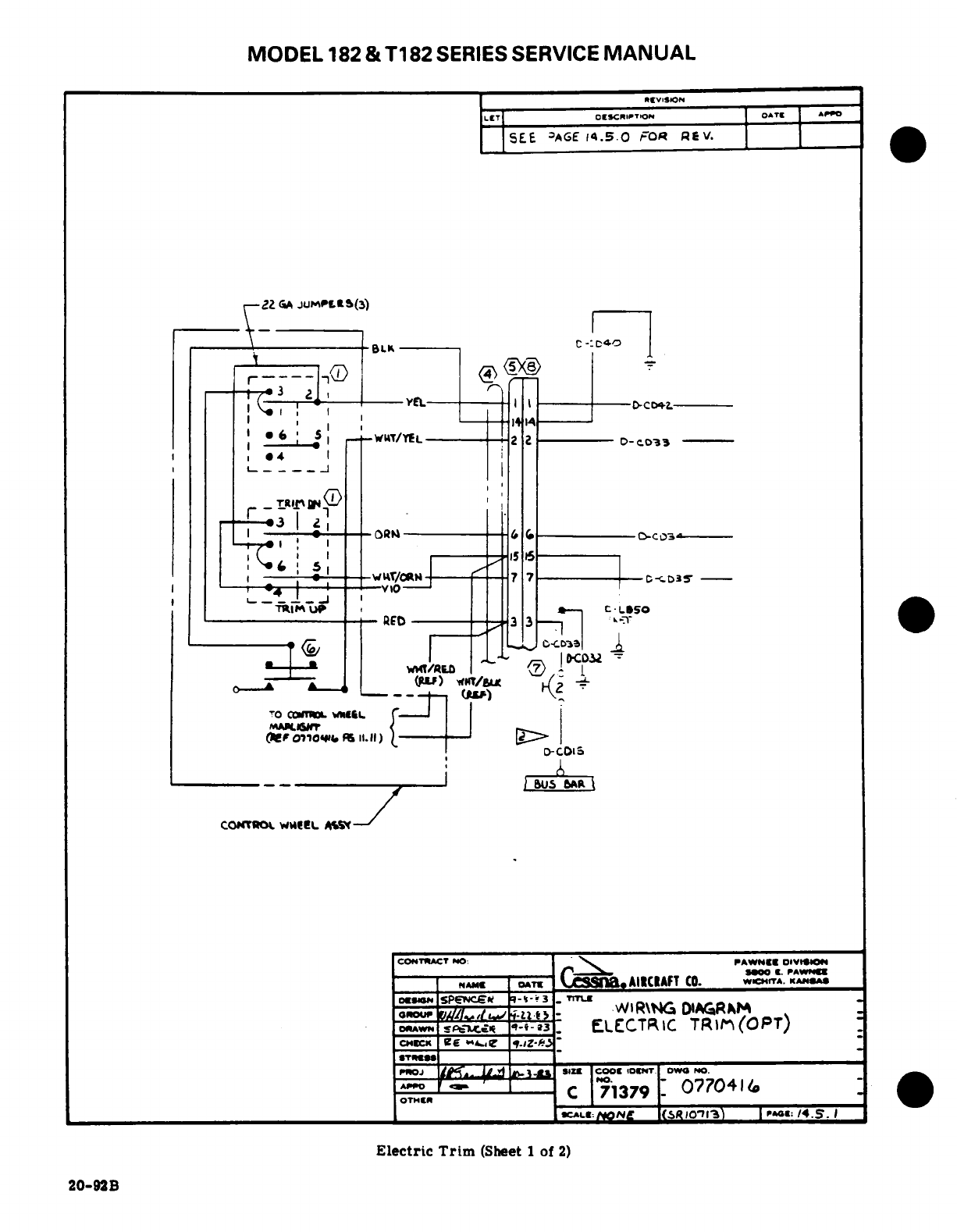
MODEL
182
&
T182
SERIES
SERVICE
MANUAL
rfVI~SON
L.T
l
0SCRTlT
TO
OATCI
AP
SE.E
ZAGE
14.5.0
FOR
REV.
Zz
GA
JUMP/^tt(3)
I
---
LD
I <=
--
BLK
I
4
I
i
rIu7
I
_Tt 0»P
-OBM
---------
-.
^ IC
- --
(aIu)
I I I I- I& c -
I
--
07-10e4lo-o
FI '
..
-11)
CONTROL
WWiELM
Ai&
--
CONTRACT
NO:
PAWNEE
OliVION
NAM[
C.
W
r
ATA.
6 R
PAMNS"
RAWN
-__ .
ELECTRIC
TR
I(OFPT)
CH cam E -WMIC f-
--
MAN.16KJ
$1=
CsD
logT
DOWO
NOD.
20-92B
Te I(lR\f G ,,4
-;/4.$
20-92B
~
~ ~ ~~T
«
_________
________________________
"
w
-
1
·
tf. 1" P"Ha IKCOKllT W
O
(pu
^**r^ 139:070K!
O T C i w
'
"________________
^
---------------------- ___________'O*
COI*g
(^0-1^ 1
..
4..
mrrrgEetrc
rm
She
1of2
20-92B~~~~~
o~~cc
5
11
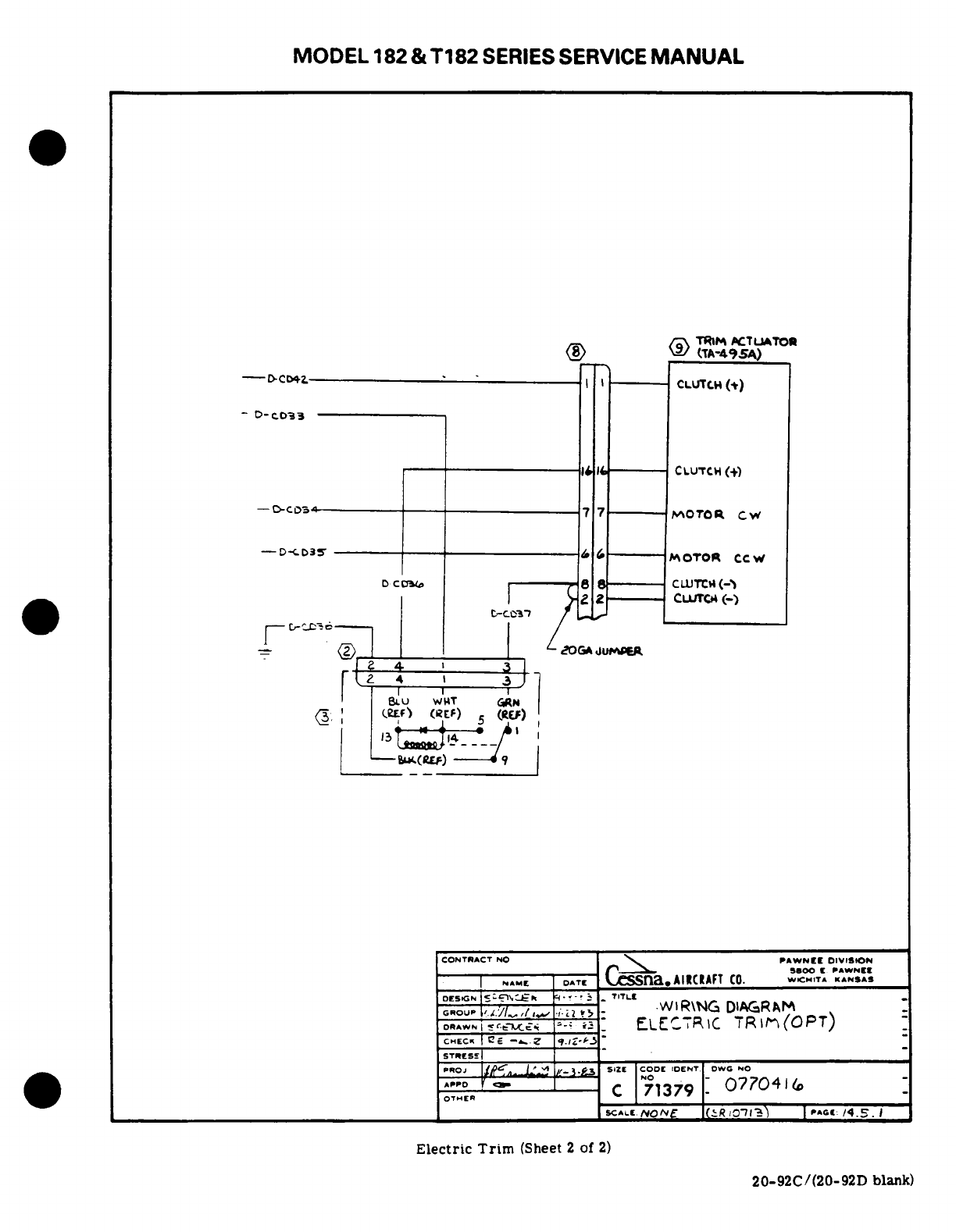
MODEL
182
&
T182
SERIES
SERVICE
MANUAL
s;\
TRIM
ACTUATOR
>
/
(TA-495A)
-
-CD-.
CLUcH
(^)
-
D-CD3
--
7
Moo7R'
cw
--------------- IGI/----
CLU
TCO I
+)
-D-CD3S
6
--
MOTOR
CCW
DCo
-
-
8
8
CLUTCHI
(-'i
C I >
2
2
CLU'
Ct
(-)
I
<2)
__ ___ ______ _
ZOGA^IuPER
[42
4
,
3J
BLu
wtT
WRN
~5.,
,
,(pE)
(REF)
5
(?)
I
I 1
13t,__.
`1
4
--
lK.("F)
-9
CONTRACT
NO
PAWNEE DIVISION
___________________
_______ S"'---
5800
I
PAWNEC
l
AME
DATE
Ces
a.AIICRAFT
CO.
WICNITA
KANSAS
DESIGN
-1%,l:.~k q
--
TITLE
G.ROup |.
X
,-
_
IR\NG
DIAGRAM
,DRAWNi.":_
_ _
-_
ELECTRIC
TRI/M(OPT)
CH£ECK |
g
-_.
q./-*3
_
STIESI
_
PROJ
ZIPc
[' l
-
5ftS
SIZ
E
CODE
IDENT
DWO
NO
A^PD
-
C
71379
077041G
OTHER
l________________________ ___
SCAE
ON
(,'RO71)
PGC:
/4.A.
.
Electric
Trim
(Sheet
2
of
2)
20-92C/(20-92D
blank)
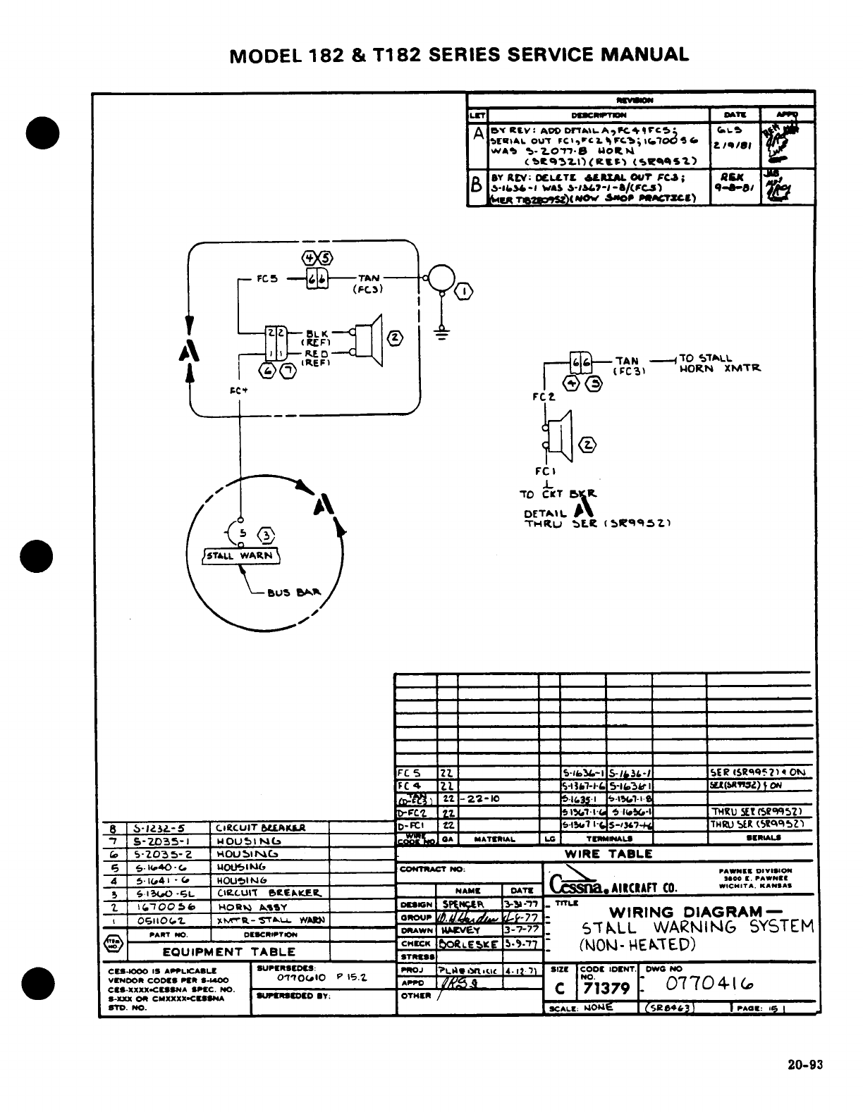
MODEL
182
&
T182
SERIES
SERVICE
MANUAL
LET
D-CRMPT11N
DAl
FA
elItv:
A00"t
wAb
'b-2.0T7-ms
uoWR
b
BY
Rfy:
OCLTL
6LRXAL
ou
FCa;
aK
_
gkcTiaa2Vp9W w0f
aZ
PRACMICI)
_
|
FC5
--
T
A-TAN
---
)
/
(OCST)
FI
Q
t
-- '
BLK
{ t3 FF I r'-_TAN
-TO
S'IALL
I1 ©0 l^L(LFCt'
WORN
XMTRt
FCl
/''
"
TO
CKT
it&-
i
F5-427l _ S1il 5-1 b OU
A(.RI
W
A))
t
ON
\ V
-22-10
= 351
$
_7_
rC t
I
_________
.
IA ____
THRU
SET
Se
tD52)
8e s-laL-5
CIRCUIT
6UAK«
LA
'
D-FC
2
________ __
-1S
1- S-7-
THRU
7AR
(U
5
b
7
S-ZD35-
I
w
U51
Nab
_____ Acs
MATIVIAL
LG
T
SERINALS -Al
*
~c
3
-20
5-2
HOU
.,I
N ____ IWIRE
TABLE
6
6,
K,40.
C.
f
w0U-te.I
_------
-
CONTaRACT.
PAWNEE:
IV110
--
4
5-
14
4
-G
HOUoINl
-"
0
ENB
1.
PAWNIE
5
S
I30 -5
CjL
CIBLLUI-
159IFEL1
ur
N
-T
|
LCSWI
AIECRAFT
CO.
WICHTA.
KANSAS
1
C.700
5b
HpORls
AsSY.
DMIGN
$SpNCE
3
.-
71
TITLE
OCI'IO.
t
R-S-rT^L
Wa
.
GROUP.
-77
WIRING
DIAGRAM-
A
RTTNO.
OCIT
--
DRA
WN uACV'EY
3-7-77
TL
5kLL
WARNING
SYSTEM
VV
EQUIPMENT
TABLE
.
__.O
.2LF1~..
-
(hNO
O-
HEKTED)
CS-.1000
IS
APPLICABSL
SUPERSEDCS:
PIRJ
,lA.Inl
4.
2
1
SIZE
ICOD
IDINT.
DWG
NO
VENDOR
COOKES
PER
-MOO
0TO(.lO
PI
IC.[
9
NO.
-
A0
CcS-KXXXXCSuISNA
SPEC.
NO.
I
71379
07
4
SXXX
OR
CMXXXXC__IA
_UOIDDD MY;
OTHIER
C/
13 CLE
STD. PnO
I
^ _ ^ ^ ^ ^ ^ ^ ^^O.^
SCALZ
OI
4EL
: I
E
6
«t-3)
I
fAO:;
I§
I
20-93
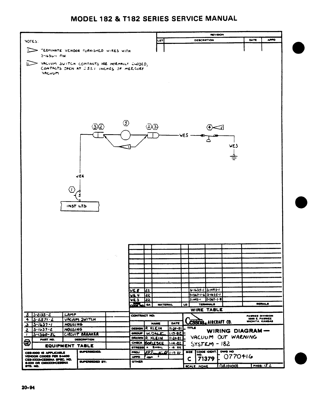
MODEL
182
&
T182
SERIES
SERVICE
MANUAL
OTEr;:
TIC
DOUCITO
|I
ATT
|
O
; '>
--
E..MINATC
VENOOt
:-URNiSr4LD
WIRS
wITH
iT
/S-
5',-_
BPIN
VALCUM
./VITC-
CONFTACtv
al /tPCI^ALLYr
,O£ED
)
ConmrAc(TS
3:PN
ArT
5I.
I/NC.ES
-t
fe£.Cutr
vhc»ynr
W
< 7 L-
/E5
_z _
wE5
4E4
IN3T
LTb
dL..
It
__A__________
m-- if7*
______
WL3
za.
_
____-
_
i-7-e-
L
GA
IMATN.L
-a
T1MU.LA. L.
WIRE
TABLE
5-2135
-.-'
LAMP
COml
r
aftwN0,
-r-_
a
-
t.
_AKUA
____ _>-I _2£________ _____
cci
MATNE
O------- |-- L -------
IECE CO. 1
--
4I
5-zs
?1i
-_
VACU
_UIM _
_____
_ _
_ _ _ _ _ _ _ _
__
_
_
aC, 6OuLrT
N-
--
o_
M
.»--_ tRI. .e.
WIRING
DIAGRAM-
PAW
No.
aa-m
AoHgg. .,LLAr 11-(o-ll_
VACUuM
OUT
WI.lN6G
CHO=
2 _
s5'z
-,4
5
EQUIPMENT
TABLE
---
-y
a-
LWE SYsrE-)
-
182
-
-
IA
,OaL
I
i
AMUCA5Zo a JAPP
Pow
?
_ OMm
*I
como
'
?
I ow wSa
NO
s-mWOm a CWOOON JM NO @0N.
0770
I
I
,r..==^
----
C
71379
07701
a.-
me".
-
I
_____ _CAL
NN
rlAol
I
PAs
i.
20-94
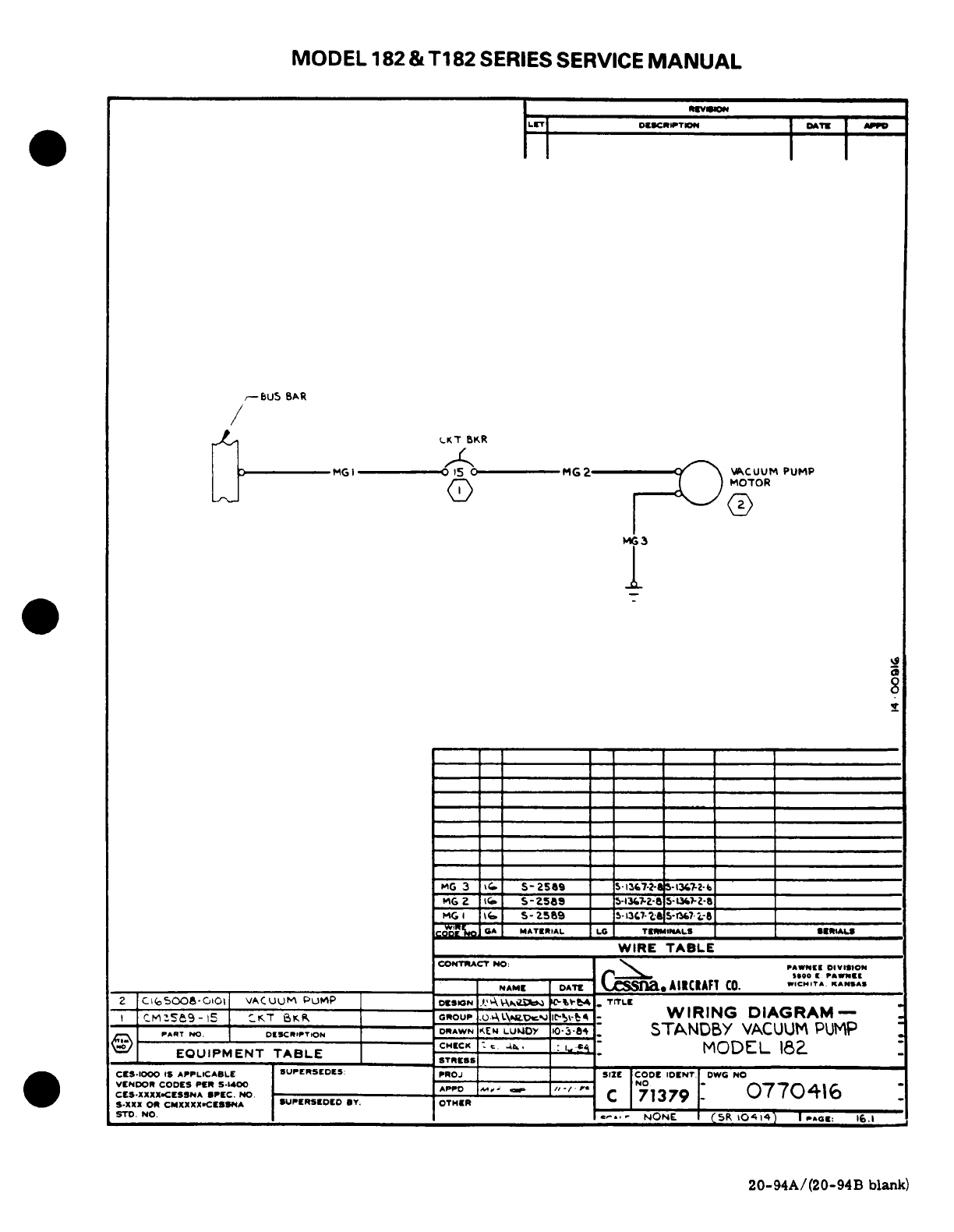
MODEL
182
&
T182
SERIES SERVICE
MANUAL
LETJ
DEOCRIIPTION
1
R
mA
-BUS
BAR
-KT
BKR
-
MG
I ------------ 0
15
0
MGC2
2\
~CUUM
PUMP
MG
3
S-258
1 -1
-2--13
-
MGI
32 \
S-2589
5-137-?-8 5-137-2--,
MGI
m1
5
-
zSD9
_-,3c,-
cs,? .~5.67
,-0
GAo
MATERIAL
LG
TERMINALS SERIA.u
WIRE
TABLE
CONTrRACT
NHO PAWN1
DIVISION
IeoO
(
PAIirE
INAE
^DAT
AIRCRAFT
CO. WICHIT,. K^,%
Z
CiS008-OGIOI
VACUUM
PuMP
DESON
.J.e. A ,4
TrrLE
,
CM:se9--5
:.YT
67
R
'
GROU.,P
.-\OU,'9
WIRING
DIAGRAM-
^PRT DO.
sc-r-eo
DRAWN
KEN
LUOy.
1
03
STANDBY
VACUUM
PUMP
EQUIPMENT
TABLE
MO
CES-1000
IS
APPLICABLE
SUPERSDES:
PROJ
SIZE
COO
I
O
DENT.
DWG
NO
VENDOR
CODES PER
S-14OO
APD
A-,,
--
'70
s.S'.
XXXEs..^
...
c.
AP
.
077041G
S-XXX
OR
CMXXXX.CESSNA
ESEDED
OTHR79
STD.
NO
.....
NONE
(5R
w0414)
I
rA9
16.1
20-94A/(20-94B
blank)

MODEL
182
&
T182
SERIES
SERVICE
MANUAL
NOTES
IqNsO1'TlE S ,~~LE:T
DECRIt"TIO
DATE
A
AP
INSTALL
S-1071-3-
18.0
TUBING
OVER
PAI
A
BY
REV
PAI
6AS
W^S
P A'I
AIG
MT
wIRE
BEFORE
INSTAL.LING
TERMINALS..
S-/347--8
WA-S
S-'37-3-8 ^
5-'37--/0O
WAS
S.5I?3-3-10
-3
B
s~
KtV:
S-1Z>2'l-L WA% I1L-5/
G
l
_
*ITe*
I Cu q_
_S2)
-
1. *|
5
-
5-1
7
*F o*'
q
5
i3Zi-
jO
CICA.JIT
aRK~CAE
-7
S
i(~O-
5I
L
CtlkCUl'
aRE3If
E
KII
k
__ C~lo'.2
G.
I
ATERIAL
ILG
TIWRMINAL I
SERIALS
A
-S3.60--1SL
c_,coirT
REAt
____
WIRE
TABLE
5
S
13.0-5
L
CC.UIT
E----KE
--
CONTRACT
NO:
PAWNEt
DIVISION
4
S-
I 3Z- C _ _C.rCuiT
BREAER
l __ SOO E PAWN
E
A
27.0oc
4
buS
B^
,
__TE
S
N
.AIR
CAFT CO. wCl T
KANS
AS
I
22EQUIPE
TASEIT ____ STRESSM _
WIRING
DIAGRAM-
AN-*
r
NO.
oESCRlTlON-
oDRAWN
:ueglS5
..
.o
CIRCUIT
BREAKE
RS
7 S- ---------
CHECK
IOCLES
E
4-
.
.o
'
'
:
i
SEQUIPMENT
TABLE
S
CES-1000
IS
APPLICABLE
SUPERSEDES.'
PROJ
C
.
J-Z.I-c
SIZE
CODE
IDENT
DWG
NO
VENDOR
CODES
PEI
S-1400
APO
07 7
NC
I
CES-XXXXCES
NA
SPEC.
NO.
0'
71379
~
I
S-XXX
OR
CMXXXXCEStSNA
SUPERSEDED
BY.
OTHER
-
7
0
STO.
NO.N
scA
E
NN
(SCA
SRC
3E
1
|.t: 4.1
20-95
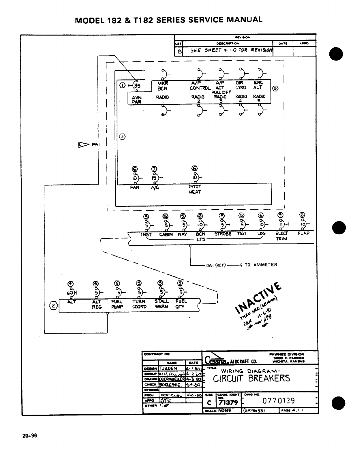
MODEL
182
&
T182
SERIES
SERVICE
MANUAL
*L»T7i
O"CNWION
0 aT
App
b
SEE
SHEET
+.
i-0
:oR
EVISlI
OT
L(3
|
MKR
A/P
A/P
01R
E
|
-
BiCN
CONTDRL
ACT
GYRO
ALT
(
;PU.
OF
F
AVN
RADIO
RADO
RADIO
RADIO
RADIO
-
PAI
I y >15
1
FAN
A/C
PITOT
I~ MS4~~~EAT
I
?NST
C
NAV
BCN
5TROCE
TAXI
tDC
ELECT
FLAP
_-
OA
----
DAI(REF)--
TO
AMMETER
\/ REC6
PUMP
COORO
WARN
QTY
5
v \
CONTRACT
NO:.
PAWN-'
OIVIONW
__
M
oAM
\jCO S
AIAHUFT
CD.
WICHITA,
uKAA
OINjAOEN
-I\.6o
Tm
u5T^SOv
E
ES-o
'a
WIRING
O\AGRA^M-
_e:
s:.
_
CIRCUIT
BREAKERS
No
C
7i379
:
0770139
oT"
ILF
C
|
71379
01
9
_
~
_
»3NONE
(
3SR933)
rp
-
S4.l
.
I1
20-96
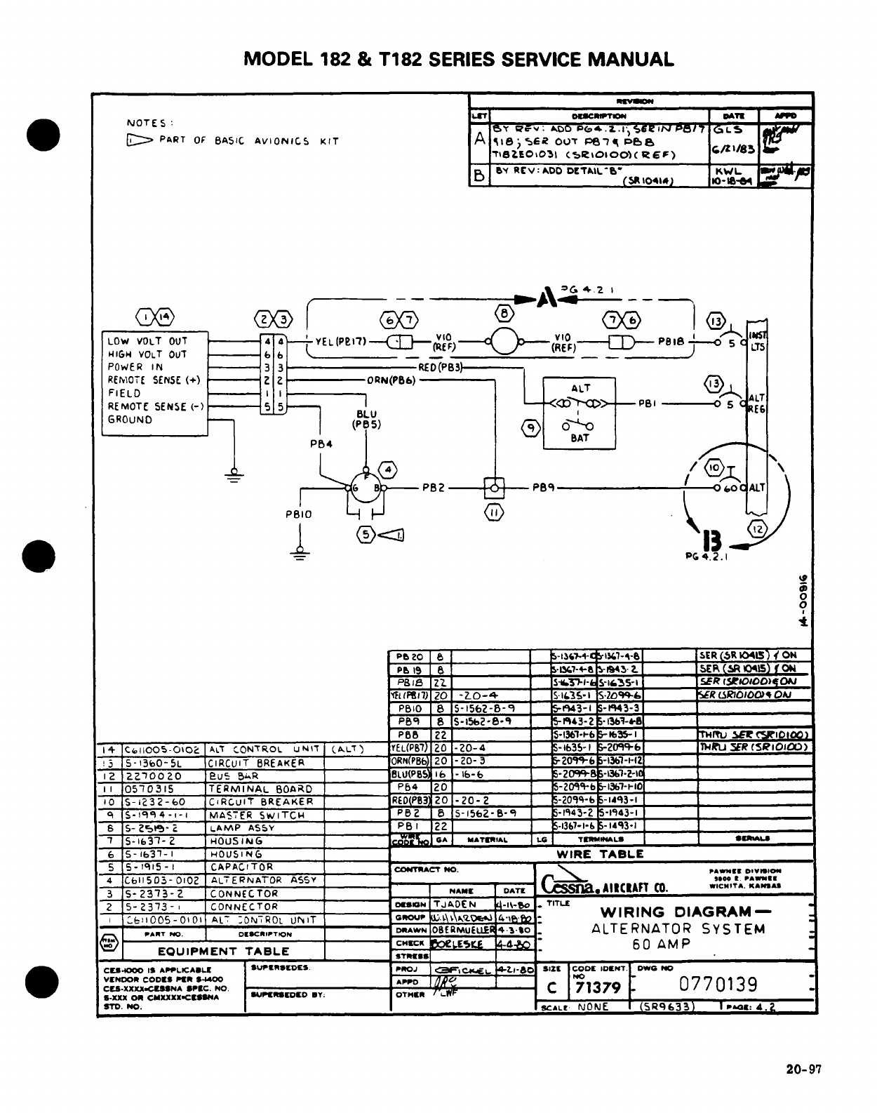
MODEL
182
&
T182
SERIES SERVICE
MANUAL
E
OTE5 gglIPT-ON D-ATE
NOTES
'
VlI
O
lw
L
D0
PART
OF
BASIC
AVIONICS
KIT
A
le;;
S6E
OUT
Pe-7
PBe
E
I
r
2IEO1031
(SRIOIOO)(cRF)
CRE
b
BY
RCv:A0
DtTh.L-6'
"KWI0
,
'________G
.2
1
- -
f
p-
~
-
--
-
LOW
VOLT
OuT
4©(:>
4
YG CEL(PPI7)---=
_(Rec)
--
REMOTE
SENSE
(+)
----- Z
Z
ORN(PB6)
ALT
REMOTE
SENSE
(-
-)55
'
L
U>~PBI
--
5
C RE
--
0----PB.4
,|---1
BAT
,
B 2PB
--
6
PB-/O8OC2T
\
/
PBIO
H
( (
/
P
'
10
01
'_~'~~~~~~~~~~~~~~~ ~PG
4.2.1
0
i
P
tZ
8 e I',-i36C-
l37-^-8
_
SER
(.SR
10415)
ON
PBI
18
1 ___
L7-c
-143
.
I
ISER
(5R
0415)
ON
PBS
ZZ
____I_
_
S-.I--
L
3SI-
___5-
SER
SflOIOO)CJ
fI(Pl7)
ZO
-ZO-4
IS.IL3-I
S-2o20 __9 _
SRL
(ROIO*
O)q
PBiO
8
5-1562-8-9
1_
943
-13
5-43-3
PB9
8
S-ISbZ-8-9
=143-
-2
_____13b-
PBB
___ _
5-1361-F
S--35-
1
THu
_
"
SlD
IO
)
14
CtlIOO-OIO0
ALT
CONTROL
UNIT
(ALT)
YEL(PB7)
20
-20-4
-l1b35-1
ZT52099- TU YR
(SI10100O)
!3
5-130O-5L
CIRCUIT
BREAKER
0RN(PBe)
20
-20-Z3
-20q-f6
-131-l--IZ
i2
Z.'0o0o
eu5
,_____;R
BlLU(P8
i
-lb-b
_-209/-
-131--I
___l__-.-0
11
05
031
S
TERMINAL
BOARD
P64 20
_
5-209-6
1367-IO
_
___
10
S-1232-bO
CIRCUIT
BREAKER
RED(PB3
20O
-20-2
-2099-b
-1493-1
q
5-199I4-i-i
MASTER
SWITCH
PB2
B
5S-1562-B-q
9
-1943-2
5-1943-1
..
6
S-
25e-
i
LAMP
ASSY
PB
i
22
__
5-1367-1-6
5-1493-1
7
S-
1637-
2
HOUS
Il
G
M
i GA
ATERIAL
ILG
T
MINALS
S
RALS
6
S-ib37-I
HNOUSING
_WIRE
TABLE
5
5-1915
-
I
CAPACI
TOR
CONTRACT
o
NOr
.
'
PAWNE
DIVWIO
4
Cbll150-0102
ALTERNATOR
ASSY
r
SOOR.
PAWUE
|3
S-237
3-2
CONNECTOR
N*AME
DATE
.
a
AIICIAFT
CO.
.c.TA.
..
,.
2
5-
373
-
CONNECTOR
DOES
TJUADEN
-I-
.
TITL
WIRING
DAGRAM-
|I
L
lOO5-010I
ALT
:ON7ROL
UNIT
GROUP
.\^ -f-
Wl
T
PART
N.
DESCRIPTION
DRAWN
IOBERWMUEEUI
4
1-o
I
ALTERNATOR
SYSTEM
EQUIPMENT
TABLE
ST
E
0
AMP
CFS-40OO
IS
APPLICASLU
SUPERSEDES
PRO.J
cr,.l
.
D4EN-Cl OzW
iCODE
IDENT.
DWG
NO
VENDO
CODE
PER
S-,4O
APPO
IE
CES-XXXXESNA
EC.
NO.71379
S-XXX
OR
CMXXXX.ClISNA
UCPWEOED
*Y:
OTNR
7
STID.
No.
SCALE
NONE
5I(SR9633)
I
PaE
4
20-97
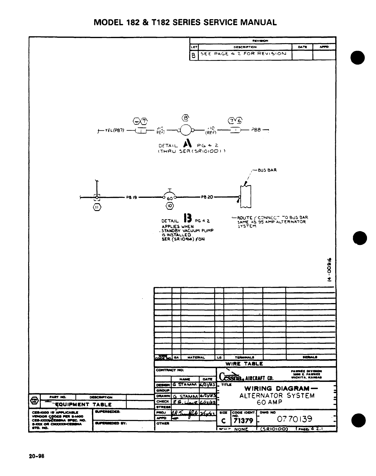
MODEL
182
&
T182
SERIES
SERVICE
MANUAL
LET
DISCRIPTIOM
DATI
AM
B
bEE
PAGe.
4-
Z
FOR
REvi\
'ON
4
-YEL(PB7)
--
rj
-
()
P
B8
-
DETAIL
A\
PC
4-
Z
(THfRU
SER(SRiOIOO
)
,-BUS
BAR
®_
P5
19
®
---
--
PeZO
DTAIL
13
-PG
4
-ROUTE
f'
CONNEC- -o
BU5
SkR
DETAL
PG
4
Z
2SAME
AS
95
,MP
ATERNIkTOR
APPLIES
WHEN
SYSTEM
.
STANO0Y
VACUUM
PUMP
15
INSTALLEDO
SER
(SR
104L4)
fOM
11
G
MATAIAL
T
ToM
AUl
WIRE
TABLE
CONIT
N
1
O:
11Mmi i.
STAMlM
-- M 1
oA
S
T[
Ces
a *
AIICIFT
1o.
»,C,' T"
,"'N
Ro
U._
WIRING
DIAGRAM-
PAWr
PO. PON O€w,.,
,RAig
.
ALTERNATOR
SYSTEM
--
QUIPMENT
TABLE
CHOCX
__________=WR
60
AMP_
cimsoo
lrA
mucAm.
i
UGIMD-i
«Pmoa Iig
".E7
1
AZK<.4
s ZT
Coc
INT.
NO"^^
11a
C
NO.
'"
7
y
379
07
70
139
9,4m
cm=xOCmSA
Oamn
C 71379
mltO.
WIRING _ _ _ _
.
·
SM."D0o
^
^.^.
.-
«I-
-
^"
NONE CSR101OO)
I
PA.
4
Z.I
20-98
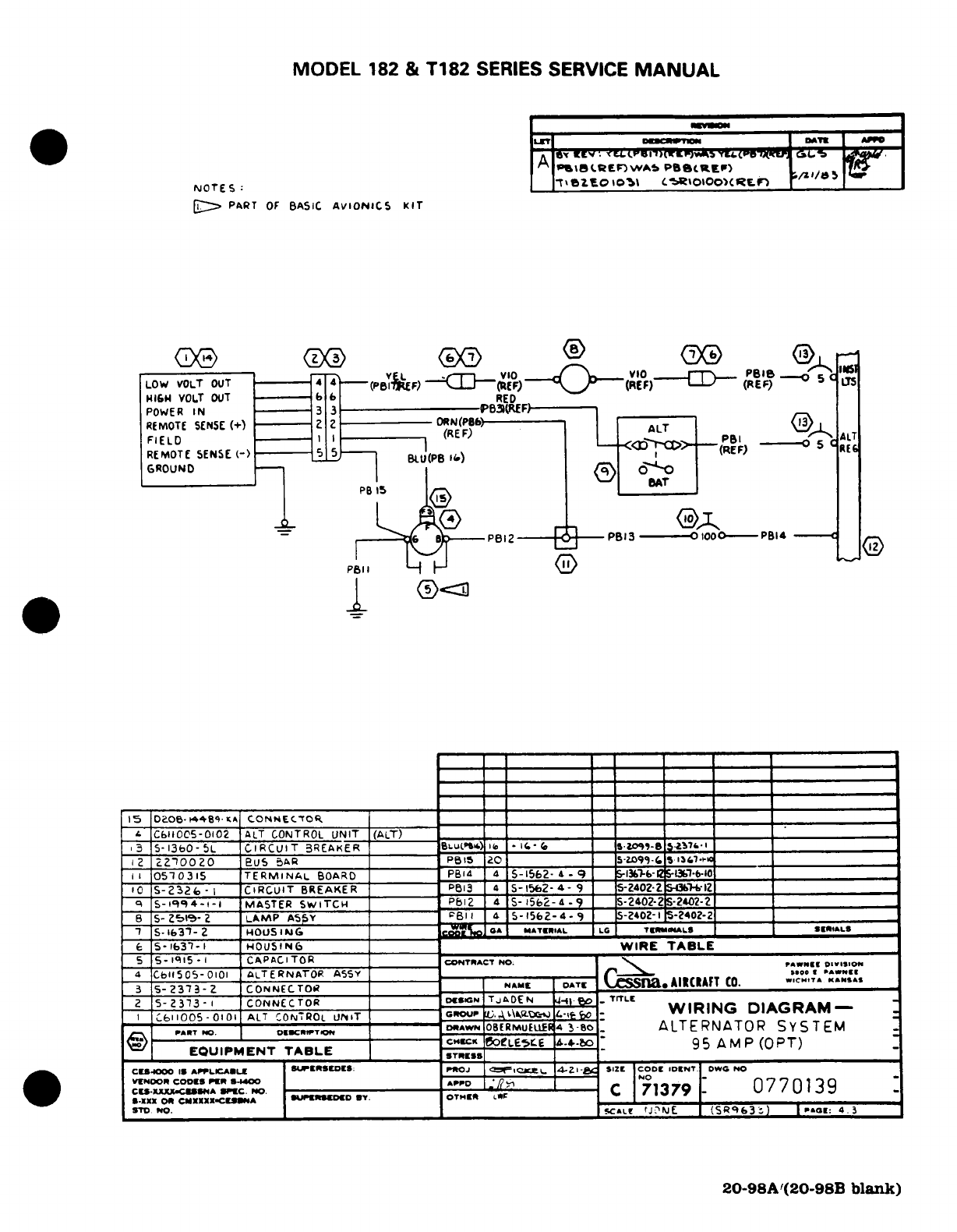
MODEL
182
&
T182
SERIES
SERVICE
MANUAL
LET
DA7S7
AP
A
c
D
I=
L
I8(BRtEwA
PBeiREr}
7i
NOTES:
OIO t IOOcE
[:
PART
OF
BASIC
AVIONICS
KIT
COs
(D
(r) 0O
<
PBle.
^
_
LOW VOLT
OUT
--
4
-(PBelfIJF)
--
D--(-EF)(RtE)
-- /
(REF)
LT
HI16
VOLT
OUT
----
b
RED
POWER
IN
3
3
PB31REF
REMOTE
SENSE
(+)
Z
2
ORN(P)-
ALT
REMOTE
SENSE
(-) -L.
.
S
BILU(RPB 1,)
-
O
/- /R
6ROUND
PB 1 H5
P51
1
Pall
"
15
D0O.
04489
*K
CONNEICTOR
_____ ___
___
-
CblC05-0102
ALT
CONTROL
UNIT
(ALT)
,3
S-13b0-5L
CIRCUIT
BREAKER
B
.
LULI)
i I--B 7'-' ____ _S.. _____
7.
i
Z
Z20
0ZO
Eus
5AR
PBt5
2I0
____ __ ______________
II
0510315
TERMINAL
BOARD
PB14
4
S-1562-
4-9
-I316-
1-3b-b-0______
I0 S-Z2f
-
I
CIRCUIT
BREAKER
PBi3
4
5-152-
-
9
S-Z402Z
IS_-_ IZ
~Bq
.4 S-Tr5- 45f4-
9
5-2402-2
-2402-2
_____-'
_________-
q
5-~994-t1-
MASYTER
SWITCH
Pbl2
4
4S-1562-
4
-
9
-2402-;
5-2402-2
B S-
Zb19-
2
LAMP
ASSY
1 ____ ____
I
1562-4-9
_
-2402-1
-2402
i
S.-i637-
Z
HOUS
I
piG
A LGA
IATElqL
LC TCRM
ILS
SRIALS
Se
Slb371-I
HOUSIN6
_
WIRE
TABLE
5 5-
Iq15
-
CAPACITOR
_CONTRACT
NO.
_
PAW_
f
OOl1.10
4
CblI505-0101
ALTERNATOR
ASSY
I
-
-t
P.AW""
3
S-237 3-
Z
A
CONNECoTOR
-----
-i
NAM
DTAIICIAFT CO.
C"^T
K"ANSAS
2
5-2313-
I CONNECTOR _
OCSGN
TJADEN
-4
TTLE
WIRING
DIAGRAM
I
C11005-O101
ALT
CONTROL
UNIT
c--a\---
.,\
W.v
6
:
--
---.
.TNO.
DRA.0«^TON---
-
D- 0 SWN
OBERMUElL4
3-
0
'
ALTERNATOR
SYSTEM
EOQUIPIMENT
TABLE
------ cECK
OfLE5LE
-4--bo
95
AMP
(OPT)
EQUIPMENT
TABLE
srwss
CIES-IOO
I1
APLICAL
E
S4ltIRSD»ES:
IpOj
< .QIk
4-Zi-C
SIZE
CODI
IDINT DoG
NO
VENDOR
CODEIS
PER
-MOO
A I N7O
0-
7
0139
CES-XXXXU.CsNA
SPEC.
NO.
.
C
71379-
0
3
II-lrXX
OR
CdxxXx.CIESIINA
SUPERSIOK
BY;
oE
LO7379 0 0
·-
·
^ **XX 0
CMIXX.CM*
*PI[0I-IAD(D
*Y. OTbaIi LW_
t
NO.
'
sc.
rJ'UhE
(SqG63_')
I
ol:
4
3
20-98A/(20-98B
blank)
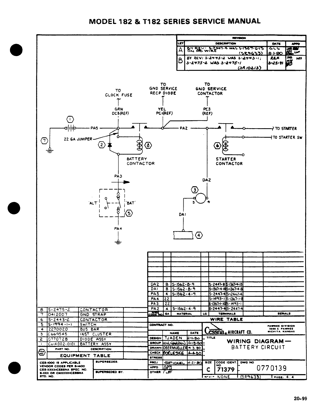
MODEL
182
&
T182
SERIES
SERVICE
MANUAL
&8Y
REV:-aW',
A
S-j
-
S-+ -;
,O
,
MS
A-ts75-A
WAS
3-467S-I
-s
_
_______(:>R/O
AJ) r-
TO
TO
TO
GND
SERVICE
6&JD
SERVICE
CLOCK
FUSE
RECP
DIODE
CONTACTOR
T T
T
GRN
YEL
PC3
DCS(REF)
PCI(REF)
(REF)
-
i---- l
-PA5
--
| I?--I-
-PAZ
70
STARTER
<~
2z
6A
JUMPER
'_I---
-
L
° 0-
iTO
STARTER
SW
2Z
6A
JUMPER
BATTERY
STARTER
CONTACTOR
CONTACTOR
PA3
_
--
l
DA2
ALT'
---
BAT
3
L
i...s
DAI
PA4
1
I_
_
ODA2
B
5-
15b.-
_-
5-2441-
95-1361-4-13
DAI
8
5-1562-
-
5-13674-
5-3
1-4-
___
PA5
4
5-156Z-
4-q
S-2447-4-2447-4_
PA4
z2
____
5-1493-1
5-1361-__
PA3
2Z
___-1361-I5-
1493-
1______
8
5-2475-2
CONTACTOR
PA2
4
5-15b2-4-q
524-4
S-2447
_
7
0412007
GND
STRAPA co AT'IAL
LO
TPE:ML
-
AL»
6
S-2443-Z
CONTACTOR
_
WIRE
TABLE
5
5-1994
-I-
SWITCH
CONTRACT
NO:
PAI
DIVISION
4
2270020
BUS
BAR
-_roo
a
-PAv,
N
3
Cbbq545
-INST
CLUSTER
NAME
DATC
|C
.
AICAFT
CO.
"C*"IT^.
K^^A
Z
C'7707'2.8
DIO
DE
ASSf Y
_DoN
TJADEN
Io TAINL
CCI400Z-0101
IBATTER
A55Y
I
s
JAour
E
--.
B.
±
L.
WIRING
DIAGRAM-
PANT
NO. ocDESCRIPTION
DRAWN
OeERMuELLEf
-3
3
B
A T
T
E
R
Y C I
R
C
U
I
T
EQUIPMENT
TABLE
'
LE
R ___ ____
CESI1000
IS
AIPPLSELICASL
SUPERSEDES;.
pmo
CL
a-Zl-gC
-
IZe
CODE IDENT
DWG
NO
VENDOO
CODES
PER
S-I4dO A KP
*.O
^~C-
No.1
7
>07
7r0i3
CESXXXX,- cSSNA DSPEC.
NO.
''o
71379
0770139
S-XXX
OR
XXCmXXXXCENA
D
OTR
JF
71379
STD.
NO.
M
I
I
.,- »
ONE
(5R9635)
I
pace:
4.
4
20-99
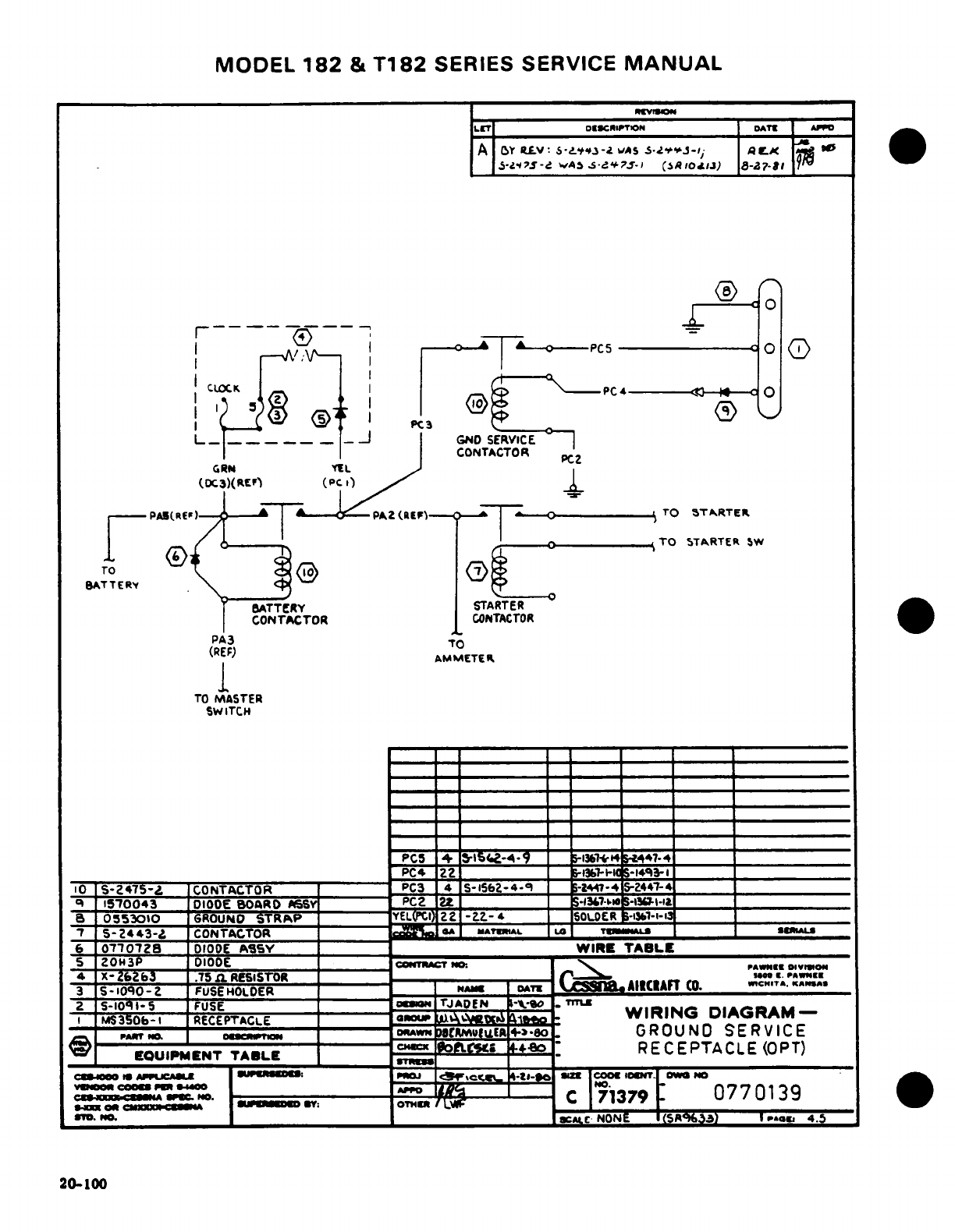
MODEL
182
&
T182
SERIES
SERVICE
MANUAL
LIT
OrUCmlIPnIN
IPDAi
A
>Y
eLv:
5-.-
'
^S
S-a,
.uJ-,
j
t.
5-ZI
S
-
d
A5
.S*. $-1;
(-R;IO.JI)
8-&7-81
r-
<®--
P
_PC5.
Qo
PC3
L-- J
GND
SERVICE
CONTACTOR
PCZ
GRN
YEL
I
(DC3)(REC)
(PCI)
r PPAS(RE)
PAZ
(RE)
--
STAORTER.
'
^ ______
'
I _____ 0 ___________
^TO
STARTER
SW
BATTERY
-BATTERY
STARTER
CONTACTOR
CONTACTOR
PA3
TO
(REF)
AMMETE
I
TO
MASTER
SWITCH
PC5
4
515
.-
4- 9 3-13
14
-
447-4
_ _
_
PC4
Z2
d________
S-
4l3-
10
S-2475-A
CONTACTOR
-1
PC3
4
5-156-4-q
-;47-4
-2447-4
9
1570043
DIODE
BOARD
/ASS
PC.
2
_-l7- l-e
a
055300
6ROUNO
STRAP
YEL(CI)
22
-ZZ-4
_SOLOER
--
1-3l-i-3
7
S-2443-L
CONTACTOR
Ga_ MAn
AL^
L
TAIM.[
-S
6
0710728
OIODE
ASSY
__
WIRE
TABLE
5
ZOH3P
DIODE
CTAcT
No:
PAWNE
OIVIOMN
4
X-Z6
.75
A RESISTORs
o"C
..
S-io0qI-5
FUSE
--- _
U
TJAODEN
L-O
WIRING
DIAGRAM-
3
XS30a-
FUSE
HOLDER
R
a
As
AECECEAFT CO.
MCT,
-
2IS3
RECEPTACLE
IwurJ DENI.0
WIRING
DIAGRAM-
Poor
rAw
)CPT
CCLMUEt
4-E+>-0
,.
GROUND
SERVICE
PAU?.
IomL't:9l
4eo
'
RECEPTACLE
(O
PT)
EQUIPMENT
TABLE
-
S b
RECEPTACLE
(OPT)
c
1m'0 Ie A8
»
_B: cPLc |4-1C-t-0
Om
COO€
1INT.
OW-
NO
czO^
.
"^a.R
t
171379
.
0770139
9mncxwom
p
my
H
IW
C
71379
rm.
o. ^ac-
NONE
-(SR9633
I
ro 4.5
20-100
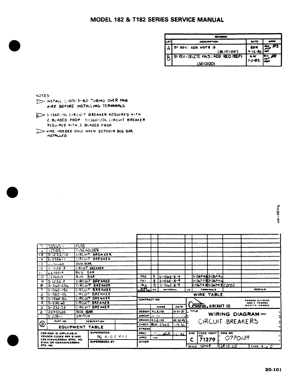
MODEL
182
&
T182
SERIES SERVICE
MANUAL
LET
D__ OIECRnmIPTION iDATIE
Alm
A
br
RfV:
ADD
NOTr
.3
xii
p
w
b
x
REV:
*LE
PAs;
DD
RED
UEF)
cw _
______
.e-o.oo)
______
__
7-
-
8.
ur.
LS",10 T5'
NOTE5-
'i-
INSTALL
-1071-3-1LtC
"UBiN,-
OvE R
PA6
WlRF
BEFORE
INSTALLING
TLRM^WIL5
>
b
1360-15L
CIRCUT
BREAKER REQUIRED piTH
2
BLADED PROP
-1i360-20L
CIRCUIT
BREAKER
REOuiqED
wilH
3
BLADED
PROP
;:WIRL
NEEDED
ONLr
W'HEN
e2?700
BUS
BAR
INSTALLED.
-J
'e-_ ;_SOO_________ __
i5
S~2-Z/0
iRLcUvrT
BREAf
__
_
,4
S-
232(-
1 I
RCUIT
BREAKEA
_ _
_
3
c_)uu.O
BuS
____
______
_
12
5-
Ic3j-S
LR.UIT
REAaiUK
II
i.700cl9
BuS
_________ __
_0
2?o001o
BuS
BAR
PA
6
-t8
-
_ S-______ ______________
q
5-122
.-
2
CIRCUIT
BR
AEVR
PA?
8
5-/S-&-8-q
_
3
-3.7.-1. 95-uL-- __
e
15-30-ao.
ClRCuliT
BREAKER
,
8
-
15- -q_
ib-1?-Mg
4
S
97l
srn)
7
i-
1360-i5L
CIRCuT
BREAKER
'R
*
GA M ATtERIAL LG
TtEMINALS
_SE I
*
t
'
A L-s
*
.
s-,3.0-iL
lRcu
BRE,.E~,R
WIRE
TABLE
5
5-13'0-5L
(CIRCUITONACT NORAR
COoACT
NCo .10
4 S2?..2-O C
RCu
T
BREAKER
,o
,,.,,.[
3
S-23(-.'
CIRCUIT
BREAKER
NAME
DATC
LCSSna.AICT
CO. wC...
ANAS
a
27OO
00
BuS
BPR
DESIGN
KLLINJ
10-2i-.l
TIT
LE
s52Z81-
5fWITCbH
cGOUP
,,
.
. -
WIRING
DIAGRAM-
[
r
NO. oDESCRIPTIONL
D*AwN
L'"
I
"'- l."'a
CIRCUIT BREAKERS
CHECK
f:)E'-E
.3.
<)
EQUIPMENT
TABLE
___________________
CIS-10IO
IS
APPLICABLE
SUPEISIDES
PROJ
' ./
SIZE
CODE
IDtNT
DWG
NO
VNOOR
CODxS
PR
S-1400
PG
4 1
C
t 1 AP D
No
7,,
7
CES-XXXXXCCISSNA
SPEC.
NO.
-
C
71379
S
XIX
OR
CMIXXXXCESSNA
UPLIWDOD
BY:
OTHER
I
TD
NO.
SCALE
'C
VON
(SRI
10:3
4.
G
20-101
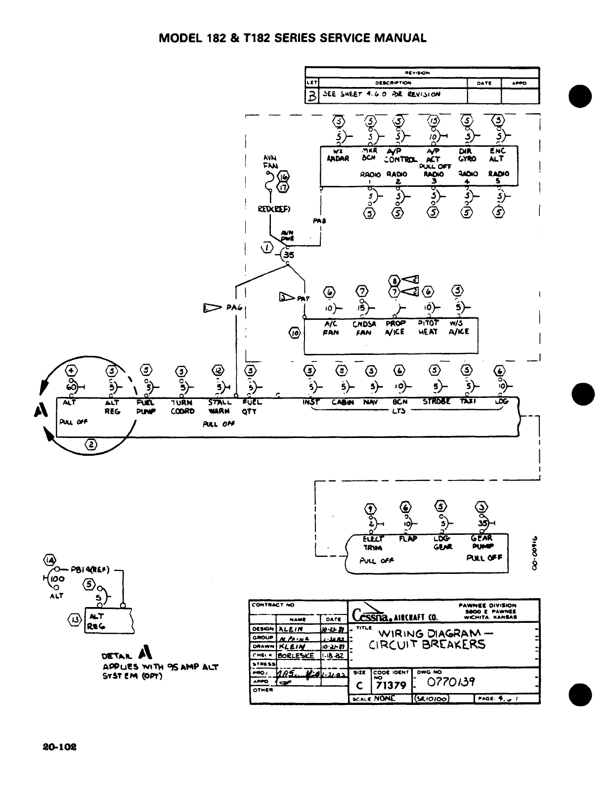
MODEL
182
&
T182
SERIES
SERVICE
MANUAL
LETJ
o1cmpyr OATS
0A
P,
2
'fE
SiCEr 4.4
o
0Wt esiio
=
I)-
5>)-
/o>)
S)-
S)
wI
.KIR
AVP
AvP
ODI
CNC.
I
M
lXq
.ADAR
COM
TOITL.
P.T
GYRO
ALT
RL'
xUI.
OUTl
8
RAOlO
QADI O
RAAIO
A.IO
RADIO
i
&
3
4.
1S
D
PA/, a
I°}
'°
/
.
-
.o-
,>
L-
-
, )-
-_
_
&
,5A4.T
~.I..T)
S)
<I)
S'
r'
t. '5)
I
PAN
FAN
VIC
At
A/E
ALT
ALT
FUEL
URN STALL
FUEL IN5T
CAS,
NAV
ECN
STROB
E
TAX
I
PSI
4tP
E>>PA^, SIw 10)- PW-S _
PAWY
5)
[ __------
REC°A O P(D I(D
-
_ _
AL."r
A___
__
0-rCesna
AlltlAFT
CO.
WCHITA
KANSAS
OGt.oup.
LLIN
i.
WIRINSG
DCDIAGCRA
-
:M
-
OtAW
,(L-)I
,o*.I-p
_
CICUIT
BREAERS
7F4-
P*-O-* 'WR_
A7 °
°
_
AOPUIS
WiM
fPAr'..
A_4P
_ _N?
_
.,
;
C
7
13 7 9 1
7770/3
:
-c
NOC
(soo)
cs
t.
P
)
I
20-10o
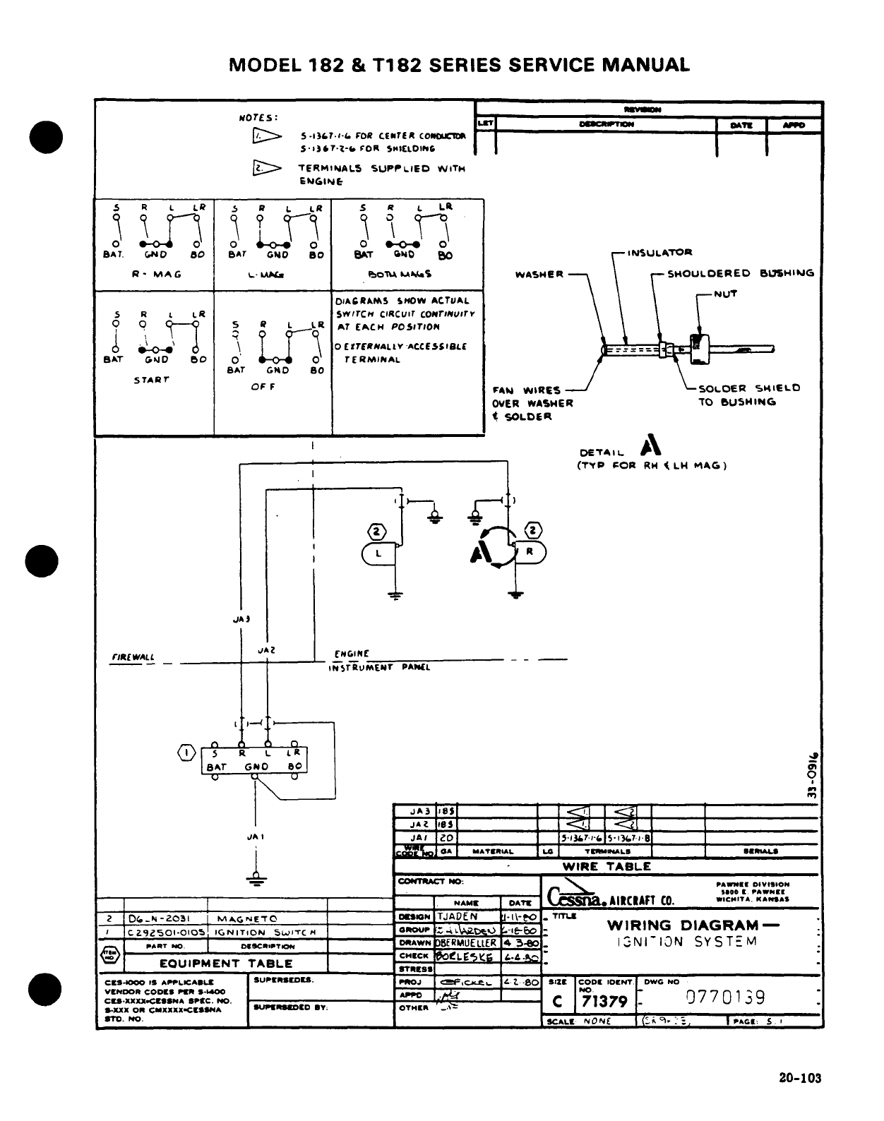
MODEL
182
&
T182
SERIES
SERVICE
MANUAL
NOTEs:
^
t
/>
$-13T.r-,
-(,
FOR
CENTER
CONDUCI
I
136-T.Z-f
FOR
SHIELDOING
[:> :
TERMiNALS
SUPPLIED
WITH
ENGINE
R
L
L L S LR SR
L
LQ
BAT
CGND
80
BATT NOo r8
INSULATOR
R-
MAG
L.-LAmE
Ibolu
LAA.S
WASHER
\
i-SHOULDERED
BUSHINJG
DIA6RAfMS
SHOW
ACTUAL
\
N
5
R
I
LR
SWITCH
CIRCUIT
CONTlrUITY
?O
O
0S
5
L
LR
AT
EACH
POSITION
\
6»o§6 \ o0
oETERNALLY
'ACCESSIBLE
BAT
GJD
BO
0
T
rERMINAL
BAT
Gn
/
STAR
T
TAROF F
FAN
WIRES
SOOER
SHIELD
OVER
WASH4ER
TO
BUSHING
SOLDER
DETAIL
(T'P
FOR
R
LH
MAG)
JA3
JIZ
T
c
g
)
FIREWALL
AZ
NCI
INSTRUMErNT
PANEL
11 -°-i
G^>
5
R L Ill
BAT
GNO
o
JA3
S
21
J1
JA
I
JAI
zO
5I
137-C5-
171
|I
01I
~i
CBIL
^B~A
I
MATERIAL
LO
TRM4ALS
R
»AL
irlREWL
-
ENGWIRE
TABLE
_N T
COWTACT
NO:
^ PAWNI
DIVISION
*SO»
I.
PAWNl
-|= -=__^
--
OATC
s
FNAME
CessnaicAFT
CO.
WICAITA
co.f^K
2
D0_N-2031
IMAGNETo
OESGN
TJADEN
;-\-
eo
TITLE
CZ9250I-0oI05O
IGNITION
SWITC-
rOUP
;
L
-__
.
T-le60
WIRING
DIAGRAM-
Q -PC^RT
NDR-|
DX
Ci.>TOD
OAWN
DBIMUELLER
4
3-80
_
INI-13N
SYSTEM
EOUIPMENT
TABLE
CHE
LES
A6
CES-4000O
IS
AP1PICASLC
SUPERSLDLE
PHOJ
c
me'
a
z
-80
SIZE
|CODE
IDENT
DWG
NO
VENDOR
CODEC
S
*-OO
P
7
r7
07701j9
cs.-XXxl-ES«NA
8p109. NO.o
C
71379
-
7 019
S-XXX
ON
CMXXXX-CCS*NA
SUPEREDCD
D
my:
OTHER
.-
C1TO.
NO.
D O
[R
SCALE
NONE
I
(
:
qi
|
I
PA*a
S.
20-103
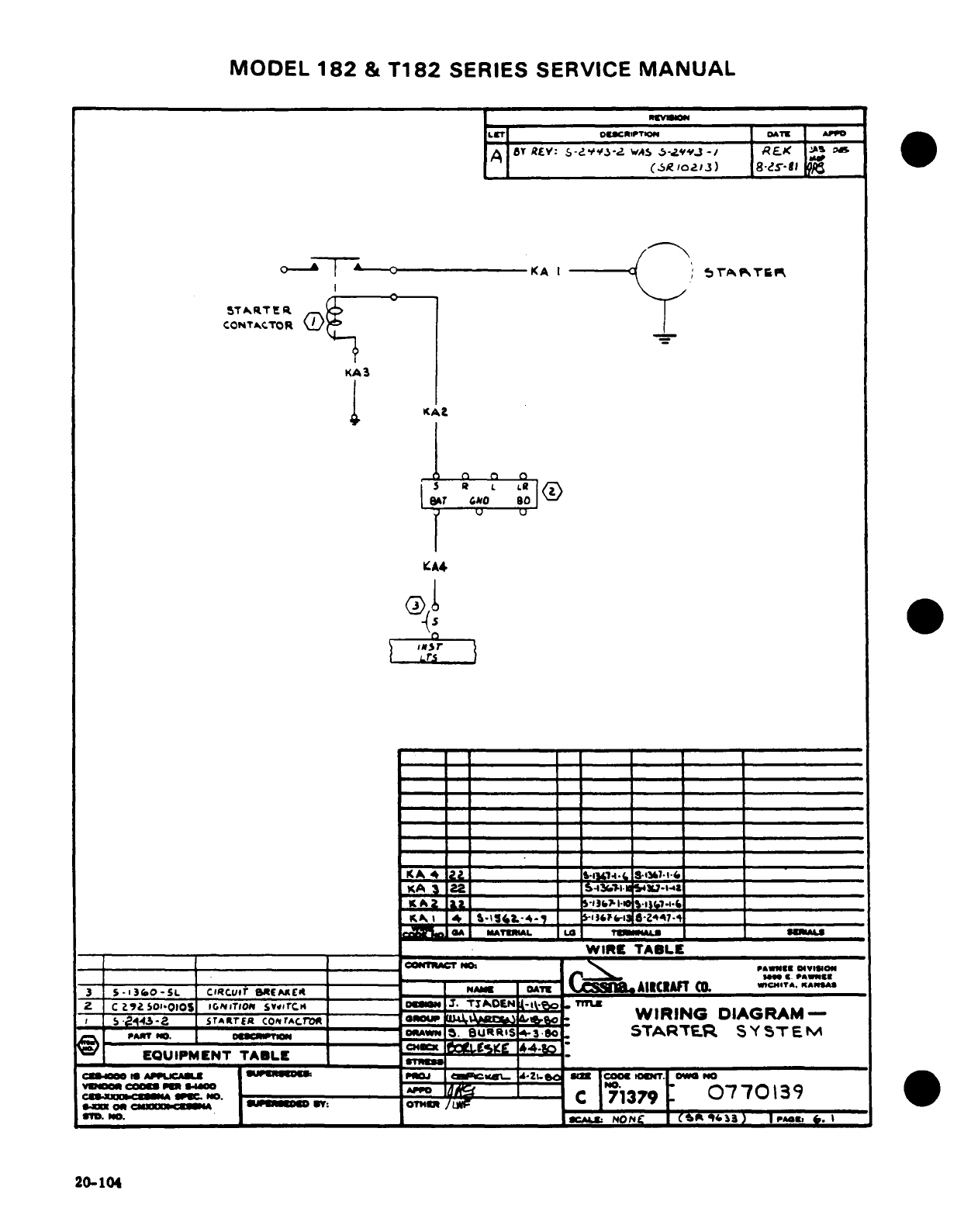
MODEL
182
&
T182
SERIES
SERVICE
MANUAL
L&T
_OhCmN'fPT'
"T
ATE
IAPPO
A
ar
REY:
s-e"-'
wAs
.5-zqqvJ
-
j40
0-- AI A-------------
KA
I
---
; T
TQM
ST^RTCR
A.
i i
CONTACTOR
0
KA3
j OA
Z
.
'i
"l®
n
OT
,4GO
s8
:rs
i
KA
4
I
C
Z9Z5o.01O01S
,o~,rlON
s$wrc.m
oasm,1.
TL I SEN-i.
L
T
n.St
I
5.-?.43
-A
.Srra
co-rAcroe
I
GRouP
bamM.«a-
WIRING
DIAGRAMI-
I-
NO.
o'
.mo
-.
I
OAWN
aS.
-BURRIS
$.L
S-TARTER
SY STEM
19
EQUIPMENT TABLg
CHUCK
m-oP.PIC-CA,
w
Il ...... PaJ mPi.l -1 4-zieoln
·
a0
Icoe
OCMr./
owm
NO
Sl
e--c:m A mMe,,0O 7a -o- I
NO.
0770139
94OM 00
upv
my.a0 7137
-
KAXX
SM "D. NHI3 LI--1. WHMOM
I
.
Molt
I ,.'.
I
-
20-104
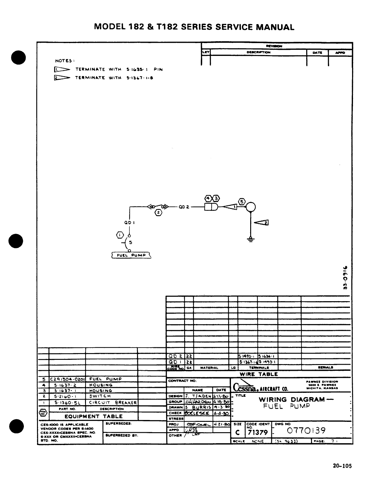
MODEL
182
&
T182
SERIES
SERVICE
MANUAL
OTSLETJ DECRTIOWI
DATE
I
NOTES:
::
TERMINATE
WITHI
S
-Im-- I
PIN
L^>
TElRMIAtkTE
WITH
5-137-
-8
ID
I
5
0
* i
Ft
UD 2u 1 MP
I __ __ __
i4>3I
_____
_____=______
WIRE
TABLE
5
C2qi5o04-O2OI
FUEL
PUMP
CONT__
CT
NO:
PAWNEE
D.VISION
4
SDi'('7-
2
HOING ____
_
o
PAWNEE
5
si(.37-
I
HOUSING
-
_
--
NAMEr
DCATEL
AC
.
WICHITA.
AN"
2
S-21k0-
I
SwT
C.H
oESnJ.
TJADL
hE\-k
-
TITL
I
S-1560-5L
CIRCuJIT
BREAKER
_
COUr
liaFs
4
_
WIRING
DIAGRAM--
PART NO.
DESoCRPTION
-
ORAW#N
IS
BURRIS
-3-o.
FUEL
PUMP
EQUIPMENT
TABLE
CES-DO00
IS
ArrLICASLE
SUPERSEDES:
PROJ
|.C«F 14
Zf-BC
SIZE
|CODZ
IDENT.
DWG
NO
VENDOR
CODOS
PE
S-O4
9
r
070
39
W^
CES-XXXX-CXSSNA
OPEC.
NO.
---
O
R
C
71379
0
7
I
(
3
9
S-XXX
01
CMXXXX.CKBSNA
SUPEIDCD
BY:
OTmI
L
STD.
NO.
SCKAL
NCNE
| i 9q j) |
AG:
7
20-105
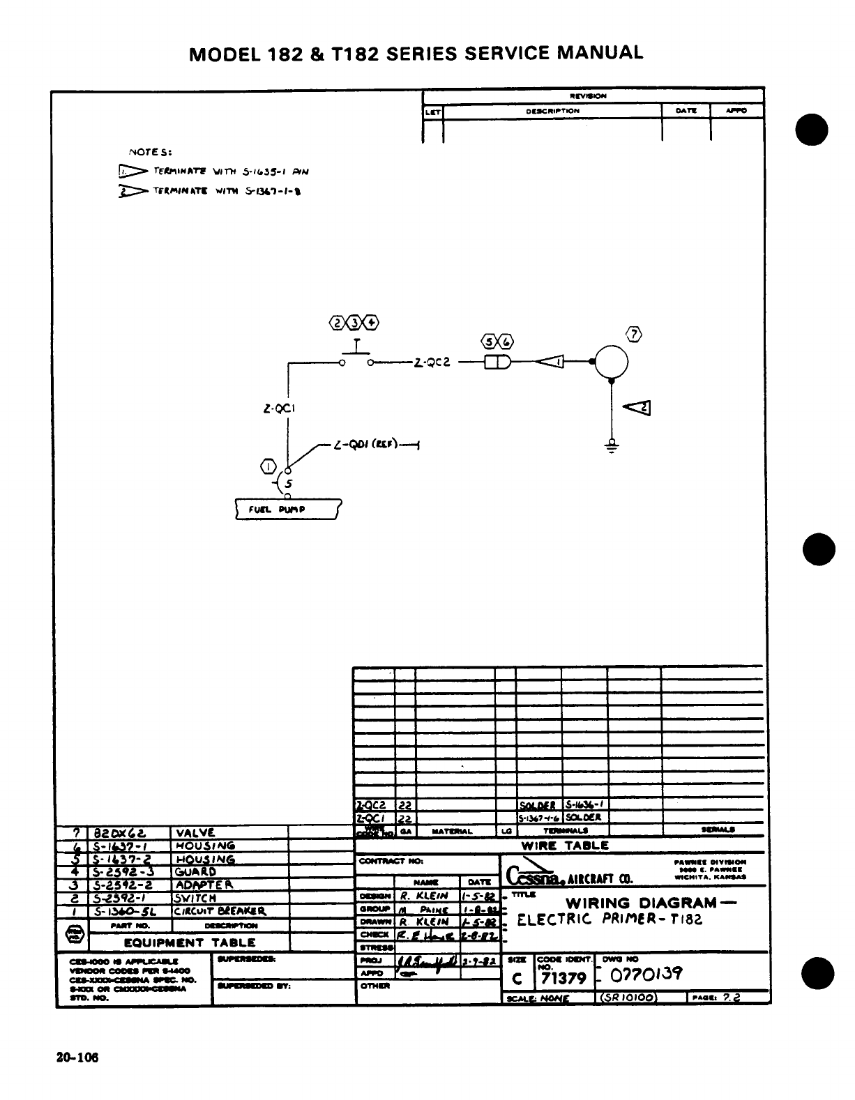
MODEL
182
&
T182
SERIES SERVICE
MANUAL
LETj
ODCRIPTbN
OAT
A |I
n
NOTE
S:
D>,
rFlMiNArv
ITnf
5-i.33s--l
P
>
Tf(M»Ntlg
WITh
S-
1-I-
ZQCI
C3
1
________________________________
L I _________ S-E<
SOLA
-
7
eaDX(.L
VALVE
______a
A
Lmaia
L
T1111
»«11A11
-
,OS-1&S9-1
_OU__NG
WIRE
TABLE
-rC33-_ _OuS
__
-
_-1_
7-_
AOUSA8~
=mnO-T,.
.
_TABLE______
,f5'
&.ff -_ _. _A--
-
s
E
5-5s~LZ-
ADAPTE
R
-
A
R.
E
aLEAC
C.
WCHT.
I
.S-_3_0-_L
__ClrCUiTEAC_
GOUl*
_M
_~
,-
i
WIRING DIAGRAM-
PA
W
OA.
mv--
R
-LgEIN
.-.
:
ELECTRIC
PRIEtR-rTI8
EQUIPMENT
TABLE
--
CK
-
F,
_ _ _ _ _
m.,
,. ,
.o.I
rw-inces
cee
APPLICLE llu««llllsu
P
S=
com
NOR
".E
owS
NO
SmC-O
No.
m
_____my.___
__APO
____IC
j71379
07?013?
2 a.J
9-
S"t
TC
"maO-
R.-
-
?;
7_7
a
MO
M
.
OTR.q
C
sim.
.-.
_
_________c SRQ0
10100}
A
r
?7.
~
20-106
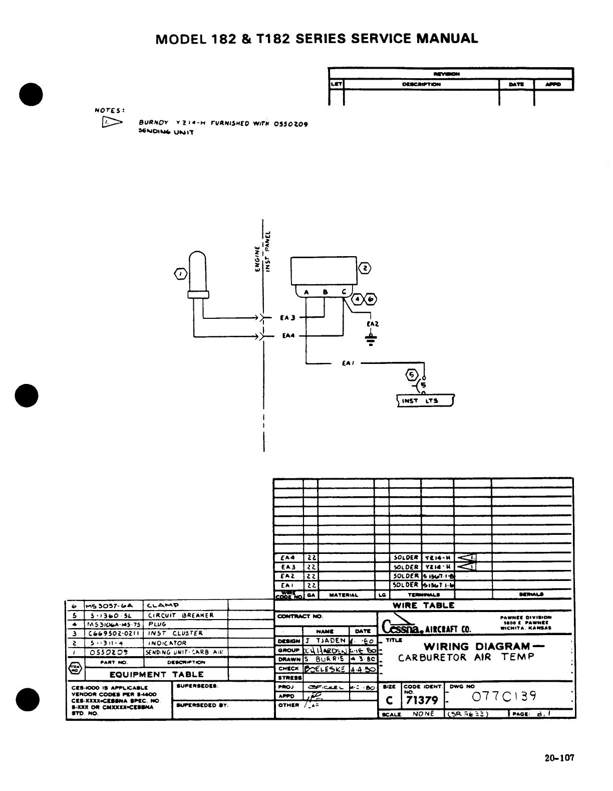
MODEL
182
&
T182
SERIES
SERVICE
MANUAL
TIi
DRECaRIPum
I DAE
)
"l D T
1
OT
|
""
-
NOrES:
>
BuRNOy
Y
2
14-H
FUrPANISD
wIrT
0550209
MCUDlIM U
IT
Z
C
I-
EA4
LA
(
INS
EA4
__
SOLDER
I.14-
-
_
.A4
2-
_ __I
EA3
a
22
_
O0LDER
Y114-4
_
EA2
z.2
SOLDER
S
i1 I___
ECAl 2
SOLDER
IT ______-
-
A
MATERIAL
LC
TaUIiLA
I
i
SRA
,
~5oT7-,,
cL.'O
____WIRE
TABLE
5
5
-3 r 0
SL
CIRCUIT
13REAKER
CONTRACT
NO:
PAWNE
DIVISION
4 rj^53iCAI-wS475
PLUGS
W
00
Io
PAWNEE
3 Ce
9$02--OZ
I tNST
CLV
rER
|
AI
"
| NAMElc A aN
Am
tO.
""CHITA.
K"^"'
S
,-311-4
INODCATOR
D
OlGN
J
TIDEN
N-
Io
.
TITL
i
OSs50t
zo .
NDNC
J ulr. ^R
AI
G
ROUP
:L: «
.
_.
WIRING DIAGRAM
PANfT
MO--
---
O«»CT.>T09 f
OAAWN
s
BURR'S
.e
.
CARBURETOR
AIR
TEMP
PA
rrT
0
rCC.
I
oE
LEcN.l.
T
EQUIPMENT
TABLE
STRESS
CES-IOO
IS
APPLICASLI
S UIaSOL DS:
IPOJ
^C .L : D_ [.-
II CODL
ID[NT.
DWC
NO
,MOOR
CODES
,.
,4,OO
APPO.
-o.
0-7
c
VE XXoS-CSxSIN
S0.
--.
P-OO.-C 71379
*-XXX
OX
CNXXXIXSusi
CR#
LED
*Y:
OTHXR
_A-
TD.
NO.-
SCALE
NONE
C5
e
-,)
I
PAG"
:
.I
20-107
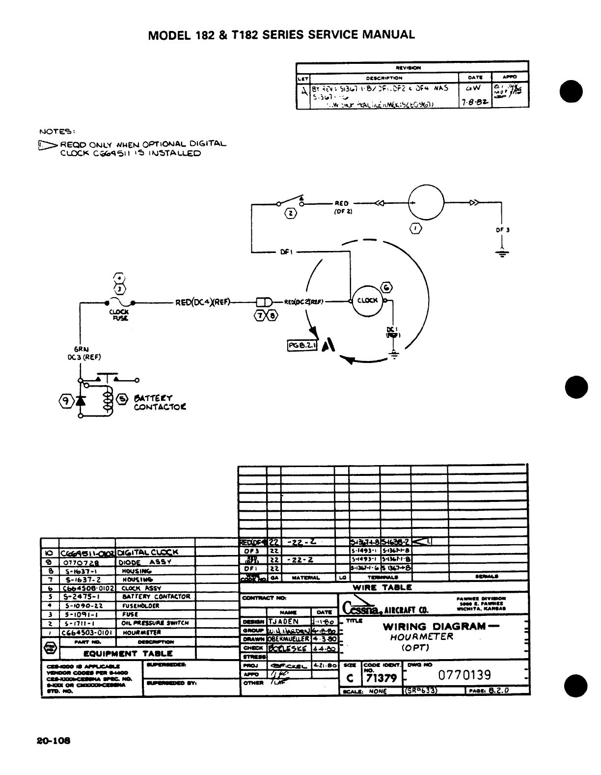
MODEL
182
&
T182
SERIES
SERVICE
MANUAL
LIT
OKISCirNIPTON DAT»E APPO
_
,t
v.1
.
t-6/
F,.Or2
-
3 .F
NX^S
,,=
7
,_
..
v
-.
,0' -'A~L.;,w,. tO9r: }
,,..,__:_ .'.
7
-8-8Z-
MOTES:
9
REQD
ONCY
HwEI
N
OPTIONAL
DIGITAL
CLOCK
CG4
511
1
5 I
STALLED
o
-"
RcED -<
O
Q@~ D~~OF
3
-
Df
l>
1.
6RL
T
GRIJ
MA
la
07707
D0IDE
ASY1_ Z1 122- a _-' I-_-
O??
|p7a.z.g
(lO A\S5, 1, 2 -'Z-Z
=
s-4)-
-t
;-t-,
5-1i37-1
I
HouSI f I
_
*22i3b-,
_
7 5
-1637-
2
MOuV14
___ ___
GA
_
ATI[AIL
IaG
TI
A 8 s
,
_ _ _ _&"
O
Cb640S8-010
CLOCK
ASSSY_
WIRE
TABLE
5
5-2475-1
SATrEII
CONTACTOR
_
M__
cT
NO.
4
5-1090-_Z
FUSEII4LOER
_____
-e
3
5-l6oq-l
FUSf
,I M
,-Z_ C C
-
&
ACIAF
C
.
mc,1.
i,",6A.,,
2
S-17311-I
OIL PSSUIIM
SwirTcH
a
T
JAEN
.- .
TInl
C6a4503-0101
HoutNIT1
GR.
.a.
-
.
WI
.
WIRING
DIAGRAM-
PA^
T
,^I.
OmNo"N
AWN
EMU
EK
HOURMETER
..
E
QUPMENT
TABLE
I
"g
-
(OPT)
icoo"4S
PM
11c-E
=mrio
'
Fa.ci«>
-ti80,
Sc |
COO
100T.
.
w
N-(O
_
-s ow-" 1
'"= C
W"
71379
0770139
94M
ON
inmoaml l
NVI
0
C
1
71379
am.
l.
CAL.
NON
(SR°633)
I
AGI
8.Z.O
20-108

MODEL
182
&
T182
SERIES
SERVICE
MANUAL
-RE
BI
'
K
(DC.
)
(REF)
DETAIL
A Ia
2
(REQD
WHEN
OPT
DIGITAL
CLOCK
I,
ISirALLED)
In
0
COVACT
PO. PAWNes
DIVION
owtucr to:
I
-
\
ry~wrrr
Os a
PANS
ANAME
AI
SSl
ICRFT
CO.
wCAnTA.
KANAS
GROUP
W
T
IRIMG
DIARAM
-
op"VS.
u_\s
30_
HOURMETER
(OPT)
S m !..
______c
cN
POJF
-
SLL 2 GC
IZE
COOS
OSNT
DOW 1N
Acco
LIN
0770139
OTHER -C
71379
3OCK:
NJON
F
o*A3
1 :o T
8.Z.
20-109
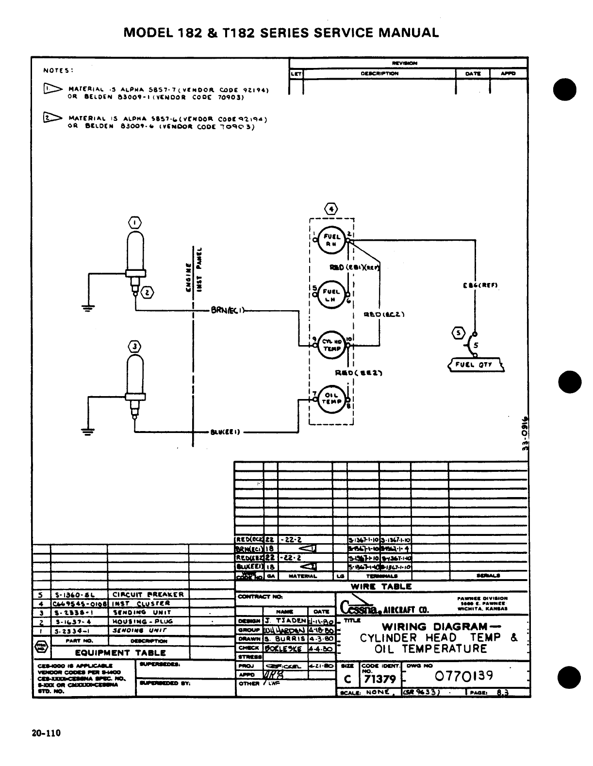
MODEL
182
&
T182
SERIES
SERVICE
MANUAL
NOTES:
_
[>
MArERIAk
,5
ALPHA
SS7-7
(VlNOOR
COODE
9ZI94)
_
OR
BELDCN
83009-1
(VCVE
OO
COOC
70903)
~>
MMATERIAL
IS ALPHA
SS57
-.
(VFNOOR
CODE2qll4)
OR
BELDEN
83009-64
(VEmOOf
COOD
-tOS1
3)
0rI 0
.
01I I I I r-10
i
1
E"I _ IA = 5
OPIS
SOMA
,p
,
_WIREALL
TTB
S
S-i360-&U
CIRCUIT
FRE^XER
CONcTRAC
Not
PAWTc
eL0
4I IC4-
I T CLSrt Soi C-.
O
-W
-Z
S-3-
-
4
_ __OUSIN
-
PLUG
o
.
c- 1 -J ._
,OJ
c
Z O
COD2
lO
no
I
-__.
-.--
J4- _ _
_
_
$-
IDIN-
-_ _ _
CI
IUIT
BY.
[:
I
~NQ
-
-------
_____WIRE
TABLE
5
S-l3QO-SL
CIP.CUI
PRCAKCER
_
C
NO,
S
?-13aa-
'I
INDo»MG
U IT
.
YNAM ODATE
AlCA(IAF
CO.
wCNITA.
KANIAS
S
-lib.2-4
*-
OtS.NG-6.PL~U
Jr
.
T3
N
...
-o. x
.'TIT.
AA
B
-
I
3-Z$34-i
s
P(Oms
u,,r
-o
a.A^WQP~,4
I.-~
WIRING
DIAGRAM-
PA.T.
N
,
ame
,
,,e. e.-
oaunI.,r4.-.o.
CYLINDER
HEAD TEMP
&
EQUIPMENT
TABIL
--
g
SLE
±s.
OIL
TEMPERATURE
CIloo
Il
S
---
lma
.
PROJ
AP:U!AS1l~ Szl-Ilo
pSo
oOl
IOmt.T
owe
NO
ORM
Cld-
,----- = ^.
--
I-
C
71379
I3
C)
c*-EXXX
A
O
PEC.
NO..
_______B__Y;
OTHtM
/
K'f
*
t o
*'*
o
*
^ -----
---
----
^ -----
_^_^_^_^_^
___ __ *uAU.:
NONr-
.
r5»4,$3)
*
I,0-, 8.~
20-110
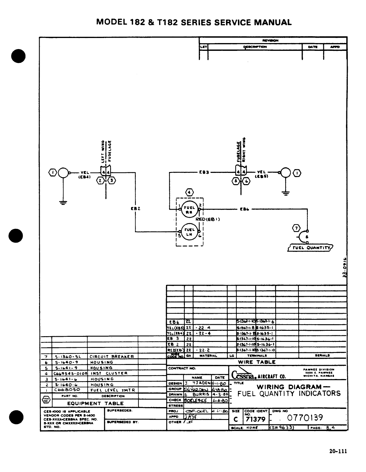
MODEL
182
&
T182
SERIES
SERVICE
MANUAL
el.
·
R LN EcoEbrl q 1 : I 1SP
»~
i
s
.
0
EB
(ES. Z9
Z2
H-OUSIi-S *I¢ S-I
_______&-O:IDIISIO
I_ FULZLEVEL _
-I3(
.
S-'FU
L
-_U_ FU_ _-
P
5- l3~O-%L
CIRC.UIT
BREA.I~ER
________ GA
MATERIAL
L.G
TEIQUA
NTTLS
SEIICALORS
.-
14-9 HOUSING
WIRE
TABLE
TA
4 CMO9R 4CODS
MR
INST
CLUSTERAP_
_
-o
2 0-111
.-
____
.-
U( 1 t -T_
.AIRCRAFT
C.
wInI.,A. ICAN*,A
,
Sci.4o-Z.
HOUSING(L
(.___
o.
G.
_____
DESI.N.
WIRING
DIAGRAM-
PAR.TrNO..
DC.RpTION
-- --
D.AWN.
BURR|S
4-1-.0.
FUEL
QUANTITY
INDICATORS
EQUIPMENT
TABLE
SRE
m~CES-OOO
1S
APpLICABLE
SUPERSEDES
POJ
Cr
l-
'-
SI
COD
IDNT.
DWGC
NO
VENDOR
CODES
C
5.
1- 0- A2 S7 n
1
O
C7S-XXX-CE
CXN
*PEC.
NO.
-
R
C
71379
.L
7
OLI
O
4
S-XIS
5
OR
0
CNTXXXX.CENA
SUPERISDED
BY:
OT-ER
/_ElF
I
B^PTDo. NO__.
___S_______
CA4-3
FUEL QUANTITY
I PNDICAGE:
ORS
20-111
20-111
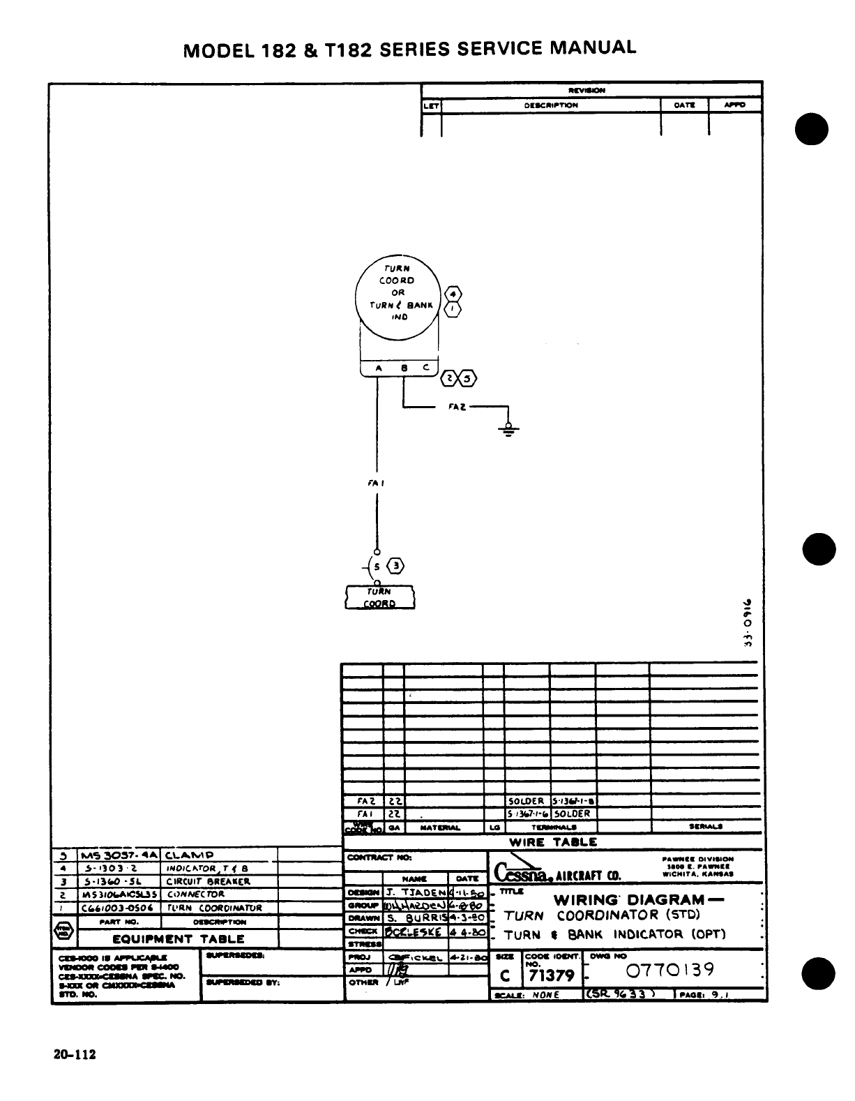
MODEL
182
&
T182
SERIES
SERVICE
MANUAL
LET
DLOCNIPl'ON
OATI AT
m
cuM
to
COO
RO
;'A
I
o^^o®~~~~~~~~
0
r
i
OLDER
raz
I_ _
OR
I
- -
apa
Dvso
I
CA0i0O3-oSOe
r.RN
COOmR01oATuIR
CI'-
SOL
WIRING
DIAGRAM
:
1PART Nw. orvzc o^1
5.
*URRI
4-eOA
TURN
COORDINATOR
(STD)
4c
bOO
1 0
*_t
"
: c IXO T
_
_; STlRa
E SS -c-_
_
1_
_
_
_
_
_
_
_
*
>
-
n
C.
N =.
cwm"0
1*
APyuXASL.
suSensu
PmOJ
<w
wcw^~
II-2g
z.
CO"
I
owE
NO
,O c-IuO I'a"
oA
_____
/--I/
C
7L
1379
SMX.
"O.
_
NOIIE
1C1
3
PAGMI g 9.1
20-112
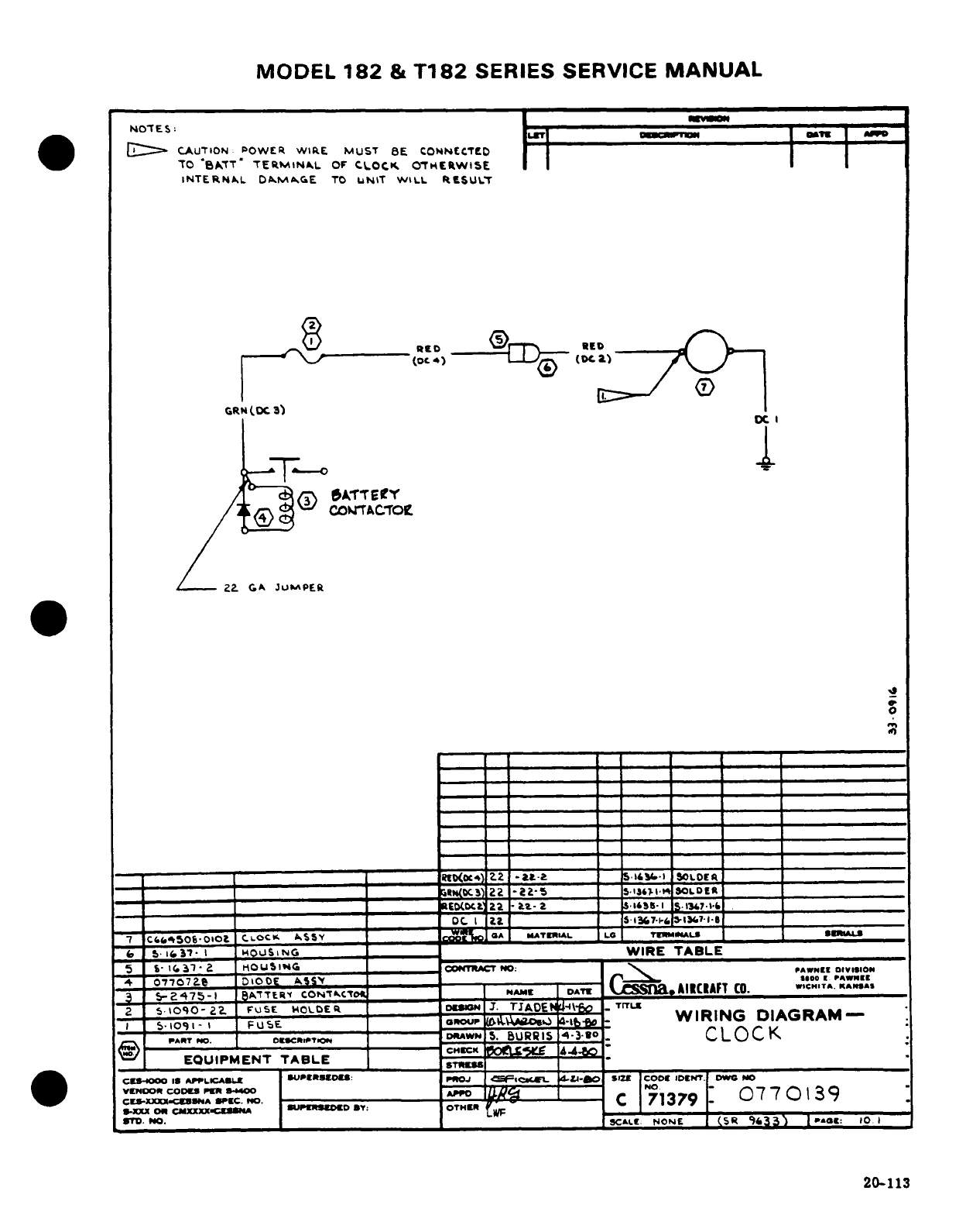
MODEL
182
&
T182
SERIES
SERVICE
MANUAL
NOTES
|
I~o'T F_
$;
E>
C.AUTION
POWER
WIRE
MUST
BE
CONNECTED
'TO
BATT'
TERMINAL
OF
CLOCK
OCLERWISE
INTERNhkL
DA.MAGE
TO
UNIT
WILL
RESULT
_
RE0
RED
(CC
4)
GRN
(0C
3)
DC
I
^ QW
%
corTACToe
"?* S&Gi(.LO'TI I..00 I-la
_~~ _ .~ _____^ cx-DC I
_
2- _ S-I i-E >
t»
_I- ____7_1S__
7
C&O.4S506-01L
CLOCK.
ASSy
GA
MATTEiAL
La
TERNUALS
11
»P1*1ALS
b
5.1
37I1- I
HOUISLNG
WIRE
TABLE
5
S-
IG 7
-
HOUSING
CONTRACT
NO:
PAWNER
DIVISION
4
077076..
DIODE
AISS'-
1S0
I PA1
NKR
5
2475-1
BATTERr'
CONTLrCT _ NAcM
DAT.
S
AIItA
CRAFT
CO.
WICHITA.
K"ANS
2
5
OiO9-
ZZ
FuSE
HCOIE
R
ousN J. TIAOE/-.
TITLU
S
IO9O-
.
FUSE
RHOOaERUO
-
T3A0
-.
WIRING
DIAGRAM-
ART
NO.
DCIPTI-
-
D,,RAW
S.
BURRIS
.34-.0
CLOCK
EQUIPMENT
TABLE
ST-RE
CES-WOo I
APPLICAL.C
IUVCPRLDo:
PIOJ
CfI.LL 4j-. SI
Z
Icoo
IODET.
owt
NO
NO
VNOR
CODes
PA
-
NO
COxxx
PC.
o.
cxxxxcaS D
:
C
71379
77
*-XXX
01
CNXXXX.CC--NA
*Ual'amot
*r:
OTnER
[
r=
-
CTD No, XSCL-: NONC
(SR
9&
)33~
|,ac: o10
i
20-113

MODEL
182
&
T182
SERIES
SERVICE
MANUAL
NO-TL S
:
Lcl
OSC»m
ATR
I
K
>
;
4ST&.LL
S-163(b-1 ON
VENOR.
Nl. IL
I-ol
o(ctEM)
L)K
(
r.)
(DC.
(D
Fq
--- --
-0-
(DC
5)
MAT
ryaL
i
oml T
atu
I
-
119-01 1
PO
1
(O
L a^IJ-AMOUS.oS ------ SSS.^^ a,-*~
WIRING
DIAGRAM-
,
AT
NO.
,~~ ------
N
.
SuR
4-8
bxrolTAML
CLOCK
(OPT)
__
EQUIPMENT
TABLE
.
I
c804000
1
PLiCAME
"N m-; pmj
i
Qawo~g
«21i-
Om
CA=
looff
D no
1
S
t^
SSq
No
.t42s
1 :
.1
13
:~F 0
770139
L-11
cS-
c
co
-oa
I
__
__
o
CT
Ir C
71379
_
-
_ _ _ _
Z _ _a
4
lr
__
_
-m
"D.
1
C
4L&NOML 0
R121 JA39
20-114

MODEL
182
&
T182
SERIES
SERVICE
MANUAL
LET
_
OECTIP
0AE
APPb,
|>
NSTI^.
51i3^S
»
TERSMiNsk
ODN
VENDOR
VXRE
1
A
v-v...
I
GlFA
, '
--
L3
CtO
.L
GRN
fLA4)
tLA
0
1
1
1
LC.»
J J2
COUBTE»
I 1
rs
IIt
k
_*&
_I _1 _
I
LA7
22
_
_
-I37-b-
S
, .. _
_
.
_ 2 _
^3
__
e s -z1
I-LI
5
-13 f
3-c-15-1
C5TD)
LAS
I 22
SIZE
HO-l&M
5.14.
COI
2
5
-14-31-
I4O6 INGS
-
I LA7I
z22
.
DV _______DCNL-. -_-
C-5-» T____.__
7
5- O IM.
HOLSIN&
SOCKET CI
dA MATJLERIAL LGa ERSCNALIT(T SERA
I
5-
X
41-9 HOUSIN6
*SOCKET
C
I
WIRE
TABLE
5
5!
.640-9
7OVs'INC_
-PIN
S- 2D
..
-I
£50
SI0
IVON
PA|-"
___^_____________________________________4[
L*5
».
-if.20-,1
3I
-Z1.37-i
NOISINC
NAME
DATE
AIRCRAFTCH_
CO.
WICHITA.
IANSAS
-
5.18
-
31--1
CTCN
TJADEN
TITLE
WIRING-'
DIAG
RAM
5-
1340
-
CL
IRCulr
BaEAKE
R
op"p
PAR-T
'
.
DESICRIPTION
-
A(
OEE
RMUELLER-
-s80.P
DNALOAE
LIGMTG( «STD)
4
EOUIPMENRE
TABLE
R Y (OPT
CES-IO
3
IS
APPLICAUL
PO.SlUIEDL
E
SE
COD
ID
NT.
DWG
N
O
CES*XXX.CESSNA
PEC.
NO.
SUPERSEDEDA
No
71379
0770139
ST-D
.
3
1
No.
H 1S, SCALEN
NN
DATCIAFT C.SR%
3A
,I
20-115
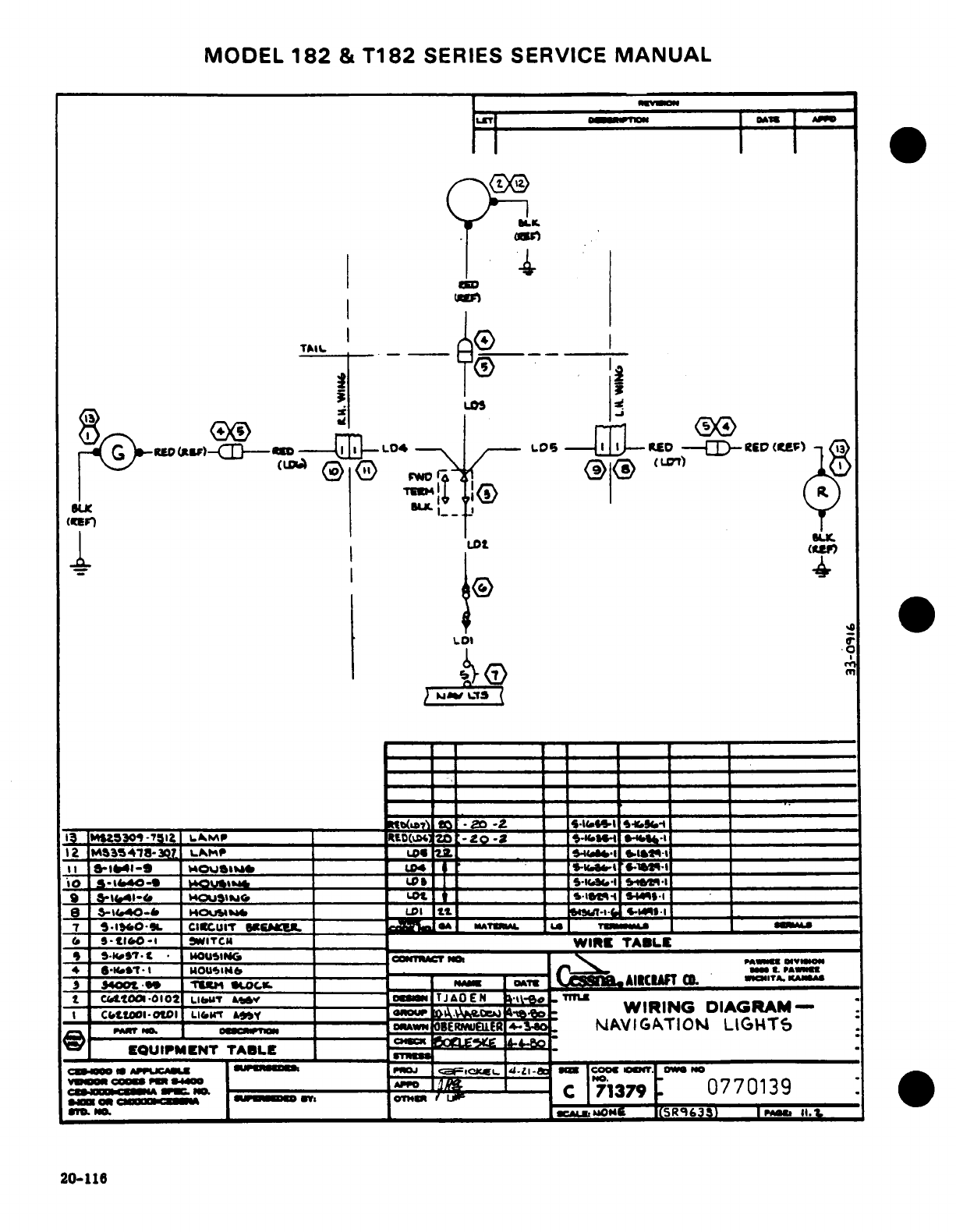
MODEL
182
&
T182
SERIES
SERVICE
MANUAL
TIIL
T&I.
___
__
L04
Los
LOS)
(LDO
aO
G
I
(um
IW 1
Lot
r
t.D!
.
Los
I=
t
-
46
i
i
__ll _9
'
.
--
-
19
640oI-'z
.kMpusi
___ ____ it. -to-___ i-,-f-
_____-__-
1
a-ti4-
-
HouamtbM
____
'D
'~__ _ _________
8
a->-
H1u-
1. tI __________
*
Ul ~-I .WI
.'
i______________
7
S-1»40-L
cIu
a
L
A, MjAtN. -- AL I6a"
T'm
A
-qAl.
I
e
s-M?-.
t
HIOUING
________
w
ttm "a
o-
.
I
4
8'lflJ0'
t
OUNI6
,C.
AIEC
3.
PAUIN_
3
OC.
I
_ M
1.AT 1
AI
C0wiAT CO.
'
_IT,
KNmm
-
cttoo.o
MCb __
E,._
1
-.
o
GR
.
Tfl
WIRING DIAGRAM-
A
-
OIEi"-NIER
.
AVIGATION
LIGHTS
EQUIPMENT
TABLE
-
C
.
c»aft
s
APPJcaML
U
-Ic" eC L4. jz-a
GM
coow
OmT.
us
-. m
coINA
P.M.44
AM--
NO.
_ili
_
-..
a.
sw
I.
C
71379
0770139
0'WA
-.
8
ol
(SR9633)
.t
20-116
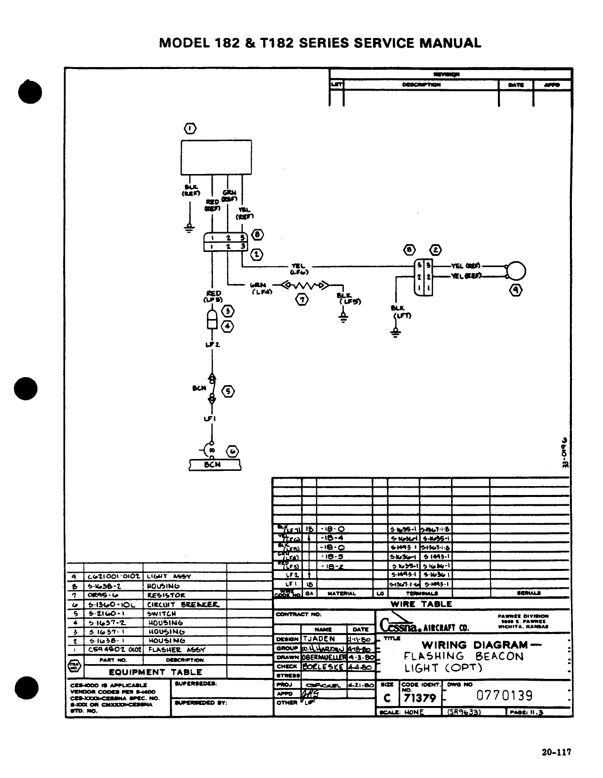
MODEL
182
&
T182
SERIES SERVICE
MANUAL
I
(1f Ltt
I IT
~~~~~ii)~~~~~
6rL
I |
.-
-®
lb
is 0
6
WA-i
i i -ii<,»
-4
-
L
''
1 -A 1-
0o
_ s,
*-
S
._1_l--
-15-4
_1
S*-_
A
CL.1001010
otO.
LI(T
&&J~y
LF"
I4I
_'I, ___l__1
_
t
-1.bt-2.
I1Ou'L14M(
LF: _I
Lb
-Ifl.
J
_ _
._1
.
7
O04r,
-
I.
gIEbi'SToc
GA*
MATERIAL
LO
,TuiuLS I
-
_o
j-I3(.O-1OL
CItLWUIT
SeEL _r _
WIRE
TABLE
5
S
tli(O
-
I SWIT_
CWThACr
NO:
AC
P
IN
_
S-I(5.'7t
UOUSING6
__
_
--
C. rPAUE
,
i
oIlw
..
AN
AI-C4AF
CO.
ICHUA.
KA"BAS
t o
SIh
e,-
1
wouslNb
SN
TJADCN
_-
T-
.
,
CS'4O
001ot
FLA-5E.
ASY"-
GYOUa
..
WIRING
DIAGRAM-
_ PAR.T NOD.C OBEmERWE4
,-
DA-W
FLASHING
BEACON
EQUIPMENT TABLE
CHI
LE5
LIGHT
(OPT)
CE
-000
19
laLICA
[lSUPERSEDES.
J
C
z.i-:o
*
CODE
DENT.
No
1X Co.
.m
NA
*Y:.NO
OTHE
L
C
71379
0
oTD.
NO.
WOKE
ISR9_3_3)
1-.G
PAe.
11.5
20-117
*
'"4®~~~cu
L
vo
Qc
4
t
20-117
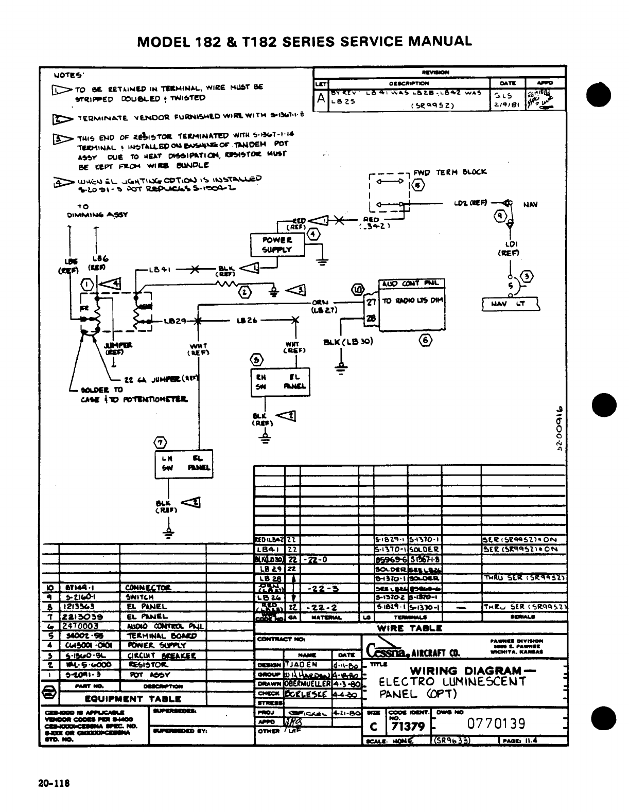
MODEL
182
&
T182
SERIES
SERVICE
MANUAL
GTO
e
tIET^lJW
.
I
.tMIMAL,
Wl
E
HMSTr
M
LET
O.SCR"
1N
-ATZ
O
iStIPED
COUs-LDWTCo
A
LB
Z5
L-L L
W
S
.
ID
TR.MINA.TE.
VENDO0R
FUWIS~etD
WIRI
WIT4
S-131-
E
[>r
llS
EQO OF
aElISTOK T6KMIMMO
JJ"Il
5+»7-1-1*
'1'4i*
E'ND0
OF
ItElJtTO
EUrimmo'
mrt.
I'TMII.MAL
.
i1T'&LEL.DO6Pcublka-O
&
o
OEM
POT1
&
Y
Wou
TO
4rT
lIrtl4IOM
,
wrfOK
MUir
BE
OPT1 F'1
Wl
M
BUNDLE
--
CT
FWP
TEEM
bLOCK
%-Lost-^ Q 0» PCB(S&-l^OI.-L 1t IQ
TO
.
,
IAg I~~LDI
108sO~~~~~~~~S
-
a
P*o
|
0
-LB041
I
-:
-
O
.
@"
I .L
I
I
rJ
" * '
T
JI MPJXY
w
lT
w"
SLK
(LB
300)
96L
E(
uTO
tW
L
I "L
-
-___(REP
.
I
o
2----W <1
-l-^
^
l
-______________
____ _
DI~
{Lb
.'
? S'1 ?1*!9-1
0I
_,_
(_
_
S_
_)
eO
N
«
5
.
(L
z (B
7) ONL
Z
car
-
\i mI,
1
,
_ ._l____1-_ ___S( IL
6
-O-28fH
M
|5E
t
_-__
_ _
-
(p 2470003
k
J*10
COMMOL
PNL
WIRE
TABLE
=0 <9 ^
'I
-
..
O
__
WtU
SiA
(5gqll1
5
. .
)^
3T.tI, HIHtMN&L §
p
CNlA
CT
sO=
_6
~
~
»- 2470003
< U060
Ch0ziL
P4L
_-
..
_"
WIR
TA
5 ~
~
~ ~
's
40tO
9
OKFI"^I-
P
....o-i _W
Etg&
BOMsZ_
_N
4
C_500_
-OW
Oi
F_ NE_
_
_
SL Y
_
IB
_ _
-
-
C
a
.
-_
_.
S
-IlsO
-4. cIct
______
.iLB2EI
I
ia
I^TAIRCRAFT
CO.
WIC"ETA
KAE
.
I.
9
-40003
RII1o0o.
IO _____ TJEN T-,-A
o
N
TIT
).u6-3
I
mT0
V
,6'.
w"k,,.
, .,
WIRING
DIAGRAM
-
P,.MBn.
1 .WMU- Or
SEmUERI4-80.
ELECTRO
LUMNIES.CEMT
EQUIPMENT
TABLE
s GLEL.
o
PAMEL
(OPT)
C4SROI
M
A
euc«.
«
«
pj
icur.
io. q
a.n
as
i
C""4
""
N
Aur-
--
|
CO.
O
N"
E
,ugi^,,_-"
m[
Irm
C
713790
0770139
,_
O__l__^____ C
715379
20
Os
s11 U i. U8
OT4r
/L
20-119I I
IAu:
H4~i4(
I(SRqb38)
I
U.4
20-118
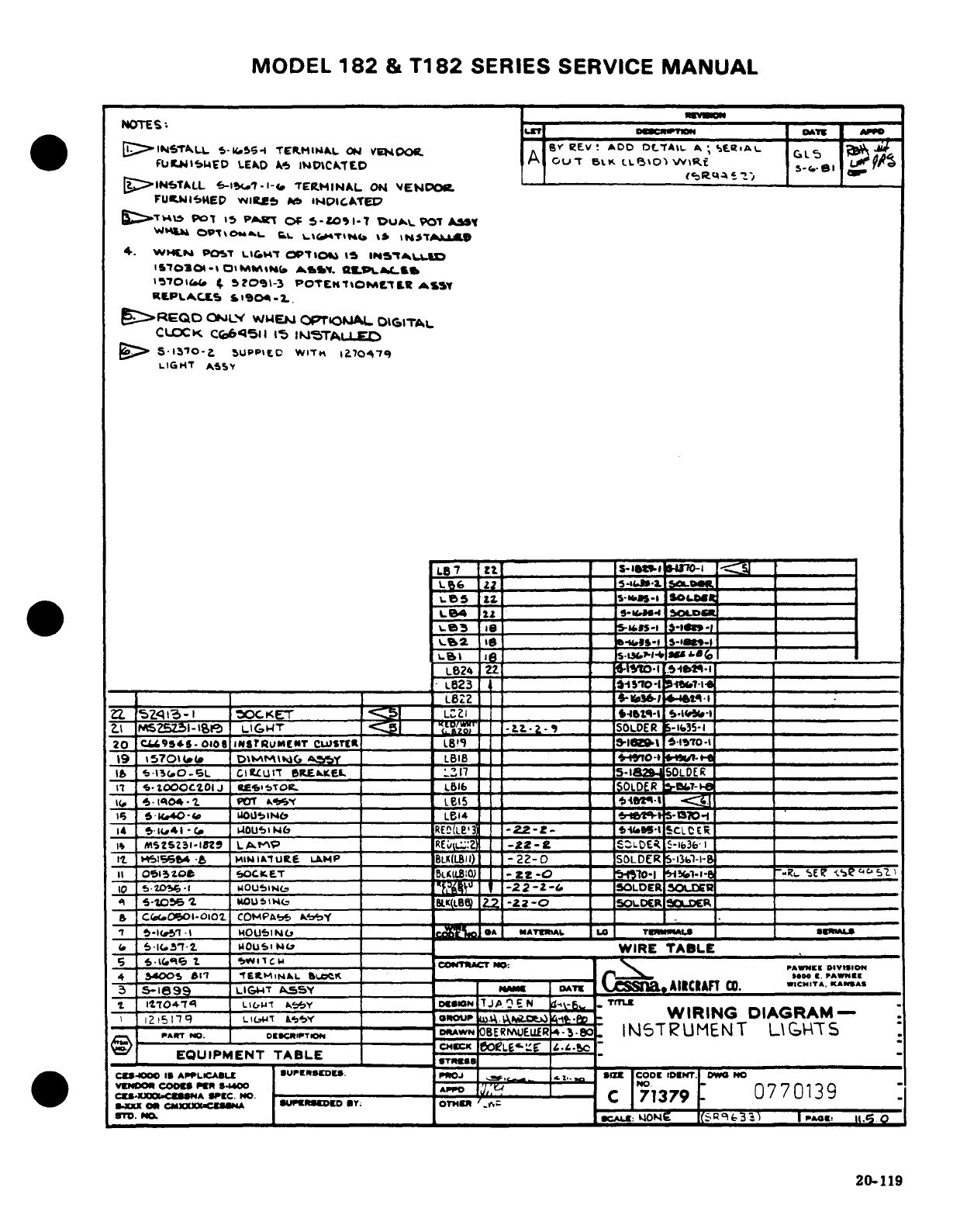
MODEL
182
&
T182
SERIES SERVICE
MANUAL
E>lINST^ALL
S-k56-1
TEKMIIA.
L
ON
VEN40t
REV
*
ADD
OLTAI.
A;,
',ERAL
la
S
FUL1ISLt
ED
LEAD kM
INDlCLTtD
A
OUT
sL.
LL
R.V V-iOl
Lo,
INstAMLL
eS-l-T-l-.
'TERMINAL
ON
VENCO
FUtIU145UED
wiES
«6
ImNIICATED
_>T^'
PoT
IS p^[
OF
5-LOI-T
Du
WPOT
AV1'
4'.
WHfN
POST
LIC.l%
OPtIlOM
IS
ISS-^LLD
ISIOaCX-,
OiuMlKMr f
A9&M.
s -CP
i
15701(o
.
52051-3
POTENITOME..2
ASll
RLPLAC.S
&104-2..
&>JREQD
ONdLY
WEiJ
OPrTIONAL
OtClTAL
CLOCK
Cr6615ll
15
I
IMTA
LLED
>
5I513170-2
SUPPItD
WITHn
1i7079
LIGHT
AI5S
LB
7I
Ztl
L8- S-lau l 1
1
___
2____ __
s-.ar5X
l---
I
---
L
b4
2sA S
_
,I_4
1._ __
LBz4
22
4
Y10I
ZtI2e
L8
ZZ I I
-
!,tO-I
4J~filFI,
\.%
IM~7.I-IF:J
LIG4T
,
oLEb--I
_____________
20
C9IS4S-
01
INSTUMENT
Cwsr
_______ I
LB!923
SI
_l _
,
-elano--i
19
c.957014d-o
DIMslTUCL
ct
-
L____
LBI1
_ I/_ Sl
-I
lb
S-
5130O-SL
CItUl7T
6RE&KEL.
.I'17
_
5-.
SOLDER
-
I1
-
2t0OCtOlJ
eslTOi. _____t L61b
S
LDEBR
HBT7-
__
I.,
slb A
-t
POT
ks _ LelS __
15
-: I
1
5I 6
.4O
0
OUIN
115114
____
LlI4
e
*
______ _ S-0___
.
14
S
141
C
OUsIu5 ____
RED(LB3
_ -Z2-- _
IX3B-I
SCLCER
It1
M525231-lB29
LAsPZ _ -22-2
__
-ZLDE
-
_S-31
____________
1T
wlSsb54
-
l4
M*IAULIRE
LAMP
B_
iLKLBII)
-2Z-0
SOLDER
5-l-I-
_
II
051350Jt
SOCKE.T
BK
-____
-
.O) -2- _
-R.
-'
Ef-1-
-t
'-Et
R
.
5
1
10
5
20W-l
MOULiNo
_. _-2 -222--=
SOLDER
L
_
A
s-'2DX
2
lmOUIH
____
tLK(LB8)
Z2
-22
-0 5LDR
OR
b
C(Cl-.01-0I02
COMPAtSbY
L ____
I 1(rl -I 1I01 t OIN
________
.
AA r.
MU
TLL iO _rMinAAu iU..S
_.
5Ic.3T-.
.OUS
i
IN,
_____
WIRE
TABLE
S
6-
t--e
I
cw
CONTACT
NO:
-
PAWN- DISoIIvo
4 OO5s40 6 T1'7
EIMIN&LL
&LOCtK
S
1000
I.
PAWNe
3
S-ies99
LIlIIT
a5sy L'fsm
AICFT
CO_.
WICHITA.
KANSAS
I'
17''0474T
LI&,IT
bY
DS
TJA.
?
E
N
-
T.LE
1215179.
LiltT
G&RY, o
our
.k.
.
b
.
WIRING
DIAGRAM-
PAIT
O.
ODEcRIPTON
DAWN
OBERMUEUE
58.0.o
INST
RUMENT
L
GHTS
EQUIPMENT
TABLE
eoL
_
C-000 IS
APPLICABLE
IUPlCo.
OJ
|.
Sl-2 I *I
COD
IDT.
OW
NO
VO tCo.i
M4400
Ac.. .- .
77
S
.N,.OR COCO S0
D
I S MYC
717379
t UO
0770139
0W
GCXXlXXX.MIA
|IIDC D
CY:
OTHNIC
/I=
SDo.
NOI ICONA:
qoNE
(596
3
1
rI9
2.01|
20-119
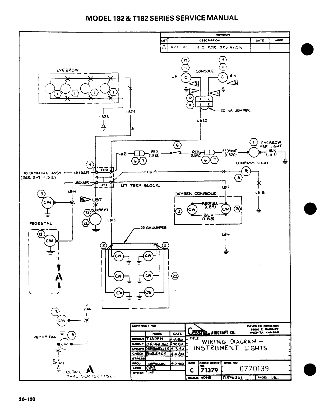
MODEL
182
&
T182
SERIES
SERVICE
MANUAL
A
--
C
,,, i
- .
F.R
VEVlICN
EYE
bOW
CO50LE
LH
H
-
Ic
LBZ4
|
t-
o
w
JUMPE6
L8
LBE
(DMILP
L0614T
O-m-(ERED
--.-
.
TDl -R-wD
BLK/
"-
'
iLEZ
(LB13) (L620)(LBI I)C
®
.-.
__
z /
_
(}
COMP^A'
LI(T
-
T0
IMMIN6
AkSSY
L65(nF)
-
O
<
p-19
---
0(SE
5sT
>5
t
'B71
13
0 IOXY6EN
CONJSOLE
L116
PE
oeT
@AL
L115
__(LBa)6
_
I<....^
/La
icTww-'
/
,
1,
Q1 <Z r
"
D,
-; r ^ -
-
y
_I'r.-~ s
AScw wINT
NT
LIH
S
^
;
w
C i
oN
W
I \AR l CR
PAw
nM--b
P^t~EN-M
^ Irns.
r
Dom
EN
-
m.
T
C _
UEBUEuER
.3. 8o0
INSTRUMENT
LIGS5
..
.BLK
I
-
A\
7
C
7
1379
0770139
'
rTH-|IU
S,.'-K
l5Rc
-
i' -,~ II
.
.
__________
_________ _________
__ _
____
___i-
i
C
.
O E
(
B
3
€ II.S
I
20-120
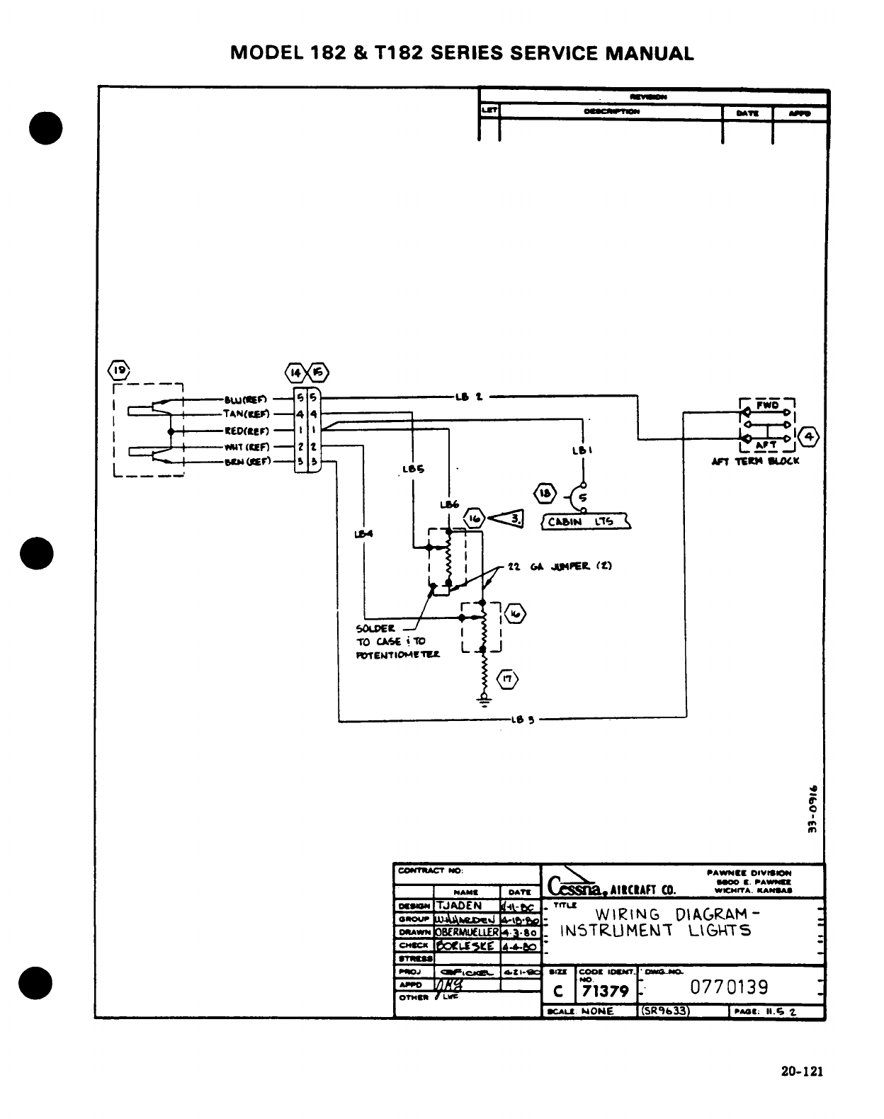
MODEL
182
&
T182
SERIES SERVICE
MANUAL
II _ -E(r--t
-
__-L)
~ L__ _
amr@" 2 2
_AFS
W'G _
Am
KM
^U I | | v1
@S
J4E
<
LL^&
'Tg 4rNSfkLIM7tCVt
LvGRTS
- -
TO
CAE
i 1T0
®I2
--
E
--
tl -----
,4
CO
-
ACT
P
r
O
:PAWNErE
DVI8
^ :hl
68M
a.
PAW~tI OlV
_ _ "A "~ lD'TL
s
AIICIlAFT
CO.
W
.
r^.AS"
o0t»N
TJADEN
bl-f T
TIu
a2^E.
4h
~~^-S.bBo
WIRING
?OIAGRAM-
O««*WNos[
3BmRmeLR,
43o
INSTRU
MENIT
UlG&
TS
PmJ
L.-
.
o
P
D
OJ J*fict-_ *tl-c
*l2X
COO
IlOimT
* m
oP ,Lam
c
713379
0770139
3C&
NO
IE
ME=(SR4633)
PA66;r20-121
20-121
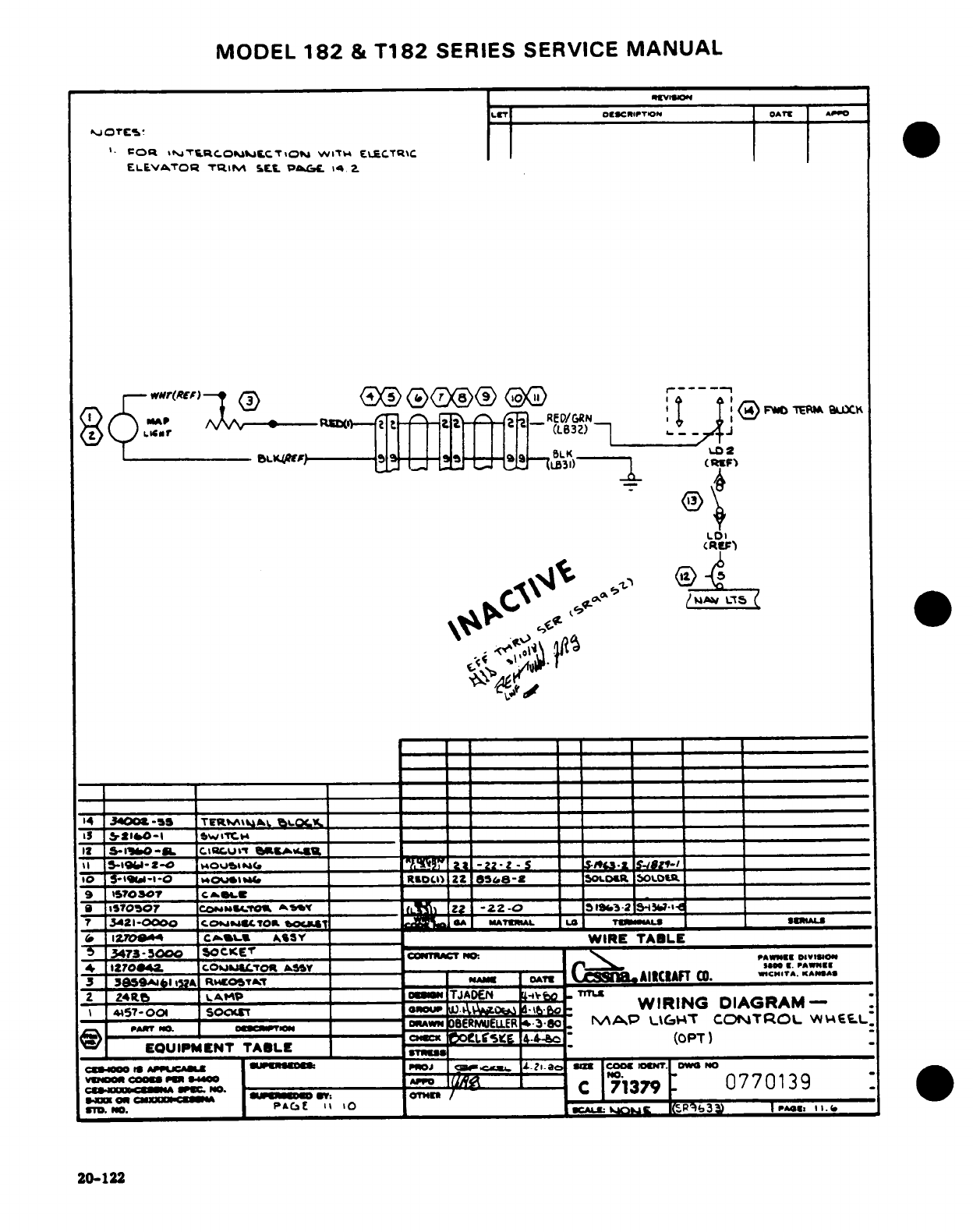
MODEL
182
&
T182
SERIES
SERVICE
MANUAL
LET
CI__OEStCRIPTION OATM
^p
'*
rca
sj.LRCOhJtCtO
Wl
ELECTR\C
ELEVATOR
'rCtAIM
S.t
P&,C.
4.
SO'APl P K
E
-a-REP/CRN
Li .,t
R
__
(L0(e><9>
)
-
- 2
_~~LK.~~~~~~~R(F! 11i _
2
EF'(RF
144
340OL
ti
-
-
_
IS
S-.i-
WIQC.u_______
_______
_
_
_
5-i94.1-2-o
c4>acb4b
ftKxa _._ _ _-22_ _-_
-.
93
5480-1
10
5-'9il-m-O
bAo0»Jexbb
______
RD(io
22
65&a8-g
OR
_0opast
50Oc.
9
«S7S3tT
ca
^.Sa
____ __
_
iTo7507
"
I I_ -22-0- _- ai3-2 sW-
4
7
Is21-0,00oo
co-taaT0m
Oc-
". -
6 ATINAL_
L
IT
AIIS
I IIA
I
(
17004
Z
C^LZ
^ASY
__ _
WIRE
TABLE
*
3473-5000
SOCKET
____ o_
r
_~
D
'2
l2?004a.
I
¢
o
' " m e
L
I
NIS,
IBE.
PAW1II
4
12roxo
CO,,,,,
ASk,
-,
v _,,,,
[_S"
^
3
-MaS9eAbiStiA
RZHtObT^T
--
----.
_
_ _AM«c
am
^'ACiAFT CA.
wCHITA.
KAAS
2
24RtB
L.A^fP
O
TJADEN
e
_
Tm
I »45s7-oo SOOcT __
e1w
k!
l>tr~
-
WIRING
DIAGRAM-
_
-
Pr oM
a^
SPERt1JEILER
83
, !A.P
LIGHCT-
CONTROL
WVEFL:
@
EQUIPMENT
TABLE
C
C
4
(OPT)
m
.
.POJ
s
a
co
NT.
NO
vanes
c!nnm
NM4400
1m
Al"
NO.
I a
"
°
!a
-C.
71379.
0770139
. .
P
0
________ 1_ _________
.
20-122
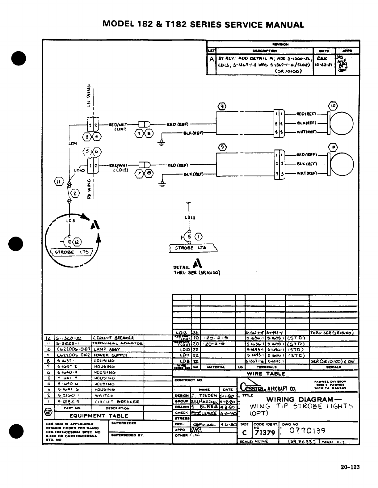
MODEL
182
&
T182
SERIES SERVICE
MANUAL
LET 3
OOIMNPTION
0*TI
LDIj,
5-ij.7-j-3
WASS
S-i3.7--*/(LO)
)
DO
-
I.
a
fu
!
<_
©
3
<i
_*J=DIr2
-
®< :S
i
J
1tT
Selt
(S\1010PF
I)
2
\ t(t0-7
Et
w UT--E
tE
--------
2
2
---
LK(tEF)--
1
(
o
LUO L Ja ^-D^- _ _ _ ,s_^ S-.Ey
&I C 6
-01 I
I
o®
<§@
T _
T
-
C.
k
A
LT
\dYB ,-n /^---.
I
STROBE
LTS
DETAIL
A
THRu
SeA
(SRloIOO)
I
S- i
35L
-SL
C.ISuIT
detAt..
__
I
20
-20-
Z-
I
I
4x I Ip C I CsT
C)
I
C.-
20ZS
-
I
ITERI| Alot _____ l
0
-20-2o-9
|"-0
ITL
WR""'"
I1
D-IAG
A
I
cS)
__
10
CRZZOOC-
010LMP
ASY
I._
LDIO
22
R__ N* (S) |_____
I
q
C(«220060102
F
RWER
UPPLY
|
LD
22
|
Is
14q
l4-1151
l(i (SD) _______
a
-
I
31
u
LUOUSINb
_____
Lo6
j
____ _H___ -ls
I.
r
,a
(_eoroo)toa~
l. 1 fI(
UINb
ZHOUIN
._ [ OGA
MATERIAL
LG
T
)MINALS | |I*L
tllo-q A0uS.,o
_______I
WIRE
TABLE
_5|S
1'
API
A 1 10USIp 6O________
COSNTACT
--
I-
:
VEDO4 CODS PERl'40
P
|A
INE[OUS\N(
________________ C
I
0:F39
DIVISION
4
5
t40
('
S0U)IWCI
o.
·
O
PAWIN
EE
C a,.4lS-XXXX-C UNA L t IC SSn ICIA T CO.
.P
NCM
.
KN
-
S2 zD. I IILCI
DIGN
T3L
O
T, I(
S
T
TLC
'
i
123a..
1
,LcuJilT
MeeEK
GRoup
Ar.J ^20-123
WIRING
DIAGRAM
-
PAT NO.T
DCRI
-
DA.
o-BU.r.lS..0
WING
TIP
5TROBE
LIGWTb
EQUIPMENT
TABLE
C---C-
7oLL
a^^
(OPT)
*__ CIS-1000O
IS
APL.CABL
rSUPERSEDES:
PqOJ
I.~ 4sjc
SIZE CODE
IDIN?.
DWG
NO
VCNOOR
CODES
PER
S-IOO
--
- -
NO
-
T7
3
cS-XXXXz.CESSNA
Sc.
NO
71379 0
C 0
I
9
-XXX O1R
CMXXXX.CESSNA
SlUElRSJEDDO
OY: .It-
j
SrrTD.
M
O. SCALI:
NONE
CS
9 33 PAGE: II.
20-123
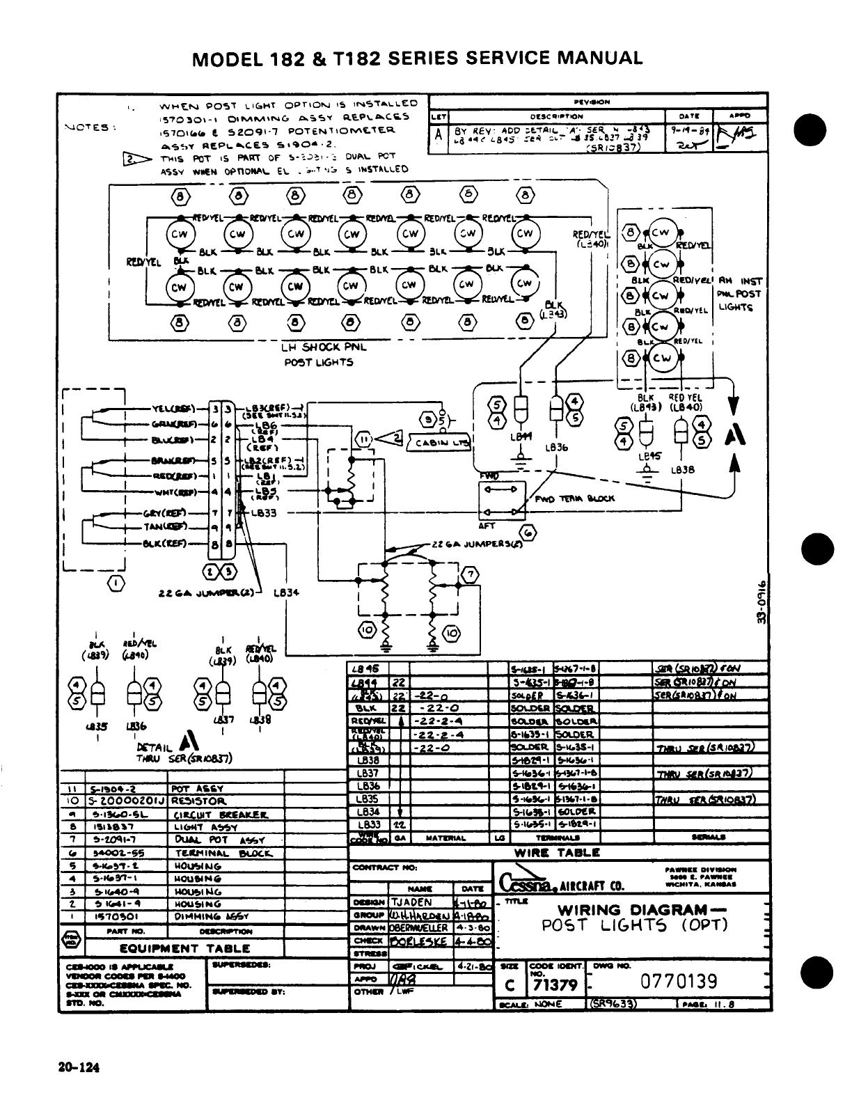
MODEL
182
&
T182
SERIES SERVICE
MANUAL
tvnt-.t
0oS
LIG0HT
OPrTOs
IS INrT&CiLECD
Pv4WON
1570o30>->
OIDAv
N&
ANAr o S EPS'C
aPIC.LS
oLrTC
m T Econ
OT
|A
CT
£E
:,S70o(.(
Y
,
5Z091-
POT5EN'TO
*
%CtE.
A
^Y
REV:
DD
e.A-IL
'A'.
5R
.4
'
9*
_-aST _Ri:~.
_>37-2
_' _ _
-
__S
[
ASSv
WIm
OPnOA..
EI
.
,--
'":
"
>*ST
LLEO
I-~
-
/ojkt\
--
I t Iv
k+"-<L~)
'----.~
I
'
2 Y I ~
-
7"-'----------_
, T
8YEL LRnrfLSD/RI!Y& L-eu
7
-
^; _
_
D
Y_
; (^w>
(c)
(c)C
(
<)3(
(w)Q)
(cw
E
WREDtWIY
-, ._L
tLK
SLK
'
5
s
LKa
--
BI
-t
BLK
--
I
I
cw
W),L
.|
EO
VEL
1
POST
I|> <
O
>
e (,,
()
,
!
~WYLEtIDYEL
LII'TS
LH
SHOCK
PNL
/ /
POST
LIGHTS
- -
|
G>
_~~~_
__ _____ _? nE V^BLKREDYEL
IL-
---
UTC
I)_
4
4
:t5
---
)
4
-
e
D
|/
I I
S
I
L84,6
_
I
IW*7
e
1 I4L,35
i;j-)8 I +(j) (4
(%<;^)
22
_ 5 5$1e~t~4
p-~- -TLAN(B^»--
q
4
yAFT
(
!?
I---l-semrK)-
z-
I_
-
j--
-uMPEB(A
tl
7L «IBI JU
„
-2-^
=
AK-
'
I
0
o3A
2.
-22-0
TAU
SR(Slio87a
)
L.
38
IgIq
-*
-
'0
S-
ZOOOOZOIJ
RE5lrTO.
/
_ _
LB3S5
I
_
S
1
---
T-It#u
mtas0oaI7)
O^ -IS
o-sL
cI.lCrT
VE*A
I_
_
LB34
__
S-H.51
SOLeR
-
B
Isistr
7
LS61
M^a)SY_
LB33
It
____=_____
__= »1
.»-lOt-
7
|
-20q1-1
|
Duk
POT
^aY
GA
IgO
MAT
TRIAL
La
T
ca
5IOOt-SS
TIEMINKL
BLOC
"__
WIRE
TABLE
5
d$KCa5¶
-
HOU'4G
____.
CONTR
ACT
NO:I PAWI OIVIIT
4
s-i<
yt-i
noiigs
1
I
IQAT_
MM
i.
M-UM6
___
t
I
-1TJADEN -t.r iouic
om-
gms
-
_
I
*I2__41-
ioSuiI
L________ _
0to
AiOrN-_I
WIRING
DIAGRAM-
|I 0^
o-
|
oaaca
-
--
00^AIWz6EB¥UEIER
14-60.o
POST
LIGHTS
(OPT)
1
EQUIPMENT
TABLE
_c ^ fS
-_
CEOOO
IS
ApruCM.
mUPW
s
PHJ
w_
.CX«L..
4.
la
cooS
OT.
ow
NO.
vWo.
COOiKn
P
64400
AM-
jO. -77
U4-O
anCMUO
i
T:
|
V.
OTHR
y7| C
71379
t
°
77
10.
NO.
|j
___
_ __ _
_____
_
-CA
U
i(SR&f33)
ip
I.
a.
20-124

MODEL
182
&
T182
SERIES SERVICE
MANUAL
NOTES:
*
D~>
MATERIAL
s5
ALPHA
5857-7
(/ENDt
C.ODE
92194)
OR
:ELDE
IJ
3009
-
I
(VEDOOR
CODE
70903)
2E~:>
MATERIAL
5
ALPHA
5857-
o(vENDOR
CODE
92
I14
OR
aELDEN
83009-6(VENDOR
CODE
70903)
-IH
LAND
LN
TAXI
TAI
(LC3)
A
u
TAX
XOr
I
<0
LAUD
LEI
LC
I
0
i?
~XIT5~Ts~a.U(
~: _ 1
11
s-
TAXt
LTS
LD6
LTS
I
IS-186
_
I
15
F
.15e
7-i-l
LM.ULE2 _
I_;3
54931
5-37.9
______I7-
8
LE
I _ 1
S-134.7-4
-14q9-I
B3LC3]
_
__ 5I- ji s-_-_-___ ____e
_
l,
5-s493-I
-tI _____-_________e-
LC
I 8 -___
___I
l-1-I
5-4.S
3-1
GA0
MATRIlAL
LC
TEMtALU
SERALS
6 5-1360-10L
CIRCUnIT
BREAKE
WIRE
TABLE
5
4591
LIGH
T C
Ow
NO;
P. at II
DllVISION
4
1270082
DIODE
ACSSY
-0
M
C.I
PAA
3
5-203-
TERM.
A
DAPTER
AME
AI
-t.
T
2
5-21iO-I
-
^ITCH
D-
SgN
TJADEN
.6e
.
TITLE
I
51360b-5L
C I
CLIT BREAER
owGROUP A
WIRING
DIAGRAM-
PART
NO.
o.c
:,t
DRAWN
0BEUWELER
*1-3-o
.
LANDING
LIGHT
EQUIPMENT
TABLE
CH
ES
CES-IlOO
IS
APPLICABLE
SUPERSEDES.
PIrJ
-r.C jl.
iL-1-Bo
SIZE
CODE IDCNT.
DWG
NO
VENDOR
COcDES MR
4400
0770 39
C
uxxXXCn"NA
PrcC.
N.
*.
-A
D-
C
71379
S-
BX
O
CMXXXXCxSSNA UPERSEDEDO
BY;
OTMER
/ L
STD.
SO.
CALE
NONE
(SR%933)
I
PA:t
1.9
20-125
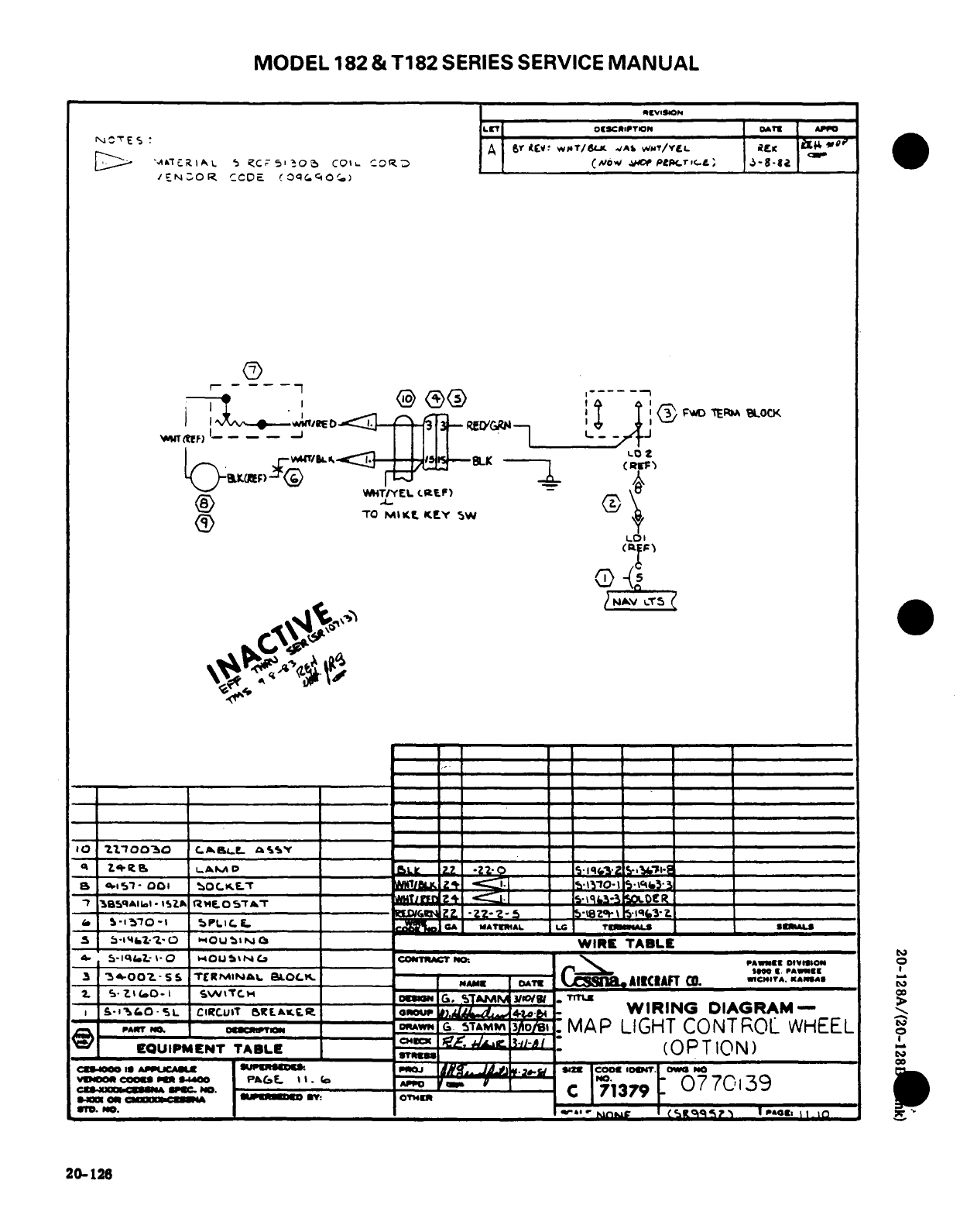
MODEL
182
&
T182
SERIES SERVICE
MANUAL
EVISION
r^i"C $:
,'
,£V:E
5w#.A
6/r
4CV
W
,t/L'
JA
V1T/YL
rC
^r.
D
A
E^ I A, L
5
C 5' Co0 COiO-
D
A
_
(ow
V
ptWrK.
i-g-»- 0a
/ENZOR
CCDE
rOqrqO,~)
/
_ _-
CO
c -----
-_
|
-Kf
-
__
(R)
,~X-t
®®<
I
O +~~ot^F)~~~ ~
'
^ FvnD
TEPM
BLOCK
_
>0
)
TO
Ml\Kt
K
t
SW
\se®
M4T/YEL
(AltF)
-
11 Ll Is I ILO
I
_
»bqA..«L
O
ISZA
COeA
osLT&T-
I
I
IW
_" F0LL
- -.
.----.
-
=-
-_
---------- -----
tmZZN
-z. 2Z-2-3
5.ia..-
=
5
*
1
f3
Z.
5
_________2
..
I
~1 -i o ~
PL.I
C.
C
CA
M"WTIAL
L
T
IS~AL
SIALS
__5 _ _-__ _o _ou_ _ _
WIRE
TABLE
4.
-qL--0
4
OUbiNCa
[t
..
a
PAWN
DIVISION
_ _-__q_
_t__ O
HON,
_
.
PAW
,S
_3^-OOZ-
SS
TERMINAL
BLOLr..
T
C^
AICIAFT
CA
.
."c^^.
,~
-
2t-\0Tc DI
SWGTCl
SMM
35059
Tr
---
>
I
5--iO
5iL
CIRCuT
BREAKR
aouP
^M
WIRING
DIAGRAM-
r<
G
,
.A
'S-
-TAMM
r
,
.
MAP
LIGHT
CONTROL
WHEEL
EQUIPMENT
TABLE
L
(OPTION)
CK5
0o0
1r
APLIC-ll
B.mogI.
Lg
Z
J
,Lj
.sm
[*
coc
,inT"
Nowa
I
ITO.. NO.
I&Me
(SIZE
fl 77'
i204am
CU
COO
24. *EA
W:
OTH
20-126

MODEL
182
&
T182
SERIES
SERVICE
MANUAL
NO
E..
S:
-L
-clraT ^t ^r
COMNNLCT
LH"
8LACI.
WILL
TO
SOCALT
6A.
.
6AKXET
Z-LW2
-B
f(L.-LH
b)
iZ-Lh
.1
/
-LHZ
2
_
4
_
5-
13701
.T--'
^-
L-HI
2^
________
_ _ 49 ____-__^__93-l
_
«.____________WIRE
TABLE
CO.ETRACT
NO
PA-f---
-
DIVISION
MSZ5338-7079 LAMP
_____
_
-
L.
SlO
I 'OAWNE
C7-"
-
I
q
S 6ET
-E'
-,AM',TGe
AIlCRAFT
co.
CHITA.
KANSAS
2
5-2I60-3
SWITCH
DC€N_
_/^~ _Sl KLI
TI
TLE.
_
DAr~
5-i360-5L
CRCUrT
BRK
OUP
^
A
-
WIRING
DIAGRAM-
PAT
MO.
DESCRIPTION
DRAWN
g KL/Nt-
.
ICE
DETECTOR
EQUIPMENT
TABLE
ST"swsSS
LIGHT
(OPT)
Tl8
CES-1000
IS
APLICA
LE
5UPERSEDES.
*J
,
SIZE
CODE
IDCNT
|w|
NO-
»r~o;
-1 -9W
s-n
coo[
,OENTwc
VENDOR
CODES
PIER
S.IdOO
A737O
NO
CtIS-'XXXeCISSNA
SPIC.
NO.
1D
S7
0
70
139
S-XXX
OR
CMXXXX-CESSNA
SUPERSLEDD
SY
OTHER---
_'
T
71379
!rrl»T~~~~~~~~~~~cuD. N EO. (_
,
STO NO. SCALN
A
20-127
20-127
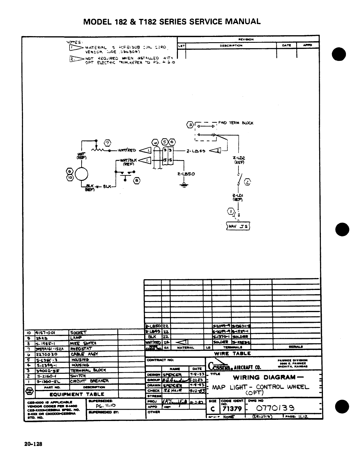
MODEL
182
&
T182
SERIES
SERVICE
MANUAL
Dr
WTSP
Rl^
-CF>1308
:.)'L
LCT|
OZ_|c
'TONoTs I A|
'
E ~ttSK
--
bE
,-f63ObO
' _
.OMT
<tIQ-lkE
WEN
iST5LLOD
;lT
OPrT
!CTYtC
W
IM.ktCER
L
C>.
-..
a
-
_-
-
FWD
TERM
WUX
J^p~
'NA^A----Win/ReO<<3.-.3'---2-LB-E
1
4
©0 I-
SO
w d,- IC-~
~ BLMU(~Fr~ ~(FEn
oli
10
41S
001
SOCKCTr
2z
_m
_
a
I3.?02
,-
IKmE
~I N& I I
PAma
a
s-16c-L.
Ifcrr
aI;_'
___.,.._-,
WIRING
DIAG
RAM-
>C
t -I,_ _t. mcOSTr _
GA
I~
ATWL
,Law s
'
T"
S-z1lfe0-BL
I.TCH
____» S
R
I-
.
WIRING
DIAGRAM-
^ >*PA«WV* __________._
______
S
-
MA
P
LIGIHT
-
CONTROL
W1HeEL
EQUIPMENT
TABLE
-OPT)
cr.am
Of
AUP
CA*L
f
UJ«pB*:
I
(o-
IMS[
'
sri-3a*
rZ
: COoa Ein' ow
NO
vome
coea*
Pn
6-60
pf..
11.10
NO.
0
j2inhA
? U-oC_
3^
713
0770 3 __
9U
a.D0R X
r
ac
OTHRR
C
ao. O.
.--
l
Ho*
O
II
,
6
l t
i
112
20-128
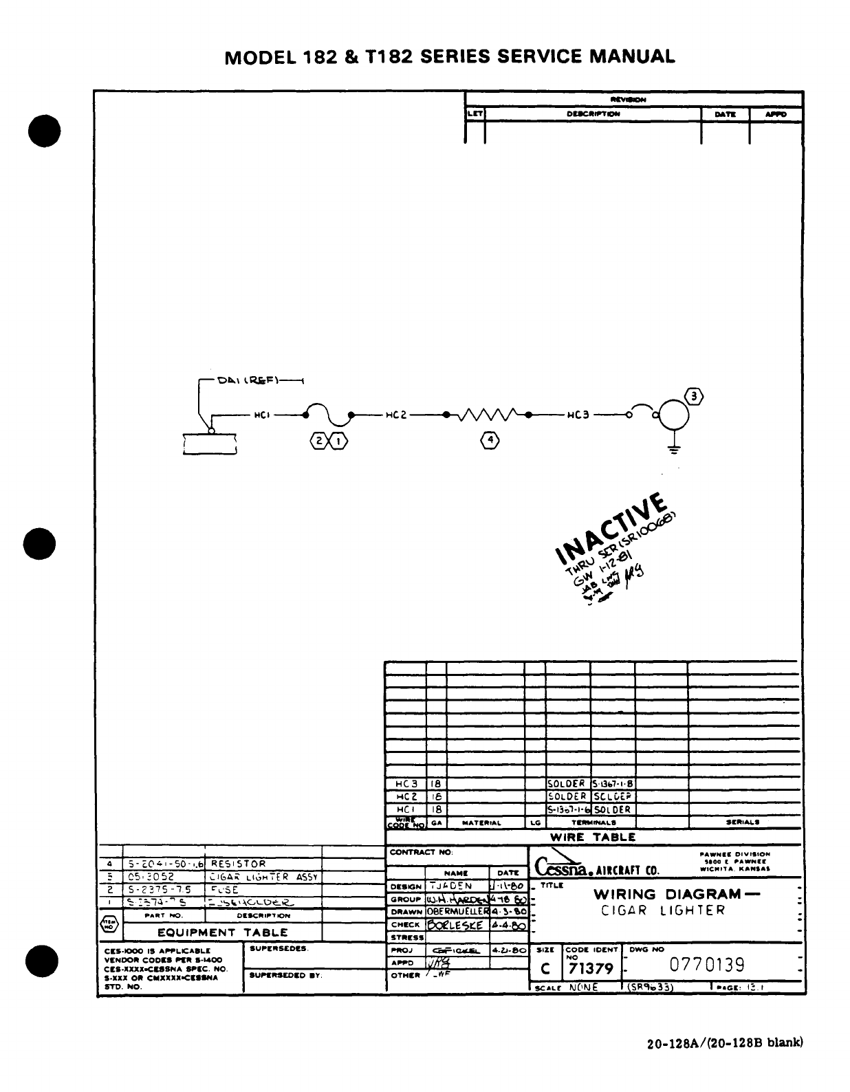
MODEL
182
&
T182
SERIES
SERVICE
MANUAL
LEn
LIT
_______CIPTO______
PDATT
AI
r
C
,-\ t9h ^^
MCI
NC
a
Wt
C
3
--
z
r-^T
©0
=I
I
*_
_
HC3
18
_
SOLDER
S-t37-iB
HCZ
16
_ _
SOLDER
SCLCL
__
HC
18
_____s-_
_ -1-i- SOLDER
SSOGA
CA
MATEIIAL
LG
T
IRNUALS
SIERIAIL
WIRE TABLE
CONTRACT NO:
\ PAWMI
DIVISION
4
5
'
.0
0
,.b
R
ESIS
T
O
R
0
N
PAWNEE
Dvso
C5
5-0502.
aR
EIGHTO____-ER
-AY
NAME
DA^
C
S
a.AIRICIAFT
CO.T. "C
PK'AN
"SAS
~.
5.[~-75_~.
5
C-.S
DE)IGN
TJ/.CIN
.-
I-O
.
TITLE.
--
'05.305A
- '
-
tU
M-ERA-S5-----..
_R
1_:_-_
Z-
'
15-u^
.-
54------SEG ESROUP
ISC\.
D
G -E,6
TITLE
WIRING
DIAGRAM-
-
PARTo
I
oDscIPTN-
DRAWN
OeERPUELLE;
4-%o CIGR
L
I G
H
T
E
R
EQUIPMENT
TABLE
CSTRCK
eiSAL
CrS-1OO
IS
APPLI
CASLE
SUPIRSEDES
POJ
C
Q
~.
4-t.-J-8
SIZE
CODE
IDENT
DWC
NO
VENDOR
COD.S
P,
5-1
APO
771NO
CS-XXXX-CSNA
SPC
NO
.
=
C
71379
07
0139
S.XXX
OR
CMXXXX.CISSNA
SUPERISEDED
SBY
OTHIR
/
-F_
0ST.
NO.
I
scLfr
hIJCE
(SR9%33)
I
*GC:
I.I
20-128A/(20-128B
blank)

MODEL
182
&
T182
SERIES
SERVICE
MANUAL
40'NOTES.
-
OCIII
LUE
WAKIN
L'rLoT
.E"
PIhF
-
.1
-t
OFe
T
" ,
I
WIRE
TABLE
I
I 10102
TL
I I.
C'P"
I
'
WIRING
DIAGRAM
PART
O
A
DESCIPTION
DAWN
5UR
3
9
HrrEW
PITOT
-T
4
i
EQUIPMENT
TABLE
STS
EJED
TAIL
WA
NING
IOPT'
CES-SOOC
IS APPLICABSLE
SUPERSEDES
PROJ
<!r AL-..Z
SIZE
CODE
DENT.
DW,
No
j
I'S(~Ol-(p
WOUS·I)
I I I
I
~' ~
I
"
° '
'-VENDOR
CODES
cEr ,S-40
APPOr
...
¢.,.,,,o,5, _,,
_
_u __
..
£4
*^- 1HETED
PITOT
'
TD)
E
E
C-XXXSIIXOCexxSNZCEA
l
PE.
.
6
C
71379
-7 1
0139
S
-XXX
On
C
*i
XXENA
zO
CONTACT
SE
IOED
V.S
OTON
a4m.
o. 5 I H»4 IXcr 1940-U51 I;So HOC>I[a __r___________SC O
PAGE:
15
20-129
20-
129

MODEL
182
&
T182
SERIES
SERVICE
MANUAL
NOTES
.
Lr
oucaPrm
o IDT
D
REMOvE
4e
DISCARD
JENDOR
FURNIt
Si4TEDM
IN
ALA
5
s
Y
£'l: A,
OE.L
A
t.
^
s im t
K
.,L3_
UK
TEXMiNATE
wiTH
5
-s
TERMINALS.
mLI4
i5,
LI-
LIo
O)
4-4-
B
y
.eV
R
r
6,R
IrN
NEIeU,
WEI9 NI; D
-
-I?-
G
'r
>
TERMINET,
vENDO
cuWNIS5HED
LEAD
,ITH u
sAour
wel,
W4
4
4, A 4e, 3-VI IL-
.eRroamL.
A-o
,%t-,1
W914;
Mir54,C
Iq.,
S--l<<7-1-3-.
i.s
,r ,Ia
/<%
sd
t
¢
3
bM16
1
3I
aI________aI
--
sl'oo) to
E
I'Slei
1
t.,i2is (S3-#jl
iai
oo)i
0
Er&/
leiSI II
aw
MR
(lOa)401o
NE
I
,
159
>-
I
itOl
4
0
1 ~~5 $-15~- IL.
Ci-c~ulta1 1 isc,-
1416)o
14
$-I
_'L/
-I:L.
C4iCUI'
F
'
____
I___ __l_ _ __ _1&"/I,
,.
SOSO.
COMPR~e~aldO;P.
i
'~S
.i-.6 It)-,N4-,
4_
S-3I3-£
1.4ueINx it ____
5
-
a 1010)u
WE
(MIOl
S-1&37-1
HOUSING
dHE _______ ; =__a_
TI___olo_)
9
S-203S-2
tU4
N
.
I I SMOS-
HEJ
i (.OC
a
S-i035-15
CKifua&l -Rsg ~gi =
-
^T
-i3C CT. JNAJt OOU4G:
FAN
A_. L___
-
IaI _
.m'
,=
_ _ -1»s- SWITCIHU51
"
I -o
.
a
O.
-
0.
~oz
i
N
-P.U
N
oAICIAIr- 1
4
.
S iAOIT.
_
IAN1
T
9
S-
03S-24
14OIN0 _-
CAP
=_
]'6. TA0_ _____
t.o
r.l
i S-z035-1s
H.OiUSW
Hl.
,A3=) -4,
I76tj0oss
L012
A5.
(ARA).
WIRING
DIAGRAM-
1QUIPMENT
TABLE
C
_WI.
cg-s
o
is
AJ2PLC
SAILE c------ t-
1
ws
No»
-
4or
SWITCH
(AI _
_
NO^..
«
0170139
_1 mQla ctm^ WA F
'
WNl
OIA-
^" _«^N,:- o~~p~T
S.
BURFR
*-w-
AIR
CONOITIONER
COPT)
eSitco UAm
ow"
n.
2Y
1
DM0
_ -C 713790
7
0
130.
a
s
_ -Im
aO N L 196UeD 1
om
m'
L
20-130
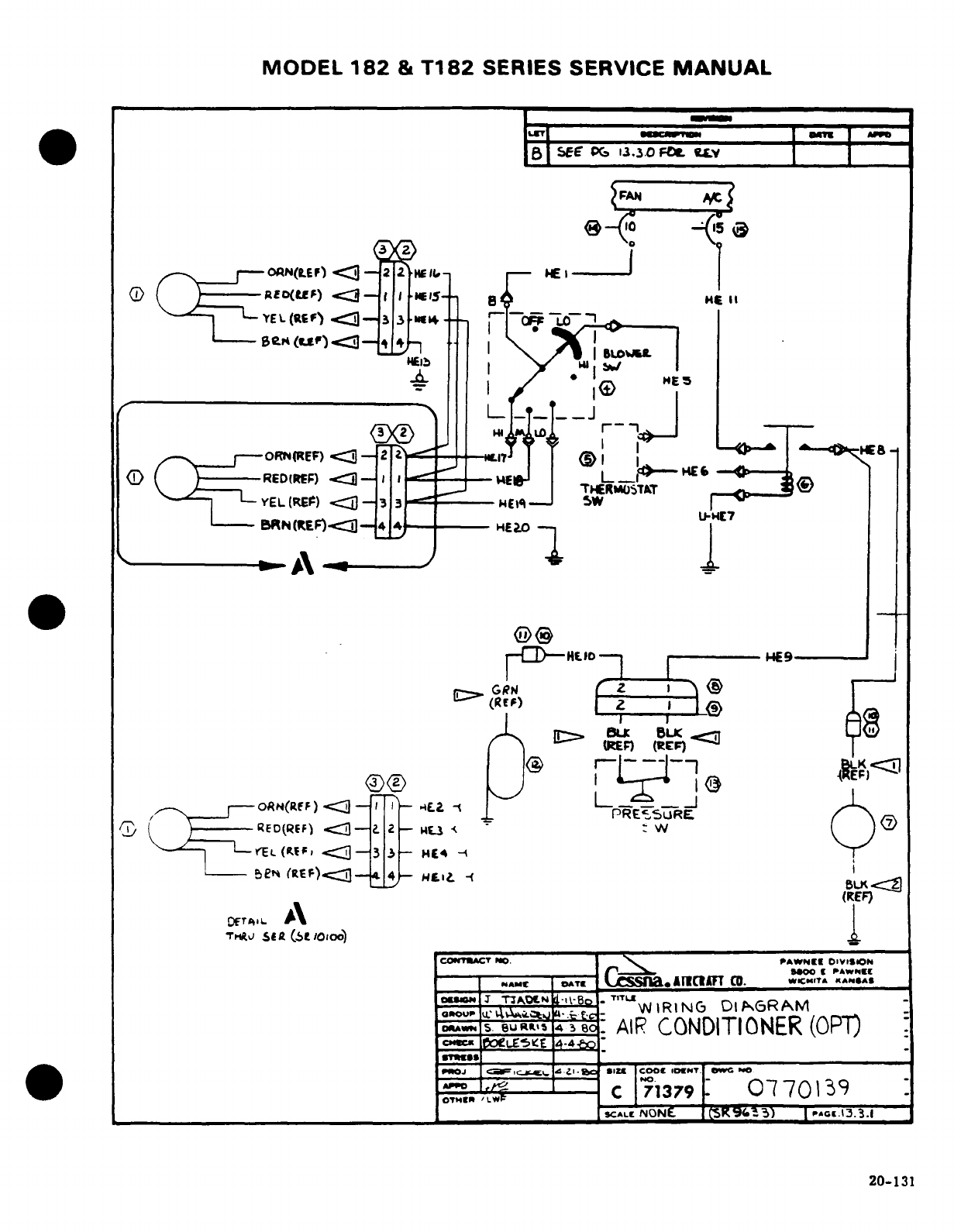
MODEL
182
&
T182
SERIES
SERVICE
MANUAL
I
SE
PG
13.3
0
FO
I
I
@F1AN
43-(o
X{s
@
OoRN(P^-^ )rORN(LEF) 0
2
HE
-
HE
-
roD(Wr)
_
IES
HE
II
LYE
L (R
F)
4-3
3
W
4
--
-
O
-
REI. .J I
HiE5
QoRn<REF)
CJLIer r 6e
E8
-
-
B
N(REF)
3
4
_-
HE.
6
|
YEL(RE3
)
-<
3_3
2E-
U
'
f~rt (EF~ cD
3
<
HE4
HE
-A."
i
-
-- -
ICD-HE'o-I
-------
E9
0 ~RN(REF)
.1
-"
EZ
..
N
-
RE,
5uRE
4 -L (
z '
-
1
OJ _
>
GB-OC
I'C 713
79/
Gt
o
0
O.
/
^...,._.__.~
SCAIR
C(
N
D
TIONEP
,
I |3.(REF)
:
CE, AIL AlK
· 2
r seiJ (SE
CbL
'oao)
cokWh1cT
Poo.
PAWNEE
OIVISION
NAME
DATE
o
.n
1
i.
AClCkFT
CO.
wCcerA
cKANSAS
am.
I3--OTtFAQCN
TITL
-
JRING
DiN
GRAM
I-o- r..F--N rC,.F) 3-4,. C4
O
IDI[NT.I
-(
NB
MOAWN
S
sUpR'43
LAIR
CONDITIONER
(OP
T)
ca4cz
opeLea
4-4.6V
Un>€»i
__ES__-
_-o
_OTR
I
LWP
c
71379
07
701
_
_
20-131
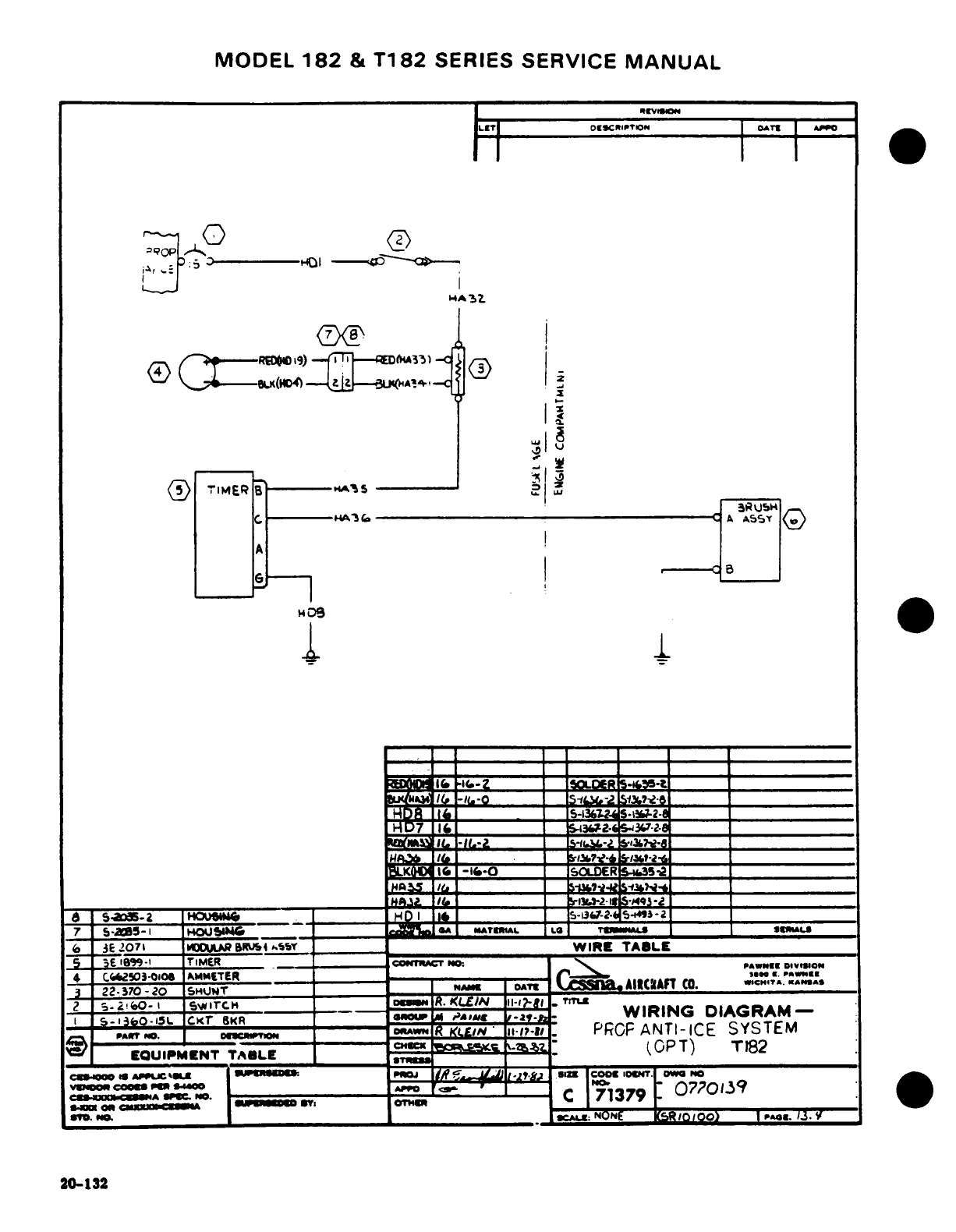
MODEL
182
&
T182
SERIES
SERVICE
MANUAL
_ A 7~~~MA.
1<X^~ 1 14.
:r,
3------^)
---
^
I
-c
II
1
SE)-
TIMER
COMMA
NNO PA--- _ V3
II
_
_5-"'
-
'Ti
*
S
I&
IS
-Z
-
~S^R 5^5^
6
IE
.
'Ei07~
11JUd
B"uS4
,,5
/
!Y
WIRE
TABLE
I
;E
1X
TS'MER
- - - - --
-- -
i
_ _m
_
.
.
S_____
DO
22-370
-20
MSHIETE_
I
NAM
OATS
%
5
laAIRRF
CO0..
.....
A.KASAS
±@
ItL
_________
__S-.3
S.f-2-
----------------
2 S-,!
(-
I
~irC.
H
D7
o________"KE
IW- ______________
2
S
0-,
CKr
SKR
__
low
0 #C-I5
_
WIRING
D
.IAG
RAM
Sr r0 #~R
KLFM._
fl OlL-D
PI
:_G;F _ANTI-ICE
SYSTEM_
E207QUIPM
ICNT
____LEE L
(
_GP
T)
T2TA
*
IE18-I
TIMER
_ _
--------- COTw
IS
N.
v
PW
BNOo
2 .20.-. SN.TCNu
WIRING
DIAGRAM-1
<w WHSmcoo"
PM
PG4t0 M
.
1
Z
OO
o
w
39o
CM&UoESSNA
AP
-=NO
--
--
rT
C
71379
077?039
2T032O.
ta.
_____
NN
I100)
PAO.3.
20-132
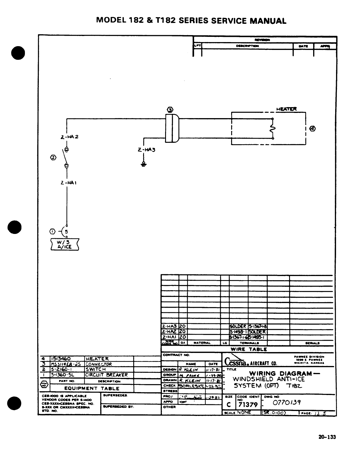
MODEL
182
&
T182
SERIES SERVICE
MANUAL
,j
-
2r _ _
I
_
2_-A I_
N
.A 2
w/5
LA/I
CE
Z-HA3
Z0
= __
_
Z-NAI
ZO-
_
DE
o^
0
M.O
RIL
L*C
AtIEnMAL
-
UUSLu
___ __
_WIRE
TABLE
C__r_
NO:
p
&*M((r
olIVSlON
4
l5l3O460
cE.ATER
.iN
·,*
,-^-
T
M3I14
'-S
CCNNL-frL I- fr
NA*ME
OAT
CSna.AICAFT
CO.
.c.T.
^.,
2
S-Zi60-I
SWITCH
o___n
..
i--2
TITL
IRING
_
-1360-5L
CIRCUIT
BREAKER
GRoUP
.
,,,,
,---*
WIRING
DIAGRAM-
,.PAR
TO
DoCT
---
O-
o,
~.i,,
,
,-1,-r
.
WINDSHIELD
ANTI-ICE
EQUIPMENT
TABLE
c-l
-
^ SS
5YSTEM
(OTP)
7-
CE-000O
IS
APPLICABLESIM:
J
SSUPERE
S.. 7DE
z.
ooZ
IoENT.
owc
NO
VNDO0
COO
P
SmP 4 7700 r39
X]XXI.OCESSA
O O.O
C
71379
077013J
crXXX
0o
cMxxxx-CC--4A
sufCDMO mY: OcHtN1
srt.
no.
Sc^AL
hNNE
(
S
.OIOC)
I
ct/.:
I
' -
20-133
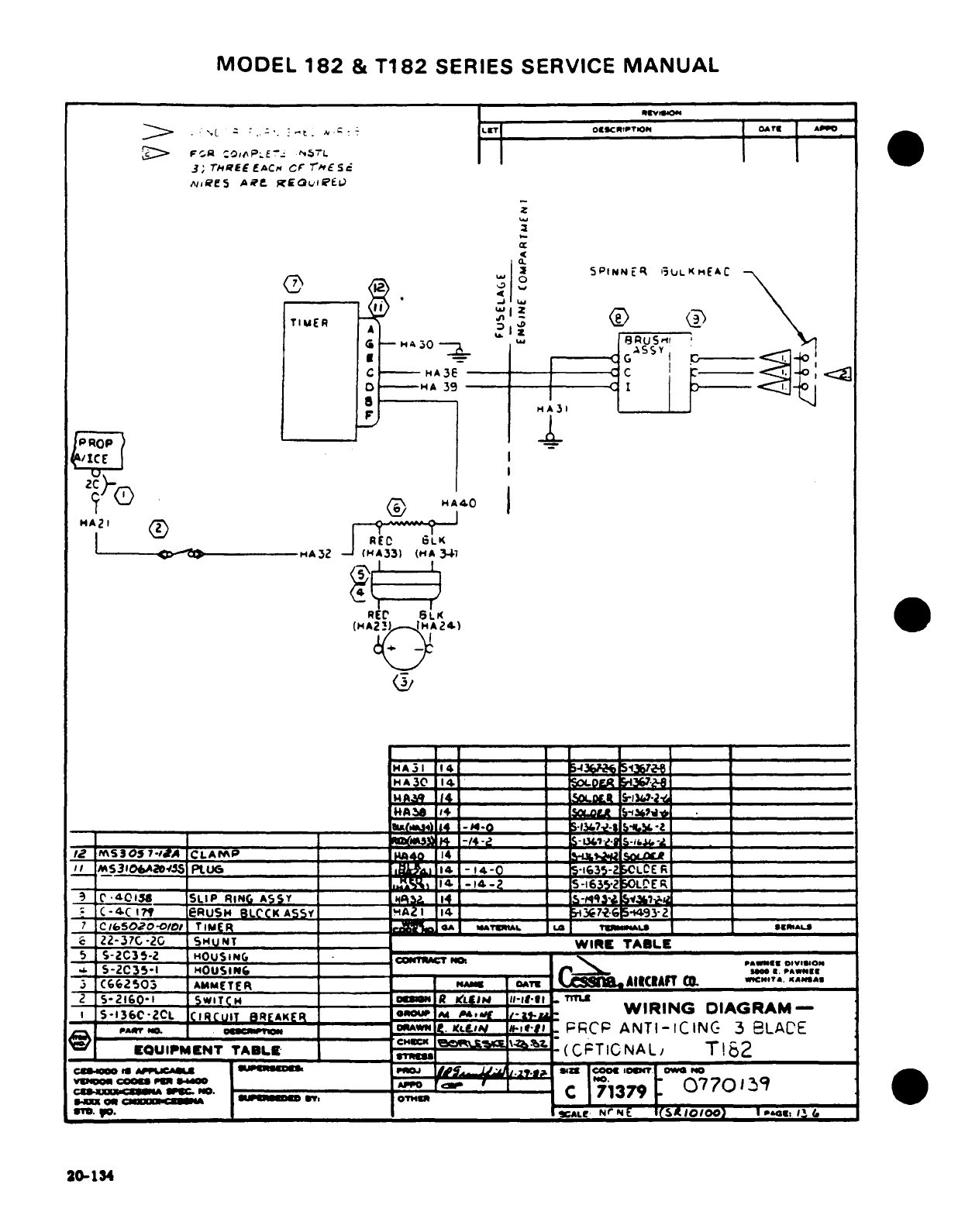
MODEL
182
&
T182
SERIES SERVICE
MANUAL
-L>
'
.-
( -' -
LC
,
O
s-tCPRTsOm | *N| ^o
A
FCR
CO;0PLE-
-
N5L
3;
Th
EE
EACM
Cr
rTesc
A/iRES
AE
C
RgEO
I'Ei.
z
·,
i
w 5°tSPINNER
IijLKMEAC
TIMER> \>
I
I
0-=-
j
C
FtHA 3E-CC C C--
o
0 A---
39-
C
I
-
F
___A31 _J J
P
_o
(t/ICE' I
2C 0
@
HA40
JI
-- -
S f'lMA3Z.--2
(MA33)
(HA
347
REr
6LK
(HA2l*A
24.)
HA30
14
1
.
_
4RA?~
_
14
.-.
3t S>-36,_-
14AM
_
14
____ _ S
-
-
______________
_
______________
_ 4_____
--
13k.O
5
-
---
~~_ ____ __________ IaaPf~~~~tm~
"41
-/4-0
,-13-.i
.-.-
-
I2
NMS3057-m/A
CLAMP
140
1
4
_
.
1 _
-
II
MS31lOASO45S
P
_UG
14
-
14-0
_
S3CLCEfi
_ ~~~~_ _
_______ __ _ 14 -14a
5-1632
0LER
_
)
C
4.o01
SLIP
RING
ASSY
A
-
_
_
.
C-4.C
171_
eRUS,
BLCCK
ASSY
l______ 14_ _
37-6
5-4.93-2
7
Cb1650OO-/fE
TIMER
WINE
e
GA
I
ATOmiL
L
tPowA
U I S^
ERL-
6
22-37C-2
SHUNT
__ _
WIRE
TABLE
5_
S-2C35-Z
HOUSINCG__P
I
·
P
____PW___
Cs--
O
.
S-2C35-1
HOUSING
a
I.
fA«w«_
3
C66250
3
AuMETER
|
_-
O"
'
-to. |AIRCAT
C
WH.
A.
2
5-2160-1
SWITCH
o____R
LEM
1- i-I
WIRING
DIAGRAM-
1
S-136C-ZCL
IRClUIT BREAKER
~
A4
PAI.
»»
WIRING
DIAGRAM-
P,
*
Sr
.
L
^C.Lj-
o^L .;-,*:
FPRCP
ANTI-ICING
3
eLACE
EQUIPMENT
TABLE-
g
(CFTICNALL
T82_
sss
O"CA"
MA 1
1'c"
'OI 070Iw
___ju___ _ 0-,
I
'
9w
u-m5@,,smN
,,
II
vO
-.
C
71379
0770
.a
. , .
L0.e
NNE
(S
o10100)
'I o,,
.I
20-134
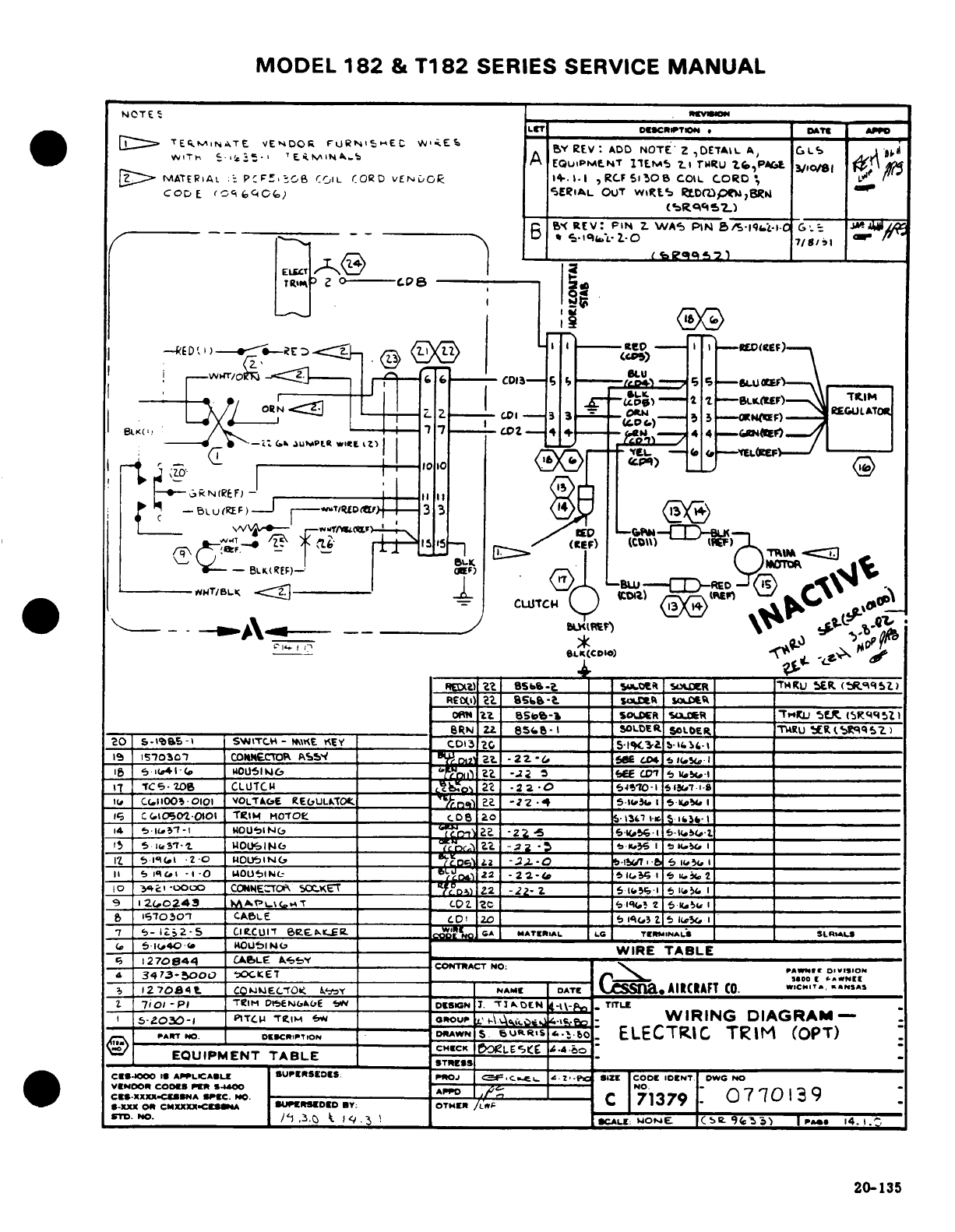
MODEL
182
&
T182
SERIES
SERVICE
MANUAL
NOTE
RE
ISO
U
Irt
DOSCRPTION
.
DATE
Ai
G
TE^^INATE
VECDOD
FRNIEC ;REA BVY
EV
:
ADD
NOTE
2
,DETAIL
A,
CS
LId
IA
EQUIPMINT
11EMS
21
T?
U
Ztu
P4,lE
3,/,j
p'I
s
COGDE
9P-Ci O c C5ERIAL
OUT
WIRL.
FtDropCtMB
_
I%~I
'L
.
________ ___________ ________
/
B'
RW3
EV: PIN
Z7
WAA
PIN
-I/S.-i9-i
G,-T
IJl23_
.-
E -Bii E
-, ,
.C
I I
I 3/5
C i '---€._J.~6
---
S-
l
- -
8L-» < ^
: -// 7 1' 'C I
(1/
-
-" "
;
-- --
-
$--CD J
-
I -~ro-~ S/_O_
-
N-
-3 3
--- .
5--'pF)&
OKIL
17 GP) 4 4(
I
6
M
(C
N(RfF)
f
RE()
2
S--2-5
||
|
I
|S
,
h-BL
~F)
-
II e--«-T/yo7y s(-3 I!19 ('tt0iY
Ir
e,-
1-.
|
CLUTCH
I2
-.
3.0 2220
-
I
CLIS
-
5IS
I
I
-I
ls|
C0..IIOOI
0101
|VOLTE
REbULIO~
|____l -'lt
2a_
oKa.-J.
.
tou,-
-I I ___a___
CW
I' cC.._O2OI_
T~
HOTO
_
c
5"'"_
z__________I.-
..
j________6.N
_
86-1
SOLDER
SOLEKu
E
Z
14
I'0
l-I CE
WOUSIN
.
_____ 1I
&,
I I
us
1- W
S
sl-('
IJOU16VINb
I
.3I
____ ________
-
3
I
'
I
1
1
5-
2
CIUTICH
,__
i_.'."%o__iZ
-2-o _
.iW
5
u
_____..
_____N^-_
_-
1C
C5(Il
210
OULtIN
I
1
O
L-L l s4l 12
2-
34
p.
I
0 .I-1 TI
-
H
o
C
E
TOC
___H ___ D22
2-
5I.3,
IS 1.
.
I_________
S
1270o44
CALE
b4 ____
NTA
NO:I 22N -D
_5
D
I
T
1
3473-500
CLE0 l |
I
Ct .Zootr-
A
I
I
z
7o84
t
NAMEc~rov.
C..-~x C^,.z
o
^&z .
AIICRAF!
CO.
,,C.'...
KNSAS
2*
l
7084n
CANK6L-rOK
_____ ________
A
DA2
T
________ l__
_
5 l_____________________
Z
7iol
-PI
TIMC
DIIENMAbE
_____ ___ DeSt7.
a3A0EN
t--p |
TITLE
1,
5-2O30-
PITC
m
w
o.
WIRING
DIAGRAM-
OO.
0.
...
,o
.DRAWN
S...
UR.RIS
ELECTRIC
TRIM
(OPT)
:
-
-
ITRES
TD.
"0. o |./
34^3-50
.
1
/.3' !I_________________
.
CALEC
9N I
.-
:M.
EQ<UIPMENT
TABLE9'5
I
L20-135.
.
*Cr-100o
r
APLICABLE
SUPERSEDES;
PIRO
=cz
-e
..
c
SIZE
ICODE
IOENT.
ow POO
VENOOR
CODES
Pf
*1400 ---- ~ ----
---
NO.
-
/N-l
i^-ii-il-l
C T DN o
-
1^~cllr~lorr
.3.0s
6Ut.lb
1^.3,
'
_«CAL E MNE C
i4.
i.c.
20-135
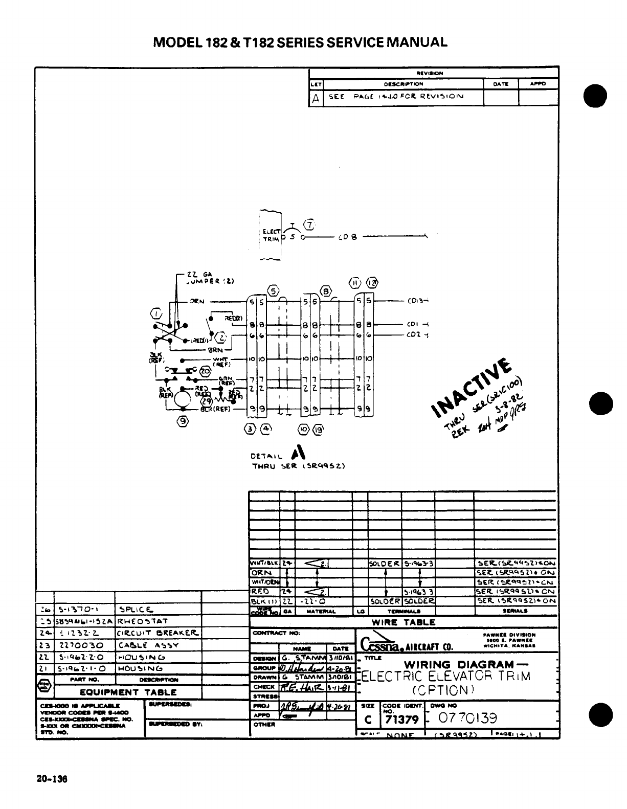
MODEL
182
&
T182
SERIES
SERVICE
MANUAL
RIVISION
LIET
OCSCKIpT*ON
OAT| AP
A
SEE
P"GE
I-J.O
Cl
REVi5IOI\
V
EL ___
_ _ _'
sTRi e
3
8 8
D
i
(OG
I
cU
w
-
ID
wt4T
90
to
90
10
10 10
TI
'
---------
D
7
-7
9bZF)
9
919
9 ~
·
CC3llb A
DE'T
L
L
THRU
ISER 5-q 5 z.)
lll ,r1 ; l
l
'
I I I I I
I
;i
IT 1o 1
1
99AILK
I+ E.
I
SOLOER.
5-qh.33
_____________
0.cW
I
I
T
I
~I I
c
I It ''ER
'
tq 2)A
Ch
W
NRF.I I*
|
*
I
I _
q3
IS1
3
|SER
(lAtqq
S
C
1RLK
lI
IZL
-Vl'0
SOLOER
SOLDEZr
5ER
'(57tqSZ)
ON
*.'.o
S-
-
'70-
*
5PLIC
FL
_,,_,_o mGA
MATRILAL
Ia_ TIuIZL
CS
OSrALS
15
585RA9lI
-.
5Z.A
R
E0oTAE
T
_____
AWIRE
TABLE
14-
-
11iZ.-Z.
CIC-CUlT
lBEAKLKER.
CONrAC
NO:
PAWN*
I
OIVISION
___________LNs
150to
Z- 1iu
i9_0 It.
PAWNER
23
'A
Z1700310
CnAFLE
At.SS%-
N
OATY
C l
AllCRAFT
CO.
W
AC"T.
KANSAS
Z'L
Eqb
Z.'O
!1IOUSlIN.C
OagmN
G.
,sCAIF
3r11011
TTlll
z1
s-5qz
l--O
I
OUSNCA
a
.51N
.
G
WIRING
DIAGRAM-
PAT
NO.
O
-
6,
.
-
S-TAMM
snol
iELECTRIC
ELEVATOR
TRiM
EQUIPMENT
TABLE
C
Ht". ^1 L'
,
(CPTION
)
c0M.1oo
APjuCAS
U
proj
J
.
IsOzT. ow
No
N
vuwoom
coogw a PUM
$-mOO
__ __
IS-X]ISSxS^
-_
No.
C
719
07
70139
94m
onr
VILNI4
IrSpT:
OTHE
37
M.1'0.
No._____________________
-.
,-
N.
I"gmo,
l
I.I9.
20-136
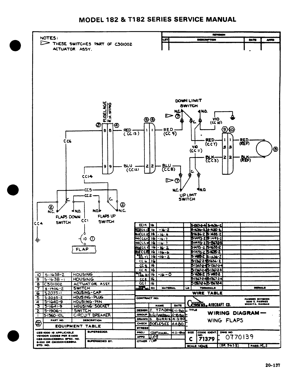
MODEL
182
&
T182
SERIES SERVICE
MANUAL
NOTES:
_
I
_
~
THESE
SWITCHES
PRT
OF
C300Z
i
ACTUATOR
ASSY.
ulr~
DtDOWN
LIMIT
SWITCH
. .- .-
I
I8 It
U-----
ccL
RRED-
CII
RED
VfIO
83
aT
.
(cc
11)
e
iO9
S-
1
Z2
BLUC)
(Cc
-lZ
K,,C
I
1
_
®
CC5L
CcoI4
^ ^
--
6 $05ccz
UP
LIMrT
Z 5-1906-1
.
S
I
,O S
",,<
.SWITCH
HX,."^ ^HO.
KaW
^N.C.
FLAP5
DOWN
FLAPS
UP
C4,
SWITCH
CC
.SWITC
-
-
16
2-
-
14C IC--
z
Io
"-14-
7^,-z oau
-
t _____ ]
,
,a M0 CJ*XXlX.I -I
-
-
r2U
iS
____|*__*_____
FLAP
1
e?
16
-I-
l
__a____.
CC
6
-
II
___CL _I
.10
S-038-a2
HOUSING
r
16
-g
___I__
I
TA
9
-1(038 -1 ouiiG
I
-HOl
a
___._
8
IC3010oz
ACrJA-ACCT
ASS
*.
_____"cc
116
7
5-lo4-2
SWITCH
NuAMM,_S*
«a»
L*
l5
-
u
G
52035-1
HOUSING-CeAP
______ ____
WIRE
TABLE
5
5-2035-2
HOUSING-PLUG
6N___c___
M=
NO:
w
Mvm
4
5-IQ40-9
HOUSING-PIN
"Do
E
C
.
A.
r»CATi
-1
-9
ous
iN6
5
i
g-- -s L
co.
HO
S
GC
.
KAN"
:
5-1906-i
SWITCH
3____
Ss.
T3N TT xIG
I 5-1360-IOL
CIRCUIT
BREAKEAR____
2
GROUP
-
WIRING
DIAGRAM
-
oPAR.
-OCRTION
OUAWNmS
8URR
a-e
WING FLAPS
EQUIPMENT
TABLE
CH
F
vcus-.o
,,
pen,
suemacOO
Pma
gc5~L
z7--
O
CO
.
_" O77u1
=,,CU-,-=-=u-
'=C.
NO.
P
71379
0770
1
*^Ix
OftCNIOUIO-NA
*890=
*T;
aTHot
/
Lwp_
C
71
T7D.
NO.
I _ luu
CAM
K
(SR
fc
3
I
«
-
.
20-137
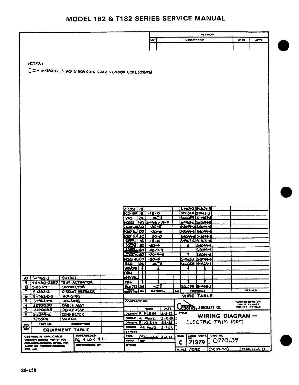
MODEL
182
&
T182
SERIES
SERVICE
MANUAL
-
____ IIX
I
NOTES:
[C
M^aTER
AL
5
RCF
5130
COIL
COAD,
/ENOO0
C4o.
(OWL)
i-':1i
7a
s.ia 1-a
_I
-ao-s
0
20
-20
__
SIL-3
,
SwiTCH____ ThuI cow Mo. ____ ___
5
su93O-a.1
4 ELCTORk
-a--
t *2Ap
-0-A.4
_ 1~5tA»l
$S-
').ZIL
TI
-oa
,
cG WIRE
TABLE^
_s_ __
_
_________
C_
_9
___________.___ _______HUSNGCOTRCTN.
PAWNE9
DOVUION
s
.as-3
._,_____I
CSL
AC _.___
so
C.
»
|444_0-325_
TRir_
AfcTrArTO
______
Vt__
-
W______.
_KANSA
8.ZZ7005
PALAY
ASSY
NAM
o,-
ICA C-O.
MCATA.
KANSA
-
S-2349-a
coNNECTOR
oUS
R
LE
WIRING
DIAGRAM-2-
I
7205P4
SwITCQ4
ocwn ptl 3
--
WIRING
D
IAGRAM-
N
._ r
---
OAwN
R.
KLE
IN
--
ELECTRIC
TRIM
(OPT'
_
EQUIPMENT
TABLE
S
^9
39-8
CU4OW1000
!
APjeA"IW pj V5I., on^^
l f Y Coc00a lOT.
WOO
No
cao#
CNO0
Po
1.
4
104
14.11
I c O.
077013
'55^c no
1043
1.0
cC4.
TC
71379
077013
1-
-o. t
NOE
lCl
O1OO)
1
.«a./4..3
20-138
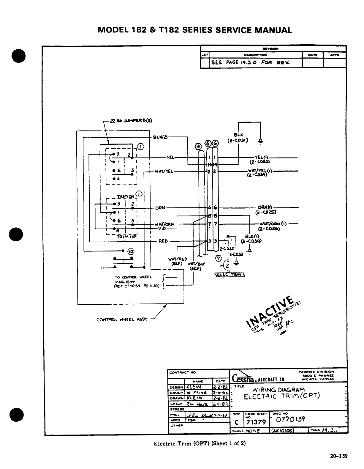
MODEL
182
&
T182
SERIES
SERVICE
MANUAL
LET
O__
_CTIO"N
E
___ 0AB
SEE
PAGE
14..0
FbR
R
V.
-Z2
6A
JUnMPnlts
(3)
r
-- ----
YEL
--- --
II ----- -----
(t-cD31)
-
15 _
:wwr/YEL
E
(I)
r
-I
,
| c.
4
I
I
'
i _--B--A---"n
-
cR 1
__(
i
-C(D
S)
To =1
I
Is
o
)
TRIM
UP
I
(-
8XI(0
zED
(bc
9(b.C
c·_A
--
44 I (-L'
IBTO
CiTRL
W
EEL
(p II
I
J
CONTROL
WC-EL
AWSX
----VI/
'T
CONTRACT NO
PAWNEE
DIVISION
OO
E
PAWNEE
NAME
rDATE E..S
na.AIClAFT
CO.
WICHITA
KANSAS
DESIGN
KLtEIN
2-.,
_
TITLE
GROUP
/L
PAINE
_-I4L
-
WIlR\N6
DIAGRAM
SATRWN
KL-'I
m:
ELECTRIC
TR7I(OPT)
CHEICK
eS
^
E
e
-
:
-ST{ESSI._
-
PrOJ
..
SIZE
COODE
IDENT
DWG NO
.OT
E C|
71379
SCALE
OiNE
(Se1010) I
PAGE
/4.3.1
Electric
Trim
(OPT) (Sheet
1 of
2)
20-139
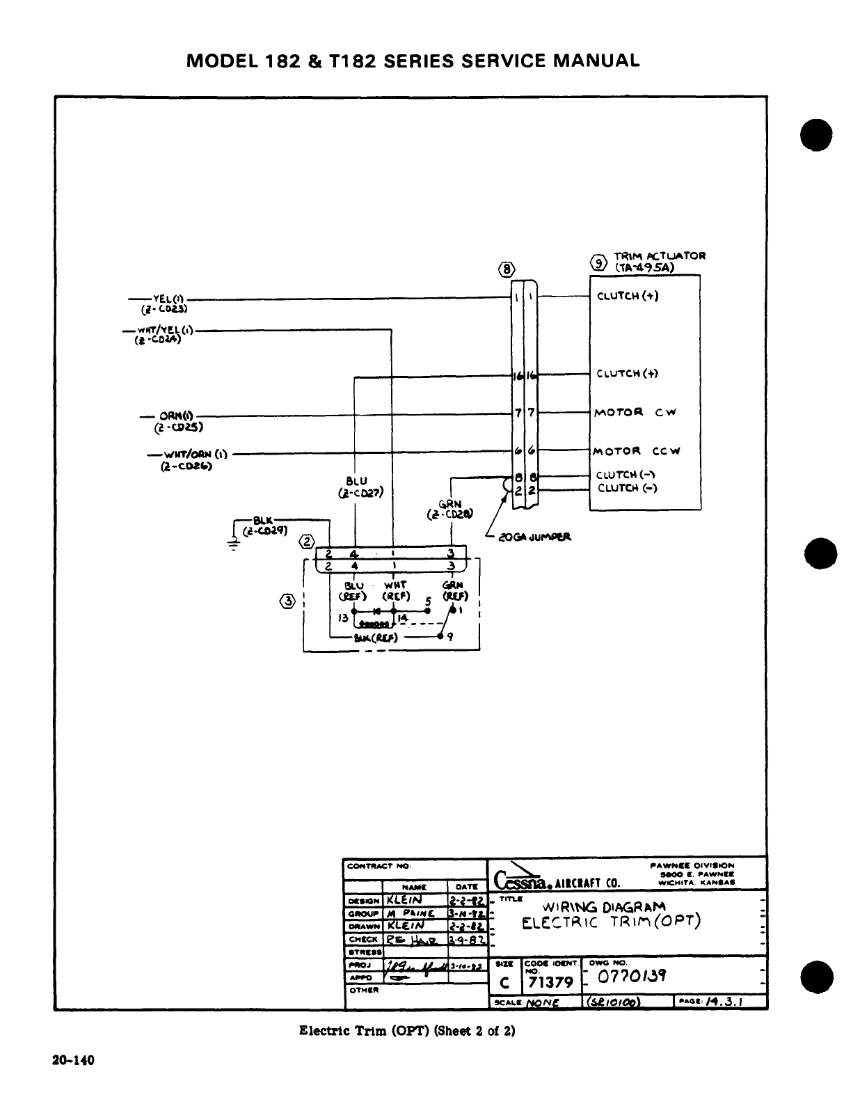
MODEL
182
&
T182
SERIES SERVICE
MANUAL
T
iRiM
CTLuATOR
(
\t/
(n\HPtW-A49SA)
-
YEL(l
-------------------- I I
CLUTCH
(+)
Ci-
coa.3)
(i
-C.b)
--
It
CLUTCH(+)
--
ORKI)
7
7
o-----
ro
cw
(2
-CD25)
--
wM/o--b
(I)
-(
M
OTOR
CC
(2-co0b)
BLU
8
8
CLUTC (-N'
i-coa?)
(; 2.--- 2-
-
CLurC
(-)
CaRN
BL
C-C
,?.)
Z4
3
BLU
WWAT
(R
JWL(RE)
5 (W)
b
aw~
gu
)
14
9
CONTRACT
NO:
PIAWNEC
OIVISION
$O_
I. PAW49n(
NAM
"
OAT
S
Sn
I
CA
l
t
AFT
CO.
WICHITA.
^
KANSA
·
O·
I-I
L
2^
_
TITUL
GoOUr
Pl.E
.--
WIR\NG
DIAGRAM
lo*Aw
KL
-Z
:
ELECCTR
tC
TRI
"(OPT)
CNECK
egs
Ht q-
POJ
seffn(
1.e_
3-1.tl
I
SI=
COO0
IOCNT
OWG
NO.
"'
0.
?7013,5
*
OTHER
1379
07701
._O______
SC
ALE
f No
(St
to to)
I-AE 14.3.
Electric
Trim
(OPT)
(Sheet
2
of
2)
20-140

MODEL
182
&
T182
SERIES
SERVICE
MANUAL
ORN
I__ ___=_=_=_==
rsx
_tC* i__
I____
__
__
z
___
3_ I___ I___
tLK
I __
LER
S-z3
-CD2.L
Zo
S,-2.-"
-20,1
a-cb40
Is$ -__
s-_-_ l-4^<
t-C.D37
_ _______
_
2S-.'-(o
0--a
F
_CD _______ .4ol^jlJ s-
·
_-c>3S4_
_______
5-aoq-q
.o-q'
___________
-__
'
___-_Z__-3Z,75 aIPA7 A
7--crR
a
-Cl
i-
______ _____
6
S-Z3-
1
1ONHEC.rOR
__
-co3.
Ia ____
soLDER
S-I-
7
s-IZL3Z
-z. ZIiCUIT
BPsYKER
GA
MATERIAL
Lc
TMISALS
S
T
CAUS
.a
S-
,BaS-3
SIT-H
____WIRE
TABLE
_
s-2-350-3
ClNNeTR-CzR
-----
CONTRACT
NO.
P AWKE DIVSIO
4 _ 30
-A
BL
Y
________________________.
3
2.-7
35
1^Y
s5
- -
IRE- DATM
NS
YLssnL
a.
IICRAFT
CO.
-WIC"A.
KANSSl
Z
S-23'-. -a DSYET_ ON
SPgPCJERk
q-t-»3
TITLE
Z _-3=4- st
-
T
^______
ou
,wl,
4-
-Z-
WIRING DIAGRAM-
PART
NO.
ofESCRIPTIOm
DRAWN
SKgNZ.ER
C-R-Ct3
.
-'|
I
.
EQU.PMENT
TA;LE
,--------,o, o
. .
CK
-.
:-
tLEC
.
TRIC
TRIM,
OPT)
EQUIPMENT
TABLE
STRSS
CES-IOOO IS
APPLICABLE
SUPERSEDES: IPOJ
jiRE,.
J~
.
SIZE CODE
IDENT DWG
NO
VENDOR
COCS
lR
-o
.
1
40 c D.O 1 73.0 NO
CES-XXXX-.CCES-NA
SPEC.
NO.
71379
0
770
1
3
S-XXX OR
CMXXXX-CENA
U
D
OTHERI
TDO.
NO.
NONgE
(SRc'71I
PAGE:
i4.*.O.
20-140A
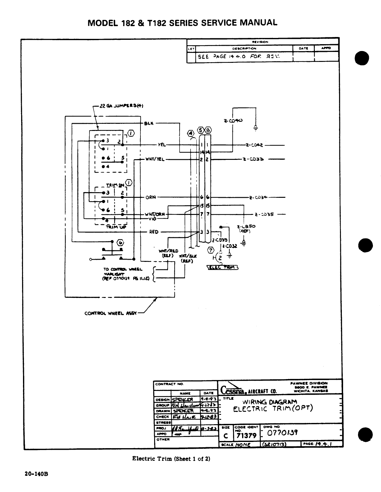
MODEL
182
&
T182
SERIES
SERVICE
MANUAL
r-- uD
m..o..-
BLI 20~- CD
I
,
L P4
I-
I
Il
*4W,:
II
^
.-
A J--4
--
(RU)
------
i
1^UP
e
4
l-IBSo
_--'-I
_
I,
3
I
I
co-
------- l
uL
-
f$i
TO
camoL·
WMS&L
-
t-ilL'Tfli
l.
COMTUOL
WWE!L.
AW-
CONTRACT
:NO
PAWNe- OIV*i
-
ues o-*
CEssa.
AIRCRAFT
CO.
W"0E.PAWNEE
o;P
WI
4
WRNOA
DIAR^AM
oDwN
SPE3
_ :
ELECTRiC
TRiM(OPT)
RED ; 13
7137
c~zc-O __
I
__»_______
_____
I
AoP
,_ v
NO
.
139
07701,
:
OTHER713
Electric
Trim
(Sheet
1
of
2)
20-140B
20-140B
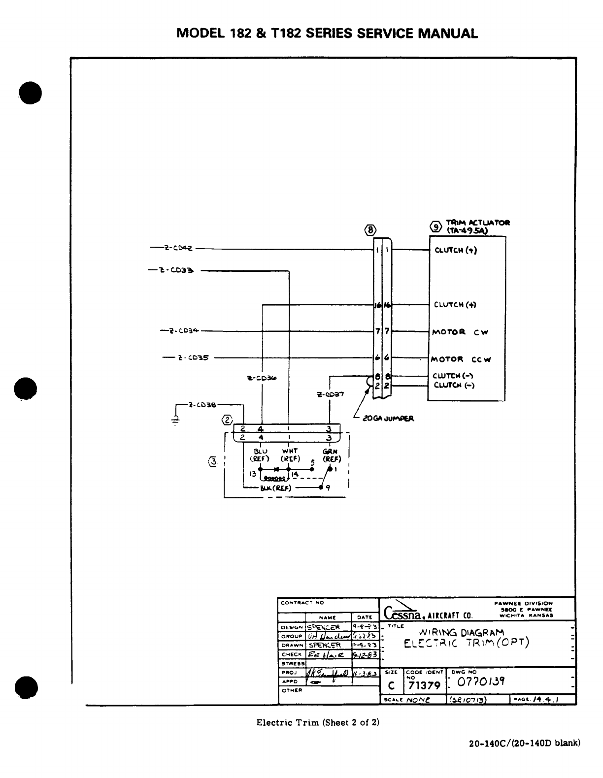
MODEL
182
&
T182
SERIES
SERVICE
MANUAL
O
T
R
iM
ACTUATOR
(> °/
*(IT1A-49SA)
--
C----------------
i _I ----
CLUTCH
(*)
--
g-
C
-
D33
-I
--
,*
CLUTCH
(+)
-t- :oaJ*.
7
?
mOTroI,
cw
--
2
-CoD35
&
----
OTOR
CCW
4r
4
3
BLU
WI8T
-AUN
('F)
(RNF)
5
IF)
I I Id
2
-
i(
CONTRACT
NO
PAWNEE DIVlSION
11S0S0
E
PAWNEE
NAME
DATE
Cen.a.
AIRCRAFT
CO.
WICHITA
KANSAS
DESIGN
S-
q
TITLE
GROUP
-
tI
IR\NG
DIAGR
AM
O.,,N
S--.
E-R
.
.3-
E
'LT
IC
TI
R
IRI,
(OPT)
CBECK
m'e(
AIr
I---*<
SCTRCES,
-
I
L
e
1V
DROJ
DA
T-- StIT
CODE
IDEN
T
DWC
NSO
E
O TlEti
C
71379
07?0
:SCALE
~oIE
(CSe
C7'3)
I '^° -.T4. I
Electric
Trim
(Sheet
2
of
2)
20-140C/(20-140D
blank)
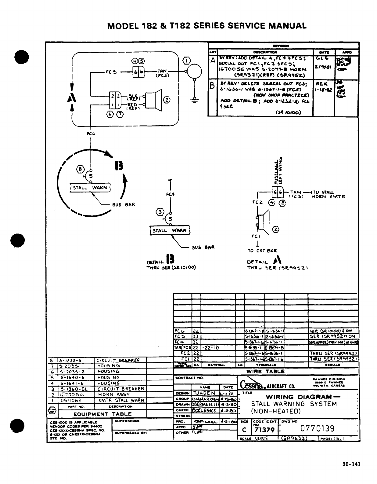
MODEL
182
&
T182
SERIES SERVICE
MANUAL
A'- I~
ICIV:
AD)DE'TL'A:)FC
~
C;
DT
A
SERIAL
OUT
FC%,PFC.
.CJ
;
|B <^ @L
A
W^L
OUT
FC4t=C1 FCS;
CL
| _FC5_r
-"-AN_
_
IC700SCO
WA 5-?20-7-S
HON
IORN
8
R
EV:
DLLCTL
6LRZAL
OUT
OCC;
ALK
AO
T212~ _^5~~~L~~ij~
-
~
IQI~~~N W lOP P^CTCLI)
fL'
A
'
vrS-IG-I
WS
8-Iab?-1-(
(P)
{_s
4E
A
A
TAN
AC|OD
DL
i
ALb
ADB
a-"
-JIZ- F.4
8
CFC.
F
Z
X
4-41, ~~IrC-
/
IL3
13DFL
"
/T"R
(
^ L10100) SERu
(
S t 9 4
.
I- 5
i s)
STALL WARNI
-I
C
2
ITAN -I-b
1Ru
5I
CTT
ALL
\= TSir\?3
2.5/r iL~
I
.LJ _ 1
-1FCI
.
HOIN
X"
-TRR
4 S-
~O35-
2
MOu5i~NO
_____
r
5 _
WIRE
TABLE
4
S(Ib4I~b
R-160
OUSING
ZZ
-2Z-
10ARCAF =50
PAWN
3 5-360-L
CIRCBUS
BRAER
F
cz
I
.
"CIT,
SA
S
2
.;70O5(^
HORN
Aa n
JDEN
^
R
G
0511062
XMTR-STAr
bwcARN
TCIZ__-TALL
WAIROUP
IU
I
7
5-
-
DRAWP'
3BEMUELS p_ l _
STALL
WARNING
SYSTEM5AA
Q
TO
CKr
T
,KI.
EQUIPMENT
TABLES 20TR2ES»
1
(O- ATE
CS LCu L
5-1uRS40TD
ILEsU
R.
.
OJ
NG
I
SOO) Tcr tu E.I (C5O.Et. Dw q
NO
4C
i E S U-I
-
.~
A.ER
Axt
D.n
AiO)
(
ON
Z
CESo
X7CES00
SPElC.
nO.
R
N
A5
NO
u
J
A
-_
r0
5
1.1
I-iL& WAR
G-rour
5
'-i
_
WIRNER cDA
RAM-Z
N
K:
E4
21
.
13-NlT--(
s6n.O-x
3.- c.f~a«»M
tnK
auNipa
eE
FC
..
i3
5-1-t-6b
`--M3b-l
'T14KU
5ER (5KsR
Sz)
b-
.
3^ s IO HOIS
IN
G.LLX GArcs I
MATCLIAL
G
TG INMAL* SO IER.
DWGALS
4,,
-
7o035-Z
ouSIN,'-
WIRE
TABLE
5
S-lb40-f(
HOUSI
NG
CNT
ACT
NO;
PAWNEH
DIVISION
*
S-iX iX
CXXXX
C HOUSA UCER
D D
*Y-:
-
°"
OTD.
o
SCALE-
1O
SRSR3
PAG:
15
.
20-141
EQUIPMENT
TABLE
---
Sg
(N
N-HEATED)_
CES4OOO
IS
AP'LIC.ADLI
SUP[RSEDIS:
PROj
Cx1"qc.KiO_
14-ZI-a
:
SIZE
CODE
IDENT.
DWG
NO
VNoon
CODES
m
»-»
APo
^W
NO
0770139
CES.XXXX.CESSNA
SPEC.
NO.
.„.,_„. ,.,
---
C 71379
-
9-XXX
ON
CMdXXXXeCZr8NA
SUPERSEDED
BY;
OTHER
LW
STD.
NO.
SK:CALE:
NONE
{SRCI(D~)
I
9.
A G
=:
15.1
20-141
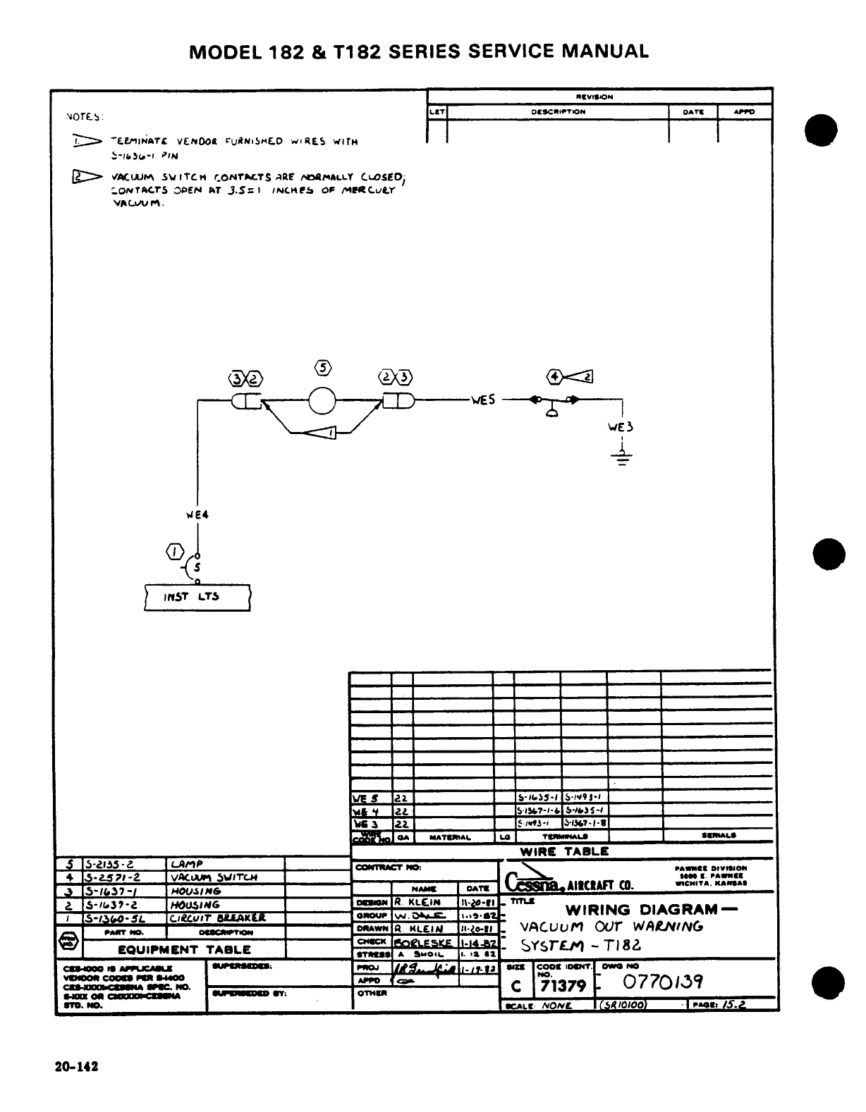
MODEL
182
&
T182
SERIES
SERVICE
MANUAL
Rvi$1ON
NorTE
b
-
LE
OLSCNIPT1IN
OATC APo
>
-Etr'NlATCg
vENDOO
rURNIS.LD
WIRES
w
IH
i-I
(.-i
*'PIN
<_,5I_,r-r
,
L
'
V
ACKUU
5S
ITCi
reoNrrT.TS
A Cp
/NO4AILLY
CLOSEOD
_
ONCTCrS
OPEN
T
3.5"
1
iNCHrep
OF
"mLCOrD
VA1
I
M.
wE)
yES
WE 3
/
E IN&TLTi
U
.
.5
-
3
7-
1
-
t
6
u
Z.L
_-_________
S-I(7-<
r-/- ___
________
iC
a
2
____
__
=
' Jts- IS>?-IT-
__
_________
j_?_
oA
"^MATMAL
Li
Tl3INlAI
SE»rALl
_-a--
L.AMP
WiWIRE
TABLE
$
5-1.t55.
-2P. tcmucr
M~.
-
5-zii-.
VAC.UUI
SITC.H.
_
I
_
S
N
^
5-1,37-1
"J.ousi;m6
1NAu
o^ATR ACSaAIIC»AFT
CO.
C".TA,.
KANSAS
.
5-1/37-Z
HOUlIMG
oa____ R.
KLEIM 1\%--ei
TiTL
7
.-
S-1iO-.L
cllurt
wILAKi~
o-ROUP
w
,.._
_..
WIRING
DIAGRAM-
_)
r
,T
NO..
0 ow
0
a
KLIAl
,IlAo-i
-,
VACUUM
Ocr
WAItNG
EQUIPMENT
TABLE
_esl ,
YsrTF-
-
Tl8Z
s$ -_11M,
A
s-o.
l
,.
0,
0I
cro eo n
*
j IP
otcoo so
APO. owf No
Cos01
onSsSw-
"D.=u
p
my,
CKoT.
-
C
71379
0770139
8h.J _ N_____ _ ._ _ _ 0q
2gm_2.
,
_0.
K,,.L
NONL
(,
I10oo)
PAGI
1
/S.
20-142
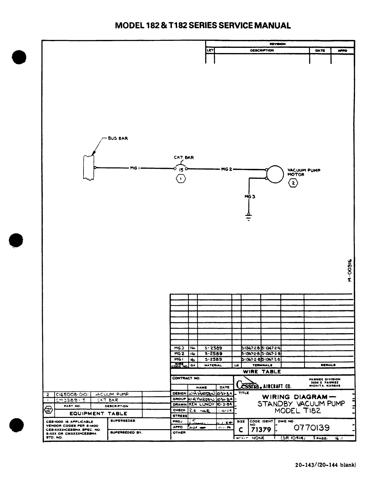
MODEL
182
&
T182
SERIES
SERVICE
MANUAL
-BUS
BAR
)
l-
G
I
M
15
-MG
G
VACUUM
PUMP
-vQ ___3iM
0
MOTOR
<D
MIG
3
i
MG3
_
5-
2589
-13~7-
Z-8
5
-W
7-Z-6
MG
2
i
,o
s-z5a
_5-i37-2-.
-13s%7-Z-
MGI
I _
5-2589
5-1
l7-2-
5-IX7-
t-___
I
C
GA
MATERIAL
LC TE
NALS
*IA
I
___ _
WIRE
TABLE
CONTRACTNO:
NOPAWNI \ I 1ton
S1I00 I
PAlIV
l
-
NAME
-DATE
essn
AIIRCAFT
CO.
WIC*".^
"IA.
s
2
C165008-0101
ACUUM
PUMP
DESIGN
>B t3
TITLE
WIRING
I
'M58I9-'
'(7
BKR
GROUP
WIRING
DIAGRAM
PART
N0.
DESCRITON
DRAWN
-K-
LUNDY
10-3
~4
STANDBY
VACUUM
PUMP
EQUIPMENT
TABLE
CE
MODEL
TI.
:
CES-KOO
I
APPLICASLE
SUPRSEDES
POJ
i,
SIZE
CODE
IDENT.
DWG
NO
V'N~"I CO"''"'' A" '--...,.
'-UOO
NO
'
79 0770139
CCS-XXX
O- C XA OPEC.E
NO
C
71379:
S-XXX
OR CMXXXX-CESbMA
BSUPERSEDED BY.
OTtHER
STD.
NO.
NO-
-
. ,
NE0
(SR
10414/
I
,AGE:
I.I
20-143/(20-144
blank)
