D2007 3 13 S 206 & T206 SERIES (1969 THRU 1976) Cessna_206_T206_1969 1976_MM_D2007 Cessna 1969 1976 MM
User Manual: Cessna_206_T206_1969-1976_MM_D2007-3-13
Open the PDF directly: View PDF ![]() .
.
Page Count: 542 [warning: Documents this large are best viewed by clicking the View PDF Link!]
- D2007-3-13 - MODELS 206 & T206 SERIES (1969 THRU 1976)
- TEMPORARY REVISION NUMBER 7
- TEMPORARY REVISION NUMBER 6
- TEMPORARY REVISION NUMBER 5
- TEMPORARY REVISION NUMBER 4
- TEMPORARY REVISION NUMBER 3
- LIST OF EFFECTIVE PAGES
- TABLE OF CONTENTS
- CROSS REFERENCE LISTING OF POPULAR NAME VS. MODEL NUMBERS AND SERIALS
- FOREWORD
- SECTION 1 - GENERAL DESCRIPTION
- SECTION 2 - GROUND HANDLING, SERVICING, CLEANING, LUBRICATION AND INSPECTION
- SECTION 3 - FUSELAGE
- SECTION 4 - WINGS AND EMPENNAGE
- SECTION 5 - LANDING GEAR AND BRAKES
- TABLE OF CONTENTS
- LANDING GEAR
- DESCRIPTION
- MAIN LANDING GEAR
- TROUBLE SHOOTING
- REMOVAL
- INSTALLATION
- REMOVAL AND INSTALLATION OF MAIN LANDING GEAR BRAKE FAIRINGS
- REMOVAL AND INSTALLATION OF STANDARD MAIN WHEEL SPEED FAIRINGS
- MAIN WHEEL AND TIRE ASSEMBLY
- DESCRIPTION
- REMOVAL OF MAIN WHEEL AND TIRE ASSEMBLY
- DISASSEMBLY OF CLEVELAND MAIN WHEEL AND TIRE ASSEMBLY
- INSPECTION AND REPAIR OF CLEVELAND MAIN WHEEL AND TIRE ASSEMBLY
- REASSEMBLY OF CLEVELAND MAIN WHEEL AND TIRE ASSEMBLY
- DISASSEMBLY OF MCCAULEY MAIN WHEEL AND TIRE ASSEMBLY
- INSPECTION AND REPAIR OF MCCAULEY MAIN WHEEL AND TIRE ASSEMBLY
- REASSEMBLY OF MCCAULEY MAIN WHEEL AND TIRE ASSEMBLY
- MAIN AND NOSE WHEEL THRU-BOLT NUT OR CAPSCREW TORQUE VALUES
- INSTALLATION OF MAIN WHEEL AND TIRE ASSEMBLY
- REMOVAL OF MAIN WHEEL AND AXLE
- INSTALLATION OF MAIN WHEEL AND AXLE
- MAIN WHEEL ALIGNMENT
- WHEEL BALANCING
- STEP BRACKET INSTALLATION
- BRAKE LINE FAIRING REPLACEMENT
- NOSE GEAR
- TROUBLE SHOOTING
- REPLACEMENT OF NOSE GEAR
- STANDARD NOSE GEAR SPEED FAIRING REPLACEMENT
- HEAVY-DUTY NOSE WHEEL SPEED FAIRING ADJUSTMENT
- NOSE WHEEL AND TIRE ASSEMBLY
- DESCRIPTION
- REMOVAL OF NOSE WHEEL AND TIRE ASSEMBLY
- DISASSEMBLY OF CLEVELAND NOSE WHEEL AND TIRE ASSEMBLY
- INSPECTION AND REPAIR OF CLEVELAND NOSE WHEEL AND TIRE ASSEMBLY
- REASSEMBLY OF CLEVELAND NOSE WHEEL AND TIRE ASSEMBLY
- DISASSEMBLY OF MCCAULEY NOSE WHEEL AND TIRE ASSEMBLY
- INSPECTION AND REPAIR OF MCCAULEY NOSE WHEEL AND TIRE ASSEMBLY
- REASSEMBLY OF MCCAULEY NOSE WHEEL AND TIRE ASSEMBLY
- INSTALLATION OF NOSE WHEEL AND TIRE ASSEMBLY
- STANDARD NOSE GEAR STRUT
- HEAVY-DUTY NOSE GEAR STRUT
- WHEEL BALANCING
- TORQUE LINKS
- SHIMMY DAMPENER
- NOSE WHEEL STEERING SYSTEM
- BRAKE SYSTEM
- SECTION 6 - AILERON CONTROL SYSTEM
- SECTION 7 - WING FLAP CONTROL SYSTEM
- SECTION 8 - ELEVATOR CONTROL SYSTEMS
- SECTION 9 - ELEVATOR TRIM CONTROL SYSTEM
- SECTION 10 - RUDDER CONTROL SYSTEM
- SECTION 11 - RUDDER TRIM CONTROL SYSTEM
- SECTION 12 - NORMALLY ASPIRATED ENGINE
- TABLE OF CONTENTS
- ENGINE COWLING
- ENGINE
- DESCRIPTION
- ENGINE DATA
- TIME BETWEEN OVERHAUL (TBO)
- OVERSPEED LIMITATIONS
- TROUBLE SHOOTING
- REMOVAL
- STATIC RUN-UP PROCEDURES
- CLEANING
- ACCESSORIES REMOVAL
- INSPECTION
- BUILD-UP
- INSTALLATION
- FLEXIBLE FLUID HOSES
- ENGINE BAFFLES
- ENGINE OIL SYSTEM
- ENGINE FUEL SYSTEM
- INDUCTION AIR SYSTEM
- IGNITION SYSTEM
- ENGINE CONTROLS
- STARTING SYSTEM
- EXHAUST SYSTEM
- EXTREME WEATHER MAINTENANCE
- GROUND SERVICE RECEPTACLE
- HAND-CRANKING
- SECTION 12A - TURBOCHARGED ENGINE
- TABLE OF CONTENTS
- ENGINE COWLING
- ENGINE
- DESCRIPTION
- ENGINE DATA
- TIME BETWEEN OVERHAUL (TBO)
- OVERSPEED LIMITATIONS
- TROUBLE SHOOTING
- REMOVAL
- STATIC RUN-UP PROCEDURES
- CLEANING
- ACCESSORIES REMOVAL
- INSPECTION
- BUILD-UP
- INSTALLATION
- FLEXIBLE FLUID HOSES
- ENGINE BAFFLES
- ENGINE OIL SYSTEM
- ENGINE FUEL SYSTEM
- INDUCTION AIR SYSTEM
- IGNITION SYSTEM
- ENGINE CONTROLS
- STARTING SYSTEM
- EXHAUST SYSTEM
- TURBOCHARGER
- CONTROLLER AND WASTE-GATE ACTUATOR
- EXTREME WEATHER MAINTENANCE
- GROUND SERVICE RECEPTACLE
- HAND-CRANKING
- SECTION 13 - FUEL SYSTEM
- TABLE OF CONTENTS
- FUEL SYSTEM
- DESCRIPTION
- PRECAUTIONS
- TROUBLE SHOOTING
- FUEL VENTS
- FUEL CELLS
- FUEL QUANTITY TRANSMITTERS
- SECTION 14 - PROPELLERS AND PROPELLER GOVERNORS
- SECTION 15 - UTILITY SYSTEMS
- TABLE OF CONTENTS
- UTILITY SYSTEMS
- HEATING SYSTEM
- DEFROSTER SYSTEM
- VENTILATING SYSTEM
- OXYGEN SYSTEM
- DESCRIPTION
- MAINTENANCE PRECAUTIONS
- REPLACEMENT OF COMPONENTS
- OXYGEN CYLINDER GENERAL INFORMATION
- OXYGEN CYLINDER SERVICE REQUIREMENTS
- OXYGEN CYLINDER INSPECTION REQUIREMENTS
- OXYGEN SYSTEM COMPONENT SERVICE REQUIREMENTS
- OXYGEN SYSTEM COMPONENT INSPECTION REQUIREMENTS
- MASKS AND HOSE
- SYSTEM PURGING
- FUNCTIONAL TESTING
- SYSTEM LEAK TEST
- SYSTEM CHARGING
- SECTION 16 - INSTRUMENTS AND INSTRUMENT SYSTEMS
- TABLE OF CONTENTS
- INSTRUMENTS AND INSTRUMENT SYSTEM
- GENERAL
- INSTRUMENT PANEL
- SHOCK MOUNTS
- INSTRUMENTS
- PITOT AND STATIC SYSTEMS
- DESCRIPTION
- MAINTENANCE
- STATIC PRESSURE SYSTEM INSPECTION AND LEAKAGE TEST
- PITOT SYSTEM INSPECTION AND LEAKAGE TEST
- BLOWING OUT LINES
- REMOVAL AND INSTALLATION OF
- TROUBLE SHOOTING-PITOT STATIC SYSTEM
- TRUE AIRSPEED INDICATOR
- TROUBLE SHOOTING-AIRSPEED INDICATOR
- TROUBLE SHOOTING-ALTIMETER
- TROUBLE SHOOTING-VERTICAL SPEED INDICATOR
- TROUBLE SHOOTING-PITOT TUBE HEATER
- VACUUM SYSTEM
- ENGINE INDICATORS
- MANIFOLD PRESSURE/FUEL FLOW INDICATOR
- CYLINDER HEAD TEMPERATURE GAGE
- OIL PRESSURE GAGE
- OIL TEMPERATURE GAGE
- FUEL QUANTITY INDICATING SYSTEM
- HOURMETER
- MAGNETIC COMPASS
- STALL WARNING HORN AND TRANSMITTER
- TURN-AND-SLIP INDICATOR
- TURN COORDINATOR
- ELECTRIC CLOCK
- WING LEVELER
- SECTION 17 - ELECTRICAL SYSTEMS
- TABLE OF CONTENTS
- ELECTRICAL SYSTEMS
- GENERAL
- ELECTRICAL POWER SUPPLY SYSTEM
- BATTERY POWER SYSTEM
- BATTERY
- BATTERY BOX
- BATTERY CONTACTOR
- BATTERY CONTACTOR CLOSING CIRCUIT
- GROUND SERVICE RECEPTACLE
- ALTERNATOR POWER SYSTEM
- RIGGING THROTTLE OPERATED MICRO-SWITCH
- AUXILIARY ELECTRIC FUEL PUMP FLOW RATE ADJUSTMENT
- AIRCRAFT LIGHTING SYSTEM
- DESCRIPTION
- TROUBLE SHOOTING
- LANDING AND TAXI LIGHTS
- NAVIGATION LIGHTS
- ANTI-COLLISION STROBE LIGHTS
- FLASHING BEACON LIGHT
- INSTRUMENT LIGHTING
- ELECTROLUMINESCENT PANEL LIGHTING
- PEDESTAL LIGHTS
- INSTRUMENT POST LIGHTING
- COURTESY LIGHTS
- INTERIOR LIGHTING
- CONTROL WHEEL MAP LIGHTING
- COMPASS AND RADIO DIAL LIGHTS
- ELECTRIC CLOCK
- STALL WARNING SYSTEM
- PITOT AND STALL WARNING HEATERS
- CIGAR LIGHTER
- SKYDIVING KIT
- EMERGENCY LOCATOR TRANSMITTER
- ELECTRICAL LOAD ANALYSIS CHART
- SECTION 18 - STRUCTURAL REPAIR
- TABLE OF CONTENTS
- STRUCTURAL REPAIR
- REPAIR CRITERIA
- EQUIPMENT AND TOOLS
- WING TWIST AND HORIZONTAL STABILIZER ANGLE-OF-INCIDENCE
- REPAIR MATERIALS
- WING
- ELEVATORS AND RUDDERS
- FIN AND STABILIZER
- FUSELAGE
- BULKHEADS
- REPLACEMENT OF HI-SHEAR RIVETS
- NOSE GEAR WHEEL WELL AND FIREWALL
- BAFFLES
- ENGINE COWLING
- REPAIR OF ABS COMPONENTS
- REPAIR OF GLASS-FIBER CONSTRUCTED
- BONDED DOORS
- SECTION 19 - PAINTING
- SECTION 20 - WIRING DIAGRAMS
- TABLE OF CONTENTS
- 12 - VOLT
- D.C. POWER
- IGNITION
- ENGINE CONTROL
- FUEL AND OIL
- ENGINE INSTRUMENTS
- FLIGHT INSTRUMENTS
- MISCELLANEOUS INSTRUMENTS
- LIGHTING
- DOME AND COURTESY LIGHTS
- DOME AND COURTESY LIGHTS
- INSTRUMENT LIGHTS
- LANDING LIGHTS
- NAVIGATION LIGHTS
- NAVIGATION LIGHTS
- FLASHING BEACON LIGHT
- FLASHING BEACON LIGHT (FLOATPLANE)
- FLASHING BEACON LIGHT (FLOATPLANE)
- ELECTROLUMINESCENT PANEL
- POST LIGHTING
- POST LIGHTING
- CONTROL WHEEL MAP LIGHT
- CONTROL WHEEL MAP LIGHT
- CONTROL WHEEL MAP LIGHT
- CONTROL WHEEL MAP LIGHT
- CONTROL WHEEL MAP LIGHT
- SKYDIVING SIGNAL LIGHT
- LANDING LIGHTS
- LANDING AND TAXI LIGHTS
- LANDING AND TAXI LIGHTS
- FLASHING BEACON LIGHT
- FLASHING BEACON LIGHT
- ELECTROLUMINESCENT PANEL
- ELECTROLUMINESCENT PANEL
- INSTRUMENT LIGHTS
- INSTRUMENT LIGHTS
- INSTRUMENT LIGHTS
- POST LIGHTING
- POST LIGHTING
- POST LIGHTING
- WING TIP STROBE LIGHTS
- WING TIP STROBE LIGHTS
- WING TIP STROBE LIGHTS
- HEATING VENTILATION AND DE-ICE
- CONTROL SURFACES
- 24 - VOLT
- D.C. POWER
- IGNITION
- ENGINE CONTROL
- FUEL AND OIL
- ENGINE INSTRUMENTS
- FLIGHT INSTRUMENTS
- MISCELLANEOUS INSTRUMENTS
- LIGHTING
- DOME AND COURTESY
- DOME AND COURTESY
- NAVIGATION LIGHTS
- NAVIGATION LIGHTS
- FLASHING BEACON LIGHT (FLOATPLANE)
- FLASHING BEACON LIGHT (FLOATPLANE)
- CONTROL WHEEL MAP LIGHT
- CONTROL WHEEL MAP LIGHT
- SKYDIVING SIGNAL LIGHT
- LANDING LIGHTS
- LANDING AND TAXI LIGHTS
- LANDING AND TAXI LIGHTS
- FLASHING BEACON LIGHT
- ELECTROLUMINESCENT PANEL
- ELECTROLUMINESCENT PANEL
- INSTRUMENT LIGHTS
- INSTRUMENT LIGHTS
- INSTRUMENT LIGHTS
- POST LIGHTING
- POST LIGHTING
- POST LIGHTING
- WING TIP STROBE LIGHT
- WING TIP STROBE LIGHT
- HEATING, VENTILATION AND DE-ICE
Cessna
SERVICE
MANUAL
1969
thru
1976
MODEL
206
&
T206
SERIES
Member
of
GAMA
THIS
REPRINT
OF
BASIC SERVICE
MANUAL
D2007-13,
DATED
15
OCTOBER
1972,
INCORPORATES
CHANGE
1,
DATED
15
OCTOBER
1973;
CHANGE
2,
DATED
1
SEPTEMBER
1974;
CHANGE
3,
DATED
1
OCTOBER
1975;
TEMPORARY
CHANGE
1,
DATED
5
SEPTEMBER
1977;
AND
TEMPORARY
CHANGE
2,
DATED
22
JANUARY
1978.
)
COPYRIGHT
©
1984
CESSNA AIRCRAFT
COMPANY
15
OCTOBER
1972
WICHITA,
KANSAS.
USA
15
OCTOB
1972
D2007-3-13
CHANGED
1
OCTOBER
1975
(RGI-100-10/01)
A
Te~t
Gr -y(~''n
TEMPORARY
REVISION
NUMBER
7
DATE
July
1,
2007
MANUAL
TITLE
MANUAL
NUMBER
-
PAPER
COPY
D2007-3-1
3
MANUAL
NUMBER
-AEROFICHE
TEMPORARY
REVISION
NUMBER
D2007-3-1
3AF
D2007-3TR7
MANUAL
DATE
15
October
1972
REVISION
NUMBER
3
DATE
1
October
1975
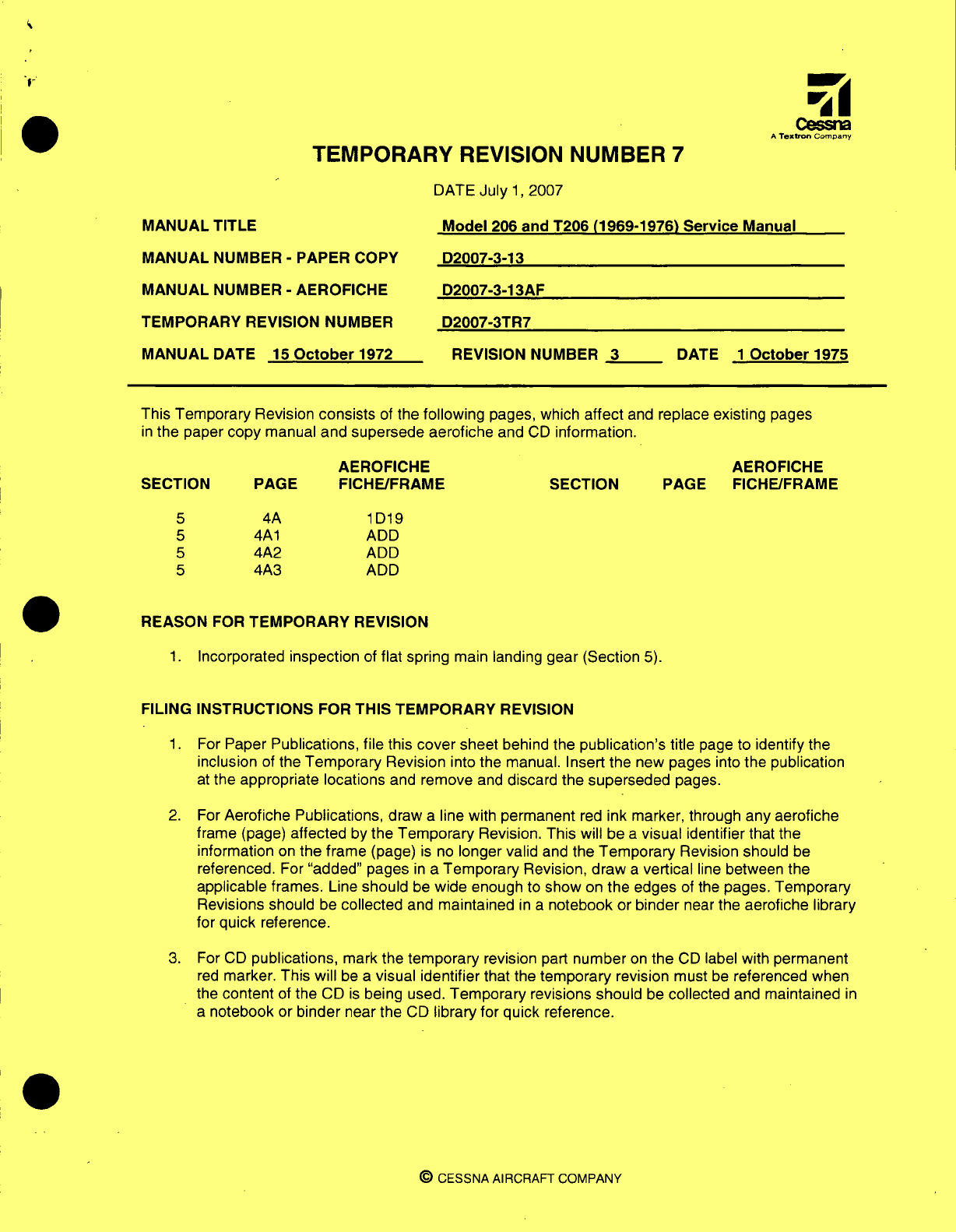
This Temporary
Revision
consists
of
the
following
pages,
which
affect
and
replace existing
pages
in
the
paper
copy
manual
and
supersede
aerofiche
and
CD
information.
AEROFICHE
PAGE
FICHE/FRAME
4A
4A
1
4A2
4A3
1D19
ADD
ADD
ADD
1
.
Incorporated
inspection
of
flat
spring
main
landing
gear (Section
5).
FILING INSTRUCTIONS
FOR
THIS
TEMPORARY
REVISION
1
.
For
Paper
Publications, file
this
cover
sheet
behind
the
publication's
title
page
to
identify
the
inclusion
of
the
Temporary
Revision
into
the
manual. Insert
the new
pages
into
the
publication
at
the
appropriate
locations
and
remove
and
discard
the
superseded
pages.
2.
For
Aerofiche
Publications,
draw
a
line
with
permanent
red
ink
marker,
through
any
aerofiche
frame
(page)
affected
by
the
Temporary
Revision.
This
will be
a
visual
identifier
that the
information
on
the
frame
(page)
is
no
longer valid
and
the
Temporary
Revision should
be
referenced.
For
"added"
pages
in
a
Temporary
Revision,
draw
a
vertical
line
between
the
applicable
frames.
Line
should
be
wide
enough
to
show
on
the edges
of
the
pages.
Temporary
Revisions
should
be
collected
and
maintained
in a
notebook
or
binder
near
the
aerofiche
library
for
quick
reference.
3.
For
CD
publications,
mark
the
temporary
revision
part
number
on
the
CD
label with
permanent
red
marker.
This
will
be
a
visual identifier
that
the
temporary
revision must
be
referenced
when
the
content
of
the
CD
is
being
used.
Temporary
revisions should
be
collected
and
maintained
in
a
notebook
or
binder
near
the
CD
library
for
quick reference.
©9
CESSNA
AIRCRAFT
COMPANY
Model
206
and
T206 (1969-1976)
Service
Manual
SECTION
5
5
5
5
AEROFICHE
SECTION
PAGE
FICHE/FRAME
REASON
FOR
TEMPORARY
REVISION
Cessna
A
Texlrn
Company
TEMPORARY
REVISION
NUMBER
6
DATE
5
April
2004
MANUAL
TITLE
Model
206
&
T206 Series
1969
Thru
1976
Service Manual
MANUAL
NUMBER
-
PAPER
COPY
MANUAL
NUMBER
-
AEROFICHE
TEMPORARY
REVISION
NUMBER
D2007-3-13
D2007-3-13AF
D2007-3TR6
MANUAL
DATE
15
October
1972
REVISION NUMBER.
3
DATE
1
October
1975
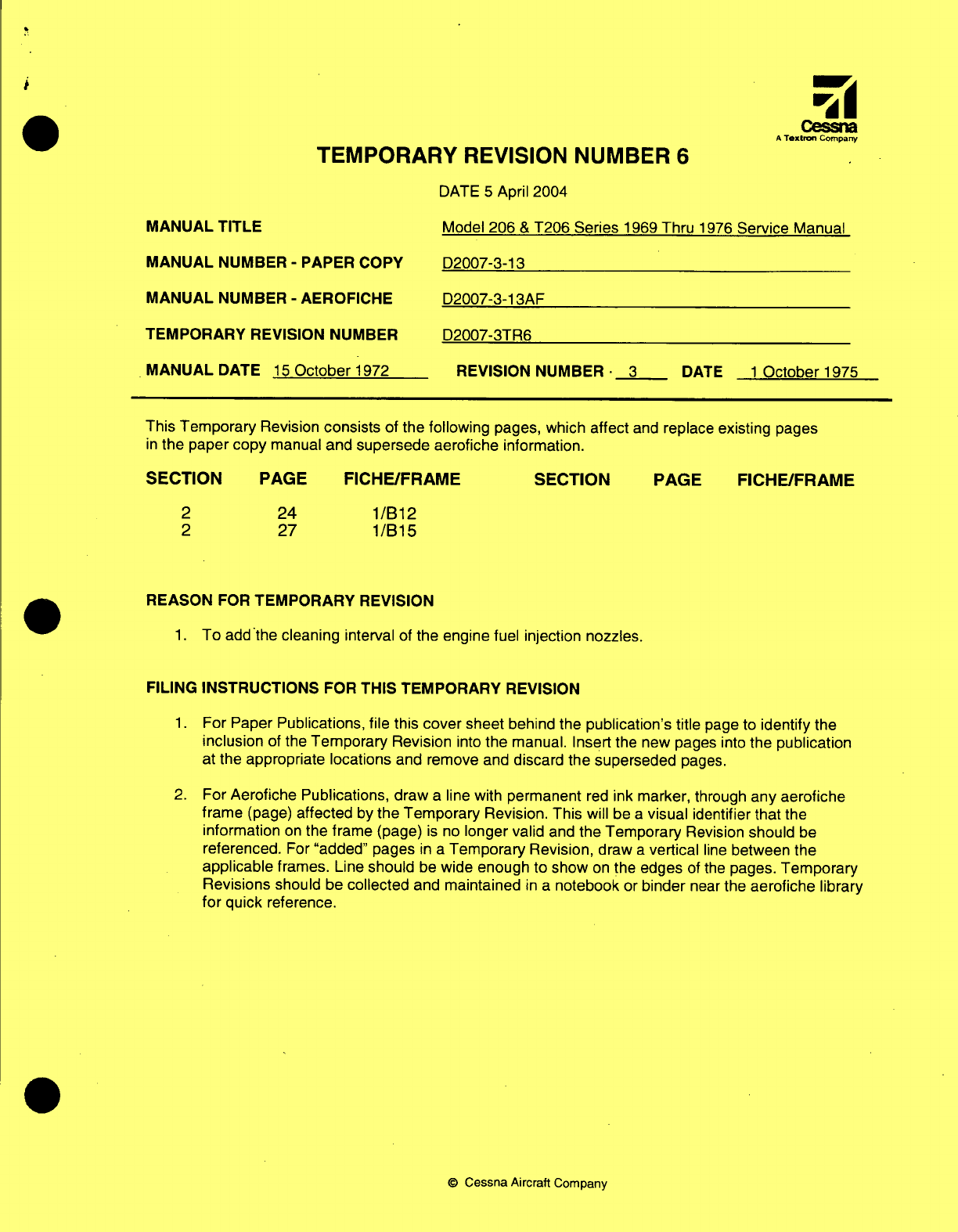
This
Temporary
Revision
consists
of
the
following
pages, which
affect
and
replace
existing
pages
in
the
paper
copy
manual
and
supersede
aerofiche
information.
SECTION
PAGE
FICHE/FRAME
2
2
24
27 1/B12
1/B15
REASON
FOR
TEMPORARY
REVISION
1.
To
add
the
cleaning
interval
of
the
engine
fuel
injection
nozzles.
FILING INSTRUCTIONS
FOR
THIS
TEMPORARY
REVISION
1.
For
Paper
Publications, file
this
cover
sheet
behind
the
publication's title
page
to
identify
the
inclusion
of
the
Temporary
Revision
into
the
manual. Insert
the new
pages
into
the
publication
at
the
appropriate
locations
and
remove
and
discard
the
superseded
pages.
2.
For
Aerofiche Publications, draw
a
line
with
permanent
red
ink
marker, through
any
aerofiche
frame
(page)
affected
by
the Temporary
Revision.
This
will
be
a
visual
identifier
that
the
information
on
the frame
(page)
is
no
longer
valid
and
the
Temporary
Revision
should
be
referenced.
For
"added"
pages
in
a
Temporary
Revision,
draw
a
vertical
line
between
the
applicable
frames.
Line
should
be
wide enough
to show
on
the
edges
of the
pages.
Temporary
Revisions
should
be
collected
and
maintained
in
a
notebook
or
binder
near
the
aerofiche
library
for
quick
reference.
©
Cessna
Aircraft
Company
SECTION PAGE FICHE/FRAME
Cessn
A
Textron
Company
TEMPORARY
REVISION NUMBER
5
DATE
6
January
2003
MANUAL
TITLE
Model
206
&
T206
Series
1969
Thru
1976
Service
Manual
MANUAL
NUMBER
-
PAPER
COPY
D2007-3-13
MANUAL
NUMBER
-
AEROFICHE D2007-3-13AF
TEMPORARY
REVISION NUMBER D2007-3TR5
MANUAL
DATE
15
October
1972 REVISION
NUMBER
3
DATE
1
October
1975
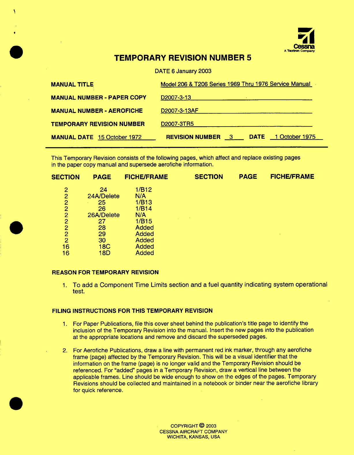
This
Temporary Revision
consists
of
the
following
pages, which
affect
and
replace
existing
pages
in
the paper
copy
manual
and
supersede
aerofiche information.
SECTION
PAGE
FICHE/FRAME SECTION PAGE
FICHE/FRAME
2
24
1/B12
2
24A/Delete
N/A
2
25
1/B13
2
26
1/B14
2
26A/Delete
N/A
2
27
1/B15
2
28
Added
2
29
Added
2
30
Added
16
18C
Added
16
18D
Added
REASON
FOR
TEMPORARY
REVISION
1.
To
add
a
Component
Time
Limits
section and
a
fuel
quantity
indicating
system operational
test.
FILING INSTRUCTIONS
FOR
THIS TEMPORARY
REVISION
1.
For
Paper
Publications,
file this
cover
sheet behind the publication's
title
page
to
identify the
inclusion of
the Temporary
Revision
into
the
manual.
Insert
the
new
pages
into
the
publication
at
the
appropriate locations
and
remove and
discard
the
superseded
pages.
2.
For
Aerofiche
Publications,
draw
a
line with
permanent
red
ink
marker,
through
any aerofiche
frame
(page)
affected
by
the
Temporary
Revision.
This
will
be
a
visual
identifier
that
the
information
on
the
frame
(page)
is
no
longer
valid
and the
Temporary Revision
should
be
referenced.
For
"added"
pages
in
a
Temporary
Revision,
draw
a
vertical
line
between
the
applicable frames.
Line
should
be
wide enough
to
show
on
the
edges
of
the
pages.
Temporary
Revisions
should
be
collected
and maintained
in
a
notebook
or
binder
near
the aerofiche
library
for
quick reference.
COPYRIGHT
©
2003
CESSNA
AIRCRAFT
COMPANY
WICHITA, KANSAS,
USA
TEMPORARY
REVISION NUMBER
4
DATED
15
May
2000
MANUAL
TITLE
MODEL
206
&
T206
SERIES 1969 THRU 1976 SERVICE
MANUAL
MANUAL
NUMBER
-
PAPER
COPY
D2007-3-13
AEROFICHE
D2007-3-13AF
TEMPORARY
REVISION NUMBER PAPER
COPY
D2007-3TR4
AEROFICHE
N/A
MANUAL
DATE
15
OCTOBER
1972
REVISION
NUMBER
3
DATE
1
OCTOBER
1975
This Temporary
Revision
consists
of
the
following
pages,
which
affect
existing
pages
in
the
paper
copy
manual
and
supersede
aerofiche information.
AEROFICHE AEROFICHE
SECTION PAGE
FICHE/FRAME
SECTION
PAGE
FICHE/FRAME
2
24A
Added
2
26A
Added
REASON
FOR
TEMPORARY
REVISION
To
include
the
inspection
requirements of
Cessna
Service
Bulletin
SEB99-18.
FILING INSTRUCTIONS
FOR
THIS
TEMPORARY
REVISION
For
Paper
Publications:
File
this
cover sheet
behind
the
publication's
title
page
to
identify
the
inclusion
of the
Temporary
Revision
into the manual.
Insert
the
new
pages into
the
publication
at the
appropriate
locations.
Draw
a
line,
with
a
permanent
red
ink marker,
through
any
superceded
information.
For
Aerofiche Publications:
Draw
a
line
through any
aerofiche
frame (page)
affected
by
the
Temporary
Revision with
a
permanent
red
ink marker.
This
will
be
a
visual
identifier
that
the
information
on
the frame
(page)
is
no
longer
valid
and the
Temporary
Revision
should
be
referenced.
For
"added"
pages
in
a
Temporary Revision,
draw
a
vertical
line between
the
applicable
frames
which
is
wide enough
to
show
on
the
edges
of the
pages.
Temporary Revisions
should
be
collected
and
maintained
in
a
notebook
or
binder
near
the
aerofiche
library
for
quick
reference.
COPYRIGHT
©
2000
CESSNA AIRCRAFT COMPANY
WICHITA,
KANSAS,
USA
TEMPORARY
REVISION NUMBER
3
DATED
3
October
1994
MANUAL
TITLE
MODEL
206
&
T206 SERIES
1969
THRU
1976
SERVICE
MANUAL
MANUAL
NUMBER
-
PAPER COPY
D2007-3-13
AEROFICHE
D2007-3-13AF
TEMPORARY
REVISION NUMBER
-
PAPER
COPY
D2007-3TR3-13
AEROFICHE
N/A
MANUAL
DATE
15
OCTOBER
1972
REVISION
NUMBER
3
DATE
1
OCTOBER
1975
This Temporary Revision
consists
of
the
following
pages,
which
affect
and
replace
existing pages
in
the
paper
copy
manual
and
supersede
aerofiche
information.
AEROFICHE
AEROFICHE
SECTION
PAGE
FICHE/FRAME
SECTION
PAGE
FICHE/FRAME
16 17
2
C21
16
18 2
C22
16
18A
2 C23
16
18B
added
16
18C/D
added
REASON
FOR
TEMPORARY
REVISION
1.
To
revise
procedure
to
incorporate
both
Stewart
Warner
and
Rochester
fuel
gage
transmitter calibration.
2.
To
revise
procedures
to
incorporate
both
electrically
and
pressure
controlled
oil
temperature.
3.
To
add
tables
to
aid
in
trouble
shooting
the
cylinder
head
and
oil
temperature
gages.
FILING
INSTRUCTIONS
FOR
THIS
TEMPORARY
REVISION
For
Paper
Publications:
File
this
cover
sheet
behind
the
publication's
title page
to
identify
the
inclusion
of
the
Temporary
Revision
into
the
manual.
Insert
the new
pages
into
the
publication
at
the
appropriate
locations
and
remove
and
discard
the
superseded
pages.
For
Aerofiche Publications:
Draw
a
line through
any
aerofiche
frame
(page)
affected
by
the
Temporary
Revision
with
a
permanent
red
ink
marker.
This
will
be
a
visual
identifier
that
the
information
on
the
frame
(page)
is no
longer
valid
and
the
Temporary
Revision
should
be
referenced.
For
"added" pages
in
a
Temporary Revision,
draw
a
vertical
line
between
the
applicable
frames
which
is
wide
enough
to
show
on
the
edges
of
the
pages.
Temporary
Revisions
should
be
collected
and
maintained
in a
notebook
or
binder
near
the
aerofiche
library
for
quick
reference.
COPYRIGHT
©
1994
CESSNA
AIRCRAFT
COMPANY
WICHITA,
KANSAS,
USA
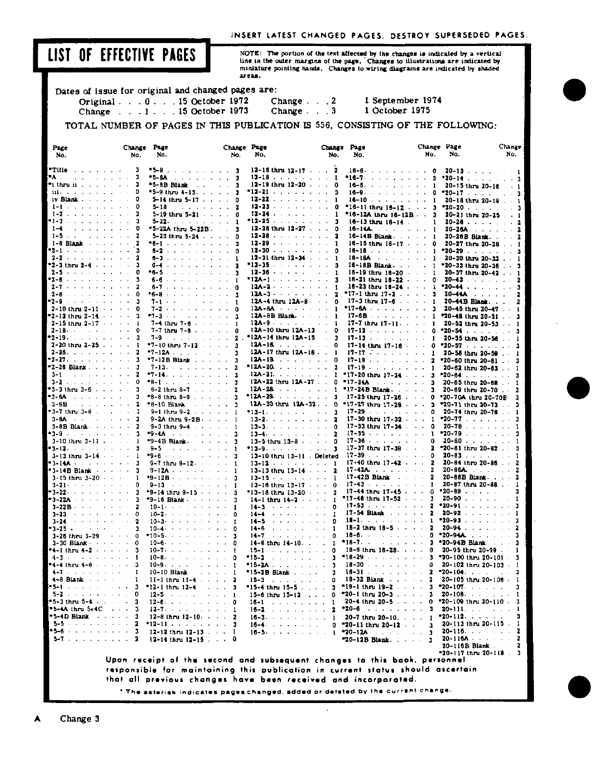
INSERT
LATEST
CHANGED
PAGES.
DESTROY
SUPERSEDED
PAGES.
LIST
OF
EFFECTIVE
PAGES
NOTE:
The
portion
of
the
text
afFcted
by
Lhe
cange
is
indicated
by
a
vertical
I
line
In
the
outer
marl
of
o
the
papg.
Change.
to
illustraUon
are
indicated
by
miniature
pointinglr
hands.
Changes
to
iring
dialan
are
indicated
by
shaded
areaU.
Dates
of
issue
for
original
and
changed
pages
are:
Original
. . .
0
..
15
October
1972
Change
...
2
1
September
1974
Change
. . . . .
15
October
1973
Change
. .
3
1
October
1975
TOTAL
NUMBER
OF
PAGES
IN
THIS
PUBLICATION
IS
556,
CONSISTING
OF
THE
FOLLOWING:
Page
Change
Page
Chge
Page
Change Page
Change
Page Change
No. No.
No.
No.
No.
No.
No.
No.
No.
No.
'Title
......
.
3
*
5-8 ......
..
3
12-18
thru
12-17.
..
2
1
.
.......
20-13
....
A
. . .
.....
3
'5-8A
...
3118
. . .. ...
20-14
..
. .3
I
thru
i
....
.
3
i*5-SB
Blank
.. ..
3
12-19
thru
12-20
.
.
0
16-8
.
....... 1
20-1
thru
20-16
iLl.
.......
0
'5-9
thru
4-13
.
12-21
......3 2-16-9
.
......
.
0
20-17
. ..3
iv
Blank
.....
0
5-14
thin
5-17
....
0
12-23.
........
16-10
........ I
0-18
thru
20-1
.
1-1
. . . . . . .
0
5-18
. . . . . .
12-23
... . . . .
0
'16-11
thnI
16-12
. .
.
3
20-20
... . . . .
1-2
.
.......
2
5-19
thru
5-21
.. ..
0
12-24
..... I
.16-12A
Lhru
16-12B
-
3
20-21
thru
20-25
. 1
I-3
....... 3
5-22.
.
........
12-25
....
..
3
16-13
thni
16-14
1
20-26
.......
1-4
.....
...
0
*5-2ZA
thru
5-22B.
3
12-26
thru
12-27
...
0
16-14A ......
20-26A
......
1-5
.
....
.2
5-23
thn
5-24
....
0
12-28
......
I15-14B
Blank
....
20-268
Blank.
.
.2
1-6 Blank
. ..-
2
*6-1
.........
3
12-29
........
I
16-15
thru
16-17
-
20-thru
20-28
. . 1
'2-1
.......
..
3 -2
.0
12-30
...
0
16-18
... ... . .
20-29
.
.......
3
2-2
........
2
6-3
...
I
12-31
thru
12-34
·
I
16-8A
. . .
I
20-30
thnu
20-32
.
'2-3
thru
2-4
.- .
3
6-4
.........
2
1-35
......
.
3
16-18B
Blank.
. .-
*20-33
thin
20-36
. 3
2-5
........
0
6-5
.........
3
12-36
..... 1-9
th
1-20
-
1
20-37
th
20-42
.
2-6
..
.....
..
3
6-6
.. .
I
12A-
3
18-21
th
15-22
.
-
0
20-43
... 2
2-7
.........
2
6-7
.........
0
12A-2.
16-23
thr
1-24
. .
120-44
.......
2-8
.....
..
0 6-
.......
.
3
IIA-3
.
.......
2
17-
thru
1-2
....
20-44A
.....
2
·
2-9
........
3
7-1
I.
. . .
.th
I
1
2-8.A-4
thru
172A-8l
I
204
Blank.
. .. 2
2-10
thru
2-11
...
0
7-2
.0
12A .....
I
. .
17-A
. . . .
20-45
thru
20-47
. 1
'2-12
thru
2-14
-
3
7-3
.
......
3
12A-8B
Blaik.
I
17-6B
. .. .. .
'20-48
thru
20-51
. 3
2-15
thru 2-17
.
?-4
thru
I-6
7
I
12-9
17-7
thr
1-11
.....
1-
th
1
11
.
20-52
thru
20-53
I.
2-18
.
.
- -
0
7-7
thru
-8
.....
0
12-10
thru
1IA-13
0
1-12
.
....
.
20-5
.......
3
'2-19
.
......
3
7-9
... .
'12A-14
thru
12A-15
.
3
17-13
.
..... 1
20-35
th
0-5
. 1
2-20
thru
2-25.. 1
7-10
thun
7-13
. ...
12A-& .....
0
1-14
thin
17-16
- -
20-57
.......
3
2-26
..
2
'7-IZA
...
12AI-7
thA
12k1-I.
.
I
17-17
.......
.
20-58
thrui
20-59
. - 1
2-27
.
.....
. .
3
7-12B
Blink
... ..
1A-19
.. .. .
0
17-18
......
.. .
2
20-60
thru
20-61
. 3
'2-26
Blank
. .. -
3
7-13.
......
.12A-20
. . . . .
3
17-19
......
.
20-62
thru
20-63
. 1
3-1
. . . . . . .
.2
*7-14.
.
....
... - . ..
I-20
th
1
7-
24
3
·.
'3*20-64
.
....
.. 3
3-2
. ..
0 8-
.. .
313A-22
thru
12A-27
.
.
0
'17-24A .....
3
20-65
thru
20-68
. 1
'3-3
thru
3-6
...
3
8-2
thru
8-7
..... IA-
..
2.-
. .
1
'17-24B Blank
. .
3
20-69
thru
20-70
.2
'3-6A
......
.
3
'8-8
thru
8-9
. ...
3
12A-29.
....
.
3
17-25
thin 17-26
·
0
20-70A
thnI
20-70E
3
3-6B
......
2 -10
Blink
I. LAA-
3
.
k
0
'17-11
Ithr 11-28
3
·
20-'1
thru
20-73
3.
'3-7
thru
3-8
3
9-1
thru
9-2
.....
13-1
......
3
17-29
.. . .
20-74
thru
20-76
.
3-8A
. . .
2
9-2A
thrun
9-28
. .
13-2
.........
2
17-30
thru
17-32
- -
1
20-77
.. .3
3-8 Blank
..
2
9-3 thru
9-4
..... 1
13-3
........
0
17-33
thniru
17-34
. .
20-78
. . 1
3-9
. . . . . .
3
9-4A
......
3
13-4
........
2
17-35
......
.
20-79
. . . . . . .3
3-10
thru
3-11
-
1
9-4B
Blaink..-
.
th
-. .
1-8
.
0
-36
.0......
20-80
.......
3-12
.
3
9-5
. .. . . . .
'13-9
.....
.
3
1-37
thru
17-38
·
.
2
'20-81
thru
20-82
. 3
3-13
thru
3-14
1
'9-6
...
3
13-10
th
13-11
.
Deleted
17-39
......
20-83
.
. .
. .
3-14A
. .
3
9-7
thru 9-12
.
.1
13-12
......
..
17-40
thru
17-42
·.
.
20-84 thru
20-86
.
.
2
3-14B
Blank
. .
3
9-I2A
. ...
13-13
thrn
13-14
.
2
17-42A. ......
20-86A.
.
.
2
3-15
thru
3-20
1
'9-12-
.3
13-15
. .. .- -
17-42B
Blank
.
.
220-868
Blank
.-2
3-21-
0
9-13
...
3-6
th
13-
17
·
r
.·
0
1'7-43
......
20-87
thru
20-88
.1
3-22
....... 3
9-4
thru 9-15
.
3
13-18
thru
13-20
.
.
·
3
17-44
thru
17-45
. .
20-89
.
.
.
.
3
·
3-22.A .....
3
9-1
Blank ..... 3
14-1
thru
14-2
-
1
'I
17-46
thru
17-52
.
3
20-90
.....
3-22B
.. .
2
10-1
. .
i
14-3
.......
0
17-53.
. . . ..
2'20-91
. . . . .3
3-23
.
0
10-2
. ..
0
14-4
........ i
17-54
Blank
..
2
0-92
.......
1
3-24
......
10-3
..
14.....
1-5
........
0
-1 ........
20-93
... . . . .3
3-25
··
3
10.4
. .
14-6.
. .
I
18-2
thru
18-5
..
3
20-94
.....
3-26
thri
3-29
..
.0
'10-5
.
......
14-7
.......
.
0
18-6
.. ....
20-94A
. . 3
3-30 Blank
0
10-6
.
0
14-8
thru
14-10.
.
18-7.
..
....
320-94B
Blank
. . 3
4-1
thru
4-2
3
10-7
.
15-1
........
0
18-8
th 18-28.
. . .
0
20-95
thru
20-99
.
I
4-3
. . .
1I 10-8.-1
. . . .
'18-29
......
..
20-100
thru
20-101
3
4-4 thru 4-6
. . . .
3
10-9
.
.... I
'15-2A
........ 3
18-30
......
..
20-102
thin
20-103
1
4-
. . . . . . .
I
10-10
Blank
.
'15-2B
Blnk
. ...
3
18-31
.
.....
'20-104.
. 3
4-8
Blank
.... 1
11-1
thru
11-4
. 1-3 .
.....
0
18-32
Blank
.. ...
2
0-105
thru
20-106
.
:5-1
. .
3
'12-1
thru
12-4
-. .
15-4
thru
15-5
.
3
19-1
thn
19-2
.
3
20-107
.....
3
5-2
. -..
0
12-5......
15-6
thru
15-12.
. .
0
20-1
thn
20-3
. . .
3
20-108.
. . . .1
*5-3
thru
5-4
.
3
12-6.
.. .
.16-1
. .
....... 1
20-4
thiru
20-5
..
0
'20-109
thru
20-110
3
'5-4A
thru
5r4C
. .-
3
12-7..
.. ..
16-2.
........
2
*20-6
........
20-111.
.. I
'5-4D Blank
..... 3
12-8
thru
12-10
. .
2
16-3.
.
. .
I
0-7
thru
20-10.
. .
1
'20-112
.
....
.
5-5
....
2
'111
.......
. .
16-4
.....
..
0
'20-11
thru
20-12
3
20-113
thn.
20-115
I
5-6
.........
3
12-12
thru
12-1
1 .....
0-I.
320-11
. ... 2
5-
. . . . . . . .
.2
12-14
thru
12-S
. .
0
20-12
Blank
. . .
3
20-116
. .. . 2
20-116B
Blank
2
*20-117
Ir,
20-1
20-I8
3
Upon
receipt
of
the second
and
subsequent
changes
to
this
book,
personnel
responsible
for
maintaining
this
publication
in
current
status
should
ascertain
that
all
previous changes
have
been
received
and
incorporated.
'The
asterisk
indicates
pages
changed,
added
or
deleted
by
the
current
change.
A
Change
3
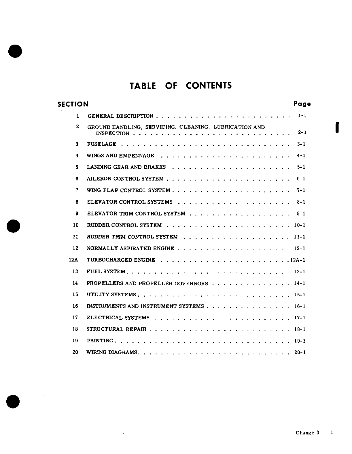
TABLE
OF
CONTENTS
SECTION
Page
1
GENERAL
DESCRIPTION
........................ 1-1
2
GROUND HANDLING,
SERVICING,
CLEANING, LUBRICATION
AND
INSPECTION
................ ............
2-1
3
FUSELAGE
................. . . . . . . . . . . . . .
3-1
4
WINGS
AND
EMPENNAGE
.......................
4-1
5
LANDING
GEAR
AND
BRAKES
..................... 5-1
6
AILERON
CONTROL SYSTEM
......................
6-1
7
WING
FLAP
CONTROL SYSTEM
..................... 7-1
8
ELEVATOR
CONTROL
SYSTEMS
....................
8-1
9
ELEVATOR
TRIM
CONTROL
SYSTEM
..................
9-1
10
RUDDER
CONTROL
SYSTEM
......................
10-1
11
RUDDER
TRIM
CONTROL SYSTEM
...................
11-1
12
NORMALLY
ASPIRATED
ENGINE
....................
12-1
12A
TURBOCHARGED
ENGINE
.......................
12A-1
13
FUEL
SYSTEM.
............................
13-1
14
PROPELLERS
AND
PROPELLER
GOVERNORS
.... .........
14-1
15
UTILITY
SYSTEMS
...........................
15-1
16
INSTRUMENTS
AND
INSTRUMENT
SYSTEMS
...............
16-1
17
ELECTRICAL
SYSTEMS
........................
17-1
18
STRUCTURAL
REPAIR
.....................
.
18-1
19
PAINTING
....... ............ ............
19-1
20
WIRING DIAGRAMS
..
......................
.
20-1
Change 3
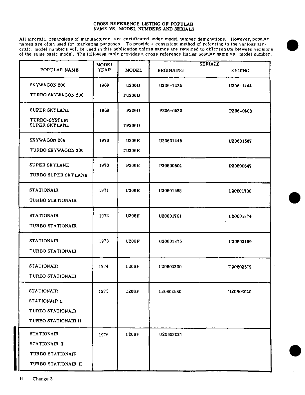
CROSS
REFERENCE
LISTING
OF
POPULAR
NAME
VS.
MODEL
NUMBERS
AND
SERIALS
All
aircraft,
regardless
of
manufacturer,
are
certificated
under
model
number
designations.
However,
popular
names
are
often
used
for marketing
purposes.
To
provide
a
consistent
method
of
referring
to
the
various
air-
craft.
model
numbers
will
be
used
in
this
publication
unless
names
are
required
to
differentiate
between
versions
of
the
same
basic
model.
The
following
table
provides
a
cross
reference
listing
popular
name
vs.
model
number.
MODEL
SERIALS
POPULAR
NAME
YEAR
MODEL
BEGINNING
ENDING
SKYWAGON
206
1969
U206D
U206-1235
U206-1444
TURBO
SKYWAGON
206
TU206D
SUPER
SKYLANE
1969
P206D
P206-0520
P206-0603
TURBO-SYSTEM
SUPER
SKYLANE
TP206D
SKYWAGON
206 1970
U206E
U20601445 U20601587
TURBO
SKYWAGON
206
TU206E
SUPER
SKYLANE
1970
P206E
P20600604
P20600647
TURBO SUPER
SKYLANE
STATIONAIR
1971
U206E U20601588
U20601700
TURBO
STATIONAIR
STATIONAIR
1972
U206F
U20601701
U20601874
TURBO
STATIONAIR
STATIONAIR
1973
U206F
U20601875 U20602199
TURBO
STATIONAIR
STATIONAIR
1974
U206F
U20602200 U20602579
TURBO
STATIONAIR
STATIONAIR
1975
U206F
U20602580
U20603020
STATIONAIR
II
TURBO
STATIONAIR
TURBO
STATIONAIR
II
STATIONAIR
1976
U206F U20603021
STATIONAIR
II
TURBO
STATIONAmR
TURBO
STATIONAIR
11
~~~~ii Change
3
ii
Change 3
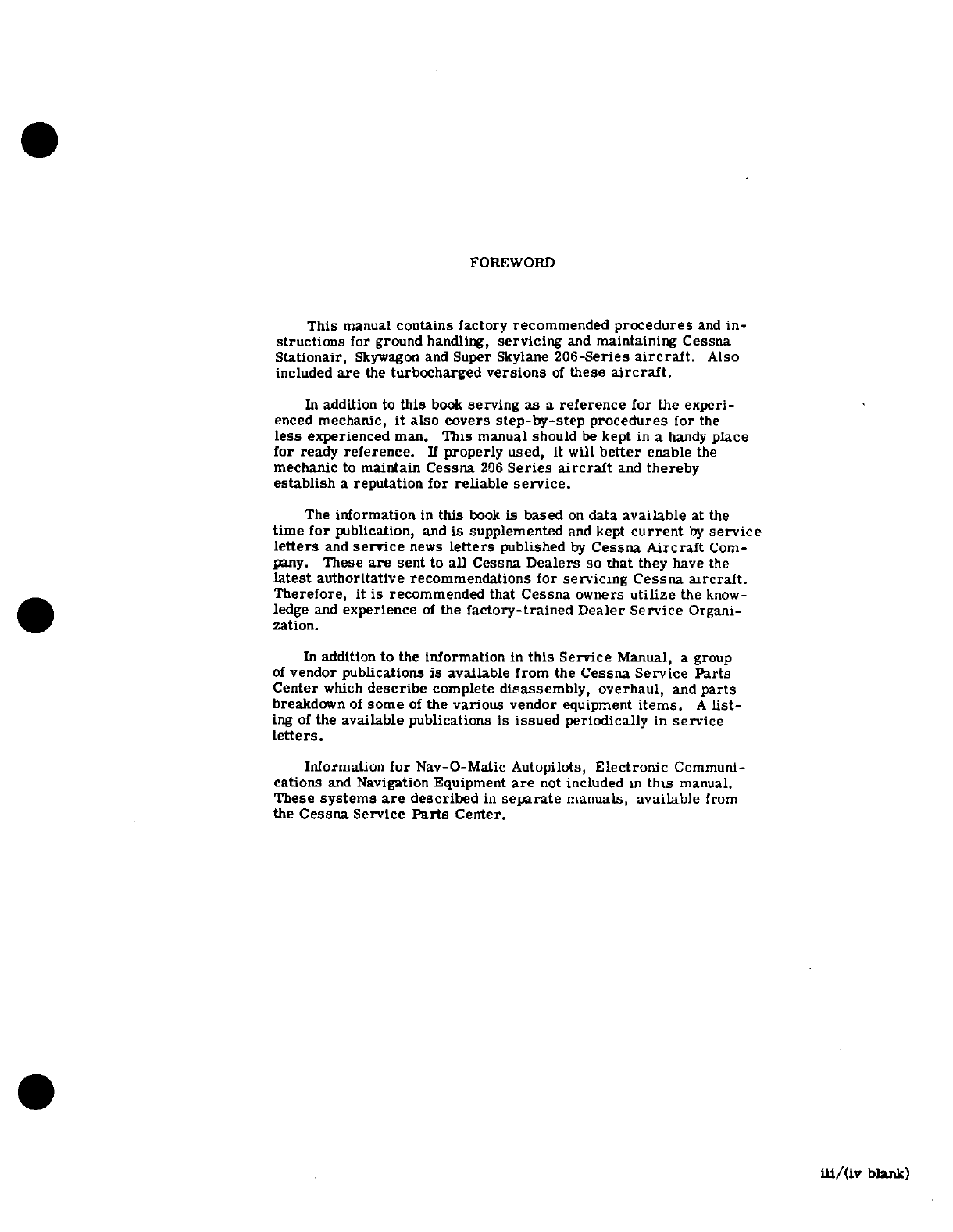
FOREWORD
This
manual
contains
factory
recommended
procedures
and
in-
structions
for
ground
handling,
servicing
and
maintaining
Cessna
Stationair,
Skywagon
and Super
Skylane
206-Series
aircraft.
Also
included
are
the
turbocharged
versions
of
these
aircraft.
In
addition
to
this
book
serving
as
a
reference
for
the experi-
enced
mechanic,
it
also
covers
step-by-step
procedures
for
the
less
experienced
man.
This
manual should
be
kept
in
a
handy
place
for
ready
reference.
If
properly
used,
it
will
better
enable
the
mechanic
to
maintain
Cessna
206
Series
aircraft
and
thereby
establish
a
reputation
for reliable
service.
The
information
in
this
book
is
based
on
data
available
at
the
time for
publication,
and
is
supplemented
and
kept
current
by
service
letters
and
service
news
letters
published
by
Cessna
Aircraft
Com-
pany.
These
are
sent
to
all
Cessna
Dealers
so
that
they
have
the
latest
authoritative
recommendations for
servicing Cessna
aircraft.
Therefore,
it
is
recommended that
Cessna
owners
utilize
the
know-
ledge
and
experience
of
the
factory-trained
Dealer
Service
Organi-
zation.
In
addition
to
the
information
in
this
Service
Manual,
a
group
of
vendor publications
is
available
from
the
Cessna
Service
Parts
Center
which
describe
complete
disassembly,
overhaul,
and
parts
breakdown
of
some
of
the
various
vendor
equipment
items.
A
list-
ing
of
the
available
publications
is
issued
periodically
in
service
letters.
Information
for
Nav-O-Matic Autopilots,
Electronic
Communi-
cations
and
Navigation
Equipment
are
not
included
in
this
manual.
These
systems
are
described
in
separate
manuals,
available
from
the
Cessna
Service
Parts
Center.
iii/(iv
blank)
SECTION
1
GENERAL
DESCRIPTION
TABLE
OF
CONTENTS
Page
GENERAL
DESCRIPTION
..........
.
1-1
Description
..............
1-1
Skywagon
and
Turbo
Skywagon
206-
Stationair
and
Turbo
Stationair-Series
. .
1-1
Series
.......
...
.....
.
1-1
Description
........... ....... 1-1
Description
.... ........
1-1
Aircraft
Specifications
.. .. . . . .
1-1
Super
Skylane
and
Turbo
Super
Stations
............
.
1-1
Skylane
206-Series
..........
1-1
Torque
Values
...... ......
1-1
1-1.
GENERAL
DESCRIPTION.
all-metal
constant speed
propeller.
In
addition,
Turbo
Super
Skylane
206-Series
engines
are
turbo-
1-2.
SKYWAGON
AND
TURBO
SKYWAGON
206-SE-
charged.
RIES.
1-6.
STATIONAIR
AND
TURBO
STATIONAIR-SERIES.
1-3.
DESCRIPTION.
Cessna
Skywagon
and
Turbo
Skywagon
206-Series
aircraft,
described
in
this
man- 1-7.
DESCRIPTION.
Cessna
Stationair
and
Turbo-
ual,
are
single-engine,
high-wing,
strut-braced
Stationair-Series
aircraft,
described
in
this
manual,
monoplanes
of
all-metal,
semimonocoque
construc-
are
single-engine,
high-wing,
strut-braced
mono-
tion.
These
aircraft
are
equipped
with
a
fixed
tri-
planes
of
all-metal,
semimonocoque
construction.
cycle
landing
gear
employing
spring-steel
main
land-
These
aircraft
are
equipped
with
a
fixed
tricycle
land-
ing
gear
struts
and
a
steerable
nose
gear
with
an
ing
gear
employing
spring-steel
main landing
gear
air/hydraulic
fluid
shock
strut.
Wing
flaps
are
elec-
struts
and
a
steerable
nose
gear
with
an
air/hydraulic
trically-actuated.
Both the
Skywagon
and
Turbo
fluid
shock
strut.
Wing
flaps
are
electrically-actua-
Skywagon
206-Series
aircraft
are
equipped
with
large
ted.
Both
the
Stationair
and
Turbo
Stationair-Series
double
cargo
doors
on
the
right
side
of
the
fuselage
aircraft
are
equipped
with
large
double
cargo
doors
and an
entrance
door
on
the
left
side
of
the
cabin.
on
the
right side
of
the
fuselage
and an
entrance
door
The
pilot's
seat
only
is
standard,
but
provisions
are
on
the
left
side
of
the cabin.
The
seating
arrangement
made
for
the
addition
of
optional
seats
to
make
a
six-
of
these
aircraft
consists
of
six individual
seats.
Sta-
place
aircraft.
Skywagon
and
Turbo
Skywagon
206-
tionair
and
Turbo
Stationair-Series
aircraft are
pow-
Series
aircraft
are
powered
by
a
six-cylinder,
hori-
ered
by
a
six-cylinder,
horizontally
opposed,
air-
zontally
opposed,
air-cooled,
fuel-injection
Conti-
cooled,
fuel-injection
Continental
engine,
driving
an
nental
engine,
driving
an
all-metal,
constant
speed
all-metal,
constant
speed
propeller.
In
addition,
propeller.
In
addition,
Turbo
Skywagon
206-Series Turbo
Stationair
engines
are
turbocharged.
aircraft
engines
are
turbocharged.
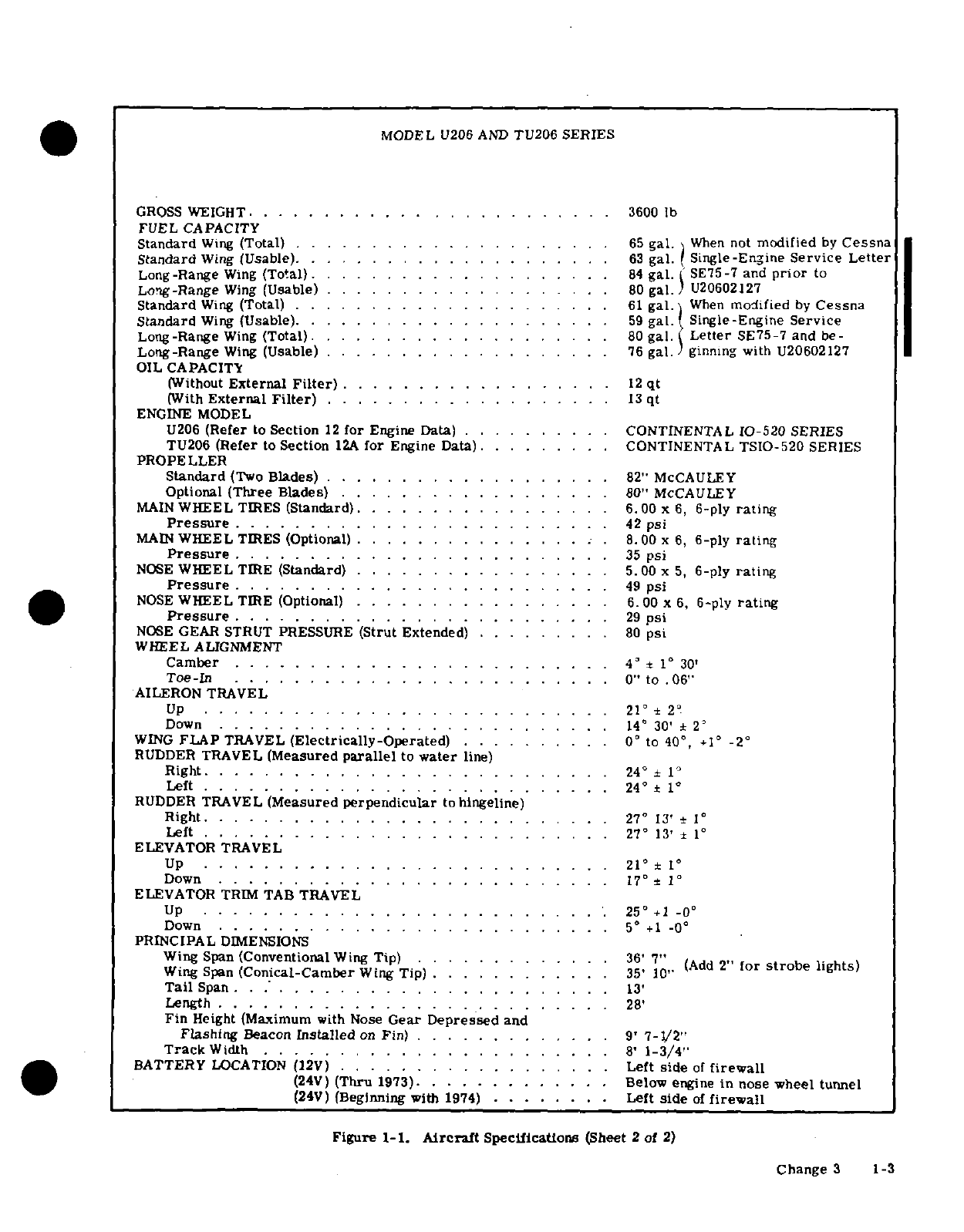
1-8.
AIRCRAFT SPECIFICATIONS.
Leading
parti-
1-4.
SUPER
SKYLANE
AND
TURBO
SUPER
SKY-
culars
of
these
aircraft,
with
dimensions based
on
LANE
206-SERIES.
gross
weight,
are
given
in
figure
1-1.
If
these
dimensions
are
used for
constructing
a
hangar
or
1-5.
DESCRIPTION.
Cessna
Super
Skylane
and
computing
clearances,
remember
that
such
factors
Turbo
Super
Skylane
206-Series
aircraft,
described
as
nose
gear
strut
inflation,
tire
pressures,
tire
in
this
manual,
are
single-engine,
high-wing,
strut- sizes
and
load
distribution
may
result
in
some
di-
braced
monoplanes
of
all-metal,
semimonocoque
mensions
that
are
considerably
different
from
those
construction.
These
aircraft
are
equipped
with
a
listed.
fixed
tricycle
landing
gear
employing
spring-steel
main
landing
gear
struts
and
a
steerable
nose
gear
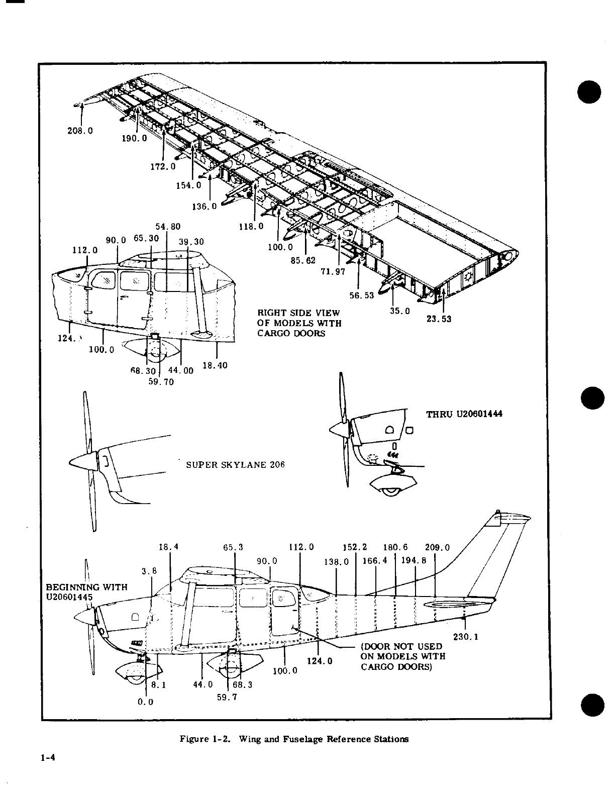
1-9.
STATIONS.
A
station diagram
is
shown
in
with
an
air/hydraulic
fluid shock
strut.
Wing
flaps
figure
1-2
to
assist
in
locating
equipment
when
a
are
electrically-actuated.
Both
the
Super
Skylane
written
description
is
inadequate
or
impractical.
and
the
Turbo
Super Skylane
2 0
6-Series
aircraft
are
equipped
with an
entrance
door'on
each
side
of
the
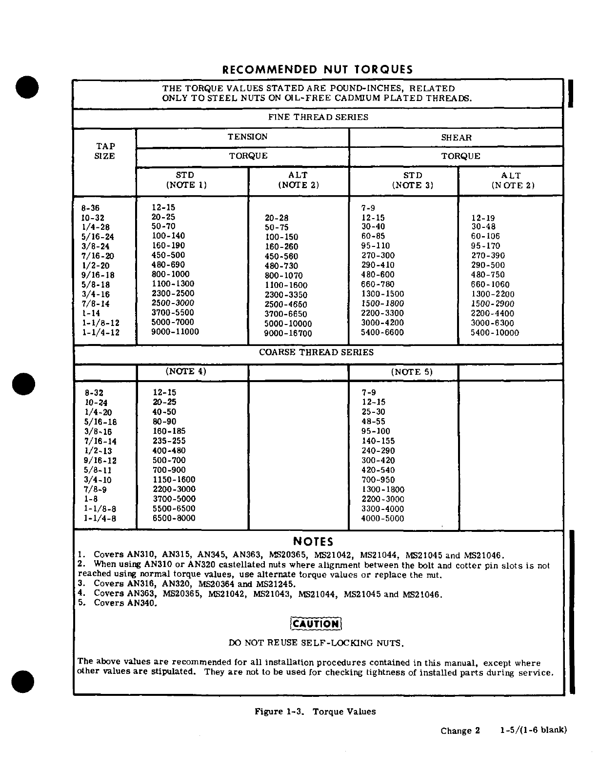
1-10.
TORQUE
VALUES.
A
chart
of
recommended
cabin,
and
a
baggage
door
on
the
left
side
of
the
nut
torque
values
is
shown
in
figure
1-3.
These
tor-
fuselage.
The
seating
arrangement
of
these
aircraft
que
values
are
recommended
for
all
installation
pro-
consists
of
six
individual
seats.
Super
Skylane
and
cedures
contained
in
this
manual,
except where
other
Turbo
Super
Skylane
206-Series
aircraft
are
power-
values
are
stipulated.
They
are
not
to
be
used
for
ed
by
a
six-cylinder,
horizontally
opposed,
air-
checking
tightness
of
installed
parts
during
service.
cooled,
fuel-injection
Continental
engine,
driving
an
1-1
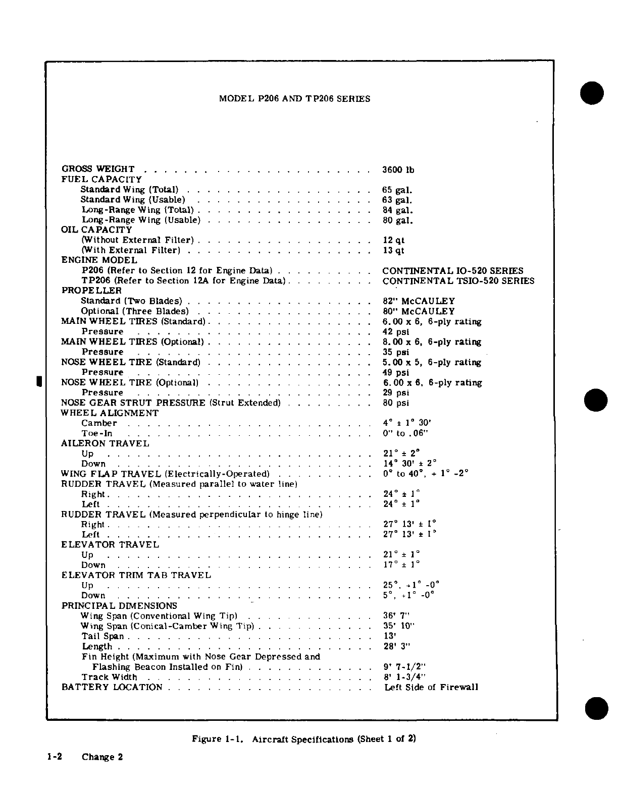
MODEL
P206
AND
TP206
SERIES
GROSS
WEIGHT
.......................
3600
lb
FUEL
CAPACITY
Standard
Wing
(Total)
. .
......
.
.......
.
65
gal.
Standard
Wing
(Usable)
......
... ...
....
.
63
gal.
Long-Range
Wing
ITotal)
. ..
............
84
gal.
Long-Range
Wing
(Usable) .
............
80
gal.
OIL
CAPACITY
(Without
External
Filter)
.................
12
qt
(With
External
Filter)
...................
13
qt
ENGINE MODEL
P206
(Refer
to
Section
12
for
Engine
Data)
.
........
.
CONTINENTAL
10-520
SERIES
TP206
(Refer
to
Section
12A
for
Engine
Data)
.........
CONTINENTAL
TSIO-520
SERIES
PROPELLER
Standard
(Two
Blades)
.
................
..
82"
McCAULEY
Optional
(Three
Blades)
................
.
80"
McCAULEY
MAIN
WHEEL
TIRES
(Standard).
... . . .. .
......
6.00
x 6,
6-ply
rating
Pressure
........................
42
psi
MAIN
WHEEL
TIRES
(Optional) . . . .
.............
8.00
x
6,
6-ply
rating
Pressure
.. .
.... ....
.. . . . . . . . .. ...
35
psi
NOSE
WHEEL
TIRE
(Standard)
..... ............
5.00
x
5,
6-ply
rating
Pressure
. . . .. . . . ... .. . . . . .. .
49
psi
NOSE
WHEEL
TIRE
(Optional)
.
...............
6.00
x 6,
6-ply
rating
Pressure
.... . . . . . . ....... . . .. .
29
psi
NOSE
GEAR
STRUT PRESSURE
(Strut
Extended)
.........
80
psi
WHEEL
ALIGNMENT
Cam
ber
. . . ................ .. .. . . 4
°
±
1
°
30'
Toe-In
. . ... . . .
......
.. .
.....
.
0"
to .0
6
"
AILERON
TRAVEL
Up
....... ............... ....
21
±
2
°
Down
. ...
.....
... .. . . ... . .
14°
30'
±
2
°
WING
FLAP
TRAVEL
(Electrically-Operated)
.. .. .. 0
°
to
40
°
. +
1
-2
°
RUDDER
TRAVEL
(Measured
parallel
to
water
line)
Right.
. . . . . . ... ...... . . . ..
24
°
±
1
Left
...................
..
24°±
1
°
RUDDER
TRAVEL
(Measured
perpendicular
to
hinge
line)
Right . .. .
....
.. . . . . . . . .. . . .
27°
13'
±
I
Left
.. ... .. .. . .. . ... . . .. .. .
27 °
13'
±
ELEVATOR
TRAVEL
Up
.... . .. . . . .. . .......... .. .
21
±1
°
Dow
n
.. . . . . .. . .. . .
.....
......
17"
±
1
°
ELEVATOR
TRIM
TAB
TRAVEL
Up
. . . .. . . . . . .. . . . . . .
25 °
.
41 °
-0O
Dow
n
.... ... . .
..............
.. 5
°+1
-0
PRINCIPAL
DIMENSIONS
Wing Span
(Conventional
Wing
Tip)
.............
36'
7"
Wing
Span
IConical-Camber
Wing
Tip)
... . . ...
35'
10'
Tail
Span
........... .......
.....
13'
Length . . . .. . . . . . . ..... .
......
.
28'
3"
Fin
Height
(Maximum
with
Nose
Gear
Depressed
and
Flashing
Beacon
Installed
on
Fin)
.
..........
.
9'
7-1/2"
Track
Width
. .
...........
.
......
.
8'
1-3/4"
BATTERY
LOCATION
. ...
.........
.. .. ...
Left
Side
of
Firewall
Figure
1-1.
Aircraft
Specifications
(Sheet
I
of
2)
1-2
Change
2
59
70
.
C^,
B
y\
'
SUPER
SKYLANE 206
ThRU
u?0_
100
0
112.0 100.0
~20601445_^
-j tf X ! * -^
85. 62
RIGHT
SIDE
VIEW
NOT
USED
OF MODELS
WITH
<12 |
<4-p
low
^
'
^
1000CARGO
DOORS
8.1
44.0
8.3
Figure
1-2.
Wing
and
Fuselage
Reference
Stations
~1 ~59.-47
THRU U20601444
SUPER
SKYLANE
206
18.4
65.3
112.0
152.2
180.6
209.0
3.8
10.1
BEGINNING
wITH
ON
MODELS
WITH
8.1
44.0
68.3
Figure
1-2.
Wing
and
Fuselage Reference
Stations
1-4
MODEL
U206
AND
TU206
SERIES
GROSS
WEIGHT.
................... .....
.
3600 lb
FUEL CAPACITY
Standard
Wing
(Total)
....................
.
65
gal.
When
not
modified
by
Cessna
Standard
Wing
(Usable)
....................
63
gal.
Single-Engine
Service
Letter
Long-Range
Wing
(Total)
..................
..
84
gal.
SE75-7
and
prior
to
Long-Range
Wing
(Usable)
.........
..
80
gal.
U20602127
Standard
Wing
(Total)
....................
.
61
gal.
When
modified
by
Cessna
Standard
Wing
(Usable).
............
.
.........
59
gal.
Single-Engine
Service
Long-Range
Wing
(Total).
...............
....
...
80
gal.
Letter
SE75-7
and
be-
Long-Range
Wing
(Usable)
........ ............
.
76
gal.
ginning with
U20602127
OIL
CAPACITY
(Without
External
Filter)
................
..
12
qt
(With
External
Filter)
.
.......
..........
13
qt
ENGINE
MODEL
U206
(Refer
to
Section
12
for
Engine
Data)
....
......
CONTINENTAL
10-520
SERIES
TU206
(Refer
to
Section
12A
for
Engine
Data)..........
CONTINENTAL
TSIO-520
SERIES
PROPELLER
Standard
(Two
Blades)
.
................
.
82"
McCAULEY
Optional
(Three Blades)
..................
.
80"
McCAULEY
MAIN
WHEEL
TIRES
(Standard).
..........
...
6.00
x
6,
6-ply
rating
Pressure
.......................
42
psi
MAIN
WHEEL
TIRES
(Optional)
.
..........
..
8.00
x
6,
6-ply
rating
Pressure
........................
.
35
psi
NOSE
WHEEL
TIRE
(Standard)
...............
5.00
x
5,
6-ply
rating
Pressure
.
49
psi
NOSE
WHEEL
TIRE
(Optional)
.....
..
6.00
x
6,
6-ply
rating
Pressure
.........................
29
psi
NOSE
GEAR
STRUT PRESSURE
(Strut Extended)
........
80
psi
WHEEL
ALIGNMENT
Camber
...
............... ....
4'
+ 1
°
30'
Toe-In
........... ......
....
0"
to
.06
AILERON TRAVEL
U
p
............ . .... . ........ .
21 °
2
°
Down
..............
14'
30' ±
2'
WING
FLAP
TRAVEL
(Electrically-Operated)
. .
0
to
400,
+1
-2
RUDDER
TRAVEL
(Measured
parallel
to
water
line)
Right.
....................
24
°
±
1'
Left
..
.....
. .. .. .. . .....
.......
24
°
±
1
°
RUDDER
TRAVEL
(Measured
perpendicular
to
hingeline)
Right .. .... . ..... . . ........ . ..
. .
27°
13'
±
1
Left
........
. . . . .
.
. .
.
.
.... .
.
27
°
13' ±
1
°
ELEVATOR
TRAVEL
U
p
......................... . .
21
°1 °
Dow
n
......................... .
17 °
1
ELEVATOR
TRIM
TAB TRAVEL
Up
..... . ..............
25
+1
-0
°
Down
.........................
. 5
°+1
-0
PRINCIPAL
DIMENSIONS
Wing Span
(Conventional
Wing
Tip)
........
..
36'
7"
(Add
2"
for
strobe
lights)
Wing
Span
(Conical-Camber
Wing
Tip)
.
...........
35'
10"
g
Tail
Span
......................
13'
Length
...................
. . .....
28'
Fin
Height
(Maximum
with
Nose
Gear
Depressed
and
Flashing
Beacon
Installed
on
Fin)
.... ...........
9'
7-1/2"
Track
Width
..................
.
8'
1-3/4"
BATTERY
LOCATION
(12V)
..................
Left
side
of
firewall
(24V)
Thru
1973) ............
Below
engine
in
nose
wheel
tunnel
(24V)
Beginning
with
1974)
........
Left
side
of
firewall
Figure
1-1.
Aircraft
Specifications
(Sheet
2
of
2)
Change
3
1-3
RECOMMENDED
NUT
TORQUES
THE
TORQUE VALUES
STATED
ARE
POUND-INCHES,
RELATED
ONLY
TO
STEEL
NUTS
ON
OIL-FREE
CADMIUM
PLATED
THREADS.
FINE
THREAD SERIES
TENSION
SHEAR
TAP
SIZE TORQUE
TORQUE
STD
ALT STD
ALT
(NOTE
1)
(NOTE
2)
(NOTE
3)
(NOTE
2)
8-36
12-15
7-9
10-32
20-25
20-28
12-15 12-19
1/4-28
50-70
50-75
30-40
30-48
5/16-24
100-140
100-150
60-85
60-106
3/8-24
160-190
160-260
95-110
95-170
7/16-20
450-500
450-560
270-300 270-390
1/2-20
480-690
480-730
290-410
290-500
9/16-18
800-1000 800-1070 480-600
480-750
5/8-18
1100-1300 1100-1600
660-780
660-1060
3/4-16
2300-2500 2300-3350
1300-1500
1300-2200
7/8-14
2500-3000
2500-4650
1500-1800 1500-2900
1-14
3700-5500
3700-6650 2200-3300 2200-4400
1-1/8-12
5000-7000
5000-10000 3000-4200 3000-6300
1-1/4-12
9000-11000
9000-16700 5400-6600
5400-10000
COARSE
THREAD SERIES
(NOTE
4)
(NOTE
5)
8-32
12-15
7-9
10-24
20-25
12-15
1/4-20 40-50 25-30
5/16-18
80-90 48-55
3/8-16
160-185
95-100
7/16-14
235-255
140-155
1/2-13
400-480
240-290
9/16-12
500-700
300-420
5/8-11
700-900
420-540
3/4-10
1150-1600
700-950
7/8-9
2200-3000
1300-1800
1-8
3700-5000 2200-3000
1-1/8-8
5500-6500 3300-4000
1-1/4-8
6500-8000 4000-5000
NOTES
1.
Covers
AN310,
AN315,
AN345,
AN363,
MS20365, MS21042, MS21044, MS21045
and
MS21046.
2.
When
using
AN310
or
AN320
castellated
nuts
where
alignment
between the
bolt
and
cotter
pin
slots
is
not
reached
using
normal
torque values,
use
alternate
torque
values
or
replace
the
nut.
3.
Covers
AN316,
AN320,
MS20364
and
MS21245.
4.
Covers
AN363,
MS20365,
MS21042,
MS21043,
MS21044,
MS21045
and
MS21046.
5.
Covers
AN340.
CAUTION
DO
NOT
REUSE
SELF-LOCKING
NUTS.
The
above
values
are
recommended
for
all installation
procedures
contained
in
this
manual,
except where
other
values
are
stipulated.
They
are
not
to
be
used
for
checking
tightness
of
installed
parts
during
service.
Figure
1-3.
Torque
Values
Change
2
1-5/(1-6
blank)
SECTION
2
GROUND
HANDLING.
SERVICING.
CLEANING, LUBRICATION
AND
INSPECTION
TABLE
OF
CONTENTS
Page
GROUND HANDLING
...........
2-1
Tires
.... .....
2-7
Towing
. . ..............
2-1
Nose
Gear
Strut
....... .... .
2-8
Hoisting
..............
.
2-1
Nose
Gear
Shimmy
Dampener
...
2-8
Jacking
............
. 2-1
Hydraulic
Brake
System
... .
2-9
Parking
...............
2-2
Oxygen
System
....
...
..... 2-9
Tie-Down
.... .... ......
.
2-2
Face Masks
.............
2-9
Flyable
Storage
............
2-2
CLEANING
.
............
.
2-9
Returning
Aircraft
to
Service
....
.2-2
General
Description
....
.
2-9
Temporary
Storage
..........
2-2
Upholstery
and
Interior
..
2-9
Inspection
During
Storage
.....
2-4
Plastic
Trim
........
2-9
Returning
Aircraft
to
Service
....
2-4
Windshield
and
Windows
....
2-9
Indefinite
Storage
...........
2-5
Aluminum
Surfaces
..... 2-9
Inspection
During
Storage
.....
2-5
Painted
Surfaces
. ...
.......
2-9
Returning
Aircraft
to
Service
.... 2-5
Engine
Compartment
.. .
.....
2-10
Leveling
...............
2-6
Propellers
.....
....
.....
2-10
SERVICING
...............
2-6
Wheels
...............
2-10
Fuel
Tanks
.... ..........
2-6
LUBRICATION
.
..........
2-10
Fuel
Drains
.............
2-6
General
Description
..........
2-10
Engine
Oil
.........
....
2-6
Nose
Gear
Torque
Links
........
2-10
Engine Induction Air
Filter
.......
2-7
Tachometer
Drive
Shaft
.... .
2-10
Vacuum
System
Air
Filter
.......
2-7
Wheel
Bearing Lubrication
...
....
2-10
Battery
............
... 2-7
Wing
Flap
Act
ator
. . .
2-10
INSPECTION
..............
2-19
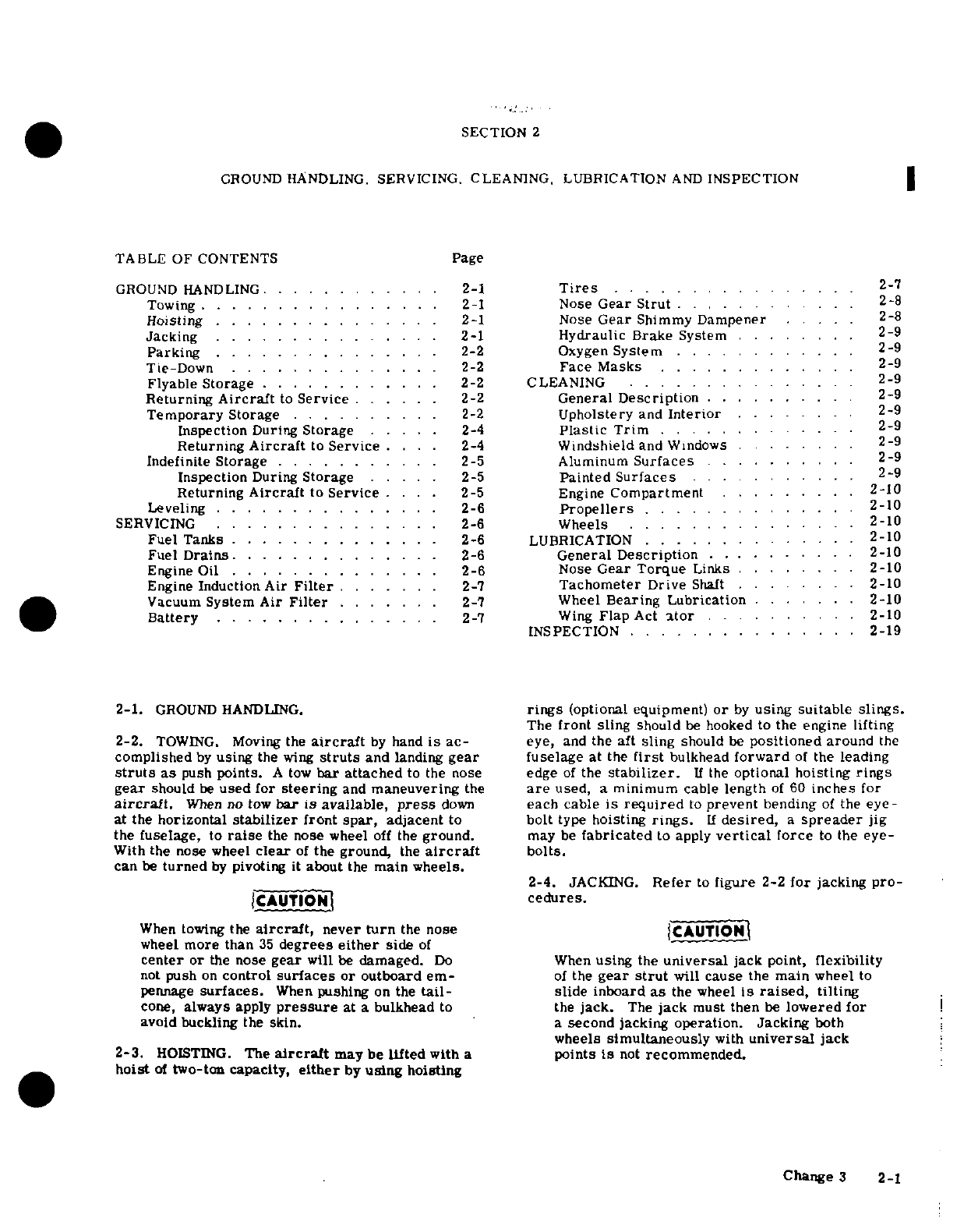
2-1.
GROUND
HANDLING.
rings
(optional
equipment)
or
by
using
suitable
slings.
The
front
sling
should
be
hooked
to
the
engine
lifting
2-2.
TOWING.
Moving
the
aircraft
by
hand
is
ac-
eye,
and
the
aft
sling
should
be
positioned
around
the
complished
by
using
the
wing
struts
and
landing
gear
fuselage
at
the
first
bulkhead
forward
of
the
leading
struts
as
push
points.
A
tow
bar
attached
to
the
nose
edge
of
the
stabilizer.
If
the
optional
hoisting
rings
gear
should
be
used for
steering
and
maneuvering
the
are
used,
a minimum
cable
length
of
60
inches
for
aircraft.
When
no
tow
bar is available,
press
down
each cable
is
required
to
prevent
bending
of
the
eye-
at
the
horizontal
stabilizer
front
spar,
adjacent
to
bolt
type
hoisting
rings.
If
desired,
a
spreader
jig
the
fuselage,
to
raise
the
nose
wheel
off
the
ground.
may
be
fabricated
to
apply
vertical
force
to
the eye-
With
the nose
wheel
clear
of
the
ground,
the
aircraft
bolts.
can
be
turned
by
pivoting
it
about
the
main
wheels.
2-4.
JACKING.
Refer
to
figure
2-2
for
jacking
pro-
JCAUTIONI
cedures.
When
towing
the
aircraft,
never
turn
the
nose
CAUTION|
wheel
more
than
35
degrees
either
side
of
center
or
the
nose
gear
will
be
damaged.
Do
When
using
the
universal
jack
point,
flexibility
not
push
on
control
surfaces
or
outboard
em-
of
the
gear
strut
will
cause
the
main
wheel
to
pennage
surfaces.
When
pushing
on
the
tail-
slide inboard
as
the
wheel
is
raised,
tilting
cone,
always
apply
pressure
at
a
bulkhead
to
the
jack.
The
jack
must
then
be
lowered
for
avoid
buckling
the
skin.
a
second
jacking
operation.
Jacking
both
wheels
simultaneously
with
universal
jack
2-3.
HOISTING.
The
aircraft
may be
lifted
with
a
points
is
not
recommended.
hoist
of
two-ton
capacity,
either
by
using
hoisting
Change
3 2-1
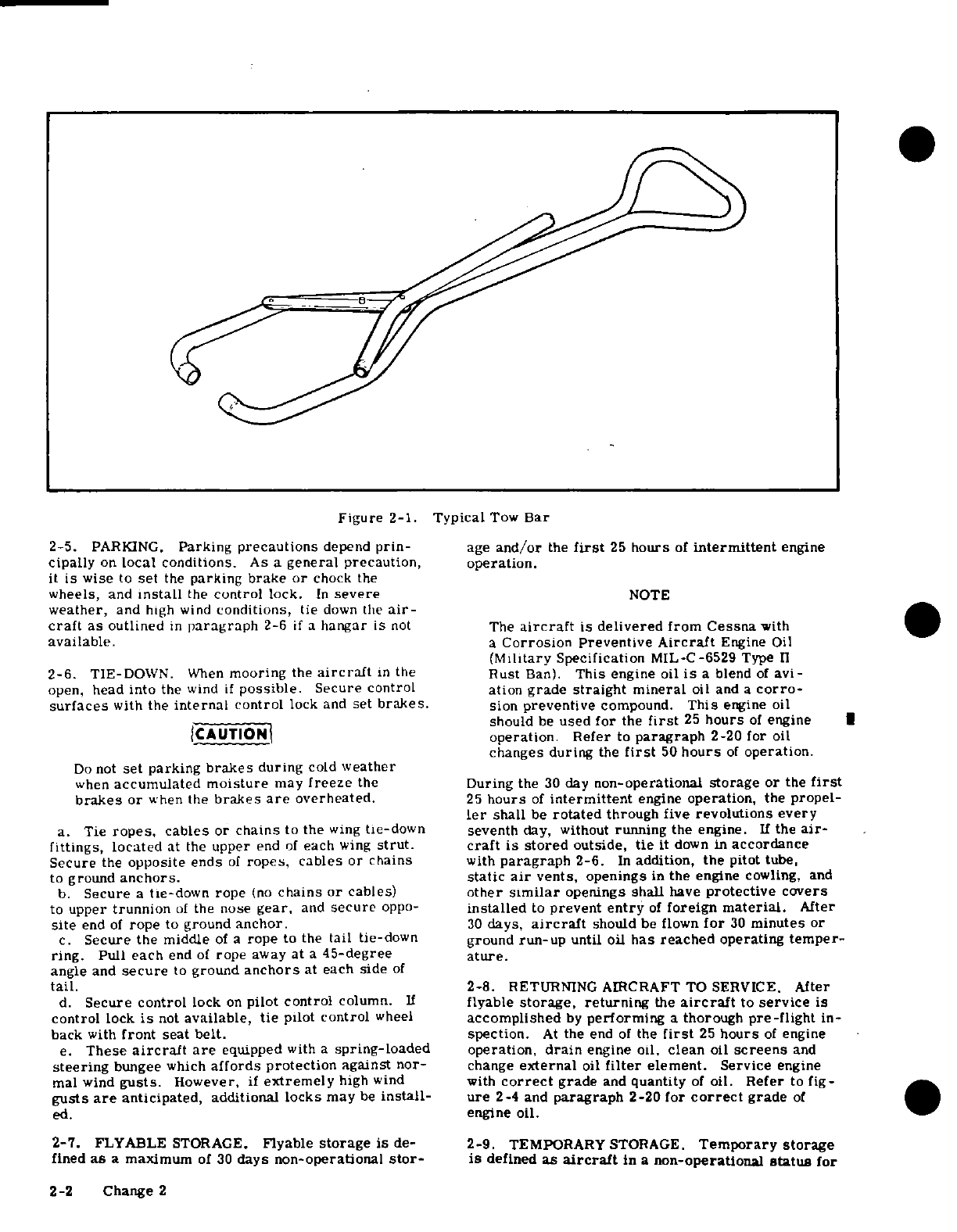
Figure
2-1.
Typical
Tow
Bar
2-5.
PARKING.
Parking
precautions
depend
prin-
age
and/or
the
first
25
hours
of
intermittent
engine
cipally
on
local
conditions.
As
a
general
precaution,
operation.
it
is
wise
to
set
the
parking brake
or
chock
the
wheels,
and
install
the
control
lock.
In
severe
NOTE
weather,
and
high
wind
conditions,
tie
down
the
air-
craft
as
outlined
in
paragraph
2-6
if
a
hangar
is
not
The
aircraft
is
delivered
from
Cessna
with
available.
a
Corrosion
Preventive
Aircraft
Engine
Oil
(Military
Specification
MIL-C-6529
Type
II
2-6.
TIE-DOWN.
When
mooring
the
aircraft
in
the
Rust
Ban).
This
engine
oil
is
a
blend
of
avi-
open,
head
into
the
wind
if
possible.
Secure
control
ation
grade
straight
mineral
oil and
a
corro-
surfaces
with
the
internal
control
lock
and
set
brakes.
sion
preventive
compound.
This
engine
oil
should
be
used
for
the
first
25
hours
of
engine
CAUTION
operation.
Refer
to
paragraph
2-20
for
oil
changes
during
the
first
50
hours
of
operation.
Do
not
set parking
brakes
during
cold
weather
when
accumulated
moisture
may
freeze
the
During
the
30
day
non-operational
storage
or
the
first
brakes
or
when
the
brakes
are
overheated.
25
hours
of
intermittent
engine
operation,
the
propel-
ler
shall
be
rotated
through
five
revolutions every
a.
Tie
ropes,
cables
or
chains
to
the
wing
tie-down
seventh
day,
without
running
the
engine.
If
the
air-
fittings,
located
at
the
upper
end
of
each
wing
strut.
craft
is
stored
outside,
tie
it
down
in
accordance
Secure
the
opposite ends
of
ropes, cables
or
chains
with
paragraph
2-6.
In
addition,
the
pitot
tube,
to
ground
anchors.
static
air
vents,
openings
in
the
engine
cowling, and
b.
Secure
a
tie-down rope
(no
chains
or
cables)
other
similar
openings
shall
have
protective
covers
to
upper
trunnion
of
the
nose
gear,
and
secure
oppo-
installed
to
prevent
entry
of
foreign
material.
After
site
end
of
rope
to
ground
anchor.
30
days,
aircraft
should
be flown
for
30
minutes
or
c.
Secure
the
middle
of
a
rope
to
the
tail
tie-down
ground
run-up
until oil
has
reached
operating
temper-
ring.
Pull
each
end
of
rope
away
at
a
45-degree
ature.
angle
and
secure
to
ground
anchors
at
each side
of
tail.
2-8.
RETURNING
AIRCRAFT
TO SERVICE.
After
d.
Secure
control
lock
on
pilot
control
column.
If
flyable
storage,
returning
the
aircraft
to
service
is
control
lock
is
not
available,
tie
pilot
control
wheel
accomplished
by
performing
a
thorough
pre-flight
in-
back
with
front
seat
belt.
spection.
At
the
end
of
the
first
25
hours
of
engine
e.
These
aircraft
are
equipped
with
a
spring-loaded
operation,
drain
engine
oil,
clean
oil
screens
and
steering
bungee
which
affords protection
against
nor-
change
external
oil
filter
element.
Service
engine
mal
wind
gusts.
However,
if
extremely
high
wind
with
correct
grade
and
quantity
of
oil.
Refer
to
fig-
gusts
are
anticipated,
additional
locks
may
be
install-
ure
2-4
and
paragraph
2-20
for
correct
grade
of
ed.
engine
oil.
2-7.
FLYABLE
STORAGE.
Flyable
storage
is
de-
2-9.
TEMPORARY
STORAGE.
Temporary
storage
fined
as
a maximum
of
30
days
non-operational
stor-
is
defined
as
aircraft
in
a
non-operational
status
for
2-2
Change
2
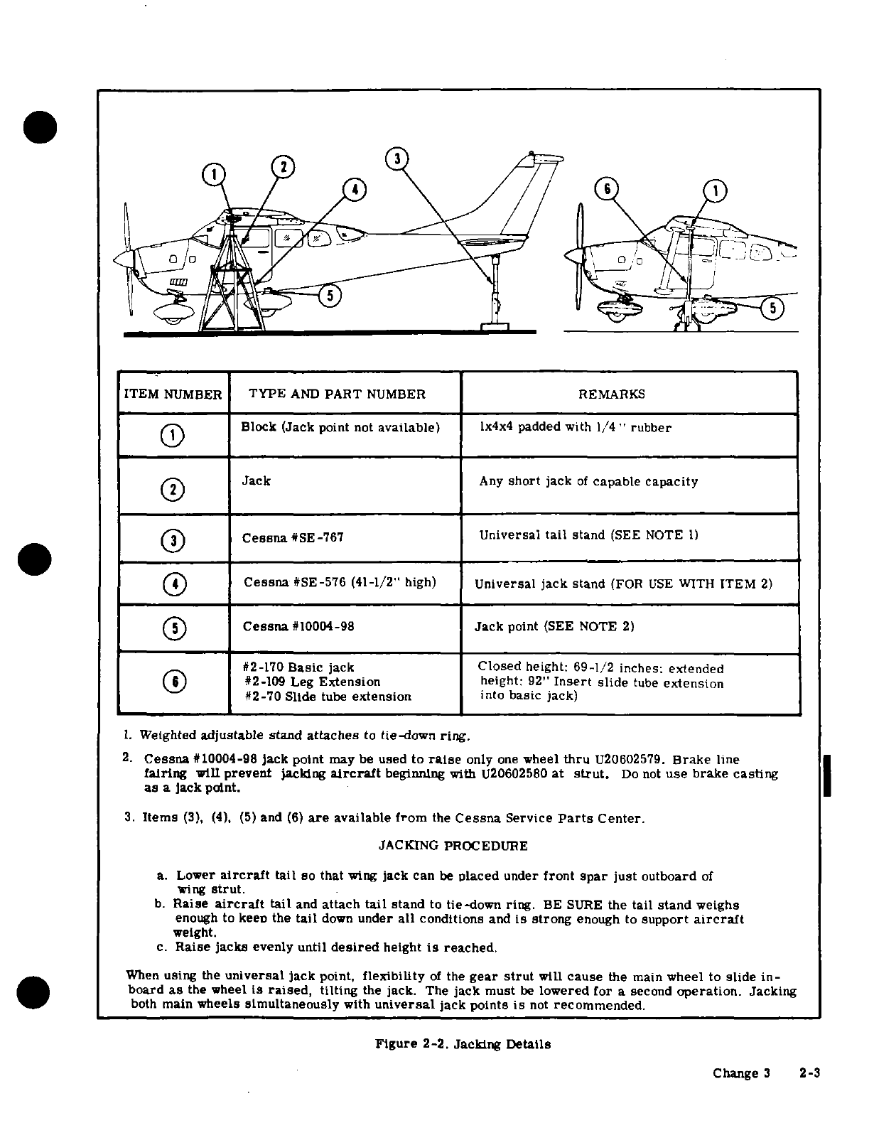
ITEM
NUMBER
TYPE
AND
PART
NUMBER
REMARKS
II\
Block
(Jack
point
not
available)
lx4x4
padded
with
1/4
"
rubber
Jack
Any
short
jack
of
capable
capacity
Cessna
#SE-767
Universal
tail
stand
(SEE
NOTE
1)
Cessna
#SE-576
(41-1/2"
high)
Universal jack
stand
(FOR
USE
WITH
ITEM
2)
O(iJ
Cessna
#10004-98
Jack
point
(SEE
NOTE
2)
#2-170
Basic
jack
Closed
height:
69-1/2
inches:
extended
#2-109
Leg
Extension
height:
92"
Insert
slide
tube
extension
#2-70 Slide
tube
extension
into
basic
jack)
1.
Weighted
adjustable
stand
attaches
to
tie-down
ring.
2.
Cessna
#10004-98
jack
point
may
be
used
to
raise
only
one
wheel
thru
U20602579.
Brake
line
fairing
will
prevent
jacking
aircraft
beginning
with
U20602580
at
strut.
Do
not
use
brake
casting
as
a
jack
point.
3.
Items
(3),
(4).
(5)
and
(6)
are
available
from
the
Cessna
Service
Parts
Center.
JACKING PROCEDURE
a.
Lower
aircraft
tail
so that
wing
jack
can
be
placed
under
front
spar
just
outboard
of
wing
strut.
b.
Raise
aircraft
tail
and
attach
tail
stand
to
tie-down
ring.
BE
SURE
the
tail
stand
weighs
enough
to keeo
the
tail
down
under
all
conditions
and
is
strong
enough
to
support
aircraft
weight.
c.
Raise jacks
evenly
until
desired
height
is
reached.
When
using
the
universal
jack
point,
flexibility
of
the
gear
strut
will
cause
the
main
wheel
to
slide
in-
board
as
the
wheel
is
raised,
tilting
the
jack.
The
jack
must
be
lowered
for
a
second
operation.
Jacking
both
main
wheels
simultaneously
with
universal
jack
points
is
not
recommended.
Figure
2-2.
Jacking Details
Change
3
2-3
a
maximum
of
90
days.
The
aircraft
is
constructed
hole
of
each
cylinder
with
the
piston
in
a
down
po-
of
corrosion
resistant
alclad
aluminum,
which
will
sition.
Rotate
crankshaft
as
each
pair
of
cylinders
last
indefinitely
under
normal
conditions
if
kept
is sprayed.
clean,
however,
these alloys
are
subject
to
oxidation.
i.
After
completing
step
"h,
"
rotate
crankshaft
so
The
first
indication
of
corrosion
on
unpainted
sur-
that
no
piston
is
at a
top
position.
If
the
aircraft
is
faces
is
in
the
form
of
white
deposits
or
spots.
On
to
be
stored
outside, stop two-bladed
propeller
so
painted
surfaces,
the
paint
is
discolored
or
blistered.
that
blades
are
as
near
horizontal
as
possible
to
pro-
Storage
in
a
dry
hangar
is
essential
to
good
preser-
vide
maximum
clearance
with
passing
aircraft.
vation
and
should
be
procured
if
possible.
Varying
j.
Again
spray
each
cylinder
without moving
the
conditions
will
alter
the
measures
of
preservation,
crankshaft
to
thoroughly
cover
all
interior
surfaces
but
under
normal
conditions
in
a
dry hangar,
and
for
of
the
cylinder
above the
piston.
storage periods
not
to
exceed
90
days,
the following
k.
Install
spark
plugs
and
connect
spark
plug
leads.
methods
of
treatment
are
suggested:
1.
Apply
preservative
oil
to
the
engine
interior
by
spraying
approximately
two
ounces
of
the
preservative
a.
Fill
fuel
tanks
with
correct
grade
of
gasoline.
oil
through
the
oil
filler
tube.
b.
Clean
and wax
aircraft
thoroughly.
m.
Seal
all
engine
openings
exposed
to
the
atmos-
c.
Clean
any
oil
or grease
from
tires
and
coat
tires
phere
using
suitable
plugs
or
non-hygroscopic
tape.
with
a
tire
preservative.
Cover
tires
to
protect
Attach
a
red
streamer
at
each
point
that
a
plug
or
against
grease
and
oil.
tape
is installed.
d.
Either
block
up
fuselage
to
relieve
pressure
on
n.
If
the
aircraft
is
to
be
stored
outside,
perform
tires
or
rotate
wheels
every
30
days
to
change
sup-
the
procedures
outlined
in
paragraph
2-6.
In
addition,
porting
paints
and
prevent
flat
spotting
the
tires.
the
pitot
tube,
static
source
vents,
air
vents,
open-
e.
Lubricate
all
airframe
items
and
seal
or
cover ings
in
the
engine
cowling
and
other
similar
openings
all
openings
which could
allow
moisture
and/or
dust
should
have
protective
covers
installed
to
prevent
to
enter.
entry
of
foreign
material.
o.
Attach
a
warning
placard
to
the
propeller
to the
NOTE
effect
that
the
propeller
shall
not
be
moved
while
the
engine
is
in
storage.
The
aircraft
battery
serial
number
is
recorded
in
the
aircraft
equipment
list.
To
assure
ac- 2-10.
INSPECTION
DURING
STORAGE.
curate
warranty
records,
the
battery
should
be
a.
Inspect
airframe
for
corrosion
at
least
once
a
re-installed
in
the
same
aircraft
from
which
it
month
and
remove
dust
collections
as
frequently
as
was
removed.
If
the
battery
is
returned
to
possible.
Clean
and
wax
as required.
service
in
a
different
aircraft,
appropriate
b.
Inspect
the
interior
of
at
least
one
cylinder
record
changes
must
be
made
and
notification
through
the
spark
plug
hole
for
corrosion
at
least
sent
to
the
Cessna
Claims
Department.
once
a
month.
f.
Remove
battery
and
store
in
a
cool
dry
place;
NOTE
service
the
battery periodically
and
charge
as
re-
quired.
Do
not
move
crankshaft
when
inspecting
interior
of
cylinder for
corrosion.
NOTE
c.
If
at
the
end of
the
90
day
period,
the
aircraft
is
An
engine
treated
in
accordance
with the
fol-
to
be
continued
in
non-operational
storage,
again
per-
lowing may
be
considered
protected
against
form
the
procedural
steps
"g
thru
o"
of
paragraph
normal
atmospheric
corrosion
for
a
period
2-9.
not
to
exceed
90
days.
2-11.
RETURNING
AIRCRAFT
TO
SERVICE.
After
g.
Disconnect
spark
plug
leads
and
remove
upper
temporary storage,
use
the following
procedures
to
and
lower
spark
plugs from
each
cylinder.
return
the
aircraft
to
service.
a.
Remove
aircraft
from
blocks
and
check
tires
NOTE
for
proper
inflation.
Check
for
proper
nose
gear
strut
inflation.
The
preservative
oil must
be
Lubricating
Oil
-
b.
Check
battery
and
install.
Contact
and
Volatile,
Corrosion
Inhibited,
c.
Check
that oil
sump has
proper
grade
and
quantity
MIL-L-46002.
Grade
1
or
equivalent.
The
of
engine
oil.
following
oils
are
approved
for
spraying
op-
d.
Service
induction
air
filter
and
remove warning
erations
by
Teledyne
Continental
Motors,
placard
from
propeller.
Nucle
Oil
105
-
Daubert
Chemical
Co.,
4700
e.
Remove
materials
used
to
cover
openings.
So.
Central
Ave.,
Chicago,
Illinois,
Petratect
f.
Remove,
clean,
and
gap
spark
plugs.
VA
-
Pennsylvania
Refining
Co., Butler,
Penn-
g.
While
spark
plugs
are
removed,
rotate propeller
sylvania,
Ferro-Gard
1009G
-
Ranco
Labora-
several
revolutions
to
clear excess
rust
preventive
tories,
Inc.,
3617
Brownsville Rd.,
Pittsburg,
oil
from
cylinders.
Pennsylvania.
h.
Install
spark
plugs
and
torque
to
value
specified
in
Section
12
or
12A.
h.
Using
a
portable
pressure
sprayer,
atomize
i.
Check
fuel
strainer.
Remove
and
clean
filter
spray
preservative
oil
through
the
upper
spark
plug
screen
if
necessary.
Check
fuel
tanks
and
fuel
lines
2-4
Change 3
for
moisture
and
sediment,
drain
enough fuel
to
plug
in
the
breather
and
clamping
in
place
eliminate
moisture
and
sediment,
m. Seal
all
other
engine
openings
exposed
to
atmos-
j.
Perform
a
thorough
pre-flight
inspection,
then
phere
using
suitable
plugs
or
non-hygroscopic
tape.
start
and
warm-up
engine.
N
NOTE
2-12.
INDEFINITE
STORAGE.
Indefinite
storage
is
defined
as
aircraft
in
a
non-operational
status
for
an
Attach
a
red
streamer
to
each
place
plugs
indefinite
period
of
time.
Engines
treated
in
accor-
or
tape
is
installed.
Either
attach
red
dance
with
the
following
may
be
considered
protected
streamers
outside
of
the
sealed
area
with
against
normal
atmosphere
corrosion,
provided
the tape
or
to
the
nside
of
the
sealed
area
procedures
outlined
in
paragraph
2-13
are
performed
with
safety
wire
to prevent
wicking
of
at
the
intervals
specified.
moisture
into
the
sealed
area.
at the
intervals
specified.
a.
Operate
engine
until
oil
temperature
reaches
normal
operating
range.
Drain
engine
oil
sump
and
n.
Drain
corrosion-preventive
mixture from
engine
close
drain
valve
or
install
drain
plug.
sump
and
reinstall
drain
plug
or
close
drain
valve.
b.
Fill
oil
sump
to
normal operating
capacity
with
corrosion
preventive
mixture
which
has
been
thor-
NOTE
oughly
mixed
and
pre-heated
to
a minimum
of
221°F
at
the
time
it
is
added
to
the
engine.
The
corrosion-preventive
mixture
is
harm-
ful
to
paint
and
should
be
wiped
from
painted
NOTE
surfaces
immediately.
Corrosion-preventive
mixture
consists
of
o.
Attach
a
warning
placard
on
the
throttle
control
one
part
compound
MIL-C-6529,
Type
I,
knob
to
the
effect
that
the
engine
contains
no
lubri-
mixed
with
three
parts
new
lubricating
oil
cating
oil.
Placard
the
propeller
to
the
effect
that
it
of
the
grade recommended
for
service.
should
not
be
moved
while the
engine
is
in
storage.
Continental
Motors
Corporation
recom-
o.
Prepare
airframe
for
storage
as
outlined
in
mends
Cosmoline
No.
1223,
supplied
by
paragraph
2-9
thru
step
"f."
E.
F.
Houghton
&
Co.,
305
W.
LeHigh
Avenue,
Philadelphia,
Pa.
During
all
NOTE
spraying
operations
corrosion
mixture
is
pre-heated
to
221
°
to
250°F.
As
an
alternate
method
of
indefinite
storage,
the
aircraft
may
be
serviced
in
accordance
c.
Immediately
after
filling
the
oil sump
with
cor-
with
paragraph
2-9 providing
the
aircraft
is
rosion
preventive
mixture,
fy
the
aircraft
for
a
run-up
at
maximum
intervals
of
90
days
and
period
of
time
not
to
exceed
a
maximum
of
30
minutes.
then
reserviced
per paragraph
2-9.
d.
After
flight and
with
engine
operating
at
1200
to
1500
rpm
and
induction
air
filter
removed,
spray
2-13.
INSPECTION
DURING
STORAGE.
Aircraft
corrosion
preventive
mixture
into
induction
airbox,
in
an
indefinite
storage
shall
be
inspected
as
follows:
at
the
rate
of
one-half gallon
per
minute,
until
heavy
a.
Inspect
cylinder
protex
plugs
each
7
days.
smoke
comes
from
the
exhaust
stack,
then
increase
b.
Change
protex
plugs
if
their
color indicates
the
spray
until
engine
is
stopped.
an unsafe
condition.
c.
If
the
protex
plugs
have
changed
color
in
one
ICAUTION|
half
of
the
cylinders all
desiccant
material
in the
engine
shall
be
replaced
with
new
material.
Injecting
corrosion-preventive
mixture
too
d.
Every
6
months
respray
the
cylinders interior
fast
can
cause
a
hydrostatic
lock.
with
corrosion-preventive
mixture.
e.
Do
not
rotate
propeller
after
completing
step
"d."
NOTE
f.
Remove
all
spark
plugs
and
spray
corrosion-
preventive
mixture,
which
has
been
pre-heated
to
221
°
Before
spraying,
inspect
the
interior
of
to
250°F.,
into
all spark
plug
holes
to
thoroughly
cov-
one
cylinder for
corrosion
through
the
er
interior
surfaces
of
cylinders.
spark
plug
hole
and
remove
at
least
one
g.
Install
spark
plugs
or
solid
plugs
in
the
lower
rocker
box
cover
and
inspect
the
valve
spark
plug
holes
and
install
dehydrator
plugs
in
the
mechanism.
upper
spark
plug
holes.
Be
sure
that
dehydrator
plugs
are
blue
in
color
when
installed.
h.
Cover
spark
plug
lead
terminals
with
shipping
2-14.
RETURNING
AIRCRAFT
TO
SERVICE.
After
plugs
(AN4060-1)
or
other
suitable
covers,
indefinite
storage,
use
the
following
procedure
to
re-
i.
With
throttle
in
full
open
position,
place
a
bag of
turn
the
aircraft
to
service.
desiccant
in
the
induction
air
intake
and
seal
opening
a.
Remove
aircraft
from blocks
and
check
tires
for
with
moisture
resistant
paper
and
tape.
correct
inflation.
Check
for
correct
nose
gear
strut
j.
Place
a
bag
of
desiccant
in
the
exhausts
tailpipe
inflation.
(s)
and
seal
openings
with
moisture
resistant
tape.
b.
Check
battery
and
install.
k.
Seal cold
air
inlet
to
the
heater
muff
with
mois-
c.
Remove
all
materials
used
to
seal
and
cover
ture
resistant
tape.
openings.
1.
Seal engine
breather
tube
by
inserting
a
protex
d.
Remove
warning
placards
posted
at
throttle
and
2-5
propeller.
to
figure
13-5.)
e.
Remove
and
clean
engine
oil
screen,
then
rein-
stall
and
safety.
On
aircraft
equipped
with an
exter-
2-20.
ENGINE
OIL.
Check engine
lubricating
oil
nal oil
filter,
install
new
filter
element,
with
the
dipstick
five
to
ten
minutes
after
the
engine
f.
Remove
oil sump
drain
plug
or
open
drain
valve
has
been
stopped.
The
aircraft
should
be
in
as
near
and
drain
sump.
Install
or
close
drain
valve
and
a
level
position
as
possible
when
checking
the
engine
safety,
oil
so
that
a
true
reading
is
obtained.
Engine
oil
should
be
drained
while
the
engine
is
still
hot,
and
NOTE
the
nose
of
the
aircraft
should
be
raised
slightly
for
more
positive
draining
of
any
sludge
which may
have
The
corrosion-preventive
mixture
will
mix
collected
in
the
engine
oil
sump.
Engine
oil
should
with
the
engine
lubricating
oil,
so
flushing
be
changed
every
six
months,
even
though
less
than
the
oil
system
is
not
necessary.
Draining
the
specified
hours
have
accumulated.
Reduce
these
the
oil sump
will
remove
enough
of
the
cor-
intervals
for
prolonged
operations
in
dusty
areas
in
rosion-preventive
mixture,
cold
climates
where
sludging
conditions
exist,
or
where
short
flights
and
long
idle
periods
are
encoun-
g.
Service
and
install
the
induction
air
filter.
tered,
which
cause
sludging
conditions.
Always
h.
Remove
protex
plugs
and
spark
plugs
or
plugs
change
oil,
clean
oil
screens
and
clean
and/or
change
installed
in
spark
plug
holes
and
rotate propeller
by
external
filter
element
whenever
oil
on
the
dipstick
hand
several
revolutions
to
clear
corrosion-preven-
appears
dirty. Ashless
dispersant
oil,
conforming
to
tive
mixture
from
the
cylinders.
Continental
Motors
Specification
No.
MHS-24A,
shall
i.
Clean,
gap
and
install
spark
plugs.
Torque
plugs
be
used
in
these engines.
Multi-viscosity
oil
may
be
to
value
specified
in
Section
12
or
12A.
used
to
extend
the
operating
temperature
range,
im-
j.
Check
fuel
strainer.
Remove and
clean
filter
prove
cold engine
starting
and
lubrication
of
the
en-
screen.
Check
fuel
tanks
and
fuel
lines
for
moisture
gine
during
the
critical
warm-up
period,
thus
permit-
and
sediment,
and
drain
enough
fuel
to
eliminate.
ting
flight
through
wider
ranges
of
climate
change
k.
Perform
a
thorough
pre-flight
inspection,
then without
the
necessity
of
changing oil.
The
multi-vis-
start
and
warm-up
engine.
cosity
grades
are
recommended
for
aircraft
engines
1.
Thoroughly
clean
aircraft
and flight
test
aircraft.
subjected
to wide
variations
in
ambient
air
tempera-
tures
when
cold
starting
of
the
engine
must
be
accom-
2-15.
LEVELING.
Reference
point
for
leveling
the
plished
at
temperatures
below
30
F.
aircraft
longitudinally
is
the
top
centerline
of
the
tailcone
between
the
rear
window
and
vertical
fin.
Corresponding
points
on
front
seat
rails
may
be
NOTE
used
to
level
the
aircraft
laterally.
New
or
newly
overhauled
engines
should
be
2-16.
SERVICING.
operated
on
aviation
grade
straight
mineral
oil
until
the
first
oil
change.
The
aircraft
is
2-17.
DESCRIPTION.
Servicing
requirements are
delivered
from
Cessna
with
straight
mineral
shown
in
figure
2-4.
The
following
paragraphs
oil
(MIL-C-6529,
Type
II,
RUST
BAN.)
If
supplement
this
figure
by
adding
details
not
included oil
must
be
added
during
the
first
25
hours,
in
the
figure.
use
only
aviation
grade
straight
mineral
oil
conforming
to
Specification
MIL-6082.
Af-
2-18. FUEL.
Fuel
cells
should
be
filled
immediate-
ter
the
first
25
hours
of
operation, drain
ly
after
flight
to
lessen
condensation
in
the
cells
and
engine
oil
sump
and
clean
both
the
oil
suction
lines.
Cell
capacities
are
listed
in
figure
1-1.
The
strainer
and
the
oil
pressure
screen.
If
an
recommended
fuel
grade
to
be
used
is
given
in
figure
optional
oil
filter
is
installed,
change
filter
2-4.
element
at
this
time.
Refill
sump
with
straight
mineral
oil
and
use
until
a
total
of
2-19. FUEL
DRAINS.
Drains
are
located
at
various
50
hours
have
accumulated
or
oil
consump-
places
throughout
the
fuel
system.
Refer
to
Section
tion
has
stabilized,
then
change
to
ashless
13
for
locations
of
the
various
drains
in
the
system.
dispersant
oil.
The
strainer
drain
valve
is
an
integral
part
of
the
fuel
strainer
assembly.
The
strainer
drain
is
equip-
When
changing
engine
oil,
remove
and
clean
oil
ped with
a
control
which
is
located adjacent
to
the
screens,
or install
a
new
filter
element
on
aircraft
oil
dipstick.
Access
to
the
control
is
gained
through
equipped
with
an
external
oil
filter.
An
oil
quick-
the
oil
dipstick
access
door.
Remove
drain
plugs
drain
valve
may be
installed.
This
valve
provides
and
open
drain
valves
at
the
intervals
specified
in
a quick
and
cleaner
method
of
draining the
engine
oil.
figure
2-4.
Also,
during
daily inspection
of
the
fuel
This
valve
is
installed
in
the
oil
drain
port
of
the
oil
strainer,
if
water
is
found
in
the
strainer.
there
is
a
sump.
To
drain
the oil,
proceed
as
follows:
possibility
that
the
wing
cell
sumps
or
fuel
lines
con-
a.
Operate
engine
until
oil
temperature
is
at
nor-
tain
water.
Therefore,
all
fuel
plugs
should
be
re-
mal
operating
temperature.
moved and
all water
drained
from
the
fuel
system.
b.
(With
Quick-Drain
Valve)
Attach a
hose
to the
On
aircraft
equipped
with
rubberized
fuel
cells,
a
fuel
sampler
cup
is
furnished.
To
activate
drain
valve
for
fuel
sampling,
place
cup to
valve
and
de-
press
valve
with
rod
protruding from
cup.
(Refer
2-6
Change 3
quick-drain
valve
in
oil
sump.
Push
up
on
quick-
times.
A
new
filter
should
be
installed
drain
valve
until
it
locks
open,
and
allow
oil
to
after
using
500
hours
of
engine
operating
_
drain
through
hose
into
a
container.
time
or
one
year,
whichever should
occur
c.
(Without
Quick-Drain
Valve)
Remove
oil
drain
first.
However,
a
new
filter
should
be
plug
from
engine
sump
and
allow
oil
to
drain
into
a
installed
anytime
the
existing
filter
is
container.
damaged.
A
damaged
filter
may
have
d.
After
oil
has
drained,
close
quick-drain
valve,
sharp
or
broken
edges
in
the
filtering
if
installed,
and
remove hose.
Install
and
safety
panels
which
would
allow
unfiltered
air
drain
plug.
to
enter
the
induction
system.
Any
filter
e.
Remove
and
clean
oil
screen.
that
appears
doubtful,
shall
have
a
new
f.
Service
engine
with
correct
quantity
and
grade
filter
installed
in
its
place.
of
engine
oil.
~O~~f ~en
6~gine
oil.
d.
After
washing,
rinse
filter
with
clear
water
NOTE
until
rinse
water
draining
from
filter
is
clear.
Allow
water
to
drain
from
filter
and
dry
with
com-
Refer
to
inspection
charts
for
intervals
for
pressed
air
(not
over
100
psi).
changing
oil and
filter
elements.
Refer
to
figure
2-4
for
correct
grade
of
engine
oil,
NOTE
and
refer
to
figure
1-1
for
correct
capacities.
The
filtering
panels
of
the
filter
may
become
2-21.
ENGINE
INDUCTION
AIR
FILTER.
The
in-
distorted
when
wet,
but
they
will
return
to
duction
air
filter
keeps
dust
and
dirt
from entering
their
original
shape
when
dry.
the
induction
system.
The
value
of
maintaining
the
air
filter
in
a
good
clean
condition can
never
be
over-
e.
Be
sure
airbox
is
clean,
and
inspect
filter.
If
stressed.
More
engine
wear
is
caused
through
the
filter
is
damaged,
a
new
filter
should
be
installed.
use
of
a
dirty
or
damaged
air
filter
than
is
generally
I
Install
filter
at
entrance
to
airbox
with
gasket
believed.
The
frequency
with
which
the
filter
should
on
aft
face
of
filter
frame
and with
flow
arrows
on
be
removed, inspected
and
cleaned
will
be
determined
filter
frame
pointed
in
the
correct
direction.
primarily
by
aircraft
operating conditions.
A
good
AIR
FILTER.
The
vac-
general
rule,
however,
is
to
remove,
inspect
and
uum
system
central
air
filter
keeps
dust
and
dirt
clean the
filter
at
least
every
50
hours
of
engine
op-
u
system
central
air
filter
keeps
dust
and
dirt
erating
time,
and
more frequently
if
warranted
by
from
entering
the
vacuum
operated
instruments.
n-
operating
conditions.
Some
operators
prefer
to
hold
spect
the
filter
element
every
200
hours
of
operating
spare
induction
air
filters
at
their
home
base
of
op-
time for damage
Change
the
central
air
filter
ele-
eration
so
that
a
clean
filter
is
always
readily
avail-
ment
when
damaged
or
at
every
500
hours
of
oper-
able for
use.
Under
extremely
dusty
conditions ating
time
and
whenever
the
suction
gage
reading
daily
servicing
of
the
filter
i
recommended.
To
drops
below
4.6
inches
of
mercury.
Also,
do not
service
the
induction
filter,
proceed
as
follows:
operate
the
vacuum
system
with
the
filter
element
a.
Remove
filter
from
aircraft.
removed
or
a
vacuum
line
disconnected
as
particles
of
dust
or
other
foreign
matter
may
enter
the
system
NOTE
and
damage
the
vacuum
operated
instruments.
Use care to prevent
damage
to
filter
element 2-23.
BATTERY.
Battery
servicing
involves
adding
when
cleaningree
filter
with
compressed
air.
distilled
water
to
maintain
the
electrolyte
even
with
n c g f r wh c
the
horizontal
baffle
plate
or
split
ring
at
the
bottom
b.
Clean
filter
by
blowing
with
compressed
air
(not
of
the
filler
holes,
checking
cable
connections,
and
over
100
psi)
from
direction
opposite
of
normal
air
neutralizing
and
cleaning:off
any
spilled
electrolyte
over
100
psindicate)
from
direction
oppoiteof
or
corrosion.
Use
bicarbonate
of
soda
(baking
soda)
flow.
Arrows
on
filter
case
indicate
direction
of
neutralize
electrolyte
or
corr-
and
clean
water
to
neutralize
electrolyte
or
corro-
~~normal
air fln~ow.
gsion.
Follow
with
a
thorough
flushing
with
clean
wa-
ICAUTION1
ter.
Do
not
allow
bicarbonate
of
soda
to
enter
bat-
tery.
Brighten
cable
and
terminal
connection
with
a
wire
brush,
then
coat
with
petroleum
jelly
before
Do
not
use
solvent
or
cleaning
fluids
to
wash
wire
brushc
then
th
battery
every
50
hours
(or
at
filter.
Use
only
a
water
and
household
deter-
connecting.
Check
the
battery every
50
hours
(or
at
filter.
Use
only
a
water
and
household
deter-
weather.
Add
gent
solution
when
washing
the
filter.
least
every
30
days),
oftener
in
hot
weather.
Add
only
distilled
water,
not
acid
or
"rejuvenators,
"
to
.After c g
as
o
d
in
sp
,
te f r
maintain
electrolyte
level
in
the
battery.
Inspect
the
c.-
Alter
>^Tanin
as
outlned
ln ir
tep
"b",
the
filter
battery
box
and
clean
and
remove
any
evidence
of
may
be
washed,
if
necessary,
in
a
solution
of
warm
water
and
a
mild
household
detergent.
A
cold
water
corrosion.
solution may
be
used.
2-24.
TIRES.
Maintain
tire
pressure
at
the
value
specified
In
figure
1-1.
When
checking
pressure,
NOTE
examine
tires
for
wear,
cuts,
bruises
and
slippage.
The filter assembl maybeRemove
oil,
grease
and
mud
from
tires
with
soap
The
filter
assembly
may
be
cleaned
with
and
water.
compressed
air
a maximum
of
30
times
or
it
may
be
washed
a
maximum
of
20
Change
2
2-7
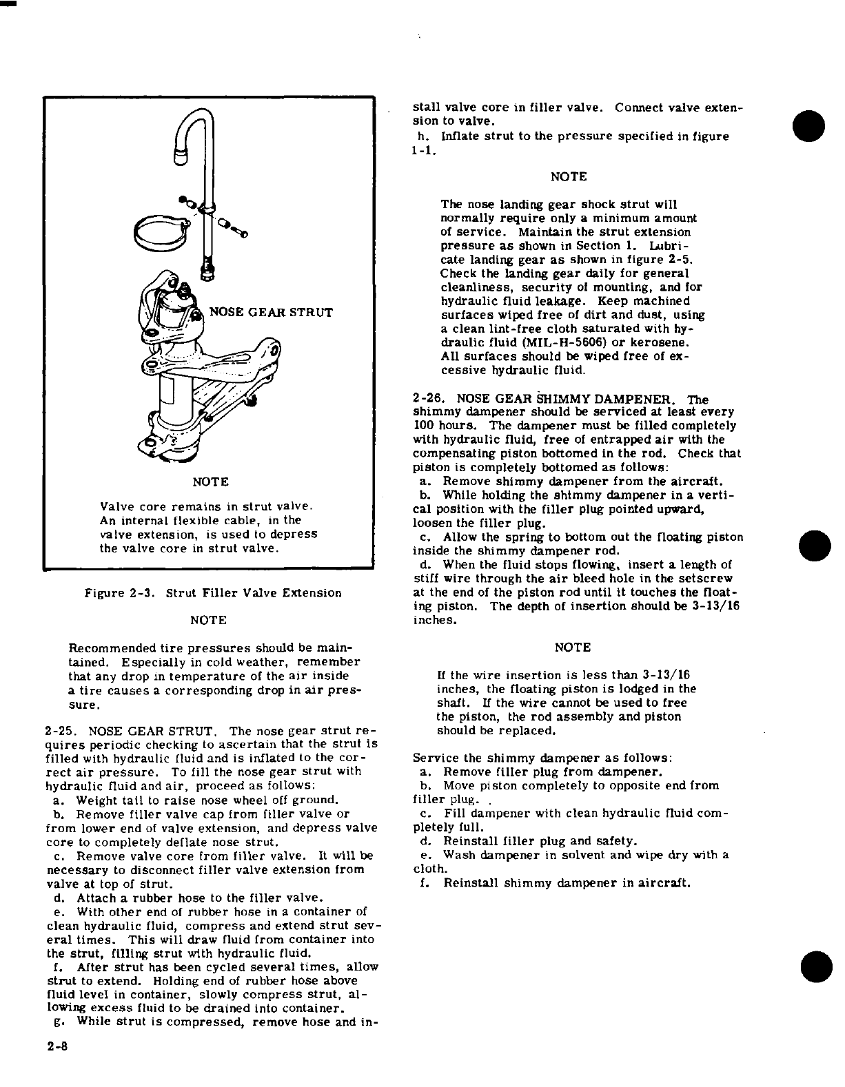
stall
valve
core
in
filler
valve. Connect valve
exten-
sion
to
valve.
h.
Infate
strut
to
the
pressure
specified
in
figure
~~Y ~ ~~~~~~1-1.
NOTE
The
nose landing
gear
shock
strut
will
normally
require
only
a
minimum
amount
of
service.
Maintain
the
strut
extension
pressure
as
shown
in
Section
1.
Lubri-
cate landing
gear
as
shown
in
figure
2-5.
/y)^ ~~
|1~ ~Check
the
landing
gear
daily
for general
cleanliness,
security
of
mounting,
and
for
hydraulic
fluid
leakage.
Keep
machined
NOSE
GEAR
STRUT
surfaces
wiped
free
of
dirt
and
dust,
using
a
clean
lint-free
cloth
saturated
with
hy-
^-gO._ ^ ./^ \draulic
fluid
(MIL-H-5606)
or
kerosene.
Ad.z'i,'" / ·
AU
surfaces
should
be
wiped
free
of
ex-
cessive
hydraulic
fluid.
'
/_.U
2-26.
NOSE
GEAR
SHIMMYDAMPENER.
The
shimmy
dampener
should
be
serviced
at
least
every
-.
\t i-vV^:^\/100
hours.
The
dampener
must
be
filled
completely
with
hydraulic
fluid,
free
of
entrapped
air
with
the
·
_'sfc<^~,/~~
~compensating
piston bottomed
in
the
rod.
Check
that
piston
is
completely bottomed
as
follows:
NOTE
a.
Remove
shimmy
dampener
from
the
aircraft.
b.
While
holding
the
shimmy
dampener
in
a
verti-
Valve
core
remains
in
strut
valve.
cal
position
with
the
filler
plug
pointed upward,
An
internal
flexible
cable,
in
the
loosen
the
filler
plug.
valve
extension,
is
used
to
depress
c.
Allow
the
spring
to
bottom
out
the
floating
piston
the
valve
core
in
strut
valve.
inside
the
shimmy
dampener rod.
-,W~~~~~~~~ ~~~~d.
When
the
fluid
stops
flowing,
insert
a
length
of
stiff
wire
through
the
air
bleed
hole
in
the
setscrew
Figure
2-3.
Strut
Filler
Valve
Extension
at
the
end
of
the
piston
rod
until
it
touches
the
float-
ing
piston.
The depth
of
insertion
should
be
3-13/16
NOTE
inches.
Recommended
tire
pressures
should
be
main-
NOTE
tained.
Especially
in
cold
weather,
remember
that
any
drop
in
temperature
of
the
air
inside
If
the
wire
insertion
is
less
than
3-13/16
a
tire
causes
a
corresponding
drop
in
air
pres-
inches,
the
floating
piston
is
lodged
in the
sure,
shaft.
If
the
wire
cannot
be
used
to
free
the
piston,
the
rod
assembly
and
piston
2-25.
NOSE
GEAR
STRUT. The
nose
gear
strut
re-
should
be
replaced.
quires
periodic
checking
to
ascertain
that the
strut
is
filled
with
hydraulic
fluid
and
is
inflated
to
the
cor-
Service
the
shimmy
dampener
as
follows:
rect
air
pressure.
To
fill
the
nose
gear
strut
with
a.
Remove
filler
plug
from
dampener.
hydraulic
fluid
and
air,
proceed
as
follows:
b.
Move
piston
completely
to
opposite
end
from
a.
Weight
tail
to
raise
nose
wheel
off
ground.
filler
plug.
b.
Remove
filler
valve cap
from
filler
valve
or
c.
Fill
dampener
with
clean
hydraulic
fluid
com-
from
lower
end
of
valve
extension,
and
depress
valve
pletely
full.
core
to
completely
deflate
nose
strut.
d.
Reinstall
filler
plug
and
safety.
c.
Remove
valve
core
from
filler
valve.
It
will
be
e.
Wash
dampener
in
solvent
and
wipe
dry
with
a
necessary
to
disconnect
filler
valve
extension
from
cloth.
valve at
top
of
strut.
f.
Reinstall
shimmy
dampener
in
aircraft.
d.
Attach a
rubber
hose
to
the
filler
valve.
e.
With
other
end
of
rubber
hose
in
a
container
of
clean
hydraulic
fluid,
compress
and
extend
strut
sev-
eral
times.
This
will
draw
fluid
from
container
into
the
strut,
filling
strut
with
hydraulic
fluid.
f.
After
strut
has
been
cycled
several
times,
allow
strut
to
extend.
Holding
end
of
rubber
hose
above
fluid
level
in
container,
slowly
compress
strut,
al-
lowing
excess
fluid
to
be
drained
into
container.
g.
While
strut
is
compressed,
remove hose
and
in-
2-8
NOTE
2-34.
WINDSHIELD
AND
WINDOWS.
These
surfaces
should
be
cleaned
carefully
with
plenty
of
fresh
water
Keep
shimmy dampener,
especially
the
and
a
mild
detergent,
using
the
palm
of
the
hand
to
exposed
portions
of
the
dampener piston
feel
and
dislodge
any
caked
dirt
or
mud.
A
sponge,
shaft, clean
to
prevent
collection
of
dust soft
cloth,
or
chamois
may
be
used,
but only
as
a
and
grit
which
could cut the
seals
in
the
means
of
carrying
water
to
the
plastic.
Rinse
thor-
dampener
barrel.
Keep
machined
sur-
oughly,
then
dry
with
a
clean
moist chamois.
Do not
faces
wiped
free
of
dirt
and
dust,
using
a
rub
the
plastic
with
a
dry
cloth
as
this
builds
up
an
clean
lint-free
cloth
saturated
with
hy-
electrostatic
charge
which
attracts
dust.
Oil and
draulic
fluid
(MIL-H-5606)
or
kerosene.
grease
may
be
removed
by
rubbing
lightly
with
a
soft
All
surfaces
should
be
wiped
free
of
ex-
cloth
moistened
with
Stoddard
solvent.
cessive
hydraulic
fluid.
CAUTION
2-27.
HYDRAULIC
BRAKE
SYSTEMS.
Check
brake
master
cylinders
and
refill
with
hydraulic
fluid
as
Do
not
use gasoline,
alcohol,
benzene,
acetone,
required
every
200
hours.
Bleed
the
brake system
of
carbon
tetrachloride,
fire
extinguisher
fluid,
entrapped
air
whenever
there
is
a
spongy
response
to
de-icer
fluid,
lacquer
thinner
or
glass
window
the
brake
pedals.
Refer
to
Section
5
for filling
and
cleaning
spray.
These
solvents
will
soften
and
bleeding
the
brake
systems.
craze
the
plastic.
2-28.
OXYGEN SYSTEM.
Refer
to
Section
15.
After
washing,
the
plastic
windshield
and
windows
should
be
cleaned
with
an
aircraft
windshield
cleaner.
2-29.
FACE
MASKS.
Refer
to
Section
15.
Apply
the
cleaner
with
soft
cloths
and
rub
with
mod-
erate
pressure.
Allow
the
cleaner
to
dry,
then
wipe
2-30.
CLEANING.
it off
with
soft
flannel
cloths.
A
thin,
even
coat
of
wax,
polished
out
by
hand
with
soft
flannel
cloths,
2-31.
GENERAL
DESCRIPTION.
Keeping
the
air-
will
fill
in
minor
scratches
and help
prevent further
craft
clean
is
important.
Besides
maintaining
the
scratching.
Do
not
use
a
canvas
cover
on
the
wind-
trim
appearance
of
the
aircraft,
cleaning
lessens
the
shield
or
windows
unless
freezing
rain
or
sleet
is
possibility
of
corrosion
and
makes
inspection
and
anticipated
since
the cover
may
scratch
the
plastic
maintenance
easier.
surface.
2-32.
UPHOLSTERY
AND
INTERIOR.
Cleaning
2-35.
ALUMINUM
SURFACES.
The
aluminum
sur-
prolongs
the
life
of
upholstery
fabrics
and
interior
faces
require
a
minimum
of
care,
but
should
never
trim.
To
clean
the
interior,
proceed
as
follows:
be
neglected.
The
aircraft
may
be
washed
with
clean
a.
Empty
all
the
ash
trays.
water
to
remove
dirt
and
may
be
washed
with
non-
b.
Brush
out
or
vacuum
clean
the
upholstery
and
alkaline
grease
solvents
to
remove oil
and/or
grease.
carpeting
to
remove
dirt.
Household-type
detergent
soap
powders
are
effective
c.
Wipe
leather
and
plastic
surfaces
with
a
damp
cleaners,
but
should
be
used
cautiously since
some
cloth.
of
them
are
strongly
alkaline.
Many
good
aluminum
d.
Soiled
upholstery
fabrics
and
carpet
may
be
cleaners,
polishes
and
waxes
are
available
from
com-
cleaned
with
a
foam-type
detergent,
used according
mercial suppliers
of
aircraft
products.
to
the
manufacturer's instructions.
e.
Oily
spots
and
stains
may
be
cleaned
with
house-
hold
spot
removers,
used sparingly.
Before
using
2-36.
PAINTED
SURFACES.
The
painted
exterior
any
solvent,
read
the
instructions
on
the
container
surfaces
of
the
aircraft,
under
normal
conditions,
and
test
it
on
an
obscure
place
in
the
fabric
to
be
require
a
minimum
of
polishing
or
buffing.
Approx-
cleaned.
Never
saturate
the
fabric
with
a
volatile
imately
15
days
are
required
for
acrylic
paint
to
cure
solvent;
it
may
damage the packing
and
backing
ma-
completely;
in
most
cases,
the
curing
period
will
terial.
have
been
completed
prior
to
delivery
of
the
aircraft.
f.
Scrape
off
sticky
materials
with
a
dull
knife,
In
the
event
that
polishing
or
buffing
is
required
with-
then spot
clean
the
area.
in
the
curing period,
it is
recommended
that
the
work
be
done
by
an
experienced
painter.
Generally,
the
2-33.
PLASTIC
TRIM.
The
instrument
panel,
plas-
painted
surfaces
can
be
kept
bright
by
washing
with
tic
trim
and
control
knobs
need
only
be
wiped
off
with
water
and
mild soap,
followed
by
a
rinse
with
water
a
damp
cloth.
Oil
and
grease
on
the
control
wheel
and
drying
with
cloths
or
a
chamois.
Harsh
or
abra-
and
control
knobs
can
be
removed
with
a
cloth
mois-
sive soaps
or detergents
which
cause
corrosion
or
tened
with
Stoddard
solvent.
make
scratches
should never
be
used.
Remove
stub-
born
oil
and
grease
with
a
cloth
moistened
with
Stod-
CAUTIONJi
dard
solvent.
After
the
curing
period,
the
aircraft
may
be
waxed with
a
good
automotive
wax.
A
heavier
Do
not
use
gasoline,
alcohol,
benzene,
acetone, coating
of
wax
on
the
leading
edges
of
the wings
and
carbon
tetrachloride, fire
extinguisher
fluid,
tail
and
on
the
engine
nose cap
will
help
reduce
the
de-icer
fluid,
lacquer thinner
or
glass
window
abrasion
encountered
in
these
areas.
cleaning
spray.
These
solvents
will
soften
and
craze
the
plastic.
Change
3
2-9
2-37.
ENGINE
COMPARTMENT.
Cleaning
is
essen-
remove,
clean
and
lubricate
jack
screw
whenever
tial
to
minimize
any
danger
of
fire,
and
for
proper
actuator
slippage
is
experienced.
If
lubrication
is
inspection
of
engine
components.
The
engine
and
required,
proceed
as
follows:
engine
compartment
may
be
washed
down
with
a a.
Gain
access
to
actuator
by
removing
suitable solvent,
such
as
Stoddard
solvent
or
equiva-
appropriate
inspection
plates
on
lower
surface
of
lent,
then
dried
thoroughly.
wing.
b.
Expose
jack
screw
by
operating
flaps
to
CAUTION
full-down
position.
c.
Wipe
a
small
amount
of
lubricant
from
Particular
care
should
be
given
to
electrical
jack
screw
with
a
rag
and
examine
for
condition.
equipment
before
cleaning.
Solvent
should
Lubricant
should
not be
dirty,
sticky,
gummy
or
not
be
allowed
to
enter
magnetos,
starters,
frothy
in
appearance.
alternators,
voltage
regulators,
and
the
like.
d.
Inspect
wiped
area
on
jack
screw
for
Hence,
these
components
should
be
protected presence
of
hard scale
deposit.
Previous
wiping
before
saturating
the
engine
with
solvent. action,
will
have
exposed
bare
metal
if
no
deposit
Any
oil,
fuel,
and
air
openings
on
the
engine
is
present.
and
accessories
should
be
covered
before
e.
If
any
of
the
preceding
conditions
exist,
washing
the
engine
with
solvent.
Caustic clean
and
relubricate
jack
screw
as
outlined
in
steps
cleaning
solutions
should
be
used
cautiously
"f"
thru
"n".
and
should
always
be
properly
neutralized
f.
Remove
actuator
from
aircraft
in
accor-
after
their
use.
dance
with
procedures
outlined
in
Section
7.
g.
Remove
all
existing
lubricant
from
jack
2-38.
PROPELLER.
The
propeller
should
be
wiped
screw
and
torque
tube
by
running
the
nut
assembly
occasionally
with
an oily
cloth
to
remove
grass
and
to
the
end
of
the
jack
screw
away
from
the
gearbox,
bug
stains.
In
salt
water
areas,
this
will
assist
in
and
soaking the
nut
assembly
and
jack
screw
in
Stod-
corrosion-proofing
the
propeller.
dard
solvent.
2-39.
WHEELS.
The
wheels
should
be
washed
NOTE
periodically
and
examined
for corrosion,
chipped
paint
and
cracks
or
dents
in
the
wheel
castings.
Care
must
be
taken
to
prevent
solvent
from
Sand
smooth,
prime
and
repaint
minor
defects.
entering
gearbox.
The
gearbox
lubricant
is
Cracked
wheel
halves
shall
be
replaced.
not
affected
and
should
not be
disturbed.
2-40.
LUBRICATION.
h.
After
soaking,
clean
entire
length
of
jack
screw
with
a
wire
brush,
rinse
with
solvent
2-41.
GENERAL
DESCRIPTION.
Lubrication
re-
and
dry
with
compressed
air.
quirements
are
outlined
in
figure
2-5.
Before
ad-
ding
lubricant
to
a
fitting,
wipe
the
fitting
free
of
NOTE
dirt.
Lubricate
until
grease
appears
around
part
being
lubricated
and
wipe
excess
grease
from
parts.
Do
not
disassemble
nut
and
ball
retainer
The
following
paragraphs
supplement
figure
2-5
by
assembly.
adding
details
not
shown
in
the
figure.
i.
Relubricate
jack
screw
with
MIL-G-
2-42.
NOSE
GEAR
TORQUE
LINKS.
Lubricate
21164
(Molybdenum
Disulfide
Grease)
as
outlined
in
torque
links
every
50
hours.
When
operating
in
steps
"j"
thru
"m".
dusty
conditions,
more frequent
lubrication
is
re-
j.
Rotate
nut down
screw
toward
the
motor.
commended.
k.
Coat
screw
and
thread
end
of
nut with
grease
and
run
nut
to
full
extension.
2-43.
TACHOMETER
DRIVE
SHAFT.
Refer
to
Sec-
1.
Repeat
the
process
and
pack
lubricant
in
tion
16
for
lubrication
instructions.
the cavity
between
the
nut
and
ball
retainer
at
the
threaded
end
of
the
nut.
2-44.
WHEEL
BEARING
LUBRICATION.
Clean
and
m.
Repeat the
process
and
work
nut
back
and
repack
wheel
bearings
at
the
first
100-hour
inspection
forth
several
times.
and
at
each
500-hour
inspection
thereafter.
If
more
n.
Remove
excess
grease.
than
the
usual
number
of
take-off
and
landings
are
o.
Reinstall
actuator
in
aircraft
in
accor-
made,
extensive
taxiing
is
required
or
the
aircraft
dance
with
instructions
outlined
in
Section
7.
is
operated
in
dusty
areas
or
under
seacoast
con-
b.
On
aircraft
prior
to
Serials
P20600648
and
U206-
ditions,
clean
and
lubricate
wheel
bearings
at
each
601673
which have
been
modified
by
Service
Kit
100-hour
inspection.
SK150-37
proceed
as
follows:
1.
At
each
100-hour
inspection,
expose
jack
2-45.
WING
FLAP
ACTUATOR
screw
by
operating flaps
to
full-down
position,
and
a.
On
aircraft
prior
to
P20600648 and
U20601673
inspect
wing
flap
actuator
jack
screw
for
proper
which
have
not
been
modified
by
Service
Kit
SK150-
lubrication.
If
lubrication
is
required,
proceed
as
37,
proceed
as
follows:
follows:
1.
At
each
100
hour
inspection,
inspect
wing
a.
Clean
jack
screw
with
solvent
rag,
if
flap
actuator
jack
screw
and
ball
retainer
assembly
necessary,
and
dry
with
compressed
air.
for
lubrication,
and
lubricate
if
required.
Also,
b.
Relubricate
jack
screw
with
MIL-G-
2-10
21164
(Molybdenum
Disulfide
Grease)
as
required.
NOTE
c.
On
aircraft
beginning
with
Serial
U20601673,
clean
and
lubricate
wing
flap
actuator
jack
screw
It
is
not
necessary
to
remove
actuator
from
each
100
hours
as
follows:
aircraft
to
clean
or
lubricate
threads.
1.
Expose
jack
screw
by
operating
flaps
to
full-
down
position.
3.
With
oil
can,
apply
light
coat
of
No.
10
2.
Clean jack
screw
threads
with
solvent
rag
weight,
non-detergent
oil
to
threads
of
jack
screw.
and
dry
with
compressed
air.
SHOP
NOTES:
2-11
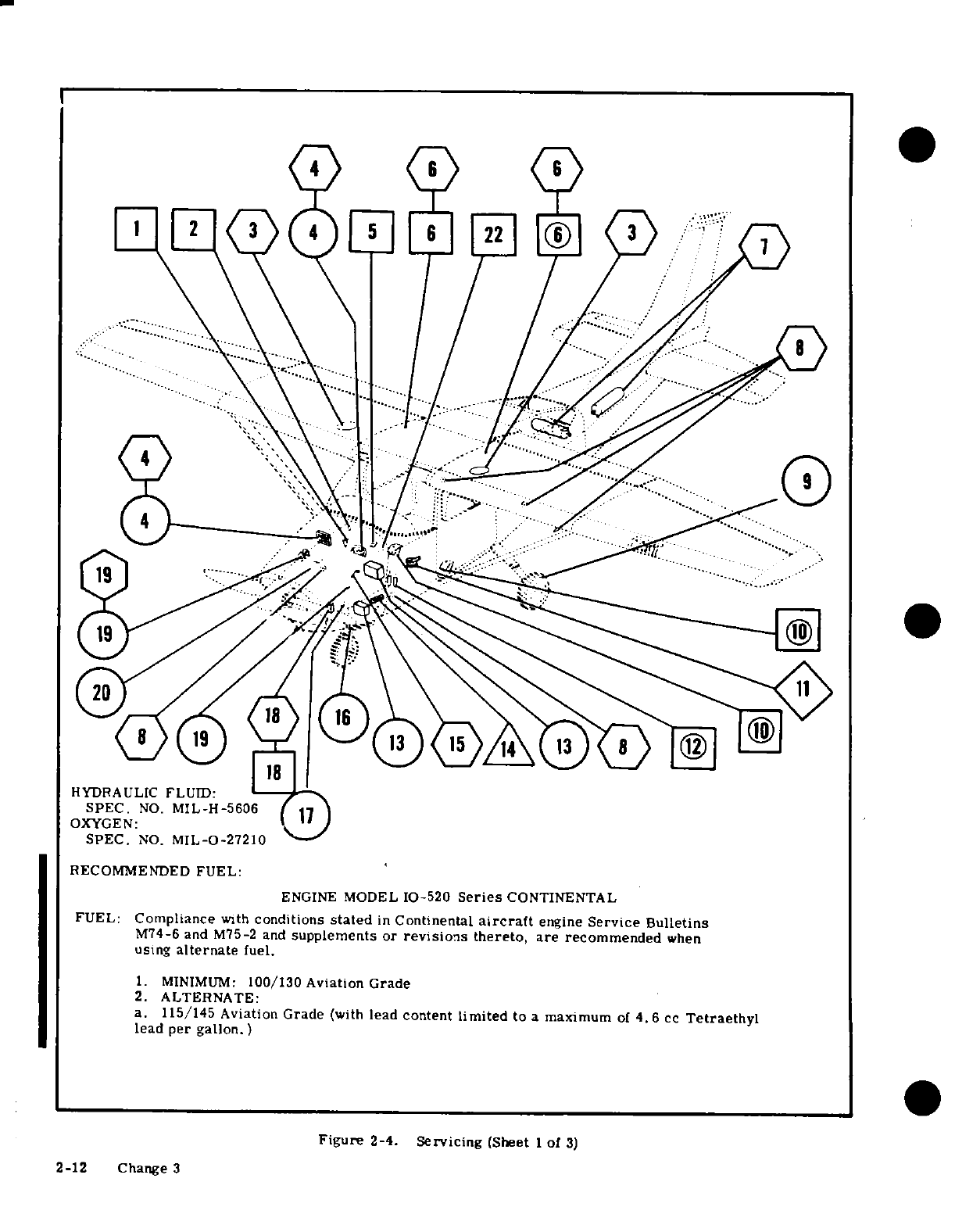
HYDRAULIC
FLUID:
SPEC.
NO.
MIL-H-5606
OXYGEN:
SPEC.
NO.
MIL-0-27210
RECOMMENDED
FUEL:
ENGINE
MODEL
10-520
Series
CONTINENTAL
FUEL:
Compliance
with
conditions
stated
in
Continental
aircraft
engine
Service
Bulletins
M74-6
and
M75-2 and
supplements
or
revisions
thereto,
are
recommended
when
using
alternate
fuel.
1.
MINIMUM:
100/130
Aviation
Grade
2.
ALTERNATE:
a.
115/145
Aviation
Grade
(with
lead
content
limited
to
a
maximum
of
4.6
cc
Tetraethyl
lead
per gallon.)
Figure
2-4.
Servicing
(Sheet
1
of
3)
2-12
Change 3
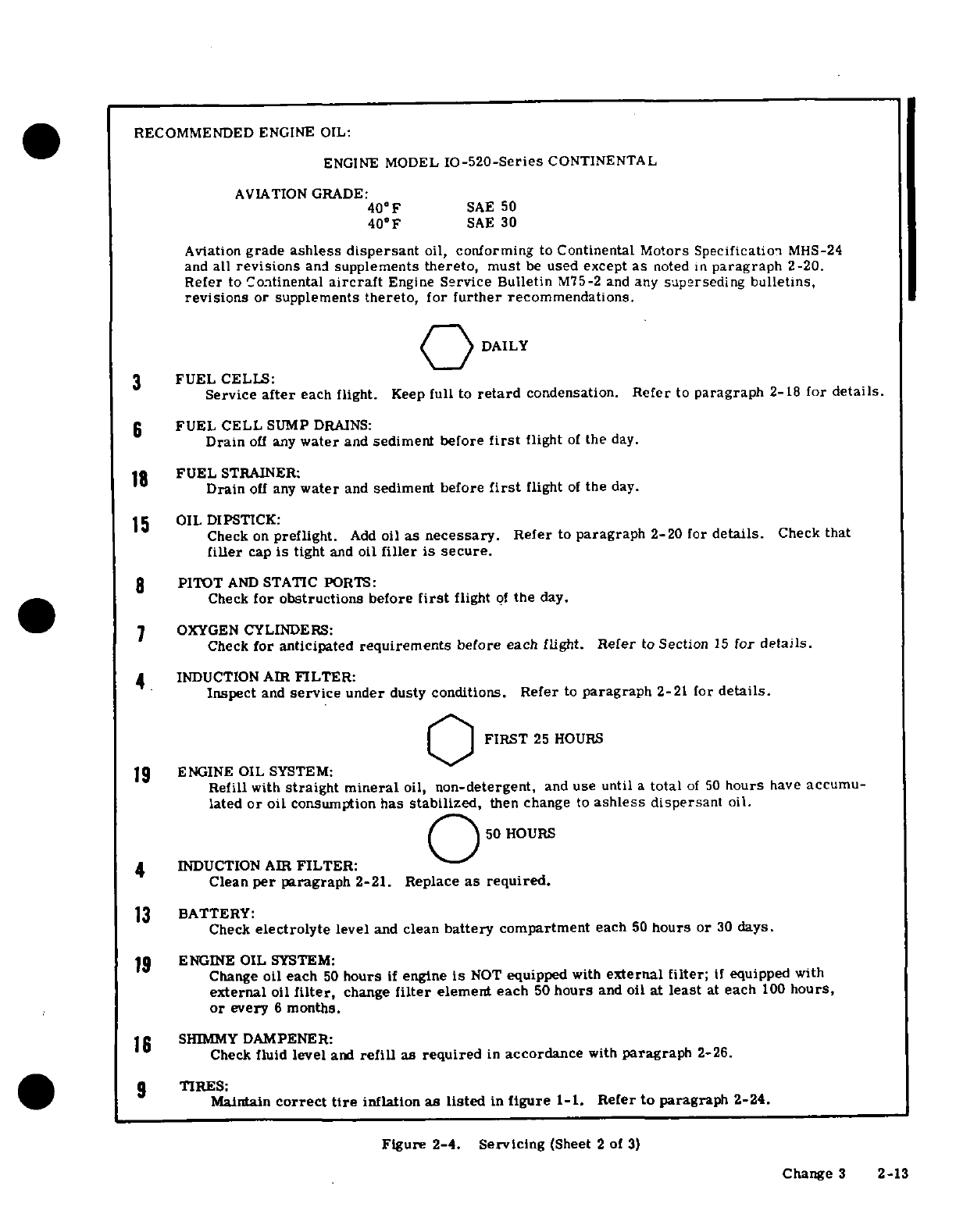
RECOMMENDED
ENGINE OIL:
ENGINE
MODEL
IO-520-Series
CONTINENTAL
AVIATION
GRADE:
40°F
SAE
50
40°F
SAE
30
Aviation
grade
ashless dispersant
oil,
conforming
to
Continental
Motors Specification
MHS-24
and
all
revisions
and
supplements
thereto,
must
be
used except
as
noted
in
paragraph
2-20.
Refer
to
Continental
aircraft
Engine
Service Bulletin
M75-2 and
any
superseding
bulletins,
revisions
or
supplements
thereto,
for
further
recommendations.
DAILY
3
FUEL
CELLS:
Service
after
each flight.
Keep
full
to
retard
condensation.
Refer to
paragraph
2-18
for
details.
6
FUEL
CELL
SUMP
DRAINS:
Drain
off
any
water
and
sediment
before
first
flight
of
the
day.
18
FUEL
STRAINER:
Drain
off
any
water
and
sediment
before
first
flight
of
the
day.
15
OIL DIPSTICK:
Check
on
preflight.
Add
oil
as
necessary.
Refer
to
paragraph
2-20
for
details.
Check
that
filler
cap
is
tight
and
oil
filler
is
secure.
8
PITOT
AND
STATIC
PORTS:
Check
for obstructions
before
first
flight
of
the
day.
7
OXYGEN
CYLINDERS:
Check
for
anticipated
requirements
before each flight.
Refer
to
Section
15
for
details.
4
INDUCTION
AIR
FILTER:
Inspect
and
service
under
dusty
conditions.
Refer
to
paragraph
2-21
for
details.
FIRST
25
HOURS
19
ENGINE
OIL
SYSTEM:
Refill
with
straight
mineral
oil,
non-detergent,
and
use
until
a
total
of
50
hours
have
accumu-
lated
or
oil
consumption
has
stabilized,
then change
to
ashless
dispersant
oil.
50
HOURS
4
INDUCTION
AIR
FILTER:
Clean
per
paragraph
2-21.
Replace
as required.
13
BATTERY:
Check
electrolyte
level
and
clean
battery
compartment
each
50
hours
or
30
days.
19
ENGINE
OIL
SYSTEM:
Change
oil
each
50
hours
if
engine
is
NOT
equipped
with
external
filter;
if
equipped
with
external
oil
filter,
change
filter
element
each
50
hours
and
oil
at
least
at
each
100
hours,
or
every
6
months.
16
SHIMMY
DAMPENER:
Check
fluid
level
and
refill
as
required
in
accordance
with
paragraph
2-26.
9
TIRES:
Maintain
correct
tire
inflation
as
listed
in
figure
1-1.
Refer
to
paragraph
2-24.
Figure
2-4.
Servicing
(Sheet
2
of
3)
Change
3
2-13
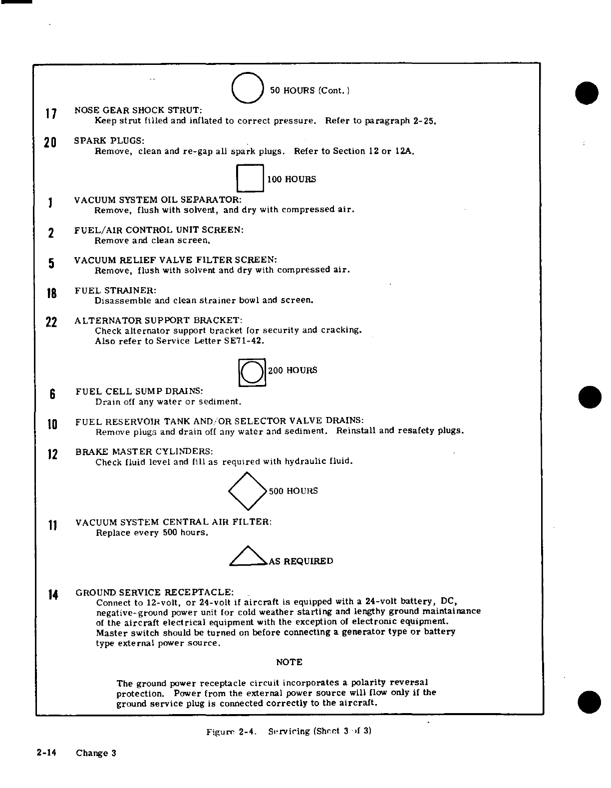
50
HOURS
(Cont.)
1
7
NOSE
GEAR
SHOCK
STRUT:
Keep
strut
filled
and
inflated
to
correct pressure.
Refer
to
paragraph
2-25.
20
SPARK
PLUGS:
Remove,
clean
and
re-gap
all
spark
plugs.
Refer
to
Section
12
or
12A.
100
HOURS
1 VACUUM
SYSTEM
OIL
SEPARATOR:
Remove,
flush
with
solvent,
and
dry
with
compressed
air.
2
FUEL/AIR
CONTROL
UNIT
SCREEN:
Remove
and
clean
screen.
5
VACUUM
RELIEF
VALVE
FILTER
SCREEN:
Remove,
flush
with
solvent
and
dry
with
compressed
air.
18
FUEL
STRAINER:
Disassemble
and
clean
strainer
bowl
and
screen.
22
ALTERNATOR
SUPPORT
BRACKET:
Check
alternator
support
bracket
for
security
and
cracking.
Also
refer
to
Service
Letter
SE71-42.
200
HOURS
6
FUEL
CELL
SUMP
DRAINS:
Drain
off
any
water or sediment.
10
FUEL
RESERVOIR
TANK
AND/OR
SELECTOR
VALVE
DRAINS:
Remove
plugs
and
drain
off
any
water
and
sediment.
Reinstall
and
resafety
plugs.
12
BRAKE
MASTER
CYLINDERS:
Check
fluid
level
and
fill
as
required
with
hydraulic
fluid.
0 5500
HOURS
11
VACUUM
SYSTEM
CENTRAL
AIR
FILTER:
Replace
every
500
hours.
/
AS
REQUIRED
14
GROUND
SERVICE
RECEPTACLE:
Connect
to
12-volt,
or
24-volt
if
aircraft
is
equipped
with
a
24-volt
battery,
DC,
negative-ground
power
unit
for
cold
weather
starting
and
lengthy
ground
maintainance
of
the
aircraft
electrical
equipment
with
the
exception
of
electronic
equipment.
Master
switch
should
be
turned
on
before
connecting
a
generator
type
or
battery
type
external
power
source.
NOTE
The
ground
power
receptacle
circuit incorporates
a
polarity
reversal
protection.
Power
from
the
external
power
source
will
flow
only
if
the
ground
service
plug
is connected
correctly
to
the
aircraft.
Figure
2-4.
Servicing
(Sheet
3
'f
3)
2-14 Change 3
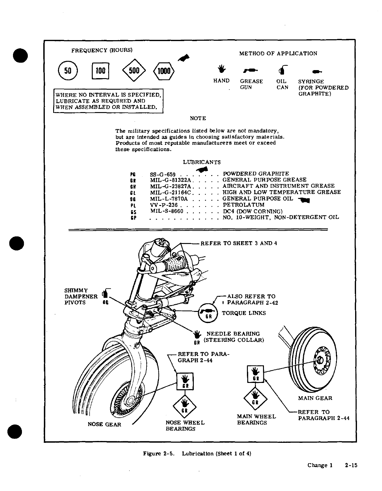
FREQUENCY
(HOURS)
FREQUENCY~ (HOURS)
METHOD
OF
APPLICATION
50^e<F ___, -- , _
ri-001^
<
/N
-HAND
GREASE
OIL
SYRINGE
GUN
CAN
(FOR
POWDERED
WHERE
NO
INTERVAL
IS
SPECIFIED,
GRAPHITE)
LUBRICATE
AS
REQUIRED
AND
WHEN
ASSEMBLED
OR
INSTALLED.
NOTE
The
military specifications listed
below
are
not
mandatory,
but
are
intended
as
guides
in
choosing
satisfactory
materials.
Products
of
most
reputable
manufacturers
meet
or
exceed
these
specifications.
LUBRICANTS
PS
SS-G-659 .. . .
.POWDERED
GRAPHITE
GR
MIL-G-81322A.
....
GENERAL
PURPOSE
GREASE
CH
MIL-G-23827A.
....
AIRCRAFT
AND
INSTRUMENT
GREASE
St
MIL-G-21164C
.....
HIGH
AND
LOW
TEMPERATURE
GREASE
OG
MIL-L-7870A
.....
GENERAL
PURPOSE
OIL
Pt
W-P-236
.......
PETROLATUM
GS
MIL-S-8660
......
DC4
(DOW
CORNING)
GP
...........
.
NO.
10-WEIGHT,
NON-DETERGENT
OIL
o-
.
REFREFER
TO
SHEET
3
AND
4
SHIMMY
/ k
DAMPENER
A
/-->ALSO REFER
TO
PIVOTS
0C
I
_,
PARAGRAPH
2-42
)
TORQUE
LINKS
NEEDLE
BEARING
Go
(STEERING
COLLAR)
BEARIN SM
AIN
GEAR
nil II | ^iy--~REFER
TO
MAIN
WHEEL
PARAGRAPH
2-44
NOSE
GEAR
NOSE
WHEEL
BEARINGS
BEARINGS
Figure
2-5.
Lubrication
(Sheet
1
of
4)
Change
1
2-15
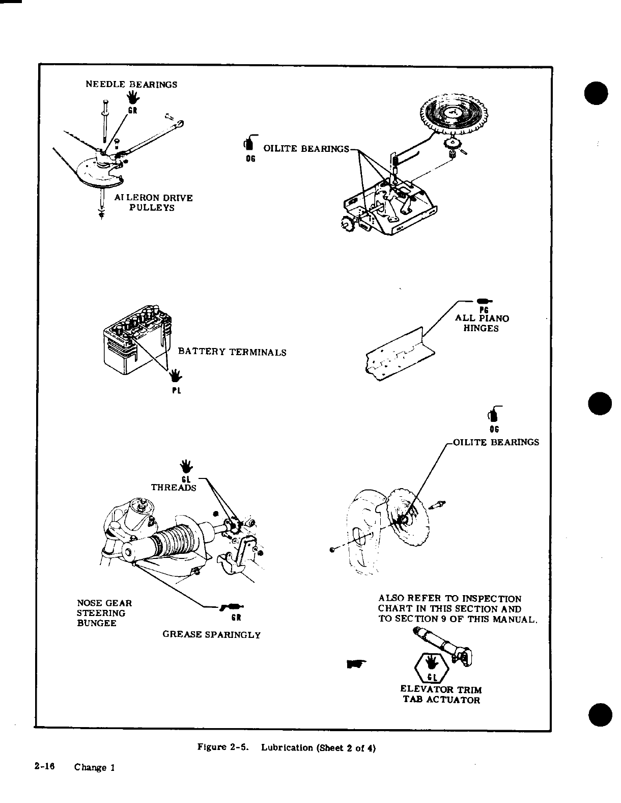
NEEDLE
BEARINGS
.
-1
OILITE
BEARINGS
06
AI
LERON
DRIVE
PULLEYS
ALL
PIANO
HINGES
BATTERY
TERMINALS
OILITE
BEARINGS
THREADS
NOSE
GEAR
ALSO
REFER
TO
INSPECTION
-CHART
IN
THIS
SECTION
AND
BUNGEE
TO
SECTION
9
OF
THIS
MANUAL.
GREASE SPARINGLY
ELEVATOR TRIM
TAB
ACTUATOR
Figure
2-5. Lubrication
(Sheet
2
of
4)
2-16
Change 1
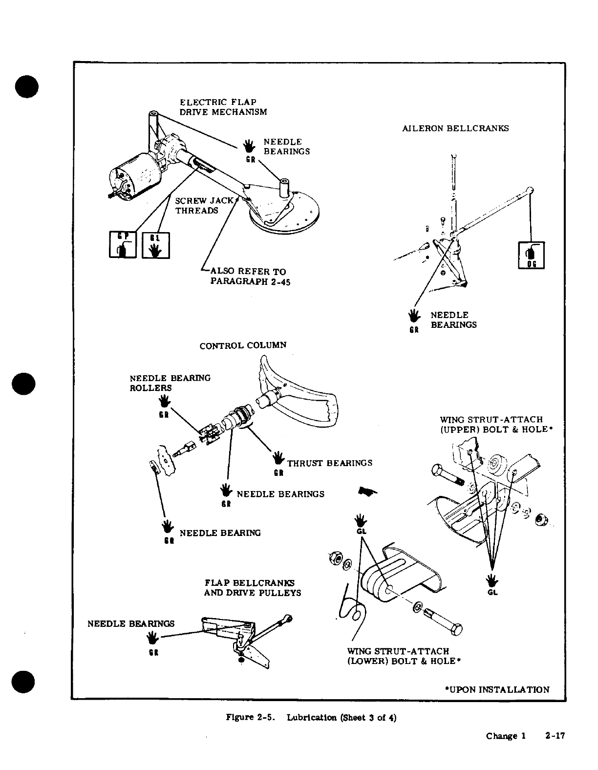
ELECTRIC
FLAP
DRIVE
MECHANISM
AILERON
BELLCRANKS
NEEDLE
BEARINGS
CONTROL
COLUMN
FLAP
BELLCRANKS
AND
DRIVE
PULLEYS
NEEDLE
BEARINGS
WING
STRUT-ATTACH
(LOWER)
BOLT
&
HOLE*
*UPON
INSTALLATION
Figure
2-5.
Lubrication
(Sheet
3
of
4)
Change
1
2-17
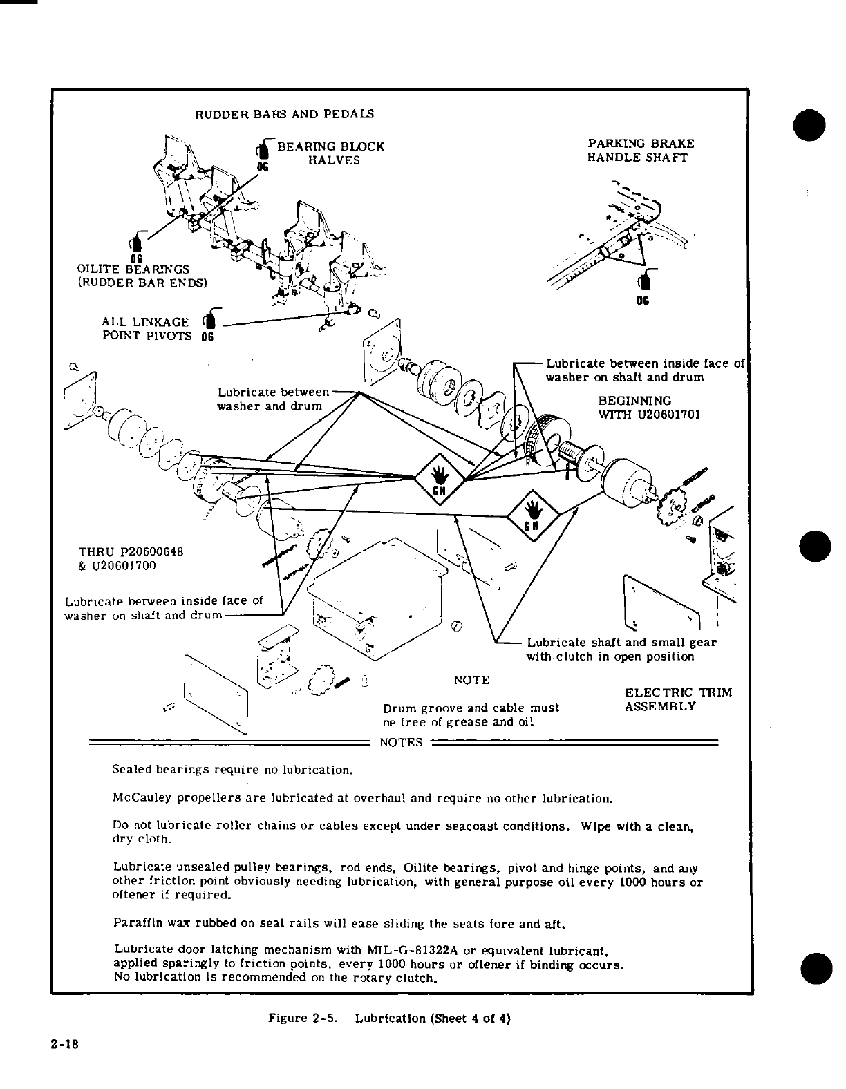
RUDDER
BARS
AND
PEDALS
r
BEARING
BLOCK PARKING
BRAKE
i *r *» HALVES HANDLE
SHAFT
06^HALVES
06
OILITE BEARINGS
(RUDDER BAR
ENDS)
s
ALL
LINKAGE
/
POINT
PIVOTS
0C
~
-
Lubricate
between
inside
face
of
>XI, |1|
^
\
~washer
on
shaft
and
drum
Lubricate
between
BEGINNING
washer
and
drum
WITH
20601701
THRU
P20600648
/
:
&
U20601700/
'
Lubricate
between
inside
face
of
washer
on
shaft
and
drum
Lubricate
shaft
and
small
gear
with
clutch
in open
position
\ v r
.
!
-NOTE
ELECTRIC
TRIM
§
'
~\ |~
Drum
groove
and
cable
must
ASSEMBLY
i••,^<~.
~
be
free
of
grease
and
oil
NOTES
Sealed
bearings require
no
lubrication.
McCauley
propellers are
lubricated
at
overhaul
and
require
no
other
lubrication.
Do
not
lubricate
roller
chains
or
cables
except
under
seacoast
conditions.
Wipe
with
a
clean,
dry
cloth.
Lubricate
unsealed
pulley
bearings,
rod
ends,
Oilite
bearings,
pivot
and
hinge
points,
and
any
other
friction
point
obviously needing
lubrication,
with
general
purpose
oil
every
1000
hours
or
oftener
if
required.
Paraffin
wax
rubbed
on
seat
rails
will
ease
sliding
the
seats
fore
and
aft.
Lubricate
door
latching
mechanism
with
MIL-G-81322A
or
equivalent
lubricant,
applied
sparingly
to
friction
points,
every
1000
hours
or
oftener
if
binding
occurs.
No
lubrication
is
recommended
on
the
rotary
clutch.
Figure
2-5.
Lubrication
(Sheet
4
of
4)
2-18
I
INSPECTION
REQUIREMENTS.
As
required
by
Federal
Aviation
Regulations,
all
civil
aircraft
of
U.S.
registry
must
undergo
a
COMPLETE
INSPECTION
(ANNUAL)
each
twelve
calendar
months.
In
addition
to
the
required
ANNUAL
inspection,
aircraft
operated
commercially
(for
hire)
must
also
have
a
COMPLETE
AIRCRAFT
INSPECTION
every
100
hours
of
operation.
In
lieu
of
the
above
requirements,
an
aircraft
may
be
inspected
in
accordance
with
a
progressive
inspection
schedule,
which
allows
the
work
load
to
be
divided
into
smaller
operations
that
can
be
accomplished
in
shorter
time
periods.
Therefore,
the
Cessna
Aircraft
Company
recommends
PROGRESSIVE CARE
for
aircraft
that
are
being
flown
200
hours
or
more
per year,
and
the
100
HOUR
inspection
for
all
other
aircraft.
11
INSPECTION
CHARTS.
The
following
charts
show
the
recommended
intervals
at
which
items
are
to
be
inspected.
As
shown
in
the
charts,
there
are
items
to
be
checked
each
50
hours,
each
100
hours,
each
200
hours,
and
also
Special
Inspection
items
which
require
servicing
or
inspection
at
intervals
other
than
50,
100
or
200
hours.
a.
When
conducting
an
inspection
at
50
hours,
all
items
marked
under
EACH
50
HOURS
would
be
inspected,
serviced
or
otherwise
accomplished
as necessary
to
insure
continuous
airworthiness.
b.
At
each
100
hours,
the
50
hour
items
would
be
accomplished
in
addition
to
the
items
marked
under
EACH
100
HOURS
as
necessary
to
insure
continuous
airworthiness.
c.
An
inspection
conducted
at
200
hour
intervals
would
likewise
include
the
50
hour
items
and
100
hour
items
in
addition
to
those at
EACH
200
HOURS.
d.
The
numbers appearing
in
the
SPECIAL
INSPECTION
ITEMS
column
refer
to
data
listed
at
the
end
of
the
inspection
charts.
These
items
should
be
checked
at
each
inspection
interval
to
insure
that
applicable
servicing
and
inspection
requirements
are
accomplished
at
the
specified
intervals.
e.
A
COMPLETE
AIRCRAFT
INSPECTION
includes
all
50,
100
and
200
hour
items
plus those
Special
Inspection
Items
which
are
due
at
the
time
of
the
inspection.
III
INSPECTION
PROGRAM
SELECTION.
AS A
GUIDE
FOR
SELECTING
THE
INSPECTION
PROGRAM
THAT
BEST
SUITS
THE
OPERATION
OF
THE
AIRCRAFT,
THE
FOLLOWING
IS
PROVIDED.
1. IF
THE
AIRCRAFT
IS
FLOWN
LESS
THAN
200
HOURS
ANNUALLY.
.
IF
FLOWN
FOR
HIRE
An
aircraft
operating
in
this category
must
have
a
COMPLETE
AIRCRAFT
INSPECTION
each
100
hours
and
each
12
calendar
months
of
operation.
A
COMPLETE
AIRCRAFT
INSPECTION
consists
of
all
50,
100,
200
and
Special
Inspection
Items
shown
in
the
in-
spection
charts
as
defined
in
paragraph
i
above.
b.
IF
NOT
FLOWN
FOR
HIRE
An
aircraft
operating
in
this
category
must
have
a
COMPLETE
AIRCRAFT INSPECTION
each
12
calendar
months
(ANNUAL).
A
COMPLETE
AIRCRAFT
INSPECTION
consists
of
all
50,
100,
200
and
Special
Inspection
Items
shown in
the
inspection
charts
as
defined
in
paragraph
n
above.
In
addition,
it
is
recommended
that
between
annual
inspections,
all
items
be
inspected
at
the
intervals
specified
in
the
inspection
charts.
Change
3
2-19
2. IF
THE
AIRCRAFT
IS
FLOWN
MORE
THAN
200
HOURS
ANNUALLY.
Whether
flown
for
hire
or
not,
it is
recommended
that
aircraft
operating
in
this
category
be
placed
on
the
CESSNA
PROGRESSIVE
CARE
PROGRAM.
However,
if
not
placed
on
Progressive
Care,
the
inspection
requirements
for
aircraft
in
this
category
are
the
same
as
those
defined
under
paragraph
III
1.
(a)
and
(b).
Cessna
Progressive
Care
may
be
utilized
as
a
total
concept
program
which
insures
that
the
inspection
intervals
in
the
inspection
charts
are
not
exceeded.
Manuals
and
forms
which
are
required
for
conducting
Progressive
Care
in-
spections
are
available
from
the
Cessna
Service
Parts
Center.
IV
INSPECTION
GUIDE
LINES.
(a)
MOVABLE
PARTS
for:
lubrication,
servicing,
security
of
attachment,
binding,
excessive
wear,
safetying,
proper
operation,
proper
adjustment,
correct
travel,
cracked
fittings,
security
of
hinges,
defective
bearings,
cleanliness,
corrosion,
deformation,
sealing
and
tension.
(b)
FLUID
LINES
AND
HOSES
for:
leaks,
cracks,
dents,
kinks, chafing,
proper
radius,
security,
corrosion,
deterioration,
obstruction
and
foreign
matter.
(c)
METAL
PARTS
for:
security
of
attachment,
cracks,
metal
distortion,
broken spotwelds,
corrosion,
condition
of
paint
and any
other apparent
damage.
(d)
WIRING
for:
security,
chafing,
burning,
defective
insulation,
loose
or
broken
terminals,
heat
deterioration
and
corroded
terminals.
(e)
BOLTS
IN
CRITICAL
AREAS
for:
correct
torque
in accordance
with
torque
values
given
in the
chart
in
Section
1,
when
installed
or
when
visual
inspection
indicates
the
need
for
a
torque
check.
NOTE
Torque
values
listed
in
Section
1
are
derived
from
oil-free
cadmium-plated
threads,
and
are
recommended
for
all
installation
procedures
contained
in
this
book
except
where
other
values
are
stipulated.
They
are
not
to
be
used
for
checking
tightness
of
installed
parts
during
service.
(f)
FILTERS,
SCREENS
&
FLUIDS
for:
cleanliness,
contamination
and/or
replacement
at
specified
intervals.
(g)
AIRCRAFT
FILE.
Miscellaneous
data,
information
and
licenses
are
a
part
of
the
aircraft
file.
Check
that
the
following
documents
are
up-to-date
and
in
accordance
with
current
Federal
Aviation
Regulations.
Most
of
the
items
listed
are
required
by
the
United
States
Federal
Aviation Regulations.
Since
the
regulations
of
other
nations
may
require
other
documents
and
data,
owners
of
exported
aircraft
should
check with
their
own
aviation
officials
to
determine
their
individual
requirements.
To
be
displayed
in
the
aircraft
at
all
times:
1.
Aircraft
Airworthiness
Certificate
(FAA
Form
8100-2).
2.
Aircraft
Registration
Certificate
(FAA
Form
8050-3).
3.
Aircraft
Radio
Station
License,
if
transmitter
is
installed
(FCC
Form
556).
To
be
carried
in
the
aircraft
at all
times:
1.
Weight
and
Balance,
and
associated
papers
(Latest
copy
of
the
Repair
and
Alteration
Form,
FAA
Form
337,
if applicable).
2.
Aircraft
Equipment
List.
To be
made
available
upon
request:
1.
Aircraft
Log
Book
and
Engine
Log
Book.
2-20
Change 1
(h)
ENGINE
RUN-UP.
Before
beginning
the
step-by-step
inspection,
start,
run
up
and
shut
down
the
engine
in
accordance
with
instructions
in
the
Owner's
Manual.
During the
run-up,
observe the
following,
making
note
of any
discrepancies or
abnormalities:
1.
Engine
temperatures
and
pressures.
2.
Static
rpm.
(Also
refer
to Section
12
or
12A
of
this
Manual.)
3.
Magneto
drop.
(Also
refer
to
Section
12
or
12A
of
this
Manual).
4.
Engine
response
to
changes
in
power.
5. Any
unusual
engine
noises.
6.
Fuel
selector
and/or
shut-off
valve;
operate
engine(s)
on
each
tank
(or
cell)
position
and
OFF
position
long
enough to
ensure
shut-off
and/or
selector
valve
functions
properly.
7.
Idling
speed
and
mixture;
proper
idle
cut-off.
8.
Alternator
and
ammeter.
9.
Suction
gage.
10.
Fuel
flow
indicator.
After
the
inspection
has
been
completed,
an
engine
run-up
should
again
be
performed
to
determine
that
any
discrepancies
or abnormalities
have
been
corrected.
SHOP
NOTES:
Change
1
2-21
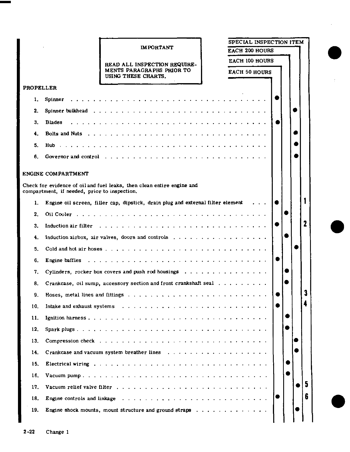
SPECIAL
INSPECTION
ITEM
IMPORTANT
EACH
200
HOURS
EACH
100
HOURS
READ
ALL
INSPECTION
REQUIRE-
EACH
100
HOURS
MENTS
PARAGRAPHS
PRIOR
TO
EACH
50
HOURS
USING
THESE
CHARTS.
PROPELLER
1.
Spinner
...................................
2.
Spinner
bulkhead
...................
.
3.
Blades
...................
4.
Bolts
and
Nuts
........................ . . . . . . . .
5.
H
ub
. . . . . . . . . ......................... ...
6.
Governor
and
control
............................
.
ENGINE
COMPARTMENT
Check
for
evidence
of
oil
and
fuel
leaks,
then
clean
entire
engine
and
compartment,
if
needed,
prior
to inspection.
1.
Engine oil
screen,
filler
cap,
dipstick,
drain
plug and
external
filter
element
. .. * I
2.
Oil
Cooler
.......................... . . . . . ... .
3.
Induction
air
filter
.....
.
........................
2
4.
Induction
airbox,
air
valves,
doors
and
controls
................
.
5.
Cold and
hot
air
hoses
. .. . . .. . . .. . . .. . .
6.
Engine
baffles
..................
.. .. .. . .. . . . ..
7.
Cylinders,
rocker
box
covers
and
push
rod
housings
..............
.
8.
Crankcase,
oil
sump,
accessory
section
and
front
crankshaft
seal
..
......
.
9.
Hoses,
metal
lines
and
fittings
..................... ....
...
3
10.
Intake
and
exhaust
systems
. . .. .. ... ... . ... . . .. . . .. . ..
4
11.
Ignition
harness
..........................
.
12.
Spark
plugs
..........................
*
13.
Compression
check
..............................
14.
Crankcase
and
vacuum
system
breather
lines
.........
15.
Electrical
wiring
...................
.
16.
Vacuum
pump
.................................
17.
Vacuum
relief
valve
filter
................... .........
*
5
18.
Engine
controls
and
linkage
........................
... ·
6
19.
Engine
shock
mounts,
mount
structure
and ground
straps
........
2-22
Change
1
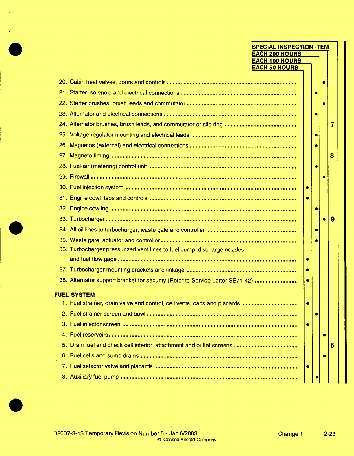
SPECIAL INSPECTION
ITEM
EACH
200
HOURS
EACH
100 HOURS
EACH
50
HOURS
20. Cabin heat
valves,
doors
and
controls
.............................................
21.
Starter,
solenoid
and
electrical connections
........................................
22.
Starter
brushes,
brush leads and
commutator
...................
...................
23.
Alternator
and
electrical connections
..............................................
24.
Alternator brushes,
brush
leads,
and
commutator
or
slip
ring
.........................
7
25.
Voltage
regulator
mounting
and
electrical
leads
.................................... ·
26.
Magnetos (external)
and
electrical connections
............................
.........
27.
Magneto
timing
.............. ........................................... 8
28. Fuel-air
(metering)
control
unit
...................................................
29.
Firewall.......................................................................
30.
Fuel
injection
system
........................................................... ·
31.
Engine
cowl
flaps
and
controls
................................................... a
32. Engine
cowling
........................................ .......................
*
33.
Turbocharger..................................................................
* 9
34.
All
oil
lines
to
turbocharger, waste
gate and
controller
................................
35.
Waste
gate,
actuator
and
controller
...............................................
0
36.
Turbocharger
pressurized
vent
lines
to
fuel pump,
discharge
nozzles
and
fuel
flow
gage
.................................. .................
...........
37.
Turbocharger
mounting
brackets
and
linkage
......................................
38.
Alternator
support
bracket
for
security
(Refer
to
Service
Letter
SE71-42)
..............
FUEL
SYSTEM
1.
Fuel
strainer,
drain
valve
and
control,
cell
vents,
caps and
placards
................... ·
2.
Fuel
strainer
screen
and
bowl
.................................................... ·
3.
Fuel
injector
screen
............................................................ ·
4.
Fuel
reservoirs
................................................................. ·
5.
Drain
fuel
and
check
cell
interior,
attachment
and
outlet
screens
...................... 5
6.
Fuel
cells
and
sump
drains
...................................................... ·
7.
Fuel
selector
valve
and
placards
.................................................
0
8.
Auxiliary fuel
pump
...................................................
.....
... ·
D2007-3-13
Temporary
Revision
Number
5
-
Jan
6/2003 Change
1
2-23
0
Cessna
Aircraft
Company
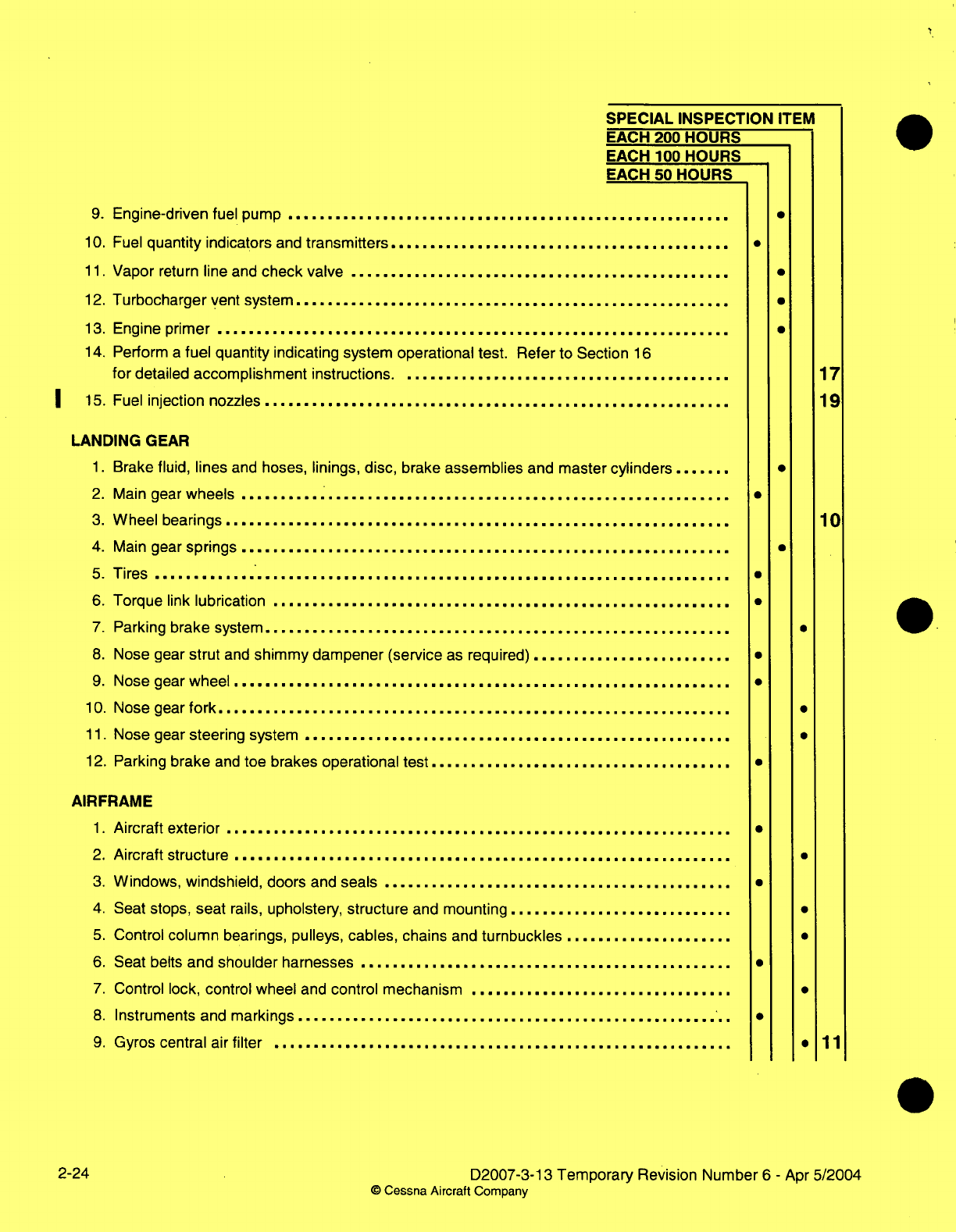
SPECIAL
INSPECTION
ITEM
EACH
200 HOURS
EACH
100
HOURS
EACH
50
HOURS
9.
Engine-driven
fuel
pump
........................................................ ·
10.
Fuel
quantity
indicators
and
transmitters
...........................................
11.
Vapor
return
line
and
check
valve
................................................ ·
12.
Turbocharger
vent
system
....................................................... ·
13.
Engine
primer
................................................................. ·
14.
Perform
a
fuel
quantity indicating system operational
test.
Refer
to
Section
16
for
detailed
accomplishment
instructions
.........................................
17
|
15.
Fuel
injection
nozzles
..........................................................
19
LANDING
GEAR
1.
Brake
fluid, lines
and hoses,
linings, disc,
brake
assemblies
and master
cylinders
.......
0
2.
Main
gear
wheels
.................................. ................. ........
3.
Wheel
bearings
................. ..............................................
10
4.
Main
gear
springs
................
...
..............
..........................
.
5.
Tires
.........................................................................
6.
Torque
link
lubrication
..........................................................
7.
Parking
brake
system
................. ................. ................. .....
8.
Nose
gear
strut
and
shimmy dampener (service
as
required)
.........................
9.
Nose gear
wheel
.................................. ................. .........
10.
Nose gear
fork
....................................................
...........
11.
Nose
gear
steering
system
................. ................................
12.
Parking
brake
and
toe
brakes operational
test
......................................
AIRFRAME
1.
Aircraft
exterior
...................................................
.............
2.
Aircraft structure
.........................................................
3.
Windows,
windshield,
doors
and
seals
........................................
4.
Seat stops,
seat
rails,
upholstery,
structure
and
mounting
............................
5.
Control
column
bearings,
pulleys,
cables, chains
and
turnbuckles
.....................
6.
Seat
belts
and
shoulder
harnesses
...............................................
7.
Control
lock,
control
wheel
and
control mechanism
.................................
8.
Instruments
and
markings
.......................................................
9.
Gyros
central
air
filter
..........................................................
11
2-24
D2007-3-13
Temporary
Revision Number
6
-
Apr
5/2004
©
Cessna Aircraft
Company
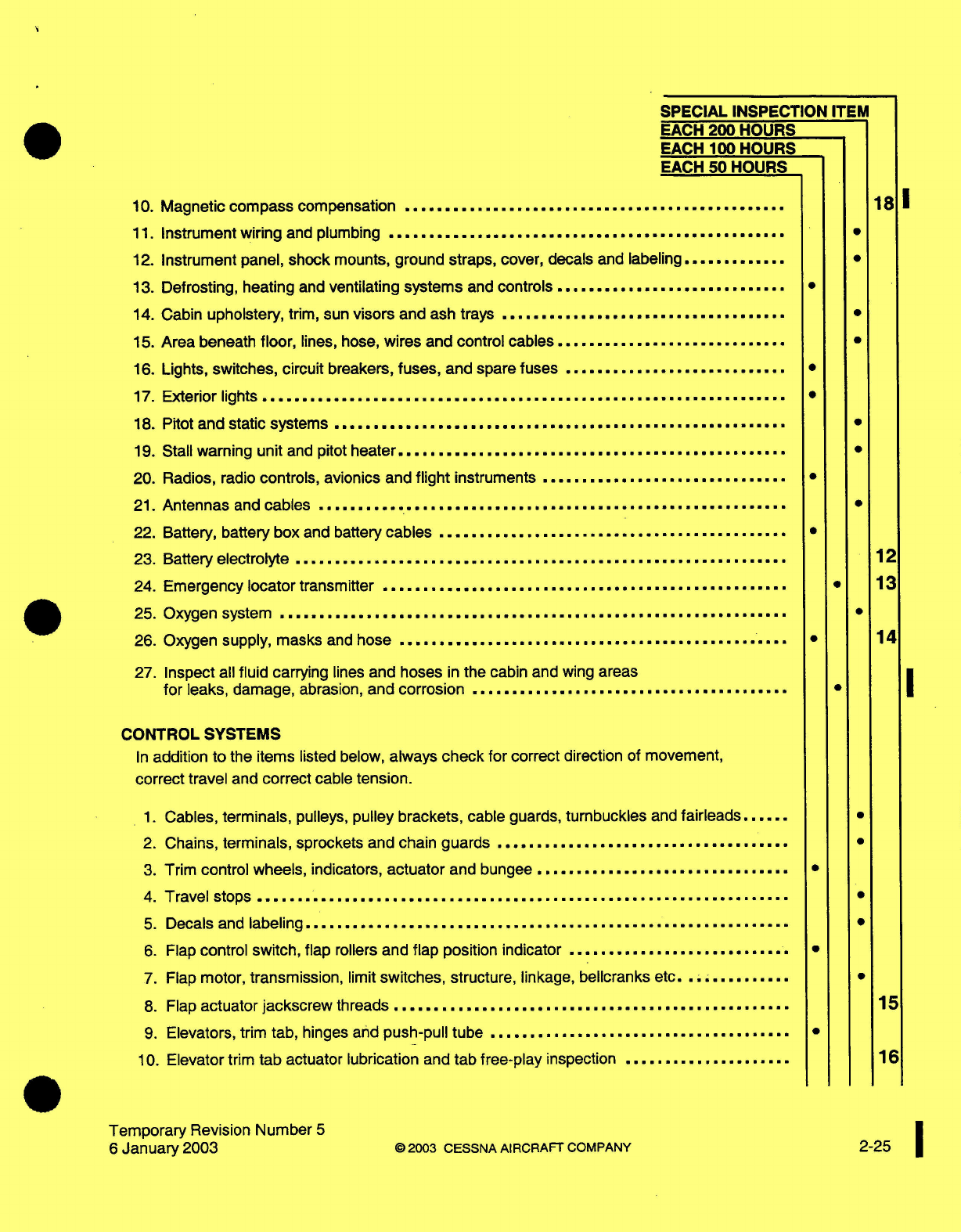
SPECIAL
INSPECTION
ITEM
EACH
200
HOURS
EACH
100
HOURS
EACH
50
HOURS
10.
Magnetic
compass
compensation
................................................
11.
Instrument wiring
and
plumbing
..........
........................................
12.
Instrument panel,
shock
mounts,
ground
straps,
cover,
decals and
labeling.............
13.
Defrosting,
heating
and
ventilating
systems
and
controls
.............................
14.
Cabin
upholstery,
trim,
sun
visors
and
ash
trays
....................................
15.
Area beneath
floor,
lines,
hose,
wires
and
control cables
.............................
16.
Lights,
switches,
circuit
breakers,
fuses,
and
spare
fuses
............................
17.
Exterior
lights
..................................................................
18.
Pitot
and
static systems
.........................................................
19.
Stall
warning unit
and
pitot
heater
.................................................
20. Radios,
radio
controls,
avionics
and
flight
instruments
...............................
21.
Antennas
and
cables ...........................................................
22.
Battery,
battery box
and battery
cables
............................................
23.
Battery
electrolyte ..............................................................
24. Emergency
locator
transmitter
...................................................
25.
Oxygen
system
................................................................
26.
Oxygen
supply,
masks
and
hose
.................................................
27.
Inspect
all
fluid
carrying
lines
and
hoses
in
the
cabin and
wing
areas
for
leaks, damage,
abrasion,
and
corrosion ........................................
181
*
*
*
*
12
*
13
*
14
CONTROL SYSTEMS
In
addition
to
the
items
listed
below,
always
check
for
correct
direction
of
movement,
correct
travel
and
correct
cable
tension.
1.
2.
3.
4.
5.
6.
7.
8.
9.
10.
Cables,
terminals,
pulleys,
pulley
brackets,
cable
guards,
turnbuckles
and
fairleads......
Chains,
terminals,
sprockets
and chain
guards .....................................
Trim
control
wheels,
indicators,
actuator
and bungee
................................
Travel stops
...................................................................
Decals
and
labeling.............................................................
Flap
control switch,
flap
rollers
and
flap
position
indicator
............................
Flap
motor,
transmission,
limit
switches,
structure,
linkage,
bellcranks
etc...........
Flap
actuator
jackscrew
threads
..................................................
Elevators, trim
tab,
hinges
and
push-pull
tube
......................................
Elevator
trim
tab
actuator
lubrication
and
tab
free-play
inspection
.....................
Temporary
Revision
Number
5
6
January
2003
*
.
.
15
16
©2003
CESSNA AIRCRAFT
COMPANY
2-25
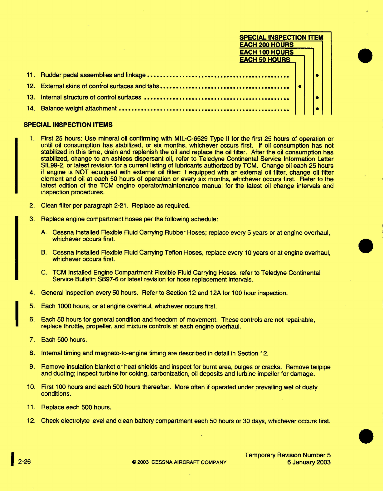
SPECIAL
INSPECTION
ITEM
EACH
200
HOURS
EACH
100
HOURS
EACH
50
HOURS
11.
Rudder
pedal
assemblies
and
linkage
.............................................
12.
Extenal
skins
of
control
surfaces
and
tabs.........................................
13.
Internal
structure of
control surfaces
........................................
......
14.
Balance
weight
attachment
......................................................
SPECIAL
INSPECTION
ITEMS
1.
First
25
hours:
use
mineral
oil
confirming
witn
MIL-C-6529
Type
II
for
the
first
25
nours
of
operation
or
until
oil
consumption
has
stabilized, or
six
months,
whichever
occurs
first.
If
oil
consumption
has
not
stabilized
in
this
time,
drain
and
replenish
the
oil and
replace
the
oil
filter.
After the
oil
consumption
has
stabilized,
change to
an
ashless dispersant
oil,
refer
to Teledyne
Continental
Service Information
Letter
SIL99-2, or latest revision
for
a
current
listing
of
lubricants
authorized
by
TCM.
Change
oil each
25
hours
if
engine
is
NOT
equipped
with
external
oil
filter;
if
equipped
with
an
external
oil
filter,
change
oil
filter
element
and oil at
each
50
hours of
operation
or
every
six
months,
whichever occurs
first. Refer
to
the
latest
edition
of
the
TCM
engine
operator/maintenance
manual
for
the
latest
oil
change intervals
and
inspection
procedures.
2.
Clean
filter
per paragraph
2-21.
Replace as required.
3.
Replace engine
compartment
hoses
per
the following
schedule:
A.
Cessna Installed
Flexible
Fluid
Carrying
Rubber Hoses;
replace
every
5
years
or
at
engine
overhaul,
whichever
occurs
first.
B.
Cessna Installed
Flexible
Fluid
Carrying
Teflon
Hoses,
replace every
10
years
or
at
engine overhaul,
whichever
occurs
first.
C.
TCM
Installed
Engine Compartment
Flexible
Fluid
Carrying
Hoses,
refer to
Teledyne
Continental
Service
Bulletin SB97-6
or
latest
revision
for
hose
replacement
intervals.
4. General
inspection every
50
hours.
Refer
to
Section
12
and
12A
for
100
hour
inspection.
5.
Each
1000 hours,
or
at
engine
overhaul,
whichever occurs
first.
6. Each
50
hours
for
general condition
and
freedom
of
movement.
These
controls
are not
repairable,
replace
throttle, propeller,
and
mixture
controls
at each
engine
overhaul.
7. Each
500 hours.
8.
Internal
timing
and magneto-to-engine
timing
are
described
in
detail
in
Section
12.
9.
Remove insulation
blanket
or
heat
shields
and
inspect
for
burnt
area,
bulges
or
cracks.
Remove
tailpipe
and
ducting;
inspect
turbine
for
coking,
carbonization,
oil
deposits
and
turbine impeller
for
damage.
10.
First
100
hours
and
each
500
hours
thereafter.
More
often
if
operated
under
prevailing
wet
of
dusty
conditions.
11.
Replace
each
500 hours.
12.
Check
electrolyte
level
and clean
battery
compartment
each
50
hours
or
30
days,
whichever
occurs
first.
Temporary
Revision
Number
5
2-26
©2003
CESSNA
AIRCRAFT
COMPANY
6
January
2003
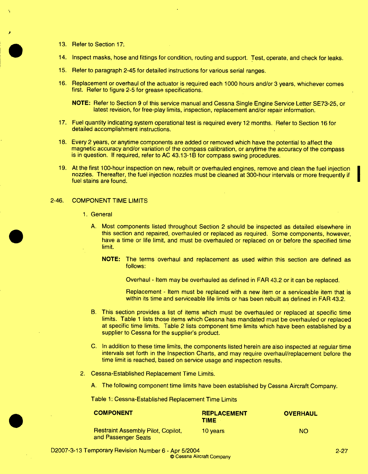
13.
Refer
to
Section
17;
14.
Inspect masks, hose
and
fittings for
condition,
routing
and
support.
Test,
operate,
and
check
for
leaks.
15.
Refer
to
paragraph 2-45
for
detailed
instructions
for
various
serial
ranges.
16.
Replacement
or
overhaul
of
the
actuator
is
required each
1000
hours
and/or
3
years,
whichever
comes
first.
Refer
to
figure
2-5
for
grease
specifications.
NOTE:
Refer
to
Section
9
of
this
service
manual
and
Cessna
Single
Engine
Service
Letter SE73-25,
or
latest
revision,
for
free-play
limits,
inspection, replacement
and/or
repair
information.
17.
Fuel
quantity
indicating
system
operational test
is
required
every
12
months.
Refer
to
Section
16
for
detailed
accomplishment
instructions.
18.
Every
2
years,
or
anytime
components
are added or removed
which have
the
potential
to
affect
the
magnetic
accuracy
and/or
variation
of
the
compass
calibration,
or
anytime
the
accuracy
of
the
compass
is
in
question.
If
required,
refer to
AC
43.13-1
B
for
compass
swing
procedures.
19.
At
the
first
100-hour
inspection
on new,
rebuilt
or
overhauled engines,
remove
and
clean
the
fuel
injection
nozzles.
Thereafter, the
fuel injection nozzles
must
be
cleaned
at
300-hour
intervals
or
more
frequently
if
fuel
stains
are found.
2-46.
COMPONENT
TIME
LIMITS
1.
General
A.
Most
components
listed
throughout
Section
2
should
be
inspected
as
detailed elsewhere
in
this section
and repaired,
overhauled
or
replaced
as
required.
Some
components, however,
have
a
time or
life
limit,
and
must
be
overhauled
or
replaced
on
or
before the
specified
time
limit.
NOTE:
The terms
overhaul
and
replacement
as used
within
this
section
are
defined
as
follows:
Overhaul
-
Item
may
be
overhauled
as
defined
in
FAR 43.2
or
it
can
be
replaced.
Replacement
-
Item
must
be
replaced
with
a
new
item
or
a
serviceable
item
that
is
within
its
time
and
serviceable
life
limits
or
has
been
rebuilt
as
defined
in
FAR
43.2.
B.
This
section provides
a
list of items
which must
be
overhauled
or
replaced
at
specific
time
limits.
Table
1
lists
those
items
which Cessna
has
mandated
must
be
overhauled
or
replaced
at
specific
time limits. Table
2
lists
component
time limits
which
have
been
established by
a
supplier
to
Cessna
for
the
supplier's
product.
C.
In
addition
to
these
time limits,
the
components
listed herein
are
also
inspected
at
regular
time
intervals set forth
in
the
Inspection
Charts,
and
may
require
overhaul/replacement
before
the
time limit
is
reached,
based
on
service usage
and
inspection
results.
2.
Cessna-Established
Replacement
Time
Limits.
A.
The following
component
time
limits have
been
established
by
Cessna
Aircraft
Company.
Table
1:
Cessna-Established Replacement Time
Limits
COMPONENT REPLACEMENT
OVERHAUL
TIME
Restraint Assembly
Pilot,
Copilot,
10
years
NO
and
Passenger
Seats
D2007-3-13
Temporary
Revision Number
6
-
Apr
5/2004
2-27
©
Cessna
Aircraft
Company
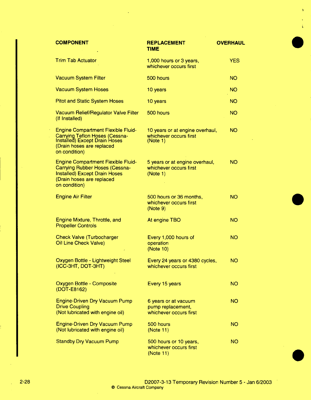
COMPONENT REPLACEMENT
TIME
Trim Tab
Actuator
Vacuum
System
Filter
Vacuum
System
Hoses
Pitot
and
Static
System Hoses
Vacuum
Relief/Regulator
Valve
Filter
(If
Installed)
Engine
Compartment
Flexible
Fluid-
Carrying
Teflon
Hoses
(Cessna-
Installed)
Except
Drain
Hoses
(Drain
hoses
are
replaced
on
condition)
Engine
Compartment
Flexible
Fluid-
Carrying
Rubber Hoses
(Cessna-
Installed)
Except
Drain
Hoses
(Drain hoses
are replaced
on
condition)
Engine
Air
Filter
Engine Mixture,
Throttle,
and
Propeller
Controls
Check
Valve
(Turbocharger
Oil
Line
Check Valve)
Oxygen
Bottle
-
Lightweight
Steel
(ICC-3HT,
DOT-3HT)
Oxygen
Bottle
-
Composite
(DOT-E8162)
Engine-Driven
Dry
Vacuum
Pump
Drive
Coupling
(Not
lubricated
with
engine
oil)
Engine-Driven
Dry
Vacuum
Pump
(Not
lubricated
with
engine
oil)
Standby
Dry
Vacuum
Pump
1,000
hours
or
3
years,
whichever occurs
first
500
hours
10
years
10
years
500
hours
10
years
or
at
engine overhaul,
whichever occurs
first
(Note
1)
5
years
or
at
engine
overhaul,
whichever
occurs
first
(Note
1)
500
hours
or
36
months,
whichever
occurs
first
(Note
9)
At
engine
TBO
Every 1,000
hours
of
operation
(Note
10)
Every
24
years
or
4380
cycles,
whichever occurs
first
Every
15
years
6
years
or
at
vacuum
pump
replacement,
whichever occurs
first
500
hours
(Note
11)
500
hours
or
10
years,
whichever
occurs
first
(Note
11)
OVERHAUL
YES
NO
NO
NO
NO
NO
NO
NO
NO
NO
NO
NO
NO
NO
NO
D2007-3-13
Temporary
Revision
Number
5
-
Jan
6/2003
0
Cessna
Aircraft
Company
2-28
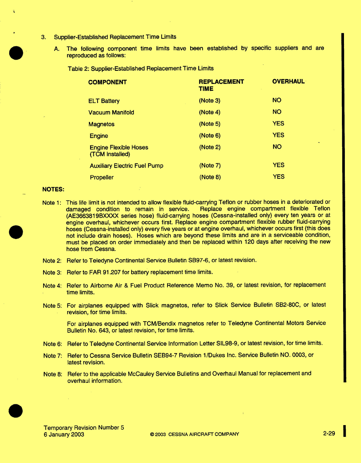
3.
Supplier-Established Replacement
Time
Limits
A.
The
following component
time
limits
have been
established
by
reproduced
as
follows:
specific
suppliers
and
are
Table
2:
Supplier-Established Replacement Time
Limits
COMPONENT
REPLACEMENT
TIME
OVERHAUL
ELT
Battery
Vacuum
Manifold
Magnetos
Engine
Engine
Flexible Hoses
(TCM
Installed)
Auxiliary
Electric
Fuel Pump
Propeller
(Note
3)
(Note
4)
(Note
5)
(Note
6)
(Note
2)
(Note
7)
(Note
8)
NO
NO
YES
YES
NO
YES
YES
NOTES:
Note
1:
This
life
limit
is
not
intended
to
allow flexible fluid-carrying
Teflon
or rubber
hoses
in
a
deteriorated
or
damaged
condition
to
remain
in
service.
Replace
engine
compartment flexible
Teflon
(AE3663819BXXXX
series
hose)
fluid-carrying
hoses (Cessna-installed
only)
every
ten
years or
at
engine
overhaul,
whichever
occurs
first.
Replace
engine
compartment
flexible
rubber
fluid-carrying
hoses
(Cessna-installed
only)
every
five
years
or
at
engine overhaul, whichever
occurs first (this
does
not include
drain hoses).
Hoses
which
are
beyond
these
limits
and
are
in
a
serviceable
condition,
must
be
placed
on
order
immediately
and
then
be
replaced within
120
days
after
receiving
the
new
hose
from
Cessna.
Note
2:
Refer
to
Teledyne
Continental
Service
Bulletin
SB97-6,
or
latest
revision.
Note
3:
Refer to
FAR
91.207
for
battery
replacement time limits.
Note
4:
Refer
to
Airborne
Air
&
Fuel
Product
Reference Memo
No.
39,
or
latest
revision,
for
replacement
time
limits.
Note
5:
For
airplanes
equipped
with
Slick
magnetos,
refer
to Slick
Service
Bulletin SB2-80C,
or
latest
revision,
for
time
limits.
For
airplanes
equipped
with
TCM/Bendix
magnetos
refer
to
Teledyne
Continental
Motors
Service
Bulletin
No.
643,
or
latest
revision,
for
time limits.
Note
6:
Refer
to
Teledyne
Continental
Service
Information
Letter
SIL98-9,
or
latest
revision,
for
time
limits.
Note
7:
Refer to
Cessna
Service
Bulletin SEB94-7
Revision
1/Dukes
Inc.
Service
Bulletin
NO. 0003,
or
latest
revision.
Note
8:
Refer to
the
applicable McCauley Service
Bulletins
and
Overhaul
Manual
for
replacement
and
overhaul information.
Temporary
Revision Number
5
6
January
2003
©
2003
CESSNA
AIRCRAFT
COMPANY
2-29
1
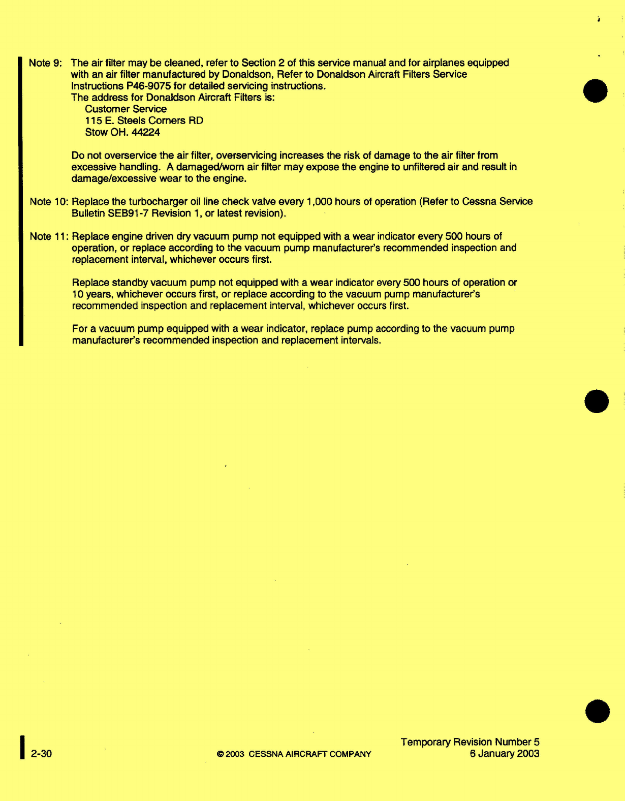
Note
9:
The
air
filter
may
be cleaned, refer
to
Section
2
of
this service
manual
and
for
airplanes
equipped
with
an
air
filter
manufactured
by Donaldson,
Refer to
Donaldson
Aircraft
Filters
Service
Instructions
P46-9075
for
detailed
servicing instructions.
The
address
for
Donaldson
Aircraft
Filters
is:
Customer Service
115
E.
Steels
Comers
RD
Stow
OH.
44224
Do
not
overservice
the air filter,
overservicing increases
the
risk
of
damage
to
the
air
filter from
excessive
handling.
A
damaged/worn
air filter
may
expose
the
engine
to unfiltered
air
and
result
in
damage/excessive wear to
the
engine.
Note
10:
Replace
the
turbocharger
oil
line
check
valve every 1,000
hours
of
operation
(Refer
to Cessna Service
Bulletin
SEB91-7
Revision
1,
or latest revision).
Note
11:
Replace
engine
driven dry vacuum pump not
equipped
with
a
wear indicator
every
500
hours
of
operation, or replace
according
to
the
vacuum
pump
manufacturer's
recommended inspection
and
replacement
interval,
whichever occurs
first.
Replace
standby vacuum
pump not
equipped
with
a
wear
indicator
every 500
hours
of operation
or
10
years,
whichever occurs first, or
replace
according
to
the
vacuum
pump
manufacturer's
recommended
inspection
and
replacement
interval,
whichever
occurs
first.
For
a
vacuum pump
equipped
with
a
wear
indicator,
replace pump
according
to
the
vacuum
pump
manufacturer's
recommended inspection
and
replacement
intervals.
©
2003
CESSNA
AIRCRAFT
COMPANY
Temporary
Revision Number
5
6
January
2003
1
2-30
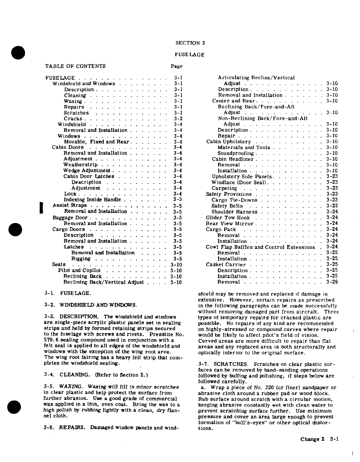
SECTION
3
FUSE
LAGE
TABLE
OF
CONTENTS
Page
FUSELAGE
........
.
....
.
3-1
Articulating
Recline/Vertical
Windshield
and
Windows
.........
3-1
Adjust
..............
3-10
Description
.............
3-1
Description
.
...........
3-10
Cleaning
............
3-1
Removal and
Installation
.......
3-10
Waxing
................
3-1
Center
and
Rear
...........
3-10
Repairs
..............
3-1
Reclining
Back/Fore-and-Aft
Scratches
.............
3-1
Adjust
........ ....
3-10
Cracks
..........
.. . 3-2
Non-Reclining
Back/Fore-and-Aft
Windshield
..............
3-4
Adjust
..............
3-10
Removal
and
Installation
.......
3-4
Description
............
3-10
W
indows
....... ...... . . 3-4
Repair
............ . . .
3-10
Movable,
Fixed
and
Rear.......
3-4
Cabin
Upholstery
........
. . .
3-10
Cabin
Doors
.............
3-4
Materials
and
Tools
.........
3-10
Removal and
Installation
.......
3-4
Soundproofing
.... ........
3-10
Adjustment
.............
3-4
Cabin
Headliner
...........
.
3-10
Weatherstrip
............
3-4
Removal
..
............
3-10
Wedge
Adjustment
... ..
3-4
Installation
.....
.
........
3-10
Cabin
Door
Latches
.........
3-4
Upholstery
Side
Panels
......
. 3-23
Description
...........
3-4 Windlace
(Door
Seal).
..........
3-23
Adjustment
...........
3-4
Carpeting
..............
3-23
Lock.
............
...
3-4
Safety
Provisions
............
3-23
Indexing
Inside
Handle
........
3-5
Cargo
Tie-Downs
...........
3-23
Assist
Straps
.............
3-5
Safety
Belts
............
3-23
Removal
and
Installation
.......
3-5
Shoulder
Harness
...........
3-24
Baggage
Door
..............
3-5
Glider
Tow
Hook
......
... . 3-24
Removal
and
Installation
.......
3-5
Rear
View
Mirror
........
.. 3-24
Cargo Doors
..............
3-5
Cargo
Pack
..............
3-24
Description
............
3-5
Removal
........ ....
.
3-24
Removal
and
Installation
.......
3-5
Installation
............
3-24
Latches
....
..
3-5
Cowl
Flap
Baffles
and
Control
Extensions
.3-24
Removal and
Installation
. . . 3-5
Removal
............
.
3-25
Rigging
.............
3-5
Installation
.
...........
.3-25
Seats
...... . ..
3-10
Casket
Carrier
....... . . . . . . 3-25
Pilot
and
Copilot
...........
3-10
Description
.............
3-25
Reclining
Back
........
.. . 3-10
Installation
.............
3-25
Reclining
Back/Vertical
Adjust
....
3-10
Removal
.
....
... .. . . 3-29
3-1.
FUSELAGE.
shield
may
be
removed
and
replaced
if
damage
is
extensive.
However,
certain
repairs
as
prescribed
3-2.
WINDSHIELD
AND
WINDOWS.
in
the
following
paragraphs
can
be
made
successfully
without
removing
damaged
part
from
aircraft.
Three
3-3.
DESCRIPTION. The
windshield
and
windows
types
of
temporary
repairs
for
cracked
plastic
are
are
single-piece
acrylic
plastic
panels
set
in
sealing
possible.
No
repairs
of
any
kind
are
recommended
strips
and held
by
formed
retaining
strips
secured
on
highly-stressed
or
compound
curves
where
repair
to
the
fuselage
with
screws
and
rivets.
Presstite
No.
would
be
likely
to
affect
pilot's
field
of
vision.
579.6
sealing
compound
used
in
conjunction
with
a
Curved
areas
are
more
difficult
to
repair
than
flat
felt seal
is
applied
to
all
edges
of
the
windshield
and
areas
and
any
replaced
area
is
both
structurally
and
windows
with
the
exception
of
the
wing
root
area.
optically
inferior
to
the
original
surface.
The wing
root
fairing
has
a
heavy
felt
strip
that
com-
pletes
the
windshield
sealing.
3-7.
SCRATCHES.
Scratches
on
clear
plastic sur-
faces
can
be
removed
by
hand-sanding
operations
3-4.
CLEANING.
(Refer
to
Section
2.)
followed
by
buffing
and
polishing,
if
steps
below
are
followed
carefully.
3-5.
WAXING.
Waxing will
fill
in
minor
scratches
a.
Wrap
a
piece
of
No.
320
(or
finer)
sandpaper
or
in
clear
plastic
and help
protect
the
surface
from
abrasive
cloth
around
a
rubber
pad
or
wood
block.
further
abrasion.
Use
a
good
grade
of
commercial
Rub
surface
around
scratch
with
a
circular
motion,
wax
applied
in
a
thin,
even
coat.
Bring
the
wax
to
a
keeping
abrasive
constantly
wet
with
clean
water
to
high
polish
by
rubbing
lightly
with
a
clean,
dry
flan-
prevent
scratching
surface
further.
Use
minimum
nel
cloth.
pressure
and
cover
an
area
large
enough
to
prevent
formation
of
"bull's-eyes"
or
other
optical
distor-
3-6.
REPAIRS.
Damaged
window
panels
and
wind-
tions.
Change
2 3-1
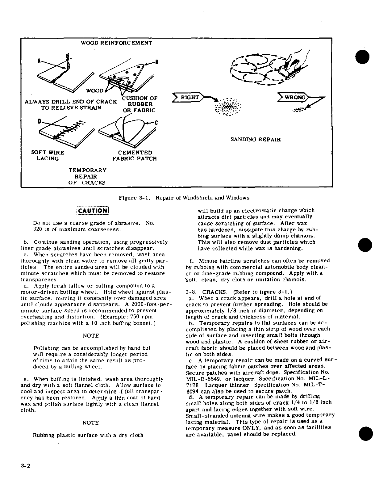
Figure
3-1.
Repair
of
Windshield
and
Windows
CAUTION
will build
up
an
electrostatic
charge
which
attracts
dirt
particles
and may
eventually
Do
not
use
a
coarse
grade
of
abrasive.
No.
cause
scratching
of
surface. After
wax
320
is
of
maximum
coarseness.
has
hardened,
dissipate
this
charge
by
rub-
bing
surface
with
a
slightly
damp
chamois.
b.
Continue
sanding
operation,
using
progressively
This
will
also
remove
dust
particles
which
finer
grade
abrasives
until
scratches
disappear.
have
collected
while
wax
is
hardening.
c.
When
scratches
have been
removed,
wash
area
thoroughly
with
clean
water
to
remove
all
gritty
par-
f.
Minute
hairline
scratches
can
often
be
removed
tides.
The
entire
sanded
area
will
be
clouded
with
by
rubbing
with
commercial
automobile
body
clean-
minute
scratches
which
must
be
removed
to
restore
er
or
fine-grade
rubbing
compound.
Apply
with
a
transparency.
soft,
clean, dry
cloth
or imitation
chamois.
d.
Apply
fresh
tallow
or
buffing
compound
to
a
motor-driven
buffing
wheel.
Hold
wheel
against
plas-
3-8.
CRACKS.
(Refer
to
figure 3-1.)
tic
surface,
moving
it
constantly
over
damaged
area
a. When a
crack
appears,
drill
a
hole
at end
of
until
cloudy
appearance
disappears.
A
2000-foot-per-
crack
to
prevent
further
spreading.
Hole
should
be
minute
surface
speed
is
recommended
to
prevent
approximately
1/8
inch
in
diameter,
depending
on
overheating
and
distortion.
(Example:
750
rpm
length
of
crack
and
thickness
of
material.
polishing machine
with
a
10
inch
buffing
bonnet.)
b.
Temporary
repairs
to
flat
surfaces
can
be
ac-
complished
by
placing
a
thin
strip
of
wood
over
each
NOTE
side
of
surface
and
inserting small
bolts
through
wood
and
plastic.
A
cushion
of
sheet rubber
or
air-
Polishing
can
be
accomplished
by
hand
but
craft
fabric
should
be
placed
between
wood
and
plas-
will
require
a
considerably
longer
period
tic
on
both
sides.
of
time
to
attain
the
same
result
as
pro-
c.
A
temporary
repair
can
be
made
on
a
curved
sur-
duced
by
a
buffing
wheel.
face
by
placing
fabric
patches
over
affected
areas.
Secure
patches
with
aircraft
dope.
Specification
No.
e.
When
buffing
is
finished,
wash
area
thoroughly MIL-D-5549,
or
lacquer.
Specification
No.
MIL-L-
and dry
with
a
soft
flannel cloth.
Allow
surface
to
7178.
Lacquer
thinner,
Specification
No.
MIL-T-
cool
and
inspect
area
to
determine
if
full
transpar-
6094
can
also
be
used
to
secure
patch.
ency
has
been
restored.
Apply
a
thin
coat
of
hard
d. A
temporary
repair
can
be
made
by
drilling
wax
and
polish
surface
lightly
with
a
clean
flannel
small
holes
along
both
sides
of
crack
1/4
to
1/8
inch
cloth.
apart
and
lacing
edges
together
with
soft
wire.
Small-stranded
antenna
wire makes
a
good
temporary
NOTE
lacing
material.
This
type
of
repair
is
used
as
a
temporary
measure
ONLY,
and
as
soon
as
facilities
Rubbing
plastic
surface
with
a
dry
cloth
are
available,
panel should
be
replaced.
3-2
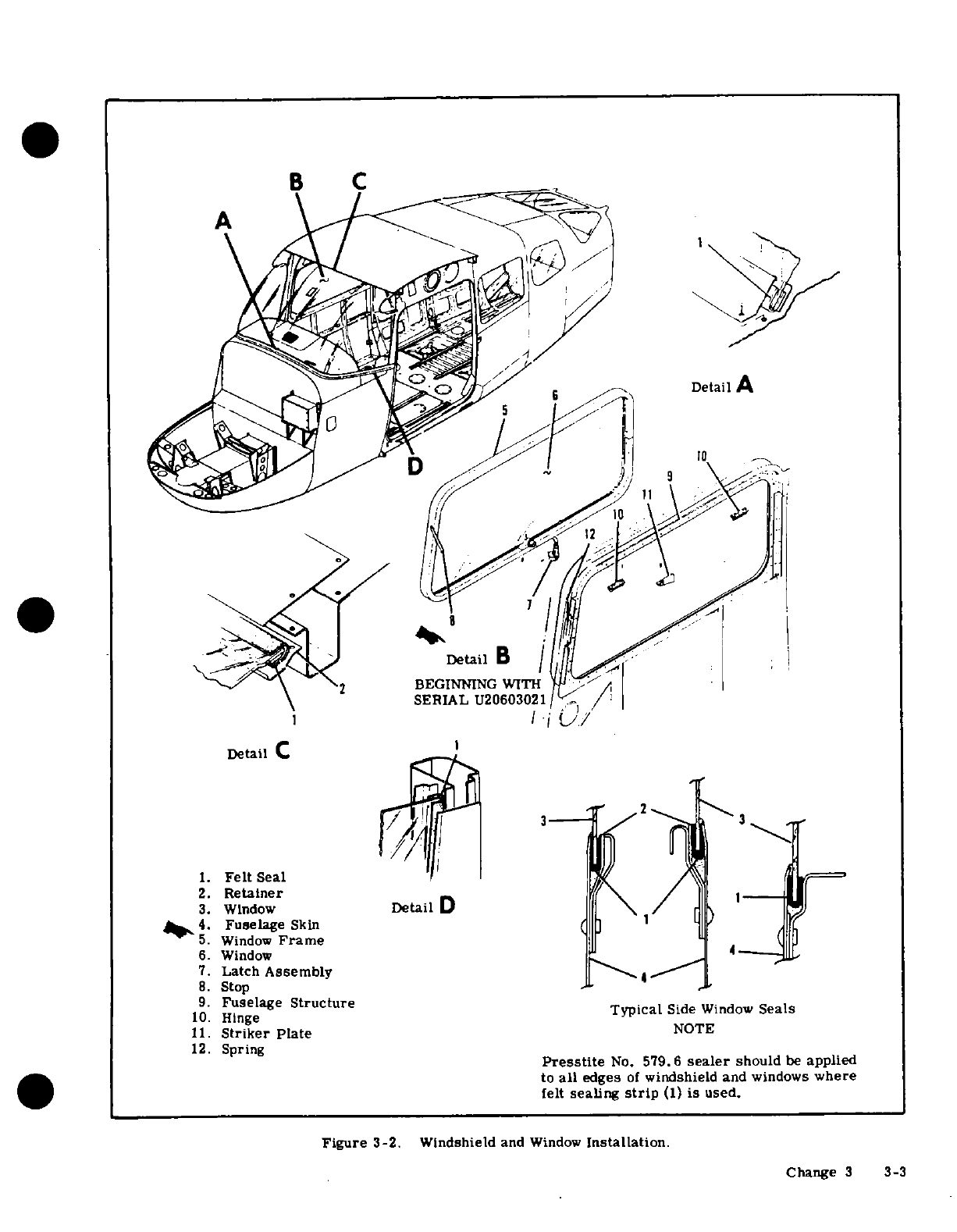
B
C
A
Detail
A
,k
^^ 2
BEGINNING
WITH
SERIAL
U20603021
Detail
C
1.
Felt
Seal
2.
Retainer
3.
Window
Detail
D
4
Fuselage
Skin
'
5.
Window
Frame
(
6.
Window
4
7.
Latch
Assembly
8.
Stop
9.
Fuselage
Structure
Typical
Side
Window
Seals
10.
Hinge
11.
Striker
Plate
NOTE
12.
Spring
Presstite
No.
579.6
sealer
should
be
applied
to
all
edges
of
windshield
and
windows
where
felt
sealing
strip
(1) is
used.
Figure
3-2.
Windshield
and
Window
Installation.
Change
3
3-3
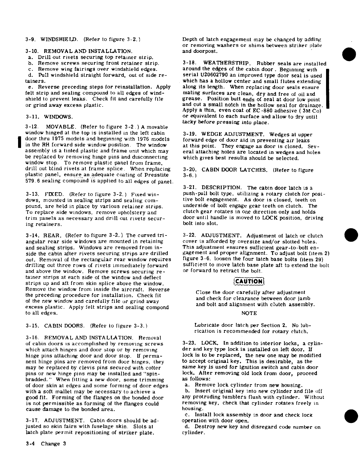
3-9.
WINDSHIELD.
(Refer
to
figure
3-2.)
Depth
of
latch
engagement
may
be
changed
by
adding
or
removing
washers
or
shims
between
striker
plate
3-10.
REMOVAL
AND
INSTALLATION.
and
doorpost.
a.
Drill
out
rivets
securing
top
retainer
strip.
b.
Remove
screws
securing
front
retainer
strip.
3-18.
WEATHERSTRIP.
Rubber
seals
are
installed
c.
Remove
wing
fairings
over
windshield edges. around
the
edges
of
the
cabin
door.
Beginning
with
d.
Pull
windshield
straight
forward,
out
of
side
re-
serial
U20602790
an
improved
type
door
seal
is
used
tainers.
which
has
a
hollow
center
and
small
flutes
extending
e.
Reverse
preceding
steps
for
reinstallation.
Apply
along
its
length.
When
replacing
door
seals
ensure
felt
strip
and
sealing
compound
to
all edges
of
wind-
mating
surfaces
are
clean,
dry
and
free
of
oil
and
shield
to
prevent
leaks.
Check
fit
and
carefully
file
grease.
Position
butt ends
of
seal
at door
low
point
or
grind
away
excess
plastic.
and
cut
a
small
notch
in
the
hollow
seal
for drainage.
Apply
a
thin,
even
coat
of
EC-880
adhesive
(
3M
Co)
3-11.
WINDOWS.
or
equivalent
to
each
surface
and
allow
to
dry
until
tacky
before
pressing
into
place.
3-12.
MOVABLE.
(Refer
to
figure
3-2 )
A
movable
window
hinged
at
the
top
is
installed
in
the left
cabin
3-19.
WEDGE
ADJUSTMENT.
Wedges
at
upper
door
thru
1975
models
and
beginning
with
1976
models
forward
edge
of
door
aid
in
preventing
air
leaks
in
the
RH
forward
side
window
position.
The
window
at
this
point. They
engage
as
door
is
closed.
Sev-
assembly is
a
tinted
plastic
and
frame
unit
which
may
eral
attaching holes
are
located
in
wedges
and
holes
be
replaced
by
removing
hinge
pins
and
disconnecting
which
gives
best
results
should
be
selected.
window
stop.
To
remove
plastic
panel
from
frame,
drill
out
blind
rivets
at
frame splice.
When
replacing
3-20.
CABIN
DOOR
LATCHES.
(Refer
to
figure
plastic
panel,
ensure
an
adequate
coating
of
Presstite
3-6.)
579.6
sealing
compound
is
applied
to
all
edges
of
panel.
3-21.
DESCRIPTION. The
cabin
door
latch
is
a
3-13.
FIXED.
(Refer
to
figure
3-2.)
Fixed
win-
push-pull
bolt
type,
utilizing
a
rotary
clutch
for posi-
dows,
mounted
in
sealing
strips
and
sealing
com-
tive
bolt
engagement.
As
door
is
closed,
teeth
on
pound,
are
held
in
place
by
various
retainer
strips.
underside
of
bolt
engage
gear
teeth
on
clutch.
The
To
replace
side
windows,
remove
upholstery
and
clutch
gear
rotates
in
one
direction
only
and
holds
trim
panels
as
necessary
and
drill
out
rivets
secur-
door
until
handle
is
moved
to
LOCK
position,
driving
ing
retainers.
bolt into
slot.
3-14.
REAR.
(Refer
to
figure
3-2.)
The
curved
tri-
3-22.
ADJUSTMENT.
Adjustment
of
latch
or
clutch
angular
rear
side
windows
are
mounted
in
retaining
cover
is
afforded
by
oversize
and/or
slotted
holes.
and
sealing
strips.
Windows
are
removed
from
in-
This
adjustment
ensures
sufficient
gear-to-bolt
en-
side
the
cabin
after
rivets
securing
strips
are
drilled
gagement
and
proper
alignment.
To
adjust
bolt
(item
2)
out.
Removal
of
the
rectangular
rear
window
requires
figure
3-6.
loosen
the
four
latch
base
bolts
(item
29)
drilling
out
three
rows
of
rivets
immediately
forward sufficient
to
move
latch
base
plate
aft
to
extend
the
bolt
and
above
the
window.
Remove
screws
securing
re-
or
forward
to
retract
the
bolt.
tainer
strips
at
each
side
of
the
window
and
deflect
strips
up
and aft
from
skin
splice
above
the
window.
{CAUTION
Remove
the
window
from
inside
the
aircraft.
Reverse
Close
the
door
carefully
alter
adjustment
the
preceding
procedure
for
installation.
Check
fit
and
check
for
clearance
between
door
jamb
of
the
new
window
and
carefully
file
or
grind
away
and
bolt
and
alignment
with
clutch
assembly.
excess plastic.
Apply
felt
strips
and
sealing
compond
to
all
edges.
NOTE
3-15.
CABIN
DOORS.
(Refer
to
figure
3-3.)
Lubricate
door
latch
per Section
2.
No
lub-
rication
is
recommended
for
rotary
clutch.
3-16
REMOVAL
AND
INSTALLATION.
Removal
of
cabin
doors
is
accomplished
by
removing
screws
3-23.
LOCK.
In
addition
to
interior
locks,
a
cylin-
which
attach
hinges
and door
stop
or
by
removing
der
and
key
type
lock
is
installed
on
left
door.
If
hinge
pins
attaching
door
and
door stop.
If
perma-
lock
is
to
be
replaced,
the
new
one
may
be
modified
nent
hinge
pins
are
removed
from
door
hinges,
they
to
accept
original
key.
This
is
desirable,
as
the
may
be
replaced
by
clevis
pins
secured
with
cotter
same
key
is
used
for
ignition
switch
and
cabin
door
pins
or
new
hinge
pins
may
be
installed
and
"spin-
lock.
After removing
old
lock
from
door,
proceed
bradded."
When
fitting
a
new
door,
some
trimming
as
follows:
of
door
skin
at
edges
and
some
forming
of
door
edges
a.
Remove
lock
cylinder
from
new
housing.
with
a
soft
mallet
may
be
necessary
to
achieve
a
b.
Insert original
key
into
new
cylinder
and
file
off
good
fit.
Forming
of
the
flanges
on
the bonded
door
any
protruding
tumblers
flush
with
cylinder.
Without
is
not
permissible
as
forming
of
the
flanges
could
removing
key,
check that
cylinder
rotates
freely
in
cause
damage
to
the bonded
area.
housing.
c.
Install
lock
assembly
in
door
and
check
lock
3-17.
ADJUSTMENT.
Cabin
doors
should
be
ad-
operation
with
door
open.
justed
so
skin
fairs
with
fuselage
skin.
Slots
at
d.
Destroy
new key
and
disregard
code
number
on
latch plate
permit
repositioning
of
striker
plate.
cylinder.
3-4 Change 3
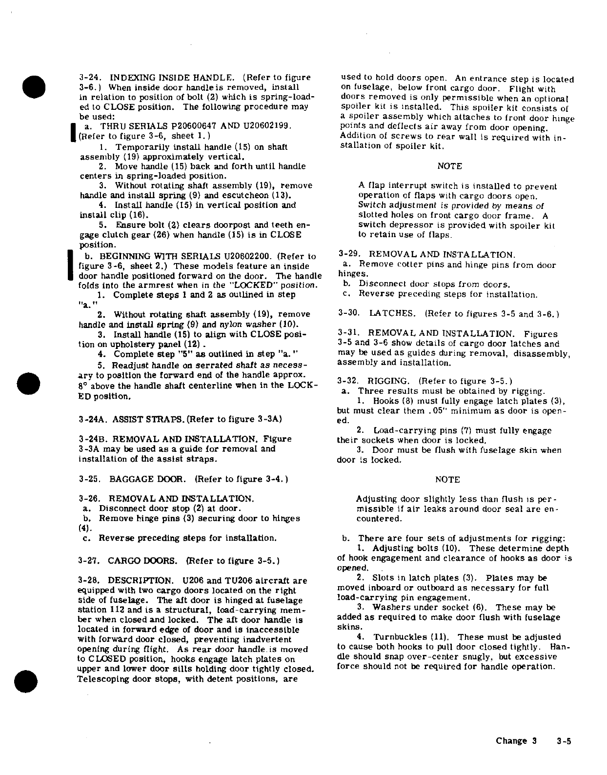
3-24.
INDEXING
INSIDE
HANDLE.
(Refer
to
figure
used
to
hold
doors
open.
An
entrance
step
is
located
3-6.)
When
inside door
handleis
removed,
install
on
fuselage,
below
front
cargo
door.
Flight
with
in
relation
to
position
of
bolt
(2)
which
is
spring-load-
doors
removed
is
only
permissible
when
an
optional
ed
to
CLOSE
position.
The
following
procedure
may
spoiler
kit
is
installed.
This
spoiler
kit
consists
of
be
used:
a
spoiler
assembly
which
attaches
to
front
door
hinge
a.
THRU
SERIALS
P20600647
AND
U20602199.
points
and
deflects
air
away
from
door
opening.
(Refer
to
figure 3-6,
sheet
1.)
Addition
of
screws
to
rear
wall
is
required
with
in-
1.
Temporarily
install
handle
(15)
on
shaft
stallation
of
spoiler
kit.
assembly
(19)
approximately
vertical.
2.
Move
handle
(15)
back
and
forth
until
handle
NOTE
centers
in
spring-loaded
position.
3.
Without
rotating
shaft
assembly
(19),
remove
A
flap
interrupt
switch
is
installed
to
prevent
handle
and
install
spring
(9)
and
escutcheon
(13).
operation
of
flaps
with
cargo doors
open.
4.
Install
handle
(15)
in
vertical
position
and
Switch
adjustment
is
provided
by
means
of
install
clip
(16).
slotted
holes
on
front
cargo
door
frame.
A
5.
Ensure
bolt
(2)
clears
doorpost
and
teeth
en-
switch
depressor
is
provided
with
spoiler
kit
gage
clutch
gear
(26)
when
handle
(15)
is
in CLOSE
to
retain
use
of
flaps.
position.
b.
BEGINNING
WITH
SERIALS
U20602200.
(Refer
to
3-29.
REMOVAL
AND
INSTALLATION.
figure
3-6,
sheet
2.)
These
models
feature
an
inside
a.
Remove
cotter
pins
and
hinge
pins
from
door
door handle
positioned
forward
on
the
door.
The
handle
hinges.
folds
into
the
armrest
when
in
the
"LOCKED"
position.
b.
Disconnect
door
stops
from
doors.
1.
Complete
steps
1
and
2
as
outlined
in
step
c.
Reverse
preceding
steps
for
installation.
,a.
"
2.
Without
rotating
shaft
assembly
(19),
remove
3-30.
LATCHES.
(Refer
to
figures
3-5
and
3-6.)
handle
and
install
spring
(9)
and nylon
washer
(10).
3.
Install
handle
(15)
to
align
with
CLOSE
posi-
3-31.
REMOVAL
AND
INSTALLATION.
Figures
tion
on
upholstery
panel
(12)
.3-5
and
3-6
show
details
of
cargo
door
latches
and
4.
Complete
step
"5"
as
outlined
in
step
"a."
may
be
used
as
guides
during
removal,
disassembly,
5.
Readjust
handle
on
serrated
shaft
as
necess-
assembly
and
installation.
ary
to
position
the
forward
end
of
the
handle
approx.
3-32.
RIGGING.
(Refer
to
figure
3-5.)
8°
above
the
handle
shaft
centerline
when in
the
LOCK-
Three
results
must
be
obtained
a.
Three
results
must
be
obtained
by
rigging.
ED
position.
1.
Hooks
(8)
must
fully
engage
latch
plates
(3),
but
must
clear
them
.05"
minimum
as
door
is
open-
3-24A.
ASSIST
STRAPS.
(Refer
to
figure
3-3A)
ed.
2.
Load-carrying
pins
(7)
must
fully
engage
3-24B.
REMOVAL
AND
INSTALLATION.
Figure
their
sockets
when
door
is
locked.
3-3A
may
be
used
as
a guide
for
removal
and
3.
Door
must
be
flush with
fuselage
skin
when
installation
of
the
assist
straps.
door
is locked.
3-25.
BAGGAGE
DOOR.
(Refer
to
figure
3-4.)
NOTE
3-26.
REMOVAL
AND
INSTALLATION.
Adjusting door
slightly
less
than
flush
is
per-
a.
Disconnect door stop
(2)
at
door.
missible
if
air
leaks
around
door
seal
are
en-
b.
Remove
hinge
pins
(3)
securing
door
to
hinges
countered.
(4).
c.
Reverse
preceding
steps
for
installation.
b.
There
are
four
sets
of
adjustments
for
rigging:
1.
Adjusting
bolts
(10).
These
determine
depth
3-27.
CARGO
DOORS.
(Refer
to
figure
3-5.)
of
hook
engagement
and
clearance
of
hooks
as
door
is
opened.
3-28.
DESCRIPTION.
U206
and
TU206
aircraft
are
2.
Slots
in
latch
plates
(3).
Plates
may
be
equipped
with
two
cargo
doors
located
on
the
right
moved
inboard
or
outboard
as
necessary
for
full
side
of
fuselage.
The
aft
door
is
hinged
at
fuselage
load-carrying
pin
engagement.
station
112
and
is
a
structural,
load-carrying
mem-
3.
Washers
under
socket
(6).
These
may
be
ber
when
closed
and locked.
The
aft
door
handle
is
added
as
required
to
make
door
flush
with
fuselage
located
in
forward
edge
of
door
and
is
inaccessible
skins.
with
forward
door
closed, preventing
inadvertent
4.
Turnbuckles
(11).
These must
be
adjusted
opening
during
flight.
As
rear
door
handle
is
moved
to
cause
both hooks
to pull
door
closed
tightly.
Han-
to CLOSED
position,
hooks
engage
latch
plates
on
dle
should snap
over-center
snugly,
but
excessive
upper and lower
door
sills
holding
door
tightly
closed.
force
should
not
be
required
for
handle
operation.
Telescoping
door
stops,
with
detent
positions,
are
Change
3
3-5
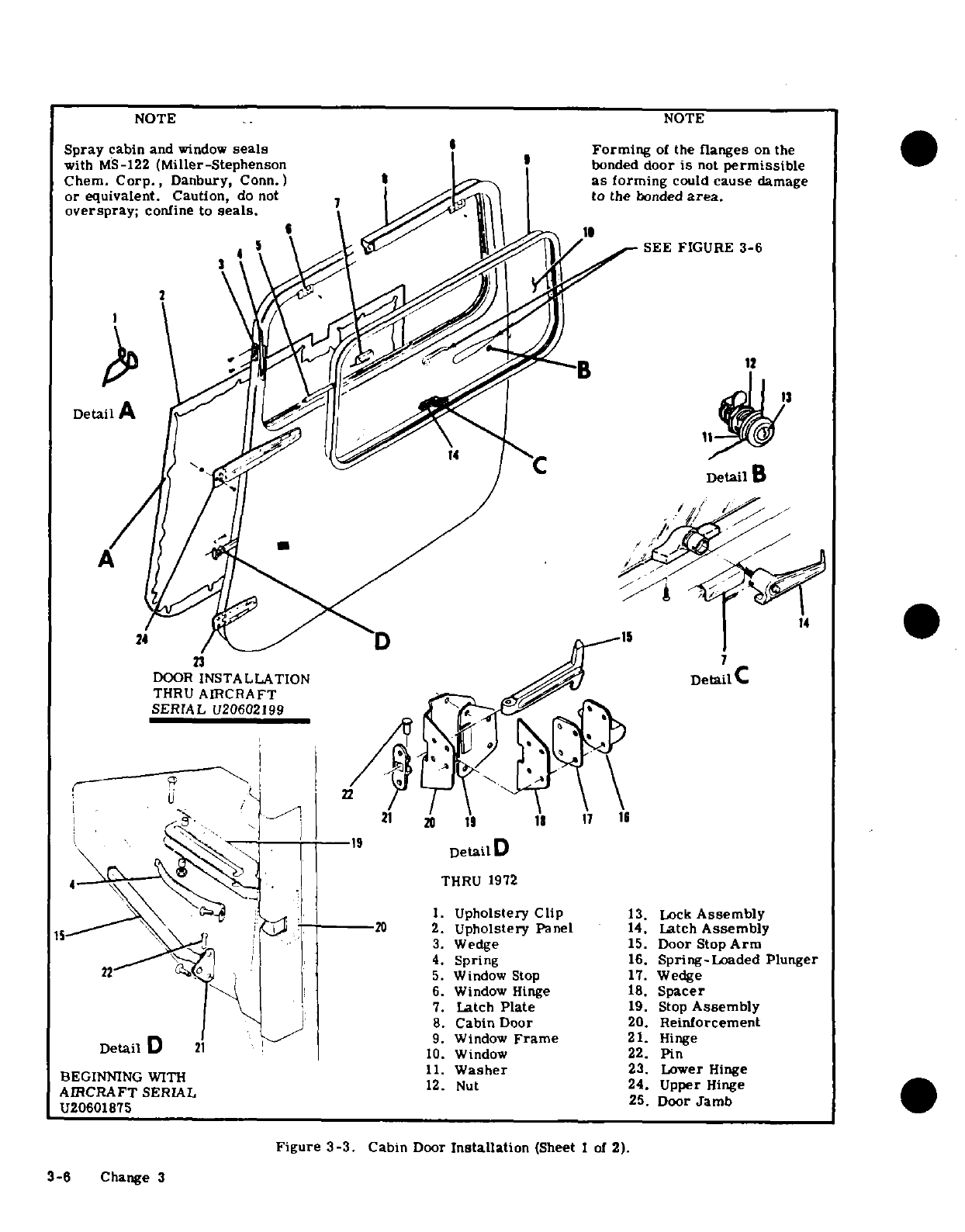
NOTE
NOTE
Spray
cabin
and
window
seals
Forming
of
the
flanges
on
the
with
MS-122
(Miller-Stephenson
bonded
door
is
not
permissible
Chem.
Corp.,
Danbury,
Conn.)
as
forming
could
cause
damage
or
equivalent.
Caution,
do
not
7
to
the
bonded
area.
overspray;
confine to
seals.
SEE FIGURE
3-6
Detail
A
Detail
B
A
14
24
D
5
23
DOOR
INSTALLATION
DetailC
THRU
AIRCRAFT
19
Detail
D
4 THRU
1972
1.
Upholstery Clip
13.
Lock
Assembly
15-- ^ '\ \
'
?
!
'20
2.
Upholstery
Panel
14.
Latch
Assembly
22 ^ ^ j3.
Wedge
15.
Door
Stop
Arm
4.
Spring
16.
Spring-Loaded
Plunger
N~22 "p i5.
Window Stop
17.
Wedge
6.
Window Hinge
18.
Spacer
7.
Latch
Plate
19.
Stop
Assembly
:> ^8.
Cabin Door
20.
Reinforcement
Da D
-
2 -^9-F9.
Window
Frame
21.
Hinge
Detail D
2
10.
Window
22.
Pin
BEGINNING
WITH
11.
Washer
23.
Lower
Hinge
AIRCRAFT
SERIAL
12.
Nut 24.
Upper
Hinge
AIRCRAFT
SERIAL
TU20601875
.25.
Door
Jamb
Figure
3-3.
Cabin
Door
Installation
(Sheet
1
of
2).
3-6
Change 3
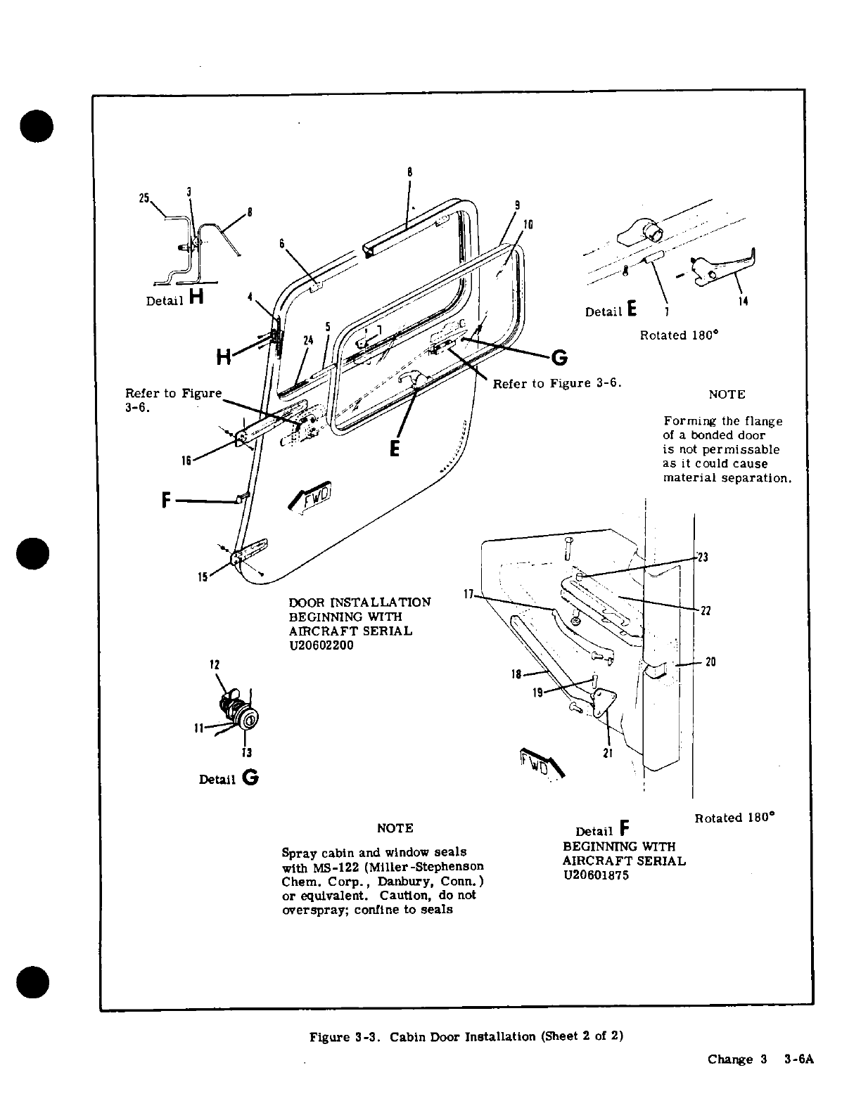
Refer
to Fire Detail H^' /, ' [
DetailE
14
'1y 24 / 5/,/^^ ^^ ^^ l,
Rotated
180
C
\\et to^
'
FigureRefer
to
Figure
3-6.
Forming
the
flange
."i<1; -^.
'- "
/
Jof
a
bonded
door
12C^\ AiE
is
not
permissable
^is
;/
..
as
it
could
cause
material
separation.
F
DOOR
INSTALLATION
1
BEGINNING WITH
AIRCRAFT SERIAL
U20602200
12
20
t11l
2
Detail
G
NOTE
Detail
F
Rotated
180
Spray
cabin
and
window
seals
BEGINNING
WITH
AIRCRAFT
SERIAL
with
MS-122
(Miller-Stephenson
ARRF
SERIAL
Chem.
Corp.,
Danbury,
Conn.)
U0
75
or
equivalent. Caution,
do
not
overspray;
confine
to
seals
Figure
3-3.
Cabin
Door
Installation
(Sheet
2
of
2)
Change
3
3-6A
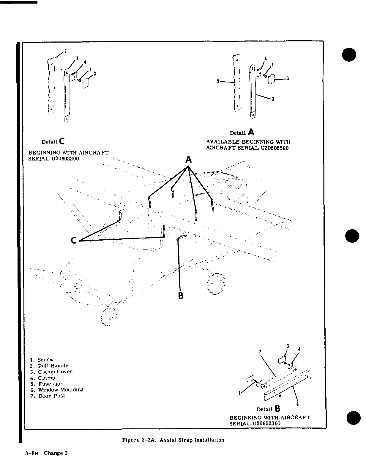
Detail
A
DetailC
AVAILABLE
BEGINNING
WITH
AIRCRAFT
SERIAL
U20602580
BEGINNING
WITH
AIRCRAFT
SERIAL
U20602200
1.
Screw
2.
Pull
Handle
3.
Clamp
Cover
\
h.,
4.
Clamp
, ,
5.
Fuselage
6.
Window
Moulding
/ ,
7.
Door
Post
Detail
B
BEGINNING
WITH
AIRCRAFT
SERIAL
U20602360
Figure
3-3A.
Assist
Strap Installation
3-6B
Change 2
3-6B
Change
2
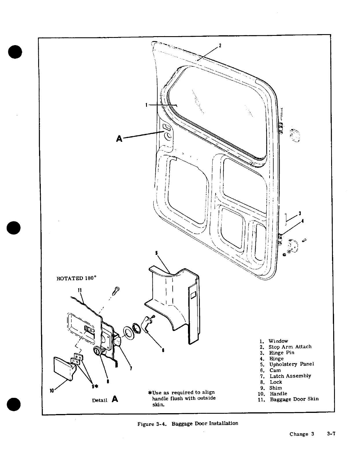
2
A
ROTATED
180°
1.
Window
2.
Stop
Arm
Attach
6 3.
Hinge
Pin
4.
Hinge
5.
Upholstery
Panel
6.
Cam
7.
Latch
Assembly
8.
Lock
10 9.
Shim
*Use
as
required
to
align
10.
Handle
Detail
A
handle
flush
with
outside
11.
Baggage
Door
Skin
skin.
Figure
3-4. Baggage
Door
Installation
Change
3
3-7
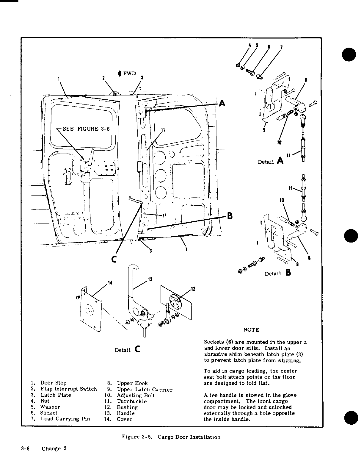
2
FWD
3
SEE
FIGURE
3-6
11
Detail
A
11
-
/ ,
$1
Ir^ ~~~ ~
e'
lDetail
B
NOTE
Sockets
(6)
are
mounted
in
the
upper
a
Detail
C
and
lower
door
sills.
Install
an
abrasive
shim
beneath
latch
plate
(3)
to
prevent
latch
plate from
slipping.
To
aid
in
cargo
loading,
the
center
seat
bolt
attach
points
on
the
floor
1.
Door
Stop
8.
Upper
Hook
are
designed
to
fold
flat.
2.
Flap
Interrupt
Switch
9.
Upper
Latch
Carrier
3.
Latch Plate
10.
Adjusting
Bolt
A
tee
handle
is
stowed
in
the
glove
4.
Nut
11.
Turnbuckle
compartment.
The
front
cargo
5.
Washer
12.
Bushing
door
may
be
locked
and
unlocked
6.
Socket
13.
Handle
externally
through
a
hole
opposite
7.
Load
Carrying
Pin
14.
Cover
the
inside
handle.
Figure
3-5.
Cargo Door
Installation
3-8
Change 3
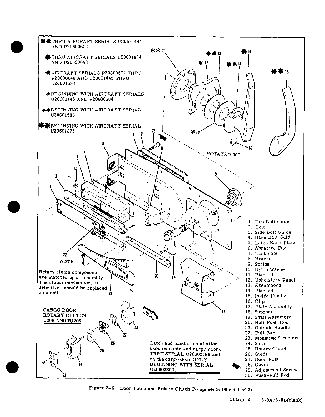
**THRU
AIRCRAFT
SERIALS
U206-1444
AND
P20600603
*THRU
AIRCRAFT
SERIALS
U20601874
AND
P20600648
*AIRCRAFT
SERIALS
P20600604
THRU
P20600648
AND
U20601445
THRU
U20601587
*BEGINNING
WITH
AIRCRAFT
SERIALS
U20601445
AND
P20600604
**BEGINNING
WITH
AIRCRAFT
SERIAL
U20601588
**BEGINNING
WITH
AIRCRAFT
SERIAL
U20601875
ROTATED
90°
1.
Top
Bolt
Guide
2.
Bolt
3.
Side Bolt
Guide
4.
Base
Bolt
Guide
5.
Latch
Base
Plate
6.
Abrasive
Pad
7.
Lockplate
8.
Bracket
9.
Spring
10.
Nylon
Washer
Rotary
clutch
components
11.
Placard
are
matched
upon
assembly.
12.
Upholstery
Panel
The
clutch
mechanism,
if
13.
Escutcheon
defective,
should
be
replaced
14.
Placard
as a unit.
15.
Inside
Handle
16.
Clip
17.
Plate
Assembly
CARGO
DOOR
18.
Support
ROTARY
CLUTCH
19.
Shaft
Assembly
20.
Bolt
Push
Rod
21.
Outside
Handle
22.
Pull
Bar
23.
Mounting
Structure
24.
Shim
25.
Rotary
Clutch
26.
Guide
27.
Door
Post
28.
Cover
29.
Adjustment
Screw
30.
Push-Pull
Rod
Figure
3-6.
Door
Latch
and
Rotary
Clutch
Components
(Sheet
1
of
2)
Change
2
3-8A/3-8B(blank)
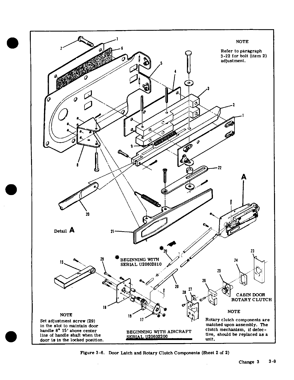
NOTE
Refer
to
paragraph
3-22
for
bolt
(item
2)
A
20
Detail
A
21
20
23
ROTARY
CLUTCH
SERIAL
20602810
Set
adjustment
screw
(29)
17
Rotary
clutch components
are
in
the
slot
to
maintain
door
matched
upon
assembly.
The
handle
8- 15'
above
center
BEGINNING
WITH
AIRCRAFT
clutch
mechanism,
if
defec-
line
of
handle
shaft
when
the
SERIAL
U20602200
tive, should
be
replaced
as
a
door
is
in
the
locked
position.
unit.
Figure
3-6.
Door
Latch
and
Rotary
Clutch
Components
(Sheet
2
of
2)
Change
3
3-9
3-33.
SEATS.
(Refer
to
figure
3-7.)
by
a
mechanic
unfamiliar
with
upholstery
practices.
the
mechanic
should
make
careful
notes
during
re-
3-34.
PILOT
AND
COPILOT.
moval
of
each
item
to
facilitate
its
replacement
later.
a.
RECLINING
BACK.
(Standard
pilot/Op-
tional
copilot.)
3-41.
MATERIALS
AND
TOOLS.
Materials
and
b.
RECLINING
BACK/VERTICAL
ADJUST.
tools
will
vary
with
job.
Scissors
for
trimming
up-
(Optional
1969
ONLY.
)
holstery
to
size
and
a
dull-bladed
putty knife
for
c.
ARTICULATING
RECLINE/VERTICAL
wedging
material
beneath
retainer
strips
are
the
ADJUST.
(Optional
1970
AND
ON.)
only
tools
required
for
most
trim
work.
Use
in-
dustrial
rubber
cement
to
hold
soundproofing
mats
3-35.
DESCRIPTION.
These
seats
are
manually-
and
fabric
edges
in
place.
Refer
to
Section
18
for
operated
throughout
their
full
range
of
operation.
thermo-plastic
repairs.
Seat
stops
are
provided
to
limit
fore-and-aft
travel.
Install
seat
stops
on
rails
as
follows:
3-42.
SOUNDPROOFING.
The
aircraft
is
insulated
1.
Pilots seat:
inbd
rail
fwd
and
aft.
with
spun
glass
mat-type insulation
and a
sound
dead-
2.
Copilots seat:
outbd
rail
fwd
and aft.
ener
compound
applied
to
inner
surfaces
of
skin
in
3.
Center
L
H
seat:
outbd
rail
fwd
and
aft.
most
areas
of
cabin
and
baggage
compartment.
4.
Center
R
H
seat:
outbd
rail
fwd
and
inbd
rail
aft.
All
soundproofing
material
should
be
replaced
5
Aft
L
H
seat:
outbd
rail
fwd
and
aft.
in
its
original
position
any
time it
is
removed.
6.
Aft
R H
seat:
outbd
rail
aft
only.
A
soundproofing
panel
is
placed
in
the
gap
be-
tween
the
wing and
fuselage
and
held
in
place
3-36.
REMOVAL
AND
INSTALLATION.
by
the wing
root
fairing.
a.
Remove
seat
stops
from
rails.
b.
Slide
seat
fore-and-aft
to
disengage
seat
rollers
from
rails.
3-43.
CABIN
HEADLINER.
(Refer
to
figure
3-10.)
c.
Lift
seat
out.
d.
Reverse
the
preceding
steps
for
installation.
3-44.
REMOVAL.
Ensure
all
seat
stops
are
reinstalled.
a.
Remove sun
visors,
all inside
finish
strips
and
plates,
door
post
upper
shields,
front
spar
trim
WAR NI
NG
shield,
dome
light
console
and any
other
visible re-
tainers
securing
headliner.
It
is
extremely
important
that
pilot's
seat
b.
Work
edges
of
headliner
free
from metal
teeth
stops
are
installed,
since
acceleration
and
which
hold
fabric.
deceleration
could
possiblypermit seat
c.
Starting
at
front
of
headliner,
work headliner
to
become
disengaged
from
seat
rails
and
down,
removing
screws
through
metal
tabs
which
create
a
hazardous
situation,
especially
dur-
hold
wire
bows
to
cabin
top.
Pry
loose
outer
ends
ing
take-off
and
landing.
of
bows
from
retainers
above
doors.
Detach
each
bow
in
succession.
3-37.
CENTER
AND
REAR.
a.
RECLINING
BACK/FORE-AND-AFT
AD-
NOTE
.JUST.
b.
NON-RECLINING
BACK/FORE-AND-AFT
Always
work
from
front
to
rear
when
remov-
ADJUST. ing
headliner.
3-38.
DESCRIPTION.
These
seats
are
provided
d.
Remove
headliner
assembly
and
bows
from
air-
with
fore-and-aft
adjustment
provisions.
Seat
stops
craft.
are
installed
to
limit
travel.
Removal
and
installa-
tion
is
outlined
in
paragraph
3-36.
NOTE
3-39.
REPAIR.
Replacement
of
defective
parts
is
Due
to
difference
in
length
and
contour
of
recommended
in
repair
of
seats.
However,
a
wire
bows,
each
bow
should
be
tagged
to
cracked
framework
may
be
welded,
provided
crack
assure
proper
location
in
headliner.
is
not
in
an
area
of
stress
concentration
(close
to
a
hinge
or
bearing
point).
The
square-tube
framework
e.
Remove
spun
glass
soundproofing
panels.
is
6061
aluminum,
heat-treated
to
a
T-6
condition.
Use
a
heliarc
weld
on
these
seats,
as torch
welds
NOTE
will
destroy
heat-treatment
of
frame
structure.
Fig-
ure
3-8
outlines
instructions
for
replacing
defective
The
lightweight
soundproofing
panels
are
cams
on
reclining
seat
backs.
held
in
place
with
industrial
rubber
cement.
3-40.
CABIN
UPHOLSTERY.
Due
to
the
wide
selec-
3-45.
INSTALLATION.
tion
of
fabrics,
styles
and
colors,
it
is
impossible
to
a.
Before
installation,
check
all items
concealed
depict
each
particular
type
of
upholstery.
The
fol-
by
headliner
for
security.
Use
wide
cloth
tape
to
lowing
paragraphs
describe
general
procedures
which
secure
loose
wires
to
fuselage
and
to
seal
openings
will
serve
as
a
guide
in
removal
and
replacement
of
in
wing
roots.
Straighten
tabs
bent
during
removal
upholstery.
Major
work,
if
possible,
should
be
done
of
headliner.
by
an
experienced
mechanic.
If
work
must
be
done
3-10
Change
1
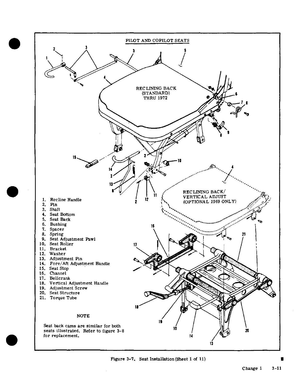
PILOT
AND
COPILOT
SEATS
THRU
1972
RECLINING
BACK/
VERTICAL
ADJUST
1.
Recline
Handle
12
VERTICAL
(OPTIONAL
1969
ONLY)
2.
Pin
3.
Shaft
4.
Seat
Bottom
5.
Seat
Back
6.
Bushing
7.
Spacer
8.
Spring
9.
Seat
Adjustment
Pawl
10.
Seat
Roller
11.
Bracket
12.
Washer
13.
Adjustment
Pin
14.
Fore/Aft
Adjustment
Handle
15.
Seat
Stop
16.
Channel
17.
Bellcrank
18.
Vertical
Adjustment
Handle
19.
Adjustment
Screw
20.
Seat
Structure
21.
Torque
Tube
NOTE
Seat back
cams
are
similar
for
both
seats
illustrated.
Refer
to
figure
3-8
for
replacement.
14
Figure
3-7.
Seat
Installation(Sheet
I
of
11)
|
Change
1
3-11
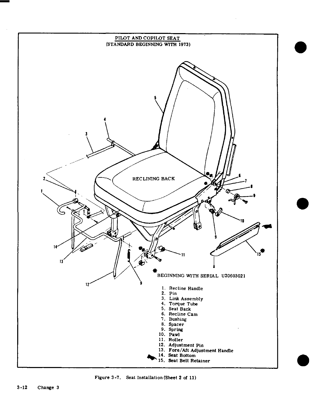
PILOT
AND
COPILOT
SEAT
(STANDARD
BEGINNING
WITH
1973)
3
1
2
RECLINING
BACK
1
BEGINNING
WITH
SERIAL
U20603021
12
9
1.
Recline
Handle
2.
Pin
3.
Link
Assembly
4.
Torque
Tube
5.
Seat
Back
6.
Recline
Cam
7.
Bushing
8.
Spacer
9.
Spring
10.
Pawl
11.
Roller
12.
Adjustment
Pin
13.
Fore/Aft
Adjustment
Handle
14.
Seat Bottom
15.
Seat
Belt
Retainer
Figure
3-7.
Seat
Installation
(Sheet
2
of
11)
3-12
Change 3
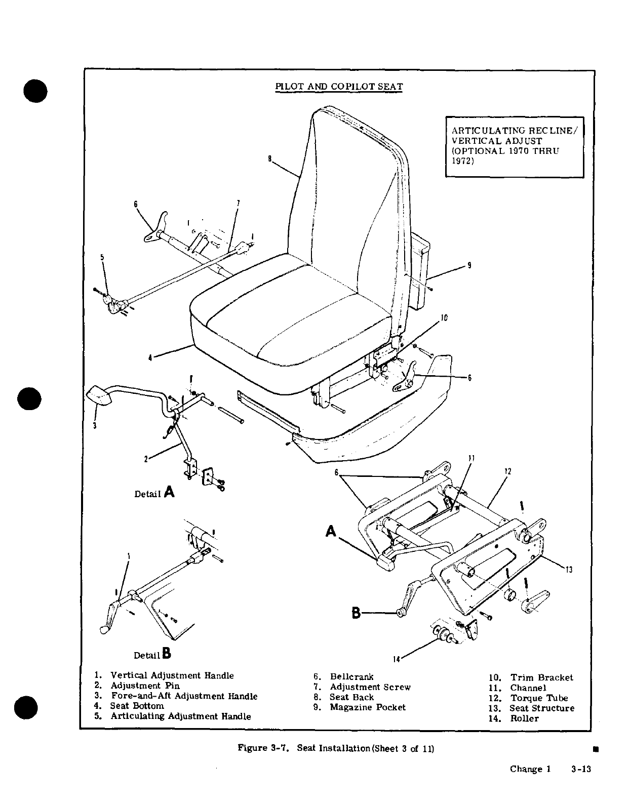
PILOT
AND
COPILOT
SEAT
ARTICULATING
RECLINE/
VERTICAL
ADJUST
OPTIONAL
1970
THRU
1972)
Detail
B
14
1.
Vertical
Adjustment
Handle
6.
Bellcrank
10.
Trim
Bracket
2.
Adjustment
Pin
7.
Adjustment Screw
11.
Channel
3.
Fore-and-Aft
Adjustment
Handle
8.
Seat
Back
12.
Torque
Tube
4.
Seat
Bottom
9.
Magazine
Pocket
13.
Seat
Structure
5.
Articulating
Adjustment
Handle
14.
Roller
Figure
3-7.
Seat
Installation(Sheet
3
of
11)
Change
1
3-13
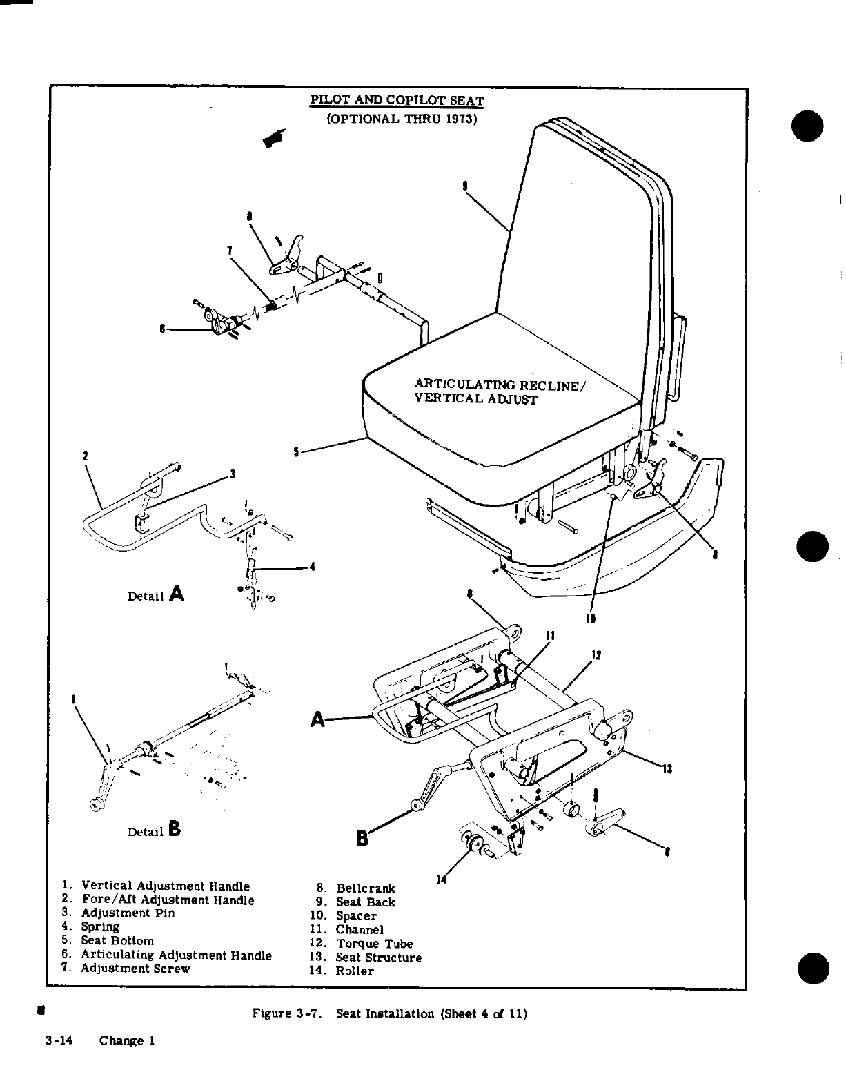
PILOT
AND
COPILOT
SEAT
(OPTIONAL
THRU
1973)
VERTICAL
ADJUST
4
Detail
A
8
,>Mi <
,,
Detail
B
14
1.
Vertical
Adjustment
Handle
8.
Bellcrank
2.
Fore/Aft
Adjustment
Handle
9.
Seat
Back
3.
Adjustment
Pin
10.
Spacer
4.
Spring
11.
Channel
5.
Seat
Bottom
12.
Torque
Tube
6.
Articulating
Adjustment
Handle
13.
Seat
Structure
7.
Adjustment
Screw
14.
Roller
*
Figure
3-7.
Seat
Installation
(Sheet
4
of
11)
3-14
Change
1
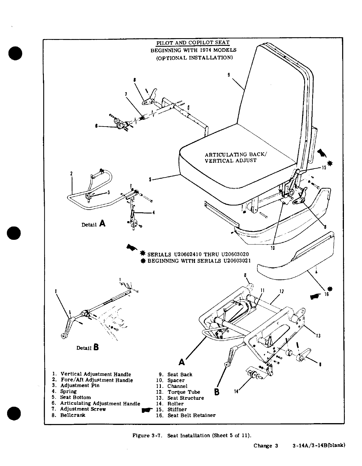
PILOT
AND
COPILOT
SEAT
BEGINNING
WITH
1974
MODELS
(OPTIONAL INSTALLATION)
9
9
ARTICULATING
BACK/
VERTICAL
ADJUST
Detail
A
1.
Vertical
Adjustment
Handle
9.
Seat
Sack
SERIALS
U20602410
THRU
U20603020
*
BEGINNING
WITH
SERIALS U20603021
Detail
1.
Vertical
Adjustment
Handle
9.
Seat
Back
2.
Fore/Art
Adjustment
Handle
10.
Spacer
/ /-
3.
Adjustment
Pin
11.
Channel
4.
Spring
12.
Torque
Tube
B
14
5.
Seat
Bottom
13.
Seat
Structure
6.
Articulating
Adjustment
Handle
14.
Roller
7.
Adjustment
Screw
15.
Stiffner
8.
Bellcrank
16.
Seat
Belt
Retainer
Figure
3-7. Seat
Installation
(Sheet
5
of
11).
Change
3
3-14A/3-14B(blank)
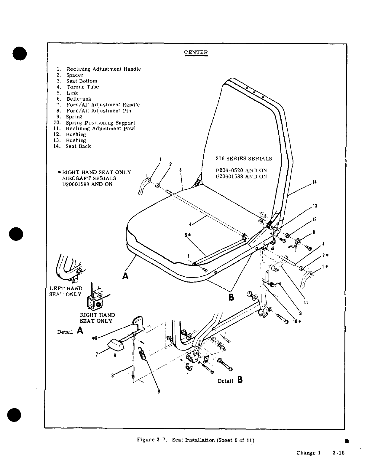
CENTER
1.
Reclining
Adjustment
Handle
2.
Spacer
3.
Seat
Bottom
4.
Torque
Tube
5.
Link
6.
Bellcrank
7.
Fore/Aft
Adjustment
Handle
8.
Fore/Aft
Adjustment
Pin
9.
Spring
10.
Spring
Positioning
Support
11.
Reclining
Adjustment
Pawl
12.
Bushing
13.
Bushing
14.
Seat
Back
1
206
SERIES SERIALS
2
*RIGHT
HAND
SEAT
ONLY
P206-0520AND
ON
AIRCRAFT
SERIALS
20601588
AND
ON
U2060158R
AND
ON
0, /\S \\1\ ^ ^134
2*
SEAA
.
LEFT
HAND
SEAT
ONLY\
\
RIGHT
HAND
9
SEAT
ONLY
19*
Detail
A
'<^-^~~ \
Detail
B
9
Figure
3-7.
Seat
Installation
(Sheet
6
of
11)
Change
1
3-15
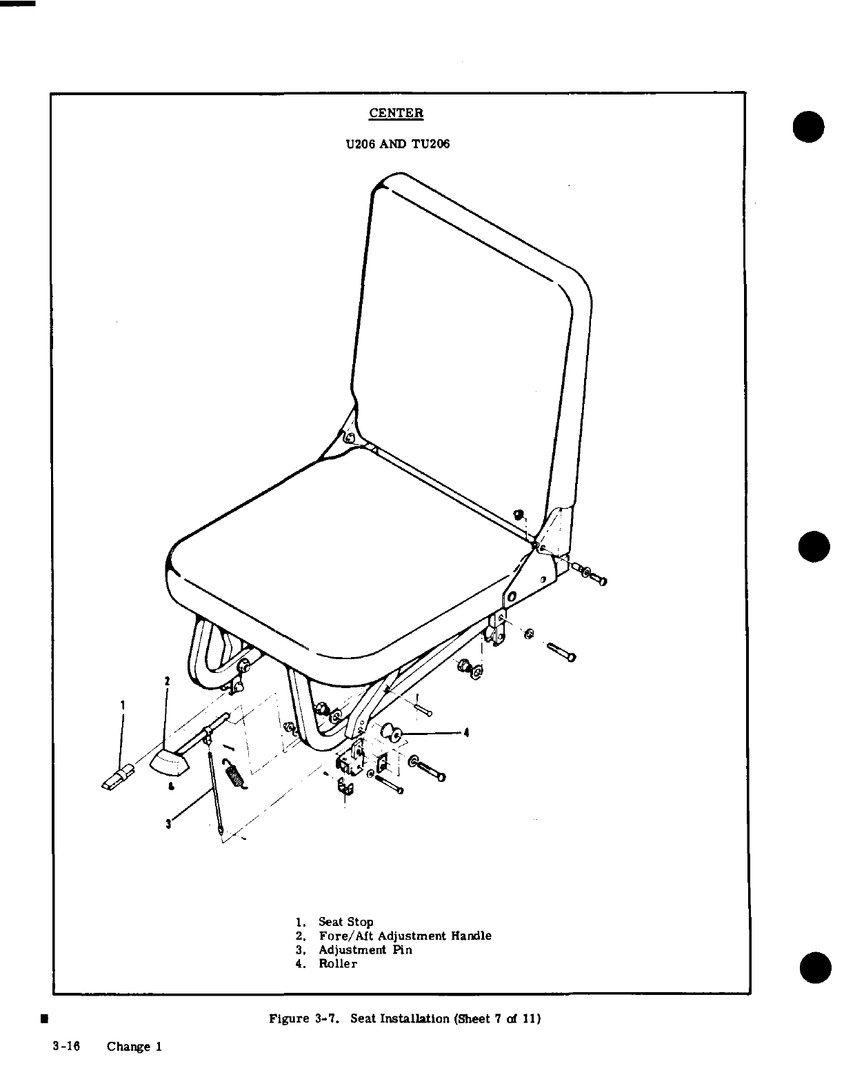
1.
Seat
Stop
2.
Fore/Aft
Adjustment
Handle
3.
Adjustment
Pin
4.
Roller
Figure
3-7.
Seat
Installation
(Sheet 7
of
11)
3-16
Change 1
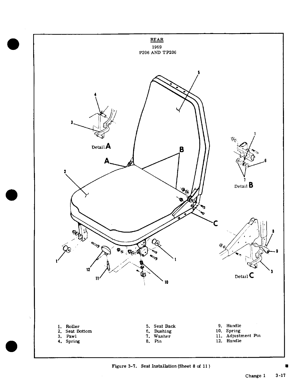
REAR
1969
P206
AND
TP206
4
DetailA
e
il
B
Detail
11
Detail
C
3
1.
Roller
5.
Seat
Back
9.
Handle
2.
Seat
Bottom
6.
Bushing
10.
Spring
3.
Pawl
7.
Washer
11.
Adjustment
Pin
4.
Spring
8.
Pin
12.
Handle
Figure
3-7.
Seat
Installation
(Sheet
8
of
11)
I
Change
1
3-17
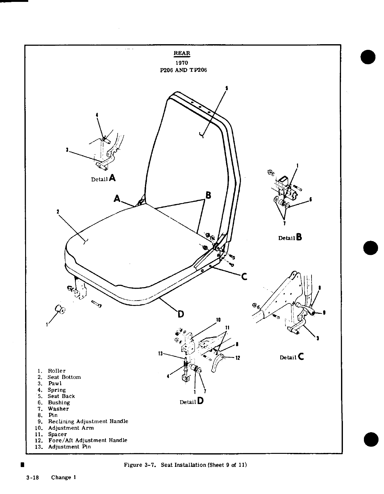
REAR
1970
P206
AND
TP206
4
3
Detail
A
2. Seat
Bottom
3.
Pawl
4.
Spring
5.
Seat
Back
6.
Bushing
Detail
D
7.
Washer
8.
Pin
9.
Reclining
Adjustment
Handle
10.
Adjustment
Arm
11.
Spacer
12.
Fore/Aft
Adjustment
Handle
13.
Adjustment
Pin
Figure
3-7.
Seat
Installation
(Sheet
9
of
11)
3-18
Change
1
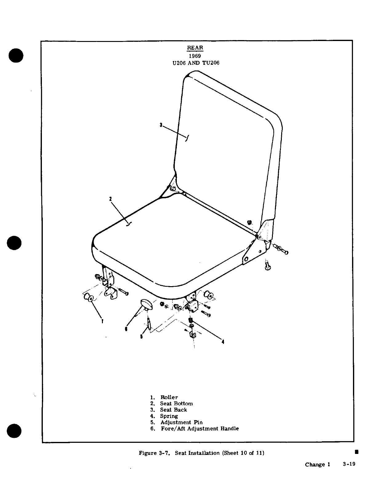
1.
Roller
2.
Seat
Bottom
3.
Seat
Back
4.
Spring
5.
Adjustment Pin
6.
Fore/Aft
Adjustment
Handle
Figure
3-7.
Seat
Installation
(Sheet
10
of
11)
|
Change
1
3-19
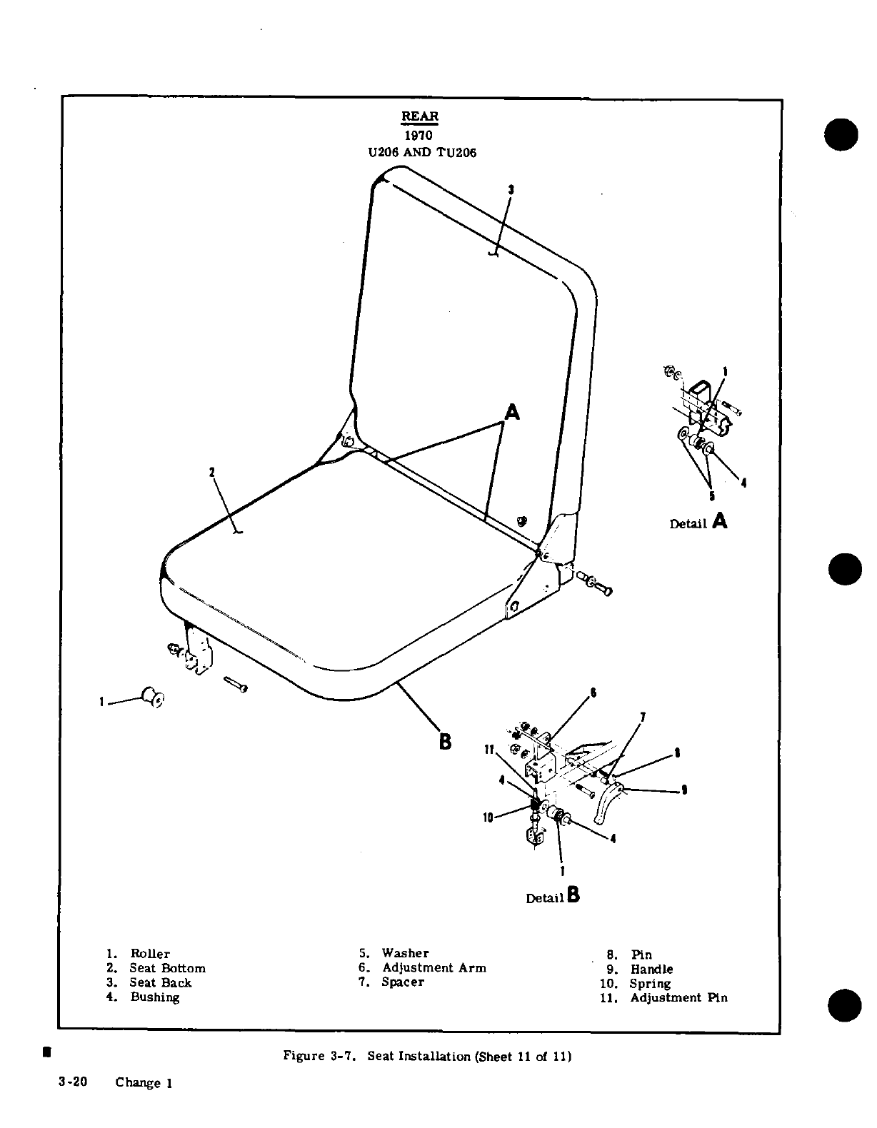
REAR
1970
U206
AND
TU206
11
Detail
A
B
3.
Seat
Back
7.
Spacer
10.
Spring
4.
Bushing
11.
Adjustment
Pin
Figure
3-7. Seat
Installation
(Sheet
11
of
11)
3-20
Change
1
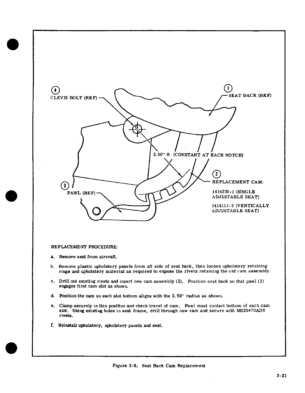
CLEVIS
BOLT
(REF)
SEAT
BACK
(REF)
2.50"
R.
(CONSTANT
AT
EACH
NOTCH)
REPLACEMENT
CAM:
PAWL
(REF)
1414230-1 (SINGLE
ADJUSTABLE
SEAT)
ADJUSTABLE
SEAT
1414111-5
(VERTICALLY
ADJUSTABLE
SEAT)
REPLACEMENT
PROCEDURE:
a.
Remove
seat
from
aircraft.
b.
Remove
plastic
upholstery
panels
from
aft
side
of
seat
back,
then
loosen
upholstery
retaining
rings
and
upholstery
material
as required
to
expose the
rivets
retaining
the
old
cam
assembly.
c.
Drill
out
existing
rivets
and
insert
new
cam
assembly
(2).
Position
seat
back
so
that
pawl
(3)
engages
first
cam
slot
as
shown.
d.
Position
the
cam
so
each
slot
bottom
aligns
with
the
2.
50"
radius
as
shown.
e.
Clamp
securely
in
this
position
and
check
travel
of
cam. Pawl
must
contact
bottom
of
each
cam
slot.
Using
existing
holes
in
seat
frame,
drill
through
new
cam
and
secure
with
MS20470AD6
rivets.
f.
Reinstall
upholstery,
upholstery panels
and
seat.
Figure
3-8.
Seat
Back
Cam
Replacement
3-21
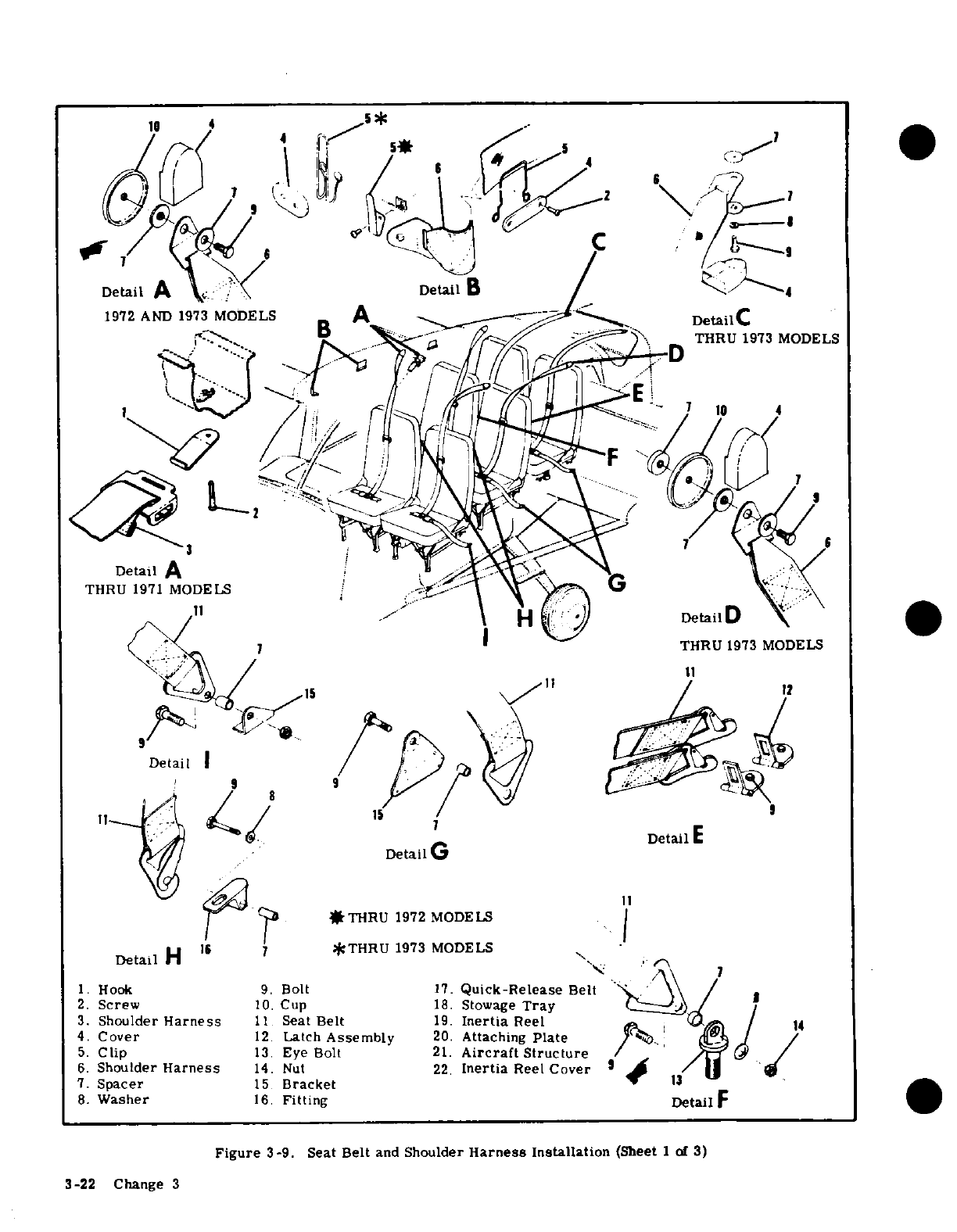
1.
Hook
9.
Bolt
17.
Quick-Release
Belt
2.
Screw
10.
Cup
18.
Stowage
Tray
3.
Shoulder
Harness
11.
Seat
Belt
19.
Inertia
Reel
4.
Cover
12.
Latch
Assembly
20.
Attaching
Plate
5.
Clip
13.
Eye
Bolt
21.
Aircraft
Structure
6.
Shoulder
Harness
14.
Nut
22.
Inertia
Reel
Cover
7.
Spacer
15.
Bracket
8.
Washer
16.
Fitting
Figure
3-9. Seat
Belt
and
Shoulder
Harness
Installation
(Sheet
1
of
3)
3-22 Change 3
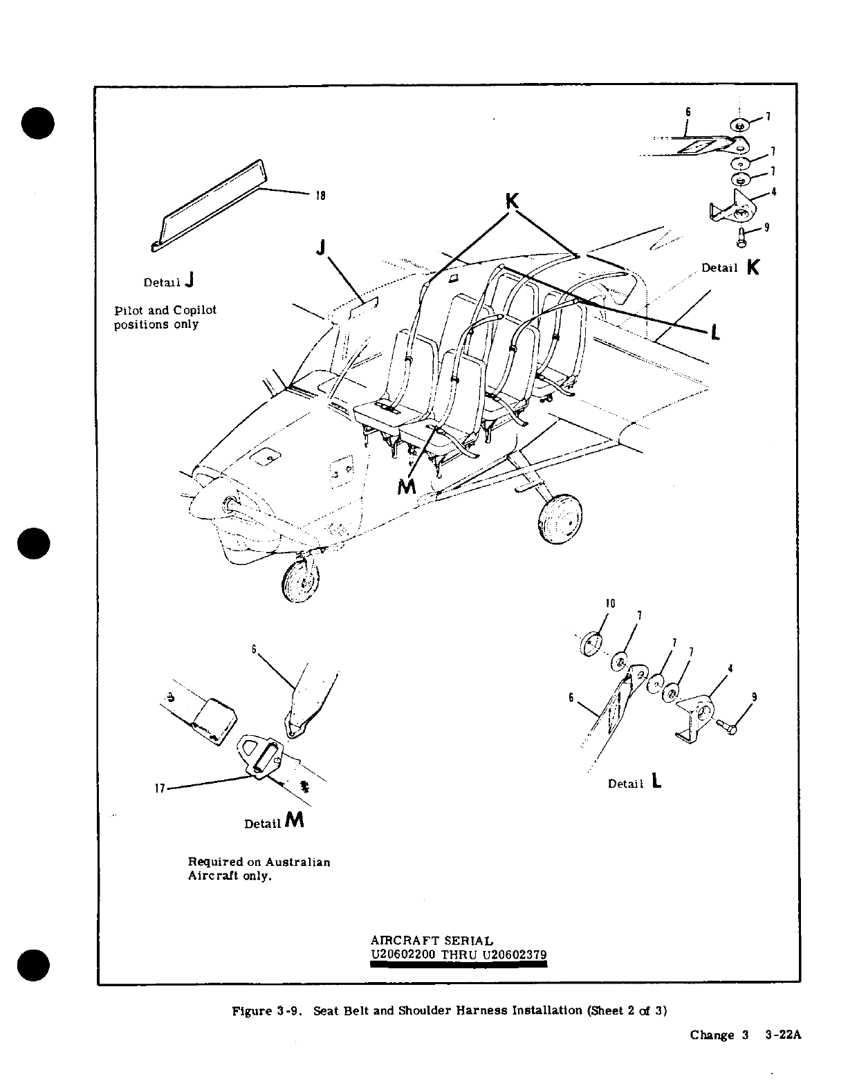
K
Detail
K
Detail
J
Pilot
and
Copilot
positions
only
7
7
17
Detail
L
Detail
M
Required
on
Australian
Aircraft
only.
AIRCRAFT
SERIAL
U20602200
THRU
U20602379
Figure
3-9. Seat
Belt
and
Shoulder
Harness
Installation
(Sheet
2
of
3)
Change
3
3-22A
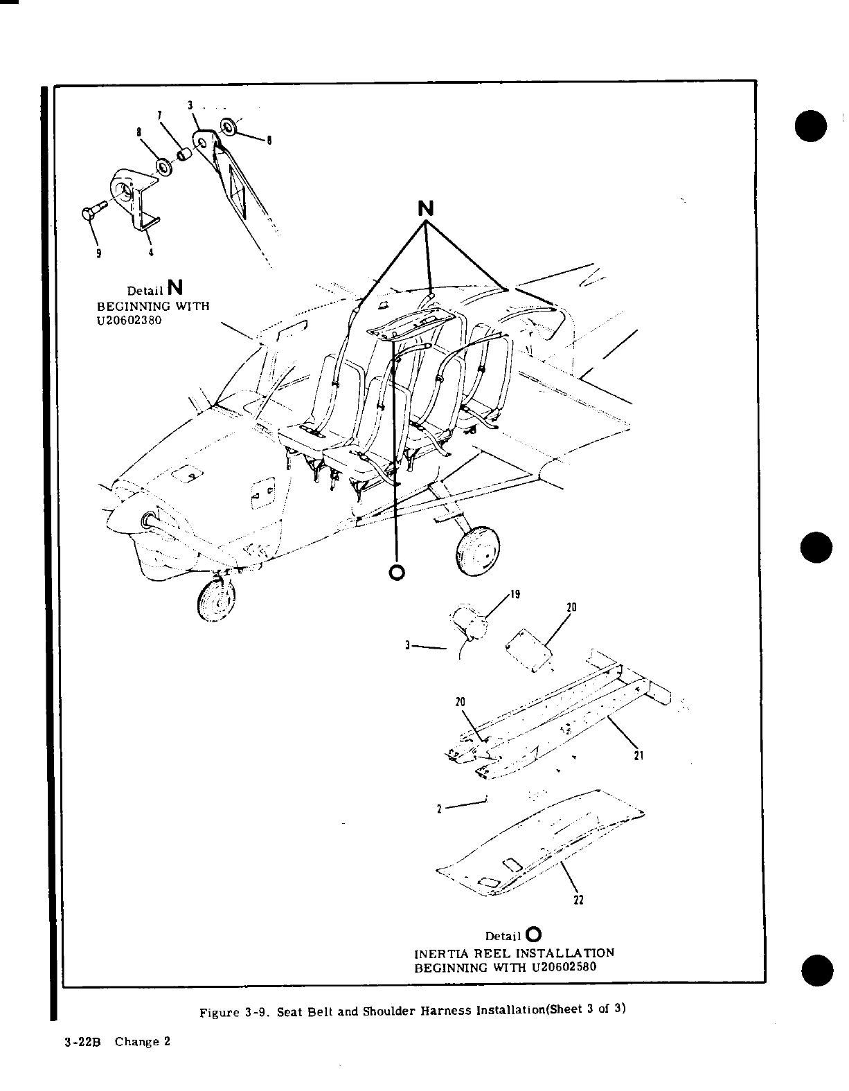
* 4
N
Detail
N
-
BEGINNING
WITH
...--.
U20602380
.
..
20
-
21
22
Detail O
INERTIA
REEL
INSTALLATION
BEGINNING
WITH
U20602580
Figure
3-9. Seat
Belt
and
Shoulder
Harness
Installation(Sheet
3
of
3)
3-22B
Change
2
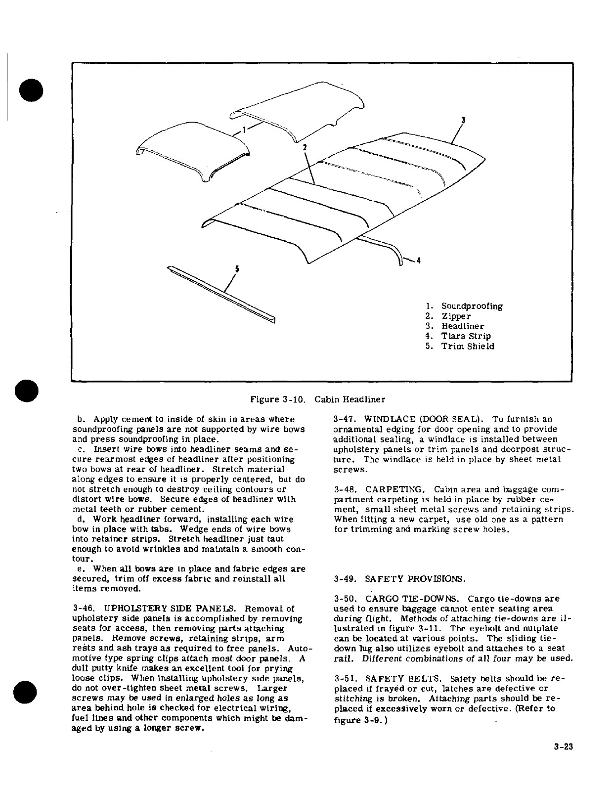
1.
Soundproofing
2.
Zipper
3.
Headliner
4.
Tiara
Strip
5.
Trim
Shield
Figure
3-10.
Cabin
Headliner
b.
Apply
cement
to
inside
of
skin
in
areas
where
3-47.
WINDLACE
(DOOR
SEAL).
To
furnish
an
soundproofing
panels
are
not
supported
by
wire
bows
ornamental
edging
for
door
opening
and
to
provide
and
press
soundproofing
in
place.
additional
sealing,
a
windlace
is
installed
between
c.
Insert
wire
bows
into
headliner
seams
and
se-
upholstery
panels
or
trim
panels
and
doorpost
struc-
cure
rearmost
edges
of
headliner
after
positioning
ture.
The
windlace is
held in
place
by
sheet
metal
two
bows
at
rear
of
headliner.
Stretch
material
screws.
along
edges
to
ensure
it
is properly
centered,
but
do
not
stretch
enough
to
destroy
ceiling
contours or
3-48.
CARPETING.
Cabin
area
and
baggage
com-
distort
wire
bows.
Secure edges
of
headliner
with
partment
carpeting
is
held
in
place
by
rubber
ce-
metal
teeth
or rubber
cement.
ment,
small
sheet metal
screws
and
retaining
strips.
d.
Work
headliner forward,
installing
each
wire
When
fitting
a
new
carpet,
use
old
one
as
a
pattern
bow
in
place
with
tabs.
Wedge
ends
of
wire
bows
for
trimming
and
marking
screw
holes.
into
retainer
strips.
Stretch headliner
just
taut
enough
to
avoid
wrinkles
and
maintain
a
smooth
con-
tour.
e.
When
all
bows
are
in
place
and
fabric
edges
are
secured,
trim
off
excess
fabric
and
reinstall
all
3-49.
SAFETY
PROVISIONS.
items
removed.
3-50.
CARGO
TIE-DOWNS.
Cargo tie-downs
are
3-46.
UPHOLSTERY
SIDE
PANELS.
Removal
of
used
to
ensure
baggage
cannot
enter
seating
area
upholstery
side panels
is
accomplished
by
removing during flight.
Methods
of
attaching
tie-downs
are
il-
seats
for
access,
then
removing
parts
attaching
lustrated
in
figure
3-11.
The
eyebolt
and
nutplate
panels.
Remove
screws,
retaining
strips,
arm
can
be
located at
various
points.
The
sliding
tie-
rests
and
ash
trays
as
required
to
free panels.
Auto-
down
lug
also
utilizes
eyebolt and
attaches
to
a
seat
motive
type
spring
clips
attach
most door
panels.
A
rail.
Different
combinations
of
all
four
may
be
used.
dull putty
knife
makes
an
excellent
tool for
prying
loose
clips.
When
installing
upholstery
side
panels,
3-51.
SAFETY
BELTS. Safety
belts
should
be
re-
do
not
over-tighten
sheet
metal
screws.
Larger
placed
if
frayed
or
cut,
latches
are
defective
or
screws
may
be
used
in
enlarged
holes
as
long
as
stitching
is
broken.
Attaching
parts
should
be
re-
area
behind
hole
is
checked
for
electrical
wiring,
placed
if
excessively
worn
or
defective.
(Refer
to
fuel
lines
and
other
components
which
might
be
dam-
figure
3-9.)
aged
by
using
a
longer
screw.
3-23
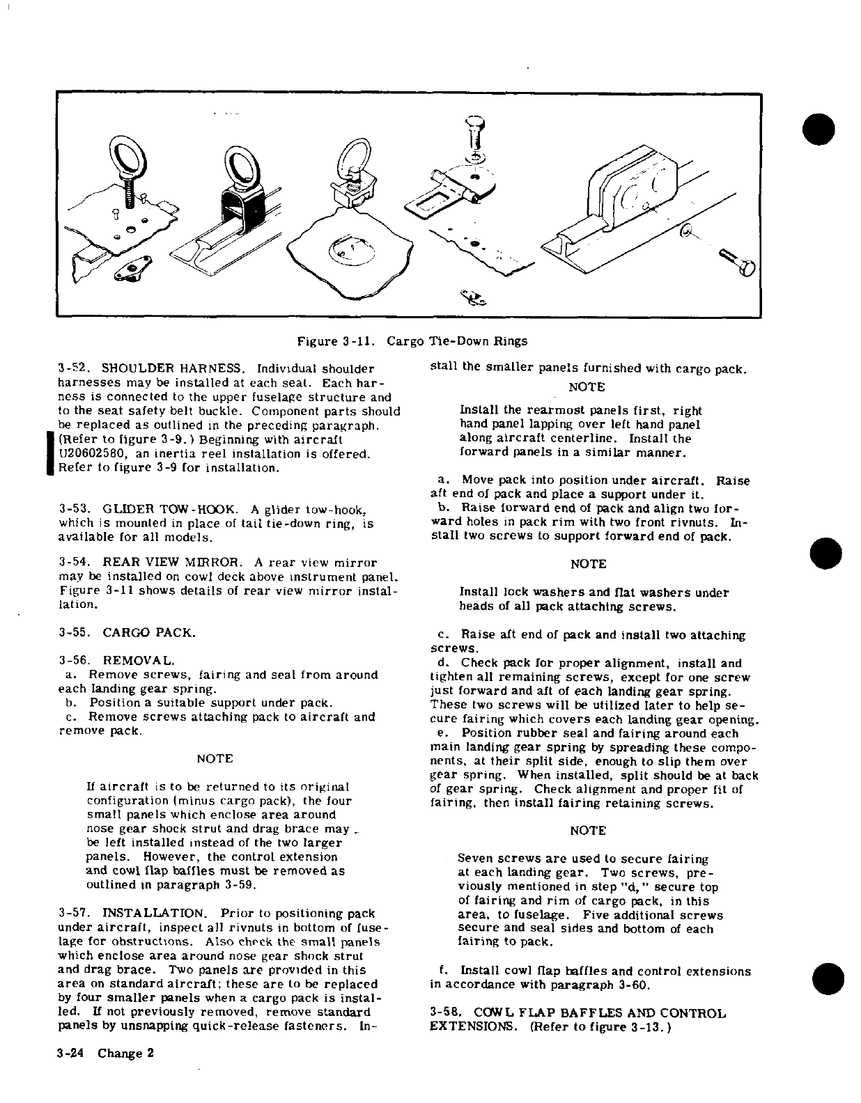
Figure
3-11.
Cargo
Tie-Down
Rings
3-52.
SHOULDER
HARNESS.
Individual
shoulder
stall
the
smaller
panels furnished
with
cargo
pack.
harnesses
may
be
installed
at
each
seat.
Each
har-
NOTE
ness
is
connected
to
the
upper fuselage
structure
and
to
the
seat
safety
belt
buckle. Component
parts
should
Install
the
rearmost
panels
first,
right
be
replaced
as
outlined
in
the
preceding
paragraph.
hand
panel
lapping
over
left
hand
panel
(Refer
to
figure
3-9.)
Beginning
with
aircraft
along
aircraft
centerline.
Install
the
U20602580,
an
inertia
reel
installation
is
offered.
forward panels
in
a
similar
manner.
Refer
to
figure
3-9
for
installation.
a.
Move
pack
into
position
under
aircraft.
Raise
aft
end
of
pack
and
place
a
support
under
it.
3-53.
GLIDER
TOW-HOOK.
A
glider
tow-hook,
b.
Raise
forward
end
of
pack
and
align
two
for-
which
is
mounted
in
place
of
tail
tie-down
ring,
is
ward
holes
in
pack
rim
with
two
front
rivnuts.
In-
available
for
all
models.
stall
two
screws
to
support
forward
end
of
pack.
3-54.
REAR
VIEW
MIRROR.
A
rear
view
mirror
NOTE
may
be
installed
on
cowl
deck
above
instrument
panel.
Figure
3-11 shows
details
of
rear
view
mirror
instal-
Install
lock
washers
and
flat
washers
under
lation.
heads
of
all
pack
attaching
screws.
3-55.
CARGO
PACK.
c.
Raise
aft
end
of
pack
and
install
two
attaching
screws.
3-56.
REMOVAL.
d.
Check
pack
for
proper
alignment,
install
and
a.
Remove
screws,
fairing
and
seal
from
around
tighten all remaining
screws,
except
for
one
screw
each
landing
gear
spring.
just
forward
and aft
of
each
landing
gear
spring.
b.
Position
a
suitable
support
under
pack.
These
two
screws
will
be
utilized
later
to
help
se-
c.
Remove
screws
attaching
pack
to
aircraft
and
cure
fairing
which
covers
each landing
gear
opening.
remove
pack.
e.
Position
rubber
seal
and
fairing
around
each
main
landing
gear
spring
by
spreading
these
compo-
NOTE
nents,
at
their
split
side,
enough
to
slip
them
over
gear
spring.
When
installed,
split
should
be
at
back
If
aircraft
is to
be
returned
to
its
original
of
gear spring.
Check
alignment
and
proper
fit
of
configuration
(minus
cargo
pack),
the
four
fairing,
then
install
fairing
retaining
screws.
small
panels
which
enclose
area
around
nose
gear
shock
strut
and
drag
brace
may
_
NOTE
be
left
installed instead
of
the
two
larger
panels.
However,
the
control extension
Seven
screws
are
used
to
secure
fairing
and
cowl
flap
baffles
must
be
removed
as
at
each
landing
gear.
Two
screws,
pre-
outlined
in
paragraph
3-59.
viously mentioned
in
step
"d,"
secure
top
of
fairing
and
rim
of
cargo
pack,
in
this
3-57.
INSTALLATION.
Prior
to
positioning
pack
area,
to
fuselage.
Five
additional
screws
under
aircraft,
inspect
all
rivnuts
in
bottom
of
fuse-
secure
and
seal
sides
and
bottom
of
each
lage
for
obstructions.
Also
check
the
small
panels
fairing
to
pack.
which
enclose
area
around
nose
gear
shock
strut
and
drag
brace.
Two
panels
are
provided
in
this
f.
Install
cowl
flap
baffles
and
control
extensions
area
on
standard
aircraft;
these
are
to
be
replaced
in
accordance
with
paragraph
3-60.
by
four
smaller
panels
when
a
cargo
pack
is
instal-
led.
If
not
previously
removed,
remove
standard
3-58.
COWL
FLAP
BAFFLES
AND
CONTROL
panels
by
unsnapping
quick-release fasteners.
In-
EXTENSIONS.
(Refer
to
figure
3-13.)
3-24
Change
2
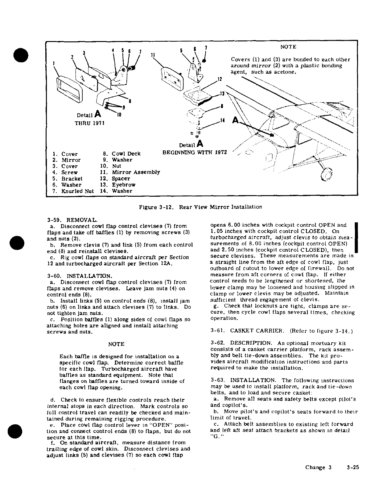
NOTE
2
/
Covers
(1)
and
(3)
are
bonded
to
each
other
around
mirror
(2)
with
a
plastic
bonding
agent,
such
as
acetone.
Detail
A
.
THRU
1971
1-
A
Detail
A
.
.
/-....
1.
Cover
8.
Cowl
Deck
BEGINNING
WITH
1972
.
2.
Mirror
9.
Washer
3.
Cover
10.
Nut
4.
Screw
11.
Mirror
Assembly
5.
Bracket
12.
Spacer
6.
Washer
13.
Eyebrow
7.
Knurled
Nut
14.
Washer
Figure
3-12.
Rear
View
Mirror
Installation
3-59.
REMOVAL.
a.
Disconnect
cowl
flap
control
clevises
(7)
from
opens
6.00 inches
with
cockpit
control
OPEN and
flaps
and take
off
baffles
(1)
by
removing
screws
(3)
1.05
inches
with
cockpit
control
CLOSED.
On
and
nuts
(2).
turbocharged
aircraft,
adjust
clevis
to
obtain
mea-
b.
Remove
clevis
(7)
and
link
(5)
from
each control
surements
of
8.00
inches
(cockpit
control
OPEN)
end
(8)
and
reinstall
clevises,
and
2.
50
inches
(cockpit
control
CLOSED),
then
c.
Rig
cowl
flaps
on
standard
aircraft
per
Section
secure clevises.
These
measurements
are
made
in
12
and
turbocharged
aircraft
per
Section
12A.
a
straight
line
from
the
aft
edge
of
cowl
flap,
just
outboard
of
cutout
to
lower
edge
of
firewall.
Do not
3-60.
INSTALLATION.
measure
from
aft
corners
of
cowl
flap.
If
either
a.
Disconnect
cowl
flap
control
clevises
(7)
from
control
needs to
be
lengthened
or
shortened,
the
flaps
and
remove
clevises.
Leave
jam nuts
(4)
on
lower
clamp
may
be
loosened
and
housing
slipped
in
control
ends
(8).
clamp
or
lower
clevis
may
be
adjusted.
Maintain
b.
Install
links
(5)
on
control
ends
(8),
install
jam
sufficient
thread
engagement
of
clevis.
nuts
(6)
on
links
and
attach
clevises
(7)
to
links.
Do
g.
Check
that
locknuts
are
tight,
clamps
are
se-
not
tighten
jam
nuts.
cure,
then
cycle
cowl
flaps
several
times,
checking
c.
Position
baffles
(1)
along
sides
of
cowl
flaps
so
operation.
attaching
holes
are
aligned
and
install
attaching
screws
and nuts.
3-61.
CASKET
CARRIER.
(Refer
to
figure
3-14.)
NOTE
3-62.
DESCRIPTION.
An
optional
mortuary
kit
consists
of
a
casket
carrier
platform,
rack assem-
Each
baffle
is
designed
for
installation
on
a
bly
and
belt
tie-down
assemblies.
The
kit
pro-
specific
cowl
flap.
Determine
correct
baffle
vides
aircraft
modification
instructions
and
parts
for
each
flap.
Turbocharged
aircraft
have
required
to
make
the
installation.
baffles
as
standard
equipment.
Note
that
flanges
on
baffles
are
turned
toward inside
of
3-63.
INSTALLATION.
The
following
instructions
each
cowl
flap
opening. may
be
used
to
install
platform,
rack
and
tie-down
belts,
and
to
load
and
secure casket:
d.
Check
to
ensure
flexible
controls
reach
their
a.
Remove
all
seats
and
safety
belts
except
pilot's
internal
stops
in
each
direction.
Mark
controls
so
and
copilot's.
full
control
travel
can
readily
be
checked
and
main-
b.
Move
pilot's
and
copilot's
seats
forward
to their
tained
during
remaining
rigging
procedure.
limit
of
travel.
e.
Place
cowl
flap
control
lever
in
"OPEN"
post-
c.
Attach
belt
assemblies
to
existing
left
forward
tion
and
connect
control
ends
(8)
to
flaps,
but
do
not
and
left
aft
seat
attach
brackets
as
shown
in
detail
secure
at
this
time.
"G."
f.
On
standard
aircraft,
measure
distance
from
trailing
edge
of
cowl
skin.
Disconnect
clevises
and
adjust
links
(5)
and
clevises
(7)
so
each
cowl
flap
Change
3
3-25
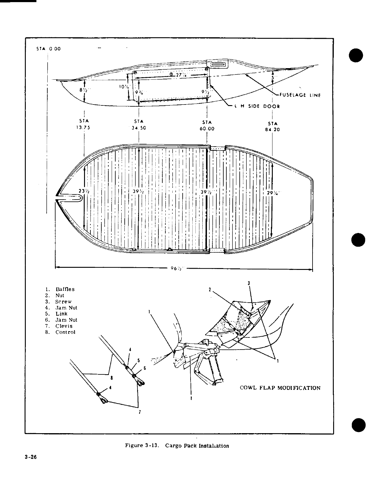
STA
0 00
9 1/ 2
FUSELAGE
LINE
H
SIDE
DOOR
STA STA
STA
STA
13.75
34
50
60
.00
84.
20
231/2
96
1/2
3
1.
Baffles
2
2.
Nut
3.
Screw
4.
Jam
Nut
5.
Link
6.
Jam
Nut
7.
Clevis
8.
Control
4 COWL
FLAP
MODIFICATION
7
Figure
3-13.
Cargo
Pack
Installation
3-26
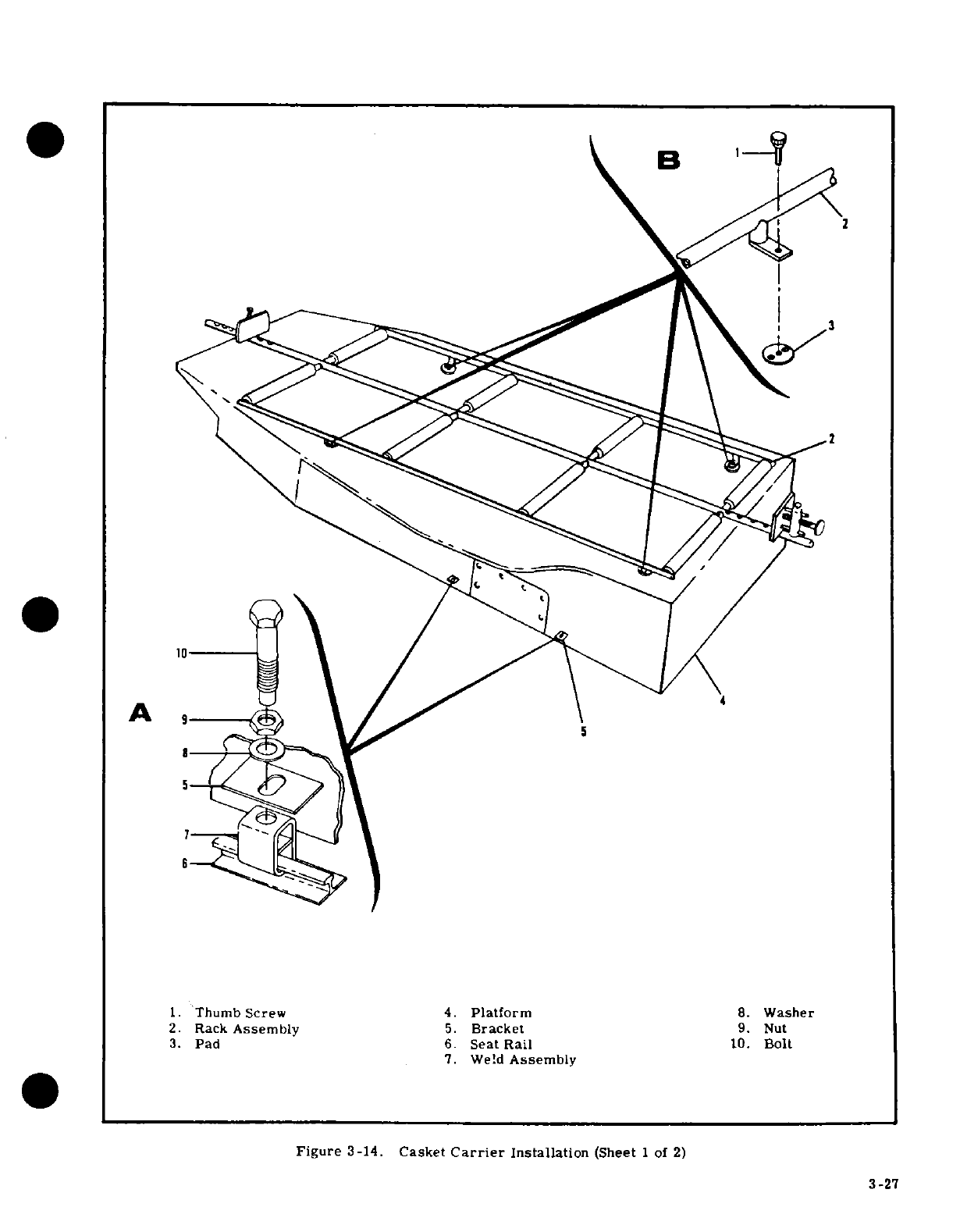
1.
Thumb
Screw
4.
Platform
8.
Washer
2.
Rack
Assembly
5.
Bracket
9.
Nut
3.
Pad
6.
Seat
Rail
10.
Bolt
7.
Weld
Assembly
3-27
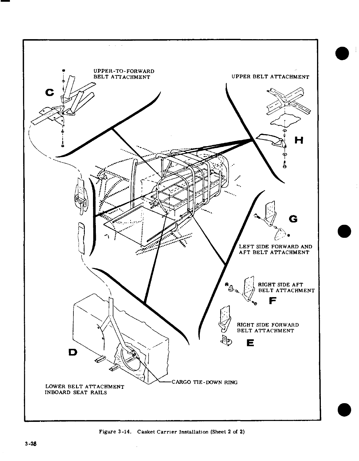
UPPER-TO-FORWARD
BELT
ATTACHMENT
UPPER
BELT
ATTACHMENT
LEFT
SIDE
FORWARD
AND
AFT
BELT
ATTACHMENT
RIGHT
SIDE
AFT
BELT
ATTACHMENT
RIGHT SIDE
FORWARD
BELT
ATTACHMENT
CARGO
TIE-DOWN
RING
LOWER
BELT
ATTACHMENT
INBOARD
SEAT
RAILS
Figure
3-14.
Casket
Carrier
Installation
(Sheet
2
of
2)
3-28

d.
Place
platform
in
cabin
and
butt
aft
end
of
plat-
i.
Attach
upper
belt
to
forward
belt
as
shown
in
de-
form
against
step.
tail
"C."
e.
Secure
both
sides
of
platform
to
outboard
seat
j.
Attach right
forward
and
right
aft
belts
to
ex-
rails
as
shown
in
detail
"A.
"
isting
seat
belt
attach
points
as
shown in
details
"E"
f.
Install
rack
on
platform as
shown
in
detail
"B."
and
"F."
g.
Install
cargo
tie-down
rings
on
inboard
seat
k.
Remove
pilot's
seat
back
by
removing
quick-
rails
and
attach
lower
belt
as
shown
in
detail
"D."
release
pins.
l.
Load
casket,
adjusting
end
plates
on
rack
NOTE
according
to
casket
length.
Tighten
forward
end
plate snugly.
The
cargo tie-down
ring
on
left
inboard
m.
Tighten
all
belts
securely
and
recheck all
tie-
seat
rail
is
tightened
down
against
seat
down
attachments.
rail,
since
no
seat
adjusting
hole
exists
n.
Reinstall
pilot's
seat
back.
in
rail
at
this
point. The
cargo tie-
down
ring
on
right
inboard
seat
rail
will
3-64.
REMOVAL.
After
casket
has
been
removed,
engage
an
existing
seat
adjustment
hole.
platform, rack,
and
belts
may
be
removed
by
re-
versing
installation
procedure.
h.
Attach
upper
belt
at
four
points
as
shown
in
de-
tail
"H."
SHOP
NOTES:
3-29/(3-30
blank)
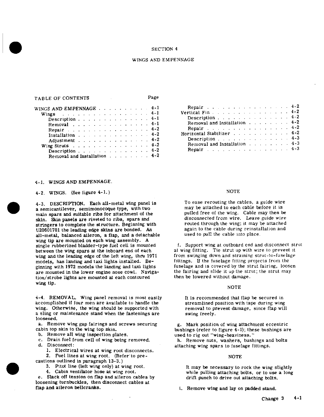
SECTION
4
WINGS
AND
EMPENNAGE
TABLE
OF
CONTENTS
Page
WINGS
AND
EMPENNAGE
..........
4-1
Repair
..
....
..
4-2
Wings
..............
...
4-1
Vertical
Fin
.
...........
. .
4-2
Description
..............
4-1
Description
.......
....... 4-2
Removal.
...........
. 4-1
Removal
and
Installation
........
4-2
Repair
..... . . . . ..
4-2
Repair
. . . . . . .
4-2
Installation.
...........
. 4-2
Horizontal
Stabilizer.
......... .4-2
Adjustment
..............
4-2
Description
.
....... .....
.
4-3
Wing
Struts
.............
. 4-2
Removal
and
Installation
....
. ..
4-3
Description
.
.........
4-2
Repair
.......... ...... 4-3
Removal
and
Installation
....
4-2
4-1.
WINGS
AND
EMPENNAGE.
4-2.
WINGS.
(See
figure 4-1.)
NOTE
4-3.
DESCRIPTION.
Each
all-metal
wing
panel
is
To
ease
rerouting
the
cables,
a
guide
wire
a
semicantilever,
semimonocoque
type,
with
two
may
be
attached
to
each
cable
before
it
is
main
spars
and
suitable
ribs
for
attachment
of
the
pulled
free
of
the wing.
Cable may
then
be
skin.
Skin
panels
are
riveted
to
ribs,
spars
and
disconnected from
wire.
Leave
guide
wire
stringers
to
complete
the
structure.
Beginning
with
routed
through
the
wing;
it
may
be
attached
U20601701
the
leading
edge
skins
are
bonded.
An
again
to
the
cable
during
reinstallation
and
all-metal,
balanced
aileron,
a
flap,
and
a
detachable
used
to
pull
the
cable
into
place.
wing
tip
are
mounted
on
each
wing
assembly.
A
single
rubberized
bladder-type
fuel
cell
is
mounted
f.
Support
wing
at
outboard
end and
disconnect
strut
between
the
wing
spars
at
the
inboard
end
of
each
at
wing
fitting.
Tie
strut
up
with
wire
to
prevent
it
wing
and
the
leading
edge of
the
left
wing,
thru
1971
from
swinging
down
and
straining
strut-to-fuselage
models, has
landing
and
taxi
lights installed.
Be-
fittings.
If
the
fuselage
fitting
projects
from
the
ginning
with
1972
models
the
landing
and
taxi
lights
fuselage
and
is
covered
by
the
strut
fairing,
loosen
are
mounted
in
the
lower
engine
nose
cowl.
Naviga-
the
fairing
and
slide
it
up
the
strut;
the
strut
may
tion/strobe
lights
are
mounted
at
each
contoured
then
be
lowered
without
damage.
wing
tip.
NOTE
4-4.
REMOVAL.
Wing
panel
removal
is
most
easily
It
is
recommended
that
flap
be
secured
in
accomplished
if
four
men
are
available
to
handle the
streamlined
position
with
tape
during
wing
wing.
Otherwise,
the
wing
should
be
supported
with
removal
to
prevent
damage,
since
flap
will
a
sling
or
maintenance
stand
when
the
fastenings
are
swing
freely.
loosened.
a.
Remove
wing
gap
fairings
and
screws
securing
g.
Mark
position
of
wing
attachment
eccentric
cabin
top
skin
to
the
wing
top
skin.
bushings
(refer
to
figure
4-1);
these
bushings
are
b.
Remove
all
wing
inspection plates. used
to
rig
out
"wing-heaviness."
c.
Drain
fuel
from
cell
of
wing
being
removed.
h.
Remove
nuts,
washers,
bushings
and
bolts
d.
Disconnect:
attaching
wing
spars
to
fuselage
fittings.
1.
Electrical
wires
at
wing
root
disconnects.
2.
Fuel
lines
at
wing
root.
(Refer
to
pre-
NOTE
cautions
outlined
in
paragraph
13-3.)
3.
Pitot
line
(left
wing
only)
at
wing
root.
It
may
be
necessary
to
rock
the
wing
slightly
4.
Cabin
ventilator
hose
at
wing
root.
while pulling
attaching
bolts,
or
to
use
a
long
e.
Slack
off
tension
on
flap and
aileron
cables
by
drift
punch
to
drive
out
attaching bolts.
loosening
turnbuckles,
then
disconnect
cables
at
flap
and
aileron
bellcranks.
i.
Remove
wing
and
lay
on
padded
stand.
Change
3
4-1
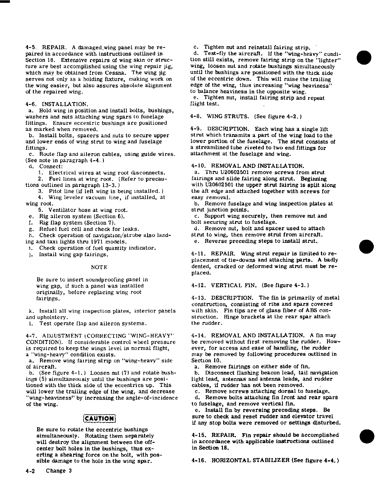
4-5.
REPAIR.
A
damaged-wing
panel
may
be
re-
c. Tighten
nut
and
reinstall
fairing
strip.
paired
in
accordance
with
instructions
outlined
in
d.
Test-fly
the
aircraft.
If
the
"wing-heavy"
condi-
Section
18.
Extensive
repairs
of
wing
skin
or
struc-
tion
still
exists,
remove
fairing
strip
on
the
"lighter"
ture are
best accomplished using
the
wing
repair
jig,
wing,
loosen
nut and
rotate
bushings
simultaneously
which
may
be
obtained
from
Cessna.
The
wing jig
until
the
bushings
are
positioned
with the
thick
side
serves
not
only
as
a
holding
fixture,
making
work
on
of
the
eccentric
down.
This
will
raise
the
trailing
the
wing
easier,
but
also
assures
absolute
alignment
edge
of
the
wing,
thus
increasing
"wing
heaviness"
of
the
repaired
wing.
to
balance
heaviness
in
the
opposite
wing.
e.
Tighten
nut,
install
fairing
strip
and
repeat
4-6.
INSTALLATION.
flight
test.
a.
Hold
wing
in
position
and
install
bolts,
bushings,
washers
and
nuts
attaching
wing
spars
to
fuselage 4-8.
WING
STRUTS.
(See
figure
4-2.)
fittings.
Ensure
eccentric
bushings
are
positioned
as marked
when
removed.
4-9.
DESCRIPTION.
Each
wing
has
a
single
lift
b.
Install
bolts,
spacers
and
nuts to
secure
upper
strut
which
transmits
a
part
of
the
wing
load
to the
and
lower
ends
of
wing
strut
to
wing
and
fuselage
lower
portion
of
the
fuselage.
The
strut
consists
of
fittings.
a
streamlined
tube
riveted to
two
end
fittings
for
c.
Route
flap
and
aileron
cables,
using
guide
wires.
attachment
at
the
fuselage
and wing.
(See
note
in
paragraph
4-4. )
d.
Connect:
4-10.
REMOVAL AND
INSTALLATION.
1.
Electrical
wires
at
wing
root
disconnects.
a.
Thru
U20602501
remove
screws
from
strut
2.
Fuel
lines
at
wing
root.
(Refer
to
precau-
fairings
and
slide
fairing
along
strut.
Beginning
tions
outlined
in
paragraph
13-3.)
with
U20602501
the
upper
strut
fairing
is split
along
3.
Pitot
line
(if
left
wing
is
being
installed.
)
the
aft
edge and
attached
together
with
screws
for
4.
Wing
leveler
vacuum
line,
if
installed,
at
easy
removal.
wing
root.
b.
Remove
fuselage
and
wing
inspection
plates
at
5.
Ventilator
hose at
wing
root.
strut
junction
points.
e.
Rig
aileron
system
(Section
6).
c.
Support
wing
securely,
then
remove
nut
and
f.
Rig
flap
system
(Section
7).
bolt
securing
strut
to
fuselage.
g.
Refuel fuel
cell
and
check
for leaks.
d.
Remove
nut,
bolt
and
spacer
used
to
attach
h.
Check
operation
of
navigation/strobe
also
land-
strut
to
wing,
then
remove
strut
from
aircraft.
ing
and
taxi
lights thru
1971
models.
e.
Reverse preceding
steps
to
install
strut.
i.
Check
operation
of
fuel quantity
indicator.
j.
Install
wing
gap
fairings.
4-11.
REPAIR.
Wing
strut
repair
is
limited
to
re-
placement
of
tie-downs
and
attaching
parts.
A
badly
NOTE
dented,
cracked
or
deformed
wing
strut
must
be
re-
placed.
Be
sure
to
insert
soundproofing
panel
in
wing gap,
if
such
a
panel
was
installed
4-12.
VERTICAL
FIN.
(See
figure
4-3.)
originally,
before
replacing
wing
root
fairings.
4-13.
DESCRIPTION.
The
fin
is
primarily
of
metal
construction, consisting
of
ribs
and
spars
covered
k.
Install all
wing
inspection
plates,
interior
panels
with
skin.
Fin
tips
are
of
glass
fiber
of
ABS
con-
and
upholstery.
struction.
Hinge
brackets
at
the
rear
spar
attach
1.
Test
operate
flap
and
aileron systems.
the
rudder.
4-7.
ADJUSTMENT (CORRECTING
"WING-HEAVY"
4-14.
REMOVAL
AND
INSTALLATION.
A
fin
may
CONDITION).
If
considerable
control
wheel
pressure
be
removed
without
first
removing
the
rudder.
How-
is
required
to
keep
the
wings
level
in
normal
flight,
ever,
for
access
and
ease
of
handling,
the
rudder
a
"wing-heavy" condition
exists.
may
be
removed
by
following
procedures
outlined
in
a.
Remove
wing
fairing
strip
on
"wing-heavy"
side
Section
10.
of
aircraft.
a.
Remove
fairings
on
either
side
of
fin.
b.
(See
figure 4-1.
)
Loosen
nut
(7)
and
rotate
bush- b.
Disconnect
flashing
beacon
lead,
tail
navigation
ings
(5)
simultaneously
until
the
bushings
are
posi-
light
lead,
antennas
and
antenna
leads,
and
rudder
tioned
with
the
thick
side
of
the
eccentrics
up.
This
cables,
if
rudder
has
not
been
removed.
will
lower
the
trailing
edge
of
the
wing,
and
decrease
c.
Remove
screws
attaching
dorsal
to
fuselage.
"wing-heaviness"
by
increasing
the
angle-of-incidence
d.
Remove
bolts
attaching
fin
front
and
rear
spars
of
the
wing.
to
fuselage,
and
remove
vertical
fin.
e.
Install
fin
by
reversing
preceding
steps.
Be
CAUTION
sure
to
check
and
reset
rudder
and
elevator
travel
if
any
stop bolts were
removed
or
settings disturbed.
Be
sure
to
rotate
the
eccentric
bushings
simultaneously.
Rotating
them
separately
4-15.
REPAIR.
Fin
repair
should
be
accomplished
will
destroy
the
alignment
between
the
off-
in
accordance
with
applicable
instructions
outlined
center
bolt
holes
in
the
bushings,
thus
ex- in
Section
18.
erting
a
shearing
force
on
the
bolt,
with
pos-
sible
damage
to
the
hole
in
the
wing
spar.
4-16.
HORIZONTAL
STABILIZER
(See
figure
4-4.)
4-2
Change
3
4-17.
DESCRIPTION.
The
horizontal
stabilizer
is
dures
outlined
in
paragraph
4-14.
primarily
of
metal
construction, consisting
of
ribs
c.
Disconnect
elevator
trim
control
cables
at
and
a
front
and
rear
spar
which
extend
throughout
clevis
and
turnbuckle
inside
tailcone,
remove
pulleys
the
full
spars
and
ribs.
Stabilizer
tips
are
of
ABS
which
route
aft
cables
into
horizontal
stabilizer,
and
construction.
The
elevator
tab
actuator
screw
is
pull
cables
out
of
tailcone.
contained
within
the
horizontal
stabilizer
assembly,
d.
Remove
bolts
securing horizontal
stabilizer
to
and
is
supported
by
a
bracket riveted
to
the
rear
fuselage.
spar.
The
underside
of
the
stabilizer
contains
a
e.
Remove
horizontal
stabilizer.
covered
opening
which
provides
access
to
the
eleva-
f.
Install horizontal
stabilizer
by
reversing
pre-
tor
tab
actuator screw.
Hinge
brackets
at
the
rear
ceding
steps.
Rig
control
systems as
necessary.
spar
support
the
elevators.
Check
operation
of
tail
navigation
light
and
flashing
beacon.
4-18.
REMOVAL
AND
INSTALLATION.
a.
Remove
elevators
and
rudder
in
accordance
with
4-19.
REPAIR.
Horizontal
stabilizer
repair
should
procedures
outlined
in
Sections
8
and
10.
be
accomplished
in
accordance
with
applicable
pro-
b.
Remove
vertical
fin
in
accordance
with
proce-
cedures
outlined
in
Section
18.
SHOP
NOTES:
Change
1
4-3
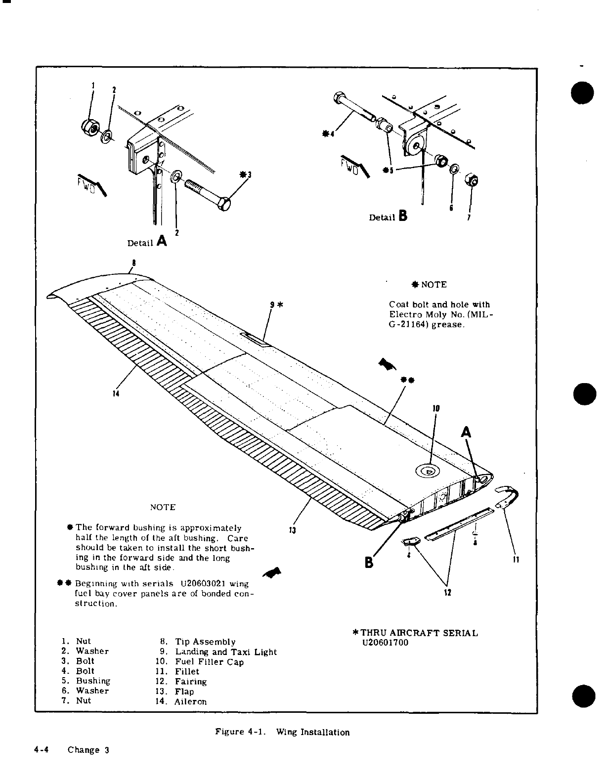
2
2
Detail
B
Detail
A
*
NOTE
9
*
Coat
bolt
and
hole
with
Electro
Moly
No.
(MIL-
G-21164)
grease.
NOTE
*The forward
bushing
is
approximately
13
half
the
length
of
the
aft
bushing.
Care
should
be
taken
to
install
the
short
bush-
ing
in
the
forward
side
and
the
long
11
bushing
in
the
aft
side.
**
Beginning
with
serials
U20603021
wing
fuel
bay
cover
panels
are
of
bonded con-
12
struction.
*THRU
AIRCRAFT
SERIAL
1.
Nut
8.
Tip
Assembly
U20601700
2.
Washer
9.
Landing
and
Taxi
Light
3.
Bolt
10.
Fuel
Filler
Cap
4.
Bolt
11.
Fillet
5.
Bushing
12.
Fairing
6.
Washer
13.
Flap
7.
Nut
14.
Aileron
Figure
4-1.
Wing
Installation
4-4
Change
3
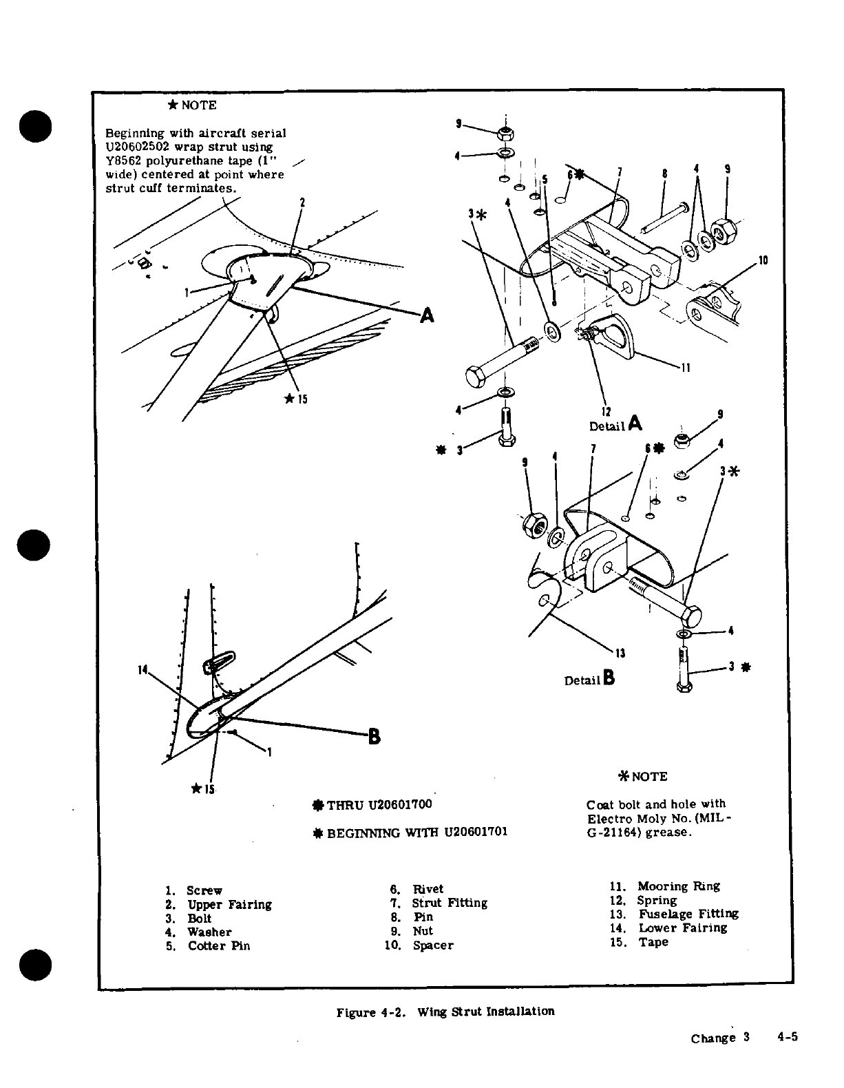
*
NOTE
Beginning
with
aircraft
serial
U20602502
wrap
strut
using
Y8562
polyurethane
tape (1"
4
wide)
centered
at
point
where
7 9
strut
cuff
terminates.
10
12
9
7
4
14
*
*
NOTE
*15
*THRU U20601700
Coat
bolt
and hole
with
Electro
Moly
No.
(MIL-
*
BEGINNING
WITH
U20601701
G-21164)
grease.
1. Screw
6.
Rivet
11.
Mooring
Ring
2.
Upper
Fairing
7.
Strut
Fitting
12.
Spring
3.
Bolt
8.
Pin
13.
Fuselage
Fitting
4.
Washer
9.
Nut
14.
Lower
Fairing
5.
Cotter
Pin
10.
Spacer
15.
Tape
Figure
4-2.
Wing
Strut
Installation
Change
3
4-5
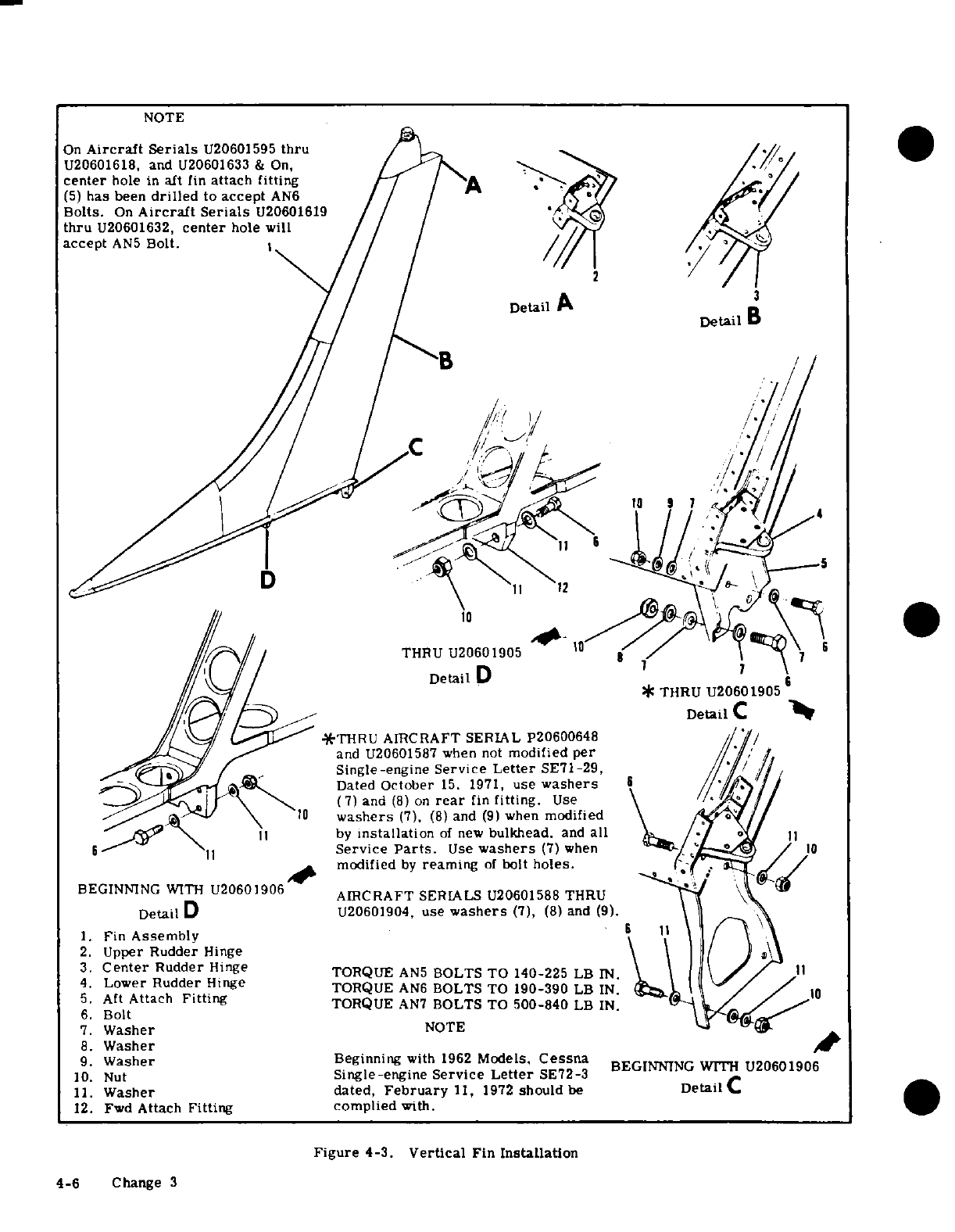
NOTE
On
Aircraft Serials
U20601595
thru
U20601618,
and
U20601633
&
On,
center
hole
in
aft
fin
attach
fitting
(5)
has been
drilled
to
accept
AN6
Bolts.
On
Aircraft
Serials
U20601619
thru
U20601632,
center
hole
will
accept
AN5
Bolt.
Detail
A
Detail
B
B
THRU
U20601905
10
/
Detail
D
12l
\
DetailD
D
*
THRU
U20601905
Detail
C
/
THRU
AIRCRAFT SERIAL
P20600648
and
U20601587
when
not
modified
per
Single-engine
Service
Letter
SE71-29,
/
Dated
October
15.
1971,
use
washers
/Jv
1-'*
L
\ \
(
7)
and
(8)
on
rear
fin
fitting.
Use
a10
washers
(7).
(8)
and
(9)
when
modified
ii11
by
installation
of
new
bulkhead.
and
all
/ /
H
56
\]
Service
Parts.
Use
washers
(7)
when
modified
by
reaming
of
bolt
holes.
*
BEGINNING
WITH
U20601906
AIRCRAFT
SERIALS
U20601588
THRU
Detail
D
U20601904,
use
washers
(7),
(8)
and
(9).
1.
Fin
Assembly
2.
Upper
Rudder
Hinge
3.
Center
Rudder
Hinge
TORQUE
AN5
BOLTS TO
140-225
LB
IN.
4.
Lower
Rudder
Hinge
TORQUE
AN6
BOLTS
TO
190-390
LB
IN.
5.
Aft
Attach
Fitting
TORQUE
AN7
BOLTS
TO
500-840
LB
IN.
6.
Bolt
7.
Washer
NOTE
8.
Washer
9.
Washer
Beginning
with
1962
Models,
Cessna
BEGINNING
WITH
U20601906
10.
Nut
Single-engine
Service
Letter
SE72-3
11.
Washer
dated,
February
11,
1972
should
be
Detail
C
12.
Fwd
Attach
Fitting complied
with.
Figure
4-3.
Vertical
Fin
Installation
4-6
Change 3
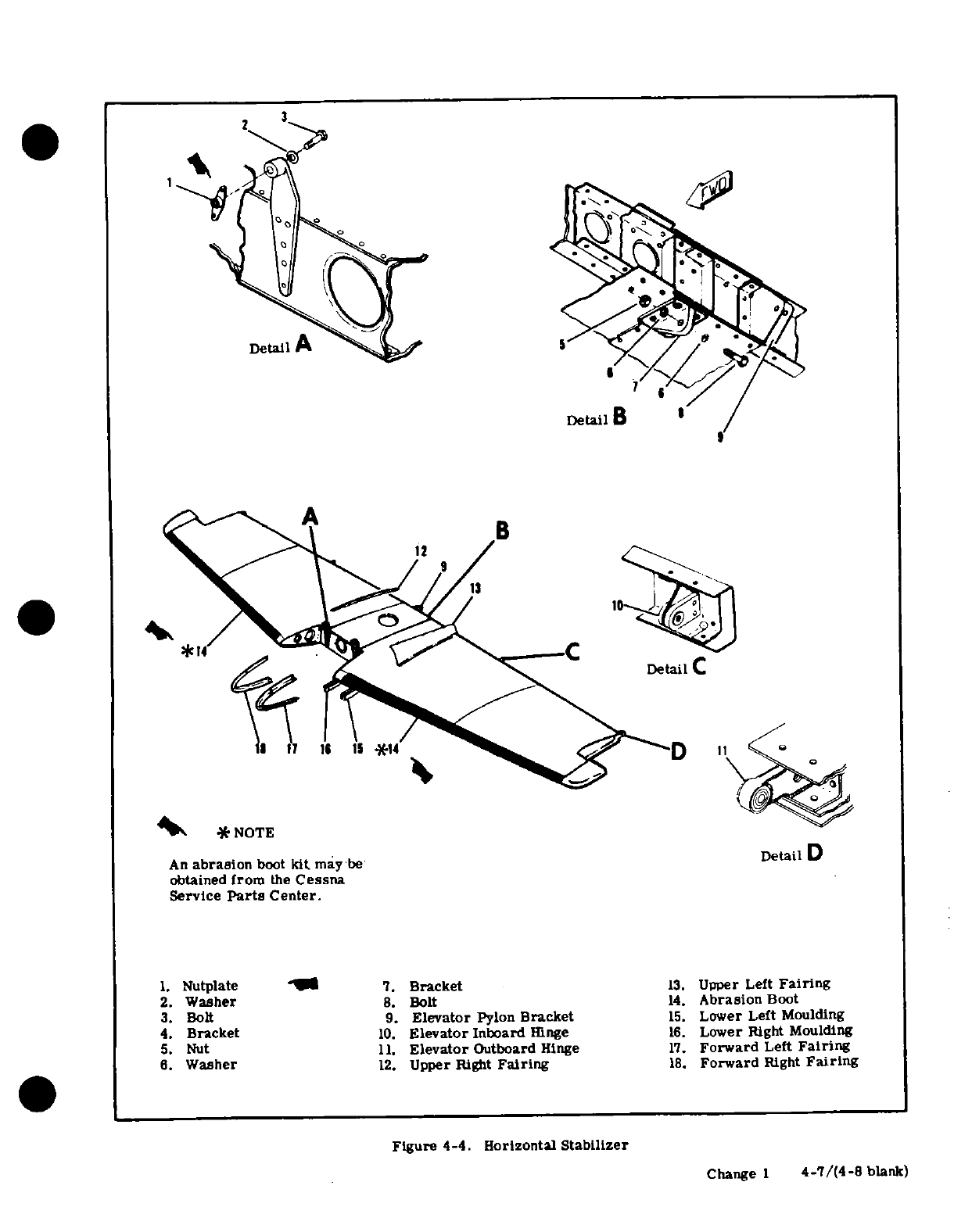
2
3
6
6 I *14
D
/
* <
4>
*
NOTE
Bo,-ilii i.Detail D
An
abrasion
boot
kit
may
be
Detail
D
obtained
from
the
Cessna
Service
Parts
Center.
1.
Nutplate
7.
Bracket
13.
Upper
Left
Fairing
2.
Washer
8.
Bolt
14.
Abrasion
Boot
3.
Bolt
9.
Elevator
Pylon
Bracket
15.
Lower Left
Moulding
4.
Bracket
10.
Elevator
Inboard
Hinge
16.
Lower
Right
Moulding
5.
Nut
11.
Elevator
Outboard
Hinge
17.
Forward
Left
Fairing
6.
Washer
12.
Upper
Right
Fairing
18.
Forward
Right
Fairing
Figure
4-4.
Horizontal
Stabilizer
Change
1
4-7/(4-8
blank)
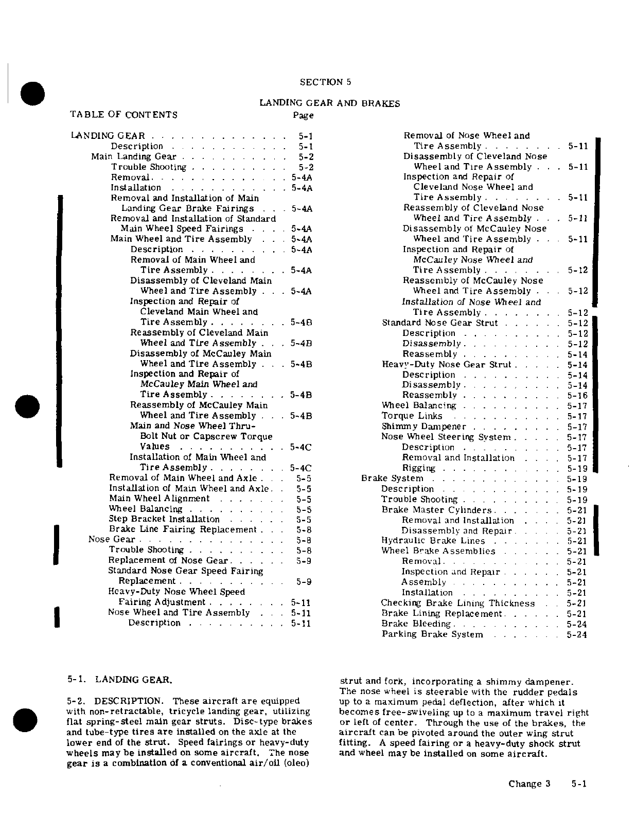
SECTION
5
LANDING
GEAR
AND
BRAKES
TABLE
OF
CONTENTS
Page
LANDING
GEAR
.
.....
... ..
5-1
Removal
of
Nose
Wheel
and
Description
...........
5-1
Tire
Assembly
.. ..
5-11
Main
Landing
Gear
...........
5-2
Disassembly
of
Cleveland
Nose
Trouble
Shooting
....
... ... .
5-2
Wheel and
Tire
Assembly
· .
5-11
Removal.
.. ... .. ..
5-4A
Inspection
and
Repair
of
Installation
..........
.
5-4A
Cleveland
Nose
Wheel
and
Removal
and
Installation
of
Main
Tire
Assembly
........
.
5-11
Landing
Gear
Brake
Fairings
. .
.5-4A
Reassembly
of
Cleveland
Nose
Removal
and
Installation
of
Standard
Wheel
and
Tire
Assembly
..
5-11
Main
Wheel
Speed
Fairings
... .
5-4A
Disassembly
of
McCauley
Nose
Main
Wheel
and
Tire
Assembly
. . .
5-4A
Wheel and
Tire
Assembly
..
5-11
Description
..........
5-4A
Inspection
and
Repair
of
Removal
of
Main
Wheel and
McCauley
Nose
Wheel
and
Tire
Assembly
.......
..
5-4A
Tire
Assembly
.
......
.
5-12
Disassembly
of
Cleveland
Main
Reassembly
of
McCauley
Nose
Wheel
and
Tire
Assembly
. .
.5-4A
Wheel
and
Tire
Assembly
·.
5-12
Inspection
and
Repair
of
Installation
of
Nose
Wheel
and
Cleveland
Main Wheel
and
Tire
Assembly
.
......
5-12
Tire
Assembly
.......
5-4B
Standard
Nose
Gear
Strut
......
5-12
Reassembly
of
Cleveland
Main
Description
........
.
5-12
Wheel
and
Tire
Assembly
. . .
5-4B
Disassembly
..........
5-12
Disassembly
of
McCauley
Main
Reassembly
..........
5-14
Wheel and
Tire
Assembly
. .
5-4B
Heavy-Duty
Nose
Gear Strut
.
....
5-14
Inspection
and
Repair
of
Description
. ... ... .
5-14
McCauley
Main Wheel and
Disassembly
.
........
5-14
Tire
Assembly
........
.
5-4B
Reassembly
.
.....
.
5-16
Reassembly
of
McCauley
Main
Wheel
Balancing .
.........
5-17
Wheel and
Tire
Assembly
..
.5-4B
Torque
Links .
..........
5-17
Main
and
Nose
Wheel
Thru-
Shimmy
Dampener
.....
.. . 5-17
Bolt
Nut
or
Capscrew Torque
Nose
Wheel
Steering
System
.....
5-17
Values
...........
5-4C
Description
..
........
5-17
Installation
of
Main
Wheel and
Removal
and
Installation
....
.
5-17
Tire
Assembly
........
5-4C
Rigging
..........
.
5-19
Removal
of
Main
Wheel
and
Axle
. .
5-5
Brake
System
...... .....
.. .
5-19
Installation
of
Main
Wheel
and
Axle. .
5-5
Description
. ... .
......
5-19
Main
Wheel
Alignment
.......
5-5
Trouble
Shooting
.
......
5-19
Wheel
Balancing
..........
5-5
Brake
Master Cylinders.
... . . 5-21
Step
Bracket
Installation
... .. 5-5 Removal
and
nstallation
.... 5-21
Brake
Line
Fairing
Replacement
. . . 5-8
Disassembly
and
Repair
..
5-21
Nose
Gear
.
....................
5-8
Hydraulic Brake Lines
.......
5-21
Trouble
Shooting
..........
5-8
Wheel
Brake
Assemblies
......
5-21
Replacement
of
Nose
Gear.
......
5-9
Removal.
....
... 5-21
Standard
Nose
Gear
Speed
Fairing
Inspection
and
Repair
......
5-21
Replacement
...........
5-9
Assembly
..........
5-21
Heavy-Duty
Nose
Wheel
Speed
Installation
..........
5-21
Fairing
Adjustment
........
5-11
Checking
Brake
Lining
Thickness
. 5-21
Nose
Wheel
and
Tire
Assembly
. ..
5-11
Brake
Lining
Replacement.
.....
5-21
Description
. . . . .. .
5-11
Brake
Bleeding.
.
.........
5-24
Parking
Brake
System
.....
5-24
5-1.
LANDING
GEAR.
strut
and
fork,
incorporating
a
shimmy
dampener.
The nose
wheel
is
steerable
with
the
rudder
pedals
5-2.
DESCRIPTION.
These
aircraft are
equipped
up
to
a
maximum
pedal
deflection,
after
which
it
with
non-retractable, tricycle
landing
gear,
utilizing
becomes
free-swiveling
up
to
a
maximum
travel
right
flat
spring-steel
main
gear
struts.
Disc-type
brakes
or
left
of
center.
Through
the
use
of
the
brakes,
the
and
tube-type
tires
are
installed
on
the
axle
at
the
aircraft
can
be
pivoted
around
the
outer
wing
strut
lower
end
of
the
strut.
Speed
fairings
or
heavy-duty
fitting.
A
speed
fairing or
a
heavy-duty
shock
strut
wheels
may
be
installed
on
some
aircraft.
The
nose and
wheel
may
be
installed
on
some
aircraft.
gear
is
a
combination
of
a
conventional
air/oil
(oleo)
Change
3
5-1
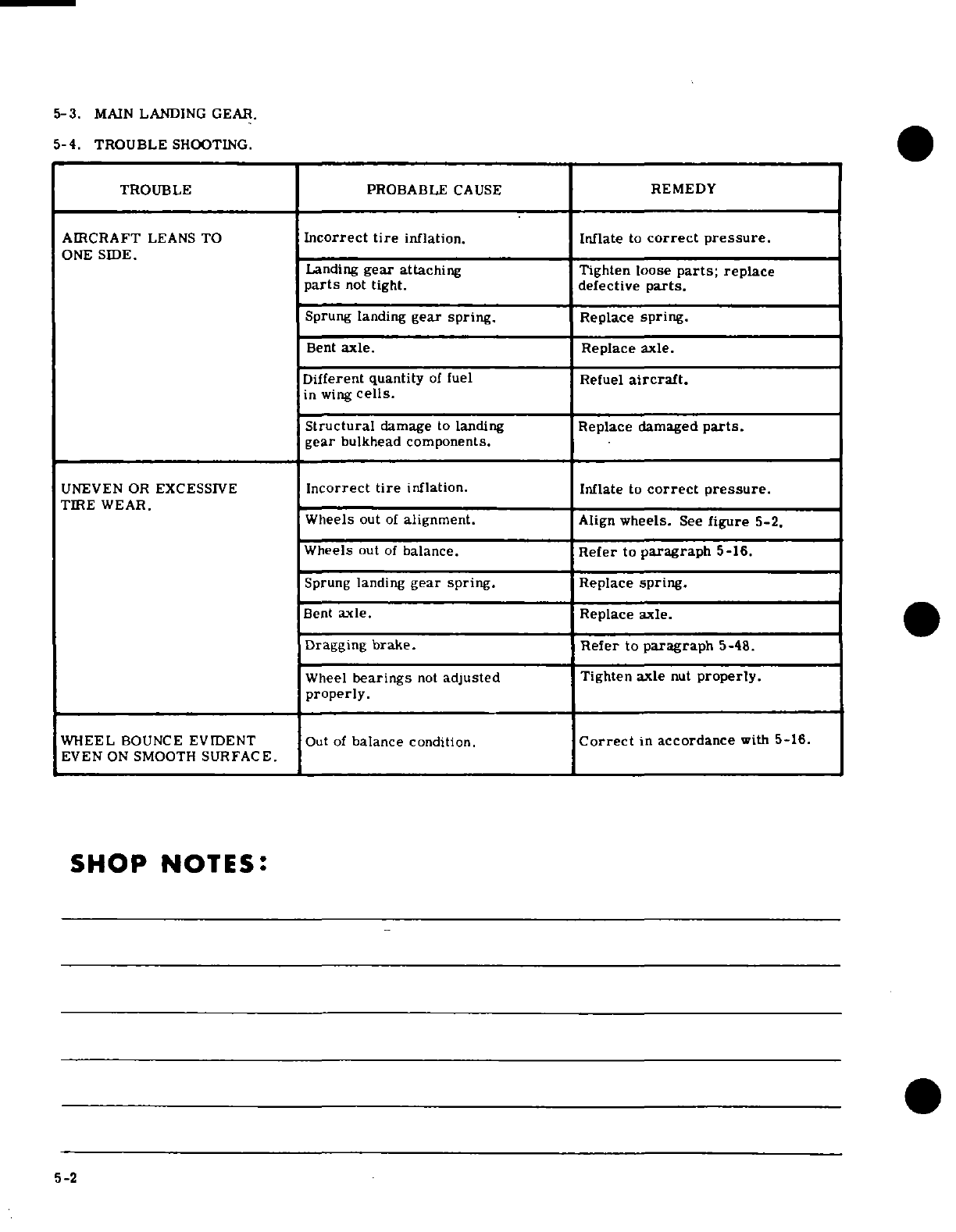
5-3.
MAIN
LANDING
GEAR.
5-4.
TROUBLE
SHOOTING.
TROUBLE
PROBABLE
CAUSE
REMEDY
AIRCRAFT
LEANS
TO
Incorrect
tire
inflation.
Inflate
to
correct pressure.
ONE SIDE.
Landing
gear
attaching
Tighten loose
parts;
replace
parts
not
tight. defective
parts.
Sprung
landing
gear
spring.
Replace
spring.
Bent
axle.
Replace
axle.
Different quantity
of
fuel
Refuel
aircraft.
in
wing
cells.
Structural
damage
to
landing
Replace
damaged
parts.
gear
bulkhead
components.
UNEVEN
OR
EXCESSIVE
Incorrect
tire
inflation.
Inflate
to
correct pressure.
TIRE
WEAR.
Wheels
out
of
alignment.
Align
wheels.
See
figure
5-2.
Wheels
out
of
balance.
Refer
to
paragraph
5-16.
Sprung
landing
gear
spring.
Replace
spring.
Bent
axle.
Replace
axle.
Dragging
brake.
Refer
to
paragraph
5-48.
Wheel
bearings
not
adjusted
Tighten
axle
nut
properly.
properly.
WHEEL
BOUNCE
EVIDENT
Out
of
balance
condition.
Correct
in
accordance
with
5-16.
EVEN
ON
SMOOTH
SURFACE.
SHOP
NOTES:
5-2
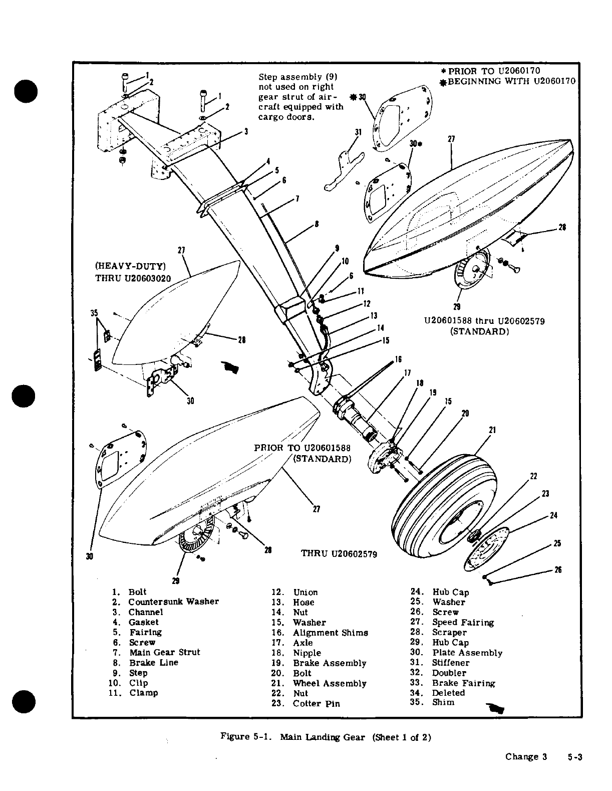
,„, ~~~~*
PRIOR
TO
U2060170
Step
assembly
(9)
*BEGINNING
WTH
U2060170
I~J~ = -^not
used
on
right
-
2
not
used
on
right
*BEGINNING
WITH
U2060170
I
-
^iJ /,'1
gear
strut
of
air-
*30
^...-
/
'
|I 2
craft
equipped
with
\
-
f
/
.I
.
^
.-
cargo
doors.
3 3 K
/' /
<ti, 31
fe ~ ~/
.
/fi-28 *^~\ \
(STANDARD)~
*y
'
ttu
/ /
is
(HEAVY-DUTY)
o
0/^'*' ^^
</
/*
21
THRU
U20603020
~~~~29'C--^^^~1
29
1.
Bolt
12.
Union
24.
Hub
Cap
2.
Countersunk
Washer
13.
Hose
25.
Washer
3.
Channel
14.
Nut 26.
Screw
4.
Gasket15.
Washer
27.
Speed
U206airing
5.
Fairng16.
Alignment
Shims
28.
Scraper
.
Screwolt
1.
UnioAxle
24.
Hub
Cap
7.
Co
untersunk
Wtsher
1.
Nipple
30.
Plate
Assembly
8.
Brake
Line
19.
Brake
Assembly
31.
Stiffener
9.
Channe l
14.
Bolt
32.
Douber
1.
Clasket
15.
Waheel
Assembly
33.
Brake
Fairing
5.
Fairing
16.
Alignment
Shims
28.
Scraper
6.
Screw
17.
Axle
29.
Hub
Cap
7.
Main
Gear
Strut
18.
Nipple
30.
Plate
Assembly
8.
Brake
Line
19.
Brake
Assembly
31.
Stiffener
9.
Step
20.
Bolt
32.
Doubler
10.
Clip
21.
Wheel
Assembly
33.
Brake
Fairing
11.
Clamp
22.
Nut 34.
Deleted
23.
Cotter Pin
35.
Shim
Figure
5-1.
Main
Landing
Gear
(Sheet
1
of
2)
Change
3
5-3
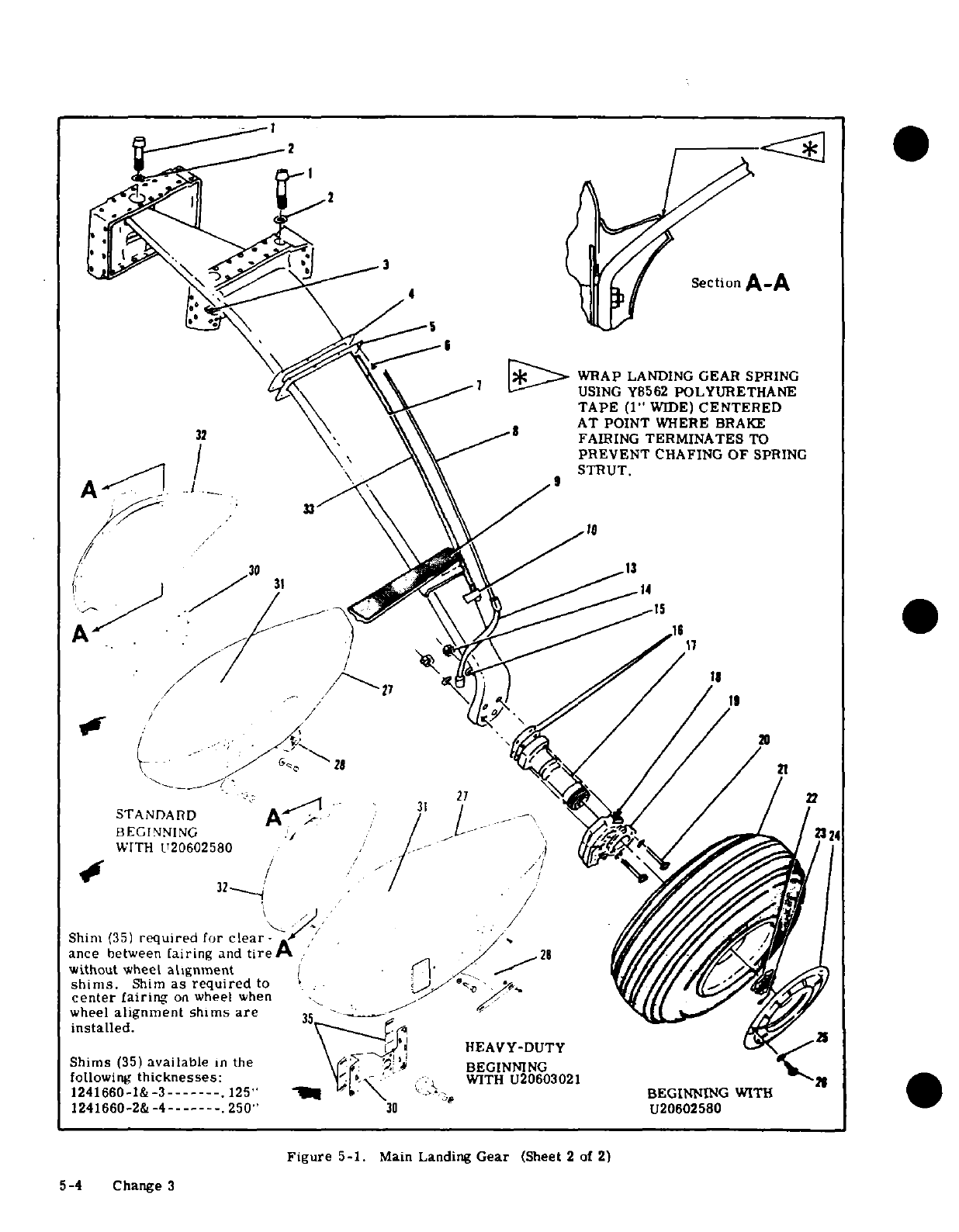
WRAP
LANDING
GEAR
SPRING
USING
Y8562
POLYURETHANE
TAPE
(1"
WIDE)
CENTERED
AT
POINT
WHERE
BRAKE
FAIRING
TERMINATES
TO
PREVENT
CHAFING
OF
SPRING
STRUT.
Shim
(35)
required
for
clear-
ance
between
fairing
and
tire
without
wheel
alignment
shims. Shim as required to
center
fairing
on
wheel
when
installed.
Shims (35) available in the
following
thicknesses:
1241660-1&-3-------.125"
1241660-2&
-4------.250"
Figure
5-1.
Main
Landing
Gear
(Sheet
2
of
2)
5-4 Change 3
5-4
Change
3
5-5.
REMOVAL.
(Refer
to
figure
5-1.)
a.
Remove floorboard
access
covers over
spring strut being
removed.
b.
Hoist
or
jack
aircraft
as
outlined
in
Section
2.
c.
Remove
brake
bleeder
screw
and
drain
hydraulic
brake
fluid
from
gear
being
removed.
d.
Disconnect
and
cap
or
plug
brake
line
at
bulkhead
fitting
in
fuselage,
e.
Remove
screws
attaching
landing
gear
strut
fairing
and
gasket
to
fuselage.
f.
Remove inboard
bolt, loosen
two
outboard
bolts
and
work
strut
out
to
remove.
NOTE:
Use
care when
removing
strut
to
prevent
damage
to
hydraulic
brake
line.
Retain
any
shims
under
inboard
bolt.
5-5A.
CORROSION CONTROL
ON
LANDING
GEAR
SPRINGS.
a.
General
(1)
The
main
landing
gear
springs
are
made
from
high
strength
steel that
is
shot
peened
on
the
lower
surface
to
increase
the
fatigue
life
of
the part.
(2)
The
shot
peened
layer
is
between
0.010 and
0.020
inch
thick.
(3) If
the
protective
layer
of
paint
is
chipped,
scratched,
or worn
away,
the
steel
may
corrode
(rust).
NOTE:
Corrosion
pits
that
extend
past
the
shot
peen layer
of
the
gear
spring
will
cause
a
significant
decrease
in
the
fatigue
life
of
the
spring.
(4)
Operation
from
unimproved surfaces
increases
the
possibility
of
damage.
b.
Corrosion removal
and repair.
WARNING:
Do
not
use
chemical
rust
removers
or
paint
strippers
on
landing
gear
springs. High-strength
steel
parts
are
very
susceptible
to
hydrogen
embrittlement.
Acidic
solutions,
such
as
rust
removers
and
paint
strippers,
can
cause
hydrogen embrittlement.
Hydrogen
embrittlement
is
an
undetectable,
time-delayed
process. Since
the
process
is
time
delayed,
failure
can
occur
after
the
part
is
returned
to
service.
(1)
Examine for
signs
of
corrosion
(red
rust)
if
damage
to
the
paint
finish
of
the
landing
gear
spring
is
found.
(2)
Carefully
remove any
rust
by
light
sanding.
(a)
The
sanding
must
blend
the
damage
into the
adjacent
area
in
an
approximate
20:1
ratio.
EXAMPLE:
An
0.005-inch
deep
pit.
The
pit
must
be
blended
toa
0.10-inch
radius
or
0.20-inch
diameter.
(b)
Make
sure
the
last
sanding
marks
are
along
an
inboard-to-outboard
direction,
or
along the
long
dimension
of
the
spring.
(3)
After
the
sanding
is
complete,
measure
the
depth
of
the
removed
material from
the
damaged
area.
NOTE: The
maximum
combined
depth
of
removed
material
to
the
top
and
bottom
or
leading
and
trailing
edge
is
not
to
be
more
than
0.063
inch'at
any
two
opposite
points
on
the
gear
spring. This
measurement
limitation includes
areas that have
previously
been
damaged
and
repaired.
(a)
Make
sure
the
depth
of
the
damage area
on
the
bottom
of
the
gear
spring
is
not
more
than 0.012
inch
deep.
1 If
the
damage
is
deeper
than
0.01 2
inch
deep
and
less
than
0.063
inch
deep,
replace
or
shot
peen
the
gear
spring.
The
gear
spring
must
be
removed
and
sent
to an
approved
facility
to
be
shot
peened.
a
The
shot peen
specification
is
to
be
Almen
intensity
of
0.01
2
to
0.01
6
with
330
steel
shot.
D2007-3-13
Temporary
Revision
7
-
July
1/2007
5-4A
©
Cessna Aircraft
Company
ku
Viflam
OuluFCL
mu Lu t..pI I
'
u.'IC y tC I..
..
It. Iu -_
.IJI
~
...
'L
.
L-I
I!
~..
-tI
--.
J -L-
gear
spring
is
not
more
than
0.063
inch
deep.
1 If
the
damage
is
deeper
than 0.063
inch deep,
replace
the
gear
spring.
(4)
Touch-up
paint
as
required.
NOTE:
Additional information
regarding
corrosion
control
can
be
found
in
FAA
Documents AC-43-4,
Chapter
6,
or
AC43.1
3-1
B
Chapter
6.
c.
Axle
bolt hole
corrosion.
(1)
Operation
of
an
airplane
on
skis
increases
the
loads
on
the
lower
part
of
the
gear
spring
because
of
the
unsymmetrical
and
twisting loads.
(a)
The
increased
loads have
produced spring
fractures
that
originate
from
pits
in
the
axle
attach
holes.
1
Catastrophic
failures
can
occur
from
fatigue
cracks
as small
as
0.003
to
0.01 0-
inch long
that
originated
at
pits.
NOTE:
Although operation
on
skis causes
more
loads,
the
criteria apply
to
all
airplanes.
(2)
There
is
no
maximum
damage depth for
pits
that
develop
in
the
axle bolt
holes.
If
pits
or
corrosion
is
found,
ream
to
remove
it,
subject
to
the
following
limitations:
(a)
Remove
the
minimum material
necessary
to
repair the damage.
(b)
Make
sure
the
diameter
of
the
axle
attachment
holes are
no
more
than
0.383
inch
for
3/8-
inch bolts.
(c)
Make
sure
the
diameter
of
the
axle
attachment
holes
are
no
more
than
0.32
1
inch
for
5/16-
inch
bolts.
(d) If
reaming
to
the
maximum
dimension
does
not
remove
all
signs
of
corrosion,
discard
the
landing
gear
spring.
5-6.
INSTALLATION.
(Refer
to
figure
5-1.)
*
To install
the
main
landing
gear,
reverse
the
procedures
outlined
in
paragraph
5-5.
Special
attention
should
be
paid
to
the
following:S
a.
When
installing
main
landing gear
strut, the
outboard
channel
attaching
bolts
should
be
tightened
to
a
torque value
of
600
-
750
pound-inches.
NOTE:
The
convex surface
of
the
outboard
channel
is
installed against
the
lower
side
of
the
strut,
When
channel attaching bolts
are
torqued
to
600
-
750
pound-inches,
the
channel
should
have
a
minimum
of
80
percent
contact
with
the
lower
side
of
the
strut.
b.
After
installation,
fill and
bleed
affected
brake
system
in
accordance
with
paragraph
5-60.
5-6A.
REMOVAL
AND
INSTALLATION
OF
MAIN
LANDING
GEAR
BRAKE
FAIRINGS.
(Refer
to
figure
5-1,
sheet
2.)
a.
Remove
screws
from
perimeter
of
fairing.
b.
Remove
screws
from
nutplates holding
fairing
together.
c.
Flex
brake
fairing
over landing
gear spring
strut
to
remove.
d.
Reverse
preceding
steps
to
install
brake
fairing.
5-7.
REMOVAL
AND
INSTALLATION
OF
STANDARD
MAIN
WHEEL
SPEED
FAIRINGS.
Main
wheel
speed
fairings
are
removed
by
removing
the
screws
attaching
the
inboard
side
of
the
fairing
to
the
adapter
plate,
and
removing
the
bolt
securing
the
outboard
side
to
the axle
nut.
Installation
is
the
reverse
of
removal.
Refer
to
Service
Kit
Ski
82-
12
for
repair
of
speed
fairings
installed
on
models prior
to 1971.
Standard
main
wheel
speed
fairing scraper-to-tire clearance
should
be
adjusted
for
a
minimum
clearance
of
0.25-
inch
to
a
maximum
clearance
of
0.38-inch.
Optional
heavy-duty
main
wheel
scraper-to-tire
clearance
should
be
adjusted
to
0.40
to
0.60-inch.
Elongated
holes
in
the
scraper
are
provided
so
the
scraper
may
be
adjusted.
5-4A1
D2007-3-13
Temporary
Revision
7
-
July
1/2007
0D
Cessna
Aircraft
Company
/kN
KAL-
--
+k- A-+h M
-,
A-pl-
-
+hn
Inorlinn
nrAnn
trnilinn
-.-
Hrin
rr
tnn
rf
tho
I
CAUTION:
Always
check scraper-to-tire clearance
after
installing
speed
fairing,
whenever
a
tire
has been
changed
and
whenever
scraper
adjustment
has
been
disturbed. Wipe
fuel and
oil
from
the
speed
fairings
to
prevent stains
and
deterioration.
If
the
aircraft
is
flown
from
surfaces
with
mud,
snow
or
ice,
fairings
should
be
checked
to
make sure
there
is
no
accumulation
which could
prevent
normal
wheel rotation.
5-7A.
MAIN
WHEEL
AND
TIRE
ASSEMBLY.
5-7B3.
DESCRIPTION.
The aircraft
may
be
equipped
with
either
Cleveland
or
McCauley
wheel
and
tire
assemblies.
Separate disassembly, inspection
and
reassembly
instructions
are
provided
for
each
type.
Basic
differences
of
the
two
types
are
discussed
in
paragraph
5-1
1 D,
and
thru-bolt
nut
and
capscrew
torque valves
are
listed
in
figure
5-1
l
A.
CAUTION:
Use
of
recapped tires
is
not
recommended. However,
if
recapped
tires
are
used
on
the
aircraft,
make
sure
there
is
sufficient
clearance
between
tire
and
wheel
fairings,
if
fairings
are
installed.
Ensure
that
speed fairing
scraper-to-tire
clearance
is
adjusted
to
the
values
specified
in
paragraph
5-7.
5-8.
REMOVAL
OF
MAIN
WHEEL
AND
TIRE
ASSEMBLY.
(Refer
to
figure
5-1
1.)
NOTE:
It is
not
necessary
to
remove
main
wheels
to
reline
brakes
or
remove
brake
parts
other
than
the
brake
disc
or
torque
plate.
a.
Using
universal
jack
point,
jack
wheel
as
outlined
in
Section
2.
b.
Remove
speed
fairing
as
outlined
in
paragraph
5-7.
c.
Remove
cotter
pin
and
axle
nut
after
removing
hub
cap.
d.
Remove bolts
and
washers
attaching
back
plate;
remove
back
plate.
e.
Pull
wheel
from
axle.
5-9.
DISASSEMBLY
OF
CLEVELAND
MAIN
WHEEL
AND
TIRE
ASSEMBLY.
(Refer
to
figure
5-1
1.)
a.
Deflate
tire and
break
tire
beads
loose.
CAUTION: Avoid
damaging
wheel
flanges
when
breaking
tire
beads
loose.
A
scratch,
gouge
or
nick
may
cause
wheel
failure.
b.
Remove
thru-bolts
and
separate
wheel halves,
removing
tire,
tube
and
brake
disc.
c.
Remove
grease
seal
rings,
felts
and
bearing
cones
from wheel
halves.
D2007-3
13
Temporary
Revision
7
-
July
1/2007
©
Cessna
Aircraft
Company
I
I
I
5-4A2

(This
page
intentionally
left
blank.)
5-4A3
D2007-3-13
Temporary
Revision
7
-
July
1/2007
©
Cessna
Aircraft
Company
NOTE
tire
beads
loose.
A
scratch,
gouge
or
nick
in
wheel
flanges
could
cause
wheel
failure.
Bearing
cups
are
a
press-fit
in
the
wheel
halves
and
should
not be
removed
unless
b.
Remove
valve
core
and
deflate
tire
and
tube.
replacement
is
necessary
to
remove
bearing
Break
tire
beads
loose from
wheel
flanges.
cups,
heat
wheel
half
in
boiling
water for
15
c.
Remove
cap
screws.
minutes.
Using
an
arbor
press,
if
available,
d.
Remove
brake
disc.
press
out
bearing
cup
and
press
in
new
cup
e.
Separate
wheel
flanges
from
wheel
hub.
Retain
while
wheel
is
still
hot.
spacers
on
each
side
of
wheel
hub.
f.
Remove
wheel
hub
from
tire.
5-10.
INSPECTION
AND
REPAIR
OF
CLEVELAND
g.
Remove
retainer
rings
and
remove
grease
seal
MAIN
WHEEL
AND
TIRE
ASSEMBLY.
(Refer
to
retainers,
grease seal
felts
and
bearing
cones.
figure
5-11.
)
a.
Clean
all
metal
parts
and
grease
seal
felts
in
NOTE
cleaning solvent
and
dry
thoroughly.
b.
Inspect
wheel
halves
for
cracks.
Cracked
wheel
The
bearing
cups
(races)
are
a
press-fit
halves
shall
be
discarded
and
new
parts
used.
Sand
in
the
wheel
hub
and
should not
be
removed
out
small
nicks,
gouges
and
corroded
areas.
When
unless
a
new
part
is
to
be
installed.
To
the
protective
coating
has been
removed, the
area
remove
the
bearing
cup,
heat
wheel
in
boil-
should be
cleaned thoroughly,
primed
with zinc
chro-
ing
water
for
30
minutes
or
in
an
oven
to
mate
and
painted
with
aluminum
lacquer.
exceed
121'C
(250°F).
Using
an
arbor
c.
If
excessively
warped
or
scored,
or
worn
to
a
press,
if
available,
press
out
the
bearing
thickness
of
.340-inch,
brake
disc
should
be
replaced
cup and
press
in
the
new
bearing
cup
while
with
a
new
part.
Sand
smooth
small
nicks
and
scratch-
the
wheel
hub
is
still
hot.
es.
d.
Carefully
inspect
bearing
cones
and
cups
for
dam-
5-11B.
INSPECTION
AND
REPAIR OF
McCAULEY
age
and
discoloration.
After
cleaning,
pack
bearing
MAIN
WHEEL
AND
TIRE
ASSEMBLY.
(Refer
to
cones
with
clean
aircraft
wheel
bearing
grease
(Section
figure
9-11.
)
2)
before
installing
in
the
wheel.
a.
Clean
all
metal
parts, grease seal
felts
and
mylar
spacers
in
cleaning
solvent
and
dry
thoroughly.
5-11.
REASSEMBLY
OF
CLEVELAND
MAIN
WHEEL
b.
Inspect
wheel
flanges
and
wheel
hub
for
cracks.
AND
TIRE
ASSEMBLY.
(Refer
to
figure
5-11.
)
Cracked
wheel
flanges
or
hub
shall
be
discarded
and
a.
Insert
thru-bolts
through
brake disc
and
posi-
new
parts
installed.
Sand out
smooth
nicks,
gouges
tion
in
the
inner
wheel
half,
using
the
bolts
to
guide
and
corroded
areas.
When
the
protective
coating
has
disc.
Assure
that
the
disc
is
bottomed
in
wheel
half.
been
removed,
the
area
should
be
cleaned thoroughly,
b.
Position
the
tire
and
tube
with
the
inflation
primed
with
zinc
chromate
and
painted
with
aluminum
valve
through
hole
in
outboard
wheel
half. Place
lacquer.
the
inner
wheel
half
in
position.
Apply
a
light
force
c.
If
excessively
warped
or scored,
or
worn
to
a
to
bring
wheel
halves
together.
Maintaining
the
light
thickness
of
0.
190-inch,
brake
disc
should
be
re-
force,
assemble
a
washer
and
nut
on
one
thru-bolt
placed
with
a
new
part.
Sand
smooth
small
nicks
and
tighten
snugly.
Assemble
the
remaining
nuts
and
and
scratches.
washers
on
thru-bolts
and
torque
to
value
specified
d.
Carefully
inspect
bearing
cones
and
cups
for
in
figure
5-11A.
damage
and
discoloration.
After
cleaning,
pack
bearing
cones
with
clean
aircraft
wheel
bearing
CAUTION
grease
(refer
to
Section
2)
before installing
in
the
wheel
hub.
Uneven
or
improper
torque
of
thru-bolt
nuts
may
cause
failure
of
bolts,
with
resultant
5-11C.
REASSEMBLY
OF
McCAULEY
WHEEL
AND
wheel
failure.
TIRE
ASSEMBLY.
(Refer
to
figure
5-11.)
a.
Place
wheel
hub
in
tire
and
tube
with
tube
infla-
c.
Clean
and
repack bearing
cones
with
clean
air-
tion
stem
in
cutout
of
wheel
hub.
craft
wheel
bearing
grease
(Section
2).
b.
Place
spacer
and
wheel
flange
on
inboard
side
d.
Assemble
the
bearing
cones,
grease
seal
felts,
of
wheel
hub
(opposite
of
tube
inflation
stem),
then
and
rings
into the
wheel
halves.
place
washer under
head
of
each
capscrew
and
start
e.
Inflate
tire
to
seat
tire
beads,
then
adjust
to
capscrews
into
wheel
hub
threads.
correct
pressure.
c.
Place
spacer
and
wheel flange
on
other
side
and
align
valve
stem
in
cutout
in
wheel
flange.
5-11A.
DISASSEMBLY
OF
McCAULEY
MAIN
WHEEL
d.
Place washer
under
head
of
each
capscrew
and
AND
TIRE
ASSEMBLY.
(Refer
to
figure
5-11.
)
start
capscrews
into
hub
threads.
a.
Remove
screws
attaching
hub
cap;
remove
hub
cap.
CAUTION
WARNING
Be
sure
that
spacers
and
wheel flanges
are
seated
on
flange
of
wheel hub.
Un-
Injury
can
result
from
attempting to
remove
even
or
improper
torque
of
capscrews
wheel
flanges
with
the
tire
and
tube
inflated.
can
cause
failure
of
capscrews,
with
re-
Avoid
damaging
wheel
flanges
when
breaking
sultant
wheel
failure.
5-4B Change
3
e. Tighten
capscrews
evenly
and
torque
to
the
value
5-12.
INSTALLATION
OF
MAIN
WHEEL
AND
TIRE
specified
in
figure
5-11A.
ASSEMBLY.
f.
Clean
and
pack
bearing
cones
with
clean
aircraft
a.
Place
wheel
on
axle.
wheel
bearing
grease.
b.
Install
axle
nut
and
tighten until
a
slight
bear-
g.
Assemble
bearing
cones,
grease
seal
felts
and
ing
drag
is
obvious
when
the
wheel
is
rotated.
Back
retainers
into
wheel
hub.
off
nut
to
nearest
castellation
and
install
cotter
pin.
h.
Inflate
tire
to
seat
tire
beads,
then
adjust
to
c.
Place
brake
back plate
in
position
and
secure
correct
tire
pressure.
Refer
to
Section
1
for
cor-
with
bolts
and
washers.
Safety
wire
the
bolts.
rect
tire
pressure.
d.
Install
speed
fairing
as
outlined
in
paragraph
5-7.
5-11D.
MAIN
AND
NOSE
WHEEL
THRU-BOLT
NUT
(CAUTION)
OR
CAPSCREW
TORQUE VALUES.
(Refer
to
figure
5-11A.
) During
assembly
of
the main
and
nose wheel,
Always
check
scraper-to-tire
clearance
after
the
thru-bolt
nuts
or
capscrews
should
be
tightened
installing
speed
fairings,
whenever
a
tire
has
evenly
and
torqued
to
the
values
specified
in
figure
been
changed,
and
whenever
scraper
adjust-
5-11A.
To
facilitate
identification
of
wheel
manu-
ment
has
been
disturbed.
The
standard
main
facturers,
solid
wheels
are
manufactured
by
Cleve- wheel
speed
fairing
scraper-to-tire
clearance
land
Aircraft
Products
Co.,
and
webbed
wheels
are
should
be
adjusted
for
a
minimum
clearance
of
manufactured
by
McCauley
Industrial
Corporation.
0.
25
inch
to
a
maximum
clearance
of
0.38
Cleveland wheels
are
also
identified
by
having
two
inch.
The
optional
heavy-duty
main
wheel
wheel
halves
as
shown
in
figure
5-4
and
figure
5-11.
fairing
scraper-to-tire
clearance
should
be
McCauley
wheels
are
identified
by
having
two
wheel
adjusted
to
0.40
to
0.60
inch.
Elongated
holes
flanges
and
a
hub
as
shown
in
figure
5-4
and
figure
in
the
scraper
are
provided
so
that
scraper
5-11.
may
be
adjusted.
Wipe
fuel and
oil
from
the
speed
fairings
to
prevent
stains
and
deterio-
SHOP
NOTES:
Change
3
5-4C/(5-4D
blank)
ration.
If
the
aircraft
is
flown
from
surfaces
NOTE
with mud,
snow,
or
ice,
the
fairings
should
be
checked
to
make
sure
there is
no
accumu-
The
step
bracket
is
secured
to
the
landing
gear
lation
which
could
prevent
normal
wheel
rotation.
spring
strut
with
EA9309,
or
a
similar
epoxy
base adhesive.
5-13.
REMOVAL
OF
MAIN
WHEEL
AND
AXLE.
a.
Remove
speed
fairing
in
accordance
with
para-
a.
Mark
the
position
of
the
bracket
so
that
the
re-
graph
5-7.
placement
bracket
will
be
installed
in
approximately
h.
Remove
wheel
in
accordance
with
paragraph
5-8.
the
same
position.
c.
Disconnect,
drain,
and
plug
the
hydraulic brake
b.
Remove
all
traces
of
the
original
adhesive
as
line
at
the
brake
cylinder.
well
as
any
rust,
paint, or
scale
with
a
wire
brush
d.
Remove
four
nuts
and
bolts
securing
axle
and and
coarse
sandpaper.
brake
components
to
spring
strut.
c.
Leave
surfaces
slightly
roughened
or abraided,
but
deep
scratches
or
nicks
should
be
avoided.
NOTE
d.
Clean
the
surfaces
to
be
bonded
thorouehly.
If
a
solvent
is
used,
remove
all
traces
of
the
solvent
When
removing
axle
from
spring
strut,
note
with
a
clean,
dry
cloth.
It
is
important
for
the
sur-
number
and
position
of
the
wheel
alignment
faces
to
be
clean
and
dry.
shims.
Mark
these
shims
or
tape
them
to-
e.
Check
the
fit
of
the
step
bracket
on the
spring.
gether carefully
so
they
can
be
reinstalled
A
gap
of
not
more
than
1/32
inch
is
permissible.
in
exactly
the
same
position
to
ensure
that
f.
Mix
the
adhesive
carefully according
to
manu-
wheel
alignment
is
not
disturbed,
facturer's
directions.
g.
Spread
a
coat
of
adhesive
on
the
surfaces
to
be
5-14.
INSTALLATION
OF
MAIN
WHEEL
AND
AXLE.
bonded,
and
place
step bracket
in
position
on
the
a.
Secure
axle
and
brake
componentsto
spring
spring.
Tap
the
bracket
upward
to
insure
a
tight
fit.
sturt,
making
sure
that
wheel
alignment
shims
and
h.
Form
a
small
fillet
of
the
adhesive
at
all
edges
speed
fairing
mounting
plate
are reinstalled
in
their
of
the
bonded
surfaces.
Remove
excess
adhesive
original positions.
with
lacquer thinner.
b.
Install
wheel
assembly
on
axle
in
accordance
i.
Allow
the
adhesive
to
cure
thoroughly
accord-
with
paragraph
5-12.
ing
to
manufacturer's
recommendations
before
flex-
c.
Connect
hydraulic
brake
line
to
brake
cylinder.
ing
the
gear
spring or
applying
loads
to
the
step.
d.
Fill
and
bleed
affected
brake
system
in
accord-
j.
Repaint
gear
spring
and
step
bracket
after
curing
ance
with
paragraph
5-60.
is
complete.
5-15.
MAIN
WHEEL
ALIGNMENT.
Correct
main
5-17A.
BRAKE
LINE FAIRING
REPLACEMENT.
wheel
alignment
is
obtained
through
the
use
of
(Refer
to
figure
5-1,
sheet
2.
)
tapered
shims
between
the
gear
strut
and
the flange
a.
Disconnect brake
line
(13)
at
brake
assembly
(19)
of
the
axle.
See
figure
5-2
for
procedure
to
use
in
and
drain
fluid,
or
plug
line
to
avoid
draining.
checking
alignment.
Wheel
shims,
and
the
correction
b.
Work
brake
line
and
split
hose
out
of
clip
(10)
and
imposed
on
the
wheel
by
the
various
shims,
are listed
flex
line
(8)
away
from
spring
strut
(7).
in
the
illustration.
c.
Remove
all
traces
of
original
adhesive
as
well as
any
rust,
paint
or
scale
with
a
wire brush
and
sand-
NOTE
paper.
Sand
inner
surface
of
fairing
strip
(33),
run-
ning
sandpaper
marks
lengthwise; leave
primer
on
Failure
to
obtain
acceptable
wheel
alignment
spring
strut
(7).
through
the
use
of
the
shims indicates
a
de-
d.
Thoroughly
clean
surfaces
to
be
bonded.
If
a
formed
main
gear
strut
or
strut
attaching
solvent
is
used, remove
all
traces
of
the
solvent
with
bulkhead
out
of
alignment.
a
clean
dry
cloth.
It
is
important
for
the
surfaces
to
be
clean
and
dry.
Solvent
should not
be
used
on
the
5-16. WHEEL
BALANCING.
Since
uneven
tire
wear
vinyl
fairing
strip
(33).
is
usually
the
cause
of
wheel
unbalance,
replacing
e.
Leave
surfaces
slightly
roughened
or
abraded.
the
tire
probably
will
correct
this
condition.
Tire
Deep
scratches
or
nicks
should
be
avoided.
and
tube
manufacturing
tolerances
permit
a
specified
f.
Mix
the
adhesive
(A-1186-B,
B.
F.
Goodrich,
amount
of
static
unbalance.
The
lightweight point
Akron,
Ohio
44318),
according
to
manufacturer's
of
the
tire
is
marked
with
a
red
dot
on
the
tire
side-
directions.
wall
and
the
heavyweight
point
of
the
tube
is
marked
g.
Apply
a thin
uniform
coat
of
adhesive
to
each
with
a
contrasting
color
line
(usually
near
the valve
bonding
surface.
Work life
of
A-1186-B
is
approxi-
stem).
When
installing
a
new
tire,
place
these
marks
mately
8
hours
at 75°F.
The
material
will
cure
in
adjacent
to
each
other.
If
a
wheel
becomes
unbal-
24
hours
at
75°
or
in
20
minutes at
200°
F.
anced during
service,
it
may
be
statically
rebalanced.
h.
Press
brake
line
(8)
into
groove
of
fairing
strip
Wheel
balancing equipment
is
available
from
the
(33)
and
raise
line
and
strip
to
attach
to
aft
side
of
Cessna
Service
Parts
Center.
spring
strut
(7)
and
fit
into
clip
(10).
i.
Immediately
wrap
fairing
strip
(33)
and
spring
5-17.
STEP
BRACKET
INSTALLATION.
strut
(7)
with
masking
tape
in
five
equally-spaced
Change
2
5-5
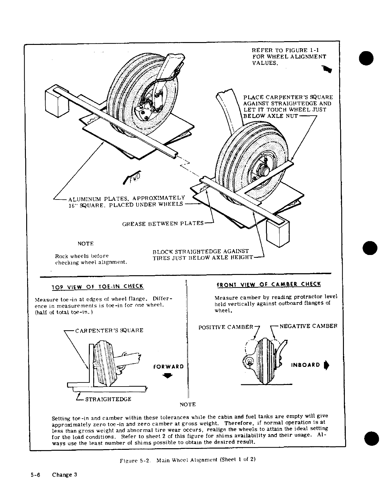
REFER
TO
FIGURE
1-1
FOR
WHEEL
ALIGNMENT
VALUES.
PLACE
CARPENTER'S
SQUARE
AGAINST
STRAIGHTEDGE
AND
LET
IT
TOUCH
WHEEL
JUST
BELOW
AXLE
NUT
ALUMINUM
PLATES. APPROXIMATELY
18"
SQUARE.
PLACED
UNDER
WHEELS
GREASE
BETWEEN
PLATES
NOTE
BLOCK
STRAIGHTEDGE
AGAINST
Rock
wheels
before
TIRES
JUST
BELOW AXLE
HEIGHT
checking
wheel
alignment.
TOP VIEW
OF
TOE-IN
CHECK FRONT
VIEW
OF
CAMBER
CHECK
Measure
toe-in
at
edges
of
wheel
flange.
Differ-
Measure
camber
by
reading
protractor
level
ence
in
measurements
is
toe-in
for
one
wheel.
held
vertically
against
outboard
flanges
of
(half
of
total
toe-in.)
wheel.
CARPENTER'S
SQUARE
POSITIVE
CAMBER NEGATIVE
CAMBER
FORWARD
INBOARD
STRAIGHTEDGE
NOTE
Setting
toe-in
and
camber
within
these
tolerances
while
the
cabin
and
fuel
tanks
are
empty
will
give
approximately
zero
toe-in
and
zero
camber
at
gross
weight.
Therefore,
if
normal
operation
is
at
less
than
gross
weight
and
abnormal
tire
wear
occurs,
realign
the
wheels
to
attain
the
ideal
setting
for
the load
conditions.
Refer
to
sheet
2
of
this
figure
for
shims
availability
and
their
usage.
Al-
ways
use
the
least
number
of
shims
possible
to
obtain
the
desired
result.
Figure
5-2.
Main
Wheel
Alignment (Sheet
1
of
2)
5-6
Change
3
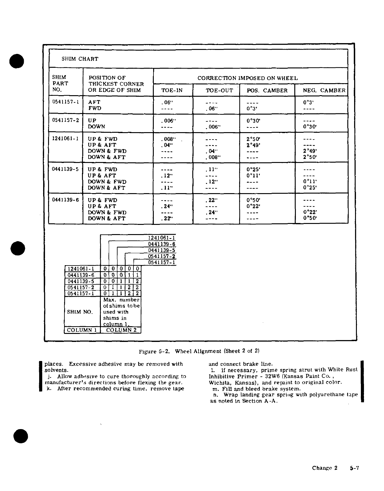
SHIM
CHART
SHIM
POSITION
OF
CORRECTION IMPOSED
ON
WHEEL
PART
THICKEST
CORNER
NO.
OR
EDGE
OF
SHIM
TOE-IN TOE-OUT
POS. CAMBER NEG.
CAMBER
0541157-1
AFT
.06"
----
----
0°3
'
FWD
----
.06"
03
'
----
0541157-2
UP
.006"
---
0030
'
---
DOWN
---
.006"
----
0°30
'
1241061-1
UP&
FWD .008"
---
2050
'
---
UP&
AFT
.04"
----
2°49
'
---
DOWN
&
FWD
----
.04"
---
2049
'
DOWN
&
AFT
----
.008"
----
2°50
'
0441139-5
UP
&
FWD
----
.11"
025
'
----
UP
&
AFT
.12"
----
011
'
----
DOWN&
FWD
----
.12"
----
0°11
'
DOWN&
AFT
.11"
----
----
0°25'
0441139-6
UP&
FWD
---
.22"
050
----
UP&
AFT
.24"
----
0°22'
DOWN
&
FWD
---
.24"
----
0°22
'
DOWN&
AFT
.22"
---
----
0°50
'
1241061-1
0441139-6
0441139-5
0541157-2
0541157-1
1241061-1
0 0
0 00
0441139-6
00
1
0441139-5
0
0
11
2
0541157-2
0
1 1
22
0541157-1
0
1
2
Max.
number
of
shims
to
be
SHIM
NO.
used
with
shims
in
column
1.
COLUMN 1
COLUMN
2
Figure
5-2.
Wheel
Alignment
(Sheet
2
of
2)
places.
Excessive
adhesive
may
be
removed
with
and
connect
brake
line.
solvents.
1.
If
necessary,
prime
spring
strut
with
White
Rust
j.
Allow
adhesive
to
cure
thoroughly
according
to
Inhibitive
Primer
-
32W6
(Kansas
Paint
Co.
manufacturer's
directions
before
flexing
the
gear.
Wichita,
Kansas),
and
repaint
to
original
color.
k.
After
recommended
curing time,
remove
tape
m.
Fill
and
bleed
brake
system.
n.
Wrap
landing
gear
spring
with
polyurethane
tape
as
noted
in
Section
A-A.
Change
2
5-7
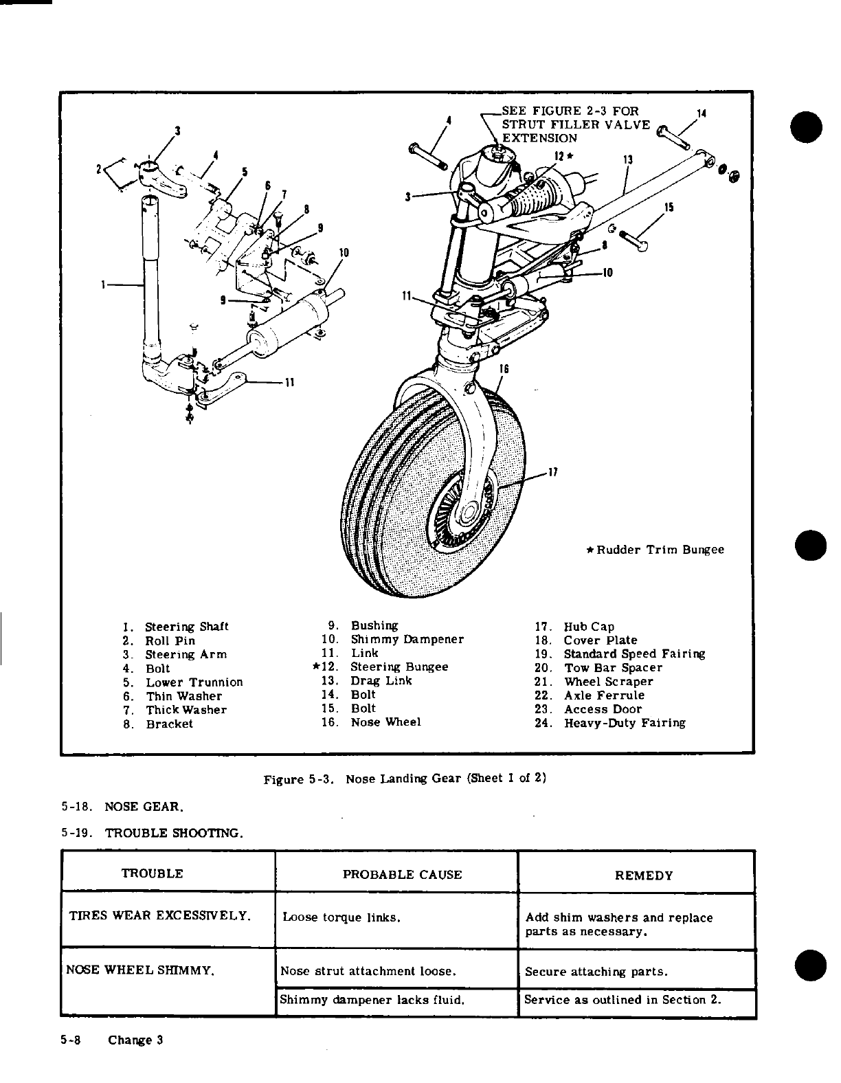
3.
Steering
Arm
11.
Link
19.
Standard
Speed
Fairing
4.
Bolt
*12.
Steering
Bungee
20.
Tow
Bar
Spacer
5.
Lower
Trunnion
13.
Drag
Link
21.
Wheel
Scraper
6.
Thin
Washer
14.
Bolt
22.
Axle
Ferrule
7.
Thick
Washer
15.
Bolt
23.
Access
Door
8.
Bracket
16.
Nose
Wheel
24.
Heavy-Duty
Fairing
Figure
5-3.
Nose Landing
Gear
(Sheet
1
of
2)
5-18.
NOSE
GEAR.
5-19.
TROUBLE
SHOOTING.
TROUBLE
PROBABLE
CAUSE
REMEDY
TIRES
WEAR
EXCESSIVELY.
Loose
torque
links.
Add
shim
washers
and
replace
parts
as
necessary.
NOSE
WHEEL
SHIMMY.
Nose
strut
attachment
loose.
Secure
attaching
parts.
Shimmy
dampener
lacks
fluid.
Service
as
outlined
in
Section
2.
5-8
Change 3
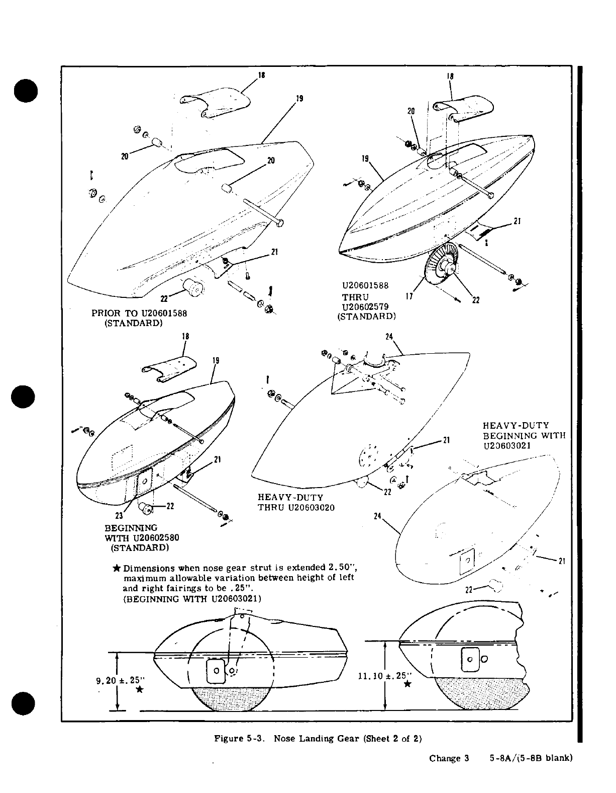
18
18
*
U20602579
PRIOR TO
U20601588
(STANDARD)
(STANDARD)
18
24
19
HEAVY-DUTY
BEGINNING
WITH
U20603021
HEAVY-DUTY
THRU
U20603020
/ /
BEGINNING
WITH
U20602580
/
(STANDARD)
21
*
Dimensions
when
nose
gear
strut
is
extended
2.50",
maximum
allowable
variation
between
height
of
left
and
right fairings
to
be
.25".
22
(BEGINNING
WITH
U20603021)
9.201.
25'
11.
1.101*.2'2
Figure
5-3.
Nose
Landing
Gear
(Sheet
2
of
2)
Change
3
5-8A/(5-8B
blank)
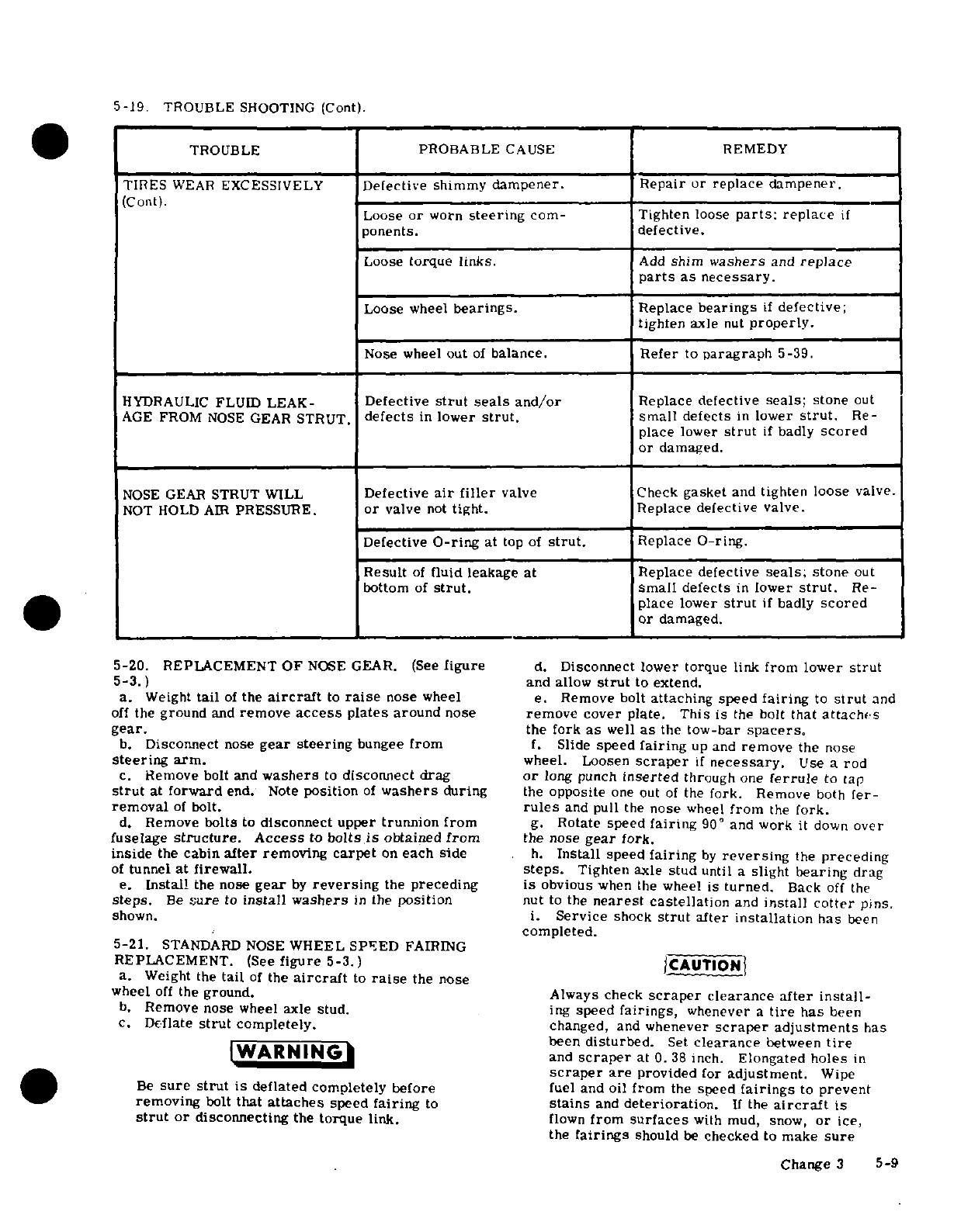
5-19.
TROUBLE
SHOOTING
(Cont).
TROUBLE
PROBABLE
CAUSE
REMEDY
TIRES
WEAR
EXCESSIVELY
Defective
shimmy
dampener. Repair
or
replace
dampener.
(Cont).
Loose
or
worn
steering
com-
Tighten
loose
parts:
replace
if
ponents.
defective.
Loose
torque
links.
Add
shim
washers
and
replace
parts
as
necessary.
Loose
wheel
bearings.
Replace
bearings
if
defective;
tighten
axle
nut
properly.
Nose
wheel
out
of
balance.
Refer
to
paragraph
5-39.
HYDRAULIC
FLUID
LEAK-
Defective
strut
seals and/or
Replace defective
seals;
stone
out
AGE
FROM
NOSE
GEAR
STRUT.
defects
in
lower
strut.
small
defects
in
lower
strut.
Re-
place
lower
strut
if
badly
scored
or
damaged.
NOSE
GEAR
STRUT WILL
Defective
air
filler
valve
Check
gasket
and
tighten
loose
valve.
NOT
HOLD AIR
PRESSURE.
or
valve
not
tight.
Replace
defective
valve.
Defective
O-ring
at
top
of
strut.
Replace
O-ring.
Result
of
fluid
leakage
at
Replace
defective
seals;
stone
out
bottom
of
strut.
small
defects
in
lower
strut.
Re-
place
lower
strut
if
badly
scored
or
damaged.
5-20.
REPLACEMENT
OF
NOSE
GEAR.
(See
figure
d.
Disconnect
lower torque
link
from
lower
strut
5-3.)
and
allow
strut
to
extend.
a.
Weight
tail
of
the
aircraft
to
raise
nose
wheel
e.
Remove
bolt
attaching speed
fairing
to
strut
and
off
the
ground
and
remove
access
plates
around
nose
remove
cover
plate.
This
is
the
bolt
that
attache
s
gear.
the fork
as
well
as
the
tow-bar
spacers.
b.
Disconnect
nose
gear
steering
bungee
from
f.
Slide
speed
fairing
up
and
remove
the
nose
steering arm.
wheel.
Loosen
scraper
if
necessary.
Use
a
rod
c.
Remove
bolt
and
washers
to
disconnect drag
or
long
punch
inserted
through
one
ferrule
to
tap
strut
at
forward
end.
Note
position
of
washers
during
the
opposite
one
out
of
the
fork. Remove
both
fer-
removal
of
bolt.
rules
and
pull
the
nose
wheel
from
the
fork.
d.
Remove
bolts
to
disconnect
upper
trunnion from
g.
Rotate
speed
fairing
90°
and
work
it
down
over
fuselage
structure.
Access
to
bolts
is
obtained
from
the
nose
gear
fork.
inside
the
cabin
after
removing
carpet
on
each side
h.
Install
speed
fairing
by
reversing
the
preceding
of
tunnel
at
firewall.
steps.
Tighten
axle
stud
until
a
slight
bearing
drag
e.
Install
the
nose
gear
by
reversing
the
preceding
is
obvious
when
the
wheel
is
turned.
Back
off
the
steps.
Be
sure
to
install
washers
in
the
position
nut
to
the
nearest
castellation
and
install
cotter
pins.
shown.
i.
Service
shock
strut
after
installation
has
been
completed.
5-21.
STANDARD
NOSE
WHEEL
SPEED
FAIRING
REPLACEMENT.
(See
figure
5-3.)
CAUTION
a.
Weight
the
tail
of
the
aircraft
to
raise
the
nose
wheel
off
the
ground.
Always
check
scraper
clearance
after
install-
b.
Remove
nose
wheel
axle
stud.
ing
speed
fairings,
whenever
a
tire
has
been
c.
Deflate
strut
completely.
changed,
and
whenever
scraper
adjustments
has
been
disturbed.
Set
clearance
between
tire
WARNING
and
scraper
at
0.38
inch.
Elongated
holes
in
scraper
are
provided
for
adjustment.
Wipe
Be
sure
strut
is
deflated completely before
fuel
and
oil
from
the
speed
fairings
to
prevent
removing
bolt
that
attaches
speed
fairing
to
stains
and
deterioration.
If
the
aircraft
is
strut
or
disconnecting
the
torque
link.
flown
from
surfaces
with mud,
snow,
or
ice,
the
fairings
should
be
checked
to
make
sure
Change
3
5-9
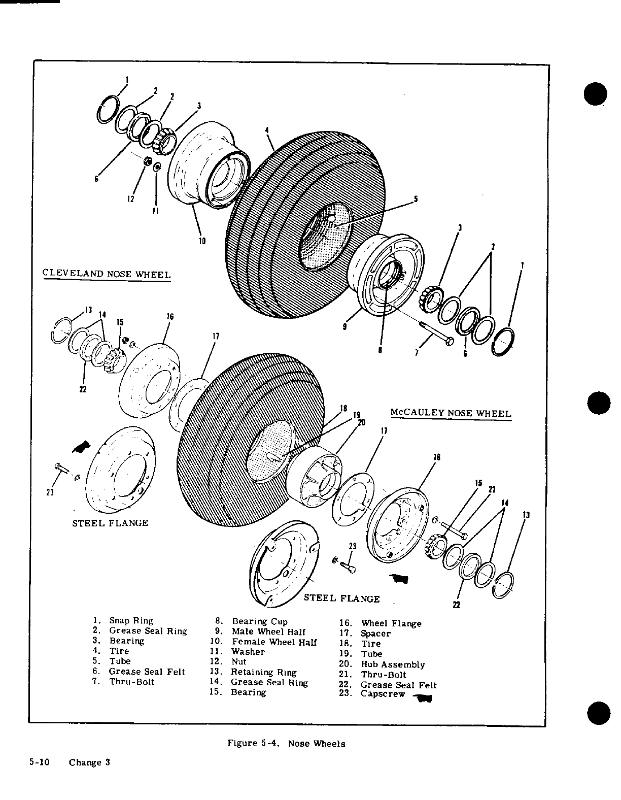
CLEVELAND
NOSE
WHEEL
MCCAULEY
NOSE
WHEEL
STEEL
FLANGE
STEEL
FLANGE
1.
Snap
Ring
8.
Bearing
Cup
16.
Wheel
Flange
2.
Grease
Seal Ring
9.
Male
Wheel
Half
17.
Spacer
3.
Bearing
10.
Female
Wheel
Half
18.
Tire
4.
Tire
11.
Washer
19.
Tube
5.
Tube
12.
Nut
20.
Hub
Assembly
6.
Grease
Seal
Felt
13.
Retaining
Ring
21.
Thru-Bolt
7.
Thru-Bolt
14.
Grease
Seal Ring
22.
Grease
Seal
Felt
15.
Bearing
23.
Capscrew
Figure
5-4.
Nose
Wheels
5-10
Change 3
there
is
no
accumulation
which
could
prevent
that
speed
fairing
scraper-to-tire
clear-
normal
wheel
rotation.
ance
is
adjusted
to
values
specified
in
para-
graph
5-21
or
5-22.
5-22.
HEAVY-DUTY
NOSE
WHEEL
SPEED
FAIRING
REPLACEMENT.
5-23.
REMOVAL OF
NOSE
WHEEL
AND
TIRE
a.
Weight
the
tail
of
the
aircraft
to
raise
nose
ASSEMBLY.
Removal
of
nose
wheel
and
tire assem-
wheel
off
the
ground.
bly
may
be
accomplished as
outlined
in
paragraph
b.
Remove
nose
wheel
axle
stud.
5-21
or
5-22.
c.
Deflate
strut
and
disconnect
lower
torque
link
from
fork
hub.
5-24.
DISASSEMBLY
OF
CLEVELAND
NOSE
WHEEL
AND
TIRE
ASSEMBLY.
(Refer
to
figure
5-4.)
WARNING
a.
Completely
deflate
the
tire
and
break
tire
beads
loose.
Be
sure
strut
is
deflated
completely
before
WARNING
disconnecting
torque
link.
d.
Remove bolt
securing
speed
fairing
to
fork
hub.
Injury
can
result
from
attempting
to
separate
The
speed
fairing
is
attached
to
the
lugs
on
the
for-
wheel
halves
with
tire
inflated.
Avoid
damag-
ward
side
of
the
fork
hub
and
the
tow-bar
spacers
ing
wheel
flanges
when
breaking
tire
beads
are
also
attached
with
same
bolt.
loose.
e.
Slide
speed
fairing
up
and
remove
the
nose
wheel.
Loosen
scraper
if
necessary.
Use
a
rod or
b.
Remove
thru-bolts
and
separate
wheel
halves.
long punch
inserted
through
one
ferrule
to
tap
the
c.
Remove
tire
and
tube.
opposite
one
out
of
the
fork.
Remove
both
ferrules
d.
Remove
bearing retaining
rings,
grease
seals
and
pull the
nose
wheel
from
the
fork.
and
bearing
cones.
f.
Remove
bolts
attaching
wheel
fork
to
lower
strut
and
remove
fork
and
speed
fairing.
NOTE
g.
Install
speed
fairing
by
reversing
the
preceding
steps.
Tighten
axle
stud until
a
slight
bearing
drag
The
bearing
cups
are
a
press
fit
in
the
wheel
is
obvious
when
the
wheel
is
turned.
Back
off
the
nut
halves
and
should
not
be
removed
unless
re-
to
the
nearest
castellation
and
install
cotter
pins.
placement
is
necessary.
To
remove,
heat
h.
Service
shock
strut
after
installation
has
been
wheel
half
in
boiling
water
for
15
minutes.
completed.
Using
an
arbor
press,
if
available,
press
out
the
bearing
cup
and
press
in
the
new
one
CAUTION
while
the
wheel
is
still
hot.
Always
check
scraper
clearance
after
install-
5-25.
INSPECTION
AND
REPAIR OF
CLEVELAND
ing
speed
fairing,
when
ever
a
tire
has
been
NOSE
WHEEL
AND
TIRE
ASSEMBLY.
Procedures
changed,
and
whenever
scraper
adjustment
outlined
in
paragraph
5-10
for
the
main wheel
and
has
been
disturbed.
Set
clearance
between
tire
assemblies
may
be
used
as
a
guide
for
inspection
tire
and
scraper
at
0.38
inch.
Elongated
and
repair
of
the
nose
wheel
and
tire
assembly.
holes
in
the
scraper
are
provided
for
adjust-
ment.
Wipe
fuel
and
oil
from
the
speed
5-26.
REASSEMBLY
OF
CLEVELAND
NOSE
WHEEL
fairings
to
prevent
stains
and
deterioration.
AND
TIRE
ASSEMBLY.
(Refer
to figure
5-4.)
If
the
aircraft
is
flown
from
surfaces
with
mud, snow,
or
ice,
the
fairings
should
be
a.
Place
tire
and
tube
on
wheel
half.
Insert thru-
checked
to
make
sure
there
is
no
accumu-
bolts,
position
other
wheel
half,
and
secure
with
nuts
lation
which could
prevent
normal
wheel
and
washers.
Torque
nuts
to
value
specified
in
rotation.
figure
5-11A.
5-22A.
NOSE
WHEEL
AND
TIRE
ASSEMBLY.
CAUTION
5-22B.
DESCRIPTION.
The
aircraft
may
be
equipped
Uneven
or
improper
torque
of
the
thru-bolt
with
either
Cleveland
or
McCauley
wheel
assemblies.
nuts
may
cause
bolt
failure
with
resultant
Separate
disassembly,
inspection
and
reassembly
in-
wheel
failure.
structions
are
provided for each
type.
Basic
differ-
ences
of
the
two
types
are
discussed
in
paragraph
b.
Clean
and
repack bearing
cones
with
clean
wheel
5-11D,
and
thru-bolt
nut and
capscrew
torque
values
bearing
grease.
are
listed
in
figure
5-11A.
c.
Assemble
bearing
cones,
seals,
and
retainers
into
the
wheel
halves.
CAUTION
d.
Inflate
tire
to
seat
tire
beads, then
adjust
to
correct
pressure.
Use
of
recapped
tires
is
not
recommend-
ed.
However,
if
recapped
tires
are
used
5-27.
DISASSEMBLY
OF
McCAULEY
NOSE
WHEEL
on
the
aircraft,
make
sure
there
is
suffi-
AND
TIRE
ASSEMBLY.
(Refer
to
figure
5-4.)
cient
clearnace
between
tire
and
wheel
a.
Remove
screws
attaching
hub
caps;
remove
hub
fairings,
if
fairings
are
installed. Ensure
caps.
Change
3
5-11
WuNING
and
nuts
on
thru-bolts.
d.
If
the
wheel
and
tire
assembly
is
equipped
with
Injury
can
result
from
attempting
to
remove
capscrews,
place
spoicer
and
wheel
folange
on
one
side
wheel
flanges
with
tire
and
tube
inflated.
of
wheel
hub.
Place washer under
head
of
each
cap-
Avoid
damaging wheel
flanges
when
break-
screw,
insert
capscrew
through
wheel
flange
and
ing
tire
beads
loose.
A
scratch,
gouge
or
spacer
and
start
capscrews
into
wheel
hub
threads.
nick
in
wheel flange could
cause
wheel
fail-
Place
spacer
and
wheel flange
on
other
side
of
wheel
ure.
hub
and
align
valve
stem
in
cutout
in
wheel flange.
Place washer
under
head
of
each
capscrew,
insert
b.
Completely
deflate
tire
and
break
tire
beads
capscrew
through
wheel
flange
and
spacer
and
start
loose
at
wheel
flanges.
capscrews
into
wheel
hub
threads.
c.
If
the
wheel
and
tire
assembly is
equipped
with
thru-bolts.
remove
thru-bolt
nuts
and
washers, re-
CAUTION
move
thru-bolts
and
separate
wheel
flanges
from
wheel
hub.
Retain
spacers
between
wheel
flanges
Be
sure
that
spacers
and
wheel
flanges
are
and
wheel
hub.
seated
on
flange
of
wheel
hub.
Uneven
or
d.
If
the
wheel
and
tire
assembly
is
equipped
with
improper
torque
of
thru-bolts
or
capscrews
capscrews.
remove
capscrews
and
washers
and
sepa-
can
cause
failure
of
the
thru-bolts
capscrews
rate
wheel flanges
from
wheel
hub.
Retain
spacers
or
hub
threads
with
resultant
wheel
failure.
on
each
side
of
wheel
hub.
e.
Remove
wheel
hub
from
tire
and
tube.
e.
Tighten
thru-bolts
or
capscrews
evenly
and
tor-
f.
Remove
retainer
rings
and
remove
grease
seal
que
to
the
value
specified
in
figure
5-11A.
retainers,
grease
seal felts
and
bearing
cones
from
f.
Clean
and
pack
bearing
cones
with
clean
aircraft
wheel
hub.
wheel
bearing
grease.
(Refer
to
Section
2
for
grease
type.
)
NOTE
g.
Assemble
bearing
cones,
grease
seal felts
and
retainer
into wheel
hub.
The
bearing
cups
(races) are
a
press-fit
in
i.
Inflate
tire
to
seat
tire
beads,
then
adjust
to
cor-
the wheel
hub
and
should
not be
removed
rect
pressure
specified
in
figure
1-1.
unless
a
new
part
is
to
be
installed.
To
re-
move
the
bearing
cup.
heat
wheel
hub
in
5-30.
INSTALLATION
OF
NOSE
WHEEL
AND
TIRE
boiling
water for
30
minutes,
or
in
an
oven
ASSEMBLY.
Procedures
are
outlined
in
paragraphs
not
to
exceed
121'
(250°F).
Using an
arbor
5-21
or
5-22.
press.
if
available,
press
out
the
bearing
cup
and
press
in
the
new
bearing
cup
while
5-31.
STANDARD
NOSE
GEAR
STRUT.
the
wheel
hub
is
still
hot.
5-32.
DESCRIPTION. The
standard
nose
gear
shock
5-28
INSPECTION
AND
REPAIR
OF
McCAULEY
strut
is
shown
in
figure
5-5.
The
optional heavy-
NOSE
WHEEL
AND
TIRE
ASSEMBLY.
(Refer
to
duty
shock
strut
is
shown
in
figure
5-6. Replacement
figure
5-4.
)
of
the
nose
gear
is
accomplished
as
outlined
in
para-
a.
Clean
all
metal
parts. grease seal
felts
and
my-
graph
5-20.
lar
spacers
in
cleaning
solvent
and
dry
thoroughly.
b.
Inspect
wheel
flanges
and wheel
hub
for
cracks.
5-33.
STANDARD
NOSE
GEAR
DISASSEMBLY.
(See
Cracked
wheel
flanges
or
hubs
shall
be
discarded
and
figure
5-5.)
The
following
procedure
applies
to
the
new
parts
will
be
installed.
Sand
out
smooth
nicks,
nose
gear
shock
strut
after
it
has
been
removed
from
gou;es
and
corroded
areas.
When
the
protective
coat-
the
aircraft,
and
the
speed
fairing
and
nose
wheel
ing
has
been
removed.
the
area
should
be
cleaned
have
been
removed.
In
many
cases,
separating
the
thoroughly.
primed
with
zinc
chromate
and
painted
upper
and
lower
struts
will
permit
inspection
and
with
aluminum
lacquer.
parts
replacement
without
removal or
complete
dis-
c.
Carefully
inspect
bearing
cones
and
cups
for
assembly.
damage
and
discoloration.
After
cleaning,
pack
bear-
IWARNING
in!:
cones
with
clean
aircraft
wheel
bearing
grease
be-
fore
installing
in
the
wheel
hub.
(Refer
to
Section
2
for
grease
type.
)
Deflate
strut
completely
before
removing
bolt
1a),
lock
ring
(30),
or
bolt
(32).
Also
deflate
5-29.
REASSEMBLY
OF
McCAULEY
NOSE
WHEEL
strut
before
disconnecting
torque links.
ANI
TIRE
ASSEMBLY.
(Refer
to
figure
5-4.)
a.
Install
tube
in
tire.
aligning
index
marks
on
tire
a.
Remove
torque
links.
Note
position
of
washers,
and
tube.
shims,
spacers,
and
bushings.
b.
Place
wheel
hub
in
tire
with
valve
stem
in
cutout
b.
Remove
shimmy
dampener.
of
wheel
hub.
c.
Remove
steering
shaft
by
driving
out
roll
pins
c.
If
the
wheel
and
tire
assembly
is
equipped
with
and
removing
steering
arm.
thra-iolts,
place
spacer
and
wheel
flange
on
one
d.
Remove
lock
ring
from
groove inside
of
lower
side
of
wheel
hub.
With
washer
under
head
of
thru-
end
of
upper
strut.
A
small
hole
is
provided
in the
tblt.
insert
bolt
through
wheel
flange
and
wheel
hub.
lock
ring groove
to
facilitate
removal.
Place
spacer
and
wheel
flange
on
other
side
and
align
val-'e
ptem
in
ritoll
in
whpel flange.
Install
washers
5-It
Clanre
3
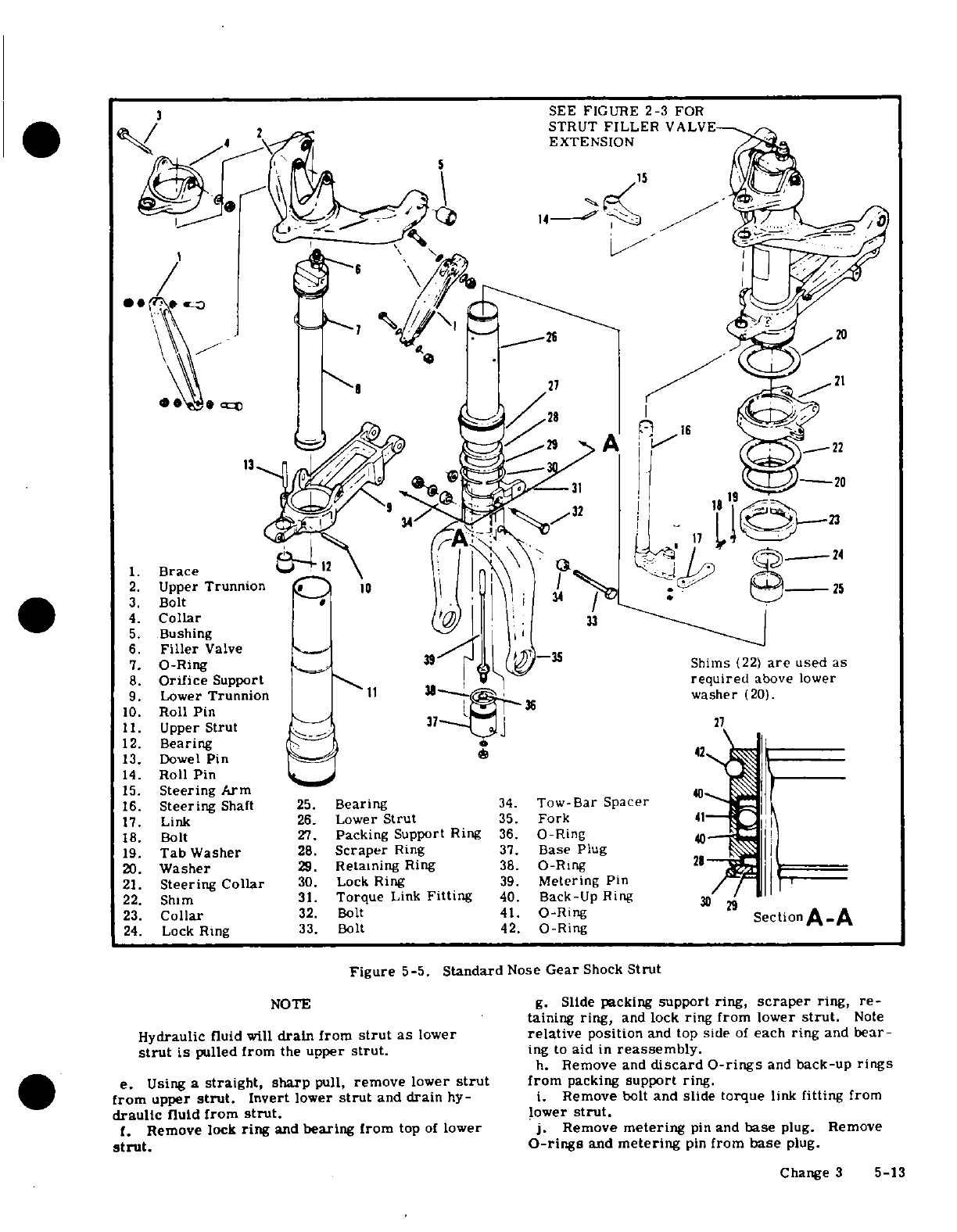
3
SEE
FIGURE
2-3
FOR
15
21
28/
91 g7 kX1 1922
1.
Brace
2.
Upper
Trunnion
25
3.
Bolt
3-
4.
Collar
33
5.
Bushing
6.
Filler
Valve
_
1
7.
O-Ring
35
Shims
(22)
are
used
as
8.
Orifice
Support
required
above
lower
9.
Lower
Trunnion
11
washer
(20).
10.
Roll
Pin
11.
Upper
Strut
27
12.
Bearing
13.
Dowel
Pin
42
14.
Roll
Pin
15.
Steering
Arm
16.
Steering
Shaft
25.
Bearing
34.
Tow-Bar
Spacer
17.
Link
26.
Lower
Strut
35.
Fork
4
18.
Bolt
27.
Packing
Support
Ring
36.
O-Ring
40
19.
Tab Washer
28.
Scraper
Ring
37.
Base
Plug
20.
Washer
29.
Retaining
Ring
38.
O-Ring
21.
Steering
Collar
30.
Lock
Ring
39.
Metering
Pin
22.
Shim
31.
Torque
Link
Fitting
40.
Back-Up
Ring
30
23.
Collar
32.
Bolt
41.
O-Ring
Section
A.A
24.
Lock Ring
33.
Bolt
42.
O-Ring
Figure
5-5.
Standard
Nose
Gear
Shock
Strut
NOTE
g.
Slide
packing
support
ring,
scraper
ring,
re-
taining ring,
and
lock
ring from lower
strut.
Note
Hydraulic
fluid
will
drain
from
strut
as
lower
relative
position
and
top
side
of
each
ring
and
bear-
strut
is
pulled
from
the
upper
strut.
ing
to
aid
in
reassembly.
h.
Remove
and
discard O-rings
and
back-up
rings
e.
Using
a
straight,
sharp
pull,
remove
lower
strut
from
packing
support
ring.
from
upper
strut.
Invert
lower
strut
and
drain
hy-
i.
Remove
bolt
and
slide
torque
link
fitting
from
draulic
fluid
from
strut.
lower
strut.
f.
Remove
lock
ring
and
bearing
from
top
of
lower
j.
Remove
metering
pin
and
base
plug. Remove
strut.
O-rings
and
metering
pin
from
base
plug.
Change
3
5-13
NOTE
next to
the
O-ring.
h.
When
installing
bearing
at
top
of
lower
strut,
be
Lower
strut
and
fork
are
a
press
fit,
drilled
sure
that
beveled
edge
of
bearing
is
installed
up next
on
assembly.
Separation
of
these
parts
is
not
to
lock
ring.
recommended
except
for
replacement
of
parts.
i.
When
installing
lock
ring,
position
the
lock
ring
so
that
one
of
its
ends
covers
the
small
access
hole
k.
Remove
bolt,
tab
washer,
and
unscrew
collar,
in
the lock
ring
groove
at
the
bottom
of
upper
strut.
and
remove shim(s),
washers,
and
steering
collar
j.
When
installing
shimmy
dampener,
do
not
tighten
from
upper
strut.
attaching bolts
to
a
torque
value
in
excess
of
10
lb-in.
l.
Remove
clamp
attaching
the
filler
extension
k.
Tighten
torque
link
center
bolt
snug.
Then
valve
to
strut
and
disconnect
from
filler
valve
at
top
tighten
to next
castellation
and
install
cotter
pin.
of
the
strut.
1.
Service
the
shock
strut
with
hydraulic
fluid and
m.
Remove
bolt
at top
of
strut,
and
remove
collar
compressed
air.
Install
strut
filler
valve
extension
and
orifice
support.
Remove
O-ring
and valve
from
and
install
strut
in
aircraft.
orifice
support.
n.
Bushings
and
bearings
in
lower
trunnion,
upper
NOTE
trunnion
and
collar
may
be
replaced
as
required.
Needle
bearing
in
steering
collar
should
not
be
re-
It
is
easier
to
service
the
shock
strut
just
placed;
replace
the
steering
collar
if
needle
bearing before
installation,
although
it may
be
ser-
is
defective.
viced
after
installation
if
desired.
Refer
to
Section
2.
NOTE
5-35.
HEAVY-DUTY
NOSE
GEAR
STRUT.
Upper
and lower
trunnions
are
press-fitted
to
the
upper
strut,
with
braces
installed
5-36.
DESCRIPTION.
The
heavy-duty
nose
gear
is
during
assembly.
Pin
is
also
press-fitted
shown in
figure
5-6,
which
may
be
used
as
a
guide
to
the
lower trunnion.
during
maintenance. Replacement
procedures
are
the
same
as
those
given
in
paragraph
5-20.
Refer
to
5-34.
STANDARD
NOSE
GEAR
STRUT
ASSEMBLY.
paragraph
5-22
for
speed
fairing replacement.
a.
Thoroughly
clean
all
parts
in
solvent
and
inspect
them
carefully.
Replace
all
worn
or
defective
parts
5-37.
HEAVY-DUTY
NOSE
GEAR
DISASSEMBLY.
and
all
O-rings,
seals,
and
back-up
rings
with
new
(See
figure
5-6.)
This
paragraph
outlines
complete
parts.
disassembly
of
the
heavy-duty
nose
gear
shock
strut
b.
Assemble
the
strut
by
reversing
the
order
of
the
after
it
has
been
removed
from
the
aircraft,
and
the
procedure
outlined
in
paragraph
5-33
with
the
excep-
nose
wheel and
speed
fairing
have
been
removed
from
tion
that
special
attention
must
be
paid
to
the
follow-
the
strut.
In
many
cases,
separating
the
upper and
ing
procedures.
lower
struts
will
permit
inspection
and
parts
replace-
c.
Sharp metal edges
should
be
smoothed
with
No.
ment
without
removal or
complete
disassembly.
400
emery
paper,
then
thoroughly
cleaned
with
sol-
vent.
WARNING
d.
Used
sparingly,
Dow
Corning
DC-4
compound
is
recommended
for
O-ring
lubrication.
All
other
in-
Deflate
strut
completely
before
removing
bolt
ternal
parts
should
be
liberally
coated
with
hydraulic
(3),
lock
ring
(30),
or
bolt
(33).
Also
deflate
fluid
during
assembly.
strut
before
disconnecting
torque
links.
NOTE
a.
Remove
torque
links.
Note
position
of
washers,
shims,
spacers,
and
bushings.
Cleaniness
and
proper
lubrication,
along
with
b.
Remove
shimmy
dampener.
careful
workmanship
are
important
during
c.
Remove
link
from
steering
shaft
and
collar.
assembly
of
the
shock
strut.
d.
Remove
steering
shaft
by
driving
out
roll
pins
and
removing
steering arm.
e.
Lubricate
needle
bearings
as
shown
in
Section
e.
Remove
lock
ring
from groove
inside
of
lower
2
before
installing.
end
of
upper
strut.
A
small
hole
is
provided
in the
f.
When
installing
collar,
screw
it
onto
the
upper
lock
ring
groove
to
facilitate
removal.
strut
until
it
is
flush
with the
lower
end
of
the
strut,
to
the
nearest
one-third
turn.
Use
shims
as
re-
NOTE
quired
above
lower
washer,
to
fill
gap
between
col-
lars.
Shims
are
available
from
the
Cessna Service
Hydraulic
fluid
will
drain
from
strut
as
lower
Parts
Center
as
follows:
strut
is
pulled from
the
upper
strut.
1243030-5
...... ....
...
0.006"
f.
Using
a
straight, sharp
pull,
remove
lower
strut
-6
......
0.012"
from upper
strut.
Invert
lower
strut
and
drain
hy-
-7
..............
0.020"
draulic
fluid
from
strut.
g.
Remove
lock
ring
and
bearing
from
top
end
of
Use
a
new
tab
washer
to
safety
bolt.
lower
strut.
g.
Install
the
contoured
back-up
ring,
one
on
each
h.
Slide
packing
support
ring,
scraper
ring,
re-
side
of
O-ring
with
concave
surface
of
back-up ring
taining
ring,
and lock
ring
from lower
strut.
Note
5-14
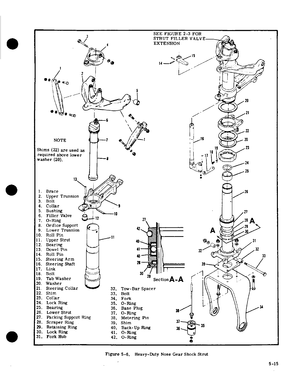
SEE
FIGURE
2-3
FOR
3
STRUT
FILLER
VALVE
EXTENSION
21
NOTE
1620
Shims
(22)
are
used
as
18
required
above
lower
8
17
1
washer
(20).
-
C 24
13
e
*
1.
Brace
26
2.
Upper
Trunnion -/
3.
Bolt
4.
Collar
(
.I
9
5.
Bushing
.
27
6.
Filler
Valve
7.
O-Ring
27
28
A
8.
Orifice
Support
/
29
9.
Lower Trunnion
-
42
A
10.
Roll
Pin
11.
Upper
Strut
1..
40.
31
12.
Bearing
41
13.
Dowel
Pin
41
2 /32
14.
Roll
Pin
33
15.
Steering
Arm
16.
Steering
Shaft
2
39
-
17.
Link
18.
Bolt
30
2
19.
Tab
Washer
9
ectionA-A
20.
Washer
21.
Steering
Collar
32.
Tow-Bar
Spacer
22.
Shim
33.
Bolt
23.
Collar
34.
Fork
24.
Lock Ring
35.
O-Ring
25.
Bearing
36.
Base Plug
34
26.
Lower
Strut
37.
O-Ring
27.
Packing
Support
Ring
38.
Metering
Pin
l
28.
Scraper
Ring
39.
Shim
31
29.
Retaining
Ring
40.
Back-Up
Ring
36
30.
Lock
Ring
41.
O-Ring
31.
Fork
Hub
42.
O-Ring
Figure
5-6.
Heavy-Duty Nose
Gear
Shock
Strut
5-15
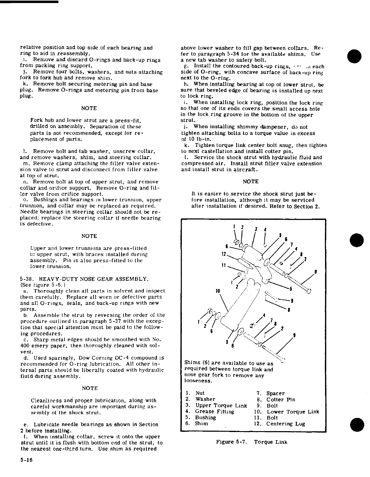
relative
position
and top
side
of
each
bearing
and
above
lower
washer
to
fill
gap
between
collars.
Re-
ring
to
aid
in
reassembly. fer
to
paragraph
5-34
for
the
available
shims.
Use
i.
Remove
and
discard
O-rings
and
back-up
rings
a
new
tab washer
to
safety
bolt.
from
packing
ring
support.
g.
Install
the
contoured
back-up
rings,
each
j.
Remove
four
bolts,
washers,
and
nuts
attaching side
of
O-ring,
with
concave
surface
of
back-up
ring
fork
to
fork
hub
and
remove
shim. next
to
the
O-ring.
k.
Remove
bolt
securing
metering
pin and
base
h.
When
installing
bearing
at
top
of
lower
strut,
be
plug. Remove
O-rings
and
metering
pin
from base
sure
that
beveled
edge
of
bearing
is
installed
up
next
plug.
to
lock
ring.
i.
When
installing
lock
ring,
position
the lock
ring
NOTE
so
that
one
of
its
ends
covers
the
small
access
hole
in
the
lock
ring
groove
in
the
bottom
of
the
upper
Fork
hub
and
lower
strut
are
a
press-fit, strut.
drilled
on
assembly.
Separation
of
these
j.
When
installing
shimmy
dampener,
do not
parts
is
not
recommended,
except
for
re-
tighten
attaching bolts
to
a
torque
value
in
excess
placement
of
parts.
of
10
lb-in.
k.
Tighten
torque
link
center
bolt
snug,
then
tighten
1.
Remove
bolt
and
tab
washer,
unscrew
collar,
to next
castellation
and
install
cotter
pin.
and
remove
washers,
shim,
and
steering
collar.
1.
Service
the
shock
strut
with
hydraulic
fluid
and
m.
Remove
clamp
attaching
the
filler
valve
exten-
compressed
air.
Install
strut filler
valve
extension
sion
valve
to
strut
and
disconnect
from
filler
valve
and
install
strut
in
aircraft.
at top
of
strut.
n.
Remove
bolt
at
top
of
upper
strut,
and
remove
NOTE
collar
and
orifice
support.
Remove
O-ring
and fil-
ler
valve
from
orifice
support.
It
is
easier
to
service
the
shock
strut
just
be-
o.
Bushings
and
bearings
in
lower
trunnion,
upper
fore
installation,
although
it
may
be
serviced
trunnion,
and
collar
may
be
replaced
as
required, after
installation
if
desired.
Refer
to
Section
2.
Needle
bearings
in
steering
collar
should
not
be
re-
placed:
replace
the
steering
collar
if
needle
bearing
is
defective.
NOTE
Upper
and lower
trunmons
are
press-fitted
//
4
to
upper
strut,
with
braces
installed
during
12
assembly.
Pin
is
also
press-fitted
to
the
lower
trunnion.
5-38.
HEAVY-DUTY
NOSE
GEAR
ASSEMBLY.
(See
figure
5-6.)
2
a.
Thoroughly clean
all
parts
in
solvent
and
inspect
10
/ /
them
carefully.
Replace all
worn
or
defective
parts
and
all
O-rings,
seals,
and
back-up
rings
with
new
parts./
b.
Assemble
the
strut
by
reversing
the
order
of
the
/ 4
procedure
outlined
in
paragraph
5-37
with the
excep-
/
tion
that
special
attention
must
be
paid
to
the
follow-
2
ing
procedures.
6
9
c.
Sharp
metal edges
should
be
smoothed
with
No.
400
emery
paper,
then
thoroughly
cleaned
with
sol- /
vent.
d.
Used
sparingly,
Dow
Corning
DC-
4
compound
is
recommended
for
O-ring
lubrication.
All
other
in-
Shims
(6)
are
available
to use
as
ternal
parts
should
be
liberally
coated
with
hydraulic
required
between
torque
link
and
fluid
during
assembly.
nose
gear
fork
to
remove
any
looseness.
NOTE
1.
Nut
7.
Spacer
Cleanliness
and
proper
lubrication,
along
with
2.
Washer
8.
Cotter
Pin
careful
workmanship
are
important
during
as-
3.
Upper
Torque
Link
9.
Bolt
sembly
of
the shock
strut.
4.
Grease
Fitting
10.
Lower
Torque
Link
5.
Bushing
11.
Bolt
e.
Lubricate
needle
bearings
as
shown
in
Section
6.
Shim
12.
Centering
Lug
2
before
installing.
f.
When
installing
collar,
screw
it
onto the
upper
strut
until
it
is
flush
with
bottom
end
of
the
strut,
to
Figure
5-7.
Torque
Link
the
nearest one-third
turn.
Use
shim
as required
5-16
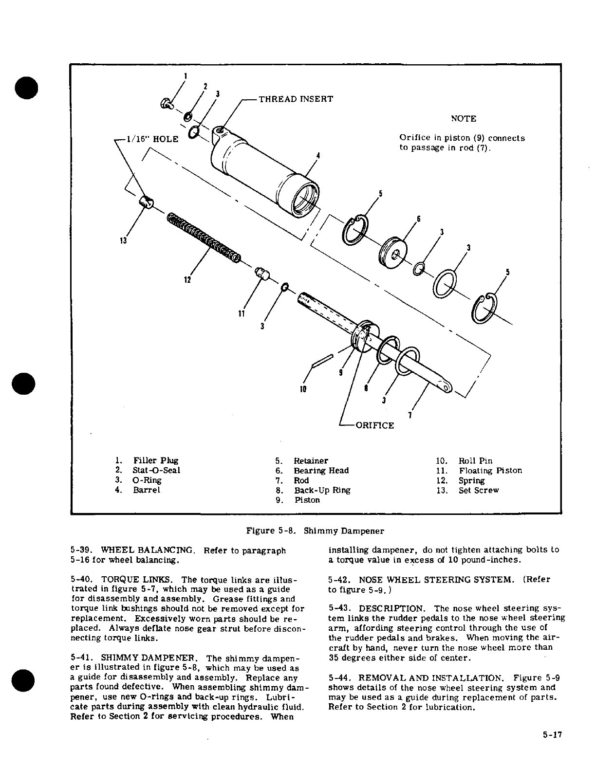
1.
Filler
Plug
5.
Retainer
10.
Roll
Pin
2.
Stat-O-Seal
6.
Bearing
Head
11.
Floating
Piston
3.
O-Ring
7.
Rod
12.
Spring
4.
Barrel
8.
Back-Up
Ring
13.
Set
Screw
9.
Piston
Figure
5-8.
Shimmy
Dampener
5-39.
WHEEL
BALANCING.
Refer
to
paragraph
installing
dampener,
do
not
tighten
attaching
bolts
to
5-16
for
wheel
balancing.
a
torque
value
in
excess
of
10
pound-inches.
5-40.
TORQUE
LINKS.
The
torque
links
are
illus-
5-42.
NOSE
WHEEL
STEERING
SYSTEM.
(Refer
trated
in
figure
5-7,
which
may
be
used
as
a
guide
to
figure
5-9.)
for disassembly
and
assembly.
Grease fittings
and
torque
link
bushings should
not
be
removed
except
for
5-43. DESCRIPTION.
The
nose
wheel
steering
sys-
replacement. Excessively
worn
parts
should
be
re-
tern
links
the
rudder
pedals
to
the
nose wheel
steering
placed.
Always
deflate
nose
gear
strut
before discon-
arm,
affording
steering
control
through
the
use
of
necting
torque
links.
the
rudder pedals
and
brakes.
When
moving
the
air-
craft
by
hand,
never
turn
the
nose
wheel
more
than
5-41.
SHIMMY
DAMPENER.
The
shimmy dampen-
35
degrees
either
side
of
center.
er
is
illustrated
in
figure
5-8,
which
may
be
used
as
a
guide
for
disassembly
and
assembly.
Replace
any
5-44.
REMOVAL
AND
INSTALLATION.
Figure
5-9
parts
found
defective.
When
assembling
shimmy
dam-
shows
details
of
the
nose
wheel
steering
system
and
pener,
use
new
O-rings
and
back-up
rings.
Lubri-
may
be
used
as
a
guide
during
replacement
of
parts.
cate
parts
during
assembly
with
clean
hydraulic
fluid.
Refer
to
Section
2
for lubrication.
Refer
to
Section
2
for
servicing
procedures.
When
5-17
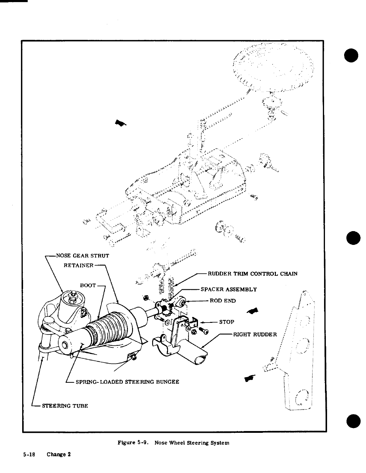
RUDDER
TRIM
CONTROL
CHAIN
SPACER
ASSEMBLY
RIGHT
RUDDER
---
LSPRING-LOADED
STEERING
BUNGEE
STEERING
TUBE
.-
Figure
5-9.
Nose
Wheel
Steering
System
5-18 Change 2
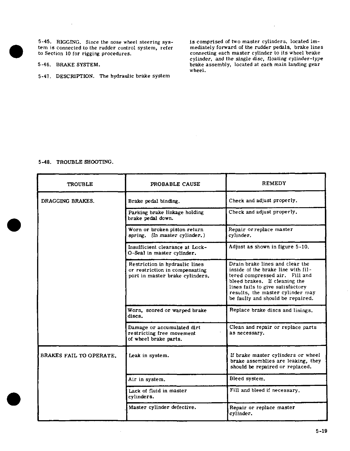
5-45.
RIGGING.
Since
the nose
wheel
steering
sys-
is
comprised
of
two
master
cylinders,
located
im-
ter
is
connected
to
the
rudder
control
system,
refer
mediately
forward
of
the
rudder pedals,
brake
lines
to
Section
10
for
rigging
procedures,
connecting
each
master
cylinder
to
its
wheel
brake
cylinder,
and
the
single
disc,
floating
cylinder-type
5-46.
BRAKE
SYSTEM.
brake
assembly,
located
at
each main
landing
gear
wheel.
5-47. DESCRIPTION.
The
hydraulic
brake
system
5-48.
TROUBLE
SHOOTING.
TROUBLE PROBABLE
CAUSE
REMEDY
DRAGGING
BRAKES.
Brake
pedal
binding.
Check
and
adjust
properly.
Parking
brake
linkage
holding Check
and
adjust
properly.
brake
pedal
down.
Worn
or
broken piston
return
Repair
orreplace
master
spring.
(In
master
cylinder.)
cylinder.
Insufficient
clearance
at
Lock-
Adjust
as
shown
in
figure
5-10.
O-Seal
in
master
cylinder.
Restriction
in
hydraulic
lines Drain
brake
lines
and
clear
the
or
restriction
in
compensating
inside
of
the
brake
line
with
fil-
port
in
master
brake
cylinders.
tered
compressed
air.
Fill
and
bleed
brakes.
If
cleaning
the
lines
fails
to
give
satisfactory
results,
the
master
cylinder
may
be
faulty
and
should
be
repaired.
Worn,
scored
or
warped
brake
Replace brake
discs
and
linings.
discs.
Damage
or
accumulated
dirt
Clean
and
repair
or
replace
parts
restricting
free
movement
as
necessary.
of
wheel
brake
parts.
BRAKES
FAIL
TO
OPERATE.
Leak
in
system.
If
brake
master cylinders
or
wheel
brake
assemblies
are
leaking,
they
should
be
repaired
or
replaced.
Air
in
system.
Bleed
system.
Lack
of
fluid
in
master
Fill
and
bleed
if
necessary.
cylinders.
Master
cylinder
defective.
Repair or
replace
master
cylinder.
5-19
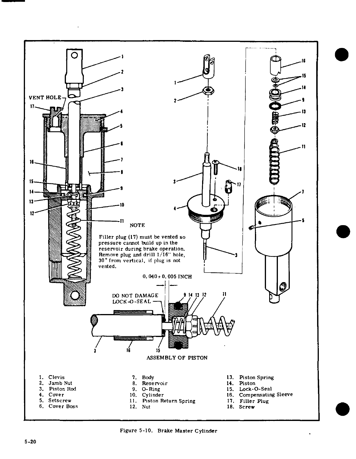
2
1
VENT
HOLE
9
17
5 12
6 11
NOTE
Filler
plug
(17)
must
be
vented
so
pressure
cannot
build
up
in
the
reservoir
during brake operation.
Remove
plug
and
drill
1/16"
hole,
3
30°
from
vertical,
if
plug
is
not
vented.
0.
040
±
0.005
INCH
DO
NOT
DAMAGE
914
3
12
11
LOCK-O-SEAL
16
1I
1
ASSEMBLY
OF
PISTON
1.
Clevis
7.
Body
13.
Piston
Spring
2.
Jamb
Nut 8.
Reservoir
14.
Piston
3.
Piston
Rod
9.
0-Ring
15.
Lock-O-Seal
4.
Cover
10.
Cylinder
16.
Compensating
Sleeve
5.
Setscrew
11.
Piston
Return Spring
17.
Filler
Plug
6.
Cover
Boss
12.
Nut
18.
Screw
Figure
5-10.
Brake
Master
Cylinder
5-20
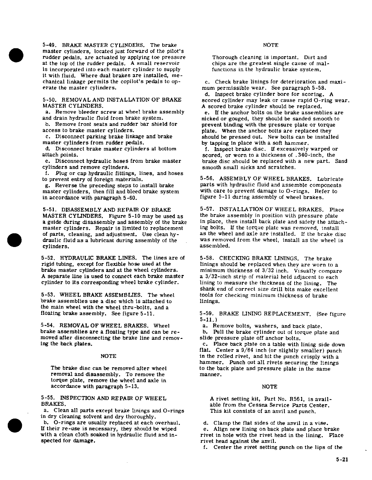
5-49.
BRAKE
MASTER
CYLINDERS.
The
brake
NOTE
master
cylinders,
located
just
forward
of
the
pilot's
rudder
pedals,
are
actuated
by
applying
toe
pressure
Thorough
cleaning is
important.
Dirt
and
at
the
top
of
the
rudder pedals.
A
small
reservoir
chips
are
the
greatest
single
cause
of
mal-
is incorporated
into
each
master
cylinder
to
supply
functions
in
the
hydraulic
brake
system.
it
with
fluid.
Where
dual
brakes are
installed,
me-
chanical
linkage
permits
the
copilot's
pedals
to
op-
c.
Check
brake
linings
for
deterioration
and maxi-
erate
the
master
cylinders.
mum
permissible
wear.
See
paragraph
5-58.
d.
Inspect
brake
cylinder bore
for
scoring.
A
5-50.
REMOVAL
AND
INSTALLATION
OF
BRAKE
scored
cylinder
may
leak or
cause
rapid
O-ring
wear.
MASTER
CYLINDERS.
A
scored
brake cylinder
should
be
replaced.
a.
Remove
bleeder
screw
at
wheel
brake
assembly
e.
If
the
anchor
bolts
on
the
brake
assemblies
are
and
drain
hydraulic
fluid
from
brake
system.
nicked
or
gouged,
they
should
be
sanded
smooth
to
b.
Remove
front
seats
and
rudder
bar
shield
for
prevent
binding
with
the
pressure
plate
or
torque
access
to
brake
master
cylinders,
plate.
When
the
anchor
bolts
are
replaced
they
c.
Disconnect
parking
brake
linkage
and
brake
should
be
pressed
out.
New
bolts
can
be
installed
master
cylinders
from
rudder
pedals.
by
tapping
in
place
with
a
soft
hammer.
d.
Disconnect
brake
master
cylinders
at
bottom
f.
Inspect
brake
disc.
If
excessively
warped
or
attach
points.
scored,
or
worn
to
a
thickness
of
.340-inch,
the
e.
Disconnect
hydraulic
hoses
from
brake
master
brake
disc
should
be
replaced
with
a
new
part.
Sand
cylinders
and
remove
cylinders.
smooth
small
nicks
and
scratches.
f.
Plug
or
cap
hydraulic
fittings,
lines,
and
hoses
to
prevent
entry
of
foreign
materials.
5-56.
ASSEMBLY
OF
WHEEL
BRAKES.
Lubricate
g.
Reverse
the
preceding
steps
to
install
brake
parts
with
hydraulic
fluid
and
assemble
components
master
cylinders,
then
fill
and
bleed
brake
system
with
care
to
prevent
damage
to
O-rings.
Refer
to
in
accordance
with
paragraph
5-60.
figure
5-11
during
assembly
of
wheel
brakes.
5-51.
DISASSEMBLY
AND
REPAIR
OF
BRAKE
5-57.
INSTALLATION
OF
WHEEL
BRAKES.
Place
MASTER CYLINDERS.
Figure
5-10 may
be
used
as
the
brake
assembly
in
position
with
pressure
plate
a
guide
during
disassembly
and
assembly
of
the
brake
in
place,
then
install
back
plate and
safety
the
attach-
master
cylinders.
Repair
is
limited
to
replacement
ing
bolts.
If
the
torque
plate
was
removed,
install
of
parts,
cleaning,
and
adjustment.
Use
clean
hy-
as
the
wheel
and
axle
are
installed.
If
the
brake disc
draulic
fluid
as
a
lubricant
during
assembly
of
the
was
removed from
the
wheel,
install
as
the
wheel
is
cylinders.
assembled.
5-52.
HYDRAULIC
BRAKE
LINES. The
lines
are
of
5-58.
CHECKING
BRAKE LININGS.
The
brake
rigid
tubing,
except
for
flexible
hose
used
at
the
linings
should
be
replaced
when
they
are
worn
to
a
brake
master
cylinders
and
at
the
wheel
cylinders.
minimum
thickness
of
3/32
inch.
Visually
compare
A
separate
line
is
used
to
connect
each
brake
master
a
3/32-inch
strip
of
material
held
adjacent
to
each
cylinder
to
its
corresponding
wheel
brake cylinder.
lining
to
measure
the
thickness
of
the
lining.
The
shank
end
of
correct
size
drill
bits
make
excellent
5-53.
WHEEL
BRAKE
ASSEMBLIES.
The wheel
tools
for
checking
minimum
thickness
of
brake
brake
assemblies
use
a
disc
which
is
attached
to
linings.
the
main
wheel
with
the
wheel
thru-bolts,
and a
floating
brake
assembly.
See
figure
5-11.
5-59.
BRAKE
LINING
REPLACEMENT.
(See
figure
5-11.)
5-54.
REMOVAL
OF
WHEEL
BRAKES.
Wheel
a.
Remove
bolts,
washers,
and
back
plate.
brake
assemblies are
a floating
type
and
can
be
re-
b.
Pull the
brake
cylinder
out
of
torque
plate
and
moved
after
disconnecting
the
brake
line
and
remov-
slide
pressure
plate
off
anchor
balts.
ing
the back
plates.
c.
Place
back
plate
on
a
table
with
lining
side
down
flat. Center
a
9/64
inch
(or
slightly
smaller)
punch
NOTE
in
the
rolled
rivet,
and
hit
the
punch
crisply
with
a
hammer.
Punch
out
all
rivets
securing
the
linings
The
brake
disc
can
be
removed
after
wheel
to
the back
plate
and
pressure
plate
in
the
same
removal
and
disassembly.
To
remove
the
manner.
torque
plate,
remove
the
wheel and
axle
in
accordance
with
paragraph
5-13.
NOTE
5-55.
INSPECTION
AND
REPAIR OF
WHEEL
A
rivet
setting
kit,
Part
No.
R561,
is
avail-
BRAKES.
able
from
the
Cessna
Service
Parts
Center.
a.
Clean
all
parts
except
brake linings
and
O-rings
This
kit
consists
of an
anvil
and punch.
in
dry
cleaning solvent
and
dry
thoroughly.
b.
O-rings are
usually
replaced
at
each
overhaul.
d.
Clamp
the
flat
sides
of
the
anvil
in
a
vise.
If
their
re-use
is
necessary,
they
should
be
wiped
e.
Align
new
lining
on
back
plate
and
place
brake
with
a
clean
cloth
soaked
in
hydraulic fluid
and
in-
rivet
in
hole
with
the
rivet
head
in
the
lining.
Place
spected
for
damage.
rivet
head
against
the
anvil.
f.
Center
the
rivet
setting
punch
on
the
lips
of
the
5-21
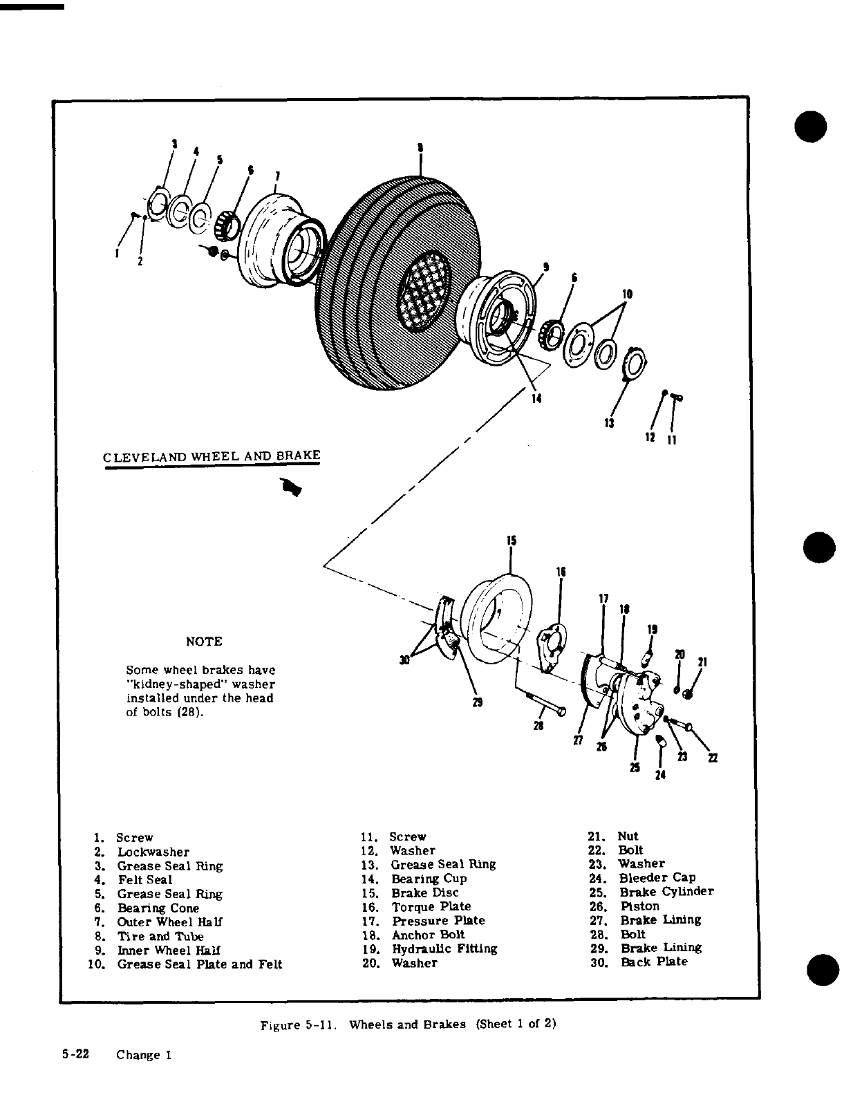
10
12
11
CLEVELAND
WHEEL
AND BRAKE
24
1
Some
wheel
brakes
have
\U
l
i
"kidney-shaped"
washer
I /
installed
under
the
head
> VY
of
bolts
(28).
a
1.
Screw
11.
Screw
21.
Nut
2.
Lockwasher
12.
Washer
22.
Bolt
3.
Grease
Seal
Ring
13.
Grease
Seal
Ring
23.
Washer
4.
Felt
Seal
14.
Bearing
Cup
24.
Bleeder
Cap
5.
Grease
Seal
Ring
15.
Brake
Disc
25.
Brake
Cylinder
6.
Bearing
Cone
16.
Torque
Plate
26.
Piston
7.
Outer
Wheel
Hall
17.
Pressure
Plate
27.
Brake
Lining
8.
Tire
and
Tube
18.
Anchor
Bolt
28.
Bolt
9.
Inner
Wheel
Half
19.
Hydraulic
Fitting
29.
Brake
Lining
10.
Grease
Seal
Plate
and
Felt
20.
Washer
30.
Back
Plate
Figure
5-11.
Wheels
and
Brakes
(Sheet 1
of
2)
5-22
Change
I
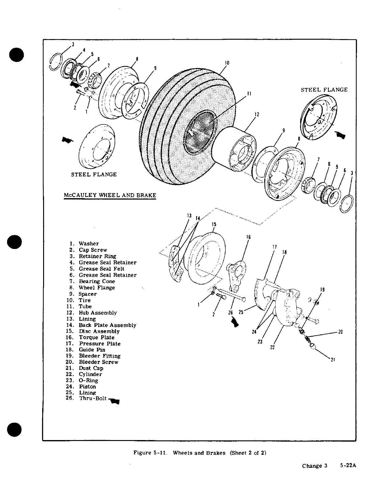
3
STEEL
FLANGE
2
I
13
/
/'
>
1
Washer
:/
//
12
)8
STEEL
FLANGE
McCAULEY
WHEEL
AND
BRAKE
1.
Washer
17
2.
Cap
Screw
la
3.
Retainer
Ring
4.
Grease
Seal
Retainer
/ /
5.
Grease
Seal
Felt
i< \' (4
1
1
6.
Grease
Seal
Retainer
7.
Bearing
Cone/
/ /
8.
Wheel
Flange
9.
Spacer
19
-
10.
Tire
/
r
,
11.
Tube
12.
Hub
Assembly
2 2
5
13.
Lining //
*$
14.
Back
Plate
Assembly
/ r
15.
Disc
Assembly
24
/20
16.
Torque
Plate
17.
Pressure
Plate
23
18.
Guide
Pin
2
19.
Bleeder
Fitting
20.
Bleeder
Screw
21.
Dust
Cap
22.
Cylinder
23.
O-Ring
24.
Piston
25.
Lining
26.
Thru-Bolt-
Figure
5-11.
Wheels
and
Brakes
(Sheet
2
of
2)
Change
3
5-22A
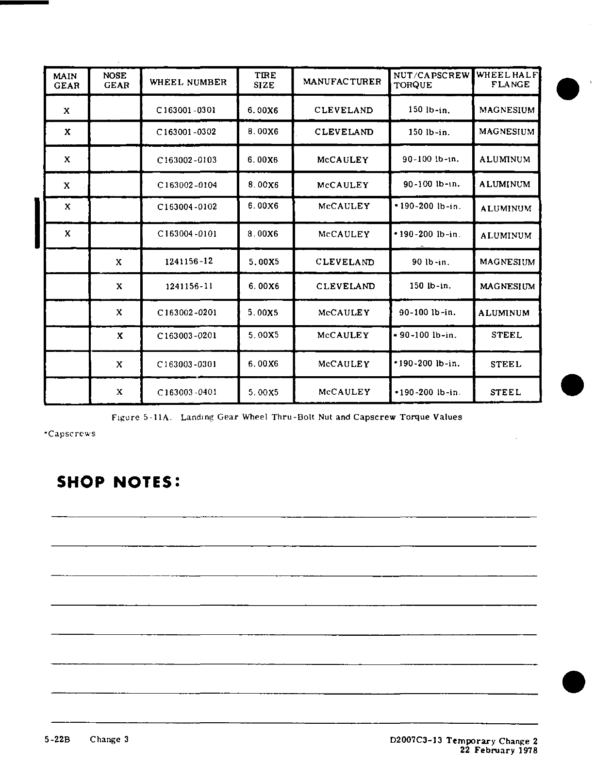
MAIN NOSE
TIRE
NUT/CAPSCREW
WHEELHALF
GEAR GEAR
WHEEL
NUMBER
SIZE
MANUFACTURER TORQUE FLANGE
x
C163001-0301
6.00X6
CLEVELAND
150
Ib-in.
MAGNESIUM
X
C163001-0302
8 .00X6
CLEVELAND
150
Ib-in.
MAGNESIUM
X
C163002-0103
6.00X6
McCAULEY
90-100
Ib-in.
ALUMINUM
X
I
C163002-0104
|8
00X6
McCAULEY
90-100
lb-in.
ALUMINUM
X
C163004-0102
6.
00X6
McCAULEY
1190-200
Ib-in.
1
ALUMINUM
X I
C163004-0101
8.00X6
McCAULEY
190-200
Ib-in.
ALUMINUM
X
1241156-12
5.00X5 CLEVELAND
90
lb-in.
MAGNESIUM
X
i
1241156-11
6.00X6
CLEVELAND
150
lb-in.
MAGNESIUM
X
C163002-0201
5.00X5
McCAULEY
90-100
Ib-in.
ALUMINUM
X
C
163003-0201
5.00X5
McCAULEY
90-100
Ib-in.
STEEL
X
C163003-0301
6.00X6
McCAULEY
*190-200
lb-in.
STEEL
X
C163003-0401
5.00X5
McCAULEY
'190-200
Ib-in
STEEL
Figure
5-11A.
Landing
Gear
Wheel
Thru-Bolt
Nut
and
Capscrew
Torque
Values
-Capscrews
SHOP
NOTES:
5-22B
Change
3
D2007C3-13
Temporary
Change
2
22
February
1978
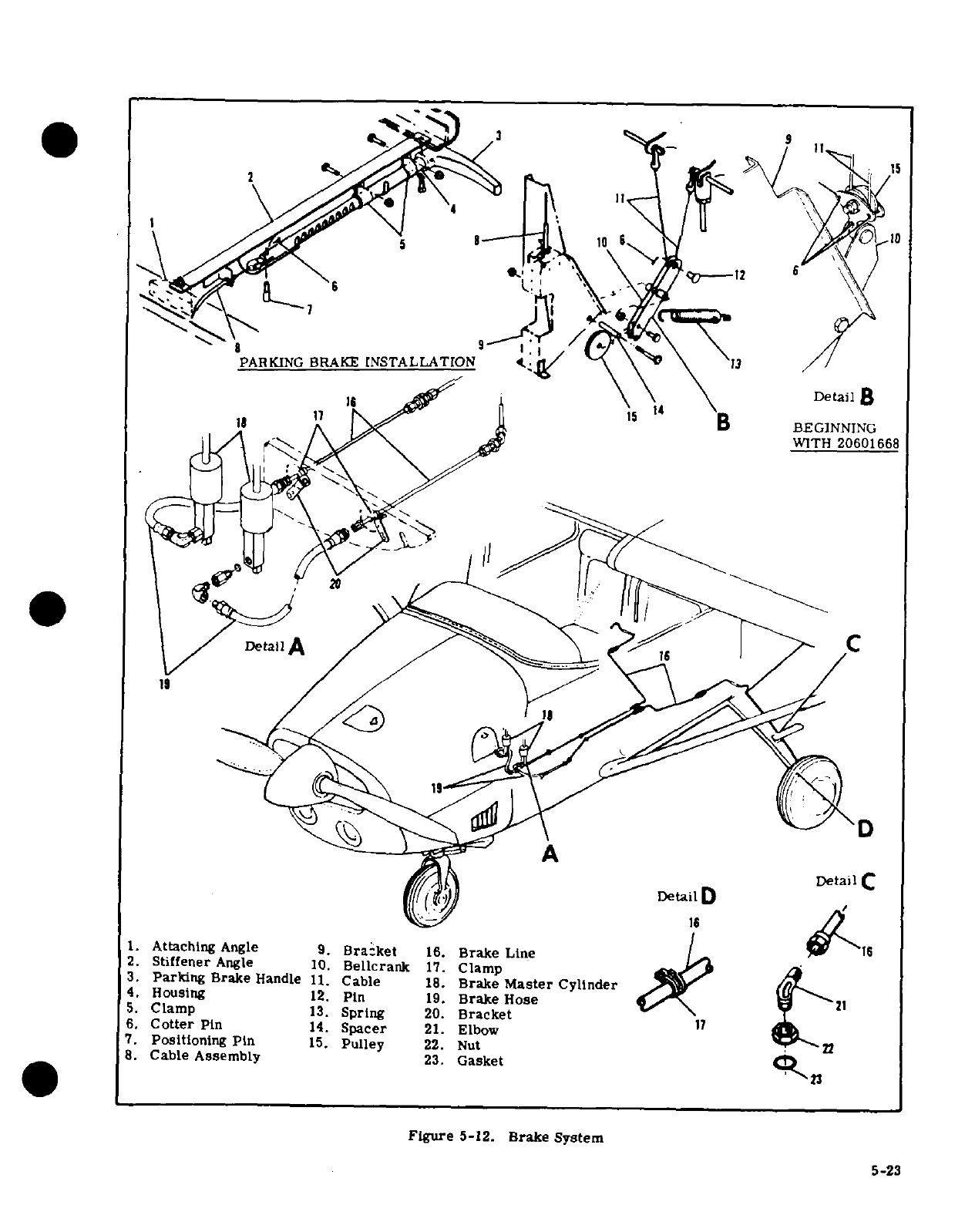
13.
Spring
20.
Bracket20601668
"1 t=I
.
Cable
Assembly
23.
Gasket
2f
5-23
1916
D
Detail
D
1.
Attaching
Angle
9.
Bracket
16.
Brake
Line
2.
Stiffener
Angle
10.
Bellcrank
17.
Clamp
3.
Parking
Brake
Handle
11.
Cable
18.
Brake
Master
Cylinder
4. Housing
12.
Pin
19.
Brake
Hose
5.
Clamp
13.
Spring
20.
Bracket
6.
Cotter
Pin
14.
Spacer
21.
Elbow
7.
Positioning
Pin
15.
Pulley
22.
Nut
8.
Cable
Assembly
23.
Gasket
Figure
5-12.
Brake
System
5-23
rivet.
While
holding
the back
plate
down
firmly
immersed
end
of
the
hose
at
the
brake
master
cylin-
against
the
lining,
hit
the
punch
with
a
hammer
to
der
for
evidence
of
bubbles
being
forced
from
the
set
the
rivet.
Repeat
blows
on
the
punch
until
lining
brake system.
When
bubbling
has
ceased,
remove
is
firmly
against
the
back
plate.
the
bleeder source
from
the
brake
wheel
cylinder
and
g.
Realign
the
lining
on
the
back
plate
and
install
tighten
the
bleeder
valve.
rivets
in
remaining
holes.
h.
Install
a
new
lining
on
pressure
plate
in
the
same
NOTE
manner.
i.
Position
pressure
plate
on
anchor
bolts,
and
Ensure
that
the
free
end
of
the
hose
from
the
place
cylinder
in
position
so
the
anchor
bolts
slide
brake
master
cylinder
remains immersed
into
torque plate. during
the
entire
bleeding
process.
j.
Install
the
back
plates
with
bolts
and
washers.
Safety
wire
the
bolts.
d.
Remove
hose
from
brake
master
cylinder
and
replace
filler
plug.
Be
sure
vent
hole
in
filler
plug
5-60.
BRAKE
BLEEDING.
Standard
bleeding,
with
is
open.
a
clean hydraulic
pressure
source
connected
to
the
wheel
cylinder
bleeder, is
recommended.
5-61.
PARKING
BRAKE
SYSTEM.
a.
Remove
brake
master
cylinder
filler
plug and
screw
a
flexible
hose
with
a
suitable
fitting
into the
5-62.
DESCRIPTION.
The
parking
brake
system
is
filler
hole.
Immerse
the
free
end
of
the
hose
in
a
essentially
a
ratchet-held
handle
which
depresses
container
with
enough
hydraulic
fluid
to
cover
the
and
holds
the
brake
master
cylinders
in
the
compress-
end
of
the
hose.
ed
position.
No
adjustment
is
provided
in
the
system.
b.
Connect
a
clean
hydraulic
pressure
source,
such
Replacement
of
worn
or
defective
parts
will
restore
as
a
hydraulic
hand
pump
or
Hydro
Fill
unit,
to
the
the
system
to
its
correct
operation.
Figure
5-12
may
bleeder
valve
in
the
wheel
cylinder.
be
used
as
a
guide
for
replacement
of
parts.
c.
As
fluid
is
pumped
into
the
system, observe
the
SHOP
NOTES:
5-24
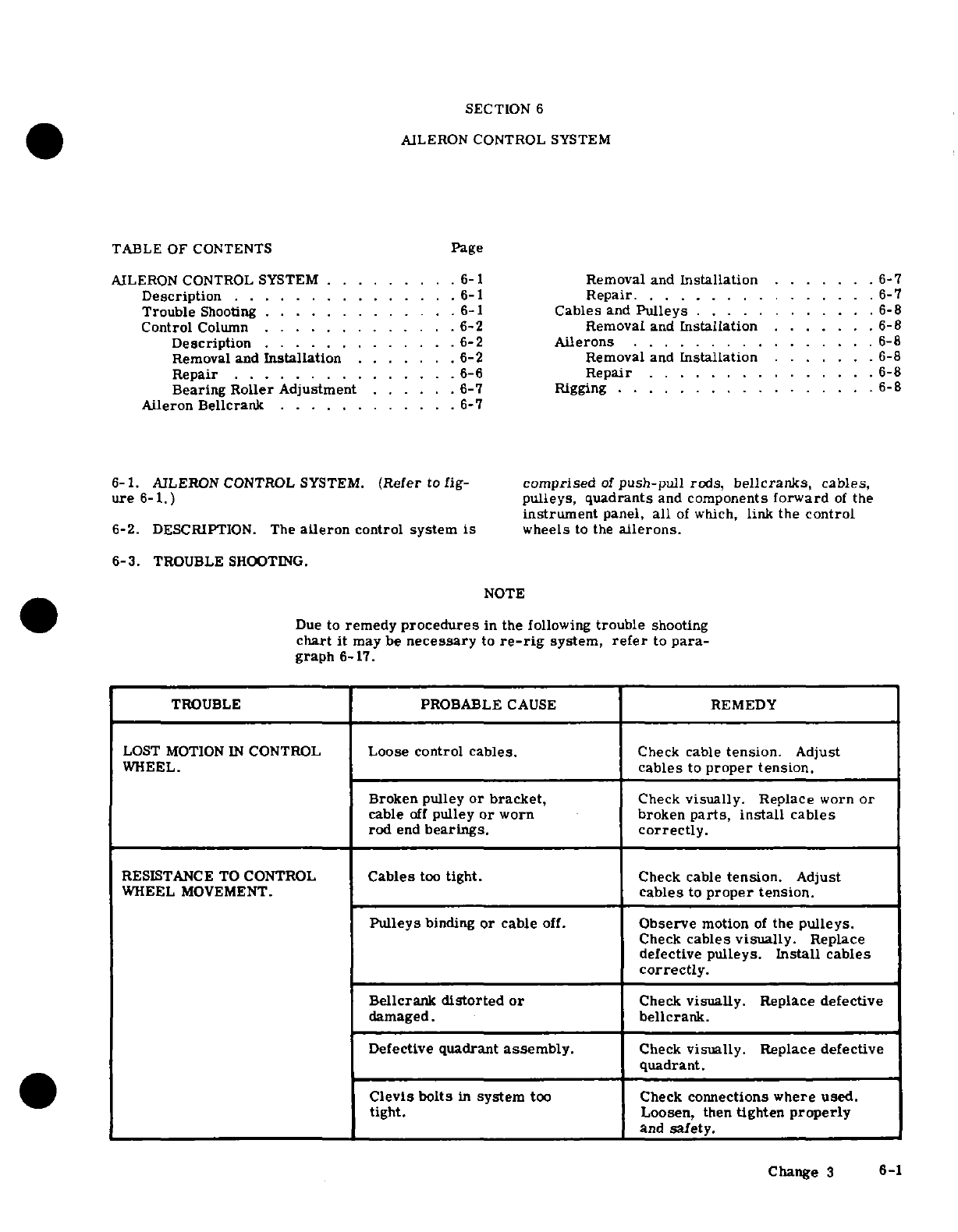
SECTION
6
AILERON
CONTROL
SYSTEM
TABLE OF
CONTENTS
Page
AILERON CONTROL
SYSTEM
.........
6-1
Removal
and
Installation
.......
6-7
Description
............
6-1
Repair
...........
6-7
Trouble
Shooting
............
6-1
Cables
and
Pulleys
............
6-8
Control
Column
.............
6-2
Removal
and
Installation
.......
.
6-8
Description
................
6-2
Ailerons.
..............
6-8
Removal
and
Installation
......
.
6-2
Removal and
Installation
.....
.
6-8
Repair.
.........
6-6 Repair
...............
6-8
Bearing
Roller
Adjustment
......
6-7
Rigging
............ ....
6-8
Aileron
Bellcrank
.........
.. .
6-7
6-1.
AILERON CONTROL
SYSTEM.
(Refer
to
fig-
comprised
of
push-pull
rods,
bellcranks,
cables,
ure 6-1.)
pulleys,
quadrants
and
components
forward
of
the
instrument
panel,
all
of
which,
link
the
control
6-2.
DESCRIPTION.
The
aileron
control
system
is
wheels
to
the
ailerons.
6-3.
TROUBLE
SHOOTING.
NOTE
Due
to
remedy
procedures
in
the
following
trouble
shooting
chart
it
may
be
necessary
to
re-rig
system,
refer
to
para-
graph
6-17.
TROUBLE
PROBABLE
CAUSE
REMEDY
LOST
MOTION
IN
CONTROL
Loose
control
cables.
Check cable
tension.
Adjust
WHEEL.
cables
to
proper
tension.
Broken pulley
or
bracket,
Check
visually.
Replace
worn
or
cable
off
pulley
or
worn
broken
parts,
install
cables
rod
end
bearings,
correctly.
RESISTANCE
TO
CONTROL
Cables
too
tight.
Check cable
tension.
Adjust
WHEEL
MOVEMENT.
cables
to
proper
tension.
Pulleys
binding
or
cable
off.
Observe
motion
of
the
pulleys.
Check
cables
visually.
Replace
defective
pulleys.
Install
cables
correctly.
Bellcrank
distorted
or
Check
visually.
Replace
defective
damaged.
bellcrank.
Defective
quadrant
assembly.
Check
visually. Replace defective
quadrant.
Clevis
bolts
in
system
too
Check
connections
where
used.
tight.
Loosen,
then
tighten
properly
and
safety.
Change
3
6-1
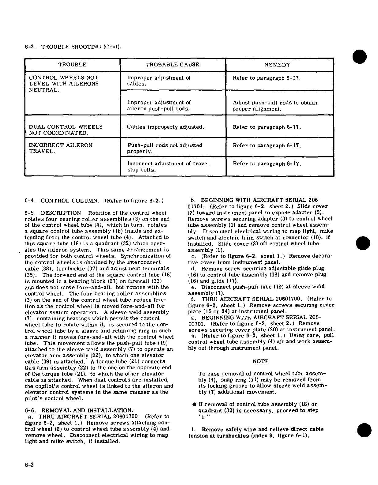
6-3.
TROUBLE
SHOOTING
(Cont).
TROUBLE
PROBABLE
CAUSE
REMEDY
CONTROL
WHEELS
NOT
Improper
adjustment
of
Refer
to
paragraph
6-17.
LEVEL
WITH
AILERONS
cables.
NEUTRAL.
Improper
adjustment
of
Adjust
push-pull rods
to
obtain
aileron
push-pull
rods. proper
alignment.
DUAL
CONTROL
WHEELS
Cables improperly
adjusted.
Refer
to
paragraph
6-17.
NOT
COORDINATED.
INCORRECT
AILERON
Push-pull
rods
not
adjusted
Refer
to
paragraph
6-17.
TRAVEL.
properly.
Incorrect
adjustment
of
travel
Refer
to
paragraph
6-17.
stop
bolts.
6-4.
CONTROL
COLUMN.
(Refer
to
figure
6-2.)
b.
BEGINNING
WITH
AIRCRAFT
SERIAL
206-
01701.
(Refer
to
figure
6-2,
sheet
2.)
Slide cover
6-5.
DESCRIPTION.
Rotation
of
the
control
wheel
(2)
toward
instrument
panel
to
expose
adapter
(3).
rotates
four
bearing
roller
assemblies
(3)
on
the
end
Remove
screws
securing
adapter
(3)
to
control
wheel
of
the
control
wheel
tube
(4),
which
in
turn,
rotates
tube
assembly
(1)
and
remove
control
wheel
assem-
a
square control
tube
assembly
(18)
inside
and
ex-
bly.
Disconnect
electrical
wiring
to
map
light,
mike
tending
from
the
control
wheel
tube
(4).
Attached
to
switch
and
electric
trim
switch
at
connector
(18),
if
this
square
tube
(18)
is
a
quadrant
(32)
which
oper-
installed.
Slide
cover
(2)
off
control
wheel
tube
ates
the
aileron
system.
This
same
arrangement
is
assembly
(1).
provided
for
both
control wheels.
Synchronization
of
c.
(Refer
to
figure
6-2,
sheet
1.)
Remove
decora-
the
control wheels
is
obtained
by
the
interconnect
tive cover
from
instrument
panel.
cable
(38),
turnbuckle
(37)
and
adjustment
terminals
d.
Remove
screw
securing
adjustable
glide
plug
(35).
The
forward
end
of
the
square control
tube
(18) (16)
to
control
tube
assembly
(18)
and
remove
plug
is
mounted
in
a
bearing
block
(27)
on
firewall
(33)
(16)
and
glide
(17).
and
does
not
move
fore-and-aft,
but
rotates
with
the
e.
Disconnect
push-pull
tube
(19)
at
sleeve
weld
control
wheel.
The
four
bearing
roller
assemblies
assembly
(7).
(3)
on
the
end
of
the
control
wheel
tube
reduce
fric-
f.
THRU
AIRCRAFT
SERIAL
20601700.
(Refer
to
tion
as
the
control
wheel
is
moved
fore-and-aft
for
figure
6-2,
sheet
1.)
Remove
screws
securing
cover
elevator
system
operation.
A
sleeve
weld
assembly
plate
(15
or
24)
at
instrument
panel.
(7),
containing
bearings
which
permit
the
control
g.
BEGINNING
WITH
AIRCRAFT
SERIAL
206-
wheel
tube to
rotate
within
it, is
secured
to
the
con-
01701.
(Refer
to
figure
6-2, sheet
2.)
Remove
trol
wheel
tube
by
a
sleeve
and
retaining
ring
in
such
screws
securing
cover
plate
(20)
at
instrument
panel.
a
manner
it moves
fore-and-aft
with
the
control
wheel
h.
(Refer
to
figure
6-2,
sheet
1.)
Using
care,
pull
tube.
This
movement
allows
the
push-pull
tube
(19)
control
wheel
tube
assembly
(4)
aft
and
work
assem-
attached
to
the sleeve
weld
assembly
(7)
to
operate
an bly
out
through
instrument
panel.
elevator
arm
assembly
(22),
to
which
one
elevator
cable
(39)
is
attached.
A
torque
tube
(21)
connects
NOTE
this arm
assembly
(22)
to
the
one
on
the
opposite
end
of
the
torque
tube
(21),
to
which
the
other elevator
To
ease
removal
of
control
wheel
tube
assem-
cable
is
attached.
When
dual
controls
are
installed,
bly
(4),
snap
ring
(11)
may
be
removed
from
the
copilot's
control
wheel
is
linked
to
the
aileron
and
its
locking
groove
to
allow
sleeve
weld
assem-
elevator
control
systems
in
the
same
manner
as
the
bly
(7)
additional
movement.
pilot's
control
wheel.
If
removal
of
control
tube
assembly
(18)
or
6-6.
REMOVAL
AND
INSTALLATION.
quadrant
(32)
is
necessary,
proceed
to
step
a.
THRU
AIRCRAFT
SERIAL
20601700.
(Refer
to
"i."
figure
6-2,
sheet
1.)
Remove
screws
attaching
con-
trol
wheel
(2)
to
control
wheel
tube
assembly
(4)
and
i.
Remove
safety
wire
and
relieve
direct
cable
remove
wheel.
Disconnect
electrical
wiring to
map
tension
at
turnbuckles
(index
9,
figure
6-1).
light
and mike
switch,
if
installed.
6-2
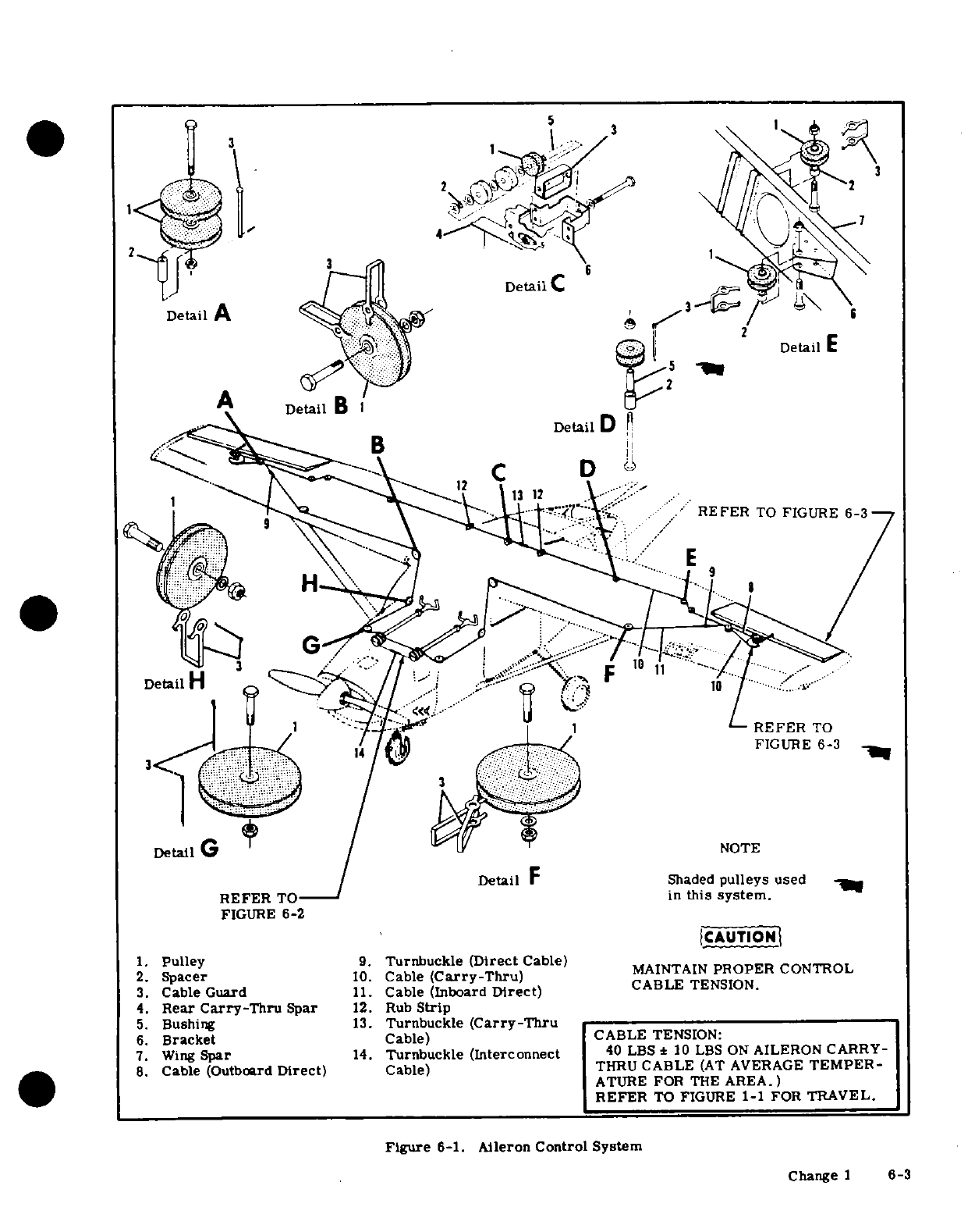
2
1
Detail
DetalA
3
REFER
TO
FIGURE
6-3
DetailH
REFER
TO
FIGURE
6-3
3
Detail
G
NOTE
Detail
F
Shaded
pulleys
used
REFER
TO
in
this
system.
FIGURE
6-2
CAUTION
1.
Pulley
9.
Turnbuckle
(Direct
Cable)
MAINT
AIN
PROPE
R
CON
TROL
14.
Turnbuckle (Interconnect
40
LBS
M
10
LBS
ON AIPROP
ERON
CARRY-
2.
Spacer
10.
Cable
(Carry-Thru)
3.
Cable
Guard
11.
Cable
(Inbod
rect)NON.
4.
Rear
Carry-Thru
Spar
12.
Rub
Strip
.
Cable
(Outbrd
Drect)
Cable)
THRU
CABLE
TE MPENSION:
?.
Wing
Spar
14.
Turnbuckle
(Interconnect
40
LBS
±
10
LBS
ON AILERON
CARRY-
8.
Cable
(Outboard
Direct)
Cable)
THRU
CABLE
(AT
AVERAGE
TEMPER-
ATURE
FOR
THE
AREA.)
REFER
TO
FIGURE
1-1
FOR
TRAVEL.
Figure
6-1.
Aileron
Control
System
Change
1
6-3
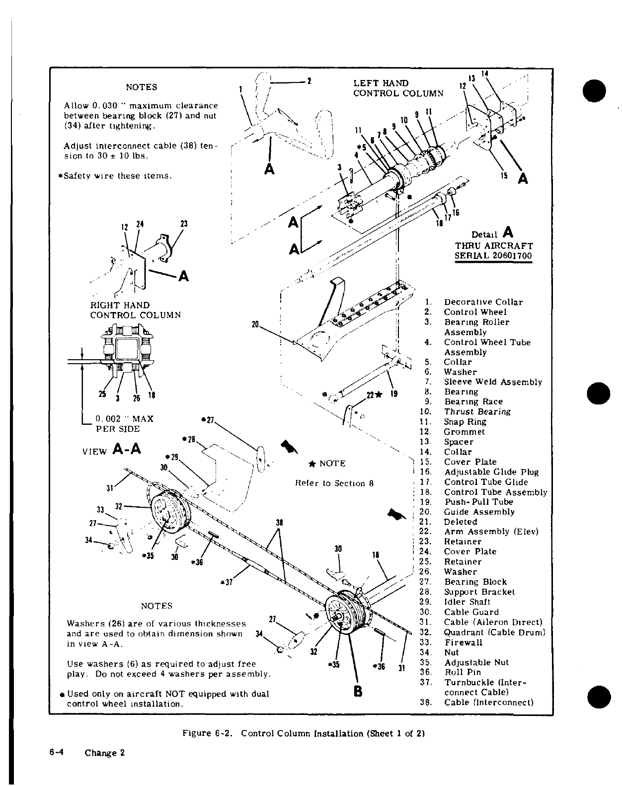
1 2
LEFT
HAND
12
/CONTROL
COLUMN
Allow
0.030
"
maximum
clearance
between
bearing
block
(27)
and
nut
9
(34)
after
tightening.
9
Adjust
interconnect
cable
(38)
ten-
sion
to
30
±
10
lbs. 4
*Safety wire
these
items.
-
/
A
12
24
23
Detail
A
THRU
AIRCRAFT
SERIAL
20601700
RIGHT
HAND
1.
Decorative Collar
CONTROL
COLUMN
/ .
2.
Control
Wheel
3.
Bearing
Roller
Assembly
4.
Control
Wheel
Tube
Assembly
5.
Collar
6.
Washer
7.
Sleeve
Weld
Assembly
25
11
---
22* 19
8.
Bearing
9.
Bearing
Race
10.
Thrust
Bearing
*
11.
Snap
Ring
PER
SIDE
12.
Grommet
Spacer
VIEW
A-A
14.
Collar
*
NOTE
15.
Cover
Plate
16.
Adjustable
Glide
Plug
Refer
to
Section
8
1
.
Control
Tube
Glide
18.
Control
Tube
Assembly
32
-
19.
Push-Pull
Tube
20.
Guide
Assembly
27-
.
38
21.
Deleted
.22.
Arm
Assembly
(Elev)
23.
Retainer
*35
24.
Cover Plate
*36
25.
Retainer
26.
Washer
27.
Bearing
Block
28.
Support Bracket
NOTES
29.
Idler
Shaft
30.
Cable
Guard
Washers
(26)
are
of
various
thicknesses
27
31.
Cable
(Aileron
Direct)
and
are
used
to
obtain
dimension
shown
34
32.
Quadrant
(Cable
Drum)
in
view
A-A.
33.
Firewall
/
34.
Nut
Use
washers
(6)
as
required
to
adjust
free
*
35.
Adjustable
Nut
play.
Do
not
exceed
4
washers
per
assembly.
36.
Roll
Pin
37.
Turnbuckle
(Inter-
Used
only
on
aircraft
NOT
equipped
with
dual
B
connect
Cable)
control
wheel
installation.
38.
Cable
(Interconnect)
Figure
6-2.
Control
Column
Installation
(Sheet
1
of
2)
6-4
Change
2
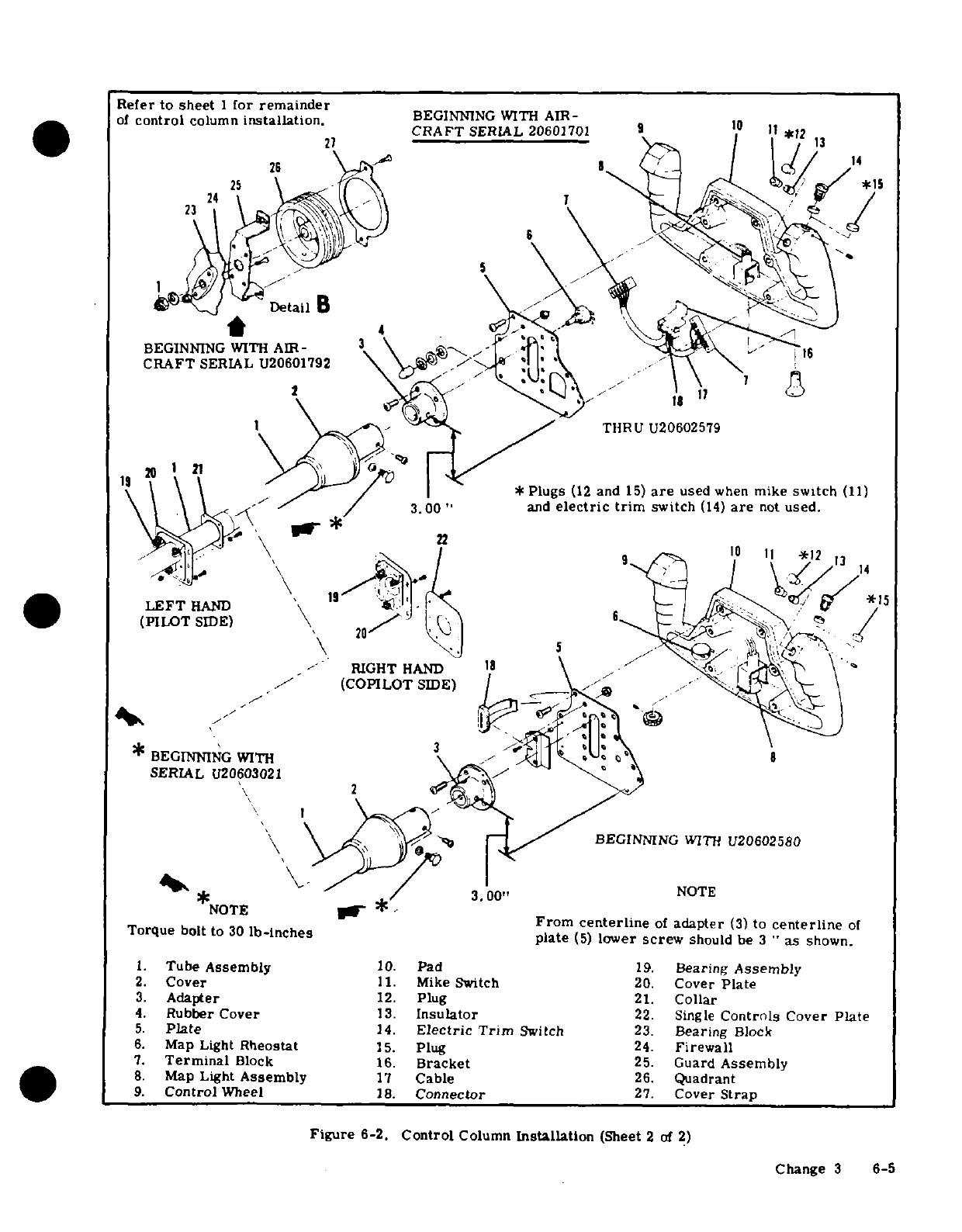
1.
Tube
Assembly
10.
Pad
19.
Bearing
Assembly
2.
Cover
11.
Mike
Switch
20.
Cover
Plate
3.
Adapter
12.
Plug
21.
Collar
4.
Rubber
Cover
13.
Insulator
22.
Single
Controls
Cover
Plate
5.
Plate
14.
Electric
Trim
Switch
23.
Bearing
Block
6.
Map
Light
Rheostat
15.
Plug
24.
Firewall
7.
Terminal
Block
16.
Bracket
25.
Guard
Assembly
8.
Map
Light
Assembly
17
Cable
26.
Quadrant
9.
Control
Wheel
18.
Connector
27.
Cover
Strap
Figure
6-2.
Control
Column
Installation
(Sheet
2
of
2)
Change
3
6-5
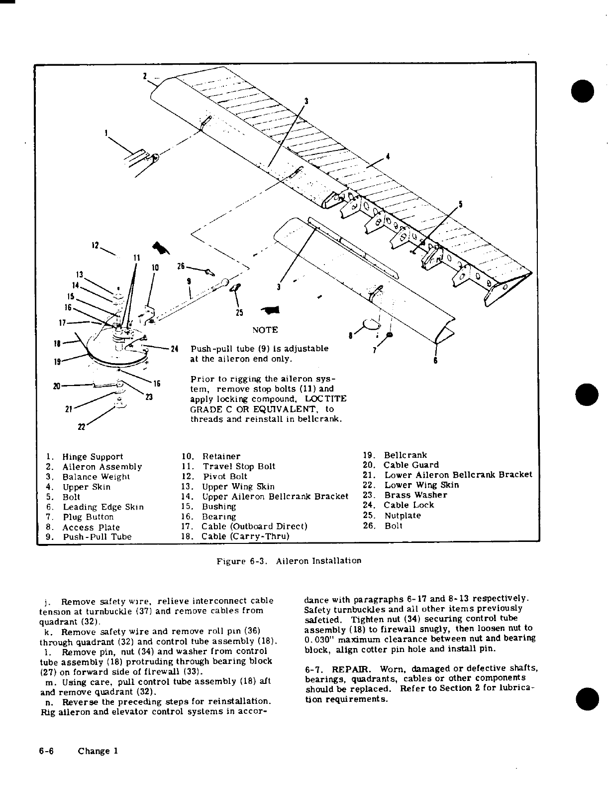
12
14
3
X\ y^^"NOTE >
"V
tJL--"--24
Push-pull
tube
(9)
is
adjustable
7
19
"' -
at
the
aileron
end only.
0
is-_____
1
Prior
to
rigging
the
aileron
sys-
tem,
remove
stop
bolts
(11)
and
apply locking
compound,
LOCTITE
21
/ '
GRADE
C
OR
EQUIVALENT,
to
22/.^~
~threads
and
reinstall
in
bellcrank.
1.
Hinge
Support
10.
Retainer
19.
Bellcrank
2.
Aileron Assembly
11.
Travel
Stop
Bolt
20.
Cable
Guard
3.
Balance
Weight
12.
Pivot
Bolt
21.
Lower
Aileron
Bellerank
Bracket
4.
Upper
Skin
13.
Upper
Wing
Skin
22.
Lower
Wing
Skin
5.
Bolt
14.
Upper
Aileron Bellcrank
Bracket
23.
Brass
Washer
6.
Leading
Edge
Skin
15.
Bushing
24.
Cable
Lock
7.
Plug
Button
16.
Bearing
25.
Nutplate
8.
Access
Plate
17.
Cable (Outboard
Direct)
26.
Bolt
9.
Push-Pull
Tube
18.
Cable
(Carry-Thru)
Figure
6-3.
Aileron
Installation
j.
Remove
safety
wire,
relieve
interconnect
cable
dance
with
paragraphs
6-17 and
8-13
respectively.
tension
at
turnbuckle
(37)
and
remove
cables
from
Safety
turnbuckles
and
all
other
items
previously
quadrant
(32).
safetied.
Tighten
nut
(34)
securing
control
tube
k.
Remove
safety
wire
and
remove
roll
pin
(36)
assembly
(18)
to
firewall
snugly,
then
loosen
nut
to
through
quadrant
(32)
and
control
tube
assembly
(18).
0. 030"
maximum
clearance
between
nut and
bearing
1.
Remove
pin, nut
(34)
and
washer from control
block,
align
cotter
pin hole
and
install
pin.
tube
assembly
(18)
protruding
through
bearing
block
(27)
on
forward
side
of
firewall
(33).
6-7.
REPAIR.
Worn,
damaged
or
defective
shafts,
m.
Using
care,
pull
control
tube
assembly
(18)
aft
bearings, quadrants,
cables
or
other
components
and
remove quadrant
(32).
should
be
replaced.
Refer
to
Section
2
for
lubrica-
n.
Reverse
the
preceding
steps
for
reinstallation.
tion
requirements.
Rig
aileron
and
elevator
control
systems
in
accor-
6-6
Change 1
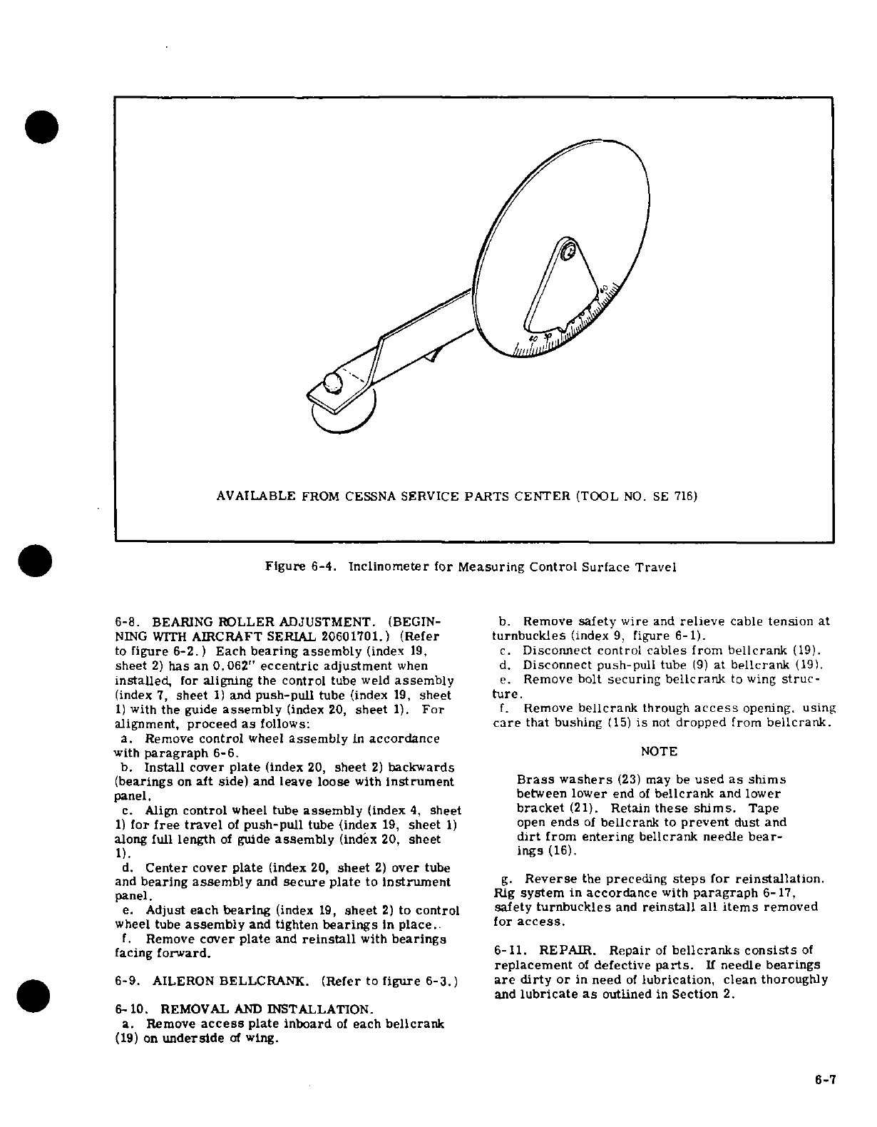
AVAILABLE
FROM
CESSNA
SERVICE
PARTS
CENTER
(TOOL
NO.
SE
716)
Figure
6-4.
Inclinometer
for
Measuring
Control Surface
Travel
6-8.
BEARING
ROLLER
ADJUSTMENT.
(BEGIN-
b.
Remove
safety
wire
and
relieve
cable
tension
at
NING WITH
AIRCRAFT
SERIAL
20601701.)
(Refer
turnbuckles
(index
9,
figure
6-1).
to
figure 6-2.)
Each
bearing assembly
(index
19,
c.
Disconnect
control
cables
from
bellcrank
(19).
sheet
2)
has
an
0.062"
eccentric
adjustment
when
d.
Disconnect push-pull
tube
(9)
at
bellcrank
(19).
installed,
for
aligning
the
control
tube weld
assembly
e.
Remove
bolt
securing
bellcrank
to
wing
struc-
(index
7,
sheet
1)
and
push-pull
tube
(index
19,
sheet
ture.
1)
with
the
guide
assembly
(index
20,
sheet
1).
For
f.
Remove
bellcrank
through
access
opening.
using
alignment,
proceed
as
follows:
care
that
bushing
(15)
is
not
dropped
from
bellcrank.
a.
Remove
control
wheel
assembly
in
accordance
with
paragraph
6-6.
NOTE
b.
Install
cover
plate
(index
20,
sheet
2)
backwards
(bearings
on
aft
side)
and
leave
loose
with
instrument
Brass
washers
(23)
may
be
used
as
shims
panel, between
lower
end
of
bellcrank
and lower
c.
Align
control
wheel
tube
assembly
(index
4,
sheet
bracket
(21).
Retain
these
shims.
Tape
1)
for
free
travel
of
push-pull
tube
(index
19,
sheet
1)
open
ends
of
bellcrank
to
prevent
dust
and
along
full
length
of
guide
assembly
(index
20,
sheet
dirt
from entering
bellcrank
needle
bear-
1).
ings
(16).
d.
Center
cover
plate
(index
20,
sheet
2)
over
tube
and
bearing
assembly
and
secure
plate
to
instrument
g.
Reverse
the
preceding
steps
for
reinstallation.
panel.
Rig
system
in
accordance
with
paragraph
6-17,
e.
Adjust each
bearing
(index
19,
sheet
2)
to
control safety
turnbuckles
and
reinstall
all
items
removed
wheel
tube
assembly
and
tighten
bearings
in
place.
for
access.
f.
Remove
cover
plate
and
reinstall
with
bearings
facing
forward.
6-11. REPAIR.
Repair
of
bellcranks consists
of
replacement
of
defective
parts.
If
needle
bearings
6-9.
AILERON
BELLCRANK.
(Refer
to
figure
6-3.)
are dirty
or
in
need
of
lubrication,
clean
thoroughly
and
lubricate
as
outlined
in
Section
2.
6- 10.
REMOVAL
AND
INSTALLATION.
a.
Remove
access
plate inboard
of
each
bellcrank
(19)
on
underside
of
wing.
6-7
6-12.
CABLES
AND
PULLEYS.
(Refer
to
figure
f.
Check
aileron
travel
and
alignment,
re-rig
if
6-1.) necessary,
in
accordance
with
paragraph
6-17.
6-13.
REMOVAL
AND
INSTALLATION.
6-16.
REPAIR.
Aileron
repair
may be
accomplished
a.
Remove
access
plates,
wing
root
fairings
and
in
accordance
with
instructions
outlined
in
Section
18.
upholstery
as
required.
Before
installation, ensure
balance weights
and hinges
b. Remove
safety wire
and
relieve
cable
tension
at
are
securely
attached.
turnbuckles
(9
and
13).
c.
Disconnect
cables
from
aileron
bellcranks
(index 6-17.
RIGGING.
19,
figure 6-3)
and
quadrants
(index
32,
figure
6-2).
a.
(Refer
to
figure
6-1.)
Remove
access
plates
d.
Remove
cable
guards
and
pulleys
as
necessary
and
upholstery
as
required.
to
work
cables
free
of
aircraft.
b.
Remove
safety
wire
and
relieve
cable
tension
at
turnbuckles
(9
and
13).
NOTE
c.
(Refer
to
figure
6-3.)
Disconnect
push-pull
tubes
(9)
at
ailerons
(2).
To
ease
routing
of
cables,
a
length
of
wire
d.
(Refer
to
figure
6-2.)
Adjust
turnbuckle
(37)
may
be
attached
to
end
of
cable
before
and
adjustment
nuts
(35)
on
interconnect
cable
(38)
being
withdrawn from
aircraft.
Leave
to
remove slack,
acquire proper tension
(30±10
wire
in
place,
routed
through
structure;
pounds)
and
position
both
control
wheels
level
(syn-
then
attach
cable
being
installed
and
use
chronized).
to
pull
cable
into
position.
e.
Tape
a
bar
across
both
control wheels
to hold
them
in
neutral
position.
e.
Reverse
the
preceding
steps
for
reinstallation.
f.
(Refer
to
figure
6-1.)
Adjust
direct
cable
turn-
f.
After
cables
are
routed
in
position,
install
pul-
buckles
(9)
and
carry-thru
cable
turnbuckle
(13)
to
leys
and
cable
guards.
Ensure
cables
are
positioned
position
bellcranks
(index
19,
figure 6-3)
approxi-
in
pulley
grooves
before
installing guards.
mately
in
neutral
while
maintaining
proper
cable
g.
Re-rig aileron
system
in
accordance
with
para-
tension.
graph
6-
17,
safety
turnbuckles
and
install
access
g.
Streamline
ailerons
with
reference
to
flaps
plates,
fairings
and
upholstery
removed
in
step
"a."
(flaps
full
UP
positions),
then
adjust
push-pull
tubes
(index
9.
figure
6-3)
to fit and
install.
6-14.
AILERONS.
(Refer
to
figure
6-3.
)
h.
With
ailerons
streamlined,
mount
an
inclino-
meter
on
trailing
edge
of
aileron
and
set
pointer
to
6-15.
REMOVAL
AND
INSTALLATION.
0°.
a.
Remove
access
plates
(8)
and
plug
buttons
(7)
i.
Remove
bar
from
control wheels
and
adjust
from
underside
of
aileron.
travel
stops
(index
11,
figure
6-3)
to obtain
travel
b.
Disconnect push-pull
tube
(9)
at
ailerons.
specified
in
figure
1-1.
c.
Remove
bolts
(5)
attaching
ailerons
to
hinge
j.
Ensure
all
turnbuckles
are
safetied,
all
cables
supports
(1).
and
cable
guards
are
properly
installed,
all
jam
nuts
d.
Using
care
pull
ailerons
out
and
down.
are
tight
and
replace
all
parts
removed
for
access.
e.
Reverse
the
preceding
steps
for
reinstallation.
WARNING
NOTE Be
sure
ailerons
move
in
correct
direction
If
rigging
was
correct
and
push
pull
tube
when
operated
by
the
control
wheels.
adjustment
was
not
disturbed,
it should
not
be
necessary
to
re-rig
system.
SHOP
NOTES:
6-8 Change 3
SECTION
7
WING
FLAP
CONTROL
SYSTEM
TABLE
OF
CONTENTS
Page
WING
FLAP
CONTROL
SYSTEM
......
7-1
Bellcranks
..............
7-5
Description
..............
7-1
Removal
and
Installation
..
7-5
Operational
Check
...........
7-1
Repair
..............
7-5
Trouble
Shooting
............
7-2
Flaps.
7-5
Flap
Motor
and
Transmission
Assembly
.7-3
Removaland
Installation
......
7-5
Removal
and
Installation
......
7-3 Repair
..............
7-5
Repair
.
...........
. 7-3
Cables
and
Pulleys
.....
.......
7-5
Flap
Control
Lever
..............
7-3
Removal
and
Installation
......
7-5
Removal
and
Installation
......
7-3
Rigging
-
Flaps
.........
...
7-5
Drive
Pulleys
.......
7-5
Rigging
-
Flap
Control
Lever
and
Removal
and
Installation
.
.....
7-5
Follow-Up
. . .
......
7-13
Repair
.............
7-5
7-1.
WING
FLAP
CONTROL
SYSTEM.
(Refer
to
motor
should
NOT
continuously
freewheel
at
travel
figure
7-1.)
extremes.
c.
BEGINNING
WITH
AIRCRAFT SERIAL
U206-
7-2.
DESCRIPTION.
The
wing
flap
control system
01674
AND
ALL AIRCRAFT MODIFIED
IN
ACCOR-
consists
of an
electric
motor
and
transmission assem-
DANCE
WITH
FIGURE
7-2
SHEET
3
Check
for
bly,
drive
pulleys,
synchronizing
push-pull
tubes,
positive
shut-off
of
motor
at
the
flap
travel
extremes,
bellcranks,
push-pull
rods, cables,
pulleys
and
a
FLAP
MOTOR
MUST
STOP
OR
DAMAGE
WILL
RE-
follow-up
control.
Power
from
the
motor
and
trans-
SULT.
mission
assembly
is
transmitted
to
the
flaps
by
a
d.
Check
flaps
for
sluggishness
in
operation.
In
system
of
drive
pulleys,
cables
and
synchronizing
flight
at
110
MPH (THRU
AIRCRAFT
SERIALS
P206-
tubes.
Electrical
power to
the motor
is
controlled
by 00648
AND
U20601700)
and
120
MPH
(BEGINNING
two
microswitches
mounted
on
a
"floating"
arm,
a
WITH
AIRCRAFT
SERIAL
U20601701).
indicated
control
lever
and
a
follow-up
control.
As
the
control
airspeed,
flaps
should
fully
extend
in
approximately
lever
is
moved
to
the
desired
flap
setting,
a
switch
is
15.5
seconds
and
retract
in
approximately 7.5
sec-
tripped
actuating
the
flap
motor.
As
the
flaps
move,
onds.
On
the ground,
with
engine
running, the
flaps
the
floating
arm
is
rotated
by
the
follow-up
control
should extend
in
approximately
8
seconds
and
retract
until
the
active
switch
clears
the
control
lever
cam,
in
approximately
7.5
seconds.
breaking
the
circuit.
To
reverse
the
direction
of
e. With
flaps
full
UP,
mount
an
inclinometer
on
one
flap
travel,
the
control
lever
is
moved
in
the
opposite
flap
and
set
to 0
°
. Lower
flaps
to
full
DOWN
position
direction.
When
the
control
lever
cam
contacts
the
and
check
flap
angle
as
specified
in
figure
1-
1.
Check
second
switch
the
flap
motor
is
energized
in
the
op-
approximate
mid-range
percentage
setting
against
posite
direction.
Likewise,
the follow-up
control
degrees
as
indicated
on
inclinometer.
Repeat
the
moves
the
floating
arm
until
the
second
switch
is
same
procedure
for
the
opposite flap.
clear
of
the
control
lever
cam.
NOTE
7-3.
OPERATIONAL
CHECK.
a.
Operate flaps
through
their
full
range
of
travel,
An
inclinometer
for measuring
control
sur-
*
observing for
uneven
or
jumpy
motion,
binding and
face
travel
is
available
from
the
Cessna
lost
motion in
the
system.
Ensure
flaps
are
moving
Service
Parts
Center.
Refer
to
figure
6-4.
together
through
their
full
range
of
travel.
b.
THRU
AIRCRAFT
SERIALS
P20600648
AND
f.
Remove
access
plates
and
attempt
to
rock drive
U20601673
WHEN
NOT
MODIFIED
IN
ACCORDANCE
pulleys
and
bellcranks
to
check
for
bearing wear.
WITH
FIGURE
7-2,
SHEET
3.
Check
for positive
g.
Inspect
flap
rollers
and
tracks
for
evidence
of
shut-off
of
motor
at
the
flap
travel
extremes,
the
binding
and
defective
parts.
Change
1
7-1
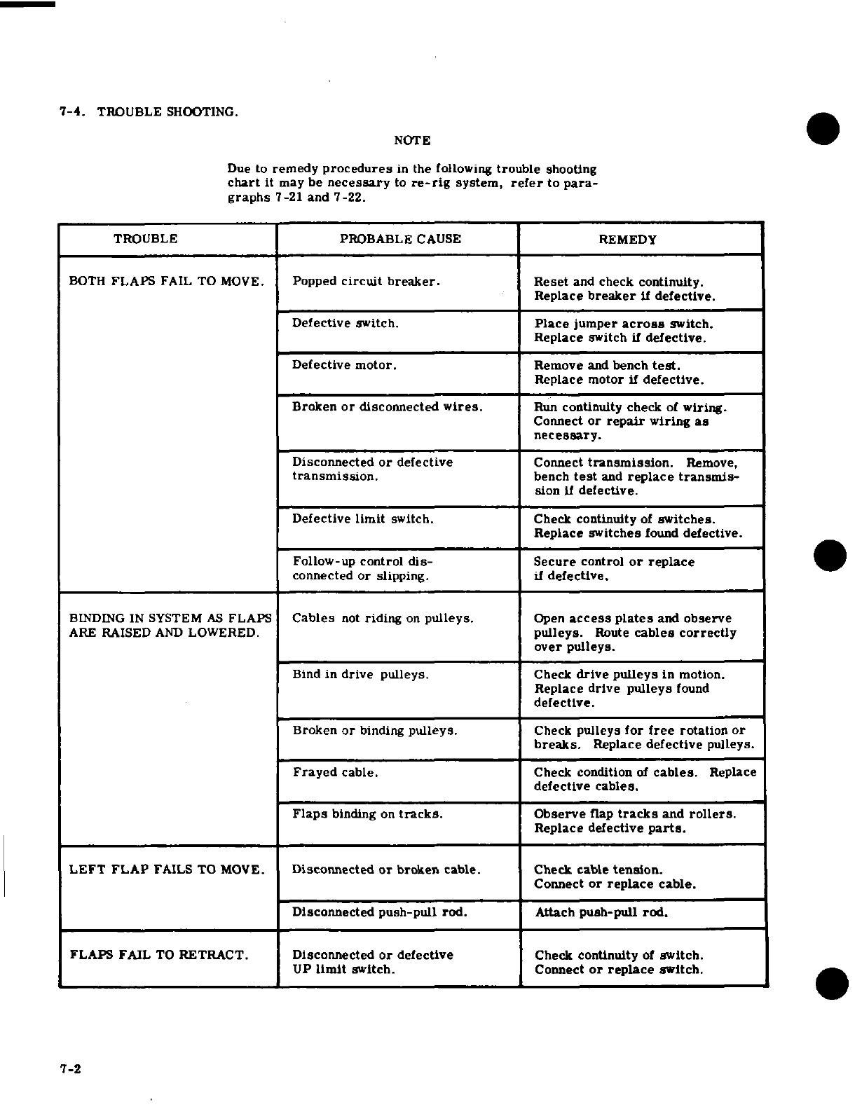
7-4.
TROUBLE
SHOOTING.
NOTE
Due
to
remedy
procedures
in
the
following
trouble
shooting
chart
it
may
be
necessary
to
re-rig
system,
refer
to
para-
graphs
7-21
and
7-22.
TROUBLE PROBABLE
CAUSE
REMEDY
BOTH
FLAPS
FAIL TO
MOVE.
Popped
circuit
breaker.
Reset
and
check
continuity.
Replace
breaker
if
defective.
Defective switch.
Place
jumper
across
switch.
Replace
switch
if
defective.
Defective
motor.
Remove
and
bench
test.
Replace
motor if
defective.
Broken
or
disconnected
wires.
Run
continuity
check
of
wiring.
Connect
or
repair
wiring
as
necessary.
Disconnected
or
defective
Connect
transmission.
Remove,
transmission.
bench
test
and
replace
transmis-
sion
if
defective.
Defective
limit
switch.
Check
continuity
of
switches.
Replace
switches
found
defective.
Follow-up
control
dis-
Secure
control
or
replace
connected
or
slipping.
if
defective.
BINDING
IN
SYSTEM
AS
FLAPS
Cables
not
riding
on
pulleys.
Open
access plates
and
observe
ARE
RAISED
AND
LOWERED.
pulleys.
Route
cables
correctly
over
pulleys.
Bind
in drive pulleys.
Check
drive pulleys
in
motion.
Replace
drive
pulleys
found
defective.
Broken
or
binding
pulleys.
Check
pulleys
for
free
rotation
or
breaks.
Replace
defective
pulleys.
Frayed
cable.
Check condition
of
cables.
Replace
defective
cables.
Flaps
binding
on
tracks.
Observe
flap
tracks
and
rollers.
Replace
defective
parts.
LEFT
FLAP
FAILS
TO
MOVE.
Disconnected
or
broken
cable.
Check
cable
tension.
Connect
or
replace
cable.
Disconnected
push-pull rod.
Attach
push-pull
rod.
FLAPS
FAIL
TO
RETRACT.
Disconnected
or
defective
Check
continuity
of
switch.
UP
limit
switch.
Connect
or
replace
switch.
7-2
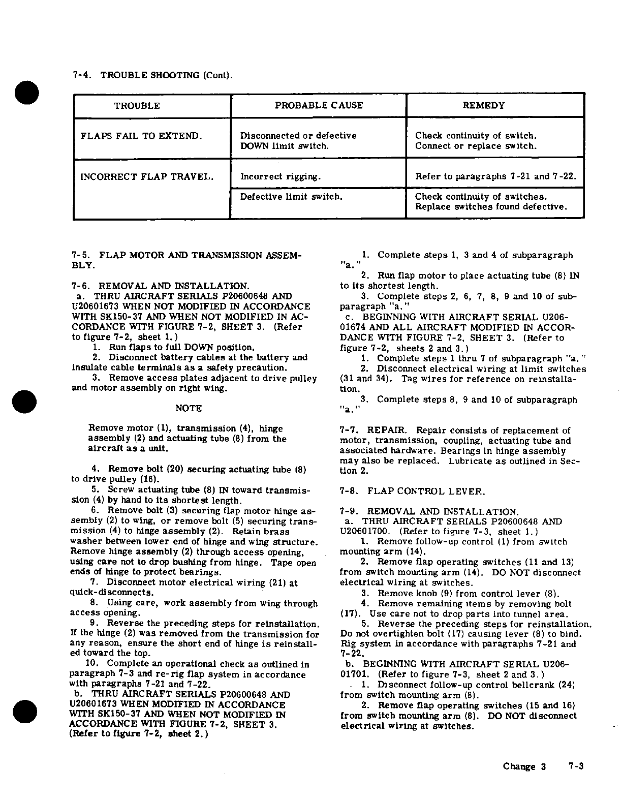
7-4.
TROUBLE
SHOOTING
(Cont).
TROUBLE
PROBABLE
CAUSE
REMEDY
FLAPS
FAIL
TO
EXTEND.
Disconnected
or
defective
Check continuity
of
switch.
DOWN
limit
switch.
Connect
or
replace
switch.
INCORRECT
FLAP
TRAVEL.
Incorrect
rigging.
Refer
to
paragraphs
7-21
and
7-22.
Defective
limit
switch.
Check
continuity
of
switches.
Replace
switches
found
defective.
7-5. FLAP
MOTOR
AND
TRANSMISSION
ASSEM-
1.
Complete
steps
1, 3
and
4
of
subparagraph
BLY.
"a."
2.
Run
flap
motor
to
place
actuating
tube
(8)
IN
7-6.
REMOVAL
AND
INSTALLATION.
to
its
shortest
length.
a.
THRU
AIRCRAFT
SERIALS P20600648
AND
3.
Complete
steps
2, 6,
7, 8,
9
and
10
of
sub-
U20601673
WHEN
NOT
MODIFIED
IN
ACCORDANCE
paragraph
"a."
WITH
SK150-37
AND
WHEN
NOT
MODIFIED
IN
AC-
c.
BEGINNING
WITH
AIRCRAFT
SERIAL
U206-
CORDANCE
WITH
FIGURE
7-2,
SHEET
3.
(Refer
01674
AND
ALL
AIRCRAFT
MODIFIED
IN
ACCOR-
to
figure
7-2, sheet
1.)
DANCE
WITH
FIGURE
7-2,
SHEET
3.
(Refer
to
1.
Run
flaps
to
full
DOWN
position.
figure
7-2,
sheets
2
and
3.)
2.
Disconnect
battery
cables
at
the
battery
and
1.
Complete
steps
1
thru
7
of
subparagraph
"a."
insulate
cable
terminals
as
a
safety
precaution.
2.
Disconnect
electrical
wiring
at
limit
switches
3.
Remove
access
plates
adjacent
to
drive
pulley
(31
and
34).
Tag
wires
for
reference
on
reinstalla-
and
motor
assembly
on
right
wing.
tion.
3.
Complete
steps
8,
9
and
10
of
subparagraph
NOTE
"a."
Remove
motor
(1),
transmission
(4),
hinge
7-7.
REPAIR.
Repair
consists
of
replacement
of
assembly
(2)
and
actuating
tube
(8)
from
the motor,
transmission,
coupling,
actuating
tube and
aircraft
as
a
unit.
associated
hardware. Bearings
in
hinge
assembly
may
also
be
replaced.
Lubricate
as
outlined
in
Sec-
4.
Remove
bolt
(20)
securing
actuating
tube
(8)
tion
2.
to
drive
pulley
(16).
5.
Screw
actuating
tube
(8)
IN
toward
transmis-
7-8.
FLAP
CONTROL
LEVER.
sion
(4)
by
hand
to
its
shortest
length.
6.
Remove
bolt
(3)
securing
flap
motor
hinge
as-
7-9.
REMOVAL
AND
INSTALLATION.
sembly
(2)
to
wing,
or
remove
bolt
(5)
securing
trans-
a.
THRU
AIRCRAFT
SERIALS
P20600648
AND
mission
(4)
to
hinge
assembly
(2).
Retain
brass
U20601700.
(Refer
to
figure 7-3,
sheet
1.)
washer
between
lower
end
of
hinge
and
wing
structure.
1.
Remove
follow-up
control
(1)
from
switch
Remove hinge
assembly
(2)
through
access
opening,
mounting
arm
(14).
using
care
not
to
drop
bushing from
hinge.
Tape
open
2.
Remove
flap
operating
switches
(11
and
13)
ends
of
hinge to
protect
bearings.
from
switch
mounting
arm
(14).
DO NOT
disconnect
7.
Disconnect
motor
electrical
wiring
(21)
at
electrical
wiring
at
switches.
quick-disconnects.
3.
Remove knob
(9)
from
control
lever
(8).
8.
Using
care,
work
assembly
from
wing
through
4.
Remove
remaining
items
by
removing
bolt
access
opening.
(17).
Use
care
not
to
drop
parts
into
tunnel
area.
9.
Reverse
the
preceding
steps
for
reinstallation.
5.
Reverse
the
preceding
steps
for
reinstallation.
If
the hinge
(2)
was
removed from
the
transmission
for
Do
not
overtighten
bolt
(17)
causing
lever
(8)
to
bind.
any
reason,
ensure
the
short
end
of
hinge
is
reinstall-
Rig
system
in
accordance
with
paragraphs
7-21
and
ed
toward the
top.
7-22.
10.
Complete
an
operational
check
as
outlined
in
b. BEGINNING
WITH
AIRCRAFT
SERIAL
U206-
paragraph
7-3
and
re-rig
flap
system
in
accordance
01701.
(Refer
to
figure
7-3,
sheet
2
and
3.)
with
paragraphs
7-21
and
7-22.
1.
Disconnect
follow-up
control
bellcrank
(24)
b.
THRU
AIRCRAFT
SERIALS
P20600648
AND
from
switch
mounting
arm
(8).
U20601673
WHEN
MODIFIED
IN
ACCORDANCE
2.
Remove
flap
operating
switches
(15
and
16)
WITH
SK150-37
AND
WHEN
NOT
MODIFIED
IN
from
switch
mounting
arm
(8).
DO NOT
disconnect
ACCORDANCE
WITH
FIGURE
7-2,
SHEET
3.
electrical
wiring
at
switches.
(Refer
to
figure
7-2, sheet 2.)
Change
3
7-3
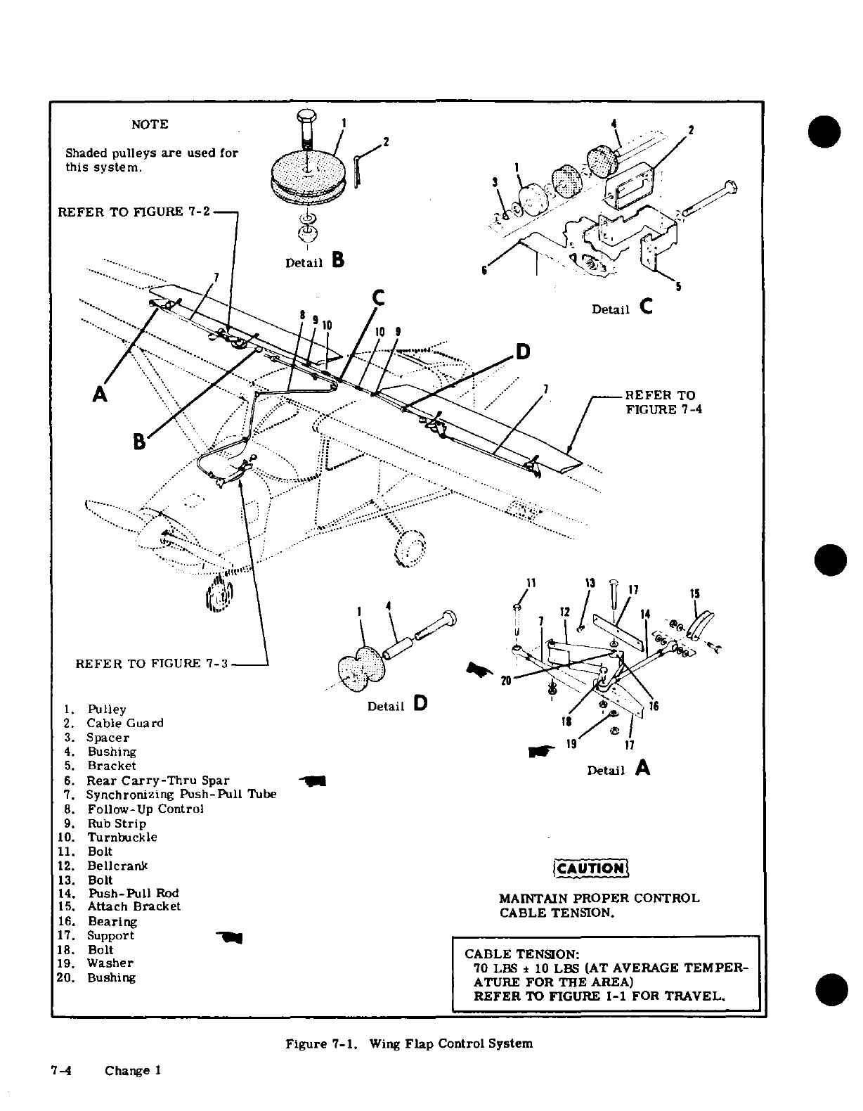
NOTE
4
2
Shaded
pulleys
are
used
for
this
system.
1
REFER
TO
FIGURE
7-2
DetailB
7
DetaiL
B
6
Detail
B
A
'/'
-. . -' .. '.
.,
..
r
'' .
"REFER
TO
·..
' "" / ...
-*'""
""
-'":;.*-';;;;
^ \ 1"" '"...'.i
B :-: .*----:: ;
'
I 1 4
-
· .. . /'
A X'
.' .. .,
REFER
TO
FIGURE
7-3
........
1.
Pulley
Detail
D
1.
2.
Cable Guard
i
3.
Spacer
19
17
4.
Bushing
"
5.
Bracket
Detail
A
6.
Rear
Carry-Thru
Spar
7.
Synchronizing
Push-Pull
Tube
8.
Follow-Up
Control
9.
Rub
Strip
10.
Turnbuckle
11.
Bolt
12.
Bellcrank
|CAUTIONt
13.
Bolt
14.
Push-Pull
Rod
MAINTAIN
PROPER
CONTROL
15.
Attach
Bracket
CABLE
TENSION.
16.
Bearing
17.
Support
18.
Bolt
CABLE
TENSION:
19.
Washer
70
LBS
±
10
LBS
(AT AVERAGE
TEMPER-
20.
Bushing
ATURE
FOR
THE
AREA)
REFER
TO
FIGURE
1-1
FOR
TRAVEL.
Figure
7-1.
Wing
Flap
Control
System
7-4
Change I
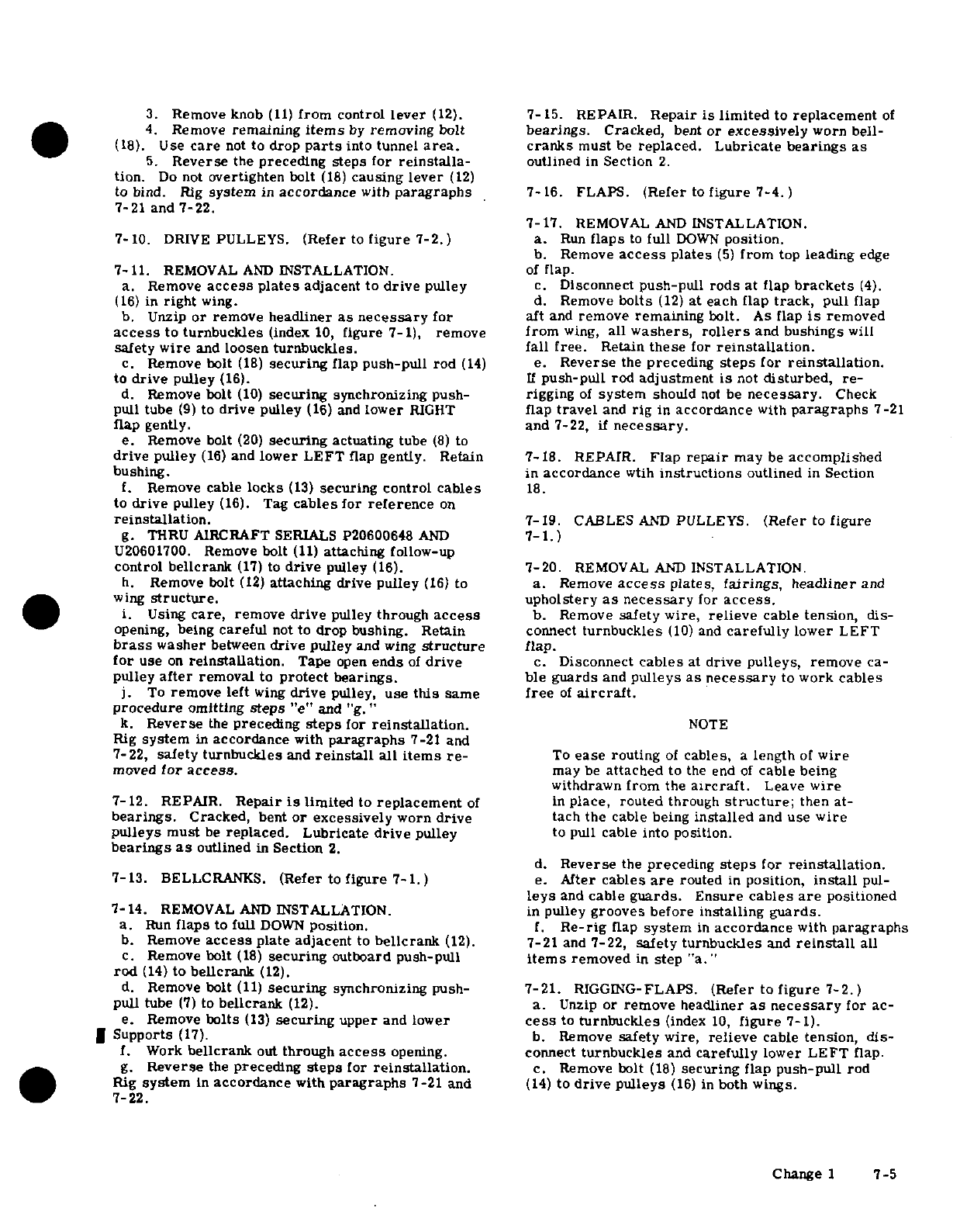
3.
Remove
knob
(11)
from
control
lever
(12).
7-15.
REPAIR.
Repair
is
limited
to
replacement
of
4.
Remove
remaining
items
by
removing
bolt
bearings.
Cracked,
bent
or
excessively
worn bell-
(18).
Use
care
not
to
drop
parts
into
tunnel
area.
cranks
must
be
replaced. Lubricate
bearings
as
5.
Reverse
the
preceding
steps for
reinstalla-
outlined
in
Section
2.
tion.
Do
not
overtighten
bolt
(18)
causing
lever
(12)
to
bind.
Rig
system
in
accordance
with
paragraphs
7-
16.
FLAPS.
(Refer
to
figure
7-4.)
7-21 and
7-22.
7-17.
REMOVAL
AND
INSTALLATION.
7-10.
DRIVE
PULLEYS.
(Refer
to
figure
7-2.)
a.
Run
flaps
to
full
DOWN
position.
b.
Remove
access
plates
(5)
from
top
leading
edge
7-11.
REMOVAL
AND
INSTALLATION.
of
flap.
a.
Remove
access
plates
adjacent
to
drive
pulley
c.
Disconnect
push-pull
rods
at flap
brackets
(4).
(16)
in
right
wing.
d.
Remove
bolts
(12)
at
each
flap
track,
pull flap
b.
Unzip
or
remove
headliner
as
necessary
for
aft
and
remove
remaining
bolt.
As
flap
is
removed
access
to
turnbuckles
(index
10,
figure
7-1),
remove
from
wing,
all
washers,
rollers
and
bushings
will
safety
wire
and
loosen
turnbuckles. fall free.
Retain
these
for
reinstallation.
c.
Remove
bolt
(18)
securing
flap
push-pull
rod
(14)
e.
Reverse
the
preceding
steps
for
reinstallation.
to
drive
pulley
(16).
If
push-pull
rod
adjustment
is
not
disturbed,
re-
d.
Remove
bolt
(10)
securing
synchronizing
push-
rigging
of
system
should
not
be
necessary.
Check
pull tube
(9)
to
drive
pulley
(16)
and
lower
RIGHT
flap
travel
and
rig
in
accordance
with
paragraphs
7-21
flap gently.
and 7-22,
if
necessary.
e.
Remove
bolt
(20)
securing
actuating
tube
(8)
to
drive
pulley
(16)
and
lower
LEFT
flap
gently.
Retain 7-18.
REPAIR.
Flap
repair
may
be
accomplished
bushing.
in
accordance
with
instructions
outlined
in
Section
f.
Remove
cable
locks
(13)
securing
control
cables
18.
to
drive
pulley
(16).
Tag
cables
for
reference
on
reinstallation.
7-19.
CABLES
AND
PULLEYS.
(Refer
to
figure
g.
THRU
AIRCRAFT
SERIALS
P20600648
AND
7-1.)
U20601700.
Remove
bolt
(11)
attaching
follow-up
control bellcrank
(17)
to
drive
pulley
(16).
7-20.
REMOVAL
AND
INSTALLATION.
h.
Remove
bolt
(12)
attaching
drive
pulley
(16)
to
a.
Remove
access
plates,
fairings,
headliner
and
wing
structure.
upholstery
as
necessary
for
access.
i.
Using
care,
remove
drive
pulley
through
access
b. Remove
safety
wire,
relieve
cable
tension,
dis-
opening,
being
careful
not
to
drop
bushing.
Retain
connect
turnbuckles
(10)
and
carefully
lower
LEFT
brass
washer
between
drive
pulley
and
wing
structure
flap.
for
use
on
reinstallation.
Tape
open
ends
of
drive
c.
Disconnect
cables
at
drive
pulleys,
remove
ca-
pulley
after
removal
to
protect
bearings.
ble
guards
and
pulleys
as
necessary
to
work cables
j.
To
remove left
wing
drive
pulley,
use
this
same
free
of
aircraft.
procedure
omitting
steps
"e"
and
"g."
k.
Reverse
the
preceding
steps
for
reinstallation.
NOTE
Rig
system
in
accordance
with
paragraphs
7-21
and
7-22,
safety
turnbuckles
and
reinstall
all
items
re-
To
ease
routing
of
cables,
a
length
of
wire
moved
for
access.
may
be
attached
to
the
end
of
cable
being
withdrawn
from
the
aircraft.
Leave
wire
7-12.
REPAIR.
Repair
is
limited
to
replacement
of
in
place, routed
through
structure;
then
at-
bearings.
Cracked,
bent
or
excessively
worn
drive
tach
the
cable
being
installed
and
use
wire
pulleys
must
be
replaced. Lubricate
drive
pulley
to pull
cable
into
position.
bearings
as
outlined
in
Section
2.
d.
Reverse
the
preceding
steps
for
reinstallation.
7-13.
BELLCRANKS.
(Refer
to
figure
7-1.)
e.
After
cables
are
routed
in
position,
install
pul-
leys
and
cable
guards.
Ensure
cables
are
positioned
7-14.
REMOVAL
AND
INSTALLATION.
in
pulley
grooves before
installing guards.
a.
Run
flaps
to
full
DOWN
position.
f.
Re-rig
flap
system
in
accordance
with
paragraphs
b.
Remove
access
plate
adjacent
to
bellcrank
(12).
7-21
and
7-22,
safety
turnbuckles
and
reinstall
all
c.
Remove
bolt
(18)
securing
outboard
push-pull
items
removed
in
step
"a."
rod
(14)
to
bellcrank
(12).
d.
Remove
bolt
(11)
securing
synchronizing
push-
7-21.
RIGGING-FLAPS.
(Refer to
figure
7-2.)
pull
tube
(7)
to
bellcrank
(12).
a.
Unzip
or
remove
headliner
as
necessary
for
ac-
e.
Remove
bolts
(13)
securing
upper
and
lower
cess
to
turnbuckles
(index
10,
figure
7-1).
*
Supports
(17).
b.
Remove
safety wire,
relieve
cable
tension,
dis-
f.
Work
bellcrank
out
through
access
opening.
connect
turnbuckles
and
carefully
lower
LEFT
flap.
g.
Reverse
the
preceding
steps
for
reinstallation.
c.
Remove
bolt
(18)
securing
flap
push-pull
rod
Rig
system
in
accordance
with
paragraphs
7-21
and
(14)
to
drive
pulleys
(16)
in
both
wings.
7-22.
Change
1
7-5
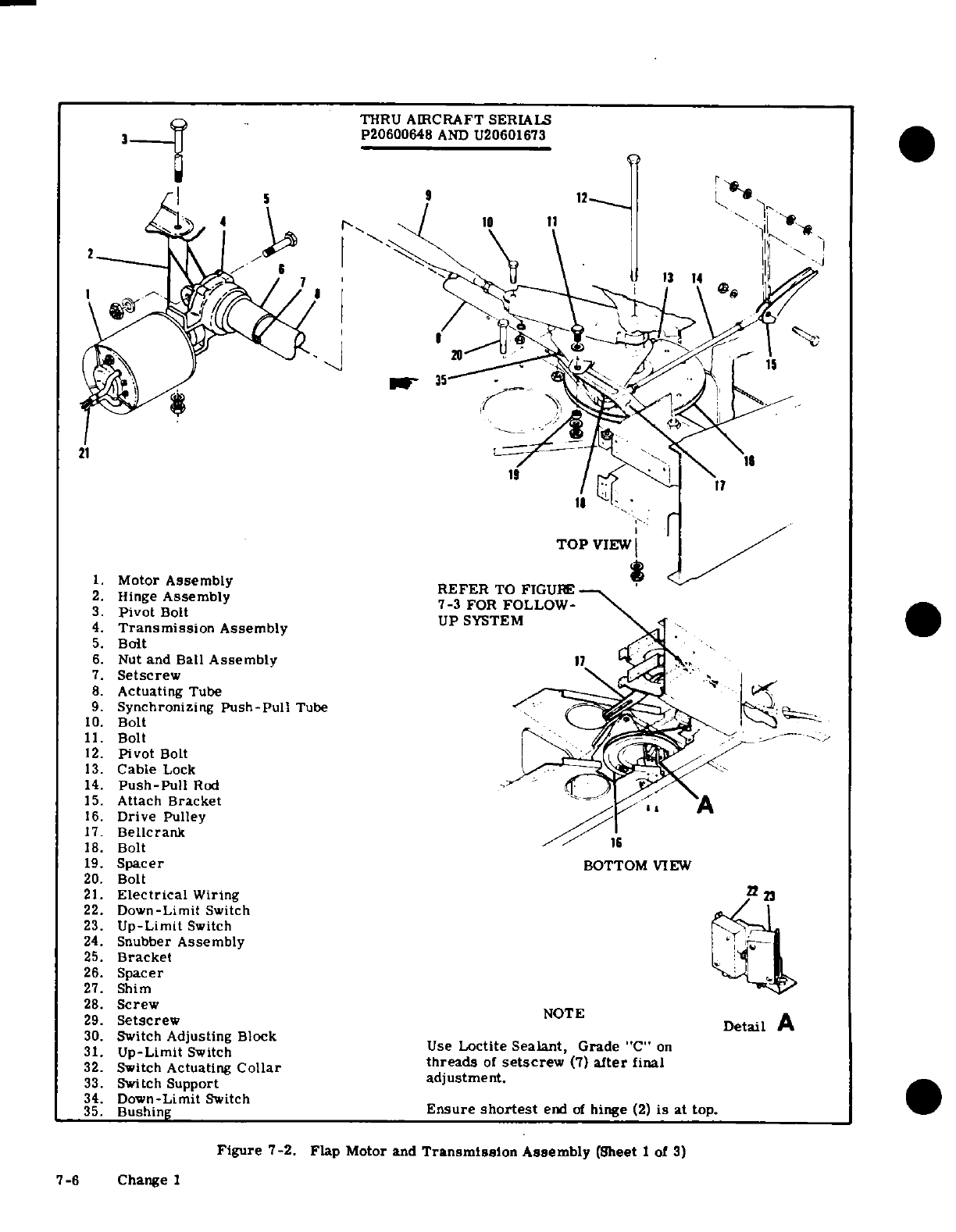
1.
Motor
Assembly
2.
Hinge
Assembly
3.
Pivot
Bolt
4.
Transmission
Assembly
5.
Bolt
6.
Nut
and Ball
Assembly
7.
Setscrew
8.
Actuating
Tube
9.
Synchronizing
Push-Pull
Tube
10.
Bolt
11.
Bolt
12.
Pivot
Bolt
13.
Cable
Lock
14.
Push-Pull
Rod
15.
Attach Bracket
16.
Drive
Pulley
17.
Bellcrank
18.
Bolt
19.
Spacer
20.
Bolt
21.
Electrical
Wiring
22.
Down-Limit
Switch
23.
Up-Limit
Switch
24.
Snubber
Assembly
25.
Bracket
26.
Spacer
27.
Shim
28.
Screw
29.
Setscrew
30.
Switch
Adjusting
Block
31.
Up-Limit
Switch
Use
Loctite Sealant,
Grade
"C"
on
32.
Switch
Actuating
Collar
threads
of
setscrew
(7)
after
final
33.
Switch
Support
adjustment.
34.
Down-Limit
Switch
35.
Bushing
Ensure
shortest
end
of
hinge
(2)
is
at top.
Figure
7-2.
Flap
Motor
and
Transmission
Assembly
(Sheet
1
of
3)
7-6
Change
1
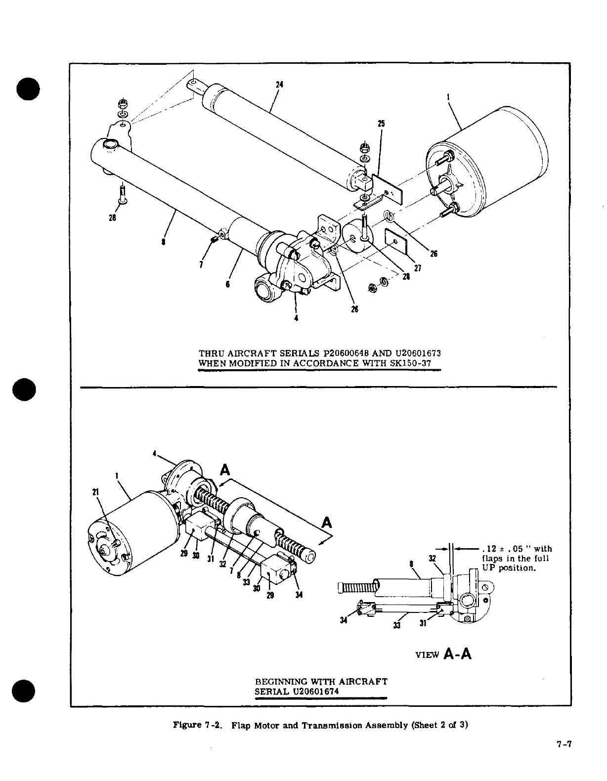
THRU
AIRCRAFT
SERIALS p20600648
AND
U20601673
WHEN
MODIFIED
IN
ACCORDANCE
WITH
SK150-37
4
A
3 1 flaps
in
the
full
7
UP
position.
VIEW
A-A
BEGINNING
WITH
AIRCRAFT
7-7
7 -7
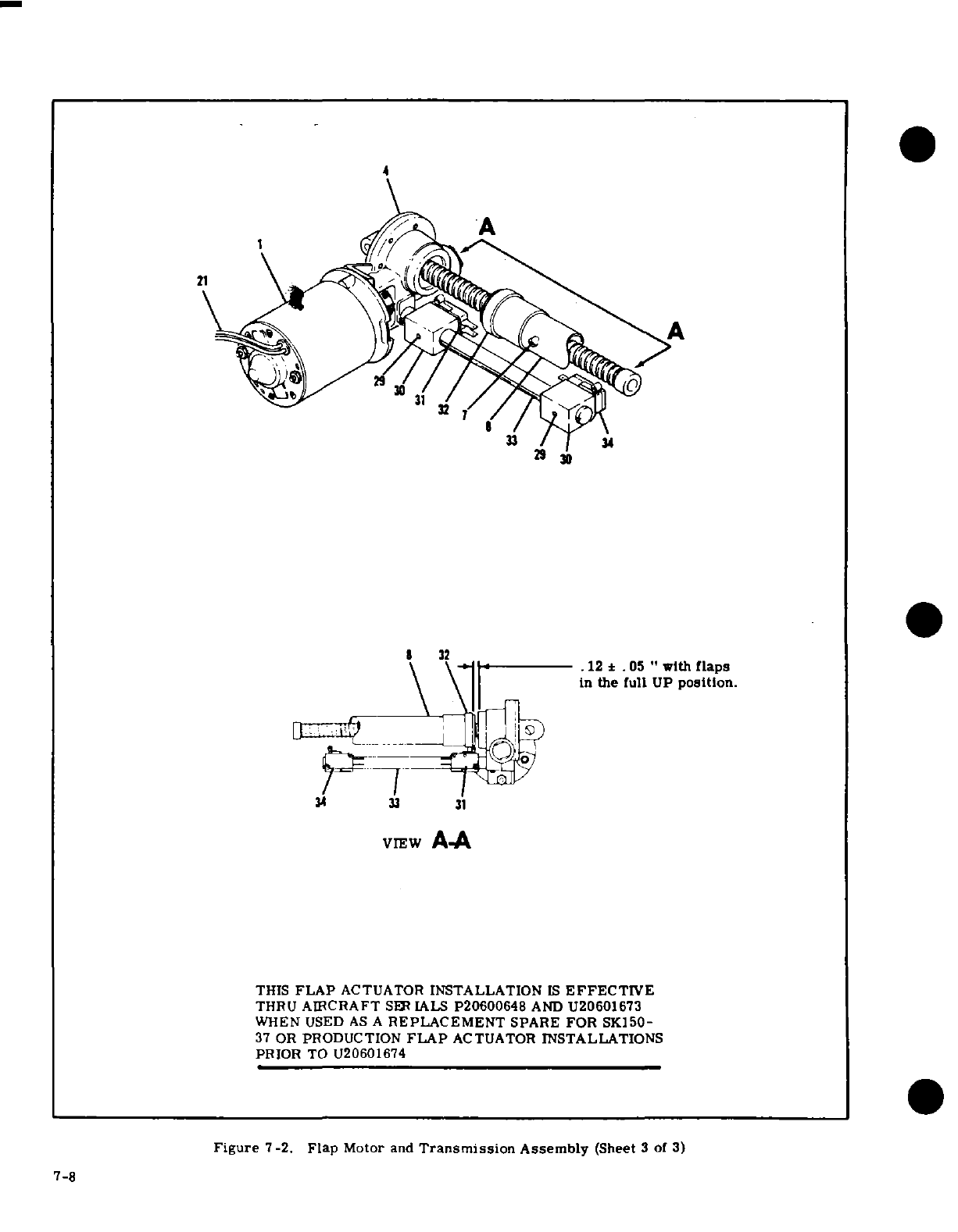
4
A
8 32
.12±
.05
"
with
flaps
in
the
full
UP
position.
34
33
31
VIEW
A-A
THIS
FLAP
ACTUATOR
INSTALLATION
IS
EFFECTIVE
THRU
AIRCRAFT
SER
IALS
P20600648
AND
U20601673
WHEN USED
AS
A
REPLACEMENT
SPARE
FOR
SK150-
37
OR
PRODUCTION
FLAP
ACTUATOR
INSTALLATIONS
PRIOR
TO
U20601674
Figure
7-2.
Flap
Motor
and
Transmission
Assembly
(Sheet
3
of
3)
7-8
d.
Remove
bolt
(10)
securing
synchronizing
push-
align
RIGHT
drive
pulley
so
that
the
centerline
of
bolt
pull
tube
(9)
to
drive
pulley
(16)
in
right
wing
and
hole
for
inboard
push-pull
rod
is
4.20
inches
aft
of
carefully
lower
RIGHT
flap.
fuel
well
bulkhead
(refer
to
figure
7-5).
Tighten
set-
e.
Remove
bolt
securing
synchronizing
push-pull
screw
(7)
in
accordance
with
procedures
outlined
in
tube
to
drive
pulley
in
left
wing.
the
following
note
and
secure
actuating
tube
to
drive
f.
Disconnect
outboard
flap
push-pull
rods
from pulley
with
bolt
(20).
bellcranks
in
both
wings.
g.
Disconnect actuating
tube
(8)
from
drive
pulley
NOTE
(16).
Thru
Aircraft Serial
U20602223:
Tighten
NOTE
setscrew
(7).
Aircraft
Serials
U20602224
thru
U20602376:
Apply
grade
CV
sealant
Ensure
that
the 3/32
inch
retract
cable
is
to
setscrew
(7)
threads
and
torque
to
45
connected
to
the
forward
side
of
the
right
lb-in.
Beginning
with
Aircraft
Serial
drive
pulley
and
to
the
aft
side
of
the
left
U20602377:
Apply
grade
CV
sealant
to
drive
pulley
and
that
the
1/8
inch
direct setscrew
(7)
threads
and
torque
to
60
lb-in.
cable
is
connected
to
the
aft
side
of
the
1.
Manually
holding
RIGHT
flap
full
up,
adjust
right drive
pulley
and
to
the
forward
side
push-pull
rods
to
align
with
drive
pulley and
bell-
of
the
left drive
pulley.
Ensure
that
the
crank
attachment holes.
Connect
push-pull
rods
right
drive
pulley
rotates
clockwise,
when
viewed
from
below,
as
the
flaps
are
ex-and
locknuts.
tended.
(
Refer
to
figure
7-5.
)NOT
h.
Adjust
synchronizing
push-pull
tube
(9)
in
RIGHT
The
right
flap
and
actuator
MUST
be
correctly
The
right
flap
and
actuator
MUST
be
correctly
wing
to
48.69
inches
between
centers
of
rod
end
holes,
rigged before
cables
and
left
flap
can
be
rig-
rigged
before
cables
and
left
flap
can
be rig-
tighten jam nuts
and
connect
to
bellcrank
and
drive
ged
pulley.
i.
THRU
AIRCRAFT
SERIALS P20600648
AND
m.
Mount
an
inclinometer
on
trailing
edge
of
RIGHT
U20601673
WHEN
NOT
MODIFIED
IN
ACCORDANCE
WITH
SK150-37
AND
WHEN
NOT
MODIFIED
IN
ACCORDANCE
WITH
FIGURE
7-2,
SHEET
3. (ReferNOTE
to
figure
7-2,
sheet
1.)
Screw
actuating
tube
(8)
IN
toward
transmission
(4)
by
hand
to
its
shortest
length
An
inclinometer
for
measuring
control surface
(flaps
full
up
position).
Loosen
setscrew
(7)
securing
trael
is
available from
the
Cessna
Service
actuating
tube
to
nut
and
ball
assembly
(6),
hold
nut
Parts
Center.
Refer
to
figure
6-4.
and
ball
assembly
so
that
it
will
not
move
and
adjust
actuating
tube
IN
or
OUT
as
necessary
to
position
the
n.
THRU
AIRCRAFT
SERIALS
P20600648
AND
RIGHT
drive
pulley
so
that the
centerline
of
bolt
hole
U20601673
AND
ALL
AIRCRAFT
NOT
MODIFIED
for
the
inboard
push-pull
rod
attachment
is
4.20
IN ACCORDANCE
WITH
FIGURE
7-2,
SHEET
3.
inches
aft
of
fuel
well
bulkhead
(refer
to
figure
7-5).
1.
With RIGHT
flap
in
full
UP
position,
adjust
Tighten
setscrew
(7)
and
secure
actuating
tube to
UP-LMIT
switch
(23)
to
operate
and
shut-off
elec-
drive
pulley
with
bolt
(20).
trical
power
to
motor
at
degree
of
travel
specified
j.
THRU
AIRCRAFT
SERIALS
P20600648
AND
U20601673
WHEN
MODIFIED
IN
ACCORDANCE
WITH in figure
1-1.
2.
Run
RIGHT
flap
to
DOWN
position
and
adjust
SK150-37
AND
WHEN
NOT
MODIFIED
IN
ACCOR-
2.
Run
RIGHT
flap
to
DOWN
position
and
SK150-37
AND
WHEN
NOT
MODIFIED
IN
ACCOR-
DOWN-LIMIT
switch
(22)
to
operate
and
shut-off
DANCE
WITH
FIGURE
7-2,
SHEET
3.
Operate
flap
DOWN-LIMIT
switch
(22)
to
operate
and shut-off
DANCE
WITH
FIGURE
7-2,
SHEET
3.
Operate
flap
electrical
power
to
motor
at
degree
of
travel
speci-
motor
until
actuating
tube
(8)
is
IN
to
its
shortest
electrical
power
to
motor
at
degree
of
travel
spec-
length
(flaps
full
up
position). Loosen
setscrew
(7)
fied
in
figure
1-1.
o.
BEGINNING WITH
AIRCRAFT SERIAL
U206-
securing
actuating
tube
to
nut
and
ball
assembly
(6),
BEGINNNG
WITH
AIRCRAFT
Serial
U206-
-
hold
nut
and
ball
assembly
so
that
it
will
not
move
01674
AND
ALL
AIRCRAFT
MODIFIED
IN
ACCOR-
and
adjust
actuating
tube
IN
or
OUT
as
necessary
to
DANCE
WITH
FIGURE
7-2,
SHEET
3.
position
the
RIGHT
drive
pulley
so
that the
centerline
1.
With
RIGHT
flap
in
full
UP
position,
loosen
of
bolt
hole
for
the
inboard
push-pull
rod
attachment
setscrew
(29)
and
slide
UP-LIMIT
switch
(31)
adjust-
is
4.20
inches
aft
of
fuel well
bulkhead
(refer
to
figure
ment
block
(30)
to
operate
switch and
shut-off
elec-
7-5).
Tighten
setscrew
(7)
and
secure
actuating
tube
trical
power
to
motor
at
degree
of
travel
specfied
in
to drive
pulley
with
bolt
(20).
figure
1-1.
Tighten
setscrew
(29).
2.
Run RIGHT
flap
to
DOWN
position
and
adjust
k.
BEGINNING
WITH
AIRCRAFT
SERIAL
U206-
01674
AND
ALL AIRCRAFT MODIFIED
IN
ACCOR-
DOWN-LIMIT
switch
(34)
adjustment
block
(30)
to
operate
switch
and
shut-off
electrical
power
to
motor
at
degree
of
travel
specified
in
figure
1-1.
Tighten
ating
tube
(8)
IN
toward
transmission
(4)
by
hand
to
setscrew
(29).
12±.05
inches
between
switch
actuating
collar
(32)
p.
Run
RIGHT
flap to
full
UP
position.
and
transmission
as
illustrated
in
figure 7-2,
VIEW
q.
Complete
step
"h"
for
synchronizing
push-pull
A-A.
Loosen
setscrew
(7)
securing
actuating
collar
tube
in
LEFT
wing
(32).
Hold
actuating
collar
to
maintain
.
12±.05"
and
r.
Connect
control
cables
at
turnbuckles
(index
10,
adjust
actuating
tube
(8)
IN
or
OUT
as
necessary
to
figure
7-1).
Adjust
turnbuckles
to
position
left
drive
pulley
so
that
the
centerline
of
bolt
hole
for
the
in-
Change
2
7-9
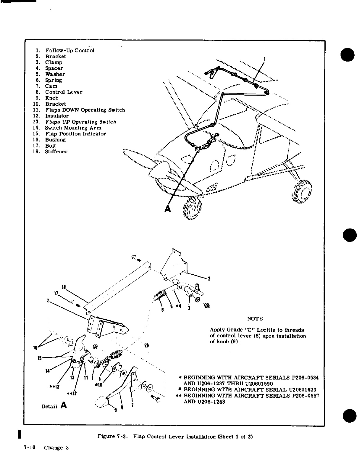
1.
Follow-Up
Control
2.
Bracket
3.
Clamp
4.
Spacer
5.
Washer
6.
Spring
7.
Cam
8.
Control Lever
9.
Knob
10.
Bracket
11.
Flaps
DOWN
Operating
Switch
12.
Insulator
13.
Flaps
UP
Operating
Switch
14.
Switch
Mounting
Arm
15.
Flap
Position
Indicator
16.
Bushing
17.
Bolt
18.
Stiffener
of
control lever (8)
upon
Istalletion
'I
.. .
A
*.18 i
$>
:
/
-d
/ .
17
'"'"/ 5'
":
' "
*4"":®"
'i"/=- ;
NOTE
i ~lJ 1~~
·
~-^
>
~Apply
Grade
"C"
Loctite
to
threads
of
control
lever
(8)
upon
installation
of
knob
(9).
/
13
/
11
1 S/ '^'LV
1
*
BEGINNING WITH
AIRCRAFT
SERIALS
P206-0534
*10
/
ol jiJ AND
U206-1237
THRU
U20601590
It /
/>'
/
.-. : .*
BEGINNING
WITH
AIRCRAFT
SERIAL
U20601633
**12
r Ax\
|
as_.<
**
BEGINNING WITH
AIRCRAFT
SERIALS
P206-0557
Detail
A '<,\[AND
U206-1248
Figure
7-3.
Flap
Control
Lever
Installation
(Sheet
1
of
3)
7-10
Change 3
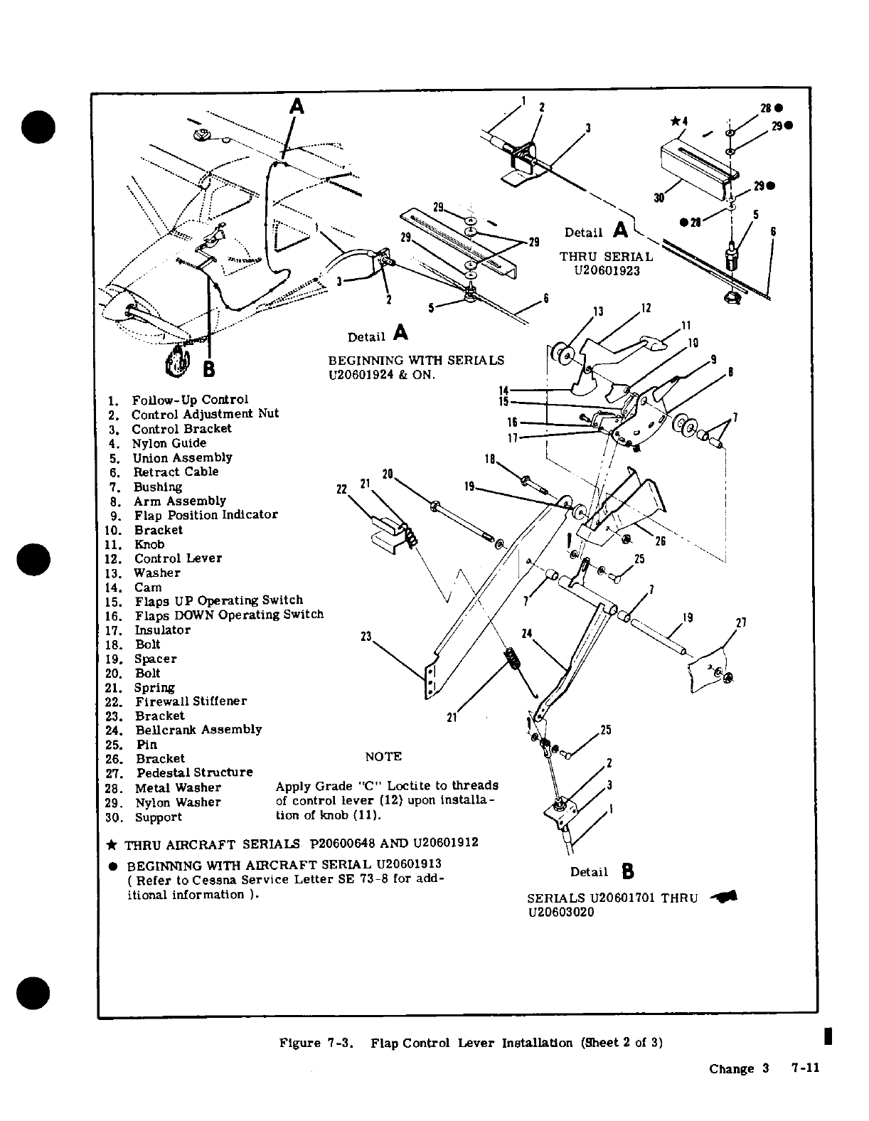
__ -~ ~~~~~~
A /~1
2
28
0
t EyX*4
290
N/
*
29290S
A^-$
.. '
-29?
Detail
A
/
6
/
1 ?S
THRU
SERIAL
""~/ , '< *,/--
^,.
U20601923
Detail
A
/10
/"
.1
BEGINNING
WITH
SERIALS
e
B
DU20601924
&
ON.
/ // 8
1.
Follow-Up
Control
1i5
2.
Control
Adjustment
Nut
3.
Control
Bracket
.16
<7
4.
Nylon
Guide
/
5.
Union
Assemblyt
6.
Retract
Cable
20
7.
Bushing
22
21
1
8.
Arm
Assembly
9.
Flap
Position Indicator
>\p ;
10.
Bracket
11.
Knob1 26
12.
Control
Lever
25
1
13.
Washer
14.
Cam
\
15.
Flaps
UP
Operating
Switch
16.
Flaps
DOWN
Operating
Switch
/27/
13
27
18.
Bolt
19.
Spacer
20.
Bolt
\
/ /
t
21.
Spring
22.
Firewall
Stiffener
23.
Bracket
21
24.
Bellcrank
Assembly
25.
Pin
nt
/
26.
Bracket
NOTE
27.
Pedestal Structure
28.
Metal
Washer
Apply
Grade
"C"
Loctite
to
threads
29.
Nylon
Washer
of
control
lever
(12)
upon
installa-
30.
Support
tion
of
knob
(11).
*
THRU
AIRCRAFT SERIALS
P20600648
AND
U20601912
*
BEGINNING
WITH
AIRCRAFT
SERIAL
U20601913
(
Refer
to
Cessna Service
Letter
SE
73-8
for
add-
Detail
B
itional information
).
SERIALS
U20601701
THRU
_
U20603020
Figure
7-3.
Flap
Control
Lever
Installation
(Sheet
2
of
3)
Change
3
7-11
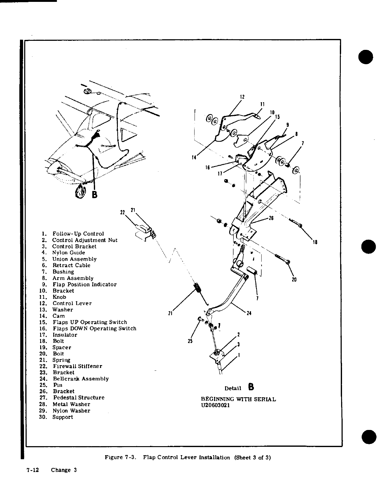
1.
Follow-Up
Control
2.
Control
Adjustment
Nut
3.
Control
Bracket
4.
Nylon
Guide
5.
Union
Assembly
6.
Retract
Cable
7.
Bushing
8.
Arm
Assembly
20
9.
Flap Position
Indicator
10.
Bracket
11.
Knob
7
12.
Control
Lever
13.
Washer
14.
Cam
15.
Flaps
UP
Operating
Switch
16.
Flaps
DOWN
Operating
Switch
17.
Insulator
18.
Bolt
19.
Spacer
20.
Bolt
21.
Spring
22.
Firewall
Stiffener
23.
Bracket
24.
Bellcrank
Assembly
25.
Pin
26.
Bracket
27.
Pedestal
Structure
BEGINNING
WITH
SERIAL
28.
Metal
Washer
U20603021
29.
Nylon
Washer
30.
Support
Figure
7-3.
Flap
Control
Lever
Installation
(Sheet
3
of
3)
7-12
Change
3
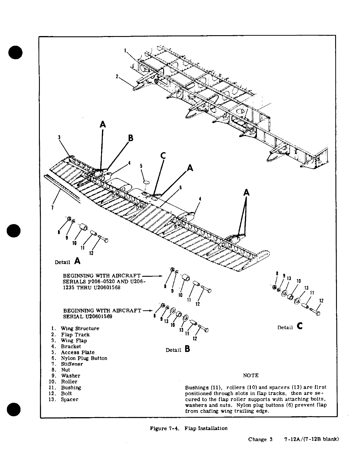
A
B
C
Detail
A
BEGINNING
WITH
AIRCRAFT
8 9 13
SERIALS
P206-0520
AND
U206-
/ / 10
1235 THRU
U20601568
BEGINNING
WITH
AIRCRAFT
1
SERIAL
U20601569/
/
1.
Wing
Structure
Detail
C
2.
Flap
Track
3.
Wing
Flap
12
4.
Bracket
5.
Access
Plate
Detail
B
6.
Nylon
Plug
Button
7.
Stiffener
8.
Nut
9.
Washer
NOTE
10.
Roller
11.
Bushing
Bushings
(11),
rollers
(10) and
spacers
(13)
are
first
12.
Bolt
positioned
through
slots
in
flap
tracks,
then
are
se-
13.
Spacer
cured
to
the
flap
roller
supports
with
attaching bolts,
washers
and
nuts.
Nylon
plug
buttons
(6)
prevent
flap
from
chafing
wing
trailing
edge.
Figure
7-4.
Flap
Installation
Change
3
7-12A/(7-12B
blank)
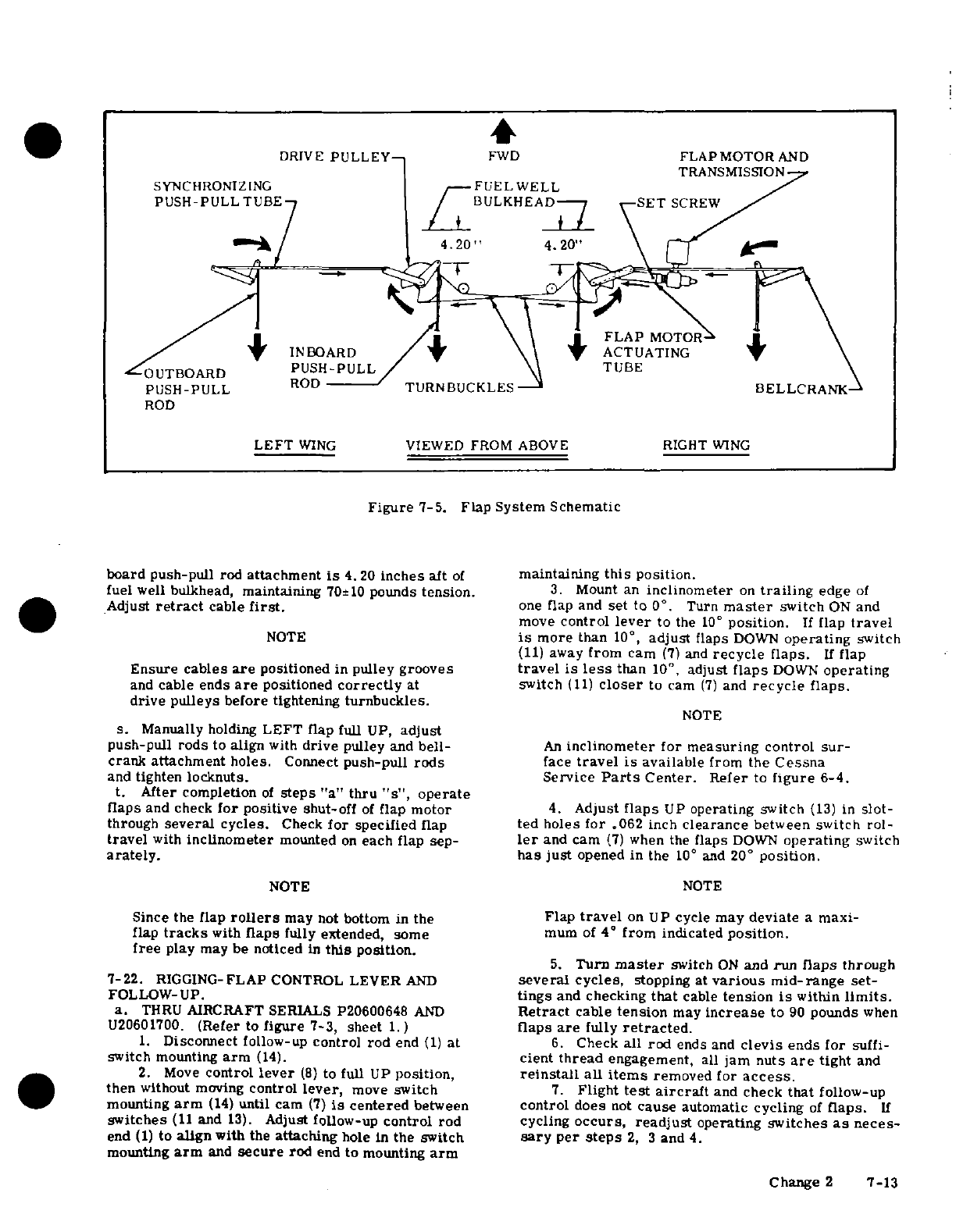
DRIVE
PULLEY
FWD
FLAPMOTOR
AND
TRANSMISSION
SYNCHRONIZING
FUEL
WELL
PUSH-PULLTUBE
BULKHEAD SET
SCREW
24.20
4
0
4
.
FLAP
MOTOR
INBOARD
ACTUATING
PUSH-PULL
TUBE
OUTBOARD
PUSH-PULL
TUBE
PUSH-PULL
ROD
TURNBUCKLES
BELLCRANK
ROD
LEFT
WING
VIEWED
FROM ABOVE RIGHT
WING
Figure
7-5.
Flap
System
Schematic
board
push-pull
rod
attachment
is
4.20
inches
aft
of
maintaining
this
position.
fuel
well bulkhead,
maintaining
70±10
pounds
tension.
3.
Mount
an
inclinometer
on
trailing
edge
of
Adjust
retract
cable
first.
one
flap
and
set
to 0
°
.
Turn
master
switch
ON
and
move
control
lever
to
the
10°
position.
If
flap
travel
NOTE is
more
than
10
°
,
adjust
flaps
DOWN
operating
switch
(11)
away
from
cam
(7)
and
recycle
flaps.
If
flap
Ensure
cables
are
positioned
in
pulley
grooves
travel
is
less
than
10
°
,
adjust
flaps
DOWN
operating
and
cable
ends
are
positioned
correctly
at
switch
(11)
closer
to
cam
(7)
and
recycle
flaps.
drive
pulleys
before
tightening
turnbuckles.
NOTE
s.
Manually
holding
LEFT
flap
full
UP,
adjust
push-pull
rods
to
align
with
drive
pulley
and
bell-
An
inclinometer
for measuring
control
sur-
crank
attachment
holes.
Connect
push-pull
rods
face
travel
is
available
from
the
Cessna
and
tighten
locknuts.
Service
Parts
Center.
Refer
to
figure
6-4.
t. After
completion
of
steps
"a"
thru
"s",
operate
flaps
and
check
for
positive
shut-off
of
flap
motor
4.
Adjust
flaps
UP
operating
switch
(13)
in
slot-
through
several
cycles.
Check
for
specified
flap
ted
holes
for
.062
inch
clearance
between
switch
rol-
travel
with
inclinometer
mounted
on
each
flap
sep-
ler
and
cam
(7)
when
the
flaps
DOWN
operating
switch
arately.
has
just
opened in
the
10°
and
20°
position.
NOTE
NOTE
Since
the
flap
rollers
may
not
bottom
in
the
Flap
travel
on
UP cycle
may
deviate
a
maxi-
flap
tracks
with
flaps
fully
extended,
some
mum
of
4°
from
indicated
position.
free
play
may
be
noticed
in
this
position.
5.
Turn
master
switch
ON
and
run
flaps
through
7-22.
RIGGING-FLAP
CONTROL
LEVER
AND
several cycles,
stopping
at
various mid-range
set-
FOLLOW-UP.
tings
and
checking
that
cable
tension
is
within
limits.
a.
THRU
AIRCRAFT
SERIALS
P20600648
AND
Retract
cable
tension
may
increase
to
90
pounds
when
U20601700.
(Refer
to
figure
7-3, sheet
1.)
flaps
are
fully
retracted.
1.
Disconnect
follow-up
control
rod
end
(1)
at
6.
Check
all rod
ends
and
clevis
ends for
suffi-
switch mounting
arm
(14).
cient
thread
engagement,
all
jam
nuts
are
tight
and
2.
Move
control
lever
(8)
to
full
UP
position,
reinstall
all
items
removed for
access.
then
without
moving
control
lever,
move
switch
7.
Flight
test
aircraft
and
check
that
follow-up
mounting
arm
(14)
until
cam
(7)
is
centered
between
control
does
not
cause
automatic cycling
of
flaps.
If
switches
(11
and
13).
Adjust
follow-up
control
rod cycling
occurs, readjust
operating
switches
as
neces-
end
(1)
to
align
with
the
attaching
hole
in
the
switch
sary
per
steps
2,
3
and
4.
mounting
arm
and
secure
rod
end
to mounting
arm
Change
2
7-13
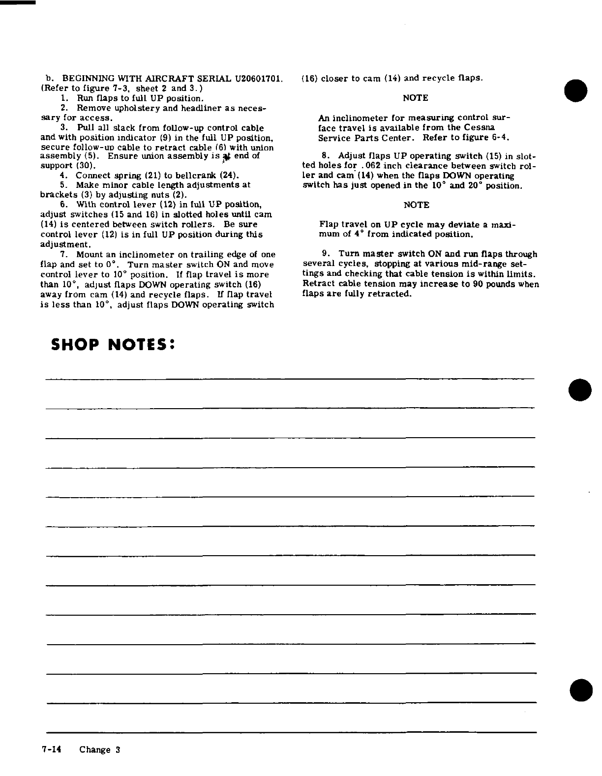
b. BEGINNING
WITH
AIRCRAFT
SERIAL
U20601701.
(16)
closer
to
cam
(14)
and
recycle flaps.
(Refer
to
figure
7-3,
sheet
2
and
3.
)
1.
Run
flaps
to
full
UP
position.
NOTE
2.
Remove
upholstery
and
headliner
as
neces-
sary
for
access.
An
inclinometer
for
measuring
control sur-
3.
Pull
all
slack from
follow-up
control
cable
face
travel
is
available
from
the
Cessna
and
with
position indicator
(9)
in
the
full
UP
position,
Service
Parts
Center.
Refer
to
figure
6-4.
secure
follow-up cable
to
retract
cable
(6)
with
union
assembly
(5).
Ensure
union
assembly
is
at
end
of
8.
Adjust
flaps
UP
operating
switch
(15)
in
slot-
support
(30).
ted
holes
for
.062
inch
clearance
between
switch
rol-
4.
Connect
spring
(21)
to
bellcrank
(24).
ler
and
cam
(14)
when
the
flaps
DOWN
operating
5.
Make
minor
cable
length
adjustments
at
switch
has
just
opened in
the
10°
and
20
°
position.
brackets
(3)
by
adjusting
nuts
(2).
6.
With
control
lever
(12)
in
lull
UP
position,
NOTE
adjust switches
(15
and
16)
in
slotted
holes
until
cam
(14)
is
centered
between
switch
rollers.
Be
sure
Flap
travel
on
UP
cycle
may
deviate
a
maxi-
control
lever
(12)
is
in
full
UP
position during
this
mum
of
4
°
from
indicated
position.
adjustment.
7.
Mount
an
inclinometer
on
trailing
edge
of
one
9.
Turn
master
switch
ON
and
run
flaps
through
flap
and
set
to
0
°
.
Turn
master
switch
ON
and
move
several
cycles,
stopping
at
various
mid-range
set-
control
lever
to
10
°
position.
If
flap
travel
is
more
tings
and
checking
that
cable
tension
is
within
limits.
than
10°
,
adjust
flaps
DOWN
operating
switch
(16)
Retract
cable
tension
may
increase
to
90
pounds
when
away
from
cam
(14)
and
recycle
flaps.
If
flap
travel
flaps
are
fully
retracted.
is
less
than
10
°
,
adjust
flaps
DOWN
operating
switch
SHOP
NOTES:
7-14 Change 3
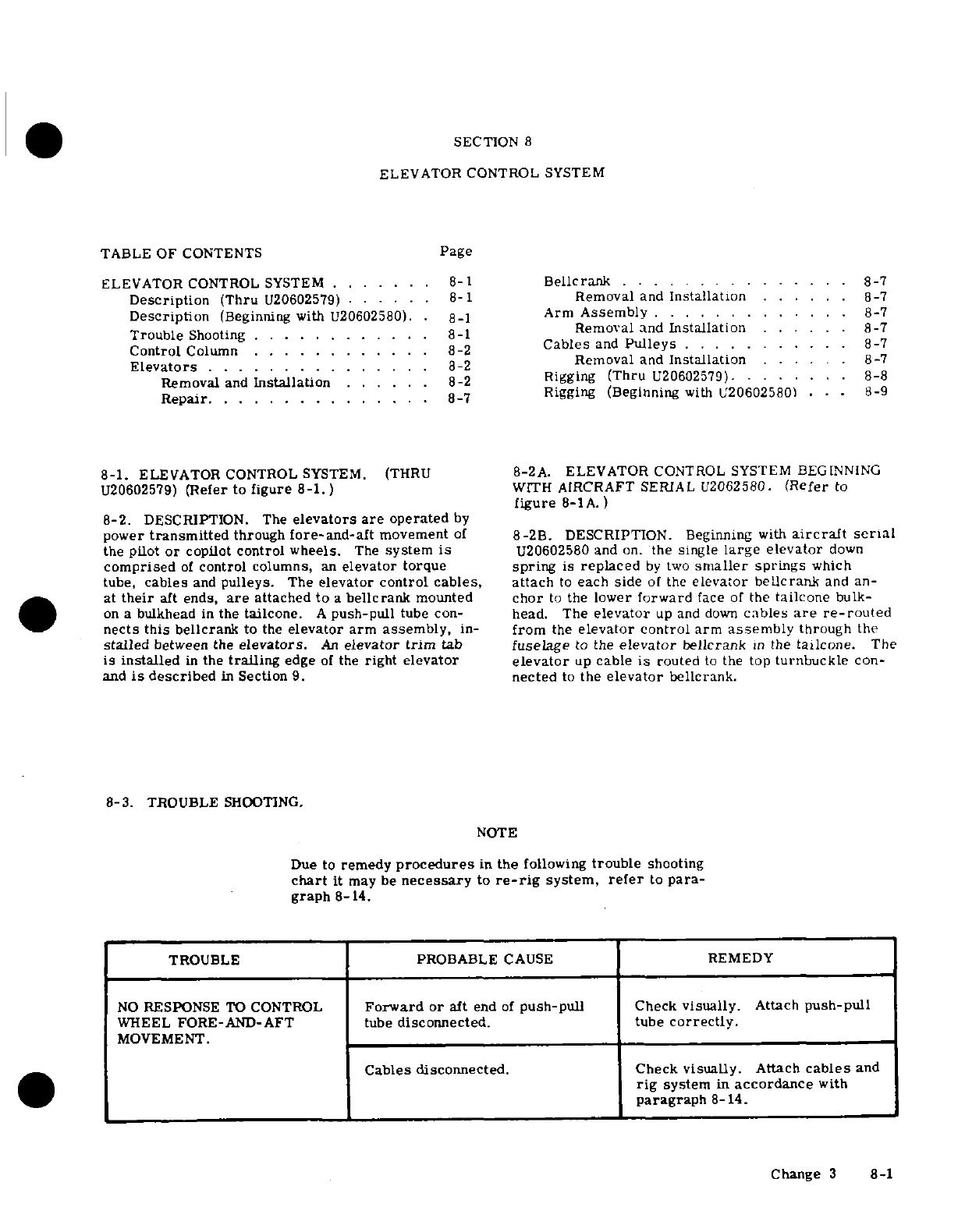
SECTION
8
ELEVATOR
CONTROL
SYSTEM
TABLE
OF
CONTENTS
Page
ELEVATOR
CONTROL
SYSTEM
.......
8-1
Bellcrank
.... .........
.
8-7
Description
(Thru
U20602579)
......
8-1
Removal
and
Installation
...... 8-7
Description
(Beginning
with
U20602580).
.8-1
Arm
Assembly
.......
8-7
Trouble
Shooting
... .. ..
.. .. ..
8-1
Removal and
Installation
......
8-7
Control
Column
...........
. 8-2
Cables
and
Pulleys
. ...
....
8-7
Elevators
.
......
.......
...
8-2
Removal
and
Installation
......
8-7
Removal
and
Installation
.......... ........
8-2 Rigging
(Thru
U20602579).
.............................
.
8-8
Repair
..............
8-7
Rigging
(Beginning
with
U20602580)
...
8-9
8-1.
ELEVATOR
CONTROL
SYSTEM.
(THRU
8-2A.
ELEVATOR
CONTROL SYSTEM BEGINNING
U20602579)
(Refer
to
figure
8-1.)
WITH
AIRCRAFT
SERIAL
U2062580.
(Refer
to
figure
8-1
A.)
8-2.
DESCRIPTION.
The
elevators are
operated
by
power
transmitted
through
fore-and-aft
movement
of
8-2B.
DESCRIPTION.
Beginning
with
aircraft serial
the
pilot
or
copilot
control
wheels.
The
system
is
U20602580
and
on.
the
single
large
elevator
down
comprised
of
control columns,
an
elevator
torque
spring
is
replaced
by
two
smaller
springs
which
tube,
cables
and
pulleys.
The
elevator
control
cables, attach
to
each
side
of
the
elevator
bellcrank
and
an-
at
their
aft ends,
are
attached
to
a
bellcrank
mounted
chor
to
the
lower
forward
face
of
the
tailcone
bulk-
on
a
bulkhead
in
the
tailcone.
A
push-pull
tube
con-
head.
The
elevator
up
and
down
cables
are
re-routed
nects
this
bellcrank
to
the
elevator arm
assembly,
in-
from
the
elevator control
arm
assembly
through
the
stalled
between
the
elevators.
An
elevator
trim
tab
fuselage
to
the
elevator
bellcrank
in
the
tailcone.
The
is installed
in
the
trailing
edge
of
the
right
elevator
elevator
up
cable
is
routed
to
the
top
turnbuckle
con-
and
is
described
in
Section
9.
nected
to
the
elevator
bellcrank.
8-3.
TROUBLE
SHOOTING.
NOTE
Due to
remedy
procedures
in
the
following
trouble
shooting
chart
it
may
be
necessary
to
re-rig
system,
refer
to
para-
graph
8-14.
TROUBLE PROBABLE
CAUSE
REMEDY
NO
RESPONSE
TO
CONTROL
Forward
or
aft
end
of
push-pull
Check
visually.
Attach
push-pull
WHEEL
FORE-AND-AFT
tube
disconnected.
tube
correctly.
MOVEMENT.
Cables
disconnected.
Check
visually.
Attach
cables
and
rig
system
in
accordance
with
paragraph
8-
14.
Change
3
8-1
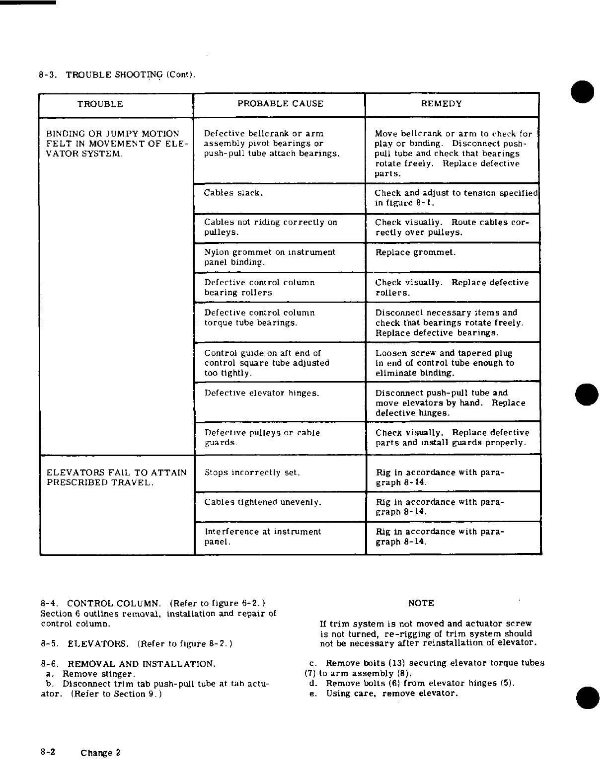
8-3.
TROUBLE
SHOOTING
(Cont).
TROUBLE
PROBABLE
CAUSE
REMEDY
BINDING
OR
JUMPY
MOTION
Defective
bellcrank
or
arm
Move
bellcrank
or
arm
to
check
for
FELT
IN
MOVEMENT
OF
ELE-
assembly
pivot
bearings
or
play
or
binding.
Disconnect
push-
VATOR
SYSTEM.
push-pull
tube
attach
bearings.
pull
tube
and
check that
bearings
rotate
freely.
Replace
defective
parts.
Cables
slack.
Check
and
adjust
to
tension
specified
in
figure
8- 1.
Cables
not
riding
correctly
on
Check
visually.
Route
cables
cor-
pulleys.
rectly
over
pulleys.
Nylon
grommet
on
instrument
Replace
grommet.
panel
binding.
Defective
control
column
Check
visually.
Replace
defective
bearing
rollers.
rollers.
Defective
control
column
Disconnect
necessary items
and
torque
tube
bearings.
check
that
bearings
rotate
freely.
Replace defective
bearings.
Control
guide
on
aft
end
of
Loosen
screw
and
tapered
plug
control
square
tube
adjusted
in
end
of
control
tube
enough
to
too
tightly.
eliminate
binding.
Defective
elevator
hinges. Disconnect
push-pull
tube
and
move
elevators
by
hand.
Replace
defective
hinges.
Defective
pulleys
or
cable
Check
visually.
Replace defective
guards.
parts
and
install
guards
properly.
ELEVATORS
FAIL
TO
ATTAIN
Stops
incorrectly
set.
Rig
in
accordance
with
para-
PRESCRIBED
TRAVEL.
graph
8-14.
Cables
tightened
unevenly.
Rig
in
accordance
with
para-
graph
8-14.
Interference
at
instrument
Rig
in
accordance
with
para-
panel.
graph
8-14.
8-4.
CONTROL
COLUMN.
(Refer
to
figure
6-2.)
NOTE
Section
6
outlines
removal,
installation
and
repair
of
control
column.
If
trim
system
is
not
moved and
actuator
screw
is
not
turned,
re-rigging
of
trim
system
should
8-5.
ELEVATORS.
(Refer
to
figure
8-2.)
not
be
necessary after
reinstallation
of
elevator.
8-6.
REMOVAL
AND
INSTALLATION.
c.
Remove
bolts
(13)
securing
elevator
torque
tubes
a.
Remove
stinger.
(7)
to
arm assembly
(8).
b.
Disconnect
trim
tab
push-pull
tube
at
tab
actu-
d.
Remove
bolts
(6)
from
elevator
hinges
(5).
ator.
(Refer
to
Section
9.)
e.
Using
care,
remove
elevator.
8-2 Change 2
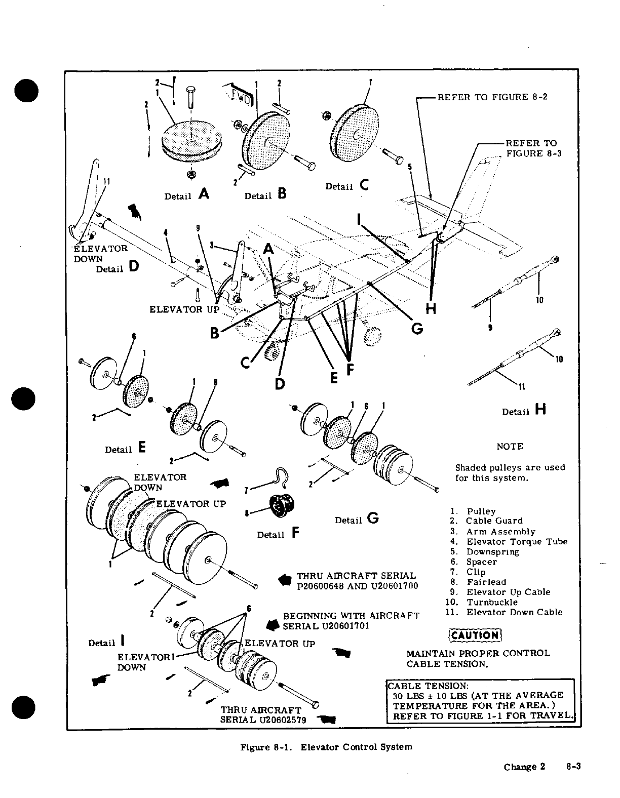
REFER
TO
FIGURE
8-2
REFER
TO
FIGURE
8-3
Detail
C
Detail
A
Detail
B
* ... ...
9
ELEVATOR
DOWN
Detail
D
B
-
Detail
H
Shaded
pulleys
are
used
ELEVATOR
for
this
system.
Detail
G
2.
Cable
Guard
Detail
F
3.
Arm
Assembly
4.
Elevator
Torque
Tube
5.
Downspring
6.
Spacer
THRU
AIRCRAFT
SERIAL
7.
Clip
/
P20600648
AND
U20601700
8
Fairlead
9.
Elevator
Up
Cable
~~~~/
10.
Turnbuckle
2
BEGINNING
WITH
AIRCRAFT
11.
Elevator
Down
Cable
*
SERIAL
U20601701
Detail
I
ELEVATOR
UP
ELEVATORI
MAINTAIN
PROPER
CONTROL
DOWN
/
CABLE
TENSION.
-
CABLE
TENSION:
30
LBS
±
10
LBS
(AT
THE
AVERAGE
TEMPERATURE FOR
THE
AREA.)
.
SERIAL
U20602579
-
REFER
TO
FIGURE
1-1 FOR
TRAVEL
Figure
8-1.
Elevator
Control
System
Change
2
8-3
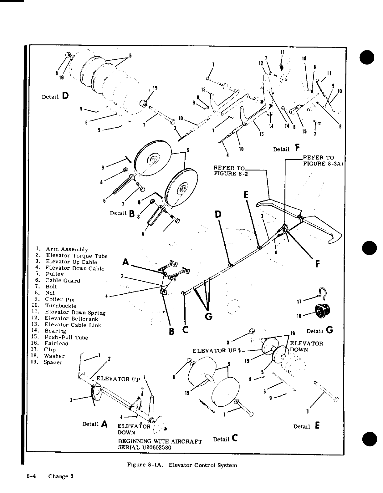
7
12
19
4
wDetail
D
7is 1
3
2
'
Lf
//--=
;
!:
\
'
1
.
,y S_^ 5\
10
Detail
F
.\ g/ gg)
/
-
[
4
__REFER
TO
9 t/ g)
'REFER
TOI
/_
FIGURE
8-3A)
FIGURE
8-2
DetailB
B
D
1.
Arm Assembly
2.
Elevator
Torque
Tube
3.
Elevator
Up
Cable
A
4.
Elevator
Down
Cable
5.
Pulley
3
6.
Cable
Guard
7.
Bolt
8.
Nut
4
9.
Cotter
Pin
10.
Turnbuckle
\
I
1
11.
Elevator
Down
Spring
G
12.
Elevator
Bellcrank
13.
Elevator
Cable
Link
14.
Bearing
B
,
19
Detail
G
15.
Push-Pull
Tube
16.
Fairlead
ELEVATOR
17.
Clip
ELEVATOR
UP
5)DOWN
18.
Washer
2_
o
19.
Spacer
/
L.,
,
,
/
; 5
-,
·
ELEVATOR
UP
I
/ /
1
3- i
11
19
( ,
<
t ,'I
6
j9
1
Detail
A
ELEVATOR; Detail
E
DOWN
BEGINNING
WITH
AIRCRAFT
Detail
C
SERIAL
U20602580
Figure
8-1A.
Elevator
Control
System
8-4 Change 2
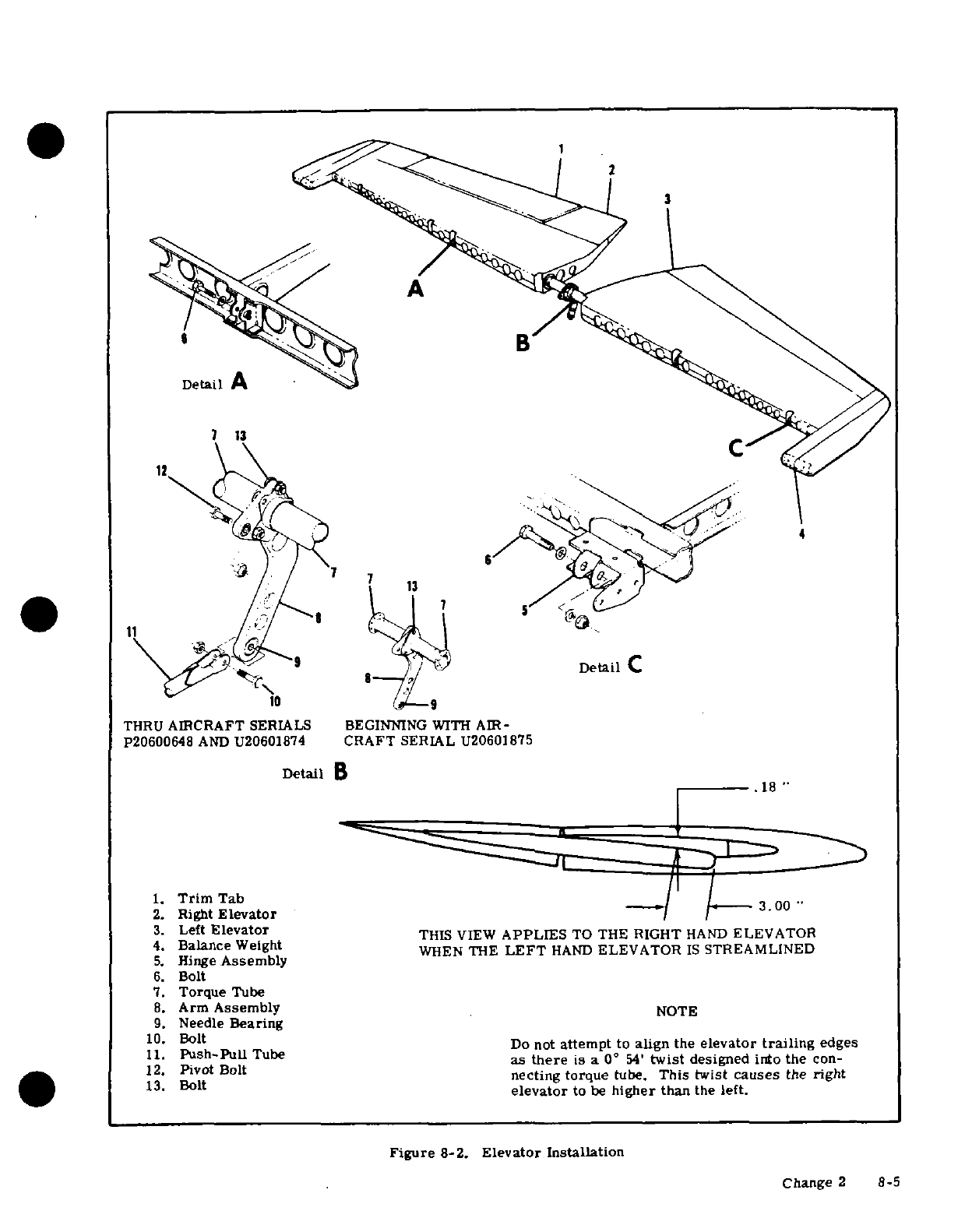
A
7 13
C
Detail
C
THRU
AIRCRAFT
SERIALS
BEGINNING
WITH
AIR-
P20600648
AND
U20601874
CRAFT
SERIAL
U20601875
Detail
B
.18
1.
Trim
Tab
2.
Right
Elevator
3.00
3.
Left
Elevator
THIS VIEW
APPLIES
TO
THE
RIGHT
HAND
ELEVATOR
4.
Balance
Weight
WHEN
THE
LEFT
HAND
ELEVATOR
IS
STREAMLINED
5.
Hinge
Assembly
6.
Bolt
7.
Torque
Tube
8.
Arm
Assembly
NOTE
9.
Needle
Bearing
10.
Bolt
Do
not
attempt
to
align the
elevator
trailing
edges
11.
Push-PullTube
as
there
is
a
0
°
54'
twist
designed
into
the
con-
12.
Pivot Bolt
necting
torque
tube.
This
twist
causes
the
right
13.
Bolt
elevator
to
be
higher
than
the
left.
Figure
8-2.
Elevator
Installation
Change
2 8-5
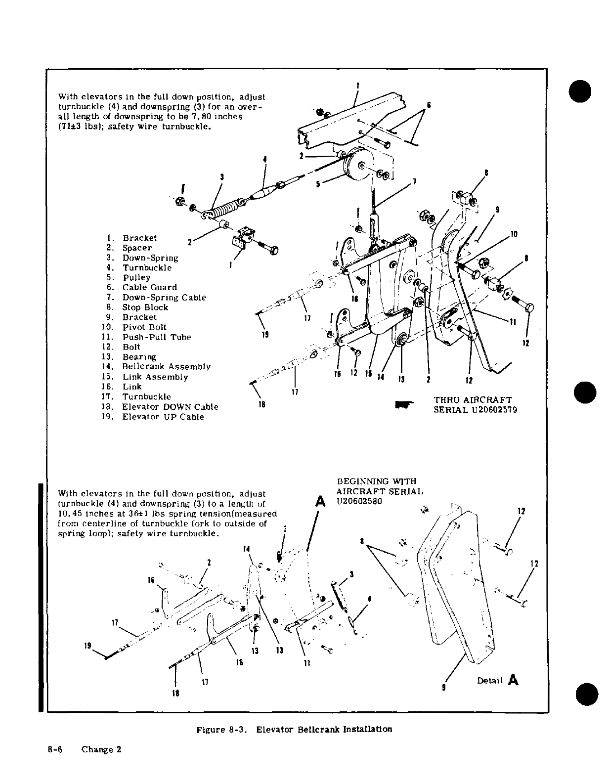
With
elevators
in
the
full
down
position, adjust
turnbuckle
(4)
and
downspring
(34
for
an
over-
9
all
length
of
downspring
to
be
7.80
inches
(71±3
Ibs);
safety wire
turnbuckle.
3
8
7
3.
Down-Spring
l
4.
Turnbuckle
I F
0/
,2-
5.
Pulley
,
;l
6.
Cable
Guard
7.
Down-Spring
Cable
'i
-
-
8.
Stop
Block
A,
\
9.
Bracket
1
7
10.
Pivot
Bolt
11.
Push-Pull
Tube
19
12.
Bolt
<
13.
Bearing
14.
Bellcrank
Assembly
12
1
15.
Link
Assembly
---
1I
2 12
16.
Link
7
4.
Turnbuckle
'
17.
Turnbuckle
THRU
AIRCRAFT
18.
Elevator
DOWN
Cable
18
SERIAL
U206025'79
19.
Elevator
UP
Cable
BEGINNING WITH
With
elevators
in
the
full
down
position,
adjust
AIRCRAFT
SERIAL
turnbuckle
(4)
and
downspring
(3)
to
a
length
of
A
U20602580
10.45
inches
at
361
lbs spring tension(measured
/
from
centerline
of
turnbuckle
fork
to
outside
of
3
14.ir
8-3.
Elevmblr
-,:r
Installatdon
spr-
ang
loop)
safety
ire
urnbuckle.
18.,E"'v',oI
DOWN
C,1
v
\,
S'
2.
Figure
8-3.
Elevator
Bellcran
Installation
8-6
Change
2
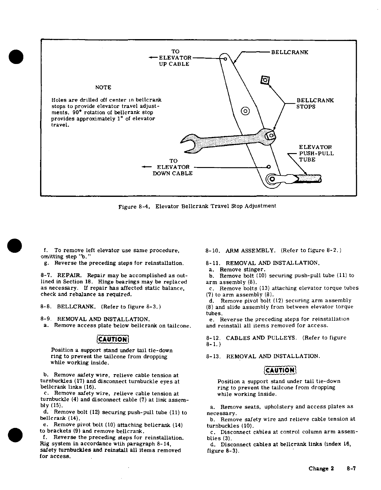
TO
BELLCRANK
*-ELEVATOR
/
UP
CABLE
NOTE
Holes
are
drilled
off
center
in
bellcrank
BELLCRANK
stops
to
provide
elevator travel adjust-
S
TOPS
ments.
90
°
rotation
of
bellcrank
stop
provides approximately
1
°
of
elevator
travel.
j ;
.... =.
;
.-- --
^..t
ELEVATOR
Is si
"'
\ \
^
PUSH-PULL
TO
TUBE
-
ELEVATOR
DOWN
CABLE
Figure
8-4.
Elevator
Bellcrank
Travel
Stop
Adjustment
f.
To
remove
left
elevator
use
same
procedure,
8-10.
ARM
ASSEMBLY.
(Refer
to
figure
8-2.)
omitting step
"b."
g.
Reverse
the
preceding
steps
for
reinstallation.
8-11.
REMOVAL
AND
INSTALLATION.
a.
Remove
stinger.
8-7.
REPAIR.
Repair
may
be
accomplished
as
out-
b.
Remove
bolt
(10)
securing
push-pull
tube
(11)
to
lined
in
Section
18.
Hinge
bearings
may
be
replaced
arm
assembly
(8).
as
necessary.
If
repair
has
affected
static
balance,
c.
Remove
bolts
(13)
attaching
elevator
torque
tubes
check
and
rebalance
as
required.
(7)
to
arm
assembly
(8).
d.
Remove pivot
bolt
(12)
securing
arm
assembly
8-8.
BELLCRANK.
(Refer
to
figure
8-3.)
(8)
and
slide
assembly
from
between
elevator
torque
tubes.
8-9.
REMOVAL
AND
INSTALLATION.
e.
Reverse
the
preceding
steps
for
reinstallation
a.
Remove
access
plate
below
bellcrank
on
tailcone.
and
reinstall
all
items
removed
for
access.
(CAUTIONl|
8-12.
CABLES
AND
PULLEYS.
(Refer
to
figure
8-1.)
Position
a
support
stand
under
tail
tie-down
ring
to
prevent
the
tailcone
from
dropping
8-13.
REMOVAL
AND
INSTALLATION.
while
working
inside.
}CAUTIONl
b.
Remove
safety
wire,
relieve
cable
tension
at
turnbuckles
(17)
and
disconnect
turnbuckle
eyes
at
Position
a
support
stand
under
tail
tie-down
bellcrank links
(16).
ring
to
prevent
the
tailcone
from
dropping
c.
Remove
safety
wire,
relieve
cable
tension
at
while
working
inside.
turnbuckle
(4)
and
disconnect
cable
(7)
at
link
assem-
bly
(15).
a.
Remove
seats,
upholstery
and
access
plates
as
d.
Remove
bolt
(12)
securing push-pull
tube
(11)
to
necessary.
bellcrank
(14).
b.
Remove
safety
wire
and
relieve
cable
tension
at
e.
Remove
pivot bolt
(10)
attaching
bellcrank
(14)
turnbuckles
(10).
to
brackets
(9)
and
remove
bellcrank.
c.
Disconnect
cables
at
control
column
arm
assem-
f.
Reverse
the
preceding
steps
for
reinstallation.
blies
(3).
Rig
system
in
accordance
wtih
paragraph
8-14,
d.
Disconnect
cables
at
bellcrank
links
(index
16,
safety
turnbuckles
and
reinstall
all
items
removed
figure
8-3).
for
access.
Change
2
8-7
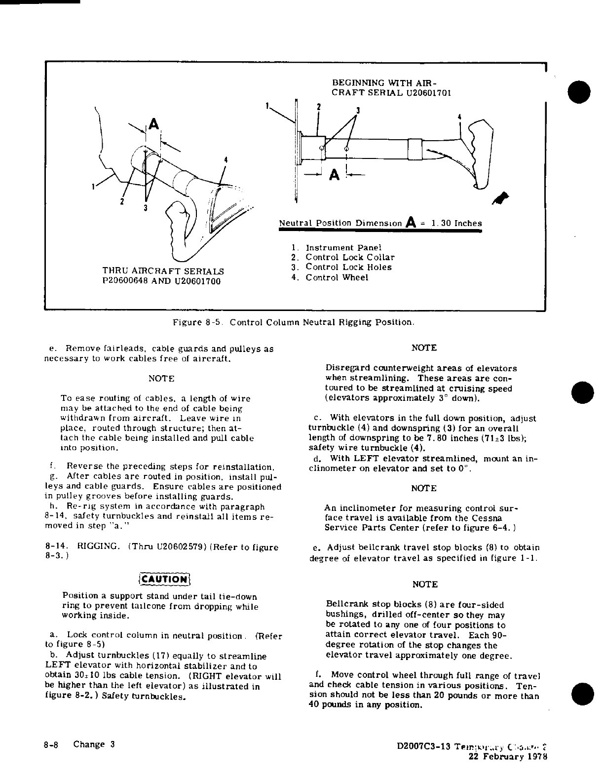
1
BEGINNING
WITH
AIR-
CRAFT
SERIAL
U20601701
4
Neutral
Position
Dimension
A =
1.30
Inches
1.
Instrument
Panel
2.
Control
Lock
Collar
3.
Control
Lock
Holes
THRU
AIRCRAFT
SERIALS
4.
Control
Wheel
P20600648
AND
U20601700
Figure
8-5.
Control
Column
Neutral
Rigging
Position.
e.
Remove
fairleads,
cable
guards
and
pulleys
as
NOTE
necessary
to
work
cables
free
of
aircraft.
Disregard
counterweight
areas
of
elevators
NOTE
when
streamlining.
These
areas
are
con-
toured
to
be
streamlined
at
cruising
speed
To
ease
routing
of
cables,
a
length
of
wire
(elevators
approximately
3
°
down).
may
be
attached
to
the
end
of
cable
being
withdrawn from
aircraft.
Leave
wire
in
c.
With
elevators
in
the
full
down
position,
adjust
place, routed
through
structure;
then
at-
turnbuckle
(4)
and
downspring
(3)
for
an
overall
tach the
cable
being
installed
and
pull
cable
length
of
downspring
to
be
7.80
inches
(71±3
lbs);
into
position.
safety
wire
turnbuckle
(4).
d.
With
LEFT
elevator
streamlined,
mount an
in-
f.
Reverse
the
preceding
steps
for
reinstallation.
clinometer
on
elevator
and
set
to
0°.
g.
After
cables
are
routed
in
position,
install
pul-
leys
and
cable
guards.
Ensure cables
are
positioned
NOTE
in
pulley
grooves
before
installing
guards.
h.
Re-rig
system
in
accordance
with
paragraph
An
inclinometer
for
measuring
control
sur-
8-14,
safety
turnbuckles
and
reinstall
all
items
re-
face
travel
is
available
from
the
Cessna
moved
in
step
"a."
Service
Parts
Center
(refer
to figure
6-4.)
8-14.
RIGGING.
(Thru
U20602579)
(Refer
to
figure
e.
Adjust
bellcrank
travel
stop
blocks
(8)
to
obtain
8-3.
)
degree
of
elevator
travel
as specified
in
figure
1-1.
CAUTION
NOTE
Position
a
support
stand
under
tail
tie-down
ring
to
prevent
tailcone
from
dropping
while
Bellcrank
stop
blocks
(8)
are
four-sided
working
inside.
bushings,
drilled
off-center
so
they
may
be
rotated
to
any one
of
four
positions
to
a.
Lock
control
column
in
neutral
position.
(Refer
attain
correct
elevator
travel.
Each
90-
to
figure
8-5)
degree rotation
of
the
stop
changes
the
b.
Adjust
turnbuckles
(17)
equally
to
streamline
elevator
travel
approximately
one
degree.
LEFT
elevator
with
horizontal
stabilizer
and
to
obtain
30±10
lbs cable
tension.
(RIGHT
elevator
will
f.
Move
control
wheel
through
full
range
of
travel
be
higher
than
the
left
elevator)
as
illustrated
in
and
check
cable
tension
in
various
positions.
Ten-
figure
8-2.)
Safety
turnbuckles.
sion
should
not
be
less
than
20
pounds
or
more
than
40
pounds
in
any
position.
8-8
Change
3
D2007C3-13
Temporary
Change
2
22
February
1978
g.
Check
to
see
that all
turnbuckles
are
safetied
elevator bellcrank
and
elevator
control
cables.
and
all
parts
are
secured,
then
reinstall
all
parts
d.
With
left
elevator
in
streamlined
position,
removed
for
access.
mount
an
inclinometer
on
elevator
and
set
to
0°.
WARNING
NONE
Be
sure
elevators
move
in
the
correct
direc-
An
inclinometer
for measuring
control
sur-
tion
when
operated
by
the
control
wheels. face
travel
is
available
from
the
Cessna
Service
Parts
Center.
Refer
to
figure
6-4.
8-14A.
RIGGING.
(Beginning
with U20602580).
CAUTION
e.
Adjust
bellcrank
travel
stop
blocks
(16)
to
obtain
of
elevator
travel as
specified
in
figure
1-1.
)
Position
a
support
stand
under
tail
tie-down
f.
Move
control
wheel
through full
range
of
travel
ring to
prevent
the
tailcone
from
dropping
and check
cable
tension
in
various
positions.
Tension
while
working
inside.
should
not be
less
than
20
pounds
or
more
than
40
pounds
in
any
position.
a.
Place
contour
block
on
left
hand
elevator
and
g.
Ensure
that
all
turnbuckles
are
safetied
and
all
lock
control
column
in
neutral
position.
(Refer
to
fig-
parts
secured,
then
re-install
all
parts
removed
for
ure
8-5.)
access.
b.
With
elevators
in
the
full
down
position, adjust
WARNING
turnbuckles
(4)
and
downspring
(3)
to
a
length
of
10.45
inches
at
36±1
lbs
spring
tension
(measured
from
centerline
of
turnbuckle
fork
to outside
of
Be
sure elevators
move
in
the
correct
di-
spring
loop;
safety
wire
turnbuckles
(4).
rection
when
operated
by
the
control
wheels.
c.
Install
turnbuckles
(4)
and
downsprings
(3) to
SHOP
NOTES:
D2007C3-13
Temporary
Change
2
Change
3
8-9/(8-10
blank)
22
February
1978
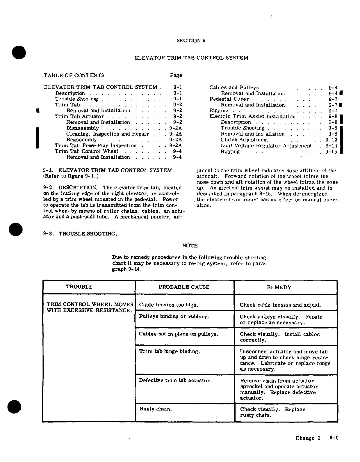
SECTION
9
ELEVATOR
TRIM TAB
CONTROL
SYSTEM
TABLE
OF
CONTENTS
Page
ELEVATOR
TRIM
TAB
CONTROL
SYSTEM
.
9-1
Cables
and
Pulleys
..........
.
9-4
Description
... ..
....
......
.
9-1
Removal
and
Installation
.. . ..
9-4
Trouble
Shooting
....
..
9-1
Pedestal
Cover
............
9-7
Trim
Tab .
...........
.
9-2
Removal
and
Installation
......
9-7
|
Removal
and
Installation
......
9-2
Rigging
. ... .
.............
.
9-7
Trim
Tab
Actuator
.
.........
9-2
Electric
Trim
Assist
Installation
.. .
9-8
Removal
and
Installation
.....
.
9-2
Description
.. . . .
.......
9-8
Disassembly
........
..
9-2A
Trouble
Shooting
. . . . .. ..
9-8
Cleaning,
Inspection
and
Repair
.. ..
9-2A
Removal
and
Installation
... ...
9-8
Reassembly
......
9-2A
Clutch
Adjustment
...
......
9-13
Trim
Tab
Free-Play
Inspection
.....
9-2A
Dual
Voltage
Regulator Adjustment
. .
9-14
Trim
Tab
Control
Wheel
......
.
9-4
Rigging
....
... ... .
9-15
Removal
and
Installation......
9-4
9-1.
ELEVATOR
TRIM
TAB
CONTROL
SYSTEM.
jacent
to
the
trim
wheel
indicates
nose
attitude
of
the
(Refer
to
figure
9-1.)
aircraft.
Forward rotation
of
the
wheel
trims
the
nose
down
and aft
rotation
of
the
wheel
trims
the
nose
9-2.
DESCRIPTION.
The
elevator
trim
tab,
located
up.
An
electric
trim
assist
may
be
installed
and
is
on
the
trailing
edge
of
the
right
elevator,
is
control-
described
in
paragraph
9-16.
When
de-energized
led
by
a
trim
wheel
mounted
in
the
pedestal.
Power
the
electric
trim
assist
has
no
effect
on
manual
oper-
to
operate
the tab
is
transmitted
from
the
trim
con-
ation.
trol
wheel
by
means
of
roller
chains,
cables,
an
actu-
ator
and
a
push-pull
tube.
A
mechanical
pointer,
ad-
9-3.
TROUBLE
SHOOTING.
NOTE
Due
to
remedy
procedures
in
the
following
trouble
shooting
chart
it
may
be
necessary
to
re-rig
system,
refer
to
para-
graph
9-14.
TROUBLE
PROBABLE
CAUSE
REMEDY
TRIM
CONTROL WHEEL
MOVES
Cable tension
too
high.
Check
cable
tension
and
adjust.
WITH
EXCESSIVE
RESISTANCE.
Pulleys
binding
or
rubbing.
Check
pulleys
visually.
Repair
or
replace
as
necessary.
Cables
not
in
place
on
pulleys.
Check
visually.
Install
cables
correctly.
Trim
tab
hinge
binding.
Disconnect
actuator
and move
tab
up
and
down
to
check
hinge
resis-
tance.
Lubricate
or
replace
hinge
as
necessary.
Defective
trim
tab
actuator.
Remove
chain
from
actuator
sprocket
and
operate
actuator
manually.
Replace
defective
actuator.
Rusty
chain.
Check
visually.
Replace
rusty
chain.
Change
1
9-1
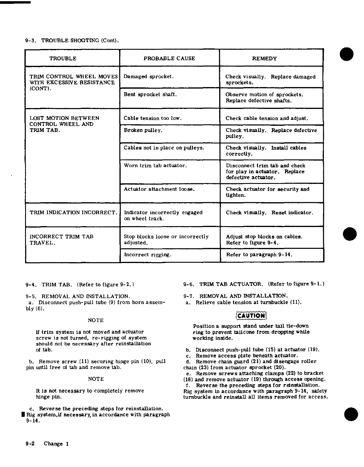
9-3.
TROUBLE
SHOOTING
(Cont).
TROUBLE
PROBABLE
CAUSE
REMEDY
TRIM
CONTROL WHEEL
MOVES
Damaged
sprocket.
Check
visually.
Replace
damaged
WITH
EXCESSIVE
RESISTANCE
sprockets.
(CONT).
Bent
sprocket
shaft.
Observe
motion
of
sprockets.
Replace
defective
shafts.
LOST
MOTION
BETWEEN
Cable
tension
too
low.
Check
cable
tension
and
adjust.
CONTROL
WHEEL
AND
TRIM
TAB.
Broken
pulley.
Check
visually.
Replace
defective
pulley.
Cables
not
in place
on
pulleys.
Check
visually.
Install
cables
correctly.
Worn
trim
tab
actuator.
Disconnect
trim
tab
and
check
for
play
in
actuator.
Replace
defective
actuator.
Actuator attachment
loose.
Check
actuator
for
security
and
tighten.
TRIM
INDICATION
INCORRECT.
Indicator
incorrectly
engaged
Check
visually.
Reset
indicator.
on
wheel
track.
INCORRECT
TRIM
TAB
Stop
blocks
loose
or incorrectly
Adjust
stop
blocks
on
cables.
TRAVEL.
adjusted. Refer
to
figure
9-4.
Incorrect
rigging.
Refer to
paragraph
9-14.
9-4.
TRIM
TAB.
(Refer
to
figure
9-2.)
9-6.
TRIM
TAB
ACTUATOR.
(Refer to figure
9-1.)
9-5.
REMOVAL
AND
INSTALLATION.
9-7.
REMOVAL
AND
INSTALLATION.
a.
Disconnect
push-pull
tube
(9)
from
horn
assem-
a.
Relieve
cable
tension
at
turnbuckle
(11).
bly
(6).
NOTE
CAUTION
Position
a
support
stand
under
tail
tie-down
If
trim
system
is
not
moved and
actuator
ring
to
prevent tailcone
from dropping
while
screw
is
not
turned,
re-rigging
of
system
working
inside.
should
not
be
necessary
after
reinstallation
of
tab.
b.
Disconnect
push-pull
tube
(15)
at
actuator
(19).
c.
Remove
access
plate
beneath
actuator.
b.
Remove
screw
(11)
securing
hinge
pin
(10),
pull
d.
Remove
chain
guard
(21)
and
disengage
roller
pin
until
free
of
tab
and
remove
tab.
chain
(23)
from
actuator
sprocket
(20).
e.
Remove
screws
attaching
clamps
(22)
to
bracket
NOTE
(18)
and
remove
actuator
(19)
through
access
opening.
f.
Reverse
the
preceding
steps
for
reinstallation.
It
is
not
necessary
to
completely
remove
Rig
system
in
accordance
with
paragraph
9-14,
safety
hinge pin.
turnbuckle
and
reinstall
all
items
removed
for
access.
c.
Reverse
the
preceding
steps
for
reinstallation.
Rig
system,if
necessary,
in
accordance
with
paragraph
9-14.
9-2
Change 1
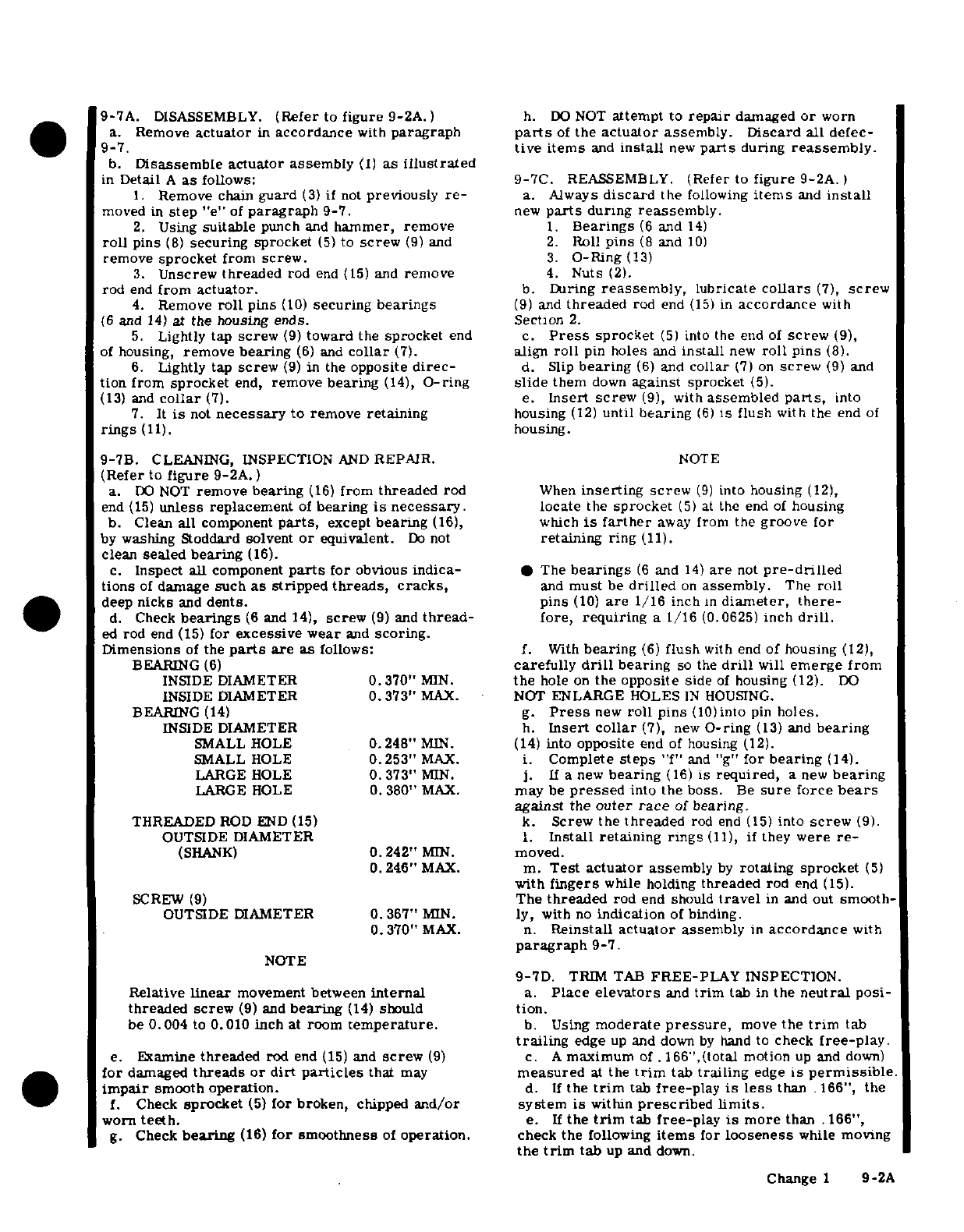
9-7A.
DISASSEMBLY.
(Refer
to
figure
9-2A.)
h.
DO
NOT
attempt
to
repair
damaged
or
worn
a.
Remove
actuator
in
accordance
with
paragraph
parts
of
the
actuator
assembly.
Discard
all
defec-
9-7.
tive items
and
install
new
parts
during
reassembly.
b.
Disassemble actuator assembly
(1)
as
illustrated
in
Detail
A
as
follows:
9-7C.
REASSEMBLY.
(Refer
to
figure
9-2A.
1.
Remove
chain
guard
(3)
if
not
previously
re-
a.
Always
discard
the
following
items
and
install
moved
in
step
"e"
of
paragraph
9-7.
new
parts
during
reassembly.
2.
Using
suitable
punch
and
hammer,
remove
1.
Bearings
(6
and
14)
roll
pins
(8)
securing sprocket
(5)
to
screw
(9)
and
2.
Roll
pins
(8
and
10)
remove
sprocket
from
screw.
3.
O-Ring(13)
3.
Unscrew
threaded
rod
end
(15)
and
remove
4.
Nuts
(2).
rod
end
from
actuator.
b.
During
reassembly,
lubricate
collars
(7),
screw
4.
Remove
roll
pins
(10)
securing
bearings
(9)
and
threaded
rod
end
(15)
in
accordance
with
(6
and
14)
at
the
housing
ends.
Section
2.
5.
Lightly
tap
screw
(9)
toward
the
sprocket
end
c.
Press
sprocket
(5)
into
the
end
of
screw
(9),
of
housing,
remove
bearing
(6)
and
collar
(7).
align
roll
pin
holes
and
install
new
roll
pins
(8).
6.
Lightly
tap
screw
(9)
in
the
opposite
direc-
d.
Slip
bearing
(6)
and
collar
(7)
on
screw
(9)
and
tion
from
sprocket
end,
remove
bearing
(14),
O-ring
slide
them
down
against
sprocket
(5).
(13)
and
collar
(7).
e.
Insert screw
(9),
with
assembled
parts,
into
7.
It
is
not
necessary
to
remove
retaining
housing
(12)
until
bearing
(6)
is
flush
with
the
end
of
rings
(11).
housing.
9-7B.
CLEANING,
INSPECTION
AND
REPAIR.
NOTE
(Refer
to
figure
9-2A.
)
a.
DO
NOT
remove
bearing
(16)
from
threaded
rod
When
inserting
screw
(9)
into
housing
(12),
end
(15)
unless
replacement
of
bearing
is
necessary.
locate
the
sprocket
(5)
at
the
end
of
housing
b.
Clean
all
component
parts,
except
bearing
(16),
which
is
farther
away
from
the
groove
for
by
washing
Stoddard
solvent
or
equivalent.
Do
not
retaining
ring
(11).
clean
sealed
bearing
(16).
c.
Inspect
all
component
parts
for
obvious
indica-
* The
bearings
(6
and
14)
are
not
pre-drilled
tions
of
damage
such
as
stripped
threads,
cracks,
and
must
be
drilled
on
assembly.
The
roll
deep
nicks
and
dents.
pins
(10)
are
1/16
inch
in
diameter,
there-
d.
Check
bearings
(6
and
14),
screw
(9)
and
thread-
fore,
requiring
a
1/16
(0.0625)
inch
drill.
ed
rod
end
(15)
for
excessive
wear
and
scoring.
Dimensions
of
the
parts
are
as
follows:
f.
With
bearing
(6)
flush
with end
of
housing
(12),
BEARING
(6)
carefully
drill
bearing
so
the
drill
will
emerge from
INSIDE
DIAMETER
0.370"
MIN.
the
hole
on
the
opposite
side
of
housing
(12).
DO
INSIDE
DIAMETER
0.
373"
MAX.
NOT
ENLARGE
HOLES
IN
HOUSING.
BEARING
(14)
g.
Press
new
roll
pins
(10)into
pin
holes.
INSIDE
DIAMETER
h.
Insert
collar
(7),
new
O-ring
(13)
and
bearing
SMALL
HOLE
0.248"
MIN.
(14)
into
opposite
end
of
housing
(12).
SMALL
HOLE
0.253"
MAX.
i.
Complete
steps
"f"
and "g"
for bearing
(14).
LARGE HOLE
0.373"
MIN.
j.
If
a
new
bearing
(16)
is
required,
a
new
bearing
LARGE
HOLE
0.
380"
MAX.
may
be
pressed
into
the
boss.
Be
sure
force
bears
against
the
outer
race
of
bearing.
THREADED
ROD
END
(15)
k.
Screw
the
threaded
rod
end
(15)
into
screw
(9).
OUTSIDE
DIAMETER
1.
Install
retaining
rings
(11),
if
they
were
re-
(SHANK)
0.242"
MIN.
moved.
0.246"
MAX. m.
Test
actuator
assembly
by
rotating
sprocket
(5)
with
fingers
while holding
threaded
rod
end
(15).
SCREW
(9)
The
threaded
rod
end
should
travel
in
and
out
smooth-
OUTSIDE DIAMETER
0.
367"
MIN.
ly,
with
no
indication
of
binding.
0.370"
MAX.
n.
Reinstall
actuator
assembly
in
accordance
with
paragraph
9-7.
NOTE
9-7D.
TRIM TAB
FREE-PLAY
INSPECTION.
Relative
linear
movement
between
internal
a.
Place
elevators
and
trim
tab
in
the
neutral
posi-
threaded
screw
(9)
and
bearing
(14)
should
tion.
be
0.004
to
0.010
inch at room
temperature.
b.
Using
moderate
pressure,
move
the
trim
tab
trailing
edge
up
and
down
by
hand
to
check
free-play.
e.
Examine
threaded
rod
end
(15)
and
screw
(9)
c.
A
maximum
of.
166",(total
motion
up
and
down)
for
damaged
threads
or dirt
particles
that
may
measured
at
the
trim
tab
trailing
edge
is
permissible.
impair
smooth
operation.
d.
If
the
trim
tab
free-play
is
less
than
.166",
the
f.
Check
sprocket
(5)
for
broken,
chipped
and/or
system
is
within
prescribed
limits.
worn
teeth.
e.
If
the
trim
tab
free-play
is
more
than
.166",
g.
Check
bearing
(16)
for
smoothness
of
operation,
check
the
following
items
for
looseness
while
moving
the
trim
tab
up
and
down.
Change
1
9-2A
1.
Check
push-pull
tube
to
trim
tab
horn
assem-
f.
If
looseness
is
apparent
while
checking
steps
bly
attachment
for
looseness.
e-1
and
e-2,
repair
by
installing
new
parts.
2.
Check
push-pull
tube to
actuator
assembly
g.
If
looseness
is
apparent
while
checking
step
e-3,
threaded
rod
end
attachment
for
looseness.
refer
to
paragraphs 9-6
through 9-7C.
Recheck
trim
3.
Check
actuator
assembly
threaded
rod
end
tab
free-play.
for
looseness
in
the
actuator
assembly
with
push-pull
tube
disconnected.
SHOP
NOTES:
9-2B
Change
1
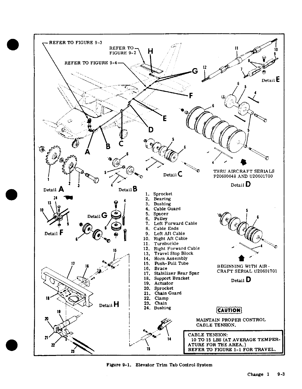
REFER
TO
FIGURE
9-3
REFER
TO
/
11
11
FIGURE
9-2
H
REFER
TO
FIGURE
9-4
1
..
Detail
A
Detail
D
_ _
1.
Sprocket
24
2.
Bearing
3.
Bushing
10
4.
Cable
Guard
5.
Spacer
6.
Pulley
7.
Left
Forward
Cable
8.
Cable
Ends
Detail
F
9.
Left
Aft
Cable
10.
Right
Aft
Cable
11.
Turnbuckle
15
12.
Right
Forward
Cable
-
13.
Travel
Stop
Block
14.
Horn
Assembly
11
15.
Push-Pull
Tube
16.
Brace
CRAFT
SERIAL
U20601701
17.
Stabilizer
Rear
Spar
CRAFT
SERIAL
U20601701
18.
Support
Bracket Detail
D
19.
Actuator
20.
Sprocket
21.
Chain
Guard
22.
Clamp
Detail
H
23.
Chain
24.
Bushing
ICAUTIONI
20
MAINTAIN
PROPER
CONTROL
CABLE
TENSION.
CABLE
TENSION:
14
10
TO
15
LBS
(AT
AVERAGE
TEMPER-
22
ATURE
FOR
THE
AREA.)
15
REFER
TO
FIGURE
1-1
FOR
TRAVEL.
Figure
9-1.
Elevator
Trim
Tab Control
System
Change
1
9-3
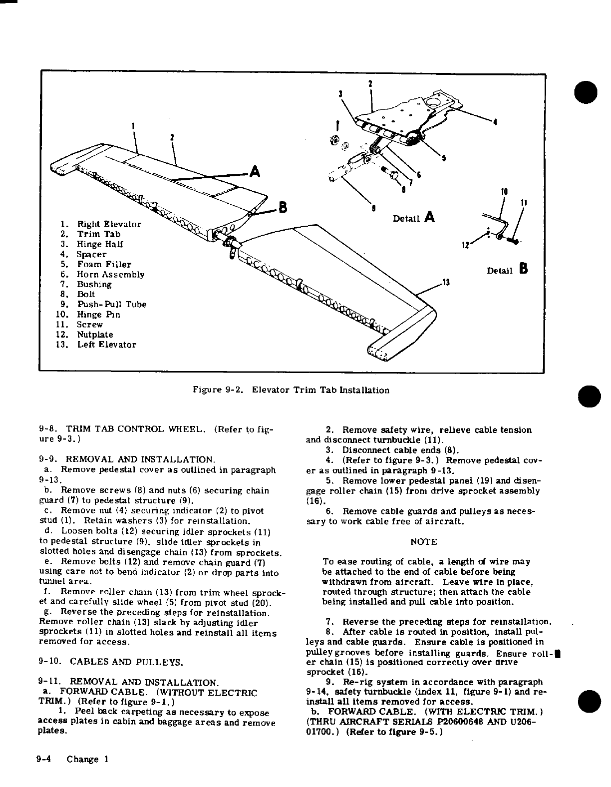
2
B
9
Detail A
1.
Right
Elevator
2.
Trim
Tab
i
3.
Hinge Half
12
4.
Spacer
5.
Foam
Filler
Detail
B
6.
Horn
Assembly
7.
Bushing
8.
Bolt
9.
Push-Pull
Tube
10.
Hinge
Pin
11.
Screw
12.
Nutplate
13.
Left
Elevator
Figure
9-2.
Elevator
Trim
Tab
Installation
9-8.
TRIM TAB
CONTROL
WHEEL.
(Refer
to
fig-
2.
Remove
safety
wire,
relieve
cable
tension
ure
9-3.)
and
disconnect
turnbuckle
(11).
3.
Disconnect
cable
ends
(8).
9-9.
REMOVAL
AND
INSTALLATION.
4.
(Refer
to
figure 9-3.)
Remove
pedestal
cov-
a.
Remove
pedestal
cover
as
outlined
in
paragraph
er
as
outlined
in
paragraph
9-13.
9-13.
5.
Remove
lower pedestal
panel
(19)
and
disen-
b.
Remove
screws
(8)
and
nuts
(6)
securing
chain
gage
roller
chain
(15)
from
drive sprocket
assembly
guard
(7)
to
pedestal
structure
(9).
(16).
c.
Remove
nut
(4)
securing
Indicator
(2)
to
pivot
6.
Remove
cable
guards
and
pulleys
as
neces-
stud
(1).
Retain
washers
(3)
for
reinstallation.
sary
to
work
cable
free
of
aircraft.
d.
Loosen
bolts
(12)
securing
idler
sprockets
(11)
to
pedestal
structure
(9),
slide
idler
sprockets
in
NOTE
slotted
holes
and
disengage
chain
(13)
from
sprockets.
e.
Remove
bolts
(12)
and
remove
chain
guard
(7)
To
ease
routing
of
cable,
a
length
of
wire
may
using
care
not
to
bend
indicator
(2)
or
drop
parts
into
be
attached
to
the
end
of
cable
before
being
tunnel
area.
withdrawn
from
aircraft.
Leave
wire
in
place,
f.
Remove
roller
chain
(13)
from
trim
wheel
sprock-
routed
through
structure;
then
attach
the
cable
et and
carefully
slide
wheel
(5)
from
pivot
stud
(20).
being
installed
and pull
cable into
position.
g.
Reverse
the
preceding
steps
for
reinstallation.
Remove
roller
chain
(13)
slack
by
adjusting
idler
7.
Reverse
the
preceding
steps
for reinstallation.
sprockets
(11)
in
slotted holes
and
reinstall
all
items
8.
After
cable
is
routed
in
position,
install
pul-
removed
for
access.
leys
and
cable
guards.
Ensure
cable
is
positione
in
pulleygrooves
before
installing
guards.
Ensure
roll-i
9-10.
CABLES
AND
PULLEYS.
er
chain
(15)
is
positioned
correctly
over
drive
sprocket
(16).
9-11.
REMOVAL
AND
INSTALLATION.
9.
Re-rig
system
in
accordance
with
paragraph
a.
FORWARD
CABLE.
(WITHOUT
ELECTRIC
9-14,
safety
turnbuckle
(index
11,
figure
9-1) and
re-
TRIM.)
(Refer
to
figure
9-1.
)
install
all items
removed
for
access.
1.
Peel
back
carpeting
as
necessary
to
expose
b.
FORWARD
CABLE.
(WITH
ELECTRIC
TRIM.)
access
plates
in
cabin
and baggage
areas
and
remove
(THRU
AIRCRAFT
SERIALS
P20600648
AND
U206-
plates.
01700.)
(Refer to
figure
9-5.)
9-4
Change I
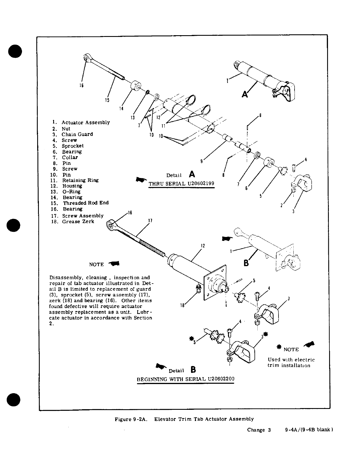
1.
Actuator Assembly
2.
Nut
3.
Chain
Guard
4.
Screw
5.
Sprocket
6.
Bearing
7.
Collar
8.
Pin
9.
Screw
10.
Pin
Detail
A
8
11.
Retaining
Ring
11.
Housing
Ring
12.
Housing
13.
O-Ring
14.
Bearing
15.
Threaded
Rod
End
16.
Bearing
17.
Screw
Assembly
18.
Grease
Zerk
NOTE
Disassembly,
cleaning
,
inspection
and
repair
of
tab
actuator
illustrated
in
Det-
ail
B
is
limited
to
replacement
of
guard
4
(3),
sprocket
(5),
screw assembly
(17),
zerk
(18)
and
bearing
(16).
Other
items
found
defective
will
require
actuator
assembly
replacement
as
a
unit.
Lubr-
cate
actuator
in
accordance
with
Section
2.
*
NOTE
Used
with
electric
trim
installation
BEGINNING
WITH
SERIAL
U20602200
Figure
9-2A.
Elevator
Trim
Tab
Actuator
Assembly
Change
3
9-4A/(9-4B
blank )
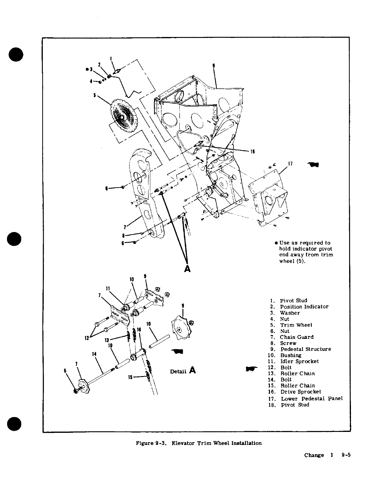
*
1
.
17
~~6--"t^cd~ \
|I
~*
Use
as
required
to
hold
indicator
pivot
end away
from
trim
wheel
(5).
A
It
/
>^.N^ ^/^^fI~~~~ 1.
Pivot
Stud
2.
Position
Indicator
3.
Washer
4.
Nut
y ^ 16~ ~10 i\
^
5.
Trim
Wheel
j16
"\
\ ^
}
6.
Nut
7.
Chain
Guard
10
\
\
I 8
8.
Screw
1 4 ~~~\ j~ 91\~
_"~ 9
9.
Pedestal
Structure
14
\
AdzA
10.
Bushing
7 \ \^v
\\i
11.
Idler
Sprocket
s \ \/
Detail
A
r
12.
Bolt
13.
Roller
Chain
14.
Bolt
15.
Roller
Chain
aJ S\\
16.
Drive
Sprocket
17.
Lower
Pedestal
Panel
18.
Pivot
Stud
Figure
9-3.
Elevator
Trim
Wheel
Installation
Change
1
9-5
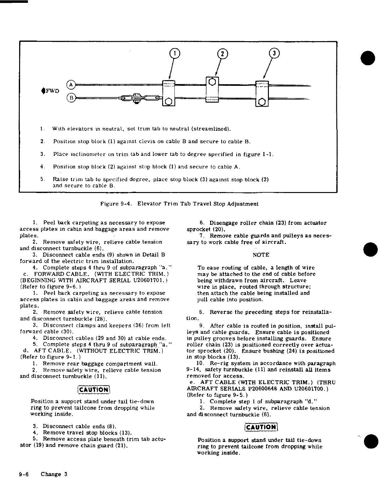
FWD
L
1.
With
elevators
in
neutral,
set
trim
tab
to
neutral
(streamlined)
2.
Position
stop
block
(1)
against
clevis
on
cable
B
and
secure
to
cable
B.
3.
Place
inclinometer
on
trim
tab
and
lower
tab
to
degree
specified
in
figure
1-1.
4.
Position
stop
block
(2)
against
stop
block
(1)
and
secure
to
cable
A.
5.
Raise
trim
tab
to
specified
degree,
place
stop
block
(3)
against
stop
block
(2)
and
secure
to
cable
B.
Figure
9-4.
Elevator
Trim
Tab
Travel
Stop
Adjustment
1.
Peel
back
carpeting
as
necessary
to
expose
6.
Disengage
roller
chain
(23)
from actuator
access
plates
in
cabin
and baggage
areas
and
remove
sprocket
(20).
plates.
-7.
Remove
cable
guards
and
pulleys
as
neces-
2.
Remove
safety
wire,
relieve
cable
tension
sary
to
work
cable
free
of
aircraft.
and
disconnect turnbuckle
(6).
3.
Disconnect
cable
ends
(9)
shown
in
Detail
B
NOTE
forward
of
the
electric
trim
installation.
4.
Complete
steps
4
thru
9
of
subparagraph
"a."
To
ease
routing
of
cable,
a
length
of
wire
c.
FORWARD
CABLE.
(WITH
ELECTRIC
TRIM.)
may
be
attached
to
the
end
of
cable
before
(BEGINNING
WITH
AIRCRAFT
SERIAL
U20601701.)
being
withdrawn
from
aircraft.
Leave
(Refer
to
figure
9-6.
)
wire
in
place, routed
through
structure;
1.
Peel
back
carpeting
as
necessary
to
expose
then
attach
the
cable
being
installed
and
access
plates
in
cabin
and
baggage
areas
and
remove
pull
cable
into
position.
plates.
2.
Remove
safety
wire, relieve
cable
tension
8.
Reverse
the
preceding
steps
for
reinstalla-
and
disconnect turnbuckle
(28).
tion.
3.
Disconnect
clamps
and
keepers
(36)
from
left
9.
After
cable
is
routed
in
position,
install
pul-
forward
cable
(30).
leys
and
cable
guards. Ensure
cable
is
positioned
4.
Disconnect
cables
(29
and
30)
at
cable
ends.
in
pulley
grooves
before
installing guards.
Ensure
5.
Complete
steps
4
thru
9
of
subparagraph
"a."
roller
chain
(23)
is
positioned
correctly
over
actua-
d.
AFT
CABLE.
(WITHOUT
ELECTRIC TRIM.)
tor
sprocket
(20).
Ensure
bushing
(24)
is
positioned
(Refer
to
figure
9-1.
) in
stop
blocks
(13).
1.
Remove
rear
baggage
compartment
wall.
10.
Re-rig
system
in
accordance
with
paragraph
2.
Remove
safety
wire,
relieve
cable
tension
9-14,
safety turnbuckle
(11)
and
reinstall
all
items
and
disconnect turnbuckle
(11).
removed
for
access.
e.
AFT
CABLE
(WITH
ELECTRIC
TRIM.)
(THRU
JCAUTION 1
AIRCRAFT
SERIALS P2060064&
AND
32qQI0601100.
(Refer
to
figure
9-5.)
Position
a
support
stand
under
tail
tie-down
1.
Complete
step
1
of
subparagraph
"d."
ring
to
prevent tailcone
from
dropping
while
2.
Remove
safety wire,
relieve
cable
tension
working
inside.
and
disconnect
turnbuckle
(6).
3.
Disconnect
cable
ends
(8).
{CAUTION
I
4.
Remove
travel
stop
blocks
(13).
5.
Remove
access
plate
beneath
trim
tab
actu-
Position
a
support
stand
under
tail
tie-down
ator
(19)
and
remove
chain
guard
(21).
ring
to
prevent tailcone
from
dropping
while
working
inside.
9-6
Change
3
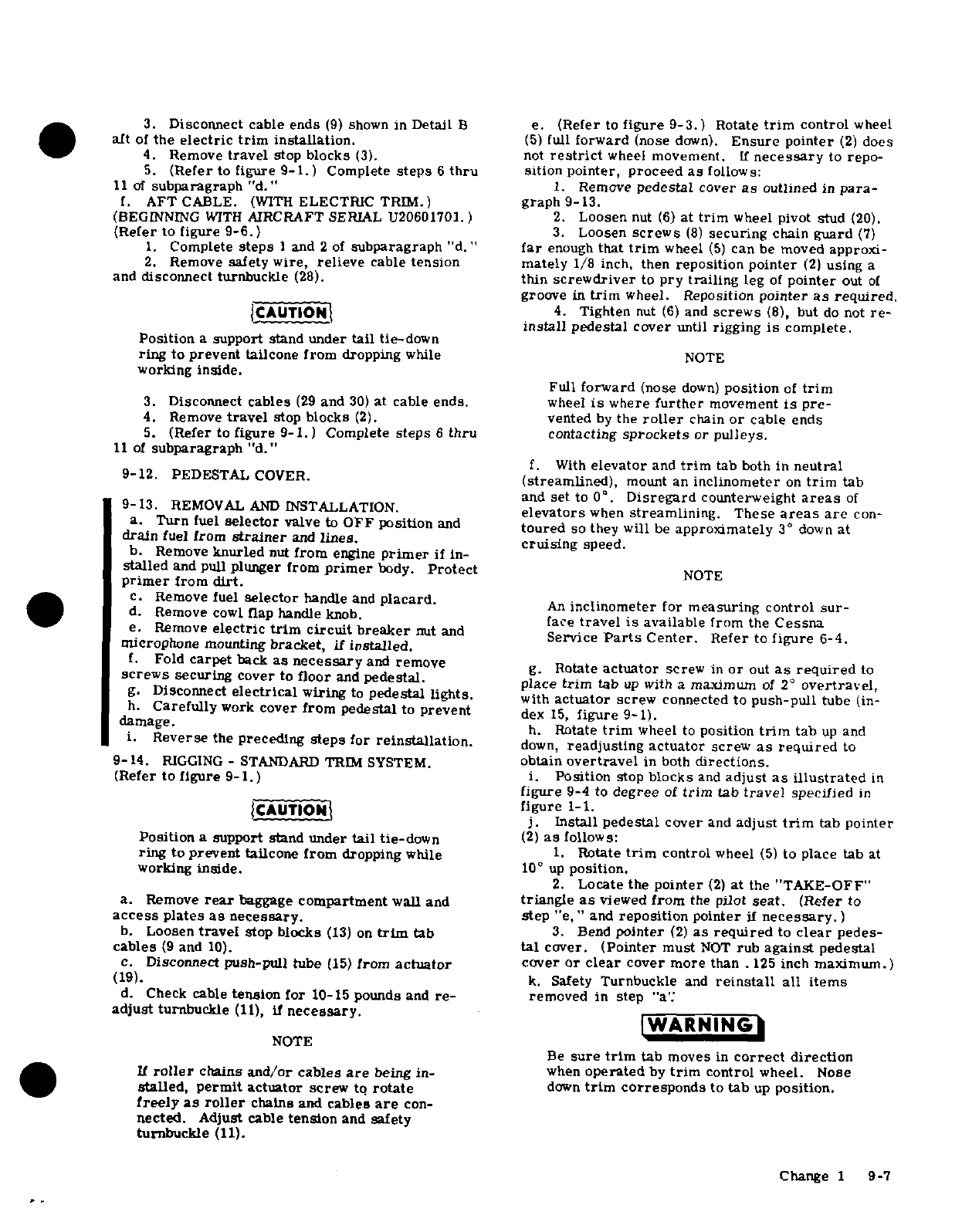
3.
Disconnect
cable
ends
(9)
shown
in
Detail
B e.
(Refer
to
figure
9-3.)
Rotate
trim
control
wheel
aft
of
the
electric
trim
installation.
(5)
full
forward
(nose
down).
Ensure
pointer
(2)
does
4.
Remove
travel
stop
blocks
(3).
not
restrict
wheel
movement.
If
necessary
to
repo-
5.
(Refer
to
figure
9-1.)
Complete
steps
6
thru
sition
pointer, proceed
as
follows:
11 of
subparagraph
"d."
1.
Remove
pedestal
cover
as
outlined
in
para-
f.
AFT
CABLE.
(WITH
ELECTRIC
TRIM.)
graph
9-13.
(BEGINNING
WITH
AIRCRAFT
SERIAL U20601701.)
2.
Loosen
nut
(6)
at
trim
wheel
pivot
stud
(20).
(Refer to
figure
9-6.)
3.
Loosen
screws
(8)
securing
chain
guard
(7)
1.
Complete
steps
I
and
2
of
subparagraph
"d."
far
enough
that
trim
wheel
(5)
can
be
moved
approxi-
2.
Remove
safety
wire,
relieve
cable
tension mately
1/8
inch,
then
reposition pointer
(2)
using
a
and
disconnect turnbuckle
(28).
thin
screwdriver
to
pry
trailing
leg
of
pointer
out
of
groove
in
trim
wheel.
Reposition
pointer
as
required.
CAUTION
4.
Tighten
nut
(6)
and
screws
(8),
but
do
not
re-
install
pedestal
cover
until
rigging
is
complete.
Position
a
support
stand
under
tail
tie-down
ring
to
prevent
tailcone
from
dropping
while
NOTE
working
inside.
Full
forward
(nose
down)
position
of
trim
3.
Disconnect
cables
(29
and
30)
at
cable
ends.
wheel
is
where
further
movement
is
pre-
4.
Remove
travel
stop
blocks
(2).
vented
by
the
roller
chain
or
cable
ends
5.
(Refer
to
figure
9-1.)
Complete
steps
6
thru
contacting
sprockets
or
pulleys.
11
of
subparagraph "d."
f.
With
elevator
and
trim
tab
both
in
neutral
9-12.
PEDESTAL
COVER.
(streamlined),
mount
an
inclinometer
on
trim
tab
and
set
to 0
°
.
Disregard
counterweight
areas
of
9-13.
REMOVAL
AND
INSTALLATION.
elevators
when
streamlining.
These
areas
are
con-
a.
Turn
fuel
selector
valve
to
OFF
position
and
toured
so they
will
be
approximately
3°
down at
drain
fuel
from
strainer
and
lines.
cruising
speed.
b.
Remove
knurled
nut
from
engine
primer
if
in-
stalled
and pull
plunger
from
primer
body.
Protect
NOTE
primer
from
dirt.
c.
Remove
fuel
selector
handle
and
placard.
d.
Remove
cowl
flap
handle/knob.
An
inclinometer
for
measuring
control
sur-
face
travel
is
available
from
the
Cessna
e.
Remove
electric
trim
circuit
breaker
nut
and
Service
Parts
Center.
Refer to
figure
6-4.
microphone
mounting
bracket,
if
installed.
f.
Fold
carpet
back
as
necessary
and
remove
g.
Rotate
actuator
screw
in
or
out
as
required
to
screws
securing
cover
to
floor
and
pedestal.
place
trim
tab
up
with
a
maximum
of
2'
overtravel,
g.
Disconnect
electrical
wiring
to
pedestal
lights.
with
actuator
screw
connected
to
push-pull
tube
(in-
h.
Carefully
work
cover
from
pedestal
to
prevent
dex
15,
figure
9-1).
damage.
h.
Rotate
trim
wheel
to
position
trim
tab
up
and
i.
Reverse
the
preceding
steps
for
reinstallation.
down,
readjusting actuator
screw
as
required
to
9-14.
RIGGING
-
STANDARD TRIM
SYSTEM.
obtain
overtravel
in
both
directions.
(Refer
to
figure
9-1.)
i.
Position
stop
blocks
and
adjust
as
illustrated
in
figure
9-4
to
degree
of
trim
tab
travel
specified
in
CAUTION
figure
1-1.
j.
Install
pedestal
cover
and
adjust
trim
tab
pointer
Position
a
support
stand
under
tail
tie-down
(2)
as
follows:
ring
to
prevent
tailcone
from
dropping
while
1.
Rotate
trim
control
wheel
(5)
to
place
tab
at
working
inside.
10 °
up
position.
2.
Locate
the
pointer
(2)
at
the
"TAKE-OFF"
a.
Remove
rear
baggage
compartment
wall and
triangle as
viewed
from
the
pilot
seat.
(Refer
to
access
plates
as
necessary.
step
"e,"
and
reposition
pointer
if
necessary.)
b.
Loosen
travel
stop
blocks
(13)
on
trim
tab
3.
Bend
pointer
(2)
as
required
to
clear
pedes-
cables
(9
and
10).
tal
cover.
(Pointer
must
NOT
rub
against
pedestal
c.
Disconnect
push-pull
tube
(15)
from
actuator
cover
or
clear
cover
more
than
.125
inch
maximum.)
(19).
k.
Safety
Turnbuckle
and
reinstall
all
items
d.
Check
cable
tension
for
10-15
pounds
and
re-
removed
in
step
"a".
adjust
turnbuckle
(11),
if
necessary.
WARNING
NOTE
Be
sure
trim
tab
moves
in
correct
direction
If
roller
chains
and/or
cables
are
being
in-
when
operated
by
trim
control
wheel.
Nose
stalled, permit
actuator
screw
to
rotate
down
trim
corresponds
to
tab
up
position.
freely
as
roller
chains
and
cables
are
con-
nected.
Adjust
cable
tension
and
safety
turnbuckle
(11).
Change
1
9-7
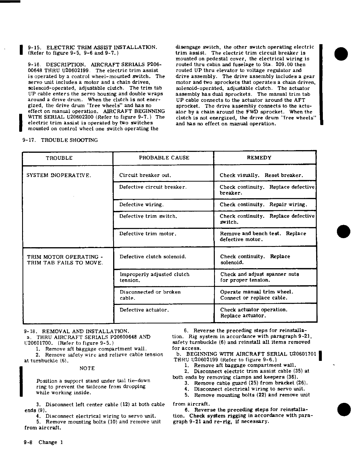
9-15.
ELECTRIC
TRIM
ASSIST
INSTALLATION.
disengage
switch,
the
other
switch
operating
electric
(Refer
to
figure
9-5,
9-6
and
9-7.)
trim
assist.
The
electric
trim
circuit
breaker
is
mounted
on
pedestal
cover,
the
electrical
wiring
is
9-16
DESCRIPTION. AIRCRAFT
SERIALS
P206-
routed
thru
cabin
and
fuselage
to
Sta.
209.00 then
00648
THRU U20602199.
The
electric
trim
assist
routed
UP
thru
elevator
to
voltage
regulator
and
is
operated
by
a
control
wheel-mounted
switch.
The
drive
assembly.
The
drive assembly
includes
a
gear
servo
unit
includes
a
motor
and
a
chain
driven,
motor
and
two
sprockets
that
operates
a
chain
driven,
solenoid-operated, adjustable
clutch.
The
trim
tab
solenoid-operated,
adjustable
clutch.
The
actuator
UP
cable
enters
the
servo
housing
and double
wraps assembly
has
dual
sprockets.
The manual
trim
tab
around
a
drive
drum.
When
the clutch
is
not
ener-
UP
cable
connects
to
the
actuator
around
the
AFT
gized, the
drive
drum
"free
wheels"
and
has
no
sprocket.
The
drive
assembly
connects
to
the
actu-
effect
on
manual
operation.
AIRCRAFT
BEGINNING
ator
by
a
chain
around
the
FWD
sprocket.
When
the
WITH
SERIAL
U20602200
(Refer
to
figure
9-7.)
The
clutch
is
not
energized,
the
drive
drum
"free
wheels"
electric
trim
assist
is
operated
by
two
switches
and
has
no
effect
on
manual
operation.
mounted
on
control
wheel
one
switch
operating
the
9-17.
TROUBLE
SHOOTING
TROUBLE
PROBABLE
CAUSE
REMEDY
SYSTEM
INOPERATIVE.
Circuit breaker
out.
Check
visually. Reset
breaker.
Defective
circuit
breaker.
Check
continuity.
Replace
defective
breaker.
Defective
wiring.
Check
continuity.
Repair
wiring.
Defective
trim
switch.
Check
continuity.
Replace
defective
switch.
Defective
trim
motor.
Remove
and
bench
test.
Replace
defective
motor.
TRIM
MOTOR
OPERATING
-
Defective
clutch
solenoid.
Check
continuity.
Replace
TRIM
TAB FAILS
TO
MOVE.
solenoid.
Improperly
adjusted
clutch
Check
and
adjust
spanner
nuts
tension. for
proper
tension.
Disconnected
or
broken
Operate
manual
trim
wheel.
cable.
Connect
or
replace
cable.
Defective
actuator.
Check
actuator
operation.
Replace
actuator.
9-18.
REMOVAL
AND
INSTALLATION.
6.
Reverse
the
preceding
steps
for
reinstalla-
a.
THRU
AIRCRAFT
SERIALS P20600648
AND
tion.
Rig
system
in
accordance
with
paragraph
9-21,
U20601700.
(Refer
to
figure
9-5.)
safety turnbuckle
(6)
and
reinstall
all items
removed
1.
Remove
aft baggage
compartment
wall.
for
access.
2.
Remove
safety
wire
and
relieve
cable
tension
b. BEGINNING
WITH
AIRCRAFT
SERIAL
U20601701
at
turnbuckle
(6).
THRU U20602199
(Refer
to
figure
9-6.)
1.
Remove
aft
baggage
compartment
wall.
2.
Disconnect
electric trim
assist
cable
(35)
at
both
ends
by
removing
clamps
and
keepers
(36).
Position
a
support
stand
under
tail
tie-down
3.
Remove
cable
guard
(25)
from
bracket
(26).
ring
to
prevent
the
tailcone
from dropping
4.
Disconnect
electrical
wiring
to
servo
unit.
while
working
inside.
5.
Remove
mounting
bolts
(22)
and
remove
unit
3.
Disconnect
left
center
cable
(12)
at
both
cable
from
aircraft.
ends
(9).
6.
Reverse
the
preceding
steps
for
reinstalla-
4.
Disconnect
electrical
wiring
to
servo
unit.
tion.
Check
system
rigging
in
accordance
with
para-
5.
Remove
mounting
bolts
(10)
and
remove
unit
graph
9-21 and
re-rig,
if
necessary.
from
aircraft.
9-8
Change
1
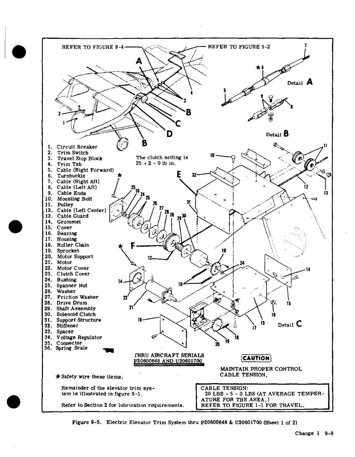
REFER
TO
FIGURE
9-4
REFER
TO
FIGURE
9-2
Detail
A
-D
Detail
1.
Circuit
Breaker
B
,
\
'
2.
Trim
Switch
3.
Travel
Stop
Block
The
clutch
setting
is0
'<
4.
Trim
Tab
25
+
2
-
O
lb
in.
5.
Cable
(Right
Forward)
6.
Turnbuckle
*
E
32
7.
Cable
(Rght
Aft)
/
8.
Cable (Left
Aft)
2312
9.
Cable Ends
/
24
13
10.
Mounting
Bolt
25
\>
11.
Pulley
2t \3
12.
Cable (Left
Center)
i
/ 2
13.
Cable
Guard
f-q
i
14.
Grommet
'
15.
Cover
16.
Bearing
17.
Housing
18.
Roller
Chain
19.
Sprocket
\
' 1
20.
Motor
Support
21.
Motor
22.
Motor
Cover
14
23.
Clutch
Cover
.
24.
Bushing
14
25.
Spanner
Nut
.o
26.
Washer
27.
Friction
Washer
28.
Drive
Drum
/
15
29.
Shalt
Assembly
21
30.
Solenoid
Clutch
15
31.
Support
Structure
IS
32.
Stiffener
17
Detail
33.
Spacer
34.
Voltage
Regulator\
11
35.
Connector
2
36.
Spring
Scale
-
fHRU
AIRCRAFT
SERIALS
ICA
t
P20600648
AND
U20601700
CAUTIONI
MAINTAIN
PROPER
CONTROL
*Safety
wire
these
items.
CABLE
TENSION.
Remainder
of
the
elevator
trim
sys-
CABLE
TENSION:
tern
is
illustrated
in
figure
9-1.
20
LBS
+
5
-
0
LBS
(AT
AVERAGE
TEMPER-
ATURE
FOR
THE
AREA.)
Refer
to
Section
2
for
lubrication
requirements.
REFER
TO
FIGURE
1-1
FOR
TRAVEL.
Figure
9-5.
Electric
Elevator
Trim
System
thru
P20600648
&
U20601700
(Sheet
1
of
2)
Change
1
9-9
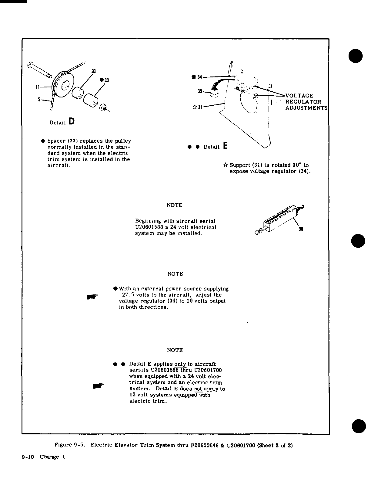
Detail
D
*
Spacer
(33)
replaces
the
pulley
normally
installed
in
the
stan-
dard system
when
the
electric
trim
system is installed
in
the
aircraft.
*
Support
(31)
is
rotated
90'
to
expose
voltage
regulator
(34).
NOTE
Beginning
with
aircraft serial
U20601588
a
24
volt
electrical
system
may
be
installed.
NOTE
*With
an
external
power
source
supplying
27.5
volts
to
the
aircraft,
adjust
the
voltage
regulator
(34)
to
10
volts
output
in
both
directions.
NOTE
*
Detail
E
applies only
to
aircraft
serials
U20601588
thru
U20601700
when
equipped with
a
24
volt
elec-
trical
system
and
an
electric
trim
system.
Detail
E
does
not
apply
to
12
volt
systems
equipped
with
electric
trim.
Figure
9-5.
Electric
Elevator
Trim
System
thru
P20600648
&
U20601700
(Sheet
2 of 2)
9-10
Change 1
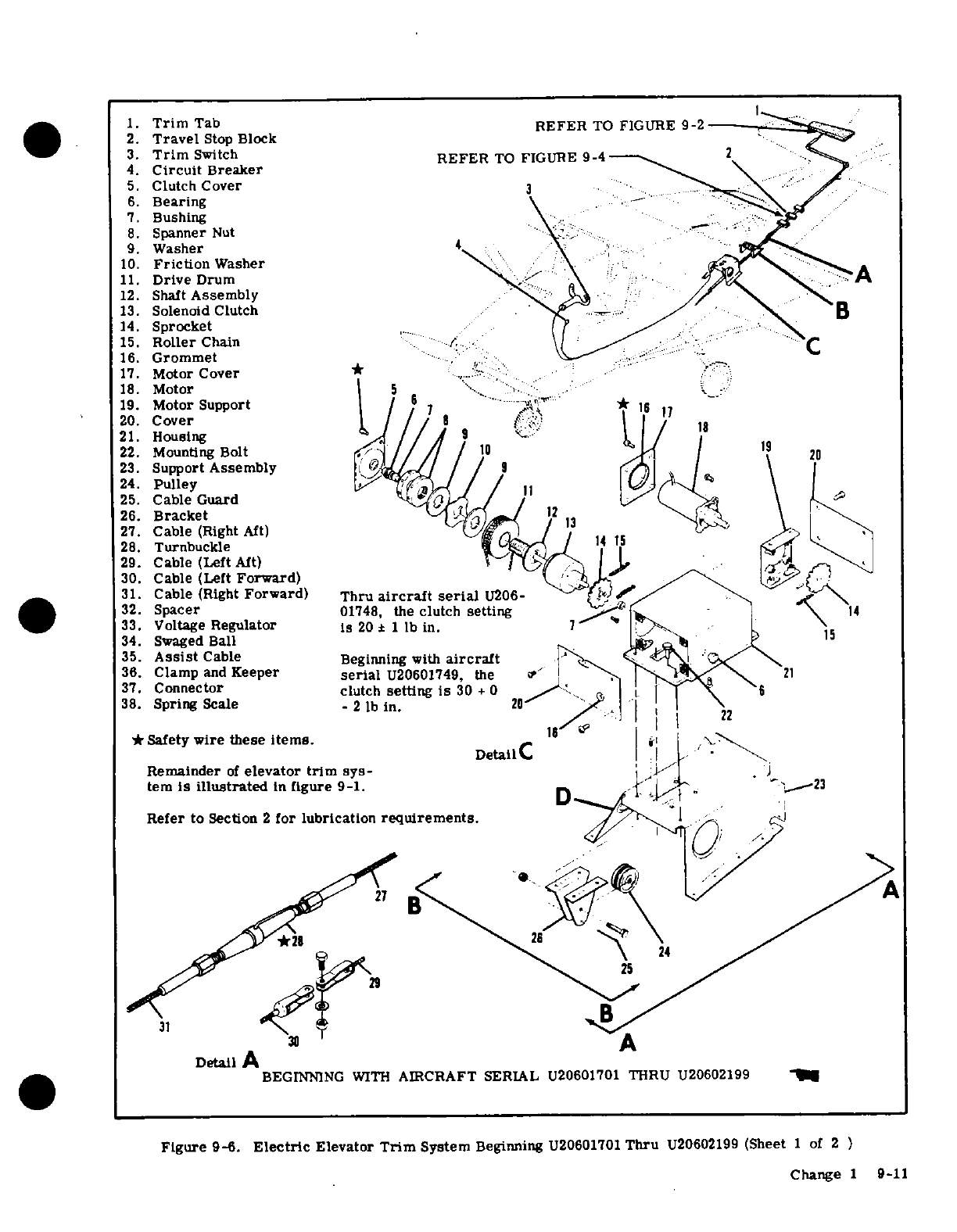
1.
Trim
Tab
REFER
TO FIGURE
9-2
2.
Travel
Stop
Block
3.
Trim
Switch
REFER
TO
FIGURE
9-4
2
4.
Circuit
Breaker
5.
Clutch
Cover
3
6.
Bearing
7.
Bushing
8.
Spanner
Nut
9.
Washer
4
10.
Friction
Washer
11.
Drive
Drum
12.
Shaft
Assembly
13.
Solenoid
Clutch
B
14.
Sprocket
15.
Roller
Chain
16.
Grommet
17.
Motor
Cover
* '
18.
Motor
5
. ..
19.
Motor
Support
/
6
7
-
20.
Cover
8 |17
21.
Housing
22.
Mounting
Bolt
10
19
23.
Support
Assembly
9
24.
Pulley
\4
25.
Cable
Guard
26.
Bracket
12
27.
Cable
(Right
Aft)
/
I.
28.
Turnbuckle
4
1
29.
Cable
(Left
Aft)
W
30.
Cable
(Left
Forward)
31.
Cable
(Right
Forward)
Thru
aircraft serial
U206-
32.
Spacer
01748,
the clutch
setting
4
33.
Voltage
Regulator
Is
20
± 1
lb
in.
34.
Swaged
Ball
15
35.
Assist
Cable
Beginning
with
aircraft
36.
Clamp
and
Keeper
serial
U20601749,
the
.
\
al-
21
37.
Connector
clutch
setting
is
30
+
0
6
38.
Spring
Scale
-
2
lb
in.
20
*
Safety
wire
these
items.
18
2
DetailC
I
, \
Remainder
of
elevator
trim
sys-J/ j
tem
is
illustrated
in
figure
9-1.
.
'
23
Refer
to Section
2
for lubrication
requirements,
,^
r
,A B': < ^^/
2>^y \0^ ^\
8~~~~25
30
A
Detail
A
BEGINNING
WITH
AIRCRAFT
SERIAL
U20601701 THRU
U20602199
Figure
9-6.
Electric
Elevator
Trim
System
Beginning
U20601701
Thru
U20602199
(Sheet
1
of
2
)
Change
1
9-11
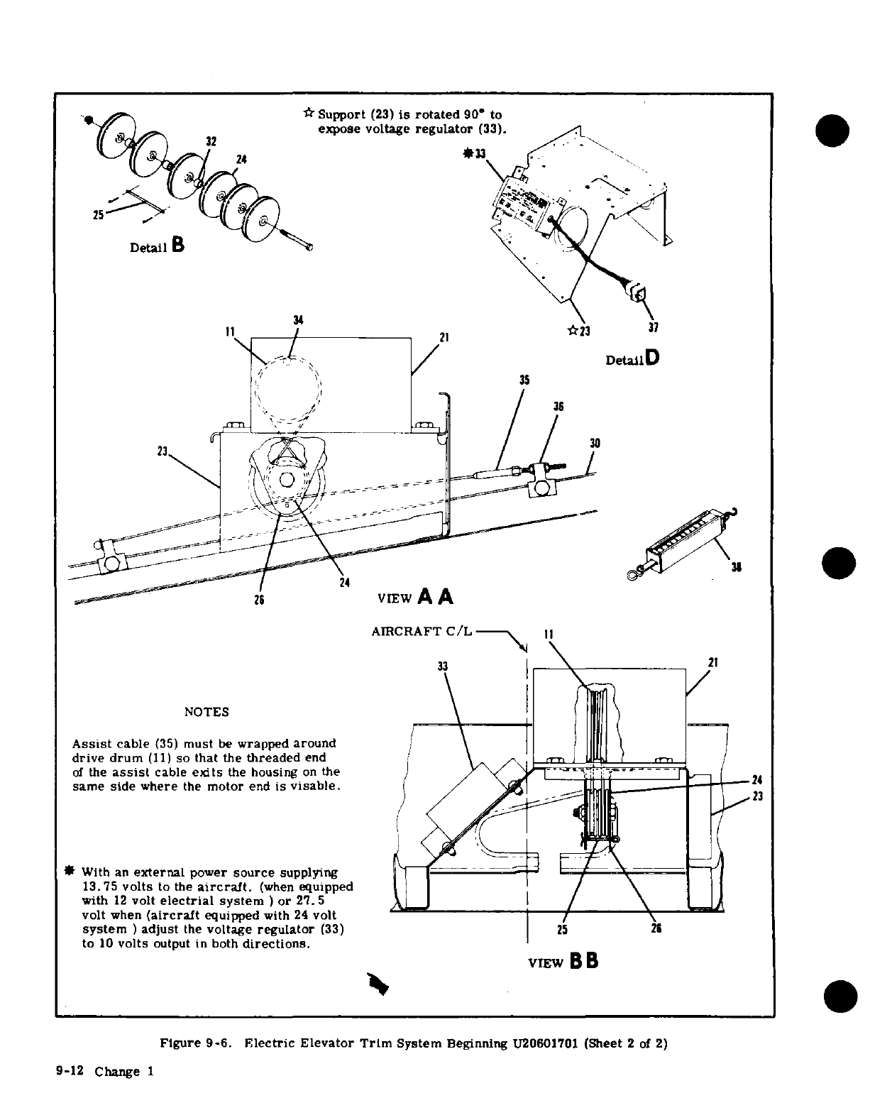
*
Support
(23)
is
rotated
90*
to
expose voltage
regulator
(33).
*33
34
11 / 21
23
37
.Detail
D
//
35
26
VIEW
A
A
AIRCRAFT
C/L
33
21
NOTES
Assist
cable
(35)
must
be
wrapped
around
/
drive
drum
(11)
so
that
the
threaded
end
.
of
the
assist
cable
exits
the
housing
on
the
-24
24
same side
where
the
motor
end
is
visable.
/23
*
With
an
external
power
source
supplying
13.75
volts
to
the
aircraft.
(when
equipped
with
12
volt
electrial
system
)
or
27.5
_
/
volt
when
(aircraft
equipped
with
24
volt
/
system
)
adjust
the
voltage
regulator
(33)
25
26
to
10
volts
output in
both
directions.
VIEW
B
B
Figure
9-6.
Electric
Elevator
Trim
System
Beginning
U20601701
(Sheet
2
of
2)
9-12
Change
1
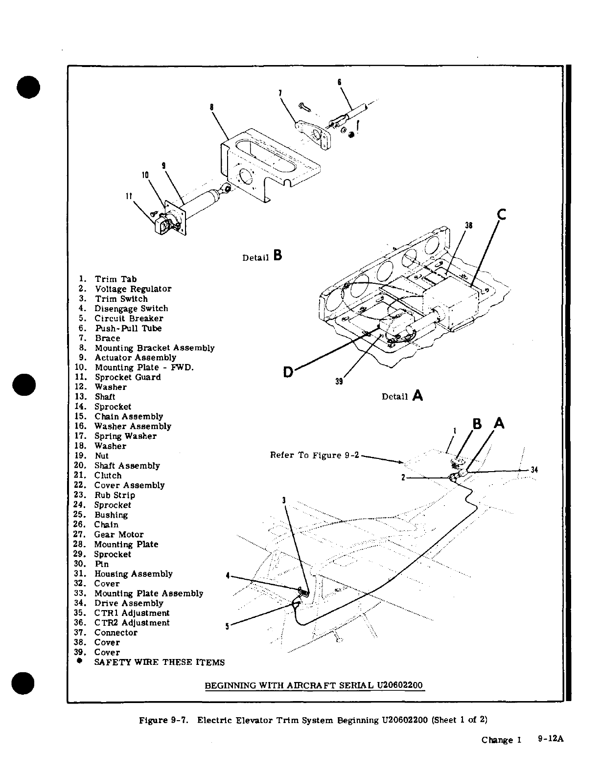
1.
Trim
Tab
2.
Voltage
Regulator
3.
Trim
Switch
4.
Disengage
Switch
5.
Circuit
Breaker
6.
Push-Pull
Tube
7.
Brace
8.
Mounting
Bracket Assembly
9.
Actuator
Assembly
10.
Mounting
Plate
-
FWD.
11.
Sprocket Guard
12.
Washer
13.
Shaft
14.
Sprocket
15.
Chain
Assembly
16.
Washer Assembly
17.
Spring
Washer
18.
Washer
19.
Nut
20.
Shaft
Assembly
21.
Clutch
22.
Cover
Assembly
23.
Rub
Strip
24.
Sprocket
25.
Bushing
26.
Chain
27.
Gear
Motor
28.
Mounting
Plate
29.
Sprocket
30.
Pin
31.
Housing
Assembly
32.
Cover
33.
Mounting
Plate
Assembly
34.
Drive
Assembly
35.
CTR1
Adjustment
36.
CTR2
Adjustment
37.
Connector
38.
Cover
39.
Cover
SAFETY
WIRE
THESE
ITEMS
Figure
9-7.
Electric
Elevator
Trim
System
Beginning
U20602200
(Sheet
1
of
2)
Change
1
9-12A
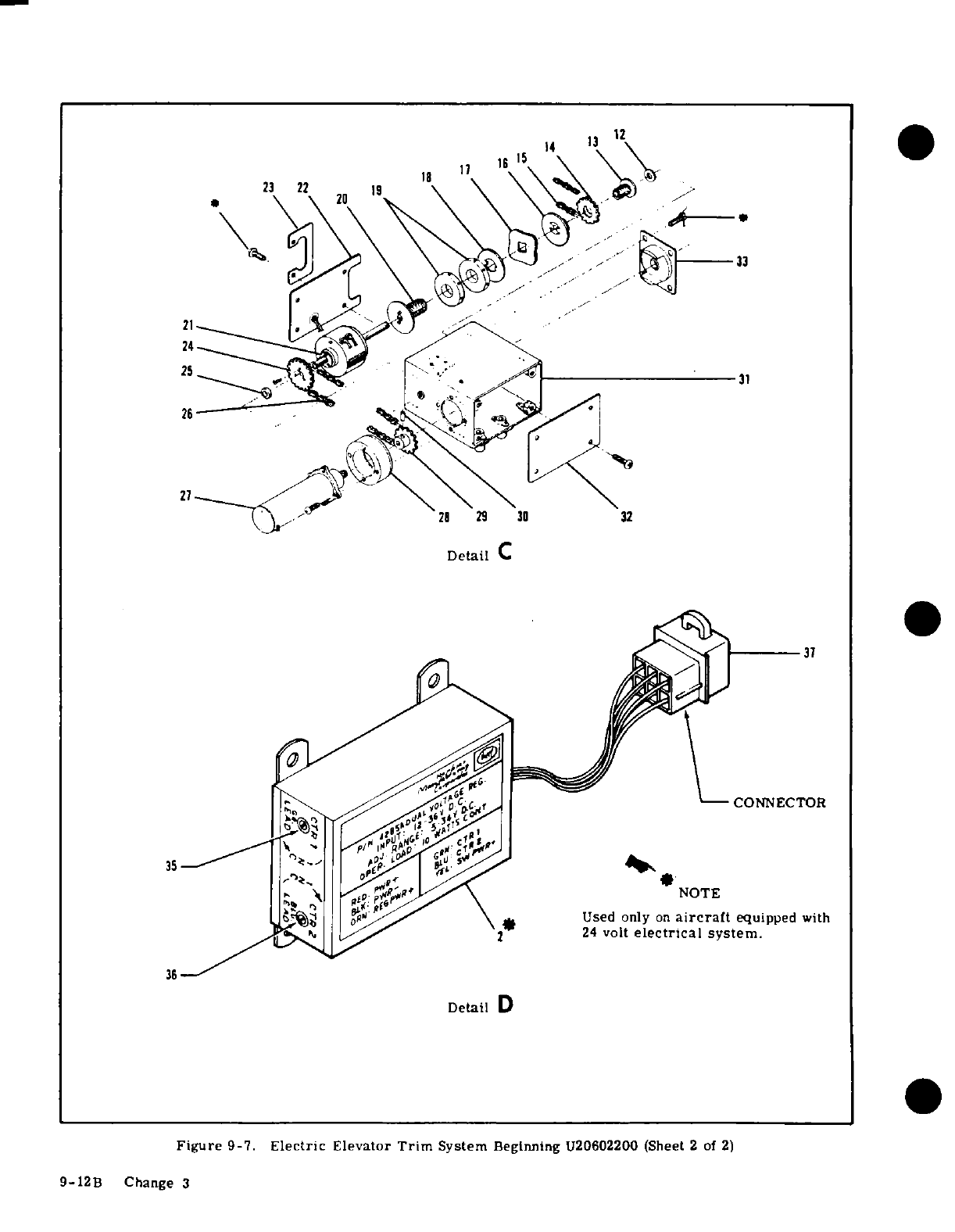
14
3
3
23
22
20
2 1 \\>;\a
etC2
29
30
32
Detail
C
37
CONNECTOR
35
4'
I
;
^
NOTE
.
't
o i*^^ 0\
*
Used
only
on
aircraft
equipped
with
J^j^
1, 3,2-
24
volt
electrical
system.
36,-
Detail
D
Figure
9-7.
Electric
Elevator
Trim
System
Beginning
U20602200
(Sheet
2
of
2)
9-12B
Change
3
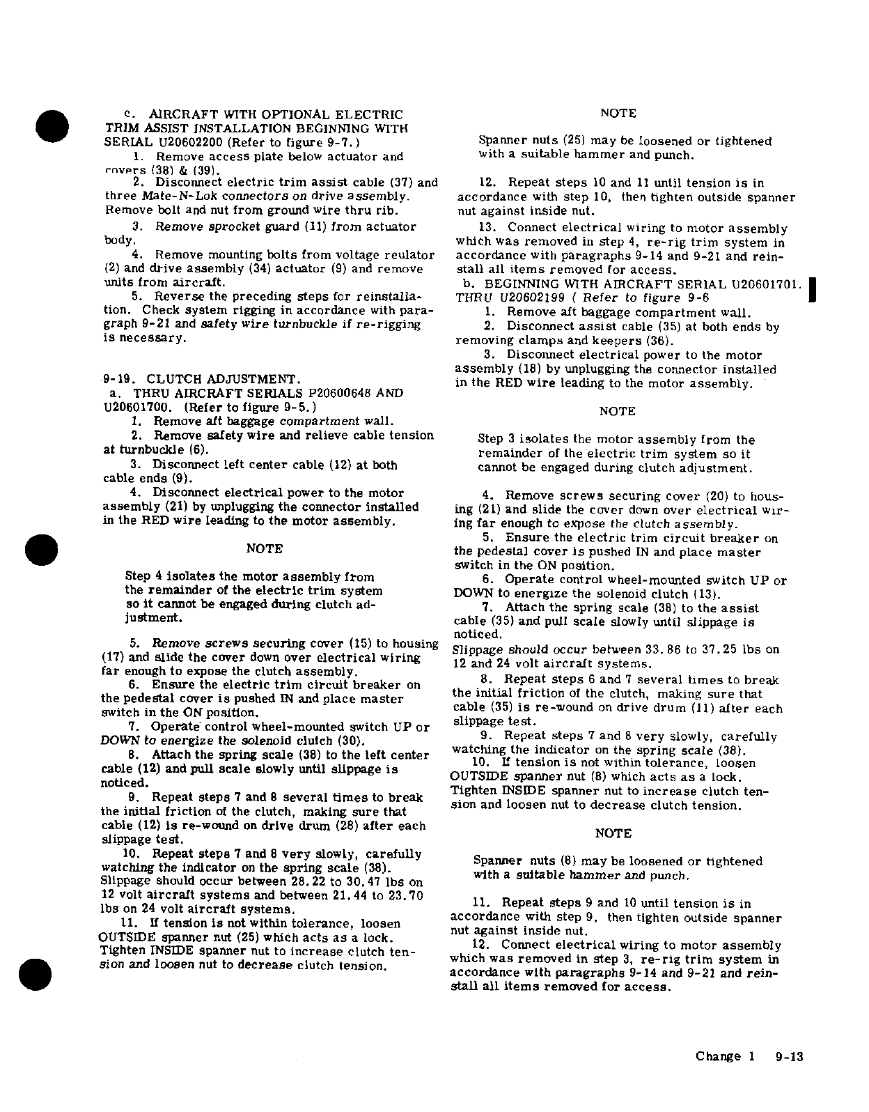
e.
AIRCRAFT
WITH
OPTIONAL
ELECTRIC
NOTE
TRIM
ASSIST INSTALLATION
BEGINNING
WITH
SERIAL
U20602200
(Refer
to
figure
9-7.)
Spanner
nuts
(25)
may
be
loosened
or
tightened
1.
Remove
access
plate
below
actuator
and
with
a
suitable hammer
and
punch.
rnvprs
(38)
&
(39).
2.
Disconnect
electric
trim
assist
cable
(37)
and
12.
Repeat
steps
10
and
11
until
tension
is in
three
Mate-N-Lok
connectors
on
drive
assembly.
accordance
with
step
10,
then
tighten outside spanner
Remove
bolt
and nut
from
ground
wire
thru
rib.
nut
against
inside
nut.
3.
Remove sprocket
guard
(11)
from
actuator
13.
Connect
electrical
wiring
to
motor
assembly
body,
which
was removed
in
step
4,
re-rig
trim
system
in
4.
Remove mounting
bolts
from voltage
reulator
accordance
with
paragraphs
9-14
and
9-21
and
rein-
(2)
and
drive
assembly
(34)
actuator
(9)
and
remove
stall
all
items
removed
for
access.
units
from
aircraft.
b.
BEGINNING
WITH
AIRCRAFT
SERIAL
U20601701.
I
5.
Reverse
the
preceding
steps
for
reinstalla-
THRU
U20602199
(
Refer
to
figure
9-6
tion.
Check
system
rigging
in accordance
with
para-
1.
Remove aft
baggage
compartment
wall.
graph 9-21
and
safety wire
turnbuckle
if
re-rigging
2.
Disconnect
assist
cable
(35)
at
both
ends
by
is
necessary.
removing
clamps
and
keepers
(36).
3.
Disconnect
electrical
power
to
the
motor
assembly
(18)
by
unplugging
the
connector
installed
9-19.
CLUTCH
ADJUSTMENT.
in
the
RED
wire
leading
to
the
motor
assembly.
a.
THRU
AIRCRAFT
SERIALS P20600648
AND
U20601700.
(Refer
to
figure
9-5.)
NOTE
1.
Remove
aft
baggage
compartment
wall.
2.
Remove
safety
wire
and
relieve
cable
tension
Step
3
isolates
the
motor
assembly
from
the
at
turnbuckle
(6).
remainder
of
the
electric
trim
system
so
it
3.
Disconnect
left
center
cable
(12)
at
both
cannot
be
engaged
during
clutch
adjustment.
cable
ends
(9).
4.
Disconnect
electrical
power
to
the
motor
4.
Remove
screws
securing
cover
(20)
to
hous-
assembly
(21)
by
unplugging
the
connector
installed
ing
(21)
and
slide
the
cover
down
over
electrical
wlr-
in
the
RED
wire
leading
to
the motor
assembly.
ing
far
enough
to
expose
the
clutch
assembly.
5.
Ensure
the
electric
trim
circuit
breaker
on
NOTE
the
pedestal cover
is
pushed
IN
and
place
master
switch
in
the
ON
position.
Step
4
isolates
the motor
assembly
from
6.
Operate control
wheel-mounted
switch
UP
or
the
remainder
of
the
electric
trim
system
DOWN
to
energize
the
solenoid
clutch
(13).
so
it
cannot be engaged
during
clutch
ad-
7.
Attach
the
spring
scale
(38)
to
the
assist
justment.
cable
(35)
and
pull
scale
slowly
until
slippage
is
noticed.
5.
Remove
screws
securing
cover
(15)
to
housing
Slippage
should
occur
between
33.
86
to
37.25
bs
on
(17)
and
slide
the
cover
down
over
electrical
wiring
12
and
24
volt
aircraft
systems.
far
enough
to
expose
the clutch
assembly.
6.
Ensure
the
electric
trim
circuit
breaker
on
.
Repeat
steps
6
and
7
several
tlmes
to
break
the
pedestal
cover
is
pushed
IN
and
place
master
the
initial
friction
of
the
clutch,
making
sure
that
switch
in
the
ON
position,
cable
(35)
is
re-wound
on
drive
drum
(11)
after
each
7.
Operate
control
wheel-mounted
switch UP
or
slippage
test.
DOWN
to
energize
the solenoid
clutch
(30).
9.
Repeat
steps
7
and
8
very
slowly,
carefully
8.
Attach
the
spring
scale
(38)
to
the
left
center
watching
the indicator
on
the
spring
scale
(38).
10.
If
tension
is
not
within
tolerance,
loosen
cable
(12)
and
pull
scale
slowly
until
slippage
is
OUTSIDE
spanner
nut
(8)
which
act
as
a
lock.
~~~~~~~~noticed. ~Tighten
INSIDE
spanner
nut
to
increase
clutch
ten-
9.
Repeat
steps
7
and
8
several
times
to
breakn
nut
to
crease
clutch
ten
sion
and
loosen
nut
to
decrease
clutch
tension.
the
initial friction
of
the clutch,
making
sure
that
cable
(12)
is
re-wound
on
drive
drum
(28)
after
each
NOTE
slippage
test.
10.
Repeat
steps
7
and
8
very
slowly,
carefully
S
n
(
m
b
loos
or
i
Spamer
nuts
(81
may
be
loosened
or
tightened
watching
the
indicator
on
the
spring
scale
(38).
it
a
suitable
ammer
and
pun.
with
a
suitable hammer
and
punch.
Slippage
should
occur
between
28.22
to
30.47
lbs
on
12
volt
aircraft
systems
and
between
21.44
to
23.70.
Repeat
steps
9
and
10
until
tension
is in
fIbs
on
24
volt
aircraft
systems.
,,11.
Repeat
steps
9
and
l0
until
tension
Is
in
11.
If tension
is
not
within
tolerance,
loosen
accordance
with
step
9,
then
tighten outside spanner
11.
If
tension
is
not
within
tolerance,
loosen
nut
aainst
inside
nut.
nut
against inside
nut.
OUTSIDE
spanner
nut
(25)
which
acts
as
a
lock
nu
ain
i
nut.
OUTihSIDE
spanner
nut
(25)
which
acts
as
a
lock.
12.
Connect
electrical
wiring
to
motor
assembly
Tighten
NSDE
spanner
nut
to
inde
crease
clutch
tension
which
was removed
in
step
3,
re-rig
trim
system
in
sion
and
loosen
nut
to
decrease
clutch
tension.
accordance
with
paragraphs
9-14
and
9-21
and
rein-
accordance
with
paragraphs
9-14
and
9-21
and
rein-
stall
all
items
removed for
access.
Change
1
9-13
BEGINNING
WITH
AIRCRAFT
SERIAL
U20602200
c.
Disconnect
the
electrical
power
leads
to the
(Refer
to
figure
9-7.) motor
by
unplugging
the
connectors
installed
in the
1.
Remove
access
plate
below
actuator
and
RED
and
BLACK
wires
leading
to
the
motor
assem-
covers
(38)
&
(39).
bly.
2.
Remove
safety wire
and
relieve
cable
tension
d.
Connect
one
lead
of
a
dc
voltmeter
capable
of
and
chain
tension
at
turnbuckles. measuring
the
aircraft
voltage
to
either
the
RED or
3.
Disconnect
electric
motor
by
unplugging
the
BLACK
wire
leading
to
the
motor
and
the
other
volt-
three
Mate-N-Lok
connectors
leading
to
the
motor
meter
lead
to
a
good
aircraft
ground.
assembly.
e.
Operate
the
electric
trim
switch
to
the
NOSE
UP
4.
Remove
mounting
bolts
from
drive
assembly.
and
NOSE
DOWN
positions
and
check
voltage
present
It
is
necessary
to
remove
from
elevator
to
make
the
at
the
RED
and
BLACK
wires.
necessary
adjustments
to
clutch.
f.
Adjust
CTR
1
and CTR
2
adjustment
screws
on
the
voltage
regulator
counterclockwise
(CCW),
then
NOTE
slowly
turn
adjustment
screws
clockwise
(CW)
until
a
10
volt
output
is
obtained for
both
(RED
and
BLACK)
Step
3
isolates
the
motor
assembly
from
the
leads.
remainder
of
the
electric
trim
system
so
it
g.
Remove
voltmeter
and
reconnect
the
motor
as-
cannot
be
engaged
during
clutch
adjustment.
sembly
power
leads.
Be
sure
to
connect
RED
to
RED
and
BLACK
to
BLACK
when
reconnecting
leads.
5.
Remove
screws
securing
covers
(23)
and
(22)
h.
Check
trim
system
for
proper
operation
and
re-
to
housing
(31)
and
slide
the
cover
down
over
electri-
install
all
items
removed
for
access.
cal
wiring
far
enough
to
expose
the
clutch
assembly.
6.
Ensure
the
electric
trim
circuit breaker
on
9-20A.
DUAL
VOLTAGE
REGULATOR ADJUST-
the
pedestal
cover
is
pushed
in
and
place
master
MENT.
(24
VOLT
SYSTEM
ONLY
BEGINNING
WITH
switch
in
the
ON
position.
U20602200)
7.
Operate control
wheel-
mounted
switch
UP
or
(Refer
to
figure
9-7.)
DOWN
to
energize
the
solenoid
clutch
(21).
a.
Remove
access
cover
(39).
8.
Attach
the
spring
scale
(Index
(38)
in
Figure
b. Connect
an
external
power
source
of
13.75
volts
9-6
to
chain
and
pull
scale
slowly
until
slippage
is
(aircraft
equipped with
12
volt
electrical
systems)
or
noticed.
27.5
volts
(aircraft
equipeed
with
24
volt
electrical
9.
Repeat
Steps
7
&
8
several
times
to
break
systems)
dc
continuous
to
the
aircraft
electrical
sys-
the
initial friction
of
the
clutch.
tem
or
if
an
external
power
supply
is
not
available,
10.
Repeat
Steps
8
and
9
very
slowly,
carefully
run
the
aircraft
engine
at
approximately
1000
RPM
to
watching the
indicator
on
the
spring
scale.
Slippage
maintain
the
normal
operating
aircraft
voltage.
should
occur
between
29.1
to
32.9
lbs.
on
12
and
24
volt
aircraft
systems.
c.
Disconnect
the
electrical
power
leads
to
the
11.
IF
tension
is
not
within
tolerance,
loosen
motor
by
unplugging
the
connectors
installed
in
the
OUTSIDE
spanner
nut
(19)
which
acts
as
a
lock.
RED
and
BLACK
wire
leading
to
the
motor
assembly.
Tighten
INSIDE
spanner
nut
to
increase
clutch
ten-
d.
Connect
one
lead
of
a
dc
voltmeter
capable
of
sion
and
loosen
nut
to
decrease
clutch
tension.
measuring
the
aircraft
voltage
to
either
the
RED
or
BLACK
wire
leading
to
the motor
and
the
other
volt-
NOTE
meter
lead
to
a
good
aircraft
ground.
e.
Operate
the
electric
trim
switch
to
the
Nose
UP
Spanner
nut
(19)
may
be
loosened
or
tightened
and
Nose
DOWN
positions
and
check
voltage
present
with
a
suitable
hammer
and
punch.
at
the
RED
and
BLACK
wires.
f.
Adjust
CTR
1
and
CTR
2
adjustment
screws
on
12.
Repeat
Steps
10
and
11
until
tension
is
in
the
voltage
regulator
counterclockwise
(CCW).
then
accordance
with
10.
then
tighten outside spanner
nut
slowly
turn
adjustment
screws
clockwise
(CW)
until
against
inside
nut. a
13.5
volt
output
is obtained
for
both
(RED
and
13.
Connect
electrical
wiring
to
motor
assembly
BLACK
)
leads.
which
was
removed
in
Step
3,
re-rig
trim
system
in
g.
Remove
voltmeter
and
reconnect
the
motor
as-
accordance
with
paragraphs
9-14
and
9-21
and
re-
sembly
power
leads.
Be
sure
to
connect
RED
to
RED
install
all
items
removed
for
access.
and
BLACK
to
BLACK
when
reconnecting
leads.
h.
Check
to
see
if
full
"NOSE
UP"
to
full
"NOSE
9-20.
DUAL
VOLTAGE REGULATOR
ADJUSTMENT.
DOWN"
and
full
"NOSE
DOWN"
to
full
"NOSE
UP"
(Beginning
with
aircraft
serials
U20601588
(24
volt
cycle
time
is
32
+
or
-3
seconds.
systems
only)
and
U20601701
(12
volt
and
24
volt
sys-
Readjust
voltage
regulator as
required
to
obtain
tems.)
32±3
seconds
cycle
time.
a.
Remove
the
aft
baggage
compartment
wall.
j.
Check
trim
system
for
proper operation
and
re-
b.
Connect
an
external
power
source
of
13.75
volts
install
all
items
removed
for
access.
(aircraft
equipped
with
12
volt
electrical systems)
or
27.
5
volts
(aircraft
equipped
with
24
volt
electri-
CAUTION
cal
systems)
dc
continuous
to
the
aircraft
electrical
The
trim
motor
should
be
allowed
to
cool
system,
or
if
an
external
power
supply
is
not
avail-
between
voltage
regulator
adjustments
for
able,
run
the
aircraft
engine
at
approximately
1000
approximately
5
minutes
if
several
actua-
rpm
to
maintain
the
normal
operating
aircraft
volt-
tions
of
the
motor
becomes
necessary
dur-
age.
ing
adjustment.
9-14
Change 3
9-21.
RIGGING
-
ELECTRIC
TRIM
ASSIST.
drum
(11).
a.
THRU
AIRCRAFT
SERIALS
P20600648
AND
6.
Connect
assist
cable
(35)
to
left
forward
U20601700.
(Refer
to
figure
9-5.)
cable
(30)
and
adjust
the
assist
cable
to
25+5-0
1.
The
standard
manual
elevator
trim
control
pounds
tension.
system
MUST be
rigged
in
accordance
with
para-
7.
Recheck
trim
tab
travel
with
an
inclinometer
graph
9-14
prior
to
rigging
the
electric
trim
assist.
for
degree
of
travel
specified
in
figure
1-1,
safety
2.
Remove
rear
compartment
baggage
wall.
turnbuckle
(28)
and
reinstall
all
items
removed
for
3.
Remove
safety
wire
and
adjust turnbuckle
access.
(6)
to
increase
trim
system
cable
tension
from
10
c.
AIRCRAFT
SERIAL
U20601749
THRU
U20602199
to
15
lbs
to
20+5-0
lbs.
(Refer
to
figure
9-6.
)
4.
Recheck
trim
tab
travel
with an
inclinometer
1.
Complete
steps
1
thru
5
of
subparagraph
"b.
for
degree
of
travel
specified
in
figure
1-1.
safety
2.
Connect
assist
cable
(35)
to
left
forward
turnbuckle
(6)
and
reinstall
all
items
removed
for cable
(30)
and
adjust
the
assist
cable
to
10+5-0
access.
pounds
tension.
b.
AIRCRAFT
SERIALS
U20601701
THRU
U206-
d.
BEGINNING
WITH
AIRCRAFT
SERIAL
U206-
01748.
(Refer
to
figure
9-6.)
02200
(Refer
to
figure
9-7.)
1.
Complete
steps
1
and
2
of
subparagraph
"a."
1.
Complete
steps
1
and
2
of
subparagraph
"a"
2.
Disconnect
assist
cable
(35)
at
both
ends
by
2.
Rig
electric
trim
drive
chain
as
follows:
removing
clamps
and
keepers
(36).
a.
Move
elevator trim
tab
to
full
"NOSE
UP"
3.
Remove
safety
wire
and
adjust
turnbuckle
position.
(28)
to
increase
trim
system
cable
tension
from
10
b.
Locate
NAS288
terminal
on
upper
side
of.
to
15
lbs
to
20+5-0
lbs.
chain
at
a
point
0. 75
inches from
drive
4.
Rotate
trim
control
wheel
to
place
trim
tab
assembly
housing.
in
the
approximate
mid-travel
position
(10 °up).
c.
Adjust
AN155
barrel
until
chain
deflection
5.
Index
the swaged
ball
(34)
to
the
top
of
drive
between
Sprockets
is
approximatley
0.
25
inch.
d.
Resafety turnbuckle
and
reinstall
all
items
removed
for
access.
SHOP
NOTES:
Change
3
9-15/(9-16
blank)
SECTION
10
RUDDER
CONTROL
SYSTEM
TABLE
OF
CONTENTS
Page
RUDDER
CONTROL
SYSTEM
........
10-1
Removal and
Installation
....
.
10-9
Description
.. . . .. ... . . .
10-1
Repair
...... . . .. . .. .
10-9
Trouble
Shooting
............
10-1
Cables
and
Pulleys
......
10-9
Rudder
Pedal
Assembly
.........
10-9
Removal
and
Installation
......
10-9
Removal
and
Installation
......
10-9
Rigging.
...........
10-9
Rudder
................
10-9
10-1.
RUDDER
CONTROL
SYSTEM.
(Refer
to
fig-
prised
of
the
rudder
pedals
installation,
cables
and
ure
10-1.)
pulleys,
all
of
which
link
the
pedals
to
the
rudder
and
nose
wheel
steering.
When
dual
controls
are
10-2.
DESCRIPTION.
Rudder
control
is
maintained
installed,
stowable
rudder
pedals
are
provided
at
through
use
of
conventional
rudder
pedals
which
also
the
copilot's
position.
control
nose
wheel
steering.
The
system
is
com-
10-3. TROUBLE
SHOOTING.
NOTE
Due
to
remedy
procedures
in
the
following
trouble
shooting
chart
it
may be
necessary
to
re-rig
system,
refer
to
para-
graph
10-11.
TROUBLE
PROBABLE
CAUSE
REMEDY
RUDDER
DOES NOT
RESPOND
Broken
or
disconnected
cables.
Open
access
plates
and
check
TO
PEDAL
MOVEMENT.
visually.
Connect
or
replace
cable
s.
Change
1
10-1
10-3.
TROUBLE
SHOOTING
(Cont).
TROUBLE PROBABLE
CAUSE
REMEDY
BINDING
OR
JUMPY
MOVE-
Cables
too
tight.
Refer
to
figure
10-1
for
cable
MENT
OF
RUDDER
PEDALS.
tension.
Rig
system
in
accor-
dance
with
paragraph
10-11.
Cables
not
riding properly
on
Open
access
plates
and
check
pulleys.
visually.
Route
cables
cor-
rectly
over
pulleys.
Binding,
broken
or
defective
Open
access
plates
and
check
pulleys
or
cable
guards. visually.
Replace defective
pulleys
and
install
guards
properly.
Pedal
bars
need
lubrication.
Refer
to Section
2.
Defective
rudder
bar
bearings.
If
lubrication
fails
to
eliminate
binding.
Replace
bearing
blocks.
Defective
rudder
hinge
bushings.
Check
visually.
Replace defective
bushings.
Clevis
bolts
too
tight.
Check
and
readjust
bolts
to
eliminate
binding.
Steering
rods
improperly
Rig
system
in
accordance
with
adjusted.
paragraph
10-11.
LOST
MOTION
BETWEEN
Insufficient
cable
tension.
Refer
to
figure
10-
for
cable
RUDDER
PEDALS
AND
tension.
Rig
system
in
accor-
RUDDER.
dance
with
paragraph
10-11.
INCORRECT
RUDDER
TRAVEL.
Incorrect
rigging.
Rig
in
accordance
with
paragraph
10-11.
STOWABLE
PEDALS
DO
Broken
or
defective
control.
Disengage
control
and check
NOT
DISENGAGE.
manually.
Replace
control.
STOWABLE
PEDALS
DO
Defective
cover,
catch
or
Check
visually.
Replace
defective
NOT STOW.
latch
pin.
parts.
STOWABLE
PEDALS
DO
Binding
control.
Check
control
operation.
Repair
NOT
RE-ENGAGE.
or
replace
control.
Misaligned
or
bent
mechanism.
Check
visually.
Repair
or
replace
defective
parts.
10-2
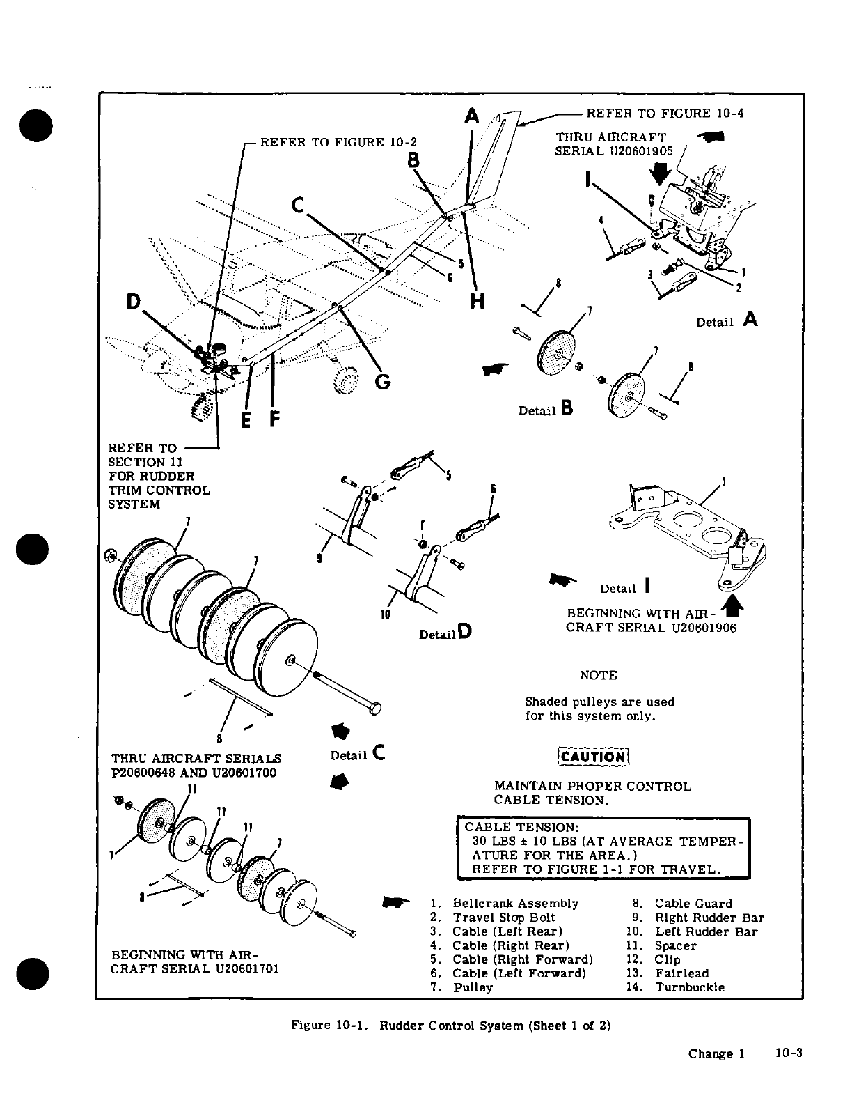
A
REFER
TO
FIGURE
10-4
REFER
TO
FIGURE
10-2
THRU
AIRCRAFT
SERIAL
U20601905
D
H
7
A
"'
.D/
7
^
;p :
Detail
A
REFER
TO
SECTION
11
FOR RUDDER
TRIM
CONTROL
SYSTEM.
*<-ll
DetailD
for
BEGINNING
WITH
AIR-
+
Detail4
CRAFT
SERIAL
U20601906
<s'^-l(~~ , ^
-NOTE
Shaded
pulleys are
used
for
this
system
only.
THRU
AIRCRAFT
SERIALS
Detail
C
BCAUTION
P20600648
AND
U20601700
M
])
w
MAINTAIN
PROPER
CONTROL
.":/
..
:
CABLE
TENSION.
if
I
CABLE
TENSION:
/7lU1
30
LBS
*
10
LBS
(AT
AVERAGE
TEMPER-
I7 1 4
.
^^ATURE
FOR
THE
AREA.)
."< (3~ '^ff^e 6REFER
TO
FIGURE
1-1
FOR
TRAVEL.
8"
^-
,'^
J
it/
9^f
1.
Bellcrank
Assembly
8.
Cable
Guard
2.
Travel
Stop
Bolt
9.
Right
Rudder
Bar
3.
Cable
(Left
Rear)
10.
Left
Rudder
Bar
4.
Cable
(Right
Rear)
11.
Spacer
BEGINNING
WITH
AIR-
5.
Cable
(Right
Forward)
12.
Clip
CRAFT
SERIAL
U20601701
6.
Cable
(Left
Forward)
13.
Fairlead
7.
Pulley
14.
Turnbuckle
Figure
10-1.
Rudder
Control
System
(Sheet
1
of
2)
Change
1
10-3
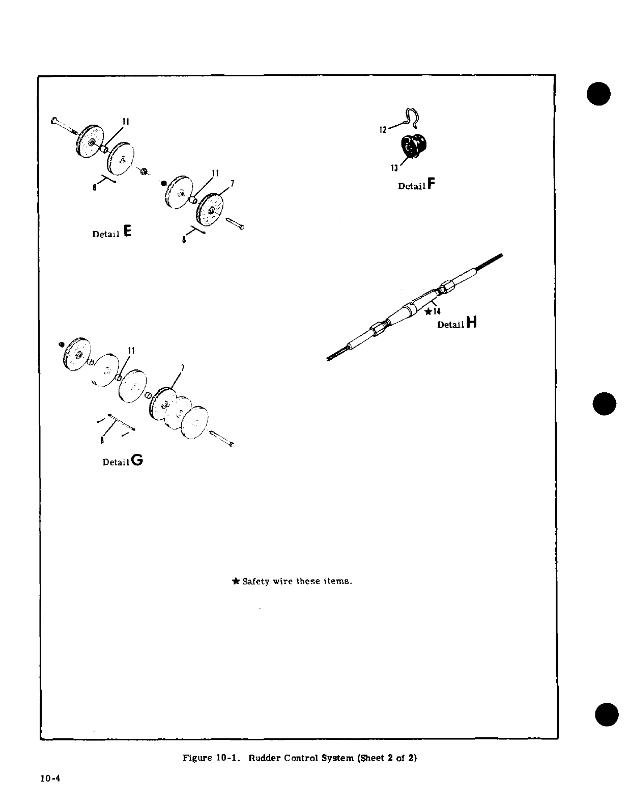
12
11
13
DetailF
Detail
E
Detail
H
DetailG
*
Safety
wire
these
items.
Figure
10-1.
Rudder
Control
System
(Sheet
2
of
2)
10-4
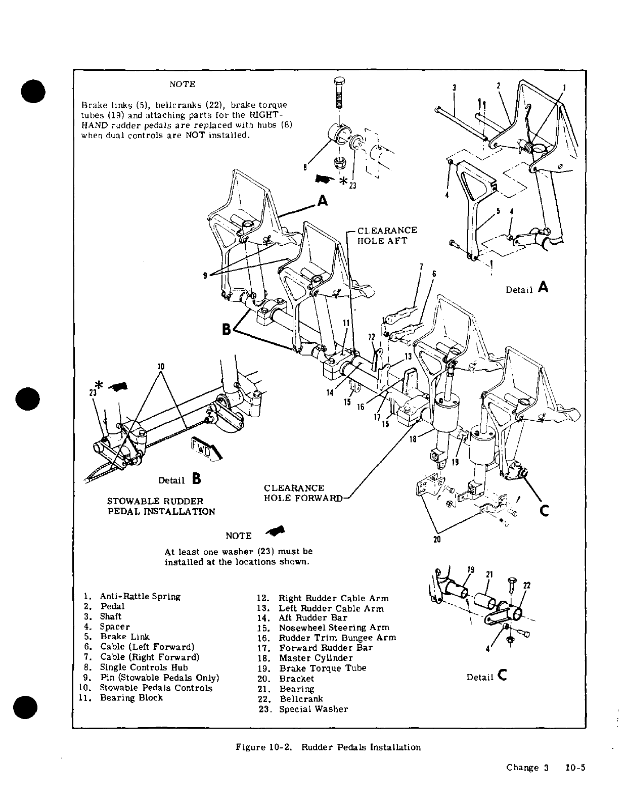
NOTE
Brake
links
(5),
bellcranks
(22),
brake torque
tubes
(19)
and
attaching
parts
for
the
RIGHT-
HAND
rudder
pedals
are
replaced
with
hubs
(8)
when
dual
controls
are
NOT
installed.
HOLE
AFT
Detail
A
STOWABLE RUDDER
HOLE
FORWARD
PEDAL
INSTALLATION
NOTE
At
least
one
washer
(23)
must
be
installed
at
the
locations
shown.
1.
Anti-Rattle
Spring
12.
Right
Rudder Cable Arm
2.
Pedal
13.
Left Rudder
Cable
Arm
3.
Shaft
14.
Aft
Rudder Bar
4.
Spacer
15.
Nosewheel
Steering
Arm
5.
Brake
Link
16.
Rudder
Trim
Bungee
Arm
6.
Cable
(Left
Forward)
17.
Forward
Rudder
Bar
7.
Cable
(Right
Forward)
18.
Master
Cylinder
8.
Single
Controls
Hub
19.
Brake
Torque
Tube
9.
Pin
(Stowable
Pedals
Only)
20.
Bracket
10.
Stowable
Pedals
Controls
21.
Bearing
11.
Bearing
Block
22.
Bellcrank
23.
Special
Washer
Figure
10-2.
Rudder
Pedals
Installation
Change
3
10-5
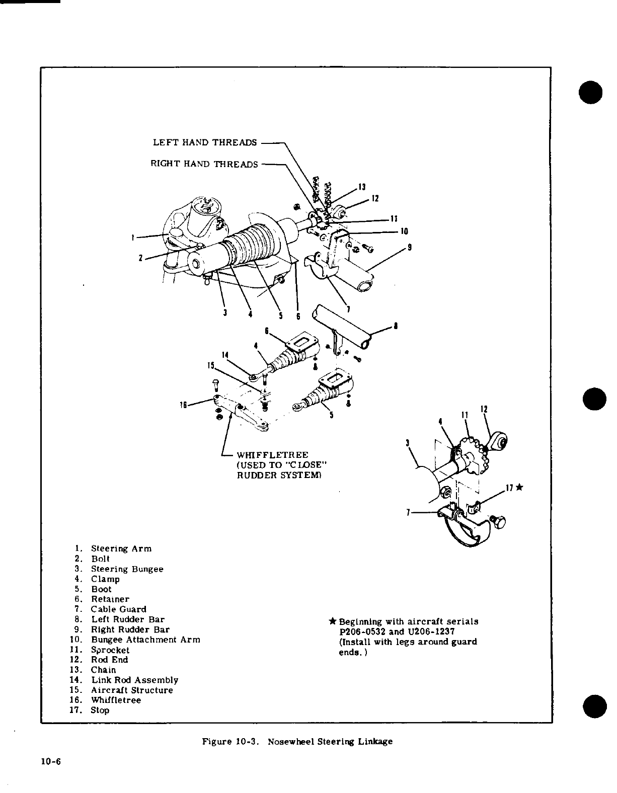
LEFT
HAND
THREADS
RIGHT
HAND
THREADS
12
4
(USED
TO
"CLOSE" \L l.5
;!W 1
II
'9'
1.
Steering
Arm
WHIFFLETREE
(USED
TO
"CLOSE'
RUDDER
SYSTEM)
.
Steering
Arm
2.
Bolt
3.
Steering
Bungee
4.
Clamp
5.
Boot
6.
Retainer
7.
Cable
Guard
8.
Left
Rudder
Bar
*
Beginning
with
aircraft serials
9.
Right
Rudder
Bar
P206-0532
and
U206-1237
10.
Bungee
Attachment
Arm
(Install
with
legs
around
guard
11.
Sprocket
ends.)
12.
Rod
End
13.
Chain
14.
Link
Rod
Assembly
15.
Aircraft Structure
16.
Whiffletree
17.
Stop
Figure
10-3.
Nosewheel
Steering
Linkage
10-6
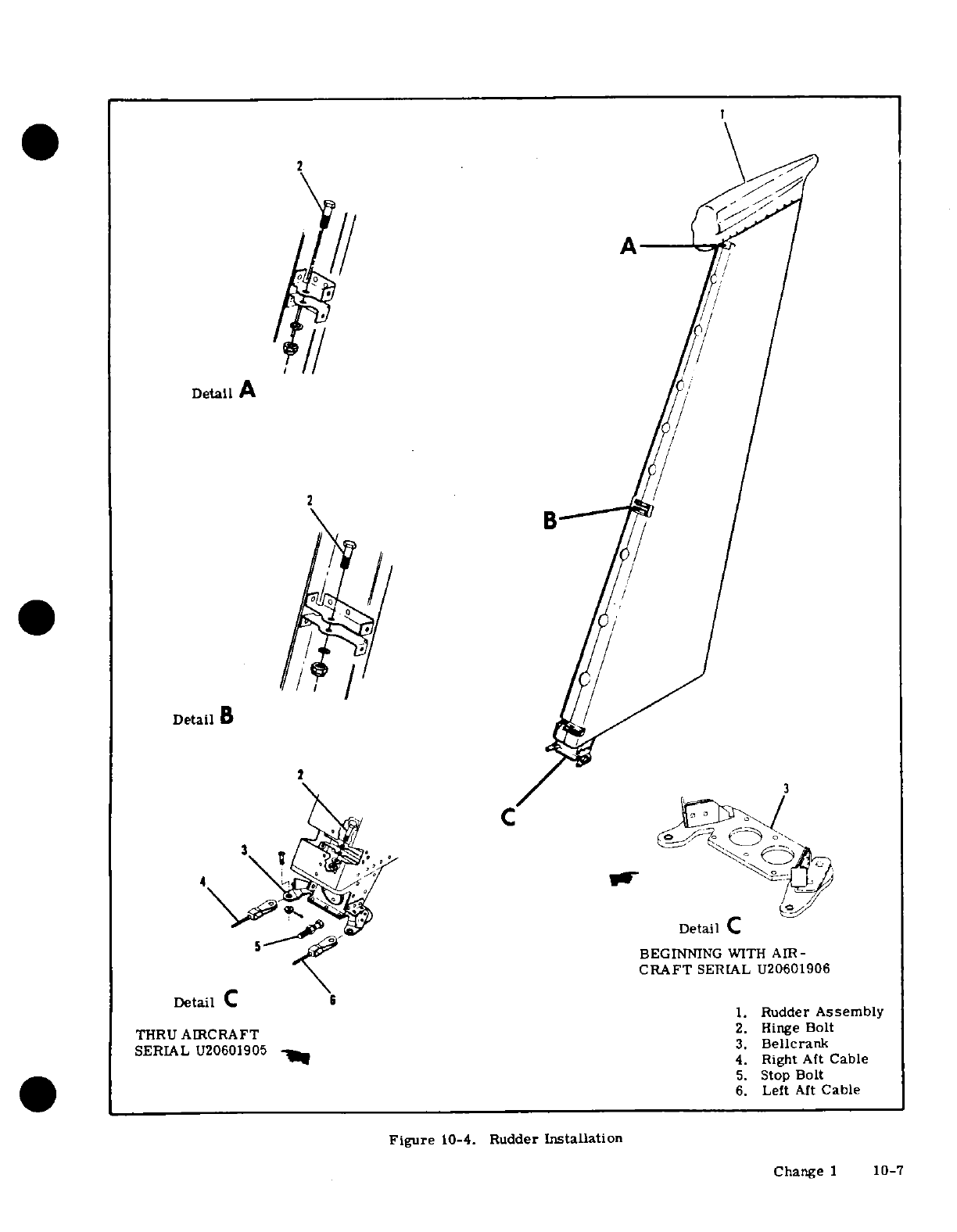
2
Detail
A
/
C
/
C
CRAFT
SERIAL
U20601906
Detail
C
6
1.
Rudder
Assembly
THRU
AIRCRAFT
2.
Hinge
Bolt
SERIAL
U20601905
3.
Bellcrank
4.
Right
Aft
Cable
5.
Stop
Bolt
6.
Left
Aft
Cable
Figure
10-4.
Rudder
Installation
Change
1
10-7
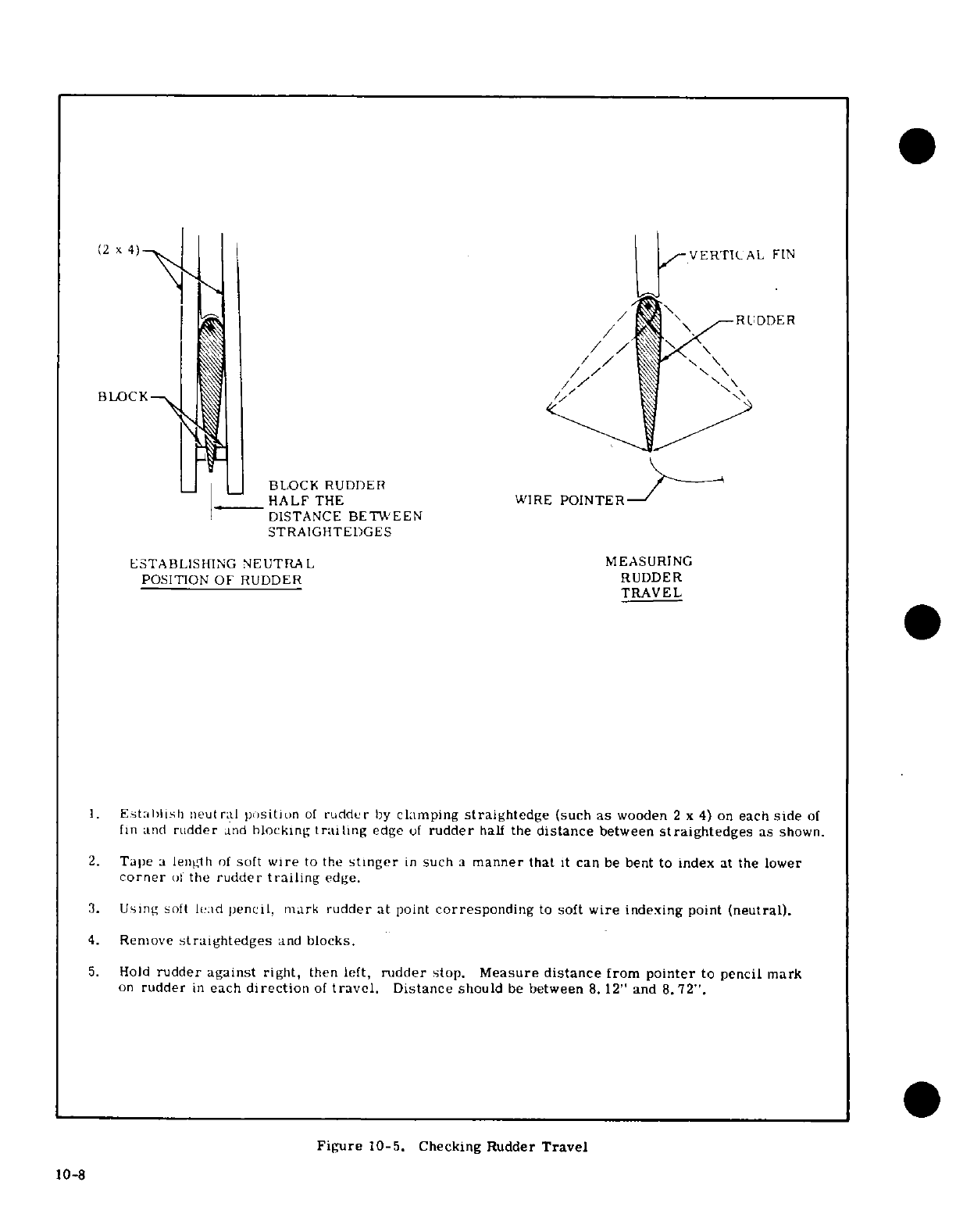
1.
Establish
neutral
position
of
rudder
by
clamping
straightedge
(such
as
wooden
2 x 4) on
each
side
of
fin and
rudder
and
blocking
trailing
edge
of
rudder
half
the
distance
between
straightedges
as
shown.
2.
Tape
a
length
of
soft
wire
to
the
stinger
in
such
a
manner
that
it
can
be
bent
to
index
at
the
lower
corner
of
the
rudder
trailing
edge.
3.
Using
soft
lead
pencil,
mark
rudder
at
point
corresponding
to
soft
wire
indexing
point
(neutral).
4.
Remove
straightedges
and
blocks.
5.
Hold
rudder
against
right,
then left,
rudder
stop.
Measure
distance
from
pointer
to
pencil mark
on
rudder
in
each
direction
of
travel.
Distance
should
be
between
8.
12"
and
8.72".
Figure
10-5.
Checking Rudder
Travel
10-8
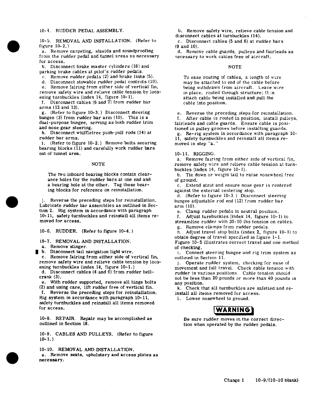
10-4. RUDDER
PEDAL
ASSEMBLY.
b.
Remove
safety
wire,
relieve
cable
tension
and
disconnect
cables at
turnbuckles
(14).
10-5.
REMOVAL
AND
INSTALLATION.
(Refer
to
c.
Disconnect
cables
(5
and
6)
at
rudder
bars
figure
10-2.)
(9
and
10).
a.
Remove
carpeting, shields
and
soundproofing
d.
Remove
cable
guards,
pulleys
and
fairleads
as
from
the
rudder
pedal
and tunnel
areas
as necessary necessary
to
work
cables
free
of
aircraft.
for
access.
b.
Disconnect
brake
master
cylinders
(18)
and
NOTE
parking
brake
cables
at
pilot's
rudder
pedals.
c.
Remove
rudder pedals
(2)
and
brake links
(5).
To
ease
routing
of
cables,
a
length
of
wire
d.
Disconnect
stowable
rudder
pedal
controls
(10).
may
be
attached
to
end
of
the
cable
before
e.
Remove
fairing
from
either
side
of
vertical
fin,
being
withdrawn
from
aircraft.
Leave
wire
remove safety
wire
and
relieve
cable
tension
by
loos-
in
place.
routed
through
structure;
then
ening
turnbuckles
(index
14,
figure
10-1).
attach
cable
being
installed
and pull
the
f.
Disconnect
cables
(6
and
7)
from
rudder
bar
cable
into
position.
arms
(12
and
13).
g.
(Refer
to
figure
10-3.) Disconnect
steering
e.
Reverse
the
preceding
steps
for
reinstallation.
bungee
(3)
from
rudder
bar
arm
(10).
This
is
a
f.
After
cable
is routed
in
position,
install
pulleys,
dual-purpose
bungee,
serving
as
both
rudder
trim
fairleads
and
cable
guards.
Ensure
cable
is
posi-
and
nose
gear
steering.
tioned
in
pulley
grooves
before
installing guards.
h.
Disconnect
whiffletree
push-pull
rods
(14)
at
g.
Re-rig
system
in
accordance
with
paragraph
10-
rudder
bar
arms.
11,
safety turnbuckles
and
reinstall
all
items
re-
i.
(Refer
to
figure
10-2.)
Remove
bolts
securing
moved in
step
"a."
bearing
blocks
(11)
and
carefully
work
rudder
bars
out
of
tunnel
area.
10-11.
RIGGING.
a.
Remove
fairing
from
either
side
of
vertical
fin,
NOTE
remove
safety
wire
and
relieve
cable
tension
at
turn-
buckles
(index
14,
figure
10-1).
The
two
inboard
bearing
blocks
contain
clear-
b.
Tie
down
or
weight
tail
to
raise
nosewheel
free
ance
holes
for
the
rudder
bars
at
one end
and
of
ground.
a
bearing
hole
at
the
other.
Tag
these
bear-
c.
Extend
strut
and
ensure
nose
gear
is
centered
ing
blocks
for
reference
on
reinstallation.
against
the
external
centering
stop.
d.
(Refer
to
figure
10-3.
)
Disconnect
steering
j.
Reverse
the
preceding
steps for
reinstallation.
bungee
adjustable
rod
end
(12)
from
rudder
bar
Lubricate
rudder
bar
assemblies
as
outlined
in
Sec-
arm
(10).
tion
2.
Rig
system
in
accordance
with
paragraph
e.
Clamp
rudder
pedals
in
neutral
position.
10-11,
safety
turnbuckles
and
reinstall
all
items
re-
f.
Adjust
turnbuckles
(index
14,
figure
10-1)
to
moved
for
access.
streamline
rudder
with
30±10
Ibs
tension
on
cables.
g.
Remove
clamps
from
rudder
pedals.
10-6.
RUDDER.
(Refer
to
figure
10-4.)
h.
Adjust
travel
stop
bolts
(index
2,
figure
10-1)
to
obtain
degree
of
travel
specified
in
figure
1-1.
10-7.
REMOVAL
AND
INSTALLATION.
Figure
10-5
illustrates
correct
travel
and
one
method
a.
Remove
stinger.
of
checking.
b.
Disconnect
tail
navigation
light
wire.
i.
Connect
steering
bungee
and
rig
trim
system
as
c.
Remove
fairing
from
either
side
of
vertical
fin,
outlined
in
Section
11.
remove
safety wire
and
relieve
cable
tension
by
loos-
j.
Operate
rudder
system,
checking
for
ease
of
ening
turnbuckles
(index
14,
figure
10-1.)
movement
and full
travel.
Check
cable
tension
with
d.
Disconnect
cables
(4
and
6)
from
rudder
bell- rudder
in
various
positions.
Cable
tension
should
crank
(3).
not be
less
than
20
pounds
or
more
than
40
pounds
in
e. With
rudder
supported,
remove
all
hinge
bolts
any
position.
(2)
and
using
care,
lift
rudder
free
of
vertical
fin.
k.
Check
that
all
turnbuckles
are
safetied
and
re-
f.
Reverse
the
preceding
steps
for
reinstallation.
install all
items
removed
for
access.
Rig
system
in
accordance
with
paragraph
10-11,
1.
Lower
nosewheel
to
ground.
safety
turnbuckles
and
reinstall
all
items
removed
for
access.
WARNING
10-8.
REPAIR.
Repair
maybe
accomplished
as
Be
sure
rudder
moves
in
the
correct
direc-
outlined
in
Section
18.
tion
when
operated
by
the
rudder pedals.
10-9.
CABLES
AND
PULLEYS.
(Refer
to
figure
10-1.)
10-10.
REMOVAL
AND
INSTALLATION.
a.
Remove
seats,
upholstery
and
access
plates
as
necessary.
Change
1
10-9/(10-10
blank)
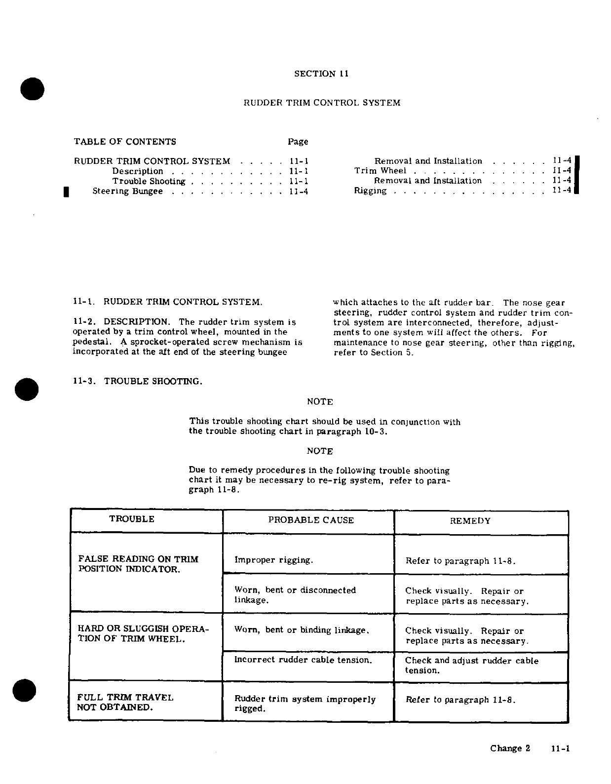
SECTION
11
RUDDER TRIM
CONTROL
SYSTEM
TABLE OF
CONTENTS
Page
RUDDER TRIM
CONTROL
SYSTEM
.....
11-1
Removal and
Installation
. ... .
11-4
Description
... . ... . .. . .
11-1
Trim
Wheel
. ..
....
.. .. .. . .
11-4
Trouble
Shooting
..........
11-1
Removal and
Installation
......
11-4
|
Steering
Bungee
.. ... . .
....
11-4
Rigging
.. .
...........
11-41
11-1.
RUDDER
TRIM
CONTROL
SYSTEM.
which
attaches
to
the
aft
rudder
bar.
The
nose
gear
steering,
rudder
control
system
and
rudder
trim
con-
11-2. DESCRIPTION.
The
rudder
trim
system
is
trol
system
are
interconnected,
therefore,
adjust-
operated
by
a
trim
control
wheel,
mounted
in
the
ments
to
one
system
will
affect the
others.
For
pedestal.
A
sprocket-operated
screw
mechanism
is
maintenance
to
nose
gear
steering, other
than
rigging,
incorporated
at
the
aft
end
of
the
steering
bungee
refer
to
Section
5.
11-3.
TROUBLE
SHOOTING.
NOTE
This
trouble
shooting
chart
should
be
used
in
conjunction
with
the
trouble
shooting
chart
in
paragraph
10-3.
NOTE
Due
to
remedy
procedures
in
the
following
trouble
shooting
chart
it
may
be
necessary
to
re-rig
system,
refer
to
para-
graph
11-8.
TROUBLE
PROBABLE
CAUSE
REMEDY
FALSE
READING
ON
TRIM
Improper
rigging.
Refer
to
paragraph
11-8.
POSITION
INDICATOR.
Worn,
bent
or
disconnected
Check
visually.
Repair
or
linkage.
replace
parts
as
necessary.
HARD
OR
SLUGGISH
OPERA-
Worn,
bent
or
binding
linkage.
Check
visually.
Repair
or
TION
OF
TRIM
WHEEL.
replace
parts
as
necessary.
Incorrect rudder
cable
tension.
Check
and
adjust
rudder
cable
tension.
FULL
TRIM
TRAVEL
Rudder
trim
system
improperly
Refer
to
paragraph
11-8.
NOT
OBTAINED.
rigged.
Change
2 11-1
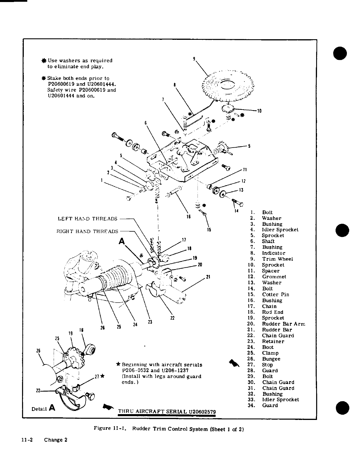
*
Use
washers
as
required
to
eliminate
end
play.
#
Stake
both
ends
prior
to
P20600619
and
U20601444.
Safety
wire
P20600619
and
U20601444
and
on.
1.
Bolt
2.
Washer
3.
Bushing
4.
Idler
Sprocket
5.
Sprocket
6.
Shaft
7.
Bushing
8.
Indicator
9.
Trim
Wheel
10.
Sprocket
11.
Spacer
12.
Grommet
13.
Washer
14.
Bolt
15.
Cotter
Pin
16.
Bushing
17.
Chain
18.
Rod
End
19.
Sprocket
20.
Rudder
Bar
Arm
21.
Rudder
Bar
22.
Chain
Guard
23.
Retainer
24.
Boot
25.
Clamp
26.
Bungee
*
Beginning
with
aircraft serials
27.
Stop
206-0532 and
U206-1237
28.
Guard
(Install
with
legs
around
guard
29.
Bolt
ends.)
30.
Chain
Guard
31.
Chain
Guard
32.
Bushing
33.
Idler
Sprocket
34.
Guard
THRU
AIRCRAFT
SERIAL
U20602579
Figure
11-1.
Rudder
Trim
Control
System
(Sheet
1
of
2)
11-2
Change
2
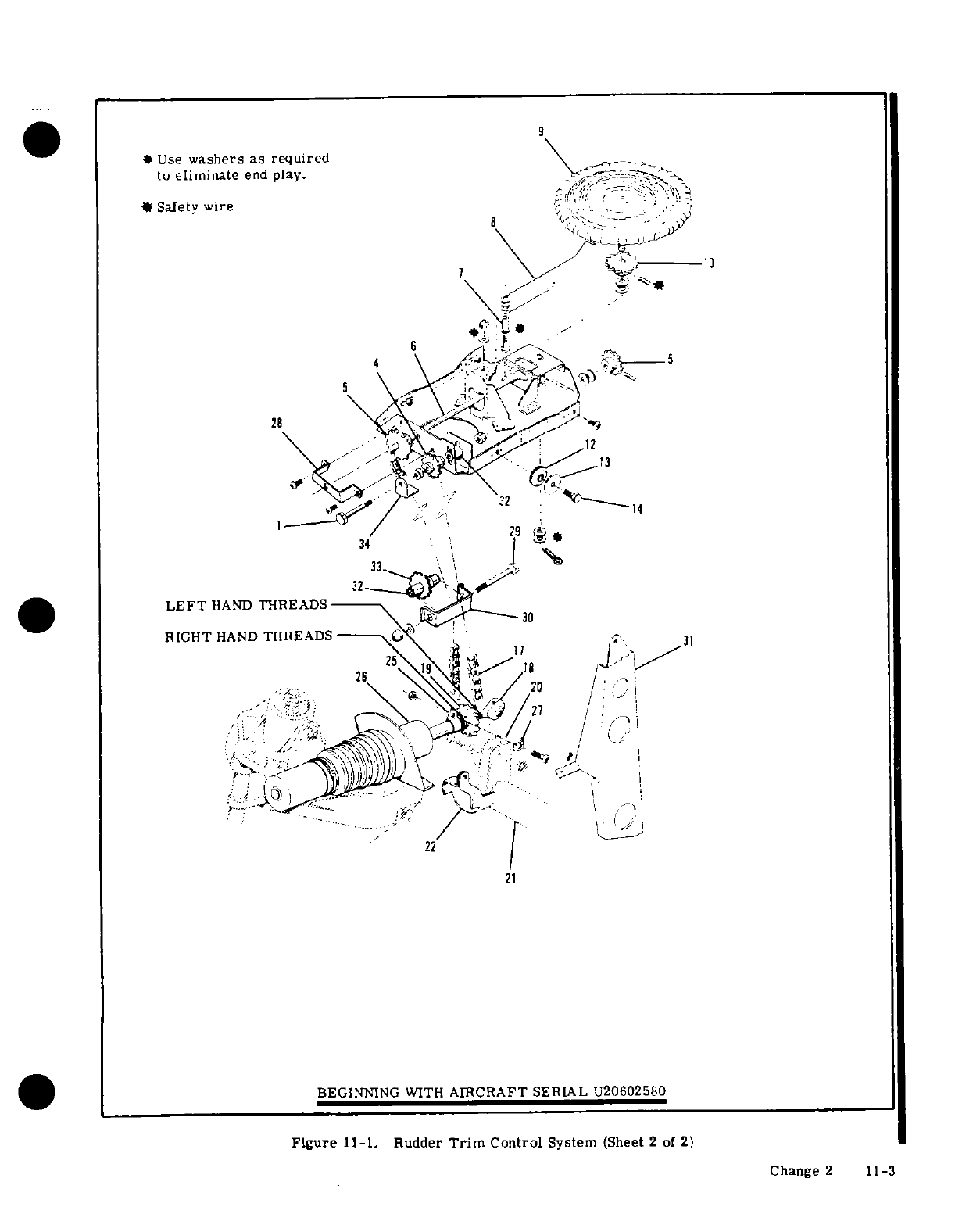
*
Use
washers as
required
to
eliminate
end
play.
-.
*
Safety
wire
8 q '_
-0
.
S
,
28
LEFT
HAND
THREADS
RIGHT
HAND
THREADS
31
'
-*
21
BEGINNING
WITH
AIRCRAFT SERIAL
U20602580
Figure
11-1.
Rudder
Trim
Control
System
(Sheet
2
of
2)
Change
2
11-3
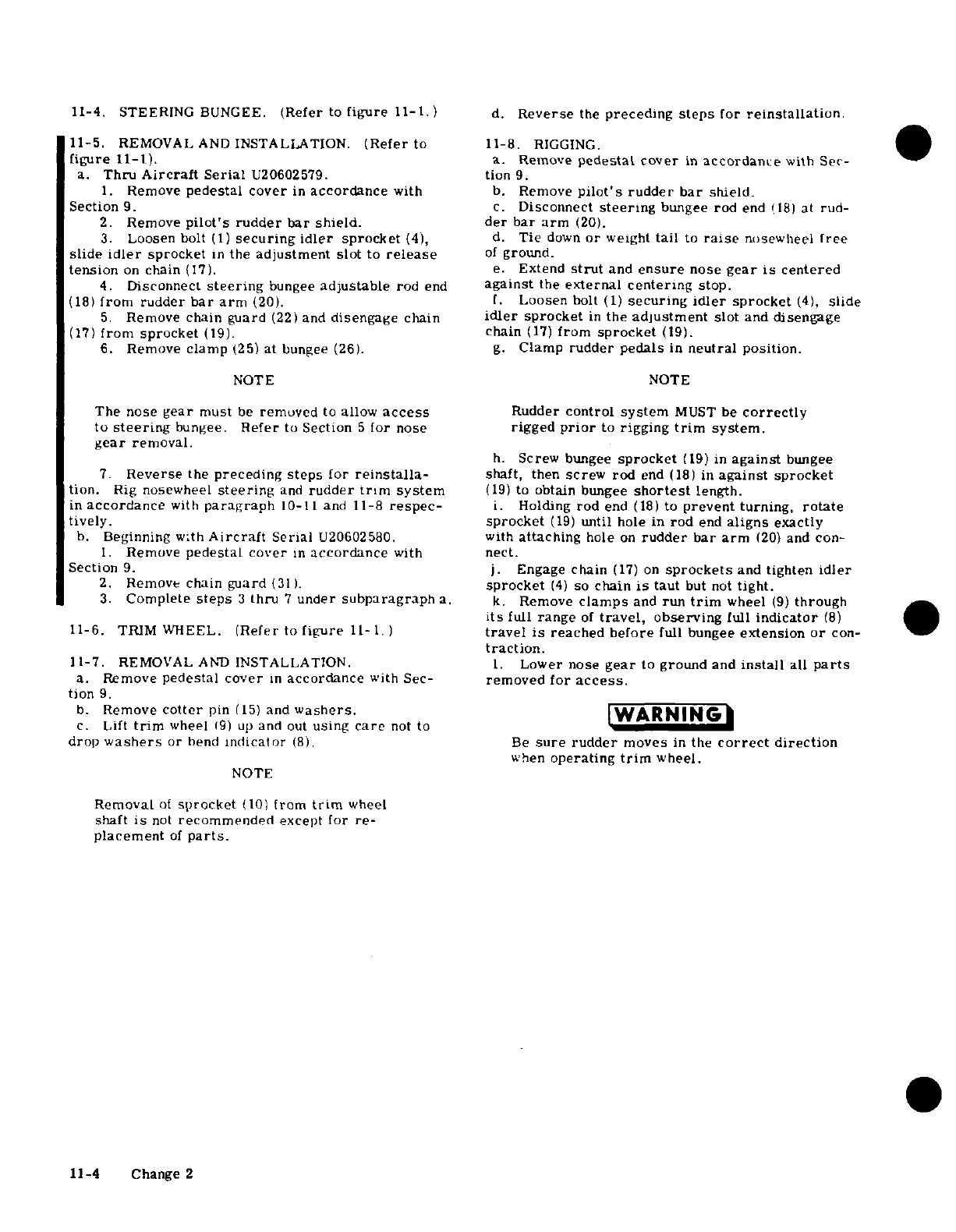
11-4.
STEERING
BUNGEE.
(Refer
to
figure
11-1.)
d.
Reverse
the
preceding
steps
for
reinstallation.
11-5.
REMOVAL
AND
INSTALLATION.
(Refer
to
11-8.
RIGGING.
figure
11-1).
a.
Remove
pedestal
cover
in
accordance
with
Sec-
a.
Thru
Aircraft
Serial
U20602579.
tion
9.
1.
Remove
pedestal
cover
in
accordance
with
b.
Remove
pilot's
rudder
bar
shield.
Section
9.
c.
Disconnect
steering
bungee
rod
end
(18)
at
rud-
2.
Remove
pilot's
rudder
bar
shield.
der
bar
arm
(20).
3.
Loosen
bolt
(1)
securing
idler
sprocket
(4), d.
Tie
down
or
weight
tail
to
raise
nosewheel
free
slide
idler
sprocket
in
the
adjustment
slot
to
release
of
ground.
tension
on
chain
(17).
e.
Extend
strut
and
ensure
nose
gear
is
centered
4.
Disconnect
steering
bungee
adjustable
rod
end
against
the
external centering
stop.
(18)
from
rudder
bar
arm
(20).
f.
Loosen
bolt
(1)
securing
idler
sprocket
(4),
slide
5.
Remove
chain
guard
(22)
and
disengage
chain
idler
sprocket
in
the
adjustment
slot
and
disengage
(17)
from
sprocket
(19).
chain
(17)
from
sprocket
(19).
6.
Remove
clamp
(25)
at bungee
(26).
g.
Clamp
rudder
pedals
in
neutral
position.
NOTE
NOTE
The
nose
gear
must
be
removed
to
allow
access
Rudder
control
system
MUST
be
correctly
to
steering
bungee.
Refer
to
Section
5
for
nose
rigged
prior
to
rigging
trim
system.
gear
removal.
h.
Screw
bungee
sprocket
(19)
in
against
bungee
7.
Reverse
the
preceding
steps
for
reinstalla-
shaft,
then
screw
rod
end
(18)
in
against
sprocket
tion.
Rig
nosewheel
steering
and
rudder
trim
system
(19)
to
obtain bungee
shortest
length.
in
accordance
with
paragraph
10-11
and
11-8
respec-
i.
Holding
rod
end
(18)
to
prevent
turning,
rotate
tively.
sprocket
(19)
until
hole in
rod
end
aligns
exactly
b.
Beginning
with
Aircraft
Serial
U20602580.
with
attaching
hole
on
rudder
bar
arm
(20)
and
con-
1.
Remove
pedestal
cover
in
accordance
with
nect.
Section
9.
j.
Engage
chain
(17)
on
sprockets
and
tighten
idler
2.
Remove
chain
guard
(31).
sprocket
(4)
so
chain
is
taut
but
not
tight.
3.
Complete
steps
3
thru
7
under
subparagraph
a.
k.
Remove
clamps
and
run
trim
wheel
(9)
through
its
full
range
of
travel,
observing
full
indicator
(8)
11-6.
TRIM WHEEL.
(Refer
to
figure
11-
1.)
travel
is
reached before
full
bungee
extension
or
con-
traction.
11-7.
REMOVAL
AND
INSTALLATION.
1.
Lower nose
gear
to
ground
and
install
all
parts
a.
Remove
pedestal cover
in
accordance
with
Sec-
removed
for
access.
tion
9.
b.
Remove
cotter
pin
(15)
and
washers.
WARNING
c.
Lift
trim
wheel
19)
up
and
out
using
care
not
to
drop
washers
or
bend
indicator
(8).
Be
sure
rudder
moves
in
the
correct
direction
when
operating
trim
wheel.
NOTE
Removal
of
sprocket
(10)
from
trim
wheel
shaft
is
not
recommended
except
for
re-
placement
of
parts.
11-4
Change
2
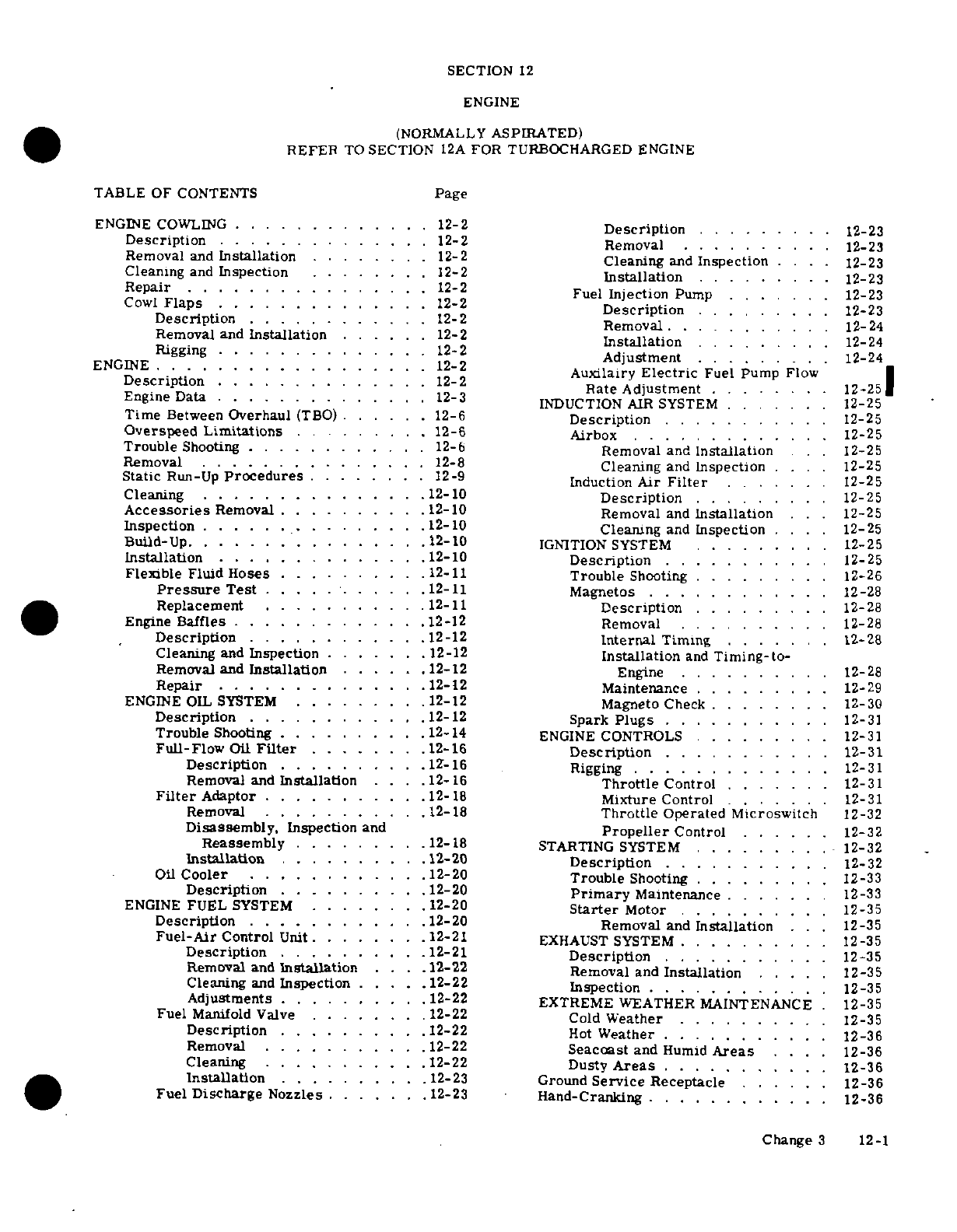
SECTION
12
ENGINE
(NORMALLY
ASPIRATED)
REFER
TO
SECTION
12A
FOR
TURBOCHARGED
ENGINE
TABLE
OF
CONTENTS
Page
ENGINE
COWLING .............
12-2
Description
.........
12-23
Description
.. . .. . . 12-2
Removal
12-23
Removal
and
Installation
.. .
12-2
Cleaning
and
Inspection
.....
12-23
Cleaning
and
Inspection
12-2
Installation
......
.
.
12-23
Repair
...
.............
. 12-2
Fuel
Injection
Pump
.......
12-23
Cowl
Flaps.
......
12-2
Description.
..
.....
. 12-23
Description
.
12-2
Removal
.
12-23
Removal and
Installation
.
12-2
Installation
..
12-24
Rigging
.............. 12-2
Adjustment.
....
12-24
ENGINE
. . . .. .. ..
12-2 Auxiliary
Electric
Fuel
Pump
12-24
Description
12-2
Rate
Adjustment
.. .
12-25
Engine
Data
...
12-3
INDUCTION
AIR
SYSTEM
....
12-25
Time
Between
Overhaul
(TBO)
.. 12-6
Description
....
12-25
Overspeed
Limitations
.
....
12-6
Airbox
12-25
Trouble
Shooting
.............
12-6
Removal
and
Installation
..
12-25
Removal
...............
12-8
Cleaning
and
Inspection
..
12-25
Static
Run-Up
Procedures
....
12-9
Induction
Air
Filter
...
12-25
Cleaning
......
.
12-10
Description
.....
12-25
Accessories
Removal .
.......
12-10
Removal
and
Installation
..
12-25
Inspection
...............
12-10
Cleaning
and
Inspection
....
12-25
Build-Up
.
.............
.12-10
IGNITION
SYSTEM
..
....
.
12-25
Installation
..............
12-10
Description
......
12-25
Flexible
Fluid Hoses
.........
12-11
Trouble
Shooting
..12-26
Pressure
Test
..........
12-11
Magnetos
.
......
..12-28
Replacement
.
..........
12-11
Description
...
......
12-28
Engine
Baffles
.
..........
12-12
Removal ...
......
12-28
Description
..........
12-12
Internal
Timing
......
12-28
Cleaning
and
Inspection
..
12-12
Installation
and
Timing-to-
Removal
and
Installation
.12-12
Engine
.....
12-28
Repair
.
...........
12-12
Maintenance
..... ....
12-29
ENGINE
OIL
SYSTEM
.........
12-12
Magneto
Check
........
12-30
Description
............
12-12 Spark
Plugs
......
12-31
Trouble
Shooting
........
.
12-14
ENGINE
CONTROLS
.......
12-31
Full-Flow
Oil
Filter
.......
12-16
Description
.
.....
.12-31
Description
.........
.
12-16
Rigging .. ....
12-31
Removal and
Installation
.12-16
Throttle
Control
.......
12-31
Filter
Adaptor
..........
.
12-18
Mixture
Control
.
....
12-31
Removal
......
..
12-18
Throttle
Operated
Microswitch
12-32
Disassembly,
Inspection
and
Propeller
Control
..
12-32
Reassembly
........
12-18
STARTING
SYSTEM
.. .
12-32
Installation
.........
12-20
Description
.
.....
12-32
Oil
Cooler
..
....
.
12-20
Trouble
Shooting .. .
12-33
Description
..........
12-20
Primary
Maintenance
..
12-33
ENGINE
FUEL
SYSTEM
.....
. 12-20
Starter
Motor
.
.
12-35
Description
.....
..
12-20
Removal
and
Installation
.
12-35
Fuel-Air
Control
Unit
......
12-21
EXHAUST
SYSTEM
.
12-35
Description
........
12-21
Description
.
.......
12-35
Removal
and
Installation
12-22
Removal
and
Installation
..
12-35
Cleaning
and
Inspection
12-22
Inspection
...
........
12-35
Adjustments
...........
12-22
EXTREME
WEATHER
MAINTENANCE
12-35
Fuel
Manifold
Valve
.......
12-22 Cold
Weather
.
12-35
Description
.......
.
12-22
Hot
Weather
.........
12-36
Removal
..........
12-22
Seacoast
and
Humid
Areas
....
12-36
Cleaning
.........
12-22
Dusty
Areas
.........
12-36
Installation
.
.........
12-23
Ground
Service
Receptacle
..
12-36
Fuel
Discharge
Nozzles
.
....
12-23
Hand-Cranking
..
........
12-36
Change
3
12-1
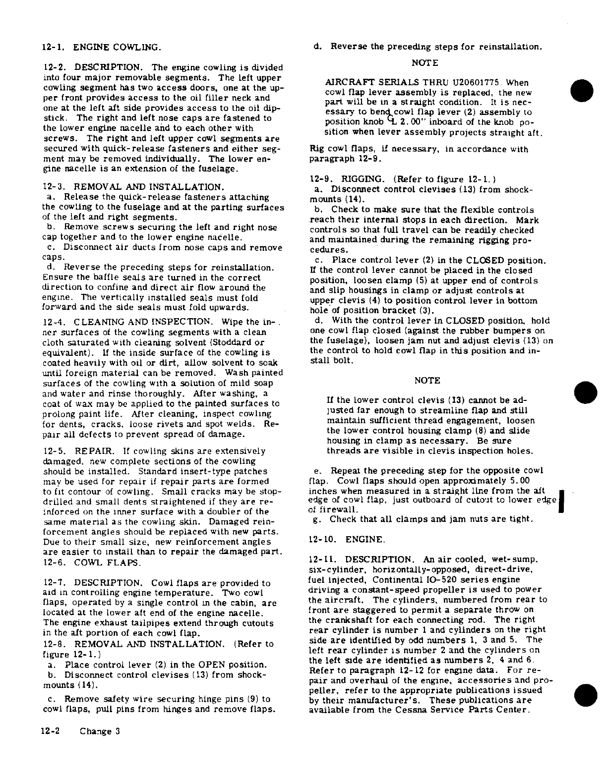
12-1.
ENGINE
COWLING.
d.
Reverse
the
preceding
steps
for
reinstallation.
12-2.
DESCRIPTION.
The
engine
cowling
is
divided
NOTE
into
four
major
removable
segments.
The
left
upper
AIRCRAFT
SERIALS
THRU
U20601775
When
cowling
segment
has
two
access
doors,
one
at
the
up- cowl
flap
lever
assembly is replaced,
the
new
per
front
provides
access
to
the
oil
filler
neck
and
part
will
be
a
straight
condition.
It
is
nec-
one
at
the
left
aft side
provides
access
to
the oil
dip-
essary
to
bendcowl
flap
lever
(2)
assembly
to
stick.
The
right
and
left
nose
caps
are
fastened
to
position
knob
L
2.00"
inboard
of
the
knob
po-
the
lower
engine
nacelle
and
to
each
other
with
sition
when
lever assembly
projects straight
aft.
screws.
The
right
and
left
upper
cowl
segments
are
secured
with
quick-release
fasteners
and
either
seg-
Rig
cowl
flaps,
if
necessary,
in
accordance
with
ment
may
be
removed
individually.
The
lower
en-
paragraph
12-9.
gine
nacelle
is
an
extension
of
the
fuselage.
12-9.
RIGGING.
(Refer
to
figure
12-1.)
12-3.
REMOVAL
AND
INSTALLATION.
a.
Disconnect
control
cevises
(13)
from
shock-
a.
Release
the
quick-release fasteners
attaching
mounts
(14).
the
cowling to
the
fuselage
and
at
the
parting
surfaces
b.
Check
to
make
sure
that the
flexible controls
of
the
left
and
right
segments. reach
their
internal
stops
in
each
direction.
Mark
b.
Remove
screws
securing
the
left
and
right
nose
controls
so
that
full
travel
can
be
readily
checked
cap
together
and
to
the
lower
engine
nacelle.
and
maintained
during
the
remaining
rigging
pro-
c.
Disconnect
air
ducts from
nose
caps
and
remove
cedures.
caps.
c.
Place control
lever
(2)
in
the
CLOSED
position.
d.
Reverse
the
preceding
steps
for
reinstallation.
If
the
control
lever
cannot
be
placed
in
the
closed
Ensure
the
baffle
seals
are
turned
in
the
correct
position,
loosen
clamp
(5)
at
upper
end
of
controls
direction
to
confine and
direct
air
flow
around
the
and
slip housings
in
clamp
or
adjust
controls
at
engine.
The
vertically
installed
seals
must
fold
upper
clevis
(4)
to
position
control
lever
in
bottom
forward
and
the side
seals
must
fold
upwards.
hole
of
position
bracket
(3).
12-4.
CLEANING
AND
INSPECTION.
Wipe
the
in-
d.
With
the
control
lever
in
CLOSED
position,
hold
ner
surfaces
of
the cowling
segments
with
a
clean
one
cowl
flap
closed
(against
the
rubber
bumpers
on
cloth
saturated
with
cleaning solvent
(Stoddard
or
the
fuselage), loosen
jam
nut
and
adjust
clevis
(13)
on
equivalent).
If
the
inside
surface
of
the
cowling
is
the
control
to
hold
cowl
fap
in
this
position
and in-
coated
heavily
with
oil or
dirt,
allow
solvent
to soak
stall
bolt.
until
foreign
material
can
be
removed.
Wash
painted
surfaces
of
the
cowling with
a
solution
of
mild
soapNOTE
and
water
and
rinse
thoroughly. After
washing,
a
If
the
lower
control
clevis
(13)
cannot
be
ad- I
coat
of
wax
may
be
applied
to
the painted
surfaces
to
te
er
ontrol
es
(1)
canno
b
ad
lusted
far
enough
to
streamline
flap
and
still
prolong
paint
life. After
cleaning,
inspect
cowling
f i
i
for
dents,
cracks,
loose
rivets
and
spot
welds.
Re-
maintain
sufficient
thread
engagement,
loosen
the
lower
control
housing
clamp
(8)
and
slide
pair
all
defects
to
prevent
spread
of
damage.
housing
in
clamp
as
nec
a
e
housing
in
clamp
as
necessary.
Be
sure
12-5.
REPAIR.
If
cowling
skins
are
extensively
threads
are
visible
in
clevis
inspection holes.
damaged,
new
complete
sections
of
the cowling
should
be
installed.
Standard
insert-type
patches
e.
Repeat
the
preceding
step
for
the
opposite
cowl
may
be
used
for
repair
if
repair
parts
are
formed
flap.
Cowl
flaps
should
open
approximately
5.00
to
fit
contour
of
cowling.
Small
cracks
may
be
stop-
inches
when
measured
in
a
straight
line
from
the
aft *
drilled
and
small
dents
straightened
if
they
are
re-
edge
of
cowl
flap,
just
outboard
of
cutout
to
lower
edge
inforced
on
the
inner
surface
with
a
doubler
of
the
of
firewall.
same
material
as
the
cowling
skin.
Damaged
rein-
g.
Check
that
all
clamps
and
jam
nuts
are
tight.
forcement
angles
should
be
replaced
with
new
parts.
Due
to
their
small size,
new
reinforcement
angles
12-10.
ENGINE.
are
easier
to
install
than
to
repair
the
damaged
part.
12-6.
COWL
FLAPS.
12-11. DESCRIPTION.
An
air
cooled,
wet-sump.
six-cylinder,
horizontally-opposed,
direct-drive,
12-7.
DESCRIPTION.
Cowl
flaps
are
provided to
fuel
injected,
Continental
10-520
series
engine
aid
in
controlling
engine
temperature.
Two
cowl
driving
a
constant-speed
propeller
is
used
to
power
flaps,
operated
by
a
single
control
in
the cabin,
are
the
aircraft.
The
cylinders
numbered
from
rear
to
located
at
the
lower
aft
end
of
the
engine
nacelle. front
are
staggered
to
permit
a
separate
throw
on
The
engine
exhaust
tailpipes
extend
through cutouts
the
crankshaft for
each
connectig
rod.
The
right
in
the
aft
portion
of
each
cowl
flap.
rear
cylinder
is
number
1
and
cylinders
on
the
right
12-8.
REMOVAL
AND
INSTALLATION.
(Refer
to
side
are
identified
by
odd
numbers
1,
3
and
5.
The
left
rear
cylinder
is
number
2
and
the
cylinders
on
f[aigure
12-1coto.)
(2)
in
th PE
oito.the
left
side
are
identified
as
numbers
2, 4
and
6.
a.
Place
control
lever
(2)
in
the
OPEN
position.paragraph
12-12
for
engine
data.
For
re-
b.
Disconnect
control
devises
(13)
from
shock-
b.
Disconnect control
clevises
(13)
from
shock
pair
and
overhaul
of
the
engine,
accessories
and
pro-
mounts
(14).
peller,
refer
to
the
appropriate
publications
issued
c.
Remove
safety
wire
securing
hinge
pins
(9)
to
by
their manufacturer's.
These publications
are
cowl
flaps,
pull
pins
from
hinges
and
remove
flaps.
available
from
the
Cessna
Service
Parts
Center.
12-2
Change 3
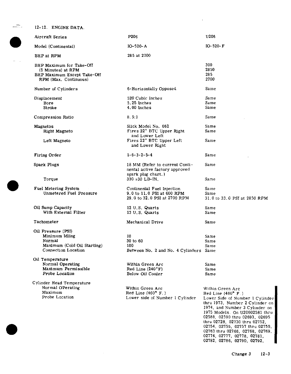
12-12.
ENGINE
DATA.
Aircraft
Series
P206
U206
Model
(Continental)
10-520-A
IO-520-F
BHP
at
RPM
285
at
2700
BHP
Maximum
for
Take-Off
300
(5
Minutes)
at
RPM
2850
BHP
Maximum
Except
Take-Off
285
RPM (Max.
Continuous)
2700
Number
of
Cylinders 6-Horizontally
Opposed
Same
Displacement
520
Cubic
Inches
Same
Bore
5.25
Inches
Same
Stroke
4.00
Inches
Same
Compression
Ratio
8.5:1
Same
Magnetos
Slick
Model
No.
662
Same
Right Magneto
Fires
22
°
BTC
Upper Right
Same
and
Lower
Left
Left
Magneto
Fires
22
°
BTC
Upper
Left
Same
and
Lower
Right
Firing Order
1-6-3-2-5-4
Same
Spark
Plugs
18
MM
(Refer
to
current
Conti-
Same
nental
active
factory
approved
spark
plug
chart.
)
Torque
330
230
LB-IN.
Same
Fuel
Metering
System
Continental
Fuel Injection
Same
Unmetered
Fuel
Pressure
9.
0
to
11.0
PSI
at
600
RPM
Same
29.0
to
32.0
PSI
at
2700
RPM
31.0
to
33.0
PSI
at
2850
RPM
Oil
Sump
Capacity
12
U.S.
Quarts
Same
With
External
Filter
13
U.S.
Quarts
Same
Tachometer
Mechanical
Drive
Same
Oil
Pressure
(PSI)
Minimum
Idling
10
Same
Normal
30
to
60
Same
Maximum
(Cold
Oil
Starting)
100
Same
Connection Location
Between
No.
2
and
No.
4
Cylinders
Same
Oil
Temperature
Normal Operating
Within
Green
Arc
Same
Maximum
Permissible
Red
Line
(240°F)
Same
Probe
Location
Below
Oil
Cooler
Same
Cylinder
Head
Temperature
Normal
Operating
Within
Green
Arc
Within
Green
Arc
Maximum
Red
Line
(460"
F.
)
Red Line
(460°
F.
)
Probe
Location
Lower
side
of
Number
1
Cylinder
Lower
Side
of
Number
I
Cylinder
thru
1973,
Number
2
Cylinder
on
1974,
and
Number
3
Cylinder
on
1975
Models.
On
U20602581
thru
02588,
02590
thru
02693.
02695
thru
02728, 02730
thru
02752,
02754,
02755,
02757
thru
02759.
02763
thru
02766,
02768, 02769,
02774,
02777, 02778,
02781,
02782,
02786,
02790,
02792,
Change
3
12-3
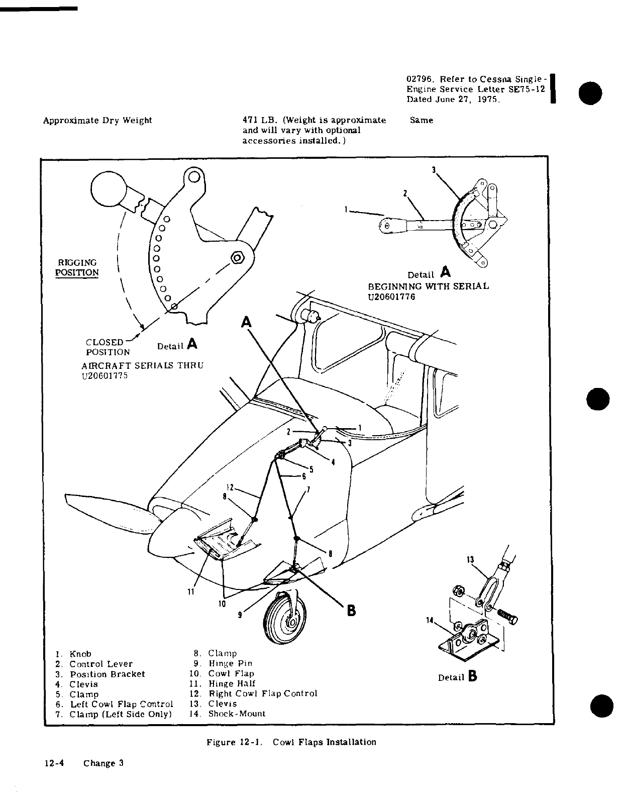
1.
Knob
8.
Clamp
2.
Control
Lever
9.
Hinge
Pin
3.
Position
Bracket
10.
Cowl
Flap
4.
Clevis
11.
Hinge
Half
5.
Clamp
12.
Right
Cowl
Flap
Control
6.
Left
Cowl
Flap
Control
13.
Clevis
7.
Clamp
(Left
Side
Only)
14.
Shock-Mount
Figure
12-1.
Cowl
Flaps
Installation
12-4
Change
3
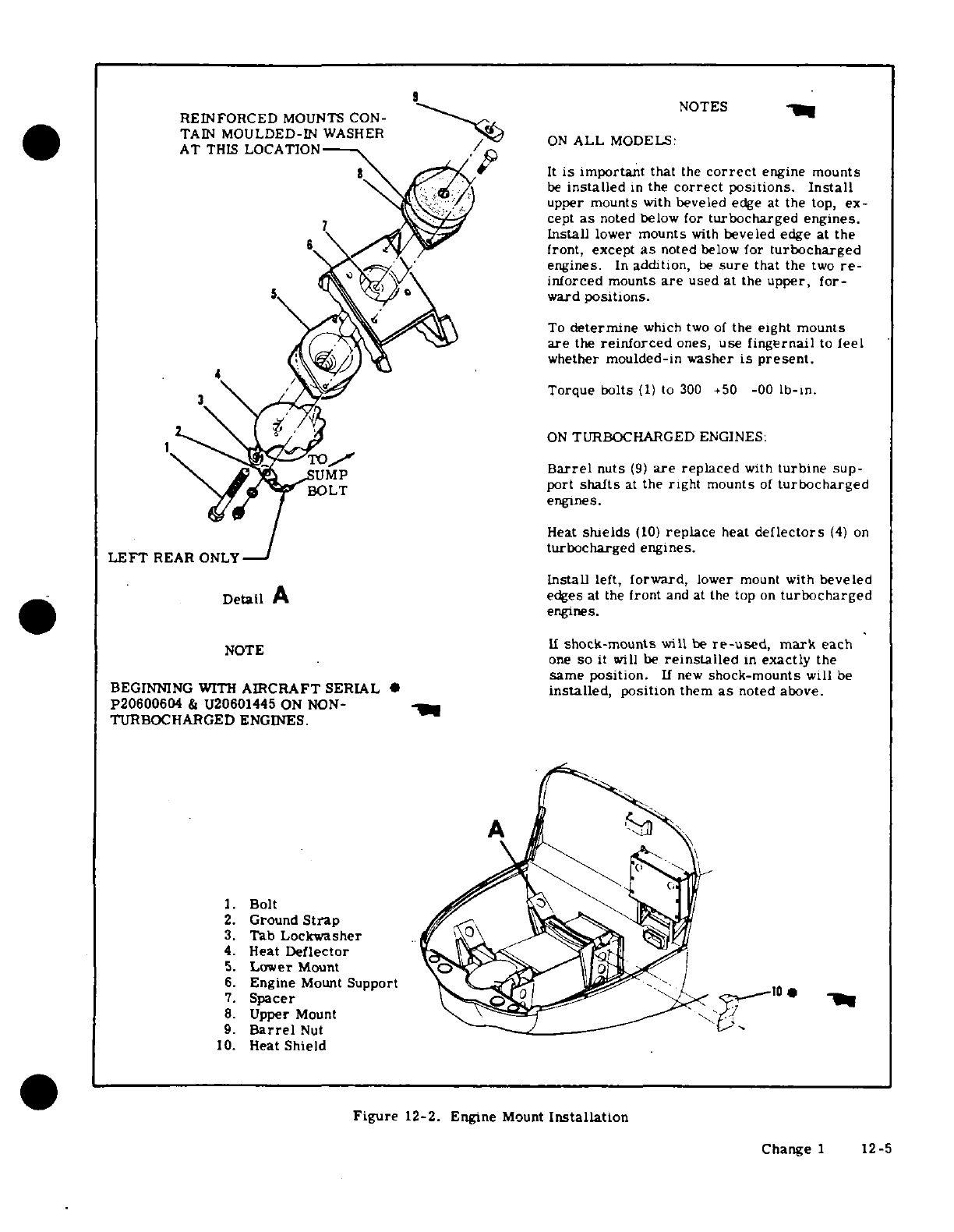
NOTES
REINFORCED
MOUNTS
CON-
TAIN
MOULDED-IN
WASHER
AT
THIS
LOCATION
ON
ALL
MODELS
It
is
important
that
the
correct
engine
mounts
be
installed
in
the
correct
positions.
Install
upper mounts
with
beveled
edge at
the
top,
ex-
cept
as
noted
below for
turbocharged
engines.
Install
lower
mounts
with
beveled
edge
at
the
front,
except
as
noted
below
for
turbocharged
engines.
In
addition,
be
sure
that
the
two
re-
inforced
mounts
are
used
at
the
upper,
for-
ward
positions.
To
determine
which
two
of
the
eight
mounts
are
the
reinforced
ones,
use
fingernail
to
feel
whether
moulded-in
washer
is
present.
3
Torque
bolts
(1)
to
300 +50
-00
lb-in.
ON
TURBOCHARGED
ENGINES:
TO SUMP
Barrel
nuts
(9)
are
replaced
with
turbine
sup-
BOLT
port
shafts
at
the
right
mounts
of
turbocharged
engines.
Heat
shields
(10)
replace
heat
deflectors
(4)
on
turbocharged engines.
LEFT
REAR
ONLY
Install
left,
forward,
lower
mount
with
beveled
Detail
A
edges
at the
front
and at
the
top
on
turbocharged
engines.
NOTE
II
shock-mounts
will
be
re-used,
mark
each
one
so
it
will
be
reinstalled
in
exactly
the
same
position.
If
new
shock-mounts
will
be
BEGINNING
WITH
AIRCRAFT
SERIAL
·
installed,
position
them
as
noted
above.
P20600604
&
U20601445
ON
NON-
TURBOCHARGED ENGINES.
I.
Bolt
2.
Ground
Strap
3.
Tab
Lockwasher
4.
Heat
Deflector
5.
Lower
Mount
6.
Engine
Mount
Support -10
7.
Spacer
8.
Upper
Mount
9.
Barrel
Nut
10.
Heat
Shield
Figure
12-2. Engine
Mount
Installation
Change
1
12-5
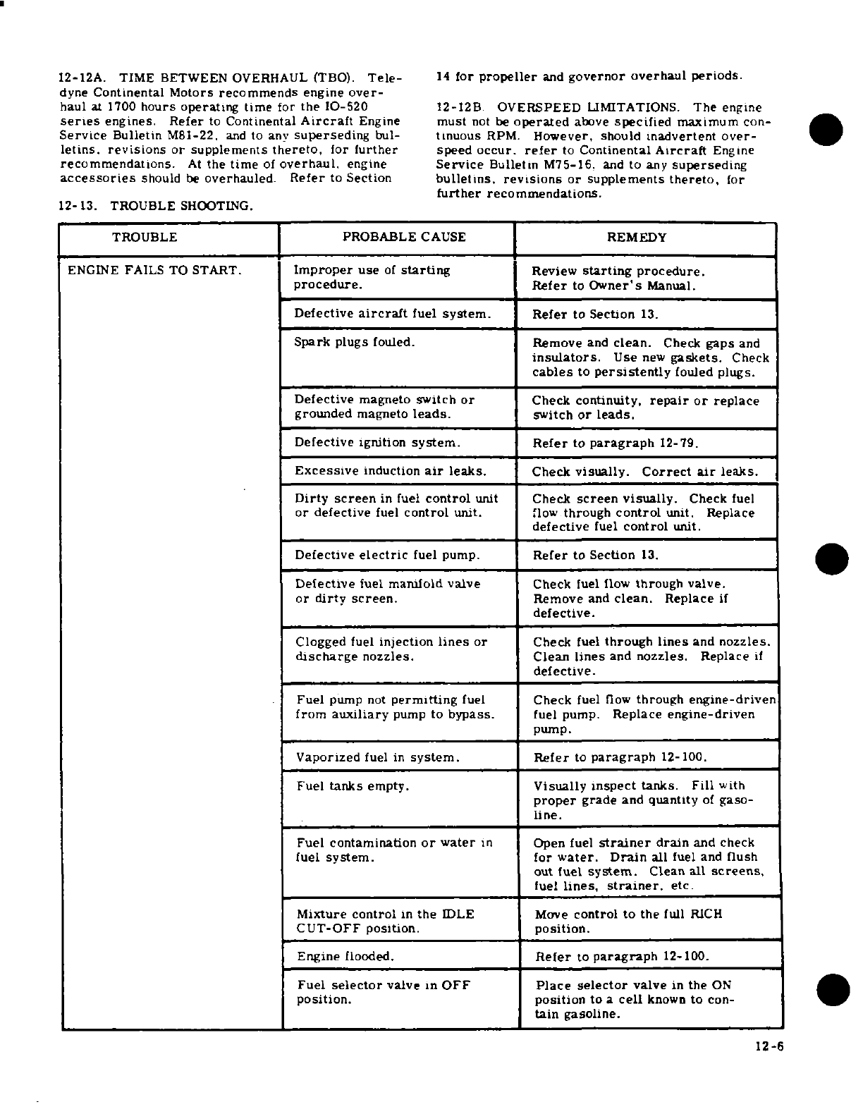
12-12A.
TIME
BETWEEN
OVERHAUL (TBO).
Tele-
14
for
propeller
and
governor
overhaul
periods.
dyne
Continental
Motors
recommends
engine
over-
haul
at
1700
hours
operating
time
for
the
1O-520
12-12B.
OVERSPEED
LIMITATIONS.
The
engine
series
engines.
Refer
to
Continental
Aircraft
Engine
must
not
be
operated
above
specified
maximum
con-
Service
Bulletin
M81-22,
and
to
any
superseding
bul-
tinuous
RPM.
However, should
inadvertent
over-
letins.
revisions
or supplements
thereto,
for
further
speed
occur,
refer
to
Continental
Aircraft
Engine
recommendations.
At
the
time
of
overhaul,
engine
Service
Bulletin
M75-16,
and
to
any
superseding
accessories
should
be
overhauled. Refer
to
Section
bulletins,
revisions
or supplements
thereto,
for
further
recommendations.
12-13. TROUBLE
SHOOTING.
TROUBLE PROBABLE
CAUSE
REMEDY
ENGINE
FAILS
TO
START.
Improper
use
of
starting
Review
starting
procedure.
procedure.
Refer
to
Owner's
Manual.
Defective
aircraft
fuel
system.
Refer
to
Section
13.
Spark
plugs
fouled.
Remove
and
clean.
Check
gaps
and
insulators.
Use
new
gaskets.
Check
cables
to
persistently
fouled
plugs.
Defective
magneto
switch
or
Check
continuity,
repair
or
replace
grounded
magneto
leads.
switch
or
leads.
Defective
ignition
system.
Refer
to
paragraph
12-79.
Excessive
induction
air
leaks.
Check
visually.
Correct
air
leaks.
Dirty
screen
in
fuel
control
unit
Check
screen
visually.
Check
fuel
or
defective
fuel
control
unit.
flow
through
control
unit. Replace
defective
fuel
control
unit.
Defective
electric
fuel
pump.
Refer
to
Section
13.
Defective
fuel
manifold
valve
Check
fuel
flow
through
valve.
or
dirty screen.
Remove
and
clean.
Replace
if
defective.
Clogged
fuel
injection
lines
or
Check
fuel
through
lines
and
nozzles.
discharge
nozzles. Clean
lines
and
nozzles.
Replace
if
defective.
Fuel
pump
not
permitting
fuel
Check
fuel
flow
through
engine-driven
from
auxiliary
pump
to
bypass.
fuel
pump.
Replace
engine-driven
pump.
Vaporized
fuel
in
system. Refer
to
paragraph
12-100.
Fuel
tanks
empty.
Visually
inspect
tanks.
Fill
with
proper
grade
and
quantity
of
gaso-
line.
Fuel
contamination
or
water
in
Open fuel
strainer
drain
and
check
fuel
system.
for
water.
Drain
all
fuel and
flush
out
fuel
system.
Clean
all
screens,
fuel
lines,
strainer.
etc.
Mixture
control
in
the
IDLE
Move
control to
the
full
RICH
CUT-OFF position.
position.
Engine
flooded.
Refer
to
paragraph
12-100.
Fuel
selector
valve
in
OFF
Place
selector
valve
in
the
ON
position.
position
to
a
cell
known
to
con-
tain gasoline.
12-6
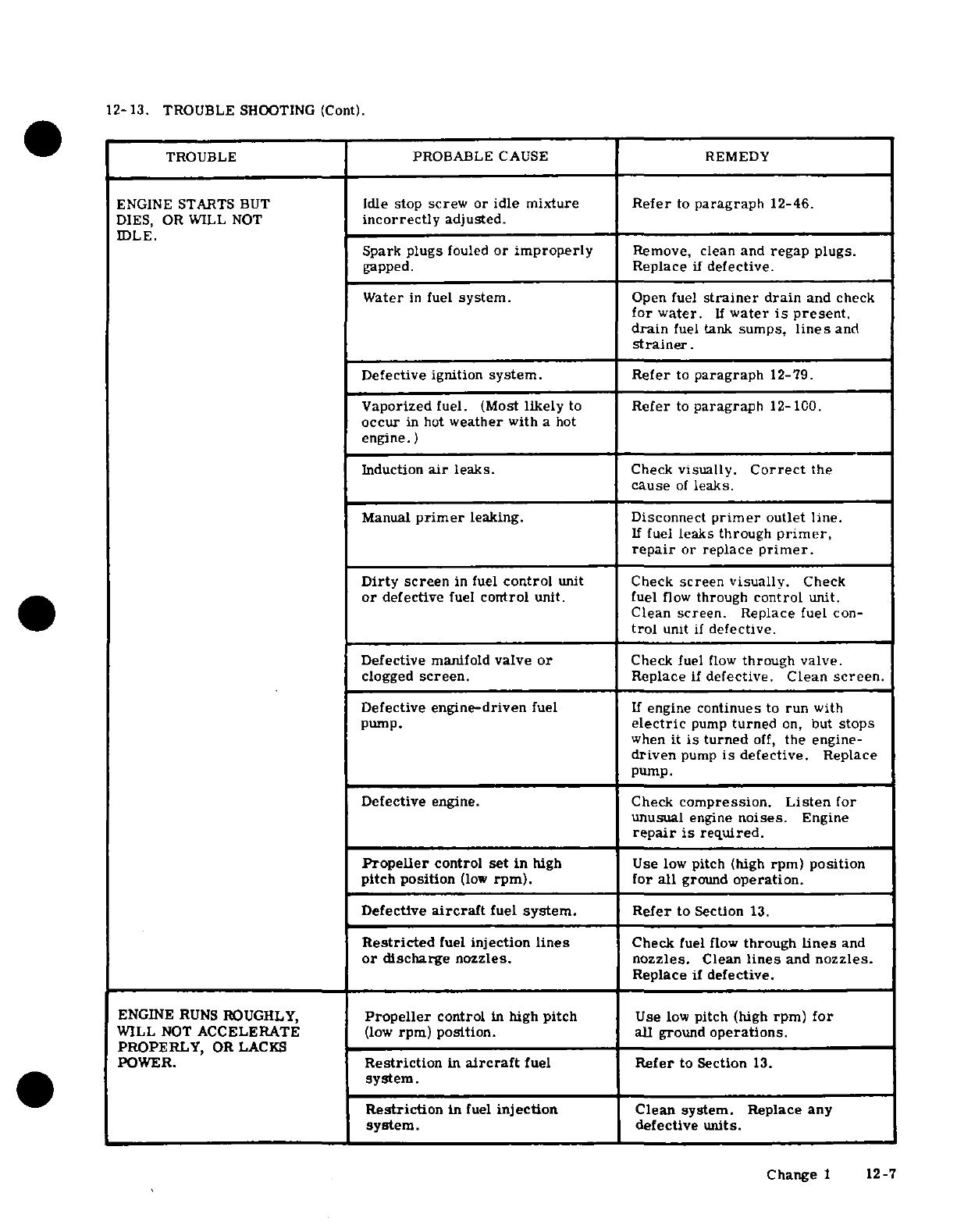
12-13.
TROUBLE
SHOOTING
(Cont).
TROUBLE PROBABLE
CAUSE
REMEDY
ENGINE
STARTS
BUT
Idle
stop
screw
or
idle mixture
Refer
to
paragraph
12-46.
DIES,
OR
WILL
NOT
incorrectly
adjusted.
IDLE.
Spark
plugs
fouled
or
improperly
Remove,
clean and
regap
plugs.
gapped.
Replace
if
defective.
Water
in
fuel
system.
Open
fuel
strainer
drain
and
check
for
water.
If
water
is
present.
drain
fuel
tank
sumps,
lines
and
strainer.
Defective ignition
system.
Refer
to
paragraph
12-79.
Vaporized
fuel.
(Most
likely
to
Refer
to
paragraph
12-100.
occur
in
hot
weather
with
a
hot
engine.)
Induction
air
leaks.
Check
visually.
Correct
the
cause
of
leaks.
Manual
primer
leaking. Disconnect
primer
outlet
line.
If
fuel
leaks
through
primer,
repair
or replace
primer.
Dirty screen
in
fuel
control
unit
Check
screen
visually.
Check
or
defective
fuel
control
unit. fuel
flow
through
control
unit.
Clean
screen.
Replace
fuel
con-
trol
unit
if
defective.
Defective
manifold
valve
or
Check
fuel
flow
through
valve.
clogged
screen.
Replace
if
defective.
Clean
screen.
Defective
engine-driven
fuel
If
engine
continues
to
run
with
pump.
electric
pump
turned
on,
but
stops
when
it
is
turned
off,
the
engine-
driven
pump
is
defective.
Replace
pump.
Defective
engine.
Check
compression.
Listen
for
unusual
engine
noises.
Engine
repair
is
required.
Propeller
control
set
in
high
Use
low
pitch
(high
rpm)
position
pitch
position
(low
rpm).
for
all
ground
operation.
Defective
aircraft
fuel
system.
Refer
to Section
13.
Restricted
fuel
injection
lines
Check
fuel
flow
through
lines
and
or
discharge
nozzles.
nozzles.
Clean
lines
and
nozzles.
Replace
if
defective.
ENGINE
RUNS
ROUGHLY,
Propeller
control
in
high
pitch
Use
low
pitch
(high
rpm)
for
WILL
NOT
ACCELERATE
(low
rpm)
position.
all
ground
operations.
PROPERLY,
OR LACKS
POWER.
Restriction
in
aircraft
fuel
Refer to
Section
13.
system.
Restriction
in
fuel
injection
Clean
system.
Replace any
system.
defective
units.
Change
1
12-7
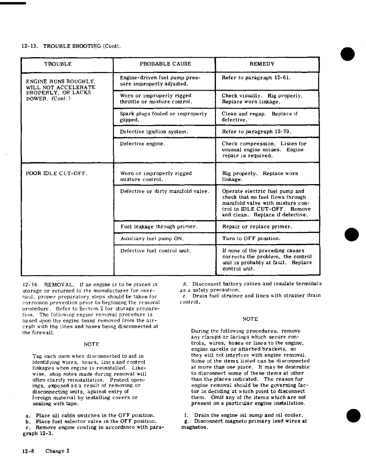
12-13.
TROUBLE
SHOOTING
(Cont).
TROUBLE
PROBABLE
CAUSE
REMEDY
Engine-driven
fuel
pump
pres-
Refer
to
paragraph
12-61.
ENGINE
RUNS ROUGHLY
sure improperly
adjusted.
WILL
NOT
ACCELERATE
PROPERLY.
OR
LACKS
POWER
(Cont.)
Worn
or
improperly
rigged
Check
visually.
Rig
properly.
throttle
or
mixture
control.
Replace
worn
linkage.
Spark
plugs
fouled
or
improperly
Clean
and
regap.
Replace
if
gapped.
defective.
Defective
ignition
system. Refer
to
paragraph
12-79.
Defective
engine.
Check
compression.
Listen
for
unusual
engine
noises.
Engine
repair
is
required.
POOR IDLE
CUT-OFF.
Worn
or
improperly
rigged
Rig
properly.
Replace
worn
mixture
control.
linkage.
Defective
or
dirty
manifold valve.
Operate
electric
fuel
pump
and
check
that
no
fuel
flows
through
manifold
valve
with
mixture
con-
trol
in
IDLE
CUT-OFF.
Remove
and
clean.
Replace
if
defective.
Fuel
leakage
through
primer.
Repair
or
replace
primer.
Auxiliary
fuel pump
ON.
Turn
to
OFF
position.
Defective
fuel
control
unit.
If
none
of
the
preceding
causes
corrects
the
problem,
the
control
unit
is
probably
at
fault.
Replace
control
unit.
12-14.
REMOVAL.
If
an
engine
is
to
be
placed
in
d.
Disconnect
battery
cables
and
insulate
terminals
storage
or
returned
to
the
manufacturer
for
over-
as
a
safety
precaution.
haul,
proper preparatory
steps
should
be
taken
for
c.
Drain
fuel
strainer
and
lines
with
strainer
drain
corrosion
prevention
prior
to
beginning
the
removal
control.
procedure.
Refer
to
Section
2
for
storage
prepara-
tion.
The
following engine
removal
procedure
is
based
upon
the
engine
being
removed
from
the
air-
NOTE
craft
with
the
lines
and
hoses
being
disconnected
at
the
firewall.
During
the following
procedures,
remove
any
clamps or
lacings
which
secure
con-
NOTE
trols,
wires,
hoses
or lines
to
the
engine,
engine
nacelle
or
attached
brackets,
so
Tag
each item
when
disconnected
to
aid
in
they will
not
interfere
with
engine
removal.
identifying
wires,
hoses,
lines
and
control
Some
of
the
items
listed
can
be
disconnected
linkages
when
engine
is
reinstalled.
Like-
at
more
than
one
place.
It
may
be
desirable
wise,
shop
notes
made
during
removal
will to
disconnect
some
of
these
items
at
other
often
clarify
reinstallation.
Protect
open-
than
the
places
indicated.
The
reason
for
ings,
exposed
as
a
result
of
removing
or
engine
removal
should
be
the
governing
fac-
disconnecting
units,
against
entry
of
tor
in
deciding
at
which
point
to
disconnect
foreign
material
by
installing
covers
or
them.
Omit
any
of
the
items
which
are
not
sealing
with
tape.
present
on
a
particular
engine
installation.
a.
Place
all
cabin
switches
in
the
OFF
position.
f.
Drain
the
engine
oil sump
and
oil
cooler.
b.
Place
fuel
selector
valve
in
the
OFF
position.
g.
Disconnect
magneto
primary
lead
wires
at
c.
Remove engine
cowling
in
accordance
with
para-
magnetos.
graph
12-3.
12-8
Change 2
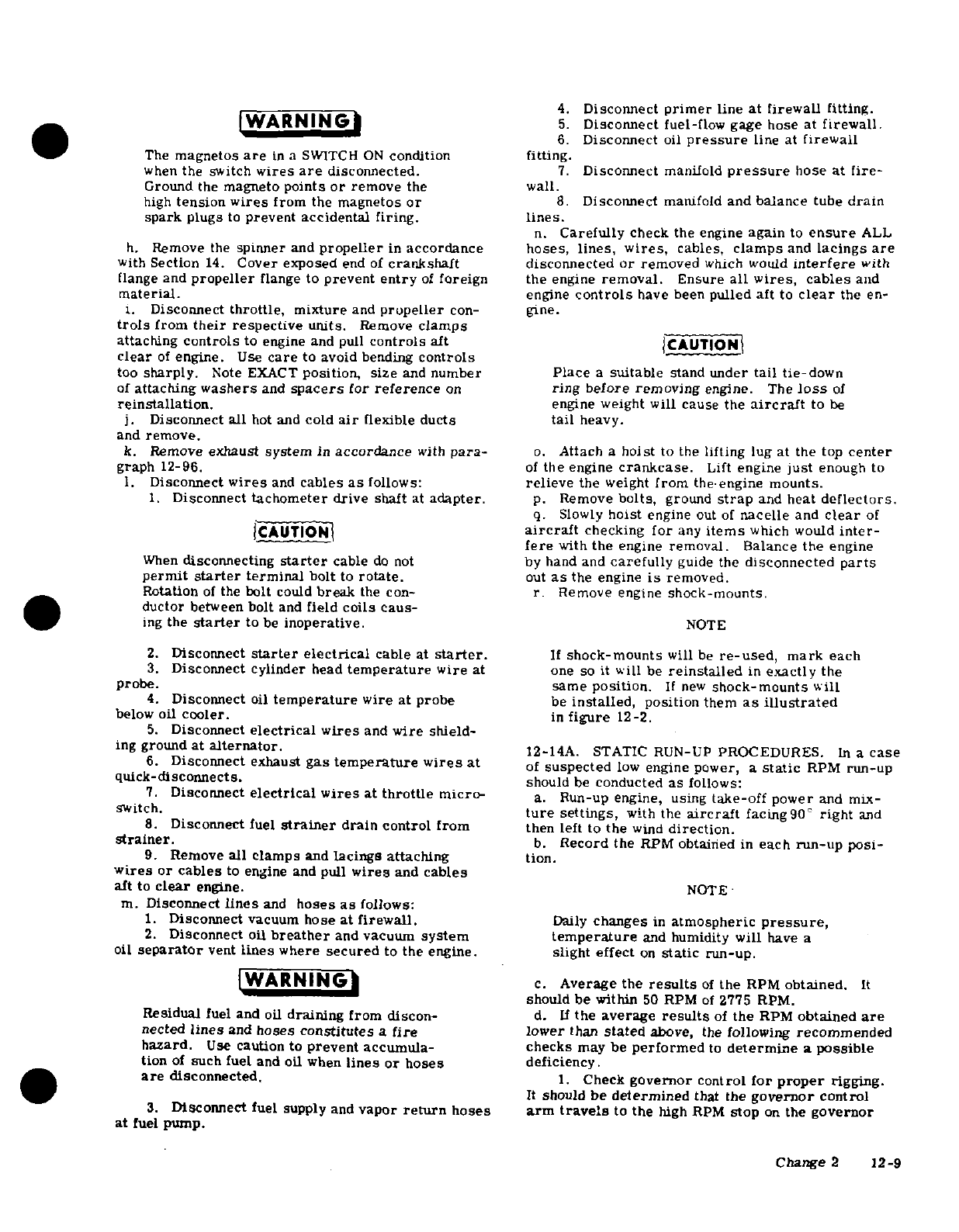
4.
Disconnect
primer
line
at
firewall
fitting.
WARNING
5.
Disconnect
fuel-flow
gage hose
at
firewall.
6.
Disconnect
oil
pressure
line
at
firewall
The
magnetos
are
in
a
SWITCH
ON
condition
fitting.
when
the
switch
wires
are
disconnected.
7.
Disconnect
manifold
pressure
hose
at
fire-
Ground
the
magneto
points
or
remove
the wall.
high
tension
wires
from
the
magnetos
or
8.
Disconnect
manifold
and
balance
tube
drain
spark
plugs
to
prevent
accidental
firing.
lines.
n.
Carefully
check
the
engine
again
to
ensure
ALL
h.
Remove
the
spinner
and
propeller
in
accordance
hoses,
lines,
wires,
cables,
clamps
and
lacings
are
with
Section
14.
Cover exposed
end
of
crankshaft
disconnected
or
removed
which
would
interfere
with
flange
and
propeller
flange
to
prevent
entry
of
foreign
the
engine
removal.
Ensure
all
wires,
cables
and
material.
engine
controls
have been
pulled aft
to
clear
the
en-
i.
Disconnect
throttle,
mixture
and
propeller
con-
gine.
trols
from
their
respective units.
Remove
clamps
attaching
controls
to
engine
and
pull
controls
aft
CAUTION
clear
of
engine.
Use
care
to avoid
bending
controls
too
sharply.
Note
EXACT
position,
size
and
number
Place
a
suitable
stand
under
tail
tie-down
of
attaching
washers
and
spacers
for
reference
on
ring
before
removing
engine. The
loss
of
reinstallation.
engine
weight
will
cause the
aircraft
to
be
j.
Disconnect
all
hot and
cold
air
flexible
ducts
tail
heavy.
and
remove.
k.
Remove
exhaust
system
in
accordance
with
para-
o.
Attach
a
hoist
to
the
lifting
lug
at
the
top
center
graph
12-96.
of
the
engine
crankcase.
Lift
engine
just
enough
to
1.
Disconnect
wires
and
cables
as
follows:
relieve
the
weight
from
the
engine
mounts.
1.
Disconnect
tachometer
drive
shaft
at
adapter.
p.
Remove
bolts,
ground
strap
and
heat
deflectors.
q.
Slowly
hoist
engine
out
of
nacelle
and
clear
of
CAUTION1
aircraft
checking
for
any
items
which
would
inter-
fere
with
the
engine
removal.
Balance
the
engine
When
disconnecting
starter
cable
do
not
by
hand
and
carefully
guide
the
disconnected
parts
permit
starter
terminal
bolt
to
rotate.
out
as
the
engine
is
removed.
Rotation
of
the
bolt
could
break
the
con-
r.
Remove engine
shock-mounts.
ductor
between
bolt
and
field
coils caus-
ing
the
starter
to
be
inoperative.
NOTE
2.
Disconnect
starter
electrical
cable
at
starter.
If
shock-mounts
will
be
re-used,
mark
each
3.
Disconnect cylinder
head
temperature
wire
at
one
so it
will
be
reinstalled
in
exactly
the
probe. same
position.
If
new
shock-mounts
will
4.
Disconnect
oil
temperature
wire
at
probe
be
installed,
position
them
as
illustrated
below
oil
cooler.
in
figure
12-2.
5.
Disconnect
electrical
wires
and
wire shield-
ing
ground
at
alternator.
12-14A.
STATIC
RUN-UP
PROCEDURES.
In
a
case
6.
Disconnect
exhaust
gas
temperature
wires at
of
suspected
low
engine
power,
a
static
RPM
run-up
quick-disconnects.
should
be
conducted
as
follows:
7.
Disconnect
electrical wires
at
throttle
micro-
a.
Run-up
engine, using
take-off
power
and
mx-
switch.
ture
settings,
with
the
aircraft
facing90'
right
and
8.
Disconnect
fuel
strainer
drain control
from
then left to
the
wind
direction.
strainer.
b.
Record
the
RPM
obtained
in
each
run-up
posi-
9.
Remove
all
clamps
and
lacings attaching
tion.
wires
or
cables
to
engine
and pull
wires
and
cables
aft
to
clear
engine.
NOTE
m.
Disconnect
lines
and
hoses
as
follows:
1.
Disconnect
vacuum
hose
at firewall.
Daily
changes
in
atmospheric
pressure,
2.
Disconnect
oil
breather
and
vacuum
system
temperature
and
humidity
will
have
a
oil
separator
vent
lines
where
secured
to
the
engine,
slight
effect
on
static
run-up.
WARNING
c.
Average the
results
of
the
RPM
obtained.
It
should
be
within
50
RPM
of
2775 RPM.
Residual
fuel
and
oil
draining
from
discon-
d.
If
the
average
results
of
the
RPM
obtained
are
nected
lines
and
hoses
constitutes
a
fire
lower
than
stated
above,
the
following
recommended
hazard.
Use
caution to
prevent
accumula- checks
may
be
performed
to
determine
a
possible
tion
of
such fuel
and
oil
when
lines
or
hoses
deficiency.
are
disconnected.
1.
Check
governor
control
for
proper
rigging.
It
should
be
determined
that the
governor
control
3.
Disconnect
fuel supply
and
vapor
return
hoses
arm
travels
to
the
high
RPM
stop
on
the
governor
at
fuel
pump.
Change
2
12-9
and
that the
high RPM
stop
screw is
adjusted
prop-
12-17. INSPECTION.
For
specific
items
to
be
in-
erly.
(Refer
to Section
14
for
procedures).
spected,
refer
to
the
engine
manufacturer's
manual.
a.
Visually
inspect
the
engine
for
loose
nuts,
bolts,
NOTE
cracks
and fin
damage.
b.
Inspect
baffles,
baffle
seals
and
brackets
for
If
verification
of
governor
operation
is
cracks,
deterioration
and
breakage.
necessary
the
governor
may
be
removed
c.
Inspect
all
hoses
for
internal
swelling,
chafing
from
the
engine
and
a
flat
plate
installed
through
protective
plys,
cuts,
breaks,
stiffness,
over
the
engine
pad.
Run-up
engine
to
damaged
threads
and
loose connections.
Excessive
determine
that
governor
was
adjusted
heat
on
hoses
will
cause
them
to
become
brittle
and
properly.
easily
broken.
Hoses
and
lines
are
most
likely
to
crack
or break
near
the
end
fittings
and
support
2.
Check
carburetor
heat
control
(carburetor
points.
equipped
engines)
for
proper
rigging.
If
partially
d.
Inspect
for
color
bleaching
of
the
end
fittings
or
open
it
would
cause
a
slight
power
loss.
On
fuel
in-
severe
discoloration
of
the
hoses.
jected
engines
check
operation or
alternate
air
door
spring
or
magnetic
lock
to
make
sure
door
will
re-
NOTE
main
closed
in
normal
operation.
3.
Check
magneto
timing,
spark
plugs
and
igni-
Avoid
excessive
flexing
and
sharp
bends
tion
harness
for
settings
and
conditions.
when
examining
hoses
for
stiffness.
4.
On
fuel
injection engines,
check
fuel
injec-
tion
nozzles for
restriction
and
check
for
correct
e.
All
flexible
fluid
carrying
hoses
in
the
engine
unmetered
fuel
flow.
compartment
should
be
replaced at
engine
overhaul
5.
Check
condition
of
induction
air
filter.
Clean
or
every
five
years,
whichever
occurs
first.
if
required.
f.
For
major
engine
repairs,
refer
to
the
manu-
6.
Perform
an
engine
compression
check
(Refer
facturer's
overhaul
and
repair
manual.
to
engine
Manufacturer's
Manual).
12-18.
BUILD-UP.
Engine
build-up
consists
of
in-
12-15.
CLEANING. The
engine
may
be
cleaned
with
stallation
of
parts,
accessories
and
components
to
Stoddard solvent
or
equivalent,
then
dried
thoroughly.
the
basic
engine
to
build
up
an
engine unit
ready
for
installation
on
the
aircraft.
All
safety
wire,
lock-
CAUTION
washers,
nuts,
gaskets
and
rubber
connections
should be
new
parts.
Particular
care
should
be
given
to
electrical
equipment
before cleaning.
Cleaning
fluids
12-19.
INSTALLATION.
Before
installing
the
en-
should
not
be
allowed
to
enter
magnetos,
gine
on
the
aircraft,
install
any
items
which
were
starter,
alternator,
etc.
Protect
these
com-
removed
from
the
engine
or
aircraft
after
the
engine
ponents
before
saturating
the
engine
with
sol-
was
removed.
vent.
All
other
openings
should
also
be
cov-
ered
before
cleaning
the
engine
assembly.
NOTE
Caustic
cleaning
solutions
should
be
used
cautiously
and
should
always
be
properly
Remove
all
protective
covers,
plugs,
caps
neutralized
after
their
use.
and
identification
tags
as
each item
is
con-
nected
or
installed.
Omit
any
items
not
present
on
a
particular
engine
installation.
12-16. ACCESSORIES
REMOVAL.
Removal
of
en-
gine
accessories
for
overhaul
or
for
engine
replace-
a.
Hoist
the
engine
to
a
point
just
above
the
nacelle.
ment
involves
stripping
the engine
of
parts,
acces-
b.
Install
engine
shock-mounts
and
ground
strap
as
series
and
components
to
reduce
it
to
the
bare
en-
illustrated
in
figure
12-2.
gine.
During
the
removal
process,
removed
items
c.
Carefully
lower
engine
slowly
into
place
on
the
should
be
examined
carefully
and
defective
parts
engine
mounts.
Route
controls, lines,
hoses
and
should
be
tagged
for
repair
or replacement
with
new
wires
in
place
as
the
engine
is
positioned
on
the
en-
components.
gine
mounts.
NOTE
NOTE
Items
easily
confused
with
similar
items
Be
sure
engine
shock-mounts,
spacers
and
should
be
tagged
to
provide
a
means
of
washers
are
in
place
as
the
engine
is
identification
when
being
installed
on
a
lowered
into
position.
new
engine.
All
openings
exposed
by
the
removal
of
an
item
should
be
closed
by
d.
Install engine-to-mount
bolts,
then
remove
the
installing
a
suitable cover
or
cap
over
hoist
and
support stand placed
under
tail
tie-down
the
opening.
This
will
prevent
entry
fitting.
Torque
bolts
to
300+50-00
lb-in.
foreign
material.
If
suitable
covers
are
e.
Route
throttle,
mixture
and
propeller
controls
not
available,
tape
may
be
used
to
cover
to
their
respective units
and
connect.
Secure
con-
the
openings.
trols
in
position
with
clamps.
12-10
Change 2
NOTE
k.
Complete
a
magneto switch
ground-out
and
con-
tinuity
check,
then
connect
primary
lead
wires
to
the
Throughout
the
aircraft
fuel
system,from
magnetos.
Remove
the
temporary
ground
or
connect
the
fuel
cells
to
the
engine-driven
pump,
spark
plug
leads,
whichever
procedure
was
used
dur-
use NS-40
(RAS-4)
(Snap-On-Tools
Corp.
,
ing
removal.
Kenosha, Wisconsin),
MIL-T-5544
(Thread
Compound
Antiseize, Graphite Petrolatum),
WARNING
USP
PetrolaOOum
or
enNine
oil as
a
thread
lubricator
or
to
seal
a
leaking
connection.
Be
sure
magneto
switch
is
in
OFF
position
Apply
sparingly
to
male
threads
only,
omit-
when
connecting
switch
wires
to
magnetos.
ting
the
first
two
threads,
exercising
ex-
treme
caution
to
avoid
"stringing"
sealer
1.
Clean
and
install
induction
air
filter
in
accor-
across
the
end
of
the
fittiMVH.
Always
en-
dance
with
Section
2.
sure
that
a
compound, the
residue
from
a
m.
Service
engine
with
proper
grade
and
quantity
of
previously
used
compound,
or
any
other
engine
oil.
Refer
to
Section
2
if engine
is
new,
newly
foreign
material
cannot
enter
the
system.
overhauled
or
has
been
in
storage.
n.
Check
all
switches
are
in
the OFF
position
and
f.
Connect
lines
and
hoses
as
follows:
connect
battery
cables.
1.
Connect
manifold
and
balance
tube
drain
o.
Rig
engine
controls
in
accordance
with
para-
lines.
graphs
12-85,
12-86
and 12-87.
2.
Connect manifold
pressure
hose at
firewall.
p.
Inspect
engine
installation
for
security,
correct
3.
Connect
oil
pressure
line
at
firewall fitting,
routing
of
controls,
lines,
hoses
and
electrical
wir-
4.
Connect
fuel-flow
gage
hose
at firewall.
ing,
proper
safetying
and
tightness
of
all
components.
5.
Connect
primer
line
at
firewall
fitting.
q.
Install
engine
cowling
in
accordance
with
para-
6.
Connect
fuel
supply
and
vapor
return
hose
at graph
12-3.
firewall.
r.
Perform
an engine
run-up
and
make
final
adjust-
7.
Connect
oil
breather
and
vacuum
system
oil
ments
on
the
engine
controls.
separator
vent
lines
where
secured
to
the
engine.
8.
Connect
vacuum
hose
at firewall.
12-20.
FLEXIBLE
FLUID
HOSES.
9.
Install
clamps
and
lacings
securing.hoses
and
lines
to
the
engine
to
prevent
chafing.
12-21.
PRESSURE
TEST.
g.
Connect
wires
and
cables as
follows:
a.
After
each
50
hours
of
engine
operation,
all
flex-
1.
Connect
electrical
wires
and
wire
shielding
ible
fluid
hoses
in
the
engine
compartment
should
be
ground
at
alternator.
pressure
tested
as
follows:
2.
Connect
cylinder
head
temperature
wire at
1.
Place
mixture
control
in
the idle
cut-off
posi-
probe.
ton.
|CAUTIONI
2.
Operate
the
auxiliary
fuel
pump
in
the
high
position.
When
connecting
starter
cable,
do
not
permit
3.
Examine
the
exterior
of
hoses
for
evidence
starter
terminal
bolt to
rotate.
Rotation
of
of
leakage
or
wetness.
the
bolt
could
break
the
conductor
between
4.
Hoses
found
leaking should
be
replaced.
bolt
and
field
coils
causing
the
starter
to
be
5.
After
pressure
testing
fuel
hoses,
allow
suf-
inoperative.
ficient
time
for
excess
fuel
to
drain
overboard
from
the
engine
manifold
before
attempting
an
engine
start.
3.
Connect
starter
electrical
cable
at
starter.
6.
Refer
to
paragraph
12-17
for
detailed
inspe
6
-
4.
Connect
tachometer
drive
shaft at
adapter.
tion
procedures
for
flexible
hoses.
Be
sure
drive
cable
engages drive
in
adapter.
Torque
housing
attach
nut
to
100-lb-in.
12-22.
REPLACEMENT.
5.
Connect
exhaust
gas
temperature
wires at
a.
Hoses
should
not
be
twisted
on
installation.
quick-disconnects.
Pressure
applied
to
a
twisted
hose
may
cause
failure
6.
Connect
electrical
wires
aticro-
or
loosening
of
throttle
micronut.
switch.
b.
Provide
as
large
a
bend
radius
as
possible.
7.
Connect
oil
temperature
wire
to
probe
below
c.
Hoses
should
have
a minimum
of
one-half
inch
oil
cooler.
clearance
from
other
lines,
ducts,
hoses
or
sur-
8.
Connect
fuel
strainer
drain
control
to
strainer.
rounding
objects
or
be
butterfly
clamped to
them.
9.
Install
clamps
and
lacings securing
wires
and
d.
Rubber
hoses
will
take
a
permanent set
during
cables
to
engine, engine mount
and
brackets,
extended
use
in
service.
Straightening
a
hose
with
h.
Install
exhaust
system
in
accordance
with
para-
a
bend
having
a
permanent
set
will
result
in
hose
graph
12-96.
cracking.
Care
should
be
taken
during
removal
so
i.
Connect
all
hot
and
cold
air
flexible
ducts.
that
hose
is
not
bent
excessively,
and
during
rein-
j.
Instll roeller
nd
stallation
to
assure
hose
is
returned
to
its
original
instructions
outlined
in
Section
14.
position.
e.
Refer
to
AC
43.13,
Chapter
10,
for
additional
installation procedures
for
flexible
fluid
hose
assem-
blies.
Change
3
12-11
12-23.
ENGINE
BAFFLES.
are
routed
through
some
baffles.
Make
sure
that
these
parts
are
reinstalled
correctly after installa-
12-24. DESCRIPTION.
The
sheet metal
baffles
in-
tion
of
baffles.
stalled
on
the
engine
direct
the
flow
of
air
around
the
cylinders
and
other
engine
components
to
provide
12-27.
REPAIR.
Repair
of
an
individual
segment
of
optimum cooling.
These baffles
incorporate rubber-
engine
baffle
is
generally
impractical,
since,
due
to
asbestos
composition
seals
at
points
of
contact
with
the
small
size
and
formed
shape
of
the
part,
replace-
the
engine
cowling
and
other
engine
components
to
ment
is
usually
more
economical.
However,
small
help confine and
direct
the
airflow
to
the
desired
area.
cracks
may
be
stop-drilled
and
a
reinforcing
doubler
It
is
very
important
to
engine
cooling
that
the baffles
installed.
Other
repairs
may be
made
as
long
as
and
seals
are
in
good
condition
and
installed
correctly.
strength
and
cooling
requirements
are
met.
Replace
The
vertical
seals
must
fold
forward
and
the
aide
sealing
strips
if
they
do
not
seal
properly.
seals
must
fold
upwards.
Removal
and
installation
of
the
various
baffle
segments
is
possible
with
the
cowl-
12-28.
ENGINE
OIL SYSTEM.
(Refer
to
figure
ing
removed.
Be
sure
that
any
new
baffles
seal
pro-
12-3.)
perly.
12-29.
DESCRIPTION.
A
wet-sump,
pressure-
12-25.
CLEANING
AND
INSPECTION.
The
engine
lubricating
oil
system
is
employed
in
the
engine.
baffles
should
be
cleaned
with
a
suitable
solvent
to
Oil
under
pressure
from
the
oil
pump
is
fed
through
remove
oil
and
dirt.
drilled
crankcase
passages
which
supply
oil
to
the
crankshaft
main
bearings
and
camshaft
bearings.
Connecting
rod
bearings
are
pressure-lubricated
NOTE
through
internal
passages
in
the
crankshaft.
Valve
mechanisms
are
lubricated
through
the
hollow
push-
The
rubber-asbestos
seals
are
oil
and
grease rods,
which
are
supplied
with
oil
from the
crankcase
resistant
but
should not be
soaked
in
solvent
oil
passages.
The
propeller
is
supplied
oil,
boosted
for
long
periods,
by
the
governor
through
the
forward
end
of
the
crank-
shaft.
Oil
is
returned
by
gravity
to
the
engine
oil
Inspect
baffles
for
cracks
in
the
metal
and
for
loose
sump.
Cylinder
walls
and
piston
pins
are
spray-
and/or
torn
seals.
Repair
or
replace
any
defective
lubricated
by
oil
escaping from
connecting
rod
bear-
parts.
ings.
The
engine
is
equipped with
an oil
cooler
and
a
thermostat
valve
to
regulate
engine
oil
temperature.
12-26.
REMOVAL
AND
INSTALLATION.
Removal
A
pressure
relief
valve
is
installed
to
maintain
pro-
and
installation
of
the
various
baffle
segments
is
per
oil
pressure
at
higher
engine
speeds.
Removable
possible
with the
cowling
removed.
Be
sure
that
any
oil
filter
screens
are
provided
within
the
oil
system.
replaced
baffles
and
seals
are
installed
correctly
and
An
external,
replaceable
element
oil
filter
is
avail-
that
they
seal
to
direct
the
airflow in
the
correct
di-
able
as
optional
equipment.
The
engine
may
also
be
rection.
Various
lines,
hoses,
wires
and
controls
equipped
with
a
non-congealing
oil
cooler.
SHOP
NOTES:
12-12
Change
1
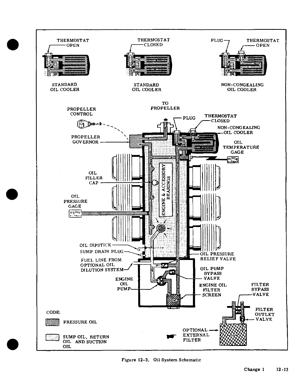
THERMOSTAT THERMOSTAT
PLUG
THERMOSTAT
OPEN
CLOSED
OPEN
STANDARD
STANDARD
NON-CONGEALING
OIL
COOLER
OIL
COOLER
OIL
COOLER
TO
PROPELLER
PROPELLER
CONTROL
CONTROL
THERMOSTAT
PROPELLER
GOVERNOR
TEMPERATURE
GAGE
OIL
FILLER
CAP
OIL
PRESSURE
GAGE
OIL
DIPSTICK
SUMP
DRAIN
PLUG
OIL
PRESSURE
FUEL
LINE
FROM
RELIEF
VALVE
OPTIONAL
OIL
DILUTION
SYSTEM
OIL
PUMP
BYPASS
ENGINE
VALVE
OIL
ENGINE
OIL
FILTER
PUMP
FILTER
BYPASS
SCREEN
VALVE
PRESSURE
OIL VALVE
OPTIONAL
SUMP
OIL,
RETURN
EXTERNAL
OIL
Figure
12-3.
Oil
System
Schematic
Change
1
12-13
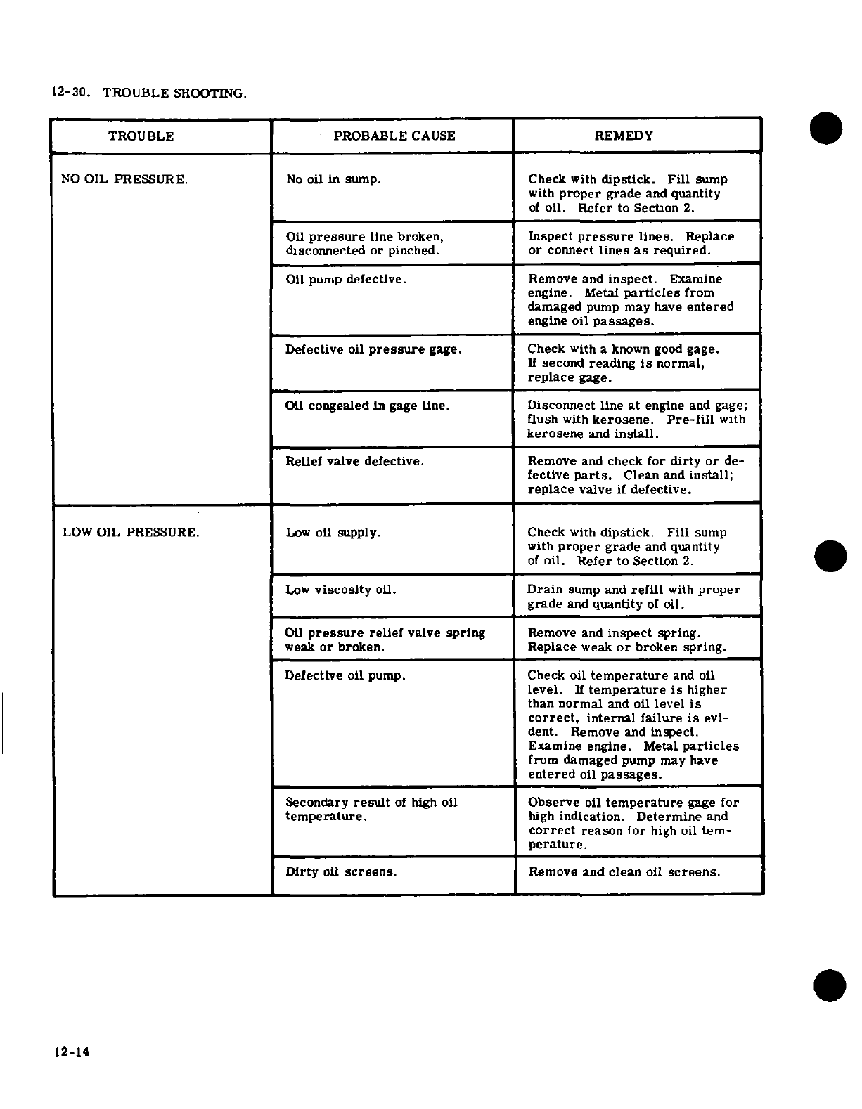
12-30.
TROUBLE
SHOOTING.
TROUBLE
PROBABLE
CAUSE
REMEDY
NO
OIL
PRESSURE.
No
oil
in
sump. Check
with
dipstick.
Fill
sump
with
proper
grade
and
quantity
of
oil.
Refer
to
Section
2.
Oil
pressure
line
broken,
Inspect
pressure
lines.
Replace
disconnected
or
pinched.
or
connect
lines
as
required.
Oil
pump
defective.
Remove
and
inspect.
Examine
engine.
Metal
particles
from
damaged
pump
may
have
entered
engine
oil
passages.
Defective
oil
pressure
gage.
Check
with
a
known
good
gage.
If
second
reading
is
normal,
replace
gage.
Oil
congealed
in
gage
line. Disconnect line
at
engine
and
gage;
flush
with
kerosene.
Pre-fill
with
kerosene
and
install.
Relief
valve
defective.
Remove
and
check
for
dirty
or
de-
fective
parts.
Clean
and
install;
replace
valve
if
defective.
LOW
OIL
PRESSURE.
Low
oil supply. Check
with
dipstick.
Fill
sump
with
proper
grade
and
quantity
of
oil.
Refer
to
Section
2.
Low
viscosity
oil.
Drain
sump and
refill
with
proper
grade
and
quantity
of
oil.
Oil
pressure
relief
valve
spring
Remove
and
inspect
spring.
weak
or
broken.
Replace
weak
or
broken
spring.
Defective
oil
pump.
Check
oil
temperature
and
oil
level.
If
temperature
is
higher
than
normal
and
oil
level is
correct,
internal
failure
is
evi-
dent.
Remove
and
inspect.
Examine
engine.
Metal
particles
from
damaged
pump
may
have
entered
oil
passages.
Secondary
result
of
high
oil
Observe
oil
temperature
gage
for
temperature.
high
indication.
Determine
and
correct
reason
for
high oil
tem-
perature.
Dirty
oil
screens.
Remove
and clean
oil
screens.
12-14
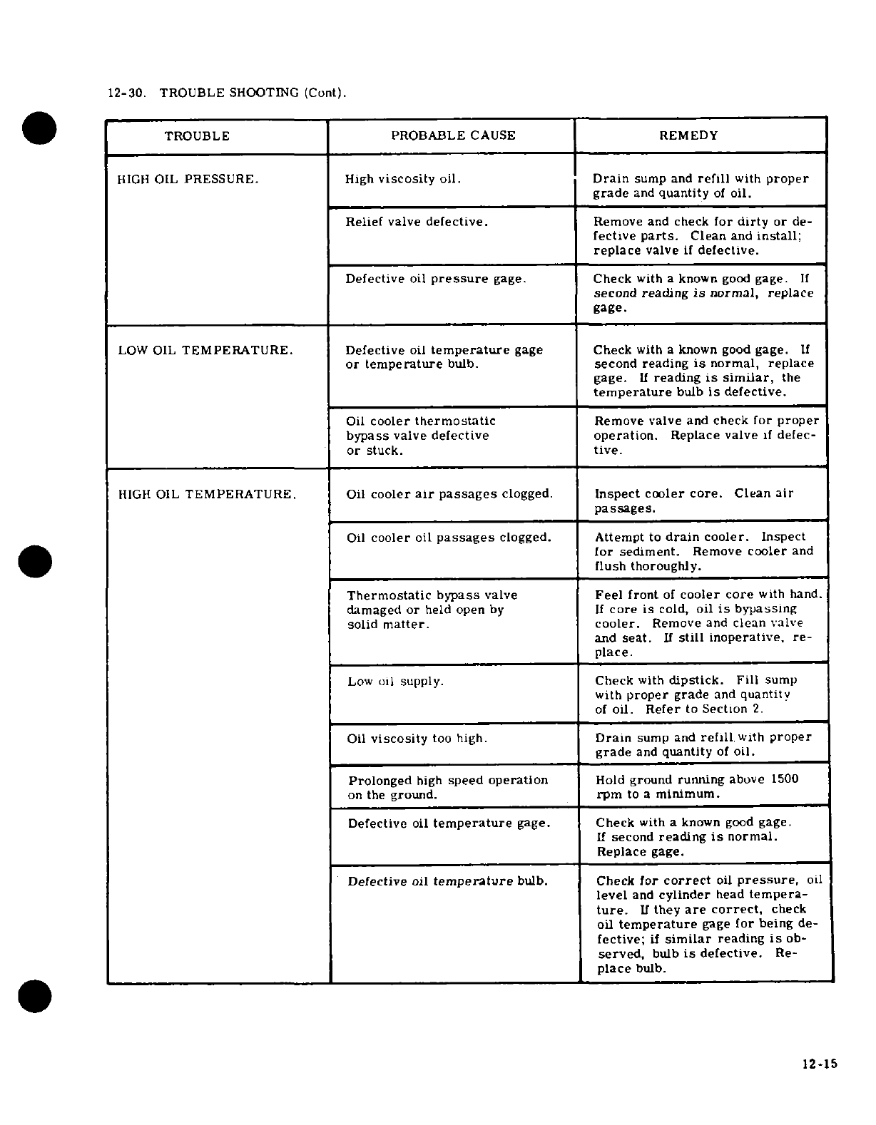
12-30.
TROUBLE
SHOOTING
(Cont).
TROUBLE PROBABLE
CAUSE REMEDY
HIGH
OIL
PRESSURE.
High
viscosity
oil.
Drain
sump
and
refill
with
proper
grade
and
quantity
of
oil.
Relief
valve
defective.
Remove
and
check
for
dirty
or
de-
fective
parts.
Clean
and
install;
replace
valve
if
defective.
Defective
oil
pressure
gage.
Check
with
a
known
good
gage.
If
second
reading
is
normal, replace
gage.
LOW
OIL
TEMPERATURE.
Defective
oil
temperature
gage
Check
with
a
known good
gage.
If
or
temperature
bulb.
second reading
is
normal, replace
gage.
If
reading
is
similar,
the
temperature
bulb
is
defective.
Oil
cooler
thermostatic
Remove
valve
and
check
for
proper
bypass
valve
defective
operation.
Replace
valve
if
defec-
or
stuck.
tive.
HIGH
OIL
TEMPERATURE.
Oil
cooler
air
passages
clogged.
Inspect
cooler
core.
Clean
air
passages.
Oil
cooler
oil
passages
clogged.
Attempt
to
drain
cooler.
Inspect
for
sediment.
Remove
cooler
and
flush
thoroughly.
Thermostatic
bypass
valve
Feel
front
of
cooler
core
with
hand.
damaged
or
held
open
by
If
core
is
cold,
oil
is
bypassing
solid
matter.
cooler.
Remove
and
clean
valve
and
seat.
If
still
inoperative,
re-
place.
Low
oil
supply.
Check
with
dipstick.
Fill
sump
with
proper
grade
and
quantity
of
oil.
Refer
to
Section
2.
Oil
viscosity
too high.
Drain
sump
and
refill
with
proper
grade
and
quantity
of
oil.
Prolonged
high
speed
operation
Hold
ground
running
above
1500
on
the
ground.
rpm
to
a
minimum.
Defective
oil
temperature
gage.
Check
with
a
known
good
gage.
If
second
reading
is
normal.
Replace
gage.
Defective
oil
temperature
bulb. Check
for
correct
oil
pressure,
oil
level
and
cylinder
head
tempera-
ture.
I
they
are
correct,
check
oil
temperature
gage
for being
de-
fective;
if
similar
reading
is
ob-
served,
bulb
is
defective.
Re-
place
bulb.
12-15
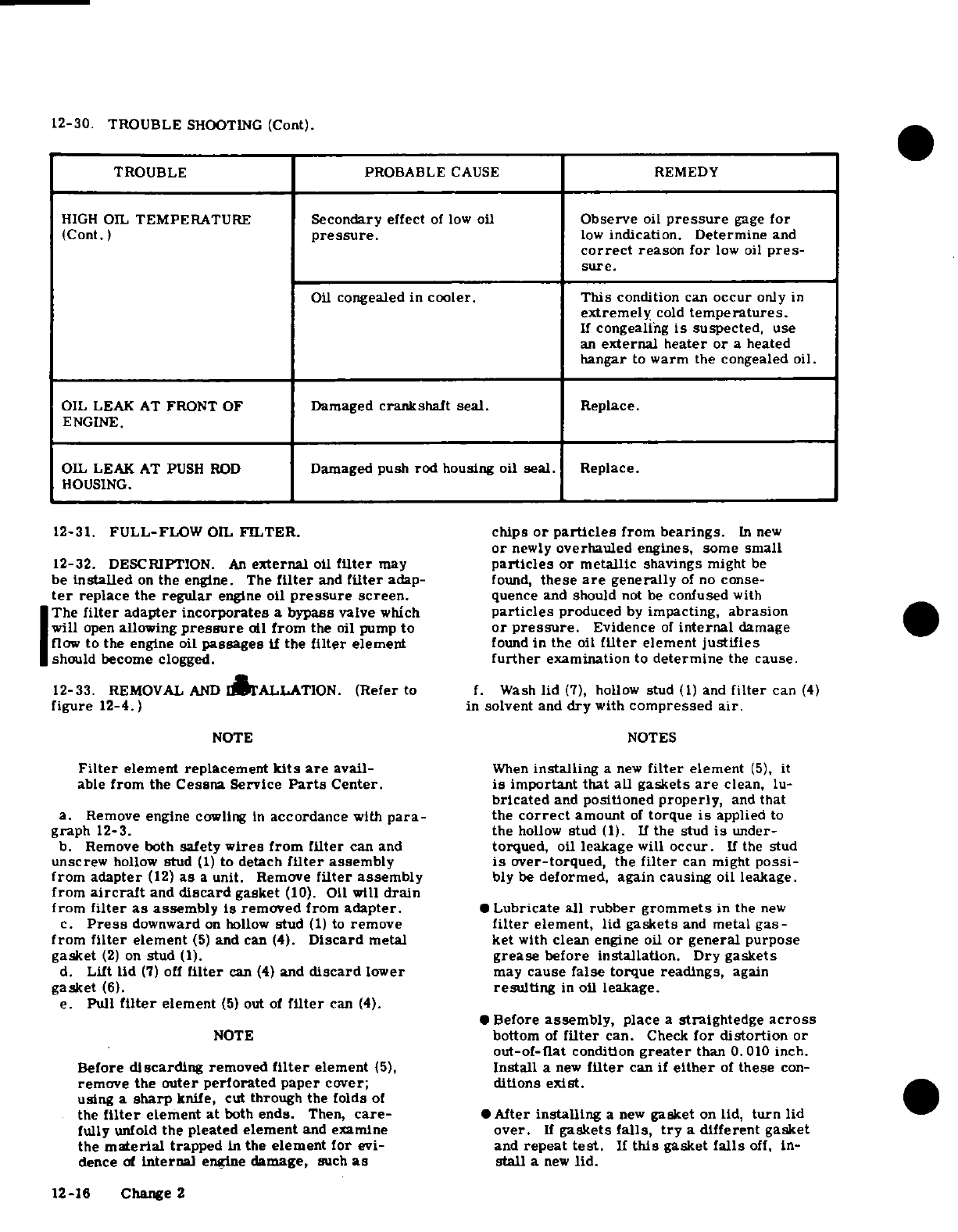
12-30.
TROUBLE
SHOOTING
(Cont).
TROUBLE
PROBABLE
CAUSE
REMEDY
HIGH
OIL
TEMPERATURE
Secondary
effect
of
low
oil
Observe
oil
pressure
gage
for
(Cont.)
pressure.
low
indication. Determine
and
correct
reason
for
low
oil
pres-
sure.
Oil
congealed
in
cooler.
This
condition
can
occur
only
in
extremely
cold
temperatures.
If
congealing
is
suspected,
use
an
external heater
or
a
heated
hangar
to
warm
the
congealed
oil.
OIL
LEAK
AT
FRONT OF
Damaged
crankshaft seal.
Replace.
ENGINE.
OIL LEAK AT
PUSH ROD
Damaged
push
rod
housing oil
seal.
Replace.
HOUSING.
12-31.
FULL-FLOW
OIL
FILTER.
chips
or
particles
from
bearings.
In
new
or
newly
overhauled
engines, some
small
12-32.
DESCRIPTION.
An
external
oil
filter
may
particles
or
metallic
shavings
might
be
be
installed
on
the
engine.
The
filter
and
filter
adap-
found,
these
are
generally
of
no
conse-
ter
replace the
regular
engine
oil
pressure
screen.
quence
and
should
not be
confused
with
The
filter
adapter incorporates
a
bypass
valve
which
particles
produced
by
impacting,
abrasion
will
open
allowing
pressure
oil
from
the oil
pump
to
or
pressure.
Evidence
of
internal
damage
flow
to
the
engine
oil
passages
if the
filter
element
found
in
the
oil
filter
element
justifies
should
become
clogged.
further
examination
to
determine
the
cause.
12-33.
REMOVAL
AND
INSTALLATION.
(Refer
to
f.
Wash
lid
(7),
hollow
stud
(1)
and
filter
can
(4)
figure
12-4.)
in
solvent
and
dry
with
compressed
air.
NOTE NOTES
Filter
element replacement
kits
are
avail-
When
installing
a
new
filter
element
(5),
it
able
from
the
Cessna
Service
Parts
Center.
is
important
that
all gaskets
are
clean,
lu-
bricated
and
positioned
properly,
and
that
a.
Remove
engine
cowling
in
accordance
with
para-
the
correct
amount
of
torque
is
applied
to
graph
12-3.
the
hollow
stud
(1).
If
the
stud
is
under-
b.
Remove both
safety
wires
from
filter
can
and
torqued,
oil
leakage
will
occur.
If
the
stud
unscrew
hollow
stud
(1)
to
detach
filter
assembly
is
over-torqued,
the
filter
can
might
possi-
from
adapter
(12)
as
a
unit. Remove
filter
assembly
bly
be
deformed,
again causing oil
leakage.
from
aircraft
and
discard
gasket
(10).
Oil
will
drain
from
filter
as
assembly
is
removed
from
adapter.
*Lubricate
all
rubber grommets
in
the
new
c.
Press
downward
on
hollow
stud
(1)
to
remove
filter
element,
lid
gaskets
and
metal
gas-
from
filter
element
(5)
and
can
(4).
Discard
metal
ket
with
clean
engine
oil
or
general
purpose
gasket
(2)
on
stud
(1).
grease
before
installation.
Dry gaskets
d.
Lift
lid
(7)
off
filter
can
(4)
and
discard
lower
may
cause
false
torque
readings,
again
gasket
(6).
resulting
in
oil
leakage.
e.
Pull
filter
element
(5)
out
of
filter
can
(4).
*Before
assembly,
place
a
straightedge
across
NOTE
bottom
of
filter
can.
Check
for
distortion
or
out-of-flat
condition
greater
than
0.010
inch.
Before
discarding
removed
filter
element
(5),
Install
a
new
filter
can
if
either
of
these
con-
remove
the
outer
perforated paper
cover;
ditions
exist.
using
a
sharp
knife, cut
through
the
folds
of
the
filter
element at
both
ends.
Then,
care-
*After
installing
a
new
gasket
on
lid,
turn
lid
fully
unfold
the
pleated
element
and
examine
over.
If
gaskets
falls,
try
a
different
gasket
the
material
trapped
in
the
element
for
evi-
and
repeat
test.
If
this
gasket
falls
off,
in-
dence
of
internal
engine
damage,
such
as
stall
a
new
lid.
12-16
Change
2
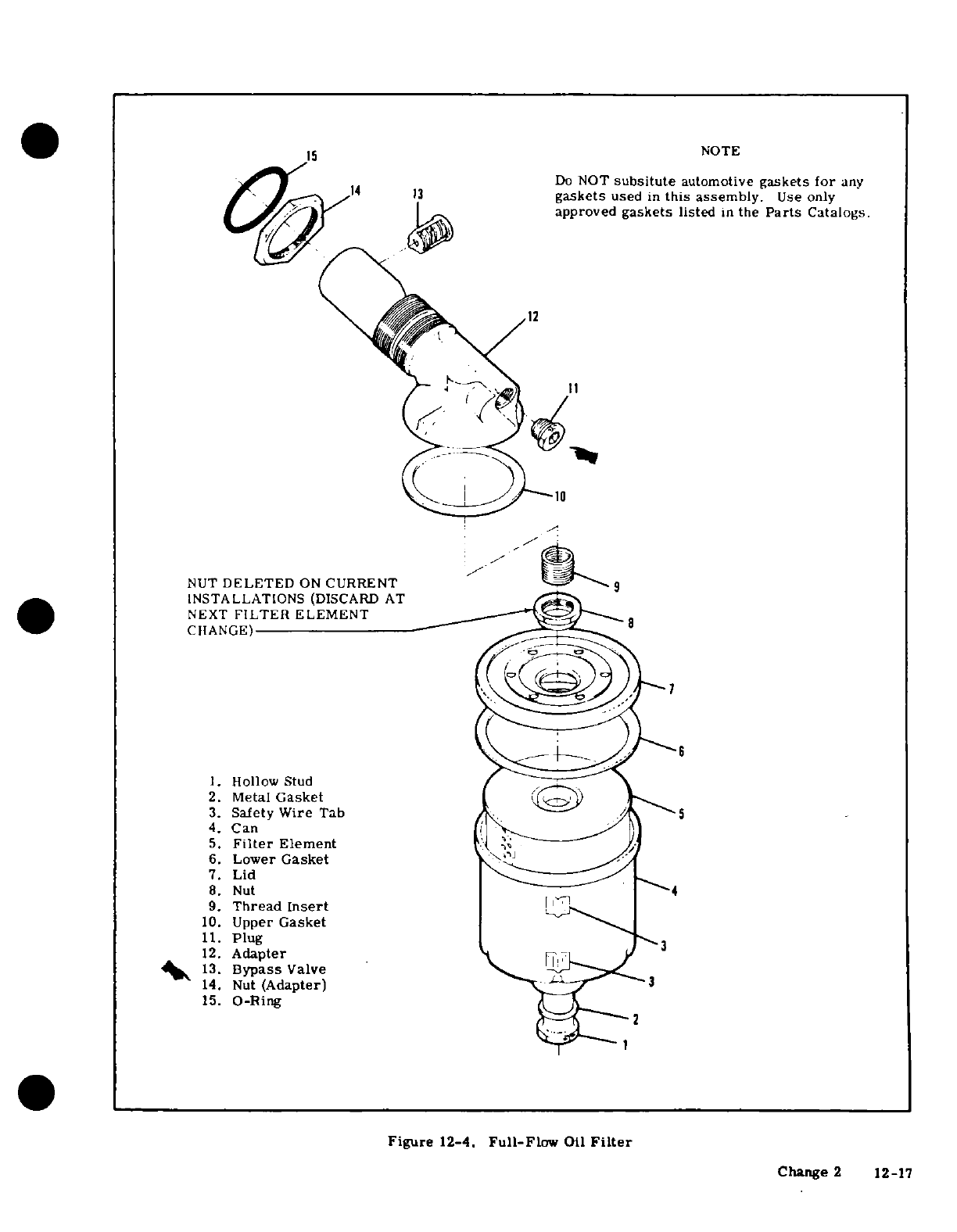
NOTE
14
13Do
NOT
subsitute
automotive
gaskets
for
any
1
gaskets
used
in
this
assembly.
Use
only
approved
gaskets
listed
in
the
Parts
Catalogs.
12
NUT
DELETED
ON
CURRENT
INSTALLATIONS
(DISCARD
AT
NEXT
FILTER
ELEMENT
CHANGE)
1.
Hollow
Stud
2.
Metal
Gasket
3.
Safety
Wire
Tab 5
4.
Can
5.
Filter
Element
6.
Lower
Gasket
7.
Lid
8.
Nut
4
9.
Thread Insert
10.
Upper
Gasket
11.
Plug
12.
Adapter
13.
Bypass
Valve
14.
Nut
(Adapter)
3
15.
O-Ring
Figure
12-4.
Full-Flow
Oil
Filter
Change
2
12-17
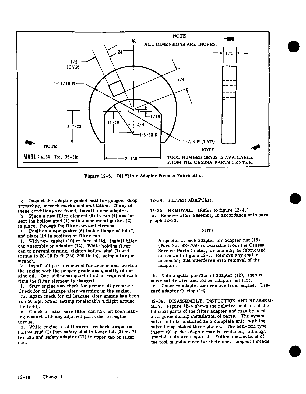
NOTE
1/2
ALL
DIMENSIONS
ARE
INCHES.
1/2
1
/2
(TYP)
1-11/16
R
1/16
J/32
"-1-5/32
R
NOTE
NT
1-5/32
R1-7/8
R
(TYP)
NOTE
+
MATL
4130
(Re.
35-38)
2.135
-
TOOL
NUMBER
SE709
IS
AVAILABLE
FROM THE
CESSNA
PARTS
CENTER.
Figure
12-5.
Oil
Filter
Adapter
Wrench
Fabrication
g.
Inspect
the
adapter
gasket
seat for
gouges, deep
12-34.
FILTER
ADAPTER.
scratches,
wrench
marks
and
mutilation.
If
any
of
these
conditions
are
found,
install
a
new
adapter.
12-35.
REMOVAL.
(Refer
to
figure
12-4.)
h.
Place
a
new
filter
element
(5)
in
can
(4)
and
in-
a.
Remove
filter
assembly
in
accordance
with
para-
sert
the
hollow
stud
(1)
with
a
new
metal
gasket
(2)
graph
12-33.
in
place,
through the
filter
can
and
element.
i.
Position
a
new
gasket
(6)
inside
flange
of
lid
(7)
NOTE
and
place
lid
in
position
on
filter
can.
j.
With
new
gasket
(10)
on
face
of
lid,
install
filter
A
special
wrench
adapter
for
adapter
nut
(15)
can
assembly
on
adapter
(12).
While
holding
filter (Part
No.
SE-709)
is
available
from
the
Cessna
can
to
prevent
turning,
tighten
hollow
stud
(1)
and
Service
Parts
Center,
or
one
may
be
fabricated
torque
to
20-25
lb-ft
(240-300
lb-in),
using
a
torque
as
shown
in
figure
12-5.
Remove
any
engine
wrench.
accessory
that
interferes
with
removal
of
the
k.
Install all
parts
removed
for
access
and
service
adapter.
the
engine
with the
proper
grade
and
quantity
of
en-
gine
oil.
One
additional
quart
of
oil
is
required
each
b.
Note
angular
position
of
adapter
(12),
then
re-
time
the
filter
element
is
changed.
move
safety
wire
and
loosen
adapter
nut
(15).
1.
Start
engine
and check
for
proper
oil
pressure.
c.
Unscrew
adapter
and
remove
from
engine.
Dis-
Check
for
oil
leakage
after
warming
up
the
engine.
card
adapter
O-ring
(16).
m.
Again
check
for
oil
leakage
after
engine
has
been
run
at
high
power
setting (preferably
a
flight around
12-36.
DISASSEMBLY,
INSPECTION
AND
REASSEM-
the field).
BLY.
Figure
12-4
shows
the
relative
position
of
the
n.
Check
to
make
sure
filter
can
has
not
been
mak-
internal
parts
of
the
filter
adapter
and
may
be
used
ing
contact
with
any
adjacent
parts
due
to
engine
as
a
guide
during
installation
of
parts.
The
bypass
torque.
valve
is
to
be
installed
as
a
complete
unit,
with
the
o.
While
engine
is
still
warm,
recheck
torque
on
valve
being
staked
three
places.
The
hell-coil
type
hollow
stud
(1)
then
safety
stud
to
lower
tab
(3)
on
fil-
insert
(9)
in
the
adapter
may
be
replaced,
although
ter
can
and
safety
adapter
(12)
to
upper
tab
on
filter
special
tools
are required.
Follow
instructions
of
can.
the
tool
manufacturer
for
their
use.
Inspect
threads
12-18 Change 1
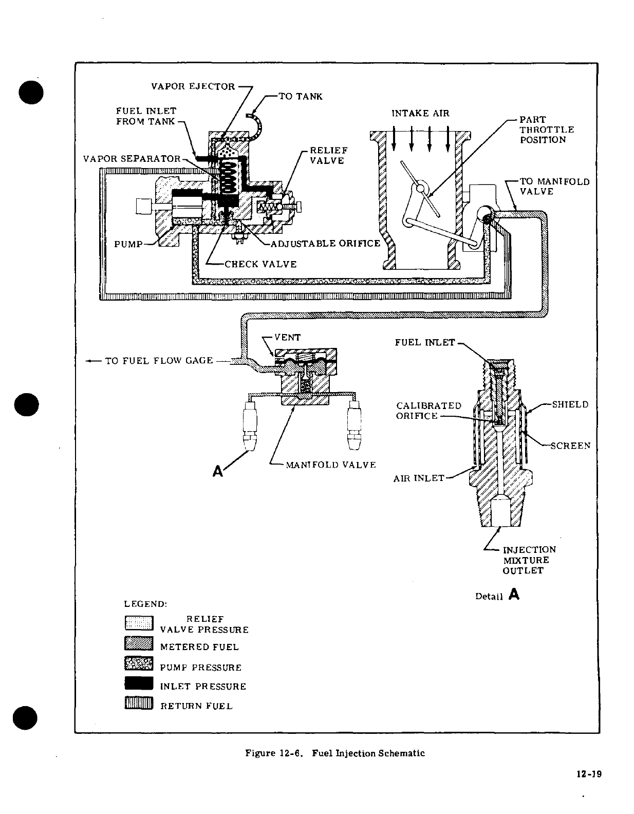
VAPOR
EJECTOR
TO
TANK
TO
MANIFOLD
MANIFOLD
VALVE
OUTLET
LEGEND:
RELIEF
INLET
PRESSURE
Figure
12-6.
Fuel
Injection
Schematic
12-19
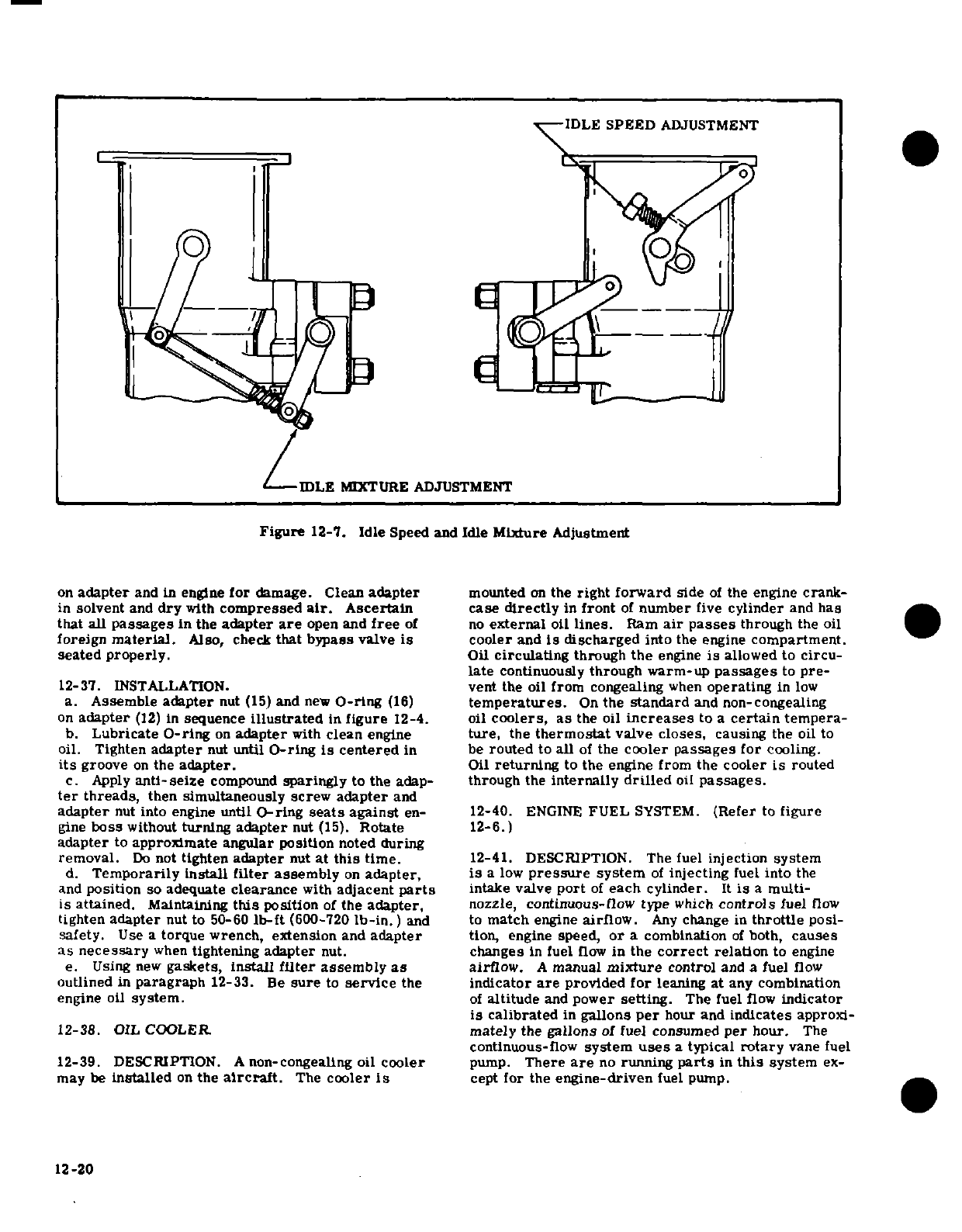
IDLE
SPEED
ADJUSTMENT
IDLE
MIXTURE
ADJUSTMENT
Figure
12-7.
Idle
Speed
and
Idle
Mixture
Adjustment
on
adapter
and in engine
for
damage.
Clean
adapter
mounted
on
the
right
forward
side
of
the
engine
crank-
in
solvent
and
dry
with
compressed
air.
Ascertain
case
directly
in
front
of
number
five
cylinder
and
has
that
all
passages
in
the
adapter
are
open
and
free
of
no
external
oil
lines.
Ram
air
passes
through
the
oil
foreign
material.
Also,
check
that
bypass
valve
is
cooler and
is
discharged
into
the
engine
compartment.
seated
properly.
Oil
circulating
through
the
engine
is
allowed
to
circu
late
continuously
through
warm-up
passages
to
pre-
12-37.
INNSTALLATIION.
vent
the
oil
from congealing
when
operating
in
low
a.
Assemble
adapter
nut
(15)
and
new
L8-rIiLng
(16)
temperatures.
On
the
standard
and
non-coLngealing
on
adapter
(12)
in
sequence
illustrated
in
figure
12-4.
oil
coolers,
as
the oil
increases
to
a
certain
tempera-
b.
Lubricate
OL-rPOYg
on
adapter
with
clean
engine
ture,
the
thermostat
valve
closes,
causing
the oil
to
oil.
Tighten
adapter
nut
until
O-ring
is
centered
in
be
routed
to
all
of
the
cooler
passages
for
cooling.
its
groove
on
the
adapter.
Oil
returning
to
the
engine from
the
cooler
is
routed
c.
Apply
anti-seize
compound
sparingly
to
the
adap-
through
the
internally
drilled
oil
passages.
ter
threads,
then
simultaneously
screw
adapter
and
adapter
nut
into
engine
unItOiMNN
T-ring
seats
against
en-
12-40.
ENGINE
FUEL
SYSTEM.
(Refer
INo
figUYre
gKUUUUne
boss
without
turning
adapter
nut
(15).
Rotate
12-6.)
adapter
to
approAAUImate
angular
positOiLon
noted
during
removal.
Do
not
tighten
adapter
nut
at
this
time.
12-41.
DESCRIPTION.
The
fuel
injection
system
d.
Temporarily
install
filter
assembly
on
adapter,
is
a low
pressure
system
of
injecting
fuel
into
the
and
position
so
adequate
clearance
with
adjacent
parts
intake
valve
port
of
each
cylinder.
It
is
a
multi-
is attained.
Maintaining
this
position
of
the
adapter,
nozzle,
continuous-flow
type
which
controls
fuel
flow
tighten
adapter
nut to
50-60
lb-ft
(600-720
lb-in.)
and
to
match
engine
airflow.
Any
change in
throttle
posi-
safety.
Use
a
torque wrench,
extension
and
adapter
tion,
engine
speed,
or
a
combination
of
both,
causes
as
necessary
when
tightening
adapter
nut.
changes
in
fuel
flow
in
the
correct
relation
to engine
e.
Using
new
gaskets,
install
filter
assembly
as
airflow.
A
manual
mixture
control
and
a
fuel
flow
outlined
in
paragraph
12-33.
Be
sure
to
service
the
indicator
are
provided
for
leaning
at
any
combination
engine
oil
system.
of
altitude
and
power
setting.
The
fuel
flow
indicator
is
calibrated
in
gallons
per
hour
and
indicates
approxi-
12-38.
OIL
COOLER.
mately
the
gallons
of
fuel
consumed
per
hour.
The
continuous-flow
system
uses
a
typical
rotary
vane
fuel
12-39.
DESCRIPTION.
A
non-congealing
oil
cooler
pump.
There
are
no
running
parts
in
this
system
ex-
may
be
installed
on
the
aircraft.
The
cooler
Is
cept
for
the
engine-driven
fuel
pump.
12-20
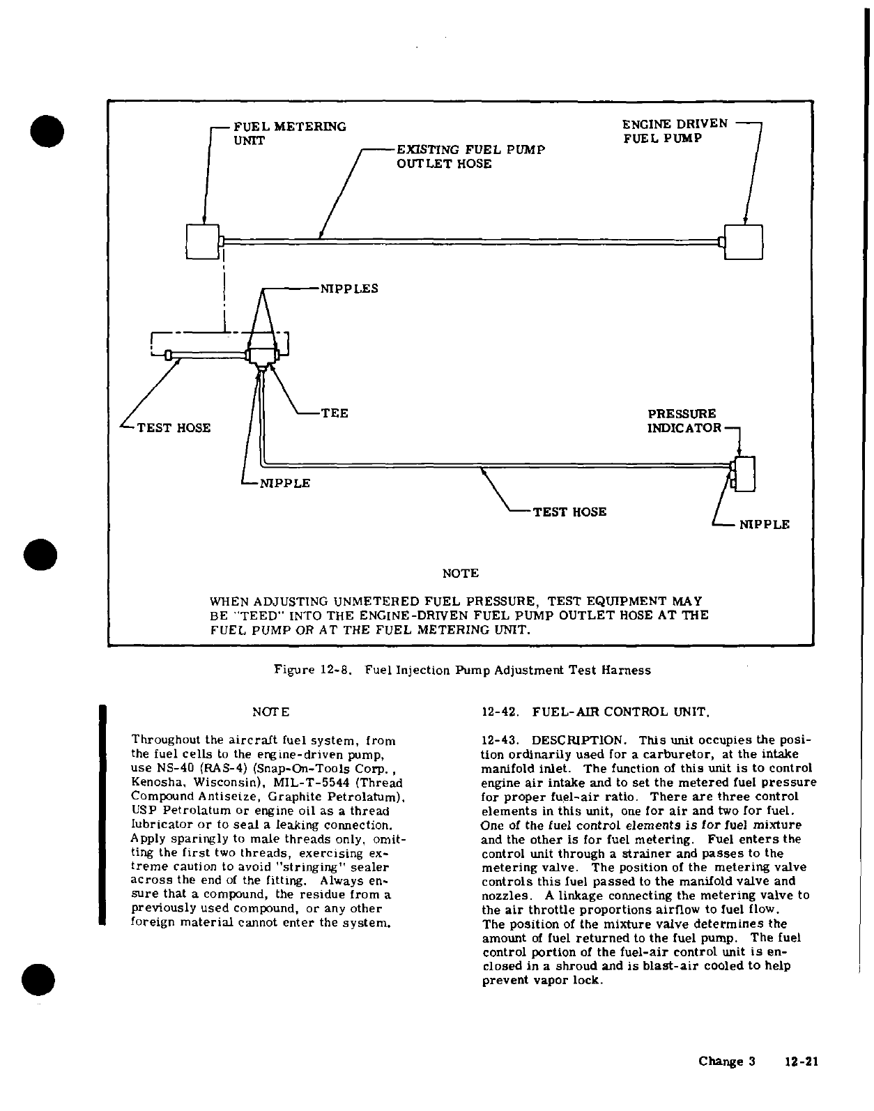
-
FUEL
METERING
ENGINE
DRIVEN
UNIT
FUEL
PUMP
UNEXISTING
FUEL
PUMP
OUTLET
HOSE
NIPPLES
NOTE
WHEN
ADJUSTING
UNMETERED
FUEL
PRESSURE,
TEST
EQUIPMENT
MAY
BE
"TEED"
INTO THE
ENGINE-DRIVEN
FUEL PUMP
OUTLET
HOSE
AT
THE
FUEL
PUMP
OR
AT
THE
FUEL
METERING
UNIT.
Figure
12-8.
Fuel
Injection
Pump
Adjustment
Test
Harness
NOTE
12-42.
FUEL-AIR
CONTROL
UNIT.
Throughout
the
aircraft
fuel
system,
from
12-43. DESCRIPTION.
This
unit
occupies
the
posi-
the
fuel
cells
to
the
engine-driven
pump,
tion
ordinarily
used
for
a
carburetor,
at
the
intake
use
NS-40
(RAS-4)
(Snap-On-Tools
Corp.,
manifold
inlet.
The
function
of
this
unit
is
to control
Kenosha.
Wisconsin),
MIL-T-5544 (Thread
engine
air
intake
and
to
set
the
metered
fuel
pressure
Compound
Antiseize, Graphite
Petrolatum),
for
proper
fuel-air
ratio.
There
are three
control
USP
Petrolatum
or
engine
oil
as
a
thread
elements
in
this
unit,
one
for
air
and
two
for
fuel.
lubricator
or
to
seal
a
leaking
connection.
One
of
the
fuel
control
elements
is
for
fuel
mixture
Apply
sparingly
to
male
threads
only,
omit-
and
the
other
is
for
fuel
metering.
Fuel
enters
the
ting
the
first
two
threads,
exercising
ex-
control
unit
through
a
strainer
and
passes
to the
treme
caution to avoid
"stringing"
sealer
metering
valve. The
position
of
the
metering
valve
across
the
end
of
the
fitting.
Always
en-
controls
this
fuel
passed
to
the
manifold
valve
and
sure
that
a
compound,
the
residue
from
a
nozzles.
A
linkage
connecting
the
metering
valve
to
previously
used
compound,
or
any
other
the
air
throttle
proportions
airflow
to fuel
flow.
foreign
material
cannot
enter
the
system.
The
position
of
the
mixture
valve
determines
the
amount
of
fuel
returned
to
the
fuel
pump.
The
fuel
control portion
of
the
fuel-air
control
unit
is
en-
closed in
a
shroud
and
is
blast-air
cooled
to
help
prevent
vapor
lock.
Change
3
12-21
12-44.
REMOVAL
AND
INSTALLATION.
b.
Advance
throttle
to
increase
engine
speed
to
a.
Place all
cockpit
switches
and
fuel
shut-off
valve
1000
rpm.
in
the
OFF
position.
c.
Pull mixture
control
knob
slowly
and
steadily
b.
Remove
cowling
in
accordance
with
paragraph
toward
the
idle
cut-off
position, observing
tacho-
12-3.
meter,
then
return
control
full
IN
(RICH)
position
c.
Remove
induction
airbox
in
accordance
with
before
engine
stops.
paragraph
12-65.
d.
Adjust
mixture
adjusting
nut
to
obtain
a
slight
d.
Disconnect
engine
controls
at
throttle
and
mix-
and
momentary
gain
of
25
rpm maximum
at
1000
rpm
ture
control
arms.
engine
speed
as
mixture
control
is
moved
from
full
IN
(RICH)
toward
idle
cut-off
position.
Return
con-
NOTE
trol
to
full
IN
(RICH)
to
prevent
engine
stoppage.
e.
If
mixture
is
set
too
LEAN,
engine speed
will
Cap
all
disconnected
hoses,
lines
and
fittings.
drop
immediately,
thus
requiring
a
richer
mixture.
Tighten
adjusting
nut
(clockwise)
for
a
richer
mixture.
e.
The
three
fuel
lines
which
attach
to
the
fuel
con-
f.
If
mixture
is
set
too
RICH,
engine
speed
will in-
trol
unit
are
routed inside
flexible
tubing
to
help
cool
crease
above
25
rpm,
thus
requiring
a
leaner
mix-
the
fuel.
Loosen
tubing
clamps
at
the
control
unit
ture.
Back
off
adjusting
nut
(counterclockwise)
for
and
slide
tubing
back
to
gain
access
to
the
fuel
line
a
leaner
mixture.
fittings.
f.
Disconnect
fuel
lines
at
control
unit.
NOTE
g.
Loosen
hose
clamps
which
secure
the
control
unit
to
the
right
and
left
intake manifolds.
After
each
adjustment
to
the
idle
mixture,
h.
Remove
control
unit.
run
engine
up
to
approximately
2000
rpm
i.
Cover
the
open
ends
of
the
intake
manifold
piping
to
clear
engine
of
excess
fuel
to
obtain
a
to
prevent
entry
of
foreign
matter.
correct
idle
speed.
j.
Reverse
the
preceding
steps
for
reinstallation.
Use
new
gaskets
when
installing
control
unit.
Rig
12-47.
FUEL
MANIFOLD
VALVE
(FUEL
DISTRIB-
throttle
and
mixture
controls
in
accordance
with
para-
UTOR).
graphs
12-85
and
12-86
respectively.
Rig
throttle-
operated microswitch
in
accordance
with
Section
13.
12-48. DESCRIPTION.
Metered fuel
flows
to the
fuel
manifold
valve,
which
provides
a
central
point
12-45.
CLEANING
AND
INSPECTION.
for
distributing
fuel to
the
individual
cylinders.
An
a.
Check
control
connections,
levers
and
linkage
for
internal
diaphragm,
operated
by
fuel
pressure,
security,
safetying
and
for
lost
motion
due
to
wear.
raises
or
lowers
a
plunger
to
open
and
close
the
in-
b.
Remove
the
fuel
screen
assembly
and
clean
in
dividual
cylinder
supply
ports
simultaneously.
A
solvent
(Stoddard
or
equivalent).
Reinstall
and
safety.
needle valve
in
the
plunger
ensures
that
the
plunger
c.
Check
the
air
control
body
for
cracks
and
con-
fully opens
the
outlet
ports
before
fuel
flow
starts
trol
unit
for
overall
condition,
and
closes
the
ports
simultaneously
for
positive
engine
shut-down.
A
fine-mesh
screen
is
includ-
12-46.
ADJUSTMENTS.
(Refer
to
figure
12-7.)
The
ed
in
the
fuel
manifold
valve.
idle
speed
adjustment
is
a
conventional
spring-loaded
screw
located
in
the
air
throttle
lever.
The
idle
NOTE
mixture
adjustment
is
the
locknut
at
the
metering
valve
end
of
the linkage.
Tightening
the
nut
to
shor-
The
fuel
manifold
valves
are
supplied
in
two
ten the linkage
provides
a
richer
mixture.
A
leaner
flow
ranges.
When
replacing
a
valve
assem-
mixture
is
obtained
by
backing
off
the
nut
to
lengthen
bly,
be
sure
the
replacement
valve
has
the
the
linkage.
Idle
speed
and
mixture adjustment
same
suffix
letter
as
the
one
stamped
on
the
should
be
accomplished
after
the
engine
has
been cover
of
the valve
removed.
warmed
up.
Since
idle
rpm
may
be affected
by
idle
mixture
adjustment,
it
may
be
necessary
to
readjust
12-49.
REMOVAL.
idle
rpm
after
setting
the idle
mixture
correctly.
a.
Set
the
throttle
stop
screw to
obtain
600
±
25
NOTE
rpm,
with
throttle
control
pulled
full
out
against
idle
stop.
Cap
all
disconnected
lines, hoses
and
fittings.
NOTE
a.
Disconnect
all
fuel
and
fuel
injection
lines
at
the
fuel
manifold.
Engine
idle
speed
may
vary
among
different
b.
Remove
bolts
which
secure
fuel
manifold
and
engines.
An
engine
should
idle smoothly,
remove
manifold.
without
excessive
vibration
and
the idle
speed
should
be
high
enough
to
maintain
idling
oil
12-50.
CLEANING.
pressure
and to
preclude
any
possibility
of
a.
Remove
manifold valve
from
engine
in
accor-
engine
stoppage
in
flight
when
the
throttle
is
dance
with
paragraph
12-49 and
remove
safety
wire
closed.
from
cover attaching
screws.
12-22
Change 1
b.
Hold
the
top
cover
down
against
internal
spring
cated
in
the
cylinder
heads.
The
outlet
of
each
noz-
until
all
four
cover
attaching
screws
have been
re-
zle
is
directed
into
the
intake
port
of
each
cylinder.
moved,
then
gently
lift
off
the
cover.
Use
care
not
The
nozzle
body
contains
a
drilled
central
passage
to
damage
the
spring-loaded
diaphragm
below
cover.
with
a
counterbore
at
each
end. The
lower
end
is
c.
Remove
the
upper
spring
and
lift
the
diaphragm
used
as
a
chamber
for
fuel-air
mixture
before
the
assembly
straight
up.
spray
leaves
the
nozzle.
The
upper
bore
contains
an
orifice
for
calibrating
the
nozzles.
Near
the
top,
NOTE
radial
holes
connect
the
upper
counterbore
with
the
outside
of
the
nozzle
body
for
air
admission.
These
If
the
valve
attached
to
the
diaphragm
is
radial
holes
enter
the
counterbore
above
the
orifice
stuck
in
the
bore
of
the
body,
grasp
the
and draw
outside
air
through
a
cylindrical
screen
center
nut,
rotate
and
lift
at
the
same
fitted
over
the
nozzle
body.
This
screen
prevents
time
to
work
gently
out
of
the
body.
dirt
and
foreign
material
from
entering
the nozzle.
A
press-fit
shield
is
mounted
on
the
nozzle
body
and
CAUTION
extends
over
the
greater
part
of
the
filter
screen,
leaving
a
small
opening
at
the bottom
of
the
shield.
Do
not
attempt
to
remove
needle
or
spring
This
provides
an
air
bleed
into
the
nozzle
which aids
from
inside
plunger
valve.
Removal
of
in
vaporizing
the
fuel
by
breaking
the
high
vacuum
in
these
items
will
disturb
the
calibration
of
the intake
manifold at
idle
rpm
and
keeps
the
fuel
the
valve.
lines
filled.
The
nozzles
are
calibrated
in
several
ranges.
All
nozzles
furnished for
one
engine
are
the
d.
Using
clean
gasoline,
flush
out
the
chamber
be-
same range
and
are
identified
by
a
number
and a
low
the
screen.
suffix
letter
stamped
on
the
flat
portion
of
the
nozzle
e.
Flush
above
the
screen
and
inside
the
center
body.
When
replacing
a
fuel
discharge
nozzle
be
bore
making
sure
that
outlet
passages
are
open.
Use
sure
it
is
of
the
same
calibrated
range
as
the
rest
of
only
a
gentle
stream
of
compressed
air
to
remove the
nozzles
in
the
engine.
When
a
complete
set
of
dust
and
dirt
and to
dry.
nozzles
is
being
installed,
the
number
must
be
the
same
as
the
one
removed,
but
the
suffix
letters
may
CAUTION
be
different,
as
long
as
they
are
the
same
for
all
nozzles
being
installed
on
a
particular
engine.
The
filter
screen
is
a
tight
fit
in
the
body
and
may
be
damaged
if
removal
is
attempted.
It
12-54.
REMOVAL.
should
be
removed
only
if
a
new
screen
is
to
be
installed.
NOTE
f.
Clean diaphragm,
valve
and
top
cover
in
the
Plug
or
cap
all
disconnected
lines
and
fittings.
same
manner.
Be
sure
the
vent
hole in
the
top cover
is
open
and
clean.
a.
Disconnect the
fuel
injection
lines
at
the
fuel
dis-
g.
Carefully
replace
diaphragm
and
valve.
Check
charge
nozzles.
Remove
nozzles
with
a
1/2
inch
deep
that
valve
works
freely
in
body
bore.
well
socket
wrench.
h.
Position
diaphragm
so
that
horizontal
hole
in
plunger
valve
is
90
degrees
from
the
fuel
inlet
port
12-55.
CLEANING
AND
INSPECTION.
To
clean
in
the valve
body.
nozzles,
immerse
in
clean
solvent
and
use
compress-
i.
Place
upper
spring
in
position
on
diaphragm.
ed
air
to
dry
them.
When
cleaning,
direct
air
through
j.
Place
cover
in
position so that
vent
hole in
the
nozzle
in
the
direction
opposite
of
normal
fuel flow
Do
not
remove the
nozzle
shield
or
distort
it
in
any
cover is
90
degrees
from inlet port
in
valve
body.
Install
cover
attaching
screws
and
tighten
to
20±1
way.
Do
not
use
a
wire
or
other
metal
object
to clean
lb-in.
Install
safety wire
on
cover
screws.
the
orifice
or
metering
jet.
After
cleaning,
check
the
shield
height
from
the
hex
portion
of
the
nozzle.
The
k.
Install
fuel
manifold valve
assembly
on
engine
sheld
height
from
thehex
portion
of
the
nozzle.
The
in
accordance
with
paragraph
12-51
and
reconnect
bottom
of
the
shield
should
be
approximately
1/16
all
lines
and
hoses
to
valve.
-inch
above
the
hex
portion
of
the nozzle.
1.
Inspect
installation
and
install
cowling..
INSTALLATION.
12-56.
INSTALLATION.
12-51.
INSTALLATION.
a.
Install
nozzles
in
the
cylinders
and
tighten
to a
a.
Secure
the
fuel manifold
to
the
crankcase
with
torque
value
of
60
to
80
Ib-in.
the
two
crankcase
bolts.
b.
Connect
the
fuel
lines at discharge
nozzles.
b.
Connect
the
fuel
lines
and
the
six
fuel
injection
c.
Check
installation
for
crimped
lines,
loose
fit-
lines.
Inspect completed
installation
and
install
tings,
etc.
cowling.
1
2-57.
FUEL
INJECTION
PUMP.
12-52.
FUEL
DISCHARGE
NOZZLES.
12-58.
DESCRIPTION.
The
fuel
pump
is
a
positive-
12-53.
DESCRIPTION.
From
the
fuel
manifold
displacement,
rotating
vane
type,
connected
to the
valve,
individual,
identical
size
and
length
fuel
lines
accessory
drive
section
of
the
engine.
Fuel
enters
carry
metered
fuel
to
the
fuel
discharge
nozzles
lo-
the
pump
at
the
swirl
well
of
the
pump
vapor separa-
12-23
tor.
Here,
vapor
is
separated
by
a
swirling
motion
12-60.
INSTALLATION.
so
that
only
liquid
fuel
is
fed
to
the
pump.
The
vapor
a.
Position
a
new
gasket
and fuel
pump
on
the
is
drawn
from
the
top
center
of
the
swirl
well
by
a
mounting
studs
with
fuel
pump
inlet
to
the
left.
Be
small
pressure
jet
of
fuel
and
is
fed
into
the
vapor
sure
pump
drive
aligns
with
drive
in
the
engine.
return
line, where
it
is
returned
to
the
aircraft
fuel
b. Secure
pump
to
engine
with
plain
washers,
in-
system.
Since
the
pump
is
engine-driven,
changes
ternal
tooth
lock
washers
and
nuts. Tighten
nuts
in
engine
speed
affects
total
pump
flow
proportion-
evenly.
ally.
A
check
valve
allows
the
auxiliary
fuel
pump
c.
Install
cooling
shroud
on
fuel
pump.
pressure
to
bypass
the
engine-driven
fuel
pump
for
d.
Install
all
fittings
and
connect
all lines.
starting,
or
in
the
event
of
engine-driven
fuel
pump
e.
Install
the
flexible
ram
air
tube
on
the
air
horn
failure.
The
pump
supplies more
fuel than
is
re-
of
the
fuel
pump
shroud
and
install
clamp
quired
by
the
engine;
therefore,
a
spring-loaded,
f.
Replace
the
alternator
drive
belt
and
tighten
the
diaphragm type
relief
valve
is
provided,
with
an ad-
nuts
on
the
adjusting
arm
so
that
the
drive
belt
has
justable orifice
installed
in
the fuel
passage
to
the
proper
tension.
Refer
to
Section
17.
relief
valve
to
maintain
desired
fuel
pressure
for
g.
Inspect
completed
installation.
engine
power
setting.
The
adjustable
orifice
allows
the
exact
desired
pressure
setting at
full
throttle.
12-61.
ADJUSTMENT.
The
full
rich
performance
The
fuel
pump
is
equipped
with
a manual
mixture
of
the fuel
injection
system
is
controlled
by
manual
control
to
provide
positive mixture
control
throughout
adjustment
of
the
air
throttle,
fuel
mixture
and
pump
the range
required
by
the
injection
system. This
con-
pressure at
idle
and
only
by
pump
pressure
at
full
trol
limits
output
of
the
pump
from
full
rich
to
idle
throttle.
To
make
full
rich
adjustments,
proceed
as
cut-off.
Non-adjustable
mechanical
stops
are
located
follows:
at
these
positions.
The fuel
pump
is
ram-air
cooled a.
Remove
engine cowling in
accordance
with
para-
to
help
prevent
high
fuel
temperatures.
The
ram
air
graph
12-3.
is
picked
up
at
the
upper
left
engine
baffle
and
direct-
ed
through
a
flexible
tube
to
the
fuel
pump
shroud.
NOTE
The
fuel
supply
and
return
lines
from
the
fuel
pump
to
the
control
unit
are
routed
inside
flexible
tubes to
Inspect
the
slot-headed
adjustable orifice
help
prevent
vaporized
fuel
at
these
points.
needle
valve
(located
just
below
the
fuel
pump
inlet
fitting)
to
see
if
it is
epoxy
12-59.
REMOVAL.
sealed
or
safety
wired
to
the
brass
nut.
a.
Place
fuel shut-off valve
in
OFF
position
and
If
the needle valve
is
epoxy
sealed,
Con-
mixture control
in
IDLE
CUT-OFF
position.
tinental
Aircraft
Engine
Service
Bulletin
b.
Remove
cowling
in
accordance
with
paragraph
No.
70-10
must
be
complied
with
before
12-3.
calibration
of
the
unit
can
be
performed.
c.
Loosen the
clamps
and
slide
the
flexible
tubes
free
of
the
horns
on
the
fuel
pump
shroud to
gain
ac-
b.
Disconnect
the
engine-driven
fuel
pump
outlet
cess
to
the fuel
lines.
cess
to
the
fuel
lines.
d.
Remove
the
alternator
drive
belt.
fitting
or
the
fuel
metering
unit
inlet fitting
and
"tee"
e.
Tag and
disconnect
all
lines
and
fittings
attach-
the
test
gage
into
the
fuel
injection
system
as
illus-
ed
to
the fuel
pump.
trated
in
figure
12-8.
NOTE
NOTE
Plug
or
cap
all
disconnected
lines,
hoseses
Cessna
Service
Kit
No.
SK320-2
provides
and
fittings.
a
test
gage, line
and
fittings for
connecting
the
test
gage into
the
system
to
perform
f.
Remove
the
shroud surrounding
the
fuel
pump
accurate calibration
of
the
enginedriven
g.
Remove
the nuts
and
washers
attaching
the fuel
fuel
pump.
pump
to
the
engine.
h.
Remove
fuel
pump
and
gasket.
c.
The
test
gage
MUST
be
vented
to
atmosphere
and
MUST
be
held
as
near
to
the
level
of
the
engine-driven
WARNING
fuel
pump
as
possible.
Bleed
air
from
test
gage
line
prior
to
taking
readings.
Residual
fuel
draining
from
lines
and
hose
constitutes
a
fire
hazard.
Use
caution
to
NOTE
prevent
accumulation
of
fuel
when
lines
or
hoses
are
disconnected.
The
test
gage
should
be
checked
for accuracy
at
least
every
90
days
or
anytime
an
error
is
i. If
a
replacement
pump
is
not being
installed
im-
suspected.
The
tachometer accuracy
should
mediately,
a
temporary
cover
should
be
installed
on
also
be
determined
prior
to
making
any ad-
the
fuel pump
mount pad.
justments
to
the
pump.
d.
Start
engine
and
warm-up
thoroughly.
Set
mix-
ture
control
to
full
rich
position
and
propeller
con-
trol
full
forward
(low
pitch,
high
rpm).
12-24
Change
1
e.
Adjust
engine
idle
speed
to
600
-
25
rpm
and
gine baffle.
A
spring-loaded
alternate
air
door
is
check
test
gage
for
9-11
PSI.
Refer
to
figure
12-7
incorporated
in
the
airbox
and
will
open
by
engine
for idle
mixture adjustment.
suction
if
the
air
filter
should
become
clogged.
This
permits
unfiltered
induction
air
to
be
drawn
from
NOTE
within
the
engine
compartment.
Do
not
adjust
idle
mixture
until
idle
pump
12-64.
AIRBOX.
pressure
is
obtained.
12-65.
REMOVAL
AND
INSTALLATION.
WARNING
a.
Remove
cowling
in
accordance
with
paragraph
12-3.
DO
NOT
make
fuel
pump
pressure
adjust-
b.
Remove
induction
air
filter.
ments
while
engine
is
operating.
c.
Disconnect
electrical
wiring
at
throttle-operated
micro-switch
and
tape
terminals as
a
safety
precau-
f. If
the
pump
pressure
is
not
9
to
11
PSI,
stop
en-
tion.
gine
and
turn
the
fuel
pump
relief
valve
adjustment,
d.
Remove
clamps
attaching
lines,
wires
and
con-
on
the
centerline
of
the
fuel
pump
clockwise
(CW)
to
trols
to
airbox.
increase
pressure
and
counterclockwise
(CCW)
to
e.
Remove
bolts securing airbox
to
fuel-air
control
decrease
pressure.
unit and
engine
and
remove
airbox
and
gasket.
g.
Maintaining idle
pump
pressure
and
idle
RPM,
f.
Install
a
cover
over
fuel-air
control
opening.
obtain
correct
idle
mixture
in
accordance
with
para-
g.
Reverse
the
preceding
steps
for
reinstallation.
graph
12-46.
Adjust
throttle
operated
switch in
accordance
with
h.
Completion
of
the
preceding
steps
have
provided:
Section
13.
1.
Correct
idle
pump
pressure.
2.
Correct
fuel
flow.
12-66.
CLEANING
AND
INSPECTION.
Clean
metal
3.
Correct
fuel
metering
cam
to
throttle
plate
parts
of
the
induction
airbox
with
Stoddard solvent
or
orientation.
equivalent.
Inspect
for
cracks,
dents,
loose
rivets,
i.
Advance
to
full
throttle
and
maximum
rated
en-
etc.
Minor
cracks
may
be
stop-drilled.
In
case
of
gine
speed
with
the
mixture
control
in
full
rich posi-
continued
or
severe
cracking,
replace
airbox.
In-
tion
and
propeller
control
in
full
forward
(low
pitch,
spect
alternate
spring-loaded
door
for freedom
of
high
rpm).
operation
and
complete
closing.
j.
Check
test
gage
for
pressures
specified
in
para-
graph
12-
12.
If
pressure
is
incorrect,
stop
engine
12-67.
INDUCTION
AIR
FILTER.
and
adjust
pressure
by
loosening
locknut and
turning
the
slotheaded
needle
valve
located
just
below
the
fuel 12-68. DESCRIPTION.
An
induction
air
filter,
pump
inlet
fitting
clockwise
(CW)
to
increase
pressure
mounted
at
the
airbox
inlet,
removes
dust
particles
and
counterclockwise
(CCW)
to
decrease
pressure.
from
the
ram
air
entering
the
engine.
NOTE
12-69.
REMOVAL
AND
INSTALLATION.
a.
Remove
cowling
in
accordance
with
paragraph
If
at
static
run-up,
rated
RPM
cannot
be
12-3.
achieved
at
full
throttle,
adjust
pump
b.
Remove
bolts
securing
filter
to
the
upper
left
pressure
slightly
below
limits
making
engine
baffle
and
induction
airbox
inlet.
certain
the
correct
pressures
are
ob-
c.
Reverse
the
preceding
steps
for
reinstallation.
tained
when
rated
RPM
is
achieved
dur-
Make
sure
the
gasket
is
in
place
between
the
filter
ing
take-off
roll.
and
airbox
intake.
k.
After
correct
pressures
are
obtained,
safety
12-70.
CLEANING
AND
INSPECTION.
Clean
and
adjustable
orifice
and
orifice
locknut.
inspect
filter
in
accordance
with
instructions
in
Sec-
l.
Remove
test
equipment,
run
engine
to
check
for
tion
2.
leaks
and
install
cowling.
12-71.
IGNITION
SYSTEM.
12-61A.
AUXILIARY
ELECTRIC FUEL
PUMP
FLOW
RATE
ADJUSTMENT.
Refer
to Section
13.
12-72. DESCRIPTION.
The
ignition
system
is
com-
prised
of
two
magnetos,
two
spark
plugs
in
each
cyl-
12-62.
INDUCTION
AIR
SYSTEM.
inder,
an
ignition
wiring
harness,
an
ignition
switch
mounted
on
the
instrument
panel
and
required
wiring
12-63. DESCRIPTION. Ram
air
enters
the
induc-
between the
ignition
switch
and
magnetos.
tion
air
system
through
a
filter
at
the
upper
left
en-
Change
3
12-25
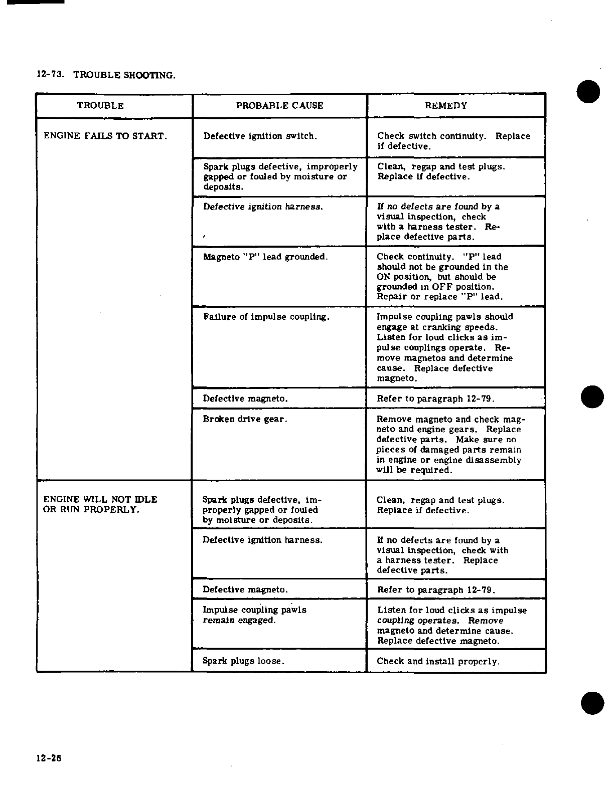
12-73.
TROUBLE
SHOOTING.
TROUBLE
PROBABLE
CAUSE
REMEDY
ENGINE
FAILS
TO
START.
Defective
ignition
switch. Check
switch
continuity.
Replace
if
defective.
Spark
plugs
defective,
improperly
Clean, regap
and
test
plugs.
gapped
or
fouled
by
moisture or
Replace
if
defective.
deposits.
Defective
ignition
harness.
If no
defects
are
found
by
a
visual
inspection,
check
with
a
harness
tester.
Re-
place
defective
parts.
Magneto
"P"
lead
grounded. Check
continuity.
"P"
lead
should
not be
grounded
in the
ON
position,
but
should
be
grounded
in
OFF
position.
Repair
or
replace
"P"
lead.
Failure
of
impulse
coupling.
Impulse
coupling
pawls
should
engage
at
cranking
speeds.
Listen
for
loud
clicks
as
im-
pulse
couplings
operate.
Re-
move
magnetos
and
determine
cause.
Replace
defective
magneto.
Defective magneto.
Refer
to
paragraph
12-79.
Broken
drive
gear.
Remove
magneto
and
check
mag-
neto
and engine
gears.
Replace
defective
parts.
Make
sure
no
pieces
of
damaged
parts
remain
in
engine
or
engine
disassembly
will
be
required.
ENGINE WILL
NOT
IDLE
Spark
plugs
defective,
im-
Clean,
regap
and
test
plugs.
OR
RUN
PROPERLY.
properly
gapped
or
fouled
Replace
if
defective.
by
moisture
or
deposits.
Defective
ignition
harness.
If
no
defects
are
found by
a
visual
inspection,
check
with
a
harness
tester.
Replace
defective
parts.
Defective magneto.
Refer
to
paragraph
12-79.
Impulse
coupling
pawls
Listen
for
loud
clicks
as
impulse
remain
engaged.
coupling
operates.
Remove
magneto
and
determine
cause.
Replace
defective
magneto.
Spark
plugs loose.
Check
and
install
properly.
12-26
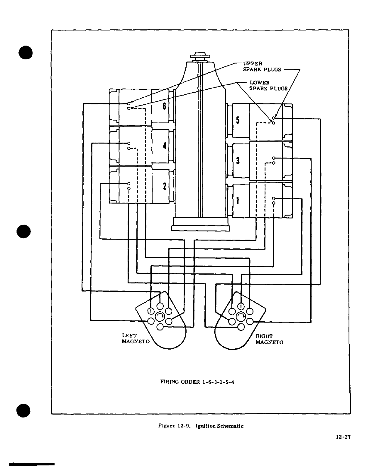
UPPER
SPARK
PLUGS
LOWER
SPARK
PLUGS
1 -1- I
I
I
I
I
LEFT
RIGHT
MAGNETO
MAGNETO
FIRING ORDER
1-6-3-2-5-4
Figure
12-9.
Ignition Schematic
12-27
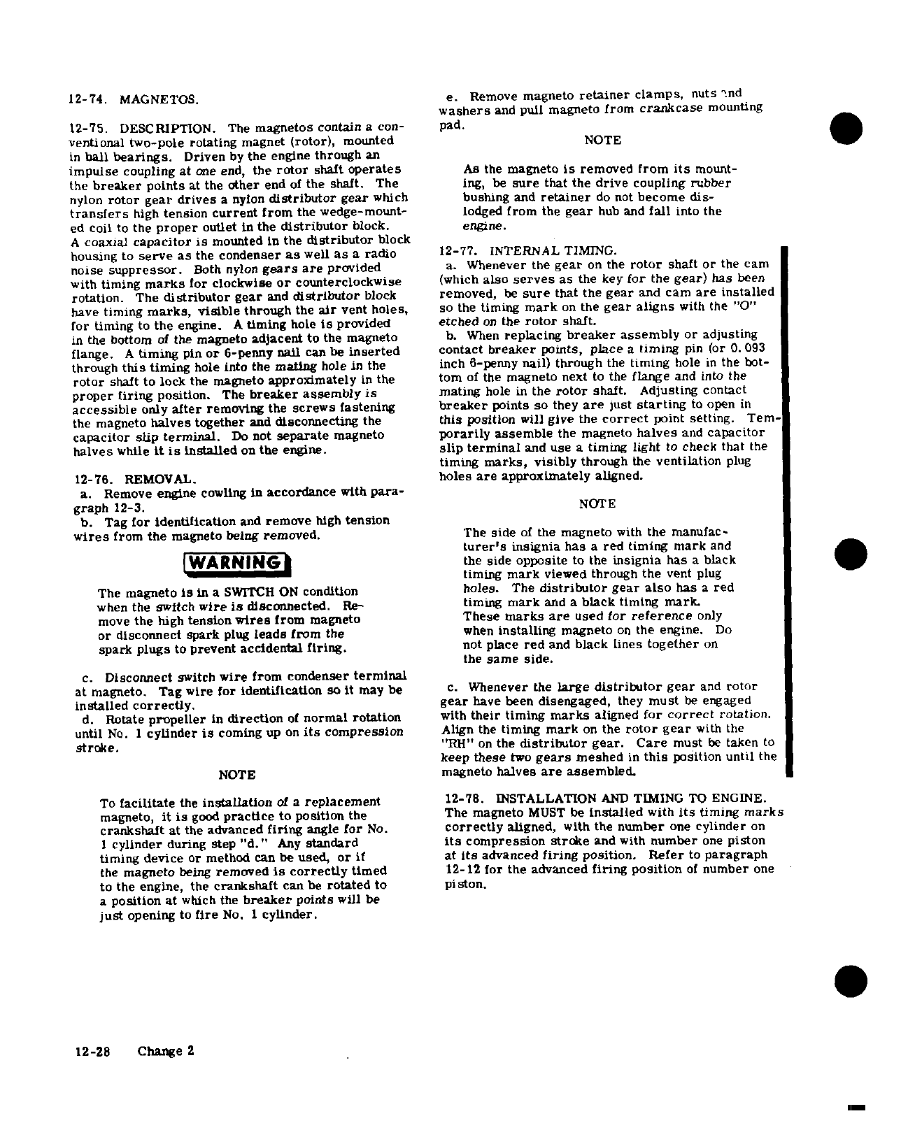
12-74.
MAGNETOS.
e.
Remove
magneto
retainer
clamps,
nuts
and
washers
and
pull
magneto
from
crankcase
mounting
12-75.
DESCRIPTION. The
magnetos
contain
a
con-
pad.
ventional
two-pole rotating
magnet
(rotor),
mounted
NOTE
in
ball
bearings.
Driven
by
the
engine
through
an
impulse
coupling
at
one
end,
the
rotor
shaft
operates
As
the
magneto
is
removed
from
its
mount-
the
breaker
points
at
the
other
end
of
the
shaft.
The ing,
be
sure
that the
drive
coupling
rubber
nylon
rotor
gear drives
a
nylon
distributor
gear
which
bushing
and
retainer
do
not
become
dis-
transfers
high
tension
current
from
the
wedge-mount-
lodged
from
the
gear
hub
and
fall
into
the
ed
coil
to
the
proper
outlet
in
the
distributor
block.
engine.
A
coaxial
capacitor
is
mounted
in
the
distributor
block
housing
to
serve as
the
condenser
as
well
as
a
radio
12-77.
INTERNAL
TIMING.
noise
suppressor.
Both
nylon
gears
are
provided
a.
Whenever
the
gear
on
the
rotor
shaft
or
the
cam
with
timing
marks
for
clockwise
or
counterclockwise
(which
also
serves
as
the
key
for
the
gear)
has
been
rotation.
The
distributor
gear
and
distributor
block
removed,
be
sure
that
the
gear
and
cam
are
installed
have
timing
marks,
visible
through
the
air
vent
holes,
so
the
timing
mark
on
the
gear
aligns
with
the
"0"
for timing
to
the
engine.
A
timing
hole
is
provided
etched
on
the
rotor
shaft.
in
the
bottom
of
the
magneto
adjacent
to
the
magneto
b.
When
replacing
breaker
assembly
or
adjusting
flange.
A
timing
pin
or
6-penny
nail
can
be
inserted
contact
breaker
points,
place
a
timing
pin
(or
0.
093
through
this
timing
hole
into
the
mating
hole
in
the
inch
6-penny
nail)
through
the
timing
hole
in
the
bot-
rotor
shaft
to
lock
the magneto
approximately
in
the
tom
of
the
magneto
next
to
the
flange
and
into
the
proper
firing
position.
The
breaker
assembly
is
mating
hole
in
the
rotor
shaft.
Adjusting contact
accessible
only
after
removing
the
screws
fastening
breaker
points
so
they
are
just
starting
to
open
in
the
magneto
halves
together
and
disconnecting
the
this
position
will
give
the
correct
point setting.
Tem
capacitor
slip
terminal.
Do
not
separate
magneto
porarily
assemble
the
magneto
halves
and
capacitor
halves
while
it is
installed
on
the
engine.
slip
terminal
and
use
a
timing
light
to
check
that
the
timing
marks,
visibly
through
the
ventilation
plug
12-76.
REMOVAL.
holes
are
approximately
aligned.
a.
Remove
engine
cowling
in
accordance
with
para-
graph
12-3.
NOTE
b.
Tag
for
identification
and
remove
high
tension
wires
from
the
magneto
being
removed.
The
side
of
the
magneto
with
the
manufac-
turer's
insignia
has
a
red
timing
mark
and
WARNING
the
side
opposite
to
the
insignia
has
a
black
timing
mark
viewed
through
the
vent
plug
The
magneto
is
in
a
SWITCH
ON
condition
holes.
The
distributor
gear
also
has
a
red
when
the switch
wire
is
disconnected.
Re-
timing
mark
and
a
black
timing
mark.
move
the
high
tension
wires
from
magneto
These
marks
are
used for
reference
only
or
disconnect
spark
plug
leads
from
the
when
installing
magneto
on
the
engine.
Do
spark
plugs
to
prevent
accidental
firing.
not
place
red
and
black
lines
together
on
the
same
side.
c.
Disconnect
switch
wire from
condenser
terminal
at
magneto.
Tag
wire
for
identification
so
it
may
be
c.
Whenever
the
large
distributor
gear
and
rotor
installed
correctly,
gear
have
been
disengaged,
they
must
be
engaged
d.
Rotate
propeller
in
direction
of
normal
rotation
with
their
timing
marks
aligned
for
correct
rotation.
until
No.
1
cylinder
is
coming
up
on
its
compression
Align the
timing
mark
on
the
rotor
gear
with
the
stroke.
"RH"
on
the
distributor
gear.
Care
must
be
taken
to
keep
these
two
gears
meshed
in
this
position
until
the
NOTE
magneto
halves
are
assembled.
To
facilitate
the
installation
of
a
replacement
12-78.
INSTALLATION
AND
TIMING
TO ENGINE.
magneto,
it is
good
practice
to
position
the
The
magneto
MUST
be
installed
with
its
timing
marks
crankshaft
at
the
advanced
firing
angle
for
No.
correctly
aligned,
with the
number
one
cylinder
on
1
cylinder
during step
"d."
Any
standard
its
compression
stroke
and
with
number
one
piston
timing
device
or
method
can
be
used,
or
if
at
its
advanced
firing
position.
Refer
to
paragraph
the
magneto
being
removed
is
correctly
timed
12-12
for
the
advanced
firing
position
of
number
one
to
the
engine,
the
crankshaft
can
be
rotated
to
piston.
a
position at
which
the
breaker
points
will
be
just
opening
to
fire
No.
1
cylinder.
12-28
Change
2
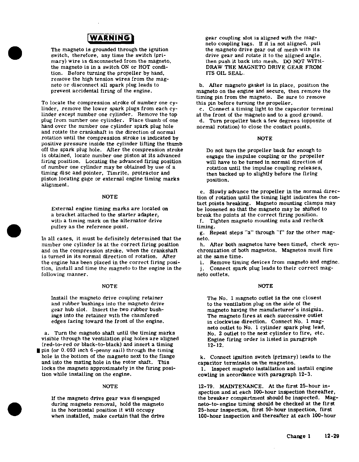
WARNING
gear
coupling
slot
is
aligned
with
the
mag-
neto
coupling
lugs.
If
it
is
not
aligned,
pull
The
magneto
is
grounded
through
the
ignition
the
magneto
drive
gear
out
of
mesh
with
its
switch,
therefore,
any
time
the
switch
(pri-
drive
gear
and
rotate
it
to
the aligned
angle.
mary)
wire
is
disconnected
from
the
magneto,
then
push
it
back
into
mesh.
DO
NOT WITH-
the
magneto
is
in
a
switch
ON
or
HOT
condi-
DRAW
THE
MAGNETO
DRIVE GEAR
FROM
tion.
Before
turning
the
propeller
by
hand,
ITS
OIL SEAL.
remove
the
high
tension
wires
from
the
mag-
neto
or
disconnect
all
spark
plug
leads
to
b.
After
magneto
gasket
is
in
place,
position
the
prevent
accidental
firing
of
the
engine.
magneto
on
the
engine
and
secure,
then
remove
the
timing
pin
from
the
magneto.
Be
sure
to
remove
To
locate
the
compression
stroke
of
number
one
cy-
this
pin
before turning
the
propeller.
linder, remove
the
lower
spark
plugs
from
each
cy-
c.
Connect a
timing
light
to
the
capacitor
terminal
linder
except
number
one
cylinder.
Remove
the
top
at
the
front
of
the
magneto
and
to
a good
ground.
plug
from
number
one
cylinder.
Place
thumb
of
one
d.
Turn propeller
back a
few
degrees
opposite
of
hand
over
the
number
one
cylinder spark
plug
hole
normal
rotation)
to
close
the
contact
points.
and
rotate
the
crankshaft
in
the
direction
of
normal
rotation
until
the
compression
stroke
is
indicated
by
NOTE
positive
pressure
inside
the cylinder lifting
the
thumb
off
the
spark
plug
hole.
After
the
compression stroke
Do
not
turn
the
propeller
back
far
enough
to
is
obtained,
locate
number
one
piston
at
its
advanced
engage
the
impulse
coupling
or
the
propeller
firing
position.
Locating the advanced
firing
position
will have to be
turned
in
normal
direction
of
of
number
one
cylinder
may
be
obtained
by
use
of
a
rotation
until
the
impulse
coupling
releases,
timing
disc
and
pointer,
Timrite,
protractor
and then
backed
up
to
slightly
before
the
firing
piston
locating
gage
or
external
engine
timing
marks
position.
alignment.
e.
Slowly
advance
the
propeller
in
the
normal
direc-
NOTE
tion
of
rotation
until
the
timing
light
indicates
the
con-
tact
points breaking.
Magneto
mounting
clamps
may
External
engine
timing
marks are
located
on
be
loosened so
that
the magneto
may
be
shifted
to
a
bracket
attached to
the
starter
adapter,
break
the
points
at
the
correct
firing
position.
with
a
timing
mark
on
the
alternator
drive
f.
Tighten
magneto
mounting
nuts
and
recheck
pulley
as
the
reference
point,
timing.
g.
Repeat
steps
"a"
through
"f
for
the
other
mag-
In
all
cases,
it
must
be
definitely
determined
that
the
neto.
number
one
cylinder
is
at
the
correct
firing
position
h.
After
both
magnetos
have
been
timed,
check
syn-
and
on
the
compression
stroke,
when
the
crankshaft chronization
of
both
magnetos. Magnetos
must
fire
is
turned
in
its
normal
direction
of
rotation.
After
at
the
same
time.
the
engine
has
been
placed
in
the
correct
firing
posi-
i.
Remove
timing
devices
from
magneto
and engine.
tion,
install
and
time
the
magneto
to
the
engine
in
the
j.
Connect
spark
plug
leads
to
their
correct
mag-
following
manner.
neto
outlets.
NOTE
NOTE
Install
the magneto
drive
coupling
retainer
The
No.
1
magneto
outlet
is
the
one
closest
and
rubber
bushings
into
the
magneto
drive
to
the
ventilation
plug
on
the
side
of
the
gear
hub
slot.
Insert
the
two
rubber
bush-
magneto
having
the
manufacturer's
insignia.
ings
into
the
retainer
with
the
chamfered
The
magneto
fires
at
each
successive
outlet
edges facing
toward
the
front
of
the
engine. in
clockwise
direction.
Connect
No.
1
mag-
neto
outlet
to
No.
1
cylinder
spark
plug
lead,
a.
Turn
the magneto
shaft until
the
timing
marks
No.
2
outlet to
the
next
cylinder
to
fire,
etc.
visible
through
the
ventilation
plug
holes
are
aligned
Engine
firing
order
is
listed
in
paragraph
(red-to-red
or
black-to-black)
and
insert
a
timing
12-12.
pin
(or
0.093
inch
6
-penny
nail)
through
the
timing
hole
in
the
bottom
of
the
magneto
next
to
the
flange
k.
Connect
ignition
switch
(primary)
leads
to the
and into
the
mating hole
in
the
rotor
shaft.
This
capacitor
terminals
on
the
magnetos.
locks
the magneto
approximately
in
the
firing
posi-
1.
Inspect
magneto
installation
and
install
engine
tion
while
installing
on
the
engine,
cowling in
accordance
with
paragraph
12-3.
NOTE
12-79.
MAINTENANCE. At
the
first
25-hour
in-
spection
and
at
each
100-hour
inspection
thereafter,
If
the magneto
drive
gear
was
disengaged
the
breaker
compartment
should
be
inspected.
Mag-
during
magneto
removal,
hold
the
magneto
neto-to-engine
timing
should
be
checked
at
the
first
in
the
horizontal
position
it
will
occupy
25-hour inspection,
first
50-hour
inspection,
first
when
installed,
make
certain
that
the
drive
100-hour
inspection
and
thereafter
at
each
100-hour
Change
1
12-29
inspection.
If
timing
is
as specified
in
paragraph
12-
4.
Check
the
carbon
brush
on
the
distributor
12,
internal
timing
need
not
be
checked.
If
timing
is
gear
for
excessive
wear.
The
brush
must
extend
a
out
of
tolerance,
remove
magneto
and
set
internal
minimum
of
1/32
inch
beyond
the
end
of
the
gear
timing,
then
install
and
time to
the
engine.
In
the
shaft.
The
spring
which
the
carbon
brush
contacts
event the magneto
internal
timing
marks
are
off
should
be
bent
our
approximately
20
degrees
from
more
than
plus
or
minus
five
degrees
when
the
break-
vertical,
since
spring
pressure
on
the
brush
holds
er
points
open
to
fire
number
one
cylinder,
remove the
distributor
gear
shaft
against
the
thrust
bearing
the magneto
and
check
the magneto
internal
timing.
in
the
distributor
block.
Whenever
the
magneto
halves
are
separated
the
5.
Oil
the
bearings
at
each
end
of
the
distributor
breaker
point
assembly
should
always
be
checked.
gear
shaft
with
a
drop
of
SAE 20
oil.
Wipe
excess
oil
As
long
as
internal
timing
and
magneto-to-engine
from
parts.
timing
are
within the
preceding
tolerances,
it is
6.
Make
sure
internal
timing
is
correct
and
re-
recommended
that
the
magneto be
checked
internally
assemble
magneto.
Install
and
properly
time
mag-
only
at
500
hour
intervals.
It
is
normal
for contact
neto
to engine.
points
to
burn
and
the
cam
to
wear
a
comparable
amount
so
the
magneto will
remain
in
time
within
12-80.
MAGNETO
CHECK.
Advanced
timing set-
itself.
This
is
accomplished
by
having
a
good
area
tings
in
some
cases,
is
the
result
of
the
erroneous
making
contact
on
the
surface
between
the
points
practice
of
bumping
magnetos
up
in
timing
in
order
and
the
correct
amount
of
spring
pressure
on
the
to
reduce
RPM
drop
on
single
ignition.
NEVER
AD-
cam.
The
area
on
the
points
should
be
twenty-five
VANCE
TIMING
BEYOND
SPECIFICATIONS
IN
OR-
percent
of
the
area
making
contact.
The
spring
DER
TO
REDUCE
RPM
DROP.
Too
much
impor-
pressure
at
the
cam
should
be
10.5
to
12.5
ounces.
tance
is
being
attached
to
RPM
drop
on
single
igni-
When
the
contact
points
burn,
the
area
becomes
tion.
RPM
drop
on
single
ignition
is
a
natural
char-
irregular,
which
is
not
detrimental
to
the
operation
acteristic
of
dual
ignition design.
The
purpose
of
of
the
points
unless
metal
transfer
is
too
great
which
the
following
magneto
check
is
to
determine
that
all
will
cause
the
engine to
misfire.
Figure
12-10
illus-
cylinders
are
firing.
If
all
cylinders
are
not
firing,
trates
good
and
bad
contact
points.
A
small
dent
will
the
engine
will
run
extremely
rough
and
cause
for
appear
on
the
nylon
insulator
between
the
cam
follow-
investigation
will
be
quite
apparent.
The amount
of
er
and
the
breaker
bar.
This
is
normal
and
does
not
RPM
drop
is
not
necessarily
significant
and
will
be
require
replacement.
influenced
by
ambient
air
temperature,
humidity,
airport
altitude, etc.
In
fact,
absence
of
RPM
drop
NOTE
should
be
cause
for
suspicion
that
the magneto
timing
has
been
bumped
up
and
is
set
in advance
of
the
setting
If
ignition
trouble
should develop,
spark
plugs
specified.
Magneto
checks
should
be
performed
on
a
and
ignition
wiring
should
be
checked
first.
If
comparative
basis
between
individual
right
and left
the
trouble
definitely
is
associated
with
a
mag-
magneto
performance.
neto,
use
the
following
to help
disclose
the
a.
Start
and
run
engine until
the
oil
and
cylinder
source
of
trouble
without
overhauling the
mag-
head
temperature
is
in
the
normal operating range.
neto.
b.
Place
the
propeller
control
in
the
full
low
pitch
(high
rpm)
position.
a.
Moisture
Check.
c.
Advance
engine
speed
to
1700
rpm.
1.
Remove
magneto
from
engine
and
remove
d.
Turn
the
ignition
switch
to
the
"R"
position
and
screws
securing
the
magneto
halves
together,
dis-
note
the
rpm
drop,
then
return
the
switch
to the
connect
capacitor
slip
terminal
and
remove
distrib-
"BOTH"
position
to
clear
the
opposite
set
of
plugs.
utor.
Inspect
for
moisture.
e.
Turn
the
switch
to
the
"L"
position
and
note
the
2.
Check
distributor gear
finger
and
carbon rpm
drop, then
return
the
switch
to
the
"BOTH"
brush
for
moisture.
position.
3.
Check
breaker
point
assembly
for
moisture,
f.
The
rpm
drop
should
not
exceed
150
rpm
on
especially
on
the
surfaces
of
the
breaker
points.
either
magneto
or
show
greater
than
50
rpm
differ-
4.
If
any
moisture
is
evident
in
the
preceding ential
between
magnetos.
A
smooth rpm
drop-off
places,
wipe
with
a
soft,
dry,
clean,
lint-free
cloth.
past
normal
is
usually
a
sign
of
a
too
lean
or
too
b.
Breaker
Compartment
Check.
rich
mixture.
A
sharp
rpm
drop-off
past
normal
is
1.
Check
all
parts
of
the
breaker
point
assem-
usually
a sign
of
a
fouled plug,
a
defective
harness
bly
for
security.
lead
or
a
magneto
out
of
time.
If
there
is
doubt
con-
2.
Check
breaker
point
surface
for
evidence
of
cerning
operation
of
the
ignition
system,
rpm
checks
excessive
wear,
burning,
deep
pits
and
carbon
de-
at
a
leaner
mixture
setting
or
at
higher
engine
speeds
posits.
Breaker
points
may
be
cleaned
with
a
hard-
will
usually
confirm
whether
a
deficiency
exists.
finish
paper.
If
breaker
point
assembly
is
defective,
install
a
new
assembly.
Make
no
attempt
to
stone
or
NOTE
dress
the
breaker
points. Clean
new
breaker
points
with
clean,
unleaded
gasoline
and
hard-finish
paper
An
absence
of
rpm
drop
may
be
an
indication
before
installing.
of
faulty grounding
of
one
side
of
the
ignition
3.
Check
capacitor
mounting
bracket
for
cracks
system,
a
disconnected
ground
lead
at
mag-
or looseness.
neto
or
possibly
the
magneto
timing
is
set
too
far
in
advance.
12-30
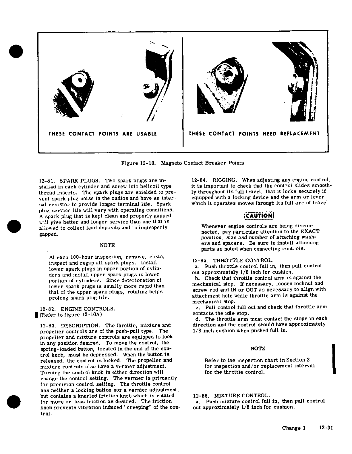
THESE
CONTACT POINTS
ARE
USABLE
THESE
CONTACT POINTS
NEED
REPLACEMENT
Figure
12-10.
Magneto
Contact
Breaker
Points
12-81.
SPARK
PLUGS. Two
spark
plugs
are
in-
12-84.
RIGGING.
When
adjusting
any
engine
control.
stalled
in
each
cylinder
and
screw
into
helicoil
type
it is
important
to
check
that
the
control
slides
smooth-
thread
inserts.
The
spark
plugs
are
shielded
to
pre-
ly
throughout
its
full
travel,
that
it
locks
securely
if
vent
spark
plug
noise
in
the
radios
and
have
an
inter-
equipped
with
a
locking device
and
the
arm
or
lever
nal
resistor
to
provide
longer
terminal
life.
Spark
which
it
operates
moves
through
its
full
arc
of
travel.
plug
service
life
will
vary
with
operating
conditions.
A
spark
plug
that
is
kept
clean
and
properly
gapped
CAUTION
will
give
better
and
longer
service
than
one
that
is
allowed
to
collect
lead
deposits
and
is
improperly
Whenever
engine
controls
are
being
discon-
gapped.
nected,
pay
particular
attention
to
the
EXACT
position,
size
and
number
of
attaching
wash-
NOTE
ers
and
spacers.
Be
sure
to
install
attaching
parts
as
noted
when
connecting
controls.
At
each
100-hour
inspection, remove,
clean,
inspect
and
regap
all
spark
plugs.
Install
12-85.
THROTTLE
CONTROL.
lower
spark
plugs
in
upper
portion
of
cylin- a.
Push
throttle
control
full
in,
then
pull
control
ders
and
install
upper
spark
plugs
in
lower
out
approximately
1/8
inch
for
cushion.
portion
of
cylinders.
Since
deterioration
of
b.
Check
that
throttle
control
arm
is
against
the
lower
spark
plugs
is
usually more rapid
than
mechanical
stop.
If
necessary,
loosen locknut
and
that
of
the
upper
spark
plugs,
rotating
helps screw
rod
end
IN
or
OUT
as necessary
to
align
with
prolong spark
plug
life.
attachment
hole
while
throttle
arm
is
against
the
mechanical
stop.
12-82.
ENGINE
CONTROLS.
c.
Pull
control
full
out and
check
that
throttle
arm
(Refer
to
figure
12-10A)
contacts
the idle
stop.
d.
The
throttle
arm
must
contact
the
stops
in
each
12-83.
DESCRIPTION.
The
throttle,
mixture
and
direction
and
the
control
should have
approximately
propeller
controls
are
of
the
push-pull
type. The
1/8
inch
cushion
when
pushed
full
in.
propeller
and
mixture
controls
are
equipped
to
lock
in any
position
desired.
To
move
the
control,
the
spring-loaded
button,
located
in
the
end
of
the
con-
NOTE
trol
knob,
must
be
depressed.
When
the button
is
released,
the
control
is
locked.
The
propeller
and
Refer
to
the
inspection
chart
in
Section
2
mixture
controls
also
have
a
vernier
adjustment. for inspection
and/or
replacement
interval
Turning
the
control
knob
in
either
direction
will
for
the
throttle
control.
change
the
control
setting.
The
vernier
is
primarily
for
precision
control
setting.
The
throttle
control
has
neither
a
locking
button
nor
a
vernier
adjustment,
but
contains
a
knurled
friction
knob
which
is
rotated
12-86.
MIXTURE
CONTROL.
for
more
or
less
friction as desired.
The
friction
a.
Push
mixture
control
full
in,
then
pull
control
knob
prevents
vibration
induced
"creeping"
of
the
con-
out
approximately
1/8
inch
for
cushion.
trol.
Change
1
12-31
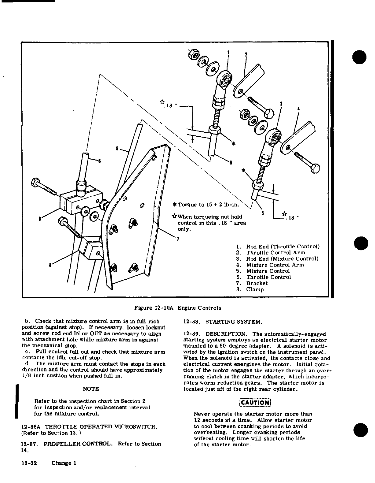
3
18
4
*Torque
to
15
2 lb-in.
When
torqueing
nut
hold
18
"
control
in
this
.18
"
area
only.
1.
Rod
End
(Throttle
Control)
2.
Throttle
Control
Arm
3.
Rod
End
(Mixture
Control)
4.
Mixture
Control
Arm
5.
Mixture
Control
6.
Throttle
Control
7.
Bracket
8.
Clamp
Figure
12-10A
Engine
Controls
b.
Check
that
mixture
control
arm
is
in
full
rich
12-88.
STARTING
SYSTEM.
position
(against
stop).
If
necessary,
loosen
locknut
and
screw
rod
end
IN
or
OUT
as
necessary
to
align
12-89. DESCRIPTION.
The
automatically-engaged
with
attachment
hole
while
mixture
arm
is
against
starting
system
employs
an
electrical
starter
motor
the mechanical
stop.
mounted
to
a
90-degree
adapter.
A
solenoid
is
acti-
c.
Pull
control
full out
and
check
that mixture
arm
vated
by
the
ignition
switch
on
the
instrument
panel.
contacts
the idle
cut-off
stop.
When
the
solenoid
is
activated,
its
contacts
close
and
d.
The
mixture
arm
must
contact
the
stops
in
each
electrical
current
energizes
the
motor. Initial
rota-
direction
and
the
control
should
have
approximately
tion
of
the motor engages the
starter
through
an
over-
1/8 inch
cushion
when
pushed full
in.
running
clutch
in
the
starter
adapter,
which
incorpo-
rates
worm
reduction
gears.
The
starter
motor
is
NOTE
located
just
aft
of
the
right
rear
cylinder.
Refer
to
the
inspection
chart
in
Section
2
CAUTION
for inspection
and/or
replacement
interval
for
the
mixture
control.
Never
operate
the
starter
motor
more
than
12
seconds
at
a
time.
Allow
starter
motor
12-86A
THROTTLE
OPERATED
MICROSWITCH.
to
cool
between
cranking
periods
to avoid
(Refer
to
Section
13.)
overheating.
Longer cranking
periods
without
cooling
time
will
shorten
the
life
12-87.
PROPELLER
CONTROL.
Refer
to
Section
of
the
starter
motor.
14.
12-32 Change
1
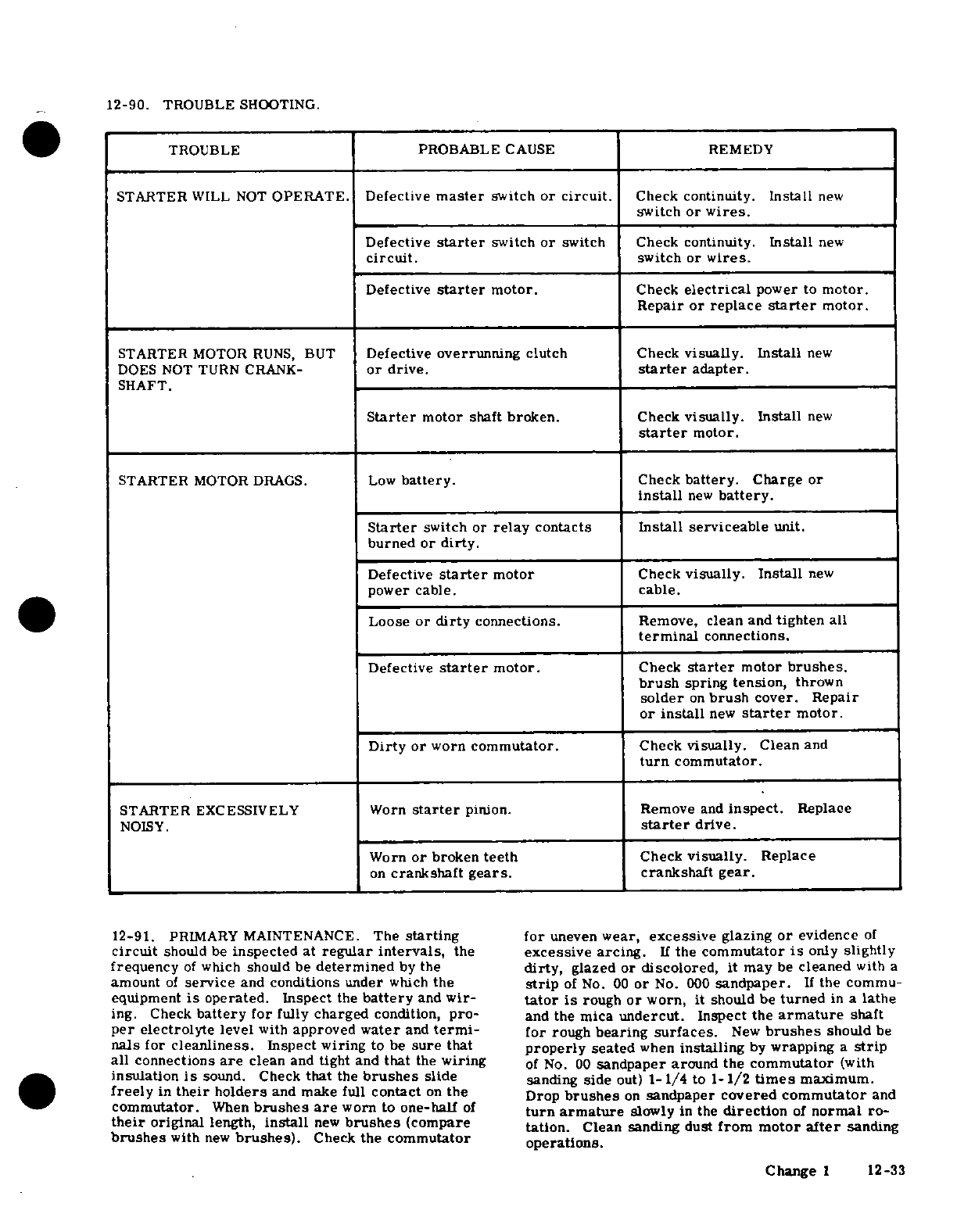
12-90.
TROUBLE
SHOOTING.
TROUBLE
PROBABLE
CAUSE
REMEDY
STARTER
WILL
NOT
OPERATE.
Defective
master
switch
or
circuit.
Check
continuity.
Install
new
switch
or
wires.
Defective
starter
switch
or
switch Check
continuity.
Install
new
circuit.
switch
or
wires.
Defective
starter
motor.
Check
electrical
power
to
motor.
Repair or
replace
starter
motor.
STARTER
MOTOR
RUNS,
BUT
Defective
overrunning
clutch
Check
visually.
Install
new
DOES NOT
TURN
CRANK-
or
drive.
starter
adapter.
SHAFT.
Starter
motor
shaft
broken.
Check
visually.
Install
new
starter
motor.
STARTER
MOTOR
DRAGS.
Low
battery.
Check
battery.
Charge
or
install
new
battery.
Starter
switch
or
relay
contacts
Install serviceable
unit.
burned
or
dirty.
Defective
starter
motor
Check
visually.
Install
new
power cable,
cable.
Loose
or
dirty
connections.
Remove,
clean
and
tighten
all
terminal
connections.
Defective
starter
motor.
Check
starter
motor
brushes,
brush
spring
tension,
thrown
solder
on
brush
cover.
Repair
or install
new
starter
motor.
Dirty
or
worn
commutator.
Check
visually.
Clean
and
turn
commutator.
STARTER
EXCESSIVELY
Worn
starter
pinion. Remove
and
inspect.
Replace
NOISY.
starter
drive.
Worn
or
broken
teeth
Check
visually.
Replace
on
crankshaft
gears.
crankshaft
gear.
12-91.
PRIMARY
MAINTENANCE.
The
starting
for
uneven
wear,
excessive
glazing
or
evidence
of
circuit
should
be
inspected
at
regular
intervals,
the
excessive
arcing.
If
the
commutator
is
only
slightly
frequency
of
which
should
be
determined
by
the
dirty,
glazed
or
discolored,
it
may
be
cleaned
with
a
amount
of
service
and
conditions
under
which
the
strip
of
No.
00
or
No. 000
sandpaper.
If
the commu-
equipment
is
operated.
Inspect
the
battery
and
wir-
tator
is
rough
or
worn,
it
should
be
turned
in
a
lathe
ing.
Check
battery
for
fully
charged
condition,
pro-
and
the
mica
undercut.
Inspect the
armature
shaft
per
electrolyte
level
with
approved
water
and
termi-
for
rough
bearing
surfaces.
New
brushes
should
be
nals
for
cleanliness.
Inspect wiring
to
be
sure
that
properly
seated
when
installing
by
wrapping
a
strip
all
connections
are
clean
and
tight
and
that
the
wiring
of
No.
00
sandpaper
around
the
commutator
(with
insulation
is
sound. Check
that
the
brushes
slide
sanding
side
out)
1-1/4
to
1-1/2
times
maximum.
freely
in
their
holders
and
make
full
contact
on
the
Drop
brushes
on
sandpaper
covered commutator
and
commutator.
When
brushes
are
worn
to
one-half
of
turn
armature
slowly
in
the
direction
of
normal
ro-
their
original
length,
install
new
brushes
(compare
tation.
Clean
sanding dust
from
motor
after
sanding
brushes
with
new
brushes).
Check
the
commutator operations.
Change
1
12-33
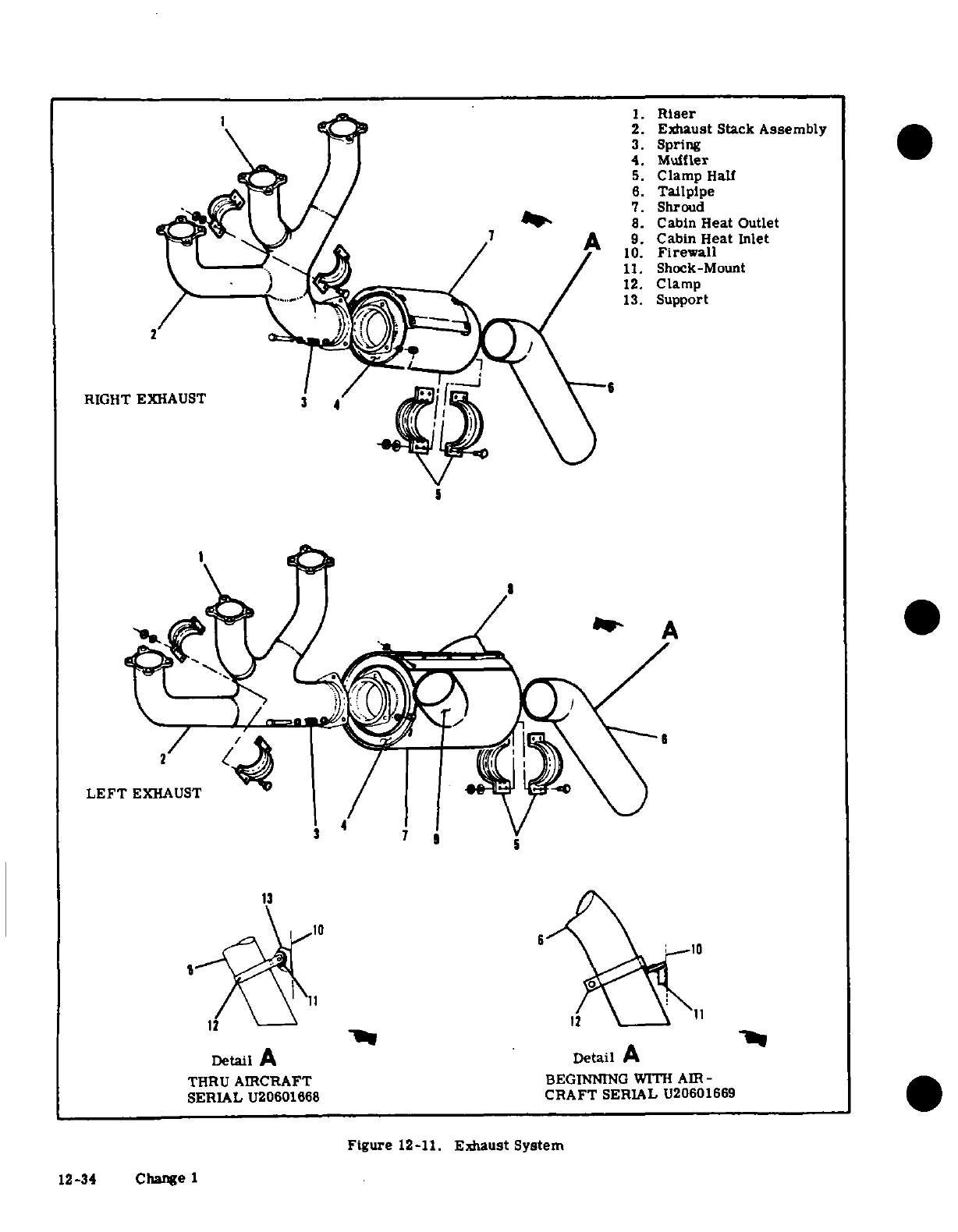
©©
Riser
2.
Exhaust
Stack
Assembly
4.
Muffler
5.
Clamp
Hall
6.
Tailpipe
.^(^y ~~ |t~~~
/./
^7.
Shroud
N/
/
_
8.
Cabin
Heat
Outlet
10.
Firewall
~\~ Jo.~ ^~ji
/ /
n
11.
Shock-Mount
<
) / /
~12.
Clamp
.2/~
.
"'^
...
>~ "/~
~13.
Support
2 /
RIGHT
EXHAUST
3
4
LEFT
EXHAUST
3 4
13 ',
Detail
A
Detail
A
THRU
AIRCRAFT
BEGINNING
WITH AIR
-
SERIAL
U20601668
CRAFT
SERIAL
U20601669
Figure
12-11.
Exhaust
System
12-34
Change
1
12-92. STARTER
MOTOR.
a.
Remove
engine
cowling
as
required
so
that
ALL
surfaces
of
the
exhaust
assemblies
can
be
visually
12-93.
REMOVAL
AND
INSTALLATION.
inspected.
a.
Remove
engine
cowling
in
accordance
with
para-
graph
12-3.
NOTE
CAUTION
Especially
check the
areas
adjacent
to
welds
and
slip
joints.
Look
for
gas
deposits
in
sur-
When
disconnecting
starter
electrical
cable,
rounding
areas,
indicating
that
exhaust
gases
do
not
permit
terminal
bolt to
rotate.
Ro-
are
escaping through
a
crack
or
hole
or
tation
of
the
bolt
could
break
the
conductor
around
the
slip
joints.
between
bolt
and
field
coils
causing
the
starter
to
be
inoperative.
b.
After
visual
inspection,
an
air
leak
check
should
be
made
on
the
exhaust
system
as
follows:
b.
Disconnect
battery
cables
and
insulate
as
a
1.
Attach
the
pressure
side
of
an
industrial
safety
precaution.
vacuum
cleaner
to
the
tailpipe
opening,
using
a
rub-
c.
Disconnect
electrical
cable
at
starter
motor.
ber
plug
to
effect
a
seal
as
required.
d.
Remove
nuts
and
washers
securing
motor
to
starter
adapter
and
remove
motor.
Refer
to
engine
NOTE
manufacturer's
overhaul
manual
for
adapter
removal.
e.
Reverse
the
preceding
steps
for
reinstallation.
The
inside
of
the
vacuum
cleaner
hose
should
Install
a
new
O-ring
seal
on
motor,
then
install
motor.
be
free
of
any
contamination
that
might
be
Be
sure
motor
drive
engages
with
the
adapter
drive
blown
into
the
engine exhaust
system.
when
installing.
2.
With
vacuum
cleaner
operating,
all joints
12-94.
EXHAUST
SYSTEM.
in
the
exhaust
system
may
be
checked
manually
by
feel,
or
by
using
a
soap
and
water
solution
and
12-95.
DESCRIPTION.
The
exhaust
system
consists
watching
for bubbles.
Forming
of
bubbles
is
con-
of
two
exhaust
stack
assemblies,
for
the
left
and
right
sidered
acceptable,
If
bubbles
are
blown
away
bank
of
cylinders.
Each
cylinder
has
a
riser
pipe
at- system
is
not
considered
acceptable.
tached
to
the
exhaust
port.
The
three
risers
at
each
c.
Where
a
surface
is
not
accessible
for
a
visual
bank
of
cylinders
are
joined
together
into
a
collector
inspection,
or
for
a
more positive
test,
the
following
pipe
forming
an
exhaust
stack
assembly.
The
center
procedure is
recommended.
riser
on
each
bank
is
detachable.
but
the
front
and
aft
1.
Remove
exhaust stack
assemblies.
risers
are
welded
to
the
collector
pipe.
The
left
muf-
2.
Use
rubber
expansion
plugs
to
seal
openings.
fler
is
enclosed
in
a
shroud
which
captures
exhaust
3.
Using
a
manometer or
gage,
apply
approxi-
heat
which
is
used
to
heat the
cabin.
mately
1-1/2
psi
(3
inches
of
mercury)
air
pressure
12-96.
REMOVAL
AND
INSTALLATION.
(Refer
to while
each
stack
assembly
is submerged
in
water.
figure
12-11.
)
Any
leaks
will
appear
as
bubbles
and
can
be
readily
a.
Remove
engine
cowling
in
accordance
with
para-
detected.
graph
12-3.
4.
It
is
recommended
that
exhaust
stacks
found
b.
Disconnect
ducts
from
heater
shroud
on
left
muf-
defective
be
replaced
before the
next
night.
fler
assembly.
d.
After
installation
of
exhaust
system
components
c.
Disconnect
tailpipe
braces
from
shock-mounts
at
perform
the
inspection
in
step
"b"
of
this
paragraph
firewall
brackets.
to
ascertain
that
system
is
acceptable
d.
Remove
nuts,
springs
and
bolts
attaching
tailpipe
12-98.
EXTREME
WEATHER
MAINTENANCE.
and
muffler
to
collector
pipe
and
remove
muffler
and
tailpipe
assemblies.
12-99.
COLD
WEATHER.
Cold
weather
starting
will
e.
Remove
nuts
attaching
exhaust
stack
assemblies
be
me
easier
by
the
installation
of
an
oil
dilution
to
the
cylinders
and
remove exhaust
stacks
and
gas-ketsand a
ground
service
system,
an
engine
primer
system
and
a ground
service
t
Reverse
the
preceding
steps
for
reinstallation.
receptacle.
The
primer
system
is
manually-operated
f.
Reverse
the
preceding
steps
for
reinstallation.
Install a new coppe
o
g
e
b
n
e
from
the
cabin.
Fuel
is
supplied
by
a
line
from
the
Install
a
new
copper-asbestos
gasket
between
each
a new coppr-
o g
t
b n
eh
fuel
strainer
to
the
plunger.
Operating
the
primer
riser
and
its
mounting
pad on
each
cylinder,
regard-
fl
s
r
to
te
p
.
O
t
forces
fuel
to
the
engine.
With
an
external
power
re-
less
of
apparent
condition
of
those removed. Torque
foes
fel
o
he
engin.
Wit
an
eterna
er re-
exhaust
stack
nuts
at
cylinders
to
100-
110
pound- The
following
may
also
be
used
to
assist
engine
start-
ex
h asstcnustclnest1010puding
in
extreme
cold
weather.
After
the
last
flight
of
inches.
the
day,
drain
the
engine
oil
into
a
clean
container
so
12-97 INSPECTION.
Since
exhaust
systems
of
this
the
oil
can
be
preheated.
Cover
the
engine to
prevent
type
are
subject
to
burning,
cracking
and
general
ice
or
snow
from
collecting
inside
the cowling.
When
deterioration
from
alternate
thermal
stresses
and
preparing
the
aircraft
for
flight
or
engine
runup
after
vibrations,
inspection
is
important
and
should
be
these
conditions
have
been followed,
preheat
the
drain-
accomplished every
100
hours
of
operation.
Also,
a engine
oil
thorough
inspection
of
the
engine
exhaust
syst
ed
engine
oil.
thorough
inspection of
the
engine
exhaust system
ceptacle
installed,
an
external
power
source
may
be
should
be
made
to
detect
cracks
causing
leaks
which
connected
to
assist
in cold
weather
or
low
battery
could
result
in
loss
of
engine
power.
To
inspect
the
starting.
Refer
to
paragraph
12-103
for
use
of
the
engine
exhaust
system, proceed
as
follows:
external
power
receptacle.
Change
3
12-35
WARNING
12-100.
HOT
WEATHER.
Engine
starting
in
hot
Do
not
heat
the oil
above
121°C
(250°F).
A
weather
or
with
a
hot
engine
is
sometimes
hampered
flash
fire
may
result.
Before
pulling
the
by
vapor
formation
in
the
fuel
lines.
To
purge
the
propeller
through,
ascertain
that
the
mag-
vapor,
move
the
mixture
control
to
full
rich,
open
neto
switch
is
in
the
OFF position
to
prevent
the
throttle
1-1/2
inches
and
prime
with the
auxliary
accidental firing
of
the
engine.
fuel
pump
switch
in
the
HI
position
until
the
fuel flow
indicator
reads
4-6
gal/hr.
Then
shut
off
the
fuel
After
preheating
the
engine
oil,
gasoline
may
be
mix-
pump
switch
and engage
the
starter.
As
the
flooded
ed with
the
heated
oil
in
a
ratio
of
1
part
gasoline
to
mixture
becomes
progressively
leaner,
reaching
a
12
parts
engine
oil
before
pouring
into
the
engine
oil
combustible
mixture,
the
engine
will
start.
If
the
sump.
If
the
free
air
temperature
is
below
minus
engine
tends
to
die,
turn
the
auxiliary
fuel
pump
29°C
(-20F),
the
engine
compartment
should
be
pre-
switch
momentarily
to
HI
at
appropriate
intervals
heated
by
a
ground
heater.
After
the
engine
compart-
until
vapor
is
fully
cleared
and
the
engine
runs
ment
has
been
preheated,
inspect
all
engine
drain
and
smoothly.
vent
lines
for
presence
of
ice.
After
this
procedure
has
been
complied
with,
pull
propeller
through
sev-
CAUTION
eral
revolutions
by
hand
before attempting
to
start
the
engine.
Never
operate
the
starting
motor
more
than
12
seconds
at
a
time.
Allow
starter
motor
to
CAUTION
cool
between
cranking
periods
to
avoid
over-
heating.
Longer
cranking
periods
will
shorten
Due
to
the
desludging effect
of
the
diluted
the
life
of
the
starter
motor.
oil,
engine
operation
should
be
observed
closely
during the
initial
warm-up
of
the
12-101.
SEACOAST
AND
HUMID
AREAS.
In
salt
engine.
Engines
that
have
considerable
water
areas
special
care
should
be
taken to
keep
amount
of
operational
hours
accumulated
the
engine,
accessories
and
airframe
clean to
pre-
since
their
last
dilution
period
may
be
vent
oxidation.
In
humid
areas,
fuel
and
oil
should
seriously
affected
by
the
dilution
process.
be
checked
frequently
and
drained
of
condensation
This
will
be
caused
by
the
diluted
oil
di- to
prevent
corrosion.
lodging sludge
and
carbon
deposits
within
the
engine.
This
residue
will
collect
in
the
12-102.
DUSTY
AREAS.
Dust
induced
into
the
intake
oil
sump
and
possibly
clog
the
screened
system
of
the
engine
is
probably
the
greatest
single
inlet
to
the
oil
sump.
Small
deposits
may
cause
of
early
engine
wear.
When
operating
in
high
actually
enter
the
oil
sump
and
be
trapped
dust conditions,
service
the induction
air
filter
daily
by
the
main
oil
filter
screen.
Partial or as
outlined
in
Section
2.
Also
change
engine
oil
and
complete
loss
of
engine
lubrication
may
re-
lubricate
airframe
items
more
often
than
specified.
suit
from
either
condition.
If
these
condi-
tions
are
anticipated
after
oil
dilution,
the
12-103.
GROUND
SERVICE
RECEPTACLE.
With
engine should
be
run
for several
minutes
the
ground
service receptacle
installed,
the
use
of
at
normal
operating
temperatures
and
then
an
external
power
source
is
recommended for
cold
stopped and
inspected
for
evidence
of
sludge
weather
starting,
low
battery starting
and
lengthy
and
carbon
deposits
in
the
oil
sump
and
oil maintenance
of
the
aircraft
electrical
system.
Refer
filter
screen.
Future occurrence
of
this
to
Section
17
for
additional
information.
condition
can
be
prevented
by
diluting
the
oil
prior
to
each
engine
oil
change.
This
12-104.
HAND-CRANKING.
A
normal
hand-crank-
will
also
prevent
the
accumulation
of
the
ing
procedure
may
be
used
to
start
the
engine.
sludge
and
carbon
deposits.
SHOP
NOTES:
12-36
Change 1
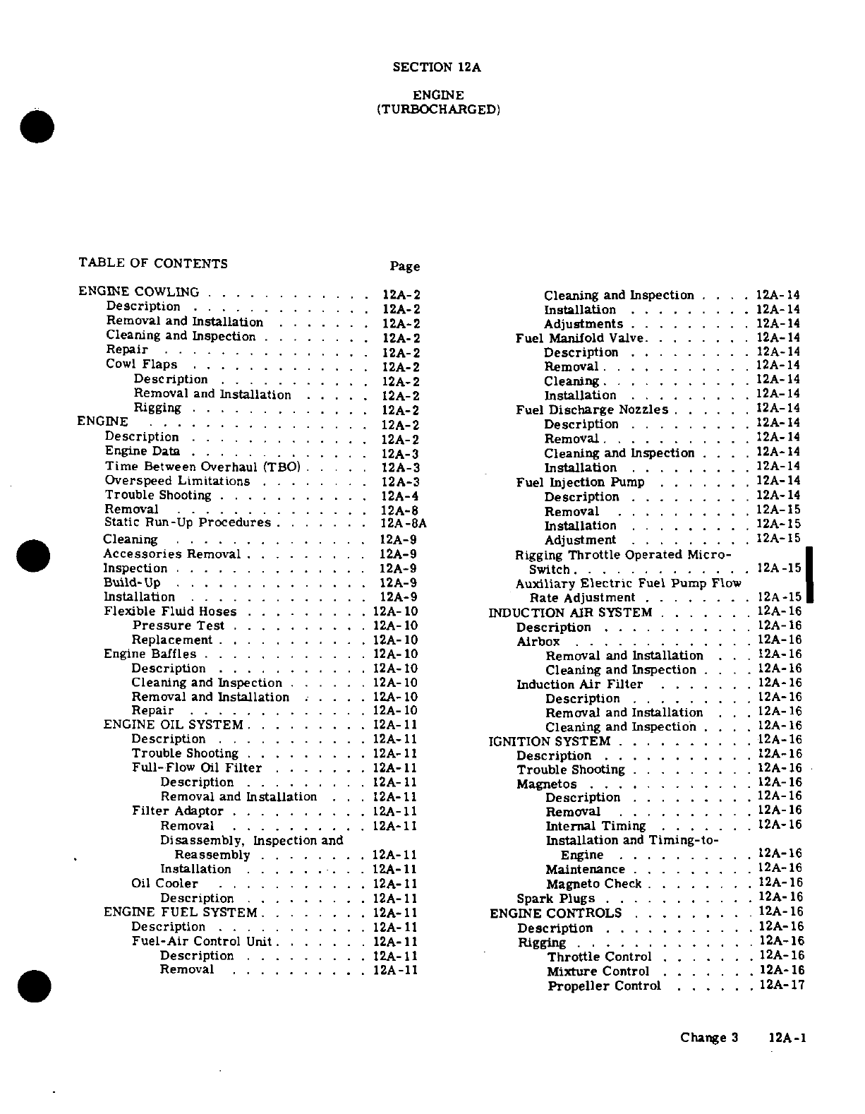
SECTION
12A
ENGINE
(TURBOCHARGED)
TABLE
OF CONTENTS
Page
ENGINE
COWLING
............
12A-2
Cleaning
and
Inspection
....
12A-14
Description
.............
12A-2
Installation
....
.....
12A-14
Removal
and
Installation
.......
12A-2
Adjustments
........
.
12A-14
Cleaning
and
Inspection
........
12A-2
Fuel
Manifold
Valve.
.
12A-14
Repair
...............
12A-2
Description
.........
12A-14
Cowl
Flaps
.............
12A-2
Removal
.
..........
12A-14
Description
........
.
12A-2
Cleaning
.
....
12A-14
Removal
and
Installation
.....
12A-2
Installation
... .
12A-14
Rigging
.
...........
.
12A-2
Fuel
Discharge
Nozzles
......
12A-14
ENGINE
................
12A-2
Description
..
12A-14
Description
........
12A-2
Removal
.
.........
12A-14
Engine Data
........
12A-3
Cleaning
and
Inspection
..
12A-
14
Time
Between
Overhaul
(TBO)
.. ..
12A-3
Installation
.. ...
12A-14
Overspeed
Limitations
........
12A-3
Fuel
Injection
Pump
..
12A-14
Trouble
Shooting
...........
12A-4
Description
..
12A-14
Removal
.............
.
12A-8
Removal
.....
12
.
A-15
Static
Run-Up
Procedures
.......
12A-8A
Installation
.........
12A-15
Cleaning
.
....
.... .
12A-9
Adjustment
........
12A-15
Accessories
Removal
.
.....
12A-9
Rigging
Throttle
Operated
Micro-
*
Inspection
.
....
... .
12A-9 Switch.
...
12A..-15
Buld-Up
..
........
12A-9
Auxiliary
Electric
Fuel
Pump
F\ov'
Installation
.........
12A-9
Rate Adjustment
.....
12A-15
Flexible
Fluid
Hoses
........
12A-10
INDUCTION AIR
SYSTEM
..
12A-16
Pressure
Test
..........
12A-10
Description
....
.A-16
Replacement
........
.
12A-10
Airbox
.......
12A-16
Engine
Baffles
.... .....
12A-10
Removal
and
Installation
.
.12A-16
Description
...........
12A-
10
Cleaning
and
Inspection
....
12A-
16
Cleaning
and
Inspection
......
12A-10
Induction
Air
Filter
..
12A-16
Removal
and
Installation
....
.
12A-10
Description
.........
12A-16
Repair
.
...........
12A-
10
Removal
and
Installation
.. .
12A-16
ENGINE
OIL
SYSTEM
......
12A-11
Cleaning
and
Inspection
..
12A-16
Description
.......
.. .
12A-11
IGNITION
SYSTEM
.
.........
12A-16
Trouble
Shooting
.........
12A-11
Description
.......
12A-16
Full-Flow
Oil
Filter
.......
12A-11
Trouble
Shooting
.........
12A-16
Description
.........
12A-11
Magnetos
..... .......
12A-16
Removal
and
Installation
..
12A-11
Description
.. ...
12A-16
Filter
Adaptor
..
......
12A-11
Removal
....
..
12A-16
Removal
.......
12A-11
Internal
Timing
......
12A-16
Disassembly,
Inspection
and
Installation
and
Timing-to-
Reassembly
........
12A-11
Engine
..
12A-16
Installation
.........
12A-11
Maintenance
...
12A-16
Oil
Cooler
...........
12A-11
Magneto
Check
.
.....
12A-16
Description
.......
.
12A-11
Spark
Plugs
...........
1A-
ENGINE
FUEL
SYSTEM
........
12A-11
ENGINE
CONTROLS
.........
12A-16
Description
.
........
12A-11
Description
.. ..
12A-16
Fuel-Air
Control
Unit
.
....
.
12A-11
Rigging
.............
A-16
Description
.....
12A-11
Throttle
Control
.. .
12A-16
Removal
.
.........
12A-11
Mixture
Control
.. ...
12A-16
Propeller
Control
... .
12A-17
Change
3
12A-1
STARTING
SYSTEM
.........
12A-17
Operation
............
12A-21
Description
...........
12A-
17
Trouble
Shooting
.........
12o-24
Trouble
Shooting
.......
12A-17
Controller
and
Turbocharger
Operational
Primary
Maintenance
......
.12A-17
Flight
Check
.........
12A-26
Starter
Motor
... .. .
12A-17
Removal and
Installation
of
Removal
and
Installation
. .
12A-17
Turbocharger Controller
....
12A-27
EXHAUST
SYSTEM
..........
12A-17
Controller
Adjustment
......
12A-27
Description
...........
12A-17
Removal and
Installation
of
Waste-
Removal
............
12A-17
Gate
and
Actuator
...
12A-27
Installation
.. .. . . ..
12A-17
Adjustment
of
Waste-Gate Actuator.
12A-30
IInspection
.......
12A-20
EXTREME
WEATHER
MAINTENANCE
.
12A-30
TURBOCHARGER
.........
12A-21
Cold
Weather
..........
12A-30
Description
...........
12A-21
Hot
Weather
...........
12A-30
Removal
and
Installation
.....
12A-21
Seacoast
and
Humid
Areas
.....
12A-31
CONTROLLER
AND
WASTE-GATE
Dusty
Areas
...........
12A-31
ACTUATOR
..........
.
12A-21
Ground
Service
Receptacle
......
12A-31
Functions
............
12A-21
Hand-Cranking
............
12A-31
12A-1.
ENGINE
COWLING.
12A-8.
REMOVAL
AND
INSTALLATION.
Refer
to
paragraph
12-8.
12A-2.
DESCRIPTION.
The
engine
cowling
is
simi-
lar
to
that
described
In
Section
12,
except
it is
wider
12A-9.
RIGGING.
Refer
to
paragraph
12-9.
at
the
front,
with
additional
ram
air
openings
in
the
(
Refer
to
figure
12-1)
right
and
left
nose
caps.
The
opening
in
the
right
side
supplies
ram
air
to
the
turbocharger.
The
open-
12A-10.
ENGINE.
ing
in
the
left
side
supplies
ram
air
to
the cabin
heat-
ing
system.
12A-11.
DESCRIPTION.
An
air-cooled,
horizon-
tally-opposed,
direct-drive,
fuel-Injected,
six-cylin-
12A-3.
REMOVAL
AND
INSTALLATION.
Refer
to
der
turbocharged
Continental
TSIO-520
series
engine,
paragraph
12-3.
driving
a
constant-speed
propeller,
is
used
to
power
the
aircraft.
The
cylinders,
numbered
from
rear
to
12A-4.
CLEANING
AND
INSPECTION.
Refer
to
front,
are
staggered
to
permit
a
separate
throw
on
paragraph
12-4.
the
crankshaft for
each
connecting rod.
The
right
rear
cylinder
is
number
1
and
cylinders
on
the
right
12A-5.
REPAIR.
Refer
to
paragraph
12-5.
side
are
identified
by
odd
numbers
1, 3
and
5.
The
left
rear
cylinder
is
number
2
and
the
cylinders
on
12A-6.
COWL
FLAPS.
the
left
side
are
identified
as
2,
4
and
6.
Refer
to
paragraph
12A-12
for
engine
data. For
repair
and
12A-7.
DESCRIPTION.
The
cowl
flaps
are
similar
overhaul
of
the
engine,
accessories
and
propeller,
to
that
described
in
Section
12,
except
the
overboard
refer
to
the
appropriate
publications
issued
by
their
exhaust tube
for
the
cabin
heater
extends
through
manufacturer's.
These
publications
are
available
the
cutout in
the
aft
portion
of
the
left
cowl
flap.
from
the
Cessna
Service
Parts
Center.
SHOP
NOTES:
12A-2
Change
1
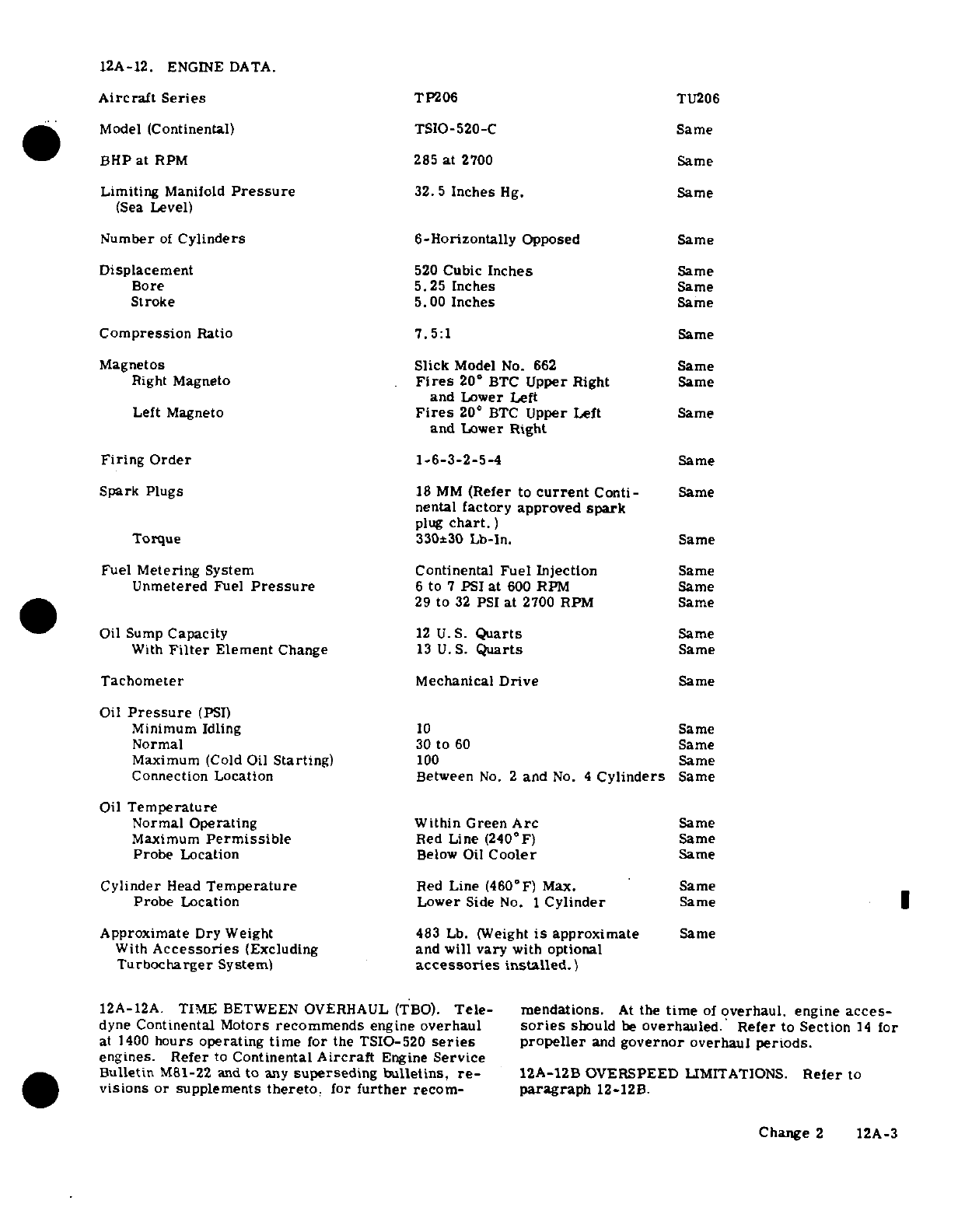
12A-12.
ENGINE
DATA.
Aircraft
Series
TP206
TU206
Model
(Continental)
TSIO-520-C
Same
BHP
at
RPM
285
at
2700 Same
Limiting
Manifold
Pressure
32.5
Inches
Hg.
Same
(Sea
Level)
Number
of
Cylinders
6-Horizontally
Opposed
Same
Displacement
520
Cubic
Inches
Same
Bore
5.25
Inches
Same
Stroke
5.00
Inches
Same
Compression
Ratio
7.5:1
Same
Magnetos
Slick
Model
No.
662
Same
Right
Magneto
Fires
20°
BTC
Upper
Right
Same
and
Lower
Left
Left
Magneto
Fires
20°
BTC
Upper
Left
Same
and
Lower
Right
Firing
Order
1-6-3-2-5-4
Same
Spark Plugs
18 MM
(Refer
to
current
Conti-
Same
nental
factory
approved
spark
plug
chart.)
Torque
330±30
Lb-in.
Same
Fuel
Metering
System
Continental
Fuel
Injection
Same
Unmetered
Fuel
Pressure
6
to
7
PSI
at
600
RPM
Same
~~~~ ~29
to
32
PSI
at
2700
RPM
Same
Oil Sump
Capacity
12
U.S.
Quarts
Same
With
Filter
Element
Change
13
U.S.
Quarts
Same
Tachometer
Mechanical
Drive
Same
Oil
Pressure
(PSI
Minimum
Idling
10
Same
Normal
30
to
60
Same
Maximum
(Cold
Oil
Starting)
100
Same
Connection
Location
Between
No.
2
and
No.
4
Cylinders
Same
Oil
Temperature
Normal
Operating
Within Green
Arc
Same
Maximum
Permissible
Red
Line
(240'F)
Same
Probe
Location
Below
Oil
Cooler
Same
Cylinder
Head
Temperature
Red
Line
(460°F)
Max.
Same
Probe
Location Lower
Side
No.
1
Cylinder
Same
Approximate
Dry
Weight
483
Lb.
(Weight
is
approximate
Same
With
Accessories
(Excluding
and will
vary
with
optional
Turbocharger
System)
accessories
installed.)
12A-12A.
TIME
BETWEEN
OVERHAUL
(TBO).
Tele-
mendations.
At
the
time
of
overhaul,
engine
acces-
dyne
Continental
Motors
recommends
engine
overhaul
sories
should
be
overhauled.
Refer
to
Section
14
for
at 1400
hours
operating
time
for
the TSIO-520
series
propeller
and
governor
overhaul
periods.
engines. Refer
to
Continental
Aircraft
Engine
Service
Bulletin
M81-22
and
to
any
superseding
bulletins,
re-
12A-12B
OVERSPEED
LIMITATIONS.
Refer
to
visions
or supplements
thereto.
for
further
recom-
paragraph
12-12B.
Change
2
12A-3
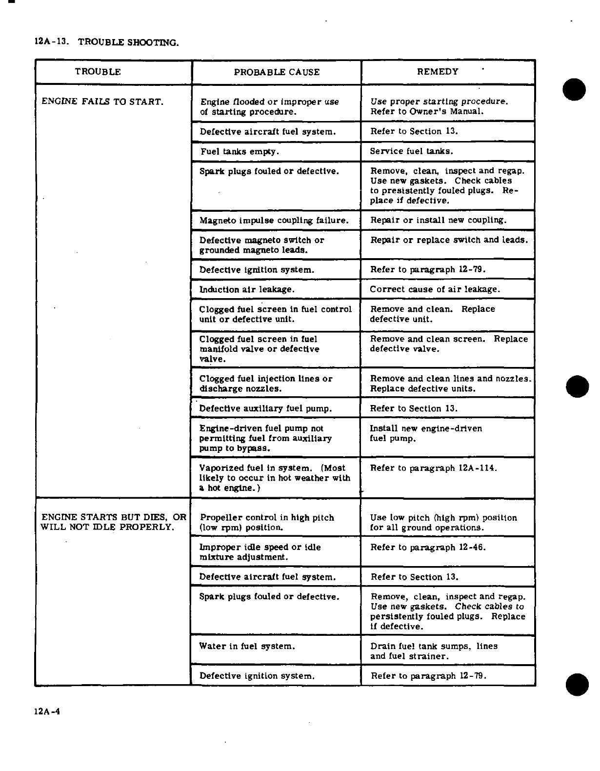
12A-13.
TROUBLE
SHOOTING.
TROUBLE PROBABLE
CAUSE
REMEDY
ENGINE
FAILS
TO
START.
Engine
flooded
or
improper
use Use
proper
starting
procedure.
of
starting
procedure.
Refer
to
Owner's
Manual.
Defective
aircraft
fuel
system.
Refer
to
Section
13.
Fuel
tanks
empty.
Service
fuel
tanks.
Spark
plugs
fouled
or
defective.
Remove,
clean,
inspect
and
regap.
Use
new
gaskets.
Check
cables
to
presistently
fouled
plugs.
Re-
place
if
defective.
Magneto
impulse
coupling
failure.
Repair
or
install
new
coupling.
Defective
magneto switch
or
Repair
or
replace
switch
and
leads.
grounded
magneto
leads.
Defective
ignition
system.
Refer
to
paragraph
12-79.
Induction
air
leakage.
Correct
cause
of
air
leakage.
Clogged
fuel
screen
in fuel
control
Remove
and
clean.
Replace
unit
or
defective
unit.
defective
unit.
Clogged
fuel
screen
in
fuel
Remove
and
clean
screen.
Replace
manifold valve
or
defective
defective
valve.
valve.
Clogged
fuel
injection
lines
or
Remove
and
clean
lines
and
nozzles.
discharge
nozzles.
Replace
defective
units.
Defective
auxiliary
fuel
pump.
Refer
to
Section
13.
Engine-driven
fuel
pump
not
Install
new
engine-driven
permitting
fuel
from
auxiliary
fuel
pump.
pump
to
bypass.
Vaporized
fuel
in
system.
(Most
Refer
to
paragraph
12A-114.
likely
to
occur
in
hot
weather
with
a
hot
engine.)
ENGINE
STARTS
BUT DIES,
OR
Propeller
control
in
high
pitch
Use
low
pitch
(high rpm)
position
WILL
NOT
IDLE
PROPERLY.
(low
rpm) position.
for all
ground
operations.
Improper
idle
speed
or
idle
Refer
to
paragraph
12-46.
mixture
adjustment.
Defective
aircraft
fuel
system. Refer
to
Section
13.
Spark
plugs
fouled
or
defective.
Remove,
clean,
inspect
and
regap.
Use
new
gaskets.
Check
cables
to
persistently
fouled
plugs. Replace
if
defective.
Water
in
fuel
system.
Drain
fuel
tank
sumps,
lines
and
fuel
strainer.
Defective ignition
system.
Refer
to
paragraph
12-79.
12A-4
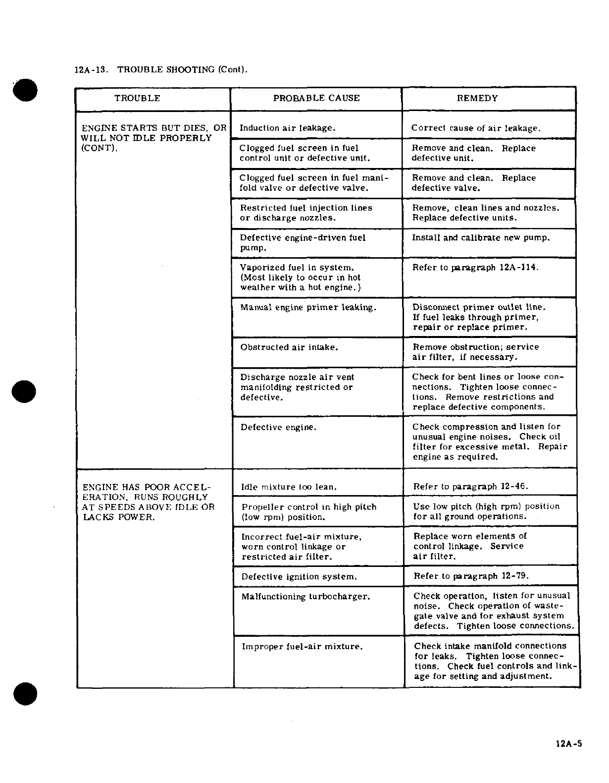
12A-13. TROUBLE
SHOOTING
(Cont).
TROUBLE PROBABLE
CAUSE
REMEDY
ENGINE
STARTS
BUT
DIES,
OR
Induction
air
leakage.
Correct
cause
of
air
leakage.
WILL
NOT
IDLE
PROPERLY
(CONT).
Clogged fuel
screen
in
fuel
Remove
and
clean.
Replace
control
unit
or
defective
unit.
defective
unit.
Clogged
fuel
screen
in
fuel
mani-
Remove and
clean.
Replace
fold
valve
or
defective
valve.
defective
valve.
Restricted
fuel
injection
lines
Remove,
clean
lines
and
nozzles.
or
discharge
nozzles.
Replace
defective
units.
Defective
engine-driven
fuel
Install
and
calibrate
new
pump.
pump.
Vaporized
fuel
in
system.
Refer
to
paragraph
12A-114.
(Most
likely
to
occur
in
hot
weather
with
a hot
engine.)
Manual
engine
primer
leaking.
Disconnect
primer
outlet line.
If
fuel
leaks
through
primer,
repair
or
replace
primer.
Obstructed
air
intake.
Remove
obstruction;
service
air
filter,
if
necessary.
Discharge
nozzle
air
vent
Check
for
bent
lines
or
loose
con-
manifolding
restricted
or nections.
Tighten
loose
connec-
defective.
tions.
Remove
restrictions
and
replace
defective
components.
Defective
engine.
Check
compression
and
listen
for
unusual
engine
noises.
Check
oil
filter
for
excessive
metal.
Repair
engine
as
required.
ENGINE
HAS
POOR
ACCEL-
Idle
mixture
too
lean.
Refer
to
paragraph
12-46.
ERATION,
RUNS
ROUGHLY
AT
SPEEDS
ABOVE
IDLE
OR
Propeller
control
in
high
pitch Use
low
pitch (high
rpm)
position
LACKS
POWER.
(low
rpm)
position.
for
all
ground
operations.
Incorrect
fuel-air
mixture,
Replace
worn
elements
of
worn
control
linkage
or
control
linkage.
Service
restricted
air
filter.
air
filter.
Defective
ignition
system.
Refer
to
paragraph
12-79.
Malfunctioning
turbocharger.
Check
operation,
listen for
unusual
noise.
Check
operation
of
waste-
gate
valve
and
for
exhaust
system
defects.
Tighten loose
connections.
Improper
fuel-air
mixture.
Check
intake
manifold
connections
for
leaks.
Tighten
loose
connec-
tions.
Check
fuel
controls
and
link-
age
for setting
and
adjustment.
12A-5
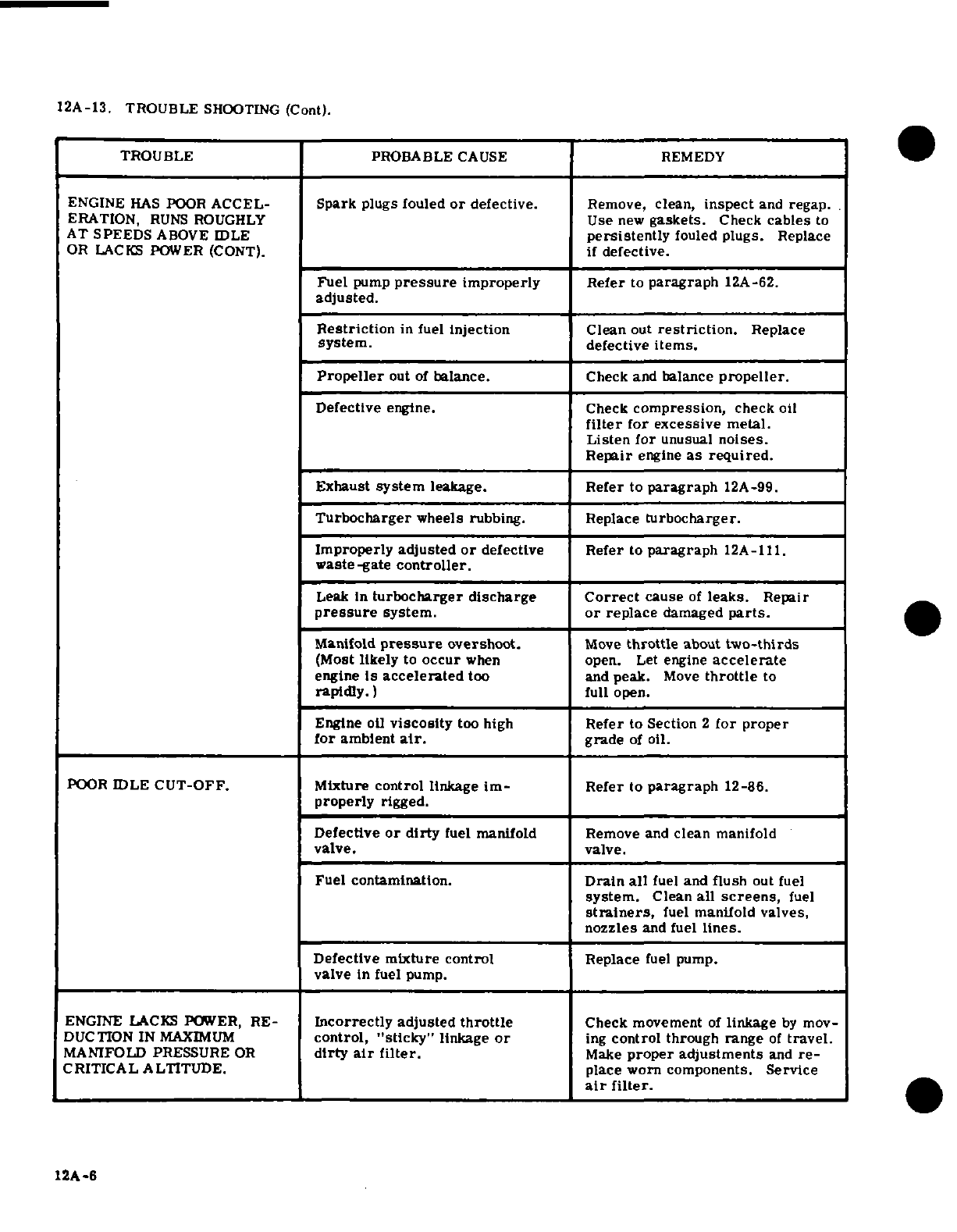
12A-13. TROUBLE
SHOOTING
(Cont).
TROUBLE
PROBABLE
CAUSE
REMEDY
ENGINE
HAS
POOR
ACCEL-
Spark
plugs
fouled
or
defective.
Remove,
clean,
inspect
and
regap.
ERATION,
RUNS
ROUGHLY
Use
new
gaskets.
Check
cables
to
AT
SPEEDS
ABOVE
IDLE
persistently
fouled
plugs.
Replace
OR
LACKS
POWER
(CONT).
if
defective.
Fuel
pump
pressure
improperly
Refer
to
paragraph
12A-62.
adjusted.
Restriction
in fuel
injection
Clean
out
restriction.
Replace
system.
defective
items.
Propeller
out
of
balance.
Check
and
balance
propeller.
Defective
engine.
Check
compression,
check
oil
filter
for
excessive
metal.
Listen
for
unusual
noises.
Repair
engine
as
required.
Exhaust
system
leakage.
Refer
to
paragraph
12A-99.
Turbocharger
wheels
rubbing.
Replace
turbocharger.
Improperly
adjusted
or
defective
Refer
to
paragraph
12A-111.
waste-gate
controller.
Leak
in
turbocharger
discharge
Correct
cause
of
leaks.
Repair
pressure
system.
or
replace
damaged
parts.
MrnifolA
pressure
overshoot.
Move
throttle
about
two-thirds
(Most
likely
to
occur
when
open.
Let
engine
accelerate
engine
is
accelerated
too
and
peak.
Move
throttle
to
rapidly.)
full
open.
Engine oil
viscosity
too
high
Refer
to
Section
2
for
proper
for
ambient
air.
grade
of
oil.
POOR
IDLE
CUT-OFF. Mixture
control
linkage
im-
Refer
to
paragraph
12-86.
properly
rigged.
Defective
or
dirty
fuel
manifold
Remove
and
clean
manifold
valve. valve.
Fuel
contamination.
Drain
all
fuel
and
flush
out
fuel
system.
Clean
all
screens,
fuel
strainers,
fuel
manifold
valves,
nozzles
and fuel
lines.
Defective
mixture
control
Replace
fuel
pump.
valve
in
fuel
pump.
ENGINE
LACKS
POWER,
RE-
Incorrectly
adjusted
throttle
Check movement
of
linkage
by
mov-
DUCTION
IN
MAXIMUM
control, "sticky"
linkage
or
ing
control
through
range
of
travel.
MANIFOLD
PRESSURE
OR
dirty
air
filter.
Make
proper adjustments
and
re-
CRITICAL
ALTITUDE.
place worn components.
Service
air
filter.
12A-6
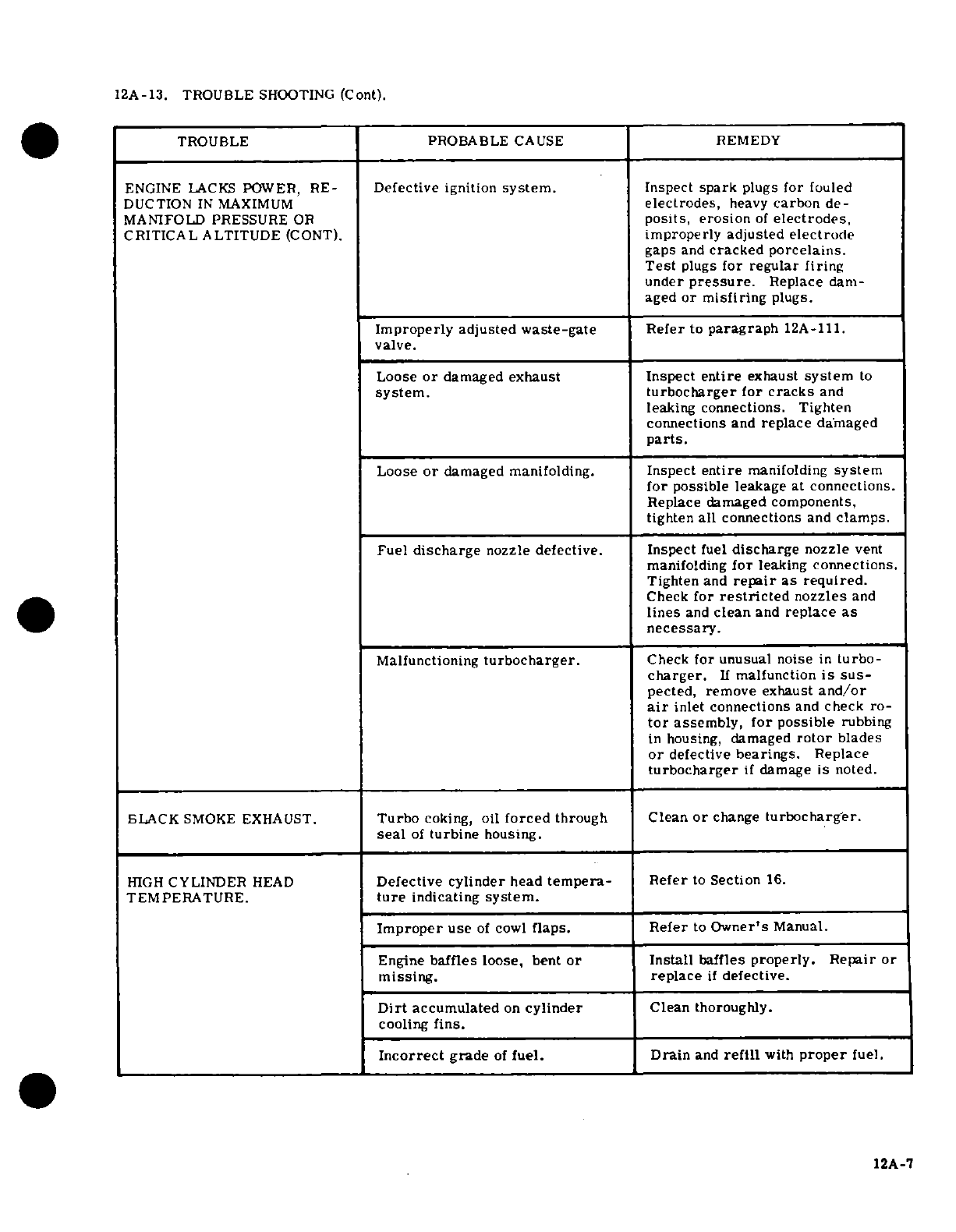
12A-13. TROUBLE
SHOOTING
(Cont).
TROUBLE PROBABLE
CAUSE
REMEDY
ENGINE
LACKS
POWER,
RE-
Defective
ignition
system.
Inspect
spark
plugs for
fouled
DUCTION
IN
MAXIMUM
electrodes,
heavy
carbon
de-
MANIFOLD PRESSURE
OR
posits,
erosion
of
electrodes,
CRITICAL
ALTITUDE
(CONT).
improperly adjusted
electrode
gaps
and
cracked
porcelains.
Test
plugs
for
regular firing
under
pressure.
Replace
dam-
aged
or
misfiring
plugs.
Improperly adjusted
waste-gate
Refer
to
paragraph
12A-111.
valve.
Loose
or
damaged
exhaust Inspect
entire
exhaust
system
to
system.
turbocharger
for
cracks
and
leaking
connections.
Tighten
connections
and
replace
damaged
parts.
Loose
or
damaged manifolding.
Inspect
entire
manifolding
system
for
possible
leakage
at
connections.
Replace damaged
components,
tighten
all
connections
and
clamps.
Fuel
discharge
nozzle
defective.
Inspect
fuel
discharge
nozzle
vent
manifolding
for
leaking
connections.
Tighten
and
repair
as required.
Check
for
restricted
nozzles
and
lines
and
clean
and
replace
as
necessary.
Malfunctioning
turbocharger.
Check
for unusual
noise
in
turbo-
charger.
If
malfunction
is
sus-
pected,
remove exhaust
and/or
air
inlet
connections
and
check
ro-
tor
assembly,
for
possible
rubbing
in
housing,
damaged
rotor
blades
or
defective
bearings.
Replace
turbocharger
if
damage
is
noted.
BLACK
SMOKE
EXHAUST.
Turbo
coking,
oil
forced
through Clean
or
change
turbocharger.
seal
of
turbine
housing.
HIGH
CYLINDER
HEAD
Defective
cylinder
head
tempera-
Refer
to
Section
16.
TEMPERATURE.
ture
indicating
system.
Improper
use
of
cowl
flaps. Refer
to
Owner's
Manual.
Engine
baffles
loose,
bent
or
Install
baffles
properly.
Repair
or
missing.
replace
if
defective.
Dirt
accumulated
on
cylinder
Clean
thoroughly.
cooling
fins.
Incorrect
grade
of
fuel.
Drain
and
refill
with
proper
fuel.
12A-7
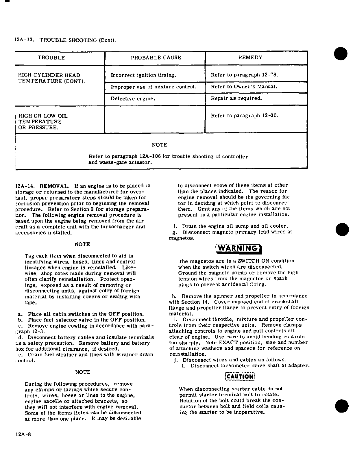
12A-13.
TROUBLE
SHOOTING
(Cont).
TROUBLE
PROBABLE
CAUSE
REMEDY
HIGH
CYLINDER
HEAD
Incorrect
ignition
timing. Refer
to
paragraph
12-78.
TEMPERATURE
(CONT).
Improper
use
of
mixture
control.
Refer
to
Owner's
Manual.
Defective
engine.
Repair
as
required.
HIGH
OR
LOW
OIL
Refer
to
paragraph
12-30.
TEMPERATURE
OR
PRESSURE.
NOTE
Refer
to
paragraph
12A-106
for
trouble
shooting
of
controller
and
waste-gate
actuator.
12A-14. REMOVAL.
If
an
engine
is
to
be
placed
in
to
disconnect
some
of
these
items
at
other
storage
or returned
to
the
manufacturer
for
over-
than
the
places
indicated.
The
reason
for
haul,
proper
preparatory steps
should
be
taken
for
engine
removal
should
be
the
governing
fac-
corrosion
prevention
prior
to beginning
the
removal
tor
in
deciding
at
which
point to
disconnect
procedure.
Refer
to
Section
2
for
storage
prepara-
them. Omit
any
of
the
items
which
are
not
tion.
The
following
engine
removal
procedure is
present
on
a
particular
engine
installation.
based
upon
the
engine
being
removed
from
the
air-
craft
as
a
complete
unit
with
the
turbocharger
and
f.
Drain
the
engine
oil sump
and
oil
cooler.
accessories
installed.
g.
Disconnect
magneto
primary
lead
wires
at
magnetos.
NOTE
IWARNING
Tag
each
item
when
disconnected
to
aid
in
identifying
wires,
hoses,
lines
and
control
The
magnetos
are
in
a
SWITCH
ON
condition
linkages
when
engine
is
reinstalled.
Like-
when
the
switch
wires
are
disconnected.
wise,
shop
notes
made
during
removal
will
Ground
the
magneto
points
or
remove
the
high
often
clarify
reinstallation.
Protect
open-
tension
wires
from
the
magnetos
or
spark
ings,
exposed
as
a
result
of
removing
or
plugs
to
prevent
accidental firing.
disconnecting
units,
against
entry
of
foreign
material
by
installing
covers
or
sealing
with
h.
Remove
the
spinner
and
propeller
in
accordance
tape.
with
Section
14.
Cover
exposed
end
of
crankshaft
flange
and
propeller
flange
to
prevent
entry
of
foreign
a.
Place
all
cabin
switches
in
the
OFF
position.
material.
b.
Place
fuel
selector
valve
in
the
OFF
position.
i.
Disconnect
throttle,
mixture
and
propeller
con-
c.
Remove
engine
cowling
in
accordance
with
para-
trols
from
their
respective units.
Remove
clamps
graph
12-3.
attaching
controls
to
engine
and
pull
controls
aft
d.
Disconnect
battery
cables
and
insulate
terminals
clear
of
engine.
Use
care
to
avoid
bending
controls
as
a
safety
precaution.
Remove
battery
and
battery
too
sharply.
Note EXACT
position,
size
and
number
box
for
additional
clearance,
if
desired.
of
attaching
washers
and
spacers
for
reference
on
e.
Drain
fuel
strainer
and
lines
with
strainer
drain
reinstallation.
control.
j.
Disconnect
wires
and
cables
as
follows:
1.
Disconnect
tachometer
drive
shaft
at
adapter.
NOTE
CAUTION
During
the
following
procedures,
remove
any
clamps
or
lacings
which
secure
con-
When
disconnecting
starter
cable
do
not
trols,
wires,
hoses
or
lines
to
the
engine,
permit
starter
terminal
bolt
to
rotate.
engine
nacelle
or
attached
brackets,
so
Rotation
of
the
bolt
could
break
the
con-
they
will
not
interfere
with engine
removal.
ductor
between
bolt
and
field
coils
caus-
Some
of
the
items
listed
can
be
disconnected
ing
the
starter
to
be
inoperative.
at
more
than
one
place.
It
may
be
desirable
12A-8
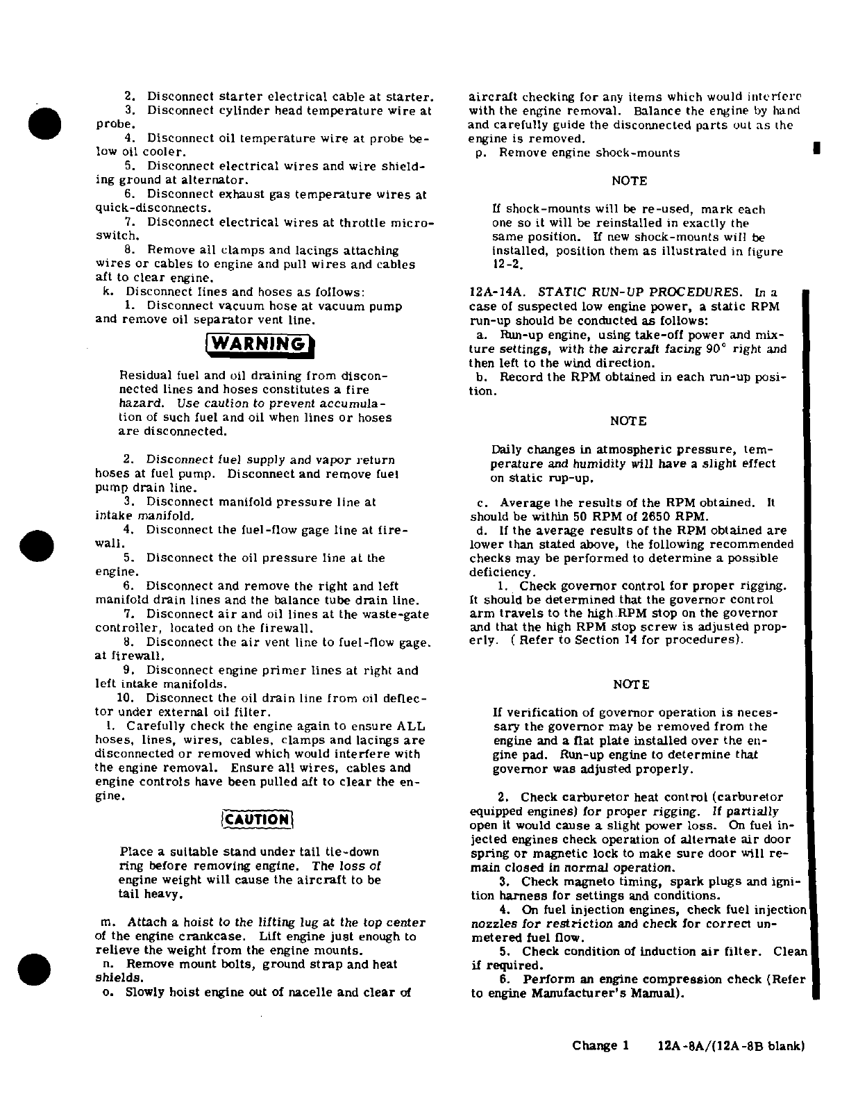
2.
Disconnect
starter
electrical
cable
at
starter.
aircraft
checking
for
any
items
which
would
interfere
3.
Disconnect
cylinder
head
temperature
wire
at
with
the
engine
removal.
Balance
the
engine
by
hand
probe.
and
carefully
guide
the
disconnected
parts
out
as
the
4.
Disconnect
oil
temperature
wire
at
probe
be-
engine
is
removed.
low
oil
cooler.
p.
Remove
engine
shock-mounts
5.
Disconnect
electrical
wires
and
wire
shield-
ing
ground
at
alternator.
NOTE
6.
Disconnect
exhaust
gas
temperature
wires
at
quick-disconnects.
If
shock-mounts
will
be
re-used,
mark
each
7.
Disconnect
electrical
wires
at
throttle
micro-
one
so
it
will
be
reinstalled
in
exactly
the
switch. same
position.
If
new
shock-mounts
will
be
8.
Remove
all clamps
and
lacings attaching installed, position
them
as
illustrated
in
figure
wires
or
cables
to
engine and
pull
wires
and
cables
12-2.
aft
to
clear
engine.
k.
Disconnect
lines
and
hoses
as
follows:
12A-14A.
STATIC
RUN-UP
PROCEDURES.
In
a
1.
Disconnect
vacuum
hose
at
vacuum
pump
case
of
suspected
low
engine
power,
a
static
RPM
and
remove
oil
separator
vent
line.
run-up
should be
conducted
as
follows:
NI a
.
Run-up
engine,
using
take-off
power
and
mix-
WARNING
tlure
settings,
with
the
aircraft
facing
90
°
right
and
then
left to
the
wind
direction.
Residual
fuel
and oil
draining
from
discon-
b.
Record
the
RPM
obtained
in
each
run-up
posi-
nected
lines
and
hoses
constitutes
a
fire
tion.
hazard.
Use
caution
to
prevent
accumula-
tion
of
such fuel and
oil
when
lines
or
hoses
NOTE
are
disconnected.
Daily
changes
in
atmospheric
pressure,
tem-
2.
Disconnect
fuel supply and
vapor
return
ture
and
humidity
will
have
a
slight
effect
hoses
at fuel
pump.
Disconnect
and
remove
fuel
on
static
rup-up.
pump
drain
line.
3.
Disconnect
manifold
pressure
line
at
c.
Average the
results
of
the
RPM
obtained.
It
intake
manifold.
should
be
within
50
RPM
of
2650
RPM.
4.
Disconnect
the
fuel-flow
gage
line
at
fire-
d.
If
the
average
results
of
the
RPM
obtained
are
wall.
lower
than
stated
above,
the
following
recommended
5.
Disconnect
the
oil
pressure
line
at
the
checks
may
be
performed
to
determine
a
possible
engine. deficiency.
6.
Disconnect
and
remove
the
right
and
left
1.
Check
governor
control
for
proper
rigging.
manifold
drain
lines
and
the
balance tube
drain
line.
It
should
be
determined
that
the
governor
control
7.
Disconnect
air
and oil
lines at
the
waste-gate
arm
travels
to
the
high
RPM
stop
on
the
governor
controller,
located
on
the
firewall.
and
that
the
high
RPM
stop
screw is
adjusted
prop-
8.
Disconnect
the
air
vent
line
to
fuel-flow
gage.
erly.
(
Refer
to
Section
14
for
procedures).
at firewall.
9.
Disconnect
engine
primer
lines
at
right
and
left
intake
manifolds.
NOTE
10.
Disconnect
the
oil
drain
line
from
oil
deflec-
tor
under
external
oil
filter.
If
verification
of
governor operation
is
neces-
I.
Carefully
check
the
engine
again
to
ensure
ALL
sary
the
governor
may
be
removed from
the
hoses,
lines,
wires,
cables, clamps
and
lacings
are
engine
and
a
flat
plate
installed
over
the
en-
disconnected
or
removed
which
would
interfere
with
gine
pad.
Run-up
engine
to
determine
that
the
engine
removal.
Ensure
all
wires,
cables
and
governor
was
adjusted
properly.
engine
controls
have
been
pulled
aft to
clear
the
en-
gine.
2.
Check
carburetor
heat
control
(carburetor
|CT~AC~UTION I ~equipped
engines)
for proper
rigging.
If
partially
CAUTION
I
open
it
would
cause
a
slight
power
loss.
On
fuel
in-
jected engines
check
operation
of
alternate
air
door
Place
a
suitable stand under
tail
tie-down
spring
or
magnetic
lock
to
make
sure
door
will
re-
ring
before
removing
engine.
The
loss
of
main
closed
in
normal
operation.
engine
weight
will
cause
the
aircraft
to
be
3.
Check
magneto timing,
spark
plugs
and
igni-
tail
heavy.
tion
harness
for
settings
and
conditions.
4.
On
fuel
injection
engines,
check
fuel
injection
m.
Attach
a
hoist
to
the
lifting
lug
at
the
top
center
nozzles
for
restriction
and
check
for
correct
un-
of
the
engine
crankcase.
Lift
engine
just
enough
to
metered
fuel
flow.
relieve
the weight
from
the
engine
mounts.
5.
Check
condition
of
induction
air
filter.
Clean
n.
Remove
mount
bolts,
ground
strap
and
heat
if
required.
shields.
6.
Perform
an
engine
compression
check
(Refer
o.
Slowly
hoist
engine
out of
nacelle
and
clear
of
to
engine
Manufacturer's
Manual).
Change
1
12A-8A/(12A-8B
blank)
12A-15. CLEANING.
Refer
to
paragraph
12-15.
12A-16.
ACCESSORIES REMOVAL.
Refer
to
para-
NOTE
graph
12-16.
Be
sure
engine
shock-mounts,
spacers
12A-17. INSPECTION.
Refer
to
paragraph
12-17.
and
washers
are
in
place
as
the
engine
is
lowered
into
position.
12A-18.
BUILD-UP.
Refer
to
paragraph
12-18.
12A-19.
INSTALLATION.
Before
installing
the
d.
Attach
ground
strap
under
engine
sump
bolt
engine
on
the
aircraft,
install
any
items
which
were
and
install
engine
mount
bolts.
Torque
bolts
to
300+
removed
from
the
engine
or
aircraft
after
the
engine 50-00
lb-in.
Bend
tab
washers
to
form
lock
for
mount
was
removed.
bolts.
Install
heat
shields.
e.
Remove
support
stand placed
under
tail
tie-down
NOTE
fitting
and remove
hoist.
Remove
all
protective
covers,
plugs,
caps
and
identification
tags
as
each
item
is
con-
NOTE
nected
or
installed.
Omit
any
items
not
present
on
a
particular
engine
installation.
If
the
exhaust
system
was
loosened
or
removed,
refer
to
paragraph
12A-98.
a.
Hoist
the
engine
to
a
point
just
above
the
nacelle.
b.
Install
engine
shock-mounts
and
ground
strap
as
illustrated
in
figure
12-2.
c.
Carefully
lower
engine
slowly into
place
on
the
f.
Connect
flexible
ducting
on
heater
shroud
and
engine
mounts.
Route
controls,
lines,
hoses
and
cabin
valve.
wires
in
place
as
the
engine
is
positioned
on
the
en-
g.
Route
propeller
governor
control
along
left
side
gine
mounts.
of
engine and
secure
with
clamps.
SHOP
NOTES:
Change
1
12A-9
NOTE
k.
Rig
engine
controls
in
accordance
with
para-
graphs
12-85,
12-86
and 12-87.
Throughout
the
aircraft
fuel
system,
from
1.
Install
propeller
and
spinner
in
accordance
with
the
fuel
cells
to
the
engine
driven
fuel
pump,
instructions
outlined
in
Section
14.
use
RAS-4
(Snap-On
Tools
Corp.,
Kenosha,
m.
Complete
a magneto
switch
ground-out
and
con-
Wisconsin),
MIL-T-5544
(Thread
Compound,
tinuity
check,
then
connect
primary
lead
wires
to the
Antiseize,
Graphite-Petrolatum)
or
equivalent, magnetos.
Remove
the
temporary
ground
or
connect
as
a
thread
lubricant
or
to
seal
a leaking
connec-
spark
plug
leads,
whichever
procedure
was
used dur-
tion.
Apply
sparingly
to
male
fittings
only,
omit-
ing
removal.
ting
the
first
two
threads.
Always
ensure
that
a
WAR
I
compound,
the
residue
from
a
previously
used
]
WARNING|
compound
or
any
other
foreign
material
cannot
enter
the
system.
Throughout the
fuel
injec-
Be
sure
magneto
switch
is
in
OFF
position
tion
system,
from
the
engine-driven
fuel
pump
when
connecting
switch
wires
to
magnetos.
through
the
discharge
nozzles, use
only
I
fuel
soluble
lubricant,
such
as
engine
lubricating
n.
Clean
and
install
induction
air
filter
in
accor-
oil,
on
fitting
threads.
Do
not
use
any
other
dance
with
Section
2.
form
of
thread
compound
on
the
fuel
injection
o.
Service
engine
with
proper grade
and
quantity
of
system
fittings.
engine
oil.
Refer
to
Section
2
if
engine
is
new,
newly
overhauled
or
has
been
in
storage.
h.
Connect
lines
and
hoses
as
follows:
p.
Check
all
switches
are
in
the
OFF
position
and
1.
Install
and
connect
the
left
and
right
manifold
connect
battery
cables.
drain
lines
and
the
balance
tube
drain
line.
q.
Inspect
engine
installation
for
security,
correct
2.
Connect
the
oil
pressure
line
at
its
fitting.
routing
of
controls,
lines,
hoses
and
electrical
wir-
3.
Connect
the
fuel-flow
gage
line
at firewall.
ing,
proper
safetying
and
tightness
of
all
components.
4.
Connect
the
fuel
supply
and
the
vapor
return
lines
at
the
fuel
pump.
Connect
and
install
fuel
pump
NOTE
drain
line.
5.
Connect
manifold
pressure
line
at
intake
mani-
When
installing
a
new
or
newly
overhauled
fold.
engine,
and
prior
to
starting
the
engine,
6.
Connect
vacuum
line
at
the
vacuum
pump,
and
disconnect
the
oil
inlet
line
at
the
controller
Install
oil
separator
vent
line.
and
the oil
outlet
line
at
the
controller.
7.
Connect
air
and
oil
lines
at
waste-gate
con-
Connect
these
oil
lines
to
a
full-flow
oil
troller
on
firewall.
filter,
allowing
oil
to
bypass
the
controller.
8.
Connect
air
vent
line
to
fuel-flow
gage
line
With
filter
connected,
operate
engine
approxi-
at
firewall.
mately
15
minutes
to
filter
out
any
foreign
9.
Connect
engine
primer
lines
at right
and
left
particles
from
the
oil. This
is
done
to
pre-
intake
manifolds. vent
foreign
material
from
entering
the
con-
10.
Connect
oil
drain
line
to
oil
deflector
under
troller.
external
oil
filter.
11.
Install
all
clamps
securing
lines
and
hoses
to
r.
Install
engine cowling
in
accordance
with
para-
engine
or
structure.
graph
12-3.
i.
Connect
wires
and
cables
as
follows:
s.
Perform
an
engine
run-up
and
make
final
adjust-
1.
Connect
oil
temperature
wire
at
probe
below
ments
on
the
engine
controls.
oil
cooler.
2.
Connect
tachometer drive
to
adapter
and
tor-
12A-20.
FLEXIBLE
FLUID
HOSES.
Refer
to
para-
que
to
100
lb-in. graph
12-20.
IWARNING
12A-21.
PRESSURE
TEST.
Refer
to
paragraph
12-
21.
When
connecting
starter
cable,
do
not
permit
starter
terminal
bolt
to
rotate.
Rotation
of
12A-22.
REPLACEMENT.
Refer
to
paragraph
12-
the bolt
could
break
conductor
between
terminal
22.
and
field
coils
causing
starter
to
be
inoperative.
12A-23.
ENGINE
BAFFLES.
Refer
to
paragraph
3.
Connect
starter
electrical
lead.
12-23.
4.
Connect
cylinder
head
temperature
wire
at
probe.
12A-24.
DESCRIPTION.
Refer
to
paragraph
12-24.
5.
Connect
electrical wires
and
wire
shielding
ground
to
alternator.
12A-25.
CLEANING
AND
INSPECTION.
Refer
to
6.
Connect
electrical
wires
to
throttle
switch.
paragraph
12-25.
7.
Connect
exhaust
gas
temperature
wires
at
quick-disconnects.
12A-26.
REMOVAL
AND
INSTALLATION.
Refer
to
8.
Install
clamps
that
attach
wires
or
cables,
to
paragraph
12-26.
engine
or
structure.
j.
Connect
engine
controls
and
install
block
clamps.
12A-27.
REPAIR.
Refer
to
paragraph
12-27.
12A-10
12A-28.
ENGINE
OIL
SYSTEM.
Refer
to
figure
engine
airflow.
A
manual
mixture
control
and
a
fuel
12A-1. flow
indicator
are
provided
for
leaning
at
any
combi-
nation
of
altitude
and power
setting.
The fuel
flow
12A-29.
DESCRIPTION.
The
engine
lubrication
indicator
is
calibrated
in
gallons
per hour
and
indi-
system
is
a
full-pressure,
wet-sump
type.
Lubri-
cates
approximately
the
gallons
of
fuel
consumed
per
cating
oil
is
drawn
from
the
engine
sump
to
the
oil
hour.
The
continuous-flow
system uses
a
typical
pump
through
a
suction
screen
and
tube.
From
the
rotary
vane
fuel
pump.
There
are
no
running
parts
pump,
oil
under
pressure
is
passed
to
the
full-flow
in
this
system
except
for
the
engine-driven
fuel
pump.
oil
filter,
where
it
is
filtered
before
entering
the
The
four
major
components
of
the
system
are:
the
passages
of
the
engine.
Bypass valves
are
provided.
fuel
injection
pump,
fuel-air
control
unit,
fuel
mani-
Oil
from
the
filter
is
routed
through
drilled
and
cor-
fold
valve
and
the
fuel
discharge
nozzles.
The
fuel
ed
passages
to
all
moving
parts
requiring
lubrication.
injection
pump
incorporates
an
adjustable
aneroid
Oil
furnished
to
the
propeller
governor
for
propeller
sensing
unit
which
is
pressurized
from
the
discharge
operation is also
routed
through
internal
passages.
side
of
the
turbocharger
compressor.
Turbocharger
Oil
pressure
is
maintained
by
an
adjustable,
spring-
discharge
air
pressure
is also
used
to
vent
the
fuel
loaded
relief
valve
mounted
in
the
lower
portion
of
discharge
nozzles
and
the vent
port
of
the
fuel-flow
the
pump
body.
Oil
temperature
is
automatically
gage.
regulated
by
an oil
cooler
and
a
thermostat
control
valve.
When
+he
oil
temperature
reaches
a
prede-
NOTE
termined
temperature
the
thermostat
valve
closes,
causing
the
oil
to
be
routed
through the
externally
Throughout
the
aircraft
fuel
system,
from
mounted
cooler.
Engine
oil
is also
used
to
control
the
fuel
cells
to
the
engine-driven
fuel
pump,
the
waste-gate
and
lubricate
the
turbocharger bear-
use
RAS-4
(Snap-On Tools
Corp.,
Kenosha,
ings.
Oil
is
returned
to
the
engine
sump
from
the
Wisconsin), MIL-T-5544
(Thread
Compound,
turbocharger
by
a
scavenger
pump, which
is
inte-
Antiseize,
Graphite-Petrolatum)
or
equivalent,
gral
with
the
engine
oil
pump.
The
oil
filler
neck
is
as
a
thread
lubricant or
to
seal
a
leaking
con-
located
on
top
of
the
engine
and
is
reached
through
nection.
Apply
sparingly
to
male
fittings
only,
an
access
door
in
the
top
of
the
left
cowl.
The oil
omitting
the
first
two
threads.
Always
ensure
level
in
the
sump
is
checked
on
a
dipstick at
the
that
a
compound,
the
residue
from
a
previously
rear
of
number
two
cylinder
and
is
reached
through
used
compound
or
any
other
foreign
material
an
access
door
in
the
side
of
the left
cowl.
cannot
enter
the system.
Throughout
the
fuel
injection
system,
from
the
engine-driven
fuel
12A-30. TROUBLE
SHOOTING.
Refer
to
paragraph
pump
through the
discharge
nozzles,
use
only
12-30.
a
fuel
soluble
lubricant,
such
as
engine
lubri-
cating
oil,
on
the
fitting
threads.
Do
not
use
12A-31.
FULL-FLOW
OIL
FILTER.
Refer
to
para-
any
other
form
of
thread
compound
on
the
in-
graph
12-31.
jection
system
fittings.
12A-32. DESCRIPTION.
Refer
to
paragraph
12-32. 12A-42.
FUEL-AIR
CONTROL
UNIT.
Refer
to
paragraph
12-42.
12A-33.
REMOVAL
AND
INSTALLATION.
Refer
to
paragraph
12-33.
12A-43.
DESCRIPTION.
Refer
to
paragraph
12-43.
12A-34.
FILTER
ADAPTER.
Refer
to
paragraph
12A-44.
REMOVAL.
12-34.
a.
Place
all
cabin switches
and fuel
shut-off
valve
in
the
OFF position.
12A-35.
REMOVAL.
Refer
to
paragraph
12-35.
b.
Remove
cowling
in
accordance
with
paragraph
12-3.
12A-36.
DISASSEMBLY,
INSPECTION
AND
RE-
c.
Loosen
clamp
and
disconnect flexible
duct
from
ASSEMBLY.
Refer
to
paragraph
12-36.
elbow
at
top
of
air
throttle.
d.
Tag
and
disconnect
electrical
wires
from
elec-
12A-37. INSTALLATION.
Refer
to
paragraph
12-37.
tric
fuel
pump
microswitch.
e.
Disconnect
throttle
and
mixture
control
rod
ends
12A-38.
OIL
COOLER.
Refer
to
paragraph
12-38.
at
fuel-air
control
unit.
12A-39.
DESCRIPTION.
Refer
to
paragraph
12-39.
NOTE
12A-40.
ENGINE
FUEL
SYSTEM.
Refer
to
figure
Cap
or
plug
all
disconnected hoses,
lines
and
12A-2.
fittings.
12A-41.
DESCRIPTION. The
fuel
injection
system
f.
Disconnect
cooling
air
blast
tube
from
fuel
con-
is
a
low
pressure
system
of
injecting
fuel
into
the
trol
valve
shroud.
intake
valve
port
of
each
cylinder.
It
is
a
multi-
g.
Disconnect
and
tag
all fuel
lines
at
the
fuel
con-
nozzle,
continuous-flow
type
which
controls
fuel
trol
valve.
flow to
match
engine
airflow.
Any
change
in
throttle
h.
Remove
nuts
and
washers securing
triangular
position,
engine
speed,
or
a
combination
of
both,
brace
to
fuel-air
control
unit
and
engine,
at
lower
causes
changes
in
fuel
flow in
the
correct
relation
to end
of
control
unit.
Remove
brace.
12A-11
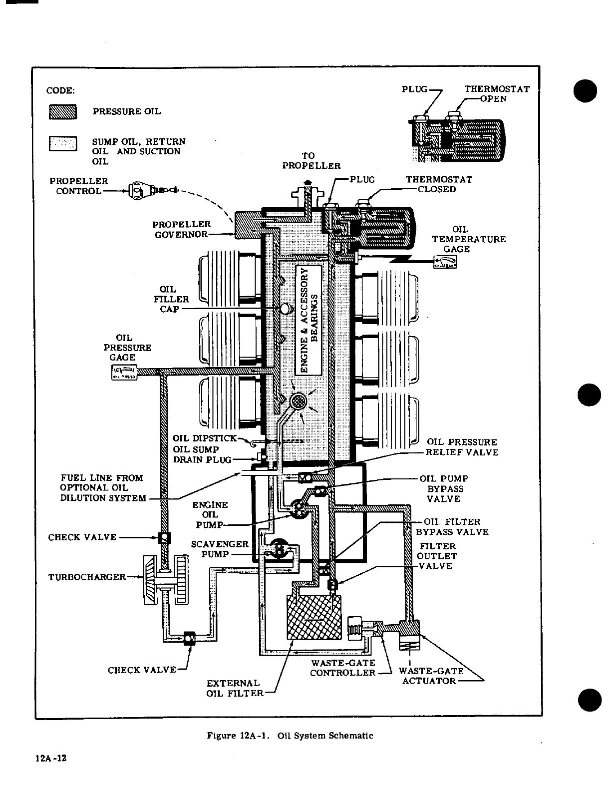
CODE:
PLUG
THERMOSTAT
PRESSURE
OIL
SUMP
OIL,
RETURN
OIL
AND
SUCTION
TO
OIL
PROPELLER
PROPELLER
PLUG
THERMOSTAT
CONTROL
CLOSED
PROPELLER
OIL
GOVERNOR
TEMPERATURE
GAGE
OIL
FILLER
CAP
OIL
PRESSURE
GAGE
OIL
DIPSTICK
OIL
PRESSURE
OIL
SUMP
RELIEF
VALVE
DRAIN
PLUG
FUEL
LINE
FROM
OIL
PUMP
OPTIONAL OIL
BYPASS
DILUTION
SYSTEM
ENGINE
VALVE
OIL
PUMP OIL
FILTER
CHECK
VALVE
BYPASS
VALVE
SCAVENGER
FILTER
PUMP
OUTLET
TURBOCHARGER
WASTE-GATE
CHECK
VALVE
CONTROLLER
WASTE-GATE
EXTERNAL
ACTUATOR
OIL
FILTER
Figure
12A-1.
Oil
System
Schematic
12A
-12
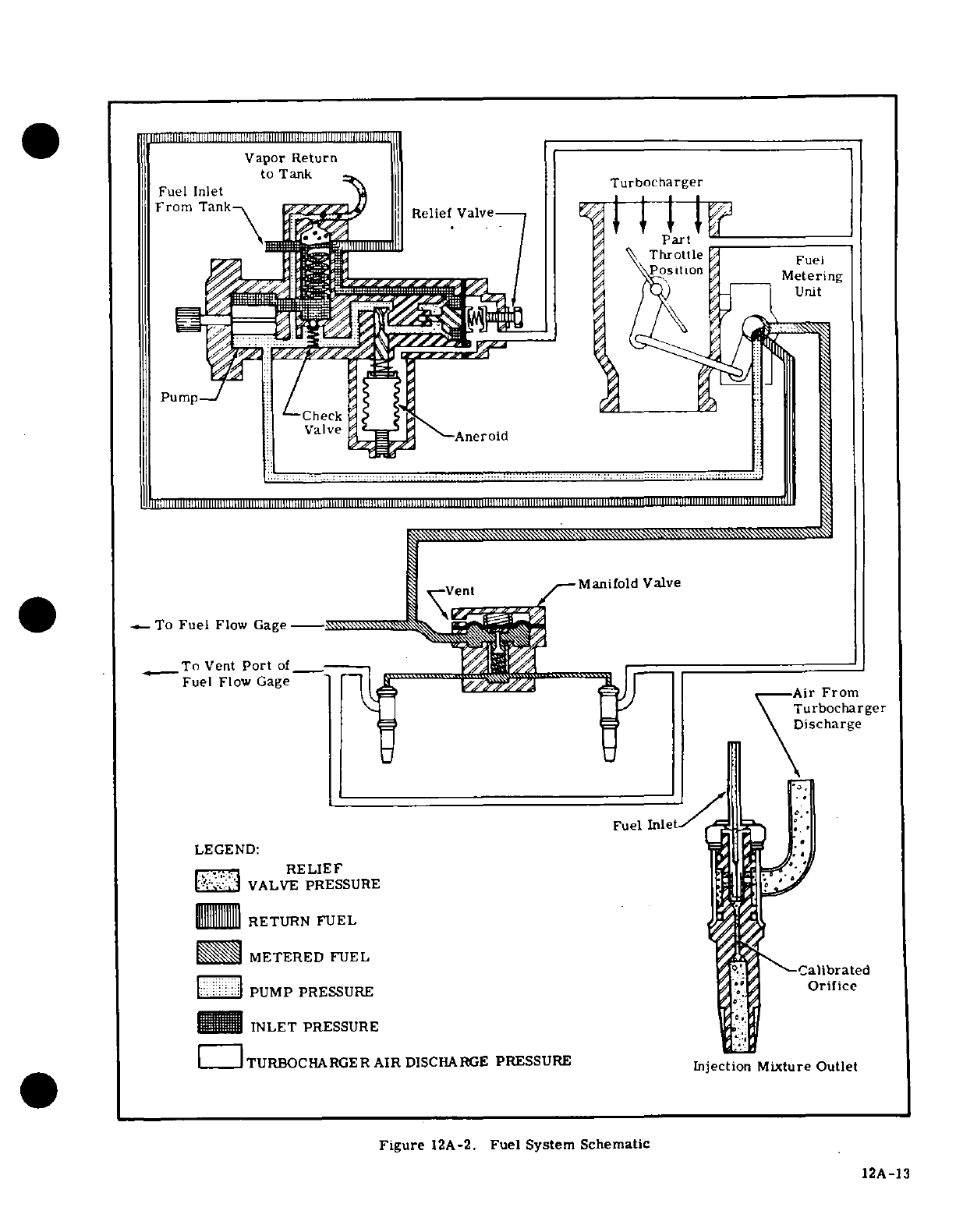
Manifold
Valve
To
Fuel
Flow
Gage
--------
To
Vent
Port
of
Fuel
Flow
Gage Air
From
-
-Turbocharger
fl
1
\Discharge
Fuel
Inlet
LEGEND:
RELIEF
VALVE
PRESSURE
RETURN
FUEL
METERED
FUEL
PUMP
PRESSURE
Orifice
INLET
PRESSURE
TURBOCHARGER
AIR
DISCHARGE
PRESSURE
Injection
Mixture
Outlet
Figure
12A-2.
Fuel
System
Schematic
12A-13
i.
Remove
bolt
attaching
fuel-air
control
unit
to
graph
12-3.
brace
at
top
of
control
unit.
j.
Loosen
hose
clamps
which
secure
fuel-air
con-
NOTE
trol
unit
to
right
and
left
intake
manifold
assemblies
and
slip
hoses
from
fuel-air
control
unit.
Plug
or
cap
all
disconnected
lines
and
fittings.
k.
Remove
fuel-air
control
unit.
b.
Disconnect nozzle
pressurization
line
at
nozzles
12A-45.
CLEANING
AND
INSPECTION.
Refer
to
and
disconnect
pressurization
line
at
"tee"
fitting
so
paragraph
12-45.
that
pressurization
line
may
be
moved
away
from
discharge
nozzles.
12A-46.
INSTALLATION.
c.
Disconnect
fuel
injection
line
at
fuel
discharge
a.
Place
control
unit
in
position
at
rear
of
engine.
nozzle.
b.
Install
bolt
attaching control
unit
to
brace at
top
d.
Using
care
to
prevent
damage
or
loss
of
washers
of
unit.
Ascertain
that
shock-mount
is
in
place
and
in and
O-rings,
lift
sleeve assembly
from
fuel
dis-
good
condition.
charge
nozzle.
c.
Install
triangular
brace
at
lower
end
of
control
e.
Using
a
standard 1/2-inch
deep
socket, remove
unit.
fuel
discharge
nozzle
from cylinder.
d.
Install hoses
and
clamps
which
secure
control
unit to
right
and
left
intake
manifold
assemblies.
12A-56.
CLEANING
AND
INSPECTION.
Refer
to
Tighten
hose
clamps.
paragraph
12-55.
e.
Connect
fuel
lines
to
unit
and
connect
air
blast
tube
at
fuel
control
shroud.
12A-57.
INSTALLATION.
f.
Connect
throttle
and
mixture
control
rod
ends
a.
Using
a
standard
1/2-inch
deep
socket, install
to
control
unit.
nozzle
body
in
cylinder
and
tighten
to
a
torque
value
g.
Connect
electrical
wires
to
electric
fuel
pump
of
60-80
lb-in.
microswitch.
Check
switch
rigging
in
accordance
b.
Install
O-rings,
sleeve
assembly
and
washers.
with
Section
13.
c.
Align
sleeve
assembly
and
connect
pressuriza-
h.
Install
induction
air
duct
to
elbow
at
top
of
con-
tion
line
to
nozzles.
Connect
pressurization
line
to
trol
unit.
"tee"
fitting.
i.
Inspect
installation
and
install
cowling.
d.
Install O-ring
and
washer at
top
of
discharge
nozzle
and
connect fuel
injection
line
to
nozzle.
12A-47.
ADJUSTMENTS.
Refer
to
paragraph
12-46.
e.
Inspect
installation
for
crimped lines
and
loose
fittings.
12A-48.
FUEL
MANIFOLD VALVE
(FUEL
DISTRI-
f.
Inspect
nozzle
pressurization
vent
system
for
BUTOR).
Refer
to
paragraph
12-47.
leakage.
A
tight
system
is
required,
since
turbo-
charger
discharge
pressure
is
applied
to
various
12A-49.
DESCRIPTION.
Refer
to
paragraph
12-48.
other
components
of
the
injection
system.
g.
Install
cowling.
12A-50.
REMOVAL.
Refer
to
paragraph
12-49.
12A-58.
FUEL
INJECTION
PUMP.
12A-51. CLEANING.
Refer to
paragraph
12-50.
12A-59.
DESCRIPTION.
The
fuel
pump
is
a
positive
12A-52. INSTALLATION.
Refer
to
paragraph
12-51.
displacement,
rotating
vane
type.
It
has
a
splined
shaft
for
connection
to
the
accessory
drive
section
12A-53.
FUEL
DISCHARGE
NOZZLES.
of
the
engine.
Fuel
enters
the
pump
at
the
swirl
well
of
the
pump
vapor
separator.
Here,
vapor
is
separ-
12A-54.
DESCRIPTION.
From
the
fuel
manifold
ated
by
a
swirling
motion
so
that
only
liquid
fuel
is
fed
valve,
individual,
identical
size
and length
fuel
lines
to
the
pump.
The
vapor
is
drawn
from
the
top
center
carry
metered
fuel to
the
fuel
discharge
nozzles
lo-
of
the
swirl
well
by
a
small
pressure
jet
of
fuel
and
cated
in
the
cylinder
heads.
The
outlet
of
each
nozzle
is
fed
into
the
vapor
return
line
where
it
is
returned
is
directed
into
the
intake
port
of
each
cylinder.
An
to
the
fuel tank.
Since
the pump
is
engine-driven,
air
bleed
and
nozzle
pressurization
arrangement
is
changes
in engine
speed
affect total
pump
flow
propor-
incorporated
in
each nozzle
to
aid
in
vaporization
of
tionally.
A
check
valve
allows
the
auxiliary
fuel
pump
the
fuel.
The
nozzles
are
calibrated
in
several
ranges.
pressure
to
bypass
the
engine-driven
pump
for
start-
All
nozzles
furnished for
one
engine
are
of
the
same
ing,
or
in
the event
of
engine-driven
fuel
pump
failure
calibrated
range
and
are
identified
by
a
number
and
in
flight.
The
pump
supplies
more
fuel
than
is required
suffix
letter
stamped
on
the
flat
portion
of
the nozzle
by
the
engine;
therefore,
a
relief
valve
is
provided
body.
When
replacing
a
fuel
discharge
nozzle,
be
to
maintain
a
constant
fuel
pump
pressure.
The
sure
that
it
is
of
the
same
calibrated
range
as
the
engine-driven
fuel
pump
is
equipped
with
an
aneroid.
rest
of
the
nozzles
in
that
engine.
When
a
complete
The
aneroid
and
relief
valve
are
pressurized
from
the
set
of
nozzles
is
being
replaced,
the
number must
be
discharge
side
of
the
turbocharger
compressor
to
the
same
as
the
one
removed
but
the
suffix
letter
maintain
a
proper
fuel/air
ratio
at
altitude.
The
may
be
different,
as
long
as
they
are
the
same for
aneroid
is
adjustable
for
fuel
pump
outlet
pressure
all
nozzles
being
installed
in
a
particular
engine.
at
full
throttle
and
the
relief
valve
is
adjustable
for
12A-55.
REMOVAL.
fuel
pump
outlet
pressure
at
idle.
a.
Remove
engine
cowling
in
accordance
with
para-
12A-14
Change
3
12A-60.
REMOVAL.
NOTE
a.
Place
fuel
selector
valve
handle
in
OFF
position.
b.
Remove engine
cowling
in
accordance
with
para-
The
test
gage
should
be
checked
for
accuracy
graph
12-3.
at
least
every
90
days
or
anytime
an
error
is
c.
Remove
alternator
and
left
rear
intake
elbow.
suspected.
The
tachometer
accuracy
should
d.
Hoist
engine
far
enough
to
remove
weight
from
also
be
determined
prior
to making
any
ad-
engine
mount
and
remove
left
rear
engine
mount
leg,
justments
to
the
pump.
shock-mount
and
alternator
bracket.
e.
Remove
flexible
duct
and
shroud,
removing
fuel
d.
Start
engine
and
warm-up
thoroughly.
Set
mix-
lines
and
fittings
as
necessary.
Tag
each
fitting
and
ture
control
to
full
rich
position
and
propeller
con-
line
for
identification
and
cap
or
seal
to
prevent
en-
trol
full
forward
(low
pitch,
high
rpm).
try
of
foreign
material.
Flanges
of
shroud
may
be
e.
Adjust
engine
idle
speed
to
600
±
25
rpm
and
straightened
to
facilitate
removal
and
installation,
check
test
gage
for
6-7
PSI.
Refer
to
figure
12-7
but
must
be
re-formed
after
installation.
Note
an-
for
idle
mixture
adjustment.
gular
position
of
fittings
before
removal.
f.
Remove
nuts
and
washers
attaching
fuel
pump
NOTE
to engine
and
pull pump
aft to
remove.
Remove
thin
gasket.
Do
not
adjust
idle
mixture
until
idle
pump
g.
Place
temporary
cover
on
pump mounting
pad.
pressure
is
obtained.
12A-61. INSTALLATION.
WARNING
a.
Install
and
align
any
fittings
removed
after
pump
removal.
DO
NOT
make
fuel
pump
pressure
adjust-
b.
Using
new
thin
gasket,
install
pump
with
aneroid
ments
while
engine
is operating.
chamber
down.
c.
Install
cooling
shroud
and
remainder
of
fittings,
f.
If
the
pump
pressure
is
not
6
to
7
PSI,
stop
en-
bending
flanges
of
shroud
to
their
original positions
gine
and
turn
the
fuel
pump
relief
valve
adjustment,
and
aligning
fittings
as
noted
during removal.
on
the
centerline
of
the
fuel
pump
clockwise
(CW)
to
d.
Connect
all
fuel
lines
and
shroud
flexible
duct.
increase
pressure
and
counterclockwise
(CCW) to
e.
Install
alternator
bracket,
shock-mount
and
decrease
pressure.
engine
mount
leg.
Remove
hoist,
then
adjust
alter-
g.
Maintaining
idle
pump
pressure
and
idle
RPM,
nator drive
belt
tension. Refer
to
Section
17.
obtain
correct
idle
mixture
in
accordance
with
para-
f.
Install
intake
elbow.
graph
12-46.
g.
Start
engine
and
perform
an
operational
check,
h.
Completion
of
the
preceding
steps
have
provided:
adjusting
fuel
pump
if
required.
I.
Correct
idle
pump
pressure.
h.
Install
cowling.
2.
Correct
fuel
flow.
3.
Correct
fuel
metering
cam
to
throttle
plate
12A-62.
ADJUSTMENT.
Adjustments
of
the
fuel in-
orientation.
jection
pump
requires
special
equipment
and
proce-
i.
Advance
to
full
throttle
and
maximum
rated
en-
dures.
Adjustment
to
the
aneroid
applies
only
to
the
gine
speed
with
the
mixture control
in
full
rich
posi-
full
throttle
setting.
Adjustment
of
the idle
position
tion
and
propeller
control
in
full
forward
(low
pitch,
is
obtained
through
the
relief
valve.
To
adjust
the
high
rpm).
pump
to
the
pressures
specified
in
paragraph
12A-12,
j.
Check
test
gage
for
pressures
specified
in
para-
proceed
as
follows:
graph
12A-12.
If
pressure
is
incorrect,
stop engine
a.
Remove engine
cowling
in
accordance
with
para-
and
adjust
pressure
by
loosening
locknut and
turning
graph
12-3.
the
adjusting
screw
located
at
rear
of
aneroid
coun-
b.
Disconnect
the
existing
engine-driven
fuel
pump
terclockwise
(CCW)
to
increase
pressure
and
clock-
pressure
hose
at
the
fuel
metering
unit
and
the
ex- wise
(CW)
to
decrease
pressure.
isting
fuel
gage vent
hose
at
the
air
manifold
valve.
Connect
the
test
gage
pressure
hoses.
vent
hose
and
NOTE
fittings
into
the
fuel
injection
system
as
illustrated
in
figure
12A-8.
If
at
static
run-up,
rated
RPM
cannot
be
c.
The
test
gage
MUST
be
vented
to
upper
deck
achieved
at
full
throttle,
adjust
pump
pres-
pressure
and
MUST
be
held
as near
to
the
level
of
sure
slightly
below
limits
making
certain
the
engine-driven
pump
as
possible.
Bleed
air
from
the
correct
pressures
are
obtained
when
test
gage
line
prior
to taking
readings.
rated
RPM
is
achieved
during
take-off roll.
NOTE
k.
After
correct
pressures
are
obtained,
tighten
locknut.
Cessna
Service
Kit
No.
SK320-2
provides
1.
Remove
test
equipment, run
engine
to
check
for
a
test
gage,
lines
and
fittings
for
con-
leaks
and
install
cowling.
necting
the
test
gage
into
the
system
to
12A-62A.
RIGGING
THROTTLE
OPERATED
MICRO-
perform accurate
calibration
of
the
engine-
SWITCH.
Refer
to
Section
13,
driven
fuel
pump.
12A-62B.
AUXILIARY
ELECTRIC
FUEL
PUMP
FLOW
RATE ADJUSTMENT.
Refer
to Section
13.
D2007C3-13
Temporary
Change
2
Change
3
12A-15
22
February
1978
12A-63.
INDUCTION AIR
SYSTEM.
b.
Remove
screws
attaching
airbox
to
upper
rear
baffle.
12A-64.
DESCRIPTION.
Ram
air
to
the
engine
en-
c.
Loosen
clamp and
disconnect flexible
air
duct
to
ters
an
induction
air
duct
at
the
right
side
of
the
nose
airbox.
cap.
The
air
is
filtered
through
a
dry
filter,
located
d.
Remove
four
screws
attaching
airbox
to
forward
in
the induction
airbox.
From
the
filter,
the
air
pas-
air
duct
and
work
airbox
and
filter
from
aircraft.
ses
through
a
flexible
duct to
the
inlet
of
the
turbo-
e.
Remove
four bolts,
washers
and
nuts
attaching
charger
compressor.
The
pressurized
air
is
then
filter
between
airbox halves.
routed
through
a
duct to
the
fuel-air
control
unit
mounted
behind
the
engine
and
is
then
supplied
to
NOTE
the
cylinders
through
the
intake manifold
piping.
The
fuel-air
control
unit
is
connected
to
the
cylinder
in-
When
installing
filter,
note
direction
of
air
take
manifold
by
elbows,
hoses
and
clamps.
The
in-
flow.
Inspect and
install
gasket
at
aft
face
take
manifold
is
attached
to
each
cylinder
by
four
of
filter
assembly.
Also,
when
tightening
bolts
through
a
welded
flange,
which
is sealed
by
a
bolts
fastening
filter,
push
inward
on
lower
gasket.
A
balance
tube
passes
around
the
front side
end
of
the
upper
duct (where
turbocharger
of
the
engine
to
complete
the
manifold
assembly.
An
inlet
connects
to
the
upper
duct).
This
is
alternate
air
door,
mounted
in
the
duct between
the
done
so that
inlet
hose
doesn't
chafe
against
filter
and
the
turbocharger
compressor,
is
held
clos-
the cowling.
ed
by
a
small
magnet.
If
the
induction
air
filter
should become clogged,
suction
from
the
turbocharger
f.
Reverse
the
preceding
steps
for
reinstallation.
compressor
will
open
the
door
permitting
the com-
pressor
to
draw heated,
unfiltered
air
from
within
12A-71. CLEANING
AND
INSPECTION.
Clean
and
the
engine
compartment.
The
alternate
air
door
inspect
filter
in
accordance
with
Section
2.
should
be
checked
periodically
for
freedom
of
oper-
ation
and
complete closing.
The
induction
air
filter
12A-72.
IGNITION
SYSTEM.
Refer
to
paragraph
should
be
removed
and
cleaned
at
each
50-hour
in-
12-71.
spection,
more
often
when
operating
under
dusty
con-
ditions.
Refer
to
Section
2.
12A-73.
DESCRIPTION.
Refer
to
paragraph
12-72.
12A-65.
AIRBOX.
12A-74.
TROUBLE
SHOOTING.
Refer
to
paragraph
12-73.
12A-66.
REMOVAL
AND
INSTALLATION.
a.
Remove
engine
cowling
in
accordance
with
para-
12A-75.
MAGNETOS.
Refer
to
paragraph
12-74.
graph
12-3.
b.
Loosen
clamp
at
lower
end
of
airbox
and
remove
12A-76.
DESCRIPTION.
Refer
to
paragraph
12-75.
flexible
duct.
c.
Remove
two
screws,
washers
and
nuts
attaching
12A-77. REMOVAL.
Refer
to
paragraph
12-76.
airbox
to
upper
rear
engine
baffle.
d.
Remove
four
screws
attaching
airbox
to
induc-
12A-78.
INTERNAL
TIMING.
Refer
to
paragraph
tion
air
duct and
work
airbox
and
filter
from
duct.
12-77.
e.
Remove
screws
attaching
clips
on
duct
to
clips
on
rocker
box
covers.
12A-79.
INSTALLATION
AND
TIMING-TO-ENGINE.
f.
Remove
screws
attaching lower
side
of
induction
Refer
to
paragraph
12-78.
air
duct
to
the
two
front
cylinder
rocker
box
covers.
g.
Loosen
clamp
and
remove
air
duct
from flexible
12A-80. MAINTENANCE.
Refer
to
paragraph
12-79.
inlet
air
duct
and
remove
duct.
h.
Reverse
the
preceding
steps
for
reinstallation.
12A-81.
MAGNETO
CHECK.
Refer
to
paragraph
12-80.
NOTE
12A-82. SPARK PLUGS.
Refer
to
paragraph
12-81.
Clean
filter
and
ascertain
that
induction
air
ducts
and
airbox
are
clean
when
installing.
12A-83.
ENGINE
CONTROLS.
Refer
to
paragraph
12-82.
12A-67.
CLEANING
AND
INSPECTION.
Refer
to
paragraph
12-66. 12A-84.
DESCRIPTION.
Refer
to
paragraph
12-83.
12A-68.
INDUCTION
AIR
FILTER.
12A-85.
RIGGING.
Refer
to
paragraph
12-84.
12A-69. DESCRIPTION.
An
induction
air
filter,
12A-86.
THROTTLE
CONTROL.
Refer
to
paragraph
mounted
in
the
aft end
of
the
airbox
removes
dust
12-85.
particles
from
the
ram
air
entering
the
engine.
12A-87.
MIXTURE
CONTROL.
Refer
to
paragraph
12A-70.
REMOVAL
AND
INSTALLATION.
12-86.
a.
Remove
right
half
of
engine
cowling
in
accor-
dance
with
paragraph
12-3.
12A-16
12A-88.
PROPELLER
CONTROL.
Refer
to
Section
b.
Remove
intake
manifold
balance
tube
from
front
14.
of
engine.
c.
Remove
heat
shield
at
front
of
engine.
12A-89.
STARTING
SYSTEM.
Refer
to
paragraph
d.
Loosen
clamp
and
disconnect
flexible
duct
at
aft
12-88.
end
of
cabin
heater
shroud
on
left
exhaust
stack
assembly.
12A-90.
DESCRIPTION.
Refer
to
paragraph
12-89.
e.
Remove
clamps
and bolts
securing
rear
heat
shield
to
engine
and
remove
heat
shield.
12A-91.
TROUBLE
SHOOTING.
Refer
to
paragraph
f.
Remove
clamps
attaching
left
exhaust
stack
12-90.
assembly
to
riser
pipes
and
to
rear
crossover
pipe
on
left side
of
engine.
12A-92.
PRIMARY
MAINTENANCE.
Refer
to
para-
g.
Work
left exhaust
stack
assembly
down
from
graph
12-91.
risers
and
out
of
crossover
pipes
at
front
and
rear
of
engine.
12A-93.
STARTER
MOTOR.
h.
Remove
four
nuts
and
washers
attaching
ex-
haust
riser
pipe
to
each
cylinder
on
left
bank
of
cyl-
12A-94.
REMOVAL
AND
INSTALLATION.
inders
and
remove
riser
pipes
and
gaskets.
a.
Remove
cowling
in
accordance
with
paragraph
i.
Remove
clamp attaching
exhaust
tailpipe
to
ex-
12-3.
haust
port
of
turbine.
b.
Remove
induction
airbox
in
accordance
with
j.
Remove
bolts
attaching
waste-gate
to
right
ex-
paragraph
12A-66.
haust
stack
assembly.
Work
tailpipe
from
turbine
c.
Disconnect
electrical
power
cable
at
starter
and
lower
waste-gate
and
tailpipe
into
cowling.
and
insulate
terminal
as
a
safety
precaution.
k.
Remove
bolts
attaching
turbocharger
to
mount-
d.
Remove
nuts
securing
starter
and
remove
ing
brackets.
starter.
1.
Remove
bolts
and
nuts
attaching
turbocharger
e.
Reverse
the
preceding
steps
for
reinstallation.
to
right
exhaust
stack
assembly.
Lower
turbocharger
Install
a
new
O-ring
and
be
sure
the
starter
drive
into
cowling.
engages
with
the
drive
in
the
adapter.
m.
Remove
bolts,
nuts
and
clamps attaching
right
exhaust
stack
assembly
to
riser
pipes
on
right
side
12A-95.
EXHAUST
SYSTEM.
Refer
to
figure
of
engine.
12A-3.
n.
Work
right
exhaust
stack
assembly
down
from
risers
and
remove.
12A-96.
DESCRIPTION.
The
exhaust
system
con-
o.
Remove
nuts
and
washers attaching
riser
pipes
sists
of
two
exhaust
stack
assemblies,
one
for
the
to
front
two
cylinders
on
right
side
of
engine
and
left
and
one
for
the
right
bank
of
cylinders.
These
remove
riser
pipes
and
gaskets.
exhaust
stack
assemblies
are
joined
together
to
p.
Remove
nuts
and
washers
attaching
exhaust
pipe
route
the
exhaust from
all
cylinders
through
the
to
rear
cylinder
on
right
side
of
engine and
remove
waste-gate
or turbine.
The
three
risers
on
the pipe
and
gasket.
left
bank
of
cylinders
are
joined
together
into
a
common
pipe
to
form
the left
stack assembly.
The
12A-98. INSTALLATION.
right
rear
cylinder
exhaust
is
routed
down
and
aft
to
the
rear
of
the
engine
where
it
connects
to
the
NOTE
left
stack
assembly.
The
risers
on
the
two
right
front
cylinders
are
connected
to
a
common
pipe to
It
is
important
that
the
complete exhaust
sys-
form
the
right
stack
assembly.
The
right
stack
tem,
including the
turbocharger
and
waste-
assembly
connects
to
the
left
stack
assembly
at
gate,
be
installed
without
pre-loading
any
the
front
of
the
engine.
Mounting
pads
for
the
section
of
the
exhaust
stack
assembly.
waste-gate
and
turbine
are
provided
on
the right
stack
assembly.
From
the
exhaust
port
of
the
tur-
a.
Use
new
gaskets
between
exhaust
stacks
and
en-
bine,
a
tailpipe
routes
the
exhaust
overboard
through
gine
cylinders,
at
each
end
of
waste-gate
and between
the
lower
fuselage.
The
exhaust
port
of
the
waste-
turbocharger
and
exhaust
stack.
gate
is
routed
into the
tailpipe
so
the
exhaust gas
can
b.
Place
all sections
of
exhaust
stacks
in
position
be
expelled from
the
system
when
not
needed
at
the
and
torque
nuts
attaching
them
to
the
cylinders
evenly
turbine.
The
waste-gate
is
actuated
by
the
waste-
to
100-110
lb-in.,
while
riser
clamps
are
loose.
gate
actuator
which,
in
turn,
is
controlled
by
the
c.
Manually
check
that
crossover
pipe
slip-joints
do
waste-gate
controller.
Also,
sleeving
is
installed
not bind.
Tighten
clamp
attaching left
risers
to
left
on
the
fuel
hose
from
the
engine-driven
pump to
the
stack assembly.
Tighten
the
clamp
attaching right
fuel
metering
body
and
on
the
hose
from
the
auxiliary stack
to
right
front
riser.
fuel
pump to
the
engine-driven
pump.
This
is
to
pre-
d.
Raise
turbocharger
into
position
and
install
bolts
vent
excessive
heat
on
these
fuel
hoses
as
they
route
and
nuts
attaching
turbocharger
to
right exhaust
stack
close
to
the
exhaust
stack.
and
those
attaching
turbocharger
to
front
and
rear
turbocharger
supports
(figure
12A-5).
Tighten
bolts
12A-97.
REMOVAL.
securely.
a.
Remove
engine
cowling
and
right
and
left
nose
caps
in
accordance
with
paragraph
12-3.
Change
1
12A-17
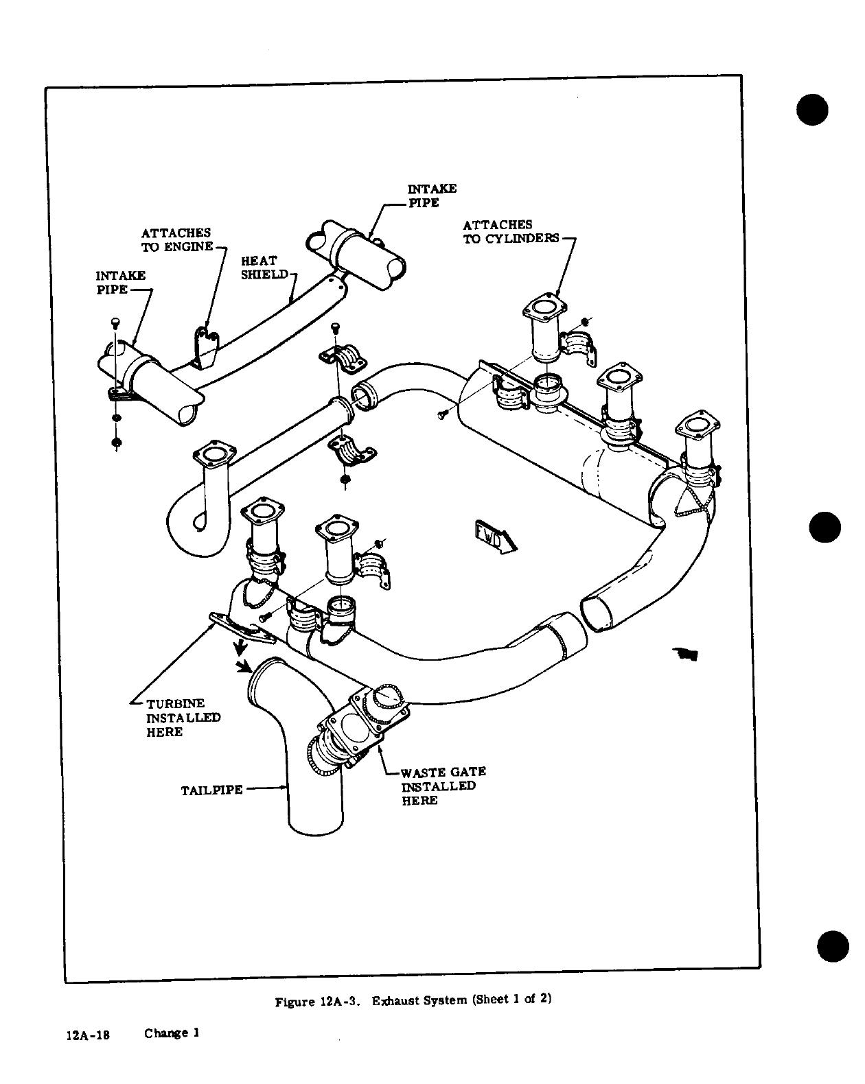
INTAKE
ATTACHES
ATTACHES
TO ENGINE
TO
CYLINDERS
HEAT
INTAKE SHIELD
TURBINE
i
-
INSTALLED
A
HERE
i|?
V-WASTE
GATE
TAILPIPE
INSTALLED
HERE
Figure
12A-3.
Exhaust System
(Sheet
1
of
2)
12A-18
Change
I
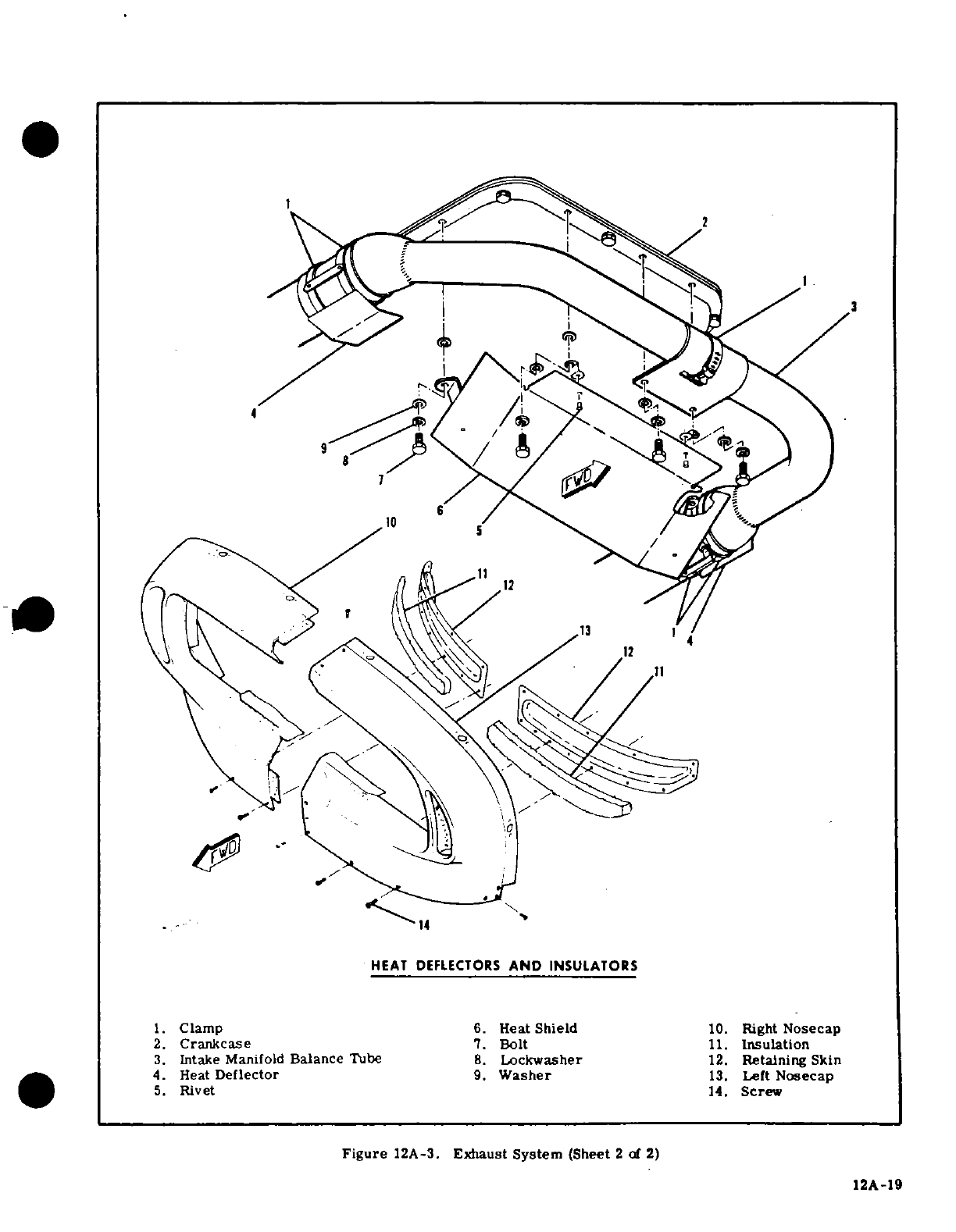
4
1.
Clamp 6.
Heat
Shield
10.
Right
Nosecap
2. Crankcase
7.
Bolt
11.
Insulation
3.
Intake
Manifold
Balance
Tube
8.
Lockwasher
12.
Retaining
Skin
4.
Heat
Deflector
9.
Washer
13.
Left
Nosecap
5.
Rivet
14.
Screw
Figure
12A-3.
Exhaust
System
(Sheet
2
of
2)
12A-19
12A-19
e.
Install
bolts
and
nuts
attaching
waste-gate
to
should
be
made
to
detect
cracks
causing
leaks
which
right
hand
exhaust
stack
and
tighten
securely.
could
result
in
loss
of
optimum
turbocharger
effi-
f.
While applying an
upward
force
of
one
G
to
ciency
and
engine
power.
To
inspect
the
engine
ex-
counteract
weight
of
turbocharger
and
waste-gate
haust
system,
proceed
as
follows:
assembly,
tighten
clamp attaching
exhaust
stack
to
a.
Remove engine
cowling
as required
so
that
ALL
riser.
surfaces
of
the exhaust
assemblies
can
be
visually
g.
Tighten
clamp
securing
tailpipe
to
turbocharger.
inspected.
h.
Be
sure
all parts
are
secure
and
safetled
as
re-
quired,
then
perform
step
"b"
of
paragraph
12A-99
WARNING
to
check
for
air
leaks.
i.
Install
heater
shroud
duct
and
heat
shields.
j.
Install
intake
manifold
balance
tube
at front
of
Never
use
highly
flammable
solvents
engine and
install
heat
shields
at
front
of
engine,
on
engine
exhaust
systems.
Never
use
then
install
nose
caps
and
cowling.
a
wire
brush
or
abrasives
to
clean
ex-
haust
systems
or
mark
on
the
system
NOTE
with
lead
pencils.
The
lower
sections
of
turbocharger supports
(in-
dex
8,
figure
12A-5)
are
supplied
as
service
parts
with
their
upper
holes
omitted. These
undrilled
NOTE
parts
are
also
supplied
when
a
new
turbocharger
inlet
stack,
right front
stack,
or
either
of
the
Especially
check
the
areas
adjacent to
welds
two
right
front
risers
is
ordered.
The
follow-
and
slip
joints.
Look
for
gas
deposits
in
sur-
ing
steps
outline the
proper
procedure
for
rounding
areas,
indicating
that
exhaust
gases
drilling
and
installing
the
supports.
are
escaping
through
a
crack
or
hole
or
around
the
slip
joints.
k.
Install
all
parts
but
do
not
tighten
attaching
clamps
or
bolts.
b.
After
visual
inspection,
an
air
leak
check
should
1.
Torque
nuts attaching
risers
to
cylinders
evenly
be made
on
the
exhaust
system
as
follows:
to
100-110
lb-in.
1.
Attach
the
pressure
side
of an
industrial
m.
Tighten
bolts
and
clamps
per
steps
"d"
through
vacuum
cleaner
to
the
tailpipe
opening,
using
a
rub-
"g".
ber
plug
to
effect
a
seal
as
required.
NOTE
NOTE
It
is
important
that
weight
of
turbocharger
and
The
inside
of
the
vacuum
cleaner
hose
should
waste-gate
assembly
be
counteracted,
as
listed
be
free
of
any
contamination
that
might
be
in
step
"f",
when
tightening
clamps attaching
blown
into
the
engine
exhaust
system.
stacks
to
risers.
2.
With
vacuum
cleaner
operating,
all
joints
n.
Make
hole
locations
in
undrilled
supports
to in
the exhaust
system
may
be checked
manually
by
match
existing
holes
in
upper
supports. feel,
or
by
using
a
soap
and
water
solution
and
o.
Remove
lower
supports,
leaving
all
other
parts
watching
for
bubbles.
Forming
of
bubbles
is
accep-
tight.
table,
if
bubbles
are
blown
away
system
is
not
-p.
Drill
the marked
holes
with
a
3/8-inch
drill.
acceptable.
Also,
some
bubbles
will
appear
at
the
On
earlier
models
the
holes
were
0.
257-Inch,
there-
joint
of
the
turbocharger
turbine
and
compressor
fore,
it
may
be
necessary
to
enlarge
the
holes
in
bearing
housing.
upper
supports.
c.
Where
a
surface
is
not
accessible
for
a
visual
q.
Reinstall
supports,
install
bolts
fastening
upper
inspection,
or
for
a
more positive
test,
the
following
and lower
supports together,
then
tighten all bolts
procedure
is
recommended.
securely.
If
any
exhaust
system
bolts
or
clamps
1.
Remove
exhaust
stack
assemblies.
were
loosened
while
lower
supports
were
not
install-
2.
Use
rubber
expansion
plugs
to
seal
openings.
ed,
loosen
all
clamps
and
bolts
and
repeat
the
install-
3.
Using
a
manometer
or
gage,
apply
approxi-
ation
procedure
to
be
sure
no
pre-loading
is
present.
mately
1-1/2
psi
(3
inches
of
mercury)
air
pressure
r.
Be
sure
all
parts are
secure
and
safetled as
re-
while
each
stack
assembly
is
submerged
in
water.
quired,
reinstall
any
parts
removed
for
access,
then
Any
leaks
will
appear
as
bubbles
and
can
be
readily
install
nose
caps
and
cowling.
detected.
12A-99. INSPECTION. Since
exhaust
systems
of
4.
It
is
recommended
that
exhaust
stacks
found
this
type
are
subject
to
burning,
crackingand
general
defective
be
replaced
before
the
next
flight.
deterioration
from
alternate thermal
stresses
and d.
After
installation
of
exhaust
system
components
vibrations,
inspection
is
important
and
should
be
ac-
perform
the
inspection
in
step
"b"
of
this
paragraph
complished
every
50
hours
of
operation.
Also,
a
to
ascertain
that
sysyem
is acceptable.
thorough
inspection
of
the
engine
exhaust
system
12A-20 Change
3
D2007C3-13
Temporary
Change
2
22
February
1978
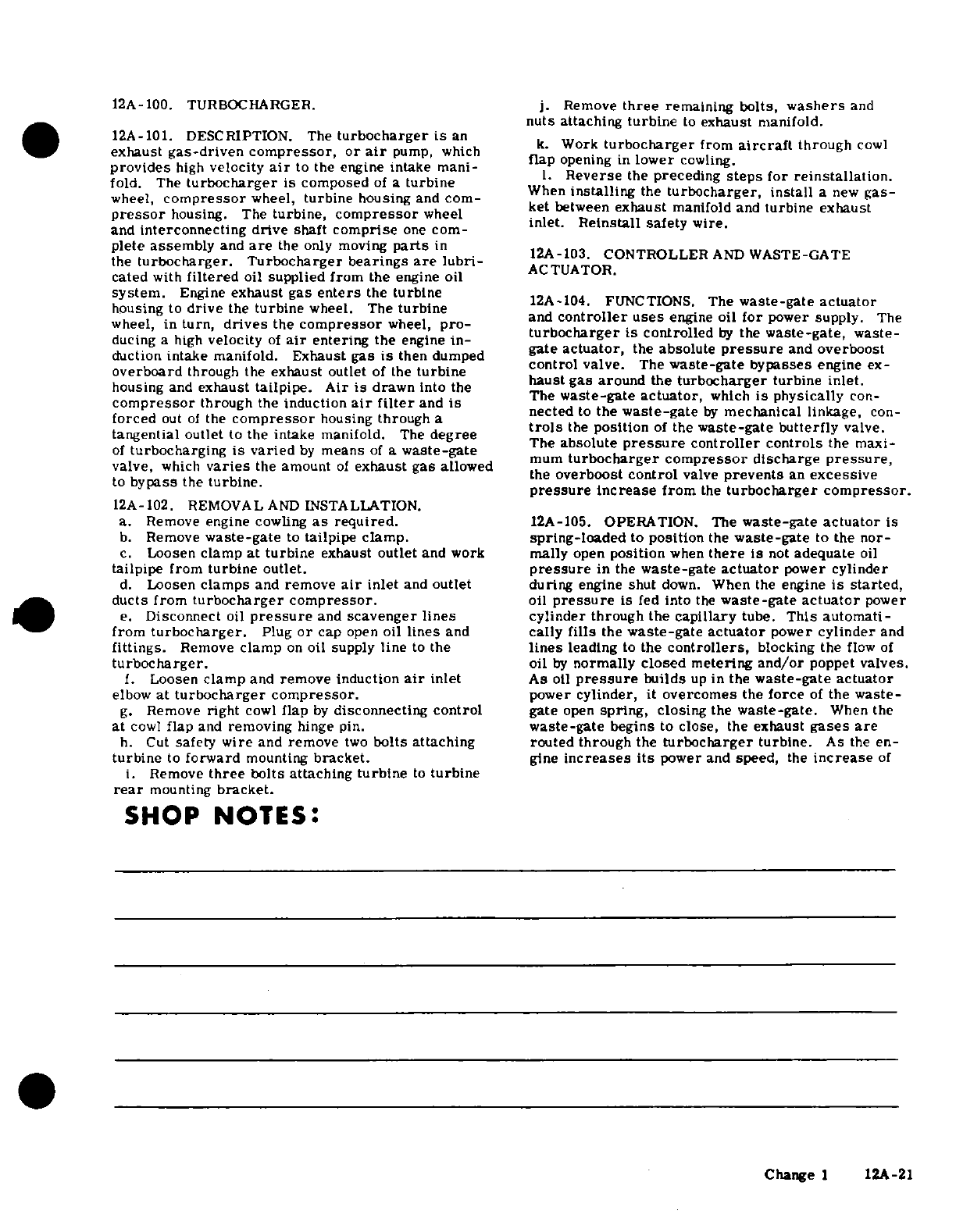
12A-100.
TURBOCHARGER.
j.
Remove
three
remaining
bolts,
washers
and
nuts
attaching
turbine
to
exhaust manifold.
12A-101.
DESCRIPTION. The
turbocharger
is
an
k.
Work
turbocharger
from
aircraft
through
cowl
exhaust
gas-driven
compressor,
or
air
pump,
which
k.
Work
turbocharger
from
aircraft
through
cowl
provides
high
velocity
air
to
the
engine
intake
mani-
flap
opening
in
lower
cowling
fold.
The
turbocharger
is
composed
of
a
turbine
l.
Reverse
the
preceding
steps
for
reinstallation.
wheel,
compressor
wheel,
turbine housing
and
com-
When
installing
the
turbocharger,
install
a
new
gas-
w opressor
housing.
The
turbine,
compressor
wheel
ket
between
exhaust
manifold
and
turbine
exhaust
presser
housing.
The
turbine,
compressor
wheel
and
interconnecting drive
shaft
comprise
one
com-et
ta
saety
wire.
plete
assembly
and
are
the
only
moving
parts
in-13
ONTRO
R
AN
WA
AT
the
turbocharger.
Turbocharger bearings
are
lubri-
AC
AOWASTE-GATE
cated
with
filtered
oil supplied
from
the
engine
oil
system.
Engine
exhaust
gas
enters
the
turbine
12A-1.
NCTIONS.
The
waste-gate
actuator
housing
to
drive
the
turbine
wheel.
The
turbine
wheel,
in
turn,
drives
the
compressor
wheel,
pro-
and
controller uses
engine
oil
for
power
supply.
The
turbocharger
is
controlled
by
the
waste-gate,
waste-
ducing
a
high
velocity
of
air
entering
the
engine
in-
turbocharger
s
controlled
by
the
wastegate,
wast
duction
intake manifold.
Exhaust
gas
is
then dumped
gate
actuator,
the
absolute
pressure
and
overboost
duction
intake
manifold. Exhaust
gas
is
then
dumped
control
valve.
The
waste-gate
bypasses
engine
ex-
overboard
through the
exhaust
outlet
of
the
turbine
ctr
va
he
te-gate
ine
e
housing
and
exhaust
tailpipe.
Air
is
drawn
into
the
haust
gas around
the
turbocharger
turbine
inlet.
compressor through
the
induction
air
filter
and
is
The
waste-gate
actuator,
which
is
physically
con-
compressor
through
the
induction
air
filter
and
is
forced
out
of
the
compressor
housing
through
a
nected
to
the
waste-gate
by
mechanical
linkage,
con-
trols
the
position
of the
waste-gate butterfly
valve.
tangential
outlet
to
the
intake manifold.
The
degree
trols
the
positon
of
the
wate-gate
butterfly
valve
of
turbocharging
is
varied
by
means
of
a
waste-gate
The
solute
pressure
controller
controls
the
maxi-
mum
turbocharger
compressor
discharge
pressure,
valve,
which
varies
the
amount
of
exhaust
gas
allowed
rboos
coro
e
pre
s
an
essive
to
..
bypass the turbine ~the
overboost
control
valve
prevents
an
excessive
to
bypass
the
turbine.
pressure
increase
from
the
turbocharger
compressor.
12A-102. REMOVAL
AND
INSTALLATION.
a.
Remove
engine
cowling
as
required.
12A-105.
OPERATION.
The
waste-gate
actuator
is
b.
Remove
waste-gate
to
tailpipe
clamp,
spring-loaded
to
position
the
waste-gate
to
the
nor-
c.
Loosen
clamp
at turbine
exhaust
outlet
and
work
mally
open
position
when
there
is
not
adequate
oil
tailpipe
from
turbine
outlet.
pressure
in
the
waste-gate
actuator
power
cylinder
d.
Loosen
clamps
and
remove
air
inlet
and
outlet
during
engine
shut
down.
When
the
engine
is
started,
ducts from
turbocharger
compressor.
oil
pressure
is
fed
into
the
waste-gate
actuator
power
e.
Disconnect
oil
pressure
and
scavenger
lines
cylinder
through the
capillary
tube.
This automati-
from
turbocharger.
Plug
or
cap
open
oil
lines
and
cally
fills
the
waste-gate
actuator
power
cylinder
and
fittings.
Remove
clamp
on
oil
supply
line
to
the
lines
leading
to
the
controllers,
blocking the
flow
of
turbocharger.
oil
by
normally
closed
metering
and/or
poppet
valves.
1.
Loosen
clamp
and
remove induction
air
inlet
As
oil
pressure
builds
up
in
the
waste-gate
actuator
elbow
at
turbocharger
compressor.
power
cylinder,
it
overcomes
the
force
of
the
waste-
g.
Remove
right
cowl
flap
by
disconnecting
control
gate
open
spring,
closing
the
waste-gate.
When the
at
cowl
flap
and
removing
hinge
pin.
waste-gate
begins
to
close,
the exhaust
gases
are
h.
Cut
safety
wire
and
remove
two
bolts
attaching
routed
through
the
turbocharger
turbine.
As
the
en-
turbine
to
forward
mounting
bracket.
gine
increases
its
power
and
speed,
the
increase
of
i.
Remove
three
bolts attaching
turbine
to
turbine
rear
mounting
bracket.
SHOP
NOTES:
Change
1
12A-21
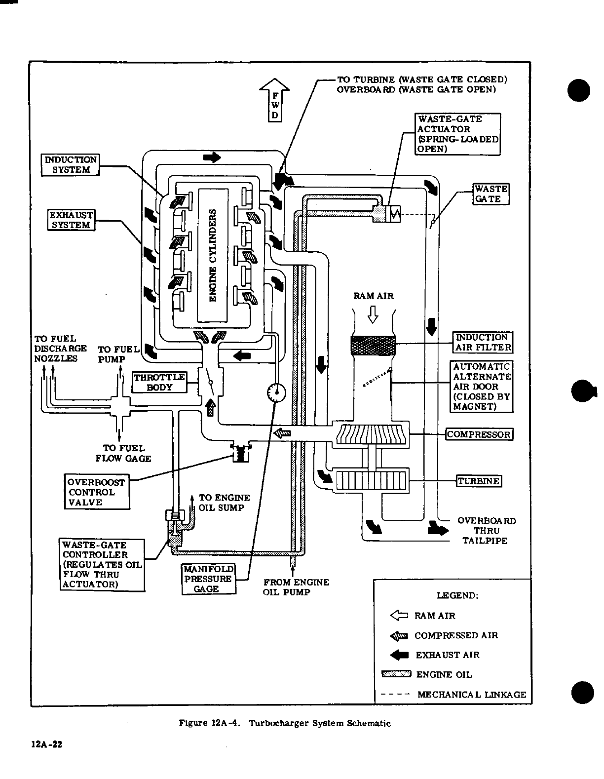
TO
TURBINE
(WASTE
GATE
CLOSED)
OVERBOARD
(WASTE
GATE
OPEN)
WASTE-GATE
ACTUATOR
(SPRING-LOADED
NOZZLES PUMP
\ | /
... -
8
A1R
FIGATE
I
INDUCT
IOIn RINDUCTION)
TO
FUl
IDCTONE
S
DISCHARGE
.TO
FUELILTE
., I oE
OVERBOARD
YASTE-ATE
FLO
W
THR U
|MNIFOLD
|J .
R|1
RAM
R
AIR
N L P
C
OMPRESSED
AIR
TO
FUEL
INDUCTION
OVDISCHARGE
TO
FUEL
OST
EXHAUST
AIRILTER
I
|T|
T
THROTTLE
ALTERNATE
| I r'-| -]1r ^J I
(CLOSED
BY
MAGNET)
////
\\\
-
MECHANICMPSSL
LINKAGE
1
2A
-22
CONTROL
FT
/-
VALVEI.
TO
OIN
AGAGE
OIL
PIL
S
UMP
LEGEND:
*~~~~~~~WASTE-GATE ^
EXHAUST
AIRL
'.'
ENGINE
OIL
----
MECHANICAL
LINKAGE
Figure
12A-4.
Turbocharger
System
Schematic
12A-22
temperature
and
pressure
of
the
exhaust
gases
causes
versely,
at
engine
idle,
the
turbocharger
runs
slowly
the
turbocharger
to
rotate
faster,
raising
the
turbo-
with
low
compressor pressure
output;
therefore,
the
charger compressor
outlet
pressure.
As
the
com-
low
pressure
applied
to
aneroid
bellows is
not
suffi-
pressor
outlet
pressure
rises,
the
aneroid
bellows
cient
to
affect
the
unseating
of
the
normally
closed
and
the
absolute
pressure
controller
sense
the
in-
metering
valve.
Consequently,
engine
oil
pressure
crease
in
pressure.
When
at
high
engine
speed
and
keeps
the
waste-gate
closed.
The
overboost
control
load
and
the
proper
absolute
pressure
is
reached,
the
valve
acts
as
a
pressure
relief
valve
and
will
open
to
force
on
the
aneroid
bellows opens
the
normally prevent
an
excessive
pressure
increase
from
the
closed metering
valve.
When
the
oil
pressure
in
the
turbocharger
compressor.
Above
19,000 feet,
the
waste-gate
actuator
power
cylinder is
lowered
suffi-
absolute
pressure
controller
will continue
to
maintain
ciently,
the
waste-gate
actuator
open
spring
forces
32.
5±.
5
inches
of
mercury
manifold
pressure
at
full
the
mechanical
linkage to
open
the
waste-gate.
A
throttle.
It
is
necessary
to
reduce
manifold
pressure
portion
of
the
exhaust
gases
then
bypasses
the
turbo-
with
the
throttle
to
follow
the
maximum
manifold
charger
turbine,
thus
preventing
further
increase
of
pressure
versus
altitude
schedule
shown
on
the
instru-
turbocharger
speed
and
holding
the
compressor
dis-
ment
panel
placard.
charge
absolute
pressure
to
the
desired
valve.
Con-
CAUTION
All
turbocharged
engine
installations
on
Cessna
aircraft
are
equipped
with
controller
systems
which
automatically
control
the
engine within
prescribed
manifold
pressure
limits.
Although
these automatic
controller systems
are
very
reliable
and
eliminate
the
need
for
manual
control
through constant
throttle
manipulation,
they
are
not
infallible. For
instance,
such
things
as
rapid
throttle
manipulation
(especially
with
cold
oil),
momentary
waste-gate
sticking,
air
in
the
oil
system
of
the
controller, etc.,
can
cause
overboosting.
Consequently,
it
is
still
necessary
that
the
pilot
observe
and
be
prepared
to
control
the
mani-
fold
pressure,
particularly
during
take-off
and power
changes
in
flight.
The
slight
overboosting
of
manifold
pressure
beyond
established
minimums,
which
is
occasionally
experienced
during
initial
take-off roll
or
during
a
change
to
full
throttle
operation
in
flight,
is
not
considered
detrimental
to
the
engine
as
long
as
it
is
momentary.
Momentary
overboost
is
generally
in
the
area
of
2
to
3
inches
and
can
usually
be
controlled
by
slower throttle
movement.
No
corrective
action
is
required
where
momentary
overboosting
corrects
itself
and
is
followed
by
normal
engine
operation.
However,
if
overboosting
of
this
nature
persists,
or
if
the
amount
of
overboost
goes
as
high
as
6
inches,
the
controller
and
overboost
control
should
be
checked
for
necessary
adjustment or
replacement
of
the
malfunctioning
component.
OVERBOOST EXCEEDING
6
INCHES
beyond
established
minimums
is
excessive
and
can
result
in
engine
damage.
It
is
recommended
that
overboosting
of
this
nature
be
reported
to
your
Cessna Dealer,
who
will
be
glad
to
determine
what, if
any,
corrective
action
needs to
be
taken.
12A
-23
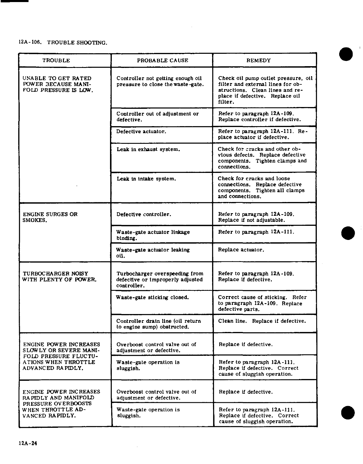
12A- 106.
TROUBLE
SHOOTING.
TROUBLE
PROBABLE
CAUSE
REMEDY
UNABLE
TO
GET
RATED
Controller
not
getting
enough
oil
Check
oil
pump
outlet
pressure,
oil
POWER
BECAUSE
MANI-
pressure
to
close
thewaste-gate.
filter
and
external
lines
for
ob-
FOLD
PRESSURE
IS
LOW.
structions.
Clean
lines
and
re-
place
if
defective. Replace
oil
filter.
Controller
out of
adjustment
or
Refer
to
paragraph
12A-109.
defective. Replace
controller
if
defective.
Defective
actuator.
Refer
to
paragraph
12A-111.
Re-
place
actuator
if
defective.
Leak
in
exhaust
system.
Check
for
cracks
and
other
ob-
vious
defects.
Replace defective
components.
Tighten
clamps
and
connections.
Leak
in
intake
system.
Check
for
cracks
and
loose
connections.
Replace
defective
components.
Tighten
all
clamps
and
connections.
ENGINE SURGES
OR
Defective
controller.
Refer
to
paragraph
12A-109.
SMOKES.
Replace
if
not
adjustable.
Waste-gate
actuator
linkage
Refer
to
paragraph
12A-111.
binding.
_
Waste-gate actuator
leaking
Replace
actuator.
oil.
TURBOCHARGER
NOISY
Turbocharger
overspeeding
from
Refer
to
paragraph
12A-109.
WITH
PLENTY OF
POWER.
defective
or
improperly
adjusted
Replace
if
defective.
controller.
Waste-gate
sticking
closed.
Correct
cause
of
sticking.
Refer
to
paragraph
12A-109.
Replace
defective
parts.
Controller
drain
line (oil
return
Clean
line.
Replace
if
defective.
to
engine
sump)
obstructed.
ENGINE
POWER INCREASES
Overboost
control
valve
out
of
Replace
if
defective.
SLOWLY
OR
SEVERE
MANI-
adjustment
or
defective.
FOLD
PRESSURE
FLUCTU-
ATIONS WHEN
THROTTLE
Waste-gate
operation
is
Refer
to
paragraph
12A-111.
ADVANCED
RAPIDLY.
sluggish.
Replace
if
defective.
Correct
cause
of
sluggish
operation.
ENGINE
POWER
INCREASES
Overboost
control
valve
out
of
Replace
if
defective.
RAPIDLY
AND
MANIFOLD
adjustment
or
defective.
PRESSURE OVERBOOSTS
WHEN
THROTTLE
AD-
Waste-gate
operation
is
Refer
to
paragraph
12A-111.
VANCED
RAPIDLY.
sluggish.
Replace
if
defective.
Correct
cause
of
sluggish
operation.
12A-24
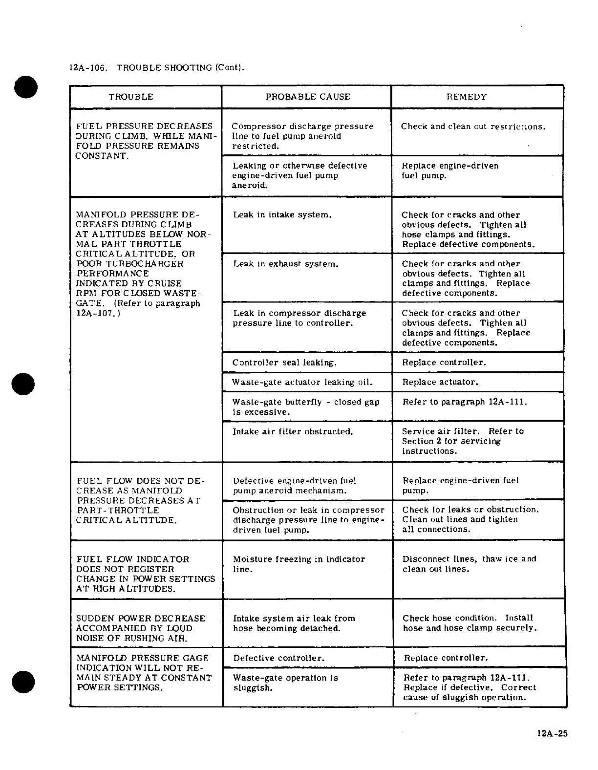
12A-106.
TROUBLE
SHOOTING
(Cont).
TROUBLE PROBABLE
CAUSE
REMEDY
FUEL
PRESSURE
DECREASES
Compressor
discharge
pressure
Check
and
clean
out
restrictions.
DURING
CLIMB,
WHILE
MANI-
line
to
fuel
pump
aneroid
FOLD
PRESSURE
REMAINS
restricted.
CONSTANT.
Leaking
or
otherwise
defective
Replace
engine-driven
engine-driven
fuel
pump
fuel
pump.
aneroid.
MANIFOLD
PRESSURE
DE-
Leak
in
intake
system.
Check
for
cracks
and other
CREASES
DURING
CLIMB
obvious
defects.
Tighten
all
AT
ALTITUDES
BELOW
NOR-
hose
clamps
and
fittings.
MAL
PART
THROTTLE
Replace
defective
components.
CRITICAL
ALTITUDE,
OR
POOR
TURBOCHARGER
Leak
in
exhaust
system.
Check
for
cracks
and
other
PERFORMANCE
obvious
defects.
Tighten
all
INDICATED
BY
CRUISE
clamps
and
fittings.
Replace
RPM
FOR
CLOSED WASTE-
defective
components.
GATE.
(Refer
to
paragraph
12A-107.)
Leak
in
compressor
discharge
Check
for
cracks
and other
pressure
line
to
controller.
obvious
defects.
Tighten
all
clamps
and
fittings.
Replace
defective
components.
Controller
seal
leaking. Replace
controller.
Waste-gate
actuator
leaking
oil.
Replace
actuator.
Waste-gate
butterfly
-
closed
gap
Refer
to
paragraph
12A-111.
is
excessive.
Intake
air
filter
obstructed. Service
air
filter.
Refer
to
Section
2
for
servicing
instructions.
FUEL
FLOW DOES
NOT
DE-
Defective
engine-driven
fuel
Replace
engine-driven
fuel
CREASE
AS
MANIFOLD
pump
aneroid
mechanism.
pump.
PRESSURE
DECREASES
AT
PART-THROTTLE
Obstruction
or
leak
in
compressor
Check
for
leaks or
obstruction.
CRITICAL
ALTITUDE.
discharge
pressure
line
to
engine-
Clean
out
lines
and
tighten
driven
fuel pump.
all
connections.
FUEL
FLOW
INDICATOR
Moisture freezing
in
indicator
Disconnect
lines,
thaw
ice
and
DOES NOT
REGISTER
line.
clean
out
lines.
CHANGE
IN
POWER
SETTINGS
AT
HIGH
ALTITUDES.
SUDDEN
POWER
DECREASE
Intake
system
air
leak
from
Check
hose
condition.
Install
ACCOMPANIED
BY
LOUD
hose
becoming
detached. hose
and
hose
clamp
securely.
NOISE
OF
RUSHING
AIR.
MANIFOLD
PRESSURE
GAGE
Defective
controller.
Replace
controller.
INDICATION
WILL
NOT
RE-
MAIN
STEADY
AT CONSTANT
Waste-gate
operation
is Refer
to
paragraph
12A-111.
POWER SETTINGS.
sluggish.
Replace
if
defective.
Correct
cause
of
sluggish
operation.
12A-25
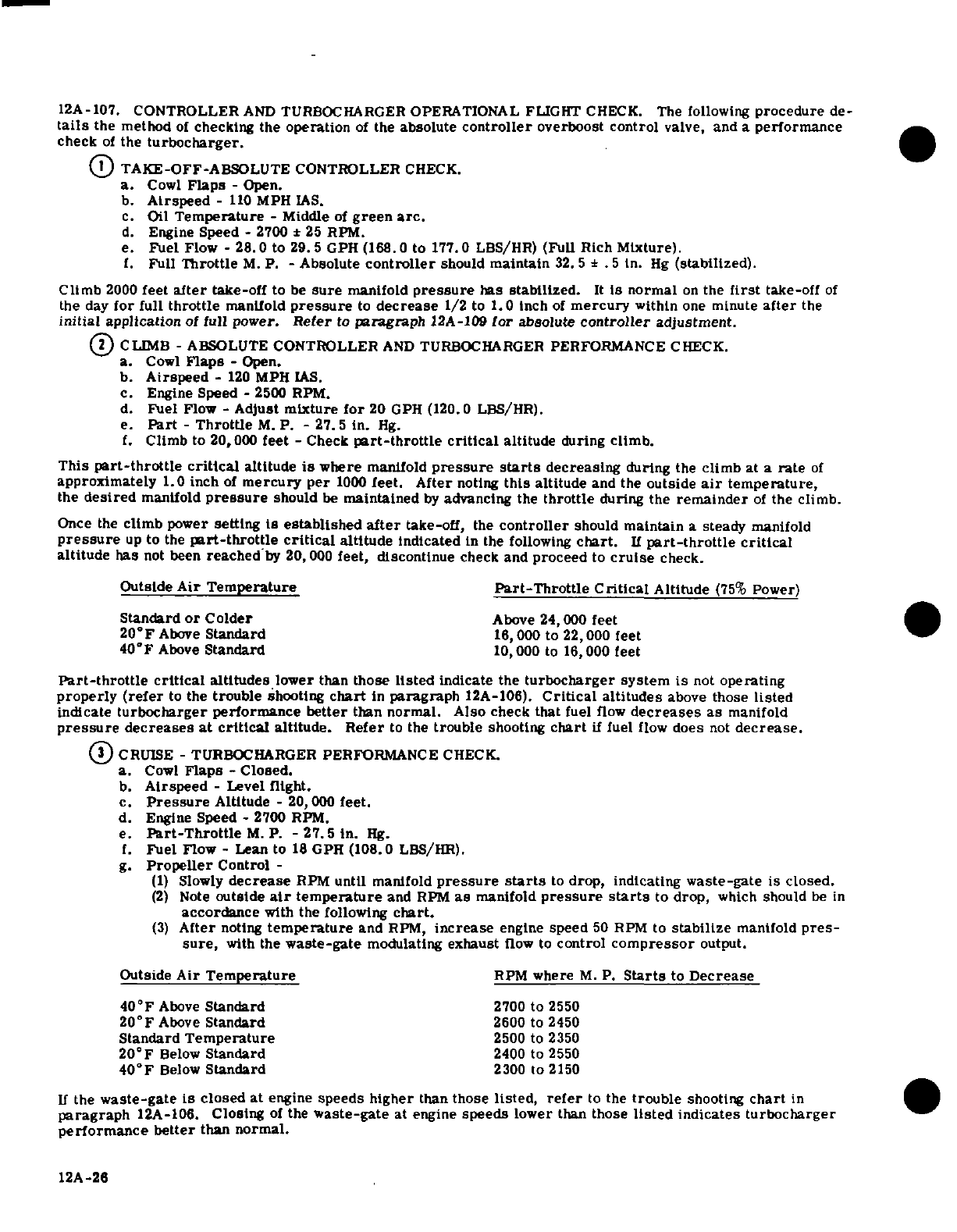
12A-107.
CONTROLLER
AND
TURBOCHARGER
OPERATIONAL
FLIGHT
CHECK.
The
following
procedure
de-
tails
the method
of
checking
the
operation
of
the
absolute
controller
overboost
control
valve,
and a
performance
check
of
the
turbocharger.
1
TAKE-OFF-ABSOLUTE
CONTROLLER
CHECK.
a.
Cowl
Flaps
-
Open.
b.
Airspeed
-
110
MPH
IAS.
c.
Oil
Temperature
- Middle
of
green
arc.
d.
Engine
Speed
-
2700
*
25
RPM.
e.
Fuel
Flow
-
28.0
to
29.5
GPH
(168.0
to
177.0
LBS/HR) (Full
Rich
Mixture).
1.
Full
Throttle
M.
P.
-
Absolute
controller
should
maintain
32.5
±
.5
in.
Hg
(stabilized).
Climb
2000
feet
after
take-off
to
be
sure
manifold
pressure
has
stabilized.
It
is
normal
on
the
first
take-off
of
the
day
for
full
throttle
manifold
pressure
to
decrease
1/2
to
1.0
inch
of
mercury
within
one
minute
after
the
initial
application
of
full
power.
Refer
to
paragraph
12A-109
for
absolute
controller
adjustment.
2
CLIMB
-
ABSOLUTE
CONTROLLER
AND
TURBOCHARGER
PERFORMANCE
CHECK.
a.
Cowl
Flaps
-
Open.
b.
Airspeed
-
120
MPH
IAS.
c.
Engine
Speed
-
2500
RPM.
d.
Fuel
Flow
-
Adjust
mixture
for
20 GPH
(120.0
LBS/HR).
e.
Part
-
Throttle
M.
P.
-
27.5
in.
Hg.
f.
Climb
to
20,000
feet
-
Check
part-throttle critical
altitude
during
climb.
This
part-throttle critical
altitude
is
where
manifold
pressure
starts
decreasing
during
the
climb
at a
rate
of
approximately
1.0 inch
of
mercury
per
1000
feet.
After
noting
this
altitude
and
the
outside
air
temperature,
the
desired
manifold
pressure
should
be
maintained
by
advancing
the
throttle
during the
remainder
of
the
climb.
Once the
climb
power
setting
is
established
after
take-off,
the
controller
should
maintain
a
steady
manifold
pressure
up
to
the
part-throttle
critical
altitude
indicated
in
the
following
chart.
If
part-throttle critical
altitude
has
not
been
reached
by
20,
000
feet, discontinue
check
and
proceed to
cruise
check.
Outside
Air
Temperature
Part-Throttle
Critical
Altitude
(75%
Power)
Standard
or
Colder
Above
24,000
feet
20°F
Above
Standard
16,000
to
22,000
feet
40'F
Above
Standard
10,000
to
16,000
feet
Part-throttle
critical
altitudes
lower
than
those
listed
indicate the
turbocharger
system
is
not
operating
properly
(refer
to
the
trouble
shooting
chart
in
paragraph
12A-106).
Critical
altitudes
above
those
listed
indicate
turbocharger
performance
better
than
normal.
Also
check
that
fuel
flow
decreases
as
manifold
pressure
decreases at
critical
altitude. Refer
to
the
trouble
shooting
chart
if
fuel
flow
does
not
decrease.
3
CRUISE
-
TURBOCHARGER
PERFORMANCE
CHECK.
a.
Cowl
Flaps
-
Closed.
b.
Airspeed
-
Level
flight.
c.
Pressure
Altitude
-
20,000
feet.
d.
Engine
Speed
-
2700
RPM.
e.
Part-Throttle
M.
P.
-
27.5
in.
Hg.
f.
Fuel
Flow
- Lean to
18
GPH
(108.0
LBS/HR).
g.
Propeller
Control
-
(1)
Slowly
decrease
RPM
until
manifold
pressure
starts
to
drop,
indicating
waste-gate
is
closed.
(2)
Note
outside
air
temperature
and
RPM
as
manifold
pressure
starts
to
drop,
which
should
be
in
accordance
with
the following
chart.
(3)
After
noting
temperature
and
RPM,
increase
engine
speed
50
RPM
to
stabilize
manifold
pres-
sure,
with
the
waste-gate
modulating
exhaust
flow to
control
compressor
output.
Outside
Air
Temperature
RPM
where
M.
P.
Starts
to
Decrease
40°F
Above
Standard
2700
to
2550
20°F
Above
Standard
2600
to
2450
Standard
Temperature
2500
to
2350
20°F
Below
Standard
2400
to
2550
40°F
Below
Standard
2300
to
2150
If
the
waste-gate
is
closed
at
engine
speeds
higher
than
those
listed,
refer
to
the
trouble
shooting
chart
in
paragraph
12A-106.
Closing
of
the
waste-gate
at engine
speeds
lower
than
those
listed
indicates
turbocharger
performance
better
than
normal.
12A-26
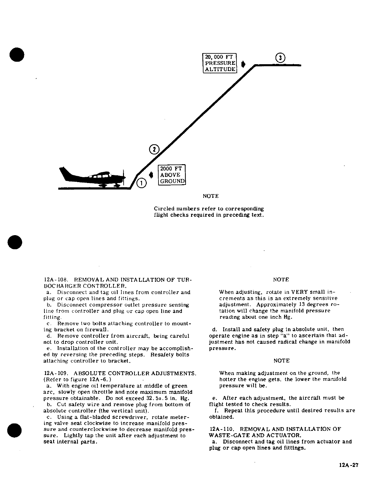
20,000
FT
PRESSURE
ALTITUDE
2000
FT
ABOVE
GROUND
NOTE
Circled
numbers
refer
to
corresponding
flight
checks
required
in
preceding
text.
12A-108.
REMOVAL
AND
INSTALLATION
OF
TUR-
NOTE
BOCHARGER
CONTROLLER.
a.
Disconnect
and
tag
oil
lines
from
controller
and
When
adjusting,
rotate
in
VERY
small
in-
plug
or
cap
open
lines
and
fittings.
crements
as
this
is
an
extremely
sensitive
b.
Disconnect
compressor
outlet
pressure
sensing
adjustment.
Approximately
13
degrees
ro-
line
from
controller
and
plug
or
cap
open
line
and
tation
will
change
the
manifold
pressure
fitting. reading
about
one
inch
Hg.
c.
Remove
two
bolts attaching
controller
to
mount-
ing
bracket
on
firewall.
d.
Install
and
safety
plug
in
absolute
unit, then
d.
Remove
controller
from
aircraft,
being
careful
operate
engine
as
in
step
"a"
to
ascertain
that
ad-
not
to
drop
controller
unit.
justment
has
not
caused radical
change
in
manifold
e.
Installation
of
the
controller
may
be
accomplish-
pressure.
ed
by
reversing
the
preceding
steps.
Resafety
bolts
attaching
controller
to
bracket.
NOTE
12A-109. ABSOLUTE
CONTROLLER
ADJUSTMENTS. When
making
adjustment
on
the
ground,
the
(Refer
to
figure
12A-6.)
hotter
the
engine
gets.
the
lower
the
manifold
a.
With
engine
oil
temperature
at
middle
of
green
pressure
will
be.
arc,
slowly
open
throttle
and
note
maximum
manifold
pressure
obtainable.
Do
not
exceed
32. 5±.
5
in.
Hg.
e.
After
each
adjustment,
the
aircraft
must
be
b.
Cut
safety wire
and
remove
plug
from
bottom
of
flight
tested
to
check
results.
absolute
controller
(the
vertical
unit).
f.
Repeat
this procedure
until
desired
results
are
c.
Using
a
flat-bladed
screwdriver,
rotate
meter-
obtained.
ing
valve
seat
clockwise
to
increase
manifold
pres-
sure
and
counterclockwise
to
decrease
manifold
pres-
12A-110.
REMOVAL
AND
INSTALLATION
OF
sure.
Lightly
tap
the
unit
after
each
adjustment
to
WASTE-GATE
AND
ACTUATOR.
seat
internal
parts.
a.
Disconnect
and
tag
oil
lines
from
actuator
and
plug
or
cap
open
lines
and
fittings.
12A-27
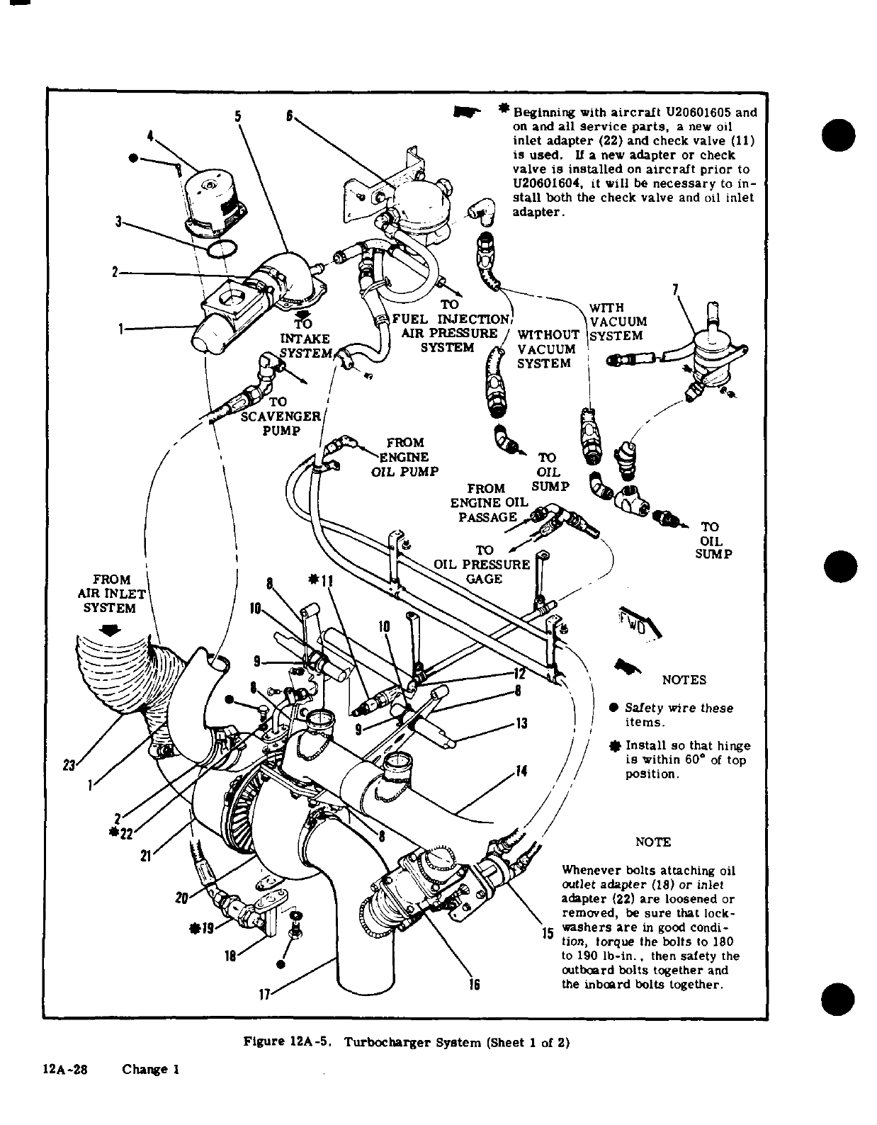
5
6 *
Beginning
with
aircraft
U20601605
and
on
and
all
service
parts,
a
new oil
4
inlet
adapter
(22)
and
check
valve
(11)
is
used.
If
a
new
adapter
or
check
valve
is
installed
on
aircraft
prior
to
U20601604,
it
will
be
necessary
to
in-
stall
both
the
check
valve
and oil
inlet
-
adapter.
TO
-
WITH
FUEL
INJECTION,
VACUUM
INTAKE
IAIR
PRESSURE
WITHOUT
SYSTEM
SYSTEMtC
1
SYSTEM
VACUUM
SYSTEM
TO
SCAVENGER/
PUMP
ENGINE
TO
TO
FROM
AIR
INLET
SYSTEM
Safety
wire
these
/
14
/
position.
is
within
60
°
of
top
Whenever
bolts attaching
oil
outlet
adapter
(18)
or
inlet
adapter
(22)
are
loosened
or
removed, be sure that lock-
washers
are
in
good
condi-
ion,
torque
the
bolts
torque
the
bolts
to
180
to
190
lb-in.,
then
safety
the
outboard
bolts
together
and
16
the
inboard
bolts
together.
Figure
12A-5.
Turbocharger
System
(Sheet
1
of
2)
12A-28
Change
1
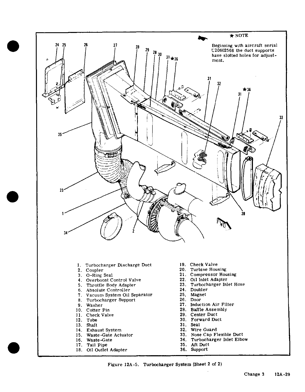
-
*
NOTE
24
25
26
7
8
Beginning
with
aircraft serial
0
2U20602568
the
duct
supports
'-/2 '0
*
have
slotted
holes
or
adjust-
31
1.
Turbocharger
Discharge
Duct
19.
Check
Valve
2.
Coupler
20.
Turbine
Housing
3.
O-Ring
Seal
21.
Compressor
Housing
4.
Overboost
Control
Valve
22.
Oil
Inlet
Adapter
5.
Throttle
Body
Adapter
23.
Turbocharger
Inlet
Hose
6.
Absolute
Controller
24.
Doubler
7.
Vacuum
System
Oil
Separator
25,
Magnet
8.
Turbocharger
Support
26.
Door
9.
Washer
27.
Induction
Air
Filter
10.
Cotter
Pin
28.
Baffle
Assembly
11.
Check
Valve
29.
Center
Duct
12.
Tube
30.
Forward
Duct
13.
Shaft
31.
Seal
14.
Exhaust
System
32.
Wire
Guard
15.
Waste-Gate
Actuator
33.
Nose
Cap
Flexible
Duct
16.
Waste-Gate
34.
Turbocharger
Inlet
Elbow
17.
Tail
Pipe
35.
Aft
Duct
18.
Oil
Outlet
Adapter
36.
Support
Figure
12A-5.
Turbocharger
System
(Sheet
2
of
2)
Change
3
12A-29
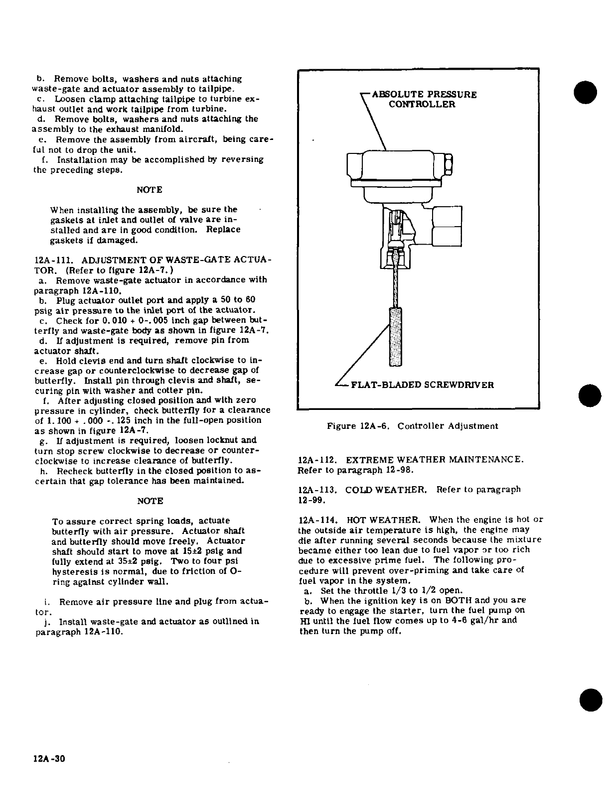
b.
Remove
bolts,
washers
and
nuts
attaching
waste-gate
and
actuator
assembly
to
tailpipe.
c.
Loosen
clamp
attaching tailpipe
to
turbine
ex-
ABSOLUTE
PRESSURE
haust
outlet
and
work
tailpipe from
turbine.
CONTROLLER
d.
Remove
bolts,
washers
and
nuts
attaching
the
assembly
to
the
exhaust
manifold.
e.
Remove
the
assembly
from
aircraft,
being
care-
ful
not
to
drop
the
unit.
f.
Installation
may
be
accomplished
by
reversing
the
preceding
steps.
NOTE
When
installing
the
assembly,
be
sure
the
gaskets
at
inlet
and outlet
of
valve
are
in-
stalled
and
are
in
good
condition.
Replace
gaskets
if
damaged.
12A-111.
ADJUSTMENT
OF
WASTE-GATE
ACTUA-
TOR.
(Refer
to
figure
12A-7.)
a.
Remove
waste-gate actuator
in
accordance
with
paragraph
12A-110.
b.
Plug
actuator
outlet
port
and
apply
a
50
to
60
psig
air
pressure
to
the
inlet
port
of
the
actuator.
c.
Check
for
0.010
+
0-.005
inch gap
between
but-
terfly
and
waste-gate
body
as
shown
in
figure
12A-7.
d.
If
adjustment
is
required,
remove
pin
from
actuator
shaft.
e. Hold
clevis
end
and
turn
shaft
clockwise
to
in-
crease
gap
or
counterclockwise
to
decrease
gap
of
butterfly.
Install
pin
through
clevis
and
shaft,
se-
FLAT-BLADED
SCEWDRIVER
curing
pin
with
washer
and
cotter
pin.
f.
After
adjusting closed
position
and
with
zero
pressure
in
cylinder,
check
butterfly
for
a
clearance
of
1.
100
+
.000
-.
125
inch in
the
full-open position
as
shown
in
figure
12A-7.
Figure
12A-6.
Controller
Adjustment
g.
If
adjustment
is
required,
loosen
locknut and
turn
stop
screw
clockwise
to
decrease
or
counter-
clockwise
to
increase
clearance
of
butterfly.
12A-112.
EXTREME
WEATHER
MAINTENANCE.
h.
Recheck
butterfly
in
the
closed
position
to
as-
Refer
to
paragraph
12-98.
certain
that
gap
tolerance
has
been
maintained.
12A-113.
COLD WEATHER.
Refer
to
paragraph
NOTE
12-99.
To
assure
correct
spring
loads,
actuate
12A-114.
HOT
WEATHER. When
the
engine
is
hot
or
butterfly
with
air
pressure.
Actuator
shaft
the
outside
air
temperature
is
high,
the
engine
may
and
butterfly
should
move
freely.
Actuator
die
after
running
several
seconds because
the
mixture
shaft
should
start
to
move
at
15±2
psig
and
became
either
too
lean
due
to fuel
vapor
or
too
rich
fully
extend
at
35±2
psig.
Two
to
four
psi
due
to
excessive
prime
fuel. The
following
pro-
hysteresis
is
normal,
due
to
friction
of
O-
cedure
will
prevent
over-priming
and
take
care
of
ring
against cylinder
wall.
fuel
vapor
in
the
system.
a.
Set
the
throttle
1/3
to
1/2 open.
i.
Remove
air
pressure
line
and
plug
from
actua-
b.
When
the
ignition
key
is
on BOTH
and
you
are
tor.
ready
to
engage
the
starter,
turn
the
fuel
pump
on
j.
Install waste-gate
and
actuator as
outlined
in
HI
until
the
fuel
flow
comes
up
to
4-6
gal/hr
and
paragraph
12A-110.
then
turn
the
pump
off.
12A
-30
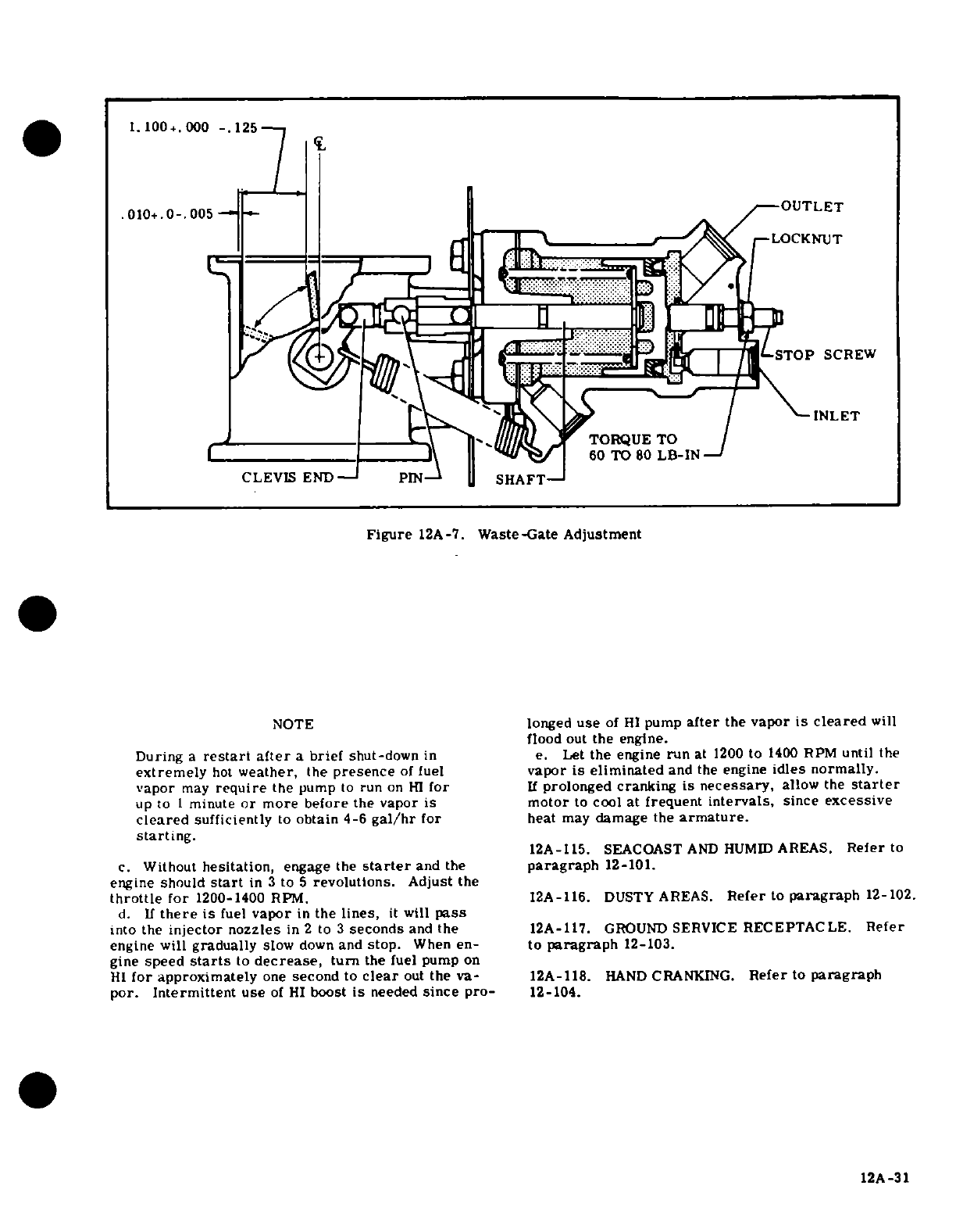
1.
100+.000
-.
125
.010+.0-.
005
OUTLET
LOCKNUT
CLEVIS
END
PIN
SHAFT
Figure
12A-7.
Waste-Gate
Adjustment
NOTE
longed
use
of
HI
pump
after
the
vapor
is
cleared
will
flood
out
the
engine.
During
a
restart
after
a
brief
shut-down
in
e.
Let
the
engine
run
at
1200
to
1400
RPM
until
the
extremely
hot
weather,
the
presence
of
fuel
vapor
is
eliminated
and
the
engine
idles normally.
vapor
may
require
the
pump
to
run
on
HI
for
If
prolonged
cranking
is
necessary,
allow
the
starter
up
to
1
minute
or more
before
the
vapor is
motor
to
cool
at
frequent
intervals,
since
excessive
cleared
sufficiently
to
obtain 4-6
gal/hr
for
heat
may
damage
the
armature.
starting.
12A-115.
SEACOASTAND
HUMIDAREAS
Referto
c.
Without
hesitation,
engage
the
starter
and
the
paragraph
12-101.
TORQUE
TO
CLEVIS
END
PIN
SHAFT
Figurengine
should
start
in
3
to
12A-
revolutions.Gate Adjustment
throttle
for
1200-1400
RPM.
12A-116.
DUSTY
AREAS.
Refer
to
paragraph
12-102.
NOd.
If
there
is
fuel
vapor
in
s
leareds,
it
will
pass
into
the
injector
nozzles
in
2
to
3
seconds
and
the
12A-117.
GROUND
SERVICE
RECEPTACLE.
Refer
engine will gradually
slow
down
and
stop.
When
ento
paragraph
12-103ne.
gine
speed
start
ater
a
brief
shut-downn
e.
Lthe
engine
run
at
200
to
1400
RPM
until
the
extremely
hot
weather,
the
presence
of
fuel
vapor
is
eliminated
and
the
engine
idles normally.
vapor
may
require
the
pump
to
run
on
HI
for
If
prolonged
cranking
is
necessary,
allow
the
starter
up
to
i
minute
or
more
before
the
vapor
is
motor
to
cool
at
frequent
intervals,
since
excessive
cleared
sufficiently
to
obtain 4-6
gal/hr
for
heat
may
damage
the
armature.
starting.
for approximately
one
second
to
clear
out
the
va-
12A-115.
SEA
AANKND
HUMID
AR
EAS.
Refer
toa
por.
Without
hesitatient
use
of
H
boostarter aneeded
sithe
pro
paragraph
12-101.
engine
should
start
in 3 to
A
revolutions.
Adjust
the
throttle
for
1200-1400
RPM.
12A-116.
DUSTY
AREAS.
Refer
to
paragraph
12-102.
d.
If
there
is
fuel
vapor
in
the
lines,
it
will
pass
into
the
injector
nozzles
in
2
to
3
seconds
and
the
12A-117.
GROUND
SERVICE
RECEPTACLE.
Refer
engine will
gradually
slow
down
and
stop.
When
en-
to
paragraph
12-103.
gine
speed
starts
to
decrease,
turn
the
fuel
pump
on
HI
for
approximately
one
second
to
clear
out
the
va- 12A-118.
HAND
CRANKING.
Refer
to
paragraph
por.
Intermittent
use
of
HI
boost
is
needed
since
pro-
12-104.
12A-31
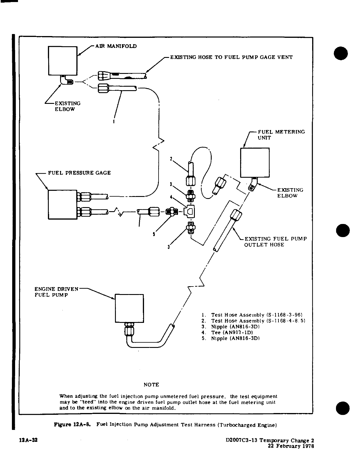
AIR
MANIFOLD
EXISTING
HOSE
TO
FUEL
PUMP
GAGE
VENT
EXISTING
ELBOW
FUEL
METERING
UNIT
FUEL
PRESSURE
GAGE
EXISTING
4
ELBOW
EXISTING
FUEL
PUMP
3
OUTLET
HOSE
ENGINE
DRIVEN
FUEL
PUMP
1.
Test
Hose
Assembly
(S-1168-3-96)
2.
Test
Hose
Assembly
(S-1168-4-8.
5)
3.
Nipple
(AN816-3D)
4.
Tee
(AN917-1D)
5.
Nipple (AN816-3D)
NOTE
When
adjusting
the
fuel
injection
pump
unmetered
fuel
pressure,
the
test
equipment
may
be
"teed"
into
the
engine
driven
fuel
pump
outlet
hose at
the
fuel
metering
unit
and
to
the
existing
elbow
on
the
air
manifold.
Figure
12A-8.
Fuel
Injection
Pump
Adjustment
Test
Harness
(Turbocharged
Engine)
12A-32
D2007C3-13
Temporary
Change
2
22
February
1978
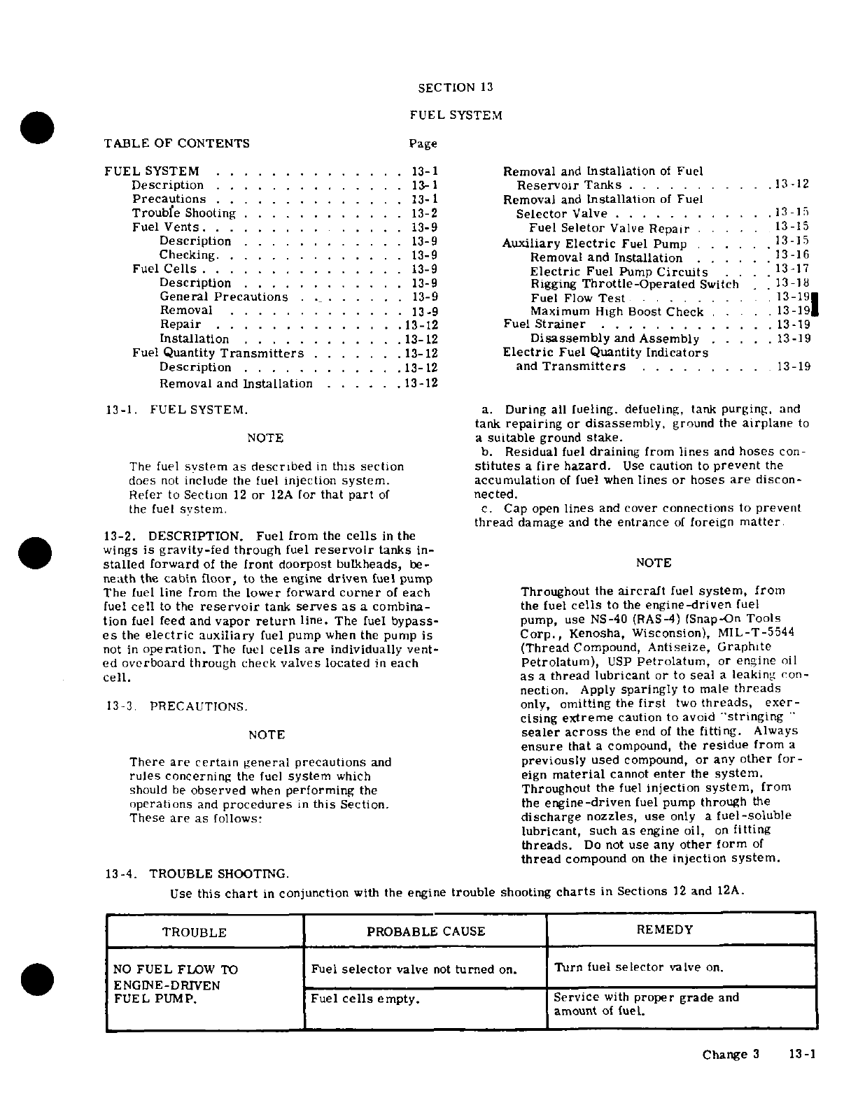
SECTION
13
FUEL
SYSTEM
TABLE
OF
CONTENTS
Page
FUEL
SYSTEM
..............
13-1
Removal
and
Installation
of
Fuel
Description
.............. 13-1
Reservoir
Tanks
.....
. .
.....
13-12
Precautions
..........
.
13-
Removal
and
Installation
of
Fuel
Trouble
Shooting
....... .. .. .
13-2
Selector
Valve
....
.. .. ....
.13
15
Fuel
Vents.3 ........
.. .
13-9
Fuel
Seletor
Valve
Repair
..
13-15
Description
.
..........
.
13-9
Auxiliary
Electric
Fuel
Pump
..
13-15
Checking
.............
13-9
Removal
and
Installation
...
13-16
Fuel
Cells
.............
.
13-9
Electric
Fuel
Pump
Circuits
.
13-17
Description
.
..........
.
13-9
Rigging
Throttle-Operated
Switch
13
18
General
Precautions
.........
13-9
Fuel
Flow
Test
........
.13-19
Removal
.............
13-9
Maximum
High
Boost
Check
.. .
.13-191
Repair
...........
13-12
Fuel
Strainer
.............
13-19
Installation
.......
....
13-12
Disassembly
and
Assembly
.....
13-19
Fuel
Quantity
Transmitters
......
13-12
Electric
Fuel
Quantity
Indicators
Description
........
. ..
13-12
and
Transmitters
.........
13-19
Removal
and
Installation
......
13-12
13-1.
FUEL
SYSTEM.
a.
During
all
fueling.
defueling,
tank
purging,
and
tank
repairing
or
disassembly,
ground
the
airplane
to
NOTE
a
suitable
ground
stake.
b.
Residual
fuel
draining
from
lines
and
hoses
con-
The fuel
system as
described
in
this
section
stitutes
a
fire
hazard.
Use
caution
to
prevent
the
does
not
include
the fuel
injection
system.
accumulation
of
fuel
when
lines
or
hoses
are
discon-
Refer
to
Section
12
or
12A
for
that
part
of
nected.
the
fuel
system.
c.
Cap
open
lines
and
cover
connections
to
prevent
thread
damage
and
the
entrance
of
foreign
matter
13-2.
DESCRIPTION.
Fuel
from
the
cells
in
the
wings
is
gravity-fed
through
fuel
reservoir
tanks
in-
stalled
forward
of
the
front
doorpost
bulkheads,
be-
NOTE
neath
the
cabin floor,
to
the
engine
driven
fuel
pump
The
fuel
line
from
the
lower
forward
corner
of
each
Throughout
the
aircraft
fuel
system,
from
fuel
cell
to
the
reservoir
tank
serves
as
a
combina-
the
fuel
cells
to
the
engine-driven
fuel
tion
fuel
feed
and
vapor
return
line.
The
fuel
bypass-
pump,
use
NS-40
(RAS-4)
(Snap-On
Tools
es
the
electric
auxiliary
fuel
pump
when
the
pump
is
Corp.,
Kenosha, Wisconsion),
MIL-T-5544
not
in
operation.
The
fuel
cells
are
individually
vent-
(Thread
Compound,
Antiseize, Graphite
ed
overboard
through
check
valves
located
in
each
Petrolatum),
USP
Petrolatum,
or
engine
oil
cell.
as
a
thread
lubricant or
to
seal
a
leaking
con-
nection.
Apply
sparingly
to male
threads
13-3.
PRECAUTIONS.
only,
omitting
the
first
two
threads,
exer-
cising
extreme
caution
to
avoid
"stringing"
NOTE
sealer
across
the
end
of
the
fitting.
Always
ensure
that
a
compound,
the
residue
from
a
There
are
certain
general
precautions
and
previously
used
compound,
or
any
other
for-
rules
concerning
the fuel
system
which
eign
material
cannot
enter
the
system.
should
be
observed
when
performing
the
Throughout the
fuel
injection
system,
from
operations
and
procedures
in
this
Section.
the
engine-driven
fuel
pump
through
the
These
are as
follows:
discharge
nozzles,
use
only
a
fuel-soluble
lubricant,
such
as
engine
oil,
on
fitting
threads.
Do
not
use
any
other
form
of
thread
compound
on
the
injection
system.
13-4.
TROUBLE
SHOOTING.
Use
this
chart
in
conjunction
with
the
engine
trouble
shooting
charts
in
Sections
12
and
12A.
TROUBLE
PROBABLE
CAUSE
REMEDY
NO
FUEL
FLOW
TO
Fuel
selector
valve
not
turned
on.
Turn fuel
selector
valve
on.
ENGINE-DRIVEN
FUEL
PUMP.
Fuel
cells
empty.
Service
with
proper
grade
and
amount
of
fuel.
Change
3
13-1
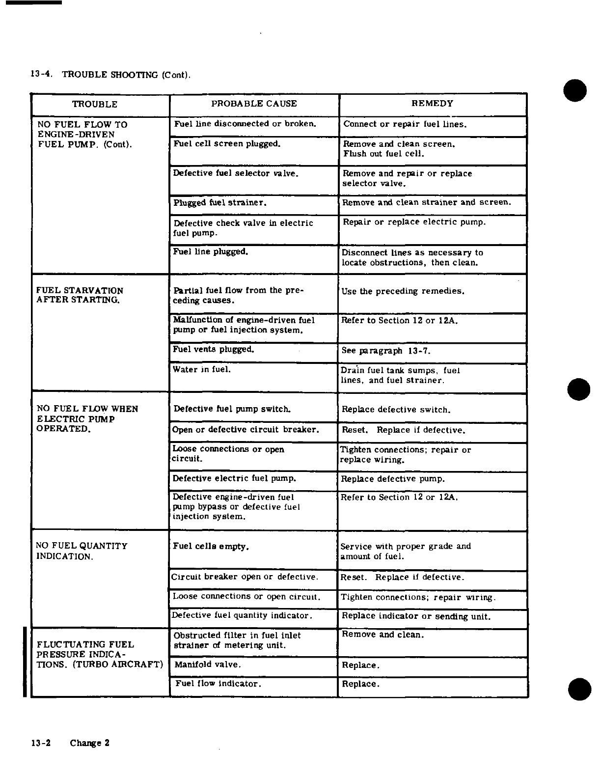
13-4.
TROUBLE
SHOOTING
(Cont).
TROUBLE PROBABLE
CAUSE
REMEDY
NO
FUEL
FLOW
TO
Fuel line
disconnected
or
broken.
Connect
or
repair
fuel
lines.
ENGINE-DRIVEN
FUEL
PUMP.
(Cont).
Fuel
cell
screen
plugged. Remove
and
clean
screen.
Flush
out
fuel
cell.
Defective
fuel
selector
valve.
Remove
and
repair
or
replace
selector
valve.
Plugged
fuel
strainer.
Remove
and
clean
strainer
and
screen.
Defective check
valve
in
electric
Repair
or
replace
electric
pump.
fuel
pump.
Fuel
line
plugged.
Disconnect
lines
as
necessary
to
locate
obstructions,
then
clean.
FUEL
STARVATION
Partial
fuel
flow
from
the
pre-
Use
the
preceding
remedies.
AFTER
STARTING.
ceding
causes.
Malfunction
of
engine-driven
fuel
Refer
to
Section
12
or
12A.
pump
or
fuel
injection
system.
Fuel
vents
plugged.
See
paragraph
13-7.
Water
in
fuel.
Drain
fuel
tank
sumps,
fuel
lines,
and fuel
strainer.
NO
FUEL
FLOW
WHEN
Defective fuel
pump
switch.
Replace
defective
switch.
ELECTRIC
PUMP
OPERATED.
Open
or
defective
circuit
breaker.
Reset.
Replace
if
defective.
Loose
connections
or
open
Tighten
connections;
repair
or
circuit.
replace wiring.
Defective
electric
fuel
pump.
Replace
defective
pump.
Defective
engine-driven
fuel
Refer
to
Section
12
or
12A.
pump
bypass
or
defective
fuel
injection
system.
NO
FUEL
QUANTITY
Fuel
cells
empty.
Service
with
proper
grade
and
INDICATION.
amount
of
fuel.
Circuit
breaker
open
or
defective.
Reset.
Replace
if
defective.
Loose
connections
or
open
circuit.
Tighten
connections;
repair
wiring.
Defective fuel
quantity
indicator.
Replace
indicator
or
sending
unit.
Obstructed
filter
in
fuel
inlet
Remove
and
clean.
FLUCTUATING
FUEL
strainer
of
metering
unit.
PRESSURE
INDICA-
TIONS.
(TURBO
AIRCRAFT)
Manifold
valve. Replace.
Fuel
flow
Indicator.
Replace.
13-2
Change
2
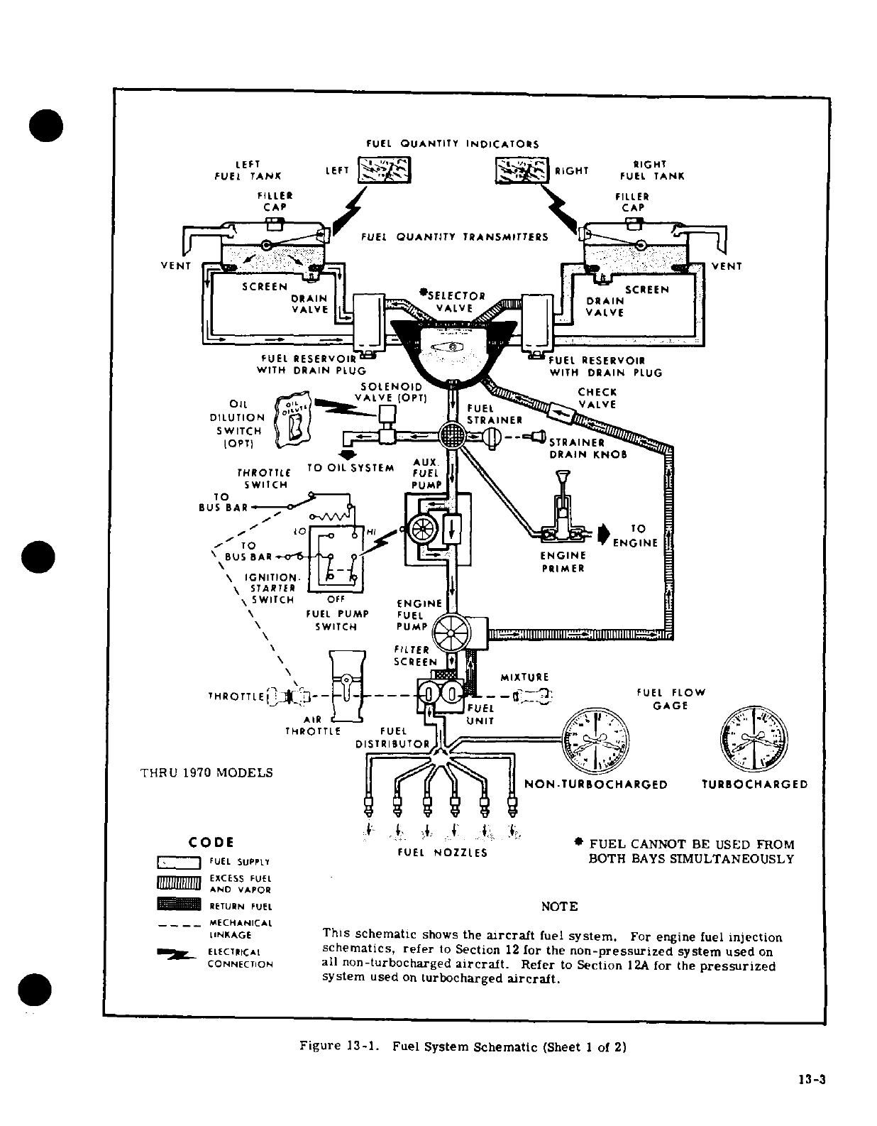
FUEL
QUANTITY
INDICATORS
LEFT
LEFT
RIGHT
FUEL
TANK
FUEL
TANK
FILLER
FILLER
CAP
CAP
FUEL
OUANTITY
TRANSMITTERS
VENTENT
T
SCREEN
ASCREEN
RAIN
SELECTOR
DIN
VALVE
VALVE
VALVE
DID
U
ON
1
FUEL
RESERVOIR
"
-' -
"UEL
RESERVOIR
WITH
DRAIN
PLUG
\
WITH
DRAIN
PLUG
SOLENOID
CHECK
VAjV
LVE
(OPT
ALVE
OIL
DILUTION
STRAINE
-
AUX
C
DRAIN
KNOB
THROTTr
TO
OIL
SYSTEM
\
BUS
BAR
-3 <
'
//
~ TO
*BUS.ARI<
P-8 £ENGINE
ENGINE
\
-
.
PRIMER
\
IGNITION.
|
\
S7ARTER
SWITCH
OFF
ENGINE
\
FUEL
PUMP
FUEL
\
SWITCH
PUMP
:Il
I[IIIF
lI
S
I1::',1111111111111:11
11111111[ 11:1'1
E \ FFILJTELR X»H
R
~\ .~..E*SCREEN
'\
AN Vi
MIXTURE
THROTTlE
j 3 I---g
GAGE
MCNA
D
FUEL
F L OW
AC R E EEE
UNIT
THROTTLE
FUEL
|I
DISTRIBUTO
THRU
1970
MODELS
|f: ?~
)
||
NON.TURBOCHARGED
TURBOCHARGED
DE
FEL
NOZZLES
BOTH
BAYS
SIMULTANEOUSLY
,['~'
1
FUEL
SUPPLY
EXCESS
FUEL
AND
VAPOR
_^B
PRETURN
FUEL
NOTE
....
__MECHANICAL
LINKAGE
This schematic
shows
the
aircraft
fuel
system.
For
engine
fuel
injection
ME.
ELECTICAL
schematics,
refer
to
Section
12
for
the
non-pressurized
system used
on
CONNECTION
all
non-turbocharged
aircraft.
Refer
to
Section
12A
for
the
pressurized
system
used
on
lurbocharged
aircraft.
Figure
13-1.
Fuel
System
Schematic
(Sheet
1
of
2)
13-3
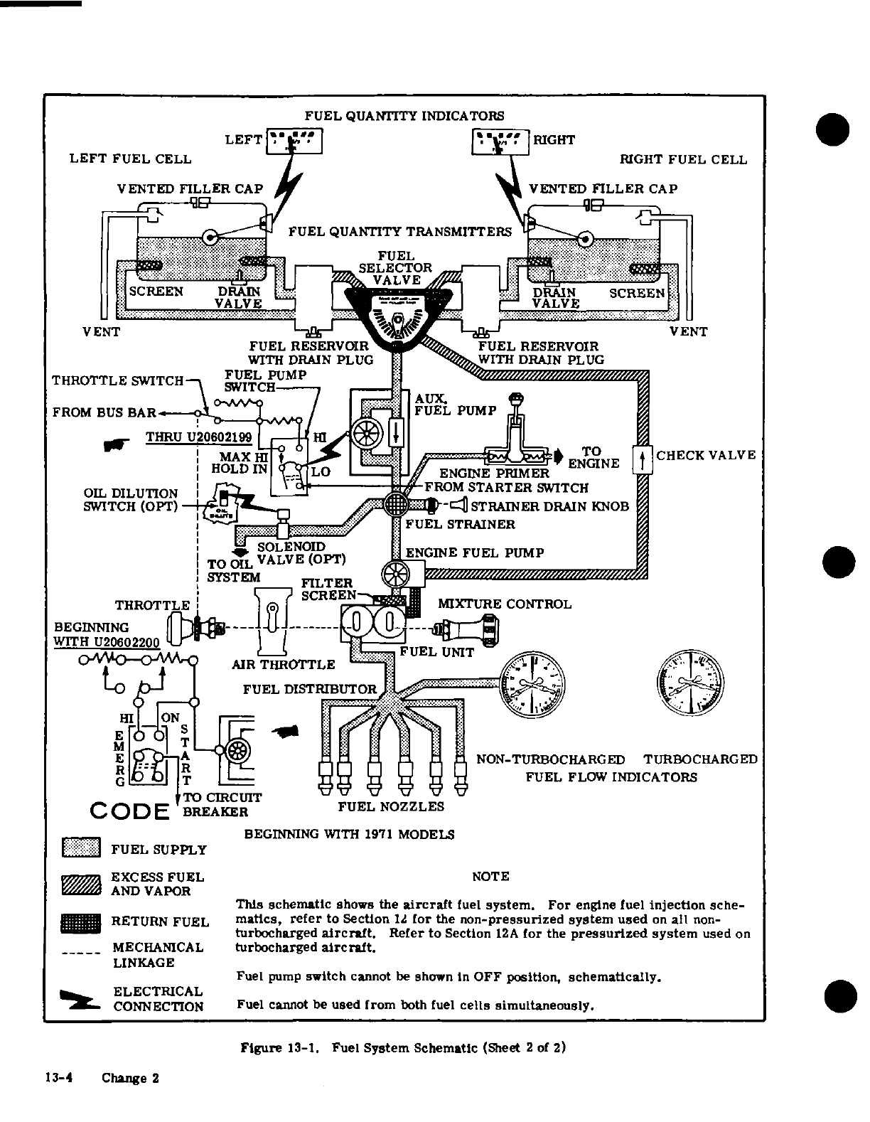
FUEL
QUANTITY
INDICATORS
LEFT
:
RIGHT
LEFT
FUEL
CELL
RIGHT
FUEL
CELL
VENTED
FILLER
CAP
VENTED
FILLER
CAP
FUEL
QUANTITY
TRANSMITTERS
SELECTOR
VALVE
SCREEN
DR
DRAIN
SCREEN
VALVE
VALVE
VENT VENT
FUEL
RESERVOIR
I
FUEL
RESERVOIR
WITH
DRAIN
PLUG
1 W
ITH
DRAIN
PLUG
THROTTLE
SWITCH
FUEL
PUMP
FROM
BUS
BAR
FUEL
PUMP
r THRU
U20602199
--
HIc)CHECK
V
OMMAX
B
' ...
NGE BU
ENGINE
A
CHECK
VALVE
HOLD
IN
Lo
'
ENGINE
PRIMER
OIL
DILUTION
»-L
J
,
FROM
STARTER
SWITCH
SWITCH
(OPT)-
STRAINER
DRAIN
KNOB
-'^
::::
:i
FUEL
STRAINER
SYS TS~EMpI
ENGI~NE
FUEL
PUMP
TOOIL
VALVE
(OPT)
EN__NE
FE
SYSTEM
FILTER
THROTTLE
MIXTURE
CONTROL
BEGINNING
f
WITH
U20602200
-L
-
f : :
EL
UNIT"/:
AIR
THROTTLE
OT I|
FUEL
DISTRIBUTOR
(
HIt |O
N-
FL
tE
IR
i
I
NON-TURBOCHARGED
TURBOCHARGED
G
0l
)
|T
I-- WSU^ g4 4FUEL
FLOW
INDICATORS
TO
CIRCUIT
CODE
BREAKER
FUEL
NOZZLES
BEGINNING
WITH
1971
MODELS
"'l::
FUEL
SUPPLY
EXCESS
FUEL
NOTE
AND
VAPOR
This
schematic
shows
the
aircraft
fuel
system. For
engine
fuel
injection
sche-
RETURN
FUEL
matlcs,
refer
to Section
1t
for
the
non-pressurized
system used
on
all
non-
turbocharged
aircraft.
Refer
to
Section
12A
for
the
pressurized
system
used
on
MECHANICAL
turbocharged
aircraft.
LINKAGE
Fuel
pump
switch
cannot
be
shown
in
OFF
position,
schematically.
ELECTRICAL
CONNECTION
Fuel
cannot
be
used
from
both
fuel
cells
simultaneously.
Figure
13-1.
Fuel
System
Schematic
(Sheet
2
of
2)
13-4
Change 2
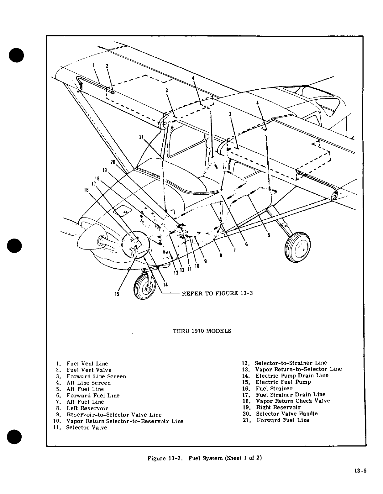
15
REFER
TO
FIGURE
13-3
1.
Fuel
Vent
Line
12.
Selector-to-Strainer
Line
2.
Fuel
Vent
Valve
13.
Vapor
Return-to-Selector
Line
3.
Forward
Line
Screen
14.
Electric
Pump
Drain
Line
4.
Aft
Line
Screen
15.
Electric
Fuel Pump
5.
Aft
Fuel
Line
16.
Fuel
Strainer
6.
Forward
Fuel
Line
17.
Fuel
Strainer
Drain
Line
7.
Aft
Fuel
Line
18.
Vapor
Return
Check
Valve
8.
Left
Reservoir
19.
Right
Reservoir
9.
Reservoir-to-Selector
Valve
Line
20.
Selector
Valve
Handle
10
Vapor Return
Slector-to-Reservoir
Line
21.
Forward
Fuel
Line
11.
Fe
Selector
Valve
Figune Screen
13-2.
Fuel
System
(Sheet
of
2)
13-5
6.
Forward
Fuel
Line
17.
Fuel
Strainer
Drain
Line
7.
Aft
Fuel
Lin
e
18.
Vapor
Return
Check
Valve
8.
L
eft
Reservoir
19.
Right
Reservoir
9.
Reservoir-to-Selector
Valve
Line
20.
Selector
Valve
Handle
10.
Vapor Return
Selector-to-Reservoir
Line
21.
Forward
Fuel
Line
11.
Selector
Valve
Figure
13-2.
Fuel
System
(Sheet
1
of
2)
13-5
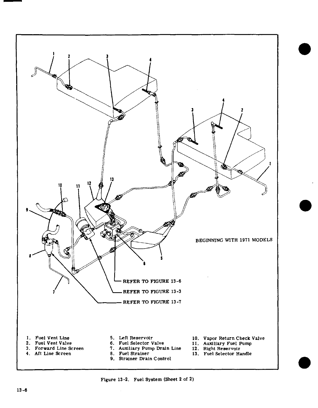
3
-
REFER
TO
FIGURE
13-6
REFER
TO
FIGURE
13-3
REFER
TO
FIGURE
13-7
1.
Fuel
Vent
Line 5.
Left
Reservoir
10.
Vapor
Return
Check
Valve
2.
Fuel
Vent
Valve
6.
Fuel
Selector
Valve
11.
Auxiliary
Fuel
Pump
3.
Forward
Line
Screen
7.
Auxiliary Pump
Drain
Line
12.
Right
Reservoir
4.
Aft
Line
Screen
8.
Fuel
Strainer
13.
Fuel
Selector
Handle
9.
Strainer
Drain
Control
Figure
13-2.
Fuel
System
(Sheet 2
of
2)
13-6
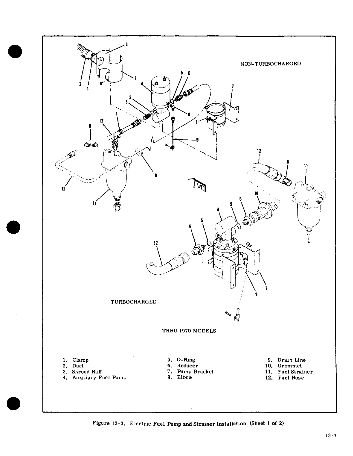
NON-TURBOCHARGED
TURBOCHARGED
1.
Clamp
5.
O-Ring
9.
Drain Line
2.
Duct
6.
Reducer
10.
Grommet
3.
Shroud Half
7.
Pump
Bracket
11.
Fuel
Strainer
4.
Auxiliary
Fuel
Pump
8. Elbow
12.
Fuel
Hose
Figure
13-3.
Electric
Fuel
Pump
and
Strainer
Installation
(Sheet
1
of
2)
13-7
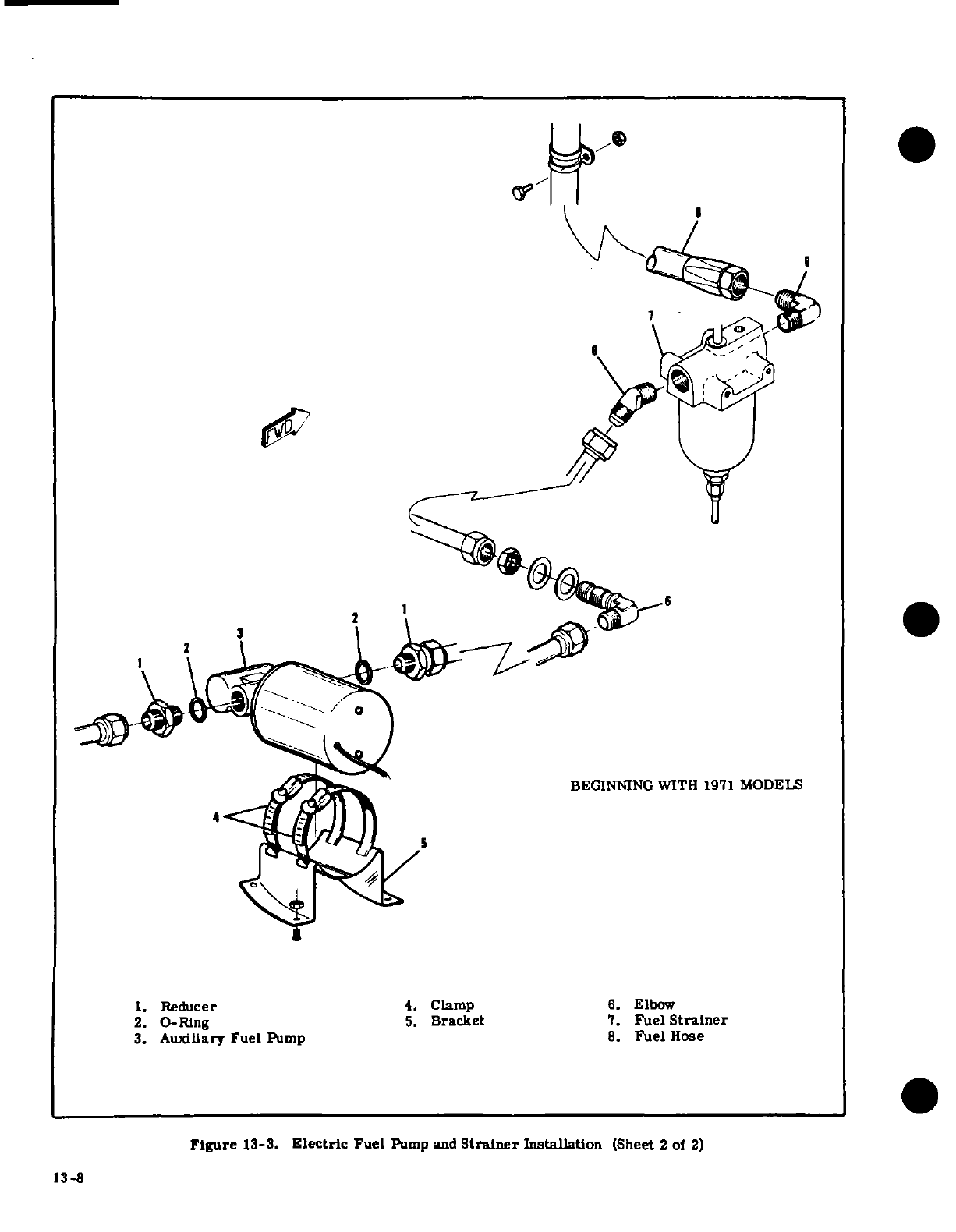
7
3
1.
Reducer
4.
Clamp
6.
Elbow
2.
O-Ring
5.
Bracket
7.
Fuel
Strainer
3.
Auxiliary Fuel
Pump
8.
Fuel
Hose
Figure
13-3.
Electric
Fuel
Pump
and
Strainer
Installation
(Sheet
2
of
2)
13-8
13-8
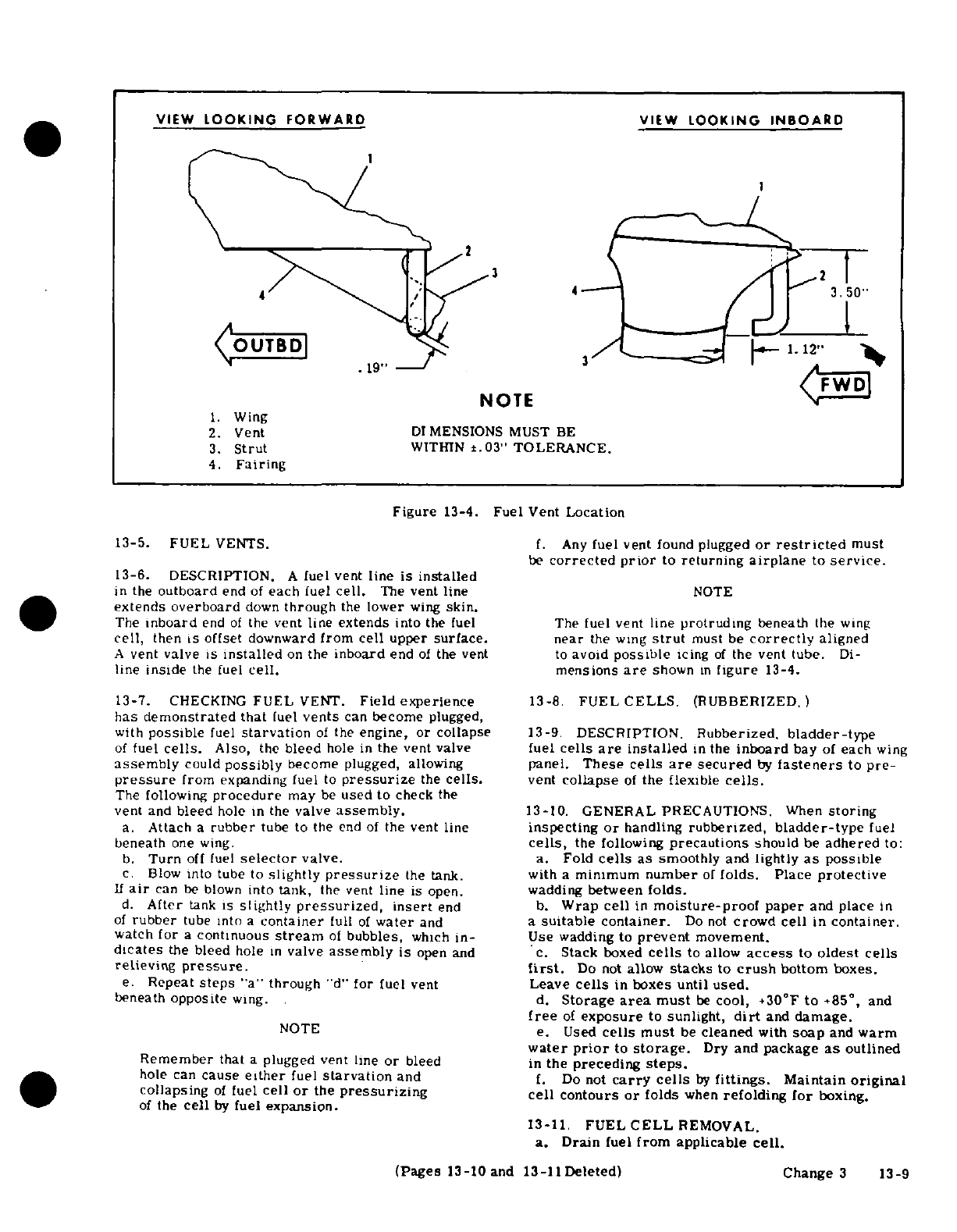
VIEW
LOOKING
FORWARD
VIEW
LOOKING
INBOARD
3
4 4
3.50"
OUTBD
1.12"
.19"
NOTE
1.
Wing
2.
Vent
DIMENSIONS
MUST
BE
3.
Strut
WITHIN
±.03"
TOLERANCE.
4.
Fairing
Figure
13-4.
Fuel
Vent
Location
13-5.
FUEL
VENTS.
f.
Any
fuel
vent
found
plugged
or
restricted
must
be
corrected
prior
to
returning
airplane
to
service.
13-6. DESCRIPTION.
A
fuel
vent
line
is
installed
in
the
outboard
end
of
each
fuel
cell.
The
vent
line
NOTE
extends
overboard
down
through
the
lower
wing
skin.
The
inboard
end
of
the
vent
line
extends
into
the
fuel The
fuel
vent
line
protruding
beneath
the
wing
cell,
then
is
offset
downward
from
cell
upper
surface. near
the wing
strut
must be
correctly
aligned
A
vent
valve
is
installed
on
the
inboard
end
of
the
vent
to
avoid
possible
icing
of
the
vent
tube.
Di-
line
inside
the
fuel
cell.
mensions
are
shown
in
figure
13-4.
13-7.
CHECKING
FUEL
VENT.
Field experience
13-8.
FUEL
CELLS.
(RUBBERIZED.
)
has
demonstrated
that
fuel
vents
can
become
plugged,
with
possible
fuel
starvation
of
the
engine,
or collapse
13-9
DESCRIPTION.
Rubberized.
bladder-type
of
fuel
cells.
Also,
the
bleed
hole
in
the vent
valve
fuel
cells
are
installed
in
the
inboard
bay
of
each
wing
assembly
could
possibly
become
plugged, allowing
panel.
These
cells
are
secured
by
fasteners
to
pre-
pressure
from
expanding
fuel
to
pressurize
the
cells.
vent
collapse
of
the
flexible
cells.
The
following
procedure
may
be
used
to
check
the
vent
and
bleed
hole in
the
valve
assembly.
13-10.
GENERAL
PRECAUTIONS.
When
storing
a.
Attach
a
rubber
tube to
the
end
of
the vent
line
inspecting
or
handling
rubberized,
bladder-type
fuel
beneath
one
wing.
cells,
the
following
precautions
should
be
adhered
to:
b.
Turn
off
fuel
selector
valve.
a.
Fold
cells
as
smoothly
and
lightly
as
possible
c.
Blow
into tube to
slightly
pressurize
the
tank.
with
a
minimum
number
of
folds. Place
protective
If
air
can
be
blown
into
tank,
the
vent
line
is
open.
wadding
between
folds.
d.
After
tank
is
slightly
pressurized,
insert
end b.
Wrap
cell
in
moisture-proof
paper
and
place
in
of
rubber
tube
into
a
container
full
of
water
and
a
suitable container.
Do
not
crowd
cell
in
container.
watch
for
a
continuous
stream
of
bubbles,
which
in-
Use
wadding
to
prevent
movement.
dicates
the
bleed
hole
in
valve
assembly
is
open
and
c.
Stack
boxed
cells
to
allow
access
to
oldest cells
relieving
pressure.
first.
Do
not
allow
stacks
to
crush
bottom
boxes.
e.
Repeat
steps
"a"
through
"d"
for
fuel
vent
Leave
cells
in
boxes
until
used.
beneath
opposite
wing.
d.
Storage
area
must
be
cool,
+30°F
to
+85
°
,
and
free
of
exposure
to
sunlight,
dirt
and
damage.
NOTE
e.
Used
cells
must
be
cleaned
with
soap
and
warm
water
prior
to
storage.
Dry
and
package
as
outlined
Remember
that
a
plugged vent
line
or
bleed
in
the
preceding
steps.
hole can
cause
either
fuel
starvation
and
f.
Do
not
carry
cells
by
fittings.
Maintain
original
collapsing
of
fuel
cell
or
the
pressurizing
cell
contours
or
folds
when
refolding
for
boxing.
of
the
cell
by
fuel
expansion.
13-11.
FUEL
CELL
REMOVAL.
a.
Drain
fuel
from
applicable
cell.
(Pages
13-10
and 13-11
Deleted)
Change
3
13-9
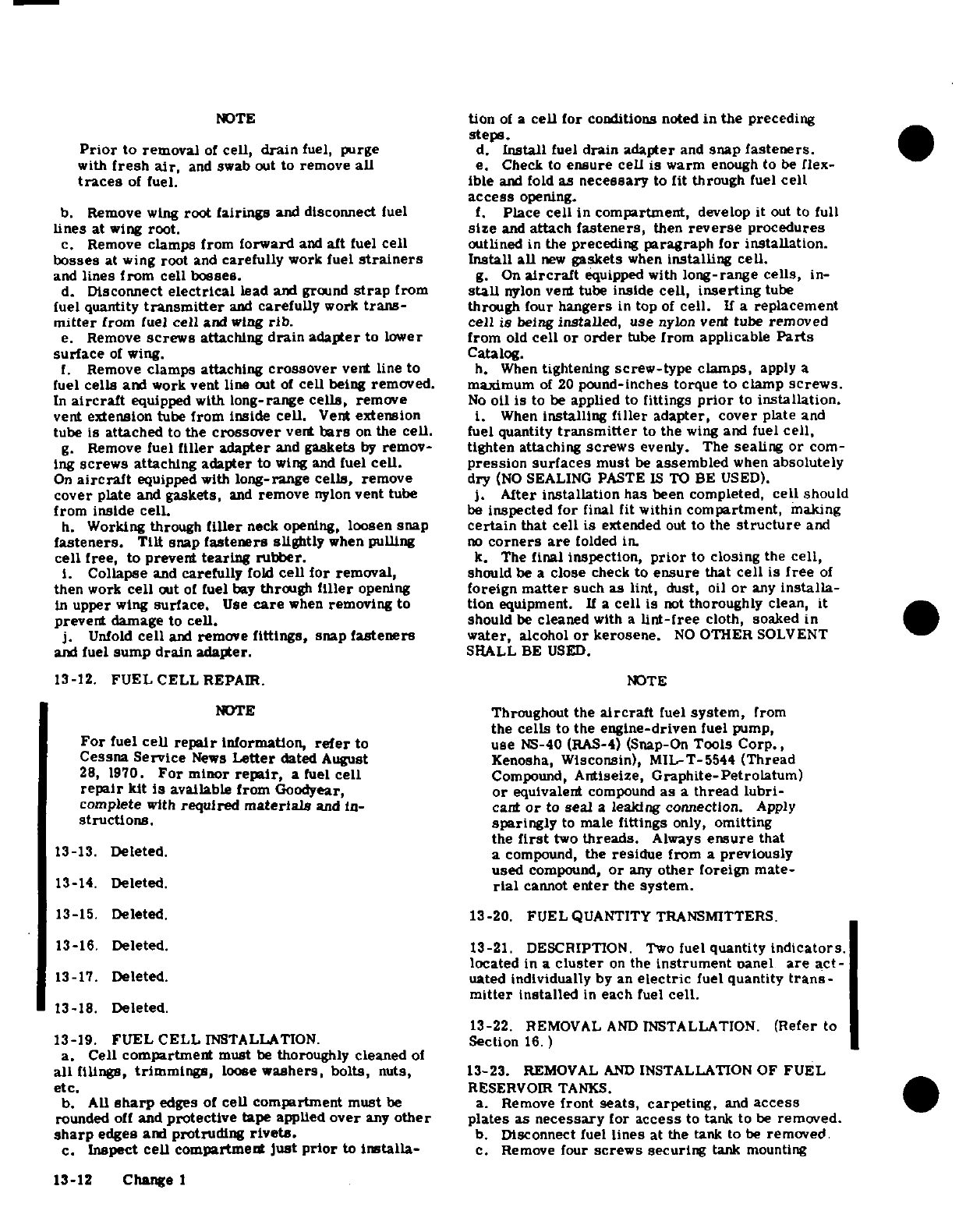
NOTE
tion
of
a
cell
for
conditions
noted
in
the
preceding
steps.
Prior
to
removal
of
cell,
drain
fuel,
purge
d.
Install
fuel
drain
adapter
and
snap
fasteners.
with
fresh
air,
and
swab
out to
remove
all
e.
Check
to
ensure
cell is
warm
enough
to
be
flex-
traces
of
fuel. ible
and
fold
as
necessary
to
fit
through
fuel
cell
access
opening.
b.
Remove
wing
root
fairings
and
disconnect
fuel
f.
Place
cell
in
compartment,
develop
it
out
to
full
lines
at
wing
root.
size
and
attach
fasteners,
then
reverse
procedures
c.
Remove
clamps from
forward
and
aft
fuel
cell
outlined
in
the
preceding
paragraph
for installation.
bosses
at wing
root
and
carefully
work
fuel
strainers
Install
all
new
gaskets
when
installing cell.
and
lines from cell
bosses.
g.
On
aircraft
equipped with
long-range
cells,
in-
d.
Disconnect
electrical
lead
and ground
strap
from
stall
nylon
vent tube
inside
cell,
inserting
tube
fuel quantity
transmitter
and
carefully
work
trans-
through four
hangers
in
top
of
cell.
If
a
replacement
mitter
from
fuel
cell
and
wing
rib.
cell
is
being
installed,
use
nylon
vent
tube
removed
e.
Remove
screws
attaching
drain
adapter
to
lower
from
old
cell or
order
tube
from
applicable
Parts
surface
of
wing.
Catalog.
f.
Remove
clamps
attaching
crossover
vent
line
to
h.
When
tightening
screw-type
clamps,
apply
a
fuel
cells
and
work
vent
line
out
of
cell
being
removed.
maximum
of
20
pound-inches
torque
to
clamp
screws.
In
aircraft
equipped with
long-range
cells,
remove
No
oil
is
to
be
applied
to
fittings
prior
to
installation.
vent
extension
tube
from inside
cell.
Vent
extension
i.
When
installing
filler
adapter, cover
plate
and
tube is
attached
to
the
crossover
vent
bars
on
the
cell.
fuel quantity
transmitter
to
the
wing
and fuel
cell,
g.
Remove
fuel
filler
adapter
and
gaskets
by
remov-
tighten
attaching
screws
evenly.
The
sealing
or
com-
ing
screws
attaching adapter
to
wing and
fuel
cell.
pression
surfaces
must
be
assembled
when
absolutely
On
aircraft
equipped
with
long-range
cells,
remove
dry
(NO
SEALING
PASTE
IS
TO
BE
USED).
cover
plate
and
gaskets,
and
remove
nylon
vent
tube
j.
After
installation
has
been
completed,
cell
should
from
inside
cell.
be
inspected
for
final
fit within
compartment,
making
h.
Working
through
filler
neck
opening,
loosen
snap
certain
that
cell
is
extended
out
to
the
structure
and
fasteners.
Tilt
snap
fasteners
slightly
when
pulling
no
corners are
folded
in.
cell
free,
to
prevent
tearing rubber.
k.
The
final inspection,
prior
to closing
the
cell,
i.
Collapse
and
carefully
fold
cell
for
removal,
should
be
a
close
check
to
ensure
that
cell
is
free
of
then
work
cell
out
of
fuel
bay
through
filler
opening
foreign
matter
such
as
lint,
dust,
oil
or
any
installa-
In
upper
wing
surface.
Use
care
when
removing
to tion
equipment.
If
a
cell is
not
thoroughly
clean,
it
prevent
damage
to cell.
should
be
cleaned
with
a
lint-free
cloth,
soaked
in
j.
Unfold
cell
and
remove
fittings,
snap
fasteners
water,
alcohol
or
kerosene.
NO
OTHER
SOLVENT
and
fuel
sump
drain
adapter.
SHALL
BE
USED.
13-12.
FUEL CELL
REPAIR.
NOTE
NOTE
Throughout
the
aircraft
fuel
system,
from
the
cells
to
the
engine-driven
fuel
pump,
For
fuel
cell
repair
information,
refer
to
use
NS-40
(RAS-4)
(Snap-On
Tools
Corp.,
Cessna
Service
News
Letter
dated
August
Kenosha,
Wisconsin),
MIL-T-5544
(Thread
28, 1970.
For
minor
repair,
a
fuel
cell
Compound,
Antiseize,
Graphite-Petrolatum)
repair
kit
is
available
from
Goodyear,
or
equivalent
compound
as
a
thread
lubri-
complete
with
required
materials
and
in-
cant
or
to
seal
a
leaking connection.
Apply
structions.
sparingly
to
male
fittings
only,
omitting
the
first
two
threads.
Always
ensure
that
13-13.
Deleted.
a
compound,
the
residue
from
a
previously
used
compound,
or
any
other
foreign
mate-
13-14.
Deleted.
rial
cannot
enter
the
system.
13-15.
Deleted. 13-20.
FUEL
QUANTITY
TRANSMITTERS.
13-16.
Deleted.
13-21. DESCRIPTION.
Two
fuel
quantity
indicators.
located
in
a
cluster
on
the
instrument
panel
are
act-
13-17.
Deleted.
uated
individually
by
an
electric
fuel
quantity
trans-
mitter
installed
in
each
fuel
cell.
13-18.
Deleted.
13-22.
REMOVAL
AND
INSTALLATION.
(Refer
to
13-19.
FUEL CELL
INSTALLATION.
Section
16.)
a.
Cell
compartment
must
be
thoroughly
cleaned
of
all
filings,
trimmings,
loose
washers,
bolts,
nuts, 13-23.
REMOVAL
AND
INSTALLATION
OF FUEL
etc.
RESERVOIR
TANKS.
b.
All
sharp
edges
of
cell
compartment must
be
a.
Remove
front
seats,
carpeting,
and
access
rounded
off
and
protective
tape
applied
over
any
other
plates
as
necessary
for
access
to tank to
be
removed.
sharp
edges
and
protruding
rivets.
b.
Disconnect
fuel
lines
at
the
tank to
be
removed.
c.
Inspect
cell
compartment just
prior
to
installa-
c.
Remove four
screws
securing
tank mounting
13-12
Change
1
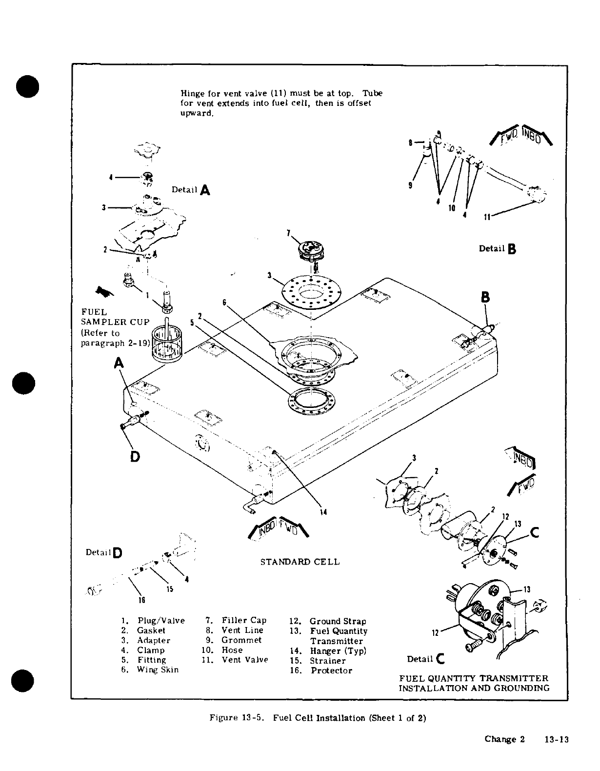
Hinge
for vent
valve
(11)
must
be at
top.
Tube
for
vent
extends
into
fuel
cell,
then
is
offset
upward.
Detail
A
3-
10
-
2
-
Detail
B
FUEL
/
SAMPLER
CUP
paragraph
2-19)
A
-
DetailD
1
*
C
STANDARD
CELL
/
13
16
1.
Plug/Valve
7.
Filler
Cap
12.
Ground
Strap
2.
Gasket
8.
Vent
Line
13.
Fuel
Quantity
12
3.
Adapter
9.
Grommet
Transmitter
4.
Clamp
10.
Hose
14.
Hanger
(Typ)
5.
Fitting
11.
Vent
Valve
15.
Strainer
Detail
C
6.
Wing
Skin
16.
Protector
FUEL
QUANTITY
TRANSMITTER
INSTALLATION
AND
GROUNDING
Figure
13-5.
Fuel
Cell
Installation
(Sheet
1
of
2)
Change
2
13-13
Hinge
for
vent
valve
(12)
must
be
at
top.
Tube
for vent
extends
into
fuel
cell,
then
is
offset
upward.
9
DetailB
3
Detail
A
10
I
I
2
B
FUEL
SAMPLER
CUP
(Refer
to
A
paragraph
2-19)
17
2
v 2
14
C
Detail
D
LONG
-
RANGE
CELL
15 14
1.
Plug/Valve
7.
Cover
Plate
13.
Ground
Strap
2.
Gasket
8.
Filler
Cap
14.
Fuel
Quantity
3.
Adapter
9.
Vent
Line
Transmitter
4.
Clamp
10.
Grommet
15.
Strainer
Detail
C
5.
Fitting
11.
Hose
16.
Protecter
6.
Wing
Skin
12.
Vent
Valve
17.
Hanger
(Typ)
FUEL
QUANTITY
TRANSMITTER
INSTALLATION
AND
GROUNDING
Figure
13-5.
Fuel
Cell
Installation
(Sheet
2
of
2)
13-14
Change
2
legs
to
fuselage
structure.
and
lubricate
O-rings
before
installation.
d.
Lift
out
the
tank.
e.
Reverse
the
preceding
steps
to
install
a
reser-
{CAUTION
voir
tank.
Install
all
parts
in
the
relative
position
de-
picted
in
figure
13-6,
otherwise
the
valve
13-24.
REMOVAL
AND
INSTALLATION
OF
FUEL
will
not
operate
correctly.
SELECTOR
VALVE.
a.
Drain
all
fuel
from
wing
tanks
at
fuel
tank
sump
j.
Install
O-ring
(18)
in
body
shaft
hole.
Install
drain
plugs.
With
valve
turned
to
LEFT
TANK,
drain
O-rings
(19)
and
teflon
seals
(20),
then
slide
shaft
left
fuel
lines
at
selector
valve;
with
valve
turned
to
and
rotor
into
place.
Position
rotor
in
exact
rela-
RIGHT
TANK,
drain
right
fuel
lines.
live
position
shown in
figure
13-6,
then
install
O-
b.
Remove
control pedestal
cover. (Refer
to
sec-
ring
(22)
and
sump
plate
(23)
tion
11
for
procedures.)
k.
Install
.
169"
diameter
pins
in
body
ports,
then
c.
Remove
access
hole
covers
in
floorboard
and
slide
springs
(17),
washers
(16),
O-rings
(15)
and
fuselage skin
in
area
of
fuel
selector
valve,
teflon
seals
over
pins.
Slide
rotor
(12)
over
shaft.
d.
Disconnect
all
fuel
lines
from
selector
valve.
Remove
.169"
dia. pins
and,
readjusting
rotor
vs.
e.
Disconnect
square
shaft from
valve
by
removing
shaft
position
as
necessary,
tap
roll
pin
(13)
into
attached
roll
pin.
place,
letting
it
protrude
on
the
side depicted.
f.
Remove
bolts
or
screws
attaching
valve
to
sup-
port
bracket
and
remove
valve.
NOTE
g.
Install
valve
by
reversing
this
procedure.
This
roll
pin
serves
also
as
a
stop,
limiting
13-25.
FUEL
SELECTOR
VALVE
REPAIR.
(See
valve
shaft
travel.
figure 13-6.
)
The
fuel
selector
valve
may
be
re-
paired
by
disassembly,
replacement
of
defective
1.
Install
O-ring
(10)
in
cover,
lubricate
shaft
(21)
parts,
and
reassembly
as
follows:
with
petrolatum,
install
large
O-ring
(11),
and
slide
cover
down
into
place.
a.
Mark
sump
plate
(23)
and
body
(1)
to
ensure
correct
reassembly,
then
remove
sump
plate
(23)
ICAUTION|
and
O-ring
(22)
after
removing
four
screws.
b.
Drive
out
roll
pin
(5)
securing
yoke
(6)
to
shaft.
Make
sure
cover
is
installed
in
relative
posi-
As yoke
is
lifted
off,
balls
(8)
and
springs
(7)
are
tion
illustrated.
A
lug
on
the
cover
protrudes
free.
Retain
them.
to
serve
as
a
stop
detent
and
if
the
cover
is
c.
Lift
off
washer
(9).
not
installed
correctly,
the valve
will
not
op-
d.
Mark
cover
(4)
and
body
to
assure later
align-
erate correctly.
ment
ot
parts
and
remove
screws
(3).
e.
With
fine
emery
paper.
sand
off
any
burrs
or
m.
Install
brass
washer
(9)
and
yoke
(6).
Note
the
sharp
edges
on
shaft
(21).
Apply
petrolatum
to
position
of
the
small
hole
in
the
squared,
upper
por-
shaft
as
a
lubricant.
then work
cover
off
shaft.
tion
of
the
yoke.
If
this
is
reversed,
the
valve
link-
f.
Drive
back
roll
pin
(13)
and
remove
rotor
(12).
age will
not
attach
properly.
Teflon
seal
(14),
O-rings
(15),
washers
(16),
and
springs
(17)
are
now
free
to
be
removed.
Check
all
13-26.
AUXILIARY
ELECTRIC
FUEL
PUMP.
On
parts
carefully
to
locate
any
defects.
aircraft
Serials
U20601619
thru
U20601632
and
air-
g.
Remove
burrs
or
sharp
edges
on
shaft,
lubri-
craft
prior
to
Serial
U20601605,
the
auxiliary
elec-
cate
and
slide
it
down.
out
of
body
(1).
Remove
tric
fuel
pump
is
mounted
on
either
the
left
side
or
teflon
seals
(20)
and
O-rings
(19).
right
side
of
the
firewall.
On
aircraft
Serials
U206-
h.
Remove
O-ring
(18)
within
body
and
O-ring
(10)
01605
thru
U20601618
and
beginning
with
U20601633,
within
cover.
the
auxiliary
electric
fuel
pump
is
located under
the
i.
Replace
all
O-rings,
lap
or
replace
teflon
seals,
floorboard
on
the
right
side
of
cabin,
immediately
SHOP
NOTES:
Change
1
13-15
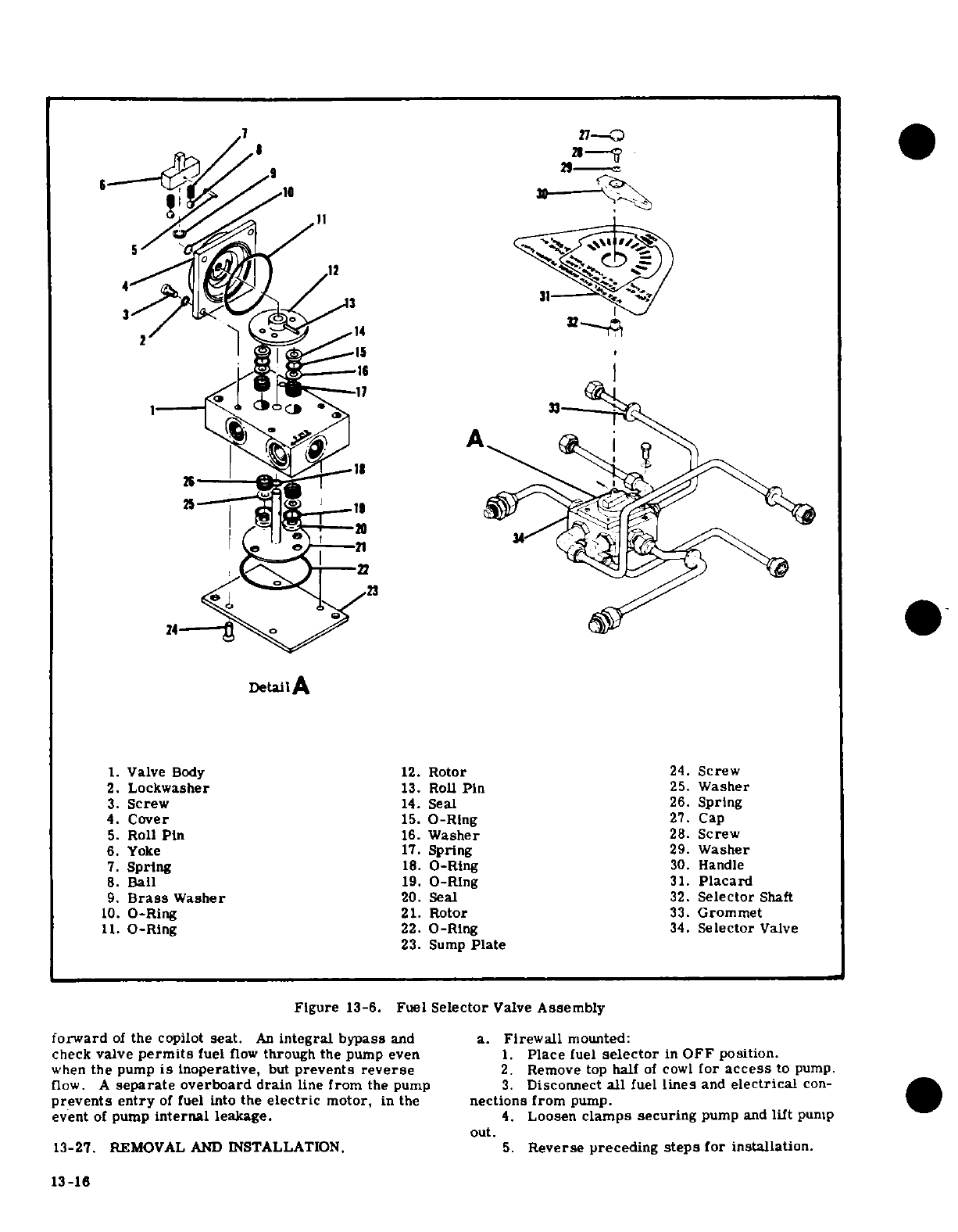
f-
---
3
-"
</;^
1i4 21
24114 o 0
.
24--
>
Detail
A
1.
Valve
Body
12.
Rotor
24.
Screw
2.
Lockwasher
13.
Roll
Pin
25.
Washer
3.
Screw
14.
Seal
26.
Spring
4.
Cover
15.
O-Rlng
27.
Cap
5.
Roll
Pin
16.
Washer
28.
Screw
6.
Yoke
17.
Spring
29.
Washer
7.
Spring
18.
O-Ring
30.
Handle
8.
Ball
19.
O-Ring
31.
Placard
9.
Brass
Washer
20.
Seal
32.
Selector
Shaft
10.
O-Ring
21.
Rotor
33.
Grommet
11.
O-Ring
22.
O-Ring
34.
Selector
Valve
23.
Sump
Plate
Figure
13-6.
Fuel
Selector
Valve
Assembly
forward
of
the
copilot
seat.
An
integral
bypass
and a.
Firewall
mounted:
check
valve
permits
fuel
flow
through
the
pump
even .
Place
fuel
selector
in
OFF position.
when
the
pump
is
inoperative,
but
prevents
reverse
2.
Remove
top
half
of
cowl
for
access
to
pump.
flow.
A
separate
overboard
drain
line
from
the
pump
3.
Disconnect
all
fuel
lines
and
electrical
con-
prevents entry
of
fuel
into
the
electric
motor,
in
the
nections
from
pump.
event
of
pump
internal
leakage.
4.
Loosen
clamps
securing
pump
and
lift
pump
out.
13-27.
REMOVAL
AND
INSTALLATION.
5.
Reverse preceding
steps
for
installation.
13-16
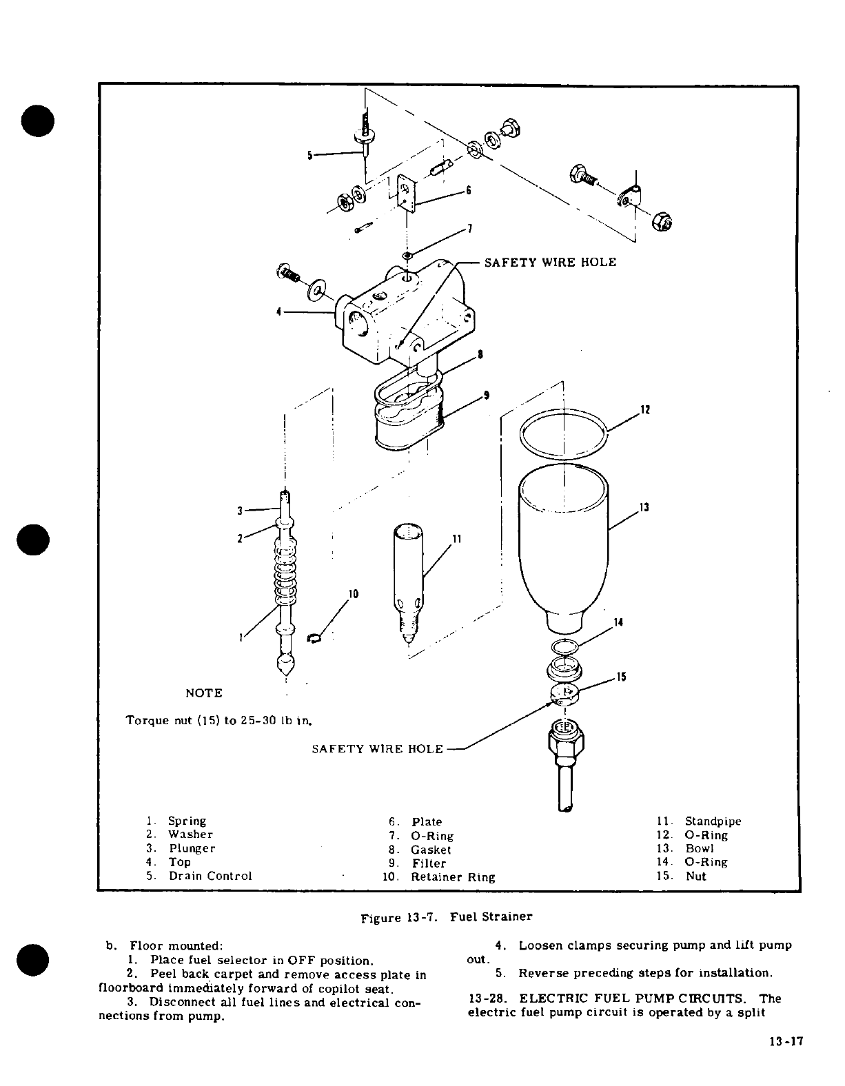
SAFETY
WIRE HOLE
NOTE
Torque
nut
(15)
to
25-30
lb
in.
SAFETY
WIRE
HOLE
1.
Spring
6.
Plate
11.
Standpipe
2.
Washer
7.
O-Ring
12.
O-Ring
3.
Plunger
8.
Gasket
13.
Bowl
4.
Top
9.
Filter
14.
O-Ring
5.
Drain
Control
10.
Retainer
Ring
15.
Nut
Figure
13-7.
Fuel
Strainer
b.
Floor
mounted:
4.
Loosen
clamps
securing
pump
and
lift
pump
1.
Place
fuel
selector
in
OFF
position.
out.
2.
Peel
back
carpet
and
remove
access
plate
in
5.
Reverse
preceding
steps
for
installation.
floorboard
immediately
forward
of
copilot
seat.
3.
Disconnect
all
fuel
lines
and
electrical
con-
13-28.
ELECTRIC
FUEL
PUMP
CIRCUITS.
The
nections
from
pump.
electric
fuel
pump
circuit
is
operated
by
a
split
13-17
rocker-type
switch.
The
low
side
of
the
switch
is
12-28B.
DESCRIPTION.
Beginning
with
U20602200,
connected
through
the
"START"
position
of
the
ig-
the
yellow
right
half of
the
switch
is
labeled
"START",
nition
switch so
that
the
fuel
pump
will
operate
only
and
its
upper
"ON"
position
is
used
for
normal
start-
while the
ignition
switch
is
in
the
"START"
position
ing,
minor
vapor
purging
and
continued
engine
opera-
and
the
low
side
of
the
fuel
pump
switch
is
turned
on.
tion
in
the
event
of an
engine-driven
pump
failure.
When
the
ignition
key
is
released,
the pump
will stop.
With
the
right
half
of
the
switch
in
the
"ON"
position.
The
high
side
of
the
fuel
pump
switch
will
operate
the the
pump
operates
at
one
of
two
flow
rates
that
are
pump
regardless
of
ignition switch
position.
A
throt-
dependent
upon
the
setting
of
the
throttle.
With
the
tie
shaft operated microswitch
adds
a
resistance
to
throttle
open
to
a
cruise
setting,
the
pump
operates
the
high
circuit
to
slow
down
the pump
when
the
throt-
high enough
capacity
to
supply
sufficient
fuel
flow
to
tie is
retarded
to
prevent
an
excessively
rich
mixture
maintain
flight
with
an
inoperative
engine-driven
fuel
as
throttle
is
retarded
while
the
electric
pump
is
pump.
When
the
throttle
is
moved
toward
the
closed
operating
in
the
high
position.
Refer
to
the
follow-
position
(as during
letdown,
landing
and
taxiing),
the
ing
paragraph
for
rigging
of
the
microswitch.
fuel
pump
flow
rate
is
automatically
reduced,
pre-
venting
an
excessively
rich
mixture
during
these
12-28A.
DESCRIPTION.
Thru
Serial
U20602199,
periods
of
reduced
engine
speed.
the
electric
auxiliary
fuel
pump, which
supplies
fuel
flow
for
starting
and
for
engine
operation
if
the
NOTE
engine-driven
fuel
pump
should fail,
is
controlled
by
the
auxiliary
fuel
pump
switch,
mounted
on
the
instru-
If
the
engine-driven
fuel
pump
is
functioning
ment
panel.
The
switch
is
a
split-rocker
type;
the
and
the
auxiliary
fuel
pump
switch
is
placed
right
half
positions
are
"HI,"
"LO"
and
off
and
the
in
the
"ON"
position,
a
fuel/air
ratio
consid-
left
half
positions
are
"MAX
HI"
and
off.
The
right
erably
richer
than
best
power
is
produced
half
of
the
switch
incorporates
an
intermediate
"LO"
unless
the
mixture is
leaned.
Therefore,
position
used for normal
starting,
and
a
"HI"
position
this
switch should
be
turned
off
during
take-
(when
the
top
of
the
switch
is
fully
depressed)
for
off.
vapor
purging
during
hot engine
starts.
Maximum
fuel
flow
is produced
when
the
left half
of
the
switch
CAUTION
is
held
in
the spring-loaded
"MAX
HI"
position.
In
the
"MAX
HI"
position,
an
interlock
within
the
switch
If
the
auxiliary
fuel
pump
switch
is
accidently
automatically
trips
the
right
half
of
the switch
to
its
placed
in
the
"ON"
position
with
the
master
"HI"
position.
When
the
spring-loaded
left
half
of
the
switch
on
and
the
engine
stopped,
the
intake
switch
is
released,
the
right
half
will
remain
in
the
manifolds
will
be
flooded.
"HI"
position
until manually
returned
to
the
off
posi-
tion.
With
the
right
half
of
the
switch
in
the
"LO"
The
red
left
half
of
the
switch
is
labeled
"EMERG",
position,
and
the
starter
button
depressed,
the
auxil-
and
its
upper
"HI"
position
is
used
in
the
event
of
an
iary
fuel
pump
will
operate at
a
low flow
rate
(pro-
engine-driven
fuel
pump
failure
during
take-off
or
viding
proper
fuel
mixture
for
starting)
as the
engine
high
power
operation.
The
"HI"
position
may
also
be
is
being
turned
over
with the
starter.
used
for
extreme
vapor
purging.
Maximum
fuel
flow
is
produced
when
the left
half
of
the switch
is held
in
NOTE
the
spring-loaded
"HI"
position.
In
this
position,
an
interlock
within
the
switch
automatically
trips
the
The
auxiliary
fuel
pump
will
not
operate
in
right
half
of
the
switch
to
the
"ON"
position.
When
the
"LO"
position until the
starter
button
is
the
spring-loaded
left
half
of
the
switch
is
released,
depressed.
the
right
half
will
remain
in
the
"ON"
position
until
manually
returned
to
the
"OFF"
position.
With
the
right
half
of
the switch
in
the
"HI"
position,
the
pump
operates
at
one
of
the
two
flow
rates
that
13-29.
RIGGING
THROTTLE
MICROSWITCH.
are
dependent
upon
the
setting
of
the
throttle.
With
(Refer
to
figure
13-8. )
The
aircraft
is
equipped
with
the
throttle
open
to
a
cruise
setting,
the
pump
is
a
throttle-operated
microswitch
which
slows
down
the
operating
at
a
high
capacity
to
supply
sufficient
fuel
electric
fuel
pump
whenever
the
throttle
is
retarded
to
maintain
flight.
When
the
throttle
is
moved
toward
while
the
electric
pump
is
being
used.
The
electric
the
closed
position
(as
during
letdown,
landing
and
fuel
pump
microswitch
should slow
down
the pump
as
taxiing),
the
fuel
pump
flow
rate
is
automatically
the
throttle
is
retarded
to
approximately
19
inches
of
reduced, preventing
an
excessively
rich
mixture
mercury
manifold
pressure
(sea
level
aircraft)
and
during
these
periods
of
reduced
engine
speed.
When
23
inches
of
mercury
manifold
pressure
(turbocharged
the
engine-driven
fuel
pump
is functioning
and
the
aircraft).
auxiliary
fuel
pump
is
functioning
and
the
auxiliary
fuel
pump
is
turned
on
"HI",
a
fuel/air
ratio
consider-
NOTE
ably
richer
than
the
best
power
is produced
unless
the
mixture
is
leaned.
If
the
auxiliary
fuel
pump
switch These
settings
must
be
established
during
is
accidently
placed
on
"HI"
(with
master
switch
on)
ground
run-up
only.
These
values
will
not
with
the
engine stopped
and
the mixture
rich,
the
apply
in
flight.
intake
manifold will
be
flooded.
a.
Start
engine
and
set
throttle
to obtain
19
inches
of
mercury
manifold
pressure
(sea
level
aircraft)
or
23
inches
of
mercury
manifold
pressure
(turbocharged
13-18 Change 3
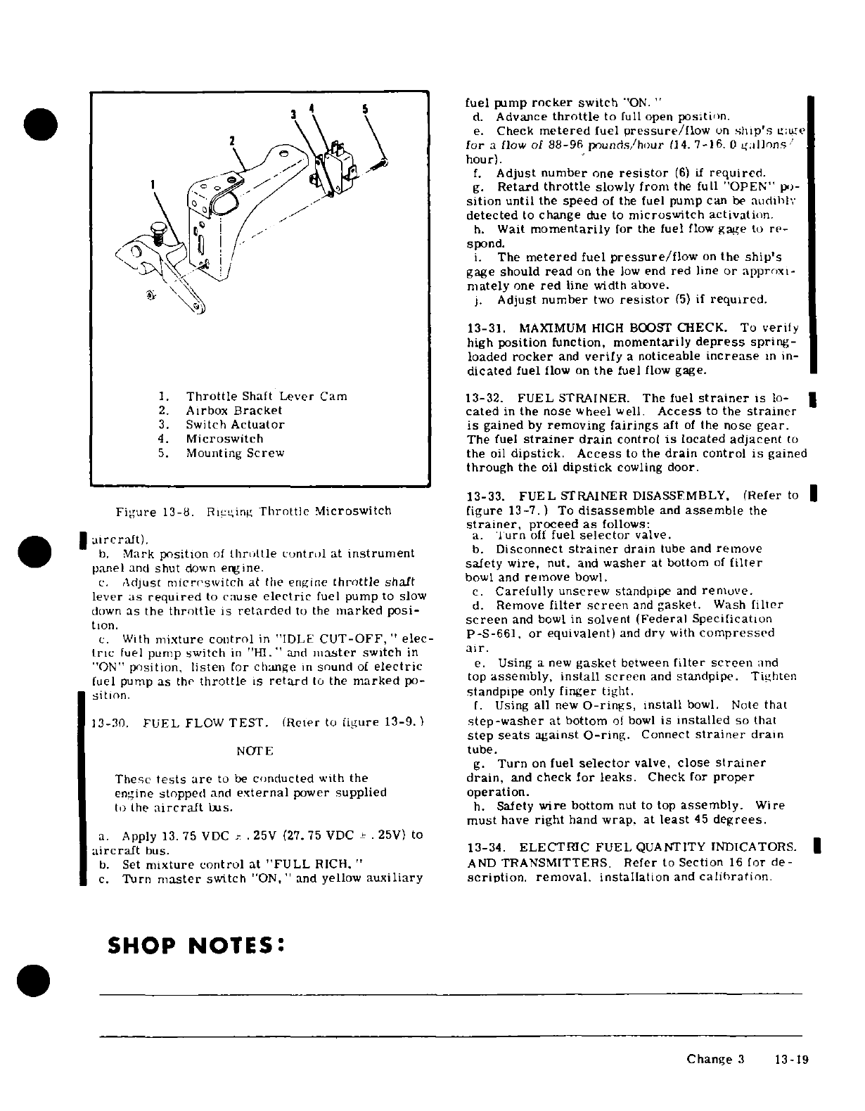
5
fuel
pump
rocker
switch
'ON.
"
d.
Advance
throttle
to
full
open
position.
e.
Check
metered
fuel
pressure/flow
on
ship's
gage
for
a
flow
of
88-96
pounds/hour
(14.
7-16.0
gallons/
hour).
f.
Adjust
number
one
resistor
(6)
if
required.
g.
Retard
throttle
slowly
from
the
full
"OPEN"
po-
sition
until
the
speed
of
the
fuel
pump
can
be
audibly
detected
to
change
due
to
microswitch activation.
h.
Wait
momentarily
for
the
fuel
flow
gage
to
re-
spond.
i.
The
metered
fuel
pressure/flow
on
the
ship's
gage
should
read
on
the
low
end
red
line
or
approxi-
mately
one
red
line
width
above.
j.
Adjust
number
two
resistor
(5)
if
required.
13-31.
MAXIMUM
HIGH
BOOST
CHECK.
To
verify
high
position
function,
momentarily
depress
spring-
loaded
rocker
and
verify
a
noticeable
increase
in
in-
dicated
fuel
flow on
the
fuel
flow
gage.
1.
Throttle
Shaft
Lever
Cam 13-32.
FUEL
STRAINER.
The fuel
strainer
is
lo-
2.
Airbox
Bracket
cated
in
the
nose
wheel
well.
Access
to
the
strainer
3.
Switch
Actuator
is
gained
by
removing
fairings
aft
of
the
nose
gear.
4.
Microswitch
The
fuel
strainer
drain
control
is
located
adjacent
to
5.
Mounting
Screw the
oil
dipstick. Access
to
the
drain
control
is
gained
through
the
oil
dipstick
cowling
door.
13-33. FUEL
STRAINER
DISASSFMBLY.
(Refer
to
Figure
13-8.
Rigging
Throttle
Microswitch figure
13-7.)
To
disassemble
and
assemble
the
strainer,
proceed
as
follows:
aircraft)
a.
Turn
off
fuel
selector
valve.
b.
Mark
position
of
throttle
control
at
instrument
b.
Disconnect
strainer
drain
tube
and
remove
panel
and
shut
down
engine.
safety
wire,
nut.
and
washer
at
bottom
of
filter
c.
Adjust
microswitch
at
the
engine
throttle
shaft
bowl
and
remove
bowl.
lever
as
required
to
cause
electric
fuel
pump
to
slow
c.
Carefully
unscrew
standpipe
and
remove.
down
as
the
throttle
is
retarded
to
the
marked
posi-
d.
Remove
filter
screen
and
gasket.
Wash
filter
tion.
screen
and bowl
in
solvent
(Federal
Specification
c.
With
mixture
control
in
"IDLE
CUT-OFF,"
elec-
P-S-661.
or
equivalent)
and
dry
with
compressed
tric
fuel
pump
switch
in
"HI."
and
master
switch
in
air.
"ON"
position,
listen
for change
in
sound
of
electric
e.
Using
a
new
gasket
between
filter
screen
and
fuel
pump
as
the
throttle
is
retard
to
the
marked
po-
top
assembly,
install
screen
and
standpipe.
Tighten
sition.
standpipe
only
finger
tight.
f.
Using
all
new
O-rings,
install
bowl.
Note
that
13-20.
FUEL
FLOW
TEST. (Refer
to
figure
13-9.)
step-washer
at
bottom
of
bowl
is
installed
so
that
step
seats
against
O-ring.
Connect
strainer
drain
NOTE
tube.
g.
Turn
on
fuel
selector
valve,
close
strainer
These
tests
are
to
be
conducted
with
the
drain,
and
check
for
leaks.
Check
for
proper
engine
stopped
and
external
power
supplied
operation.
to
the
aircraft
bus.
h.
Safety
wire
bottom
nut
to
top
assembly.
Wire
must
have
right
hand
wrap.
at
least
45
degrees.
a.
Apply
13.75
VDC
.25V
(27. 75
VDC
±
.
25V)
to
aircraft
bus. 13-34.
ELECTRIC
FUEL
QUANTITY
INDICATORS.
b.
Set
mixture control
at
"FULL
RICH.
"
AND
TRANSMITTERS.
Refer
to Section
16
for
de-
c.
Turn
master
switch
"ON,"
and
yellow
auxiliary
scription.
removal.
installation
and
calibration
SHOP
NOTES:
Change
3
13-19
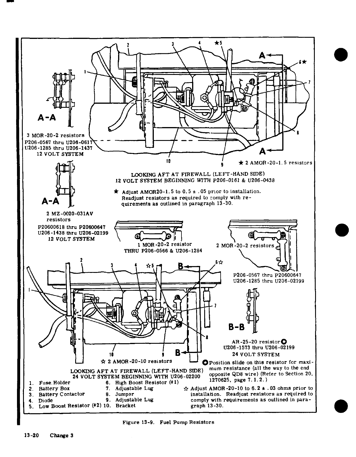
A-A
3 MOR-20-2
resistors
1
P206-0567
thru
U206-061\
12
VOLT
SYSTEM
A
-
*
2
AMOR-20-1.5
resistors
LOOKING
AFT
AT
FIREWALL
(LEFT-HAND
SIDE)
12
VOLT
SYSTEM
BEGINNING
WITH
P206-0161
&
U206-0438
*
Adjust
AMOR20-1.5
to
0.5
*
.05
prior
to
installation.
A-A
Readjust
resistors
as
required
to
comply
with
re-
quirements as
outlined
in
paragraph
13-30.
2
MZ-0020-031AV
resistors
P20600618
thru
P20600647
U206-1438
thru
U206-02199
12
VOLT
SYSTEM
1 MOR-20-2
resistor
2
MOR-20-2
resistors
THRU
P206-0566
&
U206-1284
2
P206-0567
thru
P20600647
---
U206-1285
thru
U206-02199
B-B
AR-25-20
resistor
U206-1573
thru
U206-02199
10
B
24
VOLT
SYSTEM
_
*
2
AMOR-20-10
resistors
Position
slide
on
this
resistor
for
maxi-
LOOKING
AFT
AT
FIREWALL
(LEFT-HAND
SIDE)
mum
resistance
(all
the
way
to
the
end
24
VOLT SYSTEM
BEGINNING
WITH
U206-02200
opposite
QD8
wire)
(Refer
to Section
20.
1.
Fuse
Holder
6.
High
Boost
Resistor
(#1)
1270625,
page
7.1.2.)
2.
Battery
Box
7.
Adjustable
Lug
*
Adjust
AMOR-20-10
to
6.2
*
.03
ohms
prior
to
3.
Battery
Contactor
8.
Jumper
installation.
Readjust
resistors
as
required
to
4.
Diode
9.
Adjustable
Lug
comply
with
requirements
as
outlined
in
para-
5.
Low
Boost
Resistor
(#2)
10.
Bracket graph
13-30.
Figure
13-9.
Fuel Pump
Resistors
13-20
Change
3
SECTION
14
PROPELLERS
AND
PROPELLER
GOVERNORS
TABLE
OF
CONTENTS
Page
PROPELLERS
.
...........
. .
14-1
Trouble
Shooting
.....
...
....
.
14-8
Description
......... 14-1
Removal
....... ...... ..
14-8
Repair
.
...............
14-1
Control
Arm
and
Bearing
Assembly.
14-8
Trouble
Shooting
............
14-2
Removal
and
Installation.
.....
14-8
Removal .14-3
Installation
.......
14-10
Installation
...
......
14-3
High-RPM
Stop
Adjustment
.......
14-10
PROPELLER
GOVERNORS
.........
14-3 Rigging
Propeller
Governor
Control
..
14-10
Description
.............
14-3
14-1.
PROPELLERS.
will
result
in
oil
leaving
the
piston,
thus
decreasing
the blade
pitch.
14-2.
DESCRIPTION.
The
aircraft
is
equipped
with
an
all-metal,
constant-speed,
governor-regu-
14-3.
REPAIR.
Metal
propeller
repair
first
involves
lated
propeller.
The
constant-speed
propeller
is
evaluating
the
damage
and
determining
whether
the
single-
acting,
in
which
engine
oil
pressure,
boosted
repair
will
be
a
major
or
minor
one.
Federal
Avia-
and
regulated
by
the
governor is
used
to
obtain
the
tion
Regulations,
Part
43
(FAR
43),
and
Federal
correct
blade
pitch
for
the
engine
load.
Engine
lub-
Aviation
Agency,
Advisory
Circular
No.
43.
13
(FAA
ricating
oil
is
supplied
to
the
power
piston
in
the
pro-
AC
No.
43.
13),
define
major
and
minor
repairs,
al-
peller
hub
through
the
crankshaft.
The
amount
and
terations
and
who
may
accomplish
them.
When
mak-
pressure
of
the
oil
supplied
is controlled
by
the
engine-
ing
repairs
or
alterations
to
a
propeller
FAR
43,
driven governor.
Increasing
engine speed
will
cause
FAA
AC
No.
43.13
and
the
propeller
manufacturer's
oil
to
be
admitted
to
the
piston,
thereby
increasing
instructions
must
be
observed.
the
blade
pitch.
Conversely,
decreasing
engine
speed
Change
1
14-1
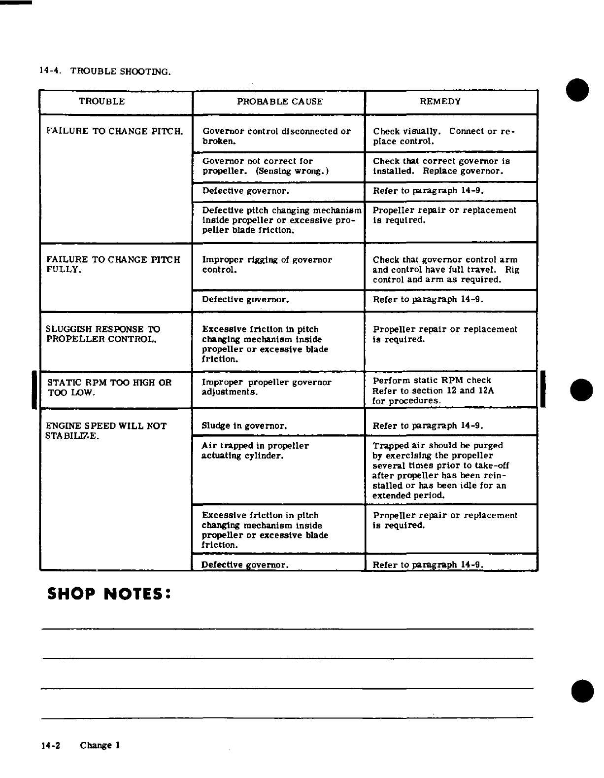
14-4.
TROUBLE
SHOOTING.
TROUBLE
PROBABLE
CAUSE
REMEDY
FAILURE
TO
CHANGE
PITCH.
Governor control disconnected
or
Check
visually.
Connect
or
re-
broken.
place
control.
Governor
not
correct
for
Check
that
correct
governor
is
propeller.
(Sensing
wrong.)
installed.
Replace
governor.
Defective
governor.
Refer
to
paragraph
14-9.
Defective
pitch
changing
mechanism
Propeller
repair
or
replacement
inside
propeller
or
excessive pro-
is
required.
peller
blade
friction.
FAILURE
TO
CHANGE
PITCH
Improper
rigging
of
governor
Check that
governor
control
arm
FULLY.
control.
and
control
have
full
travel.
Rig
control
and
arm
as
required.
Defective
governor. Refer
to
paragraph
14-9.
SLUGGISH
RESPONSE
TO
Excessive friction
in
pitch
Propeller
repair
or
replacement
PROPELLER
CONTROL.
changing
mechanism
inside
is
required.
propeller
or
excessive
blade
friction.
STATIC
RPM
TOO
HIGH
OR
Improper
propeller
governor
Perform
static
RPM
check
TOO
LOW.
adjustments.
Refer
to
section
12
and
12A
for
procedures.
ENGINE
SPEED
WILL
NOT
Sludge
in
governor.
Refer
to
paragraph
14-9.
STABILIZE.
Air
trapped
in
propeller
Trapped
air
should
be
purged
actuating
cylinder.
by
exercising
the
propeller
several
times
prior
to
take-off
after
propeller
has
been
rein-
stalled
or
has
been
idle
for
an
extended
period.
Excessive
friction
in
pitch
Propeller
repair
or
replacement
changing
mechanism
inside
is
required.
propeller
or
excessive
blade
friction.
Defective
governor.
Refer
to
paragraph
14-9.
SHOP
NOTES:
14-2
Change
1
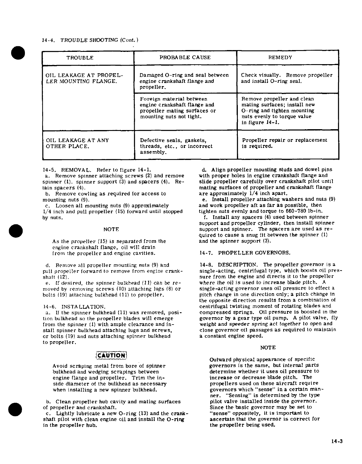
14-4.
TROUBLE
SHOOTING
(Cont.)
TROUBLE PROBABLE
CAUSE REMEDY
OIL
LEAKAGE
AT
PROPEL-
Damaged
O-ring
and
seal
between Check
visually.
Remove
propeller
LER
MOUNTING
FLANGE.
engine
crankshaft
flange
and and
install O-ring
seal.
propeller.
Foreign
material
between
Remove
propeller
and
clean
engine
crankshaft
flange
and
mating
surfaces; install
new
propeller
mating
surfaces
or
O-ring
and
tighten
mounting
mounting
nuts
not
tight.
nuts
evenly
to
torque
value
in
figure
14-1.
OIL
LEAKAGE
AT
ANY
Defective
seals,
gaskets,
Propeller repair
or
replacement
OTHER
PLACE.
threads,
etc.,
or
incorrect
is
required.
assembly.
14-5.
REMOVAL.
Refer
to
figure
14-1.
d.
Align
propeller
mounting
studs
and
dowel
pins
a.
Remove
spinner
attaching
screws
(2)
and
remove
with
proper
holes
in
engine
crankshaft
flange and
spinner
(1).
spinner support
(3)
and
spacers
(4).
Re-
slide
propeller
carefully
over
crankshaft
pilot
until
tain spacers
(4).
mating
surfaces
of
propeller
and
crankshaft
flange
b.
Remove
cowling
as required
for
access
to
are
approximately
1/4
inch
apart.
mounting
nuts
(9).
e.
Install
propeller
attaching
washers
and
nuts
(9)
c.
Loosen
all
mounting
nuts
(9)
approximately
and
work
propeller
aft
as
far
as
possible,
then
1/4
inch
and
pull
propeller
(15)
forward
until
stopped
tighten
nuts
evenly and
torque
to
660-780
lb-in.
by
nuts.
f.
Install
any
spacers
(4)
used
between
spinner
support
and
propeller
cylinder,
then
install
spinner
NOTE
support
and
spinner.
The
spacers
are
used
as
re-
quired
to
cause
a
snug
fit
between
the
spinner
(1)
As
the
propeller
(15)
is
separated
from
the
and
the
spinner
support
(3).
engine
crankshaft
flange,
oil
will
drain
from
the
propeller
and
engine
cavities.
14-7.
PROPELLER
GOVERNORS.
d.
Remove
all
propeller
mounting
nuts
(9)
and
14-8.
DESCRIPTION.
The
propeller
governor
is
a
pull
propeller
forward
to
remove
from
engine
crank-
single-acting,
centrifugal
type, which
boosts
oil
pres-
shaft
(12).
sure
from
the
engine
and
directs
it
to
the
propeller
e.
If
desired,
the
spinner
bulkhead
(11)
can
be
re-
where
the
oil
is
used
to
increase
blade
pitch.
A
moved
by
removing
screws
(10)
attaching
lugs
(8)
or
single-acting
governor uses
oil
pressure
to
effect
a
bolts
(19)
attaching
bulkhead
(11)
to
propeller.
pitch
change
in
one
direction
only;
a
pitch
change
in
the
opposite
direction
results
from
a
combination
of
14-6.
INSTALLATION.
centrifugal
twisting
moment
of
rotating
blades
and
a.
If
the
spinner
bulkhead
(11)
was
removed,
posi-
compressed
springs.
Oil
pressure
is
boosted
in
the
tion
bulkhead
so
the
propeller
blades
will
emerge governor
by
a
gear
type
oil
pump.
A
pilot
valve,
fly
from
the
spinner
(1)
with
ample
clearance
and in- weight
and
speeder
spring
act
together
to
open
and
stall
spinner
bulkhead
attaching
lugs
and
screws,
close
governor
oil
passages
as
required
to
maintain
or bolts
(19)
and
nuts
attaching spinner
bulkhead
a
constant
engine
speed.
to
propeller.
NOTE
CAUTION
Outward
physical appearance
of
specific
Avoid
scraping
metal
from
bore
of
spinner
governors
is
the
same,
but
internal
parts
bulkhead
and
wedging
scrapings
between
determine
whether
it
uses
oil
pressure
to
engine
flange
and
propeller.
Trim
the
in-
increase
or decrease
blade
pitch.
The
side
diameter
of
the
bulkhead
as necessary
propellers
used
on
these
aircraft
require
when
installing
a
new
spinner
bulkhead.
governors
which
"sense"
in
a
certain
man-
ner.
"Sensing"
is determined
by
the
type
b.
Clean
propeller
hub
cavity
and
mating
surfaces
pilot
valve
installed
inside
the
governor.
of
propeller
and
crankshaft.
Since
the
basic governor
may
be
set
to
c.
Lightly
lubricate
a
new
O-ring
(13)
and
the
crank-
"sense"
oppositely,
it
is
important
to
shaft
pilot
with
clean
engine
oil
and
install
the
O-ring
ascertain
that
the
governor
is
correct
for
in
the
propeller
hub.
the
propeller
being
used.
14-3
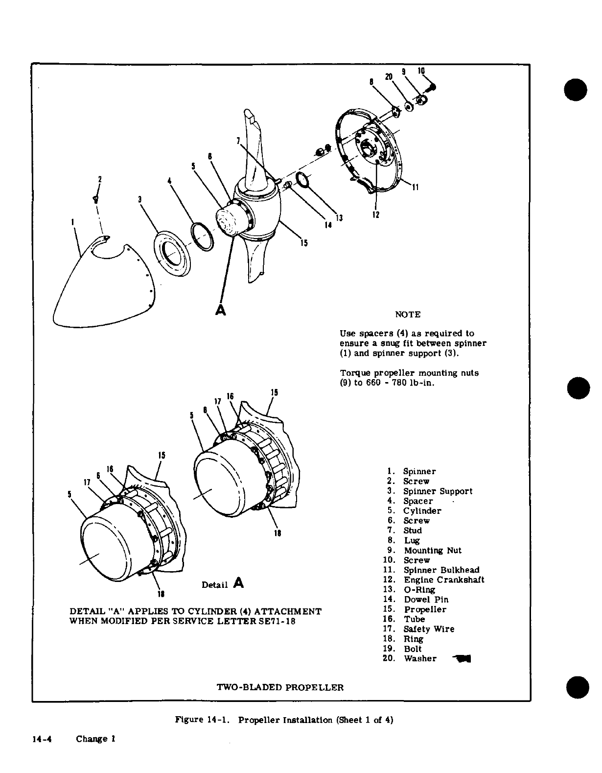
NOTE
Use
spacers
(4)
as
required
to
ensure
a
snug
fit
between
spinner
(1)
and
spinner support
(3).
Torque
propeller
mounting
nuts
(9)
to
660
-
780
lb-in.
1. Spinner
2.
Screw
3.
Spinner
Support
4.
Spacer
5.
Cylinder
6.
Screw
7.
Stud
8.
Lug
9.
Mounting
Nut
10.
Screw
11.
Spinner
Bulkhead
12.
Engine
Crankshaft
13.
O-Ring
14.
Dowel
Pin
15.
Propeller
16.
Tube
17.
Safety
Wire
18.
Ring
19.
Bolt
20.
Washer
TWO-BLADED
PROPELLER
Figure
14-1.
Propeller
Installation
(Sheet
1
of
4)
14-4 Change 1
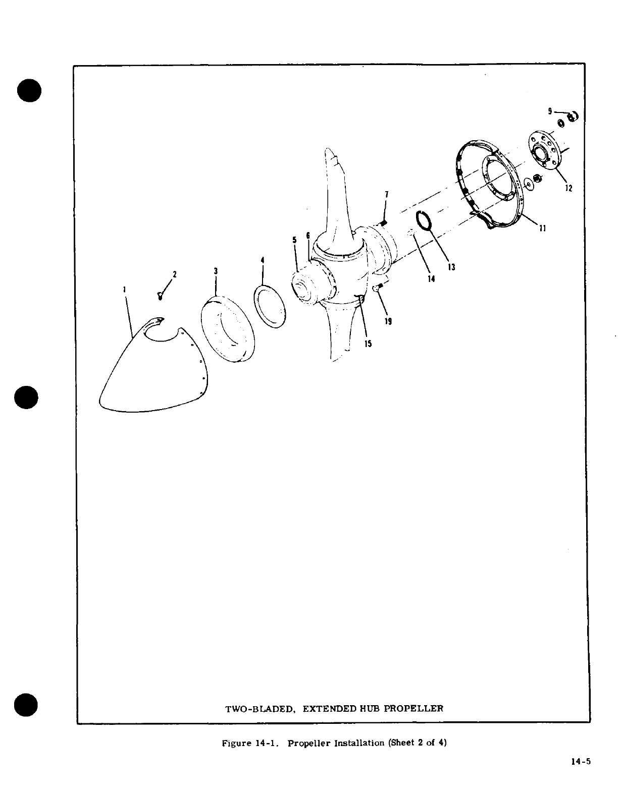
12
TWO-BLADED,
EXTENDED
HUB
PROPELLER
Figure
14-1.
Propeller
Installation
(Sheet
2
of
4)
14-5
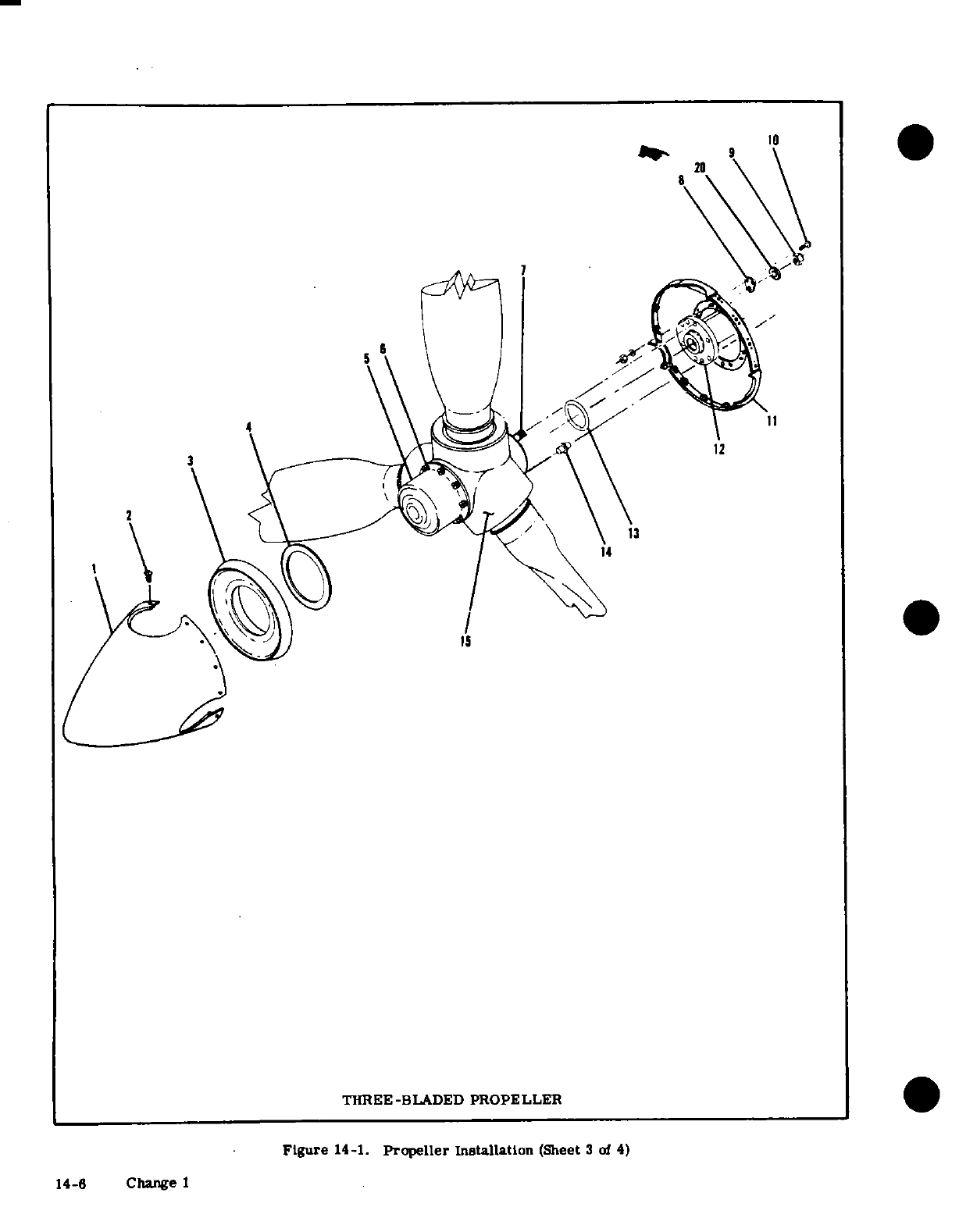
14-6
Change
I
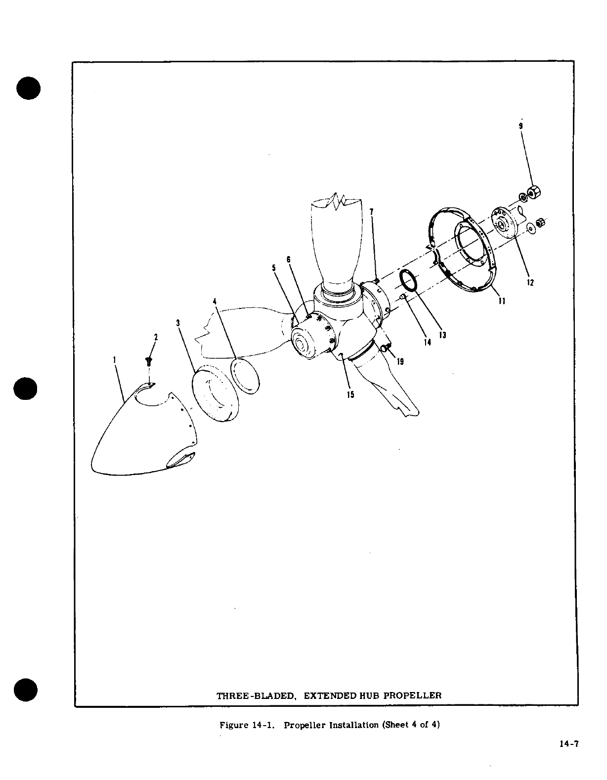
THREE-BLADED,
EXTENDED
HUB
PROPELLER
Figure
14-1.
Propeller
Installation
(Sheet
4
of
4)
14-7
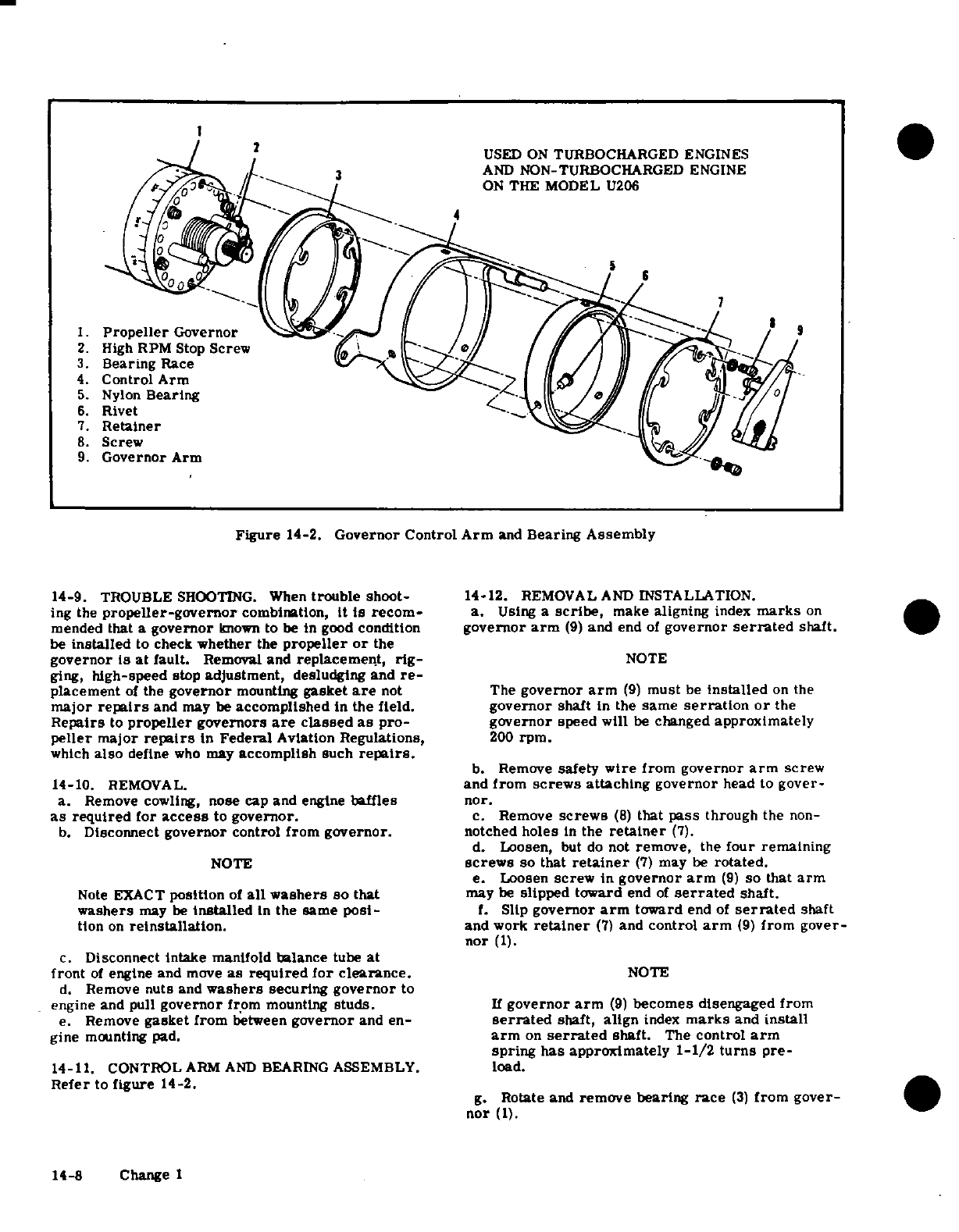
1
2 USED
ON
TURBOCHARGED
ENGINES
3
AND
NON-TURBOCHARGED
ENGINE
5Q
/ON
THE
MODEL
U206
2.
High
RPM
Stop
Screw
J
3.
Bearing
Race
4.
Control
Arm
5.
Nylon
Bearing
/ l I
AT'-V//
6.
Rivet
7.
Retainer
8.
Screw
9.
Governor
Arm
Figure
14-2.
Governor
Control
Arm
and
Bearing
Assembly
14-9. TROUBLE
SHOOTING.
When
trouble
shoot-
14-12.
REMOVAL
AND
INSTALLATION.
ing
the
propeller-governor
combination,
it
is
recom-
a.
Using
a
scribe,
make
aligning
index
marks
on
mended
that
a
governor
known
to
be
in
good
condition
governor
arm
(9)
and
end
of
governor
serrated
shaft.
be
installed
to
check
whether
the
propeller
or
the
governor
is
at
fault.
Removal
and
replacement, rig-
NOTE
ging,
high-speed
stop
adjustment,
desludging
and
re-
placement
of
the
governor
mounting
gasket
are
not The
governor
arm
(9)
must
be
installed
on
the
major
repairs
and
may
be
accomplished
in
the
field.
governor
shaft
in
the
same
serration
or
the
Repairs
to
propeller
governors
are
classed
as
pro-
governor
speed
will
be
changed
approximately
peller
major
repairs
in
Federal
Aviation
Regulations,
200
rpm.
which
also
define
who
may
accomplish
such
repairs.
b.
Remove
safety
wire
from
governor
arm screw
14-10.
REMOVAL.
and
from
screws
attaching
governor
head to
gover-
a.
Remove cowling,
nose
cap
and
engine
baffles nor.
as
required
for
access
to
governor.
c.
Remove
screws
(8)
that
pass
through
the
non-
b.
Disconnect
governor
control
from governor.
notched
holes
in
the
retainer
(7).
d.
Loosen,
but
do
not
remove,
the
four
remaining
NOTE
screws
so that
retainer
(7)
may
be
rotated.
e.
Loosen
screw
in
governor
arm
(9) so
that
arm
Note
EXACT
position
of
all
washers
so
that
may
be
slipped toward
end
of
serrated
shaft.
washers
may
be
installed
in
the
same
posi-
f.
Slip
governor
arm
toward
end
of
serrated
shaft
tion
on
reinstallation.
and
work
retainer
(7)
and
control
arm
(9)
from gover-
nor
(1).
c.
Disconnect
intake
manifold
balance
tube
at
front
of
engine and
move
as
required
for
clearance.
NOTE
d.
Remove
nuts
and
washers
securing governor
to
engine
and pull
governor
from
mounting
studs.
If
governor
arm
(9)
becomes
disengaged
from
e.
Remove
gasket
from
between
governor
and
en-
serrated
shaft,
align
index
marks
and
install
gine
mounting pad.
arm
on
serrated
shaft.
The
control
arm
spring
has approximately
1-1/2
turns
pre-
14-11.
CONTROL
ARM
AND
BEARING
ASSEMBLY.
load.
Refer
to
figure
14-2.
g.
Rotate
and
remove bearing
race
(3)
from
gover-
nor
(1).
14-8 Change I
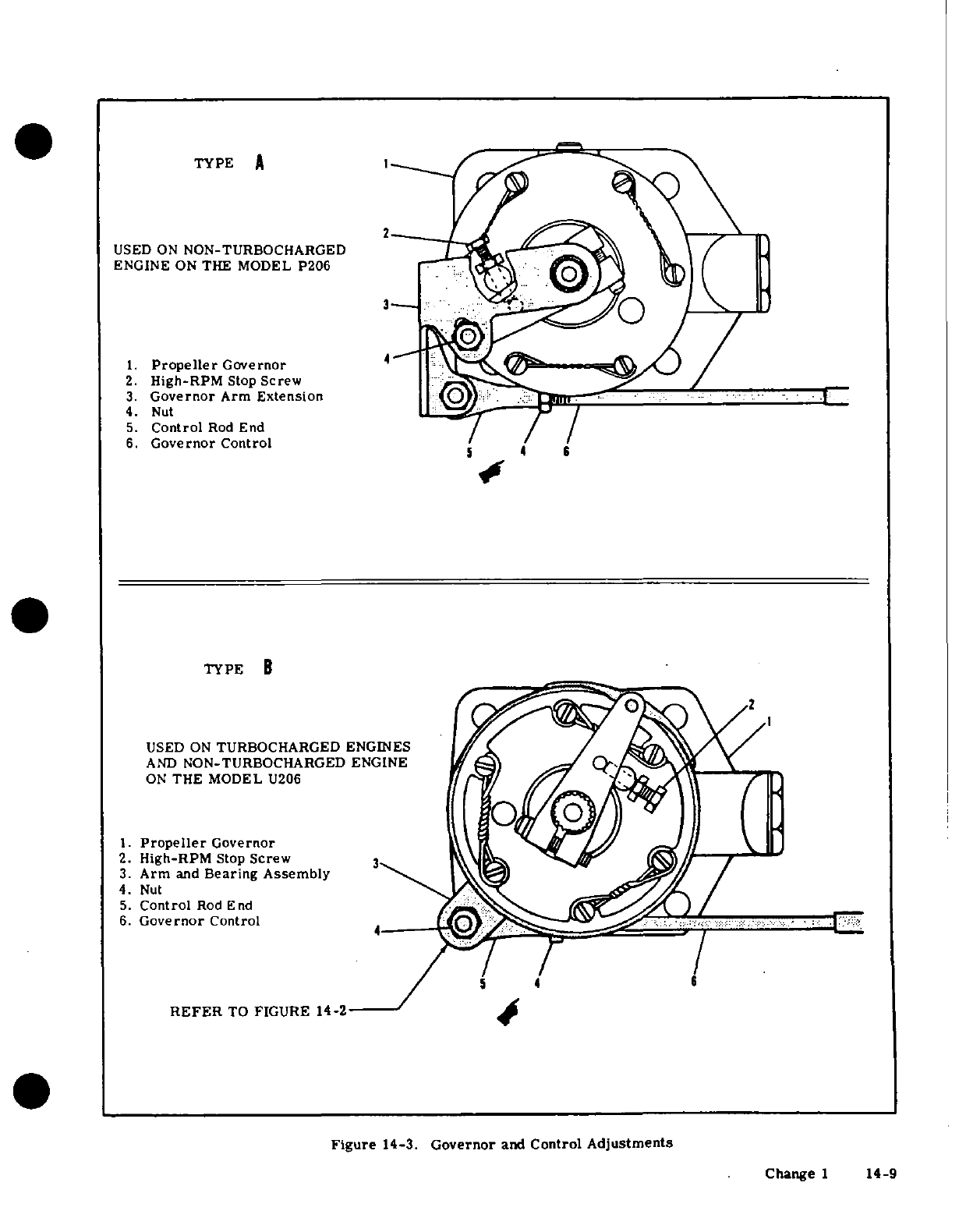
TYPE
A
1
USED
ON
NON-TURBOCHARGED
ENGINE
ON
THE MODEL
P206
1.
Propeller
Governor
2.
High-RPM
Stop
Screw
3.
Governor
Arm
Extension
4.
Nut
5.
Control
Rod
End
6.
Governor
Control
TYPE
B
USED
ON
TURBOCHARGED
ENGINES
AND
NON-TURBOCHARGED
ENGINE
ON
THE
MODEL
U206
1.
Propeller
Governor
2.
High-RPM
Stop
Screw
3
3.
Arm
and
Bearing Assembly
4.
Nut
5.
Control
Rod
End
6.
Governor
Control
5
4
REFER
TO
FIGURE
14-2
Figure
14-3.
Governor
and
Control
Adjustments
Change
1
14-9
h.
Reverse
the
preceding
steps
for
reinstallation.
the
high-rpm
at
the
maximum
rated
rpm
for
a
particular
aircraft.
Due
to
climatic
condi-
14-13.
INSTALLATION.
tions,
field
elevation,
low-pitch
blade
angle
a.
Wipe
governor
and
engine
mounting pad
clean.
and
other
considerations,
an
engine
may
not
b.
Install
a
new
gasket
on
the
mounting
studs.
In-
reach
rated
rpm
on
the
ground.
It
may
be
stall
gasket
with
raised
surface
of
the
gasket
screen necessary
to
readjust
the
governor
stop
after
toward
the
governor.
test
flying
to
obtain
maximum
rated
rpm
when
c.
Position
governor
on
mounting
studs,
aligning
airborne.
governor drive
splines
with
splines
in
the
engine and
install
mounting
nuts
and
washers.
Do
not
force
14-15.
RIGGING
PROPELLER
GOVERNOR
CON-
spline
engagement.
Rotate
engine
crankshaft
slightly
TROL.
and
splines
will
engage
smoothly
when
properly
a.
Disconnect
control
end
(5)
from
governor
(1).
aligned.
b.
Place
propeller
control
in
cabin,
full
forward,
d.
Connect
governor
control
to
governor
and
rig
then pull
it
back
approximately
1/8
inch
and lock
in
control as
outlined
in
paragraph
14-15.
this
position.
This
will allow
"cushion"
to
assure
e.
Connect
intake manifold
balance
tube,
if
removed,
full contact
with
governor high-rpm
stop
screw.
Ensure
all
clamps
are
tight.
c.
Place
governor
arm
against
high-rpm
stop
f.
Reinstall
all
items
removed
for
access.
screw.
d.
Loosen
jam nuts
and
adjust
control
rod
end
14-14.
HIGH-RPM
STOP
ADJUSTMENT.
Refer
to
until attaching
holes
align
while
governor
arm
is
figure
14-3.
against
high-rpm
stop
screw.
Be
sure
to
maintain
a.
Remove engine
cowling.
sufficient
thread
engagement
of
the
control
and
rod
b.
(TYPE
B.)
Disconnect
cabin
heater
inlet
air
end.
If
necessary,
shift
control
in
the
clamps
to
duct
from
nose
cap.
achieve
this.
c.
(TYPE
A.)
Remove
plug
button
from
left front
e.
Attach
rod
end to
the
governor.
Be
sure
all
baffle.
washers
are
installed
correctly.
d.
Remove
safety
wire
and
loosen
the
high-speed
f.
Operate
the
control
to
see
that
the
governor
arm
stop
screw
locknut.
bottoms
out
against
the
low
pitch
stop
and
bottoms
e.
Turn
the stop
screw
IN
to
decrease
maximum
out
against
or
a maximum
of
.
12"
from
the
high
pitch
rpm
and
OUT to
increase
maximum
rpm.
One
full
stop
on
the
governor
before
reaching
the
end
of
con-
turn
of
the
stop
screw
causes
a
change
of
approxi-
trol
cable
travel.
mately
25
rpm.
f.
Tighten stop
screw
locknut,
safety
wire
stop
NOTE
screw
and
make
propeller
control
linkage
adjustment
as
necessary
to
maintain
full
travel.
Non-turbocharged
engines
on
the
Model
P206
g.
Install
cabin
heater
inlet
air
duct
or
plug
button
are
equipped
with
an
offset
extension
to
the
and
install
cowling.
governor
arm.
The
offset
extension
has
an
h.
Test
operate
propeller
and
governor.
elongated
slot
to
permit
further
adjustment.
The
preceding
steps
may
still
be
used
as
an
NOTE
outline
in
the
rigging
procedure.
The
result
of
rigging,
in
all
cases,
is
full
travel
of
the
It
is
possible
for
either
the
propeller
low
governor
arm
(bottom
out
against
both
high
pitch
(high-rpm)
stop
or
the
governor
high-
and
low
pitch
stops)
with
some
"cushion"
at
rpm
stop
to
be
the
high-rpm limiting
factor.
both
ends
of
control
travel.
It
is
desirable
for
the
governor
stop
to
limit
*
Refer
to
the
inspection
chart
in
Section
2
for inspection
and/or
replacement
inter-
val
for
the
propeller
control.
SHOP
NOTES:
14-10
Change 1
SECTION
15
UTILITY
SYSTEMS
TABLE
OF
CONTENTS
Page
UTILITY
SYSTEMS
............
15-1
Description
............
15-5
Heating
System
............
15-1
Maintenance
Precautions
.......
15-6
Description
............
-15-1
Replacement
of
Components
15-6
Operation
.............
15-1
Oxygen
Cylinder
General
Trouble
Shooting
.........
15-1
Information
.....
15-6
Removal
and
Installation
of
Oxygen
Cylinder
Service
Components
....... .....
15-3
Requirements
......
.
15-10
Defroster
System
..
.........
15-3
Oxygen
Cylinder
Inspection
Description
......
15-3
Requirements
.. .. ...
15-10
Operation
.............
15-3
Oxygen
System
Component
Trouble
Shooting
.
.....
15-3
Service Requirements
.15-10
Removal
and
Installation
of
Oxygen
System
Component
Components
...........
15-3
Inspection
Requirements
...
15-10
Ventilating
System
...........
15-3
Masks
and
Hose
....
.
15-10
Description
.
........
.
15-3
Maintenance
and
Cleaning
....
15-10
Operation
... . .. .. .... .
15-3
System
Purging
... . . ... .
15-11
Trouble
Shooting
..........
15-3
Functional
Testing
.....
15-11
Removal
and
Installation
of
System
Leak
Test
.........
.
15-11
Components
.........
......
15-3
System Charging
.........
.
15-11
Oxygen
System
............
.. .
15-3
15-1.
UTILITY
SYSTEMS.
control
marked
"CABIN
HEAT",
located
on
the
in-
strument
panel,
regulates
the
volume
of
heated
air
15-2.
HEATING
SYSTEM.
entering
the
system.
Pulling
the
heater
control
full
out
supplies
maximum
flow,
and
pushing
it
in
grad-
15-3.
DESCRIPTION.
On
non-turbocharged
air-
ually
decreases
flow,
shutting
off
flow
completely
craft.
the
heating
system
is
comprised
of
the
heat
when
the
control
is
pushed
full
in.
exchange
section
of
the left
exhaust
muffler,
a
heat-
er
valve. mounted
on
the
left
forward
side
if
the
15-5. TROUBLE
SHOOTING.
Most
of
the
opera-
firewall,
a
duct
across
the
aft
side
of
the
firewall, tional
troubles
in
the heating
system
are
caused
by
a
push-pull
control
up
the
instrument
panel,
and flex-
sticking
or
binding
air
valves
and
their
controls,
ible
ducts
connecting
the
system.
On
aircraft
with
damaged
air
ducting,
or
defects
in
the
exhaust
muff-
turbocharged
engines,
the
heating
system
consists
of
ler.
In
most
cases,
valves
or
controls
can
be
freed
an
opening
in
the left
side
of
the nose
cap,
an
exhaust
by
proper
lubrication.
Damaged
or
broken
parts
shroud,
a
heater
valve, mounted
on
the
left
forward
should
be
repaired
or
replaced.
When
checking
con-
side
of
the
firewall,
to
which
is
attached
an
adapter
trols,
be
sure
valves
respond
freely
to
control
move-
and
a
tube
extending
downward
and
overboard.
The
ment,
that
they
move
in
the
correct
direction,
and
system
also
includes
a
duct
across
the
aft
side
of
the
that
they
move
through
their
full
range
of
travel
and
firewall,
a
push-pull
control
on
the
instrument
panel,
seal
properly.
Check that
hose
are
properly
secured
and
flexible
ducts
connecting
the
system.
and
replace
hose
that
are
burned,
frayed
or
crushed.
If
fumes
are
detected
in
the
cabin,
a
very
thorough
15-4. HEATER OPERATION.
On
airplanes
with
inspection
of
the
exhaust
muffler
should
be
accom-
non-turbocharged
engines,
ram
air
is ducted
through
plished.
Refer
to
the
applicable
paragraph
in
Section
an
engine
baffle
and
the
heat
exchange
section
of
the
12
for
the
non-turbocharged
engine
exhaust
system
left
exhaust
muffler,
to
the
heater
valve
at
the
fire- inspection, or
for
the
turbocharged
engine,
refer
to
wall.
On
aircraft
with
turbocharged
engines, ram
Section
12A.
Since
any
holes
or cracks
may
permit
air
is
ducted
through
an opening
in
the
left
side
of
the
exhaust
fumes
to
enter
the
cabin,
replacement
of
de-
nose
cap,
through
an
exhaust shroud,
to
the
heater
fective
parts
is
imperative because
fumes
constitute
valve at
the
firewall.
On
both
models, heated
air
an
extreme
danger.
Seal
any
gaps
in
heater
ducts
flows
from
the
heater
valve
into
a
duct
across
the
aft
across
the
firewall
with
Pro-Seal
#700
(Coast
Pro-
side
of
the
firewall,
where
it
is
distributed
into the
Seal
Co.,
Los
Angeles,
California)
compound,
or
cabin.
The
heater
valve,
operated
by
a
push-pull
equivalent
compound.
15-1
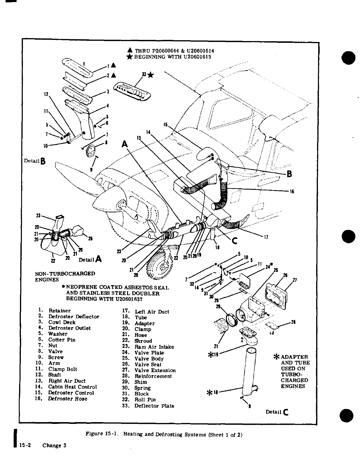
THRU
P20600644
&
U20601614
*BEGINNING
WITH
U20601615
12
2A
3*
-....
.......
"
. . ...
v I· -........
D'
'
...... ::...
. . '
:
:::-.
..
7 \,g
14\\f
'
A
DetailB
i»
212
>
NON-TURBOCHARGED
20
\\
;'S a
/
26
*NEOPRENE
COATED ASBESTOS
SEAL
*/
/2
AND
STAINLESS
STEEL
DOUBLER
31
BEGINNING
WITH U20601637
29
/N
1.
Retainer
17.
Left
Air
Duct
2.
Defroster
Deflector
18.
Tube
;-
3.
Cowl
Deck
19.
Adapter
'<.21
4.
Defroster
Outlet
20.
Clamp
5.
Washer
21.
Hose
i
6.
Cotter
Pin
22.
Shroud
7.
Nut
23.
Ram
Air
Intake 21
8.
Valve
24.
Valve
Plate
*19
*
ADAPTER
9. Screw
25.
Valve
Body
*
ADAPTER
10.
Arm
26.
Valve
Seat
AND
TBE
11.
Clamp
Bolt
27.
Valve
Extension
USED
ON
12.
Shaft
28.
Reinforcement
TURBO-
13.
Right
Air
Duct
29.
Shim
CHARGED
14.
Cabin
Heat
Control
30.
Spring
_
3.
ENGINES
15.
Defroster
Control
31.
Block
s
16.
Defroster
Hose
32.
Roll
Pin
33.
Deflector Plate
9
Detail
C
Figure
15-1.
Heating and
Defrosting Systems
(Sheet
I
of
2)
15-2
Change
3
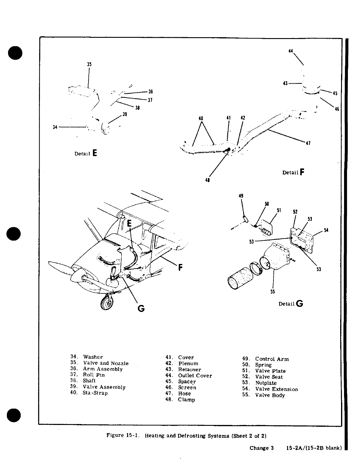
44
38
46
39
40
41
42
Detail
F
48
49
/
51
52
- 54
Detail
G
34.
Washer
41.
Cover
49.
ControlArm
35.
Valve
and
Nozzle
42.
Plenum
50.
Spring
36.
Arm
Assembly
43.
Retainer
51.
Valve
Plate
37.
Roll
Pin
44.
Outlet
Cover
52.
Valve
Seat
38.
Shaft
45.
Spacer
53.
Nutplate
39.
Valve
Assembly
46.
Screen
54.
Valve
Extension
40.
Sta-Strap
47.
Hose
55.
Valve
Body
48.
Clamp
Figure
15-1.
Heating
and
Defrosting
Systems
(Sheet
2
of
2)
Change
3
15-2A/(15-2B
blank)
15-6. REMOVAL
AND
INSTALLATION
OF
COM-
inboard
leading
edges
of
the
wings.
Each
plenum
PONENTS.
Figure
15-1
may
be
used
as
a
guide
for
chamber
is
equipped
with
a
valve
which
meters
the
removal
and
installation
of
components
of
the
heater
incoming
cabin
ventilation
air.
This
provides
a
system.
Cut
replacement
hose
to
length
and
install
chamber
for
the
expansion
of
cabin
air
which
greatly
in
the
original
routing.
Trim
hose
winding
shorter
reduces
inlet
air
noise.
Filters
at
the
air
inlets
are
than
the
hose
to
allow
hose
clamps
to
be
fitted.
De-
primarily
noise
reduction
filters.
Forward
cabin
fective
heater
valves
should
be
repaired
or
replaced.
ventilation
is
provided
by
two
fresh
airscoop
doors,
Check
for
proper operation
of
valves
and
their
con-
one
on
each
side
of
the
fuselage,
just forward
of
the
trols
after
installation
or
repair.
front
seats.
The
left
scoop
door
is
operated
by
a
control
in
the
instrument
panel
marked
"CABIN
AIR.
"
15-7.
DEFROSTER
SYSTEM.
and
the
right
scoop
door
is
operated
by
a
control
in
the
instrument
panel
marked
"AUX
CABIN
AIR.
"
15-8.
DESCRIPTION. The
system
is
composed
of
Fresh air
from
the scoop
doors is
routed
to
the
duct
a
duct
across
the
aft
side
of
the
firewall,
a
defroster
across
the
aft
side
of
the
firewall,
where
it
is
dis-
outlet,
mounted
in
the left
side
of
the
cowl
deck
im-
tributed
into
the
cabin.
As
long
as
the
"CABIN
mediately
aft
of
the
windshield,
a
defroster
control
HEAT"
control
is
pushed
full
in,
no
heated
air
can
knob
on
the
instrument
panel, and
flexible
ducting
enter
the
firewall
duct;
therefore,
when
the
"CABIN
connecting
the
system.
AIR"
or
"AUX
CABIN
AIR"
controls
are
pulled
out,
only
fresh
air
from
the
scoops
will
flow
through
the
15-9.
DEFROSTER
OPERATION.
Air
from
the
duct duct
into
the
cabin.
As
the
"CABIN HEAT"
control
across
the
aft
side
of
the
firewall
flows through
a
is
gradually
pulled
out,
more
and
more
heated
air
flexible
duct
to
the
defroster
outlet.
The
defroster
will
blend
with
the
fresh
air
from
the
scoops
and
be
control
operates
a
damper
in
the
outlet
to
regulate
distributed
into the
cabin.
All
of
the
controls
may
the
amount
of
air
deflected
across
the
inside
surface
be
set
at
any
position
from
full
open
to
full
closed.
of
the
windshield.
The
temperature
and
volume
of
this
air
is
controlled
by
the
settings
of
the
cabin
15-15.
TROUBLE
SHOOTING.
Most
of
the
opera-
heating
system
ontrol.
tional
troubles
in
the
ventilating
system
are
caused
by
sticking
or
binding
of
the
lever
in
the
inlet
scoop
15-10. TROUBLE
SHOOTING.
Most
of
the
opera-
door
or its
control.
The
spring
or
plate
in
the ple-
tional
troubles
in
the
defrosting
system
are
caused
num
chambers
could
also
bind
or
stick,
requiring
by
sticking
or
binding
of
the
damper
in
the
defroster
repair
or
replacement
of
the
plenum
chamber.
outlet or
its
control.
Since
the
defrosting
system
Check
the
filter
elements
in
the
airscoops
in
the
depends
on
proper operation
of
the
cabin
heating
sys-
leading
edges
of
the wings
for
obstructions.
The
tem.
refer
to
paaragraph 15-5
for
trouble
shooting
the
elements
may
be
removed
and
cleaned
or
replaced.
heating
and
defrosting
system.
Since
air
passing
through
the
filters
is
emitted
into
the
cabin,
do
not
use
a
cleaning
solution
which
would
15-11. REMOVAL
AND
INSTALLATION
OF
COM-
contaminate
cabin
air.
The
filters
may
be
removed
PONENTS.
Figure
15-1
may
be
used
as
a
guide
for
to
increase
air
flow.
However,
their
removal
will
removal
and
installation
of
components
of
the
de-
cause
a
slight
increase
in
noise
level.
frosting
system.
Cut
replacement
hose
to
length
and
install
in
the
original
routing.
Trim
hose
winding
15-16.
REMOVAL
AND
INSTALLATION
OF
COM-
shorter
than
the
hose
to
allow hose
clamps
to
be
fit-
PONENTS.
Figure
15-2
may
be
used
as
a
guide
for
ted.
A
detective
defroster
outlet
should
be
repaired
removal
and
installation
of
components
of
the
venti-
or
replaced.
Check
for
proper
operation
of
defroster
lating
system.
Cut
replacement
hose
to
length
and
outlet
and
its
control
after
installation
or
repair.
install
in
the
original
routing.
Trim
hose
winding
shorter
than the
hose
to
allow
hose
clamps
to
be
fit-
15-12.
VENTILATING
SYSTEM.
ted.
A
defective
plenum
chamber
should
be
repaired
or
replaced.
Check
for
proper
operation
of
ventila-
15-13.
DESCRIPTION.
The
system
is comprised
of
ting
controls
after
installation
or
repair.
two
airscoops
mounted
in
the
inboard
leading
edge
of
each
wing,
an
adjustable
ventilator
mounted
on
each
15-17.
OXYGEN
SYSTEM.
side
of
the
cabin
near
the
upper
corners
of
the
wind-
shield,
two
plenum
chambers
mounted
in
the
left
and
WARNING
right
rear
cabin
wing
root
areas,
two
fresh
airscoop
doors,
one on
each
side
of
the
fuselage,
just
forward
Under
NO
circumstances
should
the
ON-OFF
of
the
front
seats,
a
control
on
the
instrument
panel
control
on
the
oxygen
regulator
be
turned
to
for
each
of
these
scoop
doors
and
flexible
ducting
the
"ON"
position
with
the
outlet
(low
pres-
connecting
the
system.
sure)
ports
open
to
atmosphere.
Operation
of
these
units
in
this
manner
will
induce
15-14. VENTILATING
SYSTEM
OPERATION.
Air
serious
damage
to
the
regulators
and
having
received
from scoops
mounted
in
the
inboard
leading
the
following
results:
edges
of
the
wings
is
ducted
to
adjustable
ventilators
1.
Loss
of
outlet
set
pressure.
mounted
on
each
side
of
the
cabin
near
the
upper
cor-
2.
Loss
of
oxygen
flow
through
the regula-
ners
of
the
windshield.
Rear
seat ventilation
is
pro-
tor
which
will
result
in
inadequate
oxygen
being
fed
vided
by
plenum
chambers
mounted
in
the left
and
through
the
aircraft
system.
right
rear
cabin
wing
root
areas.
These
plenum
3.
Internal
leakage
of
oxygen
through
the
chambers
receive
ram
air
from
the
airscoops
in
the
regulator.
15-3
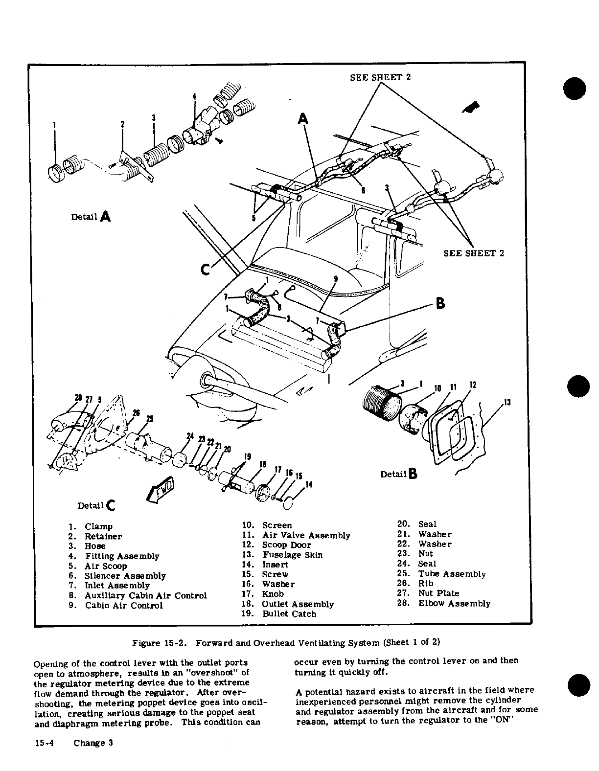
SEE
SHEET
2
DetA
i
4
et
4il
Detail
B
·
<g
~
SEE
SHEET
2
K
I'
la
12
Detail
C
1.
Clamp
10.
Screen
20.
Seal
2.
Retainer
11.
Air
Valve
Assembly
21.
Washer
3.
Hose
12.
Scoop
Door
22.
Washer
4.
Fitting
Assembly
13.
Fuselage
Skin
23.
Nut
5.
Air
Scoop
14.
Insert
24.
Seal
6.
Silencer
Assembly
15.
Screw
25.
Tube
Assembly
7.
Inlet
Assembly
16.
Washer
26.
Rib
8.
Auxiliary
Cabin
Air
Control
17.
Knob
27. Nut
Plate
9.
Cabin
Air
Control
18.
Outlet
Assembly
28.
Elbow
Assembly
19.
Bullet
Catch
Figure
15-2.
Forward
and
Overhead
Ventilating
System
(Sheet
1
of
2)
Opening
of
the
control
lever
with
the outlet
ports
occur
even
by
turning
the
control
lever
on
and
then
open
to
atmosphere,
results
in
an
"overshoot"
of
turning
it
quickly
off.
the
regulator
metering
device
due
to
the
extreme
flow
demand
through
the
regulator.
After
over-
A
potential
hazard
exists
to
aircraft
in
the
field
where
shooting,
the
metering
poppet
device
goes
into
oscil-
inexperienced
personnel
might
remove
the cylinder
lation,
creating
serious
damage
to
the
poppet
seat
and
regulator
assembly
from
the
aircraft
and
for
some
and
diaphragm
metering
probe.
This
condition can
reason,
attempt
to
turn
the
regulator
to
the
"ON"
15-4
Change
3
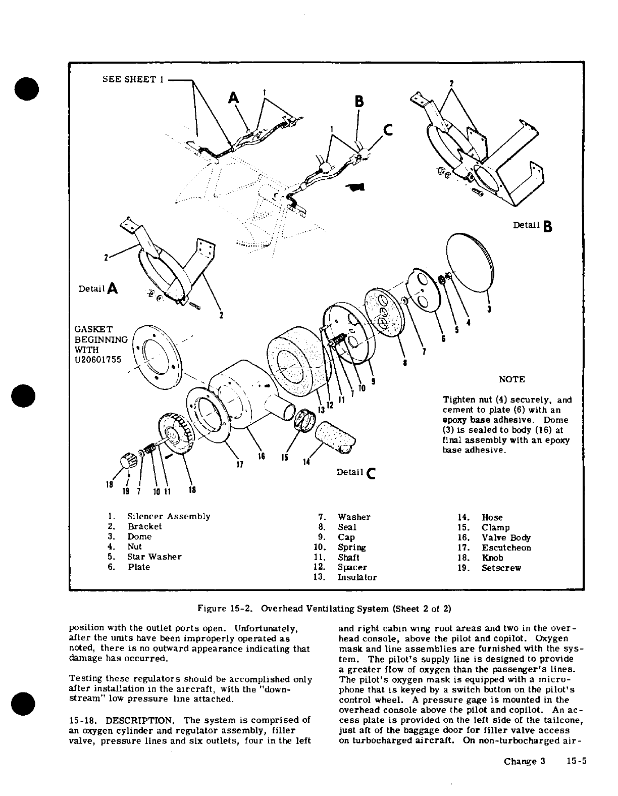
SEE
SHEET
1
Detail
GASKET
BEGINNING
WITH
U20601755
Detail
C
1.
Silencer
Assembly
7.
Washer
14.
Hose
2.
Bracket
8.
Seal
15.
Clamp
3.
Dome
9.
Cap
16.
Valve
Body
4.
Nut
10.
Spring
17.
Escutcheon
5.
Star
Washer
11.
Shaft
18.
Knob
6.
Plate
12.
Spacer
19.
Setscrew
13.
Insulator
Figure
15-2.
Overhead Ventilating
System
(Sheet
2
of
2)
position
with
the
outlet
ports
open.
Unfortunately,
and
right
cabin
wing
root
areas
and
two
in
the
over-
after
the
units
have
been
improperly
operated
as
head
console,
above
the pilot
and
copilot.
Oxygen
noted,
there
is
no
outward
appearance
indicating
that
mask
and
line
assemblies
are
furnished
with
the
sys-
damage
has
occurred.
ter.
The
pilot's
supply
line
is
designed
to
provide
a
greater
flow
of
oxygen
than
the
passenger's
lines.
Testing
these
regulators
should
be
accomplished
only
The
pilot's
oxygen
mask
is
equipped
with
a
micro-
after installation
in
the
aircraft,
with
the
"down- phone
that
is
keyed
by
a
switch
button
on
the
pilot's
stream"
low
pressure
line
attached. control
wheel.
A
pressure
gage
is
mounted
in
the
overhead console
above
the
pilot
and
copilot.
An
ac-
15-18.
DESCRIPTION.
The
system
is
comprised
of
cess
plate
is
provided
on
the
left
side
of
the
tailcone,
an
oxygen
cylinder
and
regulator
assembly,
filler
just
aft
of
the baggage
door
for
filler
valve
access
valve,
pressure
lines
and
six
outlets,
four
in
the
left
on
turbocharged
aircraft.
On
non-turbocharged
air-
Change
3
15-5
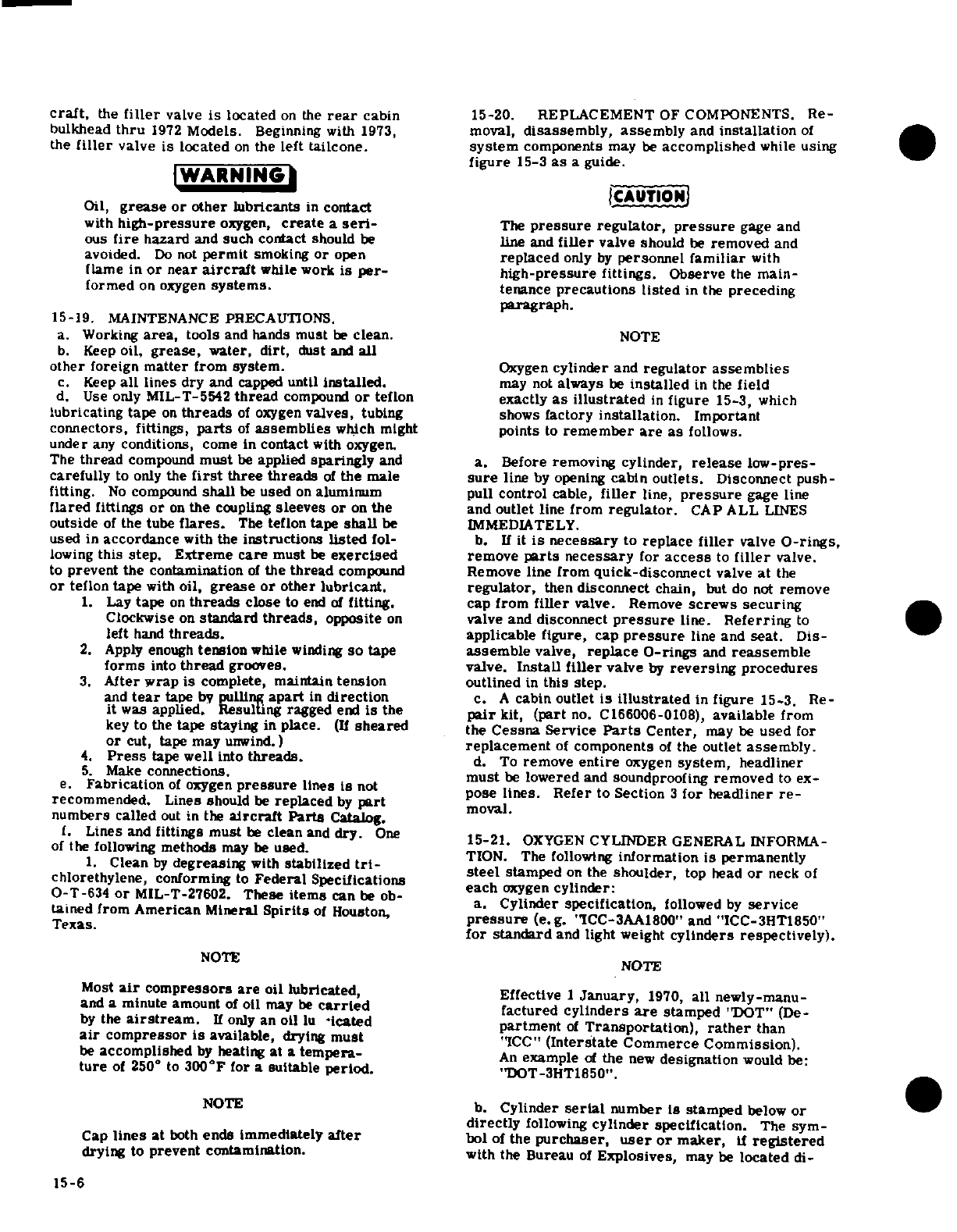
craft,
the
filler
valve
is
located
on
the
rear
cabin
15-20. REPLACEMENT
OF
COMPONENTS.
Re-
bulkhead
thru
1972
Models.
Beginning
with
1973,
moval,
disassembly, assembly
and
installation
of
the
filler
valve
is
located
on
the
left
tailcone.
system
components
may
be
accomplished
while
using
figure
15-3
as
a
guide.
WARNING
Oil,
grease
or
other
lubricants
in
contact
with
high-pressure
oxygen,
create
a
seri-
The
pressure
regulator,
pressure
gage
and
ous
fire
hazard
and such
contact
should
be
line
and
filler
valve
should
be
removed
and
avoided.
Do
not
permit
smoking
or
open
replaced
only
by
personnel
familiar
with
flame in
or
near
aircraft
while
work
is
per- high-pressure
fittings.
Observe
the
main-
formed
on
oxygen
systems.
tenance
precautions
listed
in
the
preceding
paragraph.
15-19.
MAINTENANCE
PRECAUTIONS.
a.
Working
area,
tools
and
hands
must
be
clean.
NOTE
b.
Keep
oil,
grease,
water,
dirt,
dust
and
all
other
foreign
matter
from
system.
Oxygen
cylinder
and
regulator
assemblies
c.
Keep
all
lines
dry
and
capped
until
installed.
may
not
always
be
installed
in
the
field
d.
Use only
MIL-T-5542
thread
compound
or
teflon exactly
as
illustrated
in
figure
15-3,
which
lubricating
tape
on
threads
of
oxygen
valves,
tubing
shows
factory
installation.
Important
connectors, fittings,
parts
of
assemblies
which
might
points
to
remember
are
as
follows.
under
any
conditions,
come
in
contact
with
oxygen.
The
thread
compound
must
be
applied
sparingly
and
a.
Before removing
cylinder,
release
low-pres-
carefully
to
only
the
first
three
threads
of
the
male
sure
line
by
opening
cabin
outlets.
Disconnect
push-
fitting.
No
compound
shall
be
used
on
aluminum
pull
control
cable,
filler
line,
pressure
gage
line
flared
fittings
or
on
the
coupling
sleeves
or
on
the
and
outlet
line
from
regulator.
CAP
ALL
LINES
outside
of
the
tube
flares.
The
teflon
tape
shall
be
IMMEDIATELY.
used
in
accordance
with
the
instructions
listed
fol-
b.
If
it
is
necessary
to
replace
filler
valve
O-rings,
lowing
this
step.
Extreme
care
must
be
exercised
remove
parts
necessary
for
access
to
filler
valve.
to
prevent the
contamination
of
the
thread
compound
Remove
line
from
quick-disconnect
valve
at
the
or
teflon
tape
with
oil,
grease
or
other
lubricant.
regulator,
then
disconnect
chain,
but
do
not
remove
1.
Lay
tape
on
threads
close
to
end
of
fitting.
cap from
filler
valve. Remove
screws securing
Clockwise
on
standard
threads,
opposite
on
valve
and
disconnect
pressure
line.
Referring
to
left
hand
threads.
applicable
figure,
cap
pressure
line
and
seat.
Dis-
2.
Apply
enough
tension
while
winding
so
tape
assemble
valve,
replace
O-rings
and
reassemble
forms
into
thread
grooves.
valve.
Install
filler
valve
by
reversing
procedures
3.
After
wrap
is
complete,
maintain
tension
outlined
in
this
step.
and
tear
tape
by
pulling
apart
in
direction
c.
A
cabin
outlet
is
illustrated
in
figure
15-3.
Re-
it
was applied.
Resulting
ragged
end
is
the
pair
kit,
(part
no.
C166006-0108),
available
from
key
to
the tape
staying
in
place.
(If
sheared
the
Cessna
Service
Parts
Center,
may
be
used
for
or
cut,
tape
may
unwind.)
replacement
of
components
of
the
outlet
assembly.
4.
Press
tape
well
into
threads.
d.
To
remove
entire
oxygen
system,
headliner
5.
Make
connections.
1must
be
lowered
and
soundproofing
removed
to
ex-
e.
Fabrication
of
oxygen
pressure
lines
is
not
pose
lines.
Refer
to
Section
3
for
headliner
re-
pose
lines. Refer
to
Section
3
for
headliner
re-
recommended.
Lines should
be
replaced
by
part
moval
numbers
called
out
in
the
aircraft
Parts
Catalog.
f.
Lines
and
fittings must
be
clean
and
dry.
One
15-21.
OXYGEN
CYLINDER
GENERAL
INFORMA-
of
the following
methods
may
be
used.
1.
Clean
by
degreasing
with
stabilized
tri-
TION.
The
following
information
is
permanently
chlorethylene,
conforming
to
Federal
Specifications
steel
stamped
on
the
shoulder,
top
head
or
neck
of
O-T-634
or
MIL-T-27602.
These
items
can
be
ob-
each
oxygen
cylinder:
tained
from
American
Mineral
Spirits
of
Houston,
a.
Cylinder
specification,
followed
by
service
ICC-3AA1800
and
ICC-3HT1850
for
standard
and
light
weight
cylinders
respectively).
NOTE
Most
air
compressors
are
oil
lubricated,
Effective
1
January,
1970,
all
newly-manu-
and
a
minute
amount
of
oil
may
be
carried
factured
cylinders
are
stamped
"DOT" (De-
by
the
airstream.
If
only
an
oil
lubricated
partment
of
Transportation),
rather
than
air
compressor
is
available,
drying
must 'ICC"
(Interstate
Commerce
Commission).
be
accomplished
by
heating
at
a
tempera-
An
example
of
the
new
designation
would be:
ture
of
250
°
to
300°F
for
a
suitable
period.
"DOT-3HT1850"
NOTE
b.
Cylinder
serial
number
is
stamped
below
or
directly
following
cylinder
specification.
The
sym-
Cap
lines
at
both
ends immediately
after
bol
of
the
purchaser,
user
or
maker,
if
registered
drying
to
prevent contamination.
with
the
Bureau
of
Explosives,
may
be
located
di-
15-6
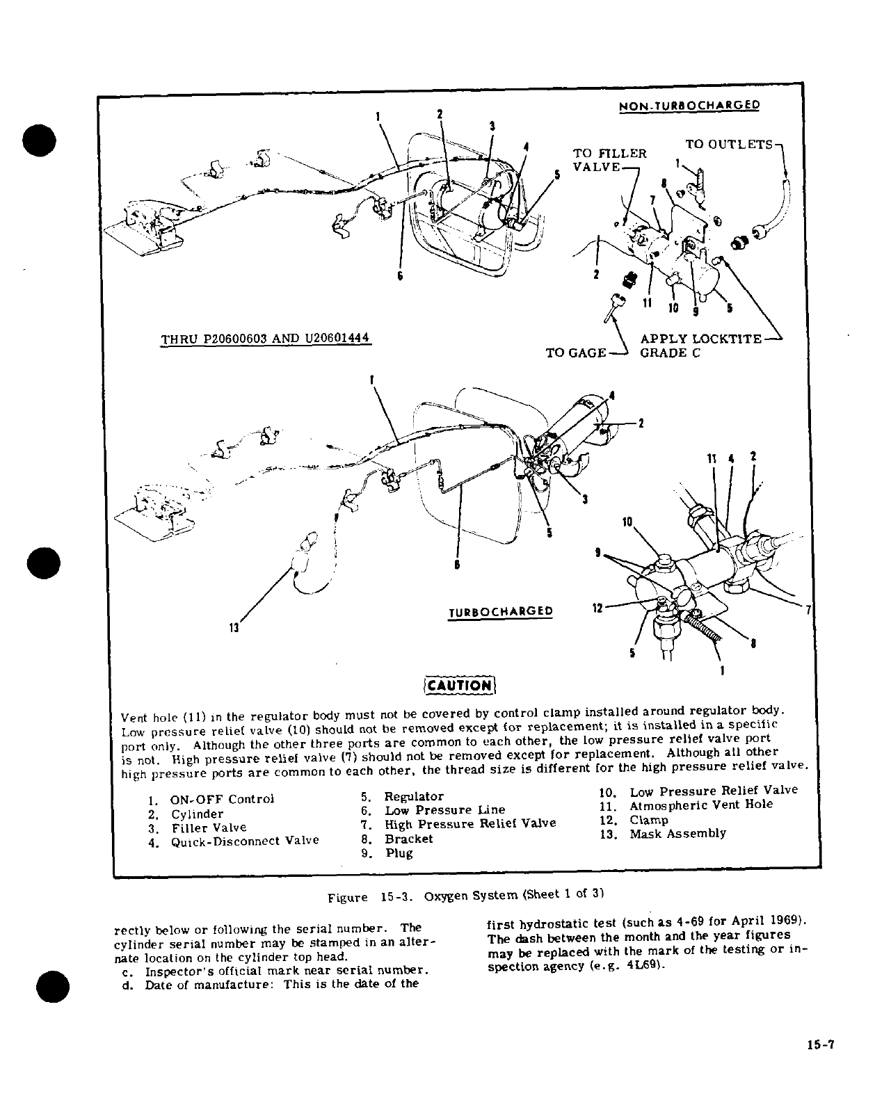
1 2
NON.TURBOCHARGED
TO
FILLER
TO
OUTLETS
VALVE
TURBOCHARGED
12
13
/.
TURBOCHARGED
12
1
CAUTION
Vent
hole
(11)
in
the
regulator
body
must
not
be
covered
by
control
clamp
installed
around
regulator
body.
Low
pressure
relief
valve
(10)
should
not
be
removed
except
for
replacement;
it
is
installed
in
a
specific
port
only. Although
the
other
three
ports
are
common
to
each
other,
the
low
pressure
relief
valve
port
is
not.
High
pressure
relief
valve
(7)
should
not
be
removed
except
for
replacement.
Although
all
other
high
pressure
ports
are
common
to
each
other,
the
thread
size
is
different
for
the
high
pressure
relief
valve.
1.
ON-OFF
Control
5.
Regulator
10.
Low
Pressure
Relief
Valve
2.
Cylinder
6.
Low
Pressure
Line
11.
Atmospheric
Vent
Hole
3.
Filler
Valve
7.
High
Pressure
Relief
Valve
12.
Clamp
4.
Quick-Disconnect
Valve
8.
Bracket
13.
Mask
Assembly
9.
Plug
Figure
15-3.
Oxygen
System
(Sheet
1
of
3)
rectly
below
or
following
the
serial
number.
The
first
hydrostatic
test
(such
as
4-69
for
April
1969).
cylinder
serial
number
may
be
stamped
in
an
alter-
The
dash
between
the
month
and
the
year figures
nate
location
on
the
cylinder
top
head.
may
be
replaced
with
the
mark
of
the
testing
or
in-
c.
Inspector's
official
mark
near
serial
number.
spection
agency
(e.g.
4L69).
d.
Date
of
manufacture:
This
is
the
date
of
the
15-7
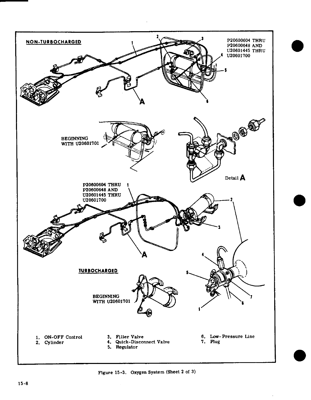
P20600604
THRU
NON-TURBOCHARGED
P20600604
THRU
P20600648
AND
U20601445 THRU
Detail
A
P20600604
THRU
P20600648
AND
U20601445
THRU
U20601700
TURBOCHARGED
BEGINNING
WITH
U20601701
1.
ON-OFF
Control
3.
Filler
Valve 6.
Low-Pressure
Line
2.
Cylinder
4.
Quick-Disconnect
Valve
7.
Plug
5.
Regulator
Figure
15-3.
Oxygen
System
(Sheet
2
of
3)
15-8
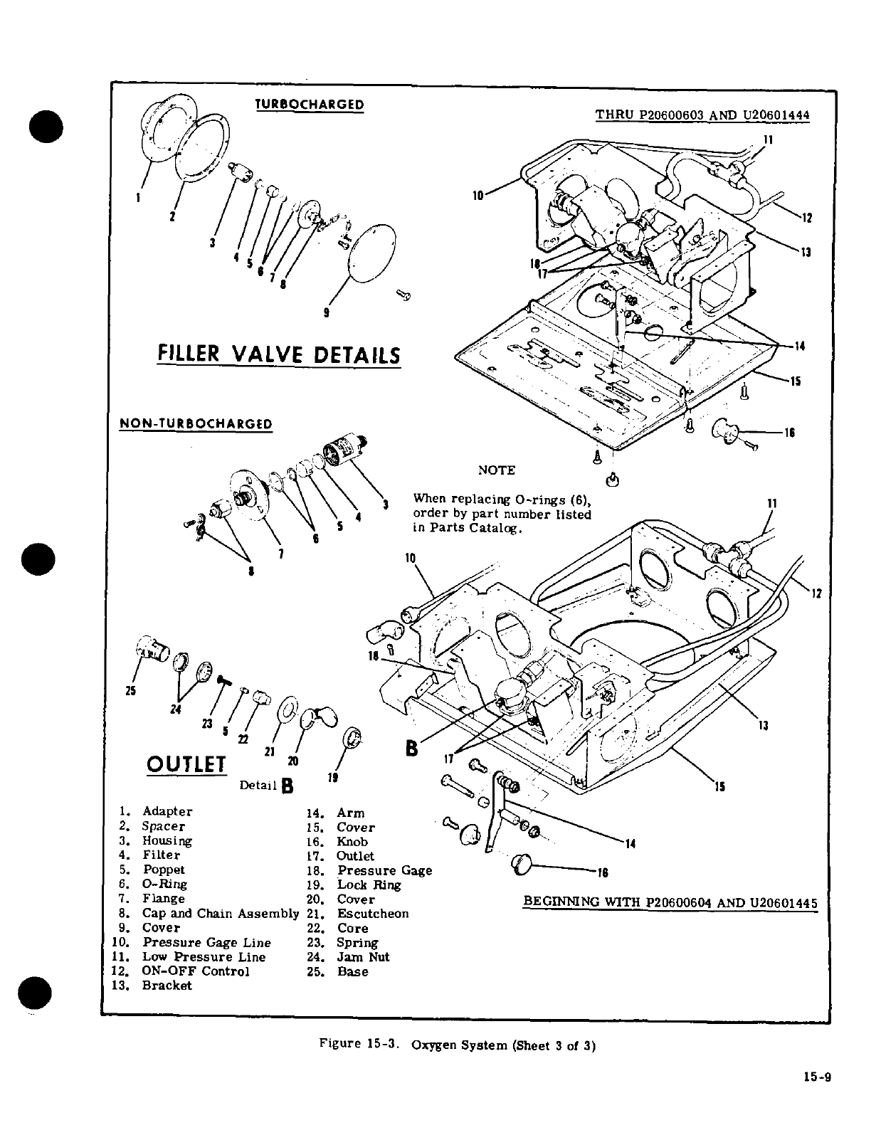
TURBOCHARGED
THRU
P20600603
AND
U20601444
2 12
FILLER
VALVE
DETAILS
14
NON-TURBOCHARGED
When
replacing
O-rings
(6), 11
4
order
by
part
number
listed
in
Parts
Catalog.
10
11
OUTLET
20
17
Detail
B
1
1.
Adapter
14.
Arm
2.
Spacer
15.
Cover
/
3.
Housing
16.
Knob14
4.
Filter
17.
Outlet
5.
Poppet
18.
Pressure
Gage
6.
O-Ring
19.
Lock
Ring
7.
Flange
20.
Cover
BEGINNING
WITH
P20600604
AND
U20601445
8.
Cap
and
Chain
Assembly
21.
Escutcheon
9.
Cover
22.
Core
10.
Pressure
Gage
Line
23.
Spring
11.
Low
Pressure
Line
24.
Jam
Nut
12.
ON-OFF
Control
25.
Base
13.
Bracket
Figure
15-3.
Oxygen
System
(Sheet
3
of
3)
15-9
e.
Hydrostatic
test
date:
The
dates
of
subsequent
hydrostatic
test.
hydrostatic
tests
shall
be
steel
stamped
(month
and
b.
FILLER
VALVE.
The
valve
shall
be
functional-
year)
directly
below
the
original
manufacture
date.
ly
tested
every
two
years
and
overhauled
every
five
The
dash between
the month
and
year figures
can
be
years
or
at
time
of
hydrostatic
test.
replaced
with the
mark
of
the
testing
agency.
c.
QUICK-RELEASE
COUPLING.
The
coupling
f.
A
Cessna
identification
placard
is
located
near
shall
be
functionally
tested
every
two
years
and
the
center
of
the
cylinder
body.
overhauled every
five
years
or
at
time
of
hydrostatic
g.
Halogen
test
stamp:
"Halogen
Tested",
date
of
test.
test
(month,
day
and
year)
and
inspector's
mark
d.
PRESSURE
GAGE.
The
gage
shall
be
checked
appears
directly
underneath
the
Cessna
identification
for accuracy
and
overhauled
by
an
FAA
approved
placard.
facility
every
five
years.
e.
OUTLETS.
The
outlets shall
be
disassembled
15-22.
OXYGEN
CYLINDER
SERVICE REQUIRE-
and
inspected
and
the
sealing
core
replaced,
re-
MENTS.
gardless
of
condition,
every
five
years.
a.
Hydrostatic
test
requirements:
1.
Standard
weight
(ICC
or
DOT-3AA1800)
15-25.
OXYGEN
SYSTEM
COMPONENT
INSPEC-
cylinders
must
be
hydrostatically
tested
to
5/3
their
TION
REQUIREMENTS.
working
pressure
every
five
years
commencing
with
a.
Examine
all
parts
for
cracks,
nicks,
damaged
the
date
of
the
last
hydrostatic
test.
threads or
other
apparent
damage.
2.
Light
weight
(ICC
or
DOT-3HT1850)
cylin-
b.
Actuate
regulator
controls
and
valve
to
check
ders
must
be
hydrostatically
tested
to
5/3
their
for
ease
of
operation.
working
pressure
every
three
years
commencing
c.
Determine
if
the
gage
is
functioning
properly
with
the
date
of
the
last
hydrostatic
test.
by
observing
the
pressure
build-up
and
the
return
to
b.
Service life
requirements:
zero
when
the
system
oxygen
is
bled
off.
1.
Standard
weight
(ICC
or
DOT-3AA1800)
d.
Replace
any
oxygen
line
that
is
chafed,
rusted,
cylinders
have
no
age
life
limitations
and
may
con-
corroded,
dented,
cracked
or
kinked.
tinue
to
be
used
until
they
fail
hydrostatic
test.
e.
Check
fittings for
corrosion
around
the
thread-
2.
Light
weight
(ICC
or
DOT-3HT1850)
cylin-
ed
area
where
lines
are
joined
together.
Pressur-
ders
must
be
retired
from
service
after
12
years
ize
the
system
and
check
for
leaks.
or
4,
380
filling
cycles
after
date
of
manufacture,
whichever
occurs
first.
15-26.
MASKS
AND
HOSE.
a.
Check
oxygen
masks
for
fabric
cracks
and
rough
NOTE
face
seals.
If
the
mask is
a
full-faced
model,
In-
spect
glass
or
plastic
for
cleanliness
and
state
of
These
test
periods
and
life
limitations
are repair.
established
by
the
Interstate
Commerce
b.
Flex
the
mask
hose gently
over
its
entirety
and
Commission
Code
of
Federal
Regulations,
check
for
evidence
of
deterioration
or
dirt.
Title
49,
Chapter
1,
Para.
73. 34.
c.
Examine
mask
and hose
storage
compartment
for
cleanliness
and
general
condition.
15-23.
OXYGEN
CYLINDER
INSPECTION
REQUIRE-
MENTS.
15-27.
MAINTENANCE
AND
CLEANING.
a.
Inspect
the
entire
exterior
surface
of
the
cylin-
a.
Clean
and
disinfect
mask
assemblies
after
use,
der
for indication
of
abuse,
dents,
bulges
and
strap
as
appropriate.
chafing.
b.
Examine
the neck
of
cylinder for
cracks,
dis-
NOTE
tortion
or
damaged
threads.
c.
Check
the
cylinders
to
determine
if
markings
Use
care
to
avoid
damaging
microphone
are
legible.
assembly
while
cleaning
and
sterilizing.
d.
Check
date
of
last
hydrostatic
test.
If
the
peri-
odic
retest
date
is past,
do
not
return
the
cylinder
b.
Wash
mask
with
a
mild soap
solution
and
rinse
to
service
until
the
test
has
been
accomplished.
it
with
clear
water.
e. Inspect
the
cylinder
mounting
bracket,
bracket
c.
To
sterilize,
swab
mask thoroughly
with
a
hold-down
bolts
and
cylinder
holding
straps
for
gauze
or
sponge
soaked
in
a
water/merthiolate
so-
cracks,
deformation,
cleanliness,
and
security
of
lutlon.
This
solution
should
contain
1/5
teaspoon
of
attachment.
merthiolate
per
one
quart
of
water.
Wipe
the
mask
f.
In
the
immediate
area
where
the
cylinder
is
with
a
clean
cloth and
let
air
dry.
stored
or
secured,
check
for
evidence
of
any
types
d.
Observe
that
each
mask
breathing
tube
end
is
of
interference,
chafing,
deformation
or
deterio-
free
of
nicks
and
that
the
tube end
will
slip
into
the
ration.
cabin
oxygen
receptacle
with
ease
and will
not
leak.
e.
If
a
mask
assembly
is
defective
(leaks,
does
not
15-24.
OXYGEN
SYSTEM
COMPONENT
SERVICE
allow
breathing
or
contains
a
defective
microphone)
REQUIREMENTS.
it
is
advisable
to
return
the
mask
assembly
to
the
a.
PRESSURE
REGULATOR.
The
regulator
shall manufacturer
or
a
repair
station.
be
functionally
tested
every
two
years
or
1,
000
hours
f.
Replace
hose
if
it
shows
evidence
of
deterio-
for
airc
oraf t
op
uerating
under
15,
000
t.
and one
year
ration.
for
aircraft
operating
over
15,000
ft.
The
regulator
g.
Hose may
be
cleaned
in
the
same
manner
as
the
shall
be
overhauled
every
five
years
ao
at
time
of
mask.
15-10
15-28.
SYSTEM
PURGING.
Whenever
components
CAUTION)
have
been
removed
and
reinstalled
or replaced,
it
is
advisable
to
purge
the
system.
Charge
oxygen
sys-
Do
not
attempt
to
tighten
any
connections
tern
in
accordance
with
procedures
outlined
in
para-
while
the
system
is
charged.
graph
15-31.
Plug
masks
into
all
outlets
and
turn
the
pilot's
control
to
ON
position
and
purge
system
15-31.
SYSTEM
CHARGING.
by
allowing
oxygen
to
flow
for
at
least
10
minutes.
Smell
oxygen
flowing
from
outlets
and
continue
to
WARNING
purge
until
system
is
odorless.
Refill
cylinders
as
required
during
and
after
purging.
BE
SURE
TO
GROUND
AIRCRAFT
AND
GROUND
SERVICING
EQUIPMENT
BE-
15-29.
FUNCTIONAL
TESTING.
Whenever
the
reg-
FORE
CHARGING OXYGEN
SYSTEM.
ulator
and
cylinder
assembly
has
been
replaced
or
overhauled,
perform
the following
flow
and
internal
a.
Do
not
attempt
to
charge
oxygen
cylinders
if
leakage
tests
to
check
that
the
system
functions
prop-
servicing
equipment
fittings
or
filler
valve
are
erly.
corroded
or
contaminated.
If
in
doubt,
clean
with
a.
Fully
charge
oxygen
system
in
accordance
with
stabilized
trichlorethylene
and let
air
dry.
Do not
procedures
outlined
in
paragraph
15-31.
allow
solvent
to
enter
any
internal
parts.
b.
Disconnect
line
and
fitting
assembly
from
pi-
b.
If
cylinder
is
completely empty,
do
not
charge,
lot's
mask
and
line
assembly.
Insert
outlet
end
of
as
the
cylinder
must
then
be
removed,
inspected
line
and
fitting
assembly
into
cabin
outlet
and
attach
and
cleaned.
opposite
end
of
line to
a
pressure
gage (gage
should
be
calibrated
in
one-pound
increments
from
0
to
100
CAUTION
PSI).
Place control
lever
in
ON
position.
Gage
pressure
should
read
75±10 PSI.
A
cylinder
which
is
completely
empty
may
c.
Insert
mask and
line
assemblies
into
all
re-
well
be
contaminated.
The
regulator
and
maining
cabin
outlets.
With
oxygen
flowing
from
all
cylinder
assembly
must
then
be
disas-
outlets,
test
gage
pressure
should
still
be 75±10
PSI.
sembled,
inspected
and
cleaned
by
an
FAA
d.
Place
oxygen
control
lever
in
OFF
position
and
approved
facility,
before
filling.
Con-
allow
test
gage
pressure
to
fall
to
0
PSI.
Remove
tamination,
as
used here,
means
dirt,
dust
all
adapter
assemblies
except
the
one
with
the
pres-
or
any
other
foreign
material, as
well
as
sure
gage. The
pressure
must
not
rise
above
0
PSI
ordinary
air
in
large
quantities.
If
a
gage
when
observed for
one
minute.
Remove
pressure
line
or
filler
line
is
disconnected
and
the
gage and
adapter
from
oxygen
outlet.
fittings
capped
immediately,
the
cylinder
will
not
become
contaminated
unless
tem-
NOTE
perature
variation
has
created
a
suction
within
the
cylinder.
Ordinary
air
contains
If
pressures
specified
in
the
foregoing
pro-
water
vapor
which could
condense
and
cedures are
not
obtained,
the
oxygen
reg-
freeze.
Since
there
are
very
small
orifices
ulator
is
not
operating
properly.
Remove
in
the
system,
it
is
very
important
that
and
replace
cylinder-regulator
assembly
this
condition
not
be
allowed
to
occur.
with
another
unit
and
repeat
test
procedure.
c.
Connect
cylinder
valve
outlet
or
outside
filler
e.
Connect mask
and
line
assemblies
to
each
cabin valve
to
manifold
or
portable
oxygen
cascade.
outlet
and
check each
mask
for
proper
operation.
d.
Slowly
open
valve
on
cascade
cylinder
or
mam-
f.
Check
pilot's
mask
microphone
and
control
fold
with
lowest
pressure,
as
noted
on
pressure
gage,
wheel
switch
for
proper
operation.
After
checking,
allow
pressure
to
equalize,
then
close
cascade
cy-
return
all
masks
to
mask
case.
linder
valve.
g.
Recharge
oxygen
system
inaccordance
with
e.
Repeat
this
procedure,
using
a
progressively
procedures
outlined
in
paragraph
15-31.
higher
pressure
cascade
cylinder,
until
system
has
been
charged
to
the
pressure
indicated
in
the
chart
15-30.
SYSTEM
LEAK
TEST.
When
oxygen
is
being
immediately
following
step
"f"
of
this
paragraph.
lost
from a
system
through
leakage,
a
sequence
of
f.
Ambient
temperature
listed
in
the
chart
is
the
steps
may
be
necessary
to
locate
the
opening.
Leak-
air
temperature
in
the
area
where
the
system
is
to
age
may
often
be
detected
by
listening
for
the
dis-
be
charged.
Filling
pressure
refers
to
the
pres-
tinct
hissing
of
escaping
gas.
Ii
this
check
proves
sure
to
which
aircraft
cylinders
should
be
filled.
negative,
it will
be
necessary
to
soap-test
all
lines
This
table gives
approximations
only
and
assumes
and
connections
with
a
castile
soap
and
water
so-
a
rise
in
temperature
of
approximately
25°F.
due
lution
or
specially
compounded
leak-test
material.
to
heat
of
compression.
This
table
also
assumes
Make
the
solution
thick
enough
to
adhere
to
the con-
the
aircraft
cylinders
will
be
filled
as
quickly
as
pos-
tours
of
the
fittings.
At
the
completion
of
the
leak-
sible
and
that
they
will
only
be
cooled
by
ambient
age
test,
remove
all
traces
of
the
leak
detector
or
air;
no
water
bath
or
other means
of
cooling
be
used.
soap
and
water
solution. Example:
If
ambient
temperature
is 70°F.,
fill
15-11
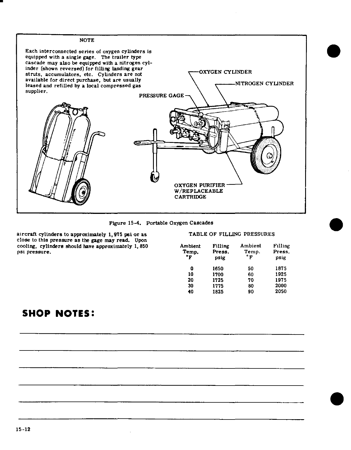
NOTE
Each
interconnected
series
of
oxygen
cylinders
is
equipped
with
a
single
gage.
The
trailer
type
cascade
may
also
be
equipped
with
a
nitrogen
cyl-
inder
(shown
reversed)
for
filling
landing
gear
struts,
accumulators,
etc.
Cylinders
are
not
OXYGEN
CYLINDER
available for
direct
purchase,
but
are
usually
NITROGEN
CYLINDER
leased
and
refilled
by
a
local
compressed
gas
supplier.
supplier.
PRESSURE
GAGE
W/REPLACEABLE
CARTRIDGE
Figure
15-4.
Portable
Oxygen
Cascades
aircraft
cylinders
to approximately
1,975
psi
or
as
TABLE
OF
FILLING PRESSURES
close
to
this
pressure
as
the gage may
read.
Upon
cooling,
cylinders
should
have
approximately
1,850 Ambient
Filling
Ambient
Filling
psi
pressure.
Temp.
Press.
Temp.
Press.
°F
psig
°F
psig
0
1650 50
1875
10
1700
60
1925
20 1725
70
1975
30
1775 80
2000
40 1825
90 2050
SHOP
NOTES:
15-12
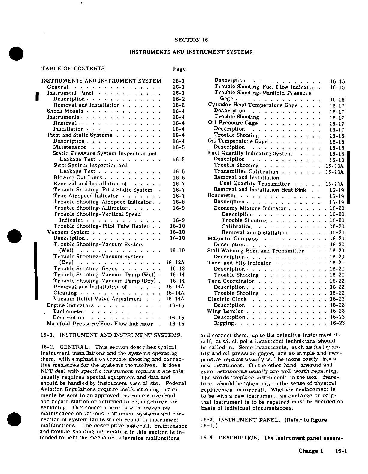
SECTION
16
INSTRUMENTS
AND
INSTRUMENT
SYSTEMS
TABLE
OF
CONTENTS
Page
INSTRUMENTS
AND
INSTRUMENT
SYSTEM
16-1
Description
.
.... ......
.
16-15
General
...............
16-1
Trouble
Shooting-Fuel
Flow
Indicator
.
16-15
Instrument
Panel
...........
16-1
Trouble
Shooting-Manifold
Pressure
Description
.............
16-2
Gage
........
16-16
Removal
and
Installation
.......
16-2
Cylinder
Head
Temperature
Gage
....
16-17
Shock
Mounts
........ .....
16-4
Description
...
.......
16-17
Instruments
..............
16-4
Trouble
Shooting
..........
16-17
Removal
..............
16-4
Oil
Pressure
Gage
..
......
16-17
Installation
.............
16-4
Description
......
.
16-17
Pitot
and
Static
Systems
........
16-4
Trouble
Shooting
..
......
16-18
Description
............
.
16-4
Oil
Temperature
Gage
..
......
16-18
Maintenance
............
16-5
Description
.....
16-18
Static
Pressure
System
Inspection
and
Fuel
Quantity
Indicating
System
....
16-18
Leakage
Test
..
........
.
16-5
Description
.
.... ......
.
16-18
Pitot System
Inspection
and
Trouble
Shooting .
.........
16-
18A
Leakage
Test
...........
16-5
Transmitter
Calibration
......
.
16-18A
Blowing
Out
Lines
..........
16-5 Removal
and
Installation
Removal
and
Installation
of
.....
16-7
Fuel
Quantity
Transmitter
....
16- 18A
Trouble Shooting-Pitot
Static
System
16-7
Removal
and
Installation
Heat
Sink
. .
16-19
True
Airspeed
Indicator
.....
..
16-7
Hourmeter
.
.........
.
16-19
Trouble Shooting-Airspeed
Indicator.
.
16-8
Description
...........
.
16-19
Trouble
Shooting-Altimeter.
.....
16-9
Economy
Mixture Indicator
.......
16-20
Trouble Shooting-Vertical
Speed
Description
.
.........
.
16-20
Indicator
............
. 16-9
Trouble
Shooting
..........
16-20
Trouble
Shooting-Pitot
Tube
Heater
.. 16-10
Calibration
.........
...
16-20
Vacuum
System
............
16-10
Removal
and
Installation
......
16-20
Description
...........
.
16-10
Magnetic
Compass
...........
16-20
Trouble
Shooting-Vacuum System
Description
............
.
16-20
(Wet)
...
.........
. 16-10
Stall
Warning
Horn
and
Transmitter
....
16-20
Trouble
Shooting-Vacuum
System
Description
..............
16-20
(Dry)
.
......... ....
16-12A
Turn-and-Slip
Indicator
.........
16-21
Trouble
Shooting-Gyros
.......
16-13
Description
..............
16-21
Trouble
Shooting-Vacuum
Pump
(Wet)
.
16-14
Trouble
Shooting
.............
16-21
Trouble
Shooting-Vacuum
Pump
(Dry)
.
16-14
Turn
Coordinator
.. .
....
16-22
Removal
and
Installation
of
.....
16-14A
Description
..
......
. . . ...
16-22
Cleaning
.......... ......
16-14A
Trouble
Shooting
.......
. . ..
16-22
Vacuum
Relief
Valve
Adjustment
. .
16-14A
Electric
Clock
... . . ..
16-23
Engine
Indicators
...... .....
16-15
Description
.............
16-23
Tachometer
..........
.
Wing
Leveler
..........
. .
16-23
Description
............
16-15
Description
..............
16-23
Manifold
Pressure/Fuel
Flow
Indicator
.
16-15
Rigging ..
...........
.
16-23
16-1.
INSTRUMENT
AND
INSTRUMENT
SYSTEMS.
and
correct
them,
up
to
the
defective
instrument
it-
self,
at
which point
instrument
technicians
should
16-2. GENERAL.
This
section
describes
typical
be
called
in.
Some
instruments,
such
as
fuel
quan-
instrument installations
and
the
systems
operating
tity
and
oil
pressure
gages,
are
so
simple
and
inex-
them,
with
emphasis
on
trouble
shooting
and
correc-
pensive
repairs
usually
will
be
more
costly
than
a
tive
measures
for
the
systems
themselves.
It
does
new
instrument.
On
the
other
hand,
aneroid
and
NOT
deal
with
specific
instrument
repairs
since
this
gyro
instruments
usually
are
well
worth
repairing.
usually
requires
special
equipment
and
data
and The
words
"replace
instrument"
in
the
text,
there-
should
be
handled
by
instrument
specialists.
Federal
fore,
should
be
taken
only
in
the
sense
of
physical
Aviation
Regulations
require
malfunctioning
instru- replacement
in
aircraft.
Whether
replacement
is
ments
be
sent
to
an
approved
instrument
overhaul
to
be
with
a
new
instrument,
an
exchange
or
orig-
and
repair
station
or
returned
to
manufacturer
for
inal
instrument
is
to
be
repaired
must
be
decided
on
servicing.
Our
concern here
is
with
preventive
basis
of
individual
circumstances.
maintenance
on
various
instrument
systems
and
cor-
rection
of
system
faults
which
result
in
instrument
16-3.
INSTRUMENT
PANEL.
(Refer
to
figure
malfunctions.
The
descriptive
material,
maintenance
16-1.)
and
trouble
shooting
information
in
this
section
is
in-
tended
to
help
the
mechanic
determine
malfunctions
16-4.
DESCRIPTION. The
instrument
panel
assem-
Change
1
16-1
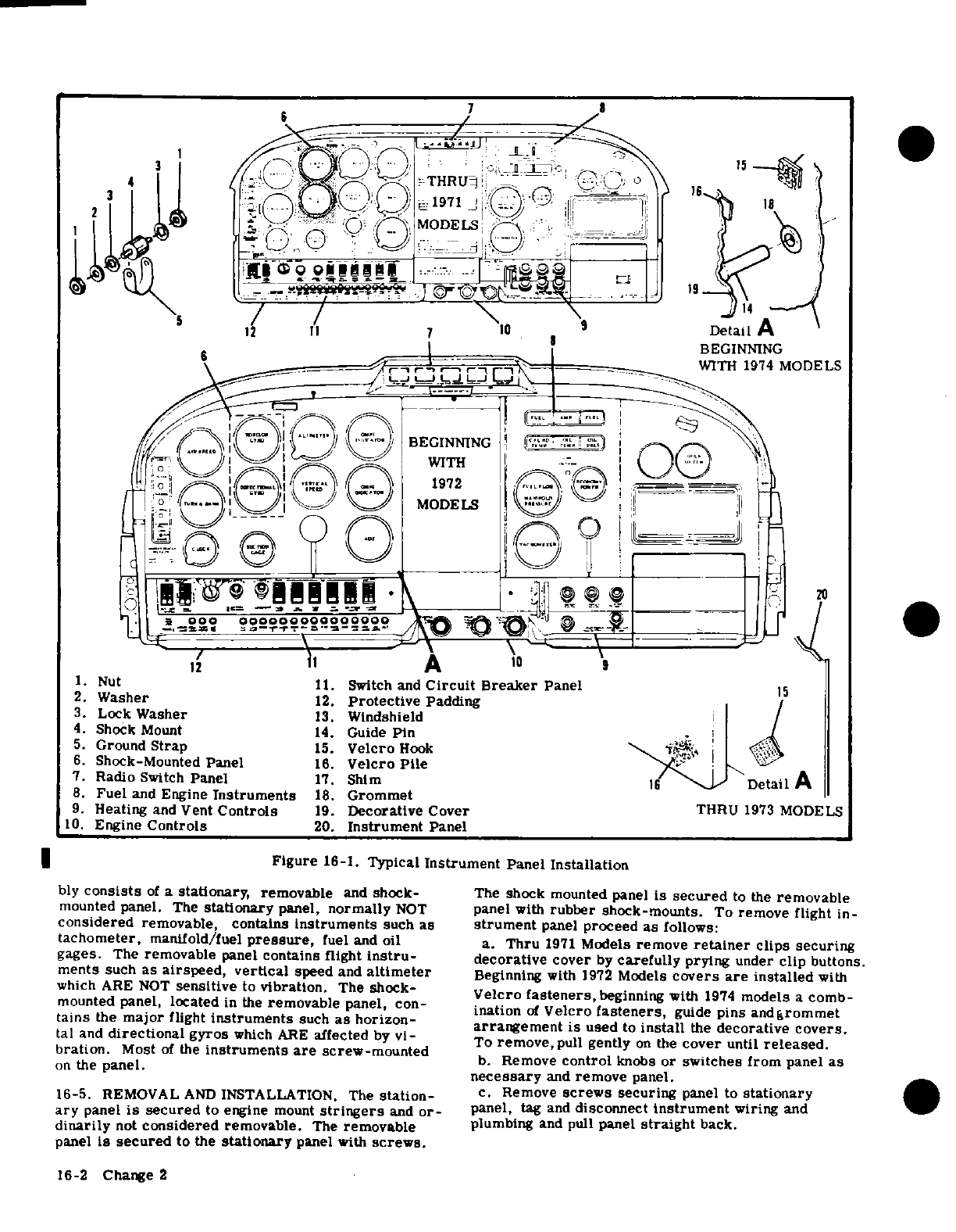
1.
Nut
11.
Switch and
Circuit
Breaker
Panel
2.
Washer
12.
Protective
Padding
3.
Lock
Washer
13.
Windshield
4.
Shock
Mount
14.
Guide
Pin
5. Ground
Strap
15.
Velcro
Hook
6.
Shock-Mounted
Panel
16.
Velcro
Pile
7.
Radio
Switch
Panel
17.
Shim
8.
Fuel
and
Engine
Instruments
18.
Grommet
9.
Heating
and
Vent
Controls
19.
Decorative
Cover
THRU
1973
MODELS
10.
Engine
Controls
20.
Instrument
Panel
Figure
16-1.
Typical
Instrument
Panel
Installation
bly
consists
of
a
stationary,
removable
and
shock-
The
shock
mounted
panel
is
secured
to
the
removable
mounted
panel.
The
stationary
panel,
normally
NOT
panel
with
rubber
shock-mounts.
To
remove
flight
in-
considered
removable, contains
instruments
such
as
strument
panel
proceed
as
follows:
tachometer,
manifold/fuel
pressure,
fuel and
oil
a.
Thru
1971
Models
remove
retainer
clips securing
gages.
The
removable
panel
contains
flight
instru-
decorative
cover
by
carefully
prying
under
clip
buttons.
ments
such
as
airspeed,
vertical
speed
and
altimeter
Beginning
with
1972
Models
covers
are
installed
with
which
ARE
NOT
sensitive
to
vibration.
The
shock-
Velcro
fasteners,
beginning
with
1974
models
a
comb-
mounted
panel,
located
in
the
removable
panel,
con-
ination
of
Velcro
fasteners,
guide
pins,
and
grommet
tains
the
major
flight
instruments
such
as
horizon-
arrangement
is
used
to
install
the
decorative
covers.
tal
and
directional
gyros
which
ARE
affected
by
vi-
To
remove,
pull
gently
on
the
cover
until
released.
bration.
Most
of
the
instruments
are
screw-mounted
b.
Remove
control
knobs
or
switches
from
panel as
on the panel.
necessary
and
remove
panel.
16-5.
REMOVAL
AND
INSTALLATION.
The
station-
c.
Remove
screws
securing
panel
to
stationary
ary
panel
is
secured
to
engine
mount
stringers
and
or-
panel,
tag
and
disconnect
instrument
wiring
and
dinarily
not
considered
removable.
The
removable
plumbing
and
pull
panel
straight
back.
panel
is secured
to
the
stationary
panel
with
screws.
16-2
Change
2
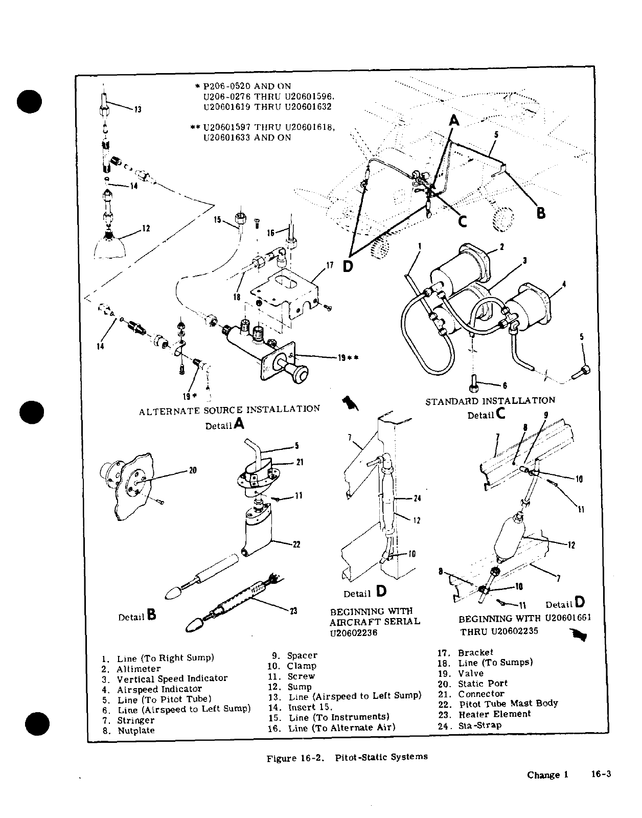
*
P206-0520
AND
ON
U206-0276
THRU
U20601596.
...
13
U20601619 THRU U20601632
8u·
**U20601597
THRU
U20601618,
.
-A
'"
h.
~ ~
U20601633
AND
ON
'-
-1 "\ i"-
: :.
.
11n
-
-^
o
::-
:
f
...
p J,''
.
!-
ALTERNATE
SOURCE
INSTALLATION
>SA ARD
I
DetailA
:;-
DetaiC
a
9
8
/
1
4
20,
^'.
Detai
U.'3
' ' A
'
.1
"'
ALTERNATE
SOURCE
BEINNNGSTALLATION
WIT
Detal
AIRCRAFT
SERIAL
BEGINNING
WITH
U20601661
o5
I
*I~^
T
21,
1
5rU20602236
T20U
U206
4.
AirspeedIndicator
12.
Sump
20.
Static
Port
6 Line (Airspeed to Leit Sump)
14.
Insert
15.
22.
pitot
Tube
Mast
Body
Figur
BEGINNING
W
TH-c
Systems
DetailB
AIRCRAFT
SERIAL
BEGINNING
WITH
U20601661
U20602236
THRU
U20602235
1.
Line
(To
Right
Sump)
9.
Spacer
17.
Bracket
2.
Altimeter
10.
Clamp
18.
Line
(To Sumps)
3.
Vertical
Speed
Indicator
11.
Screw
19.
Valve
4.
Airspeed Indicator
12.
Sump
20.
Static
Port
5.
Line
(To
Pitot
Tube)
13.
Line
(Airspeed
to
Left
Sump)
21.
Connector
6.
Line
(Airspeed
to
Left
Sump)
14.
Insert
15.
22.
pitot
Tube
Mast
Body
7.
Stringer
15.
Line
(To
Instruments)
23.
Heater
Element
8.
Nutplate
16.
Line
(To
Alternate
Air)
24.
Sta-Strap
Figure
16-2.
Pitot-Static
Systems
Change
1
16-3
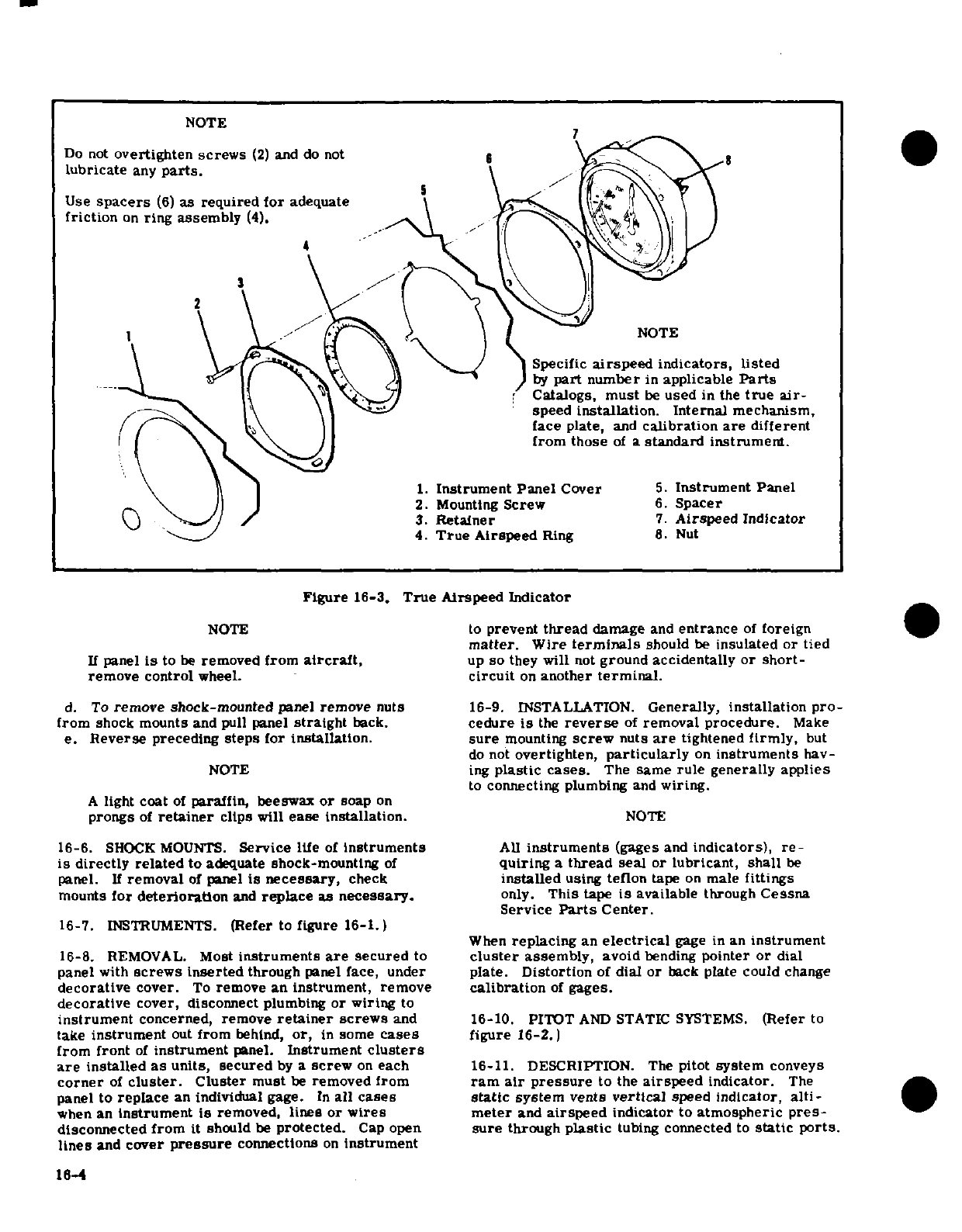
NOTE
Do
not
overtighten
screws
(2)
and
do
not
6
lubricate
any
parts.
Use
spacers
(6)
as
required for
adequate
\
friction
on
ring
assembly
(4).
4
1
NOTE
Specific
airspeed
indicators,
listed
by
part
number
in
applicable
Parts
Catalogs,
must
be
used
in
the
true
air-
speed
installation.
Internal
mechanism,
face plate,
and
calibration
are
different
from those
of
a
standard
instrument.
1.
Instrument
Panel
Cover
5.
Instrument
Panel
2.
Mounting
Screw
6.
Spacer
3.
Retainer
7.
Airspeed
Indicator
4.
True
Airspeed
Ring
8.
Nut
Figure
16-3.
True
Airspeed
Indicator
NOTE
to
prevent
thread
damage
and
entrance
of
foreign
matter.
Wire
terminals
should
be
insulated
or tied
If
panel
is
to
be
removed
from
aircraft,
up
so
they
will
not
ground
accidentally
or short-
remove
control
wheel.
circuit
on
another
terminal.
d. To
remove
shock-mounted
panel
remove
nuts
16-9.
INSTALLATION.
Generally,
installation
pro-
from
shock
mounts and
pull
panel
straight
back.
cedure
is
the
reverse
of
removal
procedure.
Make
e.
Reverse
preceding
steps
for
installation.
sure
mounting
screw
nuts
are
tightened
firmly,
but
do
not
overtighten,
particularly
on
instruments
hav-
NOTE
ing
plastic
cases.
The
same
rule
generally
applies
to
connecting
plumbing
and
wiring.
A
light
coat
of
paraffin,
beeswax
or
soap
on
prongs
of
retainer
clips
will
ease installation.
NOTE
16-6.
SHOCK MOUNTS.
Service
life
of
Instruments
All
instruments
(gages
and
indicators),
re-
is
directly
related
to
adequate
shock-mounting
of
quiring
a
thread
seal
or
lubricant,
shall
be
panel.
If
removal
of
panel
is
necessary,
check
installed
using
teflon
tape
on
male
fittings
mounts
for
deterioration
and
replace
as
necessary.
only.
This
tape
is
available
through
Cessna
Service
Parts
Center.
16-7.
INSTRUMENTS.
(Refer
to
figure
16-1.)
When
replacing
an
electrical
gage
in
an
instrument
16-8.
REMOVAL.
Most
instruments
are
secured
to
cluster
assembly,
avoid
bending
pointer
or
dial
panel
with
screws inserted
through
panel
face, under
plate.
Distortion
of
dial or
back
plate
could
change
decorative
cover.
To
remove
an instrument,
remove
calibration
of
gages.
decorative
cover, disconnect
plumbing
or
wiring
to
instrument
concerned,
remove
retainer
screws
and 16-10.
PITOT
AND
STATIC
SYSTEMS.
(Refer
to
take
instrument
out
from
behind,
or,
in
some
cases
figure
16-2.)
from
front
of
instrument
panel.
Instrument
clusters
are
installed
as
units,
secured
by
a
screw
on
each
16-11.
DESCRIPTION.
The
pitot
system
conveys
corner
of
cluster.
Cluster
must
be
removed from
ram
air
pressure
to
the
airspeed
indicator.
The
panel
to
replace
an individual
gage.
In
all
cases
static
system
vents
vertical
speed
indicator,
alti-
when
an
Instrument
is
removed,
lines
or
wires
meter
and
airspeed
indicator
to
atmospheric
pres-
disconnected from
it should
be
protected.
Cap
open
sure
through
plastic
tubing
connected
to
static
ports.
lines
and
cover
pressure
connections
on
instrument
16-4
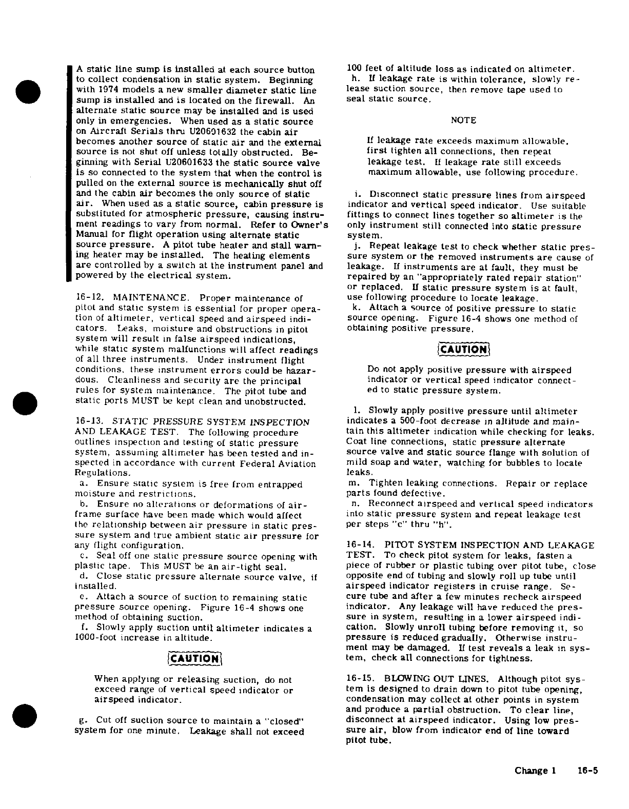
A
static
line
sump
is
installed
at
each
source
button
100
feet
of
altitude loss
as
indicated
on
altimeter.
to
collect
condensation
in
static
system.
Beginning
h.
If
leakage
rate
is
within
tolerance,
slowly
re-
with
1974
models
a
new
smaller
diameter
static
line
lease
suction
source,
then
remove
tape
used
to
sump
is
installed
and
is
located
on
the
firewall.
An
seal static
source.
alternate static
source
may
be
installed
and
is
used
only
in
emergencies.
When
used
as
a
static
source
NOTE
on
Aircraft
Serials
thru
U20601632
the cabin
air
becomes
another
source
of
static
air
and
the
external
If
leakage
rate
exceeds
maximum
allowable.
source
is
not
shut
off
unless
totally
obstructed.
Be-
first
tighten
all
connections,
then
repeat
ginning
with
Serial
U20601633
the
static
source
valve
leakage
test.
If
leakage
rate
still
exceeds
is
so
connected
to
the
system
that
when
the
control
is
maximum
allowable,
use
following
procedure.
pulled
on
the
external
source
is
mechanically
shut
off
and
the
cabin
air
becomes
the
only
source
of
static
i.
Disconnect
static
pressure
lines
from
airspeed
air.
When
used as
a
static
source,
cabin
pressure
is
indicator
and
vertical
speed
indicator.
Use
suitable
substituted
for
atmospheric
pressure,
causing
instru-
fittings
to
connect
lines together
so
altimeter
is
the
ment
readings
to
vary from
normal.
Refer
to
Owner's
only
instrument
still
connected
into
static
pressure
Manual
for
flight
operation
using
alternate
static
system.
source
pressure.
A
pitot
tube
heater
and
stall
warn-
j.
Repeat leakage
test
to
check
whether
static pres-
ing
heater
may
be
installed.
The
heating
elements
sure
system
or
the
removed
instruments
are
cause
of
are
controlled
by
a
switch
at
the
instrument
panel
and
leakage.
If
instruments
are
at
fault,
they
must
be
powered
by
the
electrical
system.
repaired
by
an
"appropriately
rated
repair
station"
or
replaced.
If
static
pressure
system
is
at
fault,
16-12.
MAINTENANCE.
Proper
maintenance
of
use
following
procedure
to
locate
leakage.
pitot
and
static
system
is
essential
for
proper
opera-
k.
Attach
a
source
of
positive
pressure
to
static
tion
of
altimeter,
vertical
speed
and
airspeed
indi-
source
opening.
Figure
16-4
shows
one
method
of
cators.
Leaks,
moisture
and
obstructions
in
pitot obtaining
positive
pressure.
system
will
result
in
false
airspeed
indications,
while
static
system
malfunctions
will
affect
readings
CAUTION
of
all
three
instruments.
Under
instrument
flight
conditions.
these
instrument
errors
could
be
hazar-
Do
not
apply
positive
pressure
with
airspeed
dous.
Cleanliness
and
security
are
the
principal
indicator or
vertical
speed
indicator
connect-
rules
for
system
maintenance.
The
pitot
tube
and ed
to
static
pressure
system.
static
ports
MUST be
kept
clean
and
unobstructed.
1.
Slowly
apply
positive
pressure
until
altimeter
16-13.
STATIC
PRESSURE
SYSTEM
INSPECTION
indicates
a
500-foot
decrease
in
altitude
and
main-
AND
LEAKAGE
TEST.
The
following
procedure
tain this
altimeter
indication
while
checking
for leaks.
outlines
inspection
and
testing
of
static
pressure
Coat line
connections, static
pressure
alternate
system,
assuming
altimeter
has
been
tested
and
in-
source
valve
and
static
source
flange
with
solution
of
spected
in
accordance
with
current
Federal
Aviation
mild
soap
and
water,
watching
for
bubbles
to
locate
Regulations.
leaks.
a.
Ensure
static
system
is
free
from
entrapped
m.
Tighten leaking connections.
Repair
or
replace
moisture
and
restrictions.
parts
found
defective.
b.
Ensure
no
alterations
or
deformations
of
air-
n.
Reconnect
airspeed
and
vertical
speed
indicators
frame
surface
have
been
made
which
would
affect
into
static
pressure
system
and
repeat
leakage
test
the
relationship
between
air
pressure
in
static
pres-
per
steps
"c"
thru
"h".
sure
system
and
true
ambient
static
air
pressure
for
any
flight
configuration.
16-14.
PITOT
SYSTEM
INSPECTION
AND
LEAKAGE
c.
Seal
off
one
static
pressure
source
opening
with
TEST.
To
check
pitot
system
for
leaks,
fasten
a
plastic
tape.
This
MUST
be
an
air-tight
seal.
piece
of
rubber
or
plastic
tubing
over
pitot
tube,
close
d.
Close
static
pressure
alternate
source
valve,
if
opposite
end
of
tubing
and
slowly
roll
up
tube until
installed.
airspeed
indicator
registers
in
cruise
range.
Se-
e.
Attach
a
source
of
suction
to
remaining
static
cure
tube
and
after
a
few
minutes
recheck
airspeed
pressure
source
opening.
Figure
16-4
shows
one
indicator.
Any
leakage
will
have
reduced
the
pres-
method
of
obtaining
suction.
sure
in
system, resulting
in
a lower
airspeed
indi-
f.
Slowly
apply
suction
until
altimeter
indicates
a
cation.
Slowly
unroll
tubing
before
removing
it,
so
1000-foot
increase
in
altitude.
pressure
is
reduced
gradually.
Otherwise
instru-
ment
may
be
damaged.
If
test reveals
a
leak
in
sys-
CAUTION
tem,
check
all
connections for
tightness.
When
applying
or
releasing
suction,
do
not
16-15.
BLOWING
OUT
LINES.
Although
pitot
sys-
exceed range
of
vertical
speed
indicator
or
tem
is
designed
to
drain
down
to
pitot
tube
opening,
airspeed
indicator.
condensation
may
collect
at
other
points
in
system
and
produce
a
partial
obstruction.
To
clear
line,
g.
Cut
off
suction
source
to
maintain
a
"closed"
disconnect
at
airspeed
indicator.
Using
low
pres-
system for
one
minute. Leakage
shall
not
exceed
sure
air,
blow
from
indicator
end
of
line
toward
pitot
tube.
Change
1
16-5
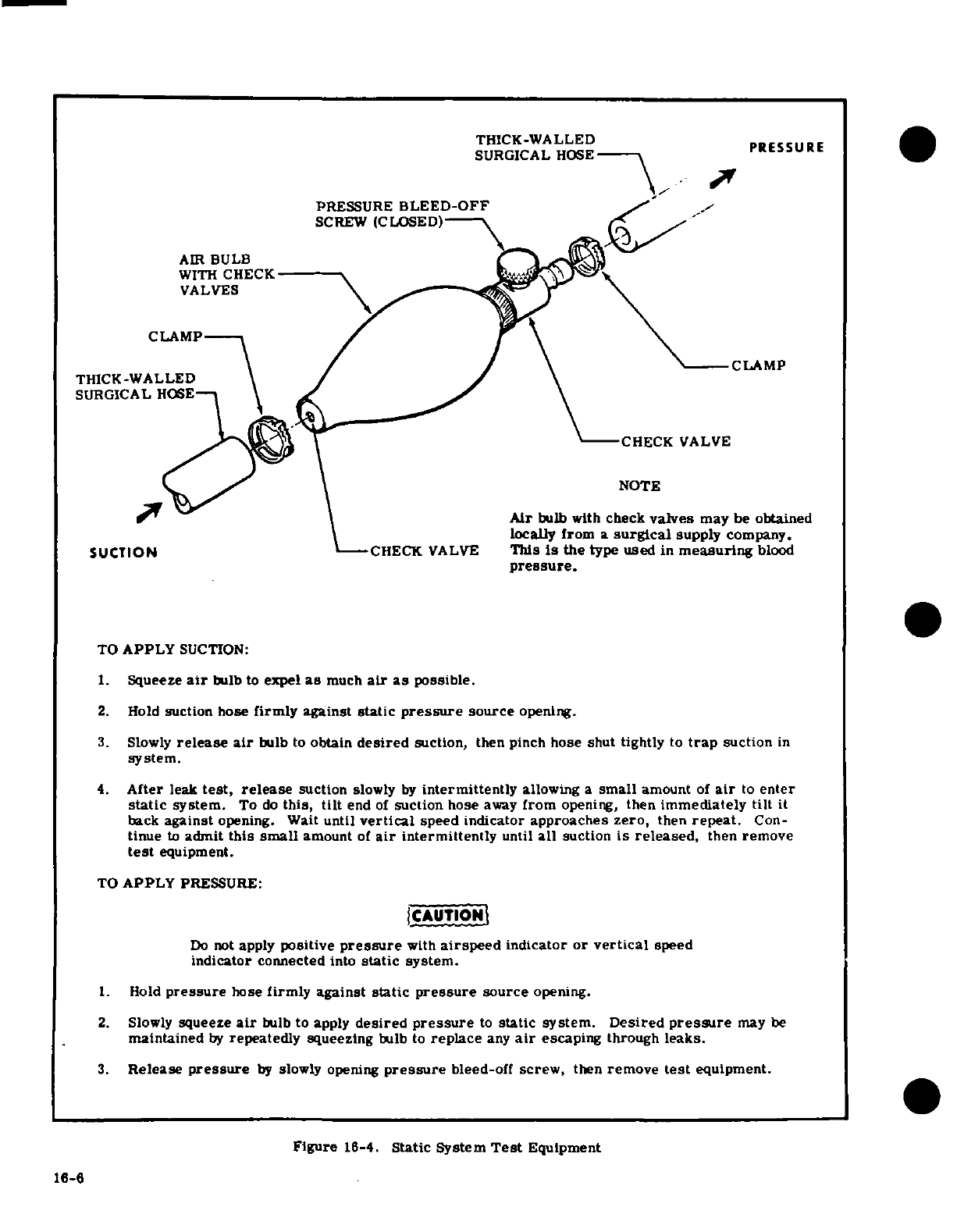
THICK-WALLED
PRESSURE
SURGICAL
HOSE
PRESSURE
BLEED-OFF
SCREW
(CLOSED)
AIR
BULB
WITH
CHECK
VALVES
CLAMP
CLAMP
THICK-WALLED
SURGICAL
HOSE
CHECK
VALVE
NOTE
Air
bulb with
check
valves
may
be
obtained
locally
from
a
surgical
supply
company.
SUCTION
CHECK
VALVE
This
is
the
type
used
in
measuring
blood
pressure.
TO
APPLY
SUCTION:
1.
Squeeze
air
bulb
to
expel
as
much
air
as
possible.
2.
Hold
suction hose
firmly
against
static
pressure
source
opening.
3.
Slowly
release
air
bulb
to
obtain
desired
suction,
then pinch
hose shut
tightly
to
trap
suction
in
system.
4.
After
leak
test,
release
suction
slowly
by
intermittently
allowing a
small
amount
of
air
to
enter
static
system.
To
do
this,
tilt
end
of
suction
hose
away
from
opening,
then
immediately
tilt
it
back
against
opening.
Wait
until
vertical
speed
indicator
approaches zero,
then
repeat.
Con-
tinue
to
admit
this
small
amount
of
air
intermittently
until
all
suction
is
released,
then
remove
test
equipment.
TO
APPLY
PRESSURE:
CAUTION
Do
not
apply
positive
pressure
with
airspeed
indicator
or
vertical
speed
indicator
connected
into
static
system.
1.
Hold
pressure
hose
firmly
against
static
pressure
source
opening.
2.
Slowly
squeeze
air
bulb
to
apply
desired
pressure
to
static
system.
Desired
pressure
may
be
maintained
by
repeatedly
squeezing
bulb
to
replace
any
air
escaping
through
leaks.
3.
Release
pressure
by
slowly
opening
pressure
bleed-off
screw,
then
remove
test
equipment.
Figure
16-4.
Static System
Test
Equipment
16-6
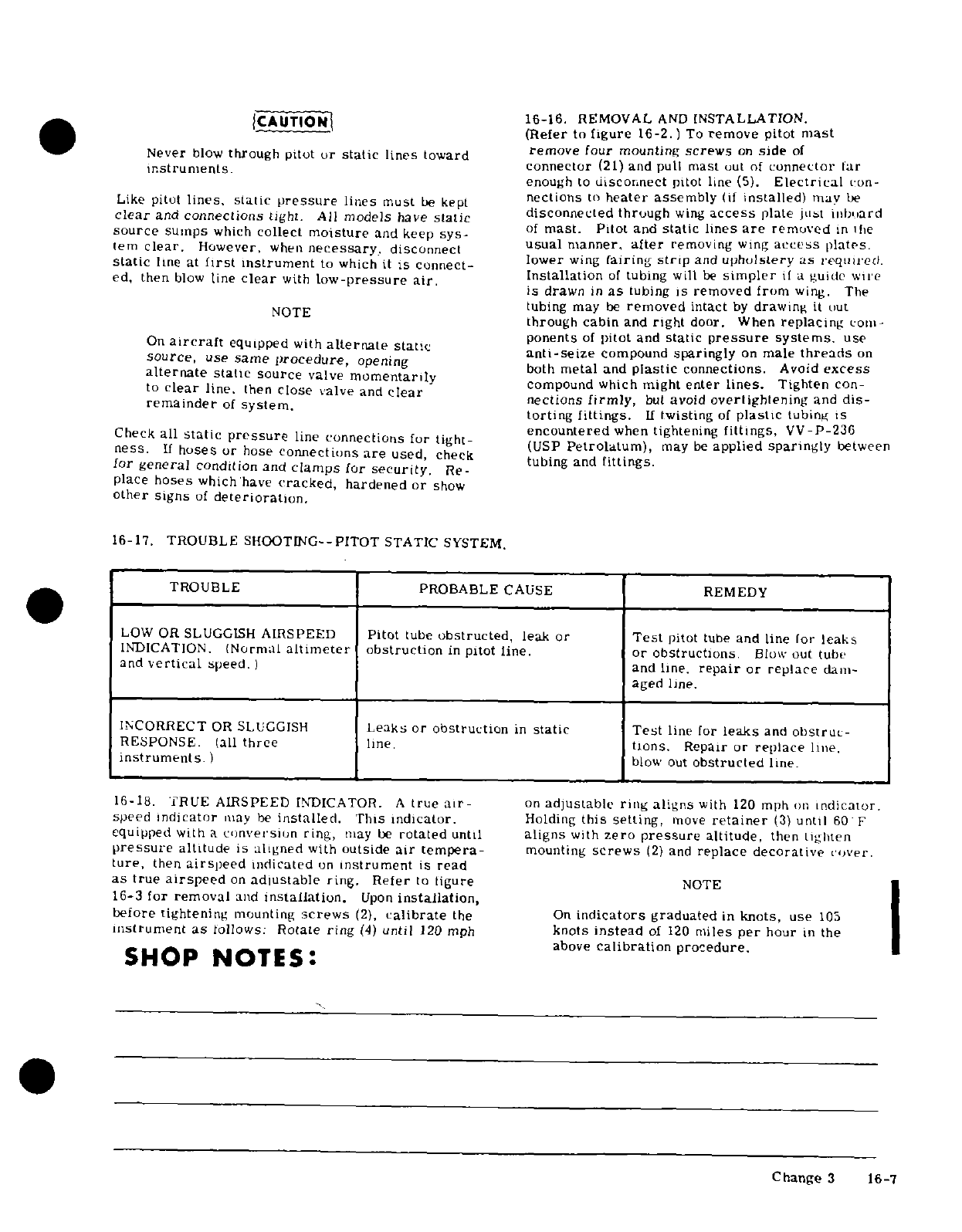
|CAUTIONI
16-16.
REMOVAL
AND
INSTALLATION.
(Refer
to
figure
16-2.)
To
remove
pitot
mast
Never
blow
through
pitot
or
static
lines
toward
remove
our
mounting
screws
on
side
of
instruments.
connector
(21)
and
pull
mast
uut
of
connector
tar
enough
to
disconnect
pitot
line
(5).
Electrical
con-
Like
pilot
lines, static
pressure
lines
must
be
kept
neclions
to
heater assembly
(if
installed)
may
be
clear
and
connections
tight. All
models
have
static
disconnected
through
wing
access
plate
just
inb.ard
source
sumps
which
collect
moisture
and
keep
sys-
of
mast.
Piot
and
static lines
are
removed
in
e
usual
manner,
alter
removing
wing
access
plates.
(em
clear.
However,
when
necessary,
disconnect
usual
manner,
after
removing
wing
access
plates
static
line
at
first
instrument
to
which
it
is connect-
lower
wing
(airing
strip
and
upholstery
as
requied.
ed, then
blow
line
clear
with
low-pressure
air.
i
ir
ed, then
blow
line
clear
with
low-pressure
air.
Installation
of
tubing
will
be
simpler
if
a
guide
wiie
is
drawn
in
as
tubing
is
removed
from
wing.
The
tubing
may
be
removed
intact
by
drawing
it
out
through
cabin
and
right
door.
When
replacing
com-
ponents
of
pilot
and
static
pressure
systems.
use
On
aircraft
equipped
with
alternate
static
anti-seize
compound
sparingly
on
male
threads
on
source,
use
same
procedure,
opening
both
metal
and
plastic
connections.
Avoid
excess
alternate
static
source
valve
momentarily
compound which
might
enter
lines.
Tighten
con-
to
clear
line,
then
close
valve
and
clear
nections
firmly,
but
avoid
overlighlening
and
dis-
remainder
of
system. torting
fittings.
If
twisting
of
plastic
tubing
is
encountered
when
tightening
fittings,
VV-P-236
Check
all
static
pressure
line
connections
for
tight-
encP
etrolatume
,
may
be
applied
sparingly
between
ness.
If
hoses
or
hose
connections
are
used,
check
tubing
and
fittings
for
general
condition
and
clamps
for
security.
Re-
place
hoses
which
have
cracked,
hardened
or
show
other
signs
of
deterioration.
16-17.
TROUBLE
SHOOTING--PITOT
STATIC
SYSTEM.
TROUBLE
PROBABLE
CAUSE
REMEDY
LOW
OR
SLUGGISH
AIRSPEED
Pitot
tube
obstructed,
leak
or
Test
pitot
tube
and
line
for
leaks
INDICATION.
(Normal
altimeter
obstruction
in
pitot
line.
or obstructions.
Blow
out
tube
and
vertical
speed. ) and
line.
repair
or replace
dam-
aged
line.
INCORRECT
OR
SLUGGISH
Leaks
or
obstruction
in
static
Test
line
for
leaks
and
obstruc-
RESPONSE.
(all
three
line.
tions.
Repair
or
replace
line.
instruments.
)
blow
out
obstructed
line.
16-18.
TRUE
AIRSPEED
INDICATOR.
A
true
air-
on
adjustable ring
aligns
with
120
mph
on
indicator.
speed
indicator
may
be
installed.
This
indicator.
Holding
this setting,
move
retainer
(3)
until
60
F
equipped
with
a
conversion
ring,
may
be
rotated
until
aligns
with
zero
pressure
altitude,
then
Lighten
pressure
altitude
is
aligned
with
outside
air tempera-
mounting
screws
(2)
and
replace decorative
cover.
ture,
then
airspeed
indicated
on
instrument
is
read
as
true
airspeed
on
adlustable
ring.
Refer
to
ligure
NOTE
16-3
for
removal
and
installation.
Upon
installation,
before tightening
mounting
screws
(2),
calibrate
the
On
indicators
graduated
in
knots,
use
105
instrument
as
follows:
Rotate
ring
(4)
until
120
mph
knots
instead
of
120
miles
per
hour
in the
_~~ ~~~SHOP
NOTES:
~above
calibration
procedure.
~~~~~~~~~~~~~ChangeSHOP
NO ES:16-7
Change
3
16-7
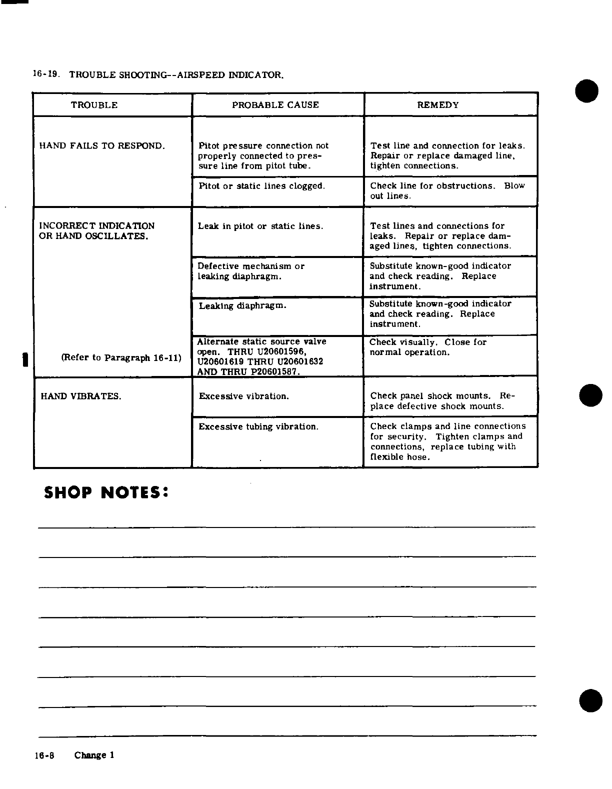
16-19. TROUBLE
SHOOTING-AIRSPEED
INDICATOR.
TROUBLE
PROBABLE
CAUSE
REMEDY
HAND
FAILS
TO RESPOND.
Pitot
pressure
connection
not
Test
line
and
connection
for
leaks.
properly
connected
to
pres-
Repair
or
replace
damaged
line,
sure
line
from
pitot
tube.
tighten
connections.
Pitot
or
static
lines
clogged.
Check
line
for
obstructions.
Blow
out
lines.
INCORRECT
INDICATION
Leak
in
pitot
or
static
lines.
Test
lines
and
connections
for
OR
HAND
OSCILLATES.
leaks.
Repair
or
replace
dam-
aged
lines,
tighten
connections.
Defective
mechanism
or
Substitute
known-good
indicator
leaking
diaphragm.
and
check
reading.
Replace
instrument.
Leaking
diaphragm. Substitute
known-good
indicator
and
check
reading.
Replace
instrument.
Alternate
static
source
valve
Check
visually.
Close
for
open.
THRU
U20601596,
normal operation.
(Refer
to
Paragraph
16-11)
U20601619
THRU U20601632
AND
THRU
P20601587.
HAND
VIBRATES.
Excessive
vibration.
Check panel
shock
mounts.
Re-
place
defective
shock
mounts.
Excessive
tubing
vibration.
Check
clamps
and
line
connections
for
security.
Tighten
clamps
and
connections,
replace
tubing with
flexible
hose.
SHOP
NOTES:
16-8
Change
1
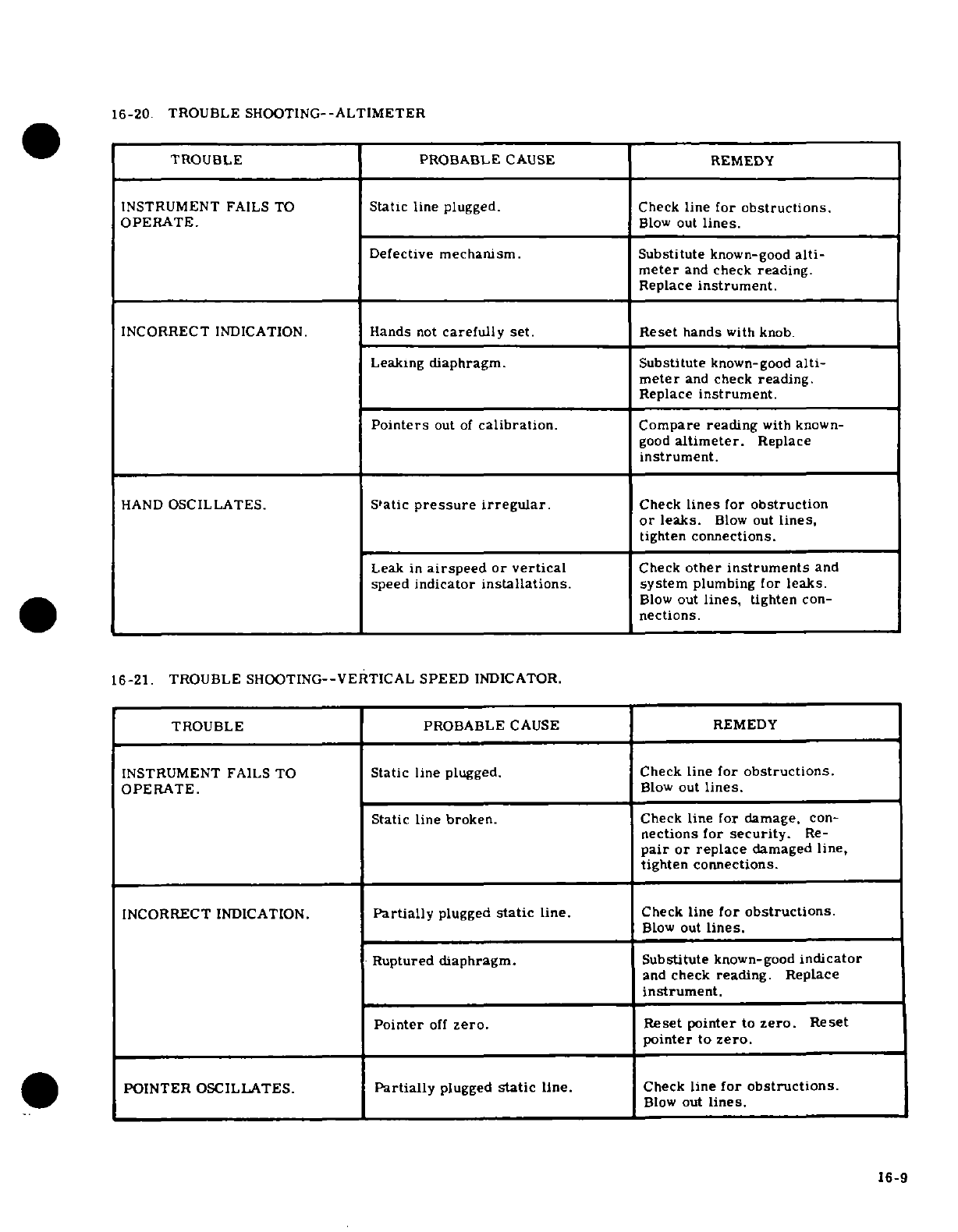
16-20.
TROUBLE
SHOOTING--ALTIMETER
0
TROUBLE
PROBABLE
CAUSE
REMEDY
INSTRUMENT
FAILS
TO
Static
line
plugged.
Check
line
for
obstructions.
OPERATE.
Blow
out
lines.
Defective
mechanism. Substitute
known-good
alti-
meter
and
check
reading.
Replace
instrument.
INCORRECT
INDICATION.
Hands
not
carefully
set.
Reset
hands
with knob.
Leaking
diaphragm.
Substitute
known-good
alti-
meter
and
check
reading.
Replace
instrument.
Pointers
out
of
calibration.
Compare reading
with
known-
good
altimeter.
Replace
instrument.
HAND
OSCILLATES.
Static
pressure
irregular.
Check
lines
for
obstruction
or
leaks.
Blow
out
lines,
tighten
connections.
Leak
in
airspeed
or
vertical
Check
other
instruments
and
speed
indicator
installations.
system
plumbing
for
leaks.
Blow
out
lines,
tighten
con-
nections.
16-21.
TROUBLE
SHOOTING--VERTICAL
SPEED
INDICATOR.
TROUBLE PROBABLE
CAUSE
REMEDY
INSTRUMENT
FAILS
TO
Static
line
plugged.
Check
line
for
obstructions.
OPERATE.
Blow
out
lines.
Static line
broken.
Check
line
for
damage,
con-
nections
for
security.
Re-
pair
or
replace
damaged
line,
tighten
connections.
INCORRECT
INDICATION.
Partially
plugged
static
line.
Check
line
for
obstructions.
Blow
out
lines.
Ruptured
diaphragm.
Substitute
known-good
indicator
and
check
reading.
Replace
instrument.
Pointer
off
zero.
Reset pointer
to
zero.
Reset
pointer
to
zero.
POINTER
OSCILLATES.
Partially
plugged
static
line.
Check
line
for
obstructions.
Blow
out
lines.
16-9
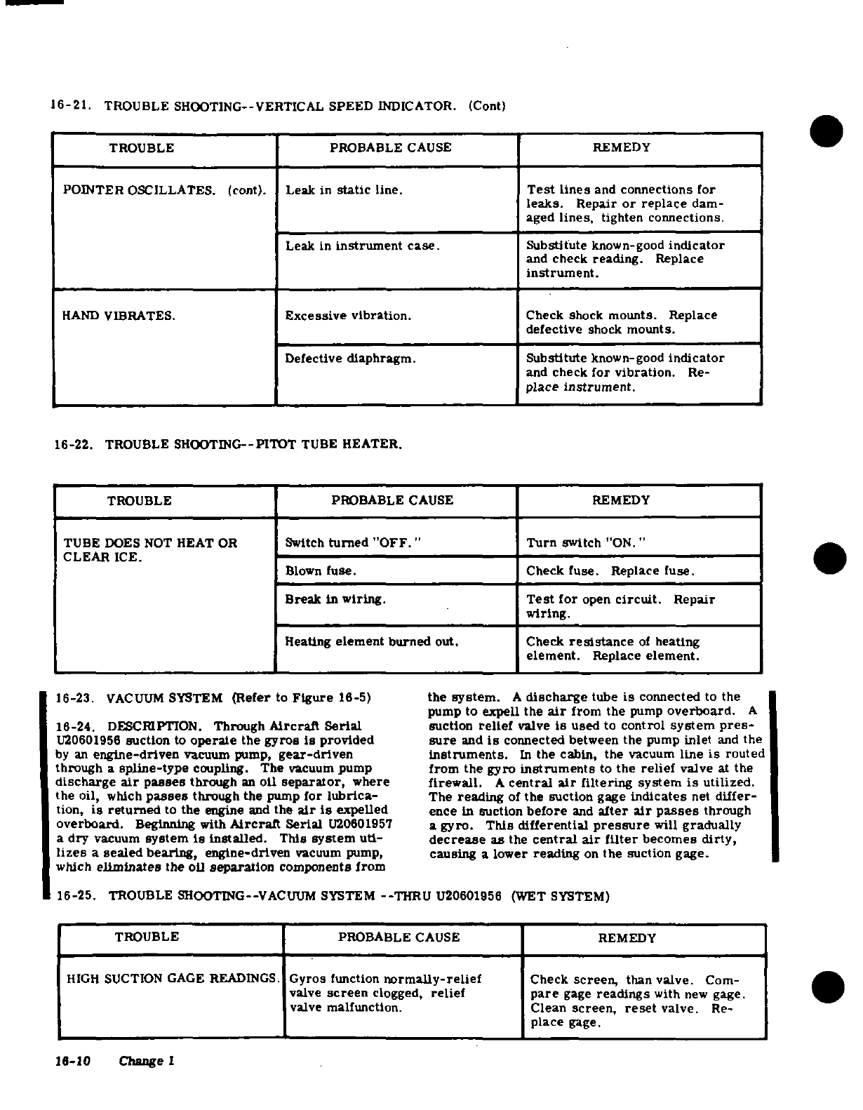
16-21.
TROUBLE SHOOTING--VERTICAL
SPEED
INDICATOR.
(Cont)
TROUBLE
PROBABLE
CAUSE
REMEDY
POINTER
OSCILLATES.
(cont). Leak
in
static
line.
Test lines
and
connections
for
leaks.
Repair
or
replace
dam-
aged
lines,
tighten
connections.
Leak
in
instrument
case.
Substitute
known-good
indicator
and
check
reading.
Replace
instrument.
HAND
VIBRATES.
Excessive
vibration.
Check
shock
mounts.
Replace
defective
shock
mounts.
Defective
diaphragm.
Substitute
known-good
indicator
and
check
for
vibration.
Re-
place
instrument.
16-22.
TROUBLE
SHOOTING--PITOT
TUBE
HEATER.
TROUBLE PROBABLE
CAUSE
REMEDY
TUBE
DOES
NOT
HEAT
OR
Switch
turned
"OFF."
Turn
switch
"ON."
CLEAR
ICE.
Blown
fuse.
Check
fuse.
Replace
fuse.
Break
in
wiring.
Test for
open
circuit.
Repair
wiring.
Heating
element
burned
out.
Check
resistance
of
heating
element.
Replace
element.
16-23.
VACUUM
SYSTEM
(Refer
to
Figure
16-5)
the
system.
A
discharge
tube
is
connected
to the
pump
to expell
the
air
from
the
pump
overboard.
A
16-24.
DESCRIPTION.
Through
Aircraft Serial
suction
relief
valve
is
used
to
control
system
pres-
U20601956
suction
to
operate
the
gyros
is
provided
sure
and
is
connected
between
the
pump
inlet
and
the
by
an
engine-driven
vacuum pump,
gear-driven instruments.
In
the
cabin,
the
vacuum
line
is
routed
through
a
spline-type
coupling.
The
vacuum
pump
from
the
gyro
instruments
to
the
relief
valve
at
the
discharge
air
passes
through
an
oil
separator,
where
firewall.
A
central
air
filtering
system
is
utilized.
the
oil,
which
passes
through the
pump
for
lubrica-
The
reading
of
the
suction
gage
indicates
net
differ-
tion,
is
returned
to
the
engine
and
the
air
is
expelled
ence
in
suction
before
and
alter
air
passes
through
overboard.
Beginning with
Aircraft
Serial
U20601957
a
gyro.
This
differential
pressure
will
gradually
a
dry
vacuum
system
is
installed.
This
system uti-
decrease
as
the
central
air
filter
becomes
dirty,
lizes
a
sealed
bearing,
engine-driven
vacuum pump,
causing
a
lower
reading
on
the suction
gage.
which
eliminates
the oil
separation
components
from
16-25.
TROUBLE
SHOOTING--VACUUM
SYSTEM
--
THRU
U20601956 (WET
SYSTEM)
TROUBLE PROBABLE
CAUSE
REMEDY
HIGH
SUCTION
GAGE
READINGS.
Gyros
function
normally-relief
Check
screen,
than
valve.
Com-
valve
screen
clogged,
relief
pare
gage
readings
with
new
gage.
0
valve
malfunction.
Clean
screen,
reset
valve.
Re-
place
gage.
16-10
Change
1
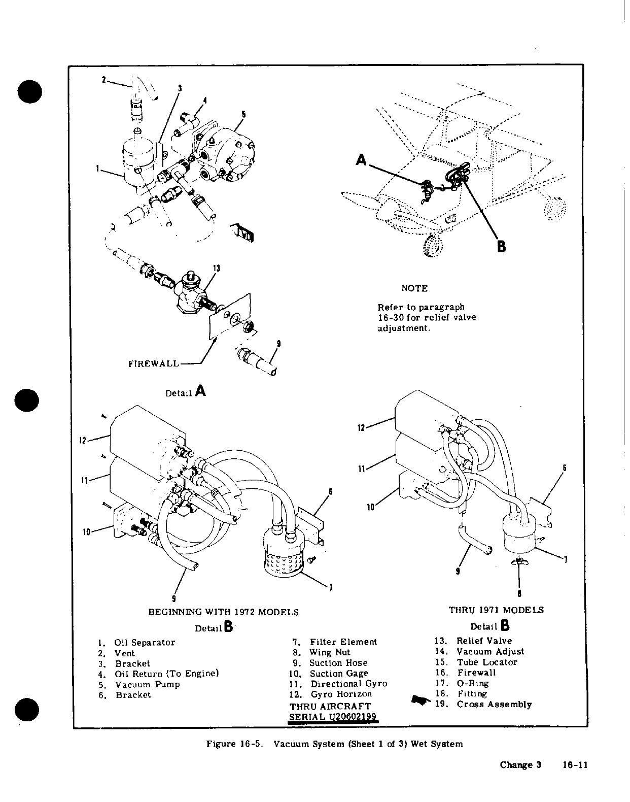
NOTE
Refer
to
paragraph
16-30
for
relief
valve
adjustment.
1.
Oil
Separator
7.
Filter
Element
13.
Relief
Valve
2.
Vent
8.
Wing
Nut
14.
Vacuum
Adjust
3.
Bracket
9.
Suction Hose
15.
Tube
Locator
4.
Oil
Return
(To
Engine)
10.
Suction
Gage
16.
Firewall
5.
Vacuum
Pump
11.
Directional
Gyro
17.
O-Ring
6.
Bracket
12.
Gyro
Horizon
18.
Fitting
19.
Cross
Assembly
Figure
16-5.
Vacuum
System
(Sheet
1
of
3)
Wet
System
Change
3
16-11
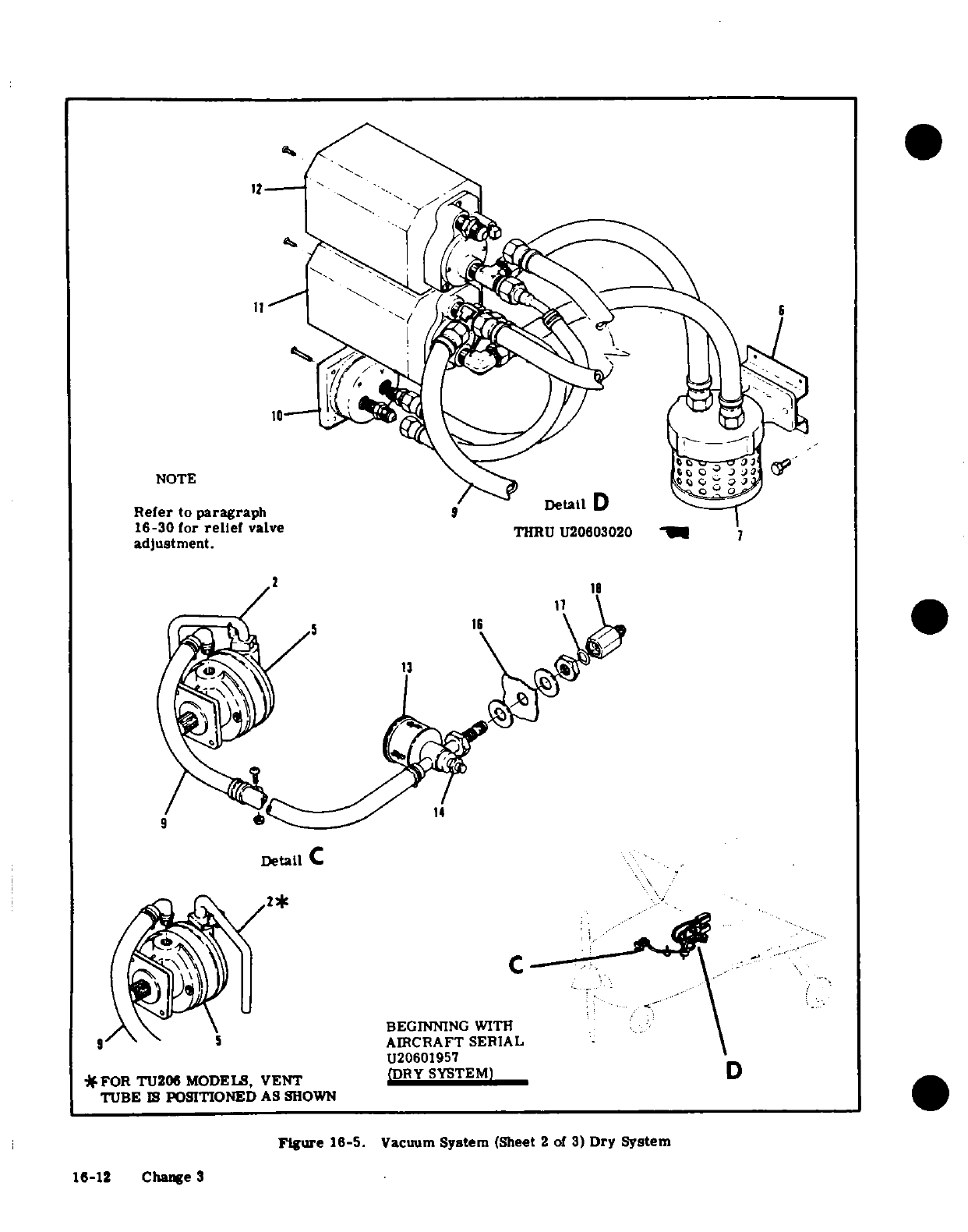
NOTE
Refer
to
paragraph
Detail
16-30
for
relief
valve
THRU
U20603020
7
adjustment.
2 18
16
*
Detail
C
2*
BEGINNING
WITH
5
AIRCRAFT
SERIAL
U20601957
*FOR
TU206
MODELS,
VENT
(DRY
SYSTEM)
D
TUBE
IS
POSITIONED
AS
SHOWN
Figure
18-5.
Vacuum
System
(Sheet
2
of
3)
Dry System
16-12 Change 3
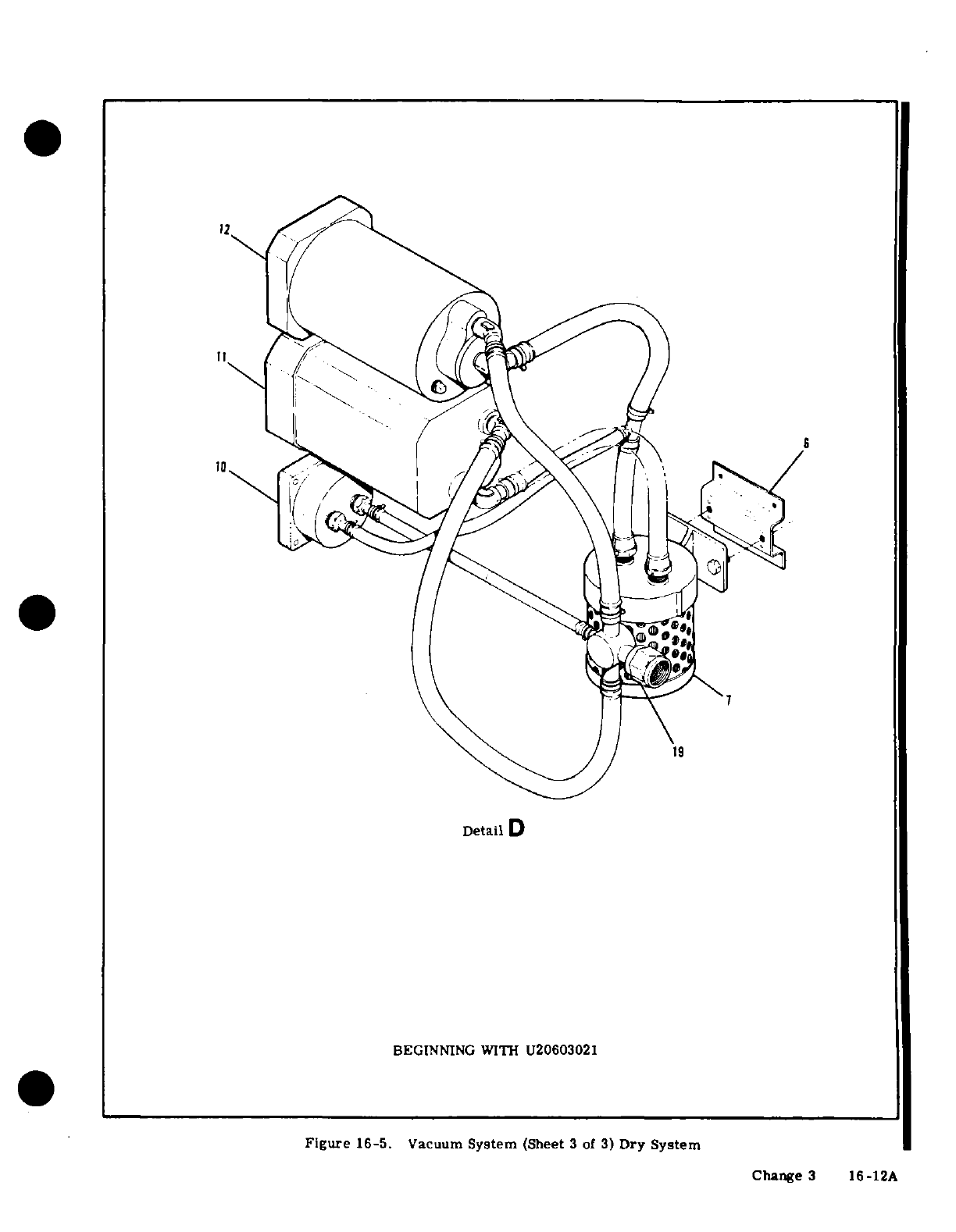
Detail D
BEGINNING
WITH
U20603021
Figure
16-5.
Vacuum
System
(Sheet
3
of
3)
Dry System
Change
3
16-12A
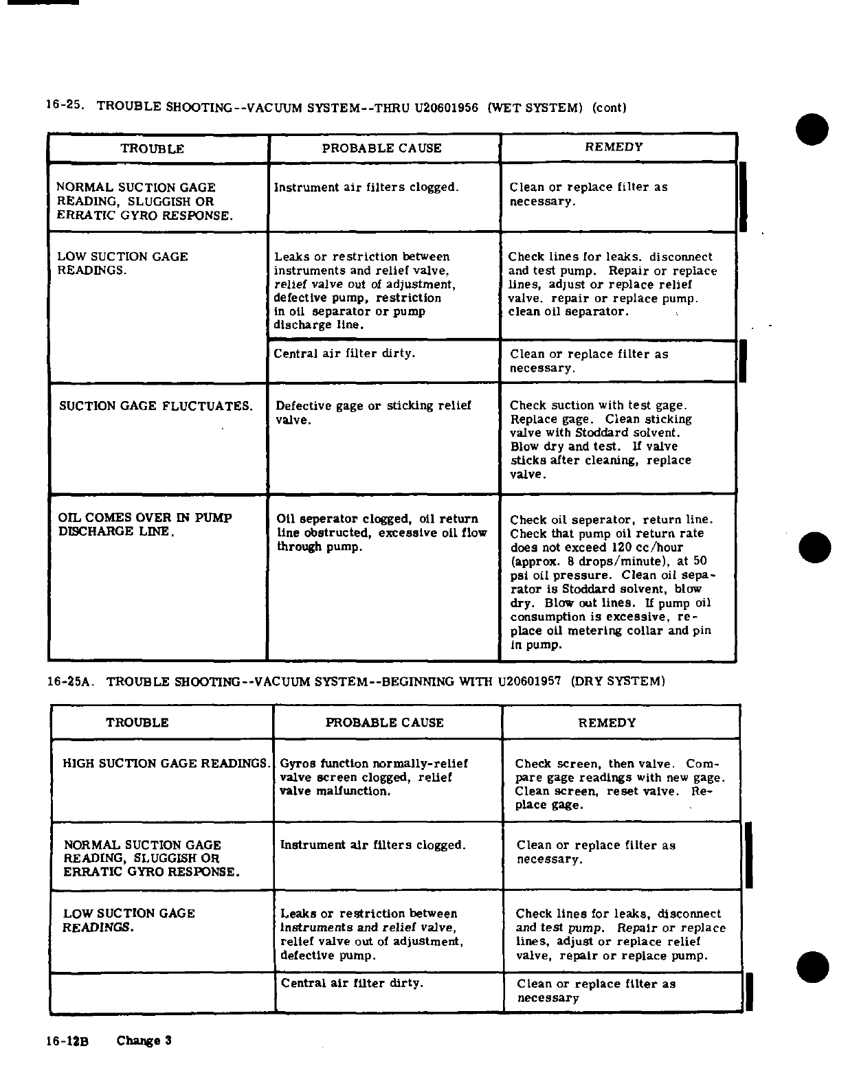
16-25.
TROUBLE
SHOOTING--VACUUM
SYSTEM--THRU
U20601956
(WET
SYSTEM)
(cont)
TROUBLE
PROBABLE
CAUSE
REMEDY
NORMAL SUCTION
GAGE
Instrument
air
filters
clogged.
Clean
or
replace
filter
as
READING,
SLUGGISH
OR
necessary.
ERRATIC
GYRO
RESPONSE.
LOW
SUCTION
GAGE
Leaks
or
restriction
between
Check
lines for
leaks.
disconnect
READINGS.
instruments
and
relief
valve.
and
test
pump.
Repair
or
replace
relief
valve
out
of
adjustment,
lines,
adjust
or
replace
relief
defective
pump,
restriction
valve.
repair
or
replace
pump.
in
oil
separator
or
pump
clean
oil
separator.
discharge
line.
Central
air
filter
dirty.
Clean
or
replace
filter
as
necessary.
SUCTION GAGE
FLUCTUATES.
Defective
gage
or
sticking
relief
Check
suction
with
test
gage.
valve.
Replace
gage.
Clean
sticking
valve
with
Stoddard
solvent.
Blow
dry
and
test.
If
valve
sticks
after
cleaning,
replace
valve.
OIL
COMES
OVER
IN
PUMP
Oil
seperator
clogged,
oil
return
Check
oil
seperator,
return
line.
DISCHARGE LINE.
line
obstructed, excessive
oil
flow
Check
that
pump
oil
return rate
through
pump.
does
not
exceed
120
cc/hour
(approx.
8
drops/minute),
at
50
psi
oil
pressure.
Clean
oil
sepa-
rator
is
Stoddard
solvent,
blow
dry.
Blow
out
lines.
If
pump
oil
consumption
is
excessive,
re-
place
oil
metering
collar
and
pin
in
pump.
16-25A. TROUBLE
SHOOTING--VACUUM
SYSTEM--BEGINNING
WITH
U20601957 (DRY SYSTEM)
TROUBLE PROBABLE
CAUSE
REMEDY
HIGH
SUCTION
GAGE
READINGS.
Gyros
function
normally-relief
Check
screen,
then valve.
Com-
valve
screen
clogged,
relief
pare
gage
readings
with
new
gage.
valve
malfunction.
Clean
screen,
reset
valve.
Re-
place
gage.
NORMAL SUCTION
GAGE
Instrument
air
filters
clogged.
Clean
or
replace
filter
as
READING,
SLUGGISH
OR
necessary.
ERRATIC
GYRO
RESPONSE.
LOW SUCTION
GAGE
Leaks
or
restriction
between
Check
lines
for
leaks,
disconnect
READINGS.
instruments
and
relief
valve,
and
test
pump.
Repair
or
replace
relief
valve
out
of
adjustment,
lines,
adjust
or
replace
relief
defective
pump.
valve,
repair
or
replace
pump.
Central
air
filter
dirty.
Clean
or
replace
filter
as
necessary
16-12B
Change 3
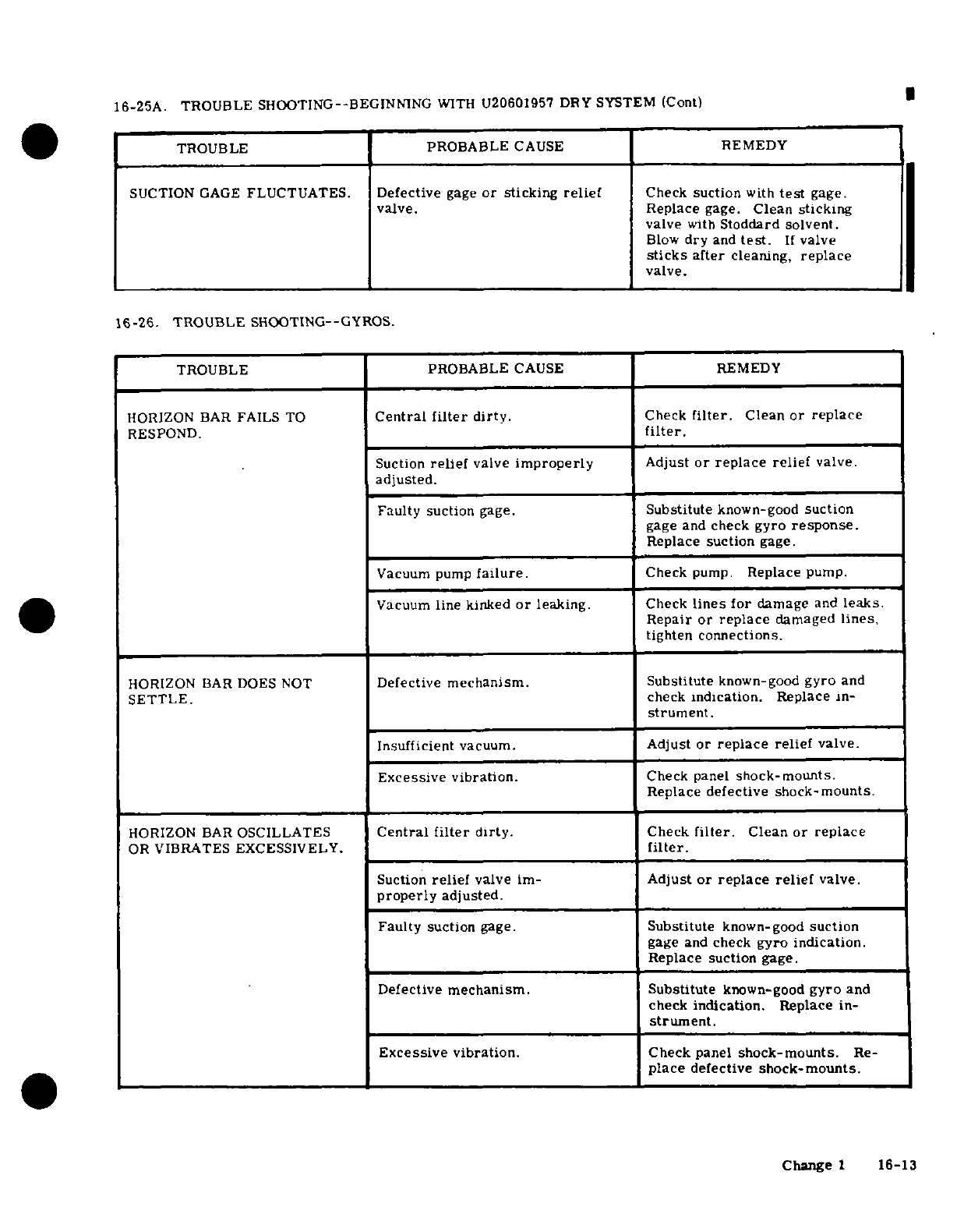
16-25A. TROUBLE
SHOOTING--BEGINNING
WITH
U20601957
DRY
SYSTEM
(Cont)
TROUBLE
PROBABLE
CAUSE
REMEDY
SUCTION
GAGE
FLUCTUATES.
Defective
gage
or
sticking
relief
Check
suction
with
test
gage.
valve.
Replace
gage.
Clean
sticking
valve
with
Stoddard solvent.
Blow
dry
and
test.
If
valve
sticks
after
cleaning,
replace
valve.
16-26.
TROUBLE
SHOOTING--GYROS.
TROUBLE PROBABLE
CAUSE
REMEDY
HORIZON BAR
FAILS
TO
Central
filter
dirty.
Check
filter.
Clean
or replace
RESPOND.
filter.
Suction
relief
valve
improperly
Adjust
or
replace
relief
valve.
adjusted.
Faulty suction
gage.
Substitute
known-good
suction
gage
and
check
gyro
response.
Replace
suction
gage.
Vacuum pump
failure.
Check
pump.
Replace
pump.
Vacuum
line
kinked
or
leaking.
Check
lines
for
damage
and
leaks.
Repair
or
replace
damaged
lines.
tighten connections.
HORIZON
BAR
DOES NOT
Defective
mechanism.
Substitute
known-good
gyro
and
SETTLE.
check
indication.
Replace
in-
strument.
Insufficient
vacuum.
Adjust
or
replace
relief
valve.
Excessive
vibration.
Check panel
shock-mounts.
Replace
defective
shock-mounts.
HORIZON BAR
OSCILLATES
Central
filter
dirty.
Check
filter.
Clean
or replace
OR
VIBRATES EXCESSIVELY.
filter.
Suction
relief
valve
im-
Adjust
or
replace
relief
valve.
properly
adjusted.
Faulty
suction
gage.
Substitute
known-good
suction
gage
and
check
gyro indication.
Replace
suction
gage.
Defective
mechanism.
Substitute
known-good
gyro
and
check
indication.
Replace
in-
strument.
Excessive vibration.
Check
panel
shock-mounts.
Re-
place
defective
shock-mounts.
Change
1
16-13
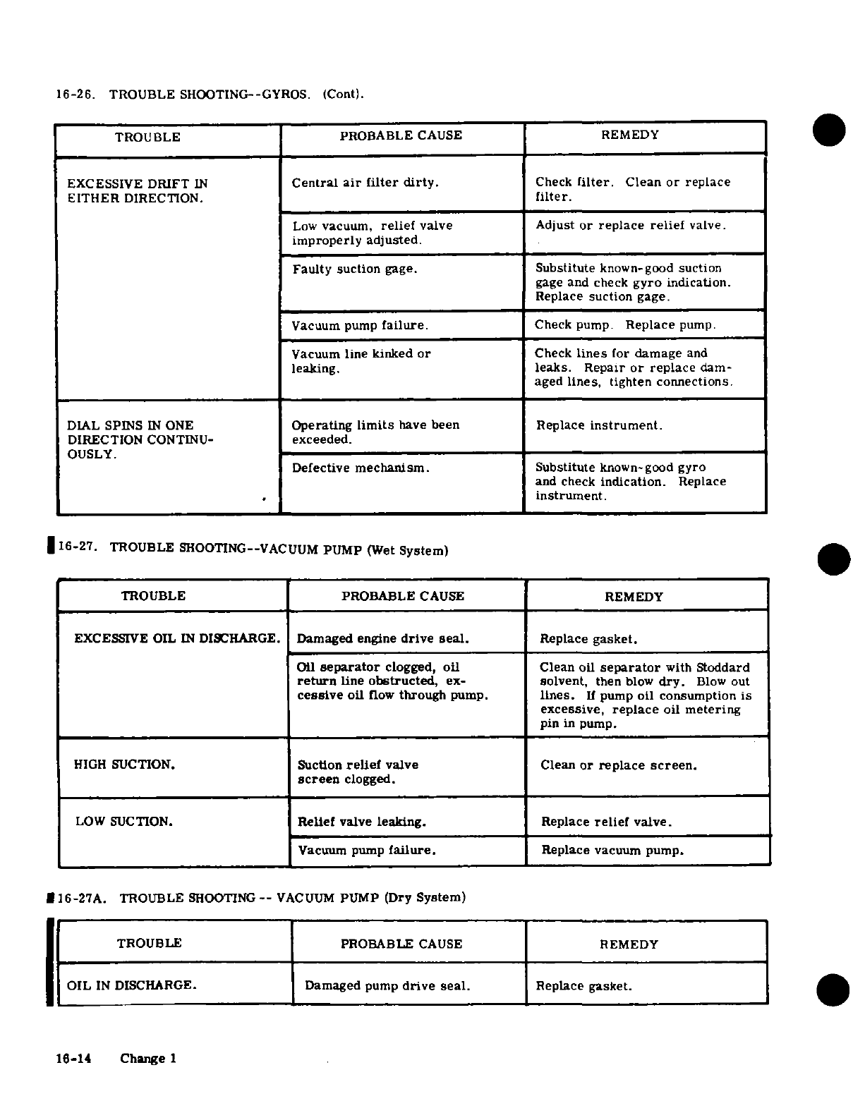
16-26.
TROUBLE
SHOOTING--GYROS.
(Cont).
TROUBLE PROBABLE
CAUSE REMEDY
EXCESSIVE
DRIFT
IN
Central
air
filter
dirty.
Check
filter.
Clean
or
replace
EITHER
DIRECTION.
filter.
Low
vacuum,
relief
valve
Adjust
or
replace
relief
valve.
improperly
adjusted.
Faulty
suction
gage.
Substitute
known-good
suction
gage and
check
gyro
indication.
Replace
suction
gage.
Vacuum pump
failure.
Check pump.
Replace
pump.
Vacuum
line kinked
or
Check
lines
for
damage
and
leaking.
leaks.
Repair
or
replace
dam-
aged
lines,
tighten connections.
DIAL
SPINS
IN
ONE
Operating
limits
have
been
Replace
instrument.
DIRECTION
CONTINU-
exceeded.
OUSLY.
Defective
mechanism.
Substitute
known-good gyro
and
check
indication.
Replace
instrument.
16-27.
TROUBLE
SHOOTING--VACUUM
PUMP
(Wet
System)
TROUBLE
PROBABLE
CAUSE
REMEDY
EXCESSIVE
OIL
IN
DISCHARGE.
Damaged engine
drive
seal.
Replace
gasket.
Oil
separator
clogged,
oil
Clean oil
separator
with
Stoddard
return
line
obstructed,
ex-
solvent,
then
blow
dry.
Blow out
cessive
oil
flow
through
pump.
lines.
If
pump
oil
consumption
is
excessive,
replace
oil
metering
pin
in
pump.
HIGH
SUCTION.
Suction
relief
valve
Clean
or
replace
screen.
screen
clogged.
LOW
SUCTION.
Relief
valve
leaking.
Replace
relief
valve.
Vacuum
pump
failure.
Replace
vacuum
pump.
16-27A.
TROUBLE
SHOOTING--
VACUUM
PUMP (Dry
System)
TROUBLE
PROBABLE
CAUSE
REMEDY
OIL
IN
DISCHARGE.
Damaged
pump
drive
seal.
Replace
gasket.
16-14
Change 1
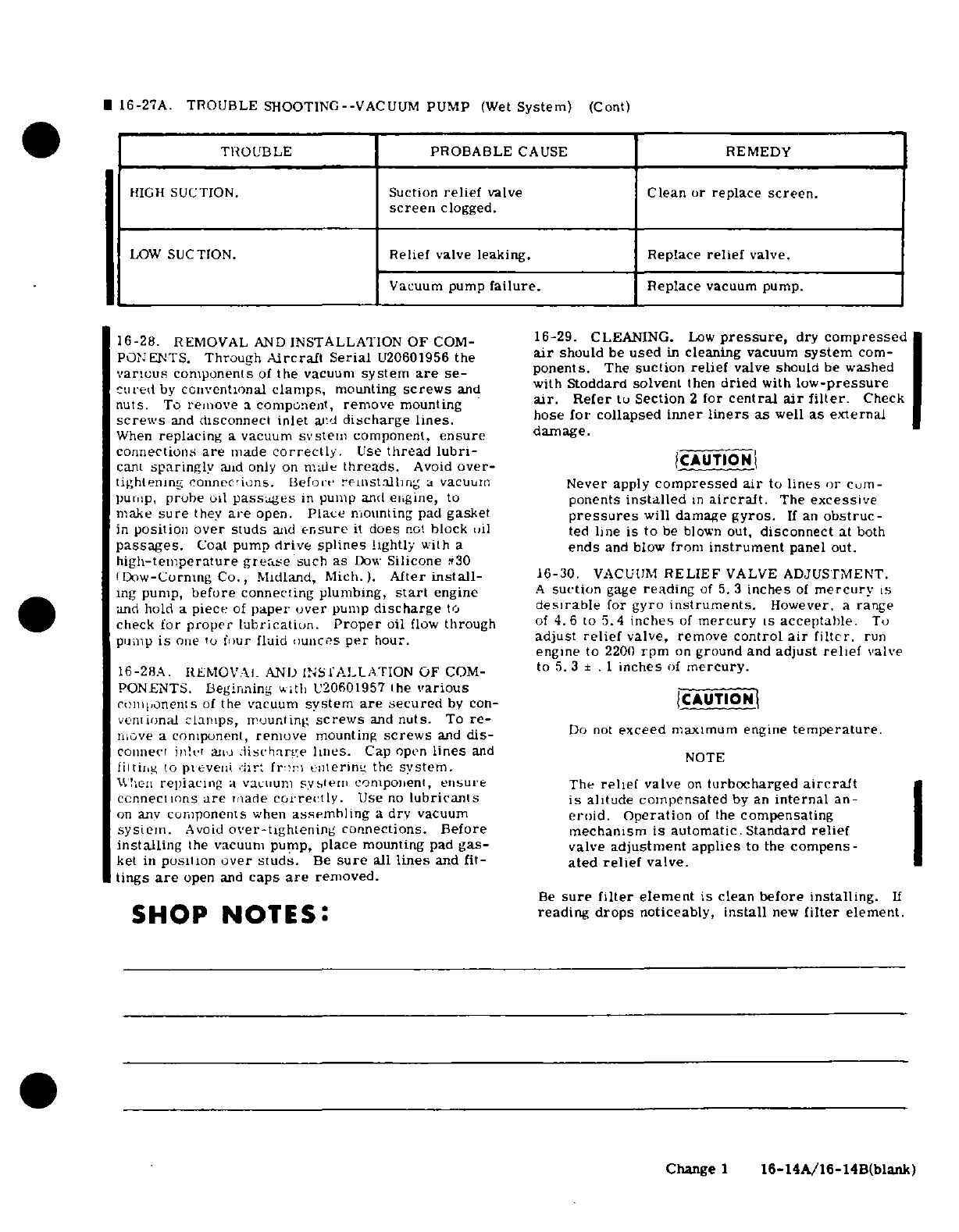
©
16-27A.
TROUBLE
SHOOTING-VACUUM
PUMP
(Wet
System)
(Cont)
TROUBLE
PROBABLE
CAUSE
REMEDY
HIGH
SUCTION.
Suction
relief
valve
Clean or
replace
screen.
screen
clogged.
LOW
SUCTION.
elief
valve
leaking. Replace
relief
valve.
Vacuum
pump
failure.
Replace
vacuum pump.
16-28.
REMOVAL
AND
INSTALLATION
OF
COM-
16-29.
CLEANING.
Low
pressure,
dry
compressed
PONENTS.
Through
Aircraft
Serial
U20601956
the
air
should
be
used
in
cleaning
vacuum
system
com-
varicus
components
of
the
vacuum
system
are
se-
ponents.
The
suction
relief
valve
should
be
washed
cured
by
conventional
clamps,
mounting
screws
and with
Stoddard
solvent
then
dried
with
low-pressure
nuts.
To
remove
a
component,
remove
mounting
air.
Refer
to
Section
2
for
central
air
filter.
Check
screws
and
disconnect
inlet
anrd
discharge
lines.
hose
for
collapsed
inner
liners
as
well
as
external
When
replacing
a
vacuum
system
component.
ensure
damage.
connections
are
made
correctly.
Use
thread
lubri-
cant
sparingly
and
only
on
male
threads.
Avoid
over-
CAUTION
tightening connections.
Before
reinstalling
a
vacuum
Never
apply
compressed
air
to
lines
or
com-
pump,
probe
oil
passages
in
pump
and
engine,
to
ponents
installed
in
aircraft.
The
excessive
make
sure
they
are
open.
Place
mounting
pad
gasket
pressures
will
damage
gyros.
If
an
obstruc-
in
position
over
studs
and
ensure
it
does
not
block
oil
ted
line
is
to
be
blown
out,
disconnect
at
both
passages.
Coat
pump
drive splines
lightly
with
a
ends
and
blow
from
instrument
panel
out.
high-temperature
grease
such
as
Dow
Silicone
#30
Dow-Corning
Co.,
Midland,
Mich.).
™fter
install-
16-30.
VACUUM
RELIEF
VALVE
ADJUSTMENT.
ing
pump,
before
connecting
plumbing,
start
engine
A
suction
gage
reading
of
5. 3
inches
of
mercury
is
and
hold
a
piece
of
paper
over
pump
discharge
to
desirable
for
gyro
instruments.
However,
a
range
check
for
proper
lubrication.
Proper
oil
flow
through
of
4.6
to
5.4
inches
of
mercury
is
acceptable.
To
pump
is
one
to
ifour
fluid
ouncrs
per
hour.
adjust
relief
valve,
remove
control
air
filter.
run
engine
to
2200
rpm
on
ground
and
adjust
relief
valve
16-28A.
RIEMOVALI
ANID
INSfTALLATION
OF
COM-
to
5.3
±
.1
inches
of
mercury.
PONENTS.
Beginning
with
U20
6
01957
the
various
comiponents
of
the
vacuum
system
are
secured
by con-
CAUTIONI
veonionat
clamps,
rmounting
screws
and
nuts.
To
re-
imve
a
component,
remove
mounting
screws
and
dis-
Do
not
exceed
maximum engine
temperature.
comnnec
in'lv
aji
:tischariLe
lines.
Cap open
lines
and
N
liltiig
to
pieveni.
dir:
fr.ri
lnlerilng
the
system.
U'l-en
repiacing
a
vacuum
systemi
component,
ensure
The
relief
valve
on
turbocharged
aircraft
connecimins
are
miade
correctly.
Use
no
lubricanls
is
alitude
compensated
by
an
internal
an-
on
anv
components
when
assemhlng
a
dry vacuum
eroid.
Operation
of
the
compensating
sysiemn. Avoid
over-tightening
connections. Before
mechanism
is
automatic. Standard
relief
installing
the
vacuum
pump,
place
mounting
pad
gas-
valve
adjustment applies
to
the
compens-
ket
in
position
over studs.
Be
sure
all
lines
and
fit-
ated
relief
valve.
tings
are
open
and
caps
are
removed.
Be
sure
filter
element
is
clean
before
installing.
If
SHOP
NOTES:
reading
drops
noticeably,
install
new
filter
element.
Change
1
16-14A/16-14B(blank)
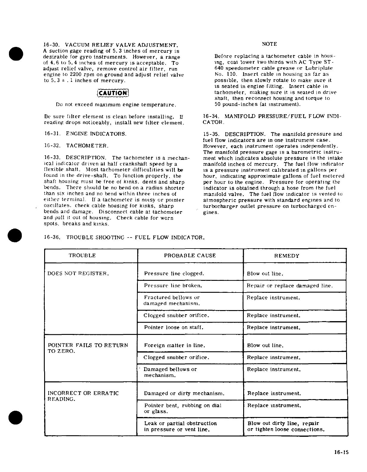
16-30.
VACUUM
RELIEF
VALVE
ADJUSTMENT.
NOTE
A
suction
gage
reading
of
5.3
inches
of
mercury
is
desirable
for
gyro
instruments.
However,
a
range
Before
replacing
a
tachometer
cable
in
hous
of
4.6
to
5.4
inches
of
mercury
is
acceptable.
To
Ing,
coat
lower
two
thirds
with
AC
Type
ST-
adjust
relief
valve,
remove
control
air
filter,
run
640
speedometer
cable
grease
or
Lubriplate
engine
to
2200
rpm
on
ground
and
adjust
relief
valve
No.
110.
Insert
cable
in
housing
as
far
as
to
5.3
±
.
1
inches
of
mercury.
possible,
then
slowly
rotate
to
make
sure
it
is
seated
in
engine
fitting.
Insert
cable
in
CAUTION
tachometer,
making
sure
it
is
seated
in
drive
shaft,
then
reconnect
housing
and
torque
to
Do
not
exceed maximum
engine
temperature.
50
pound-inches
(at
instrument).
Be
sure
filter
element
is
clean
before
installing.
If
16-34.
MANIFOLD
PRESSURE/FUEL
FLOW
INDI-
reading
drops
noticeably,
install
new
filter
element.
CATOR.
16-31. ENGINE
INDICATORS.
15-35.
DESCRIPTION.
The
manifold
pressure
and
fuel
flow
indicators
are
in
one
instrument
case.
16-32. TACHOMETER.
However,
each
instrument
operates
independently.
The
manifold
pressure
gage
is
a
barometric
instru-
16-33.
DESCRIPTION.
The
tachometer
is
a
mechan-
ment
which
indicates
absolute
pressure
in
the
intake
ical
indicator driven
at half
crankshaft
speed
by
a
manifold
inches
of
mercury.
The
fuel
flow
indicator
flexible
shaft.
Most
tachometer difficulities
will
be
is
a
pressure
instrument
calibrated
in
gallons
per
found
in
the
drive-shaft.
To
function
properly,
the
hour, indicating
approximate
gallons
of
fuel
metered
shaft
housing
must
be
free
of
kinks,
dents
and
sharp
per
hour
to
the
engine.
Pressure
for
operating
the
bends.
There
should
be
no
bend
on
a
radius
shorter
indicator
is
obtained
through
a
hose
from
the
fuel
than
six
inches
and
no
bend
within
three
inches
of
manifold valve.
The
fuel
flow
indicator
is
vented
to
either
terminal.
If
a
tachometer
is
noisy
or
pointer
atmospheric
pressure
with
standard
engines
and
to
oscillates.
check
cable
housing
for
kinks,
sharp
turbocharger
outlet
pressure
on
turbocharged
en-
bends
and
damage.
Disconnect
cable
at
tachometer
gines.
and
pull
it
out
of
housing.
Check
cable
for
worn
spots.
breaks
and
kinks.
16-36.
TROUBLE
SHOOTING
--
FUEL
FLOW
INDICATOR.
TROUBLE
PROBABLE
CAUSE
REMEDY
DOES
NOT
REGISTER.
Pressure
line
clogged.
Blow
out
line.
Pressure
line
broken.
Repair
or
replace
damaged
line.
Fractured
bellows
or
Replace
instrument.
damaged
mechanism.
Clogged
snubber
orifice.
Replace
instrument.
Pointer
loose
on
staff.
Replace
instrument.
POINTER
FAILS TO
RETURN
Foreign
matter
in
line.
Blow
out
line.
TO
ZERO.
Clogged
snubber
orifice.
Replace
instrument.
Damaged bellows
or
Replace
instrument.
mechanism.
INCORRECT
OR
ERRATIC
Damaged
or
dirty
mechanism.
Replace
instrument.
READING.
Pointer
bent,
rubbing
on
dial
Replace
instrument.
or
glass.
Leak
or
partial
obstruction
Blow
out
dirty
line,
repair
in
pressure
or
vent
line.
or
tighten
loose
connections.
16-15
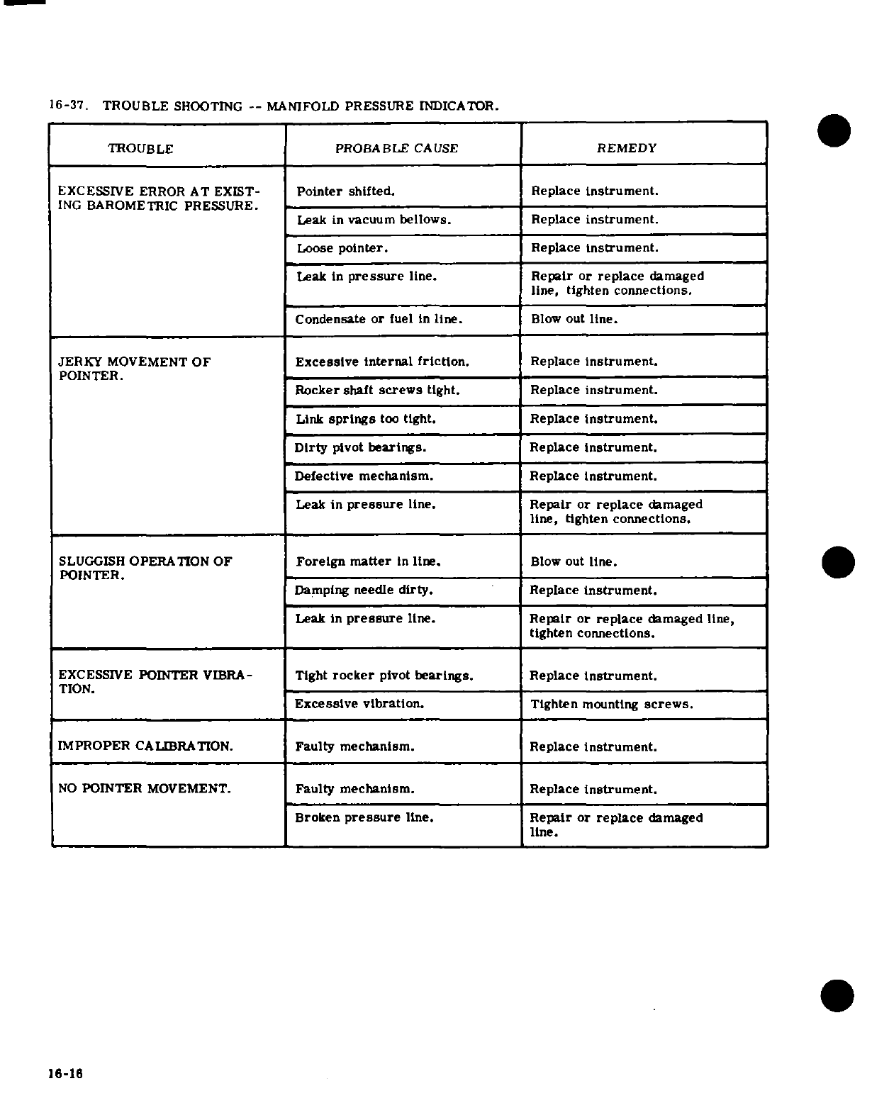
16-37. TROUBLE
SHOOTING
--
MANIFOLD PRESSURE
INDICATOR.
TROUBLE
PROBABLE
CAUSE
REMEDY
EXCESSIVE
ERROR
AT
EXIST-
Pointer
shifted.
Replace
instrument.
ING
BAROMETRIC
PRESSURE.
Leak
in
vacuum
bellows. Replace
instrument.
Loose
pointer.
Replace
instrument.
Leak in
pressure
line.
Repair or
replace
damaged
line,
tighten
connections.
Condensate
or
fuel
in
line.
Blow
out
line.
JERKY
MOVEMENT
OF
Excessive internal
friction.
Replace
instrument.
POINTER.
Rocker
shaft
screws
tight.
Replace
instrument.
Link
springs
too
tight.
Replace
Instrument.
Dirty
pivot
bearings.
Replace
instrument.
Defective
mechanism.
Replace
instrument.
Leak
in
pressure
line.
Repair
or
replace
damaged
line,
tighten
connections.
SLUGGISH
OPERATION OF
Foreign
matter
in
line.
Blow
out
line.
POINTER.
_
Damping
needle
dirty.
Replace
Instrument.
Leak in
pressure
line.
Repair or
replace
damaged
line,
tighten
connections.
EXCESSIVE
POINTER
VIBRA-
Tight
rocker
pivot
bearings.
Replace
instrument.
TION.
Excessive vibration.
Tighten
mounting
screws.
IMPROPER
CALIBRATION.
Faulty mechanism.
Replace
Instrument.
NO
POINTER
MOVEMENT.
Faulty
mechanism.
Replace
instrument.
Broken
pressure
line.
Repair or
replace
damaged
line.
16-16
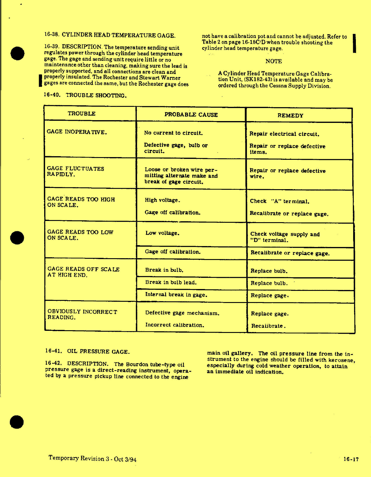
16-38.
CYLINDER
HEAD
TEMPERATURE
GAGE.
not
have
a
calibration
pot
and cannot
be
adjusted.
Refer
to
Table 2
on
page
16-18C/D
when
trouble
shooting
the
16-39.
DESCRIPTION. The
temperature
sending
unit
cylinder
head
temperature
gage.
regulates
power
through
the
cylinder head
temperature
gage. The
gage and
sending
unit
require
little
or
no
NOTE
maintenance other
than
cleaning,
making
sure
the
lead
is
properly
supported,
and
all
connections
are
clean
and
A
Cylinder
Head
Temperature
Gage
Calibra-
properly
insulated.
The Rochester
and
Stewart
Warner
tion
Unit,
(SK182-43)
is
available
and
may
be
gages are connected
the
same,
but
the
Rochester
gage
does
ordered
through
the
Cessna
Supply
Division.
16-40.
TROUBLE
SHOOTING.
TROUBLE
PROBABLE
CAUSE
REMEDY
GAGE
INOPERATIVE.
No
current
to
circuit.
Repair
electrical
circuit.
Defective
gage,
bulb
or
Repair
or
replace
defective
circuit.
items.
GAGE
FLUCTUATES
Loose or
broken
wire
per-
Repair
or
replace
defective
RAPIDLY.
mitting
alternate
make
and
wire.
break
of
gage
circuit.
GAGE
READS
TOO
HIGH
High
voltage.
Check
"A"
terminal.
ON
SCALE.
Gage
off
calibration.
Recalibrate
or
replace
gage.
GAGE
READS TOO
LOW
Low
voltage. Check
voltage supply
and
ON
SCALE. "D"
terminal.
Gage
off
calibration.
Recalibrate
or
replace
gage.
GAGE
READS
OFF
SCALE
Break
in
bulb.
Replace
bulb.
AT
HIGH
END.
Break
in
bulb
lead.
Replace
bulb.
Internal
break
in
gage.
Replace
gage.
OBVIOUSLY
INCORRECT
Defective
gage
mechanism.
Replace
gage.
READING.
Incorrect
calibration.
Recalibrate.
16-41.
OIL
PRESSURE
GAGE.
main
oil
gallery.
The
oil
pressure
line
from
the
in-
strument
to
the
engine should
be
filled
with
kerosene,
16-42.
DESCRIPTION. The
Bourdon
tube-type
oil
especially
during cold
weather
operation,
to
attain
pressure
gage
is
a
direct-reading
instrument,
opera-
an
immediate
oil
indication.
ted
by
a
pressure
pickup
line
connected
to
the
engine
Temporary
Revision
3
-
Oct
3/94
16-17
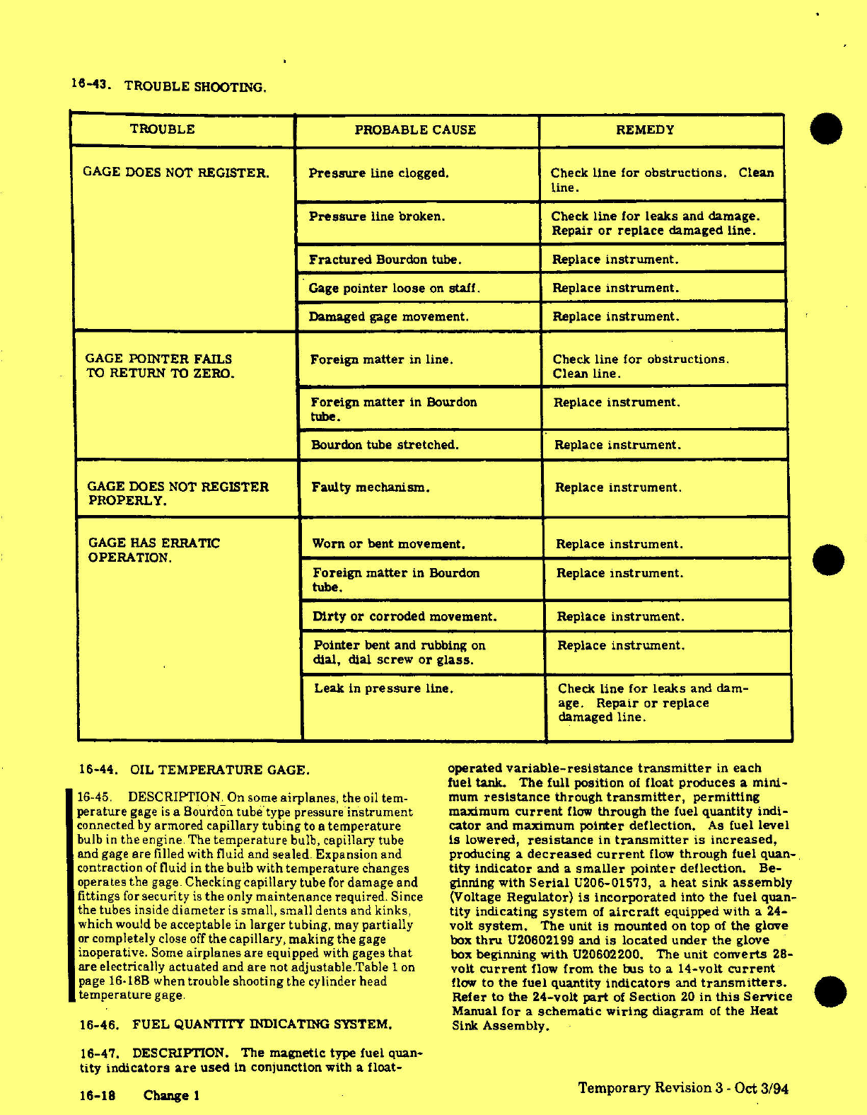
16-43.
TROUBLE
SHOOTING.
TROUBLE PROBABLE
CAUSE
REMEDY
GAGE
DOES
NOT
REGISTER.
Pressure
line
clogged.
Check
line for
obstructions.
Clean
line.
Pressure
line broken.
Check
line
for
leaks
and
damage.
Repair
or
replace
damaged
line.
Fractured
Bourdon
tube.
Replace
instrument.
Gage
pointer
loose
on
staff.
Replace
instrument.
Damaged
gage
movement. Replace
instrument.
GAGE
POINTER
FAILS
Foreign
matter
in
line.
Check
line
for obstructions.
TO
RETURN
TO
ZERO.
Clean line.
Foreign
matter
in
Bourdon
Replace
instrument.
tube.
Bourdon
tube
stretched.
Replace
instrument.
GAGE
DOES
NOT
REGISTER
Faulty mechanism.
Replace
instrument.
PROPERLY.
GAGE
HAS
ERRATIC
Worn
or
bent
movement.
Replace
instrument.
OPERATION.
Foreign
matter
in
Bourdon
Replace
instrument.
tube.
Dirty
or
corroded
movement.
Replace
instrument.
Pointer
bent
and
rubbing
on
Replace
instrument.
dial, dial
screw
or
glass.
Leak
in
pressure
line.
Check
line
for
leaks
and
dam-
age.
Repair
or
replace
damaged
line.
16-44.
OIL
TEMPERATURE
GAGE.
operated
variable-resistance
transmitter
in
each
fuel
tank.
The
full position
of
float
produces
a
mini-
16-45.
DESCRIPTION. On
some
airplanes,
the
oil
tem-
mum
resistance
through
transmitter,
permitting
perature
gage
is
a
Bourdon
tubetype
pressure
instrument
maximum
current
flow
through
the
fuel
quantity
indi-
connected
by
armored
capillary
tubing
to
a
temperature
cator
and
maximum
pointer
deflection.
As
fuel
level
bulb
in
the
engine
The
temperature
bulb,
capillary tube
is
lowered,
resistance
in
transmitter
is
increased,
and
gage
are
filled
with
fluid
and sealed.
Expansion
and
producing
a
decreased
current
flow
through
fuel
quan-
contraction
of
fluid
in
the
bulb with
temperature
changes
tity
indicator
and a
smaller
pointer
deflection.
Be-
operates
the
gage.
Checking
capillary
tube
for
damage
and
ginning with
Serial
U206-01573,
a
heat
sink
assembly
fittings
for
security
is
the
only
maintenance
required.
Since
(Voltage
Regulator)
is
incorporated
into
the
fuel
quan-
the
tubes
inside
diameter
is
small, small
dents
and
kinks,
tity indicating
system
of
aircraft
equipped
with
a
24-
which
would
be
acceptable
in
larger tubing,
may
partially
volt
system.
The
unit
is
mounted
on
top
of
the
glove
or
completely
close
off
the
capillary, making
the
gage
box
thru
U20602199
and
is
located
under the
glove
inoperative.
Some
airplanes
are
equipped
with
gages
that
box
beginning
with
U20602200.
The
unit
converts
28-
are
electrically actuated
and
are
not
adjustable.Table
1
on
volt
current
flow
from
the
bus
to
a
14-volt
current
page
16-18B
when
trouble
shooting the
cylinder
head
flow
to
the
fuel
quantity
indicators
and
transmitters.
temperature
gage.
Refer
to
the
24-volt
part
of
Section
20
in
this
Service
Manual
for
a
schematic
wiring
diagram
of
the
Heat
16-46.
FUEL
QUANTITY
INDICATING
SYSTEM.
Sink
Assembly.
16-47.
DESCRIPTION.
The
magnetic
type
fuel
quan-
tity
indicators
are
used
in
conjunction
with
a
float-
16-18 Change
1
Temporary
Revision
3
-
Oct
3/94
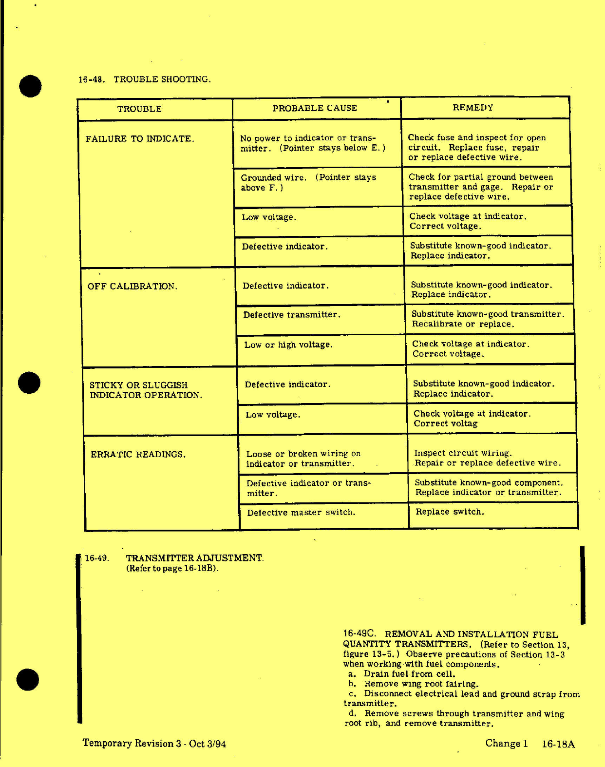
16-48.
TROUBLE
SHOOTING.
TROUBLE
PROBABLE
CAUSE
REMEDY
FAILURE
TO
INDICATE.
No
power
to
indicator
or
trans-
Check
fuse
and
inspect
for
open
mitter.
(Pointer
stays
below
E.
)
circuit.
Replace
fuse,
repair
or
replace
defective
wire.
Grounded
wire.
(Pointer
stays
Check
for
partial
ground
between
above
F.)
transmitter
and
gage.
Repair
or
replace
defective wire.
Low
voltage.
Check
voltage
at
indicator.
Correct
voltage.
Defective
indicator.
Substitute
known-good
indicator.
Replace
indicator.
OFF
CALIBRATION.
Defective
indicator.
Substitute
known-good
indicator.
Replace
indicator.
Defective
transmitter.
Substitute
known-good
transmitter.
Recalibrate
or
replace.
Low
or
high
voltage.
Check
voltage
at
indicator.
Correct
voltage.
STICKY OR
SLUGGISH
Defective
indicator.
Substitute
known-good
indicator.
INDICATOR
OPERATION.
Replace
indicator.
Low
voltage.
Check
voltage
at
indicator.
Correct
voltag
ERRATIC
READINGS.
Loose
or
broken wiring
on
Inspect
circuit
wiring.
indicator
or
transmitter.
Repair or
replace
defective
wire.
Defective
indicator
or
trans-
Substitute
known-good
component.
mitter.
Replace
indicator
or
transmitter.
Defective
master
switch.
Replace
switch.
16-49.
TRANSMITTER
ADJUSTMENT.
(Refer
to
page
16-18B).
16-49C.
REMOVAL
AND
INSTALLATION
FUEL
QUANTITY
TRANSMITTERS.
(Refer to Section
13,
figure
13-5.)
Observe
precautions
of
Section
13-3
when
working-with
fuel
components.
a.
Drain
fuel
from
cell.
b.
Remove
wing
root
fairing.
c.
Disconnect
electrical
lead
and
ground
strap
from
transmitter.
d.
Remove
screws
through
transmitter
and
wing
root
rib,
and
remove
transmitter.
Temporary
Revision
3
-
Oct
3/94
Change
1
16-18A
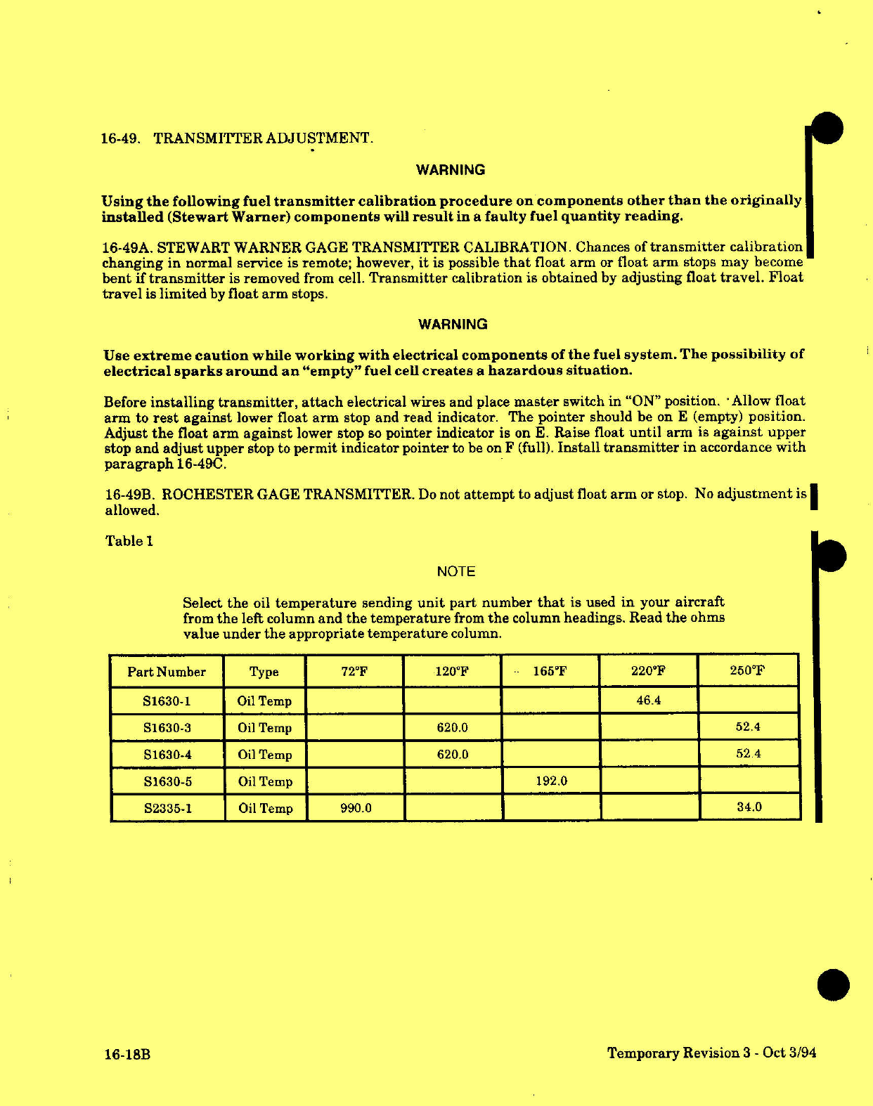
16-49.
TRANSMITTER
ADJUSTMENT.
WARNING
Using
the
following
fuel
transmitter
calibration
procedure
on
components
other
than
the
originally
installed
(Stewart Warner)
components
will
result
in
a
faulty
fuel
quantity
reading.
16-49A.
STEWART
WARNER
GAGE
TRANSMITTER
CALIBRATION.
Chances
of
transmitter
calibration
changing
in
normal
service
is
remote;
however,
it
is
possible
that
float arm
or
float
arm
stops
may
become
bent
if
transmitter
is removed
from
cell.
Transmitter
calibration
is
obtained
by
adjusting
float
travel.
Float
travel
is
limited
by
float
arm
stops.
WARNING
Use
extreme
caution
while
working
with electrical components
of
the
fuel
system.
The
possibility
of
electrical
sparks
around
an
"empty" fuel
cell
creates
a
hazardous
situation.
Before
installing
transmitter,
attach
electrical
wires
and
place
master
switch
in
"ON"
position.
Allow
float
arm
to
rest
against
lower
float
arm
stop
and
read
indicator.
The
pointer
should
be
on
E
(empty)
position.
Adjust
the
float
arm
against
lower
stop
so
pointer indicator
is
on
E.
Raise
float
until
arm
is
against
upper
stop
and
adjust
upper
stop
to
permit
indicator pointer
to
be
on
F
(full).
Install
transmitter
in
accordance
with
paragraph
16-49C.
16-49B.
ROCHESTER
GAGE
TRANSMITTER.
Do
not
attempt
to
adjust
float
arm
or
stop.
No
adjustment
is
allowed.
Table
1
NOTE
Select
the
oil
temperature
sending
unit
part
number
that
is
used
in
your
aircraft
from
the
left
column
and
the
temperature
from
the
column
headings.
Read
the
ohms
value
under
the
appropriate
temperature
column.
Part
Number
Type
72°F
120°F
165°F
220°F
250°F
S1630-1
Oil
Temp
46.4
S1630-3
Oil
Temp
620.0
52.4
S1630-4
Oil
Temp
620.0
52.4
S1630-5
Oil
Temp
192.0
S2335-1
Oil
Temp
990.0
34.0
16-18B
Temporary
Revision
3
-
Oct
3/94
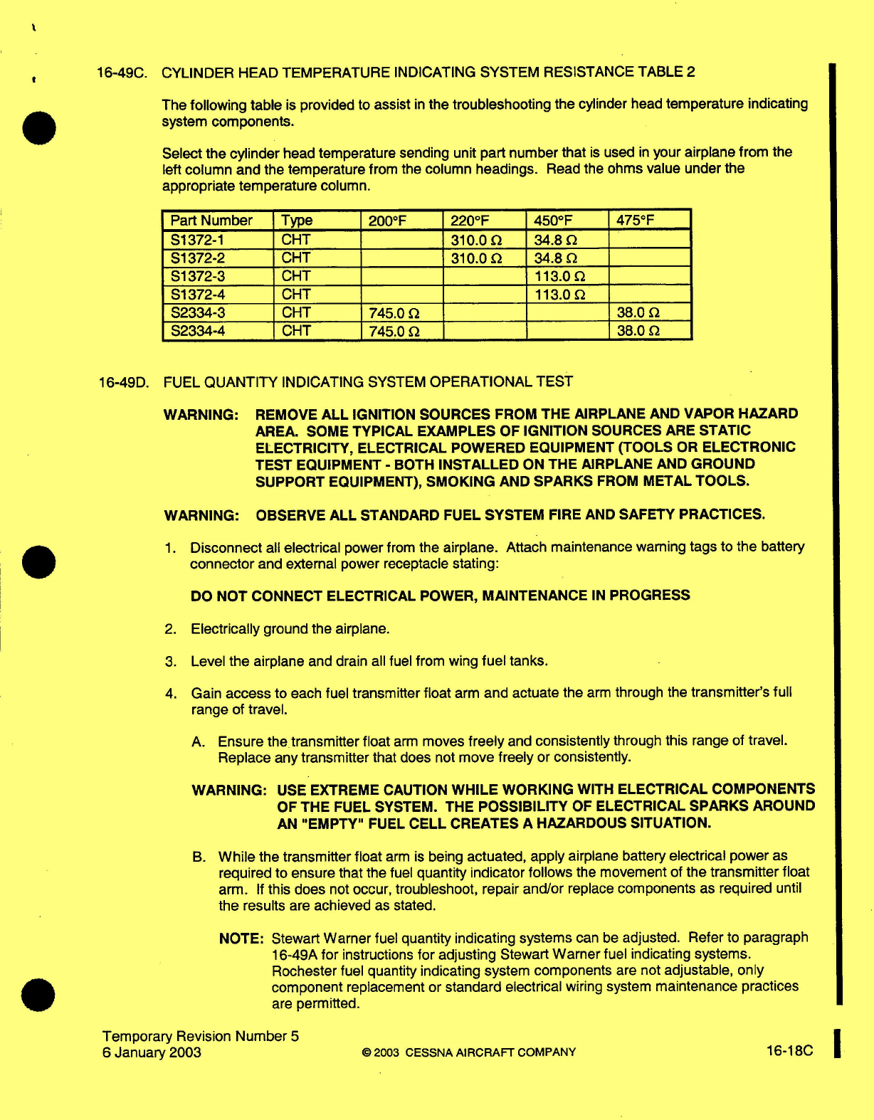
16-49C.
CYLINDER
HEAD
TEMPERATURE
INDICATING
SYSTEM
RESISTANCE TABLE
2
The
following table
is
provided
to
assist
in
the troubleshooting the
cylinder
head
temperature
indicating
system
components.
Select
the cylinder
head
temperature sending
unit part
number
that
is
used
in
your
airplane
from
the
left
column
and
the
temperature
from
the column headings.
Read
the ohms
value under the
appropriate temperature
column.
Part
Number Type
200°F
220°F 450°F
475°F
S1372-1
CHT
310.0
34.8
S1372-2
CHT
310.0
34.8
S1372-3
CHT
113.0
S1372-4
CHT
113.0
S2334-3
CHT
745.0
38.0
S2334-4
CHT
745.0
38.0
16-49D.
FUEL
QUANTITY
INDICATING
SYSTEM
OPERATIONAL
TEST
WARNING:
REMOVE
ALL
IGNITION SOURCES FROM THE
AIRPLANE
AND
VAPOR
HAZARD
AREA.
SOME
TYPICAL
EXAMPLES
OF
IGNITION
SOURCES ARE
STATIC
ELECTRICITY, ELECTRICAL
POWERED EQUIPMENT
(TOOLS
OR
ELECTRONIC
TEST
EQUIPMENT
-
BOTH
INSTALLED
ON
THE AIRPLANE
AND
GROUND
SUPPORT
EQUIPMENT),
SMOKING
AND
SPARKS
FROM
METAL
TOOLS.
WARNING:
OBSERVE
ALL
STANDARD FUEL SYSTEM
FIRE
AND
SAFETY
PRACTICES.
1. Disconnect
all
electrical
power
from
the
airplane.
Attach
maintenance
warning
tags
to
the
battery
connector
and
external
power
receptacle
stating:
DO
NOT CONNECT ELECTRICAL
POWER,
MAINTENANCE
IN
PROGRESS
2.
Electrically
ground
the
airplane.
3.
Level
the
airplane
and
drain
all
fuel
from wing
fuel
tanks.
4.
Gain
access
to
each fuel
transmitter
float
arm
and actuate the
arm
through the
transmitter's
full
range of
travel.
A.
Ensure
the
transmitter
float
arm
moves
freely
and
consistently
through
this
range
of
travel.
Replace any
transmitter
that does
not
move
freely
or
consistently.
WARNING:
USE
EXTREME
CAUTION
WHILE
WORKING
WITH
ELECTRICAL
COMPONENTS
OF
THE
FUEL SYSTEM. THE
POSSIBILITY
OF
ELECTRICAL
SPARKS
AROUND
AN
"EMPTY"
FUEL
CELL
CREATES
A
HAZARDOUS
SITUATION.
B.
While
the transmitter
float
arm
is
being
actuated,
apply
airplane battery
electrical
power
as
required
to
ensure
that
the
fuel
quantity
indicator follows
the
movement of
the
transmitter
float
arm.
If
this
does
not
occur,
troubleshoot,
repair and/or
replace
components
as
required
until
the
results
are
achieved
as
stated.
NOTE:
Stewart
Warner
fuel
quantity indicating
systems
can
be
adjusted.
Refer to paragraph
16-49A
for
instructions
for
adjusting
Stewart
Warner
fuel indicating
systems.
Rochester
fuel quantity
indicating system components
are
not
adjustable,
only
component
replacement
or
standard electrical
wiring
system
maintenance
practices
are
permitted.
Temporary
Revision
Number
5
6
January
2003
©
2003
CESSNA
AIRCRAFT
COMPANY
16-18C
5.
With
the
fuel selector
valve
in
the
"OFF"
position,
add
unusable
fuel
to
each
fuel
tank.
6.
Apply
electrical
power
as
required
to verify
the
fuel
quantity
indicator
indicates
"EMPTY".
A.
If
"EMPTY"
is
not
indicated, adjust, troubleshoot, repair
and/or
replace
fuel
indicating components
as
required until
the
"EMPTY"
indication
is
achieved.
NOTE:
Stewart
Warner
fuel
quantity
indicating
systems
can
be
adjusted. Refer
to paragraph
16-
49A
for
instructions
for
adjusting
Stewart
Warner
fuel indicating
systems.
Rochester
fuel
quantity
indicating
system
components
are not
adjustable,
only
component
replacement
or
standard electrical
wiring
system
maintenance
practices
are permitted.
7.
Fill
tanks
to capacity,
apply
electrical
power as required and
verify
fuel quantity
indicator
indicates
"FULL".
A.
If
"FULL"
is
not
indicated,
adjust, troubleshoot,
repair
and/or
replace
fuel
indicating components
as
required
until
the
"FULL"
indication
is
achieved.
NOTE:
Stewart
Warner
fuel
quantity
indicating
systems can
be
adjusted. Refer
to paragraph
16-
49A
for
instructions
for
adjusting
Stewart
Warner
fuel
indicating
systems.
Rochester
fuel
quantity
indicating
system
components
are not
adjustable, only
component
replacement
or
standard electrical
wiring
system
maintenance
practices
are
permitted.
8.
Install
any
items
and/or
equipment
removed to
accomplish
this
procedure,
remove
maintenance
warning
tags
and
connect the airplane
battery.
Temporary
Revision
Number
5
18D
2003
CESSNA
AIRCRAFT COMPANY
6
January
2003
.
16-11
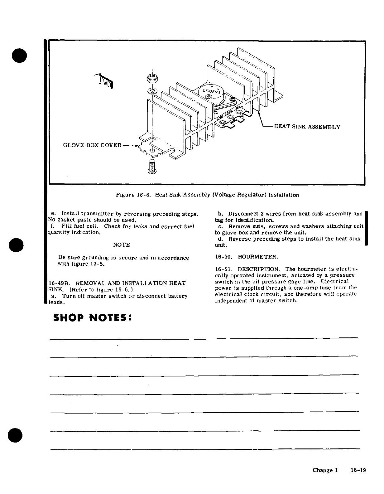
HEAT SINK
ASSEMBLY
GLOVE
BOX
COVER
Figure
16-6.
Heat
Sink
Assembly
(Voltage
Regulator)
Installation
e.
Install
transmitter
by
reversing
preceding
steps.
b.
Disconnect
3
wires
from
heat
sink
assembly
and
No
gasket
paste
should
be
used.
tag
for identification.
f.
Fill
fuel
cell.
Check
for
leaks
and
correct
fuel
c.
Remove
nuts,
screws
and
washers
attaching
unit
quantity
indication.
to
glove
box
and
remove
the
unit.
d.
Reverse
preceding
steps
to
install
the
heat
sink
NOTE
unit.
Be
sure
grounding
is
secure
and
in
accordance
16-50.
HOURMETER.
with
figure
13-5.
16-51.
DESCRIPTION.
The
hourmeter
is
electri-
cally
operated instrument, actuated
by
a
pressure
16-49B-
REMOVAL
AND
INSTALLATION
HEAT
switch
in
the
oil
pressure
gage
line.
Electrical
SINK.
(Refer
to
figure
16-6.)
power
is
supplied
through
a
one-amp
fuse
from
the
a.
Turn
off
master
switch
or
disconnect
battery
electrical
clock
circuit,
and
therefore
will
operate
leads.
independent
of
master
switch.
SHOP
NOTES:
Change
1
16-19
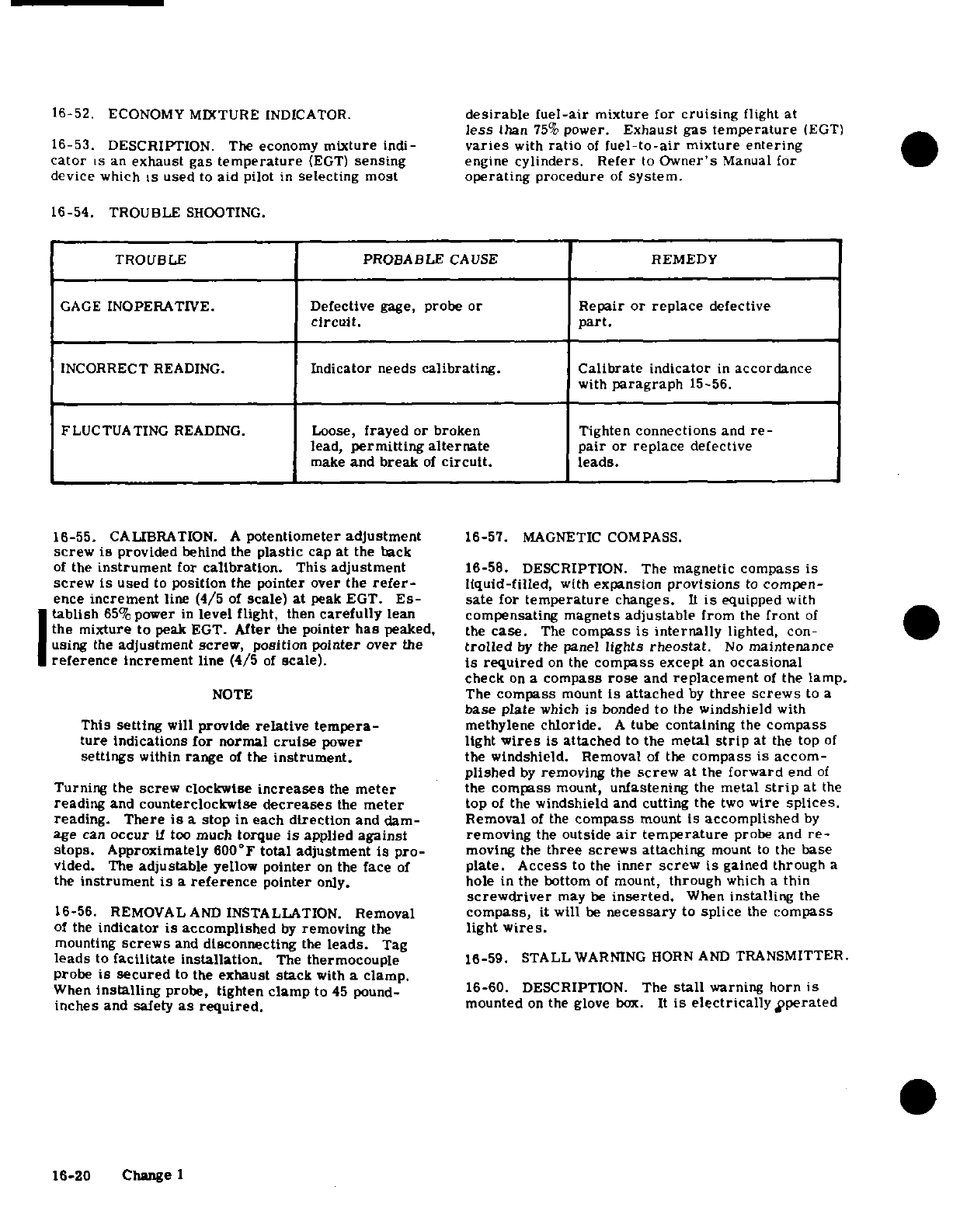
16-52.
ECONOMY
MIXTURE
INDICATOR.
desirable
fuel-air
mixture
for
cruising
flight
at
less
than
75%
power.
Exhaust
gas
temperature
(EGT)
16-53. DESCRIPTION.
The
economy
mixture
indi-
varies
with
ratio
of
fuel-to-air
mixture
entering
cator
is
an
exhaust
gas
temperature
(EGT)
sensing
engine
cylinders.
Refer
to
Owner's
Manual
for
device
which
is
used
to
aid
pilot
in
selecting
most
operating
procedure
of
system.
16-54.
TROUBLE
SHOOTING.
TROUBLE PROBABLE
CAUSE
REMEDY
GAGE
INOPERATIVE.
Defective
gage,
probe
or
Repair
or
replace
defective
circuit.
part.
INCORRECT
READING.
Indicator
needs
calibrating.
Calibrate
indicator
in
accordance
with
paragraph
15-56.
FLUCTUATING
READING.
Loose,
frayed
or
broken
Tighten
connections
and
re-
lead,
permitting alternate
pair
or
replace
defective
make
and
break
of
circuit.
leads.
16-55.
CALIBRATION.
A
potentiometer
adjustment
16-57.
MAGNETIC
COMPASS.
screw
is
provided
behind
the
plastic
cap
at
the
back
of
the
instrument
for
calibration.
This adjustment
16-58. DESCRIPTION.
The
magnetic
compass
is
screw
is
used
to
position
the
pointer
over the
refer-
liquid-filled,
with
expansion
provisions
to
compen-
ence
increment
line
(4/5
of
scale) at
peak
EGT.
Es-
sate
for
temperature
changes.
It
is
equipped
with
tablish
65%
power
in
level
flight,
then
carefully
lean
compensating magnets
adjustable
from
the
front
of
the mixture
to
peak
EGT.
After
the
pointer
has
peaked,
the
case.
The
compass
is
internally
lighted,
con-
using
the
adjustment
screw,
position
pointer
over
the
trolled
by
the
panel
lights
rheostat.
No
maintenance
reference
increment
line
(4/5
of
scale).
is
required
on
the
compass
except
an
occasional
check
on
a
compass
rose
and
replacement
of
the
lamp.
NOTE
The
compass
mount
is
attached
by
three
screws
to
a
base plate
which
is
bonded
to
the
windshield
with
This
setting
will
provide
relative tempera-
methylene
chloride.
A
tube
containing
the
compass
ture
indications
for normal
cruise
power
light
wires
is
attached
to
the
metal
strip
at
the
top
of
settings
within
range
of
the
instrument.
the
windshield.
Removal
of
the
compass is
accom-
plished
by
removing
the
screw
at
the
forward
end
of
Turning
the
screw
clockwise
increases
the
meter
the
compass
mount,
unfastening
the
metal
strip
at
the
reading
and
counterclockwise
decreases
the
meter
top
of
the
windshield
and
cutting
the
two
wire
splices.
reading.
There
is
a
stop
in
each
direction
and
dam-
Removal
of
the
compass
mount
is accomplished
by
age
can
occur
if
too
much
torque
is
applied
against
removing
the
outside
air
temperature
probe
and
re-
stops.
Approximately 600°F
total
adjustment
is
pro-
moving
the
three
screws
attaching
mount
to
the
base
vided.
The
adjustable
yellow
pointer
on
the
face
of
plate.
Access
to
the
inner
screw
is
gained through
a
the
instrument
is
a
reference
pointer
only.
hole in
the
bottom
of
mount,
through
which
a
thin
screwdriver
may
be
inserted.
When
installing
the
16-56.
REMOVAL
AND
INSTALLATION.
Removal
compass,
it
will
be
necessary
to
splice
the
compass
of
the
indicator
is
accomplished
by
removing
the
light
wires.
mounting
screws
and
disconnecting
the
leads.
Tag
leads
to
facilitate
installation.
The
thermocouple
16-59. STALL
WARNING
HORN AND
TRANSMITTER.
probe
is
secured
to
the
exhaust
stack
with
a
clamp.
When
installing
probe,
tighten
clamp
to
45
pound-
16-60.
DESCRIPTION.
The
stall
warning
horn
is
inches
and safety
as
required.
mounted
on
the
glove
box.
It
is
electrically
operated
16-20 Change
1
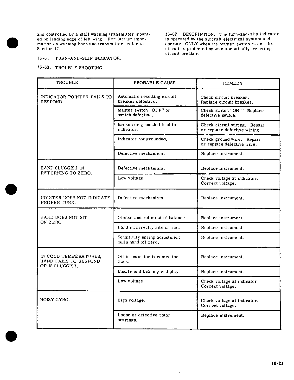
and
controlled
by
a
stall
warning
transmitter
mount-
16-62.
DESCRIPTION.
The
turn-and-slip
indicator
ed
on
leading
edge
of
left
wing.
For
further
infor-
is
operated
by
the
aircraft electrical
system
and
mation
on
warning
horn and
transmitter,
refer
to
operates
ONLY
when
the
master
switch
is
on.
Its
Section
17.
circuit
is
protected
by
an
automatically-resetting
circuit
breaker.
16-61.
TURN-AND-SLIP
INDICATOR.
16-63.
TROUBLE
SHOOTING.
TROUBLE PROBABLE
CAUSE
REMEDY
INDICATOR
POINTER
FAILS
TO
Automatic
resetting
circuit
Check
circuit
breaker.
RESPOND.
breaker
defective.
Replace
circuit
breaker.
Master
switch
"OFF"
or
Check switch
"ON."
Replace
switch
defective.
defective
switch.
Broken
or
grounded lead
to
Check
circuit
wiring.
Repair
indicator.
or
replace
defective
wiring.
Indicator
not
grounded.
Check
ground
wire.
Repair
or
replace
defective
wire.
Defective
mechanism.
Replace
instrument.
HAND
SLUGGISH
IN
Defective
mechanism.
Replace
instrument.
RETURNING
TO
ZERO.
Low
voltage.
Check
voltage
at
indicator.
Correct
voltage.
POINTER
DOES
NOT
INDICATE
Defective
mechanism.
Replace
instrument.
PROPER
TURN.
HAND
DOES
NOT
SIT
Gimbal
and
rotorout
of
balance.
Replace
instrument
ON
ZERO
Hand
incorrectly
sits
on
rod.
Replace
instrument
Sensitivity
spring
adjustment
Replace
instrument.
pulls
hand
off
zero.
IN
COLD
TEMPERATURES,
Oil
in
indicator becomes
too
Replace
instrument
HAND
FAILS
TO
RESPOND
thick.
OR
IS
SLUGGISH.
Insufficient
bearing
end
play.
Replace
instrument.
Low
voltage.
Check
voltage
at
indicator.
Correct
voltage.
NOISY GYRO.
High
voltage.
Check
voltage
at indicator.
Correct
voltage.
Loose
or
defective
rotor
Replace
instrument.
bearings.
16-21
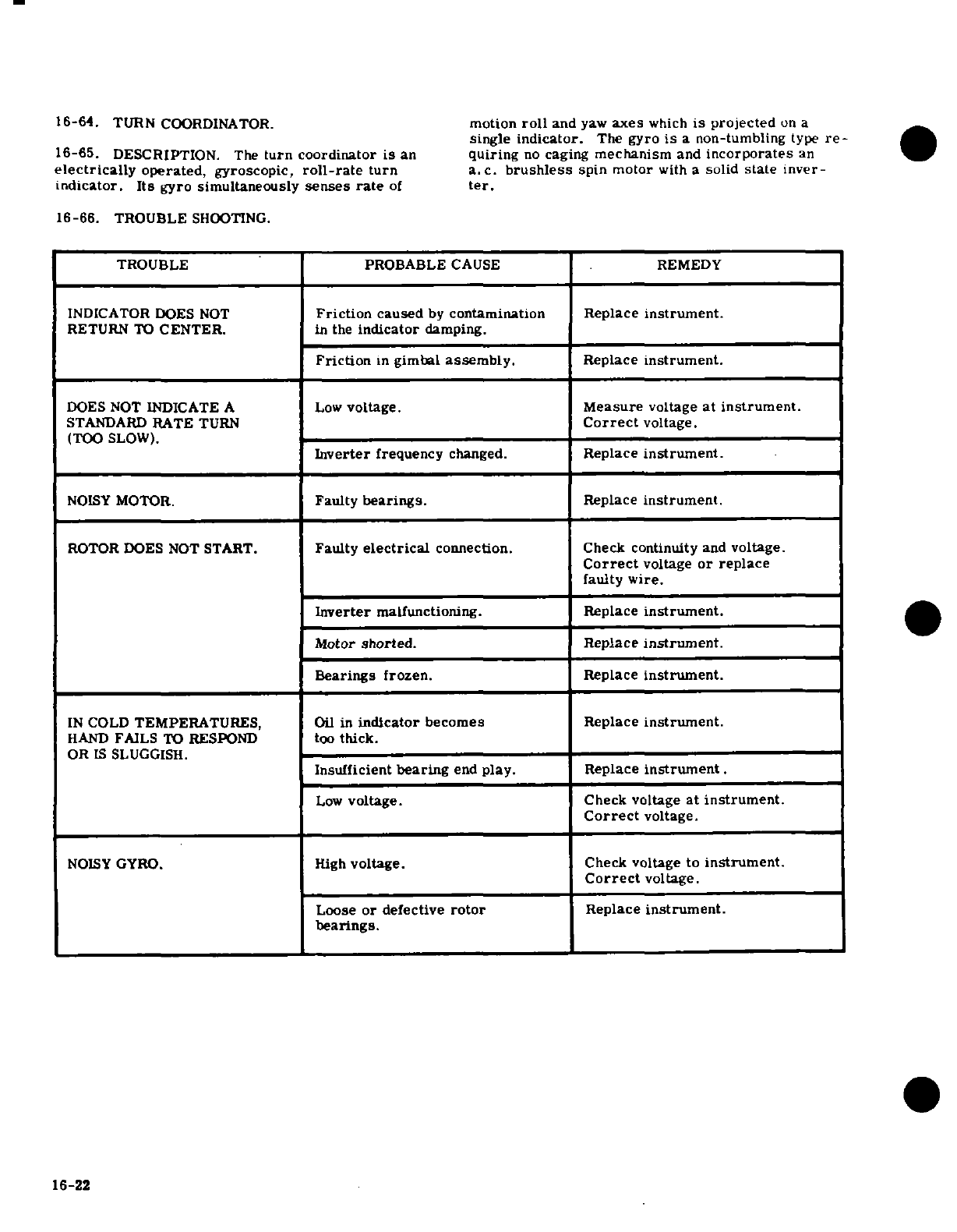
16-64.
TURN
COORDINATOR.
motion
roll
and
yaw
axes
which
is projected
on
a
single
indicator.
The
gyro
is
a
non-tumbling
type
re-
16-65.
DESCRIPTION.
The
turn
coordinator
is
an
quiring
no
caging
mechanism
and
incorporates
an
electrically
operated,
gyroscopic,
roll-rate
turn
a.
c.
brushless
spin motor
with
a
solid
state
inver-
indicator.
Its
gyro
simultaneously
senses
rate
of
ter.
16-66.
TROUBLE
SHOOTING.
TROUBLE
PROBABLE
CAUSE
REMEDY
INDICATOR
DOES
NOT
Friction
caused
by
contamination
Replace
instrument.
RETURN
TO
CENTER.
in
the
indicator
damping.
Friction
in
gimbal
assembly.
Replace
instrument.
DOES
NOT
INDICATE
A
Low
voltage.
Measure
voltage
at
instrument.
STANDARD
RATE
TURN
Correct
voltage.
(TOO
SLOW).
Inverter
frequency
changed.
Replace
instrument.
NOISY
MOTOR.
Faulty
bearings.
Replace
instrument.
ROTOR
DOES
NOT
START.
Faulty
electrical
connection.
Check
continuity
and
voltage.
Correct
voltage
or
replace
faulty
wire.
Inverter
malfunctioning. Replace
instrument.
Motor
shorted.
Replace
instrument.
Bearings
frozen.
Replace
instrument.
IN
COLD
TEMPERATURES,
Oil
in
indicator
becomes
Replace
instrument.
HAND
FAILS
TO
RESPOND
too
thick.
OR
IS
SLUGGISH.
Insufficient
bearing
end
play.
Replace
instrument.
Low
voltage.
Check
voltage
at
instrument.
Correct
voltage.
NOISY
GYRO.
High
voltage.
Check
voltage
to
instrument.
Correct
voltage.
Loose
or
defective
rotor
Replace
instrument.
bearings.
16-22
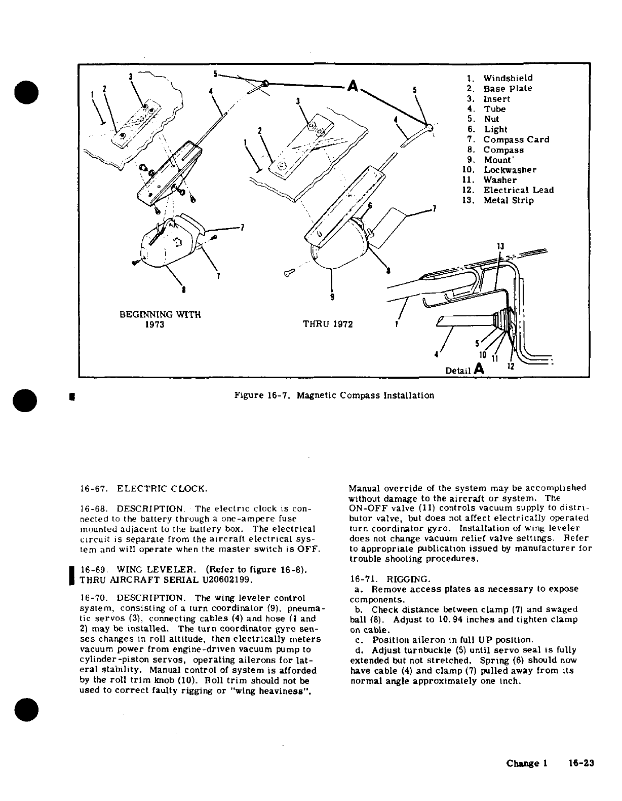
1.
Windshield
3.
Insert
2.
Base
plate
c\t
\ 4 f \\ 5.
Nut
-2 /~5.X~
6.
Light
7.
Compass
Card
8.
Compass
/ //
9.
Mount'
N^ 4^
M//
y^/ ^
/
r^10.
Lockwasher
11.
Washer
'/~ </f^ Xj/*~
·
7/
212.
Electrical
Lead
r\^t:\ B
13.
Metal
Strip
BEGINNING
WITH
/
1973
THRU 1972
1 B
,
4
10
1 1
.
Detail
A
O|
U
Figure
16-7.
Magnetic
Compass
Installation
16-67.
ELECTRIC
CLOCK.
Manual
override
of
the
system
may
be
accomplished
without
damage
to
the
aircraft
or
system.
The
16-68. DESCRIPTION.
The
electric
clock
is
con-
ON-OFF
valve
(11)
controls
vacuum supply
to
distrl-
nected
to
the
battery
through
a
one-ampere
fuse
butor
valve,
but
does
not
affect
electrically
operated
mounted
adjacent
to
the
battery
box.
The
electrical
turn
coordinator
gyro.
Installation
of
wing
leveler
circuit
is
separate
from
the
aircraft
electrical
sys-
does
not
change vacuum
relief
valve
settings.
Refer
ter
and
will
operate
when
the
master
switch
is
OFF.
to
appropriate
publication
issued
by
manufacturer
for
trouble
shooting
procedures.
16-69.
WING
LEVELER.
(Refer
to
figure
16-8).
THRU
AIRCRAFT
SERIAL
U20602199. 16-71.
RIGGING.
a.
Remove
access
plates
as necessary
to
expose
16-70. DESCRIPTION.
The
wing
leveler
control
components.
system,
consisting
of
a
turn
coordinator
(9),
pneuma-
b.
Check
distance
between
clamp
(7)
and
swaged
tic
servos
(3),
connecting
cables
(4)
and hose
(1
and
ball
(8).
Adjust
to
10.94
inches
and
tighten clamp
2)
may
be
installed.
The
turn coordinator
gyro
sen-
on
cable.
ses
changes
in
roll
attitude,
then
electrically meters
c.
Position
aileron
in
full
UP
position.
vacuum
power
from
engine-driven
vacuum
pump
to
d.
Adjust
turnbuckle
(5)
until
servo seal
is
fully
cylinder-piston
servos,
operating
ailerons
for
lat-
extended
but not
stretched.
Spring
(6)
should
now
eral
stability.
Manual
control
of
system
is
afforded
have
cable
(4)
and clamp
(7)
pulled
away
from
its
by
the
roll
trim
knob
(10).
Roll
trim
should
not
be
normal
angle
approximately
one
inch.
used
to
correct
faulty
rigging
or
"wing
heaviness".
Change
1
16-23
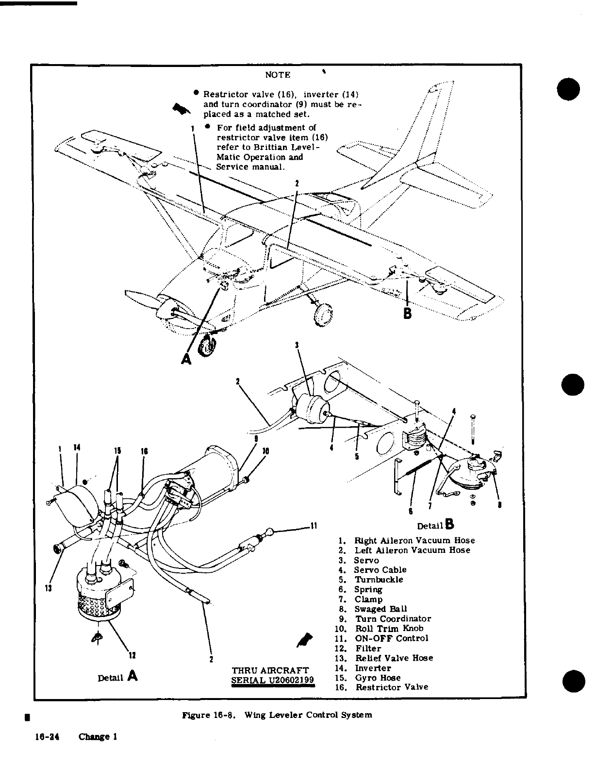
NOTE
Restrictor
valve
(16),
inverter
(14)
and
turn coordinator
(9)
must
be
re-
placed
as
a
matched
set.
For
field
adjustment
of
restrictor
valve
item
(16)
refer
to
Brittian
Level
Matic
Operation
and
Service
manual.
2
B
1.
Right
Aileron
Vacuum
Hose
2.
Left
Aileron
Vacuum
Hose
3.
Servo
4.
Servo
Cable
5.
Turnbuckle
13
6.
Spring
7.
Clamp
8.
Swaged
Ball
9.
Turn
Coordinator
10.
Roll
Trim
Knob
11.
ON-OFF
Control
12.
Filter
12 2
13.
Relief
Valve
Hose
THRU
AIRCRAFT
14.
Inverter
Detail
A
SERIAL
U20602199
15.
Gyro
Hose
16.
Restrictor
Valve
Figure
16-8.
Wing
Leveler
Control
System
16-24
Change
1
SECTION
17
ELECTRICAL
SYSTEMS
TABLE
OF
CONTENTS
Page
Transistorized
Voltage Regulator
ELECTRICAL
SYSTEMS
........
.
17-2
24
Volt
...........
17-19
General.
.
.... .......
17-2 Description
.........
17-
19
Electrical
Power
Supply
System
.....
17-2
Adjustment
.
.......
17-19
Description
.....
.
17-2
Trouble
Shooting
....
17-19
Split
Bus
Bar
.
.......
. .
17-2
Removal
and
Installation
(12
Volt)
17-19
Description
............
17-2
Removal
and
installation
(24
Volt)
17-19
Split
Bus
Power
Relay
.......
17-2
Over-Voltage
Warning
Circuit
Description
..........
.
17-2
24
Volt
.......
...
17-21
Master
Switch
........
17-3
Description
..
........
17-21
Description
.........
17-3
Adjustment
..
........
17-21
Ammeter
..
.........
17-3
Removal
and
Installation
...
17-21
Description
.........
.
17-3
Over-Voltage
Sensor
and
Warning
Battery
Power
System
.....
17-3
Light-12
Volt
(Beginning
1972
Battery
............
.
17-3
Models
...........
17-21
Description.
.
.....
17-3
Description
.
......
.
17-21
Trouble
Shooting
.........
17-3
Rigging
Throttle
Operated
Micro-
Removal
and
Installation
(12
Volt)
.
17-4
Switch
............
17-21
Removal
and
Installation
(24
Volt).
.
17-4
Auxiliary
Electric
Fuel
Pump
Flow
Cleaning
the
Battery
......
17-10
Rate Adjustment
......
.
17-21
Adding
Electrolyte
or
Water
Aircraft
Lighting
System
.......
17-22
to
the
Battery
........
17-10
Description
...........
17-22
Testing
the
Battery
... .
17-10
Trouble
Shooting
.........
17-27
Charging
the
Battery
.. .
17-10
Landing
and
Taxi
Lights
.....
17-27
Battery
Box
...........
17-10
Description
........
.
17-27
Description
....
....
17-10
Removal
and
Installation
Removal
and
Installation
of
thru
1971
Models
....
..
17-27
12
Volt
Battery
Box
.....
17-11
Removal
and
Installation
Removal
and
Installation
of
Beginning
with
1972
Models
.
17-27
24
Volt
Battery
Box
... .
17-11
Navigation
Lights
........
17-27
Maintenance
of
Battery
Box
. .
.17-11
Description
17-27
Battery
Contactor
.........
17-11
Removal
and
Installation
...
17-27
Description
...
......
17-11
Anti-Collision
Strobe
Lights
.. .
17-27
Removal
and
Installation
17-11
Description
.......
. .. .
17-27
Battery
Contactor
Closing
Operational
Requirements
... ..
17-27
Circuit............
17-11
Removal
and
Installation
. . ..
17-28
Description
.
........
17-11
Flashing
Beacon
Light
......
17-28
Ground
Service
Receptacle
....
17-12
Description
..........
17-28
Description
.
......
.
17-12
Removal
and
Installation
....
17-30
Trouble
Shooting
.
.......
17-12
Instrument
Lighting.
.......
17-30
Removal and
Installation
....
17-13
Description
.. ..
17-30
Alternator
Power
System
.....
17-13
Removal
and
Installation
....
17-30
Description
..........
17-13
Removal
and
Installation
of
Alternator
..........
17-13
Transistorized
Light
Dimming
.
17-30
Description....
.
17-13
Electroluminescent
Panel
Lighting
17-30
Alternator
Reverse
Voltage
Description
..... .....
17-30
Damage
.
......
.
17-13
Pedestal
Lights.........
17-35
Trouble
Shooting
.
......
17-15
Description
..........
17-35
Removal
and
Installation
....
17-18
Removal
and
Installation
....
17-35
Alternator
Field
Circuit Instrument
Post
Lighting
.....
17-35
Protection
..........
17-18
Description
..........
17-35
Alternator
Voltage
Regulator-12
Removal
and
Installation
....
17-38
Volt
............
17-18
Courtesy
Lights
.........
17-38
Description
.........
17-18
Description
..........
17-38
Change
3
17-1
Removal and
Installation
....
17-38
Removal
and
Installation
....
17-44
Interior
Lighting
. ....... .
17-38
Cigar
Lighter
. .........
17-44
Removal
and
Installation
..
17-38
Description
..........
17-44
Control
Wheel
Map
Lighting
.. .
17-38
Removal and
Installation
....
17-44
Description
..........
17-38
Skydiving
Kit.
..........
.
17-45
Removal
and
Installation
Description......
17-45
Thru
U206-1444
.......
17-38
Removal
and
Installation
....
17-45
Removal
and
Installation
Emergency
Locator
Transmitter
. .
17-46
U20601445
thru
U20601700...
17-38
Description
..........
17-46
Removal and
Installation
Operation
.. ........ . 17-46
U20601701
thru
U20601757.
. .
17-38
Checkout
Interval
....
17-46
Removal and
Installation
Removal and
Installation
of
Beginning
with
U20601758
Transmitter
.........
17-48
and
All
Service
Parts
Beginning
Removal
and
Installation
of
with
U20601701
...... . 17-40
Antenna...........
17-48
Compass
and
Radio
Dial
Lights.
..
17-40 Removal
and
Installation
of
Magne-
Description
............ 17-40
sium
Six
Cell
Battery
Pack
.
.17-48
Electric
Clock
..........
17-43
Removal
and
Installation
of
Lithium
Description
.
.......
.
17-43
Four
Cel
Battery
Pack
....
17-48
Stall
Warning
System
.......
17-43
Trouble
Shooting
.. ..
17-49
Description
..........
17-43
Electrical
Load
Analysis
Chart
17-51
Pitot
and
Stall
Warning
Heaters
. .
17-44
Description
.........
17-44
17-1.
ELECTRICAL
SYSTEMS.
17-5.
SPLIT
BUS
BAR.
17-2.
GENERAL.
This
section contains
service
in- 17-6.
DESCRIPTION.
Electrical
power
is
supplied
formation
necessary
to
maintain
the
Aircraft
Electri-
through
a
split bus
bar.
One
side
of
the
bus
bar
sup-
cal Power
Supply
System,
Battery
and
External
Power
plies
power
to
the
electrical
equipment while
the
other
Supply
System,
Alternator
Power
System,
Aircraft
side supplies
the
electronic
installations.
When
the
Lighting
System,
Pitot
Heater,
Stall Warning,
Cigar
master
switch
is
closed
the
battery
contactor
engages
Lighter
and
Electrical
Load
Analysis.
and
battery
power
is
supplied
to
the
electrical
side
of
the
split
bus
bar.
The
electrical
bus feeds
battery
17-3.
ELECTRICAL
POWER
SUPPLY
SYSTEM.
power
to
the
electronics
bus
through
a
normally-
closed
relay;
this relay
opens
when
the
starter
switch
17-4.
DESCRIPTION.
Electrical
energy
for
the
air-
is
engaged or
when
an
external
power
source
is
used.
craft
is
supplied
by
a 14-volt
or
optional
24-volt,
preventing
transient
voltages
from
damaging
the
semi-
direct-current,
single
wire,
negative ground
electri-
conductor
circuitry
in
the
electronic
installations.
cal
system.
A
single
33
Amp-Hour
12-volt
battery
(Refer
to
figure
17-1.)
or
optional
17
Amp-Hour,
24-volt
battery
supplies
power
for
starting
and
furnishes
a
reserve
source
of
17-7.
SPLIT
BUS
POWER
RELAY.
power
in
the
event
of
alternator
failure.
An
engine-
driven
alternator
is
the
normal source
of
power
dur-
17-8.
DESCRIPTION.
A
power
relay
is
installed
ing
flight
and
maintains
a
battery
charge
controlled
behind
the
instrument
panel
on
all
aircraft
utilizing
by
a
voltage
regulator.
An
external
power
source
a
split
bus
bar.
The
relay
is
a
normally-closed
receptacle
is
offered
as
optional
equipment
to
supple-
type,
opening
when
external
power
is
connected
or
ment the
battery
alternator
system
for
starting
and
when
the
starter
is
engaged,
thus
removing
battery
ground
operation.
power
from
the
electronic
side
of
the
split
bus
bar
and
preventing
transient
voltages
from
damaging
the
electronic
installations.
(Refer
to
figure
17-1.)
17-2
Change
3
17-9.
MASTER
SWITCH.
between
the
battery
and
the
aircraft
bus.
The
meter
indicates
the amount
of
current
flowing
either
to
or
17-10.
DESCRIPTION.
On
models
prior
to
1970,
from
the
battery.
With
a
low
battery
and
the
engine
the
operation
of
the
battery
and
alternator
system
is
operating
at
cruise
speed
the
ammeter
will
show
the
controlled
by
a
single
master
switch.
The
switch
is
full
alternator
output when
all
electrical
equipment
is
a
rocker
type
with
double-pole,
single-throw
con-
off.
When
the
battery
is
fully
charged
and
cruise
tacts.
The
switch,
when
operated,
connects
the bat-
RPM
is
maintained
with
all
electrical
equipment
off,
tery
contactor
coil
to
ground
and
the
alternator
field the
ammeter
will
show
a
minimum
charging
rate
circuit
to
the
battery,
activating
the
power
systems.
On
1970
models
and
on,
a
new
master
switch
is
uti-
17-13. BATTERY
POWER
SYSTEM.
lized.
This
switch
is
an
interlocking
split
rocker
with
the
battery
mode
on
the
right
hand
side
and
the
17-14. BATTERY.
alternator
mode
on
the
left
hand
side.
This
arrange-
ment
allows
the
battery
to
be
on
the
line
without
the
17-15.
DESCRIPTION.
On
14-volt
systems,
the
alternator,
however,
operation
of
the
alternator
battery
is
12-volts
and
is
approximately
33
ampere-
without
the
battery
on
the
line
is
not
possible.
The
hour
capacity.
On
all
14-volt
aircraft
the
battery
is
switch
is
labeled
"BAT"
and
"ALT"
below
the switch mounted
on
the
forward,
left
side
of
the
firewall.
and
is
located
on
the
left
hand
side
of
the
switch
panel.
On
the
1971
&
on
optional
28-volt
systems,
the bat-
17-11.
AMMETER.
tery
is
24-volts
and
is
approximately
17
ampere-
hour capacity.
On
28-volt
aircraft
thru
1973
models
17-12.
DESCRIPTION. The
ammeter
is
connected
the
battery
is
mounted
below
the
engine
in
the
nose
wheel
tunnel.
Beginning
with
1974
models
the
battery
is
mounted
on
the
left
hand
side
of
the
firewall.
17-16.
TROUBLE
SHOOTING.
TROUBLE
PROBABLE
CAUSE
REMEDY
BATTERY
WILL
NOT
SUPPLY
Battery
discharged.
1.
Measure
voltage
at
"BAT"
POWER
TO
BUS
OR
IS
INCAP-
terminal
of
battery
contactor
ABLE
OF
CRANKING
ENGINE
with
master
switch
and
a
suit-
able
load
such
as
a
taxi
light
turned
on.
Normal
battery
will
indicate
11.5
volts
or
more
on
a
14
volt
system
or
23
volts
or
more
on
a
28
volt
system.
If
voltage
is
low
proceed
to
step
2. If
voltage
is
normal,
pro-
ceed
to
step
3.
Battery
faulty.
2.
Check
fluid
level
in
cells
and
charge
12-volt
battery
at
14
volts
or
24-volt
battery
at
28
volts
for
approximately
30
minutes
or
until
battery
voltage
rises
to
14
volts
on
12-volt
bat-
tery
or
28
volts
on
24-volt
bat-
tery.
If
tester
indicates
a good
battery,
the
malfunction
may
be
assumed
to
be
a
discharged
bat-
tery.
If
the
tester
indicates
a
faulty
battery,
replace
the
battery.
Faulty
contactor
or
wiring.
3.
Measure
voltage
at
master
between
contactor
and
master
switch
terminal (smallest)
on
switch.
contactor
with
master
switch
closed.
Normal
indication
is
zero
volts.
If
voltage
reads
zero,
proceed
to step
4.
If
a
voltage
reading
is
obtained,
check
wiring
between
contactor
and
master
switch.
Also
check
master
switch.
Change
1
17-3
17-16.
TROUBLESHOOTING.
(Cont.)
TROUBLE
PROBABLE
CAUSE
REMEDY
BATTERY
WILL
NOT
SUPPLY
Open
coil
on
contactor.
4.
Check
continuity
between
POWER TO
BUS OR
IS
INCAP- "BAT"
terminal
and
master
ABLE
OF
CRANKING
ENGINE
switch
terminal
of
contactor.
(Cont.)
Normal
indication
on
14
volt
aircraft
is
16-24
ohms.
Nor-
mal
indication
on
28
volt
air-
craft
is
50-70
ohms.
If
ohm-
meter
indicates
an
open
coil,
replace
contactor.
If
ohm-
meter
indicates
a
good
coil,
proceed
to step
5.
Faulty
contactor contacts.
5.
Check
voltage
on
"BUS"
side
of
contactor
with
master
switch
closed.
Meter
nor-
mally
indicates
battery
voltage.
If
voltage
is
zero
or
intermit-
tent,
replace
contactor.
If
voltage
is
normal, proceed
to
step
6.
Faulty
wiring
between
con-
6.
Inspect
wiring
between
con-
tactor
and
bus.
tactor
and
bus.
Repair
or
replace
wiring.
17-17.
REMOVAL
AND
INSTALLATION
OF
12
VOLT
thus
causing
damage
to
the
battery
and
bat-
BATTERY.
(Refer to
figure
17-2.)
tery
box
support
assembly.
a.
To
gain
access
to
the
battery,
remove
the
upper
left
half
of
cowling.
e.
Remove
the
upper
engine
cowling
half
to
gain
b.
Remove the
battery
box
lid
and
disconnect
the
access
to
the
nuts,
washers
and
bolts securing
the
battery
ground cable.
battery
support
assembly
and ground
strap
to
the
tunnel
walls.
CAUTION
f.
Remove
the
nut
securing
the
ground
strap
to the
right
side
of
the
tunnel
wall
and
push the
bolt
thru
Always
remove
the
ground cable
first
and
con-
the
tunnel
hole
to
ensure
the
ground
strap
is
free
for
nect
it
last
to
prevent
accidentally
shorting
the removal.
battery
to
the
airframe
with
tools.
g.
Remove
three
nuts
and
washers
from
each
side
of
the
tunnel
which
secure
the
battery
support
assembly.
c.
Disconnect
the
positive
cable from
the
battery
h.
Inside
the
tunnel,
remove
the
three bolts
from
and
remove
the
battery
from
aircraft.
each
side
of
the
tunnel
which
secure
the
battery
sup-
d. To
install
a
battery,
reverse
this
procedure.
port
assembly
to
the
tunnel
walls.
j.
To
reinstall
the
battery,
reverse
this procedure.
17-18.
REMOVAL
AND
INSTALLATION
OF
24
VOLT
BATTERY.
(Refer
to
figure
17-2.)
17-18A.
REMOVAL
AND
INSTALLATION.
(28
VOLT
a.
Turn
Master
Switch
to
OFF
position.
BEGINNING
WITH
1974
MODELS.)
(Refer
to
figure
b.
Remove
lower
cowling
access
plate from
tunnel 17-2.)
located
under
the
engine.
a. To gain
access
to
the
battery,
remove the
upper
c.
Remove
drain
tube
from
battery
box
assembly.
left
half
of
the
engine
cowling.
d.
Remove
quick
disconnect
cable
assembly
from
b.
Remove
the
battery
box
lid
and
disconnect
the
battery
box
by
loosening
knob
on
the
cable
assembly.
battery
ground
cable.
CAUTION
CAUTION
Place
a
stand under
the
battery
box
and
sup-
Always
remove
the
ground cable
first
and
con-
port
assembly
before
removing the
nuts,
nect it
last
to
prevent accidentally
shorting
washers
and
bolts
securing
the
battery
sup-
the
battery
to
the
airframe
with
tools.
port
assembly
to
the
tunnel.
When
these
nuts,
washers
and
bolts
are
removed,
the
c.
Disconnect
the
positive
cable from
the
battery
complete
battery
and
battery
box
support
and
remove
the
battery from
the
aircraft.
assembly
will
fall
free
from
the
aircraft,
d.
To
install
the
battery,
reverse
this
procedure.
17-4
Change
1
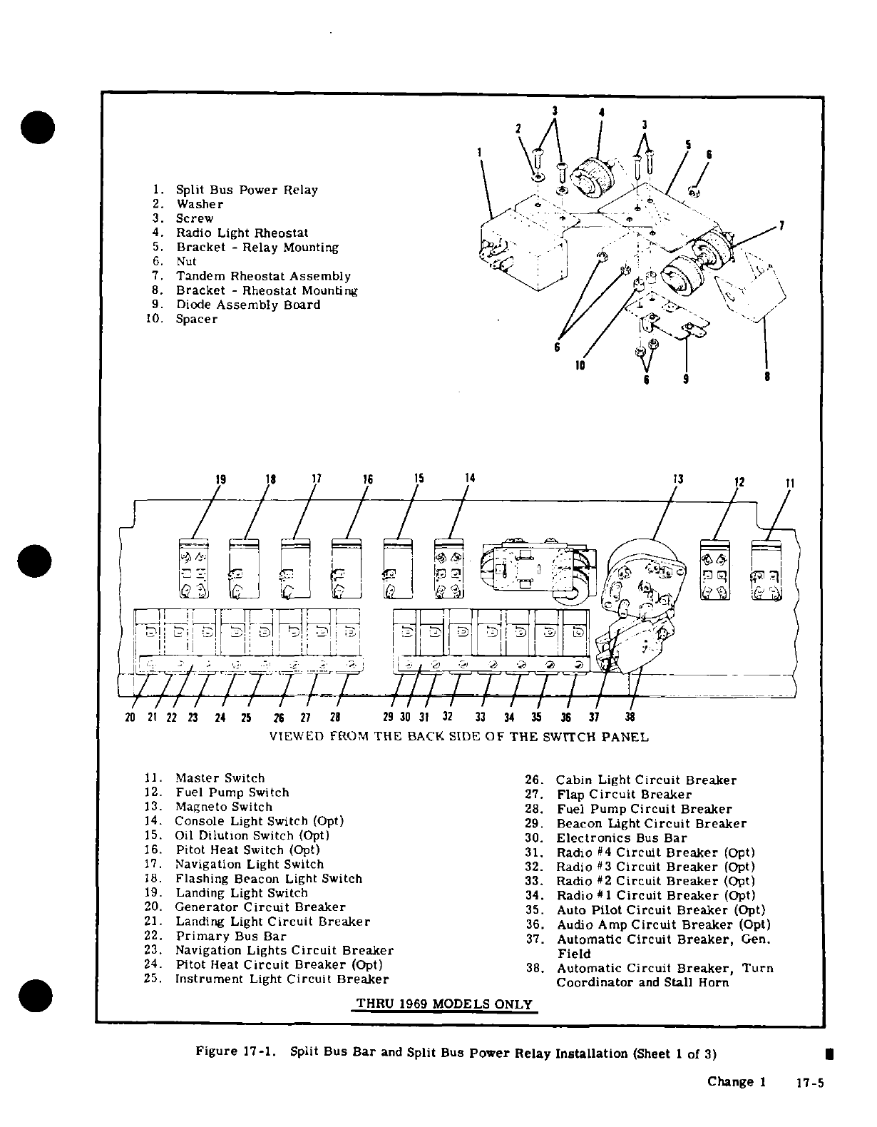
4
1 5 6
1.
Split Bus
Power
Relay
2.
Washer
3.
Screw 7
4.
Radio
Light
Rheostat
5.
Bracket
-
Relay
Mounting
6.
Nut
7.
Tandem
Rheostat Assembly
8.
Bracket
-
Rheostat
Mounting
9.
Diode
Assembly
Board
10.
Spacer
6
6
9
19 18
17 16 15
14
13
12
11
20
21
22
23
24
25
26
27
28
29
30
31
32
33
34
3 5
36
37
38
VIEWED
FROM
THE
BACK
SIDE
OF THE
SWITCH
PANEL
11.
Master
Switch
26.
Cabin
Light
Circuit
Breaker
12.
Fuel
Pump
Switch 27.
Flap
Circuit
Breaker
13.
Magneto
Switch
28.
Fuel
Pump
Circuit
Breaker
14.
Console
Light
Switch
(Opt) 29.
Beacon
Light
Circuit
Breaker
15.
Oil
Dilution
Switch
(Opt)
30.
Electronics
Bus
Bar
16.
Pitot
Heat
Switch
(Opt) 31.
Radio
#4
Circuit Breaker
(Opt)
17.
Navigation
Light
Switch
32.
Radio
#3
Circuit
Breaker
(Opt)
18.
Flashing
Beacon
Light
Switch
33.
Radio
#2
Circuit
Breaker
(Opt)
19.
Landing
Light
Switch
34.
Radio
#1
Circuit
Breaker
(Opt)
20.
Generator
Circuit Breaker
35.
Auto
Pilot
Circuit
Breaker
(Opt)
21.
Landing
Light
Circuit Breaker
36.
Audio
Amp
Circuit
Breaker
(Opt)
22.
Primary
Bus
Bar
37.
Automatic
Circuit
Breaker,
Gen.
23.
Navigation
Lights
Circuit Breaker
Field
24.
Pitot
Heat
Circuit
Breaker
(Opt)
38.
Automatic
Circuit
Breaker,
Turn
25.
Instrument
Light
Circuit
Breaker
Coordinator
and
Stall
Horn
THRU
1969
MODELS ONLY
Figure
17-1.
Split
Bus
Bar
and
Split
Bus
Power
Relay
Installation
(Sheet
1
of
3)
Change
1
17-5
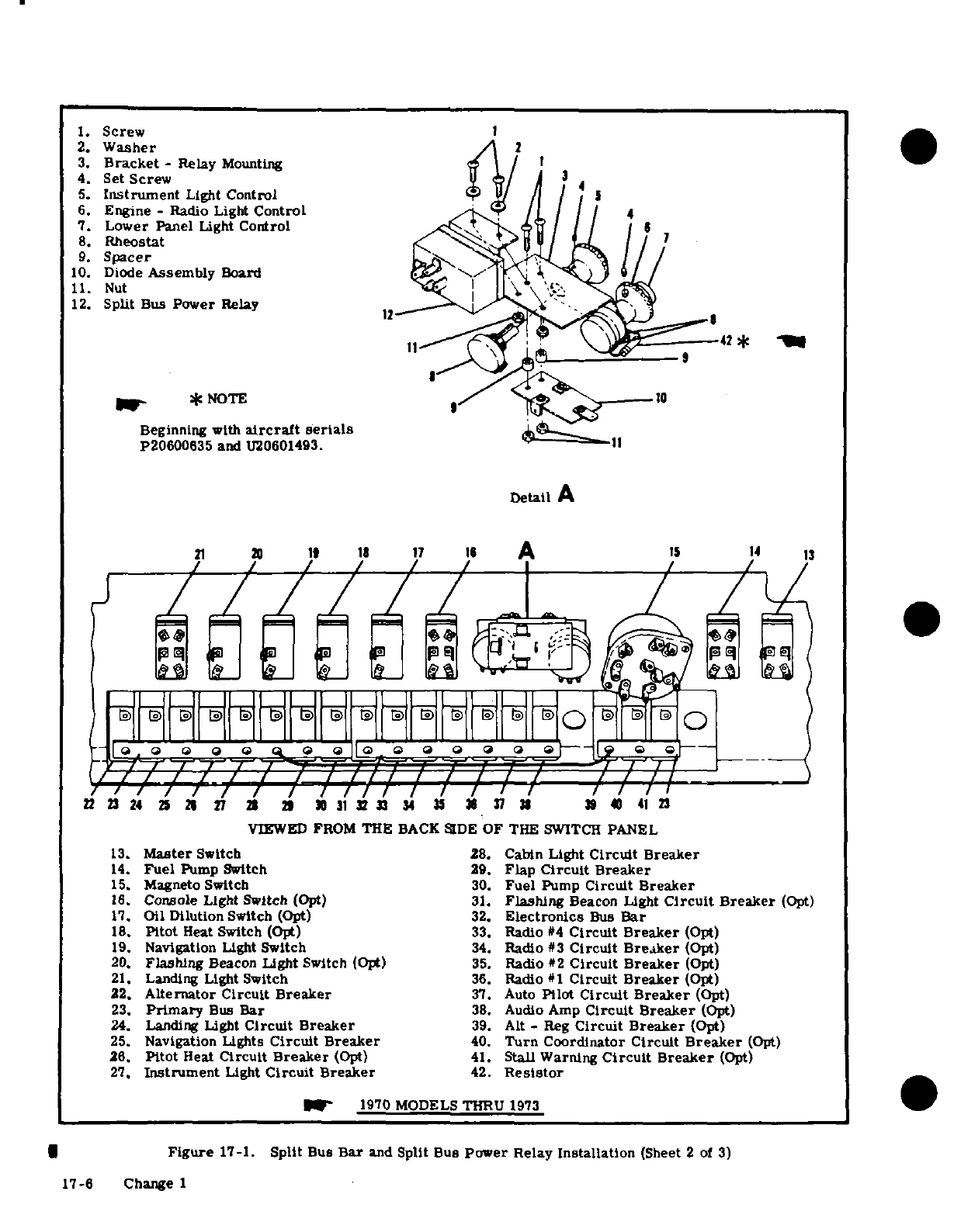
1.
Screw
2.
Washer
2
3.
Bracket
-
Relay
Mounting
4.
Set
Screw
3
5.
Instrument
Light
Control
6.
Engine
-
Radio
Light
Control
4
7.
Lower
Panel
Light
Control
8.
Rheostat
9.
Spacer
10.
Diode
Assembly
Board
11.
Nut
12.
Split
Bus
Power
Relay
11
42*
12
*
NOTE
10
Beginning
with
aircraft
serials
P20600635
and
U20601493.
I
Detail
A
21
a
1i
18
7 1 8 A
15
14
13
///
/ / / / /
/ /
r:,,, /?
/ /
/_/ 7
I
II
I2
-
24 ^ii25
/
.?
./
'-
-=,"
^.
^-
/
/II I I I I i I I
I
j
22
a
24
2n
2 7 n
30
31
33
34
3
X
37
3
40
41
2
VIEWED
FROM
THE
BACK
SIDE
OF
THE
SWITCH
PANEL
13.
Master
Switch
28.
Cabin
Light
Circuit
Breaker
14.
Fuel
Pump
Switch
29.
Flap
Circuit
Breaker
15.
Magneto
Switch
30.
Fuel
Pump
Circuit Breaker
16.
Console
Light
Switch
(Opt)
31.
Flashing
Beacon Light
Circuit
Breaker
(Opt)
17.
Oil Dilution
Switch
(Opt)
32.
Electronics
Bus
Bar
18.
Pitot
Heat
Switch
(Opt)
33.
Radio
#4
Circuit
Breaker
(Opt)
19.
Navigation
Light
Switch
34.
Radio #3
Circuit
Breaker
(Opt)
20.
Flashing
Beacon
Light
Switch
(Opt)
35.
Radio
#2
Circuit
Breaker
(Opt)
21.
Landing Light
Switch
36.
Radio
#1
Circuit
Breaker
(Opt)
22.
Alternator Circuit
Breaker
37.
Auto
Pilot
Circuit
Breaker
(Opt)
23.
Primary
Bus
Bar
38.
Audio
Amp
Circuit
Breaker
(Opt)
24.
Landing
Light
Circuit
Breaker
39.
Alt
-
Reg
Circuit
Breaker
(Opt)
25.
Navigation
Lights
Circuit Breaker
40.
Turn
Coordinator
Circuit
Breaker
(Opt)
26.
Pitot
Heat
Circuit
Breaker
(Opt)
41.
Stall Warning
Circuit Breaker
(Opt)
27.
Instrument
Light
Circuit
Breaker
42.
Resistor
W
1970
MODELS
THRU
1973
|*U
~
Figure
17-1.
Split
Bus
Bar
and
Split
Bus
Power
Relay
Installation
(Sheet
2
of
3)
17-6
Change 1
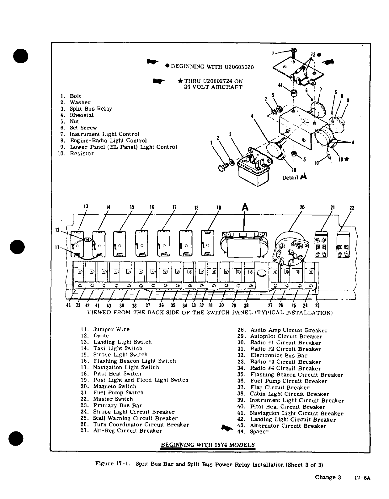
1.
Bolt
2.
Washer
3.
Split Bus
Relay
4.
Rheostat
5.
Nut
6.
Set
Screw
7.
Instrument
Light
Control
8.
Engine-Radio
Light
Control
9.
Lower
Panel
(EL
Panel)
Light
Control
10.
Resistor
VIEWED
FROM
THE
BACK
SIDE
OF
THE
SWITCH
PANEL
(TYPICAL
INSTALLATION)
11.
Jumper
Wire
28.
Audio
Amp
Circuit Breaker
12.
Diode
29.
Autopilot
Circuit
Breaker
13.
Landing
Light Switch
30.
Radio
#1
Circuit
Breaker
14.
Taxi
Light
Switch
31.
Radio
#2
Circuit
Breaker
15.
Strobe
Light
Switch
32.
Electronics
Bus
Bar
16.
Flashing
Beacon
Light
Switch
33.
Radio
#3
Circuit
Breaker
17.
Navigation Light
Switch
34.
Radio
#4
Circuit
Breaker
18.
Pitot
Heat
Switch
35.
Flashing
Beacon
Circuit
Breaker
19.
Post
Light
and Flood
Light
Switch
36.
Fuel
Pump
Circuit
Breaker
20.
Magneto
Switch
37.
Flap
Circuit
Breaker
21.
Fuel Pump
Switch
38.
Cabin
Light
Circuit
Breaker
22.
Master
Switch
39.
Instrument
Light
Circuit
Breaker
23.
Primary
Bus
Bar
40.
Pitot
Heat
Circuit
Breaker
24.
Strobe
Light
Circuit
Breaker
41.
Naviagtion
Light
Circuit
Breaker
25.
Stall
Warning
Circuit
Breaker
42.
Landing
Light
Circuit
Breaker
26.
Turn
Coordinator
Circuit
Breaker
43.
Alternator
Circuit
Breaker
27.
Alt-Reg
Circuit
Breaker
44.
Spacer
BEGINNING
WITH
1974
MODELS
Figure
17-1. Split
Bus
Bar
and
Split
Bus
Power
Relay
Installation
(Sheet
3
of
3)
Change
3
17-6A
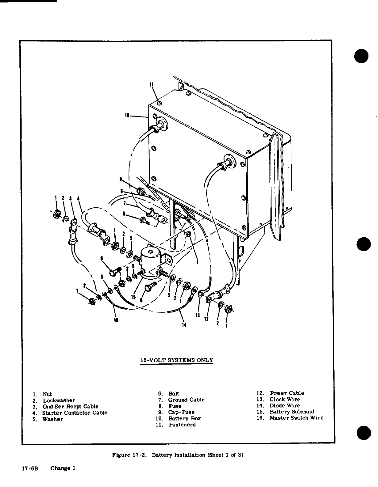
10
14
12-VOLT
SYSTEMS ONLY
1.
Nut
6.
Bolt
12.
Power
Cable
2.
Lockwasher
7.
Ground
Cable
13.
Clock
Wire
3.
Gnd
Ser
Recpt
Cable
8.
Fuse
14.
Diode
Wire
4.
Starter
Contactor
Cable
9.
Cap-Fuse
15.
Battery
Solenoid
5.
Washer
10.
Battery
Box
16.
Master
Switch
Wire
11.
Fasteners
Figure
17-2.
Battery
Installation
(Sheet
1
of
3)
17-6B
Change
1
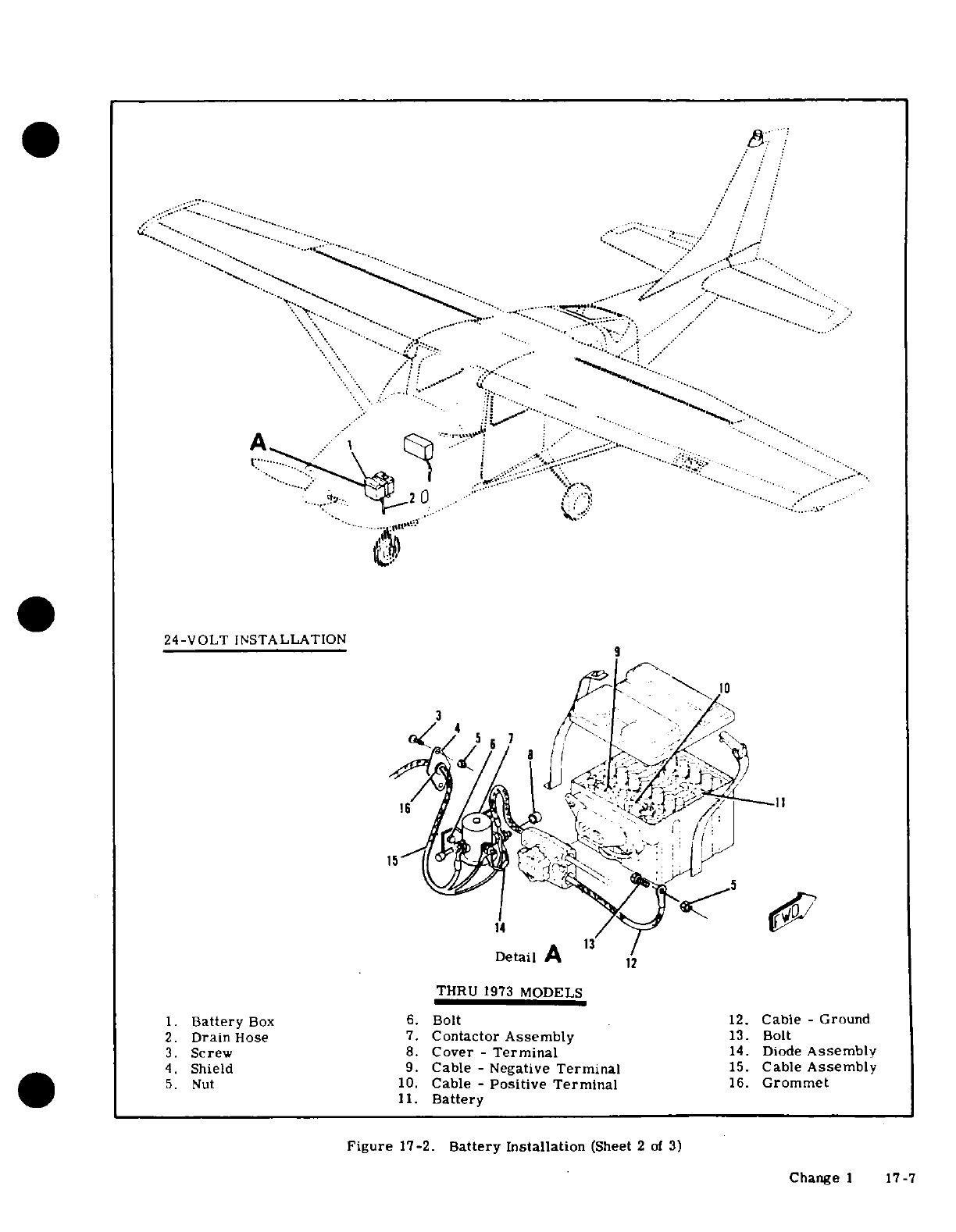
.... ....
...
...
.....
.
2
24-VOLT
INSTALLATION
1
Detail
A 13
THRU
1973
MODELS
1.
Battery
Box
6.
Bolt
12.
Cable
-
Ground
2.
Drain
Hose
7.
Contactor
Assembly
13.
Bolt
3.
Screw
8.
Cover
-
Terminal
14.
Diode
Assembly
4.
Shield
9.
Cable
-
Negative
Terminal
15.
Cable
Assembly
5.
Nut
10.
Cable
-
Positive Terminal
16.
Grommet
11.
Battery
Figure
17-2.
Battery
Installation
(Sheet
2
of
3)
Change
1
17-7
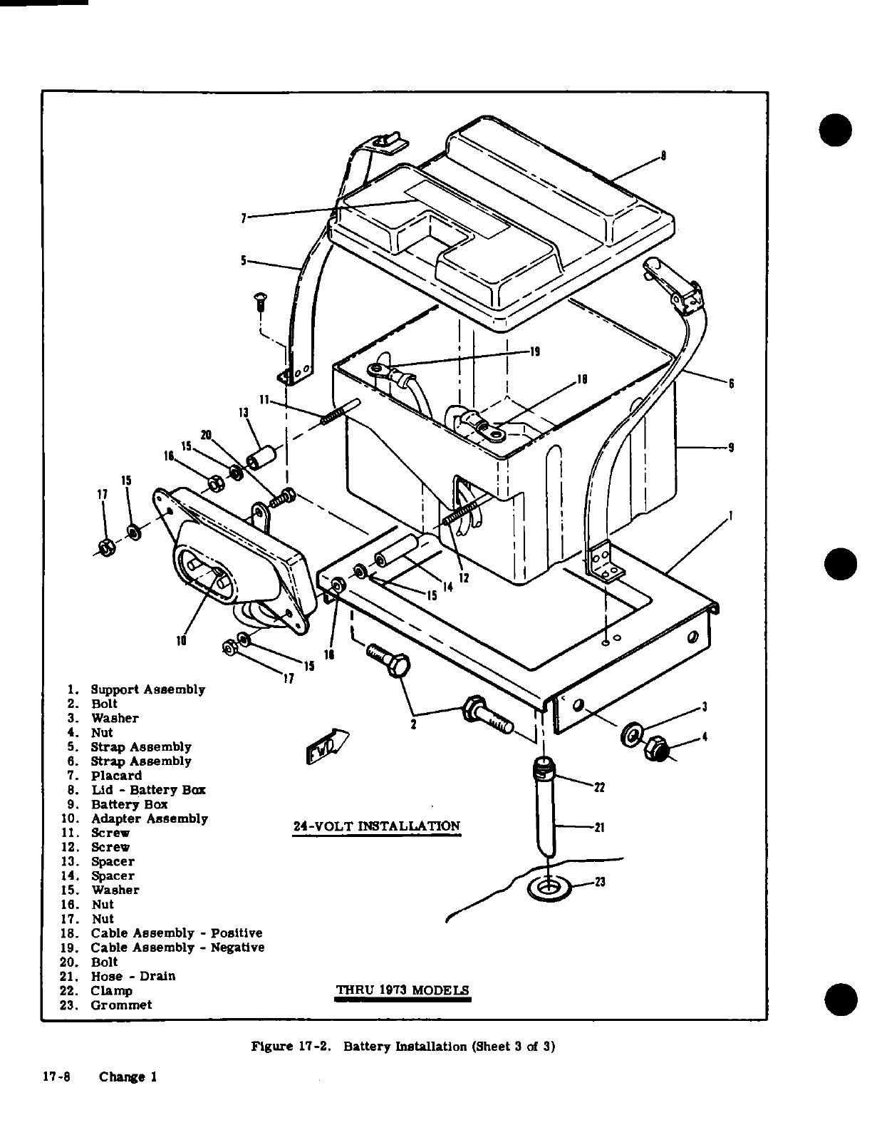
1.
Support
Assembly
2.
Bolt
3.
Washer
4.
Nut
5.
Strap
Assembly
6.
Strap
Assembly
7.
Placard
8.
Lid
-
Battery
Box
9.
Battery
Box
10.
Adapter
Assembly
11.
Screw
12.
Screw
13.
Spacer
14.Spacer
15.
Washer
16.
Nut
17.
Nut
18.
Cable
Assembly
-
Positive
19.
Cable
Assembly
-
Negative
20.
Bolt
21.
Hose
-
Drain
22.
Clamp
23.
Grommet
Figure
17-2.
Battery
Installaton
(Sheet
3
of
3)
17-8
Change
1
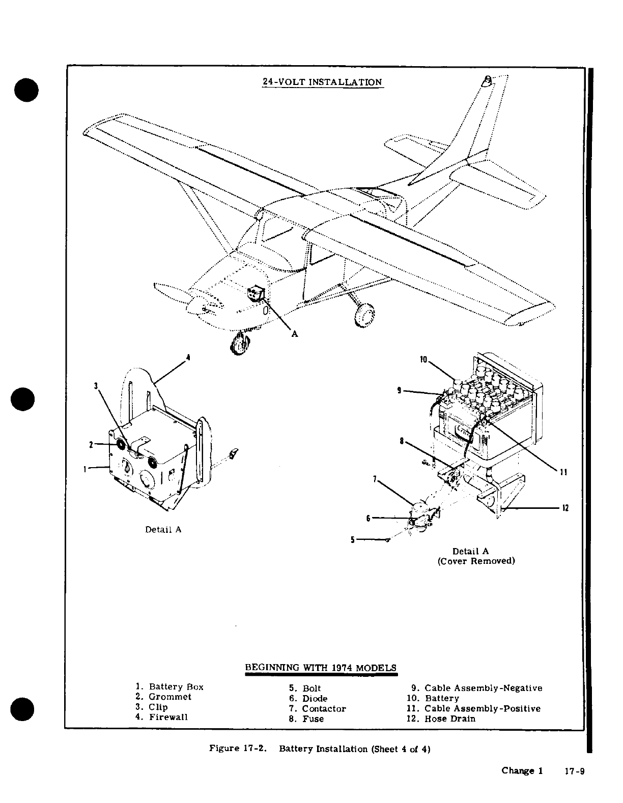
24-VOLT
INSTALLATION
-
:
12
DetailA
Detail
A
1.
Battery
Box
5.
Bolt
9.
Cable Assembly-Negative
2.
Grommet
6.
Diode
10.
Battery
4.
Firewall
8.
Fuse
12.
Hose
Drain
Figure
17-2.
Battery
Installation
(Sheet
4
of
4)
Change
1
17-9
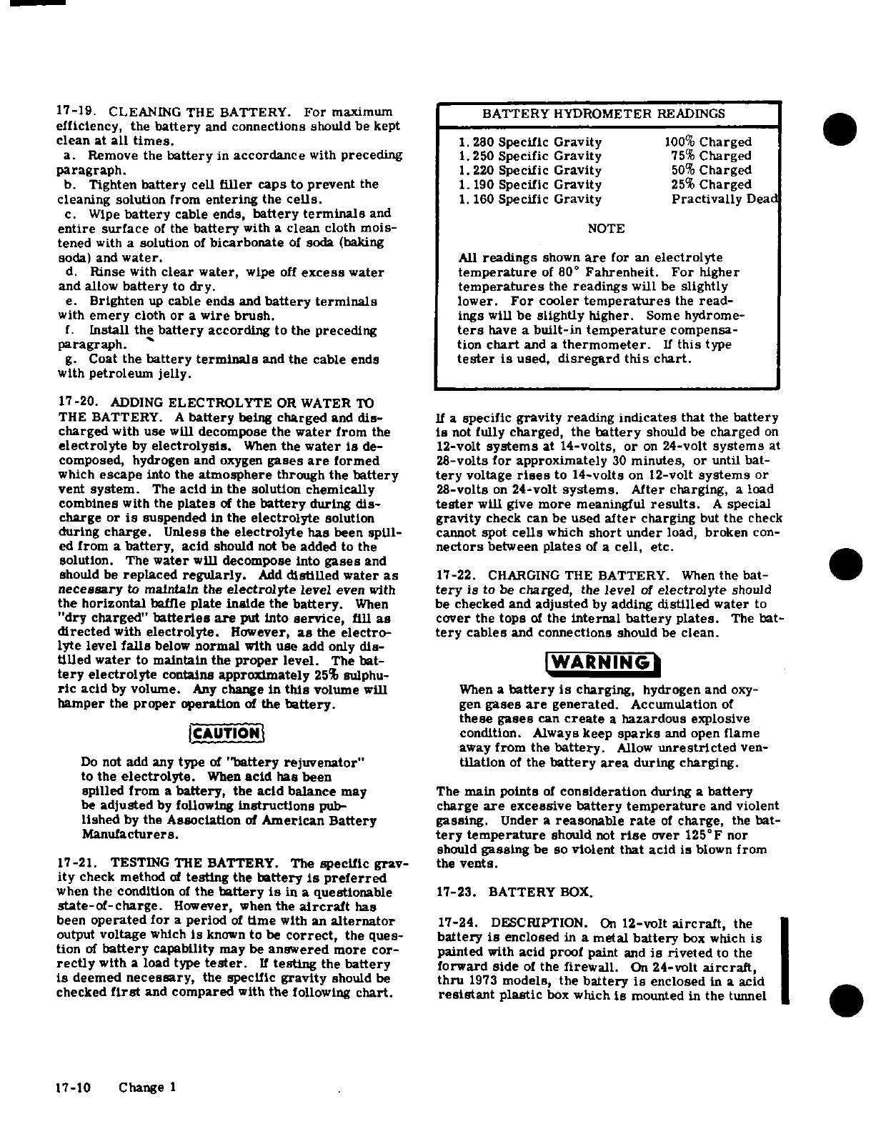
17-19.
CLEANING
THE
BATTERY.
For
maximum
BATTERY
HYDROMETER
READINGS
efficiency,
the
battery
and
connections
should
be kept
clean
at
all
times.
1.
280
Specific
Gravity
100%
Charged
a.
Remove
the
battery
in
accordance
with
preceding
1.250
Specific
Gravity
75%
Charged
paragraph.
1.220 Specific
Gravity
50%
Charged
b.
Tighten
battery
cell
filler
caps
to
prevent
the
1.
190
Specific
Gravity
25%
Charged
cleaning
solution
from
entering
the
cells.
1.
160
Specific
Gravity
Practivally
Dead
c.
Wipe
battery
cable
ends,
battery
terminals
and
entire
surface
of
the
battery
with
a
clean
cloth
mois-
NOTE
tened
with
a
solution
of
bicarbonate
of
soda
(baking
soda)
and
water.
All
readings
shown
are
for
an
electrolyte
d.
Rinse
with
clear
water,
wipe
off
excess
water
temperature
of
80
°
Fahrenheit.
For
higher
and
allow
battery
to
dry.
temperatures
the
readings
will
be
slightly
e.
Brighten
up
cable
ends
and
battery
terminals
lower.
For
cooler
temperatures
the
read-
with
emery
cloth
or
a
wire
brush.
ings
will
be
slightly
higher.
Some
hydrome-
f.
Install
the
battery
according
to
the
preceding
ters
have
a
built-in
temperature
compensa-
paragraph.
tion
chart
and
a
thermometer.
If
this
type
g.
Coat
the
battery
terminals
and
the
cable
ends
tester
is
used,
disregard this
chart.
with
petroleum
jelly.
17-20.
ADDING
ELECTROLYTE
OR
WATER
TO
THE
BATTERY.
A
battery
being
charged
and
dis-
If
a
specific
gravity
reading
indicates
that
the
battery
charged
with
use
will
decompose
the
water
from
the
is
not
fully
charged, the
battery
should
be
charged
on
electrolyte
by
electrolysis.
When
the
water
is
de-
12-volt
systems
at
14-volts,
or
on
24-volt
systems
at
composed,
hydrogen
and
oxygen
gases
are
formed
28-volts
for
approximately
30
minutes,
or
until bat-
which
escape
into
the
atmosphere
through
the
battery
tery
voltage
rises
to
14-volts
on
12-volt
systems
or
vent
system.
The
acid
in
the
solution
chemically
28-volts
on
2
4
-volt
systems.
After
charging,
a
load
combines
with
the
plates
of
the
battery
during
dis-
tester
will
give
more
meaningful
results.
A
special
charge or
is
suspended
in
the
electrolyte
solution
gravity
check can
be
used
after
charging
but
the
check
during
charge.
Unless the
electrolyte
has
been
spill-
cannot
spot
cells
which
short
under
load,
broken
con-
ed
from
a
battery,
acid
should
not
be
added
to
the
nectors
between
plates
of
a
cell,
etc.
solution.
The
water
will
decompose
into
gases
and
should
be
replaced
regularly.
Add
distilled
water
as
17-22.
CHARGING
THE
BATTERY.
When
the bat-
necessary
to
maintain the
electrolyte
level
even
with
tery
is
to
be
charged,
the
level
of
electrolyte
should
the horizontal
baffle
plate
inside
the
battery.
When
be
checked
and
adjusted
by
adding
distilled
water
to
"dry
charged"
batteries
are
put into
service,
fill
as
cover the
tops
of
the
internal
battery
plates.
The
bat-
directed
with
electrolyte.
However,
as
the
electro- tery
cables
and
connections
should
be
clean.
lyte
level
falls
below
normal
with
use
add
only
dis-
tilled
water
to
maintain
the
proper
level.
The
bat-
WARNING
tery
electrolyte
contains
approximately
25%
sulphu-
ric
acid
by
volume.
Any
change
in
this
volume will
When
a
battery
is
charging,
hydrogen
and
oxy-
hamper
the
proper
operation
of
the
battery.
gen
gases
are
generated.
Accumulation
of
these
gases
can
create
a
hazardous
explosive
CAUTION
condition.
Always
keep
sparks
and
open
flame
away
from
the
battery.
Allow
unrestricted
ven-
Do
not add
any
type
of
"battery rejuvenator"
tilation
of
the
battery
area
during
charging.
to
the
electrolyte.
When
acid
has been
spilled
from
a
battery,
the
acid
balance
may The
main
points
of
consideration
during
a
battery
be
adjusted
by
following
instructions
pub-
charge
are
excessive
battery temperature
and
violent
lished
by
the
Association
of
American
Battery
gassing.
Under
a
reasonable
rate
of
charge,
the
bat-
Manufacturers.
tery
temperature
should
not
rise
over
125°F
nor
should
gassing
be so
violent
that
acid is
blown
from
17-21.
TESTING THE
BATTERY.
The
specific
grav-
the
vents.
ity
check method
of
testing
the
battery
is
preferred
when
the
condition
of
the
battery
is
in
a
questionable
17-23.
BATTERY
BOX.
state-of-charge.
However,
when
the
aircraft
has
been
operated for
a
period
of
time
with
an
alternator
17-24.
DESCRIPTION.
On
12-volt
aircraft,
the
output
voltage
which
is
known
to
be
correct,
the
ques-
battery
is
enclosed
in
a
metal
battery
box
which
is
tion
of
battery
capability
may be
answered
more
cor-
painted
with
acid
proof
paint
and
is
riveted
to the
rectly
with
a load type
tester.
If
testing
the
battery
forward side
of
the
firewall.
On
24-volt
aircraft,
is
deemed
necessary,
the specific
gravity
should
be
thru
1973
models,
the
battery
is
enclosed
in
a acid
checked
first
and
compared
with
the
following
chart.
resistant
plastic
box
which
is
mounted
in
the
tunnel
17-10 Change 1
below
the
engine.
Beginning
with
1974
models
the
17-29.
DESCRIPTION.
The
battery
contactor
on
24-volt
aircraft,
the
battery
box
is
mounted
on
the
12-volt
systems
is
bolted
to
the
firewall
below
the
left
hand
firewall
and
constructed
of
metal
covered
battery
box.
Thru
1973
models
on
the
24
volt
system
with
acid
proof
paint.
On
all
three
systems,
the bat-
the
battery
contactor
is
bolted
to
the
tunnel
wall
be-
tery
box
completely
encloses
the
battery
preventing
low
the
engine,
beginning
with
1974
models
on
the
any
spillage
of
electrolyte
or
accumulation
of
battery
24
volt
system
the
battery
contactor
is
bolted
to the
gases
inside
the
aircraft.
All
three
battery
boxes
battery
box
support bracket
on
the
firewall.
The
are
vented
by
a
tube which
attaches
to
the
bottom
of
contactor is
a
solenoid
plunger
type, which
is
actu-
the
battery
box
and
extends
downward
through
the
ated
by
turning
the
master
switch
on.
Beginning
bottom
of
the fuselage.
with
U20601912
a
vented
battery
contactor
is
installed
When
the
master
switch
is
off,
the
battery
is
dis-
17-25.
REMOVAL
AND
INSTALLATION
OF
12
VOLT
connected
from
the
electrical
system.
A
silicon
BATTERY
BOX.
(Refer
to
figure
17-2.)
The
battery
diode
is
used
to
eliminate
spiking
of
the
transistor-
box
is
riveted
to
the
firewall.
The
rivets
must
be
ized
radio
equipment.
The
cathode
(+)
terminal
of
drilled
out
to
remove
the
box.
When
a
battery
box
is
the
diode
connects
to
the
battery
terminal
of
the bat-
installed
and
riveted
into
place,
all
rivets
and
scratch-
tery
contactor.
The
anode
(-)
terminal
of
the
diode
es
inside
the
box
should
be
painted
with
acid-proof
connects
to
the
same
terminal
on
the
contactor
as
lacquer,
Part
No.
CES1054-381,
available
from
the
the
master
switch
wire.
This
places
the
diode
Cessna Service
Parts
Center.
directly
across
the
contactor
solenoid
coil
so
the
inductive
spikes
originating
in
the coil
are
clipped
17-26.
REMOVAL
AND
INSTALLATION
OF
24
VOLT
when
the
master
switch
is
opened.
Refer
to
figure
BATTERY
BOX.
(Refer
to
figure
17-2.)
17-2
for
pictorial
installation
of
the
battery
contactor
a.
Use
paragraph
17-18
as
a
guide
for removal
and
and
diode.
replacement
of
the
battery
box.
17-30.
REMOVAL
AND
INSTALLATION.
(Refer
to
NOTE
figure
17-2.)
a.
On
12-volt
aircraft
and
24-volt
aircraft
begin-
If
rivets
are
removed
from
battery
box,
new
ning
with
1974
models,
open
battery
box
and
dis-
rivets
should
be
painted
with
acid-proof
lac- connect
negative
battery terminal.
Pull
cable
clear
quer.
Part
No.
CES1054-381,
available
from
of
aircraft.
the
Cessna Service
Parts
Center.
b.
On
24-volt
aircraft
thru
1973
models, remove
the
quick
disconnect
cable
assembly
from
the
battery
17-27.
MAINTENANCE OF
BATTERY
BOX.
The
box
by
loosening
the
knob
on
the cable
assembly.
battery
box
should
be
inspected
and
cleaned
periodi-
c. Refer
to
figure
17-2
as
a
guide
for
removal
and
cally.
The
box
and
cover
should
be
cleaned
with
a
installation.
and
water.
Hard
deposits
may
be
removed
from
a
d.
For
installation
of
battery
contactor,
reverse
metal
box
with
a
wire brush
or
from
a
plastic
box
this procedure.
with
a
plastic
scraper.
When
all
corrosive deposits
have been
removed
from
the
box,
flush
it
thoroughly
a.
On
12-volt
aircraft,
open
battery
box
and
dis-
with
clean
water.
connect
negative
battery
terminal.
Pull
cable
clear
of
aircraft.
b.
On
24-volt
aircraft,
remove
the
quick disconnect
WARNING
cable
assembly
from
the
battery
box
by
loosening
the
knob
on
the
cable
assembly.
Do
not
allow
acid
deposits
to
come
in
contact
c.
Refer
to
figure
17-2
and
use
as
a
guide
for
re-
with
skin
or
clothing.
Serious
acid
burns
moval.
may
result
unless
the
affected
area
is
washed
d.
For
replacement
of
battery
contactor,
reverse
immediately
with
soap
and
water.
Clothing
this
procedure.
will
be
ruined
upon
contact
with
battery
acid.
17-31.
BATTERY
CONTACTOR
CLOSING
CIRCUIT.
Inspect
the
cleaned
box
and
cover for
physical
dam-
age
and
for
areas
lacking
proper
acid
proofing.
A
17-32.
DESCRIPTION.
This
circuit consists
of
a
badly
damaged
or
corroded
box
should
be
replaced.
fuse,
a
resistor
and
a
diode
mounted
on
the
ground
If
the
box
or
lid
require
acid
proofing, paint
the
area
service
receptacle
bracket.
This
serves
to
shunt
a
with
acid-proof
black
lacquer,
Part
No.
CES1054-
small charge around
the
battery
contactor
so
that
381,
available
from
the
Cessna Service
Parts
Center.
ground power
may be
used
to
close
the contactor
when
the
battery
is
too
dead
to
energize
the
contactor
17-28.
BATTERY
CONTACTOR.
by
itself.
Refer to
figure
17-3.
Change
1
17-11
17-33.
GROUND
SERVICE
RECEPTACLE.
NOTE
17-34.
DESCRIPTION.
A
ground
service receptacle
When
using
ground
power
to
start
the
air-
is
installed
to
permit
the
use
of
external
power
for
craft,
close
the
master
switch
before re-
cold
weather
starting
or
when
performing
lengthy
moving
the
ground
power
plug.
This
will
electrical
maintenance.
A
reverse
polarity
protec- ensure
closure
of
the
battery
contactor
tion
system
is
utilized
whereby ground
power
must
and
excitation
of
the
alternator
field
in
the
pass
through
an
external
power
contactor
to
be con-
event
that
the
battery
is
completely
dead.
nected
to
the
bus.
A
silicon
junction
diode
is
con-
nected
in
series
with
the
coil
on
the
external
power
CAUTION
contactor
so
that
if
the
ground
power
source
is
inad-
vertently
connected
with
a
reversed
polarity,
the
Failure
to
observe
polarity
when
connecting
external
power
contactor
will
not
close. This
feature
an
external
power
source
directly
to
the
bat-
protects
the
diodes
in
the
alternator,
and
other
semi-
tery
or directly
to
the
battery
side
of
the bat-
conductor
devices
used
in
the
aircraft,
from
possible
tery
contactor,
will damage
the diodes
in the
reverse
polarity
damage.
alternator
and
other
semiconductor
devices
in
the
aircraft.
NOTE
IWARNING1
Maintenance
of
the
electronic
installations
cannot
be
performed
when
using
external External
power
receptacle
must
be
function-
power.
Application
of
external
power opens
ally
checked
after
wiring,
or
after
replace-
the
relay
supplying
voltage
to
the
electronics
ment
of
components
of
the
external
power
or
bus.
For
lengthy ground
testing
of
electronics
split
bus
systems.
Incorrect
wiring
or
mal-
systems,
connect
a
well
regulated
and
filtered
functioned
components
can
cause
immediate
power
supply
directly
to
the
battery
side
of
engagement
of
starter
when
ground
service
the
battery
contactor.
Adjust
the
supply
for
plug
is
inserted.
14-volts
on
12-volt
systems
or
28-volt
on
24-volt
systems
and
close
the
master
switch.
17-35.
TROUBLE
SHOOTING.
TROUBLE
PROBABLE
CAUSE
REMEDY
STARTER
ENGAGES
WHEN
Shorted
or
reversed
diode
in
Check
wiring
to
and
condition
GROUND
POWER
IS
CON-
split
bus-bar
system.
of
diode
mounted
on
the
split
NECTED.
bus
relay
bracket
adjacent
to
the
magneto
switch.
Correct
wiring.
Replace
diode
board
assembly.
GROUND
POWER
WILL
NOT
Ground
service
connector
1.
Check
for voltage
at
all
CRANK
ENGINE.
wired
incorrectly.
three
terminals
of
external
power
contactor
with
ground
power
connected
and
master
switch
off.
If
voltage
is
pre-
sent
on
input
and
coil
termin-
als
but
not
on
the
output
ter-
minal,
proceed
to
step
4.
If
voltage
is
present
on
the
input
terminal
but
not
on
the coil
terminal,
proceed
to
step
2.
If
voltage
is
present
on
all
three
terminals,
check wiring
between
contactor
and
bus.
2.
Check
for
voltage
at
small
terminal
of
ground
service
re-
ceptacle.
If
voltage
is
not
pre-
sent,
check
ground
service
plug
wiring.
If
voltage
is
present,
proceed
to
step
3.
17-12
17-35.
TROUBLE
SHOOTING.(Cont).
TROUBLE
PROBABLE
CAUSE
REMEDY
GROUND POWER
WILL
NOT
Open
or
mis-wired
diode
on
3.
Check
polarity
and
continuity
CRANK ENGINE.
(Cont).
ground
service
diode
board
of
diode
on
diode
board
at
rear
assembly.
of
ground
service
receptacle.
If
diode
is
open
or
improperly
wired,
replace
diode
board
assembly.
Faulty
external
power
con-
4.
Check
resistance
from
small
tactor.
(coil)
terminal
of
external
power
contactor
to
ground
(master
switch
off
and
ground
power
unplugged).
Normal indication
is
16-24
ohms.
on
12-volt
system
or
50-70
ohms
on
the
24-volt
systems.
If
resistance
indicates
an
open
coil,
replace
contactor.
If
resistance
is
normal, proceed
to
step
5.
Faulty contacts
in
external
5.
With
master
switch
off
and
power
contactor.
ground
power
applied,
check
for
voltage
drop
between
two
large
terminals
of
external
power
(turn
on
taxi
light
for
a
load).
Normal
indication
is
zero
volts.
If
voltage
is
intermittently
pres-
ent
or present all
the
time,
0.-^^y~~~~~~~~~~~~~~ ~~replace
contactor.
17-36.
REMOVAL
AND
INSTALLATION.
(Refer
17-40. DESCRIPTION.
The
60-ampere
alternator
to
figure
17-3.
)
used
on
the
aircraft
are
three-phase,
delta
connected
a.
On
12-volt
systems,
open
the
battery
box
and with
integral silicon
diode
rectifiers.
The
alternator
disconnect
the
ground
cable from
the
negative
termi-
is
rated
at
14-volts or 28-volts
at
60-amperes
con-
nal
of
the
battery
and
pull
the
cable
free
of
the
box.
tinuous
output.
The
moving
center part
of
the
alter-
b.
On
24-volt
systems,
remove
the
quick-discon-
nator
(rotor)
consists
of
an
axial
winding
with
radial
nect cable
assembly
from
the
battery
box
assembly
interlocking
poles
which
surround
the
winding.
by
loosening
the
knob
on
the
cable
assembly.
c.
Remove
the
nuts,
washers,
ground
strap,
bus
With
excitation applied
to
the
winding
through
slip
bar
and
diode
board
from
the
studs
of
the
receptacle rings
the
pole
pieces
assume
magnetic
polarity.
The
and
remove
battery
cable.
rotor
is
mounted
in
bearings
and
rotates
inside
the
d.
Remove
the
screws
and
nuts
holding
the
recep-
stator
which
contains
the windings
in
which
the
ac
tacle;
ground
strap
will
then
be
free
from
the
bracket.
current
is
generated.
The
stator
windings
are
three-
e.
To
install
a
ground
service receptacle,
reverse
phase, delta
connected
and
are
attached
to
two
diode
this
procedure.
plates,
each
of
which
contains
three
silicon
diodes.
The diode
plates
are
connected to
accomplish
full-
17-37.
ALTERNATOR
POWER
SYSTEM.
wave,
rectification
of
the
ac.
The
resulting
dc
output
is
applied
to
the
aircraft
bus
and
sensed
by
the
volt-
17-38. DESCRIPTION. The
alternator
system
con-
age
regulator.
The
regulator
controls
the
excitation
sists
of
an
engine
driven
alternator,
a
voltage
regu-
applied
to
the
alternator
field
thus
controlling
the
out-
lator
and
a
circuit
breaker
located
on
the
instrument
put
voltage
of
the
alternator.
panel.
The
system
is
controlled
by
the
left
hand
por-
tion
of
the
split
rocker, master
switch
labeled
ALT.
17-41. ALTERNATOR
REVERSE
VOLTAGE
DAM-
Beginning
with
1972
models
an
over-voltage sensor
AGE.
The
alternator
is very susceptible
to
reverse
switch
and
red
warning
light
labeled
HIGH
VOLTAGE
polarity
damage
due
to
the
very
low
resistance
of
the
are
incorporated
to
protect
the
system,
(refer
to output
windings
and
the
low
resistance
of
the
silicon
paragraph
17-57).
The
aircraft
battery
supplies
the
diodes
in
the
output.
If
a
high
current
source,
such
source
of
power for
excitation
of
the
alternator. as
a
battery
or
heavy
duty
ground power
cart
is
at-
17-39,ffs~~~~~~~~ ALT
rvertached
to
the
aircraft
with
the
polarity
inadvertently
17-39.
ALTERNATOR.
reversed,
the
current
through
the
alternator
will
flow
almost
without
limit
and
the
alternator
will
be
imme-
diately
damaged.
Change
1
17-13
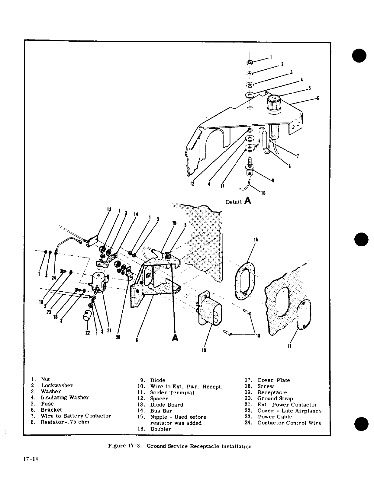
2
12
1
1.
Nut
9.
Diode
17.
Cover
Plate
2.
Lockwasher
10.
Wire
to
Ext.
Pwr.
Recept.
18.
Screw
3.
Washer
11.
Solder
Terminal
19.
Receptacle
4.
Insulating
Washer
12.
Spacer
20.
Ground
Strap
5.
Fuse
13.
Diode
Board
21.
Ext.
Power
Contactor
6.
Bracket
14.
Bus
Bar
22.
Cover
-
Late
Airplanes
7.
Wire
to
Battery
Contactor
15.
Nipple
-
Used
before
23.
Power
Cable
8.
Resistor-.
75
ohm
resistor
was
added
24.
Contactor
Control
Wire
16.
Doubler
Figure
17-3.
Ground
Service Receptacle
Installation
17-14
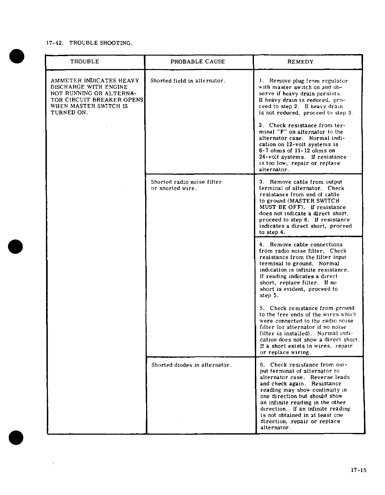
17-42.
TROUBLE
SHOOTING.
TROUBLE
PROBABLE
CAUSE
REMEDY
AMMETER
INDICATES
HEAVY
Shorted
field
in
alternator.
1.
Remove
plug
from
regulator
DISCHARGE
WITH
ENGINE
with
master
switch
on
and
ob-
NOT
RUNNING
OR
ALTERNA-
serve
if
heavy
drain
persists.
TOR
CIRCUIT BREAKER
OPENS
If
heavy
drain
is
reduced,
pro-
WHEN
MASTER
SWITCH
IS
ceed
to
step
2.
If
heavy
drain
TURNED
ON.
is
not
reduced,
proceed
to
step
3.
2.
Check
resistance
from
ter-
minal
"F"
on
alternator
to
the
alternator
case.
Normal
indi-
cation
on
12-volt
systems
is
6-7
ohms
of
11-12
ohms
on
24-volt
systems.
If
resistance
is
too
low,
repair
or replace
alternator.
Shorted
radio
noise
filter
3.
Remove
cable
from
output
or
shorted
wire.
terminal
of
alternator.
Check
resistance
from
end
of
cable
to ground
(MASTER
SWITCH
MUST
BE
OFF).
If
resistance
does
not
indicate
a
direct
short.
proceed
to
step
6.
If
resistance
indicates
a
direct
short,
proceed
to
step
4.
4.
Remove
cable connections
from radio
noise
filter.
Check
resistance
from
the
filter
input
terminal
to
ground.
Normal
indication
is
infinite
resistance.
If
reading
indicates
a
direct
short,
replace
filter.
If
no
short
is
evident,
proceed
to
step
5.
5.
Check
resistance
from
ground
to
the
free
ends
of
the
wires
which
were
connected
to
the
radio
noise
filter
(or
alternator
if
no
noise
filter
is
installed).
Normal
indi-
cation
does
not
show
a
direct
short.
If
a
short
exists
in
wires,
repair
or
replace
wiring.
Shorted
diodes
in
alternator.
6.
Check
resistance
from
out-
put
terminal
of
alternator
to
alternator
case. Reverse
leads
and
check
again.
Resistance
reading
may
show
continuity
in
one
direction
but
should
show
an
infinite
reading
in
the other
direction.
If
an
infinite
reading
is
not
obtained
in
at
least
one
direction,
repair
or
replace
alternator.
17-15
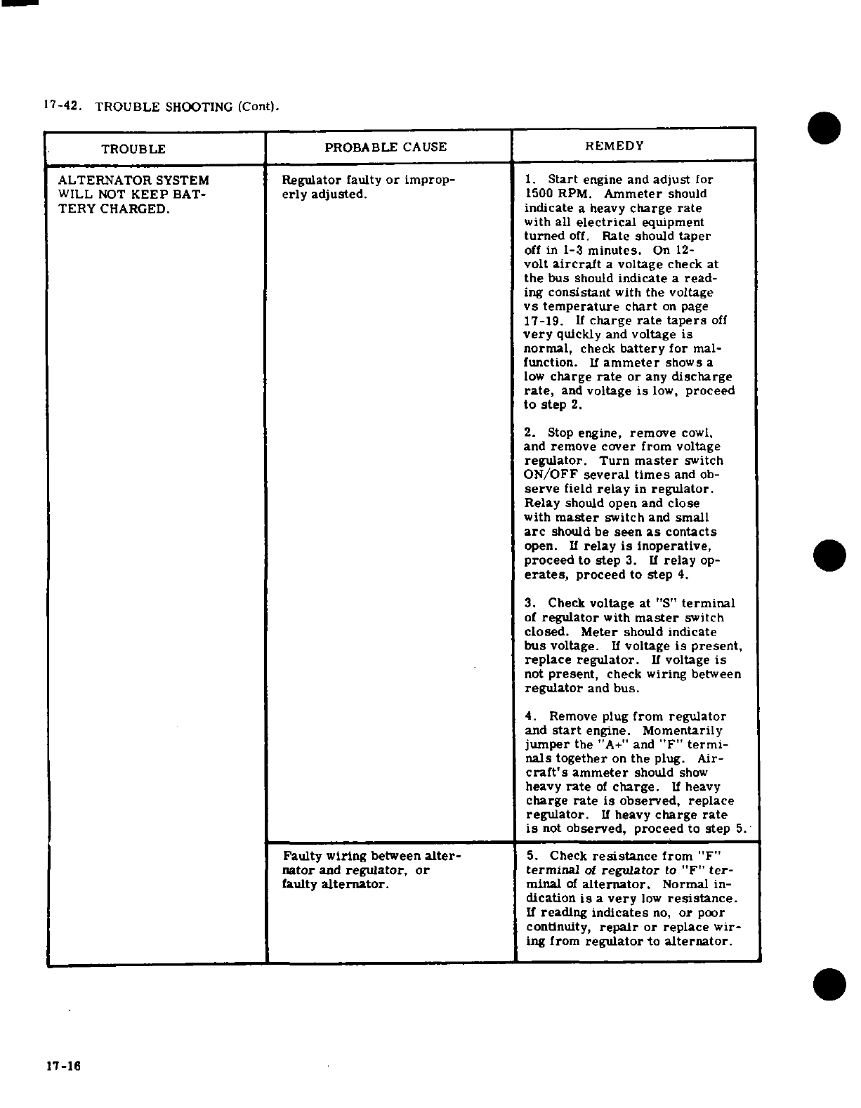
17-42.
TROUBLE
SHOOTING
(Cont).
TROUBLE
PROBABLE
CAUSE
REMEDY
ALTERNATOR
SYSTEM
Regulator
faulty
or
improp-
1.
Start
engine
and
adjust
for
WILL
NOT
KEEP
BAT-
erly
adjusted.
1500
RPM.
Ammeter
should
TERY
CHARGED.
indicate
a
heavy
charge
rate
with
all
electrical
equipment
turned
off.
Rate
should
taper
off
in
1-3
minutes.
On
12-
volt
aircraft
a
voltage
check
at
the
bus
should
indicate
a
read-
ing
consistant
with
the
voltage
vs
temperature
chart
on
page
17-19.
If
charge
rate
tapers
off
very
quickly
and
voltage
is
normal,
check
battery
for
mal-
function.
If
ammeter
shows a
low
charge
rate
or
any
discharge
rate,
and
voltage
is
low,
proceed
to
step
2.
2.
Stop
engine,
remove
cowl,
and
remove
cover
from
voltage
regulator.
Turn
master
switch
ON/OFF
several
times
and
ob-
serve
field
relay
in
regulator.
Relay
should
open and
close
with
master
switch
and
small
arc
should
be
seen
as
contacts
open.
If
relay
is
inoperative,
proceed
to step
3.
If
relay
op-
erates,
proceed
to step
4.
3.
Check
voltage
at
"S"
terminal
of
regulator
with
master
switch
closed.
Meter
should
indicate
bus
voltage.
If
voltage
is
present,
replace
regulator.
If
voltage
is
not
present,
check
wiring
between
regulator
and
bus.
4.
Remove
plug
from
regulator
and
start
engine.
Momentarily
jumper
the
"A+"
and
"F"
termi-
nals
together
on
the
plug.
Air-
craft's
ammeter
should
show
heavy
rate
of
charge.
If
heavy
charge
rate
is
observed, replace
regulator.
If
heavy
charge
rate
is
not
observed, proceed
to
step
5.
Faulty
wiring
between
alter-
5.
Check
resistance
from
"F"
nator
and
regulator,
or
terminal
of
regulator
to
"F"
ter-
faulty
alternator.
minal
of
alternator.
Normal
in-
dication
is
a
very
low
resistance.
If
reading
indicates
no,
or
poor
continuity,
repair
or
replace
wir-
ing
from
regulator
to alternator.
17-16
17-16
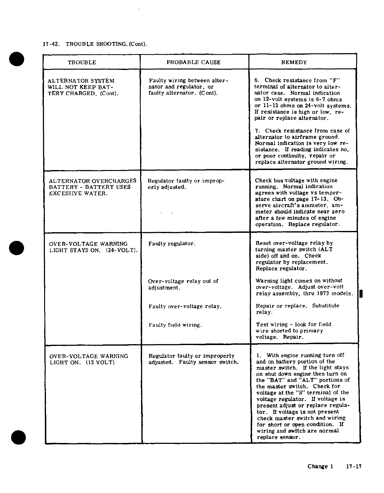
17-42.
TROUBLE
SHOOTING.
(Cont).
TROUBLE PROBABLE
CAUSE
REMEDY
ALTERNATOR
SYSTEM
Faulty
wiring
between
alter-
6.
Check
resistance
from
"F"
WILL
NOT
KEEP
BAT-
nator
and
regulator,
or
terminal
of
alternator
to
alter-
TERY
CHARGED.
(Cont).
faulty
alternator.
(Cont).
nator
case.
Normal
indication
on
12-volt
systems
is
6-7
ohms
or
11-12
ohms
on
24-volt
systems.
If
resistance
is
high
or
low,
re-
pair
or
replace
alternator.
7.
Check
resistance
from
case
of
alternator
to
airframe
ground.
Normal
indication
is
very
low
re-
sistance.
If
reading
indicates
no,
or poor
continuity,
repair
or
replace
alternator
ground
wiring.
ALTERNATOR
OVERCHARGES
Regulator
faulty
or improp-
Check
bus voltage
with
engine
BATTERY
-
BATTERY
USES
erly
adjusted.
running. Normal
indication
EXCESSIVE
WATER.
agrees
with
voltage
vs temper-
ature
chart
on
page
17-13.
Ob-
serve
aircraft's
ammeter,
am-
meter
should
indicate
near
zero
after
a
few
minutes
of
engine
operation.
Replace
regulator.
OVER-VOLTAGE
WARNING
Faulty
regulator.
Reset over-voltage
relay
by
LIGHT
STAYS
ON.
(24-VOLT).
turning
master
switch
(ALT
side)
off
and
on.
Check
regulator
by
replacement.
Replace
regulator.
Over-voltage
relay
out
of
Warning
light
comes
on
without
adjustment.
over-voltage.
Adjust
over-volt
relay
assembly,
thru
1973
models.
Faulty
over-voltage
relay.
Repair or
replace.
Substitute
relay.
Faulty
field
wiring.
Test
wiring
-
look
for
field
wire
shorted
to
primary
voltage.
Repair.
OVER-VOLTAGE
WARNING
Regulator
faulty
or improperly
1.
With
engine
running
turn
off
LIGHT
ON.
(12
VOLT)
adjusted.
Faulty
sensor
switch.
and
on
battery
portion
of
the
master
switch.
If
the light
stays
on
shut
down
engine
then
turn
on
the
"BAT"
and
"ALT"
portions
of
the
master
switch.
Check
for
voltage
at
the
"S"
terminal
of
the
voltage
regulator.
If
voltage
is
present
adjust
or replace
regula-
tor.
If
voltage
is
not
present
check
master
switch
and
wiring
for
short
or
open
condition.
If
wiring
and
switch
are
normal
replace sensor.
Change
1
17-17
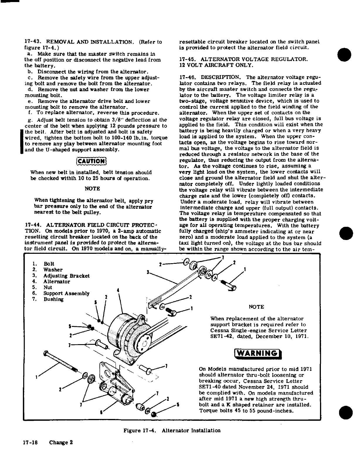
17-43.
REMOVAL
AND
INSTALLATION.
(Refer
to
resettable
circuit breaker
located
on
the
switch
panel
figure
17-4.)
is
provided to
protect
the
alternator
field
circuit.
a.
Make
sure
that
the
master
switch
remains
in
the
off
position
or
disconnect
the
negative
lead from
17-45.
ALTERNATOR
VOLTAGE
REGULATOR.
the
battery.
12
VOLT
AIRCRAFT
ONLY.
b.
Disconnect
the
wiring from
the
alternator.
c.
Remove
the
safety
wire
from
the
upper
adjust-
17-46.
DESCRIPTION.
The
alternator
voltage
regu-
ing
bolt
and
remove
the
bolt
from
the
alternator.
lator
contains
two
relays.
The
field
relay is actuated
d.
Remove
the
nut
and
washer
from
the
lower
by
the
aircraft
master
switch
and
connects
the
regu-
mounting
bolt.
lator
to
the
battery.
The
voltage
limiter
relay is
a
e.
Remove
the
alternator
drive
belt
and
lower
two-stage,
voltage
sensitive
device,
which
is
used
to
mounting
bolt to
remove
the
alternator.
control
the
current
applied
to
the
field
winding
of
the
f.
To
replace
alternator.
reverse
this
procedure.
alternator.
When
the
upper
set
of
contacts
on
the
g.
Adjust
belt
tension
to obtain
3/8"
deflection
at
the
voltage
regulator relay
are
closed,
full
bus
voltage
is
center
of
the
belt
when
applying
12
pounds
pressure
to
applied
to
the
field.
This
condition
will
exist
when
the
the
belt.
After
belt
is
adjusted
and bolt
is
safety
battery
is
being
heavily charged
or
when
a
very
heavy
wired,
tighten
the
bottom
bolt to
100-140
lb. in.
torque
load
is
applied
to
the
system.
When
the
upper
con-
to
remove
any play between
alternator
mounting
foot
tacts
open,
as
the
voltage
begins
to
rise
toward
nor-
and
the
U-shaped
support
assembly.
mal
bus
voltage, the voltage
to
the
alternator
field
is
reduced
through
a
resistor
network
in
the
base
of
the
CAUTION
regulator,
thus
reducing
the
output
from
the
alterna-
tor.
As
the
voltage
continues to
rise,
assuming
a
When
new
belt
is
installed,
belt
tension
should
very
light
load
on
the
system,
the
lower
contacts
will
be
checked
withlh
10
to
25
hours
of
operation.
close
and
ground
the
alternator
field
and
shut
the
alter-
nator
completely
off.
Under
lightly loaded
conditions
NOTE
the
voltage
relay
will
vibrate
between
the
intermediate
charge
rate
and
the
lower
(completely
off)
contacts.
When
tightening the
alternator
belt,
apply
pry
Under
a
moderate
load,
relay
will
vibrate
between
bar
pressure
only
to
the
end
of
the
alternator
intermediate charge
and
upper (full
output)
contacts.
nearest
to
the
belt
pulley. The
voltage
relay
is
temperature
compensated
so
that
the
battery
is
supplied
with
the
proper
charging
volt-
17-44.
ALTERNATOR
FIELD
CIRCUIT
PROTEC.-
age
for all
operating
temperatures.
With
the
battery
TION.
On
models
prior
to
1970,
a
2
-amp
automatic
fully
charged
(ship's ammeter
indicating
at
or
near
resetting circuit breaker
located
on
the back
of
the
zero)
and
a
moderate
load
applied
to
the
system
(a
instrument
panel
is
provided
to
protect
the
alterna-
taxi
light turned
on),
the
voltage
at
the
bus
bar
should
tor
field
circuit.
On
1970
models
and
on,
a
manually-
be
within
the range
shown
according
to
the
air
tem-
1.
Bolt
-
2.
Washer
1
3.
Adjusting
Bracket
4.
Alternator
5.
Nut
6.
Support
Assembly
2
7.
Bushing
NOTE
When
replacement
of
the
alternator
support
bracket
is
required
refer
to
Cessna
Single-engine
Service
Letter
SE71-42,
dated,
December
10, 1971.
WARNING
On
Models
manufactured
prior
to mid
1971
should
alternator
thru-bolt
loosening
or
--.
breaking
occur, Cessna
Service Letter
SE71-40
dated
November
24,
1971
should
/
be
complied
with.
On
models manufactured
after
mid
1971
a
new
high
strength
thru-
/
5
bolt
and
a
K
shaped
retainer
are
installed.
-
Torque
bolts
45
to
55
pound-inches.
Figure
17-4.
Alternator Installation
17-18 Change
2
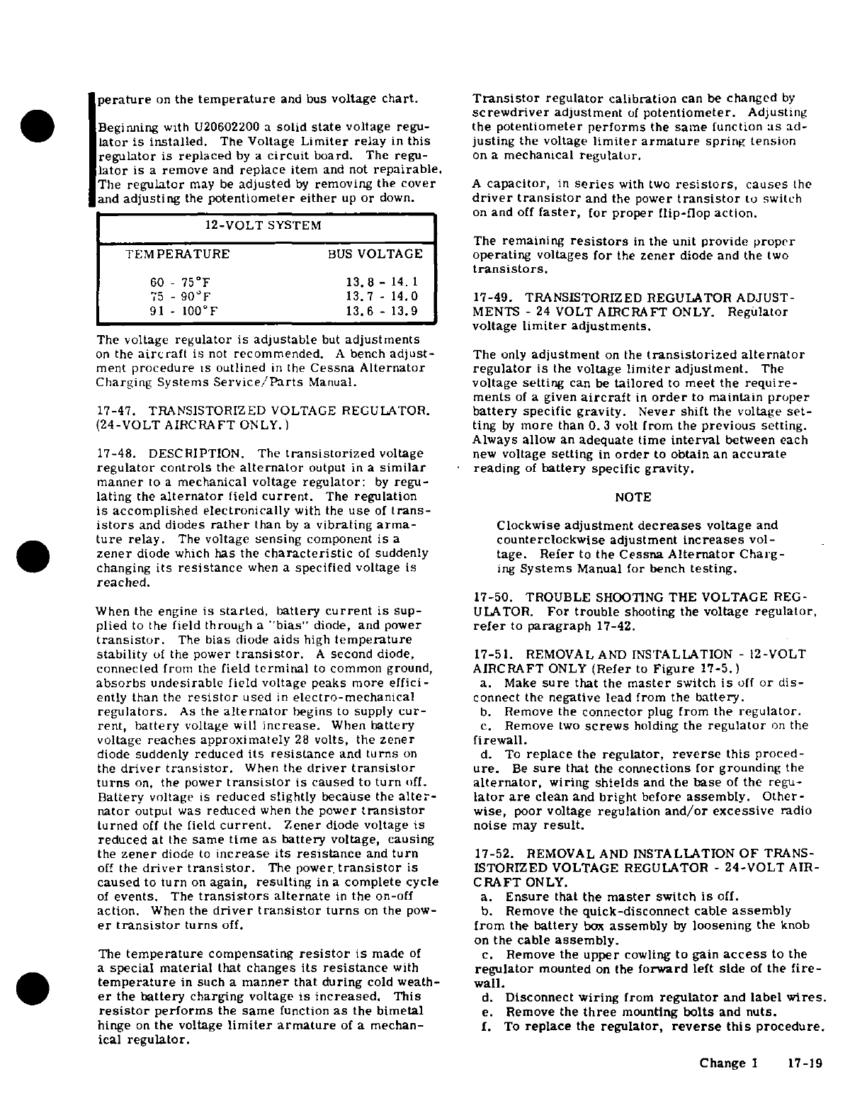
perature
on
the
temperature
and
bus
voltage
chart.
Transistor
regulator
calibration
can
be
changed
by
screwdriver
adjustment
of
potentiometer.
Adjusting
Beginning
with
U20602200
a
solid
state
voltage
regu- the
potentiometer
performs
the
same
function
as
ad-
lator
is installed.
The Voltage
Limiter
relay
in
this
justing
the
voltage
limiter
armature
spring tension
regulator
is
replaced
by
a
circuit
board.
The
regu-
on
a
mechanical
regulator.
lator
is
a
remove
and
replace
item
and
not
repairable.
The
regulator
may
be
adjusted
by
removing
the
cover
A
capacitor,
in
series
with
two
resistors,
causes
the
and
adjusting
the
potentiometer
either
up
or
down.
driver
transistor
and
the
power
transistor
to
switch
on
and
off
faster,
for proper
flip-flop action.
12-VOLT
SYSTEM
The
remaining
resistors
in
the
unit
provide proper
TEMPERATURE
BUS
VOLTAGE
operating voltages
for
the
zener
diode
and
the
two
transistors.
60
- 75°F
13.8-
14.
1
75
-
90°F
13.7
-
14.0
17-49.
TRANSISTORIZED REGULATOR ADJUST-
91-
100°F
13.6
-
13.9
MENTS
-
24
VOLT
AIRCRAFT
ONLY.
Regulator
voltage
limiter
adjustments.
The
voltage
regulator is
adjustable
but
adjustments
on
the
aircraft
is
not
recommended.
A
bench
adjust-
The
only
adjustment
on
the
transistorized
alternator
ment
procedure
is outlined
in
the
Cessna
Alternator
regulator
is
the
voltage
limiter
adjustment.
The
Charging
Systems
Service/Parts
Manual.
voltage
setting
can
be
tailored
to
meet the
require-
ments
of
a
given
aircraft
in
order
to
maintain
proper
17-47.
TRANSISTORIZED
VOLTAGE
REGULATOR.
battery
specific
gravity.
Never
shift
the
voltage
set-
(24-VOLT
AIRCRAFT
ONLY.)
ting
by
more
than
0.3
volt
from
the
previous
setting.
Always
allow
an
adequate
time
interval
between
each
17-48.
DESCRIPTION.
The
transistorized
voltage
new
voltage
setting
in
order
to
obtain
an
accurate
regulator
controls
the
alternator
output
in
a
similar
reading
of
battery
specific
gravity.
manner
to
a
mechanical
voltage
regulator:
by
regu-
lating
the
alternator
field
current.
The
regulation
NOTE
is
accomplished
electronically
with
the
use
of
trans-
istors
and
diodes
rather
than
by
a
vibrating
arma-
Clockwise
adjustment
decreases
voltage
and
ture
relay.
The
voltage
sensing
component
is
a
counterclockwise
adjustment
increases
vol-
zener
diode
which
has
the
characteristic
of
suddenly tage.
Refer
to
the
Cessna
Alternator
Charg-
changing
its
resistance
when
a
specified
voltage is
ing
Systems
Manual
for bench
testing.
reached.
17-50.
TROUBLE
SHOOTING
THE
VOLTAGE
REG-
When
the
engine
is
started,
battery
current
is
sup-
ULATOR.
For trouble
shooting
the
voltage
regulator,
plied
to
the
field through
a
"bias"
diode,
and
power
refer
to
paragraph
17-42.
transistor.
The
bias
diode
aids
high
temperature
stability
of
the
power
transistor.
A
second
diode,
17-51.
REMOVAL
AND
INSTALLATION
-
12-VOLT
connected
from
the
field
terminal
to
common
ground,
AIRCRAFT
ONLY
(Refer
to
Figure
17-5.)
absorbs
undesirable
field
voltage
peaks
more
effici-
a.
Make
sure
that
the
master
switch
is off
or
dis-
ently
than
the
resistor
used
in
electro-mechanical
connect
the
negative lead
from
the
battery.
regulators.
As
the
alternator
begins
to
supply
cur-
b.
Remove the
connector
plug
from
the
regulator.
rent,
battery
voltage
will
increase.
When
battery
c.
Remove
two
screws
holding
the
regulator
on
the
voltage
reaches
approximately
28
volts,
the
zener
firewall.
diode
suddenly
reduced
its
resistance
and
turns
on
d. To
replace
the
regulator,
reverse
this
proced-
the
driver
transistor.
When
the
driver
transistor
ure.
Be
sure
that
the
connections
for
grounding
the
turns
on,
the
power
transistor
is
caused
to
turn
off.
alternator,
wiring
shields
and
the
base
of
the
regu-
Battery
voltage
is
reduced slightly because
the
alter-
lator
are
clean
and
bright
before
assembly.
Other-
nator
output
was
reduced
when
the
power
transistor
wise,
poor voltage
regulation
and/or
excessive
radio
turned
off
the
field
current.
Zener
diode
voltage
is
noise
may
result.
reduced
at
the
same
time
as
battery
voltage,
causing
the
zener
diode
to
increase
its
resistance
and
turn
17-52.
REMOVAL
AND
INSTALLATION
OF
TRANS-
off
the
driver
transistor.
The
power
transistor
is
ISTORIZED
VOLTAGE
REGULATOR
-
24-VOLT
AIR-
caused
to
turn
on
again,
resulting
in
a
complete
cycle
CRAFT
ONLY.
of
events.
The
transistors
alternate
in
the
on-off
a.
Ensure
that
the
master
switch
is
off.
action.
When
the
driver
transistor
turns
on
the
pow-
b.
Remove
the
quick-disconnect
cable
assembly
er transistor
turns
off.
from
the
battery
box
assembly
by
loosening
the
knob
on
the
cable
assembly.
The
temperature
compensating
resistor
is
made
of
c.
Remove
the
upper
cowling
to
gain
access
to the
a
special
material
that
changes
its
resistance
with
regulator
mounted
on
the
forward
left
side
of
the
fire-
temperature
in
such
a
manner
that during
cold
weath-
wall.
er
the
battery
charging
voltage
is
increased.
This
d.
Disconnect
wiring
from
regulator
and
label
wires.
resistor
performs
the
same
function
as
the
bimetal
e.
Remove
the
three
mounting
bolts
and
nuts.
hinge
on
the
voltage
limiter
armature
of
a
mechan-
f.
To
replace
the
regulator,
reverse
this
procedure.
ical
regulator.
Change
1
17-19
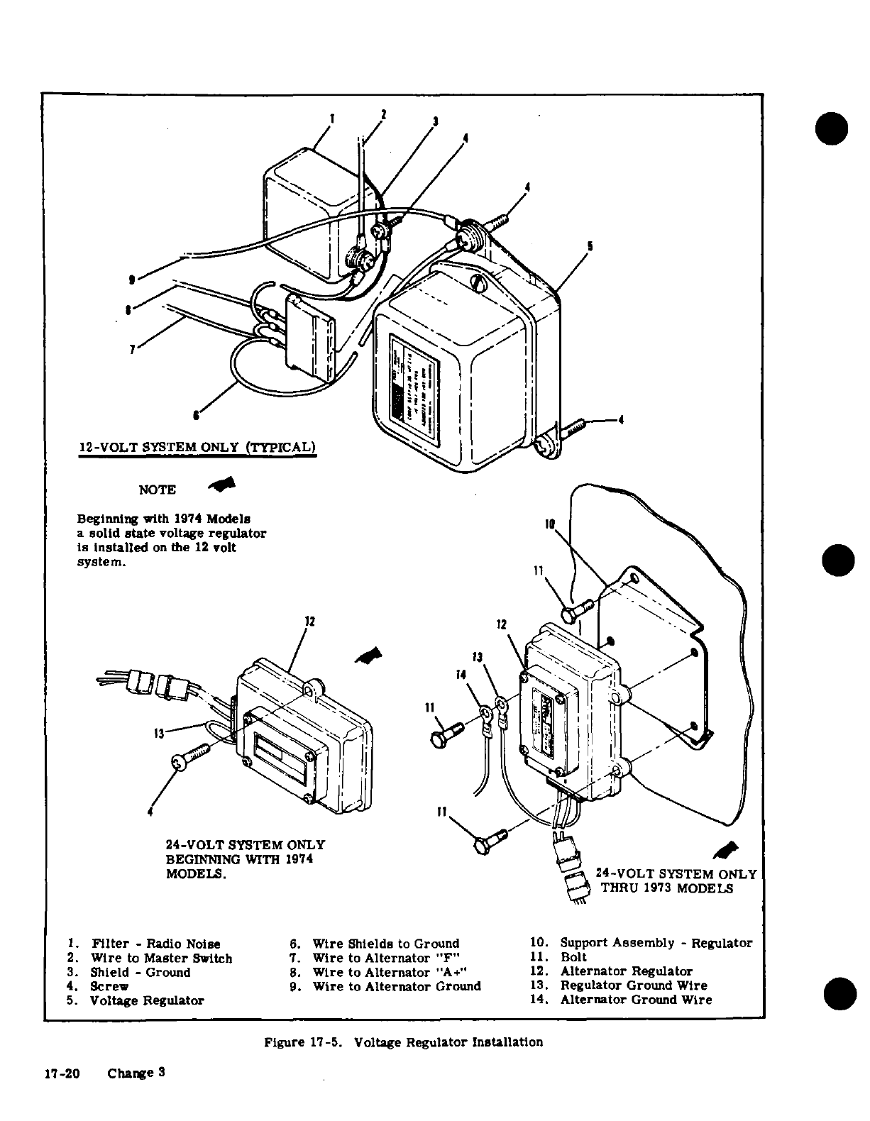
NOTE
Beginning
with
1974
Models
a
solid
state
voltage
regulator
is
installed
on
the
12
volt
system.
24-VOLT
SYSTEM
ONLY
BEGINNING
WITH
1974
MODELS.
1.
Filter
-
Radio
Noise
6.
Wire
Shields
to Ground
10.
Support
Assembly
-
Regulator
2.
Wire
to
Master
Switch
7.
Wire
to
Alternator
"F"
11.
Bolt
3.
Shield
-
Ground
8.
Wire
to
Alternator
"A+"
12.
Alternator
Regulator
4.
Screw
9.
Wire
to
Alternator
Ground
13.
Regulator
Ground
Wire
5.
Voltage
Regulator
14.
Alternator
Ground
Wire
Figure
17-5.
Voltage
Regulator
Installation
17-20
Change
3
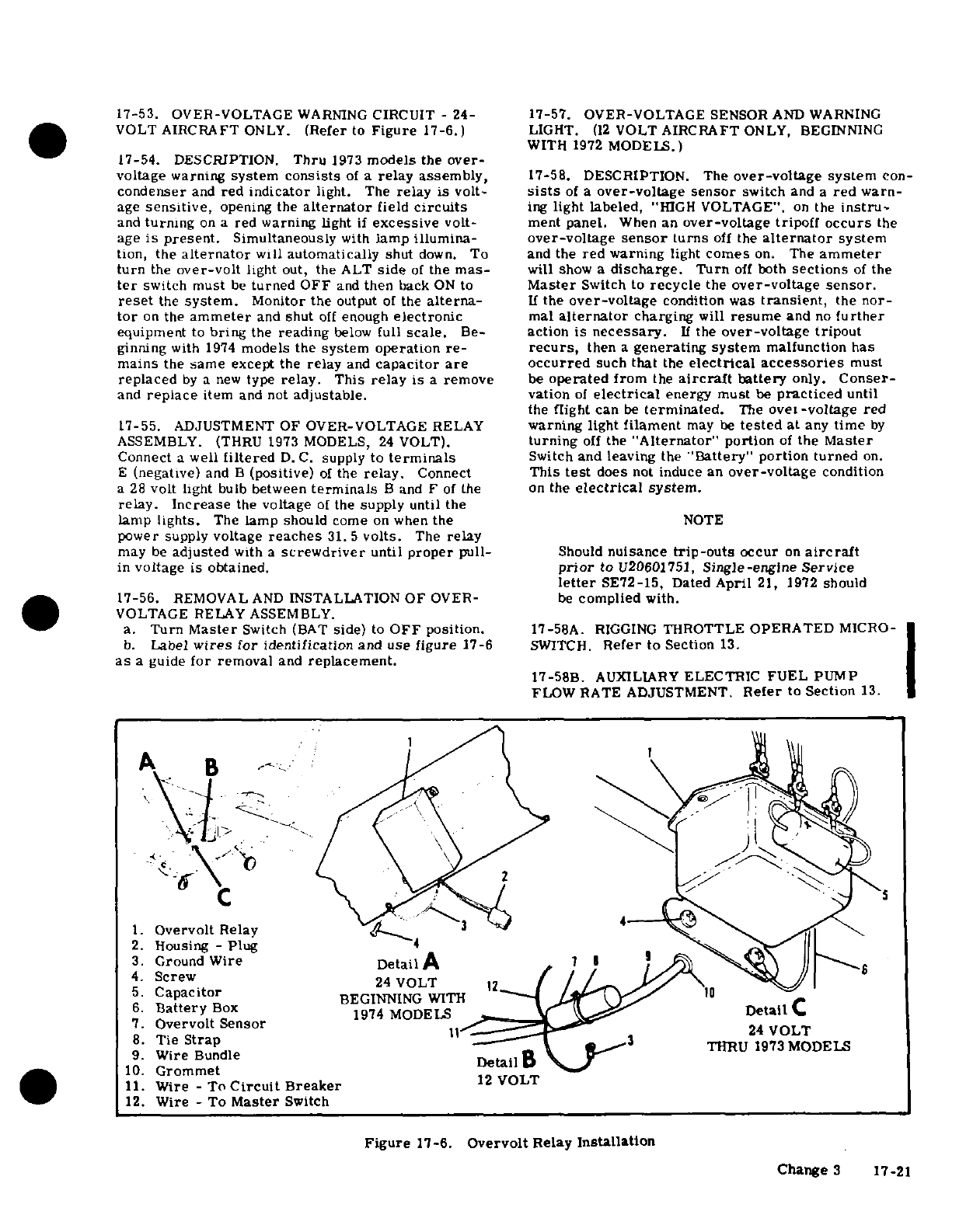
17-53. OVER-VOLTAGE
WARNING
CIRCUIT
-
24-
17-57. OVER-VOLTAGE
SENSOR
AND WARNING
VOLT
AIRCRAFT
ONLY.
(Refer
to
Figure
17-6.)
LIGHT.
(12
VOLT
AIRCRAFT
ONLY,
BEGINNING
WITH
1972
MODELS.)
17-54.
DESCRIPTION.
Thru
1973
models
the
over-
voltage
warning
system
consists
of
a
relay
assembly,
17-58.
DESCRIPTION. The
over-voltage
system
con-
condenser
and
red
indicator
light. The
relay
is
volt-
sists
of
a
over-voltage sensor
switch
and
a
red
warn-
age
sensitive,
opening
the
alternator
field
circuits
ing
light
labeled,
"HIGH
VOLTAGE".
on
the
instru-
and
turning
on
a
red warning
light
if
excessive
volt-
ment
panel.
When
an
over-voltage
tripoff
occurs
the
age
is
present.
Simultaneously
with
lamp
illumina-
over-voltage
sensor
turns
off
the
alternator
system
tion,
the
alternator
will
automatically
shut
down.
To
and
the
red
warning
light
comes
on.
The
ammeter
turn
the
over-volt
light
out,
the
ALT
side
of
the
mas-
will
show
a
discharge.
Turn
off
both
sections
of
the
ter
switch
must
be
turned
OFF
and
then
back
ON
to
Master
Switch
to
recycle
the
over-voltage
sensor.
reset
the
system.
Monitor
the
output
of
the
alterna-
If
the
over-voltage
condition
was
transient,
the
nor-
tor
on
the
ammeter
and
shut
off
enough
electronic
mal
alternator
charging
will
resume
and
no
further
equipment
to
bring
the
reading
below
full
scale.
Be-
action
is
necessary.
If
the
over-voltage
tripout
ginning
with
1974
models
the
system operation
re-
recurs,
then
a
generating
system
malfunction
has
mains
the
same
except
the
relay
and
capacitor
are
occurred
such
that
the
electrical
accessories
must
replaced
by
a
new
type
relay.
This
relay
is
a
remove
be
operated
from
the
aircraft
battery
only.
Conser-
and
replace
item
and
not
adjustable.
vation
of
electrical
energy
must
be
practiced
until
the
flight
can
be
terminated.
The
over-voltage
red
17-55.
ADJUSTMENT
OF
OVER-VOLTAGE
RELAY
warning
light
filament
may
be
tested
at
any
time
by
ASSEMBLY.
(THRU
1973
MODELS,
24
VOLT).
turning
off
the
"Alternator"
portion
of
the
Master
Connect
a
well
filtered
D.C.
supply to
terminals
Switch
and
leaving
the
"Battery" portion turned
on.
E
(negative)
and
B
(positive)
of
the
relay.
Connect
This
test
does
not
induce
an
over-voltage
condition
a
28
volt
light
bulb
between
terminals
B
and
F
of
the on
the
electrical
system.
relay.
Increase
the
voltage
of
the
supply
until
the
lamp
lights.
The
lamp should
come
on
when
the
NOTE
power supply
voltage
reaches
31.5
volts.
The
relay
may
be
adjusted
with
a
screwdriver
until
proper
pull-
Should
nuisance
trip-outs
occur
on
aircraft
in
voltage
is obtained.
prior
to
U20601751,
Single-engine Service
letter
SE72-15,
Dated
April
21,
1972
should
17-56.
REMOVAL
AND
INSTALLATION
OF
OVER-
be
complied
with.
VOLTAGE RELAY
ASSEMBLY.
a.
Turn
Master
Switch
(BAT
side)
to
OFF
position.
17-58A.
RIGGING
THROTTLE
OPERATED
MICRO-
b.
Label
wires
for
identification
and
use figure
17-6
SWITCH.
Refer
to
Section
13.
as
a
guide
for
removal
and
replacement.
17-58B.
AUXILIARY
ELECTRIC
FUEL
PUMP
FLOW
RATE
ADJUSTMENT.
Refer
to
Section
13.
1.
Overvolt
Relay
3
2.
Housing
-
Plug
3.
Ground
Wire
DetailA
7
4.
Screw
5.
Capacitor
BEGINNING WITH
6.
Battery
Box
1974
MODELS
Detail
C
7.
Overvolt
Sensor
8.
Tie
Strap
3
THRU
1973
MODELS
9.
Wire Bundle
Detail
10.
Grommet
11.
Wire
-
To
Circuit
Breaker
12
VOLT
12.
Wire -
To
Master
Switch
Figure
17-6.
Overvolt
Relay
Installation
Change
3
17-21
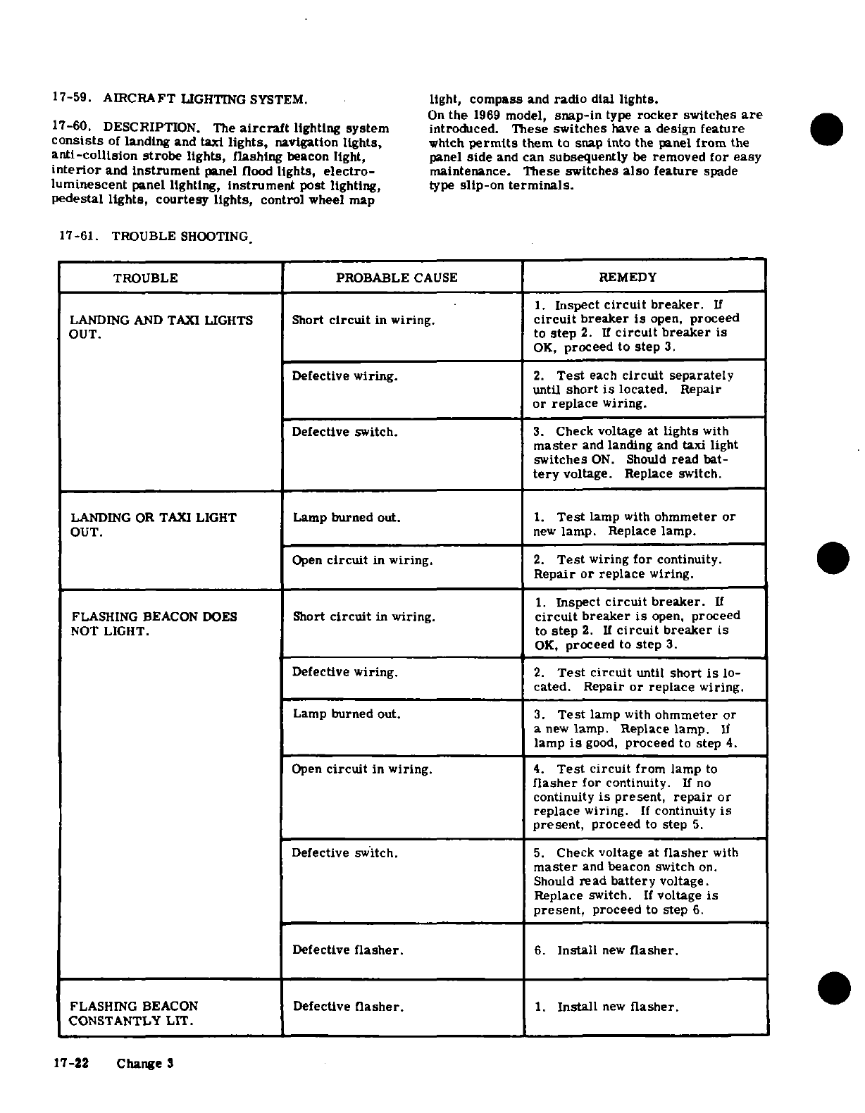
17-59.
AIRCRAFT
LIGHTING
SYSTEM.
light,
compass
and
radio
dial
lights.
On
the
1969
model,
snap-in
type
rocker
switches
are
17-60.
DESCRIPTION.
The
aircraft
lighting
system
introduced.
These
switches
have
a
design
feature
consists
of
landing
and
taxi
lights,
navigation
lights,
which
permits
them
to
snap into
the
panel
from
the
anti-collision
strobe
lights,
flashing
beacon
light,
panel
side
and
can
subsequently
be
removed
for
easy
interior
and
instrument
panel
flood
lights,
electro-
maintenance.
These
switches
also
feature
spade
luminescent
panel lighting,
instrument
post
lighting,
type
slip-on
terminals.
pedestal
lights,
courtesy
lights,
control
wheel map
17-61.
TROUBLE
SHOOTING
TROUBLE
PROBABLE
CAUSE
REMEDY
1.
Inspect
circuit
breaker.
If
LANDING
AND
TAXI
LIGHTS
Short
circuit
in
wiring.
circuit
breaker
is
open,
proceed
OUT.
to
step
2.
If
circuit
breaker
is
OK,
proceed
to
step
3.
Defective
wiring.
2.
Test
each
circuit separately
until
short
is
located.
Repair
or
replace
wiring.
Defective switch.
3.
Check
voltage
at
lights
with
master
and
landing
and
taxi
light
switches
ON.
Should
read
bat-
tery
voltage.
Replace switch.
LANDING OR
TAXI
LIGHT
Lamp
burned
out. 1.
Test
lamp
with
ohmmeter
or
OUT.
new
lamp.
Replace
lamp.
Open
circuit
in
wiring.
2.
Test
wiring
for
continuity.
Repair
or
replace
wiring.
1.
Inspect
circuit
breaker.
If
FLASHING
BEACON
DOES
Short
circuit
in
wiring.
circuit
breaker
is
open,
proceed
NOT LIGHT.
to
step
2.
If
circuit
breaker
is
OK,
proceed
to
step
3.
Defective
wiring.
2.
Test
circuit
until
short
is
lo-
cated.
Repair
or
replace
wiring.
Lamp
burned
out. 3.
Test
lamp
with
ohmmeter
or
a
new
lamp.
Replace
lamp.
If
lamp
is
good,
proceed
to
step
4.
Open
circuit
in
wiring.
4.
Test
circuit
from
lamp
to
flasher
for
continuity.
If
no
continuity
is
present,
repair
or
replace
wiring.
If
continuity
is
present,
proceed
to
step
5.
Defective switch.
5.
Check
voltage
at
flasher
with
master
and
beacon
switch
on.
Should
read
battery
voltage.
Replace
switch.
If
voltage
is
present,
proceed
to
step
6.
Defective
flasher.
6.
Install
new
flasher.
FLASHING BEACON
Defective
flasher.
1.
Install
new
flasher.
CONSTANTLY
LIT.
17-22 Change
3
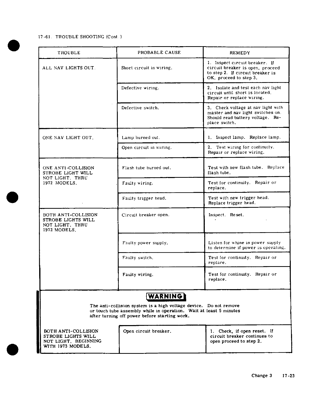
17-61.
TROUBLE
SHOOTING
(Cont
)
TROUBLE
PROBABLE
CAUSE REMEDY
1.
Inspect
circuit
breaker.
If
ALL
NAV
LIGHTS
OUT.
Short
circuit
in
wiring.
circuit
breaker
is
open,
proceed
to
step
2.
If
circuit breaker
is
OK,
proceed
to
step
3.
Defective wiring.
2.
Isolate
and
test
each
nav
light
circuit
until
short
is
located.
Repair
or replace
wiring.
Defective
switch.
3.
Check
voltage
at
nav
light
with
master
and
nav
light
switches
on.
Should
read
battery
voltage.
Re-
place
switch.
ONE
NAV
LIGHT
OUT.
Lamp
burned
out.
1.
Inspect
lamp.
Replace
lamp.
Open
circuit
in
wiring.
2.
Test
wiring
for
continuity.
Repair
or
replace
wiring.
ONE
ANTI-COLLISION
Flash
tube
burned
out.
Test
with
new
flash
tube.
Replace
STROBE
LIGHT WILL
flash
tube.
NOT
LIGHT.
THRU
1972
MODELS.
Faulty
wiring.
Test
for
continuity.
Repair
or
replace.
Faulty
trigger
head.
Test
with
new
trigger
head.
Replace
trigger
head.
BOTH
ANTI-COLLISION
Circuit
breaker
open.
Inspect.
Reset.
STROBE
LIGHTS
WILL
NOT
LIGHT.
THRU
1972
MODELS.
Faulty
power
supply.
Listen
for whine
in
power
supply
to
determine
if
power
is
operating.
Faulty
switch.
Test
for
continuity.
Repair
or
replace.
Faulty
wiring.
Test
for
continuity.
Repair
or
replace.
WARNING
The
anti-collision
system
is
a
high
voltage
device.
Do
not
remove
or
touch tube
assembly
while
in
operation.
Wait at
least
5
minutes
after
turning
off
power
before
starting
work.
BOTH
ANTI-COLLISION
Open
circuit breaker.
1.
Check,
if
open
reset.
If
STROBE
LIGHTS
WILL
circuit breaker
continues
to
NOT
LIGHT.
BEGINNING
open
proceed
to
step
2.
WITH 1973
MODELS.
Change
3
17-23
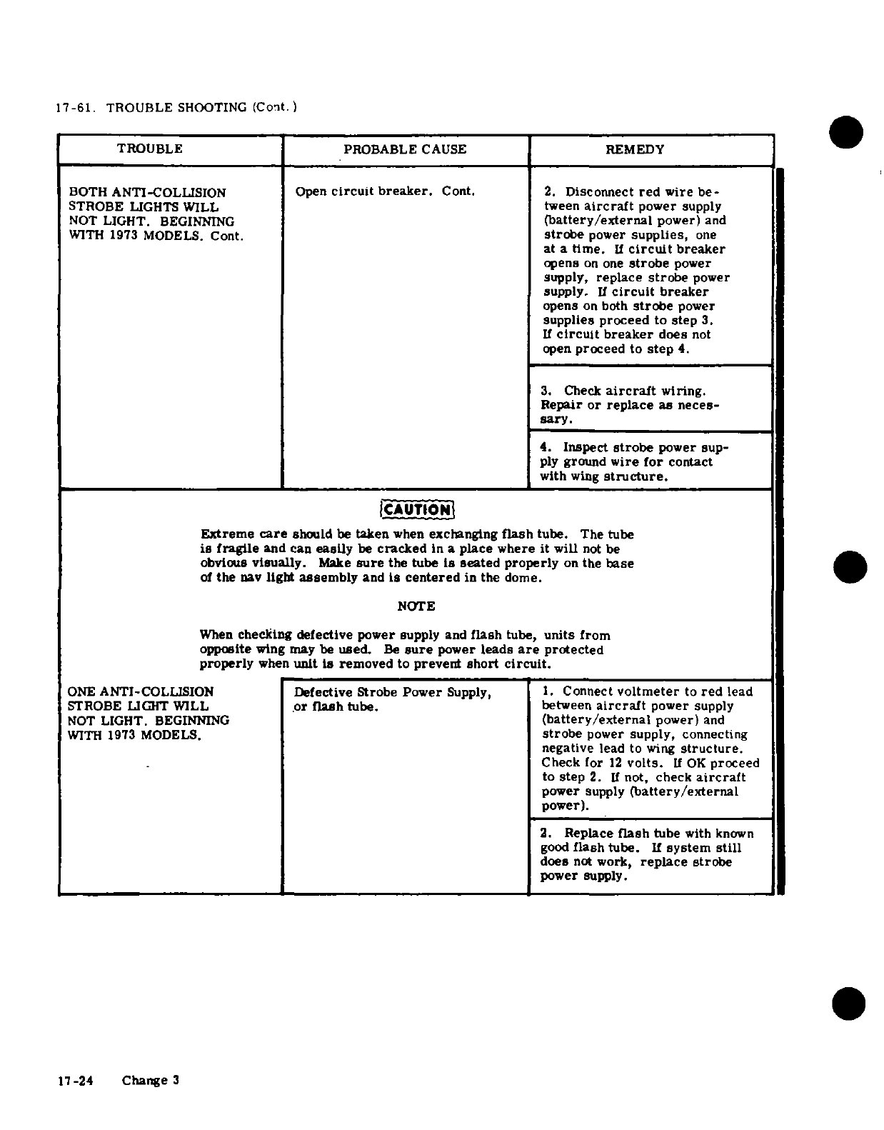
17-61.
TROUBLE
SHOOTING
(Cont.)
TROUBLE
PROBABLE
CAUSE
REMEDY
BOTH
ANTI-COLLISION Open
circuit
breaker.
Cont.
2.
Disconnect
red
wire
be-
STROBE
LIGHTS
WILL
tween
aircraft
power
supply
NOT
LIGHT.
BEGINNING
(battery/external
power)
and
WITH
1973
MODELS.
Cont.
strobe
power
supplies,
one
at a
time.
If
circuit
breaker
opens
on one
strobe
power
supply,
replace
strobe
power
supply.
If
circuit
breaker
opens
on
both
strobe
power
supplies proceed
to
step
3.
If
circuit
breaker
does
not
open
proceed to
step
4.
3.
Check
aircraft
wiring.
Repair
or
replace
as
neces-
sary.
4.
Inspect
strobe
power
sup-
ply
ground
wire
for
contact
with
wing
structure.
ICAUTION
Extreme
care
should
be
taken
when
exchanging
flash
tube.
The tube
is
fragile
and
can
easily
be
cracked
In
a
place where
it
will
not
be
obvious
visually.
Make
sure
the
tube
is seated properly
on
the
base
of
the
nav
light
assembly
and
Is
centered
in
the
dome.
NOTE
When
checking
defective
power
supply
and
flash
tube,
units
from
opposite
wing
may
be
used.
Be
sure
power
leads
are
protected
properly
when
unit
is
removed
to
prevent
short
circuit.
ONE
ANTI-COLLISION
Defective
Strobe
Power
Supply,
1.
Connect
voltmeter
to
red
lead
STROBE
LIGHT
WILL
or
flash
tube.
between
aircraft
power
supply
NOT
LIGHT.
BEGINNING
(battery/external
power)
and
WITH
1973
MODELS.
strobe
power
supply, connecting
negative
lead
to
wing
structure.
Check
for
12
volts.
If
OK
proceed
to step
2.
If
not,
check
aircraft
power
supply
(battery/external
power).
2.
Replace
flash
tube
with
known
good
flash
tube.
If
system
still
does
not
work,
replace
strobe
power
supply.
17-24
Change
3
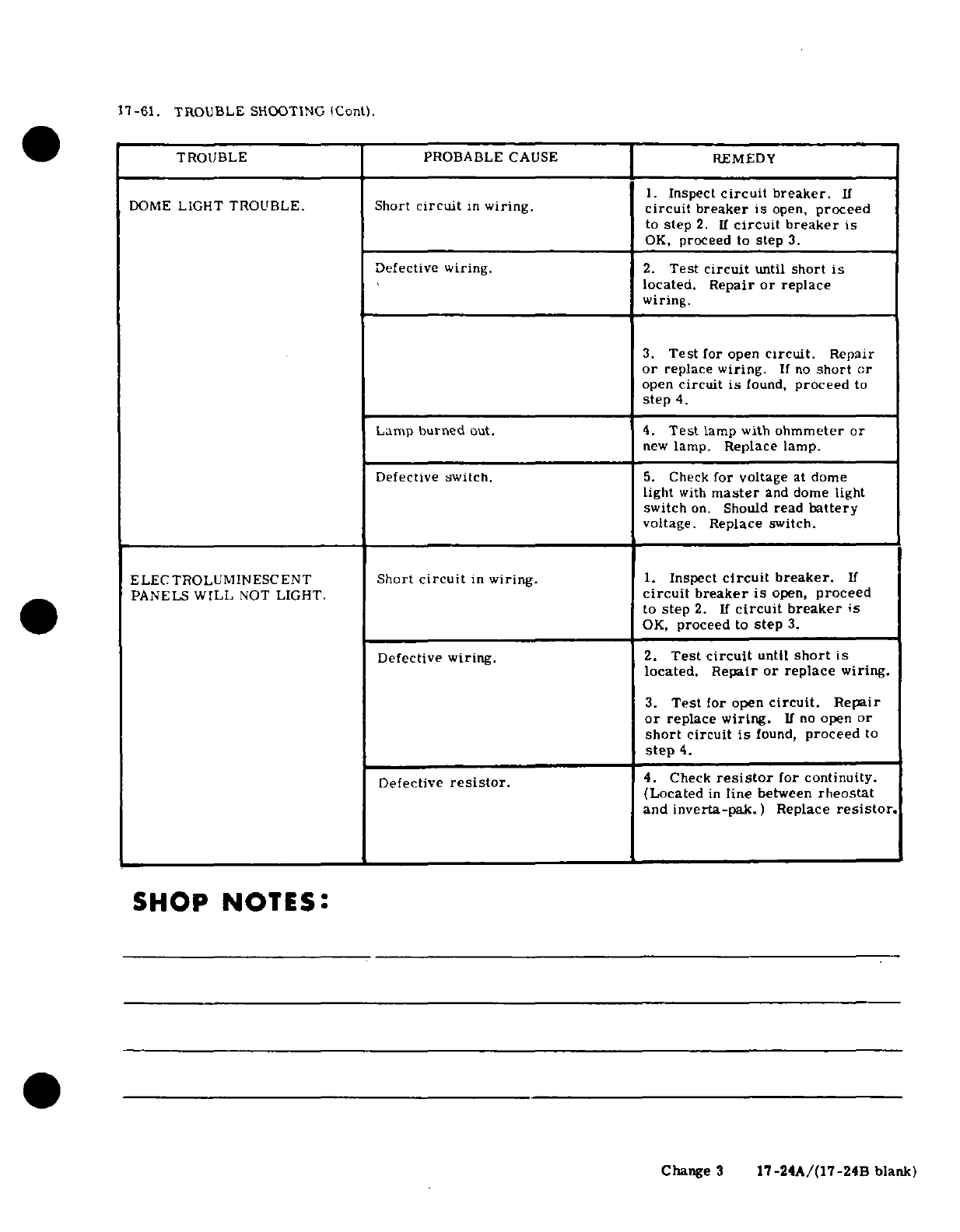
17-61.
TROUBLE
SHOOTING
(Cont).
TROUBLE PROBABLE
CAUSE REMEDY
1.
Inspect
circuit
breaker.
If
DOME
LIGHT
TROUBLE.
Short
circuit
in
wiring.
circuit
breaker
is
open,
proceed
to
step
2.
If
circuit breaker
is
OK,
proceed
to
step
3.
Defective
wiring.
2.
Test
circuit
until
short
is
located. Repair
or
replace
wiring.
3.
Test
for
open
circuit.
Repair
or
replace
wiring.
If
no
short
or
open
circuit
is
found,
proceed
to
step
4.
Lamp
burned
out.
4.
Test
lamp with
ohmmeter
or
new
lamp.
Replace lamp.
Defective switch.
5.
Check
for
voltage
at
dome
light
with
master
and
dome
light
switch
on.
Should
read
battery
voltage.
Replace
switch.
ELECTROLUMINESCENT
Short
circuit
in
wiring.
1.
Inspect
circuit
breaker.
If
PANELS
WILL
NOT
LIGHT.
circuit
breaker
is
open,
proceed
to
step
2. If
circuit
breaker
is
OK,
proceed
to
step
3.
Defective
wiring.
2.
Test
circuit
until
short
is
located. Repair
or
replace
wiring.
3.
Test
for open
circuit.
Repair
or
replace
wiring.
If
no
open
or
short
circuit
is
found,
proceed
to
step
4.
Defective
resistor.
4.
Check
resistor
for
continuity.
(Located
in
line
between
rheostat
and
inverta-pak.)
Replace
resistor.
SHOP
NOTES:
Change
3
17-24A/(17-24B
blank)
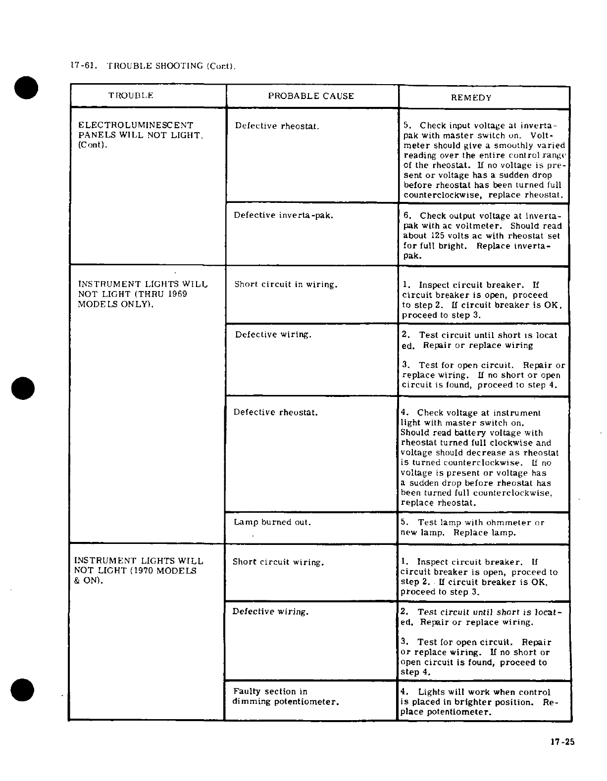
17-61. TROUBLE
SHOOTING
(Cont).
0
TROUBLE
PROBABLE
CAUSE
REMEDY
ELECTROLUMINESCENT
Defective
rheostat.
5.
Check
input
voltage
at
inverta-
PANELS
WILL
NOT
LIGHT.
pak with
master
switch
on.
Volt-
(Cont).
meter
should
give
a
smoothly
varied
reading
over
the
entire
control
range
of
the
rheostat.
If
no
voltage is
pre-
sent or
voltage
has
a
sudden
drop
before
rheostat
has
been
turned
full
counterclockwise,
replace rheostat.
Defective
inverta-pak.
6.
Check
output
voltage at
inverta-
pak with
ac
voltmeter.
Should
read
about
125
volts
ac
with
rheostat
set
for
full
bright. Replace
inverta-
pak.
INSTRUMENT
LIGHTS
WILL
Short
circuit
in
wiring.
1.
Inspect
circuit
breaker.
If
NOT
LIGHT
(THRU
1969
circuit
breaker
is
open,
proceed
MODELS
ONLY).
to
step
2.
If
circuit
breaker
is
OK,
proceed
to
step
3.
Defective
wiring.
2.
Test
circuit
until
short
is
locat
ed.
Repair
or
replace
wiring
3.
Test
for
open
circuit.
Repair
or
replace
wiring.
If
no
short or
open
circuit
is
found,
proceed
to
step
4.
Defective
rheostat.
4.
Check
voltage
at
instrument
light
with
master
switch
on.
Should
read
battery
voltage
with
rheostat
turned
full
clockwise
and
voltage
should
decrease
as
rheostat
is
turned
counterclockwise.
1f
no
voltage
is
present or
voltage
has
a
sudden
drop
before
rheostat
has
been
turned
full
counterclockwise,
replace
rheostat.
Lamp
burned
out.
5.
Test
lamp
with
ohmmeter
or
new
lamp. Replace lamp.
INSTRUMENT
LIGHTS
WILL
Short
circuit
wiring.
1.
Inspect
circuit
breaker.
If
NOT
LIGHT
(1970
MODELS
circuit
breaker
is
open,
proceed
to
&
ON).
step
2.
If
circuit
breaker
is
OK,
proceed
to
step
3.
Defective
wiring.
2.
Test
circuit
until
short
is
locat-
ed.
Repair
or
replace
wiring.
3.
Test
for
open
circuit.
Repair
or
replace
wiring.
If
no
short
or
open
circuit
is
found,
proceed
to
step
4.
Faulty
section
in
4.
Lights will
work
when
control
dimming
potentiometer.
is
placed
in
brighter
position.
Re-
place
potentiometer.
17-25
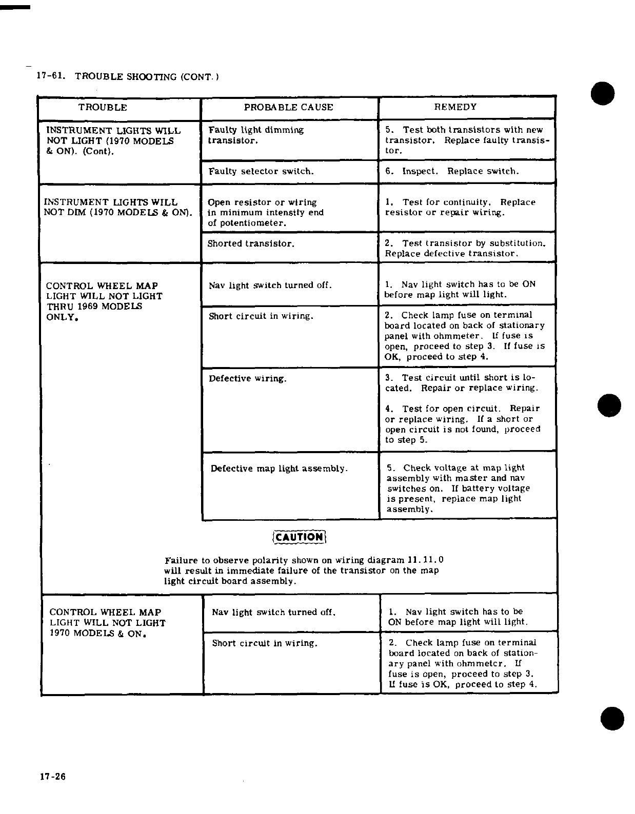
17-61.
TROUBLE
SHOOTING
(CONT.)
TROUBLE
PROBABLE
CAUSE
REMEDY
INSTRUMENT
LIGHTS
WILL
Faulty
light
dimming
5.
Test
both
transistors
with
new
NOT
LIGHT
(1970
MODELS
transistor.
transistor.
Replace
faulty
transis-
&
ON).
(Cont).
tor.
Faulty
selector
switch.
6.
Inspect.
Replace
switch.
INSTRUMENT
LIGHTS
WILL
Open
resistor
or
wiring
1.
Test
for
continuity.
Replace
NOT
DIM
(1970
MODELS
&
ON).
in
minimum
intensity
end
resistor
or repair
wiring.
of
potentiometer.
Shorted
transistor.
2.
Test
transistor
by
substitution.
Replace
defective
transistor.
CONTROL WHEEL
MAP
Nav
light
switch
turned
off. 1.
Nav
light
switch
has
to
be
ON
LIGHT WILL NOT
LIGHT
before
map
light
will
light.
THRU
1969
MODELS
ONLY.
Short
circuit
in
wiring.
2.
Check
lamp
fuse
on
terminal
board
located
on
back
of
stationary
panel
with
ohmmeter.
If
fuse
is
open,
proceed
to
step
3.
If
fuse
is
OK,
proceed
to
step
4.
Defective
wiring.
3.
Test circuit
until
short
is
lo-
cated.
Repair
or
replace
wiring.
4.
Test
for
open
circuit.
Repair
or
replace
wiring.
If
a
short
or
open
circuit
is
not found,
proceed
to
step
5.
Defective
map
light
assembly.
5.
Check voltage at
map
light
assembly
with
master
and
nav
switches
on.
If
battery
voltage
is
present,
replace
map light
assembly.
CAUTION
Failure
to
observe polarity
shown
on
wiring
diagram 11.11.0
will
result
in
immediate
failure
of
the
transistor
on
the
map
light
circuit
board
assembly.
CONTROL WHEEL MAP
Nav
light
switch
turned
off.
1.
Nav
light
switch
has
to
be
LIGHT WILL
NOT
LIGHT
ON
before
map
light
will
light.
1970
MODELS
&
ON.
Short
circuit
in
wiring.
2.
Check
lamp
fuse
on
terminal
board
located
on
back
of
station-
ary
panel
with
ohmmeter.
If
fuse
is
open,
proceed
to
step
3.
If
fuse
is
OK,
proceed
to
step
4.
17-26
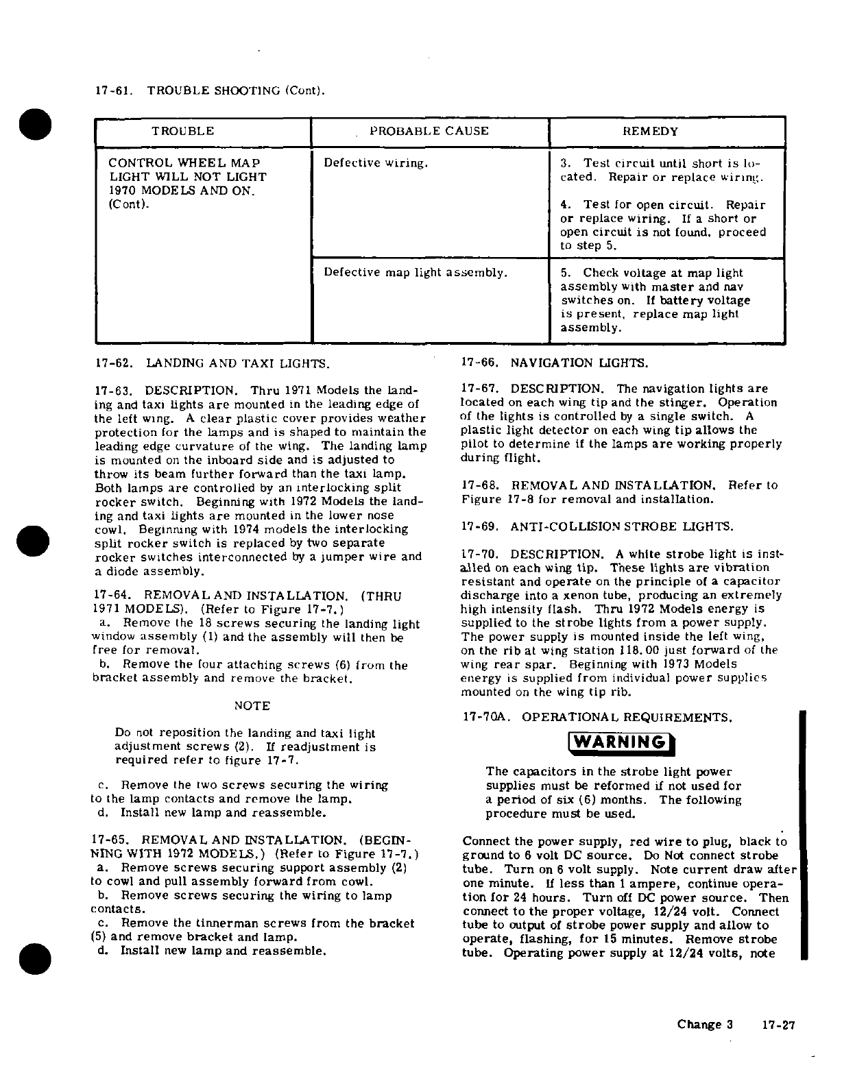
17-61.
TROUBLE
SHOOTING
(Cont).
TROUBLE
PROBABLE
CAUSE REMEDY
CONTROL
WHEEL
MAP
Defective
wiring.
3.
Test
circuit
until
short
is
lo-
LIGHT
WILL
NOT
LIGHT
cated. Repair
or
replace
wiring.
1970
MODELS
AND
ON.
(Cont).
4.
Test
for
open
circuit.
Repair
or replace
wiring.
If
a
short
or
open
circuit
is
not
found,
proceed
to
step
5.
Defective
map
light
assembly.
5.
Check
voltage
at
map light
assembly
with
master
and
nav
switches
on.
If
battery
voltage
is
present,
replace
map
light
assembly.
17-62.
LANDING
AND
TAXI
LIGHTS.
17-66.
NAVIGATION
LIGHTS.
17-63.
DESCRIPTION.
Thru
1971
Models the
land- 17-67.
DESCRIPTION.
The
navigation
lights
are
ing
and
taxi
lights
are
mounted
in
the
leading
edge
of
located
on
each
wing
tip
and
the
stinger.
Operation
the
left
wing.
A
clear
plastic
cover
provides
weather
of
the
lights
is controlled
by
a
single
switch.
A
protection
for
the
lamps
and
is
shaped
to
maintain
the
plastic
light
detector
on
each
wing
tip
allows
the
leading
edge
curvature
of
the
wing.
The landing
lamp
pilot
to
determine
if
the
lamps
are
working
properly
is
mounted
on
the
inboard
side
and
is
adjusted
to
during
flight.
throw
its
beam
further
forward
than
the
taxi lamp.
Both
lamps
are
controlled
by
an
interlocking
split
17-68.
REMOVAL
AND
INSTALLATION.
Referto
rocker
switch.
Beginning with
1972
Models
the
land-
Figure
17-8
for
removal
and
installation.
ing
and
taxi lights
are
mounted
in
the
lower
nose
cowl.
Beginning
with
1974
models
the
interlocking
17-69. ANTI-COLLISION
STROBE
LIGHTS.
split
rocker
switch
is
replaced
by
two
separate
rocker
switches interconnected
by
a
jumper
wire
and
17-70.
DESCRIPTION.
A
white
strobe
light
is
inst-
a
diode
assembly.
alled
on
each
wing
tip.
These
lights
are
vibration
resistant
and
operate
on
the
principle
of
a
capacitor
17-64.
REMOVAL
AND
INSTALLATION.
(THRU
discharge
into
a
xenon
tube,
producing
an
extremely
1971
MODELS).
(Refer
to
Figure
17-7.)
high
intensity
flash.
Thru
1972
Models
energy
is
a.
Remove the
18
screws
securing
the
landing
light
supplied
to
the
strobe
lights
from
a
power
supply.
window
assembly
(1)
and
the
assembly
will
then
be
The
power
supply
is
mounted
inside
the
left
wing,
free
for
removal.
on
the
rib
at
wing
station
118.00
just
forward
of
the
b.
Remove
the
four
attaching
screws
(6)
from
the
wing
rear
spar.
Beginning
with
1973
Models
bracket
assembly
and
remove
the
bracket.
energy
is
supplied
from
individual
power
supplies
mounted
on
the
wing
tip
rib.
NOTE
17-70A.
OPERATIONAL
REQUIREMENTS.
Do
not
reposition
the landing
and
taxi
light
adjustment
screws
(2).
If
readjustment
is
WARNING
required refer
to
figure
17-7.
The
capacitors
in
the
strobe
light
power
c.
Remove
the
two
screws
securing
the
wiring
supplies
must
be
reformed
if
not
used
for
to
the
lamp
contacts
and
remove
the
lamp.
a
period
of
six
(6)
months.
The
following
d.
Install
new
lamp
and
reassemble.
procedure
must
be
used.
17-65.
REMOVAL
AND
INSTALLATION. (BEGIN-
Connect
the
power
supply,
red wire
to
plug,
black
to
NING
WITH
1972
MODELS.)
(Refer
to
Figure
17-7.) ground
to
6
volt
DC
source.
Do
Not
connect
strobe
a.
Remove
screws
securing
support
assembly
(2)
tube.
Turn
on
6
volt
supply.
Note
current
draw
after
to
cowl
and
pull
assembly
forward
from
cowl.
one
minute.
If
less
than
1
ampere,
continue
opera-
b.
Remove
screws
securing
the
wiring
to
lamp
tion
for
24
hours.
Turn
off
DC
power
source.
Then
contacts.
connect
to
the
proper
voltage,
12/24
volt.
Connect
c.
Remove
the
tinnerman
screws
from
the
bracket
tube
to
output
of
strobe
power
supply
and
allow to
(5)
and
remove
bracket
and
lamp.
operate,
flashing,
for
15
minutes.
Remove
strobe
d.
Install
new
lamp
and
reassemble.
tube.
Operating
power
supply
at
12/24
volts,
note
Change
3
17-27
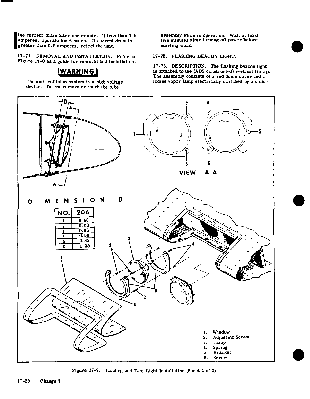
the
current
drain
after
one
minute.
If
less
than
0.5
assembly
while
in
operation.
Wait
at
least
amperes,
operate
for
6
hours.
If
current
draw
is
five
minutes
after
turning
off
power
before
greater
than
0.
5
amperes,
reject
the
unit.
starting
work.
17-71.
REMOVAL
AND
INSTALLATION.
Refer
to
17-72.
FLASHING
BEACON LIGHT.
Figure
17-8
as
a
guide
for
removal
and
installation.
17-73.
DESCRIPTION.
The
flashing
beacon
light
WARNI
NG
is
attached
to
the
(ABS
constructed)
vertical
fin
tip.
The
assembly
consists
of
a
red
dome
cover
and
a
The
anti-collision
system
is
a
high
voltage iodine
vapor
lamp
electrically
switched
by
a
solid-
device.
Do
not
remove
or
touch
the
tube
DA
2
4
VIEW
A-A
D I
M
E
N
S I
O
N
D
NO.
206
O.
68
0.
60
3
0.95
0.
50
0.85
3
1.08
2
2.
Adjusting
Screw
3.
Lamp
4.
Spring
5.
Bracket
6.
Screw
Figure
17-7.
Landing
and
Taxi
Light
Installation
(Sheet
1
of
2)
17-28
Change
3
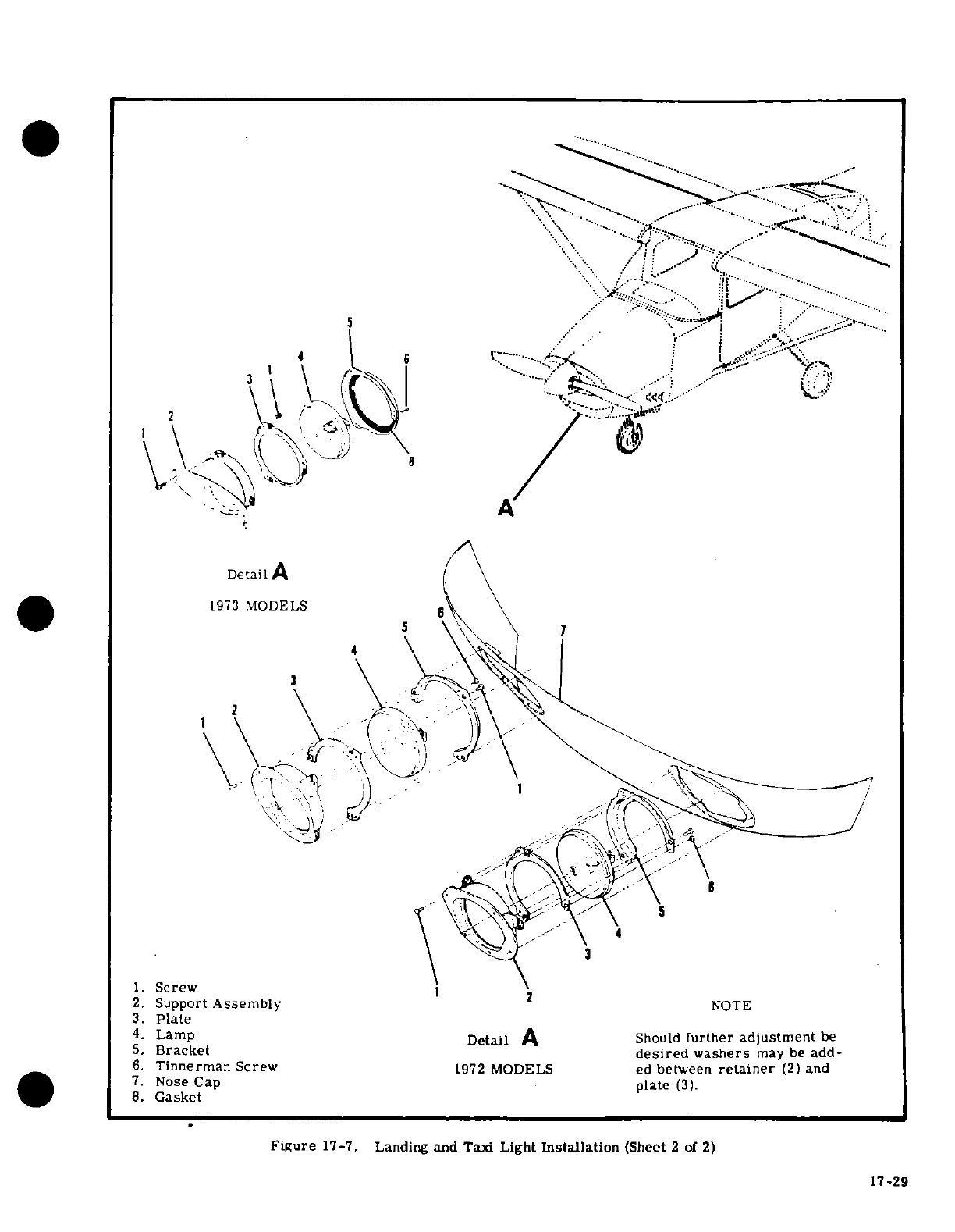
8
4
3
DetailA
1973
MODELS
1.
Screw
2
2.
Support
Assembly
NOTE
3.
Plate
4.
Lamp
Detail
A
Should
further
adjustment
be
5.
Bracket
desired
washers
may
be
add-
6.
Tinnerman
Screw
1972
MODELS
ed
between
retainer
(2)
and
7.
Nose
Cap
plate
(3).
8.
Gasket
Figure
17-7.
Landing
and
Taxi
Light
Installation
(Sheet
2
of
2)
17-29
~~~~~~~~~~
4.LmpDtilASoudfute
ajsmetb
5~~~~~.
frce esrdwses'a
ead
6.~~~~~
Tinra
Sce
192MDL
/ dbtenrtie
2
n
4. Lamp Detail A~~~~~~~~~~~~~~~~~172
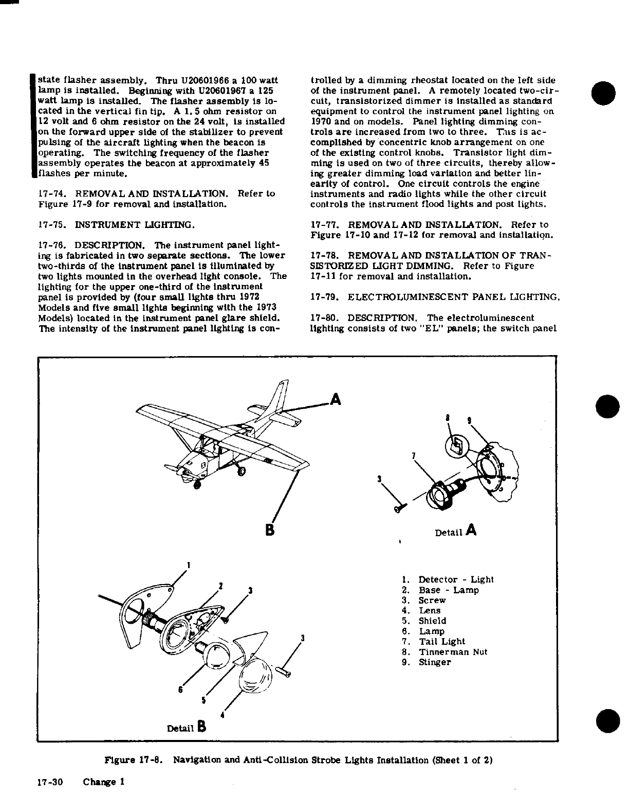
state flasher
assembly.
Thru
U20601966
a
100
watt
trolled
by
a
dimming
rheostat
located
on
the
left side
lamp
is
installed.
Beginning with
U20601967 a
125
of
the
instrument
panel.
A
remotely
located
two-cir-
watt
lamp
is
installed.
The
flasher
assembly
is
lo-
cult,
transistorized
dimmer
is
installed
as standard
cated
in
the
vertical
fin
tip.
A
1.5
ohm
resistor
on
equipment
to
control
the
instrument
panel lighting
on
12
volt
and
6
ohm
resistor
on
the
24
volt,
is
installed
1970
and
on
models.
Panel lighting dimming
con-
on
the
forward
upper
side
of
the
stabilizer
to
prevent
trols
are
increased
from
two
to
three.
This
is
ac-
pulsing
of
the
aircraft
lighting
when
the
beacon
is
complished
by
concentric
knob
arrangement
on one
operating.
The
switching frequency
of
the
flasher
of
the
existing control
knobs.
Transistor
light
dim-
assembly
operates
the
beacon
at
approximately
45
ming
is
used
on
two
of
three
circuits,
thereby
allow-
flashes
per
minute.
ing
greater
dimming
load
variation
and
better
lin-
earity
of
control.
One
circuit
controls
the
engine
17-74.
REMOVAL
AND
INSTALLATION.
Refer
to
instruments
and
radio
lights
while
the
other circuit
Figure
17-9
for
removal
and
installation.
controls
the
instrument
flood
lights
and
post
lights.
17-75.
INSTRUMENT
LIGHTING.
17-77.
REMOVAL
AND
INSTALLATION.
Refer
to
Figure
17-10
and
17-12
for removal
and
installation.
17-76.
DESCRIPTION.
The
instrument
panel
light-
ing
is
fabricated
in
two
separate
sections.
The
lower
17-78.
REMOVAL
AND
INSTALLATION
OF
TRAN-
two-thirds
of
the
instrument
panel
is
illuminated
by
SISTORIZED
LIGHT
DIMMING.
Refer
to
Figure
two
lights
mounted
in
the
overhead
light
console.
The
17-11
for
removal
and
installation.
lighting
for
the
upper
one-third
of
the
instrument
panel
is
provided
by
(four
small
lights thru
1972
17-79.
ELECTROLUMINESCENT
PANEL
LIGHTING.
Models
and five
small
lights
beginning with the
1973
Models)
located
in
the
instrument
panel
glare
shield.
17-80.
DESCRIPTION. The
electroluminescent
The
intensity
of
the
instrument
panel
lighting
is
con-
lighting
consists
of
two
"EL"
panels;
the
switch
panel
B
Detail
A
1.
Detector
-
Light
2.
Base
-
Lamp
3.
Screw
4. Lens
5.
Shield
6.
Lamp
7.
Tail
Light
8.
Tinnerman
Nut
9.
Stinger
Figure
17-8.
Navigation
and
Anti-Collision
Strobe
Lights
Installation
(Sheet
1
of
2)
17-30
Change
1
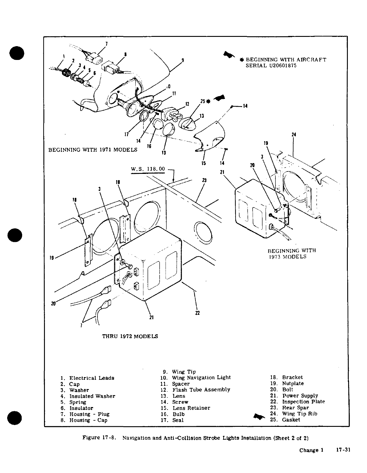
0 2
>
,:, / 9 3 ^^ *
BEGINNING
WITH
AIRCRAFT
SERIAL
U20601875
17
/ ,4 f
9
14
BEGINNING
WITH
1971
MODELS
1 V
1
\
.19
w.s.
118.
00
" 21\ r
BEGINNING
WITH
~~19^^~I 1^
'L
1973
MODELS
7
THRU
1972
MODELS
9.
Wing
Tip
1.
Electrical
Leads
10.
Wing
Navigation Light
18.
Bracket
2.
Cap
11.
Spacer
19.
Nutplate
3.
Washer
12.
Flash
Tube
Assembly
20.
Bolt
4.
Insulated Washer
13.
Lens
21.
Power
Supply
5.
Spring
14.
Screw
22.
Inspection
Plate
6.
Insulator
15.
Lens
Retainer
23.
Rear
Spar
7.
Housing
-
Plug
16.
Bulb
24.
Wing
Tip
Rib
8.
Housing
-Cap
17.
Seal
25.
Gasket
Figure
17-8.
Navigation
and
Anti-Collision
Strobe
Lights
Installation
(Sheet
2
of
2)
Change
1
17-31
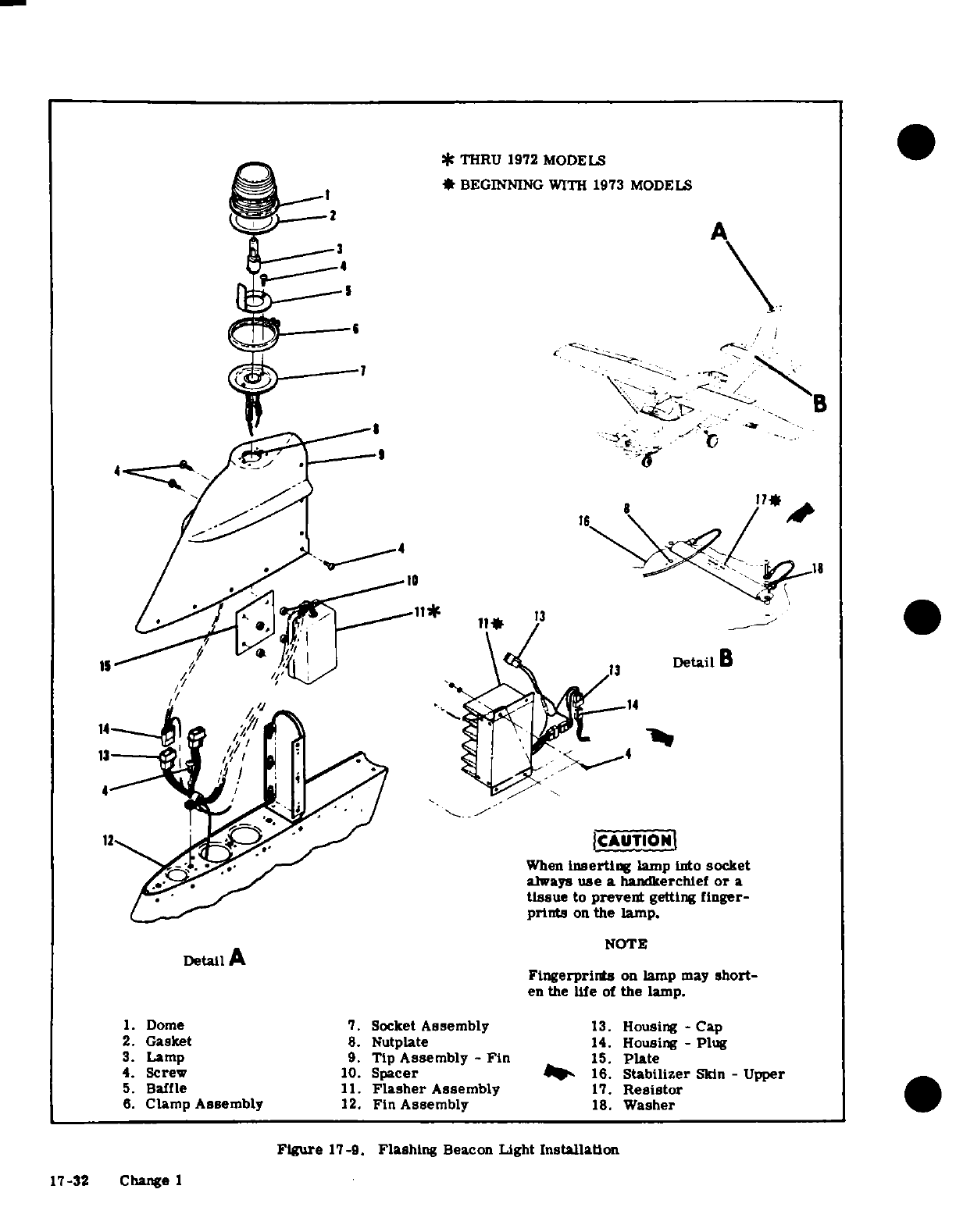
*
THRU
1972 MODELS
*
BEGINNING
WITH
1973 MODELS
A
6
4. ^--i4\
-
-'/
-.
'2C
e^ a n410
*
1
4
//~18
:7=*
lF
13i
IrS
//
s ^
,
\04 3
DetailB
V ~~~~~~~~~~~~~~~~~14
12^.
, > ,^^ ' ^
^
ICAUTIONI
-at,. >f
-
When
inserting
lamp
into
socket
/^*^^' _I~~~. ^~
/
always
use
a
handkerchief
or
a
tissue
to
prevent
getting
finger-
prints
on
the
lamp.
NOTE
Detail
A
Fingerprints
on
lamp
may
short-
en
the
life
of
the
lamp.
1.
Dome
7.
Socket
Assembly
13.
Housing
-
Cap
2.
Gasket
8.
Nutplate
14.
Housing -
Plug
3.
Lamp
9.
Tip
Assembly
-
Fin
15.
Plate
4.
Screw
10.
Spacer
_
16.
Stabilizer
Skin
-
Upper
5.
Baffle
11.
Flasher
Assembly
17.
Resistor
6.
Clamp
Assembly
12.
Fin
Assembly
18.
Washer
Figure
17-9.
Flashing
Beacon
Light
Installation
17-32 Change 1
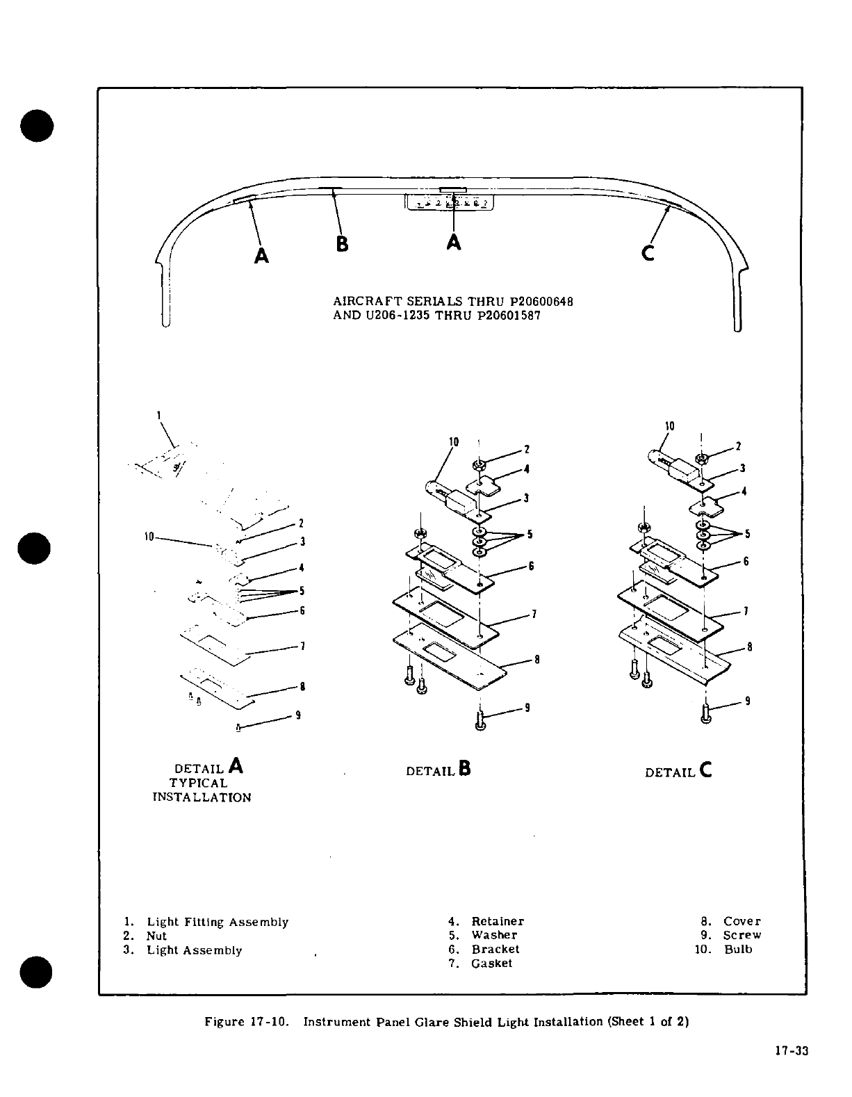
B
A
AIRCRAFT
SERIALS
THRU
P20600648
AND
U206-1235
THRU
P20601587
10
2
10
2
2
4 q
6
-6 ><6V
\
-
1' 8 88
DETAIL
A
DETAIL
B
DETAIL
C
TYPICAL
INSTALLATION
1.
Light
Fitting
Assembly
4.
Retainer
8.
Cover
2.
Nut
5.
Washer
9.
Screw
3.
Light
Assembly
6.
Bracket
10.
Bulb
7.
Gasket
Figure
17-10.
Instrument
Panel
Glare
Shield
Light
Installation
(Sheet
1
of
2)
17-33
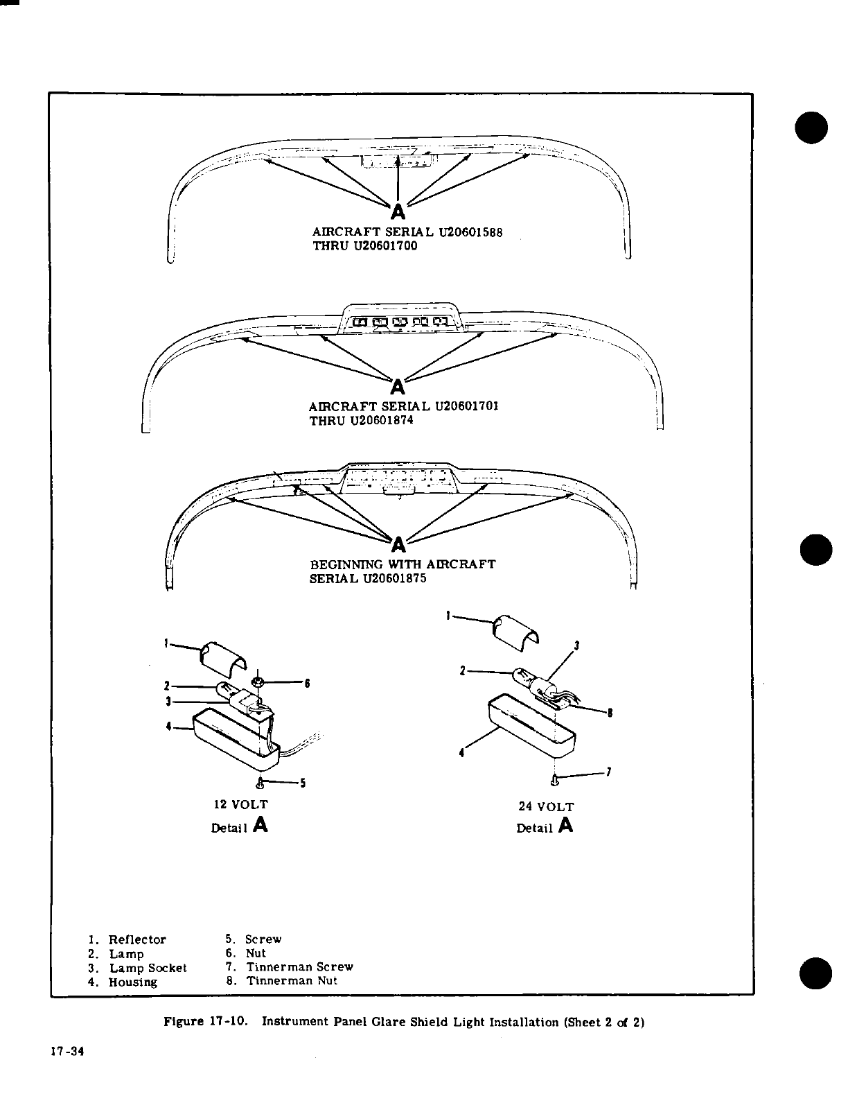
AIRCRAFT
SERIAL
U20601588
THRU
U20601700
AIRCRAFT SERIAL
U20601701
THRU
U20601874
I,
~ 01 5BEGINNING WITH
AIRCRAFT
SERIAL
U20601875
2 3
2 396 2 X
-
4
S ----
"--
12
VOLT
24
VOLT
Detail
A
Detail
A
1.
Reflector
5.
Screw
2.
Lamp
6.
Nut
3.
Lamp
Socket
7.
Tinnerman
Screw
4.
Housing
8.
Tinnerman
Nut
Figure
17-10.
Instrument
Panel
Glare
Shield
Light
Installation
(Sheet
2
of
2)
17-34
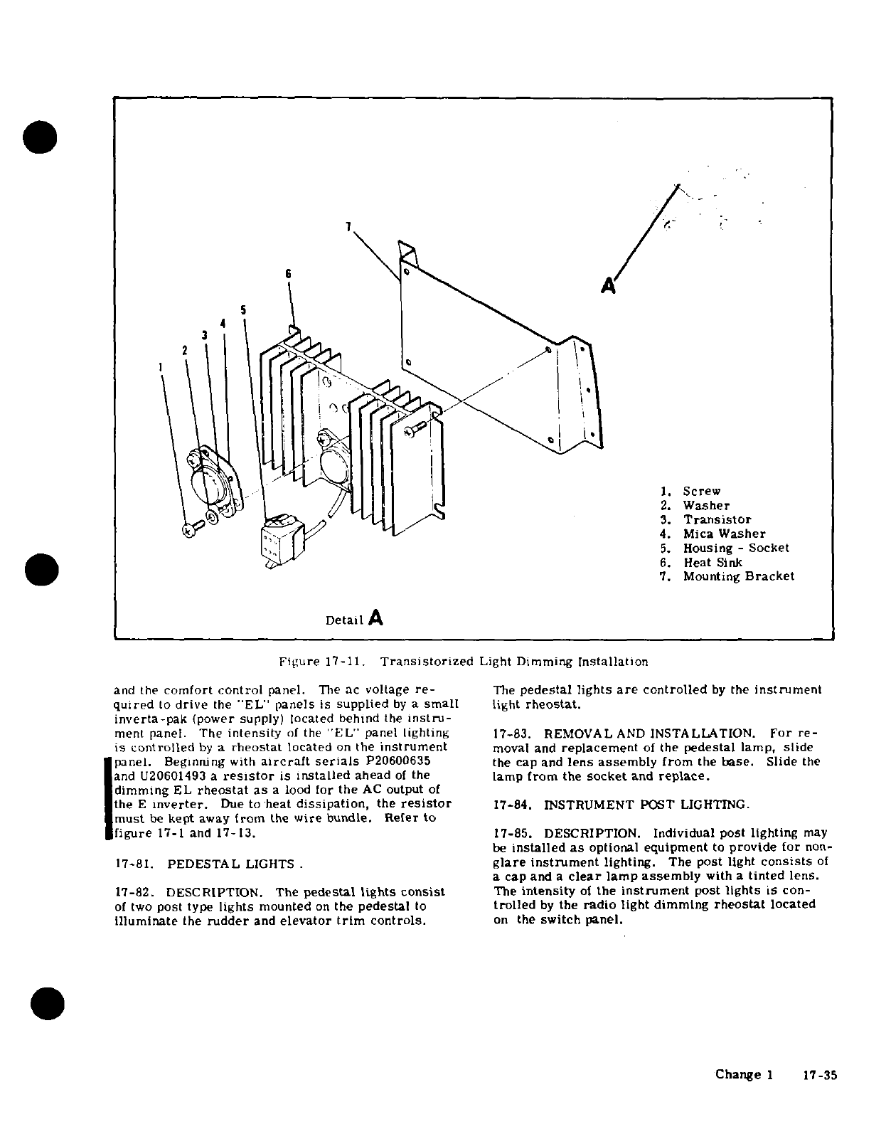
7
1
5
1. Screw
2.
Washer
3.
Transistor
4.
Mica
Washer
5.
Housing
-
Socket
6.
Heat
Sink
7.
Mounting
Bracket
Detail
A
Figure
17-11.
Transistorized
Light
Dimming
Installation
and
the
comfort
control
panel.
The
ac
voltage
re-
The
pedestal
lights
are
controlled
by
the
instrument
quired
to
drive
the
"EL"
panels
is
supplied
by
a
small
light
rheostat.
inverta-pak
(power supply)
located
behind
the
instru-
ment
panel. The
intensity
of
the
'EL"
panel lighting
17-83.
REMOVAL
AND
INSTALLATION.
For
re-
is
controlled
by
a
rheostat
located
on
the
instrument
moval
and
replacement
of
the
pedestal lamp,
slide
panel.
Beginning
with
aircraft
serials
P20600635
the cap
and
lens assembly
from
the
base.
Slide
the
and
U20601493 a
resistor
is
installed
ahead
of
the
lamp
from
the
socket
and
replace.
dimming
EL
rheostat
as
a
lood
for
the
AC
output
of
the
E
inverter.
Due
to
heat
dissipation,
the
resistor
17-84. INSTRUMENT
POST
LIGHTING.
must
be
kept
away
from
the
wire
bundle.
Refer
to
figure
17-1
and
17-13.
17-85.
DESCRIPTION.
Individual post
lighting
may
be
installed
as
optional
equipment
to
provide
for
non-
17-81.
PEDESTAL
LIGHTS
.
glare instrument
lighting.
The
post
light
consists
of
a
cap
and
a
clear
lamp
assembly
with
a
tinted
lens.
17-82.
DESCRIPTION. The
pedestal
lights
consist
The
intensity
of
the
instrument
post
lights
is
con-
of
two
post type
lights
mounted
on
the
pedestal
to
trolled
by
the
radio
light
dimming
rheostat
located
illuminate
the
rudder
and
elevator
trim
controls.
on
the
switch
panel.
Change
1
17-35
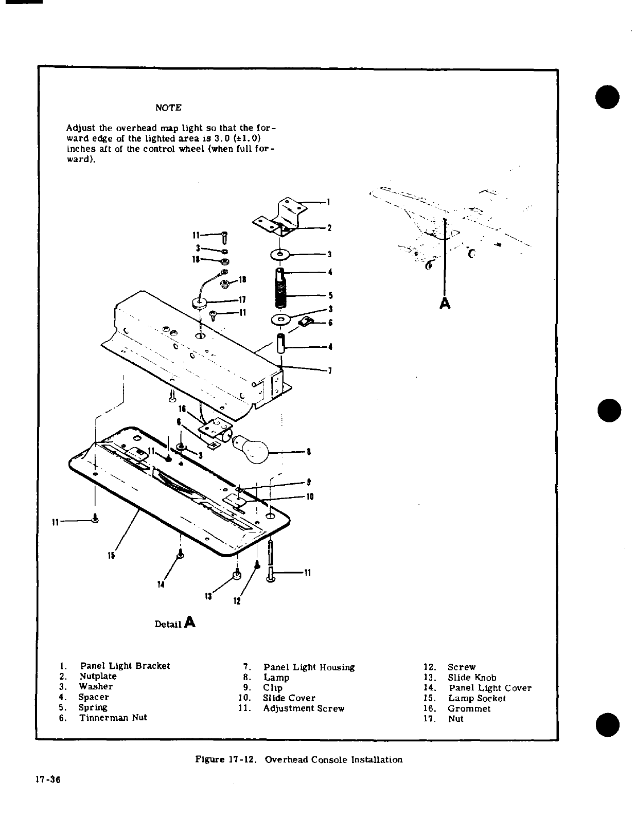
NOTE
Adjust
the
overhead
map
light
so
that
the
for-
ward
edge
of
the
lighted
area
is 3.0
(±1.0)
inches
aft
of
the
control
wheel
(when
full
for-
ward).
1.
Panel
Light
Bracket
7.
Panel
Light Housing
12.
Screw
2.
Nutplate
8.
Lamp
13.
Slide
Knob
3.
Washer
9.
Clip
14.
Panel
Light
Cover
4.
Spacer
10.
Slide Cover
15.
Lamp
Socket
5.
Spring
11.
Adjustment
Screw
16.
Grommet
6.
Tinnerman
Nut
17.
Nut
Figure
17-12.
Overhead Console
Installation
17 -36
17-36
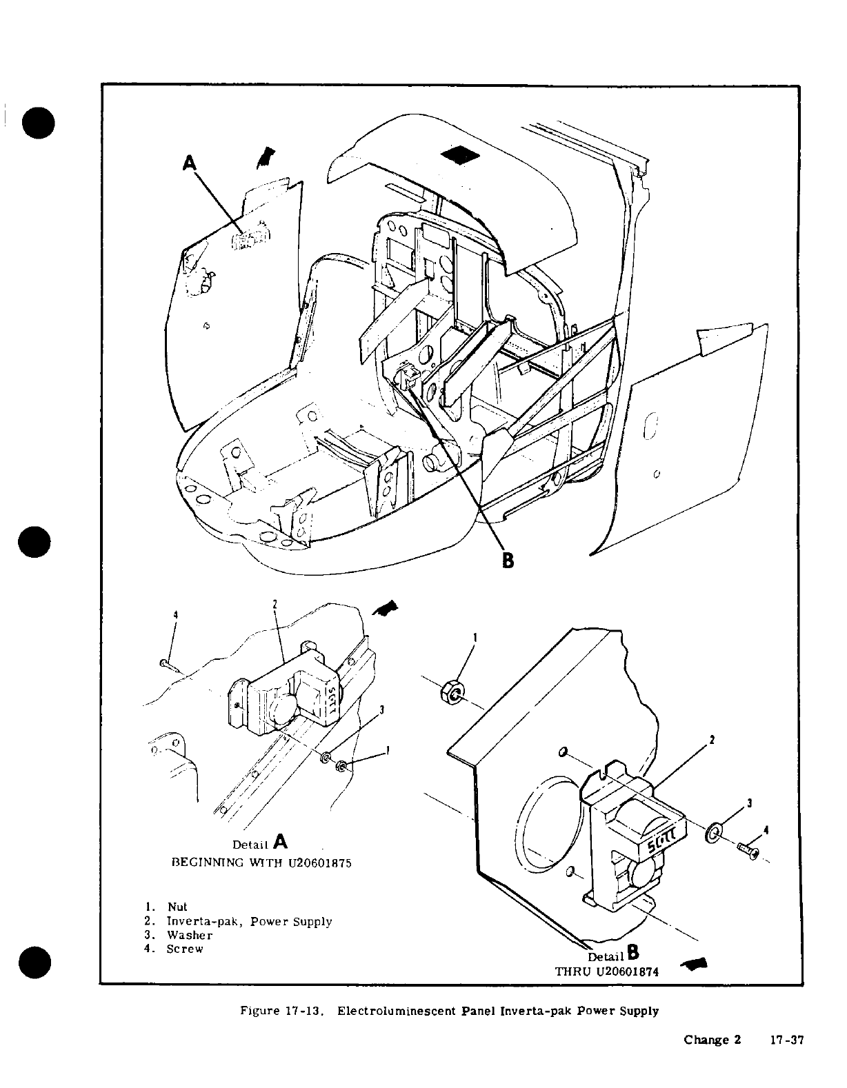
A
A-
2
BEGINNING
WITH
U2060175
1.
Nut
2.
Inverta-pak,
Power
Supply
3.
Washer
4.
Screw
Detail
B
THRU
U20601874
W
Figure
17-13.
Electroluminescent
Panel
Inverta-pak
Power
Supply
Change
2
17-37
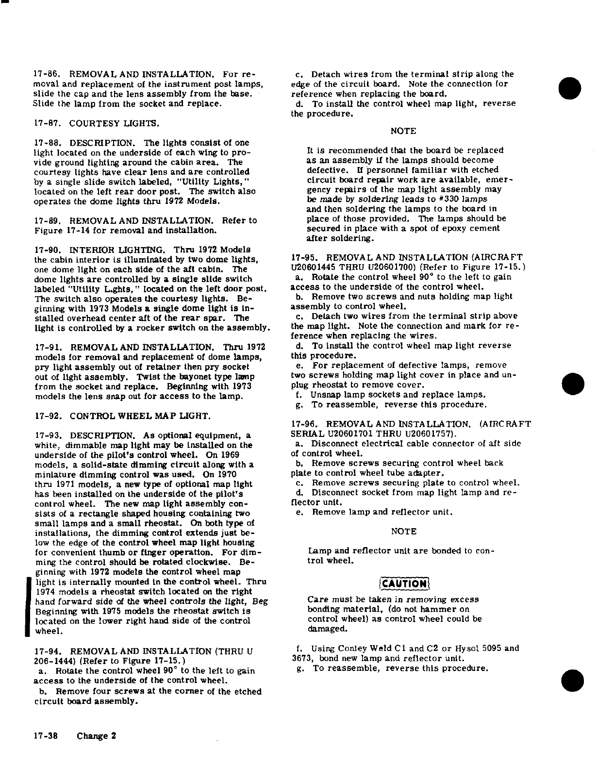
17-86.
REMOVAL
AND
INSTALLATION.
For
re-
c.
Detach
wires
from
the
terminal
strip
along
the
moval
and
replacement
of
the
instrument
post
lamps,
edge
of
the
circuit
board.
Note
the connection
for
slide
the cap
and
the
lens
assembly
from
the
base.
reference
when
replacing
the
board.
Slide
the
lamp
from
the
socket
and
replace.
d.
To
install
the
control
wheel
map
light,
reverse
the
procedure.
17-87.
COURTESY
LIGHTS.
NOTE
17-88.
DESCRIPTION.
The
lights
consist
of
one
light
located
on
the
underside
of
each
wing
to
pro-
It
is
recommended
that the
board
be
replaced
vide
ground lighting
around
the
cabin
area.
The
as
an
assembly
if
the
lamps
should
become
courtesy
lights
have
clear
lens
and
are
controlled
defective.
If
personnel
familiar
with
etched
by
a
single
slide
switch
labeled,
"Utility
Lights,"
circuit
board
repair
work
are
available,
emer-
located
on
the
left
rear
door post.
The
switch
also
gency
repairs
of
the
map
light
assembly
may
operates
the
dome
lights
thru
1972
Models.
be
made
by
soldering
leads
to
#330
lamps
and then
soldering
the
lamps
to
the
board
in
17-89.
REMOVAL
AND
INSTALLATION.
Refer
to
place
of
those provided.
The
lamps
should
be
Figure
17-14
for
removal
and
installation.
secured
in
place
with
a spot
of
epoxy
cement
after
soldering.
17-90.
INTERIOR
LIGHTING.
Thru
1972
Models
the
cabin
interior
is
illuminated
by
two
dome
lights,
17-95.
REMOVAL
AND
INSTALLATION
(AIRCRAFT
one
dome
light
on
each
side
of
the
aft
cabin.
The
U20601445
THRU U20601700)
(Refer
to
Figure
17-15.)
dome
lights
are
controlled
by
a
single
slide
switch
a.
Rotate the
control
wheel
90°
to
the
left
to
gain
labeled
"Utility
Lights,"
located
on
the
left
door post.
access
to
the
underside
of
the
control
wheel.
The
switch
also
operates
the
courtesy
lights.
Be-
b.
Remove
two
screws
and
nuts
holding map light
ginning
with
1973
Models
a
single
dome
light
is
in-
assembly
to
control
wheel.
stalled
overhead
center
aft
of
the
rear
spar.
The
c.
Detach
two
wires
from
the
terminal
strip
above
light
is
controlled
by
a
rocker
switch
on
the
assembly.
the
map
light.
Note
the
connection
and
mark
for
re-
ference
when
replacing
the
wires.
17-91.
REMOVAL
AND
INSTALLATION.
Thru
1972
d. To
install
the
control
wheel
map
light
reverse
models
for
removal
and
replacement
of
dome
lamps,
this procedure.
pry
light
assembly
out
of
retainer
then
pry
socket
e.
For
replacement
of
defective
lamps,
remove
out
of
light
assembly.
Twist
the
bayonet
type
lamp
two
screws
holding
map
light
cover
in
place
and
un-
from
the
socket
and
replace.
Beginning
with
1973
plug
rheostat
to
remove
cover.
models
the
lens
snap
out
for
access
to
the
lamp.
f.
Unsnap
lamp
sockets
and
replace
lamps.
g.
To
reassemble,
reverse
this
procedure.
17-92.
CONTROL
WHEEL
MAP
LIGHT.
17-96.
REMOVAL
AND
INSTALLATION.
(AIRCRAFT
17-93.
DESCRIPTION.
As
optional
equipment, a
SERIAL
U20601701
THRU
U20601757).
white,
dimmable
map
light
may
be
installed
on
the
a.
Disconnect
electrical
cable
connector
of
aft
side
underside
of
the
pilot's
control
wheel.
On
1969
of
control
wheel.
models,
a
solid-state
dimming
circuit
along
with
a
b.
Remove
screws
securing control
wheel
back
miniature
dimming control
was
used.
On
1970
plate
to
control
wheel
tube
adapter.
thru
1971
models,
a
new
type
of
optional
map
light
c.
Remove
screws
securing plate
to
control
wheel.
has
been
installed
on
the
underside
of
the
pilot's
d.
Disconnect socket from
map
light
lamp
and
re-
control
wheel.
The
new
map
light
assembly
con-
flector
unit.
sists
of
a
rectangle
shaped
housing containing
two
e.
Remove
lamp
and
reflector
unit.
small
lamps
and
a
small
rheostat.
On
both
type
of
installations,
the
dimming
control
extends
just
be-
NOTE
low
the
edge
of
the
control
wheel map
light
housing
for
convenient thumb
or
finger
operation.
For
dim-
Lamp
and
reflector
unit
are
bonded
to
con-
ming
the
control
should
be
rotated
clockwise.
Be-
trol
wheel.
ginning
with
1972
models
the
control
wheel
map
light
is
internally
mounted
in
the
control
wheel.
Thru
CAUTION
1974
models
a
rheostat
switch
located
on
the
right
hand
forward
side
of
the
wheel
controls
the
light,
Beg
Care
must
be
taken
in
removing
excess
Beginning
with
1975
models
the
rheostat
switch
is
bonding
material,
(do
not
hammer
on
located
on
the
lower
right
hand
side
of
the
control
control
wheel)
as
control
wheel
could
be
wheel.
damaged.
17-94.
REMOVAL
AND
INSTALLATION
(THRU
U
f.
Using
Conley
Weld
C
and
C2
or
Hysol
5095
and
206-1444)
(Refer
to
Figure
17-15.)
3673,
bond
new
lamp and
reflector
unit.
a.
Rotate
the
control
wheel
90°
to
the
left
to
gain
g.
To
reassemble,
reverse
this
procedure.
access
to
the
underside
of
the
control
wheel.
b.
Remove
four
screws
at
the
corner
of
the
etched
circuit
board
assembly.
17-38
Change
2
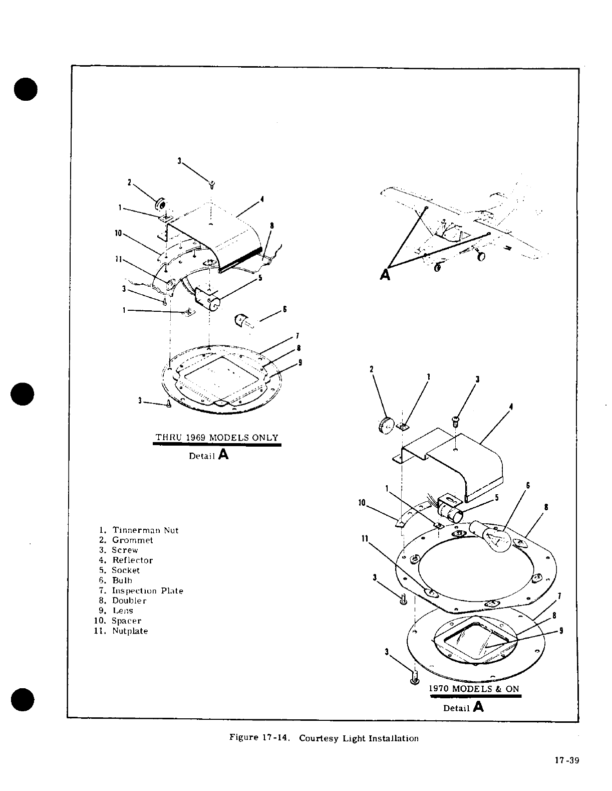
1.
Tinnerman
Nut
2.
Grommet
3.
Screw
4.
Reflector
5.
Socket
6.
Bulb
7.
Inspection Plate
8.
Doubler
9.
Lens
10.
Spacer
11.
Nutplate
1970
MODELS
&
ON
Detail
A
Figure
17-14.
Courtesy
Light
Installation
17
-39
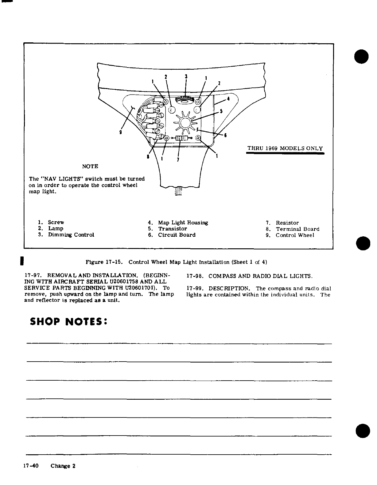
2
THRU 1969
MODELS
ONLY
NOTE
The
"NAV
LIGHTS"
switch
must
be
turned
on
in
order
to
operate
the
control
wheel
map
light.
1.
Screw
4.
Map
Light
Housing
7.
Resistor
2.
Lamp
5.
Transistor
8.
Terminal
Board
3.
Dimming
Control
6.
Circuit
Board
9.
Control
Wheel
Figure
17-15.
Control
Wheel
Map
Light
Installation
(Sheet
1
of
4)
17-97.
REMOVAL
AND
INSTALLATION.
(BEGINN-
17-98.
COMPASS
AND
RADIO
DIAL
LIGHTS.
ING
WITH
AIRCRAFT
SERIAL
U20601758
AND
ALL
SERVICE
PARTS
BEGINNING
WITH U20601701).
To
17-99.
DESCRIPTION.
The
compass
and
radio
dial
remove,
push
upward
on
the
lamp
and
turn.
The
lamp
lights
are
contained
within
the
individual
units.
The
and
reflector
is
replaced
as
a
unit.
SHOP
NOTES:
17-40 Change 2
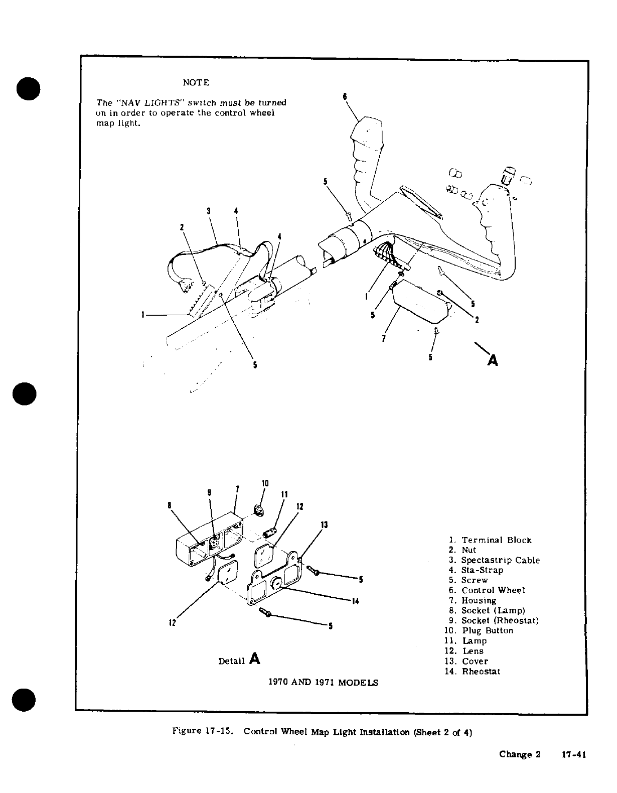
NOTE
The
"NAV
LIGHTS"
switch must
be
turned
on
in
order
to
operate
the
control
wheel
map
light.
3 4
1. Terminal Block
2. Nut
3. Spectrastrip Cable
4.
Sta-Strap
5.
Screw
6.
Control
Wheel
/
14
7.
Housing
8.
Socket
(Lamp)
12
9.
Socket
(Rheostat)
10.
Plug
Button
11.
Lamp
12.
Lens
Detail
A
13.
Cover
14.
Rheostat
1970
AND
1971
MODELS
Figure
17-15.
Control
Wheel
Map
Light
Installation
(Sheet
2
of
4)
Change
2
17-41
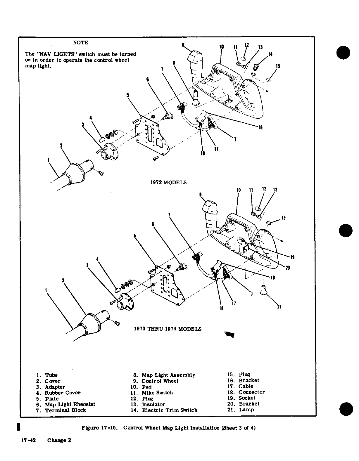
NOTE
* 12
The
"NAV
LIGHTS"
switch
must
be
turned
14
on
in
order
to
operate
the
control
wheel
map
light.
/
1972
MODELS
1 15
4
1973
THRU
1974
MODELS
1.
Tube
8.
Map
Light
Assembly
15.
plug
2.
Cover
9.
Control
Wheel
16.
Bracket
3.
Adapter
10.
Pad
17.
Cable
4.
Rubber
Cover
11.
Mike
Switch
18.
Connector
5.
Plate
12.
Plug
19.
Socket
6.
Map
Light
Rheostat
13.
Insulator
20.
Bracket
7.
Terminal
Block
14.
Electric
Trim
Switch
21.
Lamp
Figure
17-15.
Control
Wheel
Map
Light
Installation
(Sheet
3
of
4)
17-42
Change
2
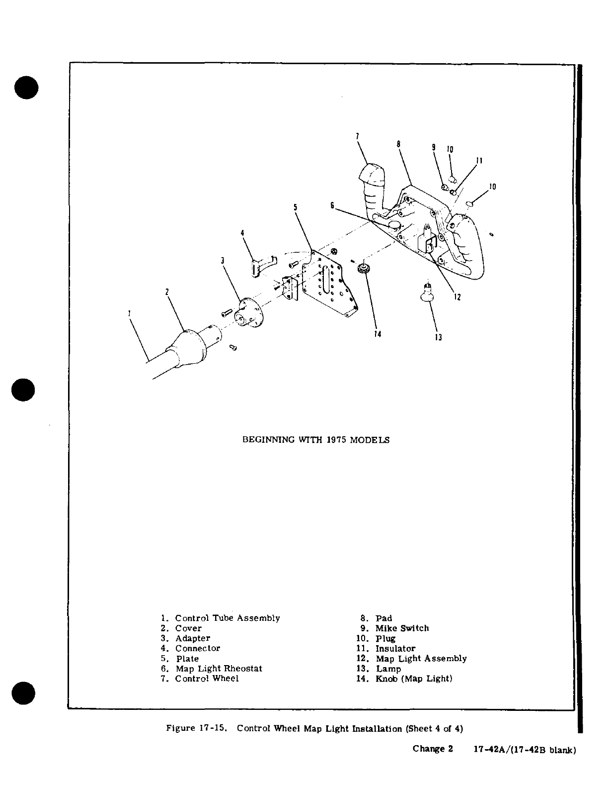
2
14
13
BEGINNING
WITH
1975
MODELS
1.
Control
Tube
Assembly
8.
Pad
2.
Cover
9.
Mike Switch
3.
Adapter
10.
Plug
4.
Connector
11.
Insulator
5.
Plate
12.
Map
Light
Assembly
6.
Map
Light
Rheostat
13.
Lamp
7.
Control
Wheel
14.
Knob
(Map
Light)
Figure
17-15.
Control
Wheel
Map
Light
Installation
(Sheet
4
of
4)
Change
2
17-42A/(17-42B
blank)
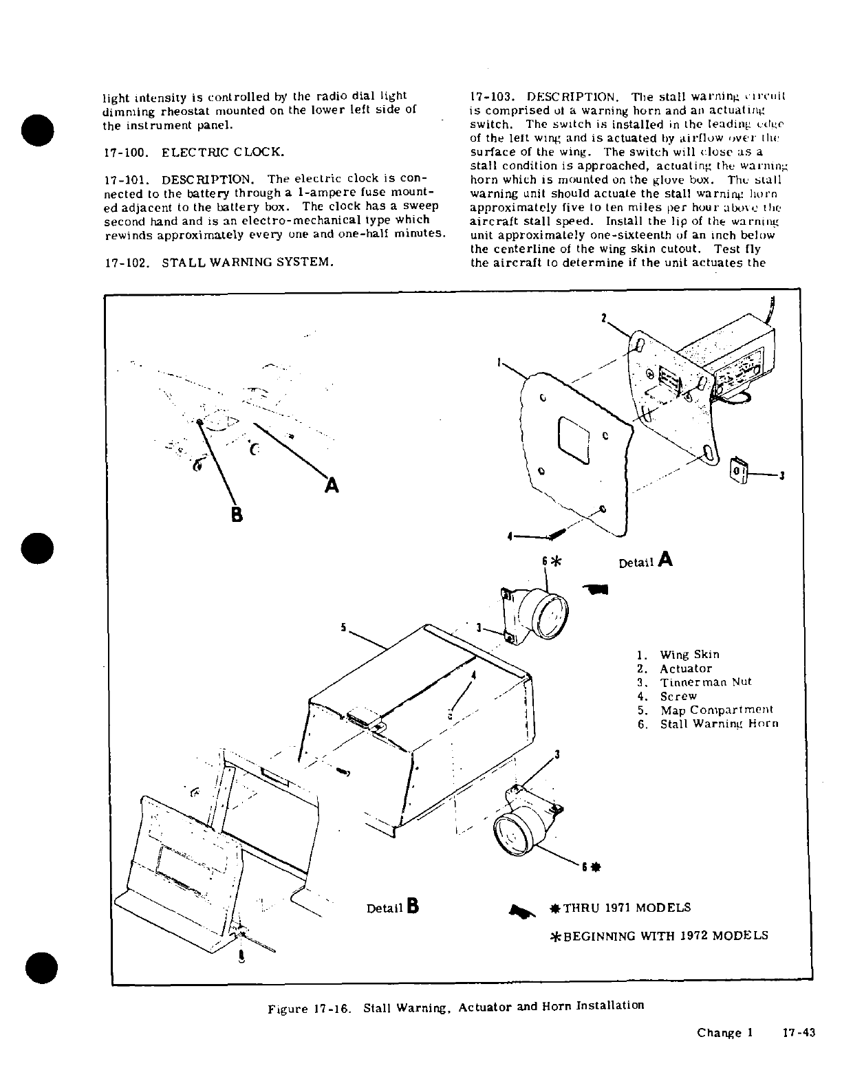
light
intensity
is controlled
by
the
radio
dial
light
17-103. DESCRIPTION.
The
stall
warning
circuit
dimming
rheostat
mounted
on
the
lower
left
side
of
is
comprised
of
a
warning
horn
and an
actuating
the
instrument
panel.
switch.
The
switch
is
installed
in
the
leading
edge
of
the
left
wing
and
is
actuated
by
airflow
over
the
17-100.
ELECTRIC
CLOCK.
surface
of
the
wing.
The
switch
will
close
as
a
stall
condition
is
approached,
actuating
the
warning
17-101.
DESCRIPTION.
The
electric
clock
is
con-
horn
which
is
mounted
on
the
glove
box.
The
stall
nected
to
the
battery
through
a
1-ampere
fuse mount-
warning
unit
should
actuate
the
stall
warning
horn
ed
adjacent
to
the
battery
box.
The
clock
has
a
sweep
approximately
five
to
ten
miles
per
hour
above
the
second
hand
and
is
an
electro-mechanical
type
which
aircraft
stall
speed.
Install
the
lip
of
the
warning
rewinds
approximately
every
one
and
one-half
minutes.
unit
approximately
one-sixteenth
of
an
inch
below
the
centerline
of
the
wing
skin
cutout.
Test
fly
17-102.
STALL
WARNING
SYSTEM.
the
aircraft
to
determine
if
the
unit
actuates
the
2
B
Detail
A
1.
Wing
Skin
2.
Actuator
3.
Tinnerman
Nut
4.
Screw
5.
Map
Compartment
/
6.
Stall
Warning
Horn
3
Detail
B
*THRU
1971
MODELS
*BEGINNING
WITH
1972
MODELS
Figure
17-16.
Stall
Warning.
Actuator
and
Horn
Installation
Change
1
17-43
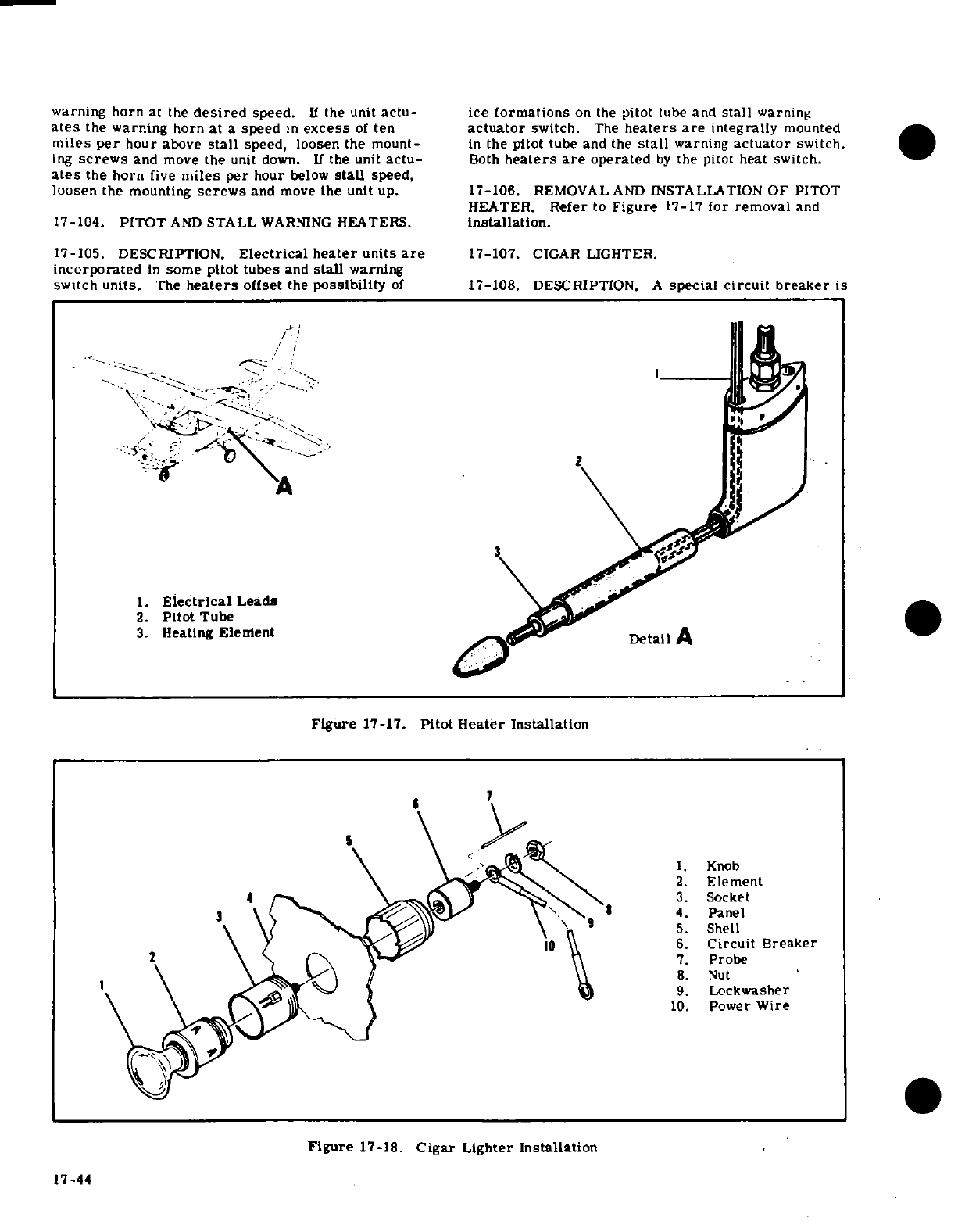
warning
horn
at
the
desired
speed.
If
the
unit
actu-
ice
formations
on
the
pitot
tube
and
stall
warning
ates
the warning
horn
at
a
speed
in
excess
of
ten
actuator
switch.
The
heaters
are
integrally
mounted
miles
per
hour
above
stall
speed,
loosen the
mount-
in
the pitot
tube
and
the
stall
warning
actuator
switch.
ing
screws
and
move
the
unit
down.
If
the
unit
actu-
Both
heaters
are
operated
by
the pitot
heat
switch.
ates
the horn
five
miles
per
hour
below
stall
speed,
loosen
the
mounting
screws
and
move
the
unit
up.
17-106.
REMOVAL
AND
INSTALLATION
OF PITOT
HEATER.
Refer
to
Figure
17-17
for
removal
and
17-104.
PITOT
AND
STALL
WARNING
HEATERS.
installation.
17-105.
DESCRIPTION.
Electrical
heater
units
are
17-107.
CIGAR
LIGHTER.
incorporated
in
some pitot
tubes
and
stall
warning
switch
units.
The
heaters
offset
the
possibility
of
17-108.
DESCRIPTION.
A
special
circuit
breaker
is
1.
Electrical
Leads
2.
Pitot
Tube
3.
Heating
Element
DetailA
Figure
17-17.
Pitot
Heater
Installation
1.
Knob
2.
Element
4
3.
Socket
8
4
Panel
5.
Shell
\ T \
6.
Circuit
Breaker
2 \ S A\ \ \7.
Probe
8.
Nut
1 \ _>< %J
S 99.
Lockwasher
10.
Power
Wire
Figure
17-18.
Cigar
Lighter Installation
17-44
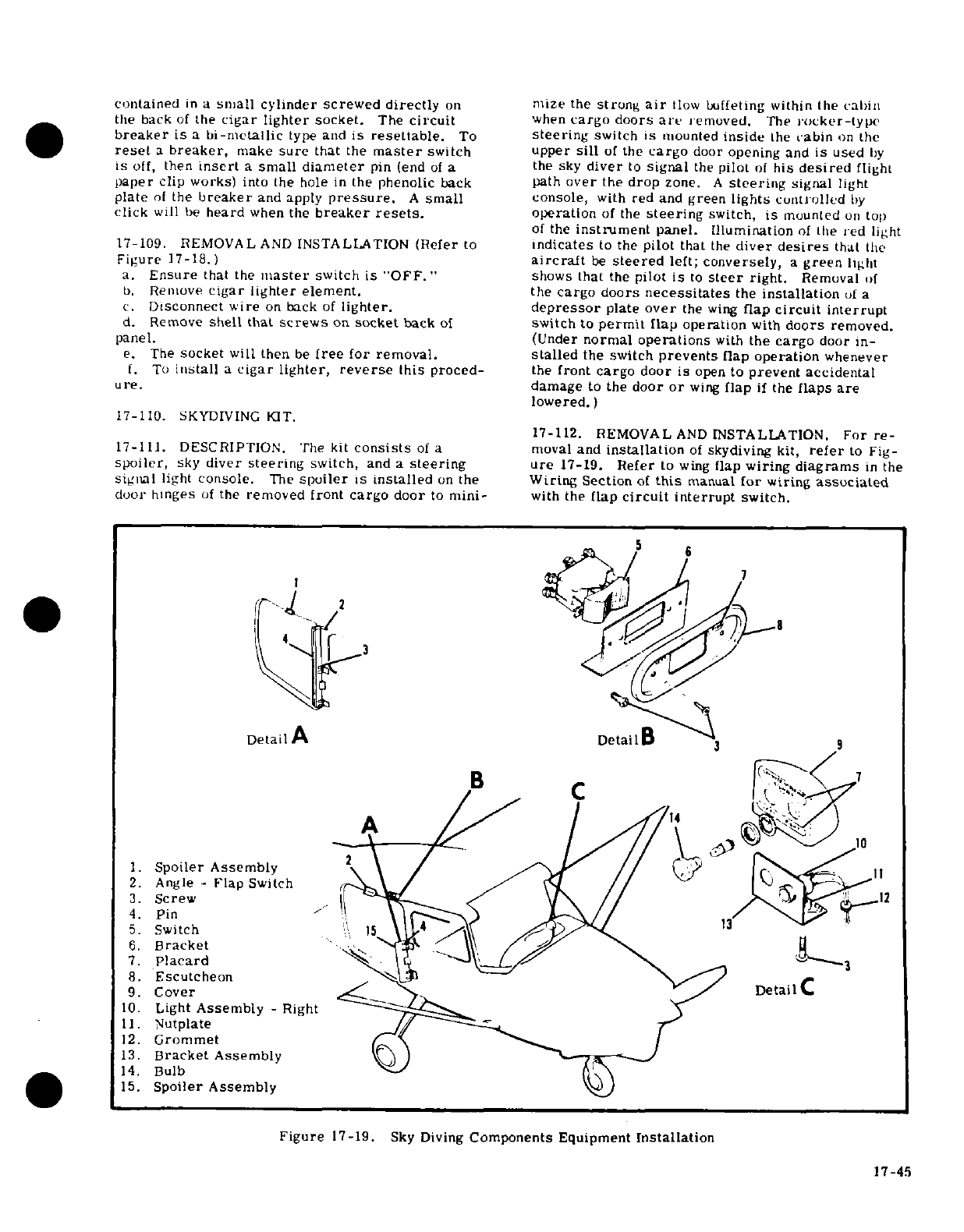
contained
in
a
small cylinder screwed
directly
on
mize
the
strong
air
tlow
buffeting within
the
cabin
the
back
of
the
cigar
lighter
socket.
The
circuit
when
cargo
doors
are
removed.
The
rocker-type
breaker
is
a
bi-metallic
type
and
is
resettable.
To
steering
switch
is
mounted
inside
the
cabin
on
the
reset
a
breaker,
make
sure
that
the
master
switch
upper
sill
of
the
cargo
door
opening and
is
used
by
is
off,
then
insert
a
small
diameter
pin (end
of
a
the
sky
diver
to
signal
the
pilot
of
his
desired
flight
paper
clip
works)
into the
hole
in
the
phenolic
back path
over
the
drop
zone.
A
steering
signal
light
plate
of
the
breaker
and
apply
pressure.
A
small
console,
with
red
and
green
lights
controlled
by
click
will
be
heard
when
the
breaker
resets,
operation
of
the
steering
switch,
is
mounted
on
top
of
the
instrument
panel.
Illumination
of
the
red
light
17-109.
REMOVAL
AND
INSTALLATION
(Refer
to
indicates
to
the
pilot
that
the
diver
desires
that
the
Figure
17-18.)
aircraft
be
steered
left; conversely,
a
green
light
a.
Ensure
that
the
master
switch
is
"OFF."
shows
that
the
pilot
is
to
steer
right.
Removal
of
b.
Remove
cigar
lighter
element,
the
cargo
doors
necessitates
the
installation
of
a
c.
Disconnect
wire
on
back
of
lighter,
depressor
plate
over
the
wing
flap
circuit
interrupt
d.
Remove
shell
that
screws
on
socket
back
of
switch
to
permit
flap
operation
with
doors
removed.
panel.
(Under
normal
operations
with
the
cargo
door
in-
e.
The
socket
will then
be
free
for
removal,
stalled
the
switch
prevents
flap
operation
whenever
f.
To
install
a
cigar
lighter,
reverse
this
proced-
the
front
cargo door
is
open
to
prevent
accidental
ure.
damage
to
the
door
or
wing
flap
if
the
flaps
are
lowered.)
17-110.
SKYDIVING
KIT.
17-112.
REMOVAL
AND
INSTALLATION.
For
re-
17-111.
DESCRIPTION.
The
kit
consists
of
a
moval
and
installation
of
skydiving
kit,
refer
to
Fig-
spoiler,
sky
diver
steering
switch,
and
a
steering
ure
17-19.
Refer
to
wing
flap
wiring
diagrams
in
the
signal
light
console.
The
spoiler
is
installed
on
the
Wiring
Section
of
this
manual
for
wiring
associated
door
hinges
of
the
removed
front
cargo door
to
mini-
with
the
flap
circuit
interrupt
switch.
1
Spoiler Assembly
2.
Angle
-
Flap
Switch
3.
Screw
4.
Pin
5.
Switch
6.
Bracket
9.
Cover
DetailC
10.
Light
Assembly
- Right
11.
Nutplate
12.
Grommet
13.
Bracket
Assembly
14.
Bulb
15.
Spoiler Assembly
Figure
17-19.
Sky
Diving
Components
Equipment
Installation
17-45

17-113.
EMERGENCY
LOCATOR
TRANSMITTER. CAUTION
17-114.
DESCRIPTION.
The
ELT
is
a
self-contained,
Do
not
leave
the
emergency
locator
transmitter
solid
state
unit, having
its
own
power
supply,
with
an
in
the
ON
position
longer
than
5
seconds
or
externally
mounted
antenna.
The
C589510-0209
trans-
you
may
activate
downed
aircraft
procedures
mitter
is
designed
to
transmit
simultaneously
on
dual
by
C.
A.
P.,
D. O.
T.
or
F.
A. A.
personnel.
emergency frequencies
of
121.5
and
243.0
Megahertz.
The
C589510-0211
transmitter
used
for
Canadian
WARNING
registry,
operates
on
121.5
only.
The
unit
is
mount-
ed
in
the
tailcone,
aft
of
the
baggage
curtain
on
the
Magnesium
(6-cell) battery-packs
(excluding
right
hand
side.
The
transmitters
are
designed
to 4
cell
lithium
battery-packs)
after
prolonged
provide
a
broadcast
tone
that
is
audio
modulated
in
a
continuous
use
(1 hour)
in
a
sealed
environ-
swept
manner
over
the
range
of
1600
to
300
Hz
in
a
ment
give
off
explosive
gas.
If
your
ELT
distinct,
easily
recognizable
distress
signal
for
re-
has
operated
for this time
period
or
longer,
ceptlon
by
serch
and
rescue
personnel
and
others
as
a
precautionary
measure,
loosen
the
monitoring
the
emergency
frequencies.
Power
is
ELT
cover
screws,
lift
the
cover
to
break
supplied
to
the
transmitter
by
a
battery-pack
which
air
tight
seal
and
let
stand
for
15
minutes
has
the
service
life
of
the
batteries
placarded
on
the
before
tightening
screws.
Keep
sparks,
batteries
and
also
on
the
outside
end
of
the
transmit-
flames
and
lighted
cigarettes
away
from
ter.
ELT's
thru
early
1974
models,
were
equipped
battery-pack.
with
a
battery-pack
containing
six
magnesium
"D"
size dry
cell
batteries
wired in
series.
(See
figure
NOTE
17-20)
Mid
1974
thru
early
1975,
ELT's
are
equipped
with
a
battery-pack
containing
four
"in-line"
lithium
After
relatively
short
periods
of
inactivation,
"D"
batteries
wired
in
series.
Early
1975
and
on
the
magnesium
(6-cell) battery-pack
develops
ELT's are
equipped
with
a
battery-pack
containing
a
coating
over
its
anode which
drastically
four
lithium
"D"
size
batteries
which
are
stacked
in
reduces
self
discharge
and
thereby
gives
two's
(See
figure
17-22).
The
ELT
exhibits
line
of
the
cell
an
extremely
long
storage
life.
sight
transmission
characteristics
which
correspond
This
coating will exhibit
a
high
resistance
approximately
to
100
miles
at
a
search
altitude
of
to
the
flow
of
electric current
when
the
10,
000
feet.
When
battery
inspection
and
replacement
battery
is
first
switched
on.
After
a
short
schedules
are
adhered
to,
the
transmitter
will
broad-
while
(less
than
15
seconds),
the
battery
cast
an
emergency
signal
at
rated
power
(75 MW-
current
will
completely
dissolve
this
coating
minimum),
for
a continuous
period
of
time
as
listed
and
enable
the
battery
to
operate
normally.
in
the
following
table.
If
this
coating
is present
when
your
ELT
is
table.
activated,
there
may
be
a
few
seconds
delay
before
the
transmitter
reaches
full
power.
TRANSMITTER
LIFE
TO
75
MILLIWATTS
OUTPUT
17-116.
CHECKOUT
INTERVAL:
100
HOURS.
6
Cell
4
Cell
Temperature
Magnesium
Lithium
a.
Turn
aircraft
master
switch
ON.
Battery
Pack
Battery
Pack
b.
Turn
aircraft
transceiver
ON
and
set
frequency
on
receiver
to
121.5
MHz.
+130°F
89
hrs
115
hrs
c.
Remove
the
ELT's
antenna
cable from
the ELT
t
70°F
95
hrs
115
hrs
unit.
-
4*F
49
hrs
95
hrs
d.
Place
the
ELT's
function
selector
switch
in
the
-40°F
23
hrs
70
hrs
ON
position
for
5
seconds
or
less.
Immediately re-
place
the
ELT
function
selector
switch
in
the
ARM
position
after
testing
ELT.
Battery-packs
have
a
normal shelf
life
of five
to
ten
e.
Test
should
be
conducted
only
within
the
time
(5-10)
years
and
must
be
replaced
at
1/2
of
normal
period
made
up
of
the
first
five
minutes
after
any
shelf
life
in
accordance
with
TSO-C91.
Cessna
hour.
specifies
3
years
replacement
of
magnesium
(6-cell)
battery-packs
and
5
years
replacement
of
lithium
CAUTION
(4-cell)
battery
packs.
Tests
with
the
antenna connected
should
be
17-115.
OPERATION.
A
three
position
switch
on
the
approved
and
confirmed
by
the
nearest
control
forward
end
of
the
unit
controls
operation.
Placing
tower.
the
switch
in
the
ON
position
will
energize
the
unit
to
start
transmitting
emergency
signals.
In
the
OFF
NOTE
position,
the unit
is
inoperative.
Placing
the
switch
in
the
ARM
position
will
set
the
unit
to
start
trans-
Without
its
antenna
connected,
the
ELT
will
mitting
emergency
signals
only
after
the
unit has
produce
sufficient signal
to
reach
your
receiver,
received
a
5g
(tolerances
are
+2
g
and
-Og)
impact
yet
it
will
not
disturb
other
communications
force,
for
a
duration
of
11-16
milliseconds. or
damage
output
circuitry.
17-46
Change
3
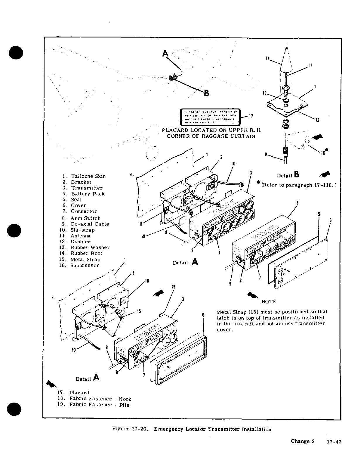
A
PLACARD
LOCATED
ON
UPPER
R.
H.
CORNER
OF
BAGGAGE
CURTAIN
1 2
9
*
r10
<
1.
Tailcone
Skin
/
DetailB
A.
2.
Bracket
3.
Transmitter
(
Refer to
paragraph
17-118.
)
4.
Battery
Pack
6. Cover
7 Connector
8.
Arm
Switch
K
9.
Co-axial
Cable
18
10.
Sta-strap
.
11.
Antenna
I9
15.
Metal
Strap
1
,
16.
Suppressor
Detail
A
I
2 2
^^^'/ ;/ /
18
9' 7
1^
' --'
s_ -.r ^ /^
3
{NOTE
Metal
Strap
(15)
must
be
positioned
so
that
3t,
T<^^,~~
ransm<~i-^i~
>
latch
is
on
top of
transmitter
as
installed
1
.ll~k^^'-^s^^^~~
~
/
>
e
in
the
aircraft
and
not
across
transmitter
6~
.~
-
~~
cover.
Detail
A
17.
Placard
18.
Fabric
Fastener
-
hook
19.
Fabric
Fastener
-
Pile
Figure
17-20.
Emergency
Locator
Transmitter
Installation
Change
3
17-47
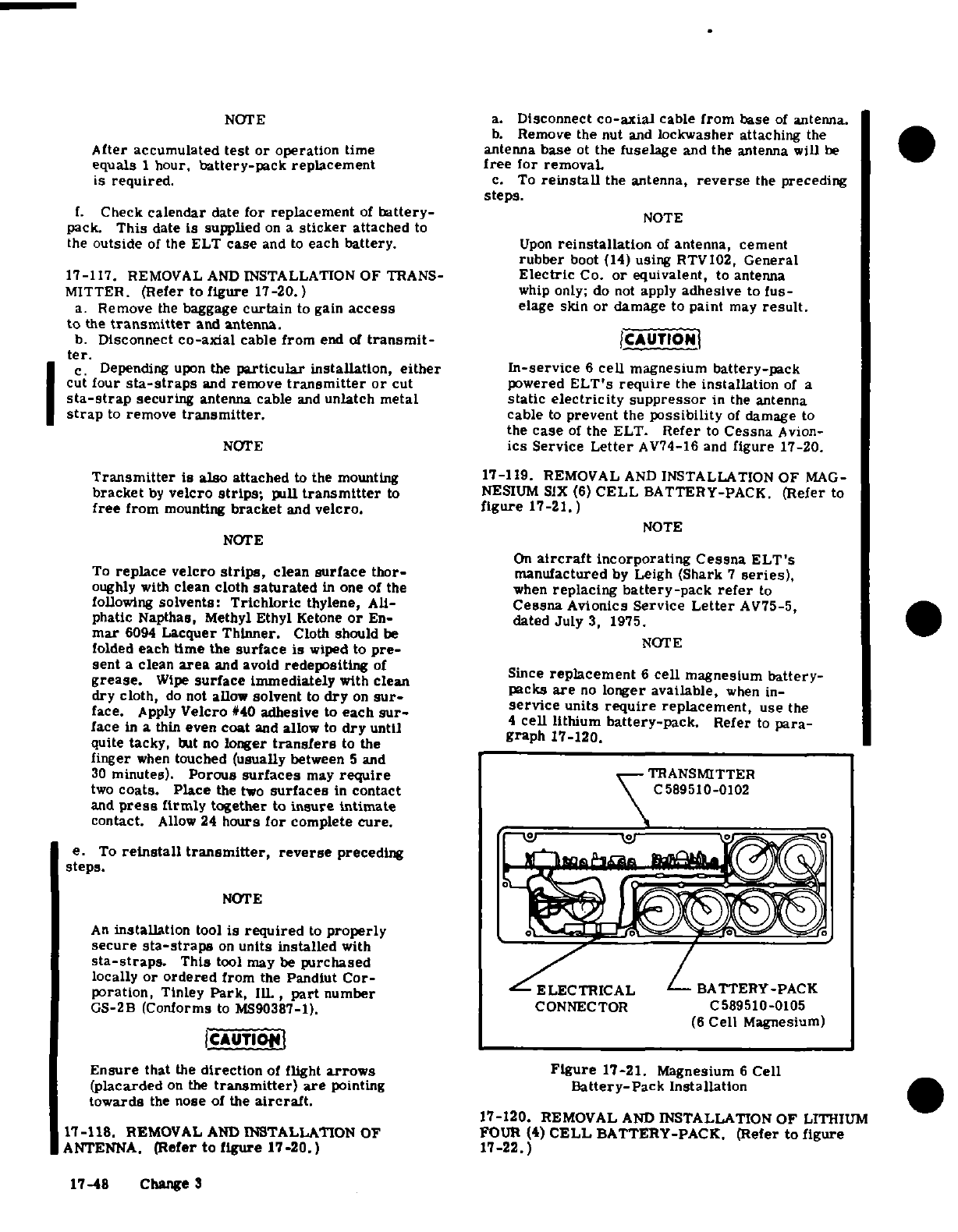
NOTE a.
Disconnect
co-axial
cable
from
base
of
antenna.
b.
Remove
the
nut
and
lockwasher
attaching
the
After
accumulated
test
or
operation
time antenna
base
ot
the
fuselage
and
the
antenna
will
be
equals
1
hour,
battery-pack
replacement
free
for
removal
is
required.
c.
To
reinstall
the antenna,
reverse
the
preceding
steps.
f.
Check
calendar
date
for replacement
of
battery-
NOTE
pack.
This
date
is
supplied
on
a
sticker
attached
to
the
outside
of
the ELT
case
and
to
each
battery.
Upon
reinstallation
of
antenna,
cement
rubber
boot
(14)
using
RTV102,
General
17-117.
REMOVAL
AND
INSTALLATION
OF
TRANS-
Electric
Co.
or
equivalent,
to
antenna
MITTER.
(Refer
to
figure
17-20.
)
whip
only;
do
not
apply
adhesive
to
fus-
a.
Remove
the
baggage
curtain
to
gain
access
elage
skin
or
damage
to
paint
may
result.
to
the
transmitter
and
antenna.
b.
Disconnect
co-axial
cable from
end
of
transmit-
CAUTION
ter.
c.
Depending
upon
the
particular
installation,
either
In-service
6
cell
magnesium
battery-pack
cut
four
sta-straps
and
remove
transmitter
or
cut
powered
ELT's
require
the
installation
of
a
sta-strap
securing
antenna
cable
and
unlatch
metal
static
electricity
suppressor
in
the
antenna
strap
to
remove
transmitter.
cable
to
prevent
the
possibility
of
damage
to
the
case
of
the
ELT.
Refer
to
Cessna
Avion-
NOTE
ics
Service
Letter
AV74-16
and
figure
17-20.
Transmitter
is
also
attached
to
the
mounting
17-119.
REMOVAL
AND
INSTALLATION
OF
MAG-
bracket
by
velcro
strips;
pull
transmitter
to
NESIUM
SIX
(6)
CELL
BATTERY-PACK.
(Refer
to
free
from
mounting
bracket
and
velcro.
figure
17-21.)
NOTE
NOTE
On
aircraft
incorporating
Cessna
ELT's
To
replace
velcro
strips,
clean
surface
thor-
manufactured
by
Leigh
(Shark
7
series),
oughly
with
clean
cloth
saturated
in
one of
the
when
replacing
battery-pack
refer
to
following
solvents:
Trichloric
thylene,
All-
Cessna
Avionics
Service
Letter
AV75-5,
phatic
Napthas, Methyl
Ethyl
Ketone
or
En-
dated
July
3,
1975.
mar
6094
Lacquer
Thinner.
Cloth
should
be
folded
each
time
the
surface is
wiped
to
pre-
sent
a
clean
area
and
avoid
redepositing
of
grease.
Wipe
surface
immediately
with
clean
Since
replacement
6
cell
magnesium
battery-
dry
cloth,
do
not
allow
solvent
to
dry
on
sur-
packs
are
no
loger
available,
when
in-
face.
Apply
Velcro
#40
adhesive
to each
sur-
service
units
require
replacement,
use
the
face
in
a
thin
even
coat
and
allow
to
dry
until
4cell
lithium
battery-pack.
Refer
to
para-
quite
tacky,
but
no
longer
transfers
to
the
graph
17-120.
finger
when
touched
(usually
between
5
and
30
minutes).
Porous
surfaces
may
require
TRANSMITTER
two
coats.
Place
the
two
surfaces
in
contact
C589510-0102
and
press
firmly
together
to
insure
intimate
contact.
Allow
24
hours
for
complete
cure.
e.
To
reinstall
transmitter,
reverse
preceding
steps.
NOTE
An
installation
tool
is
required
to
properly
secure
sta-straps
on
units
installed
with
sta-straps.
This
tool
may
be
purchased
locally
or
ordered
from
the
Pandiut
Cor-
BATTERY-PACK
poration,
Tinley
Park,
111.
,
part
number
ELECTRICAL
GS-2B
(Conforms
to
MS90387-1).
CONNECTOR
C589510-0105
(6
Cell
Magnesium)
CAUTION
Ensure
that
the
direction
of
flight
arrows
Figure
17-21.
Magnesium
6
Cell
(placarded
on
the
transmitter)
are
pointing
Battery-Pack
Installation
towards
the
nose
of
the
aircraft.
17-120.
REMOVAL
AND
INSTALLATION
OF
LITHIUM
17-118.
REMOVAL
AND
INSTALLATION
OF
FOUR
(4)
CELL
BATTERY-PACK.
(Refer to
figure
ANTENNA.
(Refer
to
figure
17-20.)
17-22.)
17-48
Change
3
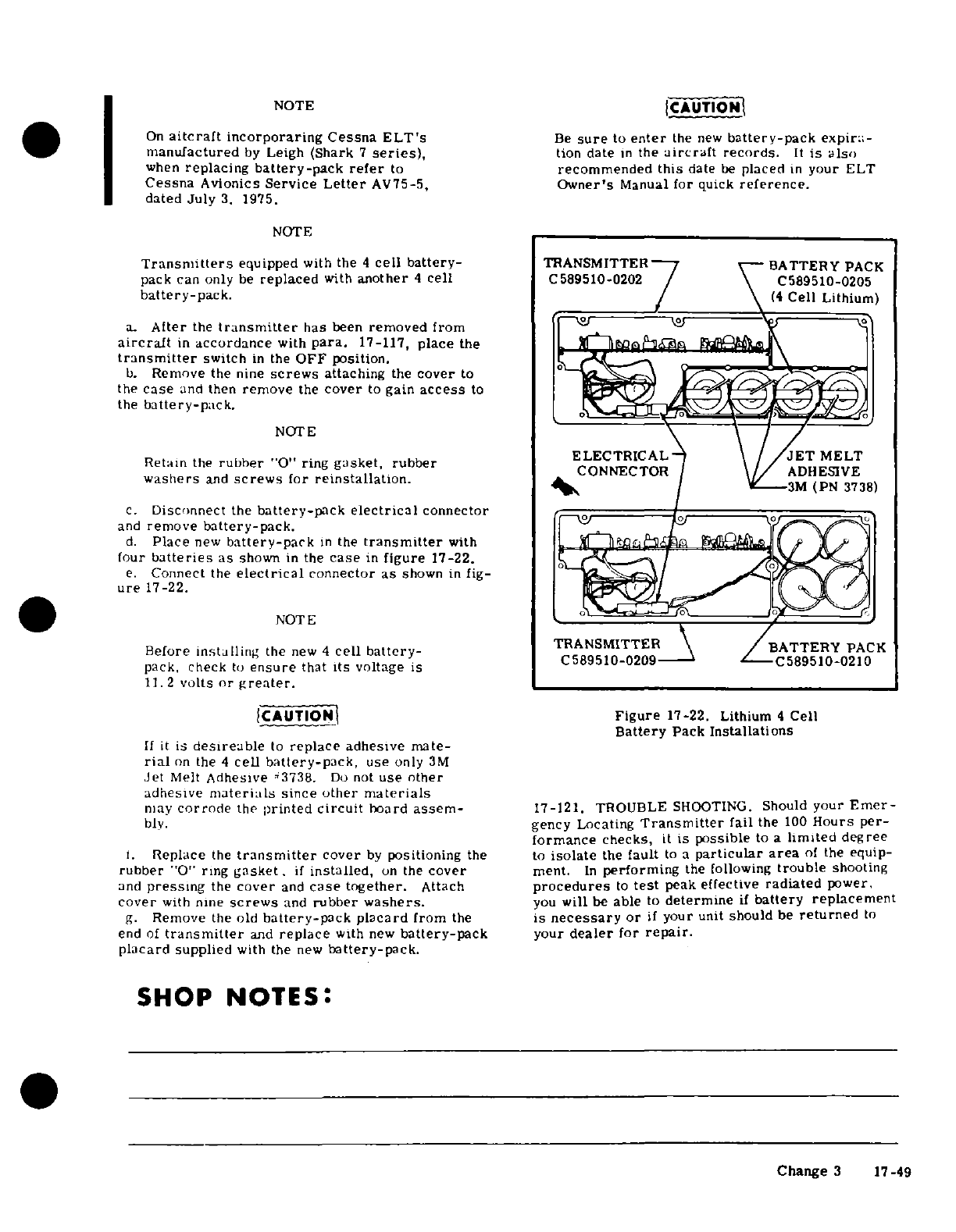
NOTE
CAUTION
On
aircraft
incorporaring
Cessna
ELT's
Be
sure
to
enter
the
new
battery-pack
expira-
manufactured
by
Leigh
(Shark
7
series),
tion
date
in
the
aircraft
records.
It
is
also
when
replacing
battery-pack
refer
to
recommended
this
date
be
placed
in
your
ELT
Cessna
Avionics
Service
Letter
AV75-5,
Owner's
Manual
for
quick
reference.
dated
July
3. 1975.
NOTE
Transmitters
equipped
with
the
4
cell
battery-
TRANSMITTER
BATTERY PACK
pack
can
only
be
replaced
with
another
4
cell
C589510-0202 C589510-0205
battery-pack.
(4
Cell Lithium)
a.
After
the
transmitter
has
been
removed
from
aircraft
in
accordance
with
para.
17-117,
place
the
transmitter
switch
in
the
OFF
position.
b.
Remove
the
nine
screws
attaching
the
cover
to
the
case
and
then
remove
the
cover
to
gain
access
to
the
battery-pack.
NOTE
Retain
the
rubber
"0"
ring
gasket, rubber
ELECTRICAL
MELT
washers
and
screws
for
reinstallation.
CONNECTOR
ADHESIVE
3M
(PN
3738)
c.
Disconnect
the
battery-pack
electrical
connector
and
remove
battery-pack.
d.
Place
new
battery-pack
in
the
transmitter
with
four
batteries
as
shown
in
the
case
in
figure
17-22.
e.
Connect
the
electrical
connector
as
shown
in
fig-
ure
17-22.
NOTE
Before
installing
the
new
4
cell
battery-
TRANSMIITTERBATTERY
PACK
pack,
check
to
ensure
that
its
voltage
is
C589510-0209
C589510-0210
11.
2
volts
or
greater.
CAUTION
Figure
17-22.
Lithium
4
Cell
Battery
Pack
Installations
If
it
is
desireable
to
replace
adhesive
mate-
rial
on
the
4
cell
battery-pack,
use
only
3M
Jet
Melt
Adhesive
3738.
Do
not
use
other
adhesive
materials
since
other
materials
may
corrode
the
printed
circuit
board
assem-
17-121. TROUBLE
SHOOTING.
Should
your
Emer-
bly. gency
Locating
Transmitter
fail
the
100
Hours
per-
formance
checks,
it
is
possible
to
a
limited
degree
1.
Replace
the
transmitter
cover
by
positioning
the
to
isolate
the
fault
to
a
particular
area
of
the
equip-
rubber
"0"
ring
gasket.
if
installed,
on
the
cover
ment.
In
performing
the
following
trouble
shooting
and
pressing
the
cover
and
case
together.
Attach
procedures
to
test
peak
effective
radiated
power.
cover
with
nine
screws
and
rubber
washers.
you
will
be
able
to
determine
if
battery
replacement
g.
Remove
the
old
battery-pack
placard
from
the
is
necessary
or
if
your
unit
should
be
returned
to
end
of
transmitter
and
replace
with
new
battery-pack
your
dealer
for
repair.
placard
supplied
with the
new
battery-pack.
SHOP NOTES:
Change
3
17-49
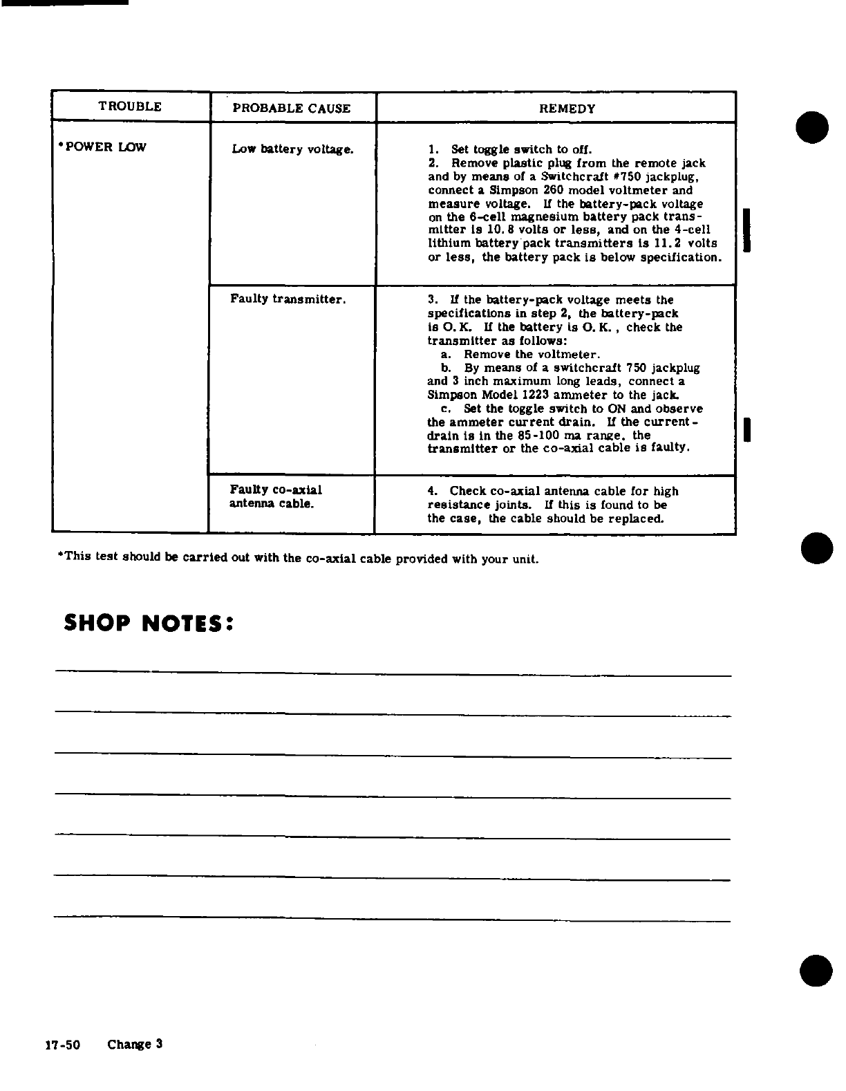
TROUBLE
PROBABLE
CAUSE
REMEDY
POWER
LOW
Low
battery
voltage.
1.
Set
toggle
switch
to
off.
2.
Remove
plastic
plug
from
the
remote
jack
and
by
means
of
a
Switchcraft
#750
jackplug.
connect
a
Simpson
260
model
voltmeter
and
measure
voltage.
If
the
battery-pack
voltage
on
the
6-cell
magnesium
battery
pack
trans-
mitter
is
10.8
volts or
less,
and
on
the
4-cell
lithium
battery
pack
transmitters
is
11.2
volts
or
less,
the
battery
pack
is
below
specification.
Faulty
transmitter.
3.
If
the
battery-pack
voltage
meets
the
specifications
in
step
2,
the
battery-pack
is
O.
K.
If
the
battery
is
O.
K.,
check
the
transmitter
as
follows:
a.
Remove
the
voltmeter.
b.
By
means
of
a
switchcraft
750
jackplug
and
3
inch
maximum
long
leads,
connect
a
Simpson
Model
1223
ammeter
to
the
jack.
c.
Set
the
toggle
switch
to
ON
and
observe
the
ammeter
current
drain.
If
the
current-
drain
is
in
the
85-100
ma
range.
the
transmitter
or
the
co-axial
cable
is
faulty.
Faulty
co-axial
4.
Check
co-axial
antenna
cable
for
high
antenna
cable.
resistance
joints.
If
this
is
found
to
be
the
case,
the
cable should
be
replaced.
*This
test
should
be
carried
out
with
the
co-axial
cable
provided
with
your unit.
SHOP NOTES:
17-50
Change
3
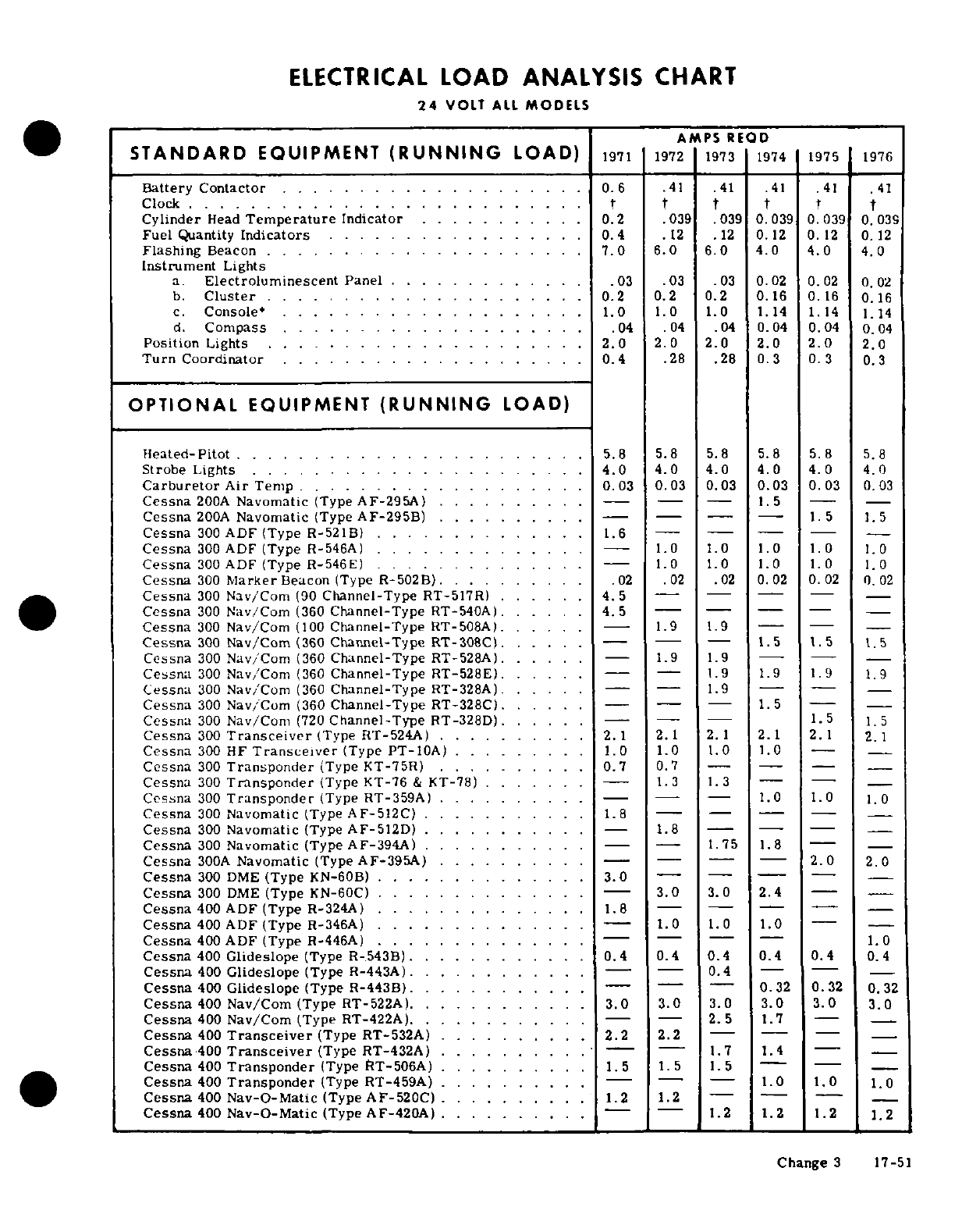
ELECTRICAL
LOAD
ANALYSIS
CHART
24
VOLT
ALL
MODELS
AMPS
REQD
STANDARD
EQUIPMENT
(RUNNING
LOAD)
1971
1972
1973
1974
1975
1976
Battery
Contactor
.. . ...
0.6
.41
.41
.41 .41 .41
Clock
. . .
.................... t t t t
t
Cylinder
Head
Temperature
Indicator
........
0.2
.039
.039
0.039
0.039
0.039
Fuel
Quantity
Indicators
. .
..............
0.4
.12
.12
0.12
0.12
0.12
Flashing
Beacon
. .
.................
7.0
6.0 6.0 4.0
4.0
4.0
Instrument
Lights
a.
Electroluminescent
Panel
........
...
.03
.03
.03
0.02
0.02
0.02
b.
Cluster
............ .......
0.2
0.2
0.2
0.16 0.16
0.16
c.
Console*
.
.....
............ .. .
1.0
1.0 1.0
1.14
1.14
1.14
d.
Compass
.... .. .. . .. ... . .. ...
.04 .04 .04
0.04
0.04
0.04
Position
Lights . . . . . ..
...........
2.0
2.0
2.0
2.0 2.0
2.0
Turn Coordinator
. . .. . .. . ... .
....
...
0.4
.28 .28
0.3
0.
3
0.3
OPTIONAL
EQUIPMENT
(RUNNING
LOAD)
Heated-Pitot
.. .
5.8
5.8 5.8
5.8
5.8
5.8
Strobe
Lights
. . . . .. . .. . ... .
....
4.0
4.0 4.0 4.0
4.0
4.0
Carburetor
Air
Temp . .
.......
.. .. ..
0.03
0.03
0.03
0.03
0.03
0.03
Cessna
200A
Navomatic
(Type
AF-295A)
..........
. - - --
1.5
Cessna
200A
Navomatic
(Type
AF-295B)
...........
- - - -
1.5
Cessna
300
ADF
(Type R-521B)
....
1.6
----
--
Cessna
300
ADF (Type
R-546A)
...
.........
..
1.0 1.0
1.0
1.0
1.0
Cessna
300
ADF
(Type
R-546E) .
..........
-
1.0 1.0 1.0
1.0
1.0
Cessna
300
Marker
Beacon (Type
R-502B)
..........
02
.02
02
0.02
0.002
0.02
Cessna
300
Nav/Com
(90
Channel-Type
RT-517R) ..
4.5
- --
Cessna
300
Nav/Com
(360
Channel-Type
RT-540A)
.
.....
4.5
---
Cessna
300
Nav/Com
(100
Channel-Type
RT-508A).
.....-
1.9
1.9
-
Cessna
300
Nav/Com
(360
Channel-Type
RT-308C).
.....
-- -
1.5 1.5
1.5
Cessna
300
Nav/Com
(360
Channel-Type
RT-528A).
.....
-
1.9 1.9
--
Cessna
300
Nav/Com
(360
Channel-Type
RT-528E).
....
--
1.9
1.9
1.9
1.9
Cessna
300
Nav/Com
(360
Channel-Type
RT-328A).
....
---
1.9
--
Cessna
300
Nav/Com
(360
Channel-Type
RT-328C).
.....
---
1.5
- -
Cessna
300
Nav/Com
(720
Channel-Type
RT-328D)
.... ---
1.5
1.5
Cessna
300
Transceiver
(Type
RT-524A)
..... .....
2.1
2.1
Cessna
300
HF
Transceiver
(Type
PT-10A)
.........
1.0
1.0
1.0
-
-
Cessna
300
Transponder
(Type
KT-75R)
.
.0.7
0.7
-- -
Cessna
300
Transponder
(Type
KT-76
&
KT-78)
.
....
-
1.3 1.3
- -
Cessna
300
Transponder
(Type
RT-359A)
.........-
- -
1.0
1.0
1.0
Cessna
300
Navomatic
(Type
AF-512C)
..
1.8
----
Cessna
300
Navomatic
(Type
AF-512D)
. ..
....
1.8
-
--
Cessna
300
Navomatic
(Type
AF-394A)
........
. - -
1.75
1.8
--
Cessna
300A
Navomatic
(Type
AF-395A)
..........-
-- -
2.0
2.0
Cessna
300 DME
(Type
KN-60B)
.............
3.0
-- -
Cessna
300
DME
(Type
KN-60C)
.
......-
3.0
3.0 2.4
-
-
Cessna
400
ADF
(Type
R-324A)
...
.1.8
-- - --
-
Cessna
400
ADF
(Type
R-346A)
. . . . -
1.0
1.0
1.0
--
Cessna
400
ADF
(Type
R-446A)
...........
. - ---
1.0
Cessna
400
Glideslope
(Type
R-.543B).
...........
0.4
0.4
0.4
0.4
0.4
0.4
Cessna
400
Glideslope
(Type
R-443A).
...........
-
0.4
--
Cessna
400
Glideslope
(Type
R-443B).
...........
-- -
0.32
0.32
0.32
Cessna
400
Nav/Com
(Type RT-522A).
...........
3.0
3.0
3.0
3.0
3.0
3.0
Cessna
400
Nav/Com
(Type
RT-422A).
..........
. - -
2.5
1.7
-
-
Cessna
400
Transceiver
(Type RT-532A)
.
....
2.2
2.2
- - -
Cessna
400
Transceiver
(Type RT-432A)
..........
1.7
1.4
--
Cessna
400
Transponder
(Type
RT-506A)
..
........
1.5
1.5
1.5
- -
Cessna
400
Transponder
(Type
RT-459A)
..........
- -- --
1.0
1.0
1.0
Cessna
400
Nav-O-Matic
(Type
AF-520C)
..........
1.2
1.2
-- -
Cessna
400
Nav-O-Matic
(Type
AF-420A)
..........
--
1.2
1.2 1.2
1.2
Change
3
17-51
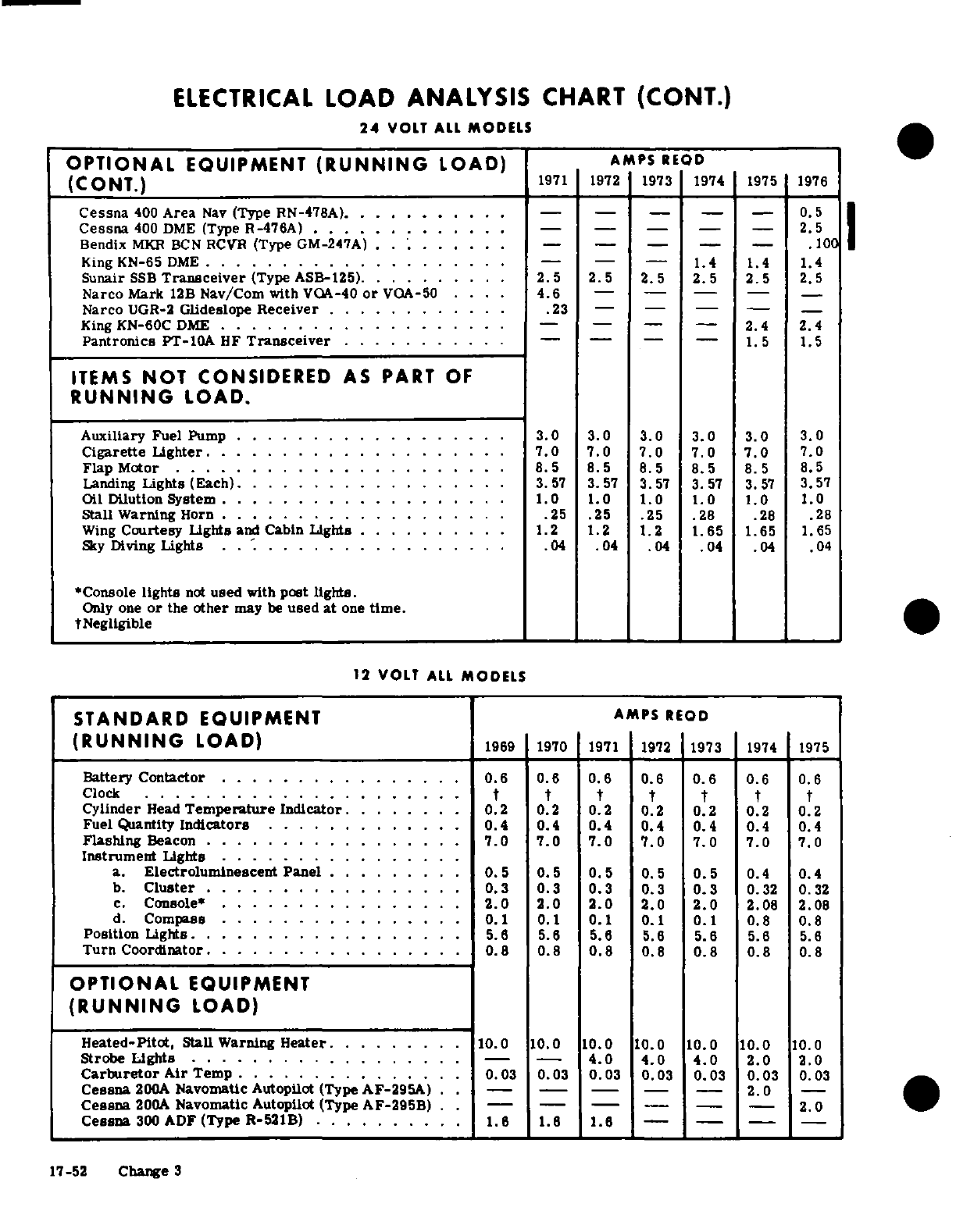
ELECTRICAL
LOAD
ANALYSIS
CHART
(CONT.)
24
VOLT
ALL
MODELS
OPTIONAL
EQUIPMENT
(RUNNING
LOAD)
AMPS
REQD
(CONT.)
1971
1972
1973
1974
1975
1976
Cessna
400
Area
Nav
(Type
RN-478A).
..........
- - - - -
0.
5
Cessna
400
DME
(Type R-476A)
.............
. - - - - -
2.5
Bendix
MKR
BCN
RCVR
(Type
GM-247A)
.........
- - - - -
.100
King
KN-65
DME
.
........ ...........
- - -
1.4
1.4
Sunair
SSB
Transceiver
(Type
ASB-125)
.
........
2.5
2.5 2.5
2.5
2.5
2.5
Narco
Mark
12B
Nav/Com
with
VOA-40
or
VOA-50
....
4.6
- - - -
Narco
UGR-2
Glideslope
Receiver
............
.23
----
King
KN-60C
DME
...................
. - - - -
2.4
2.4
Pantronics
PT-IOA
HF
Transceiver
............
- - - -
1.5
1.5
ITEMS
NOT
CONSIDERED
AS
PART
OF
RUNNING
LOAD.
Auxiliary
Fuel
Pump
..................
3.0 3.0 3.0
3.0
3.0
3.0
Cigarette
Lighter.
..
.......
......
. . .
7.0
7.0 7.0 7.0 7.0
7.0
Flap
Motor
......................
..
8.5 8.5 8.5
8.5
5 8.5
Landing
Lights (Each)
.................
3.57
3.57
3.57
3.57
3.57
3.57
Oil
Dilution System
.
............
.. . .
1.0
1.0
1.0
1.0
1.0
1.0
Stall Warning
Horn
.....
.25
.25 .25 .28
.28 .28
Wing
Courtesy
Lights
and
Cabin
Lights
. ...... .
1.2 1.2 1.2
1.65
1.65
1.65
Sky
Diving
Lights
. . ............. ...
.04
.04
.04
.04
.04
.04
*Console
lights
not
used
with
post lights.
Only
one
or
the
other
may
be
used
at
one
time.
±Negligible
12
VOLT
ALL
MODELS
STANDARD
EQUIPMENT
AMPS
REOD
(RUNNING
LOAD)
1969
1970
1971
1972
1973
1974
1975
Battery
Contactor
................
.6
0.6
0.6
0.
6
0.6
0.6
0.6
Clock
............ . . . ...... t t t t t
t
t
Cylinder
Head
Temperature
Indicator
....
.
0.2
0.2
2
0.2
0.2
0.2
0.2
Fuel Quantity
Indicators
.............
0.4
0.4
0.4
0.4
0.4
0.4
0.4
Flashing
Beacon
.................
7.0 7.0
7.0 7.0 7.0
7.0
7.0
Instrument
Lights
........
a.
Electroluminescent
Panel
.........
0.5
0.
5
0. 5 0.
5
0.
5
0.4
0.4
b.
Cluster
.................
0.3
0.3
0.3
0.3
0.3
0.32
0.32
c.
Console*
................
2.0
2.0
2.0
2.0
2.0
2.08
2.08
d.
Compass
..
........
.
0.1
0.1
0.1
0.1
0.1
0.8
0.8
Position
Lights
..................
5.6
5.6
5.6
5.6
5.6
5.6
5.6
Turn
Coordinator
.................
0.
8
0.8
0.8
0.8
0.8
0.8
0.8
OPTIONAL
EQUIPMENT
(RUNNING
LOAD)
Heated-Pitot,
Stall
Warning
Heater
.........
10.0 10.0
10.0
10.
.
0
1
0.
0
0.0 0.0
Strobe
Lights
.................. -.-
4.0
4.0
4.0
2.0
2.0
Carburetor
Air
Temp
..............
0.
03
0.03
0. 03
0.
03
0.
03
0.03
0. 03
Cessna
200A
Navomatic
Autopilot
(Type
AF-295A)
. .
2.0
-
Cessna
200A
Navomatic
Autopilot
(Type
AF-295B)
.-- --
2.0
Cessna
300
ADF
(Type R-521B)
..........
1.6
1.6
17-52
Change
3
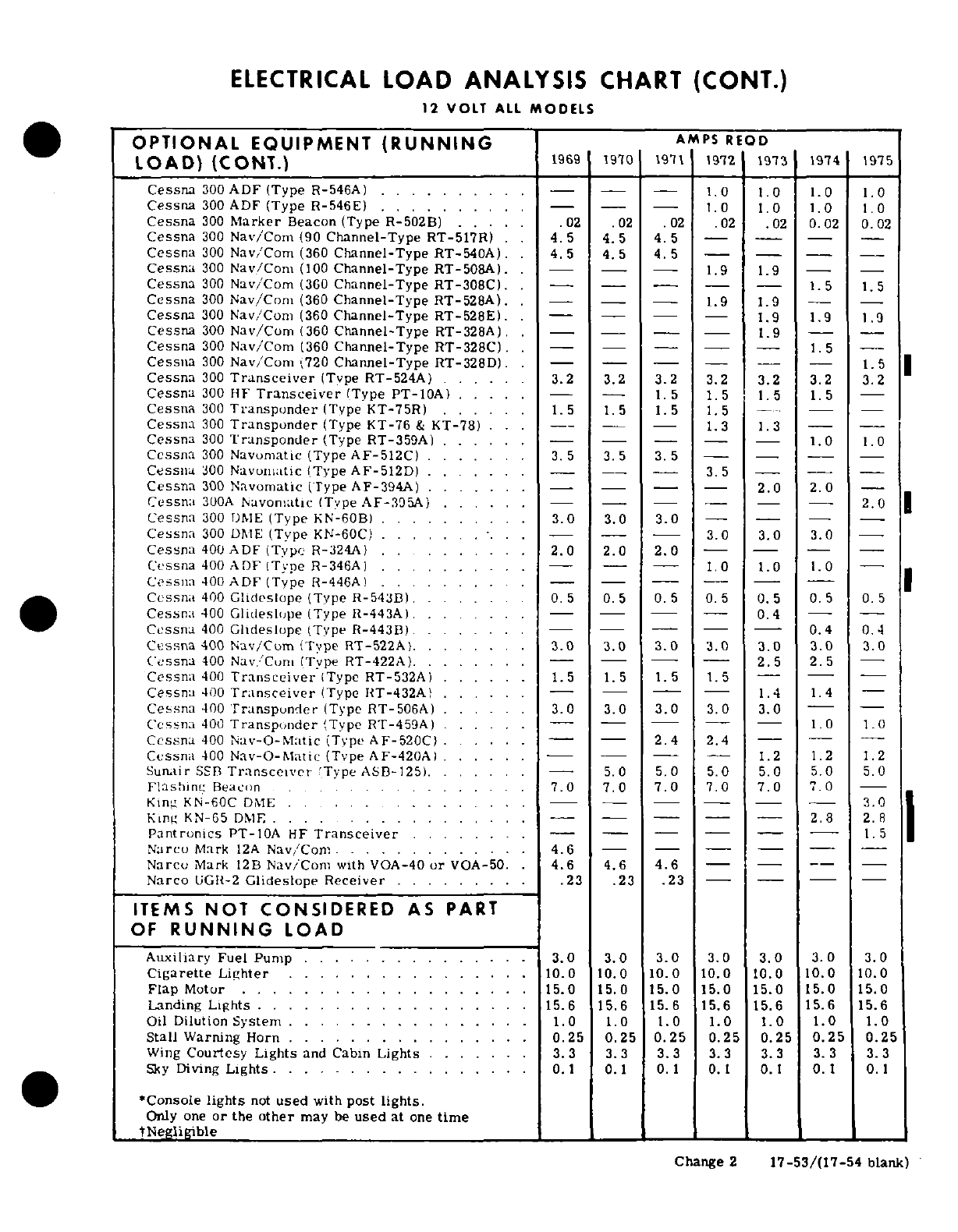
ELECTRICAL
LOAD
ANALYSIS
CHART
(CONT.)
12
VOLT
ALL
MODELS
OPTIONAL
EQUIPMENT
(RUNNING
AMPS
REQD
LOAD)
(CONT.)
1969 1970
4112
12
\I
4
T
1915
Cessna
300
ADF
(Type
R-546A)
..........
.- - --
1.0 1.0
1.0
1.0
Cessna
300
ADF
(Type
R-546E)
.... . . .
--
1.0
1.0 1.0
1.0
Cessna
300
Marker
Beacon
(Type
R-502B)
.....
.02
.02 .02
.02 .02
0.02
0.02
Cessna
300
Nay/Com
(90
Channel-Type
RT-517R)
.
4.5
4.5
4.5
-- -
Cessna
300
Nav/Com
(360
Channel-Type
RT-540A).
4.5 4.5
4.5
- - - -
Cessna
300
Nav/Com
(100
Channel-Type
RT-508A).
-- -
1.9
1.9
- -
Cessna
300
Nav/Com
(360
Channel-Type
RT-308C).
-
-- -
1.5
1.5
Cessna
300
Nav/Conm
(360
Channel-Type
RT-528A).
.- -- --
1.9
1.9
--
Cessna
300
Nav/Corn
(360
Channel-Type
RT-528E).
1,--
-- --
1.9
1.9
1.9
Cessna
300
Nav/Cornm
(360
Channel-Type
RT-328A).
--
-
1.9
-
Cessna
300
Nav/Com
(360
Channel-Type
RT-328C).
1---
- -
1.5
Cessna
300
Nav/Com
(720
Channel-Type
RT-328D)
- -
- -
-
1.5
Cessna
300
Transceiver
(Type
RT-524A)
.....
.
3.2
3.2
3.2
3.2
3.2
3.2
3.2
Cessna
300
HF
Transceiver
(Type
PT-10A)
. .. . - -
1.5
1.5
1.5
1.5
Cessna
300
Transponder
(Type
KT-75R)
... . . .
1.5
1.5
1.5
1.5
Cessna
300
Transponder
(Type
KT-76
&
KT-78)
. . --
1.3
1.3
-
Cessna
300
Transponder
(Type RT-359A)
... . . . -- - - -
1.0
1.0
Cessna
300
Navumatic
(Type
AF-512C)
....... 3. 5
3.5
3.5
- - -
Cessna
300
Navomiatic
(Type
AF-512D)
.......-
- -
3.5
-- -
Cessna
300
Navomatic
(Type
AF-394A)
......
- - --
2.0
2.0
Cessna
300A
Navomatic
(Type
AF-395A)
.. . . . . - - - --
2.0
Cessna
300
DME
(Type
KN-60B)
....
... .
3.0
3.0
3.0-
-
Cessna
300
DME
(Type
KN-60C)
. . . . . . - - -
3.0
3.0
3.0
-
Cessna
400
ADF
(Type
R-324A)
.. . . . . .
2.0
2.0
2.0
- - - -
Cessna
400
ADF
IType
R-346A)
. ... ... .
-
1.0
1.0
1.0
-
Cessna
400
ADF
(Type
R-446A)
.
.........-
- -
Cessna
400
Glideslope
(Type
R-543B)
...
0.
5
0.5
0.5
0.5
0.5 0.5
0.
5
Cessna
400
Glideeslope
(Type R-443A)
. ... --
-
0.4
- -
Cessna
400
Ghldeslupe
(Type
R-443B)
........
-
-
0.4
0.4
Cessna
400
Nay/Curn
(Type
RT-522A)
. . . . . .
3.
3.0
2.0
3.0
.0
.0
3.0
Cessna
400
Nav.Cuni
(Tvpe
RT-422A).
.......---
-
2.5
2.5
-
Cessna
400
Transceiver
(Type
RT-532A)
......
1.5
1 .5
1.5
1
.5
--
Cessna
400
Transceiver
(Type
HT-432A
..... - ---
1.4
1.4
Cessna
400
Transponder
(Type RT-506A)
.....
3.0 3.0
3.0
3.0
3.0
-
Cessna
400
Transponder
(Type
RT-459A)
... .- ---
-
-
1.0
1.0
Cessna
400
Nav-O-Matic
(Type
AF-520C)
.
.....
-
2.4
2.4
Cessna
400
Nav-O-Maric
(Type
AF-420A
.
.....
---
1.2 1.2
1.2
Sunair
SSB
Transceiver
'Tvpe
ASB-125
.
......
-
5.0
5.0
5.0
5.0 5.0
5.0
Flashinc
Beacon
.
...........
7.0 7.0
7.0
7.0
7.0
7.0
Kin-
KN-60C
DME
.
..... 0........
Kinm
KN-65
DME
....
..--
--
-
-
- -
2.8
2.R
pantronics
PT-10A
HF
Transceiver
........-
- -
1.5
Narcu
Mark
12A
Navy/Corn
.............
4.6
- - -
Narcu
Mark
12B
Nayv/Com
with
VOA-40
or
VOA-50.
.
4.6
4.6
4.6
----
Narco
UGR-2
Glideslope
Receiver
. .
......
.23 .23
.23
- -
ITEMS
NOT
CONSIDERED
AS
PART
OF
RUNNING
LOAD
Auxiliary
Fuel
Pump . ..
...... .....
3.0 3.0
3.0
3.0
3.0
3.0
3.0
Cigarette
Lighter
.. . .... .
.....
.
10.0
10.0
10.0 10.0
10.0
10.0
10.0
Flap
Motor
.. . ... .
.......
.
15.0
15.0
15.0
15.0
15.0
15.0
15.0
Landing
Lights
...............
15.6 15.6 15.6
15.6
15.6 15.6
15.6
Oil
Dilution
System . . ........
.1.0
1.0
1.0
1.0
1.0 1.0
1.0
Stall
Warning
Horn
............ ....
0.25 0.25
0.25
0.25
0.25
0.25
0.25
Wing
Courtesy Lights
and
Cabin
Lights
. .
3.3
3.3
3.3
3.3 3.3
3. 3 3.3
Sky
Diving
Lights.
. .
.....
. ..
0.1
0.1
0.1
0.1
0. 0. 0.
*Console
lights
not
used
with
post
lights.
Only
one
or
the
other
may
be
used
at
one
time
tNegligible
1
Change
2
17-53/(17-54
blank)
SECTION
18
STRUCTURAL
REPAIR
TABLE
OF
CONTENTS
Page
Repairable
Damage
.........
18-3
Ailerons
........
.
18-3
STRUCTURAL
REPAIR
...........
18-1
Negligible
Damage
... .
18-3
Repair
Criteria
................
18-1
Repairable
Damage
.
........
18-3
Equipment and
Tools
.......
...
18-1
Damage
Necessitating
Re-
Control Balancing
Fixtures
......
18-1
placement
of
Parts
........
18-3
Support Stands
.........
..
18-1
Flaps
....
... ..
18-3
Fuselage
Repair
Jig
.........
18-1
Negligible
Damage
.......
.
18-3
Wing
Jig
..........
18-2
Repairable
Damage
.........
18-3
Wing
Twist
and
Horizontal
Stabilizer
Damage
Necessitating
Re-
Angle-of-Incidence
..........
18-2
placement
of
Parts
........
18-3
Repair
Materials
..........
. 18-2
Elevators
and
Rudders
.......
.
18-3
Wing
.................
18-2
Negligible Damage
. .
........
18-3
Skin.
...............
18-2
Repairable
Damage
. .
........
18-3
Negligible
Damage
.........
18-2
Damage
Necessitating
Re-
Repairable
Damage
...........
18-2
placement
of
Parts
..
.....
.
18-3
Damage
Necessitating
Re-
Fin
and
Stabilizer
.
..........
18-4
placement
of
Parts
........
18-2
Negligible Damage
..
....
.
18-4
Stringers
..............
18-2
Repairable
Damage
. .
....
.
18-4
Negligible
Damage
.........
18-2
Damage
Necessitating
Re-
Repairable
Damage
.........
18-2
placement
of
Parts
. .
.......
18-4
Damage
Necessitating
Re-
Fuselage
.
..............
18-4
placement
of
Parts
........
18-2 Negligible
Damage
.......
.
18-4
Ribs
........
18-3
Repairable
Damage
.
.........
18-4
Negligible
Damage
.........
18-3
Damage
Necessitating
Re-
Repairable
Damage
.........
18-3
placement
of
Parts
.. .
....
.
18-4
Damage
Necessitating
Re-
Bulkheads
...............
18-4
placement
of
Parts
........
18-3
Landing
Gear
Bulkheads
......
18-4
Spars
.................
18-3
Repair
after
Hard
Landings
......
18-4
Negligible
Damage
.........
18-3
Replacement
of
Hi-Shear
Rivets
.....
18-4
Repairable
Damage
.........
18-3
Nose
Gear
Wheel
Well
and
Firewall
...
.18-5
Damage
Necessitating
Re-
Baffles
.............
.
18-5
placement
of
Parts
........
18-3 Engine
Cowling
...........
.
18-5
Leading
Edge
............
18-3
Repair
of
Cowling
Skins
........
18-5
Negligible
Damage
.........
18-3
Repair
of
Reinforcement
Angles ... .
18-5
Repairable
Damage
.........
18-3
Repair
of ABS
Components
.......
18-5
Damage
Necessitating
Re-
Repair
of
Glass-Fiber
Constructed
. .
.18-5
placement
of
Parts
........
18-3
Components
.
.......
.
18-5
Bonded
Leading
Edge
Repair
.....
18-3
Bonded
Doors
.......
... .
18-5
Negligible
Damage
........
18-3
Repairable
Damage
... . ... .
18-5
18-1.
REPAIR
CRITERIA.
18-4.
EQUIPMENT
AND
TOOLS.
18-2.
Although
this
section outlines
repair
permis-
18-5.
Equipment
and
tools
for
repair
of
structure
sible
on
structure
of
the
aircraft,
the
decision
of
may
be
fabricated
locally
for
all
but
major
repair
whether
to
repair
or
replace
a
major
unit
of
structure
jobs.
For
major
repair
of
wings
and
fuselage,
will
be
influenced
by
such
factors as
time
and
labor
special
jigs,
available
from
the
factory
are
recom-
available,
and
by
a
comparison
of
labor
costs
with mended.
These
jigs are
precision
equipment
de-
the
price
of
replacement
assemblies.
Past
experi-
signed
to
ensure accurate
alignment
of
these
air-
ence
indicates
that
replacement,
in
many
cases,
is
frame
components.
less
costly
than
major
repair.
Certainly,
when
the
aircraft
must
be
restored
to
its
airworthy
condition
18-6.
CONTROL
BALANCING
requires
the
use
of
in
a
limited
length
of
time,
replacement
is
prefer-
a
fixture
to
determine
the
static
balance
moment
of
able;
the
control
surface
assembly.
Plans
for,
and
the
use
of,
such
a
fixture
are
shown in
figure
18-9.
18-3.
Restoration
of
a
damaged
aircraft
to
its
origi-
nal
design
strength,
shape
and
alignment
involves
18-7.
SUPPORT
STANDS
shown
in
figure
18-1
are
careful
evaluation
of
the
damage,
followed
by
exact-
used
to
hold
a
fuselage
or
wing
when
it
is
removed.
ing
workmanship
in
performing
the
repairs.
This
The
stands
may
be
manufactured locally
of
any
suit-
section
suggest
the
extent
of
structural
repair
practi-
able
wood.
cal
on
the
aircraft
and
supplements
Federal
Aviation
Regulations,
Part
43.
Consult
the
factory
when
in
18-8. FUSELAGE
REPAIR JIG.
The
fuselage
jig,
doubt about
a
repair
not
specifically
mentioned
here.
which
may
be
obtained
from
the
factory,
is
a
sturdy,
D2007C3-13
Temporary
Change
1
18-1
Sheet
1
of
2
September
5/77
versatile
fixture
used
to
hold
an
entire
fuselage
and
ings
afford
access
to
the
aileron
bellcranks,
flap
to
locate
the
firewall,
wing
and
landing
gear
attach-
bellcranks,
electrical
wiring,
strut
attaching
fittings,
ment
points.
The
jig
is
ideal
for
assembling
new
aileron
control
cable
pulley
and
control
cable
dis-
parts
in
repair
of
a
badly
damaged
fuselage.
connect
points.
18-9.
WING
JIG. The
wing
jig,
which
may
also
be
18-16.
WING SKIN.
obtained
from
the
factory,
serves
as
a
holding
fix-
ture
during
extensive
repair
of
a damaged
wing. The 18-17.
NEGLIGIBLE
DAMAGE.
Any
smooth
dents
jig
locates
the
root
rib,
leading edge,
and
tip
rib
of
in
the
wing
skin
that
are
free
from
cracks,
abrasions
the
wing.
and
sharp
corners,
which
are
not
stress
wrinkles
and
do
not
interfere
with
any
internal
structure
or
18-10.
WING
TWIST
AND
STABILIZER
ANGLE-OF-
mechanism,
may
be
considered
as
negligible
dam-
INCIDENCE.Wing
twist
(washout)
and
horizontal
stab-
age.
In
areas
of
low
stress
intensity,
cracks,
deep
ilizer
angle
of
incidence
are
shown
below.
Stabilizers
do
scratches
or
deep,
sharp
dents,
which
after trim-
not
have
twist.
Wings
have
no
twist
from
the
root
to
ming
or
stop
drilling
can
be
enclosed
by
a
two-inch
the
lift
strut
station.
All
twist
in
the
wing
panel
circle,
can
be
considered
negligible
if
the
damaged
occurs
between
this station
and
the
tip
rib.
Refer
to
area
is
at
least
one
diameter
of
the
enclosing
circle
figure
18-2
for
wing
twist
measurement.
away
from
all
existing
rivet
lines
and
material
edges.
Stop
drilling
is considered
a
temporary
repair
and
a
WING
permanent
repair
should
be
made
as
soon
as practi-
Twist
(Washout)
3°
cable.
°
STABILIZER
18-18.
REPAIRABLE
DAMAGE.
Figure
18-3
out-
Angle
of
Incidence
-3
°
30'
lines
typical
repairs
to
be
employed
in
patching
skin.
Before
installing
a
patch,
trim
the
damaged
area
to
form
a
rectangular pattern,
leaving
at
least
a
one-
half
inch
radius
at
each
corner,
and
deburr.
The
sides
of
the
hole
should
lie
span-wise
or
chord-wise.
A
circular
patch
may
also
be
used.
If
the
patch
is
in
18-11.
REPAIR
MATERIALS.
an
area
where
flush
rivets
are
used,
make
a flush
patch
type
of
repair;
if
in
an
area
where flush
rivets
18-12.
Thickness
of
material
on
which
a
repair
is
are
not
used,
make
an
overlapping
type
of
repair.
to
be
made
can
easily
be
determined
by
measuring
Where
optimum
appearance
and
airflow
are
desired,
with
a
micrometer.
In
general,
material
used
in
the
flush
patch
may
be
used.
Careful
workmanship
Cessna
aircraft
covered
in
this
manual
is
made
from
will
eliminate
gaps
at
butt-joints;
however,
an
epoxy
2024
aluminum
alloy,
heat
treated
to
a
-T3, -T4,
or
type
filler
may
be
used
at
such
joints.
-T42 condition.
If
the type
of
material
cannot
be
readily
determined,
2024-T3 may
be
used
in
making
18-19.
DAMAGE
NECESSITATING
REPLACEMENT
repairs,
since
the
strength
of
-T3
is
greater
than OF
PARTS.
If
a
skin
is
badly
damaged,
repair
-T4
or
-T42
(-T4
and
-T42
may
be
used
interchange-
should
be
made
by
replacing
an
entire
skin
panel,
ably,
but
they
may
not
be
substituted
for
-T3).
When
from
one
structural
member
to
the
next.
Repair
necessary
to
form
a
part
with
a
smaller
bend
radius seams
should
be
made
to
lie along
existing
structural
than
the
standard
cold
bending
radius
for
2024-T4,
members
and
each
seam
should
be made
exactly
the
use
2024-0
and
heat
treat
to
2024-T42
after
forming.
same
in
regard
to
rivet
size, spacing,
and
pattern
The
repair material
used
in
making
a
repair
must
as
the
manufactured
seams
at
the
edges
of
the
origi-
equal
the gage
of
the
material
being
repaired
unless
,
nal
sheet.
If
the
manufactured
seams
are
different,
otherwise
noted.
It
is
often
practical
to
cut
repair
the
stronger
should
be
copied.
If
the
repair
ends
at
pieces
from
service
parts
listed
in
the
Parts
Cata-
a
structural
member
where
no
seam
is
used,
enough
logs.
repair
panel should
be
used
to
allow
an
extra
row
of
staggered
rivets,
with
sufficient
edge
margin,
to
be
A
few
components
(empennage
tips,
for
example)
are
installed.
fabricated
from
thermo-formed
plastic
or
glass
fiber
constructed
materials.
18-20.
WING
STRINGERS.
18-13.
WING.
18-21.
NEGLIGIBLE
DAMAGE.
Refer
to
paragraph
18-17.
18-14.
The
wing
assemblies
are
of
the
semi-canti-
lever
type
employing
semi-monocoque
type
of
struc-
18-22.
REPAIRABLE
DAMAGE.
Figure
18-4
out-
ture.
Basically,
the
internal
structure
consists
of
lines
a
typical
wing
stringer
repair.
Two
such
re-
built-up
front
and
rear
spar
assemblies,
formed
pairs
may
be
used
to
splice
a
new
section
of
stringer
sheet metal
nose,
intermediate,
and
trailing
edge
material
in
position,
without
the
filler
material.
ribs.
Stressed
skin,
riveted
to
the
rib
and
spar
structures,
completes
the
wing
structure.
18-23.
DAMAGE
NECESSITATING
REPLACEMENT
OF
PARTS.
If
a
stringer
is
so
badly
damaged
that
18-15.
ACCESS
openings
(hand
holes
with
removable more
than
one
section
must
be
spliced
into
it,
re-
cover
plates)
are
located
in
the
underside
of
the
wing
place
the
entire
stringer.
between the
wing
root
and
tip
section.
These
open-
18-2
D2007C3-13
Temporary
Change
1
Sheet
2
of
2
September
5/77
18-24.
WING
RIBS.
18-36.
AILERONS.
18-25.
NEGLIGIBLE
DAMAGE.
Refer
to
paragraph
18-37.
NEGLIGIBLE
DAMAGE.
Refer
to
paragraph
18-17.
18-17.
18-26.
REPAIRABLE
DAMAGE.
Figure
18-5
out-
18-38.
REPAIRABLE
DAMAGE.
The
repair
shown
lines
typical
wing
rib
repairs.
in
figure
18-8
may
be
used
to
repair
damage
to
ail-
eron
leading
edge
skins. Figure
18-3
may
be
used
18-27.
DAMAGE
NECESSITATING
REPLACEMENT
as
a
guide to
repair
damage
to flat
surface
between
OF
PARTS.
Leading edge and
trailing
edge
ribs
that
corrugations,
when
damaged
area
includes
corruga-
are
extensively
damaged should
be
replaced.
How-
tions
refer
to
figure
18-11.
It
is
recommended
that
ever,
due
to
the
necessity
of
unfastening
so
much
material
used
for
repair
be
cut
from
spare
parts
of
skin
in
order
to
replace
ribs,
they
should
be
repaired
the
same
guage and
corrugation
spacing.
Refer
to
if
practicable.
Center
ribs,
between
the
front
and
figure
18-10
for
balancing.
If
damage
would
require
rear spars
should
always
be
repaired
if
practicable.
a
repair
which
could
not
be
made
between
adjacent
ribs,
refer
to
paragraph
18-39.
18-28.
WING
SPARS.
18-39.
DAMAGE
NECESSITATING
REPLACEMENT
18-29.
NEGLIGIBLE
DAMAGE.
Due
to
the
stresses
OF
PARTS.
If
the
damage
would
require
a
repair
which wing
spars
encounter,
very
little
damage
can
which
could
not
be
made
between
adjacent
ribs,
com-
be
considered
negligible.
All
cracks,
stress
wrinkles,
plete
skin
panels
should
be
replaced.
Ribs
and
spars
deep
scratches,
and
sharp
dents
must
be
repaired.
may
be
repaired,
but
replacement
is
generally
pre-
Smooth
dents,
light
scratches,
and
abrasions
may
be
ferable.
Where
extensive
damage
has
occurred, re-
considered
negligible.
placement
of
the
aileron
assembly
is
recommended.
After
repair
and/or
repainting,
balance
in
accord-
18-30.
REPAIRABLE
DAMAGE.
Figure
18-6
out-
ance
with
figure
18-9.
lines
typical
spar
repairs.
It
is
often
practical
to
cut
repair
pieces
from
spare
parts
listed
in
Parts
18-40.
WING
FLAPS.
Catalogs.
Service
Kits
are
available for
certain
types
of
spar
repairs.
18-41.
NEGLIGIBLE
DAMAGE.
Refer
to
paragraph
18-17.
18-31.
DAMAGE
NECESSITATING
REPLACEMENT
OF
PARTS.
Damage
so
extensive
that
repair
is
not
18-42.
REPAIRABLE
DAMAGE.
Flap
repairs
should
feasible
requires
replacement
of
a
complete
wing
be
similar
to
aileron
repairs
discussed
in
paragraph
spar.
Also
refer
to
paragraph
18-2. 18-38.
A
flap leading
edge
repair
is
shown
in
figure
18-8.
18-32.
WING
LEADING
EDGE.
18-43.
DAMAGE
NECESSITATING
REPLACEMENT
18-33.
NEGLIGIBLE
DAMAGE.
Refer
to
paragraph
OF
PARTS.
Flap
repairs
which
require
replacement
18-17.
of
parts
should
be
similar
to
aileron
repairs
discuss-
ed
in
paragraph
18-39.
18-34.
REPAIRABLE
DAMAGE.
A
typical leading
edge
skin
repair
is
shown
in
figure
18-8.
An
epoxy
18-44.
ELEVATORS
AND
RUDDERS.
type
filler
may
be
used
to
fill
gaps
at
butt
joints.
To
facilitate
repair,
extra
access
holes
may
be
installed
18-45.
NEGLIGIBLE
DAMAGE.
Refer
to
paragraph
in
the
locations
noted
in
figure
18-7.
If
the
damage
18-17.
The
exception
of
negligible
damage
on
the
would
require
a
repair
which
could
not
be
made
be-
elevator
surfaces
is
the
front
spar,
where
a
crack
tween
adjacent
ribs, refer
to
the following
paragraph.
appearing
in
the web
at
the
hinge
fittings or
in
the
tip
rib
which
supports
the
overhanging
balance
weight
is
18-35.
DAMAGE
NECESSITATING
REPLACEMENT
not
considered
negligible.
Cracks
in
the
overhanging
OF
PARTS.
For
extensive
damage,
complete
lead-
tip
rib,
in
the
area
at
the
front
spar
intersection
with
ing
edge
skin panels
should
be
replaced.
To
facili-
the
web
of
the
rib,
also
cannot
be
considered
negli-
tate
replacement,
extra
access
holes
may
be
installed
gible.
in
the
locations
noted
in
figure
18-7.
18-46.
REPAIRABLE
DAMAGE.
Skin
patches
illus-
18-35A.
BONDED
LEADING
EDGE
REPAIR.
trated
in
figure
18-3 may
be
used
to
repair
skin dam-
age
to
the
rudder,
and
between
corrugations
on
the
18-35B.
NEGLIGIBLE
DAMAGE.
Refer
to
paragraph elevator.
For
skin
damage
on
the
elevator
which
in-
18-17.
cludes
corrugations, refer
to
figure
18-11.
Follow-
ing
repair
the
elevator/rudder
must
be
balanced.
18-35C.
REPAIRABLE
DAMAGE.
(Refer
to
figure
Refer
to
figure
18-10
for
balancing.
If
damage
would
18-12.)
Cut
out
damaged
area,
as
shown,
to
the
require
a
repair
which
could
not
be
made
between
edge
of
undamaged
ribs.
Using
a
corresponding
adjacent
ribs, refer
to
paragraph
18-47.
section from
a
new
leading
edge
skin,
overlap
ribs
and
secure
to
wing
using
rivet
pattern
as
shown in
18-47.
DAMAGE
NECESSITATING
REPLACEMENT
the
figure.
OF
PARTS.
If
the
damaged
area
would
require
a
re-
pair
which
could
not
be
made
between
adjacent
ribs,
Change
2
18-3
complete
skin
panels
should
be
replaced.
Ribs
and
considered
negligible.
The
skin
panel
should
spars
may
be
repaired,
but
replacement
is
generally
be
opened
sufficiently
to
permit
a
thorough
preferable.
Where
extensive
damage
has
occurred,
examination
of
the
lower
portion
of
the
land-
replacement
of
the
entire
assembly
is
recommended.
ing
gear
bulkhead
and
its
tie-in structure.
Alter
repair
and/or
repainting,
balance
in
accord-
ance
with
figure
18-9.
Wrinkles
occurring
on
open
areas
which
disappear
when
the
rivets
at
the edge
of
the
sheet
are
removed,
18-48.
FIN
AND
STABILIZER.
or
a
wrinkle
which
is
hand
removable,
may
often
be
repaired
by
the
addition
of
a
1/2
x
1/2
x
.060
inch
18-49.
NEGLIGIBLE
DAMAGE.
Refer
to
paragraph
2024-T4
extruded
angle,
riveted
over
the
wrinkle
and
18-17.
extended
to
within
1/16
to
1/8
inch
of
the
nearest
structural
members.
Rivet
pattern
should
be
identi-
18-50.
REPAIRABLE
DAMAGE.
Skin
patches
shown
cal
to
the
existing manufactured seam
at
the
edge
of
in
figure
18-3
may
be
used
to
repair
skin
damage.
the
sheet.
Access
to
the
dorsal
area
of
the fin
may
oe
gained
by
removing
the
horizontal
closing
rib
at
the
bottom
18-55. REPAIRABLE
DAMAGE.
Fuselage
skin
re-
of
the
fin.
Access
to
the
internal
fin
structure
is
pairs
may
be
accomplished
in
the
same
manner
as
best
gained
by
removing
skin
attaching
rivets
on one
wing
skin
repairs
outlined
in
paragraph
18-18.
side
of
the
rear
spar
and
ribs,
and
springing
back
Stringers,
formed
skin
flanges,
bulkhead
channels,
the
skin.
Access
to
the
stabilizer structure
may
be
and
similar
parts
may
be
repaired as
shown
in
fig-
gained
by
removing
skin
attaching
rivets
on
one
side
ure
18-4.
of
the
rear
spar
and
ribs,
and
springing
back
the
skin.
If
the
damaged
area
would
require
a
repair
18-56.
DAMAGE
NECESSITATING
REPLACEMENT
which could
not
be
made
between
adjacent
ribs,
or
OF
PARTS.
Fuselage
skin
major
repairs
may
be
a
repair
vould
be
located
in
an
area
with
compound
accomplished
in
the
same
manner
as
wing
skin
re-
curves,
see
the
following
paragraph.
pairs
outlined
in
paragraph
18-19.
Damaged
fittings
should
be
replaced.
Seat
rails
serve
as
structural
18-51.
DAMAGE
NECESSITATING
REPLACEMENT
parts
of
the
fuselage
and should
be
replaced
if
dam-
OF
PARTS.
If
the
damaged
area
would
require
a
re-
aged.
pair
which
could
not
be
made
between
adjacent
ribs
or
the
repair
would
be
located
in
an
area
with
com-
18-57.
BULKHEADS.
pound
curves,
complete
skin
panels
should
be
re-
placed.
Ribs
and
spars
may
be
repaired,
but
replace-
18-58.
LANDING
GEAR
BULKHEADS.
Since
these
ment
is
generally
preferable.
Where
damage
is
ex-
bulkheads
are
highly
stressed
members
irregularly
tensive,
replacement
of
the
entire
assembly
is
rec-
formed
to
provide
clearance
for
control
lines,
actu-
ommended.
ators,
fuel
lines,
etc.,
patch
type
repairs
will
be
for
the
most
part,
impractical.
Minor
damage
con-
18-52.
FUSELAGE.
sisting
of
small
nicks
or
scratches
may
be
repaired
by
dressing
out
the
damaged
area,
or
by
replace-
18-53. The
fuselage
is
of
semi-monocoque
construc-
ment
of
rivets.
Any
other
such
damage
should
be
tion
consisting
of
formed
bulkheads,
longitudinal
repaired
by
replacing
the
landing
gear
support
as-
stringers,
reinforcing
channels
and
skin
platings.
sembly
as
an
aligned
unit.
18-54.
NEGLIGIBLE
DAMAGE.
Refer
to
paragraph
18-59.
REPAIR
AFTER
HARD
LANDING.
Buckled
18-
17.
Mild
corrosion
appearing
upon
alclad
sur-
skin
or
floorboards
and
loose
or
sheared
rivets
in
faces
does
not
necessarily
indicate
incipient
failure
the
area
of
the
main
gear
support
will
give
evidence
of
the
base
metal.
However,
corrosion
of
all
types
of
damage
to
the
structure
from
an
extremely
hard
should
be
carefully
considered,
and
approved
reme-
landing.
When
such
evidence
is
present,
the
entire
dial action
taken.
Small cans
appear
in
the
skin
support
structure
should
be
carefully
examined
and
structure
of
all
metal
airplanes.
It
is
strongly
rec-
all
support forgings
should
be
checked
for
cracks,
ommended,
however,
that wrinkles
which
appear
to
using
a
dye
penetrant
and
proper
magnification.
have
originated
from
other
sources,
or
which
do
not
Bulkheads
in
the
area
of
possible
damage should
be
follow
the
general
appearance
of
the
remainder
of
the
checked
for
alignment
and
a
straightedge
should
be
skin
panels,
be
thoroughly
investigated.
Except
in
used
to
determine deformation
of
the
bulkhead
webs.
the
landing
gear
bulkhead
area,
wrinkles
occurring
Damaged
support
structure,
buckled
floorboards
and
over
stringers
which
disappear
when
the
rivet
pat-
skins,
and
damaged
or
questionable
forgings
should
tern
is
removed
may
be
considered
negligible.
How-
be
replaced.
Landing
gear
components
should
be
re-
ever,
the
stringer
rivet
holes
may
not
align
perfectly
placed
and
rigged
properly.
with
the
skin holes
because
of
a
permanent
"set"
in
the
stringer.
If
this
is
apparent,
replacement
of
the
18-60.
REPLACEMENT
OF HI-SEAR
RIVETS.
stringer
will
usually
restore
the
original strength
Hi-shear
rivet replacement
with
close
tolerance
bolts
characteristics
of
the
area.
or
other
commercial
fasteners
of
equivalent
strength
properties
is
permissible.
Holes
must
not
be
elon-
NOTE
gated,
and
the
Hi
shear
substitute
must
be
a
smooth
push
fit.
Field
replacement
of
main
landing
gear
Wrinkles
occurring
in
the
skin
of
the main
forgings
on
bulkheads
may
be
accomplished
by
using:
landing
gear
bulkhead
areas
should
not
be
18-4
Change
2
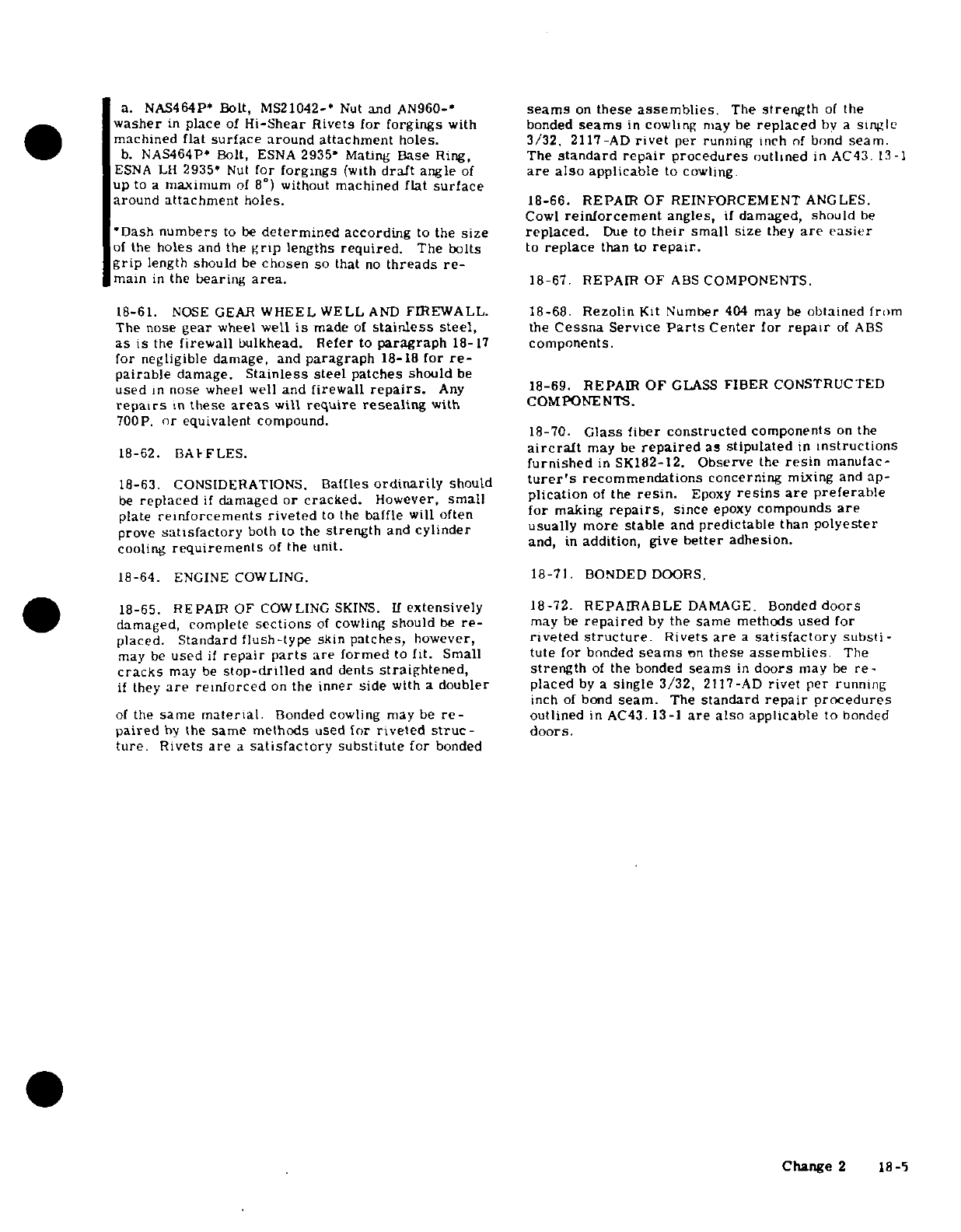
a.
NAS464P* Bolt, MS21042-*
Nut
and AN960-*
seams
on
these
assemblies.
The
strength
of
the
washer
in
place
of
Hi-Shear
Rivets
for
forgings
with bonded
seams
in
cowling
may
be
replaced
by
a
single
machined
flat
surface
around attachment
holes.
3/32.
2117-AD
rivet
per
running
inch
of
bond
seam.
b.
NAS464P*
Bolt,
ESNA
2935* Mating
Base
Ring,
The
standard
repair
procedures
outlined
in
AC43
13-1
ESNA LH
2935'
Nut
for
forgings
(with
draft
angle
of
are
also
applicable
to
cowling
up
to
a
maximum
of
8°)
without
machined
flat
surface
around
attachment
holes.
18-66.
REPAIR
OF REINFORCEMENT
ANGLES.
Cowl
reinforcement
angles,
if
damaged, should
be
*Dash
numbers
to
be
determined
according
to
the
size
replaced.
Due
to
their
small
size
they
are
easier
of
the
holes
and
the
grip
lengths
required.
The
bolts
to
replace
than
to
repair.
grip
length
should
be
chosen
so
that
no
threads
re-
main
in
the
bearing
area.
18-67.
REPAIR OF
ABS
COMPONENTS.
18-61.
NOSE
GEAR
WHEEL
WELL
AND
FIREWALL.
18-68.
Rezolin
Kit
Number
404
may
be
obtained
from
The
nose
gear
wheel
well
is
made
of
stainless
steel,
the
Cessna
Service
Parts
Center
for
repair
of
ABS
as
is
the
firewall
bulkhead.
Refer
to
paragraph
18-17
components.
for
negligible
damage,
and
paragraph
18-18
for
re-
pairable
damage.
Stainless
steel
patches
should
be
used
in
nose
wheel
well
and
firewall
repairs.
Any
18-69.
REPAIR
OF
GLASS
FIBER
CONSTRUCTED
repairs
in
these
areas
will
require
resealing
with
COMPONENTS.
700P.
or
equivalent
compound.
18-70.
Glass
fiber
constructed
components
on
the
18-62.
BAFFLES.
aircraft
may
be
repaired
as
stipulated
in
instructions
furnished
in
SK18
2
-
1 2
.
Observe
the
resin
manufac-
18-63.
CONSIDERATIONS.
Baffles
ordinarily
should
turer's
recommendations
concerning
mixing
and ap-
be
replaced
if
damaged
or
cracked.
However,
small
plication
of
the
resin.
Epoxy
resins
are
preferable
plate
reinforcements
riveted
to
the
baffle
will
often
for
making
repairs,
since
epoxy
compounds
are
prove
satisfactory
both
to
the
strength
and
cylinder
usually
more
stable
and predictable
than
polyester
cooling
requirements
of
the
unit.
and,
in
addition,
give better
adhesion.
18-64.
ENGINE COWLING.
18-71.
BONDED
DOORS.
18-65.
REPAIR
OF
COWLING
SKINS.
If
extensively
18-72.
REPAIRABLE
DAMAGE.
Bonded
doors
damaged, complete
sections
of
cowling
should
be
re-
may
be
repaired
by
the
same
methods
used
for
placed.
Standard
flush-type
skin
patches,
however,
riveted
structure.
Rivets
are
a
satisfactory
substi-
may
be
used
if
repair
parts
are
formed
to
fit. Small
tute
for
bonded
seams
on
these
assemblies
The
cracks
may
be
stop-drilled
and
dents
straightened,
strength
of
the bonded
seams
in
doors
may
be
re-
if
they
are
reinforced
on
the
inner side
with
a
doubler
placed
by
a
single
3/32,
2117-AD
rivet per
running
inch
of
bond
seam.
The
standard
repair
procedures
of
the
same
material
Bonded
cowling
may
be
re-
outlined
in
AC43.
13-1
are
also
applicable
to
bonded
paired
by
the
same
methods
used
for
riveted
struc-
doors.
ture.
Rivets
are
a
satisfactory
substitute
for
bonded
Change
2
18-5
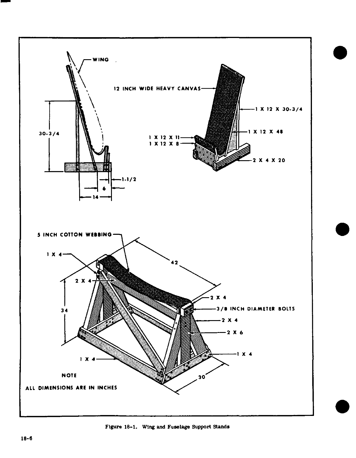
WING
12
INCH
WIDE
HEAVY
CANVAS
1 X
12
X
30-3/4
30-3/4
X
12
X 48 3/4
1
X
12
XII
X
12
X
8
2
X
4
X
20
L 1-'
-1-1/2
5
INCH
COTTON WEBBING
1X4
42
N34
/Ilf ^^^^^ ^.
3/8
INCH
DIAMETER
BOLTS
NOTE
30
ALL
DIMENSIONS
ARE
IN
INCHES
Figure
18-1.
Wing
and
Fuselage
Support
Stands
18-6
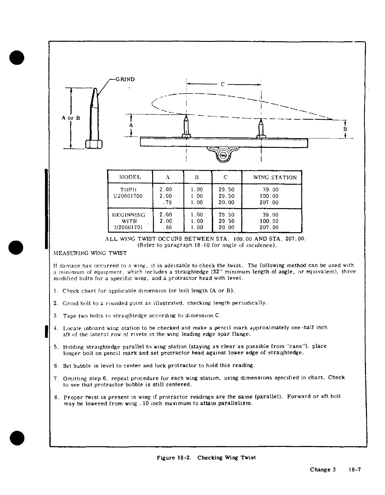
GRIND
A
Or
B
MODEL
A
B
C
WING
STATION
THRU
2.00
1.00
29.50
39.00
U32i6100
2.00
1
00
29.50
100.00
.79
1.00
20.00
207
00
uIEGINNING
2.00
1.002
29.50
39.100
WIT
iH k 2k00
1.00
29 50
100.0
U20601701
.66
1.
00
20.00
207.00
ALL
WING
TWIST
OCCURS
BETWEEN
STA.
100.00
AND STA.
207.00.
(Refer
to
paragraph
18-10
for
angle
of
incidence).
MEASURING
WING
TWIST
If
damae
has
occurred
to
a
wing.
it
is
advisable
to
check
the
twist.
The
following method
can
be
used
with
a
minimum
of
equipment.
which
includes
a
straightedge
(32"
minimum
length
of
angle,
or
equivalent).
three
modified
bolts
for
a
specific
wing,
and
a
protractor
head
with
level.
1.
Check
chart
for applicable
dimension
for
bolt
length
(A
or
B).
2.
Grind
bolt
to
a
rounded
point
as
illustrated.
checking length
periodically.
3.
Tape
two
bolts
to
straightedge
according
to
dimension
C.
4.
Locate
inboard
wing
station
to
be
checked
and
make
a
pencil
mark
approximately
one-half
inch
aft
of
the
lateral
row
of
rivets
in
the
wing
leading
edge
spar
flange.
5.
Holding
straightedge
parallel
to
wing
station
(staying
as
clear
as
possible
from
"cans").
place
longer
bolt
on
pencil
mark
and
set
protractor
head
against
lower
edge
of
straightedge.
6.
Set
bubble
in
level
to
center
and
lock
protractor
to
hold
this
reading.
7.
Omitting
step
6.
repeat
procedure
for
each
wing
station,
using
dimensions
specified
in
chart.
Check
to
see
that
protractor
bubble
is
still
centered.
8.
Proper
twist is
present
in
wing
if
protractor
readings
are
the
same
(parallel).
Forward or
aft
bolt
may
be
lowered
from
wing
.
10
inch
maximum
to
attain
parallelism.
Figure
18-2.
Checking
Wing
Twist
Change
3
18-7
MS20470AD4
RIVETS
PATCHES
AND
DOUBLERS
-
24 REQD
2024-T3
ALCLAD
6.50
DIA.
4.
00
DIA
PATCH
EXISTING
7.50
DIA.
DOUBLER
SKIN
SECTION
THRU
PATCH
3.00
DIA.
HOLE
PATCH
REPAIR
FOR
3
INCH
DIAMETER
HOLE
MS20470AD4
RIVETS
16
REQD
22
1/28*
4.
00
DIA.
3.
00
DIA.
PATCH
EXISTING
5.00
DIA.
SKIN
2.
0O DIA. HOLE
SECTION
THRU
PATCH
PATCH
REPAIR
FOR
2
INCH
DIAMETER
HOLE
MS20470AD4
RIVETS
EXISTING
2.
50 DIA.
8
REQD
EXISTING
(NODOUBLER
8REQD SKIN
PATCH
(NO
DOUBLER
REQD)
1.
75
1.00
DIA.
HOLE
DIA.
SECTION
THRU
PATCH
PATCH
REPAIR
FOR
1
INCH
DIAMETER
HOLE
|I
ORIGINAL
PARTS
i':l
REPAIR
PARTS
OVERLAPPING
CIRCULAR PATCH
REPAIR
PARTS
IN
CROSS
SECTION
CIRCULAR PATCH
0
Figure
18-3.
Skin
Repair
(Sheet 1
of
6)
18-8
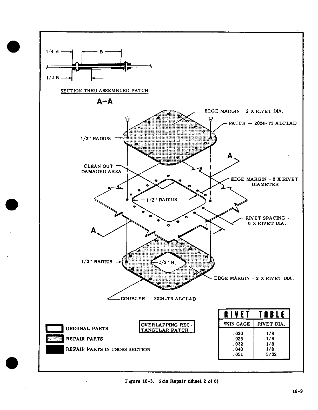
1/4
B
B
1/2 B
SECTION
THRU
ASSEMBLED
PATCH
A-A
EDGE
MARGIN
=
2
X
RIVET
DIA.
PATCH
-
2024-T3
ALCLAD
DAMAGED
AREA
EDGE
MARGIN
=
2
X
RIVET
DIAMETER
--
^
\
RIVET
SPACING
=
A^^^
/ ' -
.^\ D<
^'
6
X
RIVET
DIA.
1/2"
RADIUS
-- .
.;'ii
ji.i....
iii..i-
i/2."
R..p. iii: i
-
il:L`.i
.
EDGE
MARGIN =
2 X
RIVET
DIA.
DOUBLER
-
2024-T3
ALCLAD
RIVET
TABLE
-ORIGNL
PATS
IOVERLAPPING
REC-
I
SKIN
GAGE
RIVET
DIA.
ORIGINAL
PARTS
ITANGULAR
PATCH
.020 1/8
LJ^
REPAIR
PARTS
.025
1,/8
......
032
1/8
REPAIR
PARTS
IN
CROSS
SECTION
.040
1/8
.051
5/32
Figure
18-3.
Skln
Repair
(Sheet
2
of
6)
18-9
18-9
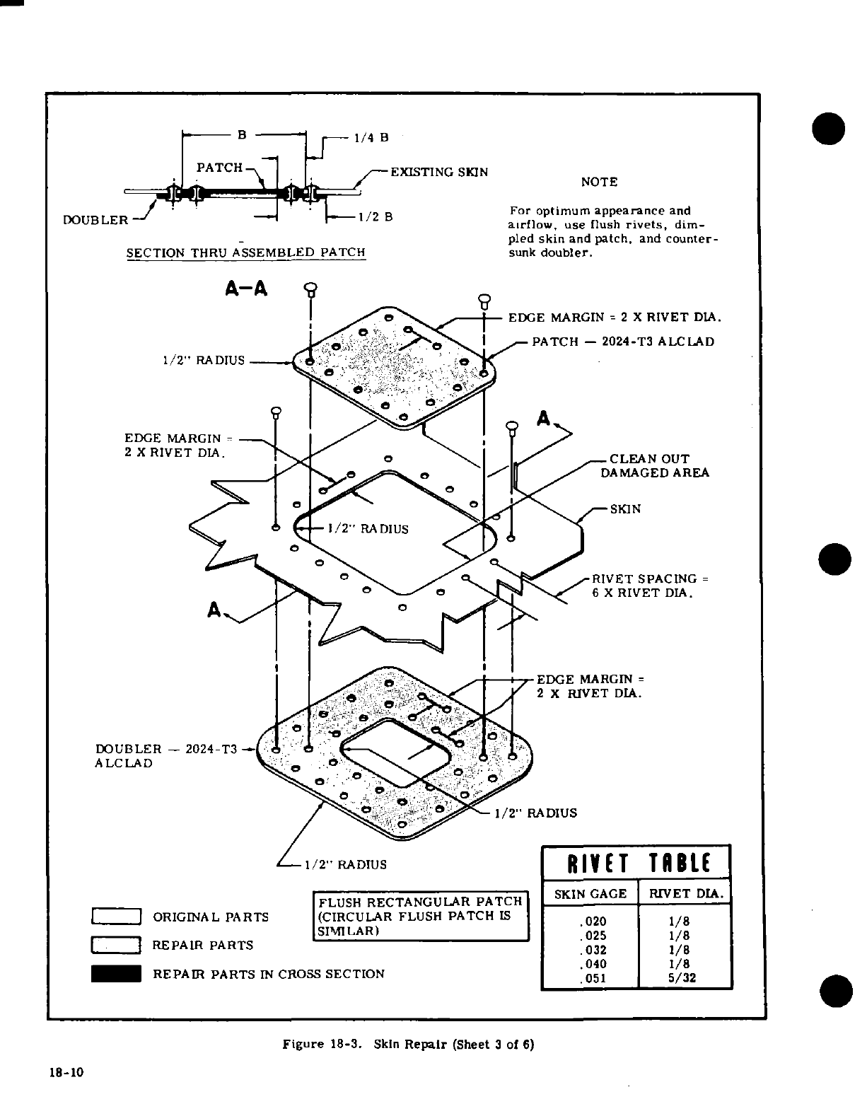
B
1/4
B
PATCH
EXISTING
SKIN
NOTE
DOUBLER
1/2
B
For
optimum
appearance
and
airflow,
use
flush
rivets,
dim-
pled
skin
and
patch,
and
counter-
SECTION
THRU
ASSEMBLED
PATCH
sunk
doubler.
A-A
EDGE
MARGIN
= 2
X
RIVET
DIA.
PATCH
-
2024-T3
ALCLAD
1/2"
RADIUS
EDGE
MARGIN
=
2 X
RIVET
DIA.
CLEAN
OUT
DAMAGED
AREA
RIVET SPACING
=
6
X
RIVET
DIA.
EDGE
MARGIN
=
2
X
RIVET
DIA.
DOUBLER
-
2024-T3
-
ALCLAD
1/2"
RADIUS
1/2
RADIUS
RIVET
TABLE
FLUSH
RECTANGULAR
PATCH
SKIN GAGE
RIVET
DIA.
ORIGINAL PARTS
(CIRCULAR
FLUSH
PATCH
IS
SIMILAR)
025
1/8
REPAIR
PARTS
032 1/8
REPAIR
PARTS
IN
CROSS
SECTION
.040
1/8
.051
5/32
Figure
18-3.
Skin
Repair
(Sheet
3
of
6)
18-10
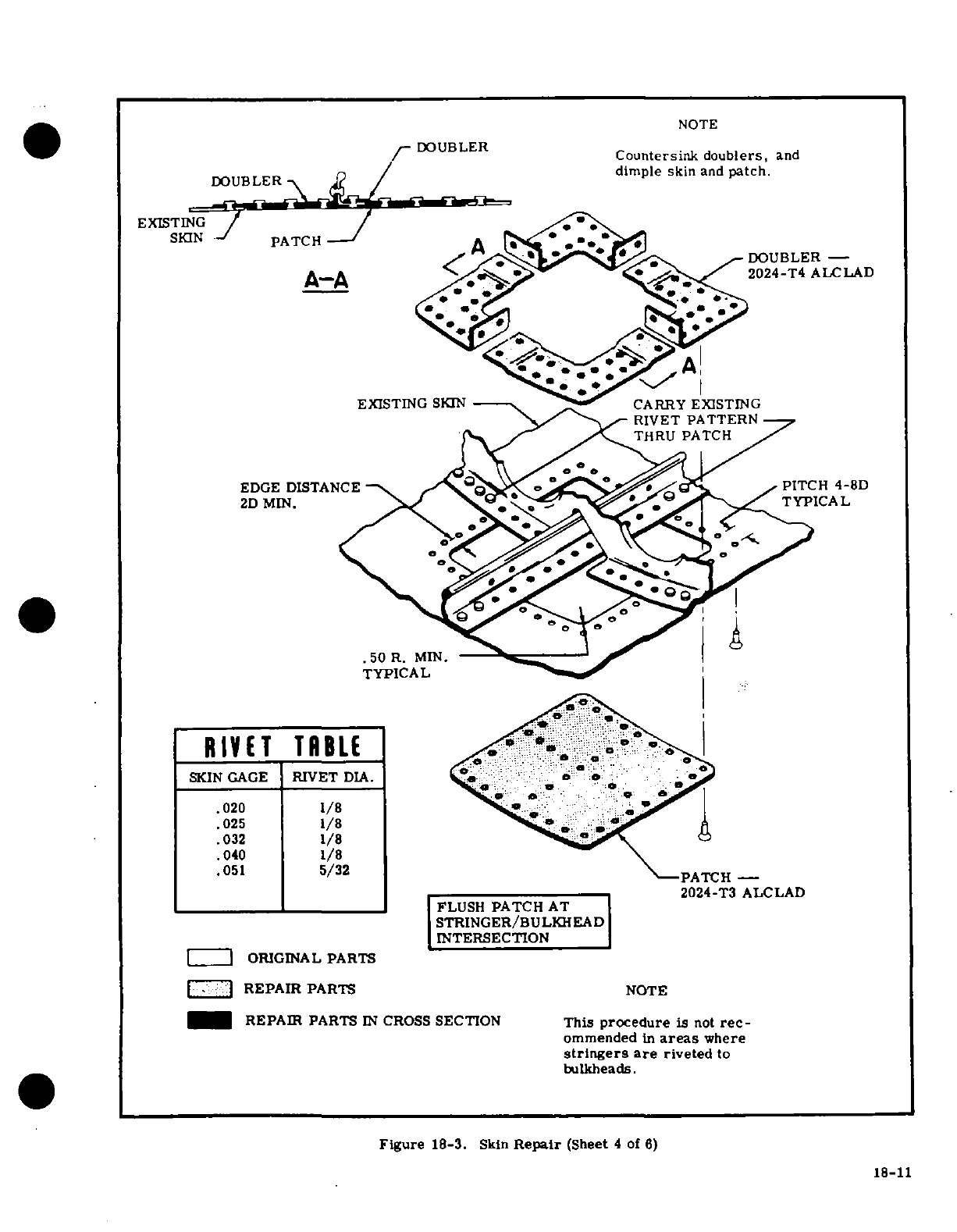
NOTE
DOUBLER
mDO~~UBLER
~
Countersink
doublers,
and
dimple
skin
and
patch.
EXISTING
/
SKIN
-
PATCH
A
,
@
*
21
< A^ l sc
e^
DOUBLER
-
A-A
/
<m.
2024-T4
ALCLAD
EXISTING
SKIN
---
`2r,
CARRY
EXISTING
~y^^^
RIVET
PATTERN
THRU
PATCH
EDGE
DISTANCE
_< 5o
PITCH
4-8D
2D
MIN.
TYPICAL
.50
R.
MI-
TYPICAL
RIVET
TRB
LL
SKIN
GAGE
RIVET
DIA.
:
a
.020
1/8
.025
1/8
.032
1/8
.040
1/8
.051
5/32
PATCH
2024-T3
ALCLAD
FLUSH
PATCH
AT
STRINGER/BULKHEAD
INTERSECTION
ORIGINAL
PARTS
[-'1
REPAIR
PARTS
NOTE
REPAIR
PARTS
IN
CROSS
SECTION
This
procedure
is
not
rec-
ommended
in
areas
where
stringers
are
riveted
to
bulkheads.
Figure
18-3.
Skin
Repair
(Sheet
4
of
6)
18-11
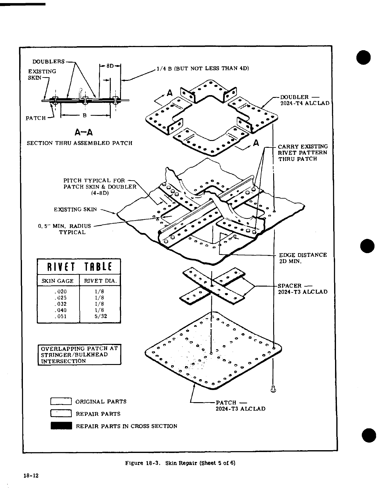
DOUBLERS
ESTING
8D
1/4
B
(BUT
NOT
LESS
THAN 4D)
SKIN
A
DOUBLER
-
PATCH
2024-T4
ALCLAD
A-A
SECTION
THRU
ASSEMBLED
PATCH
A
CARRY EXISTING
RIVET
PATTERN
THRU
PATCH
PITCH
TYPICAL
FOR
PATCH
SKIN
&
DOUBLER
(4-8D)
EXISTING
SKIN
0.
5"
MIN.
RADIUS
TYPICAL
EDGE
DISTANCE
RIVET
TABLE
MIN
SKIN
GAGE
RIVET
DIA.
SPACER
-
.020
1/8
20
/
2024-T3
ALCLAD
025
1/8
032
1/8
.040
1/8
.051
5/32
OVERLAPPING
PATCH
AT
STRINGER/BULKHEAD
o
INTERSECTION
o
o
~
ORIGINAL
PARTS PATCH
-
2024-T3
ALCLAD
L
1
REPAIR
PARTS
REPAIR
PARTS
IN
CROSS
SECTION
Figure
18-3.
Skin
Repair
(Sheet
5
of
6)
18-12
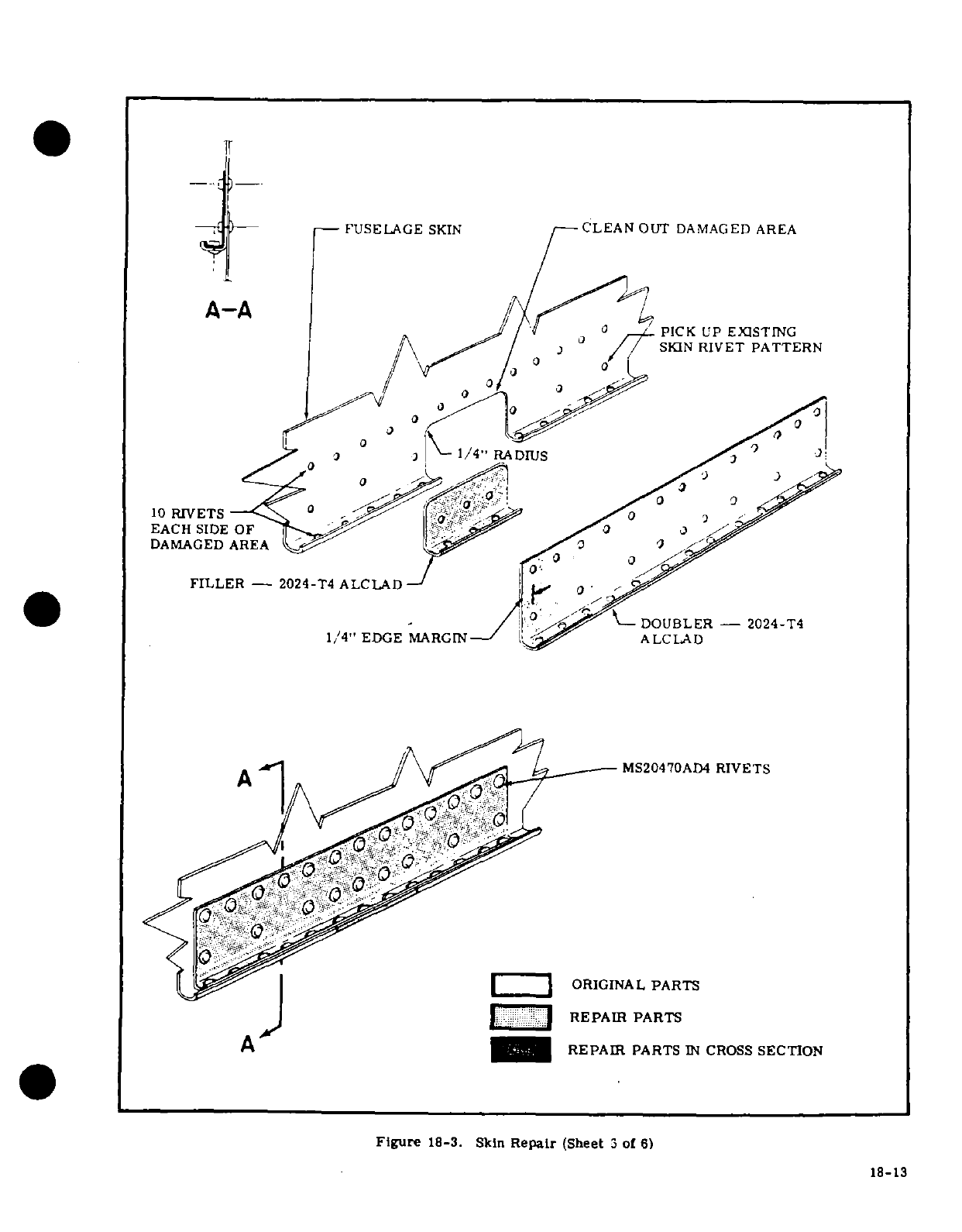
FUSELAGE
SKIN
CLEAN
OUT
DAMAGED
AREA
A-A
PICK
UP
EXISTING
SKIN
RIVET
PATTERN
1/4"
RADIUS
10
RIVETS
EACH
SIDE
OF
DAMAGED
AREA
FILLER -
2024-T4
ALCLAD
DOUBLER
-
2024-T4
1/4"
EDGE
MARGIN
ALCLAD
A
MS20470AD4
RIVETS
ORIGINAL
PARTS
REPAIR
PARTS
A
REPAIR
PARTS
IN
CROSS
SECTION
Figure
18-3.
Skin
Repair
(Sheet
3
of
6)
18-13
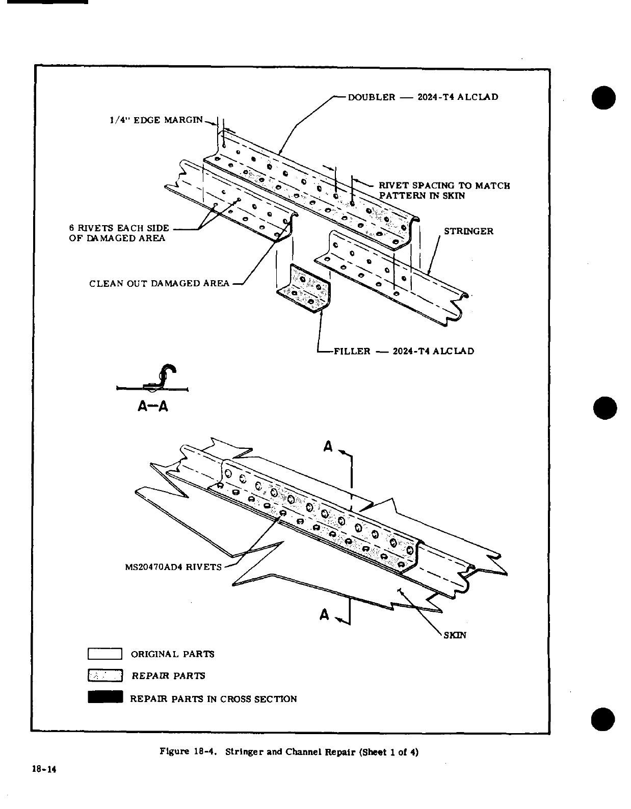
DOUBLER
-
2024-T4
ALCLAD
1/4"
EDGE
MARGIN
RIVET
SPACING TO MATCH
PATTERN
IN
SKIN
6
RIVETS
EACH
SIDE
STRNER
OF
DAMAGED
AREA
CLEAN
OUT
DAMAGED
AREA
-FILLER
-2024-T4
ALCLAD
A-A
MS20470AD4
RIVETS
SXIN
ORIGINAL
PARTS
REPAIR
PARTS
REPAIR
PARTS
IN
CROSS
SECTION
Figure
18-4.
Stringer
and
Channel
Repair
(Sheet
1
of
4)
18-14
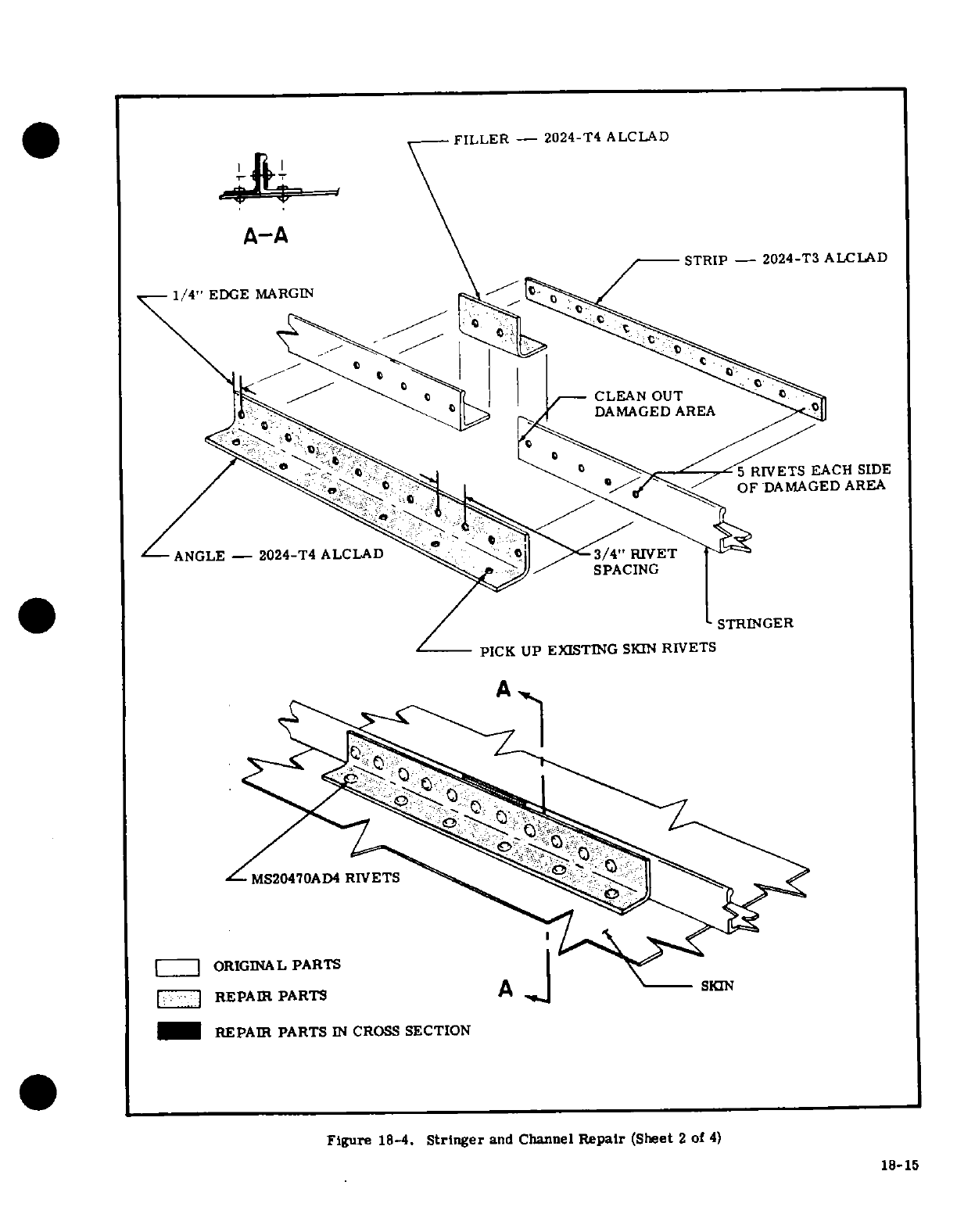
FILLER -
2024-T4
ALCLAD
A-A
STRIP
-
2024-T3
ALCLAD
1/4"
EDGE
MARGIN
CLEAN
OUT
DAMAGED
AREA
5
RIVETS
EACH
SIDE
OF
DAMAGED
AREA
ANGLE
-
2024-T4
ALCLAD
3
/4"RIVET
SPACING
STRINGER
PICK
UP
EXISTING
SKIN
RIVETS
A
MS20470AD4
RIVETS
ORIGINAL
PARTS
REPAIR
PARTS
A
SKIN
REPAIR
PARTS
IN
CROSS
SECTION
Figure
18-4.
Stringer
and
Channel
Repair
(Sheet
2
of
4)
18-15
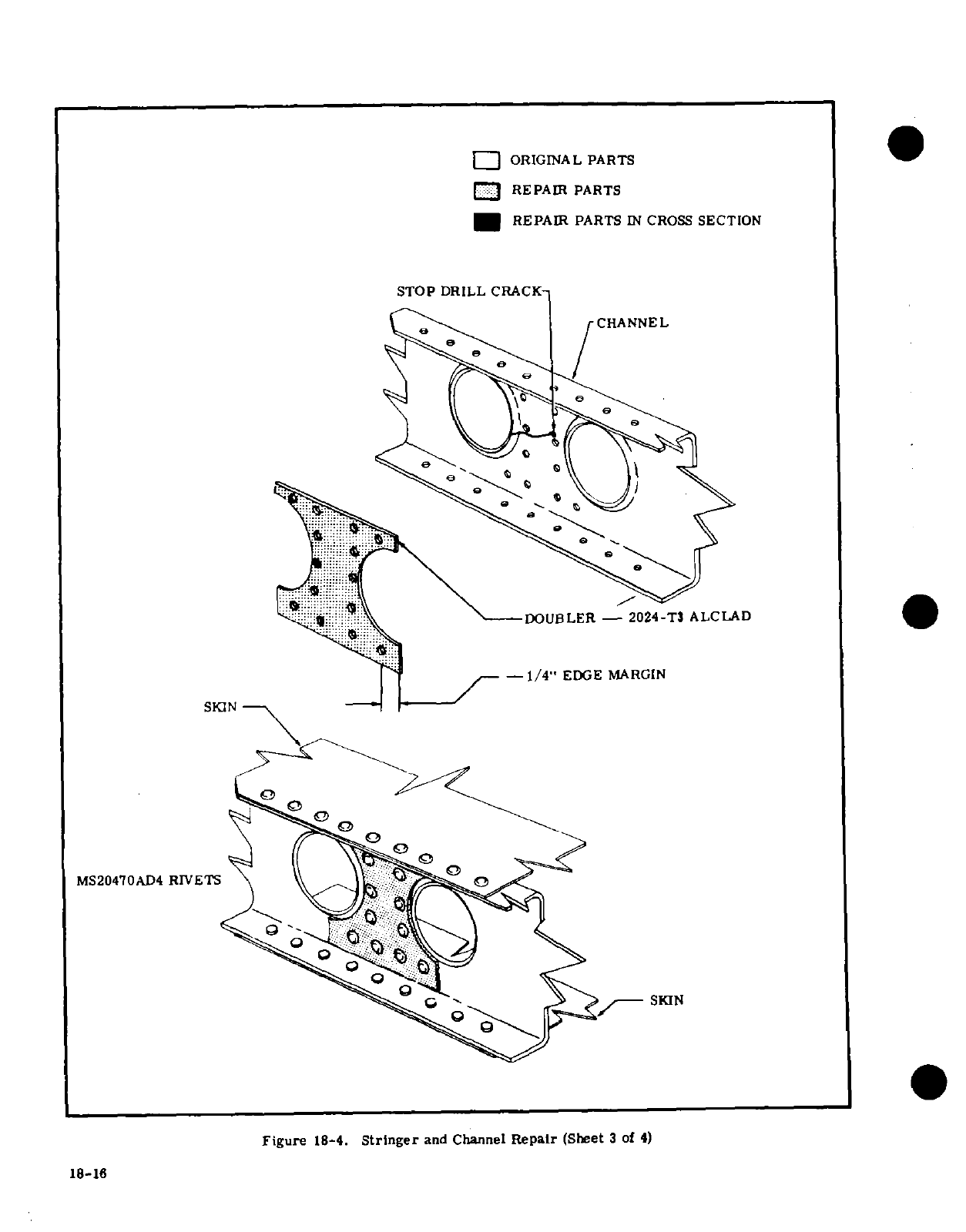
ORIGINAL
PARTS
C
3
REPAIR
PARTS
REPAIR
PARTS
IN
CROSS
SECTION
STOP
DRILL CRACK-
CHANNEL
DOUBLER
-
2024-T3
ALCLAD
-
1/4"
EDGE
MARGIN
SKIN
MS20470AD4
RIVETS
Figure
18-4.
Stringer
and
Channel
Repair
(Sheet
3
of
4)
18-16
IS-IB
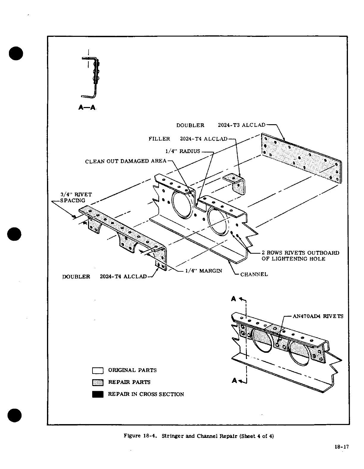
* -
A-A
DOUBLER
2024-T3
ALCLAD
FILLER
2024-T4
ALCLAD
1/4"
RADIUS
CLEAN
OUT
DAMAGED AREA
3/4"
RIVET
SPACING
2
ROWS
RIVETS OUTBOARD
OF
LIGHTENING
HOLE
DOUBLER
2024-T4
ALCLAD
CHANNEL
A
AN470AD4
RIVETS
ORIGINAL
PARTS
REPAIR
PARTS
A
REPAIR
IN
CROSS
SECTION
Figure
18-4.
Stringer
and
Channel
Repair
(Sheet
4
of
4)
18-17
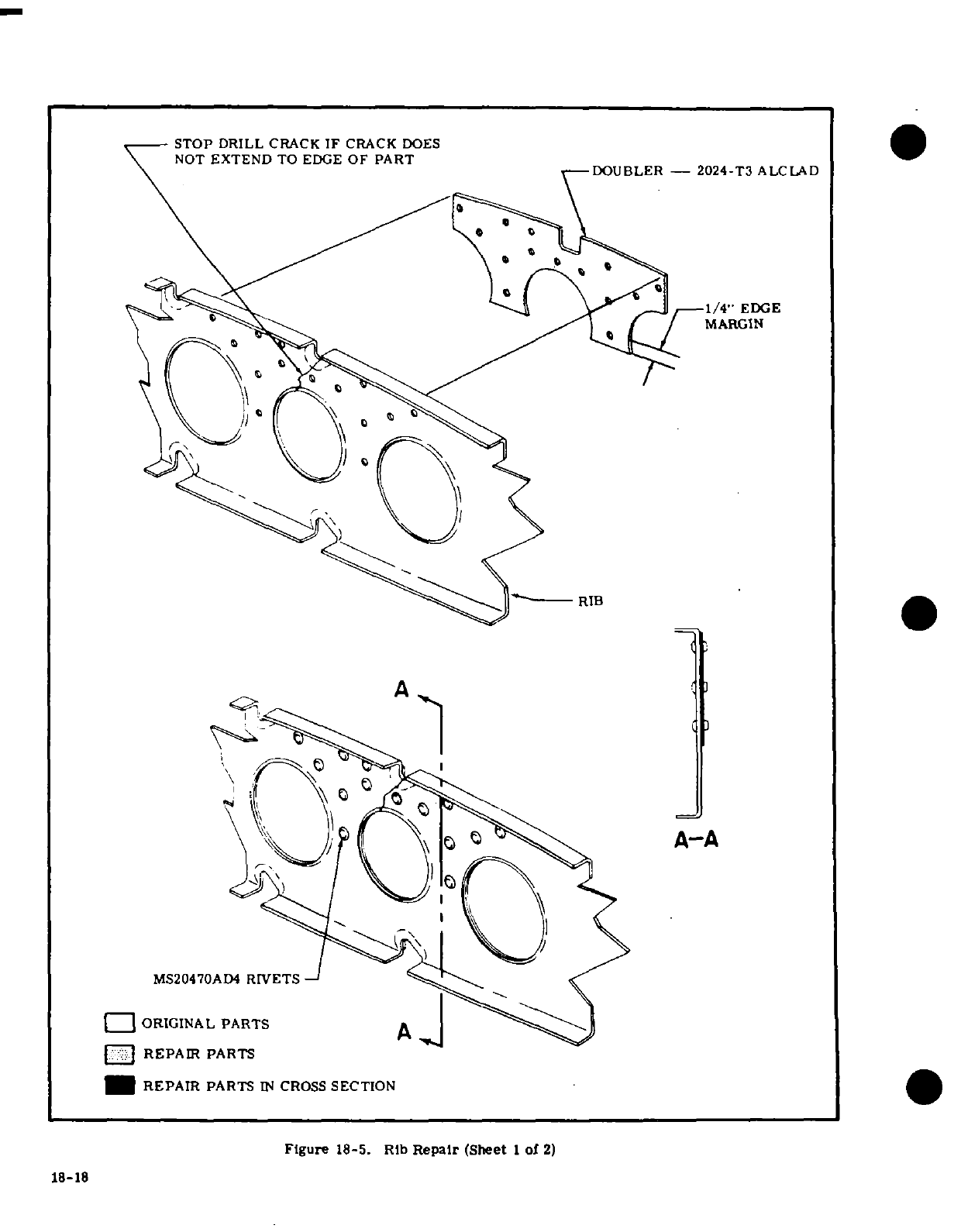
STOP
DRILL
CRACK
IF
CRACK
DOES
NOT
EXTEND
TO EDGE
OF
PART
DOUBLER
-
2024-T3
ALCLAD
1/4"
EDGE
MARGIN
ORIGINAL PARTS
REPAIR
PARTS
REPAIR
PARTS
IN
CROSS
SECTION
Figure
18-5.
Rib
Repair
(Sheet
I
of
2)
18-18
I
18-18
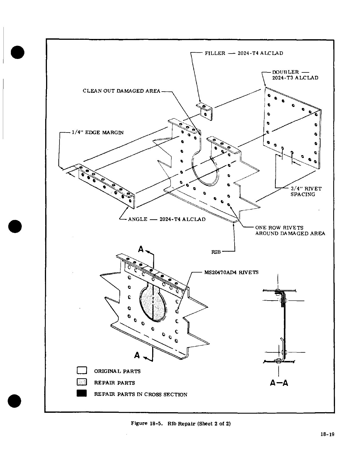
FILLER
-
2024-T4
ALCLAD
DOUBLER
-
2024-T3
ALCLAD
CLEAN
OUT
DAMAGED
AREA
1/4"
EDGE
MARGIN
3/4
"
Revet
SPACING
ANGLE-
2024-T4
ALCLAD
ONE
ROW
RIVETS
AROUND
DAMAGED
AREA
A
RIB
MS20470AD4
RIVETS
ORIGINAL
PARTS
REPAIR
PARTS
A-A
REPAIR
PARTS
IN
CROSS
SECTION
Figure
18-5.
Rib
Repair
(Sheet
2
of
2)
18-19
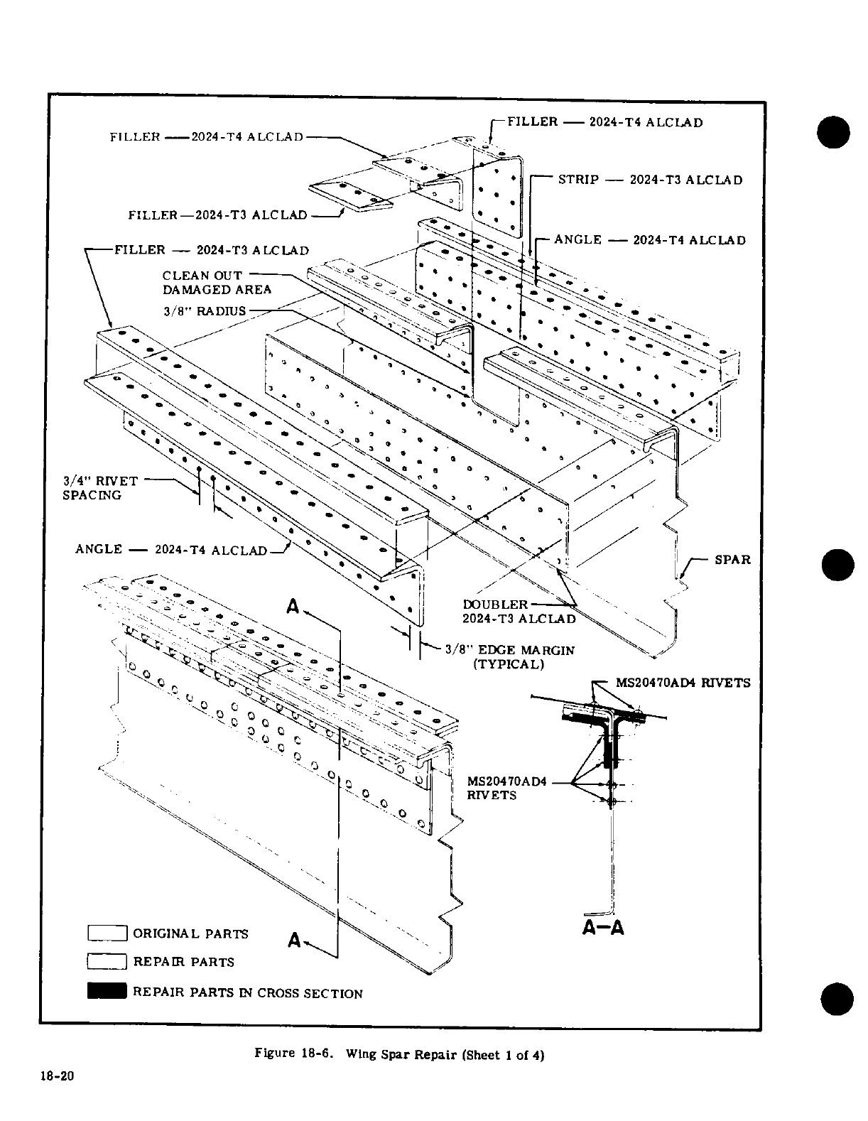
FILLER
2024-T4
ALCLAD
FILLER
- 2024-T4
ALCLAD
-" ' * -- STRIP -
2024-T3
ALCLAD
FILLER-2024-T3
ALCLAD-
-
STR
ANGLE
- 2024-T4
ALCLAD
FILLER
-
2024-T3
ALCLAD
-
CLEAN
OUT
*
_
-
DAMAGED
AREA
s
3/8"
RADIUS
A
v a
a \ | iQ
2024-T3
ALCLAD
~~~C
M23/4"047
RIVETS
REPAIRSPACING
PAS
ANGLE
--
2024-T4
ALCLAD-
~J
jl
ir S AD
REPAIR
PARTS
IN
CROSS
SECTION
Figure
18-6.
Wing
Spar Repair
(Sheet
I
of
4)
18-20
"'
'""°,~
C QS
7
»Q
'
MS20470AD4
R,-
'^ -0o
!
RIVETS
v^
-
| |
ORIGINAL
PARTS
A..
A~A
1
I
REPAIR
PARTS
REPAIR
PARTS
IN
CROSS
SECTION
Figure
18-6.
Wing
Spar
Repair
(Sheet
1
of
4)
18-20
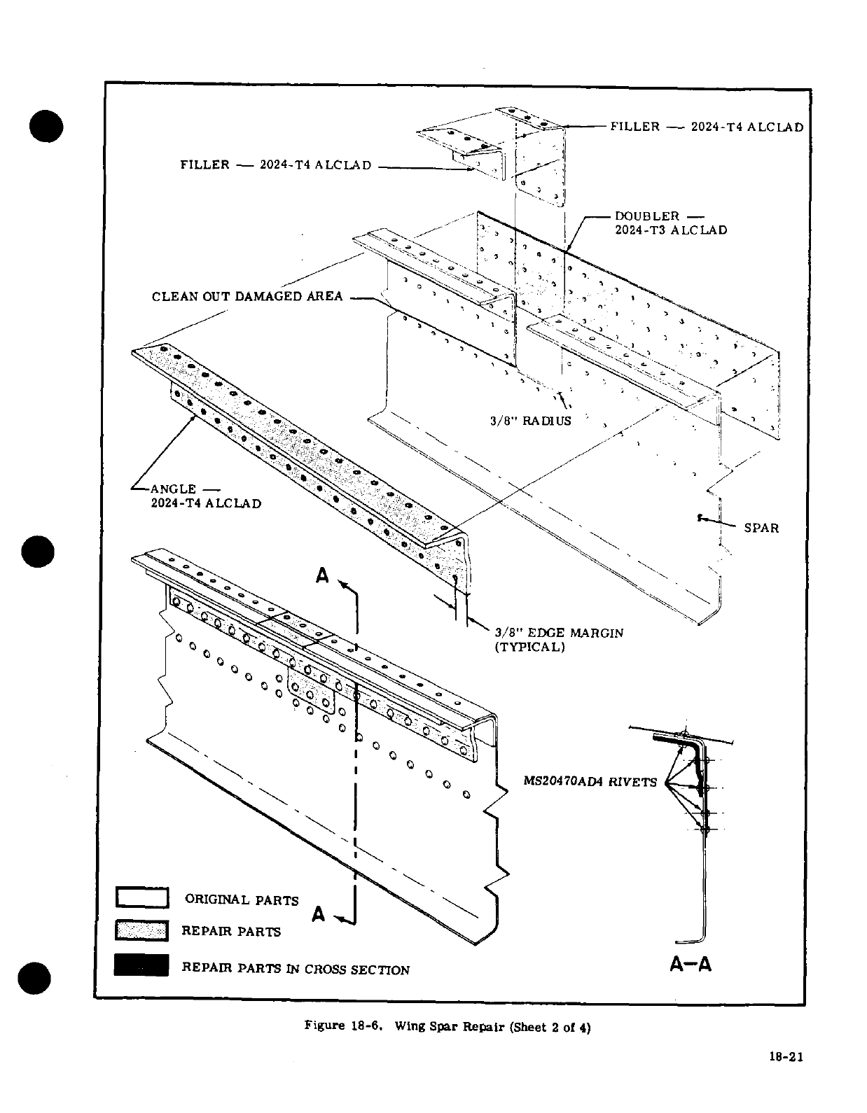
FILLER -
2024-T4
ALCLAD
FILLER -
202
4
-T±
ALCLAD
-.
,_--
!.---
DOUBLER
-
,.-'
. /,
.^
~.*^
/
2024-T3
ALCLAD
-.
3/8"
RADIUS
' , / -.
'~8
CLEAN
OUT
3/8"
EDGME
MARGIN
C 0 <o ^''^^^^^$^(TYPICAL)
° C) MS20470AD4
RIVET
S
I I
ORIGINAL
PARTS
A
|l^^^ :^R
REPAIR
PARTS
,=
I_
REPAIR
PARTS
IN
COSS
SECTION
A-A
Figure
18-6.
Wing
Spar
Repair
(Sheet
2
of
4)
18-21
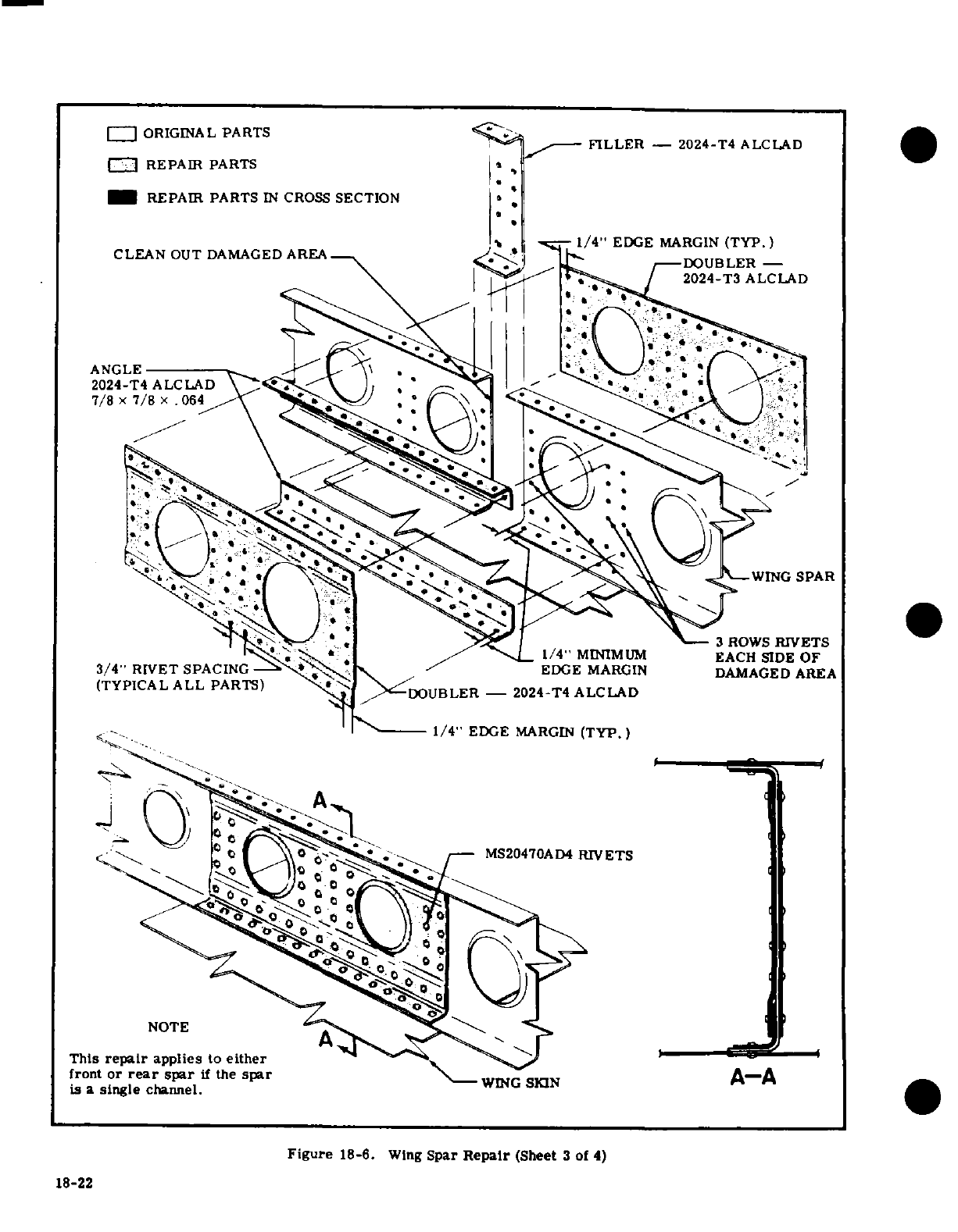
--
ORIGINAL
PARTS
FILLER
-2024-T4
ALCLAD
REPAIR
PARTS
REPAIR
PARTS
IN
CROSS
SECTION
1/4"
EDGE
MARGIN
(TYP.)
CLEAN
OUT
DAMAGED
AREA-
DOUBLER
-
2024-T3
ALCLAD
ANGLE
2024-T4
ALCLAD'
7/8
x
7/8
.
064
1-
1/4"
MINIMUM
EACH SIDE
OF
3/4"
RIVET
SPACING
*
EDGE
MARGIN
DAMAGED
AREA
(TYPICAL
ALL
PARTS)
DOUBLER
- 2024-T4
ALCLAD
1/4"
EDGE
MARGIN
(TYP)
NOTE
This
repair
applies
to
either
front
or
rear
spar
if
the
spar
A-A
WING
SKIN
A-A
is
a
single
channel.
Figure
18-6.
Wing
Spar
Repair
(Sheet
3
of
4)
18-22
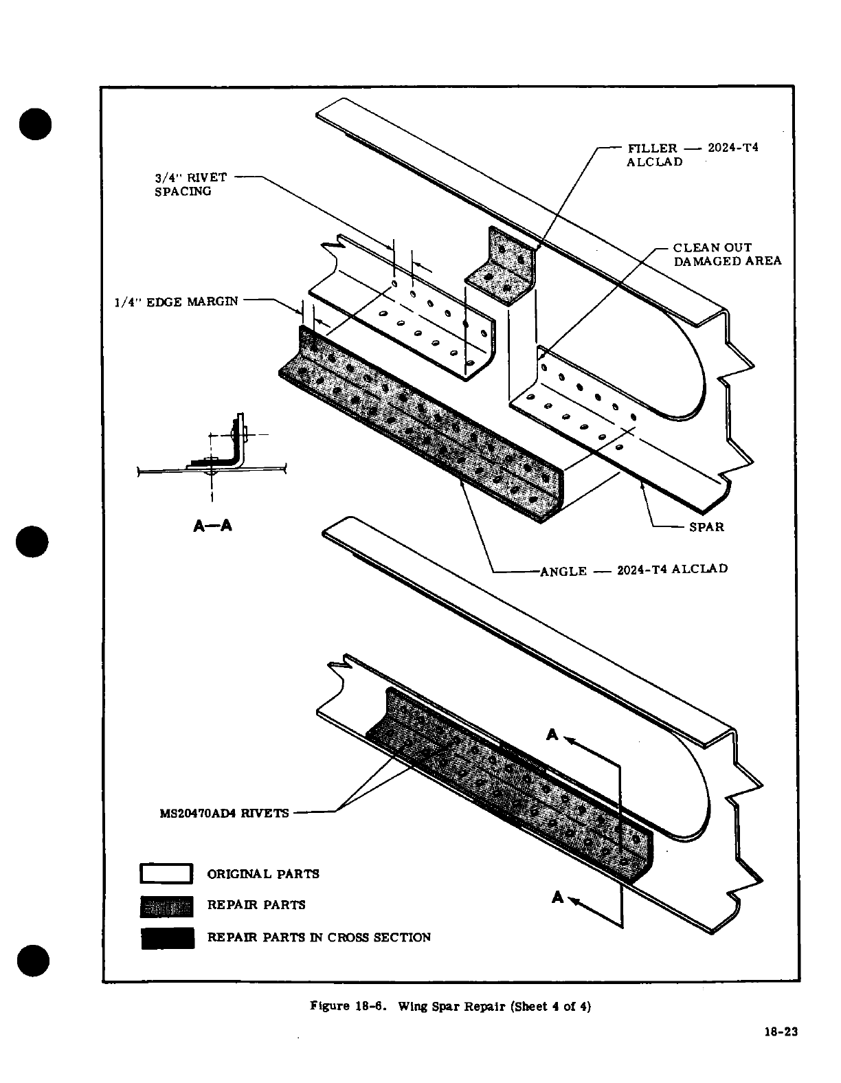
FILLER
-
2024-T4
ALCLAD
3/4"
RIVET
SPACING
CLEAN
OUT
DAMAGED
AREA
1/4"
EDGE
MARGIN
A-A
SPAR
ANGLE-
2024-T4
ALCLAD
MS20470AD4
RIVETS
-
57/7
|
ORIGINAL
PARTS
_ii .REPAIR
PARTS
A
REPAIR
PARTS
IN
CROSS
SECTION
Figure
18-6.
Wing
Spar
Repair
(Sheet
4
of
4)
18-23
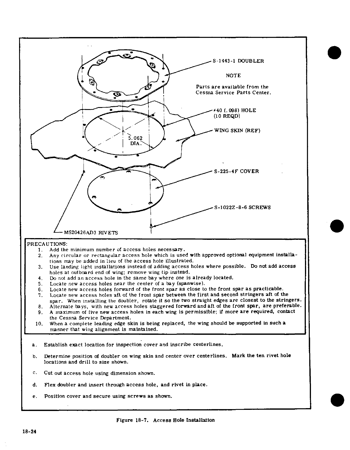
S-1443-1
DOUBLER
NOTE
.
.(^
'^Q7
^~ S
Parts
are
available
from
the
Cessna
Service
Parts
Center.
#
40
(.098)
HOLE
052
/
^<
^^ ^'(10
REQD)
1(^ ,/
'
J
+^> 's~ \XWING
SKIN
(REF)
Z ,_ [ r,
S-225-4F
COVER
Xs^^^^ <^^^ _~
S-1022Z-8-6
SCREWS
MS20426AD3
RIVETS
PRECAUTIONS:
1.
Add
the
minimum
number
of
access
holes
necessary.
2.
Any
circular
or
rectangular
access
hole
which
is used
with
approved
optional
equipment
installa-
tions
may
be
added
in
lieu
of
the
access
hole
illustrated.
3.
Use
landing
light
installations
instead
of
adding
access
holes
where
possible.
Do
not
add
access
holes
at
outboard
end
of
wing;
remove
wing
tip
instead.
4.
Do
not
add an
access
hole
in
the
same
bay
where
one
is
already
located.
5.
Locate
new
access
holes
near
the
center
of
a
bay
(spanwise).
6.
Locate
new
access
holes
forward
of
the
front
spar
as
close
to
the
front
spar
as
practicable.
7.
Locate
new
access
holes
aft
of
the
front
spar
between
the
first
and
second
stringers
aft
of
the
spar.
When
installing
the
doubler,
rotate
it
so
the
two
straight
edges
are
closest
to
the
stringers.
8.
Alternate
bays,
with
new
access
holes
staggered
forward
and
aft
of
the
front
spar,
are
preferable.
9.
A
maximum
of
five
new
access
holes
in
each
wing
is
permissible;
if
more
are
required,
contact
the
Cessna
Service
Department.
10.
When
a
complete
leading
edge
skin
is
being
replaced,
the
wing
should
be
supported
in
such
a
manner
that
wing
alignment
is
maintained.
a.
Establish
exct
location
for
inspection
cover
and
inscribe
centerlines.
b.
Determine
position
of
doubler
on
wing
skin
and
center
over
centerlines.
Mark
the
ten
rivet
hole
locations
and
drill
to
size
shown.
c.
Cut
out
access
hole
using
dimension
shown.
d.
Flex
doubler
and
insert
through
access
hole,
and
rivet
in
place.
e.
Position
cover
and
secure
using
screws
as
shown.
Figure
18-7.
Access
Hole
Installaton
18-24
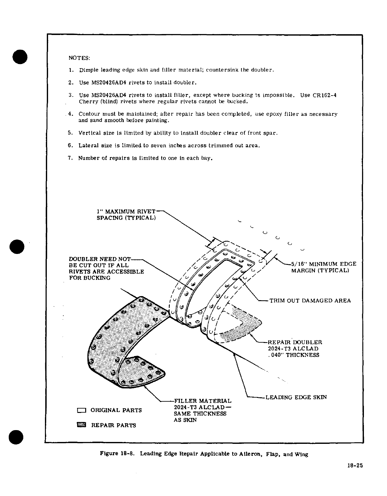
NOTES:
1.
Dimple
leading
edge
skin
and
filler
material; countersink
the
doubler.
2.
Use
MS20426AD4
rivets
to
install
doubler.
3.
Use
MS20426AD4
rivets
to
install
filler,
except where
bucking
is
impossible.
Use CR162-4
Cherry
(blind)
rivets
where
regular
rivets
cannot
be
bucked.
4.
Contour
must
be
maintained;
after
repair
has
been
completed,
use
epoxy
filler
as
necessary
and
sand
smooth
before
painting.
5.
Vertical size
is
limited
by
ability
to
install
doubler
clear
of
front
spar.
6.
Lateral
size
is
limited
to
seven
inches
across
trimmed
out
area.
7.
Number
of
repairs
is
limited
to
one
in
each
bay.
1"
MAXIMUM
RIVET
SPACING
(TYPICAL)
DOUBLER
NEED
NOT
BE CUT
OUT
IF
ALL
MINMUM
EDGE
RIVETS
ARE ACCESSIBLE MARGIN
(TYPICAL)
FOR
BUCKING
TRIM
OUT DAMAGED AREA
REPAIR
DOUBLER
2024-T3
ALCLAD
!-!"_ /'
.040"
THICKNESS
SAME
THICKNESS
---
FILLER
MATERIALLEADING
EDGE
SKIN
2024-T3
ALCLAD-
a
ORIGINAL
PARTS
SAME
THICKNESS
AS
SKIN
C
REPAIR
PARTS
Figure
18-8.
Leading
Edge
Repair
Applicable
to
Aileron, Flap,
and
Wing
18-25
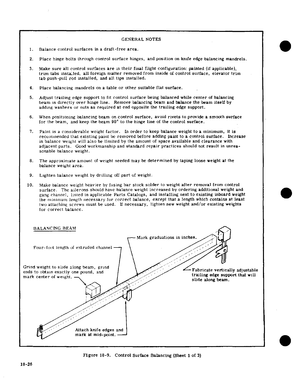
GENERAL
NOTES
1.
Balance
control
surfaces
in
a
draft-free area.
2.
Place
hinge
bolts
through
control
surface
hinges,
and
position
on
knife edge
balancing
mandrels.
3.
Make
sure
all
control
surfaces
are
in
their
final
flight
configuration: painted
(if
applicable),
trim
tabs
installed, all
foreign
matter
removed
from
inside
of
control
surface,
elevator
trim
tab
push-pull
rod
installed,
and
all tips
installed.
4.
Place
balancing
mandrels
on
a
table
or
other
suitable
flat
surface.
5.
Adjust
trailing
edge
support
to
fit
control
surface
being
balanced
while
center
of
balancing
beam is
directly
over
hinge
line.
Remove balancing
beam
and
balance
the beam
itself
by
adding
washers
or
nuts
as
required
at
end
opposite
the
trailing
edge
support.
6.
When
positioning
balancing
beam
on
control
surface,
avoid
rivets
to
provide
a
smooth
surface
for
the
beam,
and keep
the
beam
90°
to
the
hinge
line
of
the
control
surface.
7.
Paint
is
a
considerable
weight
factor.
In
order
to
keep
balance
weight
to
a
minimum,
it
is
recommended
that
existing
paint
be
removed
before
adding
paint
to
a
control
surface.
Increase
in
balance
weight
will
also
be
limited
by
the
amount
of
space
available
and
clearance
with
adjacent
parts.
Good
workmanship
and
standard
repair
practices
should
not
result
in
unrea-
sonable
balance
weight.
8.
The
approximate
amount
of
weight
needed
may
be
determined
by
taping loose
weight
at
the
balance
weight
area.
9.
Lighten balance
weight
by
drilling
off
part
of
weight.
10.
Make
balance
weight
heavier
by
fusing
bar
stock
solder
to
weight
after
removal
from
control
surface.
The
ailerons
should
have
balance
weight
increased
by
ordering
additional
weight
and
gang
channel,
listed
in
applicable
Parts
Catalogs,
and
installing
next
to
existing
inboard
weight
the
minimum length
necessary
for
correct
balance,
except
that
a
length
which
contains
at
least
two
attaching
screws
must
be
used.
If
necessary,
lighten
new
weight
and/or
existing
weights
for
correct
balance.
BALANCING BEAM
-Mark
graduations
in
inches.
Four-fout
length
of
extruded
channel
Grind
weight
to
slide
along
beam,
grind
\
ends
to
obtain exactly
one
pound,
andabricate
vertically
adjustable
mark
center
of
weight.
/
trailing
edge
support
that
will
slide
along
beam.
Attach
knife
edges
and
mark
at
mid-point.-
Figure
18-9.
Control
Surface Balancing
(Sheet
1
of
3)
18-26
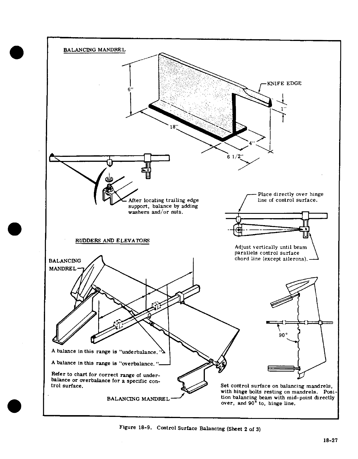
BALANCING
MANDREL
18
Place
directly
over
hinge
After
locating
trailing
edge
line
of
control
surface.
support,
balance
by
adding
washers
and/or
nuts.
RUDDERS
AND
ELEVATORS
Adjust
vertically
until
beam
parallels
control
surface
BALANCING
chord
line
(except
ailerons).
MANDREL
90
A
balance
in
this
range
is "underbalance.
A
balance
in
this range
is "overbalance."-
Refer
to
chart
for
correct
range
of
under-
balance
or
overbalance
for
a
specific
con-
trol
surface.
Set control
surface
on
balancing
mandrels,
with
hinge
bolts
resting
on
mandrels.
Posi-
BALANCING
MANDREL -
tion
balancing
beam
with
mid-point
directly
over,
and
90
to,
hinge
line.
Figure
18-9.
Control
Surface
Balancing
(Sheet
2
of
3)
18-27
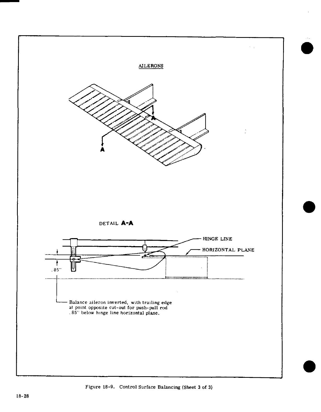
AILERONS
DETAIL
A-A
HINGE
LINE
HORIZONTAL
PLANE
85"
Balance
aileron
inverted,
with
trailing
edge
at
point
opposite
cut-out
for
push-pull
rod
85"
below
hinge
line
horizontal
plane.
Figure
18-9.
Control
Surface
Balancing
(Sheet
3
of
3)
18-28
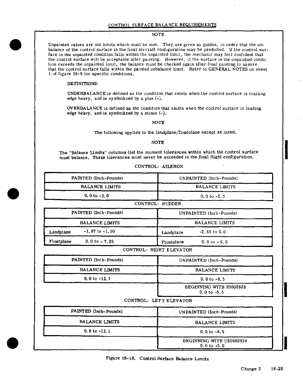
CONTROL SURFACE
BALANCE
REQUIREMENTS
NOTE
Unpainted
values
are
not
limits
which
must
be
met.
They
are
given
as
guides,
in
order
that the
un-
balance
of
the
control
surface
in
the
final
aircraft
configuration
may
be
predicted.
If
the
control
sur-
face
in
the unpainted condition
falls
within
the
unpainted
limit,
the
mechanic
may
feel
confident
that
the
control
surface
will
be
acceptable
after
painting.
However,
if
the
surface
in
the
unpainted
condi-
tion
exceeds
the
unpainted
limit,
the
balance
must
be
checked
again
after
final
painting
to
assure
that
the
control
surface
falls
within
the
painted
unbalance
limit. Refer
to
GENERAL
NOTES on
sheet
1
of
figure
18-9
for specific
conditions.
DEFINITIONS:
UNDERBALANCE
is
defined
as
the
condition
that
exists
when
the
control
surface
is
trailing
edge
heavy,
and
is
symbolized
by
a
plus
(+).
OVERBALANCE
is
defined
as
the
condition
that
exists
when
the
control
surface
is
leading
edge heavy,
and
is
symbolized
by
a
minus
(-).
NOTE
The
following
applies
to
the
landplane/floatolane
except
as
noted.
NOTE
The
"Balance
Limits"
columns
list
the
moment
tolerances
within
which the
control
surface
must balance.
These
tolerances
must
never
be
exceeded
in
the final
flight
configuration.
CONTROL:
AILERON
PAINTED
(Inch-Pounds)
UNPAINTED
(Inch-Pounds)
BALANCE LIMITS
BALANCE
LIMITS
0.0
to
+3.0
0.0
to
+2.3
CONTROL:
RUDDER
PAINTED
(Inch-Pounds)
UNPAINTED
(Inch-Pounds)
BALANCE
LIMITS BALANCE
LIMITS
Landplane
-1.87
to
+1.50
|
Landplane
-2.85
to
0.0
Floatplane
0.0
to +
7.25 Floatplane
0.0
to
+
6.0
CONTROL:
RIGHT
ELEVATOR
PAINTED
(Inch-Pounds)
UNPAINTED
(Inch-Pounds)
BALANCE
LIMITS
BALANCE
LIMITS
0.0
to
+12.1
0.0
to
+8.5
BEGINNING
WITH
20602928
0.0
to
+5.5
CONTROL:
LEFT
ELEVATOR
PAINTED
(Inch-Pounds)
UNPAINTED
(Inch-Pounds)
BALANCE
LIMITS
BALANCE
LIMITS
0.0
to
+12.1
0.0
to
+8.5
BEGINNING
WITH
U20602928
0.0
to
+5.
Figure
18-10.
Control
Surface
Balance
Limits
Change
3
18-29
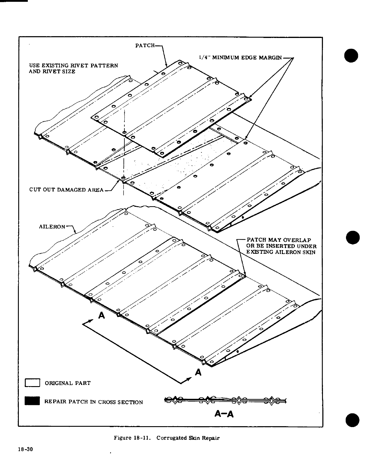
CUT
OUT
DAMAGED
AREA
by ^^ >
?<
^^^
\-PATCH
MAY
OVERLAP
OR
B~
E
INSERTED
UNDER
.^^>^ d%-/' AS''^
^^^
^KEXISTING
AILERON
SKIN
A
~~
|ORIGINAL
PART
REPAIR
PATCH
IN
CROSS
SECTION
v
-
A-A
Figure
18-11.
Corrugated
Skin
Repair
18-30
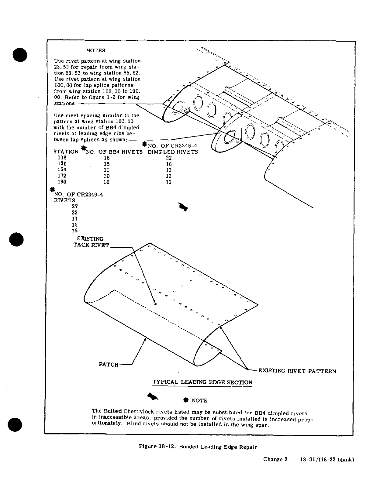
NOTES
Use
rivet
pattern
at
wing
station
23.53
for
repair
from
wing
sta-
tion
23.53
to
wing
station
85. 62.
Use
rivet
pattern
at
wing
station
100.00
for
lap
splice
patterns
from
wing
station
100.00
to
190.
00.
Refer
to
figure
1-2
for
wing
stations.
Use
rivet
spacing
similar
to
tUYe
pattern
UaIt
wing
station
100.00
with
the
number
of
BB4
dimpled
'.
rivets
at
leading
edge
ribs
be-
/ W
tween
lap
splices
as
shown:
*o
OF
CR2248-4
*NO.
OF
CR2248-4
?j
STATION
NO.
OF
BB
4
RIVETS
DIMPLED
RIVETS
118
18
22
136
15
18
154
11
13
172 10
12
190
10
12
NO.
OF
CR2249-4
RIVETS
27
23
17
15
15
EXISTING
TACK
RIVET
PATCH-
~~~~~PATCH"---'J
~-
EXJSTING
RIVET
PATTERN
TYPICAL
LEADING
EDGE
SECTION
4' *
NOTE
The
Bulbed
Cherrylock
rivets
listed
may
be
substituted
for
BB4
dimpled
rivets
in
inaccessible
areas,
provided
the
number
of
rivets
installed
is
increased
prop-
ortionately.
Blind
rivets
should
not
be
installed
in
the
wing
spar.
Figure
18-12.
Bonded
Leading Edge
Repair
Change
2
18-31/(18-32
blank)
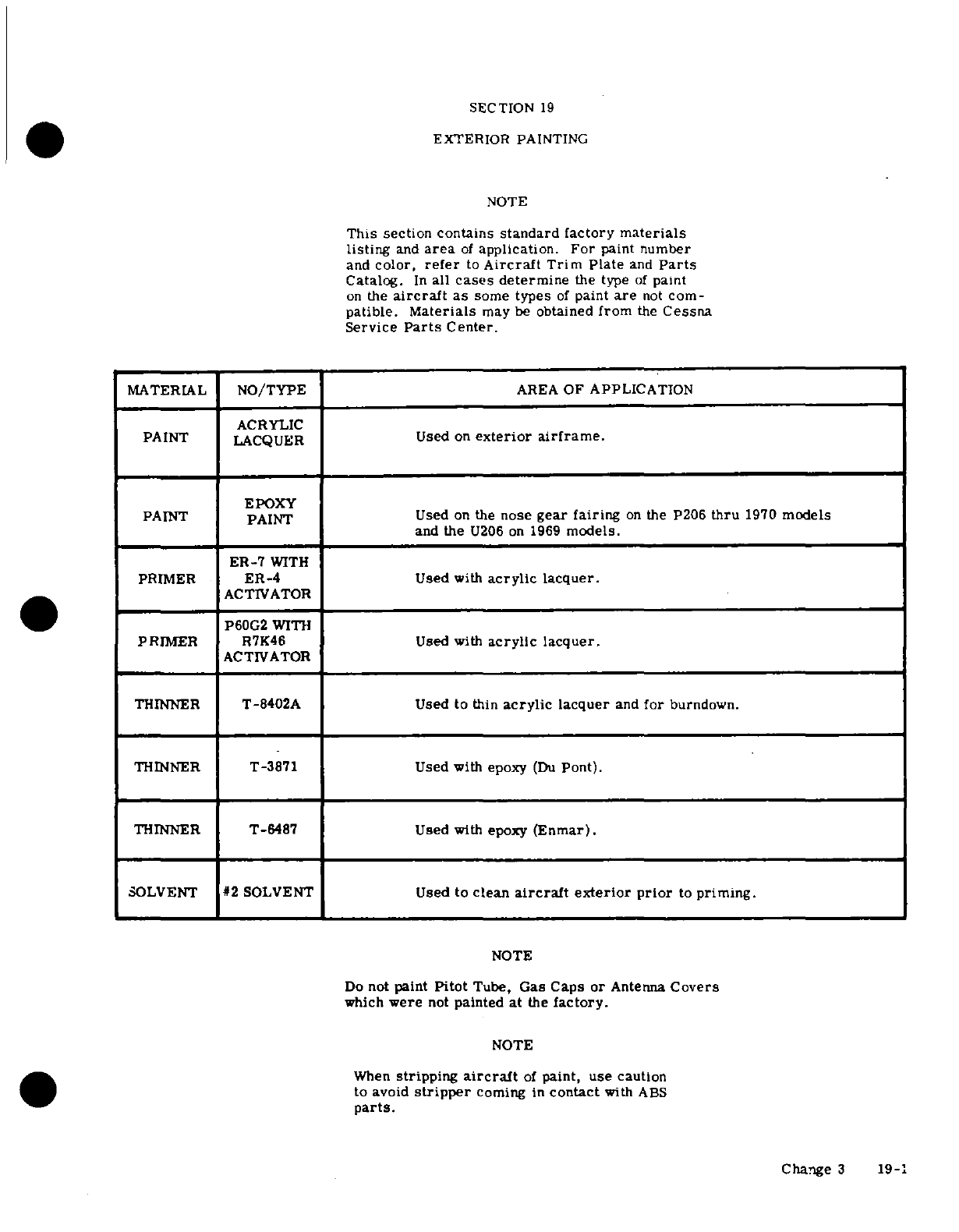
SECTION
19
EXTERIOR
PAINTING
NOTE
This
section
contains
standard factory
materials
listing
and
area
of
application.
For
paint
number
and
color,
refer
to
Aircraft
Trim
Plate
and
Parts
Catalog.
In
all
cases
determine
the
type
of
paint
on
the
aircraft
as
some
types
of
paint
are
not
com-
patible.
Materials
may
be
obtained
from
the
Cessna
Service
Parts
Center.
MATERIAL
NO/TYPE
AREA
OF
APPLICATION
ACRYLIC
PAINT
LACQUER
Used
on
exterior
airframe.
EPOXY
PAINT
PAINT
Used
on the
nose
gear
fairing
on
the P206
thru
1970
models
and
the
U206
on
1969
models.
ER-7
WITH
PRIMER
ER-4
Used
with
acrylic
lacquer.
ACTIVATOR
P60G2
WITH
ACTIVATOR
THINNER
T-8402A
Used
to
thin
acrylic
lacquer
and
for
burndown.
THINNER
T-3871 Used with
epoxy
(Du
Pont).
THINNER
T-6487
Used
with
epoxy
(Enmar).
SOLVENT
#2SOLVENT
Used
to
clean
aircraft
exterior prior
to
priming.
NOTE
Do
not
paint
Pitot
Tube,
Gas
Caps
or
Antenna
Covers
which
were
not
painted
at
the
factory.
NOTE
When
stripping
aircraft
of
paint,
use
caution
to
avoid
stripper
coming
in
contact
with
ABS
parts.
Change
3
19-1
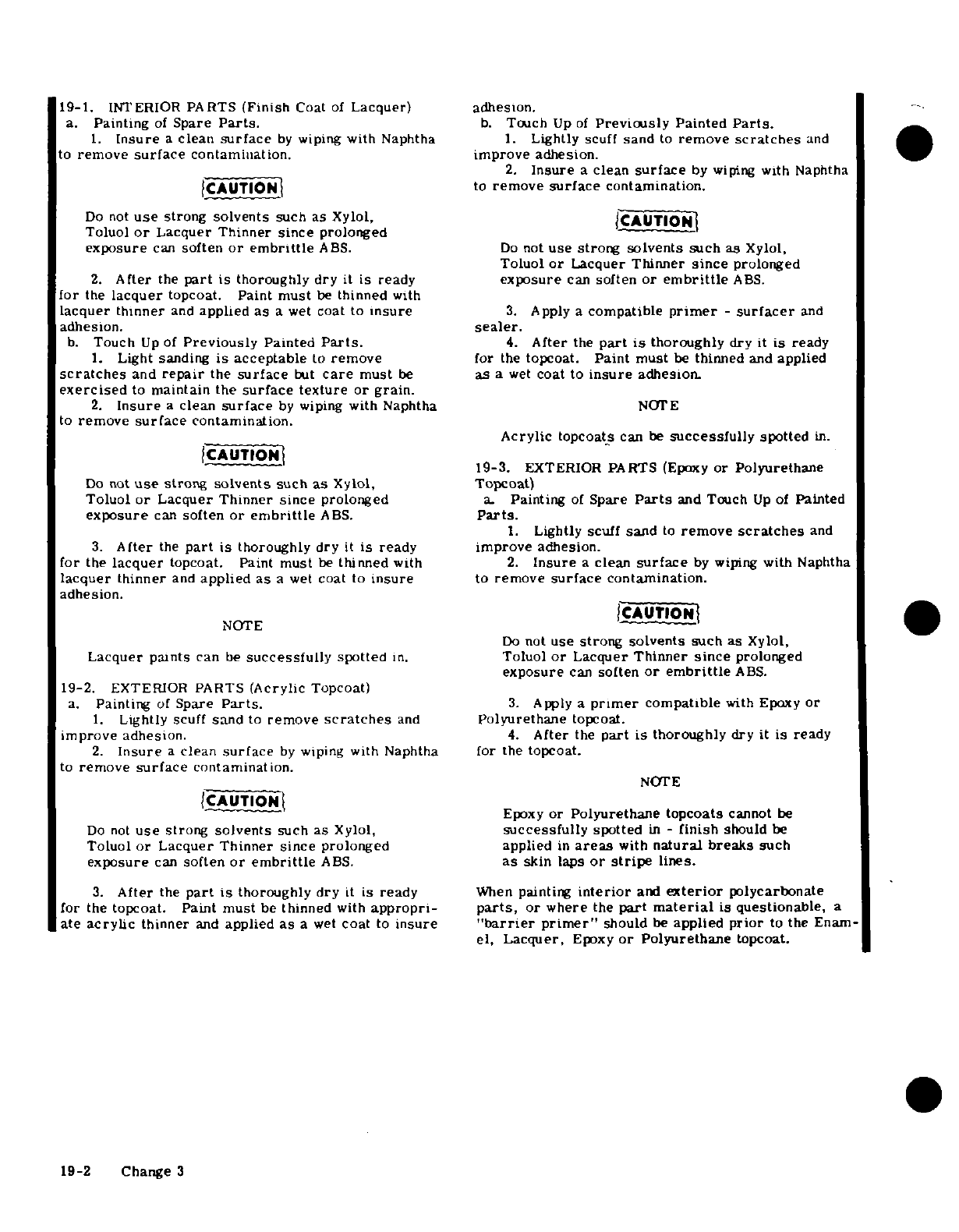
19-1.
INTERIOR
PARTS
(Finish
Coat
of
Lacquer)
adhesion.
a.
Painting
of
Spare
Parts.
b.
Touch
Up
of
Previously
Painted
Parts.
1.
Insure
a
clean
surface
by
wiping
with
Naphtha
1.
Lightly
scuff
sand
to
remove
scratches
and
to
remove
surface
contamination. improve
adhesion.
2.
Insure
a
clean
surface
by
wiping
with
Naphtha
CAUTION
to
remove
surface
contamination.
Do
not
use
strong
solvents
such
as
Xylol,
CAUTION
Toluol
or
Lacquer
Thinner
since
prolonged
exposure
can
soften
or embrittle
ABS.
Do
not
use
strong
solvents
such
as
Xylol,
Toluol
or
Lacquer
Thinner
since
prolonged
2.
After
the
part
is
thoroughly
dry
it
is
ready
exposure
can
soften
or
embrittle
ABS.
for
the
lacquer
topcoat. Paint
must
be
thinned
with
lacquer
thinner
and
applied
as
a
wet
coat
to
insure
3.
Apply
a
compatible
primer
-
surfacer
and
adhesion.
sealer.
b.
Touch
Up
of
Previously
Painted
Parts.
4.
After
the
part
is
thoroughly
dry
it
is
ready
1.
Light
sanding
is
acceptable
to
remove
for
the
topcoat.
Paint
must
be
thinned
and
applied
scratches
and
repair
the
surface
but
care
must
be
as
a
wet
coat
to
insure
adhesion.
exercised
to
maintain the
surface texture
or grain.
2.
Insure
a
clean
surface
by
wiping
with
Naphtha
NOTE
to
remove
surface
contamination.
Acrylic
topcoats
can
be
successfully
spotted
in.
CAUTION
19-3.
EXTERIOR
PARTS
(Epoxy
or
Polyurethane
Do
not
use
strong
solvents
such
as
Xylol,
Topcoat)
Toluol
or
Lacquer
Thinner since
prolonged
a.
Painting
of
Spare
Parts
and
Touch
Up
of
Painted
exposure
can
soften
or embrittle
ABS.
Parts.
1.
Lightly scuff
sand
to
remove
scratches
and
3.
After
the
part
is
thoroughly dry
it
is
ready
improve
adhesion.
for
the
lacquer
topcoat.
Paint
must
be
thinned
with
2.
Insure
a
clean
surface
by
wiping
with
Naphtha
lacquer thinner
and
applied
as
a
wet
coat
to
insure
to
remove
surface
contamination.
adhesion.
NOTE
CAUTION
NOTE
Do
not
use
strong
solvents
such
as
Xylol,
Lacquer paints
can
be
successfully
spotted
in.
Toluol
or
Lacquer
Thinner
since
prolonged
exposure
can
soften
or embrittle
ABS.
19-2.
EXTERIOR
PARTS
(Acrylic
Topcoat)
a.
Painting
of
Spare
Parts.
3.
Apply
a
primer
compatible
with
Epoxy
or
1.
Lightly
scuff
sand
to
remove
scratches
and
Polyurethane
topcoat.
improve
adhesion.
4.
After
the
part
is
thoroughly
dry
it
is
ready
2.
Insure
a
clean
surface
by
wiping
with
Naphtha
for
the
topcoat.
to
remove
surface
contamination.
NOTE
CAUTION
Epoxy
or
Polyurethane
topcoats
cannot
be
Do
not
use
strong
solvents
such
as
Xylol,
successfully
spotted
in
-
finish
should
be
Toluol
or
Lacquer
Thinner since
prolonged
applied
in
areas
with
natural
breaks
such
exposure
can
soften
or embrittle
ABS.
as
skin
laps
or
stripe
lines.
3.
After
the
part
is
thoroughly dry
it
is
ready
When
painting
interior
and
exterior
polycarbonate
for
the
topcoat.
Paint
must
be
thinned
with
appropri-
parts,
or
where
the
part
material
is
questionable,
a
ate
acrylic
thinner
and
applied
as
a
wet
coat
to
insure
"barrier
primer"
should
be
applied
prior
to
the
Enam-
el,
Lacquer,
Epoxy
or
Polyurethane
topcoat.
19-2
Change
3
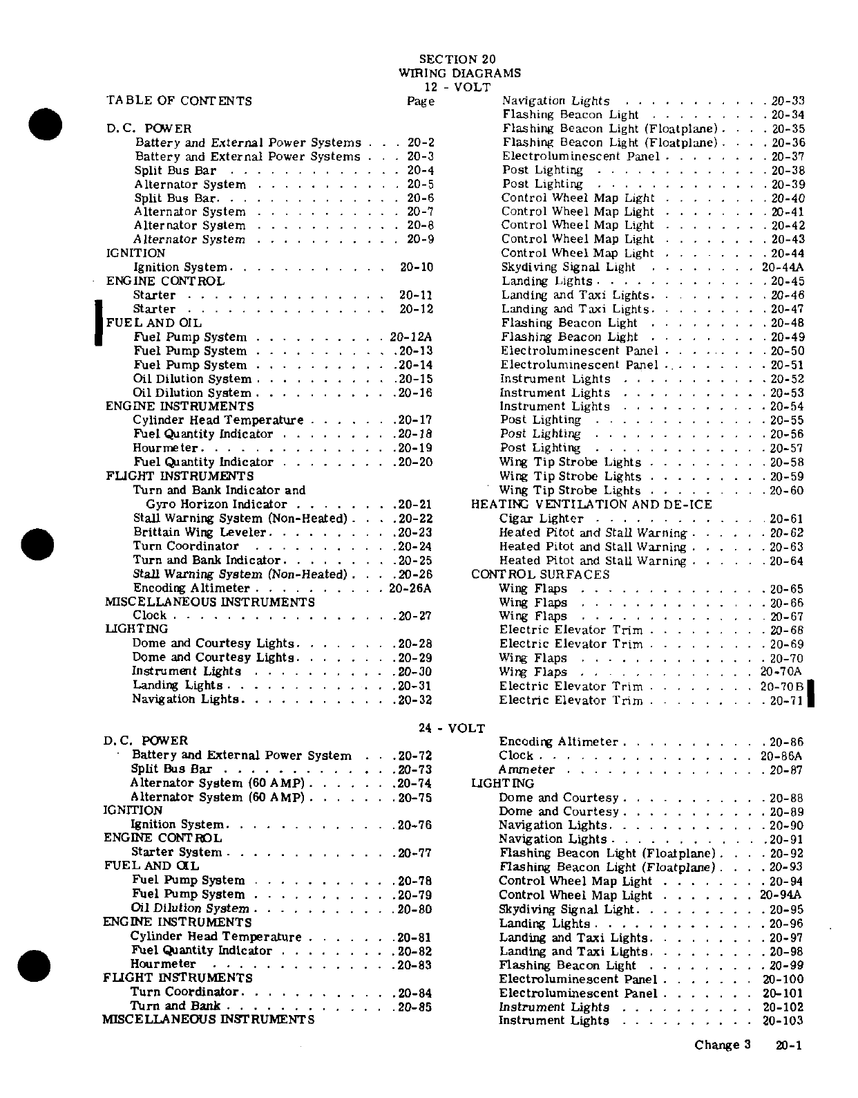
SECTION
20
WIRING
DIAGRAMS
12
-
VOLT
TABLE
OF
CONTENTS
Page Navigation
Lights
...........
20-33
Flashing
Beacon
Light
.........
20-34
D.C.
POWER
Flashing
Beacon
Light
(Floatplane)
. ..
20-35
Battery
and
External
Power
Systems
.. .
20-2
Flashing
Beacon
Light
(Floatplane)
...
20-36
Battery
and
External
Power
Systems
. . .
20-3
Electroluminescent
Panel
.
......
20-37
Split
Bus
Bar
.
..........
. 20-4
Post
Lighting
..
.........
20-38
Alternator
System
..
..........
20-5
Post
Lighting
.
............
20-39
Split
Bus
Bar. . .
.............
20-6
Control
Wheel
Map
Light
.
.....
20-40
Alternator
System
...........
20-7
Control
Wheel
Map
Light
......
.
20-41
Alternator
System
.
.....
. 20-8
Control
Wheel
Map
Light
..
.....
20-42
Alternator
System
...........
20-9
Control
Wheel
Map
Light
.
......
20-43
IGNITION
Control
Wheel
Map
Light
......
20-44
Ignition
System.
...........
20-10
Skydiving
Signal
Light
. ... . ..
20-44A
ENGINE
CONTROL
Landing
Lights
.... ....
.
.20-45
Starter
..
...........
20-11
Landing
and
Taxi
Lights.
........
20-46
Starter
.
..............
20-12
Landing
and
Taxi
Lights.
.......
20-47
FUEL
AND
OIL
Flashing
Beacon
Light
. . .
20-48
Fuel
Pump
System
.
......
.
20-12A
Flashing
Beacon
Light
......
.
20-49
Fuel
Pump System
..... ....
20-13
Electroluminescent
Panel
......
.. 20-50
Fuel
Pump
System
.
........
.20-14
Electroluminescent
Panel
........
20-51
Oil Dilution
System
.
..........
20-15
Instrument
Lights
... .. ... 20-52
Oil
Dilution
System
..........
.20-16
Instrument Lights
..........
.20-53
ENGINE
INSTRUMENTS
Instrument
Lights
.
....
......
20-54
Cylinder
Head
Temperature
.....
.20-17
Post
Lighting
..........
.
20-55
Fuel
Quantity
Indicator
.
........
20-18 Post
Lighting
.........
. .
20-56
Hourmeter.
..............
20-19
Post
Lighting
.
........
.20-57
Fuel
Quantity
Indicator
.
........
20-20
Wing
Tip Strobe
Lights
.....
.
.20-58
FLIGHT
INSTRUMENTS
Wing
Tip
Strobe
Lights .
.....
.20-59
Turn
and
Bank
Indicator
and
Wing
Tip
Strobe
Lights .
.....
20-60
Gyro
Horizon
Indicator
.......
20-21
HEATING
VENTILATION
AND
DE-ICE
Stall
Warning
System
(Non-Heated)
... 20-22
Cigar Lighter
............
20-61
Brittain
Wing
Leveler
.... 20-23 Heated
Pitot
and
Stall Warning
......
20-62
Turn
Coordinator
.......
. .20-24
Heated
Pitot
and
Stall
Warning
......
20-63
Turn
and Bank
Indicator
.......
.20-25
Heated
Pitot
and
Stall
Warning
......
20-64
Stall
Warning
System
(Non-Heated)
. .
.20-26
CONTROL SURFACES
Encoding
Altimeter
..........
20-26A
Wing
Flaps
..............
20-65
MISCELLANEOUS INSTRUMENTS
Wing
Flaps
......
.. .
.20-66
Clock
.
.........
.... 20-27
Wing
Flaps
..... ....
..
20-67
LIGHTING
Electric
Elevator Trim
.........
20-68
Dome
and
Courtesy
Lights.
......
.20-28
Electric
Elevator
Trim
... .. .
20-69
Dome
and
Courtesy
Lights.
......
.20-29
Wing
Flaps
........
. .. ..
20-70
Instrument
Lights
...........
. 20-30
Wing
Flaps
..
...........
20-70A
Landing
Lights.
...... ......
20-31
Electric
Elevator
Trim
......
.
20-70B
Navigation
Lights
.
...........
20-32
Electric
Elevator Trim
.....
.
.20-71
24
-
VOLT
D.C.
POWER
Encoding
Altimeter
...
....
. 20-86
Battery
and
External
Power
System
.
.
.20-72
Clock
.
.........
.. 20-86A
Split
Bus
Bar
...........
.. 20-73
Ammeter
..........
20-87
Alternator
System
(60
AMP)
.......
20-74
LIGHTING
Alternator
System
(60
AMP)
.......
20-75
Dome
and
Courtesy
.
......
.
20-88
IGNITION
Dome
and
Courtesy
...........
20-89
Ignition
System
............
.20-76
Navigation
Lights
..
.......
.. 20-90
ENGINE
CONTROL
Navigation
Lights
...........
20-91
Starter
System
............
20-77
Flashing
Beacon
Light
(Floatplane)
. .
20-92
FUEL
AND
OIL
Flashing
Beacon
Light
(Floatplane)
... 20-93
Fuel
Pump
System
..........
.20-78
Control
Wheel
Map
Light
.. ... .
20-94
Fuel
Pump
System
..........
.20-79
Control
Wheel
Map
Light
.......
20-94A
Oil
Dilution
System
..........
.20-80
Skydiving
Signal
Light.
........
.20-95
ENGINE
INSTRUMENTS
Landing
Lights
.
..........
20-96
Cylinder
Head
Temperature
......
.20-81
Landing
and
Taxi
Lights
.......
20-97
Fuel
Quantity
Indicator
........
.20-82
Landing and
Taxi
Lights.
.......
.20-98
Hourmeter
.............
.20-83
Flashing
Beacon
Light
......
.20-99
FLIGHT
INSTRUMENTS
Electroluminescent
Panel
.......
20-100
Turn
Coordinator
............
20-84
Electroluminescent
Panel
.......
20-101
Turn
and
Bank
............
.20-85
Instrument
Lights
........
. 20-102
MISCELLANEOUS
INSTRUMENTS
Instrument Lights
.
......
.
20-103
Change
3
20-1
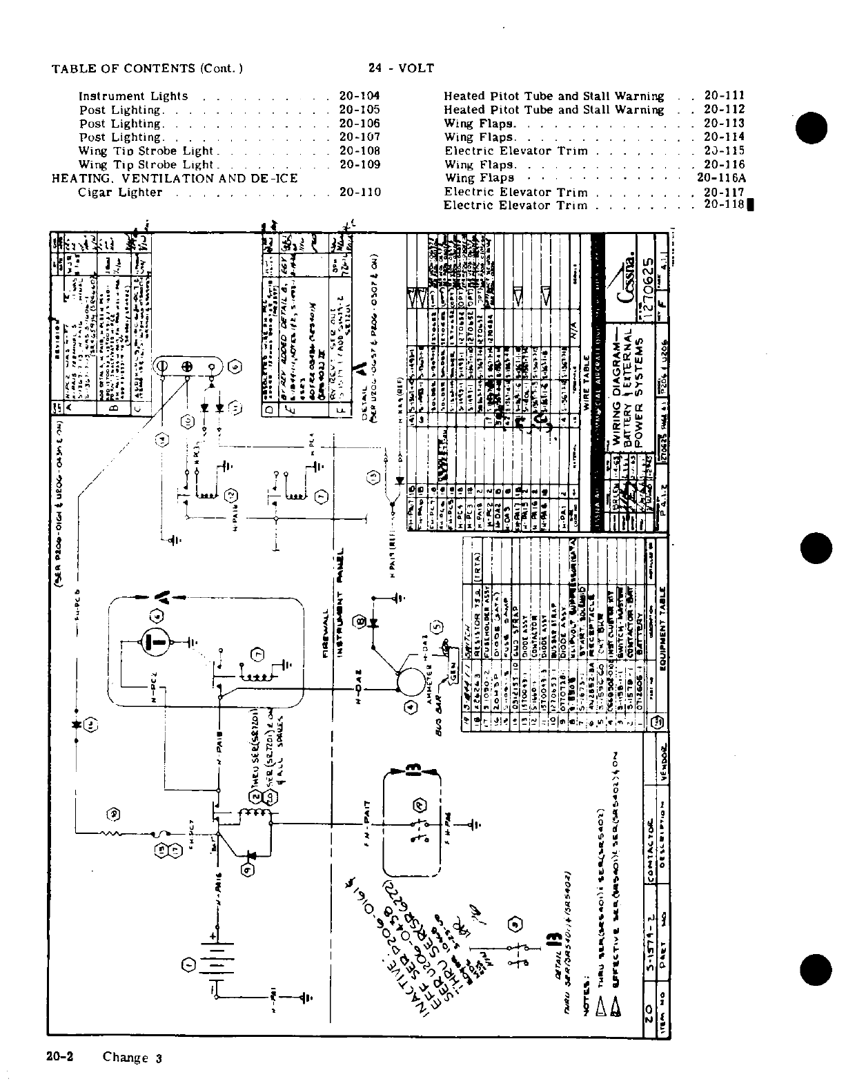
TABLE
OF
CONTENTS
(Cont.)
24
-
VOLT
Instrument
Lights
.. ... .
20-104
Heated
Pitot
Tube
and
Stall
Warning ..
20-111
Post
Lighting. .. .
.........
20-105 Heated
Pitot
Tube
and
Stall Warning
..
20-112
Post
Lighting.
. .. . . . ..... .20-106
Wing
Flaps.
....... . . . . . .
20-113
Post
Lighting. ... ... ... .
20-107
Wing
Flaps.
........ ....
20-114
Wing
Tin
Strobe
Light.
.
2.
20-108
Electric Elevator
Trim
.... ....
.
20-115
Wing
Tip
Strobe
Light.
. . . 20-109
Wing
Flaps
. .
.........
20-116
HEATING.
VENTILATION
AND
DE-ICE
Wing
Flaps
........
.20-116A
Cigar
Lighter
.......
.
20-110
Electric
Elevator
Trim
.......
.
20-117
Electric
Elevator
Trim
........
20-1181
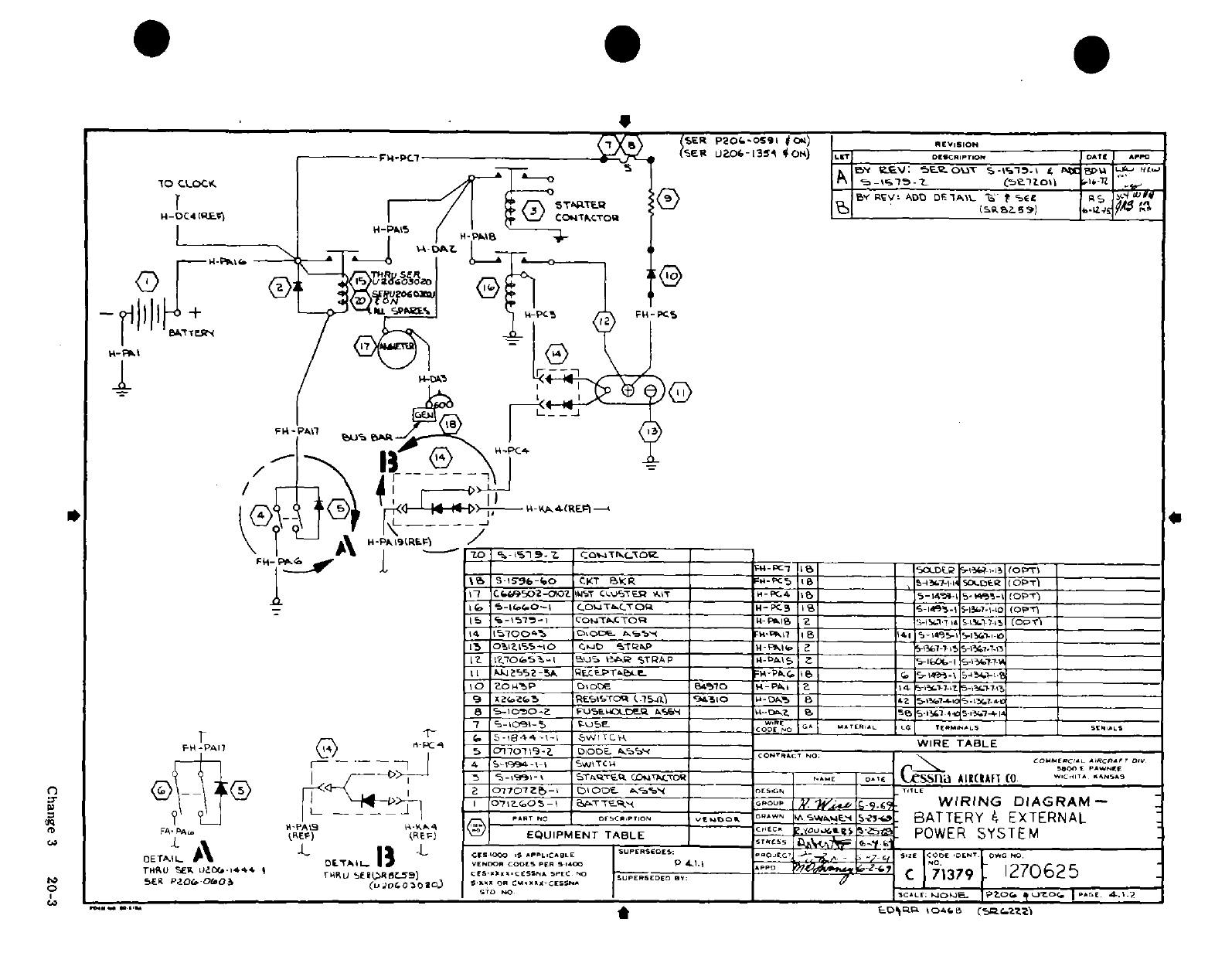
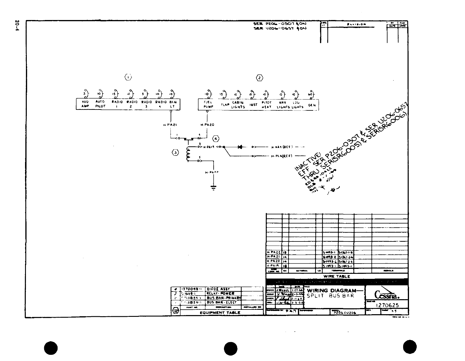
Mx-
j
h
R
{ !<
j
b~~-~
'^
.
tJ^
«-~~~~~~~~~~ ^A-:
*
i
,
§
O
0~~~~
^r":^^
i ir
0.4 ~
~
~
~ ~ ~ ~ ~ ~ ~
~~~.
20-4
^
0^~~>.-,
.
m 1
rr ~~~~9 4--fi^
'
n rf' u~~~- u..a-iH
_
03
~
40 I 4£18 |l
"
?1
^
~~~~I
a;
A
.-
Q
vc
.
3 A,~~~~~~~~~~~
0-w
-
^
2
~t
*
-
0'a
°
I0_ :
-
;_
-
0~~~~~~~~~~~~
J
-^
0
oec
2
1
0~~~~
20-4~~~~~~
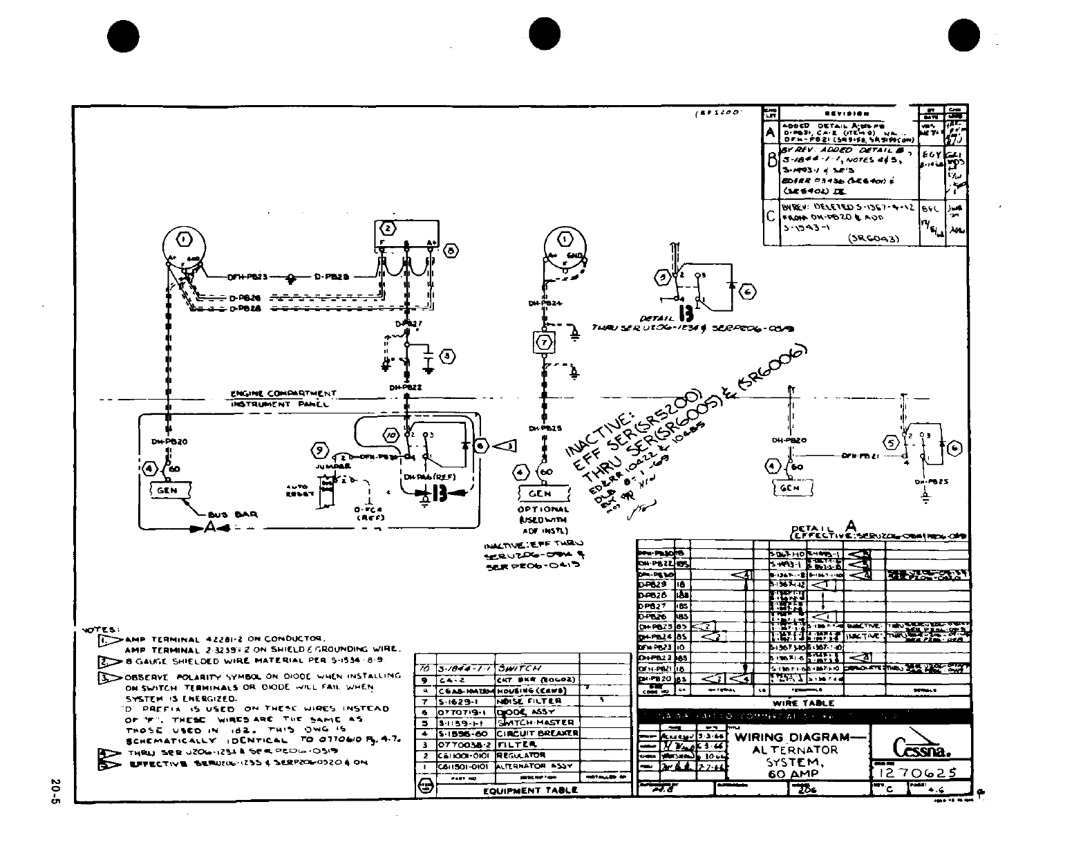
"1
"
/' ';
r
'
~-~"
I
*
'
-i .1~
.
qI?
--
:
V
.-
--
T II
I^^4
-
a
Al iii
iiir!
"
^a~l
5
.
? ti ^--jI'
ls
1sZ
i,
7u
® ^
r
14Uo
fe
2.
'^/- -i
-
CF-
m
®
1O~~~~~~~~~~,
.
~.
l It 1i tai=
Z·h
0-
6 ^a^ U^ -^^ ^^ill^ 0
,
.is i
2
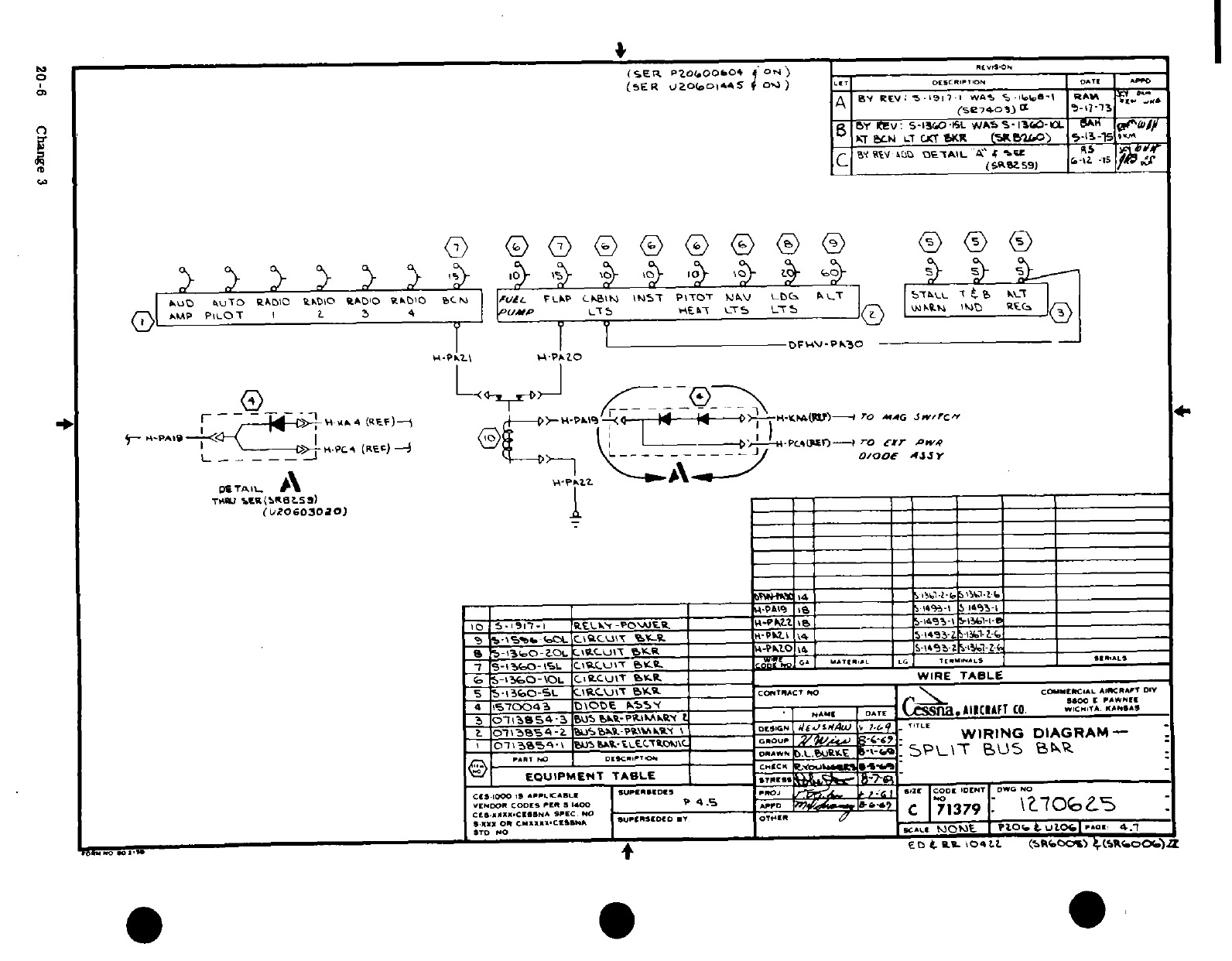
Itl~
r T ,-...I
--
-%1
:r.
s
!
-r ~i
' ?
* =5 r
Od~tt,
:,-
t'
I
[^SSI :1
!^n~ in\^ 0. m4
I~iIII
00SS.^ ,e
^trt
i
0
0
..' .
----
.
0
-,
.
-
s0~ 44 U
UO
;
??
i
~01!3§ 5i
I-
-Vi
e 0L.
o~g
c
(
4 4
on
20-6
Change
3
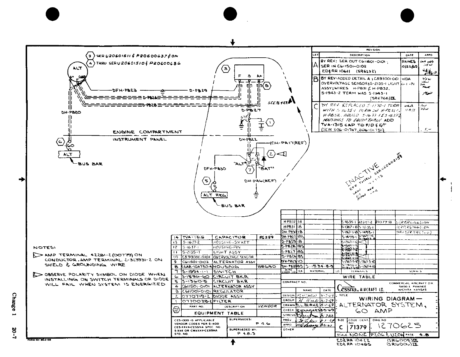
'
._ U _),:_ C ~ r,
,. ,
Q
13X gS^
S
Mg
C
I_ 1
1.
L'c
<
<
4
u"cjCo
1a1~6~/ra
>
U )
's
-l '
I/ ~ I1
r
n
-
A
Co,
O D-
"-< i x
^
ssei~ssh
:
.
il
o9
--
9-
0
'o -0C
,
0
; iS
0
I
"~ C
-
co
*1 0-
do 8 S
0
S oIr
6 a
2-
^g
1
sl ~~~~~~~iii
'
2 ! P s;~~~~~~
'a0
rn
EdJ^
CX~
r
L
0
a
*
@
-
ll
11
0
2
232~~~~~~~~~~~~~~~~~~~~~~~~-
xi
j
~t~~~~
Change
1
20-7
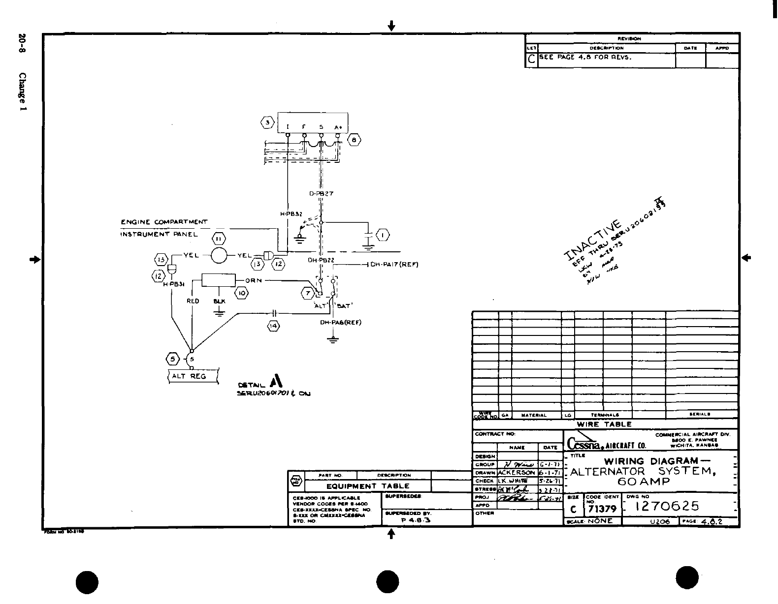
'II~~~I
5
s
,
,o
n
LON
t i
I
a ;
t
l (l ^
;
a
8
Q
I siS
a
I
'-
Z5 )s-
® eS
20-8
Change
!k1 ~ iiih
r^^ ~~~i 5§t
"
I t-
r_-"
~i
i
S.'i
T
'
1^ a' ^-~ l
s3
||
20-8- -r i^
Chng
1 1
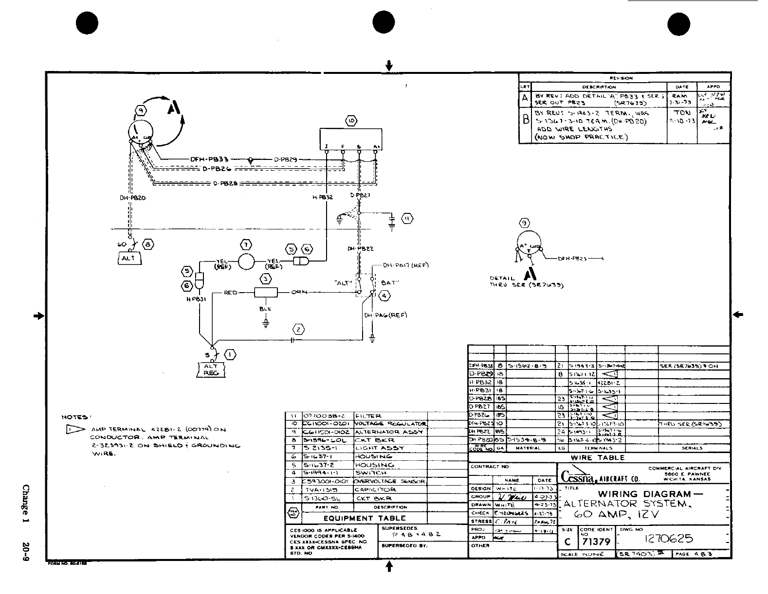
5
"
0
SIt A
. ..
I
o.oj'~ ~ zoo
W~
,
,
„
8
0 Ln
*, -
', ,
o '
of
;m
rrtc' ? M S n rv 2
a
,
,m
~
La
.--
hi -U 0
H~~~~~~Change
1
2
hi, C
*; r. 5 J'
&
^
„
m
?;
S
S
(G ?, .^ -3 ^ 1 ,,,..,
"
]
,
H~~~~~~~~~~~~~~~~~~~~~~~~~~~~~~~~~~~~~~~~~~~~~a
M3 ;'
"
S
So~~~~~~~q.;i!.^
8^Chage
2
0-9S
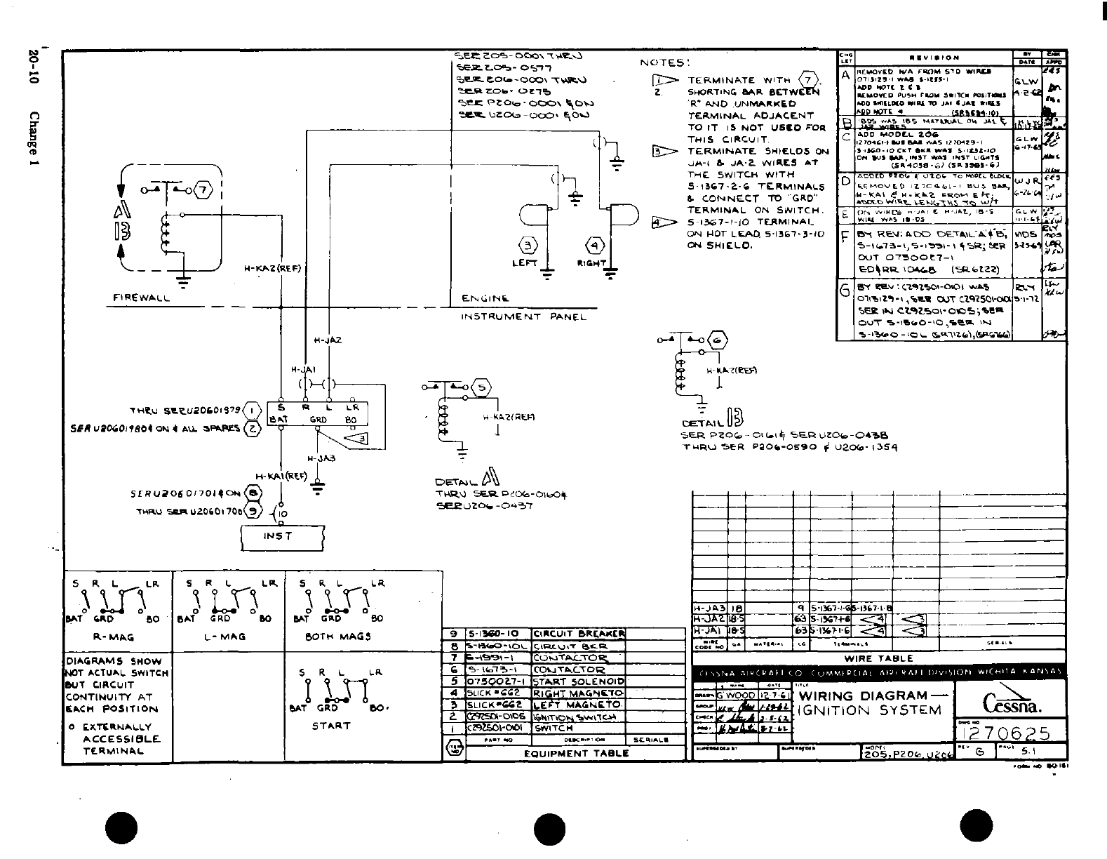
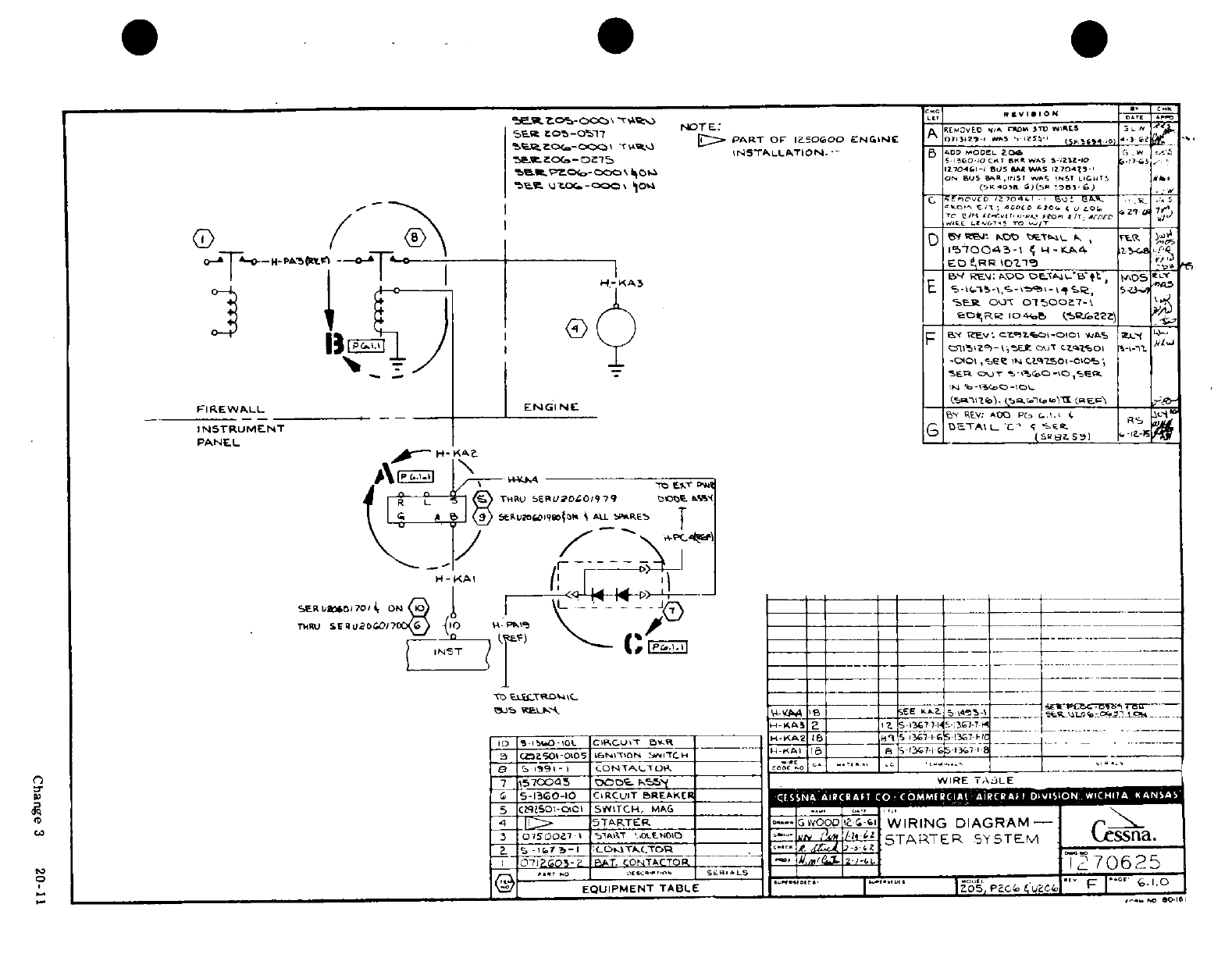
~1~,1
~1:~'~1~
: ~
/LI ,~01
E
ulJ
!
i
n
. .. . "
N
* l
~ - r t
1'
'
^
*
*-/ l"
-
,
IJJI
U,
: / < 1 ^
P
IO 7/.j l
u _
/ I,' ~
--
-0
,Q
'
"7. Ut*
ft U rLO 'rPl j
2
-)
UCC 4, 001^
£
I
7 -f
~-~
9
4f
I
IIIF
<
--
3 201
-
dl
L
inQ -;in
nj-
or n I-o
t
I i 3
7
|
I ?-
2S
si
t Ii
,
-
Change
3
20-11
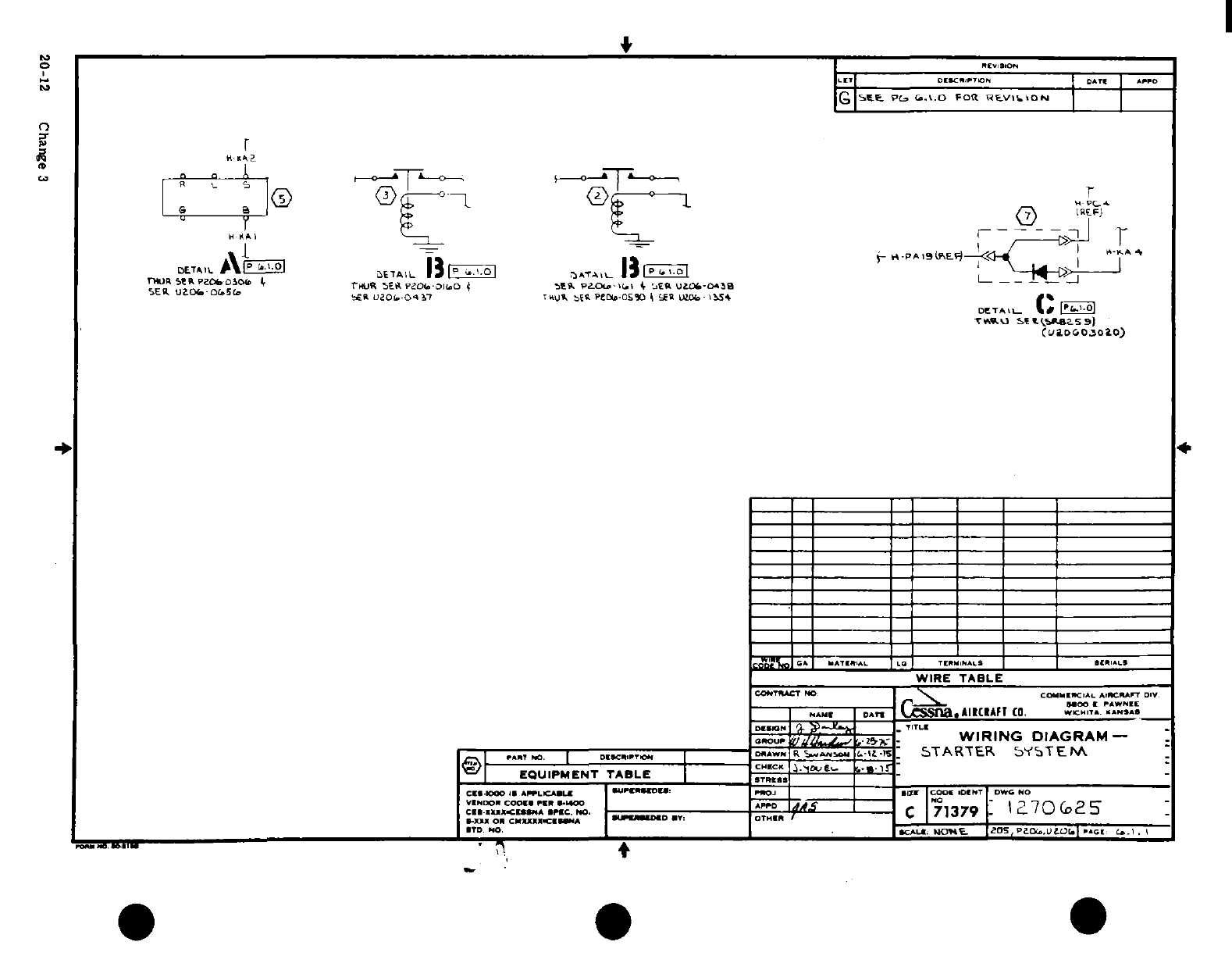
4n
£
a
4.37 Cd
ta
20-sr12
Ch
3
^
Ltj
4^
0
A I I .I zCJI
0f
0
'" .*w
iil
4
a
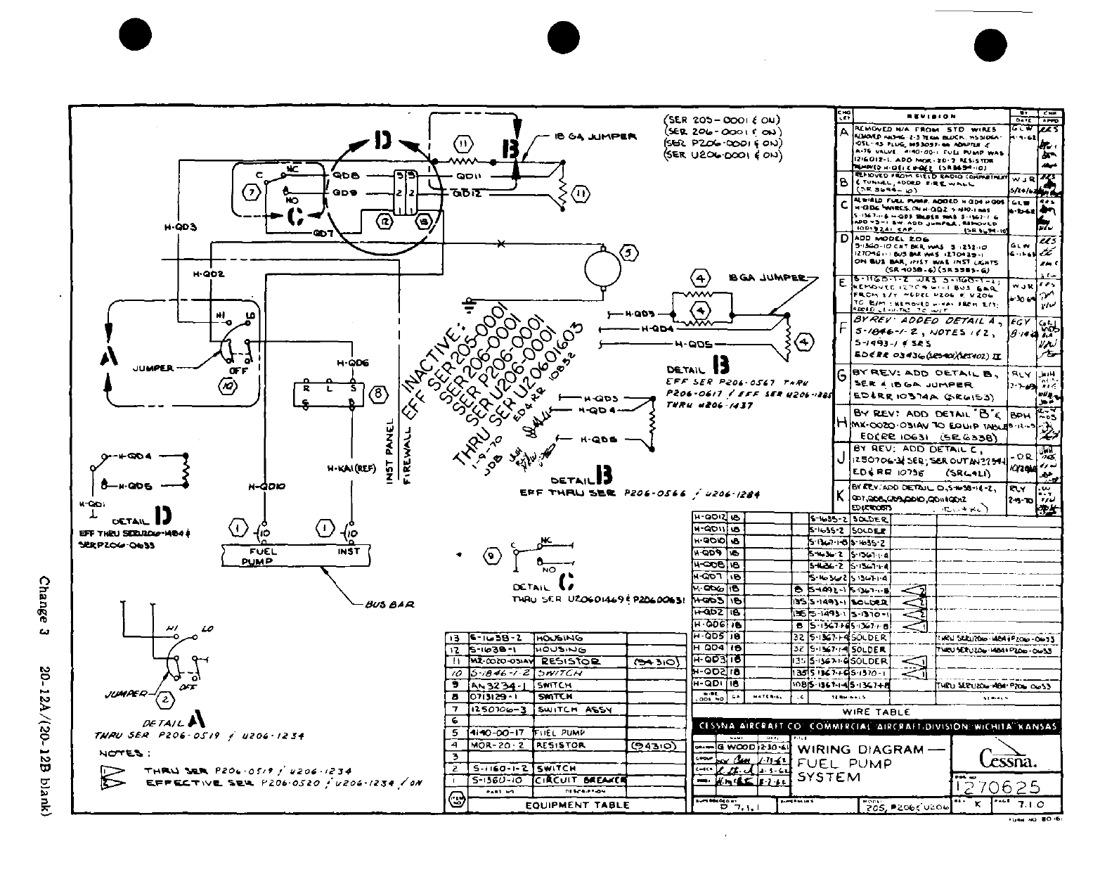
-
X
2« J
r<*;
^. I I
4, [[. I:
/
~l.:
I
-
I~
Ij l l/ h i ll
1d*
,
~
<,
~ ~
; a
-
a^1
:
I'
3.
" '
h
J
^r a I ii
o
i
'II-,!-
ili
0 ~p
j
I:
o
i~s I
-*
r'-0o0
42
~
LI~.
~ ~
j
N 0 -lll/
'
ii i -'3"
0® 0v
=
Ole
v
I NJ
-
t
..
-\i
'
v'*"*"'"I
g
Nf
SA I' 408
U
S£/-3
,
0
,
,,.
.
o0.
o
_~:_~
a-i-~~ r/5~
U
D
1tj,
FXio
,.r;
i
I
a o -
Change
3
20-12A/(20-12B
blank)
rrh
1-fg
-
,n
0
a
DC
3
s^ 21A2
2
bJa
a~~~~~~~~~~~
i
P:
"
8-
^
1^
^~~B &<^
P
j
-
1|
~~~~
-
y
t
f
j
~~6'·~~B
i
o~~~~~~~~~~~~~~~~Cag 3r
20
2/2-1Bba
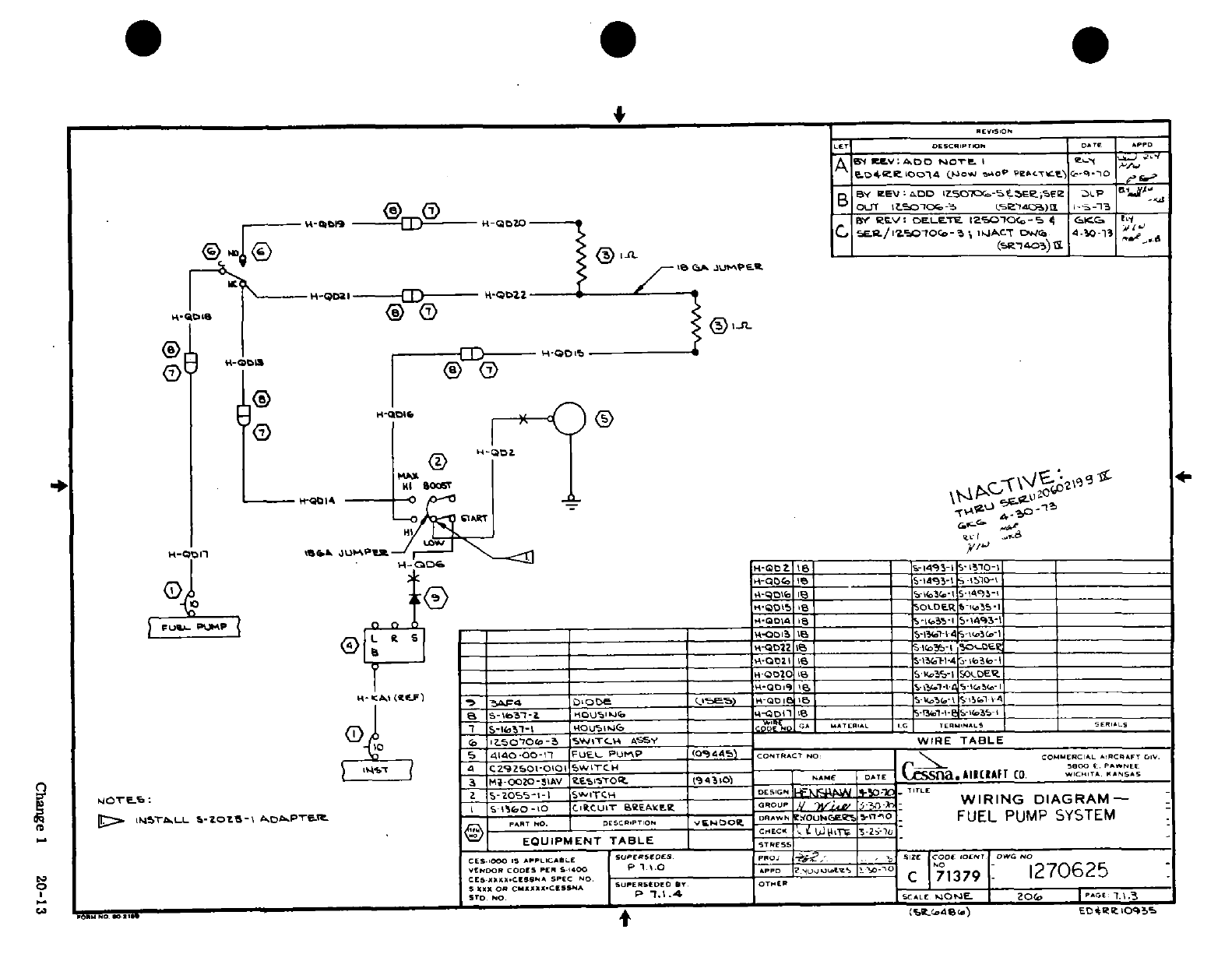
B]?~~~~~~~~~~~~~~~~~~~~~
j
0i f
i
-, 4 5
u(
-
;l
;.-
.--
,~
"_
:
rl~lil~ Lr)
oI
I I9
11
I
mI
.
l/S
0 Idi
2
0
^^^^ , ,
a
0 A
--
fl· y ^
^ pi I I-
~,1~
I
I
i0
0
,0<
m
S
CD
® ®3
0i~~~~~~~~~~~~~~~~~
~~~~~~~- 2
*
T'
'
D
w
0
l 2;
__n ID-
0 1^
^-0
Change
1
20-13
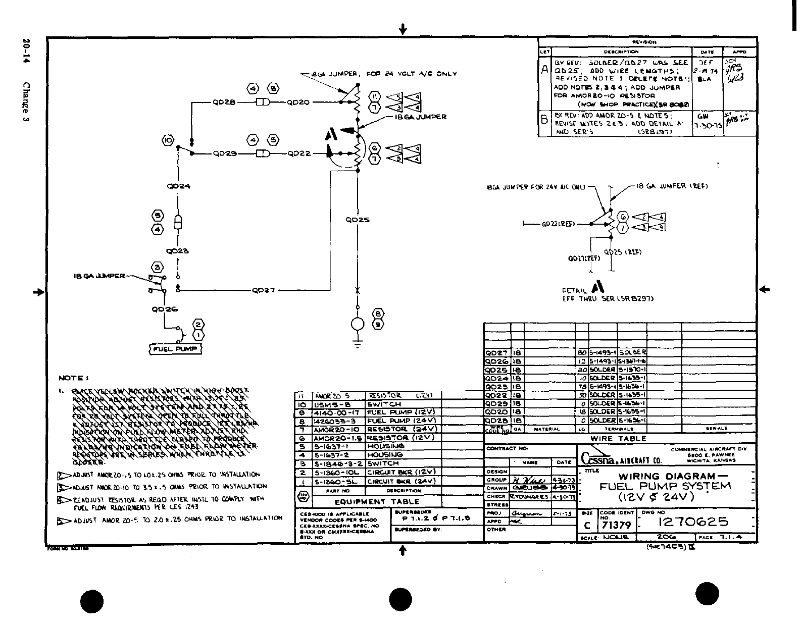
RR "5
Nv
(\ .ai<.
er -h" AV T.
Tj,
ZJ
!Ld c
A
gfo
HIJ
-
dw
«.
.$f
N
C
2
4~·5' 1J[ C4
4N
z (L~~
t
A
W
L.
0
8g
-1 4
a
a :a
0
to0ri
a~r-y~pj
a
O
20-14
Change
3
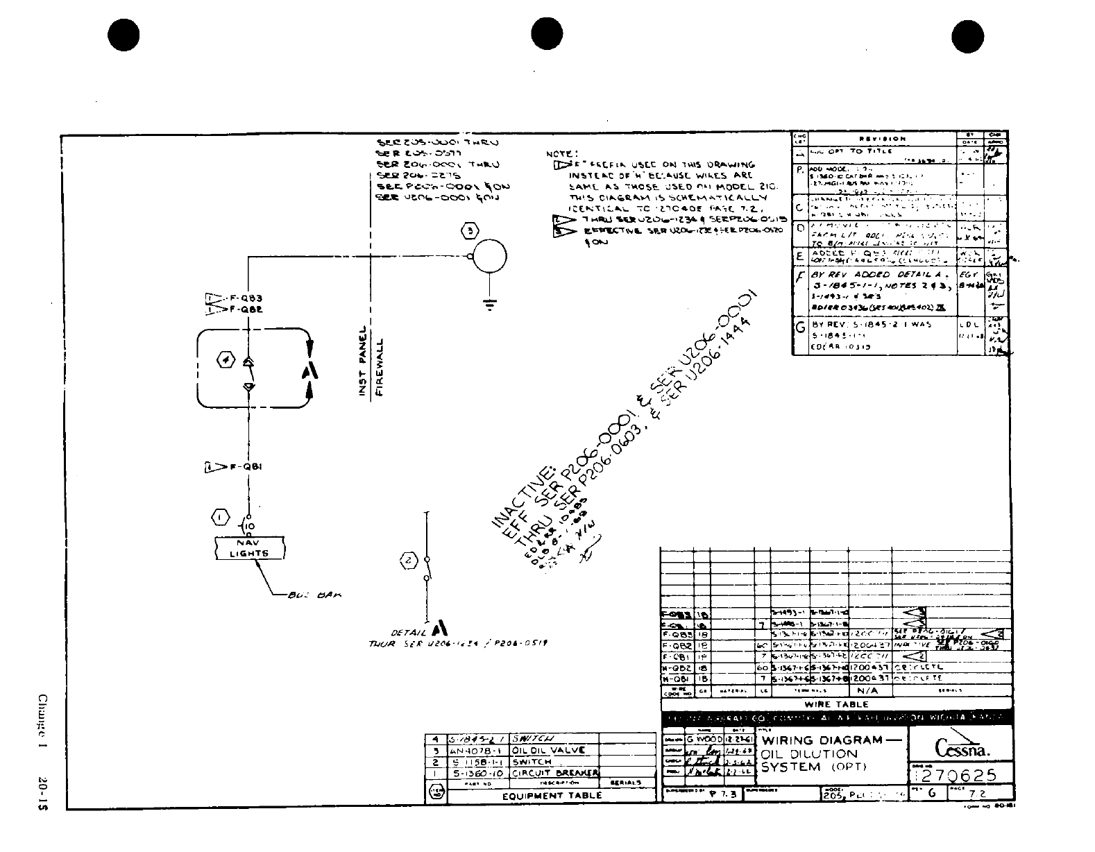
it.' *."
Z.
0
,
3 ,
mJ
'-
"!
,UJ.
.,13i i' °!, .9~=
-n2
'3i
*'
I4
''5 BP
LA
t
Chai
'
I
20-IS
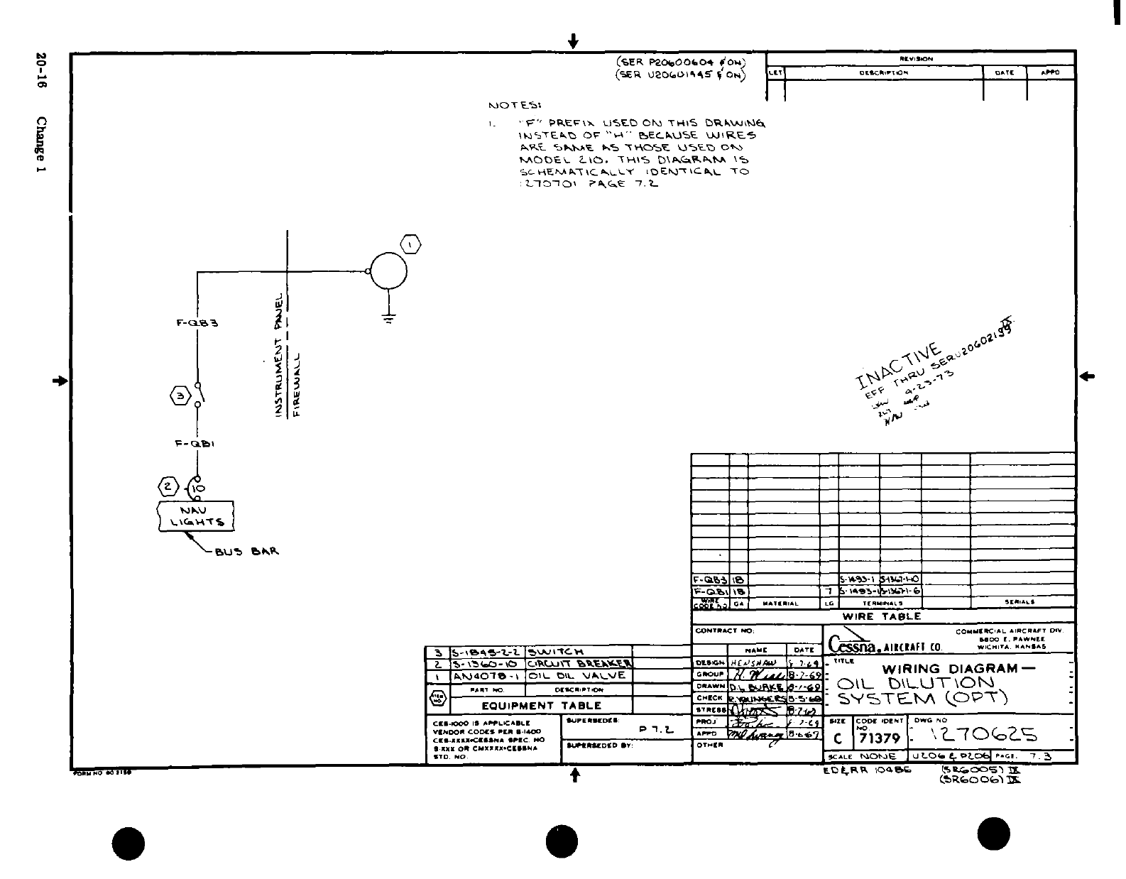
III I I I I I i
.. N
0 r·,"~~~~~~
COO
a
e("~l?
J~1
Pis
,,
'"
2~~~~~0
J~~~~~~~~~~~~~~~-
Cn
1
C; oo a
a
*L
Y
£
^ ^p^ ^ g~~~~~~~~~~~~~~~~~~~~
^s^^ ^'^1 ~~~~~~~~~~~~~~~~~~~~~~~~~~~~~~~~~~~~~~~Ia
'
i^ 1^!^-' *~~~~~~~~~~~~~~~~~~~~
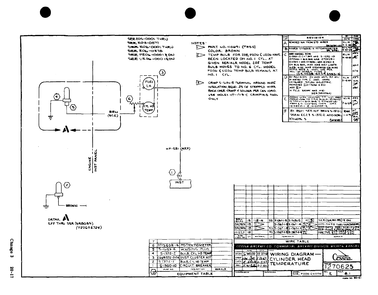
»C "'«-
«
-
'.- :,,5
7
*
u
II
"-
o
.s o;AA
0-
.-
;
i tc -§ a^^
0
d'
|
.,a' > u -tv-e0
0'ji jy .· i-
,,z -
-
-
-.-
1 haaeJ32
"
iO I0 ooZl]
zlJ 6O!a F:A :
L
922i-ir
A] *...o
(
0z
i W
.-
S
^
3
-
05s~s° i0i
0
tuiStdi
z uaO
^j
I
i
SAAA
'rs
4:"^
,
y
c^§
S
*o
P^-.'^.a
ZO
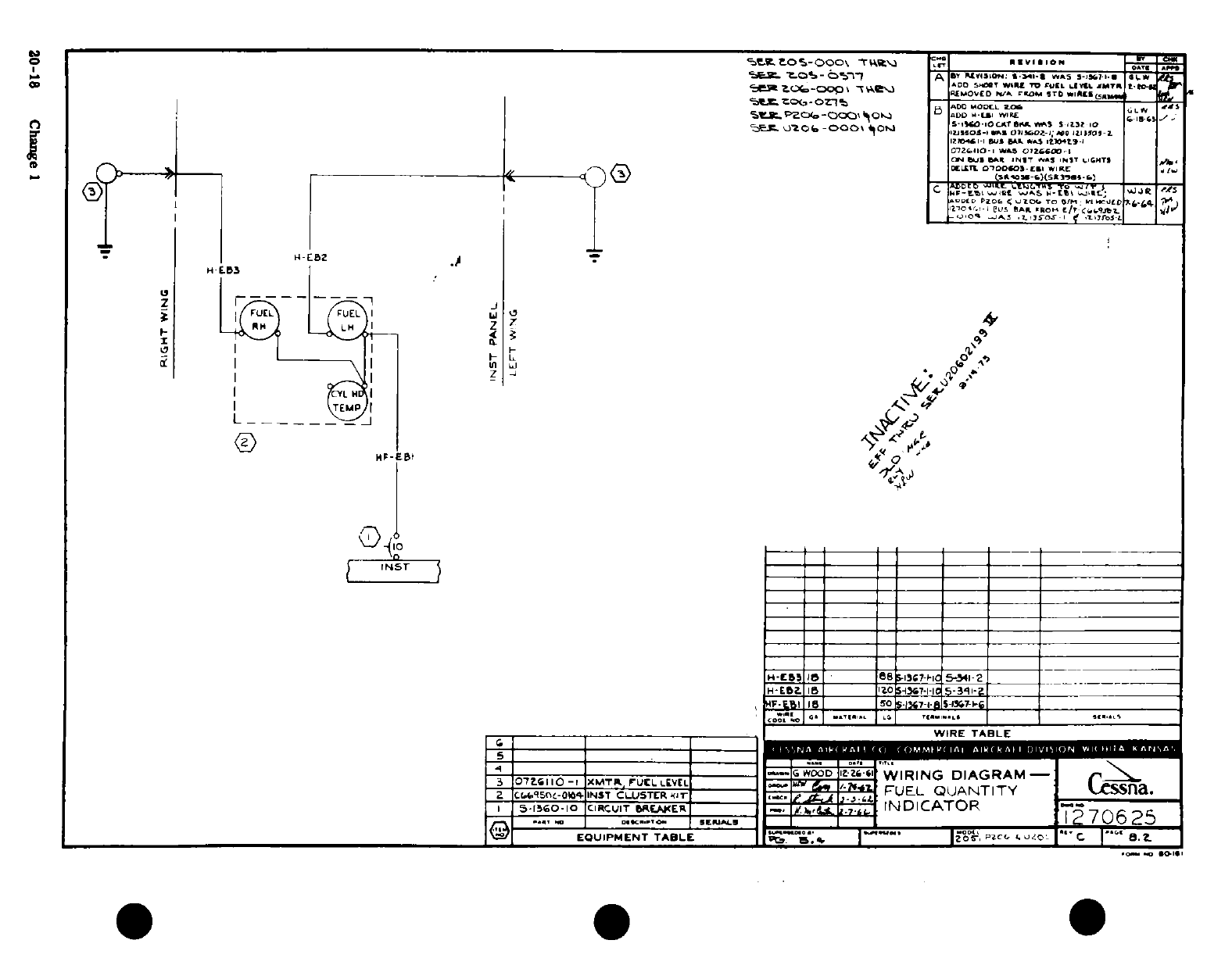
si. -)
,.'--'o
t
r~sna a
-~ o~q
i
II
53
z
q o.~ oZ 0
-
0^n.|1tQO
*0<-.0
0
W
20-18 Change
I
20-18
~ ~ ~
~
-. -- --
Chng
1
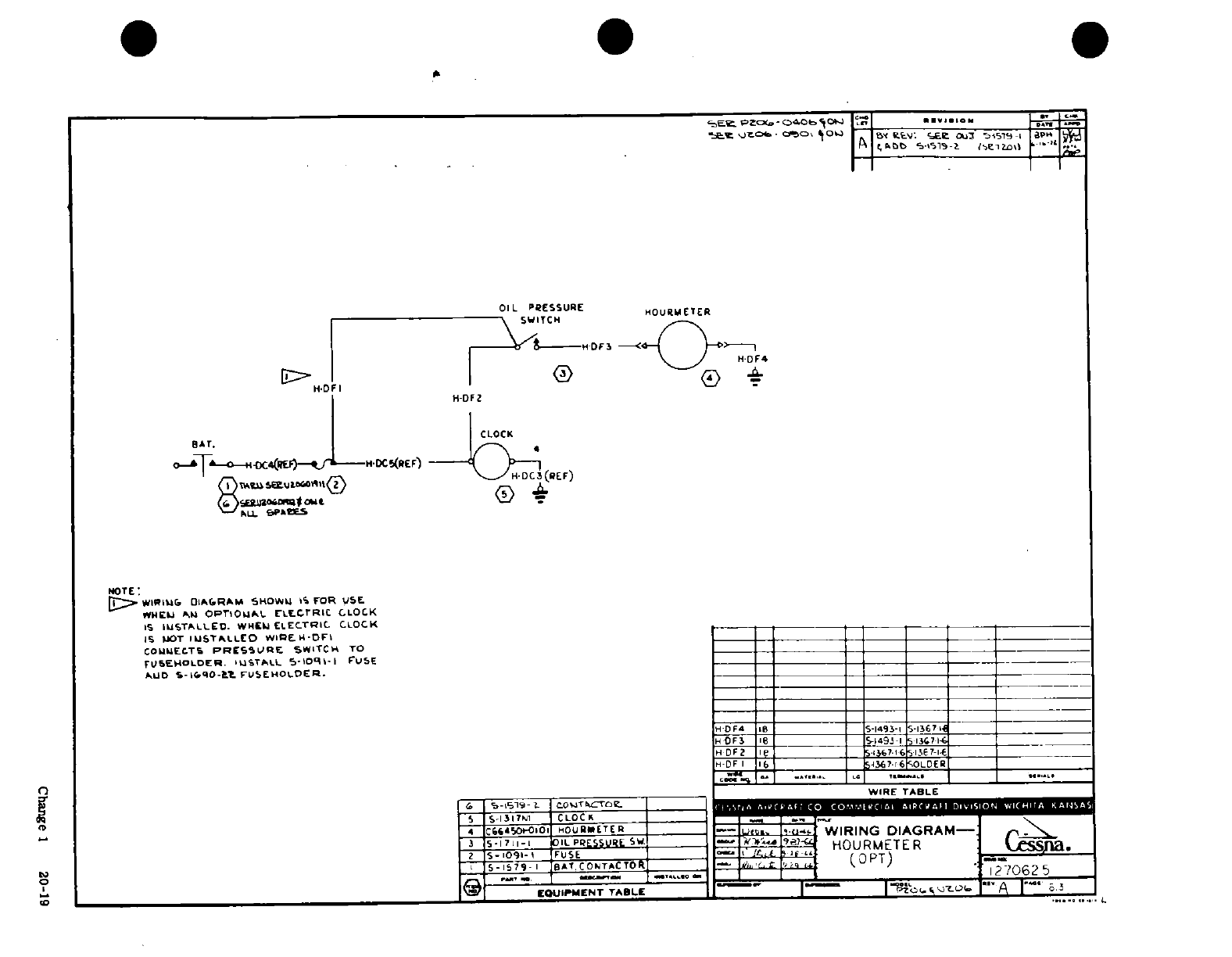
:> ^ '/' ^
/ '
rf
, ,
oo
~
~0
-
---
I
-J
12l:a
,r^C
!
I 20U-1
Irk O'U'Z uC ne
21
o ~~~
0
„o^i-
z *'t a b-ffao~~~~~~~~~~~~~~~~~~~~~~~~~~crtf
~ ~ ~ ~ ~ ~
L
0 s ^^-
, Q
/\ I *u '°'
/
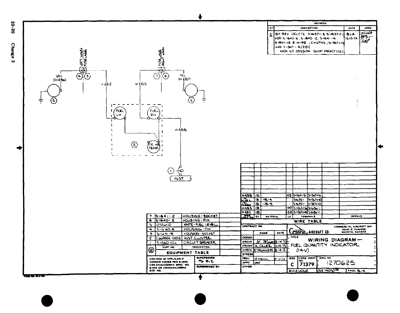
ii
>;
I
,-, a
i
X. F<
-w:-C
.
.l
'
UJr
02
N
*
.W
.
_
~,
,,,
~
<
1
--
3.
: 1-'
-!}
^-^i1 _!® I /I"
T
/
20-20
Change
3
W0-i0
rha
e
I
I
I.~~~~~~~~~~ ^^1
r
ys~~j^^
ui
ja
j
.~
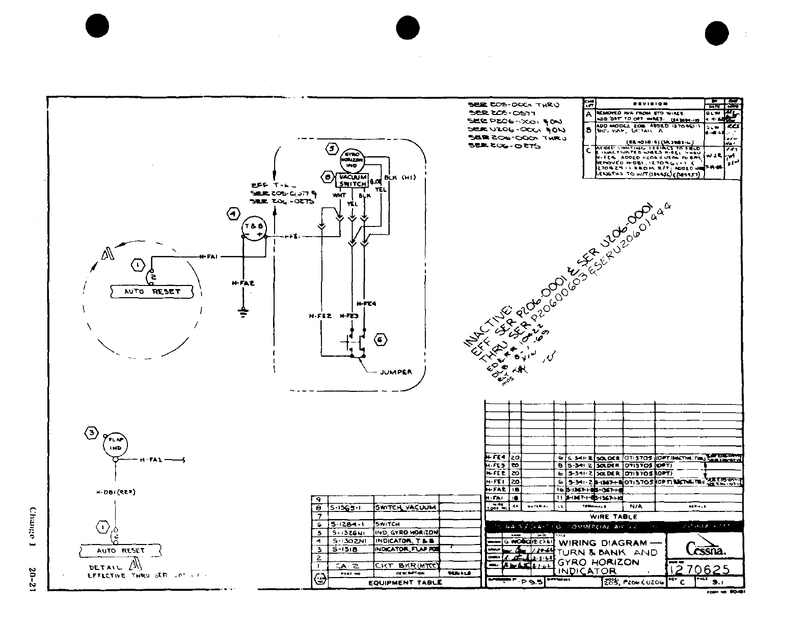
(/-"-
1
I
I I
I 1
I~1~1
-
1
C ~l:P
)
ddf
Sd.i
8*,. Io UE
iK
t
i^ (
-
Mi1f
'
<0 N U
is% iif I-l
Fo
2
00 .H?^3
t
o.
*
n
-.
-
iit
------
2
N
20_21
I ^CI>
'
i
r
i
I
C
T
Chwulc
1
20-21
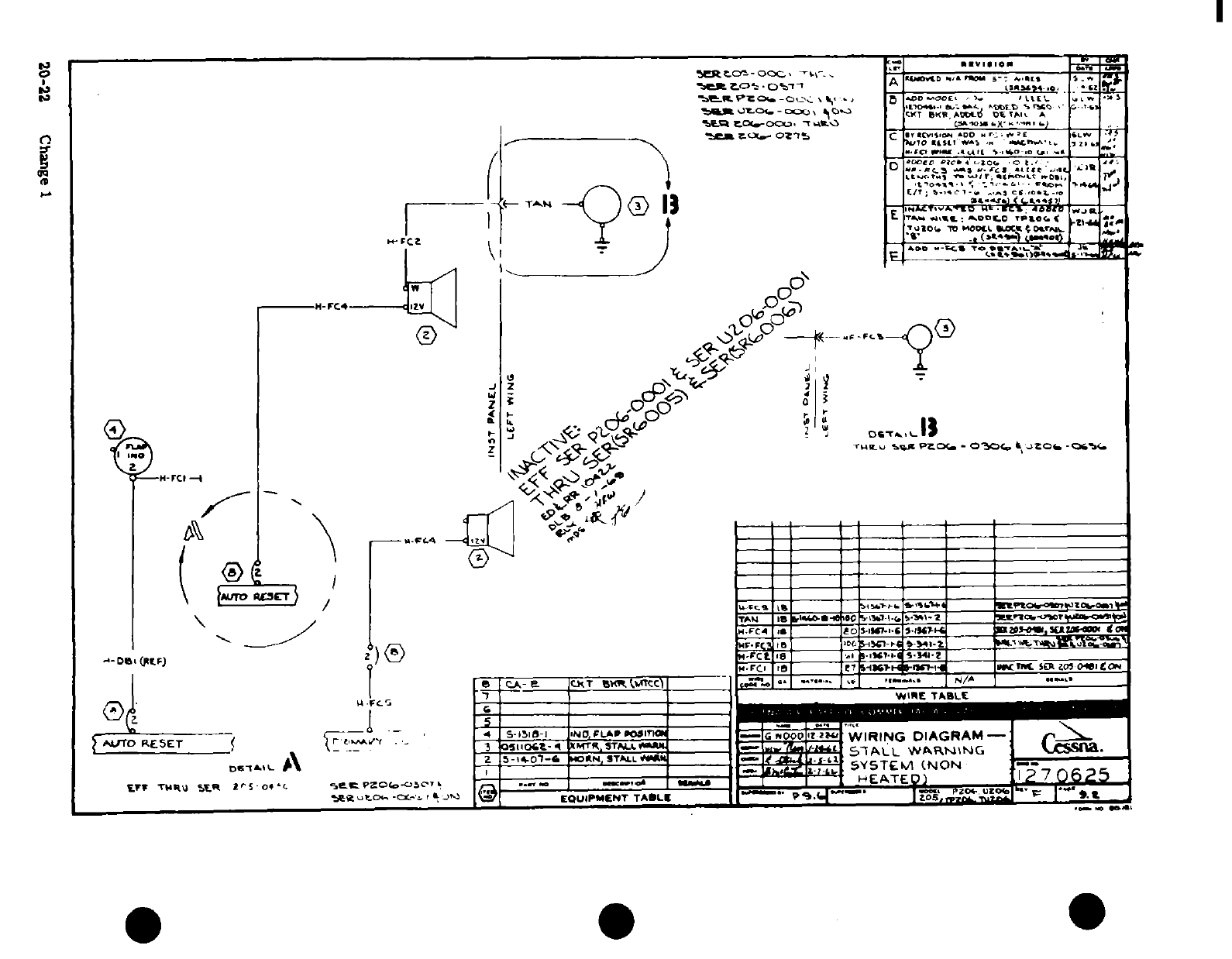
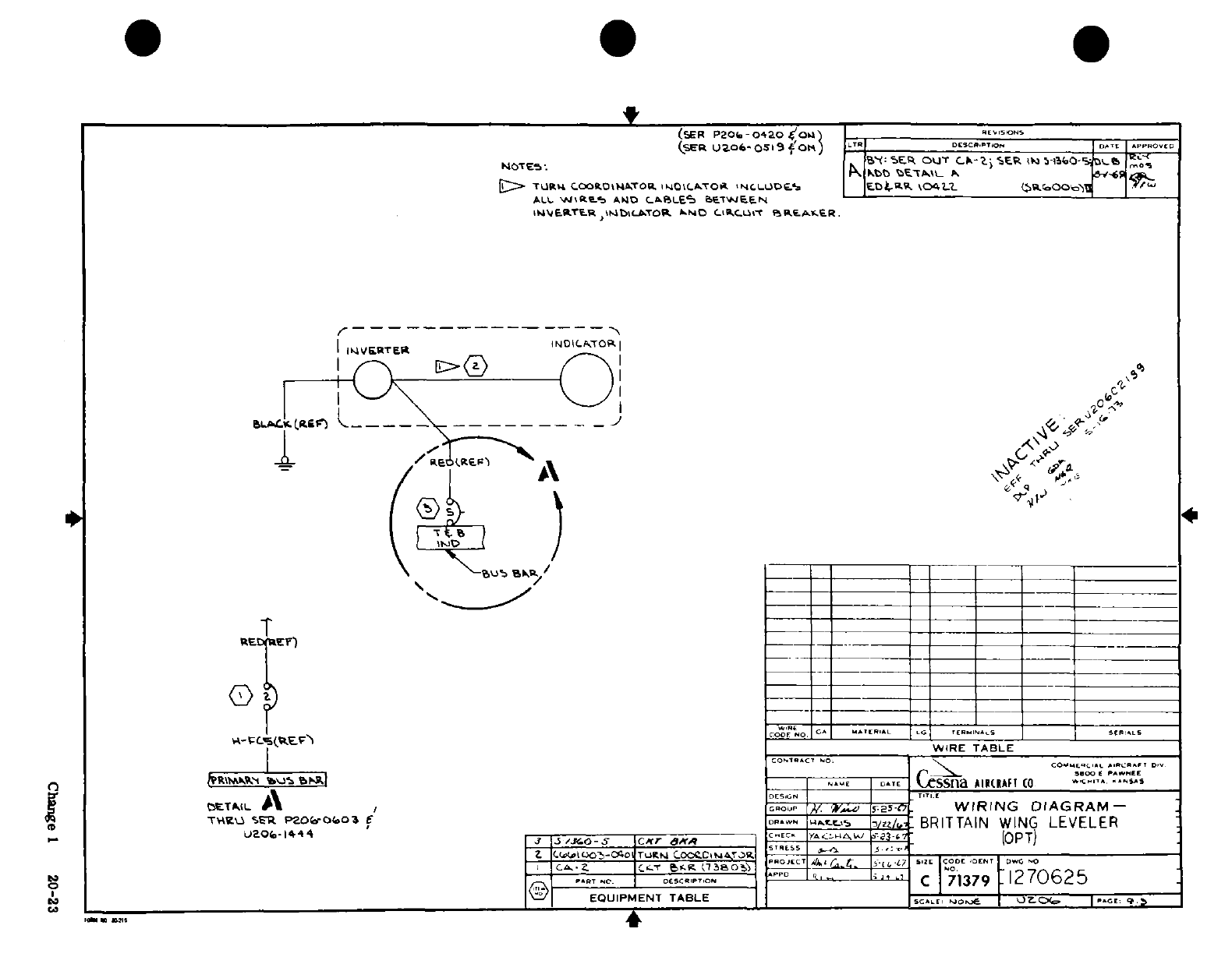
T.3
0
a
ct
"tft
"l
"7
-.
O^ ss~~~~~~~-
4
ran
'Jul0~~~~~~~~~~Chnge
0-3
an
o
„ 4
J-
of o
f
2
*§ § S S
s
?
*
S
C I
J
-
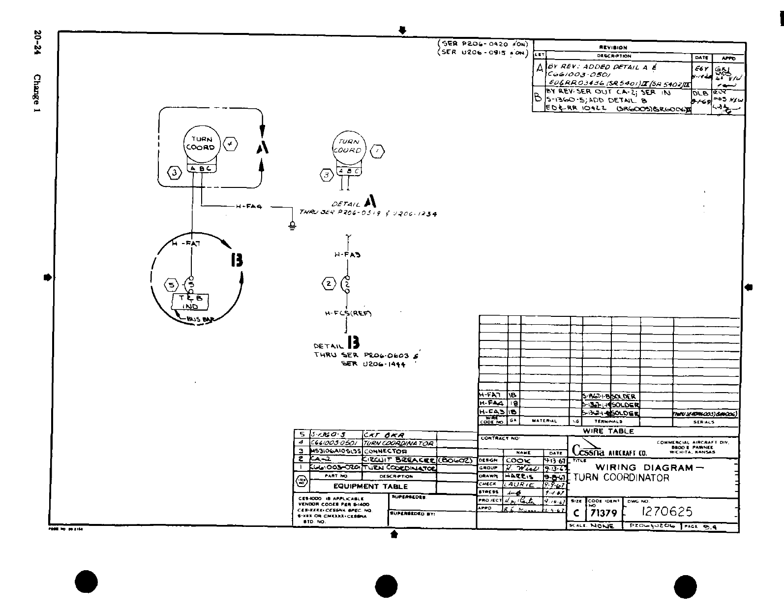
I I I,
/
I,.
n ^ L'^ ^^ 5~~~~~~~~~~~~~~~I
,
"ig~jl-0 (AVi/g;I 0
---
: <
co
0
·
f I
'0
I I i$s 3
oD
t
0.r,
i'i ^ 4
-rr
^.,
--
Cl1 i,,i 1Ii g
ld aiS&
0Ci 1, '^
^
-
ml
^'*'"J'^ o"".I?
4 p^ ^
§2
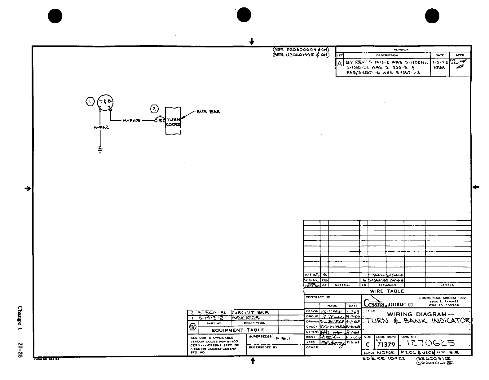
AIRCRAFT
0 a
1
l'
nip)
Zzd
)
-L
a of
-
z Sm '-'AAY
-4
o
j-
A uJJ
;
2
8
.i4.
'P
-,
I-
K'^-m~~~~~~i,"
a-^Otl~~~~~~~.4
511
0br 1
'
1'~~~ ,.-LfcJS~~~~~~~~~ -;i
L
jj
8199~~~~~~~~~~~~~~~~~~~~~~~~~~~0
0
M &
~~~~~~~~~~~~~~~~~~~~~~~~~~~~~~~~~~~~~~~~~~~~~~~~~~-
zl
w(
0
4
J(
0."
S
r€ ""M o 3~~~~~~~~~~~~~~~~>02
2 o^
1
S~~~~~~~~~~~~~~~~~~~~~~~~~~-4"
,f |g
-
$
ii,^1
¶ ^
|
\ rj
-
[4^
Ss>~~~~I
)
n i~~ ^-ff~~~~~~~~~~~~~~hne
02
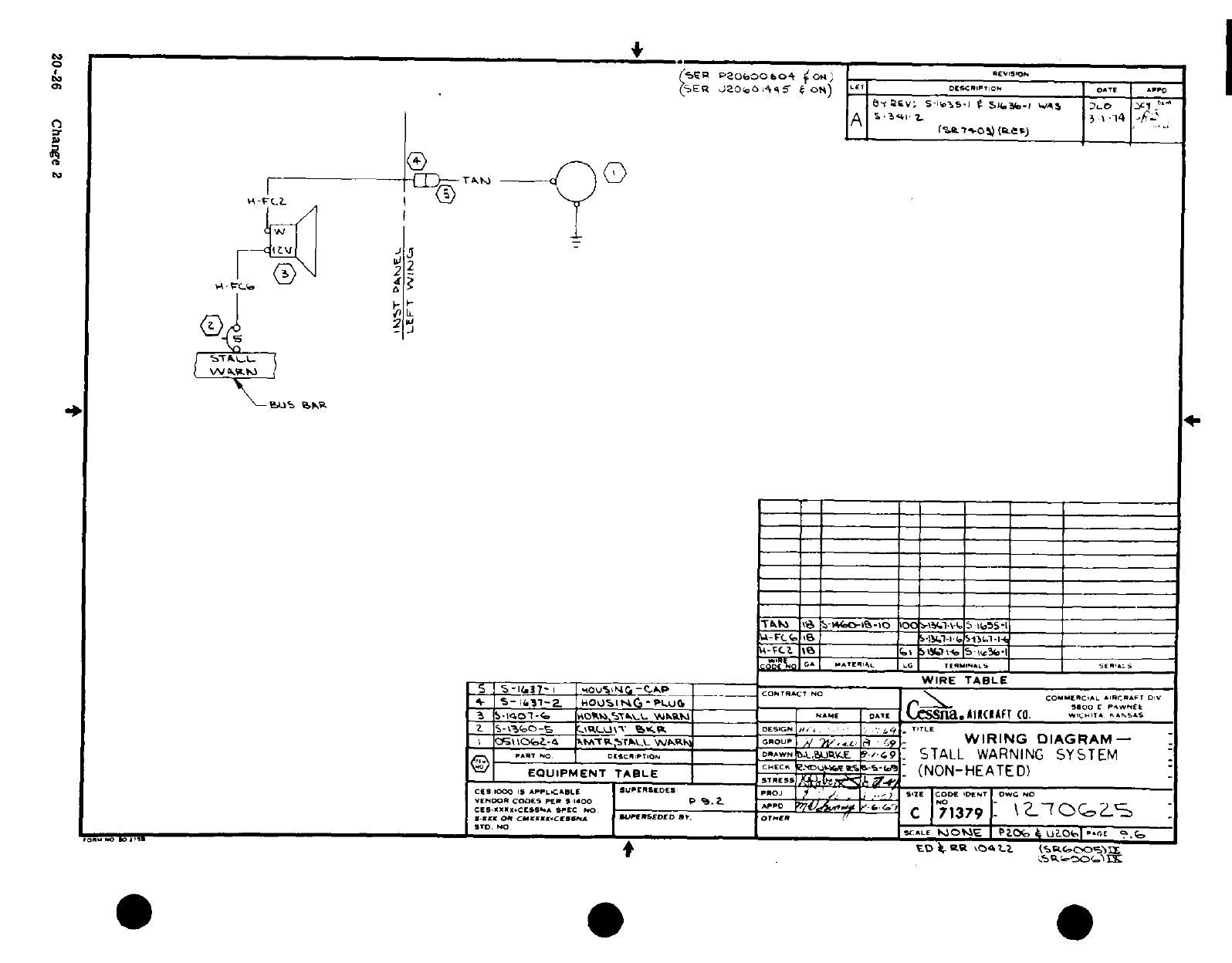
0~~~~~~~~~~~~~~~~~~~~~~~~~~
a~~~~~~~~~~~~~~~~~~~~~~~~1
If)
r:
~~~~~~~~~J
:
4''
s
~
;
'
,-
;
k ^ ^ °'*
a
-
0
-0
' .
A
o
-
I
u
Q
m ti
S
CJ
)
I I II
~~~I
jl I~~ il3
I
5~~~~~~~~~~~~~~~~~~~
VT
/-
~
~ ~ ~
~
~ ~ ~ ~ ~ ~
--
fr
w
S
-
u-'n
-t,-
4
4~
~~~~
-g
0
S
H
|/1|dI
N2
u, ^^ ^
>
'HU
^
^^ K
11 ^
^~~~~~~,
-^ ~~~~~~~~~~~~~~~~~~~~~~~~~~~~~~~~~~
.
§.
3.
^
. I
su
a~i
0
Is''*"^
-
'E
S
01iO C)NII
1
As
>**u~a Tta,.tf 1 3
-
It
-Dts
00
00
0
o
;oo at
Q~~~~~~~~~~~~~~~~~~~~~~~~~~~~~~~~~~~
0
3
0~~~~~~~~~~~~~~~~~~~~~~~~~~~~~~~~~~~~~~~
0 l
4ri
4
aza
-
a
a
wm
a~~~~~~~~~~~~~~~~~~~~~~~~~~~~~~~~~~~0
l
4; L J ~ ~ ~ ~ ~
~
~
~
~
~ ~ ~ ~ ~ ~ ~ ~
~ ~~~a
-
'^-^ /
~
1
5
I-AN,9
20kP
Z*
Cag 2,
20-26~~~*-
Change*
21
'
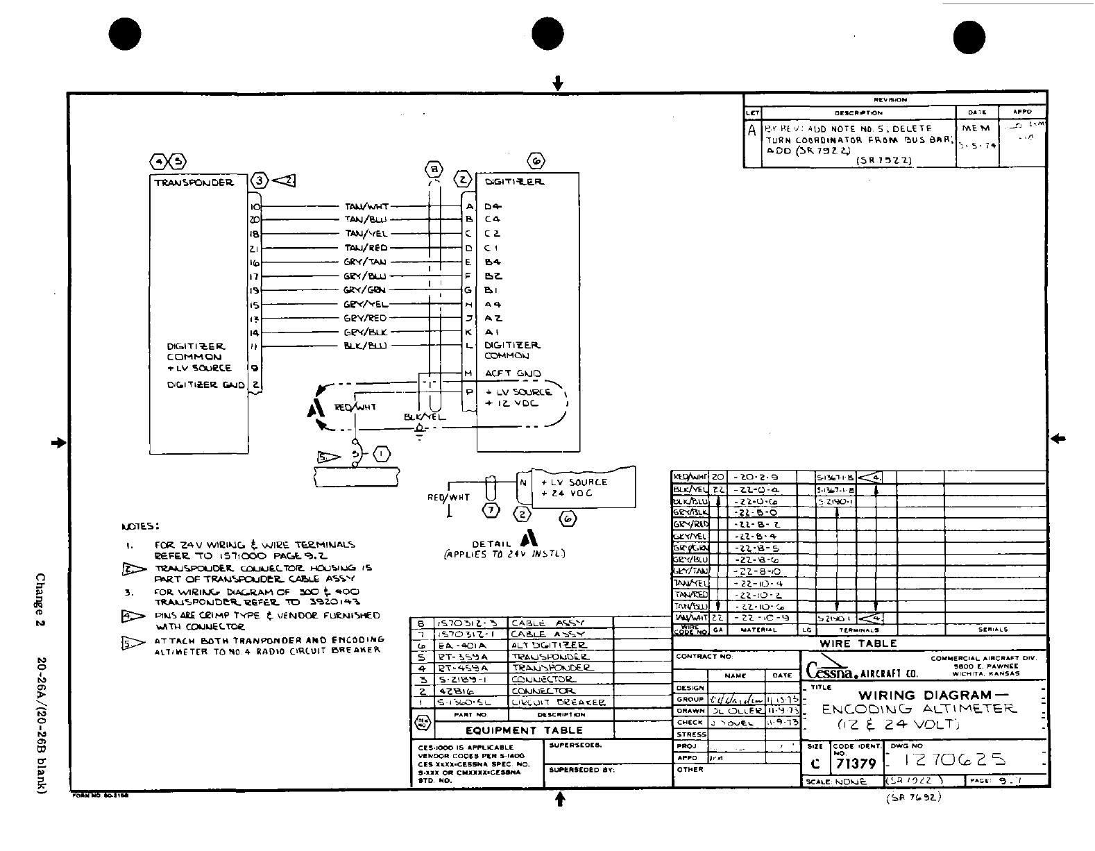
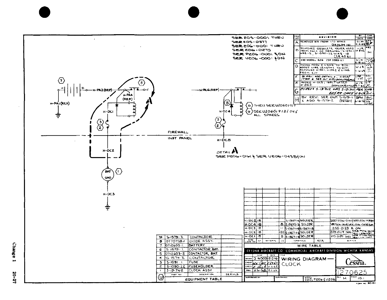
.. I 1/ °
0 7
a^ aijri^ z j
2
4%
I
u~
4
2
L
c<
"
UI I y i
Tn
1
~
..
0^'
f?
i
fl^^.nirt
^"- J
;
'i ,J 0, L
. ,
900sj
;~@'
I
I III:
ii
±
®,T
r, t
~~~~~~C.e
C
1 20-27a
-1
i
0
I
C g 1
20-27
5
"
SnS
-o
v'^
6
v
\\
.-- »
\"I ^
r^
r
*I ^ -" -* n:
^
-1 --
c/5
SV
--
^
-_
,ji,-a
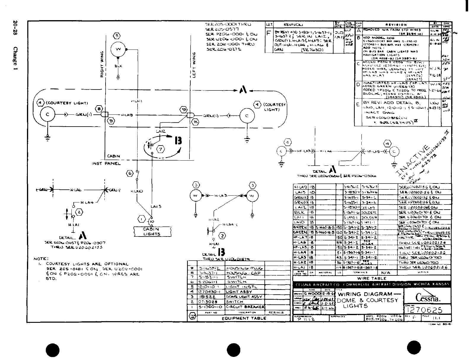
1di
^ ^i-
,'
^oI
.
*-
Da T a04
,
0o"I A-
/
6l·l'
j
a
!
li-
-
n
.o
I
, I
-
3Z L-
;
-
A
< 0
'
D...
00
>
®
-
II
J,
A
In
-"
f
zl
n e 9
^
t
;
ot-
i
s
1 t
cr
^^
a 4__ -
2'
r
°
^^~~~~uV~~~~~~~~? jVI m
£
o
0
.
-'h
0-2 Cag
5
„
I*
I
uJ
5
2
c-
Li ta
I
19?O
(2
0
0
20-28
Change
I
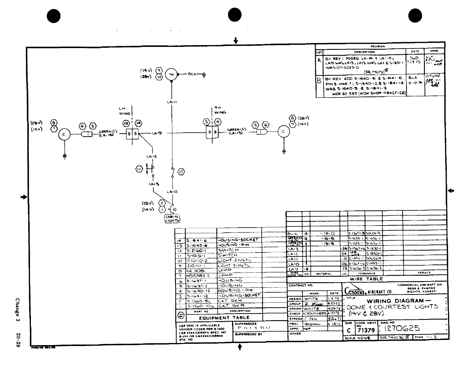
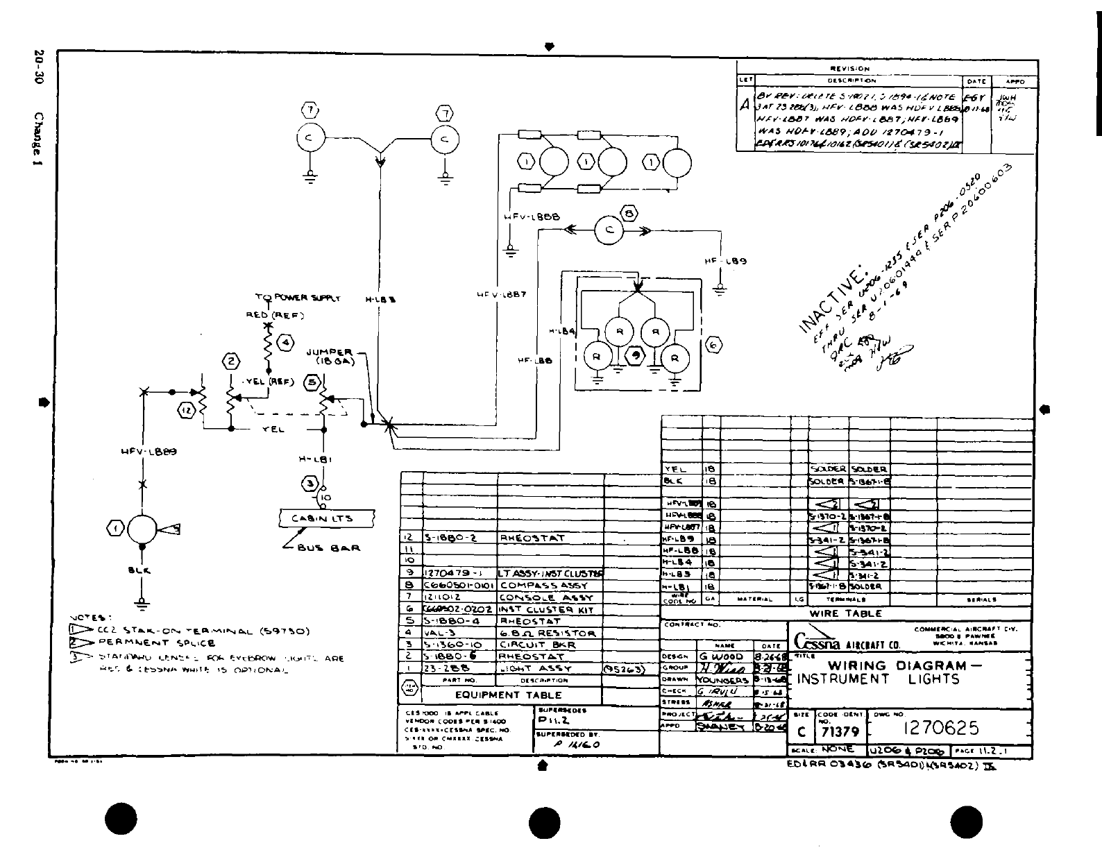
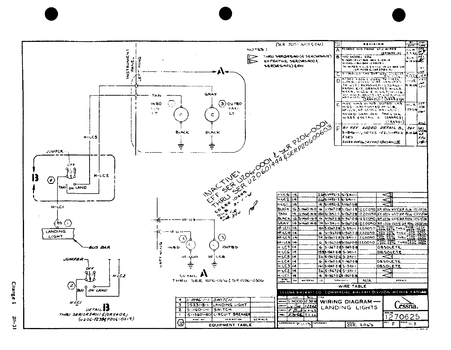
-.
,
,o- I1 -_'
0 00
-1
.,5~
r::~J'jd*
-ID
-IJ:
d.i ;;1V «m P: ° r
3
,;;,' ~ ~
~
~
~ ~ ~ ~ ~ ~ ~ ~ ~ ~ ~
*
,o¥
,c gt
J
0
00000000£OW
in
0o 'oJ
.,
s
' S
CL'^~~: i ?I%
in
Lwld~s~a~ 6
05^' n o
<?9^®
i?^^-*f
Cange
I
2011-31
?Y
^ .5
4
io 1
-
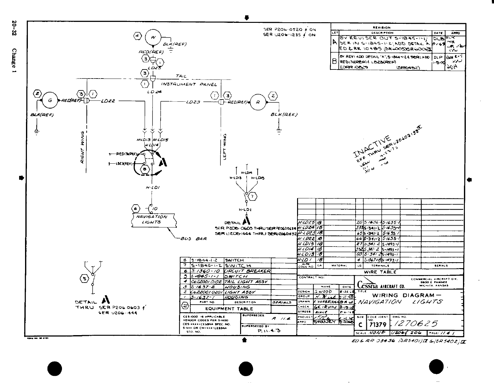
SER
P206
-0520
&
On
REVISION
32 SER U206 R-
1235
*
ot
..
Bv
S :
ON:
s~e 0W
T S- M9 4S
-
| -1; D^ ..................................ET.tSC.PTDAE
PCDa(
P
uao6--s 9ONII
kw
ou
-
s-5s-'-y
t
MtibGat)
*R N3 5-l"4S-<---,--___ t)CTAE
'
-C4
es
J /_-LI B <
REV:
ADMO
TAIA',s5I
.1 -tTe:AM
DLP
dwM I
I
Ti l
B
Rxe
WeP(bC)L
LBZSREi:
1.
'.T
1
W/
'
I
D
mLD2
_
EDrB
tO9g __________
aEtfc^^zr
__^1
BU(a/Er)
3BLk(QEC
Ej
.
.I
.
I,. 1 6<
Kv
I,,LD4LTI
\.\-'
Ij-
I M-LD4
*
jW ,LDIS
H-LD
4
______C__ = _____-_D_ = =
_
)
/A
V/6ARTo7,
_
(
i/ z6ss \
DeTAIL
A\
-m2z5
J/a
5
26
45
5-/GJ5
---- ^ ^~5ER
PZc-Cr5TmUeQROCGSb,
4-0Z4
/f
7-3J4S-4-t
'g
35-
~\
~
SePR
UEOt-I444
THRU
aJrfUZO0432
0
-tg
4 -5
9--iE
5/7__5
/
t'-5
BAA
202
Z 46Z _
6
1--2
5S/65-
LI/5
/Z
_____a
27
5M/2
S-/93
-/______
7/-ED/
x
3S2
5.7/-Z
S-/C93-O
N_ ______
2
7
20*-1-
ISW0
I.TC"
453
E,.N I 0 6
0
-
9-/
_
\T U6
3
PJO03- /0 /C/rEU
WEAKER
TBE'._
"__
WIRE
TABLE
R
/e\
/
0
i~e^-5
*7+5-
/ - /
5
E
rc
S_____
_ ______________
CO-TB*c~no:
-------
C..
-
C62Zao/o/oZ
TA/L
U/CAT
A55V
_ r_
C
'S, ^i ....
rI3
S
j
6
5^37
z
vo~j/^c ___
i
os't
Acssna
AIRCRAFT
Co.
-*
ssAs
Z
C62
007020
/
G
/LC
6. VSA 55VP IS P1
.-
I
"'C EN...
l
,
3-
/G37-7--ous~v6
oP
/
7TV
: -----
t8^
.
WIRING
DIAGRAM-
0e
9,\p
\
R.
A
"cRRI.
s0f01i
wTAI. Rae.W
C
W-9-mi
,i
4
.
A/
T1/A TZ/16
1/G7'
XER
U20a
-
444
_
5TR-
-SS f f-i-
s
oacc.....
P
^o
w
y
l.
zoC
71379
t/,706
27
5
5'0.
_P
'
C. v.4vA
3
f77I
70,0[
ft"
£9
f
QQ
,
0343
:S
76
/i'6P754v/)a
iS7z
sPsf54
z2
Zr
*
1*
*
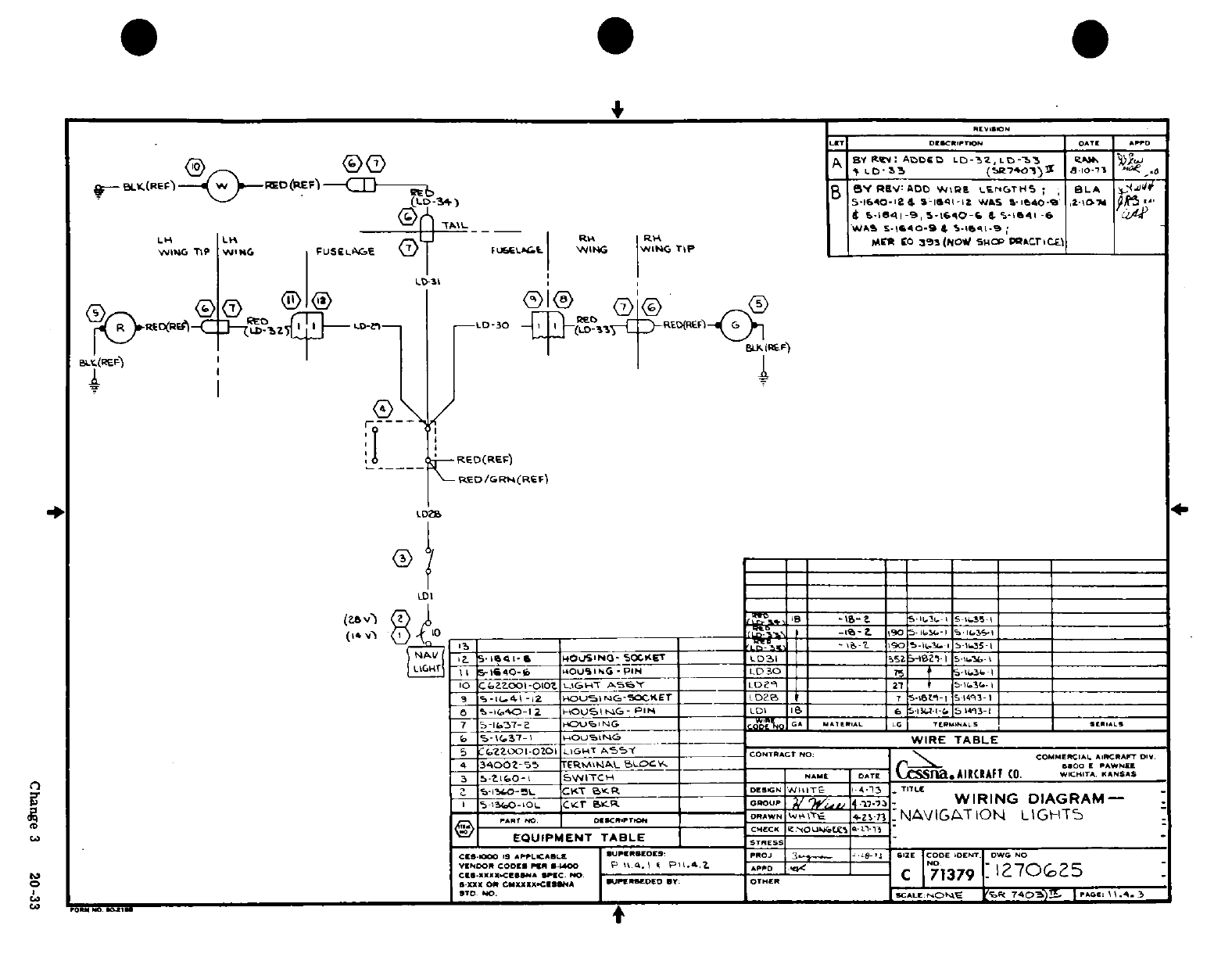
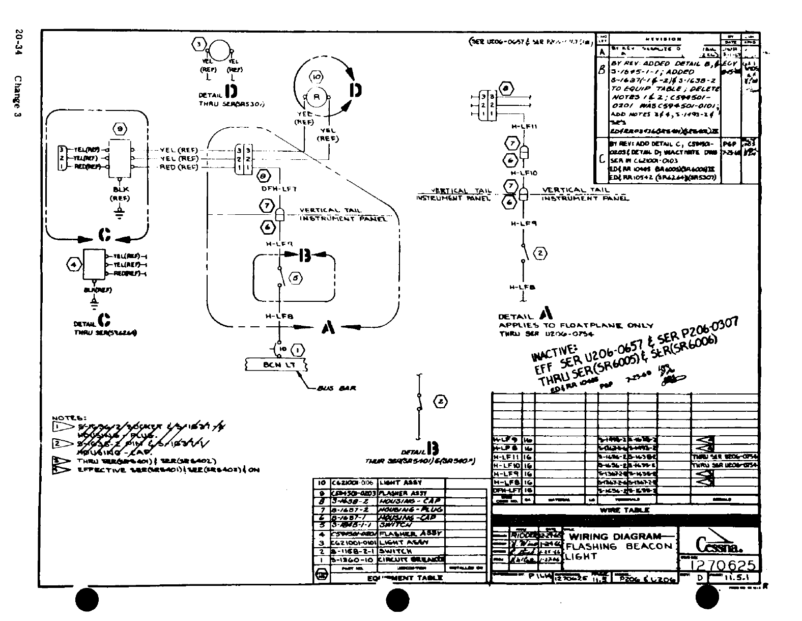
a
*. '
I
I
I1A"
-*
9,s
/
1
,-
i- s
i
/
20-34
Change
3
TTT
0y
/ ,£1 I
-
/
\ jI
/-i
rt
--
i---iI
0
20-34
Chng
S
--
UJ· 'a
JJ^
%
&£Xl 3
-QDO-
I
k
*
¥Xt4
»
'5~~i
h'l1
,vi
A
__*c. v a f
^
dB-~
A
^, ?^.yt
«
W^_ J®S&&· 5a&
20-34 Change 3~~~~~~~~~J-
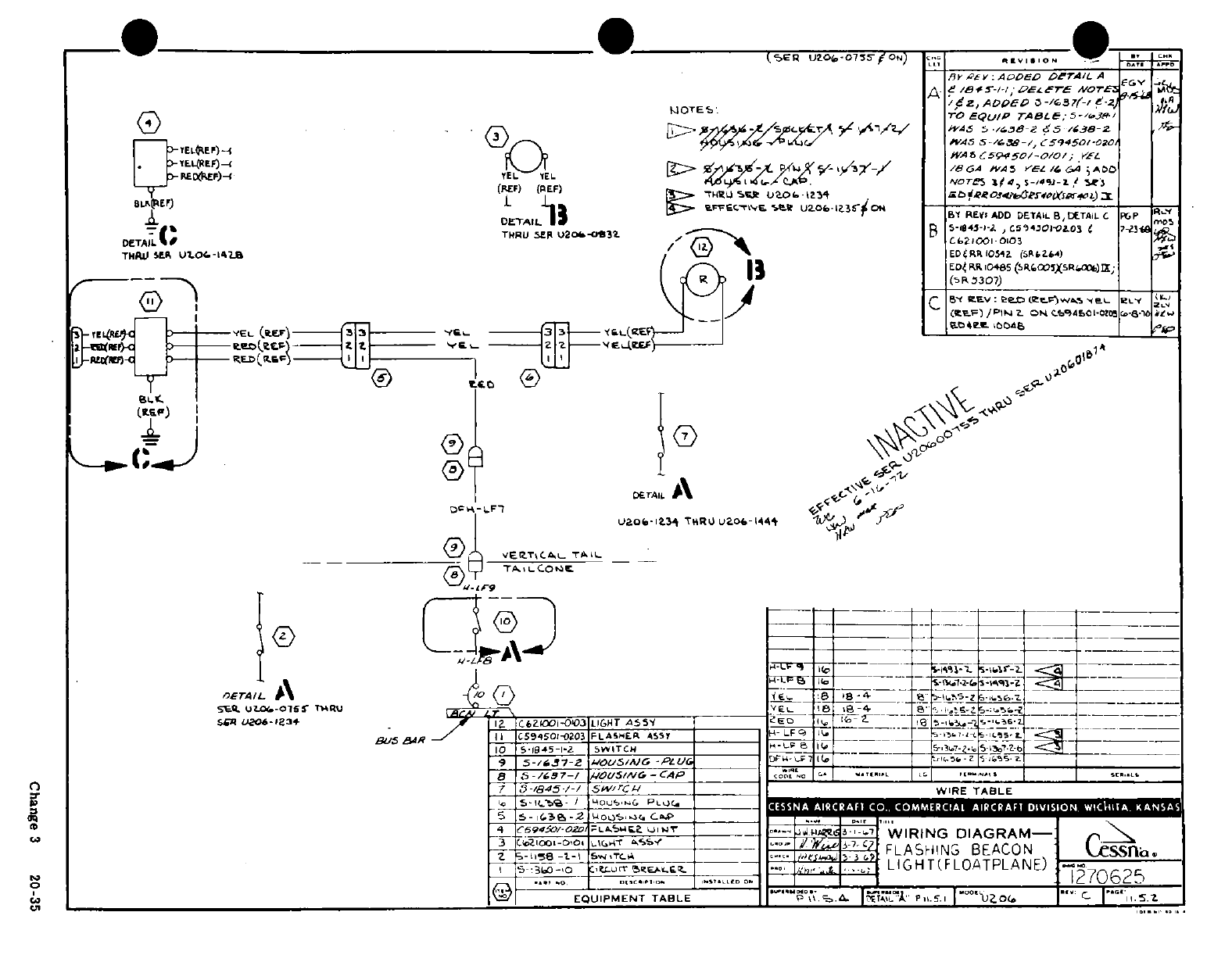
2
.l
..
2
I
I
.A
,
uO0WLU.~
-,/O
(9
<
Z=~-
e'-
,
,.
IM
I
-I
0
·
C
3 2\0-3
^ -S. \j
--
a
<
,
3-
-
N s-h
^
iJ
4
>E
F/
a
3
0·
IN-
,jr-a
CD
-i-(r"
--
^
,
Z ~
~ ~ ~
*
®(
s®®'
~~~~~~~~~:"~~~~~~~~~~ s
--
~~~~L
~~~~~~~.J~~~~~~~
z^
-
^5
I^ :
y
\ _
ff
'-
w~~~~~~~~~~~~~~~~~~~~~Cag
3 2-3
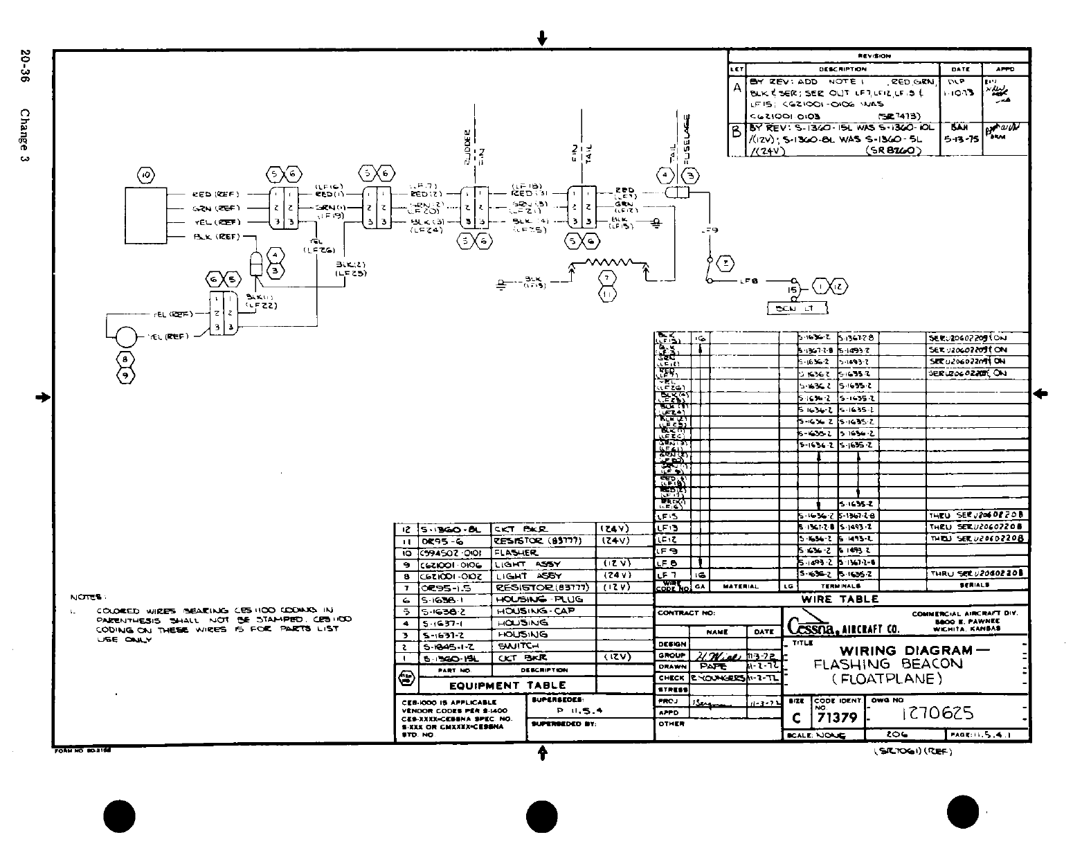
|
§r
-
i
-
^
01
I, ^ *v^
Fl
mo ¥.1s
I
'B ~ ~,-i
-,
~
?
r~, mji
-L i~,*t ;,
> i 1,1-I
a: I^
.1
4
* -
uI2I
0
.ei F0
/-L^
i/iin~ji~i
/i/'ir'i/'^
if
_
yiif
/'i/'i/ii/' ^ It t
:
4^ ^ .4
S
2-<
CI ChangeD
^j
I
6'm
"
Z t1
a
L
-
I I2
jaar
P
n
r -- -i i < "I .
i.
Lw
&u
J_ I
I-
hcj O
I
r z~ilj~s~r
2
I3 Change I3
20-36
Change
3
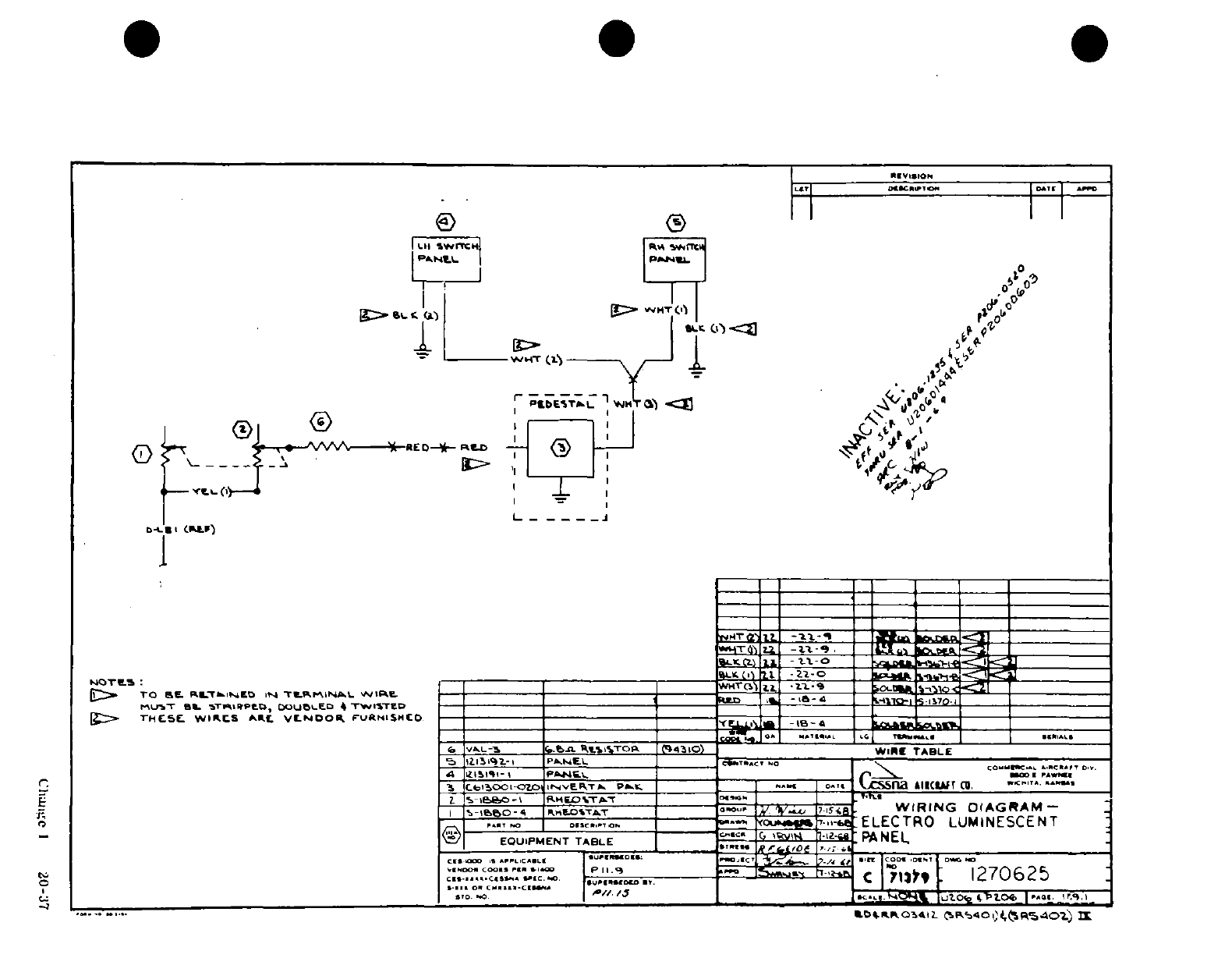
"*^.-i a
wt
4, 0t II
D
8 I
-
-I,
-_
·ii
v·v9
Bl~lnl
v¾
1
-
-· ^S'^XA^~- s: |.
5,
C1
I
20-37
I' <-^^'~,^*-~~Ci 6
'g £
20-37
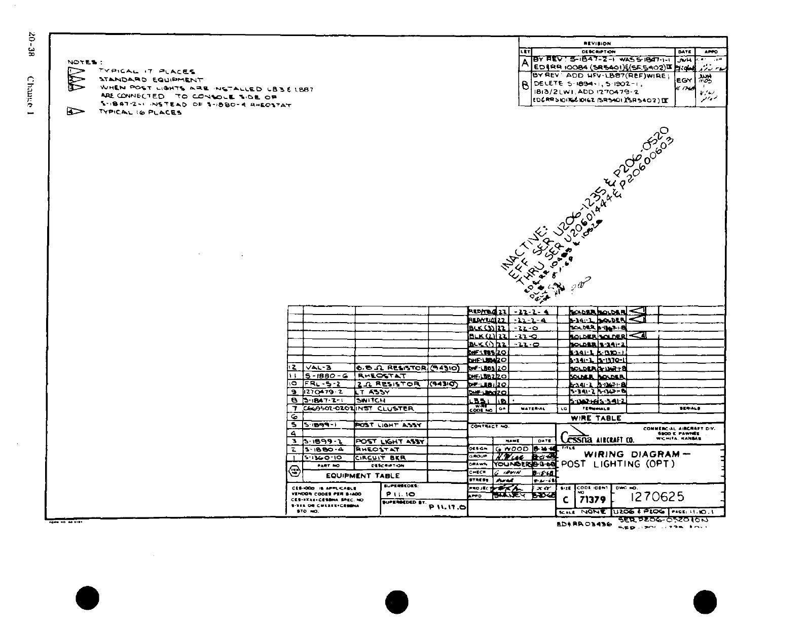
IIE
~1,.
.2 ' ' "
C2..
A
I
fJ
i
!
!
,l
0
0
'J 1 °0 kI c
I
I
xI
'
o
z
<
2-
-.
eloF-l
,
s
7
W d)L
tOy
I-J,^!
8< »: z=zs
0,
'° i
o.
'
%{o-
'
Il,
'v/nir e
aa
r
0i.. >.
on~la~h H~a
ii I 1
6,00
6
s05
0
" 0
a
j 0]~ ~~ ~ i
s
I^
OD^
ISLLJ-
^
2
0
0
Z j5ji~~~~~~~~~~~~~~~^
'
J00
ai
z
..
S ;-r
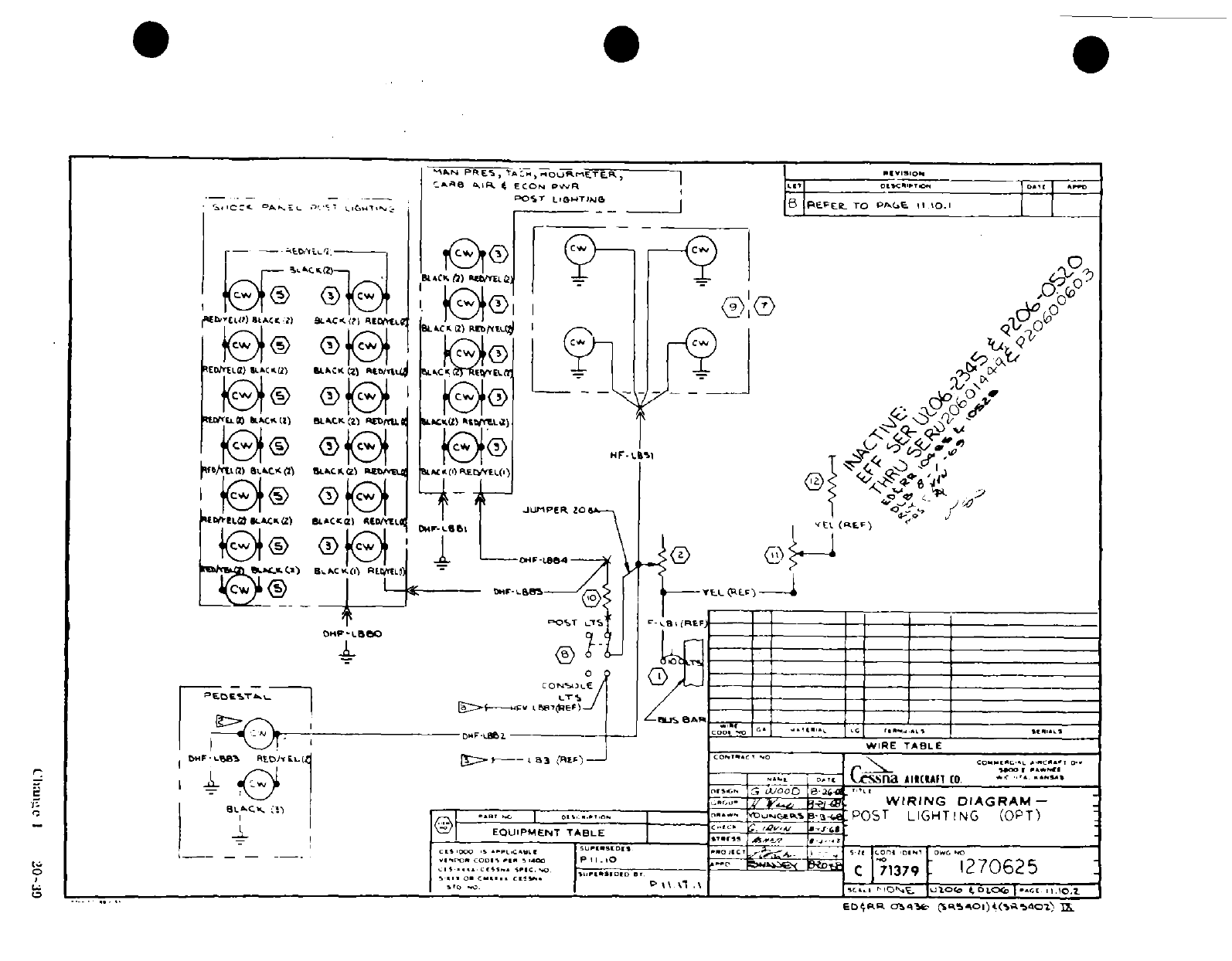
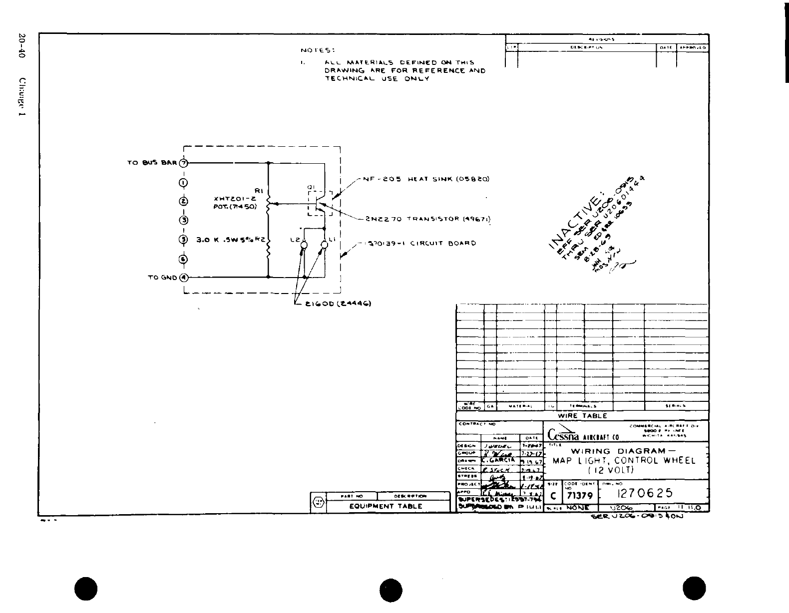
~i ,0
S,
~'~
%
?~
~ ~ -~
-' -
oT
1
-1 _ N- 2
.
\j
a ~ ':
-'
0
J0
~
0Z16, U
0~
:
'7
,
7
00
-
w3~~ x
^
'
^
-
0~~~~~I
w
~
4
Iw
-j
-
o4...,
r- hi
a20
0
:
I
I * *
20 j-40~ <I7
I
-
?r
1
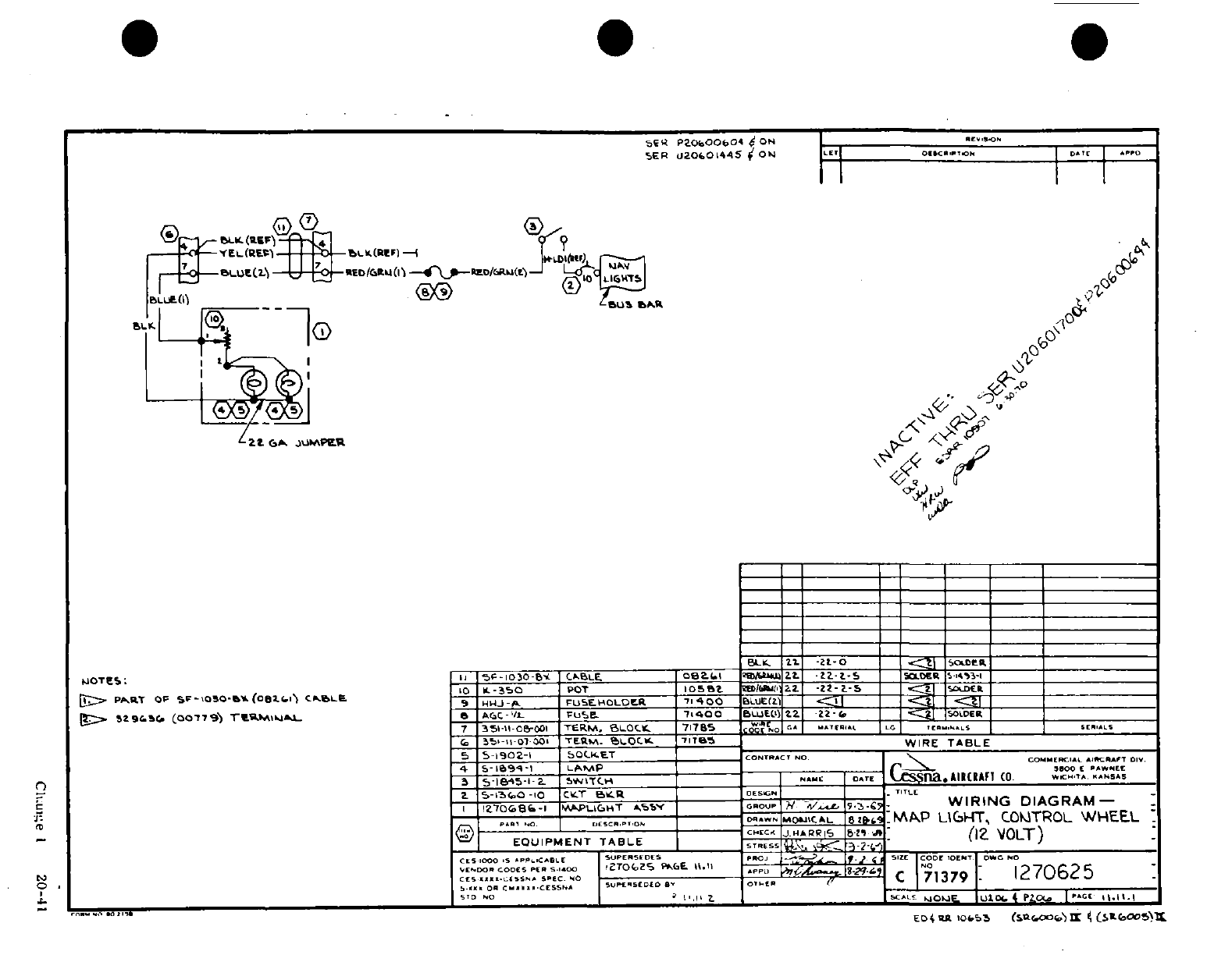
0
<<-4~~~~~~~~~~~~~~~~
A
OOr
00r,
,r
0CN h,
I
0
*~
3
7-2 :I~~~~~ j..^3
T
6
5 iit
r
tt
s~
3~f
a
-
it
a
4
s
0
a
*
Cli.un"e
I
20-411
' $
So^^OtOBg
a
"^-^-^otf's^^s
a~~~~~~~~0
q,
7m-)^;iffi<DaiflO
;
3~~~~~~~
O!F
goif~r-^
t~o
p 1i0f~ni//"S
SJ~~~~~~~~~~~~~~~~
~~~wz/*'
I
^otf'tfi~~~~~~~~~~j
in~~~~iflrh~i-
t-e
0)
;
41
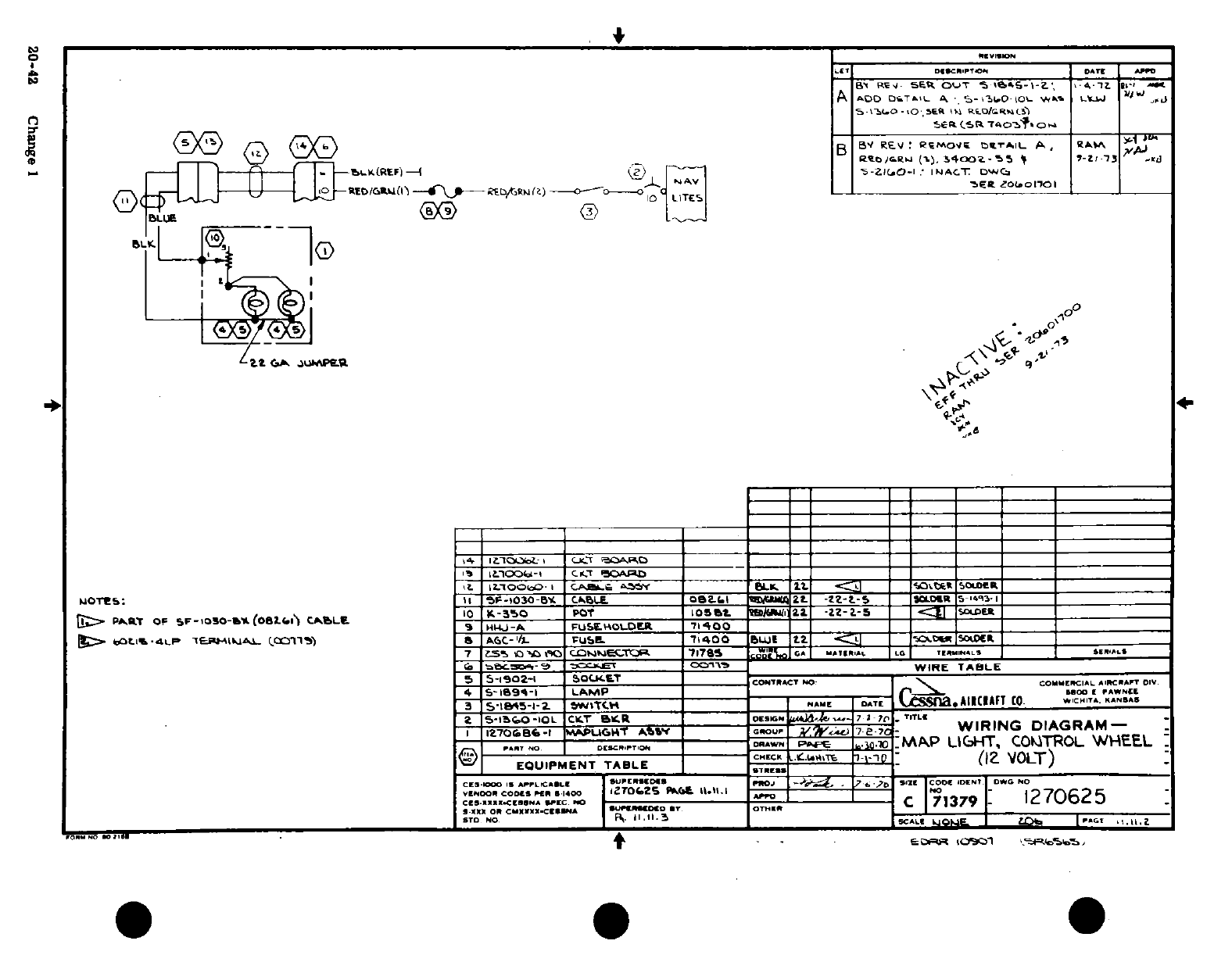
jU^1~~~~~~~~~~~~I
I I,
AI -I
p6
x'o
j
No w Z C°
,%
p
a
I.I
d,- '.1 ~ I!.
-1
La
.
a-.
-- Eut
bc cor <
£
rO
co
f
'r-
2
p
r-^/r-7 iS^
?3 I
3
0-I--d
-jiomdd E i
|
O"
t
ing
20-42
Change
1
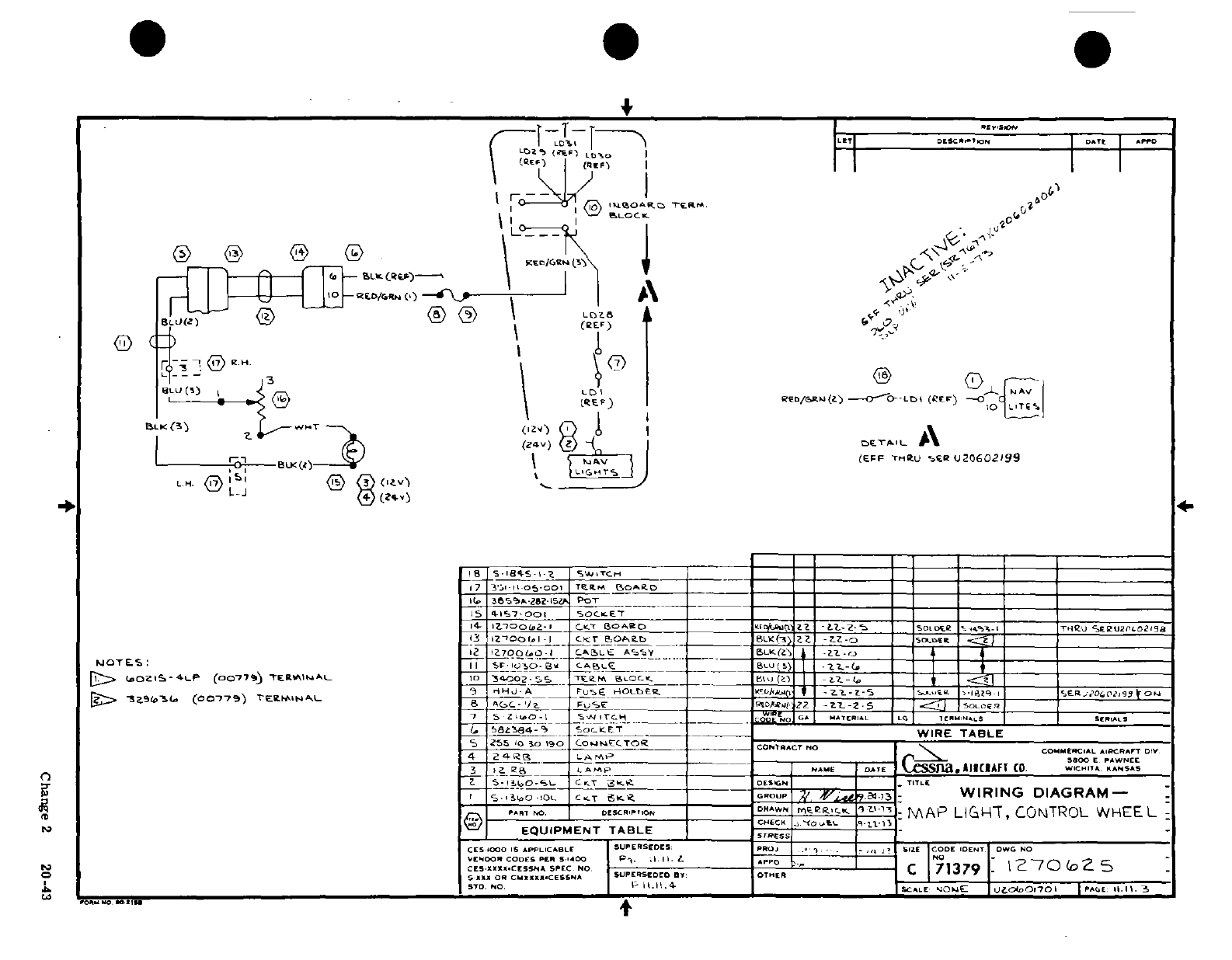
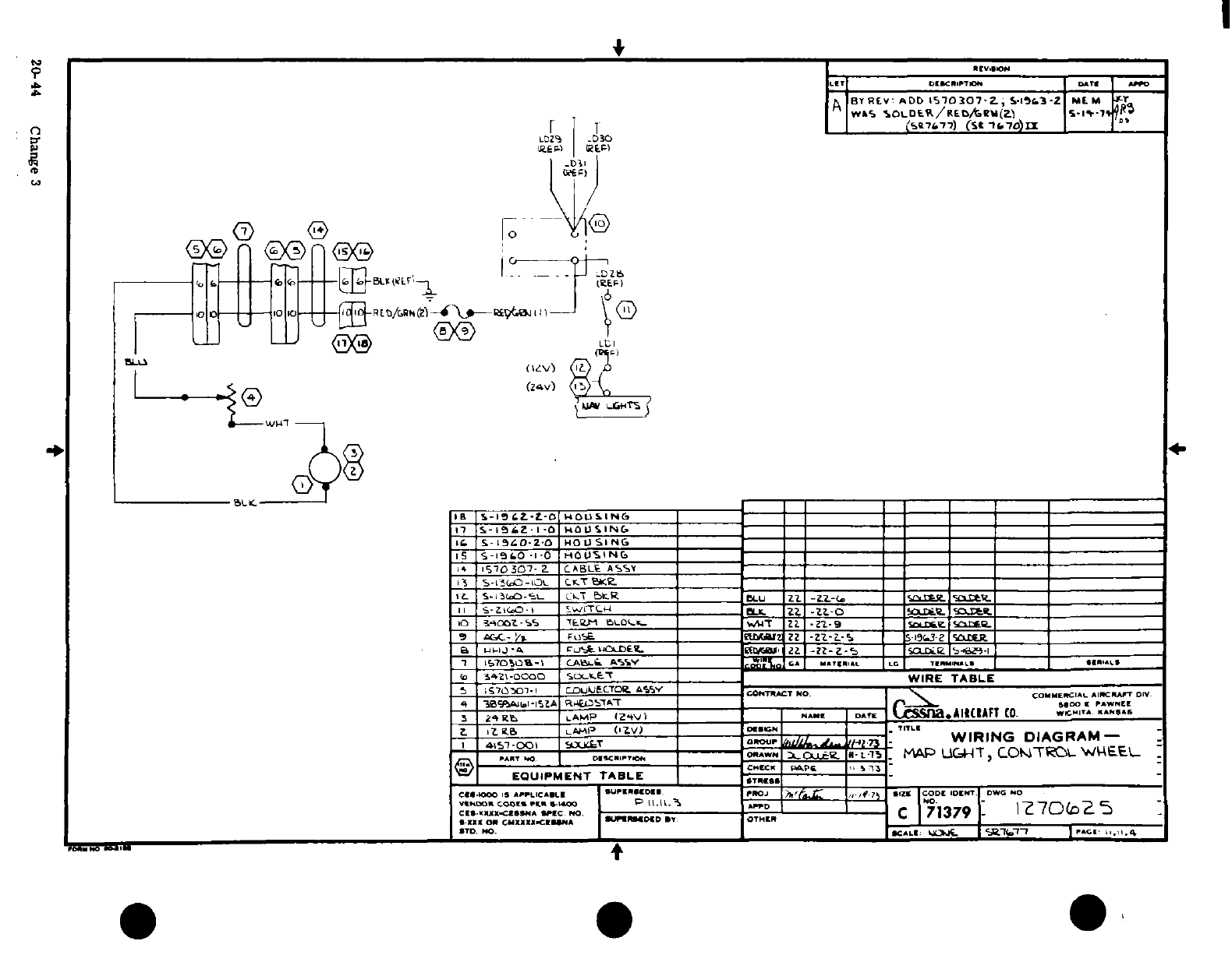
oiv
>
i
~~~~~~N r»~~~~~~~~~~~~~~~
r-w
$
8
5
Fr-
^5~-J~~~~ ~~u
a2
I0
N
' ' -
,-1
c
i
Ej
-
3
w
a
I
®0~~~~
iw~~~
-n~t
n
jl
YO :::;5
c
I
t
r$ ~~
~~
'
A
F
20 44 Changeoc 3
9
2
~
-
r^
.. " .-.
^
jl
-
i;;
..
l O "'- h
1- 0
*
.
'
ribs^ o
nn
^ r^ 0
!
S 0
'
io :
%
^ s 'a^ ^s~gf~f~irs
L
--*
t 1 < ?? |^ ^ ?§~ a
a§
M
0~~~~~~4
20-44~~~~~~~~~~~~~~~~~~~~~~~g
Chne
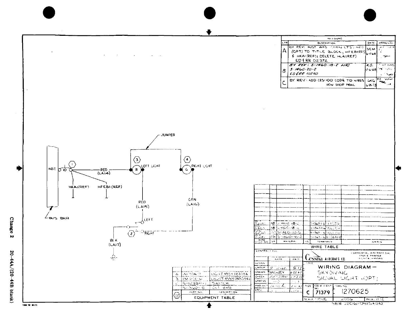
'
f
-
'C
? -
-
-
-2
i'
*'i
.-
J.
z
'
(d
^^
-.
°s
-
< ^ K ^W
coa
-7
¼'I
i
-
7
P^ ^^~~14 s
(j-
-
U
:
->-^<-^ *< >
"
*,'
1
. '
'~~~~~~~~~~~~~~~~~~~~~1
^~~~~~~~~~~
I-^D3
\ y'l
'".
^
^*
n-~~~~~
~ ~
~
a j
_
''-
0-
_
> Pv- > t s^
>- ; 0(^]^' <; 0:^ v
'-0
S^- ^ i *<; o i
-
?
;'
'
^
**-
2<
03
U
i ]'J ^ i \^ ia
2 ~
~ ~
~ ~ ~
~~~~~~~~[
"!'''i? !-;
.
n~
~ ~ ii^^ : ^^
L~~~
4-'
\ ? '~4
^~~~~~Cag
2-
204A04f
blnk
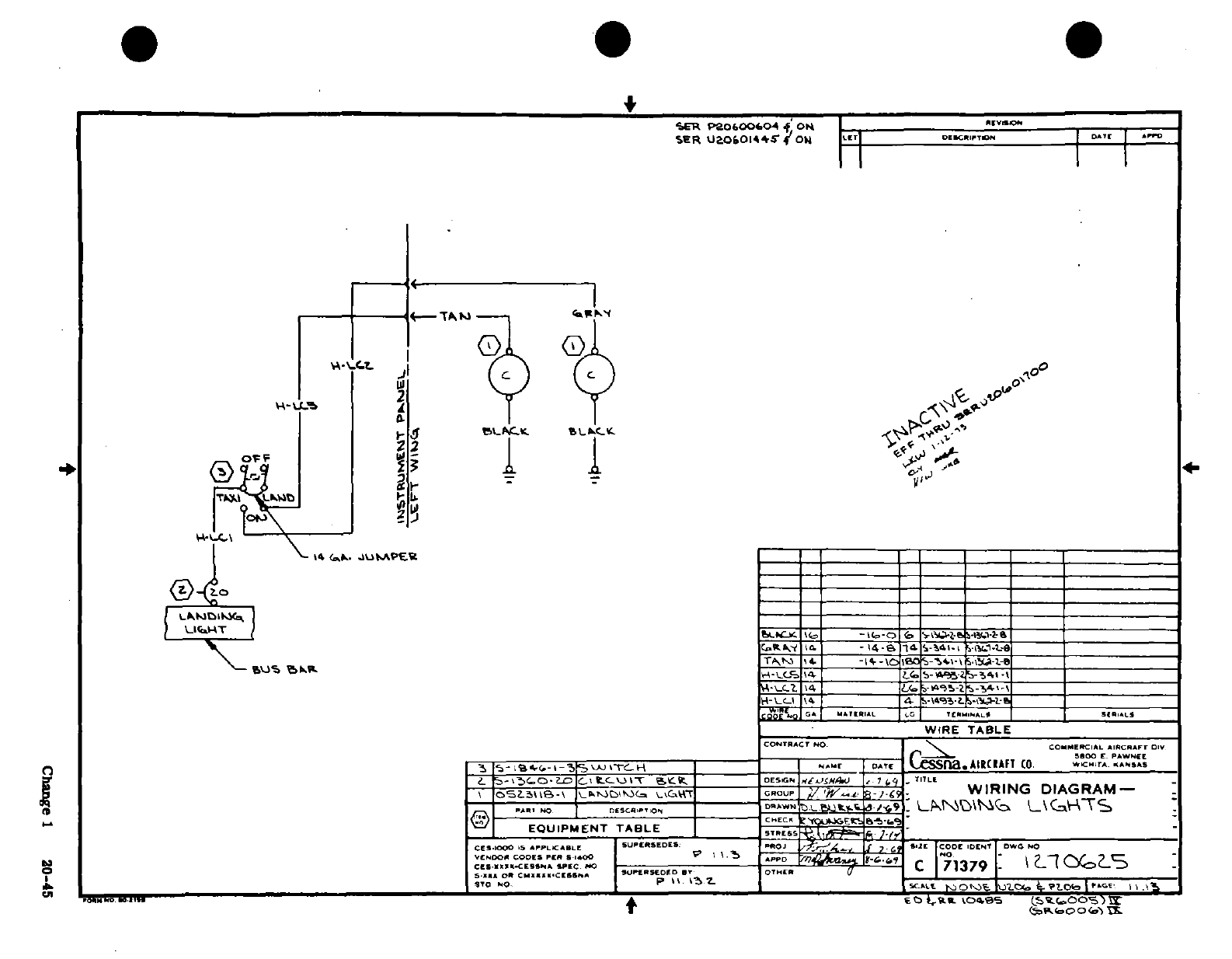
s
,"
Ir
0I
i J 'o^-'l
;
o
> ~ ~ b~~~~~~T\ ^r<-^t;i^ J
J
^
2
S
I \-A I I I I
IJI
*^^-"~~
Ik
ll"l
l 'i I'
2
^
vf
.
<^
S^<^^
a' s.2:~l
lili
%SC'4'4.4
·0,^-
i.
dl,
!1I
J
llj
l*"
>/ ^ ^ J ;!
,, ^
'4,\\^ t+1®.s^^~~~
--
^l'~.....I~e
2 0-
4
00
a
§
s
=
~~~BN'46~
~
~~~~~f XNn54
I
d2 n
A
-
^Ji^L-*~~~~~~~~~~~~~~~~~~
/--\ »
sf
inrs)
;
'?o^~~~~~~~~~~~~~~~~~~~~
i--q u
P-^--^r
*'
^ ^
S^So~~~~~~~~~~~~~~~~~~~~~
|f/\_
J
^
ts4
y"~~~~~~~~~~~~Cag 1i
20-45
~i^s
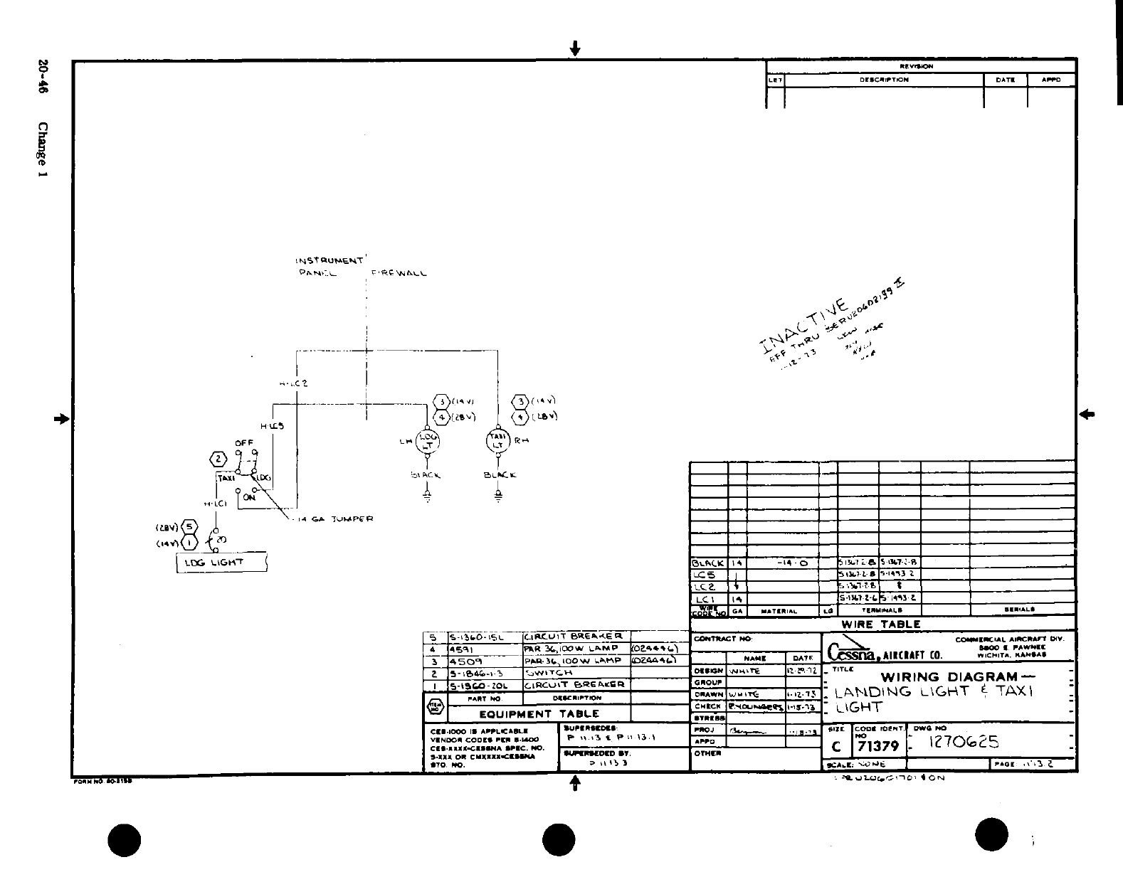
i-
I
l l
<
/
-
? 1,.
t
5
..
-
s
I
-.
-1-
A
A20-4
0
3
-4
j
^ ^
^
20-46o-re~ ~i
Change
I
U.~~~~~~~~~~~~~~t Jr
o
~
~~~~~~~
r
'; ~ £l S
.I
St s h
l
20-46 Change 1~s L'-
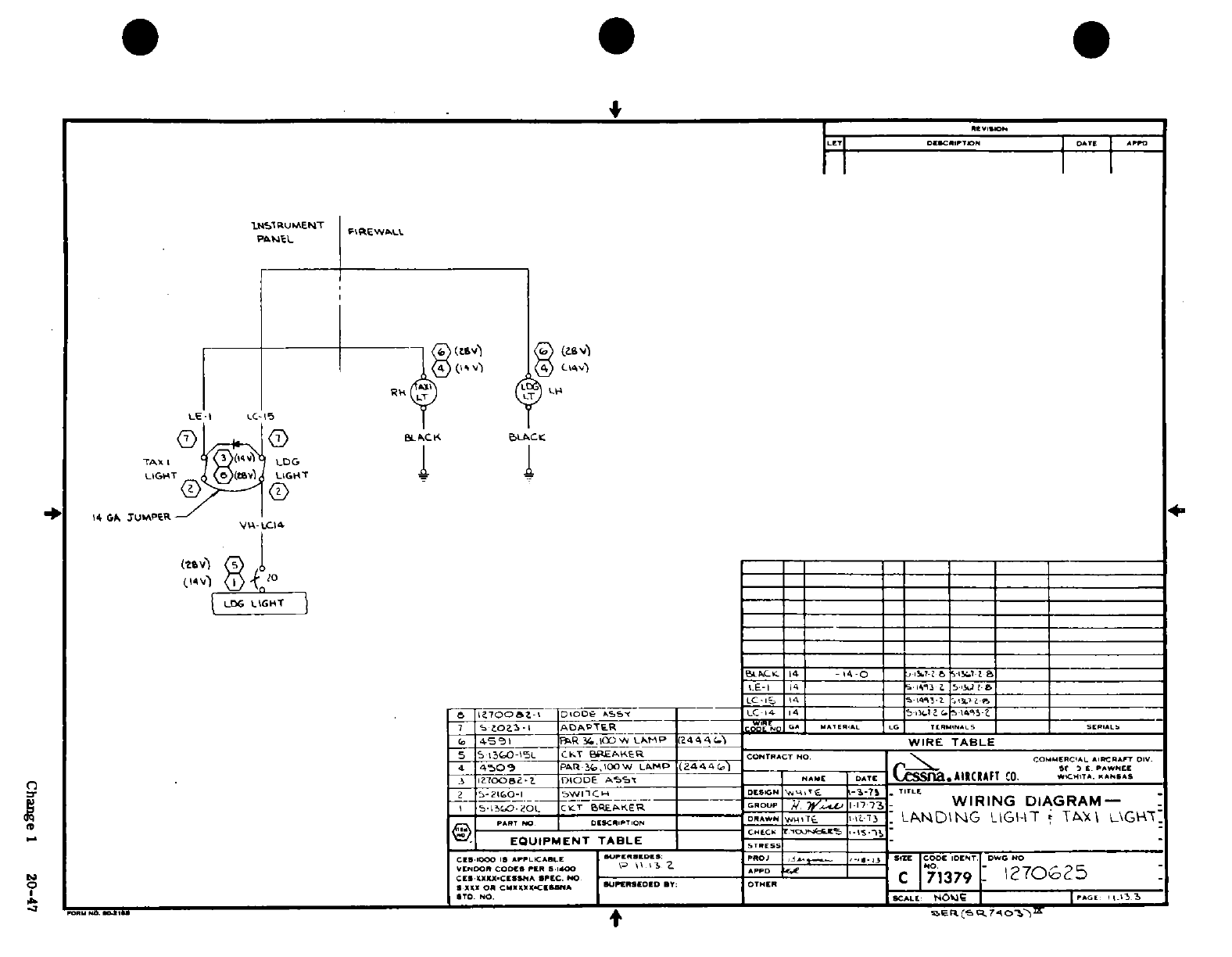
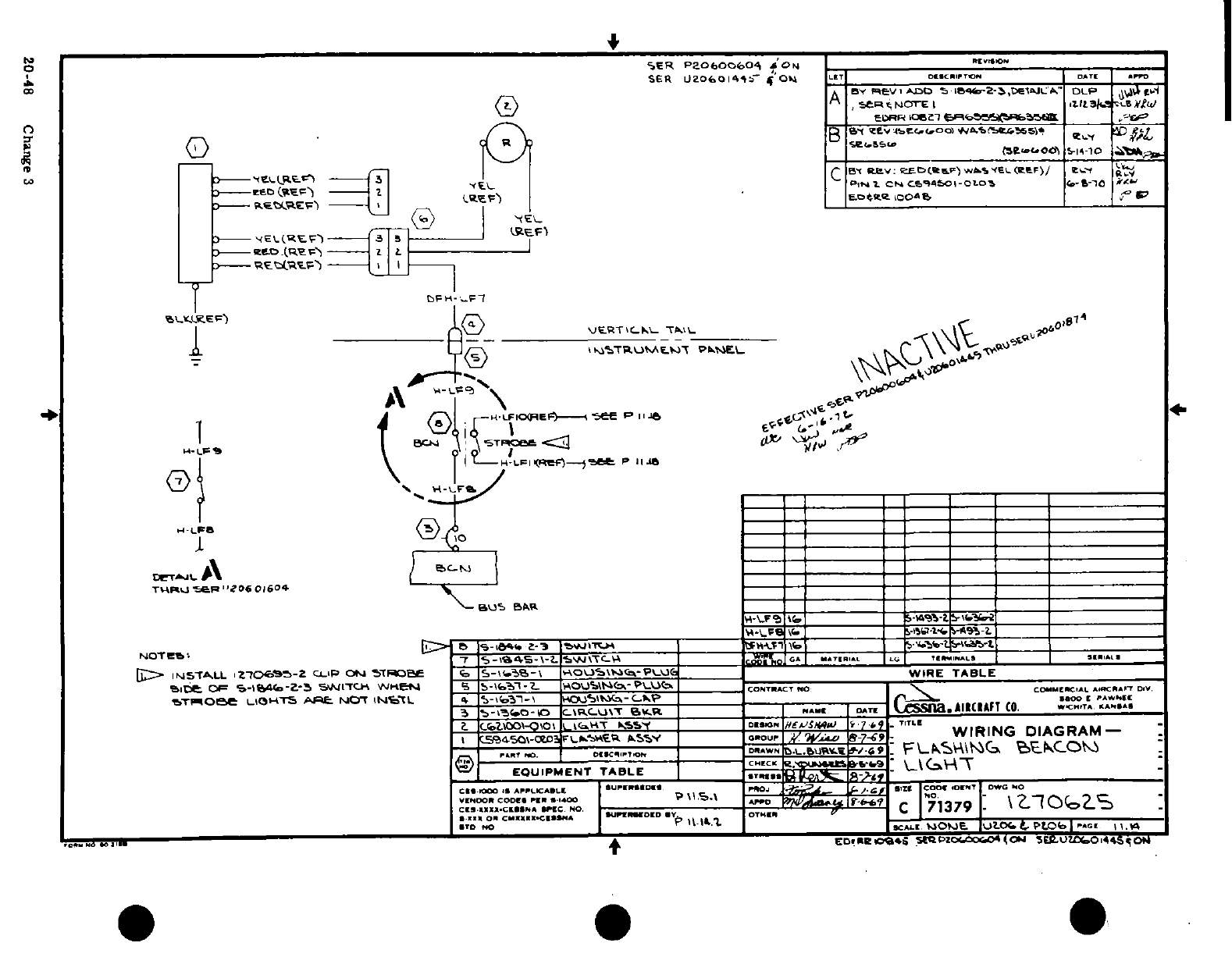
IE
^-,It~
I'~ I "I". I
I
.1. z^
i
'1
o
o-
OS
it
I!
0
^^ a^
^A
3
>< m
UJ
I1
£1
£iS
I
I
<
I uI J"
' '
Oo
0o
a
ci
2S
T
CMi
ti
*
-
i
'I'
Il
,Jr 1
·
J
0,0I
I 'i
i
dI ¢kI.HI 5
I
r
5::/
Ii
~20-48
C
®ha
nge
3
20-48
Change
3
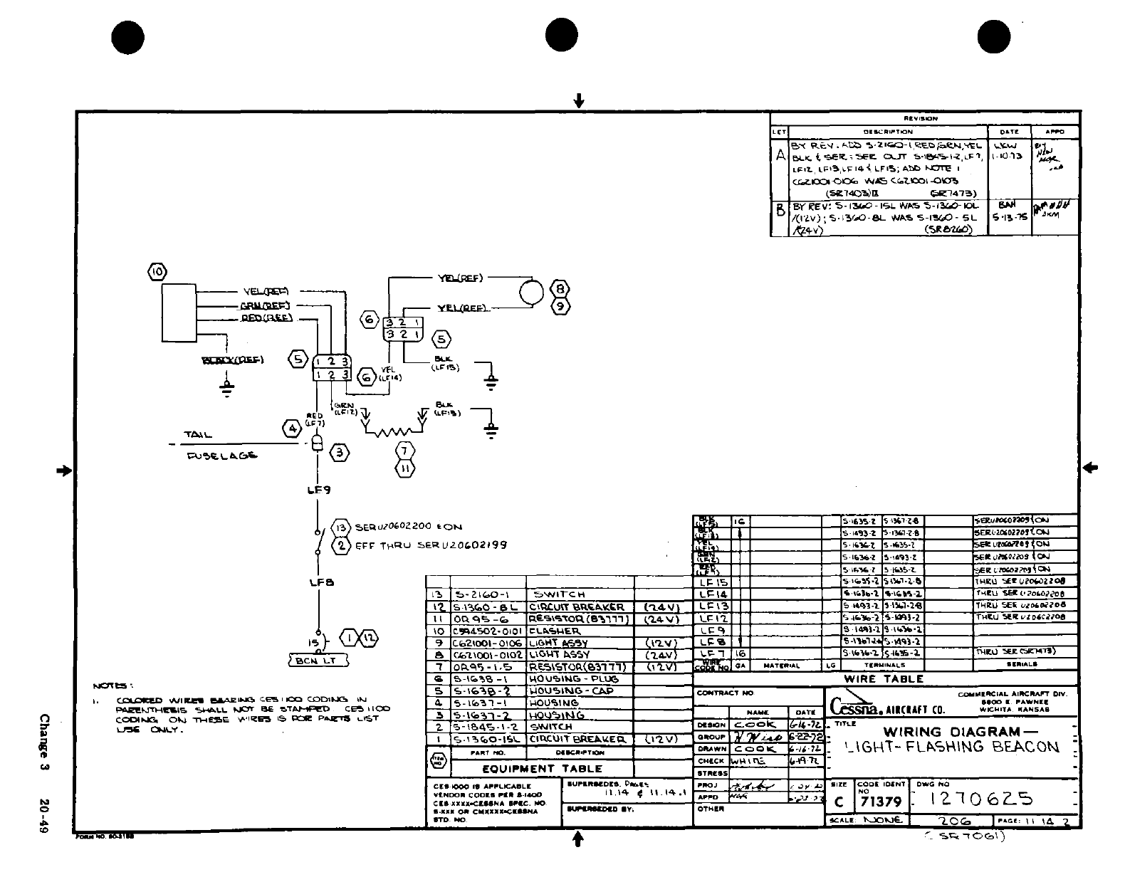
2
~i
J
3r
SFl
T
°
.
o
tLP
2
S§ ||g tt ?-
-
r
t
N
tin L4L
'--,
|ls~i!?l
|1
?
,?
Li th
'%
9
,a r
--- I
*t ,J
u
/
0'
0'
31o'
,
"~~I~k
u
2
r
r
1i 0-
is iw
~gi
I..
{,U
g
V
II
2
of~w
|11^-~~~~~~~~~J
0
7I
" '
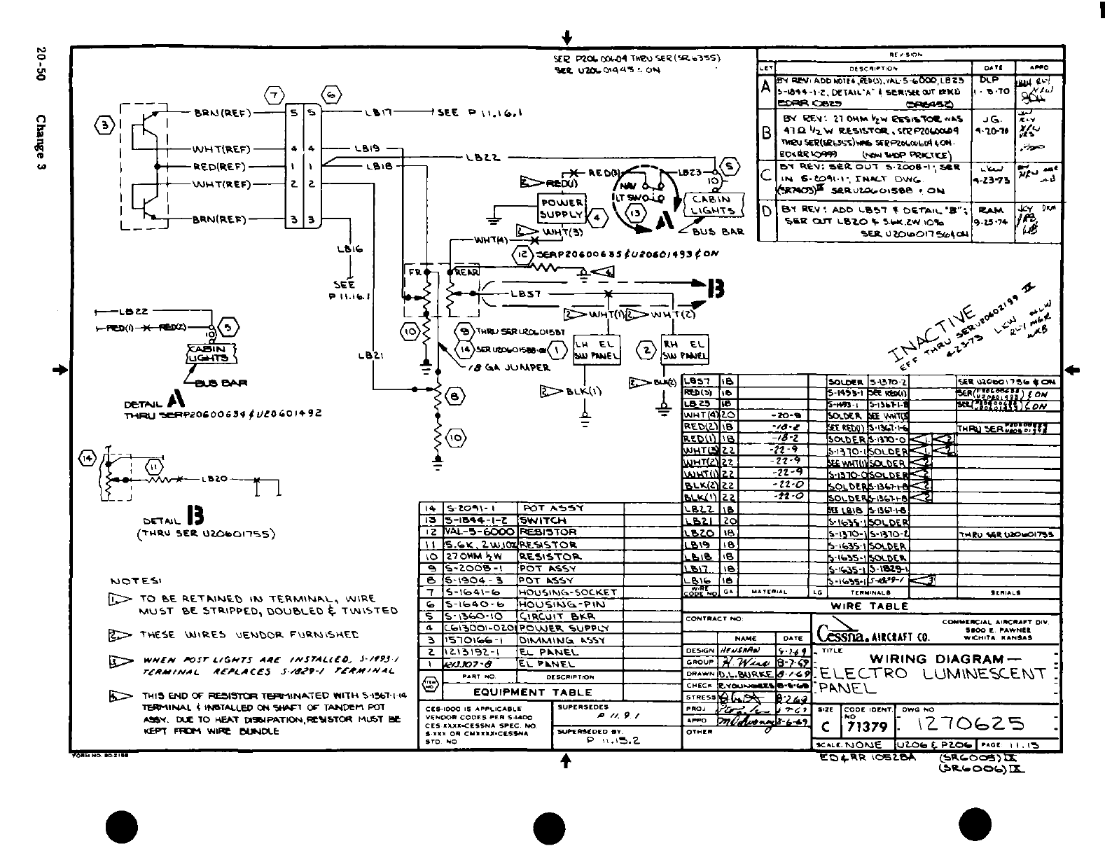
:&<
;w51iii
al
1
.
ssI;
--
^.j
i
s
2
i
b
;4
a
I®
/,
i!1
oI s2
?ir
0o
-, -.
^^£
_
s
_
?^.-^ 0 0 ^^ ? 1
'r S
J
g
irlU
wtI~~' '-IQf8
4) < CQ
U 5*'
2
W
20- 0
Ca
3-
w VI
g)
i
Ii
LA5
Cane
3'
0
i3
on
0
?
iS
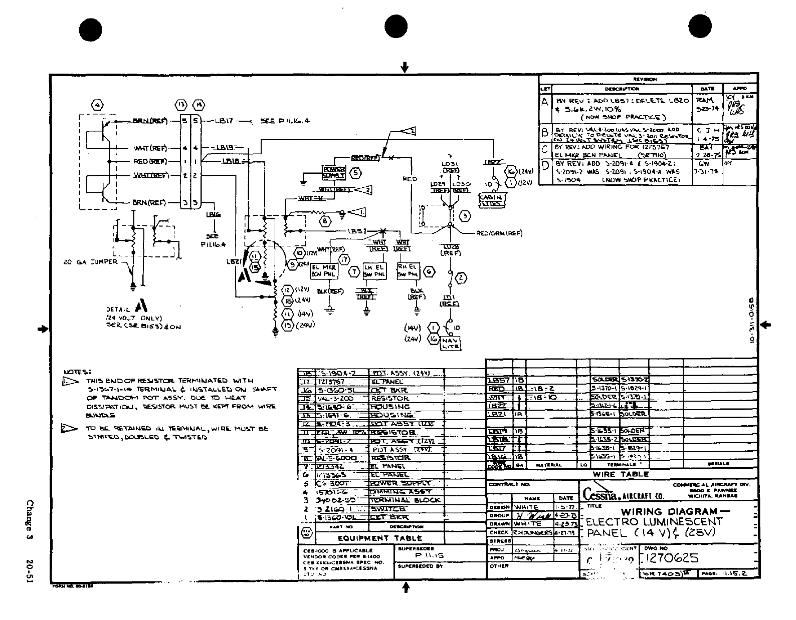
a a-II
I
:1 g§"
'
i-i
|
"
"-" F Ni5 Ilolz
o:
l
l
c a$ L
r :|lg -s$
Fo-
2
II^~~~~~ geI-
I~1s a _l
*
l-l
I
~ ' I0l0l~':'d
-
-
.. , ,. ..
_ :.
--
5-.n^
I'
. .
©r
V
^
£
<-)0
mi r~fig^^^i2 thxlA
a
-I-11 .® -J-^
~^3Change
3
20-51
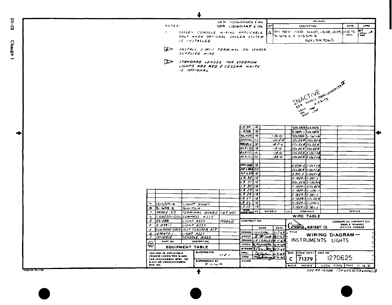
4
I
-4
J-
i-L
i
A ?
*
m
i
4
0 Cf
-.
VI2
2
0
-
-nt
8
n
s
I
U -%0
s
u
s
aA
-
%2
i
-
Dc
20-52
Change
I
2 L ~~~ K~ '4-
I-.~~
20-52
Change
1
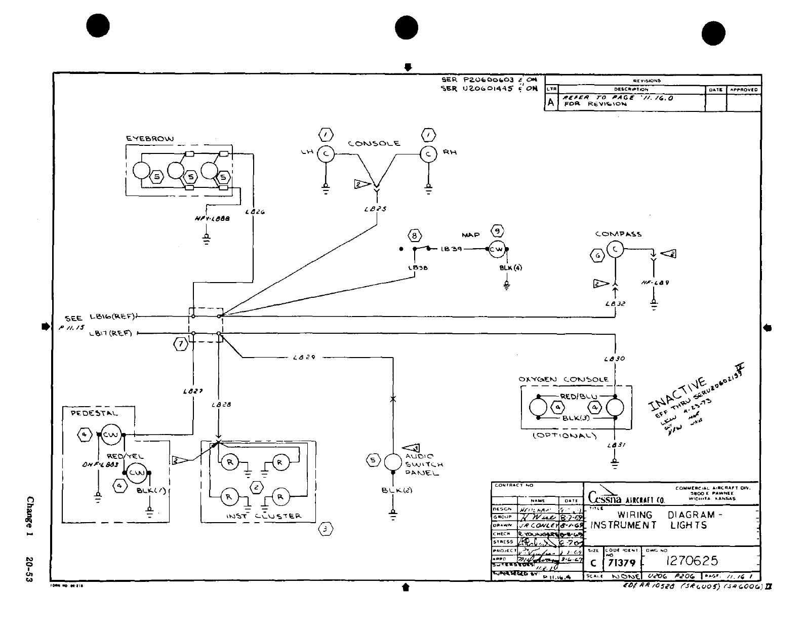
@ 0 '0
"j
2
-
o__
<C)
N-\
^^i,
3
<0 [s-
B'
C
0
v
0^
^
k.i J ® A S ®'1 I
I
~,~
.
00
1
Or^0
0
2
4d
22
O00
J tj
"
*T x )-5..-.^,,
9,
~I
0
r\
I
20-5
Q\
\
0~"
Change
1
s01
3 i~~~j ^ ,-"-- _i~'
§ C?] c
~~~
S /Y /^ 'i~~~~~~~~~~~~~~~r·
3~~~~~~~~~~~~~~~~~~Cag
1
05
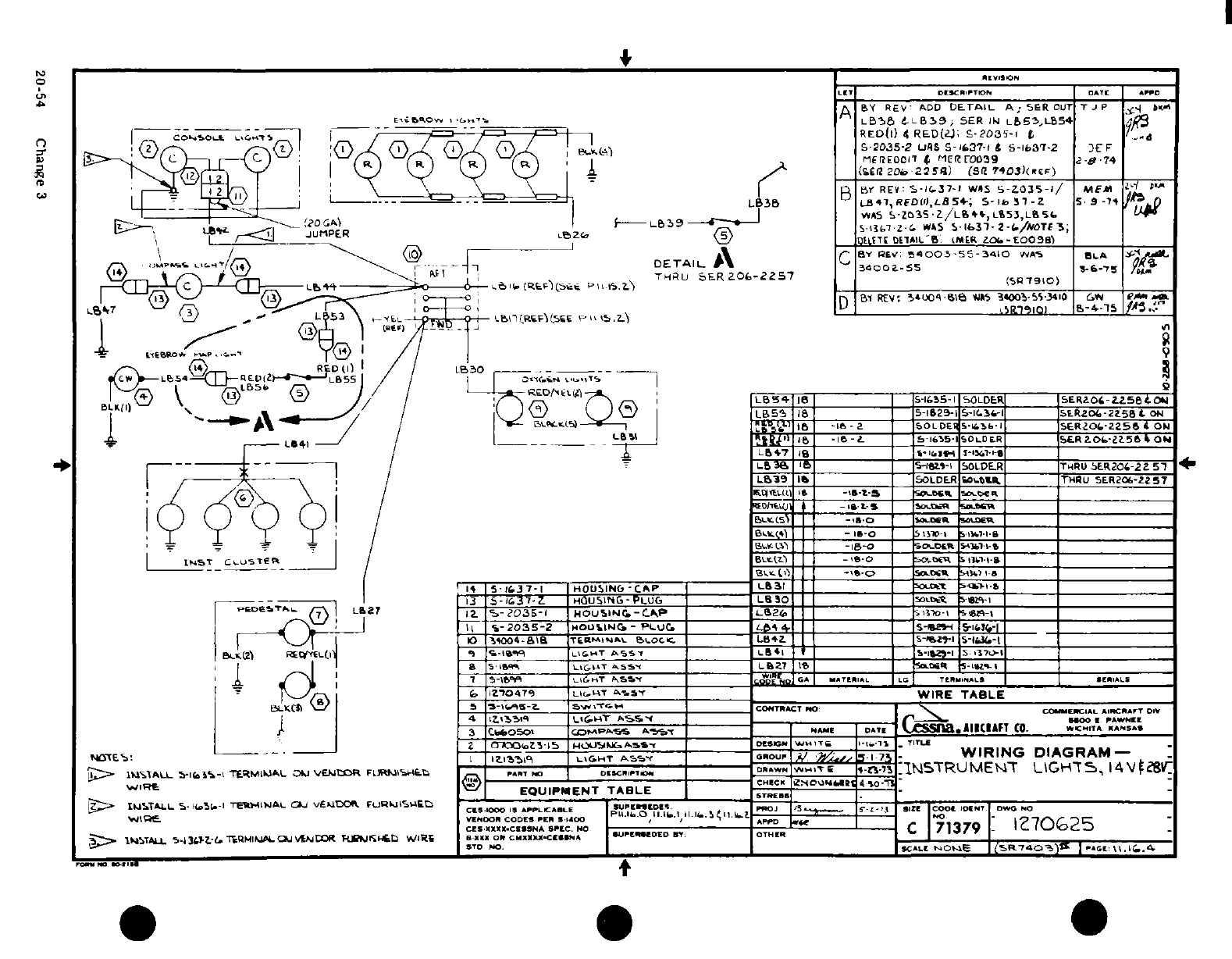
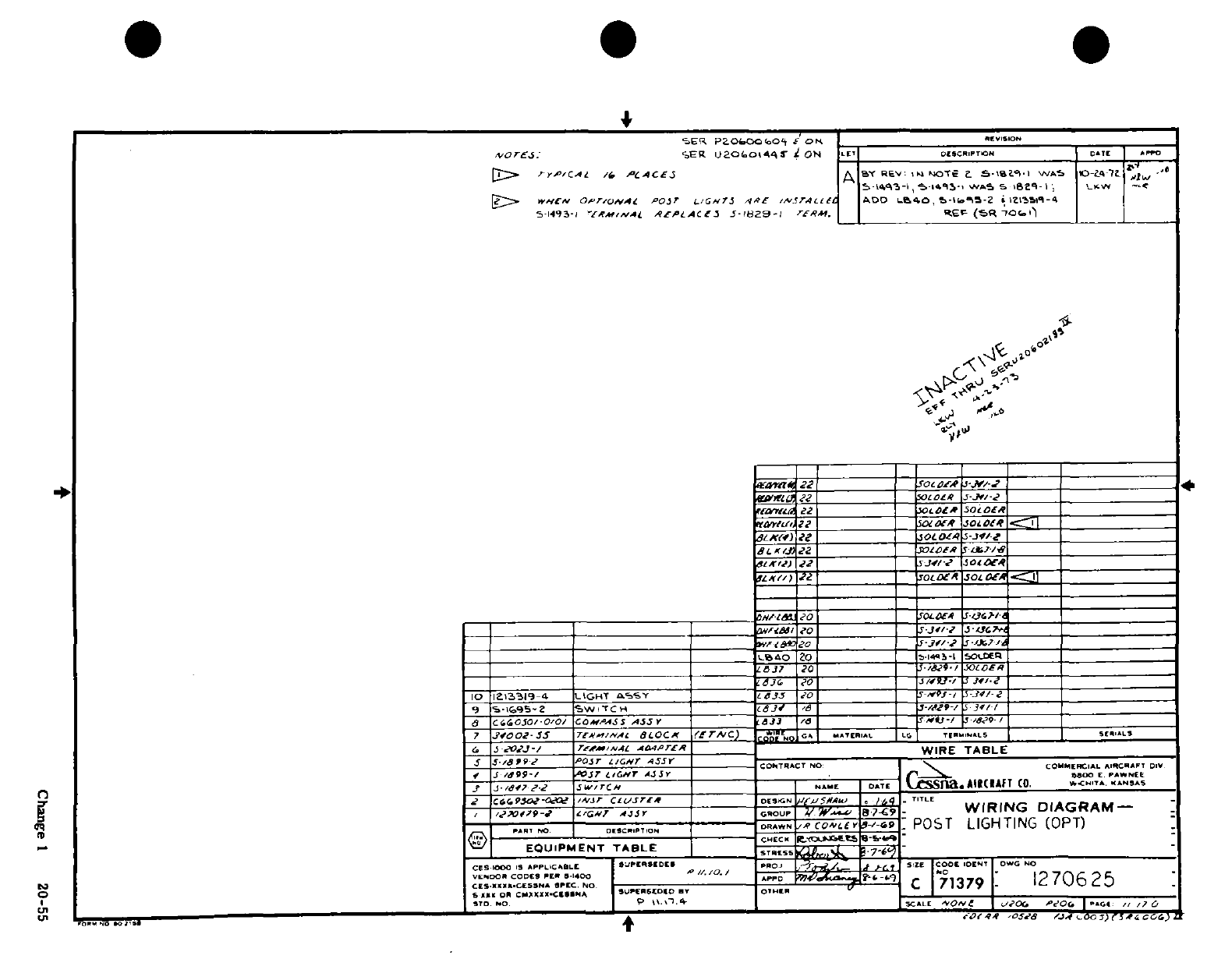
P~~~~~ ~~~~~~~~~~~~~~
',
i
'l
LO
E V' ^ (
-~~~~~~
~ ~
~~~~~~~~~~
tO
in-
*
?U' I?
|
O
s o>I*
0
O
'D~~~~~~~~~~~~~~~~~~~~~~~~~~~~~~~~~~~~~~~~~~~~~~~~~~~~~~~~~~~~~~~~~~~~~~~~~~~~~~~~~~'
Trfi/-
-
-o
-
-
'V In
*,
,N
^
Z~I U1N RK<
*
"J^
v^
wr^
^
^^
s 5
|a~~~~~~~~~~~~
ig:,;
"
l u ^
-
^ ^~~A
^
-V^N%?^
^
t ^.->''
o
-0
~~~~~~~~~~rd~
~
~~~~~~~~~~~~~~~q
~~~~~~~~~~~~~~~~~80~~~~~~~~~~~~~~~~~~~~~~~~~~~~~~~0
: 4a 2~11 1 1
11
1 1 1 1~
4,4 ~ ~
~
~ ~ ~ ~ ~ ~ ~ ~ ~
-
4
s
·
; J9^^ ^ ^^^
?/
'
¼
-
-
s~^ ^^^^i0 ^--
ztfi^
Y
~
~~~~~~~~A Li<"^
n
^^
/^i^ (^ Q u
"Z U' Oo
I
i nI
I
" I
"
<1
14~i
o 0l
ii^
%
?0
.a
z
I
.et
t
^n
ill^ l^^le? 8Sl~s
0.j
<
n
Ks
0
19w
'-~~~~~~~~~~~~~~~~~~~~~~~~~tnV~ .
um
4
'~"-
*
k A A,
~ ~ ~~ ~ ~~~~~~~~~~~~~~~~~~~~~~~~AJf
i
a~
3a
ISP'
0'
a
8
u
*I~j "J.i Chn hi ;2-
Change
1
20-55
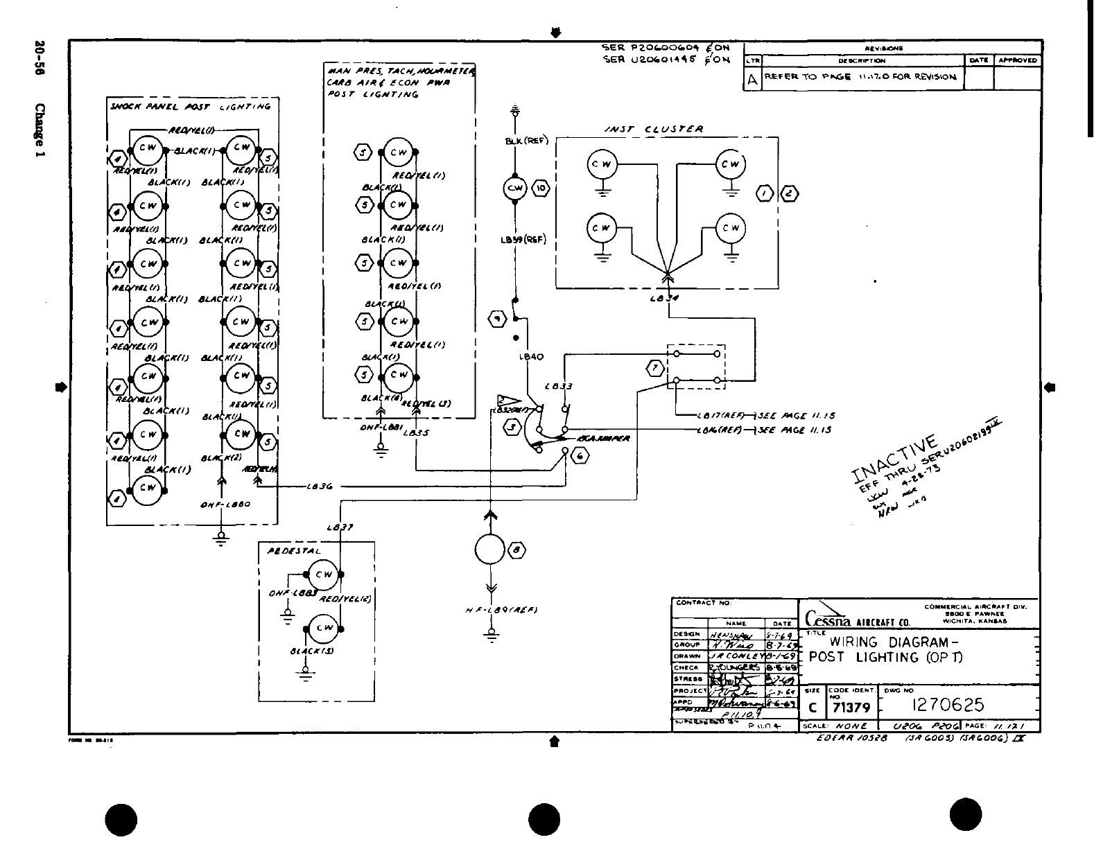
~2~~
1
CL
I--41, t
-
t
%
ya' I 3-
I it 5
....
v
---
eli'
on?
_
25 Cha--
ng
e
S. 0
-
,?
.1 f
__ _
I
.
H s kt
^
S; I~~~~~~~I
i^
5
---
!^
'
9T

w i060-982-01
1
.
1
,
i
ii
.i i i
1
Pli
O
LJf-
!is
*
klil
illtl
g
S
,-5i
8
°;
-.
a~~
-
Q
,
D 'g^S£-
--
~
.
-
-,-----.
°°
ggp^
s&;
??
^r
'
/I ^S ssor
05
u
r/7Y^
--
ii¼
O
(D-
(UD
D D
=
_a
.
o
,C 3 25e
7o
Change
3
20-57
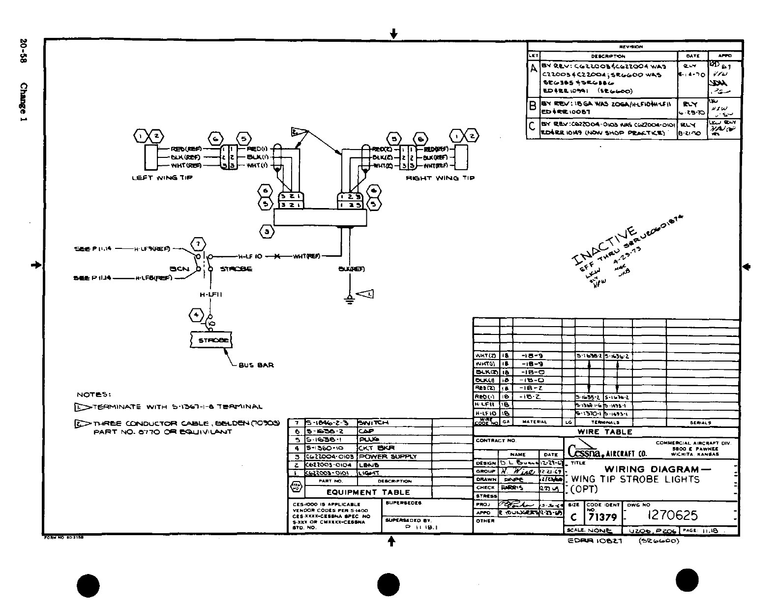
o
i
6§5
naS
^>
-/- ^y
a8 a.
*/
F*
2^
°
^
00,
'?
0;!
-
z~l^-
tj
IH Io~-I -J
°
"I
i,
1?,o
^- >Z E3
,
Vs«
«f
3
z
Z^
i i~1~ ~o~1~,.~1~
ta
i
u 11
-^ r?:3~~~~~
·* 3
0-~O-
!
i : B
S
z
A
20-58I C hang
I
Ciiii
:^ tt
s
g
<
Iol
I£1~1
I®
I~':
£
J
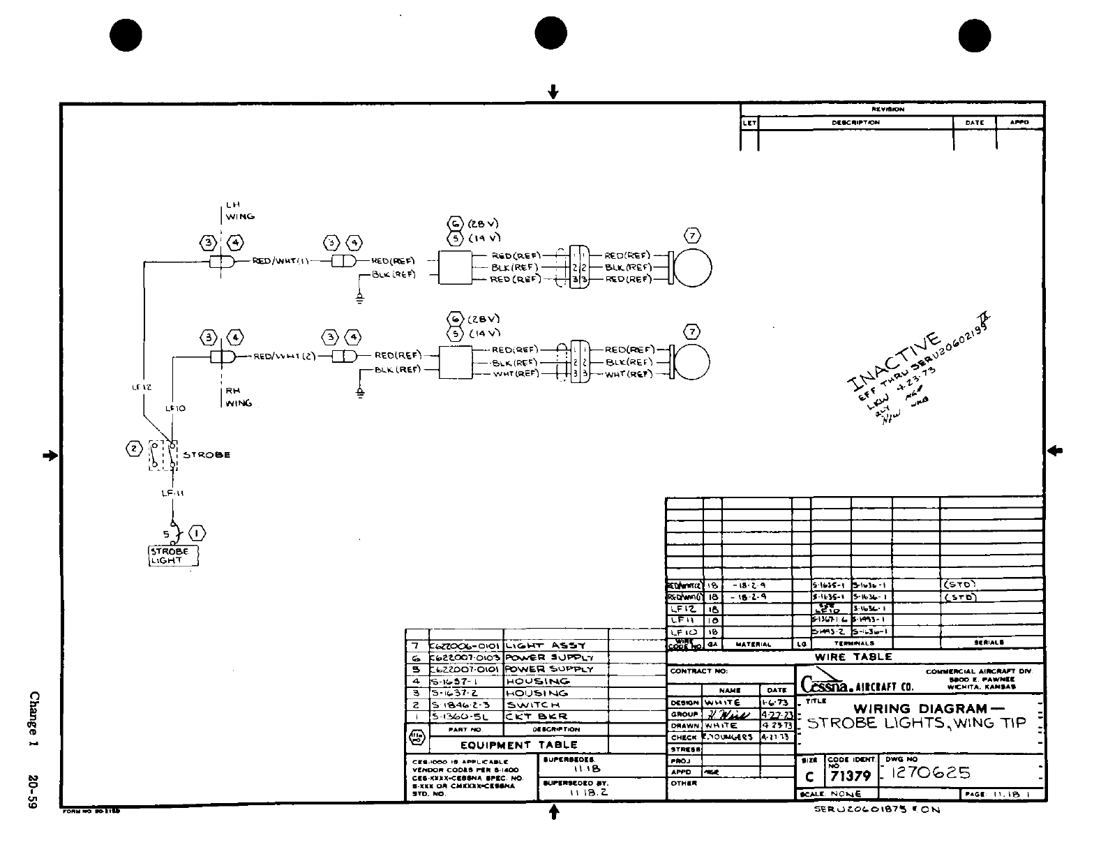
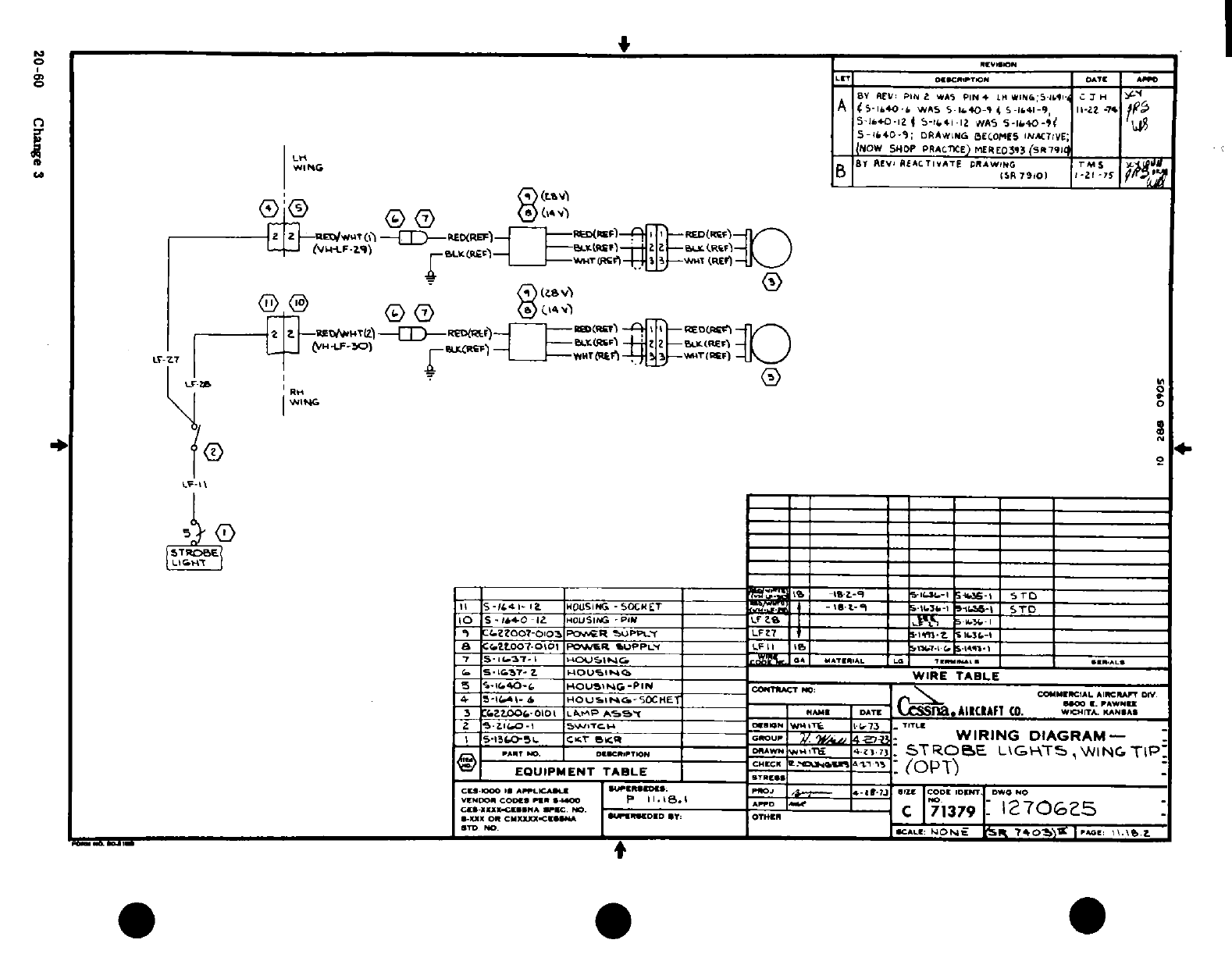
5
I
ZI
, I
ASOLO~~~// hB v1 I,
a
...
~
LJi*t
w
-
-
z0
Cs~~~~ -^ u~~~~~j
I*
I9<^~1111
.
7,~ _0 r30 0
'
V
-
I=1'11
I"
1 "-1
® I l,'
a WI
4
ay_~~~~ FU L N
O
?
I
n.
t U
9
?
'-
i---
i
d
FI j
-
OT
G
f
I
I I I I I I
I
I I,
I
I
;s.
is
i
o
A
^
"
L"·
L'
Vfli~m
"
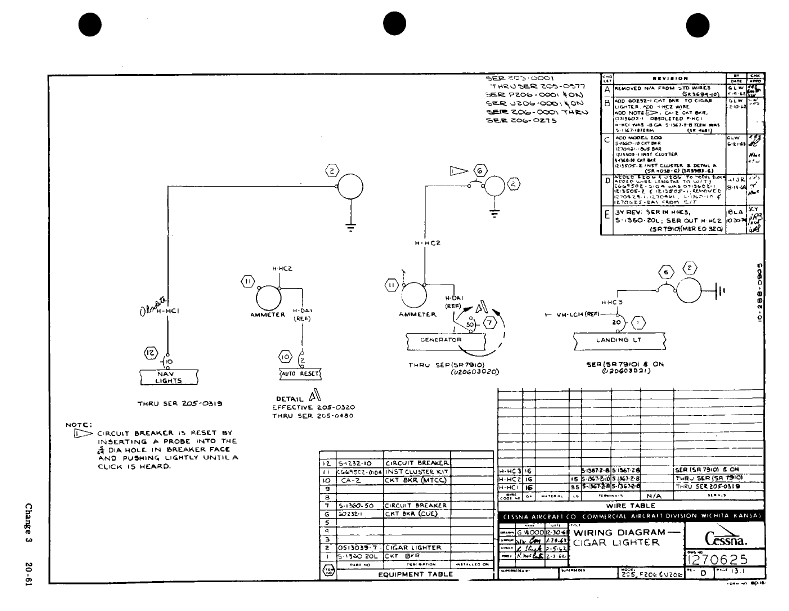
,A -
s
-a
T
o
-
*?in n
ii!
i
I
.
V 1i
-"
<.
^dimi^^o* -^ih ^
I ~~~hi
-
&oI
0,
A
o
,-~/i
gi
l^
1I
i
0-
~
d
0
d
00
9.
:
I0
00
ri0
' *
oi
.-
ii
1, tn yr
~ ~ ~ ~ ?
a w
I
u~
zu
a
5 1
4
>LJ
^ 7
c0]
1
S?3
,I r
u
ccT
<n
~
F
1
o
z
h
*
D
ZO
ft
^
Change
3
20-61
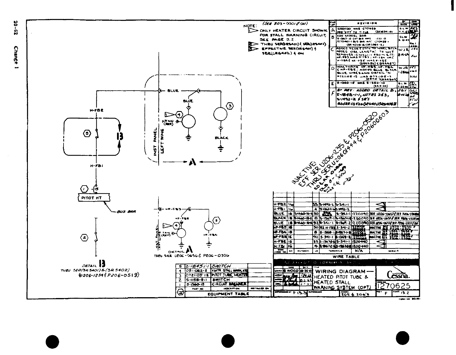
'$
'j
t
-
tf
I
2
n~i~j~pj~i. tu
"'i /
^
^' ^ ^<4 ?
^
aI
i^|
i
*
OI-r
-^if~a fsCD
L
s a Z f
.
&'
5
" *
T
*
i'y
> i 4 i
'
'*
is6r 19 Fi·
a
1C~~~~Ii
§
tiii?
"
2
!
*o 9|
;
,0-62
Che I
,
-4
1
0.
A-
.rzr
1 t-
-t
-
*^
C
I Jt0
··
=
I -·.I
C
20-62
Change
1
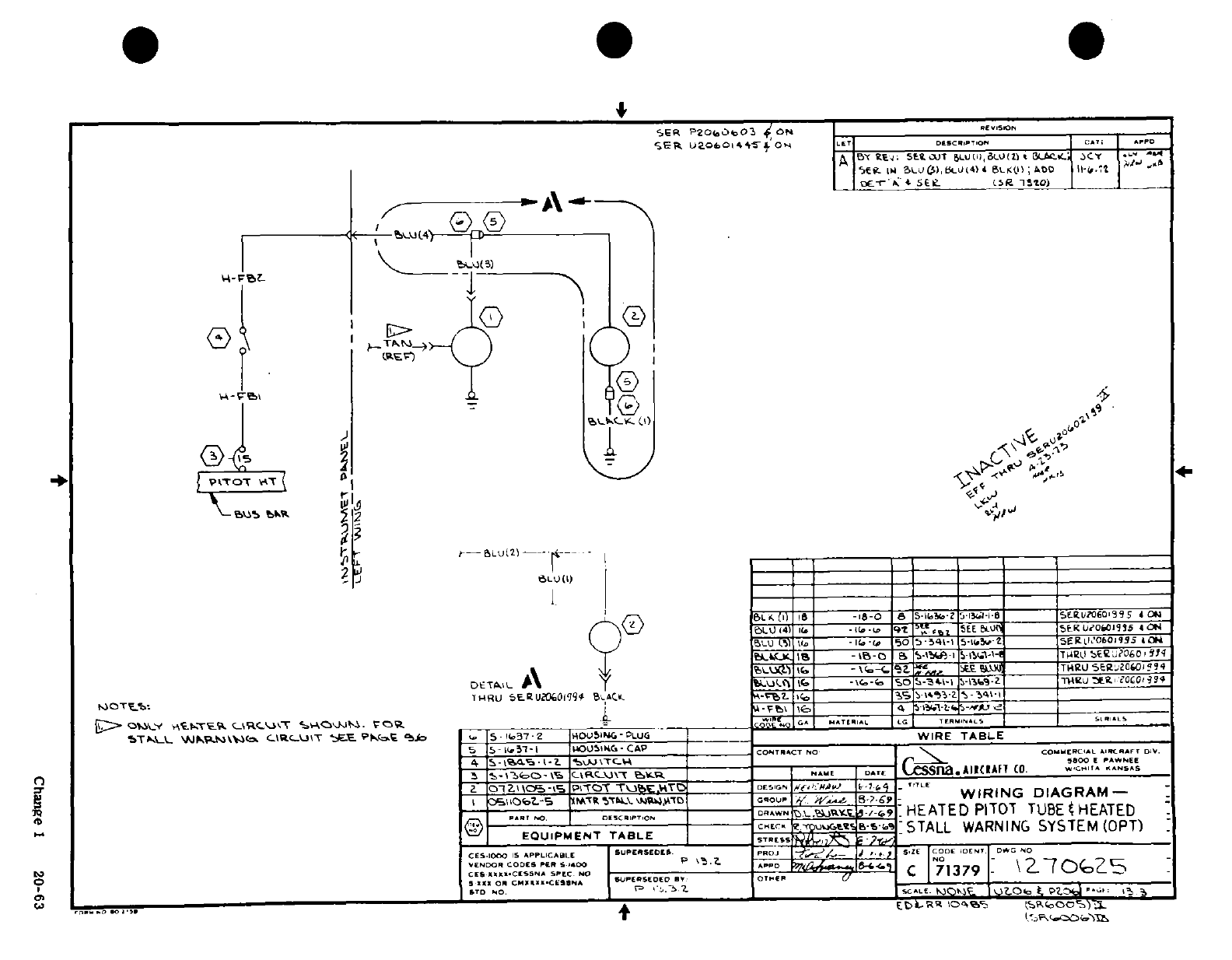
X "i
2
Z <
2:
~:< 111
- -- )
.: EC
?
°:
^
"
J
."
^ ^
1
L
rZ
,
i^
-
35^ ^Z
'i
-
u
^
0
izJJ'
-5
1-
ooo
O
I
t o
"
O^Od)^
0
^^
14J
I I1
~;~/
^
a
£*'^^~ ~ ~
~~~~~~~~-
o('
Ao ;SS^S^^aJ~s~iO a
I ^
r->J^J'l*,t
L
e Ilh
f
I
2-
6L
' 0
S.
4I
0
0
',
O
L
* 0
1
^
, . ^ ss^
Sl
4 j I
11
5 -l-r-i o
-
A S HJ
a
S ^
*SLo
O
!
d3
.'
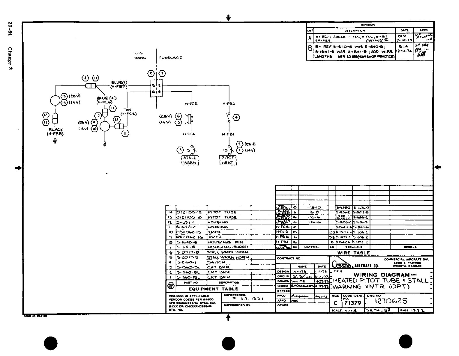
,I~r
~oI,,0 (
IJq~~~~~~~~ I >1Z0 I ImI
1 I~
''
<;
"Si 0
Sc
B
£y^|il~~~~~~~~
.-
z.
0 2
;
,
g
-
i /l c D!70
5®< co
'
-~~' O
O
20 ~~~~~~-64 ~^
z
Ch|6
re
"t0.L5"11u 0BJU Zoo
O
20-64
Change
3
9Or£AA*SA
~~~~~~~~~~-
-
03 UIJa
.
4 j -i
* ^
-~~
I--
_ -_ _ ^ t T ,;
-
? -?<'8
|
I,^^ ^ ^^ -~ h
"i
C, ~
~ ~ ~
1/^,^ fAt ^ ^S^
''
1
A
^
(?1?')
*
s^'
ooA~~~~~~oS~
ipiftip'"!/'^^ Ss°S~~II
< -0-rn-cs^'
E
J /?
/-
»
.rt pJ =
Q~~~~~~~~~r~~r-J
in~~~~rt
««j
-
[g~~~~~~l
?B
»6~~~
^ o~~~~~~~~~~~~~~~~~~~~n
s!~~~~~~~~~~~~~~~~~~
^t-^"~~~~~~~~~~~~~~~~~~~~~~~~~~~~~~~~~~~~I
20-84
Change
S9
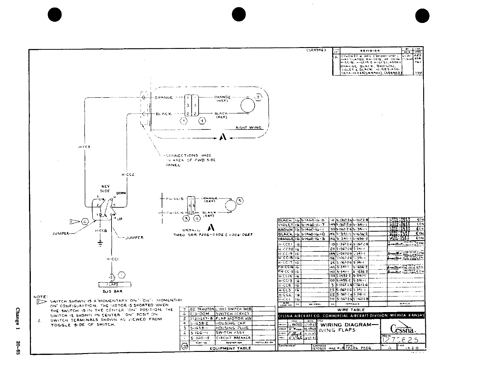
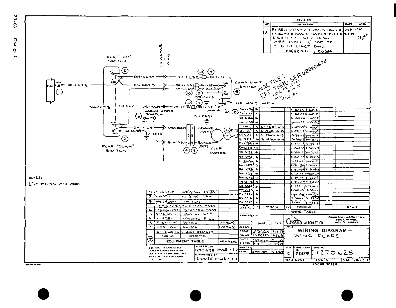
^I II II
I I IP-
^Lj
^
'- *
m
n
$1
' •" :
-o
, (I
a:S
cfl
2, -b .t:
~
t:<
*t~u)<C^^
'F00', 0
-Il.l-l^ll®
I
--
a.
1
Si t)
iT
4
i
6
I
I'I,
~',~·t""~P
-
---- - --
I LA
j 0~
Q
0ml A
.3
1.
1
0K'I
0
Zj
a
(?^<f- 0
0
*'
M"^T.-fl^O -J ^B i^
;
:
1
t"
Lu9
20-600
Ch.ulge
i-
a
1^ 1 ^
^^~~~~~~~~~~~~~~~
uid^!^
4A
4
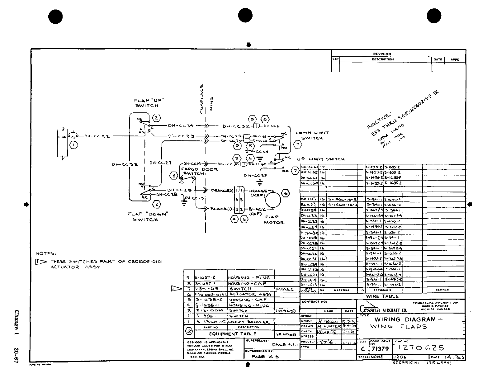
--s- -_ -
a0
If ,In~lJ~l~l~lI
-I
^ A-. s^ ^Hh-mi
zU
7
sL
0~O
~I
U
zr
tL
u
zS~~~~C I
S
-6
7A
o·r
r
ooa ocoi
o
o
ooi-iC
2
6
-- ^- -§,^a-
AgA
^ 5^ ^
-a-»^n3'S~rl
.L
1
'"
t
*
s^
0
7 ~
*-
O. OU ft 4
LED
3 o
I ®-'^ ^ i"^
|
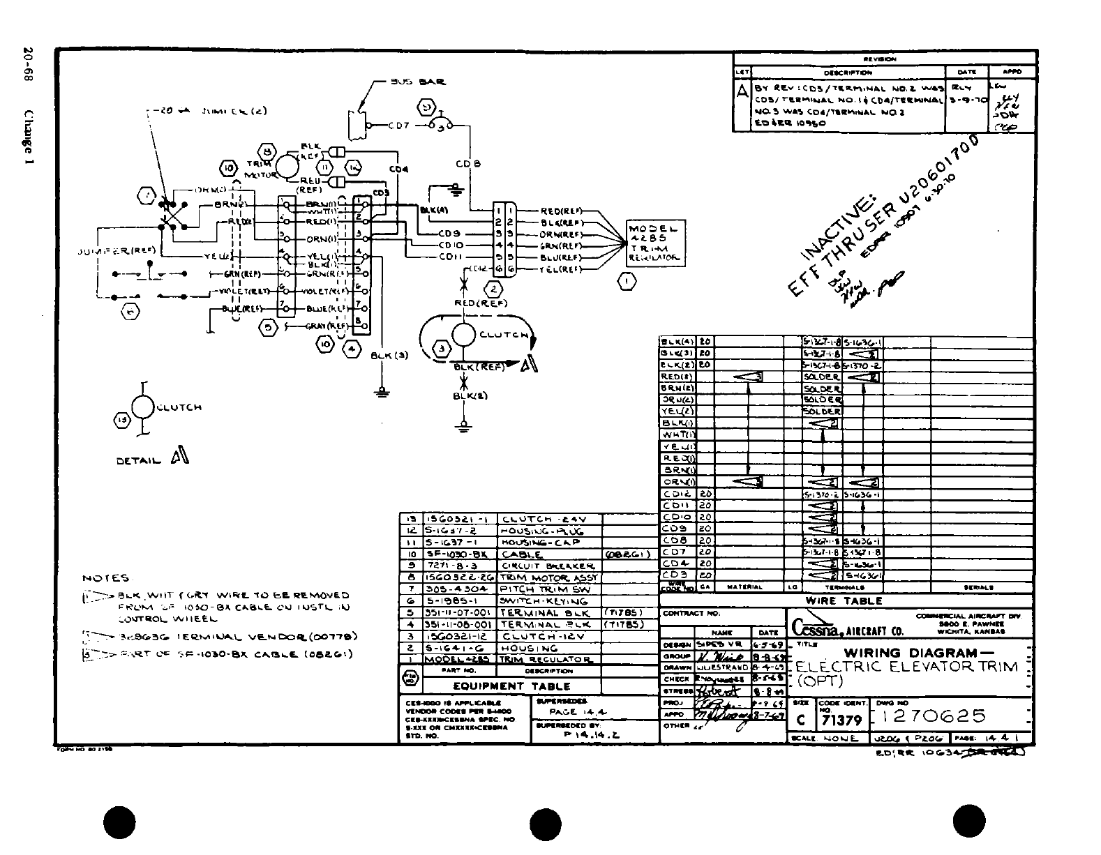
txt~~~~~~~
-^
a
*
a
S
·,.
il
1
v,??(M
,',m
I· jojI 1w}: 1
' f
"~-S o © A -'i -'~
'
V
V
:
:,'
,3 t. La
s
---- YI
LC.
JJ
,,
t
or|
I
KSFJ
1JIG
J
-0
i i iiiijitj I·
-*I
,J
-
C)
e
20-68
S
C g I
-
2068
Ctiic
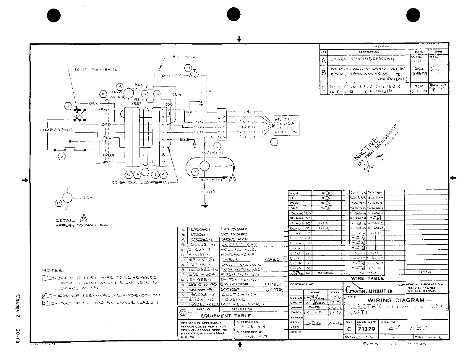
,
z~
s
c:
;
c
i
-o ~
0 i I,
I
I
'I C,
;r
I
-1
~
3^ ^ S
'
d'
I
-
~
c
-':
,-
I I P I I5
z
.
TI
O ^
/
-'If 'N iji ptj *....
*'
-
- -
„i
o°
e
z
*.eJ
0
'fl
L
'
I A
',:
I
j
4C
--
2
--
0Z
3 r r
i-
___~-------
5
^
0
,'t
'iSC
2 -4'
I
-
i^~~~~~~~~~~Change
2
20
-6
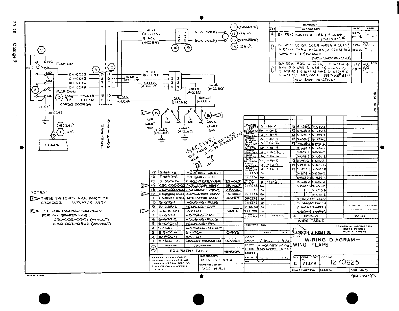
.
I ip60-/- ~
I:m~~~~~~~~~~f I"'
I, I
I
I
%o,
'
t
-
-!
I
-
o
1
OA
i
r
CD
-n
zS'^
^
1
0
£
J
4>
c
Y£
*
,d.-'
-
a
o
6/
'n c t
-
2-0 Cag
2
"<t ^1
^
,
^^^3^5^
J
jj
r,
9
I
ouk
0<.- H
-?
ay;=
L-
^
5^
.'^ ^ ^
y
^-^^j^ z ^
i
a
b
M s ^7
^
.
.,,, a za
--
@r~
~~
i-
.i:^
*rrhs-
-
s
!
to
--
.n
U-'- n
Ci
6kI
A
3
-
A A
A
I sm
sIr
I
0.
> -S
0
;„
i: hn
2
20-7 Cs ha n
2
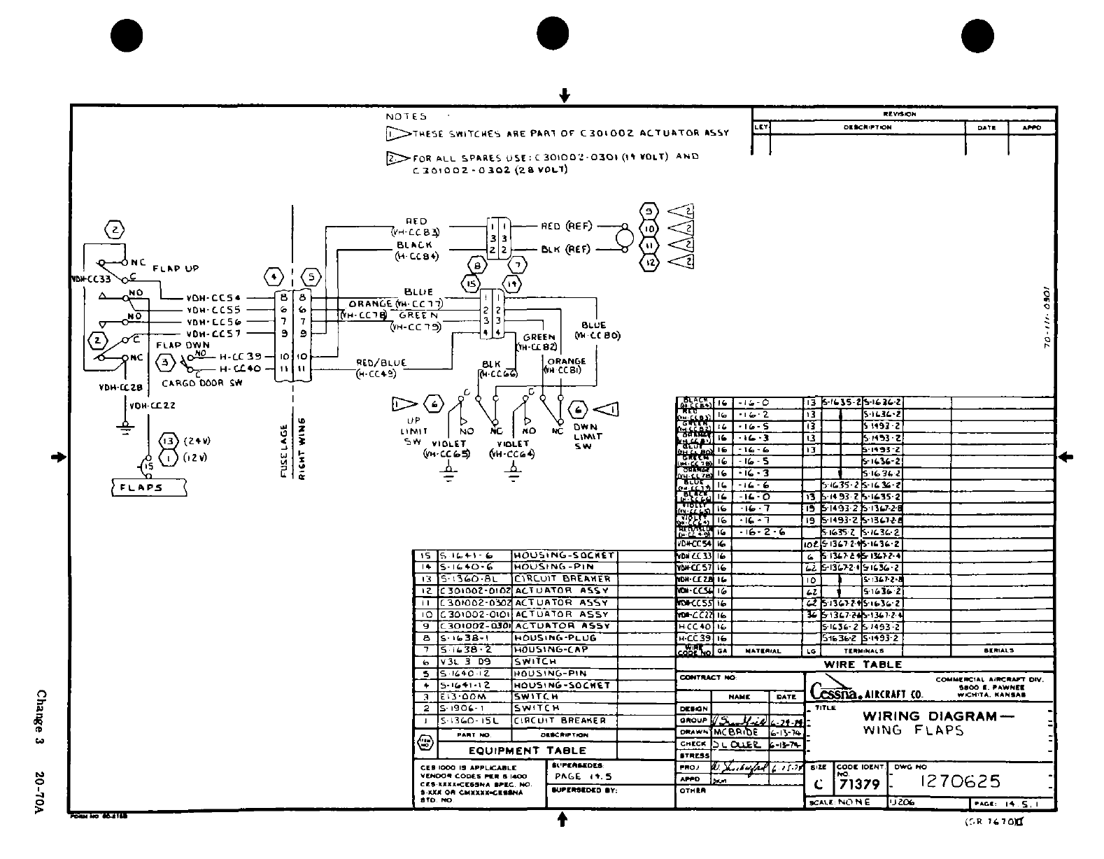
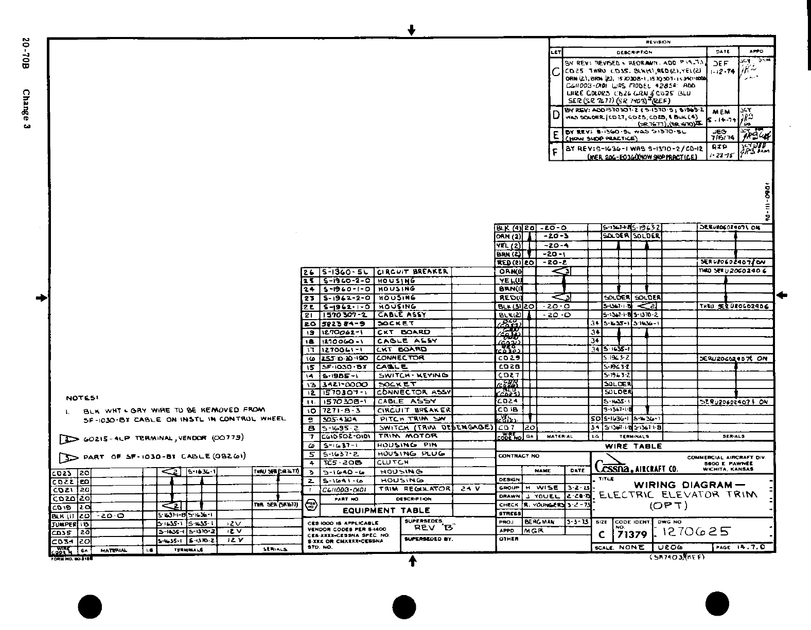
~- *~ o.
-o
n
oj
0
II
I
'Sl~ IAI~ Ir-5
|
,
~ Ir~l- ~t~~ l
Ig'"'-^~
o*l
S
"
,
3
W
£
$I'~ 1
-
-
J
/
,~£lJ'
B,_ _,- -~^-^^ ,» ^J
"'
"
-
1
.
I
r
-
-
1
-'IJ;
S"
-A -
-J
-"l-'i o
i
'9
-°°°* al
ll
/ -
u
.,
O1~1-~
11~T,11°~11~~~1
14
~11 1 O ino/0
-
l 11 ® a I
i
/
'ii
0
,N
I
>
N
'1ooooc
Q>.3So
~
^ifOO.M-O% -ar:3in~fl~j-Ogi(Or a~i~rfift-
a
00ID
07
Change
3
Ft z 0'^ll
LUG
t
r
„ (0 t 0~~~~~~~
§i
I
**
S
(L rf)
o
t
1?
,'
^
"
I~
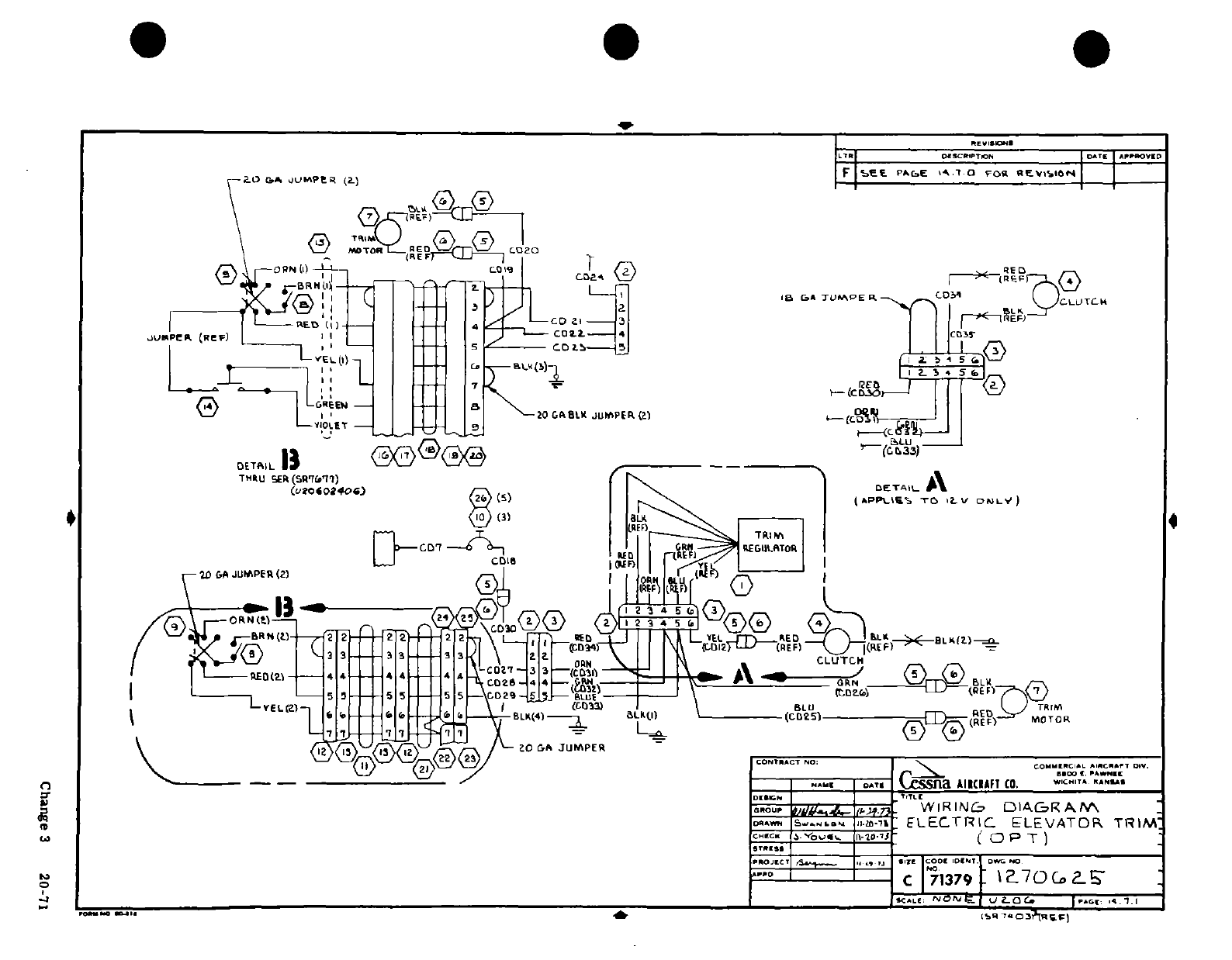
, , b
I
~~~~~~~~~;Z~~~LI'
ni L
x3
EoS"~%
c r o W
j
wer
8
Q
_ _ _ _ I r
I
Change 3
20~7i
.Ij
--
-
? 30
a 0rit3 gs
-
.j
-
a
0= t(13S
^
tn
" 'a
I
"
I I
tI
*c
.
t
u,
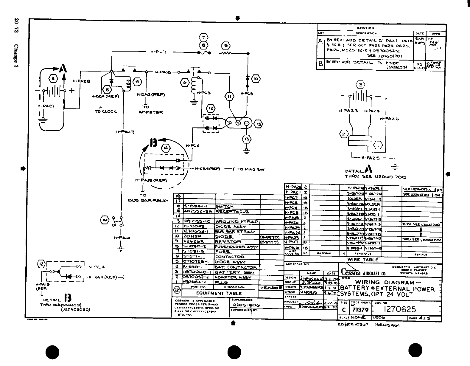
I" ; II I
0tj~ ~ t
0-ii"? IM
^ _^||,
?t
>
°1/
5- 1^ i
r-l'
§
P-
K
*^*^'.oi~~~ 4-
*
zfi
^ S ^'i ?
"
cu2i OO
zo
R
iH,^
-^j-^i-^
U4
D
m
l s
^ _- J,. ( iljiii,-i ,,,
,,
o
.
Ierr, ~ ~ ~ ~ ~
~ ~ ~
~ ~
II
-..
£ E I0
2
__
1
-
n if
UD
It
5fr,>i C fi-0
I
Izi
a.
on
-
/u .5S
1Os
c it
!
S
20-2
Change
3
; i IFI
N
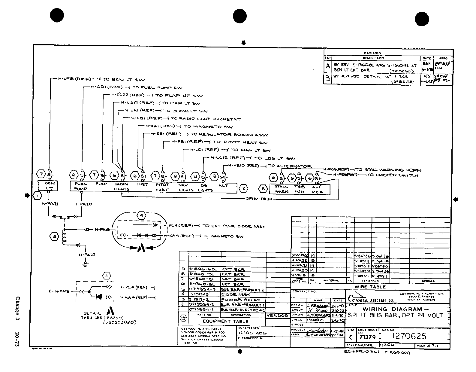
4
n 2
0
^ -o 1
T
*T
Change
3
20-73
F ~
P
%'
'i
LL~~~~~~~~~~~
N 8
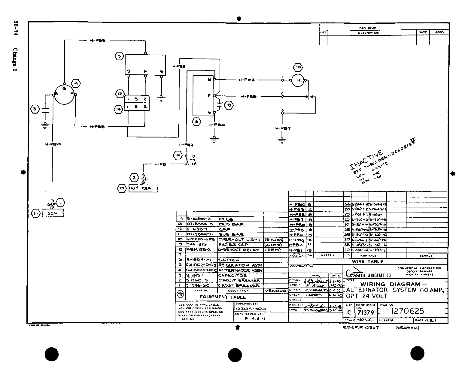
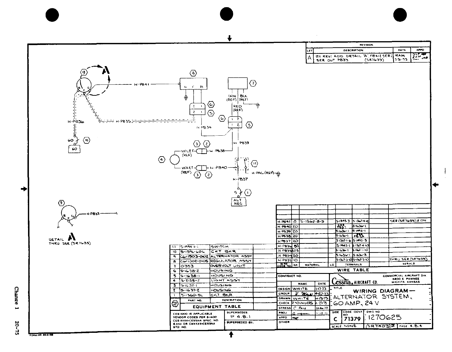
5rfi
S ad
^L
.
5"
hi
i
(
. .
·
S
I <
9
io
1
' =
0t
-.,-
--- w
-
r
--
t
00 O ON ":
"" ·
Ztg
oo
F
FPChne
J
a
0
*-0
(
-'w
z
8",
4^ -4
-ce
"'"""I
LDl
I I I
"
\~~~~~~~~~~~~~~~~~~
y\
^ ^"" N:!~~~~~~a
f \
)
-^ i!~~~~~H
^^"^" f~l t
I
©-.(
^--ff'
^ ^
'3~~~~~~~~~~~~
(
r I
I.'
-
-'-------i
-
^
r
2
]r y
<

S^lI
I
1,
0 -
?
JI
-I
w
t1il
I
~
'-
Qo *W~~
S
3
'LCI ;
-;
j
0S??
-^
u
5 o :
.o
0 03 iSw (Dm
2
2
5
LI O , 0
d_
Ii'S
t;
t'I
zli
1 m s5
S
"
L
o
0
-
ic
._ gpi
il-o ^i3
rrtN
OQ'';oO»,l*'5
as
20-?$
CHn.,e
3
ei
Sto
«
a
fl
'A
20-76 Change °1
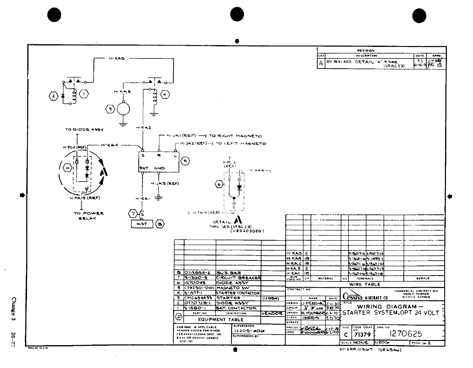
I'1
JI !" o
N
*A;s
ns
al 0
av.
6
..
1 _I
4
5
O^SS~siS
tfl
2tl
yT ~-
w
<.I
I
-
5 eJ
Ll
--r .
r
.a,
Ii-
In
,
I
Change
3
20-7i
4•,
'7
Si
4
0
t
mo
E~u'Can
2
<
J
'o
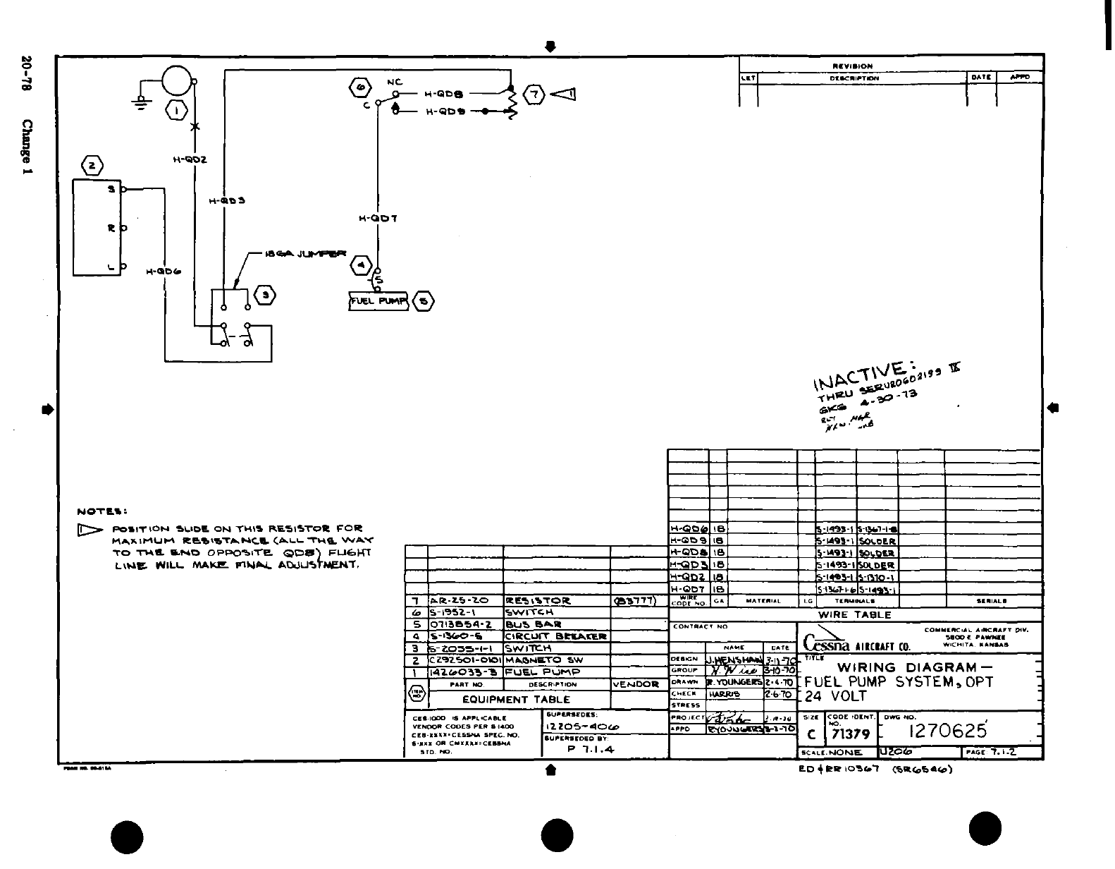
S i
"^;'
^
0 ~0
ll ^f-
jWi
;w| 6
L
~4 2'Oiua
°LN
~0
0
*1 rI t 1 r
78
Chang
IIilh
?
S
s
-
0.
20-78
Change
1
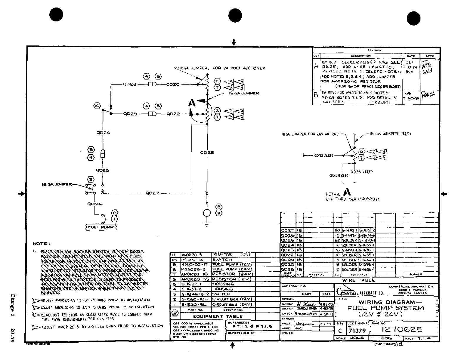
5
^-1
~ S" 3^ Ji3(9
I
tu
Iy1~
r1^
I
~
_
I
J
*I'c
I c.f2l4,l<
4
9
wwa
r:
0,
L
>
0
>L.J0
'
I-
I
"'^""''
a
3
'0
\ 7"y
^^ Vfl^>n aJ
~
of*n 0?
?1 O
a-.
I
Y
.
5^§O 8i
s
2
o£
-'o~~~~~~~~~~~Cag
3 20-
-7 N ou
Bt<o
al
-3r Jo
3
*'
-
s
/S
i N c-0<DaJr-t~iP<(ON
-[-y~
i!-»
H
/
55
^ i
**
-
-J
4*
s2
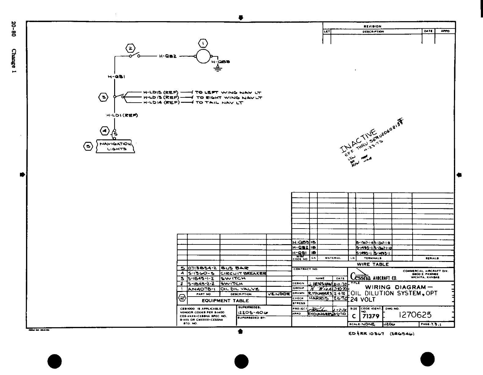
~~~~e ,
, o
;;
311 u
D-ow
I11
-
Il
I
o
I0
0
11
u I' {
i
8
.~
.,I~ ~ ~
~
~
~
~
~ ~'
.
,
IU
..
-
TIT"T ~~~~~~I
0-0 C
a
D
i J iae
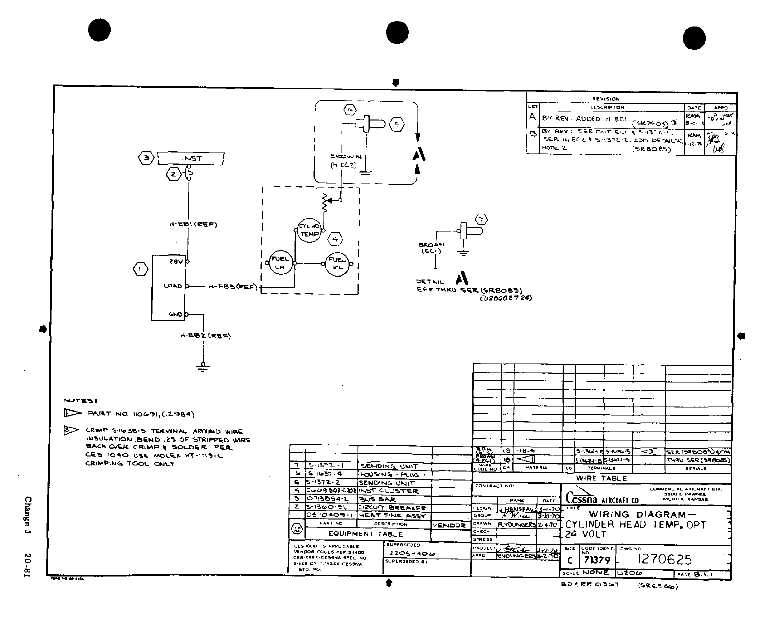
r' 6 J"
It:
_=
,
I
i0
t
n
S^£0~
0
:?~
oir
DS*- 1 1 -pD 1'~~~ a
a^T
| S r)~~~~~1-r
§I
ll
I
^^
x .
'
3
-
J
r
,
/-<
0
___- '' 3 ;'
®I~]
1
,
11j
I-- <..¢
i-
lf I ij
Zo
00h
3 20-81
*N8?5i
1
' *.
4
0 ID
*t
l
I':,t
I I-
Change
3
20-81
r-, ~
~ ~ ~ ~ ~
~~i L f
j
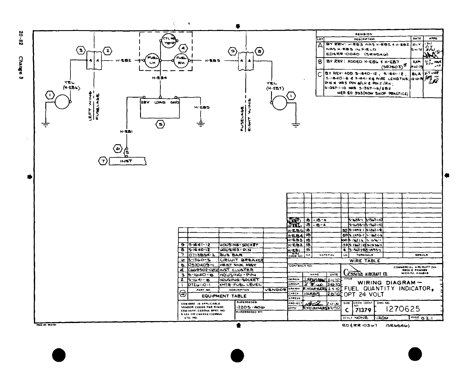
'
IA^
lol Lo.; , r
~:
*
f -ft
w
§
?
sri
Zsr
,,
r
,,,i-i,? 0
l
"
S
oa
Z
-
C
eQt Q ,
o
CD( .
OF;~~E~~q
- -
Vaw
I1'=I
20-82 Clj~,ng~~~je3
I
--
P91,o
2-82¶
ICIhange1
F
3j
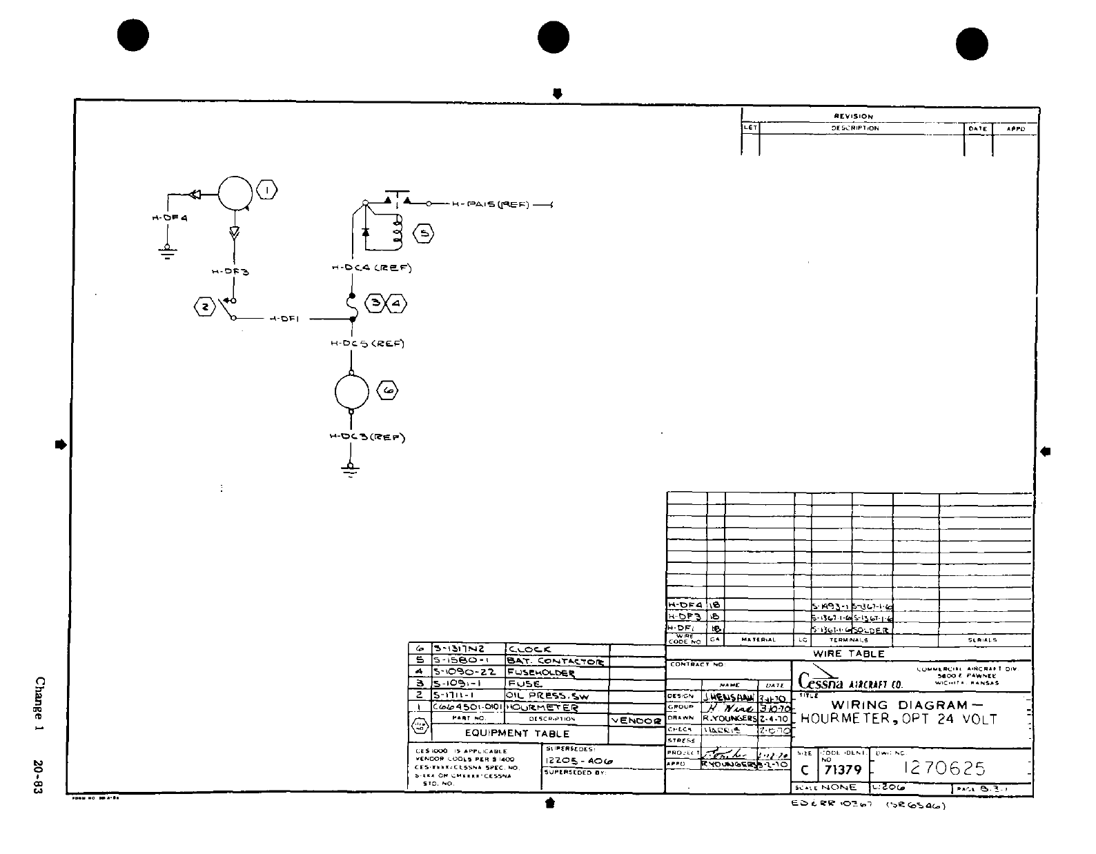
*^ I II F-
°_ __
"
EZ
-
>
\J
I......
111
,9
nib
-,
a
.°u :
.0a 1/ o08
q
' '
Z
'
u~
O
r
0 ii
I
'
Ii
I I
i
L
I
a
0
z
Is
Li*,~~~~~~~~~~~~~u
82i
Ca-
2-8
1O -S^
z
-ri
| I
i
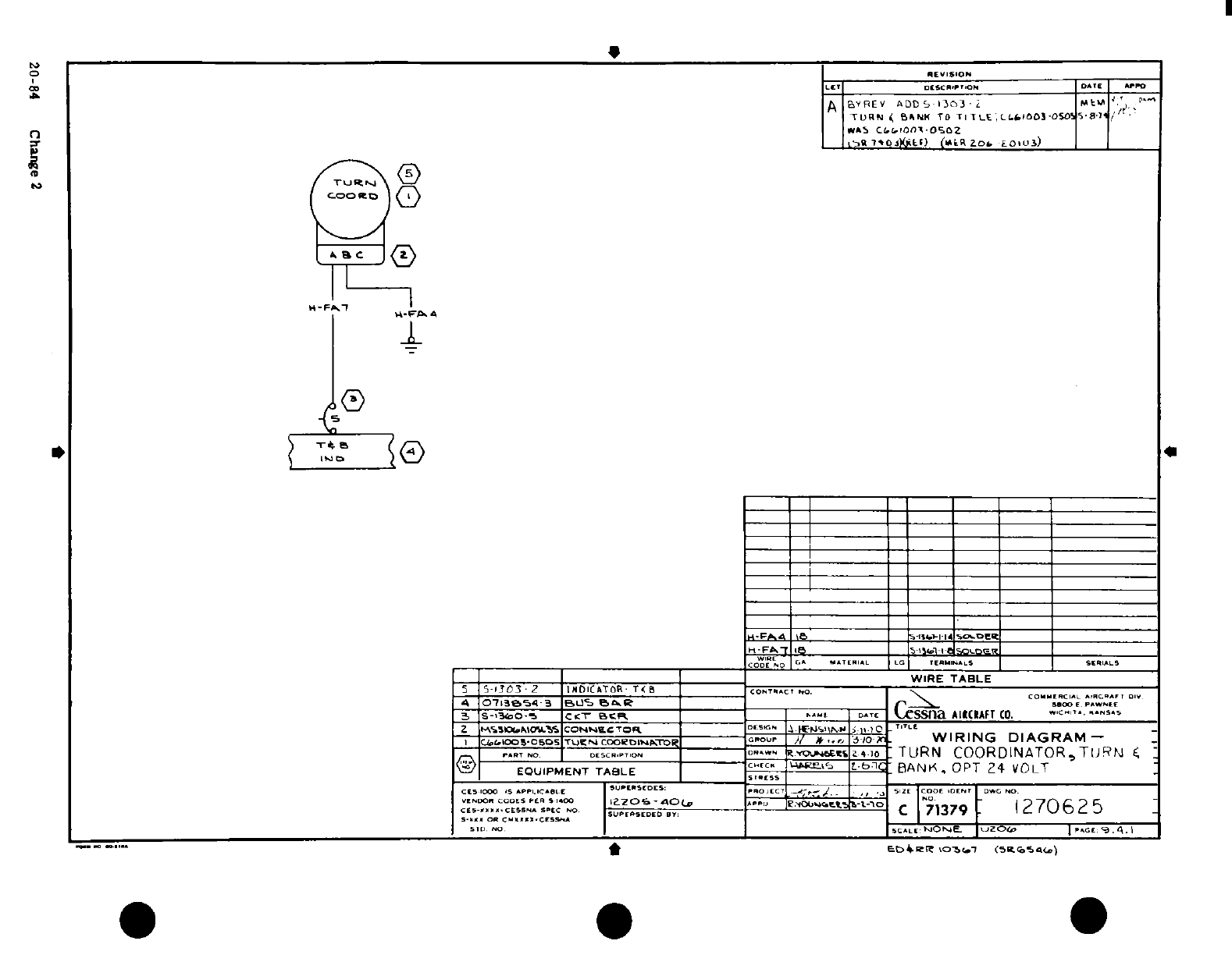
( ' ** **
*~III
I I
I
,i J 0
a
5"f
r
.l~
*:<*
S
n
1
20-4
Cag
0
0
Ir^ 0
.1.
I
1'
CD
JO8' I0
1
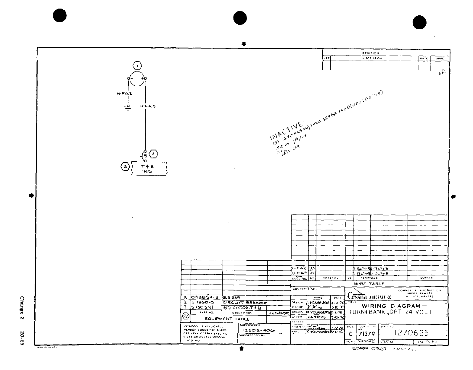
0 -i. I I >
... .
I~~~~~~~~~~~~~~~~~0
\
9~~~~~~~~~~~~~~~~~~~~~~~~~~~~~~~~~~~~~~~~1
o -i
-
0
S
S
;
' '
0
(\
J
'u
<I Q
-
J
C
a
&.~
~
~
F
oi Lio
* ;
7~~~~~~~~~~~
0-'~~~~~~~A
-- 7
LOw
h. ^
-
_S m
N
C '1~~~~~~~~~~~~~~~~~~~~~~~~~~4
rJ~~~~~~~~~~~
k
U^l^.
C~~~~~~~~~~~~~~~~~~~~~~~~~~~~~
r^
-
,^-
^ t
°< uL
LI
o
1^
^
"
3 :1:
I
i-lu~~~~~~~3
_____
p-'af-r'-
"^
5
.
I
I
^
55=-
1
I I I I
I
I I I
I-,
~1
Y;
-S n
-&
U S
-
B'
^^L^~~~~~~~~~~~~~~~~~n
$ LL^ I IIJ
h
Q~~~~~~~~~~~~~~~~
S
--
0
PIgP
C
g2
2
1 4 r
.3
*
-J^U^
"'
0 ~
O
0%
·
6_~~~~~~~~~~~~~~~~~~( i
c
3un~
2
u
g?.
IL~~~~~~~~~~~~~~~~~~~~~~~~~~~~~~~~~~~~Z'i ~~~~~~~~~~~~~~~~~~~~~~~~~~~~~f rL
;"
I~~~~~~~~~~~~~~~~~~~~~~~~~~~~~~~~i.
It~~~~~~~~~~~~~Ss-;.
*~~~~~~~~~~~~~~~~~~~~~u*
0~~~~~~~~~~~~~~~~~~~~~~~~"
S^
*~~~~~~~^*"gg
Chng
2
20-85-
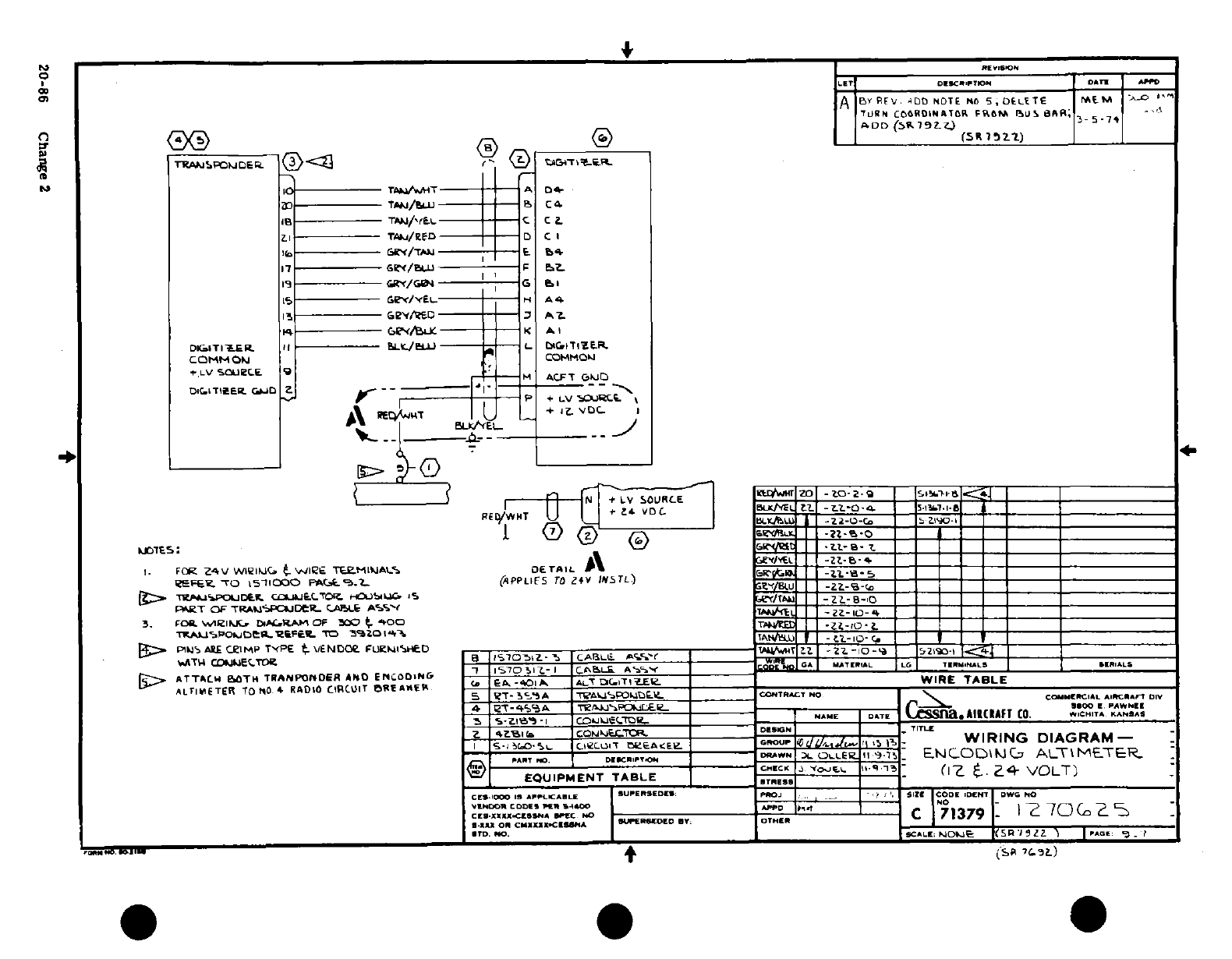
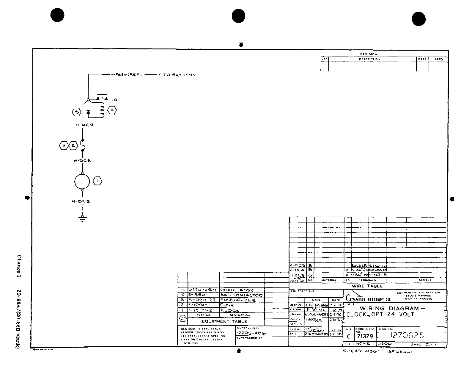
414
*I
I
I5
1^ "-I
0
H
7O
at
Change
2 20
-86A/(20-86B
blank)
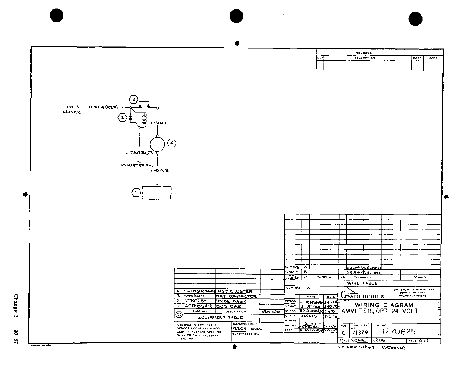
O
2
cr
p
I
0 I I,
W-
'
0
:
Z
-
w
M
O*
=f
- o
^ ^ ?
-
/I
"
sIl
,
:
,
.1
a,
2d
o
f
c,
Oo Chng
I
0-87o
»fl
*
0
*
-J
0
C
Id~~~~~~~~~~~~~~~~~~~~~~~I'
4~~~~~~~~~~~~~~~~~~~~~~F^yzS*
*S' 5 ^ B/
° hl S 0 s
ii
-4
C-~
~ ~ ~~~^Isi-
a.~~~~~~~~~~~~~~~~~~~~~~~~~~~~
l*>
&/~~~~~~~~~~~~~~~tf 0
^^
I~~~~~~~~~~~~~~~?S0
L/ ~ ~
~ ~ ~
~
~ ~ ~ ~ ~ ~ ~ ~~~~ Adof j.
a~~~~~~~~~~~~~~~a.S^
iv~~~~~~~~~~~~~~~~~3r
.;
00 ~ ~
~ ~ ~ ~ ~ ~ ~
9rT5
fr~~~~~~~~~~~~~~~~~~~Kr Ju
°
0~~~~~~~~~~~~~~~~~~~~~~~~~~~to^cs^i
S~~~~~~~~~~~~(03^;"
Chan
1 2
= 0-8
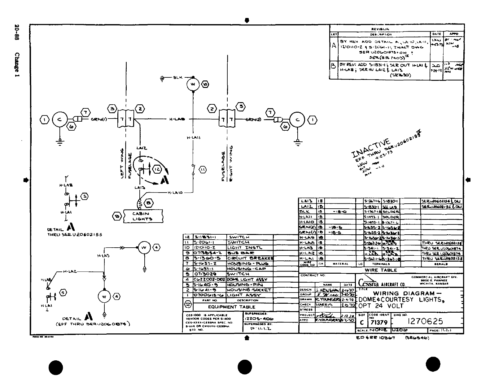
S'a'
3-
35-
91 i§
<6
O -
0
Ao.. i
,<
0i^
ac, :;
"!
,!
Pi
~:
I
I
o- S rL
4 sOO
'0-8 C
0e1
LI
I
I*M
7
I
0 m'^^^1?^^'?!
jrdj
toae 3
o
i i
Un.
-JJ
9
0
S
±
irs*>
D
208 ChangeI 1
20-88
Change
1
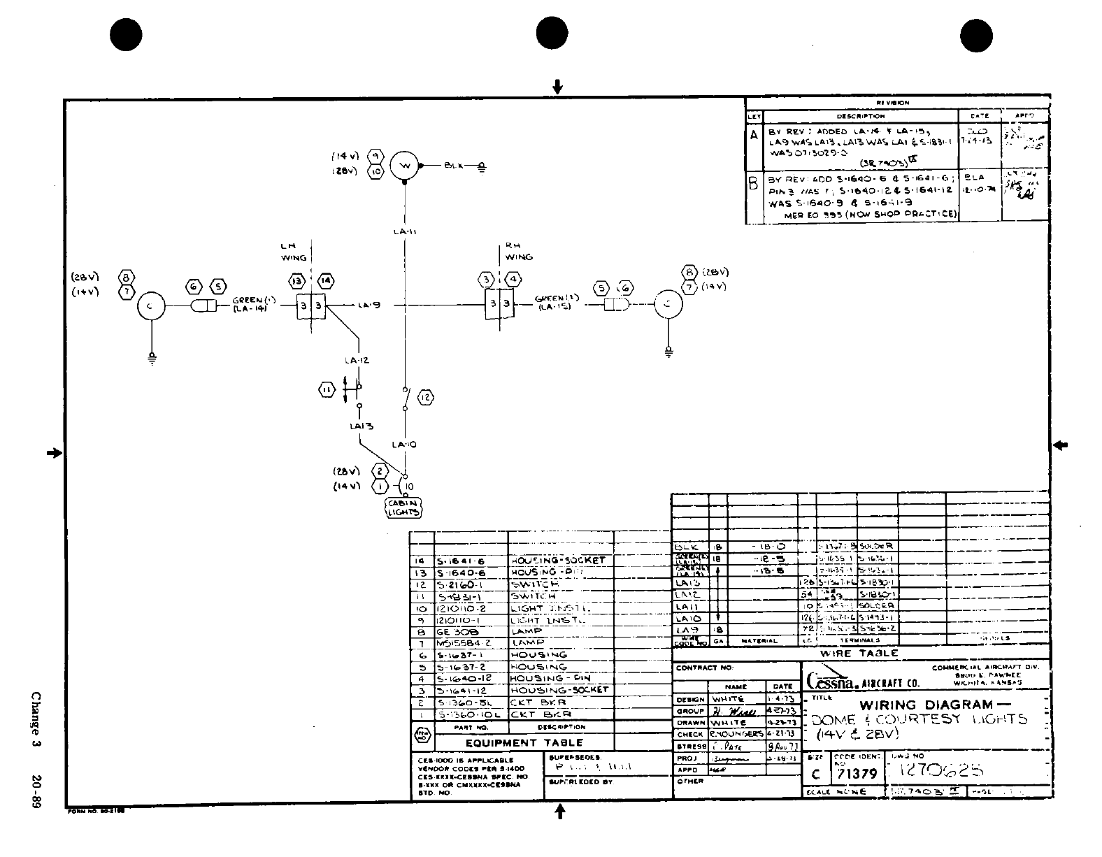
1/I ^
I
/~1 '~
I
~ I
-
»j
cd
L
-AJ
-
-5
"
U 1 <
5I'
J-
4;.
'»?
l^ -j
-
1
0
6r~~~~~
>'~~~~
r ^] .3 2-0' -89
s0
0'
E
^^-^ ^ g
L
a*xp.^Jia~~~~ ^,--
o
--
*"0
" "
iU
Y,
I n
II
II-~ %9;.0'~
"'
I·0
W
-r~~i?~~ 4*-
'
;-
O
*
7
w ^:~IYJ'u~fta co\ja
3
Ul^ 3 8 p 5.C3ne
3 28
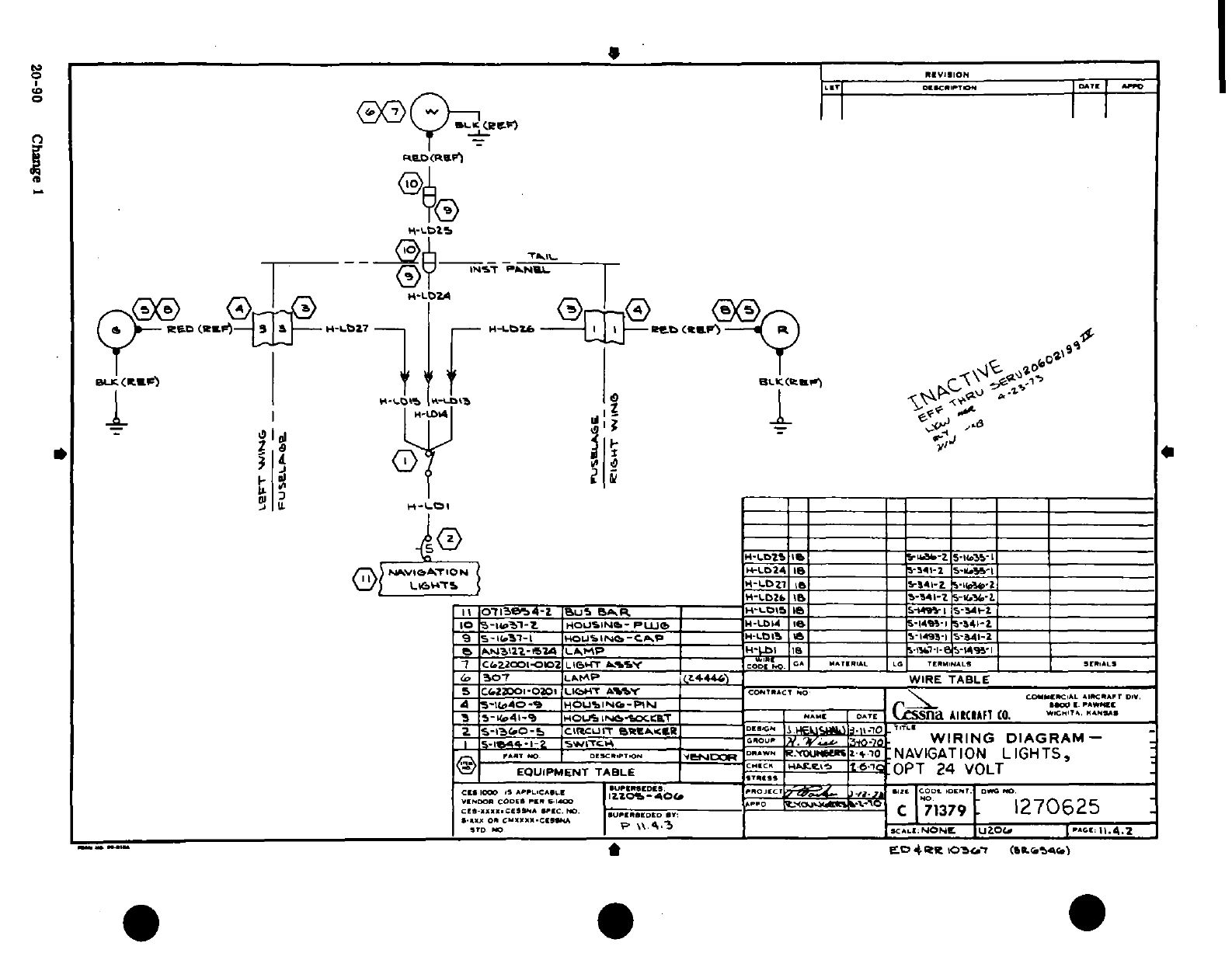
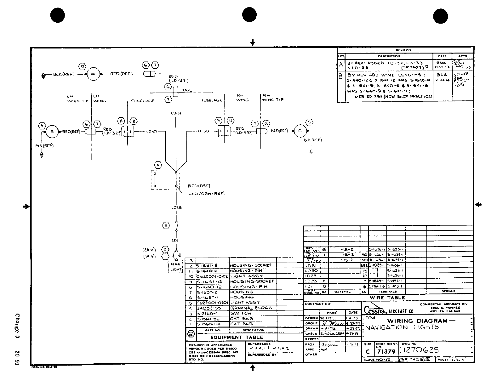
d ^'U^
~
~ ~ ~ ~ ~
~~YI~~~~~~I
I,
1
0
d
-
'J
0i
;:~
5
I"i
,
,s 5 8
o^
,b
M
I ^l^ .I
~~~~ ~'-7----
-
0
-
-
j/|
>
sT
5 * S o « '/ t £I --
0
O4
f
Is
z
z
t
--
Can
i3
8 09
it ^ „
p^^^s.^
i! I
Ilis~g
6
F 0j
o
I-
1-0
0aN00
Y--E(u
n
O
I
0
3Q :-
J *-
C 3
20
91
SM
~(J
5jS~
^~
2
-
r j^g
^ f l- So^
_s
j-as
^ ^ -^cr-
-*
^^ ^^Ut
Ji ^? ^oo-fS'-^S^^oQ" 1
*
1
;!!?~~~~~~~~~~~~~~~~~~~~~~~~
4 0
^a
ww fJ
^1^*3^^'
9
*^t*Si
"*u~~~~~~~~~~~~~~~~~~~
0~~~~~~~~
J?^
(^^-u.?
i
I DQ Qi/iA
J'fi
tf^^
niif
8
4
^
^
^
'^-J~~~pro^^iri~~~rfirj-
(yCha ge 3
2-9
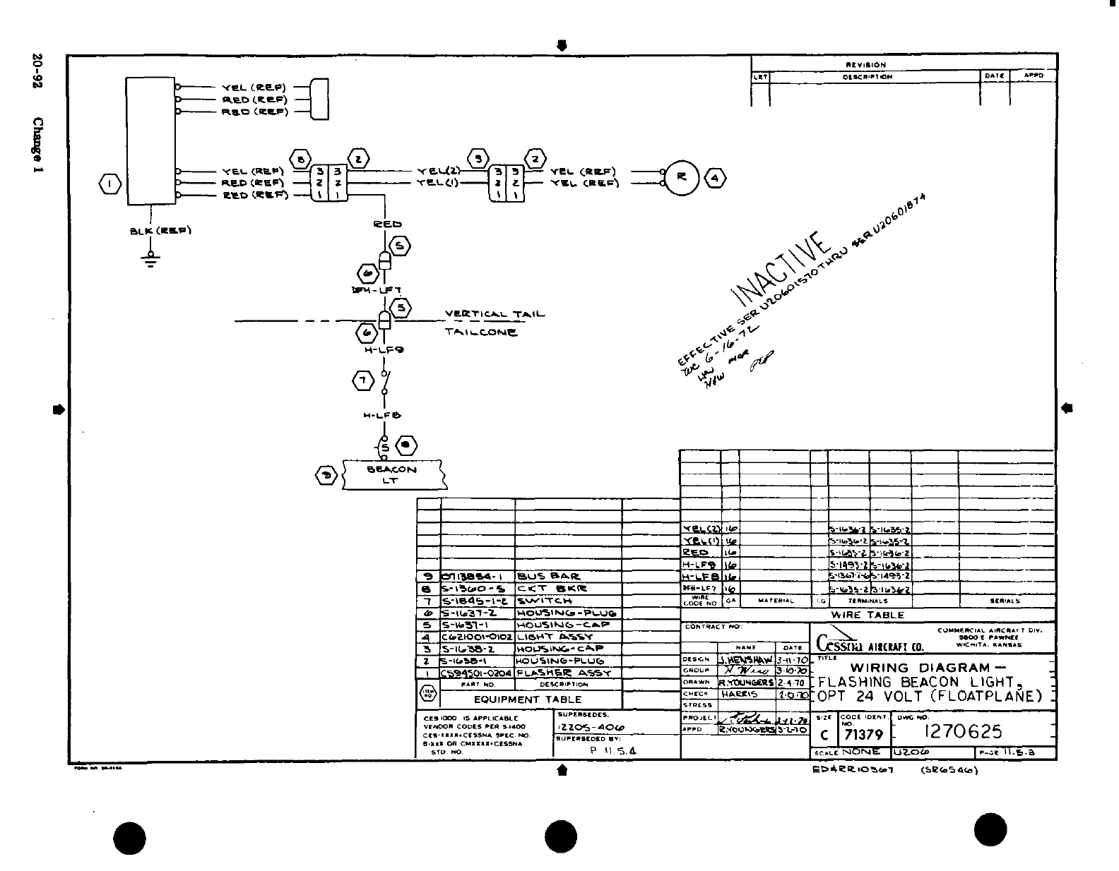
-'
n,
o
II
I-'
1__
"
^
S^?:
^
;'
*
C\ '
YEE
a
~
o
-
-.
w
/
,
sr'~,
It-
I
0
-, -3
5,o.~.,
,.
l
1^-
-
/
ii I
!
I,'10,-M,,I,,-l,,l,,H
®
I
?g~'"
1
I S)
s
"'
r:
'I" °"~a
C
t
.
r c\r r ~ <
z
r
z >O
v
4'
-
Z4
11 P4.---00
010
011
0
20-9_
C n
IS
6
tt
t
'as J 0 0 j a
Q~~~~~~~~~~~~~~~~~~~~~~~~~~~~~~~~~~~~~~~~~~~~~~~~
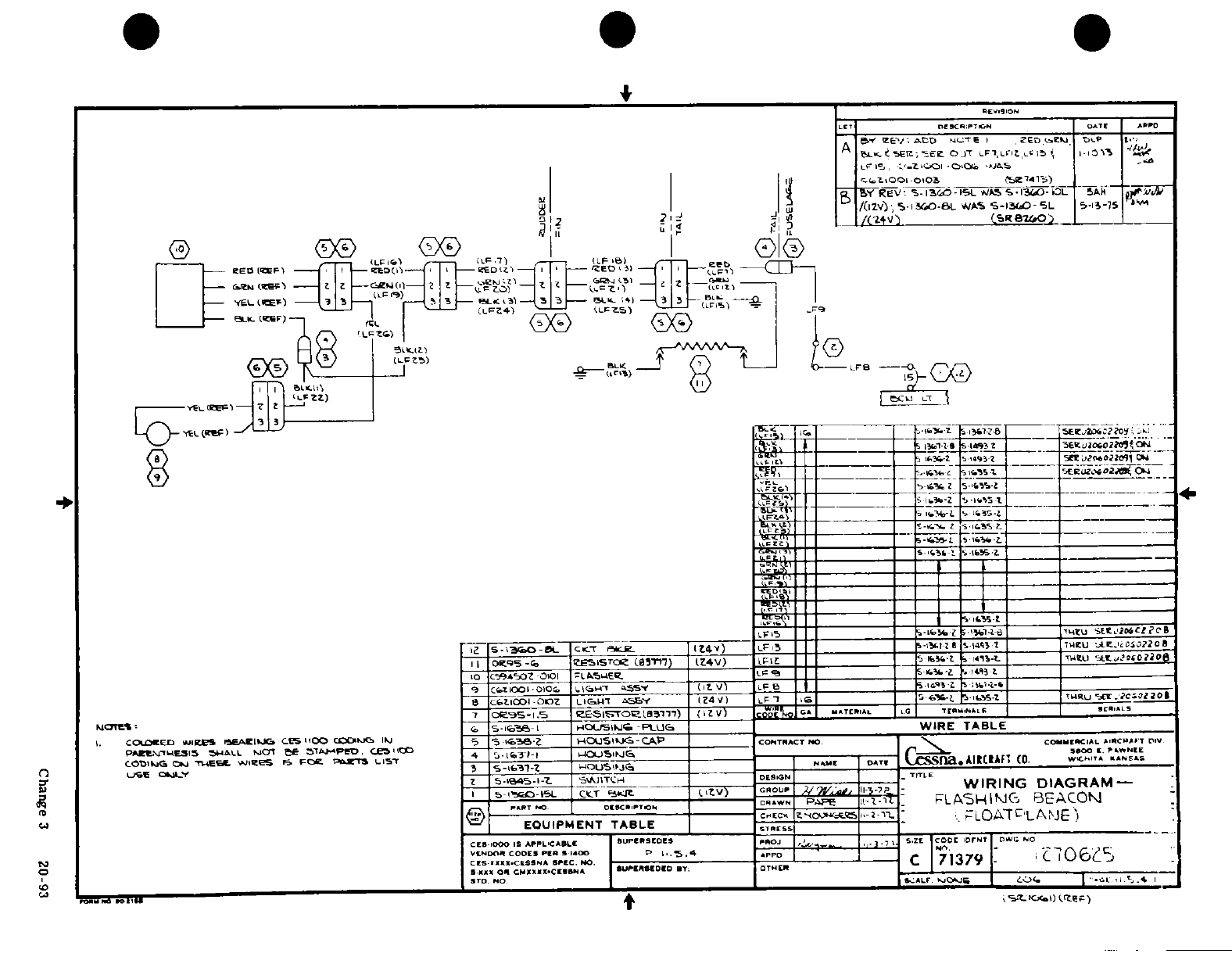
:'i
,' ' .
?
;
"' -,
~:,I~~~~
2 ^ Q~~~~
-J
u
~~~~
I^S
--
1
&,]gL
--
j in
^4-- ^q |/ |
-
~1 *~I, ~1
U
Ilia
::*
:* **"S'
",_ IP4
.ir iii
.D
:iT
l
v
I
0
,
I I
-
-ti
'
Cge
3
2: It
-lI~ 5
-I
9!
!)
Change
3
20
-93
4an I-
J ^
--
^
^~
nr. ^^sr~~~~~~~~~~i!~~
U^
^
'
r
a^
n
"-
7
"
t~
^a^i^^LP^^ IS
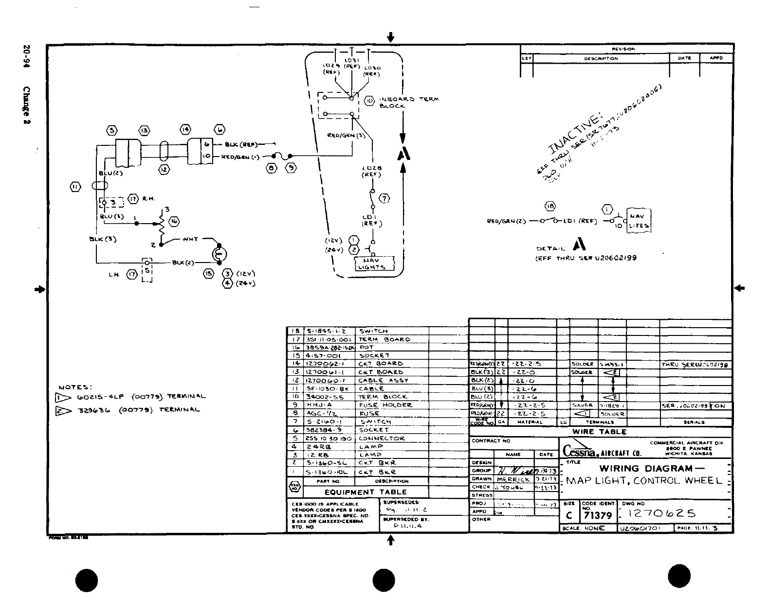
uLJ
T a
-
0
3
[ i ll
.. -
0
of Of j I 0D
--- ,
!
Q-ED
~I
036
.
0'I
0
-
'^1
t"='1
<il ^\^ ®t s,
...
a~~~~~~i
OL
i
-
C
I
--
0
/ *
.IS ^ ,IJJ
*
L
l
g
.
o
'
a
t
w
c20-94 C tgi2
I
- -
^
--
^ < ^
-1
Fon
7r- ©%
.
S
^0
-
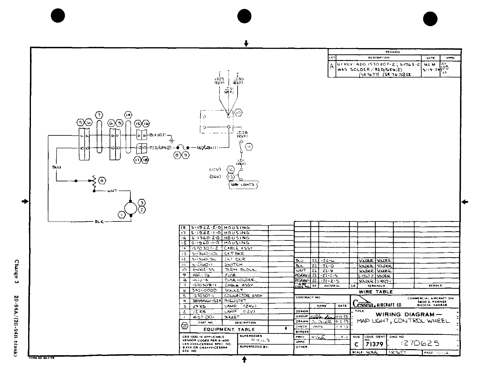
4w~~~~~~?
I Li
02
tz' ,-o
SIa~
Z-
.o o~~~~ ~
... --
s ^r ^^-
t
5
-
^^S
ddd'
"h
a
z
Qa
"
I
-
C
J
0
I
0(
0
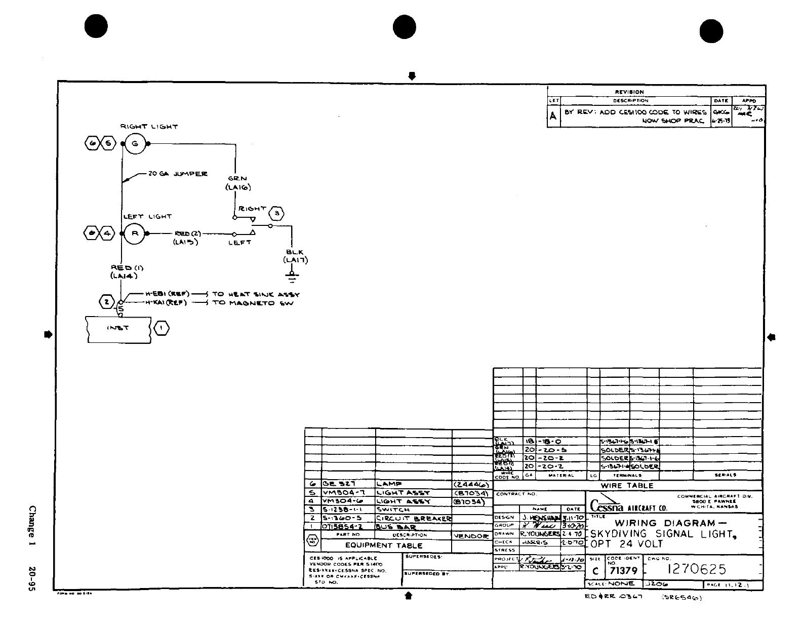
l
I'.lll
<i,~~~~~~~~~~~~~~
.
O
C
&tL
L
iz
z
.
hMIPI~I1
I;:- :
-
v~~~~~O0 ~O
.
N
N
"$N
i
e-
i
ChP1ge
1
20-95
yr 2^ ^0
-
4I
Change
1
20-95
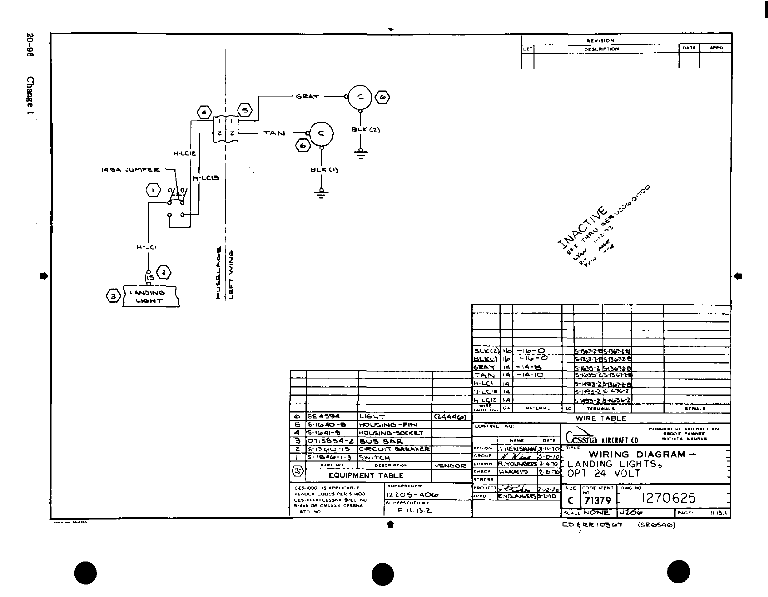
-S<-
!
N
-
'
j???
.^
-o ---- l
,
n
t .
I
0 OD
-)
v
in
i
tf-
-
I I I
IIV1N1~~1.
1:
I? -Un
20-9 I I
I
I I.
b--j ~~~--cI~~~~ I I
1®n 8-*w
I
s f IW
,Z
£0
T
20-96 Change 1
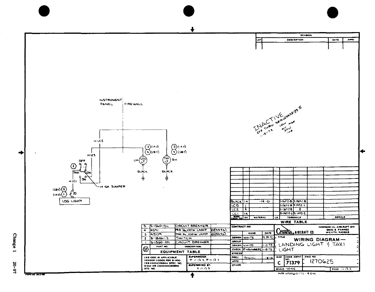
iw i"
Illl
I
sI_ :
5 P
I
I-
~--~-~. I0.J
411
I*
c
ID
.I
8$~-.
1'1"1-1-
Z~
.I
.. '
I
c
z r
a
5 i 5·U i
o
4'M
Cn *s3~1
20-
tZs
Change
1
20-97
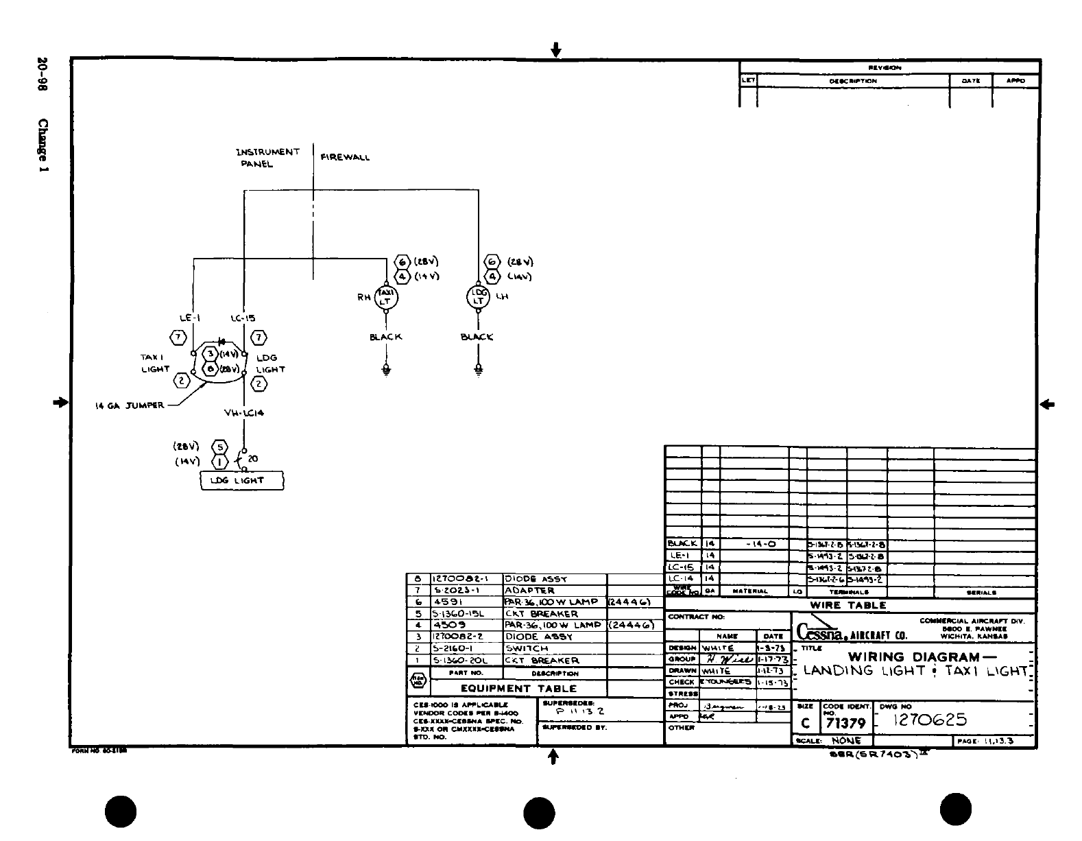
0
sS~~~i
C
2
C
azs
I5
;
a!
,Ih
5i U--Io
m il,,
20-98
CuIg
e
1~~~~~~~~~~~~~~~~
.
m~
~ l~js
?? j~~pi ^"T" w
~
-
t'^
QAuQ
~
l I.?
/*^^^ -'
^
s *
"8~~~~~~~~~~~~~~~~~~~~~
^€^-1- h
^-^I~~~~~~~~~~~~~~~~~~~~~~~IS
4
^ O B
OS*
'S
20-98~ ~ ~
~ ~ ~
~~~~~~~~~~~n^o'~
Chage
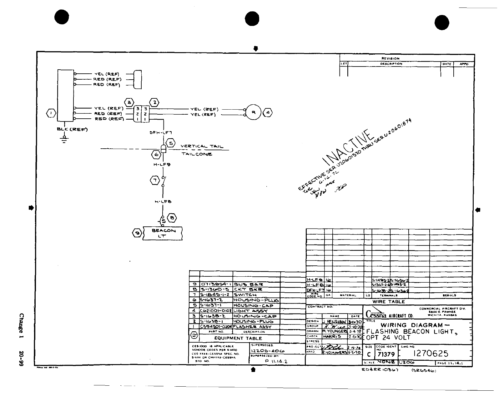
- 0
~'-- ^
5
(N_
et
%
zN
-.t
<» o
J
o
j
,
0
,
_
,o
(- 0
C1
20 -9
9
1-^-114 o
o
u
''^
/
LI S 0
P
6
½
1$ -d)~iJ~i^-
--
g
l ^
$
^.§^ 5
1.
4?C
20
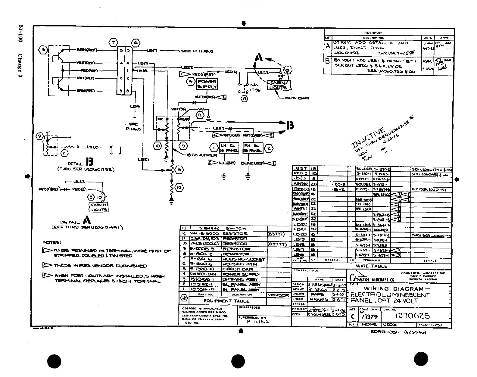
~IIL
j
h
!
V 'i?
a
O
,
-,
"5.^'
^V
H
t !ri-
N
1
zQ4<~Y
7
e
-g
24g~0-100 ~
~'L dh
L
I
30
.j
o^^r~~~~~~~~0
or
0.
3 ^^,
--
rff V
/^^i^
/ '
I
J
:
?
^20-100
Change
3
' " / /
.^".
IT t-
'*,;i~~~~~~~~~~~~~~~
-^ i | j
i
7 U,
!
*I/)~~~~~~~~~~~~~~~~~~~
<^- 1 _ ^ ;j~j ij=
y-j© rtil-h" ^^p^
13
il^
r09
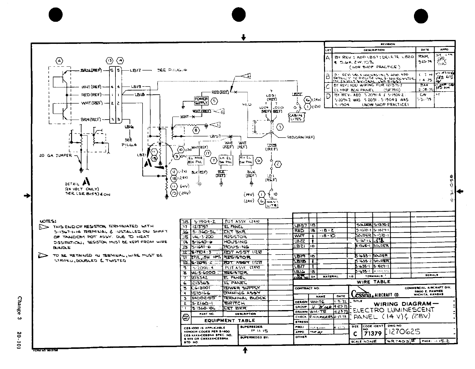
£~~~~~~~~~~~~'~)Im0
Il
I
#ft
i £ o2
-
o
Io/ Nj
'S'
!
ir
,-
,o /*~
B~----o
--
o4
Clot
I
j~
Lo
|
'
I
I
3
- I
s^^ti~o------- co 1a
-j -l
"'\
1 1
.
I e
i
0^~~~~~~F
8
Jr^~~~~~~~~~~Cp u J
S
!l7
.C~i
i_\ 1
^
&^^.hm
iigS
Is~a50o^
i§32
2
0
S^ -5 S
a
^r
^, -< I
aP^^ ^s
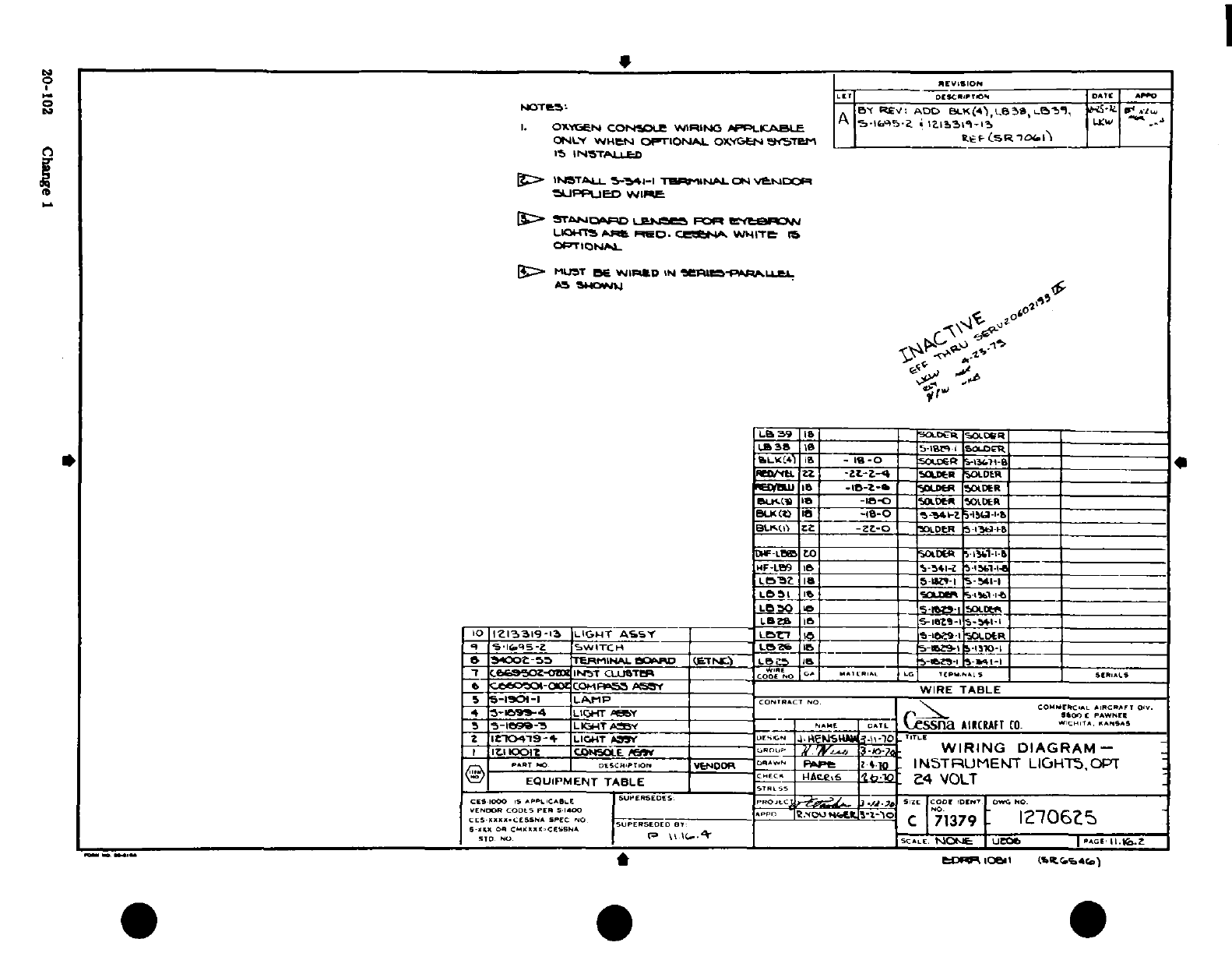
i:~~~~~~~~~~~~~~a
9~~~~~~~
OZ
0
I I
d)~~~~~~~~~~~~~~~~~~~~~~~~~~~~~~~~~~~~~~~~~~~~~~~~~~~~~~~~~~~~~~~~~U
I-O
g
~~~~~~~~~~~~~~~~~~~~~~~~~~~~~~~~~~~~~~~'
-L7 A 4N
4 5L
Li~~~~ji
* ~
r
Z·~Z
0
-I i
Ar
Lat
-
H0' li~
i
lt
a4
U. w~~~~~~~~~~~~~~.
Z
2
1
F
91
.
I
IIII
G
I
o
14~~~~~~~~~~~~~~~~~~~~~~~~~~~~~~~~~~~
Ii
I~
3
r
iq Y~~~~~~~~~j ~ ~~F
~~ X~cto~~s~o
*Pwo
20 i* Cdunge-I
if
r
3~~~~~~~~~~~~~~~;
g
-
Ii"~
~~~1
S
~~
*~~~~~~
20-101~
~ ~ :.ng
*
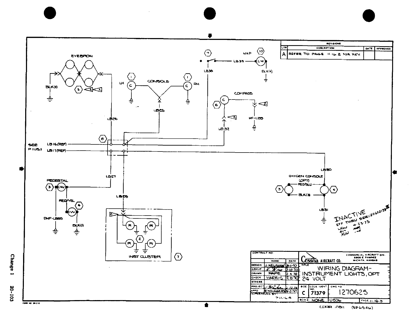
I-;
'
u
.L
®
0
A1_
o-
1
I.--'
.
y_
a
Ca
Change
1
20-103
n -ypF^ ^ ^!~~~~~~~~~~~G
0u4 I.^--
h2
k'S
^
~~0^
^
-
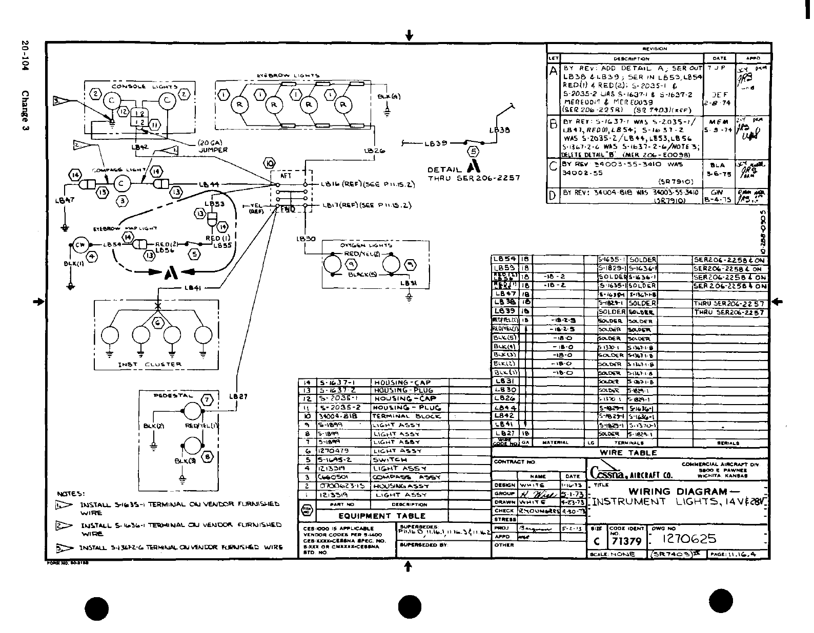
£ 3
^,
5^
,k
--.
oO
a
>*'
9..
, '
~
,
I
5
I
r N
m
^ ^ ^ -S Se:
?
*J
c
-j"J
<g
)
W;
2
0e:
n'
s
r ^ ^ S--'^§ I S
g?
s
),1w
-1
I<
Imi
I9o I~1
S 2
z"'
7:^-'.d
n'
S~i3?3rftf.<.,-*»
- -
-' 1
! 'J ' ' '
R4^,^^
h~-. ii
^-~Ilel-ldel^l+H e
0
:J
iwn 2!''
m,-
c9i
~~u
t
;,,=
J
20-104S
g.
?
?
-
<
Ce F-
W
z
-
V0
0l
rl^'
Wr
;
,
P-
0*-~~~d d
20-104 Change 3
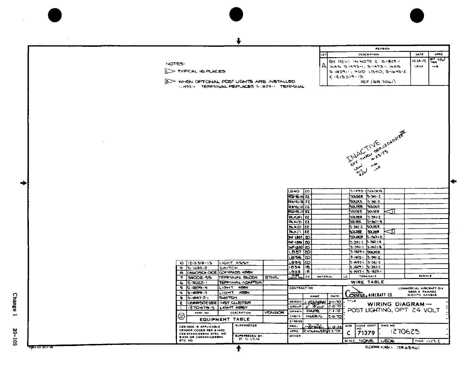
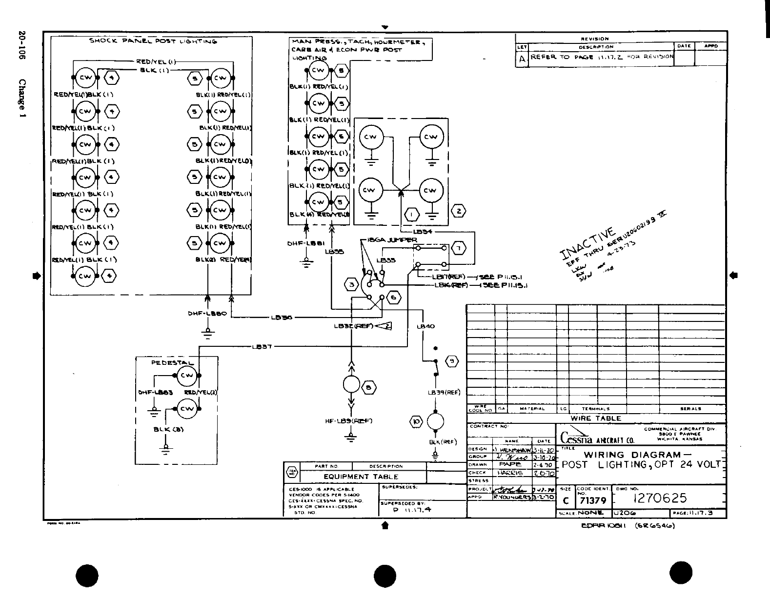
I
II
I
1i1
i
,
I
0I
I9
c^ s5
°
19 Jj~~~~~
°i»
*IIm
_
ct 2-W
.
-o
I
i1
-^
---
wK
-
20-10 Cmg e
I
91
T-O
i
.z
:-
co
20-1r0
CV "Oihag. e 1
^I®!^!^ 6 s
I e ^
$ ^
3e ^
^
e
j £
r
1
"
^S^~~~~~~~~~~~~~~~II
-'~~~~~~~~~~~~~~~~~~~~~~~~~~~~~~~~~~~~~~~~~~ae
D
S
---
sI
j
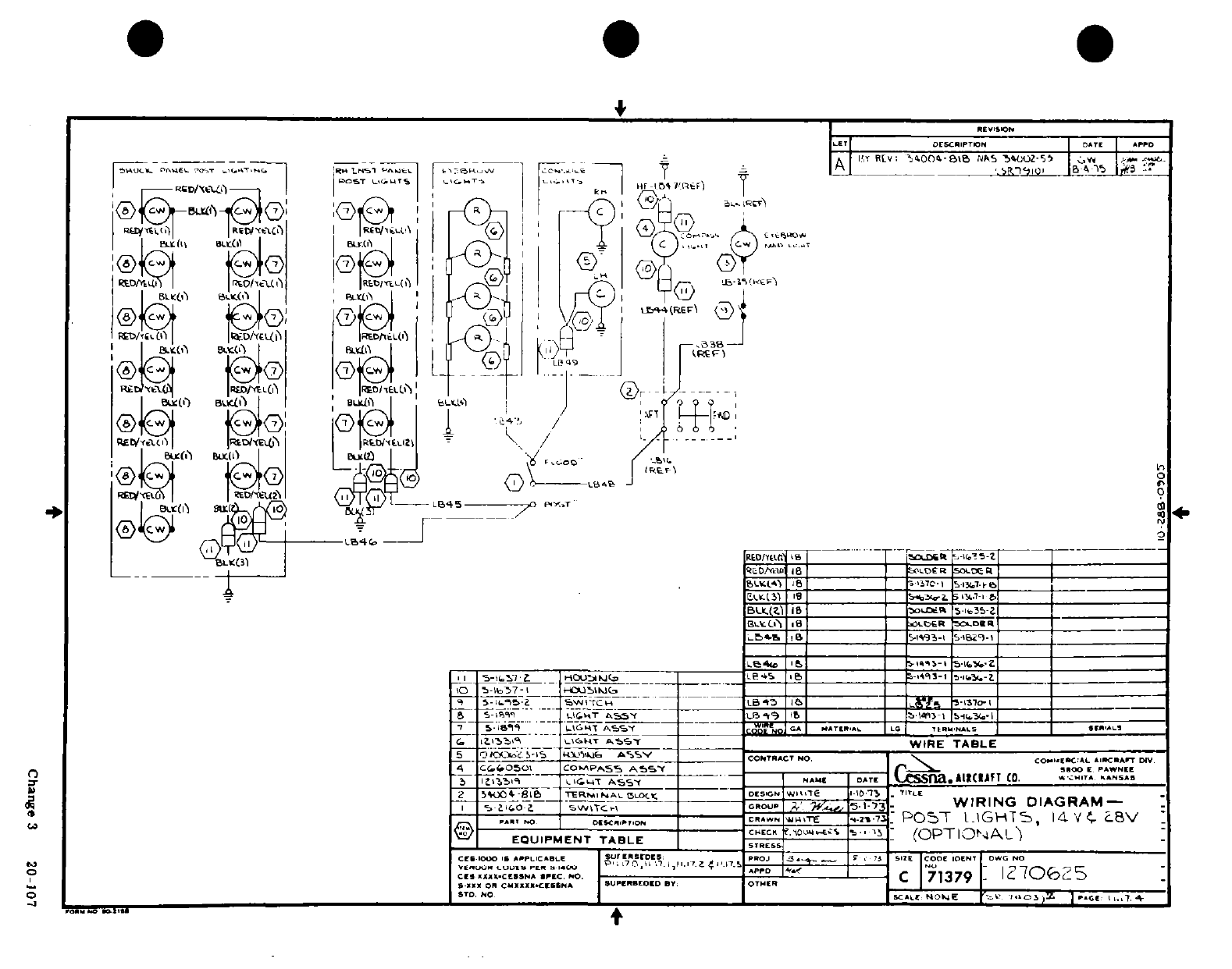
.
4!~ ~~~~~~~·
>
o
o
Q z~d
Y
X~~~~~~~~~ ®i
CD
'" *
a
.*
'ij C)
-?
o
l
,- "
52^
SS^
J.;
^^i > "·3 tQ
g
I
A®,-O,,®
'
!_ _}o
'~:
, - *
h
t
t
16L
.1
Zia
i
1"0 oo S
*'
Y
^
--
; I
.9
;'
--- ~--Io- 1 i 1-Can I3'20- 0
01 *r IrT
Orj c
____
N. U
0
.is- hi Ct I ; *
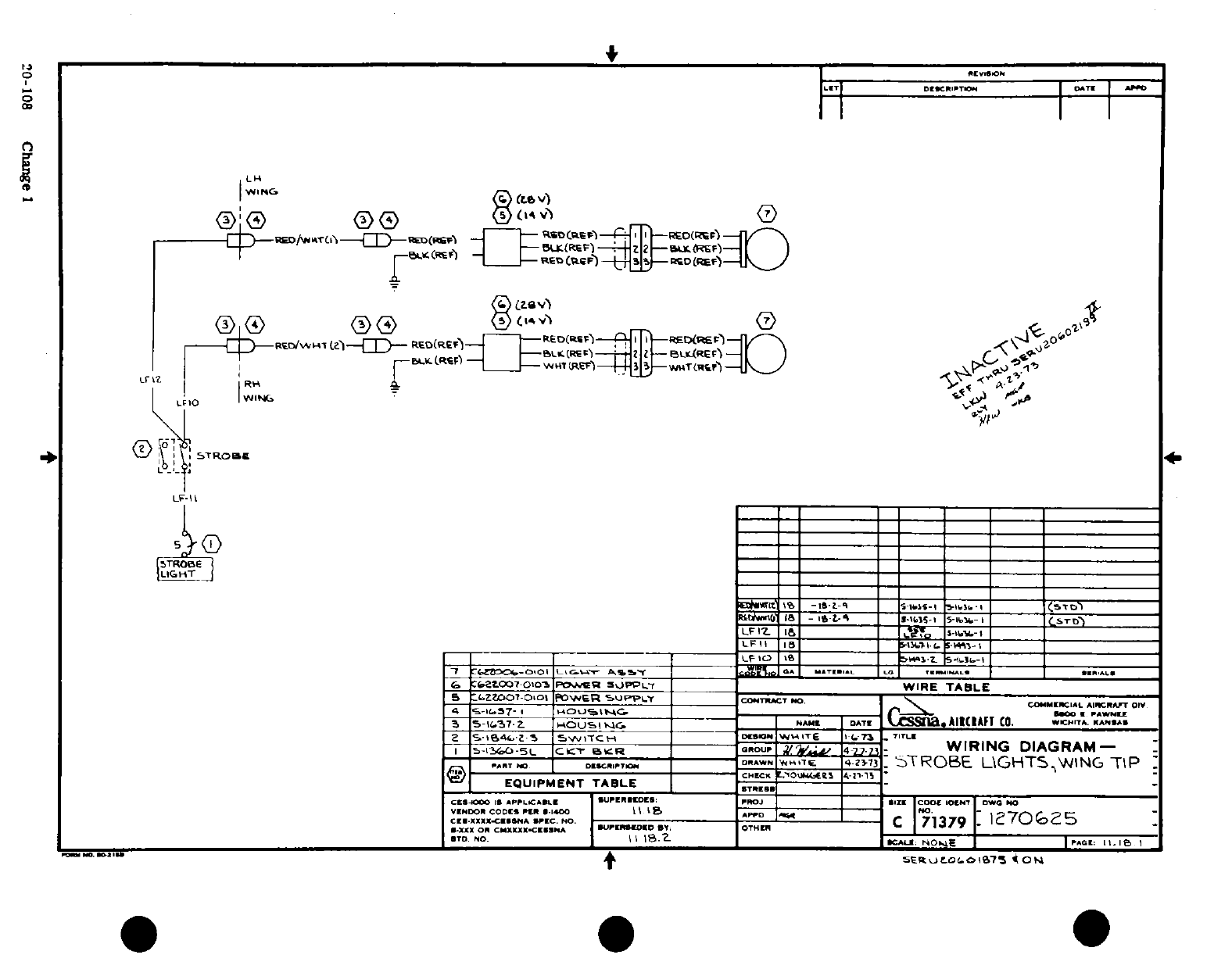
· fII I:
I
Sas.
0
%
10
Q^~~~~~~~~~~~~~~8
..
I
:
,..
81 rA^ ~
"
~
T
-- -
ow 3
Q
c
0U
'~0o-108o
Change 3
g
L
0 0-
Of,
,,
I-U¶if
r-
I
1i aXv
O Ti '-'
|
1
'
'i ^
^-'
[-
-* -
i B r ti
-
f0>f08 Change IlbO^^J~i 1*1
S
NI-
I©P§S:
§
0
~
n
A J '/".
§!
4~~~~~~~~~~~~~~~~~~~~~
*
-- -
»
"
rji'tnM
1-l0A
I
S
^~~~~~~~~~~~~~~~~~~~~~~~~~.
-J
©Q^"
e^"~~
2010Caney ©I
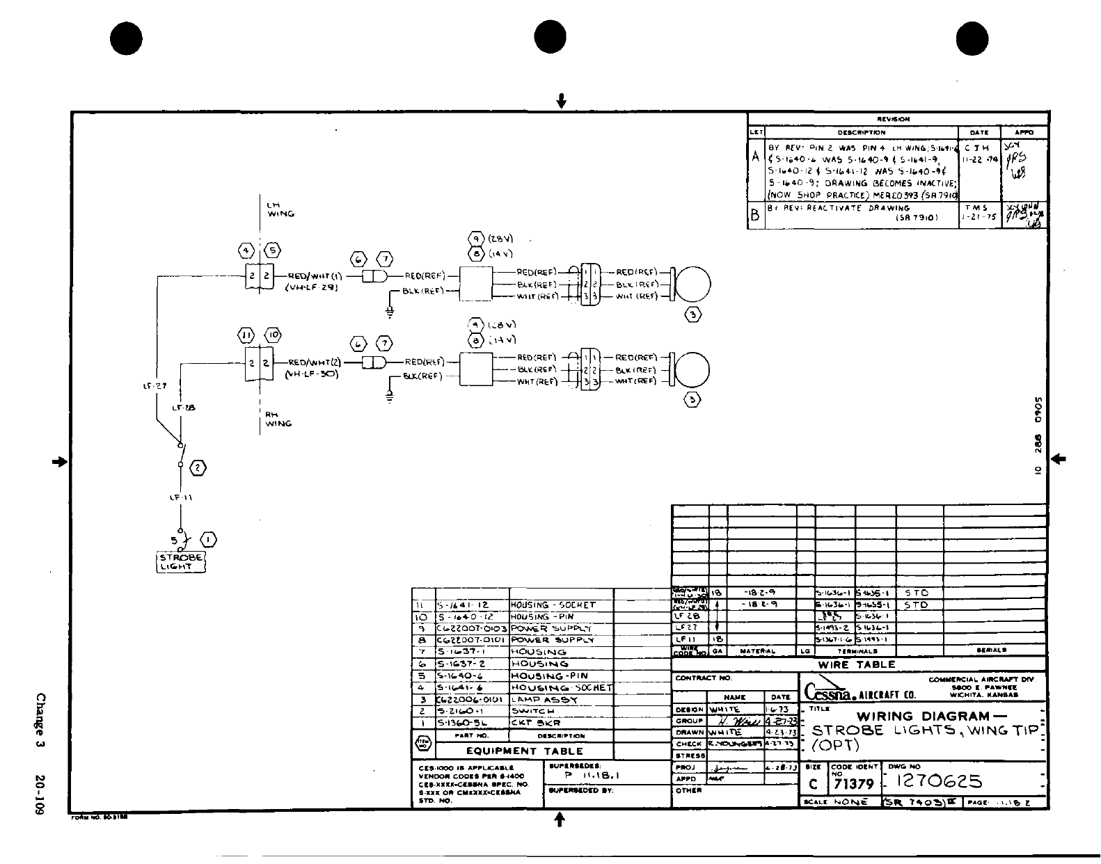
5060
es?
01
I i
'1 l,
so <
o. H0
'AL
I
?^^^
.. '
rfl
z
U <
.
D
--
.
i ^ 'i
-*
II
II
S~T^
'
5i
W
k;
a I
5
C^s-'ll
i
~1S rLY
i^'Lii
Z S-^5
-T
^O^
,c
u
2
S
-
raw
/
o~o
~
~
~
~ ~ ~
C
n
3 2
10
0V
^
i- ii ie
i
®T T
o
awi
1
-
yl4 ai<
;IC-
3
0-0
Change
3
20-109
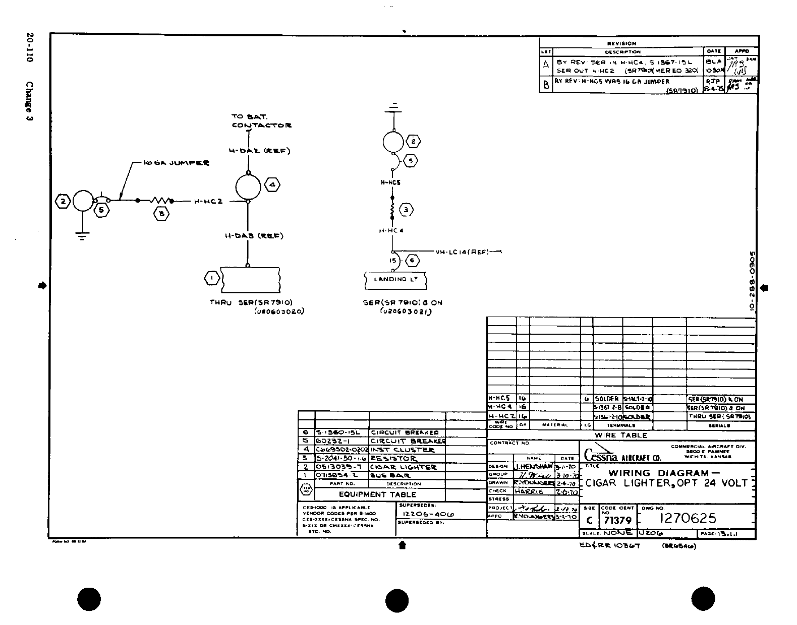
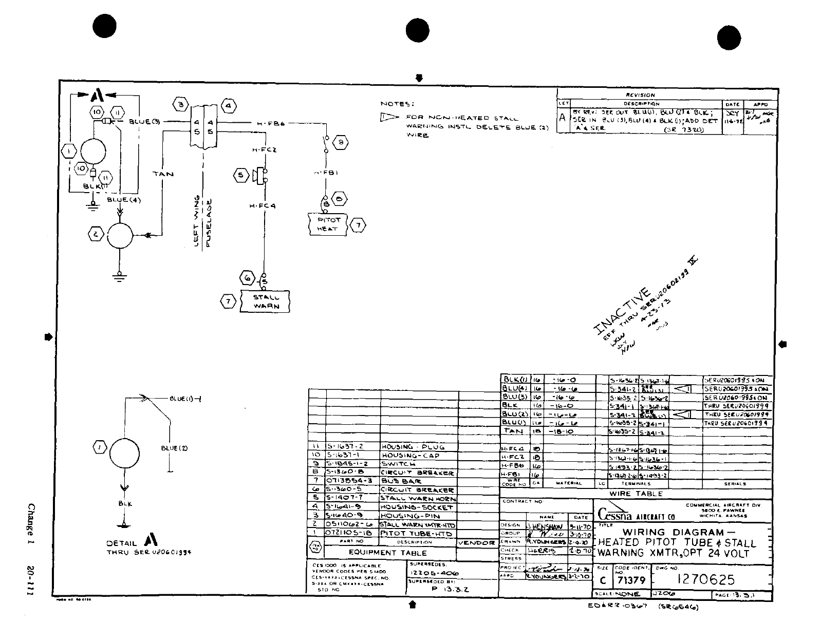
IB "ig5 I S
-
l'
.
-
z^ "'V
''
3
"'i
-
A
OON
-.,
,,z,
i"~~~~~~~~0
-
^~B
ZF-
ih
we hi
~lel~; i*- i
~
dll,
fit
Do.
.-
I I
!
0
0
I TIa
*
-a-jQ-Oj--t;(yfls;
4
®i~t~`"
e
an&/~~~~~~~~Change
I
20--
rf
i/
a
q
VI/ ^ ~ ~ ~ ~
~~~~~~~~~~~~~~~~~Cag T1
20-
1
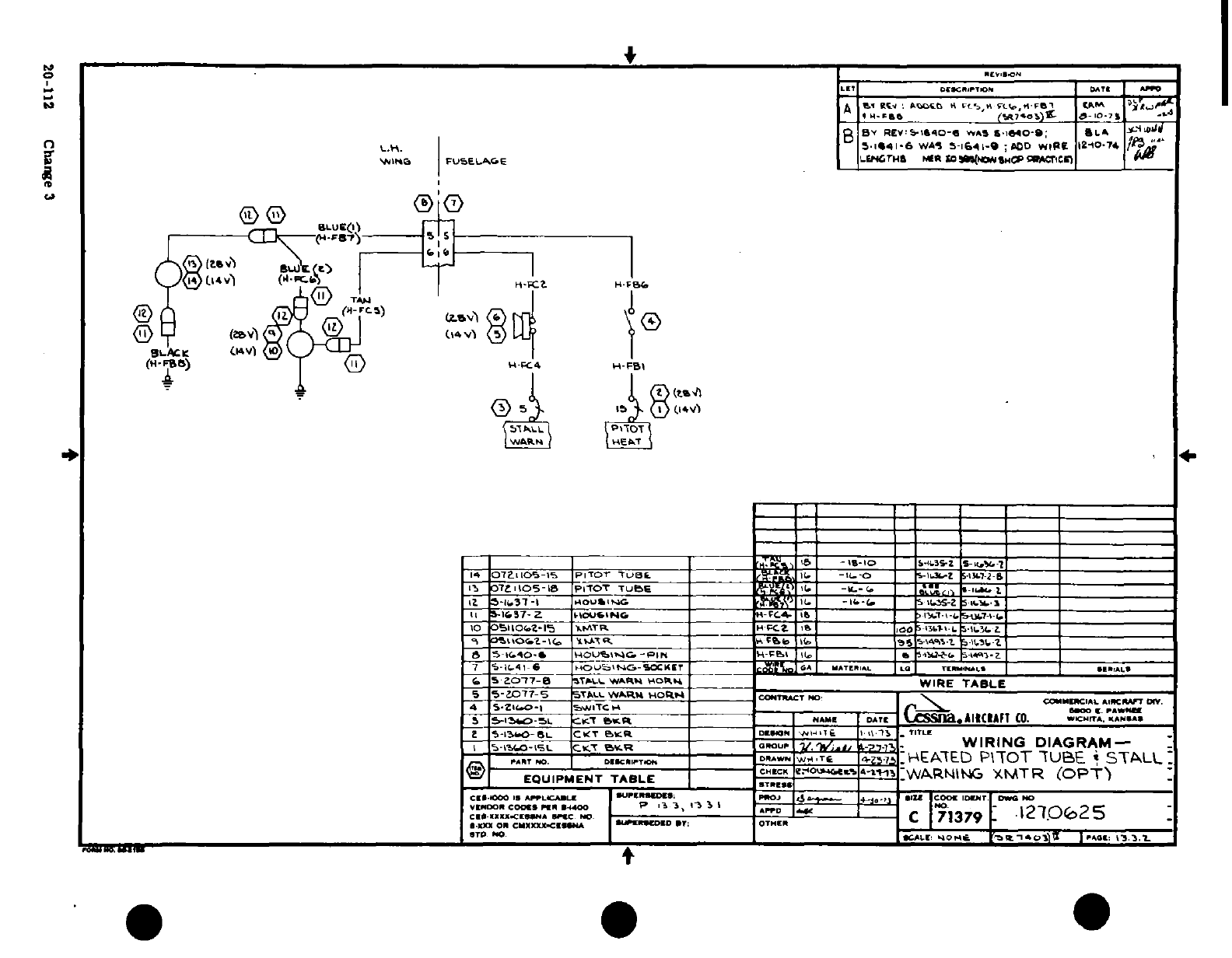
-I
I'
JAi
Sri
'
i9- llll
l
-
Sj
*
!I
i-'
Q
^
.I
-
I-
r
f3--I
I*
l o([
4,
!
w4®n
3|
w
Lo "I
ai
O 0
W
oov5 -3:-*' S
I
20~~-<><<1 Ofi~ i,,..
co<cocomE
)I
20-112
Change
3
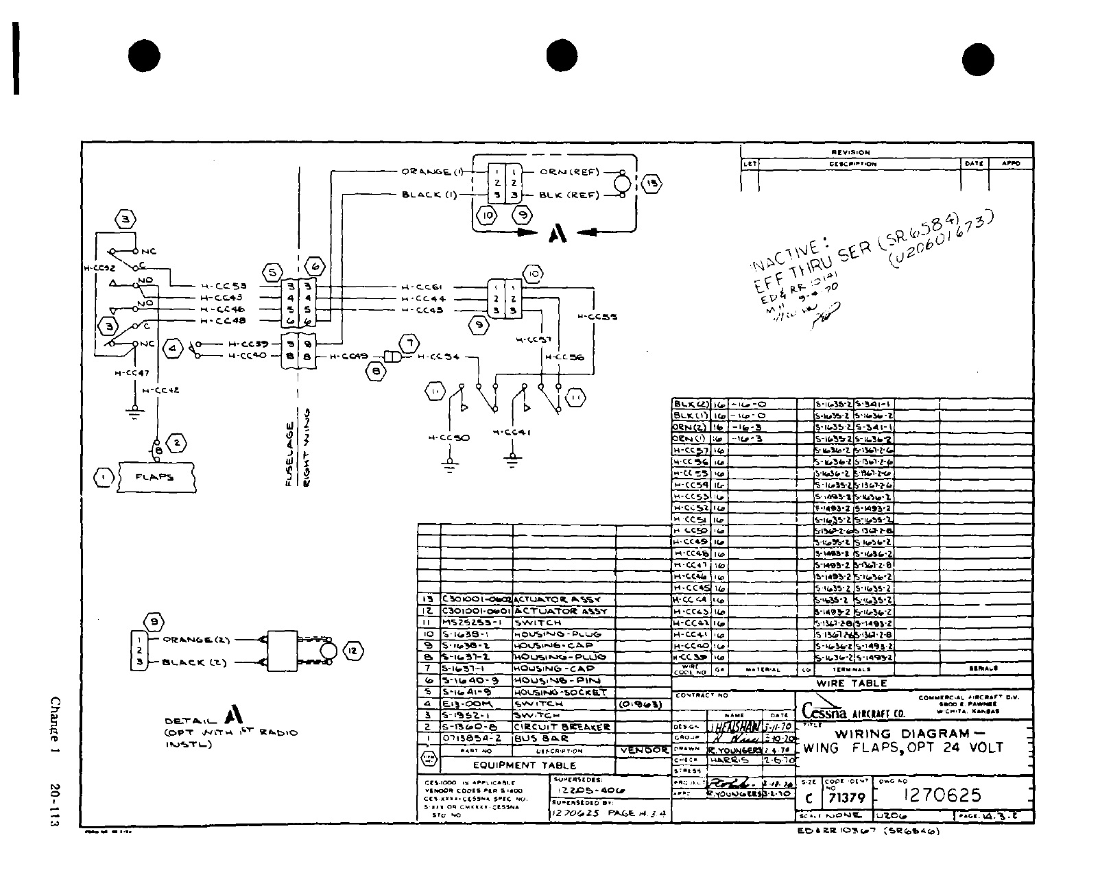
t r~~~~~~~~~~
in
0
'
a'
I, i I :
·I
®
ID
C&B)
&4-'n
Cr
I.)- ;~C .*I 0i.i
I
^-^
'
1
~
O O
-3
(
4
-
OS.0
o
7
'
'-
-8C -1
2
1
1u
--
LI
e1
I£~ ~
1
F
1 -?
/i
7a2ij
I- I
a
I
I
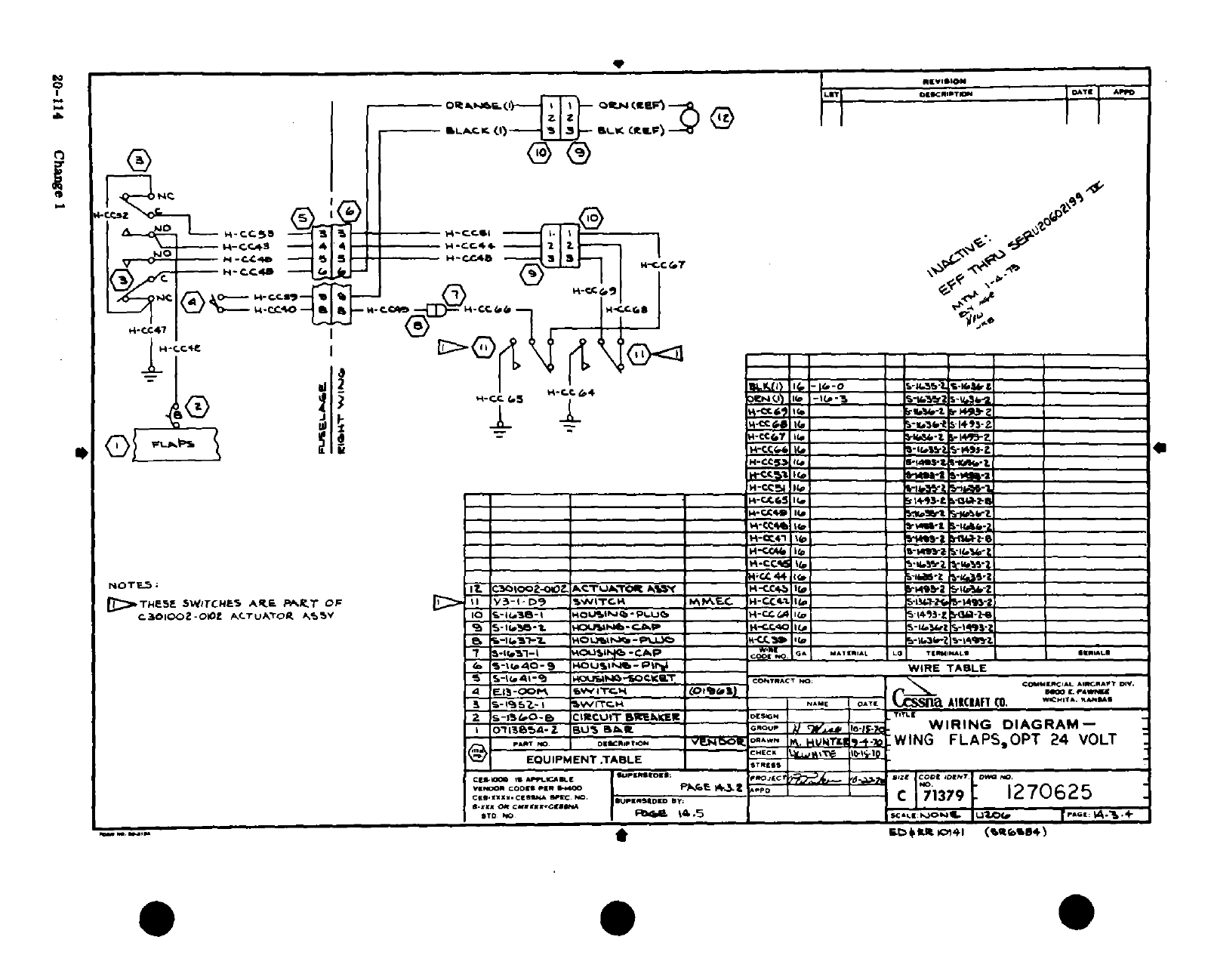
h
a
31i
ip
N~~~~~~~~~~~~~~~~~~~
i0'i:
Ic~
i~f
+
F4
<
0
.
a
z
W
~
~~
I
gfi
V^;3m~
amj
5r"
d)N
I
7 "A~~A
O I I I ~~~~~~~~~~~~~~~~jI~ e m
'
L a1II IB
a~
a£
--
J'>-^"
^^, A £ A~
A3^
.A ^ z4~>
4
i
t5A "Dji26 4
^SgMiIJ
jS
,rtj -c,25
.0M<iAriA,0*A
A£
S
3t
r' Arifi iS
-
-, "-
-
WA
`TT~~~~~~~~~~~~~~~~~~~~~~~>~~~~~
*S
T
*>
4d0
-
A
£
--
o 0 1
'
1?F
I~
-
S
-
*»
A
y
J 5 ii*~~~~~~~~~~~~~*
%T.
I~~~~~~ 7I
I
s
n
£SS~~~s~~aftaS5$3^
?3S~~~~~ij»^
^
-'.aa~~Wf
4 NI~~~~~~~~~~~~~~~~~~~~~~~~~I
II
-
0-114 ^w
I
*I
'0
F7
*Qtt^
a
Tl®
rY
\ir
*
»0-11'
os
11c >t&.
ii ©- -i
,
p j
^
1-^'p
' --
« I^-a-lr ^ .S^S:Qo'ct- oqLIN- ,
»
-.
u
"
;1 ^II
I
Ak
a
0
-"
I^ A
0
-
fifl<^j a ~
*»^-ans
ii
?
20-114~~~~~~UVU
1
Chage
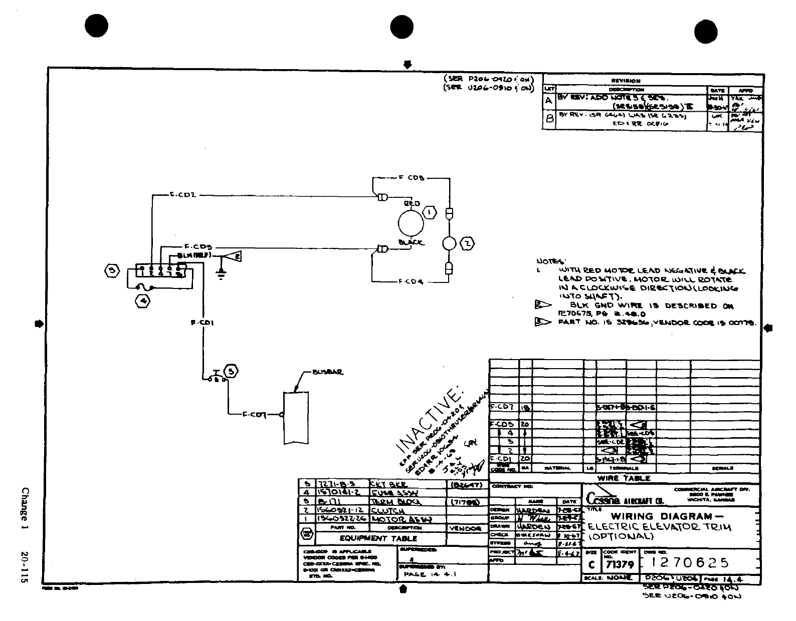
a?^ haz 0r
j
Vs
I'-
?
j
-
id11
H P
d
*j *5%j
~a aA
f
'p
N
'
-Ijji
I
jiti
s R
0f
^
Sh
aa
I
di
Ch
e ]
20-i5
Change
1
20-115
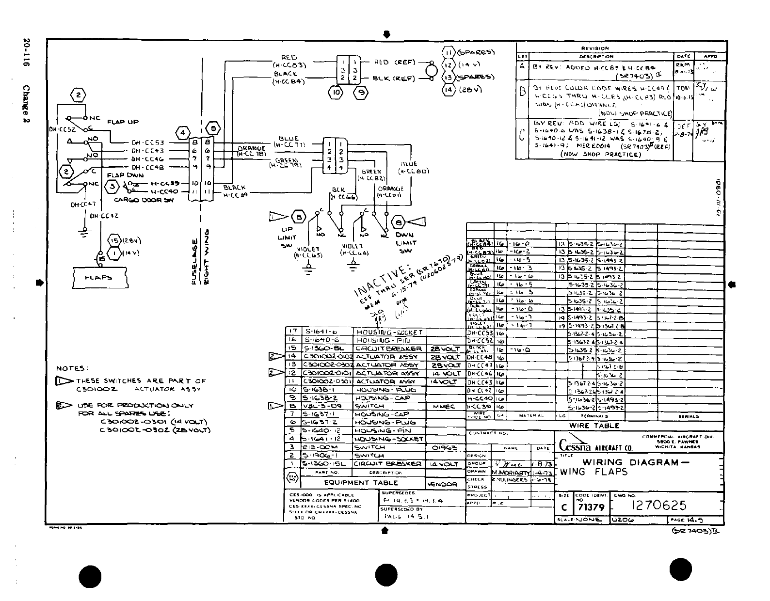

*oe r'
@1
j
0j
0-
-z
c'*".-i^^^j^^^M^'i'^s^bi^^^
.j a az
b
*
fl
';"1^ntf~[~~a~~l"'"
t''7
--
t n
" ' * --- - -F
oT ~ir
*
3
-
uJr~~~~~~~~~~J
."'
t-
.$
~Olr
.*t
aa A l
4
-·0~~,
z
-, -
U
-J 4sJJJ |
.JJ^J4
o0I I~~~~~~~~
, -,
-
¢
7
0 -i
--
LnB-.
tz G-1? 3
~
3 ^Chne
2
20-1
16A/(20-I6B
blank)
I
-
diN
L
-
ciK ¶ii
Change
2
20-116A/(20-II6B
blank)
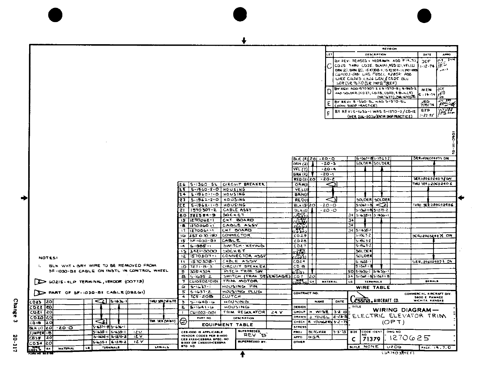
-J-
4
1:3?1
9
;:
, °
-'-^1-
3?
5ss §
1
1.
1
I
a--Illl ,l:ll Irll
-'"
>~~~~~~a~~~~~~~~~~~~u1 '1
1 f f -^'u
T' iu .iT :
Z
J
& -W
r:lb' i
'
5
>*
-
o
-
C s
,
W-O Jn
-
a
o
a
C
far ii,
v .4
0
-
>
'-
-
QO'C
r
^.
*
Z
S
a
00, 0
5
S
.J^ '5 uti,
pCse
3
20-
'ii
I
i
a QWIj N
te
W d
j0000
a
-_,ga
A A
A
Change
3
20-117
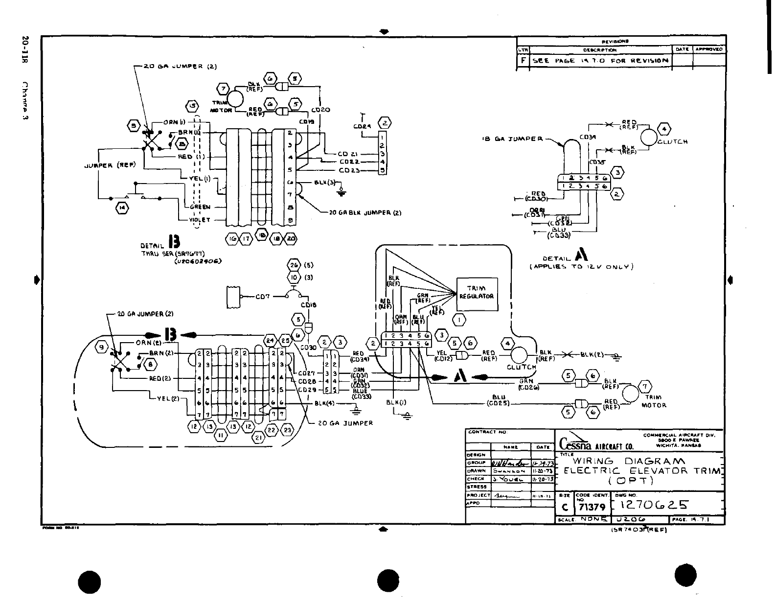
4 I
1-.
d3
4t
|-
LV
'
s
a
u n
I-- IMI
-
-J Ii
o* U
20
o 1 I ' I; 7 ri . o
I tr ie.F/, ,
SI.
-
""
~-
i
/ --
"-'t
I
I
0
U
i-Y I I
---
--
I S ~ -- ----- ft" IT
I
3a3 3 ^n. s
r^)
I
I
I
A
·- \ i I
/
-z
*r
a
-
Ca-
J
r
: IE
p
U.
i
|)
t-
U
n
b
S
K)
k
"J
.
1^
-
J
,'
^
5
T;'^,
2
-,
0
-.
o 1r0
20-118
C
3
?i
Ti
