Cessna_Caravan_II F406 POH 1986 Cessna Caravan II
User Manual: Cessna_Caravan_II-F406-POH-1986
Open the PDF directly: View PDF ![]() .
.
Page Count: 692 [warning: Documents this large are best viewed by clicking the View PDF Link!]
ZI
uessnal
Information Manual
A Memb€r ol GAMA
Cessna Aircraft Company
Model406
THIS MANUAL INCORPORATES INFORMATION ISSUED
THRU REVISION 2 TO THE PILOT'S OPERATING HANDBOOK
AND FAA APPROVED AIBPLANE FLIGHT MANUAL DATED 1
JULY 1986.
COPYRIGHT O !995
C€ssna Aircraft Company
Wichita, Kansas USA
Original lssue - 1 Julv 1986
Dt624-13
INTRODUCTION
CONTENTS
SECTION
CONTENTS
MODEL 406
2 LIMITATIONS.......
3 EMERGENCY PROCEDURES ... "
4 NORMAL PROCEDURES .....
5 PERFORMANCE ..
6 WEIGHT AND BALANCE
? DESCRIPTION OF THE AIRPLANE AND ITS SYSTEMS
8 HANDLING,SERVICEANDMAINTENANCE .
1 GENERAL
9 SUPPLEMENTS ..
ALPHABETICAL INDEX .. " .Index-1
2-L
3-1
4-l
o-r
6-1
7-l
8-1
9-1
Contents Original lssue - 1 JulY 1986
SECTION I
GENERAL
TABLE OF CONTENTS
Page
THREE-VIEW DRAWING ..,.....7-2
INTRODUCTION ........1-3
ENGINES .......1.4
PROPELLERS .......... l-4
FUEL.. ........1-5
- oIL . ....'.....1-6
=r L.raxluuM cERTIFICATED wEIGHTS .... 1-6
STANDARD AIRPLANE WEIGHTS ....,.. 1-8
CABIN, BAGGAGE AND ENTRY DIMENSIONS . . . . . . , . , . . . 1-9
SPECIFIC LOADINGS ...1-11
SYMBOLS, ABBREVIATIONS AND TERMINOLOGY ....... 1.11
General Airspeed Terminology and Symbols ....... 1-11
Meteorological Terminology .....1-13
Power Terminology .... .......1-14
Engine Controls and Instruments Terminology '.... 1-15
Airplane Performance and Flight Planning Terminology . . . . 1-16
Weight and Balance Terminology ... .....1-1?
MODEL 406 SECTION 1
GENERAL
Originat tssue - 1 July 1986 1-1
SECTION 1
GENERAL
1.
MODEL 406
13.15'*
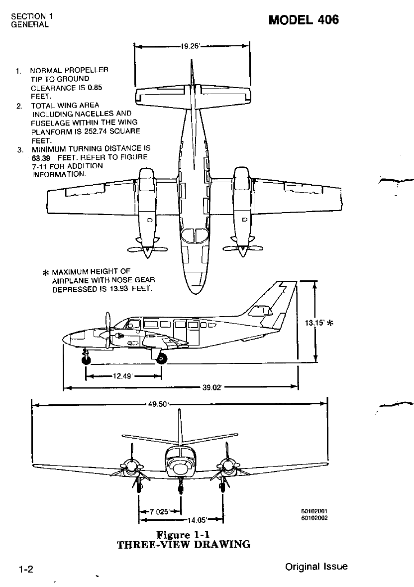
NORMAL PROPELLER
TIP TO GROUND
CLEARANCE IS 0.85
TOTAL WING AREA
INCLUOING NACELLES AND
FUSELAGE WITHIN THE WING
PLANFORM IS 252.74 SQUABE
I\,IINIMUM TURNING DISTANCE IS
63.39 FEET. REFER TO FIGURE
7-t1 FOR ADOITION
INFORMATION.
* l\,iAxll\,lUl\,1 HEIGHT OF
AIRPLANE WITH NOSE GEAR
DEPRESSED IS I3.93 FEET.
12.4e'J
Figure l.-1
THRED-VIEW DRAWING
Original lssue
NOTICE
AT THE TIME OF ISSUANCE, THIS INFOR.
MATION MANUAL WAS AN EXACT DUPLI.
CATE OF THE OFFICIAL PILOT'S OPERAT.
ING HANDBOOK AND FAA APPROVED
AIRPLANE FLIGHT MANUAL AND IS TO BE
USED FOR GENERAL PURPOSES ONLY.
IT wILL .|GI U KEPT CURRENT AND,
THEREFORE, CANNOT BE USED AS A
SUBSTITUTE FOR THE OFFICIAL PILOT'S
OPERATING HANDBOOK AND FAA
APPROVED AIRPLANE FLIGHT MANUAL
INTENDED FOR OPERATION OF THE AIR.
PLANE..
CESSNA AIRCRAFT COMPANY
ORIGINAL ISSUE - 1 JULY 1986
INTRODUCTION
PERFORI,IANCE AND SPECIFICATIONS MODEL 406
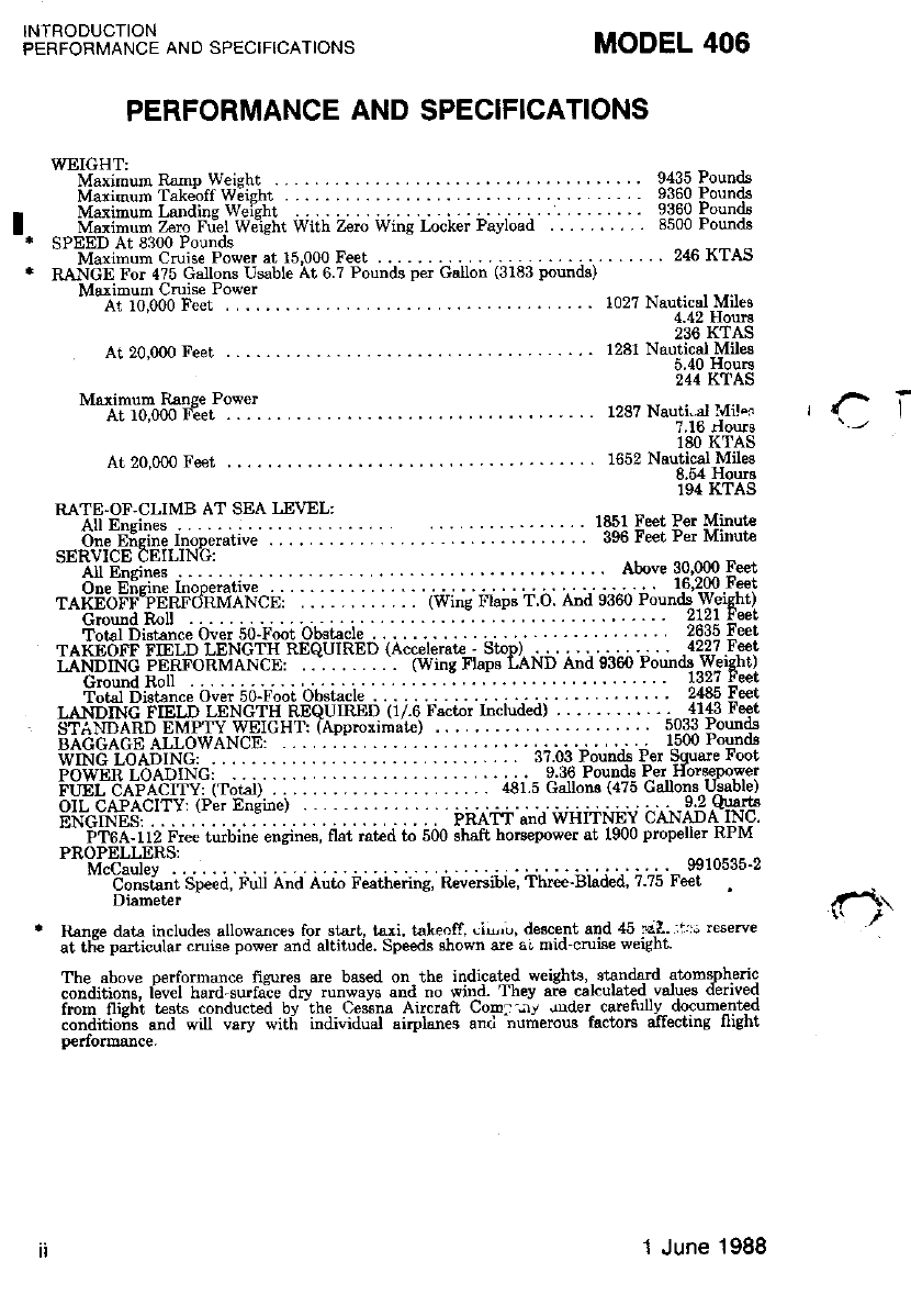
PERFORMANCE AND SPECIFICATIONS
WXIGHT:
Meximum Rimo weisht . .. .. . .... 9435 Pounds
Malisrum Takebff w;ishr . . 9360 Pounds
Miximurn Landine weiel't . .. . . 9360 Pounds
Miiimum zero friet w;rshi With zerc wing Locker Payload 8500 Pound8
SPEED At 8300 Pounds -
- Manimurn Cruise Power at 15,000 Feet . .. . . .. .. 216 KTAS
RANGE For 4?5 Gallons Usable At 6 7 Pounds per Galon (3183 pounds)
Msximum Cruise Power
- -A-10,000 Feet ......1027 Nauticall{ileg
236 KTAS
At 20,000 Feet . . .. 1281 NauticalJvlihr
244 KTAS
Maximum Raose Power
- --If io,000 f""t ......... ... -... u87 Nauti-,lviler
180 KTAS
At 20,000 Feet ..... 1652 Neulical Miles
8.54 Hours
194 KTAS
. ... . 1851 Feet Per Minutr
. . 996 Feet Per Minut€
. ... Above 30,000 Eeet
I
otal
LANDING
ST 1f9l . : :. : :. : . :. : .. : :. :. :. bii,. i;J;d; p".'.uS"l"'FlS
rit ir. ... . ::::::,idi.s81fi"::ii*t"J"Ltw;i:i
er Eneine) . . 9 2 quartg
...:..:., .., PRATT and WHITNEY CANADA INC.
urbine enclnes. flat rated to 500 shaft hoBepower at 1900 propeller RPM
sp"i,], r,ii ;r;i ai,t ii"idi,iii'!, ii"*iii,r", ir,.i,i-br,i i"ir, i:zb r#10515-2
Itanee dats includes allowances for start, taxi, tskeoff, (iu,u, desc€nt and 45 '.l1?.- rr; reserve
at tFe particular cruisp power and altitude. Speeds shown sre ai mid-cmbe weigbt.
The above oerformance fiqures are bssed on lhe indicst€d weights strndqd atomslh€ric
conditions, level hard surfaie dry runways and no wind. They are cal.ulatecl values denved
fmm flighi uesls conduced by'the Ce;na Aireraft Cop. -,1 urder carefiilv- dorumenled
conaitiois a"d wiu vary with individual airplanes anti -numerow factors allecting flight
p€dormance.
1 June 1988
INTRODUCTION
This handbook consists of 9 sections and an alphabetical index as
shown on the Contents page. This handbook includes the material
required to be turnished to the pilot by FAR Part 23 and SFAR 41. It
also c-ontgins supplemental data. supplied.b.y Ces^sna Aircraft Company.
Specific information can be rapidly found by referring to the Con-tenis
page tor the appropriate section. then referring to the Table Of Contents
9rl ,ths ,{irs!-pqge of the appropriate section, or by the use of the
Arpnaoelrcal rnoex.
IIOTE
This hand.book includes the rnaterial reouired to
be furnished to the pilot by the Federal Auiation
Regulations and additionil inlormation prouid.ed
by Cessna Aircraft Company and constiiutes the
FAA Approued Airplane Flight ManuaL
This handbook is not intended to be a zuide for basic flieht instruc-
tion or a training rnanual and should not be used as one. lt is not a
substitute. for alequate _and competent flight instruction, knowledge of
current airworthiness directives, applicable federal air regulations or
advisory circulars.
. Assuring the airworthiness of the airplane is the responsibility of the
airplane owner. Determining if the airplane is safe for nisha is the
responsibility of the pilot in command. The pilot is also responsible for
staying within _operating limitations as outlin;d by instrument markings,
placar&. and- this Pilot's Operating Handbook and FAA Approved Air-
plane Flight Manual.
Section 1 of this handbook presents basic airplane data and general
information which will be of value to the nilot.
MODEL 406 SECTION 1
GENERAL
1-3
Original lssue
SECTION 1
GENERAL MODEL 406
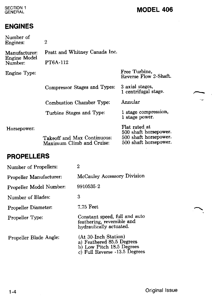
ENGINES
Number of
Engines: 2
Manufacturer: Pratt and Whitney Canada Inc.
Encine Model
Nu-mber: PTOA-112
Engine Type: Free T\rbine,
Reverse Flow Z-Shafb.
Compressor Stages and TVpes: 3 axial stages,
- I centrifugal stage. -
Combustion Chamber TYPe: Annular
Turbine Stages and Type: 1 stage compression'
1 stage Power
Horsepower: Flat rated at
500 shaft horsePower'
Takeoff and Max Continuous: 500 shaft horsepower'
Maximum Climb and Cruise: 500 shaft horsepower'
PROPELLERS
Number of Propellers: 2
PropellerManufacturer: McCauleyAccessoryDivision
Propeller Model Number: 9910535-2
Number of Blades: 3
Propeller Diameter: 7.?5 Feet -\
Propelier Tlpe: Constant speed, full and,auto
leathennq' reversrDle ano
hYdraulicallY actuated.
Propel-terBladeAngle: (At-30-Inch,StaLion)
a) I eathered 6D.D uegrees
b) Low Pitch 18.5 Degrees
c) Full Reverse -13.5 Degrees
1-4 Original lssue
MODEL 406
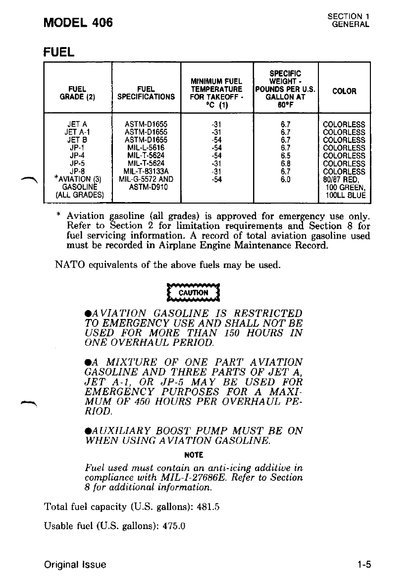
.AVIATION GASOLINE IS RESTRICTED
TO EMERGENCY USE AND SHALL NOI: BE
USED FOR MORE THAN 150 HOURS IN
ONE OVERHAUL PERIOD.
.A MIXTURE OF ONE PAR'T AVIATION
GASOLINE AND THREE PARTS OF JET A.
JET A.1, OR JP-s MAY BE USED FOR
EMERGENCY PURPOSES FOR A MAXI.
MUM OF 450 HOURS PER OVERHAUL PE.
RIOD,
.AUXILIABY BOOST PUMP MUST BE ON
WHEN USING AVIATION GASOLINE.
otE
Fuel used. mLlst contain an anti-icinp additiue in
compliance with MIL-l-27686E. Refdr to Section
8 for add.itionaL inforrnation.
Total fuel capacity (U.S. gallons): 481.5
Usable tuel (U.S. gallons): 475.0
Orioinal lssue
sEcTtoN 1
GENERAL
* Aviation gasoline (all grades) is approved for emergency use only.
Refer to Section z foi limidation - reouirements anif Se;tion 8 for
fuel servicing information. A record oT total aviation gasoline used
must be recorded in Airplane Engine Maintenance Record.
NATO equivalents of the above fuels may be used.
FUEL
FUEL
GRADE (2} FUEL
SPECIFICATIONS
MINIIiIUM FUEL
TEI''PERATURE
FOR TAKEOFF .
'c (1)
SPECtFtC
WEIGHT .
POUNDS PER U.S.
GALLON AT
60.F
COLOR
JET A
JET A-1
JET 8
JP,1
JP.4
JP-5
JP-8
*AVrATroN (3)
GASOLINE
{ALL GRADES)
ASTM-01655
ASTM.D1655
ASTTV-Dt655
MtL-L-56t6
MIL-T-5624
MtL-T-5624
MtL-T-831334
MIL-G-5572 AND
ASTM.D91O
-54
-54
-54
-54
6.7
6.7
6.8
6.7
6.0
COLORLESS
COLORLESS
COLORLESS
COLORLESS
COLORLESS
COLORLESS
COLORLESS
80/87 RED,
lOO GREEN,
lOOLL BLUE
t-c
sEcTtoN 1
GENERAL MODEL 406
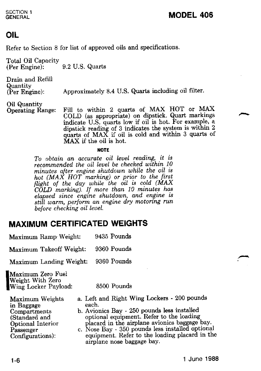
otL
Refer to Section 8 for list of approved oils and specifrcations.
Total Oil Capacity
(Per Engine): 9.2 U.S. Quarhs
Drain and Refill
Quantity
(Fer Engine): Approximately 8.4 U.S' Qua*s including oil filter'
Oil Quantity
O*"iiitr" Iianee: Fill Lo within 2 quarts of MAX HOT or MAX
- COLD (as approprilte) on dipstick' Quart markings
indicate U.S. buart's low if oif is hot. For example, a
dipstick reading of 3 indicates the system ,is within 2
ou-att" of MAX if oil is cold and within 3 quarts of
MAX it ttre oil is hot.
NOTE
To obtain an accurate oil leuel reading, lt is
recommended. the oil leuel be cheched' uithin 10
minutes after engine shutdown while the oil is
hot (MAX HOT marhing) or prior to the firs-t-
ttisht of th.e duv while - the 6iI is cold (MAX
'C1LD mdrkinil: II rnore than 10 minutes has
ela.psed. since engine shutdown, and engine is
stiil uarm, perforrn an engine dry motoring run
before checking oil leueL.
MAXIMUM CERTIFICATED WEIGHTS
Maximum Ramp Weight: 9435 Pounds
Maximum Takeoff Weight: 9360 Pounds
Maximum Landing Weight 9360 Pounds
Maximum Zero Fuel
Weisht With Zero
Wing Locker Payload: 8500 Pounds
Maximum Weights a. Left and Right Wing Lockers - 200 pounds
in Basgase each.
Co-o"u?i""nt" b. Avionics Bav - 250 pounds less installed
(Staridard and optional equipment. RBfer to the loading.
b"iionit t"r"rior piacard in ih6 airplane avionics baggage bay.
Pii"enee. c. Nose Bay - 350 pbunds less installed optional
Configrirations): equipment. Refer to the loading placard in the
- airPlane nose baggage baY'
1-6 1 June 1988
MODEL 406 SECTION 1
GENERAL
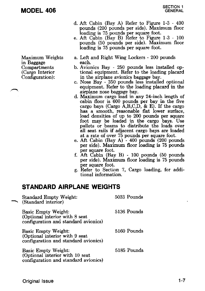
d. Aft Cabin (Bay A) Refer to Figure 1-3 - 400
pounds (200 pounds per side). Maximum floor
loading is 75 pounds per square foot.
e. Aft Cabin (Bav B) Refer to Figure 1-3 - 100
pounds (50 pounds per side). Maximurn floor
loading is 75 pounds per squzue foot.
Maximum Weights a. Left and Right Wing Lockers - 200 pounds
in Baggage each.
Compartments b. Avionics Bay - 250 pounds less installed op-
(Cargo Interior tional equipment. Refer to the loading placard
Configuration): in the airplane avionics baggage bay.
c. Nose Bay - 350 pounds less insta.lled optional
equipment. Refer to the loading placard in the
airplane nose baggage bay.
d. Maximum carso load in anv 24-inch leneth of
cabin floor is -600 pounds per bay in th! five
cargo bays (Cargo A,B,C,D, & E). If the cargo
has a smooth, reasonable flat lower surface,
load densities of up to 200 pounds per square
foot may be loaded in the cargo bays. Use
pallets or beams to distribute the loads over
all seat rails if adjacent cargo bays are loaded
at a rate of over 75 pounds per square foot.
e. Aft Cabin (Bay A) - 400 pounds (200 pounds
per side). Marimun floor loading is 75 pounds
per square foot.
f. Aft C:abin (Bay B) - 100 pounds (50 pounds
per side). Maxirnum floor loading is 75 pounds
Der souare foot.
g. ilefer- to Section ?, Cargo loading, for add!
tional information.
STANDARD AIRPLANE WEIGHTS
Standard Empty Weight:
(Standard interior)
Basic Empty Weight:
(Ootional interior with 8 seat
configuration and standard avionics)
Basic Empty Weight:
(Optional interior with 9 seat
configuration and standard avionics)
Basic Empty Weight:
(Optional interior with 10 seat
configuration and standard avionics)
Original lssue
5033 Pounds
5136 Pounds
5160 Pounds
5185 Pounds
'l-7
SECTION 1
GENERAL MODEL 406
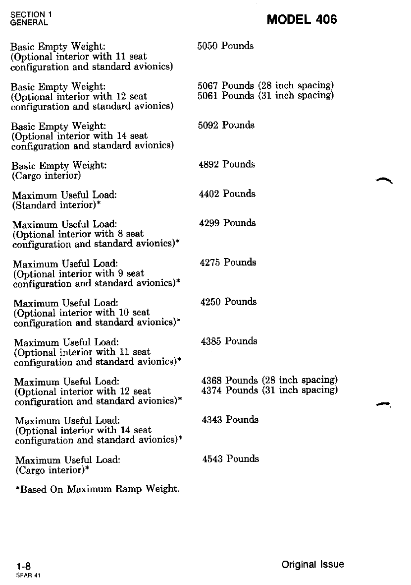
Basic Emptv Weisht: 5050 Pounds
rOotional-interior with 11 seat
configuration and standard avionics)
Basic Emptv Weight: 5067 Pounds (28 inch spacing)
(Ontional-interior with 12 seat 5061 Pounds (31 inch spacing)
co;figuration and standard avionics)
Basic Empty Weight: 5092 Pounds
(Ootional interior with 14 seat
ioifiguration and standard avionics)
Basic Empty Weight: 4892 Pounds
(Cargo interior)
Maximum Useful Load: 4402 Pounds
(Standard interior)*
Maximum Useful Load: 4299 Pounds
(Ontional interior with 8 seat
coifiguration and stsndard avionics)*
Maximum Usefirl Load: 4275 Pounds
(Ortional interior with 9 seat
ioifiguration and standard avionics)*
Maximum Useful Load: 4250 Pounds
(Optional intBrior with 10 seat
confrzuration and standard avionics)*
Maximum Useful Load: 4385 Pounds
(Optional interior with 11 seat
confi guration and standard avionics)*
Maximum Useful Load: 4368 Pounds (28 inch spacing)
(Ontional interior with 12 seat 43?4 Pounds (31 inch spacing)
configuration and standard avionics)*
Maximum Useful Load: 4343 Pounds
(Optional interior with 14 seat
ioirfi4rration and standard avionics)*
Maximum Useful Load: 4543 Pounds
(Cargo interior)*
*Based On Maximum RamP Weight.
1-8 Original lssue
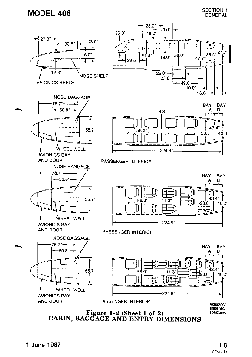
MODEL 406
AND DOOR
NOSE AAGGAGE
PASSENGEB INTEBIOR
PASSENGER INTERIOR
SECTION 1
GENERAL
BAY BAY
AB
r*r_r
43.440.0"
60852002
60851002
60866036
1-9
:ll' ,_r -l r-'-i
!l*o pi'" ,;n
49.0"
VIONICS AAY
NOSE AAGGAGE
WHEEL WELL
VIONICS BAY
AND DOOR
224.9"
PASSENGER INTERIOR
. Ifgufe l-2 (Sheet 1 of 2)
CABIN. BAGGAGE AND ENTRY DIMENSIONS
1 June 1987
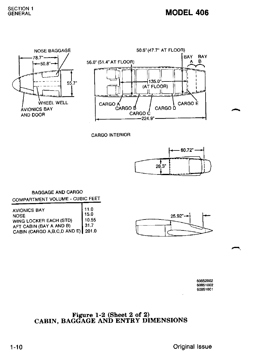
sEcTroN 1
GENERAL MODEL 406
CABGO INTERIOR
r60.72"-
--------rf*='=Frr
I 28.3'l I ll )
L__l_L_==g,
BAGGAGE AND CARGO
COMPARTMENT VOLUME . CUBIC FEET
AVIONICS BAY
NOSE
wrNG LOCKER EACH (STD)
AFT CABIN (BAY A AND B)
cABrN (CARGO A,B,C,D AND E)
11.0
15.0
10.55
31.7
201.0
608520o2
608s10q2
6085100r
Figure l-2 (Sheet 2 of 2)
CABIN. BAGG:AGE AND ENTRY DIMENSIONS
50.6"(47.7' AT FLOOR)
BAY BAY
56.0" (51.4"AT FLOOR)
(AT FLOOR)
AND DOOR
1 -10 Original lssue
MODEL 406
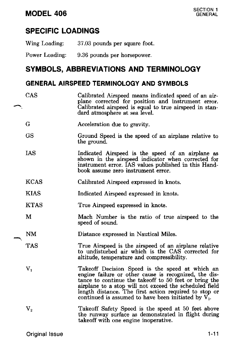
SPECIFIC LOADINGS
Wing Loading:
Power Loading:
IAS
37.03 pounds per square foot.
9.36 pounds per horsepower.
Calibrated Airspeed means indicated speed of an air-
plane corrected for position and instrument error.
Calibrated airspeed is equal to true airspeed in stan-
dard atmosphere at sea level.
Acceleration due to gravity.
Ground Speed is the speed of an airplane relative to
the ground.
Indicated Airspeed is the speed of an airplane as
shown in the airsDeed indicator when corrected for
instrument error. iAS values published in this Hand-
book assume zero instrument error.
Calibrated Airspeed expressed in knots.
Indicated Airspeed expressed in knots.
True Airspeed expressed in knots.
Mach Number is the ratio of true airspeed to the
speed of sound.
Distance expressed in Nautical Miles.
True Airsneed is the airsneed of an aimlane relative
to uadisfiirbed air which' is the CAS corrected for
altitude, temperatue and compressibility.
Takeoff Decision Speed is the speed at which an
engine failure or other cause is recognized, the dis-
tance to continue the takeoff to 50 feet or bring the
airplane to a stop will not exceed the scheduled field
length distance. The first action required to stop or
continued is assumed to have been initiated by Vr.
Takeoff Safety Speed is the speed at 50 feet above
the runway surface as demonstrated in flight during
takeoff with one enghe inoperative.
SECTION 1
GENERAL
SYMBOLS, ABBREVIATIONS AND TERMINOLOGY
GENERAL AIRSPEED TERMINOLOGY AND SYMBOLS
CAS
G
GS
KCAS
KIAS
KTAS
M
NM
TAS
Original lssue 1-11
Vrn
V""
SECTION 1
GENERAL
V""
VLo
V"co
V,ro/M"o
MODEL 406
Maneuvering Speed is the maximum speed at which
application of full available aerodynamic control will
not overctress the airplane.
Critical Ensine Failure Speed is the speed at which
the ensine was failed during certification flight test-
ins to ?etermine accelerateil stop and accelerated go
distances.
Maximum Flap Extended Speed is the highest speed
permissible with wing flaps in a prescribed extended
position.
Maximum Landins Gear Extended Speed is the
maximum speed aiwhich an airplane can be safely
flown with the landing gear extended.
Maximum Landins Gear Operating Speed is the
maximum speed ai which the landing gear can be
safely exteniied or retracted.
Air Minirnurr Control Speed is the rninirnum flight
speed at which the airplane is directionally and lat-
eiallv controllable as determined in accordance with
Fedeial Aviation Regulations. Airplane certfication
conditions include one engine becoming- inoperative
and feathered; not more than a 5-degree bank toward
the ooerative encine; takeoff power on operative en-
gine: ianding geir up; flaps in ta.keoff position; and
most cntlcal cent€r-ol-gTavl[y.
Maximum Operatins Limit Speed is the speed limit
that may n;t be aeliberat€ly exceeded in normal
flight oplrations. V is expresied in knots and M in
Mach Number.
Rotation Speed is the speed at which rotation is
initiated duiine taleoff to attain the V, clinb speed
at or before a Leight of 50 feet above runway surface
has been reached.
Stalline Speed or the minimum steady flight speed at
which Ihe-aimlane is controllable.
Stalline Speed or the minimum steady flight speed at
which -th6 airplane is controllable in the landing
confizuration.
vR
vs
Vso
1-12 Original lssue
MODEL 406
VssB
vx
Vts"
V"s.
- ISA
OAT
SECT'ON 1
GENERAL
Intentional One Engine Inoperative Speed is a mini-
mum soeed. selected bv the manufacturer, for inten-
Lionally rendering one engine inoperative, in flight,
for pilot training.
Best Anele-of-Climb Speed is the airspeed which
delivers ihe greatest gain of altitude in the short€st
possible horizontal distance.
One Encine Inoperative Best Angle-of-Climb Speed
is the a-irspeed which delivers the $eatest gain of
altitude in the shortest possible horizontal distance
Best Rate-of-Climb Speed is the airspeed which de-
livers the greatest gain in altitude in the shortesi
possible time.
One Ensine Inoperative Best Rate-of-Climb Speed is
the airspeed which delivers the greatest gain in al-
titude in the shortest possible time.
METEOROLOGICAL TERMINOLOGY
'c
"F
Indicated
Pressure
Altitude
IOAT
Temperature expressed in degrees Celsius.
Temperature expressed in degrees Faluenheit'
The number actuallv read from an altimeter when
the barometric subsiale has been set to 29.92 inches
of mercury (1013.2 millibars).
Indicated OuLside Air Temperature is the tempera-
ture indicated on the pilot's outside air temperature
indicator. The indication is not adjusted for instru-
ment error or temperature compressibility effects.
Int€rnational Standard Atmosphere in which:
(1) The air is a dry perfect gas;
(2) The temperature at sea level is 15 degrees
Celsius;
(3) The pressure at sea level is 29.92 inches Hg.
( 1013-.2 millibars);
(4) The rcmoerature sradient from sea level to the
' altitude irt ,rhich-the temperature is -56.6 de-
grees Celsius. is -1.98 degrees Celsius per 1000
Ieei.
Outside Air Temperature is the free air static t€m-
Derature, obtained either from inflight t€mperature
indications or ground meteorological sources adjusted
for instrumentirror and compressibility effects.
Original lssue 1-13
SECTION 1
GENERAL
Pressure
Altitude
MODEL 406
Altitude neasured from staldard sea-level pressure
(29.92 inches Hg.) by a pressure or barometric altim-
eter. It is the indicated pressure altitude corrected
for position and instrument error. In this handbook,
altimeter instrument erroni are assumed to be zero.
Actual atmospheric pressure at freld elevation.
An error in the indication of temperature caused by
airflow over the temperature probe. The error varies,
depending on altitude and abspeed.
The wind velocities recorded as variables on the
charts of this handbook are to be understood as the
headvind or tailwind components of the reported
wrn0s.
Station
Pressure
Temperature
Compressibility
Effects
Wind
POWER TERMINOLOGY
Auto Feather
Critical
Altitude
Cruising Climb
Power
ITT
Flameout
Flat Rated
Flight Idle
Power
Gas Generator
RPM (Ns)
Ground Idle
Power
A systen designed to automatically reduce drag of an
inoperative engine by moving the propeller to feath-
er.
The maximum altitude at which in standard tem-
perature it is possible to maintain a specified power.
The power recommended to operate the airplane in a
cmise climb (a continuous gradual clinb) profile.
Interturbine Temperature.
Unintentional loss of combustion chamber flame dur-
ing operation.
Constant horsepower over a specific altitude range.
The power required to run an engine, in flight, at the
lowest speed that will ensure satisfactory engine op-
eration and airplane handling characteristics.
Indicates the percent of gas generator rpm based
on a figure of 100 percent at 37,500 rpm.
The power required to run an engine on the ground,
as slowly as possible, yet sufficient to ensure satisfac-
tory engine, engine accessory, and airplane operation
with a minimum of thrust.
1-14 Original lssue
MODEL 406
Hot Start
Maximum
Continuous
Power
Maximum
Cruise Power
Power T\rrbine
RPM (Nf)
^ Propeller RPM
(Ne).
RPM
Reverse Thrust
SHP
Takeoff Power
Torque
Windmill
Beta Mode
Fuel Control
Lever
Gas Generator
Governor
ITT Gage
ENGINE CONTROLS AND INSTRUMENTS TERMINOLOGY
.EETL"$I
An engine start, or attempted start, which results in
ITT exceeding 1090 degrees Celsius.
The oower developed at the maximum continuous
torqui limit, ITT jimit: or Ng limit. This is equiv-
alent to takeoff power.
The power developed at the maximurn cruise torque
limit, ITT limit or Ng limit.
Indicates the percent of power turbine speed based
on a figure of 100 percent at 33,000 rpm and a
propeller speed (No) of 1900 rpm.
Indicates propeller speed in rpm.
Revolutions Per Minute.
The thrust produced when the propeller blades are
rotated past flat pitch into the Beta iange.
Shaft horsepower means the power delivered at the
propeller shaft.
The maximum power permissible for takeoff.
A measurement that is proportional to the power
output of the engine.
Propeller rotation from airstream inputs.
Ensine operational mode in which propeller blade
pitih is cbntrolled by the cockpit power lever. May
be used during ground operations only.
Cockpit Control lever which sets the fuel control in
eithei "RUN" or "CUTOFF".
Regulates the gas generator to the speed selected by
the cockpit power lever.
Interturbine temperature gage displaying air tem-
perature between the cornpressor turbine and power
turbine.
Original lssue 1-15
MODEL 406
Flyweight operated fuel met€ring device, housed in
the propeller governor. lt prevents engine overspeed
in the event of a malfunction of the propeller gov-
ernor.
Regulates the RPM of the propeller by increasing or
decreasing the propeller pitch through a pitch change
mechanism in the propeller hub.
Power Control Cockpit lever used to set gas generator Bpeed. During
Lever Beta node the power lever controls propeller blade
angle and speed.
Propeller Lever Cockpit lever used to set propeller RPM.
A gearbor mounted governor which dumps propeller
oil pressure to prevent engine danage should the
propeller governor fail.
Indicates the speed of the gas generator (Ng) or
propeller (Np).
Torque Meter The instrument that indicates the torque output of
tt)e englne gear Dox.
AIRPLANE PERFORMANCE AND FLIGHT PLANNING
TERMINOLOGY
Accelerate-Go The distance required to accelerate an airplane to Vt
Distance and assuming pilot recognizes an engine failure at Vt,
continues takeoff on the remaining engine to a
height of 50 feet.
Accelerate-Stop The distance required to accelerate an airplane to V1
Distance and assuming pilot recognizes an engine failure at Vr,
brings the airplane to a stop.
SECTION 1
GENEBAL
Overspeed
Governor
Propeller
Governor
Fropeller
Overspeed
Governor
Tachometer
Aerobatic
Maneuver An intentional maneuver involving an abrupt change
of an airplane's attitude, an abnornal attitude, or
abnormal acceleration, not necessary for normal
flieht.
Balked Landing A balked landing is. an aborted landing.(i.e., all en-
gines go-around in the landing configuration).
Balked Landing The minimum speed at which a transition to a
Transition balked landing climb should be attempted (from
Speed 5O-foot obstacle height).
1-1 6Original lssue
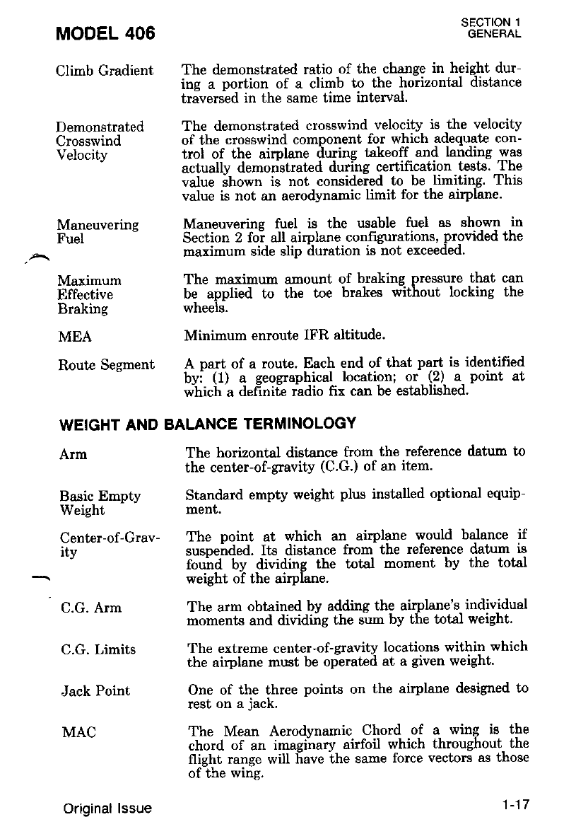
Climb Gradient The demonstrated ratio of the change in height dur-
ing a portion of a climb to the horizontal distance
traversed in the same time interval.
Demonstrated The demonstrated crosswind velocity is the velocity
Crosswind of the crosswind component for which adequate con-
Velocity trol of the airplane iiuring takeoff and landing was
actually demonstrated during certification tests. The
value ihown is not considered to be limiting. This
value is not an aerodynamic limit for the airplane.
Maneuverins Maneuvering fuel is the usable fuel as shown in
Fuel - Section 2 foi all airplane confrgurations, provided the
roaximum side slip duration is not exceeded.
MODEL 406
Maximum
Effective
Braking
Arm
Basic Empty
Weight
C.G. Arm
C.G. Limits
Jack Point
MAC
SECTION 1
GENERAL
The horizontal distance from the reference datum to
the center-of-gravlty (C.G.) of an item.
Standard empty weight plus installed optional equip-
menf,.
The maximum anount of braking pressure that can
be applied to the toe brakes without locking the
wheels.
MEA Minimum enroute IFR altitude.
Route Secment A part of a route' Each end of that part is identified
- bvi (1) a geographical location; or (2) a point at
wiich a d"frniie ridio frr can be established'
WEIGHT AND BALANCE TERMINOLOGY
Center-of-Grav- The point at which an airplane would balance if
itv suspended. Its distance from the reference daturr is
- fouird by dividing the total moment by the total
weight of the airPlane
The arm obtained by adding the airplane's individual
moments and dividGg the sum by the total weight.
The ertreme center-of-sravitv locations within which
the airplane must be oplratcil at a given weight.
One of the three points on the airplane designed to
rest on a jack.
The Mean Aerodvnamic Chord of a wing is the
chord of an imaginary airfoil which throughout the
flight range will f,ave the same force vectors as those
of the wing.
Original lssue 1-17
SECTION 1
GENERAL
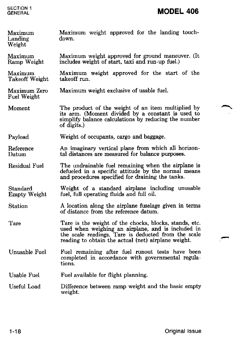
Maximum
Landing
Weight
Maximum
Ramp Weight
Maximum
Takeoff Weight
Maximum Zero
Fuel Weight
Moment
Payload
Reference
Datum
Residual Fuel
Standard
Empty Weight
Station
Tare
Unusable Fuel
Usable Fuel
Useful Load
MODEL 406
Maximum weight approved for the landing touch-
oown.
Maximum weieht aDDroved for sround maneuver. (It
includes weighl of siirt, taxi anil run-up fuel.)
Maximum weight approved for the start of the
takeoff run.
Maximum weight exclusive of usable fuel.
The product of the weight of an item multiplied by
its arm. (Moment divided by a constant is used to
simplifu balance calculations by reducing the number
of digits.)
Weight of occupants, cargo and baggage.
An imaeinarv vertical nlane from which a.ll horizon-
tal distinces-are measuied for balance purposes.
The undrainable fuel remaining when the airplane is
defueled in a specfic attitude by the normal means
and procedures specified for draining the tanks.
Weight of a standard airplane including unusable
fuel, full operating fluide and full oil.
A location along the airplane fuselage given in termg
of distance from the reference datum.
Tare is the weight of the chocks, blocks, stands, etc.
used when weighing an airplane, and is included in
the scale readings. Tare is deducted from the scale
reading to obtai; the actual (net) airplane weight.
Fuel remainins after fuel runout tests have been
completed in iccordance with governmental regula-
tions.
Fuel available for flight planning.
Difference between ramp weight and the basic empty
weight.
1-18 Original lssue
MODEL 406 SECTION 2
LIMITATIONS
sEcTloN 2
LIMITATIONS
TABLE OF CONTENTS
AIRSPEED LIMITATIONS
AIRSPEED INDICATOR MARKINGS
POWERPLANT LIMITATIONS
POWERPLANT INSTRUMENT MARKINGS
MISCELLANEOUS INSTRUMENT MARKINGS
WEIGHT LIMITS .
CENTER-OF-GRAVITY LIMITS
MANEUVER LIMITS .
FLIGHT LOAD FACTOR LIMITS
FLIGHT CREW LIMITS
KINDS OF OPERATIONAL EQUIPMENT LIMITS '
FUEL LIMITATIONS . .
MAXIMUM OPERATING ALTITUDE LIMIT .
OUTSIDE AIR TEMPERATURE LIMITS
MAXIMUM PASSENGER SEATING LIMITS .
PLACARDS
INTRODUCTION
2-6
2-6
Page
2-4
2- 10
2-tl
2-77
2-73
2-t3
2-13
2-13
2-76
2-16
2-76
2-r7
2-18
2-1 (2-2 btank)
SFAF 41
Original lssue - 1 JulY 1986

MODEL 406 SECTION 2
LIMITATIONS
INTRODUCTION
Section 2 presents the operating limitations, the significance of such
limitations, instrument markings, iolor coding and basic placards neces-
sarv for the safe operation oi ihe airplane,- its powerplants' standard
svsiems and standaid equipment. The li.rnitations included in this sec-
tion and Section 9 are aiprbved by the Federal Aviation Administration.
Observance of these opeiating limitations is required by Federal Aviation
Regulations.
Oneration in countries other than the United States may require
observance of other limitations, procedures or performance data in ap-
plicable supplements.
NOTE
oRefer to Sectinn I for arnended linitations for
airplanes equipped with specific optianal sys'
terns.
OThe airspeed.s listed in the Airspeed, Limita-
tions chari (Figure 2-1) and Airspeed Indicator
Marhings charl (Fieurb 28) are'based on Air-
speed, Calibration d'ata shoun in Section 5.
2-3
Original lssue
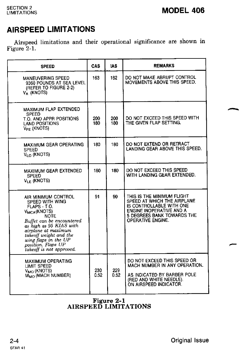
AIRSPEED LIMITATIONS
Airspeed limitations and their operational significance are shown in
Figure 2-1.
SECTION 2
LIMITATIONS
2-4
MODEL 406
cAs tAs REMARKS
MANEUVEFING SPEED
9360 POUNDS AT SEA LEVEL
IREFER TO FIGURE 2'2)
v; {KNoTS)
163 162 DO NOT MAKE ABRUPT CONTROL
MOVEMENTS ABOVE THIS SPEED.
MAXII\,!UM FLAP EXTENDED
SPEED
T.O, AND APPR POSITIONS
LAND POSITIONS
VFE (KNOTS)
200
r80 200
180 DO NOT EXCEED THIS SPEED WITH
THE GIVEN FLAP SETTING.
MAXIMUM GEAR OPERATING
Vse (KNOTS)
180 180 OO NOT EXIENO OR RETRACT
LANDING GEAR ABOVE THIS SPEED.
MAXIi/tUM GEAR EXTENDED
VLE (KNOTS)
180 180 DO NOT EXCEED THIS SPEED
WITH LANDING GEAR EXTENDED.
AIR I\.4INI[4UM CONTROL
SPEED WITH WING
FLAPS - T.O.
Vucr(KNOTS)
NOTE
Buffet can be encountered
os hieh as 95 KIAS uith
airplane at matimum
taieofl weight and the
wing flaps in the UP
Do$ition. FLaps UP
'taheof[ is noi approved.
91 90 THIS IS THE MINII\4UM FLIGHT
SPEED AT WHICH THE AIRPLANE
IS CONTROLLABLE WITH ONE
ENGINE INOPERATIVE AND A
5 DEGREES BANK TOWARDS THE
OPERATIVE ENGINE.
MAXIMUM OPERATING
LIMIT SPEED
VMO {KNOTS)
rlrMo (MACH NUMBER)
230
0.52 229
0.52
DO NOT EXCEEO THIS SPEED OR
MACH NUMBER IN ANY OPERATION.
AS INDICATED BY BABEER POLE
IRED AND WHITE NEEDLE).
ON AIRSPEED INDICATOR,
Figure 2-1
AIRSPEED LIMITATIONS
Original lssue
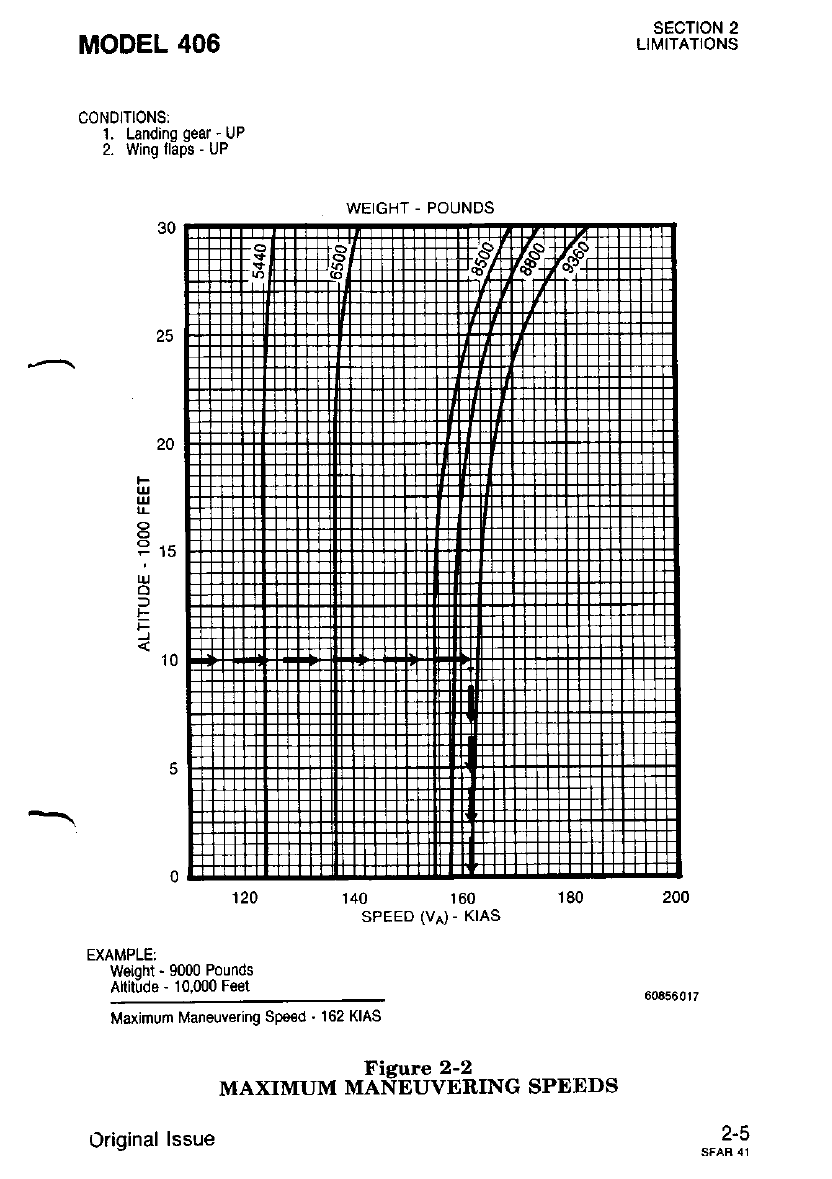
MODEL 406
CON0lTl0NSl
1. Landino qear - UP
2. Wing l6pis - UP
120
EXAMPLE:
Weioht - 9000 Pounds
Altitlde - 10.000 Feet
SECTION 2
LlirtlTATIONS
P rs
ru
o
f
t
F
't0
140 160
SPEED (VA) - KIAS
180
Maximum Maneuvering Spe€d - 162 KIAS
Ficure 2-2
MAXIMUM MANEUVERING SPEEDS
Original lssue z-a
WEIGHT - POUNOS
sEcTloN 2
LIMITATIONS MODEL 406
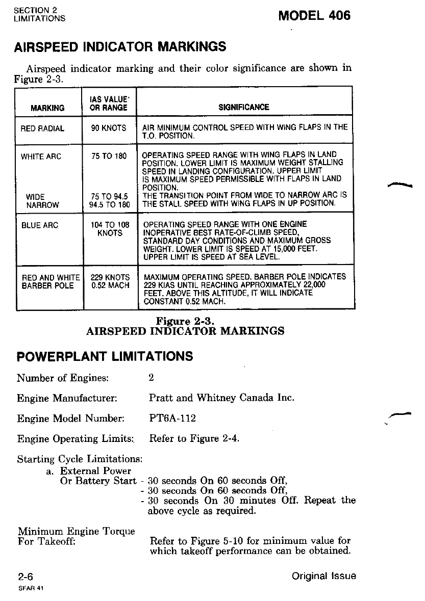
AIRSPEED INDICATOR MARKINGS
Airspeed indicator marking and their color significance are shown in
Figure 2-3.
POWERPLANT LIMITATIONS
Number of Engines: 2
Engine Manufacturer: Pratt and Whitney Canada Inc.
Engine Model Number: PT6A-112
Engine Operating Limits: Refer to Figure 2-4.
Starting Cycle Limitations:
a, External Power
Or Battery Start - 30 seconds On 60 seconds Off,
- 30 seconds On 60 seconds Ofi
- 30 seconds On 30 minutes Off. Repeat the
above cvcle as required.
Minimum Engine Torque
For Takeoffi Refer to Fizure 5-10 for minimum value for
which takeoff oerformance can be obtained.
1-O
MARKING IAS VALUE'
OR RANGE SIGNIFICANCE
RED RADIAL 90 KNOTS AIR MINIMUM CONTROL SPEED WITH WING FLAPS IN THE
T.O. POS|T|ON.
WHITE ARC
WIDE
NARROW
75 TO 180
75 TO 94.5
94.5 TO 180
OPEBATING SPEED RANGE WITH WING FLAPS IN LAND
POSITION. LOWEB LIMIT IS MAXIMUI\,i WEIGHT STALLING
SPEED IN LANDING CONFIGURATION. UPPEF LII/IT
IS MAXIMUM SPEED PERMISSIBLE WTH FLAPS IN LAND
POStTtON.
THE TRANSITION POINT FFOM WIDE TO NARROW ARC IS
THE STALL SPEED WITH WING FLAPS IN UP POSITION.
BLUE ARC 104 TO 108
KNOTS OPERATING SPEED RANGE WITH ONE ENGINE
INOPERATIVE EEST RATE.OF.CLIMB SPEED,
STANDARD DAY CONDITIONS AND MAXIMUM GROSS
WEIGHT. LOWER LIMIT IS SPEED AT 15,OOO FEET,
UPPER LIMIT IS SPEED AT SEA LEVEL,
RED AND WHITE
BARBER POLE 229 KNOTS
0.52 MACH MAXIMUM OPERATING SPEED. BARBER POLE INOICATES
229 KIAS UNTIL REACHING APPROXIMATELY 22,OOO
FEET. ABOVE THIS ALTITUDE, IT WILL INDICATE
CONSTANT 0,52 MACH.
Figure 2-3.
AIRSPEED INDICATOR MARKINGS
Original lssue
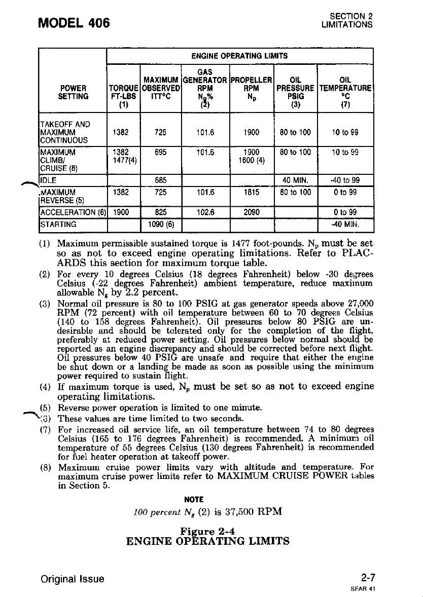
MODEL 406 SECTION 2
LIMITATIONS
(l I Maximum permissible sustained torque is 1477 foot-pounde. Ne must be set
so as not to exceed engine operating limitations. Refer to PLAC-
ARDS this section for maximum torque table.
(2) For every 10 degrees Celsius (18 degrees Fahrenheit) below -30 degrees
Celsius (-22 degrees Fahrenheit) ambient lempemture, reduce maxbnum
allowable N" by ).2 percent.
(3) Normal oil pressure is 80 to 100 PSIG at gas generator speeds above 27,000
RPM (72 percent) with oil temperature between 60 to 70 degrees Celsius
(140 to 158 degrees Fahrenheit). Oil pressures below 80 PSIG are un-
desirable and should be tolerated only for ihe completion of the flight,
preferably at reduced power setting. Oil pressures below normal should be
ieporred as an engine riiscrepancy a-nd shoutd be conected before next flight.
Oil pressures below 40 PSIG are unsafe and require that either the etrgine
be ihut down or a landing be made as soon as pbssible using the minimum
power required to sustain flight.
(4) If maximum torque is used, \ must be set so aB not to exceed engine
operating limitations.
(5) Reverse powe! ooeration is limit€d to one minute.
1 c, Th""" uutues are time limited to two seconds.
(?) For increased oil service life, an oil temperature between 74 to 80 degrees
Celsius (165 to 176 degrees Fahrenheit) is recommended. A minimum oil
temperature of 55 degrees Celsius (130 degrees Fahrenheit) is recommended
for fuel heater operation at takeoff power.
(8) Maximum cluige power limits vary with altitude and temperature. For
' maximum cruise power limits lefer 6 MAXIMUM CRUISE POWER trbleo
in Section 5.
l{OtE
100 percent Ns (2) is 37,500 RPM
Figur€ 2-4
ENGINE OPERATING LIMITS
2-7
POWEN
SETTING
ENGINE OPESATING LIMITS
iraxtmuM GAS
GENERATOR
RPM
irf
PROPELLER
RPM
Np
otL
PRESSURE
PSIG
(3)
olL
TEMPERATURE
(7)
FT.LBS
0) ITT'C
TAKEOFF AND
MAXIMUM
CONTINUOUS
1382 725 101.6 1900 80 to 100 10 to 99
MAXIMUM
CLIMB/
cRUrsE (8)
1382
't477\4) 695 '| 01.6 1900
1 600 {4)
80 to 100 10 to 99
685 40 MtN. 40 to 99
(s) 1382 725 101.6 1815 80 to 100 0t099
ACCELERATTON (6) 1900 825 102.6 2090 0to99
STARTING 1090 (6) 40 Mlr,l.
Original lssue
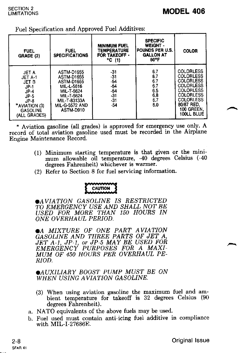
* Aviation easoline (all srades) is approved for emergency use only. A
record of total aviation gaioline used must be recorded in the Airplane
Engine Maintenance Record.
(l) Minimum sLarting t€mperature is thal given or the mini--
mum allowable oil temperature. -40 degrees Celsius (-40
degrees Fahrenheit) whichever is warmer.
(2) Refer to Section 8 for fuel servicing information.
SECTION 2
LIMITATIONS
2-8
MODEL 406
.AVIATION GASOLINE IS RESTRICI| ED
TO EMERGENCY USE AND SHALL NOT BE
USED FOR MORE THAN 150 HOURS IN
ONE OVERHAUL PERIOD.
.A MIXTURE OF ONE PART AVIATION
GASOLINE AND THREE PARTS OF JET A,
JET A-1. JP-1. or JP-\ MAY BE USED FOR
EMERGENCY PUiPOSES FON A MAXI-
MUM OF 450 HOURS PER OVERHAUL PE-
RIOD.
.AUXILIARY BOOST PUMP MUST BE ON
WHEN USING AVIATION GASOLINE.
(3) When using aviation gasoline the maximum fuel and am-
' bient tempirature foi takeoff is 32 degrees Celsius (90
degrees Fahrenheit).
a. NATO equivalents of the above fuels may be used.
b. Fuel used must contain anti-icing fuel additive in compliance
with MIL-I-276868.
Fuel Specification and Approved Fuel Additives:
GRADE (2) FUEL
SPECIFICATIONS
MINIMUM FUEL
TEMPERATURE
FOR TAKEOFF .
'c (1)
SPECtFtC
WEIGHT -
POUNDS PER U.S.
GALLON AT
600F
COLOR
JET A
JET A.1
JET B
JP.1
JP.4
Jt,-5
JP-8
*AVrATroN (3)
GASOLINE
(ALL GRADES)
ASTM.D1655
ASTM-D1655
ASTM.D1655
MtL-L-56t6
l?t lL-T-5624
MtL-T-5624
M tL-T-831 33A
MI1.G.5572 AND
ASTM.D91O
-31
-31
-54
-54
-54
-31
-31
-54
6.5
6.8
6.7
6.0
COLORLESS
COLORLESS
COLORLESS
COLORLESS
COLOBLESS
COLORLESS
COLORLESS
80/87 RED,
1OO GREEN,
l OOLL BLUE
Original lssue
MODEL 406
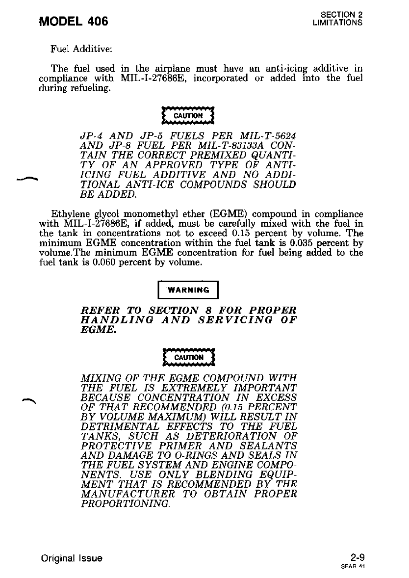
Fuel Additive:
The fuel used
compliance with
during refueling.
SECTION 2
LIMITATIONS
in the aimlane must have an anti-icine additive in
MIL-I-2?6'86E, incorporated or added into the fuel
JP.4 AND JP-, FUELS PER M1L.7,5624
AND JP,8 FUEL PER MIL-T-831334 CON-
I:AIN THE CORRECT PREMIXED qUANTI-
TY OF AN APPROVED TYPE OF ANTI-
ICING FUEL ADDITIVE AND NO ADDI-
TIONAL ANTI-ICE COMPOUNDS SHOULD
BE ADDED.
Ethylene glycol monomethyl ether (EGME) compound in compliance
with MIL-I-27686E. if added. must be carefullv mired with the fuel in
the tank in concentrations not to exceed 0.ls'percent by volume. The
minimum EGME concentration within the fuel tank is 0.035 percent bv
volume.The minimum EGME concentration for fuel beine added to th-e
fuel tank is 0.060 percent by volume.
REFER TO SECTION 8 FOR PROPER
HANDLING AND SEBVICING OF
EGME.
MIXING OF THE EGME COMPOUND WITH
THE FUEL IS EXTREMELY IMPONTANT
BECAUSE CONCENTRATION /N 'XC'SS
. OF THAT BECOMMENDED (0.15 PERCENT
BY VOLUME MAXIMUM) WILL RESULT IN
DETRIMENTAL EFFECTS TO THE FUEL
I:ANKS, SUCTI AS DETERIORATION OF
PROTECTIVE PRIMER AND SEALANTS
AND DAMAGE TO O-RINGS AND SEA'S IN
THE FUEL SYSTEM AND ENGINE COMPO.
NEN?S. USE ONLY BLENDING EqUIP-
MENT THAT IS RECOMMENDED BY THE
MANUFAC'| UREN TO OBTAIN PROPER
PROPORTIONING.
z-Y
Original lssue
SECTION 2
LIMITATIONS MODEL 406
Preflight Checks:
a. The overspeed governor check shall be performed: before the
fusi flisht of the dav, if there is an indication of malfunction,
after erigine control syst€m maintenance, or if adjustment has
been made.
b. Autofeather shall be checked before each flight and must be
operative for takeoff.
Oil Specification:
a. Refer to Section 8 for list of approved oils and specifications.
b. When addine oil, service the engines with the type and brand
which is currently being used in the engines. Do not mir tJpes
or brands of oils.
c. Tvpe II oils in compliance with Pratt and Whitney Canada Inc,
Soicification PWA 521.
d. Oi conforming to Pratt and Whitney Canada- Inc., Service
Bulletin Numb.-er 12001 and all revisions or supplements there-
to, must be used.
Propellers:
a. Number of Propellers: 2
b. Manufacturer: McCauley Accessory Division of Cessna Aircraft
Company.
Cessna Part Number: 9910535-2
Number of Blades: 3
Diameter: 7.?5 Feet
Maximum Operating Speed: 1900 RPM
Blade Angle: (At 30-Inch Station)
(1) Feathered 85.5 degrees
(2) Low Pitch 18.5 degrees
(3) Full Reverse -13.5 degrees
h Flight operation with power levers retarded below FLIGHT
IDLE are prohibited.
POWERPLANT INSTRUMENT MARKINGS
Torque Indicators:
a. 1382 Foot-Pounds Maximum Takeoff And Climb Torque At
1900 RPM (Yellow Radial)
b. 0 to 1477 Foot-Pounds (Green Arc)
c. 14?? Foot-Pounds Maximum Cruise Torque At 1600 RPM
(Red Radial)
ITT Indicators:
725 degrees Celsius (Red Line)
0 degrees to 695 degrees Celsius (Green Arc)
695 degrees to 1090 degrees Celsius (Yellow Arc)
1090 degrees Celsius (Red Triangle)
Original lssue
d.
f.
a.
b.
c.
d.
2-'10
MODEL 406 SECTION 2
LIMITATIONS
Gas Generator RPM Indicators:
a. 101.6 percent RPM (Red Line)
b. 52 percent to 101.6 percent RPM (Green Arc)
Propeller RPM Indicators:
a. 1900 RPl"{ (Red Line)
b. 1600 to 1900 RPM (Green Arc)
Oil Pressure Indicators:
a. 40 and 100 PSI (Red Radial)
b. 40 to 80 PSI (Yellow Arc)
c. 80 to 100 PSI (Green Arc)
Oil Temperature Indicators:
a. -40 degrees and *99 degrees Celsius (Red Radial)
b. *10 degrees to i-99 degrees Celsius (Green Arc)
c. -40 degrees to + 10 degrees Celsius (Yellow Arc)
MISCELLANEOUS INSTRUMENT MARKINGS
Instrument Air:
a. Red Line: 2.25 PSI
b. Green Lrc: 2.25 to 2.75 PSI
Oxygen Pressure:
a. Yellow Arc: 0 to 300 PSI
b. Green Arc: 1550 to 1850 PSI
c. Red Line: 2000 PSI
Propeller Deice Ammeter;
a. Individual indicators will be marked LEFT or RIGHT.
b. White arc operating range will be marked with the high end of
the scale marked with HI.
c. A normal operating green arc will be provided between the HI
and LOW ends of the white arc operating range.
^ wErcHT LrMlrs
Maximum Ramp Weight: 9435 Pounds
Maximum Takeoff Weight:
The takeoff weight is limited by the most restrictive of the follow- |
ing requirements:
a. Maximum Takeoff Weight: 9360 Pounds.
b. Maximum takeoff weight to achieve takeoff climb requirements
from Figure 5- 11.
c. Maximum takeoff weight as permitted by field length from
Fizure 5-12.
2-11
1 June 1987
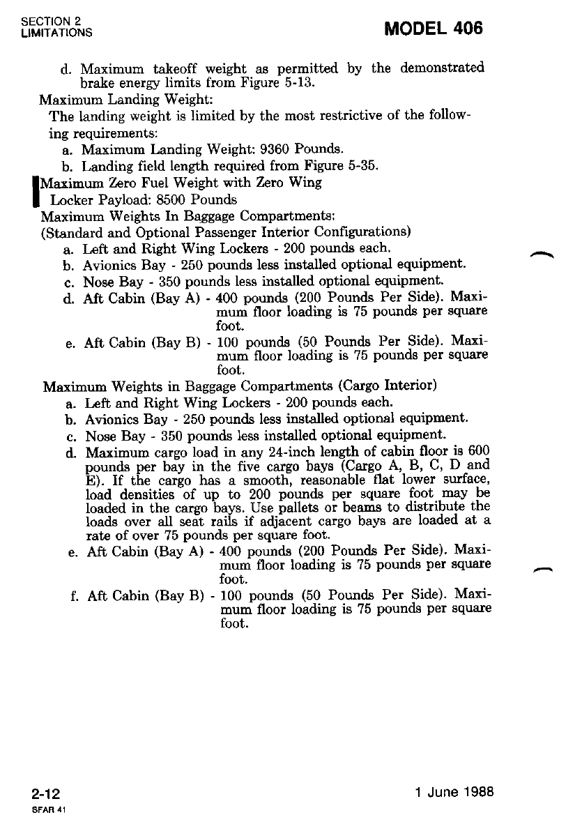
d. Maximum takeoff weight as permitted by the demonstrated
brake energy limits from Figure 5-13.
Maximum Landing Weight:
The landing weight is limited by the most restrictive of the follow-
ing requirements:
a. Maximum Landing Weight: 9360 Pounds.
b. Landing field length required from Figure 5-35.
lMarimum Zcro Fuel Weight with Zero Wing
I Locker Payload: 8500 Pounds
Maximurn Weights In Baggage Compartments:
(Standard and Optional Passenger Interior Confrgurations)
Left and Right Wing Lockers - 200 pounds each.
Avionics Bay - 250 pounds less installed optional equipment.
Nose Bay - 350 pounds less installed optional equipnent.
Aft Cabin (Bay A) - 400 pounds (200 Pounds Per Side)' Maxi-
- mum floor loading is 75 pounds per square
foot.
Aft Cabin (Bay B) - 100 pounds (50 Pounds Per Side). Maxi-
mum floor loading is 75 pounds per square
foot.
Maximum Weights in Baggage Compartments (Cargo Interior)
Left and Right Wing Lockers - 200 pountls each.
Avionics Bay - 250 pounds less installed optional equipment.
Nose Bay - 350 pounds Iess installed optional equipment.
Maximum cargo load in any 24-inch length of cabiq flo-or is 600
oounds ner balv in the five careo bavs (Careo A, B, C, D and
E). If the carlo has a smoothl reasonable -fXat lower surface,
load densities -of up to 200 pounds per square foot -may be
loaded in the cargo bays. Use pallets oi beams to dbtribute the
Ioads over all seit raiis if adjicent cargo bays are loaded at a
rate of over 75 pounds per square foot.
Aft Cabin (Bay A) - 400 pounds (200 Pounds Per Side)' Mari-
mum floor loading is ?5 pounds per square
foot.
f. Aft Cabin (Bay B) - 100 pounds (50 Pounds Per Side). Maxr
mum floor loading is ?5 pounds per square
foot.
SECTION 2
LIMITATIONS
2-12
a.
b.
d.
MODEL 406
a.
b.
c.
d.
1 June 1988
MODEL 406 SECTION 2
LIMITATIONS
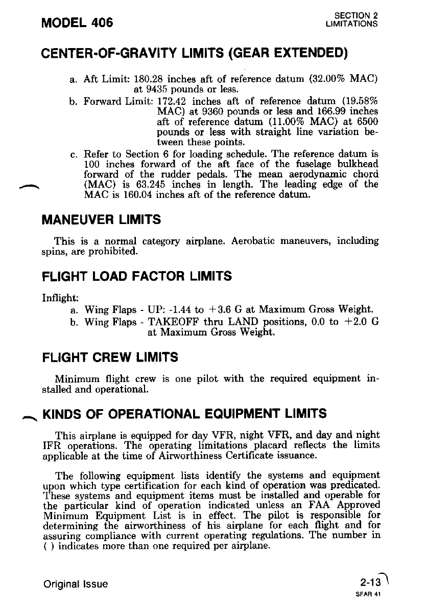
CENTER.OF-GRAVITY LIMITS (GEAR EXTENDED)
a. Aft Limit 180.28 inches aft of reference datum (32.00% MAC)
at 9435 pounds or less.
b. Forward Limit:172.42 inches aft of reference tlatum (19.58%
MAC) at 9360 pounds or less and 166.99 inches
aft of reference datum (11.00% MAC) at 6500
pounds or less with straight line variation be-
tween these points.
c. Refer to Section 6 for loading schedule. The reference datum is
100 inches forward of the aft face of the fuselage bulkhead
forward of the rudder Dedals. The mean aerodttmamic chord
(MAC) is 63.245 inchei in length. The leadin! edge of the
MAC is 160.04 inches aft of the reference datun.
MANEUVER LIMITS
This is a normal category airplane. Aerobatic maneuven, including
spins, are prohibited.
FLIGHT LOAD FACTOR LIMITS
Inflight:
a. Wing Flaps - UP: -1.44 to +3.6 G at Maximum Gross Weight.
b. Wing Flaps - TAKEOFF thru LAND positions, 0.0 to *2.0 G
at Maximum Gross Weisht.
FLIGHT CREW LIMITS
Minimum flight crew is one pilot with the required equipment in-
stalled and operational.
.\ KTNDS OF OPERATIONAL EQUIPMENT LlMlrS
This aimlane is equipped for day VFR, night \rFR, and day and night
IFR operaiions. Th6 irirerating limitations -placard reflects the limits
applicable at the time of Airworthiness Certilicate issuance.
The following equipment lists identify the systems and equipment
upon which type certification for each kind of operation was predicated.
These system-s- and equipment items must be installed and operable for
the pariicular kind 6f -operation indicated unless an FAA Approv,ed
Minihum Equipment Liit is in effect. The pilot is responsible for
determining fhe airworthiness of his airplane Tor each flilht and for
assuring compliance with current operating regulations. The number in
( ) indicates more than one required per airplane.
2-1il
Original lssue
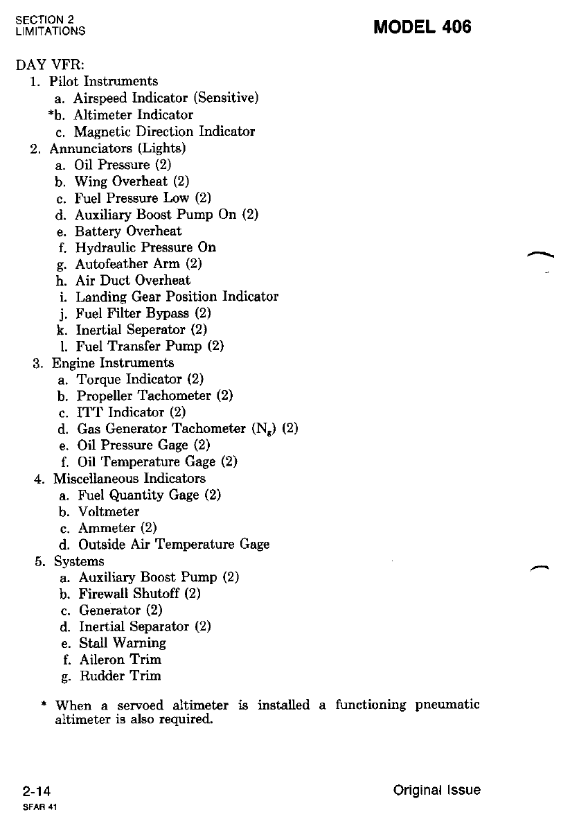
DAY VFR:
1. Pilot Instruments
a. Airspeed Indicator (Sensitive)
*b. Altimeter Indicator
c. Magnetic Direction Indicator
2. Annunciators (Lights)
a. Oil Pressure (2)
b. Wing Overheat (2)
c. Fuel Pressuie Low (2)
d. Auxiliary Boost Pump On (2)
e. Battery Overheat
f. Hydraulic Pressure On
g. Autofeather Arm (2)
h. Air Duct Overheat
i. Landing Gear Position Indicator
j. Fuel Filter Bypass (2)
k. Inertial Seperator (2)
l. Fuel Transfer Pump (2)
3. Engine Instruments
a. Torque Indicator (2)
b. Propeller Tachometer (2)
c. ITT Indicator (2)
d. Gas Generator Tachometer (Nr) (2)
e. Oil Pressure Gage (2)
f. Oil Temperature Gage (2)
4. Miscellaneous Indicators
a. Fuel Quantity Gage (2)
b. Voltmeter
c. Ammeter {2)
d. Outside Air Temperature Gage
5. Systerns
a. Auxiliary Boost Pump (2)
b. Firewall Shutoff (2)
c. Generator (2)
d. Inertial Separator (2)
e. Stall Warning
f. Aileron Trim
g. Rudder Trim
* When a servoed altimeter is installed a functioning pneumatic
altimeter is also required.
SECTION 2
LIMITATIONS
2-14
MODEL 406
Original lssue
MODEL 406 SECTION 2
LIMITATIONS
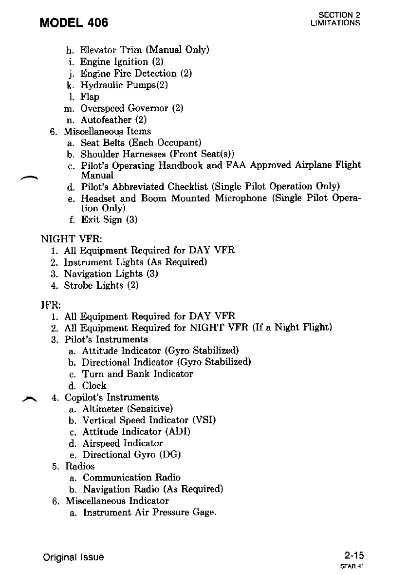
h. Elevator Trim (Manual Only)
i. Engine Ignition (2)
j. Engine Fire Detection (2)
k. Hydraulic Pumps(2)
l. Flap
m. Overspeed Governor (2)
n. Autofeather (2)
6. Miscellaneous Items
a. Seat Belts (Each Occupant)
b. Shoulder Harnesses (Front Seat(s))
c. Pilot's Operating Handbook and FAA Approved Airplane Flight
Manual
d. Pilot's Abbreviated Checklist (Single Pilot Operation Only)
e. Headset and Boom Mountcd Microphone (Single Pilot Opera-
tion Only)
f. Exit Sign (3)
NIGHTVFR:
1. All Equipment Required for DAY VTR
2. Instrument Lights (As Required)
3. Navigation Lights (3)
4. Strobe Lights (2)
IFR:
1. All Equipment Required for DAY \rFR
2. All Equiprrent Required for NIGHT VFR (If a Night Flisht)
3. Pilot's Instruments
a. Attitude Indicator (Gyro Stabilized)
b. Directional Indicator (Gyro Stabilized)
c. Turn and Bank Indicator
d. Clock
4. Copilot's Instruments
a. Altimeter (Sensitive)
b. Vertical Speed Indicator (VSI)
c. Attitude Indicator (ADI)
d. Airspeed Indicator
e. Directional Gyro (DG)
5. Radios
a. Communication Iladio
b. Navigation Radio (As Required)
6. Miscellaneous Indicator
a. Instrument Air Pressure Gage.
2-15
Original lssue
sEcroN 2
LIMITATIONS MODEL 406
2-16
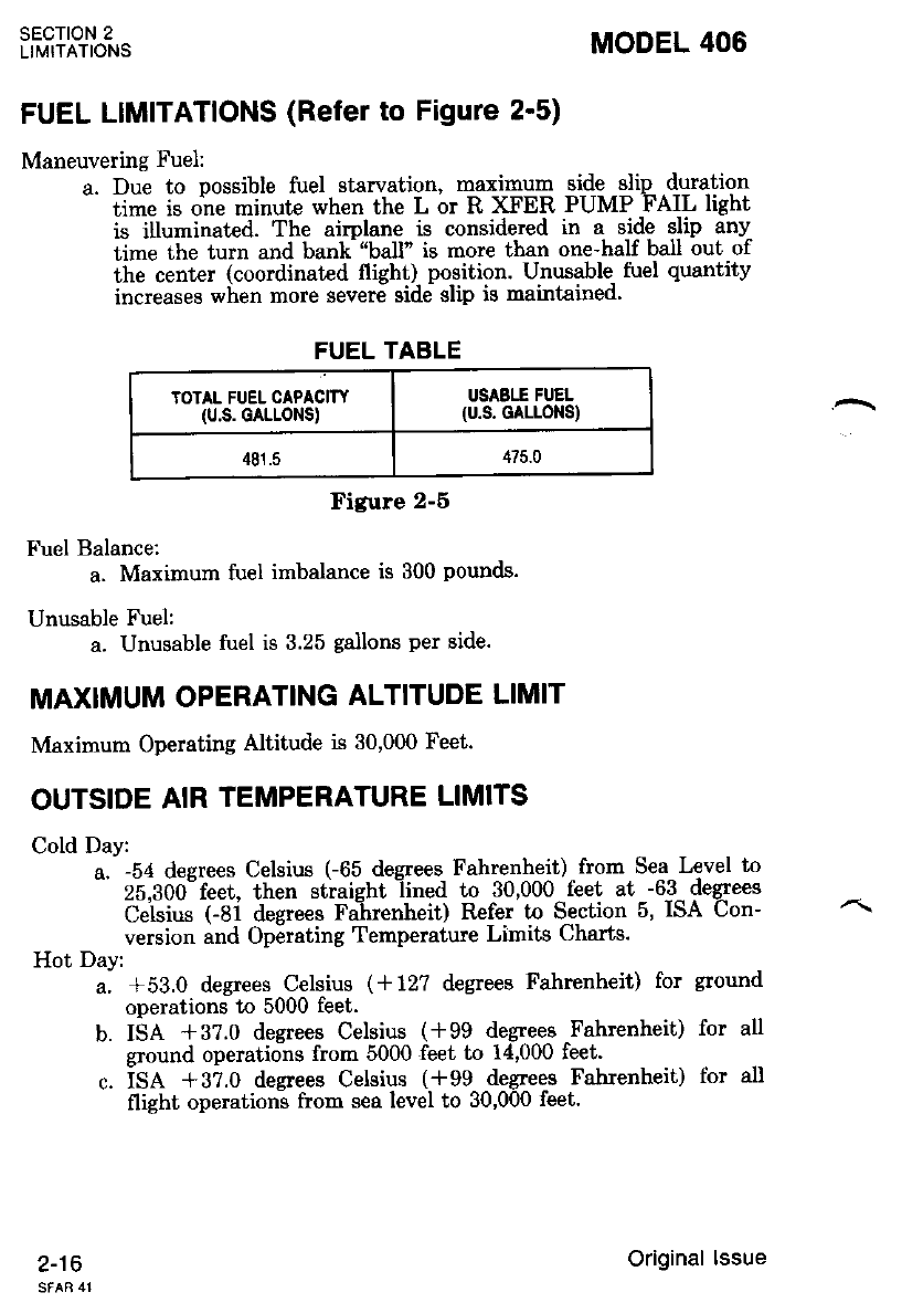
FUEL LIMITATIONS (Refet to Figure 2'5)
Maneuvering Fuel:
a. Due to possible fuel starvation, maximu4 side -slip duration
- iime is one minute when the L or R XFER PUMP FAIL light
is illuminated. The airplane is considered in a side slip any
time the turn and banh'ball" is more than one-half ball out of
the center (coordinated flight) position. Unusable- fuel quantity
increases when more severe side slip is maintained'
FUEL TABLE
TOTAL FUEL CAPACITY
(u.s. GALLONS)
USASTT FUEL
(u.s. GALLOT{S)
481.5 475.0
Figure 2-6
Fuel Balance;
a. Maximurn fuel imbalance is 300 pounds.
Unusable Fuel:
a. Unusable fuel is 3.25 gallons per side.
MAXIMUM OPERATING ALTITUDE LIMIT
Maxirnum Operating Altitude is 30,000 Feet.
OUTSIDE AIR TEMPERATURE LIMITS
Cold Day:
a. -54 degrees Celsius C65 degrees Fahreaheit) - from Sea Level to
- 25,300"feet, then straight -lined to 30,000-feet at --6-3- de4:ees
Ceisius (-8i degrees Fairenheit) Refer to S,e-ction 5, ISA Con-
version and Operating Temperatwe Limits Charts.
Hot Day:
u. +Sa.O degtees Celsius (*12? degrees Fahrenheit) for ground
operations t0 5000 feet.
b. ISA +3?.0 degrees Celsius (i99 degreee Fahrenheit) for all
ground operations from 5000 feet to 14,000 feet.
c. is.q +gz.o degrees Celsius (*99 degreqs Fahrenheit) for all
flight operations from sea level to 30,000 feet.
Original lssue

MODEL 406 sEcTtoN 2
LIMITATIONS
MAXIMUM PASSENGER SEATING LIMITS
The two forward seats are pilot seats.
A maximum of 12 passenger seats may be installed aft of the pilot
seats. Refer to Section 6 for seat locations.
Original lssue
SECTION 2
LTMITATIONS
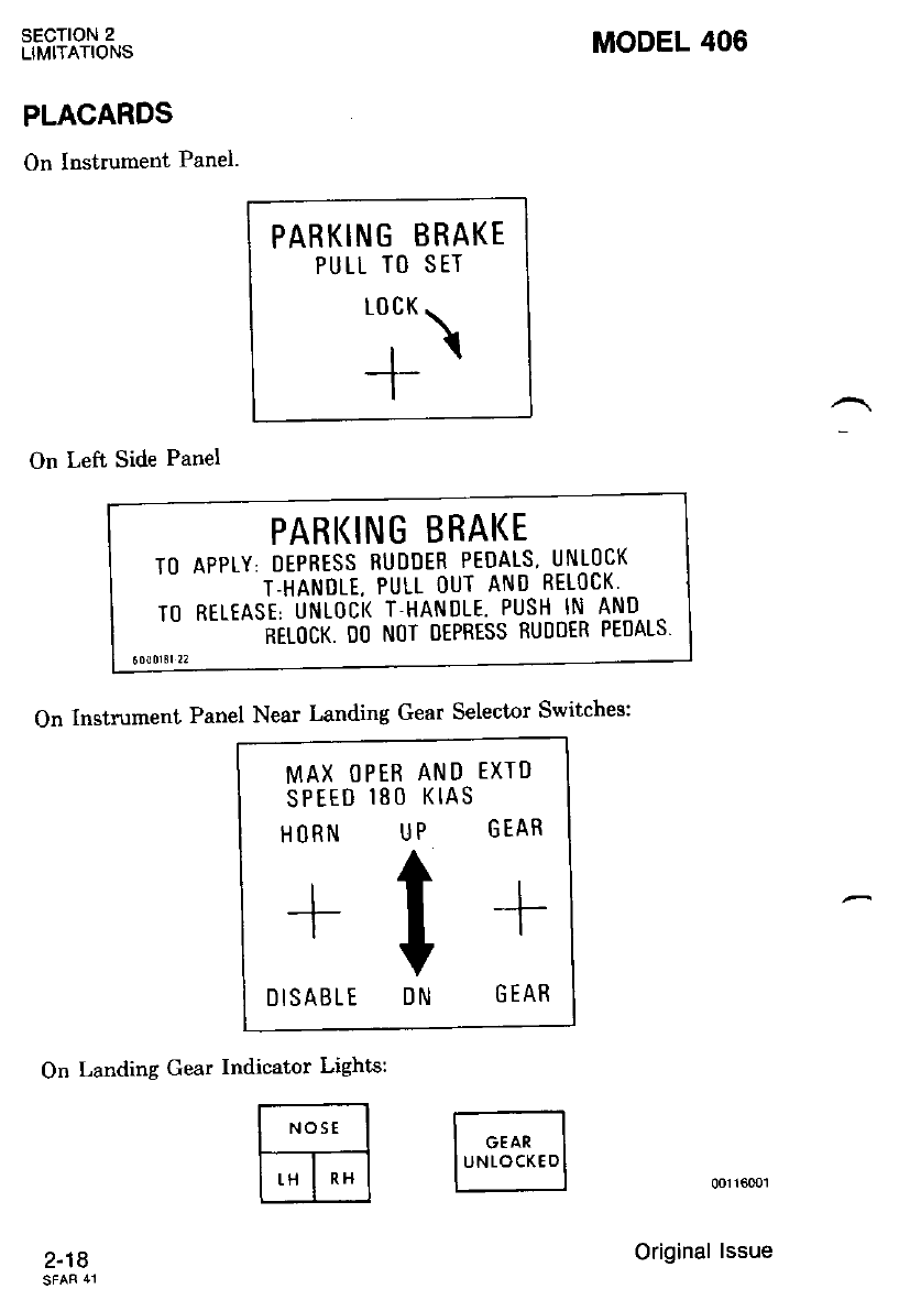
PLACARDS
On Instrument Panel.
On Left Side Panel
MODEL 406
PARKING BRAKE
PULL TO SET
"l-\
--T-
PARI(ING BRAI(E
Tt) APPIY. DEPRESS RUDDER PEDALS. UNLt)CK
T-HANOLE, PULL OUT AND RETOCK'
T() RELTASE. UNLOCK T.HANDLE. PUSH IN AND,.
.- -_- -NELOCT. OO N(]T OEPRESS RUI)OER PEDALS.
On Instrument Panel Near Landing Gear Selector Switches:
On Landing Gear Indicator Lights:
00116001
Original lssue
2-18
EXTD
GEAR
--J-
I
G EAR
R AND
t) KIAS
UP
V
DN
MAX OPE
SPEEO I8
HORN
DISABLE
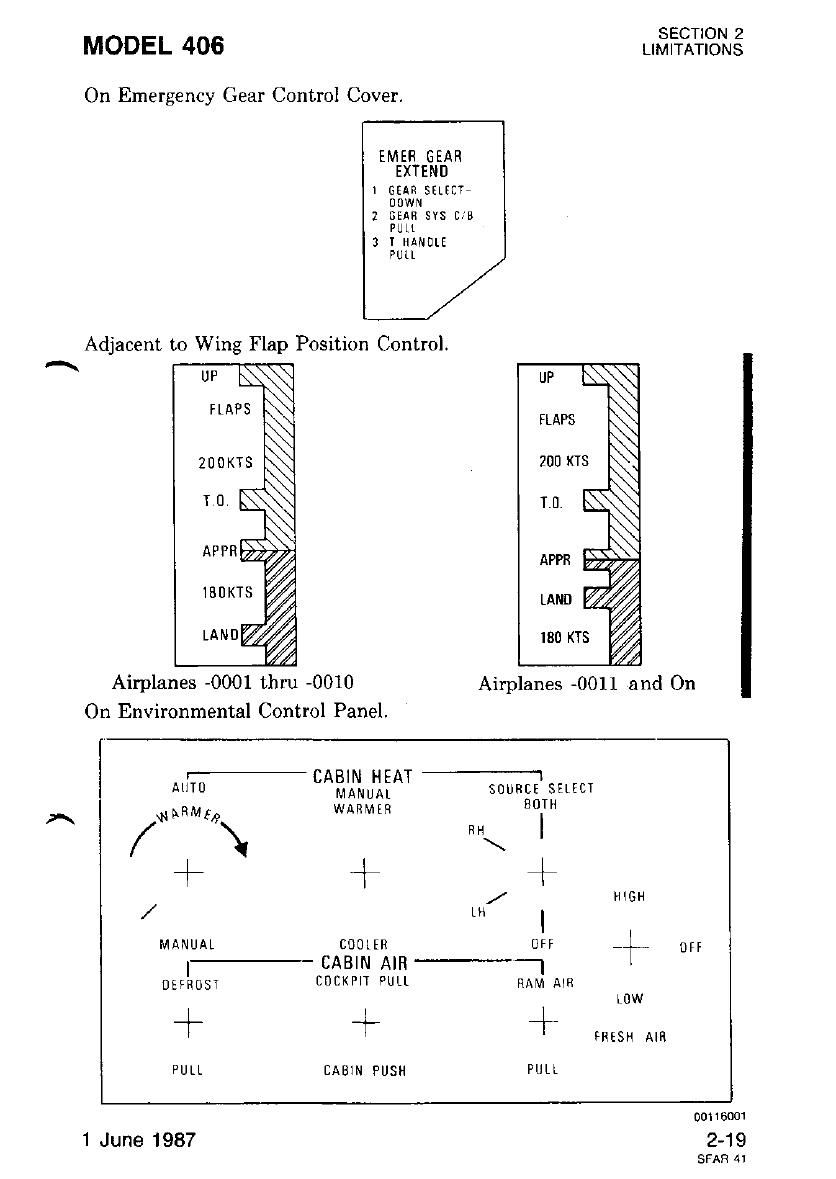
MODEL 406
On Emergency Gear Control Cover.
sEcTtoN 2
LIMITATIONS
00116001
2-19
Adjacent to Wing Flap Position Control.
Airplanes -0001 thru -0010
On Environmental Control Panel.
Airplanes -0011 and On
EMER GEAR
EXTEND
r 6tAi strtcr
? GTAS SYS C/B
PLJII
3 T HAN!TT
FLAPS
200KTS
18 O KTS
200 (TS
APPB L
LAND I
r80 KTS
o,li;- CABIN LIEAT ---lili; r,,,r,
.N NF^,rf, WAqVt q 80lH
/'"\ ,\l
t1
/ ,r/ | n'o *
I4ANUAL coorrR oir -f orr
I- CABIN AIR L
orrhost c0c(Ptr PULL RAM Ar8
++
PIJLL CAB]N PUSH PULL
FF tSH AIN
1 June 1987
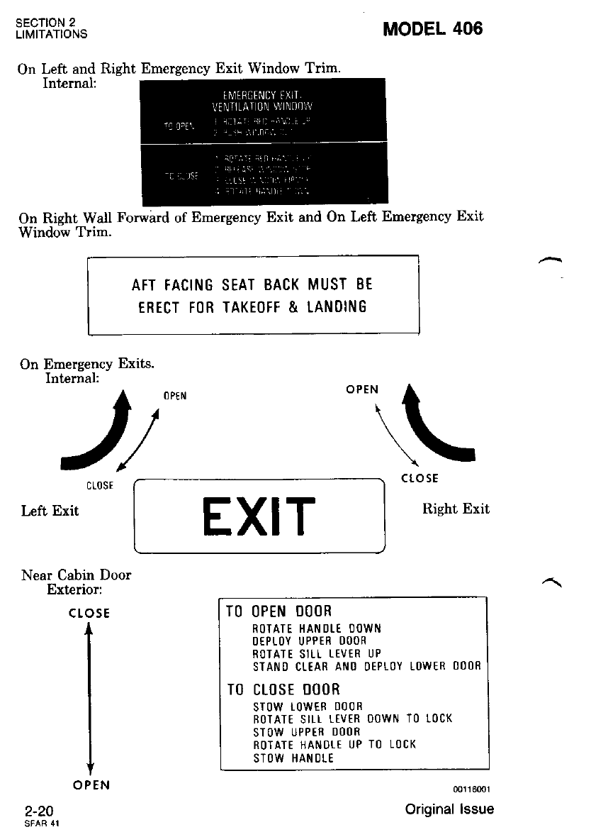
On Left and Right Emergency Exit Window Trim.
On Right Wall Forward of Emergency Exit and On Left Ernergency Exit
Window Trim.
SECTION 2
LIMITATIONS
Left Exit
2-20
MODEL 406
ct-osE
Right Exit
AFT FACING
ERECT FOR
SEAT BACK MUST 8E
TAKEOFF & LANOING
atr\
Emergency Exits.
Internal: ll
J/
On
OPTN
EXIT
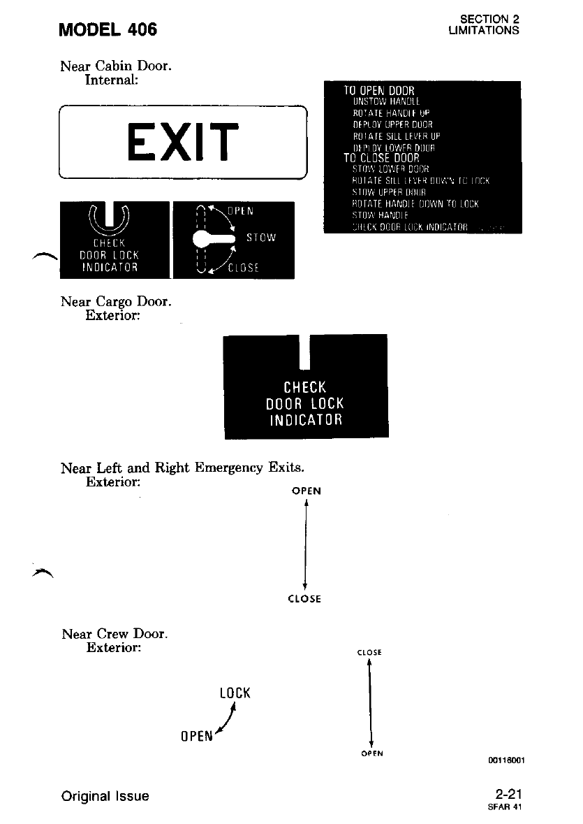
Near Cabin Door
Exterior:
CLOSE
t
I
I
I
I
OPEN
TO OPEN DOOR
ROTATE HAN DI-E OOWN
DTPT()Y U PPIR OOOR
RO]A] E SIII- TEVER LJP
STANo Cl-tAR Ar'10 oEPLoY L0WER 000R
TO CLOSE OOOR
sT0w i0wER 000R
R0TATE S -r r-tvtR 00wN T0 r0cK
STOW UPP ER DOO R
ROTATE HANOI-T UP TO TOCK
STOW HANOI.E
00116001
Original lssue
MODEL 406
Near Cabin Door.
Internal;
Near Left and Right Emergency Exits.
Exterior:
Near Crew Door.
Erterior:
LOCK
OPTN/
SECTION 2
LIMITATIONS
EXIT
OP€N
t
I
I
I
ctosE
I
I
I
I
00t 16001
^Mffi
Near Cargo Door.
Erterior:
Original lssue
SECTION 2
LIMITATIONS
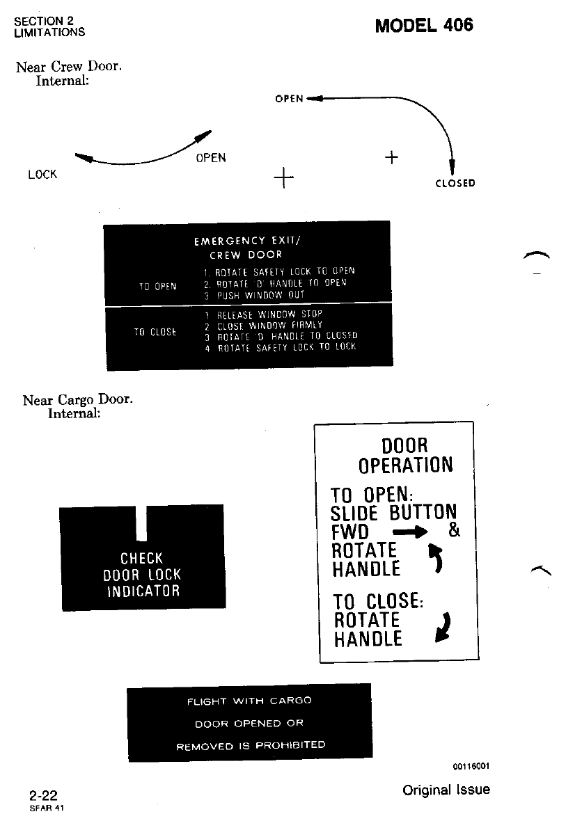
Near Crew Door.
Internal:
MODEL 406
Near Cargo Door.
Internal;
-!\
r'l
I cl,osEo
DO()R
()PERATION
T0 0PEN'
SLIDE BUTTON
FWo+&
ROTATE }
HANDLE '
TO CL(]SE'
fiRlilE )
00116001
Original lssue
2-22

MODEL 406
On Horizontal Part of Lower Baggage Shelf.
On Horizontal Part of Upper Baggage Shelf.
-r On Cover of Extemal Power Recentacle.
SECTION 2
LIMITATIONS
(rc11600r
2-23
EXTERNAI POWER
28 VoLTS 0.C. N0MTNAL
8()() AMP
STARTING CAPACITY MIN.
O() N()T EXCEEO IT(]O AMPS
Original lssue
l0 0PtN
+
l,0cx
A oFF A
LlI.rf f-Lle
r,?;"r / \ riftir-l
li;i/i f--- --"U3sl
-t-
FUtr c6ossttto ---J
T! 0Pll{
+
t0cK
SECTION 2
LIMITATIONS
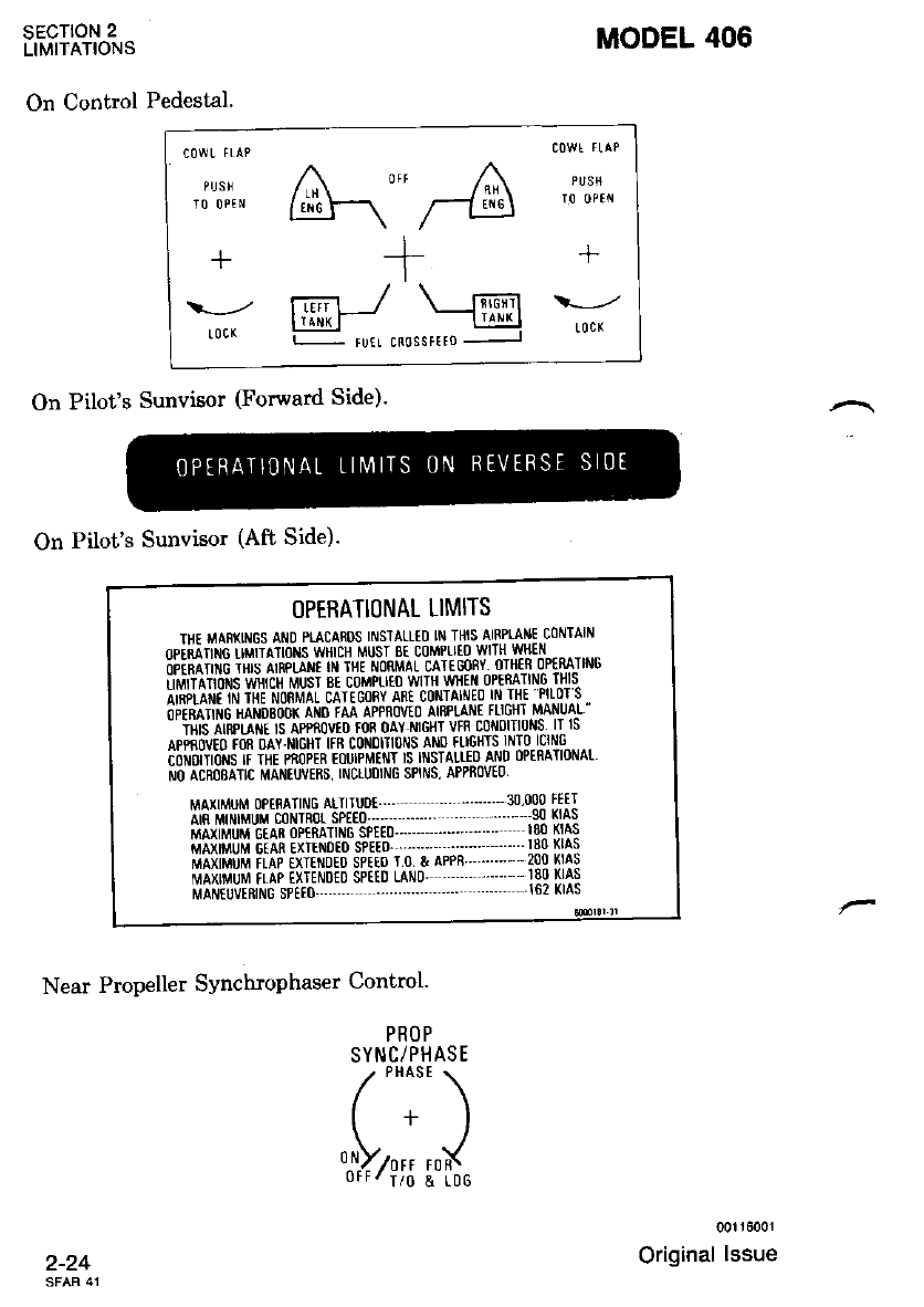
On Control Pedestal.
On Pilot's Sunvisor (Forward Side).
On Pilot's Sunvisor (Aft Side).
Near Propeller Synchrophaser Control'
(]PERATI(]NAL LIMITS
TI']I {A8KII\IGS AI\ID PLACAROS INSTALLED IN THIS AIRPIAIIIE COiITAIN
opiiririre rruiilttotts wttcH MUST sE coMPtlto wllli '/Ytlt
obiirlititic iili ainpLltt ttt Tflt i/oRMAL cATtcoRY olhtq oftn rNG
iirv:iiaTions vi{ici Musr Bt coMPtrto wtrt wxttl 0PtnATlN6 THIS
ii#iniiiii iiii-ribnl,t-rL crtlconv rru cottrt*tt0 tr ut 'ptror s
fiiiniiiie i*liitsb'ox ar,to tu rppnovto lnnmt tLtcttt r,uluat "
- iriis- inpiaii ri lprnovtD fon oay ilrcHr vfn coNolTlolls lT Is
npgnowo ron olr.ucur ttn c0it0ln0 s allo tllctlls lNT0 lclN8
hirir'orrrolrs it irt rnoptn tourPMtttl rs tttsTAtlE0 ANo oPERATlot'lat
NO ACBOEATIC MAITTUVERS, INCLUOING SPII'IS, APPROVEI]
MAXIMUM 0PtnAllN6 Alrlruot - ' -.-. ..--'--- 30'000 FttT
riCriiilrLiiuri,r counor Sptt0.,-, ....-. ...- -.-.' 90 l(lAs
iiiiiiiiriu einCoprmrm sptE0-,,,, --- ..-- r80 KlAs
i,rliiMuu eiln urtmto srElo- --.-.-' ....'-' ..- " ]80 xlas
unxim'u iLlp urtmro spE$ r 0 & APPR -...''- 200 KlAs
ir,ialiir'iur,,t rinp ixrtmto sPttD LArto' ..- - ' -- - 180 KAs
ulltuvtntle srtto - "" .----'.-' - ..--' 162 KIAS
MODEL 406
PROP
SYNC/PHASE
/'*0" \
l+l
P+', **{,
00116001
Original lssue
2-24
MODEL 406
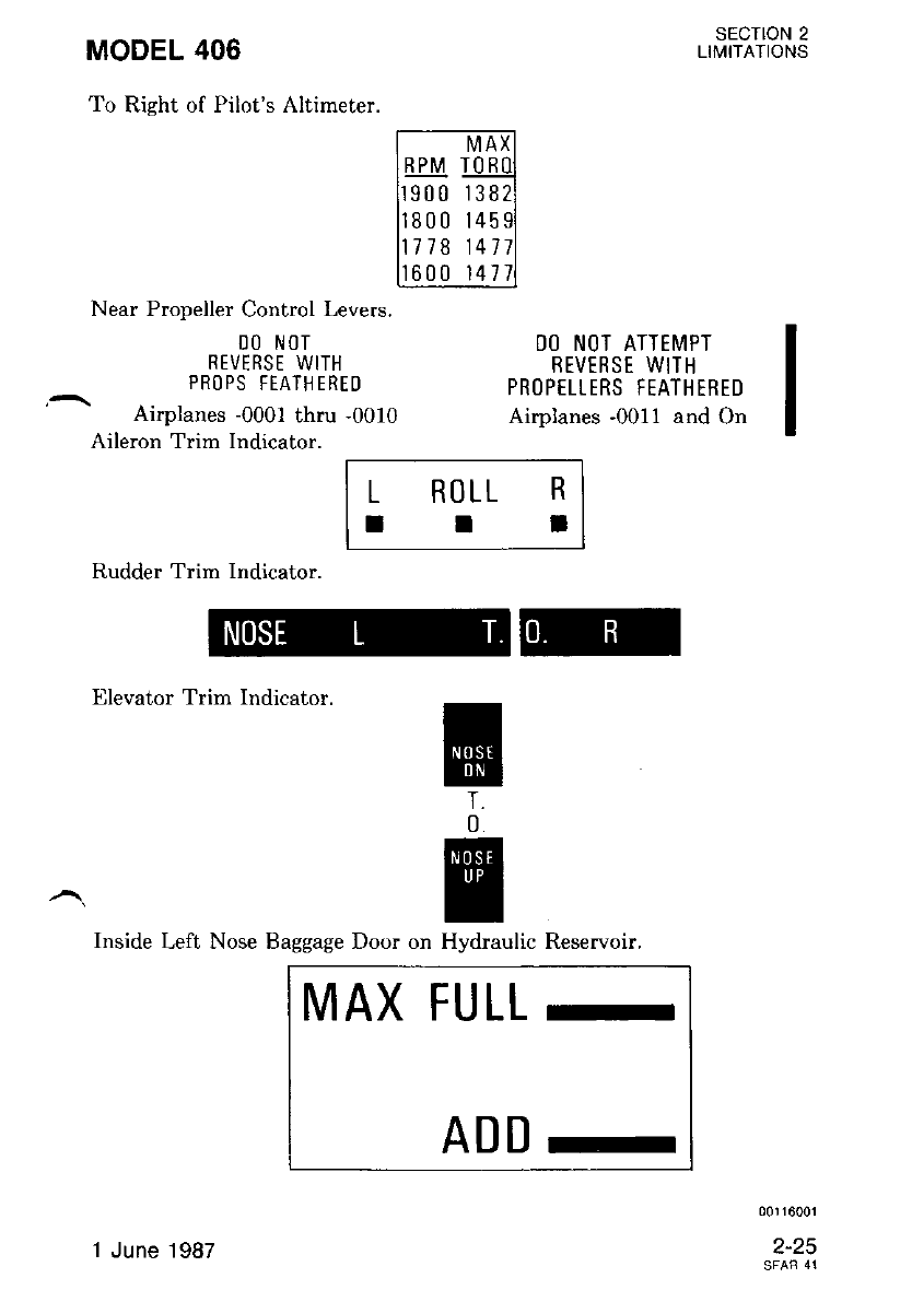
To Right of Pilot's Altimeter.
Near Propeller Control Levers.
I]O NOT
REVERSE WITH
PRO PS FEATH EREt)
Airyrlanes -000t thru -0010
Aileron Trim Indicator.
D() NOT ATTEMPT
REVERSE WITH
PRt)PTLLERS FEATHERED
Airplanes -0011 and On
sEcroN 2
LIMITATIONS
L ROLL
II R
I
Rudder Trim Indicator.
lllevator Trim Indicator.
I
0
[iH
r|r|
-
Inside Left, Nose Baggage Door on Hydraulic Reservoir.
MAX FULL
-
ADD-
00116001
2-25
'1 June .1987
sEcroN 2
LIMITATIONS
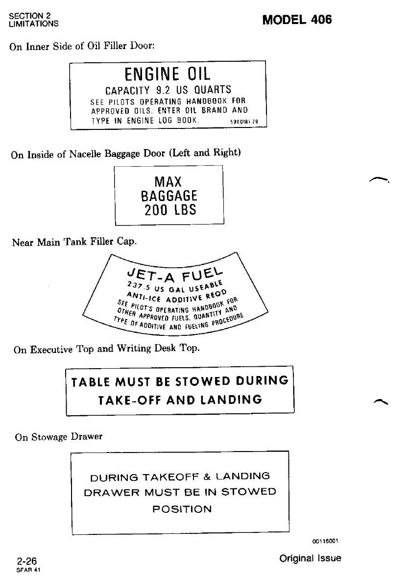
On Inner Side of Oil Filler Door:
MODEL 406
On Inside of Nacelle Baggage Door (Left and Right)
MAX
BAGGAGE
2O(] LBS
Near Main Tank Filler CaP.
On Executive Top and Writing Desk Top.
ENGINE OIL
CAPACITY 9.2 US OUARTS
SEE PITOTS OPERATING HANOBOOK FOR
APPROVTO OItS. ENTER OIT BRAND ANO
TYPt lN ENGINE t0G 800K. 5eoorsr ?s
TABLE MUST BE STOWED DURING
TAKE-OFF AND LANDING
On Stowage Drawer
l-zo
DURING TAKEOFF & LANDING
DRAWER MUST BE IN STOWED
POSITION
00116001
Original lssue
lEr:-a
6ue!
t37.s Us ol1 us€Aatl
tHi,,'j'':t#ffi
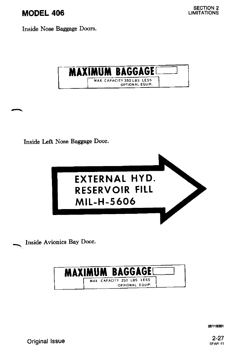
MODEL 406
Inside Nose Baggage Doors.
Inside l,eft Nose Baggage Door.
- Inside Avionics BaY Door.
sEcTtoN 2
LIMITATIONS
mrr00oi
EXTERNAL HYD.
RESERVOIR FILL
MtL-H-5606
ilr-Axriluil BAGGAGII-,
trAx cAPACITY 250 LBS LESS
OPIIONAL EQUIP,
Original lssue
SECTION 2
LIMITATIONS MODEL 406
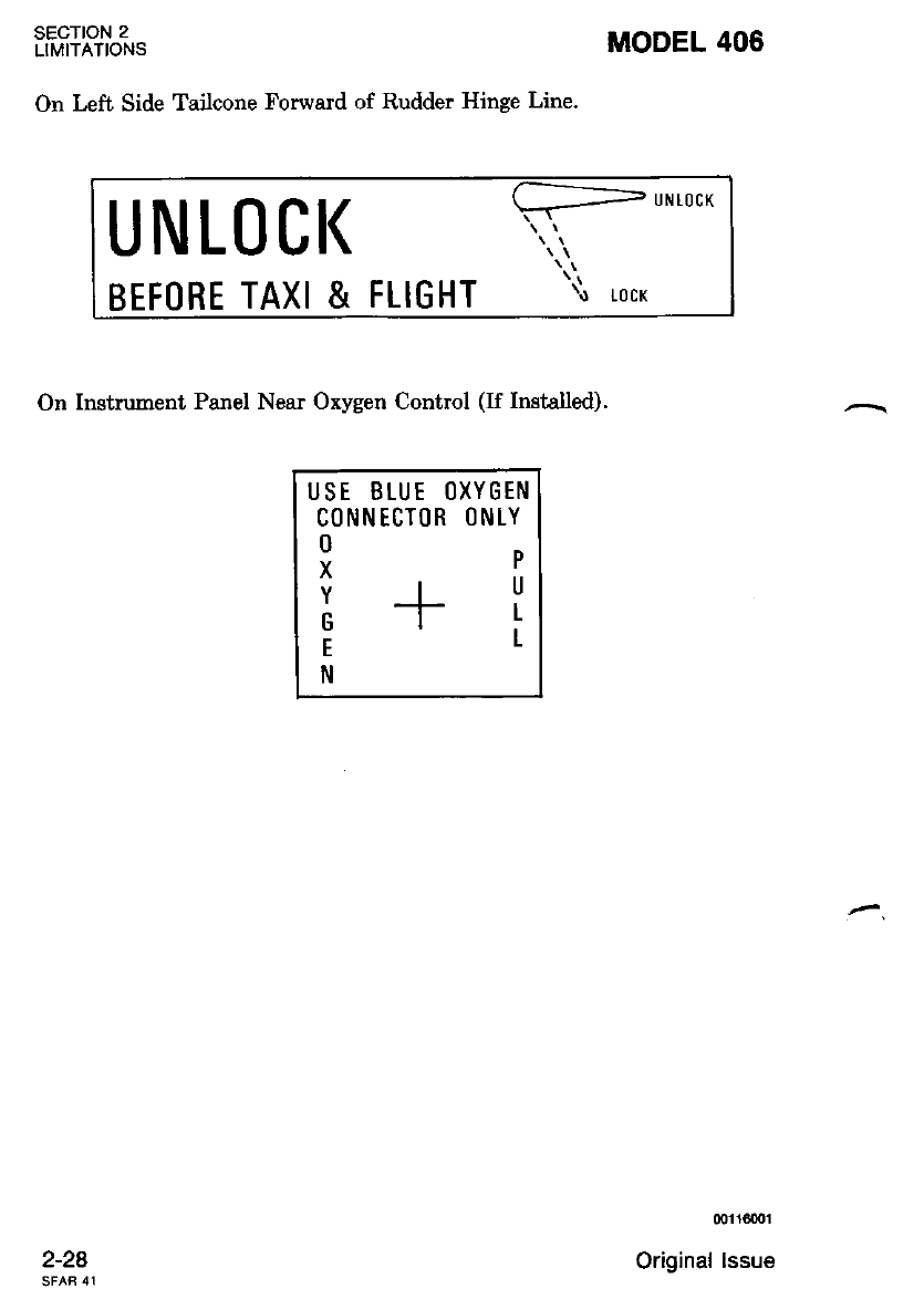
On Left Side Tailcone Forward of Rudder Hinge Line.
UNL()CI( UNTOCK
BEF()RE TAXI & FLIGHT \o to cx
On Instrument Panel Near Oxygen Control (If Installed).
USE BLUE OXYGEN
CONNECTOR ()NLY
0
X
Y
G
E
N
P
U
L
I
2-28
00116001
Original lssue
MODEL 406 EMERGENcY t*3"t8JLTtS
sEcfloN 3
EMERGENCY PROCEDURES
TABLE OF CONTENTS
INTRODUCTION
AIRSPEEDS FOR EMERGENCY OPERATIONS . ... .
EMERGENCY PROCEDURES ABBREVIATED CHECKLIST
Page
.t-o
3-5
Emergencies .....:.
-ENGINE FAILURE
Engine Failure Before V, (Speed Below 98 KIAS)
Engine Failure After Vr (Speed Above 98 KIAS) .
Decision to Abort Takeoff
Engine Failure in Flight (Speed Below Vr,ace) . .
Engine Failure in Flight (Speed Above Vr"rca) . .
Both Engines Fail in Flight
Engine Securing Procedure
AIRSTART
Starter Assist
No Starter Assist . .
SMOKE AND FIRE
Engine Fire During Ground Operations (Sufficient Runway
Remaining to Stop) . .
Cabin Fire During Ground Operations
Inflight Wing or Engine Fire . . .
Inflight Cabin Electrical Fire or Smoke
Smoke Removal
EMERGENCY DESCENT
Preferred Procedure
In Turbulent Atmospheric Conditions
GLIDE .
LANDING EMERGENCIES
Precautionary or Forced Landing With Power - .
Landing Without Power . .
Landing With Flat Main Gear Tire
Landing With Flat Nose Gear Tire
Landing With Defective Main Gear
.t-t)
.J_O
rt-O
3-7
3-8
3-8
3-8
3-8
3-9
3-10
3-10
3-10
3-10
3- 11
3-11
3-L2
3-12
3-L2
3-r2
3-13
3-13
3-14
Original lssue - 1 July 1986 3-1
SECTION 3
EMERGENCY PROCEDURES MODEL 406
3-27
3-27
TABLE OF CONTENTS (CONTINUED)
Page
Landing With Defective Nose Gear .......3-15
Landing With Power, Landing Gear Retracted ...... 3-15
Landing With Wing Flaps Retracted ....'.3-15
Engine Inoperative Landing .....3-16
Engine Inoperative Go-Around (Speed Above 101 KIAS) . . . . . 3-16
Ditching .....3-16
SYSTEM EMERGENCIES .......3-17
Propeller Synchrophaser Failure . ........ 3-17
Fuel System Emergency Procedures ......3-17
Electrical System Emergency Procedures ....... .. 3-18
Hydraulic Systems Emergencies ... ....'.3-20
Environmental Systems Emergencies . . '..3-21
Oxygen System Failure.. .......3-22
Ice Protection Systems Emergencies .... . . .. 3-22
Avionics Bus Failure . .........3-23
Emergency Exits .. .'..3-23
Emergency LocatorTransmitter Rescue Procedures . ...... .. 3-24
Encoding Altimeter Failure (Warning Flag Showing) '...... ' 3-24
Transponder Procedures For Emergency Situations ..... .. 3-24
Total Loss of Communications ... .....3-25
Electric Elevator Trim Runaway .''......3-25
SPINS . .......3-26
AMPLIFIED EMERGENCY PROCEDURES
AIRSPEEDS FOREMERGENCY OPERATIONS .... .. . ., .,
Maneuvering Speed (Ve)
Maximum Gliding Distance Speed .. . ...3-27
Air Minimum Control Speed (Vvco) . ..'..3-28
One Engine Inoperative Best Rate-of-Climb Speed (Vysc) . . . . . 3-28
Takeoff Decision Speed (Vr) ....' 3-28
Takeoff Safety Speed (Vr) ......3-28
3-2 1 June 1987
MODEL 406
TABLE OF CONTENTS (CONTINUED)
Emergencies
ENGINE FAILURE
Engine Failure Before V, (Speed Below 98 KIAS)
Engine Failure After V1 (Speed Above 98 KIAS) .
Decision to Abort Takeoff
Engine Failure in Flight (Speed Below Vr,rce) . .
Engine Failure in Flight (Speed Above V"co) . .
Both Engines Fail In Flight
Engine Securing Procedure
--\AIRSTART
Starter Assist (Preferred Procedure)
No Starter Assist . .
SMOKE AND FIRE
Engine Fire During Ground Operations (Sufficient Runway
Remaining To Stop)
Cabin Fire During Ground Operations
Inflight Wing or Engine Fire . . ,
Inflight Cabin Electrical Fire or Smoke
Smoke Removal
Supplementary Information Concerning Airplane Fires
EMERGENCY DESCENT
Preferred Procedure
In T\rrbulent Atmospheric Conditions
GLIDE .
LANDING EMERGENCIES
Precautionary or Forced Landing With Power . .
Landing Without Power . .
Landing With Flat Main Gear Tire
-\ Landing With Flat Nose Gear Tire
Landing With Defective Main Gear
Landing With Defective Nose Gear
Landing With Power, Landing Gear Retracted
Landing With Wing Flaps Retracted
Engine Inoperalive Landing
Engine Inoperative Go-Around (Speed Above 101 KIAS) . . . . .
Ditchins
SECTION 3
EMERGENCY PROCEDURES
Page
3-29
3-29
3-29
3-30
3-30
3-32
3-33
3-34
3-35
3-35
3-36
3-38
3-38
3-38
3-38
3-39
3-40
3-40
3-41
3-41
3-41
3-42
3-43
3-43
3-43
3-44
3-45
3-45
3-46
siel
3-47
3-48
3-49
1 June 1987 3-3

sEcTloN 3
EMERGENCY PROCEDURES MODEL 406
TABLE OF CONTENTS (CONTINUED)
SYSTEM EMERGENCIES
Engine Emergency Procedures
Propeller Syrrchrophaser Failure . .
Fuel System EmergencY Procedures
Electrical System Emergency Procedures
Hydraulic SystemEmergencies ....
Environmental System Emergencres
Oxygen Systen Failure ....
lce Protection Emergencies . .' . . .
Page
3-49
3-49
3-49
3-49
3-52
3-54
3-57
3-58
3-59
3-62
3-62
3-62
3-62
3-63
3-64
Avionics Bus Failure
Emergency Exits . .
Cabi;Do;r, Crew Door or Emergency Exit Not Secured Light
Illuminated (Door Not Locked) .
Total Loss of Communications ......
Electric Elevator Trim RunawaY . .
3-61
3-61
.t-ol
Nose Baggage Door OPen on Takeoff
Emergency Locator Transnitter Rescue Procedures
Encoding Altimeter Failure (Warning Flag Showing)
Transponder Procedures For Emergency Situations
SPINS . """' 3-64
rMencnNcv INF0RMATI0N ' 3-65 (3-66 blank)
3-4 Original lssue - 1 JulY 1986
INTRODUCTION
Section 3 describes the recommended procedures for emergency situ-
ations. The first part of this section provides emergency procedural
action required in an abbreviated checklist form. Amplification of the
abbreviated checklist is presented in the second part of this section.
I{OTE
Refer to Section 9 for amended operating limita-
tions, operating proced,ures, performance data
and. other necessary information for airpLanes
equipped with specific options.
^AIRSPEEDS FOR EMERGENCY OPERATIONS
MODEL 406 SECTION 3
EMERGENCY PROCEDURES
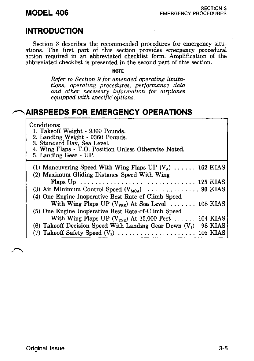
Conditions:
1. Takeoff Weight - 9360 Pounds.
2. Landing Weight - 9360 Pounds.
3. Standard Day, Sea Level.
4. Wing Flaps - T.O. Position Unless Otherwise Noted.
5- Landins Gesr - UP.
(1) Maneuvering Speed With Wing Flaps UP (VA) . . . . . . 162 KIAS
(2) Maxinum Gliding Distance Speed With Wing
Flaps Up . . 125 KIAS
(3) Air Minimum Control Speed (Vr,nce) . ......90KIAS
(4) One Engine Inoperative Best Rate-of-Climb Speed
With Wing Flaps UP (VysJ At Sea Level 108 KIAS
(5) One Engine Inoperative Best Rate-of-Climb Speed
With Wing Flaps UP (VysE) At 15,000 Feet . . . . . . 104 KIAS
(6) Takeoff Decision Speed With Landing Gear Down (Vr) 98 KIAS
(7) Takeoff Safety Speed (VJ 102 KIAS
3-5Original lssue
SECTION 3
EMERGENCY PBOCEDURES {ABBREVIATEDPBOCEDURES) MODEL 406
EMERGENCY PROCEDURES ABBREVIATED
CHECKLIST
I{OTE
This Abbreuiated Emergency Procedures Chec'
hlist ts included as a suppkment to the Am-
nlified Emerpencv Procedures CheckList. The
'Alibreuiated -Emi rgency Procedures Chechlist
should not be used until the flight crew has
become familiar with the airplane and systerns.
AII Amplified Emergency procedure item.s must
be accimitish.ed reg-ardlbsi of which ch.ecklist is
used.
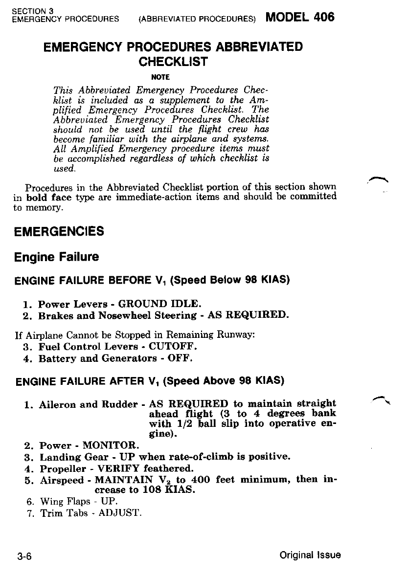
Procedures in the Abbreviated Checklist portion of this section shown
in bold face type are inmediate-action items and should be comnitted
to memory.
EMERGENCIES
Engine Failure
ENGINE FAILURE BEFORE V1 (Speed Below 98 KIAS)
l Power Levers - GROUND IDLE.
2. Brakes and Noe€wheel Steering - AS REQUIRED.
If Airplane Cannot be Stopped in Remaining Runway:
3. Fuel Control Levers - CUTOFF,
4. Battery and Generators - OFF.
ENGINE FAILURE AFTER Vl (Speed Above 98 KIAS)
1. Aileron end Rudder - AS REQUIRED to rraintain straight
ahead flight (3 to 4 degrees bank
with l/2 ball slip into operative en-
gine).
2. Power - MONITOR.
3. Landing Gear - UP when rate-of-climb is positive.
4. Propeller - VERIFY feathered'
5. Airspeed - MAINTAIN Vz to 4OO feet minimum, then in-
crease to fO8 KIAS.
6. Wing Flaps - UP.
?. Trim Tabs - ADJUST.
J-O Original lssue
MODEL 406 (neenevtnrEDpRocEDUREs) EMERGENcYt"o%t8JlT.3
After Reaching 1000 Feet Above Ground Level:
8. Inoperative Engine - SECURE.
DECISION TO ABORT TAKEOFF
1. Landing Gear - CIIDCK DOWN. Gear <Iown lights on.
2. Power Levers - FLIGHT IDLE.
3. Power Levers - GROUND IDLE after touchdown.
4. Brakes, Propeller Reverse
and Nosewheel Steering - AS REQUIRED.
If Airplane Cannot be Stopped in Remaining Runway
^. 5. Fuel Control Levers - CUTOFF.
6. Battery and Generators - OFF.
ENGINE FAILURE lN FLIGHT (Speed Below V cA)
1, Power Levers - RETARD to stop turn.
2. Aileron and Rudder - AS REQUIRED toward operative en-
gine to maintain straight-ahead.
flight.
3. Pitch Attitude - LOWER NOSE to accelerate above 9O
KIAS.
4. Accomplish procedures for Engine Failure in Flight (Speed above
Vuce)'
ENGINE FAILURE lN FLIGHT (Speed above Vri61)
1. Inoperative Engine - DETERMINE. Idle engine same aa
idle foot; also, torque, ITT and N"
will be low.
2. Inoperative Engine Power Lever - RETARD'
,\ 3, Inoperative Engine Propeller - FEATHER.
4. Operative Engine - ADJUST.
5. Lanrling Gear - UP.
6. Airspeed - lOa KIAS minimum.
7. Wing Flaps - UP.
8. If airstart is warranted, refer to AIRSTART procedures.
9. If airstart is not warranted, refer to ENGINE SECURING proce-
dures.
Original lssue
sEcloN 3
EMERGENCY PROCEDURES (ABBREVIATED PROCEOURES) MODEL 406
BOTH ENGINES FAIL IN FLIGHT
If Insufficient Altitude Exists to Permit Airstarts:
1. Refer to LANDING WITIIOUT POWER procedures.
If Sufficient Altitude Exists to Permit Airstarts:
1. Propellers - DO NOT FEATHER if airstart is attempted.
2. Airstarts - ATTEMPT, refer to AIRSTART-STARTER ASSIST
proceoures.
3. If Airstarts Fail:
a. Propellers - FEATHER.
b. Airspeed - 125 KIAS (refer to Figure 3-1 Maximum Glide)'
c. Refer to LANDING WITHOUT POWER procedures.
ENGINE SECURING PROCEDURE
1. Autofeather - OFF.
2. Power Lever - FLIGIIT IDLE.
3. Propeller Control Lever ' FEATHER.
4. Fuel Control Lever - CUTOFF.
5. Fuel Crossfeed Selector - OFF if fire hazard erists'
6. Fuel Auxiliary Boost Pump - OFF if lire hazard exists'
7. Cowl Flap - CLOSED.
8. Propeller SynchroPhaser - OFF.
9. Generator - OFF.
10. Electrical Load - REDUCE if necessary and MONITOR'
AIRSTART
STARTER ASSIST
1. Electrical Load - REDUCE.
2. Air Conditioner - OFF.
3. Windshield Anti-Ice - OFF.
4. Autofeather - OFF.
5. Power Lever - One inch forward of FLIGHT IDLE.
6. Propeller Control Lever - Forward of FEATHER'
7. Fuel Control Lever - CUTOFF.
8. Fuel Quantity - CHECK.
9. Fuel Crossfeed Selector - OFF.
10. Fuel Auxiliary Boost PumP - ON.
11. Inoperative Engine Generator - OFF.
12. Operative Engine - REDUCE ITT to 650 degrees if practical'
J-O Original lssue
MODEL 406 lnaanevtrrED 'RocEDURES) EMERGENc' *333Jll?t3
13. Airspeed - 100 KIAS minimum.
14. Altitude - 20,000 feet maximum.
15. Stert Switch - START; Check ignition light on.
16. Fuel Control Lever - RUN above 12 percent \
17. ITT and Ng - MONITOR (1090 degrees Celsius maximum).
18. Start Switch - OFF (N.52 percent or above).
19. Fuel Auxiliary Boost Pump - OFF MOMENTARILY, then NOR-
MAL.
20. Propeller Control Lever - AS DESIRED.
21. Power Lever - AS DESIRED.
22. Generator - ON.
--. 23. Electrical Equipment - AS REQUIRED.
NO STARTER ASSIST
1. Autofeather - OFF.
2. Power Lever - One inch forward of FLIGHT IDLE.
3. Propeller Control Lever - Forward of FEATHER.
4. Fuel Control Lever - CUTOFF.
5. Fuel Quantity - CHECK.
6. Fuel Crossfeed Selector - OFF.
7. Fuel Auxiliary Boost Pump - ON.
8. Inoperative Engine Generator - OFF.
9. Ignition Switch - ON, check light on.
10. Airspeed - 100 KIAS minimum (140 KIAS if propeller is feather-
ed).
11. Altitude - 20,000 feet maximum (15,000 feet if propeller is feather-
ed).
12. Fuel Control Lever - RUN (after N. Stabilizes).
13. IT'T and Ns - MONITOR (1090 degrees Celsius maximum).
14. Ignition Switch - NORMAL (Ns 52 percent or above).
. 15. Propeller Control Levers - AS DESIRED.
16. Power Lever - AS DESIRED.
17. Generator - ON.
18. Electrical Equipment - AS REQUIRED.
19. Fuel Auxiliary Boost Pump - OFF momentarily, then NORMAL.
Original lssue 3-9
SECTION 3
er"rericiruivpnoceounes (ABBREVTATEDeRocEDURES) MODEL406
SMOKE AND FIRE
ENGINE FIRE DURING GROUND OPERATIONS (Sutticient
Runway Remaining to Stop)
1. Power Levers - GROUND IDLE.
2. Brakes - AS REQUIRED.
3. Fuel Control Levers - CUTOFF.
4, Fuel Crossfeed Selector - OFF.
5. Illuminated Fire Warning Licht PJSHT# O1ffiot""rlnr,*-ffffifa
fuel shutoff valves and ARM frre
bottle (if installed).
6. Illuminated Fire Extinguisher Armed Light - PUSH (if insta ed)'
?. Emergency Assistance - REQUEST (if warranted).
8. Battery Switch - OFF.
9. As Soon As Practical - EVACUATE.
CABIN FIRE DURING GROUND OPERATIONS
l. Power Levers - GROUND IDLE.
2. Brakes - AS REQUIRED'
3. Fuel Control Levers - CUTOFF'
4. Emergency Assist€nce - REQUEST (if warranted).
5. Battery Switch - OFF.
6. Portable Fire Extinguisher - USE as required.
7. As Soon As Practical - EVACUATE.
INFLIGHT WING OR ENGINE FIRE
l. Power Lever Affected Engine - FLIGIIT IDLE.
2. Propeller Control Lever Affected Engine - FEATI{FR. ^'
3. Fuel Control Lever Affected Engine - CUTOFF.
4. Fuel Auxiliary Boost Pump Affected Engine - OFF.
5. Illuminated Fire Warning Light - PUSH to disable the gen-
erator. close the bleed air
firewall and fuel ghutoff
vslves and ARM fire bot-
tle (if inetalled).
6. Illuminated Fire Bottle Light - PUSH (if ingtalled).
7. Fuel Crossfeed Selector - OFF.
8. Engine Securing Procedure - COMPLETE.
9. As Soon As Practical - LAND and EVACUATE'
3-10 Original lssue
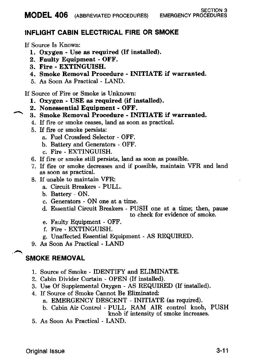
sEcT|oN 3
MODEL406 (eaenEvrnrEDpRooEDURES) ETTERGENcYPRocEDURES
INFLIGHT CABIN ELECTRICAL FIRE OR SMOKE
If Source Is Known:
1, Oxygen - Use as required (If installed).
2. Faulty Equipment - OFF.
3, Fire - EXTINGUISH.
4. Smoke Removal Procedure - INITIATE if warranted.
5. As Soon As Practical - LAND.
If Source of Fire or Smoke is Unlnown:
l. Oxygen - USE as required (if installed).
2. Nonessential Equipment - OFF.
^ 3. Smoke Removal Procedure - IMTIATE if warranted.
4. If fire or smoke ceases, land as soon as practical.
5. If fire or snoke persists:
a. Fuel Crossfeed Selector - OFF.
b. Battery and Generators - OFF.
c. Fire - EXTINGUISH.
6. If fire or smoke still persists, land as soon as possible.
7. If fire or smoke decreases and if possible, maintain VFR and land
ag soon as practical.
8. If unable to maintain VFR:
a. Circuit Breakers - PULL.
b. Battery - ON.
c. Generators - ON one at a time.
d. Essential Circuit Breakers - PUSH one at a time; then, pause
to check for evidence of smoke.
e. Faulty Equipment - OFF.
f. Fire - EXTINGUISH.
g. Unaffected Essential Equipment - AS REQUIRED.
9. As Soon As Practical - LAND
SMOKE REMOVAL
1. Source of Smoke - IDENTIFY and ELIMINATE.
2. Cabin Divider Curtain - OPEN (If installed).
3. Use Of Supplemental Oxygen - AS REQUIR.ED (If installed).
4- If Source of Smoke Cannot Be Eliminated:
a. EMERGENCY DESCENT - INITIATE (as required).
b. Cabin Air Control - PULL RAM AIR control knob, PUSH
knob if intensity of smoke increases.
5. As Soon As Practical - LAND.
Original lssue 3-11
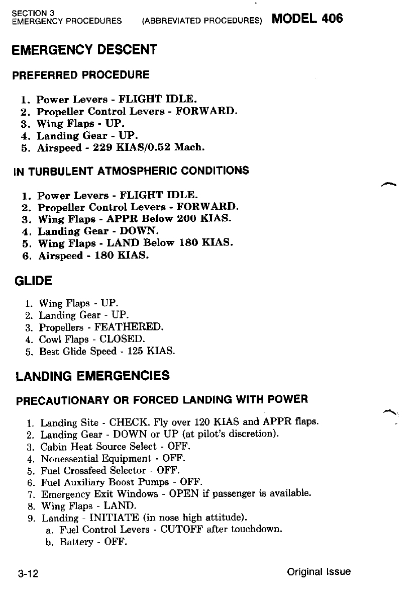
SECTION 3
EMERGENCY PROCEDURES (ABBREVIATED PROCEDURES) MODEL 406
EMERGENCY DESCENT
PREFERRED PROCEDURE
1. Power Levers - FLIGHT IDLE.
2. Propeller Control Levers - FORWARD.
3. Wing Flaps - UP.
4, Landing Gear - UP.
6. Airspeed - 229 KIAS/0.62 Mach'
IN TURBULENT ATMOSPHERIC CONDITIONS
1. Power Levers - FLIGHT IDLE.
2. Propeller Control Levers - FORWARD.
3. Wing Flape - APPR Below 2OO KIAS.
4. Landing Gear - DOWN.
5. Wing Flaps - LAND Below 180 KIAS.
6. Airspeed - 180 KIAS.
GLIDE
1. Wing Flaps - UP.
2. Landing Gear - UP.
3. Propellers - FEATHERED.
4. Cowl Flaps - CLOSED.
5. Best Glide Speed - 125 KIAS.
LANDING EMERGENCIES
PRECAUTIONARY OR FORCED LANDING WITH POWER
1. Landing Sit€ - CHECK. Fly over 120 KIAS and APPR flaps.
2. Landing Gear - DOWN or UP (at pilot's discretion).
3. Cabin Heat Source Select - OFF.
4. Nonessential EquiPment - OFF.
5. Fuel Crossfeed Selector - OFF.
6. F\el Auxiliary Boost Pumps - OFF.
7. Emergency Exit Windows - OPEN if passenger is available.
8. Wing Flaps - LAND.
9. Landing - INITIATE (in nose high attitude).
a. Fuel Control Levers - CUTOFF after touchdown.
b. Battery - OFF.
Original lssue
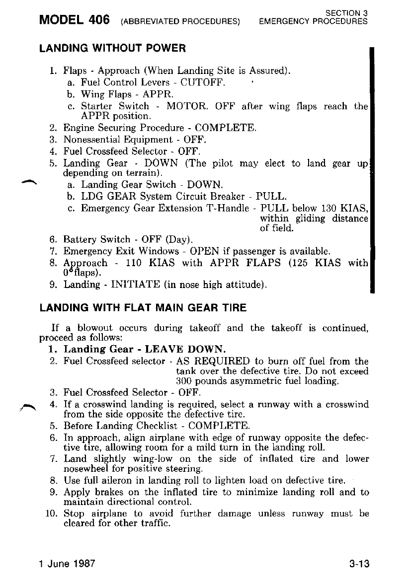
MODEL 406 (neenevrnrEo pRocEDUREs) EMERGENc' t.353Jl;T.3
LANDING WITHOUT POWER
1. Flaps - Approach (When Landing Site is Assured).
a. Fuel Control Levers - CUTOFF.
b. Wing Flaps - APPR.
c. Starter Switch - MOTOR. OFF after wing flaps reach the
APPR position.
2. Engine Securing Procedure - COMPLETE.
3. Nonessential Equipment - OFF.
4. Fuel Crossfeed Selector - OFF.
5. Landing Gear - DOWN (The pilot may elect to land gear up
depending on terrain).
a. Landing Gear Switch - DOWN.
b. LDG GEAR System Circuit Breaker - PULL.
c. Emergency Gear Extension T-Handle - PULL below 130 KIAS,
within gliding distance
of field.
6. Battery Switch - OFF (Day).
7. Emergency Exit Windows - OPEN if passenger is available.
8. Approach - 110 KIAS with APPR FLAPS (125 KIAS with
0"flans).
9. Landing - INITIATE (in nose high attitude).
LANDING WITH FLAT MAIN GEAR TIRE
If a blowout occurs during takeoff and the takeoff is continued,
proceed as follows:
1. Landing Gear - LEAVE DOWN.
2. Fuel Crossfeed selector - AS REQUIRED to burn off fuel from the
tank over the defective tire. Do not exceed
300 pounds asymmetric fuel loading.
3. Fuel Crossfeed Selector - OFF.
,\ 4. If a crosswind landing is required, select a nrnway with a crosswind
from the side opposite the defective tire.
5. Before Landing Checklist - COMPLETE.
6. In approach, align airplane with edge of runway opposite the defec-
tive tire, allowing room for a mild turn in the landing roll.
7. Land slightly wing-low on the side of inflated tire and lower
nosewheel for positive steering.
8. Use full aileron in landing roll to lighten load on defective tire.
9. Apply brakes on the inflated tire to minimize landing roll and to
maintain directional control.
10. Stop airplane to avoid further damage unless runway must be
cleared for other traffic.
1 June 1987 .t-to
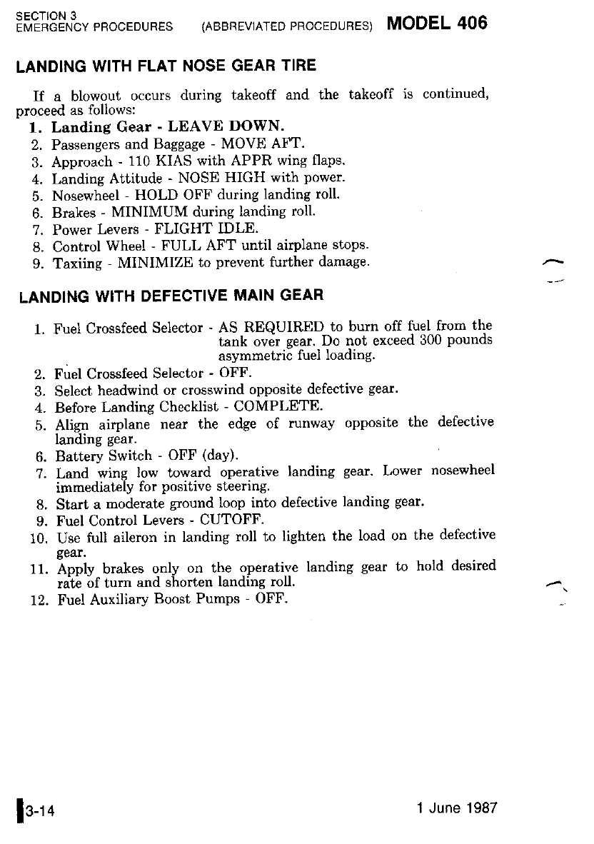
sEcTloN 3
EMEBGENCY PROCEDURES {ABBREVIATED PROCEDURES) MODEL 406
LANDING WITH FLAT NOSE GEAR TIRE
If a blowout occurs during takeoff and the takeoff is continued,
proceed as follows:
1. Landing Gear - LEAVE DOWN.
2. Passengers and Baggage - MOVE AFT.
3. Approach - 110 KIAS with APPR wing flaps.
4. Landing Attitude - NOSE HIGH with power.
5. Nosewheel - HOLD OFF during Ianding roll.
6. Brakes - MINIMUM during landing roll.
7. Power Levers - FLIGHT IDLE.
8. Control Wheel - FULL AFT until airplane stops.
9. Taxiing - MINIMIZE to prevent further damage.
LANDING WITH DEFECTIVE MAIN GEAR
1. Fuel Crossfeed Selector - AS REQUIRED to burn off tuel from the
tank over eear. Do not exceed 300 pounds
-lsYmmetrii fuel loading.
2. Fuel Crossfeed Selector - OFF.
3. Select headwind or crosswind opposite defective gear.
4. Before Landing Checklist - COMPLETE.
5. Align airplane near the edge of runway opposite the defective
landing gear.
6. Battery Switch - OFF (daY).
?. Land wing low toward operative landing gear. Lower nosewheel
immediately for positive steering.
8. Start a moderate ground loop into defective landing gear.
9. Fuel Control Levers - CUTOFF.
10. Use full aileron in landing roll to lighten the load on the defective
gear.
It. Apply, brakes only on the operative landing gear to hold desired
rate o[ turn and sborten landlng roll.
12. Fuel Auxiliary Boost Pumps - OFF.
ls-r +1 June 1987
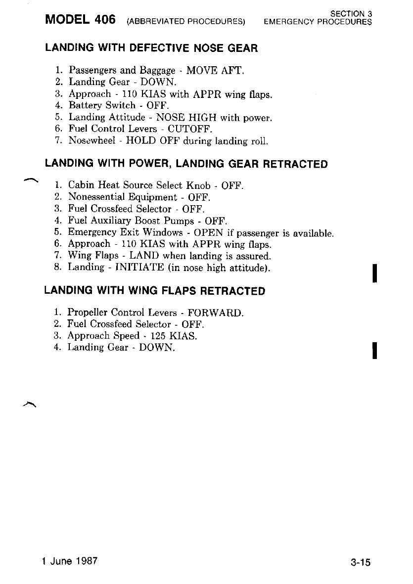
MODEL 406 lneenevrnrED pRocEDuRES) EMERGENcy e"353JLR3
LANDING WITH DEFECTIVE NOSE GEAR
1. Passengers and Baggage - MOVE AFT.
2. Landing Gear - DOWN.
3. Approach - 110 KIAS with APPR wing flaps.
4. Battery Switch - OFF.
5. Landing Attitude - NOSE HIGH with power.
6. Fuel Control Levers - CUTOFF.
7. Nosewheel - HOLD OFF during landing roll.
LANDING WITH POWER, LANDING GEAR RETRACTED
1. Cabin Heat Source Select Knob - OFF.
2. Nonessential Equipment - OFF.
3. Fuel Crossfeed Selector - OFF.
4. Fuel Auxiliary Boost Pumps - OFF.
5. Emergency Exit Windows - OPEN if passenger is available.
6. Approach - 110 KIAS with APPR wing flaps.
7. Wing Flaps - LAND when landing is assured.
8. Landing - INITIATE (in nose high attitude).
LANDING WITH WING FLAPS RETRACTED
1. Propeller Control Levers - FORWARD.
2. Fuel Crossfeed Selector - OFF.
3. Approach Speed - 125 KIAS.
4. Landing Gear - DOWN.
1 June 1987 3-15
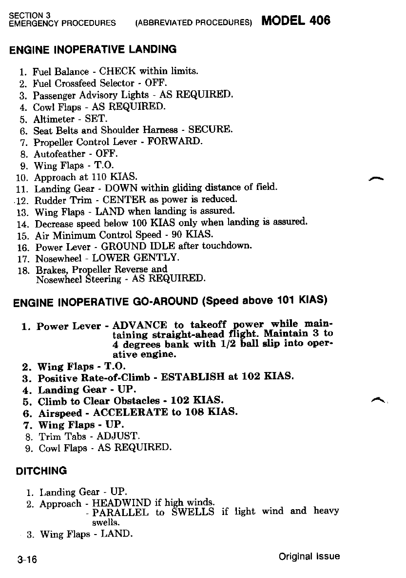
SECTION 3
EMERGENCY PROCEDURES (ABBREVIATED PROCEDURES) MODEL 406
ENGINE INOPERATIVE LANDING
1. Fuel Balance - CHECK within limits.
2. Fuel Crossfeed Selector - OFF'
3. Passenger Advisory Lights - AS REQUIRED.
4. Cowl Flaps - AS REQUIRID.
5. Altimeter - SET.
6. Seat Belts and Shoulder Hamess - SECURE'
?. Propeller Control Lever - FORWARD.
8. Autofeather - OFF.
9. Wing FIaPs - T.O.
10. Approach at 110 KIAS.
11. Landing Gear - DOWN within gliding distance of field.
.12. Rudder Trim - CENTER as power is reduced.
13. Wing Flaps - LAND when landing is assured'
14. Decrease speed below 100 KIAS only when landing is assued'
15. Air Minimurr Control Speed - 90 KIAS.
16. Power Lever - GROUND IDLE after touchdown.
17. Nosewheel - LOWER GENTLY.
18. Brakes. Propeller Reverse and
Nosewheel Steering - AS REQUIRED.
ENGINE INOPERATIVE GO-AROUND (Speed above 101 KIAS)
1. Power Lever - ADVANCE to takeoff ,power- -while main'
taining straiSht-ahead fligh!. Mailtain 3 to
4 degr-eeg bank with U2 ball elip into oper'
ative engine.
2. Wing Flaps - T.O.
3. Positive Rate-of-Climb - ESTABLISH at 1O2 KIAS'
4. Landing Gear - UP.
6. Climb to Clear Obstacles ' 1O2 KIAS.
6. Airspeed - ACCELERATE to 1O8 KIAS.
7. Wing FlaPs - UP.
8. Trim Tabs - ADJUST.
9. Cowl Flaps - AS R"EQUIR.ED'
DITCHING
1. Landing Gear - UP.
2. Approach - HEADWIND if high winds.
- PARALLEL to SWELLS if light wind and heavv
swells.
3. Wing Flaps - LAND.
3-16 Original lssue
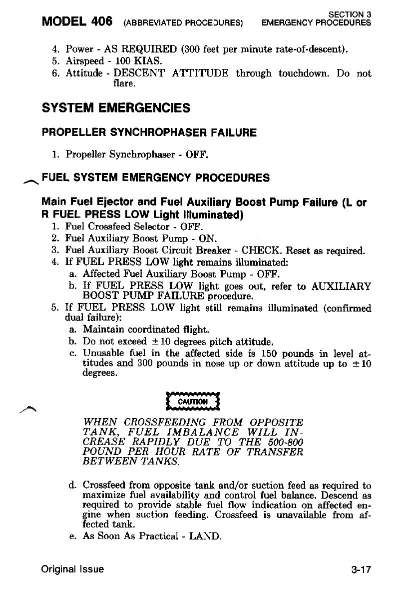
MODEL 406 lneensvrrrED pRooEDURES) EMERGENcy r"o""tFJL?.S
4. Power - AS REQUIRED (300 feet per minute rate-of-descent).
5. Airspeed - 100 KIAS.
6. Attitude - DESCENT ATTITUDE throush touchdown. Do not
flare.
SYSTEM EMERGENCIES
PROPELLER SYNCHROPHASER FAILURE
l. Propeller Synchrophaser - OFF.
. FUEL SYSTEM EMERGENCY PROCEDURES
Main Fuel Eiector and Fuel Auxiliary Boost Pump Failure (L or
R FUEL PRESS LOW Light llluminated)
1. Fuel Crosefeed Selector - OFF.
2. Fuel Auxiliary Boost Pump - ON.
3. Fuel Auxiliary Boost Circuit Breaker - CHECK. Reset as requted.
4. If FUEL PRESS LOW light rernains illuminated:
a. Affected Fuel Auxiliary Boost Pump - OFF.
b. If FUEL PRESS LOW lisht soes out, refer to ATIXILIARY
BOOST PUMP FAILURE procidure.
5. If FUEL PRESS LOW light still remains i uminated (confirmed
dual failure):
a. Maintain coordinated flight.
b. Do not exceed a 10 degrees pitch attitude.
c. Unusable fuel in the affectcd side is 150 pounds ir level at-
titudes and 300 pounds in nose up or down attitude up to + 10
oegTees.
WHEN CROSSFEEDING FROM OPPOSITE
TANK, FUEL IMBALANCE WILL IN-
CREASE RAPIDLY DUE TO THE 5OO-8OO
POUND PER HOUR RATE OF ?R/TNSFER
BETWEEN TANKS.
d. Crossfeed from opposite tank and/or suction feed as required to
maximize fuel availabilitv and control fuel balance. Descend as
required to provide stabie fuel flow indication on affected en-
gine when suction feeding. Crossfeed is unavailable from af-
fected tank.
e. As Soon As Practical - LAND.
Original lssue 3-17
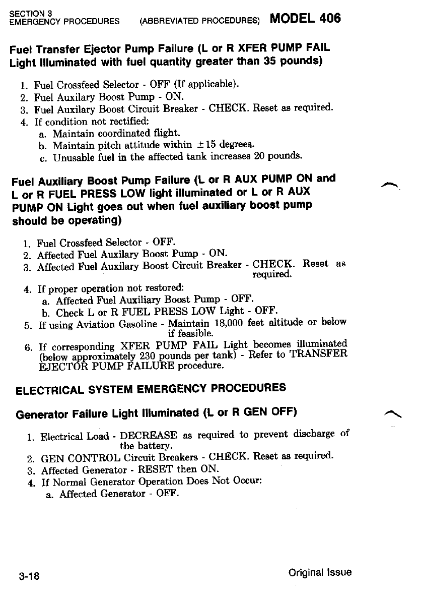
SECTION 3
EMERGENCY PROCEDURES (ABBREVIATED PROCEDURES) MODEL 406
Fuel Transter Eiector Pump Failure (L or R XFER PUMP FAIL
Light llluminated with fuel quantity greater than 35 pounds)
1. Fuel Crossfeed Selector - OFF (If applicable).
2. Fuel Auxilary Boost PumP - ON.
3. Fuel Auxilary Boost Circuit Breaker - CHECK' Reset as required'
4. If condition not rectified:
a. Maintain coordinated flight.
b. Maintain pitch attitude within t15 degrees.
c. Unusable fuel in the affected tank increases 20 pounds'
Fuel Auxiliary Boost Pump Failute (L or R AUX PUMP ON and
L or R FUEL PRESS LOW light illuminated or L or R AUx
PUMP ON Light goes out when fuel auxiliary boost pump
should be operating)
1. Fuel Crossfeed Selector - OFF.
2. Affected Fuel Auxilary Boost Pump - ON'
3. Affected Fuel Auxilary Boost Circuit Breaker ' :"1":rS Reset as
4. If proper operation not restored:
a. Affected Fuel Auxitiary Boost Pump - OFF'
b. Check L or R FUEL PRESS LOW Light - OFF'
5. If using Aviation Gasoline - Maintain 18,000 feet altitude or below
if feasible.
6. If corresponding XFER PUMP FAIL Light-becones lluminated
" ?i,"iJt" "iJtiiifrttelv z3o pounds per tankl - Rcfer to TRANSFER
EJECTOR PUMP FAILURE procedure'
ELECTRICAL SYSTEM EMERGENCY PROCEDURES
Generator Failure Light llluminated (L or R GEN OFF)
1. Electrical load - DECREASE as required to prevent discharge of
the batterY.
2. GEN CONTROL Circuit Breakers - CHECK' Rcset as required'
3. Affected Generator - RESET then ON.
4. If Normal Generator Operation Does Not Occur:
a. Affected Generator - OFF.
3-18 Original lssue
MODEL 406 leaenevrerED 'RocEDURES) EMERGENcv rr353J|l?13
Engine Start Light Remains llluminated After Engine St?t (L or
R START)
1. Battery Switch - OFF.
2. Auxiliary Power Unit - DISCONNECT (If connected).
3. Fuel Control Lever - CUTOFF.
4. Engine Shutdown - COMPLETE.
Battery Overheat Light llluminated (BATT O'HEAT)
If Light Illuminates Continuously:
1. Battery Switch - OFF.
2. Left Ammeter - CHECK while holding BATT/L GEN switch in
^ BATT position.
a. If anmeter shows zero indication:
(f) Light should extinguish.
b. If anmeter shows up scale indication:
(1) Generators - OFF.
(2) All Electrical Systern Switches - OFT.
(3) After 5 minutes:
(a) Either Generator - ON.
(b) I*ft Ammeter - CHECK while holding BATT/I, GEN
switch in BAT'T position.
1) If ammeter shows up scale indication:
a) Generator - OFF.
2) If ammeter shows zero indication:
a) Generators - ON.
b) Reinstate electrical syst€ms as required.
c) Monitor overheat lights.
3. As Soon As Practical - LAND.
If Light Begins Flashing:
1. Battery Switch - CHECK OFF.
2. Generators - OFF.
3. All Electrical Systems Switches - OFF.
4. After 5 Minutes:
a. Either Generator - ON.
b. Left Ammeter - CHECK while holding BATT/L GEN switch
in BATT position.
(1) If ammeter shows up scale indication:
(a) Generator - OFF.
(2) If ammeter shows zero indication:
(a) Generators - ON.
(b) Reinstate electrical systems as required.
(c) Monitor overheat lights.
5. As Soon As Practical - LAND.
Original lssue g-19
Pnffiir$t pRocEDURES (ABBREVTATED PRocEDURES) MODEL 406
Inverter Failure Light llluminated (AC FAIL)
1. If Optional Dual Inverter Installed:
a. Inverter Switch - Select other inverter'
HYDRAULIC SYSTEMS EMERGENCIES
Hydraulic Pressure Light llluminated Aftel Wing Flaps or
linOing Gear Retraction or Extension (HYD PRESS ON)
1. AirsPeed - 130 KIAS or less'
2. LDG GEAR and FLAP CONTROL
" 5ii"ti"Ci."'"t'Et"ii..t - -CvciE to determine which svstem is
causing the malfunction.
3. Landing Gear and/or Wing Flap -switch RAPIDLY RECYCLE'
;. i{ itch; Fails to go out and Wing Flaps are Causing the Maltunc-
t10n:
-".--Wi"g Flaps Switch - MOVE slightly away from selected posi-
11()n.
b. If Light Rernains Illuminated:
(l) Wing Flaps Switch - SELECT desired position'
(2) FLAP CONTROL SYstem
'-' bi."oit -St"aL". - piiii "fttt wing flaps reach desired posi-
5. If Light Fails to go Out and Landing Gear is Causing the Maltunc-
tion:
a. Landing Gear Switch - RAPIDLY RECYCLE'
b. If Light Remains Illuminated:
(1) iandine Gear Switch - SELECT desired position'
(2) LDG GEAR SYstem
'-' ci.*i[ g."ul"i -'-iUl,l "tt"t landing gear reaches desired
posrf,]on.
6. Before Landing - RESET applicable circuit breaker'
Landing Gear Down And Locked Light llluminated With Geal
Handle UP And HYd Press Light Out
1. Perform "LANDING GEAR WILL NOT EXTEND HYDRAULI-
CALLY" Procedure in this section'
3-20 Original lssue
MODEL 406 lnaenevrrrEDpRocEDuRES) EMERGEN.vt"ot"tEJL?.S
Landing Gear Will Not Extend Hydraulically
1 Ainpeed - 130 KIAS or less.
2. Landing Gear Switch - DOWN.
3. LDG GEAR Systems Circuit Breaker - PULL.
4. Emergency Gear Extension T-Handle - PULL.
5. Gear Down Lights - ON; Unlocked Light - OFF.
6. If Main Gear Does Not Lock Down - YAW AIRPLANE. Airloads
will lock main eear down if
up locks have reliased.
7. Gear Warning Horn - CHECK.
8. As Soon As Practical - LAND.
Landing Gear Will Not Retract Hydraulically
1. Landing Gear Switch - DOWN.
2. Gear Down Lights - ON; Unlocked Light - OFT'.
3. Gear Warning Horn - CHECK.
4. As Soon As Practical - LAND.
ENVIRONMENTAL SYSTEMS EMERGENC]ES
Wing Overheat Light llluminated (L or R WING O'HEAT)
1. Audibly verifu bleed air flow is terminated.
2. If Doubt Exists Regarding Bleed Air Termination:
a. Cabin Heat Auto/Manual Control - MANUAL.
b. Cabin Manual Temperature Switrh - WARMER for 10 sec-
onos.
c. Cabin Heat Source
Selector - SELECT the affected engine monentarily. No heat
indicates the bleed air flow has been terminated.
3. If WING O'HEAT Light Does Not Go Out In TVo Minutes:
a. Affected Engine - SECURE (refer to Engine Securing Proce-
ourer.
b. Operative Engine - ADJUST.
c. Trim Tabs - ADJUST to maintain bank toward operative en-
glne.
d. Electrical Load - DECREASE if required to prevent batt€ry
discharge.
e, Fuel Crossfeed Selector
Selector - AS REQUIRED to maintain fuel balance. Do not
crossfeed if fire hazard exists.
f. As Soon As Practical - LAND.
3-21
Original lssue

:i?tJ3i^futpRocEDUREs (ABBREVTATEDPRocEouBES) MODEL406
Air Duct Overheat Light llluminated (AlR DUCT O'HEAT)
1. Tenperature Control Knob - MANUAL (Full counterclockwise)'
2. Manual Warmer/Cooler Switch - COOLER for approximately 15
seconog.
3. Ram Air Control - PUSH'
4. Cockpit/Cabin Air Control - PULL'
5. Cabin Air Defrost Knob - PULL.
6. If AIR DUCT O'IIEAT light does not go out in two minutes:
a. Cabin Heat Source Select Switch - OFF'
b. As Soon As Practical - LAND'
Bleed Air Contamination
1. Cabin Heat Source Select - OFF'
2. Ram Air Knob - Pull to Clear Cockpit'
i. d"Ui" Heat Source Select - LH then RH (tn isolate source)'
4. If air contanination continues:
a. If supplementary oxygen ie available:
(1) Oxygen Knob - PULL ON'
(2) Assure each occupant is using oxygen'
b. Srnoke Renoval Checklist - COMPLETE'
OXYGEN SYSTEM FAILURE OF INSTALLED)
1. Maintain altitude below 10'000 feet'
ICE PROTECTION SYSTEMS EMERGENCIES
Inadvertent lcing Encounter
1. Ignition Switches - ON.
z. Engine Inertial Separator Switches - BYPASS'
3. Pitot/Static Heat Switches - ON'
4. Stall Heat Switches - ON.
5. Propeller Deice Switches - ON.
o. Igpition Switches - OFF after 5 minutes operation'
?. Leave icing conditions as soon as possible'
3-22 Original lssue
MODEL 406 asenev^rED pRooEDURES) EMERGEN.v t*3"tiJlHS
Engine Inertial Separator System Failure
1 lnertial Separator - BYPASS (monitor Inertial Separator lights)
2. Check proper operation by noting torque drop and slight rise in
IT'T.
3. If Inertial Separator fails in
the NORMAL Mode - T\:rr,r.. ignition switches ON, and leave icing
condruona as soon as posslDle.
Pitot/Static System Failure
1. Pitot/Static Heat Switches - CHECK ON.
2. Pilot's and Copilot's Instruments - DETERMINE which instru-
ments are functioning nornally.
3. Complete flight on the operative instruments.
Propeller Oeice Failure
1. Propeller Control Lever - EXERCISE then return to CRUISE.
2. Propeller Ammeter - CHECK for proper operation by periodic fluc-
tuations within the green arc.
3. If ammeter reading is below the green arc, indicating the propeller
blades may not be deicing uniformly:
a. Propeller Deice Switch - OFF for affected propeller.
4. Leave icing conditions a8 soon as possible.
Boot Operation With One Engine Inoperative.
l. Power Lever - SET (above 65 percent \ dwing deice boot ac-
tuation.
AVIONICS BUS FAILURE
1. Applicable Avionics Bus Svititch Breaker - RESET after 3 minut€s.
2. If Switch Brealer Trips Again - OFF.
3. Determine which Avionics Systems are inoperative.
EMERGENCY EXITS
Emergency Exit Window Opening
1. Emergency Release Handle - ROTATE FORWARD.
2. Emergency Erit Window - PUSH OUT and UP until the uplock
brace holds the window open.
Original lssue 3-23
sEcTtoN 3
EMERGENCY PROCEDURES (ABBREVIATED PROCEDURES) MODEL 406
Cabin Door, Crew Door or Emergency Exit Not Secured Light
illuminared (DooR NoT LOCKED)
1. Airspeed - Reduce As Required.
2. Passenger Advisory Lights - As fuquired.
3. As Soon As Practical - LAND.
EMERGENCY LOCATOR TRANSMITTER RESCUE
PROCEDURES
Before Landing
1. VHF COM - SET 121.5 MHz or known ATC frequency and trans-
mit May Day calls for aggistance if time permits.
After Landing
1. Plug Bution - REMOVE (located on side of tailcone).
2. Emergency Locator Transmitt€r Switrh - ON.
After Rescue
1. Emergency Locator Transmitter Switch - OFF.
ENCODING ALTIMETER FAILURE (Wahing Flag Showing)
Encoding Altimetcr Failure (Waming Flag Showing)
1. ALT Circuit Breaker - CHECK IN.
2. If warning flag is still showing, use the standby barometric altim-
eter.
TRANSPONDER PROCEDURES FOR EMERGENCY SITUATIONS
Energency Signal Transmission
1. Function Switch - ON'
2. Reply-Code Selector Switches - SELECT Code ?700.
Loss-of-Communications Signal Transmission
1. Function Switch - ON.
2. Renl'.'-Code Selector
S*^ititt"" - SELECT Code ?700; WAIT 1 minute, THEN SELECT
Code ?600; WAIT f5 minutes. Repeat procedures at
same intervals for remainder of flight.
Hijacked Signal Transmission
1. Function Switch - ON.
2. Reply-Code Selector Switches - SELECT Code 7500.
3-24 Original lssue
MODEL 406 rneenEvrerEDpRocEDURES) sEcTloN 3
EMERGENCY PROCEDURES
TOTAL LOSS OF COMMUNICATIONS
In the event that the audio panel or a microphone malfunctions such
that COM operation cannot be performed on COM 1, COM 2 or COM 3,
proceed as follows:
1. Employ an altemate microphone.
If the Problem Continues:
2. Function Selector Switch - EMER COM. Speaker operation will be
inoperative in all modes.
3. Employ headsets.
4. Set the desired frequency on COM 1 and proceed with communica-
tion on that COM only.
5. Set receiver selector switches to HDST for receivers to be non-
itored (NAV, MKR, ADF or DME). A reduction in. normal am-
plitude will be experienced while operating in errergency mode.
If Communications Cannot Be Re-established
6. Refer to Transponder Procedures for Energency Situations.
7. Cornply with ATC proceduree for loss of comnunications.
ELECTRIC ELEVATOR TRIM RUNAWAY
l. Control Wheel - OVERPOWER as required.
2. AP/TRIM Disconnect Switch - DISCONNECT immediatelv.
3. Manual Elevator Trim - AS REQUIRED.
otE
After thz electric trim has been disconrncted
and the emergency is ouer, pulL th,e electrir trirn
(ELEV TRIAb c[rcuit brether' Do not attempt
to Llse the electric eleuator trin system' untiL
ground maintenance has been completed.
Original lssue 3-25
sEcTloN 3
EMERGENCY PROCEDURES (ABBREVIATEDPROCEDURES) MODEL 406
SPINS
Intentional spins are not permitted in this airplane. Should a spin
occur the following recovery procedures should be employed:
l. Power Levers - FLIGIIT IDLE.
2. Ailerons - NEUTRALIZE.
3. Rudiler - HOLD FULL RUDDER opposite the direction of
rotation.
4. Control Wheel - FORWARD BRISKLY, U2 turn of spin
after applylng full rudder.
6. Inboard Engine - INCREASE POWER to slow rotation. (If
Necessary).
After rotation has etopped:
6, Rudder - NEUTRALIZE.
7. Inboard Engine (If used) - DECREASE POWER to equaliz€
ensines.
8. Control Wheel - PULL to recover from resultant dive. Ap-
ply smooth steady control pressure.
3-26 Original lssue
AMPLIFIED EMERGENCY PROCEDURES
NOTE
A complete hnowhdge of the procedures set
t'orth in this section wilL enabLe the pilnt to cope
uLIn DATLOUS efiLergencrcs tlult can oe encoun-
tered; howeuer, thh does not dirninish the fort
thd the prirnary responsibility of the pilot b to
maintain control at all times. Good judgment
and. precise attion are essentiaL and can only be
deuebped, throu4h frequ.ent practi.ce of einer-
gency and simuLoted engine inoperatiDe proce-
\urds. The nilat must lisue a thorouah knoul-
edge of all irnergency proced.ures so tlhat in thz
euent of an emergency, reaction will be precise
and done with confidence. This is required so
the pilnt can cope uith the dernands of an emer-
Sency sttturtaon.
AIRSPEEDS FOR EMERGENCY OPERATIONS
The most critical time for an engine failure in a multi-engine airplane
is during a two or three second period late in the takeoff run while the
airplane is accelerating to Vt. A detailed knowledge of recommended one
engine inoperative airspeeds is essential for safe operation of the air-
plane.
The airspeed indicator is marked with a red radial at the air mini-
mum contrbl speed and a blue arc at the one engine inoperative best
rate-of-climb speed to facilitat€ instant recognition. The following para-
gr.aphs present a. detailed discussion of the problems associated with
arrprane emergencles.
MANEUVERING SPEED (V^)
Maneuvering speed becomes important when the airplane is approach-
ing maximum operating limit speed. Maneuvering speed of 162 KIAS at
gr6ss weight is ihe maiimum sieed at which app'iicition of full available
aerodynamic control will not overstress the airplane structure.
MAXIMUM GLIDING DISTANCE SPEED
In the event of both engines-failure condition, maximum gliding dis-
tance can be obtained by feathering both propellerr, and rnaintaining
approximately 125 KIAS with landing gear and wing flaps up at the
weight of 9360 pounds, refer to Figure 3-1.
MODEL 406 SECTION 3
EMERGENCY PROCEDURES
Original lssue 3-27
AtR M|N|MUM CONTROL SPEED (Vilca)
The multi-ensine airplane must reach the air minimum control speed
nf -gO- XnS beiore fuli control deflections can count€ract the adverse
i"ttitig "tJ v"*i"g tendencies associat€d with -one engine inoperative and
full n"ower operation on the other engine with wing flaps-in T'O' posi-
iion.'fnl" sdeed is indicated by a red iadial on the airspeed indicator'
ftotE
Buffet con be encountered os high-"as q5. KIAS,
uith airplane at maximunt takeofl weLEht and
the uind flnps in thc UP Position.
ONE ENGINE INOPERATIVE BEST RATE.OF-CLIMB SPEED
(Vvst)
The one ennne inoperative best rat€-of-climb speed. becomes ,impor-
tant when theri are no obstacles ahead on takeofl' or when rt rs dlnlcull
t"'*"irii"iri "i gain altitude in one-engine emergencies' The one engine
t"ii"?iilii'r*f .iL:o}-"ii-l speed is- 108 KIAs- with wing flaps^ and
i;ei;;-;;;t G ai sea level. Thi speed is indicated bv a blue arc 104 to
f08 KI-AS on the airspeed indicator'
The variations of wing flaps up, one engine - inop-erative best rate-
of-climb speed with altitude are shown in Sectron b' lor one- engrne
iri.Jilii"J u-*t "tititu p"*oi-u""", the wings should be banked 3 to 4
degiees toward the operative engine.
TAKEOFF DECISION SPEED (V1)
The taleoff decision speed is the airspeed-on tle ground at which' as
. r""rftii ""ein" Gitui"'ot other reasoni, a decision is made to continue
iili"iiriiini; itte takeoff. At speeds below V, the takeoff is. discontin-
ued. At speeds above V1 the takeoff is continued aa one engrne rnop-er-
;il'i;ff;ff:"v;1.-ge'KiAs u"a is the same speed as Vr for this
airplane.
TAKEOFF SAFETY SPEED (V,)
The takeoff safety speed is the speed at 50 feet above the runway
"".i""" *'J"rno"iliir"d' duting takeoir with one engine inoperative with
;i^#n"* in-lh" TO. po.itionl fh" on" engine inop-erative takeoff climb
*ii"i".1i-"iitt t""ai"g'e"* up are also speiified at this speed' v, is 102
KIAS.
SECTION 3
EMERGENCY PROCEDURES (AMPLIFIED PROCEDURES) MODEL 406
3-28 Original lssue
MODEL 406 (nr,,rpr-rrreoeRocEDUFES) sEcTroN 3
EMERGENCY PROCEDUBES
EMERGENCIES
Engine Failure
ENGINE FAILURE BEFORE V1 (Speed Below 98 KIAS)
l. Power Levers - GROUND IDLE,
2. Brakes and Nosewheel Steering - AS REQUIRED.
11r NAC-ESSAR Y, CAUTIOUSLY APPLY RE-
YERS/NG AS REQUIRED ON THE OPERAT-
ING ENGINE. TO MAIN'IAIN DINECTION-
AL CONTROL, THE REVERSE THRUST IS
COUNTERAC'IED BY OPPOSITE BRAKE
AND RUDDER. IF RUNWAY BRAKING AC.
TION IS LESS THAN NORMAL DUE TO
LOOSE GRAVEL, SOD SURFACE, SNOW,
ICE OR RAIN. CAREFUL MODULATION OF
POWER WILL BE REQUIRED TO MAIN.
TAIN DIRECTIONAL CONTROL.
If Airplane Cannot be Stopped in Remaining Runway:
3. Fuel Control Levers - CUTOFF.
4. Battery and Generators - OFF.
1{OTE
The distance required for the airplnne to be
accelerated frorn'a standing slarl to yr on the
ground, and to decelerate tb a stop with heavy
brakins. is presented in the Accelerate Stop Dis-
hnce eha* in Section 5 for various combina-
tions of conditions.
Original lssue 3-29
SECTION 3
EMERGENCY PROCEDURES (AMPLIFIED PROCEDURES) MODEL 406
ENGINE FAILURE AFTER Vl (Speed above 98 KIAS)
1. Aileron and Rutlder - AS REQUIRED to maintain straight
ahead flight (3 to 4 degrees bank
with U2 ball slip into operative en-
gine).
NOTE
Uncoordinated fLight in bank greater than 5
degrees will decrease the u,sable fuel.
2. Power - MONITOR.
3. Landing Gear - UP when rate-of-climb is positive.
4. Propeller - VERIFY feathered.
DO NOT RDDUCE EITHEN ENGINE'S
POWER LEVER BELOW TAKEOFF SI"T-
TING. TO DO SO WILL INACTIVATE
THE AUTOFEATHEN FEATURE.
5. Airspeed - MAINTAIN Vz to 4OO feet minimum, then in-
crease to 108 KIAS.
6. Wing Flaps - UP.
7. Trim Tabs - ADJUST.
After Reaching 1000 Feet Above Ground Level:
8. Inoperative Engine - SECURE. Refer to Engine Securing Proce-
oure.
DECISION TO ABORT TAKEOFF
l Landing Gear - CHECK DOWN. Gear Down Lights On.
2. Power Levers - FLIGIIT IDLE.
DO NOT RETARD POWER LEVERS BE-
LOW FLIGHT IDLE WHILE AIRBORNE,
3. Power Levera - GROUND IDLE after touchdown.
4. Brakes, Propeller Reverse
and Nosewheel Steering - AS REQUIRED.
J-OU Original lssue
IF NECESSARY, CAUTIOUSLY LP?LI_i.a:
iNNSN,IC AS REQUIRED ON THE OPEIIAT.
iNe rvemn. To MAINTAIN DIRECTIoN-
At cowrnor, rHE REuERSq rytRIlQT -{q.
CouNrnnecrn'D BY oPPosIrP qIAKF
Aun Einnm. IF RUNwAY BRAKIIIG AC
ilott ts ,Ess ?;IAN NoRMAI DU-P--Tq
4^ Lbbst cnnvtL, soD suRFAcE' F-t!qV'
ICn on nerN, :AREFUL MoDULATIoN PF
-p-ownn wILL BE REQUIRED To MAIN-
TAIN DIRECTION AL CONTROL.
To malie an intelligent decision in this type of emerg€ncy'.one, must
consider the field length, field elevation, air- temperature' headwrnd'
iil""o-n'"ile-ltf ;a obiiniction height. The- limitations. of one engine
;it;';";f;'il;;;-"tto*" in Section"5 should be revies'ed before takeoff'
Xi-*ir"iiii"it,ip *J- ""."tdi"t" gq distances are predicated on the^pilot
;;;;i;;*"ff ";site failure at" Vr' If the airp.lane has.alreadv lefl the
il;;;;f,;;; "'."tg"*v o""ut", it is normillv considered prudent to
;;;ii;'"" ii; t"t<eon i"teti" the d;teriorating nature of the emergencv
indicates that continued flight may become rmposslble'
If a decision is made to land, the pilot sholld rglize (l).the airplane
mav be as much as 12 knots below the sale l (J' I lap- settrng approacn
;;d ;A iij ttt"t the total distance -to complete the maneuver wrll
gi""tty """""d published accelerate stop distance
At sea level, standard day, witlr ze-ro wind and 93^60 pounds weight'
tr'"'ii.ii"""' i i l""J"."L #'gii'ii1nS-. L".a- "]:9n is 4228'feet' while lhe
;;;i;;;;;;;t",i'dishnce required to takeoff -and. climb^ ovei a 5o-foot
^ iili""r""iil";-; d;;; i"lG; "i ea 414s. is 3865 reet. rhis total
;i."fi;; ;;;; ";- "64;[ can be reduced slishtlv .under more favorable
;;;ei;i;";';i *"i+t, t""a;;ita, oi obstructidn.lieight Still hieher field
"i"?.:ti""" *iff "",i." 'ttt" *gin"' faltore tateoff- distance to lengt-hen until
ii,;' -rtltia; 'i'- -*"&;d-;#;;';;;;sstui tat'eor is impr.obible unless
;ii; ;i;;;;d ';"4-t Jisht "uou" the runwav at.ensne railure are sreat
"'ii,ri'r,"i.- ,tni; " .tlghr ae""t"iutio" and.aititude. loss while the airplane
i.-ili"" "1""""a up fo"r an engine inoperative climb'
MODEL 406 (nrapr-rrteoPRooEDUREs) SECTION 3
EMERGENCY PROCEDURES
If airplane cannot be stopped in remaining runway'
5. Fuel Control Levers - CUTOFF.
6. Battery and Generators - OFF.
Original lssue 3-31
SECTION 3
EMERGENCY PROCEDURES (AMPLIFIED PROCEDURES} MODEL 406
During a one engine inoperative takeoff over an obstacle, one con-
dition presents an appreciable advantage; this is headwind. A decrease of
approximately 5 percent in ground distance required to clear a 50-foot
obstacle can be eained for each 10 knots of headwind. Excessive speed
above one engind inoperative best rate-of-climb speed at engine failuie is
not nearly as advantageous as one might expect since deceleration is
rapid and ground distaice is used up qriickly it higher speeds while the
airplane is being cleaned up for climb. However, the extra speed is
important for controllability.
The following facts should be used as a guide at the time of engine
failure during takeoff: (1) altitude is more valuable to safety a-fter taleoff
than is airspeed in ercess of the one engine inoperative best rate-
of-climb spe6d since ercess airspeed is lost huch mbre rapidly than is
alt itude; (2) climb or continued level flight at moderate altitude is
improbable with the landing gear extended and the propeller winrtmil-
ling (3) in no case should the airspeed be allowed to fall below the
intentional one engine inoperative speed, even though altitude is lost,
since this speed dill always providi a better chanle of climb, or a
smaller altitude loss, than any lesser speed; and (4) if the requirement
for an immediate climb is not present, allow the airplane tn accelerat€ to ,
the one engine inoperative best rate-of-climb speed with wing flaps up as
this is the optimum clirnb speed and will always provide the best chance
of climb or least altitude loss.
THE PROPELLER ON THE INOPER.
ATIVE ENGINE MUST BE FEATHER.
ED, LANDING GEAR NETRACTED AND
WING FLAPS UP OR CONTINUED
FLIGHT MAY BE IMPOSSIBLE.
One engine inoperative procedures should be practiced to better pre-
pare the pilot for actual encine inoperative emergencies. The nilot should
be very fbmiliar with the location- of all controls neceasary io complete
an emirgency shutdown and the securing procedure. Practice procedures
are in Section 4.
ENGINE FAILURE lN FLIGHT (Speed Below Vrrc )
1, Power Levers - RETARD to stop turn.
xotE
Autofeather will be inactiuated. if engine still hos
oLL Dressure-
3-32 Original lssue
2. Aileron and Rudder - AS REQUIRED toward operative en-
gine td maintain straight-ahead
flight.
NORMALLY, THE BANK ANGLE RE.
OUIRED WILL BE 5 DEGREES OR
Ltss; nownvER, INcREASE THE
BANK ANGLE AS REQUIRED TO
MAI NTAI
N STRAIGHT- AH EAD F LIGHT.
3. Pitch Attitude - LOWER NOSE to accelerate above 9O
XIAS.
4. Accomplish procedures for Engine Failure in Flight (Speed above
Vuce).
ENGINE FAILURE lN FLIGHT (Speed above VHca)
1. Inoperative Engine - DETERMINE. Idle elgine-
idle foot; also, torque' ITT
will be low.
2. Inoperative Engine Power Lever'- RETARD.
3, Inoperative Engine Propeller - FEATIIER.
4. Operative Engine - ADJUST.
l{otE
Pouer aboue FLIGH'| IDLE mary be required' on
the operating engine to maintain Syro pressure
in th.e green arc-
6. Landing Gear - UP.
6. Airspeed - 1O8 KIAS minimum.
7. Wing FlaPs - UP.
8. If airsteri is waranted, refer to AIRSTART procedure this section'
AIRSTART 15 NO? NORMALLY RECOM-
MENDED IF REASON FOR FAILURE IS
UNKNOWN OR IF ENGINE STOPPAGE
WAS DUE TO A MALFUNCTION WHICH
COULD CREATE A HAZARDOUS SITUA-
TION IF A RESTART IS ATTEMPTED.
MODEL 406 lrtrerrrreo pRocEDUREs) sEcTloN 3
EMERGENCY PROCEDURES
aame aa
and N"
Original lssue 3-33
SECTION 3
EMERGENCY PROCEDURES (AMPLIFIED PROCEDURES) MODEL 406
9. If airstart is not warranted, refer to ENGINE SECURING proce-
dure this section.
BOTH ENGINES FAIL IN FLIGHT
llotE
OBy d.esign, the engines are totqlLy independent
of each other uith the exception of d.rauinE fuel
from the same tank d,uring crossfeeding. Fuel
starDation or contamination woul.d therefore be
sl6pect,
ODepend.ing upon the circumstances and. the
amount of auailnble aLtitude at the time of oc-
currence, the pilot may choose to configure the
airpLane for maximum gtide,and. attenpt.air-
storts, or he may prepare for an immediate
land.ing.
oElectrical Dower dDaildble uill be limited to the
arnount of inergy contained in the battery. Hy'
dlauLic gear operatinn mty not be auailable.
If Insufficient Altitude Exists to Permit Airstarts:
1. Refer to LANDING WITIIOUT POWER procedures.
If Sufficient Altitude Exists to Permit Airstarts:
1. Propellers - DO NOT FEATHER if airstari is attempt€d.
2. Airstarts - AT"TEMPT, refer to AIRSTART-STARTER ASSIST
procedures,
3. If Airstarts Fail:
a. Propellers - FEATHER.
b. Airspeed - 125 KIAS (refer to Figure 3-1 Maximum Glide).
c. Refer to LANDING WITHOUT POWER procedures.
M)TE
If time permits, aduise ATC and squawk 7700.
Passenger aduisory Lights shouLd be on and Loose
items in the cabin should be secured. Reuiew
the Emergency Exit Window Opening proce-
d.ures. Fasten seat belk and shoulder harnesses.
,J-O+ Original lssue
MODEL 406 leueurteo PRocEDUREs) SECTION 3
EMERGENCY PROCEDUBES
ENGINE SECURING PROCEDURE
l. Autofeather - OFF.
2, Power Lever - FLIGHT IDLE.
3. Propeller Control Lever - FEATHER'
4. Fuel Control Lever - CUTOFF,
5. Fuel Crossfeed Selector - OFF if fire hazard exists.
6. Fuel Auxiliary Boost Pump - OFF if fue hazard exists.
?. Cowl Flap - CLOSED.
8. Propeller Synchmphaser - OFF.
9. Generator - OFF.
+ 10. Elechical Load - REDUCE if necessary and MONITOR.
AIRSTART
STARTER ASSIST (Preferred Procedure)
THE PILOT SHOULD DEI:ERMINE THE
REASON FOR ENGINE FAILURE BEFONE
ATTEMPTING AN AIRS?ART.
Electrical Load - REDUCE.
Air Conditioner - OFF.
Windshield Antilce - OFF.
Autofeather - OFF.
Power Lever - One inch forward of FLIGHT IDLE.
Propeller Control Lever - Forward of FEATHER.
Fuel Control Lever - CUTOFF.
Fuel Quantity - CHECK.
Fuel Crossfeed Selector - OFF.
Fuel Auxiliary Boost Pump - ON.
Inoperative Engine Generator - OFF.
Operative Engine - REDUCE IT"T to 650 degrees if practical.
Airspeed - 100 KIAS minimum.
Altitude - 20,000 feet maximum.
Start Switch - START; Check ignition light on.
Fuel Control Lever - RUN above 12 percent Ns .
I.
2.
3.
o.
6.
7.
8.
9.
10.
11.
12.
13.
74.
15.
16.
Original lssue 3-35
SECTION 3
EMERGENCY PROCEDURES (AMPLIFIED PROCEDURES) MODEL 406
l?. ITT and Ns - MONITOR (1090 degrees Celsius maximum)
IIOTE
If rise in N" and ITT are not indicated within
lb seconds, "place fuel control lever to CUTOFF
and abort start. Refer to ENGINE SECURING
CHECKLIST. Fuel control may be periodically
moved to CUTOFF then back to RUN if over-
t€mperature tendencies are encountered.
18. Start Switch - OFF Nr 52 percent or above'
19. Fuel Auxiliary Boost Pump - OFF MOMENTARILY, then NOR-
MAL.
20. Propeller Control Lever - AS DESIRED.
21. Power Lever - AS DESIRED.
22. Generator - ON.
orE
After bei.ng reset, generators may take up to 15
secorxts to come on arne.
23. Electrical Equipment - AS R.EQUIRED'
NO STARTER ASSIST
THE PILOT SHOULD DETERMINE THE
J?EASON FOR ENGINE FAILURE BEFORE
ATTEMPTING AN AIRSTART.
1. Autofeather - OFF.
2. Power Lever - One inch forward of FLIGHT IDLE.
3. Propeller Control Lever - Forward of FEATI{ER.
4. Fuei Control Lever - CUTOFF
5. Fuel Quantity - CHECK.
6. Fuel Crossfeed Selector - OFF.
7. Fuel Auxiliary Boost Purnp - ON.
8. Inoperative Engine Generatnr - OFF.
9. Ignition Switch - ON, check light on.
10. Airspeed - 100 KIAS minimum (140 KIAS if feathered).
11. Altitude - 20,000 feet maximum (15,000 feet if feathered).
3-36 Original lssue
MODEL 406 autpueteo PRooEDURES) SECTION 3
EMERGENCY PROCEDURES
72. Fuel Control Lever - RUN (After N, stabilizes)'
ITT and Ns - MONITOR (1090 degrees Celsius maximum)
M'TE
Olf rise in N, and ITT are not indicated within
10'seconds, place fuel control lever to CUTOFF
and abort start. Refer to ENGINE SECURING
CHECKLIST.
aEmerEencv airstdrts nTdv be attempted below
I0 perient-N" and outside the normal airspeed
env'elope, but'ITT should be closely monitored.
Fuel cbntrol lever may be periodically moved to
CUTOFF then back to RUN if overtemperature
tendencies are encountered.
ODo not attempt o.n air start with 0 percent N,
Ignition Switch - NORMAL after N. stabilizes above 52 percent.
Power Control Lever - AS DESIRED.
Power kver - AS DESIRED.
Generator - ON.
l{otE
After being rcset, generators nay tdke up to 15
seconds to come on line.
Electrical Equipment - AS R.EQUIRED.
Fuel Auxiliary Boost Pump - OFF momentarily' then NORMAL.
NOTE
1/ N, ha9 not dropped-.below 50 Percent on flane
out, an immedrate rehght may b€ afl,€mpteo Dy
retarding the power lever tn flight idle and tum-
ing on the ignitors. Do not 8tt€mpt_an air start
if the engine stoppage was cauaed by a known
engine m-alfunction which might make an at'
te mpted relight dangerous.
74.
to.
lb.
77.
18.
19.
Original lssue 3-37
sEcroN 3
ETvTCNOETCV PROCEDURES (AMPLIFIED PROCEDURES) MODEL 406
SMOKE AND FIRE
ENGINE FIRE DURING GROUND OPERATIONS (Sutficient
Runway Remaining to Stop)
l Power Levers - GROUND IDLE.
2. Brakes - AS REQUIRED,
3. Fuel Control Levers - CUTOFF.
4. Fuel Crossfeed Selector - OFF.
5. Illuninated Fire Warnine
Lieht - PUSH to disable the senerator, close the bleed air firewall
- and tuel shutoff valves and ARM fire bottle (if installed).
6. Illuminated Fire Extinguisher
Armed Light - PUSH (if installed).
?. Emergency Assist€nce - REQUEST (if warranted).
8. Battery Switch - OFF.
9. As Soon As Practical - EVACUATE.
CABIN FIRE DURING GROUND OPERATIONS
1. Power Levers - GROUND IDLE.
2. Brakes - AS REQUIRED.
3. Fuel Control Levers - CUTOFF.
4. Ernergency Assistance - REQUEST (if wananted).
5. Battery Switch - OFF.
6. Portable Fire Extinguisher - USE as required.
7. As Soon As Practical - EVACUATE.
INFLIGHT WING OR ENGINE FIRE
1, Power Lever Affected Engine - FLIGHT IDLE.
2, Propeller Control Lever Affected Engine - FEATIIER.
3, Fuel Control Lever Affected Engine - CUTOFF.
4. Fuel Auxiliary Boost Pump Affected Engine - OFF.
5. Illuminated Fire Warning
Light - PUSH to disable the generator, close the bleed air
firewall and fuel shutoff valves and ARM fire bot-
tle (if installed).
6. Illuminated Fire Bottle Light - PUSH (if installed).
M'TE
Power aboue FLIGHT IDLE may be required on
the operating engine to maintain gyro pressure
Ln tne Ereetu arc.
3-38 Original lssue
sEcTloN 3
MODEL406 (nr',rprrrreopRooEDURES) EMERGENoYpnoceounes
7. Fuel Crossfeed Selector - OFF.
8. Engine Securing Procedure - COMPLETE.
9. As Soon As Practical - LAND and EVACUATE'
INFLIGHT CABIN ELECTRICAL FIRE OR SMOKE
OPENING THE POUL WEATHER WIN-
DOWS OR EMERGENCY EXIT WINDOW
WILL CREATE A DRAFT IN THE CABIN
AND MAY IN?ENSIFY A FIRE,
If Source Is Known:
1. Oxygen - Use as required (If installed).
2. Faulty EquiPrnent - OFF.
3. Fire - EXTINCUISH.
4. Smoke Removal Procedure - INITIATE if warrsnted'
5. As Soon As Practical - LAND'
If Source of Fire or Smoke is Unknown:
1. Oxygen - USE as required (if insteled).
2. Nonessential Equipment - OFF.
3. Smoke Removal Procedure - INITIATE if warranted'
4. If fire or smoke ceases, land as soon alt practical.
5. If fire or smoke Persists:
a. Fuel Crossfeed Selector - OFF.
b. Battery and Generators - OFF.
M)IE
Without electrical power all electrically operated
pvros and eng.ine instruments, fuel boost purnps,
innunciator.-Li4hts,. wing flaps, nor,mal landing
pear er,tensnn and aLl aDlonlcs ulu oe rnoper-
a|u)e.
c. Fire - EXTINGUISH'
6. If fire or smoke still persists, land as soon as possible'
7. If fire or smoke decreases and if possible, maintain WR and land
as soon af] Practical.
Original lssue 3-39
SECTION 3
EMERGENCY PROCEOUBES (AMPLIFIED PROCEDURES) MODEL 406
8. If unable to rnaintain VFR:
a. Circuit Breakers - PULL.
b. Battery - ON.
c. Generators - ON one at a tirne.
d. Essential Circuit Breakers - PUSH one at a time; then, paus€
to check for evidence of smoke,
e. Faulty Equipment - OFF.
f. Fire - EXTINGUISH.
g. Unaffected Essential Equipment - AS REQUIRED.
9. As Soon As Practical - LAND.
SMOKE REMOVAL
1. Source of Smoke - IDENTIFY and ELIMINATE.
2. Cabin Divider Curtain - OPEN IIf ingtalled).
3. Use of Supplemental Oxygen - AS R.EQUIRED (If installed).
4. If Source of Smoke Cannot be Eliminated:
a. Emergency Descent - INITIATE (as required).
b. Cabin Air Controls - PULL Ran Air Control Knob, PUSH
knob if intensity of smoke increases.
5. As Soon As Practical - LAND.
SUPPLEMENTARY INFORMATION CONCERNING AIRPLANE
FIRES
With the use of modern installation techniques and material, the
probability of an airplane fire occuring in your airplane is extremely
iemote. However, in the event a fire is encountered, the following
information will be helpful in dealing with the emergency as quickly and
safely as possible.
The preflight checklist is provided to aid the pilot in detecting con-
ditions fohicli could contributi to an airplane fire. As a frre requires both
fuel and an ignition source,,close preflight inspection should -be giv_en to
the engine compartment and wing leading edge and lower surlaces. Leakg
in the"fuel system, oil system, or exhaust systcm can lead to a ground or
inflight fire.
NOTE
Flight shouJd not be attempted with known fuel,
oiL or exhaust leahs. The prnence of fuel, un'
usuaL oil or exhaust stdins mq/ be an indication
of systern leahs and shouLrJ be corrected prior to
flisht.
3-40 Original lssue
MODEL 406 rruprrrreo PRocEDURES) SECTION 3
EMERGENCY PROCEDURES
If an aimlane fire is discovered on the ground or during takeoff' but
pri.r to "oi"-iited flight, the airplane is -to be landed and/or stopped
and the passengers and crew evacuat€d as goon as pracucal.
Fires originating in flight must be controlled alquickly as possible in
an attempito prevent maior structural damage. The fuel boost pumps'
on applicable eirgine. should be turned off and. the.emergency.crcssteed
sei"it i. to OFF io reduce pnesssure on the total fuel s-ystem. The engine
on the wing in which the -fue exists should be shut down and the F/W
.h"i"ff .*ii"tt activated even though the fiue may not have originlt€d in
the fuel system. Descent for landing should be initiat€d immediat€ly'
Onenine the emergency exit or foul weather windows produces low
presiure ii cabin. Td av6id drawing th9 fiIg intg the cabin, the. emer-
^ ^gency exit and foul weather windows should. be kept closed' This con-
&iiioit i. ugg.ruut"d with the landing gear -and - {laps extcnded. Therefore,
inii pit t st"ould lower the landing geli as late in i-he landing approach as
possible. A no wing flap landi::g should also be attempted if practical.
Fire or smoke in the cabin should be controlled by identifoing and
shuttins down the faultv svsten. Normally the bleed air system wilt
remove-smoke from the cabin; however, if the smoke is intense, it may
be necessarv to initiate the bleed air contamination procedrrre presented
in this section. When the smoke is intense, the pilot may choose to *pel
itt" *-ote through the foul weather windows. The foul weather windows
"tro"tJ U" closed"immediatcly if the frre becomes nore intense when the
windows are opened.
EMERGENCY DESCENT
PREFERRED PROCEDURE
1. Power Levers - FLIGHT IDLE.
2. Propeller Control Levers - FORWARD.
3. Wing Flape - UP.
^ 4. Landing Gear - UP.
6. Airspeed - 229 KIAS/O.62 Mach.
IN TURBULENT ATMOSPHERIC CONDITIONS
l. Power Levers - FLIGIIT IDLE.
2, Propeller Control Levers ' FORWARD.
3. Wing Flaps - APPR below 2OO KIAS.
4. Landing Gear - DOWN.
6. Wing Flaps - LAND below 180 KIAS.
6. Airspeed - 18O KIAS.
Original lssue 3-41
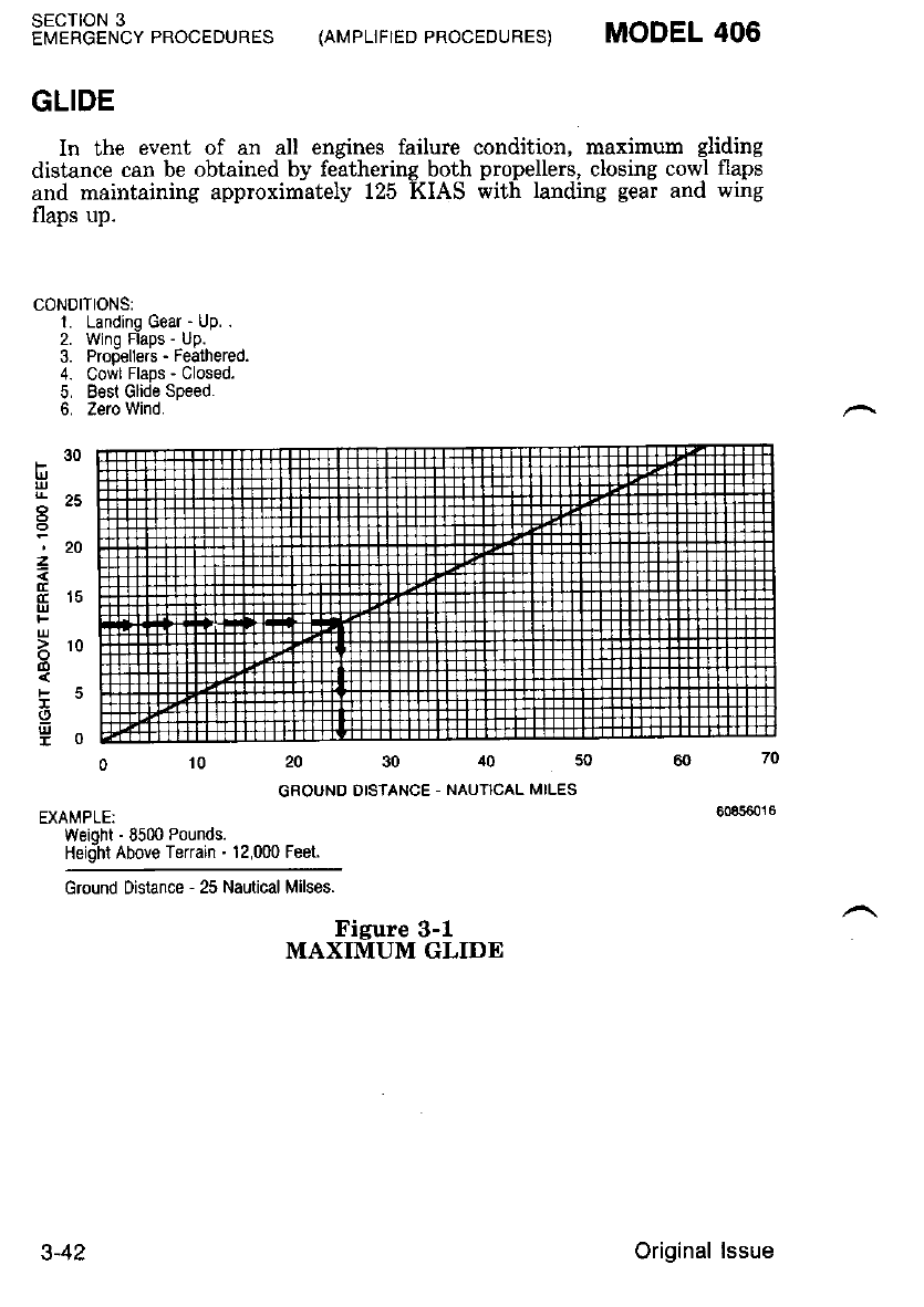
GLIDE
In the event of an all engines failure condition, maximum gliding
distance can be obtained by feathering both propellers, closing cowl flaps
and maintaining approximately 125 KIAS with landing g€ar and wing
flaps up.
CONOITIONS:
1. Landing Gear - tjp. .
2. Winq FlaDs - up.
3. Prodeller's - Feathered.
4. Cowl Flaps - Closed.
5. B€sl Glide Spe€d.
6. Zero Wind.
010203040
GROUND DISTANCE - NAUTICAL MILES
EXAMPLE:
Weioht - 8500 Pounds.
Heidht Above Terrain - 12,000 Feet.
30
F
t5
'20
1
Ers
o-
tD
i-
I
SECTION 3
EMERGENCY PROCEDURES
Ground Drstance - 25 Nautical Milses.
{AMPLIFIED PROCEDURES) MODEL 406
Figure 3-1
MAXIMUM GLIDE
3-42 Original lssue
MODEL 406 (nr',rplrrreo pRocEDUREs) SECTION 3
EMERGENCY PROCEDURES
LANDING EMERGENCIES
Any time the pilot is faced with a precautionary or forced landing, or
nne tihere landiirg gear abnormalitiei are present, he must make de-
cisions based on the circumstances present and his complete understand-
ing of the airplane.
Of a general nature, in the case of forced landings, the following
should be-considered prior to landing. First. selec[ a suitable landing site.
Airplane control enroute must be riaintained regardless of the distrac-
tions present. If time permits, advise ATC and squawk 7?00. Passenger
advisory lights should be on and loose items in the cabin should be
secured. Review the Emergency Exit Procedures and secure seat belts
aand shoulder harnesses.
PRECAUTIONARY OR FORCED LANDING WITH POWER
l. Landing Site - CHECK. Fly over site 120 KIAS with APPR flaps.
2. Landing Gear - DOWN or UP (at pilot's discretion).
3. Cabin Heat Source Select - OFF.
4. Nonessential Equipment - OFF.
5. Fuel Crossfeed Selector - OFF.
6. Fuel Auxiliary Boost Pumps - OFF.
?. Emergency Exit Windows - OPEN if passenger is available.
8. Landing - INITIATE (in nose high attitude).
a. Fuel Control Levers - CUTOFF after touchdown.
b. Battery - OFF.
LANDING WITHOUT POWER
1. Flaps - Approach (When Landing Site is Assured).
a. Fuel Control Levers - CUTOFF.
b. Wing Flaps - APPR.
c. Starter Switch - MOTOR. OFF after wing flaps reach the
APPR position.
2. Engine Securing Procedure - COMPLETE.
3. Nonessential Equipment - OFF.
4. Fuel Crossfeed Selector - OFF.
5. Landing Gear - DOWN (The pilot may elect to land gear up
depending on terrain).
a. Landing Gear Switch - DOWN.
b. LDG GEAR System Circuit Breaker - PULL.
c. Emergency Gear Extension T-Handle - PULL below 130
KIAS, within glid-
ins distance of field.
1 June 1987 3-43

SECTION 3
EMERGENCY PROCEDURES (AI'PLIFIED PROCEDURES) MODEL 406
6. Battery Switch - OFF (Day).
7. Emergency Exit Windows - OPEN if passenger is available.
8. Approach 110 KIAS with APPR FLAPS (125 KIAS with
0oflaos).
9. Landing - INITIATE (in nose high attitude).
LANDING WITH FLAT MAIN GEAR TIRE
If a blowout occurs during takeoff and the takeoff is continued,
proceed as follows:
1. Landing Gear - LEAVE DOWN.
I{OTE
Do not attempt to retract the landing gear if a
main aear tire bLowout occurs. The main gear
tire iay be d.istorted enough to bind the main
eear stiut within the wheel uell and preuent
hter extension.
2. Fuel Crossfeed Selector - CROSSFEED AS REQUIRED to burn
off fuel from the tank over the defective
tire. Do not exceed 300 pounds asymmet-
ric fuel loading.
NOTE
Fuel should. be used from this tank first, to
liehten the load on the wing, prior to attemptine
a- Iand.ing il inflight time permits. Howeuer, an
adequate.suppiy of .fuel should. be- left. in this
tanh so lhat 11 may be used during landing.
Fuel Crossfeed Selector - OFF.
If a crosswind landing is required, select a runway with a crosswind
from the side opposite the defective tire.
Before Landing Checklist - COMPLETE.
In approach, align aimlane with edge of runway opposite the defec-
tive iire, allowing room for a mild turn in the landing roll.
Land slightly wing-low on the side of inflated tire and lower
nosewheel for positive steering.
Use full aileron in landing roll to lighten load on defective tire.
3.
A
t),
7.
8.
3-44 1 June 1987
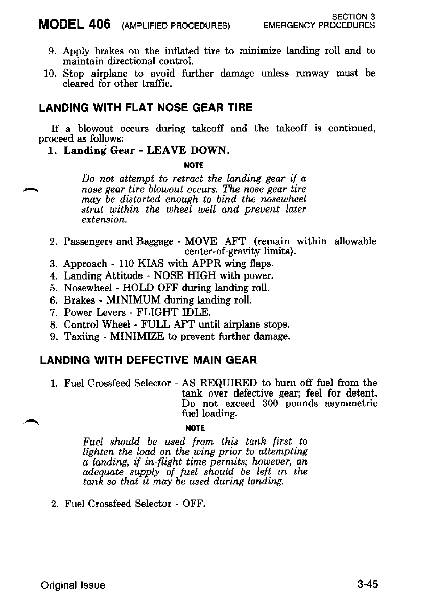
MODEL 406 (rvpuneo PRocEDURES) SECTION 3
EMERGENCY PROCEDURES
9. Apply brakes on the inllated tire to minimize landing roll and to
maintain directional control.
10. Stop airplane to avoid further damage unless runway must be
cleared for other traffic.
LANDING WITH FLAT NOSE GEAR TIRE
If a blowout occurs during takeoff and the takeoff is continued,
proceed as follows:
1. Landing Gear - LEAVE DOWN.
l{olE
Do not attempt to retrdct the LanrLing gear if a
nose Eear tire blnuout occurs. Thc nose gear tire
may be distorted, enough to bind thc noseuhee|
strut within the wheel welL and preuent Later
extension.
2' Passensers and Baggage lSSJrt r$$,#:n"l*,.within allowable
3. Approach - 110 KIAS with APPR wing flaps.
4. Landing Attitude - NOSE HIGH with power.
5. Nosewheel - HOLD OFF during landing roll.
6. Brakes - MINIMUM during landing roll.
7. Power t evers - FLIGHT IDLE.
8. Control Wheel - FULL AFT until airplane stops.
9. Taxiing - MINIMIZE to prevent further damage.
LANDING WITH DEFECTIVE MAIN GEAR
1. Fuel Crossfeed Selector - AS REQUIRED to burn off fuel from the
tank over defective gear; feel for detent.
Do not exceed 300 pounds aslnnmetric
fuel loading.
IIOTE
Fuel shnul.d be used from thi.s tank first to
lighten the lnad on the wing prior to attempting
a landing, if in-flight time permits; howeuer, an
adequate supply ol fu.eL shoul.d be left in the
tank so that it may be used during landing.
2. Fuel Crossfeed Selector - OFF.
3-45
Original lssue
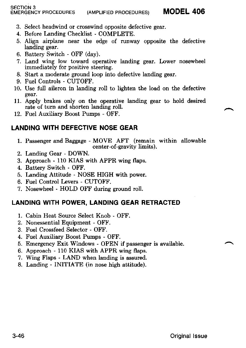
SECTION 3
EnrEneEr'rtypRocEDuREs (AMpLTFTEDpRocEDURES) MODEL406
3. Select headwind or crosswind opposite defective gear.
4. Before Landing Checklist - COMPLETE.
5. Align airplane near the edge of runway opposite the defective
landing gear.
6. Battery Switch - OFF (day).
?. Land wing low toward operative landing gear. Lower nosewheel
immediately for positive sleering.
8. Start a moderate ground loop into defective landing gear.
9. Fuel Controls - CUTOFF.
10. Use full aileron in landing roll to lighten the load on the defective
gear.
11. Apply brales only on the operative landing gear to hold desired
rate of turn and shorten landing roll.
12. Fuel Auxiliary Boost Pumps - OFF.
LAND]NG WITH DEFECTIVE NOSE GEAR
1. Passenger and Baggage - MOVE AFT (remain within allowable
center-of-gravity limits).
2. Landing Gear - DOWN.
3. Approach - 110 KIAS with APPR wing flaps.
4. Batt€ry Switch - OFF.
5. Landing Attitude - NOSE HIGH with power.
6. Fuel Control Levers - CUTOFF.
7. Nosewheel - HOLD OFF during ground roll.
LANDING WITH POWER, LANDING GEAR RETRACTED
1, Cabin Heat Source Select Knob - OFF.
2. Nonessential Equipment - OFF.
3. Fuel Crossfeed Selector - OFF.
4. Fuel Auxiliary Boost Pumps - OFF.
5. Emergency Exit Windows - OPEN if passenger is available.
6. Approach - 110 KIAS with APPR wing flaps.
7. Wing Flaps - LAND when landing is assured.
8. Landing - INITIATE (in nose high attitude).
3-46 Original lssue
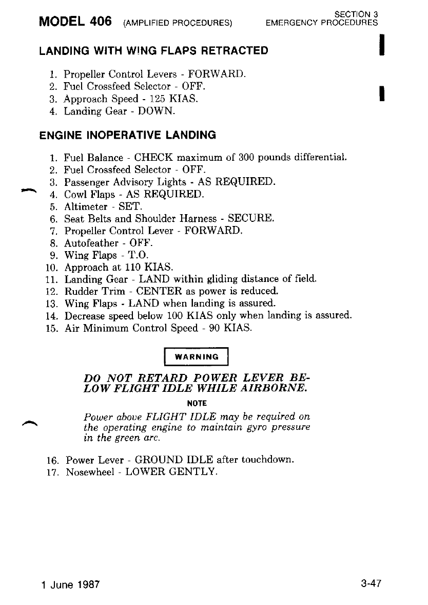
LANDING WITH WING FLAPS RETRACTED
1. Propeller Control Levers - FORWARD.
2. Fuel Crossfeed Selector - OFF.
3. Approach Speed - 125 KIAS.
4. Landing Gear - DOWN.
ENGINE INOPERATIVE LANDING
1. Fuel Balance - CHECK maximum of 300 pounds differential
2. Fuel Crossfeed Selector - OFF.
3. Passenger Advisory Lights - AS REQUIRED.
^ 4. Cowl Flaps - AS REQUIRED.
5. Altimeter - SET.
6. Seat Belts and Shoulder Harness - SECURE.
7. Propeller Control Lever - FORWARD.
8. Autofeather - OFF.
9. Wing Flaps - T.O.
10. Approach at 110 KIAS.
11. Landing Gear - LAND within gliding distance of field.
12. Rudder Trim - CENTER as power is reduced.
13. Wing Flaps - LAND when landing is assured.
14. Decrease speed below 100 KIAS only when Ianding is assured.
15. Air Minimum Control Speed - 90 KIAS.
DO NOT RETARD POWER LEVER BE-
LOW FLIGHT IDLE WHILE AIRBORNE.
NOTE
Power aboue FLIGHT IDLE may be required on
the operating engine to maintatn gyro pressure
Ln tne Ereen arc.
16. Power Lever - GROUND IDLE after touchdown.
17. Nosewheel - LOWER GENTLY.
MODEL 406 lnverrrreo PRocEDURES) SECTION 3
EMERGENCY PROCEDURES
1 June 1987 3-47
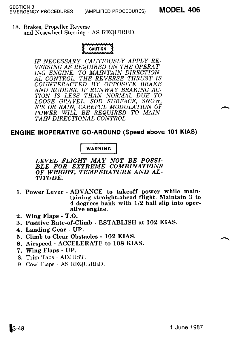
18. Brakes, Propeller Reverse
and Nosewheel Steering - AS REQUIRED.
IF NECESSARY, CAU:IIOUSLY APPLY RE-
Y'RSING AS REQUIRED ON THE OPERAT
ING ENGINE. TO MAINTAIN DIRECTION-
AL CONTROL, THE REVERSE THRUST IS
COUNTERACTED BY OPPOSITE BRAKE
AND RUDDER. IF RUNWAY BRAKING AC-
?ION IS LESS THAN NORMAL DUE TO
LOOSE GRAVEL, SOD SURFACE, SNOW,
ICE OR RAIN, CAREFUL MODULATION OF
POWER WILL BE RE?UIRED TO MAIN-
TAIN D IRECTIONAL CONTROL.
ENGINE INOPERATIVE GO-AROUND (Speed above 101 KIAS)
LEVEL FLIGHT MAY NOT BE POSSI-
BLE FOR EXTREME COMBINATIONS
OF WEIGHT. TEMPERATURE AND AL.
TITUDE.
1, Power Lever - ADVANCE to takeoff power while main-
taining straight-ahead flight. Maintain 3 to
4 degrees bank with 1/2 ball slip into oper-
ative engine.
2. Iffing Flaps - T.O.
3. Positive Rate-of-Climb - ESTABLISH at 1O2 KIAS.
4, Landing Gear - UP,
5, Climb to Clear Obstacles - 102 KIAS.
6. Airspeed - ACCELERATE to 108 KIAS.
7. Wing Flaps - UP.
8. Trim Tabs - ADJUST.
9. Cowl Flaps - AS REQUIRED.
SECTION 3
EMERGENCY PROCEDURES (AMPLIFIEDPROCEDURES) MODEL 406
F-ot 1 June 1987
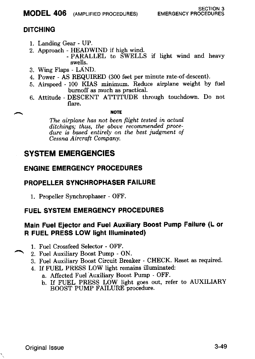
MODEL 406 leuerrrreo 'RocEDURES) EMERGENoy t"3"tPJL?13
DITCHING
1. Landing Gear - UP.
2. Approach - HEADWIND if high wind.
- PARALLEL to SWELLS if light wind and heavy
swells.
3. Wing Flaps - LAND.
4. Power - AS REQUIRED (300 feet per minute rate-of-descent)'
5. Airspeed - 100 KIAS minimum. Il,educe airplane weight by tuel
bumoff as much as practical.
6. Attitude - DESCENT ATTITUDE through touchdown. Do not
flare.
IOtE
The airplane has not been flight tested in actual
ditchinis; thus, the aboue' ricommended proce-
d.ure ii based. entirely on the best jud'gment of
Ce s s na Aircralt C ompany.
SYSTEM EMERGENCIES
ENGINE EMERGENCY PROCEDURES
PROPELLER SYNCHROPHASER FAILURE
1. Propeller Synchrophaser - OFF.
FUEL SYSTEM EMERGENCY PROCEDURES
Main Fuel Ejector and Fuel Auxiliary Boost Pump Failure (L ol
R FUEL PRESS LOW light llluminated)
1. Fuel Crossfeed Selector - OFF'
^ 2. Fuel Auxiliary Boost Pump - ON.
3. Fuel Auxiliary Boost Circuit Breaker - CHECK. Reset as required.
4. If FUEL PRESS LOW light remains illuminated:
a. Affected Fuel Auxiliary Boost Pump - OFF.
b. If FUEL PRESS LOW light goes out, refer to AUXILIARY
BOOST PUMP FAILURE procedure.
3-49
Original lssue
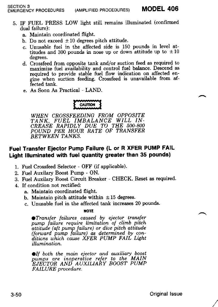
SECT'ON 3
EMERGENCY PROCEDURES (AMPLIFIED PRCCEDURES) MODEL 406
5. IF FUEL PRESS LOW light still remains illuminated (confirmed
dual failure) :
a. Maintain coordinated flight.
b. Do not exceed t 10 degrees pitrh attitude.
c. Unusable fuel in the affected side is 150 pounds in level at-
tjtudes ard 300 pounds in nose up or down attitude up to + 10
(legrees.
d. Crossfeed ftom opposite tank and/or suction feed as required to
maximize fuel availabilitv and control fuel balance. Descend as
reouired to provide stabie fuel flow indication on affected en-
gini when 6uction feeding. Crossfeed is unavailable from af-
iected tank.
e. As Soon As Practical - LAND.
WHEN CROSSFEEDING FROM OPPOSITE
TANK. FUEL IMBALANCE WILL IN-
CREASE RAPIDLY DUE TO THE 5OO.8OO
POUND PER HOUR RATE OF TNANSFER
BETWEEN ?ANXS.
Fuel Transfer Eiector Pump Failure (L or R XFER PUMP FAIL
Light llluminated with fuel quantity greater than 35 pounds)
1. Fuel Crossfeed Selector - OFF (if applicable).
2. Fuel Auxilary Boost Pump - ON.
3. Fuel Auxilary Boost Circuit Breaker - CHECK. Reset as required.
4. If condition not rectified:
a. Maintain coordinated flight.
b. Maintain pitch attitude withi! t 15 degees.
c. Unusable fuel in the affected tank increases 20 pounds.
M)IE
OTransfer faiLures caused by ejector transfer
oumo failure reouire limitation of cLimb pitch
'dttttid:e .( al t puip .faiture) or.diue pitch atiitude
(t'orward. pump failure) as determined by con-
tl.itions uhich cause XFER PUMP FAIL Ltght
illumination.
OII both the rnain ejector and auxiliary boost
DurrrDs are inoperatiue refer to the MAIN
.EJEC:TOR AND AUXILIARY BOOST PUMP
FAILURE procedure.
3-50 Original lssue
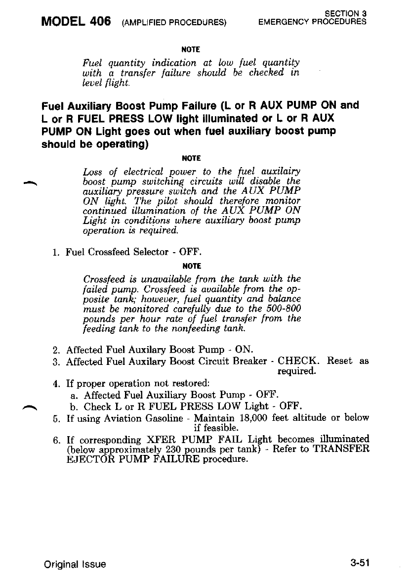
MODEL 406 (nupr-trteo pRocEDURES) sEcTroN 3
EMERGENCY PROCEDURES
Fwl quantity ind,ication at low frcl qtnnfiA
uith a transler failure shaul.d. be cheched in
leueL flight.
Fuel Auxiliary Boost Pump Failure (L or R AUX PUMP ON and
L or R FUEL PRESS LOW light illuminated or L or R AUX
PUMP ON Light goes out when fuel auxiliary boost pump
should be operating)
NOIE
Loss of electrical power to lhe fuel auxilairy
boost bump sultchine circuits will d.isable tEe
aux.tlidry 1)ressure switch and the AUX PUMP
ON light. The pilot should therefore monitor
continued illumination of the AUX PUMP ON
Light in conditions uhere auxiliary boost pump
operatl,on Ls requtred,.
1. Fuel Crossfeed Selector - OFF.
NOTE
Crossfeed is unauqiLabLe frorn the tank with the
failed pump. Crossfeed is auailnble from the op-
posite tank; howeuer, fuel quantity and balnnce
must be monitored. carefuLly du,e to the 500-800
pounds per hour rate of fuel transfer frorn the
feedinE lanh to the nonleeding Lanh.
Affected Fuel Auxilary Boost Pump - ON.
Affected Fuel Auxilary Boost Circuit Breaker - CHECK. Reset as
requreo.
If proper operation not restored:
a. Affected Fuel Auxiliary Boost Pump - OFF.
b. Check L or R FUEL PRESS LOW Light - OFF'
If usins Aviation Gasoline - Maintain 18,000 feet altitude or below
if teasible.
If correspondins XFER PUMP FAIL Light becomes illuminated
(below approximately 230 pounds per tank) - Refer to TRANSFER
EJECTOR PUMP FAILURE procedure.
2.
4.
5.
Original lssue 3-51
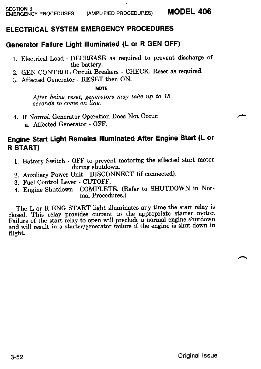
sEcroN 3
EMERGENCY PROCEDURES (AMPLIFIED PROCEOURES) MODEL 406
ELECTRICAL SYSTEM EMERGENCY PROCEDURES
Generatol Failure Light llluminated (L or R GEN OFF)
1. Electrical Load - DECREASE as required to prevent discharge of
the battery.
2. GEN CONTROL Circuit Breakers - CHECK. Reset as required'
3. Affected Generator - RESET then ON.
NOIE
After being reset, generators may tdke up to 15
seconds to come on Line
4. If Normal Generator Operation Does Not Occur:
a. Affected Generator - OFF.
Engine Stari Lighl Remains llluminated After Engine Start (L ot
R START)
1. Batterv Switch - OFF to prevent motoring the affected start motor
' during shutdown.
2. Auxiliary Power Unit - DISCONNECT (if connected)'
3. Fuel Control Lever - CUTOFF.
4. Eneine Shutdown - COMPLETE. (Rcfer to SHUTDOWN in Nor-
mal Procedures.)
The L or R ENG START light illuminatcs anv time the etart relay is
closed. This relay provides curent to the appropriate starter motor'
F.ijuii, Jt[" stait ielay to open will preclude a normal engine shutdown
"nd wiU tesult in a starier/generator f;ilure if the engine is shut down in
flight.
3-52 Original lssue
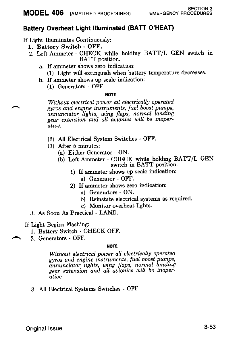
MODEL 406 (nr,,rpr-rrreoPRocEDURES) EMEBGENcYt"ot"tFJLHS
Battery Overheat Light llluminated (BATT O'HEAT)
If Light Illuminates Continuously:
1. Battery Switch - OFF.
2. l,eft Amneter - CHECK while holding BATT/L GEN switch in
BATT position.
a. If ammeter shows zero indication:
(1) Lighi will extinguish when battery temperature decreases.
b. If ammeter shows up gcale indication:
(1) Generators - OFF.
M'TE
Without electrical power all electrically operated
gyros and. engi.ne instruments, luel boos,t pumps,
annunclator LLgnLs, wlng Jtaps, normat Lanalng
gedr extension and alL aoionics will be inoper-
atLue.
(2) All Electrical System Switches - OFF'
(3) After 5 minutes:
(a) Either Generator - ON.
(b) Left Anmeter - CHECK while holding BATT/L GEN
switch in BAT'T position.
1) If ammeter shows up scale indication:
a) Generatnr - OFF'
2) If ammeter shows zero indication:
a) Generators - ON'
b) Reinstate electrical systems as required.
c) Monitor overheat lights.
3. As Soon As Practical - LAND.
If Light Begins Flashing:
1. Battery Switch - CHECK OFF.
2. Generators - OFF.
IOIE
Without electrical power all electrically operated
svros and eneine instruments, fuel boost pumps,
1nnunciator -lights, wing flaps, normaL landing
gear ertensioi and c'll A;ioiics wilL be inoper-
atwe,
3. All Electrical Systems Switches - OFF.
3-53
Original lssue
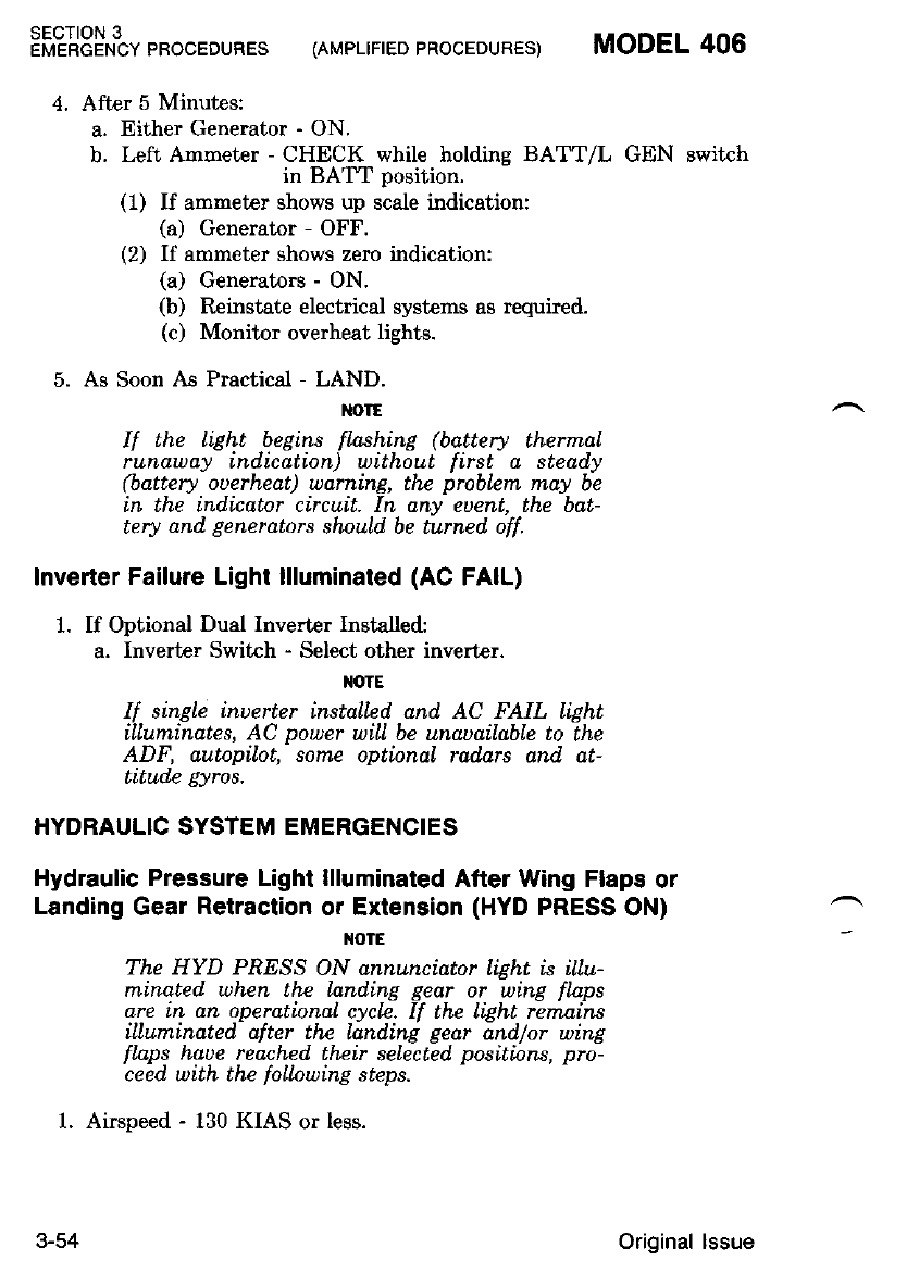
SECTION 3
EMERGENCY PBOCEDURES (AMPLIFIED PROCEDURES) MODEL 406
After 5 Minutes:
a. Either Generator - ON.
b. Left Ammeter - CHECK while holding BATT/L GEN switch
in BAT'T position.
(1) If ammeter shows up scale indication:
(a) Generator - OFF.
(2) If ammeter shows zero indication:
(a) Generators - ON.
(b) Reinstate electrical systems as required.
(c) Monitor overheat lights.
As Soon As Practical - LAND.
M)IE
If the LiAht begins flashing (battery therrnal
runaway indication) without first a steady
(battery ouerheat) uarning, the probLem may be
in the ind.icator circuit. In any eDent, the bdt-
tery dnd generdtors shnuld. be turned, off.
Inverter Failure Light llluminated (AC FAIL)
1. If Optional Dual Inverter Installed:
a. Inverter Switch - Select other invert€r.
M)TE
If single inuertur installed and AC FAIL light
illuminates, AC power wilL be unauailable to the
ADF, autopilot,- some optional rad,ars and at-
titude gyros.
HYDRAULIC SYSTEM EMERGENCIES
Hydraulic Pressure Light llluminated After Wing Flaps or
Landing Gear Retraction or Extension (HYD PRESS ON)
NOIE
The HYD PAESS ON annunciator liqht is illu-
minated. when the landing gear or -wtng flaps
are in an operational cycle. If the Light remains
iLluminated. after the land.ing gear and./or wing
flnps haue reached th.eir selected. positinns, pro-
ceed with the foLlnwing steps.
1. Airspeed - 130 KIAS or less.
3-54 Original lssue
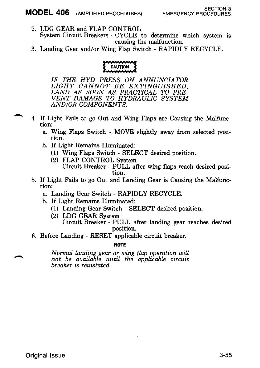
MODEL 406 leueurreo pRocEouBES) EMERGENcv r*ot"tSJLRS
2. LDG GEAR and FLAP CONTROL
Systern Circuit Breakers - CYCLE to determine which system is
causing the malfunction.
3. Landing Gear and/or Wing Flap Switch - RAPIDLY RECYCLE.
IF THE HYD PRESS ON ANNUNCIATOR
LIGHT CANNOT BE EXTINGUISHED,
LAND AS SOON AS PRACTICAL TO PRE-
VENT DAMAGE TO HYDRAULIC SYSTEM
AND/OR COMPONENTS.
4. If Light Fails to go Out and Wing Flaps are Causing the Malfunc-
f,lon:
a. Wing Flaps Switch - MOVE slightly away from selected posi-
tion.
b. If Light Rcmains llluminated:
(1) Wing Flaps Switch - SELECT desired position.
(2) FLAP CONTROL System
Circuit Breaker - PULL after wing flaps reach desired posi-
f,ron.
5. If Light Fails to go Out and Landing Gear is Causing the Malfunc-
tion:
a. Landing Gear Switrh - RAPIDLY RECYCLE.
b. If Light Remains Illuminated:
(1) Landing Gear Switch - SELECT desired position.
(2) LDG GEAR System
Circuit Breaker - PULL after landing gear reaches desired
posnon,
6. Before Landing - RESET applicable circuit breaker.
NOTE
Normnl land.ine aear or winp flap operation will
not be auaila-blZ until thi adoliiable circuit
breaker is reinstated.
Original lssue 5-55
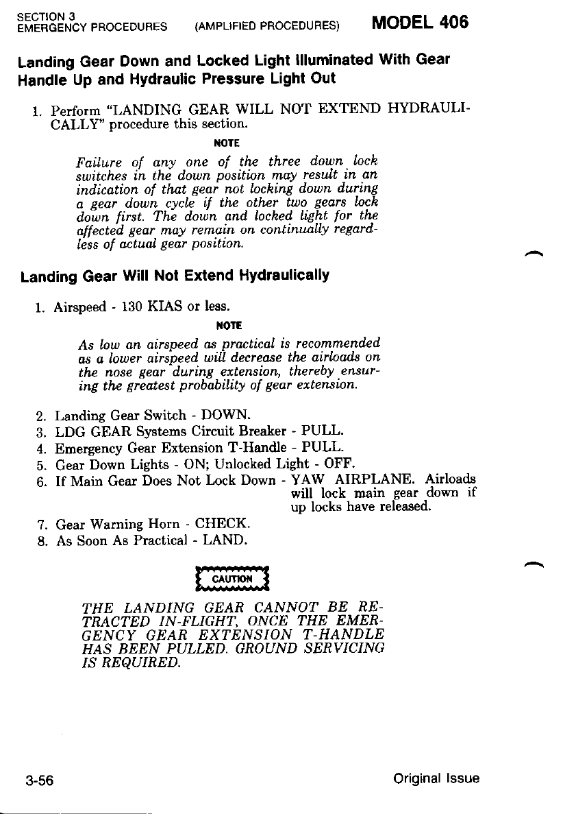
:ffiX3!$t pRocEDURES (AM'LTFTED pRocEDURES) MODEL 406
Landing Gear Down and Locked Light llluminated With Geal
Handle Up and Hydraulic Pressure Light Out
1. Perform "LANDING GEAR WILL NOT EXTEND HYDRAULI-
CALLY" procedure this section.
rtOTE
Failure of any one of the three down.Iock
switches ii th6 d.own positinn may result in an
indication of that. geai not locking down during
a eear down cvcle if the other tuo gedrs lnch
diwn first. Thi down and locked, liEht for thz
affecte.d gear, may rernain on contirutaLly regard-
less of actual gear position.
Landing Gear will Not Extend Hydraulically
l' Airspeed - 130 KIAS or less'
NOIE
As low an airspeed, as practical is recommended
as a lower airspeed will decrease thz airLoads on
the nose gear during extension, thereby ensur-
ing the greatest probabiLity of gear ertension.
Landing Gear Switch - DOWN.
LDG GEAR Systems Circuit Breaker - PULL.
Emergency Gear Extension T-Handle - PULL'
Gear Down Lights - ON; Unlocked Light - OFF.
If Main Gear Does Not Lock Down - YAW AIRPLANE. Airloads
will lock main gear down if
up locks have released.
Gear Warning Horn - CHECK.
As Soon As Practical - LAND.
THE LANDING GEAR CANNO? BE NE-
TRACTED IN-FLIGHT, ONCE THE EMER-
GENCY GEAR EXTENSION T.HANDLE
HAS BEEN PULLED. GROUND SERVICING
IS REQUIRED.
2.
3.
I
7.
8.
3-56 Original lssue
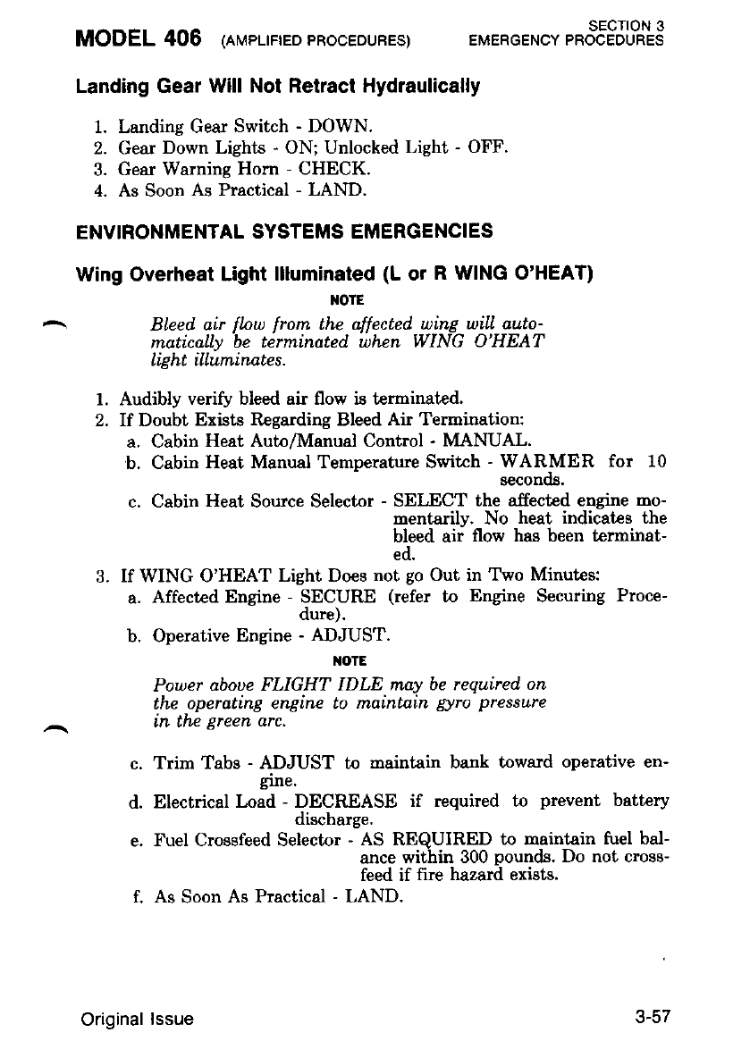
MODEL 406 (nvprrreo 'RooEDUBES) EMERGEN.' tt853Jl*s
Landing Gear Will Not Retract Hydraulically
1. Landing Gear Switch - DOWN.
2. Gear Down Lights - ON; Unlocked Light - OFF.
3. Gear Warning Horn - CHECK.
4. As Soon As Practical - LAND.
ENVIRONMENTAL SYSTEMS EMERGENCIES
Wing Overheat Light llluminated (L or R WING O'HEAT)
NOTE
Bleed. air flnu from the affected wing will auto-
matically be terminated, when WING O'HEAT
li6ht illuminates.
f. Audibly verify bleed air flow is terminated.
2. If Doubt Exists Regarding Bleed Air Termination:
a. Cabin Heat Autn/Manual Control - MANUAL.
b. Cabin Heat Manual Temperature Switch - WARMER for 10
aeconog.
c. Cabin Heat Source Selector - SELECT the affected engine mo-
mentarily. No heat indicatcs the
bleed air flow hag been t€rminat-
ed.
3. If WING O'HEAT Light Does not go Out in Two Minutes:
a. Affected Engine SECURE (refer to Engine Securing Proce-
b. Operative Engine - ADJUST.
I{OTE
Power aboue FLIGHT IDLE may be required on
the operating engine to maintain gyro pressure
in the green arc.
c. Trim Tabs - ADJUST to maintain bank toward operative en-
grne.
d. Electrical Load - DECREASE if required to prevent batt€ry
discharge.
e. Fuel Crossfeed Selector - AS REQUIRED to maintain fuel bal-
ance within 300 pounds. Do not cross-
feed if fire hazard exists.
f. As Soon As Practical - LAND.
3-57
Original lssue

SECTION 3
EMERGENCY PROCEDURES (AMPLIFIED PROCEDURES) MODEL 406
Air Duct Overheat Light llluminated (AlR DUCT O'HEAT)
1.. Temperature Control Knob - MANUAL (Full counterclockwise).
2. Manual Warmer/Cooler Switch - COOT:ER for approximately 15
seconos.
3. Ram Air Control - PUSH.
4. Cockpit/Cabin Air Control - PULL.
5. Cabin Air Defrost Knob - PULL.
6. If AIR DUCT O'HEAT light does not go out in two minutes:
a. Cabin Heat Source Select Switch - OFF.
b. As Soon As Practical - LAND.
Bleed Air Contamanation
1. Cabin Heat Source Select - OFF.
2. Ram Air Knob - PULL to clear cockpit.
3. Cabin Heat Source Select - LH then RH (to isolate source).
OtE
Air contamination orginating frorn both engines
uoul.d not normally be anticipated. Leaue source
selector in each position 2 minutes to determine
if smnhc is decreasing. If one selector positinn
elirninates smoke generatian, contintn in that
posLtLon.
4. If air contamination continues:
a. If supplementary oxygen is available:
(1) Oxygen Knob - PULL ON.
(2) Assure each occupaat is using oxygen.
b. Smoke Removal Checklist - COMPLETE.
OXYGEN SYSTEM FAILURE (IF INSTALLED)
1. Maintain altitude below 10.000 feet.
J-5d Original lssue
MODEL 406 (nruprrreo 'RooEDURES) EMERGENcv t"ot83JLT.S
ICE PROTECTION SYSTEMS EMERGENCIES
Inadvertenl lcing Encounter
1. Ignition Switches - ON.
2. Engine Inertial Separatnr Switches - BYPASS.
IF THE ENGINE INERTIAL SEPARATOR IS
NOT POSITIONED TO BYPASS. MOISTURE
- MAY COLLECT UNDER THE ENCINE /N-
LET SCREEN AND FREEZE. SUBSE-
qUENTLY, THIS ICE MAY SEPARATE
AFTER ENCOUNTERING HIGHER OUT-
SIDE 'IEMPERATURES WHICH COULD RE-
SULT IN ENCINE DAMAGE.
3. Pitot/Static Heat Switches - ON.
4. Stall Heat Switches - ON.
5. Propeller Deice Switches - ON.
6. Ignition Switrhes - OFF after 5 minut€s operation.
7. I-eave icing conditions as soon as possible'
Engine Inertial Separator System Failure
1. Inertial Separator - BYPASS (monitor inertial separator lights).
2. Check proper operation by noting torque &op and slight rise in
ITT.
3. If Inertial Separator Fails
in the NORMAL Mode - T\rrn imition switches ON ald leave ic-
ing con-ditions as soon as possible.
.t-cY
Original lssue
SECTION 3
EMERGENCY PROCEDURES {AMPLIFIED PROCEDURES) MODEL 406
Pitot/Static System Failure
1. Pitot/Static Heat Switches - CHECK ON.
2. Pilot's and Copilot's Instrunents - DETERMINE which instru-
ments are functioning normally.
,{OTE
Initiate climb or descent uith fixed power and
watch for appropriate indication on rate-
of-climb, airspeed and altimeter. If the .deire
heater hns an open circuit, no amperage change
wiLl be seen uhen suitch is mnued.
3. Complete flight on the operative instruments.
I{OTE
Copilot's pitot/static system is totally separate
lrom the pilot's system.
Propeller Deice Failure
If uneven deicing of the propeller is indicated by excessive vibration:
1. Propeller Control Lever - EXERCISE then return io CRUISE.
2. Propeller Ammeter - CHECK for proper operation by periodic fluc-
tuations within the green arc.
3. If arrmeter reading is below the green arc, indicating the propeller
blades may not be deicing uniformly:
a. Propeller Deice Switch - OFF for affected propeller.
4. Leave icing conditions as soon as possible.
Boot Operation With One Engine Inoperative
l. Power Lever - SET (above 65 percent N, during deice boot ac-
tuation.
TOIE
To prouide sufficient d.eice boot pressure during
deice boot actuation, the operating, engine
shauld be aboue 65 percent N". Power above
FLIGHT IDLE may be required on the operat-
ing engine to rnaintain gyro pressure in the
gTeen arc.
3-60 Original lssue
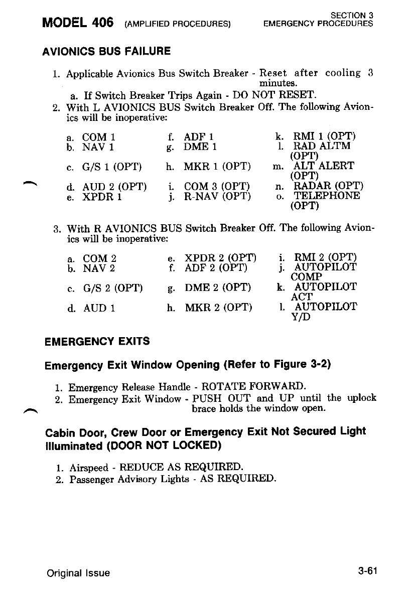
AVIONICS BUS FAILURE
1. Applicable Avionics Bus Swikh Breaker - *ff;1".:tt.t cooling 3
a. If Switch Breaker Trips Again - DO NOT RESET.
2. With L AVIONICS BUS Switch Breaker Off. The following Avion-
ics will be inoperative:
MODEL 406 (eprpupreo pRocEDuRES) SECTION 3
EMERGENCY PROCEDURES
k. RMI 1 (OPT)
I, RAD ALTM
(oPT)
m. ALT ALERT
(oPT)
n. RADAR (OPT)
o. TELEPHONE
(oPT)
RMI 2 (OPT)
AUTOPILOT
COMP
AUTOPILOT
ACT
AUTOPILOT
Y/D
a. COM 1
b. NAV 1
c. G/S 1 (OPT)
d. AUD 2 (OPT)
e. XPDR I
a. COM 2
b. NAV 2
c. G/S 2 (OPT)
d. AUD 1
f. ADF 1
s. DME 1
h. MKR 1 (OPT)
i. coM 3 (oPT)
J. R-NAV (OPT)
e. XPDR 2 (OPT) i.
f. ADF 2 (OPT) j.
e. DME 2 (OPT) k.
h. MKR 2 (OPT) l.
3. Wiih R AVIONICS BUS Switch Breaker Off. The following Avion-
ics will be inoperative:
EMERGENCY EXITS
Emergency Exit Window Opening (Refer to Figure 3-2)
1. Emergency Release Handle - ROTATE FORWARD.
2. Emergency Exit window fj3"tn"o,HTn;1X'Hj"until.the uplock
Cabin Door, Crew Door or Emergency Exit Not Secured Light
llluminated (DOOR NOT LOCKED)
1. Airspeed - REDUCE AS REQUIRED.
2. Passenger Advisory Lighb - AS REQUIRED.
3-61
Original lssue
SECTION 3
EMERGENCY PROCEDURES {AMPLIFIED PROCEDURES) MODEL 406
3. As Soon As Praciical - LAND.
DO NOT ANEMPT TO CHECK THE SE-
CURITY OF THE CABIN DOOR, CREW
DOOR OR EMENGENCY EXIT, REMNN
AS FIN FROM THE DOON AS POSSI-
BLE WITH SEAT BELTS SECURELY
FASTENED UNTIL LANDING IS COM.
PLETED,
NOSE BAGGAGE DOOR OPEN ON TAKEOFF
If a baseaee door is left unlatched. it mav open as the nose is raised
on takeofTl The doo. will not hit a propi,llei nor will there be any
unusual handling characteristics. If suffrcient runway remains for a safe
abort, the aircraft should be stopped. If the decision is made to continue
the takeofi maintain airspeed b-eiow 120 KIAS and return for landing as
soon as practical. Avoid lowering the nose abruptly which could throw
loose objects out of the compartment.
EMERGENCY LOCATOR TRANSMITTER RESCUE
PROCEDURES
Before Landing
1. VHF COM - SET 121.5 MHz or known ATC frequency and trans-
mit May Day calls for assistance if time permits.
After Landing
1. Plug Button - REMOVE (located on side of tailcone).
2. Emergency Locator Transmitter Switch - ON.
After Rescue
1. Emergency Locator Transmitter Switch - OFF.
ENCODING ALTIMETER FAILURE (Warning Flag Showing)
1. ALT Circuit Breaker - CHECK IN.
2. If warning flag is still showing, use the standby barometric altim-
eter.
TRANSPONDER PROCEDURES FOR EMERGENCY SITUATIONS
Emergency Signal Transmission
1. Function Switch - ON.
2. Reply-Code Selector Switches - SELECT code 7700.
3-62 Original lssue
Loss-of-Communications Signal Transmission
1. Function Switch - ON.
2. Repry-code serector switches }?*S!.trr$1 tJ$t }ftlul
?600: WAIT 15 minutes. RePeat
nrocedures at same intervals for re-
hainder of flight.
Hijacked Signal Transmission
1. Function Switch - ON.
2. Reply-Code Selector Switches - SELECT Code 7500'
TOTAL LOSS OF COMMUNICATIONS
In the event that the audio panel or a microp-hone {rla]functions such
ttr"f iiji"r lti"i"ioti "annJbe le.ror*ed on cdM 1, coM 2 or CoM 3'
oroceed as follows:
1. Employ an alternate nicrophone.
If the Problem Continues:
2. Function Selector Switch - EMER COM' S-peake.r operation will be
inoDerative in all modes.
Employ headsets.
Set the desired frequency on COM 1 and proceed with communica-
tion on that COM onlY.
5. Set receiver selector switches to HDST for receivers to be mon-
" i#J1NnV, Mxn, aln or DME). A reduction in normal am-
;Iild";iti il ;ip#enced while opeiatins in emergencv mode'
I{OTE
If a second audio panel is installed', the em'er-
iency function of ihe second panel will be on
COM 2.
If Communications Cannot Be Reestablished:
6. Refer to Transponder Procedures for Emergency Situations'
?. Conply with ATC procedures for loss of comnunications'
MODEL 406 (at',rpltrreoPRocEDUREs) SECTION 3
EMERGENCY PROCEDURES
3.
Original lssue 3-63
SECTION 3
ervreCGerubv pRocEouRES (AMpLIFTED pRocEDURES) MODEL 406
ELECTRIC ELEVATOR TRIM RUNAWAY
1. Control Wheel - OVERPOWER as required.
2. AP/TRIM Disconnect Switch - DISCONNECT immediatelv.
3. Manual Elevator Trim - AS REOUIRED.
I{OTE
After the eLectric trirn hos been disconnected.
and the ernergency is ouer, pull the ebctric trim
(ELEV TRIM) circuit breaker. Do not qttenDt
to use the electric eleuator trirn system uitil
ground maintenante has been comDleted,
SPINS
Intentio-nal spins are not pemitted in this airplane. Should a spin
occur the following recovery procedures should be eirployed:
1. Power Levers - FLIGHT IDLE,
2. Ailerone - NEUTRALIZE.
3. Rudder - HOLD FULL RUDDER oDposite the direction of
rotation.
4. Control Wheel - FORWAEI BBISKIY. l/2 turn of spin
after applying full rudder.
5. Inboard Engine - INCREASE POWER to slow rotation (if
necessary),
After rotation has stopped:
6. Rudder - NEUTRALIZE.
7. Inboard Engine (If Used) - DECREASE POWER to equal-
ize engines.
8, Control Wheel - PULL to recover from resultant dive. Ap-
ply smooth steady control pressure.
M)IE
The airplane hns not been flight tested in spins,
thtts the aboue recomrnended-procedure is 6ased
entirely on thc best judgment- of Cessnn Aircraft
UOnlpqny.
3-64 Original lssue
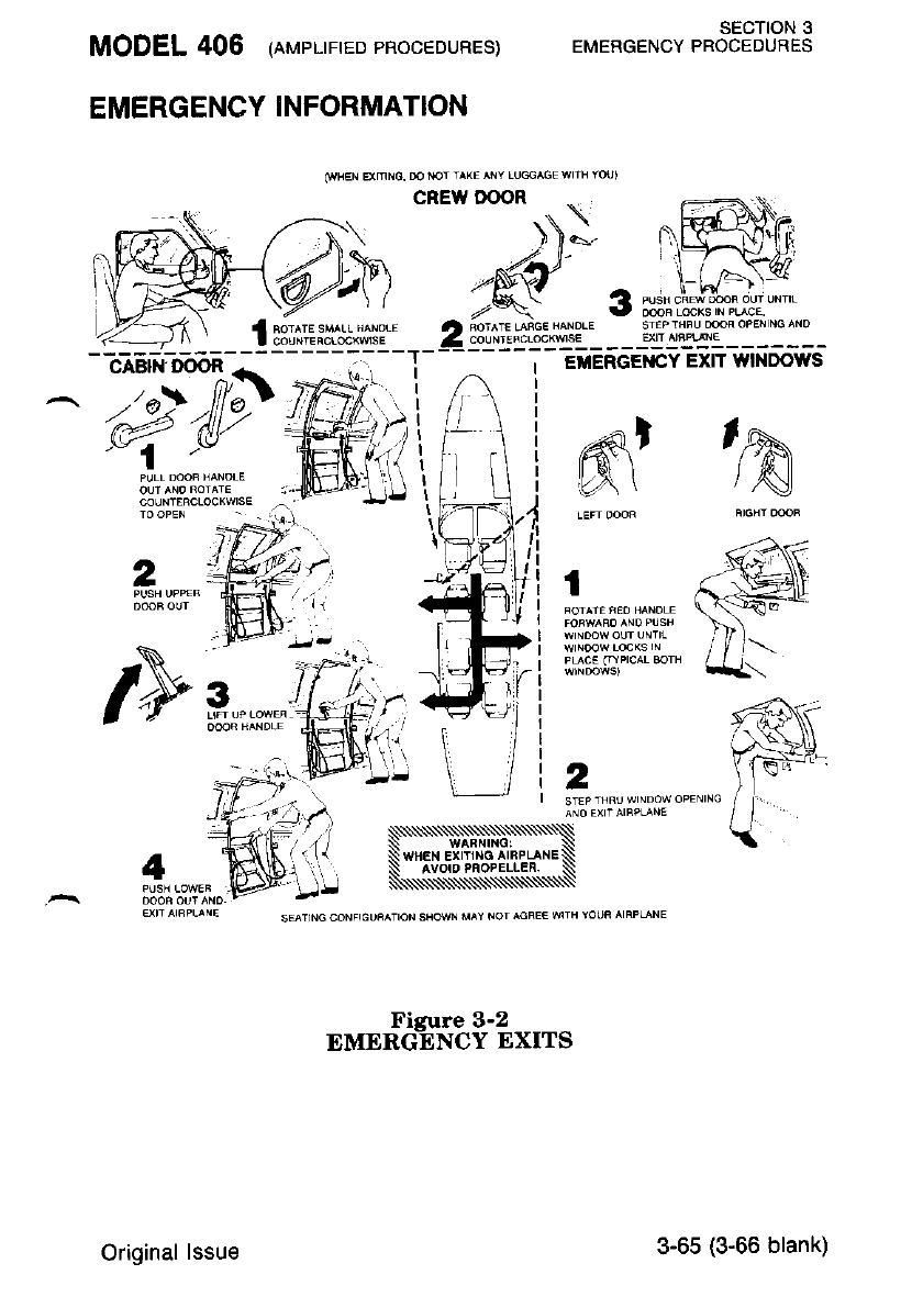
MODEL 406 (erupr-rrreopRocEDUREs)
EMERGENCY INFORMATION
(WHEN 9(MNO. DO I{OT T^XE ^NY LUGGAGE WIIH YOU'
SECTION 3
EMERGENCY PROCEDURES
3;sr
A 6ora_€ LARGE HANDLE srrP'HFUoooFoPE{NGANo
4_ 9"jrl*.j"j!a.L _ ___?ll ^'T4:_______
EMERGETICY EXIT WINDOWS
,aqI
L\I h
2
3
2
/>
Ficure 3-2
EMERGANCY EXITS
WHEN EX
Original lssue 3-65 (3-66 blank)

MODEL 406 sEcIoN 4
\IORMAL PROCEDURES
sEcTloN 4
NORMAL PROCEDURES
TABLE OF CONTENTS
INTRODUCTION
AIRSPEEDS FOR NORMALOPERATIONS .....,.. 4.3
NORMAL PROCEDURES ABBREVIATED CHECKLIST
PREFLIGHT INSPECTION
BEFORE ENGINE STARTING
Page
4-3
ENGINE STARTING
ENGINE STARTING
BEFORE TAXIING
(Battery Start)
(With External Power) .
4-4
4-7
4-8
4-8
4-9
4-9
4-9
TAXIING ..
BEFORE TAKEOFF
TAKEOFF ... 4-10
4-10
CLIMB .
CRUISE.....
DESCENT
BEFORE LANDING
BALKED LANDING
AFTER LANDING ...,.....
SHUTDOWN ...
POSTFLIGHT EMERGENCY LOCATOR TRANSMIT"TER
CHECK . ...4-rz
ENVIRONMENTAL SYSTEMS ...4.72
Oxygen System '.....' 4-12
Heaiing and Ventilating Systens ' . . . .4-13 (4-14 blank)
4-11
4-11
4-11
4-72
4-t2
AMPLIFIED NORMAL PROCEDURES
PREFLIGHT INSPECTION
BEFORE ENGINE STARTING
ENGINE STARTING (Battery Start)
ENGINE STARTING (With External Power) .
ENGINE CLEARING PROCEDURES
ENGINE IGNITION PROCEDURES
BEFORE TAXIING
TAXIING
BEFORE TAKEOFF
original lssue - l July 1986
4-77
4-19
4-20
4-22
4-24
4-25
4-1
SECTION 4
NORMAL PROCEDURES MODEL 406
TABLE OF CONTENTS (CONTTNUED)
TAKEOFF
CLIMB .
CRUISE
DESCENT
BEFORE LANDING
BALKED LANDING
AT"IERLANDING..,..
SHUTDOWN
POSTFLIGHT EMERGENCY LOCATOR TRANSMITTER
CHECK .
ENVIRONMENTAL SYSTEMS
Oxygen System
Heating and Ventilating Systems .
OTHER NORMAL PROCEDURES .. . . . .
Fire Detection and Extinguishing System
Stall . . .
Maneuvering Flight . .
Night Flying
Cold Weather Operation
AVIONICS SYSTEMS NORMAL PROCEDURES
NOISE ABATEMENT ..
PROCEDURES FOR PRACTICE DEMONSTRATION OF VMCA
Practice Demonstration of Vysa
Simulated Engine Failure in Takeoff Configuration . .
FUEL CONSERVATION .
Page
4-28
4-30
4-31
4-32
4-34
4-35
4-35
4-36
4-36
4-36
4-37
4-37
4-37
4-37
4-38
4-38
4-38
4-40
4-48
4-49
4-45
4-50
4-50
Original lssue - 1 July 1986
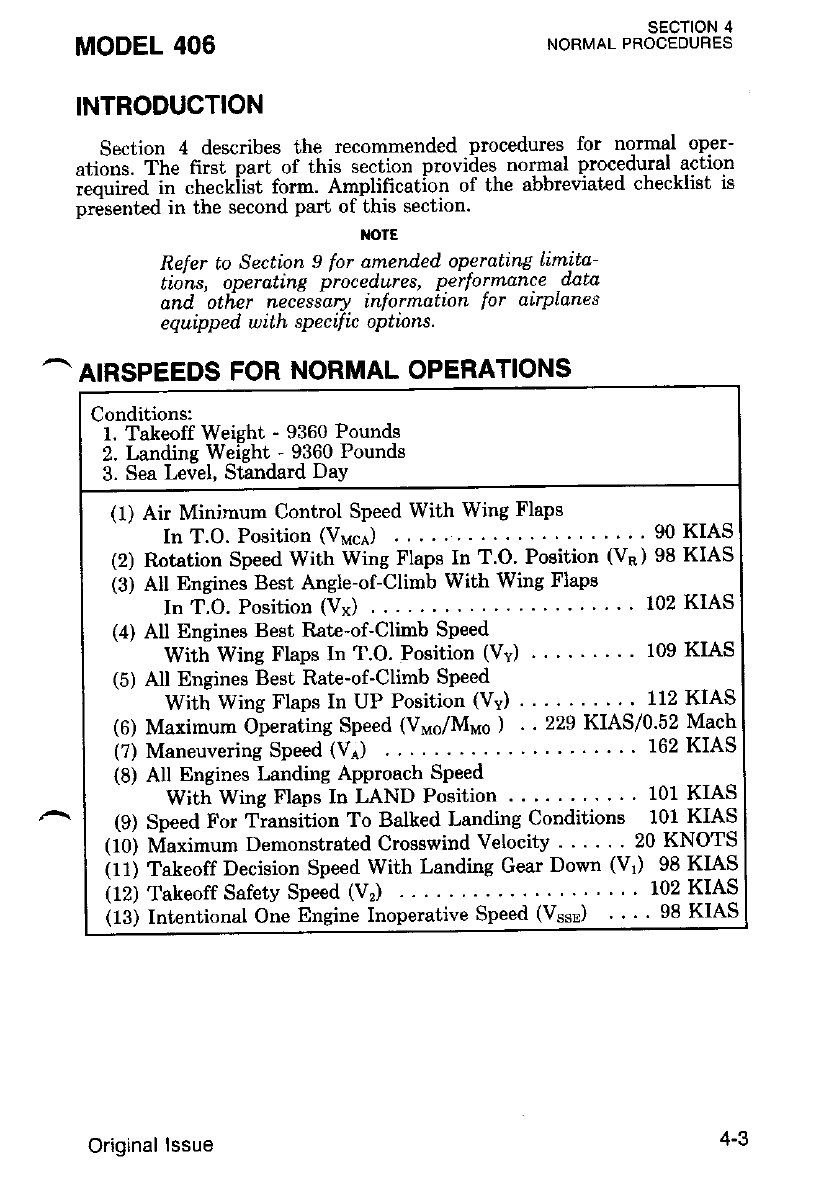
MODEL 406 SECTION 4
NORMAL PROCEDURES
INTRODUCTION
Section 4 describes the recommended procedures for normal oper-
ations. fne first part of this section provides nornal procedural action
;;;i;"d il checkiist form. Amplification of the abbreviated checklist is
presented in the second part of this section.
I{OTE
Reler to Section 9 for amended operating Limita-
tions, operqting procedures, performance .data
and olher necessary informatrcn lor alrplanes
equipped with sPecific oPtions.
^ AIRSPEEDS FoR NoRMAL oPERATIoNS
Conditions:
l. Takeoff Weight - 9360 Pounds
2. Landins Weisht - 9360 Pounds
3. Sea Leiel, Standard DaY
(1) Air Minimum Control Speed With Wing Flaps
In T.O. Position (Vuce) . .....'90KIAS
(2) Rotation Speed With Wing Flaps In T.O' Position (VR) 98 KIAS
(3) AII Engines Best Angle-of-Climb With Wing Flaps
In T.O. Position (Vx) ... .'...102KIAS
(4) All Engines Best Rate-of-Climb Speed
With Wing Flaps In T.O. Position (Vv) . ' 109 KIAS
(5) All Engines Best Rate-of-Climb Speed
With Wing Flaps In UP Position (Vv) . . . 112 KIAS
(6) Maximum Operating Speed (V"6/M"s ) . . 229 KIAS/0'52 Mach
(?) Maneuvering Speed (Ve) 162 KIAS
(8) All Engines Landing Approach Speed
With Wing Flaps In LAND Position . . ' ' 101 KIAS
(9) Speed For Transition To Balked Landing Conditions 101 KIAS
(10) Maximum Demonstrated Crosswind Velocif . '.... 20 KNOTS
(11) Takeoff Decision Speed With Landing Gear Down (Vr) 98 KIAS
itz) Takeoff Safety Speed (V,) ... '..102KIAS
itei Intentional One Engine Inoperative Speed (VssB) . . ' ' 98 KIAS
Original lssue 4-3
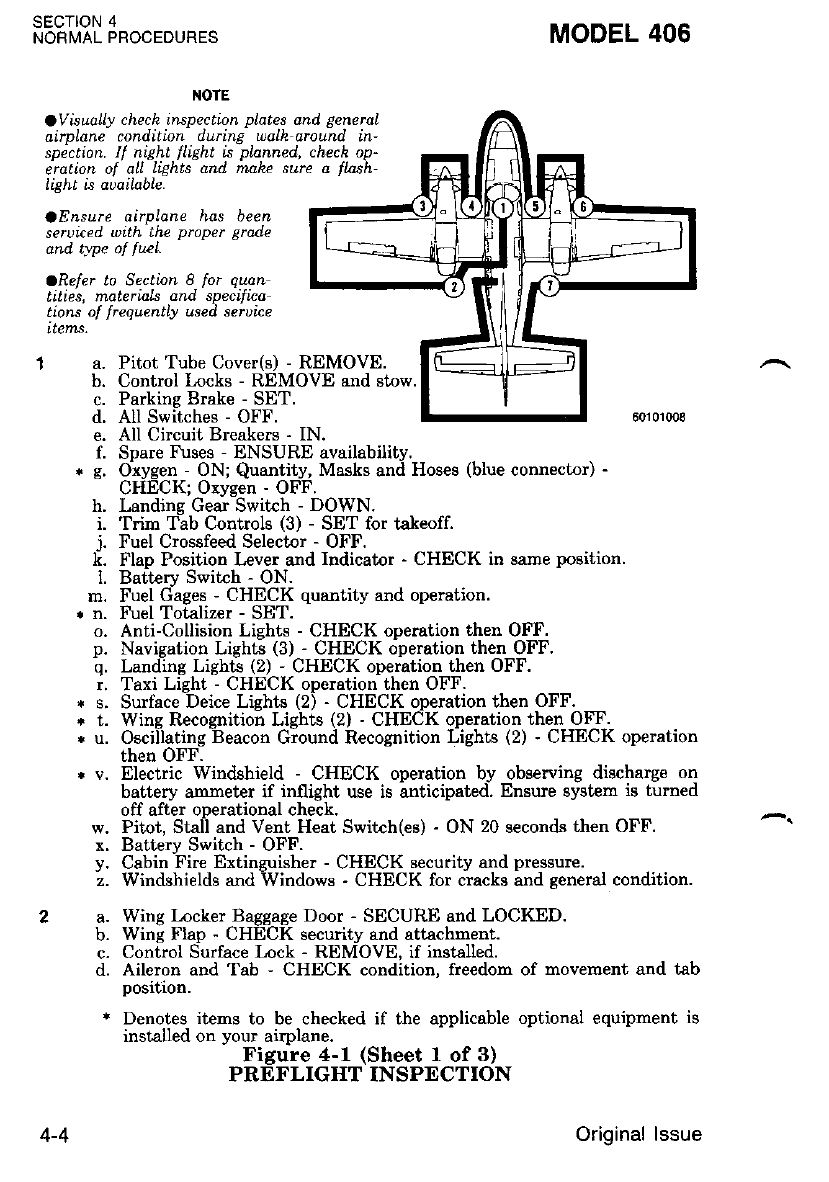
SECTION 4
NORMAL PROCEDURES
Pitot Tube Cover(s) - REMOVE.
Control l,ocks - REMOVE and stow
Parkins Brake - SET.
AII Switches - OFF.
All Circuit Breakers - IN.
MODEL 406
NOTE
OVisually check inspection pLates and generaL
oirDlonp condilion durine uolh aroL"nd in-
spiction. lf night t'light is planncd. chech op
erction ol oll liehts and mah" surp a flnsh-
light ia aoailabLe.
aE&sute oirpLone has been
seruiced uith the proper grade
dnd type of ftEL
ORefer to Sectinn 8 for quatu
tities, materinls and. specilha
tions of frequedtly used. sernice
items.
'I a.
b.
c.
d.
e.
l.
rg,
h.
i.
j.
k.
l.
m.
2a. b.
c.
d.
Spare Fuses - ENSURE availabilitv
Oxygen - ON; Quantity, Masks and Hoses (blue conneclor) -
CHECK; Orygen - OFF.
Landine Gear Switch - DOWN.
Trim T;b Controls (3) - SET for takeofi
Fuel Crossfeed Selector - OFF.
Flap Position kver and Indicator - CHECK in same position.
Battery S$'itch - ON.
Fuel Gages - CHECK quantity and opention.
Fuel Totalizer - SET.
o. Anti-Collision Lieht', - CHECK oDeration then OFF.
p. Navigation LishG (3) - CHECK o-peration then OFF.
'q. Landlng LigbG (2) - CHECK operation then OFF.
r. Taxi Light - CHECK operation then OFF.
* s. Suface Deice Lights (2) - CHECK operation then OFF.
* t. Wing Recognition Lights (2) - CHECK operation then OFF.
'r u. Oscillating Beacon Ground Recognition Lights (2) - CHECK operation
then OFF.
'r v. Electric Windshield - CHECK operation by observing discharge on
battery ammeter if inflight use is anticipated. Ensure system is turned
off after ooerational check.
w. Pitot, Stall and Vent Heat Switch(es) - ON 20 seconds then OFF.
x. Battery Switch - OFF.
v. Cabin Fire Extinzuisher - CHECK Becuritv and pressure.
z- Win&hields and Windows - CHECK for cracks and eeneral condrtion.
Wing Locker Baggage Door - SECURE and LOCKED.
Wing Flap - CHECK secwity and attachment.
Control Surface Lock - REMOVE, if installed.
Aileron and Tab - CHECK condition. fieedom of movement and tab
position.
Denotes items to be checked if the applicable optional equipment is
installed on your airplane.
Figure 4-1 (Sheet f of 3)
PREFLIGHT INSPECTION
4-4 Original lssue
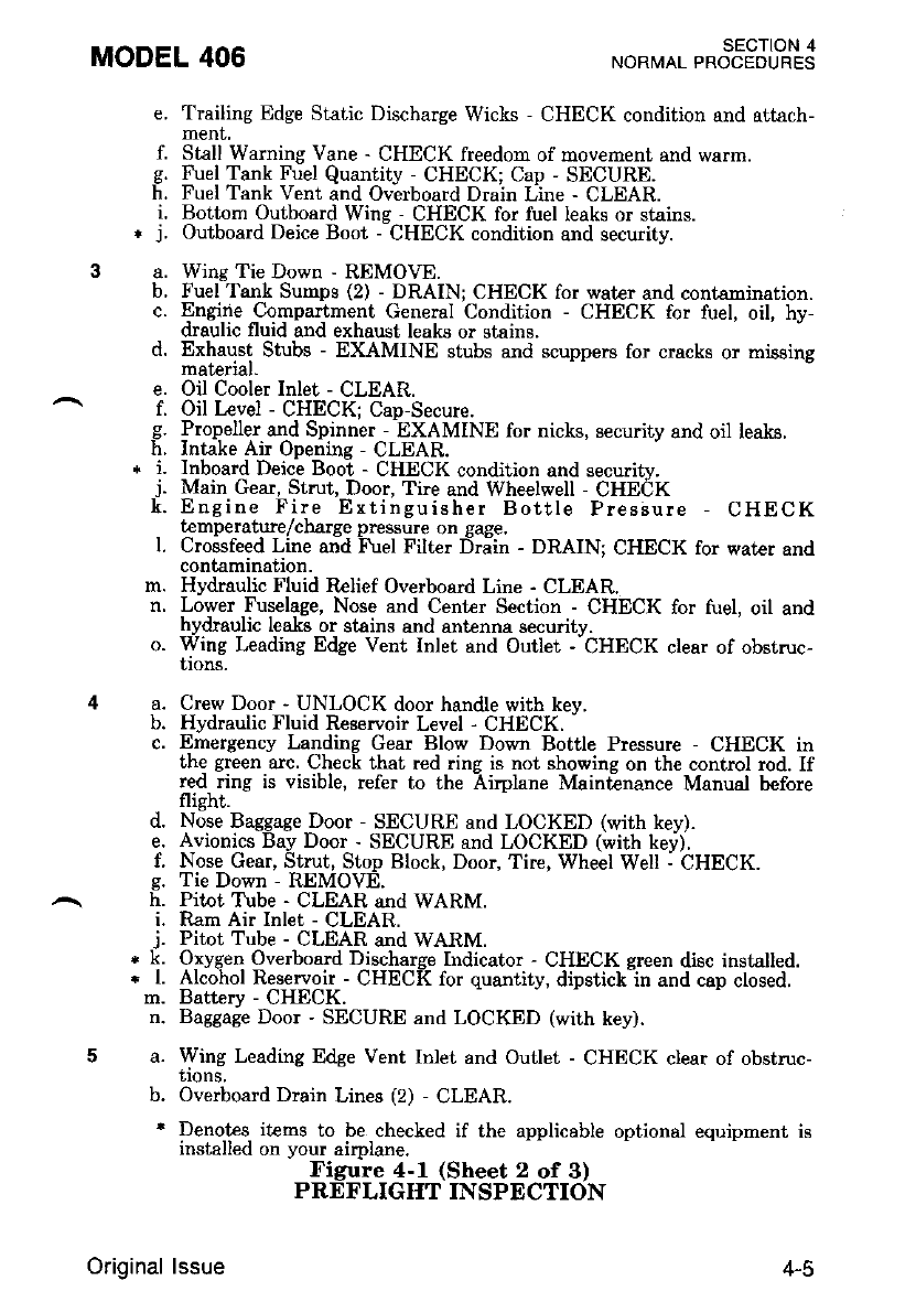
MODEL 406 SECTION 4
NORI/IAL PROCEOURES
e,
t.
h.
i.
3a. b.
c.
d.
e.
h.
J.
l.
m.
n.
o.
d.
e.
I.
i.
j.
*k.
*t.
m.
n.
5a.
b.
4a. b.
c.
Trailing Edge Static Dischalge Wicks - CHECK condition and attach-
menl,
Stall Warning Vane - CHECK freedom of movement and warm.
Fuel Tank Fuel Quantity - CHECK; Cap - SECURE.
Fuel Tank Vent and Overboard Drain Line - CLEAR.
Bottom Outboard Wine - CHECK for fuel leaks or stains.
Outboard Deice Boot - CHECK condition and securitv.
Wing Tie Down - REMOVE.
Fuel Tank Sumps (2) - DRAIN; CHECK for water and contsmination.
Engirie _Compartment General Condition - CHECK for fuel, oil, hy-
draulic fluid and exhaust leake or starns.
Exhaust Stubs - EXAMINE stubs and scuppers for cracks or missing
material.
Oil Cooler Inlet - CLEAR.
Oil Lcvel - CHECK: Cap-Secure.
Propeller and Spinner -EXAMINE for nicks, security and oil leals.
Intake Air Openine - CLEAR.
tnboard Deic-e Booi - CHECK condir,ion and securitv.
Main Gear, Strut, Door, Tire and Wheelwell - CHECK
Engine Fire Ertinguisher Bottle Pressure - CHECK
t€mperature/charge Dressure on sage.
Crossfeed Line and ifuel Filte! Driin - DRAINT CHECK for water and
contamination.
Hydraulic Fluid Relief Overboard Line - CLEAR.
Lower luselage, Nose and Cent€r Section - CHECK for fuel, oil and
hydraulic lea-ksor stains and antenna security.
Wing Leading Edge Vent Inlet and Outlet - CHECK clear of obstruc-
trons.
Crew Door - UNLOCK door handle with kev.
Hydraulic Fluid Regervoir Level - CHECK. -
Emergency Landing Gear Blow Down Bottle Pressure - CHECK in
Lhe green arc. Check ihat red ring is not showing on the control rod. If
red ring is visible. refer to the Airplane Maintenance Manual before
flight.
Nose Baggage Door - SECURE and LOCKED (with key).
Avionics Bay Door - SECURE and LOCKED (with kei).
Nose Gear, Strut, Stop Block. Door. Tire, Wheel Well - CHECK.
Tie Down - REMOVE-
Pitot T\rbe - CLEAR and WARM.
Ram Air Inlet - CLEAR.
Pitot Tube - CTEAR and WARM.
Oxygen Overboard Discharge Indicator - CHECK ereen diec installed.
Alcohol Reservoir - CHECK for quantity, dipstickln and cap closed.
Battcry - CHECK.
Baggage Door - SECURE and LOCKED (with key).
Wing Leading Edge Vent Inlet and Outlet - CHECK clear of obstruc-
llons.
Overboard Drain Lines (2) - CLEAR.
Denotes iteds to be checked if the applicable optional equipment is
installed on your airplane.
Figure 4-l (Sheet 2 of 3)
PREFLIGIIT INSPECTION
Original lssue 4-5
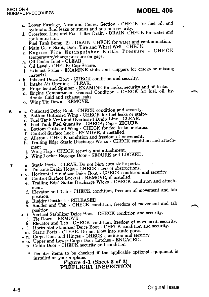
SECTION 4
NORMAL PROCEDURES MODEL 406
c. Irwer Fuselage, Nose and Center Section - CHECK for fuel oil' and
hvdraulic fluid leaks or stains and anmnna secunty - ^--
d. d';;6; ii;;;"d-ru'i Fitt"" oi"in - DRAIN; CHEcK for water and
contamination
". i'u.iT""[ So-p (2) - DRAIN; CHECK fo: water qld-contamination'
i. i\4"* G;;", Si*r, ooor, Tire and Wheel Welt ' CHECK'
;. 6;;i;;'h;;;-n-Jiieui"h". Bottle Preseure - CHECK
lemperature/charge pressure on gage.
h. Oil Cooler Inlet - CLEAR.
i. Oil Level - CHECK; CaP'Secure.
i. Exhaust Stubs - EXAMINE stubs and scuppers tbr cracks or mrssrng
- material.
, k. i=Jiard Deice Boot - CHECK condition and security'
t- lntake Air OPenine' CLEAR.
;. ijffi;ll;;;,;i5pi-n'n""-' ExetnltNe for nicks' securitv "and"oil leaks'
;: b;".i;;'b;;;;ir-ent Ger'".u1--Co"dition - cHEcK for tuel' oil' hv'
dra:ulic fluid and exhaust leaks
o. Wing Tie Down - REMOVE.
,r a- Outboard Deice Boot - CHECK condition and security-'
- b. E;ft; dtb.ard Wing - CHECK for tuel leaks or stailrs'
i. Fu"t 'fu"t Vent and O-verboard Drain Line --C-LEA8'
;. b;;i i;"i FueL Quantitv - CHECK; Cap - SECURE .
l. 'giiL.-il"iu*td wine"' CHECK for tuel leaks or gtains'
i. C"irii"l Surface Lock -- REMOVE' if installed'
e. Aileron ' CHECK condition and freedom of movemem'.
fi: t;;ti';; E;;;S;ii" ois"trarge Wiits - cHEcK condition and attach-
ment.
i. Wl"e ftup - CHECK securitv and attachment. -----
j. wiiiE h&"" S"sg"ge Door -- SECURE and LOCKED'
a. Static Ports - CLEAR. Do not blow into static ports'
6. luii"on" Drain Holes - CHECK clear of obstructions'
- i. rli"*j"Lt Si"Uitiiei O"ice Boot - CHECK condition and securitv'
i. to.iiot Surface t ock(s) - R"EMOVE' if installed-'
;: il;iH; trd;;5tiii"'iii""t'-.rg"-wi"t" - CHECK condition and attach-
ment.
f. ii6;;"" and Tab - CHECK condition, freedom of movement and tab
Dosition.
s. hudder Custlock - RELEASED.
f;. ffiffi iii"ii-l - "c-Hetii condition, freedom of movement and tab
{rlliT""J st"uili*. oeice Boot - CHECK condition and securitv'
Tie Down - REMOVE.
gieuato" und Tub - CHECK condition, freedom of movement aecunty'
il."i?ir,it"i'Suuitrzei ljeice Boot - cHEcK condition and securitv'
static Pods - CLEAR. Do not blow into static ports'
Cargo Door-and Hinges ' CHECK condition and secunry'
Uoder and fower Cargo Door Lakhes - ENGAGED'
ci6in iloo. - CHECK security and conditjon'
j.
k.
r, l.
m.
p.
* Denotes items to be checked if the applicable optional equipment is
installed on your airplane.
- Fieuie 4-1 (Sheet 3 of 3)
PREFLIGHT INSPECTION
4-6 Original lssue
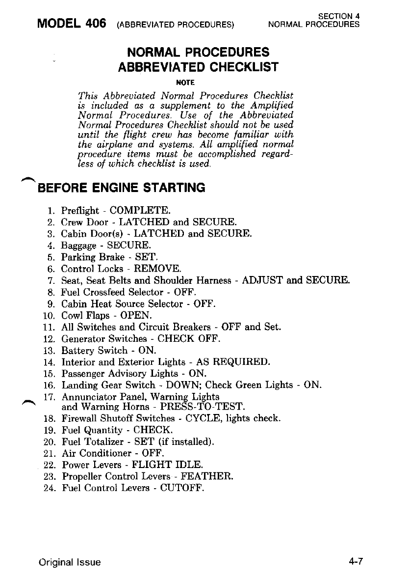
MODEL 406 (reenevrerED 'RocEDURES) *o*ro. r*otS3JLHS
NORMAL PROCEDURES
ABBREVIATED CHECKLIST
I{OTE
This Abbreuiated Normal Procedures Chechlist
is includ.ed. as a supplement to the AmpLified.
Normal Proced.ures. Use of the Abbreuiated
NormaL Proced,ures Chechlist should not be used
until the flight creu has become familiar with
lhe airplane and. systems. ALI amptified normaL
procedire items rnust be accomplished regarrl-
less of uhich chechlist is used.
BEFORE ENGINE STARTING
1. Preflight - COMPLETE.
2. Crew Door - LATCHED and SECURE.
3. Cabin Door(s) - LATCHED and SECURE.
4. Baggage - SECURE.
5. Parking Brake - SET.
6. Control Locks - REMOVE.
7. Seat, Seat Belts and Shoulder Harness - ADJUST and SECURE.
8. Fuel Crossfeed Selector - OFF.
9. Cabin Heat Source Selector - OFF.
10. Cowl Flaps - OPEN.
11. All Switches and Circuit Breakers - OFF and Set.
12. Generator Switches - CHECK OFF.
13. Battery Switch - ON.
14. Interior and Exterior Lights - AS REQUIRED.
15. Passenger Advisory Lights - ON.
16. Landing Gear Switch - DOWN; Check Green Lights - ON.
- 17. Annunciaior Panel, Waming Lights
and Warnine Horns - PRES'S-T:O-TEST.
18. Firewall Shutoff Switches - CYCLE, lights check.
19. Fuel Quantity - CHECK.
20. Fuel Totalizer - SET (if installed).
21. Air Conditioner - OFF.
22. Powet Levers - FLIGHT IDLE.
23. Propeller Control Levers - FEATHER.
24. Fuel Control Levers - CUTOFF.
Original lssue
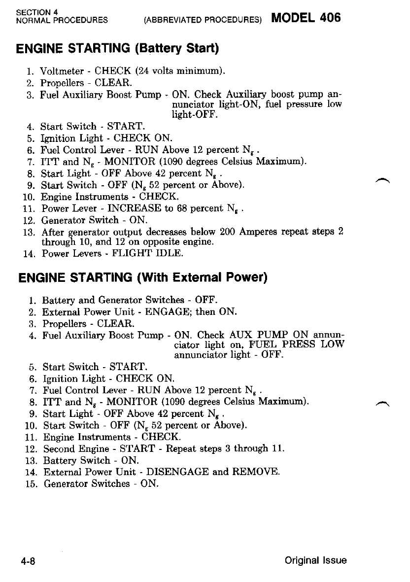
SECTION 4
NORMAL PROCEDURES (ABBREVIATED PROCEDURES) MODEL 406
ENGINE STARTING (Battery Start)
1. Voltmeter - CHECK (24 volts minimum).
2. Propellers - CLEAR.
3. Fuel Auxiliary Boost Pump - ON. Check Auxiliary boost pump an-
nunciator light-ON, fuel pressure low
light-OFF.
4. Start Switch - START.
5. Ignition Lighi - CHECK ON.
6. Fuel Control Lever - RUN Above 12 percent N..
?. IT"T and Ng - MONITOR (1090 degrees Celsius Maximun).
8. Start Light - OFF Above 42 percent N, .
9. Start Switch - OFF (Ns 52 percent or Above).
10. Engine Instruments - CHECK,
11. Power Lever - INCREASE to 68 percent N, .
12, Generator Switch - ON.
13. After generator output decreases below 200 Anperes repeat steps 2
through 10, and 12 on opposite engine.
14. Power Levers - FLIGHT IDLE.
ENGINE STARTING (With Extemal Power)
1. Battery and Generator Switches - OFF.
2. External Power Unit - ENGAGE; then ON.
3. Propellers - CLEAR.
4. Fuel Auxiliary Boost Pump - ON. Check AUX PUMP ON annun-
ciator lieht on, FUEL PRESS LOW
annunciator light - OFF.
5. Start Switch - START.
6. Ignition Light - CHECK ON.
?. Fuel Control Lever - RUN Above 12 percent Ng .
8. ITT and N8 - MONITOR (1090 degees Celsius Maximum).
9. Start Light - OFF Above 42 percent Nr.
10. Start Switrh - OFF (N.52 percent or Above).
11. Engine Instruments - CHECK.
12. Second Engine - START - Rcpeat steps 3 through 11.
13. Battery Switch - ON.
14. External Power Unit - DISENGAGE and REMOVE.
15. Generator Switches - ON.
4-8 Original lssue
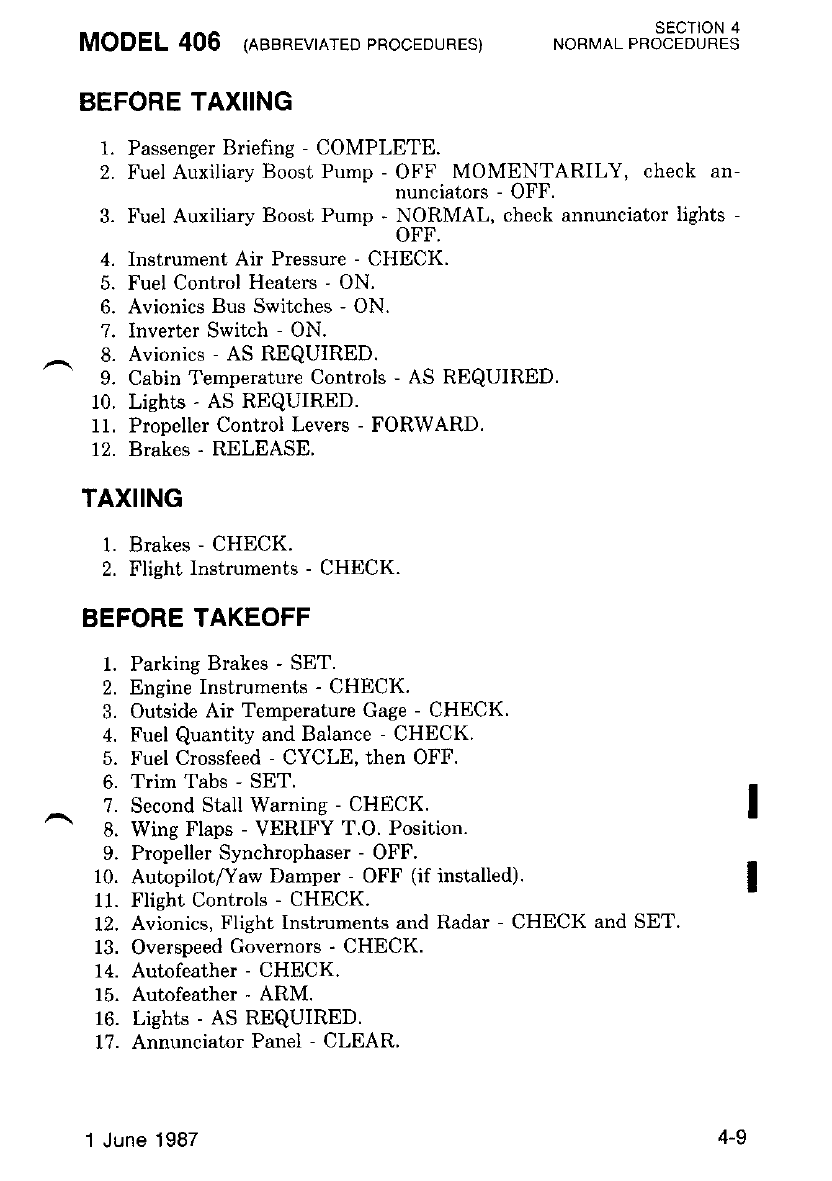
MODEL 406 (eaenevrnrED 'RocEDURES) *otto. t*oTFJl,o#3
BEFORE TAX]ING
1. Passenger Briefing - COMPLETE.
2. Fuel Auxiliary Boost Pump ffiX,"XP.YB}TARILY, check an-
3. Fuel Auxiliary Boost Pump - dfiflMAl-, check annunciator lights -
4. Instrument Air Pressure - CHECK.
5. Fuel Control Heaters - ON.
6. Avionics Bus Switches - ON.
7. Inverter Switch - ON.
8. Avionics - AS REQUIRED.
9. Cabin Temperature Controls - AS REQUIRED.
10. Lights - AS REQUIRED.
11. Propeller Control Levers - FORWARD.
12. Brakes - RELEASE.
TAXIING
1. Brakes - CHECK.
2. Flight Instruments - CHECK.
BEFORE TAKEOFF
1. Parking Brakes - SET.
2. Engine Instruments - CHECK.
3. Outside Air Temperature Gage - CHECK.
4. Fuel Quantity and Balance - CHECK.
5. Fuel Crossfeed - CYCLE, then OFF.
6. Trim Tabs - SET.
?. Second Stall Warning - CHECK. I
8. Wing Flaps - VERIFY T.O. Position.
9. Propeller Synchrophaser - OFF.
10. Autopilotfaw Damper - OFF (if installed). I
11. Flight Controls - CHECK.
12. Avionics, Flight Instruments and Radar - CHECK and SET.
13. Overspeed Governors - CHECK.
14. Autofeather - CHECK.
15. Autofeather - ARM.
16. Lights - AS REQUIRED.
17. Annunciator Panel - CLEAR.
1 June | 987 4-9
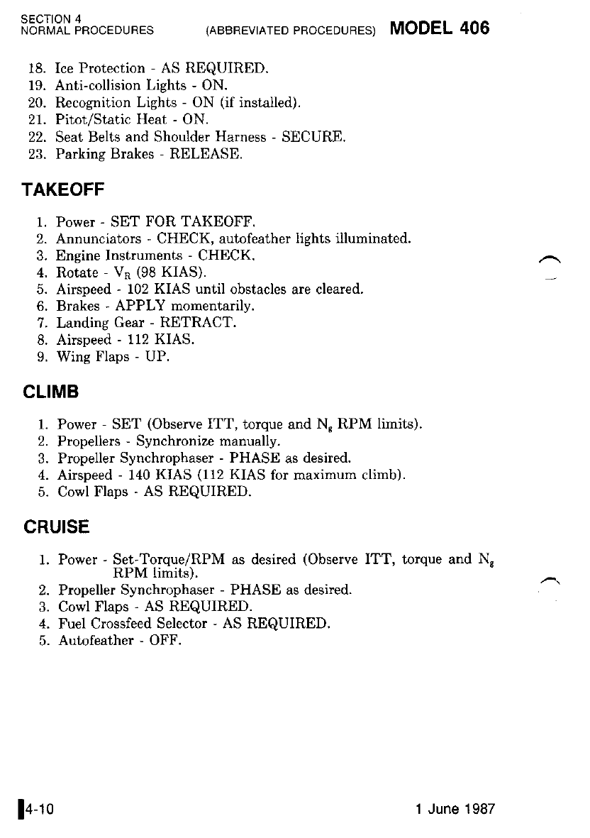
SECTION 4
lrbnvAr pnoceounes (ABBREVTATED eRocEDURES) MODEL 406
18. Ice Protection - AS REQUIRED.
19. Anti-collision Lights - ON.
20. Recognition Lights - ON (if installed).
21. Pitot/Static Heat - ON.
22. Seat Belts and Shoulder Harness - SECURE.
23. Parking Brakes - RELEASE.
TAKEOFF
1. Power - SET FOR TAKEOFF.
2. Arnunciators - CHECK, autofeather lights illuminated.
3. Engine Instruments - CHECK.
4. Rotate - VR (98 KIAS).
5. Airspeed - 102 KIAS until obstacles are cleared.
6. Brakes - APPLY momentarily.
7. Landing Gear - RETRACT.
8. Airspeed - 112 KIAS.
9. Wing Flaps - UP.
CLIMB
1. Power - SET (Observe ITT, torque and N" RPM limits).
2. Propellers - Synchronize manually.
3. Propeller Synchrophaser - PHASE as desired.
4. Airspeed - 140 KIAS (1i2 KIAS for maximum climb).
5. Cowl Flaps - AS REQUIRED.
CRUISE
1. Power - Set-Torque/RPM as desired (Observe ITT, torque and N,
RPM limits).
2. Propeller Synchrophaser - PHASE as desired.
3. Cowl Flaps - AS REQUIRED.
4. Fuel Crossfeed Selector - AS REQUIRED.
5. Autofeather - OFF.
la ro 1 June 1987
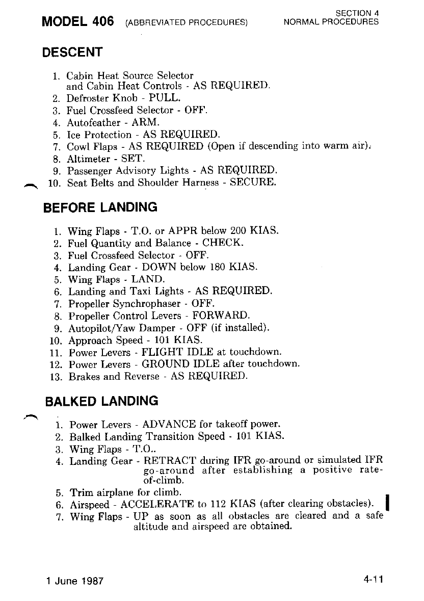
MODEL 406 lnesnevterED eRooEDURES) ,o*to,. ,*ot"t8Jl?.S
DESCENT
1. Cabin Heat Source Selector
and Cabin Heat Controls - AS REQUIRED.
2. Defroster Knob - PULL.
3. Fuel Crossfeed Selector - OFF.
4. Autofeather - ARM.
5. Ice Protection - AS REQUIRED.
?. Cowl Flaps - AS REQUIRED (Open if descending into warm air)'
8. Altimeter - SET.
9. Passenger Advisory Lights - AS REQUIRED.
^. 10. Seat Belts and Shoulder Harness - SECURE.
BEFORE LANDING
1. Wing Flaps - T.O. or APPR below 200 KIAS.
2. Fuel Quantity and Balance - CHECK.
3. Fuel Crossfeed Selector - OFF.
4. Landing Gear ' DOWN below 180 KIAS.
5. Wing Flaps - LAND.
6. Landing and Taxi Lights - AS REQUIRED.
?. Propeller SynchroPhaser - OFF.
8. Propeller Control Levers - FORWARD
9. AutopilotAaw Damper - OFF (if installed).
10. Approach Speed - 101 KIAS.
11. Power Levers - FLIGHT IDLE at touchdown.
12. Power Levers - GROUND IDI,E after touchdown.
13. Brakes and Reverse - AS REQUIRED.
BALKED LANDING
1. Power Levers - ADVANCE for takeoff power.
2. Balked Landing Transition Speed - 101 KIAS.
3. Wing Flaps - T.O..
4. Landing Gear - RETRACT during lFR.g.q-around or simulated IFR
go-around after establishing a positive rate-
of-climb.
5. Trim airplane for climb.
6. Airspeed - ACCEI,ERATE to 112 KIAS (after clearing obstacles). I
?. Wine Flaps - UP as soon as all obstacles are cleared and a safe
altitude and airspeed are obtained.
1 June 1987 4-11
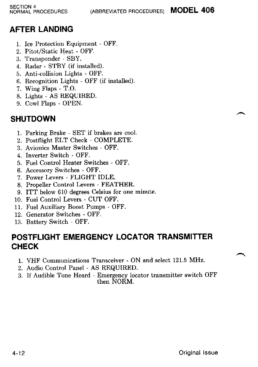
SECTION 4
NORI,IAL PROCEDURES (ABBREVIATED PROCEDUBES) MODEL 406
AFTER LANDING
1. Ice Protection Equipment - OFF.
2. Pitot/Static Heat - OFF.
3. Transponder - SBY.
4. Radar - STBY (if installed).
5. Anti-collision Lights - OFF.
6. Recognition Lights - OFF (if installed).
7. Wing Flaps - T.O.
8. Lights - AS REQUIRED.
9. Cowl Flaps - OPEN.
SHUTDOWN
1. Parking Brake - SET if brakes are cool.
2. Postflight ELT Check - COMPLETE.
3. Avionics Master Switches - OFF.
4. Inverter Swiich - OFF.
5. Fuel Control Heater Switches - OFF.
6. Accessory Switches - OFF.
7. Power Levers - FLIGHT IDLE.
8. Propeller Control Levers - FEATHER.
9. ITT below 610 degrees Celsius for one minut€.
10. Fuel Control Levers - CUT OFF.
11. Fuel Auxiliary Boost Pumps - OFF.
12. Generator Swirches - OFF.
13. Battery Switch - OFF.
POSTFLIGHT EMERGENCY LOCATOR TRANSMITTER
CHECK
1. VHF Communications Transceiver - ON and select 121.5 MHz'
2. Audio Control Panel - AS REQUIRED.
3. If Audible Tone Heard - Emergency Iocator transmitter switch OFF
then NORM.
4-12 Original lssue
MODEL 406 lreanevrnrED pRocEDURES) ro^"o. ""3"t3J1H6
ENVIRONMENTAL SYSTEMS
OXYGEN SYSTEM (IF INSTALLED)
If oxygen use is desired, proceed as follows:
1. Oxygen Control Knob - PULL ON.
2. Mask - Connect and put mask on.
3. Oxygen Flow Indicator - CHECK flow (green indicates flow).
HEATING AND VENTILATING SYSTEMS
Heater Operation - Ground:
1. Starting Engine Procedures - COMPLETED.
2. Cabin Heat Source Select - BOTH.
3. Cabin Heat Auto Control - MANUAL.
4. Cabin Heat Manual Switch - AS DESIRED.
5. Defrost and Cockpit/Cabin Air Knobs - AS DESIRED.
6. Cabin Heat Auto Control - ROTATE AS DESIRED.
Heater Operation - Flight:
1. Cabin Heat Source Select - BOTH.
2. Cabin Heat Auto Control - AS DESIRED.
3. Defrost and Cockpit/Cabin Air Knobs - AS DESIRED.
Original lssue 4-13 (4-14 blank)

AMPLIFIED NORMAL PROCEDURES
PREFLIGHT INSPECTION
The Preflight Inspection, described in Figure 4-1, is recommended for
the first,flight of the day Inspec.tion procedures for subsequent flights
may De aDDrevraf,eo at tne pttot s drscretlon.
M)TE
If a subsequent nreflipht insnection is oerformpd
ihnrtly afier shitd6w-n, be aware that eniine air
intake leading ed.ge g.s well a.s exho.ust outlets
may be uem hot.
A. If the airplanc has been in extended storage, has had recent major
maintenance or has been operated from marginal airports, a more exten-
sive ext€rior iaspection is recommended.
. After rrajor maintenance has been performed, a thorough preflight
inspection, accordance with Figure 4-1, should be completcd. Pay pir-
ticular attention to the security of access panels and dobrs and fr6e and
correct movement of control surfaces. If the airplane hae been waxed or
polished, check the external static pressure aource holes for obstructions.
The fire extinguisher bottles, located in main wheel well, should be
checked for the properly serviced indication. The indicated pressure will
change with change in ambient temperature.
If the airplane has been exposed to much ground handline, or has
been parked in a crowded hangar. it should be checked for dents and
scratches on wings, fuselage and tail surfaces, as well as damage to
navigation, anti-collision and landing lights, deice boots and avionics
antennas.
Outside storage may result in water and obstructions in airspeed
,-, "ystgT lines, condensation in fuel tanks, and dust and dirt in- the engine
' arr lnlet and exhaust areas. If anv water is detected in the fuel svstem.
the fuel tank sump quick-drain valves, fuel crossfeed line quick-drain
va.lves and fuel lllter quick-drain valves should all be thoroughly drained
until there is no evidence of water or sediment contaminaiion-. Outside
storage in windy or gusty areas, or adjacent to taxiing airplanes, calls for
special attention to control surface stops, hinges and brackets to detect
presence of wind damage. The recommended use of the control locks will
remove this problem.
Prolonged storage of the airplane will result in a water buildup in the
fuel which "leaches out" the fuel additive. An indication of this is when
an excessive amount of water accumulates in the fuel tank sumps. Refer
to Section 8 for fuel additive servicins.
MODEL 406 1er'aer-rrreopRocEDURES) SECTION 4
NORMAL PROCEDURES
Original lssue 4-15
SECTION 4
NORMAL PROCEDURES
Exhaust stubs and the exhaust heated inlet scuppers inside each stub
should be inspected for overall condition prior to each flight. Missing. or
cracked scuppers may prevent the continuous inlet heat from operating
prope y.
If the airplane has been operated from muddy fr-e.lds- or in snow or
slush, check- the main gear and nose gear wheel yqlls f91 obstructions
and cleanliness. Operation from a gravel or cinder field will require extra
attention rc propdller tips and hoiizontal stabilizer leading edg-es where
abrasion can' be' encoun-tered. Propeller stone damage can seriously re-
duce the fatigue life of the blades'
Freouentlv check all components of the landing gear retracting mecha-
nisms,'shocl struts, tires and brakes. This is esp€cially, important on
aimlanes oneratins from rouqh frelds and/or high altitudes. Improperly
ierviced shirck strits could ciuse excesgive landing and taxi loads on the
airplane structure. Landing gear shock struts should be checked before
"^"il nisltt to ensure they-aie not collapsed' This can readily be deter-
nined b1 a visual inspection of the shoik strut lower piston assembly. If
ttr" "ttpiint"a surface of the lower piston assembly is not visible. the
sliock itrut is collapsed and must be serviced before the airplane is
opet ted. A completeiy collapsed (zero ent€nsion) shock strut could cause
a'malfunction i; the -landing gear retraction syst€m. Airplanes that are
op"iut"O fro- rough fields, 6sfeciatly at high i titudes, are subjected to
abnormal landing gear abuse.
To nrevent loss of fuel in flieht, mahe sure the fuel tank filler caps are
tisfitii sealed. The fuel tank -venLs on the lower surface of the tanks
sliouli also be inspected for obstructions, ice or water, especially after
operation in cold, wet weather.
The interior inspection will vary according to, the plannq4 flight.and
the oDtional equipment installed. Prior to high-altitude flights. it is
imporiant to ch-eci< the condition and quantity of oxygen face masks (iI
i""'taUeal and hose assemblies. The oxygen supply system (if installed)
should bb functionally checked to ensur6 that it is in working order. The
o"vgutt p."".ut" sagd (if installed) should indicate 300 to 1850 pounds
pei "squate inch dEpinding upon the anticipated requirements.
Satisfactory operation of the fuel control heaters, pitot- tubes, static
sources and itall- warning transmitter heating elements is determined by
observins a discharge olithe ammeter when the fuel control, pitot/static
and stali vane switihes are turned ON' Actuating the pitot/static and
stall vane switches for 20 seconds, immediately prior to the exterior
inspeclion. will warm the heating elements sufficiently so they will feel
warm to ihe touch during the -inspection. lf operation of the static
source heaters is questionable, -run the back- of -a finger from the fuselage
skin across the stitic port and then onto the fuselage skin. If operation
is still ouestionable, the effectiveness of these heating elements can be
verified'by cautiously feeling the heat of these devices while the
Ditot/static heat switches are on.
{AMPLIFIED PROCEDURES) MODEL 406
4-16 Original lssue
If the emergency landing gear extension T-handle was noticed to be
partly extended during, the cockpit preflight lnppection. the emergency
Jandrng gear exlension blow down valve assembly should be reset a1 th'e
blowdown bottle in the left nose compartment in accor&nce with the
airplane Maintenance Manual. If the rld band is visible, the blowdown
bottle must be serviced in accordance with the airplane Maintenance
Manual before flight. lf the red band is not showins, push the cable
towards the valve assembly, then check the bottle -pressure gage for
norm{u pressure.
Flights at night and in cold weather involve a careful check of other
specific areas which will be discussed later in this section.
BEFORE ENGINE STARTING
MODEL 406 lnver-rrreo pRocEDUREs) sEcloN 4
NORMAL PBOCEDURES
1.
2.
3.
a
6.
7.
8.
9.
10.
11.
t2.
13.
14.
15.
16.
Preflight - COMPLETE.
Crew Door - LATCHED and SECURE.
Cabin Door(s) - LATCHED and SECURE.
Baggage - SECURE.
Parking Brale - SET.
Control Locks - REMOVE.
Seat, Seat Belts and Shoulder Harness - ADJUST and SECURE.
Fuel Crossfeed Selector - OFT.
Cabin Heat Source Selector - OFF.
Cowl Flaps - OPEN.
All Switches and Circuit Breakers - OFF and SET.
Generator Switches - CHECK OFF.
Battery Switrh - ON.
Interior and Erterior Lights - AS REQUIRED.
a. Master Lighting Swit{h , AS REQUIRED.
b. Panel Lights - AS REQUIRED.
c. External Lights - CHECK OFF.
I{OTE
Ground oper.ation of the high intensity anti-
collision tighls can be of.considerablc annoyance
Lo Erouna personnet and other pllots.
Passenger Advisory Lights - ON.
Larding Gear Switch - DOWN; Check Green Lights - ON.
Original lssue 4-17
1?. Annunciator Panel and Warning Lights - PRESS-TO-TEST.
a. Annunciator Panel Master
Warning Lights - PRESS to reset mast€r warning.
l{olE
The press-to-test function wiLI also test the
landi.ig gear warning horn, stall warning horn,
autopiloi mode repeater annunciators, aLL marh'
er bbacon tights, altitude alert annunciator and
the RN ani BC lights in the NAV 2 Indicator'
The gyro inuerter and auionics bus switches
nust 6e ON to check the light displays in the
autop ilo t mo de selecto r.
18. Firewall Shutoff Switches - DEPRESS, Bleed Off or Optional Fire
Bottle Armed lights illuminated; DE-
PRESS again, lights go out.
SECTION 4
NORMAL PROCEOURES 1AMPLIFIED PROCEDURES) MODEL 406
19.
20.
21.
ANY TIME THE WHITE FIRE EXTIN-
GUISHER LIGHTS ARE ILLUMINA'|ED,
DEPRESS/NG THE BUTTON WILL FIRE
THE BOTTLE.
Fuel Quantity - CHECK.
Fuel Totalizer - SET (if installed).
Air Conditioner - OFF.
Power Levers - FLIGHT IDLE.
THE PROPELLER NEVERSING LINKAGE
CAN BE DAMAGED IF THE POWER LE-
VERS ARE MOVED AFT OF THE FLIGHT
IDLE DETENT WHEN THE ENG/NES ARE
NO? Rt/NNING.
Propeller Control Levers - FEATHER.
Fuel Control Levers - CUTOFF.
24.
4-18 Original lssue
MODEL 406 (rurpurreo pRocEDUREs) SECTION 4
NORMAL PROCEDURES
1.
2.
7.
ENGINE STARTING (Battery Stan)
Voltmeter - CHECK (24 volts minimum).
Propellers - CLEAR.
Fuel Auxiliary Boost Pump - ON. Check AUX PUMP ON annun-
crator light ON, FUEL PRESS LOW
annunciator OFF.
Start Switch - START.
Ignition Light - CHECK ON.
Fuel Control Lever - RUN above 12 percent N" .
ITT and Ns - MONITOR (1090 degrees Celsius maximun).
IF NO ITT R/SE 13 OBSERVED WITHIN 10
SECONDS AFTER MOVING THE FUEL
CONTROL LEVDR TO RUN. OR ITT RAP-
IDLY APPROACHES 1O9O DEGREES CEL-
SIUS. MOVE THE FUEL CONTROL LEVER
TO CUT-OFF AND PENFORM ENGINE
CLEARING PROCEDURE.
8. Stari Light - OFF above 42 percent Ns.
9. Start Switch - OFF (Ns 52 percent or Above).
10. Engine Instruments - CHECK.
11. Power Lever - Increase to 68 percent N. .
12. Generator Switch - ON.
13. After g€nerator output decreases below 200 amperes, repeat steps 2
through 10, and 12 on opposite engine.
M)TE
ODuring a cross start of either engine the ENG
START lieht for the lirst engine slarted. may
blink as the enEine being started nears the end
ol its start cyile. Norially the tight uill not
blink but if it does it is acceptable.
OIf eith.er ENG START light remains ON after
engine stqrt, the stdrt relay or cross start rel,ay
is clnsed. Perforrn SHUTDOWN.
14. Power Levert - FLIGHT IDLE.
Do not operate or, Il.irrror", d.uring engine
starts,
Original lssue 4-19
SECTION 4
NORMAL PROCEDURES {AMPLIFIEDPROCEDURES) MODEL 406
ENGINE STARTING (With External Power)
1. Battery and Generator Switches - OFF.
2.
3.
,1
o.
7.
SHOULD THE EXTERNAL POWER UNIT
DROP OFF LINE DURING START, A TOTAL
,LOSS O,F ELECTRICAL POWEN WILL RE-
SULT WHICH COULD RESULT IN A HOT
START (ITT WILL BE INOPERATIVE).
SHOULD A IOSS OF ELECTNICAL POWER
OCCUR, IMMEDIATELY PLACE THE FUEL
CONTROL LEVER TO CUT OFF, TURN THE
BATTERY SWITCH ON, MONITOR ITT
AND ENSURE THE ENGINE IS SHUTTING
DOWN. PLACE THE STARTER SWITCH TO
THD MOTOR ONLY POSITION TO AID IN
REDUCING ITT IF NECESSARY.
M)TE
When an external power unit is used, ensure
the unit is negatioe[y ground.ed dnd regulated to
28 uolts DC with a capability of prouiding a
minimum ol 800 amperes during the starting
cycle. Exlernal power units with output exceed-
ing 1700 amperes shall not be used.
External Power Unit - ENGAGE; then ON.
Propellers - CLEAR.
Fuel Auxiliarv
Boost Pump - ON. Check AUX PUMP ON annunciatnr light ON,
- FUEL PRESS LOW annunciator light - OFF.
Start Switch - START.
Ignition Light - CHECK ON.
Fuel Control Lever - RUN above 12 percent N, . naximum).
IF NO ITT R/SE 15 OBSERVED WITHIN 10
SECON'S AFTER MOVING THE FUEL
CONTROL LEVER TO RUN, OR ITT RAP-
IDLY APPROACHES 1O9O DEGREES CEL.
SIUS, MOVE THE FUEL CONTROL LEVER
TO CUT OFF, START SWITCH OFF AND
PERFORM ENG/NE CLEARING PNOCE-
DURES.
4-20 Original lssue
8.
9.
10.
I1.
72.
MODEL 406 (ar',rpr-rrreo pRocEDUREs) SECTION 4
NORMAL PROCEDURES
ITT and N. - MONITOR (1090 degrees Celsius rnaximum).
Start Light - OFF above 42 percent N, .
Start Switch - OFF (Ns 52 percent or above).
Engine Instruments - CHECK.
Second Engine ' START - Repeat steps 3 through 11.
I{OTE
ODuring a cross start of either engine the ENG
START light for the first engine started mat/
blink as the engine being started nears the end
ol its start cycle. NormalLy the Light wilL not
blink but if it d.oes it is acceptabLe.
OIf either ENG START light remains ON
stead.y after engine start, the start relny or cross
start relay is closed.. Petorm SHUTDOWN.
13. Battery Switch - ON.
14. External Power Unit - DISENGAGE and REMO\rE.
15. Generator Switches - ON.
Engine starts may be made with airplane battery power or with an
external power unit. However, it is recommended that an external power
unit be used when the ambient air temperature is less than 0 dLgrees
Fahrenheit (-18 degrees Celsius). Refer to Cold Weather Operation ir
this section when ambient temperature is below 0 degrees Fahrenheit
(-18 degrees Celsius).
Before engine starting with the airplane batteries, check the voltmeter
for a minirnum of 24 volts. After startins the first encine, allow the
generator charge rate to decrease below 20d amperes before starting the
Secono englne.
With turbine engines, the operator must monitor ITT during each
engine start to guaid against a'"hot" start. The operator must be ready
to immediately stop the start if ITT exceeds 1090 degrees Celsius or is
raoidlv aonroachina this limit. Usuallv "hot" scarts are not a problem if
thi n6rm'al startin[ procedures are followed. A "hot" start is caused by
excessive fuel flow at normal revolutions per minutc or normal fuel flow
with insufficient revolutions per rrinute. The latter is usually the prob-
lern which is caused by attempting a start with low battery voltage. If a
cold encine does not o-,rite iate at"52 percent, it is acceptable to a-dvance
the poier lever slightly. If the staitc accelerates the gas generator
rapidly above 20 percent, suspect gear train decouple. Do not continue
start. Rapid acceleration through 35 percent Ns suggests a start on the
secondary nozzles. Anticipate a hot start.
Original lssue 4-21
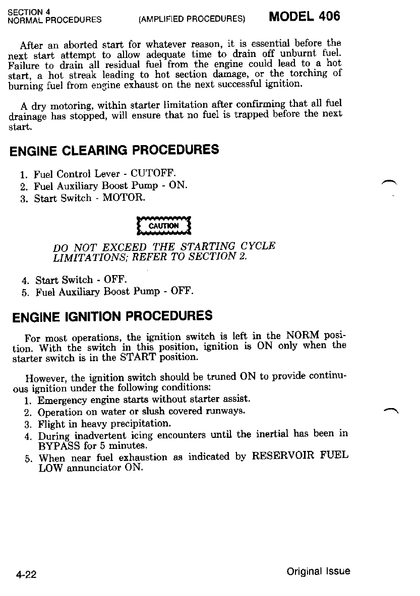
SECTION 4
NORMAL PROCEDURES
A.fter an aborted start for whatever reason, it is essential before the
""ii'.t"ti attempt to allow adequate time to drain off -unburnt fuel'
f'uit"." to drain'all residual fuel -from the engine could- lead to a hot
sGrt, a hor streah leading to hot section damage. -or. the. torching of
buming fuel from engine eihaust on the next successful igrition.
A dry motoring, within start€r limitation after confirming- that all fuel
drainagt has stopled, will ensure that no fuel is trapped before the next
starl.
ENGINE CLEARING PROCEDURES
1. Fuel Control Lever - CUTOFF.
2. Fuel AuxiliarY Boost PumP - ON.
3. Start Switch - MOTOR.
DO NOT EXCEED THE S']:ARTING CYCLE
LIMITATIONS; REFER TO SECTION 2,
4. Start Switch - OFF
5. FueI AuxiliarY Boost PumP - OFF.
ENGINE IGNITION PROCEDURES
For most operations, the ignition switch is left q -t-he NOR|'I nosi-
tioir]'w-l*, it E -i*it"h in thii position, ignition is oN onlv when the
starter switch is in the START position.
However. the ienition swikh should be truned ON to provide continu-
ous ignition undei the following conditions:
1. Emergency engine starts without starter assist.
2. Operation on wat€r or slush covered runways.
3. Flight in heavy PreciPitation'
4. During inadvert€nt icing encounters until the inertial ha"c been in
BYPASS for 5 minutes'
5. When near fuel exhaustion as indicated bv RESERVOIR FUEL
LOW annunciator ON.
{AMPLIFIED PROCEDURES) MODEL 406
4-22 Original lssue
MODEL 406 (nr"rpr:rreo pRocEDuRES) *o""or r"ot"t8Jl*S
BEFORE TAXIING
1. Passenger Briefing - COMPLETE.
2. Fuel Auxiliary Boost Pump - OFF momentarily, check AUX
PUMP ON and FUEL PRESS LOW
annunciators - OFF.
3. Fuel Auxiliary Boost Pumps - NORMAL, check annunciator
lights - OFF.
4. Instrument Air Pressure - CHECK.
5. Fuel Control Heaters - ON.
6. Avionics Bus Switches - ON.
?. Inverter Switch - ON.
8. Avionics - SET.
9.. Cabin Temperature Controls - AS REQUIRED.
a. If heating/defrosting are desired:
(1) Cabin Heat Source Select - BOTH.
TOTE
Manual Cabin Heat Control will oDen and clnse
the tentperdture control ualue lasier thnn Auto
Cabin Heat Control.
(2) Cabin Heat Auto Control - ROTATE AS DESIRED.
(3) Defrost and Cockpit/Cabin Air Knobs - AS DESIRED.
b. If ventilation is required:
(1) Cabin Heat Source Select - OFF.
(2) Fresh Air Fan Switch - LOW or HIGH.
(3) Ram Air Knob - PUSH.
(4) Defrost and Cabin/Cockpit Air Knobs - AS DESIRED.
(5) Overhead Ventilation Blower Switch (If Instaled) - HIGH
or LOW.
10. Lights - AS REQUIRED.
11. Propeller Control Levers - FORWARD.
M)TE
Do not use reuerse unless the propeller control
Leuers are in the full forward position.
12. Brakes - RELEASE.
4-23
Original lssue
TAXIING
1. Brakes - CHECK.
2. Flight Instruments - CHECK.
A steerable nosewheel, interconnected with the rudder system, pro-
vides positive control up Lo 15 degrees left or right, and free -turning
from i5 desrees I"o 50 degrees for tharp turns during taxiing. Norma-l
steerins mai be aided thro-ugh use of difierential braling and differential
power 6tr tlie main wheels. These aids are listed in the preferred order of
irse. Do not use excessive brake on the inboard side to effect a tuming
radius as decreased tire life will result.
l{otE
If the airnlane is parhed uith the nosewheel
iastered. in eithei direction, initial taxiing
shoul.d. be done uith caution. To strdighten the
nosewhnel use full opposite rudder and d.iffer-
ential power instead of differential brahing.
After a few feet of foruard. trauel, th.e nosewheel
wiLI steer normalLy.
When taxiilg near buildings or other stationary objects, observe the
minimum tumiirg distance limits; refer to Section 7. No ab,normal pre-
cautions are required when taxiing in conditions of high winds.
At some tine early in the taxi run, the brakes should be checked for
anv unusual reaction, such ari uneven bra-king. The horizontal situation
indicator should be checked for normal slaving and cross-checked with
the standbv mametic compass. Normal slavinE is indicated by oscilla-
tions of th6 gyro slaving indicator about the null point {45 degrees fixed
reference line on the HSI).
Taxi speed can be reduced by using normal bra-kir:g or by retarding
the oowei levers toward reverse aB des-ired' Minimize the use of reverse
thruit on unprepared surfaces. Placing one propeller into feather can aid
in reducing taxiing speed.
SECTION 4
NORi,l!AL PROCEDURES 1AMPLIFIED PBOCEDURES) MODEL 406
4-24 Original lssue
MODEL 406 (nrr,lpr-rrreopRocEDURES) SECTION 4
NORMAL PROCEDURES
,h"l
BEFORE TAKEOFF
1. Parking Brakes - SET.
2. Engine Instruments - CHECK.
3. Outside Air Temperature Gage - CHECK.
4. Fuel Quantity and Balance - CHECK. 200 pounds per side mini-
mum. Do not exceed 300 pounds
asymmetric fuel loading.
5. Fuel Crossfeed - CYCLE, then OFF.
6. Trim Tabs - SET elevator, aileron and rudder tabs in
TAKEOFF range.
7. Second Stall Warning - CHECK.
a. Elevator - FULL Nose up.
b. Wing Flaps - EXTEND to LAND position.
c. Stall Warning Horn - VERIFY operation.
d. Wing Flaps - RETRACT to T.O. position.
e. Stall Warning Horn - VERIFY Horn silences.
8. Wing Flaps - VERIFY T.O. position.
9. Propeller Synchrophaser - OFF.
10. Autopilot/Yaw Damper - OFF (if installed).
11. Flight Controls - CHECK.
12. Avionics, Flight Instruments and Radar - CHECK and SET-
13. Overspeed Governors - CHECK (first flight of the day and after
maintenance).
a. Propeller Control Lever - FORWARD.
b. Governor Switch - TEST.
c. Power Levers - INCREASE RPM. Propeller should stabilize at
1725 + 50 RPM.
d. Power Levers - DECREASE RPM.
e. Governor Switch - RELEASE (switch is springJoaded to NOR-
MAL).
14. Autofeather - CHECK (every flight).
a. Autofeather Switch - TEST.
b. Power Levers - INCREASE until torques are 400 foot-pounds.
Assure that both AUTO FIHER ARM annun-
ciator lights are illuminated. Slowly retard the
LH power lever to FLIGHT IDLE noting_that
in sequence: The R AUTO FTHER ARM an-
nunciator extinguishes, the L AUTO FTHER
ARM annunciator extinzuishes below 225 foot-
pounds torque and the -LH propeller begins to
feather. Increase the Ieft torque to 400 foot-
pounds. Repeat procedure for right engine.
1 June 1987 4-25
SECTION 4
NORMAL PROCEDURES (AMPLIFIED PROCEDURES) MODEL 406
NOTE
OTurbine inertia during leather may driue
toroue rasL the switch set point and cquse thc
AUTO' FTHER ARM anninciator to cvcLe off
and on.
aProper system operation i's cont'irmed once the
oroniller bepins to feather' ll is not necssary to
'susiain thelest conditions until the propeLler is
fully feathered.
oCold. engine oil may cause slow propel,l,er
feathering response Assure that the propeLler
'beeins td leaiher within 4 seconds after the
second. annunciator extinguishes.
c. Power Levers - FLIGHT IDLE.
15. Autofeather - ARM.
16. Lights - AS REQUIRED.
1?. Annunciator Panel - CLEAR.
18'IceProtectionEquipmentgtfttos"*"tt.f,*tt""*i"$Yrt"T?ttlf
outside air temperature below 4 degrees
Celsius (40 degrees Fahrenheit).
a. Heated Windshield - CHECKED.
b. Stall Vane Heat - AS REQUIRED
c. Propeller Deice - AS REQUIRED.
d. Engine Inertial Separator Switches - AS REQUIRED'
19. Anti-collision Lights - ON
20. Recognition Lights - ON (if installed).
21. Pitot/Static Heat - ON.
22. Seat Belts and Shoulder Harness - SECURE.
23. Parking Brakes - RELEASE.
Ensure the Before Takeoff Checklist is followed to pr€vent nissing an
important item.
The flieht and engine instruments should be checked -for normal
i"ai""ti"ti-*ittt "o *ii"i"g flags visible' All avionics should be set and
"hecGa io. correct freque"ncieJ or operational modes' The altimeters
;i;;IJ b;-;"i; i"po.t6a field press re, then crosschecked with each
other and against field elevation.
4-26 1 June 1987
A mental review of all engine inoperative speeds, procedures and field
length requirements should be made before takeoff. Also, review the
normal speeds and power limits (torque, ITT and fuel flow).
NOTE
Ensure ueight d.oes not exceed 9360 pound.s be-
fore takeoff.
TAKEOFF
1. Power - SET FOR TAKEOFF (1382 foot-pountls torque maxi-
mum).
2. Annunciators - CHECK Autofeather Armed Lishts - Illuminated.
.DO NOT TAKE OFF WITH AUTO-
FEATHER INOPERATIVE.
.AUTOFNATHER ARM ANNUNCIATON
LIGHTS SHOULD ILLUMINATE BE-
TWEEN 80 AND 86% N. AND REMAIN
ILLUMINATED AT HIGHER N" SETT.
INGS.
3. Engine Instruments - CHECK.
4. Rotate - VR (98 KIAS).
5. Airspeed - 102 KIAS until obstacles are cleared.
6. Brakes - APPLY momentarily.
7. Landing Gear - RETRACT. Check GEAR UNLOCKED and HYD
PRESS ON lights off.
8. Speed at 50 feet - 102 KIAS.
9. Best Rate-of-Climb Speed - 112 KIAS.
10. Wing Flaps - UP.
Before initiating the taleoff roll, a go, no-go decision should have
been made in the event an engine failure should occur. Review the
anticipated performance presented in Section 5 and assure that the
operating weight limits of Section 2 are r'ot exceeded. In addition, review
the applicable procedures and speeds associated with one-engine opera-
tion so that the transition (in the event of an engine failure) will be
smooth, positive and safe. If the anticipated performance exceeds the
runway length available or obstacle clearance requirements cannot be
achieved, it is recomqrended to take off on a more favorable runway,
off-load the airplane until the anticipated performance is consistent with
existing conditions or delay the takeoff until more favorable atmospheric
conditions exist.
MODEL 406 (nvprrrreo PRocEDURES) SECTION 4
NORMAL PROCEDURES
'I June 1987 4-27
SECTION 4
NORMAL PROCEDURES (AMPLIFIED PROCEDURES) MODEL 406
Full oower operation is recommended on takeoff since it is important
that V,'is obtained as rapidly as possible. Accelerate the airplane Lo V'
before iotaiion for addit ional safety in case of an engine failure.
Takeoff roll is most smooihly initiated by gradually advancing the
power levers until the propeller revolutions per - minute.- nears 1900.
il{esitate slightly to alloiv ihe engine to appioach stabilization. then
smoothlv re'ieas! the brakes and iontinue advancing power levers to
-"t"h fotq.r"" until the takeoff limi.t (1382 foot-pounds) is reached'
(tJnless rea'djusted. torque will increase approximate$ 50 foot-pounds as
ioeed builds'up during'takeoff roll.) If power Ievers are advanced too far
6o iapidly during iriitial application. ' expect . a surge as.the prope-ller
novernb.s -beein demanding greater blade angle. For maximum perfor-
hance takeolf power should be set before brake release. On runways
where propeller'damage from foreign objects is likely, allowing speed lo
t"iia bifoie applying iull power miy be- beneficial. Allowing the propel-
i"." ti-" to sirooi ui befoie applying takeoff torque during a touch and
go landing will minimize any asymmetric thrust.
For irosswind takeoffs the airplane is accelerated to a slightly higher
than normal rotation speed, and then is pulled off abruptly.to preir'ent
posslbi; settling back tb the runway while drifting. When -clear of the
|ound. a coord'inaled turn is made jnto the wind to correct for &ift.
After rotation at 98 KIAS, allow the airspeed to increase to Vr.
Maintain 102 KIAS until the obstacles have be cleared.
On lons runwavs, the landing gear should be retracted at the point
over the irnway where a wheels-down forced landing on that runway
would become impractical. However, on shoft runways, it mqy be prefer-
able to retract th6 landing gear after the airplane is safely airborne.
Before retracting the landing gear, apply the b-rales momentarily -to
ston the rotation 6f the main-wheels. Centrrugal force caused by the
rao'idlv rotatins wheels expands the diameter of the tires, and if ice or
-ia ti* accud, .t"d in the wheel wells, the rotatirg wheels may rub as
they enter.
To establish climb configuration, retract the landing g-ear, allow air-
soeed to increase to 112 KIAS, retract the wing flaps and then increase
airspeed to 140 KIAS. Maintain taleoff power.
CLIMB
1. Power - SET - Torque/RPM as desired (Observe ITT, Torque and
N. RPM limits).
2. Propellers - SYNCHRONIZE manually'
3. Propeller Synchrophaser - PHASE as desired.
l+-za 1 June 1987
MODEL 406 lnuerrrreo PRocEDURES)
4. Recommended Climb Sr:eed -
sEcTloN 4
NORMAL PROCEDURES
CLIMB SPEED
KIAS PRESSURE
ALTITUDE " FEET
125
1't 0
5L rO TZ,UUU
12,000 to 20,000
20.000 to 30.000
5. Speed for Maximum Climb - 112 KIAS (if required).
6. Cowl Flaps - AS REQUIRED.
Normally, maximum climb power is maintained during the climb to
cruise altitude. Adjust the power levers as required to prevent exceeding
1382 foot-pounds torque or a nominal climb ITT of 680 degrees Celsius,
^ whichever'occurs first.
NOTE
To prolong engine Life, d.o not exceed, 680 d.e-
grees Celsius ITT d.uring cLimb.
This power setting provides the best performance and range. At Iower
altitudes and outside air temperatures (below approximately 15,000 feet),
the engines will reach the torque limit before reaching the ITT or N"
limit. As the climb progresses, the ITT and N, will increase until ar
altitude is reached where the ITT or N, will dicta:te power lever position-
ing. When operating near the ITT limit, advance pirwer levers ilowly to
allow current ITT to be indicated. The rate of power (and temperature)
increase of the engine is greater than the response rate of the ITT
therefore, a rapid power lever advance could allow an overtemperature
condition to exist momentarily in the engine before the overtemperature
would be indicated.
Prior to engaging the synchrophaser system, the propellers revolutions
per minute must be closely synchronized manually (confrrm with a check
of the propeller tachometers) due to the limited capture range feature of
the system.
After light illumination, confirm the propeller revolutions per minute
has not exceeded 1900 revolutions per ninute. The propeller revolutions
per minute can be adjusted by symmetrically moving the propeller con-
trols as required. The PHASE knob may then be rotated as required to
achieve the desired noise characteristics.
If a major propeller revolutions per minute change is made with the
synchrophaser system ON and the propeller controls are not moved
symmetrically, the sSmchrophaser rnay break lock resulting in propeller
speed oscillation. The system should be turned OFF, the propeller revo-
lutions per minute reset manually and the synchrophaser turned back on.
For most normal flight operations, the cowl flaps may be allowed to
trail. In very hot arnbient conditions, it may be necessary to Iock the
cowl flaps fully open during climb.
1 June 1987 4-2sl
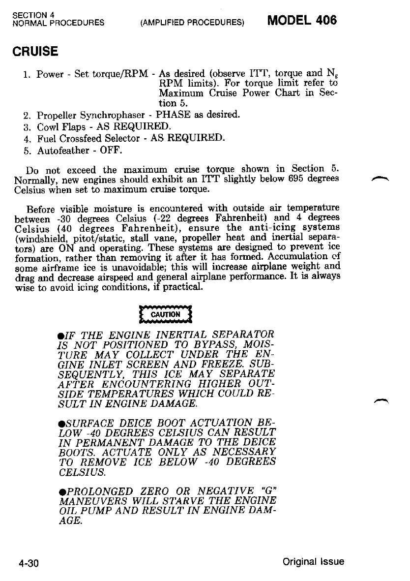
SECTION 4
NORMAL PROCEDURES (AMPLIFIED PROCEDURES} MODEL 406
CRUISE
1' Power- Set torque/RPM-*if i*1rlylru"tiIl;Tl"1f .s"1 T;
Maximum Cruise Powbr Chart in Sec-
tion 5.
2. Propeller Synchrophaser - PHASE as desired'
3. Cowl Flaps - AS REQUIRED.
4. Fuel Crossfeed Selector - AS R.EQUIRED.
5. Autofeather - OFF,
Do not exceed the maximum cruise torque shown in Section 5.
Normally, new engines should exhibit an ITT slightly below 695 degrees
Celsius when set to maximum cruise torque.
Before visible moisture is encount€red with outside air t€mperature
between -30 degrees Celsius (-22 degrees Fahrenheit) and 4 degrees
Celsius (40 desrees Fahrenheit), ensure the anti-icing systems
(windshield, pitoi/static, stall vane, propeller heat and -inertial separa-
iors) are ON and operating. These systems are desigr:ed to prevent ice
iormation, rather th'an removing it afur it has formed. Accumulation cf
somJ aitfiame ice is unavoidabl-e; this will increase airplane weight and
drae and decrease airspeed and general airplane performance. lt is always
wise to avoid icing conditions, if practical.
.IF THE ENGINE INERTIAL SEPARATOR
1S NO? POSITIONED TO BYPASS, MOIS-
TURE MAY COLLECT UNDER THE EN-
GINE INLET SCREEN AND FREEZE. SUB-
SESUEN'TLY, THIS ICE MAY SEPARATE
AFfER ENCOIJN?ERING HIGHER OU'T-
SIDE TEMPENATURES WHICH COULD RE'
SULT IN ENGINE DAMAGE.
.SURFACE DEICE BOOT ACTUATION BE-
LOW -40 DEGREES CELSIUS CAN RESULT
IN PERMANENT DAMAGE TO THE DEICE
BOOTS, AC'IUATE ONLY AS NECESSAR Y
TO REMOVE ICE BELOW .40 DEGREES
CELSIUS.
.PROLONGED ZERO OR NEGATIVE "G"
MANEUVERS WILL STARVE THE ENGINE
OIL PUMP AND RESULT IN ENGINE DAM'
AGE.
4-30 Original lssue
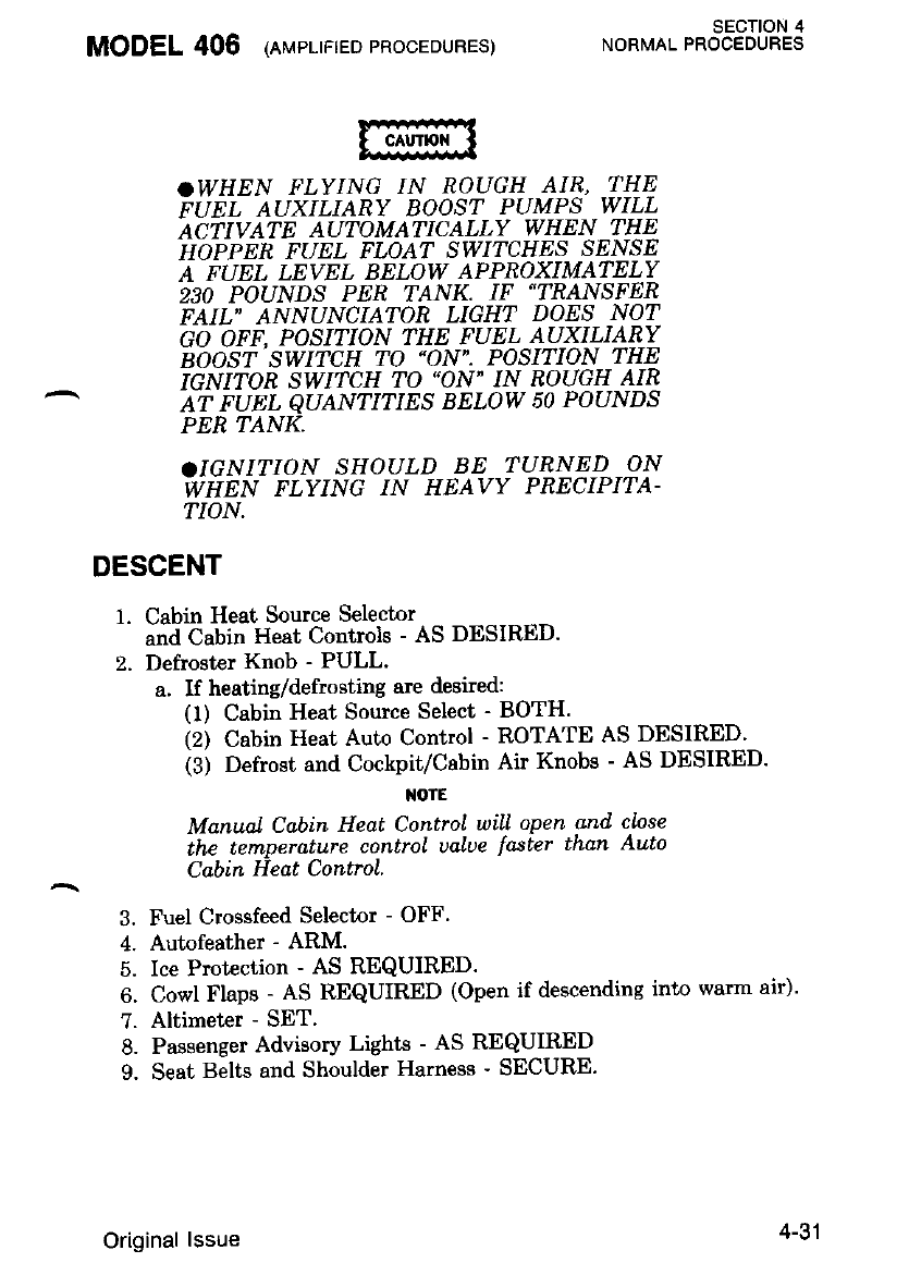
MODEL 406 (nrurpr-rrteopRocEDUREs)
Manunl Cabin Heat ControL uill open
the ternperdture control ualoe faster
Cabin Eeat Control.
Fuel Crossfeed Selector - OFF.
Autofeather - ARM.
Ice Protection - AS REQUIRED.
sEcTloN 4
NORMAL PROCEDURES
.WHEN FLYING IN ROUGH AIR, THE
PUU, 'qUXTUERY BOOST PUMPS WILL
ACTIVATE AUTOMATICALLY WHEN THE
HOPPER FUEL FLOAT SWI'|CHES SENSE
A FUEL LEVEL BELOW APPROXIMATELY
230 POUNDS PEN TANK, IF'TRANSFER
FAIL" ANNUNCIATOR LIGHT DOES NOT
GO OFF, POSITION THE FUEL AUXILIARY
BOOST,SWITCH ITO "ON". POSITION THE
IGNITOR SWITCH TO "ON" IN ROUGH AIR
AT FUEL QUANTITIES BELOW 50 POUNDS
PER TANK.
aIGNITION SHOULD BE TURNET) ON
WNTN PTYTNC IN HEAVY PRECIPITA-
TION.
DESCENT
1. Cabin Heat Source Selector
and Cabin Heat Controls - AS DESIRED.
2. Defrost€r Knob - PULL'
a. If heating/defrosting are desired:
(1) Cabin Heat Source Select - BOTH.
(2) Cabin Heat Auto Control - ROTATE AS DESIRED'
(3) Defrost and Cockpit/Cabin Air Knobs - AS DESIRED'
I{OTE
and clnse
than Auto
3.
tl
6.
7.
8.
9.
Cowl Flaps - AS REQUIRED (Open if descending into warm air)'
Altimeter - SET.
Passenger Advisory Lights - AS REQUIRED
Seat Belts and Shoulder Harness - SECURE.
Original lssue 4-31
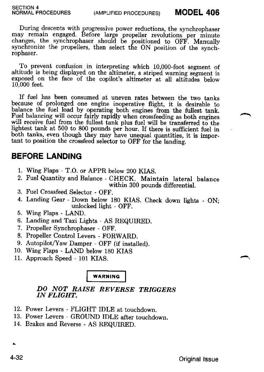
sEcTtoN 4
NOBMAL PROCEDUBES (AMPLTF|ED PRocEouREs) MODEL 406
During descents wilh progressive power reductions. the synchrophaser
may remaln engaged. Belbre large propeller revolutions Der minute
changes, .the .synchrophaser _should 6e positioned to OFF. Manually
synchronize the propellers, then select the ON position of the synch-
ropn:$er.
- To _prevent confusion in int€rpreting which 10,000-foot segment of
altitude. is being displayed on the altimeter, a striped warning seigment is
exposed on the face of the copilot's altimeter -at all altiiudei below
10,000 feet.
If fuel has been consumed at uneven rates between the two tanks
because of prolonged one engine inoperative flieht, it is desirable to
balance the fuel load by operating both ensines -from the fi.rllest tank.
Fuel balancing will occur fairly rapidlv when irossfeedile as both encines
will receive fuel from the fullest tank plus fuel will be t-ransferred t6 the
lightesi tank at 500 to 800 pounds pei hour. If there is sufficient fuel in
both tanks, even.though -the-y Bay have unequa.l quantities, it is impor-
tant to position the crossfeed selector to OFF for the landins.
BEFORE LANDING
1. Wing Flaps - T.O. or APPR below 200 KIAS.
2. Fuel Quantity and Balance - CHECK. Maintain lateral balance
within 300 pounds differential.
3. Fuel Crossfeed Selector - OFF.
4. Landing Gear - Dovn below 180 KIAS. Check down lights - ON;
unlocked light - OFF.
5. Wing Flaps - LAND.
6. Landing and Taxi Lights - AS REQUIRED.
7. Propeller Synchrophaser - OFF.
8. Propeller Control Levers - FORWARD.
9. Autopilot/Yaw Damper - OFF (if installed).
10. Wing Flaps - LAND below 180 KIAS
11. Approach Speed - 101 KIAS.
DO NOT NAISE REVERSE TRIGGERS
IN FLIGHT.
12. Power Levers - FLIGHT IDLE at touchdown.
13. Power Levers - GROUND IDLE after touchdown.
14. Brakes and Reverse - AS REQUIRED.
4-32 Original lssue
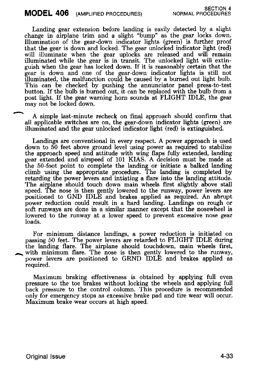
MODEL 406 (rr',rpurreoPRoCEDURES) SECTION 4
NORMAL PROCEDURES
Landing gear extension before landing is easily detected by a slight
change in airplane trim and a slight "bump" as the gear locks down.
Illumination of the gear-down indicator lights (green) is further proof
that the gear is down and locked. The gear unlocked indicator light (red)
will illuiinate when the gear uploc[s are released and wilf remain
illuminated while the sear is in transit. The unlocked lieht will extin-
guish when the gear hai locked down. If it is reasonably cErtain that the
sear is down and one of the eear-down indicator lishts is still not
illuminated, the malfunction coul-d be caused by a burneid out light bulb.
This can be checked by pushing the annunciator panel press-to-test
button. If the bulb is burned out, it can be replaced with the bulb from a
post light. If the gear warning horn sounds at FLIGHT IDLE, the gear
may not be locked down.
A simple last-minute recheck on frnal approach should confirm that
all applicable switches are on, the gear-down indicator lights (green) are
illuminated and the gear unlocked indicator light (red) is extinguished.
Landings are conventional in every respect. A power approach is used
down to 50 feet above ground level using power as required to stabilize
the approach speed and attitude with wing flaps fully extended, landing
g"ar iitended ind airspeed of 101 KIAS.-A decision must be made aI
the 50-foot point to completc the landing or initiate a balked landing
climb using the appropriate procedure. The landing is completed by
retarding the power levers and intiating a flare into the landing attitude.
The airplane should touch down main wheels frnt slightly above stall
speed. The nose is then gently lowered to the runway, power levers are
positioned to GND IDLE and brakes applied as required. Al abrupt
power reduction could result in a hard landing. Landings on rough or
soft runways are done in a similar manner except that the nosewheel is
lowered to the runway at a lower speed to prevent excesgive nose gear
loads.
For minimum distance landings, a power reduction is initiated on
passing 50 feet. The power levers are retarded to FLIGHT IDLE during
the laiding flare. The airplane should touchdown, main wheels fird
^ with minimum flare. The nose is then gently lowered to the runway,
power levers are positioned to GRND IDLE and brakes applied as
requrreo.
Maxirnum braking effectiveness is obtained by applying full even
pressure to the toe brakes without locking the wheels and applying full
back nressure to the control column. Tliis procedure is reidnirnended
only for emergency stops aB excessive brake pid and tire wear will occur.
Maximum brake wear occurs at high speed.
+-o,,
Original lssue
When a short ground run is the major consideration, retard the power
levers to reverse as required. Do not exceed the maximum revene power
limits shown in Section 2. Maximum effective braking is initiated imme-
diatelv while continuing to hold the control wheel full aft. If assymetric
reverie is experienced move po*", levers toward ground idle.
NOTE
The airplane is conlrollable with proper pilol
Lechniqie, with only one engine/propeller lully
reuersid. and Lhe other ?ngine at ftiehl idle. The
power leuers should not ie rapidly reLqrded be-
iou ground idte until symmelrtc response is
uerifted.
- For crosswind approaches, either the wingJow, crab or combination
I method may be used. After touchdown lower the nosewheel and maintain
I control. A itraight course is maintained with the steerable nosewheel,
and occasional b"raking if necessary. Excessive reversing on dirty runways
will accelerate propeller erosion.
BALKED LANDING
1. Power Levers - ADVANCE to takeoff power.
2. Balked Landing Transition Speed - 101 KIAS.
3. Wing Flaps - T.O..
NOIE
OExperience indicutes that retro'cting the land-
ing gear during an operational .VFR go ground;
uhpn on tmmPdlatc Isndtng ts contemploted'
has been cond.uciue to gear up landings.
aAluays t'olLow the Bet'ore Landing Chechlist.
4. Landing Gear - RETRACT during IFR.g.q-around or simulated IFR
qo-around aftei establishing a positive rate-
of-climb
5. Trim airplane for climb.
6. Airspeed - ACCELERATE to 112 KIAS (after clearing obstacles).
I z. Wine Flaos - UP as soon as all obstacles are cleared and a safe
I " - allilude and airspeed are obtained.
I
sEcTloN 4
NORMAL PROCEDURES (AMPLIFTED PROCEDURES) MODEL 406
4-34 '| June 1987
1.
2.
3.
4.
6.
1.
8.
9.
10.
11.
^ 12.
13.
AFTER LANDING
1. Ice Protection Equipment - OFF.
2. Pitot/Static Heat - OFF.
3. Transponder - SBY.
4. Radar - STBY (if installed).
5. Anti-Collision Lights - OFF.
6. Recognition Lights - OFF (if installed).
7. Wing Flaps - T.O.
8. Lights - AS REQUIRED.
9. Cowl Flaps - OPEN.
After leavins the active runway, the wing flaps should be retracted. Be
sure the wing -flaps switch is ide;tified beiore letracting the wing flaps.
The wing flips aie positioned to T.O. before the engines are shut down
to allow-a thorough preflight inspection of the flaps system before the
next flight.
SHUTDOWN
Parking Brake - SET if brakes are cool.
Postflight ELT Check - COMPLETE.
Avionics Master Switches - OFF.
Inverter Switch - OFF.
Fuel Control Heater Switches - OFF.
Accessory Switches - OFF.
Power Levers - FLIGHT IDLE.
Propeller Control Levers - FEATHER.
ITT below 610 degrees Celsius for one ninute.
Fuel Control Levers - CUT OFF.
Fuel Auxiliary Boost Pumps - OFF.
Generator Switches - OFF.
Battery Switch - OFF.
MODEL 406 lnrurer-rrreopRocEDURES) sEcTroN 4
NORMAL PROCEDURES
If dustv conditions exist or if the last flight of the day has been
completed, install engine inlet and exhaust covers to protect the engines
from debris. The covers may be installed after the engines have cooled
down (ITT indicators showing "off scale" temperatures)' Secure propel-
lers to prevent windmilling with no oil pressure.
Original lssue 4-35
sEcTroN 4
NORMAL PROCEDURES {AMPLIFIED PROCEOURES) MODEL 406
POSTFLIGHT EMERGENCY LOCATOR TRANSMITTER
CHECK
1. VHF Communications Transceiver - ON and select 121.5 MHz.
2. Audio Control Panel - AS REQUIRED.
NOTE
Do not trqnsml.t on 121.5 MHz unless there is
qn etlergency.
3. If Audible Tone Heard - Emergency Locator Transmitter Switches
OFF than NORM.
As long as the function selector switch on emergency locator transmit-
ter remains in the AUTO position, the emerg€ncy locator transmitter
automatically actuates following an impact of 5 g's or more over a short
period of time.
If the ernergency locator transmitter can be heard transmitting, place
the function selector switch in the OFF position and the tone should
cease. Immediately place the function selector switch in the AUTO
position to reset the emergency locator transmitter for normal operation.
ENVIRONMENTAL SYSTEMS
OXYGEN SYSTEM (lf Installed)
If oxygen use is desired proceed as follows:
1. Oxygen Control Knob - PULL ON.
PERMIT NO SMOKING WHEN USING
OXYGEN. OIL, GREASE, SOAP, LIP-
STICK, LIP BALM AND OTHER FAMY
MATERIALS CONSTITUTE A SERIOUS
FIRE HAZARD WHEN IN CONTACT
WITH OXYGEN. BE SURE HANDS AND
CLOTHING ARE OIL-FREE BEFORE
HANDLING OXYGEN EQUIPMENT.
2. Mask - CONNECT and put on mask.
3. Oxygen Flow Indicator - CHECK Flow (green indicates flow).
4. Disconnect hose coupling and push control knob in when not in
use.
4-36 Original lssue
MODEL 406 (nvpurreo eRocEDURES) *o"ro. r"ot"tFJL?.3
HEATING AND VENTILATING SYSTEMS
Heater Operation - Ground:
1. Starting Engine Procedures - COMPLETED.
2. Cabin Heat Source Selector - BOTH.
3. Cabin Heat Auto Control - MANUAL.
M)?E
Manual Cabin Heat Control will open snd close
the tempera.ture control ualue fasier than Auto
Cabin Heat ControL.
4. Cabin Heat Manual Switch - AS DESIR.ED.
5. Defrost and Cockpit/Cabin Air Knobs - AS DESIRED.
6. Cabin Heat Auto Control - ROTATE AS DESIRED.
Heater Operation - Flight;
1. Cabin Heat Source Selector - BOTH.
2. Cabin Heat Auto Control - AS DESIRED.
3. Defrost and Cockpit/Cabin Air Knobs - AS DESIRED.
OTHER NORMAL PROCEDURES
FIRE DETECTION AND EXTINGUISHING SYSTEM (IF
INSTALLED)
Fire extinguisher bottle pressures will vary considerablv with ambient
Lemperature. The lire exti::guisher bot-lle gages. are calibrated to indicate
p_roper charge based on -temperature. Gage readings must be at or above
the pressure. corr€sponding to the ambient temperaturc to indicate a
propeny sen.lceo Dotue,
STALL
The stall characteristics of the aimlane are conventional. Aural warn-
ing is provided by the gtall warning horn between 5 and 10 KIAS above
the stall in all configurations. The wing flaps UP stall is also preceded
by a moderate aerodynamic buffet whi;h iircreases in intensiW as the
s[a-ll is approached. 'The wing flaps LAND stall is preceded -by light
buff-et just priqr to the- stall. The power-on stall occuis at a ver.i steep
pitch angle with or without flaps. Ii is difficult to inadverbently sial th;
airplane -during normal maneuvering. Due to the large speed -range be-
[ween wing flaps UP and wing flapi LAND stall spe;ds, -the immidiate
relraction of wing flaps from LAND to UP should be avoided at slow
speeds. Follow all recommended procedures for wing flap retraction.
Original lssue
MANEUVERING FLIGHT
No aerobatic maneuvers, inctuding spins, are approved in this air-
pU"J; [6*"".., the airplane is convinti6nal in all respects through the
^maneuvering range encountered in normal flight.
NIGHT FLYING
Before starting the engines for a night flight' position the master
"'ilj'jiirtiiii"iiitin t" T.liGHr uttd idiutt ihe rheostats to provide
'enoueh illumination to check all swikhes, controls, etc'
Navigation lights. ajq then checked by observing. reflec.t'ions from the
oavement or qround. t ne operation of tle anti-collision lights should be
if,"iilii'^6i'.,"u'.-e*i;e-tit" -i"fl;tion" on the Eound A-fter starting th9
eneines. the retractable landing lights rray be -ext€nded -and cnecKeo
;lil;ilif. 'R":il;ft 1t.,"-l"iaitie light -switches to oFF turns the
lights off, birt leaves them extended.
Before taxi, the int€rior lighting intensity is normally de.creased to the
-i"iiiti.tit ?l^*ttl"ti uti itt" Zontr-ols and s-witches are visible' The taxi
iigil l[*n b€ turned on prior to taxiing at night.
COLD WEATHER OPERATION
Use of an APU is recommended when ambient temperatures are below
0 degrees Fahrenheit (-18 degrees Celsius)'
SECTION 4
NOBMAL PROCEDURES (AMPLIFIED PROCEDURES) MODEL 406
THE WrNGS AND TArL SU&!-AC-ES
ntusr nn CLEAR OF ICE' SNOry AN.2
iiosr PRroR To rAKEoFg 4s
-TiIENi CHARACTERISTICS CAN BE
ADVERSELY AFFEuIED.
Durins operation in cold wet weather, the possibility-of brake freezing
""#til'iii"iJt".", special pieca"tions should b-e taken' When spyere ic;nq
;;' ;'.;;;i;;-ilisi"ie uilttt freezing weather conditions - -exist' parked
;irnG;illi;tfi-fi; tt"l". i" ;oif""ondition" (not set)' If .ice is found
il "t#ir"ail d;-tltg it"ni+t inspeclio", heat the brakes with a ground
tt".i". J"i -irt" l"u'ti"it. "u"a uii tta""" of moisture are removed' If a
Ii8fia"r'titlii i; ;;;-;;ii"bi;,' .p.uv .o' pour isopropvl alcohol
iMIL-F-5566) on the brakes to remove the tce.
4-38 Original lssue
IF BRAKES ARE DEICED USING ALCOHOL,
ENSURE ALCOHOL HAS EVAPORATED
FROM THE RAMP PRIOR TO STARTING
ENGIN'S AS A FIRE COULD RESULT.
If neither heat or alcohol is available, frozen brakes can sometimes be
freed by actuating the brakes several times using maximum brake pres-
sule.
When airplane is,stopnqd on the _taxiway or runway and brale fteeze-
up occurs, actuate the brake several times using maximum pressure. To
^ raduce possibility of brake freeze-up during taxi operations in severe
weathei conditions, two taxi slowdowns (from 35 to 15 MPH) using firm
brake pressure may be made permitting brakes to reach a warm con-
dition ivaporating iny moistur6 build utwithin the brake.
After take off from slush-covered runways or taxiways, leave landing
qear down for a short period, allowing wheels to spin' This will allow
ientrifueal force to throw off any accumulated slush which should pre-
clude fr6zen brakes on landirg. Ensure wheels are stnpped before retrac-
ting the landing gear to prevent buildup of ice or slush in the wheel
wells.
During cruise, electrical equipment shouid be managed- to assure ade-
quate ge"nerator charging throughout the flight, since cold weather ad-
versely affects batt€ry capacity.
Prior to landing, and with gear down, maximum brake pressure should
be applied several-times to alleviate any brake freeze-up caused by icing
in tlie brake assembly during flying conditions.
MODEL 406 rer.,rpr-rrreopRocEDuBES) SECTION 4
NORMAL PROCEDURES
Original lssue 4-39
sEcroN 4
NORMAL PROCEDURES (AMPLIFIED PROCEDURES) MODEL 406
AVIONICS SYSTEMS NORMAL PROCEDURES
NOTE
When operating airplanes equipped with option-
al ARC 1000 series auionics, refer to Section 9
for the appropriate auionics operational proce-
d.ures and. Limitatinns.
1OOO AUDIO CONTROL PANEL
1. VOL HDST/SPKR
Control - Initial setting of both controls at 2 o'clock position. The
VOL HDST outer concentric knob sets the master vol-
urre level for the headsets. The VOL SPKR inner con-
centric knob sets the master volume level of the speaker.
ltotE
Set the indiuidunl uolume controls of each re-
ceiuer onLy after setting the master uolume leuel
controls on the aud.io control Danel.
2. INTERCOM ON/OFF
Selector Switch - AS REQUIRED. When the switch is set to the
ON position it provides communication between
pilot and copilot without having to actuate any
microphone button. In dual installations, setting
either of the INTERCOM selector switches to
ON provides intercommunication- During trans-
mrssrons where the pilot or copilot wheel micro-
phone buttons are pressed, the interphone func-
tion is muted
iIOTE
OThe interphone leueL is ad.justable only
throu4h the master HDST or SPKR controls
and shouLd be ad.justed from the initial 2 o'clock
setting to the d.esired. leuel before the indiuidual
receiuer controls are set to their final d.esired
leuel.
)The speaker interphone function shnul.d onLy
be used. with oxygen mask microphones because
the normal lip rnicrophones will cause a feed-
back squeal in the cockpit.
Olntercornmunication between piht and copilat
should not be attempted using the hand-h.eld
microphone, since keying the microphone uill
hey the transmitter for whateuer Com the func-
tion selector suitch is set.
4-40 Original lssue
MODEL 406 (rurplrrreo pBocEDURES) SECTION 4
NORMAL PROCEDLIRES
SPKR/OFF/HDST Receiver
Selector Switches - SELECT any of the receiver audio signals in-
dividrrally or in combination for simultaneous
monltrol1ng.
I{OTE
Set the ind,iuiduaL receiuer uolume controls at
th,eir final d,esired leueL onLy after establishing
the interphnne Leuel uith the nTdster controls. In
the euent that interphone is not being utilized,
set the indiuidunl receiuer uolume control's with
the mqster controls at the 2 o'clnck position.
4. Function Selector
Switch - AS REQUIRED. Select COM 1, 2, 3 or CABIN. The
transmitter sidetone audio will be heard in the headset or
sneaker for the appropriatelv selected transmitter. In dual
iirstallations, the sideione will only be heard bv pilot and
copilot when both audio control panels are set to the s€me
transmitter selection.
5. AUTO SPKR/HDST
Selector Switch - AS REQUIRED' Selects the appropriate receiver
audio or'transmitter sidetone for reception on the
headset or speaker' On dual installations, the pi-
lot's control banel activates only the pilot's head-
set or speaker and the copi.lot's control panel
activat€s only the copilot's headset or speaker.
6. Marker Beacon
HTGHA'WMUTE switch f:".*it,",t*"?; i"# l3.r'*l"i:
MUTE position is momentary and
mutes the marker beacon audio for
approximately 30 seconds.
otE
oThe marker beacon and' DME au.dio leuel is
ad.iustabl.e onLv Lhrouph the naster uolume con-
trols, therefori, it is finportant to heep the mas'
ter controls within Lheir normaL operating range
of approrimately 2 o'cloch. * any indiuiduaL
c'ornfdrt adiustment to tahe care of ambient
uoice Leuel or uariations in headset tlpes (muff,
single receiuer, etc.)
aDo not operate the master uolume controls at
an extrernbly lou setting while turning up the
indiuidunl receiuer uoLume conlrols to an ex-
tremelv hieh selttne. This could result in distor-
tion o7 NAV. CoNi and ADF audio as well as
low leuek of MKR and DME aud'io.
Original lssue 4-41
SECTION 4
NORMAL PROCEDURES {AMPLIFIED PROCEDURES) MODEL 406
?. Cabin Communication - Cockpit communication with the cabin is
accomplished bv setting the function selec-
tor switch to CABIN position and actuat-
ing the hand-held microphone or boom or
oxyeen mask micronhone. When the cabin
wrifies to communicatc with the cockpit,
actuation of the cabin-mounted micro-
phone key lights the CABIN CALL in-
ilicator on thdaudio control panel to signal
the cockpit. When the function selector
switch is-set to CABIN, communication is
established between the cockpit and cabin.
4OO AUTOMATIC DIRECTION FINDER
1. OFF/VOL Control - ON; ADJUST to desired listcning level.
2. PRI Frequency Selectorc - SELECT desired operating frequency.
3. SEC Frequency Selectors - SELECT desired operating frequency.
4. 1-2 Selector Switch - 1 position.
l.olE
The 1-2 selector switch can be plnced tn th'e "2"
position for operatinn on secondary freErcncy.
The resel.ect larnp will fLash only when freqrrcnqt
sebctian is outside of operating range of the
receLDer.
5. ADF SPEAKER/PHONE Switch - SELECT speaker or phone po-
sition as desired.
6. ADF Pushbutton - PUSH IN and note rclative bearing on ADF
7.
Indicator.
TEST Pushbutton - PUSH IN and hold until indicator pointer
slews off indicated bearins at least 10 to 20
degrees.
Indicator Pointer - Observe that pointer returm to the same rela-
tive bearing as in step 1.
HDG Control - SET goniometer-indicator dial so that index in-
dicates magnetic or true heading of airplane. Point-
er indicates bearine to station.
8.
9.
4-42 Original lssue
NOTE
When switching stations, plaNe function push-
button in the REC positian. Then, after statinn
has been selected, place lunction pushbutton in
the ADF Dosition to resume autornntic direction
find.er operation. This practice preuents the
bearing indicator from swinging bach and. forth
as freEnncy dial is rotated..
10. BFO Pushbutton - PUSH IN as required.
r|orE
A 1000-Hz tone is heard in the audio output
whcn CW signal (Morse Code) is tuned. in piop-
erry.
ELECTRIC ELEVATOR TRIM DISENGAGE CHECK
1. Operatc the electric trim switch in one direction and observe mo-
tion of the manual pitch trim wheel in the proper direction. While
perforrning the above test, nomentarily depress APIRIM DISC
switch and release. Observe that manual pitch trim wheel motion is
arrested and remains stopped when the disconnect switah is re-
leased and electric trim swilctr is actuat€d.
2. Repeat Step f. in the opposite direction.
3. Elevator Trim - SET for takeoff.
MODEL 406 1er*er-rrreo eRocEDURES) SECTION 4
NORMAL PROCEDURES
Original lssue 4-43
4OO MARKER BEACON
1. LOIHI MKR Swit'ch - SELECT HI position for airwav flving or
LO Position for ILS aPProaches'
2. SPKR/OFF/HDST MKR Switch - SEIECT speaker or headset
auoro.
3. VOL (HDST OR SPKR) CONTROL - ADJUST volume level'
4. Marker Beacon rest switch - lcruA.rP "?""igffi""1}1i"#i};:
ftotE
oThe marker beacon and, DME audin leuel is
adjustable only through the nrdster oolume con-
tr6ls, thereforL, lt is irnportant to heep -the rnos'
ter control.s within thcir nnrmaL operat.tnS. rdwe-
ol approximately 2 o'cloch ! dny LndtDl-dual
c'omi6rt adiustment to tohe care of ambient
uoicb leuel or uoriations in headset types (muff,
singLe receiuer, etc.)
ODo not operate the master uolume controk at
ii "rtr"^bLy lou setttng while tur.ning up the
indiuidual receiuer uoLume controla to an ex-
tremelv hish settine This could result in distor'
tion o7 NAV, COIrt and ADF sudio os uell as
Lou leuels of MKR and DME audio.
4OO NAVIGATION/COMMUNICATIONS
Pretuning Active Nav/Com Frequencies:
1. COM OFF/VOL Control - TURN ON; adjust to desired audio level'
2. FREQUENCY
- ^siil,elC-fons - MANUALLY ROTATE corresponding NAV or
- COM frequencv selectors (press 25/50 pushbutton
as reouired to- select the desired third fractional
COM'digi$ until the desired freqlency. is shown in
the freqiency readout window' The display bli*s
ioi approxlmatety 8 sec-onds. indicating that the
selected frequency is ready tor storage ln memory'
3. MEMORY 1,2,3
-' ifihdfu; I pnnss the active frequencv memory button as in-
ai""t"a Uv the illumiruited iiremory. bar'.The .displav
immediatily stops blinking. indicating that the new
ii"q""""v is stored in th6 active memory arrd dis-
plays thi new active frequency' The original active
frequencY is lost.
SECTION 4
NORMAL PROCEDURES 1AMPLIFIED PROCEDURES) MODEL 406
4-44 Original lssue
MODEL 406 lnverrrreo PRocEDURES) sEcTroN 4
NORMAL PROCEDURES
Preselecting and Storing Nav/Com Frequencies In Memory.
1. COM OFF/VOL CONTROL - TURN ON; adjust to desired audio
level.
2. FREQUENCY SELECTORS - MANUALLY ROTATE corre-
sponding NAV or Com frequency
selectors (press 25/50 pushbutton as
required to select the desired third
fraitional COM digit) until the de-
sired frequency is shown in the fie-
quency readout window. The dis-
play blinks for approxirrately 8 sec-
onds, indicating that the selected
frequency is ready for storage in
3. MEMORY 1. 2. 3 memorv'
Pushbuttons - PRESS the memory pushbutton of one of the NAV
or COM memories not in use. The display imme-
diately stops blinking, and displays th-e irew fre-
quency for 1 second to indicate that it is now stored
in the selected memory. The display then reverts to
indicating the active frequency.
4. Merrory 1, 2, 3 Pushbuttons - REPEAT STEPS 2 and 3 r,o smre
another frequency in the second
NAV or COM memory not in use.
IOTE
This presetting sequence for memory 2 or 3 does
not effect comrnunication and/or nauigation op-
eration on the originaL actiue frequency.
Recalling a Stored Frequency:
1. MEMORY 1,2,3 Pushbuttons - SELECT ard PRESS the desired
NAV or COM memory button,
and observe the following:
a. Frequency in selected memory becomes the active frequency.
b. Frequency readout window indicates new active frequenoy.
c. Corresponding memory bar indicates selected memory.
Communication- Receiv-er-Tranimitter Operation
1. COM OFF/VOL Control - TURN ON.
2. XMTR SEL Switch (on audio control panel) - SET to rtesired 400
NAv/COM.
3. SPEAKER/PHONE Selector Switches
(on audio control panel) - SET to desired mode.
4-45
Original lssue
SECTION 4
NORMAL PROCEDURES (AMPLIFIED PROCEDURES) MODEL 406
4. coM Frequency serection f,,t:tnf;l Sffl:i* T"ddift-^i.d'ff6tri
1. 2 or 3 pushbuiton to recall a preset
fiequency,- or by manually select'ing the
desired operating frequency using t}le
COM frequency selectors and 25/50
pushbutton.
M)TE
If duat VHF cornrnunications systems are in-
itatLed, improued cornmunication with the air-
plane on fhe ground may be obtained b-y usiryg
-the VHF COM 2 which is connected to the
uertical fin antenna. Airframe masking of the
RF sisnals lrom the Inwer ft'tselage antenna os-
sociatid wtih the VHF COM 1 sometimes im-
p air s ground c o mmunication.
5. Vol control - Adjust to desired audio level'
6. SQ Control - ROTATE counterclockwige to decrease background
' noise as required.
?. Microphone Button:
a. To Transmit - PRESS; speak into microphone'
b. To Receive - RELEASE.
Navigation OPeration:
r. "COfr,f OFF/VOL Control - TURN ON; adjust to desired audio level'
2. SPEAKER/PHONE Selectnr Switches
-- (-on audio cbntrol panel) - Set to dested mode'
3.NAVFrequencyserectionirt:,?nllrl;:Jf t""ftI"+tilf Eff8H"f ?
2'or 3 nushbutton to recall a preset
frequenci, or by using NAV frequency
selecf,or.
4. NAV VOL Control - ADJUST to desired audio level'
5. ID-VOX-T Switch:
a. To Identify Station - SET to ID to hear navigation station
identifier signal.
b. To Filter Out Station - SET to VOX to include frlter in audio
circuit.
4-46 Original lssue
SECTION 4
NORIJAL PROCEOURES
6. ARC PUSH-TO/PULL-FROM Knob (if applicable);
a. To Use As Conventional OBS - PLACE in -center detent and
select desired course.
b. To Obtain Bearing TO VOR
"' sLti"" - puSH ("1'nC/puSg-rO) krob to inner (Momentary
On) position.
olE
ARC larnp wilt iltuminate amber qhile the O4S
"iirti cira is m'ouing to center thc course- de-
iTiion potnter. Afler alignment has been
achieoed'to reflect bearing TO VQR' -automdtlc
ra.dial cenlering uilL sutomattcally sryul do.w:LA
causing the ARC lamp to 8o -out and the AftL,
hnob lo return to the center detent posrtton anq
function os a normal OBS
c. To Obtain Continuous
" B;"'tiliiRbM-Vbn St"tio" - PULL (ARC/PULL-FR) knob
to outer det€nt.
t{olE
ARC lamp witl illuminate amber: OBS, course
card, will turn to center the course deDlatlon
ioiiter uith a FROM flag to indicate bearing
'from VOR station. This $/stem .urtl co.ntrnuduy
'driDe to present the VOR radiaL the airplane ts
on untU'manually returned to the center detent
W the Pilot.
?. AP/CPLD Annunciator Lisht -clIECK ,o) Jl'6ll ti.iif,,"1tT;
1000A IFCS is engaged), amber
light illuminated'
VOR Self-Test Operation:
1. COM OFF/VOL Control - TURN ON'
2. NAV Frequency Selector Switches - S.ELECT usable VOR station
slgnar'
3. OBS KNOB - SET for 0' course-at course- index;,course deviation
pointer centers or deflects l9{9r-9gh!' $epending on
bearitts of signal; NAVAO-FROM indicator shows
TO or FROM.
MODEL 406 (avpr-rrreo PRocEDURES)
Original lssue 4-47
SECTION 4
NORMAL PROCEDURES (AMPLIFIED PROCEDURES) MODEL 406
4. IDIVOX/T Switch - PRESS to T and HOLD at T; course de-
viation pointer centers, NAV/TO-FROM in-
dicator shows FROM. AP/CPLD and XMIT
annunciators are illuminated and the COM
and NAV displavs show 188.88 with all mem-
ory bars illuminated.
5. OBS Knob - TURN to displace course approximately 10o to either
side of 0" lwhile holding' iD/VOX/f). Course de-
viation pointer deflects full scale in direction cor-
responding to course displacement.
NOISE ABATEMENT
Increased emphasis on improving the quality of our environment
requires renewed effort on the part of all pilots to rninimize the effect of
airplane noise on the public.
We, as pilots, can demonstrate our concern for environmental im-
provement by application of the following suggested procedures, and
thereby tend to build public support for aviation:
1. Pilots operating airplanes under VFR over outdoor assemblies of
persons. recreational and park areas, and other noise-sensitive areas
should make every effort to fly not less than 2000 feet above the
surface, weather permitting, even though flight at a lower level may
be consistent with the provisions of government regulations.
2. During departure from or approach to an airport, climb after
takeofl anil descent for landine should be madi: so as to avoid
prolonged flight at low altitudi near noise-sensitive areas. Avoid-
ance of noise-sensitive areas, if practical, is preferable to overflight
at relatively low altitudes.
NOTE
The preceding recommend,ed proced,ures do not
apply whe.re they uould conflic.t with Air.Traffic
Control cleqrances or instructions, or where, in
the pilot's jud.gment, an altitu.d.e of less than
2000 feet is necessary to ad,equately exercise his
duty to see and sooid. other airpl.anes.
The flyover noise level, established in compliance with FAR 36 at
maximum continuous power is 72.0 dB(A).
No determination has been made bv the Federal Aviation Administra-
tion that the noise level of this airplane is, or should be, acceptable or
unacceptable for operation at, into, or out of any airport.
4-48 Original lssue
PROCEDURES FOR PRACTICE DEMONSTRATION
oF vMcA
Enrine inoperative procedures should be practiced in anticipation of
""-"ni.ig"".y'. This practice should be conducted at a safe altitude and
.no"ia tt sr]arted at a safe speed of at least 115 KIAS-' As recovery
;i;ilii; il eained wiLh practice, the starting speed mav be lowered in
.*uii i""t"'.""t. until the feel of the airplane ir: emergency conditions is
il'"1liii"-*i. ii "itould be noted that as ihe speed is reduced, directional
"o"t-i b""o-". more diffrcult. Emphasis should be placed on Stopping
ih;-iliiiJ ttc" yaw angles bv Ihe'IMMEDIATE app-lication of rudder
"ript"i"-*ti a -tv"nankin"g sliglitly away from the yaw. Practice should be
^ i"-"ii"iila ""tiji (ti a" instinctive coirective reaction is deveJoped and
^ ittJ'"iit*ti"" procedure is automatic and, (2) airspeed, altitude, -and
n"lai"i, i"ii be 'maintained easily while the airplane is being.pre.pared for
a climb. tf a failed engine's propeller is allowed to w-rndnr[' . expect
;ia; f"; and deflection requir6d for coordination to be significantly
greater.
Practice Demonstlation ol vMcA
1. Wing FlaPs - T.O.
2. Landing Gear - UP.
3. Power Levers - SET takeoff power'
4. Airspeed - VssE (98 KIAS) minimum'
5. Trim - SET for takeoff'
6. Instmctor Pilot:
a. Power Lever of Simulated Failed Engine - IDLE'
b. ProPeller Control Lever of
Sirnulated Failed Engine - FEATHER'
7. Airspeed - DECREASE at approximately 1 Knot per second until
reaching V""^ (rdd radial) oi stall warning, whichever
occurs first.
8. Heading - MAINTAIN .with rudder and 5 degrees bank towards
operatrve engue.
V."o is used in training and is not a limitation' It is^ recommended'
br*;i""r,i;;;;;pi-r* ii.i"ing, demonstrations, takeoffs and landings'
this aimlane should not be flown at a speed slower than v ssE-
Under no circumstances should should Juce - demonstration be at-
t"-iiii'"i'i ti;;i;t;;;i1ha" ihe red radial 6ii'the airspeed indicator'
MODEL 406 (rr',rpltrteoPRocEDUREs) SECTION 4
NORMAL PROCEDURES
Original lssue 4-49
sEcTtoN 4
r.ronMAr pnoceouaes (AMpLTFTED pRocEDURES) MODEL 406
Simulated Engine Failure in Takeoff Configuration
1. Wing Flaps - T.O.
2. Landing Gear - DOWN.
3. Power Levers - SET takeoff power.
4. Airspeed - 98 KIAS ininimum.
5. Trim - SET for takeoff.
6. Instructor Pilot:
a. Power Lever of simulated failed engine - 150 foot-pounds.
7. Aileron and Rudder - AS REQUIRED to maintain straight ahead
flight (3 to 4 degrees bank with 1/2 ball slip
into operative engine).
8. Power Levers - TAKEOFF POWER, (failed engine, simulated
takeoff power) .
9. Landing Gear - UP when rate-of-climb is positive.
10. Autofeather - MONITOR for proper actuation (simulated).
11. Climb to Clear Obstacles - 102 KIAS.
12. Refer to ENGINE FAILURE AFTER ROTATION checklist.
Simulated engine failure taleoff and landing practice is most safely
done with both propellers set at 1900 revolutions per minute and the
simulated failed engine set at 150 foot-pounds.
FUEL CONSERVATION
Operational maintenance and record-keeping techniques, taken to-
gethir, can minimize wasted fuel, extend the use-ful range'of any airplane
and result in a significant reduction in general operating costs.
On preflight inspection, entrance doors, baggage doors, emergency
exits, cowl flaps and wing flaps should be checked for alignment. Any
one of these items not precisely aligned will create additional drag.
Good nechanical condition of the airplane and engines is very impor-
tant for efficient operation and therefoie, the best [se of fuel.-A ciean
exterior, especially on the wing leading edges, results in better fuel
economy.
Time spent on the ground in careful flight planning will avoid need-
less delays on the ground, unnecessary fuel stops and other conditions
that can be wasteful of time arrd fuel. Plan flight in a straight line
whenever possible and after takeoff, turn on course as soon as practical.
Take advantage of altitudes ard favorable winds, but balance the
ground speed benefits of high altitudes and winds asainst the extra time
consumed in climbing to reach best altitude, refer to Section 5, for Fuel
and Time Required Chart.
4-50 Original lssue
Plan flishts with maximum occupancy; a little effort in coordinating
and schedrlling can provide many miles of travel with no additional use
of fuel by filling empty seats.
Plan arrival and departure times to avoid peak hours of operation at
airport. Substantial fuel can be saved by reducing the -time that the
airilane is operated on the ground. A call to the tower before slarting
""fi""r, i"du',t"a power and i short run-up before takeoff will all result
in fuel savings.
In flight, use proper climb and trim techniques. r-aise the landing- gear
and wing -flaps as soon as,sat'ely practrcal and reter to becf,ron o' ror
cruise Dertbrmance rntoflnatron.
When descending, stay high and avoid a far out descent' Descend at
uour "-iru sesme;t indica6d speed with power reductions as appro-
;;t"t". Tit; ."a-.o" fot keeping th'e speed down is simplv because^ a speed
i"".au." ".ut"a a severe diaglncreaie gnd a consequent waste of energy'
b';t;.6;ai;s the landin[ gear and wir:g flaps on final approach as
lat€ a3 salely pracf,rcal.
MODEL 406 (er'aplrrteopRocEDuRES) SECTION 4
NORMAL PROCEDURES
Original lssue 4-51 (4-52 blank)

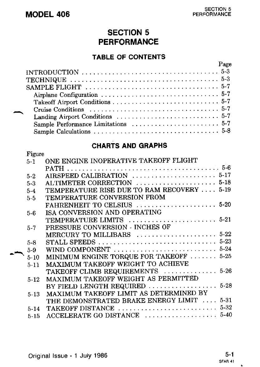
MODEL 406 SECTION 5
PERFORMANCE
sEcroN 5
PERFORMANCE
TABLE OF CONTENTS
INTRODUCTION
TECHNIQUE
SAMPLE FLIGHT
Airplane Configuration . .
Takeoff Airport Conditions
Cruise Conditions
LandingAirportConditions .....
Sample Performance Limitations
Sample Calculations ... .
Page
5-3
5-3
5-7
5-7
o-l
5-8
CHARTS AND GRAPHS
Figure
5-1 ONE ENGINE INOPERATIVE TAKEOFF FLIGHT
PATH.. ..........5-6
5-2 AIRSPEED CALIBRATION ........5-17
5-3 ALTIMETER CORRECTION ,.,....5.18
5-4 TEMPERATURE RISE DUE TO RAM RECOVERY . . . . 5.19
5-5 TEMPERATURE CONVERSION FROM
FAHRENHEIT TO CELSIUS ......5.20
5-6 ISA CONVERSION AND OPERATING
TEMPERATURE LIMITS .
5.7 PRESSURE CONVERSION - INCHES OF
MERCURY TO MILLIBARS
5-8 STALL SPEEDS
^ 5-e WIND COMPONENT . . .
- - s-ro MINIMUM ENGINE ToRQUE FoR TAKEoFF
5-11 MAXIMUM TAKEOFF WEIGHT TO ACHIEVE
TAKEOFF CLIMB REQUIREMENTS .,,.... 5-26
5-12 MAXIMUM TAKEOFF WEIGHT AS PERMITTED
BY FIELD LENGTH REQUIRED ....5-28
5-13 MAXIMUM TAKEOFF LIMIT AS DETERMINED BY
THE DEMONSTRATED BRAKE ENERGY LIMIT . . . . 5.31
5.14 TAKEOFF DISTANCE .....5-32
5-15 ACCELERATE GO DISTANCE .....5.40
5-21
5-22
5-23
5-24
5-25
5-1
Original lssue - 1 July 1986
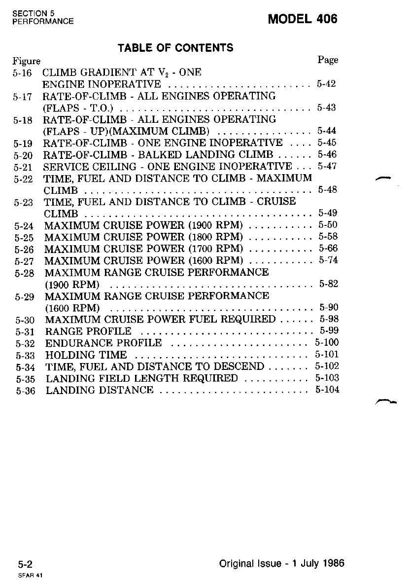
SECTION 5
PERFORMANCE
Figure
5.16 CLIMB GRAD
5-2
MODEL 406
Page
ENGINE INOPERATIVE ,....,,...5-42
5-1? RATE-OF-CLIMB - ALL ENGINES OPERATING
(FLAPS -T.O.) ... .....,..5-43
5.18 RATE-OF-CLIMB - ALL ENGINES OPERATING
(FLAPS - UP)(MAXIMUM CLIMB) . ........5-44
5-19 RATE-OF-CLIMB - ONE ENGINE INOPERATIVE .... 5.45
5-20 RATE-OF-CLIMB - BALKED LANDING CLIMB ...... 5-46
5-21 SERVICE CEILING - ONE ENGINE INOPERATIVE . . . 5-47
5-22 TIME, FUEL AND DISTANCE TO CLIMB - MAXIMUM
CLIMB . .........5-48
5-23 TIME, FUEL AND DISTANCE TO CLIMB - CRUISE
CLIMB . .........5-49
5-24 MAXTMUM CRUISE POWER (1900 RPM) . . . . 5-50
5-25 MAXTMUM CRUISE POWER (1800 RPM) . . . . 5-58
5-26 MAXIMUM CRUISE POWER (1700 RPM) . . . . 5-66
5.2? MAXIMUM CRUISE POWER (T600 RPM) . . . . 5-74
5-28 MAXIMUM RANGE CRUISE PERFORMANCE
(1900 RPM) 5-82
5.29 MAXIMUM RANGE CRUISE PERFORMANCE
(1600 RPM) ......5-90
5-30 MAXIMUM CRUISE POWER FUEL REQUIRED . . . . . . 5-98
5-31 RANGE PROFILE ........5-99
5-32 ENDURANCE PROFILE .. 5-1OO
5-33 HOLDING TIME . .......5-101
5-34 TIME, FUEL AND DISTANCE TO DESCEND ....... 5.102
5-35 LANDING FIELD LENGTH REQUIRED . . . . 5.103
5-36 LANDING DISTANCE ....5-104
TABLE OF CONTENTS
IENT AT V, - ONE
Original lssue - 1 July 1986
INTRODUCTION
Section 5 contains all the performance limitations and information
tud,*a to op"*te the airplani safely- and to-help you plan your flighk
in detail with reasonable accuracy' Sale and precse operalron oI Lne
"i-t""" t.quit". the pilot to be thoroughly familiar with and understand
thi data an-d calculatibns of this section.
The data on these graphical and tabular -charts have bee-n com..piled
irom actuat flieht tesLsl with the airplane and engines in good condition,
".itislt"t"s" "pitot techniques. Note that the cruise peiformance data
--JEr no A"to*"tt"u for wiid and/or navigational errors. Allowances for
, .t"tt. t"ti. takeoff, climb, descent and 45 ninutes reserve at the- particl-
-t" 6. c;"G power and altitude are provided in the mnge profile chart, the
"nauia"""'p.oru chart and the'maximum cruise [o*er fuel required
chatf,,
All oerformance, range and endurance charts are based on the use of
jet fuei with nominal fuel density of 6.70 pounds per gallon'
Refer to the following figures for operating weight limits:
MODEL 406
1. Power ratings include the installation,
losses.
2. Full temperature accountability within
which th6 airplane is certified.
Original lssue
sEcTloN 5
PERFORI\4ANCE
Weight To Achieve Takeoff Climb Require-
Weight As Permitted By The Field Length
bleed air aad accessory
the operational limits for
1. Maximum Takeoff
ments
2. Maximum Takeoff
Required
3. Maximun Takeoff Weight Limit As Deternined Bv The Dem-
onstrat€d Bra}e EnergY Limit
4. Landing Field Length Required
TECHNIQUE
REGULATORY COMPLIANCE
,A Information in this section is presentcd for the purpose of compliance
with the appropriate performance criteria and certification requirements
of SFAR 41.
STANDARD PERFORMANCE CONDITIONS
All nerformance in this manual is based on flight test data and the
followiirg conditions:
c-J
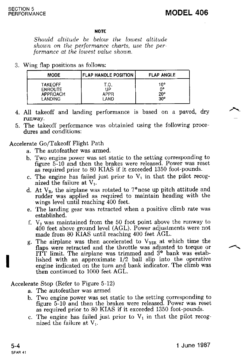
sEcroN 5
PERFORMANCE
c-+
NOTE
ShouLd aLtitude be below the lowest altltude
shown on the performance charts, use the per-
formance at the Loutest ualue shown.
3. Wing flap positions as follows:
MODEL 406
MODE FLAP HANDLE POSITION FLAP ANGLE
TAKEOFF
ENROUTE
APPROACH
LANDING
T.0.
UP
LAND
100
0'
20.
30"
4. All takeoff and landing performance is based on a paved, dry
runway.
5. The takeoff performance was obtainied using the following proce-
dures and conditions:
Accelerate Go/Takeoff Flight Path
a. The autofeather was armed.
b. Two engine power was set static to the setting corresponding to
fisure 5:10 and then the brakes were released. Power was reset
aJ required prior to 80 KIAS if it exceeded 1350 foot-pounds.
c. The engine has failed just prior to Vr in that the pilot recog-
nized the failure at Vy.
d. At Vu, the airplane was rotated to Tonose up pitch attitude and
ruddii was aiplied as required to maintain heading with the
wings level until reaching 400 feet.
e. The landing gear was retracted when a positive climb rate was
established.
f. V2 was maintained from the 50 lbot point above the runway to
400 feet above ground level (AGL). Power adjustments were not
made from 80 KIAS until reaching 400 feet AGL.
g. The aimlane was then accelerated to Vyss at which time the
- flaps were retracted and the throttle was adjusted to torque or
ITT lirnit. The airplane was trimmed and 3o bank was estab-
lished with an apbroximate 1/2 ball slip into the operative
ensine indicated on the turn and bank indicator. The climb was
then continued to 1000 feet AGL.
Accelerate Stop (Refer to Figure 5-12)
a. The autofeather was armed
b. Two engine power was set static to the setting corresponding to
fisure 5:10 and then the brakes were released. Power was reset
aJ required prior to 80 KIAS if it exceeded 1350 foot-pounds.
c. The engine has failed just prior to V1 in that the pilot recog-
nized the failure at V1.
1 June 1987
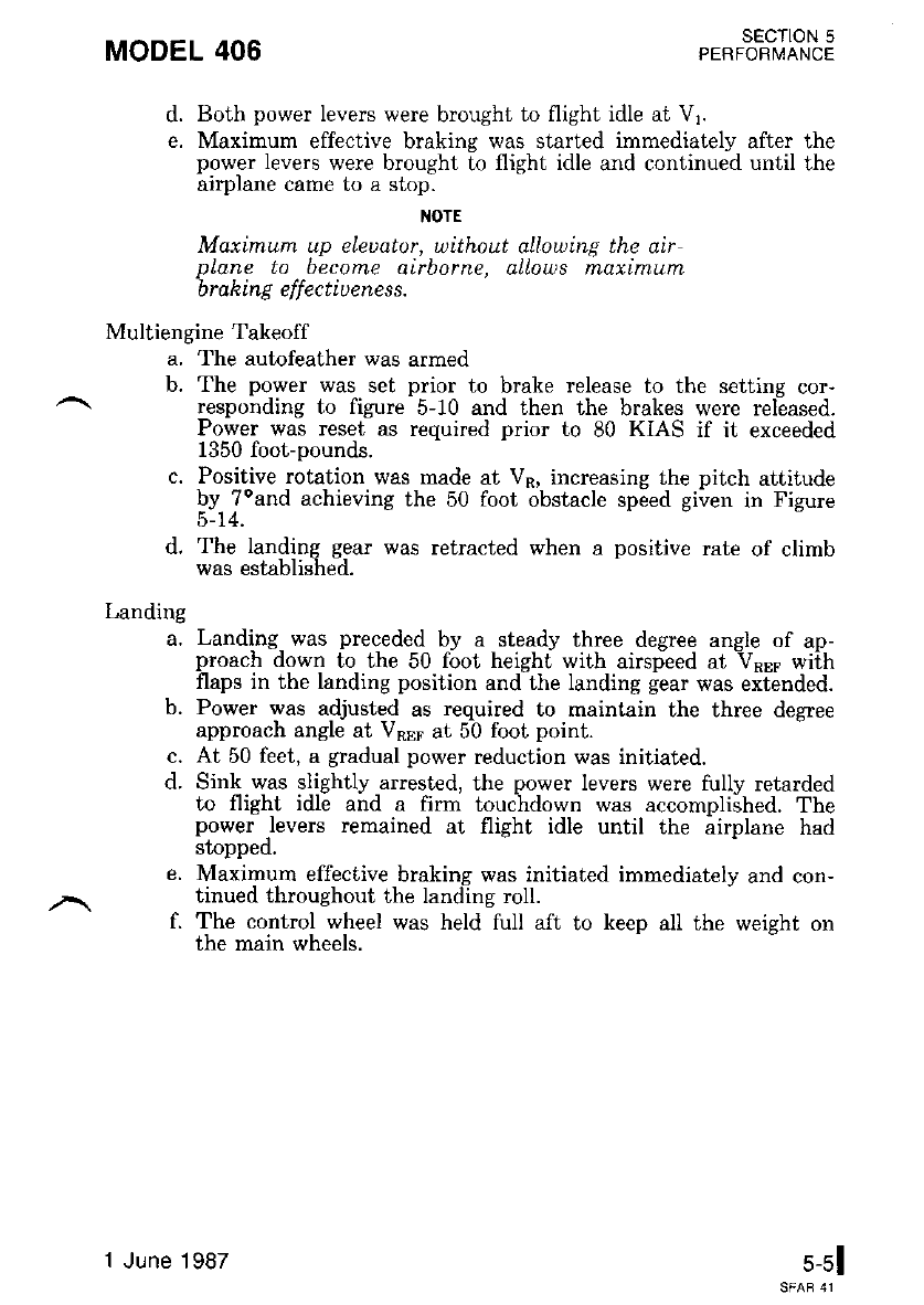
MODEL 406
Landing
a.
b.
SECTION 5
PERFORI,,IANCE
d. Both power levers were brought to flight idle ai Vr.
e. Maximum effective braking was started immediately after the
power levers were brought to flight idle and continued until the
airplane came to a stop.
TIOTE
Maximum up eLeuator, uithout allowing the air
pLane to become airborne, aLLows maximum
brahing ef
f
ectiuene s s.
Multiengine Takeoff
a, The autofeather was armed
b. The power was set prior to brake release to the setting cor-
responding to figure 5-10 and then the brakes were released.
Power was reset as required prior to 80 KIAS if it exceeded
1350 foot-pounds.
c. Positive rotation was made at Vp, increasing the pitch attitude
by Toand achieving the 50 foot obstacle speed given in Figure
5- 14.
d, The landing gear was retracted when a positive rate of climb
was established.
c.
d.
e.
I.
Landing was preceded by a steady three degree angle of ap-
proach down to the 50 foot height with airspeed at Vqs6 wiih
flaps in the landing position and the landing gear was extended.
Power was adjusted as required to maintain the three degree
approach angle at Vpse at 50 foot point.
At 50 feet, a gradual power reduction was initiated.
Sink was slightly arrested, the power levers were fully retarded
lo flighl idle and a firm touchdown was accomplished. The
power Jevers remained at flight idle until the airplane had
stopped.
Maximum effective braking was initiated immediately and con-
tinued throughout the landlng roll.
The control wheel was held full aft to keep all the weight on
the main wheels.
5-51
1 June 1987
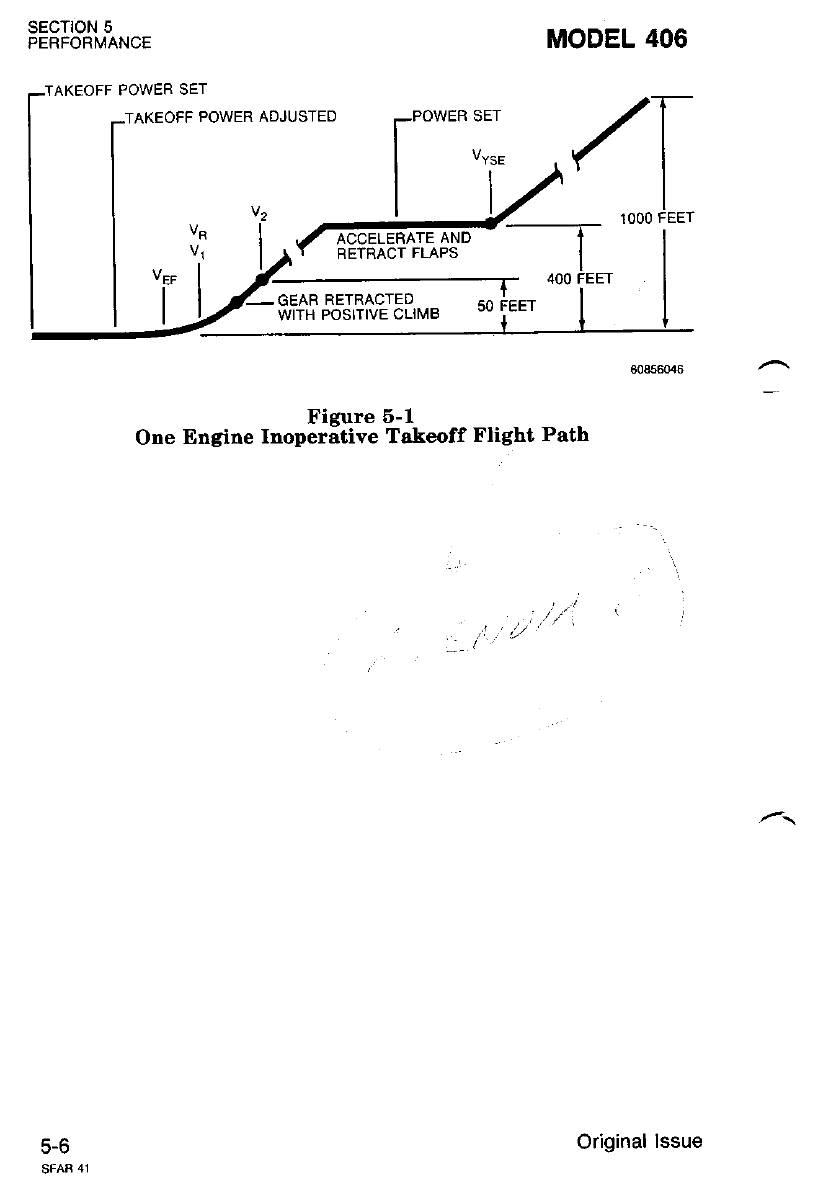
SECTION 5
PERFORMANCE
-TAKEOFF POWER SET
c-o
:TAKEOFF POWER ADJUSTED POWER SET
MODEL 406
,/T
YI
I
_ 1000 FEET
tl
FEET I
Figure 6-1
One Engine Inoperative Takeoff Flight Path
Original lssue
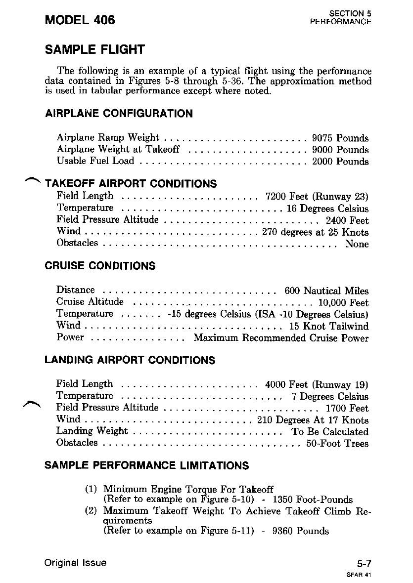
MODEL 406 SECTION 5
PERFORMANCE
SAMPLE FLIGHT
The following is an example of a typical flight using the performance
data contained in Figures 5-8 through 5-36. The approximation method
is used in tabular performalce except where noted.
AIRPLAI,..iE CONFIGURATION
Airplane Ramp Weight . . . 9075 Pounds
Airplane Weight at Takeoff . . . . . . 9000 Pounds
Usable Fuel Load . . . .... 2000 Pounds
^ TAKEoFF AIRPoRT coNDtnoNs
Field Length 7200 Feet (Runway 23)
Temperature ......16 Degrees Celsius
Field Pressure Altitude . .... 2400Feet
Wind . . . . -.. .270 degrees at 25 Knots
Obstacles .... None
CRUISE CONDITIONS
Distarce 600 Nautical Miles
Cruise Altitude . . 10,000 Feet
Temperature -15 degrees Celsius (ISA -10 Degrees Celsius)
Wind... .. 15 Knot Tailwind
Power . . Maximurn Recommended Cruise Power
LANDING AIRPORT CONOITIONS
Field kngth . . 4000 Feet (Runway 19)
_ Temperature ..... TDegrees Celsius
Field Pressure Altitude . .... 1?00Feet
Wind . . . .. .. 270 Degrees At 1? Knots
Landing Weight .... To Be Calculated
Obstacles ..... 50-Foot Trees
SAMPLE PERFORMANCE LIMITATIONS
(1) Minimum Engine Torque For Takeoff
(Refer to example on Figure 5-10) - 1350 Foot-Pounds
(2) Maximum Takeoff Weight To Achieve Takeoff Climb Re-
qurrements
(Refer to example on Figure 5-11) - 9360 Pounds
5-7
Original lssue
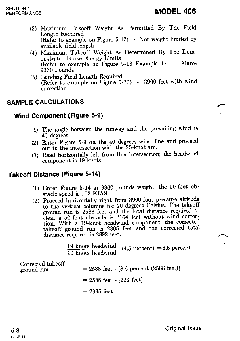
(3) Maximum Takeoff Weight As Permitted By The Field
Length Required
(Refer to eiample on Figure 5-12) - Not weight limited bv
available field length
(4) Maximum Takeoff Weight As Determined Bv The Dem-
onstrated Brake Enercv Limits
(Refer to example on"- Figure 5-13 Example 1) - Above
9360 Pounds
(5) Landine Field Lensth Required
- tn"fe" [o example"on Fi$rre 5-36) - 3900 feet with wind
cor"rection
SAMPLE CALCULATIONS
Wind Component (Figure 5-9)
(1) The angle between the runway and the prevailing wind is
40 degrees.
(2) Enter Figure 5-9 on the 40 degrees wind line and proceed
out to th; intersection with the 25-knot arc'
(3) Read horizontally left from this intersection; the headwind
component is 19 knots.
Takeoff Distance (Figure 5'14)
(1) Enter Fizure 5-14 at 9360 pounds weight; the 50-foot ob-
' stacle sDe;d is 102 KIAS.
(2) Proceed horizontally right from 3000-foot- pressure altitude
'-' to ltt" """ti"ut columns"for 20 degrees Cels:ius The takeoff
*o""a ^" is 2588 feet and the total distance reqrired to
iiear a 50-foot obstacle is 3164 feet without wind correc-
ii;;. witi-t ; 1g-knot headwind compon-ent, the correct€d
Gfeoff gtound run is 2365 feet and the corrected total
distance required is 2892 feet.
19 knots lrea4wind (4.b percent) :8.6 percent
l0 knots headwrnd
Corrected takeoff
iround run : 2588 feet - [8.6 percent (2588 feet)]
: 2588 feet - 1223 teet\
SECTION 5
PERFORMANCE
5-d
MODEL 406
: 2365 feet
Original lssue
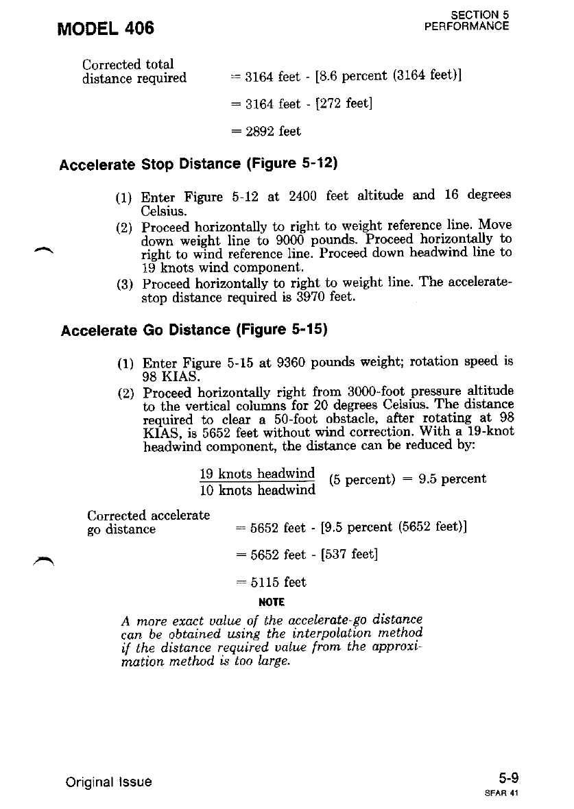
MODEL 406
Corrected total
distance required
"ERFsoE"cJlotl[E
:3164 feet - [8.6 percent (3164 feet)l
: 3164 feet - 1272 teetl
: 2892 feet
Accelerate Stop Distance (Figure 5-12)
(1) Enter Figue 5-12 at 2400 feet altitude and 16 degrees
Celsius.
(2) Proceed horizontally to right to weight refere-nce.line Move
' down weight line fo 9000 pounds. -Proceed horizontally to
rieht to wlnd reference line. Proceed down headwind line to
19 knots wind component.
(3) Proceed horizontally to right to weig,ht line. The accelerate-
stop distance required is 3970 feet.
Accelerate Go Distance (Figure 5'15)
(1) Enter Figure 5-15 at 9360 pounds weight; rotation speed is
98 KIAS.
(2) Proceed horizontally right from 3000-foot lresgYre altitude
' to the vertical columns-for 20 degrees Celsius' The distance
reouired to clear a 50-foot obstacle, after rotating at 98
KIAS, is 5652 feet without wind correction. With- a 19-knot
headwind component, the distance can be reduced by:
lg knots L-^r--.:-r
,=____=__i:s:I++ (b percent) : 9.5 percent
lu knols neaowrno
Corrected accelerate
go distance :5652 feet - [9 5 percent (5652 feet)]
: 5652 feet - [537 feet]
:5115 feet
M)TE
A more eaact ualue ol the acceLerate go disLonce.
can be obtalned using the ,nterpoLatrcn method
if the distance required' ualue from the approxi-
mation method is too Larae.
5-V
Original lssue
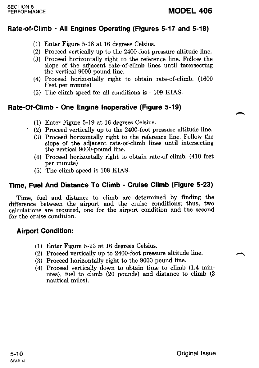
sEcloN 5
PERFORMANCE MODEL 406
Rate-ot-Climb - All Engines Operating (Figures 5-17 and 5-18)
(1) Enter Figure 5-18 at 16 degrees Celsius.
(2) Proceed vertically up to the 2400-foot pressure altitude line.
(3) Proceed horizontally right to the reference line. Follow the
slope of the adjacent rat€-of-climb lines until intersecting
the vertical 9000-pound line.
(4) Proceed horizontally right to obtain rate-of-climb. (1600
Feet per minute)
(5) The climb speed for all conditions is - 109 KIAS.
Rate-Of-Climb - One Engine Inoperative (Figure 5-19)
(1) Enter Figure 5-19 at 16 degrees Celsius.
' (2) Proceed vertically up to the 2400-foot pressure altitude line.
(3) Proceed horizontally right to the reference line. Follow the
slope of the adjacent rate-of-climb lines until intersecting
the vertical 9000-pound line.
(4) Proceed horizontally right to obtain rate-of-climb. (410 feet
per mrnule,
(5) The climb speed is 108 KIAS.
Time, Fuel And Distance To Climb - Cruise Climb (Figure 5-23)
Time, fuel and distance to climb are determined by frnding the
difference between the airport and the cmise conditions; thus, two
calculations are required, one for the airport condition and the second
for the cruise condition.
Airport Condition:
(1) Enter Figure 5-23 at 16 degrees Celsius.
(2) Proceed vertically up to 2400-foot pressure altitude line.
(3) Proceed horizontally right to the 9000-pound line.
(4) Proceed vertically down to obtain time to climb (1.4 min-
utes), fuel to climb (20 pounds) and distance io climb (3
nautical miles).
5-10 Original lssue
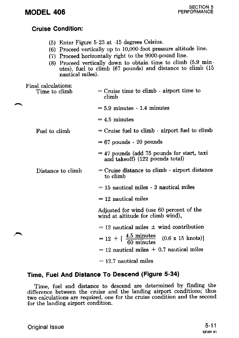
MODEL 406 SECTION 5
PEBFORMANCE
Cruise Condition:
(5) Enter Figure 5-23 at -15 degrees Celsius.
(6) Proceed vertically up to 10,000-foot pressure altitude line.
(?) Proceed horizontally right to the 9000-pound line.
(8) Proceed verticallv down to obtain time to climb (5.9 min-
' utes), tuel to cliirb (6? pounds) and distance to climb (15
nautical miles).
Final calculations:
Time to climb : Cruise time to climb - atport time to
climb
: 5.9 minut€s - 1.4 minutes
:4.5 minutes
Fuel to climb : Cruise fuel to climb - airport fuel to climb
: 67 Pounds - 20 Pounds
: 4? pounds (add ?5 pounds for star{, taxi
and takeofO (122 Pbunds total)
Distance to climb : Cruise distance to clinb - airport distance
to climb
: 15 nautical miles - 3 nautical mileg
: 12 nautical miles
Adjusted for wind (use 60 percent of the
wind at altitude for climb wind),
: 12 nautical miles a wind contribution
: rz + | 4lq m+gt€s (0.6 x 15 knots)l
- ttu mrnur€s
: 12 nautical miles * 0.7 nautical miles
- 12.7 nautical miles
Time, Fuel And Distance To Descend (Figure 5-34)
Time. fuel and distance to descend are determined by finding the
difference between the cruise and the landing airport conditions; thus
two calculations are required, one for the cruise condition and the second
for the landing airport condition.
5-11
Original lssue
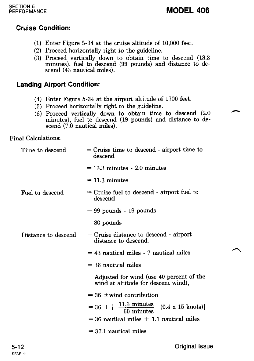
SECTION 5
PERFORMANCE MODEL 406
Cruise Condition:
(1) Enter Figure 5-34 at the cruise altitude of 10,000 feet.
(2) Proceed horizontally right to the guideline.
(3) Proceed vertically down to obtain time to descend (13.3
minutes), fuel to descend (99 pounds) and distance to de-
scend (43 nautical miles).
Landing Airport Conditionr
(4) Enter Figure 5-34 at the airport altitude of 1700 feet.
(5) Proceed horizontally right to the guideline.
(6) Proceed vertically down to obtain time to descend (2.0
minutes), fuel to descend (19 pounds) and distance to de-
scend (7.0 nautical miles).
Finai Calculations:
Time to descend : Cruise time to descend - airport time to
descend
: 13.3 minutes - 2.0 minutes
: 11.3 minutes
Fuel to descend : Cruise fuel to descend - airport fuel to
descend
: 99 pounds - 19 Pounds
: 80 Pounds
Distance to descend : Cruise distance to descend - airport
distance to descend.
: 43 nautical miles - 7 nautical miles
: 36 nautical miles
Adjusted for wind (use 40 percent of the
wind at altitude for descent wind),
: 36 + wind contribution
: 96 + t lljl minutes (0.4 x 15 knoLs)l
- tit mr.nutes
:36 nautical miles * 1.1 nautical miles
: 37.1 nautical miles
5-12 Original lssue
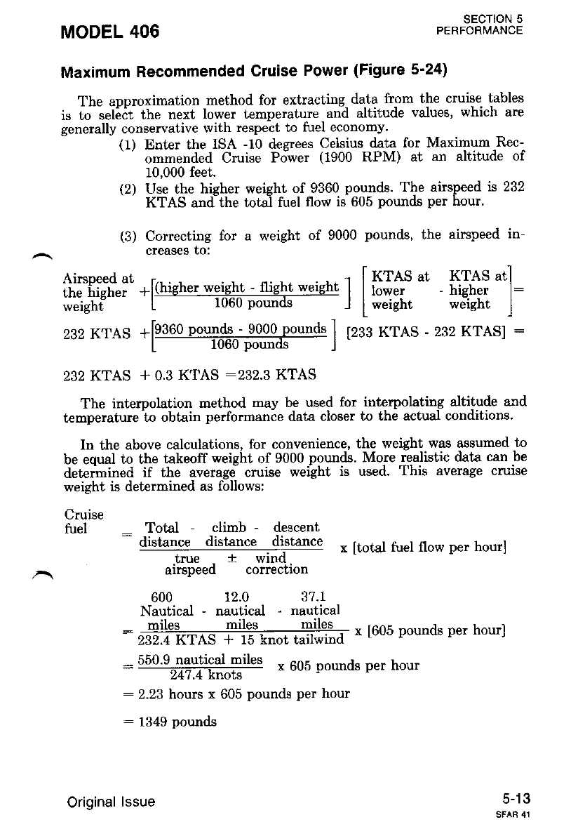
MODEL 406 sEcTloN 5
PERFORMANCE
Maximum Recommended Cruise Power (Figure 5'24)
The approximation method for extracling. dala from the cruise tables
is to seli,it the next lower temperature and altitude values, which are
generally conservative with respect to fuel economy.
(1) Enter the ISA -10 desrees Celsius data for Maximum Rec-
' ommended Cruise Pdwer (1900 RPM) at an altitude of
10,000 feet.
(2) Use the higher weight of 9360 pounds. The airspeed is 232
KTAS and the total fuel flow is 605 pounds per hour.
(3) Correcting for a weight of 9000 pounds, the airspeed in-
creaseg to:
Airsneed at .. . . . . -' i KTAS ut KTAS atl
the higher +l(hrgher wqlg-hJ - rhglt werght | | lower - higher l:
weight L rubu pounos I I weight werght l
232 KTAS + 0.3 KTAS :232.3 KTAS
The intemolation method may be used for interpolating altitude and
temperature -to obtain performance data closer to the actual conditions.
In the above calculations, for convenience, the weight was assuned to
be eoual to the takeoff weight of 9000 pounds. More realistic data can be
detenmined if the average cruise weight is used. This average cruise
232 KTAS -[9!9q!9g$::-999q-p9qd" I lzes xres - 232 KrAS] :
L l0tt0 Pounds I
weight is determined as follows:
Cruise
fuel - Total - climb - descent
- distance distance distance
true t wind
airspeed correction
600 12.0 37.1
Nautical - nautical - nautical
miles rniles miles
x [total fuel flow per hour]
x [605 pounds per hour]
- 550'9-ngutigal miles x 605 oounds per hour
247.4 knots
: 2.23 hours x 605 pounds per hour
: 1349 pounds
5-13
232.4 KTAS * 15 knot tailwind
Original lssue
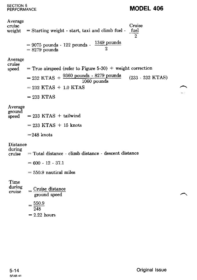
Average
crurse Cruise
weight : Starting weight - start, taxi and climb fuel - fuel
2
:90?5 pounds - 122 pounds - l34glounds
:8279 founds 2
Average
cruse
speed : True airspeed (refer to Figure 5-30) t weight correction
: 282 KTAS * 9360 pour.rd-s_- 8279pounds (233 _ 282 KTAS)
1060 pounds
: 232 KTAS + 1.0 KTAS
: 233 KTAS
Average
ground
speed : 233 KTAS * tailwind
: 233 KTAS + 15 knots
:248 knots
Distance
durins
cruisd : Total distance - climb distance - descent distance
:600-12-37.1
: 550.9 nautical miles
Time
during cruise distance
ground speed
:550.9
248
: 2.22 hours
SECTION 5
PERFORMANCE
5-14
MODEL 406
Original lssue
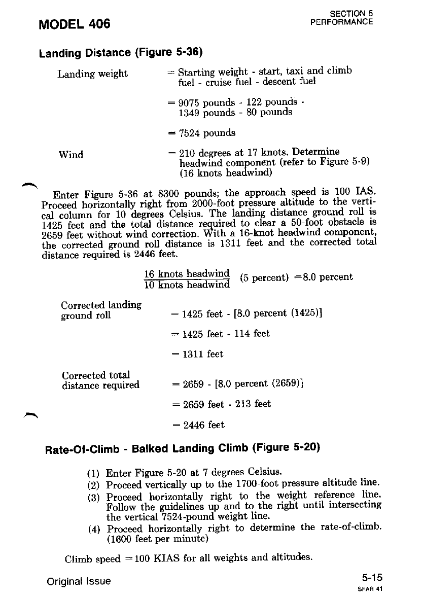
MODEL 406
Landing Distance (Figure 5'36)
SECTION 5
PERFORMANCE
Landing weight : Startine weieht - st€rt, taxi and climb
fuel - cirise fuel - descent fuel
:90?5 pounds - 122 Pounds -
1349 pounds - 80 Pounds
: 7524 pounds
:210 decrees at 17 knots. Determrne
headwiird compon€nt (refer to Figure 5-9)
(16 knols headwind)
Enter Fizure 5-36 at 8300 pounds; the approach. speed is 100 IAS'
p.i"""a' ft--"ir"tt"tiy .iint fro"i 2000-foot pressure. altitude to the verti-
i;i;;1il; f- io ii"giee. Celsius. The lai'rding distan^ce- ground roll is
iizs f""'f-i,tia- ttte totil distance required to clear a 5-0-foot obstacle is
iofs f""t ;ithout wind correction' With a 16-knot headwind comp-onent,
;i;"";;;"fi- ct;urra ioii aitt"tt"" is 1311 feet and the conected total
distance required is 2446 feet.
16 knots hea4wln4 {5 Dercent) :g.0 percent
l0Tiok headwin
Conected landing
g."""a i"U 7425 feet - [8.0 percent (1425)]
: 1425 feet - 114 feet
Wind
Corrected total
distance required
:1311 feet
: 2659 - [8.0 percent (2659)]
:2659 feet - 213 feet
: 2446 feet
Rate-Ot-Climb - Balked Landing Climb (Figute 5-20)
Climb speed :100 KIAS for all weights and altitudes.
Original lssue
(1) Enter Figure 5-20 at 7 degrees Celsius.
(Z; e.oceed vertically up to the 1700-foot pressure altitude line'
(3) Proceed horizontally right to the weight reference line'
Follow the zuidelines up and to the ri8ht untll rnterslecf,rng
the vertical -?524-pound weight line.
(4) Proceed horizontally right to determine the rate-of-climb'
(1600 feet per minute)
5-15
SECTION 5
PERFORMANCE MODEL 406
'r,^rot fi,ot rod,lir-n
(without holding fuel) : Start, taxi and climb fuel
-r cruise fuel * descent fuel
: 122 pounds -F 1349 pounds
* 80 pounds
: 1551 pounds
Holding Time (Figure 5-33)
The holding fuel required for 45 minutes at 10,000 feet is as follows:
(1) Enter Figure 5-33 at 0.75 hours.
(2) Proceed horizontally right to the altitude guideline of
10,000 feet.
(3) Proceed vertically downward to obtain the holding fuel
required (226 pounds;.
Total fuel required
(with 45 minutes
holding fuel) : Total tuel required without holding tuel
* holding fuel required for 45 minutes.
: 1551 pounds * 226 pounds
: 1777 pounds
, ,To determine holding time, the fuel available for holding must be
oelermlneo.
Fuel
available
for
holding : Initial fuel ' start, taxi and climb
fuel - cruise fuel - descent fuel
: 2000 pounds - 122 pounds
1349 pounds - 80 pounds
: 449 pounds
(1) Enter Figure 5-33 at 449 pounds of fuel available.
(2) Proceed vertically up to the intersection with the guideline
for 10,000 feet.
(3) Proceed horizontally left to obtain holding time available.
(1.5 hours)
5-16 Original lssue
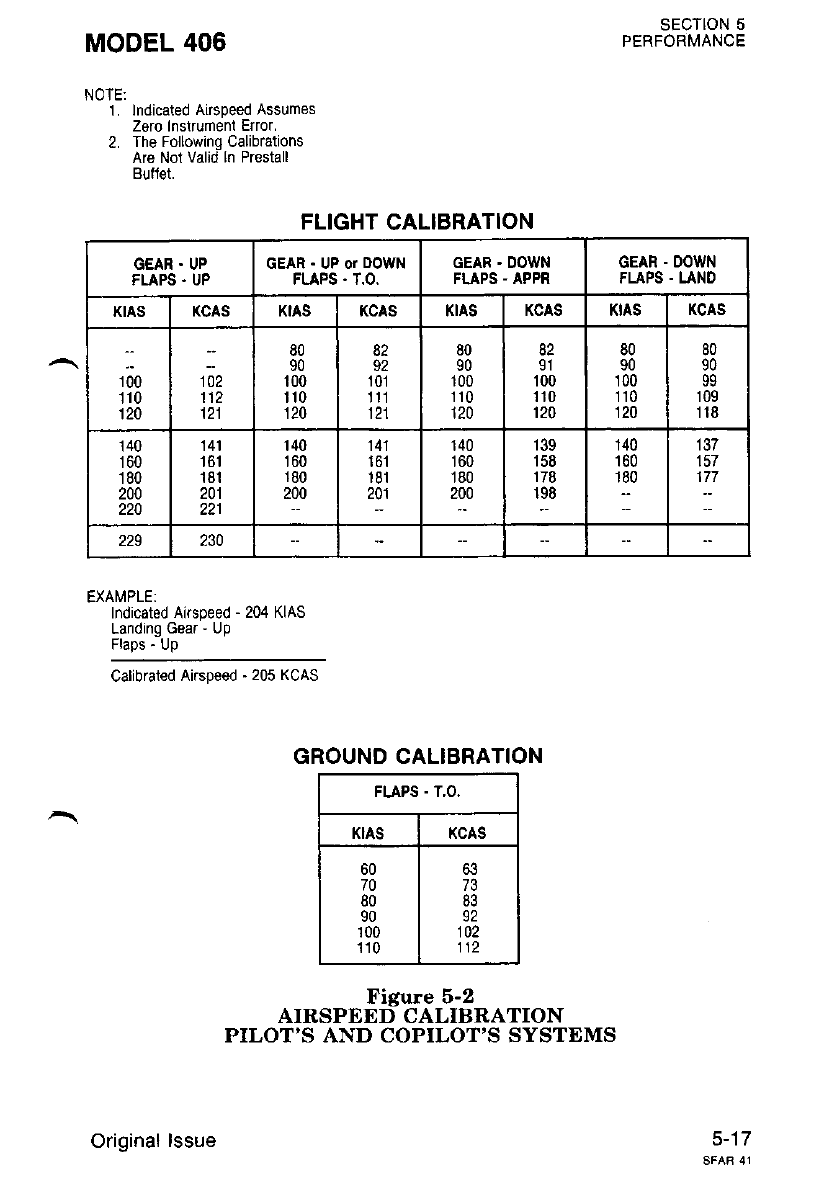
SECTION 5
MODEL 406 PERFoRMANoE
NOTE:
1. lndicated Airspeed Assumes
Zero Instrumeni Elror.
2. The Following Calibrations
Are Not valid ln Prestall
Bullet.
FLIGHT CALIBRATION
EXAMPLE:
Indicated Airspeed - 204 KIAS
Landing Gea. - Up
Flaps - Up
Calibrated Airspeed ' 205 KCAS
GROUND CALIBRATION
Figure 5-2
AIRSPEDD CALIBRATION
PILOT'S AND COPILOT'S SYSTEMS
5-17
GEAR . UP
FLAPS . UP
GEAR . UP or DOWN
FLAPS . T.O.
GEAR . DOWN
FLAPS - APPR GEAR . DOWN
FLAPS . LAND
KIAS KCAS KtAS KCAS KIAS KCAS KtAS KCAS
roo
110
120
tiz
112
121
80
90
100
'| 10
120
82
92
101
1t1
121
80
90
100
110
120
82
91
100
110
120
80
90
100
110
120
80
90
99
109
118
140
160
180
200
220
141
161
181
201
221
140
160
180
200
141
't 61
181
201
140
160
180
200
139
158
178
198
140
160
1-80
137
157
,!:
229 230
FLAPS . T,O.
KIAS KCAS
60
70
80
90
100
'110
63
73
83
92
102
112
Original lssue
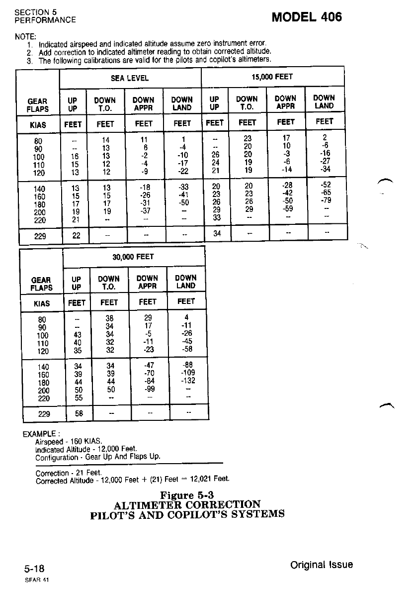
SECTION 5
PERFOBMANCE
NOTE:
1. lndicated airspeed and indicated altitude assume zero inskument elror'
2. Add co(eclion to indicated altlmeter reading to oblain corrected allitude
3. The following calibrations are valid lor the oilols and copilot s altimelsrs
EXAMPLE :
Aksoeed - 160 KIAS.
lndicated Altitude - 12,000 Feel
Conliguration ' Gear Up And Flaps Up.
3pi;1;fr,t"5ff1i2 000 Feet + (2r) Feer ' 12,02r Fe€t.
Fieure 6-3
ALTIMETE_R CORRECTION
PILOT'S AND COPILOT'S SYSTEMS
5-18
MODEL 406
GEAR
FLAPS
SEA LEVEL 'I5,0(X) FEET
UP
UP
DOWt{
T.O.
DOWN
APPR
DOWN
LAND
UP
UP
DOWN
T.O.
00wN
APPR
DOWN
LANO
KIAS FEET FFFT FEET FEET FEET FEET
80
90
100
110
120
't5
14
13
13
'11
6
-2
-9
1
-4
-10
-22
26
24
23
20
20
19
19
17
10
-3
-6
-14
2
-6
-16
-34
140
160
180
200
220
15
17
19
21
13
15
17
19
-18
-37
-33
'41
10
20
23
26
29
20
23
26
29
-28
42
-50 -65
":
229 34
GEAR
FLAPS
3O,OOO FEET
UP
UP
00wN
T.O.
DOWN
APPR 0owtl
LAND
KIAS I'EEI I'EEI FEET
80
90
100
110
120
43
40
35
38
34
34
32
32
n
17
-23
4
-11
-26
-45
-58
140
160
180
200
220
34
39
44
50
u
39
44
50
-47
-70
-84
-99
-88
-109
-.
229 58
Original lssue
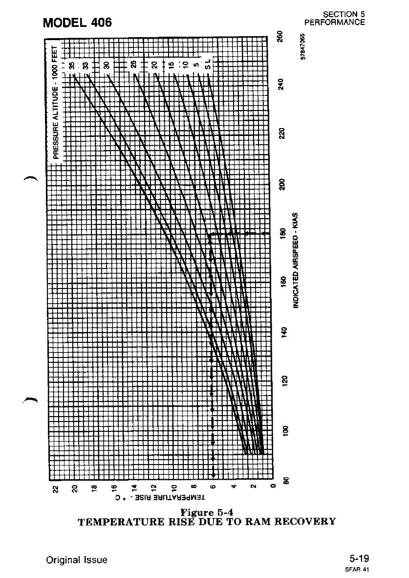
MODEL 406 sEcloN 5
PERFORMANCE
5
s
=oG
o
9T'
o
6
4
6lo-
c . ' 3slu 3un1vu3dw3r
Figure 5-4
TEMPERATURE RISE DUE TO RAM RECOVERY
Original lssue 5-19
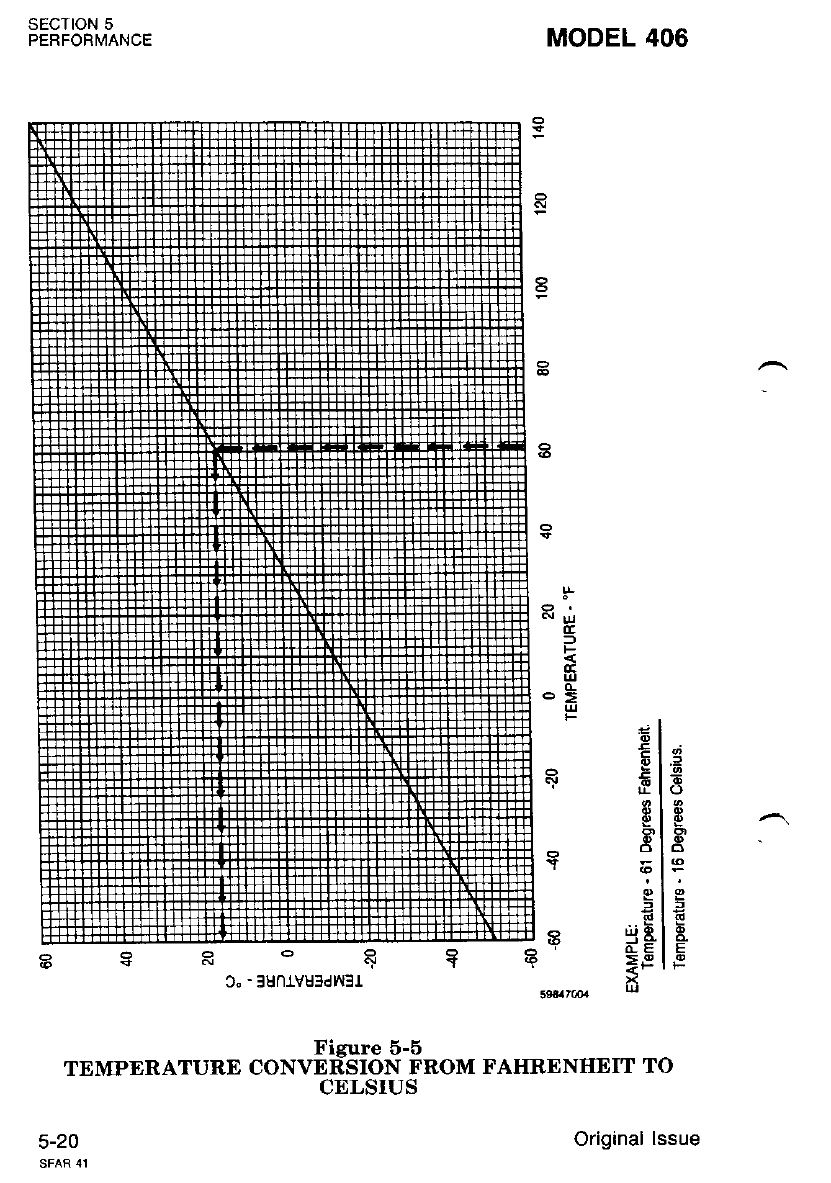
SECTION 5
PERFORMANCE
5-20
MODEL 406
.l
D8
Figure 5-6
TEMPERATURD CONVERSION FROM FAHRENHEIT TO
CELSIUS
a
o
R^
o
E
E
F
I
a
E
,jj h
Original lssue
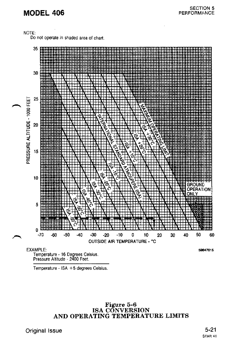
H
^U"^
E
F
UJ
Brs
SECTION 5
PERFORMI\NCE
0-70 -60 -50 40 -30 -20 -10 0 10 20
OUTSIDE AIB TEMPERATURE. 'C
EXAMPLE:
Temoerature - 16 oeorees Celsius.
Pros;ure Allitude - 2{00 Feet.
Temperature ' ISA +5 degrees Celsius.
Figure 6-6
ISA CONVERSION
AND OPERATING TEMPERATURE LIMITS
Original lssue 5'21
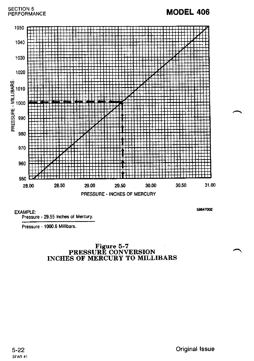
SECTION 5
PERFORMANCE MODEL 406
1050
1040
1030
1020
co
=
1010 FF
FF
1000 FF
FF
TT
eeo Fl-
FF
FF
s80 FF
tr
e70 FF
tr
11.
e6o FF
tr
r-r
950 El
28.00 a.00 29.50 30.00
PBESSUBE . INCHES OF MERCURY
EXAMPLE:
Pressure - 29.55 Inches ol M€rcury.
Pressure - 1000.6 Millibars.
Figure 5-7
PRESSURE CONVERSION
INCIIES OF MERCURY TO MILLIBARS
5-22 Original lssue
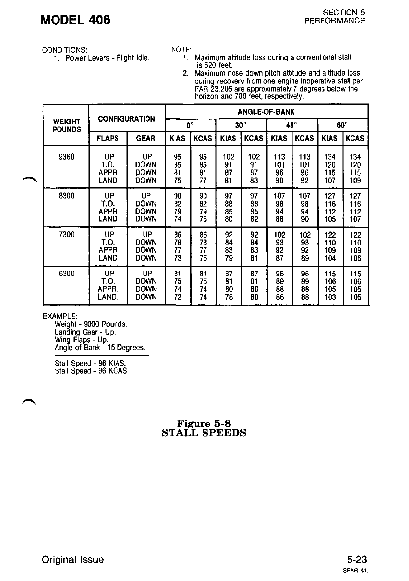
MODEL 406 SECTION 5
PERFORMANCE
CONDITIONS: NoTE:
1. Power Levers - Flight ldle. 1. l\,laximum altitude loss during a conventional stall
is 520 leet.
2. Maximum nose down pitch attitude and altitude loss
dunng recovgry from one engine inoperative stall per
FAB 23.205 are approximalely 7 degrees below the
horizon and 700 feet, respectively.
EXAMPLE:
Weight - 9000 Pounds.
Landinq Gear " LJp.
Wing Flaps - Up.
Angle-of-Bank - 15 Degrees.
Slall Speed - 96 KIAS.
Stall Speed - 96 KCAS.
Figure 6-8
STALL SPEEDS
5-23
WEIGHT
POUI{DS
CONFIGURATION ANGLE.OF.EAI{K
0" 30" 45' 60"
FLAPS GEAR KIAS KCAS KIAS KCAS KIAS KCAS KIAS KCAS
9360 UP
T.O.
APPR
LAND
UP
DOWN
DOWN
DOWN
85
81
95
85
81
77
102
91
87
81
102
91
87
83
113
101
96
90
'fi3
't 01
96
92
134
120
115
107
134
120
115
109
8300 UP
T.O.
APPR
LAND
UP
OOWN
DOWN
DOWN
90
82
7q
74
90
82
79
76
97
88
85
80
97
88
85
82
107
98
94
88
107
98
94
90
127
116
112
105
127
1't6
112
107
7300 UP
T.O.
APPR
LAND
UP
DOWN
DOWN
DOWN
86
78
77
86
78
77
75
92
84
83
79
92
84
83
8l
102
93
92
87
'102
93
92
89
122
'| 10
109
104
122
110
109
106
6300 UP
T.O.
APPR.
LAND,
UP
DOWN
DOWN
DOWN
81
74
72
81
75
74
74
87
81
80
78
87
81
80
80
96
88
6D
96
89
88
88
115
106
105
103
'| 15
106
105
105
Original lssue
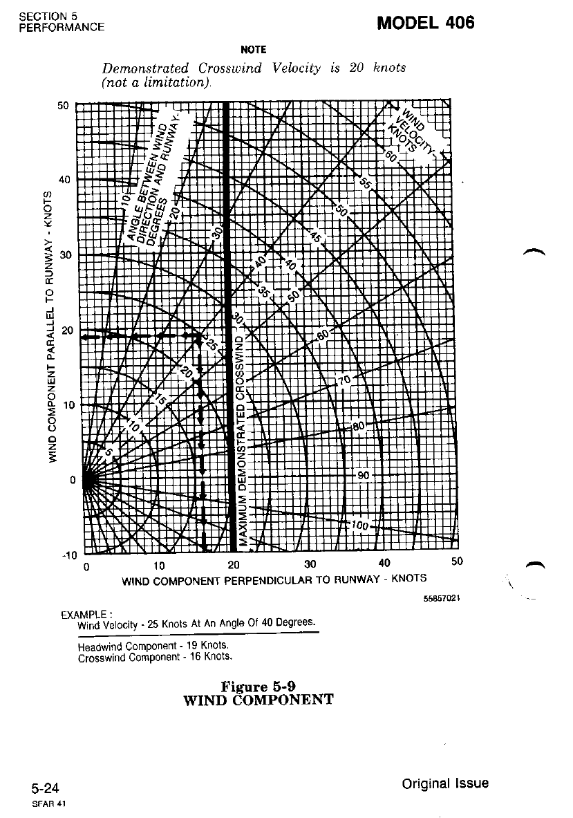
SECTION 5
PERFORMANCE MODEL 406
NOTE
Demonstruted Crosswind Ve\ocity is 20 hnots
(not a limttation).
F
o
z
;
iru
z
)
(r
o
F
E
J'O
F
z
l!
z
o
(L ta
:'
o
(.)
o
z
t
-10 --- - -
01020304050
WIND COMPONENT PERPENDICULAR TO RUNWAY - KNOTS
55857021
EXAMPLE:
- Wind Velocity - 25 Knots At An Angle Ol 40 Degrees'
Headwrnd Componeni - 19 Knols
crosswind Component - 16 Knots
J-21
Ficure 6-0
WIND COMPONENT
Original lssue
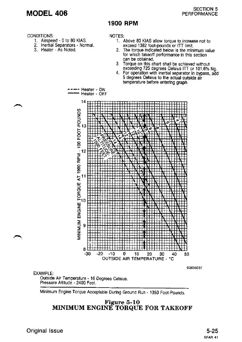
MODEL 406
CONDITIONS:
1. Airspeed - 0 to 80 KIAS.
2. Inenial Separators - Normal.
3. Heater - As Noted.
SECTION 5
PERFOBMANCE
19OO RPM
NOTESI
1 . Above 80 KIAS allow torqu€ to increase not to
exceed 1382 foot-pounds or ITT limit
2. The torque indicaled below is the minimum value
for which takeoff performance in this section
can be obtained.
3. Forque on this chart shall be achieved without
exceeding 725 degrees Celsius ITT or 101.690 No.
4. For op€raton with inerl8l separator in byoass, aAd
5 degr€es Celsius to the actual oulsrds dii
temperature before entering graph.
---- Heater - ON
-
Heater ' OFF
-20 -10 0 10 20 30 40 50
OUTSIDE AIR TEMPERATURE. "C
EXAMPLE:
Oulsrde Air Temperature - l6 Deqre€s Celstus.
Pressure Altitude - 2400 Feet. -
Minimum Engine Torque Acceptabte Durjng cround Run - 1350 Foot_pounds.
Figure 5-10
MINIMUM ENGINE TORQUE FOR TAKEOFF
Original lssue
'14
o
z
-
+13
F
o
o
'12
o
tc
o.
Flo
z
z
=
5-25
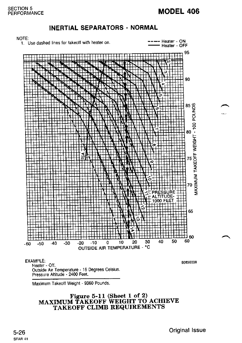
SECTION 5
PERFORMANCE MODEL 406
INERTIAL SEPARATORS - NORMAL
NOTE:
1. Use dashed lines fol takeofJ with heater on.
OUTSIDE AtR TEMPERATURE - 'C
EXAMPLE:
Heater - Oft.
Outside Air lemperature - 16 oegrees Celsius
Pressure Altitude - 2400 Feet.
Maximum Taheotf weighl - 9360 Pounds.
---- Heater - ON
-
Heatgr - OFF
+o -ro o 10 20 30 40 50
z
-
80,
F
!
g
=
7s6
ut
=
l.^ =
|," i
t>
Ficrure 5-ll (Sheet I' of 2)
MAXIMUM fNTNONN WEIGHT TO ACHIEVE
TAKEOFF CLIMB REQUIREMENTS
5-26 Original lssue
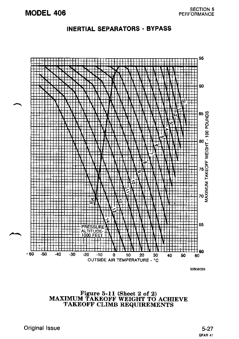
MODEL 406 SECTION 5
PERFORMANCE
INERTIAL SEPARATORS . BYPASS
-30 -20 -10 0 lo 20 30
OUTSIDE AIR TEMPERATURE . 'C
853
z
f,
80 ,'
t
I
ul
3
75ts
=
70{
-J--r-J--L.r!_J_r.r_I 60
,o 50 60
60856039
c-zl
Figure 5-11 (Sheet 2 of 2)
MAXIMUM TAKEOFF WEICHT TO ACIIIEVE
Original lssue
TAKEOFF CLIMB REQUIREMENTS
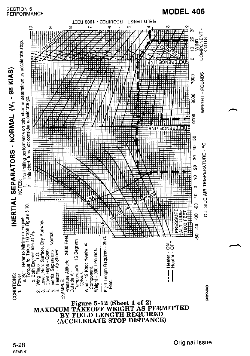
MODEL 406
rffl 0001 - ofulnoSu HreNf-] 0-llll
F@
ztL
oo
tl
lt
SECTION 5
PERFORMANCE
;
Z^^
=dz
- >Y
o
()
6Z
N=) o
8F
=
R
fR
r-
!
9I
FI
dl
5
.=
E
b:
e9
op
a3
..e
o
z
.9
F
9<
c
5 u.l
-e
N s,)
l
o
v
€
o)
J
=
!c
o
z
o
cc
o
F
t
o-
lu
o
J
s
F
E,
uJ
z
;.9
Ee
6;vt
OPP
(oin.
-r^o
I 3*3
S Ao E6
6() E_a H',
- E-=
="sts
z
9
t
z
o
5
ea >
.ry9
*-a E -
doe > F
>9E {, t;
3e Fq€Eij E
e9 -T;Y Pa
q eE aE a.a€
9{;I geE "i€
3* ";.96 Ei
,j 6iri+o@
Figure 6-12 (Sheet I of 2)
MAXIMUM rrxnoFr wErcHT AS PEEMTTTED
BY FIELD LENGTH REQUIRED
(ACCELERATE STOP DISTANCE)
5-28 Original lssue
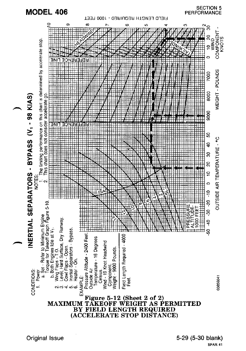
SECTION 5
PERFORMANCE
l33l 000t - 6lurnolu H1eN3-l 0-]]E
I
e
-9
8
.E
E
^ E;
o ;o
< ;€
.-. Y E.E
ao ez
g) €o
, cb
t9H
- a6
;: "9E
z. Eg
ae!
> EE
dl E€
' ..e
o r^EE
Gni
!JO
tz
E
o-a
IJJ
o ".!
o .q HF+Tffi
d#e ffiffi
tr ss; E i ;ifi+#F+ffifF;]
(E Eo= >. I 6 ^ le
.-.2 E5g?_a ;9: lq
eflcr.iEEg = E € 3lE
:EU;;.1 ;gE I:
.!:g:SB€ T€F:rs
fEfata*ss 3 - e"glg
-.^ -;SEiiriilJ = =E ,s 6ts |5-
=$:':siEEe =;s Fn: F'- | 5,
i' .-"r- iSEF-sdg lef
Ud - Figure 6-12 (Sheet 2 of 2)
MAXIMUM TAKEOFF WEIGHT AS PERMITTED
BY FIELD LENGTII REQUIRED
(ACCELERATE STOP DISTANCE)
F
z
a99
z 6il
=d>
->!.
o
O
lR
H.
H-
Co
P.>
o
PF
tl.t
=
o>F
a
^a
oo
5-29 (5-30 blank)
SFAR 41
Original lssue

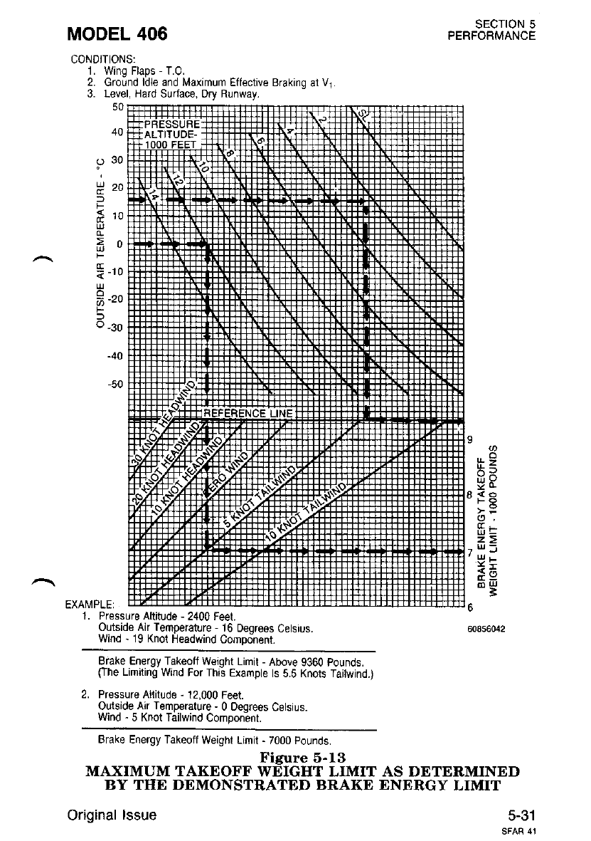
MODEL 406
CONDITIONS:
1. Wing Flaps - T.0.
2. Ground ldle and Maximum Effective Braking at Vl
3. Level, Hard Surface, Dry Runway.
sEcTroN 5
PERFORMANCE
50
40
930
tt 20
F
< r^
E'w
>n
T-to
2-zo
tr
o -30
-40
-50
iiz
o.
ca!
z=
l|', f
-t
EXA[,{PLEi
1. Pressure Altitude - 2400 Feel.
Outside Air Temperature - 16 Deqrees Cetsrus.
Wrnd - 19 Knot Headwind Compo-nent.
Brake Energy Takeofl Weight Limit - Above 9360 pounds.
CIhe Limding Wnd For Thrs Example ts 5 5 Knots Taitwind.)
2. Pressure Aliitude - 12,000 Feet.
Outside Air Temperature - 0 Deqrees Cetsius.
Wind - 5 Knot Tailwind Comoon;nr.
Brake Energy Takeoff Weight Limit - 7000 Pounds.
Fieure 5-13
MAXIMUM TAKEOFF WEIGHT LIMIT
BY THE DEMONSTRATED BRAKE
Original lssue
AS DETERMINED
ENERGY LIMIT
5-31
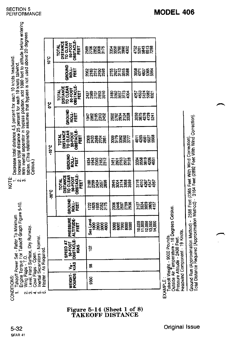
MODEL 406
SECTION 5
PERFORMANCE
P-ci<"j
z
.g
E6
o9
58
! J>
i;E E
= E o-
E;; E
a'.9 a
Ecdii
iiSE.B.
PbeP
+[sa
P 3;5
g Fi6 b
EE F?
E:; T
:9e=
H3E?A
o q = 9."
EE€E$
,
=
a 2;
gi, E
-iE E X =
;_i6i.E
.", 6*
gE s3i
,P9 E EE
Ei3 -t
.E i.
Ft-
'F
ie
-:E o
<"9 A
6
2?
o
a
.9
E
is
€=
==
3=
=I
49
5U
'?ii
No
='
@E
3>
r-€
>e
lsgr
t=ts
t*<!)
t90
tdE
l6'Y
.=
E
!e Ee
o- ga ,
E E1H
:sr: E.q
u:i ? B
=r o a;9
=FE8S
5-32
sEgEan
EdF
sEgEas : gaFa
=iE
EEH aPals
sEgEEe
e;s
gEEEan
e;e a*gFa
Pd,
5eF 6
a
5 E:5 t5 45
EeH*
>=
EE
gE
Original lssue
Fisure 6-14 (Sheet I of 8)
fAKEOFF DISTANCE
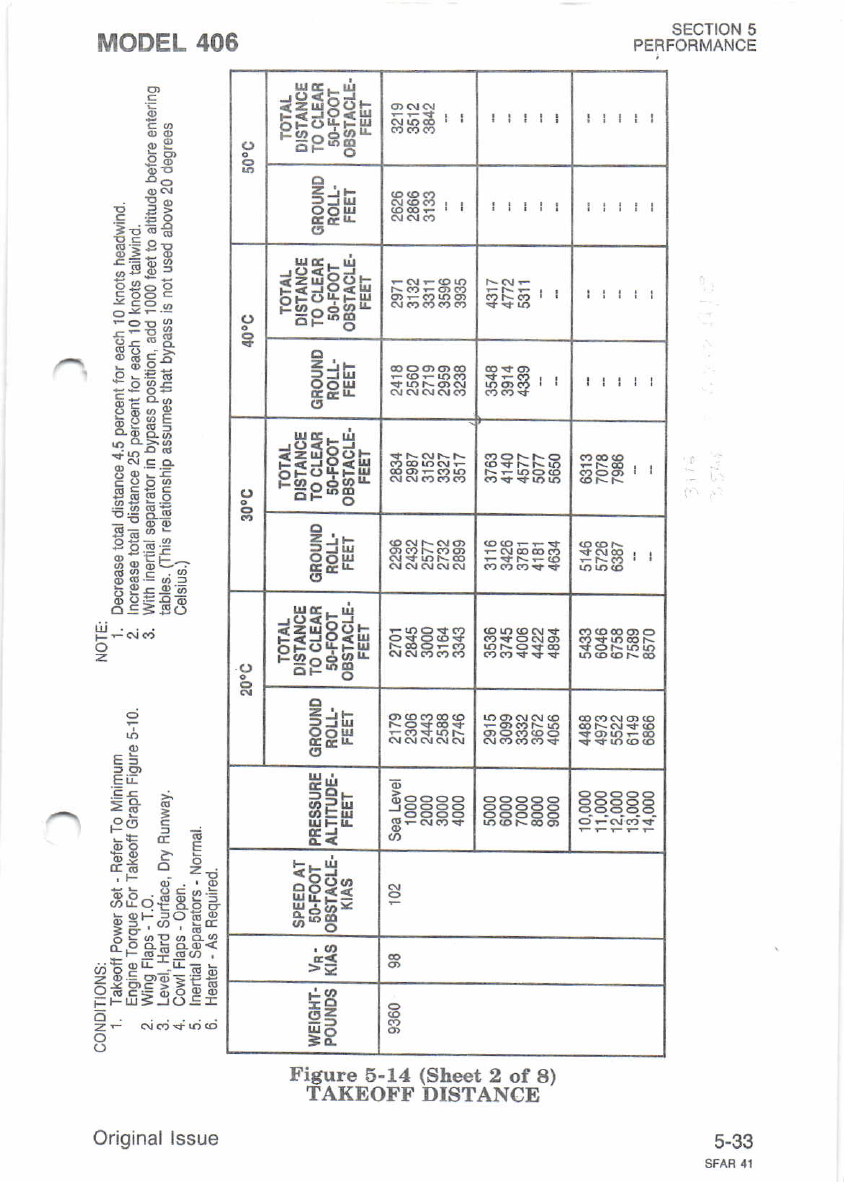
rEgEEn !iii!
o
zi,
90!!
oittii
sggEEu itt!i
Z'.E
EEH rt!rl
orHsEsn
c;F
<J sfsEsn
o
e;F
Prn
5Qr-
aifr
Ei
E
i^^^^
Y5-55
f;EH=
>*
:- tt,
?52
gF
Figure 6-14 (Sheet 2 of 8)
TAKEOFF DISTANCE
sEcTloN 5
PERFORMANCE
5-33
E6
! t>
.: .= x
3E:E
t-6x
gbrag
9Y(5
FEaE
*EE-E
=.9 q :;
6*=.e
X o H F--
oq=c).?
8!5 E8
-E
.E= ;
>* g
OEE
F; : ;
I-gFE
r.d s z;
'- oi ' il
s,E.€ EE i
h9F.?OE,9
F5sE3F€
pEssigEe
a-
z- No*ra)@
MODEL 406
H-ciaj
z
Original lssue
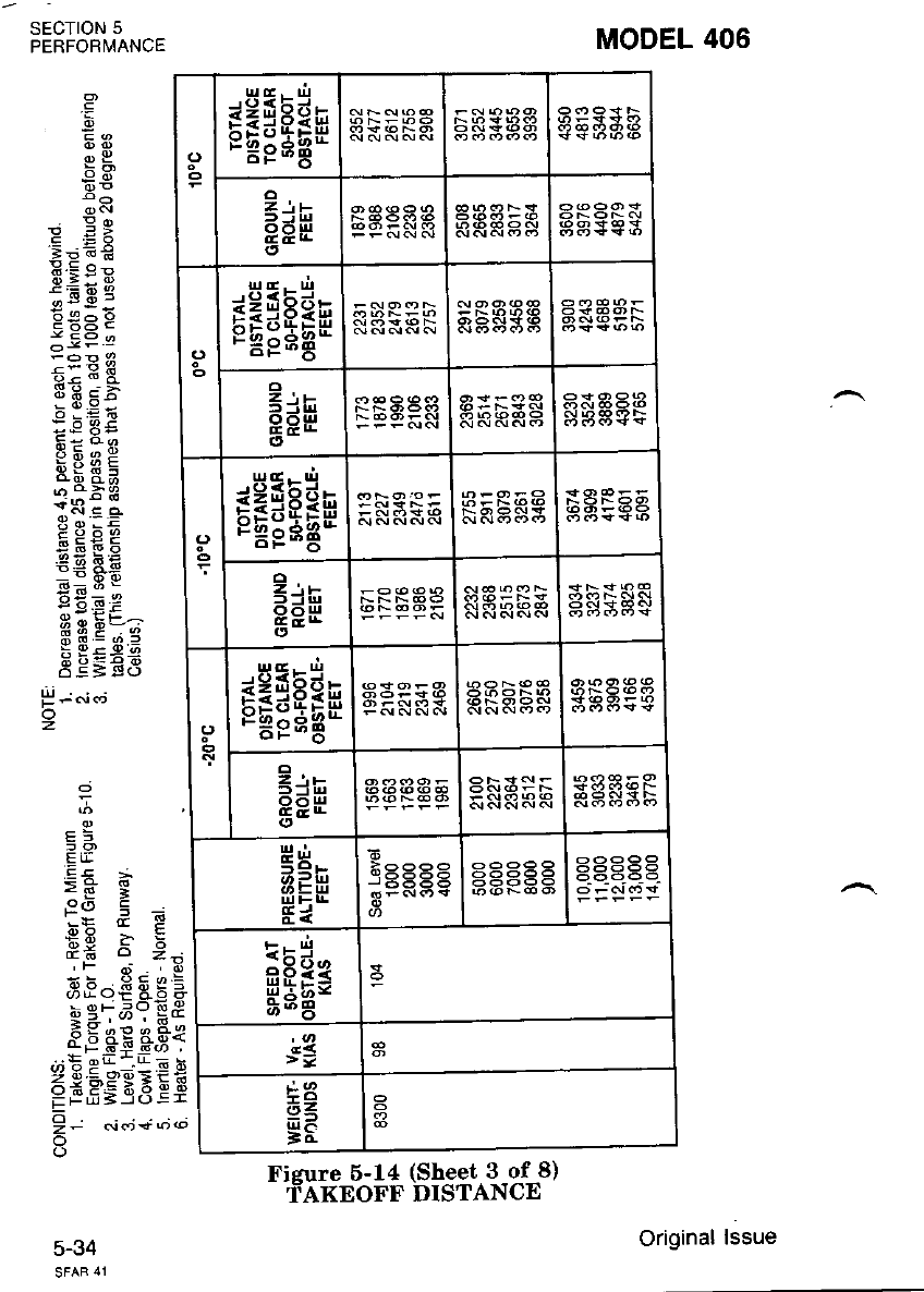
orEgHan
Z\E
oolu
rEgEan
2",
a=H
En* a6bsa a& Eaa
(J rH:Eae b8:aa
EdF aR5$S
ragEAn RKRHS
E;F 9S36b RA$S5
I
5Qr-
ut=u
Ei HE=EF 39Rg?
EgH*
>=
+3
6=
=d
Ficure 5-14 (Sheet 3 of 8)
fAKEoFF DISTANCE
MODEL 406
g
oP
6n
e !x
Ep;€
.s:; E
<-96
ii3q.
;3Et
;P8.-
[E:3
rgqE
e u b!
EKEb
EE E€
E-;i
.: Y'E F
HsE=e
EE=€$
5
-E
E3
.E4 ;
>H I
e9 , E
o?; : e
,F dt , ti
xx.9qqr=
; ef;qEE
F 3ae e.ee
zgSP'9E-<i
Ee6Ei6 Ei
!. o;..;+;ot
SECTION 5
PERFORI,IANCE
5-34
P;6i aj
z
Original lssue
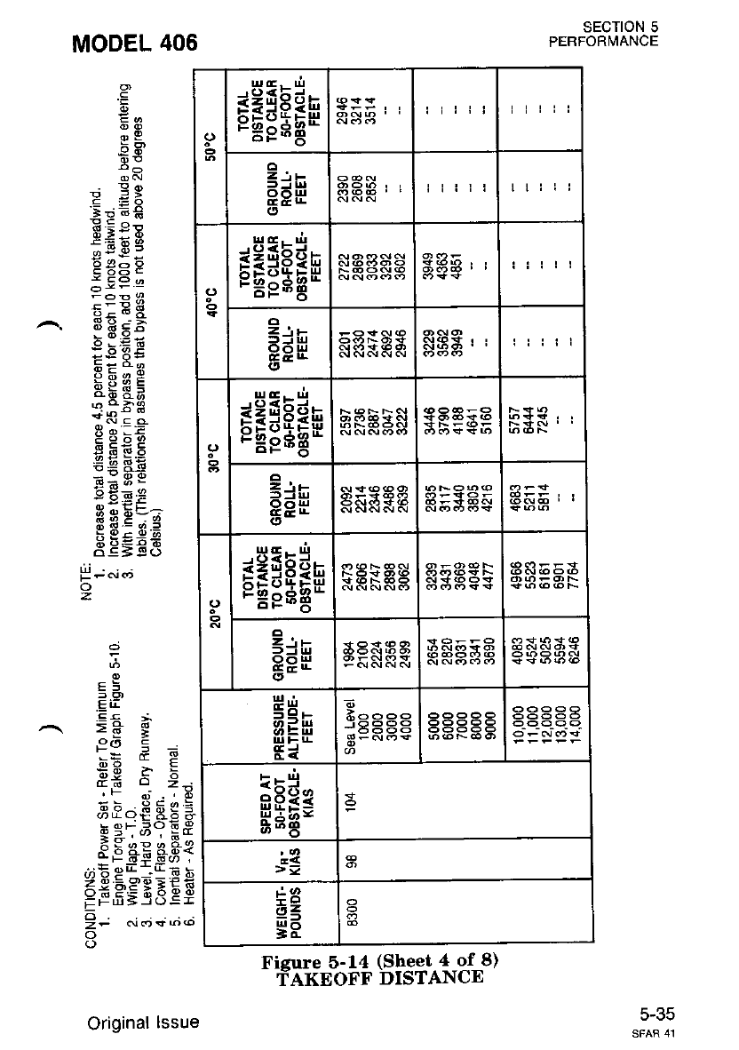
ogEsErn
Zits
oo!4 liiii ttiii
sEsEa*
9 .,-
adH tiiii
rEiEan
fi;e
orE:Egn
E;w RRAAA Sgaaa
u,|....
56.
aifr
Ei
dqsee
-.556-
3--.r-
Effi*
>=
+a
a<
gF
Fieure 5-14 (Sheet 4 of 8)
'TAKEOFF DISTANCE
SECTION 5
PERFORMANCE
MODEL 406
oP
5€
P EX
=9GE
.E=; g
o r.9 -
A@^^
E 6ts E
E=E3
UBEE.
>@Ez
F: do
E!{;F
.iEEA
sai - ^
!2 X !;
g bE 5
tPlgt
:vE!:
RA9-,i
o q = 9?."
EE=€8
H - .'i <'j
o
z
E
E
2<)
4E F.
.:.4-
831
:E b
IEE
q;
F9
8>-
9-o
;s9
fi;3
o
F
E
.E
5
F
6
E
3
F
z
s
t
z.
o
o
c-Jc
Original lssue
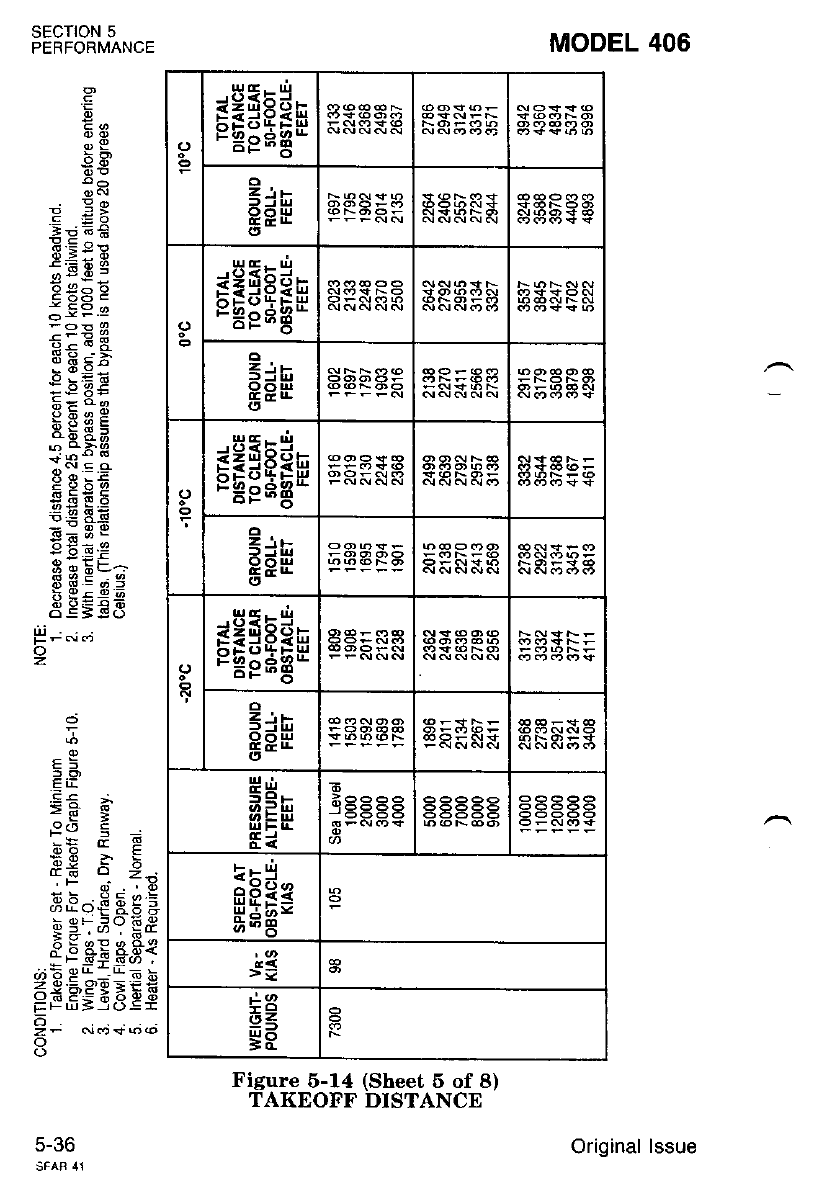
MODEL 406
.g
Za
OE
b-
9 :>
.=.=x
:96i6
U::E
t-6R
3E *F
F=do
Pbeg
og sa
l i( .s .9
qnEb
6.e 8,ii
i6;3I
6!=e
::; F
o q = a.=
o;5:r2
3 E;E3
5
.E= ;
>H g
x* a E
6gi5
L.d q z;
.l: e?, rE
3':ctE P H I
; !? F.: v !!.y
^6 5 a: &S{
=;s==sEEs
o
z- N.t<f6@
o
o
SECTION 5
PERFORMANCE
5-36
g; "': .;
z
osEgEan
E:E
8,. *
osEiEar
z,,
f,=iu
Eeil 45549
osfgEan
I ..-
f=tu
B8H
eEsEgr
EdF
Ul l- U-
si
Exj
HEEs
>=
u3
i8
Figure 5-14 (Sheet 5 of 8)
TAKEOFF DISTANCE
Original lssue
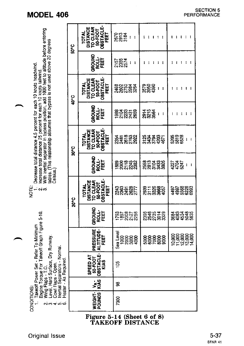
sEgeEn tlt!l ttiii
=ih
PPU
(, !lit!
sfsEee
Z'.L
8eH
<,
tilii
rfiEsn
EdF
rasEAn
z\t
-: i!
qo$
H":
=QF
Ei
i^^^^
B=an6+
Fcg*
>=
tr3
6=
=d
Figure 5-14 (Sheet 6 of 8)
TAKEOFF DISTANCE
SECTION 5
PERFORMANCE
MODEL 406
g
oP
P EX
:!.€
E:: E
;E E 5
P+ia8
--i9
FE -'+
x o!=
- Jf X:b
F=6-
Pbee
i[sa
:i-o d
;N E q
F 3 xE
iig 8E
-l3 E
:eg=
H g EEA
oq=q.:
EE=Ef;
T
.E i!
_ .g! ;
>H I
^_: a
',= & q
3*69-
Co:6dg=
u/rvt oo or
h qF_ -?o 69
=;'"''6*
^- o o: o.o<
EEBgEEEE
o
z- c.J.9* f)@
o
P;6j.t
o
2
5-37
Original lssue
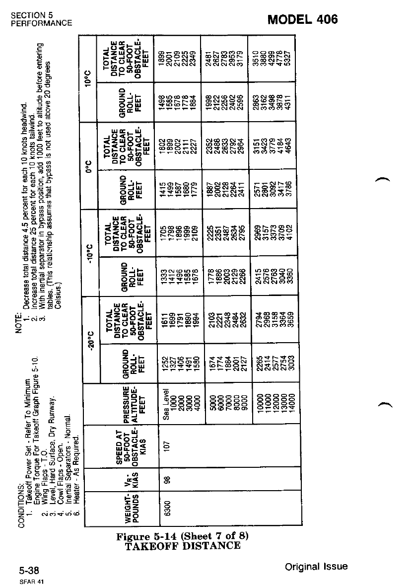
orEiEan
E;F
<J EeiEan
cdF
<) sEsEan
EdF
arrgEEn
=jr
EEH R*EFE
t=F
ttt=u
UhE
Ei
EEH=
>=
6=
gE
Fisure 6-14 (Sheet 7 of 8)
TAKEOFF DISTANCE
MODEL 406
.=
o9
*on
e EX
E;E*
=.8 o-
};; E
o >.9 i
: 3.E:
;E EE
--E*A
EgbE
*E EN
=.9 ! i;
b X;.e
2e9-!;
o q = 9.?
EE=E6
-
E
dZt
q€eij*
3E A3{
-s+-!(,r '
r--[ 6 h
,s9EfE
--93 Ef
,F
h E1
t&
<P6
FFUI
o
sEcroN 5
PERFORMANCE
5-38
f; "i.i
o
z
Original lssue
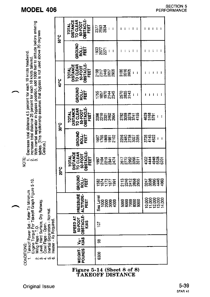
gegEEn tttll
1 Jt-
BEH
illii
<) rEsE6n
o
e;F riiii
sEgEEu
=r!:
BEE
sEiEan
c;F
HH
>=F
Fi
E
d*ess
-E666
3Fc!G'+
HEa*
>=
+3
6=
gE
Figure 6-14 (Sheet 8 of 8)
TAKEOF'F' DISTANCE
sEcTtoN 5
PERFORMANCE
MODEL 406
:
sH'
bn
: E:
E:ft€
d-=: E
:E E 5
*olz
E63E
h-6E
;3E:
F= 6o
P6!29
i[14
;cr'E g
gEbE
*EE.E
=.9 I i;
6*=.e
=W EF
6 q be:l
3fiE4.5
AE= E$
H-"i.j
o
z
G
6
zi
.:.s-
ad<
u6x
:hq
$g
i6 >-
;8
9f;
g;!
F-99+
esg
5;3
fl
o
F
F
E
.E
.E
F
e
-
F
.
u)
z
F
z,
o
J-.tv
SFAR 41
Original lssue
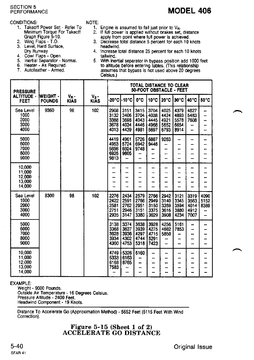
SECTION 5
PERFORMANCE
CONDITIONS:
1. Takeoff Power Set - Refer To
Minimum Torque For Takeotl
Graoh Fioure t10.
2. Wina Fla-Ds - T.O.
3. Lev;I, Hdrd Surface.
Dry RunwaY
4. UOwr FEpS - 9pen.
5. Inertial Separator - Normal.
6. Heater - As Required.
7. Autofeather - Armed.
MODEL 406
NOTEi
1. Engrne is assumed to lail iusl prior to VR.
2. tf till power is apDtigd w hout Drakes sa, dtsrance
apply trom point where tull power is achieved.
3. Decroase total distance 5 percent tor each 10 knots
h€adwind.
4. lncrease tolal distance 25 percent lor each'10 knots
tailwind,
5. With ingrtial soparator in bypass position add 1000 teet
to altitude b€loro sntering tgbles. ffhis relalonship
assumos that bypass is not used above 20 degrees
C€lsius.l
PRESSURE
ALTITUDE .iI'EIGHT .
POUNDS KIAS V2.
KIAS
IOTAL DISTANCE TO CLEAR
SO.FOOT OBSTACTT . FEET
.20"c '10'c 10'c 20'c 30'c 40'c 50'c
Sea Level
1000
2000
3000
4000
9360 98 102 2908
3132
3388
3678
4013
3151
3406
3698
4034
4439
3415
3704
4043
,t446
4981
37M
4038
4445
4968
4025
4424
4921
6793
,$79
4893
5578
6654
8914
4827
5,18i]
7608
5000
6000
7000
8000
9000
4419
4953
5698
9813
496r
5724
6921
9805
5726
6942
9748
5887
i' 9283
10.000
11,000
12,000
r 3.000
14,000
S€a Level
't 000
2000
3000
4000
8300 98 102 2276
242
2581
2751
2935
2434
259r
2762
2946
3147
2579
2951
3380
n49
3150
3629
2342
3140
3616
3908
3121
3345
3s94
3880
4234
3319
JCOJ
4014
4912
70o7
4090
5152
8389
5000
6000
7000
8000
9000
3138
3368
3628
3934
4300
sti74
3936
€02
4753
3638
3939
4297
4744
5318
3928
4215
4715
5291
7423
4256
4682
5850
5161
10,000
1 r,000
12,000
13,000
14,000
4749
6168
5326
6r63
1r
,:rt
EXAMPLE:
Weight - 9C)00 Pounds.
Orrtside Air TemDerature - 16 D€ore€s C€lsius.
Pressure Altitudri - 24tJ0 Feet. -
Headwind ComDonent - 19 Knots.
Distance To Accelerate Go lApproximation Msthod) - 5652 Fe€t (5115 Feet With Wnd
Correction).
5-40
Figure 5-15 (Sheet I of 2)
ACCELERATE GO DISTANCE
Original lssue
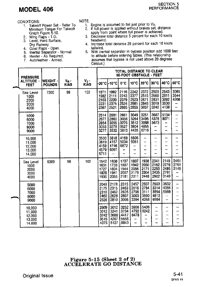
MODEL 406
CONDITIONS:
1. Takeoff Power Set - Refer To
Minimum Torque For Takeofl
Graoh Fiqule 510.
2. Wino Rabs - T.o
3. Lev6l, Hdrd surface,
Dry Runway
4. cowl Flaps - open.
5. Inertial Separato. - Normal.
6. Heater - As Required.
7. Autofeather - Armed.
SECTION 5
PERFORMANCE
NOTE:
1. Enoine is assumed to lail iusl pnor to vR
2. lf fill oower is aDplied withoul brakes set dislance
aoDlv from Do|nt \ihere full powe' is achieved
3. D&iease total distance 5 percent lor each 10 knots
headwind.
4. Increase total distance 25 porcent lor each 10 knois
tailwind.
5. With inertial separator in bypass position add 1000 feet
to altitude beiore entering tables. (This relationship
assumes that bypass is riot used above 20 degrees
Celsius.)
PRESSURE
ALTITUDE .
FEET
WEIGHT .
POUNDS KIAS V2-
KIAS
TOTAL DISTANCE TO CLEAR
sO.FOOT OBSTACLE - FEET
'20'c .10"c 10'c 20"c 30"c 40'c 50'c
Sea Level
1000
2000
3000
4000
7300 98 102 1871
1982
2103
2231
2367
1992
2111
2239
2375
2521
2116
2243
2379
2524
2685
2242
2377
2523
2681
2855
2372
2515
2671
2845
3037
2503
2660
2831
3019
3242
2W
2811
3092
3530
4138
3085
3544
42.98
5000
6000
7000
8000
9000
2514
2677
2854
3053
3277
2681
2860
3055
3279
3532
2861
3056
3276
3527
3813
3049
3264
3512
3804
4435
3251
3495
3988
4855
6716
3687
4376
5!13
5134
ro]'
10,000
11,000
12,000
13,000
14,000
3530
38r 9
4159
4579
5711
3818
4157
4746
6097
4169
5034
627-2
5606
nTt
Sea Level
1000
2000
3000
4000
6300 98 102 1542
1631
'1727
1828
1935
1638
1733
1834
194r
2055
1737
1837
1944
2057
2181
1837
1942
2056
2178
2311
1938
2050
2171
2304
2448
2041
2162
2293
2435
2602
2149
2278
2485
2781
3149
2461
2761
,110
5000
6000
7000
8000
9000
2049
2175
2310
2460
2626
2178
2315
2462
2628
2810
2315
2463
2626
2807
3008
2457
2616
2796
3003
3394
2607
278/
3111
3590
4268
2903
3314
3894
4813
6984
3632
4384
u:9'
10,000
11,000
12,000
13,000
14,000
2809
3012
3242
3515
4075
3012
3241
3600
4207
5\27
3252
3734
4417
8843
3956
4792
urt
5436
s2:2
c-+ |
Original lssue
Fieure 6-15 (Sheet 2 of 2)
ACCELERATE GO DISTANCE
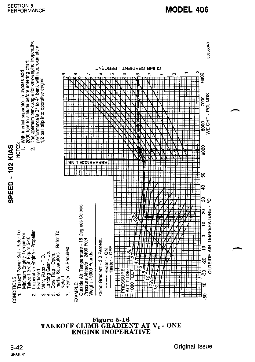
MODEL 406
sEc'noN 5
PERFORMANCE
o
cc
F
IJJ
L!
F
o
t-
l
6 z lr-
LOO
TEb
q r-
Err
(9:l
P il
Fe9
6 =*
P -H'o*
i.E HE H
bes E I
Ee_e:- >
9;;.eE
E=F1O
3ii:-JE
i;EE.;
E"9AF=
=Hi [S
ofr. _,
<tr- "
N
o
o
ut
IJJ
.L
o3
l2
o
3
E
;ioA
e;i3 q eE
; *."-_ E
- Y o-
siFH osrs 3 e=e
;E;.E"u.q;,a ! EEg
F$Efie-s9E,iE9E *;;s
9, 6i di; dd *;8dg
oi
c)u
Figure 6-16
TAKEOFF CLIMB GRADIENT AT V2. ONE
ENGINE INOPERATIVE
c-+1 Original lssue
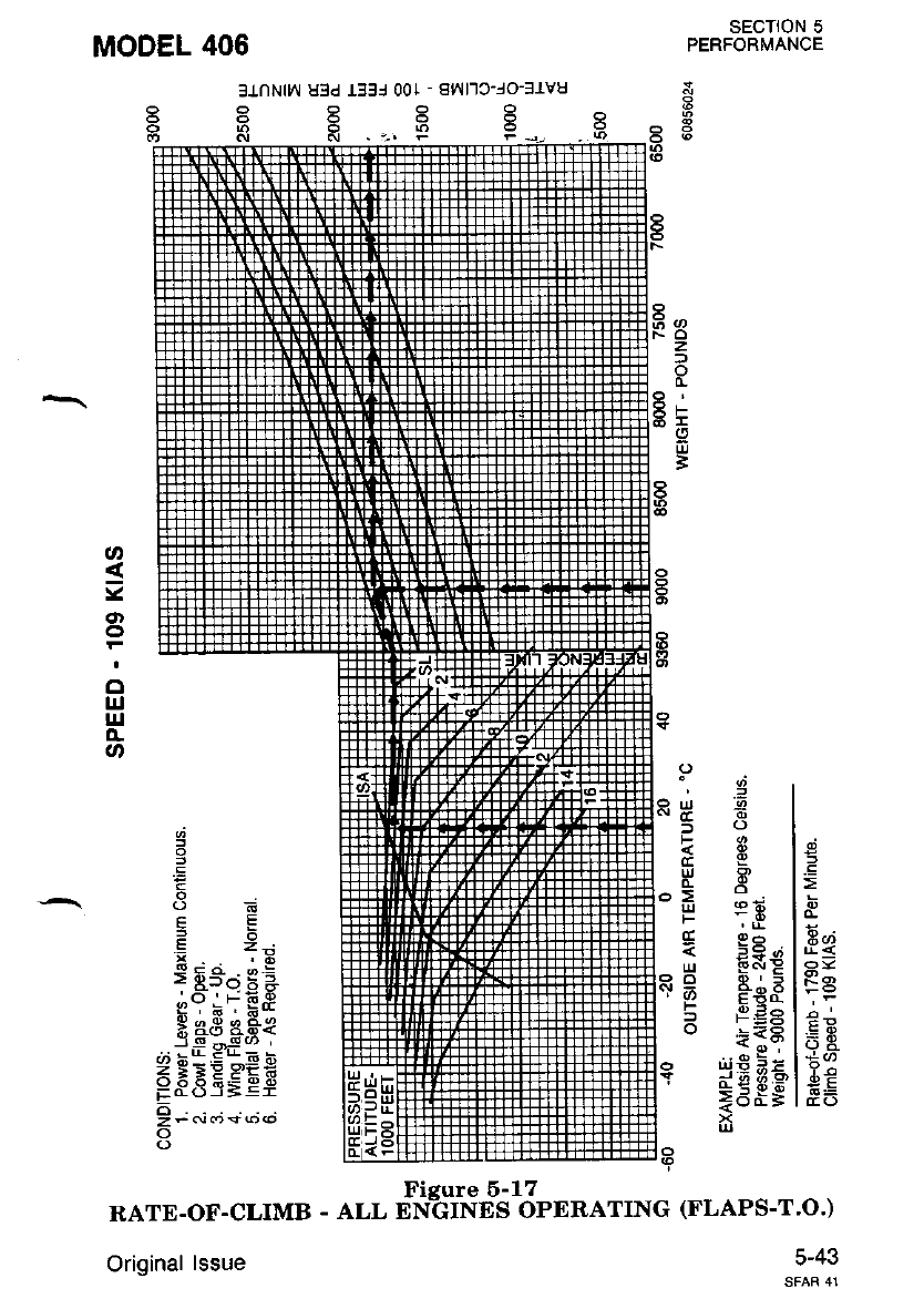
SECTION 5
PERFORMANCE
3
t3
o
z
F
g
uJ
3
:5
t
E
I
MODEL 406
31nNln u3d rf3l 00t - sl.^/l'lc-lo-31v8
Y)<|:X
.E
o=
PO
.EF
iE
cEo
u9
(!.Q
< lt?
(rg
"ua
6 eE
r ,ii
tE o-
3 EFe
H 5E.F
b ;Ee
=i9'6
i5d=
3r
5X
'z ,6
: E-";3 3
,:o'F6.9
R aE ase
rS o#g] '
di h=E*_E b
=tXE.E'ER
Fd6i.Ei
o
zFNos@@
o
o
Ficure 6-17
RATE.OF.CLIMB . ALL ENGINES oPERATING (FLAPS.T.O.)
5-43
Original lssue
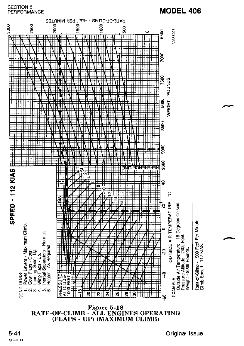
sEcloN 5
PERFORMANCE
s3_LnNtrl uld ll3l - a!'{r]c-lo-t.tvu
H K F. E F H
MODEL 406
a.-
F-Z
8i
.oo
=
.E
&-n
d' s)
oa
a*
EP
Y-*
6E
6i
TEO
Y
)6
F6
*o
>;l
!r*
< ,li
H gg"
3 FeF
.!Ap
,l;9 5 :
];89,-a
=E#s
E
'i .x
> e5- X =
.^o 'r8.9
{. a ' F*
H aB e&{
l-g -_q (') '
.;:r.ErEh
z:EP 9€€
o
5-44
Figure 5-18
RATE-OF-CLIMB - ALL ENGINES OPERATING
(FLAPS . UP) (MAXIMUM CLIMB)
Original lssue
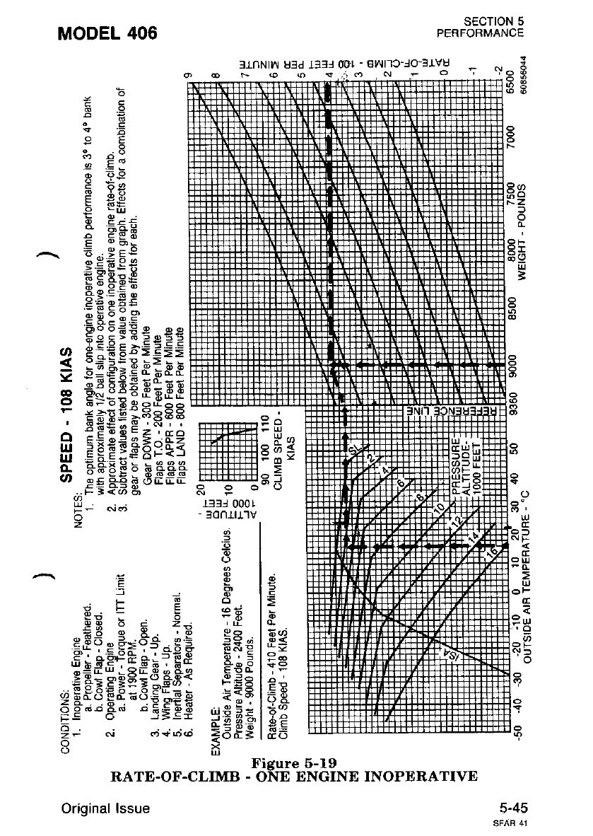
SECTION 5
PERFORMANCE
MODEL 406
- .^ F
-l-t-t-1-1-.1 (o 6
3.tnNt!"r u3d et3l @l - av{l-lc-lo-3J.vu
or .o ra) s ,:: (t . 6l
s>
f
=
o
Lli
F
G
2
l-
a
ul
6
F
o
e-.ee
5 e==
,EiPP
E:EE
FHqq
z'Ea
<.-:,LZ
6F<J
Sfff
6
FS
sE
^9
;', E:
4 .EJ
sr F.9
Z =6
F EE
-9 _ur
E 3=,-*
E 6ts:
,^, E -.; E;
'€ Ffl;F
5E;€e
;Hboor
E=Fs 3€
o EE€s;
< !;*l,iE
Y nEE-o;
r -#€*E
- :tEE:.
] EE#EE
O c!:5.
l'll ?iEEe'
E -aeEta
vr eS*€G
..tr Ee6 E
H; c,i cj
o
z[t3l 000 I
- 30n1tJ-'lv
=
r=
(EO
.?
l2
6,
o
EE
*x€
6;, d
E60-
F=5
,ii9 5=
iE ft:-e
=dE;
E
E
; 2-
oo-.i e 5
d'f8.9
-q 6 , 6*
"3 a&{
? o'S@ '
YEets*
'i=ef
E
f
.F
EE b
t,Ed r *=
.?l eE€&
e "-E-cxE
9 f,qq gq6
o
Figure 5-19
RATE.OF.CLIMB - ONE ENGINE INOPERATIVE
Original lssue 5-45
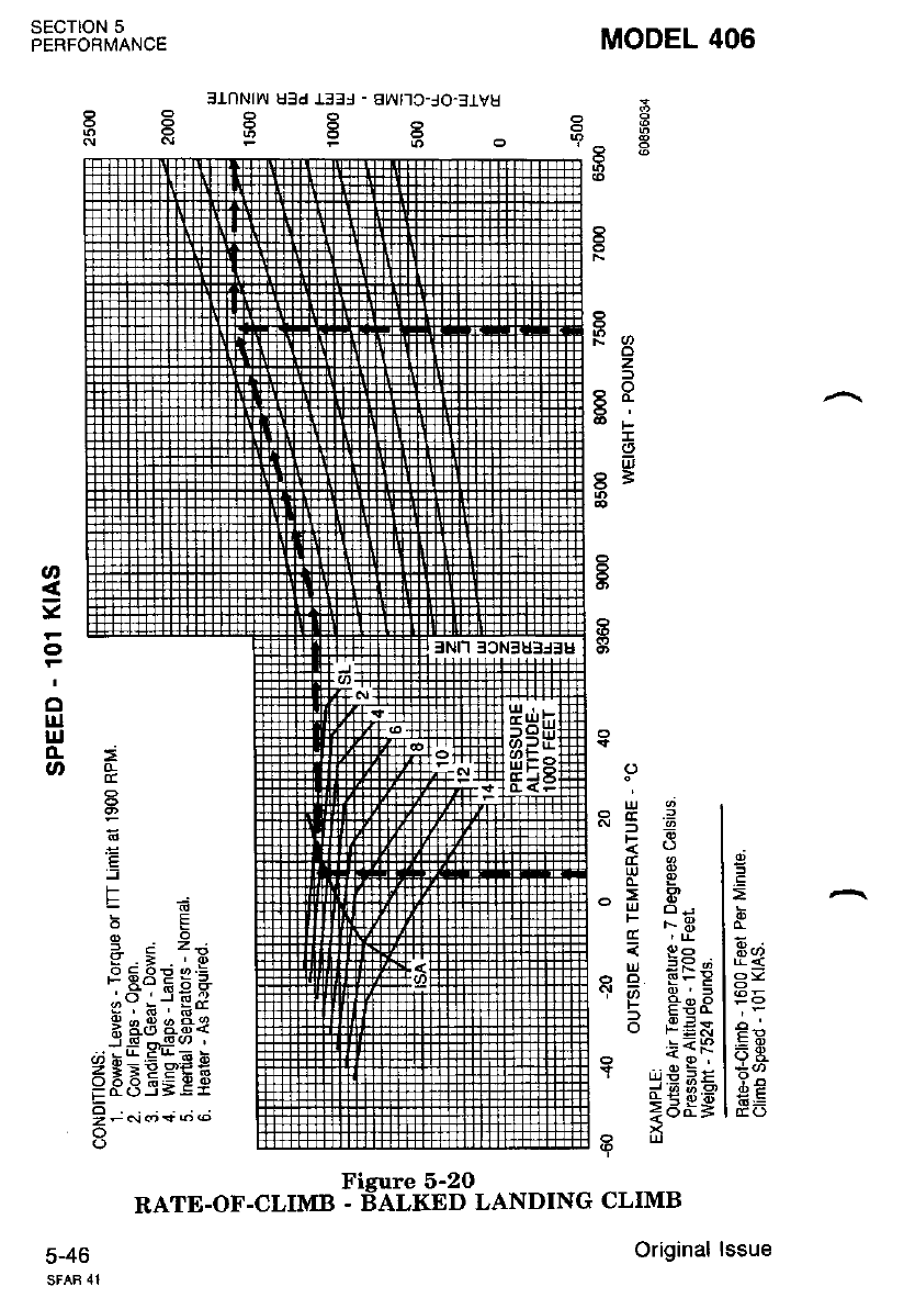
MODEL 406
SECTION 5
PERFORMANCE
a
;g
3rnNtyr u3d J,331 - a!.{t-lc-Jo-3_LVU
Ree^
N::;
:5
z
:5,I
tr
8=
:5
.E
E";
g=
€-
Y.*
d'E
6E
cco
RE;
-6
E!!
of P
- sR
< qs .
R P S:g
'( Es8
_ t:N
*:Fg
I
=
?
E
=
F
g' .5 13
e63Eql
. ^* ' q:;t
e: h; :.c
H aB a.ri*
FESEgEE
E - ..i .; +;.;
Figure 5-2O
RATE-OF-CLIMB - BALKED LANDING CLIMB
original
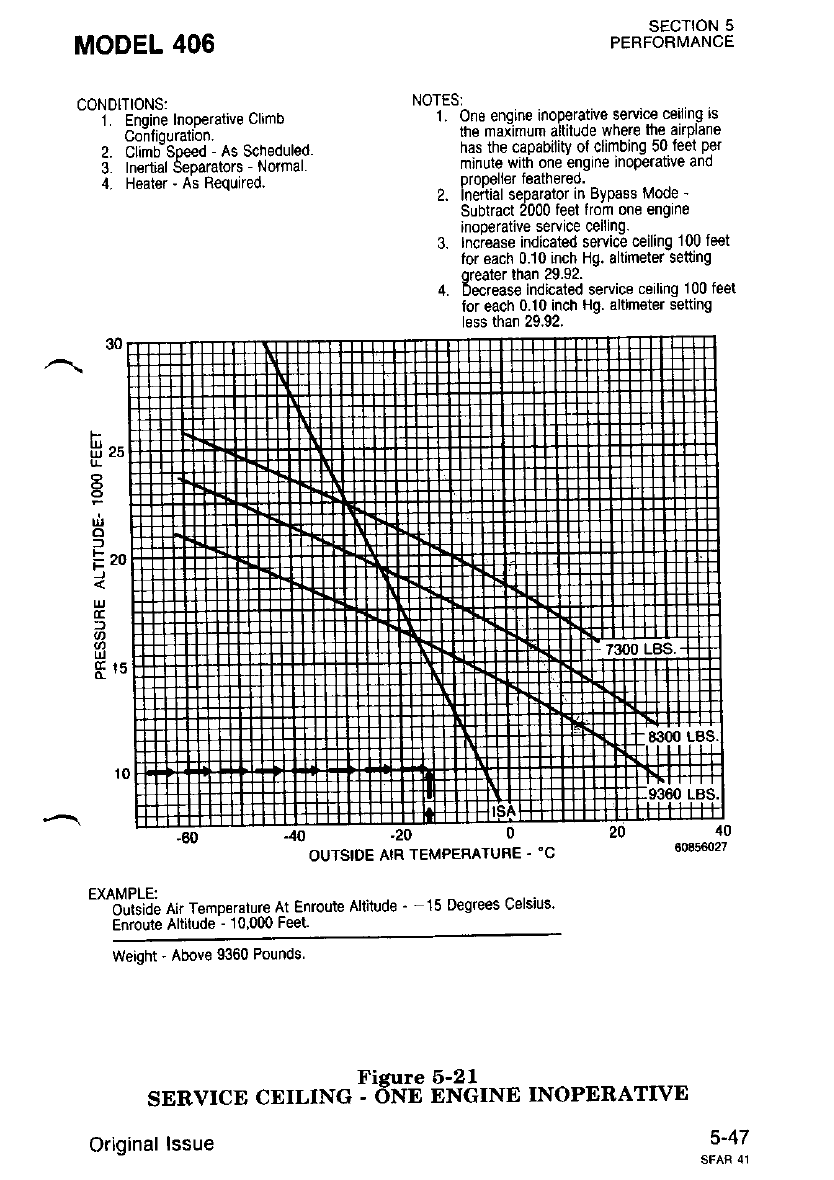
MODEL 406
CONDITIONS:
1. Engine Inoperative Climb
Confiouration.
2. Clmdsp€ed - As Scheduled.
3. Inertial Separators - Normal.
4. Heater - As Required.
SECTION 5
PERFORI\,1ANCE
NOTES:
1. One enqine inoperative service ceiling ts
the max-imum aitilude where the airplane
has the capability ol climbing 50 feet per
minute with one engine inoperative and
propeller feathered.
2. Inertial separator in Bypass Mode -
Subtract 2000 feel from one engine
inooerative service ceilinq.
3. Inciease indicated service ceilinq 100 feet
tor each 0.10 inch Hg. altimeter setting
oreater than 29.92.
4. becrease indicated service ceiling 100 fe€t
lor each 0.10 inch Hg. altimeter setting
less than 29.92.
F
llt ^,
t
o
l
Ezo
)
:)
-20
OUTSIDE AIR TEMPERATURE . 'C
t*tlo\5; on ,"to","ture At Enroute Altitude ' - 15 Degrees celsius'
Enroute Altitude - 10,000 Feet.
Weight - Above 9360 Pounds
Figure 5-21
SERVICD CEILING - dNE ENGINE INOPERATTVE
Original lssue 5-47
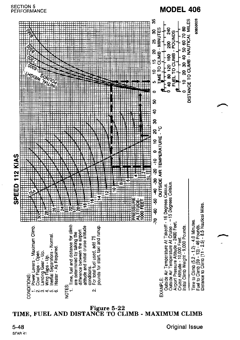
MODEL 406
SECTION 5
PERFORMANCE
TIME,
5-48
a ^6,
^J R
6> t
e9
65
g=
*o
^F
o4
F
q
o
^., [o
HgT&R
,^=l =
.=lRd
;
=JEE
6 LR:
9F+-ts
.'rt3g
o t-o
,f€
g8;
5eS
e=E
t:5 n
ul
Fl F
ottIJJ
q;
F
oul
.?O.di
6 9.=
? 5-Fn
3 3S
6 Ao
5c
>,< ^
o
=
N
o
ul
uJ
o-
og
,' '!
E.P
=92
€ i"r
:1*i
.!^.
=E9
oI6
E * E-=c€ -9
E +. e€lpE:
s F.'^ n 5 EaEi a:
'-6'=-€E ;:EE 5E
Eigfl'ft .:€ec€Ee
=o*.;.;+.;.; H- 6i
3>
Figure 5-22
FUEL AND DISTANCE TO CLIMB - MAXIMUM CLIMB
Original lssue
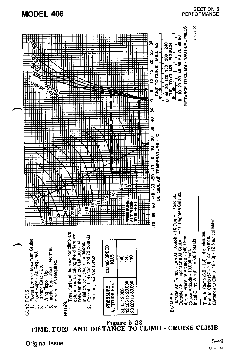
t
z
SECTION 5
PERFORMANCE
MODEL 406
!{R
=F
)i5
o
F
2
=
z
6
-t
F
B nts
=tR
6.4
.3-|-c
-d la
I9+-
. H+:
tr FE
6
ai
F
?fi
t>
'o
e
4F
EE 6
od:
qi-- ''
-P6
.-: F 9
ot-i:
q=g
i=|Io
r46
,qo
ax'
6.9?4 9
EEEq:
Rg<=c_
--e':'
ee ag=
liet^E
Lii 6i E q,v
I EE REE
=ddi5E
ul
ul
b2
gs
u,t t!
a*
EE
tr &;6
e38
. bE :a
.a ! - EEEga
Eg 5- ;s*E;:
if +-"g 3 gE:sgE;
-EigFg: EE€EE;
EFSEgEE ,,E€E€;E
=;d ("j + d<t P; dj
oo
Fisure 6-2S
TIME, FUEL AND DISTANCE TO CLIMB - CRUISE CLIMB
Original lssue 5-49
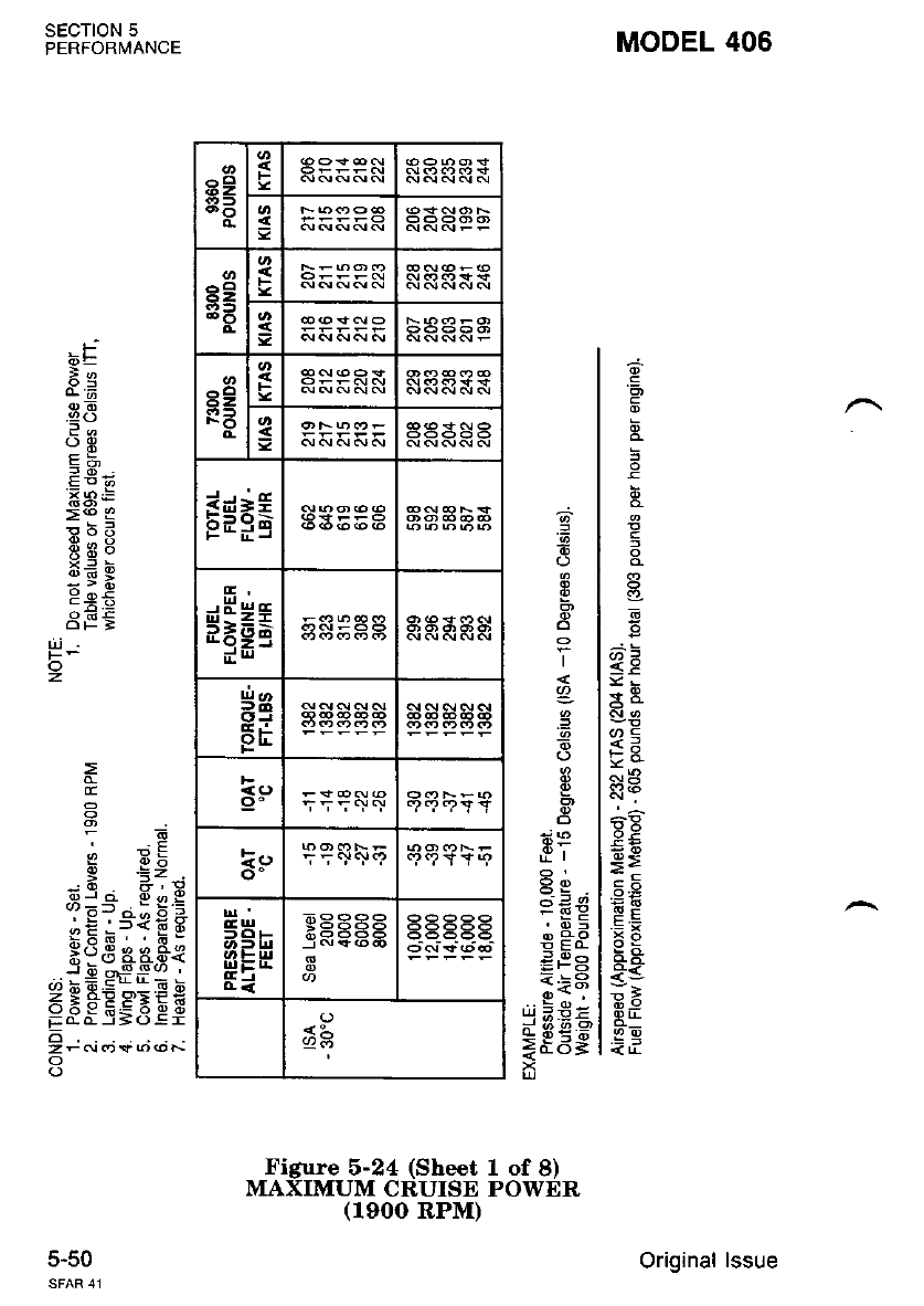
MODEL 406
'6,
6
<E
!!3
E:
x4
od3
;;
69
RIL
ito
i,i
6
.=
I
I
a_
.=
I
p
Qp
-EE
e g.o
i b=
=F6
<;3
I12 X--
g n< @
id6=
SECTION 5
PERFORMANCE
J.5U
.F
6=
ie
o)E
.92 (J
:.
EBS
>(o 3
H;9
i?:
:s:
9 o,E
dF:
6 .E;
-d. el!
oJ o o o Y
?Et.i;61
;E:J<EE
P3S aaS{
J h...9-9(,) .
.;r=-r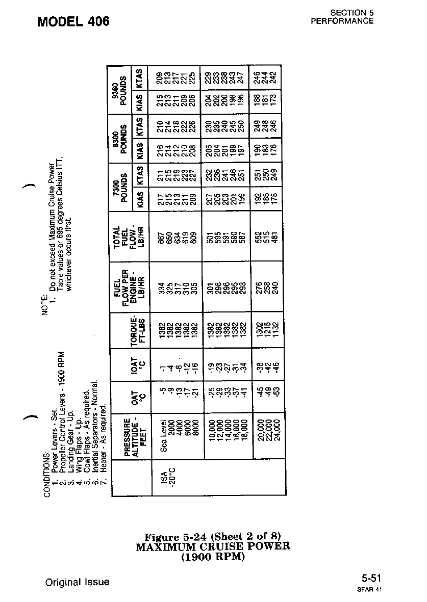
SECTION 5
PERFORMANCE
MODEL 406
.F
dE
le
od
.9()
oE
58.,
Ea:
>@ I
€i3
8U9
gE*
9 oi
8F5
e 6b
3;=-, g * =
.'^!.'=*{tB
R;3 aa*g
..:-+E'rr=.-
F$s"E9,iEc
9 ;.i,,; +; ..; ;
o
|Jl
o
z
Ficure 6-24 (Sheet 2 of 8)
MAXIMUM CRUISE POWER
(leoo RPM)
a2
3B
^cl
62
(?D F
g
a2
FO
F
s
E*=g
*Hss
54
pE
<Q ';reif
=e
o- tY9
5Hr
$EH
8E555
<:)
!2R
5-51
Original lssue
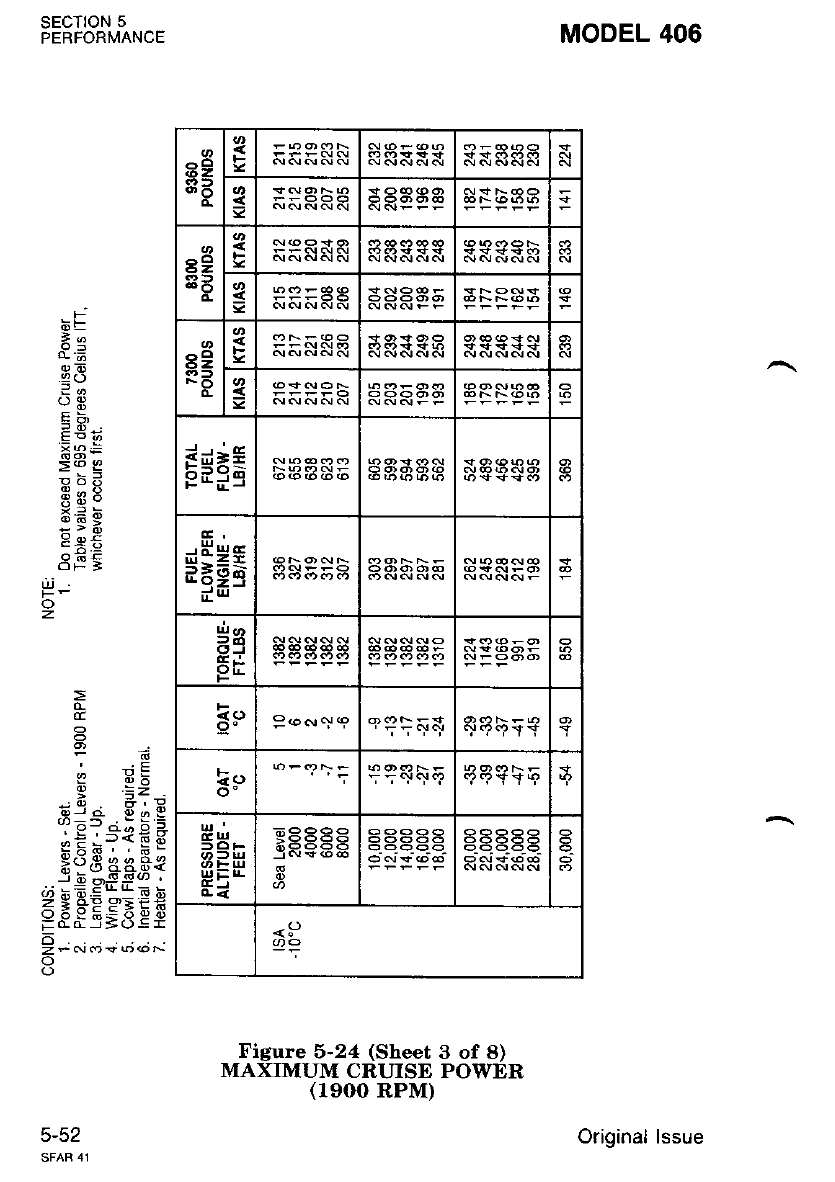
a9
8: F
3
s9
a: s
s9
FO s
EE==
9Eiq
$$*;
5q
FIi
ko P.o., a ICT9'?YY
=e 'i 5 + q! .?
53'.
ul E lr-
Ei
ja(+66
<P
MODEL 406
SECTION 5
PERFORMANCE
5-52
-F
6=
*e
38
lo
OE
E9'
EAE
>@ g
69:
x< 6
:>*;
9 oE
3F5
(I
6 E;
!o2 0,:l
@J o a o g
s)=f i -: -
.::.'D<63
H6E aast
j b ^!-9(,) .
,;-=EL4;!
6: FESEES
EO-ar=(J:r
o
zfNf)*o@N
o
UJ
o
z
Figure 5-24 (Sheet 3 of 8)
MAXIMUM CRUISE POWER
(1900 RPM)
Original lssue

a6z 3
=
6Z
3B
o.
I
3
r9
RB s
g$i6
sHgt
d9
Fi
F
k9
o-
a3b
EJ
aaaaa
SECTION 5
PERFORMANCE
MODEL 406
-t
n \,*
.0 45
--
*aE
>ro E
E?g
ES9
xn 6
:v:
a€t
=
CE
I 6b
-d. ali
oJ o q o g
oEr.i;6 =
,:;.'f<F6
r:.d ' ' 6'
;?3 g4.qt
_* i,e Pt ii; *
FFS-E9.iEE
6
o
o
z
Fieure 6-24 (Sheet 4 of 8)
MAXTMUM CRUISE PowER
(1900 RPM)
5-53
Original lssue
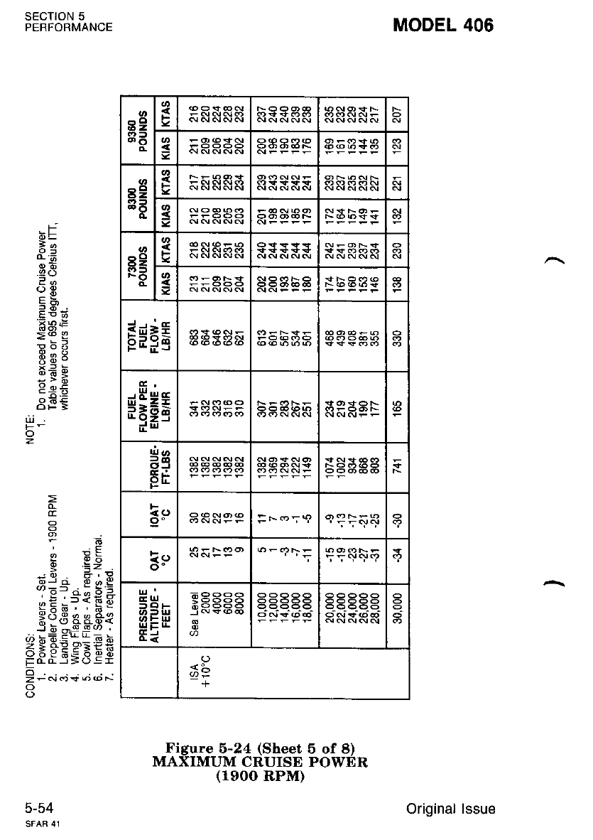
89
3E
F
3
8e
3t F
g
^o
6Z
FO 3
E*=t
*$#a
SAaAA
:F(')59
ka
o- T';qr.!9
EUI
=roF
UTE:|r-
Ei
x883a
<:-
-+
MODEL 406
SECTION 5
PERFORMANCE
5-54
.Fj
6E
2e
E8
:d
o3
EX
2E'J
EAF
=<o E
X= bt
:ii
C:E
dg:
E
F6
, ;E
6 .i;
-d. elli
or o o d g
aJ=- r -: -
.-_ ! 'f<6 hj
fldd ea*e
."i* df *;
ZgiEPE€X
o if Y E= o q o
FCarS(.):r
o
zF<\ldJ*o@ts
o
o
z
Figure 5-24 (Sheet 6 of 8)
MAXIMUM CRUISE POWER
(1900 RPM)
Original lssue
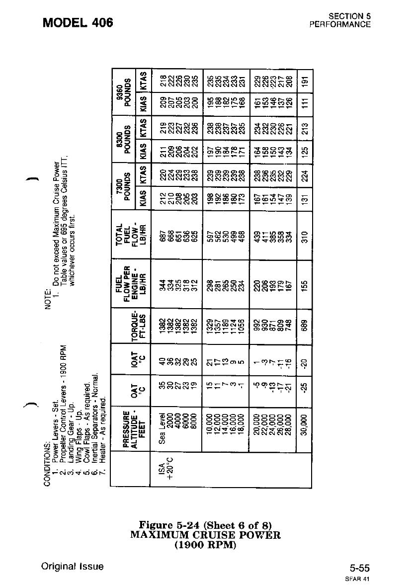
8g
EB
F
aSaaa
-o
62,
i6l
t-
3
r9
R3
s
g
fE*€
9(:C
$H*s
Hg
Fri
F
e!)
o"
EUr
rllETL
tri
+
SECTION 5
PERFORMANCE
5-55
MODEL 406
*t
o6
.9()
?a
?E
EP
8a:
>@ c
Eo!r
X= ti
Jvi
9 oi
df;
6 _E;
.: a-r;
s:="-Eiq
.:='r<6x
Ho8 aaFt
j;-sg(,,
.; k;.Er L E h
FFs'E9,qEE
o
z-c\tr"s(oroF-
o
o
o
z
Figure 5-24 (Sheet 6 of 8)
MAXIMUM CRUISE POVJER
(1900 RPM)
Original lssue
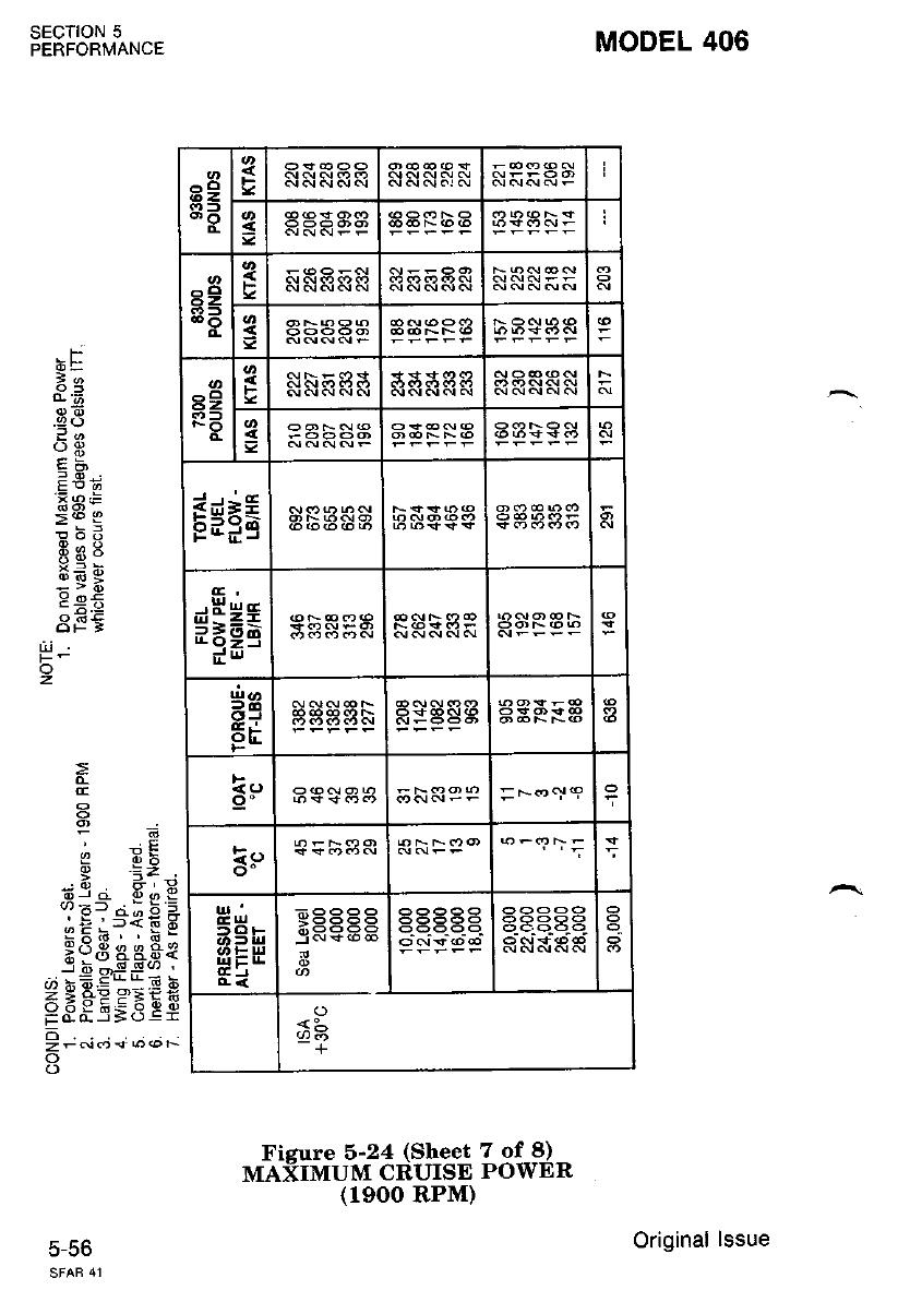
Fisure 5-24 (Sheet 7 of 8)
MAiIMUM CRUISE POWER
(19OO RPM)
MODEL 406
SECTION 5
PERFORMANCE
c-co
.F
oE
.9(J
?-
5S.
:*;
:"t I
8Uo
:e;
3F5
d
e 3t
dja 8,1, E
iE?-"{€ A
g:;, . F-
*dB eest
-..-iEEu*r
ZgtsEeEiX
P8E_E;3ee
9-r-i+;";;
o
(-)
o
z
^o
62, F
sI
r9
3A
s
a
3
62
FO
g
s
r*ng
aat
$Hgt
Hq
Eri a
F
=No<19
k9
ihltl
r|'|E:TL
<:-
+
Original lssue

39
a: gHFESF
a2
3B
i
s
89
F3 I
=HHRPF
E*=a
$Hgs 3S5RR
:e
Fi
ir
sB-
rrlETI
tri
>9994
janY-5b6
*L
+
SECTION 5
PERFORMANCE
MODEL 406
,F
6E
l-
^e=
BB
36
oE
EF,
xs:
=@ I
6:A
3q9
x= 6
:vt
9 o<
3E5
o
z
=
p d:
-d. e;i
3:=' . E s.=
eE i?fE E
Hd8 aaae
-f 6 6s!u) ,
.; != EaL= !
a 3 *'ES:8fi
FO-Cr=():r
d
z-<!ct+66F-
o
Figure 5-24 (Sheet 8 of 8)
MAXIMUM CRUISD POWER
(1900 RPM)
Original lssue
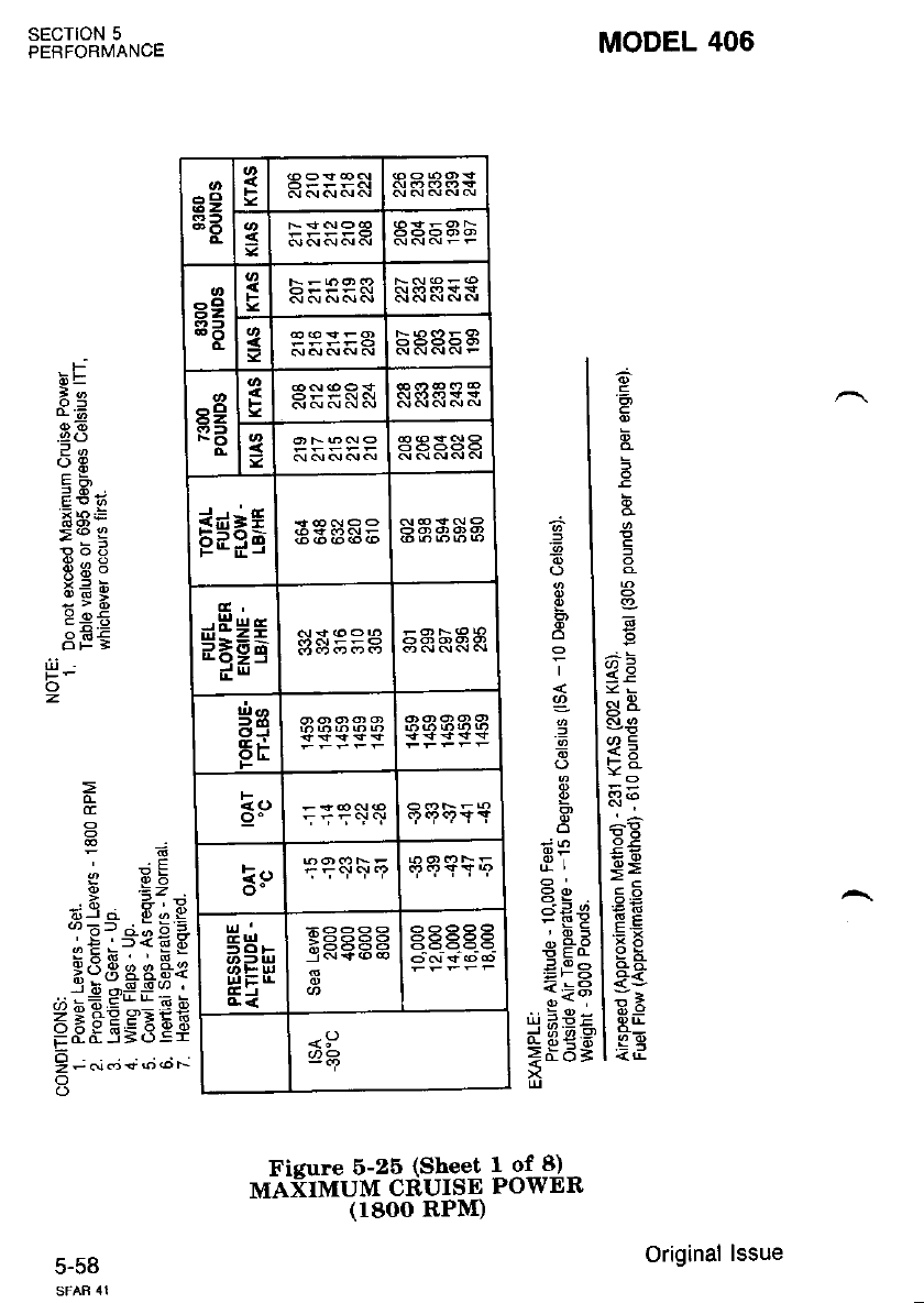
MODEL 406
.=
G
^;
<P
<!R
or=
9l? (o
o€
6S
Fr
:B
R'!
-6 1
6l
ol
ol
rl
ql
6
d
,?r
99
-s:
'E?
€ Ea
<t3
*$Es
6=
ic
a8
?-
Eni;
!p=
:Fg
9tao
:s;
3E5
(I
P=Z
6il d 6 - I
.: E13? € *
-ix6. ' E_
Xd3 s83{
. i!sff!-
29FEe=if;
;8E.s;3.Ef
9 r.i; +;.t;
o
SECTION 5
PERFORMANCE
5-36
o
z
Ficure 6-25 (Sheet I of 8)
MAXIMUM CRUISE POWER
6Z
8e 3
89
33 =
8e
NO
Re&NS
3aaaaa
r$F6
$Eea
Hq
EE
Eo 5.;5c:c!
ie qqqsE
5E-
ui; r|.
4<
EEEEg
<P
Original lssue
(18OO RPM)
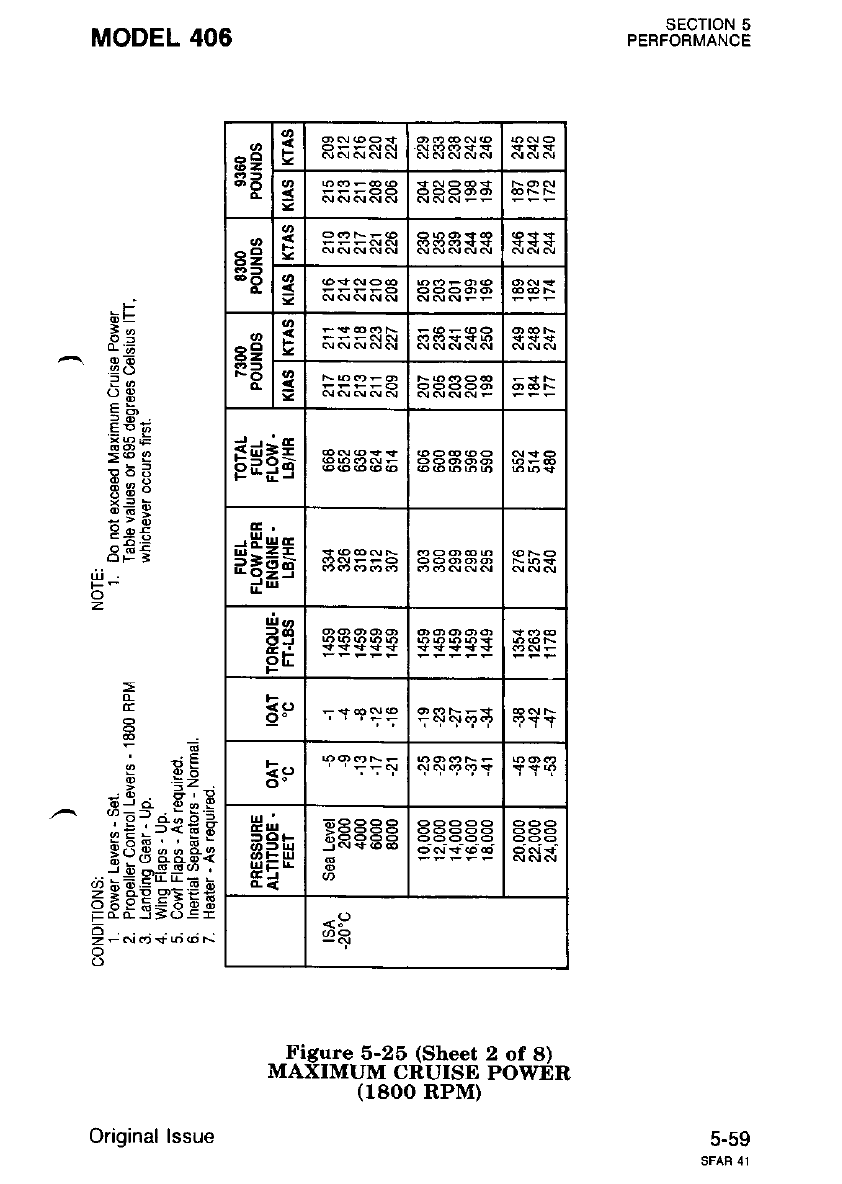
sEcTroN 5
PERFORMANCE
5-59
MODEL 406
bF
3d
^39
3o
oE
qb
'*a ts
>@ c
!bB
69:
x: d
:ii
9 oi
6 '-: ;-
E
-E
6 .i;
: f- ?i
Sl-". E e E
EE;?1E E
Rod aaae
J 6 ^-g_!(/) .
,t bE.<:*E b
<tl+Yx'.rE
EeES=3es
o
zFcrr<t*@@N
o
o
z
Figure 5-26 (Sheet 2 of 8)
MAXIMUM CRUISE POWER
(1800 RPM)
8g
8E 3NNd-.n
8e
3e
=
t2
Fe
o.
3
gNcrNNan
E*=g
$HH; 3S5Eg
5S
Er
F
l!,
o-
50F
ib-i!
|rlElr-
(EJ
699ee
<P
(,R
Original lssue
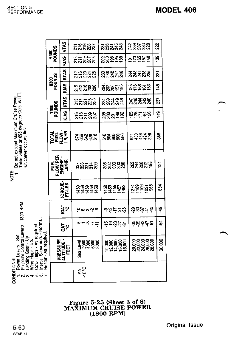
FiEure 6-25 (Sheet 3 of 8)
MAXIMUM CRUISE POWER
(r8oo RPM)
MODEL 406
sEcroN 5
PERFORMANCE
5-60
.F
dE
le
or6
_9()
:-
o3
*a:
>9 g
E9d
3E9
99X
9 oi
6flE
=
E
, !E
dja S.i,E
?E?-"*E*
eFe, , h:
Xd 3 aas€
..:9 df : =
FF"gEgEEE
9 t .i.'i +; ,.t;
o
o
z
6z l-
3
89 F
^o
6Z g
g*Pg
*Hea s
ee
Er
3--"I9 eTi{q
E!)
o- 994a9
UJ
g3-
|lli:r!
IEJ
sP
Original lssue
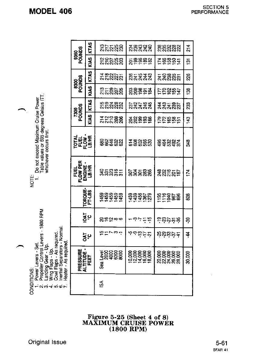
89
8A
!:
:<
89
s3 F
=
89
PB ge&eRR
E$FE
$HHs
Hq
gf
=e
o- $.r96?a
5ts-
UEr!
Ei
SECTION 5
PERFOBMANCE
5-61
MODEL 406
.F
dE
*e
' @6
.2 ()
:g
Eq'
Fa:
>@ I
qbd
.9:
x=d
:'i:
3F€
E
I d:
-d. 3:!
oJ o" @ o g
96r ci; b 1
eE i?fE E
Hu8 eaFe
jEoSSo'
E 5,.EEEEE
FO-O-r5(J:r
o
zF(!.fr*6(oF-
o
o
z
Figure 6-25 (Sheet 4 of 8)
MAXIMUM CRUISE POWER
(1800 RPM)
Original lssue
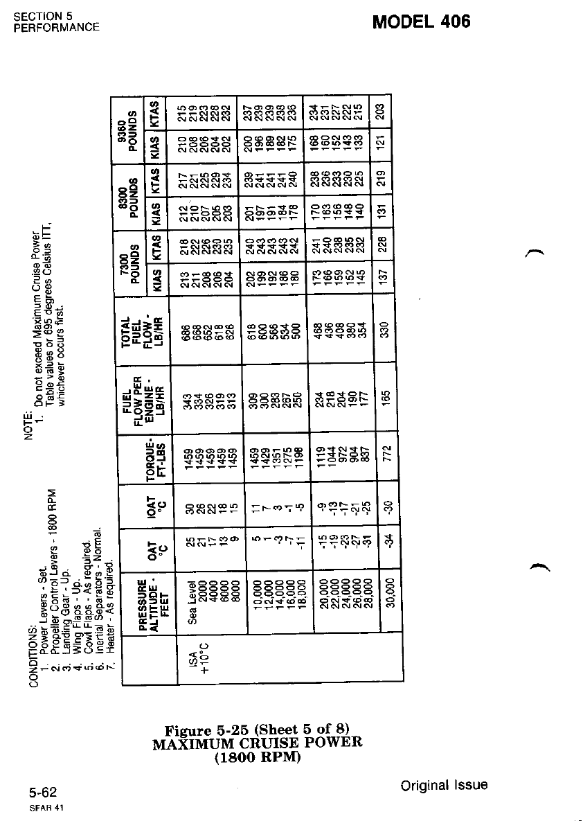
Fieure 5-26 (Sheet 5 of 8)
MAXIMUM CRUISE POWER
(1800 RPM)
MODEL 406
.Fj
6=
F3
@6
9E
=R.
!nE
SEe
Eig
8U9
:si
Ee€
3EE
r6
c db
-o =z
6J ci 6 o 9
;E:3€€s
*3S aeFe
i! gff3 -
3:3E$E$
tro.o--r>e:!
I t ..i.; + ;..t ".-
o
SECTION 5
PERFORMANCE
5-hz
o
z.
a2
83
o-
{
=
89
8e
F
:9 E88
r2
FO
F
s
g$tE PaaSa a
$E*a aaabS
d3
ts,r
ER6RA
9" qqi4{
ke
o' n
t!'
5H-
!4 E!9
c,r 33?33
-+
Original lssue
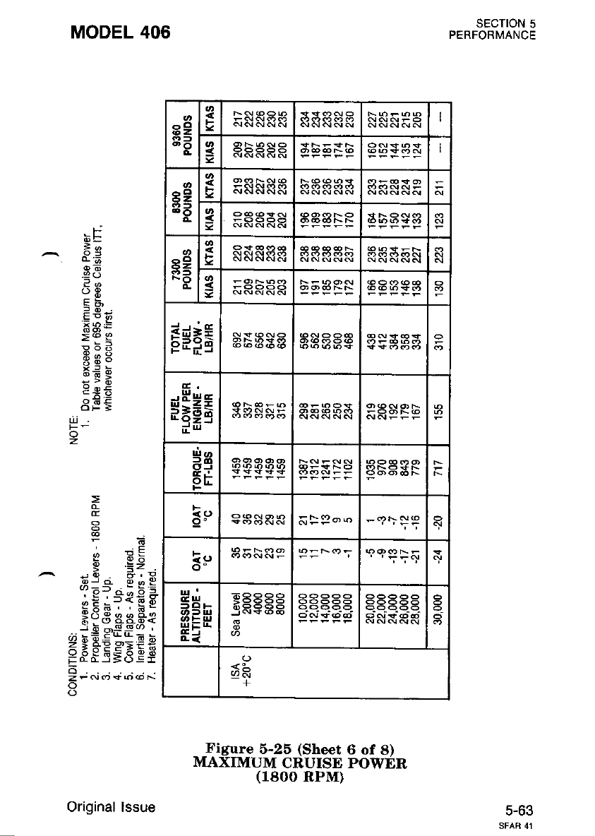
89
3e sRHHHR
r9
33
FP&h$a
-< ERRRR
89
FO
3
=ERRRR
Esnr abSaa
$Eet
34
FE
a3a3a
fe
ct" tsENRP
fi5n
UIEE
Ei
EQ9EE
j-+6;d
<:-
+
SECTION 5
PERFORMANCE
5-63
MODEL 406
.t-.-
6E
o6
-9()
3o
:g
=P
>t q
90-l
x: bt
;v;
dl.:E
z
CE
6 .i;
.,d. e;!
3=---.Eq=
eE l?fE E
Ho3 aaae
r 6 -g-! (, .
.;,=EL!t!=!
Zg+PPEIH
E3;_E;3ef
6
zFcrr(t*o@F.
o
o
Figure 5-25 (Sheet 6 of 8)
MAXIMUM CRUISD POWER
(1800 RPM)
Original lssue
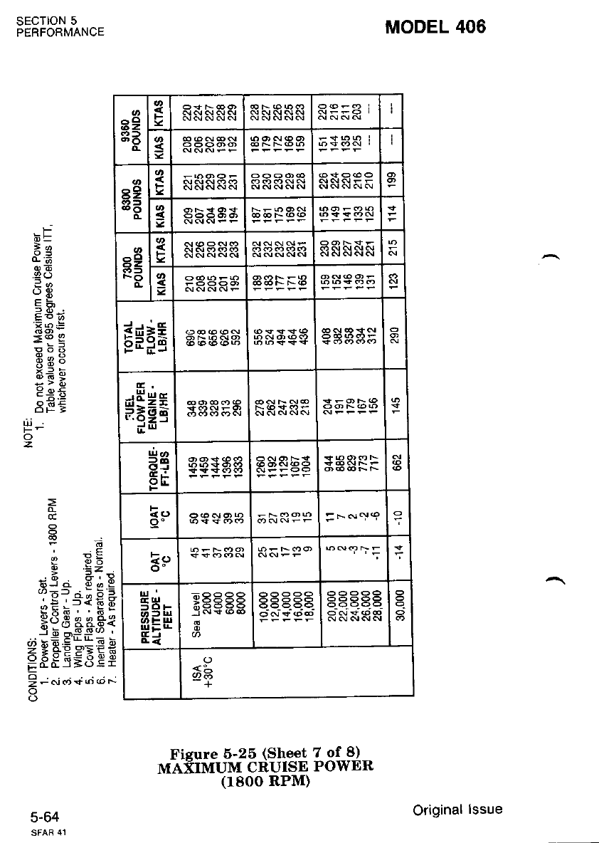
MODEL 406
SECTION 5
PERFORMANCE
c-o+
.F
6=
o)E
.9()
?a
:E
Eq'
XR:
=6 g
odd
8U9
gs;
385
Pii
' :E
I 6b
t33 a 8,), E
(r=: ^:;5
'-E'=*{;8
gxa. ' 6"
H?3 44.4{
,.,i+ slili;;
Z I HE sEit
H8E J=3 Ei
! t t,'; +;.t *
o
'iii
o
z.
Ficure 5-25 (Sheet 7 of 8)
MAXIMUM CRUISE POWER
(1800 RPM)
39
83 s
89
o- 3
-o
6Z
FO
cs
g$FE
$HHa
d9
Ei R$SEg
Eo =F.N'YI
E9
ct'
fClF
ui-r!
GJ
aaaaa EE .E.E
<:-
+
Original lssue
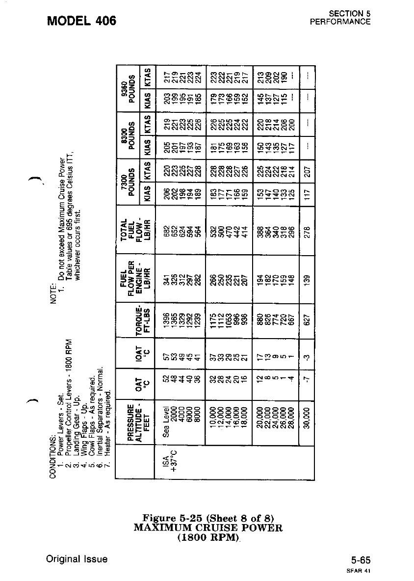
82
33 q
3FPPF€
89
AR
q
g
89
ra s
f Ex=-
pd:q aaaSa
$fr*E
14a
*4
!Ei
tsu-
aaRsg
Eo
k -<>
ul'
.lUt
:'0F
rJJ-L
Ei
6P9ee
6b
+
SECTION 5
PERFORMANCE
c-oc
MODEL 406
.f-
i6E
2e
' -9! (J
oE
E3*
>@ I
qbd
.q:
x= 6
::v:
9 oi
dfi
gr x:
6 .=;
-6. 3:i
3=3 . s E:
eE i?fE E
HdB aaFt
j-E q,SS@ '
(/i H6.E**E i
FFs'E9.BEE
o
Z-cros6(oF
o
o
z
Figure 5-25 (Sheet 8 of 8)
MAXIMUM CRUISE POWER
(18OO RPM)
Original lssue
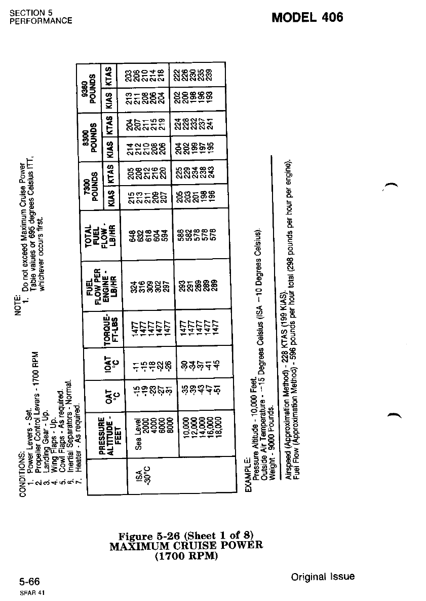
MODEL 406
E
c,
,;=
<-E
Eo
a=
N?
*.q
*E
=q
x9
I jfs
t:;
| 6-9
=l
8l
EI
F, I
6l
ll
'l
9l
8l
E, I
o
el
Q9
== a
=EP
;EA
p Er
:iq
'.ji >€i
d6q3
=i6=
LI
t-
dE
o6
9a)
.\ tt
E5;
.X RE
=6 g
o6d
Fe8
x_=;
:;e
se5
3EE
t
a
FA
I db
E .=Z
a9a F;E
i-g?'"*€*
H€,9 ee*8€
_"ie Pti;;
a:^EEg.qEE
! - *.;+;-;
(.)
sEcTtoN 5
PERFORMANCE
f,-oo
o
z.
Fieure 6-26 (Sheet 1 of 8)
MAXIMUM CRUISE POWER
39
83
ftE Agg
3aaSaa
6Z
o-
F
=:s9aa 3AE53
s2
FO 3PP=8ts
E*FE gsP33
c,
$HHs *eaa5
ee
EE
io I -----
9" | 555"Y"r
I
!s | +?sF+ qqE\E
HN
-oF
sEu
EJ
;99 9P
9X:i i66
E
g€egg
<s)
c3
Original lssue
(1700 RPM)
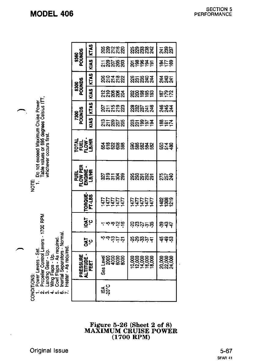
^cl
i52
c
F
=
^cl
62
.t-
i
=
62
!r:t
FO
F5:99&
=
Esrg
$fr*;
ee
FE
F?fT
l!)
o- ' 'i';ql
5H*
(,t t ltl
UIEr!
GJ
'RPPq
<!)
SECTION 5
PERFORMANCE
c-o/
MODEL 406
F
6E
7e
.3E
?q
()t
qF,
F5i;
.F3E
>@ g
E;U
69:
x= d
:;:
g g€
8F€
rli
z.
a .=: .
;@ 6,q
:E?+i€ i
3{E ce.Fe
.*ig pii;: J
6 E EESEEfi
EaaJ=o!r
6
ZF6l<D!torot--
Figure 6-26 (Sheet 2 of 8)
MAXIMUM CRUISE POWER
(1700 RPM)
Original lssue
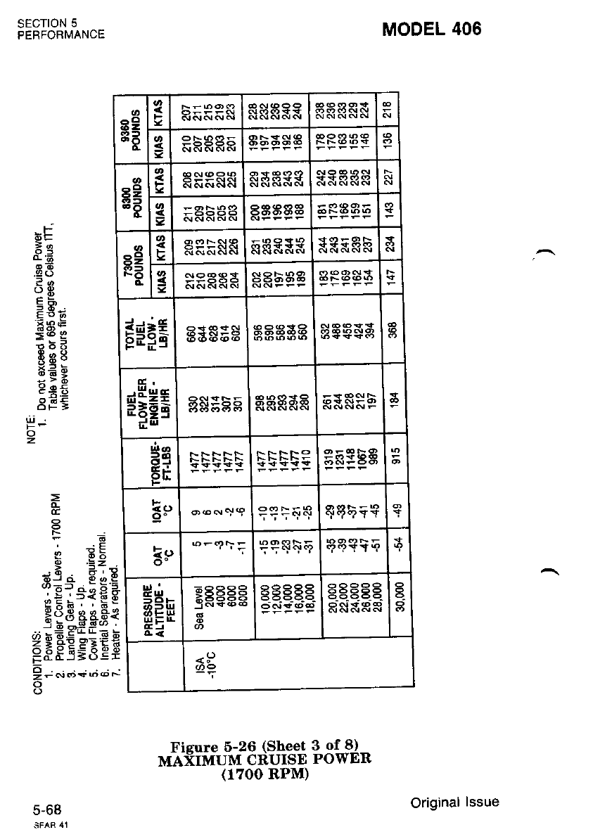
Ficure 5-26 (Sheet 3 of 8)
MAXIMUM CRUISE POWER
(1700 RPM)
MODEL 406
sEcTroN 5
PERFORMANCE
bE
le
oE
_9()
?a
()E
8RE
:6E
E66
889
*.= 6
:SR
9 oq
8FE
cc
. :E
I .=Z
6l.i 6 o E
dr=f :: X 3
_:E.'r*:(Eg
*€8 e4*8*
..:e PEf,; -
I I &E s=t€
PFES=3ef
! -.;..i+;.t *
o
o
z
5-b6
89
EA :3 I5885
EE
=aEaaa
FH
FRFESN sR&xx
gE33A3 aa53g
r$F6 E*E;H HEH*E tsES$A
$H=E gs:5 5RHRRR s
es
gE
sqi{q +6?9TY
ls,
o- ?qq\q qqsia
HH'
EEH
A<
:E556 gEBg-E 9eP99
RS&RR
<:J
Original lssue
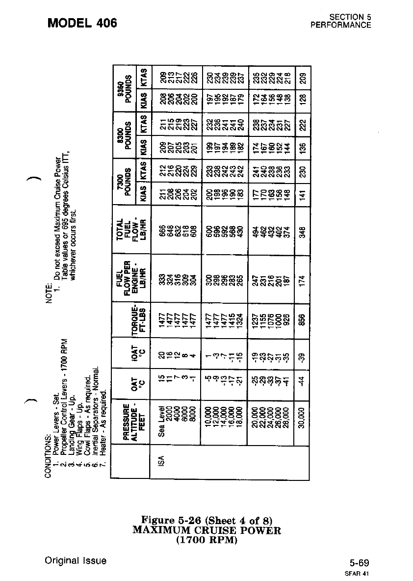
SECTION 5
PERFORMANCE
5-69
MODEL 406
XF
:;
;*
.E a5
3o
o9
EA
.FAE
>@ 3
*;T
o!p:'
x= d
:;*
:6.Y
dFi
t
!D ?!
q .=: .
-q 6,9
3=-- . E s =
.E;TfE C
Htd as.F*
J-9 o'#+-' '
@ bEE*_:E b
5 e e HE'aEE
Fo_o_J=o!r
!; "r; +.;..; i
o
(.)
z
Figure 5-26 (Sheet 4 of 8)
MAXIMUM CRUISE POWER
(1700 RPM)
a2
3t
o.
FAPFNA
s
s9
sB e&ess
3RRRRR
s9
F3
ts
3
E*rg adE68
E.
$EH; sdggg
Hq
Er RPbAS
RPS-= r<||+q'<?
le
o- ' '';5+ J
H;
agb
frEH
E=
>Pqe9 t565t5 E 5t555E
Original lssue

MODEL 406
Fj
bL
.24)
o9
Fi
Eti;
'X P=
:6 E
6:d
i_?:
:s6
E*E
8E5
t! -.,
o
z
=
CE
a
, JE
I=Z
6J.i 6 0 P
(D=l : : X 5
-:.E.' =*{E S
gXA. , A"
Bg3 ag.fr{
..:9 fiii: -
!2 6 e= -=E I
<lo*EE:b*
=ddi=o-Ei
l; .:; + ';.'' "-
SECTION 5
PERFOBMANCE
5-70
*'i'f ril1,'#3{th3$F3i'?"
(1700 RPM)
89
3A
c
3
3
sE
F
=RHHHR
a2
FO
at,
F
sRRRRR aaas R
E$i6 *aaft: EEgSg €€€g$
HEeE gHg;H ggRRR a=a8F
ae
Fri sEESE aa83A
5q AASPS | =F<"rP qP:&E
k<)
o- Ee>P- l'-'?\; qqq\E a
HHn
HE*
9 XVi5 E3REB3 ES.EE. -
RftX&R
a
+
Original lssue
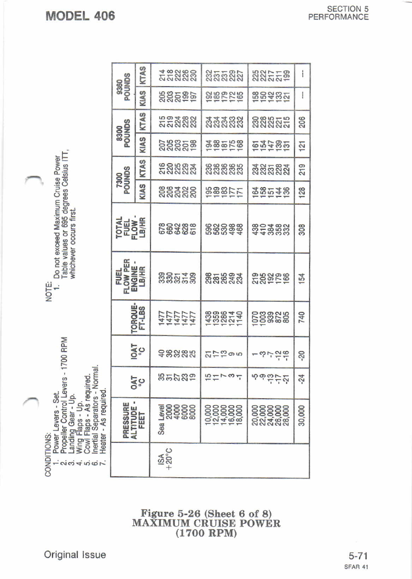
89
8B
3
3
89
8F
89
qrt
FO
F
=HHHHR
E*=g
G.
$H*E 33$Es
ee
Er
F
<ao &FP-.r
k()
o-
t||'
gH.
att)u
||,r i: rl.
Ei 3
aaaaa 9Pe 99
6E5E25
+
sEcroN 5
PERFORMANCE
5-71
MODEL 406
:F
x',
:*
.4d
ot
E5;
.E aE
=(o9
F;E
de:
x: d
:;:
peE
de:
=
a RE
e =:
rO 6'9
3i-'-13 5
eE *?TE E
*oE aaFt
,,i bE =:"E b
5leE.<:EF
-ddiJSos=
o
zFN<tro@N
o
|ji
z
Figure 5-26 (Sheet 6 of 8)
MAXIMUM CRUISE POWER
(r?oo RPM)
Original lssue
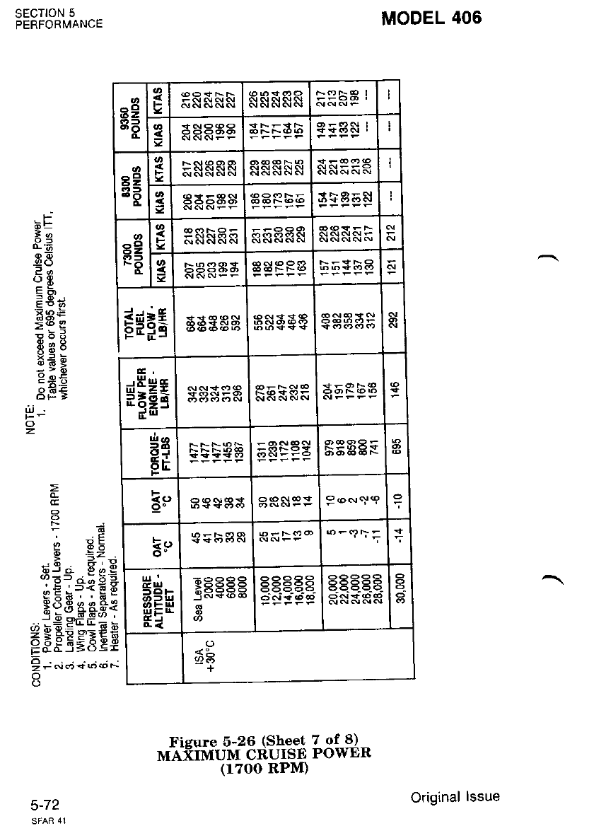
EE
8a
o.
{
=
e2
3E !
89
FO
li
=
s$FE as333
HHt;
Hg
FE 5sF93
B9$3S 9--qe
k()
o-
ut'
5Ha
HE*
ECEEE
<9-
t26
+
*i'f iil"""^f 3{?lff*13'#J"
(1700 RPM)
MODEL 406
aE-
E8
3o
E€r;
'=9E
:i6 E
!5d
frs8
::E
c;.9
3F:
I 6b
ti3 a S.), E
iEl.'*€ *
sxa6. . a6-
X.i3 aaa€
--i9 cf tr*;
Z g FE PEEE
ESEi;6 zi
!; ",i o + u..; *
o
SECTION 5
PERFORi,4ANCE
)-t1
z.
Original lssue

SECIION 5
PERFORMANCE
MODEL 406
-i
ie
-- d;
9-e
?a
oE
EH
-5 -E-;
xaE
=<o I
F;F
oe:
a= 6
;v:
peE
8E€
d
o
z
!" *!
d =;
> f _:
tji a 8,1 E
.1!':*{€F
*dE aeFe
j-6 -SSo '
=EPEgEEe
6
zFN('{r)(oF-
o
Figure 5-26 (Sheet 8 of 8)
MAXIMUM CRUISE POWER
(1700 RPM)
5-73
^al
i52
8B
a
s
r3
=HREFE
r9
NO 3
E*=g
$HHE
ee
Er a
:Po6o
3r, N.o+oa
ul'
c lrl
.,-|Jl
rrr i: rr
IEJ
;aaaa
o
*L
+
Original lssue
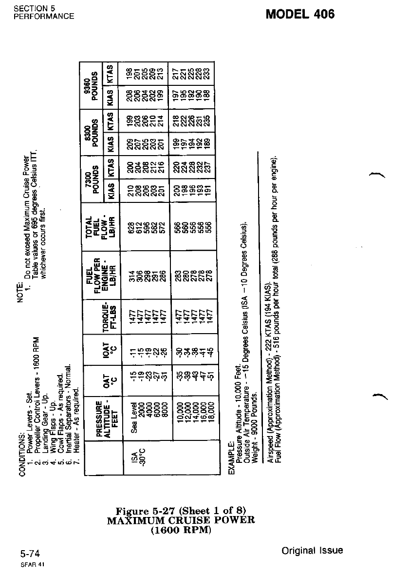
MODEL 406
E,
3
G
<E
.1t =
.\' 9
ll(,
!6
e=
=E
9i
<5
:=
Rr!
6'6
=E
E
(.)
o
I
L
.=
I
o
d
fit
Q9
Fs
arq
5b
Ei
= ^s,:
SECTION 5
PERFORMANCE
c-/ +
bF
E2
.88
?a
8n:
=6 E
E;E
69:
x4 6
;sa
3EE
=
E
f6
6 .=;
. R =;d
6r ci d o I
(rr:f : - x -
_:E.,r*{€g
Hss aes!
.":9 df : i
EFFEgEEE
! t oio.; +.;,;;
o
uJ
z
-
Fisure 5-27 (Sheet 1 of 8)
MAXIMUM CRUISE POWER
8e
83
o-
F
=
89
3B
F
82
FO
P
=
E$=5
$HHs
5s
FE
9"
is
rrl '
sH-
(r, - u,
3EH
.E:I
xaaaa qEPRP
<5)
./,8
Original lssue
(1600 RPM)
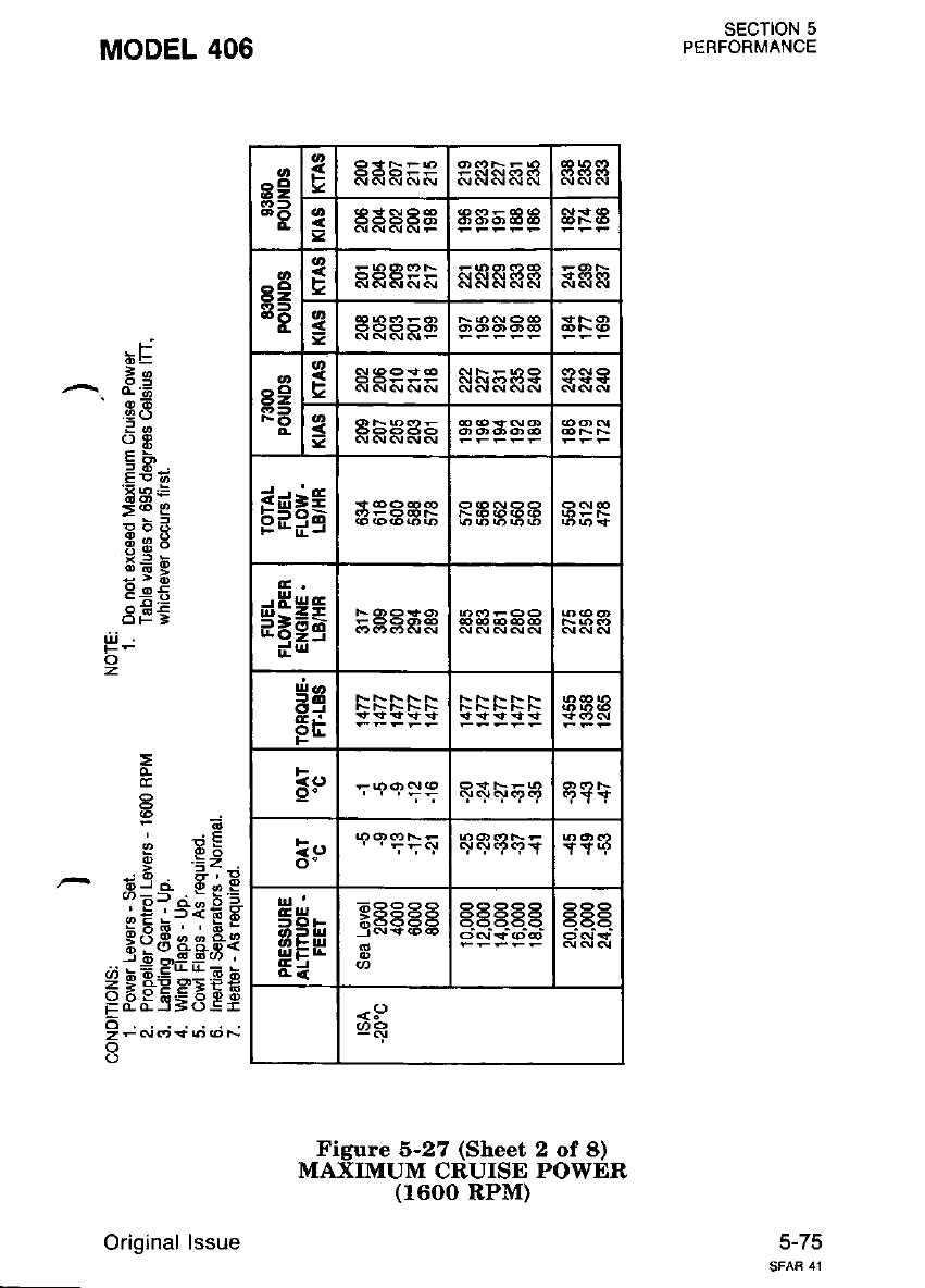
SECTION 5
PERFORMANCE
MODEL 406
r-j
bt
ie
^. d.d
'E8
oE
F€?;
'5aE
>.b 2
F;{
69:
x= 6
:YR
8eE
3EE
d'i
o
z
=
:.E
b .=Y
ti9 a 8,1, E
iE?."t€ *
PdE asFe
I d ^E_9r' .
FEFEgEE$
6
z-6r('*6@N
Figure 6-27 (Sheet 2 of a)
MAXIMUM CRUISE POWER
(1600 RPM)
5-75
89
3B
sH s
8=
FB
Faa9:P
=
EsPg
G,
$$gq :aaag
Hq
Fr
<o +qr+q).? 9tY
le
o- YY!P
frHt
|||E:r!
Ei
9FEEE
3anY6;6
E
aSaaa
<5)
Original lssue
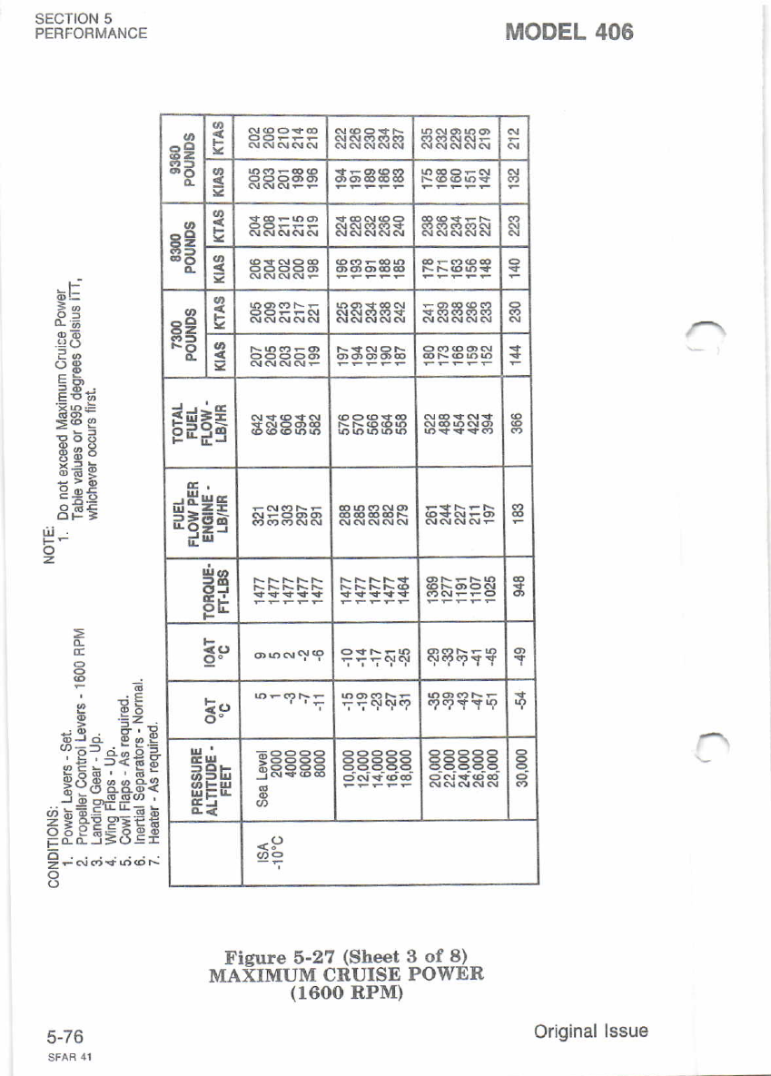
E2
3a
o-
3
=
8g
3t
d
s
=
8e
RE
t
aa
E*=g
aE!
$HHg
is
5r
F
9" 9.J.?.? a TY
kt)
o- a
t!'
5Ei-
(r>ul
frEH
Ei
9t(v6b6 gEEEg a-
<:)
Fieure 5-27 (She€t 3 of 8)
MAXTMUM CRUISE PowER
(1600 RPM)
MODEL 406
SECTION 5
PERFORMANCE
J-/O
-t:
*e
o,n'
?a
oE
=E';
=69
E;E
69:
x= d
Eie
3EE
E
Fa
b .E;
iE:="{E*
H5,g aa$i
.-i4Eff:=
EF;"E9,;EE
l"*u+;..;,-
o
t!
z.
Original lssue
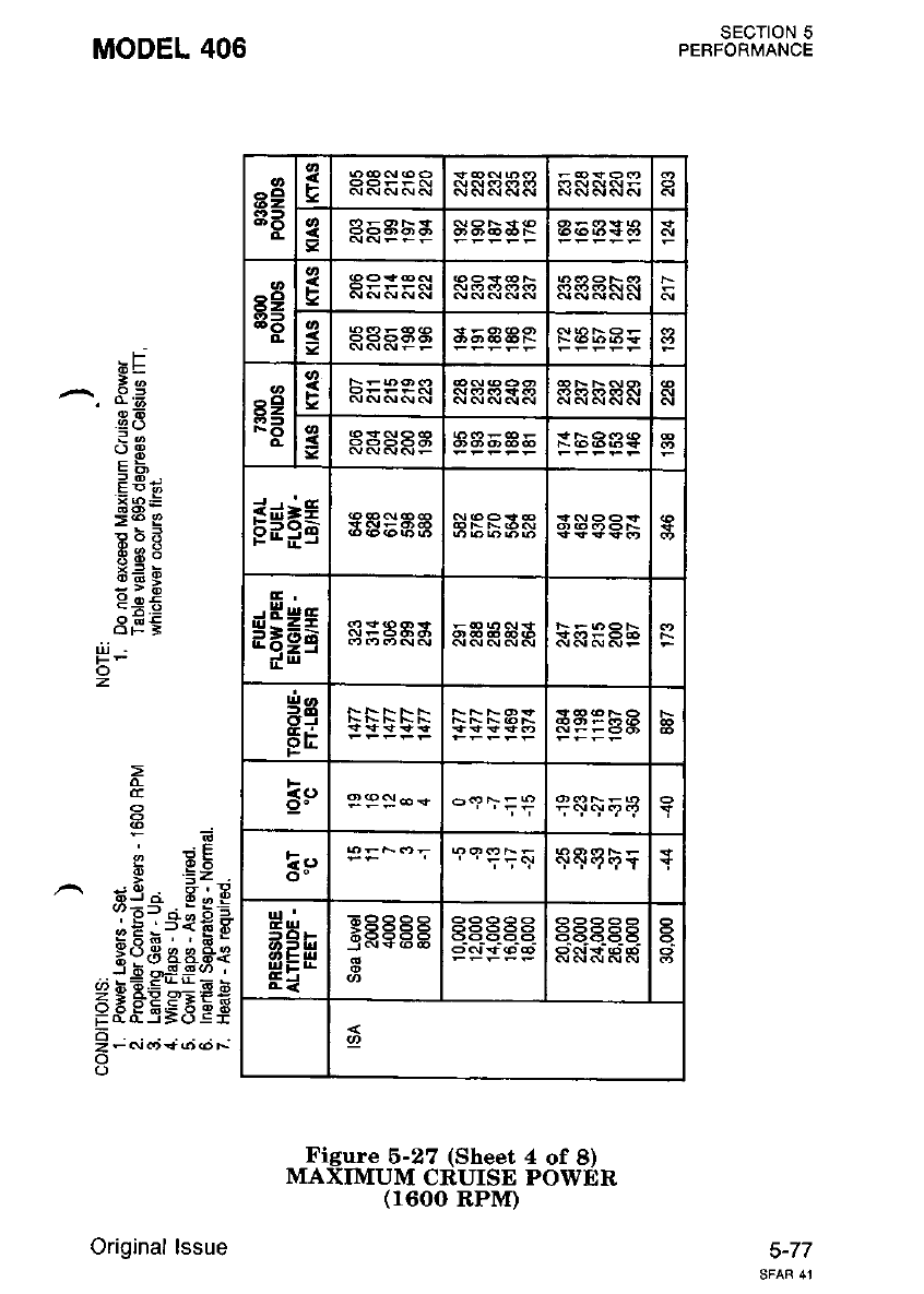
SECTION 5
PEBFORMANCE
MODEL 406
,F
:a
a8
?-
(JP
=a.,
'Fa ts
>@ I
ebE
-E:
gEP
P+6
dEi
U] Pts
e .=: .
-c 6.9
3==-- s E.=
;E:s€E F
Ps,B aAS€
J d ,--E -q(/, .
g$FEEEEe
6
zFN.r*(o@F
z
Figure 6-27 (Sheet 4 of 8)
MAXIMUM CRUISE POWER
(1600 RPM)
5-77
a2
3B
F6
=RFEEE
a9
3B
o.
F
HHFPE
Bg
FO
s
=F BAAA
s*Pa
E,
*HHg R:8AA
5q
FE
F
.to P 9:.D *('c,l \: P';.!+9q, Y
kq
o-
a3h
rr, E r!
E*
EPE9E
gHSEF aaaa a
Original lssue
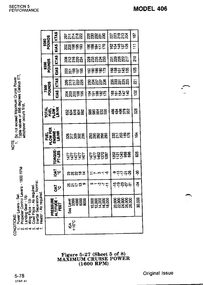
a2
8B s
s9
83 =
^o
6Z
FO
asbSE
.tt
s
g$FE aaEsa
G,
$HHs alaSE RRRRR
Hg
EE
E.r | --*-=
9o | <{ (\r.{ f F = F <o:9 .lPtr&R
I oFF-('r(D
E!.t I **--
o-l
,.' -.? rr =q
5H.
s=H
Ei
xaaa 83R?Bg g. .gg.E
R$ARR
a
a
*b
+
MODEL 406
SECTION 5
PERFORMANCE
5-/ d
-F
i6E
7e
oE
.92 ()
()9t
cE
cEi
=a-
:6 q
E6d
E60
*,= 6
;;6
:o;
6PE
!! _:
o
z,
=
E
63 a S,i, E
ie?="€€ *
gh6. '6_
H?3 44.fr{
.*i9 gdd;;
< a *zz'.-E^q
E3E5;d Et
!t".io+;,';;
o
onl'f tif"'#3{?lfi"iB3'*"J"
(1600 RPM)
Original lssue
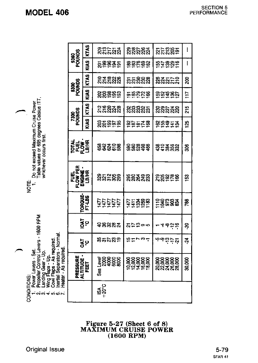
SECTION 5
PERFORMANCE
MODEL 406
btr
1c
.^ d.i
a8
?o
ot
i6;
'Eats
><o E
F;E
de:
x= d
:;R
c*5
8F€
fl-
z
Fi;
!,l x!
e .=: .
;a 6,9
3==- . E sE
'E;'-*f E E
3t3 aa.Et
., bEE*_:E b
<l*tj>:'lrE
E8E5=8ee
6
zFNcr*()@F-
o
Figure 6-27 (Sheet 6 of 8)
MAXIMUM CRUISE POWER
(1600 RPM)
5-79
89
BB
FI
I
s2
3F
F
=
s9
RB
f
g
E=l;
*5Hs
eg
EE
a
F
<<J
lr
t!'
frHr
qlL-E
Ei
*5665 g.E .Eg- a-
<:-
+
Original lssue
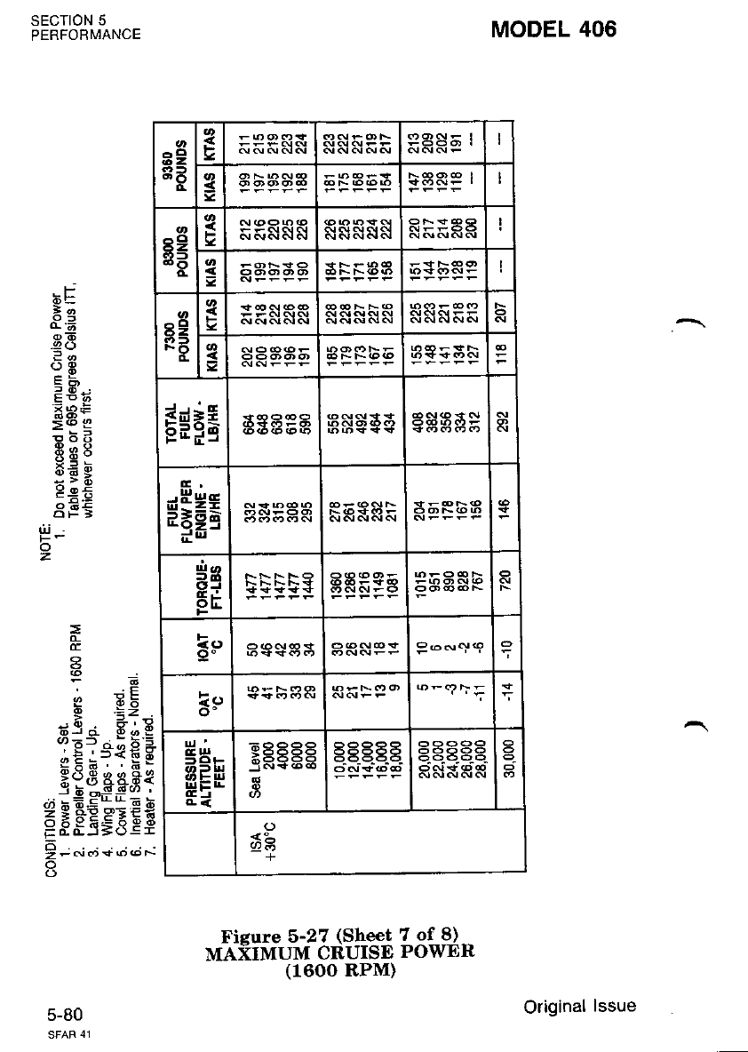
MODEL 406
SECIION 5
PERFORMANCE
c-ou
F
^Q
o6
.9 (J
?o
EN;
=6 c
6:6
860
6; e
3EE
=
E
a
9 EE
ti3 a A,i, E
iE?"{€ *
Hsg aaFe
."i9 ef f 1=
FFgEgEEE
!; o,:; +; o; *
o
z
Figure 5-27 (Sheet 7 of 8)
MAXIMUM CRUISE POWER
(1600 RPM)
39
8B
o.
F
=
r9
33
c
3RF:AA
g
s9
RA
=
Esrg
HHea
ae
EE
=--qq
3:,
frHr
EEH
4<
xaa88 g.B. . .E
o
+
Original lssue
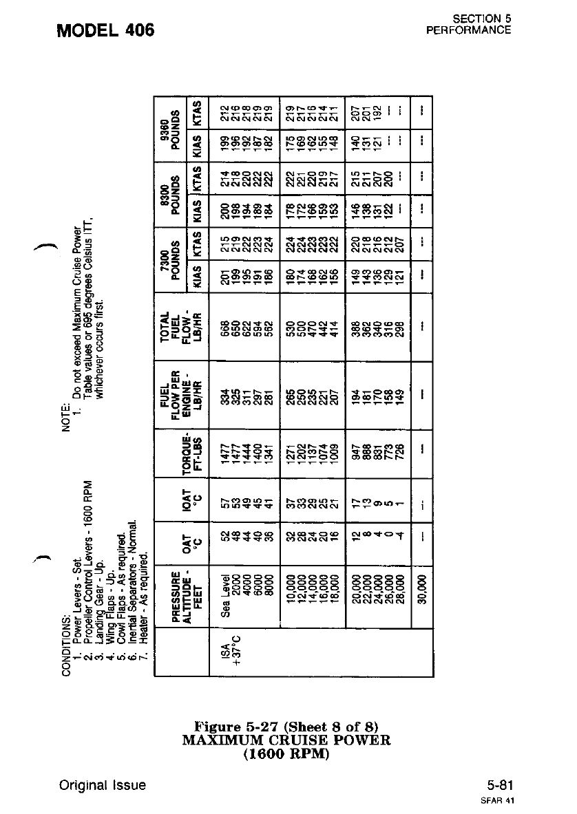
a2
3B
F
=
8e
8t
o-
F
s
rg
RF
F
=
Esrg
s$gE
is
5E
F
<t aJ
9' FP---
Ee
o-
d lrl
a3h
fr=E
Ei
*L
+
SECTION 5
PERFORMANCE
5-81
MODEL 406
fj
dE
^ Eg
.88
2a
o*
P!;
Eae
><o g
ROQ
_19:
x= d
:yi
peE
8EE
di
z
=
o-
:*E
e .=: .
Je -'9
3=-- . E q.=
oE;-,*fEF
9<5,F q q Ee
.3 ; ---s*g*d i
=;FEsEE$
6
z-6rdr<.ro(oF
Figure 5-27 (Sheet 8 of 8)
MAXIMUM CRUISE POWER
(1600 RPM)
Original lssue
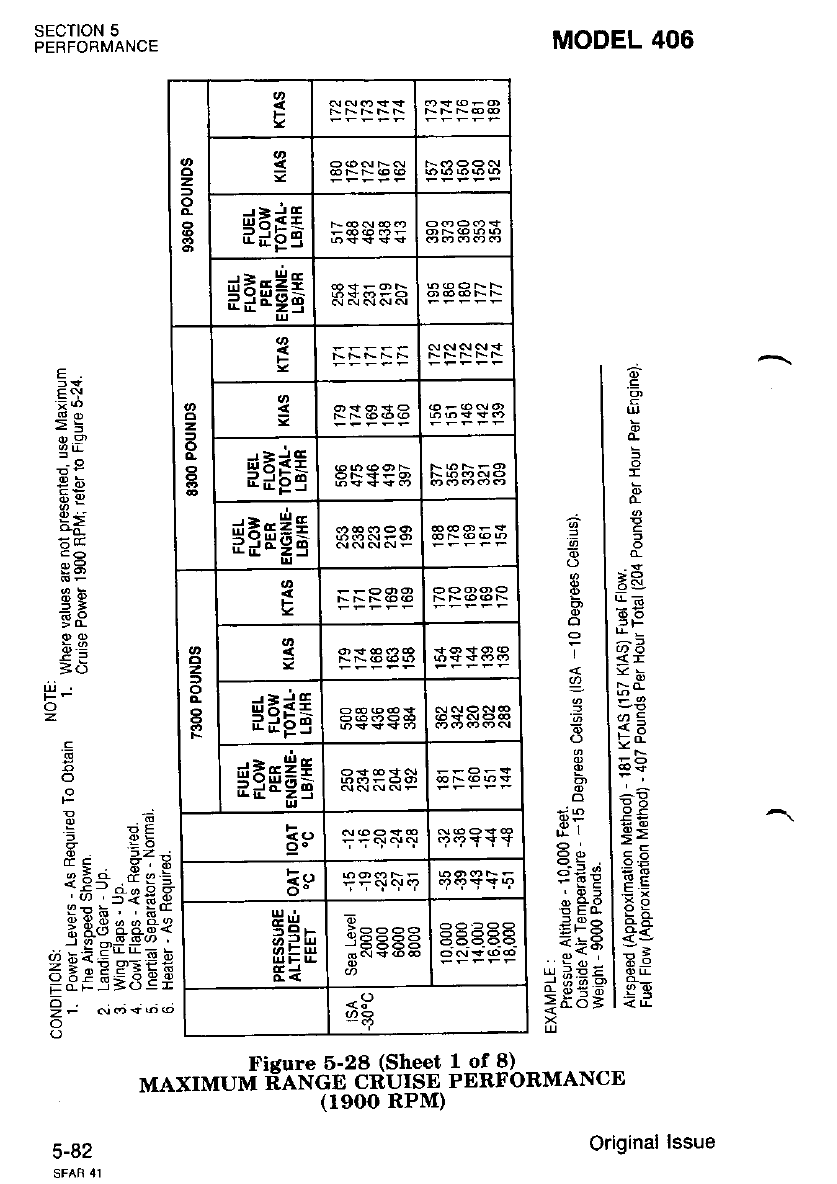
SECTION 5
PERFORMANCE MODEL 406
1of8)
PERFORMANCE
.E
o
I
}E?
?5
Eo.
5g
-!
tb
g>
.5
=9
.o{
:=
6-9
'6
I
g)
.=
I
o
6E
Et-
=.!
&o
dE
E-- 8eE
51=-{ €g
R d d d iia
ao s9,9<
*p c=d€
E.5;5E;
E
.E:
>=
a).9
Err
9f
eg
i-9
=6
ui
o
o
F
'-
E
zt
o
o
.9)
=
Ficure 5-28 (Sheet
MAXIMUM RANGE CRUISE
(reoo RPM)
5-82
z
o
F
g
dEiE
ddpS
$iFH6
z,
o
o,
I
3
$FEE
$FEHE
2
o
F
g
$iEE
#leEE
a;-sE 33PES
F
k9
ul....
Ei
E6666
<P
Original lssue
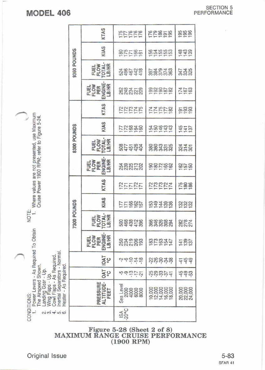
SECTION 5
PERFORMANCE
MODEL 406
Figure 6-28 (Sheet
MAXIMUM RANGE CRUISE
(1900 RPM)
Orioinal lssue
-'€ E:
>E
9r,9
P'
9;
B(]
di
o
.E
E
= PF
E. 1z-
{E-'--n g:
.:.,r ,5{EE
<!a ';"
x g3 a&e{
I d-,sl_g(, ,
d bti.E"-"E b
FFFsSEEF
o
zF c!f)+6@
o
o
2 of 8)
PERFORMANCE
5-83
z,
o=
$FEE
d*EEf
?IEg9=
z=
de-iE
ddPS
$iFH6
z, g
*iEg
$FFHE
oo
3!,
t=
6
<9
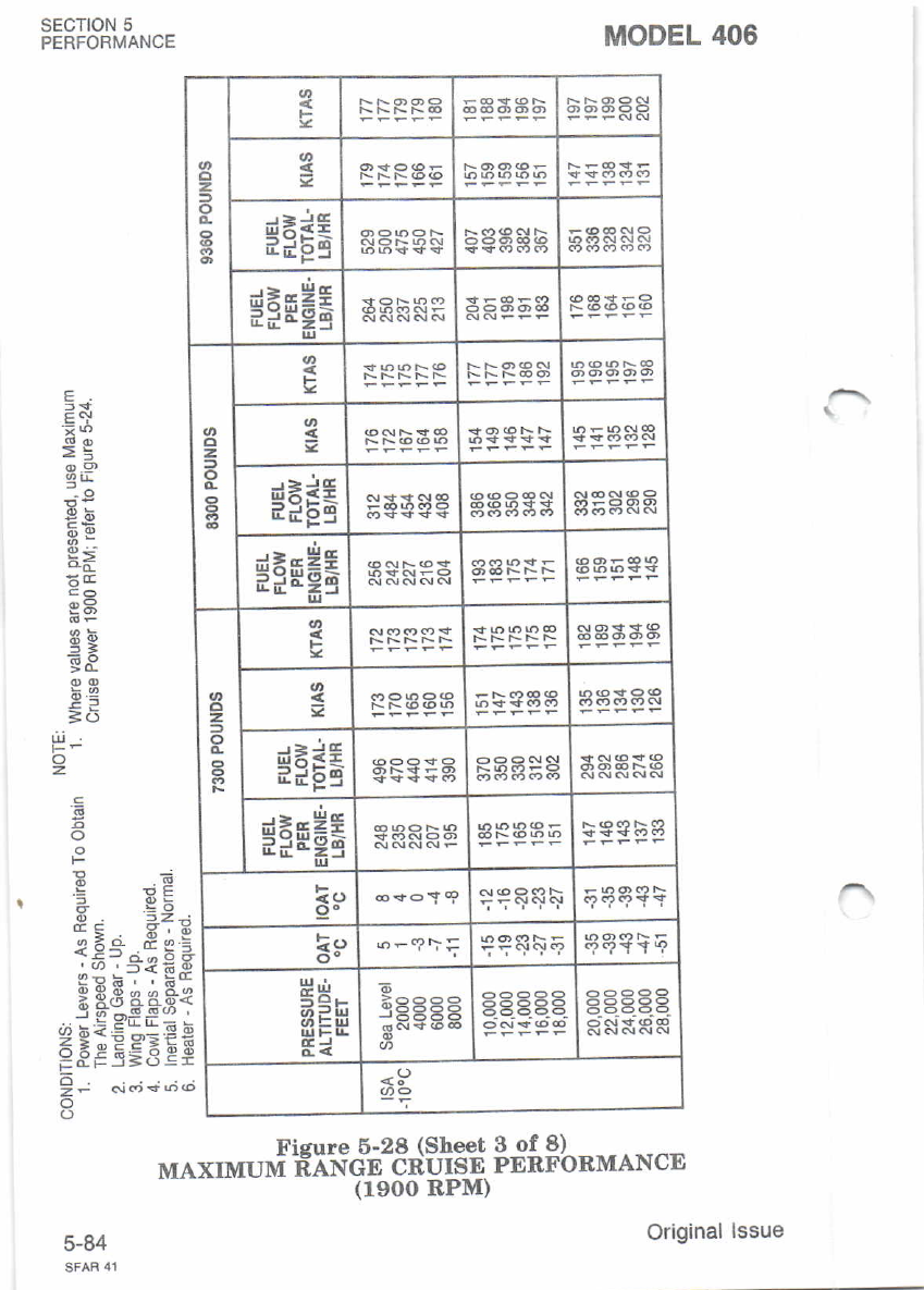
z
o
3
*IEE
d=EEE
alrg-d
z
o
o-
I3A354
de3E
EEFJ aaasa sSaEA
$iFH6
s
assSaa
s
$i6E RBA}8
$iFE6
<( <) qqsq\ E6?9YY
k9 qqq\q
5Qr
Ei
ggEs.g.
RSSAR
<s)
E <,!
€E
o.9)
3r!
g5
eg
6-o
=6
Li
o
z
E
!E
I ci ,9 ;.:
5? s* *E
*9,a.aa'i
<6o=Fg
g E5S Cs
SECTION 5
PERFORMANCE MODEL 406
3 of 8)
PERFORMANCE
o
F
6
4t
o
z?
o
Fisure 6-28 (Sheet
MAXIMUM FANGE CRUISE
(1900 RPM)
5-84 Original lssue
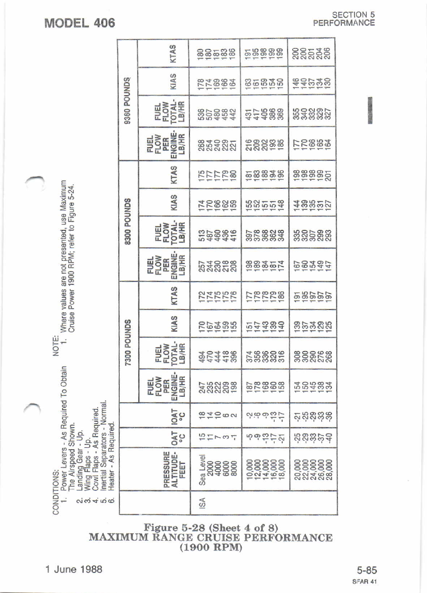
MODEL 406
zg
$FEE
$ifH6
cl
z
=
o
g
g
$FE6
FFtr#E
o
z.
o
s
dEdE
ddg9
$FFH6
E <.r
o.
l!,
o- 9=F-<.,'; 9C?PFF
H'n
AEE
E*
J6-56
Figure 5-28 (Sheet 4 of 8)
MAXIMUM RANGE CRUISE PERFORMANCE
(19OO RPM)
1 June.1988
SECTION 5
PERFORMANCE
E<!
ot.9
Et!
';9
69
95
3;
=6
iri
z
'6
5
o
E .E
= FF
5 g6
'9; Zz'j
{E-'^E *:
-:(/) .5<t-E
sqF. . E*
; g3 44-q{
_! g,= E4r= !
FF#EgBEE
o
zF a!('$6<o
c-6c
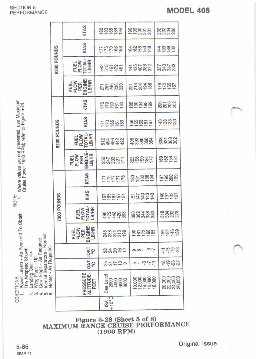
sEcloN 5
PERFORMANCE MODEL 406
5of8)
PERFORMANCE
6
Fi
;i."EHE
Hq,e,8,frf
iE c=s€
F5;,i=i
'i@
€E
o.9
Bs
q=-
5=
6^o
9 _o?
=o
z
.9
6
o
IT
3
4t
6
z-
o
o
Ficure 6-28 (Sheet
MAXIMUM EANGE CRUISE
(1900 RPM)
5-60
o
z,
g
I
s
deiE
ndi?g
$iFH6
2
o,
s
$FEE €SEgE ss88
$FFHE
cl
2
a
g
$FE6
;i*28
i;tge= 35fl38
?<>
ee
o-
H,n
o=w
Ei aaaaa
o
<9-
Original lssue
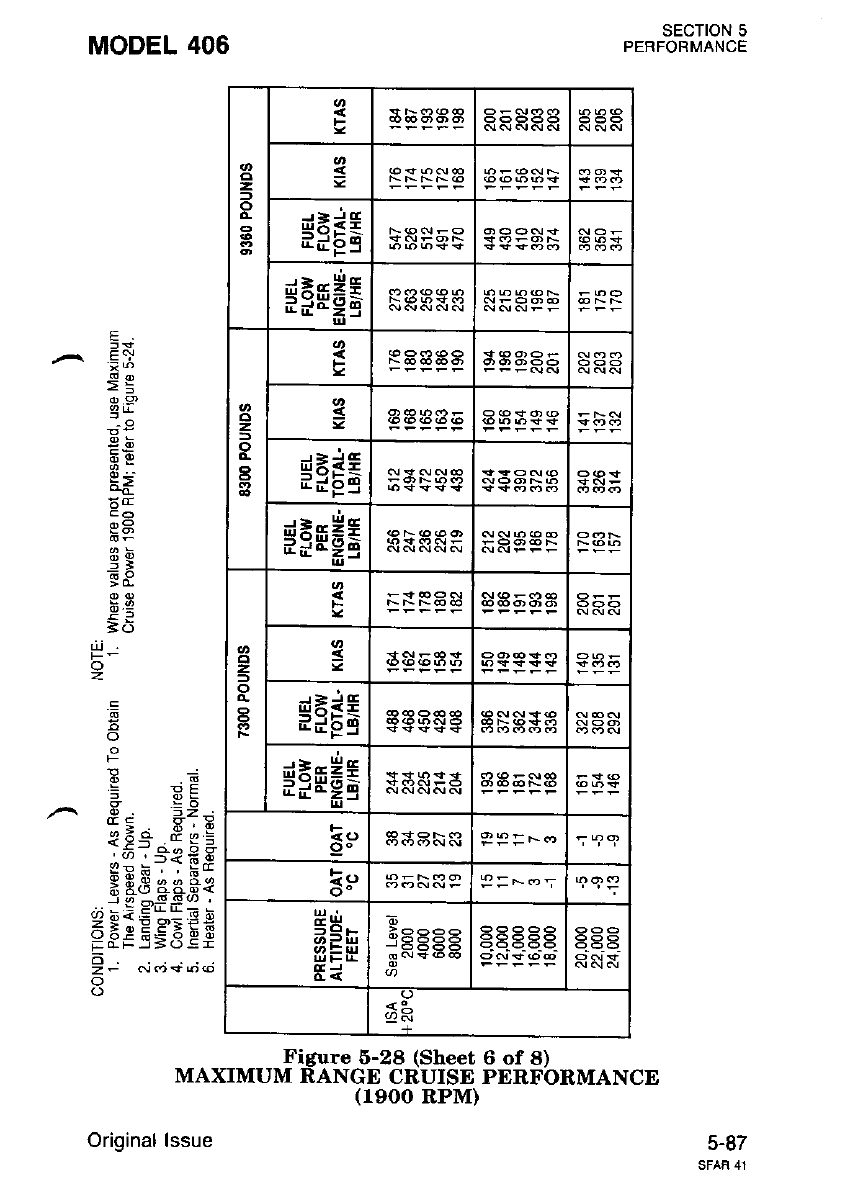
2
o
s
{EiE
EdPS
dErHt
Ed-;9
z.
o
a
s
dEi€
nlJbq
dtr*E
d d o-;9
o
z,
-
o
s
dx+E
irFE
$FFHE
oo P9=*-
k!,
aiH
6of8)
PERFORMANCE
SECTION 5
PERFORMANCE
J.6T
MODEL 406
Figure 5-28 (Sheet
MAXIMUM RANGE CRUISE
(19OO RPM)
Original lssue
E
Ei
>=
3,P
g=-
=]
G^o
E5
P-
o
z
'6
E
o
F
: 9E
; YX
I r z2;
t!a F,;E
<if -; b e
.^v, .f<69
<RE ' . ts*
; 93 4AB€
dbiE"-:Eb
5 Ee HE'BEE
EaFr=os=
d
zF Noso@
o
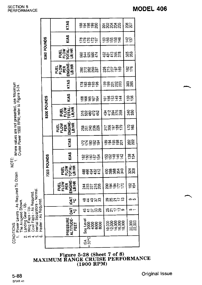
2s
dEir
ndgS
$FFEE
z
$iEE
*=*Hr
o
z.
o
Fa3aa5
g
ea*5
$FFH6
k9
o-
si
:;5566 a-a-
<2-
sEcloN 5
PERFOBMANCE MODEL 406
7 of 8)
PERFORMANCE
6
o!
t.i P-g
E- c!o I q
*?3q'3i
TEe=if;
F-5=6Ei
E
Eq
o.9
,is
g5
gt6
i;
E9
Eo
Li
o
2
F
'=
4'
o
Fisure 6-28 (Sheet
MAXIMUM EANGE CRUISE
( 1900 RPM)
5-88 Original lssue
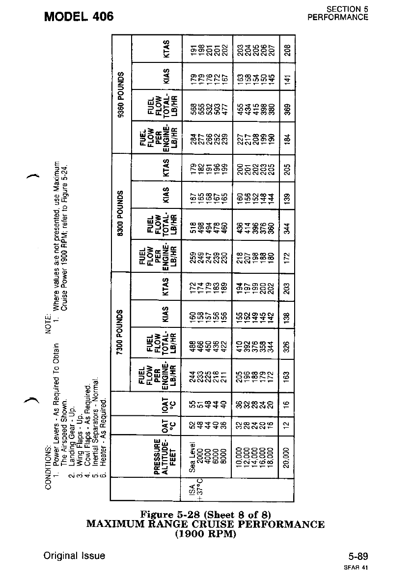
zs
d*iE
aiFB
*iFH6
z, s
d=+$
3;FB
*iFH6
z
o
s
dE3€
ddgS
*FFH6
Eo
3r,
gd
&J
J6=EE
<3-
8of8)
PERFORMANCE
SECTION 5
PERFORMANCE
5-89
MODEL 406
Figure 5-28 (Sheet
MAXIMUM RANGE CRUISE
(r9oo RPM)
Original lssue
E
E:
>E
g,P
de
g5
nb
5l
-6
o
z
.E
o
: 9E
,9; =zd
9 6_d d",:
.._o .=*{6E
(!E ' . ts*
x H3 33$€
j SoSSo '
dh<E*_:Eb
FFgSSgEF
-
zF N(r)< b@
o
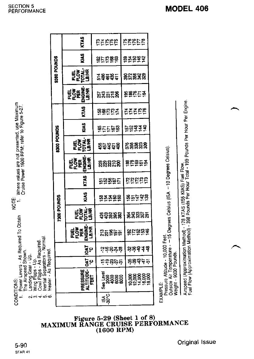
sEcTloN 5
PERFORMANCE MODEL 406
E
Eq
>=
o9
3'r-
gE
9f
gY
=6
o
z
'6
o
F
.^.
<€
b6
J9
!4 b<
E(rF
o
6
oi
_o. nc=
i.'€ € g
3g&fr2
i -=#9
55€ei
2
t
o
EFE6 sssss
$FMH5 bg EPt
o
z
-
o
t$IEE ab9F8 P3A&g
FFFHS RR&98 aRa6a
z
o
tplE;l eeeee SSSHF
*FMH6 s Naa9
F
9" q9YTT
Ir.r
o- rrqrq9 qqq+F
gH-
Fi
tee ee
<9
,=
t
}F
-9,
E.o
6e
=t
l?d
{:
-a
aE
>=
=q
t:=
.9
=
'6
E
E
o
'6
o
6:
.E
ag;
>^-/<
o,rexr orur,[i€X"r€cuii23J$13$ if i$b.MA NcE
(1600 RPM)
Original
5-90
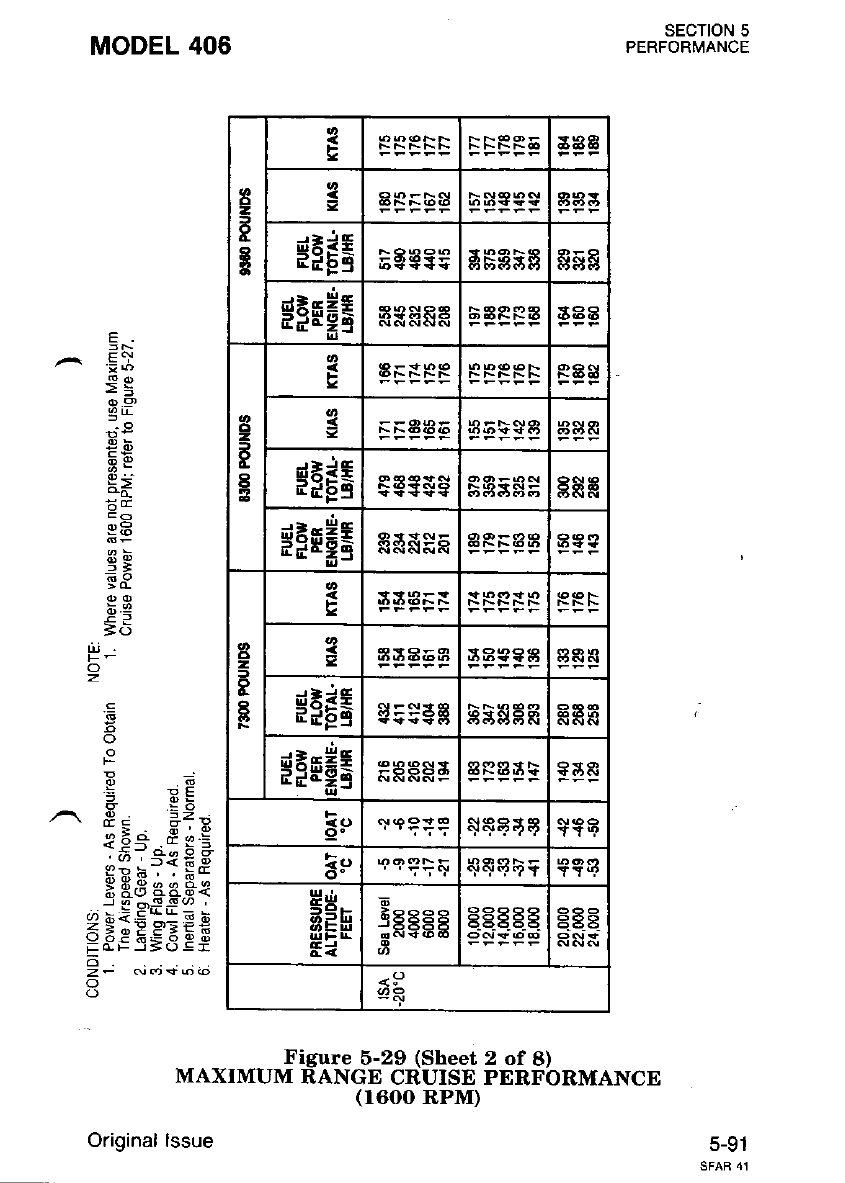
MODEL 406
o
3
I
E$FE5 F8A9P R&R
$FFH5 3AA
2
E
t
F
$FE; a$r
$Ftr E
a
3
cl
2
3
I
B
fia9ea
$iE6 gs$a R
siri e
aa
F
!r
g-B-
EEH
Fi
6
EPegP 9q9 eP
t56865
<!r
Figure 6-29 (Sheet 2 of 8)
MAXIMUM RANGE CRUISE PERFORMANCE
(1600 RPM)
Original lssue 5-91
sEcTtoN 5
PERFORMANCE
E
^ .Ei
.z=
3,P
PE
q5
3g
6-O
=6
'6
6
o
F
'i Yq
,,,r. E, =_z;
*; H ' i6
I0-' .d s:
i:- o6 0 0
Et *?: *e
;43 F*.q{
..j biE!:E b
65eE5'.iEE
d
o
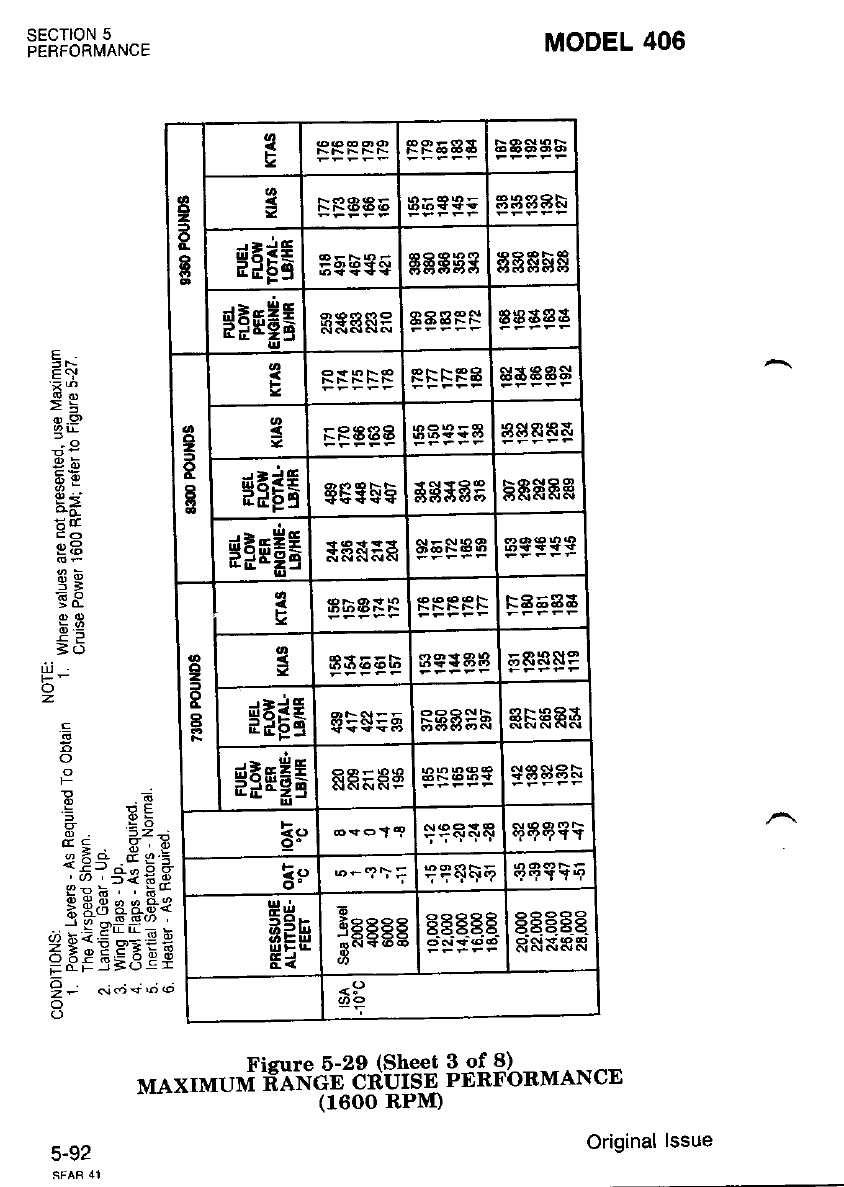
tl
2
f
o
c
I
FRsAA
saaah
HFEE sggsg ssssE
$FE;e
I
EB9g&P EAAAA
o
2
-
I
E
FF trF8 s$aa$
sFR TE8 fr3*5 SASRR&
gNEE AR9F5 8E$A 55RfrRR
*;rH G
=
9: at:3 $5fl aa
o
2
3
I
tra5aa
38E68 ag+ aE 5&s819
*eri sts=E EgSHR gF a3s
sFrHE RA=AE $asae
qqq{E
Ee
o- r,-9\= q?$$F qEsqq
P'n
AEfr
F{
-Eeeee
s"'- g_EEg.E AEEEA
RSXAR
<P
2?
Fizure 6-2e (to""J $fi$b"MANcE
MAXIMUM Eo*?L8fHtf;*,
MODEL 406
sEcTroN 5
PERFORMANCE
E
E.)
>E
o).9
9L
q5
9Y
;iq
=6
ul
o
z
.9
5 F=
:>^ 6.:9
151"i€.9
'J9 6 ' ' 6-
q:( o a o o{2
i x(5 ooaz<
2 9i= c= "if;
H8f ,5;d Ei
9- .1.;+; ",
5-92 Original lssue
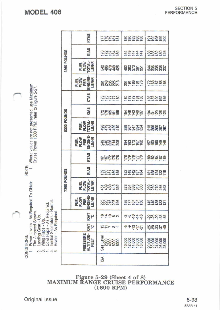
MODEL 406
ui
o
2
z
D
o
aEaaE
*FEE $a Pea 9AbAg
$FFHE
o
z.
o
t
=s5&aR
*ns6 583&R
$FsH5 geE:a
2
t
o
t*Psl AERAE
gFrHA
9" F: =-*
t!,
ct- P=Fo: eefqF
gE'-
aifr
Ei :RgEg
3
R RRRP
-5666 R8l{RS
Figure 5-29 (Sheet 4 of 8)
MAXIMUM RANGE CRUISE PERFORMANCE
(1600 RPM)
Orioinal lssue
sEcTtoN 5
PERFORMANCE
E
E1
sg
P,9
9b
95
53
b.9
=5
'6
o
F
: EE
x =Y
d s *iE
o-o ;;a:
1;r.i;b+
-:"' 'f<89
sP;, ' ts*
; E3 ac.q€
d hiE"_IE b
F.iEE5EEF
6
z- N<t*o(o
o
5-93
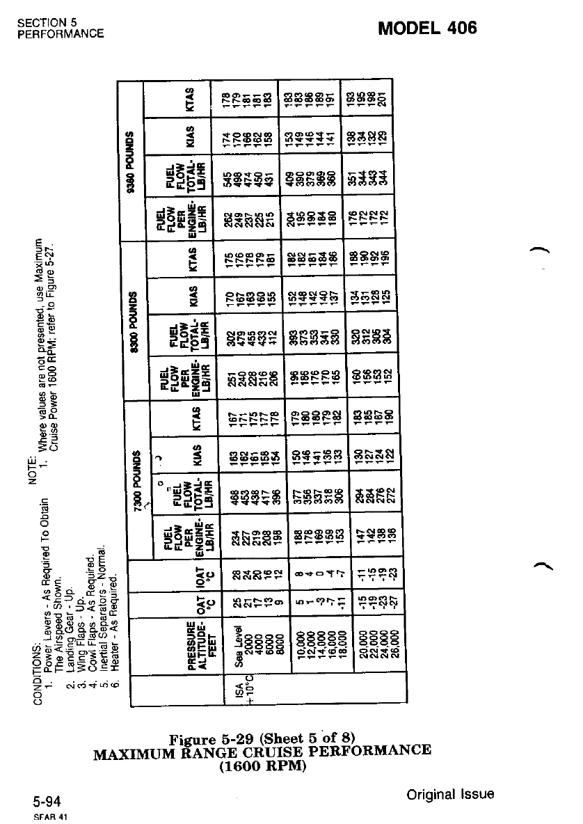
sEcTloN 5
PERFORI/!ANCE MODEL 406
E
F.r
€9
0,,9)
3r
q5
5;
E9
;o
o
.9
;
o
F
s. -2-
;5-o peE
I5i-'€ € F
x E3 gA.q€
-:, = Er L; i
Z g:E PE it
E3F.5;,5 E;
!t .:;+;.
o
o
z
E
g
=FRAS Eatgs
$tgE eEggg g$$s
$FEHE taa 3a
cl
-
3
g
F$$ 5aE B8$t
Rbaa aas$?b
$FEi stgsE ggcs
*3EHE ASPRA
.l
o
2
F
F.
RAAR $aaSa
.3 ag53a | 8NF8l
""$FEE tra5:8
$FFHE
ee
o- 6-.?t= e?sF
g'n
EEE
Ei
6
j8884 AEP 9R
tsE656 EEAg
Fizure 6-2e ("o".J Bfi$L"MANcE
MAXTMUM F".?*3fHtf;n1,
5-94 Original lssue
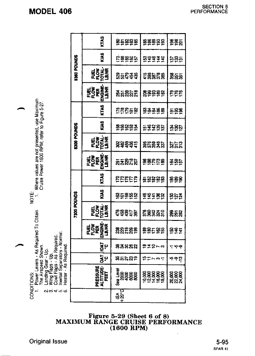
MODEL 406
z
o
2
t
I
a
R EAAb
HFrE
$FMH6 aEaa$
2
f
I
5
aasE g
44333
sPrE as Ese
$FFHE
cl
z
E
8
ag8
8F&
dEit
EdgS E5g
sirHi
o. 8S ARN 9:9 -.,
i:, a55sP P = F..o';
gln
5 -or
.td
39558
s-*" P9R
6545
Figure 5-29 (Sheet 6 of 8)
MAXIMUM RANGE CRUISE PERFORMANCE
(1600 RPI\O
Original lssue 5-95
sEcT|oN 5
PERFORMANCE
e
>5
g,P
9b
q5
=]
t(f
.=
o
: !E
Eo 3:'
*E.'^e * i
.:.o r-&€E
$ Bd ca.fr*
,i'j;iE"_1E b
<t^>/F'BEE
=3F 5=8ef
6
zF (vos6@
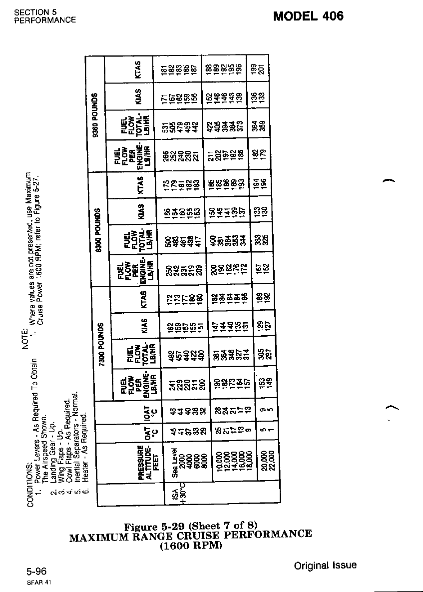
SECTION 5
PERFORMANCE
J-YO
MODEL 406
tlLi
o
z
EC}
>=
o.s,
gY
q:
5B
hq
=c
rl
)
a
.9
o
F
.bi
6a
6
o
B
q
7
o
asEA
$iE5 $ SAAF
$FEHE
o
z
)
R
a
sagsgb
$FEE 8863F gsgss
$FEHE g$ 598 aasR*
z
5
o
a
Fsa s$a a$
35+935
$EFE $be$8 gg 3s5 gR
*irHa FSRFF asRah
9" e+9as
ls SFF9'
HEn
Ei
E
sEgEg gEE. .E. E6
ct.n
--E
6b
Fisure 5-2e ,"o."j gfi$L"MANCE
MAXTMUM Fo*?ft3fHf;r,
Original lssue
'
6
.a9
-*3
!-q
P=
=o
(!
I
^g
?c
-5=
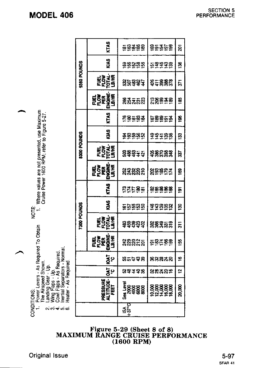
E <,!
Eg
d).9j
q5
5;
6^o
=(f
o
z
'd
5
F
i eE
* YX
iia .E;9
i-4r d;5 a
c;;?fEe
3 E3 pe.Fe
! g o+---' '
(/)bi<E*_:Eb
5.Ee EE,.€EE
6
z- .!d)$@@
o
MODEL 406
z
ot
$FEE
gFEH6
o
=
t
o
t
Fa
$FIE 8tE5e a
$FFi c
!
9=
a
t
o
I
F
HFF6
HFM!
E
B
9"
5!,
g'n
59r.
3EH
Ed ;cecc S.EEEE 6
<L
Figure 5-29 (Sheet I of 8)
MAXIMUM RANGE CRUISE PERFORMANCE
(1600 RPM)
Original lssue
SECTION 5
PERFORMANCE
5-97
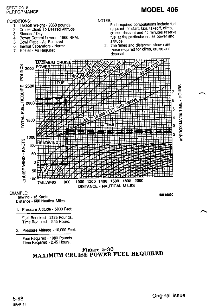
SECTION 5
PERFORMANCE
CONDITIONS:
1. Takeoft Weiohl - 9360 pounds.
2. Cruise Climd To Desirdd Altitude.
3. Standard oay.
4. Power Control Levers - 1900 RPM
5. Cowl Flaps - As Required.
6. lnortialSeparators - Normal
7. Heater - As Required.
MODEL 406
NOTES:
1 Fuel rgouired computatons include fuel
required tor start, taxi, takeotf, climb,
crurse, descenl and 45 minutes reserve
fuel at the particular cruise power and
altitude.
2. The times and distances snown are
those required lor climb, cruise and
0escenl
9 30oo
H 2500
5
llJ
j zooc
l!
J
f 1so(
o
F
F
z
o
z
-
UJ
L
a
o^
;,
llt
^=
2E
c
TAILWINO 8oo 10oo 1200 1400 1600 1800
DISTANCE . NAUTICAL MILES
EXAI\,iPLEI
Tailwind - 15 Knots.
Distance - 600 Nautical Miles.
L Pressure Altitude - 5000 Feet.
Fu€l Required - 2125 Pounds.
Time Reiluired - 2.55 Hours.
2. Pressure Altitude - 10,000 Feet.
Fuel Required - 1980 Pounds.
Time Reiruired - 2.45 Hours.
MAXIMUM C*U'S$$5?'U'iflO".,'" RE QUIRED
5-98 Original lssue
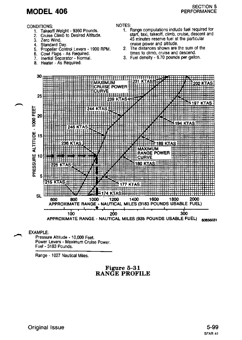
MODEL 406
CONDITIONS:
L Takeoff weioht - 9360 Pounds.
2. Cruise Climd to Desked Altituds.
3. Zero Wind.
4. Standard oav.
5. Propeller Cohtrol Levers - 1900 RPM.
6. Cowl Flaps - As Required.
7. Inenial Separator - Normal.
8. Healer - As Required.
SECTION 5
PERFORMANCE
NOTES:
1. Ranoe computations include luel required lor
start, taxi, takeofl, climb. cruise, dsscent and
45 minutes reserve fuel at the panicular
cruise Power and altitude.
2. The distances shown are the sum ol the
times to climb, cruise and descend.
3. Fuel density - 6.70 pounds per gallon
25
I
ul
u- 20
t5
Hrs
E
Fi
D
a,
u,
6m 800 1000 1200 14m 1800 1800 2000
APPROXIMATE RANGE . NAUTICAL MILES €18i} POUNDS USABLE FUEL)
' | ,', ,l ,' | | ,' ' " J
100 2N 300
AppRoxtMATE BANGE - NAUTTCAL MTLES (935 POUNOS USABLE FUEL) 6oss66r
EXAMPLE:
Pressure Altitude - 10,000 Feet.
Power Lev€rs - Maximum Cruise power.
Fuel - 3183 Pounds.
Banqe - 1027 Nautical Mites.
Figure 6-31
RANGE PROFILE
5-99
Original lssue
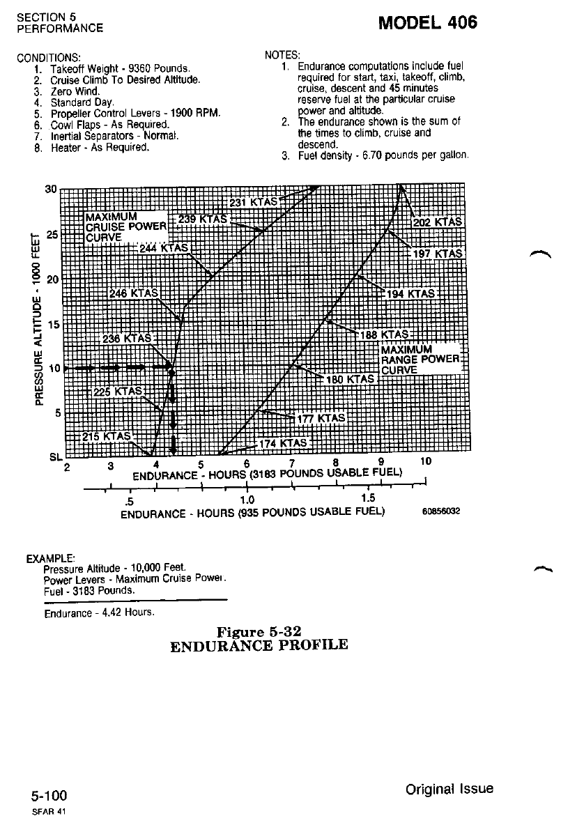
SECTION 5
PERFORMANCE
CONDITIONS:
1. Takeotf weioht - 9360 Pounds.
2. cruise Clim6To Desired Altitude.
3. Zero wind.
4. Standard oay.
5. Propeller Control Levers - 1900 RPM.
6. Cowl Flaps - As Requrred.
7. Inertial separators - Normal.
8. Heater - As Required.
EXAMPLE:
Pressure Altifude ' lu,uuu Fe€r'
Power Levers ' Maxlmum Cruise Powel'
Fuel - 31&3 Pounds.
Endurance - 4.42 Hours
Fisure 5-32
ENDURANCE PROFILE
MODEL 406
NOTESI
1. Endurance computations include fuel
required for stan, taxi, takeoff, climb,
crdise, descent and 45 minutes
reserve fuel at the particular cruise
power and altilude.
2. The endurance shown is the sum of
the times to climb, cruise and
oesc€no.
3. Fuel density . 6.70 pounds per gallon.
l- za
u,
9zo
ur
o
l
\
ul
f1(
tc
o-
5-100 Original lssue
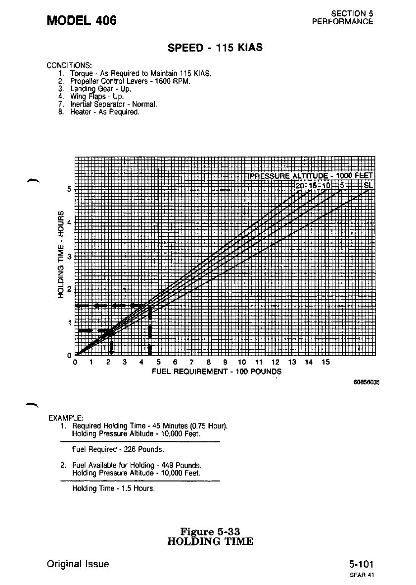
MODEL 406 SECTION 5
PERFORMANCE
5-101
SPEEO - 115 KlAs
CONDITIONS:
L Torque - As Fequked to Maintain 115 KIAS.
2. Propeller Control Levers - 1600 RPM.
3. Landino Gear - Uo.
4. Wing Flaps - Up.
7. Inertial Separator - Normal.
8. Heater - As Required.
4 5 6 7 8 9 10 11 12 13
FUEL REOUIREMENT - 1OO POUNDS
EXAMPLE:
1. Required Holding Time - 45 l\,linutes (0.75 Hou4.
Holding Pressur€ Altilude - 10,000 Feet.
t *"'ta+r*a *r* r"*
2. Fuel Available for Holdino - 449 Pounds.
Holding Pressure Altitudd - 10,000 Feet.
""-r, '^* t" to|J-
Original lssue
FiSure 5-33
HOLDING TIME
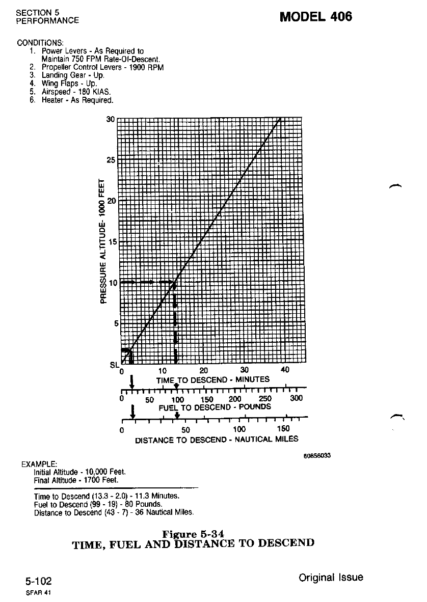
SECTION 5
PERFORIVANCE
CONDITiONS:
1. Power Levers - As Required to
Maintain 750 FPl, Rate-of-Descenr.
2. Propeller Control Levers - 1900 RPM
3. Landino Gear - Uo.
4. Wing Fiaps - Up.
5. Airspeed - 180 KIAS.
6. Heater - As Required.
EXAMPLE:
lnitialAltitude - 10,000 Fe€t.
Final Altitude - 1700 Feet.
10 20
o 50 1oo 150 2N 250 3oo
I FUEL TO OESCEND. POUNDS
k
o 50 100 150
DISTANCE TO OESCEND - NAUTICAL MILES
MODEL 406
Time to Descend (13.3 - 2.0) - 11.3 Minutes.
Fuel to Descend {99 - 19) - 80 Pounds.
Distance to Descend (43 - 7) - 36 Nautical lviles.
Figure 6-34
TIME. FUEL AND DISTANCE TO DESCEND
5-102 Original lssue
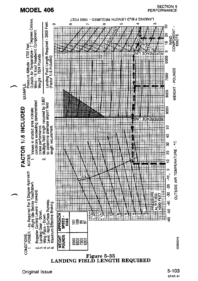
MODEL 406 SECTION 5
PERFORMANCE
l33i 000t - ofutnoSu H-t3N3-l o'l3ll 9NloNvl
9<r)
6F
6b
E,C F
6iI
Es I
E.q I
.l
I
o
EF
PA
itrts(J
6oE
R EEs
-i:6-
r. ,i9 :
=; E=
= ,:< ii
l{oN
59 ,:
$EeF
do3=
",E ?=
EE rE
E F =.5
Ee'q€
EggiEE
=.E 5>F e
.:P*=€-s'
djS85=9b
Hr c.i
ai
=
6
o
uJ
o
=t
J
o
=
q
c
o
F
()
lt
F
o 1,.^
<'r o=E
P
=gg
o
o
z
J
o
F
I
3
o
c
F
Lil
F
6
F
5
4.
o*E
E€-
g:F
eE: :g
E=Eg;
=EE
5FE;f;S
f 1d.* npl
.r 4ts*rE
H= SEscF
=d d_J=i>
l; *;+;o
o
- Figure 5'35
LANDING FIELD LENGTH REQUIRED
Orioinal lssue 5-t03
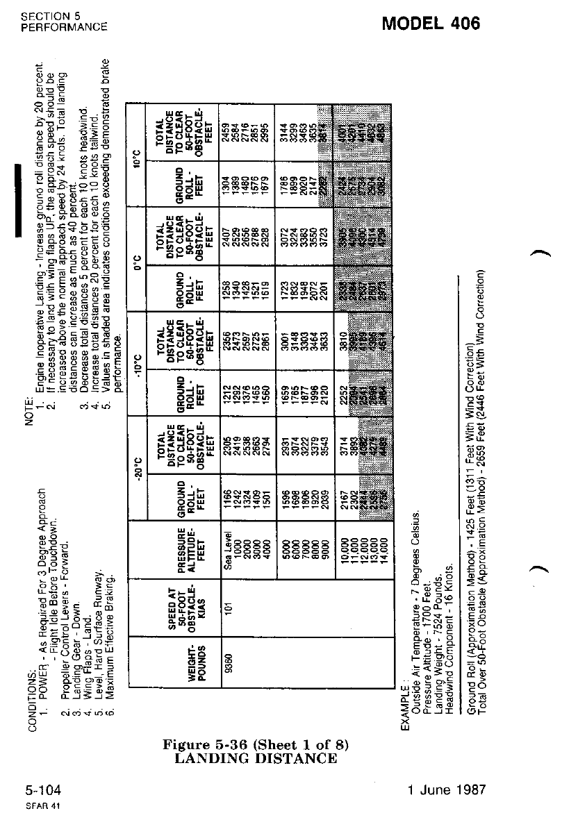
lo
l^=
I E=
I tE
lou-
I E!
lEx
l'-
l;3
l.+3
l-N
t=,
loa
| ::i
I qlo
. | Y>
q t,--
; l Ri.o
- t:=
"qi lPg
; i lE+
A qi9lP<
:{E: l:;
. |; 69 I 19
gea , l E;
E ,i F I Pt
FieF | 5f
-! xx t-6
i1;il&a
,ic 59E I ee
3:"s qi | .i3
Figure 5-36 (Sheet 1 of 8)
LANDING DISTANCE
MODEL 406
Qqq E
EpE !
i!
NSt rr !
B';E ;E g
H +s E€5
. lE; ggg
I iF;tii$
I A:BEEEE
I HAE;::E
p*s E; g 8;
icrEERfr
c:E [;s€
pi 5::3 a:
:;! SEE g
=soPi;_gE
q"-€ EEEE s
:liEsHs:E
Fe ssEEit
I
<i
9!;
od.3
- 9*
L; !" =Z
3d 9; di
:-9 d?; o:
He:3E5:
;=;, r!!o
<EX ci -ou.t
, , -(t d: c
cc E o*i'.
Z= ts!eEi
9R;5;3S
o
zF No{ @(o
o
sEcTroN 5
PERFORMANCE
H;.i dj+d
z
5-104
rEgEan
=Jh
6ifi
EE*
rfgEae
PFE
sEgEap
2..-
cdH
sEsEau
EdH
Fi
E
J5:'EE
!r5
E *s-
FB
58
1 June 1987
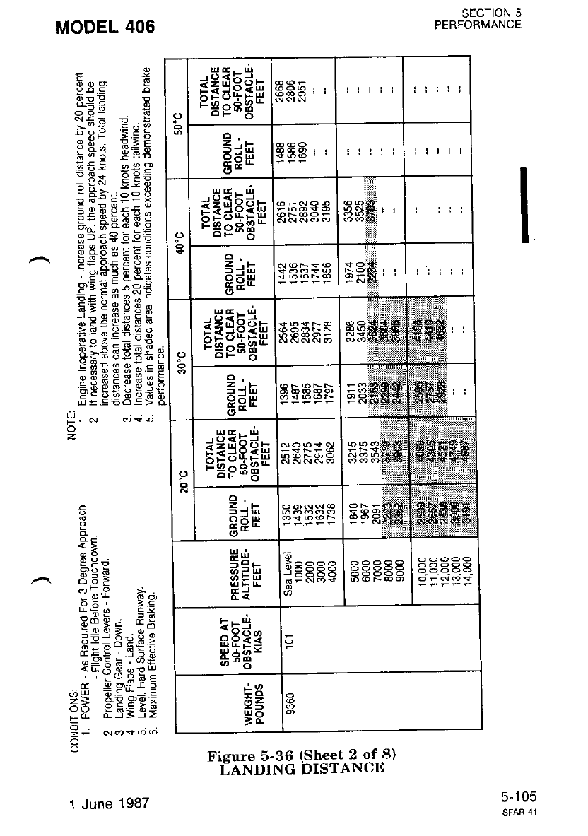
rE:Ean ilili
Z ,i-
I6ll
(5-
ittii
sEgEa* iiiri
z,r
epH
c'-
tiitl
sEgsEe gESbS
z,E
oFr!
(5-
rEgEan
z.*
Sil|r
PPH
(,-
a3a88 aaaaa
Er5
eH33
H'iE-
;9
;iz
ER
SECTION 5
PERFORMANCE
9! E
9!P r
o 6: t
;TE E:S
H .e EEE
EEE e9?
:iX E5E
!6=FFFx
EE IEEE i
s559 bEE
9*"9I s s 9
ie'-3!F*
eIEi-*e-!
i= E: sl) <
q=:FeE3
;EEEfE6
*I e c!€E
R;€Bg€c
!iiE3s;.=
Pgfie3frB
g: EcEEi
i
Pd
e;
6; =:
6E; ES
g:E= g e
.d,* *p1
_=:E';
+E Pg;
i-5;_3j
MODEL 406
P -.i a;;6
o
z
3
3
I
'-
cc
z4
oo
o
o
5-105
Fieure 5-36 (Sheet 2 of 8)
LANDING DISTANCE
1 June 1987
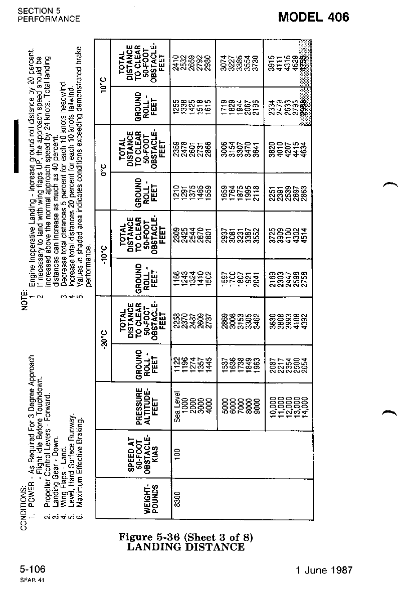
MODEL 406
I o.9
8EE E
;*E :eE
H.8: EEE
gE: €€g
= Yd 9! E
! Fi;=e i
3,:--&&E E 5
s5r€!EE
E+PsEEg
9=q<3Oo
icxiF9*
s;E i;e€
P€ 5 T 3 o s
q3:EeE3
;9EijStsA
El6 E€Ex
+3: ss€.E e
!H339;EF
Hg$EgEgE
5; e€3€g g
a;
:.€ Y
,94
ri o a!
6u Y c cc:
'=-9ol-.o:
69.P9 3 y
{;,q F -:E
=p F;gEE
6
o
o
SECTION 5
PERFORMANCE
5-106
t! -i ^i
o
z
oE;sEan
2.,
(5*
sEsEEn
z, .,
5E*
or;sEEn
Z-.*
o-
sEisAn
cl
2 -,E
OFul
E;E
ct-
rrlFE
ir-'
e6??
HHE=
;e
ii z,
gF
1 June 1987
Figure 5-36 (Sheet 3 of 8)
LANDING DISTANCE
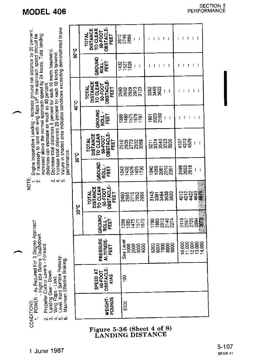
sagsEn iiiri ittii
z ,r-
I-il!
Otur
EE* iiill ltili
6eiEEn itiii
z .r-
f.iul
o6!!
EFG
(.'- ti iii
gEgear
2, ,E
epH
ct-
EeiEan EHFSH
z, .E
t-iul
BgH
a< EEFgH aaaSa
sEE=
;q
G=
gF
SECTION 5
PERFORMANCE
Eeg E
4c: e
o 5! E
d+6 9 .;
APF ;E:;
E.8* E€E
E;: **c
:9R isE
: A-.joo 6
E:; F::5
g:*[EBE
e5ssEEE
EEBEgHE
' E_:; aols
g: E;:Ri
E=qtgsi
;EE E*E 6
.:-g;,9=.99
E^;::ox
E;€FgCg
EU!402:-
EgBcEFs
H! EgE!!
I
I
9?9
,9::
:9* I9
q*^ !, E+
Ba 9: dH
a€:EEgE
iEE:id€
<-tiA *pl
cc E o'f i !
z= RE a9:
HH 8.5;-:=
9t ..i.'i +;,.t
o
MODEL 406
E
H;.i
o
z
5-107
"'f x"'f ""*3Sfsiii,8trt)
1 J une 1987
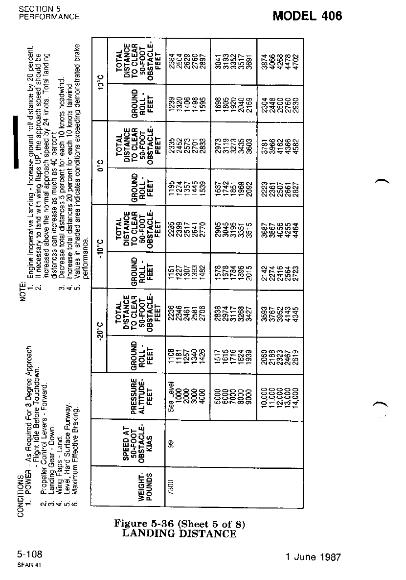
MODEL 406
doo P
E!!
-:; seE
Cq! EEE
I:Ei €€;
I : Fbt::9
I e:*ates
I H?E:::E
P5#Es;
;9.=Fg*
e:EE;e€
E= E; s.e.;
:9: its b ts
E! o P€ 9R
Bi€qgc;e
:3 Hii EeE E
FE ggEEiE
3
9
q
a>
".? I
odi
"ol,9 t
.FF; :g
Ed 9; dA
=-9 c? - o:
r::3EF;
Te::-r;"8
+T€,8 e:E
4r e o-*- 5
== FEPg;
;d n_5=-9=
6
z- Aros()@
o
SECTION 5
PERFORMANCE
2
5-108
segEan
2.,
OFt!
(5-
sE:Ean
Z,*
f_ir!
O^t!
o-
osElstn
<-h
0d-n
6E-
sEgEan
EiE
EE* 3ab9E
ul._'.
UJFI!
Erj
eFSE
HBiB-
-,o
62
gF
'I June 1987
Figure 5-36 (Sheet 5 of 8)
LANDING DISTANCE
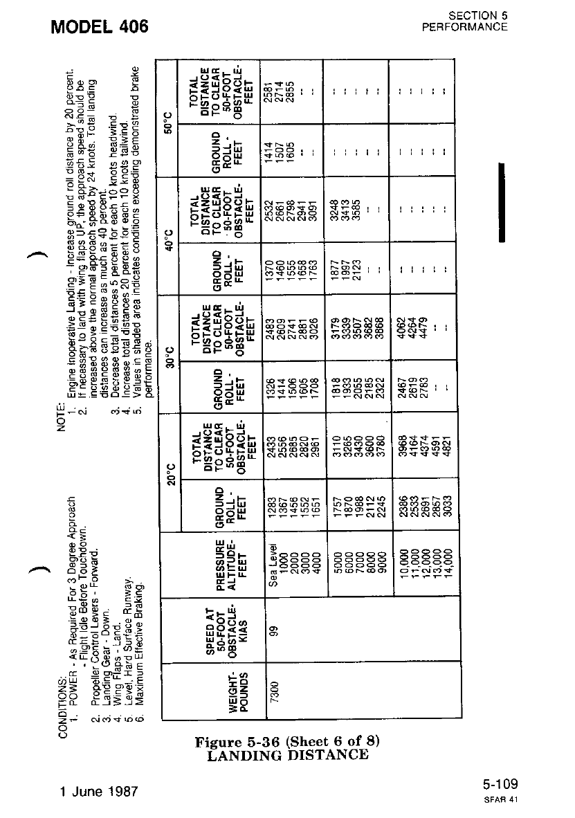
o*3$pEs
tr9pH3* lttti
cr,
z. ,E
c'-
sasE6n tiiii
c;e
rr:sse
2.ts
t.i|r1
PFH
ct-
orE:Eae
Z.E
.ExE
ct-
tt =u)
EFEr
HA12-
a-'6
;9
ii2
!uo
SECTION 5
PERFORMANCE
MODEL 406
FpE !
B'RF ;E 5
3 A - E: F
FdE Pg6
'i 49 ,^aa
€F; EE:
= =d -i! q
p Fi;=e F
g:-Bs5 E 5
gr€Ve€9
g**BI aE I
ie.SEFP
cE E i:*n€
P: b:: ti 4 =
63E69X9
lpcEEsH
E!iP€E:
a!€ F€Et s
E}8Eg;EF
Fc EEEg€E
<i
;
- e* !! c',
3E; AE
tfilr EA
':cot= o:
F:;4E€:
l9E e163
<.rri o d!u
' ! -(5 o> c
.,r 9 g#i.P
Z= 6E e,E ;
PR;i;3s
o
o
z
5-109
Fieure 5-36 (Sheet 6 of 8)
i-ANDING DISTANCE
1 June 1987
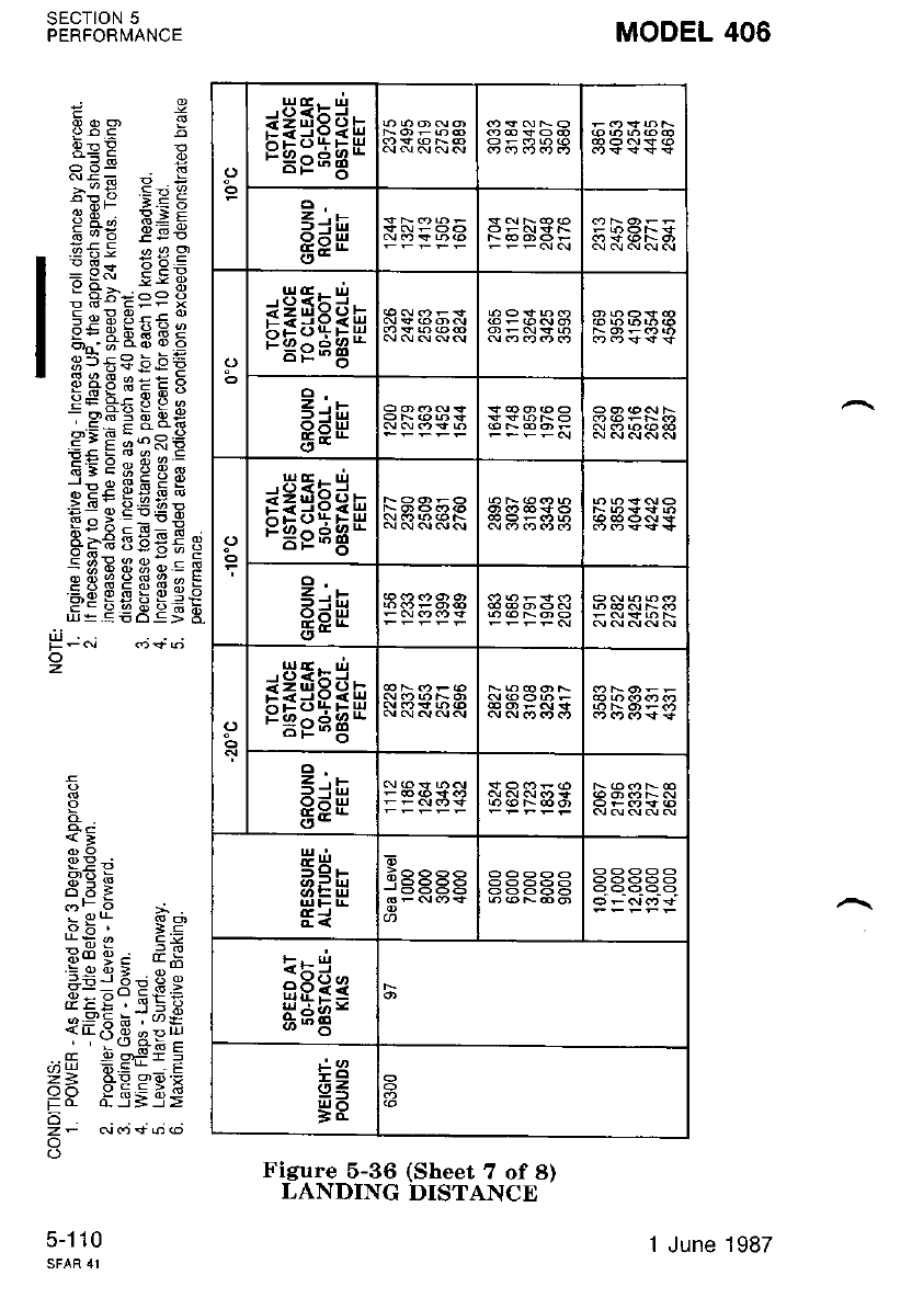
rEsEee
3+h
O-ul
o-
rEgEsr
c;e
osHgsEn gAPJS
e.-
96!+
6.E -
orEssAn
2..-
8EE
ir5
-.6??
HHE=
+3
ii z,
g8
MODEL 406
gsP g
:;E EeE
9I iB 9BF
EqE EEE
; PS E;-E.
: Fbz=e i
5 EE 3s:1
3iHBFFE
s5E3 b"E E
E5F; E g;
;9d=0PX
s:E E:n€
FE c e 3 fl q
ipc 3EE H
.E! E F€E*
e;€ lgEE e
:3dEi3osE
CH$HEfiqE
fiE egEeSE
9
q
<-
99;
R,E E
5di
oF 5 i
! 9q
06 r 1c
:!e s*
=9 o? 3 o '.-
69:9ePY
,9F 9: EEE
i*o.9 *pY
- b--Ef E
.;- =au--E
== *Es9:
EY d- J;3;
o
zF N(ri\t6@
o
SECTION 5
PERFORNNANCE
5-1 10
P-.i
z
1 June 1987
Figure 5-36 (Sheet 7 of 8)
LANDING DISTANCE
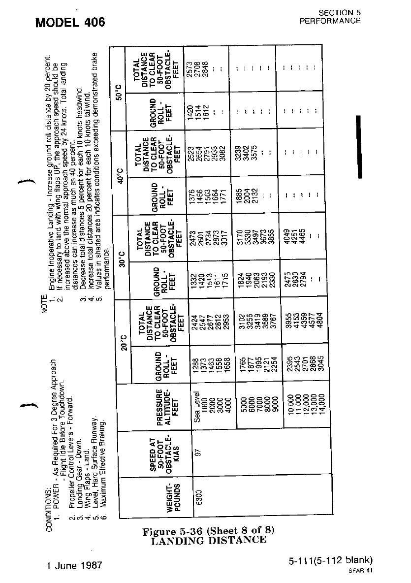
rEgEEn liiii
z,r
-irJ
o=uJ
ct- illrr rirll
o
a)
rEgEar
2..-
PEH
o- €333F ttill
o
bsE:Ean
2'.-
3.iul
e9H
(,-
sHtEsu
z.i
G;E
o- saRaa
(, E IIJ
Ei HEFFF
EEe*
HHE=
+8
az
gR
Fieure 5-36 (Sheet 8 of 8)
r;ANDING DISTANCE
SECTION 5
PERFORMANCE
5-1 11(5-112 blank)
SFAB 41
E
E.- €
9- q
geE E
eF* - E
!:; ' E 5
PtsE EEE
EE: €€E
r d*-oo b
o d: !:Fr x
E: BAEE E
g5:c 6EE
^ EEFEESi
PiE;:Ri
E=psgS;
,E* ggEg
a"-a iEEe
e FE st;;
cii$HuHs
H: EEAES
I
+
<;
P9
.^ F€E
i
aBi gg
u* !, E:
Ro e; d!
SiiAp H 9
o-:'X i6 ' w/q
,,"(rd:c
d d ogi:
Z= +Es9;
HH il=-35
!- ^i.";+;.'
o
MODEL 406
H -"i cj+d
o
z
1 June 1987

MODEL 406 sEcTtoN 6
WEIGHT AND BALANCE
SECTION 6
WEIGHT AND BALANCE
TABLE OF CONTENTS
Page
TNTRODUCTION ..... .........6-3
AIRPLANE WEIGHING PROCEDURE .....6-3
WEIGHTANDBALANCERECORD .......6-?
WEIGHT AND BALANCE DETERMINATION FOR FLIGHT . . 6-?
AIRPLANEWEIGHINGFORM. .......,..6-9
WEIGHTANDMOMENTTABLE. .......6-10
^IENTER-OF-GRAVITY LIMITS ENVELOPE GRAPH ...... 6-16
SAMPLE WEIGHT AND BALANCE COMPUTATION FORM . 6-1?
WEIGHT AND BALANCE RECORD ...,..6.18
EQUIPMENT LrST . . . 6_19 (6_20 blank)
WEIGHT AND BALANCE COMPUTATION FORM 6-19 (6-20 blank)
6-1 (6-2 blank)
SFAR 4I
Original lssue - 1 July 1986

MODEL 406 sEcroN 6
WEIGHT AND BALANCE
INTRODUCTION
Section 6 of this handbook provides procedures for establishing the
aimlane's basic emptv weight and moment and procedures for determin-
ind the weieht anit -balanie for flieht. This section also describes all
itelms on th; Weight and Balance Data sheet which was provided with
the aimlane (locatcd in the back of this handbook in a plastic envelope)
as delivered from Cessna Aircraft, Company.
NOIE
It is thz responsibility of the operator to erLsure
thAt thg airitnnp is lnadbd proierly.
^AIRPLANE WEIGHING PROCEDURE
To Establish Basic Empty Weight
The airplane nust be weighed in the following configuration
1. Wing flaps shall be fully retracted and all other control surfaces
shall be in neutral.
2. Service engine oil and landing gear hydraulic fluid reservoir as
required to obtain a normal fi.rll indication.
3. Check landing gear down and parking brake released.
4. R.ernove all equipnent and items not to be included in basic, eqFty
weight such ig -tools, cont€nts in cabinets and drawers and flobr-
mats.
5. All equiprnent and furnishings must be in their standard location to
facilitati corrections to "Airplane Standard Empty Weight" and
"Center-of-Gravity'' location.
6. All seats shall be properly installed on tracks and placed in the
most forward positibn against the seat stop. All seat backs shall be
in the vertical-position a;d seat belts crossed on the seat cushion.
?. Close all bagg.age. doors, tailcone access door, main cabin door and
emergency exrl wrndows.
8. Clean the aimlane inside and out.
9. Remove all snow, ice or water which nay tre on the airplane.
10. Weigh the airplane in a closed hangar to avoid errors caused by air
currents.
' 11. Defuel the airplane in accordance with the following steps.
6-3
Original lssue
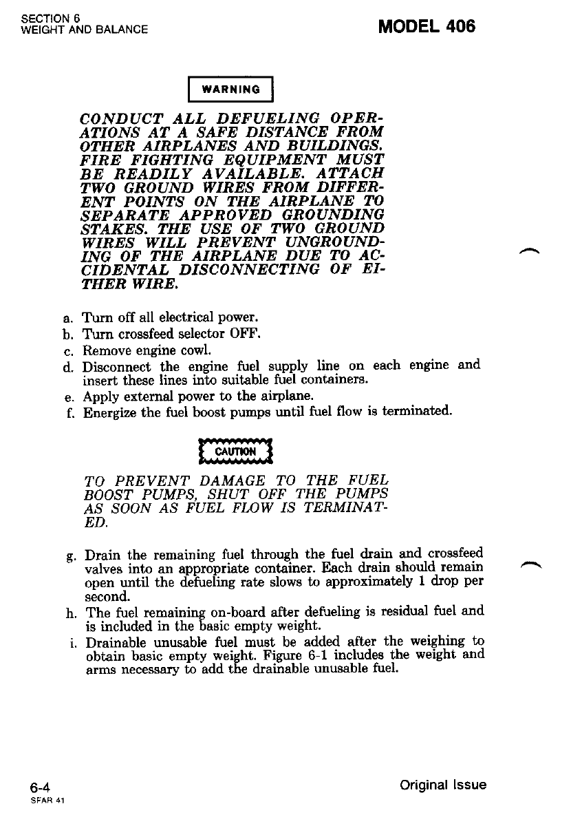
SECTION 6
WEIGHT AND BALANCE
o-+
CONDUCT ALL DEFUELING OPER-
AflOlvS AT A SATE DISTANCE FROM
OTHEE AIRPLANES AND BUILDINGS,
FIRE FIGHTING EQUIPMENT MUST
BE READILY AVAILABLE. ATTACH
TWO GROUND WIRES FROM DIFFEN-
ENT POINTS ON THE AIRPLANE TO
SEPARATE APPROVED GBOUNDING
STAKES. THE USE OF TWO GBOUND
WIRES WILL PEEVENT UNGROUND.
ING OF THE AIRPLANE DUE TO AC.
CIDENTAL DISCONNECTING OF EI-
THEN WIRE,
a. T\rrn off all electrical power.
b. Tum crossfeed selector OFF.
c. Remove engine cowl.
d. Disconnect the engine fuel supply line on each engine and
insert these lines into suitable fuel containers.
e. Apply external power to the airplane.
f. Energize the fuel boost punps until fuel flow is terminated'
MODEL 406
h.
i.
TO PREVENT DAMAGE TO THE FUEL
BOOST PUMPS, SHUT OFF THE PUMPS
AS SOON AS FUEL FLOW B TERMINAI|-
ED.
Drain the remaining fuel through the fuel lrain and - crossfeed
valves into an apprdpriate container. Each drain should remain
open until the deiireling rate slows to approximately I drop per
second.
The fuel remaining on-board after defueling is residual fuel and
is included in the basic empty weight.
Drainable unusable fuel must be added aft.er the weighing to
obtain basic empty weight. Figure 6-1 includes the weight and
arms necessary to add the drainable unusable fuel.
Original lssue
MODEL 406
12. Leveling
sEcTloN 6
WEIGHT AND BALANCE
}IOTE
The airplane mrnt be leuel during weighing to
d.eterrnine the Center-of-Grauity. Always Leuel
laterally before leueling longitudinnlly.
a. On landing Gear
(1) Inflate the main gear struts to maximum extension and the
nose gear strut to ninimum extension.
(2) Place scales under nose wheel and each main wheel.
(3) To level laterallv. place a spirit level directly on the seat
' tracks over the -mii:r spar -fi.rselage station 1??.45. Adjust
the main gear tire or strut pressurC to center the bubble.
(4) To level loneitudinallv, unscrew the two screws approxi-
' ' matelv 0.25 inch at "iivel Point" on the right side of the
fuselase at Stations 248.25 and 272.65. Place the level on
these icrews and level longitudinally by adjusting the nose
wheel tire or strut pressure to center the bubble.
b. On Jack Points
KEEP THE AIRPLANE LEVEL WHILE JAC-
KING TO PREVENT SLIPPING OFF JACK
POINT AND DAMAGING THE AIRPLANE,
ltotE
When possibl,e, secure nose gear strut to preuent
extension. Thi,s uill allow minimum' Lota| jac-
hing heieht.
(1) Raise the airplane with the hoisting jacks until all wheels
are clear of the floor.
(2) To level laterallv, place a level directly on the seat tracks
over the main spai nnelage station 177.45. Raise or l')wer
the jacks under ihe wing iack poinLs until the level bubble
centers.
(3) To level longitudinally, unscrew the two "Level Point"
screws approiimately 0.25 inch on the right side of. the
fuselase ai StationB- 248.25 and' 272.65. Place a level on
these icrews and raise or lower the nose jack until the level
bubble certers.
6-5
Original lssue
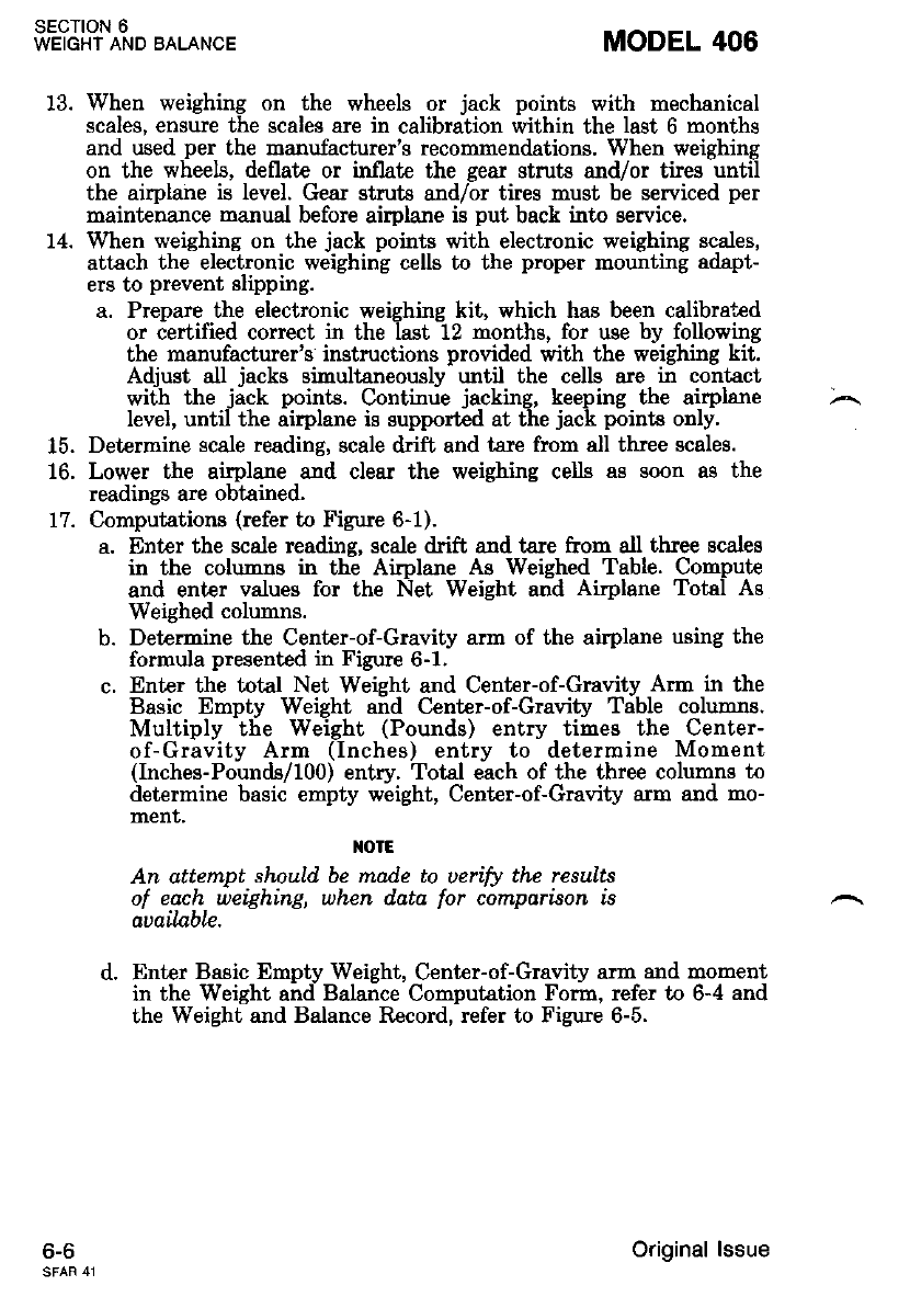
1Q
14.
sEcTtoN 6
WEIGHT AND BALANCE
6-6
When weighing on the wheels or jack points with mechanical
scales, ensure the scales are in calibration within the last 6 months
and used per the manufacturer's recommendations. When weighing
on the wheels, deflate or inllate the gear struts and/or tires until
the airplane is level. Gear struts and/or tires must be serviced per
maintenance manual before airplane is put back into service.
When weighing on the jack points with electronic weighing sca.les,
attach the electronic weighing cells to the proper mounting adapt-
ers to prevent slipping.
a. Prepare the electronic weighing kit, which has been calibra+*d
or certified correct in the last t2 months, for use by following
the manufacturer's instructions provided with the weighing kit.
Adjust all jacks simultaneously until the cells are in contact
wiih the jick poinLs. Contimie jacking, keeping the airplane
level, until the airplane is supported at the jack points only.
Determine scale reading, ecale drift and tare from all three scales.
Lower the airplane and clear the weighing cells as soon as the
readings are obtained.
Computations (refer to Figure 6-1).
a. Enter the scale reading, scale drift and tare from ell three scales
in the columns in the Aiplane As Weighed Table. Compute
and enter values for the Net Weight and Airplane Total As
Weighed columns.
b. Determine the Center-of-Gravity arm of the airplale using the
formula presented in Figure 6-1.
c. Enter the total Net Weight and Center-of-Gravity Arm in the
Basic Empty Weight a;d Center-of-Gravity Tible columns.
Multiply the Weight (Pounds) entry times the Center-
of-Gravity Arm (Inches) entry to determine Moment
(Inches-Pounds/100) entry. Total each of the thre€ columns to
determine basic empty weight, Center-of-Gravity arm and mo-
ment,
TOIE
An attempt should be made to uerifit the results
of each weighing, uhcn data for comparison is
auailable.
d. Enter Basic Empty Weight, Center-of-Gravity arn and moment
in the Weight and Balance Computation Form, refer to 6-4 and
the Weight and Balance Record, refer to Figure 6-5.
MODEL 406
z\
15.
lo,
77.
Original lssue
MODEL 406 sEcTloN 6
WEIGHT AND BALANCE
WEIGHT AND BALANCE RECORD
The Weight and Balance Record, refer to Figure 6-5, provides a record
to reflect the continuous history of changes in airplane structure and/or
equipment which affects the weight and balance of the airplane.
The Basic Empty Weight of your airplare is entered at the ap-
propriate location on the Weight and Balance Data sheet as delivered
from the factory. Changes to the structure or equipment should be
entered on the Weight and Balance Record when any modifications are
made to the airplane. It is the responsibility of the airplane owner to
assure this record is up to date, as all loadings will be based on the latest
entry.
WEIGHT AND BALANCE DETERMINATION FOR
FLIGHT
The following is a sample weight and balance determination. For an
actual determinition for vour airblane. refer to the equivalent illustra-
tions on the Weight and Iialance Data sheet provided in your airplane.
To compute the weight and balance for your airplane, use Figures 6-2
throueh 6--5 as follows: -
fut " th" Basic Ernpty Weight and Moment/lO0 from the latest entry
shown on the Weight and Balance Data sheet or Weight and Balance
Record and enter them in it€m 1 (Basic Empty Weigh-t) of Figure 6-4._
For this sample, assume a weight bf 5190 pbui:ds aid mornerit/rOo ofl
8884.5e. -.-- ---*-- --- -'l
NOTE
A blank Weight and .Bqlance Form is prouided.,
for th,e operator's conuenience, at thc end of this
sectlon.
Deterrnine arm, weight and moment/l00 of the crew, passengerc,
baggage and cabinet contents from Figures 6-2 and 6-3 and 6nter t-hem
unilir- Payload Computations in Figrire 6-4. The crew and passenger
loading table is applicable only when the Center-of-Gravity of the oc-
cupant is at the location specified.
If the seats are in any other position than stated in Figure 6-2, the
moment must be computed by multiplying occupant weight times the
arm in inches. A point 9 inches forward of the intersection of the seat
bottom and seat back with seat cushions compressed can be assumed to
be the occupant Center-of-Gravity. For a refirence in determining the
arm, the aft end of the cabin seat tracks is fuselage station 289.08.
Refer to Figure 6-4. Total the Payload Computations items and enter
the resulting Weight and Moment/100 in item 2.
o-/1 June 1988
- Refer to Figure 6-4. Total items 1 (Basic Empty Weight) and 2
l(Fuselage Payl6ad) to determine appropriate entries'for item 3 (Zero
lFuel Weight with Zero Wing Locker Payload).
I
I R"f"r to Figure 6-4. Item 4 (Wing Locker Payload) is determined from
Ithe anplicable Table of Fizure 6-2.
I --
I R"t", Lo Figure 6-4. Item 5 (Fuel Loading) is determined from the
applicable Table of Figure 6-2.
I Total items 3,4 and 5 to deterrnine 6 (Ramp Weight). Enter item 6
-totals in Fizure 6-3 to determine if the loading is within allowable linits.
If the poini falls within the envelope, the lbading is approved. If the
point f; s outside the envelope, it \i,ili be necessary to redistribute the
load.
I Refer to Figure 6-4. Subtract item 7 (Less \el- Fo1- Taxiing) from
lit --b fn"-o" Weisht) to delermine itim 8 (Takeoff Weight). The
'frol-"nt'oi-thi tu"i -r;;d i;. -t*iins is determi"ed by the difierence in
moments of the fuel loaded and the fuel remaining after taxi. Enter item
la -t"t"ls in Fizure 6-3 to determine if the loading is within allowable
-limits ttakeoff'weisht must never exceed 9360 pounds). If the point falls
outside of the envelope, it will be necessary to redistribute the load.
Refer to Section 5 for estimated fuel used during the flight. Determine
thJ esiimatcd weight of the fuel to be used. The moment h determined
br. th" diff"t"tt"" "in momenl,s of the fuel remaining after taxi and the
fiiel remainine after reaching the destination. Obtain Momen'r,/lO0 from
lFisure 6-2. Eiter the total of these weights and Moment/100 in item 9
-(kss Fuel To Destination).
Item 9 (Landins Weishi) is delermined by subtracting item 9 from
it€m 8. Enter itern- t 0 to-tals in Fizure 6-3 to determine if the loading is
within allowable limits. If the point falls within the envelope, the loading
is appr.oved. If the point falls outside the envelope, it will be necessary to
red!'ctnbute lne toao.
sEcloN 6
WEIGHT AND BALANCE
o-t
MODEL 406
1 June 1988
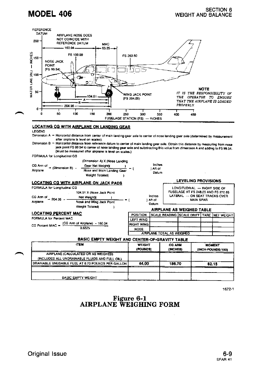
MODEL 406 SECTION 6
WEIGHT AND BALANCE
NOTE
IT tS TttE SESmNSIBlUry OF
fHE OPERAMR TO ENSURE
rHAf TEE AIRPIANE IS LOADED
wo,oht rolabd{ )
LOCATING CO WITH AIRPLANE OII JACK PAOS
FORMULA tor Longinxrn.r CC
104.51 x iNo.6 J.ck po^l
LEVELTNG PnOVtSlOftS
T-."-"*-";-*'"*;;-l
I FUSELAGE ArFS243,2s AND FS 272.65 |
I L TER^L - ON SE^r rR^Ct(S OVEA I
I M rrsp^R I
cG ^h o' 2o.r os ---...'.i9:$|+- -,
aa'lM {@ ./'d wns rdcr Poinr
rm r5o am 250 300 350 &O .r50
.USELAGE STATION (FS) _ INCHES
LOCAIING CC WITII AIRPLAI{E OiI LANOINC GEAA
L€GEND
Dim6Nion l - fldizdral dlri.n4 lrm c.nlo. ot netn bndtng g4r axt€ lo c.nr$ ot noe ta.di.g gss arr6 (d6tehin€d by no$u.€m€n,
afior altpld. k l.v€l m @los).
oimeion a - Ho.t2@rrr di3t @ r.m .€lor*a datuF lo dtd ot mah taiding g.$ dto obrain l}ls dBi.m by n€asunng hm '\@
)*rr potrI FS 09 5r b @w ot tw bndi.g gs.. .ie and 3lb3rsctinq rhi3 var6 tr@ dtMsad A ;nd a.tding to FS 99 54.
{Mu3l b. m6&r.d aft6r atlPl.G is r.vor 6 s€t6.)
FOBMUT lorLonoitudinarco (om.Nis a) x tN@ r6.di^q
CG ^- ot .,o,*.- e, _ Cd., N€r w€€rnX I _ ,
N6. .nd Main Llrd,no G.at
w€lghr Tor.r€dl )
LOCANNG PERCENT MAC
FOAMUL rd P.rhr MAC
_ _. - (cG An ol Ar@€ftr - 160 04
------_naE-
o-v
DFAINASLE IINIISABLE FUEL AT 670 POUNOS PEF GAfLON
Original lssue
Figure 6-l
AIRPLANE WEIGHING FORM

FUEL LOADING
3945.80
3981.77
4017.75
4053.72
4089.70
4125.08
4t61.66
4197.64
4233.€3
4269.61
€05.60
4341.60
4377.60
4413.71
4449.E6
4486.0r
4522.13
{558.24
4594.34
4630.43
4066.52
4702.59
4738_66
4810.76
4846 80
48E2.43
4918.85
4954.86
4990.86
5026.84
5062.82
5098.80
5134.59
5170.39
5206.19
5242.00
s2f7 _42
5313.04
5349.46
5385.30
5421.14
5457.00
5492.86
5524.72
5564.60
s600.48
5636.38
5 2.24
5708.r9
574412
5780.05
5785.58
37.4E
74.92
112.32
149.68
187.00
2?4.24
261.53
298.75
335.93
373.07
410.19
447.28
484.33
521.35
55E.37
595.3,1
632.29
669.22
70f.12
743.00
779.89
816.77
853.62
890.46
927.27
964.07
1000.85
i037.61
1074.36
1t 11.09
1147.80
1184.50
1221.14
1237 _45
1294.51
1331.15
1307.78
1404.40
r '1.41.00
14f7.60
1514.21
1550.82
1567.41
1623.99
1660.56
1697.11
r733.66
'1770.20
1806.73
1643.25
1879.76
1916.26
1952.75
r 949 24
2025.72
2062.19
2098.65
2135.11
2171.55
2208.00
2244.52
2241.03
2317.53
2351_O2
2390.50
2426.96
2403.41
2499_U
2536.26
2572.6f
2609.07
2645.45
26E1_42
2718.1-l
2154.52
2790.44
2427.15
2863.45
2899.73
2936.00
2972_17
3008_34
3044.50
3n80.65
3116.79
3152.92
3r89.05
3225.16
3261.27
3297.38
3333.47
3369.55
3405.63
3441.70
u77.77
3513.83
35{9 88
3585.92
3621.96
3658.00
3693.98
3729.95
3765.93
3801.91
3837.88
3073.85
3909.83
SECTION 6
WEIGHT AND BALANCE
I()TE
OFuel weight based on 6.70 pounds/gallon.
OFor additional fueL informatinn refer to Sec-
tion 8.
Figure 6-2 (Sheet 1 of 6)
WEIGHT AND MOMENT TABLE
6-10 Original lssue
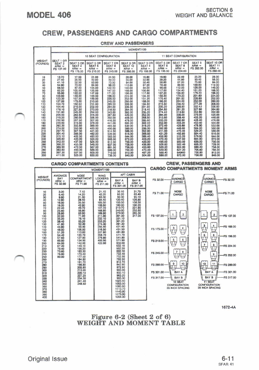
MODEL 406 SECTION 6
WEIGHT AND BALANCE
CREW. PASSENGERS AND CARGO COMPARTMENTS
CNEW. PASSETOEBA A O
CAROO COI|PARIXEIfTS XO*,IT Ant'|S
Figure 6-2 (Sheet 2 of 6)
WEIGET AND MOMENT TABLE
6-11
CREW AIO PAS3EMIERS
rTl
w
w
w
Gtr|
ww
Tit m
ww
nTn
w
CAROO OO||PARTTIIfT3 @i{TENT3
Original lssue
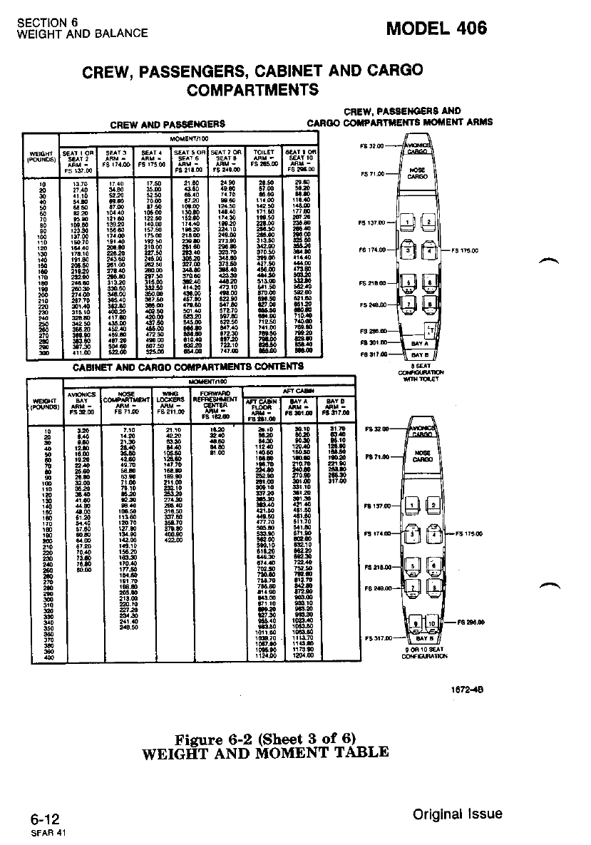
sEcTtoN 6
WEIGHT AND BALANCE MODEL 406
CREW' PASSEIICEnS IND
CAN@ @ "AFTIIEXTS TOflE TARMS
CREW, PASSENGERS, CABINET AND CARGO
COMPARTMENTS
CREW A}ID PAAS€MiEBS
6-12
caBrt{Et arD canoo colrP^nl*$rTs COi{TEXTA
Original lssue
Fisure 6-2 (Sheet 3 of 6)
WEIGtrT AND MOMENT TABLE
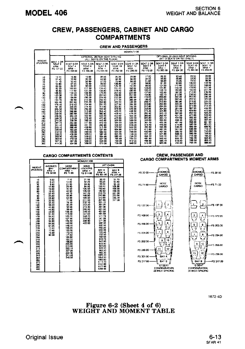
MODEL 406
CREW, PASSENGERS, CABINET AND CARGO
COMPARTMENTS
CREW At{O PASSETIOERS
CREW, PASSENGEA At{O
CAROO CO'iIPARTMEXTS MO EMTARHS
SECTION 6
WEIGHT AND BALANCE
6-13
CARGO COMPAATMENTS COXTENIS
mm
tf !f
i;t a;t
tv !7
Original lssue
Figure 6-2 (Sheet 4 of 6)
WEIGHT AND MOMENT TABLE
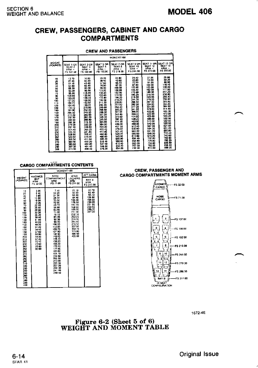
SECTION 6
WEIGHT AND BALANCE
6-14
MODEL 406
CREW, PASSENGERS, CABINET AND CARGO
COMPARTMENTS
CREW AXD PASSENOENS
CREW, PASSE]{GER AT{D
CARGO COUPARTTi,IEi{TS liloilEl{T ARli'lS
CAR(IO COIPAETMENTS CO}IIEI{TS
Ficure 6-2 (Sheet 5 of 6)
WEIGIIT AND MOMENT TABLE
Original lssue
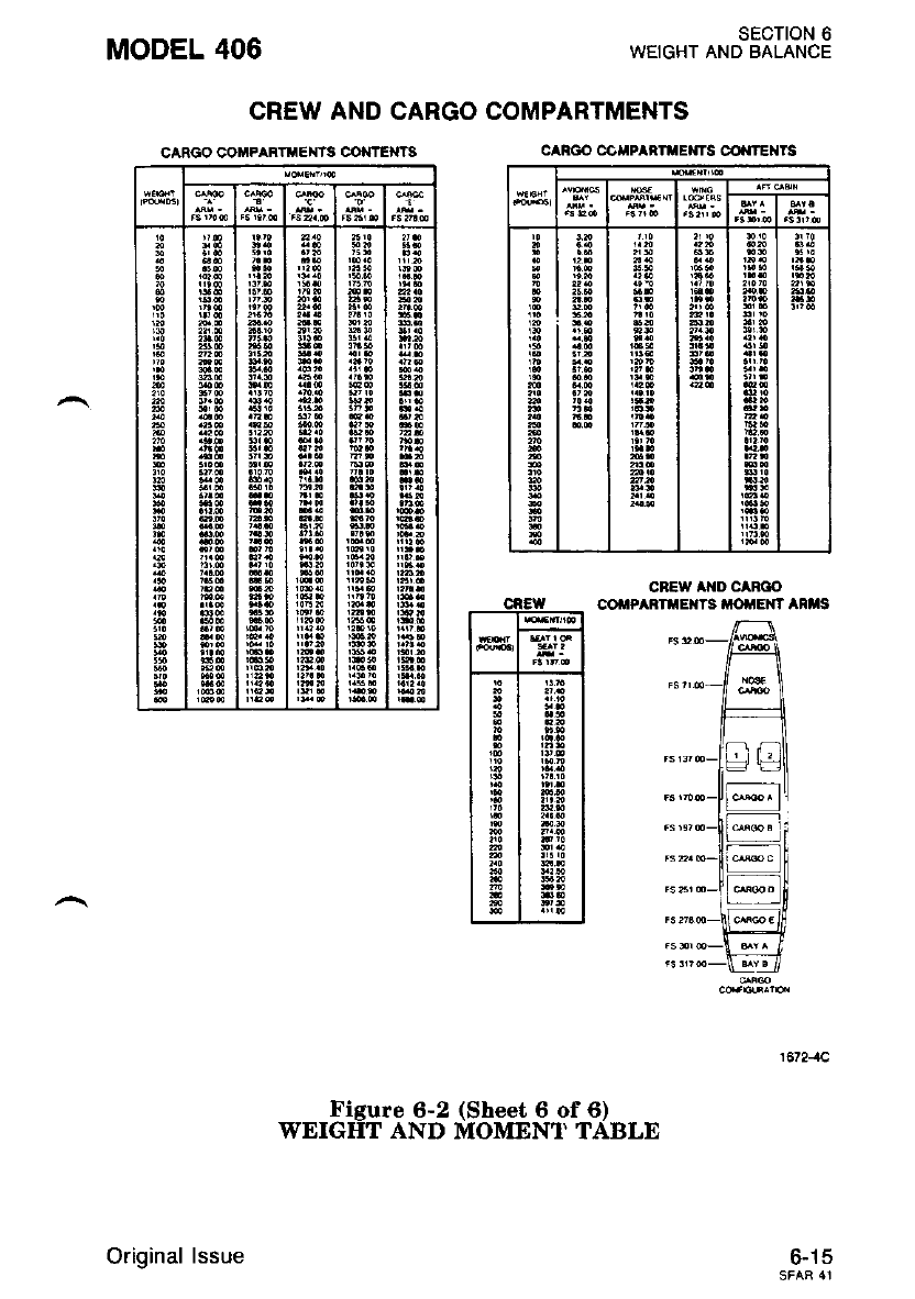
CARGO COMPART EiITS CONTE}ITS
MODEL 406
CREW AND CARGO COMPARTMENTS
SECTION 6
WEIGHT AND BALANCE
CREW AXD CABOO
cofiP^a Exrs ottErr airrs
6-15
can@ colrP^RruE Ts @ rExrs
Original lssue
Figure 6-2 (Sheet 6 of 6)
WEIGHT AND MOMENI' TABLE
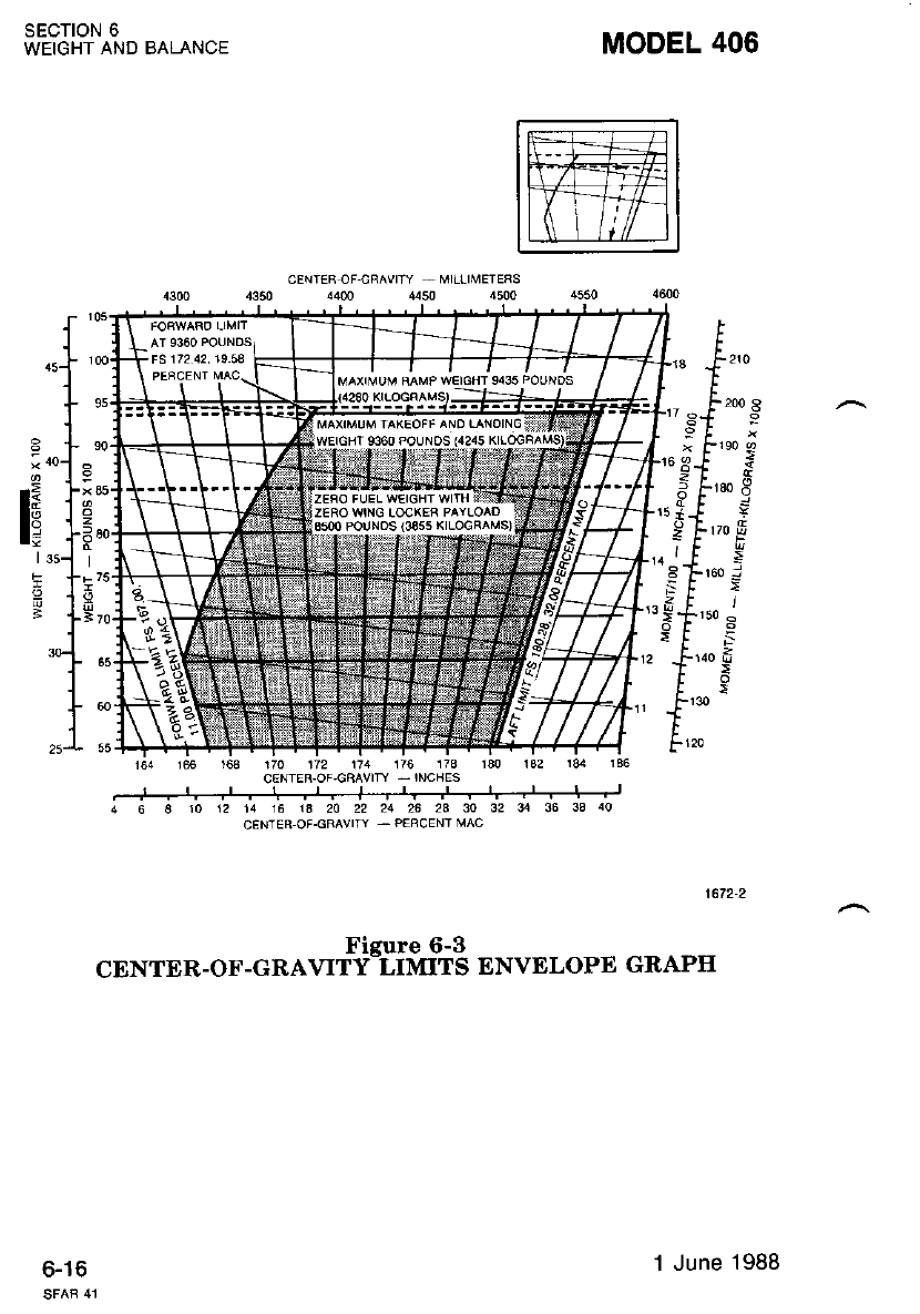
SECTION 6
WEIGHT AND BALANCE MODEL 406
164 166 r6a 170 1t2 \71 176 173 rao 132 184 136
810 12 14 16 1A 20 22 21 262A30 323-{ 36 3340
CENTER OF.GRAVITY - P€RCENT ]VAC
1672-2
Figure 6-3
CENTER-OF-GRAVITY_LIMITS ENVELOPE GRAPH
6-16 1 June 1988
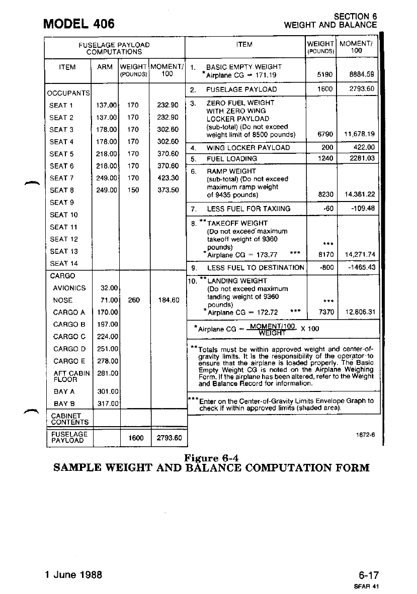
MODEL 406 SECTION 6
WEIGHT AND BALANCE
6-17
FUSELAGE PAYLOAD
CO[IPUTATIONS ITEM WEIGHT MOMENT/
100
ITEM IVOMENT/
r00 1. BASIC EMPTY WEIGHT
'Akplane CG : 171.19 5190 8884.59
OCCUPANTS
SEAT 1
SEAT 2
SEAT 3
SEAT 4
SEAT 5
SEAT 6
SEAT 7
SEAT 8
SEAT 9
SEAT 1O
SEAT 11
SEAT 12
SEAT 13
SEAT 14
137.00
137.00
178.00
178.00
218.00
218.00
249.00
249.00
170
170
170
170
170
170
170
150
232.90
232.90
302.60
302.60
370.60
370.60
423.30
373.50
2, FUSELAGE PAYLOAD 1600 2793.60
3. ZERO FUEL WEIGHT
WITH ZERO WING
LOCKER PAYLOAD
(sub-tolal) (Do not exceed
weighr limil ot 8500 pounds) 6790 11,678.19
4- WING LOCKER PAYLOAO 200 422.00
5. FUEL LOADING 1240 2241.03
6, RAMP WEIGHT
(sub'tolal) (Do nol exce€d
maximum ramp weight
of 9435 pounds) 8230 14,381.22
7, LESS FUEL FOR TAXIING -60 -109.48
8.'.TAKEoFF WEIGHT
(0o not exceed maximum
tak€off weight ot 9360
'Airplan€ CG : 173.77 8170 14,271.74
9. LESS FUEL TO DESTINATION -800 -1465.43
CARGO
AVTONICS
NOSE
CARGO A
CARGO B
CARGO C
CARGO D
CABGO E
AFT CABIN
FLOOR
BAY B
32.00
71.00
170.00
197.00
224.O0
251.00
278.00
281.00
301.00
317.00
260 184.60
O. --LANDING WEIGHT
(Oo not exceed maximum
landing weight of 9360
"Airplane cG : 172.72 7370 12,806.31
*Ai,pranecG : "SE58If* * too
--Totals must be within approved weighi and cent€r_of-
qravity limils. It rs the rosponsrbrlity of ths operator lo
;nsurb tnat tne a'rplane ia loaded properly. ih€ Basic
Empty weight CG is nor€d on the Airplane weEhrng
Form ll lh€ airplsn€ has been alt6rod, relerto theweEhl
and Balanc€ Record for information.
Enler on lhe CenteFof-Gravity Limits Env€lope Graph to
chock if within approved limils (shaded area).
CAAINET
CONTENTS
1672-AFUSELAGE 1600 2793.60
Figure 6-4
SAMPLE WEIGHT AND BALANCE COMPUTATION FORM
1 June 1988
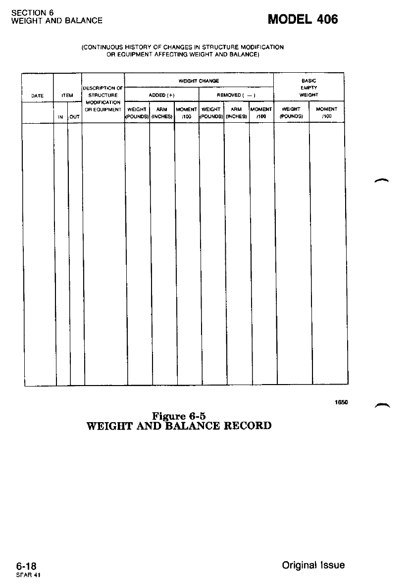
SECTION 6
WEIGHT AND BALANCE
6-18
(CoNTINUOUS fTSTOBY OF CHANGES tN STFUCTUnE MODTFTCATTON
OFI EOUIPMENT AFFECTINE WEIOHT ANO BALANCE)
MODEL 406
Figure 6-6
WEIGIIT AND BALANCE RECORD
Original lssue
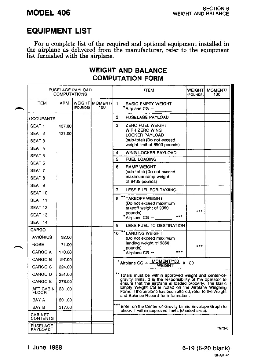
For a complete list of the required and optional equipment installed in
the airplane as delivered from the manufaiturer, refer-to the equipment
list furnished with the aimlane.
MODEL 406
EQUIPMENT LIST
WEIGHT AND BALANCE
COMPUTATION FORM
sEcTroN 6
WEIGHT AND BALANCE
6-19 (6-20 blank)
SFAR 41
FUSELAGE PAYLOAD
COMPUTATIONS
,I, BASIC EMPTY WEIGHT
*Airplane cG :
SEAT 1
SEAT 2
SEAT 3
SEAT 4
SEAT 5
SEAT 6
SEAT 7
SEAI 8
SEAT 9
SEAT 1O
SEAT 11
SEAT 12
SEAT 13
SEAT 14
137.00
137.00
ZERO FUEL WEIGHT
WITH ZERO WING
LOCKER PAYLOAD
(sub-total) (Do not exceed
w€ight llmil ot 8500 pounds)
WING LOCKER PAYLOAD
6. RAMP WEIGHT
(sub-total) {Do not 6xc€ed
maximlm ramp weighl
ol 9435 pounds)
7. LESS FUEL FOR TAXiING
8. "TAKEoFF wEtcHr
(Do nol exceed maximum
takeoit weight ol 9360
*Airptane CG :
9. LESS FUEL TO DESTINAIION
CARGO
AVTONICS
NOSE
CARGO A
CARGO B
CARGO C
CAAGO D
CARGO E
AFT CABIN
FLOOR
BAY B
32.O0
278.00
281.00
301.00
317.00
O. ..LANDING WEIGHT
(Do not exceed maximum
landing wsight oJ 9360
pounos)
'Airptans cc -
"Airprane cG : to#58#oo " too
ttToials must be wilhin approvod weight and center"o!
gravity limits. ll 's lhe .espons,bility 01 lhe operator lo
sflsure lhat ths airplane rs loaded properly. The Basc
Emotv weioht CG rs noted on the ArrDlane weiohino
Form. ll th€:irplane has been altered, reterto th€ W'erqhi
and Balance Record for inlormation.
Enter on lhe Csnter-ol-Gravity Limiis Envelope Graph to
check if within approved limils (shaded ar6a).
1 June 1988

MODEL 406 SECTION 7
DESCRIPTION OF THE AIRPLANE AND ITS SYSTEi'S
sEcIoN 7
DESCRIPTION OF THE AIRPLANE AND ITS SYSTEMS
TABLE OF CONTENTS
Page
INTRODUCTION ....,..7-5.
AIRFRAME .....7-5
FLIGHT CONTROLS ...,,7-5
Aileron System ...,.,..7-G
Aileron Trim System . ......,...7-7
Elevator Syst€m ........7-8
Elevator Trim System . .........7-9
Rudder System .......7-10
Rudder Trim System . ......,..7-11
INSTRUME}.IT PANEL . ........7-74
Overhead Console . ....7-14
Annunciator Panel .. ...7-15
FLIGHT INSTRUMENTS .......7.T9
GROUND CONTROL .... 7.20
Nosewheel Steering System .....'l-20
Minirnum T\rrning Distance .....7-21
WINGFLAPS SYSTEM .......,,7.2I
LANDINGGEAR.. .....7-23
Landing Gear Safety Switches . . . 7-23
Landing Gear Position Lights ....7-25
Landing Gear Warning Hom .. .....,,,.7-25
Landing Gear Emergency Extension System . ...... 7 -26
Landing Gear Shock Struts .....7-26
BAGGAGE COMPARTMENTS .... .,,.., 7-28
Cargo Loading ........7-29
SEATS, SEAT BELTS AND SHOULDER HARNESSES . . . . . 7.30
Pilot and Copilot Provisions . . . . . . ......7-30
Passenger Provisions ..........7-30
DOORS,WINDOWSANDEXITS ........7.31
Cabin Door ...7-31
Crew Door ....7-32
Cargo Door .......... ?-33
Windows .....7-33
EmergencyExit/VentilationWindows ..... 7-33
CONTROLLOCK.. .....7-34
Original lssue - 1 July 1986 7-1
SECTION 7
DESCRIPTION OF THE AIRPLANE AND ITS SYSTEMS MODEL 406
TABLE OF CONTENTS (CONTINUED)
Page
ENGINE .......7-34
Engine Controls .......7-35
Engine Instrumentation .. ...'..7-38
Engine Break-In Procedure ......7-39
Engine Oil System . "..7-39
Ignition System ....'..7-39
Air Induction System . ...'...'.7-40
Inertial Separator System . '.,,..1-40
Exhaust Systen ..,....7-40
Cowl Flaps "",,'..7-42
Starting Syst€m .,.....7-42
Engine Accessories . . . . . '.,....7-42
Engine Shock Mounts . ...,....7-46
Fire Detection and Extinguishing System .. '..,,.. 7-46
PROPELLER ... 7-46
Overspeed Governor Test Switch ........7-48
FUEL SYSTEM ........ 7-48
Fuel Tanks ... 7-48
Drain Valves .........7-49
Fuel Indicating Systern . '.,".'.7-49
Fuel Pumps ...7-49
Vent System ."......7-53
Crossfeed System . '.... 7-53
FirewallShutoffValveSwitches ......... 7-54
Fuel Flow Gages . ".'.7-54
Fuel Quantity Gage .. .........7-54
Fuel L,evel Low Warning Lights . ........7-54
Engine Fuel Systenr . ...7-54
HYDRAULIC SYSTEM .,....,.. 7-55
BRAKE SYSTEM .,..... 7 -57
ELECTRICALSYSTEM .....,...7-57
Battery . .'.'. ?-58
Battery and Generator Switches '."....' 7-58
Generator Control Units ........7-59
Voltmeter and Ammeters .'.'... ?-59
Circuit Breakers, Switch Breakers and Fuses ....... 7-59
Spare Fuses ...7-59
AC Power ''" 7 -62
Extemal Power Receptacle ......7-62
Original lssue - 1 July 1986
MODEL 406 SECTION 7
DESCRIPTION OF THE AIRPLANE AND ITS SYSTEMS
Page
7 -62
'7 -62
7-64
7-66
SYSTEMS ...7-68
Cabin Air System . ...' 7-68
Heating and Defrosting ..""" 7-68
Cabin Heat Controls . '.".....7-68
Cabin Air Controls . .'.7-69
Air Duct Overheat Switch . ."'.7-69
Ventilating System. . ...7-69
OXYGEN SYSTEM ..... 7.71
PITOT/STATIC PRESSURE SYSTEM .... 7.73
Pilot's System ..'.....7-'13
Copilot's System . .'...7-73
PNEUMATIC SYSTEM ......... ?-73
STALL WARNING SYSTEM .....7-'15
TCTNGEQUIPMENT.. .........'t-79
Propeller Deice System '.......- 7-79
AVTONICS .....7_75
Avionics Interference ..' 7-80
Avionics Master Switches ...'... ?-80
1000 Audio Control Panel ..'...' 7-80
Locator Beacon ....... ?-85
400 Marker Beacon . '..7-85
400 Glideslope 1...... .'.....' 7-88
400 Automatic Direction Finder . ..'..... ?-90
400 Nav/Com ........7-92
800 Yaw Damper . '..' 7-98
ELECTRICAL ELEVATOR TRIM . '...7-99 (7-100 blank)
CABIN FEATURES .... ..... 7-99 (7-100 blank)
Cabin Fire Extinzuisher .....7-99 (7-100 blank)
TABLE OF CONTENTS (CONTINUED)
LIGHTING SYSTEMS
External Lighting
Internal Lighting
BLEED AIR SYSTEM
HEATING, VENTILATING AND DEFROSTING
Original lssue - 1 July 1986 7-3
sEcloN 7
DESCRIPTION OF THE AIBPLANE AND ITS SYSTEMS
7-40 Yaw Damper .
MODEL 406
LIST OF FIGURES
Figure
7-1 Aileron System .
7-2 Aileron Trim System
7-3 Elevator System .
7-4 Elevator Trim System
7-5 Rudder System .
7-6 Rudder Trim System
?-7 Instrument Panel . .
7-8 Overhead Console .
7-9 Annunciator Panel and Warning Lights . .
7-10 Nosewheel Steering System
7-11 Minimum Turning Distance
7-12 Wing Flaps System
?-13 Landing Gear SYstem
?-14 Emergency Blow Down Bottle Pressure Gage . . '
?-15 Landing Gear Emergency Extension System .
7-16 Powerplant System .
7-1? Engine Air Flow
7-18 Propeller SynchroPhaser
7-19 Fuel System Schematic . .
7-28 Bleed Air System Schematic
?-29 Cabin Air System Schematic
?-30 Cockpit Oxygen Outlets
7-31 Oxygen Duration Chart . .
7-32 Pitot/Static Pressure System
?-33 Instrument Air System Schematic
?-34 1000 Audio Control Panel . . .
7-35 Marker Facilities
?-36 400 Marker Beacon Indicator Lights . .
7-37 Glideslope Indicator
?-38 400 ADF Controls and Indicators
7-39 400 NAV/COM Controls Panel and Indicators
Page
7-6
7-7
7-8
7-9
7- 10
7- 11
7 -t2
7 -74
7 -20
7 -27
7 -2',1
7-36
7 -4r
7 -45
7 -50
7-20 Wing Fuel Hopper Tank Schematic . . ' ' 7-57
?-21 Hydraulic System Schematic ....'.." ?-56
7-22 Hydraulic Reservoir Sight Gage .'..."7-57
?-23 Electrical System Schematic ...... . '.. ?-60
7-24 l-ntt and Right Side Consoles '........ 7-61
7-25 Cockpit Lighting and Controls . ...,..- 7 -65
7-26 Cabin Lighting and Controls . ..... ' '.. 7-65
?-2? Bleed Air Shutoff Valve ....'.'l-67
7 -67
7-70
7-7|
7-74
7 -76
7 -8r
7-86
7 -87
7-89
?-91
7 -94
7-98
Original lssue - 1 July 1986
MODEL 406 SECTION 7
DESCRIPTION OF THE AIRPLANE AND ITS SYSTEMS
INTRODUCTION
Section ? provides a description and operation of the airplane and its
s'stems' orE
Operational procedures for optional systems and'
equipment are presenled Ln sectton v
AIRFRAME
The Model 406 is an all-metal, Iow-wing airplane .The fuselage and
^ empennaqe are of semimonocoque construction' Ihe wlng and nonzonurr
^ .i'J ""i ti?"ltiu-*.f""". "." of conventional aluminum construction' The
;ffi;t*;;; -G;-I -"i" spars which attach to tuqefa.ge at bulkhead
iJ"'":ii""i. -fit"-""t"r panel iing has 2 main s.pars. which attach to the
;;;;;;i";;";;bty sparc. rE" retractable hnding gear is a tricvcle
design using oil-over-air gear shock struts.
FLIGHT CONTROLS
The flisht controls consist of the ailerons, elevaton and rudder and
ttt"i. ''t".p?"ii* i.i- .vtt"-". All of these surfaces are constructed of
aluminum and are statiaally mass balanced.
Original lssue 7-5
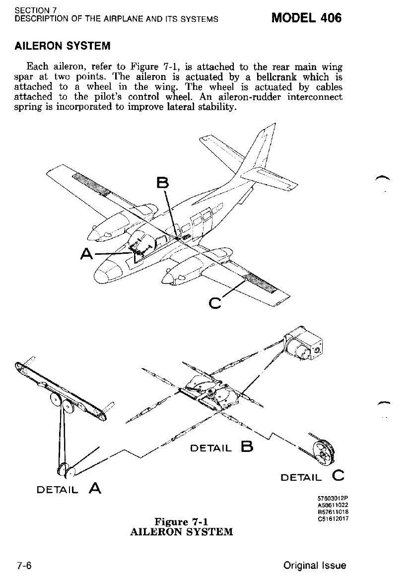
sEcTtoN 7
DESCRIPTION OF THE AIRPLANE AND ITS SYSTEIVIS MODEL 406
AILERON SYSTEM
Each aileron, refer to Figure 7-1, is attached to the rear main wing
spar at two points. The aileron is actuated by a bellcrank which is
attached to a wheel in the wins. The wheel is actuated bv cables
attached to lhe pilot's control w'heel. An aileron-rudder inteiconnect
spring is incorporated to improve lateral stability.
,*-SA
DETAIL \-
57603012P
A58611022
857611018
c51612017
7-6
DETAIL A
Figure 7-1
AILERON SYSTEM
Original lssue
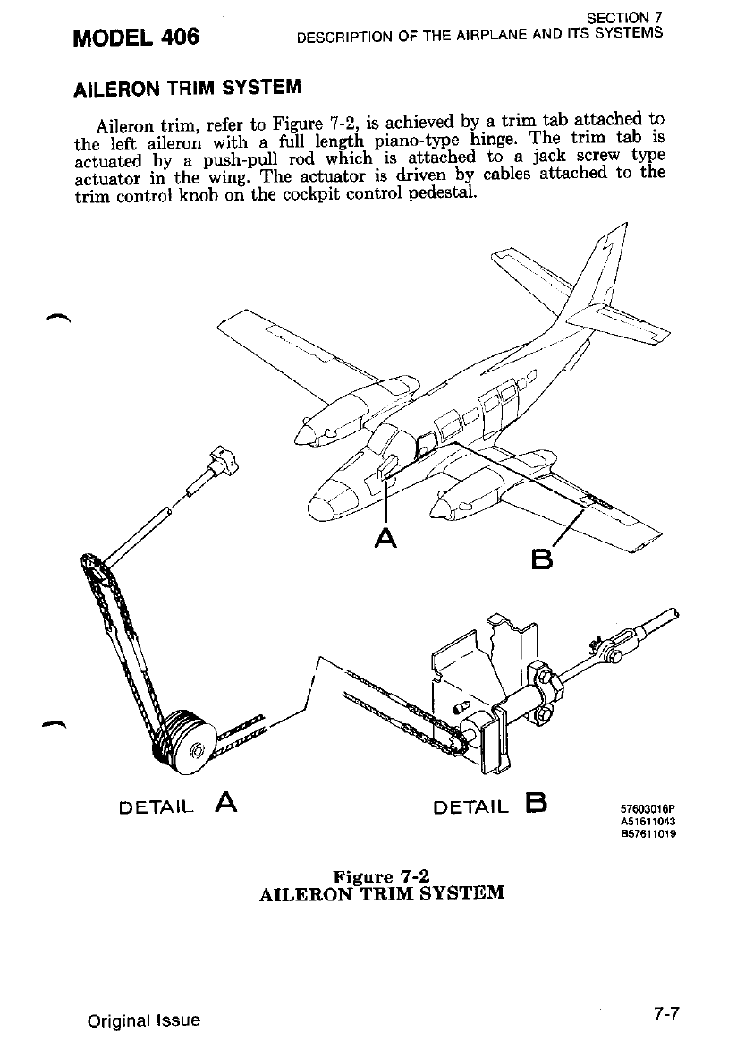
SECTION 7
DESCRIPTION OF THE AIRPLANE AND ITS SYSTEMS
AILERON TRIM SYSTEM
Aileron trim, refer to Figure 7-2, is achieved by-a trim-tab attached to
*,J'il"n-iii"i6ii';i;i'-; d'ii iengtfi piano-tvpe hinge The trim tab is
."i"ul"a tv a push-pull rod which is attached tq .a jack screw tlpe
liiiiiii ii' t["'*i"-el fitJ actuato. is driven bv cables attached to the
i;- "onttol knob oi the cockpit control pedestal.
MODEL 406
DETAIL ADETAIL B
or"r*oRtii#-',.".trt
57603010P
4516r r043
8576110r9
Original lssue 7-7
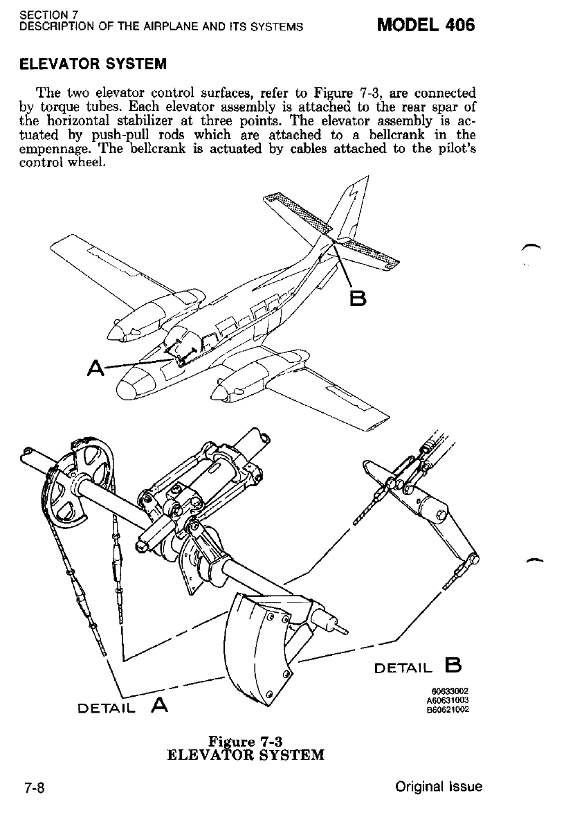
SECTION 7
DESCRIPTION OF THE AIRPLANE AND ITS SYSTEMS MODEL 406
ELEVATOR SYSTEM
The two elevator control surfaces, refer to Figure 7-3, are connected
by torque tubes. Each elevator assembly is attached to the rear spar of
the horizontal stsbilizer at three points. The elevator assemblv is ac-
tuated by push-pull rods which ire attached to a bellcrank- in the
empennage. The bellcrank is actuated by cables attached to the pilot's
control wheel.
DETAIL B
606330O2
A60631003
860621002DETAIL
7-8
Figure 7-3
ELEVATOR SYSTEM
Original lssue
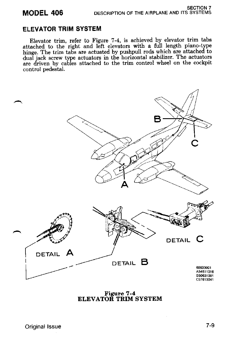
ELEVATOR TRIM SYSTEM
Elevator trim, refer to Figure 7-4, is achieved by elevator trim tabs
attached to the right and left elevators wilh q ful-l length piano-t1pe
hinee. The trim ta6s are actuated by pushpull rods which are attached to
dual iack screw t!'pe actuators in the horizontal stabilizer' The actuators
ar,e d.iuen bv cabies attached to the trim control wheel on the cockpit
control pedeital.
MODEL 406 SECTION 7
DESCRIPTION OF THE AIRPLANE AND ITS SYSTEiiIS
DETAIL C
I
60633001
454611016
B60e3r 0()1
c57613041
DETAIL
Original lssue
nrrvnt6'ffdftiol""rtrt
7-9
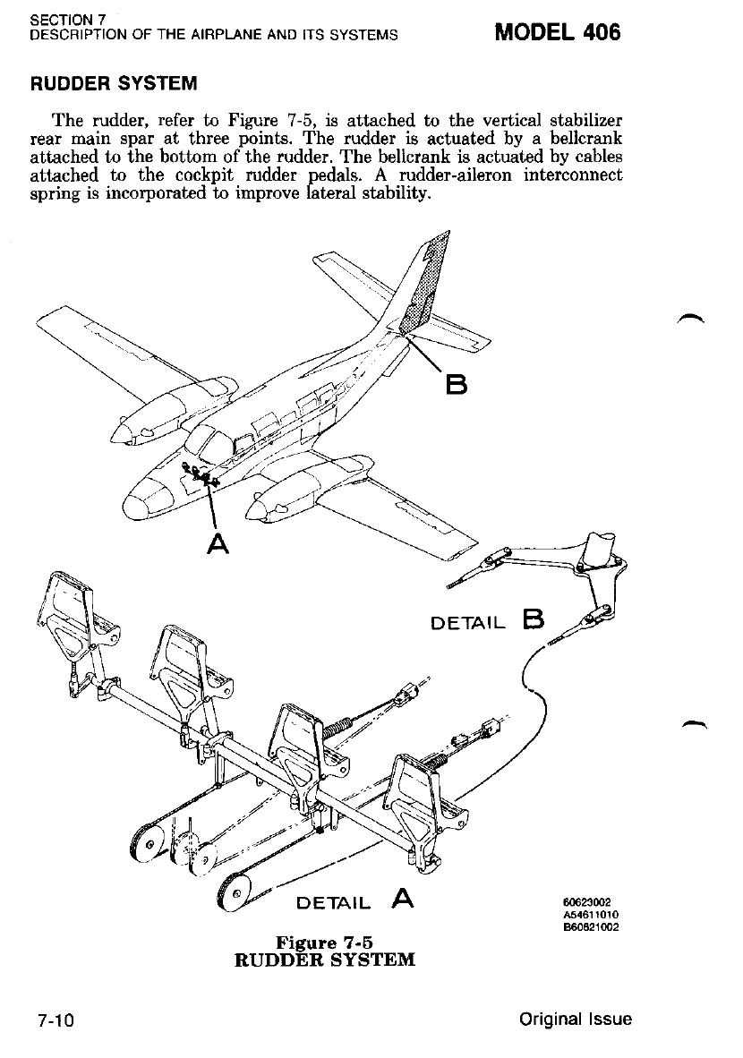
SECTION 7
DESCRIPTION OF THE AIRPLANE AND ITS SYSTEMS MODEL 406
RUDDER SYSTEM
The rudder, refer to Figure 7-5, is attached to the vertical stabilizer
rear rnain spar at three points. The rudder is actuated by a bellcrank
attached to the bottom of the rudder. The bellcrank is actuated by cables
attached to the cockpit rudder pedals. A rudder-aileron interconnect
spring is incorporated -to improve fateral stability.
DETAIL A60623@2
A54611010
860621tlo2
7-10
Figure 7-5
RUDDER SYSTEM
Original lssue
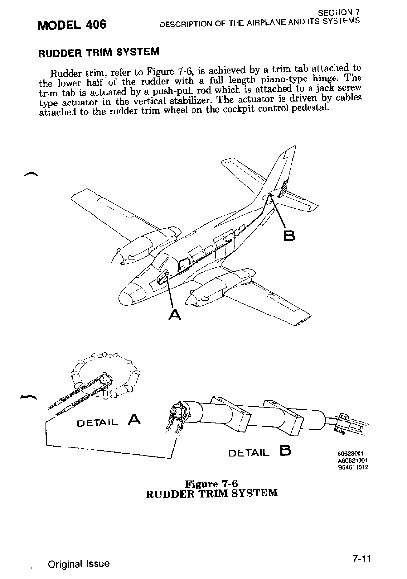
SECTION 7
DESCRIPTION OF THE AIRPLANE AND ITS SYSTEI/|S
RUDDER TRIM SYSTEM
Rudder lrim, refer to Figure ?-6, is achieved pv a trim tab attached to
th,j"il;;; il;ff';i',h";dE*.-*i*''- i -n.,{ .1".'*t' piano-tvpe hinge' rhe
i.li"'i"u l. ".t"ut"d bv a push-pyii.md *hi"h-it aitached to.a-jack screw
:ffi f, :l'#i:;; jH" j*n'-inl*;l;Jl;rff ::t,':,f"'H:',jl*o*'
MODEL 406
A
oeratl B60623m1
A60621001
854611012
DETAIL
Original lssue
*,r""rtttiitfr-3trtr*
7 -11
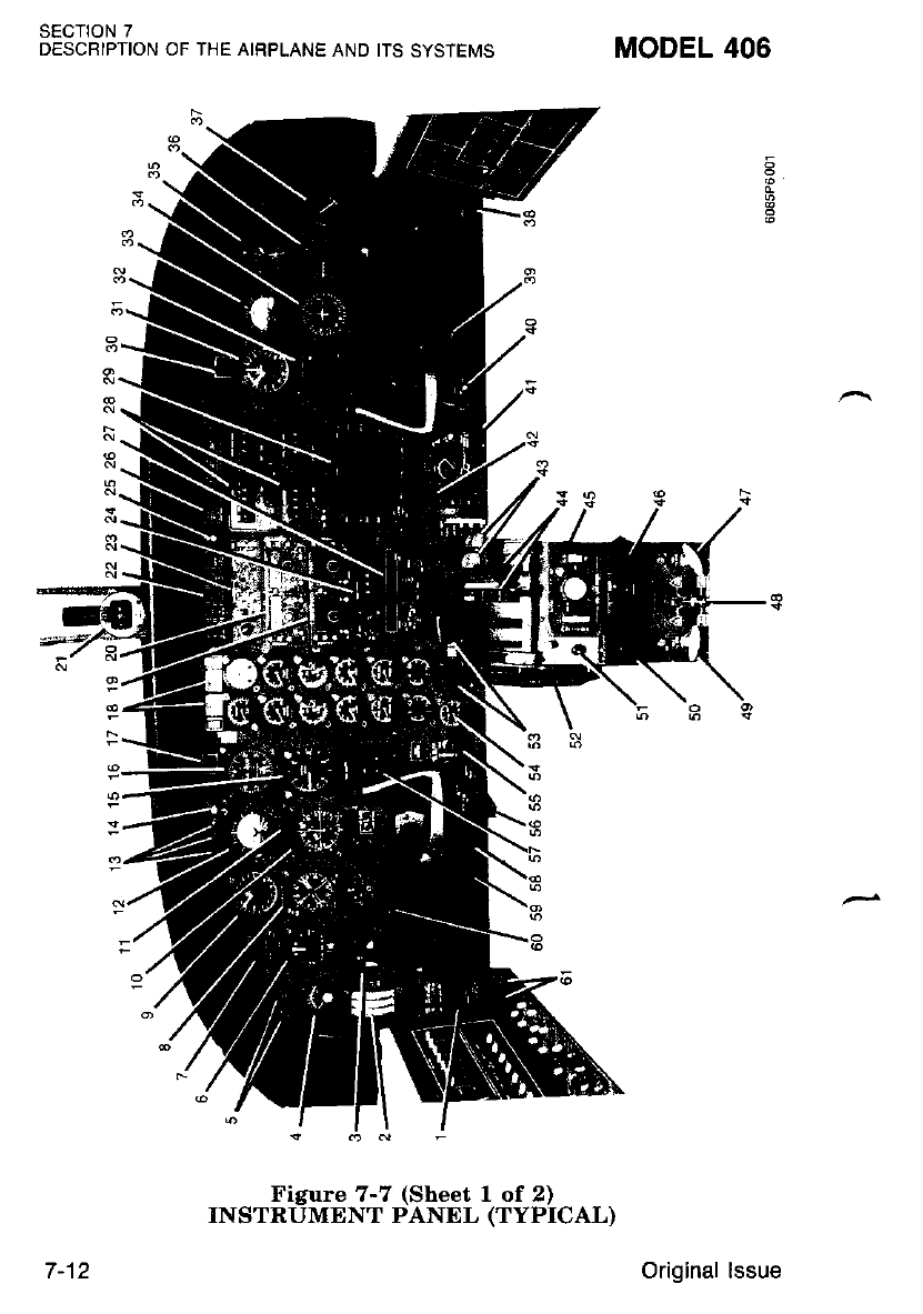
SFCTION 7
DESCBIPTION OF THE AIRPLANE AND ITS SYSTEMS MODEL 406
7-12
Figure 7-7 (Sheet 1 of 2)
INSTRUMENT PANEL (TYPICAL)
Original lssue
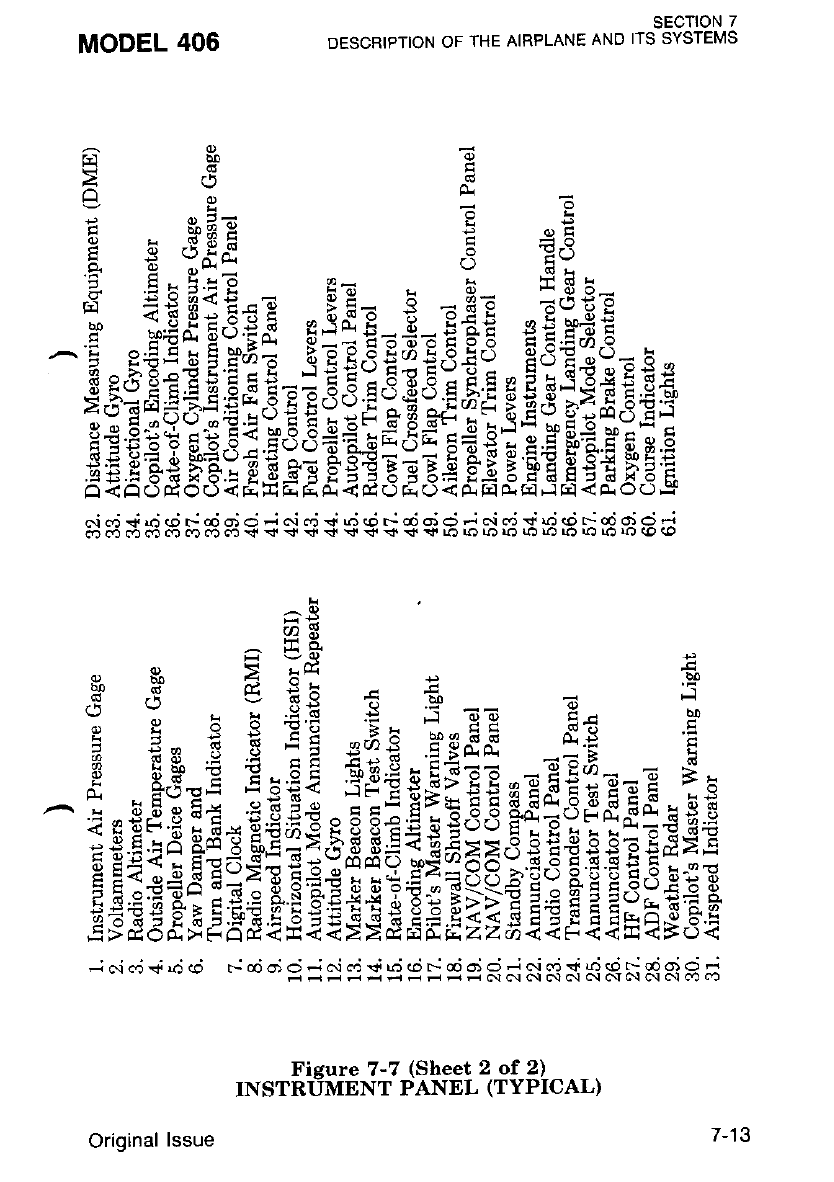
SECTION 7
DESCRIPTION OF THE AIRPLANE AND ITS SYSTEMS
trrerT
Edd
r--{ c, =
'1 I J'a-, - -::
3 - Hffi ; 33
e r:d{ 5 E?
a .EatiE - Ht x H= LE!=
s EEce*ij EiiE.E=E€e siF#!
^ Es;EriE;+s=;5€i{H{iiE H €li:g:E$
E i E33 $3f 3 E3i 33s
=
33 E 3i 3 $E 93fr 33 i
^e
cD*
lrrx
",e^lrd-f"
F .H' S €h + 6 = 5
o i r : f.E -I. 5 ET H* p
g E- : ; E! '.;.8 reFS ds 7
fr E$ * € :E *aE,.Ei;: -EE;- H
fi 8.9=E .Egfi€ 5r€t3tE:sE^E€;ErE ?E
E s ;gi::iEisgiEE 3 # EgsBii3E E if$H
.j 6i cri j d cp ._ od of o .; c.i c.j v d d F d oi o .j c.i dj S ,4 @ !: od d o .j
MODEL 406
c.i ca { .O (l) c- @ o) O i c\ ca < r.J (O c- @ o) C) d N c. ! {J (o \ cO q) Q 4
.rj cn ca c6 c.t cD co cc .+ < $ $ <l !+ <. $ <l !tr L? ro ro ro ui rn La l.) ro ro (0 <o
/-tJ
Fisure 7-7 (Sheet 2 of 2)
TT\ISTNUMNNT PANEL (TYPICAL)
Original lssue
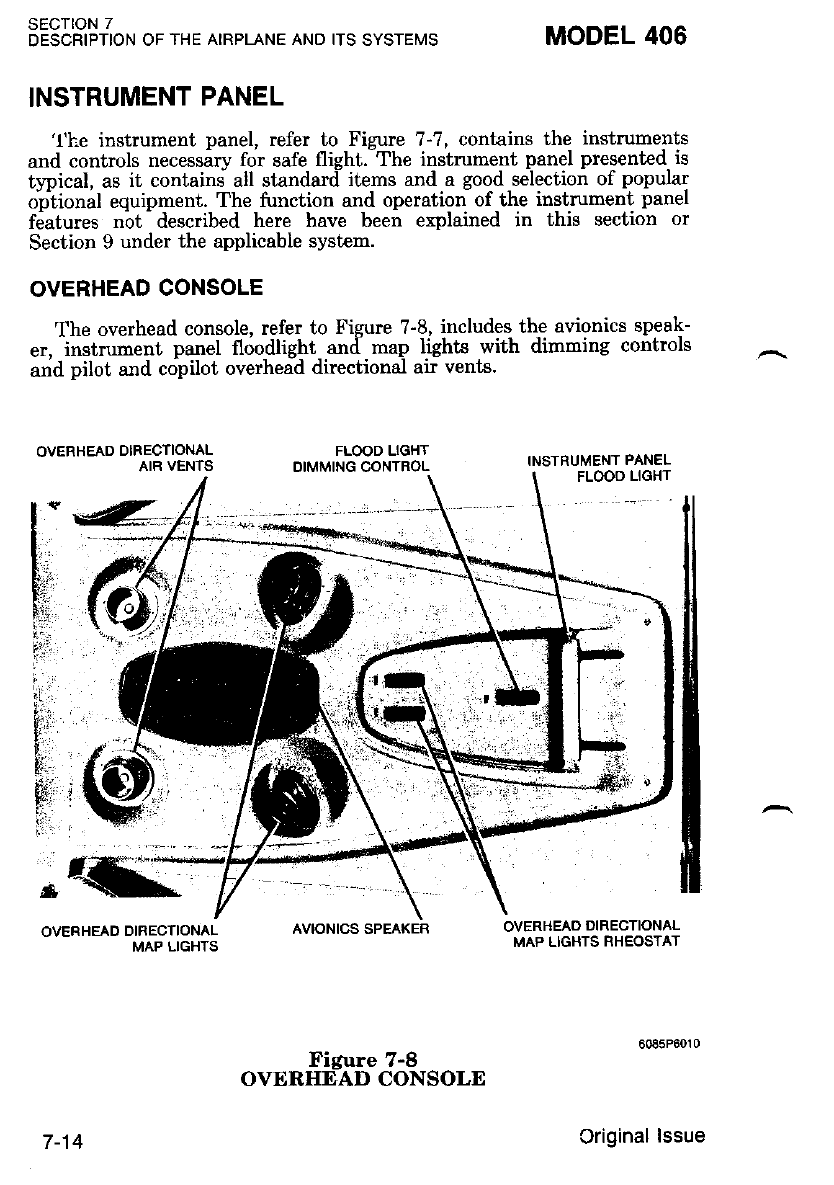
SECTION 7
DESCRIPTION OF THE AIRPLANE AND ITS SYSTEMS MODEL 406
INSTRUMENT PANEL
FLOOD LIGHT
INSTRUMENT PANEL
'l'he instrument panel, refer to Figure 7-7, contains the instruments
and controls necessar5t for safe flight.-The instmment panel presented is
trrical, as it contains all standard items and a good selection of popular
optional equipment. The function and operation of the instrument panel
features nbt- described here have been explained in this section or
Section 9 under the applicable system.
OVERHEAD CONSOLE
The overhead console, refer to Figure ?-8, includes the avionics speak-
er, instmment panel floodlight and map lights with dimming controls
and pilot and copilot overhead directional air vents.
OVERHEAD DIRECTIONAL
AIR VENTS
OVERHEAD DIBECTIONAL
MAP LIGHTS
FLOOD LIGHT
OIMMING CONTROL
AVIONICS SPEAKER OVERHEAO DIRECTIONAL
MAP LIGHTS RHEOSTAT
7-14
Figure 7-8
OVERHEAD CONSOLE
Criginal lssue
ANNUNCIATOR PANEL
The annunciator panel, refer to Figure ?-9, is located below the glare^
sUeia- on the centei irstrument pan . The panel annunciates items of
i"1"i"*i i" iti" pilot itt th" applicable -color of-red, amber, green or white'
lddiiio"ut ann^unciators are irovided on the airplane for .specific. stan-
li*a ot ,iptionut avionics systems; these annunciators are described with
their asso-ciated systems in this section or Section 9.
When a hazardous condition exists, requiring immediate corrective
actio", a ied waming light wil illuminate. Wherr an impending. possibly
auiie";ou. iondition -exiits, requiring attention but not necessarily imme.-
diate action, an anber light will illuminate. A green or whrte lrght wrll
^ iti"-i".te t6 indicate a sife ot normal configuration, condition of perfor-
ma"c",- opeiation of essential equipment or to attract attention and
imDart information of routine action purposes.
A o.""r-to-t".t button is provided in the center of the annunciator
panel. With the batt€rv and avionics switches ON and the press-to-test
iwitch actuated, the ;tal warning hom will, sound and annunciator
illumination wili occur on all annunciator panel lights, ignitor on lights'
iiie *aini"g lights. landing gear position ind unlocked lighls,. propeller
"vnchoohas6r i!"ltg. autopiloi mode selector and remote mode annun-
ciatot iepeater lishts, maiker beacon lights, BC and RNAV lights in Nav
i Cou."6 Indicaior and master warning lighLs. If the power levers are
retarded approximatelv one inch forward of flight idle detent or wing
h"p. "*t"tiaia beyond the 20 degree position, the landin-g gear warning
hoin will sound if the landine gear is not down and locked' Also'
iowering the wing flaps beyond ihe zo degree position witb the PRESS-
ro-rsSf buttoi acfivateil, will cause the laniling gear waming horn to
sound.
MODEL 406 SECTION 7
DESCBIPTION OF THE AIRPLANE AND ITS SYSTEMS
Original lssue 7-15
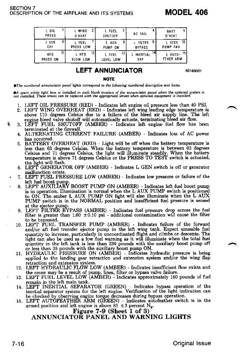
SECTION 7
DESCRIPTION OF THE AIRPLANE AND ITS SYSTEMS MODEL 406
€0r65@1
L OIL ]
PFISS
L Wtitc 2
O'IEAI r fuEt 3
SHUTOfF SATT 5
O'HEAI
T GEN L FUET
PRTSS L0W
T FILTEfr
EYPAS!
HYD
PRESS 0tl
I HYD 12 L fU TL 13
LEVTL LOW
! ttfiTtAL l4
sfP L AUTO' 15
LEFT ANNUNCIATOR
OtE
aThe Lutubeted onnu4ittor ponel lights correspond to tha lo\ouine ^untercd des.riptiDe tert itetu
aA sp.re bhn liEht LB ie iBtdle<] in .ach blznh bcoti4n ol thz da^utuittor pn@l ehzn the oprio al tlstem ig
nor iEtolbd- These leBes cM b. rcplac.<l uith tle oootopriate L6et uhz optb^al ee\iptunt is iilrole.L
1. LEFT OIL PRESSURE (RED) - Indicates left engine oil pressure less than 40 PSI.
2. LEFI WING OVERHEAT (RED) - lndicat€s Ieft wing leading edge t€Epenture is
above 110 degrees Celsius due to a failure of the bleed ai.r supply line. The Ieft
ensine bleed valve shut ff will automatically actuat€, t rmiltating bleed ai! flow.
{ 3. LEFT FUEL SHUTOFF (AMBER) - Indicat€s left engine tuel flow has been
t€rminated at the firewall.
4. ALTERNATINC CURRENT FAILURE (AMBER) - Indicat€s loes of AC power
has occurred.
BAT'TERY OVERHEAT (RED) - Licht will be off when the batt ry temp€rature is
less than 63 degrees Celsius. When the battery temp€rature is between 63 degees
Celsius and 7l desre€ Celsius, the lisht will illumina!€ steadily. When the batt€ry
temperature is abo-ve 7t degrees Celsius or l,he PRESS TO TEST switch ie actuat€d.
the lisht will flssh.
LEFT GENERATOR OFF (AMBER) - Indicat€s L GEN switch is off or generator
dalfunctioD exbts.
LEFT FUEL PRESSURE LOW (AMBER) - Indicates low prcssurc or failure of the
l.f+ 6'.1 h^^at h'|mn
ide'i-lit'iiiIenV soosr PUMP oN (AMBER) - Indicatee left tuel boost pump
is in oDeration. Illueination ia normal when th€ L AUX PUMP swikh is peitioned
to ON; The amber L AUX PUMP ON lisht wil also illuEinat€ when the L AUX
PUMP switah is in the NORMAL positioi and insuffrcient fuel pressure is sensed
5.
6.
. 1.
,8.
9.
10.
at the eiector oumD.
LEF"T FILTEh BYPASS (AMBER) - Indicstes fuel pressure drop across the tuel
fillF iq r.et r th'n 160 +o.10 Dei - additionrl contmination will caus€ the filter
Ltit'l llLlE;tt llYl-AD5 (AMbEH) - Indrcates tuel pressure orop acrosa tn
filter is gr€at€r than 1.60 :10.10 psi - additional cont€mination will cause the
to be bloassed.
LEF"I -FL'EL TRANSrER PUMP (AMBER) - Indicat€s failuE of the forward
and/or aft fuel transfer eiector DumD in the left wine tank. ExDect unusable fuel
and/or aft fuel transfer eiector Dump in the left wins tsnk. Expect utusable fuel
ousntitv to increase. oartiiularlvln uircoordinatcd flisht and climbs or descents. The
li"hr ea"n also tre useli er a low'firel wrmins rs it wil-l illuminat€ when the total'fuel
ousntitv to increase. oarticularlv in uncoordinat€d fliqht and climbs or descents. The
lieht ca; also be useci as a low'tuel warnins as it wil-l illurinat€ when the total'fuel
quantity in the left bnl is less than 230 pound.s with tie auriliary boost pump off
or less than 35 oounds with the auxiliarv boost DumD ON.
11. or less than 35 oounds with the auxiliarv boost DumD ON.
HYDRAULIC PRESSURE ON (AMBER) - fndicitce hydraulic pre*sure is being
applied to the landing gear retractiol and €xtension system and,/or the wing flap
retraction and extension sy6tem.
LEI"I HYDRAULIC FLOW LOW (AMBER) - Indicates insufficient flow exists and
rhe cauae may be a result of purnp. lines. fill,er or blpass valve failure.
LEFT FUEL LEVEL LOW IAMBER) - Indicatps abproximat€ly 160 pound8 of tuel
remain in the left main tank.
LEF I INERTIAL SEPARATOR (GREEN) - Indicates br?ass operation of the
inertial separator system for the left engin€. Vedfication of the light indication can
be checked bv obgervine ensine toroue decreases dunne bwass operation.
LEF'I AUToFEATHER A-RM (GREEN) - lodicat€, aiiofeatlier ssritch i.s in lhe
armed position and lefi engine is above 83 13 pelcent Ns.
Figure 7-9 (Shest 1 of 3)
ANNUNCIATOR PANEL AND WARNING LIGIITS
12.
, 13.
14.
7-16 Original lssue
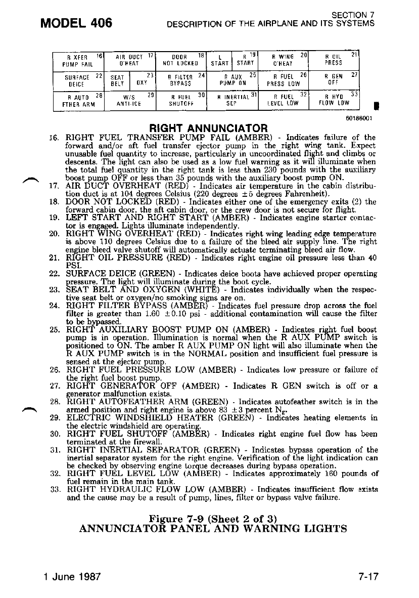
MODEL 406 SECT1ON 7
DESCRIPTION OF THE AIRPLANE AND ITS SYSTEMS
A n oucl 17
O'NTAT 000fl 13
N0r t 0cl( E0 L
STABT O'HEAI F OIL
PRESS
SUFFACE 22
DI ICE
SEAT
BI!T l]XY
2F FltrtF 24
BYPA!S F FUEL 26
PF TS5 LOW
N GEN 27
R AUTO ?8
ANTI ICE
29 B FUET 3O
S HIJTO T FSEP
B FUEL 3?
LEVEL LOW B HYD 3:]
t't.
18.
60r86001
RIGHT ANNUNCIATOR
RIGHT FUEL TRANSFER PUMP FAIL (AMBER) - Indicatee lailure of the
forward and/or aft fuel transfer ejector pump in the righ! wing tsnk. Expect
unusable fuei quantity to increase, pirticula'rly iir uncoordinatcd flight and clinros or
descents. The iight ci" also be used as a low-fuel warning as it wi iltuminat€ sr'hen
the total tuel qulntity in the dght tank is less than 23o-pounds with the auf,iliary
boost pump OFF or less than 35 pounds with the auxiliary boost pump ON.
AIR DUCT OVERHEAT (RED) - Indicates air temDemture in the cabin distribu-
tion duct is at 104 degrees Celsius (220 degrees a5 de$ees Fahrenheit).
DOOR NOT LOCKED (RED) - Indicates either one of the €m€ryency exits (2) the
forward cabin door, the aft cabin door. or the crew door is noi s€cue for flieht.
LEFT START AND RIGHT STARf (AMBER) - lndicates engine slarte; contac'
tor is engaged. Lighus illuminate independently.
RIGHT WING OVERHEAT (RXD) - Indicates risht wing leading edSF temp€rature
is above 110 degrees Celsius due to a failure of the bleed air supply line. The fight
engine bleed valve shutoff will automatically actuat€ terminating bleed air flow.
RIGHT OIL PRESSURE (RED) ' Indicates dght engine oil pressure les6 than 40
PSI.
SURFACE DEICE (GREEN) - Indicates deice boots have achieved proper operating
Dr,essure. The lieht will illuminate durins the boo! cvcle.
SEAT BELT AND OXYCEN (WHITE) - Indicates individually when rhe ftispec.
tive seat beh or o:vsen/no smokins sisns are on.
RIGHT FILTER BYPASS {AMB"ERI - Indicates tuel Dressure droD afios3 the tu€l
filter is qrealer than I.60 . 0.10 psi - additionat contarbination wili cause the filter
to be brpassed.
RIGHT AUXILIARY BOOST PUMP ON (AMBER) - Indicates risht tuel boost
pump is in operation. Illumination is normal when the R AUX PUMP switch is
DGitioned to ON. The amber R AUX PUMP ON lisht will also illuminate when the
R AUX PUMP switch is in the NORMAL oosition-and insufficient fuel pressure rs
sensed at the ejector pump.
RIGHT FUEL PRESSURE LOW (AMBER) - Indicates low pressure or failure of
the right fuel boost pump.
RIGHT GENERATOR OFF (AMBER) - Indicates R GEN switch is off or a
19.
20.
21.
22.
24.
25.
26.
27.
29.
30.
31.
32.
33.
generator malfunction exists.
28. RIGHT AUTOFEATHER ARM (GREEN) - Indicates autofeather svritch is in the
armed position and right engine is above 83 i3 percent N..
ELECTRTC WINDSHIELD HEATER (GREEN) - Indiiat€s heating elemerts rn
the electric windshield are operatins.
RIGHT FUEL SHUTOFF (AMBER) - Indicai€s right engine tuel flow has treen
terminat€d at the firewall.
RICHT INERTIAL SEPARATOR (GREEN) - Indicates b)?ass operation of the
inertial separator system for the right eng:rne. Verification of the light indication can
be checked bv observins ensine turoue decreases durine bvDass ooeration.
RIGHT FUIiL LEVEL Low (AMBERJ - Indicates apiioximitely 160 pounds of
fuel remain in the main tank.
RIGHT HYDRAULIC FLOW LOW (AMBER) - Indicates insufficient flow 3xists
and the cause may be a result of pump, lines, 6ltei or bypass valve feilure.
Figure 7-9 (Sheet 2 of 3)
ANNUNCIATOR PANEL AND WARNING LIGHTS
1 June 1987
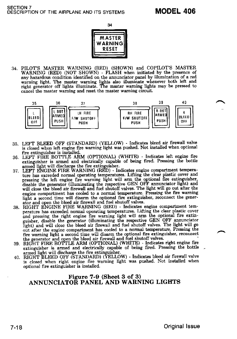
SECTION 7
DESCRIPTION OF THE AIRPLANE AND ITS SYSTEMS MODEL 406
PILOT'S MASTER WARNING (RED) (SHOWN) and COPILOT'S MASTER
WARNING (RED) (NOT SHOWN) - FLASH when initi,ated by the plesence of
anv hazardoui condition identfied oo the annunciator panel by illumination of a red
wa;nins lieht. The mast€r warninq lishts also illuditratt wbenever both left and
right g;_neiator off light€ ill'.rminate. The rnsster warning lights Eay be pressed to
csncel the master warning and reeet the mast€r waming circuit
@@@ w@@
LEFT BLEED OFF (STANDARD) (YELLOW) - lndjc4tss bleed--air luewall valve
is clo;ea when left eniine frre waming light was pwhed Not installed when oPtional
flle extinsu i6her is inst€]led.
LEI'I FihE BOTTT-E ARM (OF I-IONAL) (WHITE) - Indicat€s left eosing frre
"*tine,ji"h"r is armed and electrically capable of being lu€d Pressing the bottle
armed lisht wil discharye the fire extinguisher.
LE['T ENGINE FIRE WARNING (RED) - Indicstee engine compartdent t€mpera-
ture has erceeded normal operating t€mperatures. Lifting the clear plastic cover and
"i"""i"e tlt" left enqine fui warnine liiht will arm [h; optionel fire extinguisher,
iiofteit" senerato; (illuminatinc t[e rlsp€ctive GEN OFF annunciator light) and
ritt "ios" ttt6 bleed air firewall and tuel shritoff va.lvee. The light wi go out afIe. the
eDgine compartment has cooled to a normal temperature Pressilrg the fu€ warDing
lie-ht a second time will disarm the optional frre ertinguiaher' neconnect th€ gener'
airr and ooen l.he bleed air firewall ard tuel shuloff valves.
RIGHT ENGINE FIRE WARNING (RED) . Indicatee eDginE COInPATTrtrENT tEM.
35
37.
oerature hae exceeded normal operal,ing lemperatures. LiftiDg the clear plastic cover
ind pressins the risht eogine lue waining light will arm the optional fire extir-
imd pressins the risht eoqine fue warning light will arm the optiona.l fire extrr-
zuisher. disible thieeneril,or (illuminatini the re8pectiv€ GEN OFF annuncietor
iisht) a"d *ill close ihe bleed at Iirewall and tuel shutoff valves. The light will go
^,;+ -4.. r+'. ondin. .^hhoFrmcnl hqq .Ml..l f^ r h.mal fammrthne. PreaarDs the
39.
oii "fte. ttr" engine compartment has cooled to a normsl t€mp€rotue.. Pre6siDg
the bottle
n"" *.*ins lieh-t a seco;d time will disard the optional fire €itinguisher, recon-oect
the senera6r ind open the bleed air fires/all and tuel shutoff valve
RibhT FIRE BOfTLE ARM (OPTIoNAL) (WHITE) - Indicates right engine fue
the senera6r ind open the bleed air fires/all and tuel shutoff valve.
RIGIT FIRE BOfILE ARM (OPTIONAL) (WHITE) - INdiCAt€g
extinzuisher is armed and electrically capable of being frred Pn
TE) - Indicat€s riqht ensine fue
being frred. Pressihg th; bottle
extinzuisher is armed and €Iectrically
armed lisht will discharye the fi.e extin
armed lisht will discharye the fire extinguishe!.
40. EicATbLEED OFF (STANDARD) {YELLow) - Indicates bleed air tue'*'all valve
is closed when right engine 6re warning light was pushed. Not installed when
optional fire extinguisher is installed.
Figure 7-9 (Sheet 3 of B)
ANNUNCIATOR PANEL AND WARNING LIGIITS
7-18 Original lssue
FLIGHT INSTRUMENTS
The basic flieht instruments. refer to Fizure 7-7, consist of airspeed,
altimeter and rite-of-climb indicators, electric Lurn-and-bank and pres'
sure driven horizon and directional gyros.
Operation of the airspeed, altimeter and rate-of-climb indicators can
be ditermined by cross-checking the copilot's instruments. Also, when a
climb or descent is initiated, - these instruments should indicate the
annronriale chanee. If no chanqe is indicated, it is reasonable to assume
si;tic'source bloikage has occurred. lf the possibility of static source
icing is present, actultion of lhe L or R PITOT/STATIC switch should
.^ deici th-e -static sources. )f. only the. airspeed. indicator appears to be
' ':ffected when the climb or descent is initiated, it is reasonable to assume
a pitot system blockage has occurred. If the pqryjbillty qf- pitot sourc.e
icing is present, actuation of the L or R PITOT/STATIC switch will
cleai the ice blockage. Reference the copilot's instruments and optional
ansle-of-attack indiiator for airspeed information until a reliable air-
snded indication can be obtained.-If neither copilot's instruments or the
optional angle-of-attack system is operational, fly attitude ard power
rererencea.
Operation of the turn-and-bank needle can be checked by initiating a
stanilard rate tum and cross-checkins the turn rate with the directional
gyro. An indicated standard rate tum should show a turning rate of 3
degrees per second on the directional gyro. After shutdown of the air-
plane on the ground, abnormal noise coning from the turn-and-bank car
indicate a neir failure condition. Inaccuracy will result if the indicator is
not level in the instrument panel. With the airplane on level ground, the
ball should be centered in the race.
Operation of the directional and horizon gyros can be checked during
taxiing by watching for an abnormally slow erection rate and erratic
operat'ion. After shu--tdown of the airplaire on the ground, abnormal noise
coning from either gy'ro can indicatt a near failule condition. Checkiag
- the instrument air sase for oroner pressure and no failure buttons
- exposed will assure p-riper 91'16 piessuie is available. Low cop,ilot g1ro I
pressure accompanied by no failure buttons exposed may indicate anl
overpressure condition in the bleed air system. Such a overpressure I
condition is further verified if the copilot gyro pressure returns tol
normal with the engine(s) at flight idle. I
In flight, the directional gyro can be checked by fl5nng a standard rate
turn anii observing the diraational gyro for a turning rate gf 3 d9gre99
per second. Also t-he precession rat6- in straight and level flight shbuld
not exceed 5 degrees in 10 minutes. The horizon gyro operation can be
checked by establishing a level flight attitude; the gyro should indicate
winss level within I desree. Initiate a 20 degree bank for a 180 degree
turn-, then smoothly reiurn to level flight: gyro should indicate wings
level within 3 degrees. Establish level flight at 150 KIAS; gyro should
MODEL 406 SECTION 7
DESCRIPTTON OF THE AIRPLANE AND ITS SYSTEMS
'I June 1988 7-19
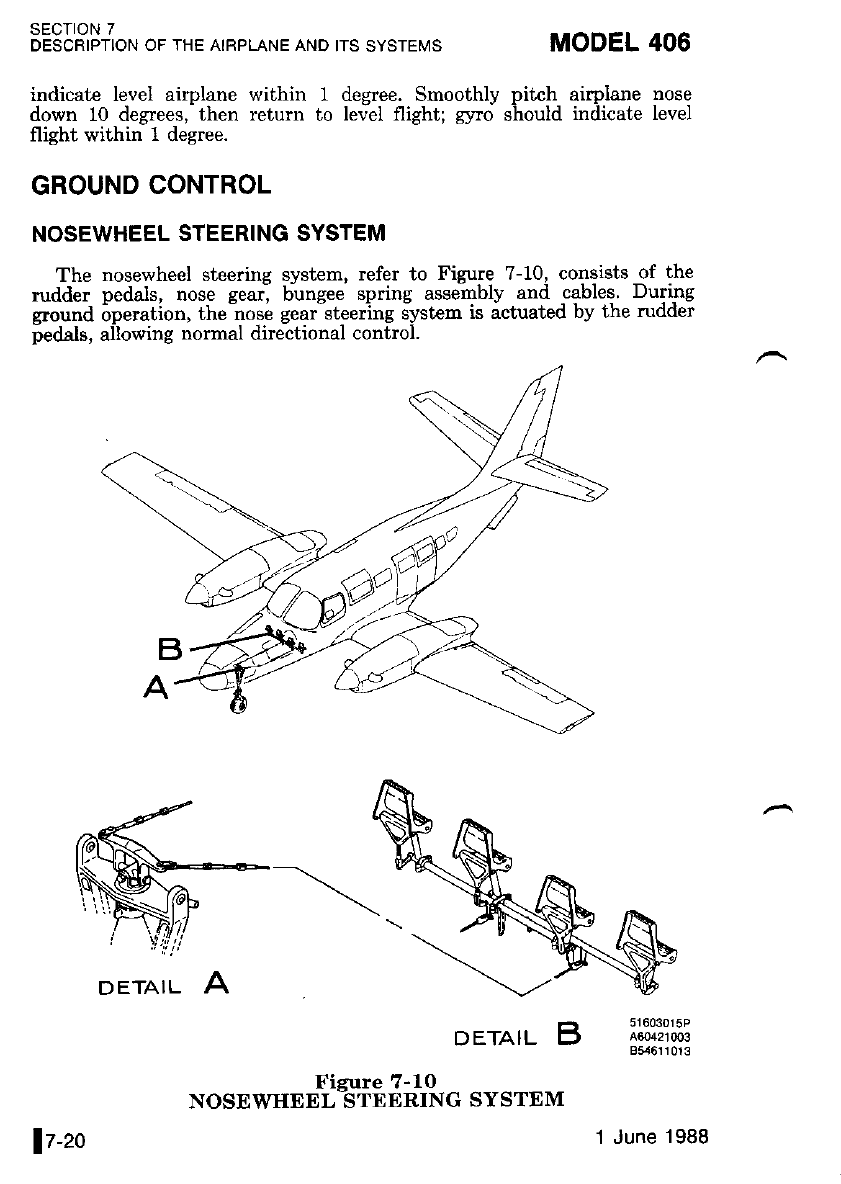
SECTION 7
DESCRIPTION OF THE AIRPLANE AND ITS SYSTEMS
indicate level airplane within 1 degree. Smoothly pikh airplane nose
down 10 degrees,'then return to tev-el night; slro should indicate level
flight within 1 degree.
GROUND CONTROL
NOSEWHEEL STEERING SYSTEM
The nosewheel steering system, refer to Figure 7-10, consists of the
rudder pedals, nose gearl bungee spring assembly and -cables. Duri-ng
groyr-rd i-peration. the no:i gear-steering iystem is actuated by the rudder
pedals, allowing normal directional control.
DETAIL B
*osu w"r #Tii f; ;,1t*. sY srE M
MODEL 406
DETAIL A
It-zo 'I June 1988
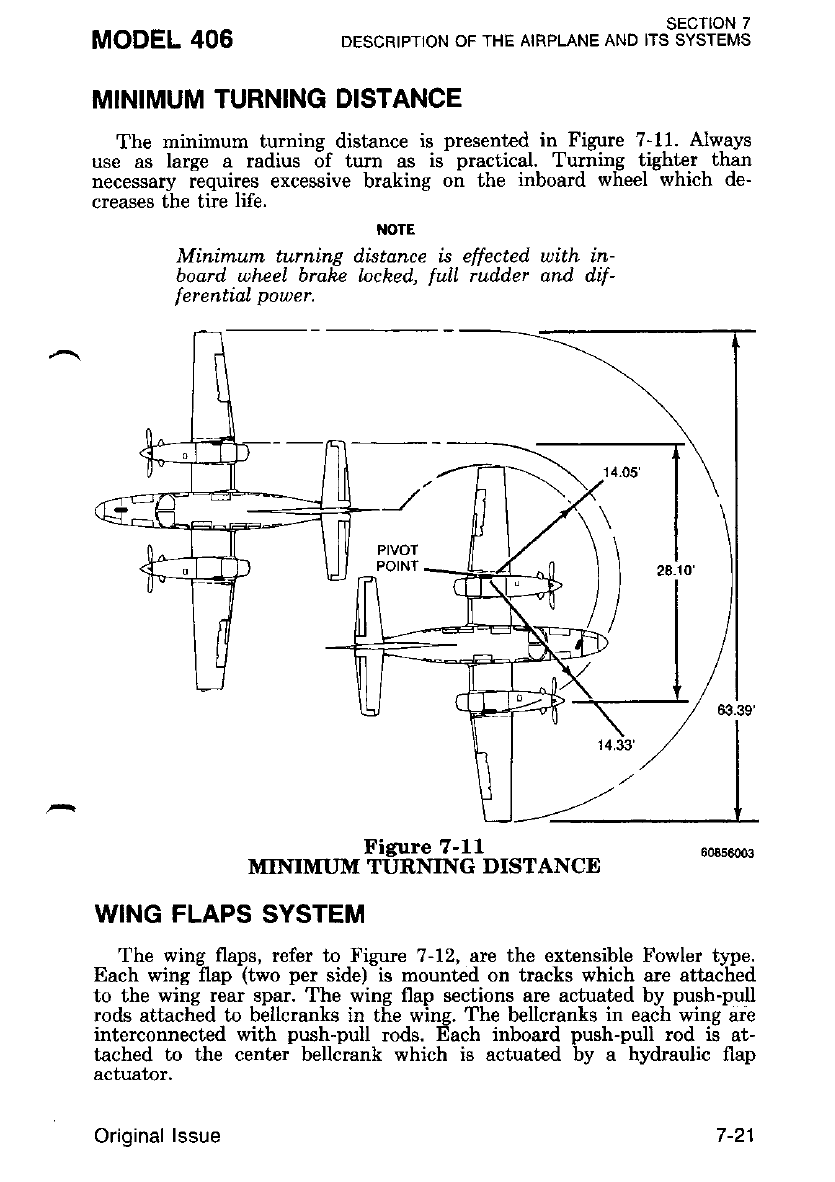
MODEL 406 SECTION 7
DESCRIPTION OF THE AIRPLANE AND ITS SYSTEMS
MINIMUM TURNING DISTANCE
The minimum turning distance is presented in Figure ?-11. Always
use as large a radius 6f turn as is- practical. Turning tighter than
necesaaly requires excessive braking on the inboard wheel which de-
creases the tire life.
NOTE
Minimum turning distance is effected with in-
board wheel brake lached, full rud.der and. d.if-
f
ercntial pouer.
Figure 7-11 6oas6oo3
MINIMUM TURNING DISTANCE
WING FLAPS SYSTEM
The wing flaps, refer to Figure 7-72, arc the extensible Fowler t14pe.
Each wing flap (two per side) is mounted on tracks which arc attached
to the wing rear spar. The wing flap sections are actuated by push-pull
rods attached to bellcranks in the wing. The bellcranks in each wing are
interconnected with push-pull rods. Each inboard push-pull rod ii at-
tached to the center bellcrank which is actuated by a hydraulic flap
acf,ualor.
Original lssue
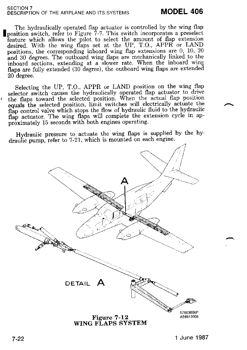
- The hydraulically operated flap actuator is controlled by the wing flap
lposition switch, refer tr-, Fizure ?-?. This switch incorporates a preselect
-?eature which allows the pilot to select the amount of flap extension
desired. With the wing flaps set at the UP, T.O., APPR or LAND
oositions. the corresponding inboard wing flap extensions are 0. 10. 20
lnd 30 deerees. The'outboard wing flaps are mechanically linked to the
inboard sictions, exlending at a slowir rate. When the inboard wing
flaps are fully extended (30-degree), the outboard wing flaps are extended
20 degree.
Selectine the UP, T.O., APPR or LAND position on the wing -flap
sele-ctoi sw-itch causes the hydraulically operated flap actuator to drive
' lhe flaps toward the selected position. When the actual {lap position
.."ri" iit" selecled position, limit switches will electrically acLuate the
itio "o"iitt valve which stops the flow of hvdraulic fluid to the lrvdraulic
fiui u"t""to.. The wing fldps will complete the extension cycle in ap-
proximately 15 seconds with both engines operating.
Hvdraulic pressure to actuate the wing flaps is supplied by the hy'
drauiic pump, refer to 7-21, which is mounted on each engrne'
SECTION 7
DESCRIPTION OF THE AIRPLANE AND ITS SYSTEMS MODEL 406
DETAIL
7-22 1 June 1987
LANDING GEAR
The retractable tricycle landing gear, refer to Figure 7-13, is elec-
trically controlled and hydraulically actuated. The individual landing gear
actuators incorporate an internal lock to hold the landing gear in the
ertended position. The landing gear is held in the retracted position by
mechanical uplocks that are released hydraulically tluring gear extension.
The landing gear completes the retraction cycle in approximately 5
seconds with both engines at maximum engine RPM. The actuation
cycle time increas€s as engine RPM decreases or with the loss of an
engine-driven hydraulic pump.
_\. Hydraulic pressure is supplied by the hydraulic pump, refer to Figure
-7-21, which is mounted on each engire. An electricallv actuated qear
control valve controls the flow of hyfuaulic fluid to thi individual Eear
cylinders. The gear control valve reciives power through the landing lear
pbsition switch. During ground operation accidentil .gear. retraition,
regardless of gear switch position, is prevented by a safety switch located
on the left landing gear shock strut. The weight of the airplane com-
press.es the shock strut, causing the safety switrh, to open, thus prevent-
ing electrical power from reaching the gear control valve.
The landi-ng gear doors are nechanically linked to their respective
landing gear, -re-tracting and extending wiih each landing geai. The
landing gear is operated by a switch,- refer to Figure ?-1--6,-which is
identified by a wheel-shaped knob. The switch positions are UP and
DOWN. To operaLe the qear, pull out the landins gear switrh and move
it to the desihd position. This allows electricaf plwer to energize the
gear control valve and the hydraulic pressure to drive the landing gear to
ihe selected position. The hfdraulic fressure light, located on thd dnnun-
ciator panel, refer to Figure 7-9, will renain on rmtil the landing gear is
locked into position.
LANDING GEAR SAFETY SWITCHES
A larding gear safety switch (squat switch) is located on each main
landing gear strut to conhol ground and airborne operation of certain
equrpmen[.
The lefi la,nding gear safety switch prevents landing gear retraction,
reduces stall vane deice heat while the airplane in on thi fround.
The right landing gear safety switch allows the landing gear warning
horn to iound if ihi landine- qear selector switch is -m-oved to thi
retracted position while the aifoline is on the ground. On the ground it
also disables {light-hour recorder and Davtron Digital Clock flight time
operation. Airborne, the right switch allows the flight-hour recorder and
Davtron clock flight time readout to function.
SECTION 7
DESCRIPTION OF THE AIRPLANE AND ITS SYSTEMS
MODEL 406
Original lssue 7-23
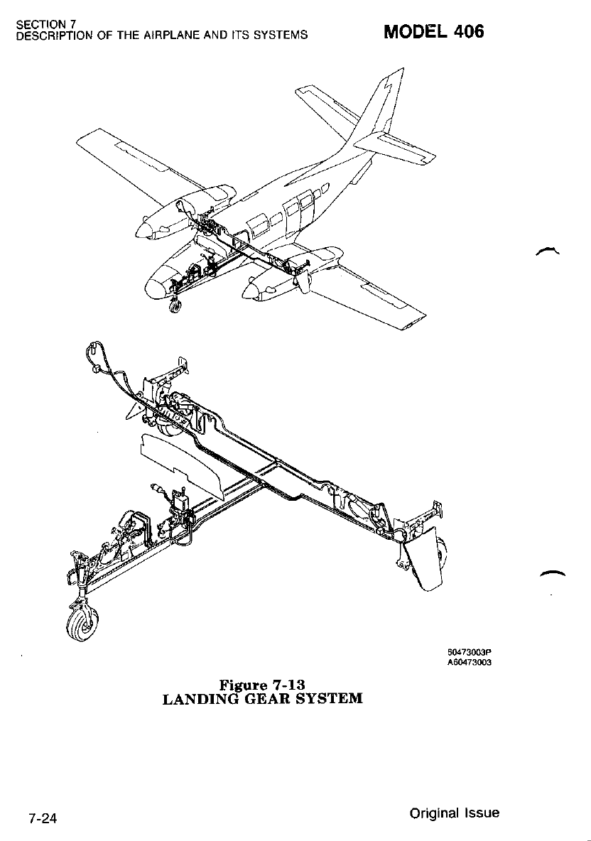
SECTION 7
DESCRIPTION OF THE AIRPLANE AND IIS SYSTEMS MODEL 406
Figure 7-13
LANDING GEAR SYSTEM
Original lssue
LANDING GEAR POSITION LIGHTS
Four landing gear position indicator lights, refer to Figure 7-14, are
contained in two modules located beneath the engine instruments just
left of the center of the instrument panel. One module contains three of
these lishts (one for each sear) which are green and will illuminate when
each laiding gear is fully extended and loc-ked. The other lighl module is
red and wlli illuminate when any or all the gears are unlocked
(intermediate position). When the gear unlocked light and gear down
lighLs are not llluminated, the landiig gear is ir the UP andlOCKED
position.
.-. LANDING GEAR WARNING HORN
The landing gear warning horn is controlled by the power levers
and/or the wiirg-flap positio-n. The warning horn *ill sound intermit-
tentlv if either or both power levers are retarded below approximatelv
one inch forward of the flight idle detent with the landing geir retracted
or if the wing flaps are loiered beyond the 20 degree posiiion with the
landing gear'in airy position except extended and loc[ed. The waming
horn ii ilso conneit6d to the UP position of the landing gear position
switch and will sound if the switch is placed in the UP position while
the aimlane is on the ground. The system can be checked by activating
the PRESS-TO-TEST"button, refer io Figure 7-9, located on- the annun-
ciator panel while retarding one power lever at a time. Also, lowering the
wine flaos bevond the 20 decree position with ihe PRESS-TO-TEST
bution a'ctivatid will cause thJlandjng gear warning horn to sound.
A warning horn disable switch is provided adjacent to the landing
gear switch.-During rapid descents wi[h the powei levers in flight idle.
ihe horn disable switch can be used Lo silence the landing gear warning
horn. Once the power levers are advanced, the horn will be reset. When
the wins flaps are extended bevond the 20 desree position and the
Ianding Eear is not down and loc[ed, the horn cannot 6e silenced by the
horn disable switch.
MODEL 406 sEcTtoN 7
DESCRIPTION OF THE AIRPLANE AND ITS SYSTEMS
Original lssue 7-25
LANDING GEAR EMERGENCY EXTENSION SYSTEM
The landing gear emergency extension sJstcm,..refe.r to Figure 7-15'
consists of a red emergency gear extensiDn 'l'-handle, (located on lnstru-
-eni nanel) a blowdoin bbtlle, refer to Figure ?-14, located in the nose
baeease compartment) and associated plumbing. The procedure for emer-
g"f,iv'g"ut eitension is girren in Section 3' Puliing the emergency control
i"t"i"""'. aw nitrogen un"der pressure into the shuttle valve. causing the
iituitt" ual"ue to frove from- the hydraulic to pneumatic position. The
nitiosln then ilows into the uplocks which ieleases the gear to the
i"eeiii nosition, and then into tie landing gear actuators, which drives
the hnding gear into the down and locked position.
M)TE
The landing gedr cannot be retracted after
emergency gear extension until the system hns
been ground seruiced.
LANDING GEAR SHOCK STRUTS
Shock absorption is provided on the landing gpar by an oil-over-air
.h;"k ;il;. Tliis strut is composed of an upper -barrel assembly.and a
lower piston assembly and consists of orifice. tapered metenng prn and
;i;t r';d fork assehbly. The metering pin incr-eases or.decreases the
how of fldraulic fluid through the orifrce according to the severity of
shock.
Landins eear shock struts should be checked before each flight to
ensure th& "are not collapsed. This can readily be determ-ined by a visual
insDection of the shock strut lower piston assembly. lt the unparnted
su*ace of the lower piston assembly- is not visible, the ,shock strut is
fully collapsed and muit be sewiced before the airplane is flown.
sEcTroN 7
DESCRIPTION OF THE AIRPLANE ANO ITS SYSTEMS MODEL 406
7-26 Original lssue
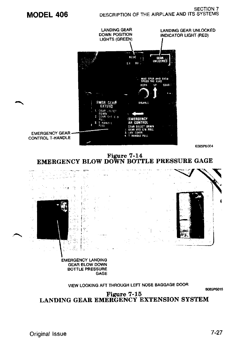
MODEL 406
EMERGENCY GEAR
CONTROL T-HANDLE
LANDING GEAR
DOWN POSITION LANDING GEAR UNLOCKED
INDICATOR LIGHT IRED)
SECTION 7
DESCRIPTION OF IHE AIRPLANE AND ITS SYSTEMS
Figure 7-14
EMERGENCY BLOW DOWN BOTTLE
VIEW LOOKING AFT THROUGH LEFT NOSE BAGGAGE DOOR
@E5P6015
Figure 7'15
LANDING GEAR EMERGENCY EXTENSION SYSTEM
Original lssue
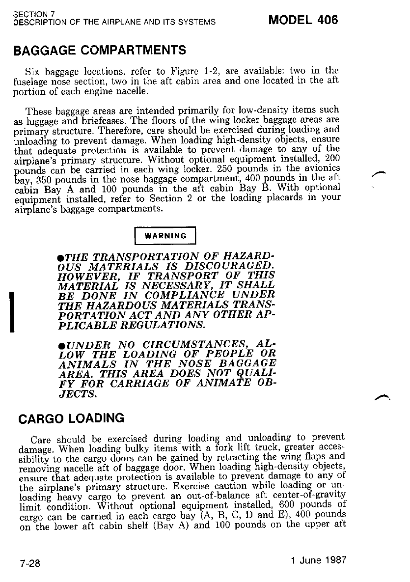
BAGGAGE COMPARTMENTS
Six bassage locations, refer to Figure 1-2, are available; two in the
tuselaee n-ose section, two in the aft cabin area and one located in the aft
portion of each engine nacelle.
These baggage areas are intended primarily for low-density items such
as lusease and briefcases. The floors of the wing locker baggage areas ate
nrimi-rv"structure. Therefore, care should be exercised during loading and
irnloading to prevent damage. Whe.n- loading high-density objects, ensure
tn"i uatiuud prolection i5 available to pievent damage Lo any of the
"irpt"*'i primiry structure. Without oplional equipm-ent inslalled, 200
oounds cai be carried in each wing locker. 250 pounds in lhe avronrcs
6uu. fSO pou"a. in lhe nose baggagd compartmenf, 400 pounds in the alt
;;6il 6^-v A and 100 pounds"in"the ait cabin Bav B.,With optional
equipment installed. refer to Section 2 or the loading placards rn your
ai'rpiane's baggage compartments.
.THE TRANSPORTATION OF HAZARD.
OUS IVATNNLCLS IS DISCOURAGED.
HOWEVER, IF TRANSPORT OF THIS
TWITNNUI 1,s N'CESSIB Y, IT SHALL
BE DONE IN COMPLIANCE UNDER
THE HAZARDOUS MATERIA'S TBANS-
PORTATION ACT AND ANY OTHER AP.
PLICABLE NEGULATIONS.
.T]NDER NO CIRCUMSTANCES' AL.
LOW THE LOADING OF PEOPLE OR
ANIMALS IN THE NOSE BAGGAGE
AREA, THIS AREA DOES NOT QUALI-
FY FOR CARRIAGE OF ANIMATE OB.
JECTS.
CARGO LOADING
Care should be exercised during loading and -unloading to prevent
damage. When loading bulky ilems wil.h a fork lifl lruck, greater acces
if iiit"u i" t-ti" "rteo d:;nrs cin be gained bv retracting lhe wing flaps and
;;;;"s n"iett" ift of baggage do-or. When loading high-densilv objects,
ensure that adequate protection is-available to prevenl.damag,e ro any or
the airplane's primary structure..Exercise cautron whrle loadrng or un-
iouai"d h""uv'cargo io prevent an out-of-balance aft center-of-gravity
ii-li--Eo"iiLii,n. Withoui opti,-,nal equipmelt installed, 600.pounds of
;;;;;;;; be carried in eaci cargo bav ie, B, C, D and E),400 pounds
;;lh;l;*;; alt c.abin shelf (Ba"v A)-and 100 pounds on the upper aft
SECTION 7
DESCRIPTION OF THE AIRPLANE AND ITS SYSTEMS MODEL 406
7 -28 1 June 1987
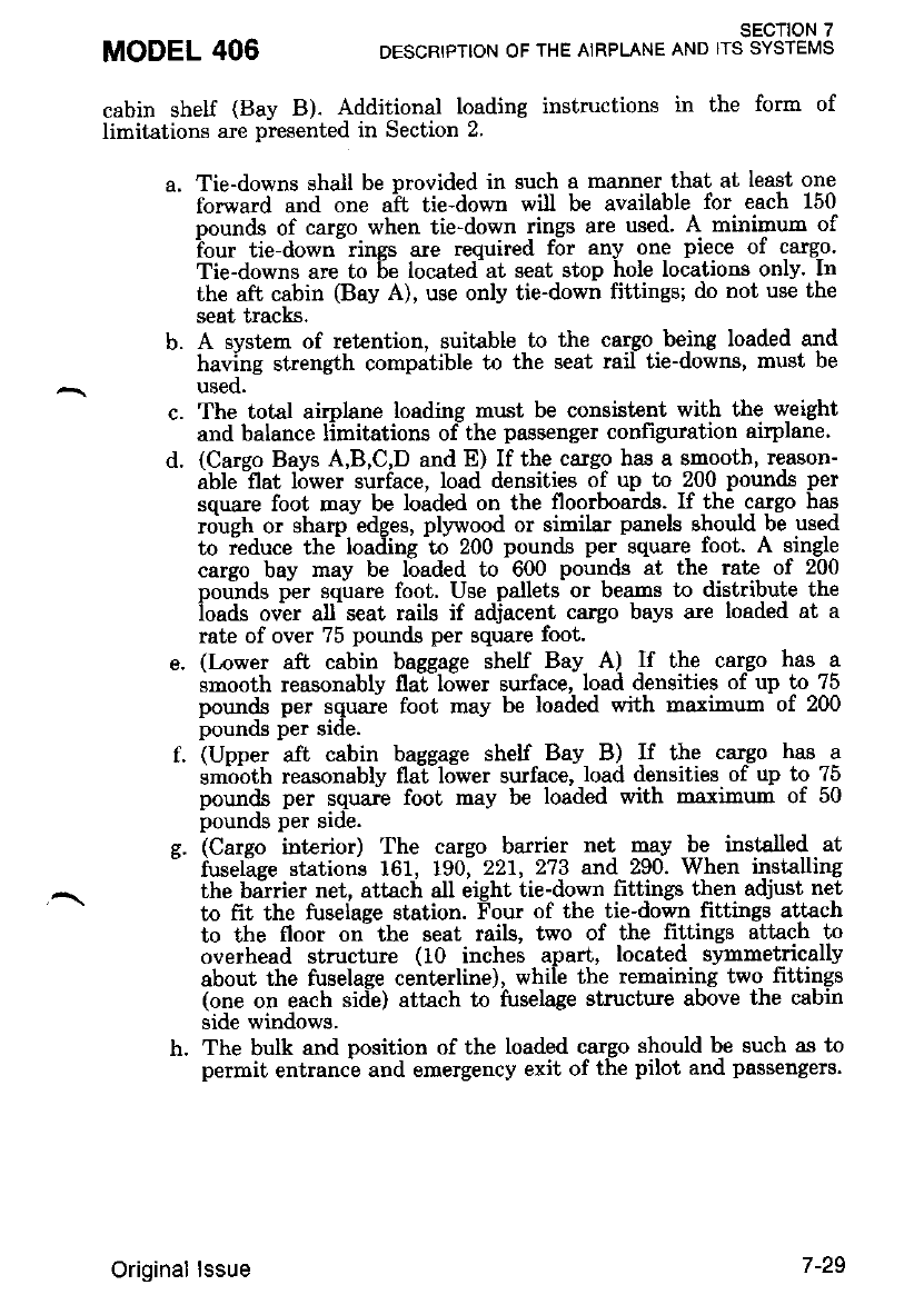
cabin shelf (Bay B). Additional loading instructions in the form of
limitations are presented in Section 2.
a. Tie-downs shall be provided in such a manner that at least one
forward and one aft tie-down will be available for each 150
pounds of carqo when Lie-down rings are used' A minimun of
?our tie-down- rings are required for any one piece of catgo.
Tie-downs are to 6e located at seat stop hole locations only. In
the aft cabin (Bay A), use only tie-down fittings; do not use the
seat tracks.
b. A svstem of retention, suitable to the cargo being loaded and
having strength compatible to the seat rail tie-downs, must be
used.
c. The total airplane loading must be consist€nt with the weight
and balance limitations ofthe passenger configuration airplane.
d. (Cargo Bays A,B,C,D and E) If the cargo has a smooth, re-ason-
able -flat l6wer surface, load densities of up to 200 pounds per
square foot may be loaded on tbe floorboards. lf the cargo has
roueh or sham edses. plvwood or similar panels should be used
to ieduce the- loaifin! io 200 pounds per square foot. A single
carso bav mav be loaded to 600 pounds at the rat€ of 200
pou-nds per sqirare foot. Use pallets- or beams to distribute the
ioads over all^ seat rails if adiacent cargo bays are loaded at a
rate of over 75 pounds per square foot.
e. (Lower aft cabin baggage shelf Bay A) If the cargo has a
snooth reasonably flailower surface, load densities of up to 75
pounds per squari foot may be loaded with maxinum of 200
pounos per sroe.
f. (Upper aft cabin baqsase shelf Bay B) If the cargo has a
smbbth reasonably flallower surface, load densities of up to ?5
pounds per square foot may be loaded with maximrm of 50
pounos per sloe.
g. (Cargo interior) The cargo barrier net may be instslled at
- fusel"aee stations 161, 190;221, 273 and 290. When installing
the biirier net, attach all eight tie-down littings then adjust net
to frit the fuseiage station. Four of the tie-down frttings attach
to the floor on the seat rails, two of the fittings attach to
overhead structure (10 inches apart, located synmetrically
about the fuselage centerline), while the remaining two fittings
(one on each side) attach to fuselage structure above the cabin
side windows.
h. The bulk and position of the loaded cargo should b,e such as to
permit entrance and emergency exit of the pilot and passengers.
MODEL 406 SECTION 7
DESCRIPTION OF THE AIRPLANE AND ITS SYSTEMS
Original lssue 7-29
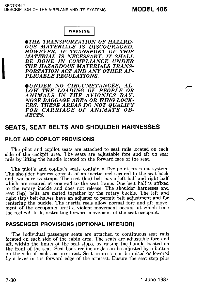
SECTION 7
DESCRIPTION OF THE AJRPLANE AND IIS SYSTEI,4S MODEL 406
.THE TRANSPORTAT:ION OF HAZARD-
OUS MATERIA.LS 1S D.'SCOURAGED.
HOWEVER, IF TRANSPORT OF THIS
MATERIAL I,s NEC.ESSANY, IT SHALL
BE DONE IN COMPLIANCE UNDER
THE HAZARDOUS MATERIATS ?IdANS-
PONTATION ACT AND ANY OTHER AP-
PLICABLE REGULATIONS.
.UNDER NO CIRCUMSTANCES, AL-
LOW THE LOADING OF PEOPLE OR
ANIMALS IN THE AVIONICS BAY,
NOSE BAGGAGE AREA OR WING LOCK-
ENS. THESE AREAS DO NOT QUALIFY
FON CARRIAGE OF ANIMATE OB-
JECTS.
SEATS, SEAT BELTS AND SHOULDER HARNESSES
PILOT AND COPILOT PROVISIONS
The oilot and copilot seats are attached to seat rails located on each
side ofihe cockpit -area. The seats are adjustable fore and aft on seat
rails by lifting the handle located on the forward face of the seat.
The pilot's and copilot's seats contain a five-point restraint system.
The shoulder harness consists of an inertia reel secured to the seat back
and two harness straps. The seat (lap) belt has a left half and right half
which are secured at one end to the seat frame. One belt half is affixed
to the rotarv buckle and does not release. The shoulder harnesses and
seat (lap) b6lts are mated together by the rotary buckle. The left and
right (ldp) belt-halves have ariadjustei to permit belt adjustment and for
centerins the buckle. The inertia reels allow normal fore and aft move-
ment ofthe occupants until a violent movement occurs, at which time
the reel will lock, iestricting forward movement of the seat occupant.
PASSENGER PROVTSTONS (OPTTONAL TNTERIOR)
The individual passenger seats are attached to continuous seat rails
located on each side of the cabin area. The seats are adjustable fore and
aft, within the limits of the seat stops, by raising the handle located on
the front of the seat. Seat back recline angle can be adjusted by a button
on the side of each seat arm rest. Seat armrests can be raised or lowered
Ly a lever in the forward edge of the armrest. Ensure the seat stop pins
7-30 1 June 1987
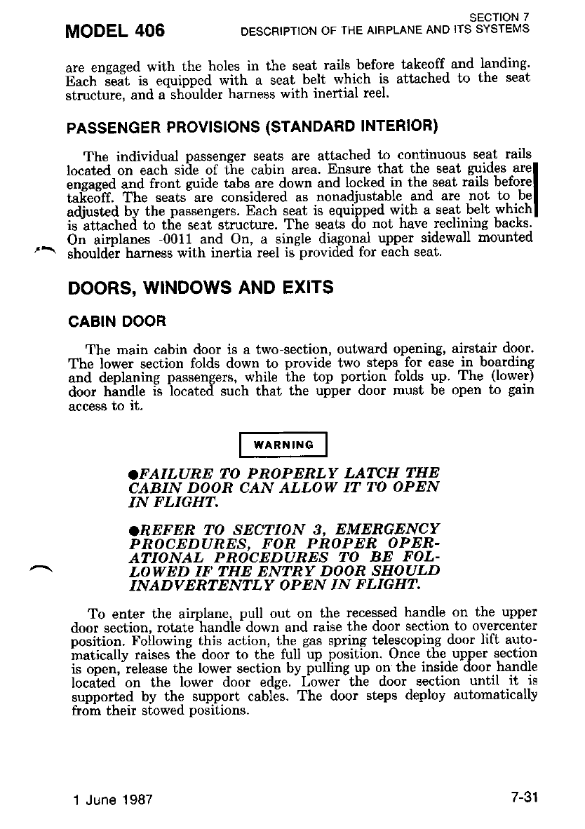
MODEL 406 SECTION 7
DESCRIPTION OF THE AIRPLANE AND ITS SYSTEMS
are ensased with the holes in the seat rails before takeoff and landing'
n".tt i"it is equipped with a seat belt which is attached to the seat
structure, and a-shoulder harness with inertial reel.
PASSENGER PROVISIONS (STANDARD INTERIOR)
The individual Dassenser seats are attached to continuous seat rails
located on each side of ti.re cabin area. Ensure that the seat guides are
engased and front zuide tabs are down and locked in the seat rails before
ta[eo'ft. The seats are considered as nonadjustable and are not to be
adjusted by the -passengers. Each seat is equipped with a seat belt which
is attached to the sert strucLure. The seats do not have reclining backs'
On airplanes -00i1 and On, a single diagonal upper sidewall mounted
shoulder harness with inertia reel is provided for each seal.
DOORS, WINDOWS AND EXITS
CABIN DOOR
The main cabin door is a two-section, outward opening, airstair door.
The lower section folds down to provide two steps for ease in boarding
1"d 4eplaline passengers, .wh-ile the top portion folds yn. The (lower)
door handle is located such that the upper door must be open to gain
access to it.
.FAILURE TO PROPERLY LATCH THE
CABIN DOOR CAN ALLOW IT TO OPEN
IN FLIGHT,
.REFER TO SECTION 3. EMERGENCY
PROCEDURES, FOR PROPER OPER-
ATIONAL PROCEDURES TO BE FOL-
LOWED IF THE ENTRY DOOR SHOULD
INADVERTENTLY OPEN IN FLIGHT.
To enter the airplane, pull out on the recessed handle on the upper
door section, rotate handle down and raise the door section to overcenter
position. Following this action, the gas spring tele-scoping door lift auto-
hatically raises thi door to the full up position. Once tbe upper section
is ooen.-release the lower section bv pulllng up on the inside door handle
located.on the lower door edge.-Lower-thi door section until it is
supported by the support cables. The door steps deploy automatically
from their stowed positions.
1 June 1987 /-o I
Closing the door from inside the airplane is acctrmplished by grasping
the support cables of the lower door section, pulling the door up until
the toD'edse is wilhin reach, then grasping lhe center of the door and
pullini inb"oard until the door is h"ld inug)y against the fuselage door
i.amel Latch the lower door seclion by rotaling the inside handle aft and
down. Check that the lower front and rear latihes are properly engaged'
After the lower door section is secured, grasp the pull strap on the upper
door section and pull down and inboard' As the door nears the closed
Dosition, pull inboard firmly. Latch the upper door section by unsLowing
inside handle ard rotate the handle down to lock. but do not use
eicissiu" force, and then up to stow position. Check front and rear
latches are proPerlY engaged.
As an additional safety feature, a cabin door warning light is p-rovided
This lisht is located in the annunciator panel. refer to Figure 7-9, and is
illuminited when the cabin door is not securely lalched or the emergency
exit/ventilation windows are not securely closed.
CREW DOOR
A crew door is installed on pilot's side providing direct access to the
";ko;i. iil d;;; ii tti"eea at ihe top and a c"trv:on ladder is provided
;.;-;fi;; ;y;!"t.. Th-" doot warning light on'the annunciator panel
will illuminaie if crew door is not closed
To enter the airplane, insert screwdriver in slot forward- of crew door
"n,i iotul" .to.t *ii.. to unlock, pull out on the recessed handle and
i"Gt" tt"itat clockwise and raise d-oor to the overcenter position' Follow-
i"e ihi" "itlo", the gas spring telescoping door lift automatically raises
thi door to the full up position.
Closine the door from inside the airplane is accomplished by grasping
the nuii "strap and pulling down and- inboard. As the door, nears the
"i-o."ilo.itl*, pull inboaid firmly to assure engagement of the latch^ing
oit"t-tiotut" 'itr handle clockwisi to lock posilion. then rotate safety
io.. t".t Landle located forward of door to -aft position. The crew door
Jtro"td Ue closed prior to flight and should not be opened in flight'
REFER TO SECTION 3, EMERGENCY
PROCEDURES, FOE PROPER OPER-
ATIONAL PROCEDURES TO BE FOL-
LOWED IF CREW DOOR SHOULD IN-
ADVERTENITLY OPEN IN FLIGHT.
SECTION 7
DESCRIPTION OF THE AIRPLANE AND ITS SYSTEMS MODEL 406
Itv 1 June 1987
CARGO DOOR
A one-piece cargo door, located forward of the cabin door, allows easy
loadine of bulk caigo. The outward opening. side hinged door is latched
ioo un? Uotto- bv "handles which can''t be operat ed when lhe cabin door
ir'.to.Ja. The d<ior warning light on the annunciator panel will illu-
minate if the cargo door is not closed.
FLIGHT WITH THE CARGO DOOR
OPEN ON REMOVED IS PROHIBITED,
wTNDOWS
Seven windows are provided on each side of the airplane All windows
u." "o"-op""ing, ixctjpt the emergency exit/ventilaiion windows and
cie- dootl A fo-ul weafher window lr incorporated lnto bo'-h the pilot's
i"a "opit.tt side windows. The foul weati.rer windows may be opened
auii"g itt ground operations and in flight. Airspeed is not restricted with
the foul weather windows oPen.
EMERGENCY EXIT/VENTILATION WINDOWS
The second cabin window from the front on the right side and the
firsl-cabin window on the lefi side of the passenger compartment can be
il;;;d ao. emergency exit or for ventilation during ground operations -
It;;;; i'h" ;ir;au*,' rotut" Ltu rea ttunat" up and iuih- the window outl
and up until the window stop holds the windor'r up 'Ihe door warnrng
lisht'on the annunciator panel will illuminate if a ernergency
exlt/ventilation window is not closed.
REFEN TO SECTION 3, EMERGENCY
PROCEDURES, FOR PROPER OPER-
ATIONAL PROCEDURES IIO BE FOL.
LOWED IF THE EMERGENCY EXIT
DOOR SHOULD INADVERTENTLY
OPEN IN FLIGHT.
MODEL 406 SECTION 7
DESCRIPTION OF THE AIRPLANE AND ITS SYSIEMS
1 June 1987 / -.t.t
sEcTtoN 7
DESCRIPTION OF THE AIRPLANE AND ITS SYSTEMIS
CONTROL LOCKS
A control column lock is provided to restrict control column move-
ment. This restriction holds the ailerons in a neutral Dosition and the
elevators slightly down position, thus preventing damale to the control
surfaces in gusty wind conditions.
The rudder can be secured with the rudder gust lock. To engage the
lock, center the rudder, ensure the elevator is fully down, then move the
external rudder lock handle to the lock position. The rudder lock is
disengaged by rotating the external rudder $:st lock handle to the unlock
position-. Thi rudder -[ock handle is located-below the rudder on left side
of tailcone stinger. To preclude takeoff with the lock engaged. a cam rn
the system disengages the lock when the elevators are raiied to the three
degrees down elevator position.
ENSURE ALL CONTROL LOCKS ARE
REMOVED OR RELEASED BEFORE
STARTING THE ENGINES,
ENGINE
The Pratt and Whitney Canada Inc. powerplant is a lightweight,
free-turbine engine. It utilizes two independent turbines; one driving a
compressor in the gas generator section,'and the gecond drivire a redilc-
tion gearing for the propeller; refer to Figure 7-16.
Inlet air enters the engine throush an annular nlenum chamber for-
med by the compressor inlet case where it is directid to the compressor.
The compressor consists of three axial stages combined with a single
centrifugal stage, assembled as an integral rinit. It provides a compres-
sion ratio of 7.0:1.
A row of stator vanes located between each staqe of compressor rotor
blades diffuses the air, raises its static pressure anil directs ii to the next
stage of compressor rotor blades. The compressed air passes through
diffuser pipes which turn it ninety degrees in direction. It is then led
through straightening vanes into the combustion chamber.
The combustion chamber liner located in the gas generator case
consists of an annular reverge-flow weldment provided with varying sized
perforations which allow entry of compressed air. The flow of air
changes direction to enter the combustion chamber liner where it re-
verses direction and mixes with fuel. The location of the combustion
chamber liner eliminates the need for a long shaft between the compres-
sor.and the turbine, thus reducing the oveiall length and weight oi the
encrne,
MODEL 406
7-34 Original lssue
Fuel is in'iected into the combustion chamber liner by 14 s-implex
nozzles supplied by a dual manifold. The mixture is initially ignited by
,*o "o611a' iqniteri which protmde into the combwtion chamber lrner'
ttt" t'esuttatit guses "*patd from the combustion chamber liner, rever-se
ii*"ii"" ;d iass through the compressor turbine guide vanes to the
.o.or"r*i tut'nine. The iurbine guide vanes ensure ihat the. expanding
*u""i it"pine" on the turbine bla"des at the proper angle, with a mini-
fu;; t;; oT "tt"tgy. The s-till expanding gasls pass forward through a
second set of stationary guide vanes to drive the power turDlne'
The comnressor and power turbines are located in the approximate
center of the engine with their shafts extending in opposite directions'
fttli pt*ia"" foi simplified installation and inspect'fn procedures' The
^ "-ri"Gi gri fto- thi power turbine is direcGd throu.gh an exhaust
;i;;r; t" the atmospheie via twin exhaust ports provided in the duct'
The eneine is flat rated at 500 shaft Horsepower on a standard day at
"e, Guei, "*ith fegZ fool-pounds torque at 1900 RPM. The s-pe-ed of the
sas senerator (Ng) is the irue speed of the compressor side of the engine
itn--iJti i. sz,sob ftPM at r00 pdrcent speed. Maximum permissible. speed
nf the ensi;,e is 38.100 RPM which -equals t01'6 percent speed' The
iurbine sp"eed on the power side of the engine is 33'000 RPM at 100
pui"""t.ii""a. which piovides a propeller shaft speed of 1900 RPM at a
reduction ratio of 0.0576:1.
All engine-driven accessorie-s, with-the exception of the power turbine
(NJ tacliomel,er-generator and -propeller ^govemors, areiounfed on the
;;;;s;t gearboi located at the rear of the engine. These are driven
i-to ttiu lompressot by a coupling shaft which ertends the drive
ihin"nf, u coniial tube G the oil'tan[ center section. The rear location
oi t-tt"- "o*po"""ts provid-es for a clean engine and simplifies any subse-
quent maintenance pmcedures.
The engine oil supply is contained in an integral tank which forms
"";-;1 tffi comoress'or inlet case' The tank has a capacity of 9 2 U'S'
quarts and is prdvided with a dipstick and drain plug.
The power turbine drives the, propeller through a two-staje planetary
reduction qearbox located at the liont ot each englne' lne gearoox
embodies aln integral torquemeter device which is instrumented to pro-
vide an accurate indication of engine power output.
ENGINE CONTROLS
The propulsion system is operated by-two sets of.three controls for
eu.h "r'siri. They ionsist of ihe powei levers, propeller control levers,
and fuei control -levers. The power and fuel control levers are engine
controls, while the third controls propeller speed.
MODEL 406 SECTION 7
DESCRIPTION OF THE ATRPLANE AND ITS SYSTEMS
Original lssue 7-35
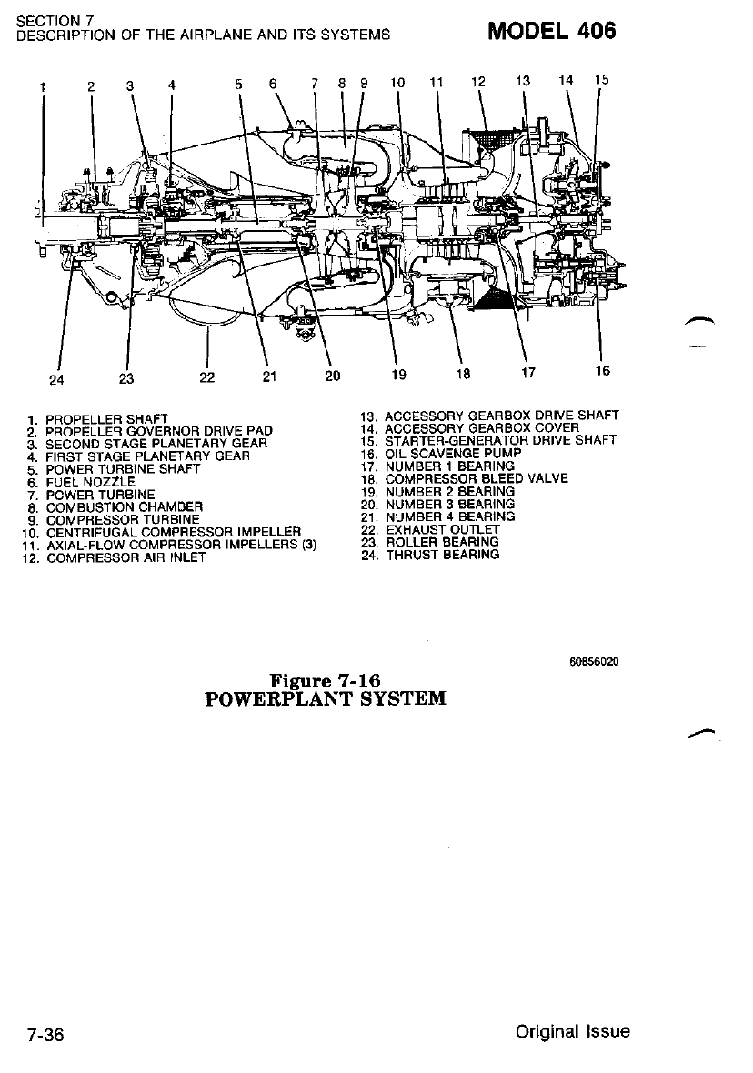
SECTION 7
DESCRIPTION OF THE AIRPLANE AND ITS SYSTEMS
I I 10 11
Figure 7-16
POWERPLANT SYSTEM
13. ACCESSORY GEARBOX DRIVE SHAFT
14, ACCESSORY OEARBOX COVER
15, STARTER-GENERATOR DRIVE SHAFT
16. OIL SCAVENGE PUMP
17. NUMBER 'I BEARING
18, COMPRESSOB BLEED VALVE
19, NUMBER 2 BEARING
20, NUMBER 3 BEARING
21. NUMBER 4 BEARING
22. EXHAUST OUTLET
23. ROLLER BEARING
24. THRUST BEARING
MODEL 406
1, PROPELLEF SHAFT
2. PROPELLER GOVEBNOR DRIVE PAO
3, SECOND STAGE PLANETARY GEAR
4, FIRST SIAGE PLANETARY GEAR
5. POWER TURBINE SHAFT
6. FUEL NOZZLE
7. POWER TURBINE
8, COMBUSTION CHAMBER
9, COIVPRESSOR TURBINE
10. CENTRIFUGAL COMPRESSOR IMPELLER
11. AXIAL.FLOW COMPRESSOR IMPELLERS (3)
12. COMPRESSOR AIR INLET
/-JO
24 23
Original lssue
Powet Level
The nower lever in the cockpit is connected through the airframe
Ii"i;;'" "d';;; ""a'i uji *."-6tv mounted in front. of t-he Fuel Control
U;;? ti; ;;"; "f ihe engine. ihe po*er control--lever controls .engine
p'"*!"-irtt"ieh-ilt" niiil""g-e from maximurn takeoff power back through
idle to maximurn reverse Power.
Plopellet Control Lever
The propeller control lever in the cockpit is connect€d throu-gh the
airframi liirkase to the propeller governor mount€d on the lorwaro
^;;tiil""f'Li;1teiti. r'h"'ptopeliit control lever controls -prop-eller
governor self,rngs lrom ttt" -aiimutn RPM position 1900 RPM to 1600
RPM and tull feather.
Fuel Contlol Level
The fuel control Iever in the cockpit is conrrected through the-air-
frame linkage to a combined lever and stop m-echanism at the top or tne
F]J-Criiidi u"ii; ihis is connected bv the tuel c-ontrol unit linkage.to
ift"" "til- i"i,aiii""'leuer o.t the side of the unit' The lever.and stop.alsg
il;";il ;-;;"idlu .top rot the tuel control unit control rod' The cockpit
iJ"". 'ili.-t*" po.itioi. onlv, R,ttt a1d Cutqff' plren !h9 tuel .control
lever is in the RUN position, the fuel control unit is set to a mlmmum
of 52 percent Nr.
Cowl Flap Cont;ol
Two cowl flap controls, refer to Figur-e ?-?, are located on the control
""d;ft;;;; ;;;tr;i fo; each engine.-These controls .are used to set the
;;;ilr;;. il anv position from f[ open to full closed' A locking feature
i."';;;;i*d",i-f- ""ich control 0o prevent inadvertent .cowl flap position
iiitii".- ti"t"tl"c- ihe conttol clocfwise engages the locking mechanism'
' Ouadrant Friction Lock
A quadrant friction lock, refer to Figure- 7-?. is p-rovided to. prevent
the three primary engine controls (six total levers) .trom creeprng onc€
thev have -been set. The locking knob (appr-oximately o-ne and one-narr
iii"t"l i"-aLt*t"r) is located ori the right side of the pedestal'
MODEL 406 SECTION 7
DESCRIPTION OF THE AIRPLANE AND ITS SYSTEMS
Original lssue
SECTION 7
DESCRIPTION OF THE AIRPLANE AND ITS SYSTEMS MODEL 406
ENGINE INSTRUMENTATION
Engine instrumentation for each engine, refer to Figure 7-?, consists
of; en-gine-torque. indicator,.propeller_ R=PM indicator, ITT indicator, N,
percent RPJVI indicator, fuel flow indicator and oil pressure/temperatuni
indicator. The indicators are placarded as to their operational param-
eters.
Engine Torque Indicatol
The torque indicator displays the torque pressure of the engine in
foot-pounds.
Propeller RPM Indicatol
The propeller RPM indicator is a tachometer which indicatcs the
propellei speed in revolutions per minute.
ITT lndicator
The interturbine temperature gage displays the air temperature in
Celsius between the compressor and power turbines.
Ns Percent RPM Indicatol
The N" RPM indicator indicates the percent of the gas generator
RPM to lurbine RPM based on a frgure of 100 percent N, at 3?,500
RPM.
Fuel Flow Indicator
The fuel flow indicator displays the flow of fuel to the engines. The
flow indicator is calibrated in pounds per hour flow. When power is
removed from the system the fuel flow indicating pointer will stow below
zero in the OFF band.
Oil Pressure/Temperature Indicatol
Oil pressure is directly measured and temperature is electrically trans-
mitted and displayed individually on a combination indicator. Oil pres-
sure is presented in pounds per square inch while oil temperature is
presented in degrees Celsius. The indicators are marked for their operat-
ing parameters,
7-38 Original lssue
ENGINE BREAK-IN PROCEDURE
There are no specific break-in procedures required for the Pratt and
Whi;;;; Cu"ia"-in". PT6A-112 ieries turboprop engines' The.e.ngnes
;;],'-[;'.J;ty "perated throughout the normal ranges authorized by the
manufacturer at the time of dellvery ot your alrplane.
ENGINE OIL SYSTEM
Engine oil, contained in an integral tank.b€tween the engine air
intake and the accessory case. cools as well 8s lubncaEs f,ne englne Jln
"l ."ai"l"t located insiiie the lower nacelle keeps the engine -oil tempera-
;,;;;-;iihi" ihJ operating limits. A thermal element is used to re-gulate
^itrJ no* of oit tlirough'the radiator. Engine oil t€mperature indical'or
si;es an instantaneou-s reading of oil temperature Engine oil also op-
irates the propeller pitch change mechanism and the engine torquemeter
syst€m.
The lubrication s'€t€m capacity per engine is 10.4 U'S. quarts. The
oil tank caDacitv is 9.2 U.S. quarh with 5 quarLs measured on the
dipstick for'addiirg purposes. Reiommended oils and oil servicing proce-
dures are covered in Section 8.
IGNITION SYSTEM
The ignition system consists of an ignition monitor - light,. ignitio.n
switch, si"art and ignition swikh, ignition excit€r, two high tensron leads
and two ignitors for each engine.
The two-oosition imition swikhes, refer to Figure ?-24' locqkd gn
tn"-ni ti,e-kirt l*a s"ia" console are ilacarded ON and NORMAL. The
ieriition switrhes should remain in th; NORMAL position for all ground
"?rti. u"a for air starts with starter assist. The ON position is to be
;;;A-";lt f- air starts without start€r. assist, heavv precipitation and
inadvertint icing encounters until inertial separators are in blpass'
' Electrical power will continuously be applied to the. ignition exciter
when the imition switch is in the ON position and the batt€ry swltch,rs
ON, and iill be terminated only when the- ignition- switch is manually
pt""itJ t" the NORMAL position, or at such lime the batte..ry..switch is
it^""a i" the OFF position. The ignition monitor lights will illuminate
it any time power is applied to the ignition exciters.
In the NORMAL position, the ignition excllep 4ll- -99! ^rJqe1v3
28vbd oowe. when th6 left or'right IGNITION AND ENGINE START
switch iir placed to the START position; however, the ignition exciters
will contiiue Lo receive 28 VDC power and the ignition monitor lights
will remain lighted even though the engine has started and tbe start
MODEL 406 SECTION 7
DESCRIPTION OF THE AIRPLANE AND ITS SYSTEMS
Original lssue 7-39
SECTION 7
DESCRIPTION OF THE AIRPLANE AND ITS SYSTEMS MODEL 406
cycle has been automatically terminated. The IGNITION AND EN-
GINE START switches must be manually positioned to the OFF pos!
tion.to inactivate the ignition exciters and to extinguish the ignltion
monllor lpnf,s.
AIR INDUCTION SYSTEM
The engine air inlet is located at the front of the engine nacelle
underneath the propeller spinner. Engine exhaust heat is utilized for
heating the engine air inlets. Hot exhaust air is picked up by a scoop
inside the left exhaust stub, plumbed through the inlet and exits through
a scoop in the right hand exhaust stub. No shutoff or temperature
indicating system is required for exhaust heated inlet.
INERTIAL SEPARATOR SYSTEM
An inertial separator system in the engine air inlet duct prevents
moisture particles from entering the compressor air inlet plenum when in
b5pass mode. Refer to Figure 7-17. The inertial separator consists of two
movable vanes and a fixed airfoil which, during normal operation, route
the inlet air through a gentle turn into the cornpressor air inlet plenun.
When separation of rnoisture particles is desired, the vanes are posi-
tioned so that the inlet aL is f6rced to execute a sharp turn in ordir to
enter the inlet plenum. This sharp turn causes any moisture particles to
separate from the inlet air and discharge overboard through the inertial
separator outlet in the Ieft side of the cowling.
The inertial separator system is electrically actuated. Normal opera-
tion of the inertial separator system while in the bypass mode is in-
dicated by green annunciator lights, L INERTIAL SEP or R INER-
TIAL SEP and a decrease in toroue and increase in ITT will also be
encountered.
The engine inlet duct is not protected by a filtering device. The
engine air inlets are protected by a screen which will prevent entry of
large articles, but does not filter the inlet air.
EXHAUST SYSTEM
The exhaust system consists of an exhaust stub fitted to the left and
right side of the engine just aft of the propeller reduction gear box. The
exhaust stubs are directed aft to utilize the remaining energy of the gases
in the form of thrust for additional aircraft propulsion.
7-40 Criginal lssue
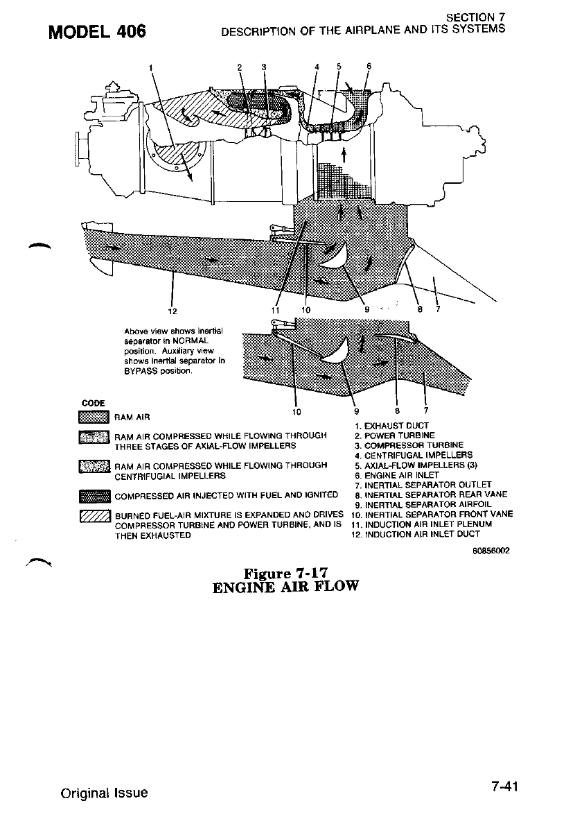
MODEL 406 SECTION 7
DESCRIPTION OF THE AIRPLANE AND ITS SYSTEMS
Abovo vl€w 6hows h€rtial
ssparator in NOBMAL
Position- Au)dliary view
shows inortal separato, in
AYPASS Position.
cooE
ffimv,un
Fll neu rtn corvpnessEo wHrL€ FLowrNG THBouqH
-
THFEE sTAGEs oF AxtAL-FLow IMPELLERS
[TSl neu etn coupnEssEo wHrLE FLowtNG TrlFouGH
-* cENTBtFUGTAL TMPELLEFS
$@ couenesseo ern rNJEcrEo wrrH FUEL ANo tGNlrEo
VVV eual,to cuet-ata MrxruFE rs ExPANDED ANo DnlvEs
-
coMpRESSoR TUFBTNE AND PowEF TlJFtalNE, aNo ls
THEN EXHAUSTED
Fisure 7-17
ENGIN-E AIR FLOW
1 . EXIIAUST DUCT
2- POWEF TUNBINE
3. COMPBESSOF TUFAINE
4. CENTRIFUGAL IMPELLEFS
5. AXIAL-FLOW IMPELLERS (3)
6, ENGINE AIR INLET
7, TNERTIAL SEPARATOB OUTLET
8. INERTIAL SEPAFAIOF REAR VANE
9- INEFTTIAL SEPAFATOF AIRFOIL
10,INENThL SEPAFATOR FFONI VANE
11.INDUCTION AIF INLEI P6NUM
12- INDUCTION AIR INL€T OUCT
604560{t2
Original lssue 7 -41
COWL FLAPS
The cowl flaps are located just aft of the inedial separator. The cowl
flaps when in the open position allows an increase in air flow through
the engine oil cooler, thus cooling the engine oil. The cowl flaps are
operated by push-pull controls locatcd on the control pedestal.
STARTING SYSTEM
Each engine is started by a three-position switch located on top of the
left side console, refer to Figure 7-23. The switch ig placarded IGNI-
TION AND ENGINE START - OFF - MOTOR ONLY. Each switch
may be placed to the MOTOR ONLY position for clearing fuel from the
engine without having the ignition circuit activated. Placing the switch
to the START position will activate both the starter and ignition exciter
which will in turn activate the appropriate IGNITION ON annunciator
Iight. When engine speed reaches 41 percent N" the start cycle will
automatically be terminated by a speed sensilg switch located in the
starter/geneiator. The starting sequehce may be-manually t€rminated at
any point during the start by resetting the toggle switch to the OFF
position and placing the fuel control lever in the CUTOFF position. The
IGNITION AND ENGINE START switches must be manuallv placed
to the OFF position to inactivate the ignition exciter and to exiiirguish
the ignition monitor light, even though the start cycle has been auto-
mati;llv terminated an-d the eneine his started.
ENGINE ACCESSORIES
All engine-driven accessories with the exceDtion of the tachometer-
generatoiand propeller governors are mounted bn the accessory gear box
located at the rear of the engine. These are driven from the compressor
by a coupling shaft which eitends the drive through a conical iube in
the oil tank center section.
Oil Pump
Pressure oil is circulated from the integal oil tank, through the
engine lubricating syst€m, by a self-contained gear t5pe pressure pump
located in the lowest part of the oil tank. The oil pump is comprised of
two gears, contained in a cast housing which is bolted to the front face
of the accessory diaphragm, and is driven by the accessory gearshaft.
The oil pump body incorporates a circular mounting boss to accom-
modate the check valve, located in the end of the filter housing. A
second mounting boss on the pump accommodates the pressure relief
varve,
SECTION 7
DESCRIPTION OF THE AIRPLANE AND ITS SYSTEMS MODEL 406
Original lssue
Fuel Pump
The fuel pump is mounted on the accessory gearbox and is driven
through .a. gearshaft and spJined coupling. The- coupling splines are
lubricated by oil mist from the auxiliary gearbox throuqh -a hble in the
gearshaft. Another splined coupling shaft-extends the drive to the fuel
control unit which is bolted to the rear face of the fuel pump. Fuel from
the airplane boost pump enters the fuel pump through dL ?a-micron (200
meshj lnlet screen, and then to the pump gear chamber from where the
fu^el is delivered at.high. pressure to t6e-fuel control unit through a
lO-micron pump.outlet lilter.. A bypass valve and cored passages in- the
pump casing enable unfillered high pressure fuel to flow ?rom ihe pump
gears to the fuel control unit whin the outlet filter is blocked. Ai-r
^'nternal _passage originating at the mating face with the fuel contrtl'unil
.eturns b5rp_ass fuel from the fuel control unit to the pump inlet down_
stream of the inlet screen. { pr_essure regulating valve in this line serves
Lo pressurize the pump gear bushings.
Hydraulic Pump
The hydraulic punp is an engine-driven constant displacement DumD
that is mounted on the accessory gear box of the engine. The bumb
9Sliyql.,u pressure^ of, t?50 poundi p=er square inch gage" and uses MIil
11-obub nyoraunc llurcl.
Tachometer - Generator - Gas Generator (Ns)
. The. tachometer-generator produces an electric cunent which is used
rn conJunction with a tachometer to indicate gas generator RpM. The
tachometer-generator drive and rnount pad is -locd-ted at the b o,clock
position on the accessory gearbox and ii driven from the int€rnal scav-
enge pump. Rotation is counterclockwise with a drive ratio of 0.112;1.
Tachometer - Generator - Power Turbine (Nt
-- Tn" polvgr turbine tachometer-generator operates in the same manner
as.lhat of the gas generator. However, t]re turbine tachometer-generator
dnve and mount pad is located on the right side of the reduction
gearbox case and rotal.es clockwise with a drivi ratio of 0.12?8:1. pronel_
ler rpm (No) is directly proportional to power turbine speed (Nj'Lv
taling into account the reduc[ion raLio in the reduction- gear box of
0.0575:1.
MODEL 406 SECTION 7
DESCRIPTION OF THE AIRPLANE AND ITS SYSTEMS
Original lssue 7-43
SECTION 7
DESCRIPTION OF THE AIRPLANE AND ITS SYSTEMS
Torque Transducer
The torque tralsducer indicating system is a measuring device which
provides an accurate indication of the torque being produced by the
power turbine. The torque tranducer receives a high and low oil pressure
input and converts the differential pressure into an electrical voltage
which is the input to the engine torque indicator-
Electrical Power Source
Electrical power is supplied by two 28 Volt DC 250 ampere engine
driven starter/generators. One 24 volt nickel cadmium battery is installed
for starting and emergency requirements. A receptacle has been provided
on the lower fuselage aft of the cabin entry door for connection of an
external power unit.
Engine Overspeed Governol
Engine overspeed governing is controlled by the primary propeller
governor -and the fuel metering unit._In the.event of a power turbine
overspeed condition, a goveming orifice in the primary propeller gov-
ernoi is opened by flyweight action of the propeller governor, to bleed off
compressor discharge pressure through the governor and computing sec-
tion of the fuel control unit to the atmosphere. When this occurs.
comDressor discharee pressure acting on the fuel control unit governor
bellows decreases a--nd- moves the mitering valve in a closing illection
thus reducing fuel flow to the flow divider.
Propeller Overspeed Governol
A propeller overspeed governor, mounted on the left side of the
reductjon gear housing, acis as a safeguard against propeUer overspeed
should the-primary propeller governor tail. The propeller overspeed gov-
ernor regulates the flow of oil to the propeller pitch-change mechanism
by means of a flyweight and speeder spring arrangement similar to the
primary propeller governor. Since it has no nechanical controls, the
bversoied- eovernoi is equipped with a t€st solenoid that resets the
gouetnot bilow it's normal overspeed setting for ground test. The over-
ipeed governor test switch is located on the left side console.
Propeller Synchrophaser
The propeller synchrophaser, refer to Figure ?-18 automatically
matches RPM of the two engines and allows the pilot to select any
desired nhase relationship between the two propellers. The RPM of one
eneine will follow chansei in the RPM of thi otier engine over a limited
raige. This limited range feature prevents either engine from losing more
thai a fixed amount of RPM in case the other eng'ine if feathered with
the synchrophaser ON. In no case will the RPM follow below that
MODEL 406
7-44 Original lssue
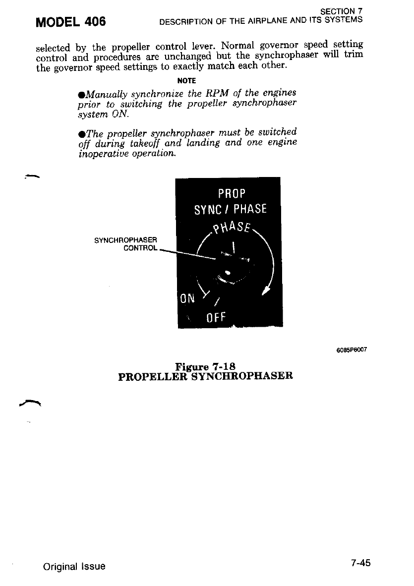
MODEL 406 SECTION 7
DESCRIPTION OF THE AIRPLANE AND ITS SYSTEi'S
6085P0007
selected bv the propeller control lever. Normal governor speed.s-etting
;;;ili ";'d pi""-"aG". are unchanged but the .svnchrophaser will trim
the qovernor speed settings to exactly match each other'
NOTE
OManually synchronize Lhe RPM of the engines
prtor to suttchlng the propeller synchropho'ser
'system ON.
oThe propeller synchrophaser must be suitch.ed
off duiing taheoff and lnnding and one enElne
inope ratiue oPe ratton.
SYNCHROPHASER
CONTROL
n*o"r""rsti'J".tii,oPr{AsER
7-45
Original lssue
SECTION 7
DESCRIPTION OF THE AIRPLANE AND ITS SYSTEMS
Interturbine Temperature Sensing System (T5)
The interturbine temperature sensing system (Ts) is designed to pro-
vide the operator with an accurate indication of engine operating tem-
peratures taken at a point between the two turbines. The system consists
bf twin leads, two bus bars and eight individual chromel-alumel ther-
mocouple probes connected in parallil. Each probe protrudes through a
threadid bbss on the power turbine stator housing into an area adjac€nt
to the ieading edge of the power turbine vanes" The probe is secured to
the boss by rneans of a flbating, threaded fitting which is part of the
thermocouole probe assemblv. Shielded leads connecL each bus bar as-
sembly to a teiminal block ;hich provides a connecting point for exter-
nal leads to a cockpit instrument.
ENGINE SHOCK MOUNTS
Each eneine is elasLomericallv mountrd to engine trws at thTee
points. The- truss attaches to thC wing leading edge and aft nacelle in
four places.
FIRE DETECTION AND EXTINGUISHING SYSTEM
Each engine fire detection and optional extinguishing syst€m consists
of two hea:t sensors located in the engine compartment, a compressed
sas, single-shot fire bottle located in the main gear well and two
innunciator/actuators located on the annunciator panel.
When the annunciator panel PRESS-TO-TEST button is pressed, the
frre warning lights should illuminate. During normal operation, if an
overheat co;dition should occur, the applicable fire warning light will
illuminate. Lifting the clear plastic covei guard and pressing the red fire
annunciator will ilose the blied air valve,-fuel firewall shutoff valve and
disable the generator and arn the optional fue extinguishing system.
Pressine thi white fire bottle armed light will deploy the fire extin-
zuisheriontents into the engine compartment. After the engine compart-
ment cools, the red fire warning light will extinguish.
r{OTE
For operati,on with one bLeed air shutoff uaLue
cLosed. or one eng,Ine Lnoperattue, pouer a,oue
flight idte may b.e required on th.e operating
englne to malntaln gyro pressure Ln tne Sreen
arc.
PROPELLER
The airplane is equipped with all-metal, three-bladed, constant-speed,
full-feathe;ing. single-.aiiing, governor-regulated propellers. Each Propel-
ler utilizes oil pressure which opposes the force of springs and coun-
terweights to obtain correct pitrh for engine load. Oil pressure from the
MODEL 406
7-46 Original lssue
SECTION 7
DESCRIPTION OF THE AIRPLANE AND ITS SYSTEMS
propeller governor drives the blades toward low- pitch (increasine RPM)
while the sprtngs and -""t"*"iinit Jtiu" blides toward high pitch
ia'"li"uiin*-iit'tfi). The source of oil pressure lor propeller operatron rs
pirt'$"$J'"11""",$';il:J:'n:"r;i:fi :l"tJtfilffi i",'*"\'"-r,:'.m1
flange.
To feather the propeller blades. the prr-'peller. control levers on lhe
.""r.inf "-"d""ui- *.i"t b" piu."d in ine tedtndr position' Unfeathering the
iYi,"i,ii"ili *.i-iitlihediv positio"ing the propeller control lever to the
'-itii*u- or higher RPM position. The unleaihering. sJstem uses engrne
oil oressure to -force the propeller out ol teather and lnto the low plf,cn
Jondlf,ron.
* An autofeathering system provides for automatic featherine of a nro-
o"li;'-*l;;-"*;L 3r r""* "i Ti'-"- i''gid. :ry'" iv"i"* is- contr;llqbi an
;;iil';;i;i ;iih ARM, oFF and" TEST poiitions ln..the oFF po:i-
ii6,i,'fn" .v.j"rn i. a"u"ii*t"a. In ARM, the'.propeller ^will automaticallv
i"attie. it enqine torque drops below approximaiely I85 foot-pounds at
i,*iii-t"""i ii6"itions'of 80 percent N, bi greater' .Aut'o feathering o-fone
iioo"ff"l' dis'aims the svstem on the bther propeller' L and R AUTO-
f'TftER AiiN,i ;;nu,i.litot lights will illumiirati when svstem is armed'
tnst i. a momentary posit"ion and providgs for a check out of the
.".t"ir iiltr il"*"i u"iooi eo percent N. The svstem is primarilv in-
tinded for use during I'akeoff and climb
Reversed propeller pitch is available for increased- landing ground roll
"tmiii* ""J"uitiiv. t'o accomplish reverse pitch, the lower levers are
;Hi,i;e #;;;J ibt-B ou"' Lhi gare and inio the BETA position Full
i!i?il"iiti'1" ii-"i""r"pti.i"a ilv i.iutaing rhe power levers- to lhe MAX
iiEVbFFbl;'(ion. tontrol "of propeli-er spied.. is .achieved t'hrough
il""i-"i"Jt-ut!i" iitciu.-4" "*r"tn"itv gtooved feedback ring is. provided
with the oropeller. Motion of l"he feedback ring is proportronal l'o propel-
i;;'Li;;""';Gi;,- and'G picked up bv a car6on -bloik.running in" the
feedback rine. The relationship between the axral posrtron ol tne reeo-
il;'i;;;s';;t lti" piop"ttut biade angle is used to maintain control of
--blade
anele from flight idle to full reverse'
MODEL 406
THE PROPELLER REVERSING LINKAGE
CAN BE DAMAGED IF THE POWER LEVER
IS MOVED AFT OF THE IDLE POSITION
wiPW TNN ENGINE 1S NO" RUNN/NG
AND THE PROPELLER IS FEATHERED.
'| June 1987 7 -47
Overspeed Governor Test Switch
An overspeed governor test switch is located on the left side of the
instrument panel. The switch is the push-to-t€st type and is used to test
the propellei overspeed governor during engine run-irp. The switch, when
depressed, actuates a solenoid on the propeller overspeed governor which
restricts propeller RPM when the powei 'lever is advanced. To check for
proper operation of the overspeed governor, during engine run-up, de-
press the press-to-test switch and advance the power lever until propeller
RPM stabilizes; propeller RPM should not exceed 1725 +50 RPM.
FUEL SYSTEM
The fuel system, refer to Figure 7-19, consists of left and right fuel
tanks, crossfeed systcm, engini fuel sys'tem, quantity and flow- instru-
mentation and necessary lines, controls, valves, pumps, etc., to complete
the systern.
FUEL TANKS
The fuel tanks are an integral portion of the sealed wet wing. Each
t^''- .' :pplies fuel to its respective engine for all operations except
- Jrsteedrng.
Each fuel tank contains a fuel filler, feed and vent lines, fuel quantity
measudng systems, drain valves, a hopper tank, transfer ejector pumps,
main ejector pump, electric boost pump and other required hardware to
cornplete the system
Each fuel tank is serviced through a flush filler located in the top
outboard surface of each wing.
The funnel-shaped hopper is located in the inboard end of each main
tank, see Figure 7-20. The hopper tank is supplied from the remainder of
the wing tank by either gravity flow or by transfer ejector punps.
The transfer eiector DumDs. located in the forward and aft inboard
end of each fuel iank. tianslei fuel from the lowest points of each fuel
tank to the hopper. These ejector pumps utilize existing fuel pressure in
conjunction with a venturi to produce a high-volume flow. As the high
preisure fuel (motive flow) is ?orced throuth the ejector orifice, a low
pressure area is created at the pump inlet, drawing in a comparatively
larse volume of fuel and Dushins it out at low pressure. Molive flow for
opdration of the transf€r ijector-pumps is provided whenever the respec-
tive auxiliary boost pump is in operation. Scavenging of fuel from the
lowest ooints of each fuel tank ensures the maximum usable fuel in all
normal-fl ight attitudes.
SECTION 7
DESCRIPTION OF THE AIRPLANE AND ITS SYSTEMS MODEL 406
7-48 Original lssue
The amount of unusable fuel is mininal due to the design of the fuel
.uri"-.E"i". io Section 2, Fuel Limitations, for rnaximum unusable fuel
quantity and flight conditions'
Durinq normal or one engine inoperative flight operations. fuel can be
,,."d fto"tt either tank thr6ugh th-e use of the fuel crossfeed selector
switch. If crossfeed operation-is initiated with nearly -fu fuel tanks, it
-usi be re^embered ihat during crossfeed operation the excess fuel not
reorrired bv the encines (500 to -800 pounds per hour) will be transferred
reouired bv the encines (500 to 600 pounds per hour) will be transf€rred
tn ihe ono-osite fueI tank. The unused tank quantitv should be monitored
to-t}re-onp"osite nrei tank. The unused tank quantity should be monitored
to nrev#t overflow. Use of fuel from the right and left tanks alternately
wili maintain fuel balance.
-nRAtN VALVES
Two drain valves are located in the lower surface of each fuel tank,
one in each crossfeed line and one in each fuel filter. The valves allow
drainins of sediment, moisture and/or residual fuel ftom the tank, Iilter
and crossfeed lines. The sprins-loaded poppet is housed in the drain
valve bodv and is spring-lodded-to the close<i position. A slot in the end
of the driin valve allows for a phillips-screwdriver operation of the valve
to the OPEN position.
FUEL INDICATING SYSTEM
The fuel quantity indicating system consists of left and right fuel
quantity systdm. _ The- system. is.a capac.itance, tePperature compensated
svstem. F.lach wlnq tuel tank rs gaged separarcIy Dy lne ruer prooes,
l6cated in the wing tank and hopper tank. The fuel probes are connected
to the signal con-ditioner in tf,e wing and - then to the fuel quantity
indicator on the instrument panel. Each fuel quantity gage operates on
28 VDC power supplied through circuit breakers. There are five fuel
probes locited in each wins fu;l tank, four in the outboard wing tank
and one each hopper tank. The fuel quantitv indicator is calibrated in
nounds and will iridicate the weieht of fuel cbntained in each fuel tank.
r-rThe indicator reads from 0 - 18;00 pounds fuel quantity with an OFF
position located under the zero pounds marking' When electrical power
is removed from the indicator the needle will indicate the OFF ra.nge.
The fuel flow is metered bv the fuel control unit and is indicated irr 10
pound increments with a iange from 0 - 500 pounds of fuel flow per
nour.
FUEL PUMPS
Main ejector pump and auxiliary.DC boost pump are located in the
bottom of each hopper tank, ensuring an adequate fuel supply to,the
selected. engine(s). The^ main ejector pump is operated by motive tlow
supplied continuously from the engine fuel control whenever the engine
MODEL 406 SECTION 7
DESCRIPTION OF THE AIRPLANE AND ITS SYSTEI'S
Original lssue 7-49
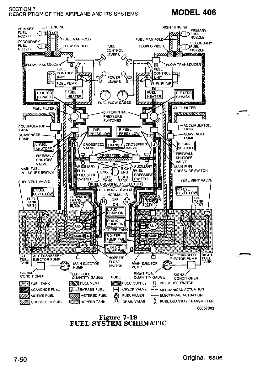
sEcTtoN 7
DESCBIPTION OF THE AIRPLANE AND ITS SYSTEI,'IS
PFIMABY LEFT ENGINE
NOZZLE
MODEL 406
FIGHT ENGINE
NOZZLE
NOZZLE
FUEL
MFUEL IANK
ffisclveree ruer
@uoreruet
@cFossFEEo FUEL
NIFUEL vENr
EBYPAss FUEL
ffiMETEB€o FUEL
ffilNoeeea terx
RIGHT FI.)EL:
cooE ouaNr|ryc^lrcE Zdr,iijiirorea
Mruel supprv ! PREssunE swrrcH
':_
I:J CHECK VALVE -- MEoIIANICAL ACTUATION
O FuEr nrL€F - ELEcrRrcaL AcruA-fioN
rs oFArN vALvE tr FUEL ouANTrrY TFANSMTTEn
60857003
7-50
",ru" "#flh'fi66frr*tt"
Original lssue
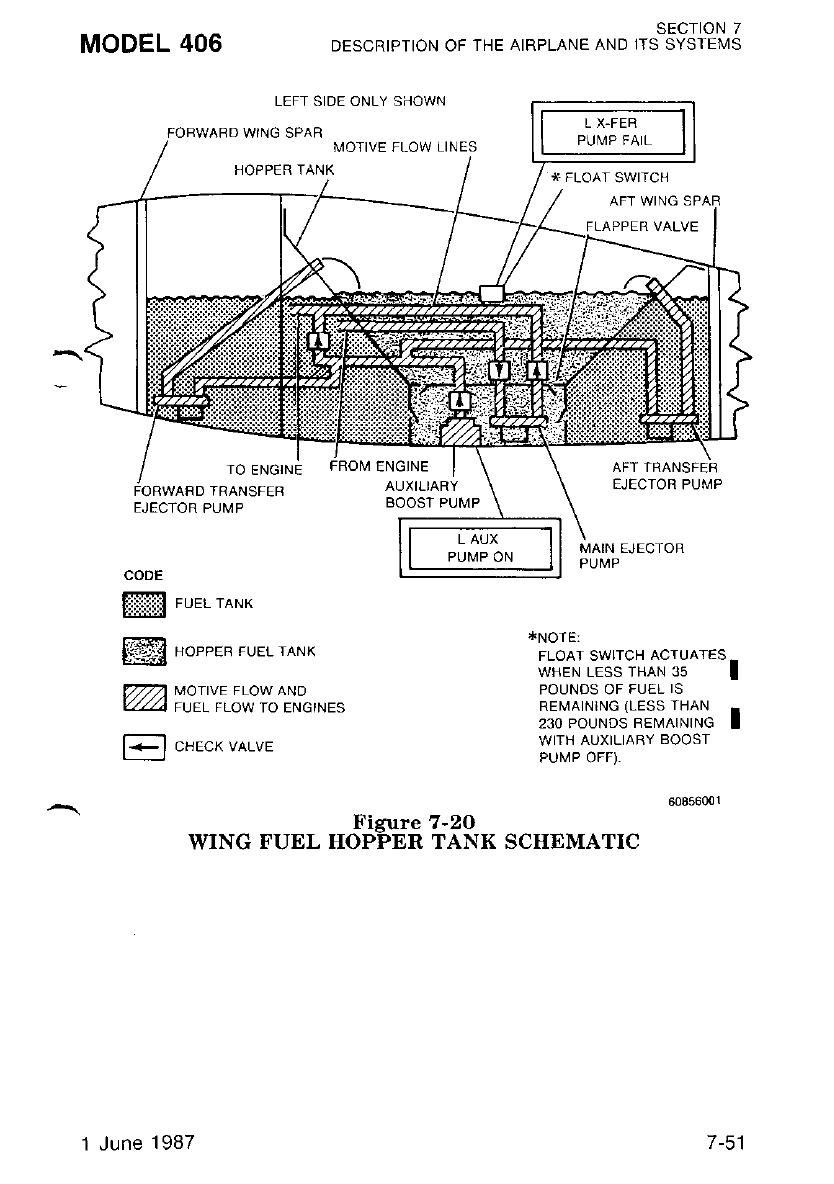
MODEL 406 SECTION 7
DESCRIPTION OF THE AIRPLANE AND ITS SYSTEMS
LEFT SIDE ONLY SHOWN
WING SPAR I\,4OTIVE FLOW LINES
HOPPER TANK * FLOAT SWITCH
VALVE
EJECTOR PUI\,4P
FUEL TANK
HOPPER FUEL TANK
MOTIVE FLOW AND
FUEL FLOW TO ENGINES
CHECK VALVE
AFT TRANSFER
EJECIOR PUMP
*NOTE:
[,'"?JSt'J?[ffiI8^"'l
POUNDS OF FUEL IS
REMAINING (LESS IHAN -
z:o pouruos nevnhttlG I
WITH AUXILIARY BOOST
PUIVP OFF),
TO ENGINE
D TRANSFEB
MAIN EJECTOR
CODE
ffi
r'ERat
tii.i-l1
m
E
Figure 7-2O
WING FUEL IIOPPER TANK SCIIEMATIC
1 June 1987 /-c I
SECTION 7
DESCRIPTION OF THE AIRPLANE AND ITS SYSTEIUS MODEL 406
is operating. The ejector pumps do not have sufficient flow and pressure
capacity for crossfeeding or supplying the transfer ejector pump motive
flow. The auxiliary DC boost pump supplies fuel to ils respective engine
in the event of main ejector pump failure or when using aviation
gasoline, to sup^ply motive flow.tb thi transfer pumps^at.low fuel levels,
ind to supply fuel for crossfeed operations. Failure of either pump will
be indicatid by illumination of the applicable left or right FUEL PRESS
LOW annunicator light which is activated by separate main ald auxil-
iary pressure switches.
THE AUXILIARY BOOST PUMPS SHOULD
NOT BE OPERATED UN'ESS SPECIFICAL-
LY REQUIRED FOR THE OPERATION BE-
ING CONDUCTED SINCE INADVERTENT
DEY BUNNING OF THE PUMPS WILL
DAMAGE THEM,
The two three-position boost pump switches, one eac-h for left and
rieht fuel svstems are located on ihe l-eft console. When the switch is in
N-ORMAL bosition, with crossfeed off, the main ejector pump operat€s
and the auiiliary boost pump does not operate but the circuitry is armed
lo automatically activad thd auxiliary bdost pump after a 3-second delay
when the maii fuel pressure switch senses low pres-sure' or when the
honner float swikh senses a low fuel level. When [he boost pump switch
is iil NORMAL position, with crossfeed ON, both main ejector pumps
operaie, the auxiliary boost pump in the feeding tank operates and the
aiixiliary boost pump in th6 non-feeding tank does not operate. OFF
position on the boosi pump switch operates the main ejector pump and
the auxiliary boost pump -does not operate. ON position operates the
main eiectoi pump and [he auxiliary boost pump. The scavenger pump
operate! whenevei the boost pump switch is in the ON position.
ftotE
Each main ejector pump operates continu,ously
when its respectioe engtne is runninE., When a
rnain punvp ond an aux pump tre both operat-
ing simultaneouLy, whether during nor.mal op'
eration or crossfeeding, the pressure frorn the
aux putnp is sufficient to ouetide the main
nump. causinP its discharle chech uaLue to close
'and'its motiue flow to-dump into the tank
through the ejecL6r pump inlet.'
I -CZ Original lssue
DESCRIPTION OF THE AIRPLANE AND $SS59J+OE[3
VENT SYSTEM
*ffi$$ffiffiffijffiffi:ffi
CROSSFEED SYSTEM
,r**:nr'ti"in'rTlks'#b:#:ff; *Jft i,TH;t:;
;,;-".1,,,"-,'.ff {-a+i'gt'{*{+g",|',"H*1*itr:,t*1"",i":f,#i
$:i*"{i*-:'i*#Jilslhlxi"ff 'fri\*l'i;":i#tr"'ix*Lffi1""
wmmwgmg'ruw
crossfeed operatlon'
mHff**H*g*ffiffi
crossfeed operatlon'
MODEL 406
^-r^i-al lcer lA
SECTION 7
DEscRtprioN oF rHE A|RPLANE ANo trs sysrEMs MODEL 406
FIREWALL SHUTOFF VALVE SWTCHES
j';f, lil:?iffi-:l,i*&1xf #'B;?*',:,i"ffi o.Tffiyd:,"Jlilxiffi :
FUEL FLOW GAGES
;:#n""';;"fu ifr "fi
il{if; :+;;ig:;i:il{";#}ff $H,:r".:*"*$
FUEL QUANTITY GAGE
-,%lr,:r"u**r#,+,rq***r[ffi
trUEL LEVEL LOW WARNING LIGHTS
i;p$;;p$5t5$:'#E jr,,iiht"+'tmjfuH,,#;,i-1!
NGINE FUEL SYSTEM
*N*#$NS+.n*-:*-k-"#t't*ffi
n+**l:**e*i*qn*tffit*
Orioin.l r-^..-
A fuel scavenge system is provided for the recovery of excess fuel
contained in the engine fuel -manifold after engine shutdown, Upon
engine shutdown, excess fuel gravity feeds from the flow divider drain
valive into a canister. Whenevdr tht fuel boost pump switches are posi-
tioned to ON, as in the next engine start, the scavenge pump will
ope-rate and pump this fuel from the canister back into the main fuel
f,anKs.
Fuel Heatel
An oil to fuel heat exchanger heats the fuel supply to facilitate proper
operation of the fuel control unit. Fuel heater operation is automatically
^ controlled by a thermostatic bypass valve.
Fuel Conlrol Heaters
Electrical heating elements are provided to prevent moisture freezing
in the fuel control syst€m pneumatic sensing lines. The heaters are
controlled by switches, one for each engine. Heaters should be on for all
engine operations.
HYDRAULIC SYSTEM
The hydraulic system, refer to Figure 7-21, supplies hy&aulic pressure
to the landing gear and wing flap systems which are electrically con-
trolled and hydraulically actuated. Refer to Wing Flaps System and
Landing Gear System in this section for a cornplete description and
operation of their respective systems. For malfunction of the hydraulic
system, refer to Section 3, Emergency Procedures.
Hydraulic pressure is supplied by the hydraulic pump which is moun-
ted on each engine. The hydraulic resewoir, located in the nose baggage
compartment, refer to Figure 7-22, incorporates a sight gage for checking
the fluid level while the gear is extended.
The hydraulic system also includes a hydraulic pressure light and a
left and right hydraulic low flow light, refer to Figure 7-9. The HYD
PRESS ON indicator light will remain illuminated until the wing flaps
reach their selected position and/or the landing gear is locked into
selected position. The L and R HYD FLOW LOW Iights illumjnate in
the eveni of a hydraulic pump, Iine failure or low ?low (low engine
RPM).
MODEL 406 SECTION 7
DESCRIPTION OF THE AIRPLANE AND ITS SYSTEMS
Original lssue 7-55
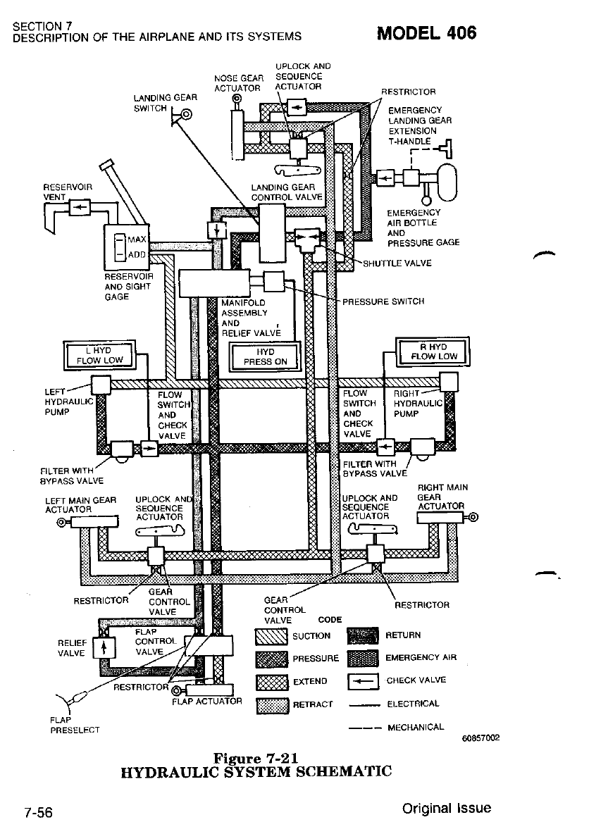
SECTION 7
DESCRIPTION OF THE AIRPLANE AND ITS SYSTEMS MODEL 406
FESTBICTOB
UPLOCK ANO
NOSE GEAR S€OUENCE
ACTUATOF ACTUATOR
LANDING GElAR
EMERGENCY
TANOING GEAR
EXTENSION
T.HANDL€ N
r-5
EMEAGENCY
AIR BOTTLE
ANO
PRESSURE GAGE
PFESSUBE SWITCH
SESTFIICTOR
FIIGHT MAIN
SEOUENCE
CONTROL
VALVE CODE
Nl sucrror
ffi enessune
ffil exr.ro
ffi nernecr
PRESELECT
ffi nerunn
@ eueneercv etn
[l cnecx verve
-
ELECTNrcAL
_-- MECHANICAL
00857002
7-56
Figure 7-21
HYDRAULIC SYSTEM SCIIEMATIC
Original lssue
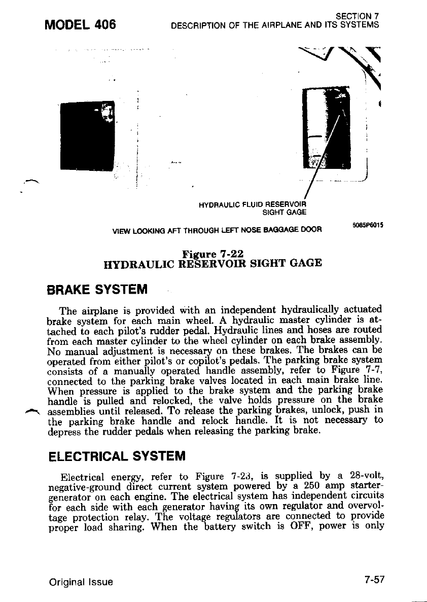
MODEL 406 SECTION 7
DESCRIPTION OF THE AIRPLANE AND ITS SYSTEMS
I
l ---
iW,
HYOFAULIC FLUID RESERVOIR
SIGHT GAGE
VIEW LOOKII'IG AFT THROUGH LEFT NOSE BAGGAGE DOOR
Fierure 7 -22
IIYDRAULIC RE_SERVOIR SIGHT GAGE
BRAKE SYSTEM
The airplane is provided with an independent hydraulically actuated
brake gvstem for eich main wheel A hydraulic master cylinder is at-
tached io each pilot's rudder pe&l.- Hydraylic lines and hoses are routed
from each master cylinder to the wheel cylinder on each b'"Le assemb-lv
No manual adiustnient is necessary on these brakes' The brakes can be
ooerated from iither pilot's or copilot's peda.ls. The parking brake system
consists of a manually operated handle assembly, refer to Figure -7-7,
connected to the parkine-brake valves located in each nain brake line.
When oressure is'applied to the brake system and the parking brake
handle'is oulled an-d- relocked, the valve holds pressure on the brake
assemblies until released. To releas€ the parking brakes, unlock, push in
the oarking brake handle and relock handle. It is not necessary to
depriss the-rudder pedals when releasing the parking brake.
ELECTRICAL SYSTEM
Electrical energy, refer to Figure ?-2J, is- supplie4 by a 28-volt,
nesative-ground diiect current syitem powered by a 250 qmp starter-
gefierator"on each engine. The el6ctrical system has independent circuits
ior each side with ea;h generator having its own regulator and overvol-
tase nrotection relav. TIie voltage rezuIators are connected to provide
pr:opei load sharing. When the -batte-ry switch is OFF, power is only
Original lssue I.JI
provided to select items by the emergency bus. These itens include the
disital clock, cabin and cockpit lighting, optional nose baggage area
lis-htins and nacelle baqaage liehtine. In addition, a "frequency memory"
v5ltaee- is provided to eacf, nav, com, ADF and optional ARC RNAV io
rehi; theii respective frequency memories. Generator failure lights,, bat-
tery overheat lighLg and system voltmeter and ammeterc are provided to
allow electrical system monitoring.
{otE
Ensure all circuit breakers are engaged an'd ser-
uiceable fuses are installed before aLl flights.
Neuer operate with any bbwn fuses or disen-
paeed circuit breaheis withoitt a thorough
hiowledge of the consequences-
BATTERY
A 39 ampere-hour nickel-cadmium battery is located in the right nose
bagqage compartment under the upholstered floor panel. Access to the
bal6r! disconnect is gained by folding back the carpeting and opening
the access door.
Startins the enqines with an external power source is a highly recom'
mended piactice that should be exercised whenever possible to prolong
the life irf the battery and to conserve battery power for times when
battery skrts must be accomplished. When it is anticipated that the
aimlaire will be idle for a period of more than two days, it is advisable to
disionnect the battery to prev-ent frequency memory ^circuits or other
equipment that may be powered by the-emergency bus from draining the
briitery. Installed equipment cont€ining frequency memory circuits must
be reset any time the battery is disconnected as the loss of electrical
power will disable the memory function.
Proper c_are..of the^ battery is extremely important and will normally
ensure availability of adequate cranking power for engine starts. The
batterv should be inspected and serviced in accordance with require-
menti defined in the Airclane Maintenance Manual, which specify that
the electrollte must be checked every 50 flight hours, and the battery
must be reConditioned every 100 flight hours. Operating conditions that
require numerous starts. and short engine operating times may necessi-
tat€ more frequent servicing of the battery to maintain peak efficiency
and to prolong battery life.
BATTERY AND GENERATOR SWITCHES
Separate battery and generator switches, refer to Figure 7-24, are
provided as a means of checking for a malfunctioning generator circuit
ind to permit such a circuit to 6e turned off. If a generator circuit fails
or malfunctions, or when one engine is not running, the switch for that
sEcTloN 7
DESCRIPTION OF THE AIRPLANE AND ITS SYSTEMS MODEL 406
7-58 Original lssue
MODEL 406 sEcT|oN 7
DESCRIPTION OF THE AIRPLANE AND ITS SYSTEMS
generator should be turned off. Operation should be continued on the
functioning generator, using only necessary electrical equipment. If both
generator iiicuits should -malfrinction, equipment can be operated at
ihort intervals on the battery alone. In eiih6r case, a landing should be
made as soon as practical to check and repair the circuits.
GENERATOR CONTROL UNITS
The generator control units regulate the starter-generator modes of
operation. Below 41 percent RPM, each starter-generator operat€s as a
starter. Above 41 percent RPM, each starter-generator operates as a
generator. Should a generator exceed the normal operating voltage, the
^. generator control unit will take the affected generator off the line.
VOLTMETER AND AMMETERS
A voltmeter and 2 ammeters, refer to Figure 7-?, are located on the
left stationary instrument panel. These indicators continuously display
bus voltage and right and left generator output in amperes. A two--
position selector switch (spring loaded to L GEN). adjacent to thel
voltmeter and ammeters, allows left generator output or battery chargel
rate to be displayed. ln the normal position (L GEN). the left ammeter
displays left generator output. In the BATT position, the left ammeter
will display battery charge rate.
CIRCUIT BREAKERS. SWITCH BREAKERS AND FUSES
Electrical systems in the airplane are protected by push-to-reset type
circuit breakers or switch breakers, refer to Figure 7-24. Should an
overload occur in any circuit, the resulting heat rise will cause the
controlling circuit breaker to "pop" out, opening the circuit or allowing
the switch breaker to return to the OFF nosition. After allowine to cool
for approximately three minutes, the ciriuit breaker may be pirshed in
(until a click is heard or felt) or the swikh brealer may be returned to
- the ON position to reenergize the circuit. For identification, deice ard
^ anti-ice Ereakers are capped in green. Fuses, located in the nose section,
prot€ct the emergency bus circuits.
SPARE FUSES
Spare fuses are located in a spare fuse bag located under the battery |
dooi in the nose section. Refer to Section 8 fdr fuse location, applicatiori,l
and changing instructions. Installing fuse limiters requires use of specific
torque. Refer to the Airplane Maintenance Manual for torque values.
1 June 1987 7-59
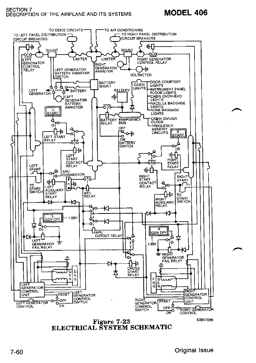
sEcTroN 7
DESCRIPTION OF THE AIRPLANE AND ITS SYSTEI,|S
TO AIB CONDITIONING
TO FIGHI PANEL OISTRIBUTION
BNEAK€BS
MODEL 406
TO oE|CE CtRCUtTS
IO LEFT PANEL
7-60
r"u"r*r"ofl t5$!"t6tff scHEMArrc
Original lssue
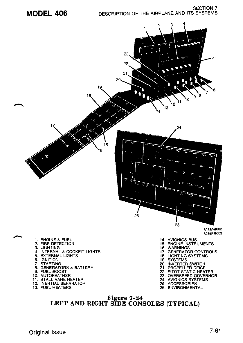
MODEL 406
1. ENGINE & FUEL
2. FIRE DETECTION
3, LIGHTING
4. INTERNAL & COCKPIT LIGHTS
5, EXTERNAL LIGHTS
6, IGNITION
7. STARTING
8. GENEBAIORS & BAITERY
9. FUEL BOOST
10. AUTOFEATHER
11. STALL VANE HEATER
12. INERTIAL SEPARATOR
13. FUEL HEATERS
6085P6002
6085P6003
14_ AVIONtCS BUS
15. ENGINE INSTRUMENTS
16. WARNINGS
17, GENERATOR CONTROLS
18, LIGHTING SYSTEMS
19. SYSTEI,S
20, INVERTER SWTCH
21. PROPELLER DEICE
22, PITOT STATIC HEATER
23, OVERSPEED GOVERNOR
24, AVIONICS SYSTEMS
25, ACCESSORIES
26. ENVIRONMENTAL
sEcTtoN 7
DESCRIPTION OF THE AIRPLANE AND ITS SYSTEMS
Figtre 7-24
LEFT AND RIGHT SIDE CONSOLES (TYPICAL)
1211
Original lssue 7-61
sEcTloN 7
DESCRIPTION OF IHE AIRPLANE AND ITS SYSTEMS MODEL 406
AC POWER
The AC system consists of a dynaverter used to power avionics
equipment. The dynaverter, located in the nose avionics compartment, is
utilized to change 28 VDC to 26 and 115 VAC 400 Hz for operation of
avionics equipment. The AC power is supplied to the autopilot or
optional IFCS, Attitude Ggo and the RMI. Other optional systems
using AC have separate inverters.
The AC system is controlled by the inverter switch, located on the left
side console, refer to Figure 7-7. An AC FAIL light on the annunciator
panel indicates AC power malfunction.
EXTERNAL POWER RECEPTACLE
Arr external power receptacle is installed on the bottom of the fuselage
just all of the main cabin door. The receptacle accepts a standard
exf,ernal power soulce plug,
LIGHTING SYSTEMS
EXTERNAL LIGHTING
The airplane is equipped with three navigation lights, two retractable
landing lights, a taxi light, two anti-collision lights, two optional wing
deice lights, two optional wing tip recognition lights and two optional
oscillating beacon ground recognition lights. Refer to Section 8 for
specific light bulb information.
All exterior lighting should be checked for proper operation before
night flying. Cockpit recognition of operational exterior lighting can be
determined by looking for ground illumination or reflections on the
ground by the various lights.
Navigation Lights
The navigation lights are located in the tailcone stinger and in each
wing tip assembly. These lights are energized with the navigation lights
switch breaker on the side console, refer to Figure 7-24. Prcpet operation
can be checked by observing illumination on objects surrounding the
wing tips to ensure the lights are illuminated.
7-62 Original lssue
Landing Lights
The retractable landing lights are located in the lower surface of the
wing tips. These lights are ixtended, retracted and illuminated by the
Iand-ine- lieht switcfi breaker on the side console, refer to Figure 7-24.
With Ihe-switch positioned to LGT LT EXT, the landing lights will
extend and illuminate. In the OFF (center) position, the lights will
remain extended but will not illuminate. In the RETRACT position, the
liehts will retract flush with the respective wing tip. It is recommended
ti'at the landing light extension speed be limited to 180 KIAS to
improve the landing light service life.
Taxi Light
The taxi light, attached to ihe nose gear, provides adequate illumina-
tion for nighi taxiing. The taxi light"is controlled by -the taxi light
switch breaker on the side console, refer to Figure 7-24.
Anti-Collision Lights
The anti-collision lights, with individual power supplies, are located in
the wing tips. These lights are actuated by the anti-collision light switch
breaker on the side console, refer to Figure 7-24.
NOTE
Do not operqte the anti-coL\i.sion lights in con-
ditions of fog, cloud.s or haze as the refLection of
the lisht beam can cause disorientation or uer-
tigo. -
Wing Deice Lights
The optional wing deice lights are installed in the outboard side of
each engine nacelle and illuminate the outboard wing leading edge deice
boots. The lights allow the pilot to check for ice accumulation on the
wing leading edges. The lights are actuated by the deice light switch
breaker on the side console, refer to Figure 7-24.
Wing Tip Recognition Lights
The optional wing tip recognition lights, if installed, are located in the
outboard leading edle rif the "wing tip.-These lights are controlled by the
recognition lighl sw'itch breaker 6n ihe left sidi console, refer to Figure
7 -24.
MODEL 406 SECTION 7
DESCRIPTION OF THE AIRPLANE AND ITS SYSTEMS
1 June '1987 /-oJ
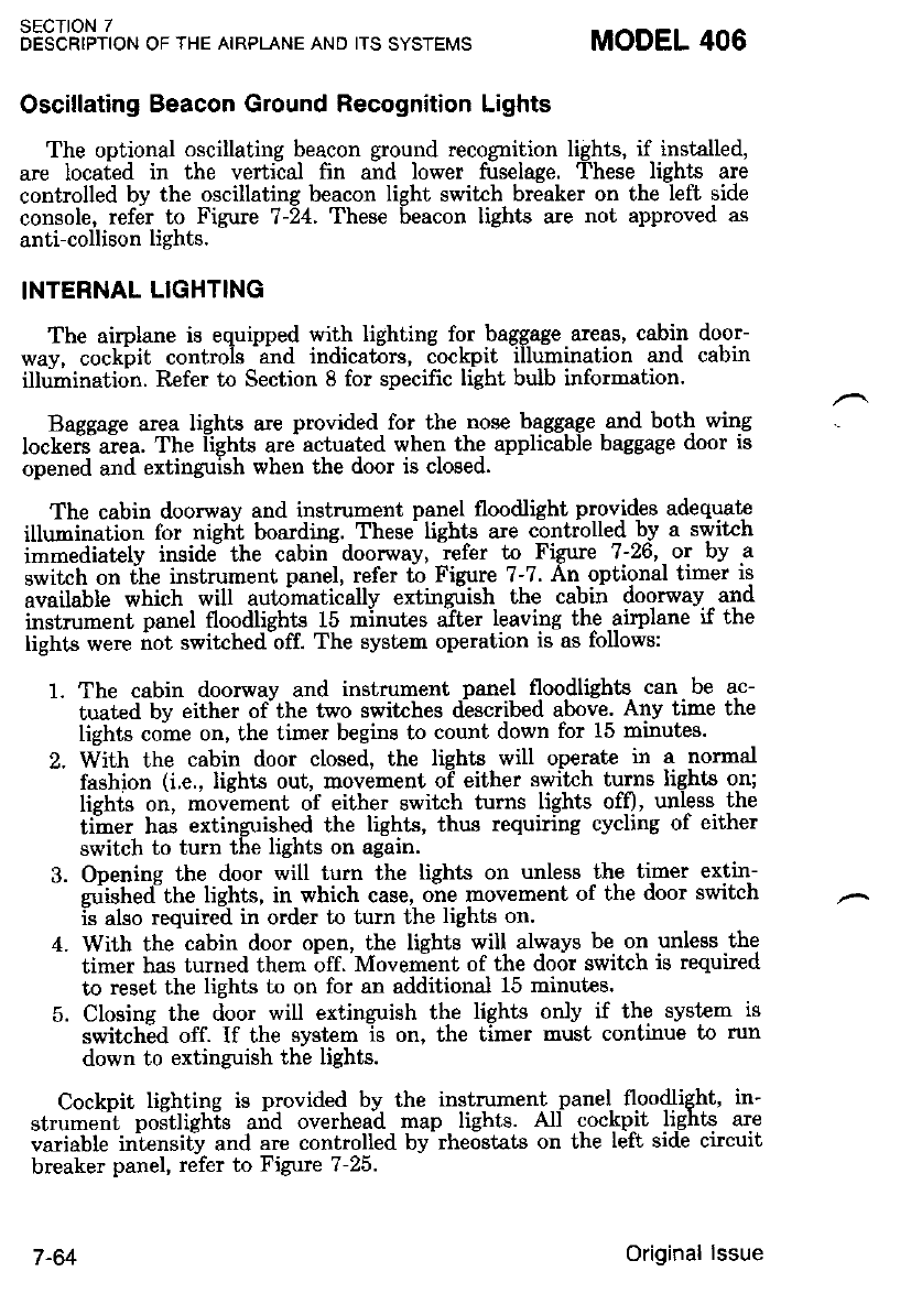
Oscillating Beacon Ground Recognition Lights
The optional oscillating beacon ground recognition lights, if installed,
are located in the vertical fin and lower fuselaee. These lights are
controlled by the oscillating beacon light switch breaker on theleft side
console, refer to Figure ?-i4. These Seacon lights are not approved as
anti-collison lights.
INTERNAL LIGHTING
The airplane is eq.uipped with lighting for bag.gage. areas, cabin door-
wav, cockbit controls and indicators, cockpit illumination and cabin
illdmination. Refer to Section 8 for specifrc light bulb information.
Bassaqe area lighb are provided for the nose baggage and both wing
lockeiJaiea. The l-ights are actuated wher] the applicable baggage door is
opened and extinguish when the door is closed.
The cabin doorway and instrument panel floodlight providps adequate
illumination for nisht boarding. These lights are controlled by a switch
immediatelv insidJ the cabin-doorwav, iefer to Figure 1-26, ot lry a
switch on ihe instrument panel, refer t-o Figure 7-7. An optional timer is
available which will autohatically extinguish the cabin doorway and
instrument panel floodlights 15 minutes after leaving the airplane if the
liehts were not switchedbff. The system operation is as follows:
1. The cabin doorway and instrument panel floodlights can be ac-
tuated bv either ofthe two switches described above. Any time the
lights coine on, the timer begins to count down for 15 minutes.
2. With the cabin door closed, the liehts will operate irr a nornal
fashion (i.e., lights out, movement o-f either swikh turns lights o-n;
lishts on, moviment of either switch turns lights off)' unless the
timer has extinguished the lights, thus requiring cycling of either
switch to turn the lights on again.
3. Ooenins the door will tum the liehts on unless the timer extin-
zubhedttte lights, in which case, one movement of the door switch
is also required in order to turn the lights on.
4. With the cabin door open, the lights will always be on unless the
timer has turned them bff. Movenient of the door switch is required
to reset the lights to on for an additional 15 minutes.
5. Closing the door will extinguish the lights only if the syst€m is
switched off. If the systcm is on, the timer must continue to run
down to extinguish the lights.
Cockpit liehtine is provided by the instrument panel floodlight. in-
strument postlighis and overhead map lights. All cockpit lights are
variable iniensit! and are controlled by rheostats on lhe left side circuit
breaker panel, refer to Figure 7-25.
sEcTtoN 7
DESCRIPTION OF THE AIRPLANE AND ITS SYSTEMS MODEL 406
I -O+ Original lssue
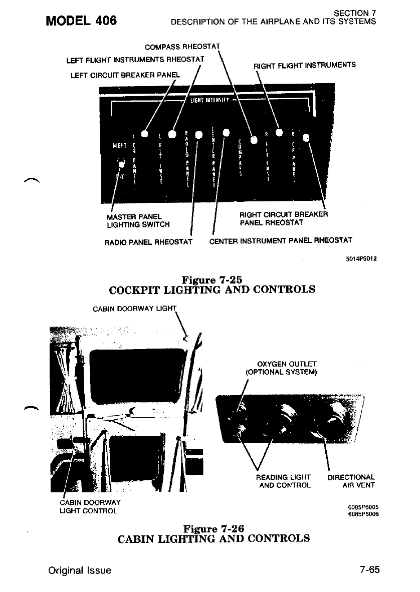
MODEL 406
COMPASS RHEOSTA
LEFT FLIGHT INSTRUMENTS FHEOSTAT
SECTION 7
DESCRIPTION OF THE AIRPLANE AND ITS SYSTEMS
BIGHT FLIGHT INSTRUMENTS
LEFT CIRCUIT BREAKER PANEL
MASTER PANEL
LIGHI]NG SWITCH
RIGHT CIRCUIT BREAKER
PANEL RHEOSTAT
RADIO PANEL RHEOSTAT CENTEB INSTRUMENT PANEL RHEOSTAT
5914P6012
Figure 7-25
COCKPIT LIGITIING AND CONTBOLS
OXYGEN OUTLET
(oPTtoNAL SYSTEM)
READINGLIGHT OIRECIIONAL
AND CONTROL AIR VEN1
6085P6005
6085P6006
LIGHT CONTROL
Original lssue
"orr* "r"#ff 'd.IioT "o*t*o".
7-65
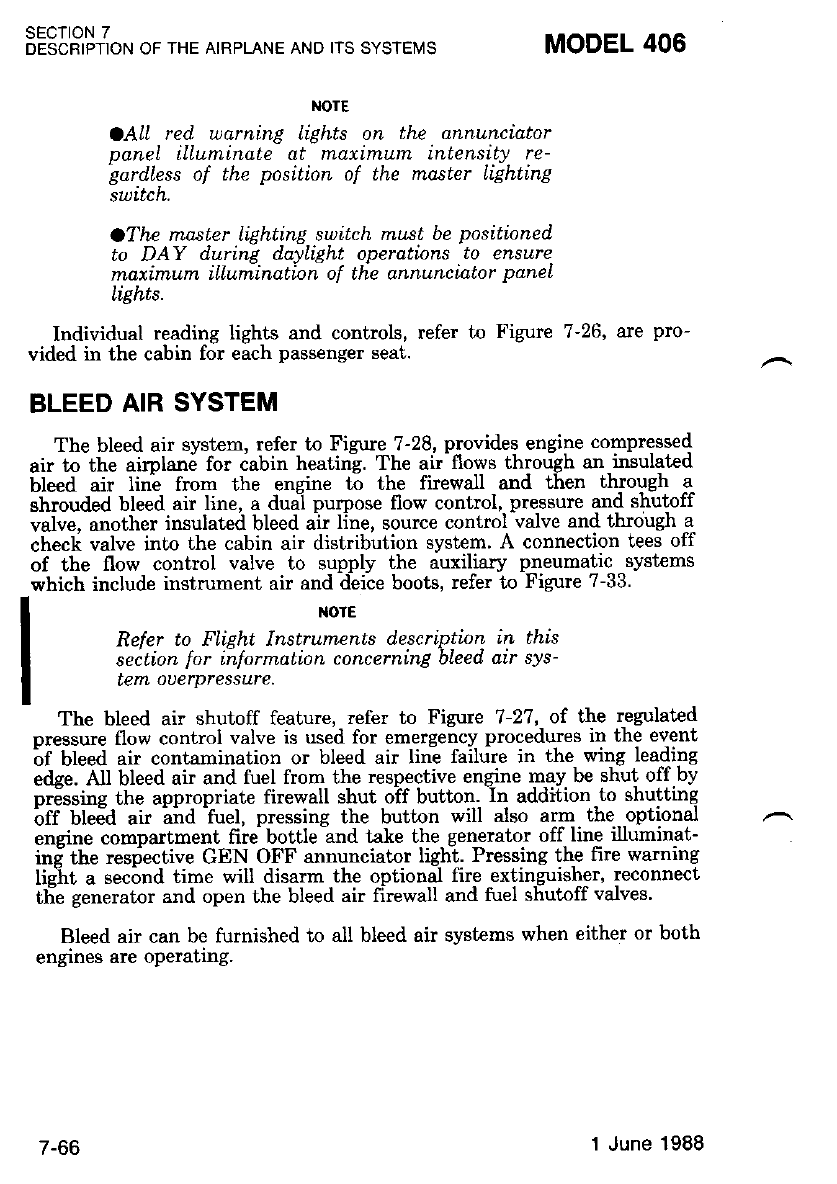
NOTE
OAll red. warning lights on the annunciator
panel ilLuminate at maximum intensity re-
bqrd,less of the position. of the rnaster Lighting
SULrcN,
OThe master lightinE switch rnust be positioned
to DAY during daylight operations to ensure
maximum iLlumination of the annunciator paneL
Iights.
Individual reading lights and controls, refer to Figure 7-26' are pro-
vided in the cabin for each passenger seat.
BLEED AIR SYSTEM
The bleed air system, refer to Figure 7-28, provides engine compressed
air to the airplane for cabin heating. The air flows through an insulated
bleed air line from the engine to the firewall and then thlo'lgh q
shrouded bleed air line, a dual purpose flow control, pressure and shutoff
valve, another insulated bleed air line, source control valve and through a
check valve into the cabin air disiribution system' A connection tees off
of the flow control valve to supply the auxiliary pneumatic syst€ms
which include instrument air and deice boots, refer to Figure 7-33.
I
I xorE
I Refer to FIiEht Instrumenls d,escription in this
I seition lor ih.formalion concerning bleed air sys-
I tern ouerpressure.
IThe bleed air shutoff feature, refer to Figure 7-27, of t}rle regulated
pressure flow control valve is used for emergency procedures in the event
^of bleed air contamination or bleed air line failure in the wing leading
e&e. All bleed air and fuel from the respective engine may be shut off by
or6ssine the appropriate firewall shut oif button. In addition to shutting
btf Uteda air -aid -fuel, pressing the button will also arm the optional
ensine compartment fire bottle and take the generator off line illuminat-
ini the respective GEN OFF annunciator light. Pressing the fire warning
lis-ht a sec;nd time will disarm the optional firre extinguisher. reconnect
tlie generator and open l,he bleed air firewall and fuel shutoff valves'
Bleed air can be furnished to all bleed air systems when either or both
engines are oPerating.
sEcTtoN 7
DESCRIPTION OF THE AIRPLANE AND IIS SYSTEMS MODEL 406
/ -oo 1 June 1988
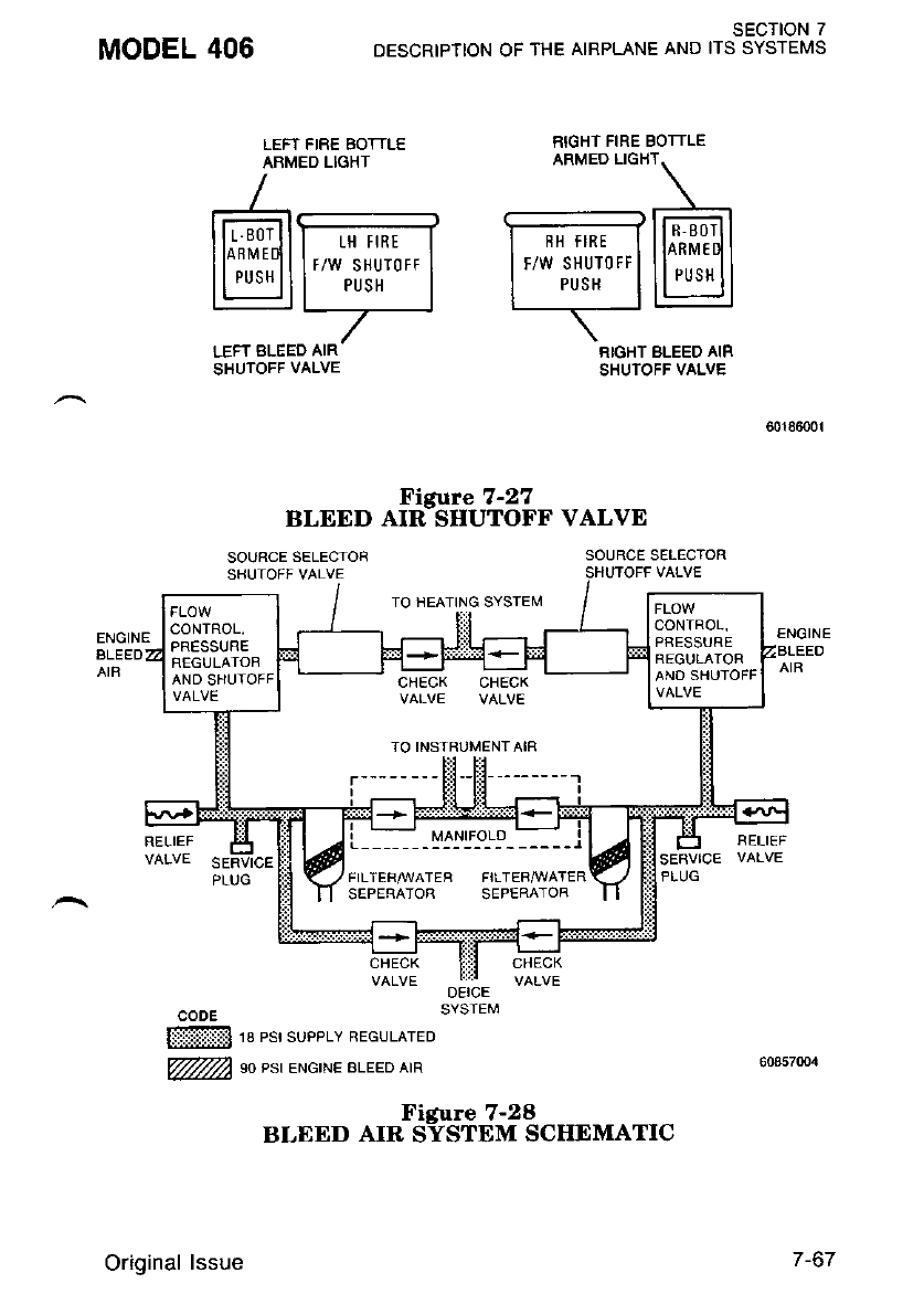
MODEL 406 sEcTloN 7
DESCRIPTION OF THE AIRPLANE AND ITS SYSTEMS
RIGHT BLEED AIR
SHUTOFF VALVE
LEFT FIRE BOTTLE RIGHT FIRE BOTTLE
ABMEDLIGHT
--
\
lh'.prlltr-,"*J I - ""lllml
ItS!ll"w;ili';"| 1",',i,'J"'l llUl
\-
LEFT BLEED AIR
SHUTOFF VALVE
BLEE D oHti,',fr 36" vALvE
SOURCE SELECTOR
SHUTOFF VALVE
SOUBCE SELECTOR
TO HEATING SYSTEI\,I
RELIEF FELIEF
OEICE
SYSTEM
ffi| re esr sueerv REGULATED
@ so et euewt ateeo ata
Figure 7-28
BLEED AIR SYSTEM SCIIEMATIC
CONTROL.
PFESSURE
REGULATOR
ANO SHUTOFF
CONTROL,
PRESSURE
FIEGULATOF
AND SHUTOFF CHECK CHECK
VALVE VALVE
TO INSTRUMENTAIR
FILTER/WATEB FILTEBA]I/ATER
SEPERATOR SEPERATOR
Original lssue 7 -67
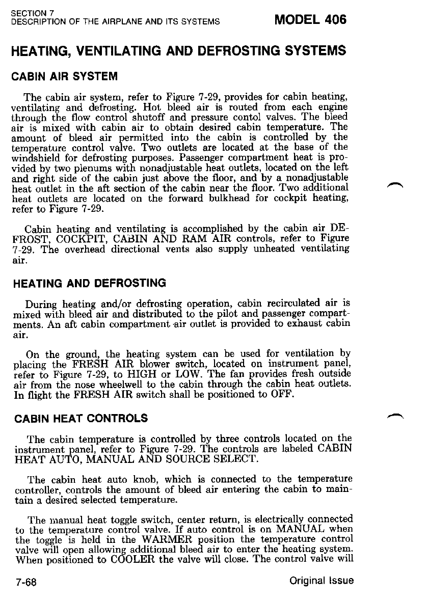
SECTION 7
DESCRIPTION OF THE AIRPLANE AND ITS SYSTENIS
HEATING, VENTILATING AND DEFROSTING SYSTEMS
CABIN AIR SYSTEM
The cabin air system, refer to Figure ?-29, provides for cabin heating,
ventilating and defrosting. Hot bleed air is routed from each engine
throush the flow control lhutoff and pressure contol valves. The bleed
air is"mixed with cabin air to obtairi desired cabin temperature. The
amount of bleed air permitted into the cabin is controlled by the
temnerature control valve. Tho outlets are located at the base of the
winilshield for defrosting purposes. Passenger compartment lreat i9 pro-
vided bv two plenums with n6nadiustable hiat ouilits, located on the left
and rielt sidd of the cabin iust above the floor, and by a nonadjustable
heat o-utlet in the afi section of the cabin near the floor. Two additional
heat outlets are located on the forward bulkhead for cockpit heating,
refer to Figure 7-29.
Cabin heating and ventilating is accomplished by the cabin air DE-
FROST. COCKPIT, CABIN AND RAM AIR controls, refer to Figure
7-29. "Ihe overhead directional vents also supply unheated ventilating
air.
HEATTNG AND DEFROSTING
Durine heatins and/or defrosting operation, cabin recirculated air is
mixed with bleedair and distributed ro the pilot and passenger compart-
ments. An aft cabin compartment air outlet is provided to exhaust cabin
air.
On the cround, the heating svstem can be used for ventilation by
Dlacins the-FRESH AIR blower switch, located on instrument panel,
iefer ti Fizure 7-29, to HIGH or LOW. The fan provides fresh outside
air from tlie nose wheelwell to the cabin through the cabin heat outlets.
In flight the FRESH AIR switch shall be positioned to OFF.
CABIN HEAT CONTROLS
The cabin temperature is controlled by three controls Iocated on the
instrument panel,- refer to Fizure 7-29. The cr.rntrols are labeled CABIN
HEAT AUTO, MANUAL AND SOURCE SELECT.
The cabin heat auto knob, which is connected to the temperature
controller, controls the amount of bleed air entering the cabin to main-
tain a desired selected temperature.
The rnanual heat togele swikh, cenler retum, is electrically connected
to th€ temDerature control valve. If auto control is on MANUAL when
the tossle'is held in the WARMER position the temperature control
valve will ooen allowing additional bleed air to enter the heating system.
When nositioned to COOLER the valve will close. The control valve will
MODEL 406
7-68 Original lssue
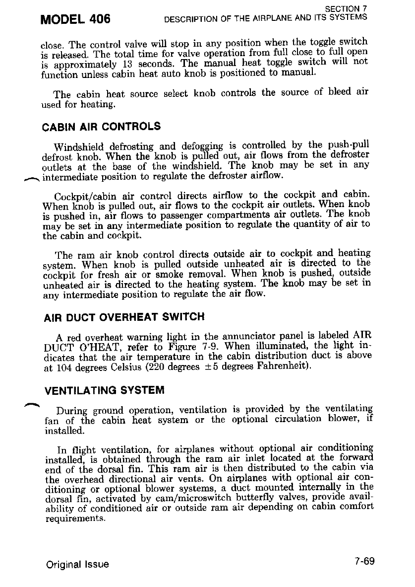
close. The control valve will stop in any position when the toggle.switch
i;t"b";;. Theiotut ti-" for vilve op,irdtion from full close to tull-open
i; ;';;"o-xlrrr;Gli'iC seconds. The nianual heat- toggle switch will not
ilt*Iil; ;;i;;; ;"bir heat auto knob is positioned to manual'
The cabin heat source select knob controls the source of bleed air
used for heating.
CABIN AIR CONTROLS
Windshield defrosting ard defogging is controlled ,bv thp plt*-pull
def;oJ 6ob. When the-knob is prifedout, air flows from the defroster
o"tl"* "t the base of the windshield. The knob may be set in any
.--. intermediate position to regulate the defroster airflow.
Cockpit/cabin air contrcl directs airflow to the cockpit and cabin'
Whe" t6;'b iJ pulled out, air flows to the cockpit air.outlets' When knob
i. pir"tt"a i", air flows to passenger compartm-ents air outlets The knob
*.^v be s"t il any intermediate position to regulate the quantity of air to
the. cabin and coekpit.
The ram air knob control directs outside air to cockpit and- heating
.v.Lt". -Wtt"n knob is pulled outside u4heated air is directed to the
iir"iiiii r". iiesh air or imoke removal. When knob- is -pushed, outside
..hJ"t"a air is directed to the heating system. The knob may be set in
any int€rmediate position to regulate the air flow.
AIR DUCT OVERHEAT SWITCH
A red overheat warning light in the annunciator panel. is labeled AIR
OUCT O'Unel, refer t5 F'igure 7-9. When i.lfu4inqled' the light in-
dicates that the air temperature in the cabin drstrlbutlon ducf, ls aoove
at 104 degrees Celsius (220 degrees t5 degrees Fahrenheit).
VENTILATING SYSTEM
During ground operation, ventilation is provided by the ventilating
fa" of tii cabin 6eat system or the optional circulation blower, if
installed.
In flight ventilation, for airplanes without- optional .air conditioning
i"staUeal i. oUtuitt"a through ihe ram air inlet .located at the forward
;d;;it" dorsal fin. This "ram air is then distributed to the cabin via
ihe ove.head directional air vents. On airplanes with- optional air con-
aitio.i"g oi optional blower systems, a. rlict mounted internally in th€
dorsal fin, activat€d by cam/microswitch butterlly -valves' provroe avarl-
abifitv of conditioned air or outside ram air depending on cabin comfort
requiiements.
MODEL 406 SECTION 7
DESCRIPTION OF THE AIRPLANE AND ITS SYSTEMS
Original lssue 7-69
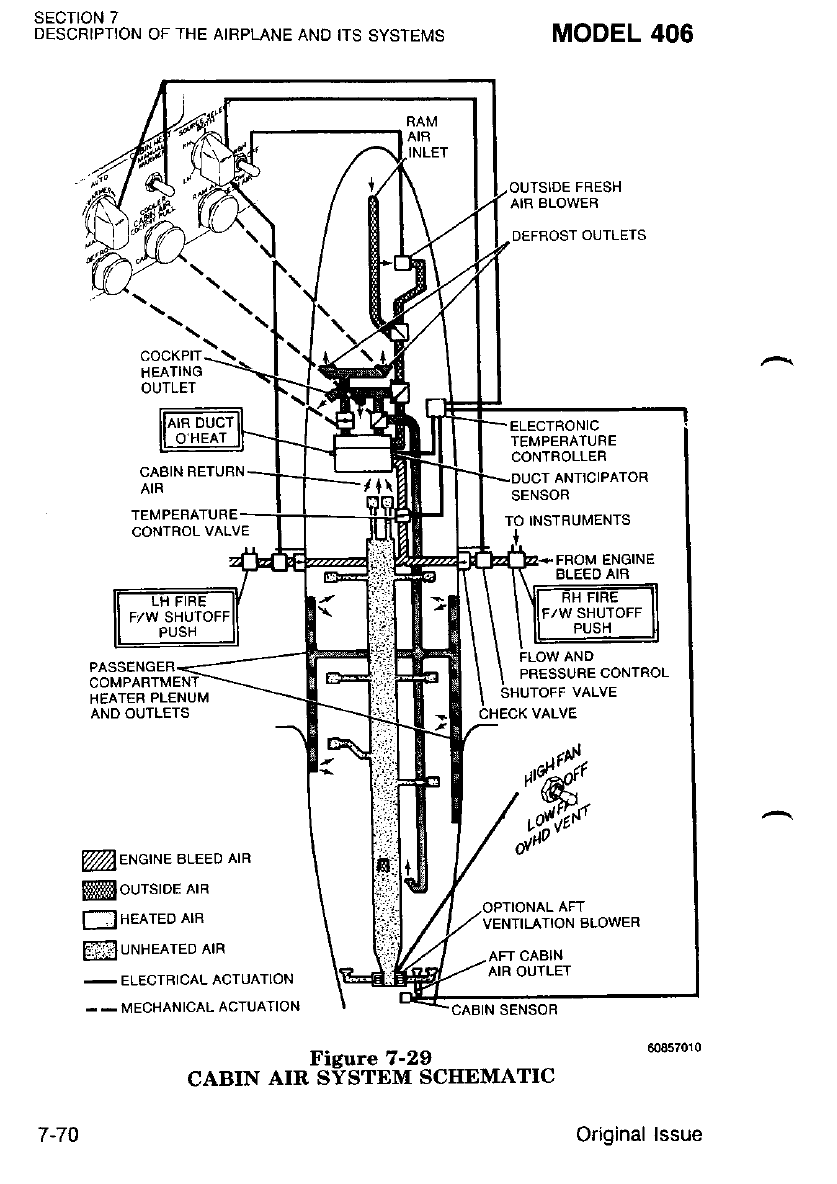
sEcloN 7
DESCRIPT!ON OF THE AIRPLANE AND ITS SYSTEMS
"o"*-r):...
HEATING
OUTLET
CABIN RETURN
MODEL 406
TEMPERATURE
CONTROL VALVE
HEATER PLENUM
AND OUTLETS
ffieNetNe ateeo eta
ffiNourstor etn
! nelreo ltn
mlUNHEATED AIR
-
ELECTRICAL ACTUATION
. - MECHANICAL ACTUATION
PRESSURE CONTROL
VENTILATION BLOWER
7-70
Figure 7-29
CABIN AIR SYSTEM SCHEMATIC
Original lssue
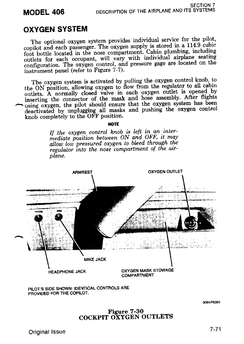
OXYGEN SYSTEM
The optional oxygen system provides individuul, ryIi!: for the pilot'
cooilot and each passenger. Ihe^oxygen supply^is stored ir.a 114'9 cubic
ir"5i'6"iir" rli"t-"iln'th-e nose compartment' Cabin plumbing' includlng
;;ii"ts i;; eaih occupattt, will vary,with individual airylane seating
iJ"n*.uilo". frte o*ygen "oniior, "i,a pressure gage are located on the
instriment oanel (refer to Figure 7-7).
The oxvgen svstem is activated by pulling the oxygen. control knob' to
th"'6v;;3iti";'-;il;1il;;*;; # flow rr-om the iigulator to all cabin
l,',]iri.. "e' "'iit-"llt";ffid ;i;; 'in each oxvgen orjtlet is onened bv
i,''"';iii;"'rl;;.;n!"toi or tfi;;i;a ho"s6 assemblv' Aftir flighti
^;':iil;i";;;, ;i';;iil.[oon ""."t" that the-oxvgen svstem has been
iiil?i"""tl?i'ilv"'iitit.!eit'i at nasG a"d pushing- the 'oxvsen control
knob completely to the OFF position'
NOTE
If the oxvpen control hnob is left in an inter-
mediate fisition between ON and OFF' it.may
aliow toi pressured oxygen to bLeed through the
regulator into the nose compartnlent ol tne alr-
plane.
MODEL 406
ARMREST
MIKE JACK
HEADPHONE JACK
PILOT S SIDE SHOWN: IDENTICAL CONTROLS ARE
PROVIDEO FOR THE COPILOT.
SECTION 7
DESCRIPTION OF THE AIRPLANE AND ITS SYSTEMS
OXYGEN OUTLET
OXYGEN MASK STOWAGE
COMPARTMENT
Original lssue "o"""rr%*ib$,1 %,rttrt.
7 -71
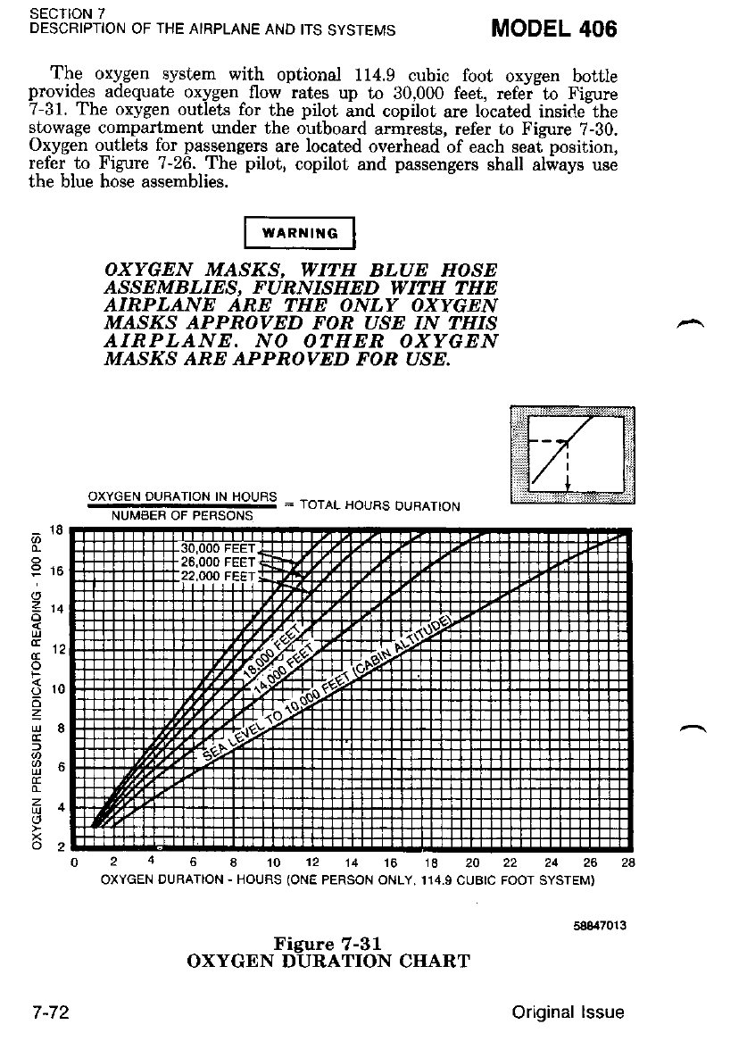
SECIION 7
DESCRIPTION OF THE AIRPLANE AND ITS SYSTEMS MODEL 406
The oxygen system with optional 114.9 cubic foot oxygen bottle
provides adequate oxygen-flow rates up to 30,000 feet, refei-to Figure
7-31. The oxygen outlets for the pilot ard copilot are located inside-the
stowage compartment under the outboard armrests, refer to Figure 7-30.
Oxygen orrtlets for passengers are located overhead of each seaf position,
refer to Figure 7-26. The pilot, copilot and passengers shall aiways use
the blue hose assemblies.
_ 18
0-
o
Etc
o
5 ro
6
=
L!8
E
0-
z.
a
o2
OXYGEN MASKS, WITH BLUE HOSE
ASSEMBLIES, FURNISHED WITH THE
AIRPLANE ARE THE ONLY OXYGEN
jwASI<S APPROVED FOR USE IN THIS
AIRPLANE. NO OTHER OXYGEN
MASKS ARE APPROVED FON USE.
OXYGEN DURATION IN HOURS
r-!!i-- - TOTAL HOURS DURATTON
NUMBER OF PERSONS
o 2 4 6 810 12 t4 16 j8 2022 24 262a
OXYGEN DURATION - HOURS (ONE PERSON ONLY. T14.9 CUBIC FOOT SYSTEM)
Figure 7-31
OXYGEN DURATION CIIART
Original lssue
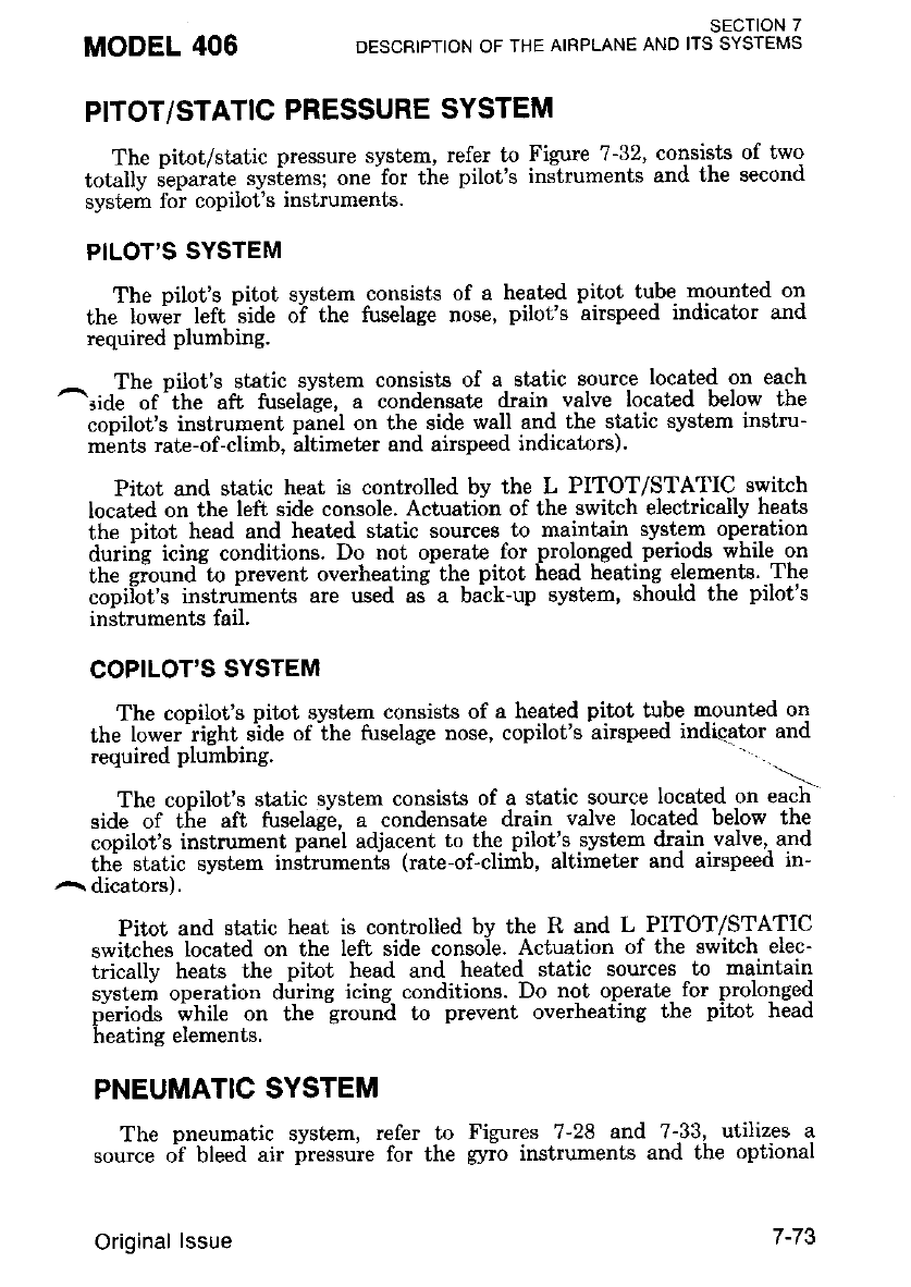
PITOT/STATIC PRESSURE SYSTEM
The pitot/static pressure system, refer to Figure 7-32, consists of two
totulty ieparite sysiems; one-for the pilot's instruments and the second
svstem fol coDilot's inslruments.
PILOT'S SYSTEM
The oilot's Ditot svstem consists of a heated pitot tube mounted on
the low'er left'side o-f the fuselage nose, pilot's airspeed indicator and
required plumbing.
The nilot's static svstem consists of a static source located on each
^ride of 'the aft fuselage, a condensat€ dlain valve located below the
cooilot's instrument panel on the side wall and the static system instru-
ments rate-of-climb, iltimercr and airspeed indicators).
Pitot and static heat is controlled by the L PITOT/STATIC switch
located on the left side console. Actuation of the switch electrically heats
the pitot head and heated static sources to maintain system operation
duriire icins conditions. Do not operate for prolonged periods while on
the giound to prevent overheating the pitot head heating elements. The
copilot's instruments are used as a batk-up system, should the pilot's
instruments fail.
COPILOT'S SYSTEM
The conilot's pitot svstem consists of a heated pitot tube mounted on
the lower'right sjde of the fuselage nose, copilot's airspeed indicator and
required plumbing. .-
The cooilot's static svstem consists of a static source located on each
side of tire aft fuselag'e, a condensate drain valve located below the
copilot's instrument panel adjacent to the pilot's system drain valve,- and
thi static system instrumen6 (rate-of-climb, altimeter and airspeed in-
a dicators).
Pitot and static heat is controlled bv the R and L PITOT/STATIC
switches located on the Ieit side console. Actuation of the switch elec-
tricallv heats the pitot head and heated static sources to maintain
svsteri operation durine icine conditions. Do not operate for prolonged
piriods rlvhile on the groun-d to prevent overheating the pitot head
heating elements.
PNEUMATIC SYSTEM
The pneumatic system, refer to Figures 7-28 and 7-33, utilizes a
"ou"ce olf bleed air pressure for the gyio instruments and the optional
MODEL 406 SECTION 7
DESCRIPTION OF THE AIRPLANE AND ITS SYSTEMS
Original lssue 7-73
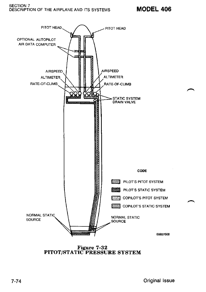
SECTION 7
DESCRIPTION OF THE AIRPLANE AND ITS SYSTEMS MODEL 406
PITOT HEAD
ALTIMETER
RATE-OF-CLIMB
NORIVAL STA
SOURCE
STATIC SYSTEM
DRAIN VALVE
cooE
@ ettor's erot ststeu
@! errols srnrrc svsrer,r
@ coPrlols Prror SYSTEM
$l coerrols sulc svsreu
NORMAL STATIC
SOURCE
7 -74
Figure 7-32
PITOT/STATIC PRESSURE SYSTEM
Original lssue
deice boots. The system consists of water separator(s) and filter(s)'
pressure regulator(s), pressure indicator(s), gyro instruments and plumb-
rng.
Bleed air flows from each ensine through firewall shutoff flow and
nressure control valves ald through check valves to the water sep-
irator(s) and air filter(s) and then-through pressure regulator(s) where
the air pressure is reduced to approximately 2.5 pounds per square inch.
The air^then flows separately tlirbugh the R and L gyro instruments ard
is routed overboard. The pressure being applied to the gyros is con-
stantly presented on the pressure indicator.
The nressure indicators monitor the air delivered to the instruments
abv the pressure rezulators. Two source indicator buttons located in the
oiessure indicatorJalert the pilot to an inactive source. Failure of either
'source would otherwise be undetected since the manifold allows the
r.emaining source to supply both banks of instruments and both in-
crcaf,ors.
NOIE
oFor operation with one bLeed' air shutoff uaLue
closed or one engine inoperatiue, poner aboue
ILIGHT'. IDLE may be. required on the operat-
ing eng[ne to mqinlain gyro pressure Ln the
Efeen arc.
ORet'er to Flight lnstrurnents d.escription in this
section for information concerning bLeed atr sys-
tem ouerpressure.
STALL WARNING SYSTEM
A stall warning system is required equipment which consists of a stall
warning transmiitei vane located in the left wing tip leading edge; a
switch located behind the instrument panel activated by the elevator
control linkage; a switch local,ed below the floorboard actuated by the
^ wing flap bell=crank; a cockpit warning horn and the necessary wfuing to
complete the system.
The stall warning horn will sound approximately 5 to 10 Knots above
the statl. The horn"will also sound wh-e-n the elevator is in the fi:ll nose
up position and the wing flaps are in the LAND position- The first stall
warnins horn check ca"n bi accomplished by activating the PRESS-
TO-TEST button, located on the annunciator panel, Refer to Figure 7-9.
The second part of the stall warning system is checked by positioning
the elevator in the full nose up position and extending the wing flaps to
LAND position. In this configuration the stall warning horn will also
sound. The stall warning vane heater should be checked by actuating the
stall vane heat switch and cautiously feeling the vane for heat.
MODEL 406 sEcrloN 7
DESCRIPTION OF THE AIRPLANE AND ITS SYSTEMS
1 June 1988 7-75
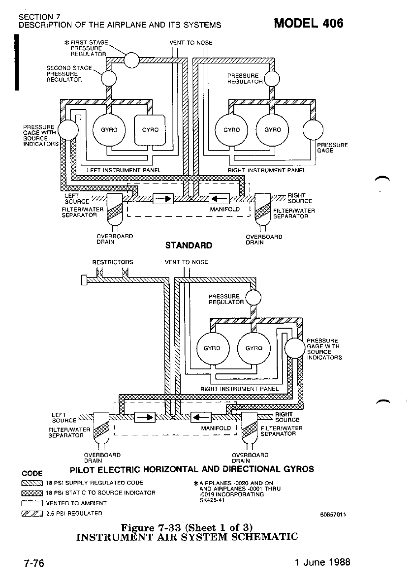
SECTION 7
DESCRIPTION OF THE AIRPLANE AND ITS SYSTEMS
V€NT TO NOSE
SECONO STAGE
PBESSURE
PAESSL]FE
SOIJFCE
MODEL 406
STANDARD
VENT TO NOSE
FIGHT INSIBUM€NT PANEL
I
LEFI
SOUBCE
BIGHT
SOUBCE
MANIFOLO I
FIGHT
SOUBCE
OVEFBOAAD
PILOT ELECTRIC HORIZONTAL ANO DIRECTIONAL GYROS
Fi\\:] 18 PSt SUPPLY REGUIATEO COO€
@ 18 PSr STATTC TO SOURCE TNDTCATOR
T'-- ] VENTED TO AMBIENT
W2 25 PSI REGULAIED
TAIRPIANES -OO2O AND ON
ANO AIFPLAN€S.OOO1 THFU
,001 9 INCOBPORATING
sK425-41
Figure 7-33 (Sheet 1 of 3)
INSTRUMENT AIR SYSTEM SCHEMATIC
FIGHT INSTRUMENT PANET
T-IO 1 June 1988
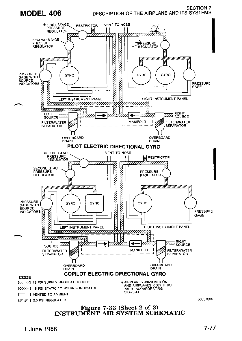
MODEL 406 SECTION 7
DESCRIPTION OF THE AIRPLANE AND IIS SYSTEMS
VENT IO NOSE
SIGH I INSTFIJM€NT PANEL
SOURCE
PILOT ELECTRIC DIRECTIONAL GYBO
PRESSUBE
SECOND STAGE
SOUFCE
VENT TO NOSE
SECONO SIAGE
PRESSUB€
RIGHT INSIBUMENT PANEL
LEFT
SOURCE SOURCE
cooE coptLoT ELEcrRlc DtREcIoNAL GYRO
*AIFPLANES OO2O AND ON
AND AIRPLANES .OOO1 IHRL]
OO]9 INCORPORATING
sK425-41
S.\:-:1 18 PSI SUPPLY FEGULATEO CODE
FE-I 18 PSI STATIC IO SOURCE 1NDICATOR
-
VENTED TO AMBIENI
zza 2.5 Pst AEGVIATEO
Figure 7-33 (Sheet 2 of 3)
INSTRUMENT AIR SYSTEM SCHDMATIC
1 June 1988
LEFT INSTfiUMENT PANEL
LEFT INSTRUMENT PANEL
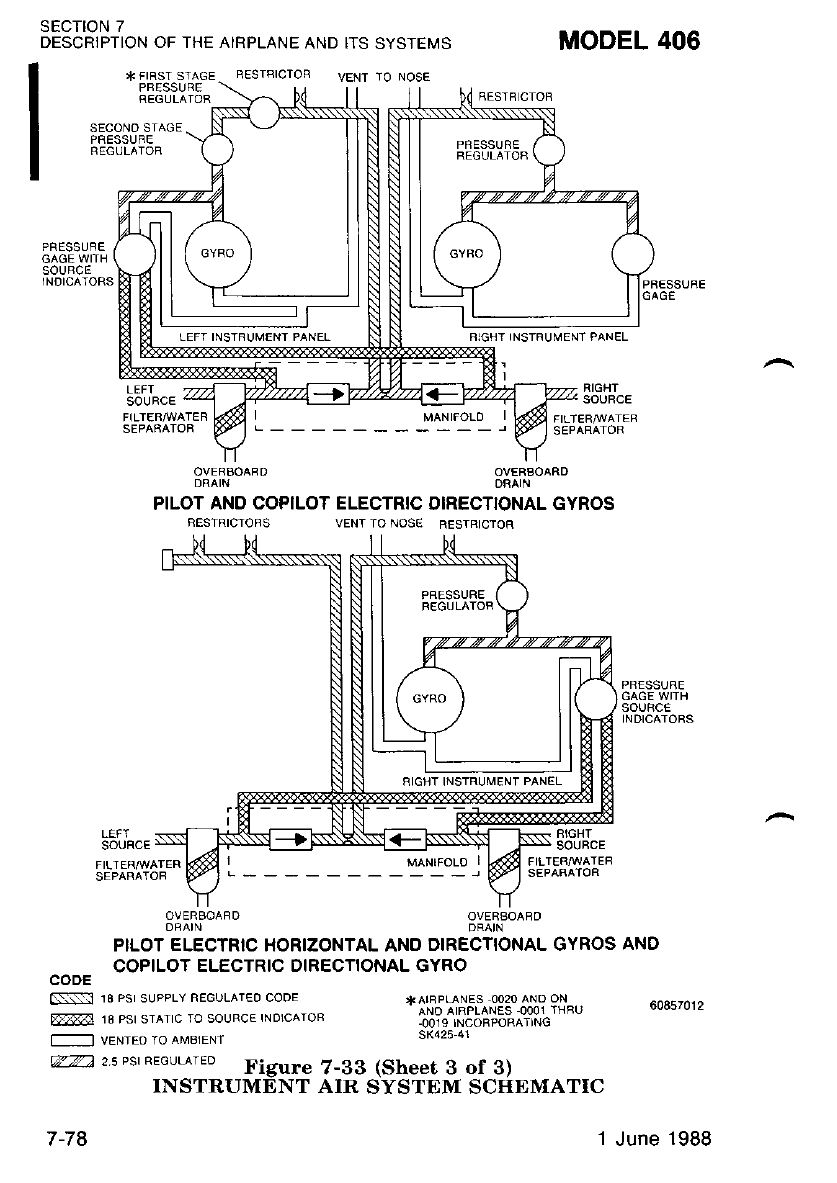
SECTION 7
DESCRIPTION OF THE AIRPLANE AND ITS SYSTEMS
* FIRST STAGE RESIAICTOF
PBESSIJRE \
REGULAIOR -\.2\ U!
VENT TO NOSE
SECONO STAGE
N 1B PsI SUPPLY FEGIJLATEO COOE
rel 18 Psr srATtc to soLJRcE lNorcAToB
-
vENTEo ro aMBIENT
MODEL 406
RESTB CTOB
RIGH-T INSTFUMENT PANEL
RIGHT
SOUFCE
PILOT AND COPILOT ELECTRIC DIRECTIONAL GYROS
VENT TO NOS€ RESTRIC'TOR
SOUFICE F!GHT
SOUBCE
OVERSOAFD
PILOT ELECTRTC HORIZONTAL AND DIRECTIONAL GYROS AND
COPILOT ELECTRIC DIRECTIONAL GYRO
CODE
*AIFPLANES OO2O ANO ON
ANO AIRPLANES OOO1 THBO
.0019 INCORPORATING
sK425 41
zz2 25 Pst aEGUL^rEo Figure 7-33 (Sheet 3 0f 3)
INSTRUMENT AIR SYSTEM SCIIEMATIC
RIGHT INSTRUMENT PANEL
7-78 1 June 1988
MODEL 406 SECTION 7
DESCBIPTION OF THE AIBPLANE AND ITS SYSTEMS
ICTNG EQUIPMENT
With the proper standard and optional equipmenL installed and oper-
ational, this'aiiplane is approved for flight into icing conditions as
a"fi".a Uu in" FAA, refer id Section 2. Kinds of Operaiion Limits and
Section 9, Flieht In Icing Conditions.
PROPELLER DEICE SYSTEM
The propeller deice svstem consists of electrically heated boots on the
orooellei biades. Each boot consists of an inboard and outboard heating
irleirent which receives its electrical power through a deice timer. To
^reduce- power dr-ain, the . timer directs- current to fhe propeller boots in
- ':vcles between elements in the following sequence:
' Heatins Period No. 1 - Outboard Halves
Heatine Period No. 2 - Inboard Halves
Each hiating period lasts approximately 20 seconds'
A readins below the sreen arc on either the left or right propeller
deice ammeier indicates that the blades of the propeller are not being
deiced uniformly.
WHEN UNEVEN DEICING OF THE
PROPELLER BLADES ON EITHER EN-
GINE IS INDICATED, IT IS IMPERA-
TIVE THAT THE ASSOCIATED PRO.
PELLER DEICE SYSTEM SWITCH
BREAKER BE TURNED OFF. UNEVEN
DEICING OF THE BLADES WILL RE.
SULT IN PROPELLER UNBALANCE
AND CAN LEAD TO ENGINE FAILURE.
Abnormal oDeratioD of the propeller deice system is indicated by
- eneine/oronellei roughness or bv trippine of the L and/or R PROPEL-
l.E'R si,idh breake-rs. Failure' of tf,e L or R PROPELLER circuit
breaker to stay reset indicates failure of the applicable propeller deice
system,
AVIONICS
Information concerning avionics equipment is contained in the ap-
plicable supplements in Section 9.
Original lssue
SECTION 7
DESCRIPTION OF THE AIRPLANE AND ITS SYSTEMS
AVIONICS INTERFERENCE
MODEL 406
{orE
When turned to a ueak NAV signal, heying the
COM transmitter ma)/ cau.se monTento.ry inter-
ference uithin the NAV receiuer causing a NAV
flag to appear. Should. circumstances warran|
ATC should. be requested to assiEn another
COM frequency.
AVIONICS MASTER SWITCHES
T\lo avionics bus switches, refer to Figure 7-24, are provided on the
left side console. Basically, the L AVIONICS BUS switch controls power
to the No. 1 avionic circuit breakers while the R AVIONICS BUS
switch controls power to the No.2 avionics circuit breakers and the
autopilot. Complete information is presented in the Avionics Bus Failure
orocedure in Siction 3.
1000 AUDro coNTRoL PANEL (TYPE F-10108)
The 1000 audio control panel provides for amplification of the audio
signals for the speaker system and allows audio switching for the cockpit
and cabin speakers, headsets, intercom and microphones. The audio
panel may be installed in a single configuration, where pilot and copilot
utilize the same panel, or in dual configuration, which has one panel for
each position.
NOTE
In a duaL configuration it is recommended, that
headsets be used, by the pilot and copilot, in-
stead. of speahers to auoid possible aud,io feed.-
back. If piLot and copiLot are tuned, to different
frequencies, they will not hear each others
sidetone on headsets.
All operating controls and indicators are located on the front of the
panel, refer to Figure ?-34. The receiver selector switches that are used
on the audio control panel are determined by the avionics equipment
installed in the airplare. Unused switches are identified with a black
boot on the switch handle.
Power to the audio control panel(s) is arranged so that, in either a
single or dual installation, accesa to a usable communication receiver/
traismitter is maintained- In a single audio control panel installation,
COM 1 is delivered as the designated emergency receiv;r/transmitter and
in the event of a failure of the control panel. comrrunications can be
maintained through COM 1 by selecting EMER COM position. In a dual
7-80 Original lssue
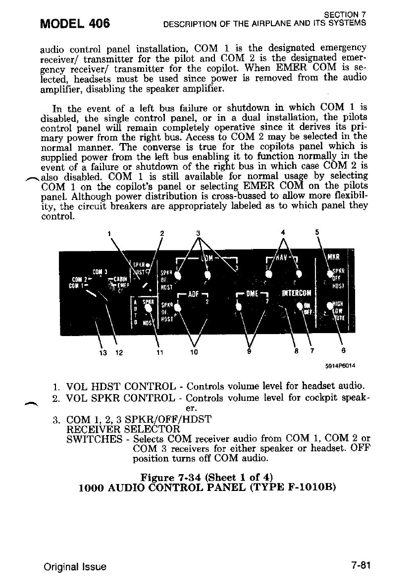
audio control penel installation, COM 1 is the designated emergency
receiver/ trans*itt"r for the pilot and COM ? is thg -@9ig41t9{ emer-
gencv receiver/ transmitter f6r the copilot. When EMER COM is se-
't""t"h, tt"ua""i. must be used since pbwer is removed from the audio
amplifier, disabling the speaker amplifier.
In the event of a left bus failure or shutdown in which COM 1 is
disabled, the single control panel, or in a dual installation, the trrilots
control oanel will remain completBlv operative since it derives its pri-
*aw oowet from the rieht bus. Access t-o COM 2 may be selected in the
normal manner. The converse is true for the copilots panel which is
suoolied nower from the left bus enabling it to function normally irr the
"uiht of i failure or shutdown of the right bus in which case COM 2 is
,,^. also disabled. COM 1 is still available lbr normal usage by selecting
COM 1 on the copilot's panel or selecting EMER COM on the- p!!o.ts
nanel. Althoueh power disiribution is cross-bussed to allow more flexibil-
ity, the circui-t biealers are appmpdately labeled as to which panel they
control.
MODEL 406 sEcTloN 7
DESCRIPTION OF THE AIRPLANE AND ITS SYSTEMS
1.
2.
3.
5914P€0t4
VOL HDST CONTROL - Controls volurae level for headset audio.
VOL SPKR CONTROL - Controls volume level for cockpit strreak-
COM 1, 2, 3 SPKR/OFF/HDST
RECEI\IER SELECTOR
SWITCHES - Selects COM receiver audio from COM 1, COM 2 or
COM 3 receivers for either speaker or headset. OFF
position turns off COM audio.
Figure 7-34 (Sheet 1 of 4)
rOOO AUDIO CONTROL PANEL (TYPE F.lOlOB)
Original lssue 7 -91
SECTION 7
DESCRIPTION OF THE AIRPLANE AND ITS SYSTEMS MODEL 406
OtL
OAIthough all the COM 1, 2, 3
SPKRIOFFIHDST swikhes select the ind.iuidual
receiuer audio for rnonitoring, the function se-
lector switch automaticalLy seLects the appro-
priate COM receiuer au.d,io for monitoring on
'either speaher or headset ds selected by the
AUTO SPKRIHDST switch.
)In a singLe instalLation, the audio signals from
the COM, NAV, ADF, DMD snd rnarher beacon
receiuers wilL be mutud. wheneuer any micro'
phone hev is actunted for COM 1, COM 2 or
COM 3 operation. In d.inl installations, the pi'
lot's microphone cqn be actuated withnut mut-
ing the aidio being monitored by the copilot.
The reuerse is also true.
4. NAV 1,2 SPKR/OFF/HDST
RECEIVER SELECTOR
SWITCHES - Selects Nav receiver audio from Nav 1 or Nav 2
receivers for either speaker or headset' OFF position
turns off Nav audio.
5. MKR SPKR/OFF/HDST
RECEIVER SELECTOR
SWITCHES - Selects marker beacon receiver audio for either
speaker or headset' Off position turns off rnarker
beacon audio'
6. HIGH/LOWMUTE
SELECTOR/SWITCH - Selects marker beacon receiver sensitivity,
HIGH or LOW. MUTE is a momentarY
contact switch position that cuts off the
malker beacon audio for approximately 30
seconds. When MUTE Position is re-
leased, switch returns to LOW.
IIOTE
In d.ual installation, the HIGH/LOW sensitiuity
is not selectabLe from the copilot's audio control
paneL.
Figure 7-34 (Sheet 2 of 4)
1OOO AUDrO CONTROL PANEL (TYPE F-lOlOB)
7 -82 Original lssue
MODEL 406 SECTION 7
DESCRIPTION OF THE AIRPLANE AND ITS SYSTEMS
7. INTERCOM ON/OFF
SELECTOR SWITCH - Turns on pilot alrd copilot nicrophones
for intcrcommunication with each other.
In dual installations, setting either of the
INTERCOM selector switches to ON pro-
vides intercommunication.
NOTE
Aud.io feedbach may be encountered. if
AUTO/SPKR is seLected during INTERCOM
operation.
SIDETONE SCREWDRIVER
ADJUST - Adjusts sidetone level in speaker. Sidetone is obtained
when transmitting on Com 1, Com 2 or Com 3.
TOIE
Sidetone adjustment is normalLy a maintenante
function and not part of tfu normal operating
proceaure.
DME 1, 2, SPKR/OFF/HDST
RECEIVER SELECTOR
SWITCHES - SelecLs DME receiver audio from DME 1 or DME 2
receivers for either speaker or headset, OFF position
turns off DME audio.
ADF 1,2, SPKR/OFF/HDST
RECEIVER SELECTOR
SWITCHES - Selects ADF receiver audio from ADF 1 or ADF 2
receivers for either speaker or headset. OFF position
turns off ADF audio.
9.
10.
11. AUTO SPKR/HDST
SELECTOR SWITCH - Selects either speaker or headset for the
associated audio selected via the function
selector switch.
Figure 7-34 (Sheet 3 of 4)
1OOO AUDIO CONTROL PANEL (TYPE F-lO1OB)
Original lssue 7-83
CABIN CALL - BackJighted green indicator that lights when the
cabin microphone switch is actuated to signal the
cockpit that the cabin wishes to communicate via
the cabin microphone and speaker. Cockpit com-
munication with the cabin is made by setting the
Function Selector Switch to the CABIN position.
The incoming audio selected via the receiver selec-
tor switches will not be interrupted wl:en the
Function Selector Switch is set to CABIN posi-
tion.
1{OtE
With duat audio control panels, pilot commu-
nication with the cabin iilt be ' the same as
preuiously described. Howeuer, both pilot's and
coDilot's selector switches must be in the CABIN
posi.tion for the copilot to communicate with the
ca0ln.
13. COM 1/COM z/COM 3/CABINIEMER
COM FUNCTION
SELECTOR SWITCH - Selects the microphone connection for
Com i, Com 2 or Com 3 transmission.
cabin communication or the emergency
mode of oDeration. In COM I' COM 2'
COM 3 aril CABIN switch positions, the
associated audio is automatically selected
for monitoring on either headset or speak-
er, as sefected bY the AUTO
SPKR/HDST switch'
Figure 7-34 (Sheet 4 of 4)
1OOO AUDIO CONTROL PANEL (TYPE F-lO1OB)
SECTION 7
DESCRIPTION OF THE AIRPLANE AND ITS SYSTEMS MODEL 406
7-84 Original lssue
MODEL 406 SECTION 7
DESCRIPTION OF THE AIRPLANE AND ITS SYSTEMS
LOCATOR BEACON (MODEL DMELT-6 AND .6C)
The locator beacon system is a battery-operated, sweep tone emer-
sencv radio transmitter incorporaling an extemally mounted whip an-
ienni and a transmitter with an intes;al 3-position switch, all located on
the left side of the fuselase tailconl. Thi switch can be reached by
removins t he plue button located adiacent to the locator beacon placard.
Normalli. the lwifuh is in the ARM'(AUTOMATIC "G" OPERATION)
oosition: this position allows the transmitter to be activated automati-
ially by the "G' switch. The ON (EMERGENCY & TEST) position
should be used only to test the equipment or whenever a rescue is
desired. The OFF (AFTER RESCUEi position should be used only after
the rescue as this position will disable all emergency transmissions.
The locator beacon transmits on both 243.0 MHz (UHF) and 121.5
MHz (VHF) emergency frequencies simultaneously. The DMELT-6C
locator beacon, provided for operation in Canada, transmits only on the
VHF emergency frequency.
Transmitter power is provided by an alkaline battery pack inside the
transmitter case.
NOTE
The battery pack must be changed no later thnn
the date specified on the_ outside of the Locator
beacon case and. on each battery case.
400 MARKER BEACON (TYPE R-4028)
The 400 Marker Beacon consists of a 75 MHz marker beacon re-
ceiver, antenna and three instrument panel mounted lights, refer to
Fizure 7-36. Marker beacon audio is controlled by a speaker phone
switch on the audio conirol oanel. Volume level of the marker beacon
audio is fixed on initial insiallation but can be ground adjusted by
avionic technicians.
Original lssue 7-85
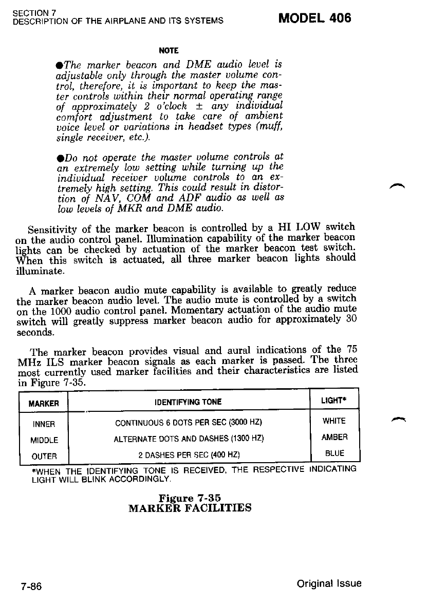
SECTION 7
DESCRIPTION OF THE AIRPLANE AND ITS SYSTEMS MODEL 406
NOTE
oThe marher beacon and DME aul'io Leuel is
adiustable onlv Lhrowh thB master uolume con-
trisL, therefore, it is important to heep the nTas'
ter controls withtn their normaL operating range
of approximately 2 o'clock + any t-ndiuidual
c'omidrt adiustrnent lo take care of ambient
uoice leuel or uariations in headset types (muff,
single receiuer, etc.).
ODo not operate the master uoLutne controls at
an extremely low setting whiLe turntng up the
indtuidunl receiuer uolume controls to an ex-
Lremelv hieh settine. This could resuLt in distor-
tion oi NAV, CON| and ADF audio as weLl as
low leuek of MKR and DME aud'io.
Sensitivitv of the marker beacon is controlled by a HI LOW switch
on thJaudirj control panel' Illumination capability of- the marker beacon
ii"hG-.u" t" ihecteil by actuation of th6 marlier beacon test switch'
Wi; thi. -;*il;t i. u"i"ut"a, aI three marker beacon lights should
illuminate.
A marker beacon audio mute capability is available to- 4eatly reduce
tfr" -".["t U"ucon audio level. The audio- mute is controlled by a switch
on ti" lObO "uaio control panel Momentary actuation of the audio mute
"iii"ti. *ii g.."tV suppress marker beacon audio for approximately 30
Secon(x].
The marker beacon provides visual and aural indications -of the 75
nfri" d-S -"tt "i b"u"6" signals as each J'arke-r is passed' The three
;;;; ";";ly "sed matker Tacilities and their characteristics are list€d
in Fizure ?-35.
*WTIEI.I TNE IDENTIFYING TONE IS RECEIVED, THE RESPECTIVE INDICATING
LIGHT WILL BLINK ACCORDINGLY,
I/|ARKER IDENTIFYING TONE LIGIIT*
INNER
MIDOLE
OUTER
coNTTNUOUS 6 DOTS PER SEC (3000 HZ)
ALTERNATE DOTS AND DASHES (1300 HZ)
2 DASHES PER SEC {4OO HZ)
WHITE
AMBER
BLUE
/-l'0
Fieure 7-36
MARKEA FACILITIES
Original lssue
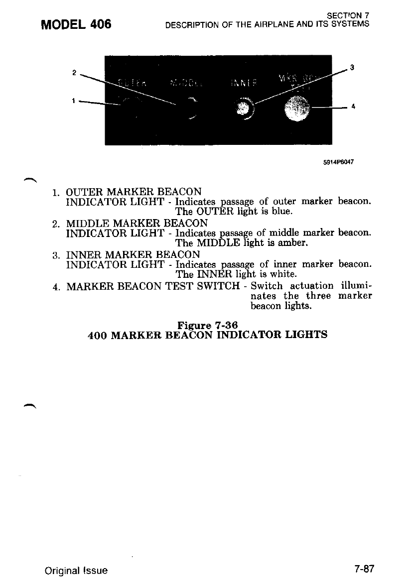
MODEL 406 SECTION 7
DESCRIPTION OF THE AIRPLANE ANO ITS SYSTEMS
591/tP80rl7
OUTER MARKER BEACON
INDICATOR LIGHT - Indicates passage of outer marker beacon.
The OUTER light is blue.
MIDDLE MARKER BEACON
INDICATOR LIGHT - Indicates passage of middle marker beacon.
The MIDDLE light is amber.
INNER MARKER BEACON
INDICATOR LIGHT - Indicates passage of inner marker beacon.
The INNER light is white.
MARKER BEACON TEST SWITCH - Switch actuation illumi-
nates the three marker
beacon lights.
Figure 7-36
4OO MARKER BEACON INDICATOR LIGHTS
Original lssue 7-87
The elideslope receiver is an airborne navigation equipment which
receives"and inierprets glideslope signals from a $ound-based instrument
landing svstem (fLS). It is uied with the localizer function of a VHF
navieaiioi receiver for making precision instrume.nt approaches to an
airp6rt. fne glideslope provid6s -vertical flight path guidance while the
localizer provides azimuth guidance.
Operation of the glideslope receiver is controlled by the associated
VHF navieation receiver. When the VHF navigation frequency selector
switches aie set to a Iocalizer frequency, the glideslope receiver is en-
".C""a ""a the paired glideslope -freqiency ii automatically selected'
f'tiehi zuida"ce is Uisptaved on ihe glidescope indicator, refer to Figure
?-3i. oi horizontal situation indicator (HSI).
SECTION 7
OESCRIPIION OF THE AIRPLANE AND ITS SYSTEMS
400 GLTDESLOPE (TYPE R-843A)
.WHEN GLIDESLOPE "OFF" OR "GS" IS
VISIBLE, GLIDESLOPE INDICATIONS ARE
UNUSABLE.
.SPURIOUS GLIDESLOPE SIGNALS MAY
EXIST IN THE AREA OF THE LOCALIZER
BACK COURSE APPROACH WHICH CAN
CATJSE THE GLIDESLOPE "GS" FLAG TO
DISAPPEAR AND PRESENT UNRELIABLE
GLIDESLOPE INFORMATION. DISREGARD
ALL GLIDESLOPE SIGNAL INDICATIONS
WHEN MAKING A LOCALIZER BACK
COURSE APPROACH UNLESS A
GLIDESLOPE (II,S BC) IS SPECIFIED ON
]:HE APPROACH CHART, AUTOPILO'| OR
OTHER AVIONIC EqUIPMENT.
MODEL 406
7-88 Original lssue
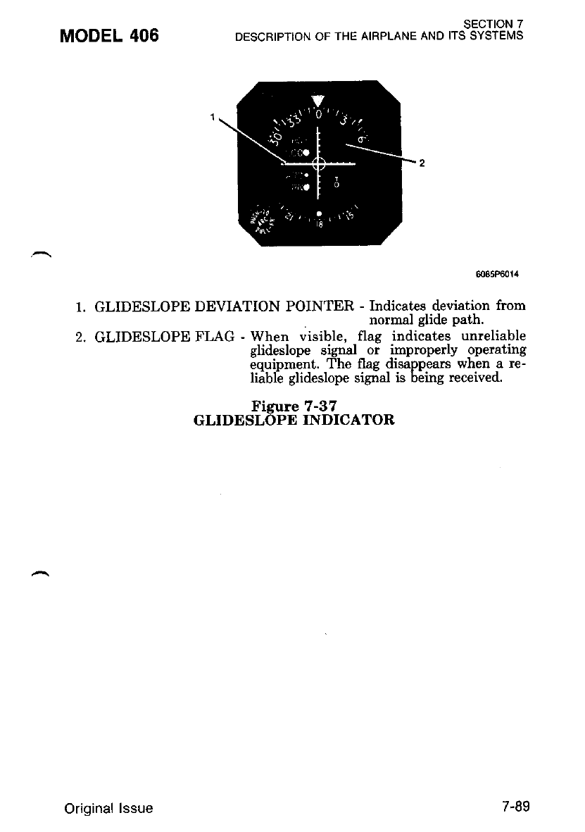
MODEL 406
1.
2.
SECTION 7
DESCRIPTION OF THE AIRPLANE AND ITS SYSTEITS
6085ft
GLIDESLOPE DEVIATION POINTER - Indicates deviation from
normal glide path.
GLIDESLOPE FLAG - When visible, flag indicates unreliable
glidgslope signal _ or lmproperly operating
equipment. The flag disappears when a re-
liibli glideslope sigial is b;ing received.
Figure 7-37
GLIDESLOPE INDICATOR
Original lssue 7-89
400 AUTOMATIC DIRECTION FINDER (TYPE R-446A)
The 400 ADF (T1pe R-446A) is an automatic direction finder set
which provides continuous, visual bearing indications of the direction
from which an RF signal is being received. It can be used for plotting
position, for homing, ind for aural reception of AM signals between 200
i<Hz and 1699 kHt. In addition, a crystal-coni;rolled, beat frequency
oscillator (BFO) permits coded identifrei of stations transmitting keyed
CW siglals (Morse Code) to be heard.
The 400 ADF consists of an R-446A receiver with dual frequency
selectors, fixed loop antenna. indicator(s) and a sense antenna. -Plnend.-
ins uoon the avionics options installed, the indicator(s) can be IN-346A
or-IN-3aGB bearing indicators or IN-13A-1, IN-404 or IN-I004A RMI
indicators. The reieiver and goniometer-indicator are panel-mounted
units. The sense and fixed loop antennas are mounted on the extcrnal
aimlane sr-,tface". Operating controls, refer to Figure 7-38' are nounted
on'the receiver front pandl. The goniometer-indicator presents station
bearing in decrees of aiimuth. The automatic pointer-stow feature alerts
the ooirator io non-ADF operation slewing the point$ to the 3 o'clock
oositibn when the REC moile or BFO is select€d' An optional RA-446A'
hl-gaOA or RA-346B receiver accessory may be substituted for the
soniometer-indicator to supply the goniometer funtion for driving a
ionventional ADF indicator or an RMI.
The frequencv ranse of the 400 ADF is electronically divided into
three bandi: 200-399 -kHz, 400-?99 kHz and 800-1699 kHz. Frequencv
snacing within each band is in l-kHz, incrementa. The operating fre-
ouencv" and band are selected bv a four-section Minilever switch which
disola-vs a digital readout of the'frequency selected and supplies a binary
code io contiol the logic circuits within the set. A secondary (standby)
operatinq frequency is-selected by another four-section minilever switch.
F'requen6y control-of the ADF is switched to the pdmary or the secon-
dary' opeiating frequency by a toggle swikh. The operating modes (ADF
;d n'Eat ari sel'ected nv inaiiiluat pushbutton- switchis. Additional
pu.frU"ttoo switches are used to seleit the BFO and to test signal
ieliability during ADF operation.
SECTION 7
DESCRIPTION OF THE AIRPLANE AND ITS SYSTEMS MODEL 406
7-90 Original lssue
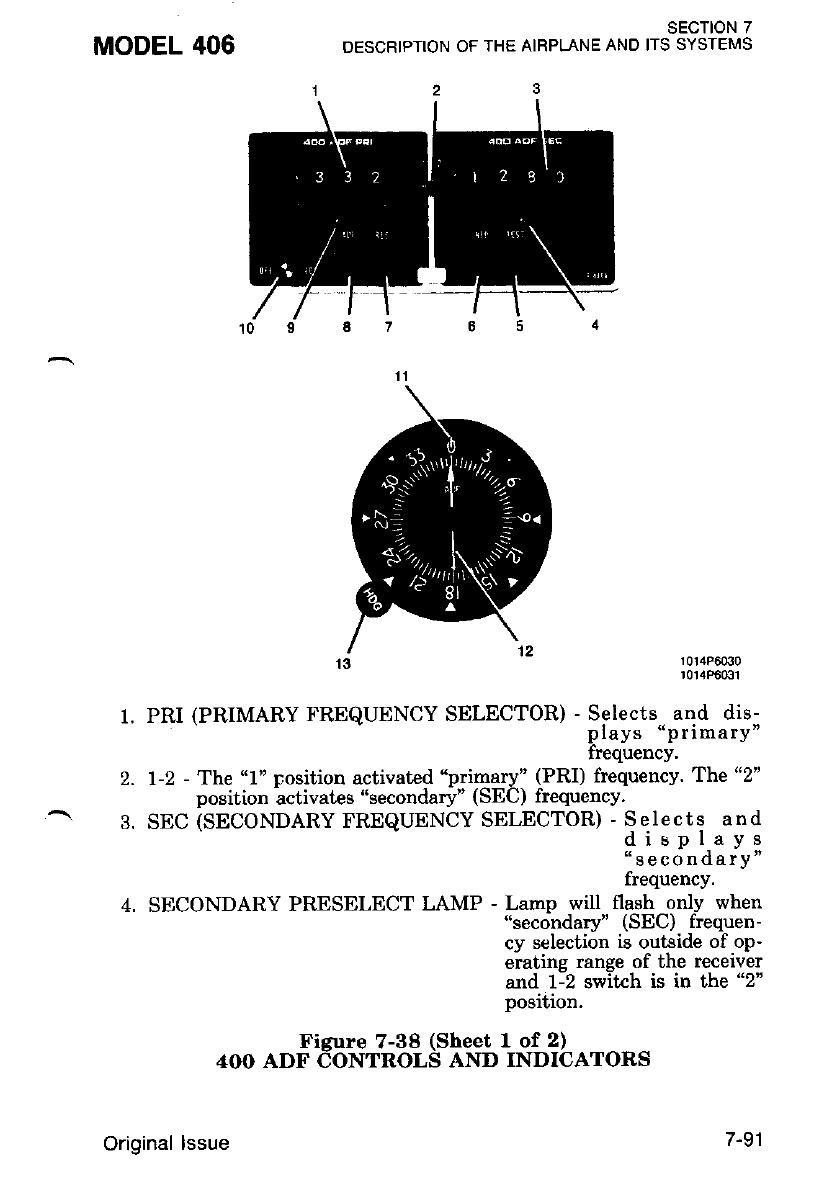
MODEL 406
t.
t
2.
q
13 l3lxF33",
PRI (PRIMARY FREQUENCY SELECTOR) - Selects-. and dis-
plays "p rimary"
frequency,
1-2 - The "1" rosition activated "primary" (PRI) frequency. The "2"
position activates "secondary" (SEC) frequency.
SEC (SEC0NDARY FREQUENCY SELECTOR) :"rt:Ti ."it
"secondarY"
frequency.
SECONDARY PRESELECT LAMP - Lamp will flash onlv when
"secondary" (SEC) frequen-
cy selection is outside of op-
eratins range of the recetver
alld t--2 switch is in the "2"
position.
Figure 7-38 (Sheet 1 of 2)
4OO ADF CONTROLS AND INDICATORS
SECTION 7
OESCRIPTION OF THE AIRPLANE AND ITS SYSTEMS
Original lssue 7-91
SECTION 7
DESCRIPTION OF THE AIRPLANE AND ITS SYSTEMS MODEL 406
7.
TEST - Momentary-on switch used only with ADF function to test
bearins reliabilitv. When held depressed, slews indicator
pointei; when reieased, if bearing is reliable, pointer re-
turns to original position.
BFO - Pushed in: Activates beat frequencv oscillator tone to permit
coded identifrer of stations tiansmitting keyed CW signals
(Morse Code) to be heard.
REC - Pushed in: Selects receive mode (set operates as a standard
communications receiver using sense antenna only).
I{OTE
When the 400 ADF is in thc REC or BFO
function, an autoratic pointer stou feature uill
'alert the pilot to non-ADF operatton by pos['
tioning and retaining the pointer dt the 3
o'clock postion.
8. ADF - Pushed in: Selects ADF mode (set operat€s as automatic
direction linder using fixed loop and sense antennas).
9. PRIMARY PRESELECT LAMP - Lamp will flash onlv when
'primary" (PRI) frequency se-
lection is outside of operating
ranqe of the receiver and 1-2
swilch is in the "1" Position.
10. OFF-VOL - Ttrrns set on or off and adjusts receiver volume.
11. INDEX - Fixed reference line for dial rotation adjustment.
12. POINTER - When HDG or VAR control is adjusted, jndicates
either relative, magnetic or true bearings of a radio
station'
13. HDG or VAR - Rotates dial to facilitate relative, magnetic or true
bearing information.
Figure 7-38 (Sheet 2 of 2)
4OO ADF EONTROLS AND INDICATORS
400 NAv/coM (TYPE RT-48s8)
The 400 NAV/COM (Tlpe RT-a85B) consists of- a .panel-mounted
receiver-transmittbr and a dual pointer remote course deviation indicator
(IN-481AC or IN-483AC)'
The set includes a ?20-channel VHF communications receiver-
tt.nsmitler and a 200-channel VHF navigation receiver' both of which
-ry b" op".ated simutaneously.- The . commugic^allqns receiver-
traismitter^ receives and Lransmits'signals between 1f8.000 and 135'975
inlHr-- i"'- ZS-XH, steps' The navigition receiver recei,v-es omni and
lo"Jrei "ie".ls betwe'en 108.00 and1u.95 MHz in 50 KHz steps. The
"lt"ultr t"duit"a to interpret the omni and localizer signals are located in
7-92 Original lssue
the course deviation indicator. Microprocessor frequency management
provides storage.for 3 pretuned navigation and 3 pretuned communica-
iron nequencres rn memory,
A "Frequency Memory" voltage is provided so that the preset fre-
quencies are not lost when the receiver is turned off. This voltage is
provided directly from the hot battery bus and is present even with the
battery switch off. To prevent battery discharge during periods of long
term storage, it is recommended the FREQ MEM circuit breaker on the
right side console be pullec.
IIOTC
If the "Frequency Memory" uo\tage k interrryt-
ed, sll stored NAV/COM lrequenctes uilL be lost.
Subsequent operation with the "Frequency
Mernory" uoLtage restored., will require new fre-
quency tnpu6.
A distance measuring equipment (DME) receiver-transmitter or a
glideslope receiver, or both, may be interconnected with the NAV/COM
set for automatic selection of the associated DME or glideslope fre-
quency. When a very high frequency omnidirectional and radio range
(VOR) frequency is selected on the NAV/COM, the associated VORTAC
(VOR/DME) station frequency will also be selected autoroatically; like-
wise, if a localizer frequency is selected, the associated glideslope fre-
quency will be selected automatically.
Both course deviation indicators include dual pointers arrd related
NAV and GS flags for both VOR/LOC and glideslbpe indications. The
indicators incorporate a back-course lamp (BC) which lights when op-
tional back course (reversed sense) operation is selected and a RNAV
lamp (RN) (IN-483AC indicator'oniy) which, when illuminated, in-
dicates that the navigation system is in the RNAV mode. Indicaton
with Automatic Radial Centering will, when selected, automatically in-
dicate the radial (bearing) to or fiom the VOR station.
AII controls for the NAV/COM, except the omni bearing selector
' (OBS) knob, which is locattid on the course deviation indiiator, are
mounted on the front panel of the receiver-transmitt€r, refer to Figure
?-39. In addition, when two or more radios are installed, airplane moun-
ted transmitt€r selector and speal<er/phone switches are firovided.
MODEL 406 SECTION 7
DESCRIPTION OF THE AIRPLANE AND ITS SYSTEMS
Original lssue
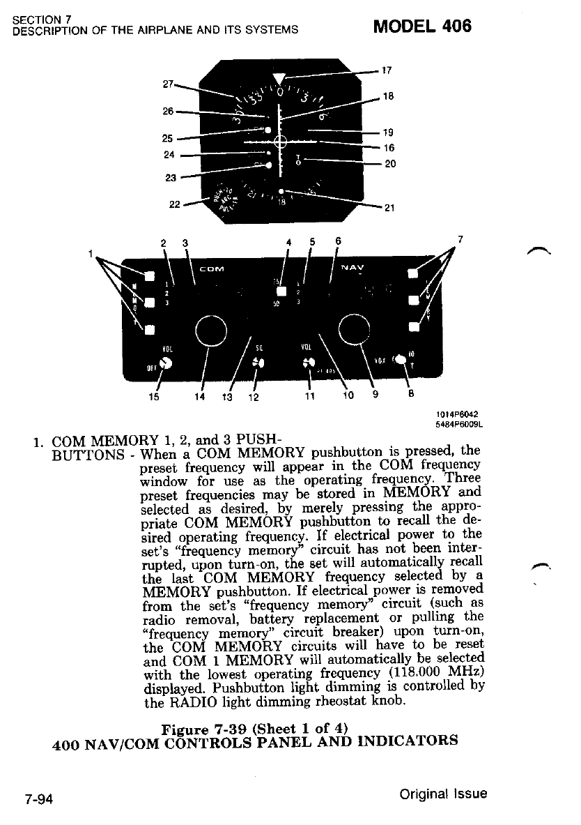
SECTION 7
DESCRIPTION OF THE AIRPLANE AND ITS SYSTEMS
5484P(jOO9L
1. COM MEMORY 1, 2, and 3 PUSH-
^' iild"rbNlt- wt'e_'i; coM MEMoRY pushbutton-E-Pre-ssed, the
preset frequency will appear in. the^UUM trequency
iui"ao* fot us6 as thi'operating freque-n-cy Three
oreset frequencies may be'stored-in NiEMORY and
ilelected ai desired, by merely pressing the appr.o-
p.i"tJ bOU MEMORV puglrbgtton to iecall the de-
iiiJd'ope.ating frequency. If electrical power to the
sets "fiequett"iy meino4l" circuit- has not been inter-
runted' urion turn-on, the set will automatically recall
itti t."t 'COtvt MEMORY frequency selected bv a
iuibMOnY pushbutton. If electrical..power.is removed
i.o- ttt" set's "frequency memoryn circuit -(such as
taaio t"-ouut, battery ieplacemint or pulling the
ufrequency memory" circuit bre*er) upon turn-on'
the tOM MEMORY circuits will have to be reset
t"a COM 1 MbMORY will automatically be selected
*tft ttt" lorveit operating frequency (118 000 MHz)
displaved. Pushbution lief,t di;Imin'g is controlled by
the RADIO light dimming rheostat knob'
Figure 7-39 (Sheet I of 4) ---- -, -^-^
4OO NAV/COM CONTROLS PANEL AND INDICATORS
MODEL 406
16
7-94 Original lssue
MODEL 406 SECTION 7
DESCRIPTION OF THE AIRPLANE AND ITS SYSTEMS
Z. COM MEMORY
BARS 1, 2, 3 - When a COM MEMORY pushbutton is pressed'
the corresponding memory bar is illumirated to in-
dicate which CoM MEMORY is in use.
J. COMMUNICATION OPERATING FREQUENCY
READOUT - Steady display indicates COM frequency -is use'
Blinking diripla-y indicates a fr-equency select€d during
memorf stoiin! and not the frequency in use-. Third
decimai place (;ither 0 or 5) is not shown on display.
4. 25150 PUSHBUT"TON - Selects last illuminated decimal place on
' COM frequency in use. If last decimal
place is 2 br'7, pressing 25/50 pushbutton
ihanqes nurnber to 5 or 0' respectively. If
last ilecimal place is 5 or 0, pressing 25/50
Pushbutton ihanges number tn 7 or 2,
respectively. When the last illuminatcd
digit on ttie set is 2 or 7, the third {igrt
on the set (not shown) will always be 0'
5. NAV MEMORY
BAR 1, 2, and 3 - When a NAV MEMORY ngshbutto-n is pressed,
the corresponding memory bar is illuminated to indicate which
NAV MEMORY is in use.
6. NAVIGATION OPERATING FREQUENCY
READOUT - Steady display indicates NAV freque-ncv -in use'
Blinkiirg di6pliy indicates. a frequencv selected during
memory storing and not the trequency m use.
?. NAV MEMORY 1, 2, and 3 PUSH-
BUT"IONS - Wheir a NAV MEMORY pushbuttnn is press€d, th€
preset frequency will appear in the NAV frequency
window foi use as th6 -operating frequency. Three
nreset freuuencies mav be-stnred in MEMORY and
irelected ai desired, 5v merely pressing the appro-
priate NAV MEMORY pushbutton to recall the de-
iired operating frequency. If electrical power to the
set's "fiequency mehory" circuit has not been inter-
rupted, uion ti:rn-on, the set will automatically recall
th; h;t -NAV MEMORY frequencv selected bv a
MEMOiiY pushbutton' If electrical power is removed
from the set's "frequency memory" circuit (such as
radio removal, batiery ieplacement or pulling the
"frequency memory" circuit breaher) upon turn-on,
the NAV-MEMORY ctcuits will have to be reset and
NAV 1 MEMORY will autnmatically be selected with
the lowest operating frequencv (108.00 \4Hz) dis-
played. Pushbutton light dimmilrg is controlled by the
ilADIo tieht dimmini rheostat knob.
Figure 7-39 (Sheet 2 of 4)
4OO NAV/COM CoNTROLS PANEL AND INDICATORS
Original lssue 7-95
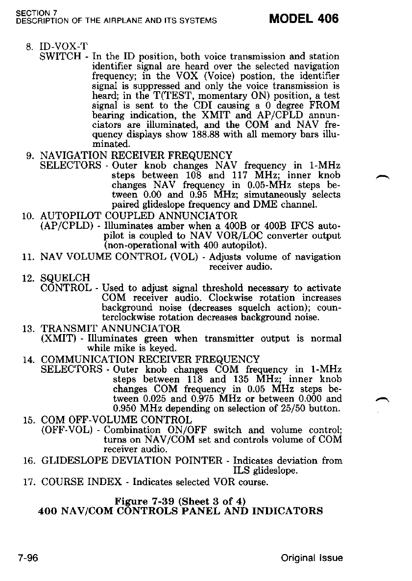
SECTION 7
DESCRIPTION OF THE AIRPLANE AND ITS SYSTEMS MODEL 406
10.
8. ID-VOX-T
SWITCH - In the ID position, both voice transmission and station
identifier signal are heard over the selected navigation
frequency; i; the VOX (Voice) postion, the identiher
signal is suppressed and only the voice transmission is
heard; in the T(TEST, momentary ON) position, a test
signal is sent to the CDI causing a 0 degree FROM
bearing indication, the XMIT and AP/CPLD annun-
ciators are illuminated, and the COM and NAV fre-
quency displays show 188.88 with all memory bars illu-
mrnat€c.
9. NAVIGATION RECEIVER FREQUENCY
SELECTORS - Outer knob changes NAV frequency in l-MHz
steps between 108 and 117 MHz; inner knob
changes NAV frequency in 0.05-MHz steps be-
tween 0.00 and 0.95 MHz: simutaneouslv selects
paired glideslope frequency and DME chanirel.
13.
74.
AUTOPILOT COUPLED ANNUNCIATOR
(AP/CPLD) - Illuminates amber when a 4008 or 4008 IFCS auto-
pilot is coupled to NAV VOR/LOC converter output
(non-operational with 400 autopilot).
NAV VOLUME CONTROL (VOL) - Adjysts volume of navigation
recerver auoro,
SQUELCH
CONTROL - Used to adjust signal threshold necessary to activate
COM receiver audio. Clockwise rotation increases
background noise (decreases souelch action): coun-
tercl6ckwise rot{tion decreases birckground noiie.
TRANSMIT ANNUNCIATOR
(XMIT) - Illuminates green when transmitter output is normal
while mike is keyed.
COMMUNICATION RECEIVER FREQUENCY
SELECTORS - Outer knob changes COM frequency in l-MHz
steps between 118 and 135 MHz; inner knob
changes COM frequency in 0.05 MHz steps be-
tween 0.025 and 0.975 MHz or between 0.000 and
0.950 MHz depending on selection of 25150 button.
I I.
72.
15, COM OFF.VOLUME CONTROL
(OFF-VOL) - Combination ON/OFF switch and volume control;
turns on NAV/COM set and controls volume of COM
receiver audio.
16. GLIDESLOPE DEVIATION POINTER - Indicates deviation from
ILS glideslope.
17. COURSE INDEX - Indicates select€d VOR course.
Figure 7-39 (Sheet 3 of 4)
4OO NAV/COM CONTROLS PANEL AND INDICATORS
7-96 Original lssue
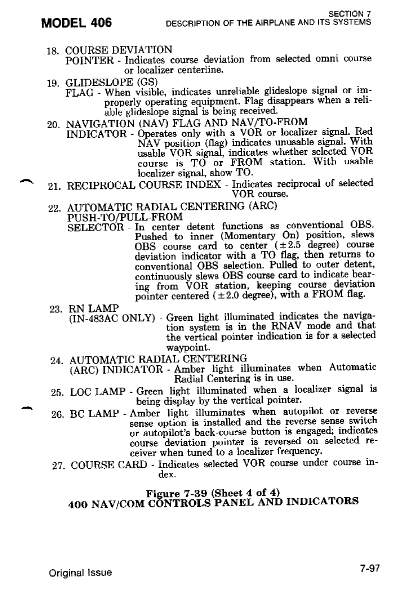
MODEL 406 SECTION 7
DESCRIPTION OF THE AIRPLANE AND ITS SYSTEMS
18.
19.
20.
COURSE DEVIATION
POINTER - Indicates course deviation from select€d omni course
or localizer centerline'
GLIDESLOPE (GS)
I'LAC - Wtte" visible, indicates unreliable glideslope signal or im-
- - - p.t-op;Ill operating equip'nlnt. Flag-disappears when a reli-
able glrdeslope slgnal rs Demg recerveq.
NAVIGATION (NAV) FLAG AND NAV/TO.FROM
it tbtCeron - op".a[u. only with a VoR or localizer signal.-.Red
' NIV positioir (flag) indicates unusable sjenal' With
usable VOR sigira[ indicates whether selected VOR
course is Td or FROM station. With usable
localizer signal, show TO.
RECIPROCAL COURSE INDEX - Indicates reciprocal of selected
VOR course.
AUTOMATIC RADIAL CENTERING (ARC)
PUSH.TO/PULL-FROM
-SEiibTOn - f" ientet detent frrnctions as -conventioral OBS'
Pushed to inner (Momentary On) position, slews
OBS course card to center (+25 de$ee) course
deviation indicator with a TO flag, then retums to
conventional OBS selection. Pulled t'o outer det€nt'
contitt,rously slews OBS course card to indicate.bear-
inc from VOR station, keeping coulse - deviation
oolnter centered ( * 2.0 degree), with a FROM flag'
RN LAMP
iii.i-aeieC ONLY) - Green light illuminated indicates the naviga-
f,lon svsf,em is in the RNAV mode and that
the ve-rtical pointer indication is for a selected
walDoint'
AUTOMATIC RADIAL CENTERING
?ln-Cj tNltCefOR - Amber light illuminates when Automatic
Radial Centering is in use'
LOC LAMP - Green light illuminated when a localizer signal is
being display by the vertical pointer'
BC LAMP - Amber light illuminates when autopilot or reverae
sense opti-on is installed and the reverse se,nse switch
or autoiilot's back-cou::se button is engagedi, indlcates
course ^deviation pointer is reverged on selected re-
ceiver when tuned-to a localizer frequency'
COURSE CARD - Indicates selected VOR courge under course in-
oex'
Figure 7-39 (Sheet 4 of 4)
4OO NAV/COM C'SNTROLS PANEL AND INDICATORS
27.
22.
23.
24.
25.
26.
27.
Original lssue
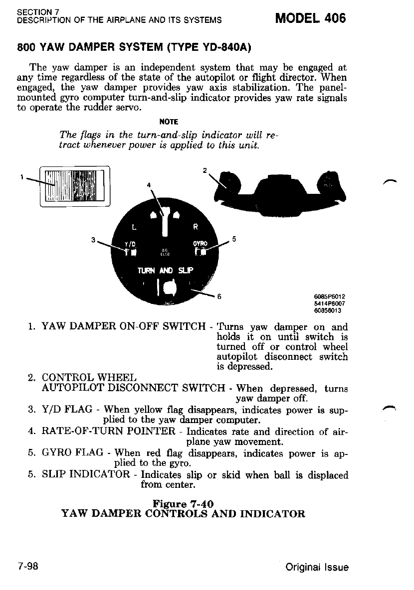
8OO YAW DAMPER SYSTEM (TYPE YD.84OA)
The yaw damper is an independent system that may be engaged at
any time regardless of the state of the autopilot or flight director. When
enlaged, thi yaw damper provides yaw aiis stabiliiation. The panel-
mounted glno computer turn-and-slip indicator provides yaw rate signals
to operate the rudder servo.
{orE
The fLags in the turn-and-slip indicator will re-
tract uheneuer power is applied. to this unit.
1. YAW DAMPER ON-OFF SWITCH - T\.uns vaw damoer on and
holds ii on until switch is
turned off or control wheel
autopilot disconnect switch
is depressed.
2. CONTROL WHEEL
AUTOPILOT DISCONNECT SWITCH - When depressed, turns
yaw damper off.
3. Y/D FLAG - When yellow flag disappears, indicates power is sup-
plied to the yaw damper computer.
4. RATE-OF-TURN POINTER - Indicates rate and direction of air-
plane yaw movement.
5. GYRO FLAG - When red flag disappears, indicates power is ap-
plied to the gyro.
5. SLIP INDICATOR - Indicates slip or skid when ball is displaced
from center.
Figure 7-4O
YAW DAMPER CONTROLS AND INDICATOR
sEcroN 7
DESCRIPTION OF THE AIRPLANE AND ITS SYSTEMS MODEL 406
608sP6012
5414P6007
ffirr|ilffiffiillil l
7-98 Original lssue
ELECTRIC ELEVATOR TRIM
The electric elevator trim system consists of an electrically- operated
dti;;-;;;; and clutch assehbly, which receives power through a
";4";;;t ott;- t*o-*ay trim iwitch and an emergency disengage
swtf,cn.
CABIN FEATURES
CABIN FIRE EXTINGUISHER
A Dortable 2.5 pound Halon 1211 fire extinguisher. is provided in case
.r ?t;'i"ti"ti*t'tr".t';Ji; n;;. Th; flre extinguisher, located beneath the
;;r'ifu1;;;;:;-h;tiJ n" "nL.xJ p'ior Lo eacL flight to ensure that bottle
o.i,."u.", as indicated by the gage on the- bo!!le' i8 wrthrn the green arc
iffi;ilffi;ti6po*ia" ri"ii?ruu'e inch)' To operaLe the boltle:
'-il Loo*.n the retaining ciamp and renove extinguisher from bracket'
i. iold bottle upright, pull ."taittittg pin, and press lever to discharge'
I{OTE
OBegin discharge 5 feet from fire, at bose, ol the
fLame, and sweep as requlred ojross tne Ju'me'
OExtingutsher should be recharged after each
uSe.
3. After discharging a fire extinguisher, ventilate the cabin'
MODEL 406 SECTION 7
DESCRIPTION OF THE AIRPLANE AND ITS SYSTEMS
Original lssue 7-99 (7-100 blank)

MODEL 406 sEcTloN 8
HANDLING, SERVICE AND MAINTENANCE
sEcTloN I
HANDLING, SERVICE AND MAINTENANCE
TABLE OF CONTENTS
INTRODUCTION .....
Publications
Cessna Owner Advisories
Cessna Service Information Subscription Program
AIRPLANE INSPECTION PERIODS
Cessna Continuous Inspection Program ' '
Cessna Custoner Care Program
CESCOM SYstem .
Engine Condition Trend Monitoring . .' "''
Servicing R€quirements
Airplale File
PREVENTIVE MAINTENANCB THAT MAY BE
ACCOMPLISHED BY A CERTIFICATED PILOT
ALTERATIONS OR REPAIRS TO AIRPLANE
GROUND HANDLING
Towing....
Parking
Tie-Down
Jacking and Leveling
SERVICING......
Cabin Fire Extinguisher
Fuel ...
Fuel Additive
Fuel Contamination
Oxygen .
Landing Gear Hydraulic Reservorr ' ' '
Alcohol Windshield Deice Reservoir " " " '
Tires . . .
Flush Toilet Reservoir
Light Bulb RePlacement
Fuse and Fuse Limiter Replacement ' ' '
CLEANING AND CARE
ExteriorCleaning ... .. .
Interior Cleaning
PROLONGED OUT-OF.SERVICE CARE . " ..
Page
8-3
8-3
8-4
8-5
8-5
8-5
8-6
8-6
8-6
, 8-8
8-9
8-10
8-10
8-11
8-11
8-12
8-12
8-13
8-13
8-14
8-14
8-15
8-18
8-19
8-21
8-22
8-22
8-22
8-22
8-23
8-27
8-28
8-28
8-31
8-35
8-1
Original lssue - 1 JulY 1986
sEcroN 8
HANDLING, SERVICE AND IVAINTENANCE MODEL 406
Page
8-14
8-17
8-20
8-22
8-23
8-24
8-24
8-25
8-25
8-26
8-26
8-27
LIST OF FIGURES
Figure
8-1 Approved Fuel Grades
8-2 EGME Additive Mixing Ratio . .
8-3 Approved Oil . .. .
8-4 Oxygen Servicing Chart . .
8-5 Light Bulb Replacement Guide .
8-6 Landing Gear Position Lights . .
8-7 Compass Light .. .
8-8 Instrument Post Lights
8-9 Annunciator Parel Lights
8-10 Ignition Lights . .
8-11 Marker Beacon, Autopilot Off and
Altitude Alert Lights .
8-12 Fuse and Fuse Limiter Replacement Guide
8-2 Original lssue - 1 July 1986
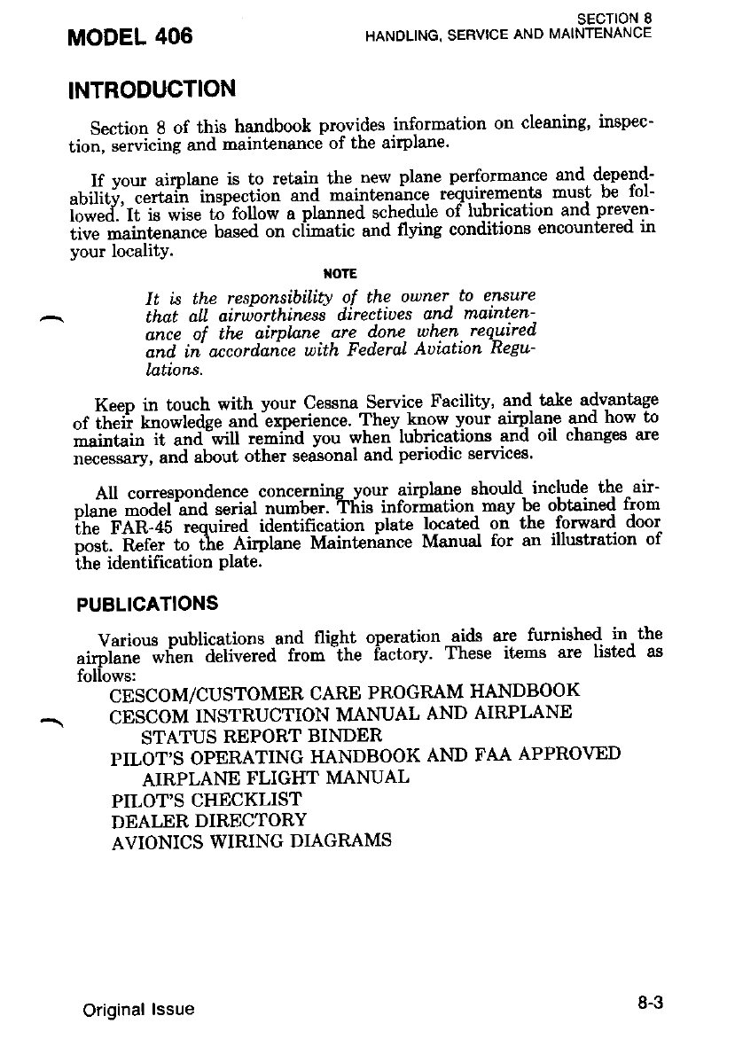
sEcrloN I
HANDLING. SERVICE AND MAINTENANCE
INTRODUCTION
Section 8 of thig handbook provides infqmation on cleaning, inspec-
tion, sewicing and naintenance of the airplane.
lf vour airplane is to retain the new plane performance and depend-
"uiiiti. ""ttiri'" l"tp""iion ""a maintenan-ce requirements must be fol-
iJti,"i'.'ti iii *t" to- iollow a planned schedule of lubrication and preven-
iiu" -"iot"tt"tt". based on cl-irnatic and flying conditions encount€red in
your locality.
otE
It is thp responsibiLity of the owner.to enaure
that all airworthiness directiues and marnten-
aii of thc airplane are done when required
and in'orcordaice uith FederaL Auiation Regu-
latiorx.
Keep in touch with your Cessna Service Facility, and take adv-antage
"f ;i;{ kt"t"*l"dce and -experience. They- know your airplane ard how to
maintain it and will remind you when lubncatrons and orl cnanges are
""""s.t y, and about other seasonal and periodic services'
All conespondence concerning your airplane should- include the air-
"r"ri" -J"I."itii*"-tiut -"u-t"t. Tlii" infothttion. mav be obtained from
ifrl'i'eri.is r"quit"a U""iincation plate located on the .forward door
i"".t. iiii"i: t" -iti" Airplatte Maintenince Manual for an illustration of
ihe identification plate.
PUBLICATIONS
Various publications and flight operation a-ids are furnished in the
ri.jritjJ-i"ti* - J"tit*"d- from "the factory' These items are listed as
foliows:
CESCOM/CUSTOMER CARE PROGRAM HANDBOOK
CESCOM INSTRUCTIOIiI MANUAL AND AIRPLANE
STATUS REPORT BINDER
PILOT'S OPERATING HANDBOOK AND FAA APPROVED
AIRPLANE FLIGHT MANUAL
PILOT'S CHECKLIST
DEALER DIRECTORY
AVIONICS WIRING DIAGRAMS
MODEL 406
Original lssue 8-3
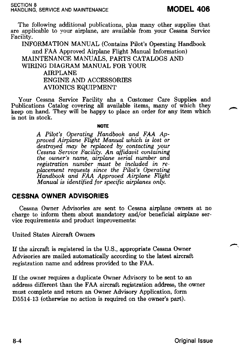
SECTION 8
HANDLING, SERVICE AND MAINTENANCE MODEL 406
The following additional publications, plus many other supplies that
are applicable to your airplane, are available from your Cessna Service
Facility.
INFORMATION MANUAL (Contains Pilot's Operating Handbook
and FAA Approved Airplane Flight Manual Information)
MAINTENANCE MANUALS, PARTS CATALOGS AND
WIRING DIAGRAM MANUAL FOR YOUR
AIRPLANE
ENGINE AND ACCESSORIES
AVIONICS EQUIPMENT
Your Cessna Service Facility ahs a Customer Care Supplies and
Publications Catalog covering all available items, m€ny of which they
keep on hand. They will be happy to place an order for any item which
is not in stock.
I{OTE
A Pilot's Operating Hand,booh and FAA Ap-
proued Airphne Fllght Marunl which is lost or
destroyed may be replarcd by contading your
Cessna Seruice FMiliW. An affidauit contdining
the ouner's name, airplane serial nurnber and
re{ktration number must be included. in re-
plarcment requests since the Pilnt's Operating
'Handbook art pAe Approued Airyla;e nigit
Manual is identified for specific airplnnes only.
CESSNA OWNER ADVISORIES
Cessna Owner Advisories are sent to Cessna airplane owners at no
charye to. inform them about mandatory and,/or beneficial airplane ser-
vice requiremenls and product improvements:
United States Aircraft Owners
If the aircraft is registered in the U.S., appropriate Cessna Owner
Advisories are mailed automatically according to the lategt aircrafl
registration nane and address provided to the FAA.
If the owner requies a duplicate Owner Advisory to be sent to an
address different than the FAA aircraft, registration address, the owner
must complete and return an Owner Advisory Application, form
D5514-13 (otherwise no action is required on the owner's part).
8-4 Original lssue
SECTION 8
HANDLING, SERVICE AND MAINTENANCE
International Aircra.ft Owners
To receive Cessna Owner Advisories, International aircraft owners must
""rtpf"" *a t"t"rn an Owner Advisory Application' form D5514-13'
Receipt of a valid Owner Adviso.ry AppJication .will-. establish the
c";;;''o;;. Aa;to"v *"*i"i-lduputate- bwner Advisory service for
;:B:;t"-";H";*;J"ti njt o"" vi"i, aiter which the owner will be sent a
renewal notice'
CESSNA SERVICE INFORMATION SUBSCRIPTION
=.PROGRAM
A subscription service for Caravan II Service Bulletins is available
directlv from the uessna '-o.riilti Su-i"tt |gpqt3?lti^Jour Cessna
Bii"llii ei,iiiitv;u 1," pr""Ja"io t"nplv vou witli denits concerning this
iriri.iiipii"ii iiiostan, aid Etand; reidv, ihroueh his service Department'
iJ ."iiiiv v".i *iih fast and effrcient service'
AIRPLANE INSPECTION PERIODS
FederalAviationRegulationsPart9l.16.9.G).defrnesthe4Fpection
,"o'u'ii"r#nG 6.-iotuopiop.riit:po"'"ied multiengine 1Il]T""' Chapter 5
;'f';fr;'lG;;; Mai"tc"ince - Iftanual contains the inspection program
i""r--'-"ttda uv Cessna Aircrah Company'
Additional inspections may be required-by the FAA''These insDections
are issued in the form "t aik"ttttit*J-niiectives and 'cal aPdv^to thc
ffd;;.;;il;; undToi "otpott"ttts of the airylane' It is the owner s
i""."*it Uitv to ensure compliance with these directives-'- ln aome cases'
the Airworihines" Directiue""retti;" ;;;;titt* com-pliance; therefore' the
owner should "n**" ,rr*ou"rtuni nonco'mpliance does not occur at future
inspection intervals.
NOTE
Refer to FAR Parts 43 and 91 for prope,lly,
iii'tiri"i"a agency or personn'el to acconphsn
ltiiiiii"tioi*' Contaci vour- locaL .Cessna ser-
uice Fdcilitv for sdditional tntormatlon'
CESSNA CONTINUOUS INSPECTION PROGRAM
The Cessna Continuous lnspection Pro-grqq has.been developed to
nrovide a modem continuo"t'ii"i*iio" tt["C]'le that satisfies the com-
ii""#i"rriril"-:i;;bi"iii,t '6qi,ii"ii""i"--a to help vou,realize ma:imum
utilization ot you" uop*o"'iT?iti''iit"t cost 'arid. down-time' Under
this prosran, vou, uoptto"" iJ p-ip"'".iiJ;4.pain$119{ in a 600 hour
cycle. This cycle is composldofiii -ptt"t"t with a phase being performed
at 50 hour int€rvals'
MODEL 406
Original lssue
sEcTtoN I
HANDLING, SERVICE AND MAINTENANCE MODEL 406
The procedures for the Cessna Continuous Inspection Procram have
been carefully worked out by the factory and ai.e followed 6y the Cessna
Dealer Organization. The complete farniliarily of Cessna Dealers with
Cessna equipment and factory-approved procedures provides the highest
level ol servrce possrDle to uessna owners.
CESSNA CUSTOMER CARE PROGRAM
Specific- benefits and provisions of the Cessna Warranty for your
qilp-lgl^e- plus other import€nt benefits for you are containid ir: your
CESCOM/Customer Care Program Handbook supplied with your - air-
plane..Yol will want. to thoroughly review this pubiiiation and [eep it in
your alrphne at all trmes,
CESCOM SYSTEM
CESCOM is Cessna's Conputerized Maintenance Records System.
This comprehensive system prbvides you with an accurat€ and iimple
method of monitoring and schedulins inspections. Caravan II Service
Bulletins, Service Kits, Airworthiness Direc-tives as well as scheduled and
unscheduled maintenance activities. For detailed information about
CXSCOM, refer to the CESCOM Instruction Manual supplied with your
airplane.
ENGINE CONDITION TREND MONITORING
. Pratt and Whitney Canada Inc. Engine Condition Trend Monitoring
is a. systfm of. recording. engine ins[rument readings, correcting thi
readrngs Jor ambrent conditions, and comparing actual engine operation
co typical engine operating characteristics.
It has been established that engine operating characteristics, such as
o,utput torque (Tq), _p_rgpeller RPM (Np), interturbine temperature
(IT'T), Sas generator RPM (Ng), and tuel-flow (Wf) are prediciable for
various engine t54res under specific ambient conditions.
. Because airplane engines operate at a wide range of altitudes, outside
alr l,emperatures, and airspeeds, corrections for varving ambient con-
ditions are also incorporated into the Trend Monitoririg pirocess.
During operation,- engine gas path components (compressor as well as
l.urbine) are exposed to internal and external factors which can deterio-
rate the airfoil surfaces, which in turn can decrade the oneratins effl-
ciency of the engine. Accomplishmenl of Eneint Condition Trend Moni-
toring allows compressor and,/or turbine deteiioration to be detected, and
in turn, alerts the operator/maint€nance facility that corrective main-
tenance action may be needed.
Engine Condition Trend Monitorins is ar integral feature of the
Cessna CESCOM program. Accomplishment of Trend Monitoring, utiliz-
.'-O Original lssue
inetheCessnaCESCOMsystem,isrelativelysimpleandconsistsof
thiee primarY activities:
oRezularrecordingofinstrumentreadingsbytheairplaneoperatolon
th;Aircrafi Flight Rccord'
O Processing, pl-o-!qng, aTd reDorting of fuel flow (Wf inter-turbine
temperature (l l"I,, ano g#"gt""i?oi nFv (Ne) deltas (deviations)
bv CESCOM.
OAnalysisandreviewof.the..reporiedTrendMonit,oringreportbythe
^- Lp"tito.'" maintenance facility'
To ensure maximum accuracv' it is ESSENTIAL to rninimize as
many enors as po.srore *;;";";;di"t engine instrum€nt readings'
sources ot error lncluoe "*uii'puiJi*, i*pr"ecise interpretation of in-
Jt"i*""i ."uaings, poor insiiinienf u"dut"iy' and poor instrument re-
;"i#tll'"*ft ""1,8*i"nr',xf;*,1*'*t'+"H$,ilT;i*'1,fl ,:""
Trend Monitoring instrument readings should P" g:P^-tlti-!:d,::"1
r"riif;"iiiiii"'i'iin 'ihJ e"gi"e adjusted to. normal-cruise-oower' Ior a
stabilized period ot "ot '"S'iriltl- HyJ minutes' The,.airP-lane inertial
separator should rre..rn t""'NbfrMAi' p;iiion' 31d'the^anti-ice/deice
equipment, arr conorrronrng' *a 6t"a air (cabin heat) should be turned
off.
*frt##*kffi#i'3Hiii"'t?$;ao'?1Hl'1$'di:i:"""T'i3ilf'
To obtain accurate re#llgs' parallax e*or' tnus-t
Ei minimized by uiewing each. Ltts'trunaenl Jrom
a zero-degree angle (i e ' stralght aneao)
,"iJ.'""fl
i:l{#"itr1:61f ',.:X1.ist1ii.llt6Y..ffi,Fi'f *':""#
tor engine op"tur-g, u"tt'i'[y" !"-i-t'i - idt*p and p-lan - tuture main-
t€nance actlvrtles wltn Loerr miintenance facility'
For those operators not upi+e QpSpOM' two additional methods mav
be used to accomplish Trend Monitoring:
O P & WC Compu-T.rend 2, which utilizes t l1"y-19!1-li:k"td HP4ICV
model programmao'" nuttf-h"ld "ulculator and optional printer'
oP&WCCompu-Trend3,whichcolsjstsofacomputerprogram
- ;"til;'; eASiC ro. an IBM Personal comput€r'
MODEL 406 sEcrloN 8
HANDLING, SERVICE AND MAINTENANCE
I Original lssue 8-7
SECTION 8
HANDLING, SERVICE AND MAINTENANCE MODEL 406
Additional information about both of these methods mav be obtained
from:
Pratt and Whitnev Canada Inc.
Box 10, Longueuil-, Quebec
Canada, J4K 4X9
Attention: Customer Support, Small Turboprops Mail
Code:1RCl
Trend Monitoring should be implemented when the engine iB new or
newly overhauled.
For additional information on Trend Monitoring, refer to the CESC-
OM Instruction Manual supplied with your airplane, and Pratt and
Whitney Canada Aircraft Inc. Gas Ttrbine Operation Information Let-
ters, Number 10 and Number 23.
SERVICING REQUIREMENTS
For ouick and readv reference. ouantities. materials. and specifications
for frequently used service items (such as fuel, oil, etc.) are shown in this
section.
In addition to the Preflight Inspection covered in Section 4, complete
servicing, inspection, and test requirements for your airplane are detailed
in the Aimlane Maintenance Manual. The Maint€nance Manual outlines
all items which require att€ntion at 50-, 100-, 200- and 600-hour inter-
vals plus those items which require servicing, inspection, and/or testing
at special intervals.
It is r€commended that you contact your Cessna Service Facility
concerning these requhements and begin scheduling your airplane for
service at the recommended intervals.
Depending on vadous flight operations, your local govemment avi-
ation agency rray require additional service, inspections, or tests. For
these regulatory requirements, owners should check with local aviation
officials where the airplane is being operated.
8-8 Original lssue
MODEL 406 SECTION 8
HANDLING, SERVICE AND MAINTENANCE
AIRPLANE FILE
There ate miscellaneous data, information and licenses-that are- 9. Part
"f th;;irpfu; fiie. The following is a checklist for- that file In addition'
X'r"it"iiJ "hJ"t rtto"ta U" mad6 of the Iatest Federai Aviation Regula-
tions to ensure that all data requirements are met'
a. To be displayed in the airplane at all times:
(1) Standard Airworthiness Certificate (FAA Form 8100-2)'
(2) Aircaft Registration Certificate (FAA Form 8050-3)'
(3) Aircraft Radio Station l,icense, (if Trinsmitter is installed'
Federal Communication Uommrssron lorm DDb''
(4) Radio Telephone Station License, (Federal. Communication
'-' bJ--t"ioi, Form 409, if Flitefone Radio Telephone is
installed).
b. To be calried in the airplane at all times:
(1) Weieht and Balance Data Sheets an{associated papers^(all
'^'
"opiZt oi tle Repair and Alteration Form' FAA Forrn 33?'
if ipplicable).
(2) Equipment List'
(3) Piiofs Operating Handbook and FAA Approved Airplane
Flight Manual.
(4) Pilot's Checklist.
c. To be made available upon request:
(1) Airframe Maintenance Records'
(2) Engine Maintenance Records.
(3) Propeller Maintenance Records'
Most of the items listed are required by -the- United States Federal
4uir1len ftesulations. Since the regulations of other natrons may requlre
other docurients and data' owners of airplanes not re€rstered ln Ine
ijnilib;G.-;houia "tt""[ with their own aviation officials to deter-
mine their individual requirements.
Cessna recommends you also carry your - CESCOM/Cuetomer Care
p.o"ii--n"iaU"oi,-C"t't"-* C-" C"ard and Pilot's Abbreviat€d Chec-
klisf in the airPlane at all times.
Original lssue 8-9
PREVENTIVE.MAINTENANCE THAT MAY BE
ACCOMPLISHED BY A CERTIFICATED PILOT
Part 43 of the FAR's allows the holder of a pilot certificate, issued
under Part 61, to perform preventive maintenance on any airplane
owned or operated by him thai is not used in air carrier service' Refer to
FAR Part -43 for a list of preventive maint€nance items the pilot is
authorized to acconplish.
NOTE
OPilots operating airplarws of other than Unit'
ed States' reEistry sfu5uld refer to the regulations
of the country of certification for information on
preuentiue maintenance that mdy be performed
by piLots.
OAll maintenance other than preuentiue main-
tenance must be accomplished, by appropriately
licensed. personnel. Conta.ct your Cessna Seruice
FaciliU for add.itional information.
OPrior to performance of preuentioe rnainten-
ance, reuiew the appLicable procedures in Lhe
Airolane Maintenance MaruaL to erxure the
proiedure is properly cornpl.eted,.
ALTERATIONS OR REPAIRS TO AIRPLANE
Alterations or repairs to the airplane nust be accomplished by appro;
nriatelv licensed personnel. lf alterations are considered, the FAA should
be corisulted to'ensure that the airworthiness of the airplane is not
violated.
SECTION 8
HANDLING, SERVICE AND MAINTENANCE MODEL 406
8-10 Original lssue
TOWING
The airplane should be lqoved. on the c-toy"d *ill the. aid of the
nosewheel towing bar provroeo *itL tft" airplane' The tow bar is de-
"fiU;;G;t [o th" itos" sear strut fork'
E'yI.!tEE?%f
ff i!.%i!{{:frhl?:f.i,
sslFt*r';**a:,wf,i&dfrxf !t'3^
"'#wa6ftf
X'Wffi:,il:i;fr{i*rt
neuice cAN occuR lF THE-TU-IIN^LtM-
,i,:fr
E,:{rEifiiiii#ii?tr",l"ifl.t
Y
#3
E ifrf
"
[[ i, fi:i"i fr
' t
i u r!
3
-[nn a x .
wTTi'"^titF.!i"i"ffi,"*"i#'il#
GROUND'
Should towing operatlons be required. which cannot be -accomplished
with the nosewheel p*ti 1"g, itt" uitpluo" c"tt be towed using a
yoke-type tow bar and a tos
,n#'3,"[*,i;l?Ji]eti#,lf*:i:,lU#i#l:lvT"L'"'ffi-'fl]
airplane with the arrpt'ane'tiii""*ii-itt"--"ient the tow,bar breaks or
-'. il,1i.ift"" Jii,"t"ii"a. if, ""-i.e!"FJ "iL' station wing and/or tail welkers
t.o ensure adequare .r"*."if f,'Jti""n 'airptane and adjacent equipment
and structures'
Refer to the airplane maintenance manual for additional towing proce-
dure information.
MODEL 406
GROUND HANDLING
SECTION 8
HANDLING, SERVICE AND MAINTENANCE
Original lssue 8-11
SECTION 8
HANDLING, SERVICE AND MAINTENANCE MODEL 406
PARKING
Parking is normally accomplished with the nosewheel aligned straight
ahead. This minimizes stress on the nose gear during starting and
simplifies the steering during subsequent departures from the parking
area. If gusty wind conditions prevail, Iock the controls to prevent
unnecessary control surface movement. When parking the airplane, head
into the wind and set the parkine brale.
DO NOT SET PARKING BRAKES WHEN
THE BRAKES ARE OVENHEATED OR DUR-
ING COLD WEATHER WHEN ACCUMU-
LATED MOISTURE MAY FNEEZE THE
BRAKES.
When setting the parking brake is impractical, chock the main and
nose wheels to prevent airplane movement.
TIE-DOWN
Proper tie-down procedure is the best precaution against damage to a
parkeci airplane by' gusty or strong wiids. To lie-iiown tbe airplane
securely, proceed as follows:
1. Head airplane into the wind, if possible.
2. Set parking brake, and instalfset control locks to restrict travel of
all moveable surfaces.
DO NOT SET PARKING BRAKE WHEN
1:H8 BRAKES ARE OVERHEATED OR DUR-
ING COLD WEATHER WHEN ACCUMU-
LATED MOISTURE MAY FREEZE THE
BRAKES.
3. Install pitot tube covers, if available.
4. Set elevator, aileron and rudder trim tabs to neutral so that the
trim tabs fair with the control surfaces.
5. Install control column lock in the pilot's control colurnn, if avail-
able. If column lock is not availabie. tie the oilot's control wheel
full aft with a seat belt.
8-12 Original lssue
SECTION 8
HANDLING, SERVICE AND MAINTENANCE
7.
JACKING AND LEVELING
Three jack points are p1ovided on the,underside^of the^aimlane' One
iack point rs located 1ut',u" ofih"-"osewheel well, and.one is-located on
ihe lbwer surface of e""h *;;,'i;bt;; *a in-tittu with the wing flap
hinge' M)rE
oErxure bolh generator suitches.are off to pre'-
tr i:-'N Ii'
f:J "?'!' ",{ 1[2*"
kf i'T',[# ",ilffi
is in the ON Position'
tNacks, idealLy suited to. the. drplane' can b-e-
i"iiiiiie uv thZ cessna Aircraft cornponv 't kree
;;i; ;;" iequired to lift the airPlane'
To level the airplane longitudilallv.and latrrally', uttle tlyee ja':k$C
^nrniigit*ry,:;r;$",'r;;;i*g,'l*i"+{5tit+lt*l1g11
screws, then level tongrtuorniVl'iJ fti"it*i"tJty' piace.a"snirit level at
Station 1?7.45 (cent€rlrne ri;;ti ipar) on-lndirside. of fuielage' lRefer
ir'iiil'iitpr"iti na-iint"nu""" Mu"lui roi additional information'
SERVICING
In addition io the PREFLIGHT INSPECTIO\ :g":::9 in Section 4'
coMPlETil-;,;*t"tlg"frqTtit]ll,l''nl-t""t'"quit"ment€f orvourair-
plane are detailed in the M
If dusty conditio.ns- exist.or if ,the last flight of the FY !f'P"t"
completed, rnstall the engme ttt'ei and e*hi'"st--cover-s to prot€c't the
encines tiom deDrls. rne coverc may be installed aftcr the engrnes
il%;;i;; fin (Inter turbine temperature indicators showrng
"off scale" temperatures) '
A,;;;';"o-e-si; atqin. or at least-700 pounds tensile-str11{h *
iil"lftr"" iie-down fittings. Secure the opposite ends of the ropcs or
chains to ground ancnon]. t*o-oi in" iij-do*" fittin-gs are.located
outboard of the naceue -oq -t; -"itt -tp* The tliird tie-down
ffiffi^; ti" Git*". qil sklq. For turther . securit)'".lle;tio^se. sear
with a rope attached aoove ,"u-tiot" g""t torque iink' !|3^ other
""['.[otfl U. attached to.a substantial ground anchor', r'ne- rope
"iiif" to ttt" ground should be 45 degrees',Attach a second rop€ rn a
similar manner to ,n" oppo"t'"-titi3-oi tu" n99e.ee3r, l1sr119 that
;#1;";;ili-;"C chafe bi th; ;;; gear or thaidamage will not
occur io the nose gear.
MODEL 406
Original lssue 8-13
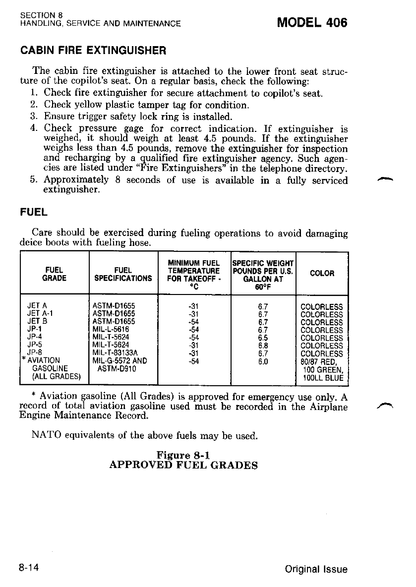
SECTION 8
HANDLJNG, SERVICE AND MAINTENANCE MODEL 406
CABIN FIRE EXTINGUISHER
The cabin fire extinzuisher is attached to the lower front seat struc-
ture of the copilot's sea[. On a regular basis, check the following:
1. Check fire extinguisher for secure attachment to copilot's seat.
2. Check yellow plastic tamper tag for condition.
3. Ensure trigger safety lock ring is installed.
4. Check pressure gage for correct indication. If extinzuisher is
weighed. it shouki weigh at least 4.5 pounds. If the exiinguisher
weighs less than 4.5 pounds, remove the extinguisher for insiection
and recharging by a -qualified fire extinguishei agency. Such agen-
cies are listed under "Fire Extinguishers't in the te-iephone directory.
5. Approximately 8 seconds of use is available in a fully serviced
extinguisher.
FUEL
Care should be exercised during fueling operations to avoid damaging
deice boots with fuelins hose.
EIIEI
GRADE FUEL
SPECIFICATIONS
MlNll'rUM FUEL
TEiIPERATURE
FON TAXEOFF .
SPECIFIC WEIGHT
POUNDS PER U,S,
GALLON AT
60.F
COLOR
JET A
JET A-1
JET B
JP-1
JP-4
JP.5
JP.8
* AV|ATIoN
GASOLINE
(ALL GRADES)
ASTM.D1655
ASTM-D1655
ASTM-D1655
MrL-L-5616
MrL-T-s624
MtL-T-5624
MtL-T-83133A
MIL,G-5572 AND
ASTM.D9lO
-54
-54
-54
-31
-54
6.8
6.7
6.0
COLORLESS
COLORLESS
COLORLESS
COLORLESS
COLORLESS
COLORLESS
COLORLESS
80/87 RED,
1OO GREEN,
lOOLL BLUE
* Aviation gasoline (All Grades) is approved for emergency use only. A
record o_f_ total aviation gasoline used must be recorded-inihe Airpiane
Encine Maintenance Record.
NATO equivalents of the above fuels may be used.
Figure 8-l
APPROVED FUEL GRADES
8-14 Original lssue
MODEL 406 SECTION 8
HANDLING, SERVICE AND ITAINTENANCE
Alternate/Emergency Fuels
Aviation gasoline, all glades, are restricted to emergency use'
.AVIATION GASOLINE IS RESTRICTE^D-
iz I
y w v;"f F ifi i {f "'!"aK i:.
C)NE OVERHAUL PERIOD'
&2y;{;"'x:.,:+,'^y7f
tff
shi}i:f
H
wt":Bf;!ffi:{0,3#'[,*r;y]ri'
RIOD.
?i!;l,Wft"Wff,fru**{o!6'i#ul'o*
FUEL ADDITIVE
A variety of fuels may- be used in the. airplane: however'--each must
l1dail#*ii[%"r'lllli:.;'*rt"ltJi"?ll"1iffi -*'i'lhMIL.
Wr.i#*r,"r*
rP 4 AND rP's FUELS le!-!4!L:rj9?!
+Xf,'FA i\frk ;,P,r,Ylli[rTi & f{tr
ii'bi-'{N-IPFRIvED rY?P 9l 4NTr.
'f
''
!r"o,l uo?t,!,:rE' T!^f
, 6
I i' { ut io"u"ii
BE ADDED.
Oriqinal lssue 8-15
Ethylene glycol monomethyl ether (EGME) compound in compliance
with MIL-I-276868, must be carefully mixed with the tuel in concentra-
tions not to exceed 0.15 percent by volune. The minimum EGME
concentmtion within the fuel tank is 0.035 percent bv volume. The
minimum EGME concentration for fuel beins idded to ihe fuel tank is
0.060 percent by volume.
SECTION 8
HANDLING, SERVICE AND MAINTENANCE MODEL 406
OMIXING OF THE EGME COMPOUND
WITH THE FUEL IS EXTREMELY IMPOR-
TANT BECAUSE CONCENTRATION IN EX-
CESS OF THAT RECOMMENDED (0.15 PER.
CENT BY VOLUME MAXIMUM) WILL RE-
SULT IN DETRIMENTAL EFFECTS TO
THE FUEL TANKS, SUCH AS DETERIORA-
TION OF PRO:TECTIVE PRIMER AND
SEALANTS AND DAMAGE TO O-RINGS
AND SEALS IN THE FUEL SYS?EM AND
ENGINE COMPONENTS. USE ONLY
BLENDING EQUIPMENT THAT IS RECOM-
MENDED BY THE MANUFACTURER TO
OBTAIN PROPER PROPORTIONING.
.DO NOT ALLOW THE CONCENTRATED
ECME COMPOUND TO COME IN CONTACT
WITH THE AIRPLANE F/NISI/ OR FUEL
CELL AS DAMAGE CAN RESULT:.
8-16 Original lssue
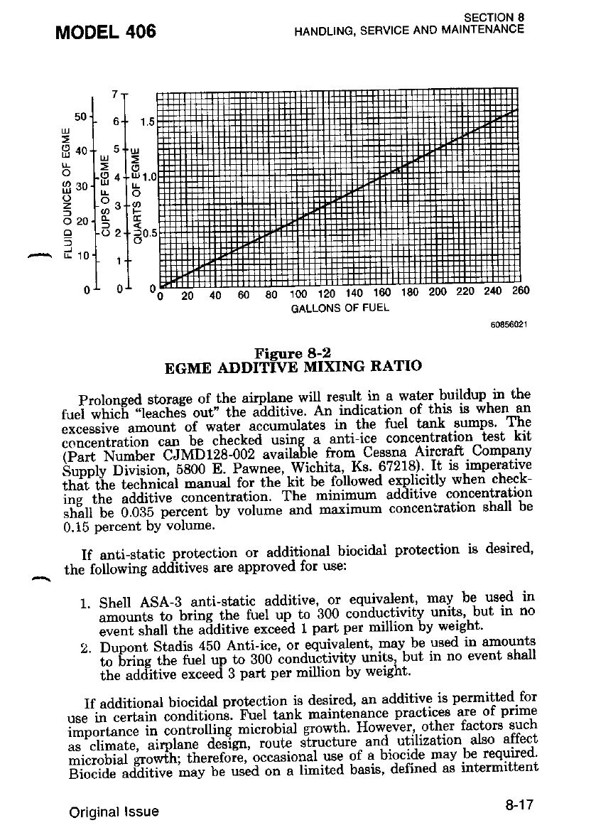
MODEL 406
20 40 60 80 100 120 140
sEcTloN 8
HANDLING. SERVICE AND MAINTENANCE
50
L!
2
o
o
z
l
o20
-
2
s4
1
Fisure 8-2
EGME ADDITI=VE MIXING RATIO
Prolonsed storage of the airplane will result in.a waPr.buildup. in the
2"i iitii"n ;r"i"it"3-o"d-itt" u'aaitiue. An indication. of this is when an
;;;;-;il;;";t oi water. accumulates in .the tuel tank. sumns' The
concentration can be checked Gng a antiice concentration -test kit
iiil^I.i;;ilr Cilmria-ooz avaihhe from Cesg.qa -Ailcraft. Companv
h'"il"r" 'ii"i.i""l -e-eoo n' p"*n"", Wichita, Ks 9?218) .ft is,imperative
iriJr"i'r'""#iiii"Li;;"i f"; ;il r.ii'L"'lo'uo*"a "'p,licitlv whei check-
i#" t]hJ ;[dill;;- concentration. The rnhimum adaitive concentration
l'ri?rr"'u! ooiri'i,"r;;;; bv ;;i;" and maximum conceniration shall be
0.15 percent bY volume'
If antistatic prot€ction or additional biocidal protection is deeired'
the lollowing adClitives are approved for use:
1. Shell ASA-3 anti-static additive, or ecuivalgni, may be used in
^ ;;;ttt"; bfit ittJ n-t"i "p to 300 coirduc.tivitv units', but in no
iu""iiliutt the aaditive exceed 1 part per million by weight'
2. Dupont Stadis 450 Anti-ice, or equivalent, may be used in smounts
' ;;;i";;i;il"i ,ip lo go0 to"aoi'tivitv units,'b"t in no event shall
the additive exceed 3 part per million by werght'
If additional biocidal protection is desired, an additive is permitted for
""""ii"J"riiiii'.iiidi-tio"i. F";i ta"k maintenance practices are of prime
#:oortr;;il "ont otti"g -i"toLiui growth However,,.other factors such
;:'"""1il""t", ;i;6; J;;lst\ loute structure and. utilization' also affect
iii.''rli6irr'hJ*iriliit"t"roi",'o""*ioiui ott of a biocide :"av be required'
g;"id" udaitiu" mav be used on a limited basis, defined as intermitt€nt
GALLONS OF FUEL
Original lssue 8-17
or noncontinuous use in a single application. -to sterilize. airplane. fuel
svstems suspected, or found l,o be conlaminated by microbial organlsms'
For those operators, where the need for biocide use is dictated, Pratt and
Whitnev Cinada Inc. recommends, as a guide, a dosage interval of once
u -o"t[,. This interval can then be adjuited, either greater or lesser, as
"" op"i"t"it own experience dictates. An engine operated in private and
com6rate aimlanes, where utilization rates are relatively lolf' may use
the, additive continuously. The following additive is permitted lbr use:
1. Sohio Biodor JF biocide additive, or equivalent, may be used in the
- fuei ut a concentration not to exceed 2?0 parts per million by
weight (20 parts per million elemental boron)'
FUEL CONTAMINATION
Fuel contamination is usually the result of foreign mat€rial present in
the fuel svstem, and may consist of wat€r, rust' sand, dirt, - microbes or
[u"te.i"t dtowtti. In addiiion, additives that are not compatible with fuel
;; ir;I;dt"- components can cause the fuel to become iontaminated'
Before the first llight of the day and after each refueling, -use the fuel
""*"t"i -a drain fu-el from the firel tank sump drains, the fuel strainer
draiirs and the crossfeed line drains to determine if contaminants are
pr"."r1.""9 that the airplane has been fueled with the proper grade and
tvDe of luel.
If contamination is detected, continue draining from all fuel drain
ooint* -l.r"til all contamination has been removed. If the airplane has
Seen serviced with the improper fuel grade, defuel completely and refuel
*iiti itt" correct grade. Db iot fly tLe airplane with contaminated or
unapproved fuel.
In addition, Omers/Operators who are not acquainted with a particu-
lar iix;d base operatoi should be assured that the fuel supply has been
"h""["a fo" con'tamination and is properly filtered before allowing the
aimlane to be serviced. Also, fuel- t€nks should be kept firll between
niihts. o.ovided weisht and balance considerations will permit, to reduce
th6 poiiibitity of waler condensing on the walls of partially frlled tanks.
To further reduce the posgibility of contaminated fuel,-routine main-
tenance of the fuel systeri should'be performed in accordance with the
aimlane Maintenance Manual. Only the proper fuel, as defrned in Sec-
iio-" z or tu" handbook, should be used, and fuel additives should not be
used unless approved by Cessna and the Federal Aviation Adminigtra-
f,lon.
fiiRlSN3, sERVrcE AND MATNTENAN.E MODEL 406
8-18 Original lssue
P.ERSONS WHO HANDLE ENGINE OIL
ARE ADVISED TO MINIMIZE SKIN
CONTAST WITH USED OIL, AND PNO-
MPTLY REMOVE ANY USED OIL
FROM THEIR .g'{IN. .A LABORATORY
STUDY, WHILE NOT CONCLUSIVE,
FOUND S UB,S?ANC',S WHICH MAY
CAUSE CANCER IN HUMANS. THOR-
OUGHLY WASH USED OIL OFF SKIN
A,S SOON AS POSSIBLE WITH SOAP
AND WATER. DO NOT USE KERO-
SENE, THINNERS OR SOLVENTS TO
REMOVE USED ENGINE OIL. IF WA-
TENLESS HAND CLEANER IS USED,
ALWAYS APPLY SKIN CREAM AFTER
USING.
The oils listed in Figure 8-3 cornply with the engine manufacturers
specifrcations. These oiE are fully appioved for use i; Pratt and Whit-
ney Canada Inc. commercially operated engines.
When adding oil, service the engines with the type and brand which is
currently being used in the engines. Refer to the airplane and engine
malntenance recoros.
MODEL 406
otL
SECTION 8
HANDLING, SERVICE AND MAINTENANCE
Miring of d'ifferent brands of oils or uiscosities
of oiti i n6t allowed; shouid oils of different
brands or ulscosities be. ina.duertently m;x,ed, thz
' oll system serDLcLnE Lnstructlons Ln tne drr-
nlane's Maintenanc-e Manual shall be carried,
but.
Original lssue 8-19
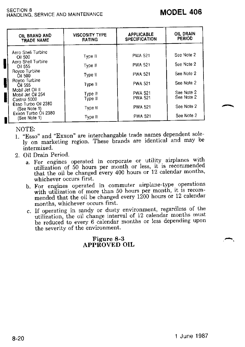
I
OIL BRAND AND
TRADE NAME
VISCOSITY TYPE
BATING
APPLICABLE
SPECIFICATION
OiL DRAIN
PERIOO
Aero ShellTurbine
oil 500
Aero Shell Turbine
oit 555
Royco Turblne
oir 500
Royco Turbine
oit 555
l\4obil Jet Oil ll
[.4obil Jel Oil 254
Castrol 5000
Esso Turbo Oil 2380
(See Note li
Exion Turbo Oil 2380
(See Note 1)
Type ll
Type ll
Type ll
Type ll
Type ll
Type ll
Type ll
Type ll
PWA 521
PWA 521
PWA 521
PWA 521
PWA 521
PWA 521
PWA 521
PWA 521
See Note 2
See Note 2
See Nole 2
See Note 2
See Note 2
See Note 2
See Nole 2
See Note 2
SECIION 8
HANDLING, SERVICE ANO MAINTENANCE
Fisure 8-3
APPR=OVED OIL
MODEL 406
NOTE:
l. "Esso" and "Exxon" are interchangable trade names dependent sole-
' r"" i" irit "ti;; ;.gi";. These 6rund" are idenl ical and mav be
intermixed.
2. Oil Drain Period.
". Fo, "neines operated in corporate or ulility. airplanes with
' "iiil""i'i?-'"t i0'[;rt. per month or less, it'is. recon'mended
iriii ttiii,iit-i"-"ttu"g"d 6u".v 400 hours or 12 calendar months'
whichever occurs first.
b. For engines operated in commuter airplane-type. operatrons
wiLh utilizalion of more than 50 hours per month' rt-IS recom-
-""i"a itt"f tttu oil be changed every 1200 hours or 12 calendar
months, whichever occurs first
c. l[ operating in sandy or dusty environmeni' regardless of l'he
"' "iirii^iir.,in. oil cliange interval of, l2 calendar months musl
be reduced to every 6 calendar months or less dependlng upon
the severity of the environment.
8-20 1 June 1987
MODEL 406 SECTION 8
HANDLING, SERVICE AND MAINTENANCE
Oil Quantity Operating Range
Fill to within 2 quarts of MAX HOT or MAX COLD (as-appropriate)
on dinstick. Suart markines indicate U.S. quarts low if oil is hot. For
e*a*ple. a dirjstick readini of 3 indicates the system is within 2 quarts
of MAX if oii is cold and within 3 quarts of MAX if the oil is hot.
M'TE
To obtain dn dccurate oil leuel reading, it is
recommended the oil leuel be checked within 10
rninutes after engine shutdown uhib the oil is
hot (MAX HOT marking) or prior to the first
flieht of the day while the oil is cold (MAX
COLD marking). If more than 10 minutes htr.s
elapsed, since engine shutdoun and engine oil is
still warm, perform an engine dry motoring run
before checkinE oil leuel.
OXYGEN (Aviators Breathing Oxygen . Specification
MIL-O-27210)
Check pressure gage for anticipated requirements before each flight.
Refill whenever pressure drops below 300 pounds per square inch.
The oxvgen cvlinder. when fullv chareed and allowed to stabilize at a
temperatuiE of it.t delrees Celsuis, contains approximately 114.9 cubic
feet of oxyge.n under .a pressure, of 1850, pounds, per Bquare inch. Filling
pressures will vary, however, due to the ambient temperature in the
filling area, and because of the t€mperature rise resultir:g from compres-
sion -of the orygen. Because of this, merely frlling to 1800 or 1850
pounds per squirt inch. will not result in a properly frlled cylinder. Fill
io the piessures indicated in Figure 8-4 for the anbient temperature.
OIL, GNEASE, OR OTHER LUBRICANTS
IN CONTACT WITH OXYGEN CNEATE A
SERIOUS FIEE HAZARD, AND SUCH
CONTACT MUST BD AVOIDED WHEN
HANDLING OXYGEN EqUIPMENT,
The cylinder is normally serviced through a filler valve located on the
forward lace of the left nose baggage door jarnb. Variations in optional
avionics installations may in so=irJ cases iequire that the cylinder be
serviced through the right nose baggage door in a similar manner.
Original lssue 8-21
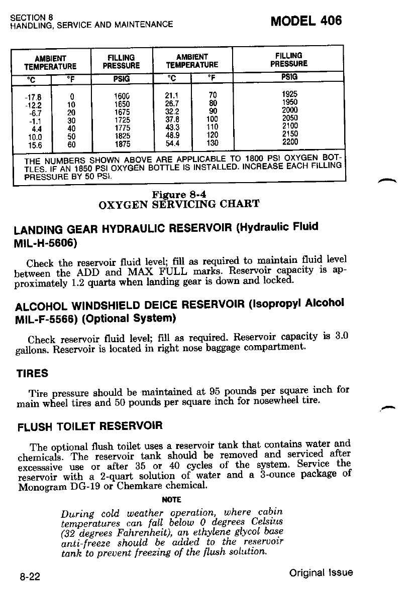
iiRlSNd sERVrcE AND MATNTENAN.E
AMBIENT
TEMPERATURE
FILLING
PRESSURE
AMEIENT
TEI'PERATURE
FILLTNO
PNESSUNE
PSIG "c FSiG
-17.8
-12.2
-6.7
4.4
10.0
15.6
0
't0
20
30
40
50
60
1600
1650
1675
1725
1775
1825
1875
21.1
26.7
32.2
37.8
43,3
48.9
54.4
70
80
90
r00
110
120
130
1925
1950
2000
2050
2100
2150
2200
THE NUMBERS SHOWN ABOVE ARE APPLICAALE TO iqqo-Psl O-XYGEN BOT-
iLEl:'iC A-N ibso FSiirivoeN eorrle ls INSTALLED INcREASE EAcH FILLING
PRESSUBE BY 50 PSI.
FiEure 8-4
OXYGEN SdRVICING CIIART
LANDING GEAR HYDRAULIC RESERVOIR (Hydraulic Fluid
MrL-H-5606)
Check the reservoir fluid level; fill as required to 'naintain fluid level
t"tiu""ti tir. A-o-o *a MAx FULL mark!. Reservoir caqacity is ap-
proximately 1.2 quarts when landing gear is down and lockeo'
ALCOHOL WINDSHIELD DEICE RESERVOIR (lsopropvl Alcohol
MIL-F-5566) (OPtional SYstem)
Check reservoir fluid level; fill as required' tleservoir capacity is 3'0
gallons. Reservoir is located in right nose baggage compartment'
TIRES
Tire pressure should be maintained at 95 pourrds per square inch for
main wlieel tires and 50 pounds per square inch tbr nosewheel tre'
FLUSH TOILET RESERVOIR
The ootional flush toilet uses a reservoir tank that contains wat€r and
"h";i;i'" '"Th" -;;;;ai tank should be removed and sergiced after
;;;;;G use or after as oi +o cvcles of the svstem Service the
;;.";;;;'*ith a-z-quart -sotution of-water and a 3-ounce package of
Monosram DG-19 or Chem}are chemical'
NOTE
DurinA, cold weather operalion, where -cab-in
tempeiatures can faLL below 0 degrees CelstLs
62'deerees Fahrenheit), an ethylene EtycoL bqse
anti-fieeze should be add.ed to the reserDotr
tanh' to preDent freezin4 of thc t'Iush soltttion'
MODEL 406
8-22 Original lssue
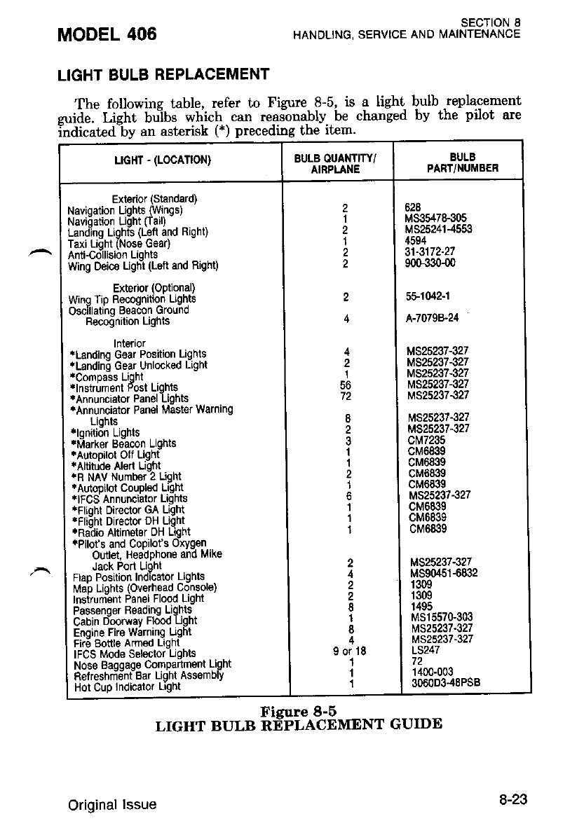
LIGHT BULB REPLACEMENT
The following table, refer to Figure 8-5. is a light bulb .replacement
zuide. Lieht bu-lbs which can reasonably be changed by the pilot are
indicated-by an asterisk (*) preceding the item.
MODEL 406 SECTION 8
HANDLING, SERVICE AND i/AINTENANCE
L|GHT - (LOCATION) BULB OUANTITY/
AIBPLANE
BULB
PART/NUMBER
Exterior (Standard)
Navioation Uohts (Winqs)
Navi6ation Lidht ftaill -
Landing Lighis (Left and Right)
Taxi Light (Nose Gsao
Anti-Collision Liohts
wing Deic€ ughi (Left and Right)
Exterior (Optional)
Wrng Tip Recognition Lights
Oscillatino Beacon Ground
Becodnition Lights
lnterior
4Landinq G€ar Position Lights
.Landino Gear Unlocked Light
rComDass Lioht
tlnstrument Fost Lqhts
*Annuncialor Panel Lights
4Annunciator Panel Master warning
Lights
xlonition Liqhts
.Marker Be-acon Lights
iAuiopilot Olf Llght
tAltitude Aled Light
.R NAV Numb€r 2 Ught
'Autopilol Couplsd Light
.IFCS Annunciator Liqhts
rFlioht Director GA Light
'Flidhl Director DH Liqht
r,Ralio Altimeter DH Light
r.pitofs and Copilot s Oxygen
Outlet, Headphone and Make
Jack Port Ught
FlaD Position Indicator Lights
Mao Liahts (Overhead Console)
lnsirum.-ent Panel Flood Light
Passenger R€adrng Lights
Cabin Doorway Flood Ught
Enqine Fir€ Warning Ught
Fire Bottle Amed Light
IFCS Mode Sslector Ughts
Nose Baggage Compartment Light
tlelreshm€nt Bar Light Ass€mDlY
Hot Cup Indicalor Lighl
2
I
2
1
4
1
56
2
3
I
1
2
1
I
1
1
2
8
1
I
90r18
1
I
1
628
M33547&305
MS252414553
4594
31-3172-27
900-330{0
5F1042-1
A-7079&24
M525237-327
M525237-327
t\4s25237€27
M525237-327
M325237327
M525237-327
MS25237327
ct\,r7235
cM6839
cM6839
cM6839
cM6839
M525237.327
cM6839
cM6839
cM6839
MS25237-327
M590451-6832
1309
1309
r495
MS1557&303
M525237-327
M525237-327
1S247
72
1400-003
3060D348PS8
LIGHT BULB $#ii%fi*'"T GUIDE
Original lssue 8-23
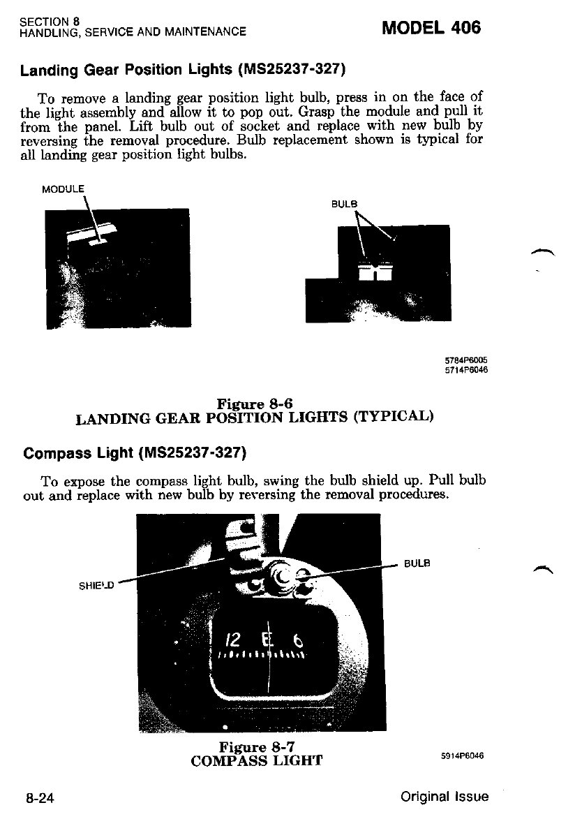
SECTION 8
HANDLING, SERVICE AND MAINTENANCE MODEL 406
Landing Gear Position Lights (M525237'327)
To remove a landing gear position light bulb, press in on the face of
the lieht assemblv and-alilow ii to pop out. Grasp the module and pull it
from ihe panel. Lift bulb out of soiket and replace with new bulb by
reversing ihe removal procedure. Bulb replacement shown ie typical for
all landing gear position lighi bulbs.
5784P6005
5714P00:10
Ficure 8-6
LANDING GEAR POS-ITION LIGHTS (TYPICAL)
Compass Light (MS25237-327)
To erpose the compass light bulb, swing the bulb shield up. Pull bulb
out and ieplace with new bulb by reversing the removal procedures.
5914P6046
Original lssue
MODULE
BULB
Figure 8-7
COMPASS LIGIIT
8-24
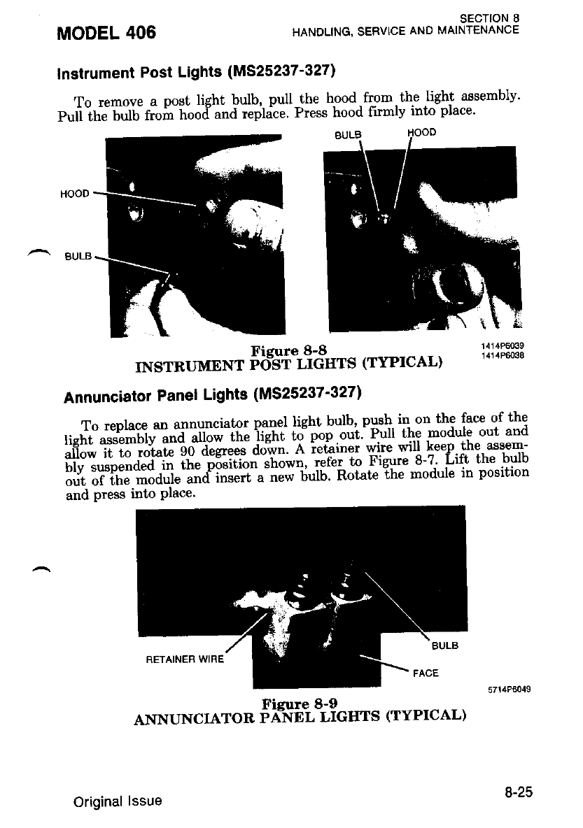
MODEL 406
^ BuLg
sEcTloN I
HANDLING, SERVICE AND MAINTENANCE
Instrument Post Lights (M525237-327)
To remove a post light bulb, pull the hood from. thp light assembly'
p"ri irt" n,iiit "h-'Lood u"d repldce. Press hood ftmlv into place'
Fieure 8-8 lXli:;ff3
INSTRUMENT porsT LtcHTS (TYPTCAL)
Annunciator Panel Lights (MS25237'327)
Toreplaceanannuncratorpanellightbulb'pusl.r'inont'hefaceofthe
ItshT;::ftili;"q-jJi;* th; j#;;e ;;p.;"i: Pu the modure out and
*it,I"m""rs?fl "$gm'l".il;i.'."ff ilsi&Tii::!'i:?'Tttr;
iiirr iiTfi" ti"aiiie 'and' insert u-nJ* 6uiu Rotatc ihe module in position
and press into Place.
Figure 8-9
ANNUNCIATOR PA-NEL LIGTITS (TYPICAL)
Original lssue 6-ZJ
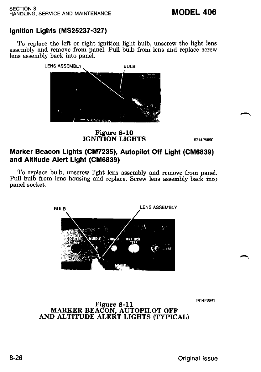
SECTION 8
HANDLING, SERVICE AND MAINTENANCE
LENS ASSEMBLY
MODEL 406
lgnition Lights (MS25237-327)
To replace the left or right ignition light bulb, unscrew the light lens
assembly and remove from panel. Pull bulb from lens and replace screw
lens assembly back into panel.
LENS ASSEMBLY BULB
Figure 8-1O
IGNITION LIGIITS 5714P6050
Marker Beacon Lights (CM7235), Autopilot Oft Light (CM6839)
and Altitude Alert Light (CM6839)
To replace bulb, unscrew light lens assembly and remove from panel.
Pull bulb from lens housing and replace. Screfr lens assembly back into
nanel socket.
Figure 8-11
MARKXR BEACON. AUTOPILOT OFF
AND ALTITUDE ALERT LIGIITS (TYPICAL)
8-26 Original lssue
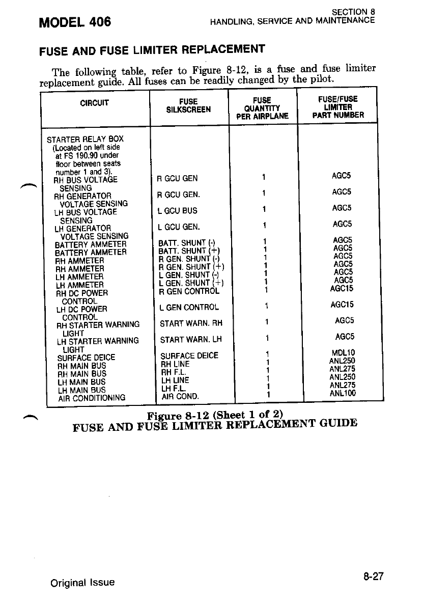
The followine table, refer to Figure 8-r!, is a. fuse. and.,fuse limiter
replacement guide All fuses can b" t."dily "hutg"d by t
MODEL 406
FUSE AND FUSE LIMITER REPLACEMENT
SECTION 8
HANDLING. SERVICE AND MAINTENANCE
FUSE/FUSE
LIM|TER
PANT NUITBER
SII.I(SCREEN
AGC5
AGC5
AGC5
AGC5
AGC5
AGC5
AGC5
AGC5
AGCS
AGC5
AGCl5
AGCI5
AGC5
AGC5
MDLlO
ANL25O
ANL275
ANL25O
ANL275
ANL1 OO
R GCU GEN
R GCU GEN.
L GCU BUS
L GCU GEN.
BATT. SHUNT (.)
BATT, SHUNT (+)
R GEN, SHUNT I)
R GEN. SHUNT {+)
L GEN. SHUNT (-)
L GEN. SHUNT (+)
R GEN CONTEOL
L GEN CONTROL
START WARN. RH
START WARN. LH
SURFACE DEICE
RH LINE
RH F.L.
LH LINE
LH F.L.
AIR COND.
STARTER RELAY BOX
(Located on lEft side
at FS 190.90 under
floor b€tween seats
number 1 and 3).
RH BUS VOLTAGE
SENSING
RH GENERATOR
VOLTAGE SENSING
LH BUS VOLTAGE
SENSING
LH GENERATOR
VOLTAGE SENSING
BATTERY AMMETER
EATTEBY AMMEIER
RH AMMETER
RH AMMETER
LH AMI\,IETER
LH AMMETER
RH DC POWEB
CONTBOL
LH DC POWER
CONTROL
RH STARTER WARNING
LIGHT
LH STARTER WARNING
LIGHT
SURFACE DEICE
RH MAIN BUS
RH MAIN BUS
LH MAIN BUS
LH MAIN 8US
AIR CONDITIONING
FUsE AND -,13$'i:tft"%Sof$blit2J*t*r cuIDE
Original lssue 8-27
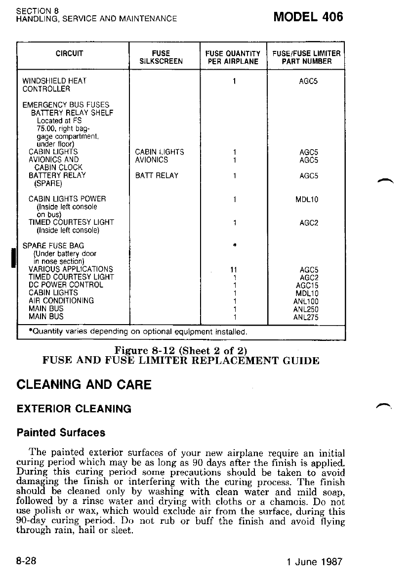
SECTION 8
HANDLING, SERVICE AND MAINTENANCE MODEL 406
WINDSHIELD HEAT
CONIBOLLER
EMERGENCY BUS FUSES
BATTEBY RELAY SHELF
Located ai FS
75.00, right bag-
gage companmenl.
unoer roo4
CABIN LIGHTS
AVIONICS AND
CABIN CLOCK
BATTERY BELAY
(SPABE)
CABIN LIGHIS POWER
(lnside leit console
on ous)
TIMED COURTESY LIGHT
(lnside lelt console)
SPARE FUSE BAG
{Under battery door
in nose section)
VARIOUS APPLICATIONS
TIMED COURTESY LIGHT
DC POWER CONTROL
CABIN LIGHTS
AIR CONDITIONING
MAIN BUS
MAIN BUS
CABIN LIGHTS
AVIONICS
EATT BELAY
rouantity varies depending on optional equipment installed.
Figure 8-12 (Sheet 2 of 2)
FUSE AND FUSE LIMITER REPLACEMENT GUIDE
CLEANING AND CARE
EXTERIOR CLEANING
Painted Surlaces
The painted _exterior surfaces of your new airplane require an initial
curing period which may be as long as 90 days af[er the finish is applied.
During this curing period some precautions should be taken to- avoid
damaging the finish or interfering with the curing process. The finish
sh.ould 6e cleaned only by washing with clean riaier and mild soap,
followed by a rinse water and drying with cloths or a chamois. Do not
use _polish or wax, which would exclude air from the surface, during this
90-day curing period. Do not rub or buff the finish and avoid flvine
through rain. hail or sleet.
8-28 1 June .1987
To heln orevent development of corrosion' particularly frliform corro-
"ion. *u'ui"pt*.' should'be spray washed at least every two or three
il""i."i".p""i"ttv in warm. dahp- and salty environments), and waxed
;ith-"'-;;A -e;ade of water repellant wai to help kegp water from
accumuliting in skin joints and around countersinks' A. heauer coatlng
;i;;;;-;i;i";a;{ edges of the wing ani tail (on airplanes wilhout
deice boots) and on the englne nose cap and propeller spmner' wrll netp
reduce abrasions encountered in these areas.
Propellel
Preflieht inspection of propeller blades for nicks and wiping them
occasion-allv wi[h an oily cloth to clean oll gr,ass and--bus starns wur
^ ;;ffi; ffi;, 'iil"ur"-r."? servlce. It is vital ihat- small n-icks on the
;;"oie1lei;,ittillartv ""* itte tips and on the- leading edges' are dressed
but'as eoon as possible since these nicks produce stress concentr&tlona'
Xii li i"e;'tii"i. ;;v;;;"h i" "iuik.' N"u"t-n.u an alkaline cleaner on the
tLa""; iurnou" grease "nd diri with Stoddard solvent'
Landing Gear
Cessna Service Facility mechanics have been trained in the - pro-per
"aiiJi.ii,"t i"a "iggittg of the landing gear system' To assure trouble-free
""lt-io.t"iiJ", hi'ie lour Cessna Serfrce -Facility check the qear regu-
iarlv aird male any necessary adjustnent' Only-properly trarneo mecn&n-
i;'ifiuid ;,d;p; t" ."p"ii oi i.aiu.t the laridins -gear components and
syst€m.
Deice Boots
The deice boots have a special, electrically conductive coating to
Uf"ed-ofisGtic'cttarges which-iausi iadio interference an$ may. perforate
itti, i"'6il.'fii"ti"L-i;a oihir iervicing operations should be done care-
fr,irvli" it"iJ-d"ii"gl"g ihis conductivl cbating or tearing the boots'
^. To nrolons the life of surface end propeller deice boots' they should- be
' - *""fi"i"i."d'L*i""a oo u .eg"t"t bisis' Keep the boots clean and free
ilt"ril"6irl*t""it-iita -ott". s'olvent's which -ia:se. rubber to swell and
i""tii.r"L]- Gttio"a f"to* are recommended cleaning and servicing
orocedureg.
MODEL 406 sEcTloN I
HANDLING, SERVICE AND MAINTENANCE
Original lssue 8-29
SECTION 8
HANDLING, SERVICE AND MAINTENANCE MODEL 406
USE ONLY THE FOLLOWING INSTRUC.
TIONS WHEN CLEANING BOOTS. DISRE-
GARD INSTRUCTIONS WHICH RECOM-
MEND PETROLEUM BASE LIqUIDS
(NONLEADED GASOLINE, METHYL-
ETHYL-KETONE, ETC.) WHICH CAN HARM
THE BOOT MATERIAL.
Clean the boots with mild soap and water, ihen rinse thoroughly with
clean water.
TOIE
aTemperature of water for cleaning d.eice boots
shall not exceed 140 d.egrees Fahrenheit.
olsopropyL sl.cohol can be used to remoue grime
uhich cannot be remoued using soap. If
isopropyl alcohnl is used for cLeaning, uash area
with mild soap and. water, then rinse thoroughly
with cLean uater.
To possibly inprove the service life of deice boots and to reduce the
adhesion of ice, it is recommended that the deice boots be treated with
AGE MASTER Number 1 and ICEX.
AGE MASTER Number 1, used to protect the rubber against deterio-
ration from ozone, sunlight, weathering, oxidation and pollution, and
ICEX, used to help retard ice adhesion and for keeping deice boots
looking new longer, are both products of and recommended by B. F.
Goodrich.
The application of both AGE MASTER Number I and ICEX should
be in accbrdance with the manufacturer's recommended directions as
outlined on the containers.
.PROTECT ADJACENT AREAS, CLO'THING,
AND USE PLASTIC OR RUBBER GLOVES
DURING APPLICATIONS, AS AGE MASTER
NUMBER i S?AINS AND ICEX CON?AINS
S I LICO NE WHICH MAKES PAINT
TOUCHUP ALMOST IMPOSSIBLE,
OENSUIIE THAT THE MANUFACTURER'S
WARNINGS AND CAUTIONS ARE AD-
HERED TO WHEN USING AGE MASTER
NUMBER 1 AND ICEX.
8-30 Original lssue
MODEL 406 SECTION 8
HANDLING, SERVICE AND MAINTENANCE
lf a hieh gloss finish is destued on the .deice.boots' ACROSEAL
-"il.i i"?ilUTt" ftoxo-Eub"t Janitorial Supplies- 1r4 Notth St Francis
b;il: iiilhl;;- xS-ozzozl mav be used in lieu of AGE MASTER
ftffi;Lr'i;;7biicnx. pi"puiition for application of ACRoSEAL is
;il':;";;;a;l'"a ro' acii-traaSrER N'uhber 1 and -ICEX' Applv a
;iii""F";t?'AbR-oSnil ott ttt"ctuun and dry su{-ace of the deice boot
;ilh;'"i;d'il;.-LeTd'v itio.ouet lv and hand buff with a soft cloth'
Small tears and abrasions in surface d€ice boots can be repaired
L"tio-"ii.iii *itti""t t"-o'rittg the boots and the conductive coating can
f"1""i'."i";i. V;; b;-"" 3'i?ti"J Si'iii"" tt"J th" p"op"t rnaterials and
know how to do this correctlY'
^ Engines
The engine compa.nments should be cleaned' using a suitable solvent'
rur""fif;:tlil"i "i".i'titg i" done "sin-g i -sprav-type cleaner' Before -spray
ii""riiiil ""'.tt"- p-tit"Ztiotil" Lr]6ttGa fdr c-ordfonent's wh'fh might be
;ffiri;il -ihJ"t.f, nv dttJ solvent. Refer to the Airplane Maintenance
ffi;;;'f;;dit liruti""tion of controls and components after ensine
cleaning.
INTERIOR CLEANING
To remove dust and loose {irt fr-om the upholstery' headliner and
carpet, clean the int€rior regularly with a vacuum cleaner'
Blot up any spilled liquid plopptly with. clear1sine ^tissue or rags'
D";;;;;i the- spqt; press^ the blotting material firmlv end hold it for
several seconds. uonf,rnue Uiottit g uitit no.more liquid is taken up'
il;; "1i".11i;iy .lGii"tJ *itt' " dutt knife, then spot-clean the area'
Oily spots may be cleaned with household spot- removen' used spar-
irrg"lv:'n""fo." usi"ng any *i""ni, t""d the instructions on the container
onrl +pot it on an oo.""i"' oi""" - o" th" fubti" to- be cleaned' Never
-'\ ilil"fri'tit'""f;H;;itfi;;t;,tiie sotuent; it mav damage the padding
and backing materials.
Original lssue 8-31
sEcTtoN I
HANDLING, SERVICE AND MAINTENANCE MODEL 406
.USE ALL CLEANING AGENTS IN AC-
CORDANCE WITH THE MANUFACTUR.
ER'S RECOMMENDATIONS.
.THE USE OF TOXIC OR INFLAMMA.
BLE CLEANING AGENTS IS DISCOUR-
AGED. IF THESE CLEANING AGENTS
ANE USED, ENSURE ADEqUATE VEN-
TILATION IS PROVIDED TO PREVENT
HARM TO THE USEN AND/OR DAM-
AGE TO THE AIRPLANE.
Soiled upholstery and carpet ma-y be cleaned with foam-t1pe. deter-
sent. used according to the manufacturer's instructions. To minimize
ivetting the fabric, keep the foam as dry as possible and remove it with a
vacuum cleaner.
The plastic trim, instrument panel and control knobs need only be
wioed ri,ith a damp cloth. Oil irnd erease on the control wheel - and
control knobs can -be removed with i cloth moistened with kerosene.
Volatile solvents, such as mentioned in paragraphs on care of the wind-
shield, must never be used since they soften and craze the acrylic.
Windows and Windshields
The cabin windows and windshield nanels are constructed of
prestretched or cast acrylic. The surface haidness of acrylic is approxi-
mately equal to that of copper or brass.
Care must be exercised to avoid scratches and gouges which may be
caused by dirty, hard or rough cloth used for cleaning. Do not use a
canvas cover on the acrylic windshield unless freezing rain or sleet is
anticipated. Canvas covers may scratch the acrylic surface.
WINDSHIEI,D AND WINDOW MAINTENANCE PROCEDURES
The following procedures provide the most cunent infornation re-
garding clearing and servicing windshield and windows. Improper clean-
ing,.or use of unapproved cleaning agents can cause danage to the
wlnoows.
8-32 Original lssue
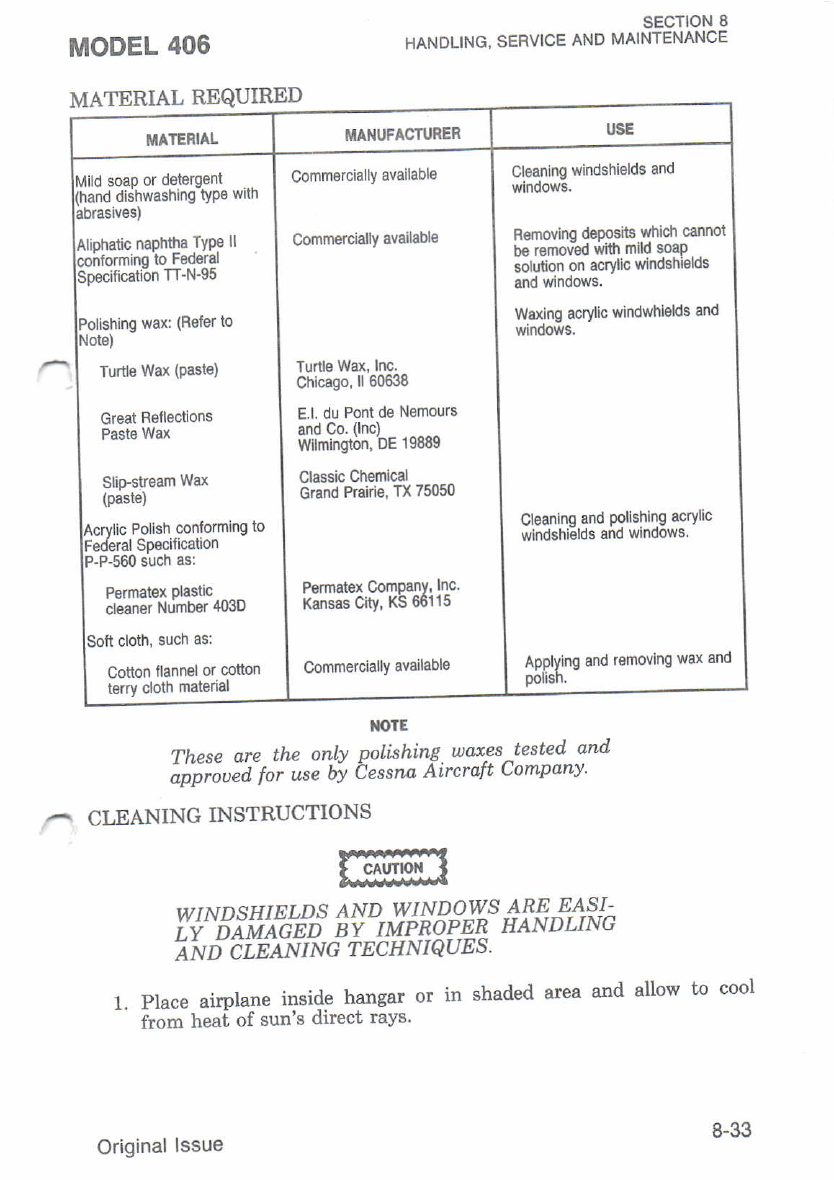
MATERIAL REQUIRED
NOTE
Cleaning windshields and
windows.
Removino dsPosits which cannot
be rsmov-od ',vfi mild 6oap
solution on acrylic windshields
and windows.
Waxing acrylic windwhlelds and
vrindows.
Cl€aning and Polishing acrylrc
windshiglds and windows
Applying and romovlng wax and
polrsn.
Comm€rcially available
Commercially available
'funle Wax, Inc.
Chicago, ll 60638
E.l. du Pont de Nernours
and co. (lnc)
Wlmington. DE 19889
Classic Chemical
Grand Prairi€, TX 75050
Permatex ComPanY, |nc.
Kansas City, KS 66i15
Commercially availabl€
soap or detergent . _
I dishwashing tYPe vrm
Turtle Wax (Paste)
Greal Fleflections
Paste Wax
Slilstream Wax
(paste)
Polish conforming to
ederal Sp€cification
-P-560 such as:
Permatex Dlastic
cleaner Number 403D
Cotton llannel or conon
te.ry cloth material
SECTION 8
HANDLING, SERVICE AND MAINTENANCE
These are the onty poLishing uaxes -lested and
iiiiiria-fiii^" iv b"ttno Air,aft companv'
^ CI,EANING INSTRUCTIONS
MODEL 406
wTNDSHIELDS AND WINDOWS A:RF--E-A-: !:
iXr6tYt;vFI.,"l,A:^uA0EEE.HANDLTN'
1. Place airplane inside hangar or in shaded area and allow to cool
from heat ol sun s drrecl raYS'
8-33
Original lssue
SECTION 8
HANDLING, SERVICE AND MAINTENANCE MODEL 406
2. Usine clean (preferablv runninq) water, flood the surface' Use bare
handi with no jewelry to feel and dislodge any dirt or abrasive
materials.
3. Using a mild soap or detergent (such as a dishwashing liquid) in
watei, wash the surface. Again use only the bare hand to provide
rubbing force. (A clean cloth may be used to transfer the Boap
solution to the surface. but extreme care must be exercised to
prevent scratching the surface.)
4, If soils which cannot be removed by a mild detcrgent remain, Type
II aliphatic naphtha applied with a soft clean cloth rnay be used as
a cleaning solvent. Be sure to frequently refold the cloth to avoid
redepositi-ng soil and/or scratching win'dshield with aly abrasive
particles.
5. Rinse surface thoroughly with clean fresh water and dry with a .-
clean cloth.
8-34
DO NOT USE ANY OF THE FOLLOWING
ON OR FOR CLEANING WINDSHIELDS
AND WINDOWS: METHANOL, DENA-
TURED ALCOHOL, GASOLINE, BENZENE,
XYLENE, MEK, ACETONE, CARBON :TET-
RACHLORIDE, LACQUER THINNER, COM-
MERCIAL OR HOUSEHOLD WINDOW
CLEANING SP/?A YS. WHEN IN DOUBT, DO
NO.f USE IT.
6. Hard polishing wax should be applied to acrylic surfaces. (The wax
has an index of refraction nearly the same as transparcnt acrylic
and- will tend to mask any shallow scratchs on the windshield
stulace,l
7. Acrylic surfaces may be polished using a polish meeting Federal
Specifications P-P-560 applied per the manufacturer's instructions.
I{OTE
When applying and remnuing uax and poLish,
use a clean soft cloth.
Original lssue
WINDSHIELD AND WINDOW PREVENTIVE MAINTENANCE
r{otE
4.
IJtilization of the t'ollowing techniques wilL help
rninimize uindshield and windou tazing.
Keep all surfaces of windshields and windows clean.
If desired, wax acrylic surfaces.
Do not park or store airplane where it ''light be subjected to direct
-"t""i '*ittt or vapors from: methanol' denatured -alcohol. gasoline.
U"nr""e. *vl"n", MEK, acetone, carbon tetrachloride, lacquer thin-
ners. commercial or household window cleaning sprays' paint stnp-
pers, or other types of solvenh.
bo not use solar screeng or shields installed on inside of airplane or
t"u"" r"" visors up against windshield. The reflected heat liom
iit""" it"-s causes-eleiated t€mperatures which accelerate,cr-azing
*a -"v cauee formation of bub6les in the inner ply of multiple ply
windshields.
MODEL 406
l.
2.
SECTION 8
HANDLING. SERVICE AND MAINTENANCE
Oxygen Masks
The pilot and copilot masks are a permanent-type mask which con-
tains a microphone for radio transmissions.
Passenser masks are reguiated, continuous-flow, dilution.type J"qlkq
*rti"illol "ot co"tai" u hictopi'tone. Au ^"qF". .can be cleaned with
.r"1r"trir. eJaiii""J--u.t. and - hoses are available from vour Cessna
Service Station.
PROLONGED OUT.OF-SERVICE CARE
Prolonsed out-of-service care applies to all airplanes which. will not be
n"";?;;; ";a;fr"G period 0eslr: than 60 dais) buJ' which are to be
i';;;;;;"; nu *ittt ttt? least irossible preparation'.If.t'he airpla::e is to
il"'.t"ita"t"-p,it-ily, or indefiri'itely, refer to the Airplane Maintenance
Manual for pioper siorage proceduris. The Airplane Maintenance Man-
uui pio"id"r u-blificatioi f6r the following procedures:
1. The procedure to be followed for pr$ervation- of engines in service
'' e;;d";; the period of inactivit:v and whether or not the engine-
;;;'L; t;L;d lutGi ttt" inactivi period' The expect€d. period. of
i""'"ti"lti,- iloJa be e"stablished and reference. made to the-Engine
Fi"-"i,*iii"i-s"tt"aue' itt" preservation carried out should be re-
;"i;a'ir;li;;;ci"J-"i"t""in.. record and on tags secured to the
engine.
Original lssue 8-35
SECTION 8
HANDLING, SERVICE AND MAINTENANCE
2.
UNDER NO CIRCUMSTANCES SHOULD
PRESERVATIVE OIL BE SPRAYED INTO
THE COMPRESSOR OR EXHAUST PONTS
OF THE ENGINE. DIRT PANTICLES DE-
POSITED ON BLADES AND VA]\!ES DUR-
ING ENGINE OPERATION WILL ADHERE
AND ALTER THE AIRFOIL SHAPE. AD-
V E RS E LY AFFECTING COMPRESSOR. EFFI.
CIENCY.
a. 0 to 7 days - Engine may be lefl in an inactive stat€, with no
preservation protection, provided: .engine is -sheltcred; humidity
is not excessively high: engine is.not subjected- to extreme
I€mperalure cnangeg that would procluce condensatlon,
b. 8 to 28 days - Enginee inactive for up to 28 days require no
presewation provided all ensine openings are siated bff and
relativ_e_ humidity in engine ii maintained at less than 40 per-
cent. _Humidity control is maintained by placing desiccanl bags
and humidity indicator on wooden ricks in -ensine exhaust
duct. Suitable windowg must be provided in exhaGt closure to
facilitate obsewation of humidity-indicators.
c. 29 to 90 d_ays - Engines inactive for a period exceeding 28 days,
but.less than g0_ days, need only havl fuel system preserved,
engine intake and exhaust opgnings covered, arid desiccant bags
and humidity indicators instblled.
d. 91 days_and over - Engines inactive over g0 days in airframe or
removed tbr long term storage in container. must. in addition
to the 29 to 90 day procedure, have engine oil drained and
unuseo accessory dnve pads sprayed.
Place a- contrasting colored plastic tape over static ports. Install all
protective -covers and cover all fuselage air inlets to prevent entry of
foreign objects.
Keep the fuel tanks full to minimize condensation in the fuel tanks.
If the airplane will be out of service for 5 davs or more. disconnect
battery arrd as necessary, clean and coat the i-ntercell hardware with
a light coal, of neutral nonconductive grease, such as oetroleum
jelly, to prevent comosion. Battery musl be maintained -in accor-
dance with Marathon Battery Instruction Manual, BA-89.
If the airplane is stored outside, tie-down aimlane in accor&nce
with the tie-down procedures in this section.
The following engine preservation schedule lists precedures to be
followed:
MODEL 406
I
8-36 Original lssue

MODEL 406 SECTION 8
HANDLING. SERVICE ANO MAINTENANCE
6. Chock the main landing geal tires; do- not. set the parking brake if a
* riili?iii"a?il;il;id i. ""tlclpit"a as brake seizing can result'
?. ;;;'J l;;;""ks move airplane to prevent flat areas on tirjs' Mark
'' ;;;'*i;i ;;;6;;il;';i.e-i. ritu""a approxirnatelv e0 degrees
from previous Position.
8. t;;ir all tuef drain points every 30 days and check for water
"' ""*ii-tf"ti"". Prolong'ed storage of the ;irplane wi.ll result in a
i,"tir'i,iiiJtit i" ine'n "t *hifi i"u"h"t out" the ethvlene glvcol
ffifii-].iiiiiitiii,'"t'ecMbl ru"i additive' An-indigation of this is
when an excesarve "-o,,ata oJ water accumulat€s in the fuel tank
ilil;":R"f";;-ili""t eaaiti* in ihis section for minimum allowa-
ble FJGME concentrations.
Original lssue 8-37 (8-38 blank)

MODEL 406 SECTION 9
SUPPLEMENTS
3
4
5
6
7
8
I
SECTION 9
SUPPLEMENTS
TABLE OF CONTENTS
INTRODUCTION e4l
SUPPLEMENTS - GENERAL
ALCOHOL WINDSHIELD DEICE SYSTEM . 2 Pages
(NOTUSED) ...lPage!
DIGITAL CLOCK DAVTRON .... ' 3 Pages
DEICE BOOT SYSTEM ...'. 5 Pages
FLIGHT IN ICING CONDITIONS . 7 PAgCS
RECOGNITION LIGHTS I PAgC
OSCILLATING BEACON GROUND
RECOGNITION LIGHTS ...... l Page
AIR CONDITIONING SYSTEM ...3Pages
ELECTRICAL WINDSHIELD ANTI-ICE SYSTEM . . 2 Pages
SUPPLEMENTS . AVIONICS
8OO ALTITUDE ENCODING/ALERTING
/PRESELECT (EA-801A) ......7Pages
400 ENCODING ALTIMETER (EA-401A) ...3 Pages
400 AREA NAVIGATION SYSTEM (RN-479A) ..... 10 Pases
400DME (R-4??A) ......4Pages
FLIGHT CONTROL SYSTEM (AF-1050A) 20 Pases
HORIZONTAL SITUATION INDICATOR (CS-8328) . 3 Pages
1OOO INTEGRATED FLIGHT CONTROL
SYSTEM (IF-1050A) .. 25 Pages
NAVIGATION SYSTEM (PN-101) . 4 Pages
RADIO ALTIMETER SYSTEM (AA-100) . . 3 Pages
RADIO MAGNETIC INDICATOR (7100RMI) ...... ' 3 Pages
1000 RADIO MAGNETIC INDICATOR (IN-1004A/B) 4 Pages
TRANSCEIVER (HF-220) 4 Pages
400 TRANSPONDER (4594) ......4 Pages
WEATHER RADAR (RDR'160) ... ...... 4 Pages
WEATHER RADAR COLOR
DISPLAY (RDR-160XD) ......6Pages
10
11
!2
74
17
18
19
20
21
22
24
1 June 1987 9-1

SECTION 9
SUPPLEMENTS MODEL 406
TABLE OF CONTENTS (CONTINUED)
KING AREA NAVIGATION SYSTEM (KNS-81) . . . 11 Pages
KING AUDIO CONTROL PANEL (KMA-24H-?0) . . . 5 Pages
KING DIGITAL ADF (KR-8?) ....8Pages
KING DIGITAL COMM (KY-196) . . 8 Pages
KINGDME (KN-63). ....4Pages
KING HF TRANSCEIVER (KHF-950) .....9 Pages
KING MARKER BEACON (KR-21) . ......4Pages
KING RADAR ALTIMETER (KRA-IOA) ...4 Pages
KING RADIO MAGNETIC INDICATOR (Kl-22s) .. . 5 Pages
KING RADIO MAGNETIC INDICATOR (KNI-582) .. 5 Pages
KING TRANSPONDER (KT-79) ..6 Pages
NARCO WEATHER RADAR (KWX-56 COLOR) ....9 Pages
KING DIGITAL NAVIGATION RECEIVER (KN-53) . 5 Paees
COLLINS HF COMMUNICATION SYSTEM (HF-230) 9 Pages
A187
25
26
27
28
to
30
34
35
36
37
38
L,'i r r.r:
.:-.
9-2 1 June 1987
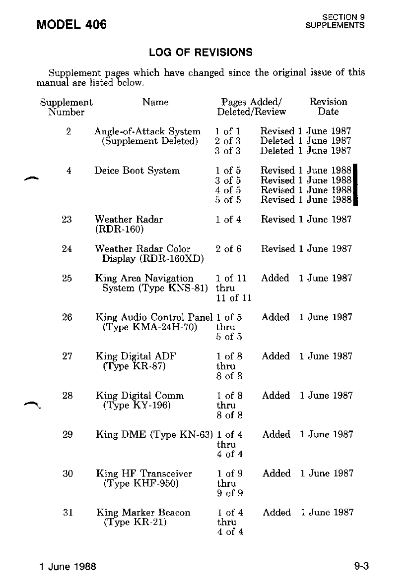
MODEL 406 SECTION 9
SUPPLEMENTS
LOG OF REVISIONS
24
1 of 11 Added 1 June 1987
thru
11 of 11
Added l June 1987
Added l June 1987
Added l June 1987
Added l June 1987
Added 1 June 1987
Added l June 1987
thIu
4of4
l of 9
thru
9of9
1of4
thru
4of4
Supplement pages which have changed since the original issue of this
manual are listed below.
Supplement Name
Number
2 Angle-of-AttackSystem
(Supplement Deleted)
4 Deice Boot Systern
King Digital ADF
(Type KR-87)
King Digital Comm
(Trpe KY-196)
King HF Transceiver
(Tipe KHF-950)
King Marker Beacon
(Ti.pe KR-21)
Weather Radar
(RDR-160)
Weather Radar Color
Display (RDR-160XD)
King Area Navigation
System (Trpe KNS-81)
26 Kine Audio Control Panel I of 5
(Type KMA-2 H-?0) thru
SOID
lot|J
thru
8of8
1of 8
thru
8of8
29
30
King DME (Type KN-6r) I of 4
Pases Added/ Revision
Deleted/Review Date
I of 1 Revised 1 June 1987
2 of 3 Deleted 1 June 1987
3 of 3 Deleted 1 June 198?
1 of 5 Revised 1 June 19881
3 of 5 Revised I June 19881
4 of 5 Revised 1 June 19881
5 of 5 Revised 1 June 19881
1 of 4 Revised 1 June 1987
2 of 6 Revised 1 June 1987
1 June 1988 9-3
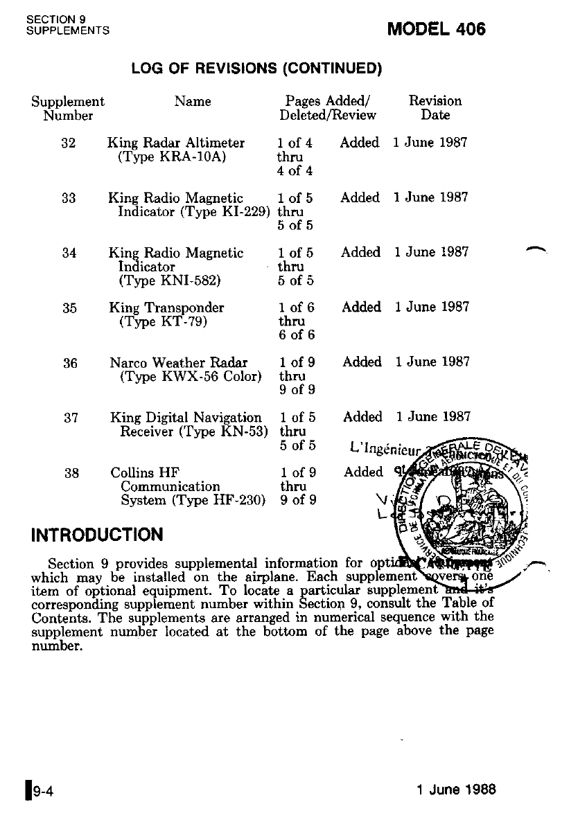
SECTION 9
SUPPLEMENTS
Supplement Name
Number
32 King Radar Altimeter
(Ttpe KRA-l0A)
LOG OF REVISTONS (CONTTNUED)
MODEL 406
Pages Added/ Revision
Deleted/Review Date
1 of 4 Added I June 198?
thru
4of4
King Radio Magnetic 1 of 5
Indicator (Type KI-229) thru
34 King P.adio Magnetic
lndicator
(Type KNI-582)
35 King Transponder
(Type KT-79)
36 Narco Weather Radar
(Tlpe KWX-56 Color)
37 King Digital Navigation
Receiver (Type KN-53)
38 Collins HF
Communication
System (Type HF-230)
INTRODUCTION
Section 9 provides supplemental information for
which may bi installed on the airplane. Each _su1
item of oritional eouipment. To locatc a particular supplement-brd#<
correspotriiing suppiement number within Section 9, conault the Table of
Conteits. Tlie srifplements are arranged in numerical sequence with the
supplement numEei located at the bottom of the page above the page
number.
SOID
1of 5
thru
5of5
lort)
thru
6of6
1of 9
thru
9of9
lotJ
thru
5of5
l of 9
thru
9of9
Added I June 1987
Added l June 1987
Added l June 1987
Added l June 1987
Added l June 1987
L'lngen
Added
\
L
ln-o 1 June 1988
ALCOHOL WINDSHIELD DEICE SYSTEM
SECTION 1 . GENERAL
This supplement provides information which must be observed when
operating the alcohol windshield deice system.
Description
The alcohol windshield deice svstem consists of an alcohol tank, a
pump, a dispersal tube for each wiidshield and a switch breaker.
The alcohol tank, located in the right nose compartment, has a 3.0
callon capacity. The tank should be frlled with isopropyl alcohol only'
Water diiution of the alcohol is not recommended, as aly water con-
tained in the alcohol will reduce the efficiency of ice removal and nay
freeze on the windshield at very low t€mperatures. The pump, located
adiacent to the tank, provides positive pressure to each windshield
diipersal tube. A disperial tube, -located it the forward base of each
windshield, provides flow patt€rn control throughout the airplane's speed
envelope. Each tube contains five holes which should be inspected and
cleaned wilh a small diameter wire as necessary.
Abnormal operation of the alcohol windshield deice system is in-
dicated by the switch breaker tripping to the OFF position or failure of
alcohol to flow onto the windshield.
SECTION 2 - LIMITATIONS
1. Discontinue alcohol dispersal 20 seconds before reaching minimum
descent altitude.
2. Do not operate system longer than 3 minutes without alcohol flow.
^ sEcTtoN 3 - EMERGENCY PROCEDURES
Not Applicable.
SECTION 4 - NORMAL PROCEDURES
1. Preflight Inspection
MODEL 406
a. Windshield Dispersal Tubes
liness.
SECTION 9
SUPPLEMENTS
CHECK condition and clean-
SUPPLEMENT 1
1ot2
Original lssue
SECTION 9
SUPPLEMENTS MODEL 406
b. Alcohol Tank
Level - CHECK. Full tank provides approximately t hour of
continuous operation. If alcohol deicing is installed on
left or right windshield only, approximately 2 hours of
continuous operation is available.
2. Before Takeoff
a. Alcohol Windshield
Switch - ON. Allow 10 seconds for alcohol flow to becin. Check
5 disnersal holes for flow at the base of each wind-
snrelo.
b. Alcohol Windshield Switch - OFF.
3. In Flight
a. During Icing Encounters:
(l) Alcohol Windshield Switch - ON.
orE
For operation in continuous enroute icing con-
d.itions, a\low approximately 0.125 to 0.25 inch
of ice to accumulate. The uindshiel.d. deice sys-
tern can be used as an anti-ice system by con-
tinuous use and. should be so used. during th.e
approach to landing. Howeuer, the maximurn
endurance with a 3.0 ga\lon tank is approxi-
mately 1.0 hour of continuous operation. If al-
cohol d.eicing is installed. on left or right wind.-
shield onLy, approximately 2 hours of continuorn
operdtton is auailable. Airspeed shnuld be 140
KIAS or belnw for best resuits.
(2) Alcohol Windshield Switch - OFF after ice removal.
4. Approach to Landing
THE WINDSHIELD DEICE SWITCH
BREAKER MUST BE POSITIONED OFF
20 SECONDS PRION TO BEACHING
MINIMUM DESCENT ALTITUDE, THE
ALCOHOL FILM MUST BE ALLOWED
TO EVAPORATE BEFORE A CLEAN
FIELD OF VISION THROUGH THE
WINDSHIELD IS AVAILABLE.
SECTION 5 - PERFORMANCE
Not Applicable.
SUPPLEMENT 1
2ot2 Original lssue

MODEL 406
SUPPLEMENT 2 DELETED
Remove existing pages I of 3, 2 of 3, and 3 of 3.
SECTION 9
SUPPLEIVENTS
I
1 June 1987 SUPPLEMENT 2l

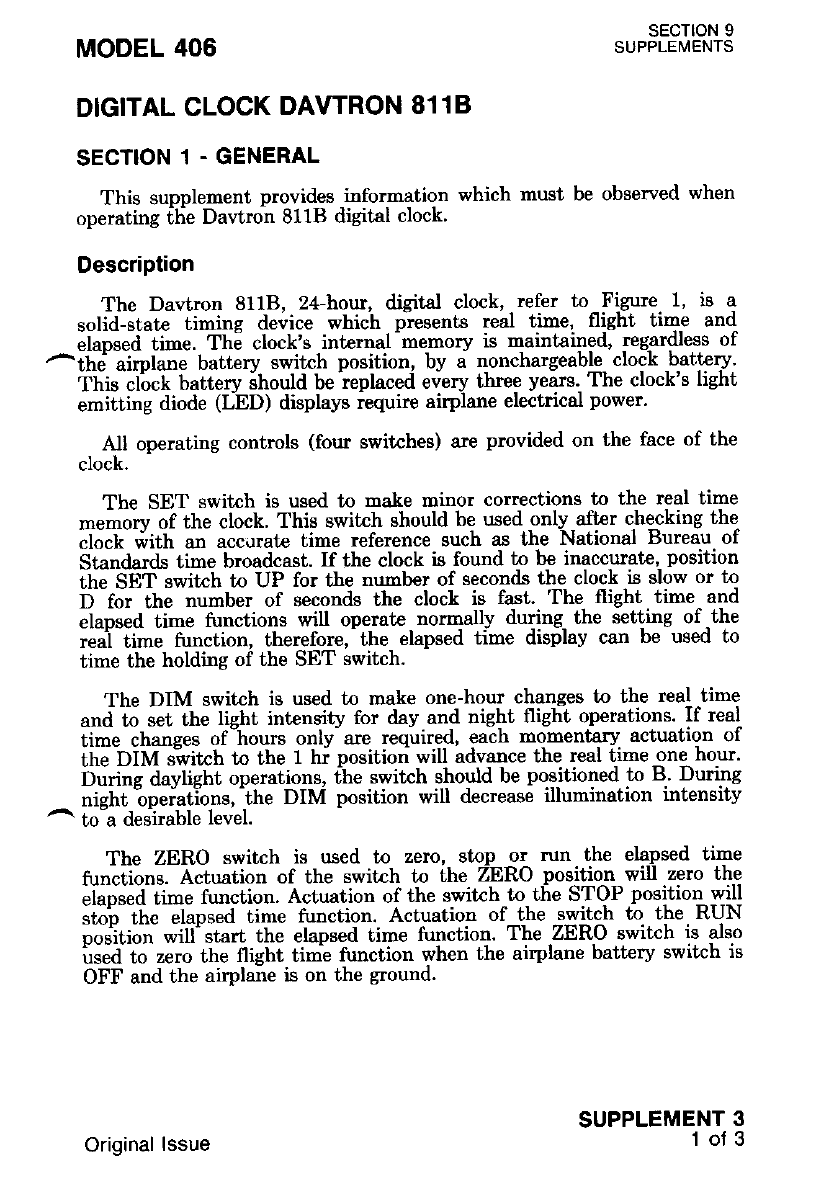
DIGITAL CLOCK DAWRON 8118
SECTION 1 - GENERAL
This supplement provides information which must be observed when
operating [tie Dawron 811B digital clock'
Description
The Davtron 8118, 24-hour, digital clock, refer to Figure f. is a
solid-slate timing device which presents real time, flight time and
elapsed time. Th6 clock's intemal -mernory is ''laintained, regardless of
^itr"' aimtane batterv switch position, by a nonchargeable clock battery'
This cl'ock battery ihould be ieplaced every three yearc. The clock's light
emitting diode (LED) displays iequire airplane electrical power.
All operating controls (four switches) are provided on the face of the
clock.
The SET switch is used to make minor corrections to the real time
memorv of the clock. This switch should be wed only aftcr checking the
clock i,ith an acc,rrat€ time reference such as Lhe National Bureau of
Standards time broadcast. If the clock is found to be inaccurate, position
thJ SET switch to UP for the mrmber of seconds the clock is slow or tn
I -foittt" number of seconds the clock is fast. The flight time and
aup"ea ti-" functions will operate normally during the setting of -the
reai time function, therefore, the elapsed time display can be used to
time the holding of the SET switch.
The DIM switch is used to make one-hour changes to the real time
a"d to set the light intensity for &y and nighi flight operations. If real
iime changes of-hourt only- are required, each momentary actuation of
tha DIM "'ivitctr tn the t hi positiori will advance the real time one hour.
burine davtisht operations, the switch should be positioned to B' During
nisht "opuiutlon., 'ihe DIM position will decrease illumination intensity
^ to-a desirable level.
The ZERO switch is used to zero, stop or run the elapsed time
fu"ciions. Actuation of the switrh to the ZERO position will zero the
"iaor"a iirn" tunction. Actuation of the switch to the STOP positioLwill
ito'J the "laps"d time function. Actuation of the switch to the RUN
po tion will' start the elapsed time function. The ZERO switch is also
i""tl to ,"ro the flight timi function when the airplane battery switch is
OFF and the airplane is on the ground.
MODEL 406 SECTION 9
SUPPLEi/|ENTS
SUPPLEMENT 3
1of 3
Original lssue
The TIME switch is used to displav red time, flight time or elapsed
time in hours, ninutes and secondi iri the two display windows. When
the switch is positioned to TIME, the real time will be displayed. When
the switch is positioned to ET, the elapsed time will be displayed. When
the switch is-positioned to FT, the flight time will be displayed. The
flieht time funition is wired through the landing gear safety swikh: thus,
fli;ht time can only be accumulatid when the weighl of the airplane is
off the landing gear.
SECTION 9
SUPPLEMENTS
1.
Figure 1
DIGITAL CLOCK
MODEL 406
z-
SET SWITCH - Used to correct real time in seconds. UP position
advances real time while D position retards real
time.
DIM SWITCH - Used to set display illumination intensitv and to
advance real time in one-hour increments'
ZERO SWITCH - Used to stop, start and zero the elapsed time
function. Tlie flisht tine function can also be
zeroed if the airphne battery switch is OFF and
the airplane is on the ground.
TIME SWITCH - Used to display real time, flight time or elapsed
tine functions in hours, minut€s and seconds.
SUPPLEMENT 3
2of3 Original lssue
MoDEL 406 su"FffJL9l+S
SECTION 2 - LIMITATIONS
Not Applicable.
SECTION 3. EMERGENCY PROCEDURES
Not Applicable.
SECTION 4. NORMAL PROCEDURES
1. Before Starting The Engines
a. Zero Switch - ZERO momentarily to zero the elapsed flight
time functions.
b. Dim Switch - AS REQUIRED.
SECTION 5 . PERFORMANCE
Not Applicable.
SUPPLEMENT 3
3of3
Original lssue

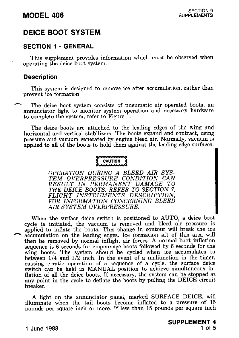
DEICE BOOT SYSTEM
SECTION 1 - GENERAL
This supplement provides information which must be observed when
op€rating the deice boot system.
Description
This system is designed to remove ice after accumulation, rather than
prevent ice formation,
The deice boot system consists of pneumatic air operated boots, an
annunciator light to monitor system operation and nicessar5r hardware
to complete the system, refer to Figure 1.
The deice boots are attached to the leading edges of the wing and
horizontal and vertical stabilizers. The boots expand and contract, using
pressure and vacuum generated by engine bleed air. Normally, vacuum is
ipplied to all of the boots to hold them against the leading edge surfaces.
MODEL 406 SECTION 9
SUPPLEMENTS
SUPPLEMENT 4
1of 5
OPERATION DURTNG A BLEED AIR SYS.
TEM OVERPRESSURE CONDI'IION CAN
RESULT IN PERMANENT DAMAGE TO
THE DEICE BOOTS. REFER 'IO SECTION 7,
FLIGHT INSTRUMENTS DESCRIPTION,
FOR INFORMATION CONCERNING BLEED
AIR SYSTEM OVERPRESSURE.
When the surface deice switch is positioned to AUTO, a deice boot
cycle is initiated, the vacuum is removed and bleed air pressure is
applied to inflate the boots. This change in contour will break the ice
^ aciumulation on the leadine edqes. Ice- formation aft of this area will
then be removed bv normaf inflieht air forces. A normal boot inflation
sequence is 6 seconds for empennage boots followed by 6 seconds for the
wing boots. The system sliould -be cycled when ice accumulat€s to
betieen 1/4 and 1/2 inch. In the eveni of a malfunction in the timer,
causine erratic operalion of a sequence of a cycle, the surface deice
switch-can be held in MANUAL position to achieve simultaneous in-
flation of all the deice boots. If tteces"try, the system can be stopped at
any point in the cycle to deflate the boots by pulling the DEICE circuit
breaker.
A lisht on the annunciator panel, marked SURFACE DEICE, will
illuminite when the tail booti become inflated to a pressure of 15
pounds per square inch or more. If less than 15 pounds per square inch
1 June 1988
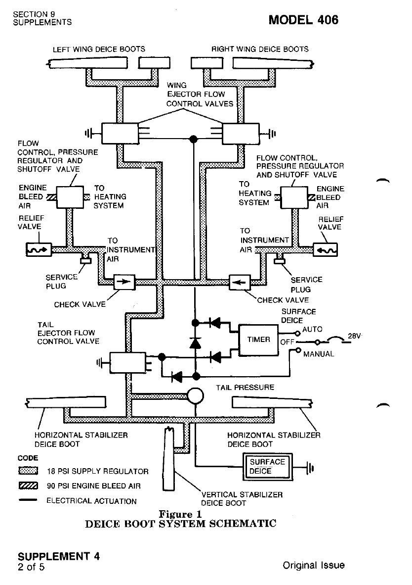
SECTION 9
SUPPLEMENTS
LEFI WING DEICE BOOTS
MODEL 406
RIGHT WING DEICE BOOTS
WING
EJECTOR FLOW
CONTROL VALVES
FLOW
CONTROL, PRESSURE
REGULATOR AND
SHUTOFF VALVE
FLOW CONTROL,
PRESSURE REGULATOR
AND SHUTOFF VALVE
ENGINE
RELIEF
VALVE
BLEED
AIR
RELIEF
VALVE
ENGINE TO
HEATING
SYSTEM
TO
SERVICE
PLUG
INSTRUMENT
TAIL PRESSURE
CHECK VALVE
SUFFACE
DEICE
SERVICE
PLUG
CHECK VALVE
TAIL
EJECTOF FLOW
CONTROL VALVE
HOBIZONTAL STABILIZER
DEICE BOOT
CODE
@ ta pst supprY REGULAToR
@l so eg ENGTNE BLEED ArR
-
ELECTRICAL ACTUAIIoN
DEICE BOOT
SUPPLEMENT 4
2ots
VERTICAL STABILIZER
OEICE BOOT
Figure 1
SYSTEM SCHEMATIC
AUTO
Original lssue
OPERATION BELOW -40 DEGREES CEL-
S/US CAN RESULT IN PERMANENT DAM-
AGE TO THE DEICE BOOTS.
^ sEcTtoN 2 - L|M|TAT|ONS
Not Applicable.
SECTION 3 - EMERGENCY PROCEDURES
1. Surface Deice Failure (one or more deice boots fail to inflate).
a. SURFACE DEICE Circuit Brealer - RESET.
b. Surface Deice Switch - OFF then AUTO.
c. If Deice Boots Fail to Inflate:
(1) Surfac_e Deice Switch - MANUAL. Hold approximately 9
seconos.
(2) Surface Deice Boots - VISUALLY OBSERVE simultaneous
inflation of all deice boots.
(3) Surface Deice Annunciator - CHECK. (Should illuminate
within 6 seconds after actuatins the surface deice switch to
MANUAL).
d. If normal operation does not occur, leave icing conditions as
soon as possltrle.
If Surface Deice Annunciator Fails to Illuminate or Ice Remains on
the Horizontal Stabilizer Surface:
a. Wing Flaps UP. (Do not extend the wing flaps with ice
build-up on the horizontal stabilizer.)
b. Coordinated Flight - MAINTAIN.
c. Airspeed - 180 KIAS Maximun.
d. Landing Wing Flaps UP; Refer to LANDING WITH WING
FLAPS RETRACTED Procedures.
2. Surface Deice Failure (one or more deice boots fail to deflate).
a. SURFACE DEICE Circuit Breal<er - RESET.
MoDEL 406 ","Ff3JL9l+3
is available, the lisht will not illuminate. indicatine that icine conditions
should be avoided-. Prior to flight in icing condit'ions, operition of the
boots should be functionally checked on ihe ground with power above
400 foot-pounds or in flight with the OAT abovl -40 degrees-Celsius.
1 June 1988 SUPPLEMEM 4I
SECTION 9
SUPPLEMENTS MODEL 406
b. Surface Dei:e Switch - OFF then AUTO.
If Surface Deice Boots Remain Inflated:
a. SURFACE DEICE Circuit Breaker - PULL.
b. Leave icing conditions as soon as possible.
If Surface Deice Boots Remain Inflated On Approach:
a. Approach - Increase approach speed by 10 KIAS.
SECTION 4. NORMAL PROCEDURES
1. Preflight Inspection.
a. Deice Boots - CHECK for tears, abrasions and cleanliness.
2. Before Takeoff.
a. Surface Deice Boot Test.
(1) Power - INCREASE to 400 foot-pounds.
(2) Surface Deice Switch - AUTO. Visually check operation of
boots and annunciator light ON.
NOTE
Positioning the surface d.eice switch to AUTO
uiLI result in one comnlete inflation and d.e-
flation cycle lasting appioximateiy 30 seconds.
3. Inflight.
a. During Icing Encounters.
(1) Surface Deice Switch - AUTO when ice accumulates be-
tween 1/4 to 1/2 inch. Repeat as necessary, allowing at
least 30 seconds between actuations.
NOlE
AccurnuLatton of a 1/2 inch of ice can cause a
cruise speed. reduction of up to 30 hnots as welL
as a stgnificant buffet and. stalL speed increase.
Increase power as required to maintain desired
airspeed.
b. Leave icing conditions as soon as possible if airplane is trot
equipped for flight in icing conditions.
SUPPLEMENT 4
4of5 1 June 1988
MODEL 406 sEcTroN I
SUPPLEI\,4ENTS
NOTE
Since winp. horizontaL stabilizer antJ uertical
stabtlizer rieice boots alone do not prouide ade'
quate protect;on for the entire airpLane, i.cing
cond.itions should be cluoided u)heneuer possible
unless the airpLane is ettruipped for flight in
icing conditions. Reler to FLiEht In Icing Con
d.itions supplement for details. If icing is en-
countered, close attention shouLd. be giDen to the
pitot static system., propellers, ind.uction systerns
and other (omponpnts subjecl lo icing.
IF ONE ENGINE INOPENATIVE AP-
PROACH IS REQUIRED, A GO AROUND
WITH ICE ACCUMULATION MAY NOT
BE POSSIBLE.
4. After Landing.
a. Ice Protection Equipment - OFF.
SECTION 5. PERFORMANCE
1. When climbing through areas of light to moderate icing conditions,
use best rate-of-climb airspeeds and higher engine power settings to
preclude ice buildup on the fuselage undersurface and lower wing
surraces.
2. During prolonged icing encounters, increase engine power to main-
tain desired airspeed as ice accumulates on the unprotected areas
and preclude ice buildup on the fuselage undersurface and lower
wrng su[aces,
3. Prestall buffet and stall speeds increase approximatelv 5 knots
when deice boots are actuated. Maintain exira speed.- especially
during an approach, before actuating the boots.
4. Maintain extra airspeed on approach to compensate for the in-
creased prestall buffet associated with ice on the unprotected areas
and the increased weight. Maintaining extra airspeed on approach
will increase the landing distance.
5. Airplane general performance is decreased with ice on the unprotec-
ted areas.
6. Climb perforrnance decreases with ice accumulation and the use of
inertial separators in the bypass mode. Subtract 300 feet per
MiNUtC frbM thE RATE-Oi".-CLIMB BAI,KED LANDING
CLIMB performance in Section 5. Subtract 200 feet per minute
from the RATE-OF-CLIMR ONE ENGINE INOPERATIVE
nelformance in Section 5.
SUPPLEMENT 4
50T5
.l June 1988

MODEL 406 SECTION 9
SUPPLEMENTS
FLIGHT IN ICING CONDITIONS
SECTION 1 - GENHRAL
This sunplement provides information which must be observed when
op"r"ii"g ihe ice proiection equipment for flight in icing conditions'
DescriPtion
An icine equioment package (Cessna Drawing 6015006. Fa-ctory Kit
Numbe; 1-94)'is available w-hich allo*s flight in .icing conditions as
deiined bv the FAA. The package consists of the following: Fuselage ice
,- rt"t""ii.i plut".: tntouta'"nd "outboard wing. horizontal stabilizer and
i".ti*t tn'4"i"" boots; Electrical anti-ice windshield (pilot's side o-nly):
i""-a"t""ti"" iigttts (le* and right). The following itemi used with flight
l"-i"i"e co"diti-o"s are requiredeq-uipment on stahdard airplanes and are
""t l"Zua"a in the icirig equipmint package: propeller deice boots;
heated pitot tube(s); heated stall warning vane; heated static vent ports;
engine inertial seParators.
The wing and empennage deice boots are designed-to remove ice after
it h; fo;;ea rathdr thai prevent its formation. The propeller deice
boois will also remove accumulated ice; however, they should be ac-
iiuui.a ptioi to entering icing conditions. The remainder.of the equip-
-!iil"'a".ig""a io pr6vert "ice accumulation and should be activated
prior to entering icing conditions.
SECTION 2 - LIMITATIONS
KINDS OF OPERATIONAL EOUIPMENT LIMITS
FLIGHT IN ICING CONDITIONS:
1. All Equipment Required for DAY lTR and IFR'
2. All Equipment Required for NIGHT VFR and IFR (If a Nieht
Flight).
3. Annunciators (Lights)
a. Surface Deice
b. Electric Windshield Anti-Ice
4. Miscellaneous Indicators
a. Propeller Deice Ammeter (2)
5. Systerns
a. Inboatd and Outboard Wing, Horizontal Stabilizer and Vertical
Fin Deice Boots
b. Electrical Anti-Ice Heated Windshield (Pilot's Side Onlv)
c. Ice Detection Light (2)
SUPPLEMENT 5
Paoe 1 of 7
Original lssue
SECTION 9
SUPPLEMENTS MODEL 406
d. Propeller Deice
e. Heated Pitot Tube (2)
f. Heated Static Vent Port (2)
g. Heated Stall Warning Vane
If the pilot's windshield is covered with ice, do not leave the electrical
windshield anti-ice switch on for rnore than 20 seconds. Operation in
excess of 20 seconds will cause an overheat condition which cin result in
failure of the windshield heating element and/or permanent distortion of
the windshield.
SECTION 3 - EMERGENCY PROCEDURES
Propeller Deice System Failure
If uneven deicing of propeller blades is indicated by excessive vibration:
1. Propellers - EXERCISE to MAX RPM.
2. Propellers Ammeter - CHECK for proper operation by periodic
fluctuations within the sreen arc.
3. If amneter reading for either propeller is below the green arc,
indicating the propeller blades may not be deicing uniformly:
a. Propeller Deice Switch - OFF (affected propeller).
4. If vibration continues leave icing conditions as soon as possible.
DO NOT OPERATE PROPELLER DEICE
FOR PROLONGED PERIODS WHEN PRO-
PELLERS ARE NOT TURNING,
Engine Inerlial Separator Failure
If Inertial Separator Fails to Transition to the Bypass Mode:
1. Affected INERTIAL SEP Circuit Breaker - RESET.
2. Affected Inertial Separator Switch - CYCLE (Normal to Bypass).
3. Affected Engine Torque and ITT Indicator - MONITOR for proper
operation by noting torque drop (typically i00 to 150 foot-pounds)
and a slight rise in ITT.
If Inertial Separator Remains Inoperative:
1. Ignition Switch - ON.
2. Leave icing conditions as soon as possible.
SUPPLEMENT 5
Paoe 2 ot 7Original lssue
MODEL 406 SECTION 9
SUPPLEMENTS
Sur{ace Deice Failure (one or more deice boots fail to inflate)
1. SURFACE DEICE Circuit Breaker - RESET.
2. Surface Deice Switch - OFF then AUTO.
3. If Deice Boots Fail to Inflate:
a. Surface Deice Switch - MANUAL; hold approximately 9 sec-
onds.
b. Surface Deice Boots - VISUALLY OBSERVE simultaneous
inflation of all deice boots.
c. Surface Deice Annunciator - CHECK. (Should illuminate with-
in 6 seconds after actuating the surface deice switch to MAN-
UAL.)
4. If normal operation does not occur, Ieave icing conditions as soon
as possible.
If Surface Deice Annunciator Fails to Illuminate or Ice Remains on the
Horizontal Stabilizer Surface:
1. Wine Flaps - UP. (Do not extend the wing flaps with ice build-up
on tEe hoiizontal stabilizer.)
2. Coordinated Flight - MAINTAIN.
3. Airspeed - 180 KIAS Maximum.
4. Laniing - Wing Flaps Up; refer to LANDING WITH WING
FLAPS RETRACTED Procedures.
Surface Deice Failure (one or ,more deice boots fail to deflate)
1. SURFACE DEICE Circuit Breaker - RESET.
2. Surface Deice Switch - OFF then AUTO'
If Surface Deice Boots Remain Inflated:
1. SURFACE DEICE Circuit Breaker - PULL.
2- Leave icing conditions as soon as possible.
If Surface Deice Boots Remain Inflated On Approach:
1. Approach - Increase approach speed by 10 KIAS.
Electric Windshield Anti-lce Failure
1. ELECT W'SHIELD Circuit Breaker - RESET.
2. Windshield Anti-Ice Switch - RESET.
3. If normal operation does not occur, leave icing conditions as soon
as possrDle.
4. Cabin Air Defrost Knob - PULL.
5. Cabin Ternperature Selector - CABIN HEAT AUTO (Maximum
clockwise).
SUPPLEMENT 5
Paoe 3 of 7
Original lssue
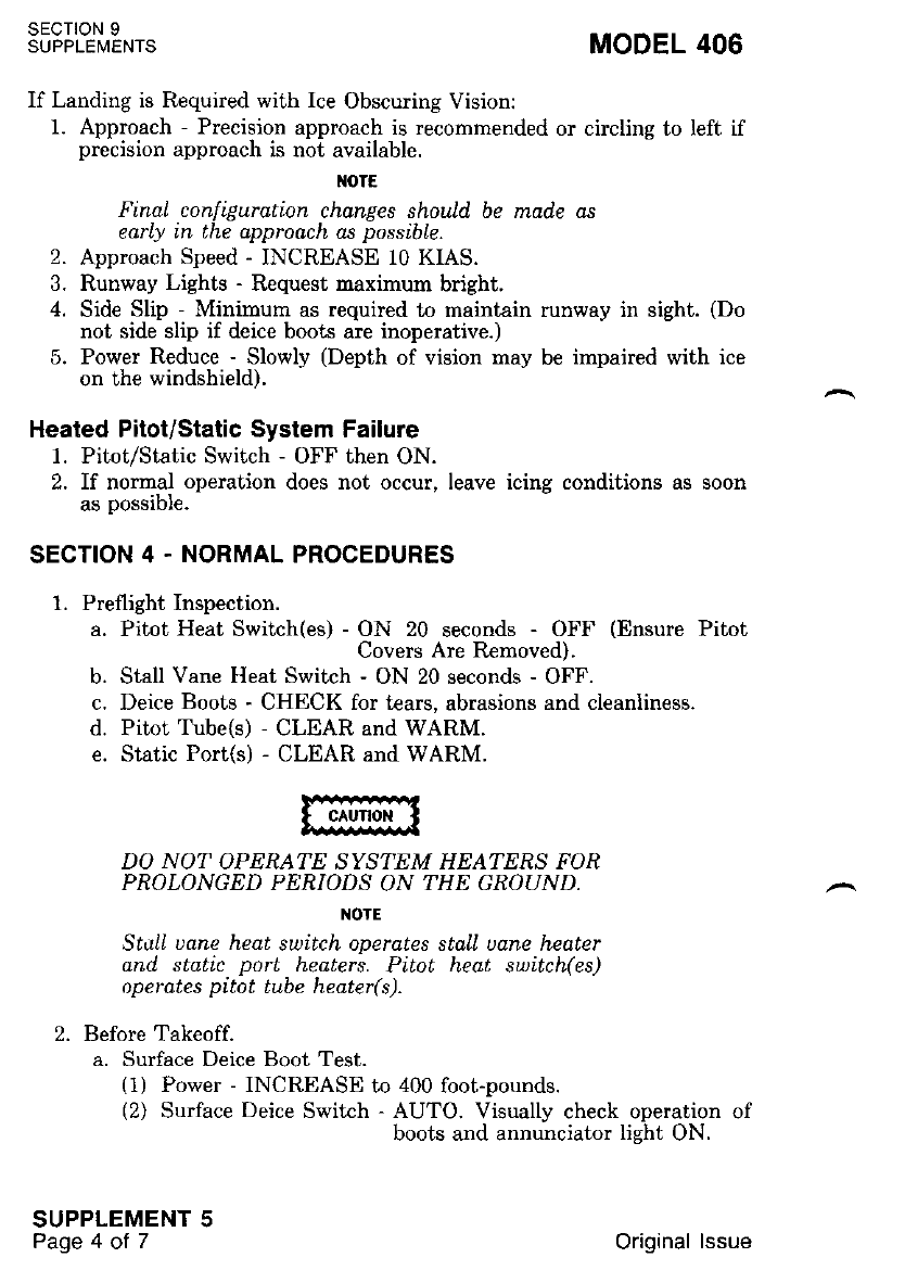
SECTION 9
SUPPLEMENTS MODEL 406
If Landing is Required with Ice Obscuring Vision:
1. Approach - Precision approach is recommended or circling to left if
precision approach is not available.
I{OTE
Final configuration changes should be made as
early in the approach as possible.
2. Approach Speed - INCREASE 10 KIAS.
3. Runway Lights - Request naximum bright.
4. Side Slip - Minimum as required to maintain runway in sight. (Do
not side slip if deice boots are inoperative.)
5. Power Reduce - Slowly (Depth of vision may be impaired with ice
on the windshield).
Healed Pitot/Static System Failure
1. Pitot/Static Switch - OFF then ON.
2. If normal operation does not occur, leave icing conditions as soon
as possible.
SECTION 4 . NORMAL PROCEDURES
1. Preflight Inspection.
a. Pitot Heat Switch(es) - ON 20 seconds - OFF (Ensure Pitot
Covers Are Removed).
b. Stall Vane Heat Switch - ON 20 seconds - OFF.
c. Deice Boots - CHECK for tears, abrasions and cleanliness.
d. Pitot Tube(s) - CLEAR and WARM.
e. Static Port(s) - CLEAR and WARM.
DO NOT OPERATE SYSTEM HEATERS FOR
PROLONGED PERIODS ON THE GROUND.
NOTE
StttLI uane heat switch operates staLl udne heater
and, stetic port heaters. Pitot heat switch(es)
operates pitot tube heater(s).
2. Before Takeoff.
a. Surface Deice Boot Test.
(1) Power - INCREASE to 400 foot-pounds.
(2) Surface Deice Switch - AUTO. Visually check operation of
boots and annunciator lieht ON.
SUPPLEMENT 5
Page 4 ot 7Original lssue
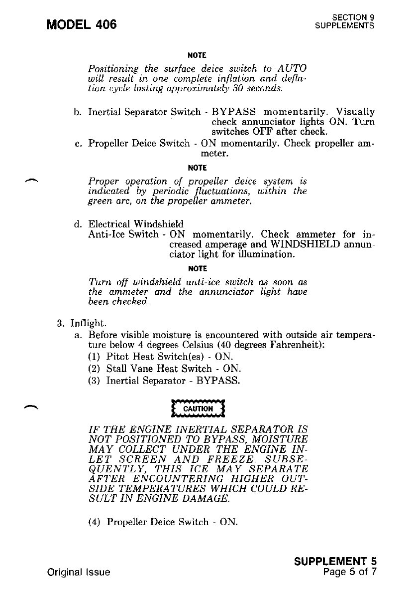
MODEL 406 SECTION 9
SUPPLEMENTS
NOTE
Positioning the surt'ace deice switch to AUTO
niLl result in one complete infLuti.on and defla-
tion cycle Lasting approximately 30 seconds.
Inertial Separator Switch - BYPASS mornentarily. Visually
check annunciator lights ON. Turn
switches OFF after check.
Propeller Deice Switch - ON momentarily. Check propeller am-
meter.
NOIE
Proper operation of propelLer deice system is
indicated. by periodic fluctuations, within the
Ereen arc, on the propeller amneter,
Electrical Windshield
Anti-Ice Switch - ON momentarily. Check ammeter for in-
creased amperage and WINDSHIELD annun-
ciator light for illumination.
xotE
Turn off windshield anti-ice switch ar soon ar
the qntmeter and the annunciator Li.eht haue
been cheched.
3. Inflight.
a. Before visible moisture is encountered with outside air tempera-
ture below 4 degrees Celsius (40 degrees Fahrenheit):
(1) Pitot Heat Switch(es) - ON.
(2) Stall Vane Heat Switch - ON.
(3) Inertial Separator - BYPASS.
IF THE ENGINE INERTIAL SEPARATOR IS
NOT POSITIONED TO BYPASS, MOISTURE
MAY COLLECT UNDEN THE ENGINE IN-
LET SCREEN AND FREEZE, SUBSE,
QUENT'LY, THIS ICE MAY SEPARATE
AFTER ENCOUNTERING HIGHER OUT-
SIDE TEMPERATURES WHICH COULD RE.
SULT IN ENGINE DAMAGE.
(4) Propeller Deice Switch - ON.
SUPPLEMENT 5
Paoe 5 of 7
b.
d.
Original lssue
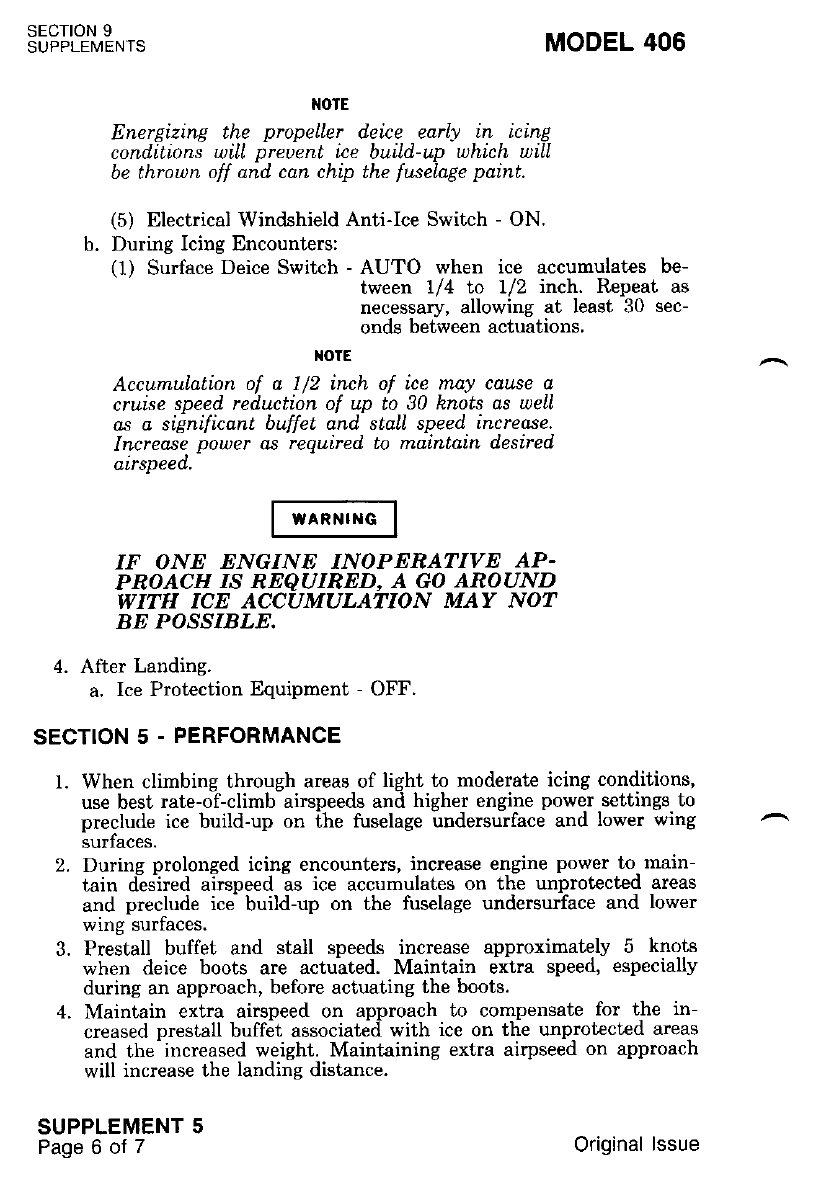
T{OTE
Energizing the propelLer d.eice earl! in icing
cond.itions wiLI preuent ice buiLd.-up which will
be throun off and. can chip the fuselage paint.
(5) Electrical Windshield Anti-Ice Switch - ON.
b. During Icing Encounters:
(1) Surface Deice Switch - AUTO when ice accumulates be-
tween 1/4 to 1/2 inch. Repeat as
necessary, allowing at least 30 sec-
onds between actuations.
TOTE
Accumulalion of a I /2 inch of ice may cause a
cruise speed reduction of up to 30 knots as welL
as a significant bu;ffet and. stall speed increase.
Increase power as required to maintain d,esired
airspeed.-
IF ONE ENGINE INOPENATIVE AP-
PROACH IS REQUIRED, A GO AROUND
WITH ICE ACCUMULATION MAY NOT
BE POSSIBLE.
4. After Landing.
a. Ice Protection Equipment - OFF.
SECTION 5 - PERFORMANCE
1. When climbing through areas of light to moderat€ icing conditions,
use best rate-of-climb airspeeds and higher engine power settings to
preclude ice build-up on the fuselage undersurface and lower wing
SUIIACES.
2. During prolonged icing encounters, increase engine power to main-
tain desjred airspeed as ice accumulates on the unprotected areas
and preclude ice build-up on the fuselage undersurface and lower
wing surfaces.
3. Prestall buffet and stall speeds increase approximately 5 knots
when deice boots are actuated. Maintain extra speed, especially
during an approach, before actuating the boots.
4. Maintain extra airspeed on approach to compensate for the in-
creased prestall buffet associated with ice on the unprot€cted areas
and the increased weight. Maintaining extra airpseed on approach
will increase the landins distance.
SECTION 9
SUPPLEMENTS
SUPPLEMENT 5
Page 6 of 7
MODEL 406
Original lssue
MODEL 406
5. Airplane general performance is decreased with ice on the unprotec-
ted areas.
6- Climb nerformance decreases with ice accumulation and^the use of
xi;l'll il:fll" lT: iloff 8fl 8t''fr 3*. Btol'?il o'Toiiil'ft"i
'Ciit{b ;".6;;ce'in Section 5 Subtract 20! -feet pil minute
i'i#' t"r'"'iin"ie:or-iitl,s -- oNn ENGINE INoPERATIVE
oerformance in Section 5.
SECTION 9
SUPPLEMENTS
SUPPLEMENT 5
Page 7 ot 7
Original lssue

MoDEL 406 suPSffJLXirS
RECOGNITION LIGHTS
SECTION 1 . GENERAL
This supplement provi{gs information which nust be observed when
operatirg [he recognition lights'
DescriPtion
The recomition lighis provide quqplementsl exter'nal- lightine for in-
creased airplane visibilitv 'fG; ligfiqs "qT b9, ut"{P-lid air traffic
control facilities and other ^opi"ri". in'to.uting the airplane in the air.
One lieht is mounted i" 15g lgadi:ng. eag" .of- ",?9]l ,l;1E -iip:" J.1*
f"ti'"t"a 'iT'inJ hnding light' A glateshield is installed rnhoard oI lne
iigtrl. to p."u""t glare into the cockpit'
SECTION 2 - LIMITATIONS
1. Ground OPerating Linitations:
a. Ground operatio,n of the recognition lights is limited t'o a
maximum p"rroo of"'fiue -mittul'"t' R"gutdl""t of time on' the
liehts must o" t*ti"a on iot -u'-i"irnit time period of thirty
m-inutes between each usage'
2. Flight Limitations:
a. None'
SECTION 3 - EMERGENCY PROCEDURES
Not APplicable.
SECTION 4. NORMAL PROCEDURES
1. The recognition lights are, operated by a switch/cfcuit breaher
located on the pilol"s left srde consote'
a. Switch - ON'
I'OTE
When airplane is on the ground' obserue ground'
o
P e r ating' i imitat io n s'
b. Swikh - OFF'
SECTION 5 . PERFORMANCE
Not APplicable'
SUPPLEMENT 6
Original lssue 1 of .l

MoDEL 4oo suPFffJLlfrS
OSCILLATING BEACON GROUND RECOGNITION
LIGHTS
SECTION 1 . GENERAL
This supplement -provides information which must be observed when
opeiuting ffie gtound tecogoition lighls'
OescriPtion
The recosnition lights provide slpplemental external. Iightine for in-
^"tJ$"d;:;i#!:"i"itliiiv.trt*" lieht'i are used.to aid air traffii control
facilities and otner arrpmnes ii-io"u'tittg ttt" airplane on the ground'
One lieht is mounted in the vertical fin and the other is mounted in
the loweifuselage.
SECTION 2 . LIMITATIONS
Not APPlicable'
SECTION 3 - EMERGENCY PROCEDURES
Not APPlicable'
SECTION 4. NORMAL PROCEDURES
1. The recognition lights are operated by a switch/circuit breaker
-' to"ut"a ori pilot's leh side console'
a. Switch - ON'
I{OTE
These beacon lilhts are not approued as flight
anti- collisio n lights'
b' Switch-OFF
SECTTON 5 . PERFORMANCE
Not APPlicable.
SUPPLEMENT 7
I of 1
Original lssue

AIR CONDITIONING SYSTEM
SECTION 1 . GENERAL
This suppler.nent p.rovides information which must be obsewed when
operating the alr concrtlonlng.
Description
The air conditioning system, consists of an electrically. driven
"o."i".ilt-.o"i""*i pattale in ih" no"", t'so evapoJators ard blower
ii#iliuri# tiir" iti- t'rt. -no""f o-puttment a''d 9I1e r1 lhe l'ailcone) and a
^fiifi';;;i'i;""LJ i" it'. iowei pa't of the right instrument panel'
llt" bto*"o distribute conditioned air to the cabin. area' .Each blower
-ot"t J""iti"af circuit is ptot"it"a by its respectiv-e circuit breaker' The
biJ#;"".il;G 6;;;il -as-a ventiliting svstem for recirculating cabin
air without'using [he air conditioni:rg syst€m'
The svst€m control panel consists of two-sritc[m and 1 rheostat' The
"uJe'i ?;'ilil,;i;;*d"a Cooi-bnF-clBcul,Arx,-cpnt-rols the mode
;i1;;;;i;;. -'Til-blo*"' .*it"h, placarded HIGH-LOW' controls the
;i";;;;;. t[" tto*"i *'ill op"tit" whenever the svstem ss'itrh is in
Jilr"rt,i. ti::" bt<ii "i-binbuufn mode' The temperaturc control rheo-
;;T. '"i;;"*d;i -Cobibn' "ooi-t" ttt" temperature. of lhe. conditioned
"il.'Ci""l*i"" t"t"tion oi the temperature iontrol lowers the air tem-
perature.
SECTION 2 . LIMITATIONS
.TO PREVENT DAMACE TO THE A]R
dbuniioNrNc IoMPRESSoR, Do NQ!
opnEAiE -TET AIR CONDI.IIONING SYS-
r.T,V--I I,T-COOI" WHEN THE OUTSIDE AIR
i-nuFtnnrunn IS BELow 20 DEGREES
rAA a N,I A UT ( -6.7 D EGRE ES CELS I US ).
.WHEN THE OUT'SIDE AIR TEMPENA-
1ililn ts crctrm IHAN 20 DEGREES
iriunwnntr ( 6.7 DESREES cELFluq.!
-edariu ro's e.ND SERVICING INTERyAT$
-uti-aE nEoucno BY PLACING rHE A!4
CbwnTircNmc sELEcroR SwITCH IN
;Coot " pon 5 MINIITES EAcH wEEK
MODEL 406 SECTION 9
SUPPLEMENTS
SUPPLEMENT 8
1of 3
Original lssue
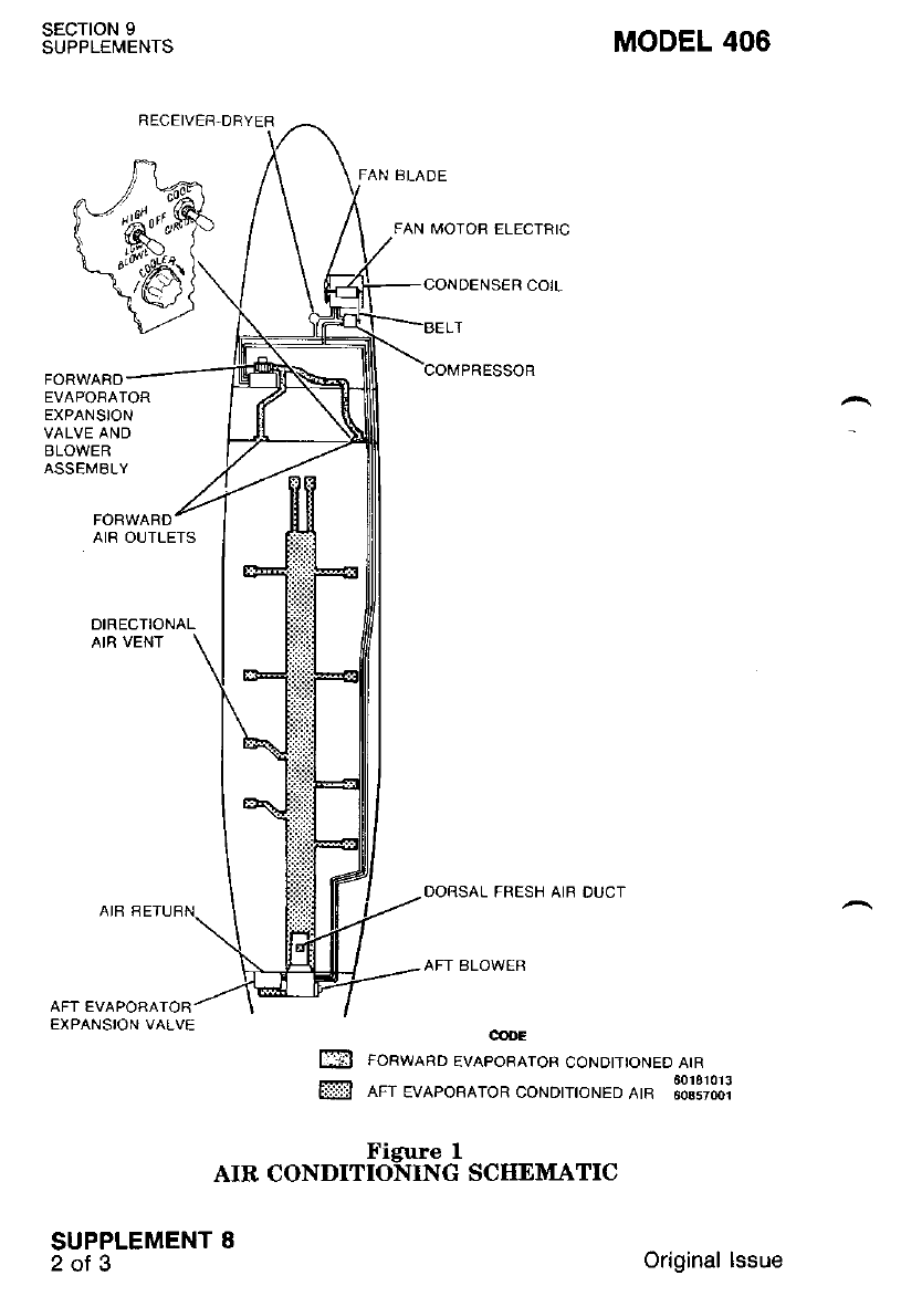
SECTION 9
SUPPLEMENTS MODEL 406
FAN BLADE
FAN MOTOR ELECTRIC
COMPRESSOR
FORWARD
EVAPORATOR
EXPANSION
VALVE AND
BLOWER
ASSEMALY
FORWARD
AIR OUTLETS
DIRECTIONAL
AIR VENT
EXPANSION VALVE
DORSAL FRESH AIB DUCT
AFT ALOWEB
co{rE
FORWARD EVAPORATOR CONDITIONED AIR
60181013
AFT EVAPOBATOR CONDITIONED AtR 6os57oo1
Figure I
AIR CONDITIONING SCIIEMATIC
SUPPLEMENT 8
2 ol 3 Original lssue
m
ffi
MoDEL 4oo su'FffJ!X'[3
SECTION 3. EMERGENCY PROCEDURES
1. Engine InoPerative Procedures
a. Air Conditioner - OFF or CIRCULATE'
SECTION 4 - NORMAL PROCEDURES
M)TE
When engines are not running,'. un elzctrtcol
interloch s-ystem is utlLlzed t'o ellmLnate opers-
iiii ii oii ro"aitioner on the ground uithout
auriliary Power unit connected'
1. Starting Procedures
a. Air Conditioner - Check OFF'
2. Before Taxi
a. Air Conditioner - As Desired'
3. Before Takeoff
a. Air Conditioner - OFF or CIRCULATE'
4. After Takeoff
a. Air Conditioner - As Desired'
5. Before Lalding
a. Ail Conditioner - OFF or CIRCULATE'
6. After Landing
a, Ait Conditioner - As Desired
SECTION 5 - PERFORMANCE
Not APPlicable
SUPPLEMENT 8
3of3
Original lssue

ELECTRICAL WINDSHIELD ANTI.ICE SYSTEM
SECTION 1 . GENERAL
This supplement provides information which must be observed when
operating ilie electrii windshield
Description
The electrical windshield anti-ice system consists of an electrically
heated element in the pilot's windshield, an inverter, an annunciator
^.light, a heat sensor, a switch and a circuit breaker.
The inverter, located in the right center wing section, supplies AC
power to the windshield. The h-eat sensor cycles the power to the
*ind"hield, providing temperature control. The green function indicator
light, will illuminate during each heating cycle.
If the indicator does not illuminate periodically, check the bulb by
oressine the PRESS-TO-TEST button. A secondary means of checking
b.opet "*indshield operation can be made by monitoring the voltam-
ineder. When the amp meter selector is positioned to BATT, a change in
charge or discharge rate will be noted during each heating cycle.
Abnormal operation of the electrical windshield anti-ice system is
indicated bv the switch breaker tripping to the OFF position and/or
failure of tire WINDSHIELD annrincialor light to illuminate and/or
triooins of the svstem circuit breaker. Failure of the breaker(s) to stay
reset in-dicates lhlt v;indshield anti-icing is impossible.
SECTION 2 - LIMITATIONS
If the nilot's windshield is covered with ice, do not leave the electrical
windshield anti-ice switch on for more than 20 seconds. Operation in
-excess of 20 seconG will cause an overheat condition which can result in
- -failure of the windshield heating element and/or permanent distortion of
the windshield.
SECTION 3. EMERGENCY PROCEDURES
1. Electric Windshield Anti-Ice Failure.
a. ELECTRIC W'SHIELD Circuit Breaker - RESET.
b. Windshield Anti-Ice Swikh - RESET.
c. If normal operation does not occur, leave icing conditions as
soon as nossible.
MODEL 406 SECTION 9
SUPPLEMENTS
SUPPLEMENT 9
1oI 2
Original lssue
SECTION 9
SUPPLEMENTS MODEL 406
SECTION 4. NORMAL PROCEDURES
1. Before Takeoff
a. Electrical Windshield
Anti-Ice Switch - ON momentarily. Check ammeter for in-
creased amperage and WINDSHIELD annun-
ciator light for illumination.
t{OTE
Turn off windshield anti-ice suitch os soon os
the qmmeter and the WINDSHIELD annun
ciator Light haue been cheched..
2. Inflighi
a. Electrical Windshield
Anti-Ice Switch - ON before entering visible rnoisture with out-
side air temperataure below 4 degrees Celsius
(40 degrees Fahrenheit).
b. Leave icing conditions as soon as possible if airplane is not
equipped for flight in icing conditions.
{OTE
Since the electrical wind.shieLd anti-ice systenT
slone does not provid.e dd.equate protection for
the entire airpline, icing c6nditi6ns should be
auoid.ed wheneuer possible unLess the airplane is
equipped for flight in icing conditions. Refer to
Fiighi In leing Conditions supplement for de
taiLs. If icing is encountered, cLose attention
should be giuen to the pitot static systent, pro-
peLLers, induction systems, uing and stabilizer
leading edges and. other cornponents subject to
LCLng.
3. After Landing
a. Electricl Windshield Anti-Ice Switch - OFF.
SECTION 5 - PERFORMANCE
Not Applicable.
SUPPLEMENT 9
2ol 2Original lssue
MODEL 406 SECTION 9
SUPPLEMENTS
8OO ALTITUDE ENCODING/ALERTING/PRESELECT
(EA-801A)
SECTION 1 . GENERAL
This supplernent provides information which must be observed when
operating ihe 800 encoding altimeter'
DescriPtion
The 800 encoding altimetPr ('type EA-801A) is an electrically driven
i".t't"ini"i ii;; -;;;."; uitpl"tt" iliit"d" and provides the pilot with a
^risual displav of the altitude. It also includes- an optrcal encoder wnlcn
;;";;.j i6id p-itiL. i--lG" code corresponding t'o the sensed altitude'
tfi"'il;C fiptti"d t ih"" Ait T.tffi" Control Radar- Beacon Svstem
t."o-"""o'iJ"r* i"'tln. "iipt""" to generat€ replies,-to Mode C - (altitude
ffi;ii";i-iil;&"ti*6 rto- ihi grou"d controller'. A second altitude
inior-ua'i'o" o"tpui- fron the altime[er can be coupled to airplane acces-
sory equiprnent such as an altitude alertcr.
The altitude alerter (T1pe AA-80rA) is an accessory, unit used with
trr" aiio ?n;odi"s altimeiei 'to supplv a preselected altitud.lr capture, signal
;;";; ;fr;-;tiifd" lioia n'"ciit" of the Autopilot .Svstem' It also
;;r;e;" ;;"tl ;A u"tJ **iogt when the airplane deviates from the
selected altitude.
The encoding altimeter is a panel-mounted barometric altimeter with
"" ,ftitiii- trt?" of -iooo to +35,000 teet'- Altitude i-s^displaved bv,a
dial and a dicital readout. The dial i8 gradxated -ln IU- numencal ol-
Ji"i."" "fiictt"t"present increments of 100 feet. with suMivision mar-
fitil f";';;il-t0- feei; the dial pointer completes one. revolution for
;;;; i0b0 f""i o] dtitud" change.'The digital readout displavs airplane
Jtiiira" iri i""i"-""G of hundre-cts and thousanrtl of feet only. Friction-
;;;;;d i;t ;d lumping of the displav is- reduced .bv the use of a
^ ;;;i"".i &;.;id'se"iJr"a"d motor<{rivin. displa.v' Electronic darnping
- crcults tn the unrt ensure that the display -fo[ows altitudf. changes
ii'""iiii *iit --ti6 ouershoot. Wtren power -is iepoygd {rop the altimeter' a
;i#A ;;il; n"t6p""* acrosi the digital altitude displav to indicate
a "oower-off" condition.
Ambient atmospheric pressure is set into the altimcter with a man-
r.ri"' Jr"i"riil r-"i"""i-kiob, and is disllaved on a four-digit readout'
eithir in inches of mercury or in millibars (as -ordered)', l he pressure
settine does not affect the output ot the opttcar encod€r' srnce fne
;;;ffi';;';;;; ;.f.-;;;d b siandard pressure (sea level; 29 92 inches
of mercurv or 1013.2 millibars).
SUPPLEMENT 1O
1of 7
Original lssue
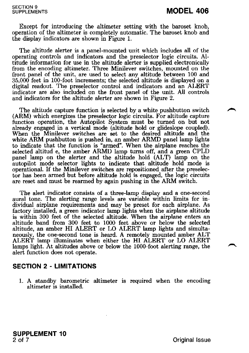
Except for introducing the altimeter setting with the baroset knob,
operation of the altineter is completely automatic. The baroset knob and
the display indicators are shown in Figure 1
The altitude alerter is a nanel-mounted unit which includes all of the
oDeratins controls and indi'cators and the preselector locic circuits. Al-
titude iriformation for use in the altitude aldrter is suppli;d electronically
from the encoding altimeter. Three Minilever switches, mounted on the
front panel of the unit, are used to select any altitude between 100 and
35,000 feet in 100-foot increnents; the selected altitude is displayed on a
digital readout. The preselector control and indicatnrs and an ALERT
indicator are also included on the front Danel of the unit. All controls
and indicators for the altitude alerter are shown in Figure 2.
The altitude caDture function is selected bv a white oushbutton switch
(ARM) which eneigizes the preselector logic Lircuits. Fbr altitude capture
function operation, the Autopilot System must be turned on but not
already engaged in a vertical mode (altitude hold or glideslope coupled).
When the Minilever switches are set to the desired altitude and the
white ARM pushbutton is pushed in, an arnber ARMD panel lamp lighLs
to indicate that the function is "armed". When the airplane reaches the
selected altitud e, the amber ARMD lamp turns off, and a green CPLD
panel lamp on the alerter and the altitude hold (ALT) lamp on Lhe
autopilot mode selector lights to indicate that altitude hold mode is
operational. If the Minilever switches are repositioned a-fter the preselec-
tor has been armed but before altitude hold is engaged, the logic circuits
are reset and must be rearmed by again pushing in the ARM switch.
The alert indicator consists of a threeJamp display and a one-second
aural tone. The alerting range levels are variable within limits for in-
dividual airplane requirements and may be preset for each airplane. As
factory installed, a green indicator lamp lights when the airplane altitude
is within 300 feet of the selected altitude. When the aimlane ent€r€ an
altitude band from 300 feet to 1000 feet above or bel6w the selected
altitude, an amber HI ALERT or LO ALERT lamp lighLs and simulta-
neously, the one-second tone is heard. A remotely mounted amber ALT
ALERT lamp illuminates when either the HI ALERT or LO ALERT
lamps light. At altitudes above or below the 1000-foot alerting range, the
alert function does not oDerate.
SECTION 2 . LIMITATIONS
1. A standby barornetric altimet€r is required when the encoding
altimeter is installed.
SECTION 9
SUPPLEMENTS
SUPPLEMENT 1O
2ot7
MODEL 406
Original lssue
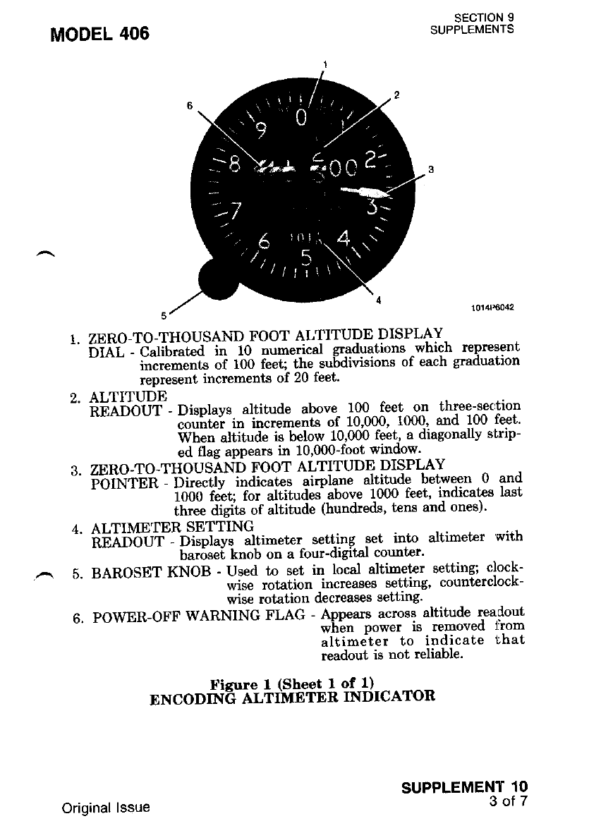
SECTION 9
SUPPLEMENTS
MODEL 406
5.
1. ZERO-TO-THOUSAND FOOT ALTITUDE DISPLAY-
6-rni --Cait.tLa in 10 numerical graduations -which represent
""^- i";;;;;t" of 100 feet; the subdivisions of each graduation
represent increments of 20 feet'
ALTITUDE
iiE qo.*O-uT- Displays altitude above 100 feet - o-n three-get:tion
- couittei in increments of 10,000, 1000' and ].OO !egt'
When altitude is below 10,000 feet, a diagonary sirlp-
ed flag appears in 10'000-foot window'
ZERO-TO.THOUSAND FOOT ALTITUDE DISPLAY
F"oirir'ei : ^Dir;ctit ;dta;s airplane alt-itude betwe,en .0 and
iooo i"lrt;-?- Jtitudei above 1000 feet' i.ndica[es last
three digits of altitude (hundreds' t€ns and ones)'
ALTIMETER SETTING
ii6Aii'ouT - Di;piays altimeter setting set into altimet€r with
haroset knob on a lbur-drgrtal counrcr'
BAROSET KNOB - Used to get in t6gsl altirng-ter setting; clock-
wise rotation increases setting, counterclock-
wise rotation decreases setting'
6. POWER-OFF WARNING FLAG - Appears across altitude readout
wh-en power is removed l'rom
altimeter to indicate that
readout is not reliable.
t
Ficure I (Sheet I of l)
ENCODTNG ALTIMETER INDICATOR
SUPPLEMENT 1O
3of7
Original lssue
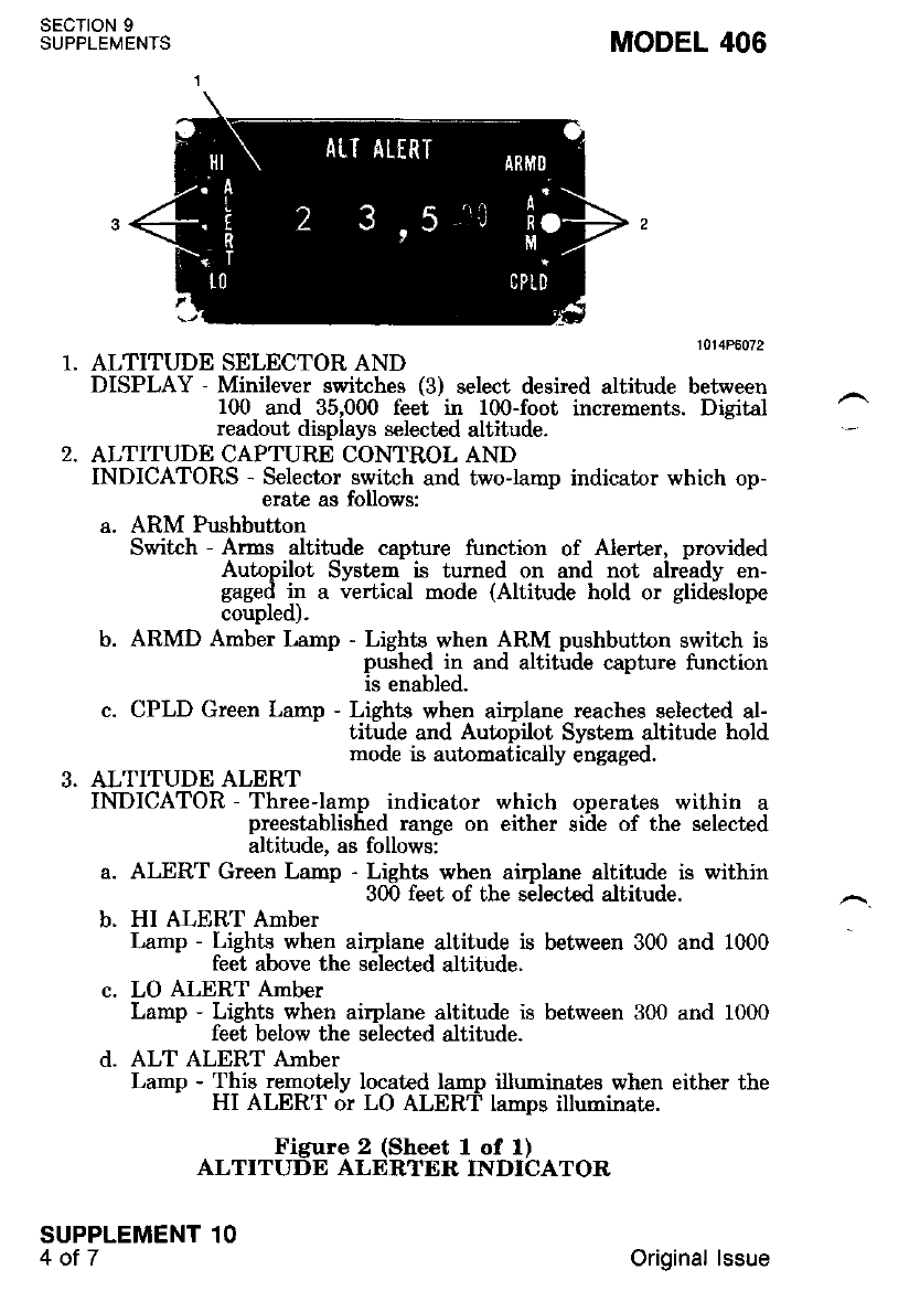
sEcTroN 9
SUPPLEMENTS MODEL 406
ALTITUDE SELECTOR AND
DISPLAY - Minilever switches (3) select desired altitude between
100 and 35,000 fe€t in 100-foot increments. Digital
readout displays selected altitude.
ALTITUDE CAPTURE CONTROL AND
INDICATORS - Selector switch and two-lamn indicator which op-
erate as follows:
a. ARM Pushbutton
Switch - Arms altitude caDture function of Alerter. orovided
Autopilot Systen is turned on and not already en-
gaged in a vertical mode (Altitude hold or glideslope
coupled).
b. ARMD Amber Lamp - Lights when ARM pushbutton switch is
pushed. in and altitude capture function
is enabled.
c. CPLD Green Lamp - Lights when airplane reaches selected al-
titude and Autopilot System altitude hold
mode is automatically engaged.
ALTITUDE ALERT
INDICATOR - Three-lamp indicator which onerates within a
preestablished range on either siile of the selected
altitude, as follows:
a. ALERT Green Lamp - Lights when airplane altitude is within
300 feet of the selected a.ltitude.
b. HI ALERT Amber
Lamp - Lights when airplane altitude is between 300 and 1000
feet above the selected altitude.
c. LO ALERT Amber
Lamp - Lights when airplane altitude is between 300 and 1000
feet below the selected altitude.
d. ALT ALERT Amber
Lamp - This remotely located la'"p illuminates when either the
HI ALERT or LO ALERT lamps illuminate.
Figure 2 (Sheet I of l)
ALTITUDE ALERTER INDICATOR
2.
SUPPLEMENT 1O
4ot7 Original lssue
MODEL 406 sEcTtoN 9
SUPPLEMENTS
SECTION 3. EMERGENCY PROCEDURES
1. Encoding Altimet€r Failure (Warning Flag Showing)
a. ENC ALT Circuit Breaker - CHECK IN.
b. If waming flag is still showing, use the standby barometric
altimeter.
SECTION 4 - NORMAL PROCEDURES
1. Altimeter Operation
a. Baroset Knob - TURN as necessary to set readout to local
altimeter setting.
b. Power-off Warning Flag - VERIFY that flag is not in view'
SUPPLEMENT 1O
50T/
DO NOT ATTEMPT TO USE ALTIM-
ETER INDICATION FOE FLIGHT IN-
FOBMATION IF WA&NING FLAG IS IN
VIEV.. FLAG TNDICATES THAT POWEry
HAS BEEN REMOVED FROM ALTIM.
ETER.
c. Altitude
- bi;;t"t - Below 1000 feet, read altitude on displav pointer and
dial. Above 1000 feet, read altitude on altitude
readout plus pointer and dial inlicatiort- for last two
dieits tfo. example, for an altitude of 12,630 feet' read
iZ]OOO feet on ieadout: read 30 feet on pointer and
dial).
2. Altitude Encoding and Accessory Operation
Oneration of the altitude encoding and accessory information func-
lioni of the altimeter is completely automatic as- soon aa power -ls
"'oiil"d-t"-ili" altimeter and the'warning flag is out of view' However, for
;ifi;;;ti; oi the altitude informati6n to the ground -controller, the
Mode C (ALT) function must be selected on the transponder'
3. Altitude Alert
M)TE
The oltitude alzrter must be used uith a prop-.
erLy fu.nctioning 800 encoding oltimeter for atl
operatton.
Original lssue
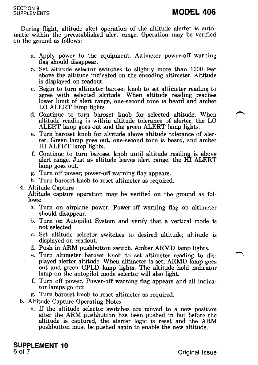
sEcTroN 9
SUPPLEMENTS MODEL 406
During flight, altitude alert operation of the altitude alerter is auto-
matic wiihiri the preestablished -alert range. Operation may be verified
on the ground as follows:
a. Apply power to the equipment. Altimeter power-off waming
flag should disappear.
b. Set altitude selector switches to slightly more than 1000 feet
above the altitude indicated on the encodins altimeter. Altitude
is displayed on readout.
c. Begin to turn altimeter baroset knob to set altimeter reading to
agree with selected altitude. When altitude reading reaches
lower limit of alert range, one-second tone is heard and amber
LO ALERT lamp lights.
d. Continue to turn baroset knob for selected altitude. When
altitude reading is within altitude tolerance of alerter, the LO
ALERT lamp goes out and the green ALERT lamp lights.
e. Turn baroset knob for altitude above altitude tolerance of aler-
ter. Green lamp goes out, one-second tone is heard, and amber
HI ALERT lamp lights.
f. Continue to turn baroset knob until altitude readins is above
alert range. Just as altitude leaves alert range, the HII ALERT
lamp goes out.
g. Turn off power; power-off warning flag appears.
h. T\rrn baroset knob to reset altimeter as required.
4. Altitude CaDture
Altitude caiture operation may be verified on the ground as fol-
lows:
a. T\rrn on airplane power. Power-off warning flag on altimeter
should disappear.
b. Turn on Autopilot System and verify that a vertical mode is
not selected.
c. Set altitude selector switches to desired altitude: altitude is
displayed on readout.
d. Push in ARM pushbutton switch. Amber ARMD lamp lights.
e. Turn altimeter baroset knob to set altimet€r reading to dis-
played alerter altitude. When altimeter is set, ARMD lamp goes
out and green CPLD lamp lights. The altitude hold indicator
lamp on the autopilot mode selector will also light.
f. Turn off power. Power-off warning flag appears and all indica-
tor lamps go out.
g. Tlm baroset knob to reset altimeter as required.
5. Altitude Capture Operating Notes
a. If the altitude selector switches are moved to a new nosition
after the ARM pushbutton has been pushed in but beiore the
altitude is captured, the alerter logic is reset and the ARM
pushbutton must be pushed again to enable the new altitude.
SUPPLEMENT 1O
6of7 Original lssue
MODEL 406
b.
SECTION 5 . PERFORMANCE
Not APPlicable.
SECTION 9
SUPPLEMENTS
SUPPLEMENT 1O
TOIT
d.
After altitude capture. and altilude hold mode is estq!-lished; if
iir" ii"iii"" l""t'"s the selected altitude' the green CPLD la4p
will remain lii. The altitude deviation will be rndrcated Dy lne
;liiiil;- fERT la-p" a"d the discepancv between the, se-
lected altitude displayed on the alert€r and the arrphne allltuoe
displayed by the altimeter'
If in" Atit"a" selectnr switches are set to a different altitude
;h;""hilil;.fiute.-ttie Autopilot Svstem will remain in the
"1';ttil;'it;ii ;;i; ijtt the grden CPLD lamp. will go oul.to
indicat€ that Lhe altitude displayed is not Lhe altrtude aL wnrcn
the airplane is being held.
ii "ftliua" hold is- manually selected on the. autopilo-t mode
;il;;;;;;; uuto.uti" iltitude capture, thc ARMD lamp
will eo oirt, the CPLD lamp will not light' and-l'he -capture logrc
circu-its will have to be reset for the next use' Ihe tunctron may
tr" ."""t "n"t altitude hold is disengaged'
Original lssue

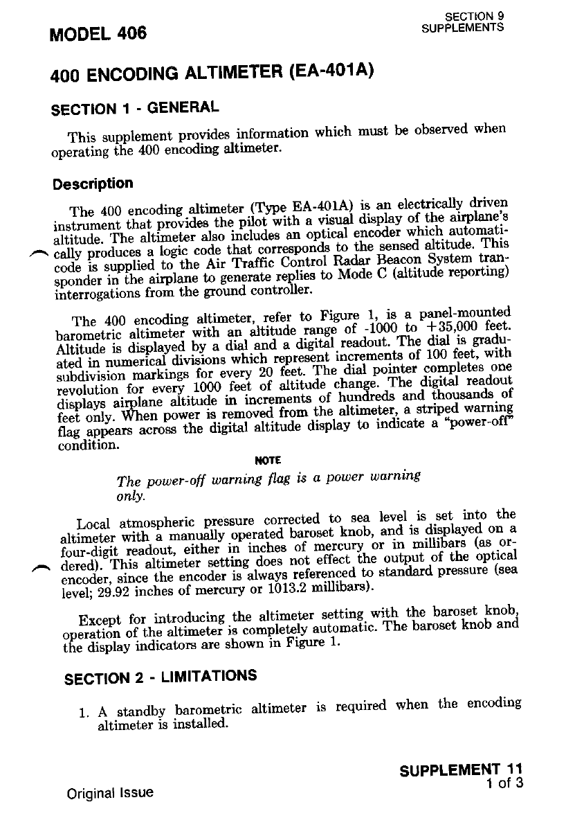
SECTION 9
SUPPLEMENTS
This supplement provides information which must be observed when
oneiating ilie 400 encoding altimeter'
DescriPtion
The 400 encoding altineter (Type FA-401A) is an electrically driven
i".t';;;; ui"i pt"'"ia"" t" pii# i'ittt s visrrgl displav of the airplane's
ii"i"ird". fi,!-"iii-!t", a..o i"'"T.ii." an optical enc6dei which automati-
^:ildl'i".$?;''l$ru"jt5:lg4l}nq*r*:#affi "$J*H#;
iii"tiJn"ilo"J t oir the ground controller'
The400encodingaltimeter,refertnFigurel'^isapanel-mounted
tu.'#"r.l""" "iiii""t"i *i*t ;; iiiiil" -'*si of '-1000ro *35'000 feet'
ltfili;^il iilpr"vJa uv u aiur*""i-i-aigidi.readout',The dial is s'adu-
ated in numerrcal- (u!'Brona ihich repre"int inc-rements of 100 feet' with
iff r$'H"'#-5'"H"is':i:+:{;;1*qhk:Tgi"t#*#*ri
displaYs airplane altitude il
feet only. When power t- ;;;;HT;; itte' attineter' a sr'rioed warning
flag,appears acnoss Lne otg#l" Jt'id'i" aisplay tn indicate a "power-ofP
condltron' [orE
The pouer-off warning flng is a pouer warning
only'
Local atmospheric pressure corrected n tT !l:I,^it- set into the
altimeter wilh. a manuary .o-p*ui"d fa^to*ut knob' and is displayed on a
four-dieit readout, erf,ner ff;;-h; of -"^t"ury or in millibars (as or-
,^ dered). This altimet€r *ttitg'iii'-t' ""t "ffect.the g"tpJt P{ !!:..9ltt-":l
encoder, since the encoder is-always referenced to standard pressure (sea
i"i,"iliii.gz i""n"s of mercury or 1013'2 millibars)'
Except for introducing the altimet€r tgttilg. dlh.^t*. bamset knob'
ooeration of the altimeter d;;;ii"klv automa-tic' The baroset knob and
if,J'Ji"pi"i i"ai".Lors are shown in Figure I'
SECTION 2 - LIMITATIONS
1. A standby barolletric altimeter is required when the encoding
altimeter rs rnstalleo'
MODEL 406
4OO ENCODING ALTIMETER (EA'401A)
SECTION 1 - GENERAL
SUPPLEMENT 11
1of 3
Original lssue
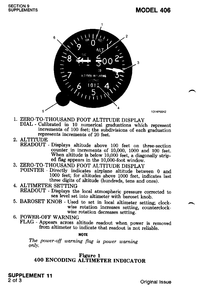
SECTION 9
SUPPLEMENTS
SUPPLEMENT 11
2of3
1. ZERO.TO-THOUSAND FOOT ALTITUDE DISPLAY
DIAL - Calibrated in 10 numerical graduations which represent
incrcments of 100 feet; the subdivisions of each eraduation
represents increments of 20 feet.
2. ALTITUDE
READOUT - Displays altitude above 100 feet on three-section
count€r in increments of 10,000, 1000 and 100 feet.
When altitude i! be-low 10,000 feet, a diagonally strip-
ed flag appears in the lO,fu0-foot windod.
3. ZERO-TO.THOUSAND FOOT ALTITUDE DISPLAY
POINTER - Directly indicates airplane altitude between 0 and
1000 feet; for altitudes above 1000 feet. indicates last
three digits of altitude (hundreds, tens and ones).
4. ALTIMETERSETTING
READOUT - Displays the local atmospheric pressure corrected to
sea level set into altimetei with 6aroset knob.
5. BAROSET KNOB - Used to set in local altimet€r settins: clock-
wise rotation increases settins. coun-t€rclock_
wise rotation decreases settingl
6. POWER-OFF WARNING
FLAG - Appears across altitude readout wheo power is removed
from altimeter to indicate that readout is not reliable.
I{OTE
Thc power-off warning flag is power warning
only,
MODEL 406
4OO ENCODING XifffiilTER INDICATOR
Original lssue
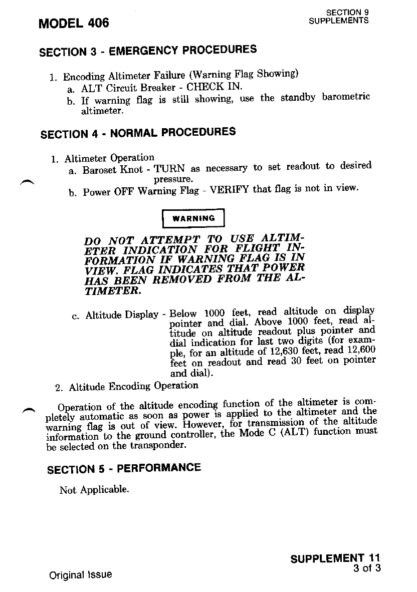
MODEL 406 SECTION 9
SUPPLEMENTS
SECTION 3. EMERGENCY PROCEDURES
1. Encoding Altimeter Failure (Warning Flag Showing)
a. ALT Circuit Breaker - CHECK IN'
b. If warning flag is still showing, use the standby barometric
altimet€r.
SECTION 4. NORMAL PROCEOURES
1. Altimeter OPeration
a. Baroset Knot - TURN as necessary to set readout to desired
pressure.
b. Power OFF Waming Flag - VERIFY that flag is not in view'
SUPPLEMENT 11
3oJ3
DO NOT ATTEMPT TO USE--4UIM-
Einri - rl.tnicArlo N FoR FLIGryT -lry,-.
ft'fn fu
ii t o r'r i e w
AR N r N G F L aq ^rg- I{
iiEw. eLe'e INDIcATES rHA!-P-gwEn
ifus'it-EEN REMovED FRoM THE AL-
TIMEIER.
c. Altitude Display - Below 1000 feet, read altitude on display
"o-t"t -una dial Abou" 1000 feet'- read al-
iii"J"'"t atitJa" readout phrs pginter and
dial indication for last two dJg:rts (Ior exam-
piu, fot un uttitoae of 12'630 feet' read 12'600
i""i on i"aaoot and read 30 feet on pointer
and dial).
2. Altitude Encoding OPeration
Operation of the altitude encoding function of tle altimet€r is com-
nletelv automatic as soon as p6iii-% ti-pii"a to the altimeter 8nd the
$'ff ts'n?|iJ' il "i ;l;;. ho*"u"'' fb'r transmission. of the altitude
information to the grouno "o"tioitlt, ihe Mode C (ALT) function must
be selected on the transponder'
SECTION 5 . PERFORMANCE
Not Applicable.
Original lssue

4OO AREA NAVIGATION SYSTEM (RN'479A)
SECTION 1 - GENERAL
This supplement provides information which -mr-rst be observed when
op"rriirrg ilie 400 Ar'ea Navigation System (RNAV)'
Description
The 400 Area Navigation Systen refened !o- as Remq!9 Navigation
( Rfi i"v i;;#i.i. ;i;;'RNAv "c;-putBr, NAV &"i-"1u"J' Distance Mea-
ilffi 'dqffi il;ibMnI ri"*l'"tAransm itter, DME Control Unit' and
Course Indicator.
The 400 RNAV Svstcm features ten programmable walpoints' easily
""t"'"tia-Ji'u i.iil"*a"*iw. rtt" active, rir airy memory-stored rraypoint'
;;;"-b"* ;i"#d i;r' dispiav. showing frequencv., beagc and distance
ili;.;i;;;Lieht E;itti"g DiodeiLED) readouts' wavpoi,nt-leqring
il[^ti;t"an;; T]ormation" is programmed from the VORTAC
(VOR/DME) station to the walpoint (wt'I )'
Frequency, IFREQ) Bearilg GRG) and Distance (DIST) are retained
in memory .by voltag€ provroed directly- from the hot battery bus This
memory vottage t, *"p" t,,u"- "*n ifter the battcry -switch as been
iltn"<i"off. TJ preveni. battery discharge {uring. periods of lons t'€rm
srorase. it is recommended tn"'ri'86 IvtEM circiii breaker on thi right
side ionsole be Pulled.
t{ofE
II the "Memory" uoltage is interrupted'..all
lniii i*rr""t;i,n for thZ RNAV displav wiLl be
lost. SubseEnnt operation ol .thz.system' ultn
the "Memory" Doltage restored' ulll requlre re-
programrning of waYPoints.
The RNAV system has three modes of operation:
^'i. V-Onplle - Regular VOR/DME op^eration' Distance' gr.o-u]d- spqed
tnd tine-to-Jtation iriformation on the DME display
uod co.,t." iniormation qn ltrg -co-gr-sgindicator are
ieiatlu" tn the VORTAC (VOR/DME) station se-
lected on the associated NAV receiver'
2. RNAV ENROUTE - Distance, ground sp-eed-and Lime-to-station
t"ro"-uiioti on the -DME display and course
intioimation on the course iniiicator are rela-
tive to the active FLY walpoint'
MODEL 406 SECTION 9
SUPPLEMENTS
SUPPLEMENT 12
1 oJ 10
Original lssue
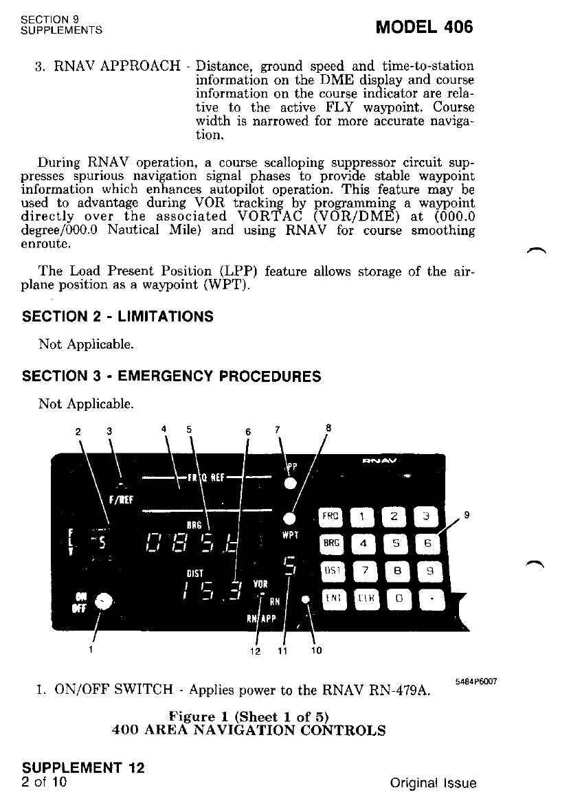
sEcroN 9
SUPPLEMENTS MODEL 406
3. RNAV APPROACH - Distance, ground speed and time-to-station
information on the DME display and course
information on the course indicator are rela-
tive to the active FLY walpoint. Course
width is narrowed for more accurate naviga-
tion.
During RNAV operation, a course scalloping suppressor circuit sup-
presses spurious navigation signal phases to provide stable walpoint
information which enhances autopilot operation. This feature may be
used to advantage during VOR tracking by programming a walpoint
directly over the associated VORTAC (VOR/DME) at (000.0
degree/000.0 Nautical Mile) and using RNAV for course smoothing
enroute.
The Load Present Position (LPP) feature allows storage of the air-
plane position as a waypoint (WPT).
SECTION 2 . LIMITATIONS
Not Applicable.
SECTION 3 . EMERGENCY PROCEDURES
Not Aonlicable.
1. ON/OFF SWITCH - Applies power to the RNAV RN-479A.
Figure 1 (Sheet I of 5)
4OO AREA NAVIGATION CONTROLS
SUPPLEMENT 12
2ot10 Original lssue
MODEL 406 SECTION 9
SUPPLEMENTS
FLY WAYPOINT
SWIICU - Selects active waypoint. di.splays.. assigned ,waSpoint
number (o-g) in wilpoint digit display, and-displavs
programmed bearing 1BRG) and distance (DIST)'
M)TE
The wqvpoint will be computed for uhirhzuer
freouenii is selected on ihe associated NAV
'rn"biuer.- The airplane DOES NOT flv Lo the
frequ.ency displnyitl in thc FREQ REF DATA
DISPLAY @.
F/REF (FRESUENCY REFERENCE
SWifCUt - When depressed, recalls stored frequency (if any) cor-
' responding to WPT displayed. for a period of 8 sec-
onds.
FREO REF (Frequencv Reference)
DATA DISPLAY - 5 aisit LED display indicating the trequencv
which must be set in the associat€d NAV re-
ceiver. The frequency must be entered from
kevboard or lecalled from nerrory using the
F/REF SWITCH (3). Anv attempt to program
frequency data into the waypoint qumb,qr- cur-
renilv sit at the FLY WAYPOII{T SWITCH
will -cause the displav to fl88h "in USE" but
new frequency data will not be inhibited from
entry.
BRG (Bearing)
DATA DISPLAY - 4-disit LED display indicating the wavpoint
bearing (from the VOR station) in memgry or
to be fut in memory'- Thqpg4n-o-!-!hjs. data is
the saire as described in FREQ REF (4) above'
In the event that a localizer frequency has been
selected and the svstem is in the RNAV-
ENROUTE (RN) oi RNAV-APPROACH (RN
APP) rnode, "Loc" will flash in the display'
DIST (Distance)
DATA DISPLAY - 4-dicit LED displav indicating the wavpoint
distance in memory or to be put in memory'
The oriein of this data is the same as in FREQ
REF (41 above. In the event that a localizer
freouencv has been selected and the system is
in 'the- RNAV-ENROUTE or RNAV-
APPROACH mode, "FrE" will flash in the dis-
PlaY'
Ficure 1 (Sheet 2 of 5)
4OO ARE{ NAVIGATION CONTROLS
SUPPLEMENT 12
3 of 10
Original lssue
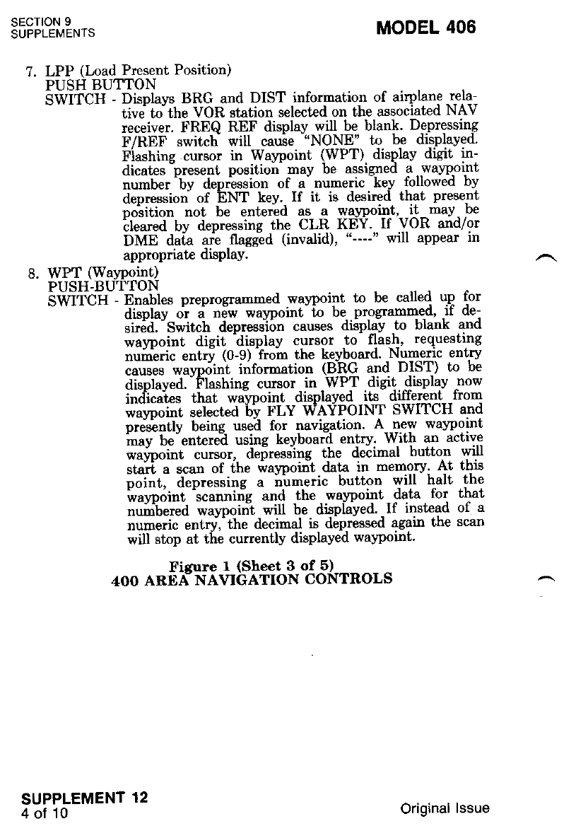
sEcroN I
SUPPLEMENTS MODEL 406
?. LPP (Load Present Position)
PUSH BUTTON
SWifCU - Displays BRG ard DIST infornatior of airplane rela-
- tive io the VOR station select€d on the associated NAV
receiver. FREQ REF display will be blank. Depressing
F/REF switcb will cause "NONE' to be disPlaved'
Fiashing cursor in Waypoint (WPT). displav digit in-
dicates "presenl. positio;- may be assigneil 1..wa1o,oint
number by depression of a numenc key tollowed Dy
depression of ENT kev. If it is desired that Present
""!iti"" noi te entetla as a waypoint' it may be
'ileared bv depressing the CLR KEY. If VOR and/or
DME da;a ari flaggid (invalid), appear in
appmpriate disPlaY.
8. WPT (WaYPoint)
PUSH-BUTTON
SWIi-CH Enables preprogrammed way'point to be called u.p for
display or a new waypoint t'o be- programmed' rr de-
ti.-Ja' "s*it"l depressi6n causes diiplay to blank and
waypoint digit display cursor to flash' reqxesting
nuiieric entrv (0-9) from the keyboard. Nltmenc ent-ry
"."t". *"ypii"i information L!-&Q q.r-r4 D.IST) to be
disnlaved" Flashins cursor in WPT digit display now
indicates that waircoint displayed its different fiom
*""ooi"t selected bv FLY WAYPOINT SWITCH and
oresentlv being used for navigation' A new waypoint
inay be-entere-d using keyboard entry' With an active
wavpoint cursor, deiressing the decimal button will
tirfi, , ."ut of fhe waypoirit data in mems.ry' At thiE
poi"t, aep.e""i"g a ium-eric button will halt the
i"uypdiot 'scannin'g and the - wa-ypoint - data . for that
num-bered walpoirit will be displayed. -If instead of a
numeric entry,'the decirnal is depressed again the scan
will stop at tle currently displayed waypoint'
Fisure I (Sheet 3 of 5)
4OO AREA- NAVIGATION CONTROLS
SUPPLEMENT 12
4 oi l0 Original lssue
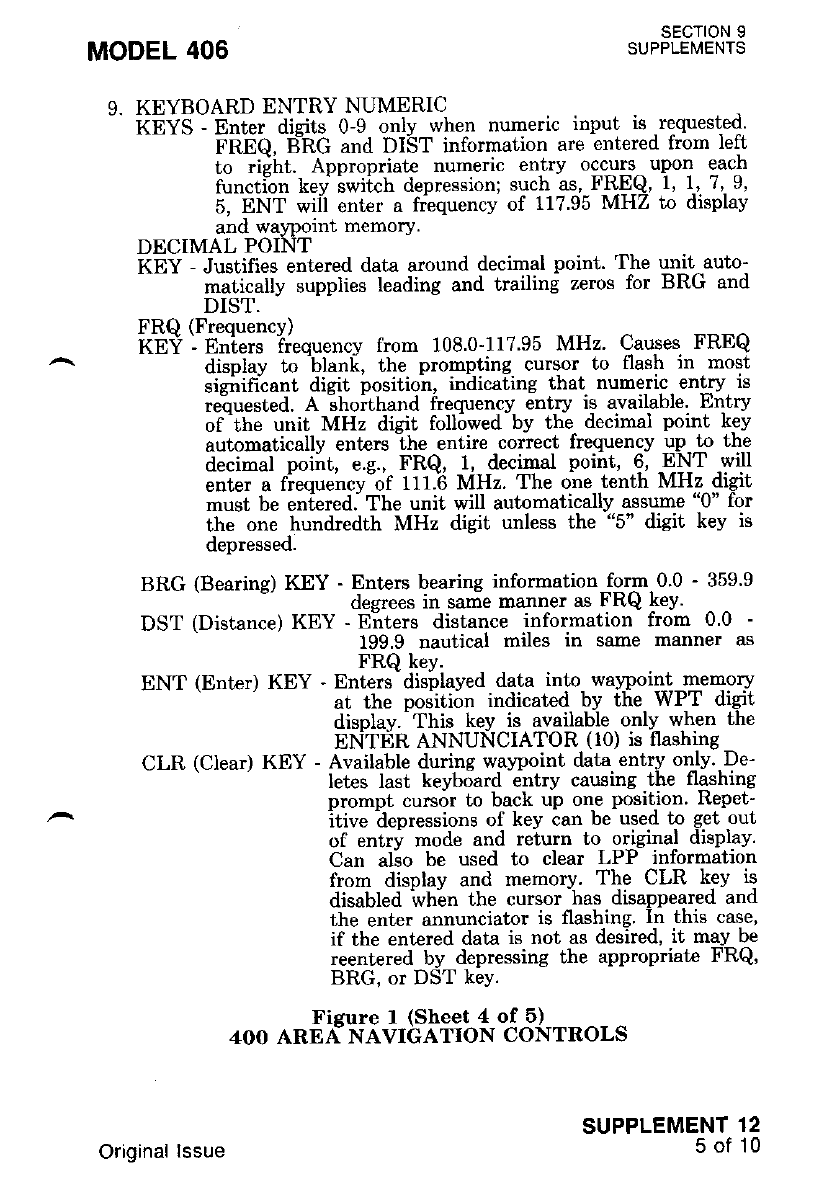
MODEL 406 sEcT|0N 9
SUPPLEMENTS
9. KEYBOARD ENTRY NUMERIC
-' KE S - Enter disits 0-9 onlv when numeric input is requested'
-- FREQ, BIRG and DIST information are entered from left
to ri;ht, Appropriate nuneric entry occurs upon each
function key swiich depression; such as, FR-EQ 1, 1-' 7,.9,
5, ENT wiil enter a frequency of 117.95 MHZ to display
and waypolnt memory.
DECIMAL POINT
KEY - Justifies entered data around decimal point. The un-it auto-
-- matically supplies leading and trailing zeros for BRG and
DIST.
FRQ (Frequency)
kEi - f"i"tr ii.qu"tt"y from 108.0-117'95 MHz. Causes FREQ
displav to 'blanli, the prompting cursor to flash in most
sidrihcant dicit position, indicating that numeric entry is
re"ouesLed. A ;hoithand frequency entry is available. Entry
of 'the unit MHz digit followed by the- decimal point k9v
automatically enters "the entire coriect frequency up to the
decimal poiirt, e.g., FRQ, i, decirqal point, 6, -ENT will
enter a fiequencv of tl1.6 MHz. The one tenth MHz digit
must be entered. The unit will autornatically assume "0" for
the one hundredth MHz digit unless the "5" digit kev is
depressed.
BRG (Bearins) KEY - Enters bearing information form 0.0 - 359.9
desrees in same manner as FRQ keY'
DST (Distance) KEY - Enters distance information from 0.0 -
199.9 nautical miles in same manner as
FRQ key.
ENT (Enter) KEY - Enters - dislplayed data into- waypoin-!-memory
at the poditiirn indicated bv the WPT digit
display.-This key is available. only- when the
ENTER ANNUNCIATOR (lo) is flashing
CLR (Clear) KEY - Available during w.avpoint data entrv oqlv..De-
Ietes last keyboard entry causing.the flashing
prompt cursor to back up one positjon. Repet-
itive depressions of key can be used to get out
of entry mode and return to olginal disPlav.
Can alio be used to clear LPP information
from disolav and memory. The CLR key is
disabled whln the cursor has disappeared and
the enter alnunciator is flashing. In this case,
if the entered data is not as desired, it may be
reentered by depressing the appropriate FRQ,
BRG, or DST keY.
Fisure I (Sheet 4 of 5)
4OO ARE{ NAVIGATION CONTROLS
SUPPLEMENT 12
5 of 10
Original lssue
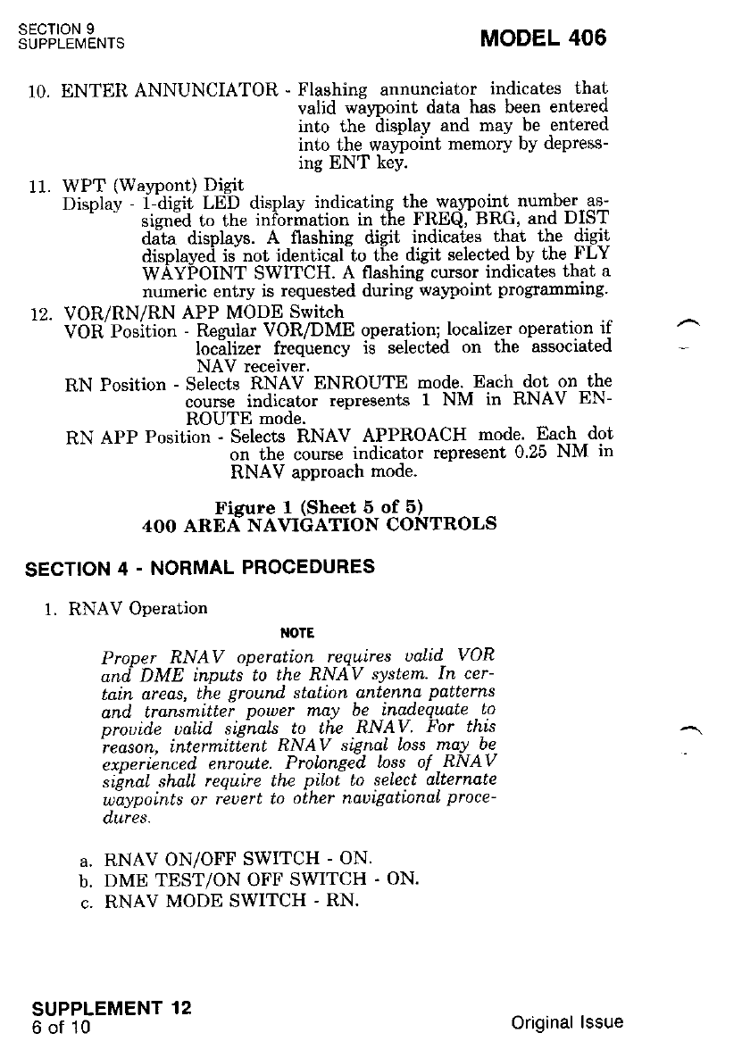
SECTION 9
SUPPLEMENTS
SECTION 4 - NORMAL PROCEDURES
1. RNAV Operation
{otE
SUPPLEMENT 12
6of10
IINTER ANNUNCIATOR - Flashing annunciator indicates that
valid wiwoint data has been entered
into the- ilisplay and may be entered
into the waypoint memory by depress-
ing ENT keY.
WPT (Watpont) Digit
Display - i-aigir I-eD display indicating the war?oint number as-
srsned to the rnrormation in tie FREQ,'BRC, and DIST
dalta displays. A flashing digit indicates that the digit
disolaveii ii not identical to the disit selected bv the FLY
wAYpOINT SwlTCH. A flashing cursor indicates that a
numeric entry is requested during warcoint programming.
VOR/RN/RN APP MODE Switch
VOR'Position - Regular VOR/DME operation; localizer operation if
loc"alizer frequency ii selected on the associated
NAV receiver.
RN Position - Selects RNAV ENROUTE mode' Each {ot ,on the
course indicator represents 1 NM in RNAV EN-
ROUTE mode.
RN APP Position - Selects RNAV APPROACH mode. Each dot
on the course indicator represent 0.25 NM in
RNAV approach mode.
MODEL 406
10.
11.
a.
b.
c.
Fisure I (Sheet 5 of 5)
4OO AREA NAVIGATION CONTROLS
Proner RNAV operation requires ualid VOR
ond DME inputs to the RN{V syslem. In cer-
tain areas, the ground stdtion antenna patterns
and transmittei power nlay be inadequate Lo
orouide ualid siahals to Lhe RNAV FoT this
'reason. intermitlent RNAV signal loss may be
experienced enroule. Prolonged Inss of RNAV
si'gnat shaLl require the pllot lo select alternate
wlaypoints or rbuert to oLher nauigationaL proce-
dures.
RNAV ON/OFF SWITCH - ON.
DME TEST/ON OFF SWITCH . ON.
RNAV MODE SWITCH - RN.
Original lssue
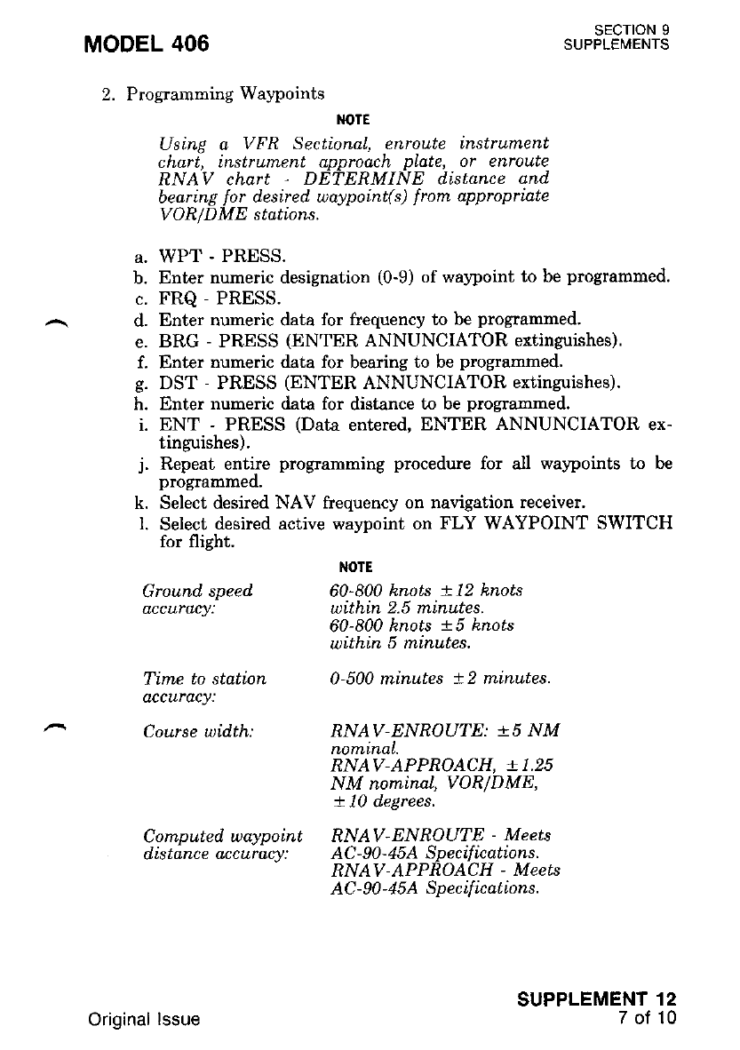
MODEL 406
2. Programrning Waypoints
SECTION 9
SUPPLEMENTS
M)TE
Using a VFR Sectional, enroute instrument
chart, instrument approach p\ate, or enroute
RNAV chart DETERMINE distance qnd
bearing for desired waypoint(s) from appropriate
VOR/DME stations.
a. WPT - PRESS.
b. Enter numeric designation (0-9) of waypoint to be programmed.
c. FRQ - PRESS.
d. Enter numeric data for frequency to be programmed.
e. BRG - PRESS (ENTER ANNUNCIATOR extinguishes).
f. Enter numeric data for bearing to be programmed.
g. DST - PRESS (ENTER ANNUNCIATOR extinguishes).
h. Enter numeric data for distance to be programrned.
i. ENT - PRESS (Data entered, ENTER ANNUNCIATOR ex-
tinguishes).
j. Repeat entire programming procedure for all waypoints to be
progmmmeo,
k. Select desired NAV frequency on navigation receiver.
L Select desired active wayDoint on FLY WAYPOINT SWITCH
for flight.
I{OTE
Ground speed 60-800 knots +12 knots
accuraty: wtthtn 2.5 minutes.
60-800 knots !5 knots
within 5 m.inutes.
Time to station 0-500 minutes !2 miruutes.
dccuracy:
Course wi.d.th: RNAV-ENROUTE: !5 NM
nominal.
RNAV-APPROACH, .T 1.25
NM nominaL, VOR/DME,
+ 10 d.egrees.
Computed, waypoint RNAV-ENROUTE - Meets
distanceaccuracy: AC-90-4SASpecifications.
RNAV-APPROACH - Meets
AC - 90 - 4 5A Sp ecif ic ations.
SUPPLEMENT 12
7of10
Original lssue
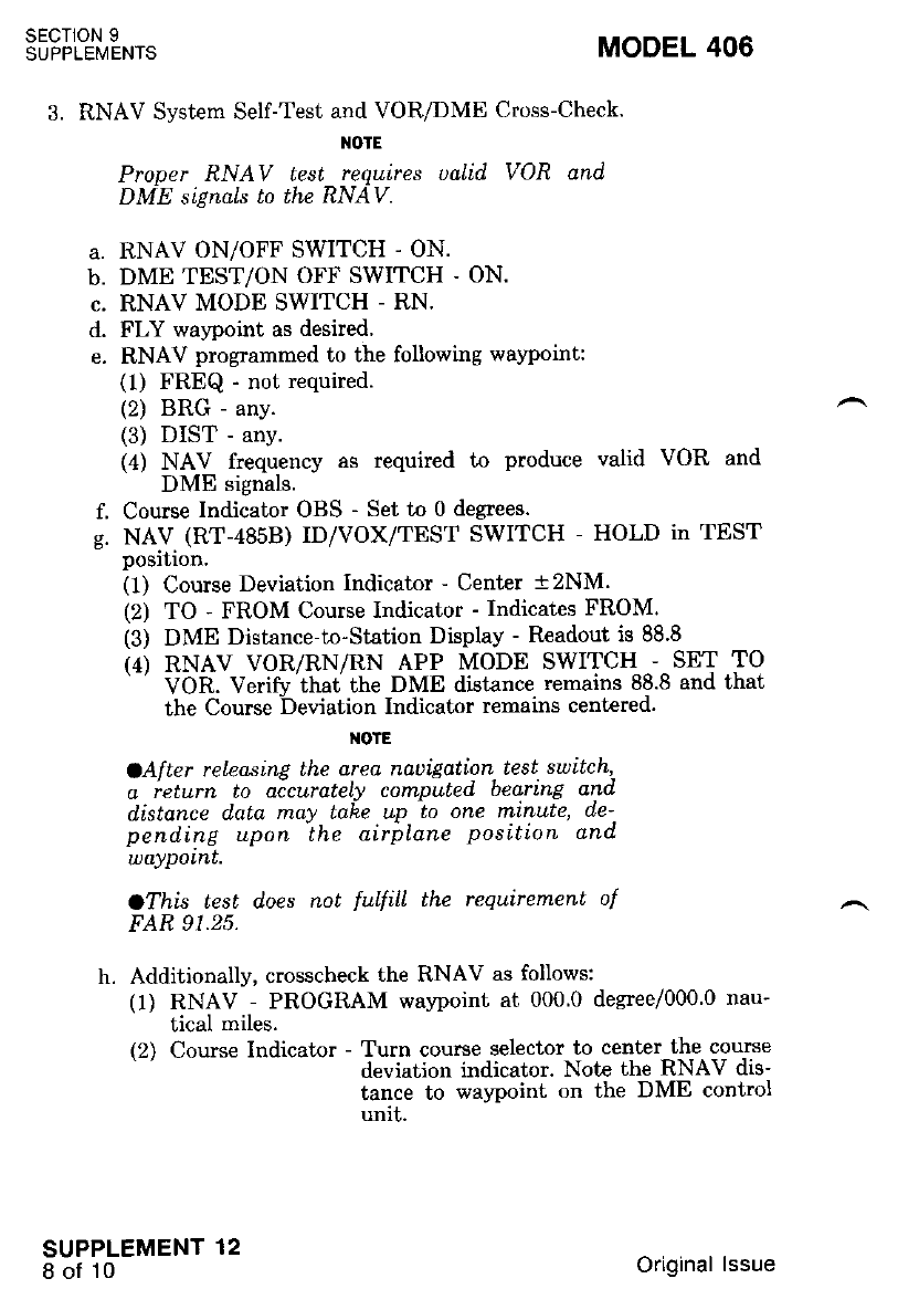
SECTION 9
SUPPLEMENTS MODEL 406
3. RNAV System Self-Test and VOR/DME Cross-Check.
NOTE
Proner RNAV test reeuires uaLid VOR and
DME stgnals to the RNAV.
a. RNAV ON/OFF SWITCH - ON.
b. DME TEST/ON OFF SWITCH . ON.
c. RNAV MODE SWITCH - RN.
d. FLY waypoint as desired.
e. RNAV programmed to the following walpoint:
(l) FREQ - not required.
(2) BRG - any.
(3) DIST - any.
(4) NAV frequency as required to produce valid VOR and
DME signals.
f. Course Indicator OBS - Set to 0 de$ees.
e. NAV (RT-a85B) ID/VOX/TEST SWITCH - HOLD in TEST
position.
(1) Course Deviation Indicator - Center t2NM.
(2) TO - FROM Course Indicator - Indicates FROM.
(3) DME Distance-to-Station Display - Readout is 88.8
(4) RNAV VOR/RN/RN APP MODE SWITCH - SET TO
' VOR. Verifu'that the DME distance remains 88.8 and that
the Course Deviation Indicator remains centered.
OTE
oAfter reteasing the area naaigation- test. switch '.
q rcturn to accurately computed bearlnE and
distance dato may tahe up to one mtnutP' de'.
pending upon'the airplane position and.
waYPoLnt.
OThis test does not fulfill the requirement of
FAR 91.25.
h. Additionally, crosscheck the RNAV as follows:
(1) RNAV - PROGRAM wa)?oint at 000.0 degree/000'0 nau-
tical miles.
(2) Course Indicator - Turn course selector to center the course
deviation indicator. Note the RNAV dis-
tance to waJpoint on the DME control
unit.
SUPPLEMENT 12
8 of 10 Original lssue
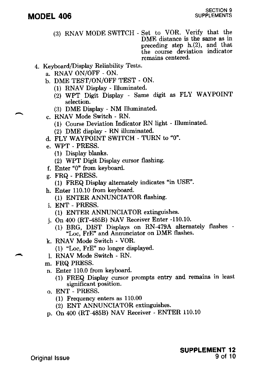
(3) RNAV MODE swlrcH B",hr',?u"Yf-l:; Jilit *3t"Jl;
p-receding step .h,(2)' and. that
:H"iliT"",,::Ji:tion indicator
4. Keyboard/Display Reliability Tests.
a. RNAV ON/OFF - ON.
b. DME TEST/ON/OFF TEST - ON.
(1) RNAV DisPlaY - Illuninated.
(2) W.PT. Digit Display - Same digit as FLY WAYPOINT
selecf,ron'
(3) DME Display - NM Illuminated'
c. RNAV Mode Switch - RN.
(1) Course Deviation Indicator RN light - Illuminated'
(2) DME disPlaY - RN illuminated.
d. FLY WAYPOINT SWITCH - TURN to "0".
e. WPT - PRESS.
(1) Display blanks'
(2) WPT Digit Display cursor flashing.
f. Enter "0" from keyboard.
g. FRQ - PRESS.
(1) FREQ Display alt€rnately indicates "in USE".
h. Enter 110.10 from keyboard.
(1) ENTER ANNUNCIATOR flashing.
i. ENT - PRESS.
(1) ENTER ANNUNCIATOR extinguishes.
j. On 400 (RT-4858) NAV Receiver Enter -110'10.
(1) BRG, DIST Displays on RN-471A altemately flashes -
' "t oc, FrE" and Airnrinciator on DME flashes.
k. RNAV Mode Switch - VOR'
(1) "Loc, FrE" no longer disPlaYed.
l. RNAV Mode Switch - RN.
m. FRQ PRESS.
n. Enter 110.0 frorn keyboard.
(1) FREQ Display cursor prompts entry and remains in least
significant position.
o. ENT - PRESS.
(1) FrequencY enters as 110.00
(2) ENT ANNUNCIATOR extinguishes.
p. On 400 (RT-4858) NAV Receiver - ENTER 110.10
MODEL 406 SECTION 9
SUPPLEMENTS
SUPPLEMENT 12
I of 10
Original lssue
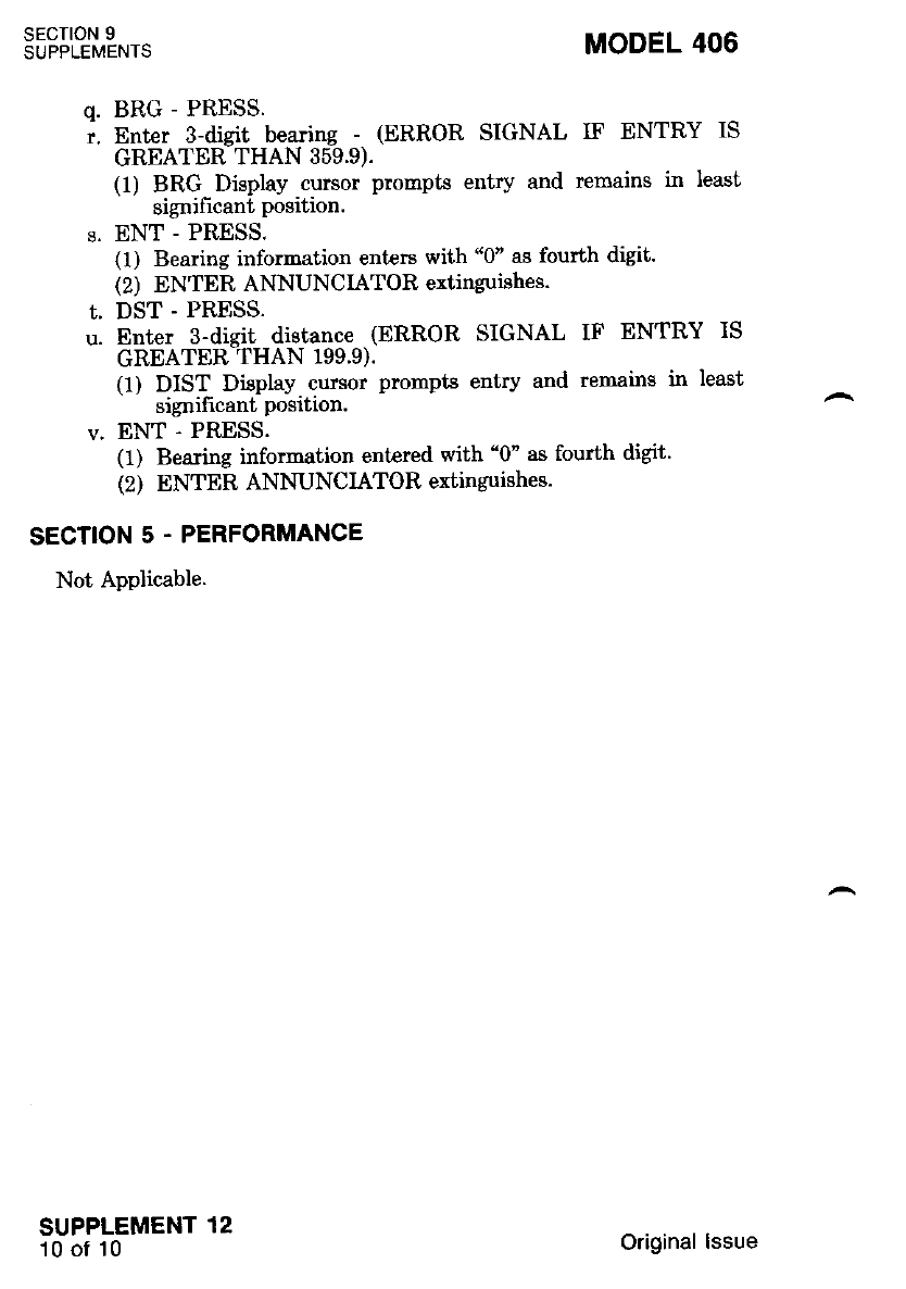
SECTION 9
SUPPLEIVENTS MODEL 406
q. BRG - PRESS.
.. nnte. a-diglt bearing - (ERROR SIGNAL IF ENTRY IS
GREATER THAN 359.9).
(1) BRG Display cursor pronpts entry and remains in least
signifrcant position.
s. ENT - PRESS.
(1) Bearing infornation enters with "0" as fourth digit.
(2) ENTER ANNUNCIATOR extinguishes.
t. DST - PRESS.
u. Enter 3-disit distance (ERROR SIGNAL IF ENTRY IS
GREATER THAN 199.9).
(1) DIST Display cursor prompts entry and remains in least
signifrcant position
v. ENT - PRESS.
(1) Bearing information entered with "0" as fourth digit'
{2) ENTER ANNUNCIATOR extinguishes.
SECTION 5 . PERFORMANCE
Not Applicable.
SUPPLEMENT 12
'10 0f 10 Original lssue
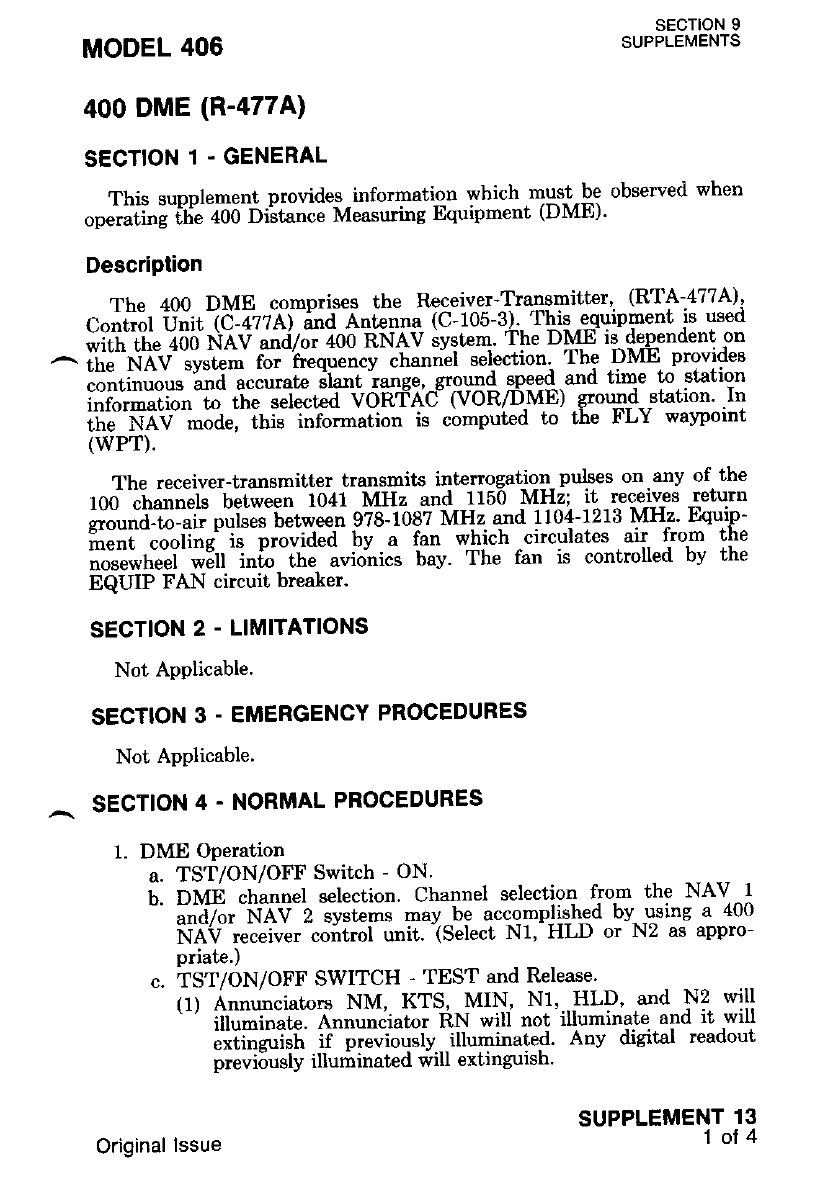
400 DME (R-477A)
SECTION 1 . GENERAL
This supplement provides information which musl-be observed when
"p"i"Tiri-iti"
-aoo biit"tt"" Measuring Equipment (DME)'
Description
The 400 DME comprises the Receiver-Trangmitter' (RTA-477A)'
c.iiiir iiilt f C:azzAiT"a A"t""na (C- 105-3),- Tbis -equipment is used
;ih"il;;iio liAn'""i7* +oo EnAv svqtc4' The DME is deoendent on
^ ir,'J"ri'iV".i.ti,:ii r-*h"d"iJ;';ri i.";i"i- *p;i!91t 1'; .DJVIE Provides
continuous and accurarc srant range, ground spee{ a-rld time to station
i;i;;ffi;;;h" *t*t"a vonfni (voR/Dr'lE) sound station ln
;:li;'NAV-;;d";lhis information is computed to the FLY walpoint
(wPT).
The receiver-transmitter transmits intenogatiq4- nulses on-any of the
f00 -channels between 1041 MHz and 1150 MHz; it receives return
;;;a;-il ptG"Jb"t *tt 978-108? MHz and 1104-1213 MHz' Equip-
iiJiil""l""ri"e'1" -pio"ia"a bv a fan which circulates air from the
iii,""i"tt"tr- *EI ittfi th" uuio"tti". bay- The fan is controlled by the
EQUIP FAN circuit breaker.
SECTION 2 - LIMITATIONS
Not ApPlicable.
SECTION 3 - EMERGENCY PROCEDURES
Not APPlicable'
,- sEcTloN 4 - NORMAL PROCEDURES
MODEL 406 SECTION 9
SUPPLEMENTS
SUPPLEMENT 13
1ot4
1. DME Operation
a. TST/ON/OFF Switch - ON.
f . OVn channel selection. Channel selectio'l fro-m the NAV 1
-' ;;V". -NAV 2 systems may be accomplished by- gsing a 400
iilV *uiu"t coitrol unit. iselect N1' HLD or N2 as appro-
priate.)
c. TST/ON/OFF SWITCH - TEST and Release'
(1) Annunciators NM, KTS, MIN, N1, HLD' and N2 will
'-' iit,]riii"ite.- Atttt,ro"iutot RN wiu not illuminate. and it will
liti"*itit if previouslv illuminated' Any digital readout
previ6usly illuririnated will extinguish'
Original lssue
(2) In approximately one second all annunciators will extin-
guish except NM, KTS and MIN will also remain on if
lhey were illuminated prior to going to TEST (i.e. if locked
on to a valid DME signal).
(3) Approximately three seconds later 8's will appear in the
nine digital readouts.
(4) Approximately four seconds later the annunciators will re-
tum to the appropriate responses for the DME frequelqy
selected. The -aigii readouts may then require sone addi-
tional time to adequately lock on to this frequency
olE
When the 400 RNAV (RN479) is installed with
a single DME, the DME will be slnued n the
Nau control unit to which the RNAV is as'
signed when the RNAV is operated' in the
RNAV mode (RN or RN APP). The DME
NI/HLD/N2 button wiLl be inoperatiue.
SECTION 5 - PERFORMANCE
Not Applicable.
SECTION 9
SUPPLEMENTS
SUPPLEMENT 13
2ot4
MODEL 406
Original lssue
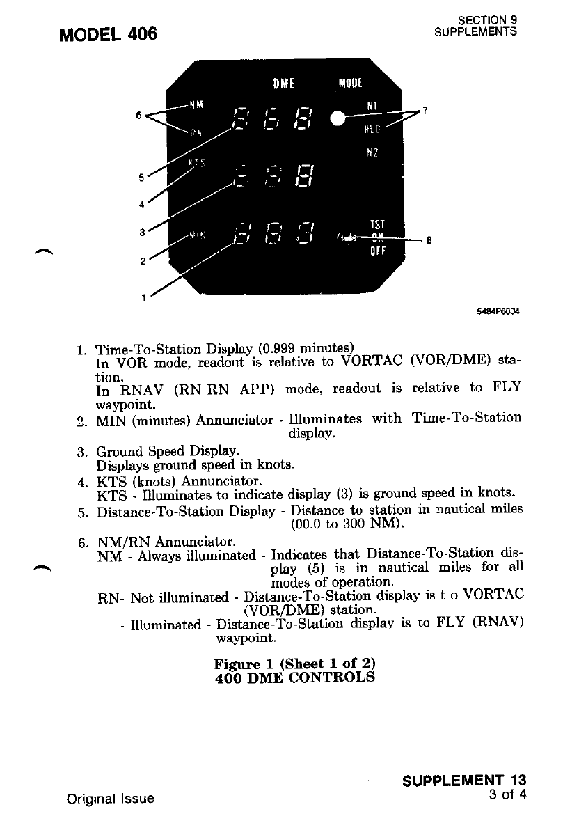
MODEL 406 SECTION 9
SUPPLEMENTS
3
1.
2.
5,{84P6(XX
Time-To-Station Display (0.999 minutes)
fn VOH ^ode, read,jut- is relative to VORTAC (VOR/DME) sta-
tion.
i" nNeV (RN-RN APP) mode, readout is relative to FLY
waypornt.
MIN (rninutes) Annunciator - Illuminates with Time-To-Station
disPlaY'
Ground Speed DisplaY.
Displays ground sPeed in knots.
KTS (knots) Annunciator.
xiS I Ittuoii"ates to indicate displav (3) is ground speed in knots'
Distance-To-Station Display - Distance to station in nautical miles
(00.0 to 300 NM)'
NM/RN Annunciator.
f.iM'- At*uu. iltuminated - Indicates that Distance-To-S-tatio-n dis-
play (5)- is in. nautical miles for all
modes of oPeration'
RN- Not illuminated - Distance-To-station display is t o VORTAC
(VOR/DME) station'
- Illuminated - Distance-fo-Station displav is to FLY (RNAV)
waypoint.
Figure I (Sheet I of 2)
4O-O DME CONTROLS
SUPPLEMENT 13
3oJ4
Original lssue
SECTION 9
SUPPLEMENTS
7.
MODEL 406
Nl/HLD/N2 Mode Switch and Annunciator. This switch inoper-
ative in the RNAV mode.
Nl - Selects and Indicates Navigation receiver I.
HLD - Holds the frequency of receiver N1 or N2, whichever was
last selected, so that it may be used for DME operation. N1
and N2 become ir:dependent of DME operation and may be
used for other purposes.
NZ - Selects and Indicates Navigation receiver 2.
TST/ON/OFF Switch.
ON - Controls power to RTA-477A and C-477A. NAV 2 is auto-
matically selected at Power On in most configurations.
TST - Self tests for the RTA-477A and C-4?7A. Momentary de-
pression of the TST Switch causes all annunciation lights to
illuminate. Approximately one second after release of the
TST switch all 8's will appear in the dicital readout win-
dows for a few seconds anri ihen normal DME operation will
resume. N1, HLD or N2 selection remains the same.
FiSure I (Sheet 2 of 2)
4OO DME CONTROLS
SUPPLEMENT 13
4ot4 Original lssue
lOOOA FLIGHT CONTROL SYSTEM (AF-l050A)
SECTION 1 - GENERAL
This supolement provides information which must be observed when
operating ffie 1000A Flight Control System.
Description
The 10004 Flight Control System is a two-axis aulopilot system that
controls the ailerons and elevators to mainiain the arrplane at a deslreo
;;;ia;a;. A vaw damper is also included in the svstem' The status of the
^.vrL*-i" aiplayed dn the mode selector. the autopilot control panel' the
r''".ii""i"t iiiuuiion indica[or (HSIl. the attitude gyro, and the autopilot
mode repeater annunciators on the pilot's panel.
A horizontal situation indicator (HSI), or directional gyr-q.^displays. a
nictorial presentation of the airplane's position relative to VUK radnls'
il;;ii; '"^;"J and glideslopi beami.- The- HSI. also- gives heading^
;;i;;;;" with respect io magiretic north and provides for selection of
the desired headin!. VOR radial and LOC course.
Precision attitude information is provided on the attitude gyro, refer
to Figure 3.
For autopilot engagement, the aulopilot/yaw damper. switch on the
aul,opilot control pinil, refer to Figure -t, is placed in ihe. AP/YD
;;;ifi;;. Piich and turn manual com--mand contrbls are located on this
i""l.oi p^".i. All other modes of flight are controlled from the mode
selecf,or.
The autopilot/yaw damper switch, when in the AP/YD position.^also
energizes the yaw damper system which tunctrons rndependenlly oI tne
"rio"piioi. The yaw damper ian be independently engaged by placing the
^ APAD switch in the YD Position.
A disconnect function is provided to automatically disconnect the
""io"ilot anv time the airplarie pitch attitude exceeds approximately 20
a"gi6.. up 6r down. The bperational capability of the disconnect func-
ii"''i -.t'Ja t " tested befoie talreoff bv pressing the TEST BEFORE
ijaCft fr,i button, located on the au'topilot contr-ol panel. When the
t".i b"tto" is pressed with the autopilot engaged, a test -voltage is
i".".t"a i"to the attitude monitor circuitry, causing autopilot disconnect'
itti. Urtt". must not be pressed in fligbt; it is for ground check only'
The control wheel must be restrained during the test.
MODEL 406 SECTION 9
SUPPLEMENTS
SUPPLEMENT 14
1oi20
Original lssue

The pilot's control wheel, refer to Figure 4, incorporates switches for
autopilot related operations. An electric elevator trim switch and an
autopilot/electric elevator trim (AP/TRIM DISC) disconnect switch are
provided on the pilot's left control horn. The pilot's right control horn
incorporates a pitch synchronization button.
The autopilot off (AP OFF) Iight, located adjacent to the attitude
gyro, will illuminate when the autopilot is disconnected by any neans
oiher than the control wheel AP/TRIM DISC switch. The AP OFF light
will remain on until it is cancelled by pressing the control wheel
AP/TRIM DISC switch. Any time the autopilot disconnects, the dis-
connect horn will produce a short tone Iasting 1 to 2 seconds with
decreasing amplitude.
SECTION 9
SUPPLEMENTS
SUPPLEMENT 14
2of2Q
MODEL 406
Original lssue
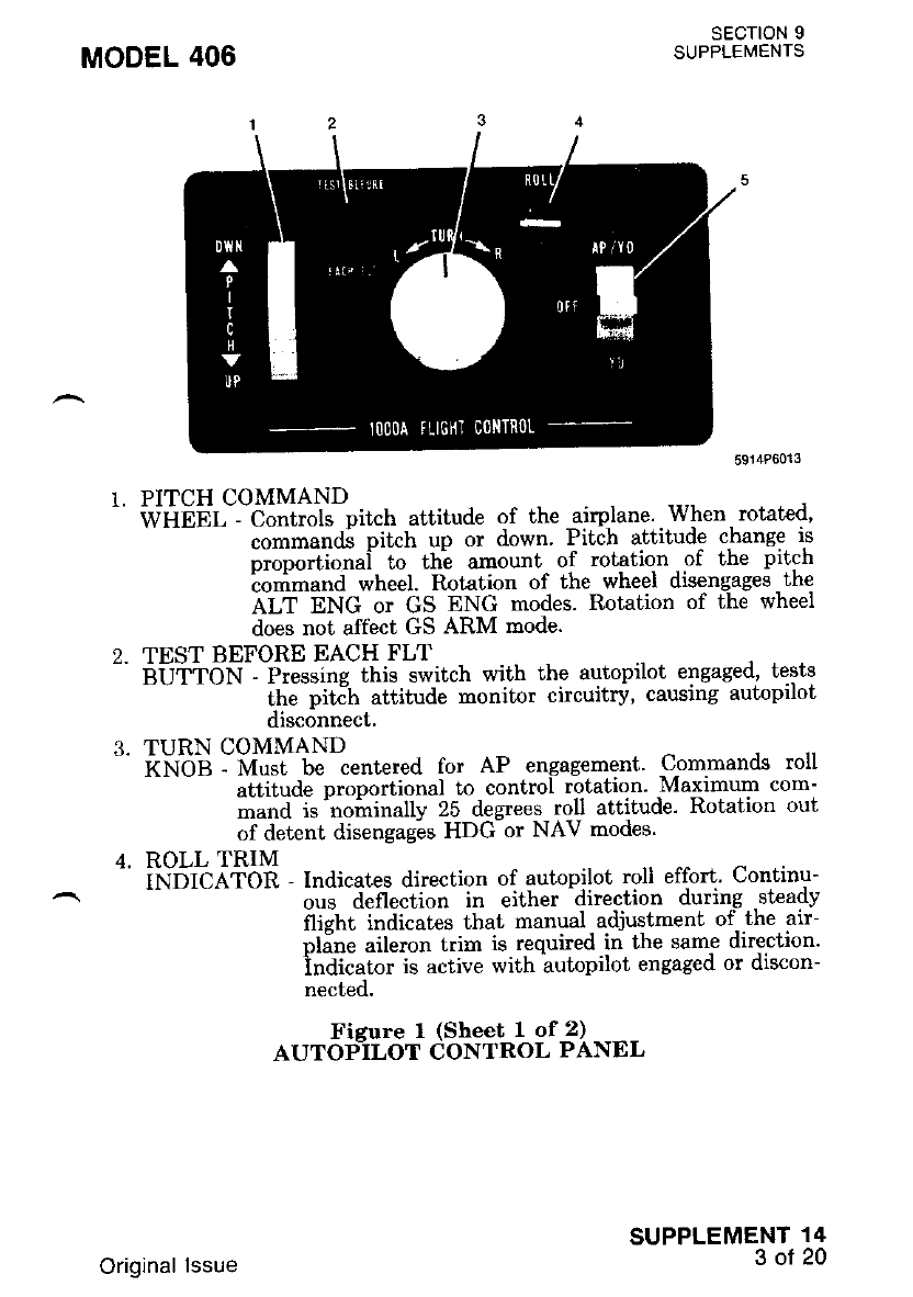
MODEL 406
1. PITCH COMMAND
t WHEbL- -C;;it"ls pitch attitude of the airylane'. When. rotated,
commands pitch up or down' Pitch attitude change is
"tooottitn"i to th'e amount of rotation of the pitch
ionimand wheel. Rotation of the wheel disengages the
Al,f pNC or GS ENG modes. Rotation of the wheel
does not affect GS ARM rnode.
2. TEST BEFORE EACH FLT
-' BUbTON - Fressing this switch with the autopilot engaged, tests
itte pititt attitude monitor circuitry, causing autopilot
disconnect.
3. TURN COMMAND
'' KNOB - M"J U" centered for AP engagement' Commands roll
attitude DroDortional to control rotation' Maximum com-
mand is'nohinally 25 degrees roll attitude' Rotation out
of deLent disengages HDG or NAV modes'
4. ROLL TRIM
-' ii.lDrcA'IOn - Indicates direction of autopilot roll effort Continu-
-- ;;a deflection in either direction during steady
flight indicates that manual - adjustment of,the air-
pline aileron trim is r-equired.in the same direction'
indicator is active with autopilot engaged or discon-
nected.
Fisure I (Sheet I of 2)
AUTOP_ILOT CONTROL PANEL
SECTION 9
SUPPLEMENTS
SUPPLEMENT 14
3of20
Original lssue
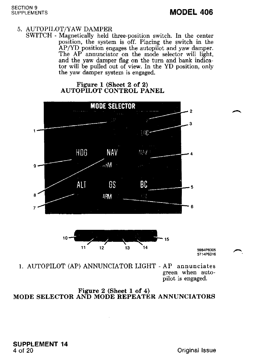
sEcTtoN 9
SUPPLEMENTS MODEL 406
AUTOPILOT/YAW DAMPER
SWITCH - Magnetically held three-position switch. In the center
position, the system is off. Placing the switch in the
AP/YD position engages the autopilot and yaw damper.
The AP annunciator on the mode selector will light,
and the yaw damper flag on the turn and bank indica-
tor will be pulled out of view. In the YD position, only
the yaw damper system is engaged.
Figure 1 (Sheet 2 of 2)
AUTOPILOT CONTROL PANEL
11 12 13 14 :9?i:BB?:
1. AUTOPILOT (AP) ANNUNCIATOR LIGHT - AP annunciates
green when auto-
pilot is engaged.
Figure 2 (Sheet I of 4)
MODE SELECTOR AND MODE REPEATER ANNUNCIATORS
SUPPLEMENT 14
4ot20 Original lssue
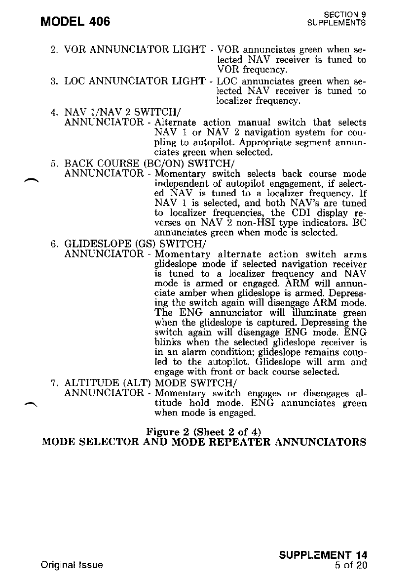
MODEL 406 SECTION 9
SUPPLEMENTS
7,
VOR ANNUNCIATOR LIGHT - VOR annunciates green when se-
lected NAV receiver is tuneo ro
VOR frequency.
LOC ANNUNCIATOR LIGHT - LOC annunciates green when se-
lected NAV receivir is tuneo ro
Iocalizer frequency.
NAV I/NAV 2 SWITCH/
ANNUNCIATOR - Alternate action manual switch that selects
NAV 1 or NAV 2 navigation system for cou-
pling to autopilot. Appropriate segment annun-
ciates green when selected.
BACK COURSE (BC/ON) SWTTCH/
ANNUNCIATOR - Momentary switch selects back course mode
independent of autopilot engagement, if select-
ed NAV is tuned to a localizer freouencv. If
NAV 1 is selected, and both NAV'g ire tirned
to localizer frequencies. the CDI display re-
verces on NAV 2 non-HSI tlpe indicaLors. BC
annunciates $een when rnode is selected.
GLIDESLOPE (GS) SWITCH/
ANNUNCIATOR - Momentary alternate action switch arms
glideslope mode if selected nayigation receiver
is tuned to a localizer freouencv and NAV
mode is armed or engaged. ARNI will annun-
ciate amber when glideslope is armed. Depress-
ing the switch again will disengage ARM mode.
The ENG annunciator will illuminate green
when the glideslope is captured. Depressing the
swikh again will disengage ENG mode. ENG
blinks when the selected glideslope receiver is
in an alarm condition; glideslope remains coup-
led to the autopilot. Glideslope will arm and
engage with front or back course selected.
ALTITUDE (ALT) MODE SWITCH/
ANNUNCIATOR - Momentary switch engages or disengages al-
titude hold mode. ENG annunciates green
when mode is engaged.
Figure 2 (Sheet 2 of 4)
MODE SELECTOR AND MODE REPEATER ANNUNCIATORS
SUPPLEMENT 14
5of20
Original lssue
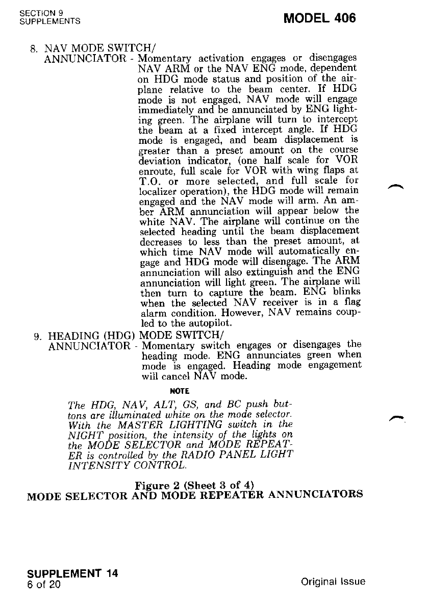
SECTION 9
SUPPLEMENTS MODEL 406
8. NAV MODE SWITCH/
ANNUNCIATOR - Momentarv activation engages or disengages
NAV ARM or the NAV ENG mode, dependent
on HDG mode status and position of the air-
olane relative to the beam center. If HDG
mode is not ensased' NAV mode will engage
immediately andbi annunciated by ENG light-
ing green. The airplane will turn !o i{e-r-c!prt
th"e beam at a fix6d intercept angle. If HDG
mode is engaged, and beam displacernent is
greater than a preset amount on the course
deviation indicaior, (one half scale for VOR
enroute, full scale for VOR with wing flaps at
T.O. or more selected, and full scale for
Iocalizer operation), the HDG mode will remain
engaged and the NAV mode will arm. An am-
bei ARnl annunciation will appear below the
white NAV. The aimlane will continue on the
selected heading uniil the beam displacement
decreases to less than the preset amount, at
which time NAV mode will automatically en-
gage and HDG mode will disengage 'The ARM
annuncration will also extinguish and ihe ENG
annunciation will light green. The airplane will
then turn to capture the beam. ENG blinks
when the select;d NAV receiver is in a flag
alarm condition. However, NAV remains coup-
led to the autoPilot.
9. HEADING (HDG) MODE SWITCH/
ANNUNCIATOR - Momentary switch engages or disengages the
headins mode. ENG annunciates green when
mode is engaged. Heading mode engagement
will cancel NAV mode.
NOTE
The HDG, NAV, ALT, GS, and BC Push but-
tons are illumtnated white on the nrode selector'
With the MASTER LIGHTING suttch in the
NIGHT position, Ihe intens[ly of the ltghts on
the MODE SELECTOR and MODE REPEAT
ER is controlLed by the RADIO PANEL LIGHT
IN?ENSI"Y CONTROL.
Figure 2 (Sheet 3 of 4)
MODE SELECTOR AN.D MODE REPEATDR ANNUNCIATORS
SUPPLEMENT 14
6of20 Original lssue
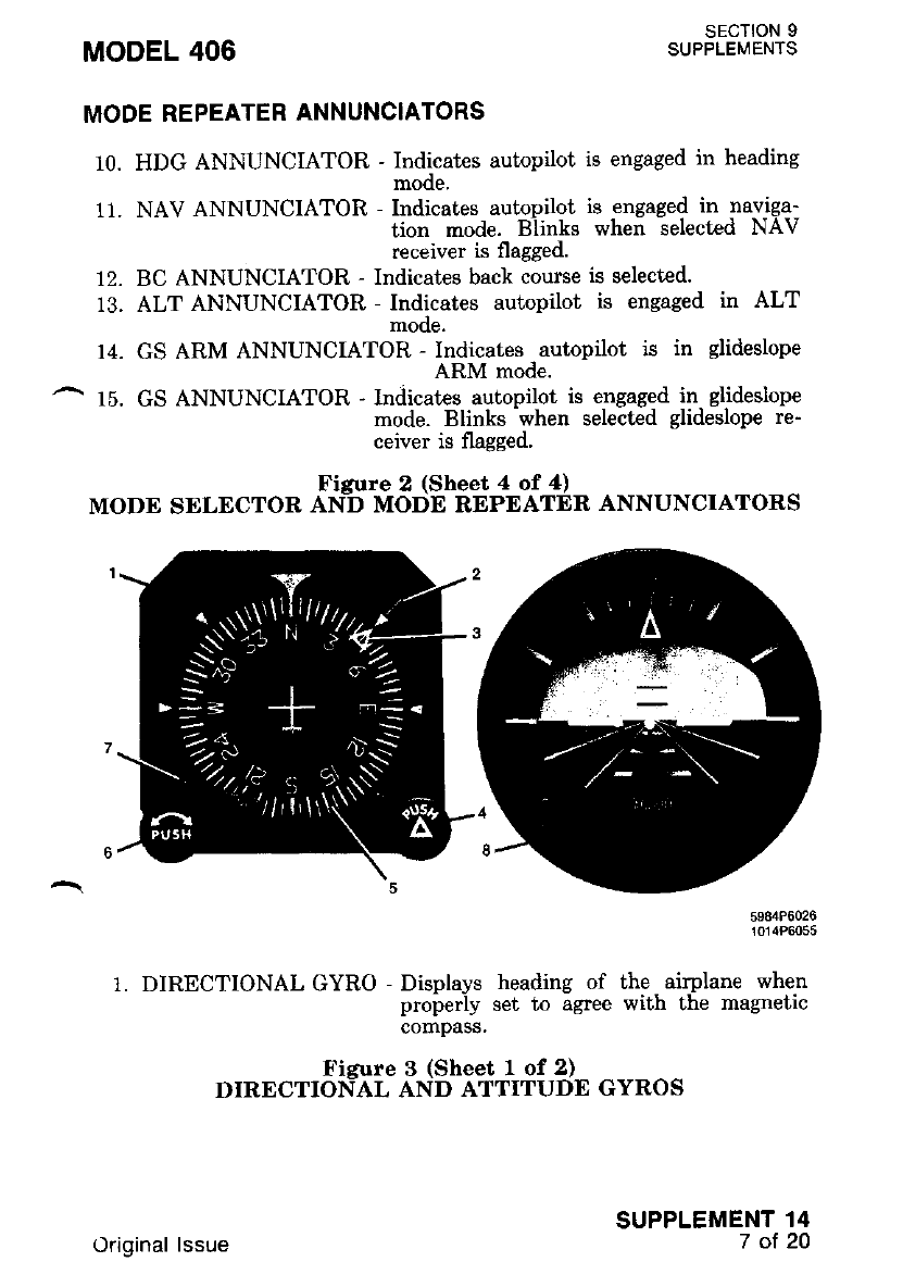
MODEL 406
MODE REPEATER ANNUNCIATORS
SECTION 9
SUPPLEMENTS
10. HDG ANNUNCIATOR - Indicates autopilot is engaged in heading
mooe.
11. NAV ANNUNCIATOR - Indicates autopilot is engaged in naviga-
tion mode. Blinks when selected NAV
receiver is flagged.
12. BC ANNUNCIATOR - Indicates back course is selected.
13. ALT ANNUNCIATOR - Indicates autopilot is engaged in ALT
mooe.
14. GS ARM ANNUNCIATOR - Indicates autopilot is in glideslope
ARM mode.
15. GS ANNUNCIATOR - Indicates autopilot is engaged in glideslope
mode. Blinks when selected glideslope re-
ceiver is flagged.
Figure 2 (Sheet 4 of 4)
MODE SDLECTOR AND MODE REPEATER ANNUNCIATORS
:3?i::3"3
1. DIRECTIONAL GYRO - Displays heading of the, airplane when
properly set to agree with the magnetic
compass,
Figure 3 (Sheet I of 2)
DIRECTIOI{AL AND ATTITUDE GYROS
SUPPLEMENT 14
7ot20
Original lssue
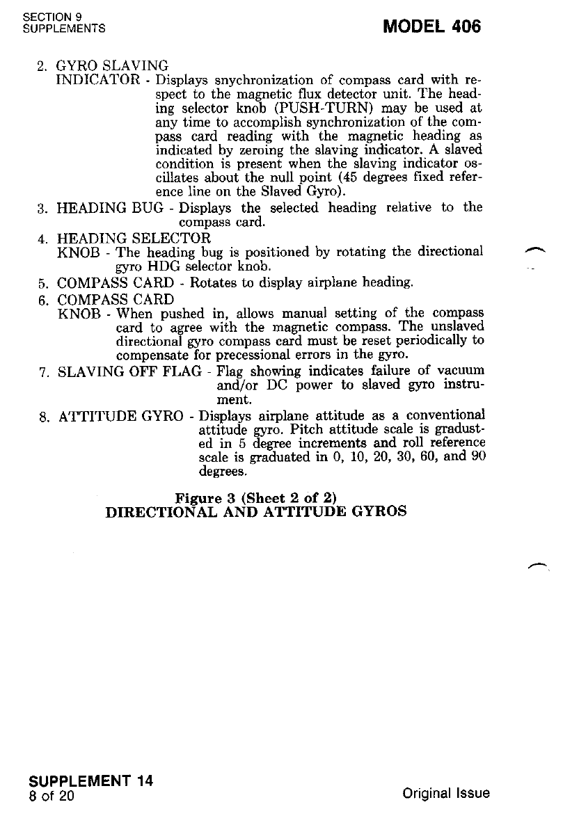
SECTION 9
SUPPLEMENTS
7.
3.
L
5.
6.
MODEL 406
GYRO SLAVING
INDICATOR - Displays snychronization of compass card with re-
spect to the magnetic flux detector unit. The head-
ing selector knoi (PUSH-TURN) may be used at
any time to accomplish synchronization of the com-
pais card reading with-the magnetic heading as
indicated by zeroing the slaving i;dicator. A slived
condition is present when the slaving indicator os-
cillates about the null point (45 degrdes fixed refer-
ence line on the Slaved Gyro).
HEADING BUG - Displays the selected heading relative to the
compass caro.
HEADING SELECTOR
KNOB - The heading bug is positioned by rotating the directional
gyro HDG selector knob.
COMPASS CARD - Rotates to display airplane heading.
COMPASS CARD
KNOB - When pushed in, allows nanual setting of the compass
card to agree with the magnetic compass. The unslaved
directionai gyro compass car:d must be reset periodically to
compensate for precessional errors in the gyro.
SLAVING OFF FLAG - Flag showing indicates failure of vacuurn
andTor DC power to slaved gyro instru-
ment.
ATTITUDE GYRO - Displays airplane attitude as a conventional
attiiud-e gyr,5. Pikh attitude scale is gradust-
ed in 5 iiaeree incrementa and roll reference
scale is gra-duated in 0, 10, 20, 30, 60, and 90
oegrees,
Figure 3 (Sheet 2 of 2)
DIRECTIONAL AND ATTITUDE GYROS
SUPPLEMENT 14
8of20 Original lssue
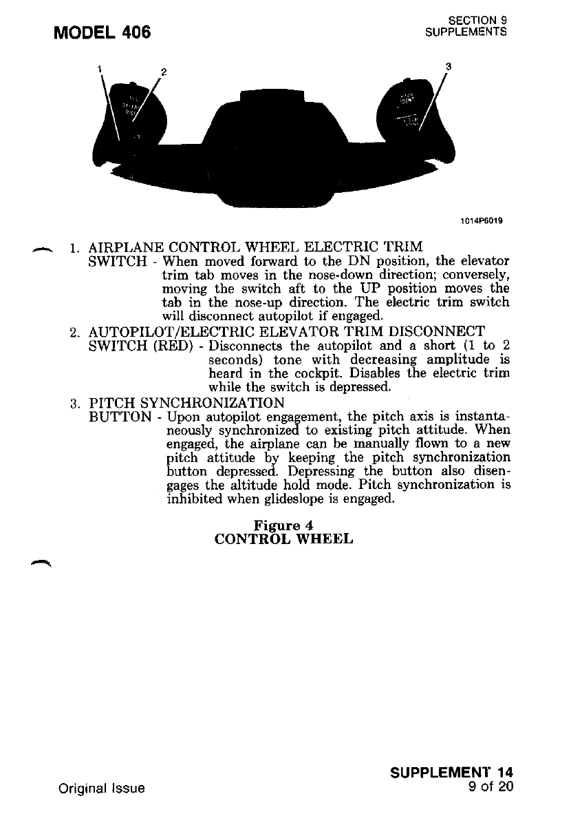
1.
1014P6019
AIRPLANE CONTROL WHEEL ELECTRIC TRIM
SWITCH - When moved forward to the DN position, the elevator
trim tab moves in the nose-down direction; conversely,
movine the switch aft to the UP Dosition moves the
tab in-the nose-up direction. The 6lectric trim switch
will disconnect autopilot if engaged.
AUTOPILOT/ELECTRIC ELEVATOR TRIM DISCONNECT'
SWITCH (RED) - Disconnects the autopilot and a short (1 to 2
seconds) tone with decreasing amplitude is
heard in the cockpit. Disables the electric trim
while the switch is depressed.
PITCH SYNCHRONIZATION
BUTTON - Upon autopilot engagement, the pitch axis is instanta-
neously syirchroniieil to existing-pitch attitude. When
engaged, the airplane can be nanually flown to a new
pitch attitude by keeping the pitch synchronization
button depressed. Defres-sing tlie butt6n also disen-
gages the altitude hold mode. Pitch slnchronization is
inhibited when glideslope is engaged.
Figure 4
CONTROL WHEEL
SUPPLEMENT 14
9oJ20
Original lssue
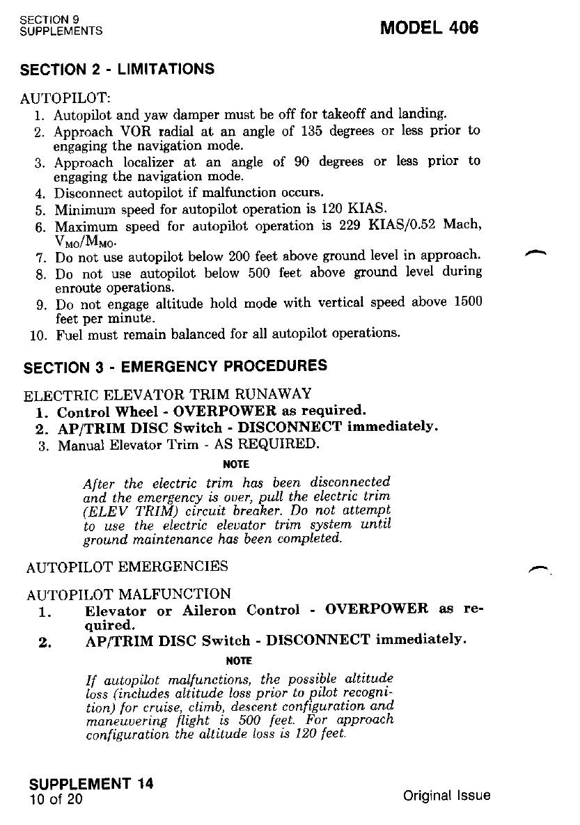
SECTION 9
SUPPLEMENTS MODEL 406
SECTION 2 - LIMITATIONS
AUTOPILOT:
1. Autopilot and yaw damper must be off for takeoff and landing.
2. Approach,VoR radial at an angle of 135 degpes or less prior to
engaging the navigation mode.
3. Approach ,localiz€r . at an .angle of 90 degrees or less prior to
engaging the navigation mode.
4. Disconnect autopilot if malfunction occurs.
5. Minimum speed for autopilot operation is 120 KIAS.
6. Maximum speed for autopilot operation is 229 KIAS/0.52 Mach,
V"o/M"o.
7. Do not use autopilot below 200 feet above ground level in approach'
8. Do not use autopilot below 500 feet above ground level during
enroute operauons.
9. Do not engage altitude hold mode with vertical speed above 1500
feet per minute.
10. Fuel must remain balanced for all autopilot operations.
SECTION 3 - EMERGENCY PROCEDURES
ELECTRIC ELEVATOR TRIM RUNAWAY
1. Control Wheel - OVERPOWER as required.
2. AP/TRIM DISC Switch - DISCONNECT immediatelv.
3. Manual Elevator Tlim - AS REQUIRED.
IIOTE
After the electric trim hos been d'isconnected
and lhe emergency is ouer' pulL the electric trim
( ELEV TRIM) circuit breaker. Do nol dttempt
to use the eLectri'c eleuator trin'L system untiL
ground maintenance has been completed.
AUTOPILOT EMERGENCIES
AUTOPILOT MALFUNCTION
Elevator or Aileron Control - OVERPOWER as re-
quired.
AP/TRIM DISC Switch - DISCONNDCT immediatelv.
TOTE
ll autopilot rnalt'unctions, the posstble altitude
loss (includes aLlitu.de loss prtor to pilot recogni-
t[on) for cruise, climb, deseent configuration and
maneuuerinE flilht is 500 [eet. For approach
con[i1uration thi altitude loss is 120 leet
SUPPLEMENT 14
10 of 20
t.
,
Original lssue
MODEL 406 SECTION 9
SUPPLEMENTS
NOTE
After the autopilot has been disconnected' and
the emergency'is ouer, pull the roll and pitch
actuator (ACT) circuit breaher. Do not attempt
to use the autopilot until ground maintenance
has been comPleted.
ENGINE FAILURE
1. Aircraft - CONTROL as required.
2. Inoperative Engine Propeller - FEATHER.
3. AP/TRIM DISC Switch - DISCONNECT.
^ 4. Operative Engine - INCREASE POWER, as required.
5. Landing Gear - UP.
6. Wing Flaps - UP or as required.
?. Trim Tabs - ADJUST.
8. Inoperative Engine - SECURE.
ENGINE INOPERATIVE COUPLED APPROACH
1. Fuel - BALANCED.
2. Trim Tabs - ADJUST.
3. Autopilot - ENGAGE per VOR, IlS/Localizer Coupling Procedure.
4. Engine Inoperative Landing Checklist - COMPLETED.
SECTION 4. NORMAL PROCEDURES
ELECTRIC ELEVATOR TRIM DISCONNECT CHECK
1. Ooerate the electric trim switch in one direction and observe mo-
tiirn of the manual pitch trim wheel in the proper direction. While
Derforming the above test, momentarily depress AP/TRIM DISC
Switch anil release. Observe that manual pitch trim wheel motion is
arrested and remains stopped when the disconnect switch is re-
leased and electric trim swiich is actuated.
2. Repeat Step f. in the opposite direction.
AUTOPILOT ATTITUDE MONITOR DISENGAGE CHECK (WITH
GYRO ERECTED)
BEFORE TAKEOFF
1. Turn Command Knob - CENTER DETENT.
2. Autopilot/Yaw Damper Switch - AP/YD. Observe annunciation on
mode selector for AP engage, and that the turn and bank yaw
damper flag is retracted.
SUPPLEMENT 14
.t1 of 20
Original lssue
SECTION 9
SUPPLEMENTS MODEL 406
TEST BEFORE EACH FLT Test Button - PUSH and HOLD.
Verifu the following:
a. Autopilot/Yaw Damper Switch - OBSERVE return to OFF po-
srtron.
b. AP OFF Light - OBSERVE illumination.
c. Autopilot Disconnect Horn - OBSERVE 1 to 2 second decreas-
lng aural tone.
AP/TRIM DISC Switch - PUSH to turn off the AP OFF light.
AutopilotAaw Damper Switch - API/D - OBSERVE annuncia-
tron.
BASIC AUTOPILOT OPERATION
BEFORE ENGAGEMENT
1. Airplane Elevator, Aileron and Rudder Trim - ADJUST.
ENGAGEMENT
1. Turn Command Knob - CENTER DETENT.
2. Autopilot/Yaw Damper Switch - AP/YD. OBSERVE AP annun-
clallon.
NOTE
Airplane rudd'er trim wiLl haue to be adjusted as
required for ball centered flight. Airplane
ailbron trim uiLl haue to be readjusted as in-
d.icated by the roll trirn indicator on the auto-
pilot conirol panel to cornpensate t'or large air-
'speed or configuration changes. Trim toward the
roll trim indicator deflection.
TURN COMMANDS
1. T\rrn Command Knob - ROTATE as desired.
PITCH COMMANDS
1. Pitch Command Wheel - ROTATE as desired. (Or)
2. pitch Synchronization Button :,}*t.:_i* "!roa""3;"utff lil'J
ihen releise button.
DISCONNECT
1. AP/TRIM DISC Switch - DISCONNECT. (Or)
2. Autopilot,/Yaw Damper Switch - OFF. (Or)
3. Pilot's Electric Elevator Trim Switch - ACTUATE.
SUPPLEMENT 14
12 ot 20
3.
,l
6.
Original lssue
NOIE
ONormaI autopilot disconnect shouLd' be con'
d.ucted with tie pilot's control wheeL APITRIM
DISC switch. The AP OFF lieht wiLl not illu-
rninate, but the dutopilnt disionnect horn wilL
prod,ure a short tone lasting 1 to 2 seconds uith
'de c r eas ing dmplttude.
all the autopilot dtsconnects by any means oth-
er' Lhan thi actiuation ol the pilot's controL
wheel AP/TRIM DISC switch, the AP OFF Light
wiLI continuously illuminate and the autopilot
disconnect h.orn wiLl produce a short tone ldst-
inE 1to 2 seconds with d.ecreasing ampLitude
The AP OFF ltght may be extinguished by cy-
cling the pilot's control wheel AP/TRIM DISC
switch.
OAutopilot disconnect uith the AP/YD switch
wtlL iLLuminate the AP OFF light and the auto-
pilol d.isconnect horn witL produce a short tone
'lasttng l to 2 seconds w[th deueasing ampli-
tude.
ALTITUDE HOLD
ENGAGEMENT
MODEL 406 SECTION 9
SUPPLEMENTS
SUPPLEMENT 14
13 of 20
DO NO? OPERATE THE AUTOPILOT IN
ALTITUDE HOLD MODE WHEN FLYING
IN MODERATE TO SEVERE TURBULENCE,
MOUNTAIN LEE WAVE ACTIVITY AND/OR
MODERATE TO SEVERE ICING CONDI-
"10NS. XOTE
To obtain smooth a\titude captures, decrease
uertical speed to 1500 t'eet per minute or less
and, decrease airplane pitch attitude to within 5
degrees of leuel when approaching desired. al-
tttud.e.
Original lssue
SECIION 9
SUPPLEMENTS MODEL 406
1. With Basic FCS:
a. Altitude Hold Mode Selector Button - PRESS at desired al-
titude. Observe annunciatlon.
2. With Optional Altitude Alert/Preselect System:
a. Desired Altitude - SELECT.
b. Altitude Alert/Preselect Arm Button - PUSH. Observe that
amber ARMD light illuminates.
NOTE
The alt;tude alertfpreseLect ARMD mode is {n-
ooeratiue when thb qutopilot is in the altitude
iold or g|{deslnpe mode. Once armed. the al
titud.e alirt/preielect mode can be disarmed by
reselecting A different altitude on the altitude
Dreselect presentation, by selecting the aLtitude
'hold modi on the mode selector or, by gltdesLope
capture.
c. Pitch Command Wheel - UP or DOWN as required to intercept
selected altitude.
d. When selected altitude is captured, OBSERVE:
(1) Altitude alert/preselect amber ARMD light goes OFF'
(2) Altitude alert/preselect green CPLD light illuminates'
(3) Mode selector ALT ENG annunciator illuminates green'
(4) Remote Annunciator ALT illuminates.
T{OTE
After enaaEement, and when the airplane has
tiqnsitiohea to kuel fliehl, the qltitude hold
mode may matntain lhe itrplnne at sn alti,tude-
stiehttv iboue or below the- selected altitude. If
th; q[tilude difference is objectional, disengage
the altitude htjid mode and acquire the desired
altitude, either by using the pitch command
wheel, or by holding the pilch synchronizotion.
button and manuoLly pitching the.tirplane untll
the desired tndicated altitude is reached Then
reengage q.ltitude hol.d mode.
SUPPLEMENT 14
14 ot 20 Original lssue
MODEL 406
DISENGAGEMENT
1. Altitude Hold Mode Selector Button - ACTUATE. (Or)
2. Pitch Synchronization Button - PRESS. (Or)
3. Pitch Command Wheel - ROTATE.
NOTE
Altitude hoLd. mod.e uill automaticaLLy disengage
in the coupled ILS mode uhen the glidesLope is
engagea.
HEADING SELECT FUNCTION
a ENGAGEMENT
1. Turn Command Knob - CENTER DETENT.
2. HSI Heading Selector Knob - ROTATE bug to desired magnetic
heading.
3. Heading Mode Selector Button - ACTUATE. Observe annuncia-
alon'
4. Remote Annunciator HDG illuminates.
5. HSI Heading Selector Knob - ADJUST for any subsequent desired
heading changes.
XOTE
OWhen an optional copilot's horizontal situation
ind.icutor is installed and connected to the auto-
pilot, the pitot's heading bug controk the head-
'ing when' NAV I recdiuei is selected by the
mode selector NAV I/NAV 2 switch, and the
copilot's headinq bug controLs heading uhen
NAV 2 receiuer is selected.. When a copilot's
directional gyro is installed., the pil.ot's heading
bug controk the head.ing when NAV I or NAV
2 recetuers ure selected.
OWhen an optional copilot's horizontal situation
indicator is installed and not connected to the
autopilot, the pilot's heading buq controk the
headinp when NAV I receiuer or NAV 2 re-
ceiuer -is selected by the mode selector NAV
1/NAV 2 switch.
DISENGAGEMENT
1. Heading Mode Selector Button - ACTUATE. (Or)
2. Turn Command Knob - ROTATE. (Or)
3. Navisation Mode - AUTO ENGAGE.
SUPPLEMENT 14
15 of 20
SECTION 9
SUPPLEMENTS
Original lssue
SECTION 9
SUPPLEMENTS MODEL 406
VOR COUPLING
ENGAGEMENT (VOR)
1. NAV 1/NAV 2 Mode Selector Button - SELECT NAV 1, NAV 2.
Observe proper annunciation (including VOR arnunciator on mode
selector).
2. Ccurse Selector Knob - ADJUST to desired VOR course
3. Wing Flaps - T.O. if VOR approach is desired.
I{OTE
4.
5.
6.
Winp Flaps must be positloned to T.O. or lower
to odtsin'the VOR aiproarh mode.
Airspeed - 120 to 160 KIAS for VOR approach.
Turn Command Knob - CENTER DETENT.
Navigation Mode Selection.
a. Variable Angle IntercePt.
(l) HSI Headine Selector Knob - ROTATE bug to the desired
heading (within 135 degrees of desired VOR course).
(2) Heading Mode Selector Button - PRESS' Obsewe ENG
green a-nnunciation on mode selector and HDG on remote
annuncrator.
(3) Navieation Mode Selector Button - PRESS. Observe an-
' nunciation of NAV ARM on mode selector. Airplane will
continue flying selected heading until the course- deviation
indicator niov6s off the peg in ttre vOR approach mode or
half scale in the VOR enro,"ute mode' HDG exeen ENG and
NAV amber ARM annunciators on the mode selector and
HDG on remote annunciator will then go out and NAV
green ENG annunciator and remote annunciator NAV will
light to indicate engagement.
NOTE
With an intercept angle in HDG mode of less
than 45 d.eerees at the time NAV engage occurs,
the airplaie will initially turn touard the track
and eiLablish a 45 d.egrees intercepl angle fol-
lowed by a turn in the opposite direct[on to the
headini required for a imooth intercept With
the inlercept crngle in HDG m.ode greater than
45 degrees,' the iirplane will initially turn to the
headlng required for a 45 degrees intercept.
SUPPLEMENT 14
16 of 20 Original lssue
b. Fixed Angle IntercePt.
(1) Heading Mode - DISENGAGE (if engaged).
(2) Maneuver the airplale to within 135 degrees of the desired
VOR course.
(3) Navigation Mode Selector Button - ACTUATE' Observe
'-' NAV"green ENG annunciation on mode selector and NAV
on remote annunciator. Airplane will turn to intercept the
VOR beam at 45 degrees int€rcept angle.
7. Propeller Control Levers - FORWARD prior to fix inbound'
8. Landing Gear - DOWN at final fix if both engines operating'
9. Wing Flaps - APPR.
10. Airspeed - 120 to 140 KIAS.
TOTE
Veri{v rolt trim indtcqtor ts neutral after finaL
conffturation is complete. Readjust aileron trim
tab as required.
11. Landing Gear - DOWN within gliding distance of field if engine
inoperative landing.
12. AP/TRIM DISC Switch - DISCONNECT at minimum descent
altitude.
13. Wing Flaps - LAND when landing is assured.
DISENGAGEMENT (VOR)
1. Navigation Mode Selector Button - ACTUATE. (Or)
2. T\.rrn Conmand Knob - ROTATE. (Or)
3. Heading Mode Selector Button - ACTUATE.
NOTE
Complete autopilot d'isconnect shouLd' normalLy
be c'onducted on a VOR approach qt the appro'
ortote ninimums or bv 2d0 leet aboue ground
'leuel uith the pilot's control wheel AP/I'RIM
DISC switch
MODEL 406 SECTION 9
SUPPLEMENTS
SUPPLEMENT 14
17 ol 20
Original lssue
SECTION 9
SUPPLEMENTS MODEL 406
ILS/LOCALIZER COUPLING
ENGAGEMENT (ILS)
1. NAV I/NAV 2 MODE Selector Button - SELECT NAV 1, N4'V 2,
observe proper annunciation on mode selector. Observe LOC an-
nunciati6n on mode selector.
2. Course Selector Knob - ADJUST to localizer front course bearing
for both front and back course approaches.
3. Back Course Mode Selector Button - ACTUATE as applicable.
Observe BC green ON annunciation on mode selector and on the
remote annuncrator,
4. Wing Flaps - T.O.
5. Airspeed - 120 to 160 KIAS.
6. Turn Command Knob - CENTER DETENT'
?. Altitude Hold Mode Selector Button - ACTUATE as appropriate if
desired. Observe annunciation.
8. Navigation Mode Selection
a. Variable Angle Intercept.
(1) HSI Heading Selector Knob - ROTATE bug for radar
vectors and/or 30 degrees to 90 degrees localizer intercept
angle. Intercept localizer before the out€r marker.
(2) Heading Mode Selector Button - ACTUATE. Observe an-
nunciation.
(3) Navigation Mode Selector Button - ACTUATE' Observe
' annunciation of NAV ARM on mode selector. Airplane will
continue flying selected heading until the colrse deviation
indicator riov-es off the pee. IIDG green ENG and NAV
amber ARM annunciators on mode silector will then go off
and NAV sreen ENG alnunciator and NAV on remote
annunciatoiwill light, indicating NAV engagement.
NOTE
With an intercept angle in HDG mod'e of less
than 30 d.egrees at the time NAV engage occurs,
lhe airplane will initially turn toward lhe trarh
and eitabtish a 30 degiees intercept angle t'ol-
[owed by a lurn in the opposite direction Lo the
headinf required for a iinooth intercept. With
the intercept angle in HDG ft7ode greater than
30 d.egrees, the airplane will initiaLLy turn to the
heading required for a 30 degrees intercept.
SUPPLEMENT 14
.18 of 20 Original lssue
MODEL 406
b. Fixed Angle Intercept.
(1) Heading Mode - DISENGAGE if engaged.
(2) Maneuver airplane to within 90 degrees of localizer bearing.
(3) Navigation Mode Selector Button - ACTUATE' Observe
NAV- rreen ENG annunciation on mode selector and NAV
on the remote annunciator. Airplane will turn to intercept
the localizer beam at a 30 degrees intercept angle.
9. Glideslope Mode Selector Button - ACTUATE. Observe annun-
ciation of GS ARM on mode selector and on the remot€ annun-
ciator. Maneuver airplane to intercept the glideslope. GS green
ENG annunciation will indicate elideslope engagement on the mode
selector and remote annunciatorl In alt:itude-hold mode, when the
glideslope deviation indicator passes through the center dot, ALT
ENG annunciation will also go off.
olE
oThe second glid,eslope connected to NAV 2 is
an option and. therefore must be installed to
haue normal glideslope operation in NAV 2 po
sition of the mode seLector.
Oclideslope uill automatically engage only il
NAV LOC [s engaged., course deuiation bar dis-
placernent is half scale (1 dot) or less, course
error is 25 d.egrees or less, and glideslope is
armed. For manual glideslope engage. actiuate
GS button when glides\ope needle is nearly cen'
tered,.
CGlid,eslope rnay be captured' from aboue or be-
LOW.
oGlideslope may be selected and wiLl function in
back course,
oWith a NAV fLag in uieu, the mode selector
NAV green ENG and the mode repeater NAV
annunciators wilL blink. With a GS flag in uieu,
the mod.e selector GS green ENG and' the mod'e
repeater GS annuncidtors wiLl blink; the quto-
piiol will remain engaged, If onty a GS flae i's in
'uiew, the autopilot may continue to be used by
disengaging the glid.estope mode by actiuating
the mode selector GS button or rolsting the
pitch command wheel, to return pitch control Lo
'lhe pitch command wheel. ILS/tocaLizer coupling
sho[ild be disengaged upon recetuing a NAV
flae.
SECTION 9
SUPPLEMENTS
SUPPLEMENT 14
19 of 20
Original lssue
SECTION 9
SUPPLEMENTS MODEL 406
I{OTE
PropelLers fuLL forward because prop modulation
may qffect g\id.eslope reception at lower RPMs.
10. Propeller Control kvers - FORWARD prior to the outer marker.
11. Landing Gear.
a. Front Course Approach - DOWN at the outer marker if both
engrnes operaf,rve.
b. Back Course Approach - DOWN 5 or 6 miles from touchdown
if both engines operative.
12. Wing Flaps - APPR.
13. Airspeed - Maintain 120 to 140 KIAS.
NOTE
Verify autopilot roll trim indicator is neutra|
at'ter.final configuration is complete. Ret m as
requLred.
14. Landing Gear - DOWN within gliding distance of freld, if engine
inoperative landing.
15. AP/TRIM DISC Switch - DISCONNECT (at decision height or by
200 feet above ground level).
16. Wing Flaps - LAND when landing is assured.
DISENGAGEMENT (ILS)
1. Navigation Mode Selector Button - ACTUATE. (Or)
2. Turn Command Knob - ROTATE. (Or)
3. Heading Mode Selector Button - ACTUATE.
,{OTE
acompLete autopilot d.isconnect shouLd normally
be cond.ucted at the appropriate minimums with
the pil6t's control wheeL AP/TRIM DISC switch.
olf an engine failure should. occur, disconnect
the autopilot, retrim, then reengage autopilot as
required.
SECTION 5 - PERFORMANCE
Not Applicable.
SUPPLEMENT 14
20 ot 20 Original lssue
MODEL 406 sEcloN I
SUPPLEMENTS
HORTZONTAL SITUATION INDICATOR (CS-8328)
SECTION 1 . GENERAL
This supplement provides information which must be observed when
operating ihe horizontal situation indicator (HSI).
Description
The CS-832B Horizontal Situation Indicator (HSI) is an additional
navisation indicator option which provides a gyro stabilized magnetic
comiass information on a dial which rotates with the airplane through-
out 360 decrees. The azimuth rine is sraduated in 5 degree increments.
Reference Eug is positioned on th; ro6ting heading diafby the heading
knob to select and display preselected compass heading. A pictorial
presentation of the airp-lan! iosition in relaaion to selecied VOR and
localizer courses.
This indicator may be used with the 400 NAV/COM radio. When
dual NAV/COM radios are insta ed, the HSI is coupled to the number 1
NAV/COM and a standard course deviation indicator (CDI) is coupled
to the nurnber 2 NAV/COM.
SECTION 2. LIMITATIONS
Not Applicable.
SECTION 3. EMERGENCY PROCEDURES
Not Applicable.
SECTION 4. NORMAL PROCEDURES
Not Applicable.
SECTION 5. PERFORMANCE
Not Applicable.
SUPPLEMENT 15
1of 3
Original lssue
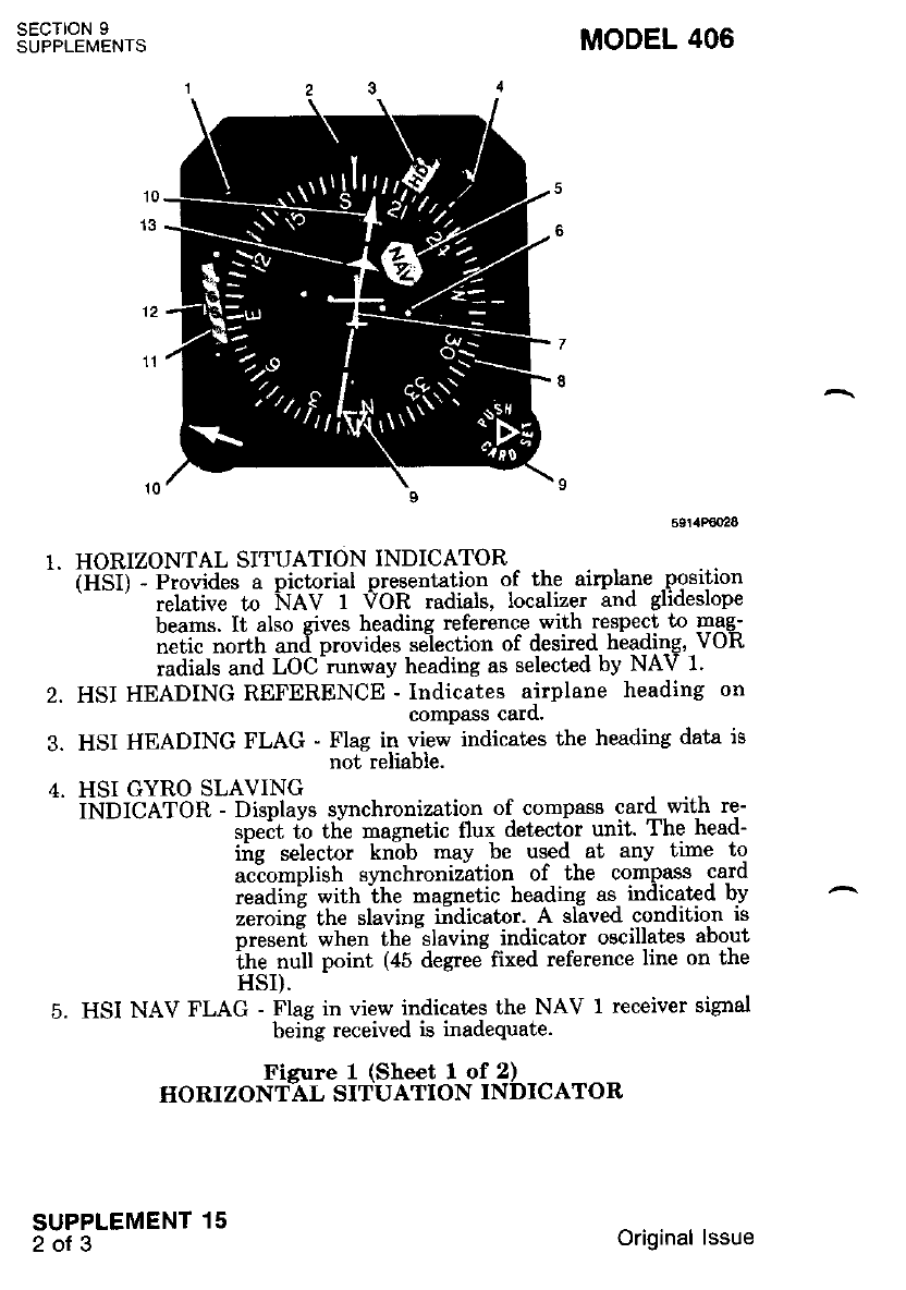
SECTION 9
SUPPLEMENTS MODEL 406
2.
3.
HORIZONTAL SITUATION INDICATOR
iifSli -Fro"ides a pictorial presentation of the airplane position
relative to NAV 1 VOR radials, localizer and glideslope
beams. It also gives heading referenc-e -with respect to mgg-
netic north and provides se-lection of desired heading, VOR
radials and LOC-runway heading as selected by NAV 1'
HSI HEADING REFERENCE - Indicates airplane heading on
compass caro.
HSI HEADING FLAG - Flag in view indicates the heading data is
not reliable.
HSI GYRO SLAVING
iNbrCAfOn - Displays synchronization of, compass card .with re-
speit io tlie magnetic flux detector unit. The head-
ing selector knob may be used at any time to
aciomplish synchronization of the compass card
readini with ihe masnetic heading as indicated by
zeroinf the slaving indicator. A slaved condition is
rreseni when the-slaving indicator oscillates about
the null point (45 degree fixed reference line on the
HSI).
HSI NAV FLAG - Flag in view indicates the NAV 1 receiver signal
being received is inadequate.
Fisure 1 (Sheet I of 2)
HORIZONT-AL SITUATION INDICATOR
SUPPLEMENT 15
2ot3 Original lssue
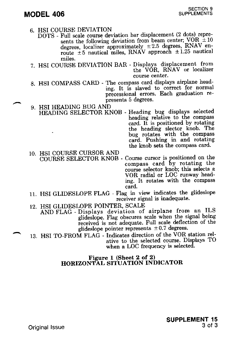
MODEL 406 SECTION 9
SUPPLEMENTS
6. HSI COURSE DEVIATION
- nOtS - Fu scale course deviation bar displacement (2 dots) repre--
- - - - i."t. the following deviation from beam center;-V-OR t10
a"et""." lo"utit". ?pproximately r2.5 degrees, RNAV en-
.rfiG 1s nautical'miles' RNAV approach a125 nautical
miles.
7. HSI COURSE DEVIATION BAR - Displavs djspla-c-ement from
the VOR. RNAV or localizer
course cenf,er'
8. HSI COMPASS CARD - The compass card displays airplane head-
ing. It ii slaved to correct for normal
pr6cessional errors' Each graduation re-
Presents 5 degrees.
9. HSI HEADING BUG AND
- iinl-oiNc Selncron KNOB - Heading bug displavs selected
headinq relative to the compass
card. I[ is positioned bY rotating
the headins slector knob. The
bue rotateJ with the comPass
caid. Pushing in and rotating
the knob sets the comPass card.
10. HSI COURSE CURSOR AND
-- bbunsn SELECToR KNoB - coursercu.:""ii- ff"tlfr?"i;" fil:
courie selector knob: this selects a
VOR radial or LOC runwaY head-
ing.- It rotates with the compass
carq.
11. HSI GLIDESLOPE FLAG - Flag in view indicates the glideslope
receiver signal is inadequate.
12. HSI GLIDESLOPE POINTER, SCALE
^-' liNb-elAC - Displays deviation of airplane from an ILS
glid6sloie. Flag obscures scale when the signal b^eing
iec"lu",i i. noi adequate. Full scale deflection of the
glideslope point€r represents +0'7 degrees'
13. HSI TO-FROM FLAG - Indicates direction of the VO& station rel-
- ati;e to the selected course' Displays TO
when a LOC frequency is selected'
Fisure I (Sheet 2 of 2)
IIORIZONTAL SITUATION INDICATOR
SUPPLEMENT 15
3of3
Original lssue

1OOOA INTEGRATED FLIGHT CONTROL SYSTEM
(rF-1050A)
SECTION 1 - GENERAL
This supplement provides infornation which must be observed when
operating flie 1OOOA]ntegrated Flight Control Svstem'
DescriPtion
The 1000A Integrated Flight Control System (IFCS) i8 a two-axis
^ au;;ilo;;t;tem thit controls"the ailerons and elevators to maintain the
^ ;i;ff; ;i a desired attitude. A vaw damper is also included in the
i"i'ti.. ttt"-teCS piovides automitic flighi control or manual control
#lii, precisio" flight direction provided by computer. command informa-
ii;;. Th; ;;t"" ;f the system'is displavei on t-he- flight. director indica-
i"r ie-oii, ihe mode seleitor, the auiopilot control panel, the horizontal
situation indicator (HSI), and the autopilot mode repeater annuncrators
on the pilot's Panel.
Operation of the flight director (FD) and automatic pilot (AP.) system
is Uisicativ the same.- The difference is whether the pilot follows the
iiieht di""""t". commands manually or allows the autopilot to fly the
airplane.
Precision flight direction information for manual contr-ol is prgvi.de$
on tir" Ftji, reter to Figure 4, by means of a symbolic airplane and pitch
.iia .tit ".--u"d bari The Flight Director' Indicator consists of the
intit"-""f panel mounted indiiator and a remote mounted electric
u"rii"J *t.i mounted in the center right side of the nose bagg€ge
.""'tii*tti"."t. Not.ul gyto erection re{uires 3 minutes from initial
;;f;];;. Aft"t initial iitivation, g1'ro erection rate is controlled -bv the
V.d.-ilnnCf switch, located beioiv the horizontal -situation indicator'
Th; V.G. bRpCT sititch is spring loaded to the NORMAL Position
-.,. *iii"tr provides an erection ra'te o-f 2'5 degrees per-minute' If faster
erectron rs desrreo, rne swikh can be held in the FAST position, for an
eieciion tate of 2d degrees per minute. The FAST-position should only
b" u."J in t"""t flight."The iutopilot and/or tight dilector will diseqgage
i'i""- tt't" V.c. shncr switcli is in ihe FAST position. The Ilight
Jii".t.t i. automatically engaged when the autopilot is. engaged, or it can
be independently engaged by depressing the !D ewrtch on lne mooe
selector, refe:r to Figure 2.
A horizontal situation indicator (HSI), refer to Figure 3,-{spla-ys- a
oicio.iai ptese"tation of the airplane's position relativi io VOR radials'
io"iii^. '..rr..J and glideslopi beami.- The. HSI . also^ gives heading
reference with respect to magnetic north and provrdes tor selecf,lon or
the desired heading, VOR radial and LOC course.
MODEL 406 SECTION 9
SUPPLEMENTS
SUPPLEMENT 16
1of25
Original lssue
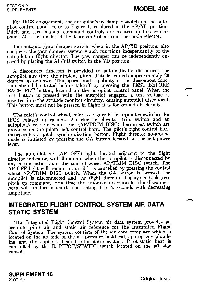
For IFCS engagement, the autopilot/yaw damper switch on the auto-
pilot control panel, refer to Figure 1, is placed in the AP|(D position.
Pitch and turn manual command controls are located on this control
panel. All other modes of flight are controlled from the mode selector.
The autopilot/yaw damper switch, when in the AP/YD position, also
energizes the yaw damper system which functions independently of the
autobilot or flight director. The yaw damper can be independently en-
gaged by placing the AP/YD switch in the YD position.
A disconnect function is provided to automatically disconnect the
autopilot any time the.airplane pitch attitude exceeds approximately 20
desrees up or down. The operational capabilitv of the disconnect func-
tio-n shou-ld be tested befoie takeoff bv presslns the TEST BEFORE
EACH FLT button, located on the auiopilot control panel. When the
test button is pressed with the autopilot engaged, a test voltage is
inserted into the attitude monitor circuitry, causing autopilot disconnect.
This button must not be pressed in flight; it is for ground check only.
The oilot's control wheel. refer to Fizure 5, incorporates switches for
IFCS i':lated ooerations. An electriC elevator trim switch and an
autopilot/electrii elevator trim (AP/TRIM DISC) disconnect switch are
provided on the pilot's left control horn. The pilot's right control horn
incorporates a pitch synchronization button. Flight director go-around
mode is initiate'd by pressing the GA button located on the Ieft power
lever.
The autopilot off (AP OFF) light, located adjacent to the flight
director indiiator, will illuminate when the autopilot is disconnected by
anv means other than the control wheel AP/TRIM DISC switch. The
AF OFF lieht will remain on until it is cancelled by pressing the control
wheel AP/TRIM DISC switch. When the GA button is pressed, the
autopilot is disconnected and the flight director displays a 6 degrees
oitci un command. Anv time the auropilot disconnects, the disconnect
ho.n *ill produce a sh'ort tone lasting- 1 to 2 seconds with decreasing
amplitude.
INTEGRATED FLIGHT CONTROL SYSTEM AIR DATA
STATIC SYSTEM
The Integrated Flight Control System air data system provides an
accurate pitot air and static air reference for the Integrated Flight
Control System. The svstem consists of the air data computer which is
tocated on the aft side of the aft pressure bulkhead, appropriate plumb-
ine and the copilot's heated pitbt-static svst€m. Pitot-static heat is
coirtrolled bv tlie R PITOT/STATIC switah located on the aft side
consore.
SECTION 9
SUPPLEMENTS
SUPPLEMENT 16
2ot25
MODEL 406
Original lssue
MODEL 406
1
1. PITCH COMMAND
-' iVHebf, - Controls pitch attitude of the airplane'. When. rotated,
commandi pitch up or down. Pifth attitude c.hangg i.s
DroDortional to the amount of rotatron ol the prtch
tonimand wheel. Rotation of the wheel disengages the
ALT ENG or GS ENG modes. Rotation of the wheel
does not affect GS ARM mode.
2. TEST BEFORE EACH FLT
- eUffON - Pressing this switch with the autopilot engaged, tests
the pit;h attitude monitor circuitry, causing autopilot
disconnect.
3. TURN COMMAND
" KN-OB - Mist be centered for FD or AP engagement Commands
roll attitude proportional Lo control rotation Maximum
command is iroriinallv 25 degrees roll attitude. Disabled
in GA mode. Rotatioi out of detent disengages HDG or
NAV modes.
4. ROLL TRIM
- iNnfCefOn - Indicates direction of autopilot roll effort. Continu-
ous deflection in either -direction during steady
flisht indicates that manual adjustment of the air-
pline aileron trim is required in the same direction'
indicator is active with autopilot and/or flight di-
rector engaged or disconnected.
Fieure 1 (She€t I of 2)
AUTOPILOT CONTROL PANEL
SECTION 9
SUPPLEMENTS
SUPPLEMENT 16
3of25
Original lssue
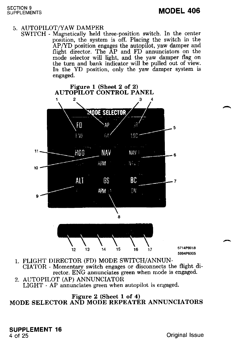
SECTION 9
SUPPLEI\,lENTS MODEL 406
5714P6016
5984P6005
AUTOPILOT/YAW DAMPER
SWITCH - Magnetically held three-position switch. In the center
position, the system is off. Placing the switch in the
AP/YD positioir engages the autopilot, yaw damper and
flight director. The AP and FD annunciators on the
mode selector will light, and ihe yaw damper flag on
the turn and bank indicatnr will be pulled out of view.
In the-YD position, only the yaw damper syst€m is
engageo.
Figure 1 (Sheet 2 of 2)
AUTOPILOT CONTROL PANEL
1234
FLIGHT DIRECTOR (FD) MODE SWITCH/ANNUN.
CIATOR - Momentary switch engages or disconnects the flight di-
rector. ENG annuncia[es green when mode is engaged.
AUTOPILOT (AP) ANNUNCIATOR
LIGHT - AP annunciates gteen when autopilot is engaged.
Figure 2 (Sheet 1 of 4)
MODE SELECTOR AND MODE REPDATER ANNUNCIATORS
SUPPLEMENT 16
4ot25 Original lssue
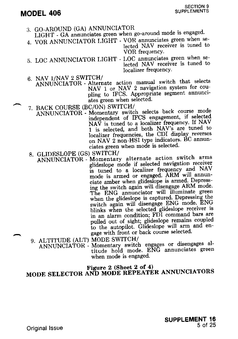
3. GO-AROUND (GA) ANNUNCIATOR
" irciif - cl u"nu"ciate" gree" whett go-"tound mode is engaged'
+. vbn aNNuNCIATOR LIGHT - voR.annurciates green when se-
lecJed NAV receivir is tuned to
VOR frequencY.
5. LOC ANNUNCIATOR LIGHT - LOC annurrciates green when se-
iected NAV receivir is tuned to
Iocalizer frequencY'
6. NAV I/NAV 2 SWITCH/
" iiriNur.rciarbh - ett"i'nut. action manual switch that selects
N.{V- i-ot NAV 2 navigation system for cou-
pling to IFCS' Appropriate segment annuncl-
ates sreen when selecleo'
7. BACK COURSE (BC/ON) SWITCH/
' ifrfr'rlfrdil',iion'l i'io*"t tary switch selects back course mode
t"i""""auit of ff'CS engagement' if selecte!
NAV is tuned to a localizer frequency' lt NAv
1 is selected, and both \AJ's. are tuned to
localizer frequencies' the CDI display-reverses
on NAV 2 non-HSI ttpe indicators BU annun-
ciates green when mode is selected'
8. GLIDESLOPE (GS) SWITCH/
- ifrNu-NEirir-oE -'uomentaiv alternate action. switch arms
- glideilope i.rode -if selected navigation receiver
t" -tu""i- to a localizer f-reqy91c-y and NAV
tode is atmed or engaged' ARM will annun-
ciate a-bet when glid6slope is armed' -D-epres-s-
i"g ift" -t*it"tt aguiil wi riis.ettgage ARM mode'
Tfie ENG anninciator will illuminate- green
*tt"n Tn" etid"ttope is captured Depressing the
";;h';Ht" ;i[-ii'""iiE EN-G inode'. ENG
blinks w"hen the selecttd glideslope recerver rs
in al alarm condition; FDI command bars are
p"rl"a i"-i"f ttgttti-elideslope r,emains coupled
to -ltt" -u*opitotl Gtidestopti will arm and en-
gtg" *ith frbnt or back course selected'
9. ALTITUDE (ALT) MODE SWITCH/
" Aili{0NCIATon - rvio-*tutv iwitch elgaqes or disengages al-
titude hoid mode' ENG annunciates green
when mode is engaged'
Figure 2 (Sheet 2 of 4l_ . ---.,
MODE SELECTOR ANff MOI'b_R-EPEATER ANNUNCIATORS
MODEL 406 sEcloN I
SUPPLEMENTS
SUPPLEMENT 16
50T23
Original lssue
SECIION 9
SUPPLEI\4ENTS MODEL 406
10. NAV MODE SWITCH/
ANNUNCIATOR - Momentary activation engages or disengages
NAV ARM or the NAV ENG rnode, dependent
on HDG mode status and position of the air-
plane relative to the bearir center. If HDG
mode is not engaged, NAV mode will engage
immediately and be annunciated bV ENG light-
ing green. The airplane will turn to intercept
the beam at a fixed intercept ansle. If HDG
mode is engaged, and beam displacement is
greater than a preset amount on the course
deviation indicafor, (one fifth scale for VOR
enroute, full scale for VOR with wing flaps at
T.O. or more selected, and full icale for
localizer operation), the HDG mode will remarn
engaged and the NAV mode will arm. An am-
ber ARM annunciation will anpear below the
white NAV. The airplane will -cbntinue on the
selected heading un[il the beam displacenent
decreases to less than the preset amount, at
which time NAV mode will automaticallv en-
gage and HDG mode will disengage. The ARM
annunciation will also extinzuish and the ENG
annunciation will light green. The airplane will
then turn to capture the beam. ENG blinks
when the selected NAV receiver is in a flas
alarm condition. However, NAV remains coupl
led to the IFCS. FDI pitch and roll command
bars will remain in sight in VOR mode, but are
pulled out,.of sight in LOC mode in the flag
alarm condition.
11. HEADING (HDG) MODE SWITCH/
ANNUNCIATOR - Momentar1r switch engages or disengages the
heading mode. ENG annunciates green when
mode is engaged. Heading mode ingagement
will cancel NAV and GA niodes.
NOIE
The HDG, NAV, ALT, GS, and BC pu.sh but-
tons are iLlurninated uhite on the mode selector.
With the MASTER LIGHTING switch in the
NIGHT position, the intensity of the lights on
the MODE SELECTOR and MODE REPEAT-
ER is controlled by the RADIO PANEL LICHT
INTENSITY CONTROL.
Figure 2 (Sheet 3 of 4)
MODE SELECTOR AND MODE REPEATER ANNUNCIATORS
SUPPLEMENT 16
6of25 Original lssue
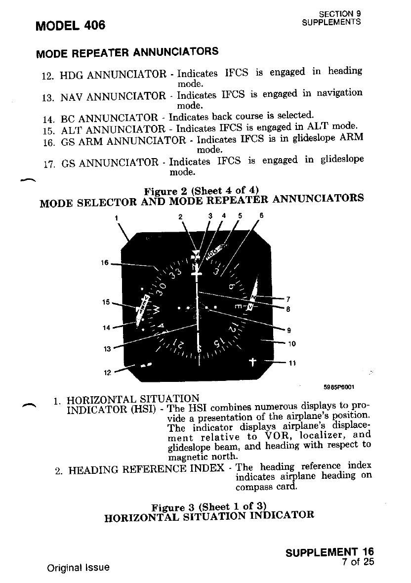
MODEL 406
MODE REPEATER ANNUNCIATORS
12. HDG ANNUNCIATOR - Indicates IFCS
mode.
13. NAV ANNUNCIATOR - Indicates IFCS
mode.
SECTION 9
SUPPLEMENTS
14. BC ANNUNCIATOR - Indicates back course is selected' -
ii. eir ANNUNCIATOR - Indicates IFCS is engaged in ALT mode'
ig. Cs anrta .qNNUNCIATOR - Indicates IFCS is in glideslope ARM
mooe,
17. GS ANNUNCIATOR - Indicates IFCS is engaged in glideslope
mode.
Figure 2 (Sheet 4 of 4)
MODE SELECTOR ANSMOIib RbPNNTNN ANNUNCIATORS
5905P6001
Il,"#8t'+ffi "GfJfr Y,Hl"**:*t1;:t?fi XT*1"T,ijryi*,,.1t
The indicator displa-y-s^ airplane s. drsphce-
ment relative t; VOR' localizer' and
glid"slope beam, and heading with respect to
iraenetic north.
HEADING REFERENCi INDEX - The heading , reference.-index
indicates airplane headrng on
compass card.
is engaged in heading
is engaged in navigation
I.
SUPPLEMENT 16
7 oI 25
n oo, ro,$itf t?+3ieiid""i'ttrc AroR
Original lssue
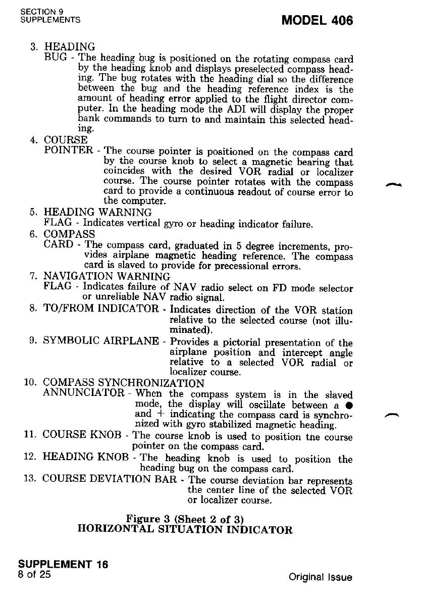
SECTION 9
SUPPLEMENTS MODEL 406
5.
HEADING
BUG -'Ihe heading bug is positioned on the rotatins compass card
by the heading knob and displavs preselected compiss head-
ing. The bug rotat€s with thi heailins dial so the-difference
between the bug and the heading ieference index is the
amount of heading error applied to the flieht director com-
puter. In the heading mode the ADI will display the proper
bank commands to turn to and maintain this selected head_
ing.
COURSE
POINTER - The course pointer is positioned on the comoass card
by the course knob to select a magnetic beaine that
coincides with the desired VOR ladial or loializer
course. The course pointer rotates with the compass
c-ard to provide a continuous readout of course error to
the computer.
HEADING WARNING
FLAG - Indicates vertical gyro or heading indicator failure.
COMPASS
CARD - The compass card. graduated in 5 degree increments, pro-
vides. airplane magnet-ic heading refdrence. The compass
card is slaved to provide for precessional errors.
NAVIGATION WARNING
FLAG - Indicates failure of NAV radio select on FD mode selector
or unreliable NAV radio signal.
TOAROM INDICATOR - Indicates direction of the VOR station
relative to the selected course (not illu-
minated).
SYMBOLIC AIRPLANE - Provides a pictorial presentation of the
airplane position and intercept angle
relative to a selected VOR radial 1r
localizer course.
COMPASS SYNCHRONIZATION
ANNUNCIATOR - When the compass system is in the slaved
mode, the display will oscillate between a O
and * indicating the compass card is svnchro-
nized with gyro stabilized magnetic heaciing.
COURSE KNOB - The course knob is used to position tne course
pointer on the compass card.-
HEADING KNOB - The heading knob is used to- position the
heading bug on the compass card.-
COURSE DEVIATION BAR - The course deviation bar reDresents
*il"j*t::ilf .the serectid voR
't.
9.
11.
72.
10.
Figure 3 (Sheet 2 of 3)
HORIZONTAL SITUATION INDICATOR
SUPPLEMENT 15
8of25 Original lssue
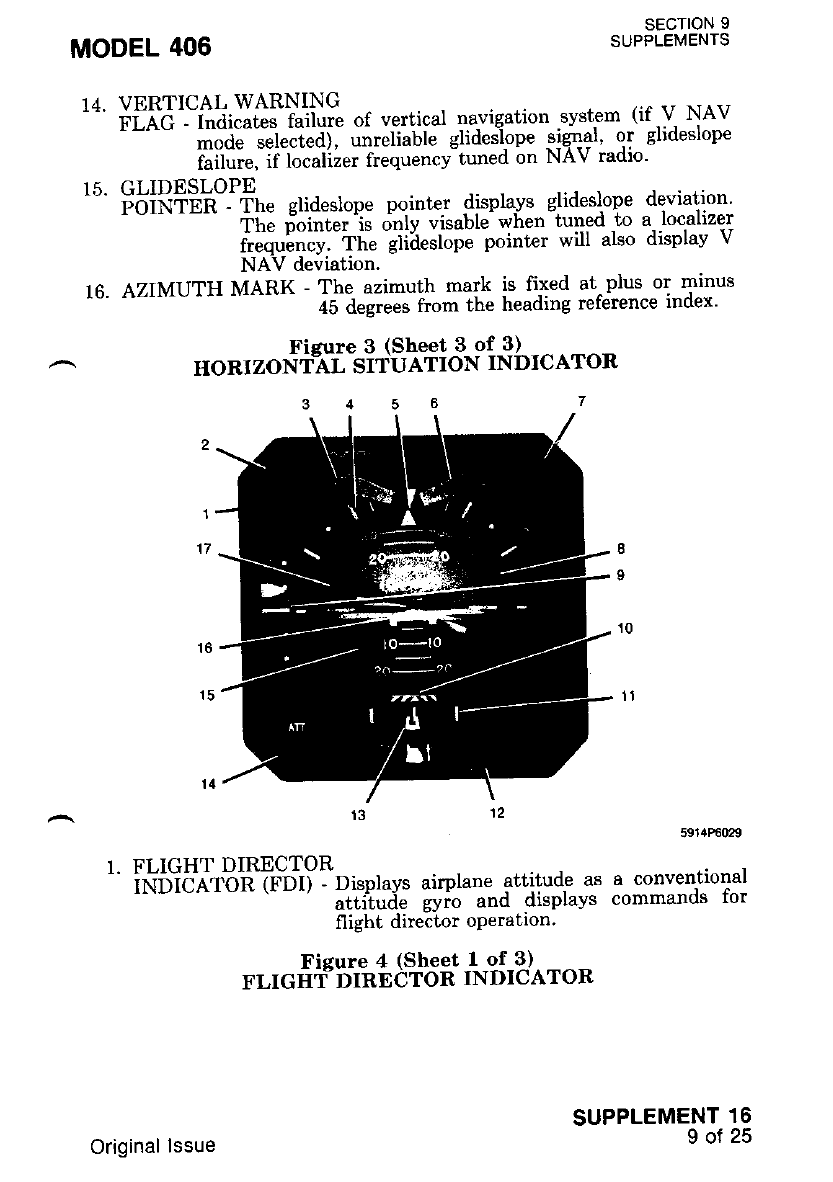
SECTION 9
SUPPLEMENTS
14. VERTICAL WARNING
'=' riet - i"ai"ri"" fuilut" of vertical navigation .svstem (if 'V NAv
''"" ;;A;;;iJeai' "-"ti"ti" glideilope -tlq1gl' qT glideslope
failure, if localizer frequency tuned on NAv radlo'
15. GLIDESLOPE
'" FoifriEn -^ rt e glideslope pointer displa.vs glideslope deviation
ihe i'ointet is dnly t'isable- wiren-tuned to a'localizer
ifi";;;:-Th" ;iih".top" polnt"' will also displav v
NAV deviation.
16. AZIMUTH MARK - The azimuth mark is fixed at^plus or minus
a5 desre; irom the heading reference index'
Fieure 3 (Sheet 3 of 3)
HORIZONiAL SITUATION INDICATOR
1. FLIGHT DIRECTOR
' iNtibe-t'on {rb11:'pttotutt airplane attitude as a conventional
*--' uttil",i" gyio a"d displays commands for
flight director operation'
MODEL 406
Fisure 4 (Sheet 1 of 3)
FLIGIIf DIRECTOR TNDICATOR
SUPPLEMENT 16
9of25
Original lssue
2.
n
7.
FDI GO-AROUND (GA)
ANNUNCIATOR - Indicates pilot has selected Go-Around Mode
on flight director.
FLIGHT DIRECTOR
(FD) WARNING FLAG - Flag in view indicates command bar data
is not reliable.
FDI ROLL ATTITUDE SCALE - Scale with 0, 10, 20, 30, 45, 60
and 90 degrees marks, indicated
with respect to roll attitude ln-
dex.
FDI ROLL ATTITUDE INDEX - Displays airplane roll attitude
against the roll attitude scale.
ATTITUDE (ATT)
WARNING FLAG - Flag in view indicates attitude g5no data is not
reliable.
FDI DECISION HEIGHT (DH)
ANNUNCIATOR - Indicates airplane has reached preset decision
height selected on the optional radio altimeter.
8. FDI ATTITUDE SPHERE - Moves with respect to symbolic
plane to display airplane pitch
roll attitude.
9. FDI GLIDESLOPE POINTER - When in view, indicates deviation
from glideslope.
10. FDI RISING
RUNWAY - (Applicable only with optional radio altimeter.) Bar
comes into view at approximaielv 200 feet altitude and
rises with descendirie' altitude. -Bar touches airnlane
symbol at touchdown.
11. FDI EXPANDED
LOCALIZER SCALE - Scale consists of 3 vertical marks. The cen-
ter mark reDresents the localizer course
center line. The rieht and left marks rn-
dicate approximately I3 percent of full
scale localizer deviation on an HSI or
course,leviation indicator.
FDI INCLINOMETER - Indicates slip to the left or right by dis-
placement of the ball.
FDI EXPANDED LOCALIZER
INDICATOR - Indicates deviation from localizer course center line.
SECTION 9
SUPPLEMENTS
SUPPLEMENT 16
10 of 25
6.
MODEL 406
alr-
and
1,2.
Figure 4 (Sheet 2 of 3)
FLIGIIT DIRECTOR INDICATOR
Original lssue
14. ATTITUDE (ATT) TEST SWITCH - When pressed' the normal
response is a 10 degrees
Pit;h uP and 20 degre.es
iieht roll of the symbohc
aiiPlane and Presentation of
thd ATT flas.
15. FDI PIrcH ArrIruDE scALE - lfil li"r:lXlkli'Ikl $?s:i:
:il;*"""[ the sYmbolic air-
16. FDI SYMBOLIC
'" eifiiL-eNe --Ai.plane attitude is displaved. bv the, relationsflp
tetween tf,e-iiied tv-uot'i" iitptutie and the movable
[;;k;;;;;i.--fh"-"w-b.oli" iirplane.is normallv
iriijiSa *ittt tt" utiitoa" sphere, horizon line for
noimal cruise attitude' During flight director.opera-
ilo", tne symbolic airplane is flown.to align rt wrth
ile tom*and bars to iatisfu the flight director com-
manos'
1 ?. FD r co MMAND BAR il# oilf#. """""*ilfs. ill.#J s:ffi;tt
referenced to the slmbollc a-lrplane lo. rn-
terceDt and maintain a desrred tllght
i"til.Ttt" command bar is retracted when
itr" nignt director is not engaged.
18. VG ERECT SWITCH - Controls erection rate .of the remotely
$",11-':,#it'lf ;f I'i$b ff',il f x#l'"l;
iihicf prouid"s a maximum erection Lime
of three minutes. If a faster erection rate
i. i".i*a, the switch can be held in the
iiltst"'oo.iiion. The fast position should
o"iu b"- u."d in level flight. The autopilot
^".ifot nieht director wil-l disconnect when
Itt"'"*ii"fi is in the FAST position Dur-
in! initial -erection. -tl-rq svstgm is in fast
erEct resardless of switch position'
MODEL 406
Ficure 4 (Sheet 3 of 3)
FLIGIIIYDIRECTOR INDICATOR
SECTION 9
SUPPLEMENTS
SUPPLEMENT 16
1l ot 25
Original lssue
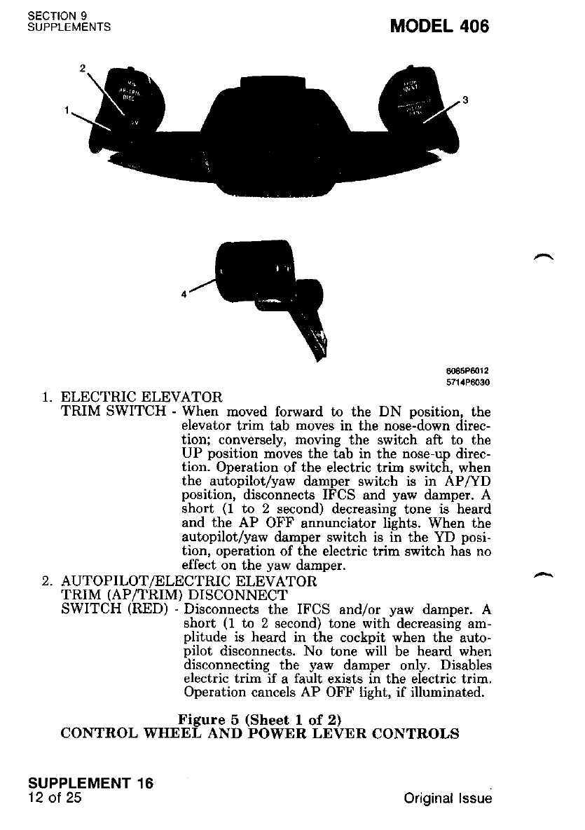
SECTION 9
S U P PLE I\,,IE NTS MODEL 406
H:",ff1:
1. ELECTRIC ELEVATOR
TRIM SWITCH - When moved forward to the DN position, the
elevator trim tab moves in the nose-down direc-
tion; conversely, moving the switch aft to the
UP position moves the tab in the nose-up direc-
tion. Operation of the electric trim switch, when
the autopilot/yaw damper switch is in AP/YD
position, disconnects IFCS and yaw damper. A
short (1 to 2 second) decreasing tone is heard
and the AP OFF annunciator lishts. When the
autopilot/yaw damper switch is in the YD posi-
tion, operation of the electric trim switch has no
effect on the yaw damper.
2. AUTOPILOT/ELECTRIC ELEVATOR
TRIM (AP/TRIM) DISCONNECT
SWITCH (RED) - Disconnects the IFCS and/or yaw damper. A
short (1 to 2 second) tone with decreasing am-
plitude is heard in the cockpit when the auto-
pilot disconnects. No tone will be heard when
disconnecting the yaw damper only. Disables
electric trim if a fault exists in the electric trim.
Operation cancels AP OFF light, if illuminated.
Figure 5 (Sheet 1 of 2)
CONTROL WHEEL AND POWER LEVER CONTROLS
SUPPLEMENT 16
'12 ot 25 Original lssue
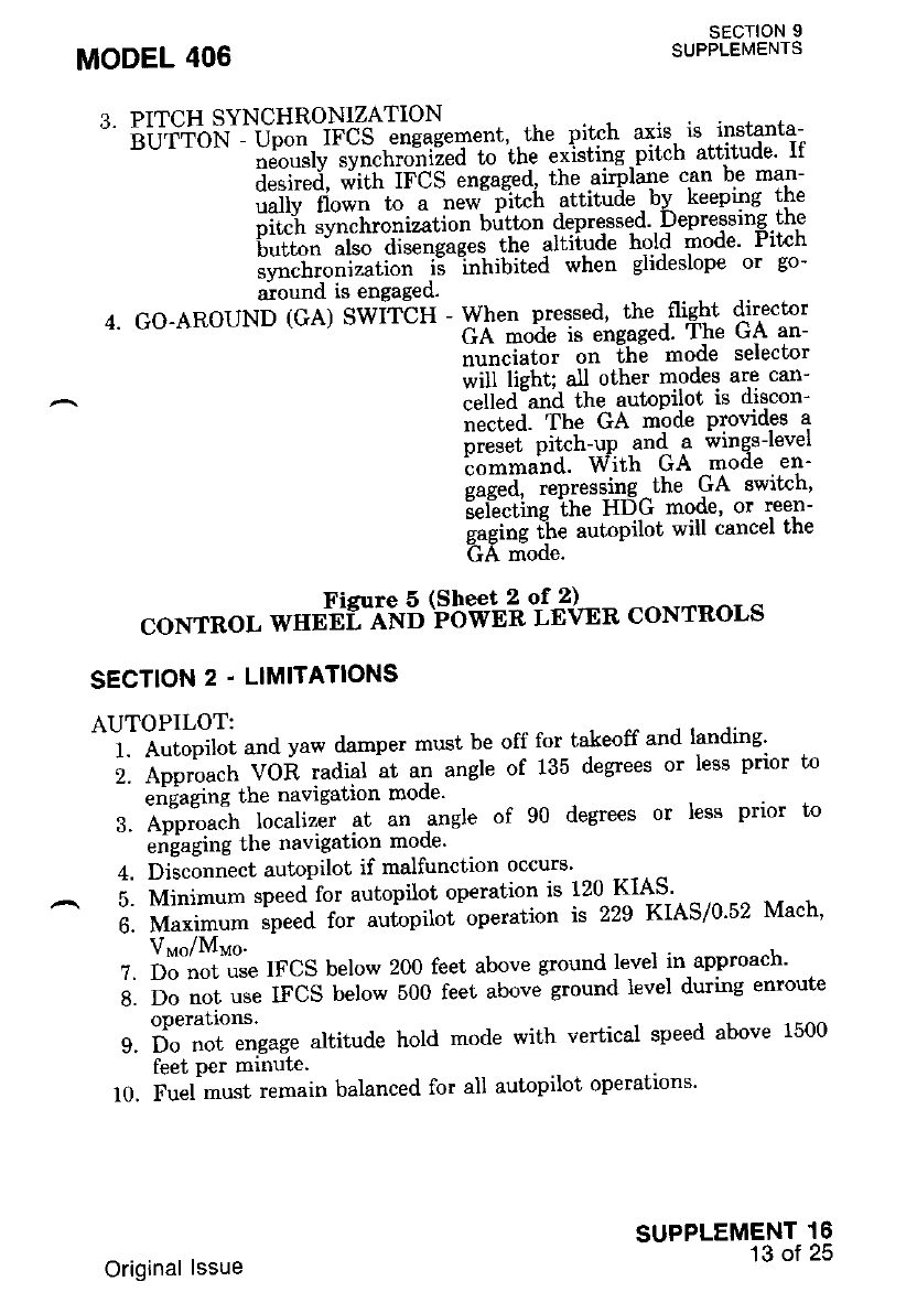
3- PITCH SYNCHRONIZATION
" biJTibN'i U;;; IFCS engaeement. . the pitch axis, is instanta-
nJo".tv .vrrcttto"n'i""id to iit" exisiing'pitch attitude' If
d.tit"'i, niiii iF-CS engaged' the airplarne can be man-
uallv llown"ti- ;;;;;:fii"h attitude . bI keeping the
oitc"h "vtt.hrotti"ation butt'on depressed'. l)epressrng.tne
'button-also disengages the altitude hold mode' rlf,cn
synchronizatiJn i; "inhibited when glideslope or go-
around is engaged'
4. GO-AROUND (GA) SWiT-CH - When pressed' the 'fliaht director
'--'-^ GA;o^d" is eirgaged' The GA an-
nunciator on lhe mode selector
will liehi; al.l olher modes are can-
.uil"d-und the autopilot is discon-
nlcied- The GA mbde Provides a
nreset Pitch-up and a wings-level
io*rnund. With GA mode en-
nae;d, - i"P."..lng the GA switch'
EeiLcting ihe HDG mode, or reen-
gaging the autopilot wrll cancel lne
GA mode.
coNrRoL *"rtfliinB (Fbffib'. E3*" coNrRols
SECTION 2 . LTMITATIONS
AUTOPILOT:
' ' I . n ti"oif", and yaw damper must be off for takeoff and landing'
i. nooti".tt VOR radial at an angle of 135 degrees or less prior to
-'
"tidugrne the navigation mode'
3. A;;;"; -localizer at an .angle of 90 degrees or less prior to
-
"ridtging the navigation mode'
4. Disconnect autopilot if malfunction occurs'
;. ffit-"- speedfor autopilot operation is 120 KIAS - -
6. Uu*i-uro speed for auiopilot operation is 229 KIAS/0'52 Mach'
Vuo/Mvo'
Z. Do'not'*e IFCS below 200 feet above ground level in-approach'
A. Do ".t use IFCS below 500 feet above ground level during enroute
operatlons.
9. il;;t engage altitude hold mode with vertical speed above 1500
feet per mrnutc.
10. Fuel must remain balanced for all autopilot operations'
MODEL 406 SECTION 9
SUPPLEMENTS
SUPPLEMENT 16
13 of 25
Original lssue
sEc-noN I
SUPPLEMENTS MODEL 406
SECTION 3. EMERGENCY PROCEDURES
ELECTRIC ELEVATOR TRIM RUNAWAY
1. Control Wheel - OVERPOWER as required.
2. AP/IRIM DISC Switch - DISCONNECT imrnediately.
3. Manual Elevator Trim - AS REQUIRED.
NOTE
After the electric trirn has been d.kconnected
and the emergency is ouer, pull the electric trim
(ELEV TRIM) circuit breaher. Do not o.ttempt
to use the electric eleuator trim system untiL
ground maintenance has been completed.
AUTOPILOT EMERGENCIES
AUTOPILOT MALFUNCTION
1. Elevator or Aileron Control - OVERPOWER as required.
1. AP/TRIM DISC Switch - DISCONNECT immediately.
I{OTE
olf autopilot malfunctions, the possible altitud.e
loss (includes altitude hss prior to pilot recogni-
tion) for cruise, climb, d,escent conliguration and,
maneuuering flight is 500 t'eet. For approach
configuration, the aLtitude loss is 120 feet.
CAfter the autopilot has been d.isconnected and
the en'Lergency is ouer, pulL the roll and pitch
actuator (ACT) circuit breaker. Do not attempt
to use the dutopilot until ground, maintenaice
has been completed.
ENGINE tr'AILURE
1. Aircraft - CONTROL as required.
2. Inoperative Engine Propeller - FEATHER.
3. AP/TRIM DISC Switch - DISCONNECT.
Operative Engine - INCREASE POWER, as required.
Landing Gear - UP.
Wing Flaps - UP or as required.
Trim Tabs - ADJUST.
Inoperative Engine - SECURE.
ENGINE INOPERATIVE COUPLED APPROACH
1. Fuel - BALANCED.
2. Trim Tabs - ADJUST.
3. Autopilot - ENGAGE per VOR, IlS/Localizer Coupling Procedure.
SUPPLEMENT 16
14 of 25
,1
5.
6.
7.
8.
Original lssue
4. Engine Inoperative Landing Checklist - COMPLETED'
SECTION 4 . NORMAL PROCEDURES
ELECTRIC ELEVATOR TRIM DISCONNECT CHECK
1. Operate the electric trim switch in one direction and observe mo-
-' ti6. oi ttt" manual pitch trim wheel in the proper.{!rgtion' While
;;i";i;; ine aboie test, momentarilv debress AP/TRIM DISC
;;l;;li ;A release. observe that manuai pitch trim wheel motion is
u.."ii"d ""d remains stopped when the disconnect switch is re-
leased and electric trim switch is activated.
^ 2. Repeat St€p f. in the opposite direction'
AUTOPILOT ATTITUDE MONITOR DISENGAGE CHECK (WITH
GYRO ERECTED)
BEFORE TAKEOFF
1. Turn Comrnand Knob - CENTER DETENT.
2. AutopilotAaw Damper
-' S;ia;h - aP/yl. ob."*e annunciation on mode selector for AP
uttd FD ettguge, and that the turn and bank yaw darnper
flas is retractec'
FD Mode Selector Button - ACTUATE. Observe FD disconnect'
TEST BEFORE EACH FLT Test Button - PUSH and HOLD'
Verify the following:
a. Autopilot/Yaw Damper Switch - OBSERVE return to OFF po-
srtron.
b. AP OFF Light - OBSERVE illumination
MODEL 406
3.
SECTION 9
SUPPLEMENTS
SUPPLEMENT 16
15 of 25
c. Autopilot Disconnect Horn - OBSERVE 1 to 2 second decreas-
ing aural tone.
6. AP/TRIM DISC Switch - PUSH to turn off the AP OFF light'
?. Autopilot Yaw Damper Switch - AP/YD - OBSERVE annuncia-
tron,
8. Left Power Lever GA Switrh - PRESS.
9. Verify the following:
a. Autopilot/Yaw Damper Switch - OBSERVE return to OFF po-
srtron.
b. AP OFF Light - OBSERVE illumination.
c. Autopilot Disconnect Horn - OBSERVE 1 to 2 second decreas-
ing aural tone.
d. FD GA Light - OBSERVE illurnination.
e. Flight Director Command Bars - CHECK for wings level pitch
up commano.
10. FD Mode Selector Button - ACTUATE. Observe FD disconnect'
11. Left Power Lever GA Switch - PRESS.
Original lssue
SECTION 9
SUPPLEMENTS MODEL 406
12. Verify that flight director engages in GA mode.
13. FD Mode Selector Button - ACTUATE. Observe FD disconnect.
BASIC AUTOPILOT OPERATION (FLIGHT DIRECTOR ON OR
oFF)
BEFORE ENGAGEMENT
1. Airplane Elevator, Aileron and Rudder Trim - ADJUST.
ENGAGEMENT
3.
Turn Command Knob - CENTER DETENT.
Pitch Synchronization
Button - If flight director engaged, MOMENTARILY PRESS to
synchronize the flight director pitch command bar to the
aimlane attitude-
Autopilot/Yaw Damper Switch - AP/YD. OBSERVE AP annun-
ciation.
NOTE
Airplane rudd,er trim will haue to be ddiusted ds
required lor ball centered. flight. Airplane
aileron trirn uill haue to be reidiwted iu in-
dicated by the roll trim ind,icator'on the auto-
pilot -control panel to compensate for large air-
speed or conliguration changes. Trim toward the
roll trim indicator d.eflecu.on.
TURN COMMANDS
1. Turn Command Knob - ROTATE as desired.
PITCH COMMANDS
1. Pitch Command Wheel - ROTATE as desired. (Or)
2. Pitch Synchronization Button - PRESS and HOLD. Manuallv
place airplane at desired attitude,
then release button.
DISCONNECT
1. AP/TRIM DISC Switch - DISCONNECT. (Or)
2. Autopilot/Yaw Damper Switch - OFF. (Or)
3. Left Power Lever Go-Around Switch - PRESS. Refer to Go-
Around operation. (Or)
4. Pilot's Electric Elevator Trin Switch - ACTUATE.
SUPPLEMENT 16
16 of 25
1.
2.
Original lssue
NOTE
Normal autopilot disconnect should be conduct-
ed with thi pilot's control wheel AP/TRIM
DISC switch. The AP OFF lieht wilt not iLIu-
m[nate, but the autopi'lot disconnecl horn uil]
produce a short tone Tasting 1 n 2 seconds with
d.ec r e as ing amplitu.d e.
NOTE
alf the autopilnt disconnects by any means oth-
er' than thi actiuotion of the pitot's control
wheel AP/TRIM DISC switch. the AP OFF light
uill continuously illuminate and the autopilot
disconnect horn will prod'uce a short tone last-
in! I to 2 seconds with decreasing arnpLitude.
Tie AP OFF light may be extinguished by cy'
cling.the pilot's control wheeL AP/TRIM DISC
swLtcn.
aAutopi.lot disconnect uith the let't pouer leuer
so-qround (GA) switch will illuminate the AP
OFF liEht and the autopilot disconnect horn uill
oroducb a short tone ldstiw 1 to 2 seconds with
'd,ecreasing dmplitude. Refer to Go-Around' Op-
erqtion.
ALTITUDE HOLD (FLIGHT DIRECTOR AND/OR AUTOPII,OT
MODES)
ENGAGEMENT
MODEL 406 SECTION 9
SUPPLEMENTS
SUPPLEMENT 16
17 ot 25
DO NOT OPERATE THE AUTOPILOT IN
ALTITUDE HOLD MODE WHEN FLYING
IN MODERATE TO SEVERE TURBULENCE,
MOUNTAIN LEE WAVE ACTIVITY AND/OR
MODERATE TO SEVERE ICING CONDI-
TIONS.
Original lssue
sEcroN 9
SUPPLEMENTS
SUPPLEMENT 16
18 of 25
flotE
To obtain smooth d.ltitud.e caotures. decrease
uertical speed to 1500 leet pei minute or less
and decrease airplane pitch attitude to with;n 5
degrees of LeueL when approaching d.esired, aL-
titude.
1. With Basic IFCS:
a. Altitude Hold Mode Selector Button - PRESS at desired alti-
tude. Observe annuncia-
tion.
2. With Optional Altitude Alert/Preselect System:
a. Desired Altitude - SELECT.
b. Altitude Alert/Preselect Arm Button - PUSH. Observe that am-
ber ARMD light iUumi-
nates.
MODEL 406
c.
d.
IIOTE
The altitude aLert/preselect ARMD mode is in-
oDeratiue when the IFCS is in the altitude haLd
or glid.estope mode- Once drmed, the sltitu.de
alertfpreselect mode can be d.isarmed by reseLec-
tinr a different allitude on the altitude preseLect
nrisen taiion. bv selectine the qltilude hold mode
'on the mode selector orby glideslope capture.
Pitch Command Wheel - UP or DOWN as required to intercept
selected altitude.
When selected altitude is captured, OBSERVE:
(1) Altitude alert/preselect amber ARMD light goes OFF.
(2) Altitude alert/preselect green CPLD light illuminates.
(3) Mode selector ALT ENG annunciator illuminates green.
(4) Remote Annunciator ALT illurninates.
NOIE
After enqapement, and when lhe airplane has
t;ansitiohA lo leuel flieht, the qLliiude hold
mod.e rnay maintain the airpLane dt an altitud.e
sLightly aboue or beLow the seLected. altitud.e. If
the altitud.e difference is objectional, disengage
the aLtitud.e hold. mod,e and. acquire the desired
altitude, either by using the pitch cornmsnd
wheel, or by hoLd)ng the pitch synchronization
button and. manuaL$r pitching the airplane until
the d.esired ind.icated altitude is reached. Then
reengqge altitud.e hoLd. mode.
Original lssue
MODEL 406
DISENGAGEMENT
1. Altitude Hold Mode Selector Button - ACTUATE. (Or)
2. Pitch Synchronization Button - PRESS. (Or)
3. Pitch Command Wheel - ROTATE.
I{OTE
ALtitude hold mod,e uilL automaticalLy disengage
in the coupled ILS mode when the gLideslope is
enSaEed.
HEADING SELECT FUNCTION
,-.ENGAGEMENT
Turn Command Knob - CENTER DETENT.
HSI Heading Selector Knob - ROTATE bug to desired magretic
heading.
Heading Mode Selector Button - ACTUATE. Observe annuncia-
tron.
Remote Annunciator HDG illuminates.
HSI Heading Selector Knob - ADJUST for any subsequent desired
heading changes.
IOTE
When an optionaL copilot's horizontal situdtion
indicator is installed and connected to the quto-
pilot, the piLot's heading bug controls the head-
ing when NAV 1 receiuer is selected by the
mod.e selector NAV 1/NAV 2 switch, and the
copilot's heading bug controls heading when
NAV 2 receiuei is ielectecl. When a iopilot's
directional gyro is instaLled, the piLot's heading
bug controls the heading when NAV 1 or NAV
2 receiuers are seLected.,
^ usnNcecentnNlt
1. Heading Mode Selector Button - ACTUATE. (Or)
2. T\rrn Command Knob - ROTATE. (Or)
3. Navigation Mode - AUTO ENGAGE.
VOR COUPLING
ENGAGEMENT (VOR)
1. NAV I/NAV 2 Mode Selector
Button - SELECT NAV 1 or NAV 2. Observe proper annunciation
(including VOR annunciator on mode selector).
2. Course Selector Knob - ADJUST to desired VOR course.
SUPPLEMENT 16
19 of 25
sEcloN I
SUPPLEI/lENTS
1.
2.
a
t
5.
Original lssue
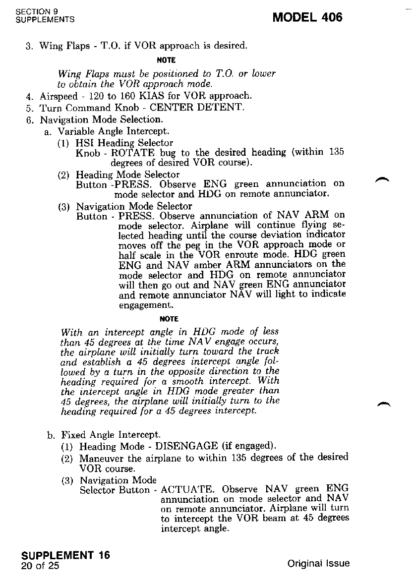
SECTION 9
SUPPLEMENTS
SUPPLEMENT 16
20 of 25
3. Wing Flaps - T.O. if VOR approach is desired.
NOTE
Wing Flaps must be pos;tioned. to T.O. or Louer
to obtain the VOR approach mode.
4. Airspeed - 120 to 160 KIAS for VOR approach.
5. Turn Command Knob - CENTER DETENT.
6. Navigation Mode Selection.
a. Variable Angle Intercept.
( I ) HSI Headins Selector
Knob - ROfATE bug to the desired heading (within 135
degrees of desired VOR course).
(2) Headine Mode Selecror
Bul,ton--PRESS. Observe ENG green annunciation on
mode selector and HDG on remote annunciator.
(3) Navieation Mode Selector
ButtSn - PRESS. Observe annunciation of NAV ARM on
mode selector. Aimlane will continue flying se-
lected headine untii the course deviation indicator
moves off the peg in the VOR approach mode or
half scale in tfie AOR enroute mode. HDG green
ENG and NAV arnber ARM annunciators on the
mode selector and HDG on remot€ annunciator
will then go out and NAV green ENG annunciator
and remo6 annunciator NAV will light to indicate
engagement.
I{OTE
With dn intercept angle in HDG mode of Less
than 45 degrees at the time NAV engage occurs,
the oirplaie wtll inititlty turn Louard the track
and. establish a 45 degiees intercept angle loL-
Iowed by a turn in the opposite direction to the
headin[ required lor a imooth intercepl W,ith
the in{ercebt angle in HDG mode gredter thnn
45 delrees, the airptane will initially turn to lhP
headi-ng required lbr a 45 degrees [ntercept.
b. Fixed Angle Intercept.
(1) Heading Mode - DISENGAGE (if engaged).
(2) Maneuver the airplane to within 135 degrees of the desired
VOR course.
(3) Navigation Mode
' Selecior Button - ACTUATE. Observe NAV green ENG
annunciation on mode selector and NAV
on remote annunciator. Airplane will turn
to intercept the VOR beam at 45 degrees
intercept angle.
MODEL 406
Original lssue
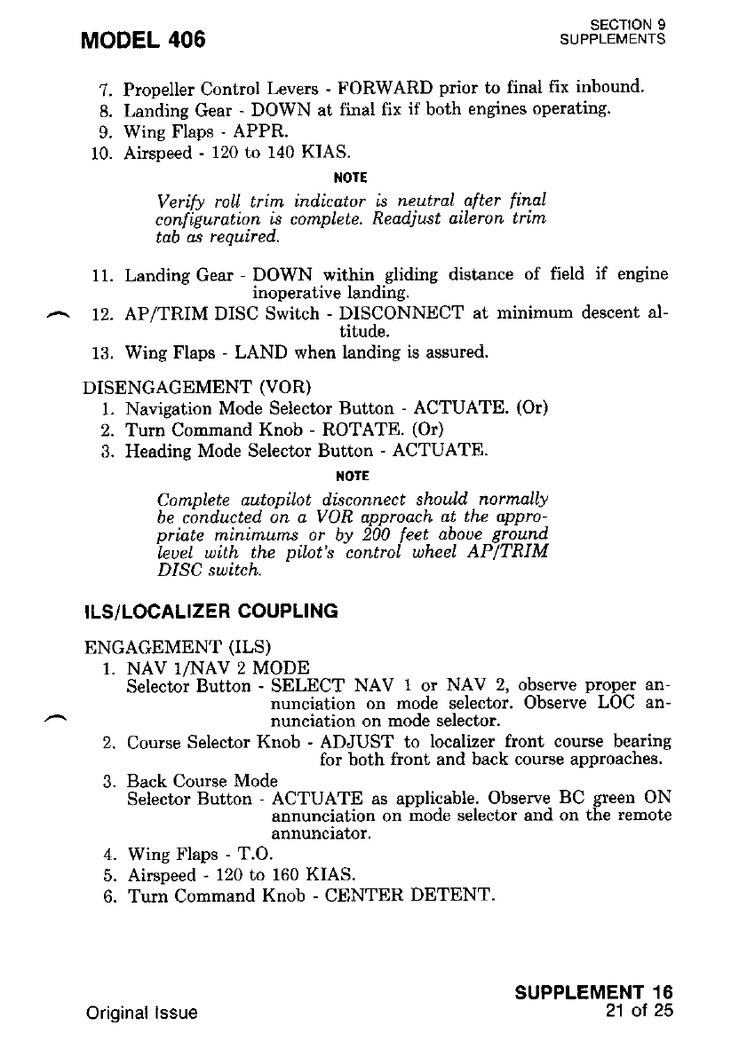
MODEL 406 SECTION 9
SUPPLEMENTS
7. Propeller Control Levers - FORWARD prior to final fix inbound.
8. Landing Gear - DOWN at firal fix if both engines operating.
9. Wing Flaps - APPR.
10. Airspeed - 120 to 140 KIAS.
NOTE
Verify roll trirn indicator is neutral after final
configuration is complete. Readjttst aileron trim
tab as required.
11. Landing Gear - DOWN within gliding distance of field if engine
inoperative landing.
12. AP/TRIM DISC Switch - DISCONNECT at minimum descent al-
titude.
13. Wing Flaps - LAND when landing is assured.
DISENGAGEMENT (VOR)
1. Navigation Mode Selector Button - ACTUATE. (Or)
2. Tum Command Knob - ROTATE. (Or)
3. Heading Mode Selector Button - ACTUATE.
IIOTE
Complete autopiLot disconnect should normally
be conducted on a VOR approach at the appro
priate minimums or by 200 feet aboue ground
leuel with the pilot's control uheel AP|TRIM
DISC switch.
ILS/LOCALIZER COUPLING
ENGAGEMENT (ILS)
1, NAV 1/NAV 2 MODE
Selector Button - SELECT NAV 1or NAV 2, observe proper an-
nunciation on mode selector. Observe LOC an-
nunciation on mode selector.
2. Course Selector Knob - ADJUST to localizer front course bearing
for both front and back course approaches.
3. Back Course Mode
Selector Button - ACTUATE as applicable. Observe BC green ON
annunciation on mode selector and on the remote
annunciator.
4. Wing Flaps - T.O.
5. Airspeed - 120 to 160 KIAS.
6. Turn Comrnand Knob - CENTER DETENT.
SUPPLEMENT.I6
21 ot 25
Original lssue
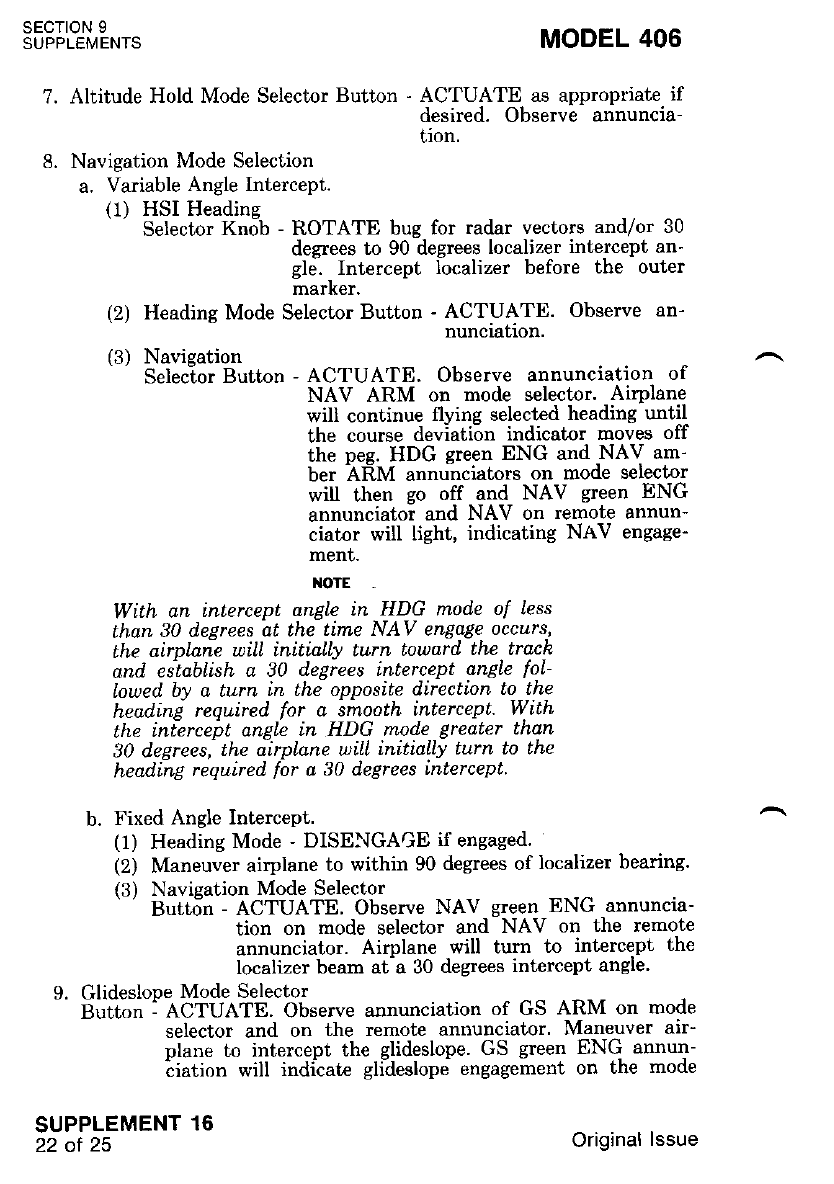
sEcroN I
SUPPLEMENTS MODEL 406
?. Aliitude Hold Mode Selector Button - ACTUATE as appropriate if
desired. Observe annuncia-
tion.
8. Navigation Mode Selection
a. Variable Angle Intercept.
(1) HSI Heading
Selector Knob - ROTATE bug for radar vectors and/or 30
degrees to 90 degrees localizer intercept an-
gle. - Intercept localizer before the outer
marKer.
(2) Heading Mode Selector Button - ACTUATE. Observe an-
nuncraf,ron.
(3) Navieation
Selec-tor Button - ACTUATE. Observe annunciation of
NAV ARM on mode selector. AirPlane
will continue flying selected heading until
the course deviation indicator moves off
the nee. HDG qreen ENG and NAV am-
ber AEM annunciators on mode selector
will then so off and NAV green ENG
annunciatoi and NAV on remote annun-
ciator will light, indicating NAV engage-
ment.
l{oTE -
Wtth an intercept angle in HDG mode of less
than 30 degrees at the time NAV engage occurs,
the airplnie will initially turn toward the track
and. establish a 30 degrees ;ntercept anELe fol-
Lowed by a turn in the opposite direction to the
heading required for a imooth intercept. W.ith
the interceiL anglc in HDG mode greater than
30 degrees,'the iirplqne uitl initiatly turn lo the
head,ing required for a 30 degrees intercept.
b. Fixed Angle Intercept.
(1) Heading Mode - DISEI,IGAGE if engaged.
(2) Maneuver airplane to within 90 degrees of localizer bearing.
{3) Navieation Mode Selector
But6n - ACTUATE' Observe NAV green ENG annuncta-
tion on mode selector and NAV on the remote
annunciator. Airplane will turn to intercept th€
localizer beam at-a 30 degrees intercept angle'
9. Glideslope Mode Selector
Burton: ACTUATE. Observe annunciation of GS ARM on mode
selector and on the remote annunciator. Maneuver air-
plane to intercept the glideslope. GS green ENG annun-
biation will indiiate gli?eslope engagement on the mode
SUPPLEMENT 16
22 of 25 Original lssue
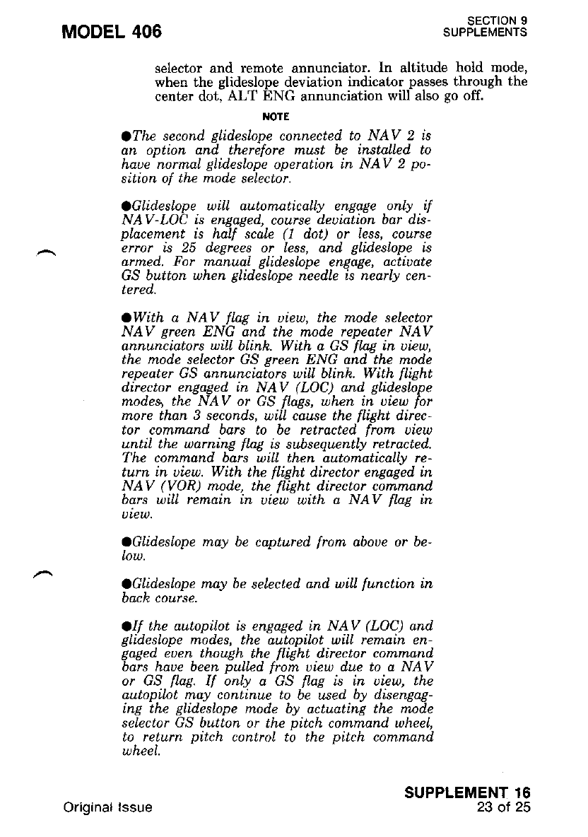
MODEL 406
selector and remote annunciator. In altitude hold mode,
when the glideslope deviation indicator passes through the
center dot, ALT ENG annunciation will also go off.
IIOTE
OThe second, gLideslope connected. to NAV 2 is
an option and therefore must be instaLLed. to
haue normal glid.esLope operation in NAV 2 po-
sition of the mode seLector.
OGLid.eslope wiLL automaticalLy enqage only if
NAV-LOC is engaged, course d.eviation bar dis-
pLacement is half scale (1 dot) or less, course
error is 25 degrees or less, and. glideslope is
armed. For manunl glidesLope engage, activate
GS button when glides\ope needle is nearly cen-
tered,-
OWith a NAV flag in uiew, the rnode sekctor
NAV green ENG and the mode repeater NAV
annunciators wiLl blink. With a GS fLag in uiew,
the mod.e selector GS preen ENG and the mode
repeater GS annuncia[ors wtll blink. With flight
director engaged in NAV (LOC) and glid.eslope
mod.es, the NAV or GS fLags, when in uiew for
more than 3 seconds, uiLL cau.se the flight direc-
tor command bars to be retracted frorn uiew
until the warning flag is subsequently retracted.
The command bars wiLl then qutomaticalLy re-
turn in uiew. With the flight director engaged. in
NAV (VOR) mode, the flight director command
bars wiLL remain in uiew with a NAV f\ag in
ULEW.
OGLideslope may be captured. from aboue or be-
LOW.
OGLideslope may be selected and wiLl function in
oacR course.
OIf the autopilot is engaged tn NAV (LOC) qnd
glidesLope mod.es, the autopilot will remain en-
gaged euen thouEh the flight director comtnand
bars haue been puLled. from uiew due to a NAV
or GS flae. If onLy a GS fLag is in uiew, the
autopilot may continue to be used by disengag-
ing the glideslope mode by actuating the mode
se\ector GS button or the pitch command wheel,
to. return pitch control to the pitch command
wneeL
sEcTtoN I
SUPPLEMENTS
SUPPLEMENT 16
23 ol 25
Original lssue
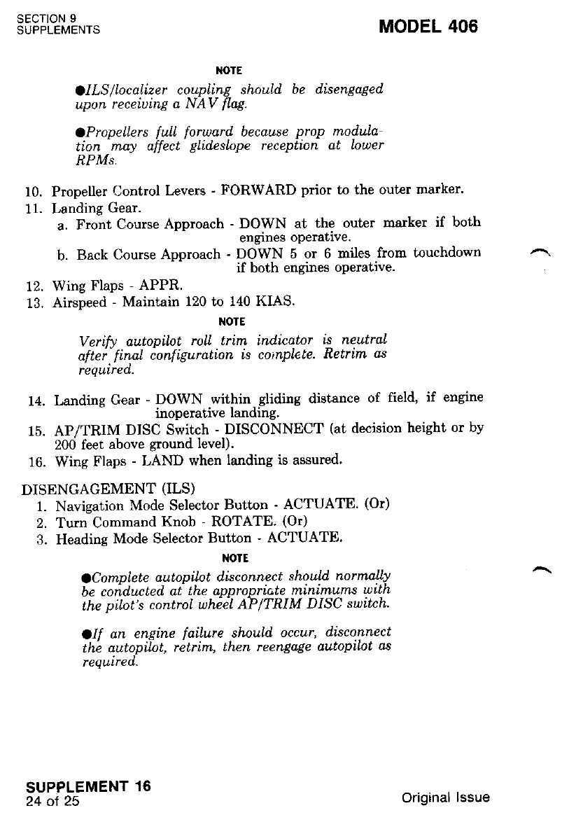
sEcloN I
SUPPLEMENTS MODEL 406
10.
1r.
M)TE
olLS/IocaLizer coupLing shouLd, be disengaged
upon receiuing a NAV flag.
CPropetlers full forward because prop modula
Lion may affect gLidesLope reception ot louer
RPMs.
Propeller Control Levers - FORWARD prior to the outer marker.
Landing Gear.
a. Front Course Approach - DOWN at the outer marker if both
engines oPerative.
b. Back Course Approach - DOWN 5 or 6 miles from touchdown
if both engines operative.
Wing tr'laps - APPR.
Airspeed - Maintain 120 to 140 KIAS.
NOTE
Verifv autopilot roll trim indicator is neutral
aftei'finql ionfiguration is co,nplete- Retrim as
required.
14. Landins Gear - DOWN within gliding distance of field, if engine
- inoperative landing.
15. AP/TRIM DISC Switch - DISCONNECT (at decision height or bv
200 feet above ground level).
16. Wing Flaps - LAND when landing is assured.
DISENGAGEMENT (ILS)
1. Navigation Mode Selector Button - ACTUATE. (Or)
2. Turn Command Knob - ROTATE. (Or)
3. Heading Mode Selector Button - ACTUATE'
NOIE
oC om plete autopilot disconnec t sho uLd normally
be coiduated ai the appropric,te m,inimums wtth
the pilot's conffol whiel AP|TRIM DISC suttch
olf an engine failure should occur, disconnect
thb autopilot, retrim, then reengqge autopiLot as
requlred.
SUPPLEMENT 16
24 oI 25 Original lssue
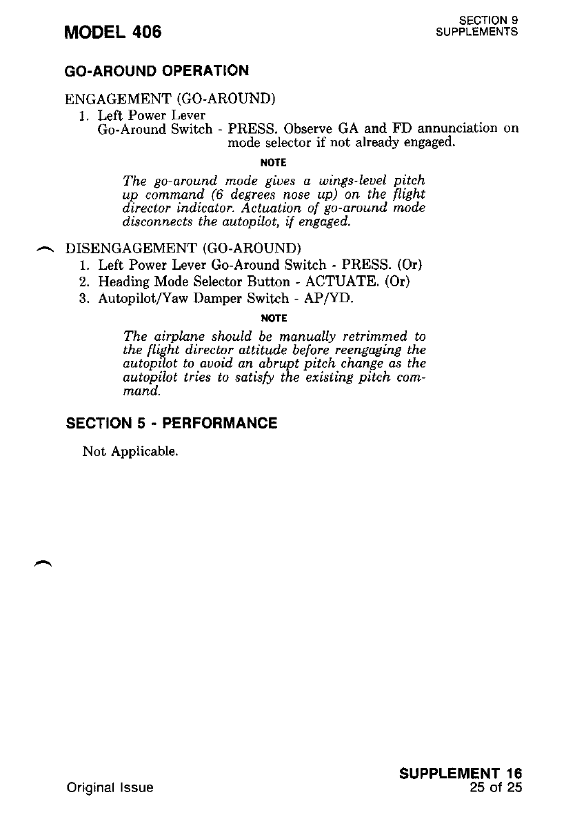
MODEL 406 SECTION 9
SUPPLEMENTS
GO.AROUND OPERATION
ENGAGEMENT (GO-AROUND)
1. Left Power Lever
Go-Around Switch - PRESS. Observe GA and FD annunciation on
mode selector if not already engaged.
NOTE
The go around. mod.e giues a wings-leueL pitch
up command (6 d.egrees nose up) on the fLight
director ind.icator. Actuation of go-around mode
disconnects the autopilot, {f engaged.
,^. DISENGAGEMENT (GO-AROUND)
1. Left Power Lever Go-Around Switch - PRESS. (Or)
2. Heading Mode Selector Button - ACTUATE. (Or)
3. AutopilotAaw Darnper Switch - AP/YD.
I{OTE
The airpLane should be manually retrimrned to
the flight director attitude before reengaging the
autopiLot to auoid, an abrupt pitch change as the
autopilot tries to satisfo the existing pitch cort-
rrand.
SECTION 5 . PERFORMANCE
Not Applicable.
SUPPLEMENT 16
25 ol 25Original lssue

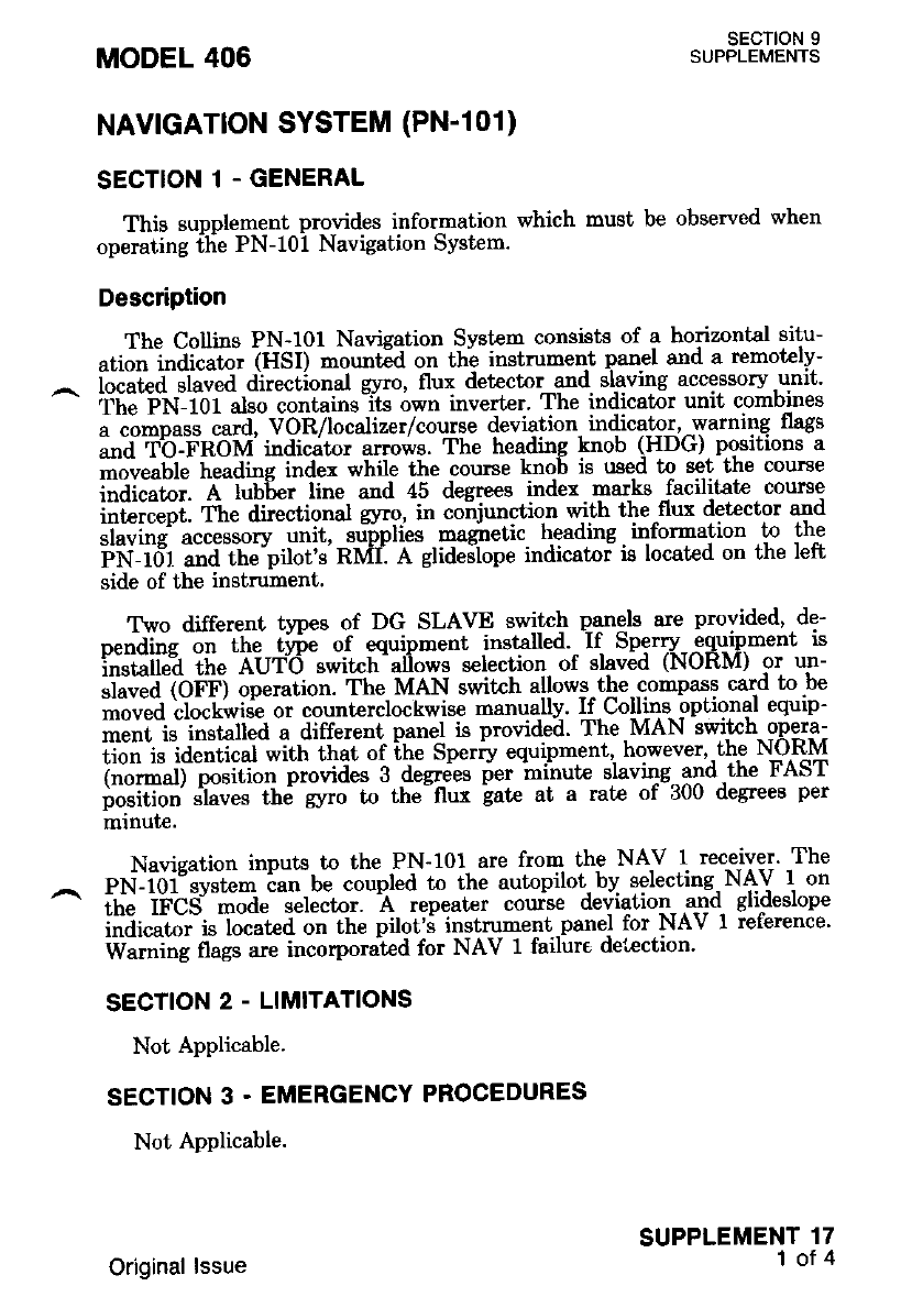
NAVIGATION SYSTEM (PN-l01)
SECTION 1 - GENERAL
This supplement provides information which must be obsewed when
operating flie PN-101 Navigation System.
Description
The Collins PN-101 Navigation System consists of a horizontal situ-
atio" i"iic?t"i irtsii -ou"tid on tlie instrument panel and a remotelv-
iliii.f-ri"tia ait"ciional gvro, flux detector qnd slaving accessory.urit'
Cil"iil.i 10iH; coiitui"s"it* own inverter' The indicator unit combines
; ;;;;;t; ;*d, VoR/localizer/course deviation indicator,,warning flegs
Lii tb-FnoM' indicdtor arrows. The heading knob (HDG) positions a
moveable heading index while the course knob is used to set the course
irai."t"i. A lub6er line and 45 degrees index marts -facilitate course
il;;ffi;: 'iit" ai**i""tt gyro, in co"njunction with the ^flux detcctor and
;ffiil;;;;"* uttit, ",frpliu* maginetic heading information to the
i;iii6t "ira-r.tt""pilot's' RMI'. A glideilope indicatoi ie located on the left
side of the instrument.
Ttvo different types of DG SLAVE switch p-ane.ls are provided, de-
p"na'i'Iig on- ttt" tffie of equipment installed. If Sperry equipment is
irilliii!? tii" AUT6 swiich'aliows selection of glaved (NORM) or un-
;i;a Oii) op"tuilott. The MAN switrh allows,the--gompasi card to be
;;;;-d ;il"i.*i;oi-co""tcrclock*ise manuallv. If-Collins- optional equip-
iri""iir l""t"f"a a differe"t panel is provided. The-MAN swiJch- 9p9r3;
iionir id;;;id-.itt ittat or in" Sperry equipment, however,.the NORM
iffi;;i ffiiti"; p.oGa"" 3 degrdes frer 'ninute slaving and .the FAST
oosition slaves the gyro to the flux gate at a rat€ ot 3uo degrees per
mtnut€.
Navieation inputs to the PN-101 are from th9 NA! 1- rec-eiver' The
P]li-idfi;il;;"" be coupled to the autopilot. bv selecting. NAV I on
if,ij iFCS"."a"- ""tJ"tot. h repeatcr course deviation. .ag1d- glideslope
indicator is locatcd on the pilot's instrument -pane-l lor NAv r rererence'
d"-fig flags are incorpora:ted for NAV 1 failure detection'
SECTION 2 - LIMITATIONS
Not Applicable.
SECTION 3 . EMERGENCY PROCEDURES
Not Applicable.
MODEL 406 sEcTtoN 9
SUPPLEMENTS
SUPPLEMENT 17
l of 4
Original lssue
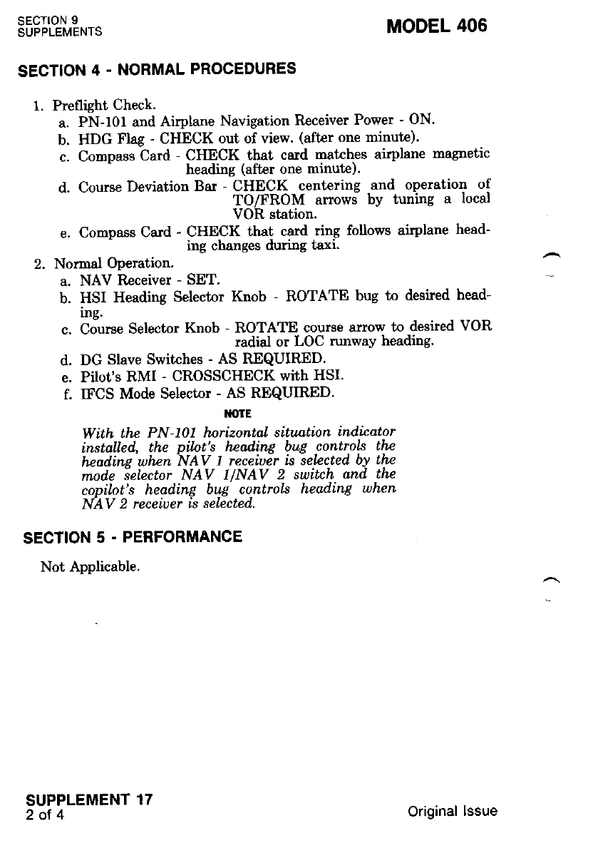
sEcT|oN 9
SUPPLEMENTS MODEL 406
SECTION 4. NORMAL PROCEDURES
1. Preflight Check.
a. PN-101 and Airplane Navigation R.eceiver Power - ON-
b. HDG Flag - CHECK out of view. (after one minute).
c. Compass Card - CHECK that card natches airplane magnetic
- heading (after one minute).
d. Course Deviation Bar - CHECK centering and operation of
TO/FROM anows by tuning a local
VOR station.
e. Compass Cad - CHECK that card ring follows airplane head-
- ing changes during taxi.
2. Normal Operation.
a. NAV Receiver - SET'
b. HSI Heading Selector Knob - ROTATE bug to desired head-
mg.
c. Course Selector Knob - ROTATE course arrow to desired VOR
radial or LOC runway heading.
d. DG Stave Switches - AS REQUIRED'
e. Pilot's RMI - CROSSCHECK with HSI.
f. IFCS Mode Selector - AS REQUIRED'
l{otE
With the PN-101 hnrizontal situation indicator
installed, the pilnt's hBading bug contlols the
hcodins whzn NAV I receiuer is selzcted by the
mod.e ielector NAV llNAV 2 switch and the
copilot's heading bug controls heading when
NAV 2 receiuer is selected.
SECTION 5 . PERFORMANCE
Not Applicable.
SUPPLEMENT 17
2ot4 Original lssue
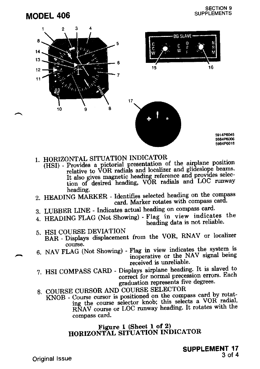
SECTION 9
SUPPLEMENTS
5911tPj6{X6
5984P6006
5984P6018
7.
HORIZONTAL SITUATION INDICATOR
ii{'iil:F;;:t". a- pictorial presentation of the. airplane position
"*-' ;"i;;i"" t" VOR radirils and localizer and glideslope beams'
i;;il-fi; iagneiic iteading reference and. provi$es selec-
iiti'--"f ai.i*a" tt"ading, VOR radials and LoC runwav
heading.
HEADING MARKER - Identifies selected headil9 on the compass
""td. M"t["t rotates with compass- card'
LUBBER LINE - Indicates actual heading on compass card'
iee-orl,rc FLAG (Not Showing) - Flag in view indicates the
"' heading data is not reliable'
HSI COURSE DEVIATION
;;il:"D"i$iv" didiac-e-e"t from the voR, RNAV or localizer
courae.
NAV FLAG (Not Showing) - Ilug i" view indicates-the. svstem is
rnoierative or the NAV signal being
reciived is unreliable'
HSI COMPASS CARD - Displays- airplane, heading' It is slaved to
"ott""f ioi nbrrral precession errors' Each
graduation represents lrve degrees'
COURSE CURSOR AND COURSF'I SELECTOR
kft-Og - Co"t"" cursor is positi^na'l on the comDaas card bv rot'at-
ins the course serectoi - knoLl this sel&t"s a VOR.radial'
iiftdv ""tii"-".-ioc -"*"v heading' It rotates with the
comPass card.
SUPPLEMENT 17
3of4
nonrzoslti"sltEiti"l"'ifr brcAroR
Original lssue
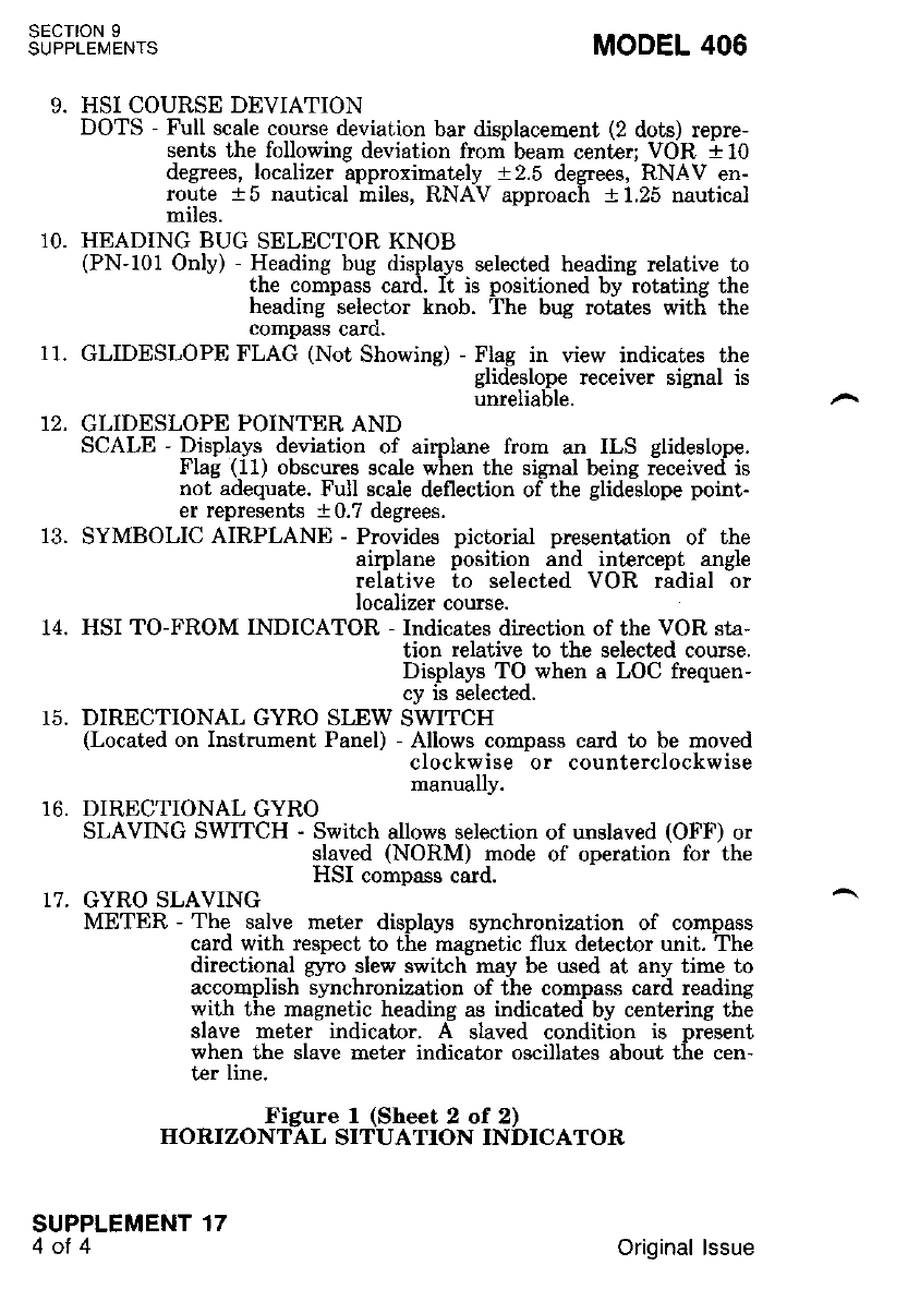
sEcroN 9
SUPPLEMENTS
9.
MODEL 406
HSI COURSE DEVIATION
DOTS - Full scale course deviation bar displacement (2 dots) repre-
sents the following deviation from beam center; VOR a 10
degrees, localizer approximately 12.5 degrees, RNAV en-
route t5 nautical miles, RNAV approach 11.25 nautical
miles.
HEADING BUG SELECTOR KNOB
(PN-101 Only) - Heading bug displays selected heading relative to
the compass card. It is positioned by rotating the
heading -selector knob. The bug rotites wit[ the
compass car0.
GLIDESLOPE FLAG (Not Showing) - Flag in view indicates the
glideslope receiver signal is
unreliable.
GLIDESLOPE POINTER AND
SCALE - Displays deviation of airplane from an ILS glideslope.
Flag (11) obscures scale when the signal being received is
not adequate. Full scale deflection of the glideslope point-
er represents a 0.7 degrees.
SYMBOLIC AIRPLANE - Provides pictorial presentation of the
airplane position and intercept angle
relative to selected VOR radial or
localizer course.
HSI TO-FROM INDICATOR - Indicates direction of the VOR sta-
tion relative to the selected course.
Displays TO when a LOC frequen-
cy is selected.
DIRECTIONAL GYRO SLEW SWITCH
(Located on Instrument Panel) - Allows compass card to be moved
clockwise or cou nte rclock w i s e
manually.
DIRECTIONAL GYRO
SLAVING SWITCH - Switch allows selection of unslaved (OFF) or
slaved (NORM) mode of operation for the
HSI comnass card.
10.
11.
14.
15.
16.
17. GYRO SLAVING
METER - The salve meter displays synchronization of cornpass
card with respect to the magnetic flux det€ctor unit. The
directional gyro slew swikh may be used at any time to
acconplish synchronization of the compass card reading
with the magnetic heading as indicated by centering the
slave meter indicator. A slaved condition is oresent
when the slave meter indicator oscillates about the cen-
ter line.
Figure I (Sheet 2 of 2)
HORIZONTAL SITUATION INDICATOR
SUPPLEMENT 17
4oI 4Original lssue
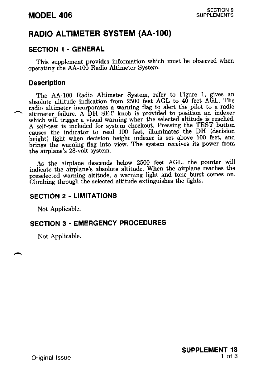
RADIO ALT]METER SYSTEM (AA.1OO)
SECTION 1 - GENERAL
This supplement provides information which must be observed when
operating ftie AA-t00 Radio Altimeter System.
Description
The AA-100 Radio Altimeter Svstem, refer to Figure 1. gives an
absolute altitude indication frorn 2500 feet AGL to 40 feet AGL. The
radio altimeter incorporat€s a warning flag to alert the pilot to a radio
aiiimeter failure. A DH SET knob ii provided to position an indexer
*hi"tt *iU trigger a visual waming when the selected altitude is reached.
A self-test is -i-ncluded for system checkout. Pressing the TE=ST button
causes the indicator to rdd 100 feet, illuminates the DH (decision
treieht) tient when decision height indexer is set above 100 feet. -and
brifigs'thd warning flag into vie-w. The system receives its power from
the airplane's 28'volt system.
As the airolane descends below 2500 feet AGL, the pointer will
indicate the airplane's absolute altitude. When the airplane reaches the
oreselected warnins altitude, a warning light and tone burst comes on.
Cll-bing through t-he selected altitude extinguishes the lighLs.
SECTION 2 . LIMITATIONS
Not Applicable.
SECTION 3. EMERGENCY PROCEDURES
Not Applicable.
MODEL 406 SECTION 9
SUPPLEMENTS
SUPPLEMENT 18
1of 3
Original lssue
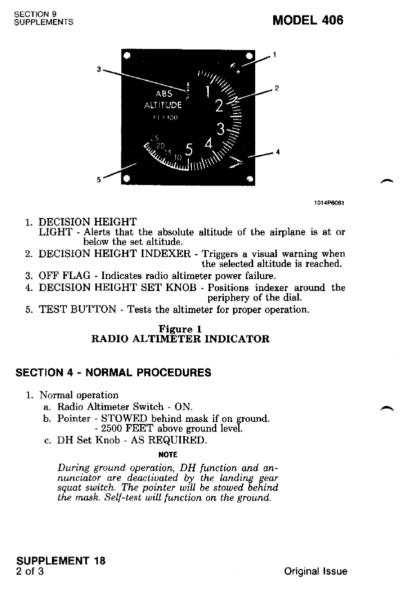
SECTION 9
SUPPLENIENTS
SUPPLEMENT 18
2ot3
DECISION HEIGHT
LIGHT - Aleds that the absolute altitude of the airplane is at or
below the set altitude.
DECISION HEIGHT INDEXER - Triggers a visual warning when
the selected altitude is reached.
OFF FLAG - Indicates radio altimeter power failure.
DECISION HEIGHT SET KNOB - Positions indexer around the
periphery of the dial.
TEST BUTTON - Tests the altimeter for proper operation.
Figure 1
RADIO ALTIMETER INDICATOR
SECTION 4 - NORMAL PROCEDURES
1. Normal operation
a. Radio Altimeter Switch - ON.
b. Pointer - STOWED behind mask if on sround.
- 2500 FEET above ground level.
c. DH Set Knob - AS REQUIRED.
TOIE
During ground. operation, DH function and. an-
nunciator are deactiuated by the Landing gear
squdt suitch. The pointer will be stowed behind
the mask. Self-test wiIL functinn on the ground..
2.
I
MODEL 406
Original lssue
MODEL 406
SECTION 5 - PERFORMANCE
Not Applicable.
SECTION 9
SUPPLEMENTS
SUPPLEMENT 18
3of3
Ground Self-Test
a. DH Set Knob - 200 FEET.
b. Test Button - PRESS and hold. Altitude pointer will indicate
100 +20 feet and the DH annunciator will illu-
minate.
c. Test Button - RELEASE. After 3 seconds the pointer will stow
behind the mask and the DH annunciator will
extinguish.
In Flight Self-Test
a. Pointer - STOWED behind mask above 2500 feet above ground
level.
b. DH Set Knob - 200 FEET.
c. Test Button - PRESS and hold. Altitude pointer will indicate
100 +20 feet and the DH annunciator will illu-
minate.
d. Test Button - RELEASE. After 3 seconds the Dointer will stow
behind the nask and the DH annunciator will
extinguish.
I{OTE
Altitude pointer will stow behind. rnask below
2500 feet-AGL if thz ground return signal is lost
or when the atrplane is in a banh in excess of
45 d.esrees.
Original lssue

RADTO MAGNETIC IND|CATOR (7100 RMI)
SECTION 1 - GENERAL
This sunplement provides inforrnation which must be observed when
operating fFe ?t00 tladio Magnetic Indicator.
Description
The Aeronetics 7100 RMI Radio Magnetic Indicatnr is used in con-
iunction with other airbome navigation equipment to aid the pilot in
"navieatine the airplarre. The RMl-eliminates the need for many of the
num"ericaf and grairhical computations necessary for deternining airplane
position.
The RMI, refer to Figure 1, is a pand-mgqnted navigation instrument
that combines the disphy of VOR and ADF !ear!99 information with
the aimlane headine on a sinsle instrument. The VOR and ADF bear-
ines ar6 displayed bi individual rotating point€rs against the background
ofa rotatirig izimuih card. The azimuth card is driven by the slaved
mag.netic. coimpass system in the airplane and continuously indicates
arrplane hea(Ung.
The RMI display consists of a rotating azinuth card, a frxe{heading
index, a double-bai pointcr and a single-bar pointer, refir to Figure l.
The azimuth card is slaved to the magnetic heading signal and rotates as
the aimlane turns so that the magpetic heading of the airplane is
continubusly displayed at the heading index.
Each pointer serves t,o indicate ADF or VOR bearings according to
the oosidion of its selector switch. The selector switches, one at each
lowei corner of the RMI, have ADF and VOR positions. The knobs are
identifred with a single or double line to relate to the single and
double-bar pointers.
SECTION 2 - LIMITATIONS
Not Applicable.
SECTION 3. EMERGENCY PROCEDURES
Not Applicable.
MODEL 406 sEcTtoN 9
SUPPLEMENTS
SUPPLEMENT 19
l of 3
Original lssue
SECTION 9
SUPPLEMENTS MODEL 406
SECTION 4 . NORMAL PROCEDURES
1. Normal Operation
l{otE
b.
c.
Operatinn ol the RMI is dependent upon input
iiforrnation from the compass systern (slaued
directinnal airo), the associdted VHF nauigation
and ADF receiuers. Refer to the appropriate
supplements in this section lor operation of this
equtpment,
Comoass Cards
(on hMI and Directional Gyro or HSI) iirf3tilfi""1j.^3;
RMI and directional
gyro or HSI will be
tne same,
ADF Receiver - SEIJCT STATION on receiver.
ADF/VOR SELECTOR SWITCH-SINGLE
BAR - ADF. The single-bar pointer will indicate the bearing of
the station.
IOtE
a&eDeat steps b and c using the doublc'bar
switch and iointer if only one ADF is instalLed
OIf a second ADF receiver is installed, repeat
stens b and c rning ADF 2 and thB douhle-bar
switch and pointer.-
NAV l Receiver - SELECT VOR STATION on nunber one
NAV receiver.
ADF/VOR SELECTOR SWITCH-SINGLE
BAR - VOR. The single-bar pointer will indicate the bearing of
the station.
NAV 2 Receiver - SELECT VOR STATION on number two
NAV receiver.
ADF/VOR SELECTOR SWITCH-DOUBLE
BAR - VOR. The double-bar pointer will indicate the bearing
of the station.
OTE
Absence of a ualid VOR signal, switching to the
ILS mode or switchinE the ADF receiDer to
ANT uill carrse Lhe poTnters to stow in the 3
o'clock positions.
SUPPLEMENT 19
Z ot g Original lssue
d.
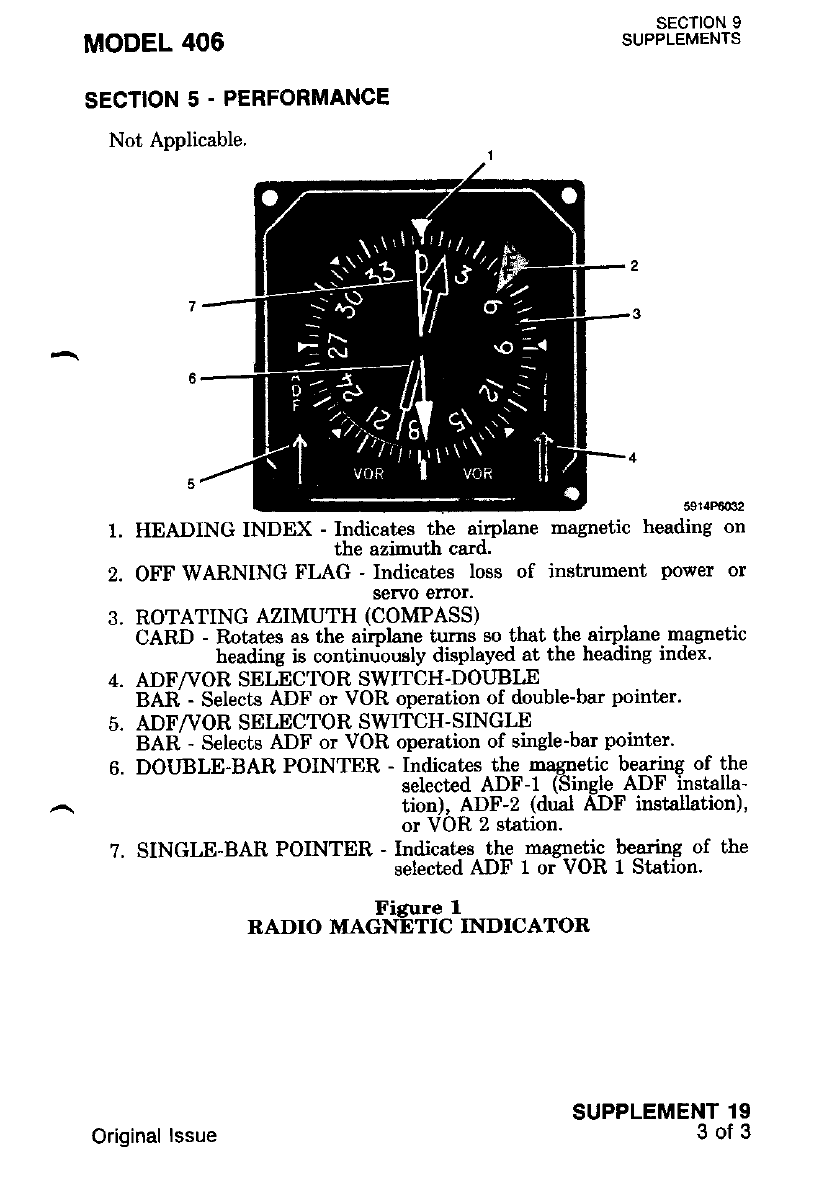
MODEL 406
SECTION 5 - PERFORMANCE
Not Applicable.
sEcTloN I
SUPPLEMENTS
5914Rt032
heading on
SUPPLEMENT 19
3of3
2.
4.
o.
7.
HEADING INDEX - Indicates the airplane
the azimuth card.
OFF WARNING FLAG - Indicates loss of instrument power or
servo erTor.
ROTATING AZIMUTH (COMPASS)
CARD - Rotates as the airplane turns so that the airplane magnetic
heading is continuously displayed at the heading index.
ADF/VOR SELECTOR SWITCH.DOUBLE
BAR - Selects ADF or VOR operation of double-bar pointer.
ADF/VOR SEI,ECTOR SWITCH-SINGLE
BAR - Selects ADF or VOR operation of single-bar pointer.
DOIJBLE-BAR POINTER - Indicates the magnetic bearing of the
selected ADF-I (Single ADF installa-
tion), ADF-Z (dual ADF installation),
or VOR 2 station.
SINGLE-BAR POINTER - Indicates the magnetic bearing of the
selected ADF 1 or VOR I Station.
uoronrec*$fi'clrNDrcAToR
magnetic
Original lssue

1OOO RADIO MAGNETIC INDICATOR (|N'1004A/B)
SECTION 1 - GENERAL
This supplement provides information which must be obsewed when
op"i"tl"i ilie roOO fiadio Magnetic Indicatnr'
DescriPtion
The 1000 Radio Magnetic Indicator (RMI) (Tvpe.IN-1'004A/B) is a
"*"1'-;.;La;;it tfi; i"cl"d; both a iadio magnetic -indicator assem-
^ tff;;t""*Viidiiiiil-.ti"g;"ii. l"aicator converber circuit' The RMI is
used in conJunctror, *trt.o.L".i uitiotti" "*lg"tion sets,to aid the pilot
in navigatmg ano rna-tntarmn!'ait""t-io" oi tttE airplane' Use of the RMI
elirninates the need ,o, p*f oi ihe numerical and graphical computa-
tions normally associated with alr navrgalron'
The RMI converter circuit int€ryrek t\ nageation signal from either
of two VHF navigation "eceiu"m, as selected' and..combines it with
il"*"ii"' i""ai"g fiiormation frorir a stabilized heading source to pro-
uiaE-"onli"uo* irplane-tn-omnirange beadng'
The RMI display consists of a rotating. azimuth card'.a frxed heading
i"d;;. ;-e;fie lui pointci*d ";i"tdbq ng!::tert re-f,er to Figure 1'
Tl;A;foiliAe t" lrti"a t" the nagnetic heading signal, and rotatps as
the airplane turns so that*ti;; ffietic neaaing of..the airplane is
i*m:l#lii:t1"f fL'li[":'tr'1ffi ,"^.'tri s,:d{i::'-sl"}' Ji}:l
[l# i,'iJ "ltl,J-a'ite '*"i'"* -tt. t" applied to the-do*F-bar pointer or
iit"*aiiif"v' e. three-position switch bir the lower right corner selects
oDeration or the smgre-oar";"i;d;-bt lnformation from either of two
VHF navisalion recervers Ji'rti'it "itt" nNIAV' computer' When the
J#in"ri "lBi"#'ltti; N;V i"ir$-v--i' the navigatioir.signals rrom the
selected receiver are.apptred L-tft" RIUI io"uerteicircuits for int€rpret€-
^ tion and are Lhen oo-ptuv"i [v"tiq !;jOg!]-tar pointer' When the switch
is set to RN, signals n"i"iftJ"ifliiiV comfruter are -couDled to the
mrlJnn'*ibiTiT'*rt$''-ft"*"#",Tffi "r*5i:$)i'il!:!
i'"ii tiii'**i."iia-on tt'" "itib'""oii'"1 i'ti" 1"19 will fiash' The two
RMI pointers displav the mJgneiic bearing- t,o the .selected ADF and
Vdi ilfr;; oi-'liliev *ule"tltii -Bittt"t ;f the pointers can be tem-
;"".illfffi;ffid -iv - !tt"*ii test switches to verifv the displaved in-
formation.
SECTION 2 - L]MITATIONS
Not APPlicable.
MODEL 406 SECTION 9
SUPPLEMENTS
SUPPLEMENT 20
l of 4
Original lssue
SECTION 9
SUPPLEMENTS
SECTION 3 - EMERGENCY PROCEDURES
Not Applicable.
SECTION 4 - NORMAL PROCEDURES
SUPPLEMENT 20
2ot 4
l{olE
Operatinn of the RMI is dependent upon input
inlormation lrom thz stahi[ized hcadins soirce
(shued directianal gyro), thz associaiil VHF
nauigatinn and ADF sets, and, the RNAV svs-
tem. Refer .to. the appropriate supplem,ents ior
operatron ol th.s equlpment.
1. Normal Operation
a. Directional
MODEL 406
Gyro - TURN ON and allow g1no to stabilize. The azimuth
card on the RMI should rotate to brins the aimlane
magnetic heading to the heading index.
heading on the gyro and RMI agree.
tg the airplane
Check that the
b. ADF Function
Switch - SET to either ADF 1 or ADF 2 and select station on
the associated ADF set. The double-bar pointcr will
indicate the station bearing.
MITE
Il only one ADF system is installed, switchina to
ADF 2 uill cause thc d,ouble-bar oointer to iarh
dt eithpr the 3 o'cloch or g o'clncE nosition. -
c. Function
Switch - SET io NAV 1 or NAV 2 and select OMNI station on
the associat€d VHF navigation set. The single-bar
pointer will indicate the station bearing.
d, Waypoint - SELECT on area navigation systen.
e. Function
Switch - RN. RN annunciator light wilt illuminate and the
single-bar pointer will ind-icate the waypoint bearing.
2. RMI Test
a. ADF Test
Switch - PRESS. Double-bar pointer will slew awav fmm the
station bearing. Releaie test switch and the double_bar
pointer will return to the station bearine.
Original lssue
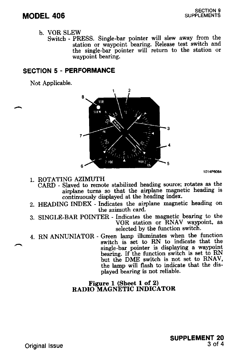
b. voR sLEw
Swikh - PRESS' Single-bar pointer q'ill slew away from the
station or wiypoint -bearing. Release test switch and
the single'bar -pointer will- return to the station or
wayPoint bearing'
SECTION 5 - PERFORMANCE
Not Applicable.
MODEL 406 SECTION 9
SUPPLEMENTS
1. ROTATINGAZIMUTH
- CARD - Slaved to remote stabilized heading source: r-otates as the
- iitpt o" turns so that the airplane magnetic heading is
coritinuougly displayed at the heading index.
2. HEADING INDEX - Indicates the airplane nagnetic heading on
the azinuth card.
3. SINGLE-BAR POINTER - Indicates the magnetic bearing to the
VOR etation or RNAV wa1rpoint, as
selected bY the frrnction swikh'
4. RN ANNUNIATOR - Green lamp illuminates when the function
switch is ;ret to RN to indicate that the
single-bar pointer is displaying a wavpqilt
beaiins. If ihe tunction iwitch is get to RN
but ttie DME switch is not set to RNAV,
the lamp will flash to indicate that the dis-
PhYed 6earing is not reliable.
Ficure I (Sheet I of 2)
RADIO_MAGNETIC INDICATOR
SUPPLEMENT 20
3of4
Original lssue
SECTION 9
SUPPLEMENTS
SUPPLEMENT 20
4ot4
5. NAV 1/NAV z/RN FUNCTION
SWITCH - Selects signals from NAV 1 or NAV 2 VHF navigation
receiver or RNAV computer for display by the single-
bar pointer.
6. ADF FUNCTION SWITCH
(Not on IN-10048) - Selects signals fmm ADF 1 or ADF 2
display by the double-bar pointer. Not
with single ADF and optional RNAV.
MODEL 406
for
used
7.
8.
DOUBLE-BAR POINTER - Indicates bearing of selected ADF sta-
tion.
VOR SLEW
SWITCH - Momentary contact swit h used to verifu the displayed
VOR or RNAV station bearine. When the switch is
pressed, the single-bar pointei slews away from the
station bearing; when the switch is released, if equip-
ment operation is normal, the pointer will return to the
station bearing.
Figure 1 (Sheet 2 of 2)
RADIO MAGNETIC INDICATOR
Original lssue
SECTION 9
SUPPLEMENTS
TRANSCEIVER (HF-220)
SECTION 1 . GENERAL
This supplement provides information which must be observed when
operating [he HF-220 transceiver'
Description
The HF-220 system provides simplex operation 9!-aly o^le of 210'000
" oi'."r""-t"t-alJ"t"t" Fi"q"""iii.-iiitti-r tle 2.000Q.1g 22'9999 MHz
^ i'fiil;;;;;*s"-ii."qretdv. "i-i"Le i" roo H")' In addition' the HF-220
^;-r.ild;; 16 sep'arate "h*"in i[ut 8un be programmed fior either sirnplex
it-fruli-aupf"i operation throughout the ian-ge' -The -priryrv, qnelll-s
;oa;;;il;it tiaeband (USB, TEL A3A, or TEL ASJ modes); however'
ii e*frl uqoiualent signal (upplr sideband with the carrier inserted ) can
te iransm-itted when-operatitt-iwith stations having only AM capability'
The HF-220 syst€m consists of a TCR-220 Transceiver (100-watts)' a
pdfilzoii p"*"i'nritbrilt"t, i--cil--zzo Conttol and the accessory AAC-
ioo Automatic Antenna CouPler.
SECTION 2 . LIMITATIONS
Not ApPlicable.
SECTION 3 - EMERGENCY PROCEDURES
Not APPlicable.
SECTION 4. NORMAL PROCEDURES
1. To Receive
a. HF COM Swikh - ON'
l. fff COfuf Audio Switrh - SPEA4ER or PHONE (on Audio
Control Panel)'
c. MODE CONTROI
" itii6iff;dt--ru-nN "to94q"9-qnil .39lec!^{esired rnode of
tp;t"tioti tVss,eM, TEL A3A or TEL A3J)'
Ali;-il; tttittui' *ut-ttp (time required for
freouencv standard to stabilize) '
d. V (Volume Controli - TiJRN control clockwise to vary the
audio gam (lnner Knoor.
SUPPLEMENT 21
1of 4
MODEL 406
Original lssue
sEcroN I
SUPPLEMENTS MODEL 406
g. Squelch Control - ADJUST counterclockwise for nornal
output; .then, slowly adjust clockwise
the recelvef $ srlent.
h. Clarifier Control - ADJUST when upper sinele sideband RF
signal is being received for haximum clarity.
Adjust V (volume) control for comfortable
listening level.
To turn the HF system antenna coupler to the frequency (channel)
select€d, rotat€ the V- (volume) Knob oui of the off det,int ai-rd allow f S
minutes warmup. Key the transmitter by momentarily pressing micro-
phone button. The 4ritenna coupler will tune automatiially andi steady
tone will be heard during the tuning cycle. Nonnal turning cycle requires
5 to 10 seconds. Within one seconii aher completion of ai,tinna coupler
tuning cycle, the tone will cease, indicating that the system is ready for
use. If the antenna coupler does not tune afLer 30 seconds, the tone will
begin to "beep" indicating that a fault has occurred, in which case,
rechannel and initiate a new cvcle.
When tuning is complete, slowly rotate squelch control to desired
squelch threshold. During reception (except foi AM mode) adiust clari-
fiir control for maximum signai clarity or most natural sounding voice.
no18e
until
SUPPLEMENT 21
2ot 4
If microphone for HF-220 system is wired.
through au.dio panel, ensure HF COMM is se-
lected before proceeding.
e. CHANAREQ SWITCH - SELECT desired method of frequen-
cy selection (FREQ/CHAN) with
two position switch.
f. CHANNEL/FREQUENCY
CONTROLS - SELECT frequency or channel using the dual
rotary frequency/channel select switc-hes. If se-
le cting a channel, use the pullout
channel/frequency card to correlate channel
number and frequency.
DO NOT ROTATE SqUELCH CONTROL TOO
FAS'T. SQUELCH CIRCUIT HAS A RELA-
TIVELY LONG TIME CONSTAN" AND RO,
TATING KNOB TOO FAR MAY RESULT IN
MISSED CALLS ON SOME OF THE
WEAKER SIGNA'S.
Original lssue
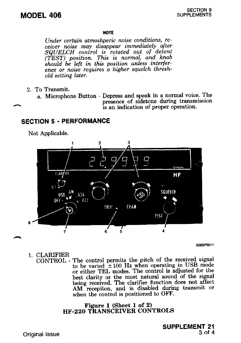
MODEL 406 SECTION 9
SUPPLEMENTS
1{OTE
IJnder certain atmoshperic noise conditions, re'
ceiuer nnise may disappear immediately a[ter
SOUELCH coniroL ts' rotdted out of d,etent
(TEST) position. Thi"s is normal, and hnob
ihoutd bi lcft in this position unlcss interfer-
ence or noise requires i higher sEnlch thresh-
old, setting Later.
2. To Transmit.
a. Microphone Button - Depress an{ sp-eak in a normal voice- The
pr$ence of sldetone dunng lransmEsron
rs an indication of proper operation'
SECTION 5 - PERFORMANCE
Not Applicable.
60a5P€011
1. CLARIFIER
COllinOl - The control permits the pitch of the received signal
to be varied 1100 Hz when operating in USLt mode
or either TEL modes. The control is adjusted for the
best clarity or the most natural sound of the signal
being received. The clarifier function does not affect
AM "recepiton, and is disabled during transmit or
when the-control is positioned to OFF.
Figure I (Sheet 1 of 2)
Id.F.22O T-RAN SCEIVER CONTROLS
SUPPLEMENT 21
3of4
Original lssue
SECTION 9
SUPPLEMENTS MODEL 406
FREQUENCY/CHANNEL
DISPLAY - The six-digit frequency/channel display indicates the
selected operating frequency or channel that is selected
with the dual rotary frequency/channel select switches.
The display brightness is controlled remotely by a
dimming pot€ntiomet€r or a variable dimming voltage
independent of the integral panel lighting dimming
control.
3. CHANNELAREQUENCY
CONTROLS - Two double concentric knobs provide for the selec-
tion of 210,000 frequencies wiih the FREQ/CHAN
switch in FREQ. In CHAN position, the knobs
select any of the 16 programmed channels (the dis-
play will indicate 01 through 16).
SQUELCH
CONTROL - The rotary squelch knob provides control of the
squelch threshold. Setting the control too far clock-
wise can result in blocking out weak signals. When
the SQUELCH control is in the TEST position, the
squelch circuit is, in effect, removed from the receiver
audio circuits. In this position msximum backcround
noise (depending on V- control setting) will be -beard.
Rotatins the control clockwise sets the souelch
thresholai required for reception.
CHANNEL/FREQUENCY
CARD - A pullout card at the lower e&e of the control Danel
provides an index of frequencies -programmed for eath of
the 16 channels.
CHANAIIEQ
SWITCH - T\ro-position switch selects the freouencv tunine meth-
od. I;r FREQ, the frequency is disirlayei to up- to six
digits which are controlled by all of the
frequency/channel eelector switches. In CHAN, the
channel is displayed in two digits which are controlled
by any one ofihd frequency/ch-annel selector switches.
VOLUME CONTROL - Varies level of audio gain.
MODE CONTROL - Select.s syst€m mde of operation.
OFF - Controls power to the system.
USB - Selects upper sideband operation for long-range voice com-
munications.
AM - Selects compatible AM operation and full AM reception.
TEL A3A/A3J - Used for com-munications with public 'correspon-
dence coastal stations in the maritime servlces.
and other radio-telephone services.
7.
8.
Figure I (Sheet 2 of 2)
HF.22O TRANSCEIVER CONTROLS
SUPPLEMENT 21
4ot4 Original lssue
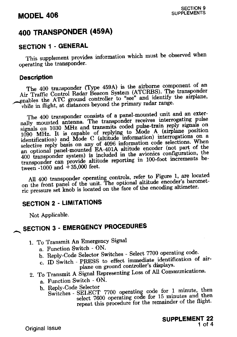
This supplement prowides information which must be observed when
operating the transponder'
DescriPtion
Atl+:"rl!:3r*ff *ilf F":"3:'3l.dP'i"$+t!"Si"ttrlHlidl.H
^lti'"Uiliii" .-etd-gtou"a controller-to "see" and 'identifv^ the arrpnne'
^"t'ii. t iiiittt, at d-istances beyond the primary raclar range'
The 400 transponder consists of a panel-morrlted git-Td sn ext€r-
nallv mount€d ur,*oou. , o"*J"ospo'nder. teceives itttenog€ting -Prnse
l1?ll'a"*""i'loao -t'tE and transmiti coded -Fulsc-rr.ain r-eplv sle-nals on
l,o;s"lxli;.,*'i#;*""";iJ,:l*l**'*Stnir'g'r"'ru"-L"";1":
selective reply basis on anv o)i iridd'i"-rot-"tion code selections' When
an optional p,anel-mount€d ee-+"Oia ;nqtd" encoder (not oart of the
400 transponder .v",'-r o il"tui"a iii- the a"io"ics configriration' the
transDonder can provrde tttffi;;;"tdt i; 100-foot inirements be-
tweei -1000 and + 35'000 feet'
All 400 transponder.operating controls' r-efer.to 'Figure I' are located
on the front palel or.tne ""ii' ti" -i-pil"""t- altitude irrcoder's baromet-
ric oressure set l(noD rs t*ut"a o" ttt"'t""e of the encoding altimeter'
SECTION 2 . L]MITATIONS
Not APPlicable.
^ sEcrloN 3 - EMERGENCY PROCEDURES
1. To Transrnit An Emergency Signal
a. Function Switch - ON'
U. n ptv-Cod" Selector Switches - Select ??00. operating code'
;. 6'S;t,"h PBESS to effect immediate- identification of air-
pnne on ground controller's disTlays'
2. To Transmit e SUnaf Reiresenting Loss of All Communications'
a. Function Switch - ON'
b. RePlv-Code Selector
"' 's"i'ii'.n!. :-sei-ech zzoo operating code. for I minute'' then
select ?6b0 opetuiing code for 15 minutes and then
."p"u" ttiJ pi[""J"i8 foi the remainder of the flight'
MODEL 406
4OO TRANSPONDER (4594)
SECTION 1 . GENERAL
SECTION 9
SUPPLEMENTS
SUPPLEMENT 22
1of 4
Original lssue
c. ID Switch - PRESS to effect immediate identi{ication of air-
plane on the ground controller's display.
SECTION 4. NORMAL PROCEDURES
1. Before Takeoff.
a. Function Switch - SBY. Allow 30 Seconds Warmup.
2. To Transmit Mode A (Airplane Position ldentifrcation) Codes In
Flight.
a. Reply-Code Selector Switches - SELECT assigned code.
b. Function Switch - ON.
c. DIM Control - ADJUST light brilliance of replay lamp.
IIOTE
During normaL operation, with the function
suilc\ in the ON position, the REPLY lnrnp
will flnsh which indicates transponder is reply-
ing to inteffogations.
d. ID Button - PRESS nomentarily when instruct€d by ground
controller to "squaw-k IDENT". REPLY iadp wi
glow steadily, indicating IDENT operation.
3. To Transmit Mode C (Altitude Information) Codes In Flight.
a. Barometric Pressue Set Knob - DIAL assigned barometric
pressure.
b. Reply-Code Selector Switches - SELECT assigned code.
c. Function Switch - ALT.
ltotE
OWh.en directed by ground controlLer to "stop
altitude sEnwh", turn function switch to ON
for Mode A operatinn on$t.
OPressure altitude is transnitted. and conuer-
sion to indicated, altitule is d.one in ATC corn-
puters. Altitude squawh wiLl agree with indi-
cated. altitude when altimeter setting in use fut
the ground controll.er is set in the altitu.de en-
coder.
d. DIM Control - ADJUST light brilliance of reply lamp.
4. Self-Test
a. Function Switch - SBY and wait 30 seconds for equipment to
warm up.
b. Function Switch - ON.
c. TST Button - PRESS. Rrply larnp should light brightly regard-
less of DII\[ c-ontroi settine. - -
SECTION 9
SUPPLEMENTS
SUPPLEMENT 22
2ot4
MODEL 406
Original lssue
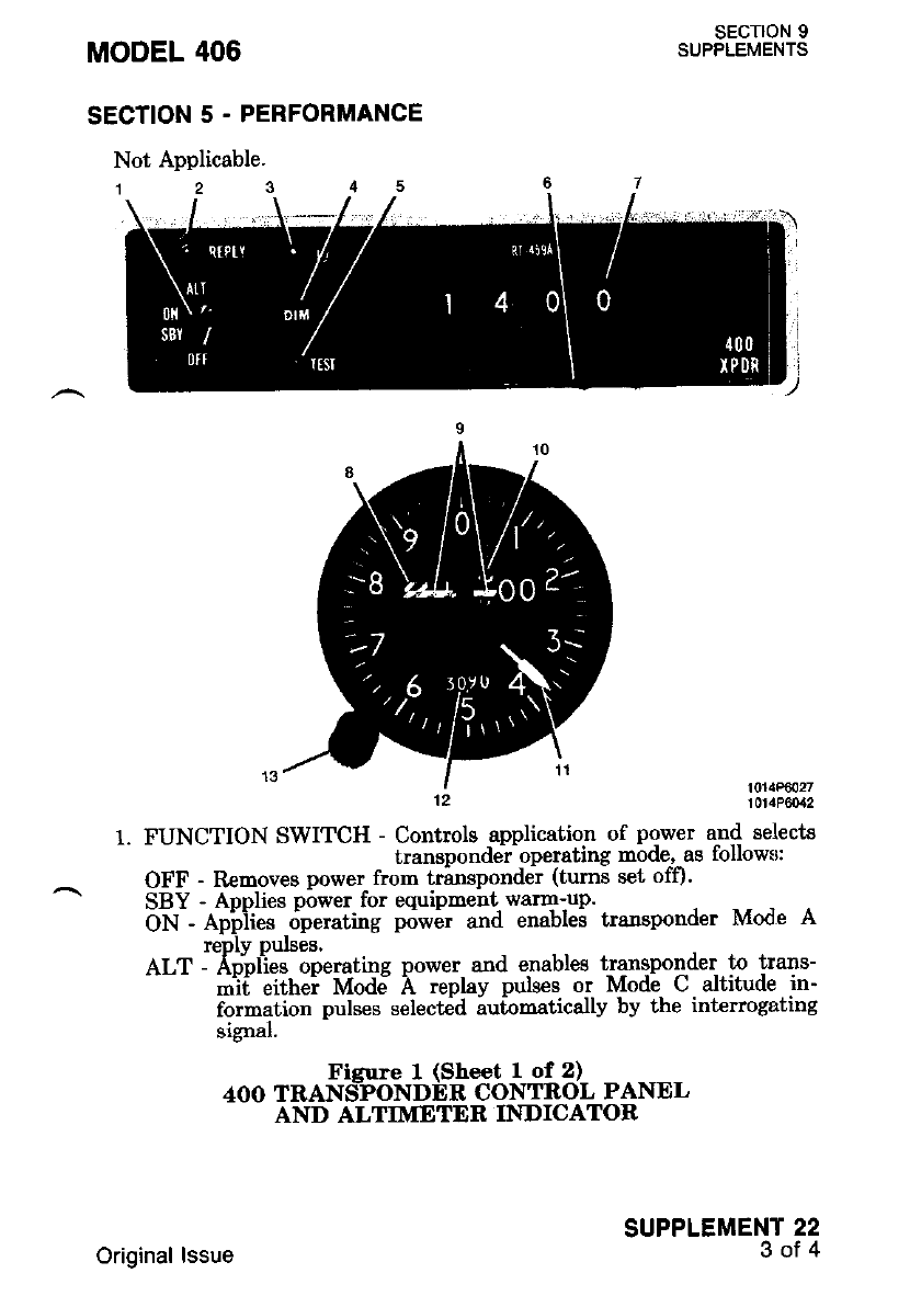
MODEL 406
SECTION 5 . PERFORMANCE
Not Applicable.
SECTION 9
SUPPLEMENTS
1014P6027
10tlP6O:12
SUPPLEMENT 22
3of4
FUNCTION SWITCH - Controlg -application of power and select's
transponder operatlng mode. as tollowll:
OFF - Rcmoves power from trirnspondeir (tums set off).
SBY - Applies power for equipment warm-up.
Otl - &biies riperating p6wir and enables transponder Mode A
reply pulses.
ALT - Aooiies operatinq power and enables transponder Lo trans-
mii eithei Mode A replay pulses or Mode C altitude in-
formation pulses select6d iu[omatically by the interrogating
srgnar.
Figure I (Sheet 1 of !)
4OO TRANSPONDER CONTROL PANEL
AND ALTIMETER INDICATOR
Original lssue
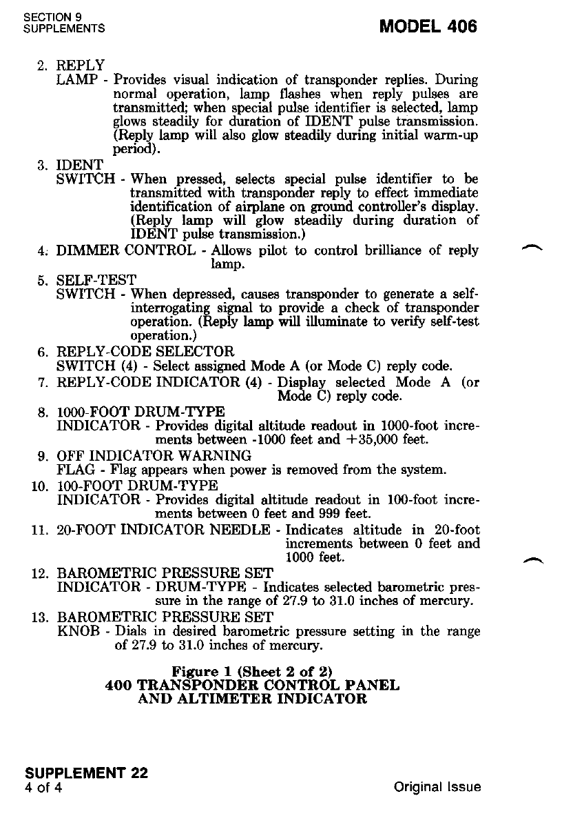
sEcTroN 9
SUPPLEMENTS
SUPPLEMENT 22
4ot4
t
6.
7.
8.
MODEL 406
REPLY
LAMP - Provides visual indication of transponder replies. During
normal operation, lamp flashes when reply pulses are
transmitted; when special pulse identifier is selected, lamp
glows steadily for duration of IDENT pulse transmission.
(Re.ply. la'np will also glow steadily during initial warm-up
penodr.
IDENT
SWITCH - When pressed, selects special pulse identifier to be
transmitt€d with transponder reply to effect immediate
identification of airplane on ground controller's display.
(Reply lanp will glow eteadily during duration of
IDENT pulse transmission. )
DIMMER CONTROL - Allows pilot to control brilliance of reply
lamp.
SELF-TEST
SWITCH - When depressed, cauaes transponder to generate a self-
int€rrogating signal to provide a check of transponder
operation. (Reply hmF will illuminate to verify self-test
operation,)
REPLY-CODE SELECTOR
SWITCH (4) - Select assigned Mode A (or Mode C) reply code.
REPLY-CODE INDICATOR (4) - Display selected Mode A (or
Mode C) reply code.
IOOO-FOOT DRUM-TYPE
INDICATOR - Provides digital altitude readout in 1000-foot ince-
ments between -1000 feet and 435,000 feet.
OFF INDICATOR WARNING
FLAG - Flag appears when power is removed from the system.
IOO.FOOT DRUM-TYPE
INDICATOR - Provides digital altitude readout in 100-foot incre-
ments between 0 feet and 999 feet.
20-FOOT INDICATOR NEEDLE - Indicates altitude in 20-foot
increnents between 0 feet and
1000 feet.
BAROMETRIC PRSSSURE SET
INDICATOR - DRUM-TYPE - Indicates selected tmrometric pres-
sure in the range of 27.9 to 31.0 inches of mercury.
BAROMETRIC PRESSURE SET
KNOB - Dials in desired barometric pressure setting in the range
of 27.9 tn 31.0 inches of mercury.
Figure I (Sheet 2 of 2)
4OO TRANSPONDER CONTROL PANEL
AND ALTIMETER INDICATOR
9.
10.
11.
Original lssue
WEATHER RADAR (RDR-160)
SECTION 1 . GENERAL
This supplement provides information which must be observed when
oDeratins ilie RDR- i60 Weather Radar.
Description
The Bendix RDR-160 Weather Radar is used to detect significant
enroute weather formations within a range of 160 -nautical miles to
oreclude undesirable penetrarion of heavy wearher and its usually asso-
^iiated turbulence. Th; indicator is mounled in the center of the instru-
ment nanel. The RDR-160 svstem consists of an indicator and a com-
binati6n transceiver/parabolii-dish antenna located in the nose radome'
Power for the system is provided by the airplane's 28-volt system. AII
controls for the system, refer to Figure 1, are located on the lower
section of the frorit panel. Internally generated range marks appear as
evenlv sDaced concentric arcs on the display to assist in determining
ranee to- the weather Larqet. Relerence marks on each side of the zero
heaiine assist in determining azimuth bearing wealher targets. A secon-
dary o6jective of the weathei radar system is gathering and presentation
of terrain data.
SECTION 2 - LIMITATIONS
1. Do not operate radar within 15 feet of ground personnel or contain-
ers holding flammable or explosive material
2. Do not operate radar during fueling operaiions.
3. When nreflishtine the radar svstem, ensure that the airplane is
facing away "from-buildings or large metal struclures that are likely
to refrect significant amr,'unts of radar energy back into the sysl,em. -
4. Do not operate radar above 20,000 feet flight altitude. I
SECTION 3. EMERGENCY PROCEDURES
Not Anolicable.
MODEL 406 sEcTtoN I
SUPPLEMENTS
SUPPLEMENT 23
1ot4
1 June 1987
SECTION 9
SUPPLEMENTS MODEL 406
SECTION 4 - NORMAL PROCEDURES
1. Preflight Test
a. Function Switch - TEST. Allow 2 minutes warm-up.
b. Wr Gain Switch - Wx.
c. Hold/Scan Switch - SCAN.
d. Tilt Switch - t4 degrees.
e. Brt Switch - AS REQUIRED.
f. Self-Test - CHECK. Four eouallv sDacd ranse marks should
appear, no displayed "-noG" and tw6 distinci bright-
niis l'evels ihould appear. Strobe line shduld
smoothly sweep full 90 degrees.
(r) Hold/Scan Switch - HOLD. Strobe line should disappear
and test pattem should "freeze" on in-
dicator.
(2) Wx Gain Switch - Wx A. Test pattem should pulse on in-
dicator.
(3) Hold/Scan Switch - SCAN.
(4) Function Switch - 10 or 20. Ttansmitter on.
(5) Tilt Switch - VARY between 0 degrees and 15 degrees.
Close in ground clutter appears at lower tilt
settings and any local moisture laden weather
appears at higher tilt settings.
2. Normal Operation
a. Function Swit h - STBY. Allow 2 minutes warm-up.
b. Wx Gain Switch - GAIN. Adjust manual gain as required.
- Wx. For contour mode of operation.
c. Furction Switch - AS REQUIRED.
d. Brt Switch - AS REQUIRED.
e. Wx A Sqritch - AS REQUIRED.
f. Hold/Scan Switch - AS REQUIRED.
g. Tilt Control - AS REQUIRED.
SECTION 5 - PERFORMANCE
Not Applicable.
SUPPLEMENT 23
2ot4 Original lssue
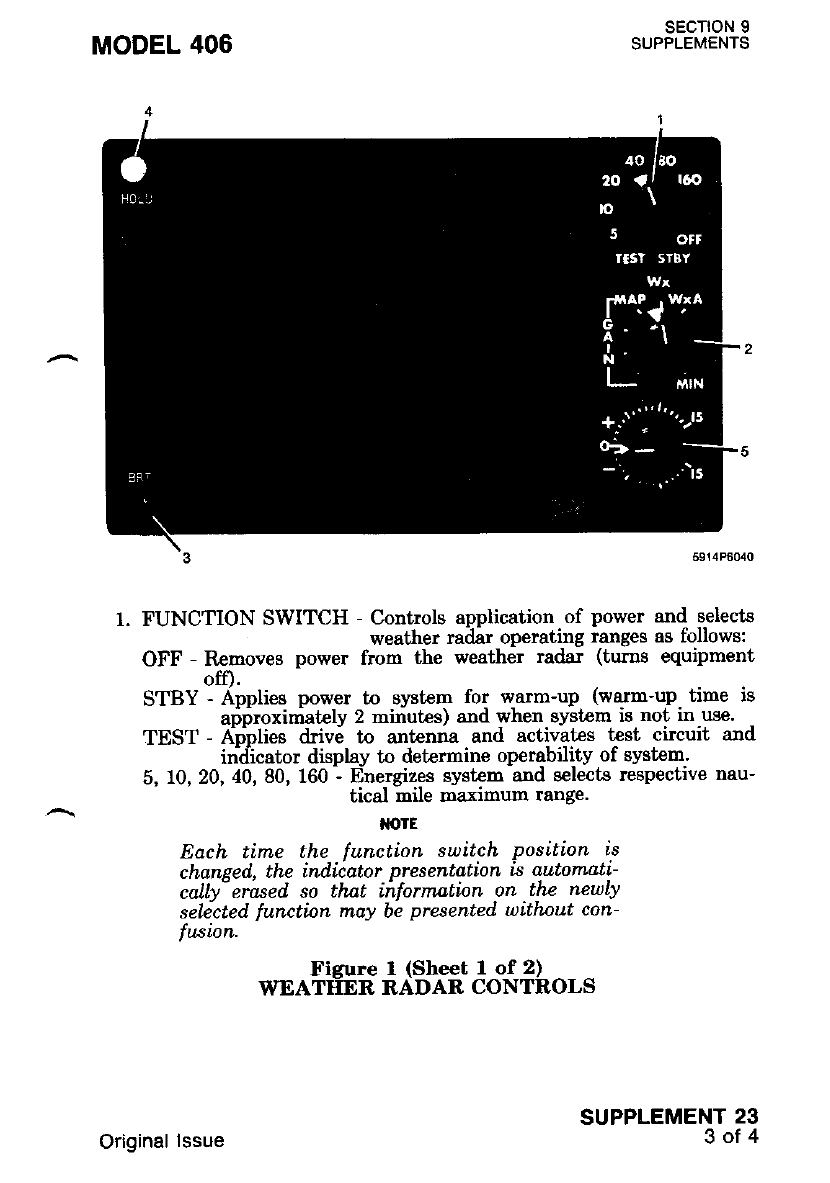
MODEL 406 sEcTroN I
SUPPLEMENTS
1. FUNCTION SWITCH - Cont_rols ap.plication. of power and selects
weather radar operating ranges as follows:
OFF - Removes power fron the weather radar (turns equipment
off).
STBY - Applies power to system for warm-up (warm-up time is
ari6roxiri,atelv 2 miriutes) and when system is not in use.
TEST - A;plies drive to antenna and activaLes test circuit and
in-ciicator display to determine operqbility of system.
5, 10, 20, 40, 80, 160 - Energizes system and selects respectrve nau-
tical mile maximum range'
M'TE
Each tirne the function switch position is
chansed. the indicator presentdtion is automati-
calty- erased so thnt ihformation on thz neuLy
selected functbn may be presented uithnut con-
fwion.
Ficure I (Sheet I of 2)
WEATTIER RADAR CONTROLS
SUPPLEMENT 23
3of4
Original lssue
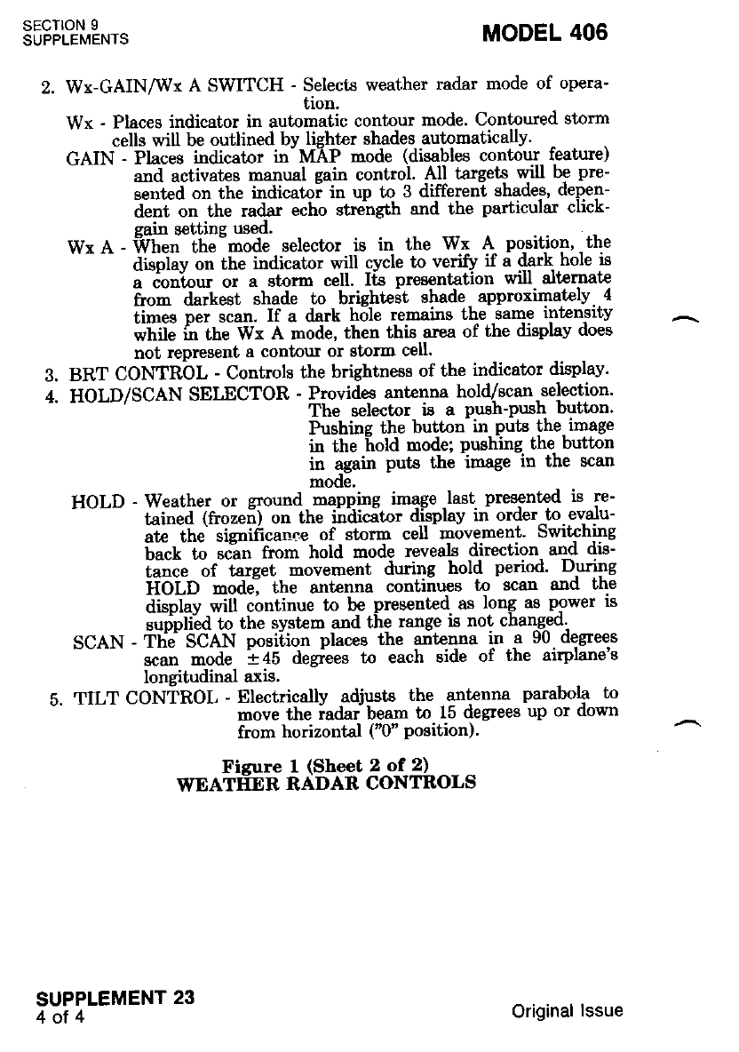
SECTION 9
SUPPLEMENTS MODEL 406
I
Wx-GAINAVT A SWITCH - Selects weather radar mode of opera-
tion.
Wx - Places indicator in automatic contour mode. Contoured storm
cells will be outlined bv liehter shades automatically'
GAIN - Places indicator in-MAP mode (disables contour feature)
and activates manual gain control. All taryets wi be pre-
sent€d on the indicatoi in up to 3 different shades, depen-
;;;;;;1il-ttd* "ilo "t""'"gttt and the particular click-
sain settine used.
Wx A - frhen the -mode selector is in the W: A- po-sition, the
' ' - - - aispdv on the indicator {ll cycle to veri$ if a dsrk,.hole is
a contour or a storm cell. Its presentation will alternate
from darkest shade to bright€st shade approximatcly. 4
ii-es Dit scan. If a dark hole remains the same intengiW
i'tti" fii tn" Wt A node, then thig area of the digplav does
not represent e contour or storm cell.
BRT CONTRbL - Controls the brightness of the indicator displav'
HOLD/SCAN SELECTOR - Pmvides antcnna hold/scan.selection'
The selector i8 a pu8h-push bugton'
Pushine the button in puts the image
in the f,old mode; Pushing the button
in again Puts the image in the scan
mode,
HOLD - Weather or ground mapping image .last presented is re-
--"-- tri"ea (fr"2efi) on the iititicito. display in order tn. evalu-
ate the sic"i6cao"e of storm cell movement' Switching
[""t to tc?" from hold mode reveals direction and dis-
iaoce of target movement during hold period' During
itOlb -6ael the antenna contiiues to scan and the
displav will continue tn be presented as long as power is
sudnlied to the svstem and the range i8 not changed'
SCAN - Tlie SCAN posiiion places the qnt€4na ln .a 90. degrees
-'--' ;; -oa" las degiees tn each side of the airplane's
longitudinal axis.
5. TILT CONiROL - Electricallv adjusts the antenna parabola to
move the iadar- beam to 15 degrees up or down
from horizontal ("0" Position)'
Figure I (Sheet 2 of 2)
WEATTER RADAR CONTROLS
SUPPLEMENT 23
4ot4 Original lssue
MODEL 406 SECTION 9
SUPPLEMENTS
WEATHER RADAR COLOR DISPLAY (RDR-160XD)
SECTION 1 . GENERAL
This supplement pmvides information which must be observed when
operating flie RDR-I60)O Color Display radar.
Descriptlon
The Bendix RDR-160XD Color Display radar is used to detect signifi-
cant enroute weather formations within a range of 160 nautical miles to
preclude undesirable penetration of healy weather and its usually asso'
biatcd turbulence. The indicatol is mounted in the center of the instru-
ment panel. The RDR-160XD svst€m consieta of an indicator and a
combiiation transceiver/parabolic-dish antenna located in the nose
radome. Power is provided by tlre airplane's 28-volt system. All controls
for the svstem are located on the front panel of the indicator, refer to
Fizure 1. The weather radar portion of the display consists of light,
mddium and heary rainfall areas shown in green, yellow and red respec-
tively. Internally generated range narks appear as evenly spaced concen-
tric arcs on the ilisplay to a-ssist in determining range to the weather
tarset or terrain feafure under observation. Azimuth reference marks are
als6 provided as an aid in determining the relalive bearing to the target.
Svstem function in use as well as the range and ralge marks in use are
dicitdlv disDlaved on the screen in the upper comers. The radar's hold
m6de nermiis ihe displav to be hozen on [[e screen for extended periods
in ordir to evaluate the'significance of storm movement. Switching back
to scan instantly reveals tf,e direction and distance the target has moved
durine the hold period In the weather alert mode, the display flashes a
warni-nq to the pilot of any heavy rainfall areas exceeding 0.47 inch (12
millirnelers) pef hour within the display range by altemately switching
the contour/normal display modes approximat€ly 4 times per ant€nna
scan. The pilot then sees the red portion of any storm cell as a flashing
on/off disDlav. Each time the operational mode of the system is changed,
a momentary digital display is presented on the indicator which shows
available ani aciive mode -dats -such as range/range narks and rainfall
intensity color key.
In addition to its primary function of weather detection, the radar
also enables mapping bf proirinent tprrain features such as lakes, bays,
rivers, inlets, shorelines, channel markers and offshore oil rigs.
SUPPLEMENT 24
1of 6
Original lssue
sEc'noN 9
SUPPLEMENTS MODEL 406
SECTION 2 - LIMITATIONS
1. Do not operate the radar system within 15 feet of ground personnel
or containers holding flammable or explosive material.
2. Do not operate the radar system during fueling operations.
3. When preflighting the radar system, ensure that the airplane is
facing away from buildings or large metal slructures Lhat are lrkely
- to refrect significant amounts of radar energy back into lhe sysl'em'
I a. Do not operate radar above 20,00d feet flight altilude.
t-
SECTION 3 . EMERGENCY PROCEDURES
Not Applicable.
SECTION 4 - NORMAL PROCEOURES
1. Preflieht Test
Function Switch - TEST. Allow 2-minute warm-up.
TILT Control - 0 degrees.
BRT Control - Mid-range posit ion.
Self-Test - CHECK:
(1) Test pattern should display five colored bands: starling
with Lhe closes[ band al the boltom ot the screen' lne
tiita" *itt be green, yellow, red, yello-w a.nd green. The red
batd t"ptesettti the most inlense'level. AII range marks will
be visibie and displayed in blue letters
tlolE
Width of test pdttern band's and position of
bands reiutiue to the range marhs is not criticaL
(2) MODE Buttons - Sequence to Wx A mode. The red test
band should alternate from red to black
approximately onc€ per second. Return
the mode to Wr.
(3) HOLD Button - PRESS. The word HOLD should flash in
the uPPer LH corner.
Function Switch - STBY. Ensute area ahead of airplane is i'lear
as sl'ated in Section 2 - Limitations of this
supplement.
Function Switch - ON. The indicator will automatically switch
to the Wx mode.
HOLD Button - Check OFF.
RANGE Buttons - 40-rnile range.
b.
c.
d.
h.
SUPPLEMENT 24
2ofo 1 June 1987
MODEL 406 SECTION 9
SUPPLEMENTS
i. TILT Control - Move UP in smal increments until a clear
picture of any local -weather appears' Close-in
lround targed may also appear in the display'
i. RANGE Buttons - Select remaining ranges and repeat TILT
control check.
k. FUNCTION Switch - STBY prior to taxi.
l. Checklist Display - If optional checklist dilplav system i-s in-
- st€I6d. refer to CC-2024A or CC-2024B
Checkl'ist Supplement for preflight test pro-
cedures.
2. Normal Operations
a. Function Switch - STBY. Allow 2 minutes warm-up'
b. MODE Buttons - AS REQUIRXD.
(1) Wr - For normal weather display.
(2) Wx A - For weather alert (flashing red area)'
(3) MAP - For terrain maPPing.
c. Function Switch - AS REQUIRED.
d. BRT Control - AS REQUIR,ED.
e. GAIN Control - AS REQUIRED (For Terrain Mapping Onlv)'
f. RANGE Buttons - AS REQUIRED'
g. TRACK Button - AS REQUIRED'
h. TILT Control - AS REQUIRED.
SECTION 5 . PERFORMANCE
Not Applicable.
SUPPLEMENT 24
3of6
Original lssue
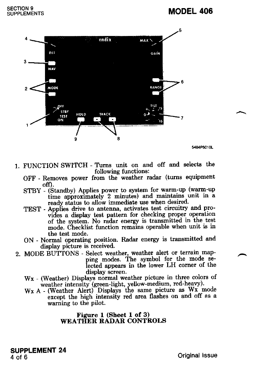
SECTION 9
SUPPLEMENTS MODEL 406
1. FUNCTION SWITCH - T\:ms unit on and off and selecte the
followine functions:
OFF - Removes power from the weather radar (tums equipment
off).
STtsY - (Standby) Applies power to system for warn-up (warm-up
- ii-" anbioxiiatelv 2 minutes) and maintains unit in a
readv stitus 16 altqw immsdiate use when desired.
tnST - lppiies drive to ant€nna, activates t€st circuitry and pro-
vides a display test pattern for checking proper operation
of the systim. No ridar energy is transmitted in the test
mode. Ciecktist function remains operable when unit is in
the test mode.
ON - Normal operating position. Radar enerry is transnitted and
display piiture is received.
2. MODE BUTTONS - Select weather, weather alert or -t€rrain-map-
ping modes. ihe symbol for the mode se-
iectid appears in the lower LH corner of the
displaY screen.
Wx - (Weather) Displavs' nornal weather picture in three colors of
weather ihtensity-(green-light, yellow-medium, red-he-ayy).
Wx A - (Weather Alert) Displays the same- picture as wx mode
ixcept the high int€ilsi[y red area flashes on and off ss a
warning to the Pilot.
Figure 1 (Sheet 1 of 3)
WEATIIER RADAR CONTROLS
SUPPLEMENT 24
4ofo Original lssue
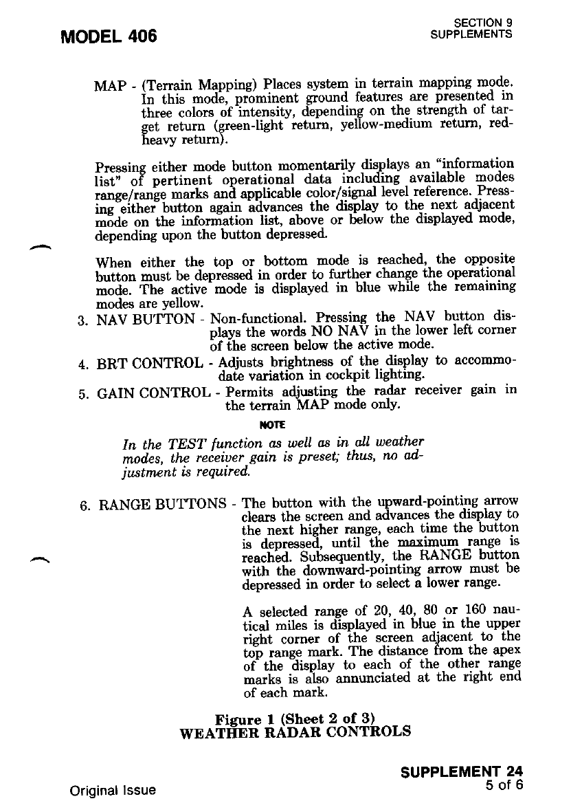
sEcroN I
SUPPLEMENTS
MODEL 406
MAP - (Terrain Mapping) Places system in terrain mapping mode'
in -itti" -oai, pr-ominent ground features are pres€nted in
ihrJe colors of intensity, depending on the strength of tar-
gJ t"td (green-light'ietuin, yefow-medium retum, red-
heaYy return).
Pressing either mode button momentarily displays an "information
li;;r;T ;;;li";l operational data iiclu4lng -available modes
.aoe"/ta"ie marks and applicable color/,sieqal level-reference' Press-
i;;";ith"; bttt"t again ibvances the dis-plav to the. next adjacent
mode on the information li.st, above or below the drsplayeo mooe,
depending upon the button depressed'
When either the top or bottom mode is reached, the oppgElt{
Uiift*r iiii.iu" depreised in order to-turther changp the operational
mode. The active mode is displayed in blue wh e the remarnmg
nodes are Yellow.
3. NAV BUT"TON - Non-tunctional. Pressing the- NAV button dis-
nlavs the words NO NAV in the lower left corner
bf ihe screen below the active mode'
4. BRT CONTROL - Adjusts brightness o-f !hq. {isplav to accommo-
date variation in cockprt lrghtrng'
5. GAIN CONTROL - Permits adjusting thc radar receiver gain in
the terrain MAP mode onlY'
llolE
In the TEST function as well as in al'l weather
inites, thc reieiuer gain is preset; thus, nn ad-
justment is required.
6. RANGE BUTTONS - The button with the upward-po-inting anow
clears the screen and advances the display to
the next higher range, each time the button
is depresseii, until the r""tjmun lange is
reachid' Subsequently, the RANGE button
with the downriard-riointing anow must be
deoressed in order tn select a lower range'
A selected ranqe of 20,40,80 or 160 nau-
tical miles is d-isplayed in blue in the upper
rielt corner of ihe screen adjacent to the
to"o ranee mark. The distance from the apex
of the lisplay to each of the. other- range
-.rt<J is a'lso annunciated at the right end
of each mark.
Fisure I (Sheet 2 of 3)
WEATtrER RADAR CONTROLS
SUPPLEMENT 24
5of6
Original lssue
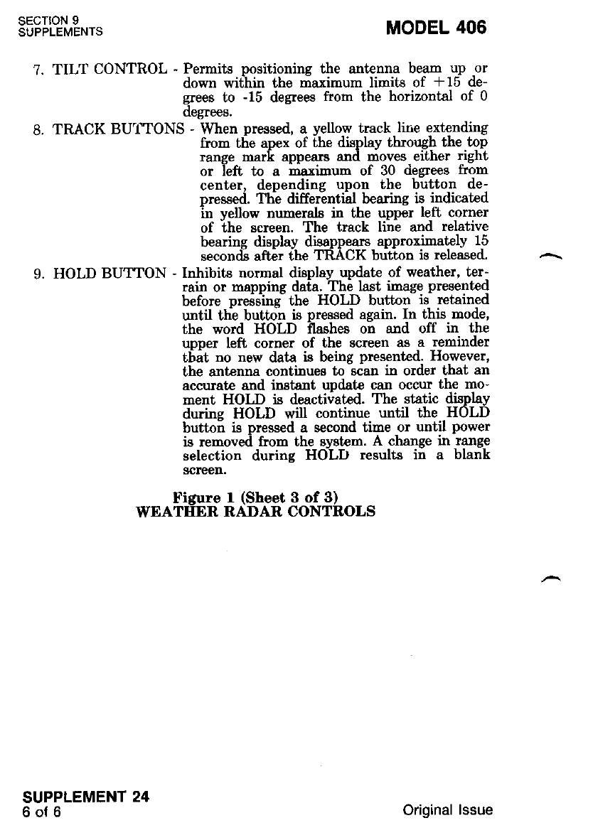
sEcTtoN 9
SUPPLEMENTS
1.
q
TILT CONTROL - Permits positionins the antenna beam up or
down wit'hin the maximum limits of *15 de-
gees to -15 degrees from the horizontal of 0
oegrees.
TRACK BU'f'TONS - When pressed, a yellow track lir'e extending
from the apex of the display through the.tgo
range mark appears and moves either right
or left to a mtximum of 30 degrees from
center, depending upon the button de-
pressed. The differintiirl bearing is indicated
in yellow numerals in the upper left corner
of the screen. The track line and relative
bearing display disappears approximately 15
seconds aft€r the TRACK button is released.
HOLD BUTTON - Inhibits normal display update of weather, ter-
rain or mapping data. The last image present€d
before oreisini the HOLD button is rctained
until thle buttdn is pressed again. In this mode,
the word HOLD ilashee on and off in the
upper left corner of the screen as a reninder
tbat no new data is being presented. However,
the antenna continues to iclan in order that an
accurate and instsnt updat€ can occur the mo-
ment HOLD is deactiiated. The static display
during HOLD will continue until the HOLD
butto; is pressed a second time or until power
is removed from the system. A change in range
selection durine HOLD results in a blank
screen.
MODEL 406
Figure I (Sheet 3 of 3)
WEATHER RADAR CONTROLS
SUPPLEMENT 24
6of6 Original lssue
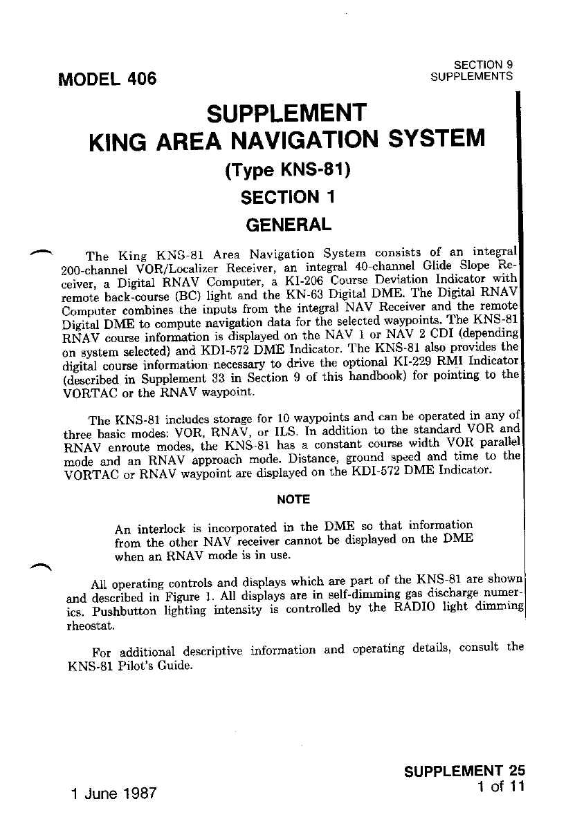
MODEL 406 SECTION 9
SUPPLEMENTS
i"it*,-.5igt"f iINAV Computer, a KI-206 Course Deviation Indicator with
i"-oil tu"L--"ouo" (BC) light and the KN-63 Digital DME The Digitsl RNAV
b-"-ptt"" combines the inputs from the integral NAV,Receiver and the remote
Oisilf O\ae to compute uivigation data for the selected walpoints' The KNS-81
'RiiAV ;";;; iti";Jiation is iisplaved on the NAV 1 or NAV 2 CDI (depending
"" "vtt"- *L"t"al and KDI-5?2 DME Indicator' The KNS'81 also provides the
Jl"it"t "ou""" infoimation necessary to ddve the optional KI-229 RMI Indicator
dA;;b"d t" Supplement 33 in Seltion 9 of this handbook) for pointing to ihe
VORTAC or the RNAV wa5point.
SUPPLEMENT
KING AREA NAVIGATION SYSTEM
(Type KNS-81)
SECTION 1
GENERAL
The King KNS-81 Area Navigation System consistsil, "1 t"t
200-channel VbR/Localizer Receiver, an integral 40-channel Glide.-Slope
The KNS-81 includes storage for 10 walrpoints and can be operat€d in any of
tftr"" ilu"i" modes: VOR, RNAV, or ILS In addition to the standald^YoR and
;iN;v ;";;;"des, ihe xNS-gl has a constsnt course width VoR parallel
;;; and un nNev approach mode. Distance, ground snl$3ng time to the
V-OfifiC - nUeV waffoint are displaved on the KDI-572 DME Indicat'or'
NOTE
An interlock is incorporated in the DME so that infolmation
from the other NAV ieceiver cannot be displayed on the DME
when an RNAV mode is in use.
AII operatins controls and displays which are part of the KNS-81 are shown
and described in Figurc l. All displays are in seU-dirnming gas-disc-harge numer-
ics. iushbutton lighting intensitv ii controlled bv the RADIO light dimming
rheostat,
For additional descriptive information and operating details' consult the
KNS-81 Pilot's Guide.
SUPPLEMENT 25
1 of 11
'1 June 1987
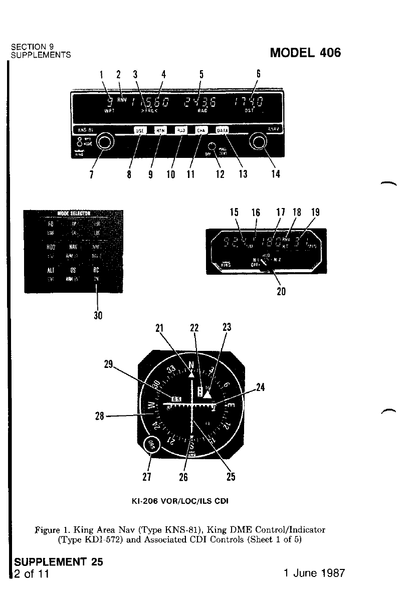
SECTION 9
SUPPLEMENTS
SUPPLEMENT 25
2ot11
Kr-206 VOR/LOC/|LS CDI
Figure 1. King Area Nav (Tlpe KNS-81), King DIr{E Control/Indicator
(Trpe KDI 572) and Associated CDI Controls (Sheet 1 of 5)
MODEL 406
1 June 1987
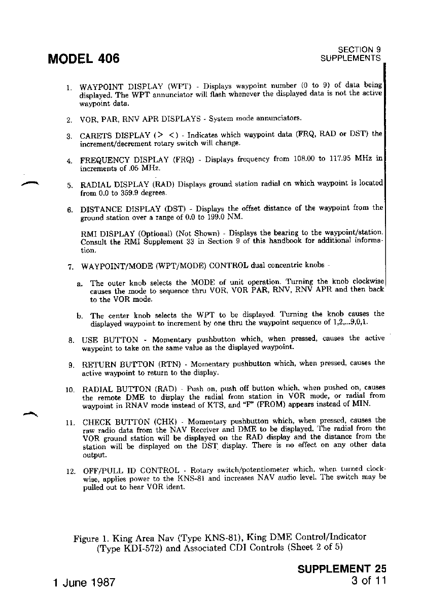
MODEL 406 sEcroN I
SUPPLEI\,1ENTS
2.
3.
WAYPOINT DISPLAY (WPT) Displavs warpoint number lu to 9) of data beins
djsplayed. Thp \tPT annun.iaror sill flish *henever the displaved dat.a is nol the acrivc
VOR, PAR, RNV APR DISPLAYS ' Svst€m mode annunciatorc'
CARETS DISPLAY (> <) 'Indicates which wavpoint data (FRQ, RAD or DST) the
inqement/decrement rotary switch will change
FREQUENCY DISPLAY (FRQ) ' Displavs frequencv from 10800 to 11795 MHz in
incremenls of .05 MHz.
RADIAL DISPLAY (RAD) Displays ground station radial on which walpoint is located
from 0.0 to 359.9 degtees.
DISTANCE DISPLAY (DST) - Displays the offset disbnce of the wavpoint ftom the
ground station over a range of 0.0 to 199.0 NM.
RMI DISPLAY (Optional) (Not Shown) ' Displavs tbe besring to the walpoint/station'
Consult the RMI Supplement 33 in S€ction 9 of this handbooL for additional informa-
WAYPOINT/MODE (WPT/MODE) CONTROL dual concentric knobs
a. Th€ outer knob selects the MODE of unit operation. Turning the knob clockwise
causes the mode to sequence thru VOR, VOR PAR, RNV, RNV APR and then back
b. The center knob selects the WPT to be disptaved Tuming the knob causes the
displayed wawoint to incrcment by on€ thru th€ walpoint sequence of 1,2" 9'0,1'
L USE BUTTON - Momentary pushbutton which' when pressed, causes the active
SUPPLEMENT 25
3 of 11
7.
L
watpoint to take on the same value as the displayed wawoint
RETURN BUTTON (RTN) - Mornentary pushbutton which, when press€d, cauees the
active wa,?oint to rcturn to the display
RADIAL BUrION (RAD) Push on, push off button which, when pushed on, causes
the remote DME to display the radial from ststion in VOR mode, or radial from
wawoint in RNAV mode inslead of KTS, ald "F" (FROM) appeam inst€ad of MIN'
CHECK BUTTON (CHK) - Moment€rv pushbutton which, when pressed, causes the
mw radio data ftom the NAV Receiver and DME lo be displaved The radial from the
VOn eround station will be displayed on th€ RAD displav and the distsnc€ from tlle
shtio; will be dsplayed on th; DST display. There is no €ffect on anv other data
output.
12. OFF/PULL ID CON'IROL - Rotarv swttch/potentio-meter.which' when turn€d dmk-
-- *i"", "ppli". power to the KNS-SI ;nd increases NAV audio l€vel The switch mav be
pulled out to hear vOR ident.
Figure 1 King Area Nav (Type KNS-81), Kine DME Control/Indicator
(Type KDI-5?2) and Associated CDI Controls (Sheet 2 of 5)
1 June 1987
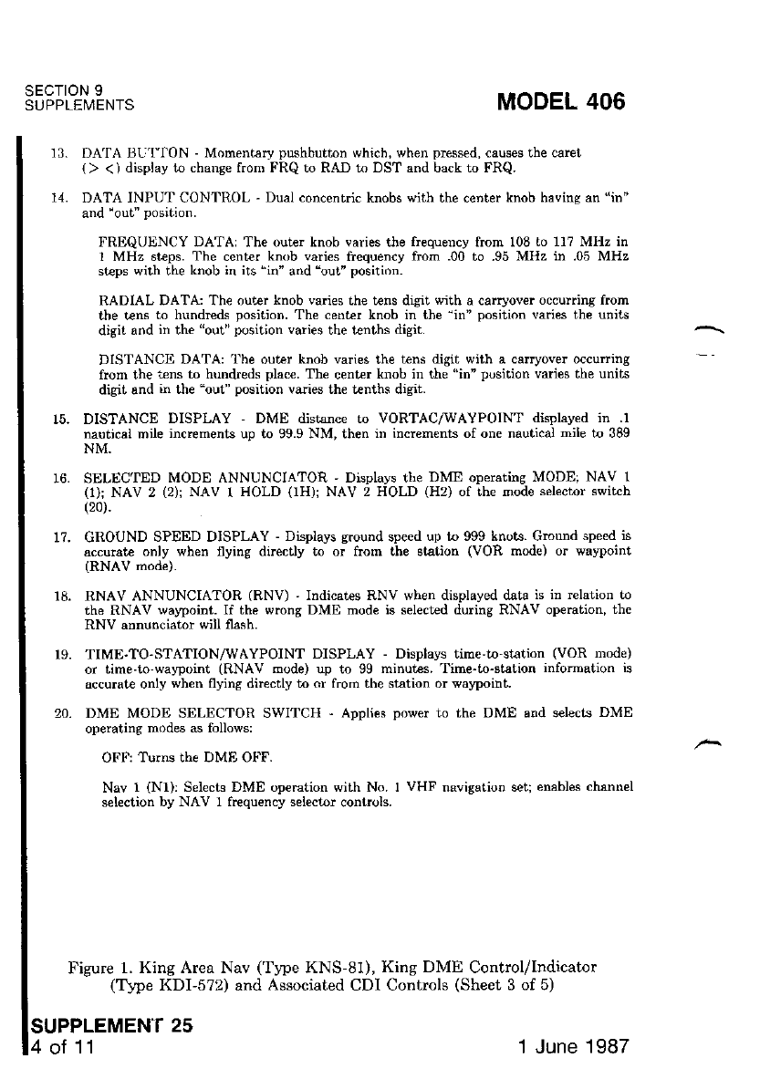
SECTION 9
SUPPLEMENTS MODEL 406
13. DATA tsU'flON - Momentsry pushbutton which, when prcssed, causes the caret
() <) display to change from FRQ to RAD to DST and back to FRQ.
14. DATA INPUT CONTROL - Dual concentric knobs with the center knob havinq an "in"
and .out" position.
FREQUIINCY DATA: The out€. knob varies the fr€quency from 108 lo 117 MHz in
I MHz steps. The cent€r knob varies ftequency fmm .00 to .95 MHz in .05 MHz
steps with the knob in iis "in" and 'out" position.
RADIAL DATA: The outer knob va.ies the t€ns digit q'ith a carryover occuning from
the tens to hundrcds position. The center knob in tbe'in" position varies the units
digit and in th€ "out" position varies the tenths digit.
DISTANCE DATA: 'l'he outer knob varies the tens digit with a canyover occurr;ng
ftom the "ens to hundreds plac€. The cent€r knob in the "in" position varies the units
digit and in the "out" position varies the t€nths digit.
15. DISTANCE DISPI"AY DME distance to VORTAC,AMAYPOINT displayed in .l
nauticsl mile increments up to 99.9 NM, then in increments of one nautical mile to 389
NM.
16. SELECTED MODE ANNUNCIATOR ' Displays the DME operatins MODE; NAV 1
(1): NAV 2 (2); NAV r HOLD (1H); NAV 2 HOLD (H2) of the mode selector switch
(20).
1?. GROUND SPEED DISPLAY - Displays ground speed up to 999 knots. Gmurd speed is
accurate only when flying directly to or ftom the station (VOR mode) or waypoint
(RNAV rnode).
18. RNAV ANNUNCIATOR (RNV) 'Indicates RNV when displayed data is in r€lation to
the RNAV walpoint. If the wrong DME mode is select€d during RNAV operation, th€
RNV annunciator will flash.
r9. TIME-TO-STATION/WAYPOINT DISPLAY - Displays time'to-station (VOR mode)
or time-to waFoint (RNAV mode) up tr] 99 minut€s. Time-to-shtion infomation is
accurate only when flying dircctly to cr from the station or waypoint.
20. DME MODE SELECTOR SWITCH ' Applies power to the DME and selects DME
operating modes as follows:
OFF: Turns the DME Ot'F.
Nav I (N1): Selecre DME op€mtion with No. I VHF navisation seq enables chann€l
selection by NAV I frequency selector controls.
Figure 1. King Area Nav (Type KNS-81), King DME Control/Indicator
(Trpe KDI-572) and Associated CDI Controls (Sheet 3 of 5)
SUPPLEMEN'T 25
of 11 1 June 1987
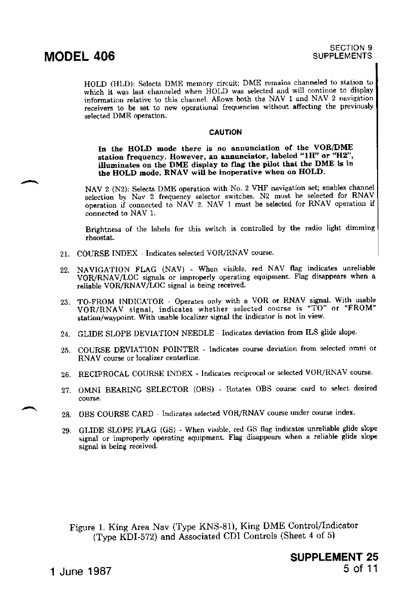
MODEL 406 sEcloN 9
SUPPLEI\,'IENTS
Rotates OBS course card to select desired
2t.
22.
24.
25.
26.
27.
28.
29.
HOLD (HLD): Selects DME memory circuiti DME remains channeled to station.to
which it was last channeled when HOLD was sel€ct€d and will continue to displav
information .elative to thjs channel Allows both the NAV r and NAV 2 navigation
receivers to be set to new operational frequencies without affecting the pr€viou.ly
selected DME operation.
CAUTION
h the EOLD mode there is no annunciation of the VOR/DME
station frequency. However, an snnunciator, labeled "lH" or "H2"'
illundinat€s on the DME display to flag tbe pilot thrt the DME k in
the HOLD dode, RNAV will b€ inoperative wher on HOLD.
NAV 2 (N2): Selects DME operation with No. 2 VHF navisation set; enabl€s clannel
selection by Nav 2 frequeniy s€l€ctor switches. N2 must b€ select€d for RNAV
operation if connect€d to NAV 2. NAV 1 must be selected for RNAV op€ration if
connected to NAV 1.
Brightness of the labels lor this swilch is controlled bv the radio lighi dimming
COURSE INDEX Indicates select€d VOR/RNAV coune
NAVICATION FLAG (NAV) - When visible, red NAV flas indicatrs unreliable
VOR/RNAV/LOC signals or improperly operating equipment. Flag disappears when a
reliable VOR/RNAV,/LOC sisnal is being rec€ived
TO-FROM 1NDICATOR Operates only wit}l a VOR or RNAV signal With usable
VOR/RNAV signal, indicates whether selected course is "TO" or "FROM"
station/walpoint. With usable localizer signal th€ indicator is not in view.
GLIDE SLOPE DEVIATION NEEDLE lndicat€s deviation from ILS slide slope'
COURSE DEVIATION POINTER - Indicates couFe deviation from select€d omni or
RNAV course or localiz€r centerlin€
RECIPROCAL COURSE INDEX - Indicat€s reciprocal or s€lecied VOR/RNAV course
OMNI BEARING SELECTOR (OBS)
OBS COURSE CARD Indicates selectad VOR/RNAV couse under couse index'
GLIDE SLOPE FLAG (GS) - When visible, red GS fiag itidicat€s unreliable glide slope
signal or improperly operating equipment- Flag disappea$ when a reliable glid€ slop€
signal is being received.
Figure 1. King Area Nav ('type KNS-81), King DME Contrcl/Indicator
- (Tlpe KDI-5?2) and Associaied CDI Controls (Sheet 4 of 5)
SUPPLEMENT 25
5 of 11
1 June 1987
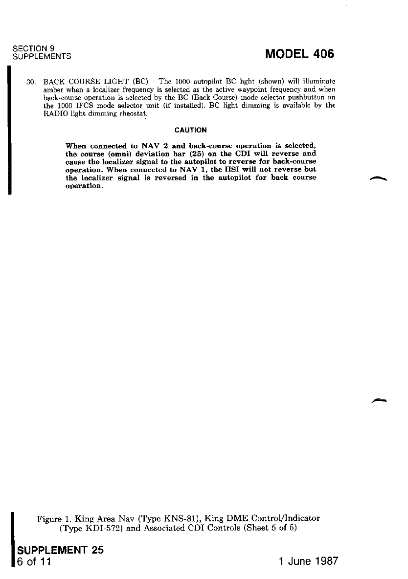
SECTION 9
SUPPLEMENIS MODEL 406
30. BACK OOURSE LIGHT (BC) The 1000 autnpilot BC lieht (shown) will illumrnate
amber when a localizer frequency is selected qs the active wa'?oint frequency and when
back-course operation is selected by the BC (Back Course) mode selector pushbutton on
the 1000 IFCS mode selector unit (if installed). BC lisht dimnins is available by th€
RADIO light dimmi.g rheostat.
CAUTION
WheD €otrn€cted to NAV 2 and back-cours€ operatiotr is selected,
the cour€e (omDi) devistion bar (26) od the CDI will revers€ and
cau6e the localizer si$ral to the autopilot to revefte for bsck-course
operatioD. When contrected to NAV l, the IISI will not reverse but
the localizer signal is reverEed in the sutopilot for bsck course
oPeration.
Figure 1. King Area Nav (T1pe KNS-81), King DME Control/Indicator
(Type KDI-5?2) and Associated CDI Controls (Sheet 5 of 5)
1 June 1987
MODEL 406 sEcloN 9
SUPPLEMENTS
SECTION 2
LIMITATlONS
The following RNAV IFR approach limitation must be adhered
airplane operation.
OPERATING LIMITATION:
1. IFR Approaches -- Follow approved published RNAV instrument proce-
oures.
SECTION 3
EMERGENCY PROCEDURES
There is no change to the airplane emergency procedures when this avionic
equipment ig installed.
sEcTloN 4
NORMAL PROCEDURES
PREFLIGHT:
AREA NAVIGATION FUNCTIONAL TEST:
The following procedure applies only to ai4orts equipped with, or in range
of, a collocated VOR/DME station.
1. OFF/PULL IDENT Control -- TURN ON
2. MODE Control -- SELECT VOR mode.
3. DME FUNCTION Switch -- SELECT N1 or N2 depending on svstem
selected.
4. OBS Knob - SET so needle is ccntered with "FROM" indication-
5. RAD Display -- ENTER a waypoint radial angle equal to the OBS value
determined in step 2.
6. DST Display -- ENTER a walpoint distance equal to the indicated
DME value.
SUPPLEMENT 25
7 ot 11
'| June 1987
SECIION 9
SUPPLEMENTS
?. MODE CONTROL 'SELECT RNV mode.
MODEL 406
The KNS-81 is operating properly if the DME distance to wa5point is less
1,0 NM and the couBe deviation needle rs within a dot of being centered.
PROGRAMMING:
Pe inent information (walpoint number, station frequency, waypoint radial,
and walpoint distance) for up to ten walpoints is entered into the memory.
Programming may be completed prior to takeoff or during flight. Any combina-
tiorr of navigational facilities (RNAV wal4roint, VOR/DME, ILS) may be loaded
the computeq however, it is desirable that each facility be numbered and
in rhe sequence in which it is to be used.
V WAYPOINTS:
t.
2. OFF/PULL IDENT Control -- TURN ON.
WPT CONTROL Knob -- SELECT watpoint 1 Turn the knob in
either direction to get "1".
DATA INPUT Control -- SELECT frequency for walpoint 1.
DATA Button -- PRESS to move > ((caret) from FRQ to RAD.
DATA INPUT Control -- SELECT radial fo. waypoint 1.
DATA Button -- PRESS to move ) ( (caret) from RAD to DST.
DATA INPUT Control -- SELECT distance for walpoint 1.
SEQUENCE 2 thru 7 -- REPEAT for all the waypoints desired up to a
maximum of t€n.
3.
4.
5.
6.
7.
8.
NOTE
VOR and ILS data are entered in a similar manner except,
RAD and DST entries are not required.
INFLIGHT USE:
OFF/PULL IDENT Control -- PULL ON.
DME FUNCTION Switch -- SELECT Nl or N2 depending on system
selected.
WPT CONTROL Knob -- ROTATE as required to select the desired
wa5rpoint number. The waypoint iaformation (frequency, radial, and
distance) associated with the WPT number will be displayed in their
respective displays.
WAYPOINT Display (WPT) -- OBSERVE that WPT is blinking in-
dicating that the waypoini is a preview waypoint and noi the active
waVDolni.
SUPPLEMENT 25
1.
2.
3.
of 11 1 June 1987
MODEL 406 SECTION 9
SUPPLEMENTS
DATA INPUT Control '' SEI FRQ, RAD, and DST as desired
preview walpoint is to be rnodified'
NOTE
Only the displayed waypoint. wherher it is lhe active walpornt
Jr'r' pr*i"*'*r'l""int. will be affecr€d by the data input tFRQ'
RAD, and DST) control.
6. RETURN gn1161 (RTN) -' PRIISS if it is desircd to return the displav
to the active walPoint number'
NOTE
The wawoint conrrol knob may also be manually rolated until
the activl waj|poinl, number is again displayed ln lreu ol usrng
the RTN Pushbutton.
7. USE Button -- PRESS if it is des ed to place preview (blinking WPT)
8.fi iily"#tri?r'ilt3""ff f ",'iiifi iT'd1'.t*-utthat.wPrisnot
" i.ilcatfi tut the active waJ&oint- is now displaled' ,--- *
i;?H;'i.;;;;":--JELEcr ii"i'"a o"pp.ropiiate navigation mode
ii;fi;;;;1;;" iruol PRESS ir ihe.radial rrom the
il;i""; dd]JJ ir'" i"ai"r wi be displaved on the DME knots displav
"i".g ",ltft ar "F' on the DME time to station display'
NOTE
The radial switch (RAD) is noi the momentary tJPe' therefore'
th" "*ii"n -,r"i Lt pt".t"a again for the normal DME informa-
tion to be disPlaYed.
9-
10.
11.
12.
oBS Knob -- sELEcr desired course the raw VoR and DME data rs
CHECK Button (CHX) -- PRESS
X*i"*1.^t-r'""t"iriii-- ti," vOn will be displaved in thetAD 'displav
;;;'.t,e ;ilE;tJ;n"" tn tt " VOR will be displaved in the DST displav'
KNS-81 OPERATIONAL NOTES:
l. VOR MODE OPERATION -- VOR mode is selected bv 'turning rhe
- ff4Onf .."t."f knob until VOR is displl{ed to the left of the wa}pornt
;;;b"". i; voR mode, the remote dMb is automat',callv tuned when
ln"'if',f S-sf is selected as the iuning source via the N1 or, N2 position
." tit" nVfe indicator' Upon iu"k-o't' di"t"o""' ground speed and time to
the VORTAC station rs displayed "n the DME display The course
SUPPLEMENT 25
9 of 11
1 June 1987
SECTION 9
SUPPLEMENTS
SUPPLEMENT 25
10 of 11
deviation indicator displays conventional anzular crosstrack deviation
from the selected course (110" fir.ll scale). Duiing VOR mode operation,
the RAD and DST displays show dashes.
2. VOR PARALLEL MODE OPERATION -- VOR pARALLEL mode is
selected by turning the MODE control knob uniil VOR pAR is disolaved
to the left of the waypoint number. If the syst€m is receiving valid
signals from a collocated VOR-DME facility, this mode provides a con_
stant cou$e width irrespective of the distance from the VORTAC and
normal DME information fu displayed on the DME indicator. The
cours€ deviation indicator displays t5 NM full scale from the select€d
course. The RAD and DST displays show dashes during operation in the
VOR PAR mode.
NOTE
a This mode of operation is primarily used when the pilot desires
to fly a constant cou$e width io either side of the selected VOR
course. By flying a VOR parallel course, the pitot is able to stav
up to a maximum of 5 NM to either side of the selected VOR
course. The Sperry 1000 or IFCS autopilot will not track a VOR
offset parallel course, but will track the selected base course in
the parallel mode of operation.
. It ie recommended that either the VOR mode or RNV ApR
mode be us€d instead of the VOR pAR mode for approach.
This procedure is recommended because the resolution of an off
corrrse indication increases qrith decreasing distance to the sta_
tion in standard VOR mode and a tightei resolution of 11.25
NM erists in the RNV APR mode, but the resolution remains
constant ( +5 NM tull scale) in the VOR pAR mode.
3. ENROUTE RNAV MODE OPERATION -- ENROUTE RNAV MODE
is s€lected by_ tuming the MODE control knob until RNV is displayerl to
the right of the wa5rpoint number. If the system is receiving vali'i Jignals
from a collocated VOR-DME facility, tliis mode providJs a constant,
course width and DME information to the walpoint. The course de_
viation indicator displays 15 NM full scale from iie selected course.
4. RNAV APPROACH MODE OPERATION __ RNAV AppROACH mode
is selected by turning -the MODE control knob until RNV ApR is
orsprayeo to the nght ot the waypoint number. If lhe system is receiving
valid signals from a collocated VOR-DME facility, this mode provides i
constant course width and DME information to the wayp;int, The
course deviation indicator displays a I l/4 NM full scaie from the
selected course. For RNAV approaches, the RNV ApR mode is normally
selected prior to final approach cou$e inl,erception.
MODEL 406
1 June 1987
SECTION 9
SUPPLEMENTS
MODEL 406
5. ILS MODE OPERATION -- ILS mode is selected bv selecting an ILS
" il;t;;;; f." the active wavpoint frequencv Whenever an ILS frequency
is the actrve wayporn! lrequency' the mode display -rem-ains the same
iiriC* ?tii, vo'fi ian, dNv oi nxv APR) 6rt the RAD and DST
)irri.u" *"'Lr-t"d. onlv conveniional angula{ deviation is p::]-id"d i"
;l:"Tii ;ili;;;inal "tull scale deviation from course ce.nterline is
t2.5ofor the localizer at -o"i-lo*tiottt and t0'7ofor. the glide slope)'
tfr"""o*t" "a""i"tlon pointer function can be reversed for back course
6'6,';;;til il lr'! eA'cr cRS mode. selector pushtutton on the
1000 IFCS rDode s€lector u"'t if in"tatt"at Absence of^thc LOC/GS
ii"*f""Ji" ""t""".tea Uv tfre NeV and GS flags in the CDI or HSI'
sEcTloN 5
PERFORMANCE
There is no change to the airplane performance when this 11i.11t:^"qutpt""'
t. t"#ft'd.'"i;il"*:-th;;{1"'-'"*tAl'tii"ltr"T*e'jl.i::"il""1"*";"i?"*X:"":'
related eaterDal antcnnas, wrlMgulr
SUPPLEMENT 25
11 of 11
1 June 1987

MODEL 406 SECTION 9
SUPPLEMENTS
SUPPLEMENT
KING AUDIO CONTROL PANEL
(Type KMA-24H-70)
sEcTloN 1
GENERAL
The King Audio Control Panel (Type KMA-24H-70) is- a compact solid
unit containi-ng all operating conlrols on the front of the unit'
There are two control knobs on the far left of the panel for intercom control,
ten push button switchee on the top center of the palel for speaker audio c
ten push button switches on the bottom center of -the panel for phone
"o.rt ol -d two control knobs on the far right of the panel for a
function Mic s€lect gwitrh and a spea.ker auto switch.
The electrical power required for operation of the audio- cofitrol panel's
headphone and/or speaker functions is supplied by RH AVIONICS BUS through
a 'p,-tlt-off type circuiL breaker labeled AUD PRI.
TNTERPHONE (INTERCOM SYSTEM)
The interphone system consists of a hot mic volume control and an intercom
The audio panel incorpolates in the center of the panel two rows of ten
Dushbutton switches, Iabeled SPEAKER on the top row and labeled PHONE on
ifi" bott rrr row. These pushbuttons permit the pilot or copibt to monitor the
va"ioue c;nutu"l"utions and navigation systems available.to the.operator' When
depressed, each pushbutton connects ita respective na-vrgatlon ancl/or commumca-
llJo "yst€- to ;ither the sp€ater (top row of pushbuttons) or the headphones
(bottoia row of pushbuttons). To disconnect a communication or navigation
system from eithe; the sp€aker or headphones, depress the desired pushbutton a
second tiure.
VOf ivoice) sensitivity control which are controlled by the two control knob€ ou
the far left of ihe panel. The inner control knob controls the intercom
ouly and does not affect the other inputs. .The-outer tontrol .fnob,1|en
n iii "f""f.t* to the detent position provides hot mic operation When rotated
i^ 1- -iear. ."-oa iha "^';'.1 L".l' Relecls intercom VOX (voice) sensitivity
to ihe midde range, the control knob selects intercom (voice) sensitivity
u"a ltt" rotation oi this control knob adjusts the voice activated intercom aud'io
level.
SPEAKER/PHONE (COM/NAV/DME/MKR & ADF) MONITOR PUSHBUTTONS
SUPPLEMENT 26
1of 5
1 June 1987
sEcTtoN I
SUPPLEI\4ENTS MODEL 406
Mrc SELECT SWTTCH (TNCLUDTNG EMG, pA & EXT pOStTtONS)
A multiple function MIC selector control swikh is located on the far right of
tfie parel and is the inner confol knob. In the COM position (1 thru 4),
microphone and audio keying are routed to the gelect€d tralsceiver and the
speaker amplifier is connected to the cockpit speaker. In the PA position, keyed
microphone audio is rout€d to the aft cabin speakers for passenger address. The
EXT (erternal ramp hail speaker) position is not uged in this install,ation. In the
EMG position, the microphone and headphones are connected directly to COM 1
aa a means of failsafe communications in the event of a failure within the Audio
Control Parel or on the RH AVIONICS BUS.
SPEAKER AUTO SELECT SWITCH
The SPKR AUTO selector control is located on the far rieht of the Danel
and is the out€r coDtrol knob. When rhe SPKR AUTO switchls oulled out. it
will automatically s€lect the audio from the transceiver selected bv the MIC seiect
switch to be heard on the cockpit spea-ker.
sEcTtoN 2
LIMITATIONS
There is no change to the airplane limitations when t}lis avionic equipment
is installed.
lf'"??rr""t rt 1 June 1987
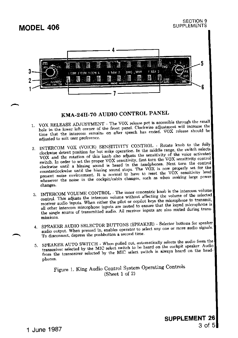
MODEL 406
KMA-z4II-7O AUDIO CONTROL PANEL
r'voxRELEASEADJUSTMENT-TheVoXrleasepotisAcc$s;blethmuehIhe,maj|
' i"'i"'i"-,r'" i.;* left corna of rhp fr nr Danel clockwise sdju'tment wrrr rncrease rne
rime that the intercom remarns t" "ii"t'"p""ttt has ended vOX release should be
adjusted to suit user Prcferenc€'
SECTION 9
SUPPLEMENTS
SUPPLEMENT 26
3of5
2 r NrERcoM vox rvorcE,, sENS''j$II.SllT,[".'.;,]:fl ;" \l.'"'"ff, jn"f*'t:
clo{k',,ise detlnr posrtio'j".i l:1-1i*^1". adiusrs rhe sensilivitv ol the vorce activaLed
vii,ilili"r'f !':,:1ii;:."?"{1:ir::hril;1{;rt*nt.si**rl*'r::llxl
:i"'#tr;it'-"".lliilf.Tl$fl ":hiift ,ri"l,iL,"*"axr'J",fl '1""'I:
lffi::I":fi: i.ffi:"lfii: il"['il:;:; ;#;;;' ;;"h';; wlen marine rarse power
changes.
rNrERcgM vor-uMx cglllgl -,TIt,ll,T"i?"jir*ffiIifl: T"ln:'F:il":ij:ffi
contn l. This adjusts the intercom vorume
;""";;;;;l;;rr" wlen either the pilot or copilor' kc)s the microphone 10 trangmrr'
'*":ilr";s::,ntlm[1ru'*s.:'lr:$* :nn'li' i:: I;l;'oi'ffi"i*::
SPEAKER AUDIO SELECTOR BUT'|ONS (SPEAXER) - Select^r buhons for speaker
ardio outDut when press€d tn "nuo'"" op"iuto-it i"f"cl anv onc or more audio sisn'ls
To disconnect, depress lhe pushburbn a sF ond Irme
SPEAKER AUro.swrTcl.:Jh:' .pY.il-:*;i:l".";TiTllll ;'J":i:','Jf $i;iJll"'.I:
ixl*ii:1.*::59":t\::"T't'*,il'i'1r:l'i;;'""ir"r' i",i*'v" h;ard on th€ head'
phones.
Fizure 1. King Audio Control Syst€m Operating Controls
- (Sheei 1 of 2)
1 June 1987
SECTION 9
SUPPLEMENTS
SUPPLEMENT 26
4of5
MIC SELECT SWITCH (Including EMG, PA and EXT posftions) - tn the EMC
(Em€ rg€.ncy ) _ posit ion, microphone 6udio, mircrophone key and headphones are con-
nect€d directly to COM L This providee failssle iornmunications in th; event of Audio
Panel Failure. In COM positions (1 ttrru 4), microphone audio ard keying is connected
to the appropdat€ transmitter and audio from the ielected receiver wili be heard on tne
spealer wlen the AUTO SPKR kDob is pdted ouL tn the pA positioo. keved micro-
phone audio is loyted- to lhe aff. cabin speakels for passenger address. The E*T posrion
is noDfirnctional in this instr_Uation. Dudng trgnsmit all received audio i! mut€d and
sidetone froE the select€d tlamEitt€r is h€rd on spesler and phones.
HEADPHONES AIJDIO SELECTOR BUITONS (PHONE) - Setector buttons for
hesdpbon€ audio output. When pressed in, enabl€s headphone operation to anv one or
more aucuo sBnals. 't o disconnect. depress rhe pushbutton(s) a second time.
Figure 1. King Audio Control System Oprerating Controls
(Sheei 2 of 2)
MODEL 406
1.
SECTION 3
EMERGENCY PROCEDURES
. There is ao c-bange to the airylane emergency procedures when this avionic
equlpment lI} rnst€Ied.
NOTE
a This tlpe of audio control palel has independent. citcuits for
speak€r and headphone functions. Thus, one failure does nol
cause the loss of both headphone and speaker audio. In case of
failure to tlansmit over the headset MIa, the operator mav still
be able to transmit using the hand-held MIC. (The hand-mike
jack is connected in parallel with the copilot,s headset jack. For
better modulation and less background noise, unplug- the co_
pilot's headset when using the hand_held MIC.)
a IF a complete failure of the audio conhol pan€l occurs. Dlace
the MIC select switch in the EMG posirion. The micropione
and headphones will be connected directly to COM 1 ag a
meaIrs of failsafe communications.
1 June 1987
MODEL 406
sEcTloN 4
NORMAL PROCEDURES
AUDTO CONTROL PANEL OPERATIONS:
SECTION 9
SUPPLEMENTS
1, MIC Select Switch -- SELECT desired conmunications transcerver
(COM 1, 2, 3 or 4 position) for.transmitting'
bi"diribii ""ili,i pri6itn .q'di" .qeleci Button(s).;, l-ElE932, SPtlAl$j}( aro/or rfrvlrD
- 6bi,i7iln svsi"m ,l""i"ed, to rngurtgl audio-over :t!hi: llti:lT:i
itip'i"*'"r i'""rtU"rtt"")- -- ttt" tt*dpnooes (bottom row of pushbut-
tons).
s. b"P;iKEn AUTO Selector Knob -- PULL oUT for automatic speaker
audio on selected commurtications recerver'
il;"t;;i#il7* n"""iu". euaio Control -- ADJUST to desired listen-
5.
6.
ine level.
t?;;;;" INTERCoM VoL Control -- ADJUST to desired
level while u.sing hot mic.
i'Litdi'6'6tr"ibx (voi-cetsensitivirvcontrol--Rpr.ArE-c-o-Y1g^!
ilif'"i;."#;; ii'"' -iJar"- '-ei and then adjust as required
desired voice activation of hot mic -ml'ercom'
SECTION 5
PERFORMANCE
There is no change to the airplane peformance when this avionic
is installed.
1 June 1987
SuPPLEMENT 261

MODEL 406 SECTION 9
SUPPLEMENTS
The King Digital ADF is a panel-mounted' digitaU-y tuned automatic direc-
ti." ;;l;;.-li l"'d""ig""d to pio"icle continuous -l-kHz- digital tunins in the
H;;;;;& or zoolln, t" iigg-tir" -a etminat€s th9. r9ed.fot nechanical
i?"'i""*it"-rtit'* ihe "y"t"m i" "o-ptit"a of a -receiver' a built-in electronic tinet'
itJ".'lii*riiaii",ii #J. ra-aae'"'.uined roop and TIT TPll1?,T*t:g
a u(drrr'ts uurwqw" - - ih" indi""toi can be a Kl-227 ' Kl-228 or
on the avionics optioDs installed'
KI-229. Operating controls and oopUl" tot the King Digital AIF are.shown and
i##Jil'ii*t il r- rt " ",dio rv"ti- *ecl.io "9"r"',:!i9l.T1-t[T^T*%f:l
]JllHfi#;;1fti";i.-.;";;tJ;ribecl in supplement 26 in section e
this handbook.
The KiIg Digital ADF can- be us€d for position plotting and homing proce-
a,r."".-arrd for" auril reception of amplitude-modulated (AM) signals'
SUPPLEMENT
KING DIGITAL ADF
(Type KR-87)
sEcTloN I
GENERAL
The "flip-flop' frequencv displav allows tyit"li"c" -b,:1:T1
"sririibs.il"*i1,Aciil,E;-i."q";;;ies by pressing tr': lr-equ:i:v llTl:.:
---'-""
"tot"i in a non-volatile nemory circuit
ton. Both pre-selected ftequencies a
fr
'''i"""i'.1'""l"".iu*ii-J"a-al'pi"v"ainselr-dinminggas^g:i*"iH"*T;
t"ff;it#;;;il ii'"o"ti""''ltii aitplaved in the Ieft window' while the
-i.i^- Jri ai*f"" either the standbv fiequency or the selected readout fro
window will disPlaY either from
built-in electronic timer.
The built-in electrcnic timer has two separate ang,indeq:n9€:l J1ilg
ti""": i"r;";;;;; mgilitr."i-titti ttutt" *tt"tt"u"" the unit. is .tumed on'
timer functions up to 59 houls "oi-sg titt"t"t' An el:Fsed timer -wlich
:1ffi il."#il; r- "o *" ss '.ninutes and 59 seconds ryl"l, " q""""t
int€rval has b€en progtammed anJ the countdotvn reaches, :00' ,the ilis^-plaJ
;;:i'?;t;;fu."si""" uott' the fligrt timer .and :tfg':1,11T",1
ilfr "lo#i",irir,'it^":d;;;-;;"il.;,t':r1T_T:lTi^g:"T1,,,*e,:*"ljlT
ro.,cPExuvuurr' '" ^' r-":"'"'- '-"' -:-la"ing io,fic"to"" are internally lighted.
The pushbutton conlrols and l,ne or.
"iiv i! "."t".it"a Uv the radio light dimming rheostat'
SUPPLEMENT 27
1of 8
1 June 1987
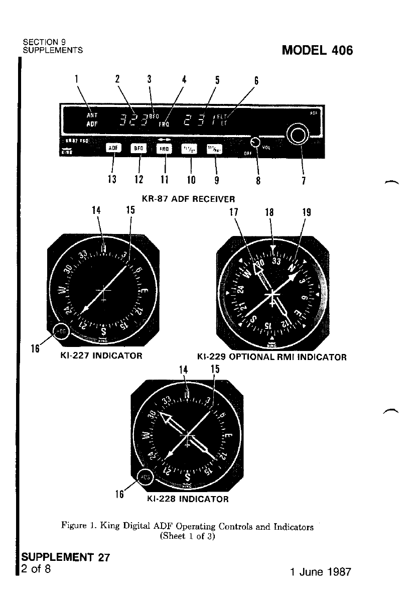
SECTION 9
SUPPLEMENIS MODEL 406
12ilt0$
KI.227 INDICATOR
Figure 1. King Digital ADF Operating Controls and Indicaton
(Sheet 1 of 3)
KI.229 OPTIONAL RMI INDICATOR
14 15
SUPPLEMENT 27
2ol 8
ro Kt-228 tNDtcAToR
1 June 1987
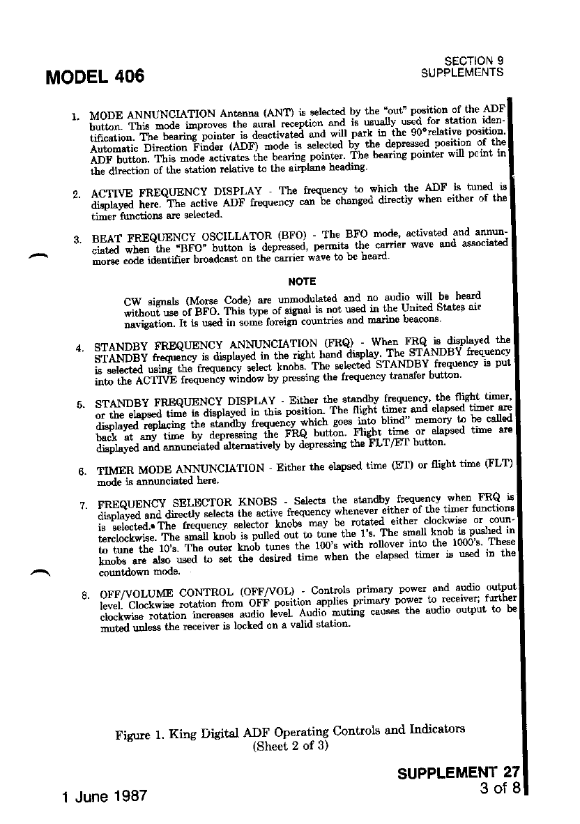
MODEL 406
7.
MODE ANNUNCIATION Antenna (ANT) is selert€d bv the'out" position of.the ADF'
tiiti"l rli" -"iJ" i'"p"oves the auret r"ception and is usuallv used for statioo iden-
ii"niii"". ft'" be*r"e'point€r is deacrivate; and will park in tbe g0orelative positioD'
;i,ffi;;i Dt'Ji"" 'Filder (ADF) mode is select€d bv the depressed positioD of .thc
Lirilii*t. rf';" -"ae activales ihe bcains poinr'er'.The bearins point€r will pt rnt in
ii"-dlteciio" of th" st"tion rclative to the airplane heading'
ACTn'E FREQTIENCY DISPLAY - The freqxencJ to which.rhe PF."*-P]* "
;ip';fi il;;*Th; ;;tl'e eor r'"q*ncv "ar b" changed direcllv when eitler or the
timer functioru are sPlected.
BEAT FnEQUENCY OSCILLATOR (BFO) - The B{O modg' activated.and arTlun-
iit i *l*-trt" -"neo" button i! depressJ' pernits the carrier wave and associated
mors€ code identiier broadcast on lhe csrrier wave lo lr€ beam'
NOTE
CW sisnals (Morse Code) are unmodulat€d and no audio :vill :b: hea:d
;h"fi;; "i itFd. This'tlpe of sisnal is noi used in t}re Unit€d Stat€e air
t"ig"ii-. ri i" .*a i. some foreigrr countries and msrine beacons'
STANDBY FREQUENCY ANNUNCIATTON (FRQ) - when Fx,Q -is displav€d the
3+fr6;i il;"}cvls displaved in rhe rislt bsnd displav Jhe STANDBY rreouencv
i^""r""r"a- *i"i trre trequ""cy setecr knobi Tbe seleded STANDBY, frequency is put
ilt" i-1" ,qCffvt f."qtencv window bv presing the flequencv transfet button
STANDBY FREQUENCY DISPLAY - Either rhe stsndbv tr€quenry' tbe nisht rimer'
iJ ii. ifitje€d.li-l- r' aisplaved in this position Tbe flisht timer.and elapsed tiEer,a-re
ti#;ff;"il"; td&-itt r'"q""oiv "i'i"r i*"-;'ito blind Bemory T F-g'd
back at snv trEe bv depressrng rne r rtQ button Flig,llt,lire !r ^etapsed llme 3r€
displsyed and anlruDciat€d alt€rnslively by depresstng In€ rLtlr I uuL@n'
TIMER MODE ANNUNCIATION - Either the elapsed time (ET) or flight time (FLT)
mode i.s alnunciated herc.
FREQUENCY SELECTOR NNOBS -- Selects the st€ndbv .ftPqu€ntv when.FRQ ts
ai"pta-v"a ana ait".rlv "elecis l.be sctite tseduencv c'/henever either of the timer Nnctnns
i"- iJi"t"a..'fft" ftequency s€lector knobs'mav be rotaled either.clockwi
;'ilil;;. il" ;;ii knob ;s pulled out.rn t"ne the.l's Tbe "P+ T,"b,:""Xyrl:l -
t-i-" *" rbt Tte oui€r kn;b tun€s the I00's with rollover-into the ltuos rh*e
il;-;-d;-G-; s.l tle du"ired iime wben lh€ eLaps€d iimer ja r*€d rn tne
oFF/voLUME coNIRoL (oFF/vOL) ' controls primary poT'.:{-l:]9-: ;ly'i
il;: 'ciiil; -irii.' i-- oFF.position appliee.primarv power l'o ,receivex..frrther
clockwise rotation rncreases &uttro t"u"t lua;6't"ti'"g ca'$ei tbe audio output t,o b€
ii,t"J ual"ss rb" re"eiuer is locked on a valid st'ation
Fieure 1. Kine Disital *,#i";""t;ti """"ols and rndicators
SECTION 9
SUPPLEMENTS
SUPPLEMENT 27
3of8
1 June 1987
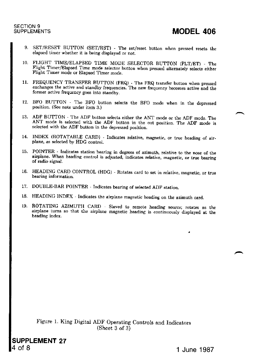
SECTION 9
SUPPLEMENTS
16.
MODEL 406
SE1'/RESET BUT'TON (SET/RST) - The set/reset button when D.essed resets rh€
elapsed timer wherher it is being d)splayed or nor.
FLIGHT TIME/ELAPSIID TIME MODE SELECTOR BUTTON GLT/ET) The
Flight Time./Elaps€d Time mode selector button wben pressed altemarely selects either
Flight Tim€r mode or Elapsed Time. mode
FREQUENCY TRANSFER BUTTON (FRe) - The FRe transfer button when Dressed
erchanges the active and standby frequencies. The new frequency becomes active ard me
former aciive frequency goes into standby.
BFO BUTTON - The BFO button selects the BFO mode when in the depressed
position. (See note under item 3.)
ADF BUITON - The ADF button selects either the ANT mode or the ADF mode. The
ANT mode is selecied with the ADF burton in the out position. The ADF mode is
selected with the ADF button in the dep.essed posirion.
INDEX (ROTATABIE CAR.D) , Indicates r€lativ€, nagnetic, or true heading of air-
plane, as selected by HDC control.
POINTER_- Indicatps station bearing in desrees of azimuth, rclative to the nose of me
alrplane. when headins conrrcl is adjusrad, indicat€s rehtive, Dagnetic, o. rrue beanng
ITEADING CARD CONTROL (HDc) Rotat€s card to s€t in relative, magnetic, or rrue
Deanng rnronnatron.
DOUBLE-BAR POINTER - Indicat€s bea.ing of selected ADF station.
HEADING INDEX - Indicates the ai.plane masnetic heading on the azimuth card.
ROTATING AZIMUIH CARD Slaved to remore heading source; mtates as th€
airplane .turns so that the airplane magnetic heading is contiruously displayed at me
77.
I8.
19-
Figure 1. King Digital ADF Operating Controls and Indicators
(sheer 3 of 3)
SUPPLEMENT 27
4ofB 1 June 1987
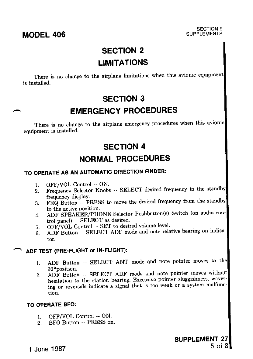
MODEL 406 SECTION 9
SUPPLEMENTS
SUPPLEMENT 27
50Td
SECTION 2
LIMITATIONS
There is no change to ihe airplane limitations when this avionic
is installed.
sEcTloN 3
EMERGENCY PROCEDURES
There is no change to the airplane emergency procedures when this
equipment is installed.
SECTION 4
NORMAL PROCEDURES
TO OPERATE AS AN AUTOMATTC DIRECTION FINDER:
1. OFF/VOL Control .. ON.
i. F""qu".t"y Selector Knobs -- SELECT desired frequency in the
frequencY disPlaY.
3. FRb Bu;ton --- FRESS to move the desired frequency from the
ing or reversals indicate aweak or a system malfunc-
tron.
TO OPERATE BFO:
1. OFF/VOL Control -- ON.
2. BFO Button -- PRESS on.
1 June 1987
to t}le active Position.
a. abf -SinafnR/PHONE Selector Pushbutton(s) Switch (on audio con-
trol panel) -- SELECT as desired.
5. OFFTVOL Control -- SET to desired volume level'
e. ebf gtit"t -- SELECT ADF mode and note relative bearing on indica-
tor.
ADF TEST (PRE-FLIGHT OT IN-FLIGHT):
1. ADF Button -- SELECT ANT mode and note pointer moves
90oposition.
2. ADi'Button -- SELECT ADF mode and not€ pointer moves
hesitation to the station bearing. Excessive pointer sluggishness'
ins or reversals indicate a signal that is loo weal or a system n
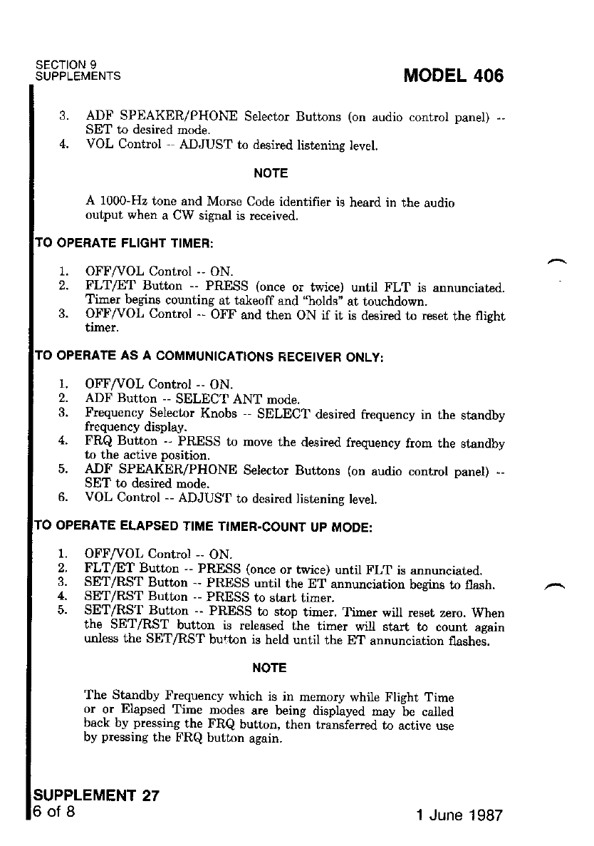
SECTION 9
SUPPLEMENTS
SUPPLEMENT 27
6of8
3.
4.
ADF SPEAKER/PHONE Selector Buttons (on audio control panel)
SET to desired mode.
VOL Control - ADJUST to desired listeninE level.
NOTE
A 1000-Hz tone and Morse Code identifier is heard in the audio
output when a CW sigral is received.
OPERATE FLIGHT TIMER:
1. OFF/VOL Control -, ON.
2. FLT/ET Button -- PRESS (once or twice) until FLT is annunciated.
Timer begins counting at takeoff and "holds" at touchdown.
3. OFF/VOL Control -- OtrF and then ON if it is desired to reset the flisht
tlmer.
OPERATE AS A COMMUNICATIONS RECEIVER ONLY:
1. OFF/VOL Control -- ON.
2. ADF Button -- SELECT ANT mode.
3. Frequency Selector Knobs -- SELECT desired frequency in the staldby
frequency display.
4. FRQ Button -- PR"ESS to
to the active position.
5. ADF SPEAKER/PHONE
SET to desired mode.
MODEL 406
move the desired frequency from the Btandby
Selector Buttons (on audio control panel) --
6. VOL Control -- ADJUS'I to desired listening level.
OPERATE ELAPSED TIME TIMER.COUNT UP MODE:
1. OFF/VOL Control - ON.
2. FLT/ET Button -- PRESS (once or twice) untit FLT is annunciated.
3. SET/RST Buttoq - PRESS until the ET annunciation besins to flash.
4. SET/RST Butr,on -- PRESS to start timer.
5. SET/RST Button -- PRESS to stop time!. Timer will reset zero. When
the SET/RST button is released the timer will start to count asain
unless the SET/RST bu+tpn is held until the ET annunciation flashei.
NOTE
The Standby Frequency which is in memory while Flight Time
or or Elapsed fime modes are being displayed may be called
back by pressing the FRQ button, then transfered to active use
by pressing the FRQ butLon again.
1 June 1987
OFF/VOL Control -- ON.
fiiini g"fio" -- PRESS (once or tq'ice) until ET is annunciated'
sei'/RSt Srtt"" -- PRESS until the ET annunciation begins to flash'
FREOUENCY SELECTOR KNOBS -- SET desired time in the e
li-" ii"pf"v. The small knob is pulled out tq tge. the 1's' Thc
inoU i" io"it"a in io tune the 10's. The outer knob tunes minutes up
59 minut€s.
NOTE
Selector knobs remain in the time set mode for 15 seconds after
ift"-i..i "tt"v or until the SET/RST, FLT/ET or FRQ button
is pressed.
SET/RST Button -- PRESS to start couutdown' When the
i"""fr"" o, it will start to count up as display flashes for 15 seconds'
NOTE
Wirile FLT or ET are displayed, the active frequency on the left
side of the window may be changed by using the frequency
selector knobs, wiihout any effect on rhe gtored st€ndby lre-
queucy or the other modes.
ADF OPERATIONAL NOTES:
ERRONEOUS ADF BEARING DUE TO RADIO FREQUENCY PHENOM'
ENA:
In the United States, the FCC, which assigns -AM radio frequencies' occa-
"iotruiiu
- *'lff- u".ign the s"ame frequency Lo more than one- station, in an area'
i:iilii "".iiti."-".. such as Night bff""i, ^"v cause signals from such sl'ations to
MODEL 406
TO OPERATE ELAPSED TIME TIMER-COUNT DOWN MODE:
sEcroN 9
SUPPLEMENTS
Certain conditions, such as Night may cause signals ftom such stations to
.r"tf"r. iftft should be take; in; consideration when using AM broadcast
SUPPLEMENT 27
7 oII
station for navigation.
Sunspots and atmospheric phenomena may occasionally -distort reception so
tft"t -Jig"li" - f".- t*o stations on the same frequency will overlap. For this
;;;;:"it is alwavs wise io make positive identification of. the- station being
i"iJ,'U" "Ut"n"iJ the tunciton selictor to ANT and listening for station call
lett€rs.
1.
2.
3.
4.
1 June 1987
SECTION 9
SUPPLEMENTS MODEL 406
STORMST
In the vicinity of electrical su)rms, an ADF indicator pointer tends to swin€i
from the station tuned toward the center of the storm.
NIGHT EFFECT:
This is a disturbance particularly strong just after sunset and just after dawn.
{DF indicator pointer may swing erraticallv at these times. If oossible. tune
Ar ADF indicator pointer may swing erratically at these times. If possible,An AlJl mdrcator pornter may swrng erratlcally at these times. lf possible, tune
to the most powerful station at the lowest frequency. If this is not possible, take
the average of pointer oscillations to det€rmine relative station bea ng.
MOUNTAIN EFFECT:
Radio waves reflecting from the surface of mountains may cause the pointer
to fluctuate or show an erroneous bearing. This should be taken into accouni
when taking bearings over mountainous terrain.
COASTAL REFRACTION:
Radio waves may be refracted when passing from land to sea or when moving
parallel to the coastline. This also should be taken into account.
SECTION 5
PERFORMANCE
There is no cbalge to the airplane performance when this avionic equipment
is installed. However, the installation of an externally mount€d antenna or related
ext€rnal ant€nnas, will regult in a minor reduction in cruise performance.
SUPPLEMENT 27
8of8 '| June 1987

MODEL 406 SECTION 9
SUPPLEMENTS
;J;;d;"G""i* -J-ii" ".-".ponding Channel numbers to be recalled
;":;;;;;Til chu.'r,"l n,t-b"" is momentarilv displaved in the ac^tive (USE)
i."o,l"n"v altpluv and the conesponding frequency is displayed in rhe STANDBY
f""ouenc-v displav. The Channel Programming mode allows the pllot t' progam
i;;;;"'";;i;; """-i" in" Ctt""t"r *ode of operation The Direct T\rning mode
i:: ;;::l:;;-;il *rii"n aro*t freq'encv changes to be made directlv into the
active frequincY disPlaY'
Large self-diurming gas discharge readouts- displav '1" :"3:yI11t:I -:!..
ii;.SEi."a thJ standby frequencies are stored in a circuit component called
b"ei"oli'ieb";rr"Jiv irt"."6r" Read ontv Memory) thaL provides .non-volatile
i"."*" "f'fi"qt"""iei and prograrnmed channels so that when the radio is turned
oii "ia tn"n back on, channel inlormation is retained'
The COMM incorporates an automatic squelch To override the automatic
."""f"it, ifti"".ft-" - c'ontiol knob is pulled out Push the knob back in t'o
relactivate the automatic squelch.
SUPPLEMENT
KING DIGITAL COMM
(Type KY-196)
SECTION 1
GENERAL
The King KY-196 Digitat Comm, Shown in Figule 1' c.oLsrsls of a nanel-
mounted receiver-tlansmitter. The set includes a ?20-channel Vtt! communrca-
iio""- t"""it"*tt-"mitter which receiveg and transmits signals between 1
and 135.975 MHz with 25-kHz spacing'
Channel Programming mode; Direct T\rning mode'
The KY-196 hae four modes of operation: Frequengy mode; Channel mode;
---i o-^-^*-r-- -^i.. r)irorr T\rninc mode. The Freouencv mode ol
Frequency mode
"""."ti* aUt" ihe;ilot to tune a frequency in ihe standby frequency
-':';i- ....- j1^-- li^ -+^-nL.,, .-i 6.tiua franrrpnnips- The Channel mode
"iJitr"" "nip-nop" the standby and active fr-equencies' The
"."t#g'i""q"*"-i"".-C-ft'" fti- tso s ,tiiq,l"-'nip-flop" pre-select featur" TPt^"-t I::
Eta!ur6 rrreqr'! rvui
to store one tiequency rn [ne slal
il"" "ir-t"r"ft""g" the; inst.antly with the touch of a button' Both the
SUPPLEMENT 28
1of I
1 June 1987
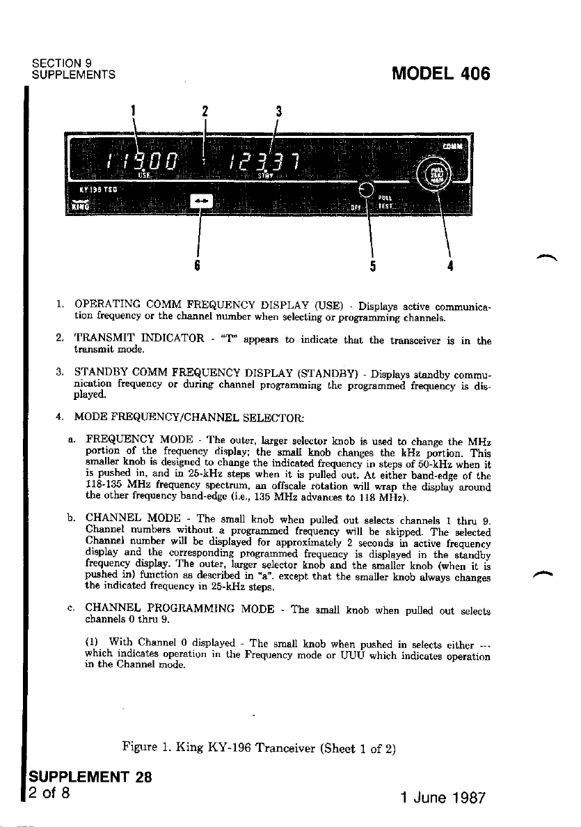
SECTION 9
SUPPLEMENIS
Figure 1. King KY-196 Tranceiver (Sheet 1 of 2)
SUPPLEMENT 28
2ot8
MODEL 406
OPERATING COMM FREQUENCY DISPLAY (USE) - Displays active communica-
tion frequency or the cbann€I number when selecting or programming channels.
TRANSMIT INDICATOR , "T, appears to indicat€ that the transceiver is in me
tmnsmit mode.
3. STANDBI COMM FREQUENCY DISPLAY (STANDBY) - Disptays Btsrdby commu,
nication frequeDcy or during channel pro$ameing the programrned frequeoiy is dis-
I. I,,TOOT TNBQUENCY/CHANNEL SELECTOR:
a. FREQUENCY MODE The outer, lalge! sele€tor knob is used to chanse the MHz
portion of the frequency display: the smalt knob chanses the kHz p6rtion. This
smalle_r k-nob is designed to .hange rhe indicated frequenry in sr,ps of sd-kHz when ;t
f_ f!t{ -11, and in 25 kHz steps when it is pu ed out. At eitirer band_edge of the
f8-135 MHz frequency spectrum, sn offscab;ot tion will wrap the displa! around
the other frequency band-edge (i.e_, 185 MHz advances to 118 MHz).
b. CHANNEL MODE - The small knob when pulted out s€lects channels I thru 9.
Channel numb€B without. a programmed frequency will be skipped. The s€lected
urranner numDer w'lt b€ dl.sptay€d for approximately 2 seconds in active frcquency
drspky and. ihe conesponding programmed fr€quency is displayed in the stsndby
rrequency drsphy. lhe out€r, larger s€lector knob snd the $rxaller knob (when it is
pNhed in) tunction as described in "a". except that the smaller knob always changes
the indicat€d frequency in 25-kHz steps.
c. CHANNEL PROGRAMMINC MODE - The small knob when pulled out serecrc
channels 0 thru 9.
(1). .With Channel 0 displayed , The smal knob when pushed in setects either , ,
which indicat* opemtion in the Frequency mode or UUU which indicates operation
in the Channel Elode.
1 June 1987
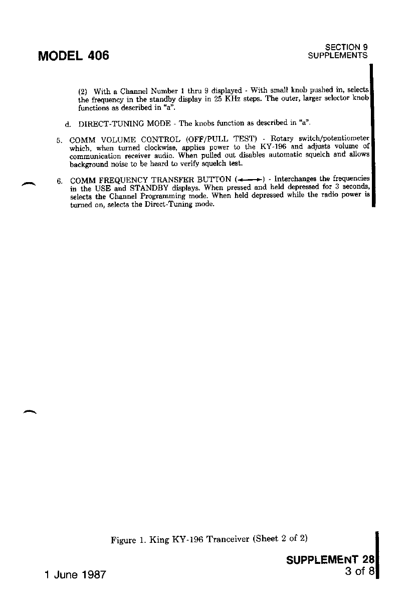
MODEL 406
(2) With a Channel Number I thlu 9 displaved - wiih small knob pushed in' s€lects
ihi frequency in the standby display in 25 KHz st€ps. The out€r' larger selector knob
functions as desnibed in "a".
d. DIRECT-TUMNC MODE - The kDobs tunction as descdbed in "a"'
COMM VOLUME CONTROL (OFF/PULL TEST) - Rotarv switch/potentiometlr
which, when turned clockwise, applies power t the KY-196 and adjr8ts volume of
communication rec€iver audio. WL-n puiled out disables automatic squelch and allows
bsckground nois€ to be heaid to vedfy squelch test.
COMM FREQUENCY TRANSFER BUTTON (<+) - Int€'-changes-the frequencies
i; ahe usE "ita sf,tNosv displays. when pressed and held depressed for.3 S€conals,
select€ the Cb-annel Programming mod€. When held depressed while the radro power 1l
tumed on, selects the Direct-Tuning mode
sEcTtoN 9
SUPPLEMENTS
SUPPLEMENT 28
3of8
Figure 1. King KY-196 Tranceiver (Sheet 2 of 2)
1 June 1987
SECTION 9
SUPPLEMENTS MODEL 406
All controls for the Kine KY-196 are mounted on the front Danel of the
-transmitt€r. Control lighting is provided by the instrument panel flood
system. Operation and description of the audio control panel used rn
with this radio are shown and described in Supplement 26 in Section
of this handbook.
SECTION 2
LIMITATIONS
There is no change to the ai4larre limitations when this avionic equipment
is installed.
sEcTroN 3
EMERGENCY PROCEDURES
There is no change to the airplane emergency procedures when this avionic
pment is installed. However, if the frequency readouts fail, the following
should be followed.
RADIO DISPLAY FAILURE:
COMM Volume Control (OFF/PULL TEST -- TURN counterclockwise
to OFF position.
COMM Transfer Button (+) -- PRESS and HOLD DEPRESSED.
COMM Volume Control (OFF/PULL TEST) -- TURN clockwise; pull
out and adjust to desired audio level; push control back in to activate the
automatic squelch.
NOTE
The radio is now in the Direct Tuning Mode. The active and
standby ftequencies are set tp 120.00 MHz. The frequency selec-
tor knobs can be used to dilectly tune the active hequency.
4. MODEAREQUENCY/CHANNEL Selector - The outer, larger selector
knob will change the numbers to the left of the decimal one MHz per
click. The smaller knob when pushed in changes the number to the right
of the decimal 50 kHz per click and 25 kHz per click when pulled out.
Therefore if the frequency 121.50 was desired, the larger knob would be
turned one click clockwise and the smalle! knob pushed in and tumed 10
clicks either clockwise or counterclockwise.
SUPPLEMENT 28
4of8
1.
2.
3.
1 June 1987
OPERATING MODE SELECTION'
1. COMM Volume Conhol (OFF/?ULL TEST) -- TURN clockwise until
radio comes on.
2. Coili4 Transfer Button ('<+) '- PRESS and HOLD DEPRESSED
for three secondB.
3. ilbffETFiiEanENcY/cHANNEL selector .-- lul-l our and
"' iib-t"ale tl" -tmall knob unti.l zero (0) appears in the active flequency
displav.
n. i,r-6frinnEeuENcY/CHANNEL Selector -- PUSH IN and RoTATE'
Select either --- or UUU'
Wten the MODE Selector knob is rotat€d, the standby fre-
que""v Jispluv *i[ altemate between --- and UUU'
a. The FREQUENCY Mode is selected when dashes (--) are
pLaved.
t. lTi drfeNNel, Mode is select€d when (UUU) is displaved'
MODEL 406 SECTION 9
SUPPLEMENTS
SECTION 4
NORMAL PROCEDURES
5. COMM Trarefer Button (*) -- PRESS to retum to the
operating mode.
NOTE
Aft.er 20 seconds of no switch/selector activity', th€ unit will
autoDatically retum to the select€d op€latrng mooe'
FREOUENCY MODE
t?ivV#r.ift iiiot{-nncervEn-rRAN sM lrrE R o PERArlo N :
1. MIC Selector Switch (on audio control .panel). -- SET tpthis mdio'
;. ^Sfi;fiil/iioNE Selectoi-B'rttons (on audio control panel) -- sET
this radio,
:. 6drriffi'voru-" Control (OFF/PULL TEST) -- TURN clockwise'
" ;;;.al,l"lL aoi""a u"dio leve! push control back in to activate
,. ilSo'6li#b"t!"$;ocY/cHANNEL serector Knobs -- sELEcr
"F".t#y"'$"iff*J+8flt.s"1GJ.*1,;.i*i:3,B"5*ll;i;'-
SUPPLEMENT 28
5of8
1 June 1987
SECTION 9
SUPPLEMENTS MODEL 406
Mike Button:
a. To Transmit -- DEPRESS and SPEAK into microDhone.
NOTE
o During COMM trarsmission, a lighted ,,T, will appear between
the "USE" and 'STANDBY" displays to indicat€ that the tran-
sceiver is operating in the transmit mode.
a Phone sidetone may be eelected by pushing the AUTO selector
button (on audio control panel) in the phone position,
b. To Receive -- RELEASE mike button.
CHANNEL MODE
SUPPLEMENT 28
6of8
MMUMCATION RECETVER-TRANSMITTER OPERATION:
1. MIC Selector Switch (on audio control panel) -- SET to this radio.
2. SPEAKER/PHONE Selector Buttons (on audio control panel) -- SET t
this radio.
3. COMM Volume Control (OFF/PULL TEST) -- TURN clockwise: pull
out and adjust to desired audio leve! push control back in to activate'the
automatic squelch.
4. MODEAREQUENCY/CHANNEL Setector Knobs -- SELECT desired
operating channel (Pull out and rotate smaller knob).
NOTE
The Channel number will be displayed in the active display and
the correspo-nding programmed frequency in rhe standbi dis-
play. The Channel number will only be displayed for approx!
mately 2 seconds, after which the o ginal aitive frequency will
again be displayed.
COMM Tr-ansfer Button (+) -- PRESS to transfe! the progratlmed
frequency ftom the "STANDBY" display into the "USE" dispiay.
MIC Button:
a. To Transmit -- DEPRESS and SPEAX into microphone.
NOTE
. qurilq_qOMM transmission, a light€d ,"T" will appear between
the'USE" and "STANDBY" displays to indicate that the tra.rl_
sceive! is operating in the transmit mode.
6.
1 June 1987
MODEL 406 SECTION 9
SUPPLEMENTS
a Phone sidetone may be selected by pushing the .AUTO selector
button (on audio control panel) in the phoDe posrtron'
CHANNEL PROGRAMMING MODE OPERATION:
1. COMM Transfer Button -- PRESS and HOLD depressed for
aecon(l8.
z. ftriiiHlrnneuENCY/cHANNEL selector Krobs -- OPERATE as fol
lows:
"]""S-"U Knob -- PULL OUT and ROTATE until the desired
-- n"-Ue. (1 tbfl 9) apPears in the active display'
b. Smslt Knob -- PUSH IN.
". L"tg"i Xt"U -- ROTATE to select the MHz portion of the
a. Siilfiti<".t -- ROTATE to select the- kHz -portion of the frequencv
e.
f.
in Gs--ode, ttte frequency is changed in 25 kHz Bteps'
i""*"i i""u -- ROT;\TE'Io pro$am in up to I channels;
fr;i--l18 i" --- or countprcloikwise from 135 Lo ---' When
u"tit At tU" desired channels are programmed'
COMM T"aosfer Button -- PRESS to return to the
mode.
i" tft" CUel.INnl mode, any chamel whose
NOTE
o After 20 seconds of no switch/selector activity'. the unit will
- automatically retuin to the selected operating mode'
a While in the Channel Programming mode the. radio q,still
tuned to the active frequency which was active when lhe unan-
nel Programning mode was entered
DIRECT-TUNING MODE OPERATION:
s€lected
SUPPLEMENT 28
7 ol 8
1. COMM Volume Control (OFF/PULL TEST) -- TURN
to OFF Position'
z. b"OMU ti"-"r"r Button (<-) -- PRESS and HOLD DEPRESSED.
1 June 1987
SECTION 9
SUPPLEMENTS MODEL 406
3. COMM Volume Control (OFF/PULL TEST) -- TURN clockwise until
radio comes on.
NOTE
The radio is now in the DIRECT-TUNING mode. Both the
active and standby frequencies are set to 120.0 MHz and the
radio tuning set to the FREQUENCY mode of opemtion. When
the MODEAREQUENCY/CHANNEL selector knobs are rctat-
ed, the frequency change will be made directly into the active
frequency display.
MODE/I'REQUENCY/CHANNEL Selector -- ROTATE to directly se-
lect active frequency.
COMM Transfer Button ( . r ) -- PRESS whenever it is desired to
return to the FREQUENCY mode of operation.
sEcTtoN 5
PERFORMANCE
There is no change to the airplane performance when this avionic equipment
is inetalled. However, this installation of an externally mounted ant€nna or
several related extemal ani€nnas, will reeult in a minor reduction in cmise
Derfolmance.
SUPPLEMENT 28
SofB 1 June 1987
SECTION 9
SUPPLEMENTS
MODEL 406
functions of each are
The Ki.ng DME (Tlpe KN-63) is the airborne ."interrogator" portion of a
""ui*iion
-tu'"tu. wbich supplies continuous' accurate'-slant range distance in-
ii"-?rii"t'ril- ^ n""d g"ound shtion t'o an airplane in flight'
"iJr"tr""l-iir" rn_as transmits in'teriogating puls€ pairs on 200 rhannels be-
##:04i;Ii; ""a irso Mn';'ii ii""iuit' *sociated ground-to-air replieg
;:;;; ,l8-il.4; *a rzrg MHz The KDI-572 ani KII:5?,4 lT"t^-D,i"t*T
Except for selection of the operating 9tr1nnet,.;vhl9) ri t:t":5d,lt--t*"IH:
D^LEP! lvr ---- -r ' Iwitches, the King DME is capable
navigation receiver frequency sele( ^. ^ r.r\r <?o p.-al f)icy
l.liliil,1i:,il:il'it;;."d;'";;;";i"on"i"ts{1,-PI:tl^t*::T:'-D^:*:l
;ili"i'"':"""#ffifr';ith"';p;;i'"e ;;"trols and displavs-' a.remote-lv mounted
^-''.i++or on'l ;ii"'"I KDI-5?4 Panel Displav for dual in-
irii-6-g -n"".iu".-rtansmitt€i and optional KDI-574 Display for dual in-
SUPPLEMENT
KING DME
(Type KN'63)
sEcTloN 1
GENERAL
ffiUil ;ffiili.'d*'.-i.-*"u"a -il:"',,,e"::T1 :ry*":":::T:**t1";
ilY:ffi i"."i"#';;-#iiaifr r"1".*i'1rrli"""-r's,sLa9cq'.ge-1"1":T,{'l
fr;".:# 11"-,i"r.?i'i"o"rlG i- *" orup u'e "ho*o in Figure l' and the
n,-.+i^.i ^f "onh gre described.
NOTE
An inte ock is incorporated in the DME 8o that information
iio--irt" odto NAV ieceiver cannot be displaved on the DME
when an RNAV mode is in use'
sEcTloN 2
LIMITATIONS
There is no change to the airplane limitations when this avionic equipment
is installed.
SUPPLEMENT 29
'I of 4
1 June 1987
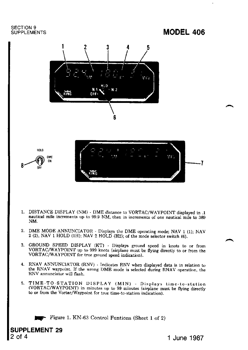
SECTION 9
SUPPLEMENTS MODEL 406
r--€*
3.
5.
DISTANCE DISPLAY (NM) - DME distance to VORTAC/WAYPOINT disolaved in .t
nautical mile increments up to 99.9 NM, then in incremenLs uf one nauri@l rnii€ ro 389
NM.
DME MODE ANNUNCIATOR, Displa!.s the DME opemring mode; NAV I (r); NAV
2 (2), NAV 1 HOLD (lH)i NAV 2 HOLD (H2); of the mode selector s*itch (6).
OROUND SPEED DISPLAY (KT) , Displays $ound speed in knors to or from
VORTAC/WAYPOINT up tI) 999 knots (airplane must b€ flying directly to or hom the
VORTAO/WAYPOINT for true sround speed indicarion).
RNAV ANNUNCIATOR (RNV) - Indicates RNV when displayed data is in relation lo
the RNAV walpoint. If the wrong DME mode is selected during RNAV operation. rne
RNV snnuncistor will flash.
TIME'TO-STATION DISPLAY (MlN) - Disptays rime-to-statron
(VORTAC/'\[AIPOIN'I) in minutes rp to 99 minut€s (sirplane must be flying directly
to or frcm tbe Vortac/Watpoint for tnre time-to-st€tion indication).
lf, Figure 1. KN-63 Control Funtions (Sheet I of 2)
SUPPLEMENT 29
2of4 1 June 1987
sEcTroN 9
SUPPLEMENTS
MODEL 406
DME MODE SELECTOR SWITCH (Oll, N1, HLD, N2) - Applies power to the DMEI
end s€lects DME opelating mode as follows. I
OFF: Turnq DME PowFr ofr' I
NAV I (Nllr Selecl.s DME operstion with NO I VHF navisstion set: enablesl
channel seledion bv NAV ) frFquencv selector conlrols l
HOLD (HLD): Selects DME memo.J circuit; DME remains channeled t-o st{tionl
to which it was last ;hanneled when HOLD was select€d and willl
continue to displav information relative to this channel Allows I
both the NAV i and NAV 2 bav;gation receivcrs Lo be se( lo newl
operationsl frequencies withoul aflectLDg the previouslv selectedl
o*" oo"t*"ot "ou'o,u
I
In the IIOLD mode there is tro antruncistiotr of the VOR/DME
elation frequency. Ilowever, an anaunciator, labeled "lH" or-'II2",
iltuminates-otr the DME disPlav to flag the pilot that the DME i6 in
the HoLD mode. I
NAV 2 (N2): Selecls DME operstion with No 2 VHF navigation s€i:.enablesl
channel selection bv NAV 2 fr€quencv s€lector switches Brigltnessl
of the labels for this switch is contrclled bv th€ radio lisht dimmincl
rhcost3r. I
PANEL DISPLAY - 2nd displav used with dual installation l
fllr"r#3Pr"":3$$?"?.swlrcH (oFF. oN, HoLD) ' serects DME op€ratinc model
'7.
8.
Figure 1. KN-63 Contrcl Funtions (Sheet 2 of 2) |
I
1 June 1987 suPPLEMENro2gl
SECTION 9
SUPPLEMENTS MODEL 406
sEcTroN 3
EMERGENCY PROCEDURES
There is no change rc the airplane emergency prccedures when this equip-
is installed.
sEcToN 4
NORMAL PROCEDURES
DME OPERATION:
1. DME Mode Selector Switch -- SET to N1 or N2 for KDI-572 or ON for
KDI-574.
2. NAV 1 and NAV 2 VHF Navigation Receivers -- ON; SET FRE-
QUENCY selector switches to VOR//DME station frequencies, as re-
qurreo.
NOTE
When the VOR frequency is s€lected, the appropriate DME
frequency is automatically channeled.
3. DME SPEAKER/?HONE selector buttons (on audio control panel) --
SET to desired mode.
SECTION 5
PERFORMANCE
There is no change to the airplane performance when this avionic equipment
is installed. However, the installation of an externally mounted antenna, or
several related ext€rnal antennas, will result in a minor reduction in cruise
performalce.
SUPPLEMENT 29
4ot4 1 June 1987
SUPPLEMENT
KING HF TRANSCEIVER
(Type KHF-950)
SECTION 1
GENERAL
The King KHF-950 is a solid-state I{F single sidebard transceiver system
providing the pilot access to 99 programmable channels plus 280,000 operating
frequencies in the 2000 to 29,999.9 kHz range. It provides receive-only and
simplex operation, as well as semi-dupler capability (transmission on one fre-
quency, reception on another) to interface with maritime radio-telephone net-
works (public correspondence). The HF Trangceiver system consists of a KCU-
951 panel-mounted control display unit, a rcmot€-mounted KAC-952 power
amplifier/antenna coupler, a remote-mounted KTR-953 Receiver exciter and an
extemal-mounted, fixed-wire, mediut{high fiequency antenna.
The KCU-951 Control Display Unit uses electronic gas discharge read outs to
display frequency, channel and node of operation' The 99 charnels cal be
programmed by the pilot on the ground or in the air, and the nonvolatile memory
stores this information even when the system is turned off. To add to the
MODEL 406 SECTION 9
SUPPLEMENTS
SUPPLEMENT 30
1of 9
operational convenience, the aatenna coupler will automatically tune the sntenna
to the specific frequency desired simply by keying the mic.
All op€rating controls for the KCU-951 Control Display Unit are shown and
described in Figure 1. Refer to the King Audio Control Panel (Type KMA-24)
shown and described in Supplement 26 in this section for the descfpiton of the
HF microphone selector swit h and HF SPEAKER/PHONE selector button
in conjunction with the KCU-591 Control Display Unit
sEcTloN 2
LIMITATIONS
There is no chaage to the airylare limitations when this avionic
is installed.
1 June 1987
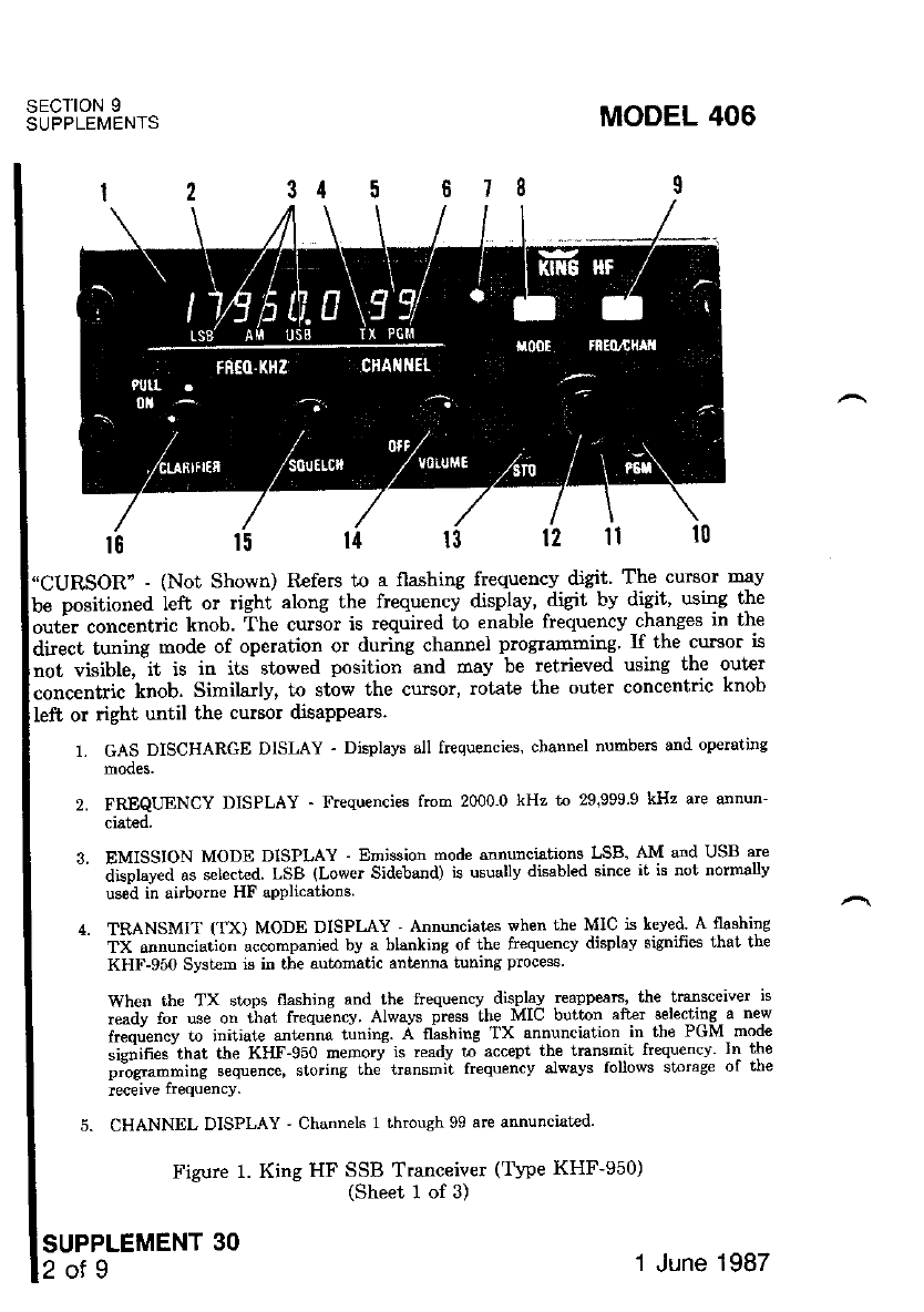
"CURSOR" - (Not Shown) R€fers to a flashing frequency digit' The cursor rnay
be positionea ieft or right along the frequencv display, digit by digit, using the
orrti" corr""nt"i" knob. the curs-or is required to enable frequency changes in tht
air"c1 1u"i"g mode of operation or during channel pro$amming. If the cursor is
not visible, -it is in its stowed position and may be retrieved using the outer
conc"ntric knob. Similarly, to stow the cursor, rctate the outer concentric knob
SECTION 9
SUPPLEMENTS
left or right until the cumor disappears.
SUPPLEMENT 30
2of9
1. cAS DISCHARGE DISLAY - Displavs all frequencies, channel numbers and operating
2. FREQUENCY DISPLAY - Frequencies frorn 2000.0 kHz to 29899.9 kHz are annun-
ciated.
3. EMISSION MODE DISPLAY -Emission mode annunciations LSB' AM and USB are
- ai"plw"a "" selected. LSB (Lower Sideband) is usuallv disabled since it is not normallv
used in airborne HF applicalions
4. TRANSMIT (TX) MODE DISPI-AY ' Annunciates when the MIC is keved A flashing
TX annunciation accompanied by a blanking of the ftequency displav signifies that the
KHP-950 System is in tbe automatic antenna tuning proce$.
When the TX stops flashing and the frequencv displav rcappeaE, the transceiver is
ready for use on that frequency Alwavs press the MIC butt'on after selecting a new
freq;ency to initiate ant€nna tuning A llashing TX annunciation . in- the PGM mode
sidifies"that the KHF-950 memory is readv to acc€pt the transmit frequencv ln the
piigt --itg sequence, storing th; uansmit frequencv alwavs follows storage of the
rcceive frequency.
5. CHANNEL DISPLAY ' Channels 1 throwh 99 are annunciat€d'
Figurc 1. King HF SSB Tranceiver (Tvpe KHF-950)
(Sheet 1 of 3)
MODEL 406
'1 June 1 987
SECTION 9
SUPPLEMENTS
MODEL 406
Il.
PROCRAM (PGM) MODE DISPLAY - Annunciates when the prosram mode is enabled
through deprcssion of the prostam (PGM) swit h
PHOTOCDLL ' Dims displsy automaticallv.
7.
8. MODE BUTTON ' Momentary depression (vcles thc KHF-9;0 emrbsian mode. from
'""* "ia"t-a (USB) to lower;ideband (LSB) to AM to A3A (simulianeous displav of
""rtf"a tv ttt" installer."ASA was previouslv used in rnarit;m€ radio relephone but is not
ei-il-,l,, T qR ic n^f n^rh'llv aUthorire.i fo. airbornc tll use anct ls not
;;;-;;;ilty. si-it*tv, r,se is n'ot normatlv auttrorlz€d for airborne HF use and is,not
*,fled tt ti" instaUer. Most aU airplane H!' SSB Com$unications are conducted in
iiSe irk,;."i"n"a i. ." single sideband "supnre*s€d" cad€r and desisnated A3J) S{nne
*"""i "t"ti.* continue to -use the AM mode but are being phased out in favor of rhe
irore elficient SSB mode of operation
FREO/CHAN BUTTON In the "out" position auows direct tuning to anv ot 2800()0
a"aih6le frequencies (simptex operation onlv) ln ihe "in" position allows selection ^i anv
of 99 availail€ channeti of prosammed pairs of receive and transmit frequencies
enabled by the installer. Most aU airplane
(simplex, semi-duplex and rcceive only operation)
o.o"ni, trll.t mav chooee receivi-onlv mode of operation bv simplv no( depre-rsrne
L-_crn "-,;,""r. . "".^.,-l 'i-" ,,t',q I..Iin' n,,r rh. trrnsmitt€r lor r€ceivinc sav WWV),
ir'"3iii iutit' " *i.rd tin€ (thus lockins out the transm;tt€r for receiving sav WWV),
or {2) vou Inav ctioose simplex operation by depreesing lhe STO swit'th a se'oncl timc
or (2) you rray choose simplex operation by depressbg the slu swrtch a s€cono.Lrme
storins the same frequencv in the transmit pnsition as was sto'ed ln the recerve posrtron'
storing the same frequency in the transmit position as was stored m the-recerve posrtron
or (3)-you Dsy wisir ro rhoosp s€mi-duplex uperarion an-d 'hange rhP rransmit fre
-,.n.w'n'i^r r^ d.nr.rsin' rhe STO swil.rh s secund l,ine. (In order uo chane€.hannel"
PROGRAM (PGM) SWITCH - Mom€ntary d€pression (with a pencil or similar
obien) enables (he program mode. PGM will appear in ihe displav. Similarl] a
denression of Lhe switch will cause the K H-F 950 Lo cxil lhe program modc
OU'IER CONCENTRIC KNOB - Causes the cu.Bor to move left or dght' one digii at a
time along the frequency display. To remove (or stow) the culsor, twist the knob leit or
right until the cursor disappears.
INNER OONCENTRIC KNOB - Mav be rotated to (1) change channels or (2) chanse
the dicit under the cursor in the frequ€ncv displav. tn ord€r to chstge channels' th€
FREQ/CHAN buiton must be in the "in" posiiion {Channel OTeralion) and the cu'sor
musr -be stowed. Prior to .hanging a trequenry digir (Dire.t T\rne Operatiun or durjng
Channel Programming), the cursor must be moved to that digit.
STORE (STO) SWTCH Momentarv deprcss;on (with a pencil or similer poiDted
obiecL) stores rhe emission mode (ie. LSB, AM, USB) and the frequencv into non
voLtile memony. In the norm3l channel programming sequence the first s€t of-data
stored is the "r;ceive" emission mode and frequencv Afier the .eceive data is stored' the
TX annunciation witl flash signirying the svst€m's r€adiness io accept' the transmit
freouency. A second momenurv depressron o[ [he STO swilrh slores thF desrrPd hanq
-it- f."qit*.y in nonvolatile -ernory Note lhat prior to selecting another channel to
queocy prior to d€pr€ssing the STO (ln order to chang€ channels
ip.. i"-pt"ti"" "r a"tu ico,ug", tht cursor must be stowed. This will occur aubmati
"itlv,rpo.i d"p."*.i"g the STdswitch the second time; however, ir1 the case of receive
."t" oiosranblne where the STO swit.h is not depressed the second rime, the curso'
only programming
must be stow€d mr
-"i,t be ito*"d -u""ally usins the out€r concentric knob.)
Figure 1. King HF SSB Tranceiver ('l'rpe KHF-950)
(Sheet 2 of 3)
SUPPLEMENT 30
3of9
1 June 1987
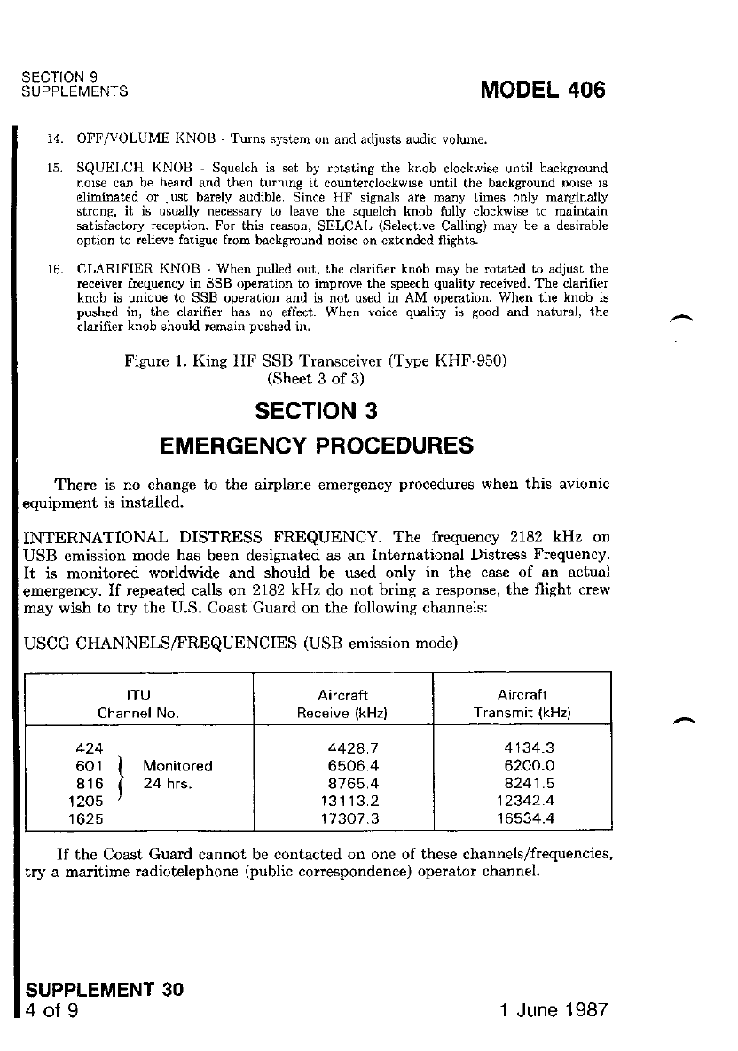
SECTION 9
SUPPLEMENTS MODEL 406
14. OFF/VOLUME KNOts -'Iurns systern on and adjusts audio volume.
15. SQUELCH KNOB Squelch is set by mtating the knob clockwise until backsround
noise caa be heard and then turning iL countarclockwise until lhe background noise is
eliminated or .iust barely audible. Since HF signals are many limes only marginally
strong, it is usually rccessary to leave the squelch knob tully clockwise to maintain
satisfactorJ r€ception. For this reason, SELCAL (Selective Calling) may be a desimble
option to relieve fatisue from background noise on extrnded flishts.
16. CLARIFIER KNOB ' When pulled out, th€ clarifier knob may be rotatad t adjust the
receivei frequ€ncy in SSB operation to improve ihe speech quality received. The cladfier
knob is unique to SSB opemtion and is not used in AM op€ration. When the knob is
pushed in, the clarifier has no effect. When voice quality is good and natural, the
claifier knob should remain pushed in.
Figure 1. King HF SSB Transceiver (Ttpe KHF-950)
(Sheet. 3 of 3)
sEcTtoN 3
EMERGENCY PROCEDURES
There is no change io ihe airplane emerg€ncy procedures when this avionic
equipment is installed.
INTERNATIONAL DISTRESS FREQUENCY. The liequency 2182 kHz on
USB emission mode has been designated as an Inteinalional Distress Frequency.
It is monitored worldwide and should be used only in the case of an actual
emergency. If repeated calls on 2182 kHz do not bring a response, the flight crew
may wish to try the U.S. Coast Guard on the following channels:
USCG CHANNELS/FREQUENCIES (USB ernission mode)
ITU
Channel No.
Aarcraft
Receive (kHz) Aircraft
Transmit (kHz)
424
601 I Monitored
816 ( 24 hrs.
1205 '
1625
4424.7
6506.4
8765.4
13113.2
17307.3
4134.3
6200.0
4241 .5
12342.4
'16534.4
If the Coast. Guard cannot be contacted on one of these channels/frequencies,
try a ma time radiotelephone (public conespondence) operator channel.
SUPPLEMENT 30
4ofg 1 June 1987
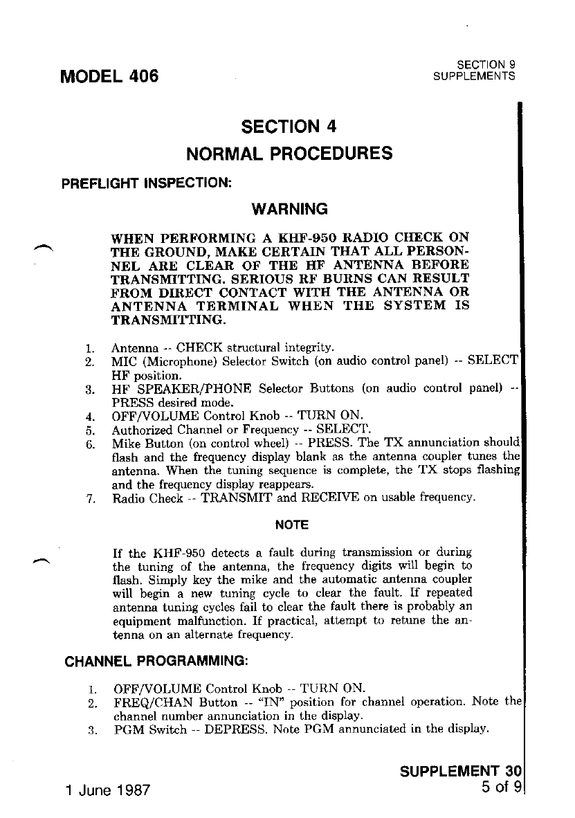
MODEL 406
SECTION 4
NORMAL PROCEDURES
PREFLIGHT INSPECTION:
SECTION 9
SUPPLEI,4ENTS
1.
2.
3.
5.
6.
WARNING
WHEN PERFORMING A KHF-g5O RADIO CIIECK ON
THE GROUND, MAKE CERTAIN THAT ALL PERSON-
NEL ARE CLEAR OF THtr HF ANTENNA BEFORE
TRANSMITTING. SERIOUS RF BURNS CAN RESULT
FROM DIRECT CONTACT WITIT TIIE ANTENNA OR
ANTENNA TERMINAL WHEN TIIE SYSTEM IS
TRANSMITTING.
Ant€nna -- CHECK structural integrity.
MIC (Microphone) Selector Switch (on audio control panel) -- SELECT
HF position.
HF SPEAKER/PHONE Selector Buttons (on audio control panel) --
PRESS desired mode.
OFF/VOLUME Control Knob -- TURN ON.
Authorized Channel or Frequency -- SELECT.
Mike Button (on control wheel) -- PRESS. The TX annunciation should
flash and the frequency display blank as the antenna coupler tunes the
OFF/VOLUME Control Knob -- TURN ON.
FREQiCHAN Button -- "IN'position for channel operation. Note the
channel number annunciation in the display.
PGM Switch -- DEPRESS. Note PGM annunciated in the display.
SUPPLEMENT 30
5ofg
antenna. When the tuning sequence is complete, the TX stops
and the frequency display reappears.
?. Radio Check '' TRANSMIT and RECEIVE on usable frequencv.
NOTE
If the KHF-950 detects a fault during transrnission or durbg
the tuning of the antenna, the flequency digits will begin to
flash, Simply key the mike and the automatic antenna coupler
will begin a new tuning cycle to clear the fault. If repeated
antenna tuning cycles fail to clear the fault there is probably an
equipment malfunction. If practical, attempt to retune the ar'-
tenna on an alternate frequency.
CHANNEL PROGRAMMING:
t.
2.
3.
.1 June 1 987
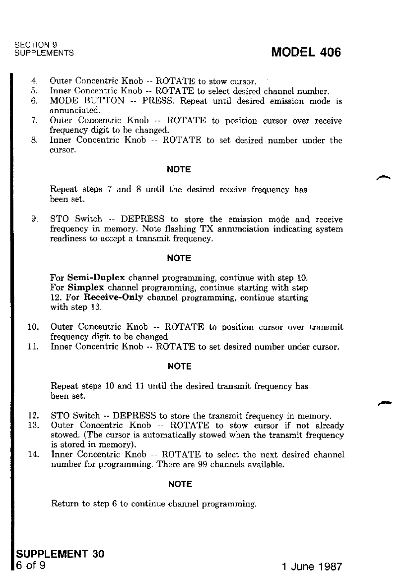
SECI1ON 9
SUPPLEIVENTS
SUPPLEMENT 30
6of9
MODEL 406
4. Outer Concentric Knob ,- ROTATE to stow cursor.
5. Imrer Concentric Knob -- ROTATE to select desired channel number.
6. MODE BUT"TON -- PRESS. R€peat until desicd emission mode is
annunciated.
7. Outer Concentric Knob -- ROTA'|IJ to position curgor over receive
frequency digit to be changed.
8. Inner Concentdc Knob -- ROTATE to set desired number under the
cursor.
NOTE
Repeat steps 7 and 8 until the desired receive frequency has
been set.
9. STO Switch -- DEPRESS to store the emission mode ard receive
frequency in memory. Note flashing TX annunciation indicating system
readiness to accept a tmnsmit frequency.
NOTE
For Semi-Duplex channel programming, continue with step 10.
For Simplex channel programming, continue starting with step
12. For Receive-Only channel programming, continue starting
with step 13.
10. Outer Concentric Knob - ROTATE to position cursor over tmnsmit
frequency digit to be changed.
11. Inner Concentric Knob -- ROTATE to set desired number under curcor,
NOTE
Repeat steps 10 and 11 until the desired transmit frequency hag
been set.
12. STO Switch -- DEPRESS to store the transmit frequency in memory.
13. Outer Concentric Knob -- ROTATII to stow cursor if not already
stowed. (The cursor is automatically stowed when the transmit frequency
is stored in memory).
14. Inner Concentdc Knob - ROTATE to select the next desired channel
number for programming. There are 99 channels available.
NOTE
Return to step 6 to continue channel programming.
1 June 1987
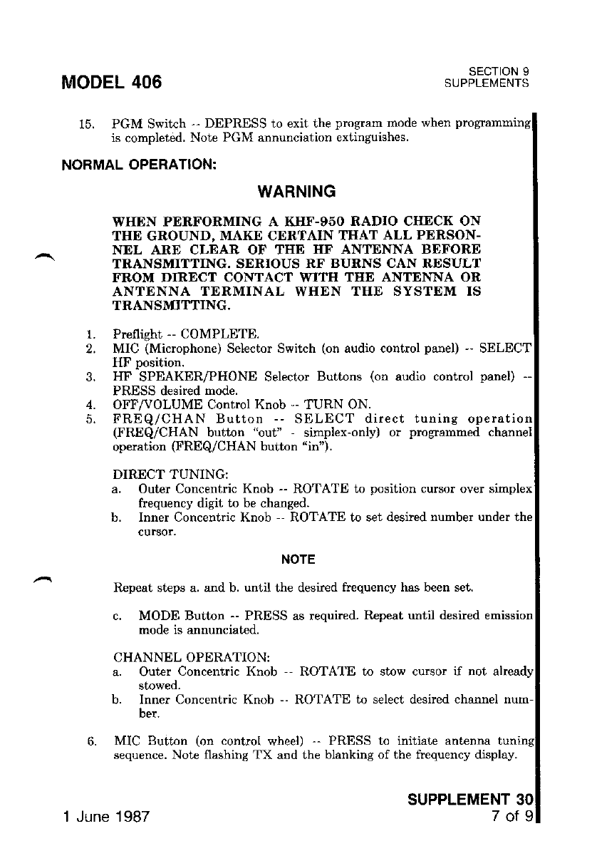
MODEL 406
15. PGM Switch -- DEPRESS to exit ihe program mode when
is completed, Note PGM annunciation extinguishes.
NORMAL OPERATION:
SECTION 9
SUPPLEI\,4ENTS
1.
2.
3.
4.
5.
WARNING
WIIDN PERFORMING A KHF-g5O RADIO CHECK ON
THE GROUND, MAKE CERTAIN TIIAT ALL PERSON-
NDL ARE CLEAR OF THE HF ANTENNA BEFORE
TRANSMITTING. SERIOUS RF BURNS CAN RDSULT
FROM DIRECT CONTACT WITII TTIE ANTENNA OR
ANTENNA TERMINAL WHEN THE SYSTEM IS
TRANSMITTING.
Preflight -- COMPLETE.
MIC (Microphone) Selector Switch (on audio control panel) -- SELECT
HF position.
I{F SPEAKER/PHONE Selecior Buttons (on audio control panel) --
PRESS desired mode.
OFF/VOLUME Control Knob '- TURN ON.
FREQ/CHAN Button -- SELECT direct tuning operation
(FREQ/CHAN button "out" - simplex-only) or programmed channel
operation (FREQ/CHAN buiton "in").
DIRECT TUNING:
Outer Concentric Knob -- ROTATE to position cursor over simplex
frequency digit to be changed.
Inner Concentric Knob -- ROTATE to set desired number under the
cur30r.
NOTE
Repeat steps a. and b. until the desired frequency has been set.
c. MODE Button -- PRESS as required. R€peat until desired emission
mode is annunciated.
CHANNEL OPERATION:
a. Ouier Concenlric Knob -- ROTA'I'E to stow cursor if nol
a.
b.
stowed.
b. Inner Concentric Knob -- ROTATE to select desired channel
ber.
MIC Button (on control wheel) -- PRBSS to initiate antenna
sequence, Note flashing TX and the blanking of the frequency display.
SUPPLEMENT
1 June 1987 Tofg
SECTION 9
SUPPLEMENTS MODEL 406
7.
8.
9.
OI'F'/VOLUME Knob -- SET to desired volume level.
SQUELCH Knob -- SET to desired level usually full clockwise.
CLARIFIER Knob -- PULL out knob and ROTATE in either direction
to optimize incoming SSB signal quality.
TIONAL NOTES:
SSB COMMUNICATIONS:
1. Mosi all airplane HF SSB communications are conducted in USB mode.
Some ground stations continue to use the AM mode, but these stations
are being phased out in favor of the more efficient SSB mode of
operation.
-DUPLEX OPERATION:
1. In semi-duplex operation, the emission mode you select (USB or AM)
will always control both receive and transmit frequencies. Also, the
receive frequency is displayed uatil the mike is keyed, at which time the
transmit frequency is displayed.
FREQUENCIES:
1. The higher frequencies are best during daylight (10,000.0 to 29,999.9
kHz) and the lower frequencies work best at night (2000.0 to 10,000.0
kHz).
G THE ANTENNA COUPLER:
1. It is necessary to retune the antenna coupler whenever the MODE
selector knob is changed from one mode to another. Pressing the MIC
button momentarily initiates antenna tuning,
ITIONAL INFORMATION:
1. For expanded information and operational instructions, refer to the
"King KHF-950 Pilot's Guide and Directory of HF Services" supplied
with your airplane.
30 1 June 1987

SECTION 5
PERFORMANCE
Thereisnochangetotheairplanepelformancewhenthisavionicequipment
i" i"#i;;. ;;*;;;,-ttte in"tattutioi- or''an externallv-mounted antenna or several
*r^i"[""i"t""f ""t"nnas will result in a minor reduction in cmise peformance'
MODEL 406 SECTION 9
SUPPLEMENTS
SUPPLEMENT 30
9of9
1 June 1987

SECTION 9
SUPPLEIVENTS
SUPPLEMENT
KING MARKER BEACON
(TYPe KR-21)
SECTION 1
GENERAL
The King Tlpe KR-21 Marker Beacon System consists of a panel mounted
75 MHz m;ke; beacon receiver, a KMA-24H-70 Audio Control Panel for
MODEL 406
SUPPLEMENT 31
1of 4
speaker/phone audio selection and externally mounted marker beacon
mounted on the under side of the airplane.
The front panel of the KR-21 Marker Beacon Receiver incorporates a
that provides for selection of HI or LO marker
positon toggle swilch lhat provides Jbr selectlon ol HI or LU mark
signal senJi;vity and a marker beacon lamp test. Three lights are installed on
signal
frint of the panel with different colored lenses to indicate passage over
markers. The whit€ light (Inner ard Fan) has an A engraved on iE lens, the b
ri;+ /n,,+.,I r.". ". o ".*"""a nn ilq tens and the amber lisht (Middle) has a
light (Outer) has an O engraved on its lens and the lisht (Middle) has
eigravect on ils lens- The ieceiver's front panel also-incorporates a photo-cell
seisor which provides automatic dimming circuits for the marker larnps
compensate for ambieut cockpii lighting.
The KMA-24H-?0 Audio Control Panel provides marker beacon SPEAKER
-a iHbfqn selector pushbuttons to let th€ operator rec€ive marker beacon audio
"imal. oue" the cockpit speaker or headphones as desired' Refer to Supplement
U6 in this manual for complete audio control panel operations'
The HI sensitivity selector switch position' Iabeled H, is used for airway
opemtion.
The LO sensitivity selector switch position, Iabeled L, is used for ILS
approaches.
The marker beacon lights test position, labeled T, is selected to verify
operation of the marker beacon lights.
All operating controls for the KR-21 Marker Beacon Receiver and marker
luu"o" of"iuti"/"ontrols on the Audio Control Panel are shown and described in
Figure 1.
1 June 1987
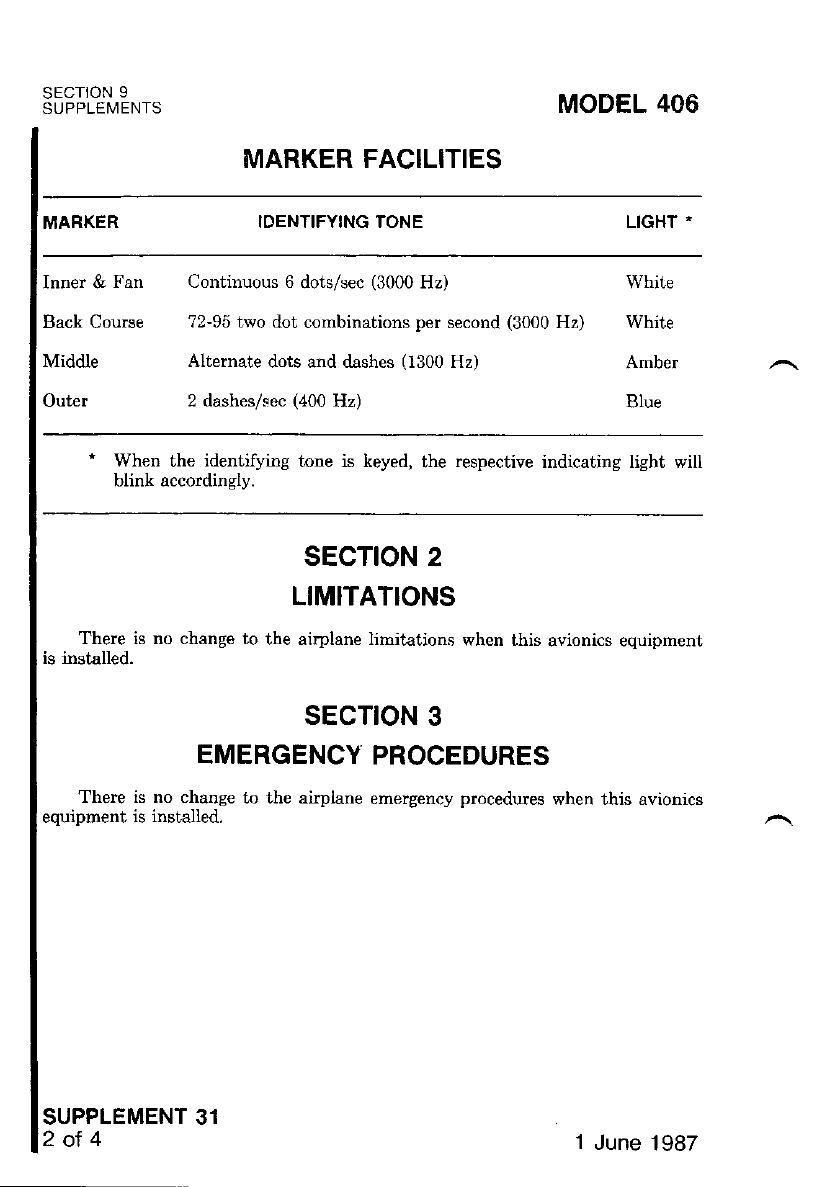
sEcIoN I
SUPPLEMENTS MODEL 406
MARKER FACILITIES
MARKER IDENTIFYING TONE LIGHT -
Inner & Fan Continuous 6 dots/sec (3000 Hz) White
Back Course 72-95 teto dot combinations per second (3000 Hz) White
Middle Altemate dots and dashes (1300 Hz) Amber
Outer 2 dashes/sec (400 Hz) Blue
a When the identifying tone is keyed, the respective indicating light will
hlinL oonnrrlinolv
sEcTtoN 2
LIMITATIONS
There is no change to the airplane limitaiions when this avionics equipment
is installed.
sEcTtoN 3
EMERGENCY PROCEDURES
There is no change to the airplane emergency procedures when this avionics
equioment is installed.
SUPPLEMENT 31
2ol 41 June 1987
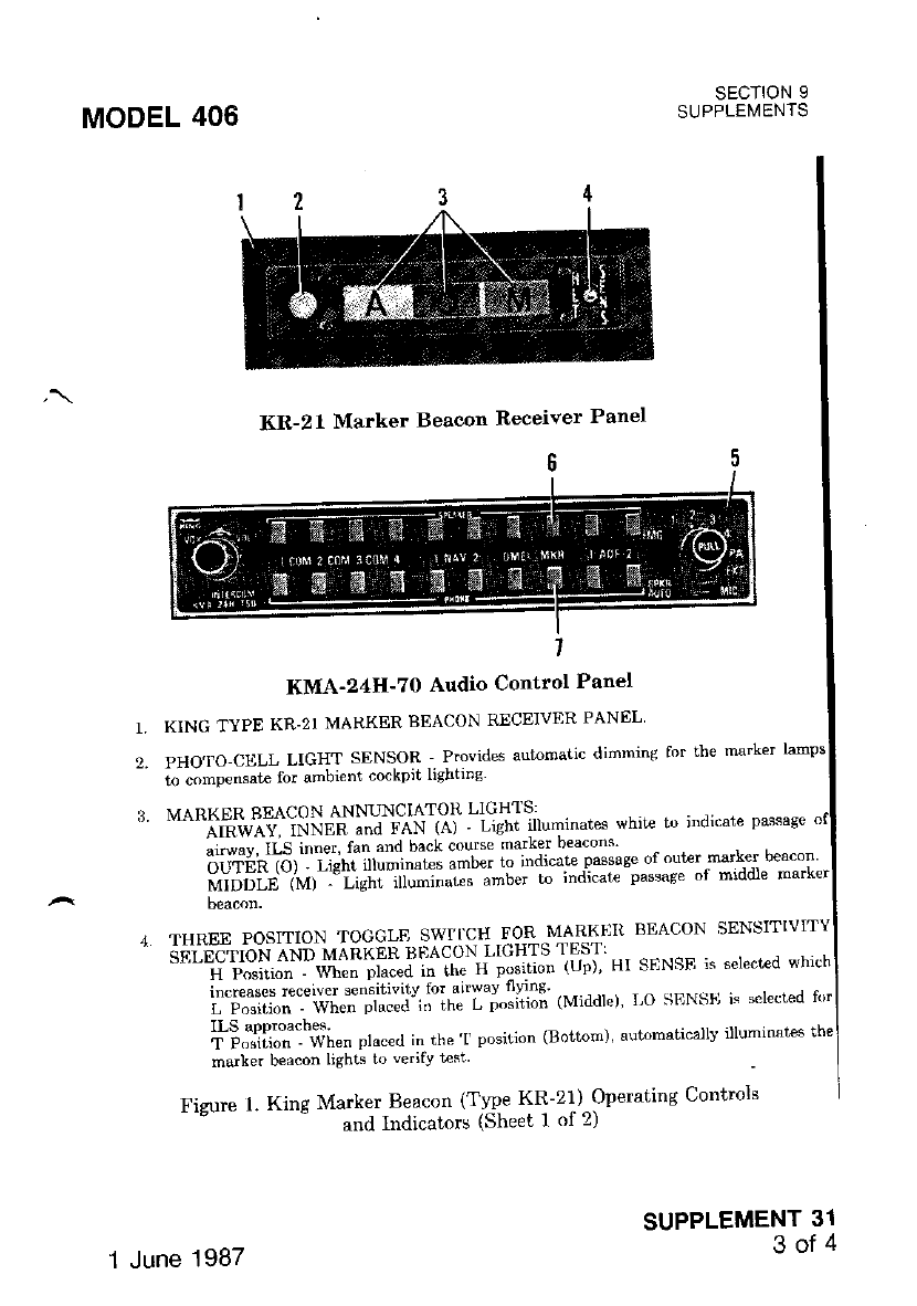
MODEL 406 SECTION 9
SUPPLEMENTS
KR-21 Marker Beacon Receiver Panel
KMA'24H'7O Audio Control Panel
KINC TYPE KR.2I MARKER BEACON RECEIVER PANEL'
PHO'|O-CELL LIGHT SENSOR Provrdes automatic dimnins for the marker ramps
ro.omDensarf, for ambi€n( .o.kp'l llgnllng
MARKER BEACON ANNUNCIATOT( LI(; H'I S:
AIRWAY. INNtH and rA-\ rAr - Lrghr illuminares whit-€ Iu ;ndicalP passase
alrJ*' *'''':li,lTl ;H:: il"#lli"'!""ii;*r "1.*r.*.,1',,^"*n .
d."o",%,"3ltili1,"r'*:f,*"i,j;"'iif "iioi,"1#*i,xl,lJJl,^ff iii j
i"i,fii;T:\il"" "'"c€cr
in the'r posiiion (Bottom), automaticarrv 'ruminates
the
marker bea.on light' 1,, verifv Les-
Fizure L King Marker Beacon tTlpe KR-211Operating Con+rols
and lndicalnrs (Sheet I ol 2)
SUPPLEMENT 31
3of4
THREE POSITION TOGGLE SWTICH FOR MARKI']IT BEACON SENSITIVITY
6F.iiiclioN tNn MAli[[Jl.liflyi::],ij.',"".,T ", sFNsF, is bercc'"d whi(h
f";:mf:';"*"Xl*::ti'i1fl'"i";i*:i (Middre)' Lo SENS'r is sereckd nrr
1
2.
1 June 1987
SECIION 9
SUPPLEMENTS
7.
5.
SECTION 4
NORMAL PROCEDURES
MARKER EEACON OPERATING PROCEDURES:
SUPPLEMENT 31
4ot4
KING XMA.24H 70 AU])TO CON'I'ROI, PANEL REQUIRED WITH KINC KR-21
MARKER BEACON INSTALLATIO:\*.
MARKER BEACON SPEAKER AUDIO MONITOR PUSHBUTTON - WheD de-
pressed, the_ markef be€con audio signals can be heard over the cab;" t.p speat<er. ,f,o
dlsconnect the mark€r b€acon audio from the cabin,top speaker, deprcss the pushbutton
MARKER BEACON PHONE AUDIO MONITOR PUSHBUTTON _ When dcpressed,
the rrsrker beacon audio srgnals can be beard over rhe headphones. r., al*"",i".t ,r,.
trtarker opacun audro t.om lhe headphones, Jepress the pushbulron a second t;m€.
Figure 1. King Marker Beacon (T1pe KR-21) Operating Controls
and .lndicatols (Sheei 2 of 2)
MODEL 406
1.
2.
3.
NOTE
The marker beacon receiver is capable of rcceiving marker
beacon signals anytime the No. 1 AVIONICS switch is'bN.
Nav Receiver Volume Control -- ADJUST to desired listening level.
HI/LO SensiLivity Selector Switr.h SELECT H tHlt -posirion for
4rygy lft1rC or L (LOt position for ILS approaches.
MKR -SPEAKER/PHONE pushbuttons (bn Audio Control panel) __
SELECT desired speaker or headphone audio.
Test (T) Selector Switch -- SELECT T position and verifu that all
marker beacon annunciator lights will illuminate full bright; irdi";
lights are operational,
SECTION 5
PERFORMANCE
Jl-rey is..no- ciange to the airplane performance when this avionics equip_
meDt is installed. However, thc installation of an extemally mounted anlenna or
several related external antennas, will result in -ino. red,r'ction ir, "*i"" p"rfo"
mance,
1 June 1987
MODEL 406 SECTION 9
SUPPLEMENTS
SUPPLEMENT
KING RADAR ALTIMETER
(Type KRA-10A)
sEcTloN 1
GENERAL
The King Radar Altimeter (Type KRA-10A), shown in Figure 1, consists of a
panel-mounted indicator, a remote mounted receiver/hansmitter and an anrenna.
-The Radar Altimeter (depending upon terrain reJlectivity and airplane bank
argle) gives an absolute altitude indication from 2b00 feet AGL to 35 llb feet
AGL. It provides continuous selection of warning altitude and annunciation of
descent to that altitude by both a DH (decision height) light and an aural
warniag. Climbing through the selected warning altitude extinguishes the DH
light. The DH-light is automatically dimmed by a photo cell. Indicator ligh ng is
controlled by the radio light dinming rheostat.
The Radar Altimeter remote receiver/transmitter is all solid-state and op-
emtes orr 28-volt primary power. Complete self-test may be accomplished both on
preflight and in-flight.
SECTION 2
LIMITATIONS
There is no change to the airplane limitation when this avionic equipme,nt is
installed.
SUPPLEMENI'32
1of 4
1 June 1987
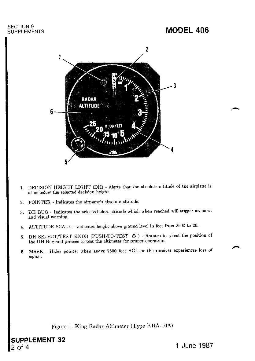
SECTION 9
SUPPLEMENTS MODEL 406
DECISION HIIIGHT LIGHT (DH) Alerts that the absolut€ altitude of the airplane ls
at or below the selected decision height.
POINTER - Indicates the airplane's absolute altitude.
DH BUG ' Indicat€s the selected aled altrtude which when reached wilt b'isser an ausl
and visual warning.
ALTITUDE SCALn Indicat€s height above ground level in feet from 2500 to 20
DH SELECT/TES'I' KNOB (PUSH-TO-TEST A ) -Rotates to select the position of
the DH Bug and presses to test the altimeter for proper opedtion.
MASK - Hides pointer when above 2500 feet AGL or the receiver experiences loss of
signal.
2.
3.
4.
5.
Figure 1. King Radar Altimeter (Twe KRA-1OA)
SUPPLEMENT 32
2 ot 4 1 June 1987
MODEL 406
sEcTroN 3
EMERGENCY PROCEDURES
There is no change to the airplane emergency procedures when thrs
eouiDment is installed.
sEcTtoN 4
NORMAL PROCEDURES
PREFLIGHT AND IN.FLIGHT SELF-TEST:
1. AVIONICS MASTER Switch -- ON.
2. DH Bug -- SET to 20 feet.
3. DH Select/Test Knob -- DEPRESS and HOLD. The indicated
should be 50 15 feet and the DH lamp should be off.
4. DH Select,rTest Knob -- DEPRESS and TURN slowly clockwise.
DH lamp shoutd light and a two-second audio tone will sound when
DH bus reaches 50 a5 feet,
5. DH Select/Test Knob - RELEASE. The DH lamp will go out and
pointer will move clockwise behind the mask. When flying at an
below 2500 feel, AGL, pointer will remain in view.
NOTE
Ground operation near laige hangars, oiher airplane, water pud-
dles and other nearby objects may cause the pointer to come
into view. This does not indicate a system malfinction since
the reflections constitute a real signal.
NORMAL OPERATION:
1. AVIONICS MASTER Swikh -- ON.
2. DH Bug -- SET as desired,
CAUTION
The radar altimeter must not be used to identify the
MDA (Minimum Descent Altitude) or DH (Decision
Ileight) while making an instrument approach.
SECTION 9
SUPPLEMENTS
SUPPLEMENT 32
3of4
1 June 1987
OPERATIONAL NOTES:
1. During take-off, radar altimeter indications are unreliable until after
approximately the first 15 seconds a1ler climbing above 50 feet altitude.
2. Depending upon termin reflectivity, initial and/or reliable indications
during descents through the 2500-foot level may not occur until the
airplane has reached absolute altitudes as low as 1500 feet.
3. Accuracy in Ievel flight or in descents at rates up to 1000 FPM is within
'lVo or 80 feet, whichever is greater.
4. The pointer will disappear from view below 2500 feet if the ground
return signal is lost. The pointer may also disappear from view mo-
mentarily when the airplane is in a banl in excess of 15o (above 2000
feet) or (45o below 1000 feet).
5. Once the indicator has reached 35 115 feet during larding approach,
further indications in this range are unreliable, since the indicator may
dwell briefly in this range even as the airplane descends fulther.
6. The pointer will move to the OFF position if primary power is lost.
SECTION 5
PERFORMANCE
There is no change to the airplane performance when this avionic equipment
is installed. However, the installation of an externally mounted antenna or several
lelated ext€rnal antennas, will resuli in minor reduction in cruise performance.
SECTION 9
SUPPLEMENTS MODEL 406
lsunruer'aexr sz 1 June 1987
MODEL 406 SECTION 9
SUPPLEI\,!ENTS
SUPPLEMENT
KING
RADIO MAGNETIC INDICATOR
(Type Kl-22e)
SECTION 1
GENERAL
The King Radio Magnetic Indicator (RMI) is used in conjunction with other
aiborne navigation equipment to aid the pilot in navigating the airplane. The
RMI eliminates the need for many of the mental computations necessary for
deterninirog the airplane position.
The RMI is a panel mount€d navigation instrument that combines the
display of VOR and ADF bearing information with the airplane heading on a
single irtstrument. The VOR and ADF magnetic bearings to the selected stations
are displayed by individual rotating pointerc against the background of a rotating
azimuth card. The azimuth card is driven by the slaved magnetic compass system
in the airplale and continuously indicates airplane heading. Thus, the relative
bearing between the airplane heading and the station is pictorially displayed.
Each pointer in the Type KI-229 RMI is dependent on its associat€d receiver
for indicating bearings. A single-bar pointer indicates VOR bearines and a
double-bar pointer indicates ADF bearings. Two NAV receivers supply VOR
signals to the RMI for selection. When one of the VOR receivers is a KNS-81
Area Navigation Syst€m, the single-bar pointer can indicate the RNAV waypoint
beadng. A two-position selector switch (NAV I/NAV 2) on the instrument panel
selects the desired VOR signal for display of bea ng information. The Ki-229
RMI is internally lighted. Intensity is controlled by the RA-DIO light dimming
lheostat.
SECTION 2
LIMITATIONS
There is no change to the airplane limitations when this avionic equipment
is installed.
SUPPLEMENT 33
.1 of 5
1 June 1987
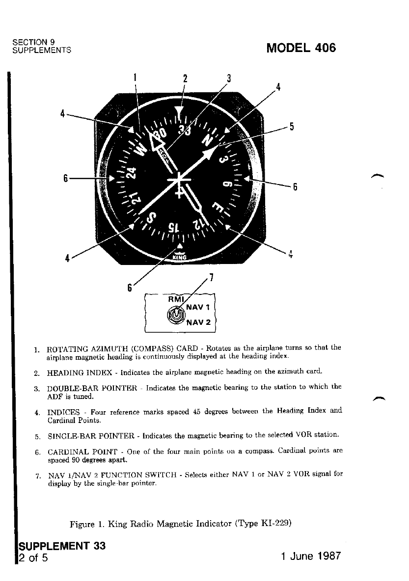
SECTION 9
SUPPLEI\,4ENTS
7.
MODEL 406
RO'I'ATING AZIMUTH (OOMPASS) CARD - Itotates as the airplane tums so that th€
airplane magnetic heading is continuouslv displaved at the heading index
HIIADING INDEX ' tndicates the ai.plane magnetic h€ading on the azimuth card'
DOUBLE-BAR POINTER lndicates the magnetic bearins to the siation to which the
INDICES - Four reference marks spaced 45 de$ee6 between the Headins Index and
Cardinal Points.
SINGLE-BAR POINTER ' lndicates the maglletic bearing to the select€d VOR stalion
CARDINAL POIN'I - One of the four main points on a compass. Cardinal poinis arc
spaced 90 degrees apart.
NAV I/NAV 2 FUNCTION SWITCH - Selecrs either NAv 1 or NAV 2 VOR sisnal for
display by the single-bar point€r'
Figure 1. King Radio Magnetic Indicator (Tt?e KI-229)
PPLEMENT 33
2.
3.
5.
6.
NAV 1
NAV 2
of5 1 June 1987
MODEL 406 SECTION 9
SUPPLEMENTS
NOTE
If the ADF receiver is turned OFF. the double-bar Doint€r will
remain fixed in its last position.
3. NAV 1-2 Selector Switch (for RMD -- SET to NAV 1 or NAV 2 and
select VOR station on the associated NAV receiver. The single-bar
point€r will indicate the magnetic beadng to the station.
NOTE
This teading is equivalent to the "TO" course reading obtained
with the standard CDI omni bea ng selector. The "FROM"
radial of the VOR station is obtained by reading the opposite
end of the oointer.
SECTION 3
EMERGENCY PROCEDURES
There is no change to the airplaae ehetgency procedutes when this avionic
equipment is insblled.
SECTION 4
NORMAL PROCEDURES
NORMAL OPERATION:
NOTE
Operation of the RMI is dependent upon input information
from the compass system (slaved directional gyro or HSI), the
associated VHF navigation and ADF rcceivers. Refer to the
appropriate supplements in this section for operation of thrs
equipment.
1. Compass Cards (on RMI and HSI) -- CHECK that headine indications
on RMI and HSI are the same.
2. ADF Receiver -- SELECT STATION on receiver. The double-bar point-
er will indicate the magnetic bearing to the station.
SUPPLEMENT 33
JOT5
1 June 1987
SECTION 9
SUPPLEMENTS MODEL 406
WARNING
a If the RMI Compass Card is not tracking the Directional
Gyro or HSl, the VOR bearings are invalid. Thismav be
caused by a failure in the RMI, Slaved Compass System'
or a loss of power from the AC Inverter.
a The ADF indications are valid relative to the nose of the
airlrlane only and may be used by referring to the llead-
ing Index and 46 degree indices on the RMI.
RMI TEST:
1. ADF Receiver -- TUNE to usable frequency with ADF mode selected'
i. ebf'S"tton (On KR-8? Receiver) -- SELECT ANT mode' Double-bar
Dointer will slew to the Lhree o'clock position
3. i-DF -- sELEcT ADF mode and OBSERVE that double-bar pohter (on
- nl,ffl leturns to the same station bearing as in step 1 to indicate a
normal operation.
NOTE
If the ADF Receiver is turned OFF, the double-bar pointer will
remain frxed in its last PositioD
4. VOR Receiver -- TUNE to usable VOR frequency.
S. VOn Receive, -- TURN Of'F. Single-bar pointer will slew to the three
o'clock position.
6. VOR Receiver -- TURN ON and OBSERVE that the single-bar pointer
- (on RMD rctums to the same station bearing as in step 4 to iudicate a
normal opelation.
NOTE
If the selecied VOR Receiver is tumed off or a reliable signal is
not being received, or an ILS frequency is selected, the single-
bar pointer will move to the stowed positiou (1ixed at the 3
o'clock position).
SUPPLEMENT 33
4of5 1 June 1987

sEcT|oN 5
PERFORMANCE
There is no change to the airplane performance when this avionic equipment
is installed in addition to that which occurs with iistallatiod of the ADF or VOR
antennas.
MODEL 406 SECTION 9
SUPPLEI,4ENTS
1 June 1987 SUPPLEMENT 33I

MODEL 406 SECTION 9
SUPPLEI,4ENTS
SUPPLEMENT
KING
RADIO MAGNETIC INDICATOR
(Type KNI-582)
SECTION 1
GENERAL
The King KNI-582 Radio Magnetic Indicator (RMI) is used in conjun(
with other airborne navigation equipment to aid the pilot in navigating
airplane, The RMI eliminates the need for many of the numerical and grap
computations necessarJr for determining the airplane position.
The RMI is a panel mounted navigation instrument that combines
display of NAV and ADF bearing information with the airplane heading on
single instrument. The NAV and ADF magnetic bearings to the selected
are displayed by individual rotating pointers against the backgound of a rotating
azimuth card. The azimuth card is driven by the slaved magnetic compass system
in the airplane and continuously indicates airplane heading. Thus, the relative
bearing between the airplane heading and the station is pictorially displayed.
Each pointer in the KNI-582 RMI is deperdent only on its associated
receiver for indicating bearings. .r single-bar pointer indicates NAV I or ADF
bearings and a double-bar pointer indicates NAV 2 or ADF bearings. The choice
of NAV of ADF information displayed by each pointer is determined by
corresponding front palel display switch.
Should a localizer frequency be selected or the NAV receiver indicate
fl,agged condition, the NAV pointer will slew to the 3 o'clock position,
A HDG flag falls into view in the upper left corner of the display when
heading information being displayed is invalid.
SUPPLEMENT
1 June 1987 1of
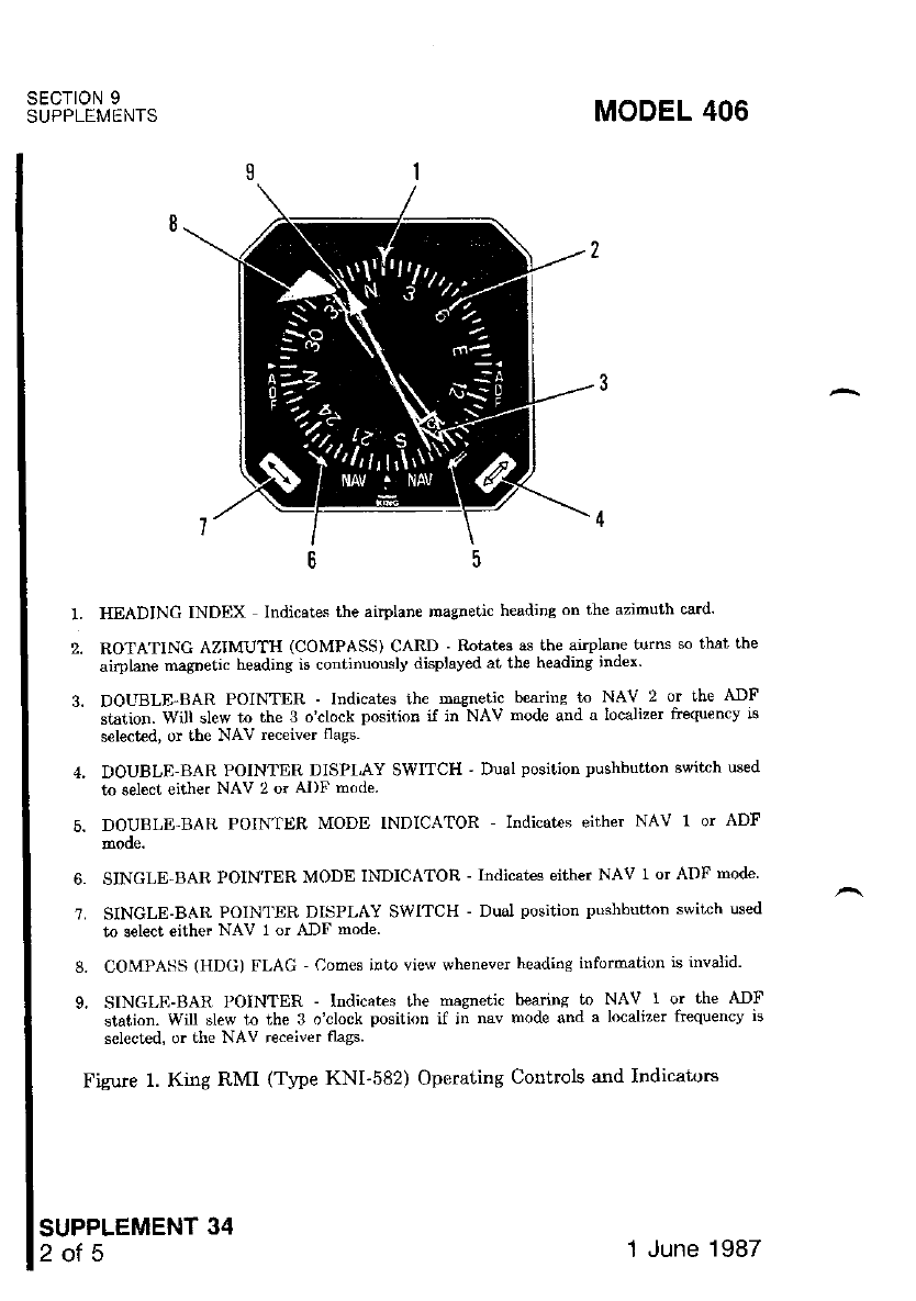
SECTION 9
SUPPLEMENTS
SUPPLEMENT 34
2of5
MODEL 406
HEADING INDEX Indicat€s the aiplane tnagnetic heiding on the azimuih card'
ROTATING AZIMUTH (COMPASS) CARD - Rotates as the anphne turns so that the
airplane magDetic heading is continuously displaved at the heading index'
DOLTBLE BAR POINTER - Indicat€s tbe masnetic b€arins to NAV 2 or the ADF
sLsrion. Will slew Lo the'l oclock posilion iJ;n NAV mode and a loca-lizer foequency i6
select€d, or the NAV receiver tlass.
DOUBLE-BAR POINTER DISPI,AY SWITCH ' Dual position pushbutton switch used
to select either NAV 2 or AI)F mode.
DOUBLE-BAII POINTTIR MODE TNDICA'rOR - Indicat€s either NAV 1or ADF
SINGLE-BAR POIN'IER MODE INDICATOR - Indicat€s either NAV r or ADF mode
SINGLE-BAR POINTER DISPLAY SWTTCH - Dual position pushbutton switch used
to select either NAV I or ADF mode
COMPASS (HDG) FLAG Com€s into view whenever headins information is invalid'
SINGLE-BAR POINTER - lndicates the msgnetic bearins to NAV I or the AIF
station. Will blew to the 3 ^.lock positi,'n if in nav rnode snd a localiTer hcquencv iq
s€lected, or the NAV receiver flags.
Figure 1. King RMI (Trpe KNI-582) Operating Controls and Indicators
1.
2.
6.
'7.
8.
9.
1 June 1987
MODEL 406
SECTION 2
LIMITATIONS
There is no change to the airplane limitations when this avionic
is installed.
SECTION 3
EMERGENCY PROCEDURES
There is no change to the airplane emelgency procedures when thrs
equipment is installed.
SECTION 4
NORMAL PROCEDURES
NORMAL OPERATION:
NOTE
Operation of the RMI is dependent upon input information
from the compass system (slaved directional gyto), the asso-
ciated VHF navigation and ADF receivers. Refer to the appro-
priate supplements in this section for operation of this equip-
ment.
Compass Cards (on RMI and HSD -- CHECK that heading
on RMI ard HSI are the same.
ADF Receiver - TUNE to usable frequency with ADF node selected,
Single- or Double Bar-Pointer Display Switch -- SELECT ADF mode.
READ magnetic bearing to the ADF station under the selected pointer.
NOTE
If the ADF receiver is turned off. the selected oointcr will
remain fixed in its last position.
SUPPLEMENT 34
3of5
SECTION 9
SUPPLEMENTS
2.
3.
4.
'1 June 1987
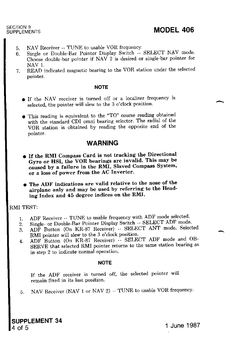
SECIION 9
SUPPLEMENIS MODEL 406
7.
NAV Receiver -- TUNE to usable VOR fiequency.
Single or Double-Bar Pointer Display Switch -' SELECT NAV mode'
Choose double-bar pointer if NAV 2 is desired or single-bar pointer 1br
NAV 1.
READ indicated magnetic bearing to the VOR station under the selected
polnter.
NOTE
a If the NAV rcceivet is turned olf or a localizer frequency is
selected, the pointer will slew to the 3 o'clock position'
o This reading is equivalent to the "TO" course reading obtained
with the st;dardCDl omni bearing selector' The radial of the
VOR station is obtained by reading the opposite end of the
pornrcr.
WARNING
o If the RMI Compass Card is not tracking the Directional
- Gy"o o. HSI, th; VOR bearings are invalid' Thisrnav be
caused by a iailure in the RMI, Slaved Cornpass System'
or a loss of power frorn the AC Inverter'
a The ADF indications are valid relative to the nose of the
- "i.pt.rr. only and may be used by referring to the llead-
ing Index and 45 degree indices on the RMI'
RMI TEST:
1. ADF Receiver -- TUNE to usable frequency with-ADtr'mode.selected'
i. di"gf* "t Oo"Ule-Bar Pointer Displav Switch SELECT ADF mode'
5. Atii Button (On KR-87 Receiver) - -' SELECT ANT mode' Selected
RMI pointer will slew to the 3 o'clock position - - . - -
. Airl''B"ttn" (On KR-8? Receiver) -- SELECT ADF mode and OB-
- 'SgnVO;hai s;lected RMI pointer returns to the same station bearing as
in step 2 to indicate normal operation'
5.
b.
NOTE
If the ADF receiver is turned off, the selected pointer will
remain fixed in its ldst Position.
5. NAV Receiver (NAV 1 or NAV 2) '- TUNE to usable VOR frequencv'
SUPPLEMENT 34
4of5 1 June 1987
Single- or Double-Bar Point€r Display Switch (as appropriate to the
selected NAV) -- SELECT NAV mode.
NAV Receiver -- TURN OFF. Appropriat€ RMI pointer will slew to the
3 o'clock position.
NAV Receiver -- TURN ON and observe ihat the appropriate RMI
pointer returns to the same station beadng as in step 6 to indicate
normal operation.
NOTE
If the eelected NAV receiver is turned off or a reliable signal is
not being received, or an ILS fiequency is selected, the appro-
priate pointer will stow at the 3 o'clock position.
SECTION 5
PERFORMANCE
There is no change to the airplane performance data when this avionic
equipment is installed.
MODEL 406 sEcTroN 9
SUPPLEMENTS
6.
7.
8.
1 June 1987 sUPPLEMENT 341

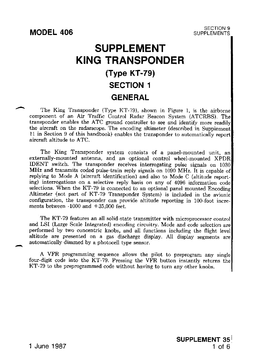
MODEL 406 SECTION 9
SUPPLEMENTS
replying to Mode A (aircraft identification) and also to Mode C (altitude report-
ing) interogations on a selective reply basis on any of 4096 inforrnation code
selections. When the KT-79 is connected to an optional panel mounted Encoding
Altimeter (not pari of KT-79 Transponder System) is included in the avionic
configr-rration, the transponder can provide altitude reporting in 100-foot incre-
ments between -1000 and *35,000 feei.
The KT-79 features an all solid,state transmitter with microprocessor control
and LSI (Large Scale Integrated) encoding circuitry. Mode and code selection are
performed by two concentric knobs, and all functions including the flight level
altitude are presented on a gas discharge display. All display segments are
automatically dimmed by a photocell t,?e sensor.
A \rFR programming sequence allows the pilot to preprogmm any single
four-digit code into the KT-?9. Pressing the VFR button instantly returns the
KT-79 to the preprogrammed code without having to turn any other knobs.
SUPPLEMENT
KING TRANSPONDER
(Type KT-79)
sEcroN 1
GENERAL
The King Transponder (Typc K1 79), shown in Figure l, is the
component of an Air Traffic Control Radar Beacon System (ATCRBS).
transponder enables the ATC ground controller to see and identify more
the aircraft on the radarscope. The encoding altimeter (described in
11 in Section 9 of this handbook) enables the transponder to automatically
aircraft altitude to ATC.
The King Transponder system consists of a panel-mounted unit, an
exiemally-mounied antenna, ald an optional control wheel-mounted
IDENT switch. The transponder receives int€rrogating pulse signals on 1030
MHz and transmits coded pulse-train reply signals on 1090 MHz. It is capable
SUPPLEMENT 35
1of 6
1 June 1987
SECTION 9
SUPPLEMENTS MODEL 406
AII King Transponder operating controls, with the exception of the oper-
ral altitude encoding altimeter setting knob and the optional remote XPDR
IDENT switch, are located on the front panel of the unit. The altimeter setting
knob is located on the encoding altimeter (not shown) and the remote XPDR
IDENT switch is located on the right-hand grip of the pilot's and left-hand grip
the copilot's control wheel. Functions ol the operating controls are described in
1.
SECTION 2
LIMITATIONS
There is no change to ihe airplane limitations when this avionic equipment
inst€lled.
sEcrloN 3
EMERGENCY PROCEDURES
TO TRANSMIT AN EMERGENCY SIGNAL:
Mode Selector Knob -' ON (or ALT).
Code Selector Knob -- SELECT 7?00 operating code.
TO TRANSMIT A SIGNAL REPRESENTING LOSS OF ALL
COTT'TITUNTCETTONS (WHEN IN A CONTROLLI]D ENVIRONMENT):
1.
2.
1.
2.
Mode Selector Knob -- ON (or ALT).
Code Selector Knob -- SELECT 7700 operating code for 1 minut€; then
SELECT ?600 operating code for 15 minutes and then REPEAT thts
procedure at the same intervals for remainder of flight.
SUPPLEMENT 35
2ofG 1 June 1987
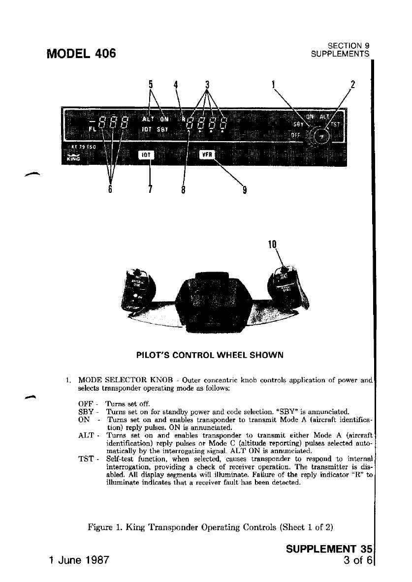
MODEL 406
OFF ,
SBY -
oN-
ALT .
SECTION 9
SUPPLEMENTS
SUPPLEMENT 35
3of6
PILOT'S CONTROL WHEEL SHOWN
MODE SELECTOR KNOB - Out€. concentic knob controls application of power ard
selects transponder op€mting nod€ as follows:
Turns set on for st$dby power and code selection. 'SBY" is annunciated.
Tums set on a]ld enables transponder to tmnsmit Mode A (aircraft id€niifica-
tion) reply pulses. ON is annunciated.
Turns set on and enables transponder to transmit €ither Mode A (aircraft
identifrcation) reply pulses or Mode C (altitude reporting) pulses selected auto-
matically by lhe interrosating sisnal. AL'r' ON tu annuDciated.
TST - Self-test function, when select€d, causes hansponder to respod to inteinal
intlrrogation, providing a check of rcceiver opemtion. The transmitter is dis-
abled. All display sesmenb will illuminat€. Failure of the reply indicator 'R" ta
illuminate indicates that a receiver fault has been detected.
Figure 1. King Transponder Operating Controls (Sheet 1 of 2)
1 June 1987
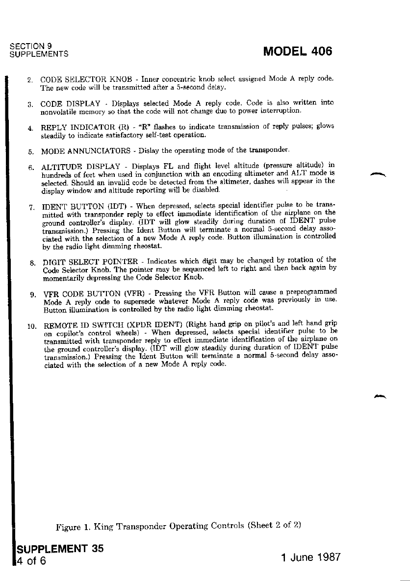
SECIION 9
SUPPLEMENTS MODEL 406
5.
6.
2. CODE SELECTOR KNOB - Inner co$c€ntric knob select assigned Mode A replv code.
The new code will be transmitted after a 5-second deiay
3. CODE DISPLAY - Displays selected Mode A replv code. Code is also w tten into
nonvolatile memory so that the code will not chang€ due to power interuption.
REPLY INDICATOR (R) - "R" fla.shes to indicate transmission of rcplv pulses; glows
staadily to indicat€ satisfactory self test operatioD.
MODE ANNUNCIATORS - Dislay the operating mode of the tsnsponder'
ALTITUDE DISPLAY Displavs FL and flighr level altitude (preqsurc altitude) in
hundreds of feet when used in conjunction lnth un encoding altrmeter and ALr mode *
sei""tea. Sm,.tta ,rl invalid code b; d€t€ct€d ftom the altimel€., dashes will app€ar jD tle
display window and altitude reportins will be disabled
Figule 1, King Transponder Operating Contrcls (Sheet 2 of 2)
?. IDDNT BUTTON (lDT) - When depressed, selects special id€ntifier puls€ to be trans-
mitted with transponder reply to effect immediale jdeniification of the auplane on tbe
cround controller's displav. itof wi glow sleadilv during duration of IDENT pulse
irarsnrission.) Pressine lhe ldenl Button will Lerminale x norma] s_second delay asso
"i"t"a "ift tit" selecti6n of a new Mode A replv code Button illumination is controlled
by the radio light dimming rheostat.
DIGIT SELECT POINTER ' Indicates which digit mav be chsnged bv rolation of the
C"a" b"L"t". x""f. the poinler mav be sequencid lett to right and ihen back asain bv
momentadly depressing the Code Selector Knob.
vTR CODE BUT'ION (\T'R) ' Prcssins the VFR Button will cause a preproFammed
Ir4-ode ,c. replv code to supersede whatever Mode A reply code was prcviously in use'
Button illumina(ion ;s coniroled bv the radio lighl dimming rheostat'
REMOTE tD SWTTCH {XPIJR IDENT) (Right hand grip on pilor s and lcft hand grip
"i-l"iifot'" "o"t.ot wheels) - when depres;d' selecls special identifier pulse to be
iirn.Jitt"a *ittt transponder reply l,o eff;ct immediat€ identificatioD of the airplane on
ii'" *..rnJ "rnt.ott*t^djsplay atbT will slow ste€dilv during duration of I]]ENT puhe
tmnamission.) Pressins the Ident Button will terminate a normal i-second derav asso'
ciat€d with the s€lection of a new Mode A replv code
35 ''l June 1987
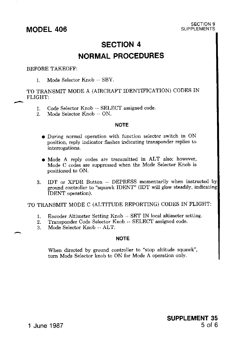
SECTION 4
NORMAL PROCEDURES
BEFORE TAKEOFF:
1. Mode Selector Knob '- SBY.
TO TRANSMIT MODE A (AIRCITAFT IDENTIFICATION) CODES IN
FLIGHT:
1. Code Selector Knob -' SELECT assigned code.
2. Mode Selector Knob'- ON
NOTE
a Du ng normal operation with lunction selector switch in ON
position, reply indicator flashes indicating transponder replies to
inte.rogations.
o Mode A reply codes are transmitted in ALT also; however,
Mode C codes are suppressed when the Mode Selector Knob is
positioned to ON.
3. IDT or XPDR Button -- DEPRESS momentarily when inshucted
ground controller to "squawk IDENT" ODT will glow steadily,
IDENT ooeration).
TO TRANSMIT MODE C (ALTITUDE REPORTING) CODES IN FLIGHT:
Encoder Altimeter Setting Knob - SET IN local altimeter setting.
Transponder Code Selector Knob -- SELECT assigned code.
Mode Selecior Knob -- ALT.
NOTE
When directed by ground controller to "stop altitude squawk",
turn Mode Selector knob to ON for Mode A operation only.
MODEL 406
1.
2.
3.
SECTION 9
SUPPLEI\4ENTS
SUPPLEMENT 35
50Ib
1 June 1987

SECTION 5
PERFORMANCE
There is no change to the airplane performance when this avionic equipment
is installed, However, the ilsta]lation ol an externally-mounted antenna or several
related external antennas, will result in a minor reduction in cruise performance.
SECTION 9
SUPPLEMENTS MODEL 406
lsueelemerur ss 1 June 1987
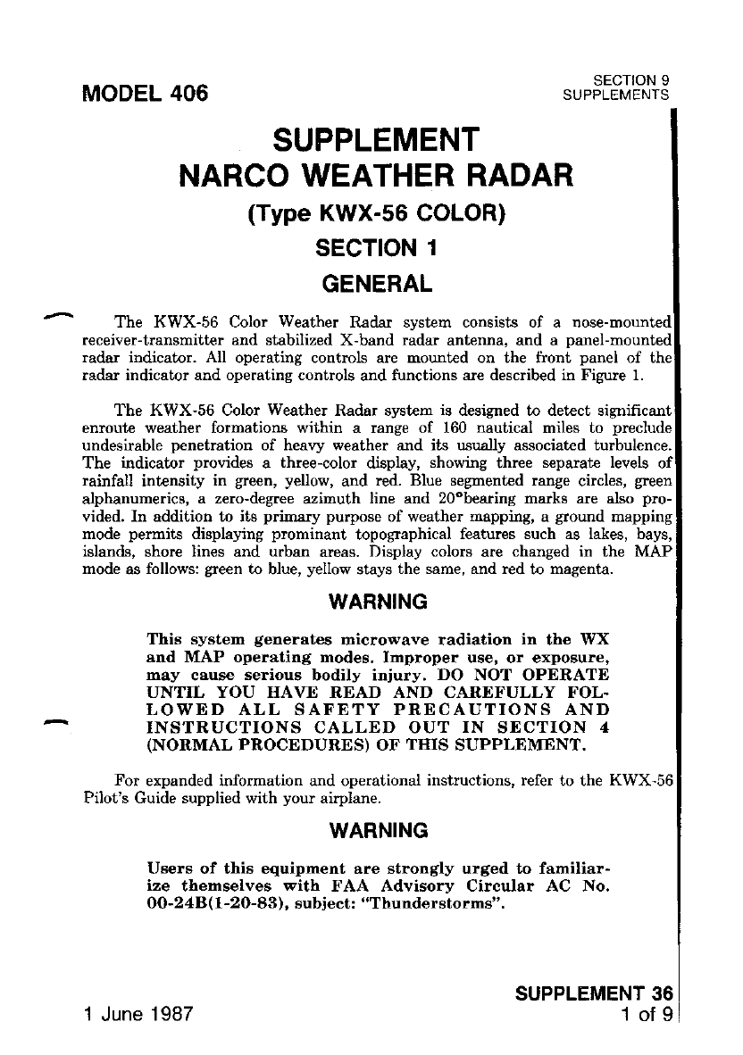
MODEL 406 SECTION 9
SUPPLEMENTS
SUPPLEMENT
NARCO WEATHER RADAR
(Type KWX-56 COLOR)
sEcTloN 1
GENERAL
The KWX-56 Color Weather Radar system consists of a
receiver-trangmitt€r and stabilized X-band radar antenna. and a oanel-
radar indicator. All operaiing controls are mounted on the tiont panel of the
radar indicator and operating controls and functions are described in Figure 1.
The KWX-56 Color Weather Radar system is designed to detect significant
enroute weather formations within a range of 160 nautical miles to preclude
undesirable penetration of heary weather and its usually associated turbulence.
The indicator provides a three-color display, showing three separate levels
rainfall intensity in green, yellow, and red. Blue segrented range circles, green
alphanumerics, a zero-degree azimuth line and 2o"bearing marks are also pro-
vided. In addition to its prinary purpose of weather mapping, a ground mapping
mode permits displaying prominant topographical features such as lakes, bays,
islands, shore lines and urban areas. Display colors are changed in the MAP
mode as follows: gxeen to blue, yellow stays the same, and red to magenta.
WARNING
This system generates microwave radiation in the WX
and MAP operating modes, Improper use, or exposu.e,
may cause serious bodily injury. DO NOT OPERATE
UNTIL YOU IIAVE READ AND CARDFULLY FOL.
LOWDD ALL SAFETY PRECAUTIONS AND
INSTRUCTIONS CALLED OUT IN SECTION 4
(NORMAL PROCEDURES) OF TITIS SUPPLEMENT.
For erpanded information and operational instructions, refer to the KWX-56
Pilot's Guide supplied with your airplane.
WARNING
Users of thi6 equipment are strongly urged to familiar-
ize themselves with FAA Advisory Circular AC No.
OO-248(1-20-83), subject: "Thunderstorms".
SUPPLEMENT 36
1of 9
1 June 1987
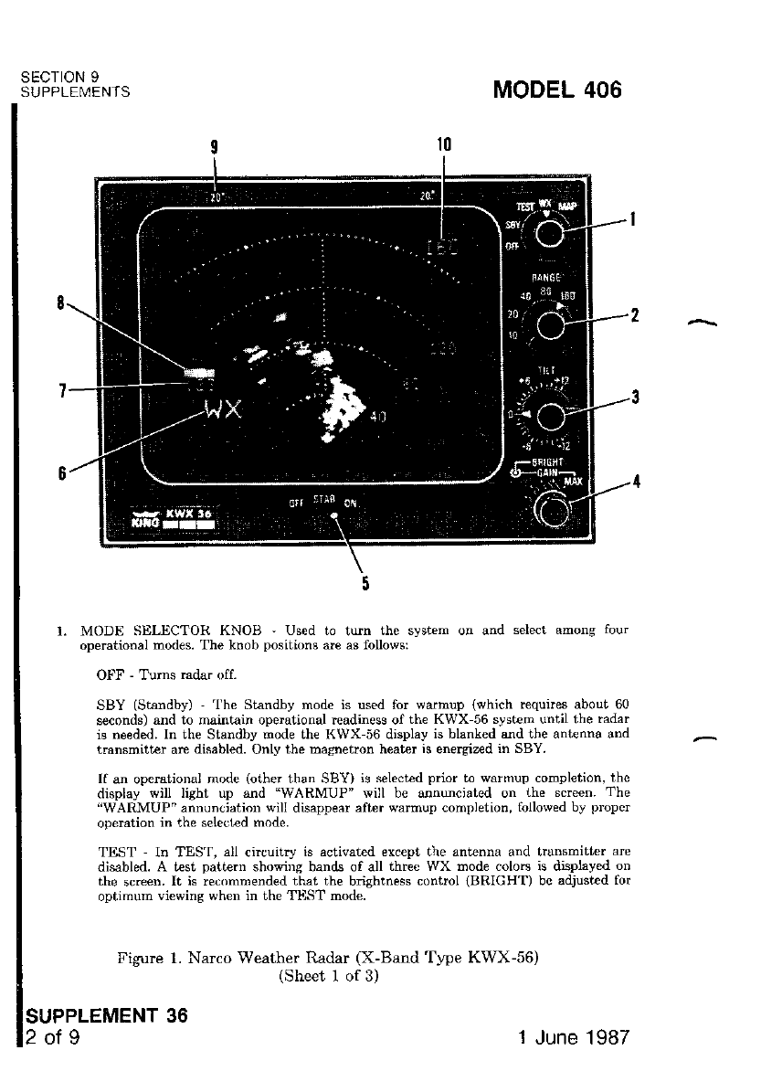
SECTION 9
SUPPLENlENTS MODEL 406
r. MODE SELECTOR KNOII ' Used to tun the system on and s€lect amons fou.
operational modes. The knob positbns are as follows:
OIT - Tlms radar off-
SBY (Stalldbv) ' 'l'he Standby mode is used for warmup iwhich requircs about 60
seconds) and to maintain operational rcadiness of the KWX-56 system until the radar
is needed. In the Standby mode th€ KWX 56 display is blanked and the antenna and
transmitter are disabled. Only the magnetron heat€r is energiz€d in SBY.
If an operational rnode (other than StsY) is select€d prior to warmup compl€tion, thc
display will light up and "WARMUP" will be annucjated on the screen. The
"WARMUP" annunciation will disappear aft€r warmup completion, followed by proper
opeEtion in the selected mode.
TEST In TES'|, all circuitry is activat€d except the antenna and trunsmitter arc
disabled. A test patie.n showiDg bands of all three WX mode colors is djsplayed on
the screen. It is recommended that the bnshtness control (BRIGHT) bc adjusied fot
optimum viewins when in the TUST mode.
Figure 1. Narco Weather Radar (X-Band 'Iype KWX-56)
(Sheet 1 of 3)
SUPPLEMENT 36
2ot9 1 June 1987
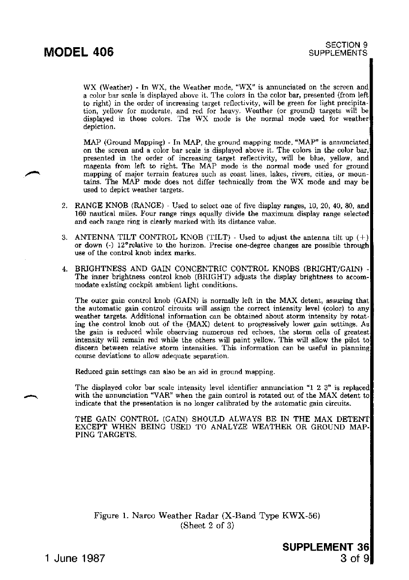
MODEL 406
WX (Weather) - In WX, the W€aiher mode, "WX" is annunciat€d on th€ scrcen
a color bar scale is displayed above it. 'l'he colors in the color bar, present€d (from
to nght) in the order of incrcasing target reflectivity, will be green for light precil
tion, yellow for rnode.at€, and red for heavy. Weather (or $ound) tafgets
displsyed in thos€ colors. The WX node is the norrnal mode used fo.
depiction.
the sain is reduced while observing mrmerous red echoes, the storm cells of
intensiw will r€main red while the otherc will paint yellow. Thb will allow the
discern between lelativ€ stolm intensities. This information can be u3etul in
couGe d€viations to alow adequate separation.
MAP (Ground Mappinc) ' In MAP, the ground mapping mode, "MAP" is snnunciated
on the screen and a color bar scale is displayed above it. The colors in the color bar,
pres€nt€d in the order of increasing target reflectivity, will be blue, yellow, and
magenta from left to right. The MAP mode is the nomal mode used for ground
mapping of major tenain features such as coast lines, lakes, riveE, cities, or moun-
t3ins. Th€ MAP mode do€s not differ t€chnicallv ftom the WX mode and mav be
used to depict weather targets.
RANCE KNOB (RANGE) I'sed to sele.r one of five display ranses. 10, 20. 40.80.
160 nautical miles. Four range rings equally divide the maximum display range
and each range riag is clearly marked with its distance value.
BRIGHTNESS AND GAIN CONCENTRIC CONTROL KNOBS (BRIGHT/GAINI
ing the control knob out of the (MAX) detent to progressively lower gain settings.
SECTION 9
SUPPLEMENIS
ANTENNA'IILT CONTROL KNOB (TILT) Used to adjust the antenna tilt up (, /
or down G) l2"relative t the ho zon. Precise one-degree changes are possible through
us€ of the control knob index rnarks.
The inner brightness conirol knob (BRIGHT) adjusts the display brightness to accom-
modate existing cockpit ambient light condrtrons.
The outer sain control knob (GAIN) is normally left in th€ MAX det€nt, assurins
the automatic gain control chcuils wil acsign the correct intensity level (color) to
weather t€rsets. Additional information can be obtained about storm intensitv bv n
with the annunciation "VAR" when the sain control is mht€d out of the MAX detent
indicate that the presentation is no longer calibrated by the automatic gain circuits.
THE GAIN CONTROL (GAIN) SHOULD ALWAYS BE IN
EXCEPT WHEN BEING USED TO ANALYZE WEATHT]R
PING TARCETS,
R€duced gain settings can also be an aid in ground mappins.
The displayed eolor bar seale intensn) level idpnrrfipr annuncist;on | 2 3" is
T}IE MAX
OR GROUND MAP
Figure 1. Narco Weather Radar (X-Band Type KWX-56)
(Sheet 2 of 3)
SUPPLEMENT
1 June 1987 3of
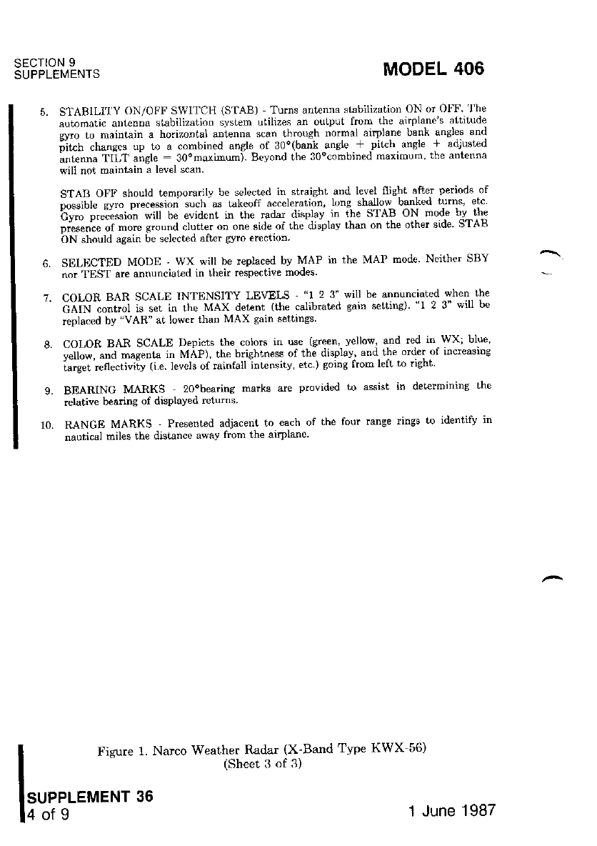
sEcroN I
SUPPLEMENTS
5.
7.
STARILI'I'Y ON/OFF SWITCII (STAB) Turns antenna stabiLizfltiorl ON or Ol'F 'l'he
automatic aDt€nDa stabilization system utilizes an output from th€ airplane's atritt"le
svro to naintain a horizontal anl.enna scan through normal aiplane bank angles and
ilt"h .hune"" up to a combined ansle ,\f 30o(bank ansle + pit(h angle + adjusted
antenna TILT airele : 30"maxunum). Bevond the 30ocombined maximum' the antenna
will not maintain a level scan.
STAB OFF should ternpomrilv be selected in stra;sht and level fiishi after periods of
p,.sible cyro precessron 'uch as ukeotl ac.elcrariun. "ng shallow bsnked rurns "k
h*" ","ii,*i.j" will be elidcnl in thc raclar Jiqplav in rhe STAB ON mode bv-th"
;;;"';;a;"." o"""d clutt€r oD one sid€ of the di;phv than on the othet side STAB
bN should again be selected after s/ro €rection
SELFICTED MODE - WX will be replaced bv MAP in th€ MAP mode Neither SRY
nor 'I EST are annunciatad in rheir respe.tive modes.
COLOR BAR SCALE INTENSITY LEVELS - "1 2 3'will be annunciated llvhen.lhe
cAiN -;;;;l is set in the MAX det€nt (the calibratrd gain selting) "1 2 3" wiu be
replsc€d by "VAR" at lower than MAX gain s€ttines
COLOR BAR SCALE D€picts the colors in use (sreen, vellow, and red in-wxr bhre'
vellow, and magenta in MAP), the brightness of the displav' and the ord€r ol rncreasms
irr""t ."n""ti";i" (i.e. levels of lairfall intensitv' etc ) going from left to right
BEARING MARKS - 2O"bearing narks arc provided to assist in determining the
relativ€ bealing of displaved retums.
RANGE MARKS ' Presented adjacent to each of lhe fo\rr range ngs to identifv in
nauticsl mit€s the distance awav from th€ &irylane'
Figure 1. Narco *""rtiifft'"{tiBaad rrpe Kwx b6)
MODEL 406
1 June 1987
MODEL 406 SECTION 9
SUPPLEMENTS
sEcToN 2
LIMITATIONS
There is no change to the airylane limitations when this avionic equipment
is installed. However, the following radar limitations must be followed
airpla-Be operation.
1. Do not operate radar during refueling or within 15 feet of ground
peIsonnel.
2. Do not operate radar above 25,000 feet flight. altitude
SECTION 3
EMERGENCY PROCEDURES
There is no change to the airplane emergency prccedures when this avionic
equipment is installed.
SECTION 4
NORMAL PROCEDURES
WARNING
The radar system generates microwave radiation and
improper use, or exposure, may cause serious bodily
injury. DO NOT OPERATD THIS EQUIPMENT UNTIL
YOU IIAVE READ AND CAREFULLY FOLLOWED
THE FOLLOWING SAFETY PNDCAUTIONS AND
INSTRUCTIONS:
SAFETY PRECAUTIONS AND INSTRUCTIONS TO BE FOLLOWED PRIOR TO
RADAR OPERATION:
Do not turn on or operate radar within 15 feet of grould personnel.
Do not turn on or operate radar during refueling operations.
Transmitter output power is radiat€d in the WX and MAP modes.
In order to prevent bodily injury to ground personnel, do not taxi the
airplane unless the KWX-56 radar system is in the "OFF," "TEST," or
"SBY" mode. Once reaching an area cleat ahead of other airplane,
ground peBonnel or large metal buildings, the system may be turned to
the TEST or WX mode io DreDaration for takeofL
SUPPLEMENT 36
5ofg
1.
2.
3.
4.
1 June 1987
SECTION 9
SUPPLEMENTS
PRIOR TO FLIGHT:
MODEL 406
Ensure Safetv Pr€cautions have been observed.
Mode Selector Knob -- SBY for approximately 60 seconds warm up.
Mode Selector Knob -- TEST. Verify uniform pattern of WX mode
colols.
Brightness Knob (BRIGHT) '- ADJUST to suit.
GAIN Conirol -- MAX. Verifu "1 2 3" annunciation under color bar.
STAB ON/OFF Switch -- AS DESIRED.
Mode Selector Knob '- WX.
RANGE Knob -- 10, 20, or 40 AS REQUIRED for weather in departure
area.
9. TILT Knob -- *4oor as required to minimize ground clutter after
takeoff.
NOTE
Within the bounds of the ground safety precautions, study the
weather conditions with the radar pdor to takeoff io eliminate
confusion from false returns due to ground clutter shortly after
takeoff.
10. Mode Selector Knob -- SBY position for taxi maneuvers.
NORMAL OPERATIONS:
WEATHER DETECTION:
1. Mode Selector Knob -- WX (allow 1 minute for warm-up if set was
previously off).
BRIGHT Knob -- ADJUST i,o suit.
RANGE Knob -- AS REQUIRED for weather.
TILT Knob --
NOTE
Proper tilt adjustment is one of the most important factors in
obtaining optimum value from a weather radar. Too high will
pass ihe majority of the radar beam above the storm cell,
particularly when the storm is at a great distance, Too low an
antenna tilt will clulter the indicator with ground returns. Opti-
mum tilt is obtained by adjusting the antenna to obtain a slight
amoult of ground clutter. The maximum distance at which
ground clutter can be obtained will depend greatly on the ter-
rain and airplane altitude.
SUPPLEMENT 36
6ol 9
1.
2.
3.
5.
6.
7.
8.
2.
3.
4.
1 June 1987
MODEL 406 SECTION 9
SUPPLEMENTS
NOTE
It is recommended that while cnroute and not using alternate
ranges that the 40 n.m. or 80 n.m. range be selected and ihe
TILT control be adjusted such that the inner l/3 of the screen
is painting ground clutter. This park position provides reason-
ably early presentation of weathe. and terain features.
5. STAB ON/CFF Switch -'ON.
NOTE
Should the attitude gyro supplying pitch and roll iaformation to
the Weather Radar fail, the display may become unusable be-
cause of eratic or unsuitable tilting of the antenna. If this
should happen, the STAB ON/OFF switch should be turned off
to disable the gyro inputs and allow normal use of the tilt
conrrol.
6. GAIN Control -- MAX. Verifu "1 2 3" annunciation under color bar.
Reduce out of MAX while observing numerous red echoes to detect
storm areas of greatest intensity.
NOTE
a Do NOT plan your route of flight to enter the shadow area
behind a significant weather rcturn. Due to signal attentuation,
the ability to define weather in the shadow area may be severely
Iimited.
r The KWX-56 Pilot's Guide should be consulted for a more
thorough description of opelating procedures for the weather
radar ald information on the interprctation of weather and
ground returns.
SUPPLEMENT 36
/ oTv
1 June 1987
SECTION 9
SUPPLEMENTS
GROUND MAPPING:
OPERATIONAL NOTES:
FALSE RETURN DISPLAYS:
SUPPLEMENT 36
Sofg
1.
2.
3.
5.
6.
NOTE
Ground mapping by tilting the antenna down can be performed
r"a"" "*t"iit c"onditions,- pa.ticularly during overwater fligits
where coast lines and islands are apparent Ground mapp-ing is a
secondary feature of this radar which is only uselul alter the
"o"."t"."i. very familiar with rhc equipmenr !!9ry 9o1qle1e
ai*u".ion of tiris fealure is ircluded in the KWX 5{1 Pilot s
Guide.
Mode Selector Switch -- MAP.
BRIGHT Knob -- ADJUST to suit
RANGE Knob -- SELECT desired range'
'fiif X"oU -- ADJUST for desired ground return displav'
STAB ON/OFF Swiich - ON.
6eiN c.,lt."i : Mei or reduce to adjust the prominence of ground
features.
MODEL 406
!. Some energy is radiated peripherally from the radar antenna which'
' ffi;; ""-3' "t-..prt"tl" conditions, - will create a false.return on the
;;;; ";;;;. when'the displav is set on the 10 or 20 mile ranges The
iuf"" ""t*" will usually be most prominently displayed at- ap^prox imately
2 mileg fiom the origin when flying at altitudes near 12'OUU ft nowever'
under certain atmosphedc conditions' the false return car stlu oe oo-
J"*.i J'^ ai-L""e from the origin approximat€lv e-quivalent to the
iirpiun"l" altltud". Care must be taken noL [o confuse this normal
t#;;;;;";';"t*; wiih a weather return This is best accomplished bv
;;;;'il;-i";;;; distance displavs (40 or more) for earlv detection of
significant weather.
z. 6?"t"J""a"i "t"tions or other airborne weather radars may occasionally
-' Ju"* i"i""i""unce with the presentation of the return' The effect of this
interference is to create one or more radial bands of false signal or noise
;;;;;i"g from the bottom cenler outward to the outer rarge scale'
i-ft"a" "f?*t" are usually of short duration and are dependent on the
".pi."";" p""iii"" "nd .",,g" from the ground station' the signal
strength, and other factors.
1 June 1987
MODEL 406 SECTION 9
SUPPLEMENTS
HIGH ALTITUDE OPERATION:
1. The KWX-56 Color Weather Radar system has been approved to a
maximum altitude of 25,000 feet. If flying at altitudes above 25,000 feet,
the radar should be turned off to protect electrical circuitry in boih the
indicator and the antenna/receiver/transmitter units.
sEcTloN 5
PERFORMANCE
There is no change to the airplane performance when this avionic equipment
is installed.
SUPPLEMENT 36
9of9
1 June 1987

MODEL 406 SECT ON 9
SUPPLEMENTS
(Type KN-53)
SECTION 1
GENERAL
The King KN-53 Digital Nav, shown in Figure 1, consists of a panel-
mounted receiver, KI-206 VOR/LOC/Glideslope Indicator and remote-mounted
KN-72 VORAOC converter.
The set includes a 2O0-channel VHF navigation receiver and a 40-chalnel
glideslope receiver vrhich may be operated simultaneously. The NAV systen
receiveg omni and localizer signals between 108.00 and 117.95 MHz in 50-kHz
steps. The glideslope receiver is automatically iuned when a localizer frequency is
selected. The circuits required to interpret the omli and localizer signals are also
an integral part of the Nav receiver.
Large self-dimming gas discharge readouts display the communications op-
erating fiequencies. The KN-53's unique "flip-flop" prc-select feature enables you
to storc one frequency in the standby display while operating on another and
then int€rchange thern instantly with the touch of a button. Both the active
(USE) and the standby frequencies are stored in a circuit component called
EAROM (Electrically Alterable Read Only Memory) that provides nonvolatile
storage of both fiequencies so that when the radio is turned off and then back on,
channel information is retained.
A DME receiver-transmitter may be interconnected for automatic selectlon
of the associated DME frequency. When a VOR fiequency is selected on the
NAV, the associated VORTAC or VOR-DME station frequency will algo be
selected automatically.
All controls for the King KN-53 are mounted on the front panel (,f the
receiver. Control lighting is provided by the instNment panel flood lip:hting
system. Operation and desc ption of the audio control panel used in conjunction
with this radio are shown and describcd in Supplement 26 in Section I of this
handbook.
SUPPLEMENT
KING DIGITAL NAVIGATION RECEIVER
'1 June 1 987 SUPPLEMEN'r 37
|
SECTION 9
SUPPLEMENTS MODEL 406
SECTION 2
LIMITATIONS
'fhere is no change to the airplane limitations when this avionics equipEent
is installed.
SECTION 3
EMERGENCY PROCEDURES
There is no change io the airplane emergency procedures when this avionics
equipment is installed. However, if the frequency readouts fail, the radio will
remain operational on the last frequency selected. The frequency control should
not be moved due to the difficulty of obtaining a known frequency under thie
condition.
SECTION 4
NORMAL PROCEDURES
NORMAL OPERA'I'ION
1. ON/OFFi^r'OL/IDENT Control -- TURN clockwise until radio comes
on'
2. SPEAKER/PHONE Selecior Buttons (on audio control panel) -- SET to
this radio.
3. ONi OFF/VOL/IDENT Control -- PUI,L out and adjust to desired audio
level.
4. Frequency Selector Knobs -- SELECT desired operating frequency'
5. l'requency Transfer Button (-) -- PRESS to tmnsfer desired
frequency from the "STBY" display into the "USE" display.
SUPPLEMENT 37
2of5 1 June 1987
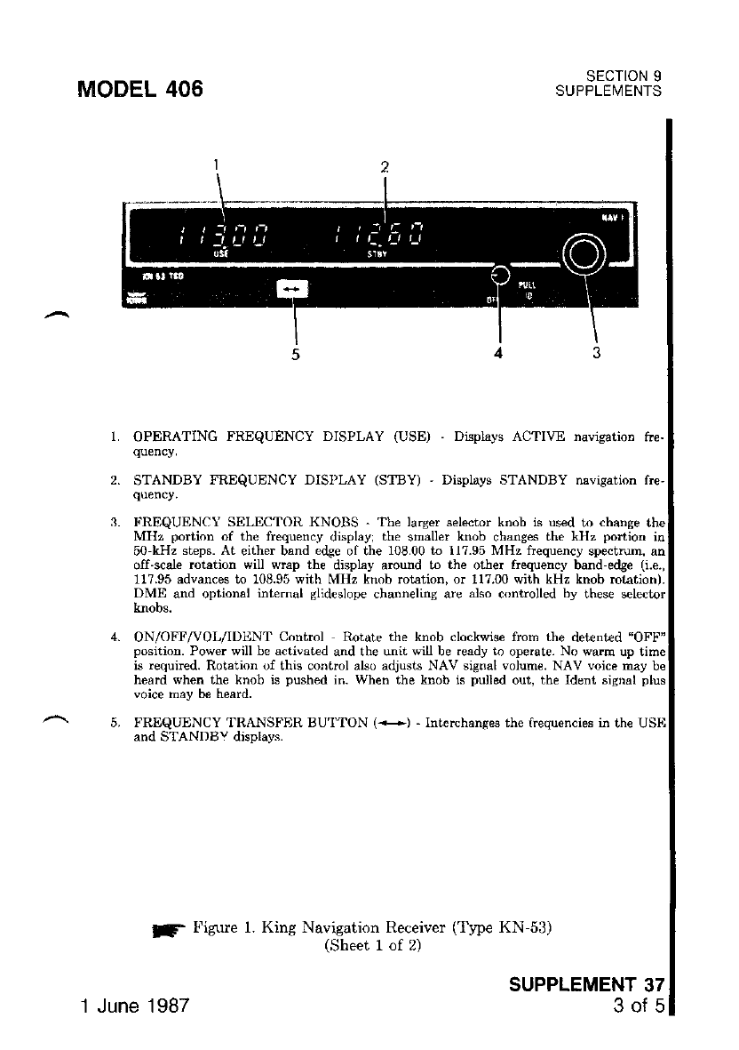
MODEL 406
1, OPERATING F'REQUENCY DISPLAY (USE)
STANDBY FREQUENCY DISPLAY (STtsY) ' Displays STANDBY nsvisatioD fre'
I'REQUEN.\ SELECTOR KNOBS . fbp larger s.lccbr knob is used to chanse
!f Figure l. King Navigation Receiver (Type KN-53)
(Sheet 1 of 2)
MHz portion of the frequency displayi the smaller knob changes the kHz portion in
50-kHz steps. At either band edSe of ihe 108.00 to ll?.95 MHz frequency spectrum, an
off-scele rotetion will wrap th€ display amund to the other frequency band edge (i.e.,
1l?.95 advances to 108.95 with MHz knob rotation, or 117.00 with kHz knob rctation).
DME and optional internal glideslope channeling are also controlled by these s€lector
knobs.
ON/OFF/VOL/IDENT Control Rotate the knob clockwise from the detent€d "OFl'"
position. Pow€r will be activated and the unit wil be .eady to ope.ate- No warm up time
is requircd. Rotation of this control also adjusts NAV signal volum€. NAV voice may be
heard when th€ knob is pushed in. When the knob is pulled out, the Ident signal plus
voice may b€ heard.
FREQUENCY TRANSFER BU'I"TON (+) - Interchanses th€ frequencies in the USI.I
and STANDBY disolavs.
SECTION 9
SUPPLEVIENTS
DispLays ACTI\rE navigation toe-
SUPPLEMENT 37
3of5
.l June 1987
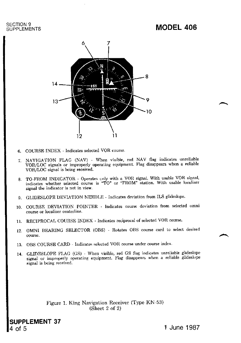
SECTION 9
SUPPLEMENTS MODEL 406
COURSE INDEX ' Indicates selected VOR coume.
NAVIGATION FLAG (NAV) - When visible, red NAV-nag indicates unreliabte
VOR/LOC signats or improperly operai,ing equipment Flag disappears when a reliable
VOR/LOC signal is being received.
TO-FROM INDICATOR - Operates only wiih a vOR sisnal. With usable VOR sjsnal'
indicat€s whether s€lected couse is "TO' or "FROM' stat;on. With usble localizer
signal the indicator is not in vr€w
GLIDESLOPE DI.IVIATION NEEDI-E - Indicates deviation fioln ILS glideslope.
COURSE I)EVIATION PONTER - lndicates courc€ deviation ftom selected omnr
course or localizer centerline.
RECIPROCAL 0OURSE lNDrlX - Indicates rccipmcal of selected VOR course
OMNI BEARING SELECTOR (OBS) - Rotates OBS course card lo select desired
OBS COURSE CARD - lndicates selected VOR couEe under course index'
GLIDESLOPE FLAG (GS) When visible, red GS flas indicstes unreliable slideslope
signal or imp.operly operaiins equipment Flag disappeab when a .eliable slidesl(rp€
signal is beins received.
F'igure 1. King Navigation Receiver (TlFe KN-53)
(Sheet 2 of 2)
SUPPLEMENT 37
6.
1.
10.
1r.
12.
13.
14.
o{5 1 June 1987

SECTION 5
PERFORMANCE
There is no change to the airplane perform,mce when this avionic equipment
is installed. However, the installation of an externally-mounted antenna or ser-
veral related external antennas, will result in a minor reduction in cruise E:rfor-
mance.
MODEL 406 SECT ON 9
SUPPLEMENTS
1 June 1987 SUPPLEMEN'r'371

MODEL 406 sEcTtoN 9
SUPPLEI.4ENTS
SUPPLEMENT
COLLINS HF
COMMUNICATION SYSTEM
(Type HF-230)
sEcTloN 1
GENERAL
The Collins HF-230 High Frequency Communication System, shown in
Figure 1, consists of a panel-mounted CTL-230 Control, TLR-230 Transceiver
(100 watts), PWR-230 Power Amplifier and accessory AAC-230 Automatic An-
tenna Coupler,
The HF-230 system provides operation on any one of 280,000 pilot-selected
discrete channels within the 2.0000 to 29.9999 MHz frequency range (frequency
spacing is 100 Hz) for simplex operation. 1n addition, the HF-230 provides 176
preprogrammed International Telecommunications Union (ITU) channels for
half-duplex operation and 40 user prograrDmed channels that can be programmed
for either simplex or half-duplex operation throughout the range.
The HF-230 system can transmit and receive using upper (USB) or lower
(LSB) sideband (A3J); split-channel, reduced-carrier telephone mode (TEL PLT
CAR) (A3A); split-channel, suppressed'carriet telephone mode (TEL SUP CAR)
(A3J); and compatible AM (A3H).
All controls for the Collins HF-230 svstem are mounted on the front panel
the CTL-230 control. The control provides automatic display dimming or may be
remotely dimmed by a dimming contrcl. Operation and description of the HF
transceiver is shown and described in Figure 1. Operation and descripiion of the
audio control panel used in conjunction with this radio are shown and described
in Supplement 26 in Section 9 of this handbook.
SECTION 2
LIMITATIONS
There is no change to the airplane limitations when this avionic equipment
is installed.
SUPPLEMENT 38
1of 9
1 June 1987
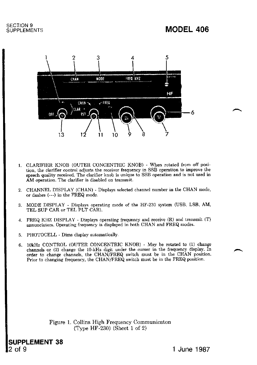
SECTION 9
SUPPLEMENTS MODEL 406
CLARIFIER KNOB (OUTER CONCENTRIC KNOB) - When rctat€d f'om off posi-
tion, the clarifier control adjusts the receiver frequency in SSB opemtion to irnprove t}e
speech quslity received. The cta fier knob is unique to SSB operation and is not used in
AM operation. The €laifier is disabled on transmit.
CHANNEL DISPLAY (CHAN) - Displays selected channel number in the CHAN mode,
or dsshes G--) in the FREQ node.
MODE DISPLAY - Displays op€ratins mode of the HF-230 syst€m (USB, LSB, AM,
TEL SUP CAR or TEL PLT CAR).
FREQ KHZ DISPLAY - Displays operatins frequeicy and receive (R) and transmit (T)
annunciators. Operating frequency is displayed in both CHAN and FREQ nodas.
PHOTOCELL - Dirns display automatically.
10kHz CONTROL (OUTER CONCENTRIC KNOB) ' May be mtated to (l) change
channels or (2) change the lo-kHz digit under the cursor in the frequency display ln
order to change channels, the CHANAREQ switch must be in the CHAN position.
Prior to chansing ftequency, th€ CHAN/FREQ switch must be in the FREQ position
Figure 1. Collins High Frequency Communicaton
(Ttpe HF-230) (Sheet 1 of 2)
SUPPLEMENT
5.
6.
of9 38 1 June 1987
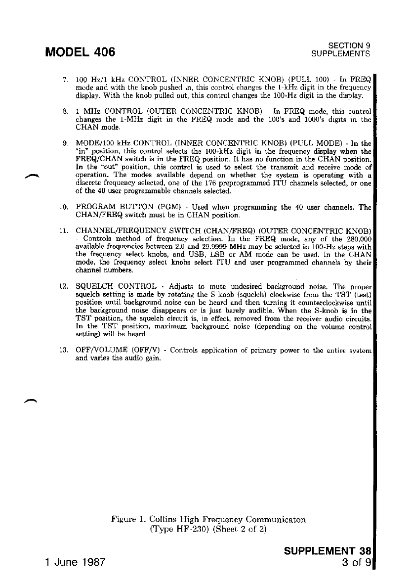
MODEL 406 SECTION 9
SUPPLEMENIS
tl.
9.
10,
r00 Hz/1. kHz CONTROL (INNER CONCENTRIC KNOII) (PULL 100) - In FREQ
mode and with th€ knob pushed in, this control changes the I kHz digit in the frequency
display. With the knob pulled out, this conhol changes the 100-Hz digit in the display.
1 MHz CONTROL (OUTER CONCENTRIC KNOB) - In FREQ mode, this control
changes th€ l'MHz digit in the FREQ mode alld the 100's and 1000's disits in the
CHAN mode.
MODE/100 kHz CONTROL (INNER CONCENTRIC KNOB) (PULL MODE) - In the
"in" position, this control selecls the 100-kHz digit in the frequency display when ihe
FREQ/CHAN ewitch is in the FREQ position. It has no tunction in the CHAN position.
Ir the "out" position, this control is used to select the transmit and receive mod€ of
op€ration. The modes available depend on whether the sj€t€m is op€rating with a
discret€ frequency selected, one of the 176 preproerammed ITU chann€ls selected, or on€
of the 40 user pro$ammable channels selectecl.
PROGRAM BUTTON (PGM) - Used vr'hen programming the 40 user channels. Th€
CHANAREQ swikh must b€ in CHAN position.
CHANNEL/FREQUENCY SWITCH (CHAN/FREQ) (OUTER CONCENTRIC KNOB)
Contrcls method of frequency selection. tn the FREQ mode, any of the 280,000
available frequercies between 2.0 and 29.9999 MHz nay be select€d in 100-Hz st€ps with
the frequency select knobs, and USB, r,SB or AM mode can be used. In the CHAN
mode, the frequency select knobs select ITU and user pmgranmed channels by therr
channel numbers,
SQUELCH CONTROL - Adjusts to mut€ undesired background noise. The proper
squelcb setting is made by rohting the S-knob (squelch) clockwis€ from the TST (test)
position until background noise can be head and then turning it count€rclockwise until
the b&ckground noise disappears or is just ba.ely audible- When the S-knob is in rrle
TST position, the squelch circuit is, in effect, removed ftom the rcceiver audio circuits.
In the TST position, maximum backsround noise (depending on the volume control
s€ttins) ",ill b€ heard.
OFF/^r'OI,UME (OFF/V) - Controls application of primary power to the entirc system
and vaies the audio sain.
-!'igure 1. Collins High Frequency Communicaton
(T1pe HF'230) (Sheet 2 of 2)
SUPPLEMENT 38
3of9
1 June 1987
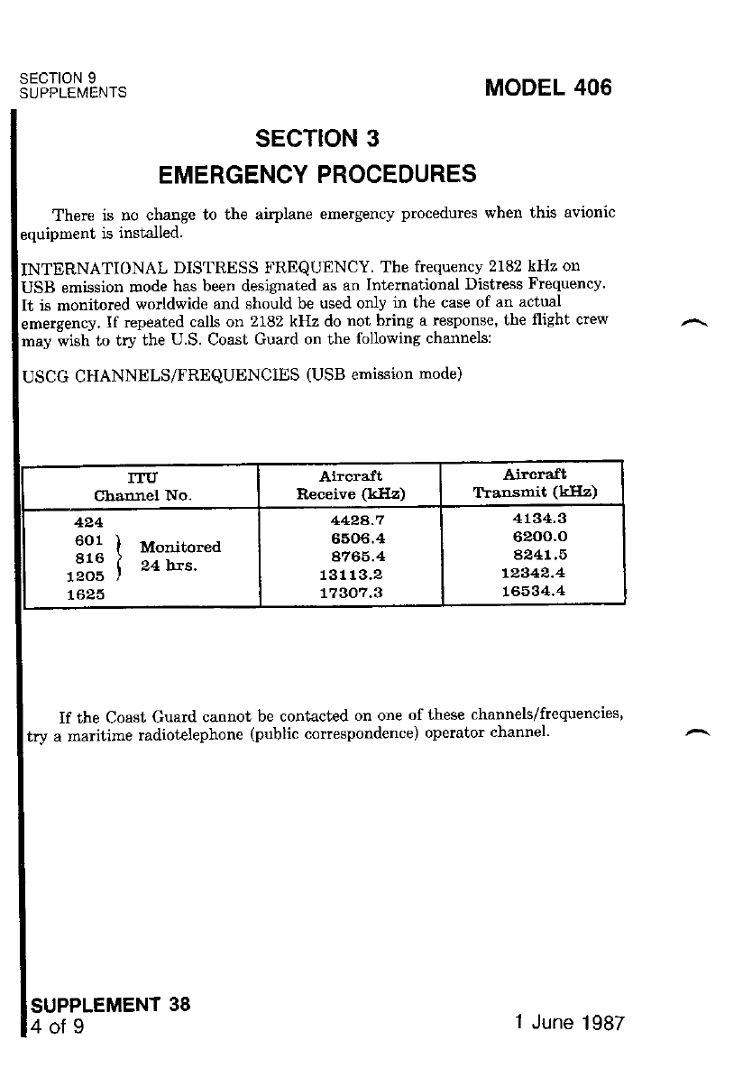
SECTION 9
SUPPLEMENTS MODEL 406
SECTION 3
EMERGENCY PROCEDURES
There is no change to the airplane emergency procedures when this avionic
rquipment is installed.
.NTERNATIONAL DISTRESS FREQUENCY. The frequencv 2182 kHz on
JSB emission mode has been designated as an Intelnaiional Distrcss Frequency'
:t is monitorcd worldwide arld should be used only in the case of an actual
)mergency. If repeated calls on 2182 kHz do not bring a response, the flight crew
rruy *ish to try the U.S. Coast Guard on the following channels:
USCG CHANNELS/FREQUENCIES (USB ernission rnode)
ITU
Channel No. Aircraft
Receive (kIIz) Aircra,ft
Tlarsmit (kHz)
424
601 I Morrjto.ea
816 i g+ ht".
1205 I
1625
4424-7
6506.4
4765.4
13113.2
77307.3
4134.3
6200.o
4241.5
12342.4
L6, 34.4
If the Coast Guard cannot be contacted on one of these channels/frequencies,
try a maritime radiotelephone (public correspondence) operator channel'
SUPPLEMENT
4ofg 1987
MODEL 406 SECTION 9
SUPPLEMENTS
SECTION 4
NORMAL PROCEDURES
PREFLIGHT INSPECTION:
WARNING
WHEN PERFORIITINC AN HF-23O RADIO CHECK ON
TIIE GROUND, MAKE CERTAIN TIIAT ALL PERSON-
NEL ARE CLEAR OF THE IIF ANTENNA BEFORE
TRANSMITTING, SERIOUS RF BURNS CAN RDSULT
FROM DIRECT CONTACT WITH TIIE ANTENNA OR
ANTENNA TERMINAL WIIEN THE SYSTEM IS
TRANSMITTING.
Antenna -- CHECK structural integrity-
MIC (Microphone) Selector Switch (on audio control panel) --
HF position.
HF SPEAKER/PHONE Selector Buttons (on audio control panel)
PRESS desired mode.
OFF/VOLUME Control Knob -- TURN ON. Allow 15-minute
(time for frequency standard to stabilize).
Authorized Channel or Frequency -- SELECT.
Microphone Button -- PRESS momentarily. The artenna coupler will
tune automatically ard a steady tone will be heard during the
cycle. Normal tuning cycle requires 5 to 10 seconds. Within one second
after completion of antenna coupler tuning cycle, the tone will cease,
indicating that the system is ready for use.
?. Radio Check -- TRANSMIT and RECEIVE on usable frequency.
NOTE
If the HF-230 detects a fault during the tuning of the antenna
aft€r 30 seconds, the tone will begin to "beep" indicating that a
fault has occurred, in which case, simply key the microphone
and the automatic antenna coupler will begin a new tuaing cycle
to clear the fault. If repeated antenna tuning cycles fail to clear
the fault there is probably an equipment malftrnction. If prac-
tical, attempt to retune the ant€nna on an alt€rnate frequency.
annunciators flash, this indicates a possible equip-
ment malfunction.
SUPPLEMENT 38
5of9
1.
2.
3.
4.
5.
6.
1 June 1 987
SECTION 9
SUPPLEMENTS
CHANNEL PROGRAMMING:
MODEL 406
I.
2.
3.
4.
5.
NOTE
Hall-duplex operation uses one frequency for receiving and a
separate frequency for transmilting, Simplex operation uses
same rcceive and tiansmit frequency.
MIC (Microphone) Selector Switch (on audio control panel) -- SELECT
HF position.
HF SPEAKER/PHONE Selector Buttons (on audio control panel) -
PRESS desired mode.
OFF/VOLUME Control Knob -- TURN ON.
CHANAREQ Switch -- Rotate to CHAN position.
Left Channel Outer Concentric Knob -- ROTATE in either direction
until user channel 1 or 40 appeaB at the right side of the CHAN
display. Then use the right outer concent c knob to select the desired
channel number (from I to 40) to be programmed.
PGM Button -- PRESS once to initiate the programming sequence. At
this point, the entirc display on the CTL-230 will begin to slowly blink.
Four Frequency Select Knobs -- ROTATE. The receive frequency will
appear in the FREQ KHZ display. Next, select the desired operating
mode (USB, LSB, AM, TEL SUP CAR, or TEL PLT CAR) by pulling
out on the PULL MODE knob and rotating it until ihe appropriat€
mode appears in the MODE display
PGM Button -- PRESS to store data. The display will blank for a short
period of time to confirm storage.
NOTE
a When the display returns, it will be blinking faster with the
transmit frequency displayed. If no changes are made within 20
seconds, the currently displayed tlansmit frequency will become
invalid and a receive-only channel will be created. Repeat Steps
7 and 8 for desired transmit frequencies.
o If additional user channels are to be programmed for half-duplex
operation, repeat Steps 5 thru 6.
9. Microphone Button -- PRESS momentarily to initiate the antenna
coupler turning cycle.
6.
7.
SUPPLEMENT 38
6of9 1 June 1987
MODEL 406
10. Volume (V) and Squelch (S) Controle -- ADJUST as desired.
NOTE
a In half-duplex operation, the mode that is selected (USB, LSB,
AM, TEL SUP CAR, or TEL PLT CAR) will alwavs control
both the receive and the transmit frequencies. The receive
frequency is shown in the FREQ KHZ display and annunciated
by the letter R (at the right side of the FREQ KHZ display)
until the mic is keyed, at which time the transmit frequency is
displayed and annunciated by the letter T. If the receive (R) or
transmit (T) annunciatrrs on the CTL-230 flash, this indicates
that the receive or transmit (as applicable) frequency data from
the TCR-230 does not match that being sent by the CTL-230.
Al equipment malfunction is probable and the system should be
checked by maintenance personnel.
a In simplex operation, the teceive and tmnsmit frequencies are
identical. The receive frequency is shown in the FREQ KHZ
display and annunciated by the letter R (at the dght side of the
FREQ KHZ display) until the mic is keyed, at which time the
ftequency remains unchanged but the R annunciator changes to
a T to indicate that the system is transmitting. If the receiver
(R) or transmit (T) annunciators on the CTL-230 flash. this
indicates that the receive or transmit (as applicable) frequency
data from the TCR-230 does not match that being sent by the
CTL-230. An equipment nalfunction is probable and the system
should be checked by maintenance personnel.
NORMAL OPERATION:
WARNING
WHEN PERFORMING AN HF-230 RADIO CHECK ON
THD GROUND, MAKE CDRTAIN THAT ALL PERSON-
NEL ARE CLEAR OF THE HF ANTENNA BEFORE
TRANSMITTING. SERIOUS RF BURNS CAN RESULT
FROM DIRECT CONTACT WITH THE ANTENNA OR
ANTDNNA TERMINAL WHEN TIIE SYSTEM IS
TRANSMITTING.
Preflight -- COMPLETE.
MIC (Microphone) Selector Switch (on audio control panel) -,
HF position.
HF SI'IIAKER/PHONE Selector Buttons (on audio control panel)
PRESS desired mode.
SECTION 9
SUPPLEMENTS
SUPPLEMENT 38
Tofg
1.
2.
.1.
'1 June 1987
SECTION 9
SUPPLEMENTS MODEL 406
4. OFF/VOLUME Control Knob -' TUIIN ON. Allow ls-minute warmup
(time for frequency standard to stabilize).
5. CHAN/TREQ Switch - Select FREQ or CHAN mode'
DIRECT TUNING:
a. Frcquency Control Knobs -' ROTATII to set desired frequency'
b. MObE Control -- PULL and ROTATE until desired mode is an-
nunciated.
CHANNEL OPERATION:
a. PULL MODE (I,€ft concentdc knob) -- PULL and ROTATE to
select desired channel number.
6. Microphone Button -- PRESS momentarily' 1'he antenna coupler will
iune auiomatically and a steady tone will be heard during the tuming
cycle. Normal tuning cycle requires 5 to 10 seconds Within one second
aiter completion of-antenna coupler tuning cycle, the tone will cease'
indicating that the system is ready for use.
?. OFF VOLUME Knob -- SET to desired volume level'
8. SQUELCH Knob -- ROTATE S-control slowly clockwise until receive
noise just disaPPears.
NOTE
Do noi rotate S-control too fast. The squelch circuit has a
relatively long time constant and rotating the knob too far may
result in missed calls on some of the weaker signals'
9. OLARIFIER Knob -- ROTATE to optimize incoming SSB sigrral qual-
rty.
NOTE
Whenever a diflercnt channel is selected, the antenna coupler
automatically returns to the home posiiion This Ieaves the-
antenna untuned to the new channel, reducing the sensitivity of
the receiver. To avoid any missed calls or poor reception, it is
recommended that the ptt butt"n be pressed momenl'arily ro
initiate an antenna coupler lune cycle for lhe new channel
(before pressing the ptt button, verify that the channel is clear)
ihe antentta *ill ttten be tuned and the system is now ready for
immediate use.
SUPPLEMENT 38
8of9 1 June 1987
OPERATIONAL NOTES: I
HF SSB COMMUNICATIONS: I
I
1. Most all aircraft HF SSB communications are conducted in USB mode l
Some ground stations continue to use the AM mode, but these stations-l
are being phased out in favor of the more efficient SSB mode ofl
operation.
I
SIMPLEX OPERATION: I
I
1. In sirnplex operation, the emission mode you select (USB or AM) wilil
always control both receive and transmit frequencies. Also the receivel
frequency is displayed until ihe mic is keyed, at which time the transmitl
frequency is displayed. I
SELECTING FREQUENCIES:
I
1. The higher frequencies are best during daylight (10'000.0 to 29,999.9
kHz) and the lower frequencies work best at night (2000.0 to 10'000.0
kHz).
SECTION 9
SUPPLENIENTS
SUPPLEMENT 38
9ofg
MODEL 406
RETUNING THE ANTEN-NA COUPLER:
1. It is necessary to retune the antenna coupler whenever the MODE
selector knob is changed from one mode to anoiher' Pressing the MIC
button momentarily initiates antenna tuning.
SECTION 5
PERFORMANCE
There is no change to the airplane performance when this avionic equipment
is installed. However, the installation o[ an externally-mounted antenna ol several
related external antennas will result in a minor reduction in cruise performance.
1 June 1987

MODEL 406
A
Abbreviations, Symbols
and Terminology ...... 1-11
Accelerate Go Distance
Cha rr. 5-44
I -"__-
|ADF. Kins ......9-2
After Landing 1-12,4 35
AileronSystem .......... 7-6
Air Conditioning Systems . . . 9-1
Airframe . . . . . . . . 7-5
Airplane Inspection Periods 8-5
Cessna Continuous Inspection
Program ........... 8-5
Cessna Customer Care
Program ........... 8-6
Propjet CESCOM System 8-6
Engine Condition Trend
Monitoring ......... 8,6
ServicingRequirements .. 8-8
AirplaneFile .......... 8-9
Airplane Performance
Terminology ......... 1-16
Airplane Weighing Form ...6-9
Airspeed Calibration Chart . 5-1?
Airspeed for Emergency
Operations . . 3-5,3-27
Airspeed Indicator Markings . 2-6
AirspeedLimitations ...... 2-4
AirspeedTerminology .... 1-11
Airstart. .....3-8,3-35
Alcohol Windshield
DeiceSystem .......... 9-1
Altimeter Correction Chart . 5-18
Altimeter, Encoding . . . 3-24,3-62
Altitude Encoding/
Alerting/Preselect ...... 9-1
Altitude Limit ...2-16
Annunciator Panel ....... ?15
lArea Navigation System . 9-1,9-2
Audio Control Panel 7-80
lAudio Control Panel. King . . 9-2
ALPHABETICAL INDEX
Automatic
DirectionFinder . ..... 7-90
Avionics Bus Failure . . 3-23,3-61
Avionics Systems . . . . . 4-40,7-79
Audio Control Panel,
1000... ...7-80
Automatic Direction Finder,
400.... ... 7-90
Avionics Interference ... 7-80
Avionics Master Switches ?-80
Glideslope, 400 . . . . . . . . ?-88
Locator Beacon ....... 7-85
Marker Beacon,400 .... ?-85
Nav/Com, 400 . .
B
. . . 7-92
Baggage, Cabin and
Entry Dimensions ..... - 1-9
BaggageCompartments ... 7-28
Battery . ....... ?-58
Balked Landing . ... .. 4-11,4-34
Beacon, Locator . . , . . . . . . ?-85
Before Engine Starting . . 4-7,4-17
Before Landing ...... 4-11,4-32
Before Takeoff . 4-9,4-25
Before Taxiing . 4-9,4-23
Bleed Air System . . . . . . . . ?-66
Brake System .-.7-57
Bus Failure, Avionics . . 3-23,3-61
c
Cabin Air System ....... 7-68
Cabin, Baggage and
EntryDimensions ...... 1-9
Cabin Door Not
Secured . .. 3-23,3-61
Cabin Features 7-99 (7-100 blank)
Cabin Fire Fxtinguisher
7-99 (7- 100 blank)
Center-of-Gravity Limits .. 2-13
Index-1
1 June 1987
ALPHABETICAL INDEX
Center'of-Gravity Limits
Enveiope Graph ... ...6-16
Cleaning and Care ....... 8-28
ExteriorCleaning...... 8-28
InteriorCare ......... 8-31
climb .. ....4-10,4-28
Climb Gradienl at
V2 - One Engine
Inoperative GraPh '. . 5-42
ColdWeather OPeration .' . 4-38
Comm, King .. ..9-2
Conservation, Fuel '...... 4-50
Control Locks ".7-34
Crew Door Not
Secured . 3-23, 3-61
Crew Limits, Flight .. ... 2-73
Cruise .. .... 4-10,4-30
D
Deice Boot SYstem........ 9-1
Descent. ....4-11,4-31
Descent, Emergency ... 3-12,3-41
Digital Clock, Davtron ..... 9-1
Dimensions, Cabin,
Baggage and IJntrY . ...' 1-9
Distance Measuring
Equipment .... 9-1
Diiching '.. 3-16,3-49
DME, King .. . .9'2
Door Not Secured,
Cabin .. .. 3-23'3-61
Doors, Windows and Exits ?-31
Cabin Door ...7-31
Emergency Exit Window 7-33
Windows ...7-33
E
Electrical
System ...... 3-18'352'757
AC Power . ..7-62
Battery . ..... 7-58
lndex-2
MODEL 406
Battery and Generator
Switches ...7-58
Circuit Breakers, Switch
Breakers and Fuses . 7-59
External Power
Receptacle ...... . 7-62
Generator Control Units . ?-59
Spare Fuses ...7-59
Voltmeter and
Ammeters ......... 7-59
Electrical Elevator
Trim..... ?-99 (7-100 blank)
Electrical Windshield
Anti-ice. ......9-1
Elevator System ......... ?-8
ELT, Postflight ... ..4'12'4'36
Emergency Descent ... 3-12,3-41
Emergency Exit ...... 3-23,3-61
Emergency
Information . 3-65 (3-66 blank)
Emergency Procedures
AbbreivatedChecklist ... 3-6
Amplified Checklist .. 3-27
Encoding
Altimeter ...... 3-24,3-62,9-1
Endurance Profile GraPh 5-100
Engine Bleed Air SYstem . . 7-66
Engine Clearing Procedures 4-22
Engine Controls
TerminologY ......... 1-15
Engine Failure . 3-6'3-29
Engines. .. .7-4"/-34
Air Induction SYstem . . . 7-40
Cowl FlaPs '. 7-42
Clearinpl Procedures .... 4-22
Engine Accessories . . . . 7-42
Engine Break-in
Procedures . "' 7-39
EngineControls .. .... 7-35
Hngine Controls
TerminologY ..... . 1-l5
I.)ngine Instruments ... ?-38
EngineOilSYstem . .. . 1-39
1 June 1987
MODEL 406
Engine Shock Mounts . . 7-46
ExhaustSystem ....... 7-40
Fire Detection and
Extingishing System .. 7-46
IgnitionProcedures .... 4'22
Ignition System ....... 7-39
StartirigSystem ....... 7-42
Engine, Before Starting . 4-7,4-17
Engine Securing
Procedure . . 3-8,3-35
Engine,Starting ...... 4-8,4-19
Entrv. Cabin
A. -: -
- - and Baggage Dimensions l-9
Environmental
System . .. 3-21,3-57,4-12,4-36
Equipment List 6-19 (6-20 blank)
Exits, Doors and Windows 7-31
F
Fire and Smoke ...... 3-10,3-38
Fire Detections and
Extinguishing System ... 4-37
Fire, Engine . 3- 10,3-38
Flap System ....7-27
Flaps, Retracted
Landing. ..3-75,3-47
FlightControls .......... 7 5
AileronSystem ........ 7-6
AileronTrim System .... 7-7
ElevatorSystem ........ 7-8
^ Elevator Trim System . . . 7-9
Rudder System ....... ?-10
Rudder Trim System ... 7-11
Flight Control System .....9-1
Flight Crew Limits ......2-13
Flight In Icing Conditions . . 9-1
Flightlnstruments ....... 7-19
Flight Load Factor Limits 2-13
Flight Planning Terminology 1-16
Fuel ... ........1-5
FuelConservation ....... 4-50
l'uelLimitations ........ 2-16
1 June 1987
ALPHAAETICAL INDEX
Fuel System 3- 17,3-49
BoostPumps ......... 7-49
Crossfeed System ...... ?-53
DrainValves ......... 7-49
Engine Fuel System . ... 7-54
Firewall Shutoff Valve
Switches ...7-54
Fuel Flow Gages ......7-54
Fuel Indicating System . . 7-49
Fuel Level Low Warning
Lights .. ...7-54
FuelQuantityGage .... 7-54
Fuel Tanks ...7-48
VentSystem ......... 7-53
Fuses, Spare ... ?-59
G
Glide... .... 3-12,3-42
Glideslope ......7-88
Go-Around, Engine
Inoperative 3- 16,3-48
GroundControl ......... 7-20
GroundHandling ........ 8-11
Jacking and Leveling ... 8-13
Parking. .....8-12
Tie-Down ....8-12
'l'owing . ..... 8-11
H
Heating, Ventilating and
Defrosting Systems
4-73 (4-14 blank), 4-37,7-68
Air Duct Overheat Switch 7-69
Cabin Air Controls . . . . . 7-69
Cabin Air System ..... ?-68
Cabin Heat Controls ...7-68
Heating and Defrosting 7-68
VentilatingSystem . .... 7-69
HF ('ommunication. Collins 9-21
HF Transceiver. King .....9-2I
Holding Time Graph .... 5-107
Index-3
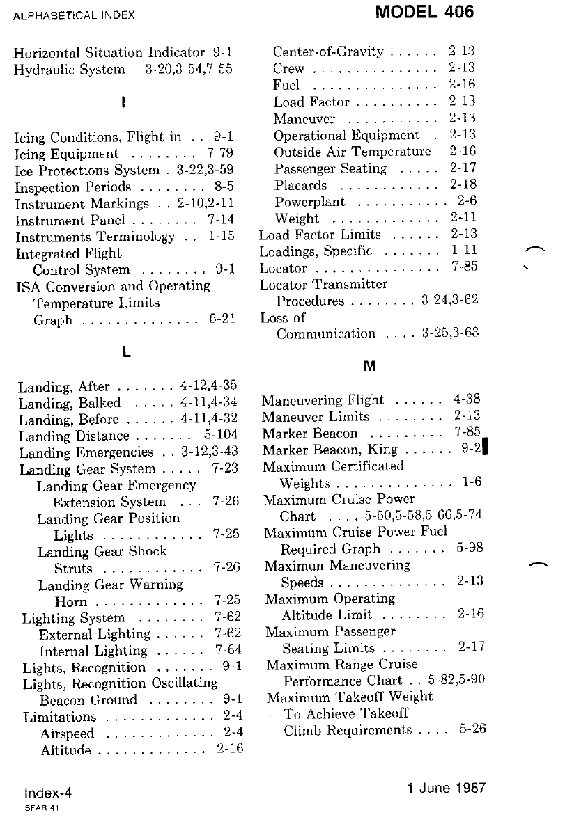
ALPHABETICAL INDEX
Horizontal Situatir,rn Indicator 9-1
Hydraulic System 3'20,3-54,7-55
I
Icing Conditions, Flight in . . 9-1
Icing Equipment .......' 7-79
Ice Protections System . 3-22,3-59
Inspection Periods . .....8-5
Instrument Markings . . 2-10,2-LI
InstrumentPanel .. ...... 7'14
Instruments TerminologY .. 1-15
Integlated Flight
ControlSystem ........ 9-1
ISA Conversion and OPerating
Temperature l,imits
Graph .. ..... 5-21
L
Landing,After'.. . .. 4-12'4-35
Landing, Balked . .. ' 4-71,4-34
Landing, Before .. ....4-11,4-32
Landing Distance . . .... 5-104
Landing Emergencies . 3- 12,3-43
Landing Gear SYstem. ... 7-23
Landing Gear EmergencY
Extension SYStem .. 7-26
Landing Gear Position
Lights .. . 7-25
Landing Gear Shock
Struts .. ...7-26
Landing Gear Warning
Horn . ' 7-25
Lighting System ...... . 7-62
External Lighting . .' 7'62
Internal Lighting .... .7-64
Lights, R€cognition .'... .9-1
Lights, Recognition Oscillating
BeaconGround .... ''.. 9-1
Limitations ......2-4
Airspeed . . ..2-4
Altitude . .... 2- 16
lndex-4
MODEL 406
Center-of-Cravity .... .. 2-13
Crew... ..... 2-13
Fuel ... .....2-16
Load Factor ...2-13
Maneuver ....2-13
OperationalEquipment 2-13
Outside Air Temperature 2-16
Passenger Seating ..... 2-77
Placards . ....2-18
Powerplant ....2-6
Weight . .. ..2-11
Load Factor Limits ...... 2-13
Loadings, Specific ....... 1-11
Locator . ....... 7-85
Locator Tlansmitter
Procedures ' 3-24,3-62
Loss of
Communication .... 3-25,3-63
M
Maneuvering Flight ... .. 4-38
Maneuver Limits ........ 2-13
Marker Beacon ..... ...7-85
Marker Beacon, King . . ... 9-21
Maximum Certificated
Weights . . ...1-6
Maximum Cruise Power
Chart .... 5-50,5-58,5-66,5-74
Maximum Cruise Power Fuel
Required Graph ....... 5-98
Maximun Maneuvering
Speeds.. ... .2-13
Maximum Operating
Altitude Limit ..... . 2-16
Maximum Passenger
Seating Limits .. .. 2-1'7
Maximum Rairge 0ruise
Performance Chart . 5-82'5-90
Maximum Takeoff Weight
To Achieve Takeoff
Climb Requirements . ..526
1 June 1987
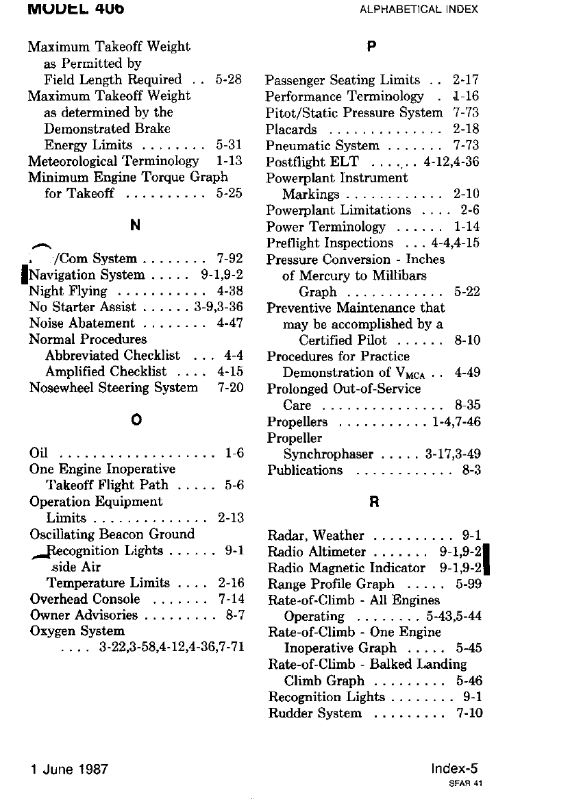
MUUEL 4Ub
Maximum Takeoff Weight
as Permitted by
Field Length Required . . 5-28
Maximum Takeoff Weight
as determined by the
Demonstrated Brake
Energy Limits ........ 5-31
Meteorological Terminology 1-13
Minimum Engine Torque Graph
for Takeoff ...5-25
N
, /Com Svstem . . . . . . . . 7 -92
lNavigatlon bysten ..... 9-1,9-2
Night Flying .... 4-38
No StarterAssist ...... 3-9,3-36
NoiseAbaterrent ........ 4-47
Normal Procedures
AbbreviatedChecklist ... 4-4
Amplified Checklist .... 4-15
Nosewheel Steering System 7-20
o
oil .... ........1-6
One Engine Inoperative
Takeoff Flight Path . . . . . 5-6
Operation Equipment
Limits .. .....2-13
Oscillating Beacon Ground
-pecognition Lighte ..... . 9-1
,side Air
Temperature Limits .... 2-16
Overhead Console ...,.., 7-74
OwnerAdvisories ......... 8-7
Oxygen Systert
. . . . 3-22,3-58,4-72,4-36,7 -7r
ALPHABETICAL INDEX
P
Passenger Seating Limits . . 2-17
Performance Terminology .1- 16
Pitot/Static Pressure System 7-73
Placards . .....2-18
Pneumatic System ....... 7-73
Postflight ELT .. ..... 4-72,4-36
Powerplant Instrument
Markings .....2-70
PowerplantLimitations .... 2-6
Power Terminology ...... 1-14
Preflightlnspections ... 4-4,4-75
Pressure Conversion - Inches
of Mercury to Millibars
Graph .. ... 5-22
Preventive Maintenance that
may be accomplished by a
Certified Pilot ...... 8-10
Procedures for Practice
Demonstration of VMqa . . 4-49
Prolonged Out-of-Service
Care... ..... 8-35
Propellers ....7-4,7-46
Propeller
Synchrophaser ..... 3-17,3-49
Publications .....8-3
R
Radar,Weather .......... 9-1
Radio Altimeter . . . . . . . 9-1,9-2I
Radio Magnetic Indicator 9-1,9-21
Range Profile Graph ..... 5-99
Rate-of-Climb - All Engines
Operating .5-43,5-U
Rate-of-Climb - One Engine
Inoperative Graph ..... 5-45
Rate-of-Climb - Balked Landing
ClimbGraph ......... 5-46
Rccognition Lights ........ 9-1
Rudder Systen ......... 7-10
lndex-s
1 June 1987
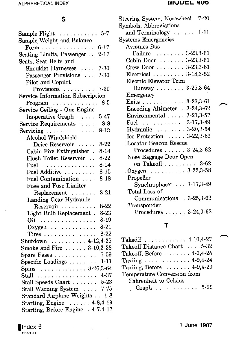
ALPHABETICAL INDEX
s
Sample Flight ....5-7
Sanple Weighi end Balance
Form... .....6-17
Seating Limits, Passenger . . 2-17
Seats, Seat Belts and
ShoulderHarnesses .... 7-30
Passenger Provisions ... 7-30
Pilot and Copilot
Provisions ......... ?-30
Service Information Subscription
Program . ..... 8-5
Service Ceiling - One Engine
Inoperative Graph .,... 5-47
Service Requirements ..... . 8-8
Servicing .......8-13
Alcohol Windshield
DeiceReservoir ..... 8-22
Cabin Fire Extinguisher . 8-14
Flush Toilet Reservoir . . 8-22
Fuel ... .....8-14
FuelAdditive ......... 8-15
Fuel Contarnination .... 8-18
Fuse and Fuse Limiter
Rcplacement ....... 8-21
Landing Gear Hydraulic
Reservoir --.8-22
Light Bulb Replacement . 8-23
oil .... .....8-19
Oxygen . ..... 8-21
Tires... .....8-22
Shutdown ... 4-12,4-35
Snoke and Fire ... .. . 3-10,3-38
Spare Fuses ..... 7-59
Specific Loadings ........ 1-11
Spins .. ....3-26,3-64
StaU... .......4-37
Stall SpeedsChart .. ..... 5-23
Stall Warning System .... 7-75
Standard Airplane Weights . . 1-8
Starting,Engine ...... 4-8'4-79
Starting, Before Engine . 4-7,4-17
I Index-6
IVIIJUEL {UO
Steering System, Nosewheel 7-20
Symbols, Abbreviations
and Terminology ...... 1-11
Systems Emergencies
Avionics Bus
Failure .
Cabin Door
Crew Door
Electrical
Electric Elevator Trim
Runway .
Emergency
3-23,3-61
3-23,3-61
3-23,3-61
3-18,3-52
3-25,3-64
Exits... .. 3-23,3-61
Encoding Altimet€r . 3-24,3-62
Environmental ..... 3-21,3-57
Fuel ... . . 3-77,3-49
Hydraulic 3-20 ,3-54
Ice Protection ..... 3-22'3-59
Locator Beacon Rescue
Procedures ... ... 3-24,3-62
Nose Baggage Door Open
onTakeoff ......... 3-62
Oxygen . .. 3-22,3-58
Propeller
Synchrophaser . .. 3-17.3-49
Total Loss of
Communications . 3-25,3-63
Transponder
Procedures
T
3-24,3-62
Takeoff . .... 4-70,4-27
Takeoff Distance Chart ... 5-32
Takeoff,Before ....... 4-9,4-25
Taxiing. .....4-9,4-24
Taxiing,Before ....... 4-9,4-23
Teurperature Conversion fiom
Fahrenheit to Celsius
. Graph . .. '. 5-2O
1 June | 987
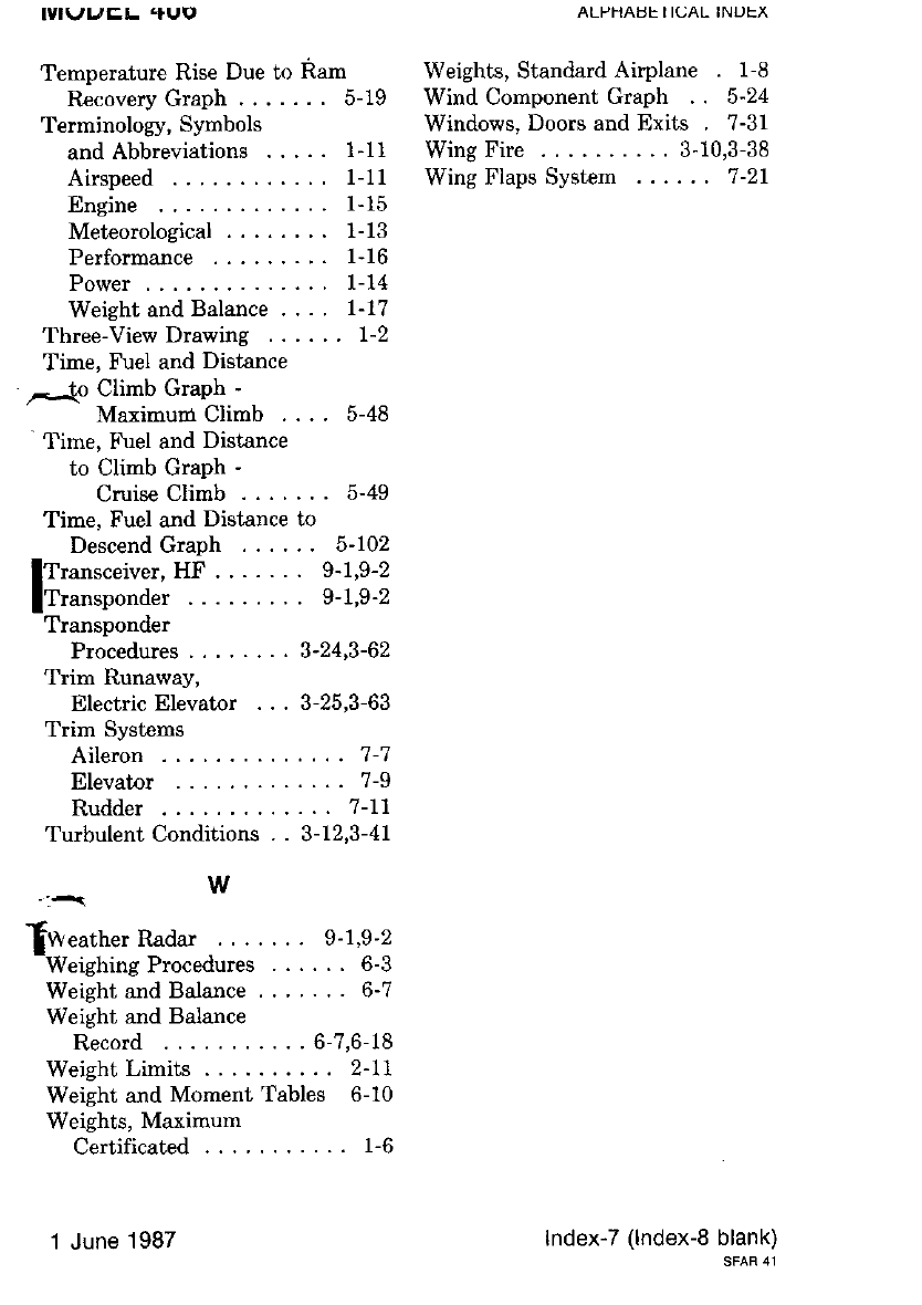
Airspeed
Engine .
Meteorological
Performance
Power ..
Weight and Balance ....
Three-ViewDrawing .....
Time, Fuel and Distance
5-(n Climb GraPh -
MaximudClimb....
Time, Fuel and Distance
to Climb Graph -
Cmise Climb
Time, Fuel and Distance to
DescendGraph ...... 5-102
Transceiver, HF....... 9-1,9-2
Transponder . . 9-t,9-2
Transponder
Procedures . 3-24,3-62
Trim Runaway,
Electric Elevator ... 3-25,3-63
Trim Systems
Aileron . ......7-7
Elevator . .....7-9
Rudder . ..... 7-11
Turbulent Conditions .. 3-12,3-41
w
f!\eatherRadar ....... 9-1.9-2
-Weighing Procedures ...... 6-3
Weight and Balance ...... - 6-7
Weight and Balance
Record . ...6-7,6-18
Weight Limits ...2-77
Weight and Moment Tables 6-10
Weights, Maximum
Certificated .... r-6
1 June 1987
lvlvt /EL .f u9
Temperature Rise Due to
IlecoveryGraph.....
Terminology, Symbols
and Abbreviations ...
ALPHABL IIL.:AL INUEX
Weights, Standard Airplane 1-8
Wind Component Graph . . 5-24
Windows, Doors and Exits 7-31
Wing Fire ...3-10,3-38
Wing Flaps System 7 -21
Index-7 (lndex-8 blank)
SFAR 41
Ram
. o-lv
1- 11
t-11
1- 15
1- 13
1- 16
t-t4
t-77
5-48
5-49