D2069 3 13 S R182 AND TR182 SERIES (1978 THRU 1986) Cessna_R182and TR182_1978 1986_D2069 Cessna R182and 1978 1986
User Manual: Cessna_R182andTR182_1978-1986_D2069-3-13
Open the PDF directly: View PDF ![]() .
.
Page Count: 794 [warning: Documents this large are best viewed by clicking the View PDF Link!]
- D2069-3-13 - MODELS R182 AND TR182 SERIES (1978 THRU 1986)
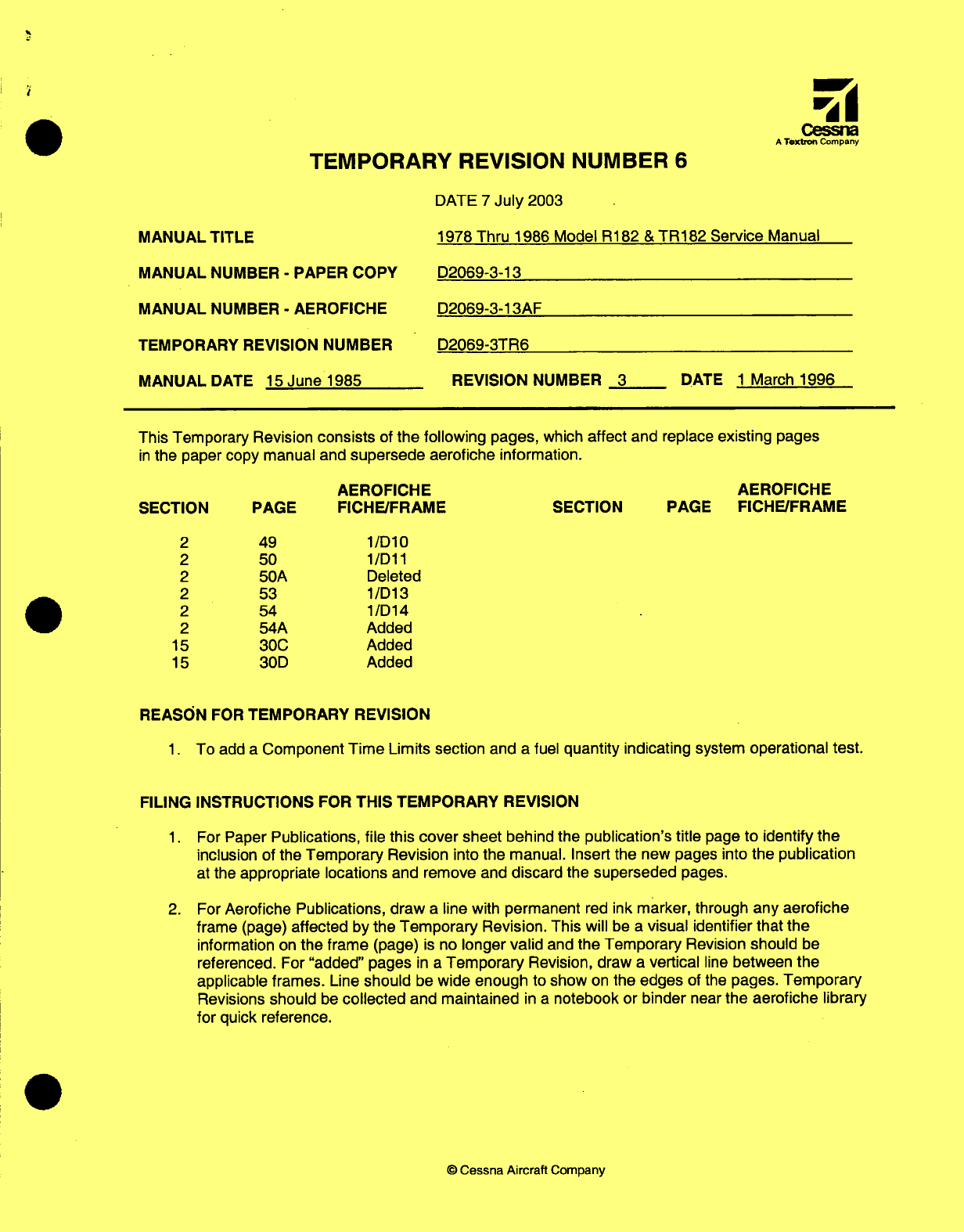
- TEMPORARY REVISION NUMBER 6
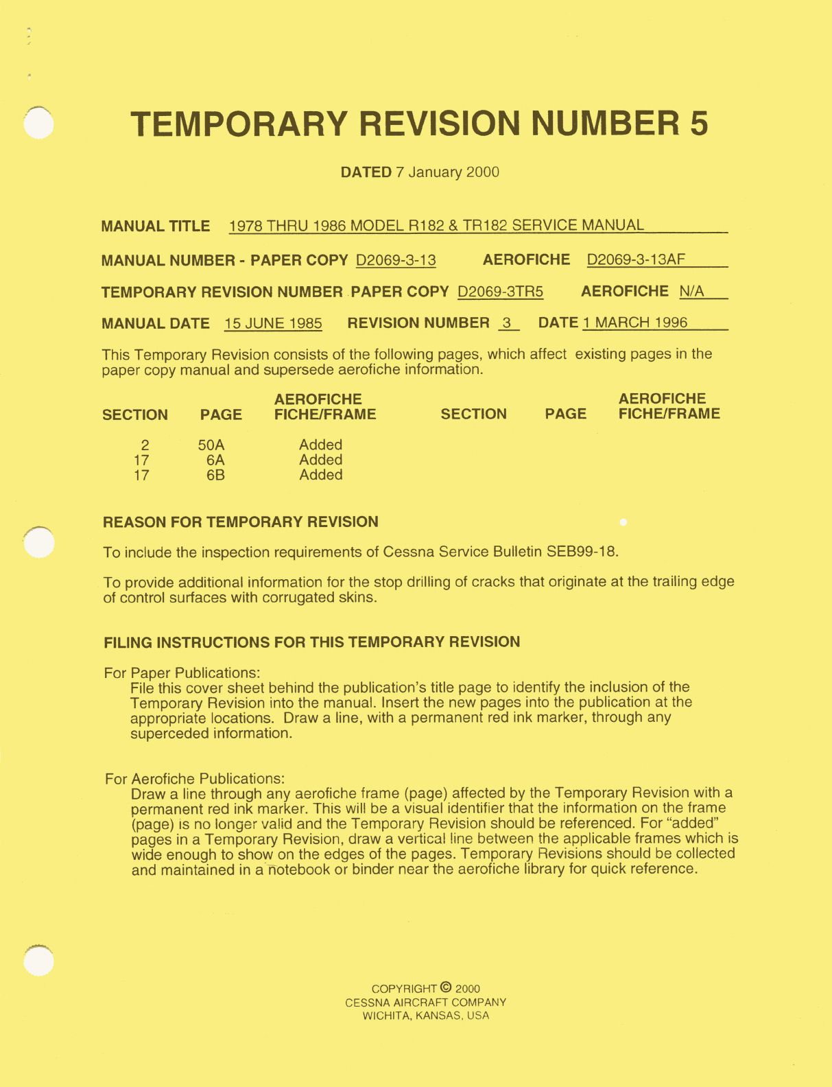
- TEMPORARY REVISION NUMBER 5
- LIST OF EFFECTIVE PAGES
- TABLE OF CONTENTS
- CROSS REFERENCE LISTING OF POPULAR NAME VS. MODEL NUMBERS AND SERIALS
- INTRODUCTION
- SECTION 1 - GENERAL DESCRIPTION
- SECTION 2 - GROUND HANDLING, SERVICING, CLEANING, LUBRICATION AND INSPECTION
- TABLE OF CONTENTS
- GROUND HANDLING
- SERVICING
- CLEANING
- LUBRICATION
- INSPECTION
- SECTION 3 - FUSELAGE
- SECTION 4 - WINGS AND EMPENNAGE
- SECTION 5 - LANDING GEAR, BRAKES AND HYDRAULIC SYSTEM
- TABLE OF CONTENTS
- LANDING GEAR RETRACTION SYSTEM
- DESCRIPTION
- TROUBLE SHOOTING
- POWER PACK
- PRIMARY THERMAL RELIEF VALVE ASSEMBLIES
- PRESSURE SWITCH
- DESCRIPTION
- REMOVAL/INSTALLATION
- DISASSEMBLY (THRU R18201541)
- INSPECTION REPAIR (THRU R18201541)
- REASSEMBLY (THRU R18201541)
- ADJUSTMENT (THRU R18201541)
- DISASSEMBLY (BEGINNING WITH R18201542)
- INSPECTION/REPAIR (BEGINNING WITH R18201542)
- REASSEMBLY (BEGINNING WITH R18201542)
- ADJUSTMENT (BEGINNING WITH R18201542)
- HYDRAULIC SYSTEM LEAK CHECK
- EMERGENCY HAND PUMP
- LANDING GEAR SELECTOR VALVE
- RIGGING THROTTLE-OPERATED GEAR WARNING HORN MICROSWITCH
- RIGGING FLAP-OPERATED GEAR WARNING SYSTEM
- MAIN LANDING GEAR
- NOSE GEAR SYSTEM
- DESCRIPTION
- OPERATION
- TROUBLE SHOOTING
- REMOVAL/INSTALLATION
- DISASSEMBLY
- INSPECTION AND REPAIR
- REASSEMBLY
- SHIMMY DAMPER
- TORQUE LINKS
- SQUAT SWITCH
- NOSE GEAR DOWNLOCK MECHANISM
- NOSE GEAR ACTUATOR
- NOSE GEAR DOORS (THRU R18201798)
- NOSE GEAR DOORS (BEGINNING WITH R18201799)
- NOSE WHEEL STEERING SYSTEM
- NOSE WHEEL AND TIRE
- BALANCING
- NOSE GEAR RIGGING (THRU R18201798)
- NOSE GEAR RIGGING (BEGINNING WITH R18201798)
- BRAKE SYSTEM
- SECTION 6 - AILERON CONTROL SYSTEM
- SECTION 7 - WING FLAP CONTROL SYSTEM
- SECTION 8 - ELEVATOR CONTROL SYSTEM
- SECTION 9 - ELEVATOR TRIM CONTROL SYSTEM
- SECTION 10 - RUDDER CONTROL SYSTEM
- SECTION 11 - NORMALLY-ASPIRATED ENGINE
- TABLE OF CONTENTS
- ENGINE COWLING
- COWL FLAPS
- ENGINE
- OIL SYSTEM
- FUEL SYSTEM
- INDUCTION AIR SYSTEM
- IGNITION SYSTEM
- ENGINE CONTROLS
- STARTING SYSTEM
- EXHAUST SYSTEM
- EXTREME WEATHER MAINTENANCE
- SECTION 11A - TURBOCHARGED ENGINE
- TABLE OF CONTENTS
- ENGINE COWLING
- COWL FLAPS
- ENGINE
- OIL SYSTEM
- FUEL SYSTEM
- INDUCTION AIR SYSTEM
- IGNITION SYSTEM
- ENGINE CONTROLS
- STARTING SYSTEM
- EXHAUST SYSTEM
- TURBOCHARGER
- ECONOMY MIXTURE INDICATOR (EGT)
- EXTREME WEATHER MAINTENANCE
- GROUND SERVICE RECEPTACLE
- SECTION 12 - FUEL SYSTEM
- SECTION 13 - PROPELLER AND GOVERNOR
- SECTION 14 - UTILITY SYSTEMS
- TABLE OF CONTENTS
- UTILITY SYSTEMS
- HEATING SYSTEM
- DEFROSTER SYSTEM
- VENTILATING SYSTEM
- OXYGEN SYSTEM
- DESCRIPTION
- TROUBLE SHOOTING
- MAINTENANCE PRECAUTIONS
- OXYGEN CYLINDER GENERAL INFORMATION
- CYLINDER-REGULATOR
- SERVICING OXYGEN CYLINDER-REGULATOR
- REMOVAL OF OXYGEN CYLINDER-REGULATOR (THRU 1981 MODELS)
- INSTALLATION OF OXYGEN CYLINDER-REGULATOR (THRU 1981 MODELS)
- REMOVAL OF OXYGEN CYLINDER-REGULATOR (BEGINNING WITH 1982 MODELS)
- INSTALLATION OF OXYGEN CYLINDER-REGULATOR (BEGINNING WITH 1982 MODELS
- INSPECTION OF OXYGEN CYLINDER-REGULATOR
- OXYGEN FILLER VALVE
- OXYGEN LINES
- OUTLET VALVE ASSEMBLIES
- OXYGEN SYSTEM FUNCTIONAL TEST
- OXYGEN GAGE
- OXYGEN MASKS
- PROPELLER DE-ICE SYSTEM (2-BLADED)
- PROPELLER DE-ICE SYSTEM (3-BLADED)
- HEATED WINDSHIELD PANEL (REMOVABLE)
- CONTROL SURFACE DISCHARGERS
- SECTION 15 - INSTRUMENTS AND INSTRUMENT SYSTEMS
- TABLE OF CONTENTS
- INSTRUMENTS/INSTRUMENT SYSTEMS
- GENERAL
- INSTRUMENT PANEL
- PITOT STATIC
- DESCRIPTION
- MAINTENANCE
- STATIC SYSTEM INSPECTION/ LEAKAGE TEST
- PITOT SYSTEM INSPECTION/LEAKAGE TEST
- BLOWING OUT LINES
- REMOVAL/INSTALLATION OF COMPONENTS
- TROUBLE SHOOTING
- TRUE AIRSPEED INDICATOR
- TROUBLE SHOOTING
- TROUBLE SHOOTING ALTIMETER
- TROUBLE SHOOTING - VERTICAL SPEED INDICATOR
- TROUBLE SHOOTING - PITOT TUBE HEATER
- VACUUM SYSTEM
- STANDBY VACUUM SYSTEM
- ENGINE INDICATORS
- TACHOMETER
- MANIFOLD PRESSURE GAGE
- FUEL PRESSURE GAGE
- MANIFOLD PRESSURE/FUEL PRESSURE GAGE
- DESCRIPTION
- DAMPENING ADJUSTMENT
- TROUBLE SHOOTING - MANIFOLD PRESSURE GAGE
- TROUBLE SHOOTING - FUEL PRESSURE GAGE
- CYLINDER HEAD TEMPERATURE GAGE
- OIL PRESSURE GAGE
- OIL TEMPERATURE GAGE
- CARBURETOR AIR TEMPERATURE GAGE
- FUEL QUANTITY INDICATING SYSTEM
- HOURMETER
- ECONOMY MIXTURE INDICATOR
- MAGNETIC COMPASS
- STALL WARNING SYSTEM/TRANSMITTER
- TURN COORDINATOR
- TURN-AND-SLIP INDICATOR
- ELECTRIC CLOCK
- OUTSIDE AIR TEMPERATURE GAGE
- SECTION 16 - ELECTRICAL SYSTEMS
- TABLE OF CONTENTS
- ELECTRICAL SYSTEMS
- GENERAL
- ELECTRICAL POWER SUPPLY SYSTEM
- BATTERY POWER SYSTEM
- GROUND SERVICE RECEPTACLE
- ALTERNATOR POWER SYSTEM
- ALTERNATOR
- ALTERNATOR VOLTAGE REGULATOR
- ALTERNATOR CONTROL UNIT
- OVER-VOLTAGE WARNING SYSTEM
- AIRCRAFT LIGHTING SYSTEM
- LANDING/TAXI LIGHTS
- NAVIGATION LIGHTS
- FLASHING BEACON
- ANTI-COLLISION STROBE LIGHTS
- OVERHEAD CONSOLE
- INSTRUMENT LIGHTING
- ELECTROLUMINESCENT PANEL LIGHTING
- INSTRUMENT POST LIGHTING
- TRANSISTORIZED LIGHT DIMMING
- DOME LIGHT
- MAP LIGHT
- CONTROL WHEEL MAP LIGHT
- LANDING GEAR INDICATOR LIGHTS
- COMPASS AND RADIO DIAL LIGHTS
- PEDESTAL LIGHTING
- STALL WARNING UNIT
- STALL WARNING SWITCH
- COURTESY LIGHTS
- PITOT/STALL WARNING HEATERS
- CIGAR LIGHTER
- EMERGENCY LOCATOR TRANSMITTER
- ELECTRICAL LOAD ANALYSIS CHART
- SECTION 17 - STRUCTURAL REPAIR
- TABLE OF CONTENTS
- STRUCTURAL REPAIR
- REPAIR CRITERIA
- EQUIPMENT AND TOOLS
- WING TWIST AND STABILIZER ANGLE-OF-INCIDENCE AND WING
- REPAIR MATERIALS
- WING
- ELEVATORS AND RUDDER
- FIN AND STABILIZER
- FUSELAGE
- BONDED DOORS
- BULKHEADS
- FIREWALL DAMAGE
- FASTENERS
- RIVETS
- REPLACEMENT OF HI-SHEAR RIVETS
- SUBSTITUTION OF RIVETS
- ENGINE MOUNT
- BAFFLES
- ENGINE COWLING
- REPAIR OF COWLING SKINS
- REPAIR OF REINFORCEMENT ANGLES
- REPAIR OF GLASS-FIBER CONSTRUCTED COMPONENTS
- CORROSION AND CORROSION CONTROL
- CONTROL CABLE WIRE BREAKAGE AND CORROSION LIMITATIONS
- SECTION 18 - PAINTING
- SECTION 19 - WIRING DIAGRAMS
- TABLE OF CONTENTS
- CIRCUIT FUNCTION SPECIFIC CIRCUIT CODE LETTERS
- D.C. POWER
- GROUND SERVICE RECEPTACLE
- BATTERY CIRCUIT
- ALTERNATOR SYSTEM, 60 AMP
- CIRCUIT BREAKERS
- CIRCUIT BREAKERS
- ALTERNATOR SYSTEM, 60 AMP
- ALTERNATOR SYSTEM, 60 AMP
- BATTERY CIRCUIT
- GROUND SERVICE RECEPTACLE
- CIRCUIT BREAKERS
- CIRCUIT BREAKERS
- BATTERY CIRCUIT
- GROUND SERVICE RECEPTACLE
- GROUND SERVICE RECEPTACLE
- ALTERNATOR SYSTEM, 95 AMP
- CIRCUIT BREAKERS
- CIRCUIT BREAKERS
- IGNITION
- ENGINE CONTROL
- FUEL & OIL
- ENGINE INSTRUMENTS
- FLIGHT INSTRUMENTS
- MISCELLANEOUS INSTRUMENTS
- LIGHTING
- LANDING GEAR
- HEATING, VENTILATION AND DE-ICING
- CONTROL SURFACES
- WARNING AND EMERGENCY
REPRINT
MODEL
R182
&
TR182
SERIES
1978
THRU
1986
SERVICE
MANUAL
1
MARCH
1996
D2069-3-13
THIS
REPRINT
SUPERSEDES
AND
REPLACES
THE
R182
&
TR182
SERIES
SERVICE MANUAL
D2069-1-13
AND
INCORPORATES REVISION
2,
DATED
1
OCTOBER
1991
AND
REVISION
3,
DATED
1
MARCH
1996
Cessna
ATextron Company
Service
Manual
1978
Thru
1986
MODEL
R182
&
TR182
SERIES
Member
of
GAMA
FAA
APPROVAL
HAS
BEEN
OBTAINED ON
TECHNICAL
DATA
IN
THIS
PUBLICATION THAT
AFFECTS
AIRPLANE
TYPE
DESIGN.
REVISION
3
TO
THE
BASIC
MANUAL
INCORPORATES
TEMPORARY
REVISION
1,
DATED
1
APRIL,
1992,
TEMPORARY
REVISION
2,
DATED
1
JUNE,
1992, TEMPORARY
REVISION
3,
DATED
3
OCTOBER,
1994 AND
TEMPORARY
REVISION
4,
DATED
21
JULY,
1995.
COPYRIGHT
°
1996
CESSNA
AIRCRAFT
COMPANY
15
JUNE
1985
WICHITA, KANSAS.
USA
D2069-3-13
REVISION
3
1
MARCH
1996
(RGI-100-10/00)
TEMPORARY
REVISION
NUMBER
6
DATE
7
July
2003
MANUAL
TITLE
1978
Thru
1986 Model
R182
&
TR182 Service
Manual
MANUAL
NUMBER
-
PAPER
COPY
MANUAL
NUMBER
-
AEROFICHE
TEMPORARY
REVISION
NUMBER
D2069-3-13
D2069-3-13AF
D2069-3TR6
MANUAL
DATE
15
June
1985
REVISION
NUMBER
3
DATE
1
March
1996
This
Temporary
Revision
consists
of
the
following
pages,
which
affect
and replace
existing
pages
in
the
paper
copy
manual and
supersede
aerofiche
information.
AEROFICHE
SECTION
PAGE
FICHE/FRAME
2
2
2
2
2
2
15
15
49
50
50A
53
54
54A
30C
30D
1/D10
1/D11
Deleted
1/D13
1/D14
Added
Added
Added
REASON
FOR
TEMPORARY
REVISION
1.
To
add
a
Component
Time
Limits section
and
a
fuel
quantity
indicating
system
operational
test.
FILING
INSTRUCTIONS
FOR
THIS
TEMPORARY
REVISION
1.
For
Paper
Publications,
file
this
cover sheet
behind
the
publication's
title
page
to identify the
inclusion of
the
Temporary
Revision into the
manual.
Insert
the
new
pages
into
the
publication
at
the
appropriate locations
and remove
and
discard
the
superseded
pages.
2.
For
Aerofiche
Publications,
draw
a
line with
permanent
red ink
marker, through
any aerofiche
frame
(page)
affected
by
the
Temporary
Revision.
This will
be
a
visual identifier
that
the
information
on
the frame
(page)
is
no
longer
valid
and
the Temporary
Revision
should
be
referenced.
For
"added"
pages
in
a
Temporary
Revision,
draw
a
vertical
line
between
the
applicable
frames.
Line
should
be
wide
enough
to
show
on
the edges
of the
pages.
Temporary
Revisions
should
be
collected
and
maintained
in a
notebook or
binder
near
the
aerofiche
library
for
quick
reference.
©
Cessna
Aircraft
Company
Cessna
A
Textron
Company
AEROFICHE
SECTION PAGE
FICHE/FRAME
TEMPORARY
REVISION
NUMBER
5
DATED
7
January
2000
MANUAL
TITLE
1978
THRU
1986
MODEL
R182
&
TR182
SERVICE
MANUAL
MANUAL
NUMBER
-
PAPER
COPY
D2069-3-13
AEROFICHE
D2069-3-13AF
TEMPORARY
REVISION
NUMBER PAPER
COPY D2069-3TR5 AEROFICHE
N/A
MANUAL
DATE 15
JUNE
1985
REVISION
NUMBER
3
DATE
1
MARCH
1996
This
Temporary
Revision
consists
of the
following
pages,
which
affect existing
pages
in
the
paper
copy
manual
and
supersede aerofiche
information.
AEROFICHE AEROFICHE
SECTION
PAGE
FICHE/FRAME
SECTION PAGE FICHE/FRAME
2
50A
Added
17
6A
Added
17
6B
Added
REASON
FOR
TEMPORARY
REVISION
To
include
the
inspection
requirements
of
Cessna
Service
Bulletin
SEB99-18.
To
provide
additional
information
for
the
stop drilling
of
cracks that originate
at the
trailing
edge
of
control
surfaces
with
corrugated
skins.
FILING
INSTRUCTIONS
FOR
THIS
TEMPORARY
REVISION
For
Paper
Publications:
File
this cover
sheet
behind
the
publication's
title
page
to
identify
the
inclusion
of
the
Temporary Revision
into
the
manual.
Insert
the
new
pages
into
the
publication
at the
appropriate
locations.
Draw
a
line, with
a
permanent
red
ink marker, through
any
superceded
information.
For
Aerofiche Publications:
Draw
a
line
through
any aerofiche
frame
(page)
affected
by
the
Temporary
Revision
with
a
permanent
red
ink marker.
This
will
be
a
visual
identifier that
the information
on
the
frame
(page)
is
no
longer
valid
and
the
Temporary
Revision
should
be
referenced.
For
"added"
pages
in
a
Temporary
Revision, draw
a
vertical
line
between
the
applicable
frames
which
is
wide
enough
to
show
on
the
edges
of the
pages.
Temporary Revisions should
be
collected
and
maintained
in
a
notebook
or
binder
near the aerofiche library
for
quick
reference.
COPYRIGHT
©
2000
CESSNA
AIRCRAFT
COMPANY
WICHITA,
KANSAS,
USA
MODEL
R182
&
TR182
SERIES
SERVICE
MANUAL
LIST
OF
EFFECTIVE
PAGES
INSERT
LATEST
CHANGED
PAGES,
DESTROY
SUPERSEDED
PAGES.
NOTE
The
portion
of
the
text
affected
by the
changes
is
indicated
by
a
vertical
line
in
the
outer
margins
of
the
page.
Changes
to
illustrations
are
indicated
by
miniature
pointing
hands.
Original
........
0
.............
15
June
1985
Revision
....... 1 .........
22
October
1985
Revision
.......
2
............. 1
October
1990
Revision
.......
3
............. 1
March
1996
TOTAL
NUMBER OF PAGES
IN
THIS
PUBLICATION
IS
808.
*
The
asterisk indicates
pages changed, added,
or
deleted
by the
current
change.
Page Revision
Page
Revision
No.
No.
No.
No.
* Title ......... ................ ... 3
5-18A
............................ 0
*
A
thru
C
..........................
3
5-18B
Blank
....................... 0
* i
thru
iv
...........................
3
5-19
thru
5-28
...................... 0
1-1
.............................. 1 *
5-28A thru
5-28B
.................... 3
1-2
thru
1-4
........................
0
5-29
thru
5-30
...................... 0
1-5
thru
1-18
.... ................... 1 *
5-31
....... ......... ............. 3
2-1
. .. .....................
......
1
5-32
thru
5-36
. ...... .. ............. 0
2-2
thru 2-4
........................
0
5-37
thru
5-38
...................... 1
2-5
thru
2-14
....................... 1
5-39
thru
5-40
...................... 0
2-15 thru
2-16
...................... 0
5-41
............................. 2
2-17
..................... 1
5-42
thru
5-43
...................... 0
2-18
thru
2-20
...................... 0
5-44
thru
5-45
...................... 1
2-21
thru
2-37
............... ... 1
5-46
............................. 0
2-38 thru
2-41
...................... 2
5-46A
............................ 1
*
2-42 thru
2-54 ......................
3
5-46B Blank
...................... 1
2-55 thru 2-58
......................
2
5-47
............................. 2
*
2-59
thru 2-83
...................... 3
5-48
............................. 1
*
2-84
Blank
......................... 3
5-49
thru
5-51
...................... 0
3-1
thru
3-2
. . . . . . . .. . . . .. . . . . . . . . . . 1
5-52
........ . . .. . . . . . . ........... 1
3-2A
........................ . . . . . 1
5
-53
............................. 0
3-2B
Blank
. . ............. 1
5-54
............................. 2
3-3
thru
3-24
.... .................. .0
5-55
............................. 0
3-25
. ......... ..........
2
5-56
............................. 1
3-26
thru 3-42
. . ............
0
5-57
............................. 0
4-1
.....................
1
5-58
thru
5-59
...................... 1
4-2
thru 4-13
.... ..............
.....
0
5-60
................ ............. 0
4-14 Blank
......................... 0
5-60A
thru
5-60B
.................... 0
5-1
thru
5-3
. .. . . . .... .. .... .. .. ... . 1 *
5-61
. . .. . .. .
.....
.. ...... .. .... . 3
5-4
.............................. 0
5-62
thru
5-66
........... ... 0
5-4A
. . .. . .... . . .... .
.....
.. .. ... .
0
5-66A
.. .. .. ..
.....
. . .
.....
.
.....
.1
5-4B
Blank
. .............. 0
5-66B
Blank
. ........... 0
5-5
thru 5-8
........................ 0
5-67
thru
5-71
...................... 0
5-8A
............................. 0
5-72
............................. 1
5-8B
Blank
... ..................... 0
5-72A
thru
5-72B
............. 2
5-9 thru
5-18
.... ........... ........ 0
5-72C
............... ............. 0
A
Revision
3
MODEL
R182
&
TR182
SERIES
SERVICE
MANUAL
5-72D
Blank
........................
0
12-17
thru
12-18
.................... 0
5-73 thru
5-74
.......................
0
12-18A
.....
.... .................. 0
*
5-75
thru
5-76
.......................
3
12-18B
Blank
....................... 0
5-77
..............................
0
12-19
thru
12-26
.................... 0
5-78
.............................. 1
12-26A
........................... 0
5-79
thru
5-80
.......................
0
12-26B
Blank
. ...................... 0
5-81
..............................
2
12-27
thru
12-37
.................... 0
5-82 thru
5-90
.......................
0
12-38
thru
12-39
.................... 1
5-91
.............................. 1
12-40
thru
12-44
.................... 0
*
5-92
thru
5-93
.......................
3
13-1
............................. 1
5-94
thru
5-97
.......................
0
13-2
thru
13-7
...................... 0
5-98
Blank
.........................
0
13-8
............................. 1
6-1
.............................. 1 13-9 .............................
2
6-2
thru
6-11
. ...............
0
13-10
thru
13-12
.................... 0
6-12
Blank
.........................
0
14-1
................... ......... 1
7-1
................
2
14-2
thru
14-40
. .......... ......... 0
7-2
thru
7-7
.........................
0
15-1
....................
3
*7-8
...................
3
15-2
thru
15-5
..................... 0
15-6
1
7-9
thru
7-11
........
0
...
.15-7
thru
15-18
. .......... ......... 0
7-12
. . ............... ...........
2
15-19
............................ 1
8-1
....................... .. 1
15-20
thru
15-22
. ........ ......... 0
8-2
thru
8-9
...................
..
0
15-22A
.
....................
0
8-10
Blank
.........................
0
15-22B
...........................
1
9-1
............................ .
1
15-22C
........................... 0
9-2
thru
9-9
.........................
0
15-22D
.................... 1
*
9-10
..............................
3
15-23
thru
15-24
.................... 0
9-11
thru
9-21
.........................
0
*
15-25
........................... 3
9-22
Blank
......................... 1
15-26
thru
15-27
.................... 0
10-1
.........................
.....
*
15-28
........ ...........
.....
... 3
10-2 thru
10-13
. ..............
0
15-29
.......................... 0
10-14
Blank
.......................
0
15-30
............................
3
11-1
thru
11-2
....................... 1 15-30A
thru
15-30
.................. 3
11-3
thru
11-22
......................
15-31
thru
15-36
.................... 0
11-22A
...................... ...
0
16-1
thru
16-2
...................... 1
11-22B
Blank
.......................
0
16-3
thru
16-9
......................
... 0
11-23
thru
11-38
.................... .0.. .-
16-10
......... . ........ 1
11-39
............................. 1
16-11
thru
16-54
................... . 0
11-40
thru
11-42
.....................
0 16-54A
........................... 0
11A
-1
thru
11A-2
................. .. 1
16-54B
....................... .... 1
11A-3
thru
11A-
16
...............
0
16-55
thru
16-58
......................
.0
11A-16A
...........................
0
16-59
. ..................... 1
11A-16B
Blank
................ ...
0
16-60
thru
16-76
.................... 0
11A-17
thru
11A-23
..................
0
16-77
................... ........ 3
11A-24
... .
....................
2
16-78
thru
16-79
....................
1
11A-25
thru
11A-33
.................
0
16-80
Blank
........................... 0
11A-34
Blank
.......................
0
17-1
.................... 1
12-1
.............................. 1
17-2
............................ 2
*
12-2 ...............................
3
17-3 ...................
.. 0
12-3
thru
12-13
................... ...
0
17-4
............................. 1
*
12-14
.............................
3
17-5
thru
17-7
...................... 0
12-15
.............................
0
17-8
............................. 1
12-16
............................. 1
Revision
3
B
MODEL
R182
&TR182
SERIES
SERVICE
MANUAL
Page
Revision
Page
Revision
No.
No.
No.
No.
17-8A
thru
17-8D ....................
0
19-1
........................... . 1
17-9
.. ....... . ...................
0
19-2 thru
19-10
..................... 0
17-10
..................
2
19-10A
........................... 0
17-10A
thru
17-10B
. ............
2
19-10B
........................... 0
17-11
thru
17-17
....................
0
19-11
thru
19-52
.................... 0
17-18
Blank
. . .............
0
19-52A
........................... 0
17-19
thru
17-52
. .............
0
19-52B
Blank
...................... 0
18-1
............................. 1
19-53
thru
19-74
.................... 0
18-2
thru
18-5
......................
0
19-74A
thru
19-74B
.................. 0
18-6
Blank
.........................
0
19-75
thru
19-82
.................... 0
Upon
receipt
of
a
revision
to
this
book,
personnel
responsible for
maintaining
this
publication in
current status
should
ascertain
that
all
previous
revisions
have
been
received
and
incorporated.
C
Revision
3
MODEL
R182
AND
TR182
SERVICE
MANUAL
TABLE
OF
CONTENTS
SECTION
PAGE
NO.
AEROFICHE/MANUAL
1.
GENERAL
DESCRIPTION
.................................. 1A9/1-1
2.
GROUND
HANDLING, SERVICING,
CLEANING,
LUBRICATION
AND
INSPECTION
..........................
1B9/2-1
3.
FUSELAGE
.................................... ........
1F15/3-1
4.
WINGS
AND
EMPENNAGE
.................................
1H17/4-1
5.
LANDING
GEAR,
BRAKES
AND
HYDRAULIC SYSTEM
............
2A3/5-1
6.
AILERON
CONTROL
SYSTEM
..............................
2F5/6-1
7.
WING
FLAP
CONTROL SYSTEM
.............................
2F23/7-1
8.
ELEVATOR
CONTROL SYSTEM
.............................
2G17/8-1
9.
ELEVATOR
TRIM
CONTROL
SYSTEM
........................
2H9/9-1
10.
RUDDER
CONTROL
SYSTEM
.............................
2113/10-1
11.
NORMALLY-ASPIRATED
ENGINE
...........................
2J9/11-1
11A.
TURBOCHARGED
ENGINE
.................................
3A3/11A-1
12.
FUEL
SYSTEM
.................................... .....
3B17/12-1
13.
PROPELLER
AND
GOVERNOR
.............................
3D21/13-1
14.
UTILITY
SYSTEMS
......................................
3E13/14-1
15.
INSTRUMENTS
AND
INSTRUMENT SYSTEMS
..................
3G11/15-1
16.
ELECTRICAL
SYSTEMS
.........
....................
319/16-1
17.
STRUCTURAL
REPAIR
....................................
4A3/17-1
18.
PAINTING
.............................................
4C17/19-1
19.
WIRING
DIAGRAMS
......................................
4D5/19-1
WARNING
When
performing any
inspection or
mainte-
nance
that
requires
turning
on
the master
switch,
installing
a
battery,
or
pulling
the
propeller
through
by
hand,
treat
the
propel-
ler
as
if
the
ignition
switch
were
ON. Do
not
stand, nor
allow
anyone
else
to
stand,
within
the
arc
of
the propeller, since
a
loose
or
bro-
ken
wire,
or
a
component
malfunction,
could
cause
the
propeller
to
rotate.
Revision
1 i
MODEL
R182
&
TR182
SERIES
SERVICE
MANUAL
CROSS
REFERENCE
LISTING
OF
POPULAR
NAME
VS.
MODEL
NUMBERS
AND
SERIALS
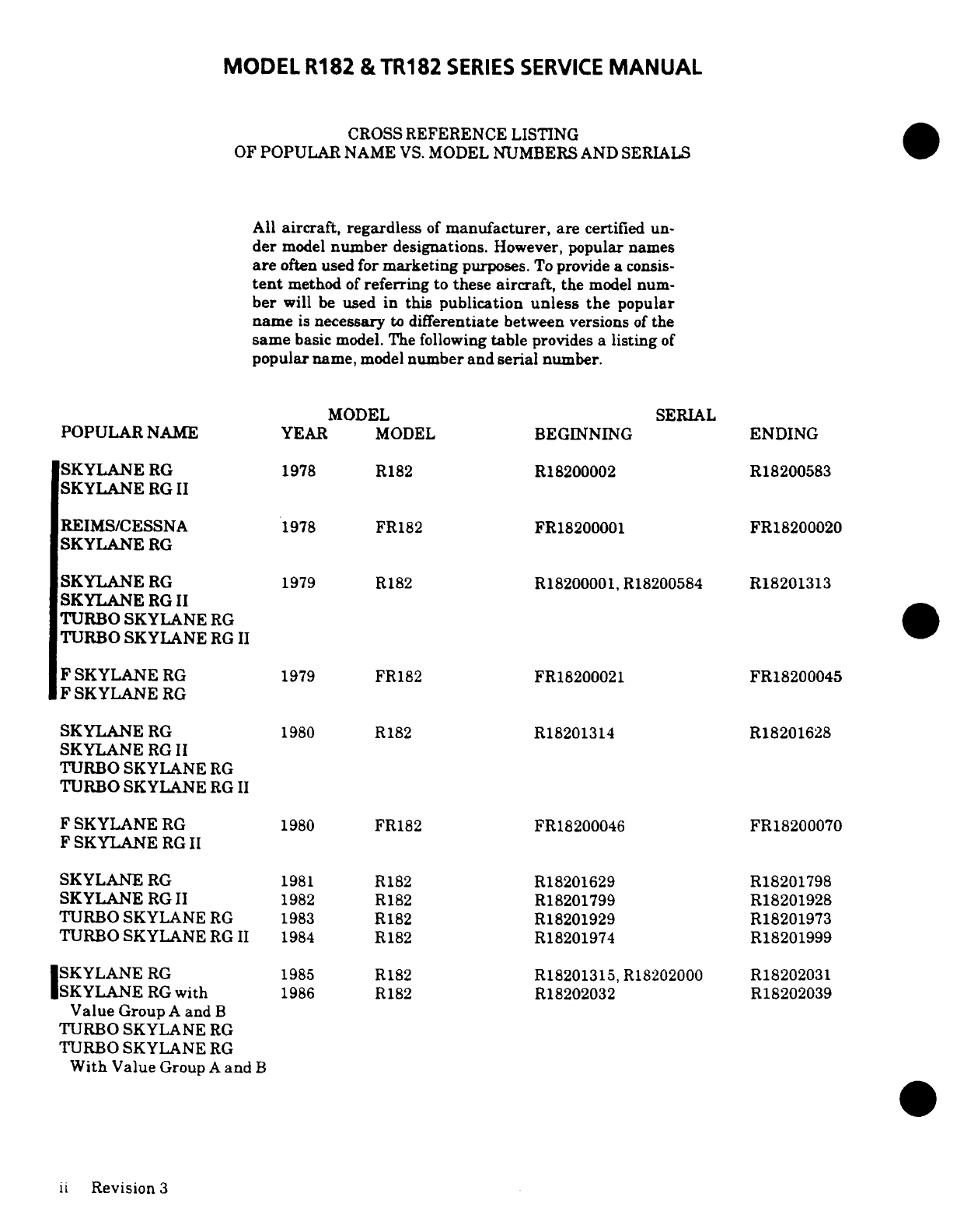
All
aircraft,
regardless
of
manufacturer,
are
certified
un-
der
model
number
designations.
However,
popular
names
are
often
used
for
marketing
purposes.
To
provide
a
consis-
tent
method
of
referring
to
these
aircraft,
the
model
num-
ber
will
be
used in
this
publication
unless the
popular
name
is
necessary
to
differentiate
between versions
of
the
same
basic
model.
The
following
table
provides
a
listing
of
popular
name,
model
number and serial
number.
MODEL
SERIAL
POPULAR
NAME
YEAR
MODEL
BEGINNING
ENDING
SKYLANERG
1978
R182
R18200002
R18200583
SKYLANE
RG
II
REIMS/CESSNA
1978
FR182
FR18200001
FR18200020
SKYLANE
RG
SKYLANE
RG
1979 R182
R18200001,R18200584
R18201313
SKYLANE
RG
II
TURBO SKYLANE
RG
TURBO
SKYLANE
RG
II
F
SKYLANE
RG
1979
FR182
FR18200021
FR18200045
F
SKYLANE
RG
SKYLANE
RG
1980
R182
R18201314
R18201628
SKYLANE
RG
II
TURBO SKYLANE
RG
TURBO SKYLANE
RG
II
F SKYLANE
RG
1980
FR182
FR18200046
FR18200070
F
SKYLANE
RG
II
SKYLANE
RG
1981
R182
R18201629
R18201798
SKYLANE
RG
II
1982
R182
R18201799
R18201928
TURBO
SKYLANE
RG 1983
R182
R18201929
R18201973
TURBO SKYLANE
RG
II
1984
R182
R18201974
R18201999
SKYLANE
RG
1985
R182
R18201315,
R18202000
R18202031
SKYLANE
RG
with
1986
R182
R18202032
R18202039
Value
Group
A
and
B
TURBO
SKYLANE
RG
TURBO
SKYLANE
RG
With
Value
Group
A
and
B
ii
Revision
3
MODEL
R182
&
TR182
SERIES
SERVICE
MANUAL
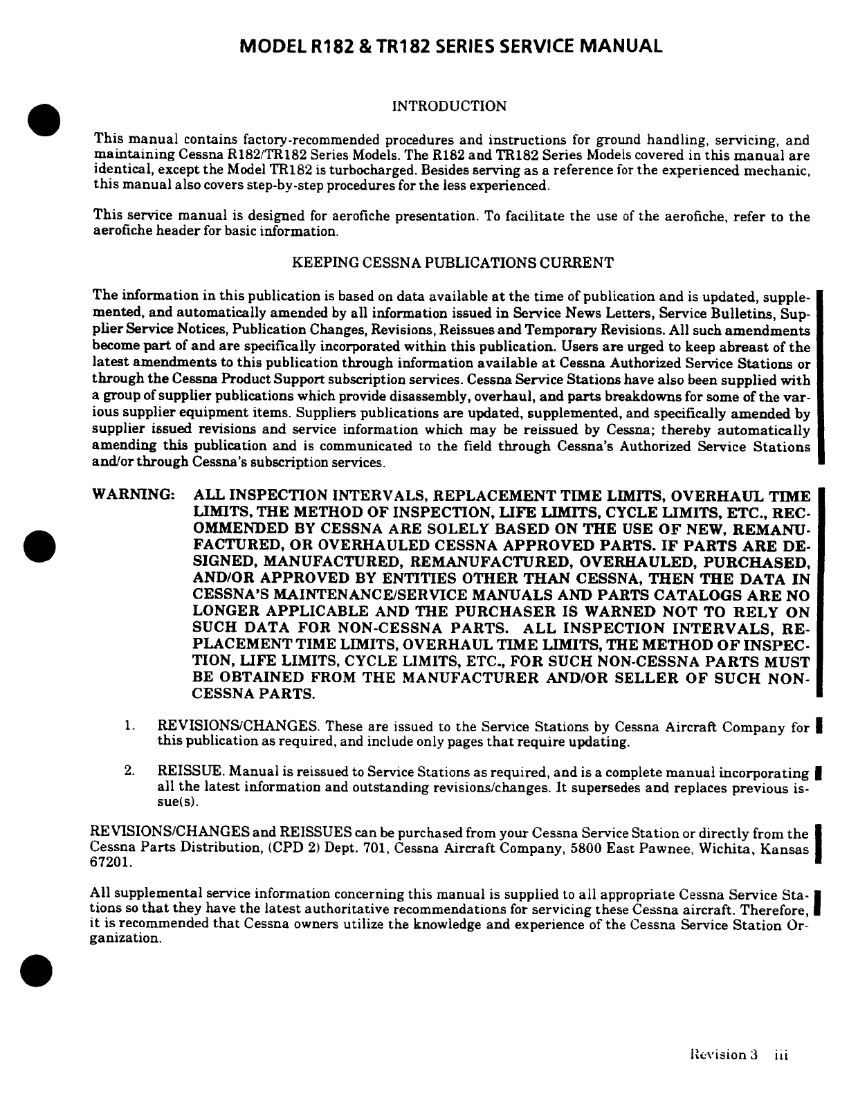
INTRODUCTION
This
manual
contains
factory-recommended
procedures
and
instructions
for
ground
handling,
servicing,
and
maintaining
Cessna
R182/TR182
Series
Models.
The
R182
and
TR182
Series
Models
covered
in
this
manual
are
identical,
except
the
Model
TR182
is
turbocharged.
Besides
serving as
a
reference
for
the
experienced
mechanic,
this
manual
also
covers
step-by-step
procedures
for
the
less
experienced.
This
service
manual
is
designed
for
aerofiche
presentation.
To
facilitate
the
use
of
the
aerofiche,
refer
to
the
aerofiche
header
for
basic
information.
KEEPING
CESSNA
PUBLICATIONS
CURRENT
The
information
in
this
publication
is
based
on
data
available
at
the time
of
publication
and
is
updated,
supple-
mented,
and
automatically
amended
by
all
information
issued
in
Service
News
Letters,
Service
Bulletins,
Sup-
plier
Service
Notices,
Publication
Changes,
Revisions,
Reissues
and
Temporary
Revisions. All such
amendments
become
part
of
and
are
specifically
incorporated
within
this
publication.
Users
are
urged
to
keep
abreast
of
the
latest
amendments
to
this
publication
through
information
available
at
Cessna
Authorized
Service
Stations
or
through
the
Cessna
Product
Support
subscription
services.
Cessna
Service
Stations
have
also
been
supplied
with
a
group
of
supplier
publications
which
provide
disassembly,
overhaul, and
parts
breakdowns
for
some
of
the
var-
ious
supplier equipment
items.
Suppliers
publications
are
updated,
supplemented,
and
specifically
amended
by
supplier
issued revisions
and
service
information
which may
be
reissued
by
Cessna;
thereby
automatically
amending
this
publication
and
is
communicated
to
the
field
through
Cessna's
Authorized
Service
Stations
and/or
through
Cessna's
subscription
services.
WARNING:
ALL
INSPECTION
INTERVALS,
REPLACEMENT
TIME
LIMITS,
OVERHAUL
TIME
LIMITS, THE
METHOD
OF
INSPECTION,
LIFE
LIMITS,
CYCLE
LIMITS,
ETC.,
REC-
OMMENDED
BY
CESSNA
ARE
SOLELY
BASED
ON
THE
USE
OF
NEW,
REMANU-
FACTURED,
OR
OVERHAULED CESSNA
APPROVED
PARTS.
IF
PARTS ARE
DE-
SIGNED,
MANUFACTURED,
REMANUFACTURED, OVERHAULED,
PURCHASED,
AND/OR
APPROVED
BY
ENTITIES
OTHER
THAN
CESSNA,
THEN
THE
DATA
IN
CESSNA'S
MAINTENANCE/SERVICE
MANUALS
AND
PARTS
CATALOGS
ARE
NO
LONGER
APPLICABLE
AND
THE
PURCHASER
IS
WARNED
NOT
TO
RELY
ON
SUCH
DATA
FOR
NON-CESSNA
PARTS.
ALL
INSPECTION
INTERVALS,
RE-
PLACEMENT
TIME LIMITS,
OVERHAUL
TIME
LIMITS,
THE
METHOD
OF
INSPEC-
TION,
LIFE
LIMITS, CYCLE
LIMITS,
ETC.,
FOR
SUCH
NON-CESSNA
PARTS
MUST
BE
OBTAINED
FROM
THE
MANUFACTURER
AND/OR
SELLER
OF
SUCH
NON-
CESSNA
PARTS.
1.
REVISIONS/CHANGES. These
are
issued
to
the
Service
Stations
by
Cessna
Aircraft
Company
for
this
publication
as
required,
and
include
only
pages
that
require
updating.
2.
REISSUE.
Manual
is
reissued
to
Service
Stations
as
required,
and
is
a
complete
manual
incorporating
all
the
latest
information
and
outstanding
revisions/changes.
It
supersedes
and
replaces
previous
is-
sue(s).
REVISIONS/CHANGES
and
REISSUES
can
be
purchased
from
your
Cessna
Service
Station
or
directly
from
the
Cessna
Parts
Distribution,
(CPD
2)
Dept.
701,
Cessna
Aircraft
Company,
5800
East
Pawnee,
Wichita,
Kansas
67201.
All
supplemental
service
information
concerning
this
manual
is
supplied
to
all
appropriate
Cessna
Service
Sta-
tions
so
that
they
have
the
latest
authoritative
recommendations
for
servicing
these
Cessna
aircraft.
Therefore,
it
is recommended
that
Cessna
owners
utilize
the
knowledge
and
experience
of
the
Cessna
Service
Station
Or-
ganization.
Revision
3
iii
MODEL
R182
&
TR182
SERIES
SERVICE
MANUAL
CUSTOMER CARE
SUPPLIES
AND
PUBLICATIONS
CATALOG
A
Customer
Care
Supplies
and Publications
Catalog
is
available
from
your
Cessna
Service
Station
or
directly
from
the
Cessna
Parts
Distribution,
(CPD
2)
Dept.
701,
Cessna
Aircraft
Company,
5800
East
Pawnee,
Wichita,
Kansas
67201.
The Supplies and
Publications
catalog
lists
all publications
and
Customer
Care
Supplies
avail-
able
from
Cessna
for
prior
year
models
as
well
as
new
products.
SUPPLEMENTAL
TYPE
CERTIFICATE
INSTALLATIONS
Inspection, maintenance
and
parts
requirements
for
supplemental
type certificate
(STC)
installations
are
not
in-
cluded
in
this
manual.
When
an
STC
installation
is
incorporated
on
the
airplane,
those
portions
of
the
airplane
affected
by
the
installation
must
be
inspected
in
accordance
with
the
inspection
program
published
by
the
owner
of
the
STC.
Since
STC
installations
may
change
systems interface,
operating characteristics
and
component
loads or
stresses
on
adjacent
structures,
Cessna
provided
inspection
criteria
may
not
be
valid
for
airplanes with
STC
installations.
CUSTOMER
COMMENTS
ON
MANUAL
Cessna
Aircraft
Company
has
endeavored
to
furnish
you
with
an
accurate, useful,
up-to-date
manual.
This
man-
ual
can
be
improved
with
your
help.
Please
use
the
return
card,
provided
with
your
manual,
to
report
any
errors,
discrepancies,
and
omissions
in
this manual
as
well
as any comments
you
wish
to
make.
iV
Revision
3
MODEL
R182
AND
TR182
SERVICE
MANUAL
SECTION
1
GENERAL
DESCRIPTION
Page
No.
TABLE
OF
CONTENTS
Aerofiche/
Manual
DESCRIPTION
..............
1A9/1-1
SAFETYING
PROCEDURES
....
1A17
1-9
Aircraft
Specifications
.......
1A9/1-1
SAFETY
WIRE
PROCEDURES
..
1A18,1-10
Stations
.................
1A9/1-1
USE
OF
COTTER
PINS
........
1A22.1-14
GENERAL
AIRFRAME
PRAC-
USE
OF
LOCKING
CLIPS
......
1A24/1-16
TICES
....................
1A13/1-5 USE
OF
LOCKWASHERS
......
1B2/1-18
TORQUEING
PROCEDURES
....
1A13/1-5
USE
OF
SELF-LOCKING
NUTS
..
1B2/1-18
Torque
Values
-
Bolts/Nuts
. ..
1A13/1-5
Torque
Values
-
Fittings
.....
1A16/1-8
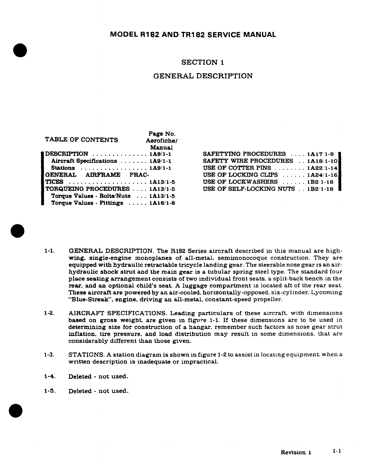
1-1.
GENERAL DESCRIPTION.
The
R182
Series
aircraft
described
in
this
manual
are
high-
wing,
single-engine
monoplanes
of
all-metal,
semimonocoque
construction.
They
are
equipped
with
hydraulic
retractable tricycle
landing
gear.
The
steerable
nose
gear
is
an
air-
hydraulic
shock
strut
and
the
main
gear
is a
tubular
spring
steel
type.
The
standard
four
place
seating arrangement
consists
of
two
individual
front
seats.
a
split-back
bench
in
the
rear,
and
an
optional
child's
seat.
A
luggage
compartment
is
located
aft
of
the
rear
seat.
These
aircraft
are
powered
by
an air-cooled,
horizontally-opposed,
six-cylinder.
Lycoming
"Blue-Streak",
engine, driving
an
all-metal, constant-speed
propeller.
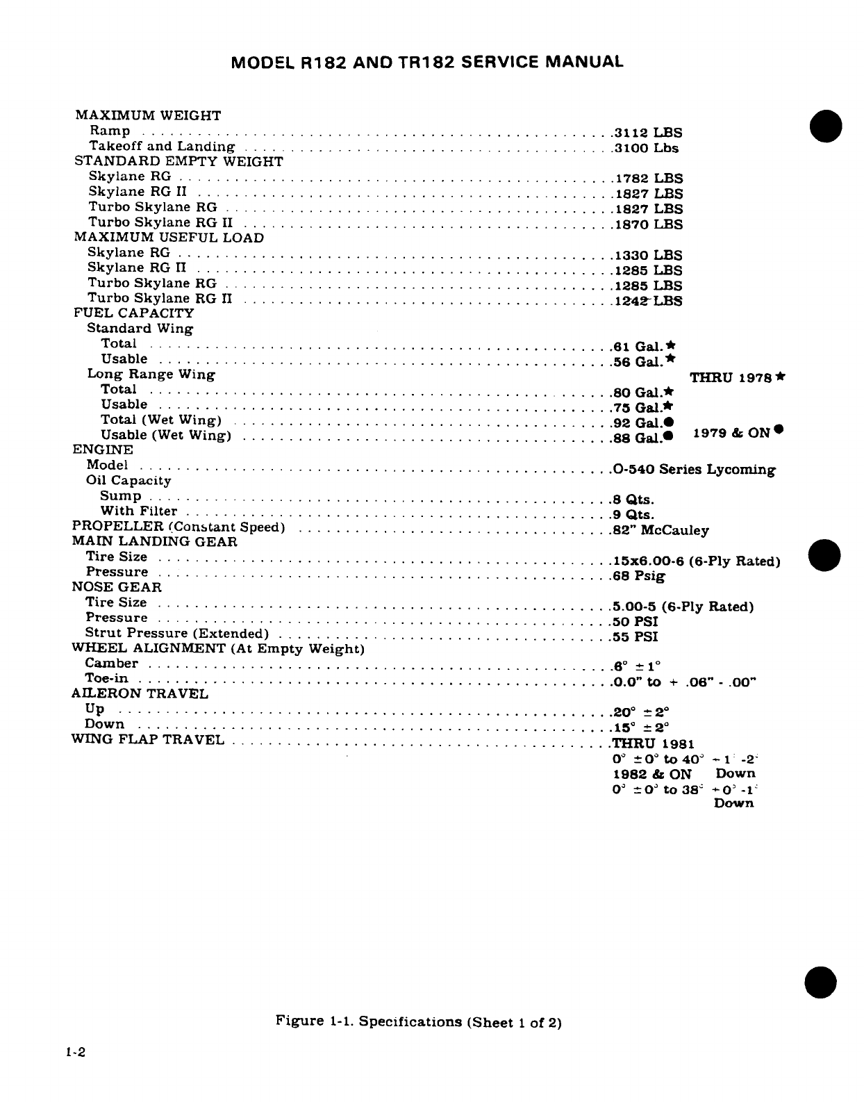
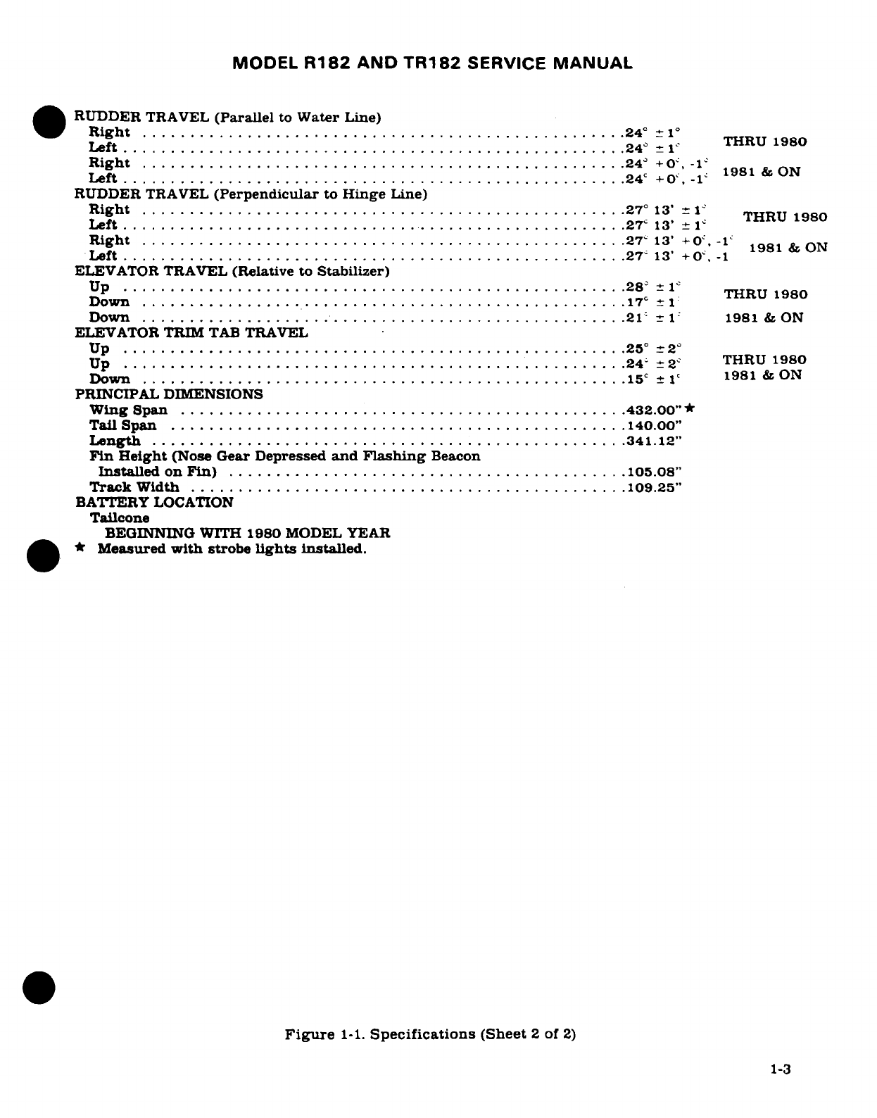
1-2.
AIRCRAFT
SPECIFICATIONS.
Leading
particulars
of
these
aircraft.
with
dimensions
based
on
gross
weight,
are
given
in
figure
1-1.
If
these
dimensions
are
to
be
used
in
determining
size
for
construction
of
a
hangar.
remember
such
factors
as
nose
gear strut
inflation,
tire
pressure,
and
load
distribution
may result
in
some
dimensions.
that
are
considerably
different
than
those
given.
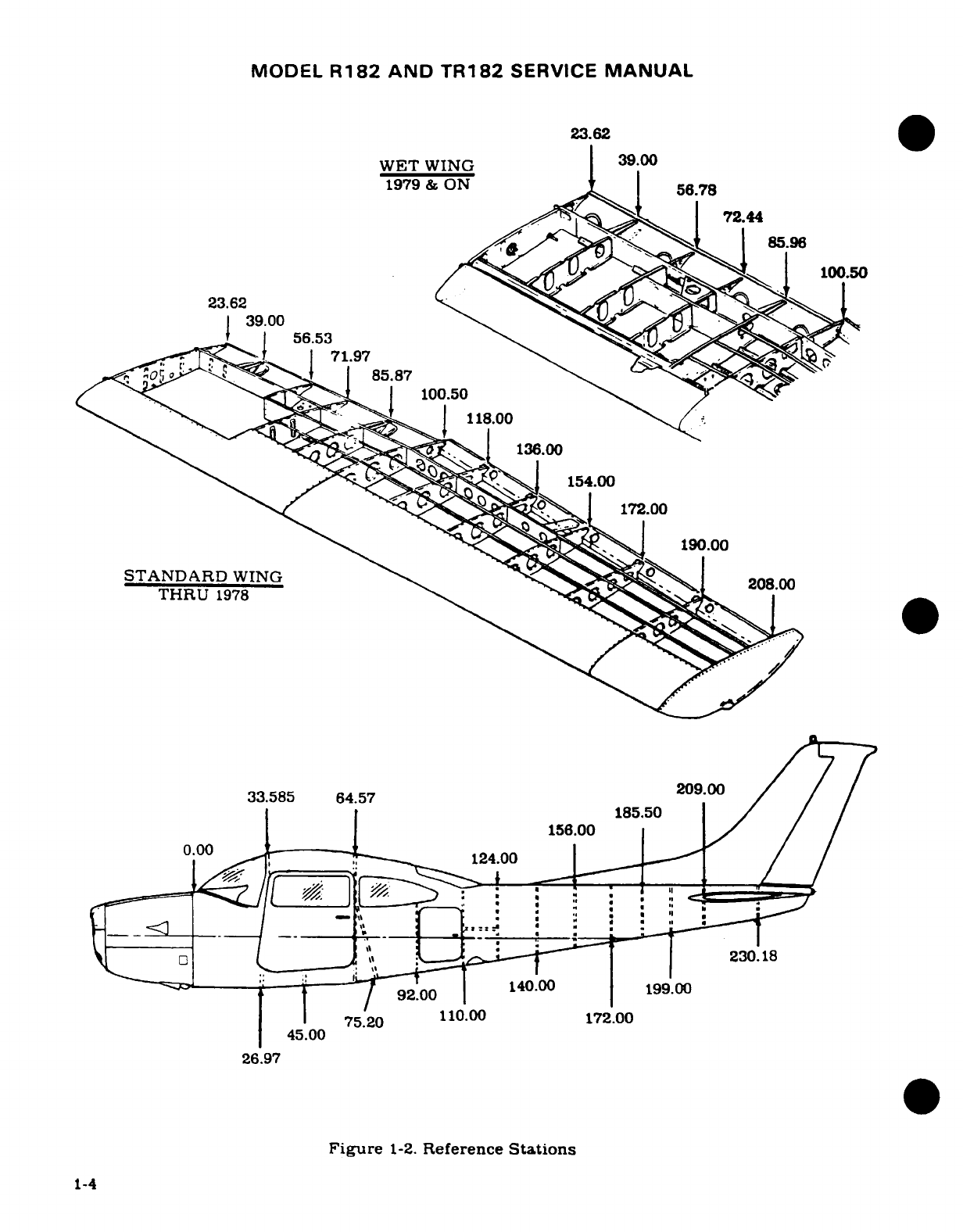
1-3.
STATIONS.
A
station
diagram
is
shown
in
figure
1-2
to
assist
in
locating
equipment.
when
a
written
description
is
inadequate
or
impractical.
1-4.
Deleted
-
not
used.
1-5.
Deleted
-
not
used.
Revision
1-1
MODEL
R182
AND
TR182
SERVICE
MANUAL
MAXIMUM WEIGHT
Ramp
......... ................ ..........
3112
LBS
Takeoff and
Landing
.......................................
3100
Lbs
STANDARD
EMPTY
WEIGHT
Skylane
RG
..................... ....... ...........
1782
LBS
Skylane
RG
II
............................................
1827
LBS
Turbo
Skylane
RG
.............. ..........................
1827
LBS
Turbo
Skylane
RG
II
........................................
1870
LBS
MAXIMUM
USEFUL
LOAD
Skylane
RG
.................. .................... .......
1330
LBS
Skylane
RG
II
............................ ................
1285
LBS
Turbo
Skylane
RG
.......................... .. ... ......
1285
LBS
Turbo
Skylane
RG
II
........................................
1242LBS
FUEL
CAPACITY
Standard
Wing
Total
..................................................
61
Gal.*
Usable
.................................................
56
Gal.*
Long
Range
Wing
THRU
1978
Total
..................................... .............
80
Gal.*
U
sable
............ .. ............................... .
75
G
al.*
Total
(W
et
W
ing)
.........................................
92
Gal.
Usable
(Wet
Wing)
.......................................
88
Gal.* 1979
&
ON
ENGINE
Model
............................ ......................
0-540
Series
Lycoming
Oil
Capacity
Sump
.................................................
8
Qts.
With
Filter
..............................................
9
Qts.
PROPELLER
(Constant
Speed)
..................................
82"
McCauley
MAIN
LANDING
GEAR
Tire
Size
................................................
15x6.00-6
(6-Ply Rated)
Pressure
.................. ..............................
.68
Psig
NOSE GEAR
Tire
Size
.................................................
5.00-5
(6-Ply
Rated)
Pressure
..................... .. ..........................
50 PSI
Strut
Pressure
(Extended)
....................................
55 PSI
WHEEL
ALIGNMENT
(At
Empty Weight)
Camber
.................................................. 6°
-1 °
Toe-in
...................................................
0.0"
to
+
.06"
-
.00"
AILERON
TRAVEL
Up
.....................................................
20
°- 2 °
Down
...................................... ............. 15°2°
WING
FLAP
TRAVEL
.........................................
THRU
1981
0°0°
to 40
- 1 -2
1982
&
ON
Down
0
-=O
°
to
38
-
0
-1-
Down
Figure
1-1.
Specifications (Sheet
1
of
2)
1-2
MODEL
R182
AND
TR182
SERVICE
MANUAL
RUDDER
TRAVEL
(Parallel
to
Water
Line)
Right
...................................................
24
1
°
24
°1
THRU
1980
Left
. .. ... . ... ... ....... . .. . .. .. .. ..
.....
...... . .
.....
. ..
24
±
-1
R
ight
...................................................
24
°
+0,
-1
Left
.....................................................
24'
+
O,
-1
1981
&
ON
RUDDER
TRAVEL
(Perpendicular
to
Hinge
Line)
Right
...................................... .............
27
°
13'
THRU
THRU
1980
Left
......... ............... ..................... ........
27
13'
±
1
Right
...... ................................... .
.27
13'
+
0
-1
1981
&
ON
Left
.....................................................
27-
13'
+
0
. -1
ELEVATOR
TRAVEL
(Relative to
Stabilizer)
U
p
.......... ............ ....................... ........
28
±
±1
THRU
1980
D
ow
n
...................................................
17
+1
Down
..................................................
21
1
1981
&
ON
ELEVATOR
TRIM
TAB
TRAVEL
Up
................................................ ...
25
2
Up
....... ..................
..
24-
±
2
THRU
1980
Down
...................................................
15
± 1
1981
&
ON
PRINCIPAL
DIMENSIONS
Wing
Span
...............................................
432.00"
Tail
Span
................................................
140.00"
Length
..................................................
341.12"
Fin
Height
(Nose
Gear
Depressed
and
Flashing
Beacon
Installed
on
Fin)
..........................................
105.08"
Track
W
idth
..............................................
109.25"
BATTERY
LOCATION
Tailcone
BEGINNING
WITH
1980
MODEL YEAR
.
*
Measured
with
strobe
lights
installed.
Figure
1-1.
Specifications
(Sheet
2
of
2)
1-3
MODEL
R182
AND
TR182
SERVICE
MANUAL
23.62
WET
WING
39.00
1979
&
ON
Y ,
56.78
THR\
1978
1
8
00.7
39.0056.53
/
71.97
33.585
64.57
20900
/
100.500 /
156.00
/
I~75.20 110.00
172.00
190.00
THRU
1978
33.585
64.57
2
185.50
~26.97~~156.00
124.00
92.00
75.20
110.00
172.00
26.97
Figure
1-2.
Reference
Stations
1-4
MODEL
R182
&
TR182
SERIES
SERVICE
MANUAL
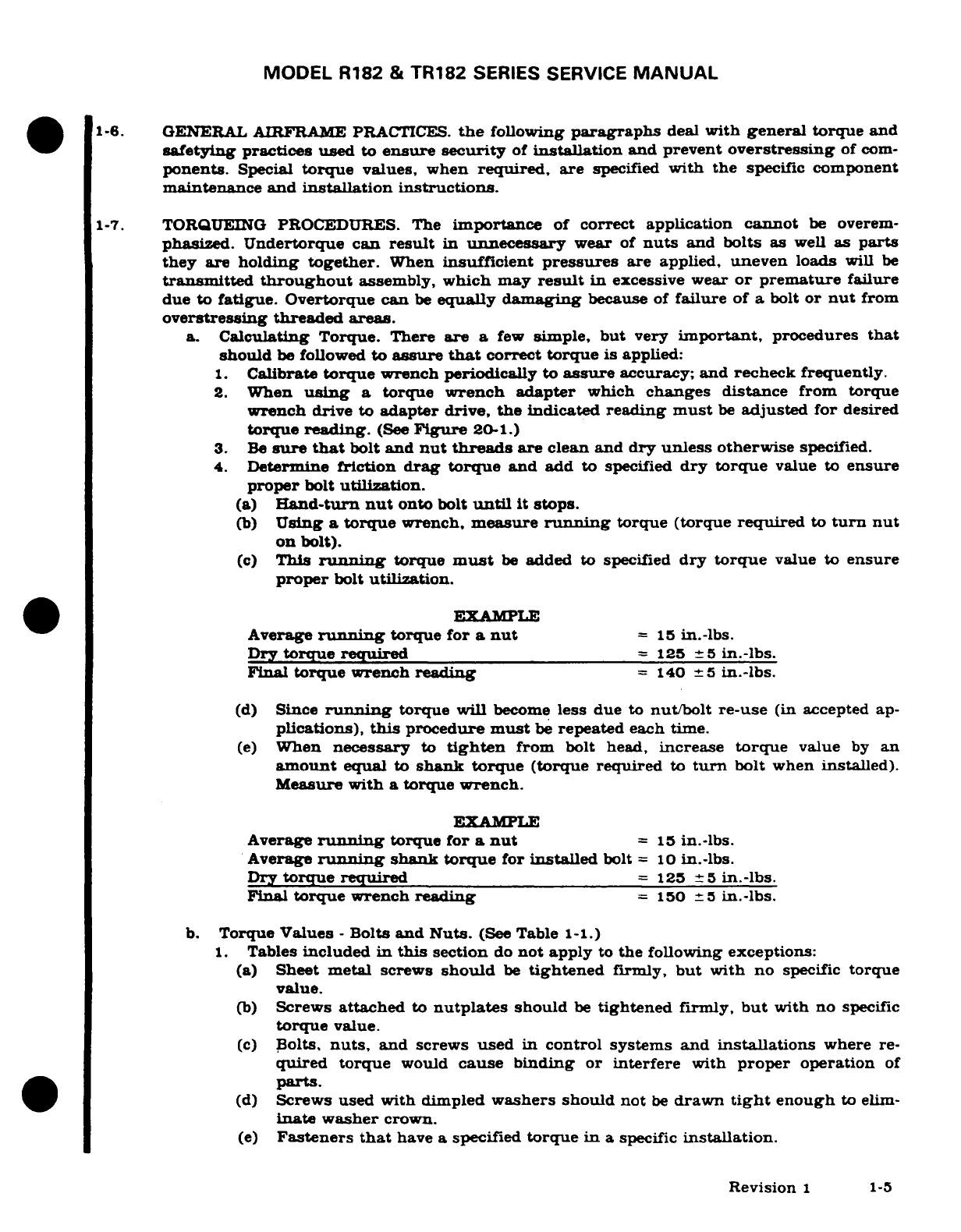
1-6.
GENERAL
AIRFRAME
PRACTICES.
the
following
paragraphs
deal
with
general
torque and
safetying
practices used
to
ensure
security
of
installation
and
prevent
overstressing
of
com-
ponents.
Special
torque
values,
when
required,
are
specified
with the
specific
component
maintenance
and
installation instructions.
1-7.
TORQUEING
PROCEDURES.
The
importance
of
correct
application
cannot
be
overem-
phasized.
Undertorque can
result
in
unnecessary
wear
of
nuts
and bolts
as
well
as
parts
they
are
holding
together.
When
insufficient
pressures
are
applied,
uneven
loads
will
be
transmitted
throughout
assembly,
which
may
result
in
excessive
wear
or
premature
failure
due
to
fatigue. Overtorque
can
be
equally
damaging
because of
failure
of
a
bolt
or
nut
from
overstressing
threaded
areas.
a.
Calculating
Torque.
There
are
a
few
simple,
but
very
important,
procedures
that
should
be
followed
to
assure
that
correct
torque
is
applied:
1.
Calibrate
torque
wrench
periodically
to
assure
accuracy;
and recheck frequently.
2.
When
using
a
torque
wrench adapter
which
changes distance
from
torque
wrench
drive to
adapter
drive,
the
indicated
reading
must
be
adjusted
for
desired
torque
reading.
(See
Figure
20-1.)
3.
Be
sure
that
bolt
and
nut
threads
are
clean and
dry
unless
otherwise
specified.
4.
Determine
friction
drag
torque
and
add
to
specified
dry torque
value
to
ensure
proper
bolt
utilization.
(a)
Hand-turn
nut
onto
bolt
until
it
stops.
(b)
Using
a
torque
wrench,
measure
running
torque
(torque
required
to
turn
nut
on
bolt).
(c)
This
running
torque
must
be
added
to specified
dry
torque
value
to
ensure
proper
bolt
utilization.
EXAMPLE
Average
running
torque for
a
nut
=
15
in.-lbs.
Dry
torque
required
=
125
5
in.-lbs.
Final
torque
wrench
reading
=
140
5
in.-lbs.
(d)
Since
running
torque
will
become
less
due
to
nut/bolt
re-use
(in
accepted ap-
plications),
this
procedure
must
be
repeated
each
time.
(e)
When
necessary
to
tighten
from
bolt
head,
increase
torque
value
by
an
amount
equal
to
shank torque
(torque required
to
turn
bolt
when
installed).
Measure
with
a
torque
wrench.
EXAMPLE
Average
running
torque for
a
nut
=
15
in.-lbs.
Average
running
shank
torque
for
installed
bolt
=
10
in.-lbs.
Dry
torque
required
=
125
±5
in.-lbs.
Final
torque
wrench
reading
=
150
5
in.-lbs.
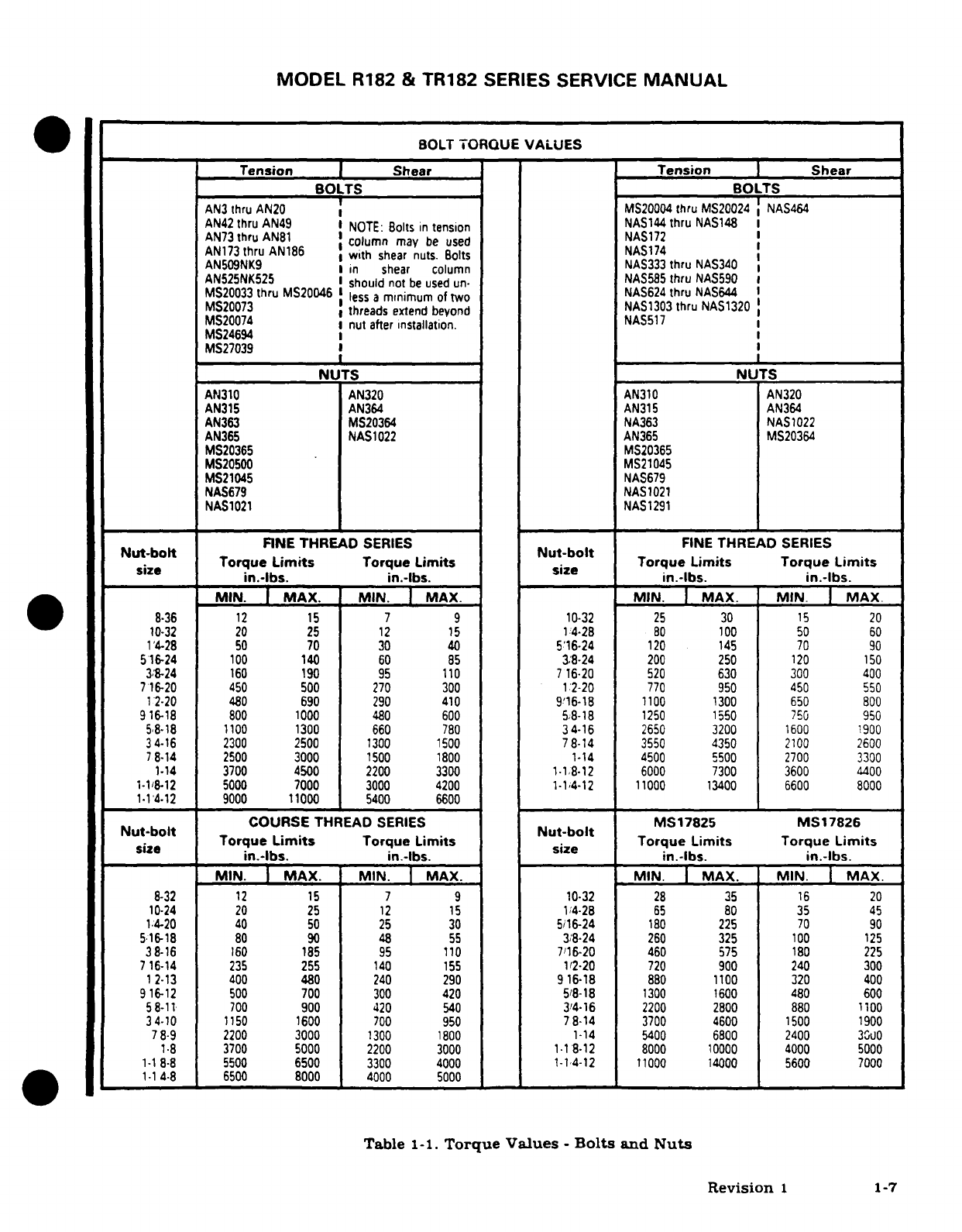
b.
Torque
Values
-
Bolts
and
Nuts.
(See
Table
1-1.)
1.
Tables
included
in
this
section
do
not
apply
to
the
following exceptions:
(a)
Sheet
metal
screws
should
be
tightened
firmly,
but
with
no
specific
torque
value.
(b)
Screws
attached
to
nutplates
should
be
tightened
firmly,
but
with
no
specific
torque
value.
(c)
Bolts,
nuts,
and
screws
used
in
control systems
and
installations
where
re-
quired torque
would
cause
binding
or
interfere
with
proper
operation
of
parts.
(d)
Screws used with dimpled
washers
should
not
be
drawn
tight
enough
to
elim-
inate
washer
crown.
(e)
Fasteners
that
have
a
specified
torque
in
a specific
installation.
Revision
1
1-5
MODEL R182
&
TR182
SERIES
SERVICE
MANUAL
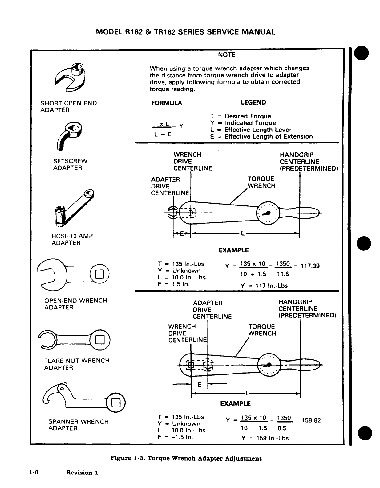
NOTE
When
using
a
torque
wrench
adapter
which
changes
the
distance
from
torque
wrench
drive
to adapter
drive,
apply
following
formula
to
obtain corrected
torque
reading.
SHORT
OPEN END
FORMULA
LEGEND
ADAPTER T
=
Desired
Torque
T
x
L
y
Y
=
Indicated
Torque
L
=
Effective
Length
Lever
E
=
Effective
Length
of
Extension
WRENCH
HANDGRIP
SETSCREW
DRIVE
CENTERLINE
ADAPTER
CENTERLINE
(PREDETERMINED)
ADAPTER
TORQUE
DRIVE
WRENCH
CENTERLINE
HOSE
CLAMP
L
ADAPTER
EXAMPLE
T
=
135
In.-Lbs
y
=
135
x
10
=
1350
=
117.39
Y
=
Unknown
~^~
\)
Y
-
=
~
~U~nknown
~
10
+ 1.5
11.5
L
=
10.0
In.-Lbs
10
+
1.5
11.5
E
=
1.5
In.
Y
=
117
In.-Lbs
OPEN-END WRENCH
ADAPTER
HANDGRIP
ADAPTER
DRIVE
CENTERLINE
CENTERLINE (PREDETERMINED)
WRENCH
TORQUE
DRIVE
WRENCH
CENTERLINE
ADAPTER
-
L-
^
\-----
E
l
EXA
M
PLE
SPANNER
WRENCH
T
=
135
In.-Lbs
Y
=
135
x
10
1350
158.82
SPANNER
WRENCH
Y
=
UkowY
Y
=
Unknown
--
15.
ADAPTER
L
=
10.0
In.-Lbs
10
-
1.5
8.5
E
=
-1.5
In.
Y
=
159
In.-Lbs
Figure
1-3.
Torque
Wrench
Adapter
Adjustment
1-6
Revision
1
MODEL
R182
&
TR182
SERIES
SERVICE
MANUAL
BOLT
TORQUE
VALUES
Tension
Shear
Tension
Shear
BOLTS
BOLTS
AN3
thru
AN20
MS20004
thru
MS20024
NAS464
AN42
thru
AN49
NOTE:
Bolts
in
tension
NAS144
thru
NAS148
AN73
thru
AN81
column
may
be
used
NAS172
AN173
thru
AN186
with
shear
nuts.
Bolts
NAS174
AN509NK9
in
shear
column
NAS333
thru
NAS34
AN525NK525
I
should
not
be
used un-
NAS585
thru
NAS590
MS20033
thru
MS20046
less
a
minimum
of
two
NAS624
thru
NAS644
MS20073
threads
extend
beyond
NAS1303
thru
NAS1320
MS20074
nut
after
installation.
NAS517
MS24694
MS27039
NUTS
NUTS
AN310 AN320
AN310
AN320
AN315 AN364
AN315
AN364
AN363 MS20364
NA363
NAS
1022
AN365 NAS1022 AN365
MS20364
MS20365 MS20365
MS20500
MS21045
MS21045
NAS679
NAS679
NAS1021
NAS1021
NAS1291
FINE THREAD
SERIES
FINE
THREAD
SERIES
Nut-bolt
Nut-bolt
size
Torque Limits Torque
Limits
Nut
Torque
Limits
Torque
Limits
in.-lbs.
in.-lbs.
in.-lbs.
in.-lbs.
MIN.
MAX.
MIN.
MAX.
MIN.
MAX.
MIN.
MAX
8-36
12
15
7 9
10-32
25
30
15
20
10-32
20
25
12
15
14-28
80
100
50
60
14-28
50
70
30
40
516-24
120 145 70
90
516-24
100
140
60
85
3/8-24
200
250
120
150
3/8-24 160
190
95 110
716-20
520
630
300
400
716-20
450
500
270 300
12-20
770
950 450
550
12-20
480
690
290
410
916-18
1100 1300
650
800
916-18
800
1000
480 600
5/8-18
1250
1550
750
950
58-18
1100
1300
660
780
34-16
2650
3200
1600
1900
34-16
2300
2500
1300
1500
78-14
3550
4350
2100 2600
7
8-14
2500
3000
1500
1800
1-14
4500
5500 2700
3300
1-14
3700
4500
2200
3300 1-1.8-12
6000
7300
3600 4400
1-1/8-12
5000
7000
3000
4200
1-1/4-12 11000
13400
6600 8000
1-1/4-12
9000
11000
5400
6600
COURSE
THREAD
SERIES
MS17825
MS17826
Nut-bolt Nut-bolt
size
Torque
Limits
Torque
Limits
Nut
Torque
Limits
Torque
Limits
in.-lbs.
in.-lbs.
in.-lbs.
in.-lbs.
MIN.
I
MAX.
MIN.
MAX.
MIN.
I
MAX.
MIN. MAX.
8-32
12
15
7 9
10-32
28
35
16
20
10-24
20
25
12
15
1/4-28
65
80
35
45
1.4-20 40
50
25 30
5/16-24
180
225
70
90
5.16-18
80
90
48
55
3/8-24
260
325
100
125
38-16
160
185
95
110
7/16-20 460
575
180
225
7
16-14
235
255
140
155
1/2-20
720
900
240
300
12-13
400
480
240
290
916-18
880
1100
320
400
9
16-12
500
700
300
420
5/8-18
1300
1600
480
600
58-11
700
900
420
540
3/4-16
2200
2800 880
1100
34-10
1150
1600
700
950
78-14
3700
4600
1500
1900
78-9
2200
3000
1300 1800
1-14
5400 6800
2400
3000
1-8
3700
5000
2200 3000
1-1
8-12 8000
10000
4000
5000
1-1
8-8
5500
6500
3300
4000
1-1/4-12 11000
14000
5600
7000
1-1
4-8
6500
8000
4000
5000
Table
1-1.
Torque
Values
-
Bolts
and
Nuts
Revision
1
1-7
MODEL
R182
&
TR182
SERIES
SERVICE
MANUAL
2.
The
values
shown
in
Table
1-1
are
based
on
parts
being
clean
and
dry
with no
lu-
bricants
added.
3.
Castellated
nuts
requiring
cotter
pins
should
be
tightened
to
low
torque
value.
Torque
can
be
increased
to
install cotter
pin,
but
should
never exceed
maximum
torque
value.
NOTE
Self-locking castellated
nuts,
MS17825
and
MS17826,
re-
quire
a
separate
torque
range.
These
values
are
shown
separately
in
torque
value
tables.
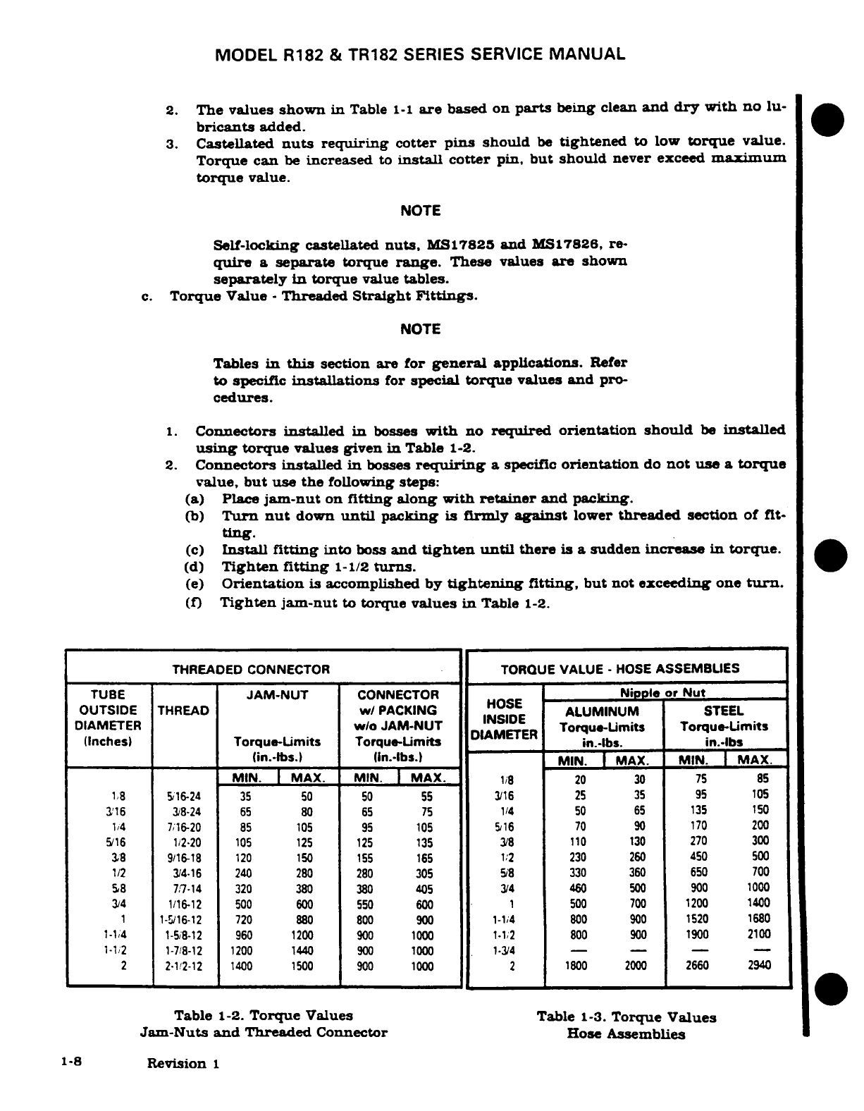
c.
Torque
Value
-
Threaded
Straight
Fittings.
NOTE
Tables
in
this
section are
for
general
applications.
Refer
to
specific
installations
for
special
torque
values
and
pro-
cedures.
1.
Connectors
installed
in
bosses
with
no
required orientation
should
be
installed
using
torque
values given
in
Table
1-2.
2.
Connectors installed
in
bosses
requiring
a
specific
orientation
do
not
use
a
torque
value,
but
use the
following
steps:
(a)
Place
jam-nut
on
fitting
along
with
retainer
and
packing.
(b)
Turn
nut
down
until
packing
is
firmly
against
lower
threaded
section
of
fit-
ting.
(c)
Install
fitting
into
boss
and
tighten
until
there
is a
sudden
increase
in
torque.
(d)
Tighten
fitting
1-1/2
turns.
(e)
Orientation
is
accomplished by
tightening
fitting,
but not
exceeding
one
turn.
(f)
Tighten jam-nut
to
torque
values
in
Table
1-2.
THREADED
CONNECTOR
TORQUE
VALUE
-
HOSE
ASSEMBLIES
TUBE
JAM-NUT
CONNECTOR
Nipple
or
Nut
HOSE
OUTSIDE
THREAD
w/
PACKING HOSE
ALUMINUM
STEEL
DIAMETER
w/o
JAM-NUT
Torque-Limits
Torque-Limits
(Inches)
Torque-Limits
Torque-Limits
DIAMETER
in.-lbs.
in.-lbs
(in.lbs.)
n.-lbs.)
MAX.
MIN.
MAX.
MIN.
MAX.
MIN.
MAX.
1/8
20
30 75
85
1/8
5/16-24
35
50
50
55 3/16
25 35
95
105
3/16
3/8-24
65
80
65 75
1/4
50
65
135
150
1/4
7/16-20 85
105 95
105
5/16
70
90
170
200
5/16
1/2-20
105 125 125
135
3/8
110
130
270 300
3/8
9/16-18
120 150 155
165
1;2
230
260
450
500
1/2
3/4-16
240
280 280
305
5/8
330 360
650
700
5/8
7/7-14 320
380
380
405
3/4
460
500
900
1000
3/4 1/16-12
500
600
550
600
1
500
700
1200 1400
1
1-5/16-12
720 880 800
900
1-14
800
900 1520 1680
1-1/4
1-5/8-12
960
1200
900
1000
1-1/2
800
900
1900
2100
1-1/2
1-7/8-12
1200 1440
900
1000
1-3/4
- - - -
2
2-1/2-12 1400
1500
900 1000
2
1800 2000
2660
2940
Table
1-2.
Torque
Values
Table
1-3.
Torque
Values
Jam-Nuts
and
Threaded
Connector
Hose
Assemblies
1-8
Revision
1
MODEL
R182
&
TR182
SERIES
SERVICE
MANUAL
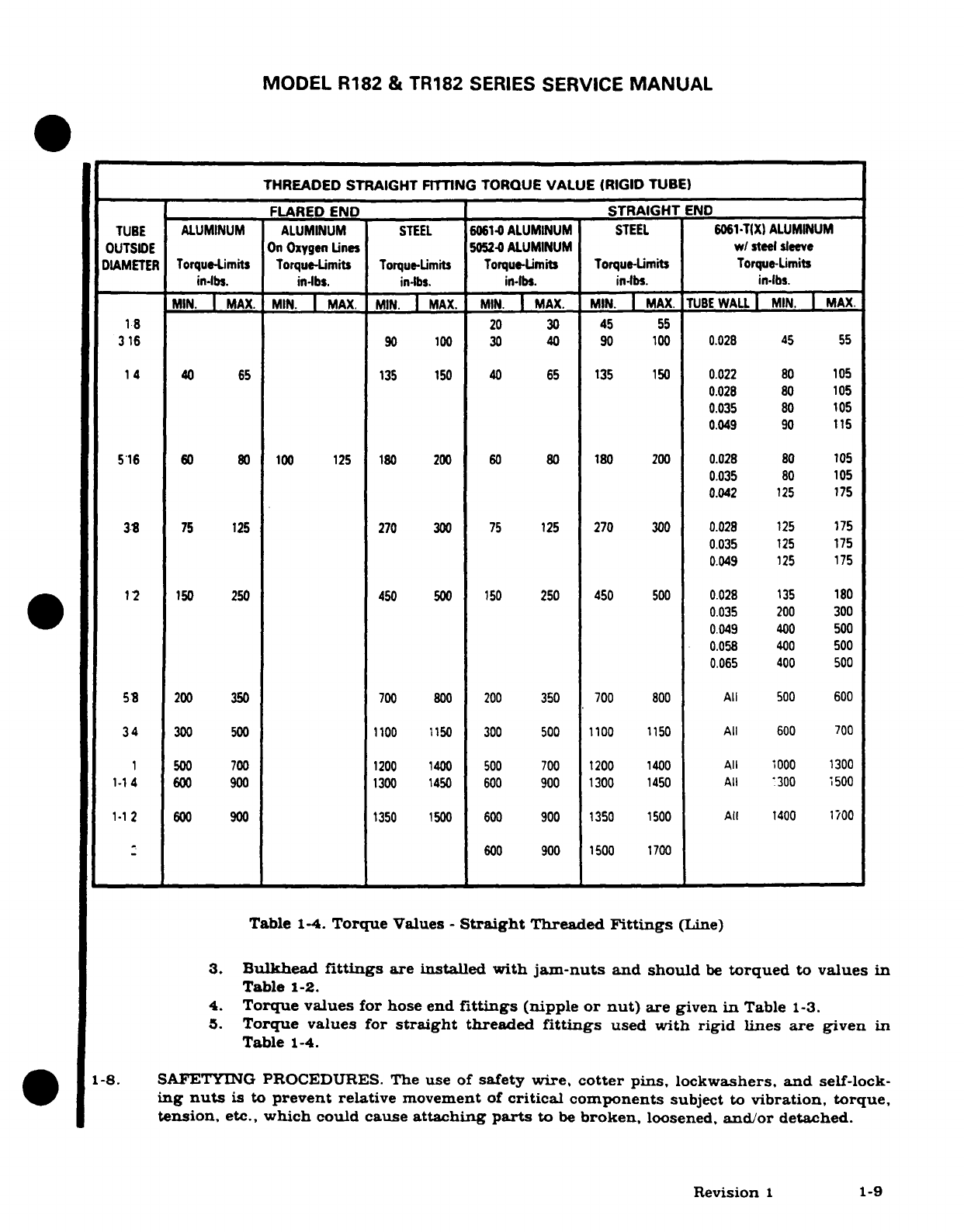
THREADED
STRAIGHT
FITTING
TORQUE
VALUE
(RIGID
TUBE)
FLARED
END
STRAIGHT
END
TUBE
ALUMINUM
ALUMINUM
STEEL
6061-
ALUMINUM
STEEL
6061-TIX)
ALUMINUM
OUTSIDE
On
Oxygen
Lines
5052-0
ALUMINUM
w/
steel
sleeve
DIAMETER
Torque-Limits
Torque-Limits
Torque-imits
Torque-Limits
Torque-Limits
Torque-Limits
in-lbs.
in-lbs.
in-lbs.
in-lbs.
inlbs.
MIN. MAX.
MIN.
MAX.
MIN. MAX.
MIN.
MAX.
MIN.
MAX.
TUBE
WALL
MIN. MAX.
18
20
30
45
55
316
90
100 30
40
90
100
0.028
45
55
14
40 65
135 150
40
65
135
150
0.022
80 105
0.028 80
105
0.035
80
105
0.049
90
115
516
60
80 100 125
180
200
60
80
180 200
0.028
80
105
0.035
80
105
0.042
125
175
38
75 125
270
300
75
125
270
300
0.028
125 175
0.035
125
175
0.049
125
175
1 2
150
250 450
500
150
250
450
500
0.028
135
180
0.035
200
300
0.049 400 500
0.058
400
500
0.065
400
500
58
200 350
700 800
200
350 700
800
All
500 600
34
300
500
1100
1150
300
500
1100
1150
All
600
700
1
500 700
1200
1400
500
700
1200
1400
All
1000 1300
1-14
600 900
1300
1450
600
900
1300
1450
All
1300
1500
1-1
2
600
900
1350
1500
600
900
1350
1500
All
1400
1700
-600
900
1500
1700
Table
1-4.
Torque
Values
-
Straight
Threaded
Fittings
(Line)
3.
Bulkhead
fittings
are installed
with
jam-nuts
and should
be
torqued
to
values
in
Table
1-2.
4.
Torque values
for
hose end
fittings
(nipple
or
nut)
are
given
in
Table
1-3.
5.
Torque values
for
straight
threaded
fittings
used
with rigid
lines
are
given
in
Table
1-4.
1-8.
SAFETYING
PROCEDURES.
The
use of
safety
wire,
cotter
pins, lockwashers,
and
self-lock-
ing
nuts
is
to
prevent
relative
movement
of
critical
components
subject
to
vibration,
torque,
tension,
etc.,
which
could
cause
attaching
parts
to
be
broken,
loosened,
and/or
detached.
Revision
1
1-9
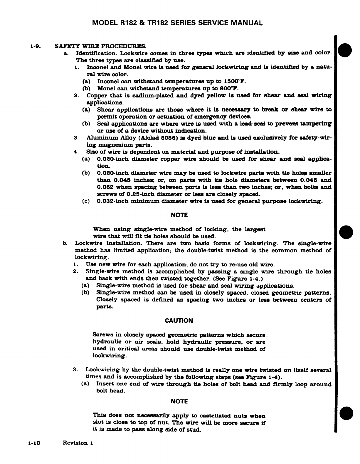
MODEL
R182
&
TR182
SERIES
SERVICE
MANUAL
1-9.
SAFETY
WIRE
PROCEDURES.
a.
Identification.
Lockwire
comes
in
three
types
which
are
identified
by
size
and
color.
The
three
types
are
classified
by
use.
1.
Inconel
and
Monel
wire
is
used
for general
lockwiring
and
is
identified
by
a
natu-
ral
wire
color.
(a)
Inconel
can
withstand
temperatures
up
to
1500F.
(b)
Monel
can
withstand
temperatures
up
to
800°F.
2.
Copper
that
is
cadium-plated
and
dyed yellow
is
used for
shear
and
seal
wiring
applications.
(a)
Shear
applications
are
those
where
it is
necessary
to
break
or
shear
wire
to
permit
operation or actuation
of
emergency
devices.
(b)
Seal
applications are
where wire
is
used
with
a
lead
seal
to
prevent-tampering
or
use
of
a
device
without indication.
3.
Aluminum
Alloy
(Alclad
5056)
is
dyed
blue
and
is
used
exclusively
for
safety-wir-
ing magnesium
parts.
4.
Size
of
wire
is
dependent
on
material and purpose
of
installation.
(a)
0.020-inch
diameter
copper wire
should
be
used
for
shear
and
seal
applica-
tion.
(b)
0.020-inch
diameter
wire
may
be
used
to
lockwire
parts
with
tie
holes
smaller
than
0.045
inches;
or,
on
parts
with
tie
hole
diameters
between
0.045
and
0.062
when
spacing
between
ports
is
less
than
two
inches;
or,
when bolts
and
screws
of
0.25-inch
diameter
or
less
are
closely
spaced.
(c)
0.032-inch
minimum
diameter
wire
is
used
for
general
purpose
lockwiring.
NOTE
When
using
single-wire
method
of
locking,
the
largest
wire
that
will
fit
tie
holes
should
be
used.
b.
Lockwire
Installation.
There
are
two
basic
forms
of
lockwiring.
The
single-wire
method
has
limited
application;
the
double-twist
method
is
the
common
method
of
lockwiring.
1.
Use
new
wire
for
each
application;
do
not
try
to
re-use
old
wire.
2.
Single-wire
method
is
accomplished
by
passing
a
single
wire
through
tie
holes
and
back
with ends
then
twisted
together.
(See
Figure
1-4.)
(a)
Single-wire method
is
used
for
shear
and
seal
wiring
applications.
(b)
Single-wire method
can
be
used
in
closely spaced.
closed
geometric
patterns.
Closely
spaced
is
defined
as
spacing
two
inches
or less
between
centers
of
parts.
CAUTION
Screws
in
closely
spaced
geometric
patterns
which
secure
hydraulic
or
air
seals,
hold
hydraulic
pressure, or
are
used
in
critical areas should
use
double-twist method
of
lockwiring.
3.
Lockwiring
by
the
double-twist
method
is
really
one
wire
twisted
on
itself
several
times
and
is
accomplished
by
the
following
steps
(see
Figure
1-4).
(a)
Insert
one
end
of
wire
through
tie
holes
of
bolt
head and
firmly
loop
around
bolt
head.
NOTE
This
does
not
necessarily
apply
to
castellated
nuts
when
slot
is
close
to
top
of
nut.
The wire
will
be
more
secure
if
it is
made
to
pass along
side
of
stud.
1-10
Revision
1
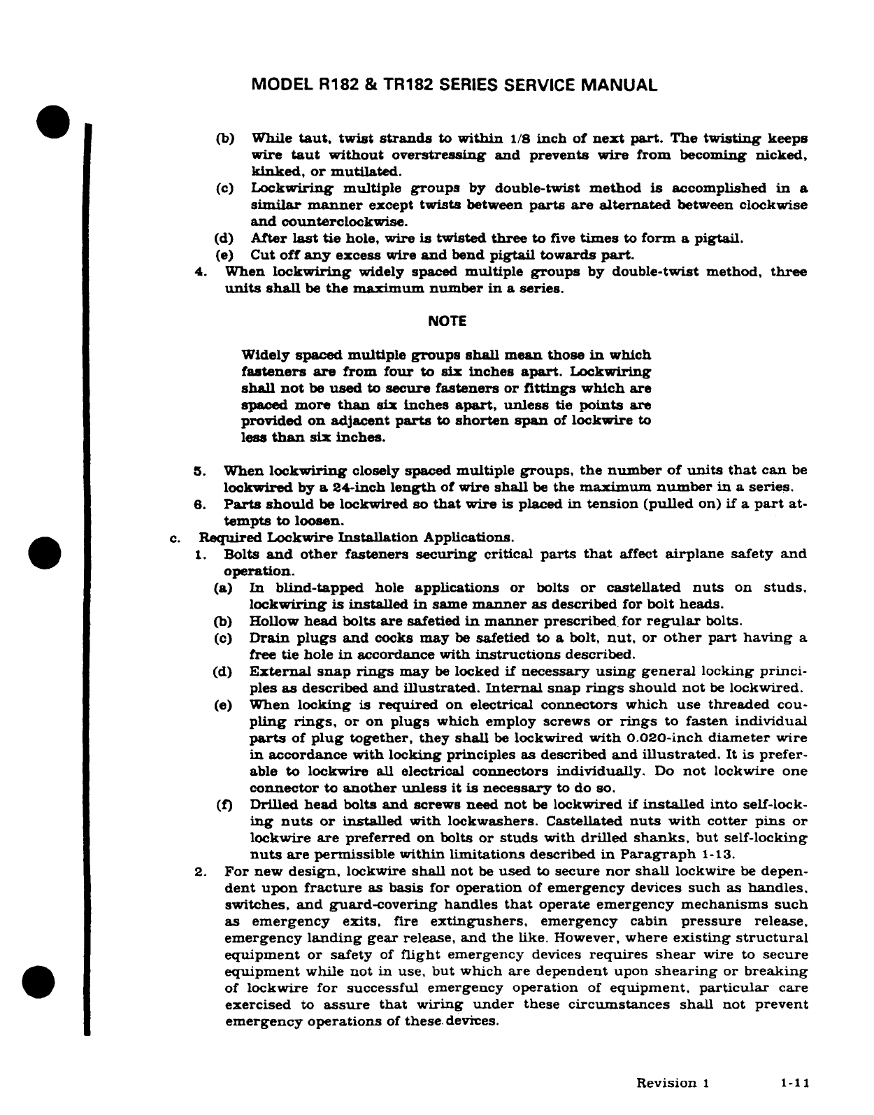
MODEL
R182
&
TR182
SERIES
SERVICE
MANUAL
(b)
While
taut,
twist
strands
to
within
1/8
inch
of
next part.
The
twisting
keeps
wire
taut
without overstressing
and
prevents
wire
from
becoming
nicked,
kinked,
or
mutilated.
(c)
Lockwiring
multiple
groups
by
double-twist
method
is
accomplished
in a
similar
manner
except
twists
between
parts
are alternated
between
clockwise
and
counterclockwise.
(d)
After
last
tie
hole,
wire
is
twisted
three
to
five
times
to
form
a
pigtail.
(e)
Cut
off
any
excess
wire
and
bend
pigtail
towards
part.
4.
When
lockwiring
widely
spaced
multiple
groups
by
double-twist
method,
three
units
shall
be
the
maximum
number
in a
series.
NOTE
Widely
spaced
multiple
groups shall
mean those
in
which
fasteners
are
from
four
to
six
inches
apart.
Lockwiring
shall
not
be
used
to
secure
fasteners
or
fittings
which
are
spaced
more
than
six
inches
apart,
unless
tie
points
are
provided
on
adjacent
parts
to
shorten span
of
lockwire
to
less
than
six
inches.
5.
When
lockwiring
closely
spaced
multiple
groups, the
number
of
units
that
can
be
lockwired
by
a
24-inch
length
of
wire
shall
be
the
maximum
number
in a
series.
6.
Parts
should
be
lockwired
so
that
wire
is
placed
in
tension
(pulled
on)
if
a
part
at-
tempts
to
loosen.
c.
Required
Lockwire
Installation
Applications.
1.
Bolts
and other
fasteners
securing
critical
parts
that
affect
airplane
safety
and
operation.
(a) In
blind-tapped
hole
applications
or
bolts
or
castellated
nuts
on
studs.
lockwiring
is
installed
in
same
manner
as
described
for
bolt
heads.
(b)
Hollow
head
bolts
are
safetied
in
manner
prescribed
for
regular
bolts.
(c)
Drain
plugs
and
cocks
may
be
safetied
to
a
bolt,
nut,
or
other
part
having
a
free
tie
hole
in
accordance with
instructions
described.
(d)
External snap
rings
may
be
locked
if
necessary
using
general
locking
princi-
ples
as
described
and
illustrated. Internal
snap
rings
should
not
be
lockwired.
(e)
When
locking
is
required
on
electrical
connectors
which
use
threaded
cou-
pling
rings,
or
on
plugs
which
employ
screws
or
rings
to
fasten
individual
parts
of
plug
together,
they
shall
be
lockwired
with 0.020-inch diameter wire
in
accordance
with
locking
principles as
described
and
illustrated.
It
is
prefer-
able
to
lockwire
all
electrical
connectors
individually.
Do
not
lockwire
one
connector
to
another unless
it
is
necessary
to
do
so.
(f) Drilled
head
bolts
and
screws
need
not
be
lockwired
if
installed
into
self-lock-
ing
nuts
or
installed with
lockwashers.
Castellated
nuts
with
cotter
pins
or
lockwire
are
preferred on
bolts
or
studs
with
drilled
shanks,
but
self-locking
nuts
are
permissible
within limitations
described
in
Paragraph
1-13.
2.
For
new
design,
lockwire
shall
not
be
used
to
secure
nor
shall
lockwire
be
depen-
dent
upon
fracture
as
basis
for
operation
of
emergency
devices
such as
handles,
switches,
and
guard-covering
handles
that
operate
emergency mechanisms
such
as
emergency
exits,
fire
extingushers,
emergency
cabin
pressure
release,
emergency
landing
gear
release,
and
the
like.
However,
where
existing
structural
equipment
or safety
of
flight
emergency
devices
requires
shear
wire
to
secure
equipment
while
not
in
use,
but
which
are
dependent
upon
shearing
or
breaking
of
lockwire
for successful
emergency
operation
of
equipment,
particular
care
exercised
to
assure
that
wiring
under
these
circumstances
shall
not
prevent
emergency operations
of
these
devices.
Revision
1
1-11
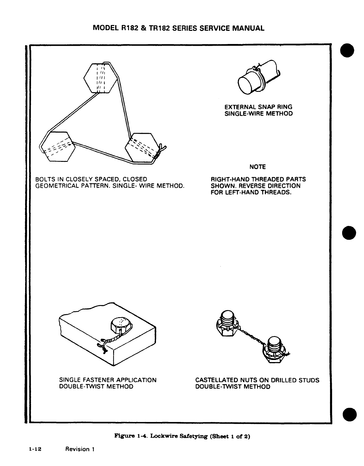
MODEL
R182
&
TR182
SERIES
SERVICE
MANUAL
II II
BOLTS
IN
CLOSELY
SPACED, CLOSED
RIGHT-HAND
THREADED
PARTS
GEOMETRICAL
PATTERN.
SINGLE-
WIRE
METHOD.
SHOWN.
REVERSE
DIRECTION
FOR
LEFT-HAND
THREADS.
SINGLE
FASTENER
APPLICATION
CASTELLATED
NUTS
ON
DRILLED
STUDS
DOUBLE-TWIST
METHOD DOUBLE-TWIST METHOD
Figure
1-4.
Lockwire
Safetying
(Sheet
1
of
2)
1-12
Revision
1
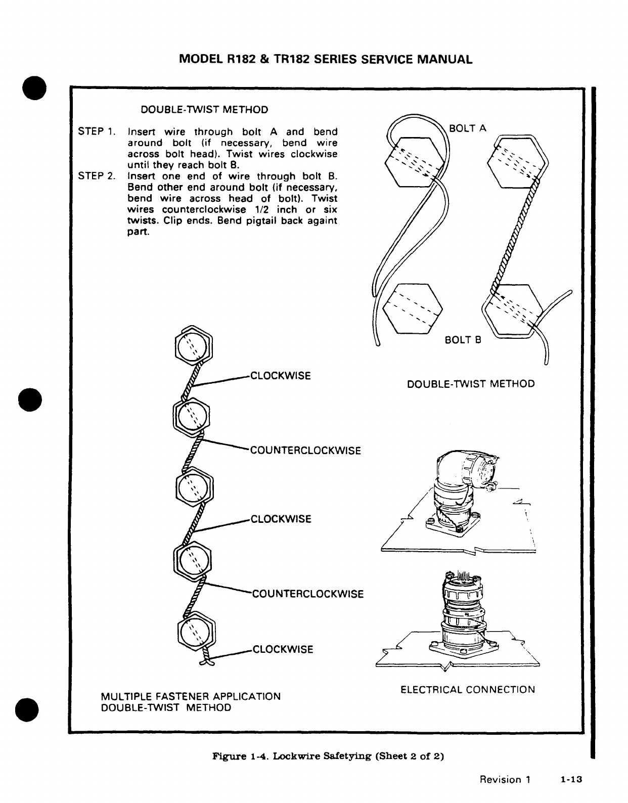
MODEL
R182
&
TR182
SERIES
SERVICE
MANUAL
DOUBLE-TWIST METHOD
STEP
1.
Insert
wire through
bolt
A
and
bend
/BOLT
A
around
bolt
(if
necessary,
bend
wire
across
bolt
head).
Twist
wires
clockwise
\\
until
they
reach
bolt
B. \" -j )
STEP
2.
Insert
one
end
of
wire through
bolt
B.
Bend
other
end
around
bolt
(if
necessary,
bend
wire
across
head
of bolt).
Twist
wires
counterclockwise
1/2
inch
or
six
twists.
Clip
ends.
Bend
pigtail
back
againt/
part.
O(^ ^1Q t^~~~
~BOLT B
DOUBLE-TWIST
METHOD
CLOCKWISE
]
---
^
DOUBLE-TWIST
METHOD
COUNTERCLOCKWISE
l
MULTIPLE
FASTENER
APPLICATION
ELECTRICAL
CONNECTION
DOUBLE-TWIST
METHOD
Figure
1-4.
Lockwire
Safetying
(Sheet
2
of
2)
Revision
1
1-13

MODEL
R182
&
TR182
SERIES
SERVICE
MANUAL
1-10. USE
OF
COTTER
PINS.
a.
Cotter
Pin
Installation.
Castellated
nuts
and
pins may
be
safetied
with
cotter
pins
or
lockwire. The
preferred
method
is
to
use
cotter
pins.
1.
Select
cotter pin material
in
accordance
with
temperature,
atmosphere,
and
service
limitations
(see
Table
1-5).
2.
Cotter
pins
shall
be
new
upon
each
application.
3.
When
nuts
are
to
be
secured
to
fastener
with
cotter
pins,
tighten
nut
to
low
side
(minimum)
of
applicable
specified
or
selected
torque
range,
unless
otherwise
specified,
and
if
necessary, continue
tightening
until
slot
aligns
with
hole.
In no
case
shall
you
exceed
high
side
(maximum)
torque
range.
4.
If
more
than
50
percent
of
cotter
pin
diameter
is
above
nut
castellation,
a
washer
should
be
used
under
nut
or
a
shorter
fastener should
be
used.
A
ma-imum
of
two
washers
may
be
permitted
under
a
nut.
5.
The
largest
diameter
cotter
pin
which
hole
and
slots
will
accommodate
should
be
used,
but
in
no
application
to
a
nut,
bolt,
or
screw
shall
pin
size
be
less
than
sizes
described
in
Table
1-6.
6.
Install
cotter
pin
with
head
firmly
in
slot
of
nut
with
axis
of
eye
at right
angles
to
bolt
shank.
Bend
prongs
so
that
head
and
upper
prong
are
firmly seated
against
bolt (see
figure
1-5).
7.
In
pin
applications, install cotter
pin
with
axis
of
eye
parallel
to
shank
of
clevis
pin
or
rod
end.
Bend
prongs
around
shank
of
pin or
rod
end
(see
Figure
1-5).
CAUTION
Cadium-plated
cotter
pins
should
not
be
used
in
applica-
tions
bringing
them
in
contact
with
fuel,
hydraulic
fluid,
or
synthetic lubricants.
COTTER
PIN
-
MINIMUM
SIZE
THREAD
SIZE
MINIMUM
PIN
SIZE
COTTER
PINS
(MS24665)
0.028
MATERIAL
TEMPERATURE
USE
8
0.044
Carbon
Steel
Up
to
450°F
Pins
that contact
cadmium-
10
0.044
plated
surfaces.
1/4
0044
5/16
0.044
General
Applications
3/8
0.072
7/16
0.072
Normal
Atmospheres
1/2
0.072
9/16
0.086
Corrosion-Resistant
Up
to
800°F
Pins
that
contact
cor-
5/8
0.086
rosion-resistant
steel.
3/4
0.086
7/8
0.086
Corrosive
atmospheres
1
0.086
1-1/8
0.116
1-1/4
0.116
1-3/8
0.116
1-1/2
0.116
Table
1-5.
Cotter
Pin
Table
1-6.
Cotter
Pin
Temperature
and
Use
Minimum
Size
1-14
Revision
1
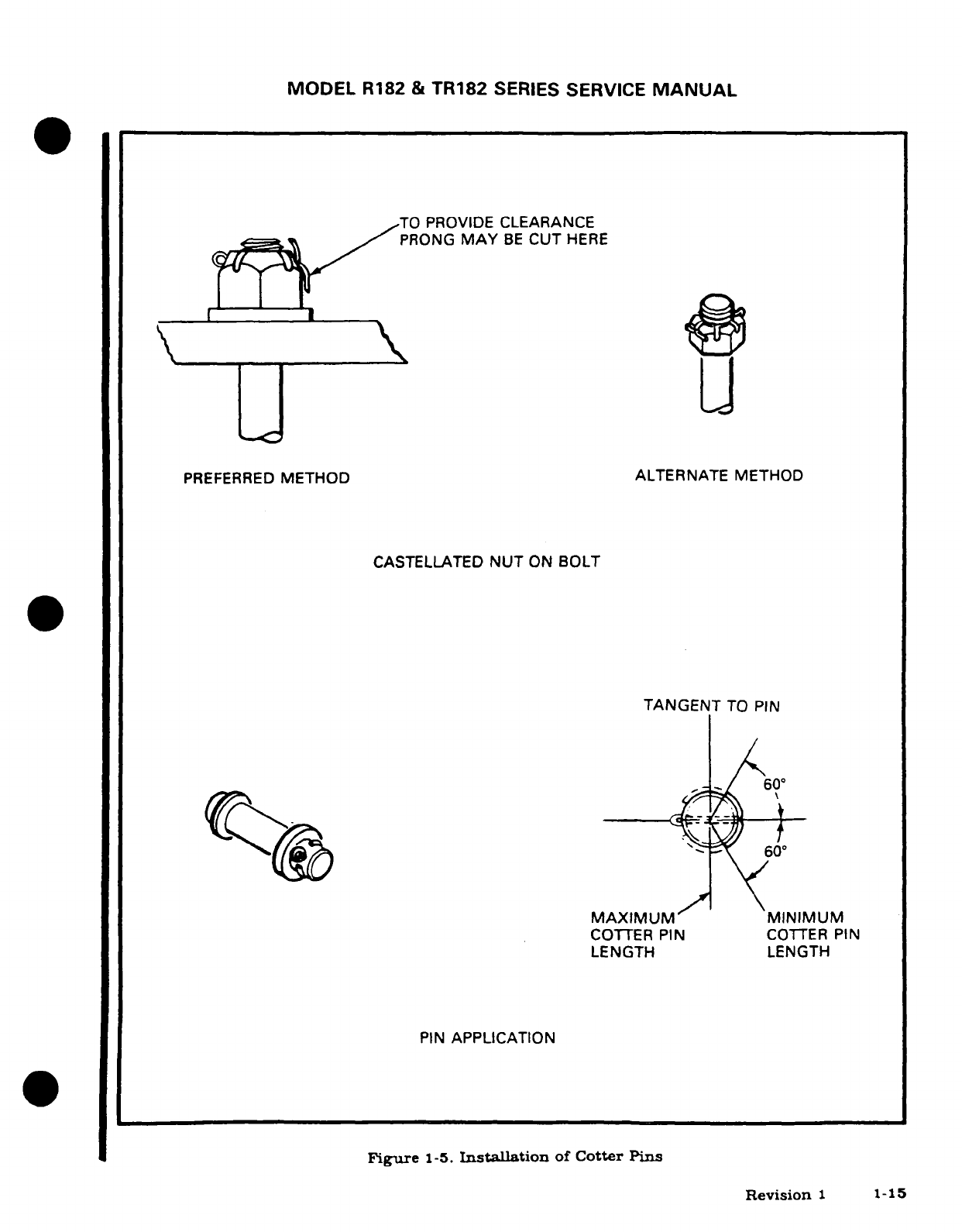
MODEL
R182
&
TR182
SERIES
SERVICE
MANUAL
TO
PROVIDE
CLEARANCE
PRONG
MAY
BE
CUT
HERE
L~~~I~~L
PREFERRED
METHOD
ALTERNATE
METHOD
CASTELLATED
NUT
ON
BOLT
TANGENT
TO
PIN
60"
MAXIMUM
MINIMUM
COTTER PIN
COTTER
PIN
LENGTH
LENGTH
PIN
APPLICATION
Figure
1-5.
Installation
of
Cotter
Pins
Revision
1
1-1
MODEL
R182
&
TR182
SERIES SERVICE
MANUAL
1-11.
USE
OF LOCKING
CLIPS.
a.
Safetying Turnbuckles.
(See
Figure
1-6.)
1.
Prior
to
safetying,
both
threaded
terminals
shall
be
screwed
an
equal
distance
into
turnbuckle
body
and
shall
be
screwed
in
at
least
so
far
that
not
more
than
three
threads
of
any
terminal
are
exposed
outside
body.
2.
After
turnbuckle
has
been
adjusted
to
its
locking
position,
with
slot
indicator
groove on
terminals
and
slot
indicator notch
on
body
aligned,
insert
end of
lock-
ing
clip
into
terminal
and
body
(refer
to
Figure
1-6)
until
U-curved
end
of
locking
clip is
over
hole
in
center
of
body.
(a)
Press
locking
clip
into
hold
to
its
full
extent.
(b)
Curved
end
of
locking
clip will
expand
and
latch
in
body
slot.
(c)
To
check
proper
seating
of
locking
clip,
attempt
to
remove
pressed
"U"
end
from
body
hole
with
fingers
only.
NOTE
Do
not
use
tool
as
locking
clip could
be
distorted.
3.
Locking
clips
are
for
one
time
use
only
and
shall
not
be
re-used.
4.
Both
locking
clips may
be
inserted
in
same
hole
of
turnbuckle
body
or
in
opposite
holes
of
turnbuckle
body.
1-16
Revision
1
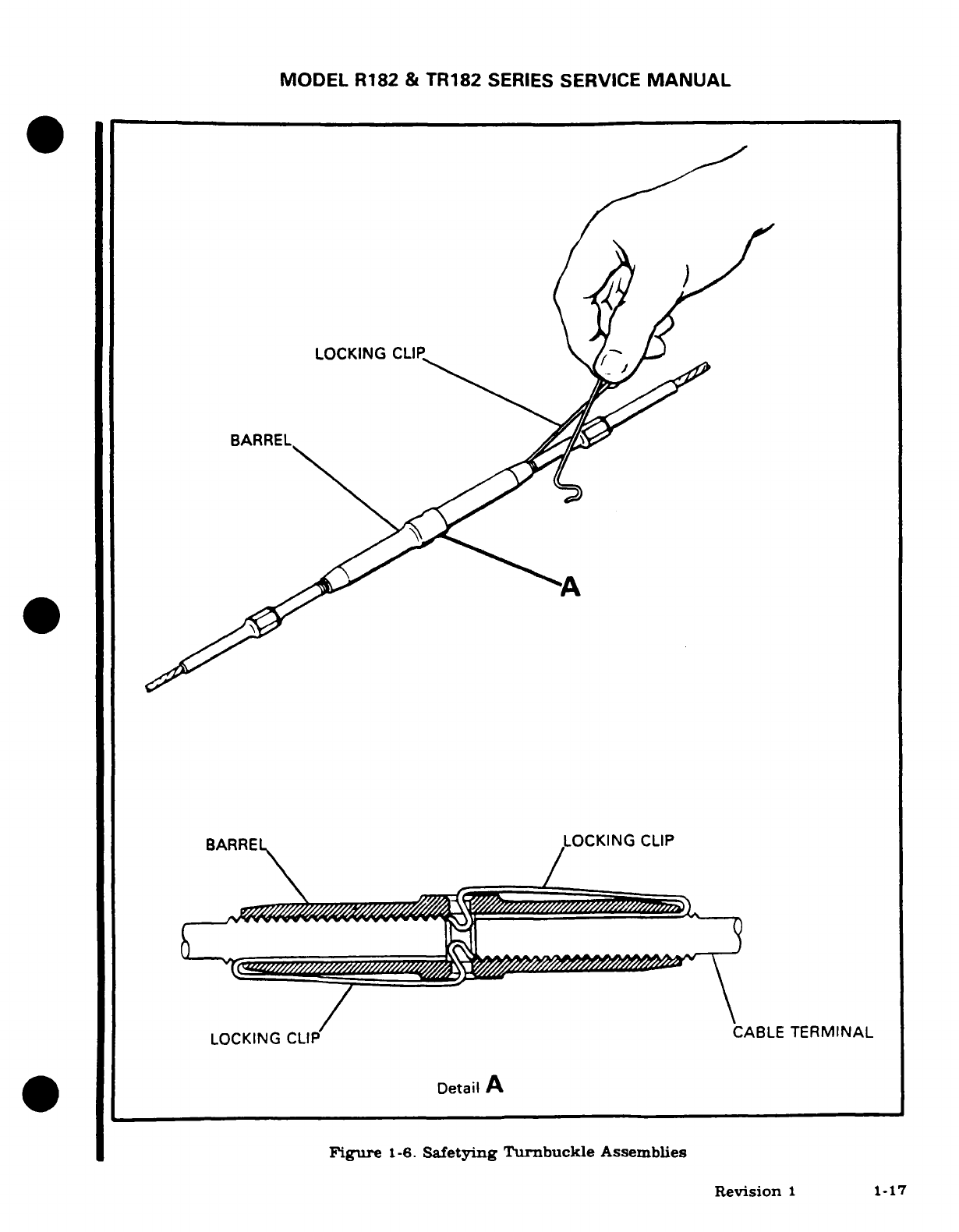
MODEL
R182
&
TR182
SERIES
SERVICE
MANUAL
-12.
USE OF
LOCKWASHERS.
a.
Lockwashers
can
be
used only
under
the
following
conditions.
1.
When
self-locking
feature
cannot
be
provided
in
externally
or
internally
threaded
part.
2.
When
a
cotter
pin
cannot
be
used to
prevent
rotation
of
internal
threads
with
re-
spect
to
external
threads.
3.
When
lockwire
cannot
be
used
to
prevent
loosening
of
threaded
parts.
4.
When
fastening
is
not used
for
fabrication
of
primary
structure.
5.
When
loosening
of
threaded
parts
would
not
endanger
safety
of
airplane
or
people.
6.
When
corrosion
encouraged
by
gouging
aluminum
or
magnesium
alloys
by
edges
of
teeth on
tooth-locked
washers
would
not
cause
malfunctioning
of
parts
being
fastened
together.
-13.
USE OF
SELF-LOCKING
NUTS.
a.
Restrictions.
1.
Self-locking
nuts
cannot
be
used
under
certain
conditions.
(a)
Used,
reworked,
or
reprocessed
nuts
should
not
be
installed
for
any
applica-
tion.
(b)
Do
not
use
if
at
joints
in
control systems
for
singular
attach
points.
(c)
Do
not
use on
externally threaded
parts
that
serve
as
an
axle
of
rotation
for
another part
where
tensional (torque)
loads
can
cause
nut
to
loosen
and/or
be-
come
separated.
Examples
are
pulleys,
levers,
linkages,
and
cam
followers.
NOTE
Self-locking
nuts
can
be
used
when
threaded
parts
are
held
by
a
positive
locking
device
that
requires
shearing
or
rupture
before
torsional
loads
can
act
on
threaded
parts.
(d)
Do
not use
where
a
loose
nut,
bolt,
or
screw could
fall
or
be
drawn
into
an
area
that
would
impede
or
damage
or
otherwise
distort
operation.
(e)
Do
not
use
to
attach
access
panels and
doors
or
to
assemble
components
that
are
routinely
disassembled
or
removed
for
access
and
servicing.
(f)
In
general,
do
not
use
self-locking
nuts
where
loss
of
bolt
affects
safety
of
flight.
2.
Bolts,
studs,
or
screws,
excluding
Hi-Locks,
must
extend
through
self-locking
nut
for
a
length
equivalent
of
two
threaded
pitches.
This
length
includes
chamfer.
3.
Self-locking
nuts
which
are
attached
to
structure
shall
be
attached
in a
positive
manner
to
eliminate
possibility
of
their
rotation
or
misalignment
when
tighten-
ing
is to
be
accomplished
by
rotating
bolts
to
structure,
and
permit
replacement
of
nuts.
1-18
Revision
1
MODEL
R182
AND
TR182
SERVICE
MANUAL
SECTION
2
GROUND
HANDLING,
SERVICING,
CLEANING,
LUBRICATION
AND
INSPECTION
WARNING
When
performing
any
inspection
or
maintenance
that
re-
quires
turning
on
the
master
switch,
installing
a
battery,
or
pulling
the
propeller
through
by
hand,
treat
the
prop-
eller
as
if
the
ignition
switch
were
ON.
Do
not
stand,
nor
allow
anyone
else
to
stand,
within
the
arc
of
the
propel-
ler,
since
a
loose
or
broken
wire,
or
a
component mal-
function,
could
cause
the
propeller
to
rotate.
Page
No.
TABLE
OF
CONTENTS
Aerofiche/
Manual
GROUND
HANDLING
.........
1B10/2-2
Nose
Gear
Shock
Strut
.......
1C2
2-18
Towing
..................
1B10/2-2
Shimmy
Dampener
.........
1C2/2-18
Hoisting
.................
1B12/2-4
Hydraulic
Fluid
Sampling
Jacking
..................
1B12/2-4
and
Contamination
Check
...
1C3/2-19
Leveling
...............
1B12/2-4
Landing
Gear
Hydraulic
Weighing
................
1B12/2-4
Retraction
System
.........
1C3'2-19
Parking
.................
1B13/2-5
Hydraulic
Brake
System
.....
1C4
2-20
Tie-Down
................
1B13/2-5
CLEANING
................
1C4/2-20
Flyable
Storage
...........
1B13/2-5
General Description
.........
1C4
2-20
Returning
Aircraft
to
Windshield
and
Windows
.....
1C52-21
Service
................
1B314/2-6
Materials
Required
........
1C5.2-21
Temporary
Storage
.........
1B14/2-6
Waxing
................
1C6
2-22
Inspection
During
Storage
..
1B15/2-7
Preventive Maintenance
....
1C6.2-22
Returning
Aircraft
to
Interior
Trim
..............
1C7.2-23
Service
................
1B16/2-8
Painted
Surfaces
...........
1C7
2-23
Indefinite
Storage
..........
1B16/2-8
Aluminum
Surfaces
.........
1C7
2-23
Inspection
During
Storage
..
1B17/2-9
Engine
and
Engine
Returning
Aircraft
to
Compartment
............
1C7
2-23
Service
................
1B18/2-10
Upholstery and
Interior
......
1C9
2-25
SERVICING
................
1B18/2-10
Propeller
.................
1C9
2-25
General
Description
.........
1B18/2-10
Wheels
..................
1C9
2-25
Fuel
. ...................
1B19/2-11
LUBRICATION
..............
1C9
2-25
Use
of
Fuel Additives
for
General Description
.........
1C9
2-25
Cold
Weather
Operation
.
..
1B19/2-11
Tachometer
Drive
Shaft
......
1C9
2-25
Drains
................
1B21/2-13
Wheel
Bearings
............
1C9
2-25
Carburetor
Drain
Plug
Nose
Gear
Torque
Links
.....
1C9
2-25
Inspection
............
1B21/2-13
Wing Flap Actuator
..........
C10
2-26
Engine
Oil
...............
1B21/2-13
Rod
End
Bearings
..........
1C10
2-26
Oil
Cooler
. ..............
B24/2-16
Nose
Gear
Steering
Collar
....
1C10
2-26
Induction
Air
Filter
.........
1B24/2-16
Nose
Gear
Pivots
...........
1C10
2-26
Vacuum
System
Filter
.......
1C1/2-17
Main Gear
Pivot Points
......
C10
2-26
Battery
..................
1C1/2-17
INSPECTION
................
1C22
2-38
Tires
................... .
1C1/2-17
Revision
1
2-1
MODEL
R182
AND
TR182
SERVICE
MANUAL
2-1.
GROUND
HANDLING.
2-2.
TOWING.
Moving
the
aircraft
by
hand
is
accomplished
by
using
the
wing
struts
and
landing
gear
struts
as
push
points.
A
tow
bar attached
to
the nose
gear should
be
used
for
steering
and
maneuvering
the
aircraft
on
the
ground.
NOTE
Tow
bar
Part
No.
0501019-1,
is
available
from
the
Cessna
Supply
Division.
CAUTION
When
towing
the
aircraft,
never
turn
the
nose
wheel
more
than
29
degrees
either
side
of
center
or
the
nose
gear
will
be
damaged.
Do
not
push
on
control
surfaces
or
outboard
empennage
surfaces.
When
pushing
on
the
tailcone.
always
apply
pressure
at
a
bulkhead
to
avoid buckling
the
skin.
2-2
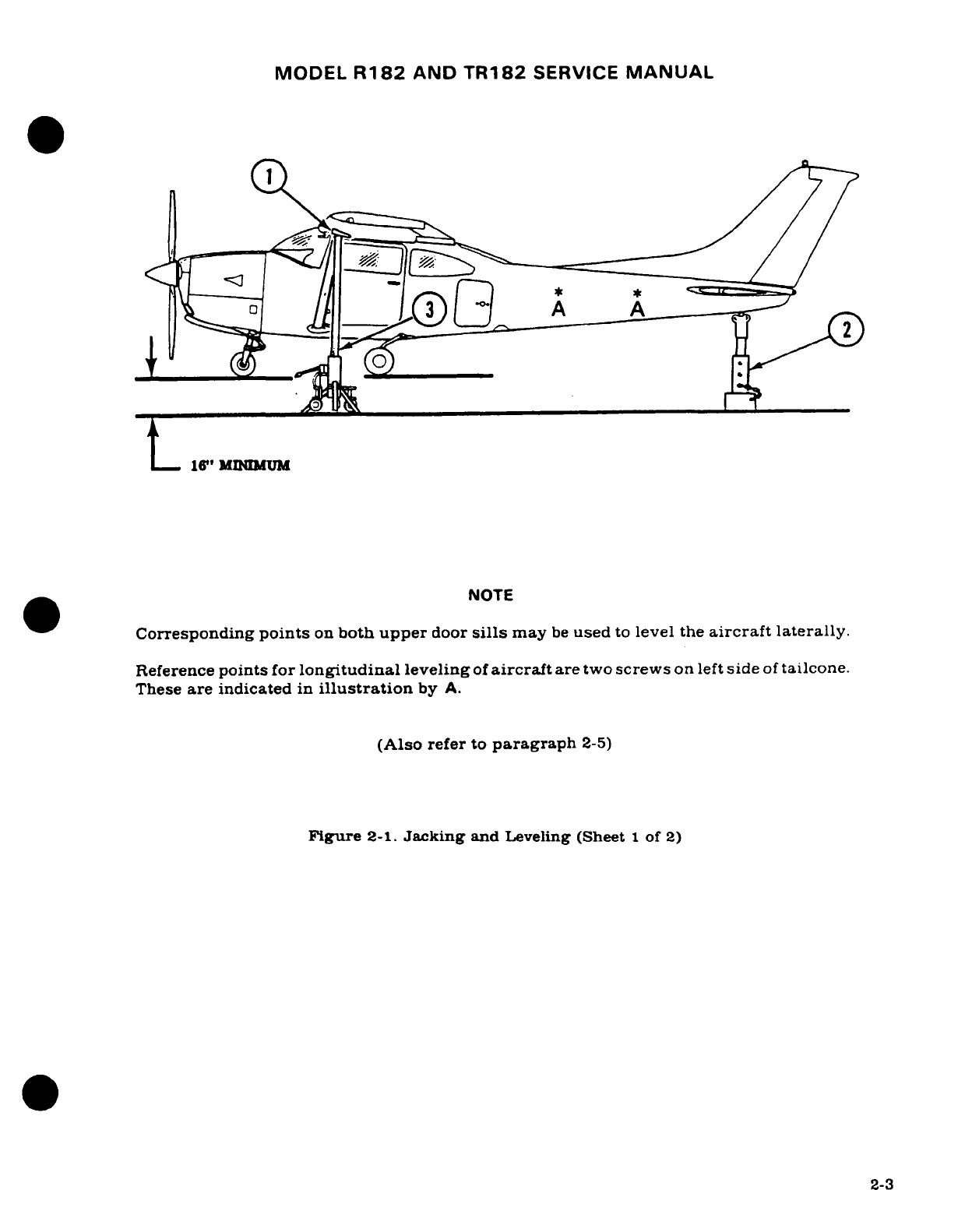
MODEL
R182
AND
TR182
SERVICE
MANUAL
I-
6"
MIINMUM
*^^~~~~~~ ~NOTE
Corresponding
points
on
both
upper
door
sills
may
be
used
to
level
the
aircraft
laterally.
Reference
points
for
longitudinal
leveling
of
aircraft
are
two
screws
on
left
side
of
tailcone.
These
are
indicated
in
illustration
by
A.
(Also
refer
to
paragraph
2-5)
Figure
2-1.
Jacking
and
Leveling
(Sheet
1
of
2)
2-3
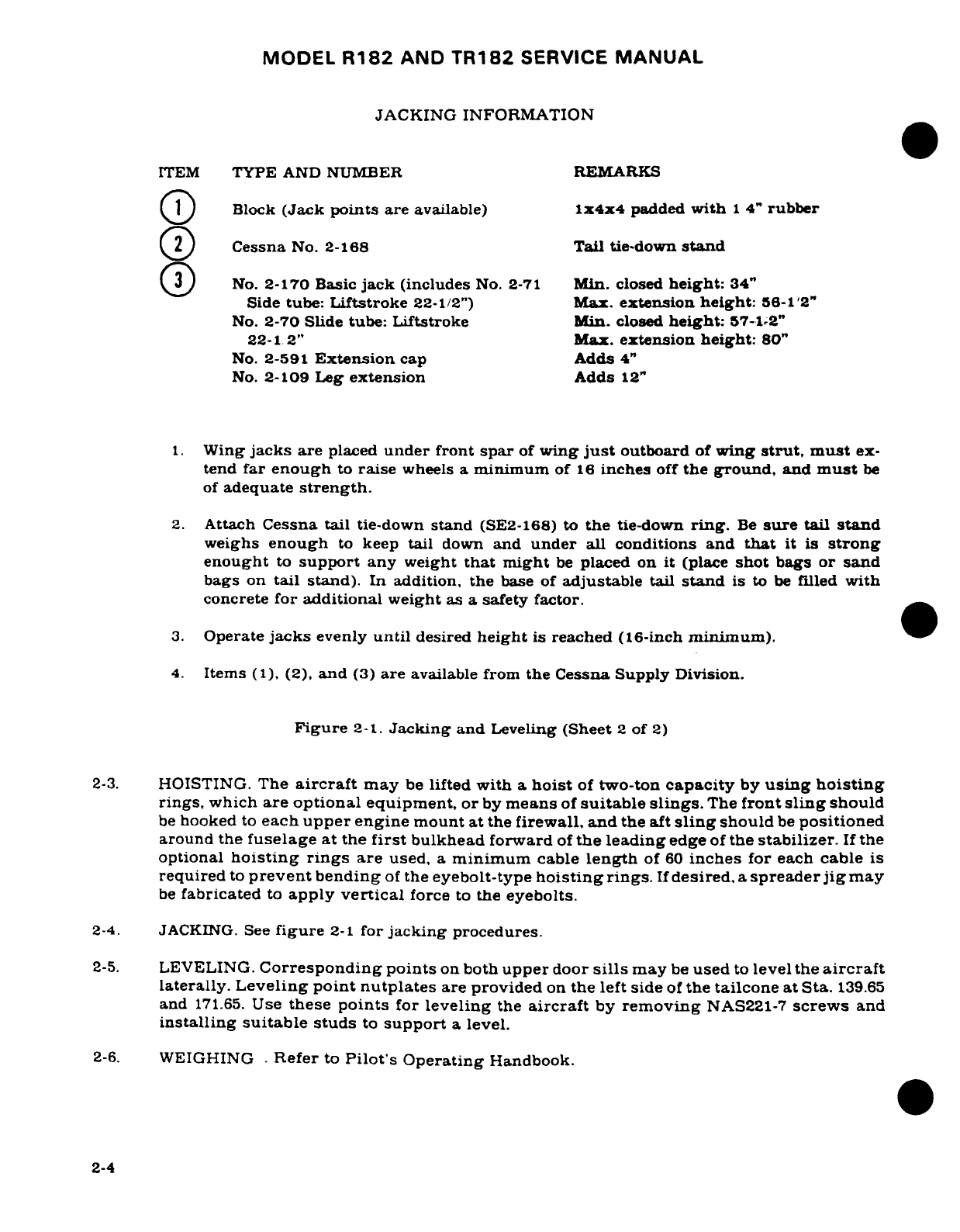
MODEL
R182
AND
TR182
SERVICE
MANUAL
JACKING
INFORMATION
ITEM
TYPE
AND
NUMBER
REMARKS
Block
(Jack
points
are
available)
1x4x4
padded
with
1
4"
rubber
Cessna
No.
2-168
Tail tie-down
stand
No.
2-170
Basic
jack
(includes
No.
2-71
Min.
closed
height:
34"
Side
tube:
Liftstroke
22-1/2")
Max.
extension
height:
56-1'2"
No.
2-70
Slide
tube:
Liftstroke
Min.
closed
height:
57-1.2"
22-1
2"
Max.
extension
height:
80"
No.
2-591
Extension
cap
Adds
4"
No.
2-109
Leg
extension
Adds
12"
1.
Wing
jacks
are
placed
under
front
spar
of
wing
just
outboard
of
wing
strut,
must
ex-
tend
far
enough
to
raise
wheels
a
minimum
of
16
inches
off
the
ground,
and
must
be
of
adequate
strength.
2.
Attach
Cessna
tail
tie-down
stand
(SE2-168) to
the
tie-down
ring.
Be
sure
tail
stand
weighs
enough
to
keep
tail
down
and
under
all
conditions
and
that
it
is
strong
enought
to
support
any
weight
that
might
be
placed
on
it
(place
shot
bags
or
sand
bags
on
tail stand).
In
addition,
the
base
of
adjustable
tail
stand
is
to
be
filled
with
concrete
for
additional
weight
as
a
safety
factor.
3.
Operate
jacks
evenly
until
desired
height
is
reached
(16-inch
minimum).
4.
Items
(1),
(2),
and
(3)
are
available
from
the Cessna Supply
Division.
Figure
2-1.
Jacking
and
Leveling
(Sheet
2
of
2)
2-3.
HOISTING.
The
aircraft
may
be
lifted
with
a
hoist
of
two-ton
capacity
by
using
hoisting
rings,
which
are
optional
equipment,
or
by
means
of
suitable
slings.
The
front
sling
should
be
hooked
to
each
upper
engine
mount
at
the
firewall,
and
the
aft
sling
should
be
positioned
around
the
fuselage
at the
first
bulkhead
forward
of
the
leading
edge
of
the
stabilizer.
If
the
optional
hoisting rings
are
used,
a
minimum
cable
length
of
60
inches
for each
cable
is
required
to
prevent
bending
of
the
eyebolt-type
hoisting
rings.
If
desired,
a
spreader
jig
may
be
fabricated
to
apply
vertical
force
to
the
eyebolts.
2-4.
JACKING.
See
figure
2-1
for
jacking
procedures.
2-5.
LEVELING.
Corresponding
points
on
both
upper
door
sills
may
be
used
to
level the
aircraft
laterally.
Leveling
point
nutplates
are
provided
on
the left
side
of
the
tailcone
at
Sta.
139.65
and
171.65.
Use
these
points
for
leveling
the
aircraft
by
removing
NAS221-7
screws
and
installing
suitable
studs
to
support
a
level.
2-6.
WEIGHING
.
Refer
to
Pilot's
Operating
Handbook.
2-4
MODEL
R182
AND
TR182
SERVICE
MANUAL
2-7.
PARKING.
Parking
precautions
depend
principally
on
local
conditions.
As
a
general
precaution, set
parking
brake
or
chock
the wheels
and
install
the
controls
lock.
In
severe
weather
and
high
wind conditions, tie
down
the
aircraft
as
outlined
in
paragraph
2-8
if a
hangar
is
not
available.
2-8.
TIE-DOWN.
When
mooring
the
aircraft
in
the
open,
head
into
the
wind
if
possible.
Secure
control
surfaces
with
the
internal
control
lock
and
set
brakes.
CAUTION
Do
not
set
parking
brakes
when they
are
overheated
or
during
cold
weather
when accumulated
moisture
may
freeze
them.
If
brake
ice
freeze-up
occurs,
operate
the
brakes
several
times
using
maximum
pressure.
a.
Tie
ropes,
cables,
or
chains
to
the
wing
tie-down
fittings
located
at
the
upper
end
of
each
wing
strut.
Secure
the
opposite
ends
of
ropes, cables,
or
chains
to
ground
anchors.
b.
Secure
a
tie-down
rope
(no
chains
or cables)
to
the
nose
gear
strut,
and
secure
opposite
end
of
rope
to
ground
anchor.
c.
Secure
the
middle
of
a
rope
to
the
tail
tie-down
ring.
Pull each
end
of
rope
away
at
a
45
degree
angle
and
secure
to
ground anchors
at
each
side
of
tail.
d.
Secure
control
lock
on
pilot
control
column.
If
control
lock
is
not
available,
tie
pilot
control
wheel
back
with
front
seat
belt.
e.
These
aircraft
are
equipped
with
a
spring-loaded
steering
bungee which affords
protection
against
normal
wind
gusts.
However,
if
extremely
high
wind
gusts
are
anticipated,
additional
external
locks
may
be
installed.
2-9.
FLYABLE
STORAGE.
Flyable storage
is
defined
as
a
maximum
of
30
days
nonoperational
storage
and/or
the
first
25
hours
of
intermittent
engine
operation.
NOTE
The
aircraft
is
delivered
from
Cessna with
MIL-L-6082
Aviation
Grade
Mineral
Oil.
This
oil
is
to
be
used
to
replenish
the
oil
supply
during
the
first
25
hours
of
operation, at
the
first
25-hour
oil
change
and
until
a
total
of
50
hours have
accumulated or
oil
consumption
has
stabilized.
Then
use
Ashless
Dispersant
Oil
conforming
to
MIL-L-22851
in
accordance with
the
oil
chart
in
figure
2-5.
Revision
1
2-5
MODEL
R182
AND
TR182
SERVICE
MANUAL
During
the
30-day
nonoperational storage
or
the
first
25
hours
of
intermittent
engine
operation,
every
seventh
day
the
propeller
shall
be
rotated
by
hand
without
running
the
engine.
After
rotating
the
engine
five
revolutions,
stop
the
propeller
45
to
90
°
from
the
position
it
was
in.
If
the
aircraft
is
stored
outside,
tie-down
in
accordance
with
paragraph
2-8.
In
addition,
the
pitot
tube,
static
air
vents,
air
vents,
openings
in
the
engine
cowling,
and
other
similar
openings
shall
have
protective
covers
installed
to
prevent
entry
of
foreign
material.
If
at the
end
of
thirty
(30)
days
aircraft
will
not
be
removed
from
storage,
the
engine
shall
be
started
and
run.
The
preferred
method
would
be
to
fly
the
aircraft
for
thirty
(30)
minutes,
and
up
to
but not exceeding
normal
oil and
cylinder
temperatures.
CAUTION
Excessive
ground
operation
shall
be
avoided.
2-10.
RETURNING
AIRCRAFT
TO
SERVICE.
After
flyable
storage,
returning
the
aircraft
to
ser-
vice
is
accomplished
by
performing
a
thorough
preflight
inspection.
At
the
end
of
the first
25
hours
of
engine
operation,
drain
engine
oil,
change
external
oil
filter
element,
and
ser-
vice
engine
with
correct
grade
and
quantity
of
engine
oil.
See
figure
2-4
and
paragraph
2-23
for
correct
grade
of
engine
oil.
2-11. TEMPORARY
STORAGE.
Temporary
storage
is
defined
as
aircraft
in a
nonoperational
status
for
a
maximum
of
90
days.
The
aircraft
is
constructed
of
corrosion
resistant
alclad
aluminum,
which
will
last
indefinitely
under
normal conditions
if kept clean,
however,
these
alloys
are
subject
to
oxidation.
The
first
indication
of
corrosion
on
unpainted
surfaces
is
in
the
form
of
white
deposits
or
spots.
On
painted
surfaces,
the
paint
is
discolored
or
blistered.
Storage
in
a
dry
hangar
is
essential
to
good
preservation
and
should
be
procured,
if
possi-
ble.
Varying
conditions
will
alter
the
measures
of
preservation,
but
under
normal
conditions
in
a
dry
hangar,
and
for
storage
periods
not
to exceed 90
days,
the
following methods
of
treatment
are
suggested.
a.
Fill
fuel
tanks
or
bays
with correct
grade
of
gasoline.
WARNING
DURING
ALL
FUELING
PROCEDURES,
FIRE
FIGHTING
EQUIPMENT
MUST BE
AVAILABLE.
TWO
GROUND
WIRES FROM
DIFFERENT
POINTS
ON
THE
AIRPLANE
TO
SEPARATE
APPROVED GROUND
STAKES
SHALL
BE
USED
TO
PREVENT
ACCIDENTAL
DISCONNECTION
OF
ONE GROUND
WIRE.
ENSURE
THAT
FUELING
NOZZLE
IS
GROUNDED
TO
THE
AIRPLANE.
NOTE
Tie
down
rings
should
be
used
as
grounding
pionts
for
all
ground
wires
during
refueling
procedures.
b.
Clean
and
wax
aircraft
thoroughly.
c.
Clean
any
oil
or
grease
from
tires
and
coat
tires
with
a
tire
preservative.
Cover
tires
to
protect
against
grease
and
oil.
d.
Either
block
up
fuselage
to
relieve
pressure
on
tires or rotate
wheels
every
30
days
to
prevent
flat
spotting
the
tires.
e.
Lubricate
all
airframe
items and
seal or
cover
all
openings
which
could
allow mois-
ture
and/or
dust
to
enter.
2-6
MODEL
R182
AND
TR182
SERVICE
MANUAL
NOTE
The
aircraft
battery
serial
number
is
recorded
in
the
aircraft
equipment
list.
To
assure
accurate
warranty
records, the
battery
should
be
reinstalled
in
the
same
aircraft
from
which
it
was
removed.
If
the
battery
is
returned
to
service
in a
different
aircraft,
appropriate
record
changes
must
be
made
and
notification
sent
to
the
Cessna
Claims
Department.
f.
Remove
battery
and
store
in
a
cool,
dry
place;
service
battery periodically
and
charge
as
required.
NOTE
An
engine
treated
in
accordance
with
the
following
may
be
considered
being
protected
against normal
atmos-
pheric corrosion
for
a
period
not
to
exceed
90
days.
g.
Disconnect
spark
plug
leads
and
remove
upper and
lower
spark
plugs
from
each
cy-
linder.
NOTE
The
preservative
oil
must
conform
to
specification
MIL-C-
6529,
Type
1.
Oil
must
be
heated
to 200°/220°F
spray
noz-
zle
temperature.
h.
Using
a
portable
pressure
sprayer, spray preservative
oil
through
the
upper
spark
plug
hole
of
each cylinder with
the
piston
in a
down
position.
Rotate
crankshaft
as
each
pair
of
cylinders
is
sprayed.
i.
After
completing
step
"h,"
rotate
crankshaft
so
that
no
piston
is
at
a
top
position.
If
the
aircraft
is
to
be
stored outside,
stop
two-bladed
propeller
so
that
blades
are as
near
horizontal
as possible
to
provide
maximum
clearance
with
passing
aircraft.
j.
Again,
spray
each
cylinder
without
moving the
crankshaft.
to
thoroughly
cover
all
interior
surfaces
of
the
cylinder
above the
piston.
k.
Install
spark
plugs
and
connect
spark
plug
leads.
1.
Apply
preservative
oil
to
the
engine
interior
by
spraying
approximately
two
ounces
of
the
preservative
oil
through
the
oil
filler
tube.
m.
Seal
all
engine
openings
exposed
to
the
atmosphere,
using suitable
plugs
or
non-
hygroscopic tape.
Attach
a
red
streamer
at
each
point
that
a
plug
or
tape
is
installed.
n.
If
the
aircraft
is
to
be
stored
outside,
perform
the
procedures outlined
in
paragraph
2-
8.
In
addition,
the
pitot
tube,
static
source
vents,
air
vents,
openings
in
the
engine
cowling,
and
other
similar
openings
should have protective
covers
installed
to
prevent
entry
of
foreign
material.
o.
Attach
a
warning
placard
to
the
propeller
to
the
effect
that
the
propeller
shall
not
be
moved
while
the
engine
is in
storage.
2-12.
INSPECTION
DURING
STORAGE.
a.
Inspect
airframe
for
corrosion
at
least
once
a
month.
Remove
dust
collections
as
frequently
as
possible.
Clean
and
wax
aircraft
as
required.
b.
Inspect
the
interior
of
at
least
one
cylinder
through
the
spark
plug
hole
for
corrosion
at
least
once
each
month.
Revision
1
2-7
MODEL
R182
AND
TR182
SERVICE
MANUAL
NOTE
Do
not move
crankshaft
when
inspecting
interior
of
cylinder
for
corrosion.
c.
If
at
the
end of
the
90
day
period,
the
aircraft
is
to
be
continued
in
non-operational
storage,
repeat
the
procedural
steps
"g"
thru
"o"
of
paragraph
2-11.
2-13.
RETURNING
AIRCRAFT
TO
SERVICE.
After
temporary storage,
use
the
following
procedures
to
return
the
aircraft
to
service.
a.
Remove
aircraft
from
blocks.
Check
tires
for
proper
inflation.
b.
Check and
install
battery.
c.
Check
that
oil
sump
has
proper
grade
and
quantity
of
engine
oil.
d.
Service
induction
air
filter
and
remove
warning
placard
from
propeller.
e.
Remove
materials
used
to
cover
openings.
f.
Remove,
clean
and
gap
spark
plugs.
g.
While
spark
plugs
are
removed,
rotate
propeller
several
revolutions
to
clear
excess
rust
preventive
oil
from
cylinders.
h.
Install
spark
plugs
and
torque
to
value
specified
in
Section
11
or
11A.
Connect
spark
plug
leads.
i.
Check fuel
strainer.
Remove
and
clean
filter
screen,
if
necessary.
Check
fuel
cells
and
fuel
lines
for
moisture
and
sediment. Drain
enough
fuel to
eliminate
moisture
and
sediment.
j.
Perform
a
thorough preflight
inspection,
then
start
and
warmup
engine.
2-14.
INDEFINITE
STORAGE.
Indefinite
storage
is
defined
as aircraft
in a
nonoperational
status
for
an
indefinite
period
of
time.
Engines
treated
in
accordance
with
the
following
may
be
considered
protected
against
normal
atmosphere
corrosion, provided
the
procedures
outlined
in
paragraph
2-15
are
performed
at the
intervals
specified.
a.
Operate
engine
until
oil
temperature
reaches
normal
operating
range.
Drain
engine
oil
sump
in
accordance
with
procedures
outlined
in
paragraph
2-23.
Close
drain
valve.
b.
Fill
oil
sump
to
normal
operating
capacity
with
corrosion
preventive
mixture
which
has
been
thoroughly
mixed.
NOTE
Corrosion-preventive
mixture
consists
of
one
part
com-
pound
(by
volume) MILC-6529.
Type
1,
mixed with
three
parts
(by
volume)
MIL-C-6082
aviation
grade
straight
mineral
oil.
c.
Immediately
after
filling
the
oil
sump
with
a
corrosion
preventive
mixture,
fly
the
aircraft
for
a
period
of
time
not
to
exceed
a
maximum
of
30
minutes.
d.
After
flight,
with
engine
operating
at
1200
to
1500
RPM.
and
induction
air
filter
removed,
spray
corrosion
preventive
mixture
into
induction
airbox.
at
the
rate
of
one-half
gallon
per
minute.
Spray
until
heavy
black
smoke
comes
from
exhaust
stack.
Then
increase
the
spray
until
engine
is
stopped.
CAUTION
Spraying
the
mixture
too
fast
can
cause
a
hydrostatic
lock.
2-8
Revision
1
MODEL
R182
AND
TR182
SERVICE
MANUAL
e.
Do
not
rotate
propeller
after
completing step
"d."
f.
Remove
all
spark
plugs
and
spray
corrosion
preventive
mixture,
which
has
been
preheated
(221°F
to
250F)
into
all
spark
plug
holes
to
thoroughly
cover
interior
surfaces
of
cylinders.
g.
Install
spark
plugs
or solid
plugs
into
the
lower
spark plug
holes
and
install
dehydrator
plugs
in
the
upper
spark
plug holes.
Be
sure
that dehydrator
plugs
are
blue
in
color
when
installed.
NOTE
To
thoroughly
cover
all
surfaces
of
the
cylinder
interior,
move
the
nozzle
of
the
spray
gun
from the
top
to
the
bottom
of
the
cylinder.
If
by
accident
the
propeller
is
rotated
following
this spraying,
respray
the
cylinders
to
insure
an
unbroken
coverage
on
all surfaces.
h.
Cover
spark
plug
lead
terminals
with
shipping
plugs
(AN4060-1),
or
other
suitable
covers.
i.
With
throttle
in
full
open
position,
place
a
bag
of
desiccant
in
the
induction
air
intake
and
seal
opening with
moisture
resistant paper
and
tape.
j.
Place
a
bag
of
desiccant
in
the
exhaust
tailpipe
and
seal
openings
with
moisture
resistant
tape.
k.
Seal
cold
air
inlet
to
the
heater
muff
with
moisture
resistant
tape.
l.
Seal
engine
breather
hose and
clamping
in
place.
m.
Seal
all
other
engine
openings
exposed
to
atmosphere,
using
suitable
plugs
or
non-
hygroscopic
tape.
NOTE
Attach
a
red
streamer
to
each location where
plugs
or
tapes
are
installed.
Either
attach
red
streamers
outside
the
sealed
area
with tape
or
to
the
inside
of
the sealed
area
with safety
wire
to
prevent
wicking
of
moisture
into
the
sealed area.
n.
Drain
corrosion preventive mixture
from
engine
sump
in
accordance
with
the
procedures
outlined
in
paragraph
2-23.
The
corrosion
preventive
mixture
is
harmful
to
paint
and
should
be
wiped
from
painted
surfaces
immediately.
o.
Attach
a
warning
placard
on
the
throttle control
knob to
the
effect
that
the
engine
contains
no
lubricating
oil.
Placard
the
propeller
to
the
effect
that
it
should
not
be
moved
while
the
engine
is in
storage.
p.
Prepare
airframe
for
storage
as
outlined
in
paragraph
2-11
thru
step
"f".
NOTE
As
an
alternate
method
of
indefinite
storage,
the
aircraft
may
be
serviced
in
accordance
with
paragraph
2-11,
providing
the
aircraft
is
run
up
at
maximum
intervals
of
90
days
and
then
reserviced
per
paragraph
2-11.
2-15.
INSPECTION
DURING STORAGE.
Aircraft
in
indefinite
storage
shall
be
inspected
as
follows:
a.
Inspect
cylinder
protex plugs
each
seven
days.
2-9
MODEL
R182
AND
TR182
SERVICE
MANUAL
b.
Change
protex
plugs
if
their
color
indicates an
unsafe
condition.
c.
If
the
protex
plugs
have
changed
color
in
one
half
of
the
cylinders,
all
desiccant
material
in
the
engine
should
be
replaced
with
new
material.
d.
Respray
the
cylinder interiors
with corrosion
preventive
mixture
every
six
months
and
replace
all
desiccant
and
Protex
plugs.
NOTE
Before
spraying,
inspect
the
interior
of
one
cylinder
for
corrosion
through
the
spark
plug
hole
and
remove
at
lease
one
rocker
box
cover
and
inspect
the
valve
mecha-
nism.
2-16.
RETURNING
AIRCRAFT
TO
SERVICE.
After
indefinite
storage,
use the
following proce-
dure
to
return
the
aircraft
to
service.
a.
Remove
aircraft
from
blocks.
Check
tires
for
correct
inflation.
b.
Check
and
install
battery.
c.
Remove
all
materials
used
to
seal
and
cover
openings.
d.
Remove
warning
placards
posted
at
throttle
and
propeller.
e.
Change
engine
oil
filter
and
close
oil
quick-drain
valve
by
pulling
down
on
stem
or
twisting
a
screwdriver
inserted
between
clip
and
body
as
shown
in
figure
2-4.
Re-
move
hose
from
stem.
Service
engine
with
oil
in
accordance
with
figure
2-4
of
this
manual.
f.
Service
and
install
the
induction
air
filter.
NOTE
The
corrosion
preventive
mixture
will
mix
with
the
engine
lubricating
oil,
so
flushing
the oil
system
is
not
necessary.
Draining
the oil
sump
will
remove
enough
of
the
corrosion
preventive
mixture.
g.
Remove
protex
plugs
and
spark plugs
or
plugs
installed
in
spark plugs
holes.
Rotate
propeller
several
revolutions
by
hand
to
clear
corrosion
preventive
mixture
from
cylinders.
h.
Clean,
gap
and
install
spark
plugs.
Torque
spark
plugs
to
value
specified
in
Section
11
or
11A.
Connect
leads.
i.
Check
fuel
strainer.
Remove and
clean
filter
screen.
Check
fuel
cells
and
fuel
lines
for
moisture
and
sediment,
and
drain
enough
fuel
to
eliminate.
j.
Perform
a
thorough
preflight
inspection,
then
start
and
warm-up
engine.
k.
Thoroughly
clean
aircraft
and
flight
test aircraft.
2-17.
SERVICING.
2-18.
GENERAL
DESCRIPTION.
Servicing
requirements
are
shown
in
figure
2-4.
The
following
paragraphs
supplement
this
figure
by
adding
details
not
included
in
the
figure.
2-10
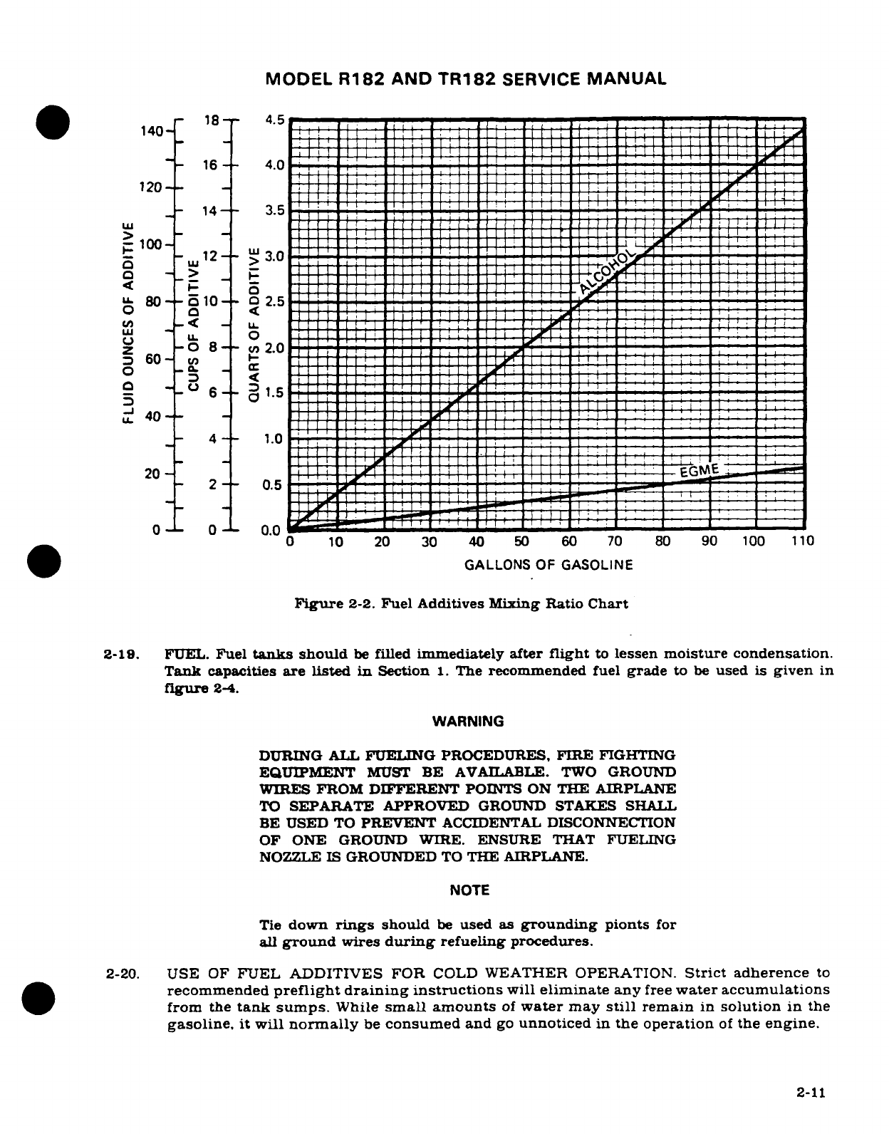
MODEL
R182
AND
TR182
SERVICE
MANUAL
18
-
4.5
140
-
16--
4.0
120
14-
-
3.5
UJI
_
100
-
|-
-:
2
8- 3.0
LL
80
a
10
02.5
o l
_<
-
: : :n:rIL
u
IL
0
z
-0
8-- 2.0
0
-
.J
40
4--
1.0
2-
0.5
0 0
0.0 0
10
20 30
40
50
60
70
80
90
100
110
Figure
2-2.
Fuel
Additives
Mixing
Ratio
Chart
2-19.
FUEL.
Fuel
tanks
should
be
filled
immediately
after
flight
to
lessen
moisture condensation.
Tank
capacities
are
listed
in
Section
I.
The
recommended
fuel
grade
to
be
used
is
given
in
figure
2-4.
WARNING
DURING
ALL
FUELING
PROCEDURES,
FIRE
FIGHTING
EQUIPMENT
MUST
BE
AVAILABLE.
TWO
GROUND
WIRES
FROM
DIFFERENT
POINTS ON THE AIRPLANE
TO
SEPARATE
APPROVED
GROUND
STAKES
SHALL
BE
USED
TO
PREVENT
ACCIDENTAL
DISCONNECTION
OF ONE
GROUND
WIRE. ENSURE
THAT
FUELING
NOZZLE
IS
GROUNDED
TO
THE
AIRPLANE.
NOTE
Tie
down
rings
should
be
used
as
grounding
pionts
for
all
ground
wires
during
refueling
procedures.
2-20.
USE
OF
FUEL
ADDITIVES
FOR
COLD
WEATHER
OPERATION.
Strict
adherence
to
recommended
preflight
draining instructions
will
eliminate
any
free
water accumulations
from
the
tank
sumps.
While
small
amounts
of
water
may
still
remain
in
solution
in
the
gasoline,
it
will
normally
be
consumed
and
go
unnoticed
in
the
operation
of
the
engine.
2-11
MODEL
R182
AND
TR182
SERVICE
MANUAL
One
exception
to
this
can
be
encountered
when
operating
under
the
combined
effect
of:
(1)
use
of
certain
fuels,
with
(2)
high
humidity
conditions
on
the
ground
(3)
followed
by
flight
at
high altitude and
low
temperature.
Under
these unusual
conditions
small
amounts
of
water
in
solution
can
precipitate
from
the
fuel
stream
and
freeze
in
sufficient
quantities
to
induce
partial
icing
of
the
engine
fuel
system.
While
these
conditions
are
quite
rare
and
will
not
normally
pose
a
problem
to
owners and
operators,
they
do
exist
in
certain
areas
of
the
world
and
consequently
must
be
dealt
with,
when
encountered.
Therefore,
to
alleviate
the
possibility
of
fuel
icing occuring
under
these
unusual
conditions
it
is
permissible
to
add
isopropyl
alcohol
or
ethylene
glycol
monomethyl
ether
(EGME)
com-
pound
to
the
fuel
supply.
See
Figure
2-2
for fuel additive
mixing
ratio.
The
introduction
of
alcohol
or
EGME
compound
into
the
fuel
provides
two
distinct
effects:
(1)
it
absorbs
the
dissolved water
from
the
gasoline
and
(2)
alcohol
has
a
freezing
temperature
depressant
effect.
Alcohol,
if
used,
is
to
be
blended with
the
fuel
in a
concentration
of
1%
by
volume.
Concentrations
greater than
1%
are
not
recommended
since
they
can
be
detrimental
to
fuel
tank
materials.
The
manner
in
which
the
alcohol
is
added to
the
fuel
is
significant
because
alcohol
is
most
effective
when
it is
completely
dissolved
in
the
fuel.
To
insure
proper
mixing
the
following
is
recommended:
1.
For
best
results
the
alcohol
should
be
added
during
the
fueling
operation
by
pouring
the
alcohol
directly
on
the
fuel
stream
issuing
from
the
fueling
nozzle.
2.
An
alternate
method
that
may
be
used
is
to
premix
the
complete
alcohol
dosage
with
some
fuel
in a
separate
clean
container (approximately
2-3
gallon capacity)
and
then
transfer this mixture
to
the
tank
prior
to
the
fuel
operation.
Any
high
quality
isopropyl
alcohol
may
be
used,
such
as:
Anti-icing
fluid
(MIL-F-5566)
or
Isopropyl
alcohol
(Federal
Specification
TT-I-735a).
Ethylene
glycol
monomethyl
ether
(EGME)
compound
in
compliance
with
MIL-I-27686
or
Phillips
PFA-55MB,
if
used,
must
be
carefully
mixed
with
the
fuel
in
concentrations
not
to
exceed
0.15%
by
volume.
CAUTION
Mixing
of
the
EGME
compound
with
the
fuel
is
extremely
important
because concentration
in
excess
of
that
recom-
mended
(0.15
percent
by
volume
maximum)
will
result
in
detrimental
affects
to
the
fuel
tanks,
such
as deterioration
of
protective
primer
and
sealants
and
damage
to
O-rings
and
seals
in
the
fuel
system
and
engine components.
Use
only
blending
equipment
that
is
recommended
by
the
manufacturer
to
obtain
proper
proportioning.
Do
not
allow
the
concentrated
EGME
compound
to
come
in
contact
with
the
airplane
finish
or
fuel
cell
as damage
can
result.
2-12
MODEL
R182
AND
TR182
SERVICE
MANUAL
Prolonged storage
of
the
airplane
will
result
in
a
water
build-up
in
the
fuel which
"leeches
out"
the additive.
An
indication
of
this
is
when
an
excessive
amount
of
water
accumulates
in
the
fuel
tank
sumps.
The
concentration
can
be
checked
using
a
differential refractometer.
It
is
imperative that
the
technical
manual
for
the
differential
refractometer
be
followed
explicitly
when
checking
the
additive
concentration.
2-21. FUEL
DRAINS.
Fuel
drains
are
located
in
the
fuel selector
valve,
fuel
tanks,
fuel
line,
fuel
strainer
and
carburetor.
The
fuel
tanks
and
fuel
strainer
have
drain
valves.
To
activate
the
tank
drain
valve
for fuel
sampling,
place
cup
up
to
valve
and
depress
valve
with
rod
prot-
ruding
from
cup.
See
Section
12
for
illustration
of
fuel
tank
drain
valve.
The
strainer
drain
valve is
an
integral
part
of
the
fuel
strainer
assembly.
The
strainer
drain
is equipped
with
a
control
which
is
located
adjacent
to
the
oil
dipstick.
Access
to
the
control
is
through
the
oil
dipstick
access
door.
Open
drains
and
remove
drain
plugs
at
intervals
specified
in
figure
2-
4.
Also,
during
daily
inspection
of
the
fuel
strainer
and
tanks,
if
water
is
found
in
the
sys-
tem,
all
fuel
drain plugs
should
be
removed
and
all
water drained
from
the
system.
2-22.
CARBURETOR
DRAIN
PLUG
INSPECTION.
In
order
to
prevent
the
possibility
of
thread
sealant
contamination
in
the
carburetor
float
chamber,
cleaning
and
inspection
of
the
carburetor
should
be
accomplished
at
each
100-hour
inspection
and
any
time
water
in
the
fuel
is
suspected.
a.
With
the
fuel
selector
valve
OFF,
remove
carburetor
drain
plug
and
clean
off
any
sealant present
on
the
end
of
the
plug
or
in
the
threads
on
the
plug.
b.
Inspect drain
plug
hole
in
the
carburetor
and
remove any
sealant
remaining
in
the
hole.
c.
Turn
fuel
selector
valve
to
ON
to
flush
float
chamber
and
drain
plug
chamber
while
probing drain
plug
hole
to
ascertain
that
all
residue
of
sealant
material
is
dislodged
and
washed
out
of
the
chamber.
Flushing
operation
should
last
15
to
30
seconds.
d.
A
second
flushing
should then
be
accomplished
and
the
drained
fuel
retained
for
inspection
to
insure
that
no
sealant
particles
are
present.
e.
Install
drain
plug
as
follows:
1.
Install
drain
plug
in
carburetor
1-1/2
to
2
turns.
2.
Apply
sealant
to
drain
plug
threads
(use
NS-40
(RAS-4)
or equivalent).
3.
Tighten and
safety
drain
plug.
f.
Turn
fuel
selector
valve
ON
and
inspect
for
evidence
of
fuel
leakage.
2-23.
ENGINE
OIL.
Check
engine lubricating
oil
with
the dipstick
five
to
ten
minutes after
the
en-
gine
has
been
stopped.
The
airplane
should
be
in
as
near
a
level
position
as
possible
when
checking the
engine
oil,
so
that
a
true
reading
is
obtained.
Engine
oil
should
be
drained
while
the
engine
is
still
hot,
and
the
nose
of
the
airplane
should
be
raised
slightly
for
more
positive
draining
of
any
sludge
which
may
have
collected
in
the engine
oil
sump.
Oil
change
may
be
extended
to
100
hours,
providing
the
oil
filter
is
changed
each
50
hours.
Change
en-
gine
oil
and
filter
at
least
every
six
months,
e.en
though
less
than
the
specified
hours
have
accumulated.
Reduce
these
intervals
for
prolonged
operations
in
dusty
areas.
in
cold
cli-
Revision
1
2-13
MODEL R182
&
TR182
SERIES
SERVICE
MANUAL
mates
where
sludging
conditions
exist,
or
where
short flights
and
long
idle
periods
are
en-
countered. which
cause
sludging
conditions.
Always
change
oil
and
oil
filter
whenever
oil
on
the
dipstick
appears
dirty.
Aviation
grade
oil
conforming
to
AVCO
Lycoming
Service
In-
struction
No.
1014,
and
any
revisions
or
supplements
thereto,
shall
be
used
in
the
"Blue
Streak"
(Lycoming)
engine.
WARNING
The
U.S.
Environmental
Protection
Agency
advises
that
mechanics
and
other
workers
who
handle
engine
oil
are
advised
to
minimize
skin
contact
with
used
oil
and
promptly
remove
used
oil
from
the
skin.
In a
laboratory
study,
mice
developed
skin
cancer
after
skin
was
exposed
to
used
engine
oil
twice
a
week
without
being
washed
off,
for
most
of
their
life
span.
Substances
found
to
cause
cancer
in
laboratory
animals
may
also
cause
cancer
in
humans.
NOTE
New
or
newly-overhauled
engines
should
be
operated
on
aviation
grade
straight
mineral
oil
until
the
first
oil
change.
If
an
ashless
dispersant
oil
is
used
in a
new
or
newly-overhauled
engine,
high
oil
consumption
may
be
experienced.
The
anti-friction
additives
in
detergent
and
dispersant
oils
will
retard
"break-in"
of
the
pistons,
rings
and
cylinder
walls.
This
condition
can
be
avoided
by
the
use
of
straight
mineral
oil.
If
oil
must
be
added
during
the
first
25
hours,
use
only aviation
grade
straight
min-
eral
oil
(non-detergent)
conforming
to
Specification
No.
MIL-L-6082.
After
the
first
25
hours
of
operation,
drain
engine
oil
sump
and change
the
oil
filter.
Refill
sump
with
straight
mineral
oil
(non-detergent) and
use
until
a
total
of
50
hours
have
accumulated
or
oil
consumption
has
stabilized,
then
change
to
ashless
dispersant
oil
in
ac-
cordance
with
the
oil
charts
in
figure
2-4.
2-14
Revision
1
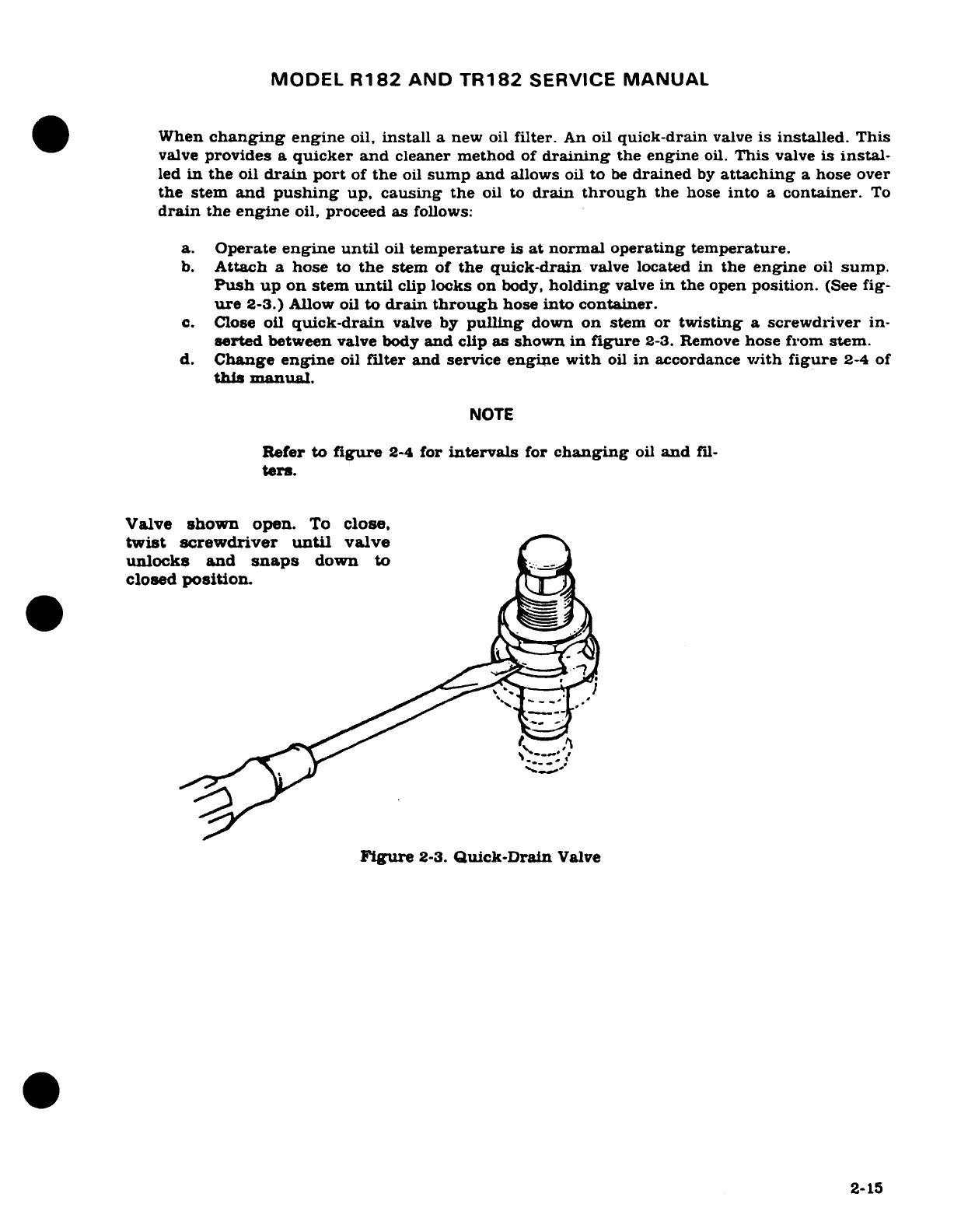
MODEL
R182
AND
TR182
SERVICE
MANUAL
When
changing
engine
oil,
install
a
new
oil
filter.
An
oil
quick-drain
valve
is
installed.
This
valve
provides
a
quicker
and
cleaner
method
of
draining
the engine
oil.
This
valve
is
instal-
led
in
the
oil
drain
port
of
the
oil
sump
and
allows
oil
to
be
drained
by
attaching
a
hose
over
the
stem
and
pushing
up,
causing
the
oil to
drain
through
the
hose
into
a
container.
To
drain
the engine
oil,
proceed
as
follows:
a.
Operate
engine
until
oil
temperature
is
at normal
operating temperature.
b.
Attach
a
hose
to
the
stem
of
the
quick-drain
valve
located in
the
engine
oil
sump.
Push
up
on
stem
until
clip
locks
on
body,
holding
valve
in
the
open
position.
(See
fig-
ure
2-3.) Allow
oil
to
drain
through
hose
into
container.
c.
Close
oil
quick-drain
valve
by
pulling
down
on
stem
or
twisting
a
screwdriver
in-
serted
between
valve
body
and
clip
as
shown
in
figure
2-3.
Remove
hose
from
stem.
d.
Change
engine
oil
filter
and
service
engine
with
oil
in
accordance
with
figure
2-4
of
this
manual.
NOTE
Refer to
figure
2-4
for
intervals
for
changing
oil
and
fil-
ters.
Valve
shown
open.
To
close,
twist
screwdriver
until
valve
~
unlocks
and
snaps
down
to
t
closed
position.
Figure
2-3.
Quick-Drain
Valve
2-15
MODEL
R182
AND
TR182
SERVICE
MANUAL
2-24.
ENGINE
OIL
COOLER.
Oil
coolers
can
be
a
cause
of
internal
engine
damage
if
not
properly
serviced.
Trapped
air
in
the
lines
and
cooler, as
a
result
of
draining
oil
from
the
oil
cooler,
can
cause
oil
aeration,
which
gives
insufficient
valve
train
lubrication
resulting
in
premature
engine
wear. Therefore,
anytime
oil
is
drained,
for
changing
or flushing,
the
following
procedures
should
be
used
to
eliminate
trapped
air.
a.
Prior
to
starting,
remove lower
spark
plugs.
If
available,
the
use
of
an
Auxiliary
Power
Cart
is
recommended.
b.
With
mixture
in
idle
cut
off,
and
magneto
switch
on "START",
rotate
engine
with
the
starter.
Rotate
engine
to
stabilize
oil
pressure,
but
DO
NOT
CRANK
LONGER
THAN
THIRTY
(30)
SECONDS
EACH TIME.
ALLOW
AT
LEAST
ONE
(1)
FULL MINUTE
BETWEEN
CYCLES
FOR
STARTER
MOTOR
COOLING.
After
oil
pressure
gage
stabilizes,
crank
an
additional
ten
(10)
seconds,
IF
WITHIN
THE
THIRTY
SECONDS
LIMIT.
c.
Repeat
this
procedure
at
least
four
(4)
times,
but
DO
NOT
EXCEED
THIRTY
(30)
SECONDS
"ON"
nor
ONE
(1)
MINUTE
"OFF"
Limitation.
d.
Reinstall
the
lower
spark
plugs.
e.
Start
engine
and
run
at
900
-
1,000
RPM
for
approximately
five
(5)
minutes.
Shut
engine
down, and
check
oil level.
Add
oil
as
necessary
to
fill
crankcase
to
full
mark
on
dipstick.
Ensure
that
oil
filter
is
safety
wired.
2-25.
ENGINE
INDUCTION
AIR
FILTER.
The
induction
air
filter
keeps
dust
and
dirt
from
enter-
ing
the
induction
system.
The
value of
maintaining
the
air
filter
in a
good clean
condition
can
never
be
overstressed.
More
engine
wear
is
caused
through
the use
of
a
dirty
or
dam-
aged
air
filter
than
is
generally
believed.
The
frequency
with
which
the
filter
should
be
re-
moved,
inspected,
and
cleaned
will
be
determined
primarily
by
aircraft operating
conditions.
A
good
general
rule,
however, is
to
remove,
inspect
and
clean
the
filter at
least
every
100
hours
of
engine
operating
time
and
more
frequently
if
warranted
by
operating
conditions.
Under
extremely
dusty
conditions,
daily
servicing
of
the filter
is
recommended.
To
service
the
induction
air
filter,
proceed
as
follows:
a.
Remove
filter
from
aircraft.
NOTE
Use
care
to
prevent
damage
to
filter
element
when
cleaning filter
with
compressed
air.
b.
Clean
filter
by
blowing
with
compressed
air
(not
over
100
psi)
from
direction
opposite
of
normal
air
flow.
Arrows
on
filter
case
indicate
direction
of
normal
air
flow.
CAUTION
Do
not
use
solvent
or
cleaning
fluids
to
wash
filter.
Use
only
a
water
and
household
detergent
solution
when
washing
the
filter.
c.
After
cleaning
as
outlined
in
step
"b",
the
filter
may
be
washed,
if
necessary.
in a
solution
of
warm
water
and
a
mild household
detergent.
A
cold
water
solution
may
be
used.
2-16
MODEL
R182
AND
TR182
SERVICE
MANUAL
NOTE
The
filter
assembly
may
be
cleaned
with
compressed
air
a
maximum
of
30
times
or
it
may
be
washed
a
maximum
of
20
times.
A
new
filter
should
be
installed
after
500
hours
of
engine operating
time
or
one
year,
whichever
should
occur
first.
However,
a
new
filter
should
be
installed
at
anytime
the
existing
filter
is
damaged.
A
damaged
filter
may
have
sharp
or
broken
edges
in
the filtering
panels
which
would
allow
unfiltered
air
to
enter
the
induction
system.
Any
filter
that
appears
doubtful,
shall
have
a
new
filter
installed
in
its
place.
d.
After
washing,
rinse
filter
with
clear
water
until
rinse
water
draining
from
filter
is
clear. Allow
water
to
drain
from
filter
and
dry
with
compressed
air
(not
over
100
psi).
NOTE
The
filtering
panels
of
the
filter
may
become
distorted
when
wet,
but
they will
return
to
their
original
shape
when
dry.
e.
Ensure
that
the
air
box
is
clean and
the
filter
and
filter
gasket
are
undamaged
and
serviceable.
f.
Install
filter
at
entrance
to
air
box
with
gasket
on
aft
face
of
filter
frame pointed
in the
correct
direction.
2-26.
VACUUM
SYSTEM
CENTRAL
AIR
FILTER.
The
vacuum system central
air
filter
keeps
dust
and
dirt
from
entering
the
vacuum operated
instruments.
Inspect
the
filter
every
100
hours
for
damage
and
cleanliness.
Change
central
air
filter
element
whenever
damaged,
every
500
hours
of
operating
time, or
annually,
whichever
comes
occurs
first:
and
whenever
it
be-
comes
sufficiently
clogged
to
cause
suction
gage
readings
to
drop
below
4.6
inches
of
mer-
cury.
Also,
do
not
operate
the
vacuum
system
with
the
filter
removed,
or
a
vacuum line
dis-
connected
as
particles
of
dust
or
other
foreign
matter
may
enter
the
system
and
damage
the
vacuum-operated
instruments.
CAUTION
Smoking
will
cause
premature
filter
clogging.
2-27.
BATTERY.
Battery
servicing
involves
adding distilled water
to
maintain
the
electrolyte
even
with
the
horizontal
baffle
plate
at
the
bottom
of
the filler
holes,
checking
the
battery
cable
connections,
and
neutralizing
and
cleaning
spilled
electrolyte
or
corrosion.
Use
bicarbonate
of
soda
(baking
soda)
and
water
to
neutralize
electrolyte
or
corrosion.
Follow
with
a
thor-
ough
flushing
with
water.
Brighten
cables
and
terminals
with
a
wire
brush,
then
coat
with
petroleum
jelly
before
connecting.
The
battery
box
also
should
be
checked
and
cleaned if
any
corrosion
is
noted
(when
applicable).
Distilled
water,
not
acid
or
"rejuvenators",
should
be
used to
maintain
electrolyte
level.
Check
the
battery
every
100
hours
(or
at
least
every
90
days),
more
often
in
hot
weather.
See
Section
16
for
detailed
battery
removal,
installation
and
testing.
2-28
TIRES.
Maintain
tire
pressure
at the
pressure
specified
in
figure
1-1.
When
checking
tire
pressure,
examine
tires
for
wear,
cuts,
bruises,
and
slippage.
Remove
oil,
grease.
and mud
from
tires
with
soap
and
water.
Revision
1
2-17
MODEL
R182
AND
TR182
SERVICE
MANUAL
NOTE
Recommended
tire
pressures
should
be
maintained.
Especially
in
cold
weather,
remember
that
any
drop
in
temperature
of
the
air
inside
a
tire
causes
a
correspond-
ing
drop
in
air
pressure.
2-29.
NOSE
GEAR
SHOCK
STRUT.
The
nose
gear
shock
strut
requires
periodic
checking
to
ensure
that
the
strut
is
filled
with
hydraulic
fluid
and
is
inflated
to
the
correct
air
pressure.
To
service
the
nose
gear
shock
strut,
proceed
as
follows:
a.
Remove
valve
core
and
fully
compress
strut.
(Fork
and
outer
barrel
in
contact.)
b.
Remove
upper
filler
plug.
c.
Extend
strut
one
inch,
fill
to
overflow
with
MIL-H-5606
Hydraulic fluid
and
replace
filler
plug.
d.
Compress
strut.
If
strut
compresses
fully,
repeat operation
"c"
and
"d"
until
strut
will
no
longer compress
fully.
e.
Remove
filler
plug,
compress
strut
fully
and
allow
fluid
to
overflow.
f.
Replace
filler
plug
and
valve
core.
g.
With
no
load
on
strut
inflate
to
55
PSI.
NOTE
The
nose
landing
gear
shock
strut
will
normally
require
only
a
minimum
amount
of
service.
Maintain
the
strut
extension
air
pressure
shown
in
figure
1-1.
Lubricate
landing
gear
as
shown
in
figure
2-5.
Check
landing
gear
daily
for
general
cleanliness,
security
of
mounting,
and
for
hydraulic
fluid leakage.
Keep
machined
surface
of
strut
barrel
wiped
free
of
dirt
and
dust,
using
a
clean,
lint-free
cloth
moistened
with
hydraulic
fluid
or
kerosene.
All
surfaces should
be
wiped
free
of
excess
hy-
draulic
fluid
or
kerosene.
Leave
a
light
film
of
fluid
on
the machine
surface
of
the
strut
barrel.
2-30.
SHIMMY
DAMPENER.
The
shimmy
dampener
contains
a
compensating
mechanism
within
the
hollow
piston
rod
for
thermal
expansion
and
contraction
of
the
hydraulic
fluid.
The
shimmy
dampener
must
be
filled
completely
with
fluid,
free
of
entrapped
air,
to
serve
its
purpose.
In
addition,
the
piston
rod
must
also
be
partially
full
of
fluid
before
the
temperature
compensating mechanism will function
properly.
It
should
be
noted
that
the
fluid
is
under
pressure
exerted
against
the
floating
piston
by
a
spring,
and
that
loosening
or
removing
the
filler
plug
will
cause
loss
of
fluid
and
necessitate removal
and
refilling
of
the
shimmy
dampener
and
piston
rod.
NOTE
The
shimmy
dampener
should
be
checked
at
each
50-hour
inspection
to
see
if it
should
be
serviced.
Use
the
following
procedure
to
fill
the
shimmy
dampener.
a.
Using
the
tow
bar,
turn
the
nose
wheel
strut
to
the
extreme
left
position
(thru
serial
R18200710),
to
the
extreme
right
position
(beginning
with
serial
R18200711),
against
the
stop.
This
will
place
the
shimmy
dampener
piston
to
the
rear
of
the cylinder
and
eliminate
the
possibility
of
trapping
air
in
the
cylinder.
2-18
MODEL
R182
AND
TR182
SERVICE
MANUAL
b.
Remove
the
filler
plug
and
fill
with
hydraulic
fluid.
c.
Replace
filler
plug
and
turn
nose
wheel
strut
through
its
entire
travel
several times.
d.
Return
strut
to
the extreme
left
position
(thru
serial
R18200710),
to
the
extreme
right
position
(beginning
with
R18200711)
against
the
stop.
e.
Remove
filler
plug
and
add
whatever
fluid
is
needed
to
fill
the
cylinder.
f.
Replace
and
safety
the
filler
plug.
NOTE
Keep
shimmy
dampener, especially
the
exposed
portions
of
the
dampener
piston shaft,
clean
to
prevent
collection
of
dust
and
grit
which
could
cut
the
seals
in
the dampener
barrel
Keep
machined surfaces
wiped
free
of
dirt
and
dust,
using
a
clean lint-free
cloth
saturated
with
hydrau-
lic
fluid
(MIL-H-5606)
or
kerosene.
All
surfaces
should
be
wiped
free of
excessive hydraulic
fluid.
2-31.
HYDRAULIC
FLUID
SAMPLING AND
CONTAMINATION
CHECK.
At
the
first
50
and
first
100-hour
inspection
and
thereafter
at
each
500-hour
inspection
or
one
year.
whichever
should occur
first,
a
sample
of
fluid
should
be
taken
and
examined
for
sediment
and
discoloration.
This
may
be
done
as
follows:
a.
Place
aircraft
master
switch
in
OFF
position
and
place
aircraft
on jacks
as shown
in
figure
2-1.
Bleed
pressure
from
system
by
moving
landing
gear
selector
valve
to
gear
UP
position.
CAUTION
Do
not
turn
master
switch
ON
while
hydraulic
system
is
open
to
atmosphere.
The
pump
will
automatically start,
causing
hydraulic
fluid
to
spray
from
any
open
line.
b.
Remove
cap
plug
from
tee
fitting
on
left
side
of
power pack
and
place
a
non-metal
container
below
opening.
c.
Place
landing
gear
selector
valve
in
down
position
and
operate
emergency
hand
pump
to
pump
fluid
into container.
d.
If
the
drain
fluid
is
clear
and
is
not
appreciably
darker
in
color
than
new
fluid.
continue
to
use
the
present
fluid.
e.
If
the
fluid
color
is
doubtful,
place
fluid
sample
in a
non-metallic
container
and
insert
a
strip
of
polished
copper
in
the
fluid.
f.
Keep
copper
in
the
fluid
for
six
hours
at
a
temperature
of
70°F
or
more.
A
slight
darkening
of
the
copper
is
permissible,
but
there
should
be
no
pitting
or
etching
visible
up
to
20X
magnification.
If
pitting
or
etching
is
evident,
drain
fluid
from
power
pack
reservoir.
Fill
power
pack with
MIL-H-5606
hydraulic
fluid
and bleed
air
from
system.
2-32.
LANDING
GEAR HYDRAULIC RETRACTION
SYSTEM.
Draining,
filling
and
bleeding
of
the
landing
gear hydraulic
retraction
system
can
be
accomplished
by
the
following
method.
a.
Place
aircraft
master
switch
in
OFF
position
and
place
aircraft on
jacks
as
shown
in
figure
2-1.
Bleed
pressure
from system
by
moving
landing
gear selector
valve
to
gear
UP
position.
2-19
MODEL
R182
AND
TR182
SERVICE
MANUAL
CAUTION
Do
not
turn
master
switch
ON
while
hydraulic
system
is
open to
atmosphere.
The
pump
will
automatically
start.
causing
hydraulic
fluid
to
spray
from
any
open
line.
b.
Drain
system
by
removing
cap
plug
from
tee
fitting
on
left
side
of
power pack and
attaching
a
drain
hose
to
opening.
Place
end
of
hose
in
a
container
of
at
least
one
gallon
capaity
and
using
emergency
hand
pump, pump
fluid
into
container.
When
power
pack
reservoir
is
empty,
replace
cap
plug
on
tee
fitting.
c.
Fill
power
pack
reservoir
full
with
MIL-H-5606
hydraulic
fluid
by
inserting
funnel
or
filler
hose
in
dipstick
opening
on
top
of
power
pack
body.
d.
Bleed
system
by
cycling
landing
gear
through
several
cycles.
Refill
power
pack
re-
servoir
with
MIL-H-5606
hydraulic
fluid
and
remove
aircraft
from jacks.
2-33.
HYDRAULIC
BRAKE
SYSTEM.
Check
brake
master cylinders
and
refill
with
hydraulic
fluid
(MIL-H-5606)
as
specified
in
the
inspection
charts.
Bleed
the
brake
system
of
entrapped
air
whenever
there
is a
spongy
response
to
the
brake
pedals.
Refer to
Section
5
for
filling
and
bleeding
of
the
brake
system.
2-34.
CLEANING.
2-35.
GENERAL
DESCRIPTION.
Keeping
the
aircraft
clean
is
important.
Besides
maintaining
the
trim
appearance
of
the
aircraft,
cleaning
lessens
the
possiblity
of
corrosion
and
makes
inspection
and
maintenance
easier.
2-20
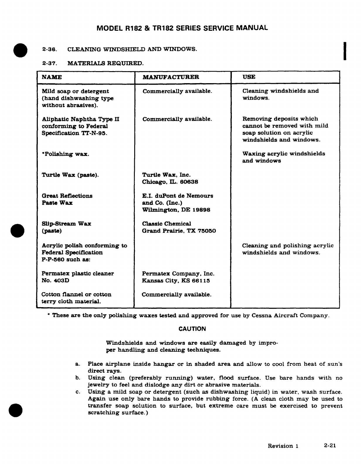
MODEL
R182
&
TR182
SERIES
SERVICE
MANUAL
2-36.
CLEANING
WINDSHIELD
AND
WINDOWS.
2-37.
MATERIALS
REQUIRED.
NAME
MANUFACTURER
USE
Mild
soap
or
detergent
Commercially
available.
Cleaning
windshields
and
(hand
dishwashing
type
windows.
without
abrasives).
Aliphatic
Naphtha
Type
II
Commercially
available.
Removing
deposits
which
conforming
to
Federal
cannot
be
removed
with
mild
Specification
TT-N-95.
soap
solution on
acrylic
windshields
and
windows.
*Polishing
wax.
Waxing
acrylic
windshields
and
windows
Turtle
Wax
(paste).
Turtle
Wax, Inc.
Chicago,
IL.
60638
Great
Reflections E.I.
duPont
de
Nemours
Paste
Wax
and
Co.
(Inc.)
Wilmington,
DE
19898
Slip-Stream
Wax
Classic
Chemical
(paste)
Grand
Prairie,
TX
75050
Acrylic
polish conforming
to
Cleaning
and
polishing
acrylic
Federal
Specification
windshields
and
windows.
P-P-560
such
as:
Permatex
plastic
cleaner
Permatex
Company,
Inc.
No.
403D
Kansas
City,
KS
66115
Cotton
flannel
or
cotton
Commercially
available.
terry
cloth
material.
*These
are
the
only
polishing
waxes tested
and
approved
for
use
by
Cessna
Aircraft
Company.
CAUTION
Windshields and
windows
are
easily
damaged
by
impro-
per
handling
and
cleaning
techniques.
a.
Place
airplane
inside
hangar
or
in
shaded
area
and
allow
to
cool
from
heat
of
sun's
direct
rays.
b.
Using
clean (preferably
running)
water,
flood
surface.
Use
bare
hands
with
no
jewelry
to
feel
and
dislodge
any
dirt
or
abrasive
materials.
c.
Using
a
mild
soap
or
detergent
(such
as
dishwashing
liquid)
in
water,
wash
surface.
Again
use
only
bare
hands
to
provide
rubbing
force.
(A
clean
cloth
may
be
used
to
transfer
soap
solution
to
surface,
but
extreme
care
must
be
exercised
to
prevent
scratching
surface.)
Revision
1
2-21
MODEL
R182
&
TR182
SERIES
SERVICE
MANUAL
d.
On
acrylic
windshields
and
windows
only,
if soils
which cannot
be
removed
by
a
mild
detergent remain,
Type
II
aliphatic
naphtha
applied
with
a
soft
clean
cloth
may
be
used
as
a
cleaning
solvent.
Be
sure
to
frequently
refold
cloth
to avoid
redepositing
soil
and/or
scratching
windshield
with any
abrasive
particles.
e.
Rinse
surface
thoroughly
with
clean
fresh
water
and
dry
with
a
clean cloth.
CAUTION
DO
NOT
use
any
of
the
following
on
or
for
cleaning
windshields
and
windows:
methanol,
denatured
alcohol,
gasoline,
benzene,
xylene,
MEK,
acetone,
carbon
tet-
rachloride,
lacquer
thinners,
commercial
or
household
window
cleaning
sprays.
2-38.
WAXING.
a.
Hand
polishing
wax
should
be
applied
to
acrylic
surfaces.
(The
wax
has
an
index
of
refraction
nearly
the
same
as
transparent
acrylic
and
tend
to
mask
any
shallow
scratches
on
windshield
surface).
b.
Acrylic
surfaces
may
be
polished
using
a
polish
meeting
Federal Specification
P-P-
560
applied
per
manufacturer's
instructions.
CAUTION
DO
NOT
use
rain
repellent
on
acrylic
surfaces.
NOTE
When
applying
and
removing
wax
and
polish,
use
a
clean
soft
cloth.
2-39.
PREVENTIVE
MAINTENANCE.
NOTE
Utilization
of
the
following
techniques
will
help
minimize
windshield
and
window
crazing.
a.
Keep
all
surfaces
of
windshields
and
windows
clean.
b.
If
desired,
wax
acrylic
surfaces.
c.
Carefully
cover
all
surfaces
during
any
painting,
powerplant
cleaning
or
other
proce-
dure
that
calls
for
use
of
any
type
of
solvents
or
chemicals.
The
following
coatings
are
approved
for
use
in
protecting
surfaces
from
solvent
attack.
1.
White
Spary
Lab,
MIL-C-6799,
Type
I,
Class
H.
2.
WPL-3
Masking
Paper
-
St.
Regis,
Newton,
MA.
3. 5
X
N
-
Poly-Spotstick
-
St.
Regis,
Newton,
MA.
4.
Protex
40
-
Mask
Off
Company,
Monrovia,
CA,
and
Southwest
Paper
Co.,
Wichita,
KS.
5.
Protex
10VS
-
Mask
Off
Company, Monrovia,
CA,
and
Southwest
Paper
Co.,
Wichita,
KS.
6.
Scotch
344
Black
Tape
-
3M
Company.
d.
Do
not
park
or
store
airplane
where
it
might
be
subjected
to
direct
contact
with
or
vapors
from:
methanol, denatured
alcohol,
gasoline,
benzene,
xylene,
MEK,
acetone,
carbon
tetrachloride,
lacquer
thinners,
commercial
or
household window
cleaning
sprays,
paint
strippers,
or
other
types
of
solvents.
2-22
Revision
1
MODEL
R182
&
TR182
SERIES
SERVICE
MANUAL
e.
Do
not
use
solar
screens
or
shields
installed
on
inside
of
airplane
or
leave
sun
visors
up
against
windshield.
The
reflected
heat
from
these
items
causes
elevated
tempera-
tures
which
accelerate
crazing
and
may
cause
formation
of
bubbles
in
the
inner
ply
of
multiple-ply
windshields.
f.
Do
not
use
a
power
drill
motor
or
other
powered
device to
clean,
polish,
or
wax
sur-
faces.
2-40.
INTERIOR
TRIM.
The
instrument
panel,
interior
plastic
trim,
and
control
knobs
need
only
be
wiped
with
a
damp
cloth.
Oil
and
grease
on
the
control
wheels
and
control
knobs
can
be
removed
with
a
cloth
moistened
with
Stoddard
solvent.
Volatile
solvents,
mentioned
in
the
caution
note
of
paragraph
2-36,
must
never
be
used
since they
soften
and
craze
the
plastic
trim.
2-41.
PAINTED
SURFACES.
The
painted
exterior
surfaces
of
your
new
Cessna
have
a
durable,
long-lasting finish.
Approximately
10
days
are
required
for the
paint
to
cure
completely;
in
most cases,
the
curing
period
will
have
been
completed
prior
to
delivery
of
the
airplane.
In
the
event
that
polishing
or
buffing
is
required
within
the
curing
period,
it
is
recommended
that
the work
be
done
by
someone
experienced
in
handling
uncured
paint.
Any
Cessna
Deal-
er
can
accomplish
this
work.
Generally,
the
painted
surfaces
can
be
kept
bright
by
washing
with
water
and
mild
soap,
fol-
lowed
by
a
rinse
with water and
drying
with cloths
or
a
chamois.
Harsh
or
abrasive soaps
or
detergents
which
cause
corrosion
or scratches should
never
be
used.
Remove
stubborn
oil
and
grease
with
a
cloth moistened
with
Stoddard
solvent.
To
seal
any minor
surface
chips
or scratches
and
protect
against
corrosion,
the
airplane
should
be
waxed
regularly
with
a
good
automotive wax
applied
in
accordance
with
the
man-
ufacturer's
instructions.
If
the
airplane
is
operated
in a
seacoast or
other salt
water
en-
vironnment,
it
must
be
washed
and
waxed
more
frequently
to
assure
adequate protection.
Special
care
should
be
taken
to
seal
around
rivet
heads and
skin
laps,
which are
the
areas
most
susceptible
to
corrosion.
A
heavier
coating
of
wax
on
the
leading
edges
of
the
wings
and tail,
and
on
the
cowl
nose
cap
and propeller
spinner
will
help
reduce
the
abrasion
en-
countered
in
these
areas.
Reapplication
of
wax
will
generally
be
necessary
after
cleaning
with
soap
solutions or
after
chemical de-icing
operations.
2-42.
ALUMINUM
SURFACES.
The
aluminum
surfaces
require
a
minimum
of
care, but
should
never
be
neglected.
The
aircraft
may
be
washed
with
clean water
to
remove
dirt
and may
be
washed
with
nonalkaline grease
solvents
to
remove
oil
and/or
grease.
Household
type
deter-
gent
soap powders
are
effective
cleaners,
but
should
be
used cautiously
since
some
of
them
are
strongly
alkaline.
Many good
aluminum
cleaners, polishes and
waxes
are
available
from
commercial
suppliers
of
aircraft
products.
2-43.
ENGINE
AND
ENGINE
COMPARTMENT.
An
engine
and
accessories
wash-down
should
be
accomplished
during
each
100-hour
inspection
to
remove
oil,
grease,
salt
corrosion
or
other
residue
that
might
conceal
component
defect
during
inspection.
Also,
periodic
cleaning
can
be
very
effective
in
preventive
maintenance.
Precautions
should
be
taken
when
working
with
cleaning
agents
such
as
wearing
of
rubber
gloves,
an
apron
or
coveralls
and
a
face
shield or
goggles.
Use
the
least
toxic
of
available
cleaning
agents
that
will
satisfactorily
accomplish
the
work.
These
cleaning
agents
include:
(1)
Stoddard
solvent
(Specification
P-D-680,
Type
II),
(2)
A
water
base
alkaline
detergent
cleaner
(MIL-C-25769J)
mixed
1
part
cleaner,
2
to
3
parts
water
and
8
to
12
parts
Stoddard
solvent
or
(3)
A
solvent
base
emulsion
cleaner
(MIL-C-4361B)
mixed
1
part
cleaner
and
3
parts
Stoddard
solvent.
Revision
1
2-23
MODEL
R182 AND
TR182
SERVICE
MANUAL
CAUTION
Do
not
use
gasoline
or
other
highly
flammable
sub-
stances
for
wash-down.
Perform
all
cleaning operations
in
well
ventilated
work
areas,
and
ensure
that
adequate
fire-
fighting
and
safety
equipment
is available.
Do
not
smoke
or
expose
a
flame
within
100
feet
of
the
cleaning area.
Compressed
air,
used
for
cleaning
agent
application
or drying,
should
be
regulated
to
the
lowest
practical
pressure.
Use
of
a
stiff
bristle
brush
rather
than
a
steel
brush
is
recommended
if
cleaning
agents
do
not
remove
excess
grease
and
grime
during
spraying.
A
recommended
procedure
for
cleaning
an
engine
and
accessories
is
as
follows.
CAUTION
Do
not
attempt
to
wash
an
engine which
is
still
hot
or
running.
Allow
the
engine
to
cool
before
cleaning.
a.
Remove
engine
cowling
in
accordance
with
paragraph
11-3.
b.
Carefully
cover
the
coupling area
between
the
vacuum
pump
and
the
engine drive
shaft
so
that
no
cleaning
solvent
can
reach
the
coupling or
seal.
c.
Cover
the
open
end
of
the
vacuum
discharge
tube.
d. Cover
the
vacuum relief
valve
filter,
if
installed
in
the
engine
compartment.
e.
Use
fresh
water
for
wash-down
when
the
engine
is
contaminated
with
salt
or
corro-
sive
chemicals.
A
cleaning
agent
such
as
described
previously
may
then
be
used
to
remove
oil
and grime.
CAUTION
Care
should
be
exercised
to
not
direct cleaning
agents
or
water
streams at
openings
on
the
starter,
magnetos,
al-
ternator,
vacuum
pump,
or
turbocharger
relief
valve.
f.
Thoroughly
rinse
with
clean,
warm
water
to
remove
all
traces
of
cleaning agents.
CAUTION
Cleaning
agents
should
never
be
left on
engine
compo-
nents
for
an
extended
period
of
time.
Failure
to
remove
them
may
cause
damage
to
components
such
as
neoprene
seals
and
silicone
fire
sleeves,
and
could
cause
additional
corrosion.
g.
Completely
dry
the
engine
and
accessories
using
clean,
dry
compressed
air.
h.
Remove
the
cover over
the
coupling
area.
i.
Remove
the
cover
from
the
vacuum
discharge
tube.
j.
Remove
the
cover
from the
vacuum
relief
valve
filter,
if
installed.
k.
If
desired,
the
engine
cowling
may
be
washed
with the
same
cleaning
agents,
then
rinsed
thoroughly
and
wiped
dry.
l.
Reinstall engine
cowling.
2-24
Revision
1
MODEL
R182
AND TR182
SERVICE
MANUAL
WARNING
For
maximum
safety,
check
that
the
magneto
switches
are
OFF,
the throttle
is
closed,
the
mixture
control
is
in
the
idle
cut-off position,
and
the airplane
is
secured
be-
fore
rotating
the
propeller
by
hand.
Do
not
stand
within
the
arc
of
the
propeller
blades
while
turning
the
propel-
ler.
m.
Before
starting
the
engine,
rotate
the propeller
by
hand
no less
than
four
complete
revolutions.
2-44.
UPHOLSTERY
AND
INTERIOR
cleaning
prolongs
the
life
of
upholstery
fabrics
and
interior
trim.
To
clean
the
interior,
proceed
as
follows:
a.
Empty all
ash
trays
and
refuse
containers.
b.
Brush
or
vacuum
clean
the upholstery
and
carpet
to
remove
dust
and
dirt.
c.
Wipe
leather
and
plastic
trim
with
a
damp
cloth.
d.
Soiled
upholstery
fabrics
and
carpet
may
be
cleaned
with
a
foam-type
detergent
used
according
to
manufacturer's
instructions.
e.
Oil
spots
and
stains
may
be
cleaned
with
household
spot
removers,
used
sparingly.
Before
using
any
solvent,
read
the
instructions
on
the container
and
test
it
on an
obscure
place
in
the
fabric to
be
cleaned.
Never
saturate
the fabric with
volatile
sol-
vent;
it
may
damage the
padding
and backing
material.
f.
Scrape
sticky
material
from
fabric
with
a
dull
knife,
then
spot
clean
the area.
2-45.
PROPELLER.
The
propeller
should
be
wiped
occasionally
with
an
oily
cloth
to
remove
grass
and
bug
stains.
In
salt
water
areas
this
will
assist
in
corrosion
proofing
the
propeller.
2-46.
WHEELS.
The
wheels
should
be
washed
periodically
and
examined for
corrosion,
chipped
paint,
and
cracks
or
dents
in
the
wheel halves
or
in
the flanges
or
hubs.
If
defects
are
found,
remove
and
repair
in
accordance
with
Section
5.
Discard
cracked
wheel
halves,
flanges
or
hubs
and
install
new
parts.
2-47.
LUBRICATION.
2-48.
GENERAL
DESCRIPTION.
Lubrication
requriements
are
shown
in
figure
2-5.
Before
adding
lubricant
to
a
fitting,
wipe
fitting
free
of
dirt.
Lubricate
until
grease
appears
around
part
being lubricated,
and
wipe
excess
grease
from
parts.
The
following
paragraphs
supplement
figure
2-5
by
adding
details
not
shown
in
the
figure.
2-49. TACHOMETER
DRIVE SHAFT.
Refer
to
Section
15.
2-50.
WHEEL
BEARINGS.
Clean
and repack
the
wheel
bearings
at
the
first
100-hour
inspection
and
at
each
500-hour
inspection
thereafter.
If
more
than
the
usual
number
of
takeoffs and
landings
are
made,
extensive
taxiing
is
required,
or
the
aircraft
is
operated
in
dusty
areas
or under
seacoast
conditions, cleaning
and
lubrication
of
the
hweel
bearings
shall
be
accom-
plished
at
each
100-hour
inspection.
2-51.
NOSE
GEAR
TORQUE
LINKS.
Lubricate
nose
gear
torque links
every
50
hours.
When
operating
from
a
dirt
strip
or
in
extremely
dusty
areas,
more
frequent
lubrication
of
the
tor-
que
links
is
required.
Revision
1
2-25
MODEL
R182
AND
TR182
SERVICE
MANUAL
2-52.
WING
FLAP
ACTUATOR.
Clean
and
lubricate
wing
flap
actuator
jack
screw
each
100
hours
as
follows:
a.
Expose
jack
screw
by
operating
flaps
to
full
down
position.
b.
Clean
jack screw
threads
with
solvent
rag
and
dry
with
compressed
air.
NOTE
It
is
not
necessary
to
remove
actuator
from
aircraft
to
clean
or
lubricate
threads.
c.
With
oil
can, apply
light
coat
of
No.
10
weight
non-detergent
oil
to
threads
of
jack
screw.
2-53.
ROD
END BEARINGS.
Periodic
inspection and lubrication
is
required
to
prevent
corrosion
of
the
bearing
in
the
rod end.
At
each
100-hour
inspection, disconnect
the
control
rods
at
the
aileron,
flap
and
nose
gear
steering
bungee,
and
inspect
each
rod
end
for corrosion.
If
no
corrosion
is
found,
wipe
the
surface
of
the
rod
end balls
with
general purpose
oil
and
ro-
tate
ball
freely
to
distribute
the
oil
over
its
entire
surface
and
connect
the
control
rods
to
their
respective
units.
If
corrosion
is
detected
during
the
inspection,
install
new
rod
ends.
2-54.
NOSE
GEAR
STEERING
COLLAR.
Lubricate
nose
gear
steering
collar
spindle
links
at
each
100-hour
inspection.
2-55.
NOSE
GEAR PIVOTS.
Lubricate
all
nose
gear
pivot
points
at
each
100-hour
inspection,
in-
cluding
the
drag
link
pivot
points.
More
frequent
lubrication
may
be
required
when
operat-
ing
in
dusty
areas.
2-56.
MAIN
GEAR
PIVOT
POINTS.
Lubricate
main landing gear
pivot assembly
at
each
500-hour
inspection.
If
more
than
the
usual number
of
takeoffs
and
landings
are
made,
lubrication
of
the
pivot
assembly
should
be
accomplished
at
each
100-hour
inspection.
2-26
Revision
1
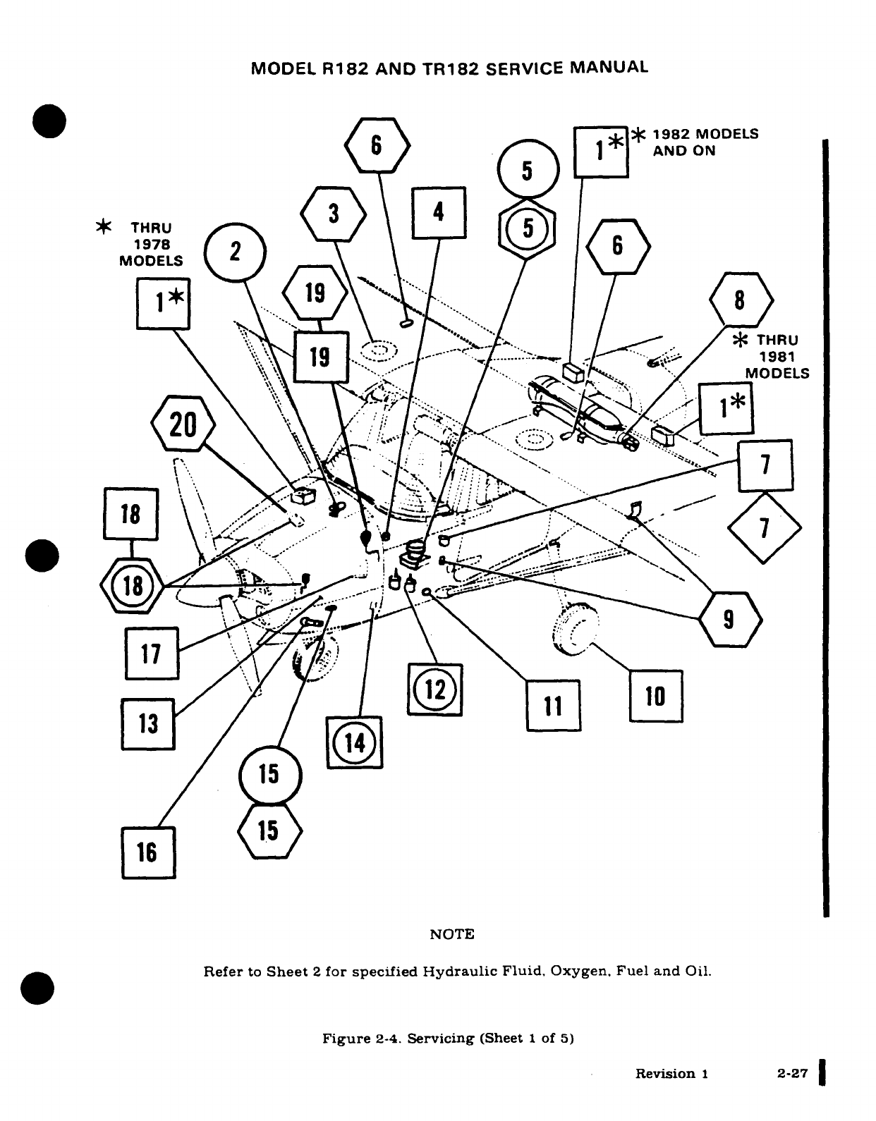
MODEL
R182
AND
TR182
SERVICE
MANUAL
*1982
MODELS
*THU
5
/1
X
AND
ON
1* ^
^@/
/
19
e
,"
ITHRU
-^
.
*
THRU
, ~'.,- .t
THRU
--
~-'.-t1
1981
\ V\ ____ ""
"I
7 -fJll^. {/
MODELS
n..\
..
\\... : -;R 1.
18,
..
16 V54
NOTE
Refer
to
Sheet
2
for
specified
Hydraulic
Fluid,
Oxygen.
Fuel and
Oil.
Figure
2-4.
Servicing
(Sheet
1
of
5)
Revision
1
2-27
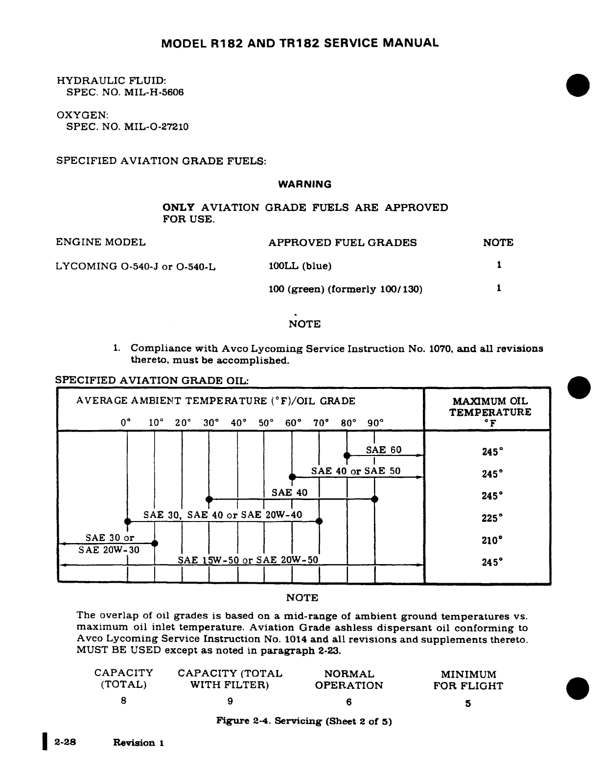
MODEL
R182
AND
TR182
SERVICE
MANUAL
HYDRAULIC
FLUID:
SPEC.
NO.
MIL-H-5606
OXYGEN:
SPEC.
NO.
MIL-O-27210
SPECIFIED
AVIATION
GRADE
FUELS:
WARNING
ONLY
AVIATION
GRADE
FUELS
ARE
APPROVED
FOR
USE.
ENGINE
MODEL
APPROVED
FUEL
GRADES
NOTE
LYCOMING
O-540-J
or
O-540-L
100LL
(blue)
1
100
(green)
(formerly
100/130)
1
NOTE
1.
Compliance
with
Avco
Lycoming
Service
Instruction
No.
1070,
and
all
revisions
thereto,
must
be
accomplished.
SPECIFIED
AVIATION GRADE
OIL:
AVERAGE
AMBIENT
TEMPERATURE
(°F)/OIL
GRADE
MAXIMUM
OIL
TEMPERATURE
0°10°
20
°
30
°
40
°
50
°
60
°
70
°
80
°
90
°F
SAE
60
245
°
SAE
40
or
SAE
50
245
°
SAE
40
1-
245
SAE
30,
SAE 40
or
SAE
20W-40
225
°
SAE
30
or
210
SAE
20W-30
SAE
15W-50
or
SAE
20W-50
*
245°
NOTE
The
overlap
of
oil
grades
is
based
on
a
mid-range
of
ambient
ground
temperatures
vs.
maximum
oil
inlet
temperature.
Aviation
Grade
ashless
dispersant
oil
conforming
to
Avco
Lycoming Service
Instruction
No.
1014
and
all
revisions
and
supplements
thereto.
MUST
BE
USED
except
as
noted
in
paragraph
2-23.
CAPACITY
CAPACITY
(TOTAL NORMAL
MINIMUM
(TOTAL)
WITH
FILTER)
OPERATION
FOR
FLIGHT
8
9 6
5
Figure
2-4.
Servicing
(Sheet
2
of
5)
2-28
Revision
1
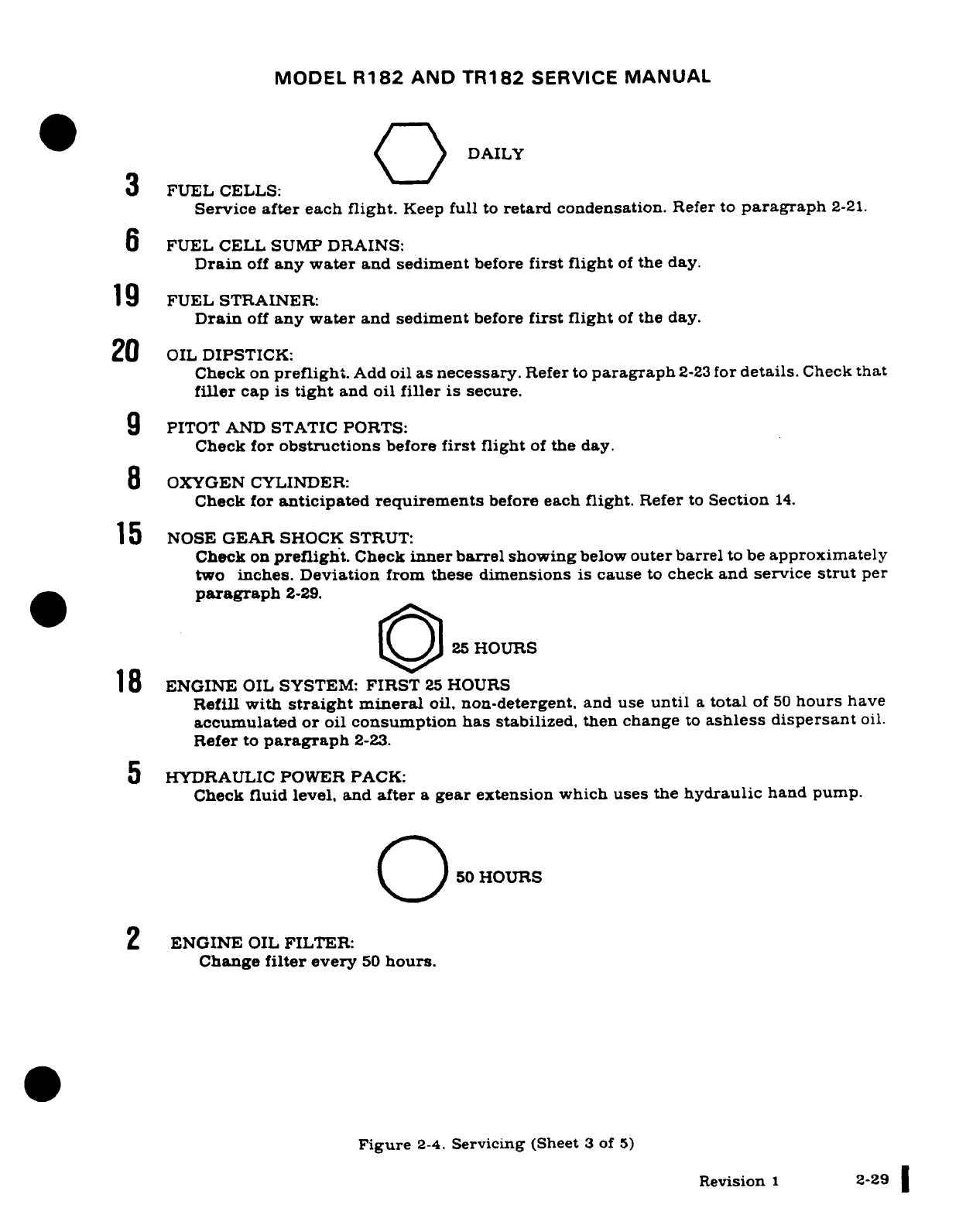
MODEL
R182
AND
TR182
SERVICE
MANUAL
DAILY
3
FUEL
CELLS:
Service
after each
flight.
Keep
full
to
retard
condensation.
Refer
to
paragraph
2-21.
6
FUEL
CELL
SUMP
DRAINS:
Drain
off
any
water
and
sediment
before
first
flight
of
the day.
19
FUEL
STRAINER:
Drain
off
any
water
and
sediment
before
first
flight
of
the
day.
20
OIL
DIPSTICK:
Check
on
preflight.
Add
oil
as
necessary.
Refer
to
paragraph
2-23
for
details.
Check
that
filler
cap
is
tight
and
oil
filler
is
secure.
9
PITOT
AND
STATIC PORTS:
Check
for
obstructions
before
first
flight
of
the
day.
8
OXYGEN
CYLINDER:
Check
for
anticipated
requirements
before
each
flight.
Refer
to
Section
14.
15
NOSE
GEAR
SHOCK
STRUT:
Check
on
preflight.
Check
inner barrel
showing
below
outer
barrel
to
be
approximately
two
inches.
Deviation
from
these
dimensions
is
cause
to
check
and service
strut
per
paragraph
2-29.
25
HOURS
18
ENGINE
OIL
SYSTEM:
FIRST
25
HOURS
Refill
with
straight
mineral
oil,
non-detergent,
and
use
until
a
total
of
50
hours
have
accumulated
or
oil
consumption
has
stabilized,
then
change
to
ashless dispersant
oil.
Refer
to
paragraph
2-23.
5
HYDRAULIC
POWER
PACK:
Check
fluid level,
and
after
a
gear
extension
which
uses
the
hydraulic
hand
pump.
50
HOURS
2
ENGINE
OIL
FILTER:
Change
filter
every
50
hours.
Figure
2-4.
Servicing
(Sheet
3
of
5)
Revision
1
2-29
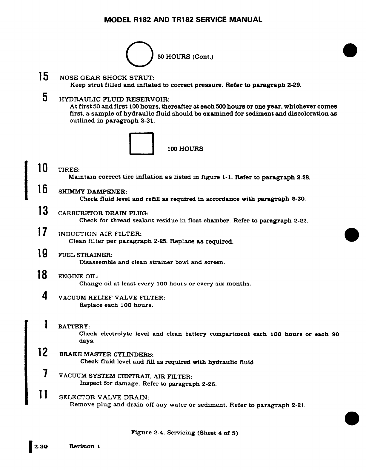
MODEL
R182
AND
TR182
SERVICE
MANUAL
O j50
HOURS
(Cont.)
15
NOSE
GEAR
SHOCK
STRUT:
Keep
strut
filled
and
inflated
to
correct
pressure.
Refer
to
paragraph
2-29.
5
HYDRAULIC
FLUID
RESERVOIR:
At
first
50
and
first
100
hours,
thereafter
at
each
500
hours or
one
year,
whichever
comes
first,
a
sample
of
hydraulic
fluid
should
be
examined
for
sediment
and
discoloration
as
outlined
in
paragraph
2-31.
[Z__
100
HOURS
10
TIRES:
Maintain
correct
tire
inflation
as
listed
in
figure
1-1.
Refer
to
paragraph
2-28.
16
SHIMMY
DAMPENER:
Check
fluid
level
and
refill
as
required
in
accordance
with
paragraph
2-30.
13
CARBURETOR
DRAIN
PLUG:
Check
for
thread
sealant
residue
in
float
chamber.
Refer
to
paragraph
2-22.
17
INDUCTION
AIR FILTER:
Clean
filter
per
paragraph
2-25.
Replace
as
required.
1
9
FUEL
STRAINER:
Disassemble
and
clean
strainer
bowl
and
screen.
18
ENGINE
OIL:
Change
oil
at
least
every
100
hours
or
every
six
months.
4
VACUUM
RELIEF
VALVE
FILTER:
Replace
each
100
hours.
BATTERY:
Check
electrolyte
level
and
clean
battery
compartment
each
100
hours
or
each
90
days.
12
BRAKE
MASTER
CYLINDERS:
Check
fluid
level
and
fill as
required with
hydraulic
fluid.
7
VACUUM
SYSTEM
CENTRAIL
AIR
FILTER:
Inspect
for
damage.
Refer
to
paragraph
2-26.
11
SELECTOR
VALVE
DRAIN:
Remove
plug
and
drain
off
any
water
or
sediment.
Refer
to
paragraph
2-21.
Figure
2-4.
Servicing
(Sheet
4
of
5)
|
2-30
Revision
1
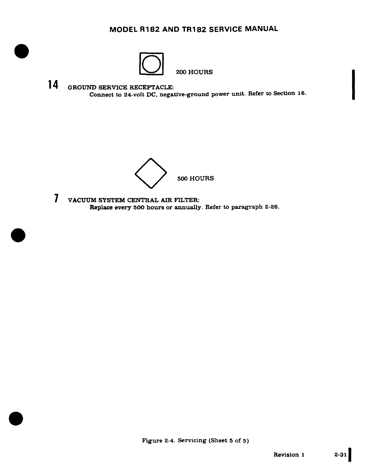
MODEL
R182
AND
TR182
SERVICE
MANUAL
200
HOURS
14
GROUND
SERVICE
RECEPTACLE:
Connect to
24-volt
DC,
negative-ground
power
unit.
Refer
to
Section
16.
500
HOURS
7
VACUUM
SYSTEM
CENTRAL
AIR
FILTER:
Replace
every
500
hours
or
annually.
Refer
to
paragraph
2-26.
Figure
2-4.
Servicing
(Sheet
5
of
5)
Revision
1
2-31
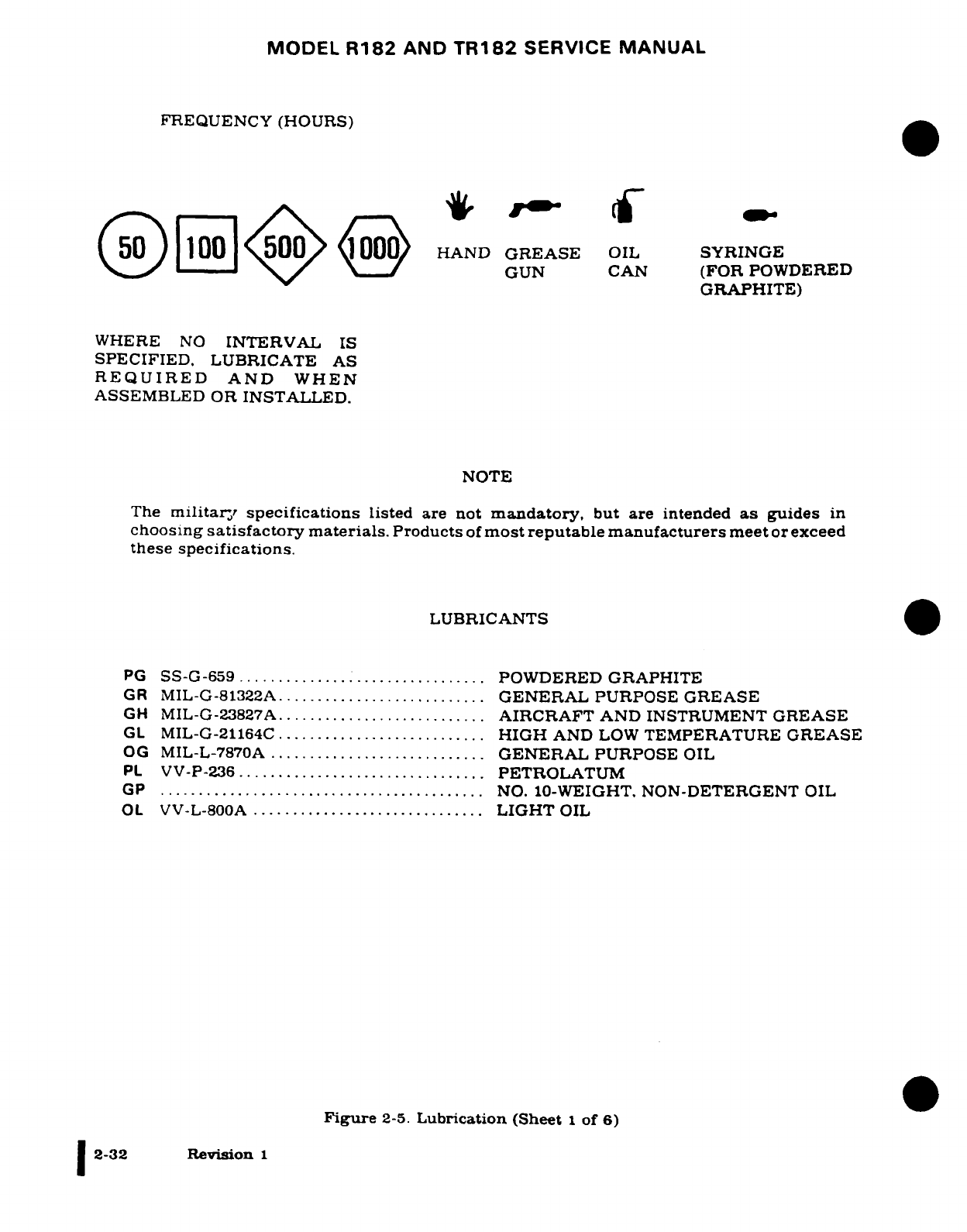
MODEL
R182
AND
TR182
SERVICE
MANUAL
FREQUENCY
(HOURS)
HAND
GREASE
OIL
SYRINGE
(
I [ HAND GRAS OLGUN
CAN
(FOR
POWDERED
GRAPHITE)
WHERE
NO
INTERVAL
IS
SPECIFIED.
LUBRICATE
AS
REQUIRED
AND
WHEN
ASSEMBLED
OR
INSTALLED.
NOTE
The
military specifications
listed
are not
mandatory,
but
are
intended
as
guides
in
choosing
satisfactory
materials.
Products
of
most reputable manufacturers
meet
or
exceed
these
specifications.
LUBRICANTS
PG
SS-G-659
.............................
POWDERED
GRAPHITE
GR
MIL-G-81322A...........................
GENERAL
PURPOSE GREASE
GH
MIL-G-23827A
...........................
AIRCRAFT
AND
INSTRUMENT
GREASE
GL
MIL-G-21164C
........................
HIGH
AND
LOW
TEMPERATURE
GREASE
OG
MIL-L-7870A
............................
GENERAL
PURPOSE
OIL
PL
VV-P-236
...............................
PETROLATUM
GP
..........................................
NO.
10-WEIGHT,
NON-DETERGENT
OIL
OL
VV-L-800A
..............................
LIGHT
OIL
Figure
2-5.
Lubrication (Sheet
1
of
6)
I2-32
Revision
1
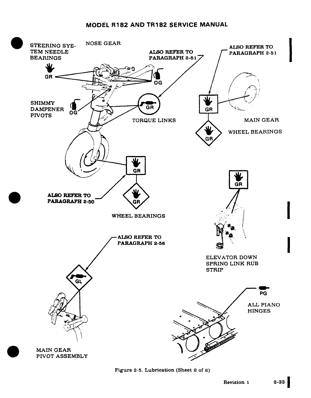
MODEL
R182
AND
TR182
SERVICE
MANUAL
STEERING
SYE-
NOSE
GEARALSO
REFERTO
TEM
NEEDLE
ALSO
REFER
TO
PARAGRAPH
2-51
BEARINGS
PARAGRAPH
2-51
GR
SHIMMY
DAMPENER
GR
PIVOTS
TORQUE
LINKS
MAIN
GEAR
(tt t
WHEEL
BEARINGS
(~GR
GR
*b
ALSOREFERTO
/
PARAGRAPH
2-50
/
WHEEL
BEARINGS
I
i"":
ALSO
REFER
TO
PARAGRAPH
2-56
ELEVATOR
DOWN
SPRING
LINK
RUB
STRIP
GL
PG
ALL
PIANO
HINGES
MAIN
GEAR
PIVOT
ASSEMBLY
Figure
2-5.
Lubrication
(Sheet
2
of
6)
Revision
1
2-33
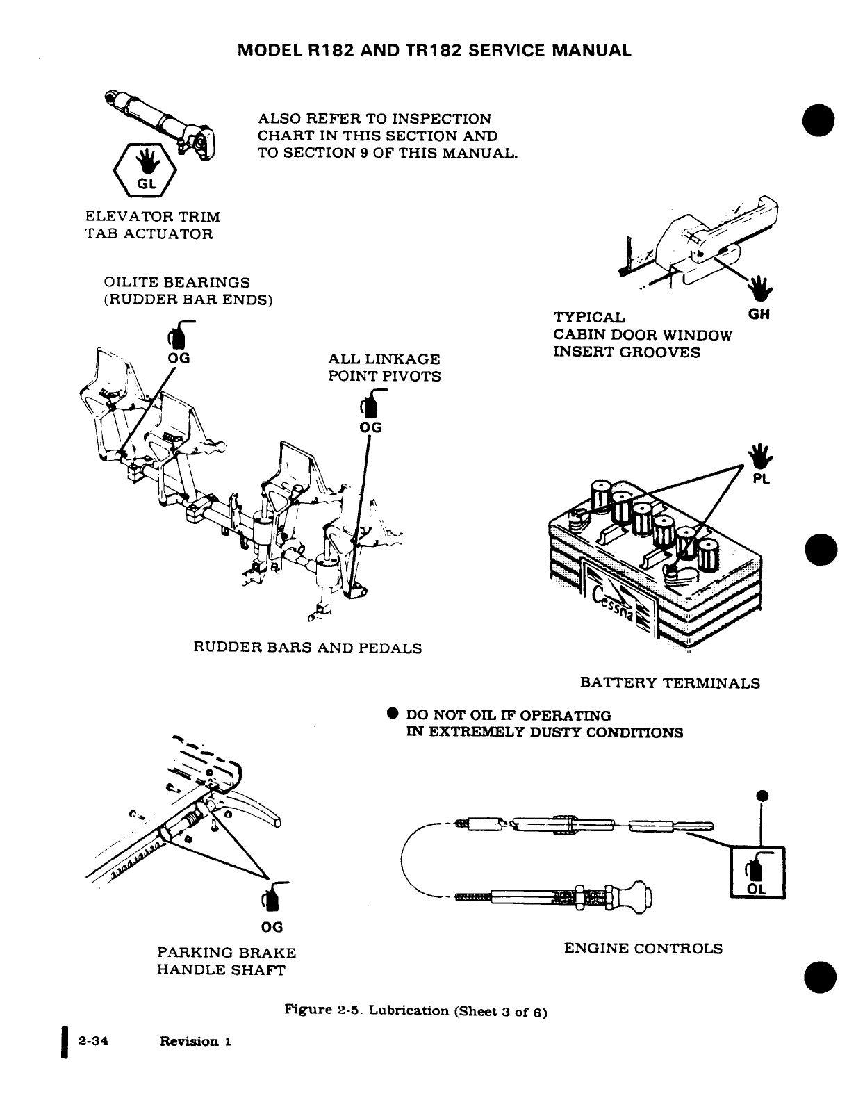
MODEL
R182
AND
TR182
SERVICE
MANUAL
ALSO
REFER
TO
INSPECTION
CHART
IN
THIS
SECTION
AND
XiZ
v) ~
TO
SECTION
9
OF
THIS
MANUAL.
ELEVATOR TRIM
TAB
ACTUATOR
OILITE
BEARINGS
(RUDDER
BAR
ENDS) TYPICAL
GH
4cCf~~~ ~~CABIN
DOOR
WINDOW
OG*
A~LL
LINKAGE
INSERT
GROOVES
OG
ALL
LINKAGE
POINT
PIVOTS
RUDDER
BARS
AND
PEDALS
BATTERY
TERMINALS
DO
NOT
OIL
IF
OPERATING
IN
EXTREMELY
DUSTY
CONDITIONS
0
OG
PARKING
BRAKE
ENGINE
CONTROLS
HANDLE
SHAFT
Figure
2-5.
Lubrication
(Sheet
3
of
6)
2-34
Revision
1
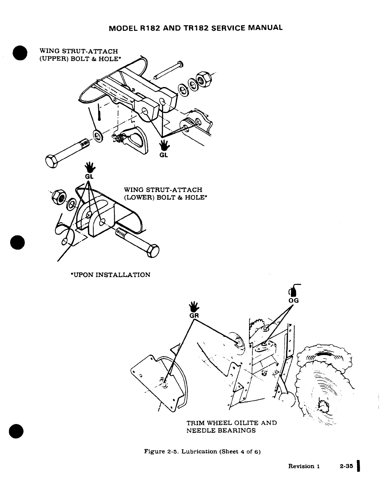
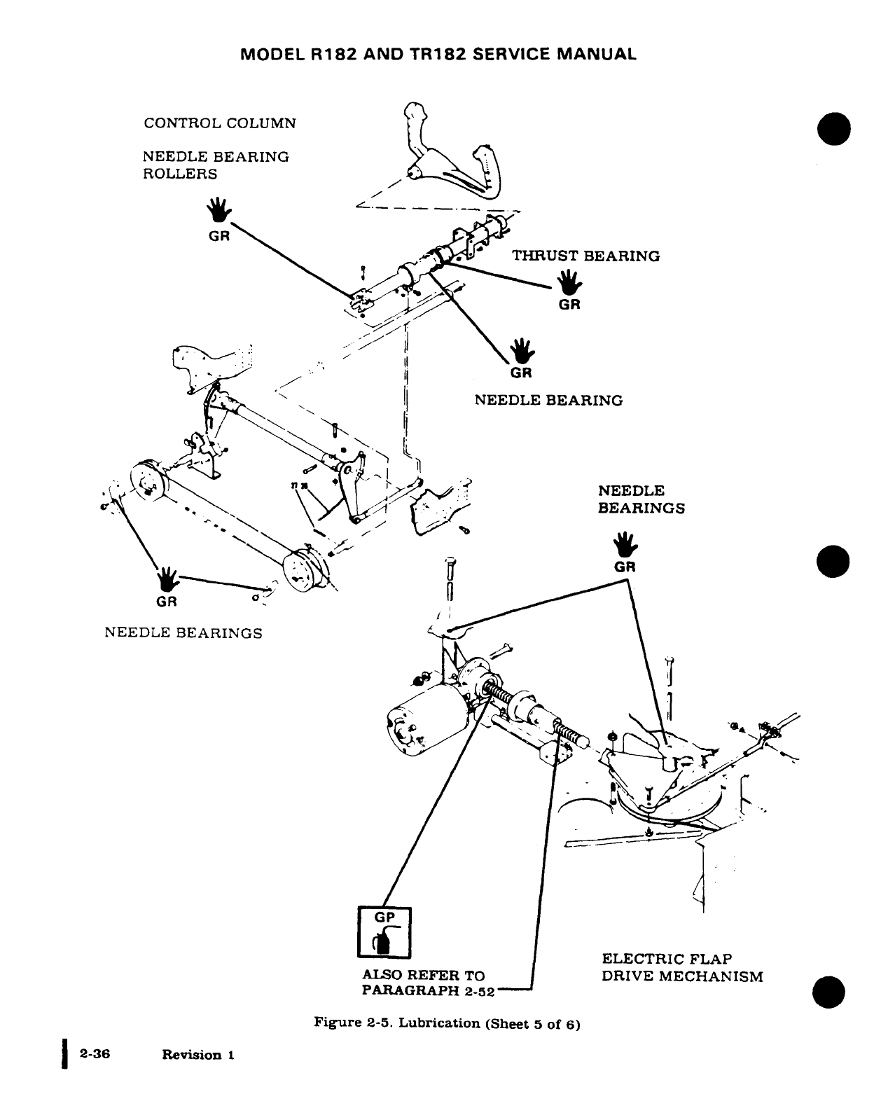
MODEL
R182
AND
TR182
SERVICE
MANUAL
CONTROL
COLUMN
NEEDLE
BEARING
ROLLERS
\· -;'^^
THRUST
BEARING
O
-*
^
|l
\GR
GR
< X l|;
NEEDLE
BEARING
{ AX REE TO
I
MANI'SM
NEEDLE
c^Xs *' \"^ \y^
/^
BEARINGS
GR
GR
NEEDLE
BEARINGS
__-
|
ELECTRIC
FLAP
ALSO
REFER
TO
|
DRIVE
MECHANISM
PARAGRAPH
2-52
Figure
2-5.
Lubrication
(Sheet
5
of
6)
2-36
Revision
1
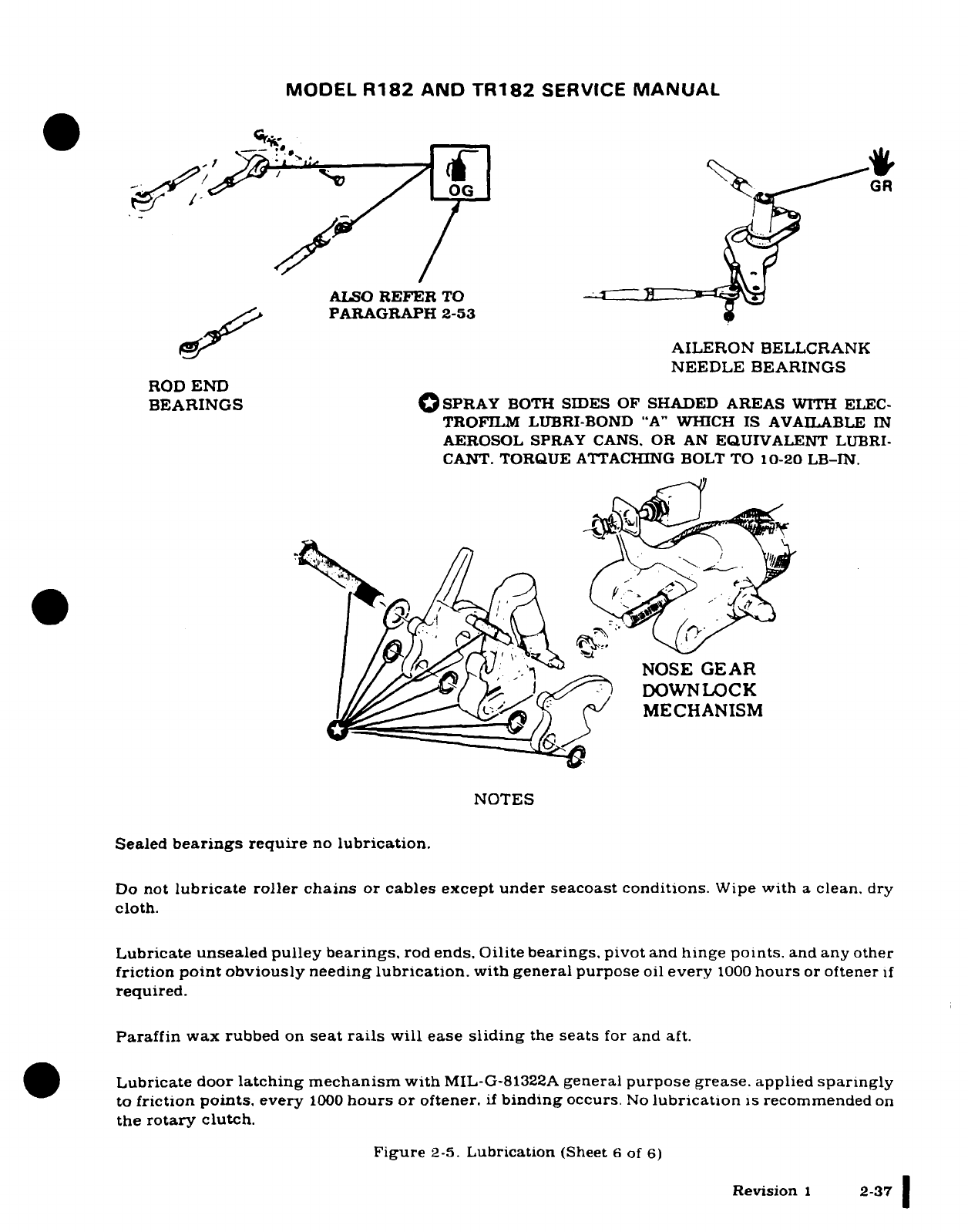
MODEL
R182
AND
TR182
SERVICE
MANUAL
0
O'eOG GR
ALSO
REFER
TO
PARAGRAPH
2-53
AILERON
BELLCRANK
NEEDLE
BEARINGS
ROD
END
BEARINGS
OSPRAY
BOTH
SIDES
OF
SHADED
AREAS
WITH
ELEC-
TROFILM
LUBRI-BOND
"A"
WHICH
IS
AVAILABLE
IN
AEROSOL
SPRAY
CANS.
OR
AN
EQUIVALENT
LUBRI-
CANT.
TORQUE
ATTACHING
BOLT
TO
10-20
LB-IN.
/
/
NOSE
GEAR
DOWN
LOCK
\j^^^^^^^
/)
f
MECHANISM
NOTES
Sealed
bearings
require
no
lubrication.
Do
not
lubricate
roller
chains
or
cables except under seacoast
conditions.
Wipe
with
a
clean,
dry
cloth.
Lubricate
unsealed pulley bearings,
rod
ends.
Oilite bearings,
pivot
and
hinge
points.
and
any
other
friction
point
obviously
needing
lubrication.
with
general purpose
oil
every
1000
hours
or
oftener
if
required.
Paraffin
wax
rubbed
on
seat
rails
will
ease
sliding
the
seats
for
and
aft.
.s
Lubricate door
latching
mechanism
with
MIL-G-81322A
general
purpose
grease.
applied
sparingly
to
friction
points,
every
1000
hours
or
oftener.
if
binding
occurs.
No
lubrication
is
recommended
on
the
rotary
clutch.
Figure
2-5.
Lubrication
(Sheet
6
of
6)
Revision
1
2-37
MODEL
R182
&
TR182
SERIES
SERVICE
MANUAL
2-57.
GENERAL
INSPECTION
(MODEL
R182
AND TR182
AIRPLANES).
NOTE
Cessna
Aircraft
Company
recommends PROGRESSIVE
CARE for
airplanes
flown
200
hours
or
more
per
year,
and
100-HOUR
INSPECTION for
airplanes
flown
less
than
200
hours
per
year.
A.
Inspection
Requirements.
(1)Two
basic
types
of inspections
are
available
as
defined
below:
(a)
As
required
by
Federal
Aviation Regulation
Part
91.409(a),
all
civil
airplanes
of U.S.
registry
must
undergo
an
annual
inspection
each
12
calendar months.
In
addition
airplanes
operated
commercially
(for
hire)
must
also
have
an
annual
100 hour
inspection
each
100
hours
of operation
as
required
by
Federal
Aviation
Regulation
Part
91.409(b).
(b)
In
lieu
of
the above
requirements,
an
airplane
may
be
inspected
in
accordance with
a
progressive
inspection
program
in
accordance
with
Federal
Aviation Regulation
Part
91.409(d),
which
allows
the
work
load
to
be
divided
into
smaller operations
that
can
be
accomplished
in
a
shorter
time period.
The
CESSNA
PROGRESSIVE
CARE
PROGRAM
has
been
developed
to
satisfy
the
requirements
of
Part
91
409 (d).
B.
Inspection
Program
Selection.
(1)
As
a
guide
for selecting
the
inspection
program
that
best
suits
the
operation
of the
airplane,
the
following
is
provided:
(a)
If
the
airplane
is
flown
less
than
200
hours
annually,
the
following
conditions
apply:
1.
If
flown
for
hire.
a.
An
airplane
operating
in
this
category must
be
inspected
each
100
hours
of
operation
(100-HOUR)
and
each
12
calendar
months
of operation
(ANNUAL).
2. If
not
flown
for
hire.
a.
An
airplane operating
in
this
category must
be
inspected
each
12
calendar
months
of
operation
(ANNUAL).
It
is
recommended
that
between annual
inspections,
all
items
be
inspected
at
the
intervals
specified
in
the
Inspection
Time Limits
Charts
and
Component
Time
Limits
Charts.
(b)
If
the
airplane
is
flown
more
than 200
hours
annually,
the
following
condition
applies:
1 Whether
flown
for
hire
or
not,
it
is
recommended
that
airplanes
operating
in
this
category
be
placed
on
the
CESSNA
PROGRESSIVE
CARE
PROGRAM.
However,
if
not
placed
on
the
CESSNA
PROGRESSIVE
CARE
PROGRAM,
the
inspection
requirements
for
airplanes
in
this
category
are the same
as
those
defined
under
Paragraph
B.
(1)(a)1.a.
or
2.a.
CESSNA
PROGRESSIVE
CARE
PROGRAM
may
be
utilized
as
a
total
concept
program
which
ensures
that
the
inspection
intervals
in
the
inspection
charts
are
not
exceeded.
Manuals
and
forms
which
are
required
for
conducting
the CESSNA
PROGRESSIVE
CARE
PROGRAM
inspections
are
available
from
the
Cessna
Supply
Division.
2-38 Revision
2
MODEL
R182
&
TR182
SERIES
SERVICE
MANUAL
C.
Inspection
Charts.
NOTE
Cessna
has prepared
these Inspection
Charts
to
assist
the
owner or
operator in
meeting
the
foregoing
responsibilities
and
to
meet
the
intent
of
Federal
Aviation
Regulation
Part
91.409(d). The
Inspection
Charts
are
not
intended
to
be
all-
inclusive,
for
no
such
charts can
replace
the
good
judgment
of
a
certified
airframe
and
powerplant
mechanic
in
performance
of
his
duties.
As the
one
primarily
responsible
for
this
airworthiness
of
the
airplane,
the
owner
or operator
should
select
only
qualified
personnel to
maintain
the
airplane.
(1) The
following Inspection
Charts
(Inspection
Time
Limits, Component
Time
Limits,
Progressive
Care
Inspection,
and
Expanded
Inspection)
show
the
recommended
intervals
at
which
items
are to
be
inspected
based
on
normal usage
under
average environmental
conditions.
Air-
planes operated
in
extremely
humid
tropics,
or
in
exceptionally
cold,
damp
climates,
etc.,
may
need
more
frequent
inspections
for
wear,
corrosion,
and
lubrication.
Under
these adverse
con-
ditions,
perform
periodic
inspections
in
compliance
with
this chart
at
more
frequent
intervals
until
the
operator
can
set
his
own
inspection
periods
based
on
field
experience. The
opera-
tor's
inspection
intervals
shall
not
deviate
from
the
inspection
time
limits
shown
in
this
manual
except
as provided
below:
(a)
Each
inspection
interval can
be
exceeded
by
10
hours
or can
be
performed early
at
any
time
prior
to
the
regular
interval
as provided
below:
1.
In
the
event
of
late
compliance
of
any
operation scheduled,
the next
operation in
sequence
retains
a
due
point
from
the
time
the
late operation
was
originally sched-
uled.
2.
In
the event
of
early
compliance
of
any
operation
scheduled,
that
occurs
10
hours
or
less
ahead
of
schedule, the
next
phase due
point
may
remain
where
originally
set.
3.
In
the
event
of
early
compliance
of
any
operation
scheduled,
that
occurs
more
than
10
hours
ahead
of
schedule,
the
next
phase due
point
must
be
rescheduled
to
es-
tablish
a
new
due point
from
the
time
of
early accomplishment.
(2)
As shown
in
the charts,
there
are
items
to be
checked
at 50
hours,
100
hours,
200
hours,
or
at
Special
of
Yearly
inspection.
Special
or
Yearly
inspection
items
require
servicing
or
inspec-
tion
at
intervals other
than
50,
100,
or
200
hours.
If
two
inspection
time
requirements
are
listed
for
one
inspection
item.
one
hourly
and
the
yearly,
both
apply
and
whichever
require-
ment
occurs
first determines
the
time
limit.
(a)
When
conducting
a
50-hour
inspection,
check
all
items
listed
under
EACH
50
HOURS.
A
100-hour
inspection
includes
all
items
listed
under
EACH
50
HOURS
and
EACH
100
HOURS.
The
200-hour
inspection
includes
all
items listed
under
EACH
50
HOURS,
EACH
100
HOURS,
and
EACH
200
HOURS.
All
of
the
items listed would
be
inspected,
serviced,
or
otherwise performed
as
necessary
to
ensure compliance
with
the
inspection
requirements.
(b)
A
COMPLETE
AIRPLANE INSPECTION
includes
all
50-,
100-,
and
200-hour
items
plus
those Special
and
Yearly
Inspection
Items
which
are
due
at
the
specified
time.
(c)
Component
Time
Limits
Charts
should
be
checked
at
each
inspection
interval to
ensure
proper
overhaul
and
replacement
requirements
are
accomplished
at
the
specified times.
Revision 1
2-39
MODEL
R182
&
TR182
SERIES
SERVICE
MANUAL
D.
Inspection
Guidelines.
(1)
The
Inspection
Charts
are
to be
used
as
a
recommended inspection
outline.
Detailed
informa-
tion
of
systems
and
components
in
the
airplane
will
be
found
in
various
chapters
of
this
Main-
tenance
Manual
and
the
pertinent vendor
publications.
It
is
recommended
that
reference
be
made
to
the
applicable
portion
of
this
manual
for
service
instructions,
installation
instructions,
and
to
the
vendor's
data
or
publications
specifications
for
torque
values,
clearances,
settings,
tolerances,
and
other
requirements.
(2)
For
the
purpose
of
this inspection,
the
term on
condition
is
defined
as
follows:
The
neces-
sary
inspections
and/or
checks
to
determine
that
a
malfunction
or
failure
will
not
occur prior to
the
next
scheduled
inspection.
(3)
MOVABLE
PARTS:
Inspect for
lubrication, servicing,
security
of
attachment,
binding,
exces-
sive
wear,
safetying,
proper operation, proper adjustment,
correct
travel,
cracked fittings,
se-
curity
of
hinges,
defective
bearings,
cleanliness,
corrosion,
deformation,
sealing,
and
tension.
(4)
FLUID
LINES
AND
HOSES:
Inspect
for
leaks,
cracks,
bulging,
collapsed,
twisted,
dents,
kinks, chafing, proper
radius,
security, discoloration,
bleaching,
deterioration,
and
proper
rout-
ing;
rubber
hoses
for
stiffness
and
metal
lines
for
corrosion.
(5)
METAL
PARTS:
Inspect
for
security
of
attachment,
cracks,
metal
distortion,
broken
spotwelds,
condition
of
paint
(especially chips
at
seams
and
around
fasteners
for
onset
of
corrosion)
and
any
other apparent
damage.
(6)
WIRING:
Inspect
for
security,
chafing,
burning,
arcing,
defective
insulation,
loose
or
broken
terminals, heat
deterioration,
and
corroded
terminals.
(7)
STRUCTURAL
FASTENERS:
Inspect
for
correct
torque
in
accordance
with
applicable
torque
values. Refer
to
Bolt Torque
Data
during installation
or
when
visual
inspection
indicates
the
need
for
a
torque
check.
NOTE
Torque
values listed
are
not
to
be
used
for
checking
tightness
of
installed
parts
during
service.
(8)
FILTERS,
SCREENS,
AND
FLUIDS:
Inspect
for
cleanliness
and
the
need
for
replacement
at
specified
intervals.
(9)
System
check
(operation
or
function) requiring
electrical
power must
be
performed
using
28.5
0.25
volts
bus
voltage.
This will
ensure
all
components
are
operating
at
their
designed
re-
quirements.
(a)
Airplane
file.
1.
Miscellaneous
data,
information,
and
licenses
are
a
part
of
the
airplane
file.
Check
that the
following
documents
are
up-to-date
and
in
accordance
with
current
Federal
Aviation
Regulations.
Most
of
the
items
listed
are
required
by
the
Federal
Aviation
Regulations.
Since
the
regulations
of
other
nations
may
require
other
documents
and
data,
owners
of
exported airplanes
should
check
with
their
own
aviation
offi-
cials
to
determine
their individual requirements.
a.
To
be
displayed
in
the
airplane
at
all
times:
1)
Standard
Airworthiness
Certificate
(FAA
Form
8100-2).
2)
Aircraft Registration Certificate
(FAA
Form
8050-3).
3)
Aircraft
Radio
Station
License
(Federal
Communication
Commission
Form
556
if
transmitter
is
installed).
4)
Radio
Telephone Station
License
(Federal
Communication
Commission
Form
409
if
Flitefone
Radio
Telephone
is
installed).
b.
To
be
carried
in
the
airplane
at
all
times:
1)
Weight
and
Balance
Data
Sheets
and
associated
papers
(all
copies
of
the
Repair
and
Alteration
Form,
FAA
Form
337,
are
applicable).
2)
Equipment
List.
3)
Pilot's
Operating
Handbook
and
FAA-Approved
Airplane
Flight Manual.
c.
To
be
made
available
upon
request:
1)
Airframe,
Engine,
Propeller,
and
Avionics Maintenance Records.
2-40
Revision
2
MODEL
R182
&
TR182
SERIES
SERVICE
MANUAL
2-58.
PREINSPECTION
CHECKS.
(MODEL
R182
AND
TR182
AIRPLANES.)
A.
Preinspection
Operational
Checks.
(1)
Before
beginning
the
step-by-step
inspection,
start
and
run
up
the
engine
and
upon
comple-
tion,
shut down
the
engine
in
accordance
with
instructions
in
the
Pilot's
Operating
Handbook
and
FAA-Approved Airplane Flight
Manual.
During
the
run-up,
observe
the
following,
making
note
of
any
discrepancies
or
abnormalities:
(a)
Engine
temperatures
and
pressures.
(b)
Static
RPM. (Also
refer
to
Section
11
of
this
manual.)
(c)
Magneto drop.
(Also
refer
to
Section
11
of
this
manual.)
(d)
Engine
response
to
changes
in
power.
(e)
Any
unusual
engine
noises.
(f)
Fuel
selector
and/or
shutoff
valve;
operate
engine
on each
tank
(or
cell)
position
and
OFF
position
long
enough
to
ensure
shutoff
and/or
selector
valve
functions
properly.
(g)
Idling
speed
and
mixture;
proper
idle
cut-off.
(h)
Alternator
and
ammeter.
(i)
Suction
gage.
(j)
Fuel
flow indicator.
(2)
After
the
inspection
has
been
completed,
an
engine
run-up
should again
be
performed
to
de-
termine
that
any
discrepancies
or
abnormalities
have
been
corrected.
(3)
Some
of
the
items
in
the
Inspection
Time
Limits
paragraph
are
optional,
therefore
not
applica-
ble
to
all
airplanes.
Mechanic's
Preinspection Discrepancies
or Abnormalities
to
be
Checked:
Mechanic's
Post-inspection
Corrective
Action
Taken:
Revision
1
2-41
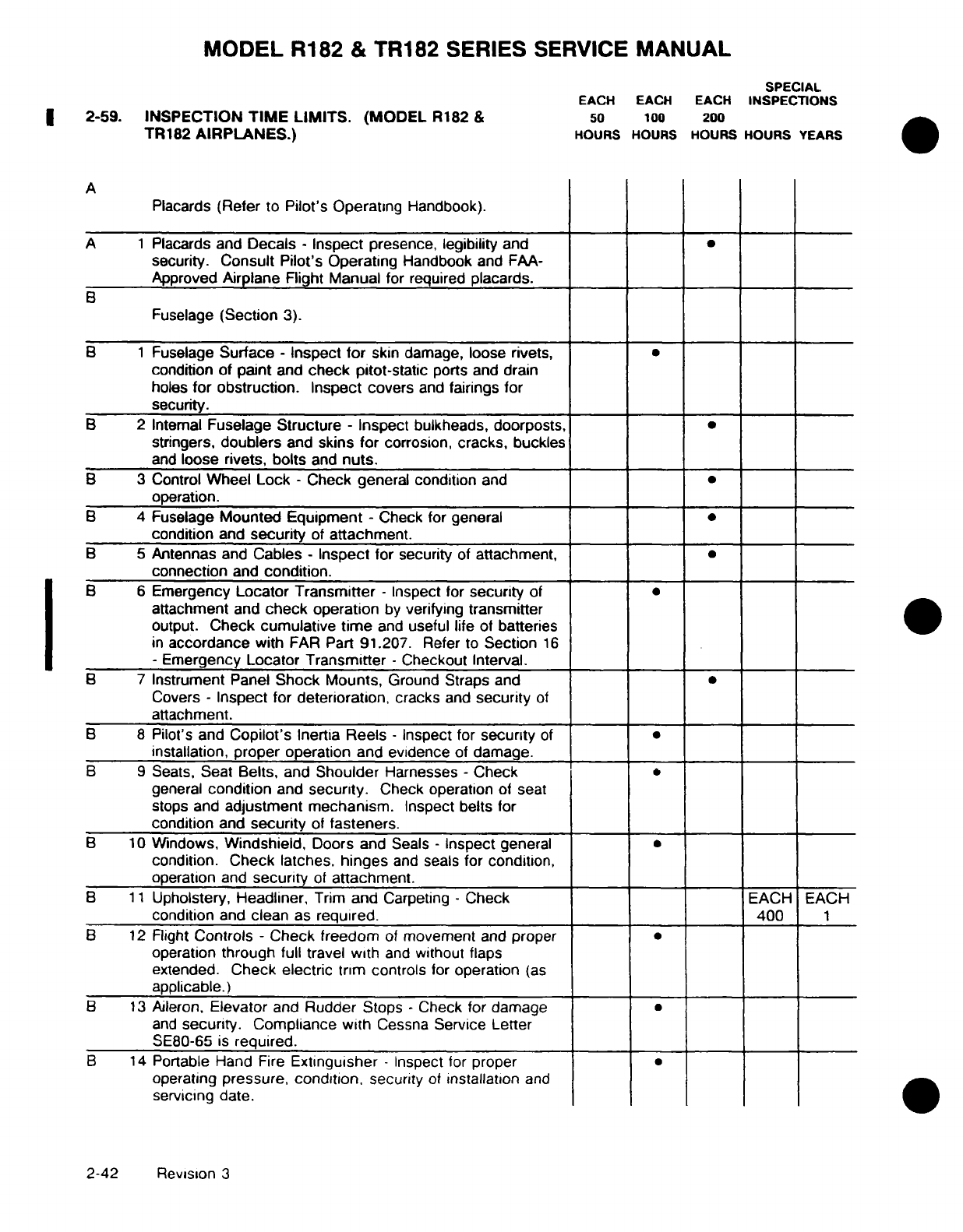
MODEL
R182
&
TR182
SERIES
SERVICE
MANUAL
SPECIAL
EACH
EACH
EACH
INSPECTIONS
2-59.
INSPECTION
TIME LIMITS.
(MODEL
R182
&
50
100
200
TR182
AIRPLANES.)
HOURS HOURS
HOURS
HOURS
YEARS
A
Placards
(Refer
to
Pilot's
Operating
Handbook).
A
1
Placards
and
Decals -
Inspect
presence,
legibility
and
security.
Consult
Pilot's
Operating
Handbook
and
FAA-
Approved
Airplane
Flight
Manual
for
required
placards.
B
Fuselage
(Section
3).
B
1
Fuselage
Surface
-
Inspect
for
skin
damage,
loose
rivets,
condition
of
paint
and
check pitot-static
ports
and
drain
holes
for obstruction.
Inspect
covers
and
fairings for
security.
B
2
Internal
Fuselage
Structure
-
Inspect
bulkheads, doorposts,
stringers,
doublers
and
skins for
corrosion,
cracks,
buckles
and
loose
rivets,
bolts
and
nuts.
B 3
Control
Wheel
Lock
-
Check general
condition
and
operation.
B
4
Fuselage
Mounted
Equipment
-
Check for
general
condition
and
security
of
attachment.
B
5
Antennas
and
Cables
- Inspect
for security
of
attachment,
connection
and
condition.
B 6
Emergency
Locator
Transmitter -
Inspect for
security
of
attachment
and
check
operation
by
verifying
transmitter
output.
Check cumulative
time
and
useful
life
of
batteries
in
accordance
with
FAR
Part
91.207.
Refer
to
Section
16
-
Emergency
Locator
Transmitter
-
Checkout
Interval.
B
7
Instrument
Panel
Shock Mounts,
Ground Straps
and
Covers
-
Inspect
for
deterioration,
cracks
and
security
of
attachment.
B
8
Pilot's
and
Copilot's
Inertia
Reels
-
Inspect
for
security
of
installation,
proper
operation
and evidence
of
damage.
B
9
Seats,
Seat
Belts,
and
Shoulder
Harnesses
-
Check
general
condition
and
security.
Check
operation
of
seat
stops and
adjustment
mechanism.
Inspect
belts
for
condition
and
security
of
fasteners.
B
10
Windows,
Windshield,
Doors
and Seals
-
Inspect general
condition.
Check latches,
hinges
and
seals
for
condition,
operation
and
security
of
attachment.
B
11
Upholstery,
Headliner,
Trim
and
Carpeting
-
Check
EACH
EACH
condition
and
clean
as
required. 400
1
B
12
Flight
Controls
-
Check freedom
of
movement
and
proper
operation
through
full
travel
with
and
without
flaps
extended.
Check
electric
trim controls
for
operation
(as
applicable.
)
B
13
Aileron,
Elevator
and
Rudder
Stops
-
Check
for damage
and
security.
Compliance
with
Cessna
Service
Letter
SE80-65
is
required.
B
14
Portable Hand
Fire
Extinguisher
-
Inspect
for
proper
operating
pressure,
condition,
security
of
installation
and
servicing
date.
2-42
Revision
3
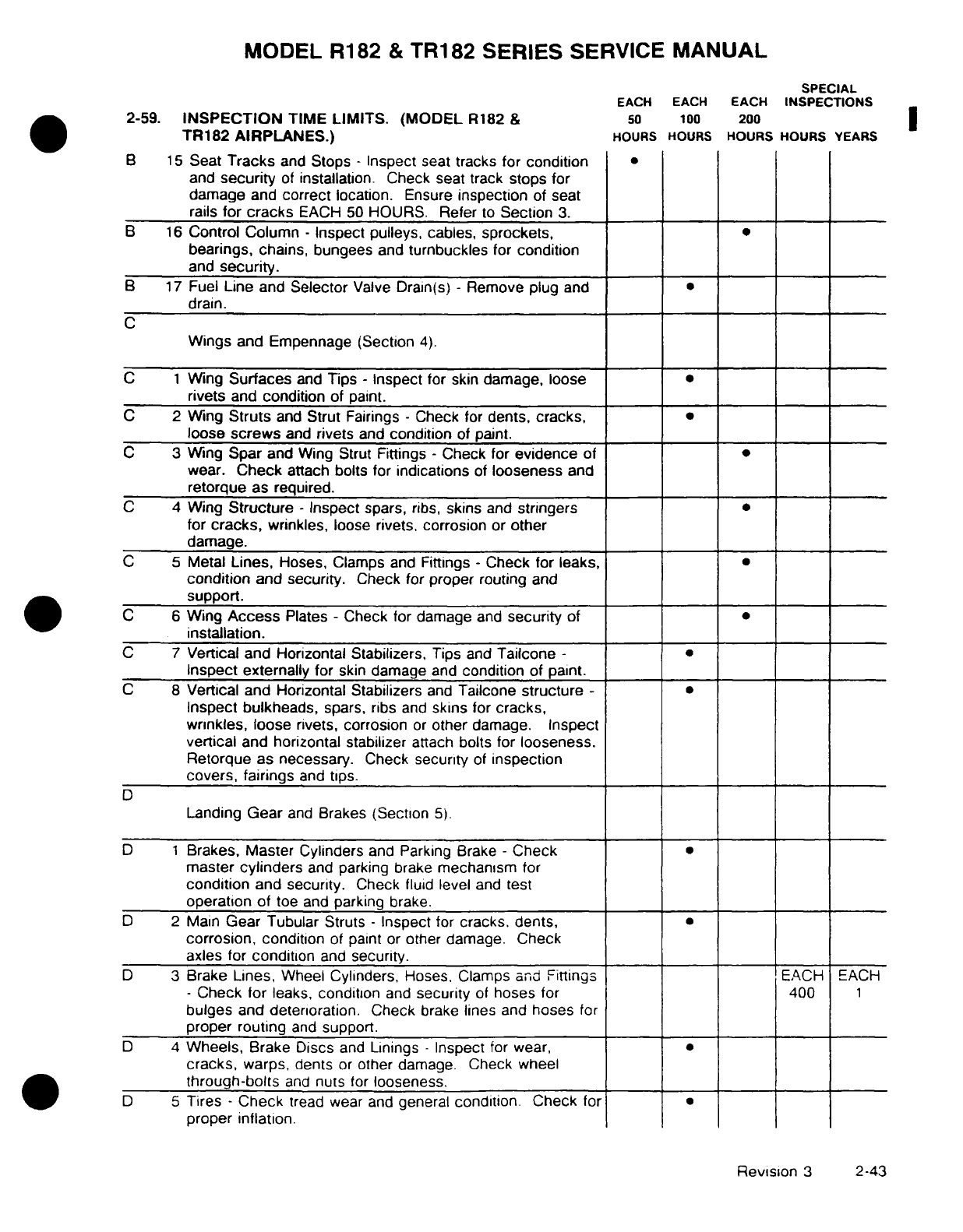
MODEL
R182
&
TR182 SERIES
SERVICE
MANUAL
SPECIAL
EACH EACH
EACH
INSPECTIONS
2-59.
INSPECTION
TIME
LIMITS.
(MODEL
R182
&
50
100
200
TR182 AIRPLANES.)
HOURS
HOURS
HOURS HOURS
YEARS
B
15
Seat
Tracks
and
Stops
-
Inspect
seat
tracks
for
condition
and
security
of
installation.
Check seat track
stops
for
damage
and
correct
location.
Ensure
inspection
of seat
rails
for
cracks
EACH
50
HOURS.
Refer
to
Section
3.
B
16
Control Column
-
Inspect pulleys, cables,
sprockets,
bearings, chains,
bungees
and
turnbuckles
for
condition
and
security.
B
17
Fuel
Line
and
Selector
Valve Drain(s)
-
Remove
plug
and
drain.
C
Wings and
Empennage
(Section
4).
C
1
Wing
Surfaces
and
Tips
-
Inspect
for
skin
damage, loose
rivets
and
condition
of
paint.
C
2
Wing
Struts
and
Strut
Fairings
-
Check
for
dents,
cracks,
loose
screws
and
rivets
and
condition
of
paint.
C
3
Wing
Spar
and
Wing
Strut Fittings
-
Check
for
evidence
of
wear.
Check
attach bolts
for
indications
of
looseness
and
retorque
as required.
C
4 Wing
Structure -
Inspect
spars,
ribs,
skins
and
stringers
for
cracks,
wrinkles,
loose
rivets,
corrosion
or
other
damage.
C
5
Metal
Lines,
Hoses, Clamps
and
Fittings
-
Check
for
leaks,
condition
and
security.
Check
for
proper routing
and
support.
C
6
Wing
Access
Plates
-
Check for
damage
and
security
of
installation.
C
7
Vertical and Horizontal Stabilizers,
Tips
and
Tailcone
-
Inspect
externally
for
skin
damage
and
condition
of
paint.
C 8
Vertical and Horizontal Stabilizers
and
Tailcone
structure
-
Inspect bulkheads,
spars,
ribs
and
skins
for
cracks,
wrinkles,
loose
rivets, corrosion
or
other
damage.
Inspect
vertical
and horizontal stabilizer
attach
bolts
for
looseness.
Retorque as necessary.
Check
security
of
inspection
covers,
fairings
and
tips.
D
Landing
Gear
and
Brakes
(Section
5).
D
1
Brakes, Master
Cylinders
and
Parking Brake
-
Check
master
cylinders
and
parking
brake
mechanism
for
condition
and
security.
Check
fluid
level
and
test
operation
of
toe
and
parking
brake.
D
2
Main
Gear
Tubular
Struts
-
Inspect for
cracks.
dents,
corrosion,
condition
of paint
or
other
damage.
Check
axles
for
condition
and
security.
D
3
Brake
Lines,
Wheel
Cylinders,
Hoses,
Clamps
and
Fittings
EACH
EACH
-
Check
for
leaks,
condition
and
security
of
hoses
for
400
1
bulges
and
deterioration.
Check
brake
lines
and
hoses
for
proper
routing
and
support.
D
4
Wheels,
Brake Discs
and
Linings
-
Inspect
for wear,
cracks,
warps,
dents
or
other damage.
Check
wheel
through-bolts
and
nuts
for
looseness.
D
5
Tires
-
Check
tread wear
and
general
condition.
Check
for
proper
inflation.
Revision
3
2-43
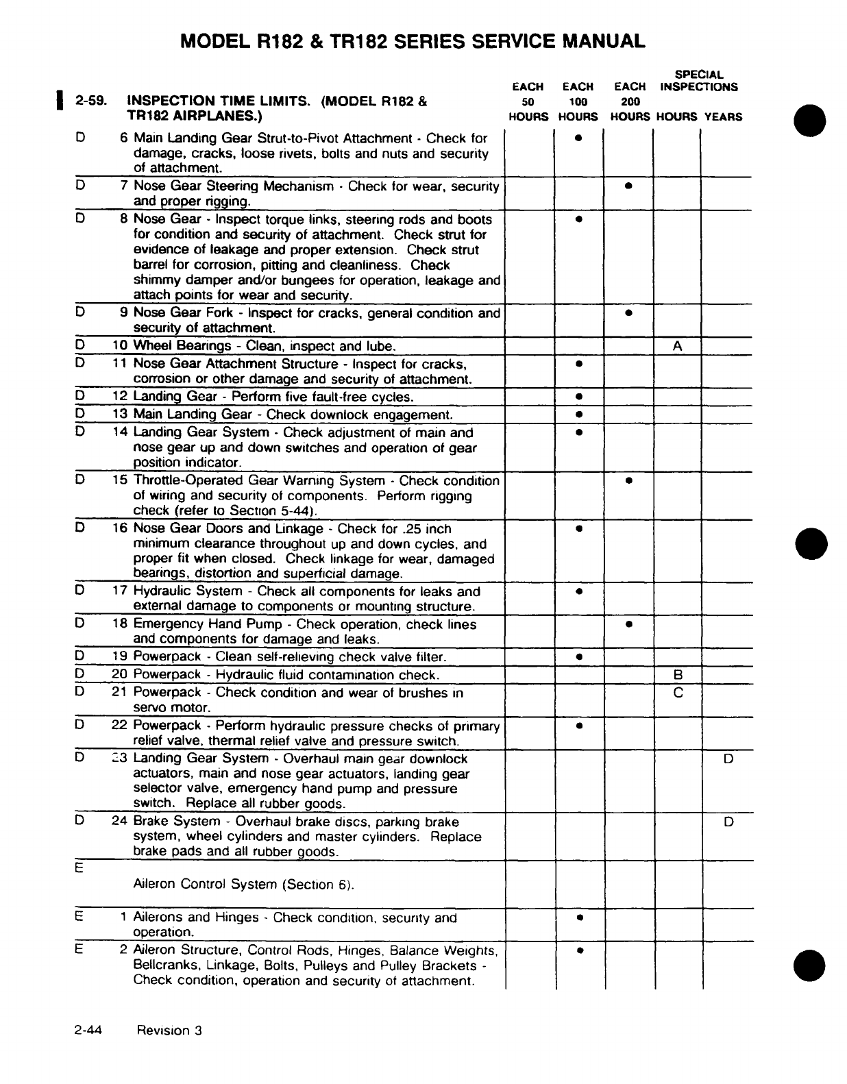
MODEL R182
&
TR182
SERIES
SERVICE
MANUAL
SPECIAL
EACH
EACH
EACH
INSPECTIONS
2-59.
INSPECTION
TIME
LIMITS.
(MODEL
R182
&
50
100
200
TR182
AIRPLANES.)
HOURS HOURS
HOURS
HOURS
YEARS
D
6 Main
Landing
Gear
Strut-to-Pivot
Attachment
-
Check
for
damage,
cracks,
loose rivets,
bolts
and
nuts
and
security
of
attachment.
D
7
Nose
Gear Steering
Mechanism
-
Check
for
wear,
security
and
proper rigging.
D
8
Nose
Gear
- Inspect
torque
links,
steering
rods
and
boots
for
condition
and
security
of
attachment.
Check
strut for
evidence
of
leakage
and
proper
extension.
Check
strut
barrel
for
corrosion,
pitting and
cleanliness.
Check
shimmy
damper and/or
bungees
for
operation,
leakage
and
attach
points for
wear
and
security.
D
9
Nose
Gear
Fork
-
Inspect
for
cracks,
general
condition
and
security
of
attachment.
D
10
Wheel
Bearings
-
Clean,
inspect
and
lube.
A
D
11
Nose
Gear Attachment Structure -
Inspect
for
cracks,
*
corrosion
or
other
damage
and
security
of
attachment.
D
12
Landing
Gear
-
Perform
five
fault-free
cycles.
D
13
Main
Landing
Gear
-
Check
downlock
engagement.
D
14
Landing
Gear
System -
Check
adjustment
of
main
and
nose
gear
up
and down
switches
and
operation
of
gear
position
indicator.
D
15
Throttle-Operated
Gear Warning
System
-
Check
condition
of
wiring
and
security
of
components.
Perform
rigging
check
(refer
to
Section
5-44).
D
16
Nose
Gear
Doors
and
Linkage
-
Check
for
.25
inch
minimum
clearance
throughout
up
and
down
cycles,
and
proper
fit
when
closed.
Check
linkage
for wear,
damaged
bearings,
distortion
and
superficial
damage.
D
17
Hydraulic System
-
Check
all
components
for
leaks
and
external
damage
to
components
or
mounting
structure.
D
18
Emergency Hand
Pump
-
Check
operation,
check lines
and
components
for
damage
and
leaks.
D
19
Powerpack
-
Clean
self-relieving
check
valve
filter.
D
20
Powerpack
-
Hydraulic
fluid
contamination
check. B
D 21
Powerpack
- Check
condition
and
wear
of
brushes
in
C
servo
motor.
D
22
Powerpack
-
Perform
hydraulic
pressure
checks
of
primary
relief
valve,
thermal
relief
valve
and
pressure
switch.
D
23
Landing
Gear
System
-
Overhaul
main
gear
downlock D
actuators,
main
and nose gear
actuators,
landing
gear
selector valve,
emergency
hand
pump
and
pressure
switch.
Replace
all
rubber
goods.
D
24
Brake
System -
Overhaul brake
discs,
parking
brake
D
system,
wheel
cylinders
and
master
cylinders.
Replace
brake
pads
and
all
rubber
goods.
E
Aileron
Control
System (Section
6).
E 1
Ailerons
and
Hinges
-
Check
condition,
security
and
operation.
E
2
Aileron
Structure,
Control
Rods, Hinges,
Balance
Weights,
·
Bellcranks,
Linkage,
Bolts,
Pulleys
and
Pulley
Brackets
-
Check
condition,
operation
and
security
of
attachment.
2-44
Revision
3
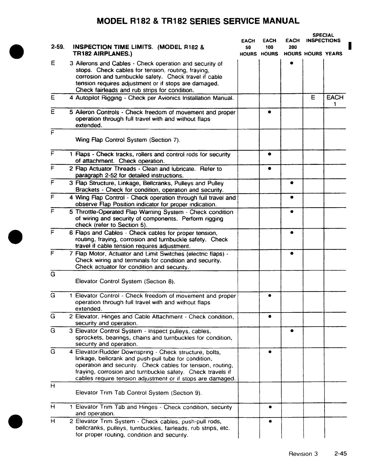
MODEL
R182
&
TR182
SERIES
SERVICE
MANUAL
SPECIAL
EACH EACH
EACH
INSPECTIONS
2-59.
INSPECTION TIME
LIMITS.
(MODEL
R182
&
50 100
200
TR182
AIRPLANES.)
HOURS
HOURS
HOURS
HOURS YEARS
E
3
Ailerons
and Cables
-
Check
operation
and
security
of
stops. Check
cables
for tension, routing,
fraying,
corrosion
and
turnbuckle
safety.
Check
travel
if
cable
tension
requires
adjustment
or
if
stops
are
damaged.
Check
fairleads
and rub
strips
for condition.
E
4
Autopilot
Rigging
-
Check
per
Avionics
Installation
Manual.
E
EACH
E
5
Aileron
Controls
-
Check
freedom
of
movement
and
proper
operation through
full travel
with
and
without flaps
extended.
F
Wing
Flap
Control
System
(Section
7).
F 1
Flaps
-
Check
tracks,
rollers
and
control
rods
for security
of attachment.
Check
operation.
F
2
Flap
Actuator
Threads
-
Clean
and lubricate.
Refer
to
paragraph 2-52 for detailed
instructions.
F
3
Flap
Structure,
Linkage,
Bellcranks,
Pulleys
and Pulley
Brackets
-
Check
for
condition,
operation
and
security.
F
4
Wing
Flap
Control
-
Check
operation through
full travel
and
observe
Flap
Position indicator
for
proper
indication.
F
5
Throttle-Operated
Flap
Warning
System
-
Check
condition
of
wiring
and
security
of
components.
Perform
rigging
check
(refer
to
Section
5).
F
6
Flaps
and
Cables
-
Check cables
for
proper
tension,
routing,
fraying,
corrosion
and
turnbuckle
safety.
Check
travel
if
cable
tension
requires
adjustment.
F
7
Flap
Motor,
Actuator
and Limit
Switches (electric
flaps)
-
Check
wiring
and
terminals
for
condition
and
security.
Check actuator
for
condition
and
security.
G
Elevator
Control
System
(Section
8).
G
1
Elevator
Control
-
Check
freedom
of
movement
and
proper
operation through
full travel
with and
without
flaps
extended.
G
2
Elevator,
Hinges
and
Cable
Attachment
-
Check
condition,
security
and
operation.
G 3
Elevator Control
System
-
Inspect
pulleys, cables,
sprockets,
bearings,
chains
and
turnbuckles
for condition,
security
and
operation.
G 4
Elevator/Rudder
Downspring
-
Check structure,
bolts,
linkage,
bellcrank
and
push-pull
tube
for
condition,
operation
and
security.
Check
cables
for
tension,
routing,
fraying,
corrosion
and
turnbuckle
safety. Check
travels
if
cables
require
tension
adjustment
or
if
stops
are
damaged.
H
Elevator Trim
Tab
Control System
(Section
9).
H
1
Elevator
Trim
Tab
and
Hinges
-
Check
condition,
security
and
operation.
H
2
Elevator
Trim
System
-
Check
cables,
push-pull
rods,
·
bellcranks,
pulleys, turnbuckles,
fairleads,
rub
strips,
etc.
for proper routing,
condition
and
security.
Revision
3
2-45
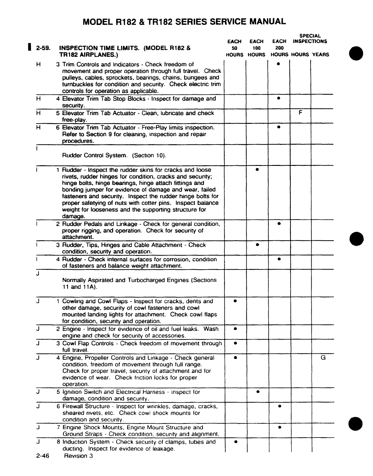
MODEL
R182
&
TR182 SERIES
SERVICE
MANUAL
SPECIAL
EACH
EACH EACH
INSPECTIONS
2-59.
INSPECTION
TIME
LIMITS.
(MODEL
R182
&
50
100
200
TR182
AIRPLANES.)
HOURS
HOURS HOURS
HOURS YEARS
H
3 Trim
Controls
and
Indicators
-
Check
freedom
of
movement
and
proper
operation through
full
travel.
Check
pulleys,
cables,
sprockets,
bearings,
chains,
bungees
and
turnbuckles
for
condition
and
security.
Check
electric
trim
controls
for
operation
as
applicable.
H
4
Elevator Trim
Tab
Stop Blocks
-
Inspect
for
damage
and
security.
H
5
Elevator
Trim
Tab
Actuator -
Clean,
lubricate
and
check
F
free-play.
H
6
Elevator
Trim
Tab
Actuator -
Free-Play
limits inspection.
Refer to
Section
9
for
cleaning,
inspection
and repair
procedures.
Rudder
Control
System.
(Section
10).
1
Rudder
-
Inspect
the
rudder
skins for
cracks
and
loose
rivets,
rudder
hinges
for
condition,
cracks
and
security;
hinge
bolts,
hinge
bearings,
hinge
attach
fittings
and
bonding
jumper
for
evidence
of
damage
and
wear,
failed
fasteners
and
security.
Inspect
the
rudder
hinge
bolts
for
proper
safetying
of nuts
with
cotter
pins.
Inspect balance
weight
for
looseness
and
the
supporting
structure
for
damage.
2
Rudder
Pedals and
Linkage
-
Check
for
general
condition,
proper
rigging,
and
operation. Check
for
security
of
attachment.
3
Rudder,
Tips,
Hinges
and
Cable
Attachment
-
Check
condition,
security
and
operation.
4
Rudder
-
Check
internal
surfaces for
corrosion,
condition
of
fasteners
and
balance
weight
attachment.
J
Normally
Aspirated
and Turbocharged
Engines
(Sections
11
and
11A).
J
1
Cowling and
Cowl
Flaps
-
Inspect
for
cracks,
dents
and
other
damage,
security
of
cowl
fasteners
and
cowl
mounted
landing
lights
for
attachment.
Check cowl
flaps
for
condition, security
and
operation.
J
2
Engine
-
Inspect for
evidence
of
oil
and
fuel
leaks.
Wash
engine
and
check
for
security
of
accessories.
J
3
Cowl
Flap
Controls
-
Check
freedom
of
movement
through
full
travel.
J
4
Engine,
Propeller
Controls
and
Linkage
-
Check general
G
condition,
freedom
of
movement
through
full
range.
Check
for proper
travel, security
of
attachment
and
for
evidence
of
wear.
Check
friction
locks
for
proper
operation.
J
5
Ignition
Switch
and
Electrical
Harness
-
Inspect
for
damage,
condition
and
security.
J
6
Firewall
Structure
-
Inspect
for
wrinkles, damage,
cracks,
sheared
rivets,
etc.
Check
cowl
shock
mounts
for
condition
and
security.
J
7
Engine
Shock Mounts,
Engine
Mount
Structure
and
Ground
Straps
-
Check
condition,
security
and
alignment.
J
8
Induction System
-
Check
security
of
clamps,
tubes
and
ducting.
Inspect for
evidence
of
leakage.
2-46
Revision
3
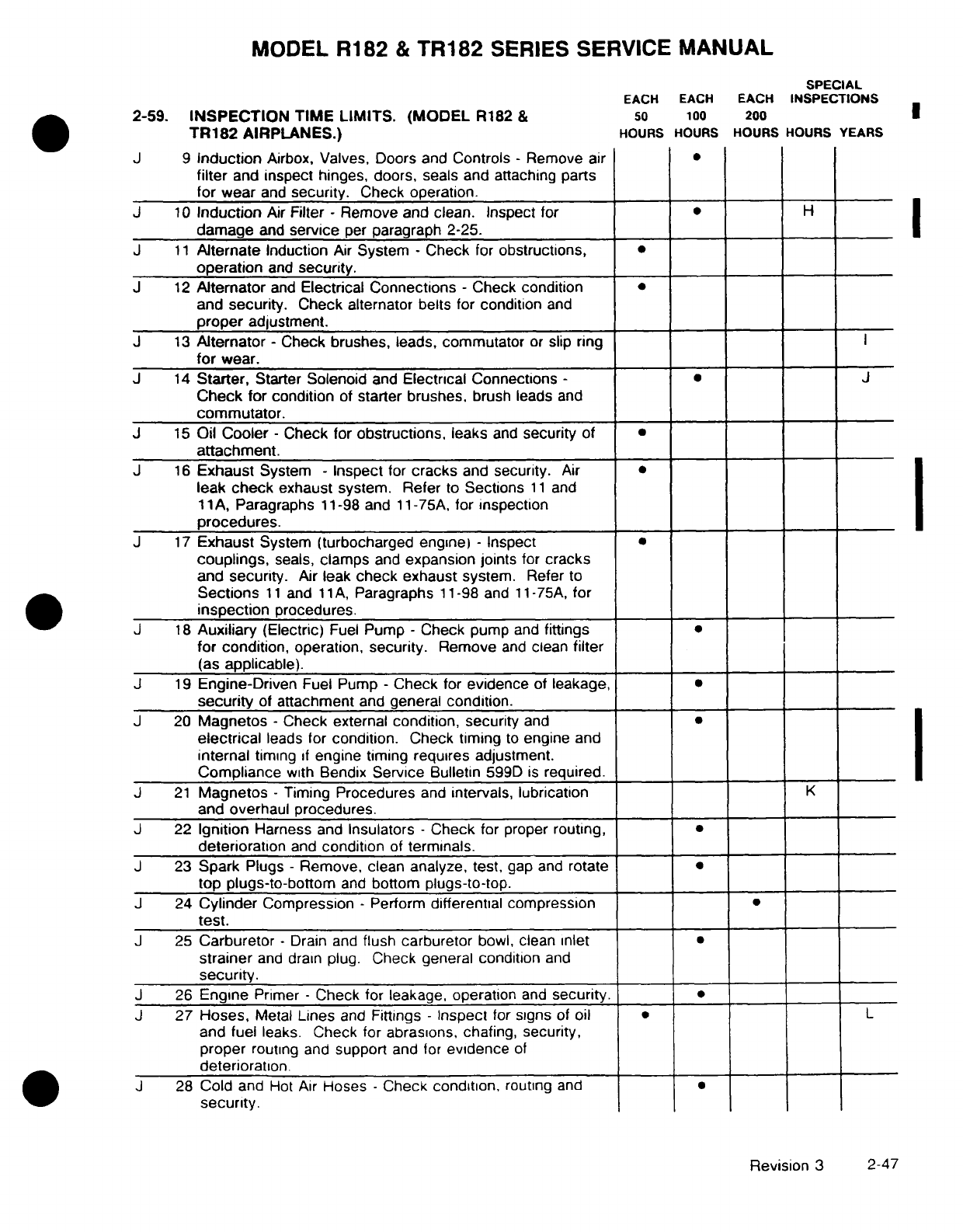
MODEL
R182
&
TR182
SERIES
SERVICE
MANUAL
SPECIAL
EACH
EACH
EACH
INSPECTIONS
2-59.
INSPECTION
TIME
LIMITS.
(MODEL
R182
&
50
100
200
TR182
AIRPLANES.)
HOURS
HOURS
HOURS HOURS
YEARS
J
9
Induction
Airbox,
Valves, Doors and
Controls
-
Remove
air
filter
and
inspect
hinges,
doors, seals
and
attaching parts
for
wear
and
security.
Check operation.
J
10
Induction
Air
Filter
-
Remove and
clean.
Inspect
for
H
damage
and
service
per
paragraph
2-25.
J
11
Alternate
Induction
Air
System
-
Check
for
obstructions,
operation
and
security.
J
12
Alternator
and
Electrical
Connections
-
Check
condition
and
security.
Check
alternator
belts
for
condition
and
proper
adjustment.
J
13
Alternator
-
Check
brushes,
leads,
commutator
or
slip ring
for
wear.
J
14
Starter,
Starter
Solenoid
and
Electrical Connections
-J
Check
for
condition
of
starter brushes,
brush leads
and
commutator.
J
15
Oil
Cooler
-
Check
for
obstructions,
leaks
and
security
of
attachment.
J
16
Exhaust
System
-
Inspect
for
cracks
and
security.
Air
leak
check
exhaust
system. Refer
to
Sections
11
and
11A,
Paragraphs
11-98 and 11-75A,
for
inspection
procedures.
J
17
Exhaust
System
(turbocharged
engine)
-
Inspect
couplings,
seals,
clamps
and
expansion
joints
for
cracks
and
security.
Air
leak
check
exhaust
system.
Refer
to
Sections
11
and
11
A,
Paragraphs
11-98
and
11-75A,
for
inspection
procedures.
J
18
Auxiliary
(Electric)
Fuel
Pump
-
Check
pump
and
fittings
for
condition,
operation,
security.
Remove
and
clean
filter
(as
applicable).
J
19
Engine-Driven
Fuel
Pump
-
Check
for
evidence
of
leakage,
·
security
of
attachment
and
general
condition.
J 20
Magnetos
-
Check external
condition, security
and
electrical
leads
for
condition.
Check
timing
to
engine
and
internal
timing
if
engine timing
requires adjustment.
Compliance
with
Bendix
Service
Bulletin
599D
is
required.
J
21
Magnetos
-
Timing
Procedures
and
intervals,
lubrication
K
and
overhaul
procedures.
J
22
Ignition
Harness
and
Insulators
-
Check
for
proper
routing,
deterioration
and
condition
of
terminals.
J
23
Spark
Plugs
-
Remove,
clean
analyze,
test,
gap and
rotate
top
plugs-to-bottom
and
bottom
plugs-to-top.
J
24
Cylinder
Compression
-
Perform
differential compression
test.
J
25
Carburetor
-
Drain and
flush
carburetor
bowl,
clean
inlet
strainer
and
drain
plug.
Check general
condition
and
security.
J
26
Engine
Primer
-
Check
for
leakage, operation
and
security.
J
27
Hoses,
Metal
Lines
and
Fittings
-
Inspect
for
signs
of
oil
L
and
fuel
leaks.
Check for
abrasions, chafing, security,
proper
routing
and
support
and
for
evidence
of
deterioration.
J 28
Cold
and
Hot
Air
Hoses
-
Check
condition,
routing
and
security.
Revision
3
2-47
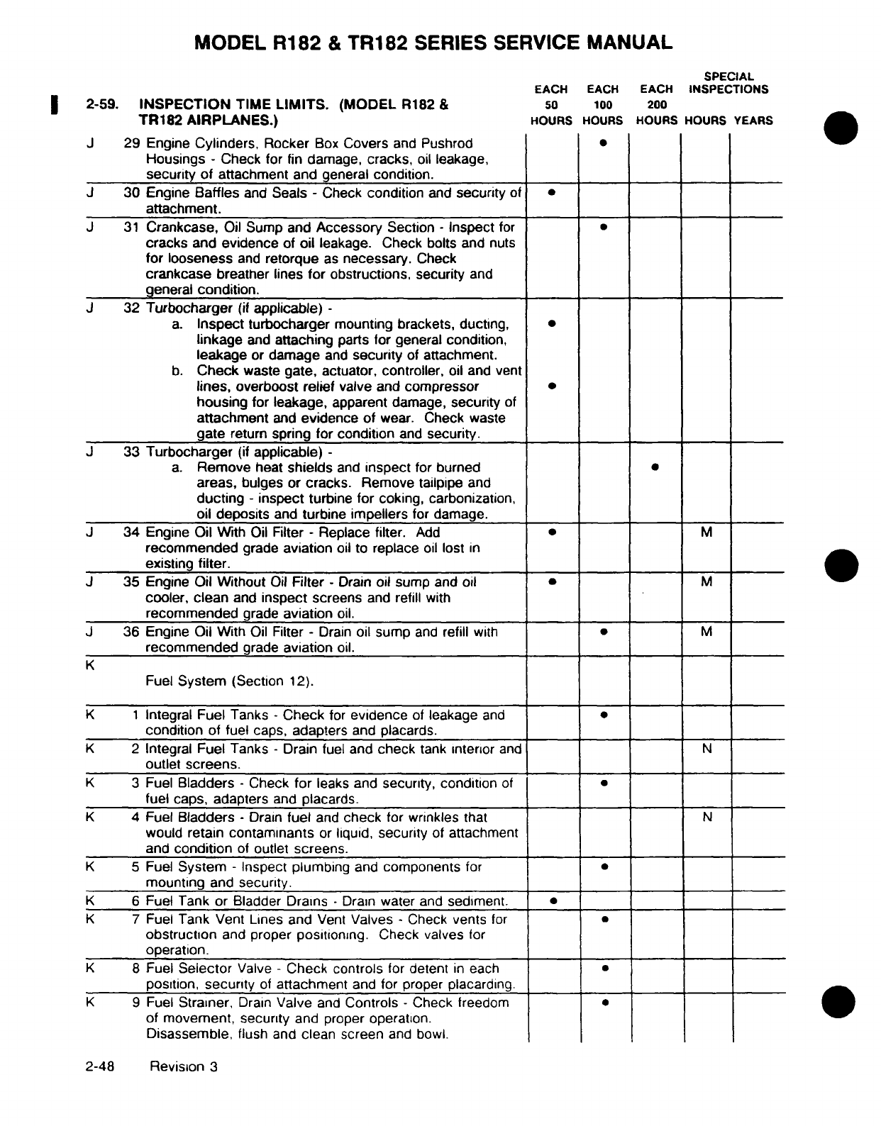
MODEL
R182
&
TR182
SERIES
SERVICE
MANUAL
SPECIAL
EACH
EACH
EACH
INSPECTIONS
2-59.
INSPECTION
TIME
LIMITS.
(MODEL
R182
&
50
100
200
TR182
AIRPLANES.)
HOURS
HOURS
HOURS HOURS
YEARS
J
29
Engine
Cylinders,
Rocker
Box
Covers
and
Pushrod
Housings
-
Check
for
fin
damage,
cracks,
oil
leakage,
security
of
attachment
and
general
condition.
J
30
Engine
Baffles
and
Seals
-
Check
condition
and
security
of
attachment.
J
31
Crankcase,
Oil
Sump
and
Accessory
Section
-
Inspect
for
cracks
and
evidence
of
oil
leakage. Check bolts
and
nuts
for
looseness
and
retorque
as
necessary.
Check
crankcase
breather
lines
for
obstructions,
security
and
general
condition.
J
32
Turbocharger
(if
applicable)
-
a.
Inspect
turbocharger
mounting brackets, ducting,
linkage
and
attaching
parts
for
general
condition,
leakage
or
damage
and
security
of
attachment.
b.
Check
waste
gate,
actuator,
controller,
oil
and
vent
lines,
overboost relief
valve
and
compressor
housing
for
leakage,
apparent
damage,
security
of
attachment
and
evidence
of
wear.
Check
waste
gate
return
spring
for condition
and
security.
J
33
Turbocharger
(if
applicable)
-
a.
Remove
heat
shields
and
inspect
for burned
areas,
bulges
or
cracks.
Remove
tailpipe
and
ducting
- inspect
turbine
for
coking,
carbonization,
oil
deposits
and
turbine impellers
for damage.
J
34
Engine
Oil
With
Oil
Filter
-
Replace
filter.
Add
M
recommended
grade
aviation
oil
to
replace
oil
lost
in
existing
filter.
J
35
Engine Oil
Without
Oil
Filter
-
Drain
oil
sump
and
oil
* M
cooler,
clean
and
inspect
screens
and refill
with
recommended
grade
aviation
oil.
J
36
Engine Oil With
Oil
Filter
-
Drain
oil
sump
and
refill
with
M
recommended
grade
aviation
oil.
K
Fuel
System
(Section
12).
K 1
Integral Fuel
Tanks
- Check
for
evidence
of
leakage
and
condition
of
fuel caps, adapters
and
placards.
K
2
Integral Fuel
Tanks
-
Drain fuel and
check
tank
interior
and
N
outlet
screens.
K
3
Fuel
Bladders
-
Check
for
leaks
and
security, condition
of
fuel
caps,
adapters
and
placards.
K
4 Fuel
Bladders
-
Drain
fuel
and
check
for
wrinkles
that
N
would
retain
contaminants
or
liquid,
security
of
attachment
and
condition
of
outlet
screens.
K
5
Fuel
System
-
Inspect plumbing
and
components
for
mounting
and
security.
K
6
Fuel
Tank or
Bladder
Drains
-
Drain
water
and
sediment.
K
7
Fuel
Tank
Vent Lines
and
Vent
Valves
-
Check
vents
for
obstruction
and
proper
positioning.
Check
valves
for
operation.
K
8 Fuel
Selector
Valve
-
Check
controls
for
detent
in
each
position,
security
of
attachment
and
for
proper
placarding.
K
9
Fuel
Strainer,
Drain
Valve
and
Controls
-
Check
freedom
of
movement, security
and
proper
operation.
Disassemble,
flush and
clean screen
and
bowl.
2-48
Revision
3
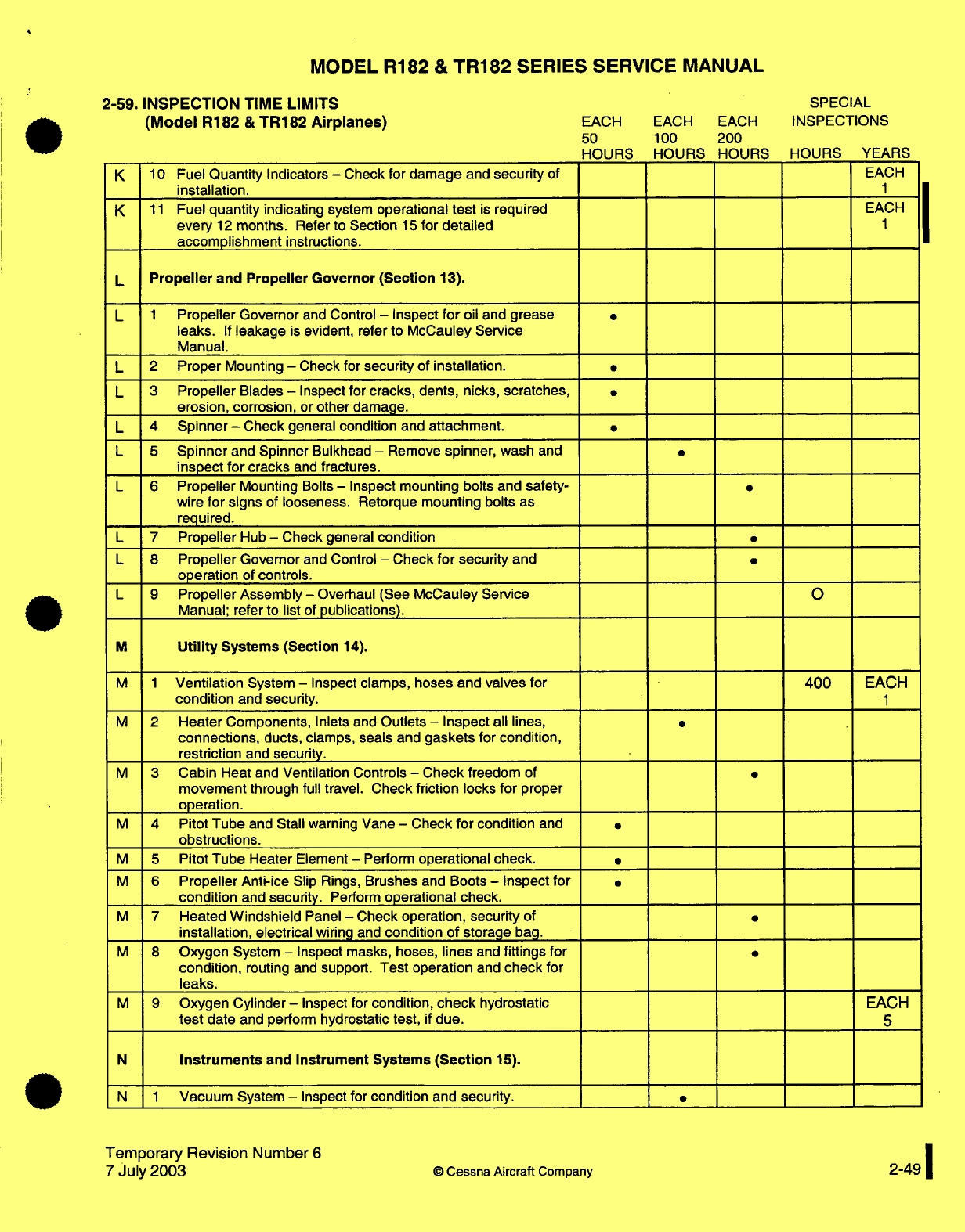
MODEL
R182
&
TR182
SERIES
SERVICE
MANUAL
2-59.
INSPECTION
TIME
LIMITS
SPECIAL
(Model
R182
&
TR182
Airplanes)
EACH
EACH EACH
INSPECTIONS
50 100
200
HOURS HOURS HOURS HOURS
YEARS
K
10
Fuel
Quantity
Indicators
-
Check
for
damage
and
security
of
EACH
installation.
1
K
11
Fuel
quantity
indicating
system
operational
test
is
required
EACH
every
12
months.
Refer
to Section
15
for
detailed
1
accomplishment
instructions.
L
Propeller
and
Propeller Governor (Section
13).
L
1
Propeller
Governor
and
Control
-
Inspect
for
oil
and
grease
leaks.
If
leakage
is
evident, refer
to McCauley
Service
Manual.
L
2
Proper
Mounting
-
Check
for
security
of
installation.
L
3
Propeller
Blades
-
Inspect
for cracks,
dents,
nicks,
scratches,
erosion,
corrosion,
or
other
damage.
L 4
Spinner
-
Check
general
condition
and
attachment.
L 5
Spinner
and
Spinner
Bulkhead
-
Remove
spinner,
wash
and
inspect
for cracks
and
fractures.
L
6
Propeller
Mounting
Bolts
-
Inspect
mounting bolts
and
safety-
wire
for signs
of
looseness.
Retorque
mounting bolts
as
required.
L
7
Propeller
Hub
-
Check general
condition
L
8
Propeller
Governor
and
Control
-
Check
for
security
and
operation
of
controls.
L 9
Propeller Assembly
-
Overhaul
(See
McCauley Service
O
Manual; refer to list
of
publications).
M
Utility
Systems (Section
14).
M 1
Ventilation
System
-
Inspect
clamps, hoses
and
valves
for
400
EACH
condition
and
security.
1
M
2
Heater
Components,
Inlets
and
Outlets
-
Inspect
all
lines,
connections,
ducts, clamps,
seals
and
gaskets
for
condition,
restriction
and
security.
M
3
Cabin
Heat
and
Ventilation Controls
-
Check
freedom
of
movement
through
full travel.
Check
friction
locks
for
proper
operation.
M
4
Pitot
Tube
and
Stall
warning
Vane
-
Check
for
condition
and
obstructions.
M
5
Pitot
Tube
Heater
Element
-
Perform
operational
check.
M
6
Propeller
Anti-ice
Slip
Rings,
Brushes
and
Boots
-
Inspect
for
condition
and
security.
Perform
operational check.
M
7
Heated
Windshield
Panel
-
Check operation,
security
of
installation,
electrical
wiring
and
condition
of
storage
bag.
M
8
Oxygen
System
-
Inspect masks,
hoses,
lines
and
fittings
for
condition,
routing and
support.
Test operation
and
check
for
leaks.
M
9
Oxygen Cylinder
-
Inspect for
condition,
check
hydrostatic EACH
test
date
and
perform
hydrostatic
test,
if
due.
5
N
Instruments
and
Instrument
Systems
(Section
15).
N 1
Vacuum
System
-
Inspect
for condition
and
security.
Temporary
Revision
Number
6
7
July 2003
©
Cessna
Aircraft
Company
2-49
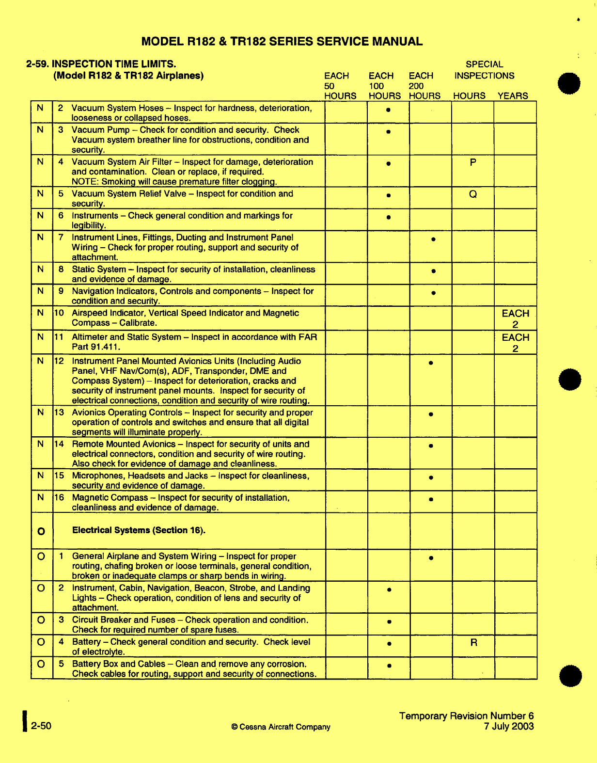
MODEL
R182
&
TR182
SERIES
SERVICE
MANUAL
2-59.
INSPECTION
TIME
LIMITS.
SPECIAL
(Model
R182
&
TR182
Airplanes)
EACH
EACH
EACH
INSPECTIONS
50
100
200
HOURS
HOURS
HOURS
HOURS
YEARS
N
2
Vacuum
System Hoses
-
Inspect
for
hardness,
deterioration,
looseness
or
collapsed hoses.
N
3
Vacuum
Pump
-
Check
for
condition
and
security.
Check
Vacuum
system
breather
line
for
obstructions,
condition
and
security.
N
4
Vacuum
System
Air
Filter
-
Inspect for
damage,
deterioration
*
P
and
contamination.
Clean
or
replace,
if
required.
NOTE:
Smoking
will
cause
premature
filter
clogging.
N
5
Vacuum
System
Relief
Valve
-
Inspect
for
condition
and
*
Q
security.
N
6
Instruments
-
Check
general
condition
and
markings
for
legibility.
N
7
Instrument
Lines,
Fittings,
Ducting and
Instrument
Panel
Wiring
-
Check
for
proper
routing,
support
and
security
of
attachment.
N
8
Static
System
-
Inspect
for
security
of
installation,
cleanliness
and
evidence
of
damage.
N
9
Navigation
Indicators,
Controls
and
components
-
Inspect
for
condition
and
security.
N
10
Airspeed
Indicator,
Vertical
Speed
Indicator
and
Magnetic
EACH
Compass
-
Calibrate.
2
N
11
Altimeter
and
Static
System
-
Inspect
in
accordance
with FAR
EACH
Part
91.411.
2
N
12
Instrument
Panel Mounted
Avionics
Units
(Including
Audio
Panel,
VHF
Nav/Com(s),
ADF,
Transponder,
DME
and
Compass
System)
-
Inspect
for
deterioration,
cracks
and
security
of
instrument panel
mounts.
Inspect
for security
of
electrical
connections, condition
and
security
of
wire routing.
N
13
Avionics
Operating
Controls
-
Inspect
for security
and
proper
operation
of
controls
and
switches
and
ensure
that
all
digital
segments
will
illuminate
properly.
N
14
Remote
Mounted
Avionics
-
Inspect
for
security
of
units
and
electrical
connectors, condition
and
security
of
wire routing.
Also
check
for
evidence
of
damage
and
cleanliness.
N
15
Microphones, Headsets
and
Jacks
-
Inspect
for
cleanliness,
security
and
evidence
of
damage.
N
16
Magnetic
Compass
-
Inspect
for security
of
installation,
cleanliness
and
evidence
of
damage.
O Electrical
Systems
(Section
16).
O
1
General
Airplane
and
System
Wiring
-
Inspect
for
proper
routing,
chafing broken
or
loose
terminals,
general
condition,
broken
or
inadequate
clamps
or
sharp bends
in
wiring.
O
2
Instrument,
Cabin,
Navigation,
Beacon, Strobe, and
Landing
Lights
-
Check operation,
condition
of
lens
and
security
of
attachment.
O
3
Circuit
Breaker
and
Fuses
-
Check
operation
and
condition.
Check
for
required
number
of
spare
fuses.
O
4
Battery
-
Check
general
condition
and
security. Check
level
* R
of
electrolyte.
O
5
Battery
Box
and
Cables
-
Clean and remove
any
corrosion.
Check
cables
for
routing,
support
and
security
of
connections.
Temporary
Revision
Number
6
2-50
©
Cessna
Aircraft
Company
7
July
2003
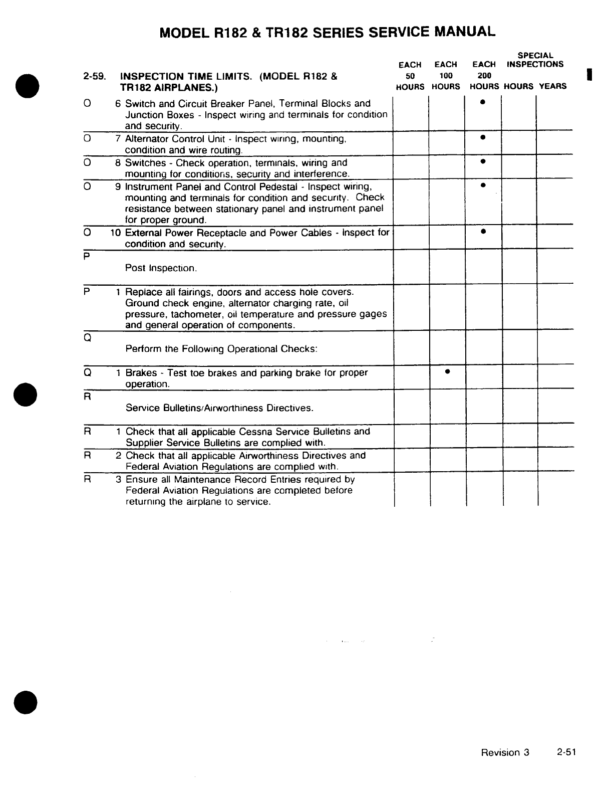
MODEL R182
&
TR182
SERIES
SERVICE
MANUAL
SPECIAL
EACH
EACH
EACH
INSPECTIONS
2-59. INSPECTION
TIME
LIMITS.
(MODEL
R182
&
50
100
200
TR182
AIRPLANES.)
HOURS HOURS
HOURS
HOURS
YEARS
O
6
Switch
and
Circuit
Breaker
Panel,
Terminal
Blocks
and
Junction
Boxes
-
Inspect
wiring
and
terminals
for
condition
and
security.
O
7
Alternator Control
Unit
-
Inspect
wiring,
mounting,
condition
and
wire
routing.
O
8
Switches -
Check
operation, terminals,
wiring
and
mounting
for
conditions, security
and
interference.
O
9
Instrument
Panel
and
Control Pedestal
-
Inspect
wiring,
mounting
and
terminals for
condition and security.
Check
resistance
between
stationary
panel
and instrument
panel
for
proper
ground.
O
10
External Power
Receptacle
and
Power
Cables
-
Inspect for
condition
and
security.
P
Post
Inspection.
P
1
Replace
all
fairings,
doors
and
access
hole
covers.
Ground
check
engine, alternator
charging
rate,
oil
pressure,
tachometer,
oil
temperature
and
pressure gages
and
general
operation
of
components.
Q
Perform
the
Following Operational
Checks:
Q
1
Brakes
-
Test
toe
brakes
and
parking
brake
for
proper
operation.
RService
Bulletins/Airworthiness
Directives.
R
1
Check
that
all
applicable
Cessna
Service
Bulletins
and
Supplier Service
Bulletins
are
complied
with.
R
2
Check
that
all
applicable
Airworthiness Directives
and
Federal
Aviation Regulations
are
complied
with.
R
3
Ensure
all
Maintenance Record
Entries
required
by
Federal
Aviation Regulations
are
completed
before
returning
the
airplane
to
service.
Revision
3
2-51
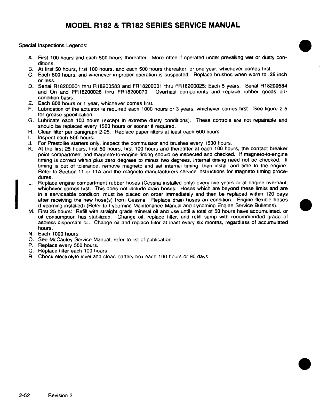
MODEL
R182
&
TR182
SERIES
SERVICE
MANUAL
Special Inspections
Legends:
A.
First
100
hours
and
each 500
hours
thereafter.
More
often
if
operated
under
prevailing
wet or
dusty
con-
ditions.
B.
At
first
50
hours,
first
100
hours, and
each
500
hours
thereafter,
or
one
year,
whichever comes
first.
C.
Each
500
hours,
and
whenever improper
operation
is
suspected.
Replace brushes when
worn
to .25
inch
or
less.
D.
Serial
R18200001
thru
R18200583
and
FR18200001
thru
FR18200025:
Each
5
years.
Serial
R18200584
and
On
and
FR18200026 thru FR18200070:
Overhaul
components
and
replace
rubber
goods on-
condition
basis.
E.
Each
600
hours
or
1
year,
whichever
comes first.
F.
Lubrication
of
the
actuator
is
required
each
1000
hours
or
3
years,
whichever
comes
first.
See
figure
2-5
for
grease
specification.
G.
Lubricate each
100
hours
(except
in
extreme
dusty
conditions).
These
controls
are
not
repairable
and
should
be
replaced
every
1500
hours
or
sooner
if
required.
H.
Clean
filter
per
paragraph
2-25.
Replace
paper
filters
at least
each 500 hours.
I. Inspect
each 500
hours.
J.
For
Prestolite
starters
only,
inspect
the
commutator and brushes
every
1500
hours.
K.
At
the
first
25 hours,
first
50
hours,
first
100
hours and
thereafter
at
each
100
hours,
the
contact
breaker
point compartment
and
magneto-to-engine
timing
should
be
inspected
and
checked.
If
magneto-to-engine
timing
is
correct
within
plus zero
degrees
to
minus
two
degrees, internal
timing
need
not
be
checked. If
timing
is
out
of
tolerance, remove
magneto
and
set internal
timing,
then
install and
time
to the
engine.
Refer
to
Section
11
or
11A
and
the
magneto
manufacturers service
instructions
for
magneto
timing
proce-
dures.
L.
Replace engine
compartment
rubber
hoses
(Cessna
installed
only) every
five
years
or
at
engine
overhaul,
whichever comes
first.
This does
not include
drain
hoses.
Hoses
which
are
beyond
these limits
and
are
in
a
serviceable
condition,
must
be
placed
on
order
immediately
and
then
be
replaced within
120
days
after receiving
the
new
hose(s) from
Cessna.
Replace
drain
hoses
on
condition.
Engine
flexible
hoses
(Lycoming
installed)
(Refer
to
Lycoming
Maintenance
Manual and
Lycoming
Engine
Service
Bulletins).
M.
First 25
hours:
Refill
with
straight
grade
mineral oil
and
use
until
a
total
of
50
hours
have
accumulated,
or
oil consumption
has
stabilized.
Change
oil,
replace filter,
and
refill
sump with
recommended
grade
of
ashless
dispersant
oil.
Change
oil
and
replace filter
at
least
every
six
months,
regardless
of
accumulated
hours.
N.
Each
1000
hours.
O.
See
McCauley
Service
Manual;
refer
to
list
of
publication.
P.
Replace
every
500
hours.
Q.
Replace
filter
each
100
hours.
R.
Check
electrolyte
level
and
clean battery
box
each
100
hours
or 90
days.
2-52
Revision
3
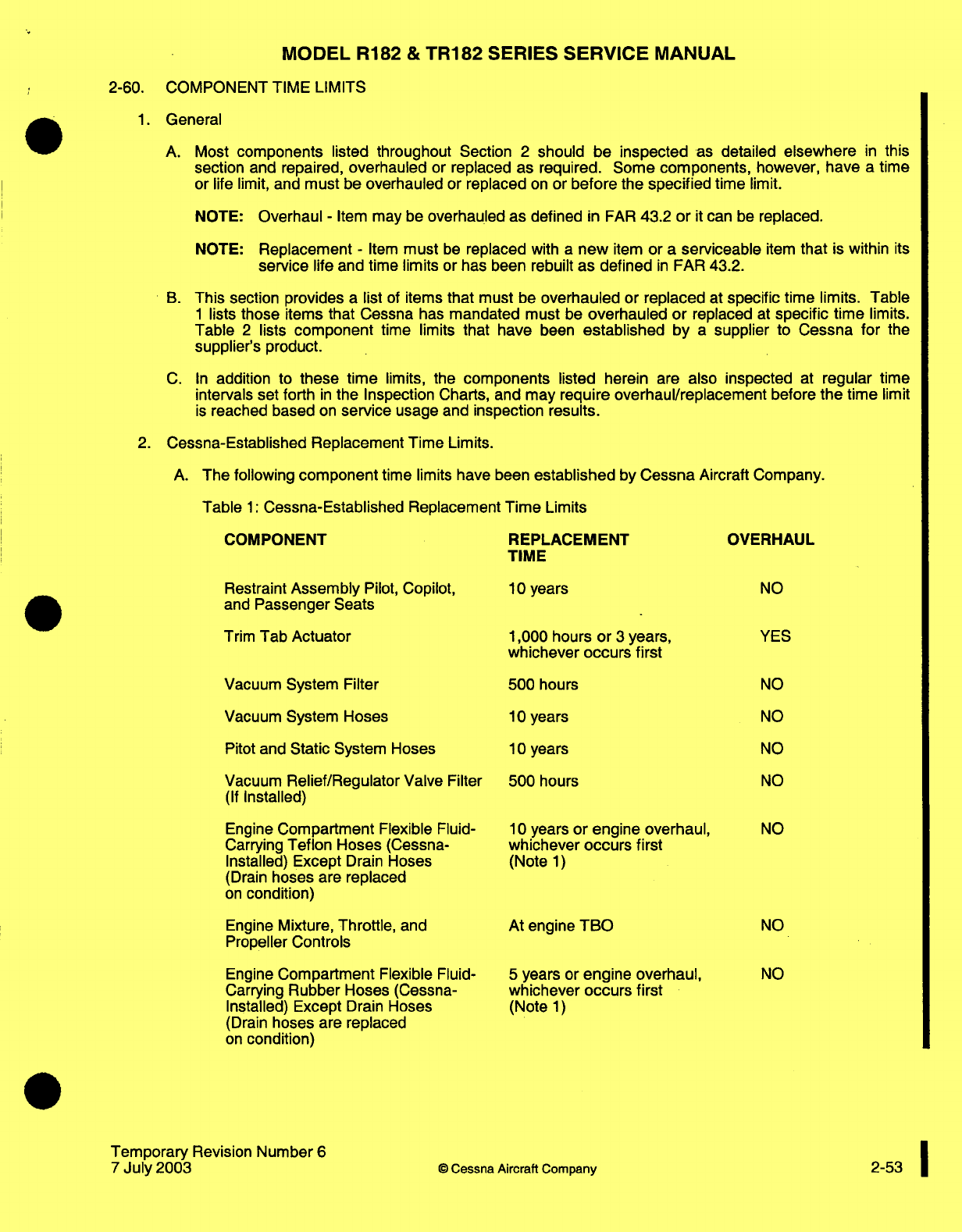
MODEL
R182
&
TR182
SERIES SERVICE
MANUAL
2-60.
COMPONENT
TIME
LIMITS
1.
General
A. Most
components
listed throughout
Section
2
should
be
inspected
as
detailed
elsewhere
in
this
section
and
repaired,
overhauled
or
replaced
as required. Some
components,
however,
have
a
time
or life limit,
and
must
be
overhauled or replaced
on
or
before
the
specified
time
limit.
NOTE:
Overhaul
-
Item
may
be
overhauled
as
defined
in
FAR
43.2
or
it
can
be
replaced.
NOTE:
Replacement
-
Item
must
be
replaced
with
a
new
item
or
a
serviceable
item
that
is
within
its
service
life and
time
limits
or
has
been
rebuilt
as defined
in
FAR
43.2.
B.
This
section
provides
a
list
of
items
that
must
be
overhauled
or
replaced
at
specific
time
limits. Table
1
lists
those
items that Cessna
has
mandated
must
be
overhauled
or
replaced
at
specific
time
limits.
Table
2
lists
component
time
limits
that have
been
established
by
a
supplier
to
Cessna
for
the
supplier's
product.
C.
In
addition
to
these
time
limits,
the
components
listed
herein
are
also
inspected
at
regular
time
intervals set
forth
in
the
Inspection
Charts,
and may
require overhaul/replacement
before
the
time
limit
is
reached
based
on
service
usage
and
inspection
results.
2.
Cessna-Established Replacement Time
Limits.
A.
The
following
component
time
limits
have
been
established
by
Cessna
Aircraft
Company.
Table
1:
Cessna-Established
Replacement
Time
Limits
COMPONENT
REPLACEMENT
TIME
OVERHAUL
Restraint
Assembly
Pilot,
Copilot,
and
Passenger
Seats
Trim
Tab Actuator
Vacuum System
Filter
Vacuum
System Hoses
Pitot
and
Static
System Hoses
Vacuum
Relief/Regulator
Valve
Filter
(If
Installed)
Engine
Compartment
Flexible
Fluid-
Carrying
Teflon Hoses
(Cessna-
Installed)
Except
Drain
Hoses
(Drain
hoses
are
replaced
on
condition)
Engine
Mixture,
Throttle,
and
Propeller
Controls
Engine
Compartment
Flexible
Fluid-
Carrying
Rubber
Hoses
(Cessna-
Installed) Except
Drain
Hoses
(Drain
hoses
are
replaced
on
condition)
Temporary
Revision
Number
6
7
July
2003
Cessna
Aircraft
Company
10
years
1,000 hours
or
3
years,
whichever
occurs first
500
hours
10
years
10
years
500 hours
10
years
or
engine overhaul,
whichever
occurs
first
(Note
1)
At
engine
TBO
5
years
or
engine overhaul,
whichever
occurs
first
(Note
1)
NO
YES
NO
NO
NO
NO
NO
NO
NO
2-53
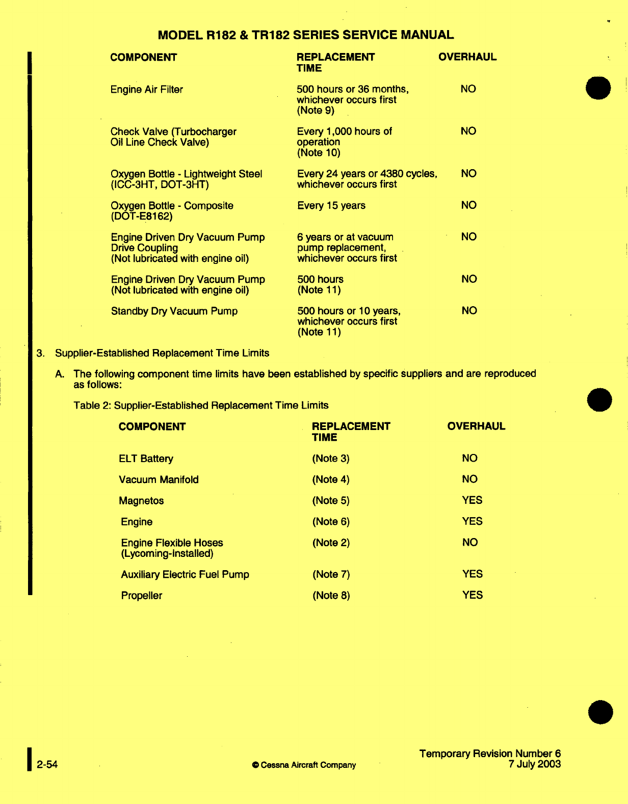
MODEL
R182
&
TR182
SERIES
SERVICE
MANUAL
COMPONENT REPLACEMENT
OVERHAUL
TIME
Engine
Air
Filter
Check
Valve
(Turbocharger
Oil Line
Check
Valve)
Oxygen Bottle
-
Lightweight
Steel
(ICC-3HT,
DOT-3HT)
Oxygen Bottle
-
Composite
(DOT-E8162)
Engine
Driven
Dry
Vacuum
Pump
Drive
Coupling
(Not
lubricated
with
engine
oil)
Engine
Driven
Dry
Vacuum
Pump
(Not
lubricated
with
engine
oil)
Standby
Dry
Vacuum
Pump
500
hours or
36
months,
whichever
occurs first
(Note
9)
Every
1,000
hours
of
operation
(Note
10)
Every 24
years
or 4380
cycles,
whichever
occurs first
Every
15
years
6
years
or
at
vacuum
pump replacement,
whichever
occurs
first
500
hours
(Note
11)
500 hours
or
10
years,
whichever
occurs
first
(Note
11)
3.
Supplier-Established
Replacement Time
Limits
A.
The
following
component time
limits
have
been
established
by
specific
suppliers and
are
reproduced
as
follows:
Table
2:
Supplier-Established
Replacement
Time
Limits
COMPONENT REPLACEMENT OVERHAUL
TIME
ELT
Battery (Note
3)
NO
Vacuum Manifold (Note
4)
NO
Magnetos
(Note
5)
YES
Engine
(Note
6)
YES
Engine
Flexible Hoses
(Note
2)
NO
(Lycoming-Installed)
Auxiliary
Electric
Fuel Pump
Propeller
(Note
7)
(Note
8)
YES
YES
©
Cessna
Aircraft
Company
Temporary
Revision
Number
6
7
July
2003
I
NO
NO
NO
NO
NO
NO
NO
2-54
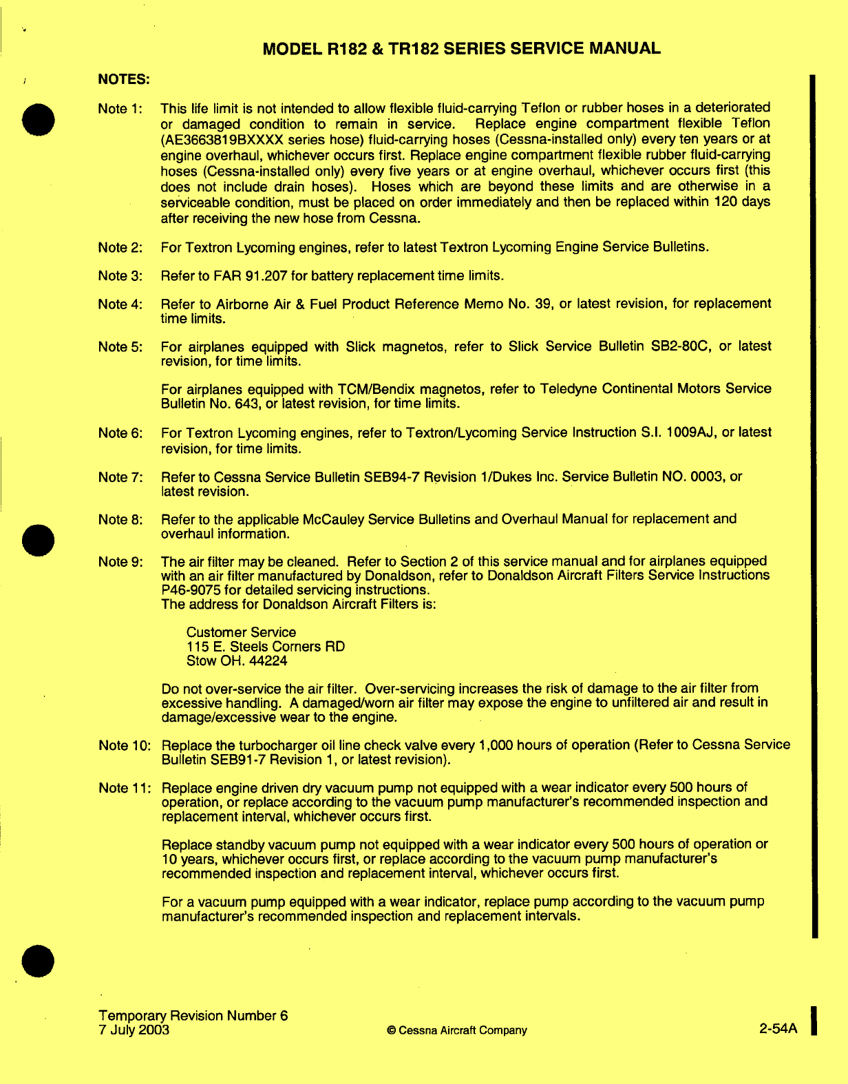
MODEL
R182
&
TR182
SERIES
SERVICE
MANUAL
NOTES:
Note
1:
This
life
limit
is
not
intended
to
allow
flexible
fluid-carrying Teflon
or
rubber hoses
in
a
deteriorated
or
damaged
condition
to
remain
in
service.
Replace engine
compartment
flexible
Teflon
(AE3663819BXXXX
series
hose)
fluid-carrying
hoses
(Cessna-installed
only)
every
ten
years
or
at
engine
overhaul,
whichever
occurs
first.
Replace
engine
compartment
flexible
rubber
fluid-carrying
hoses
(Cessna-installed only)
every five
years
or
at
engine overhaul,
whichever
occurs
first
(this
does
not
include
drain
hoses).
Hoses
which
are beyond
these limits
and
are
otherwise
in
a
serviceable
condition,
must
be
placed
on
order
immediately
and
then
be
replaced
within
120
days
after
receiving
the
new
hose from
Cessna.
Note
2:
For
Textron
Lycoming
engines,
refer
to
latest
Textron
Lycoming Engine
Service
Bulletins.
Note
3:
Refer
to
FAR
91.207
for
battery
replacement
time
limits.
Note
4:
Refer
to
Airborne Air
&
Fuel
Product
Reference
Memo
No.
39,
or
latest revision,
for replacement
time
limits.
Note
5:
For
airplanes
equipped
with
Slick
magnetos, refer
to
Slick
Service
Bulletin SB2-80C,
or
latest
revision,
for
time
limits.
For
airplanes
equipped
with
TCM/Bendix
magnetos,
refer
to
Teledyne
Continental Motors
Service
Bulletin
No.
643,
or
latest
revision,
for
time
limits.
Note
6:
For
Textron
Lycoming
engines,
refer
to
Textron/Lycoming
Service Instruction
S.I.
1009AJ, or
latest
revision,
for
time
limits.
Note
7:
Refer
to
Cessna
Service Bulletin
SEB94-7 Revision 1/Dukes
Inc.
Service
Bulletin
NO.
0003,
or
latest
revision.
Note
8:
Refer
to
the applicable McCauley Service
Bulletins and
Overhaul
Manual
for replacement
and
overhaul
information.
Note
9:
The
air
filter
may
be
cleaned.
Refer to
Section
2
of
this
service
manual
and
for airplanes equipped
with
an
air
filter
manufactured
by
Donaldson, refer to Donaldson
Aircraft
Filters
Service
Instructions
P46-9075
for
detailed
servicing
instructions.
The address
for
Donaldson
Aircraft
Filters
is:
Customer
Service
115
E.
Steels Corners
RD
Stow
OH. 44224
Do
not
over-service
the air
filter.
Over-servicing
increases the
risk
of
damage
to
the
air
filter
from
excessive
handling.
A
damaged/worn
air
filter may expose the
engine
to
unfiltered
air
and result
in
damage/excessive
wear
to
the engine.
Note
10:
Replace
the turbocharger
oil
line
check
valve
every
1,000
hours
of
operation
(Refer
to
Cessna
Service
Bulletin
SEB91-7
Revision
1,
or
latest revision).
Note
11:
Replace
engine
driven dry
vacuum
pump
not
equipped
with
a
wear
indicator
every
500
hours
of
operation,
or
replace
according
to
the vacuum pump
manufacturer's recommended inspection
and
replacement
interval,
whichever occurs
first.
Replace
standby
vacuum
pump
not
equipped
with
a
wear
indicator
every
500
hours
of
operation
or
10
years,
whichever
occurs
first,
or
replace according
to
the
vacuum
pump
manufacturer's
recommended
inspection and
replacement
interval,
whichever
occurs
first.
For
a
vacuum
pump
equipped
with
a
wear
indicator, replace
pump
according
to
the vacuum
pump
manufacturer's
recommended inspection
and
replacement
intervals.
Temporary
Revision
Number
6
1
7
July
2003
©
Cessna Aircraft Company
2-54A
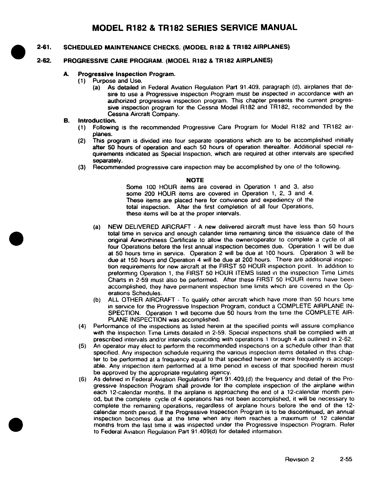
MODEL
R182
&
TR182
SERIES
SERVICE
MANUAL
2-61.
SCHEDULED
MAINTENANCE
CHECKS.
(MODEL
R182
& TR182
AIRPLANES)
2-62.
PROGRESSIVE
CARE
PROGRAM.
(MODEL
R182
&
TR182
AIRPLANES)
A.
Progressive
Inspection
Program.
(1)
Purpose
and
Use.
(a)
As
detailed
in
Federal
Aviation
Regulation
Part
91.409,
paragraph
(d),
airplanes
that
de-
sire
to
use
a
Progressive
Inspection
Program
must
be
inspected
in
accordance
with
an
authorized
progressive
inspection
program.
This
chapter presents the
current
progres-
sive
inspection
program for
the
Cessna Model
R182
and
TR182,
recommended
by
the
Cessna
Aircraft
Company.
B.
Introduction.
(1)
Following
is
the
recommended
Progressive
Care
Program
for
Model
R182
and
TR182
air-
planes.
(2)
This
program
is
divided
into four
separate
operations
which
are
to be
accomplished
initially
after
50 hours
of operation
and
each
50
hours
of
operation
thereafter.
Additional
special
re-
quirements
indicated
as
Special Inspection,
which
are required
at
other
intervals
are
specified
separately.
(3)
Recommended
progressive
care
inspection
may
be accomplished
by
one
of
the
following.
NOTE
Some
100
HOUR items
are
covered
in
Operation
1
and
3,
also
some
200
HOUR items
are
covered
in
Operation
1,
2,
3
and
4.
These
items
are
placed here
for
convience
and
expediency
of
the
total
inspection.
After
the
first
completion
of
all
four
Operations,
these
items
will be
at
the
proper
intervals.
(a)
NEW
DELIVERED AIRCRAFT
-
A
new
delivered
aircraft
must
have
less than
50
hours
total
time
in
service
and
enough
calander
time
remaining
since
the
issuance
date
of
the
original
Airworthiness Certificate
to
allow
the
owner/operator
to
complete
a
cycle
of
all
four
Operations
before
the
first
annual
inspection
becomes
due.
Operation
1
will
be due
at 50
hours
time
in
service.
Operation
2
will
be due
at
100
hours.
Operation
3
will
be
due
at
150
hours
and
Operation
4
will be
due
at
200
hours.
There
are
additional inspec-
tion requirements
for
new
aircraft
at
the
FIRST
50
HOUR
inspection
point.
In addition to
preforming
Operation
1,
the FIRST 50
HOUR
ITEMS
listed
in
the
inspection
Time
Limits
Charts
in
2-59
must
also
be
performed.
After these
FIRST
50
HOUR items
have
been
accomplished,
they
have
permanent
inspection
time
limits
which
are
covered
in
the
Op-
erations
Schedules.
(b)
ALL OTHER
AIRCRAFT
-
To
qualify
other
aircraft
which
have
more
than
50
hours
time
in
service
for
the
Progressive Inspection
Program,
conduct
a
COMPLETE
AIRPLANE
IN-
SPECTION. Operation
1
will
become
due 50
hours
from
the
time
the COMPLETE
AIR-
PLANE
INSPECTION
was
accomplished.
(4)
Performance
of
the
inspections
as
listed
herein
at
the specified
points
will
assure
compliance
with
the
Inspection
Time
Limits detailed
in
2-59.
Special
inspections
shall
be
complied
with
at
prescribed
intervals
and/or
intervals
coinciding
with operations
1
through
4
as
outlined
in
2-62.
(5)
An
operator
may
elect
to
perform
the
recommended
inspections
on
a
schedule
other
than
that
specified.
Any
inspection schedule
requiring
the
various
inspection
items
detailed
in
this
chap-
ter
to
be
performed
at
a
frequency
equal
to
that
specified
herein
or
more
frequently
is
accept-
able.
Any
inspection
item
performed
at
a
time
period
in
excess
of
that
specified herein
must
be
approved
by
the
appropriate regulating
agency.
(6)
As
defined
in
Federal
Aviation Regulations
Part
91.409,(d)
the
frequency
and
detail of
the
Pro-
gressive
Inspection
Program shall
provide
for
the
complete
inspection
of
the
airplane
within
each
12-calendar months.
If
the
airplane
is
approaching
the
end
of
a
12-calendar
month
peri-
od,
but
the
complete
cycle
of
4
operations
has
not
been
accomplished,
it
will be
necessary
to
complete
the
remaining
operations, regardless
of
airplane
hours
before the
end
of
the
12-
calendar
month
period.
If
the
Progressive
Inspection
Program
is
to
be
discontinued,
an
annual
inspection
becomes
due
at
the time when
any
item
reaches
a
maximum
of
12
calendar
months
from
the
last
time
it
was
inspected
under
the
Progressive
Inspection
Program.
Refer
to
Federal Aviation Regulation
Part
91.409(d)
for
detailed
information.
Revision
2
2-55
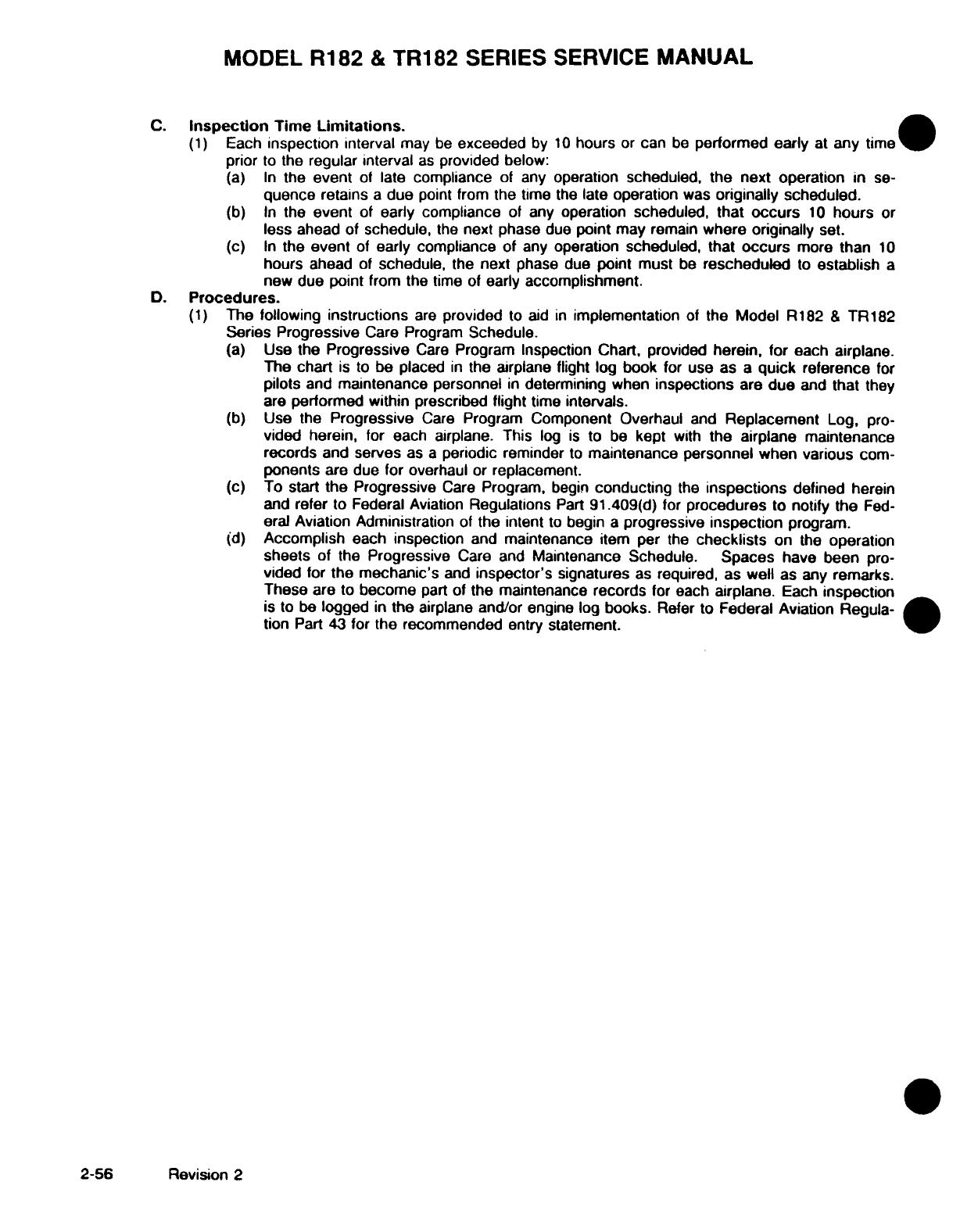
MODEL
R182
&
TR182 SERIES
SERVICE
MANUAL
C.
Inspection
Time
Limitations.
(1)
Each
inspection
interval
may
be
exceeded
by
10
hours
or
can
be
performed
early
at
any
time
prior
to
the regular
interval
as
provided
below:
(a)
In
the
event
of
late
compliance
of any
operation
scheduled,
the
next
operation
in
se-
quence
retains
a
due
point from
the
time
the
late
operation
was
originally
scheduled.
(b)
In
the
event
of early
compliance
of
any
operation
scheduled,
that
occurs
10
hours
or
less
ahead
of
schedule,
the
next phase
due
point
may
remain
where originally
set.
(c)
In
the
event
of
early compliance
of
any
operation
scheduled, that
occurs
more
than
10
hours
ahead
of
schedule,
the
next
phase
due
point
must
be
rescheduled
to
establish
a
new due
point
from the
time
of
early
accomplishment.
D.
Procedures.
(1)
The
following
instructions
are
provided
to
aid
in
implementation
of
the
Model
R182
&
TR182
Series
Progressive
Care Program
Schedule.
(a)
Use
the
Progressive
Care
Program
Inspection Chart, provided
herein,
for
each airplane.
The
chart
is
to
be
placed
in
the airplane
flight
log
book
for
use
as
a
quick
reference
for
pilots
and
maintenance
personnel
in
determining
when
inspections
are
due
and
that
they
are
performed within prescribed
flight
time
intervals.
(b)
Use
the
Progressive
Care
Program
Component Overhaul
and
Replacement
Log,
pro-
vided herein,
for
each airplane. This
log
is
to
be
kept
with
the airplane
maintenance
records
and
serves
as
a
periodic
reminder
to
maintenance
personnel
when various
com-
ponents
are
due
for overhaul
or
replacement.
(c)
To
start
the
Progressive
Care
Program,
begin
conducting
the
inspections
defined
herein
and
refer
to Federal Aviation
Regulations
Part
91.409(d)
for
procedures
to
notify
the
Fed-
eral
Aviation
Administration
of
the
intent
to
begin
a
progressive
inspection
program.
(d)
Accomplish
each
inspection
and
maintenance
item
per
the
checklists
on the
operation
sheets
of
the
Progressive
Care and
Maintenance
Schedule.
Spaces
have
been
pro-
vided
for
the
mechanic's
and
inspector's
signatures
as
required,
as well
as
any
remarks.
These
are
to
become
part
of
the
maintenance
records
for
each
airplane.
Each
inspection
is
to be
logged
in
the
airplane
and/or
engine
log
books.
Refer
to
Federal Aviation
Regula-
tion
Part
43
for
the
recommended
entry
statement.
2-56
Revision
2
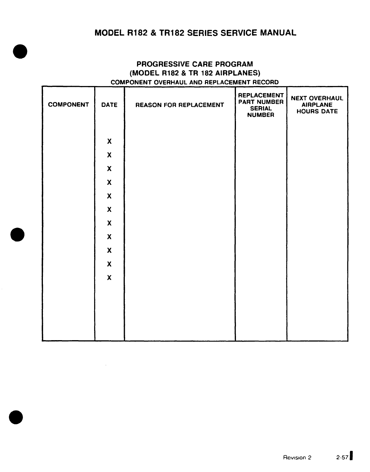
MODEL
R182
&
TR182
SERIES
SERVICE
MANUAL
PROGRESSIVE
CARE
PROGRAM
(MODEL
R182
&
TR
182
AIRPLANES)
COMPONENT
OVERHAUL AND
REPLACEMENT
RECORD
REPLACEMENT
NEXT
OVERHAUL
COMPONENT
DATE
REASON
FOR
REPLACEMENT
PART NUMBER
AIRPLANE
SERIAL
NUMBER
HOURS
DATE
NUMBER
X
X
X
X
X
X
X
x
X
X
X
Revision
2
2-57
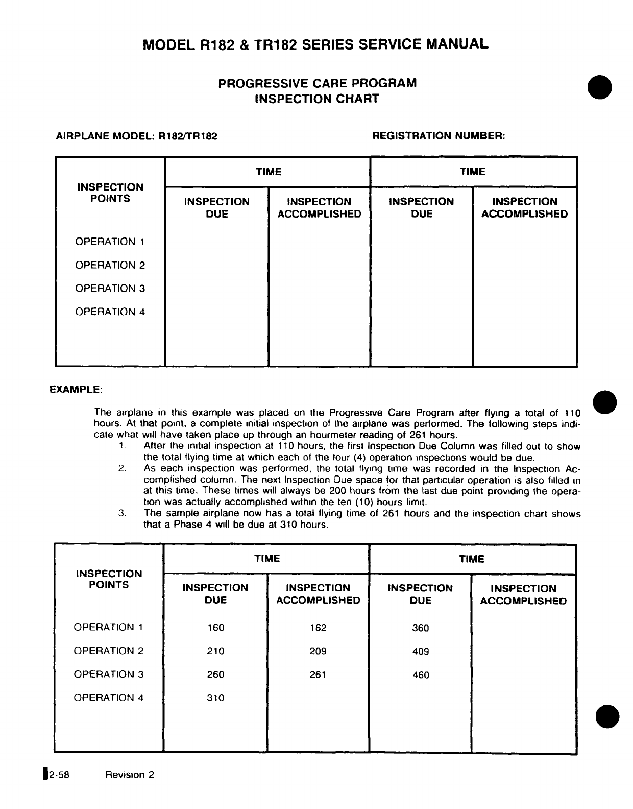
MODEL R182
&
TR182
SERIES
SERVICE
MANUAL
PROGRESSIVE
CARE
PROGRAM
INSPECTION
CHART
AIRPLANE
MODEL:
R182/TR182 REGISTRATION
NUMBER:
TIME
TIME
INSPECTION
POINTS INSPECTION
INSPECTION
INSPECTION INSPECTION
DUE
ACCOMPLISHED
DUE
ACCOMPLISHED
OPERATION
1
OPERATION
2
OPERATION
3
OPERATION
4
EXAMPLE:
The
airplane
in
this
example
was
placed
on
the Progressive Care
Program
after
flying
a
total
of
110
hours.
At
that
point,
a
complete
initial
inspection
of
the
airplane
was
performed.
The
following
steps
indi-
cate what
will
have
taken
place
up
through
an
hourmeter
reading
of
261
hours.
1.
After
the
initial
inspection
at
110
hours, the first
Inspection
Due
Column
was
filled
out to
show
the
total
flying
time
at
which
each
of
the
four
(4)
operation
inspections
would
be
due.
2.
As
each
inspection
was
performed,
the
total
flying
time
was
recorded
in
the
Inspection
Ac-
complished
column.
The
next Inspection
Due
space
for that
particular
operation
is
also
filled
in
at
this
time.
These
times
will always
be
200
hours from the
last
due
point
providing
the
opera-
tion
was
actually accomplished
within
the ten
(10)
hours
limit.
3.
The
sample airplane
now has
a
total
flying
time
of
261
hours
and
the
inspection
chart shows
that
a
Phase
4
will
be
due
at
310
hours.
TIME
TIME
INSPECTION
POINTS
INSPECTION
INSPECTION
INSPECTION INSPECTION
DUE
ACCOMPLISHED
DUE
ACCOMPLISHED
OPERATION
1
160
162
360
OPERATION
2
210
209
409
OPERATION
3
260
261
460
OPERATION
4
310
2-58
Revision
2
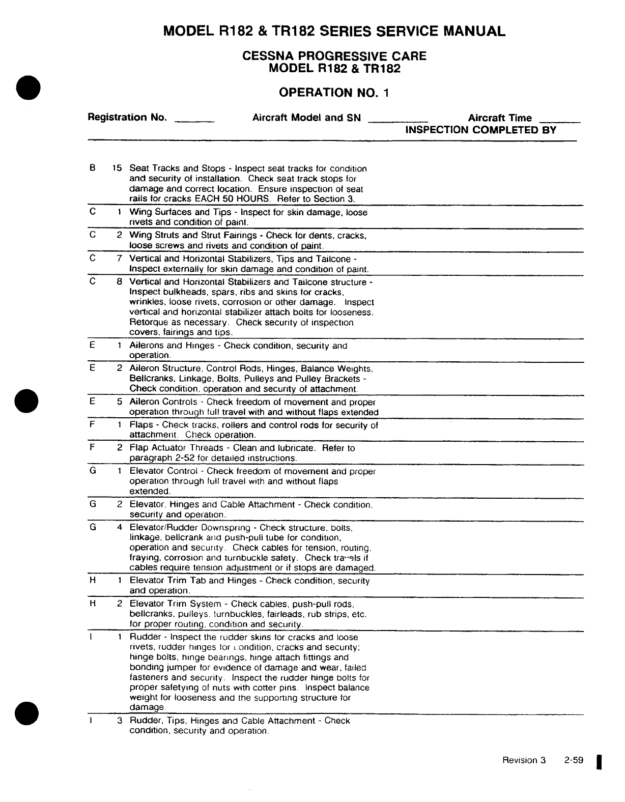
MODEL
R182
&
TR182
SERIES
SERVICE
MANUAL
CESSNA
PROGRESSIVE
CARE
MODEL
R182
&
TR182
OPERATION
NO.
1
Registration
No.
Aircraft
Model
and SN
Aircraft
Time
INSPECTION
COMPLETED BY
B
15
Seat
Tracks and
Stops
-
Inspect
seat
tracks
for
condition
and
security
of
installation.
Check
seat
track stops
for
damage
and
correct
location.
Ensure
inspection
of
seat
rails
for
cracks
EACH
50
HOURS.
Refer
to
Section
3.
C
1
Wing
Surfaces
and
Tips
-
Inspect
for
skin damage,
loose
rivets
and
condition
of
paint.
C
2
Wing
Struts and
Strut
Fairings
-
Check
for
dents,
cracks,
loose
screws
and
rivets
and
condition
of
paint.
C
7
Vertical
and
Horizontal
Stabilizers, Tips
and
Tailcone
-
Inspect externally
for
skin
damage
and
condition
of
paint.
C
8
Vertical
and
Horizontal
Stabilizers
and
Tailcone
structure
-
Inspect bulkheads,
spars,
ribs
and
skins
for
cracks,
wrinkles,
loose
rivets,
corrosion
or
other damage.
Inspect
vertical
and
horizontal
stabilizer
attach
bolts
for
looseness.
Retorque
as
necessary.
Check
security
of
inspection
covers, fairings
and
tips.
E 1 Ailerons
and
Hinges
-
Check condition,
security
and
operation.
E
2
Aileron Structure,
Control
Rods,
Hinges, Balance
Weights,
Bellcranks,
Linkage,
Bolts,
Pulleys
and
Pulley
Brackets
-
Check
condition,
operation
and
security
of attachment.
E
5
Aileron
Controls
-
Check freedom
of
movement
and
proper
operation
through
full
travel
with
and
without
flaps
extended
F 1 Flaps
-
Check
tracks,
rollers
and
control
rods
for
security
of
attachment.
Check
operation.
F
2
Flap
Actuator Threads
-
Clean
and
lubricate.
Refer
to
paragraph
2-52
for
detailed
instructions.
G
1
Elevator
Control
-
Check
freedom
of
movement
and
proper
operation
through
full
travel
with
and
without
flaps
extended.
G
2
Elevator,
Hinges
and
Cable
Attachment
-
Check
condition,
security
and
operation.
G
4
Elevator/Rudder
Downspring
-
Check
structure,
bolts,
linkage,
bellcrank
and
push-pull
tube
for
condition,
operation
and
security.
Check
cables
for
tension,
routing.
fraying,
corrosion
and
turnbuckle
safety.
Check travels
if
cables
require
tension
adjustment
or
if
stops
are
damaged.
H
1
Elevator
Trim
Tab
and
Hinges
-
Check
condition,
security
and
operation.
H
2
Elevator
Trim
System
-
Check
cables,
push-pull
rods,
bellcranks, pulleys,
turnbuckles,
fairleads,
rub
strips, etc.
for
proper
routing.
condition
and
security.
I 1 Rudder
-
Inspect
the
rudder
skins
for
cracks
and
loose
rivets,
rudder
hinges
tor
condition,
cracks
and
security;
hinge
bolts,
hinge
bearings,
hinge attach
fittings
and
bonding
jumper
for
evidence
of
damage
and
wear,
failed
fasteners
and
security.
Inspect
the
rudder hinge
bolts
for
proper safetying
of
nuts
with
cotter
pins.
Inspect
balance
weight
for
looseness
and
the
supporting structure
for
damage.
3
Rudder,
Tips,
Hinges and
Cable
Attachment
-
Check
condition, security
and
operation.
Revision
3
2-59
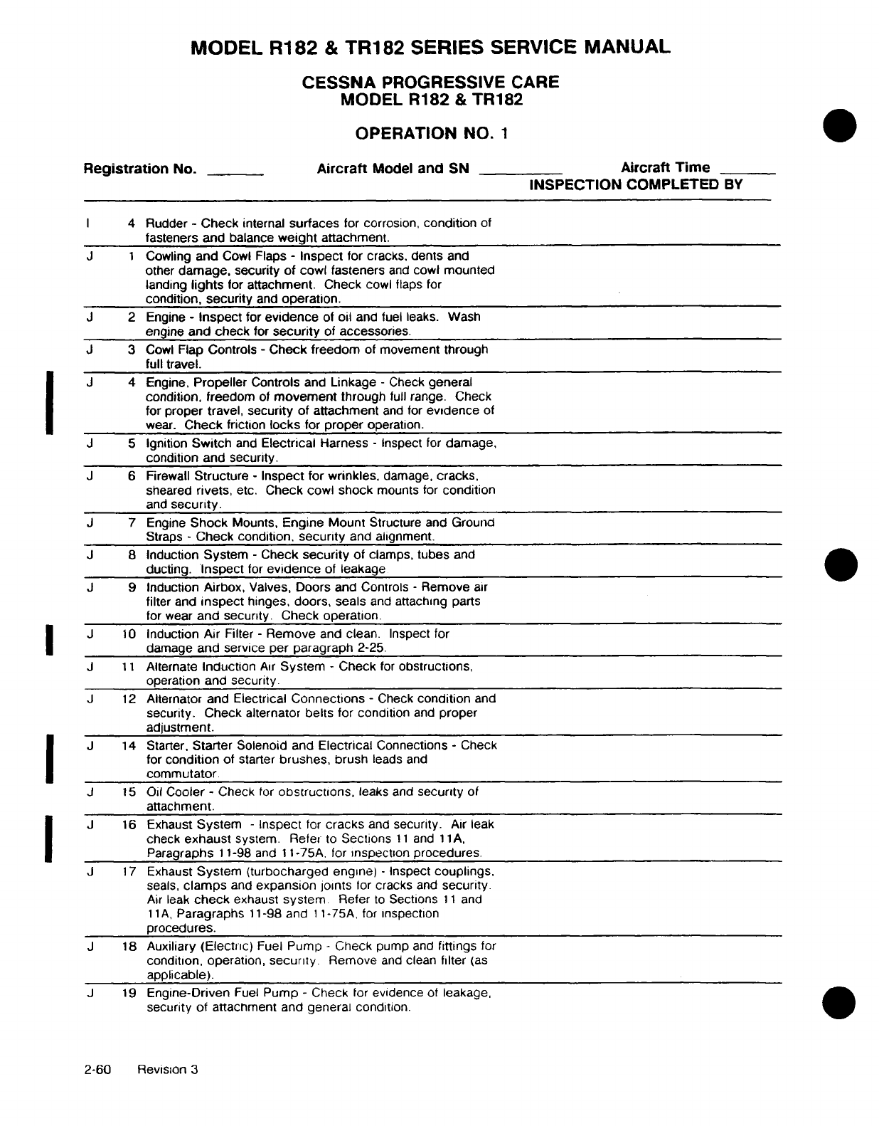
MODEL
R182
&
TR182
SERIES
SERVICE
MANUAL
CESSNA
PROGRESSIVE
CARE
MODEL R182
&
TR182
OPERATION
NO.
1
Registration
No.
Aircraft
Model and
SN
Aircraft
Time
INSPECTION
COMPLETED
BY
I
4
Rudder
-
Check
internal
surfaces
for
corrosion,
condition
of
fasteners
and
balance
weight
attachment.
J
1
Cowling
and
Cowl
Flaps
-
Inspect
for
cracks,
dents
and
other
damage, security of cowl
fasteners
and
cowl mounted
landing
lights
for
attachment. Check
cowl
flaps
for
condition,
security
and
operation.
J
2
Engine
-
Inspect
for
evidence
of
oil
and
fuel leaks.
Wash
engine
and
check
for
security
of
accessories.
J
3
Cowl
Flap
Controls
-
Check freedom
of
movement
through
full travel.
J
4 Engine.
Propeller
Controls
and
Linkage
-
Check
general
condition,
freedom
of
movement
through
full
range. Check
for proper
travel,
security
of attachment
and
for
evidence
of
wear.
Check
friction
locks
for
proper
operation.
J
5
Ignition
Switch
and
Electrical
Harness
-
Inspect
for
damage,
condition and security.
J
6
Firewall
Structure
-
Inspect
for
wrinkles,
damage,
cracks,
sheared
rivets,
etc.
Check
cowl shock
mounts
for
condition
and
security.
J
7
Engine
Shock
Mounts,
Engine
Mount
Structure and
Ground
Straps
-
Check
condition,
security
and
alignment.
J
8
Induction
System
-
Check
security
of
clamps,
tubes
and
ducting.
Inspect
for
evidence
of
leakage
J
9
Induction
Airbox,
Valves,
Doors
and
Controls
-
Remove
air
filter
and
inspect
hinges,
doors,
seals
and
attaching
parts
for
wear
and
security.
Check
operation.
J
10
Induction
Air
Filter
-
Remove
and
clean.
Inspect for
damage
and
service
per
paragraph
2-25.
J
11
Alternate
Induction
Air
System
-
Check
for
obstructions,
operation and
security.
J
12
Alternator and
Electrical
Connections
-
Check
condition
and
security.
Check
alternator
belts
for
condition
and
proper
adjustment.
J
14
Starter,
Starter
Solenoid
and
Electrical
Connections
-
Check
for
condition
of
starter
brushes,
brush
leads
and
commutator.
J
15
Oil
Cooler
-
Check
for
obstructions,
leaks and
security
of
attachment.
J
16
Exhaust
System
-
Inspect
for
cracks
and
security.
Air
leak
check
exhaust
system.
Refer
to
Sections
11
and
11A,
Paragraphs
11-98
and
11-75A.
for
inspection
procedures.
J
17
Exhaust
System
(turbocharged
engine)
-
Inspect
couplings,
seals,
clamps
and
expansion
joints
for
cracks
and
security.
Air
leak
check
exhaust
system
Refer
to
Sections
11
and
11A,
Paragraphs
11-98
and
11-75A,
for
inspection
procedures.
J
18
Auxiliary (Electric)
Fuel
Pump
-
Check
pump
and
fittings
for
condition,
operation,
security.
Remove
and
clean
filter
(as
applicable).
J
19
Engine-Driven
Fuel
Pump
-
Check
for
evidence
of
leakage,
security
of
attachment
and
general condition.
2-60
Revision
3
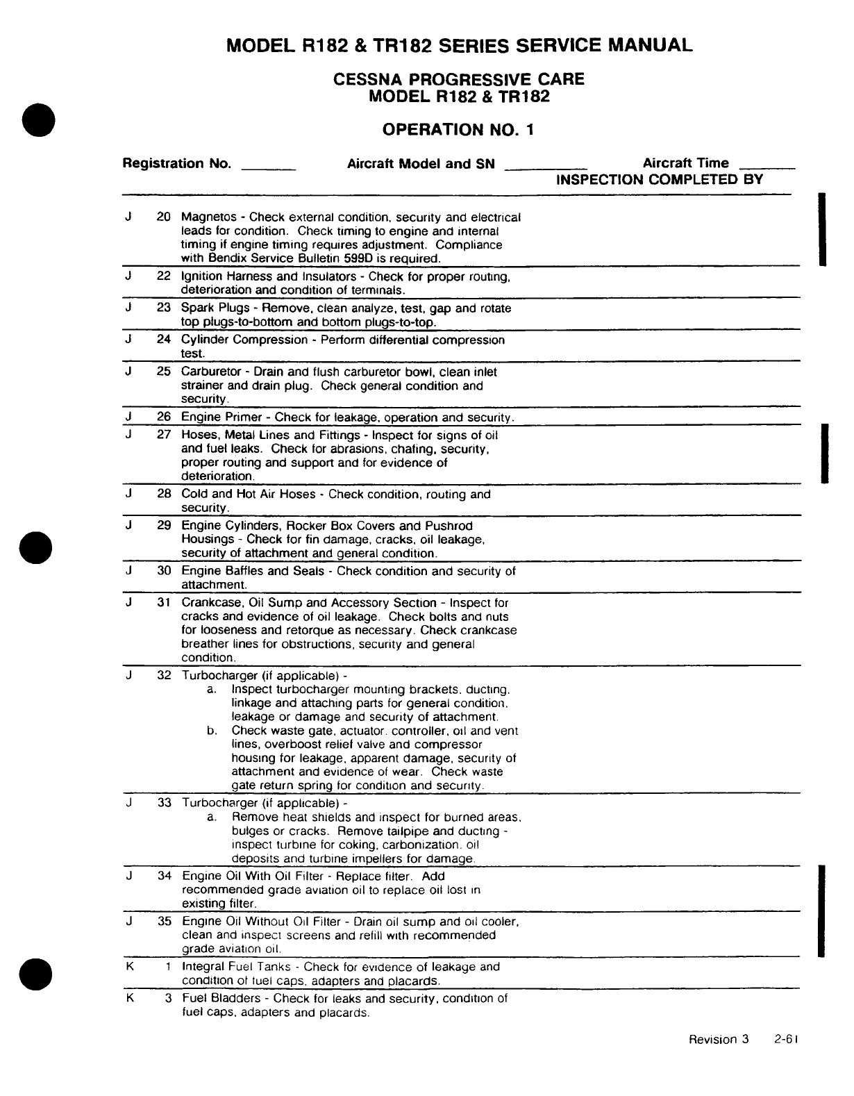
MODEL
R182
&
TR182
SERIES
SERVICE
MANUAL
CESSNA
PROGRESSIVE CARE
MODEL R182
&
TR182
OPERATION
NO.
1
Registration
No.
Aircraft
Model
and
SN
Aircraft
Time
INSPECTION COMPLETED
BY
J
20 Magnetos
-
Check
external condition,
security
and
electrical
leads
for
condition.
Check
timing
to
engine
and
internal
timing
if
engine
timing
requires adjustment.
Compliance
with Bendix
Service
Bulletin
599D
is
required.
J
22
Ignition
Harness
and
Insulators
-
Check
for
proper
routing,
deterioration
and
condition
of
terminals.
J
23
Spark
Plugs
-
Remove,
clean
analyze,
test,
gap
and
rotate
top
plugs-to-bottom
and bottom
plugs-to-top.
J
24 Cylinder
Compression
-
Perform
differential
compression
test.
J
25
Carburetor
-
Drain
and
flush
carburetor
bowl, clean
inlet
strainer
and
drain
plug.
Check
general
condition
and
security.
J
26
Engine
Primer
-
Check
for
leakage.
operation
and
security.
J
27
Hoses,
Metal
Lines
and
Fittings
-
Inspect
for
signs
of
oil
and
fuel
leaks.
Check
for
abrasions,
chafing, security,
proper
routing and
support
and
for
evidence
of
deterioration.
J
28
Cold
and
Hot
Air
Hoses
-
Check
condition, routing
and
security.
J
29
Engine
Cylinders,
Rocker
Box
Covers
and
Pushrod
Housings
-
Check
for fin
damage,
cracks,
oil
leakage,
security
of
attachment
and
general
condition.
J
30
Engine
Baffles
and Seals
-
Check
condition
and
security
of
attachment.
J
31
Crankcase,
Oil
Sump
and
Accessory
Section
-
Inspect
for
cracks
and
evidence
of
oil leakage.
Check
bolts
and
nuts
for looseness
and
retorque
as
necessary.
Check
crankcase
breather
lines
for
obstructions,
security
and
general
condition.
J
32
Turbocharger
(if
applicable)
-
a.
Inspect
turbocharger
mounting
brackets,
ducting,
linkage and attaching
parts
for
general
condition.
leakage
or
damage
and
security
of
attachment.
b.
Check
waste
gate, actuator.
controller,
oil
and
vent
lines,
overboost
relief
valve
and
compressor
housing
for
leakage,
apparent
damage,
security
of
attachment
and
evidence
of
wear.
Check
waste
gate
return
spring
for
condition
and
security.
J
33
Turbocharger
(if
applicable)
-
a.
Remove
heat
shields
and
inspect
for
burned
areas.
bulges
or
cracks.
Remove
tailpipe
and
ducting
-
inspect
turbine
for
coking,
carbonization.
oil
deposits
and
turbine
impellers
for
damage.
J
34
Engine
Oil
With
Oil
Filter
-
Replace
filter.
Add
recommended
grade
aviation
oil
to
replace
oil
lost
in
existing
filter.
J
35
Engine
Oil
Without
Oil
Filter
-
Drain
oil
sump
and
oil cooler,
clean
and
inspect
screens
and
refill with
recommended
grade
aviation
oil.
K 1
Integral
Fuel
Tanks
-
Check
for
evidence
of
leakage
and
condition
of
fuel
caps,
adapters
and
placards.
K
3
Fuel
Bladders
-
Check
for
leaks
and
security,
condition
of
fuel
caps,
adapters
and
placards.
Revision
3
2-61
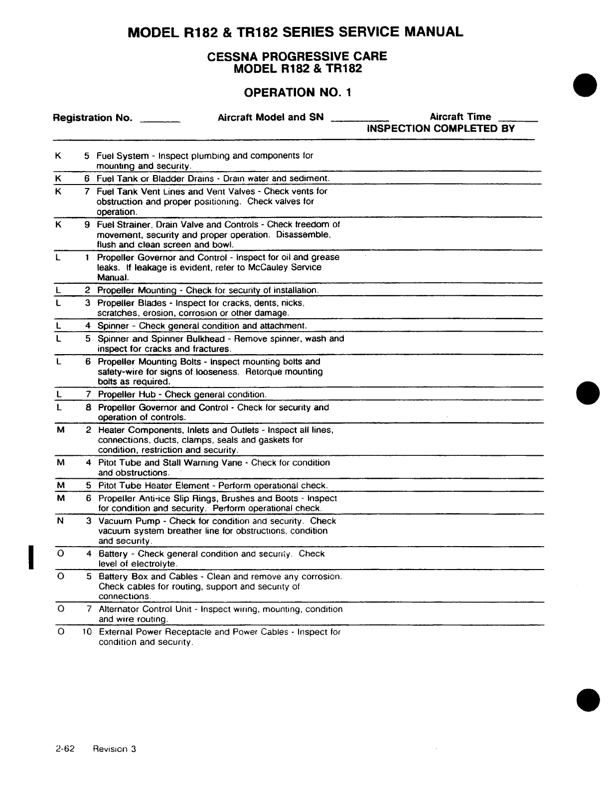
MODEL
R182
&
TR182
SERIES
SERVICE
MANUAL
CESSNA
PROGRESSIVE
CARE
MODEL R182
&
TR182
OPERATION
NO.
1
Registration
No.
Aircraft
Model
and
SN
Aircraft
Time
INSPECTION
COMPLETED
BY
K 5
Fuel
System
-
Inspect
plumbing
and
components
for
mounting and
security.
K
6
Fuel
Tank
or Bladder
Drains
-
Drain water
and
sediment.
K
7
Fuel
Tank
Vent
Lines
and
Vent Valves
-
Check
vents for
obstruction
and
proper
positioning.
Check
valves
for
operation.
K
9
Fuel
Strainer,
Drain
Valve
and
Controls
-
Check
freedom
of
movement,
security
and
proper
operation.
Disassemble,
flush
and
clean
screen
and
bowl.
L 1
Propeller
Governor
and Control
-
Inspect
for oil
and
grease
leaks.
If
leakage
is
evident,
refer
to
McCauley
Service
Manual.
L
2
Propeller
Mounting
-
Check
for
security
of
installation.
L
3
Propeller Blades
-
Inspect
for
cracks,
dents,
nicks,
scratches,
erosion,
corrosion
or
other
damage.
L
4
Spinner
-
Check
general condition
and
attachment.
L
5
Spinner
and
Spinner
Bulkhead
-
Remove
spinner,
wash
and
inspect
for
cracks
and
fractures.
L
6
Propeller
Mounting Bolts
-
Inspect
mounting bolts
and
safety-wire
for
signs
of
looseness.
Retorque
mounting
bolts
as
required.
L 7
Propeller
Hub
-
Check general condition.
L
8
Propeller
Governor
and
Control
-
Check
for
security
and
operation
of
controls.
M
2
Heater
Components,
Inlets
and
Outlets
-
Inspect all
lines,
connections, ducts,
clamps,
seals
and
gaskets
for
condition,
restriction
and
security.
M
4
Pitot
Tube
and
Stall
Warning
Vane
-
Check
for
condition
and
obstructions.
M
5
Pitot
Tube
Heater
Element
-
Perform
operational
check.
M
6
Propeller
Anti-ice
Slip
Rings,
Brushes
and Boots
-
Inspect
for
condition
and
security.
Perform
operational
check.
N
3
Vacuum
Pump
-
Check
for
condition
and
security.
Check
vacuum
system
breather
line for
obstructions,
condition
and
security.
O
4
Battery
-
Check general
condition
and
security.
Check
level
of
electrolyte.
O
5
Battery
Box
and
Cables
-
Clean
and
remove
any
corrosion.
Check
cables
for
routing,
support
and
security
of
connections.
O
7
Alternator
Control
Unit
-
Inspect
wiring,
mounting,
condition
and
wire
routing.
O
10
External Power
Receptacle
and Power
Cables
-
Inspect
for
condition
and
security.
2-62
Revision
3
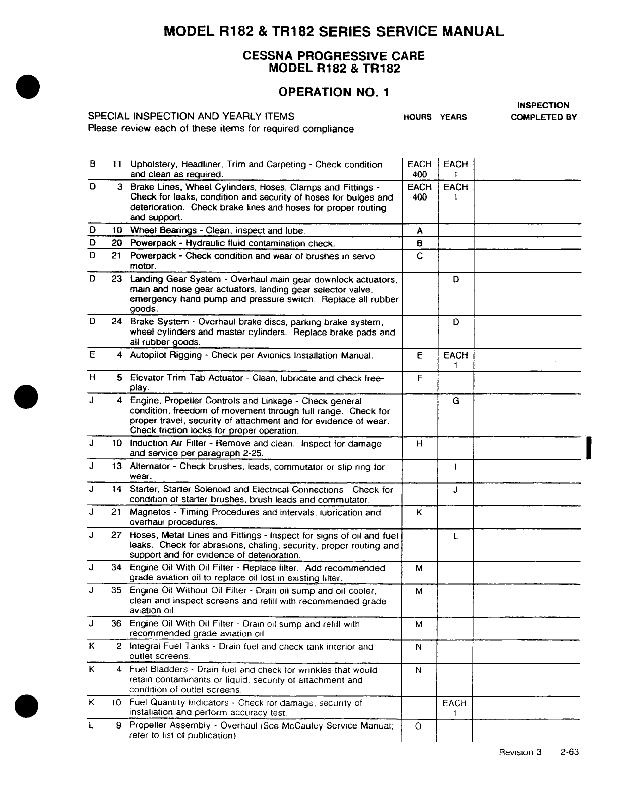
MODEL
R182
&
TR182 SERIES
SERVICE
MANUAL
CESSNA
PROGRESSIVE
CARE
MODEL
R182
&
TR182
OPERATION
NO.
1
INSPECTION
SPECIAL
INSPECTION
AND
YEARLY
ITEMS
HOURS
YEARS
COMPLETED
BY
Please
review each
of
these
items
for
required
compliance
B
11
Upholstery,
Headliner,
Trim
and
Carpeting
-
Check
condition
EACH
EACH
and
clean
as
required.
400
1
D
3
Brake
Lines. Wheel
Cylinders,
Hoses,
Clamps and
Fittings
-
EACH
EACH
Check
for
leaks,
condition
and
security
of
hoses
for
bulges
and
400
1
deterioration.
Check
brake
lines
and
hoses
for
proper
routing
and
support.
D
10
Wheel
Bearings
-
Clean,
inspect
and
lube.
A
D
20 Powerpack
-
Hydraulic
fluid
contamination
check.
B
D
21
Powerpack
-
Check
condition
and
wear
of
brushes
in
servo
C
motor.
D
23
Landing
Gear
System
-
Overhaul
main
gear
downlock
actuators,
D
main and
nose gear actuators,
landing
gear
selector
valve.
emergency
hand
pump
and pressure
switch. Replace
all
rubber
goods.
D
24
Brake
System
-
Overhaul
brake
discs,
parking
brake
system,
D
wheel
cylinders
and
master
cylinders.
Replace
brake
pads
and
all
rubber
goods.
E
4
Autopilot
Rigging
-
Check
per
Avionics
Installation
Manual.
E
EACH
H
5
Elevator
Trim
Tab
Actuator
-
Clean,
lubricate
and
check
free-
F
play.
J
4
Engine,
Propeller
Controls
and
Linkage
-
Check
general
G
condition,
freedom
of
movement
through full
range. Check
for
proper
travel,
security
of
attachment
and
for
evidence
of
wear.
Check
friction
locks
for
proper
operation.
J
10
Induction
Air
Filter
-
Remove
and
clean.
Inspect
for
damage
H
and
service
per
paragraph
2-25.
J
13
Alternator
-
Check
brushes,
leads,
commutator
or
slip
ring
for
wear.
J
14
Starter,
Starter
Solenoid
and
Electrical
Connections
-
Check
for
J
condition
of starter
brushes,
brush
leads and
commutator.
J
21
Magnetos
-
Timing Procedures
and
intervals,
lubrication
and
K
overhaul
procedures.
J
27
Hoses,
Metal
Lines
and Fittings
-
Inspect
for
signs
of oil
and
fuel
L
leaks.
Check
for
abrasions,
chafing,
security,
proper
routing
and
support
and
for
evidence
of
deterioration.
J
34
Engine
Oil
With
Oil
Filter
-
Replace
filter. Add
recommended
M
grade aviation
oil
to
replace
oil
lost
in
existing filter.
J
35
Engine
Oil
Without
Oil
Filter
-
Drain
oil
sump
and
oil
cooler,
M
clean
and
inspect screens
and
refill
with
recommended
grade
aviation oil.
J
36
Engine
Oil
With
Oil
Filter
-
Drain
oil
sump
and
refill
with
M
recommended
grade aviation
oil.
K
2
Integral
Fuel Tanks
-
Drain
fuel and
check
tank
interior
and
N
outlet
screens
K
4
Fuel
Bladders
-
Drain
fuel
and
check
for
wrinkles
that would
N
retain
contaminants
or
liquid,
security
of
attachment
and
condition
of
outlet
screens.
K
10
Fuel
Quantity
Indicators
-
Check
for
damage,
security
of
EACH
installation
and
perform
accuracy
test.
1
L
9
Propeller
Assembly
-
Overhaul
(See
McCauley Service
Manual;
0
refer
to
list of
publication)
Revision
3
2-63
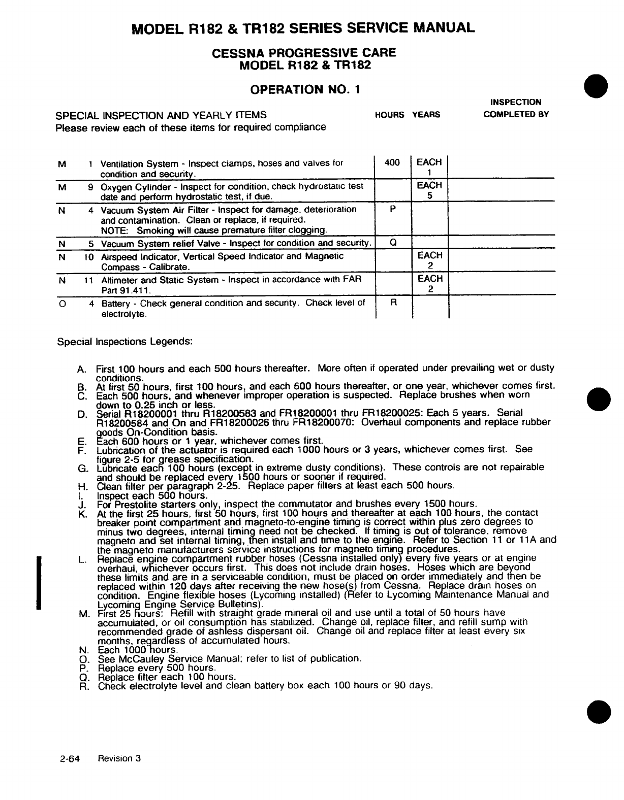
MODEL R182
&
TR182
SERIES
SERVICE
MANUAL
CESSNA
PROGRESSIVE
CARE
MODEL
R182
&
TR182
OPERATION
NO.
1
INSPECTION
SPECIAL
INSPECTION
AND
YEARLY
ITEMS
HOURS
YEARS
COMPLETED
BY
Please
review
each
of
these
items
for
required
compliance
M
1
Ventilation
System
-
Inspect
clamps,
hoses
and
valves
for
400
EACH
condition
and
security.
1
M
9
Oxygen
Cylinder
-
Inspect
for
condition,
check
hydrostatic
test
EACH
date
and
perform
hydrostatic
test,
if
due.
5
N
4
Vacuum
System
Air
Filter
-
Inspect
for
damage,
deterioration
P
and
contamination.
Clean
or
replace,
if
required.
NOTE:
Smoking
will
cause
premature
filter
clogging.
N
5
Vacuum
System
relief
Valve
-
Inspect
for
condition
and
security.
Q
N
10
Airspeed
Indicator,
Vertical
Speed
Indicator
and
Magnetic
EACH
Compass
-
Calibrate.
2
N
11
Altimeter
and
Static
System
-
Inspect
in
accordance
with
FAR
EACH
Part
91.411.
2
O
4
Battery
-
Check
general
condition
and security.
Check
level
of
R
electrolyte.
Special
Inspections
Legends:
A.
First
100
hours
and each 500
hours
thereafter.
More
often
if
operated
under
prevailing
wet
or
dusty
conditions.
B.
At
first
50
hours,
first
100
hours,
and
each
500
hours thereafter,
or
one
year,
whichever
comes
first.
C.
Each
500
hours,
and
whenever
improper
operation
is
suspected. Replace
brushes when
worn
down
to 0.25 inch
or
less.
D.
Serial
R18200001 thru
R18200583
and
FR18200001
thru FR18200025:
Each
5
years.
Serial
R18200584 and
On
and
FR18200026
thru
FR18200070:
Overhaul
components
and
replace
rubber
goods
On-Condition
basis.
E.
Each
600
hours or 1
year,
whichever
comes
first.
F.
Lubrication
of
the
actuator
is
required
each
1000
hours
or
3
years,
whichever comes first.
See
figure
2-5
for
grease
specification.
G.
Lubricate
each
100
hours
(except
in
extreme
dusty
conditions).
These
controls
are
not
repairable
and
should be
replaced every
1500
hours or
sooner
if
required.
H.
Clean
filter
per
paragraph
2-25. Replace
paper
filters
at
least
each
500
hours.
I.
Inspect
each 500 hours.
J.
For
Prestolite
starters
only,
inspect
the
commutator
and
brushes
every
1500
hours.
K.
At
the
first
25
hours,
first
50
hours,
first
100
hours
and
thereafter
at
each
100
hours,
the
contact
breaker
point
compartment
and
magneto-to-engine
timing
is
correct
within plus
zero
degrees
to
minus
two
degrees,
internal
timing
need
not
be
checked. If
timing
is
out
of
tolerance.
remove
magneto
and
set
internal timing, then
install
and
time
to the
engine.
Refer
to
Section
11
or
11A
and
the
magneto
manufacturers
service
instructions
for magneto
timing
procedures.
L.
Replace
engine
compartment
rubber
hoses
(Cessna
installed
only)
every
five years
or
at
engine
overhaul,
whichever
occurs
first.
This
does
not
include
drain
hoses.
Hoses
which
are
beyond
these
limits
and
are
in
a
serviceable
condition,
must
be placed
on
order
immediately
and
then
be
replaced
within
120
days
after
receiving
the
new hose(s)
from
Cessna.
Replace
drain
hoses
on
condition.
Engine
flexible
hoses
(Lycoming
installed)
(Refer
to
Lycoming
Maintenance
Manual
and
Lycoming
Engine
Service Bulletins).
M.
First
25
hours: Refill
with
straight
grade
mineral
oil
and
use
until
a
total
of
50
hours
have
accumulated,
or oil
consumption
has
stabilized. Change
oil,
replace
filter,
and
refill
sump
with
recommended
grade
of
ashless
dispersant
oil.
Change
oil and
replace
filter
at
least
every
six
months,
regardless
of
accumulated
hours.
N.
Each
1000
hours.
O.
See
McCauley
Service
Manual;
refer
to
list
of
publication.
P.
Replace
every
500 hours.
Q.
Replace
filter
each
100
hours.
R.
Check
electrolyte
level
and
clean
battery
box
each
100
hours
or
90
days.
2-64
Revision
3
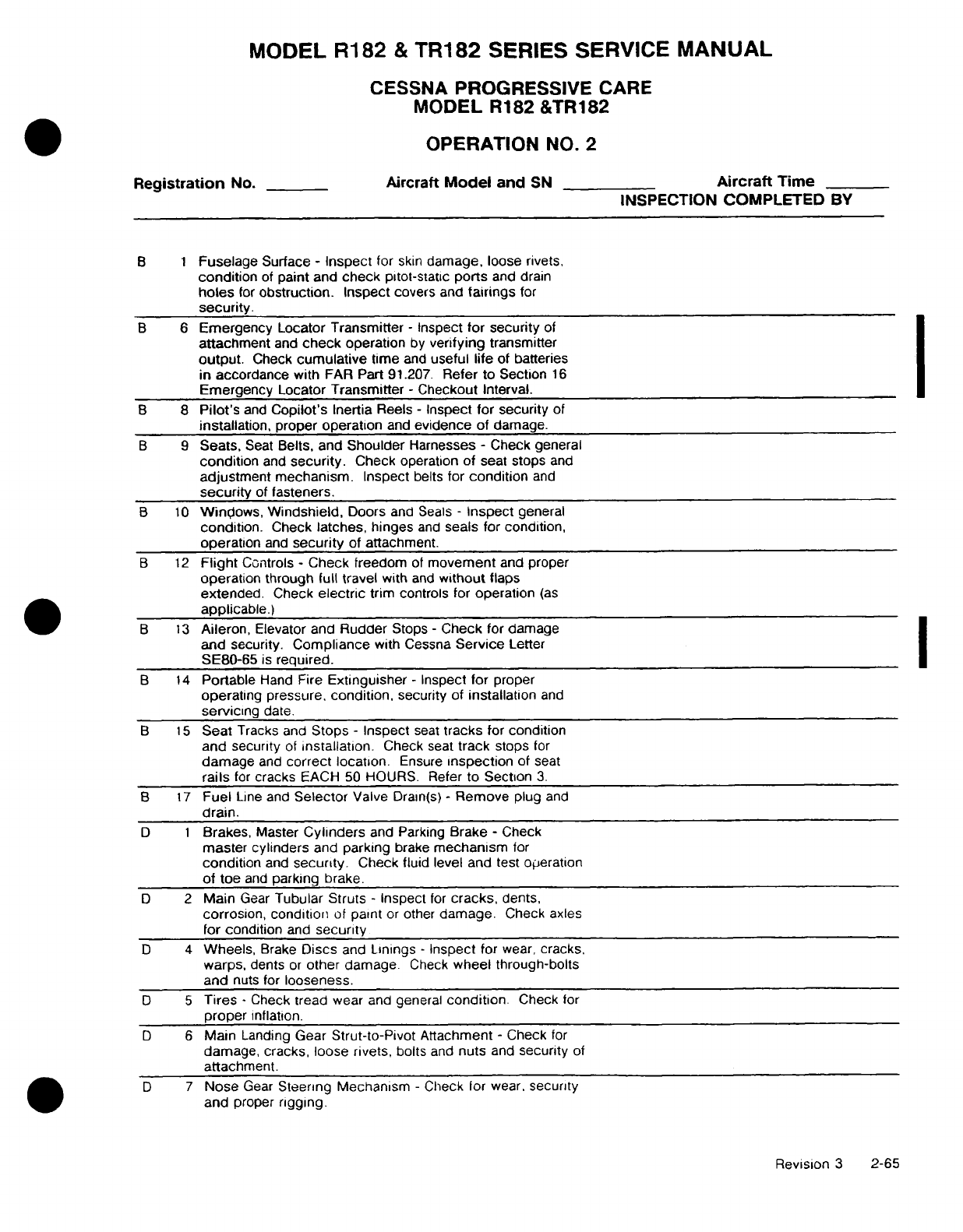
MODEL
R182
&
TR182
SERIES
SERVICE
MANUAL
CESSNA PROGRESSIVE CARE
MODEL
R182
&TR182
OPERATION
NO.
2
Registration
No.
Aircraft
Model
and
SN
Aircraft
Time
INSPECTION
COMPLETED
BY
B 1 Fuselage
Surface
-
Inspect
for
skin
damage.
loose
rivets,
condition
of
paint
and
check
pitot-static
ports
and
drain
holes
for
obstruction.
Inspect
covers
and
fairings
for
security.
B
6
Emergency Locator
Transmitter
-
Inspect
for security
of
attachment
and
check
operation
by
verifying
transmitter
output.
Check
cumulative
time
and
useful
life
of batteries
in
accordance with
FAR Part
91.207.
Refer
to Section
16
Emergency
Locator
Transmitter
-
Checkout
Interval.
B
8
Pilot's
and
Copilot's
Inertia
Reels
-
Inspect for
security
of
installation,
proper
operation
and
evidence
of
damage.
B
9
Seats,
Seat
Belts,
and
Shoulder
Harnesses
-
Check general
condition
and
security.
Check
operation
of
seat
stops
and
adjustment
mechanism.
Inspect
belts
for
condition
and
security
of
fasteners.
B
10
Windows,
Windshield,
Doors
and
Seals
-
Inspect
general
condition.
Check
latches,
hinges
and
seals
for condition,
operation
and
security
of
attachment.
B
12
Flight
Controls
-
Check
freedom
of
movement
and
proper
operation
through full travel
with
and
without
flaps
extended.
Check
electric
trim controls
for
operation
(as
applicable.)
B
13
Aileron,
Elevator
and
Rudder
Stops
-
Check
for
damage
and
security.
Compliance
with
Cessna
Service
Letter
SE80-65
is
required.
B
14
Portable
Hand
Fire
Extinguisher
-
Inspect
for proper
operating
pressure,
condition,
security
of
installation
and
servicing
date.
B
15
Seat
Tracks
and
Stops
-
Inspect
seat
tracks
for
condition
and
security
of
installation.
Check
seat
track
stops
for
damage
and
correct
location.
Ensure
inspection
of
seat
rails
for
cracks
EACH 50
HOURS.
Refer
to
Section
3.
B
17
Fuel
Line and
Selector
Valve
Drain(s)
-
Remove
plug
and
drain.
D 1
Brakes,
Master
Cylinders
and
Parking
Brake
-
Check
master
cylinders
and
parking
brake
mechanism
for
condition
and
security.
Check
fluid
level and
test operation
of toe
and
parking
brake.
D
2
Main
Gear
Tubular Struts
-
Inspect
for
cracks,
dents,
corrosion,
condition
of
paint
or
other
damage.
Check
axles
for
condition
and
security
D
4
Wheels,
Brake
Discs
and
Linings
-
Inspect
for
wear,
cracks,
warps,
dents
or
other
damage.
Check
wheel through-bolts
and
nuts for
looseness.
D 5
Tires
-
Check
tread
wear
and
general
condition.
Check
for
proper
inflation.
D
6
Main
Landing
Gear
Strut-to-Pivot
Attachment
-
Check
for
damage,
cracks,
loose
rivets,
bolts
and
nuts
and
security
of
attachment.
D
7
Nose
Gear
Steering
Mechanism
-
Check
for
wear,
security
and
proper
rigging.
Revision
3
2-65
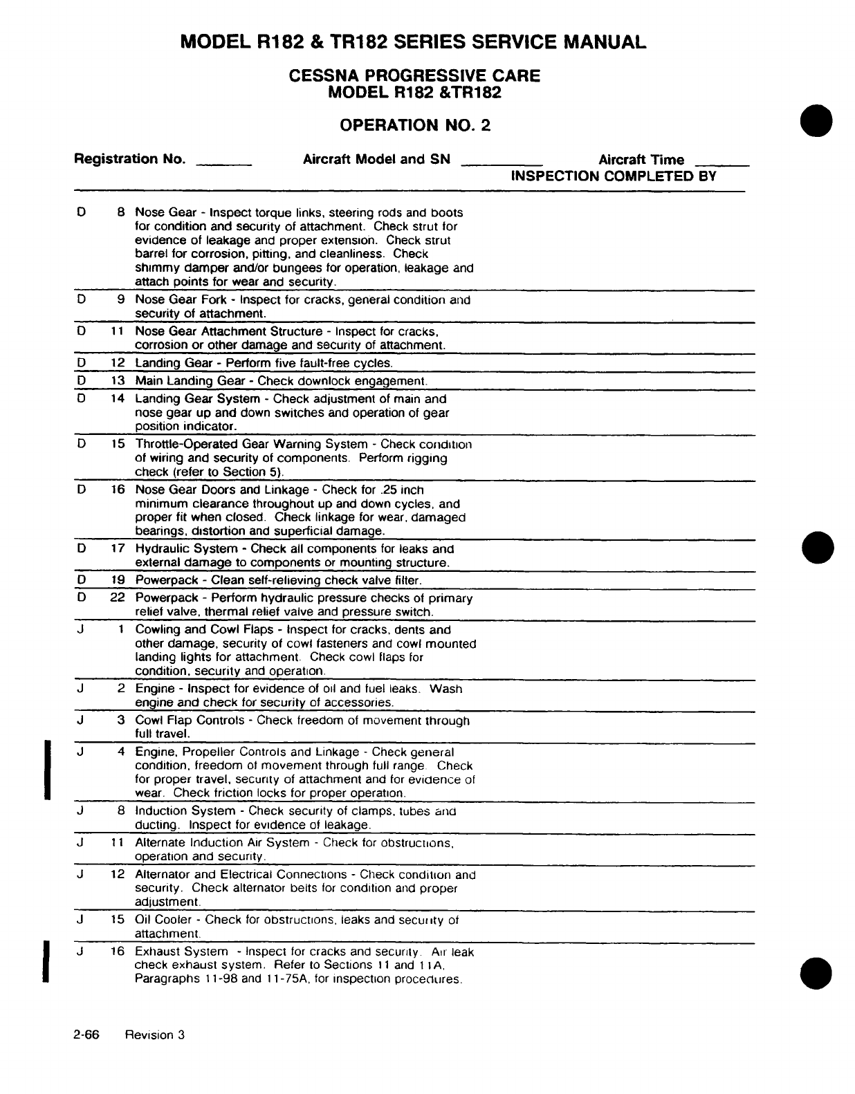
MODEL
R182
&
TR182 SERIES
SERVICE
MANUAL
CESSNA
PROGRESSIVE
CARE
MODEL
R182
&TR182
OPERATION
NO.
2
Registration
No.
Aircraft
Model
and
SN
Aircraft
Time
INSPECTION
COMPLETED
BY
0
8
Nose
Gear
-
Inspect
torque
links, steering
rods
and
boots
for
condition
and
security
of
attachment.
Check
strut
for
evidence
of
leakage
and
proper
extension.
Check
strut
barrel
for
corrosion,
pitting,
and
cleanliness.
Check
shimmy
damper
and/or
bungees
for
operation,
leakage
and
attach
points for
wear and
security.
D
9
Nose Gear
Fork
-
Inspect for
cracks,
general
condition
and
security of
attachment.
D
11
Nose Gear
Attachment Structure
-
Inspect
for
cracks.
corrosion
or
other
damage
and
security
of
attachment.
D
12
Landing
Gear
-
Perform
five
fault-free
cycles.
D
13
Main
Landing
Gear
-
Check
downlock
engagement.
D
14
Landing
Gear
System
-
Check
adjustment
of
main
and
nose
gear
up and
down
switches
and
operation
of
gear
position
indicator.
D
15
Throttle-Operated
Gear
Warning
System
-
Check
condition
of
wiring
and
security
of
components.
Perform
rigging
check
(refer
to
Section
5).
D
16
Nose
Gear
Doors
and
Linkage
-
Check
for
.25
inch
minimum
clearance
throughout
up
and
down
cycles,
and
proper
fit
when
closed. Check
linkage
for
wear,
damaged
bearings,
distortion
and
superficial
damage.
D
17
Hydraulic
System
-
Check
all
components
for
leaks
and
external
damage
to
components
or
mounting
structure.
D
19
Powerpack
-
Clean
self-relieving
check
valve
filter.
D
22 Powerpack
-
Perform
hydraulic
pressure
checks
of
primary
relief
valve,
thermal
relief valve
and
pressure
switch.
J
1
Cowling and
Cowl
Flaps
-
Inspect
for
cracks,
dents
and
other
damage,
security
of
cowl
fasteners
and
cowl
mounted
landing
lights
for
attachment.
Check
cowl
flaps
for
condition,
security
and
operation.
J
2
Engine
-
Inspect
for
evidence
of
oil
and
fuel
leaks.
Wash
engine
and
check
for
security
of
accessories.
J
3
Cowl
Flap
Controls
-
Check
freedom
of
movement
through
full
travel.
J
4
Engine.
Propeller
Controls
and
Linkage
-
Check
general
condition, freedom
of
movement
through full
range
Check
for
proper travel,
security
of
attachment
and
for
evidence
of
wear.
Check
friction
locks
for
proper operation.
J
8
Induction
System
-
Check
security
of
clamps,
tubes
and
ducting. Inspect
for
evidence
of
leakage.
J
11
Alternate
Induction
Air
System
-
Check
for
obstructions,
operation
and
security.
J
12
Alternator
and
Electrical Connections
-
Check
condition
and
security. Check
alternator
belts
for
condition
and
proper
adjustment.
J
15
Oil Cooler
-
Check
for
obstructions,
leaks
and
security
of
attachment.
J
16
Exhaust
System
-
Inspect
for
cracks
and
security
Air
leak
check
exhaust
system.
Refer
to
Sections
11
and
11A,
Paragraphs
11-98
and
11-75A,
for
inspection
procedures.
2-66
Revision
3
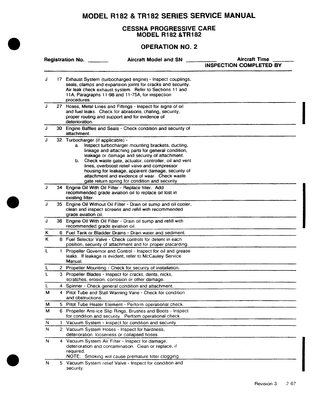
MODEL
R182
&
TR182
SERIES
SERVICE
MANUAL
CESSNA
PROGRESSIVE
CARE
MODEL
R182
&TR182
OPERATION
NO.
2
Registration
No.
Aircraft Model
and
SN
Aircraft
Time
INSPECTION COMPLETED BY
J
17
Exhaust
System
(turbocharged
engine)
-
Inspect couplings,
seals,
clamps
and
expansion joints
for
cracks
and
security.
Air
leak
check
exhaust
system.
Refer
to
Sections
11
and
11
A,
Paragraphs
11-98
and
11
-75A,
for
inspection
procedures.
J
27
Hoses, Metal
Lines
and
Fittings
-
Inspect
for
signs
of
oil
and
fuel
leaks.
Check
for
abrasions,
chafing,
security,
proper routing
and
support
and for
evidence
of
deterioration.
J
30
Engine
Baffles
and Seals
-
Check
condition
and
security
of
attachment.
J
32
Turbocharger
(if
applicable)
-
a.
Inspect
turbocharger
mounting
brackets, ducting,
linkage
and
attaching
parts
for
general
condition,
leakage
or
damage
and
security
of
attachment.
b.
Check waste gate,
actuator,
controller,
oil
and
vent
lines,
overboost
relief
valve and
compressor
housing
for
leakage,
apparent
damage,
security
of
attachment
and
evidence
of
wear.
Check
waste
gate
return
spring
for
condition
and
security.
J
34
Engine Oil
With
Oil
Filter
-
Replace
filter.
Add
recommended
grade
aviation
oil
to
replace oil
lost
in
existing filter.
J
35
Engine
Oil
Without
Oil
Filter
-
Drain
oil
sump
and
oil cooler,
clean
and
inspect
screens
and
refill
with
recommended
grade
aviation oil.
J
36
Engine Oil
With
Oil
Filter
-
Drain
oil
sump and
refill
with
recommended
grade aviation
oil.
K
6
Fuel Tank
or
Bladder
Drains
-
Drain
water
and
sediment.
K
8
Fuel
Selector
Valve
-
Check controls
for
detent
in
each
position,
security
of
attachment
and
for
proper
placarding.
L 1
Propeller
Governor
and
Control
-
Inspect
for
oil
and grease
leaks.
If
leakage
is
evident,
refer
to
McCauley Service
Manual.
L 2
Propeller Mounting
-
Check
for
security
of
installation.
L
3
Propeller Blades
-
Inspect
for
cracks,
dents,
nicks,
scratches,
erosion,
corrosion
or
other
damage.
L
4
Spinner
-
Check
general
condition
and
attachment.
M
4
Pitot
Tube
and
Stall
Warning
Vane
-
Check
for
condition
and
obstructions.
M 5
Pitot
Tube
Heater
Element
-
Perform
operational
check.
M 6
Propeller
Anti-ice
Slip
Rings,
Brushes
and
Boots
-
Inspect
for
condition
and
security.
Perform
operational check.
N 1
Vacuum
System
-
Inspect
for
condition
and
security.
N
2
Vacuum
System
Hoses
-
Inspect
for
hardness,
deterioration,
looseness
or
collapsed
hoses.
N 4
Vacuum
System
Air
Filter
-
Inspect
for
damage,
deterioration
and
contamination.
Clean
or
replace,
if
required.
NOTE:
Smoking will
cause
premature
filter
clogging.
N 5
Vacuum
System
relief
Valve
-
Inspect
for
condition
and
security.
Revision
3
2-67

MODEL
R182
&
TR182
SERIES
SERVICE
MANUAL
CESSNA
PROGRESSIVE
CARE
MODEL R182
&TR182
OPERATION
NO.
2
Registration
No.
Aircraft
Model and
SN
Aircraft
Time
INSPECTION
COMPLETED
BY
N
6
Instruments
-
Check
general
condition
and
markings
for
legibility.
O
2
Instrument,
Cabin,
Navigation,
Beacon,
Strobe, and Landing
Lights
-
Check operation,
condition
of
lens
and
security
of
attachment.
O
3
Circuit
Breakers
and
Fuses
-
Check
operation
and
condition.
Check for
required
number
of
spare
fuses.
Q
Perform
the
Following
Operational
Check:
Q
1
Brakes
-
Test
toe
brakes
and
parking
brake
for
proper
operation.
2-68
Revision
3
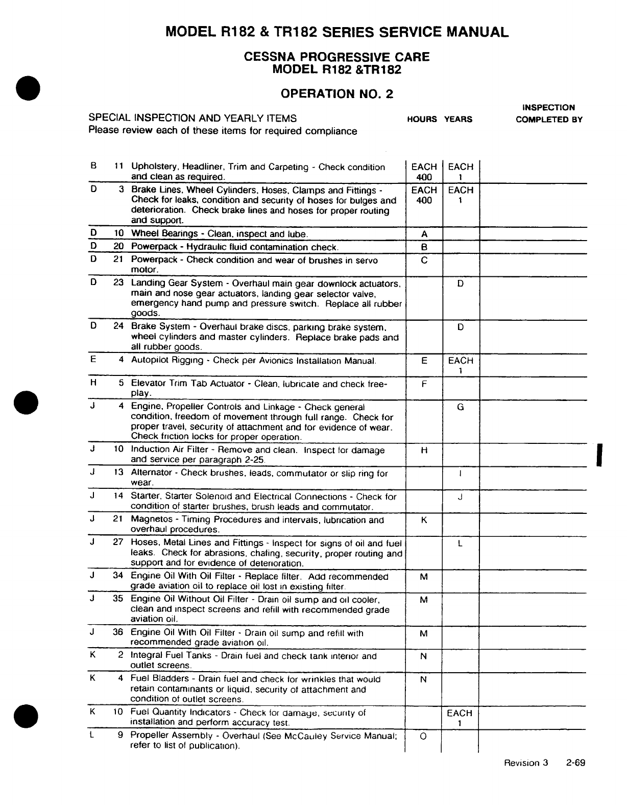
MODEL
R182
&
TR182
SERIES SERVICE
MANUAL
CESSNA
PROGRESSIVE
CARE
MODEL
R182
&TR182
OPERATION
NO.
2
INSPECTION
SPECIAL
INSPECTION
AND YEARLY
ITEMS
HOURS
YEARS
COMPLETED
BY
Please
review
each
of
these
items for
required
compliance
B
11
Upholstery. Headliner,
Trim
and
Carpeting
-
Check
condition
EACH
EACH
and
clean
as
required.
400
1
D
3
Brake
Lines,
Wheel
Cylinders,
Hoses,
Clamps
and
Fittings
-
EACH
EACH
Check
for
leaks,
condition
and
security of
hoses
for
bulges
and
400
1
deterioration.
Check
brake
lines
and
hoses for
proper
routing
and support.
D
10
Wheel
Bearings
-
Clean,
inspect
and
lube.
A
D
20
Powerpack
-
Hydraulic
fluid
contamination
check.
B
D 21
Powerpack
-
Check
condition
and wear
of brushes
in
servo
C
motor.
D
23
Landing
Gear
System
-
Overhaul
main
gear downlock actuators.
D
main
and
nose
gear
actuators,
landing
gear
selector
valve,
emergency
hand
pump
and pressure
switch.
Replace
all
rubber
goods.
D
24
Brake
System
-
Overhaul brake
discs,
parking
brake
system,
D
wheel
cylinders
and
master
cylinders.
Replace
brake pads
and
all
rubber
goods.
E
4
Autopilot
Rigging
-
Check
per Avionics
Installation
Manual.
E
EACH
1
H
5
Elevator
Trim
Tab
Actuator
-
Clean,
lubricate
and
check
free-
F
play.
J
4
Engine,
Propeller Controls
and
Linkage
-
Check
general
G
condition,
freedom of
movement
through
full
range. Check
for
proper
travel,
security
of
attachment
and
for
evidence
of
wear.
Check
friction
locks
for
proper
operation.
J
10
Induction
Air
Filter
-
Remove
and
clean.
Inspect
for
damage
H
and
service
per
paragraph 2-25.
J
13
Alternator
-
Check
brushes,
leads,
commutator
or
slip
ring
for
I
wear.
J
14
Starter,
Starter
Solenoid
and
Electrical
Connections
-
Check
for
J
condition
of
starter brushes,
brush
leads
and commutator.
J
21
Magnetos
-
Timing
Procedures
and
intervals,
lubrication
and
K
overhaul procedures.
J
27
Hoses,
Metal
Lines
and
Fittings
-
Inspect
for
signs
of
oil
and
fuel
L
leaks.
Check
for
abrasions,
chafing,
security,
proper
routing
and
support
and
for
evidence
of
deterioration.
J
34
Engine
Oil
With Oil
Filter
-
Replace
filter. Add
recommended
M
grade
aviation
oil
to
replace
oil
lost
in
existing
filter.
J 35
Engine
Oil
Without
Oil
Filter
-
Drain
oil
sump
and
oil
cooler,
M
clean
and
inspect
screens
and
refill
with
recommended
grade
aviation
oil.
J
36
Engine
Oil
With
Oil
Filter
-
Drain
oil
sump
and
refill
with
M
recommended
grade
aviation
oil.
K
2
Integral
Fuel
Tanks
-
Drain
fuel
and
check
tank
interior
and
N
outlet
screens.
K
4
Fuel
Bladders
-
Drain
fuel
and check
for
wrinkles
that
would
N
retain contaminants
or
liquid,
security
of
attachment
and
condition
of
outlet screens.
K
10
Fuel
Quantity
Indicators
-
Check
for
damage,
security
of
EACH
installation
and
perform
accuracy
test.
1
L
9
Propeller
Assembly
-
Overhaul
(See
McCauley
Service Manual;
0
refer
to
list
of
publication).
Revision
3
2-69
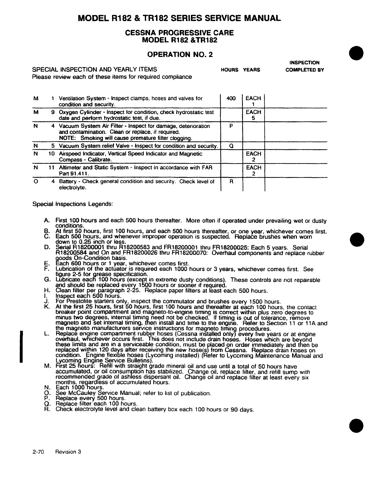
MODEL
R182
&
TR182
SERIES
SERVICE
MANUAL
CESSNA
PROGRESSIVE
CARE
MODEL
R182
&TR182
OPERATION
NO.
2
INSPECTION
SPECIAL
INSPECTION
AND
YEARLY
ITEMS
HOURS
YEARS
COMPLETED
BY
Please
review
each
of
these
items
for
required
compliance
M
1
Ventilation
System
-
Inspect
clamps,
hoses
and
valves
for
400
EACH
condition
and
security.
1
M 9
Oxygen
Cylinder
-
Inspect
for
condition,
check
hydrostatic
test
EACH
date and
perform
hydrostatic
test,
if
due.
5
N
4
Vacuum
System
Air
Filter
-
Inspect
for
damage,
deterioration
P
and
contamination.
Clean
or
replace,
if
required.
NOTE:
Smoking
will
cause premature
filter clogging.
N
5
Vacuum
System
relief
Valve
-
Inspect
for
condition
and
security.
Q
N 10
Airspeed
Indicator,
Vertical
Speed
Indicator
and
Magnetic
EACH
Compass
-
Calibrate.
2
N
11
Altimeter
and
Static
System
-
Inspect
in
accordance with
FAR
EACH
Part
91.411.
2
O
4
Battery
-
Check
general
condition
and
security.
Check level
of
R
electrolyte.
Special
Inspections
Legends:
A.
First
100
hours
and
each
500 hours
thereafter.
More
often
if
operated
under prevailing wet
or
dusty
conditions.
B.
At
first
50
hours,
first
100
hours,
and
each
500
hours
thereafter, or
one year,
whichever
comes
first.
C. Each
500
hours,
and
whenever
improper
operation
is
suspected.
Replace
brushes when
worn
down
to
0.25
inch
or
less.
D.
Serial
R18200001
thru
R18200583
and
FR18200001
thru
FR18200025:
Each
5
years.
Serial
R18200584 and
On
and
FR18200026
thru
FR18200070: Overhaul
components
and
replace
rubber
goods
On-Condition
basis.
E.
Each
600
hours
or
1
year,
whichever
comes
first.
F.
Lubrication
of
the
actuator
is
required
each
1000
hours
or
3
years,
whichever
comes
first.
See
figure
2-5
for
grease specification.
G.
Lubricate
each
100
hours
(except
in
extreme
dusty
conditions).
These
controls
are
not
repairable
and
should
be
replaced
every
1500
hours
or
sooner
if
required.
H.
Clean
filter per
paragraph
2-25. Replace
paper
filters
at
least
each
500 hours.
I.
Inspect
each
500
hours.
J.
For
Prestolite
starters only,
inspect
the
commutator
and
brushes
every
1500 hours.
K.
At
the
first 25
hours,
first
50
hours,
first
100
hours and thereafter
at
each
100 hours,
the contact
breaker
point
compartment
and
magneto-to-engine
timing
is
correct
within
plus
zero
degrees
to
minus
two
degrees,
internal
timing
need
not
be
checked.
If
timing
is out
of tolerance, remove
magneto
and
set
internal
timing, then
install
and
time
to
the
engine.
Refer
to
Section
11
or
11A
and
the
magneto manufacturers
service instructions
for
magneto
timing
procedures.
L.
Replace
engine
compartment
rubber
hoses (Cessna installed
only)
every
five
years
or
at
engine
overhaul,
whichever occurs
first.
This
does
not
include
drain
hoses.
Hoses
which
are
beyond
these
limits
and
are
in a
serviceable
condition,
must
be placed on
order
immediately
and
then
be
replaced
within
120
days
after
receiving
the
new
hose(s)
from
Cessna.
Replace
drain
hoses
on
condition. Engine flexible
hoses
(Lycoming
installed)
(Refer
to
Lycoming
Maintenance
Manual
and
Lycoming
Engine Service
Bulletins).
M.
First
25
hours:
Refill
with
straight
grade
mineral
oil
and
use
until a
total of
50
hours
have
accumulated,
or
oil
consumption
has stabilized.
Change
oil,
replace
filter,
and
refill
sump
with
recommended
grade
of
ashless
dispersant
oil.
Change
oil
and
replace filter
at
least
every
six
months,
regardless
of
accumulated
hours.
N.
Each
1000
hours.
O.
See
McCauley
Service
Manual;
refer
to
list
of
publication.
P.
Replace
every
500
hours.
Q.
Replace
filter
each
100
hours.
R.
Check
electrolyte
level
and
clean
battery
box
each
100
hours
or
90 days.
2-70
Revision
3
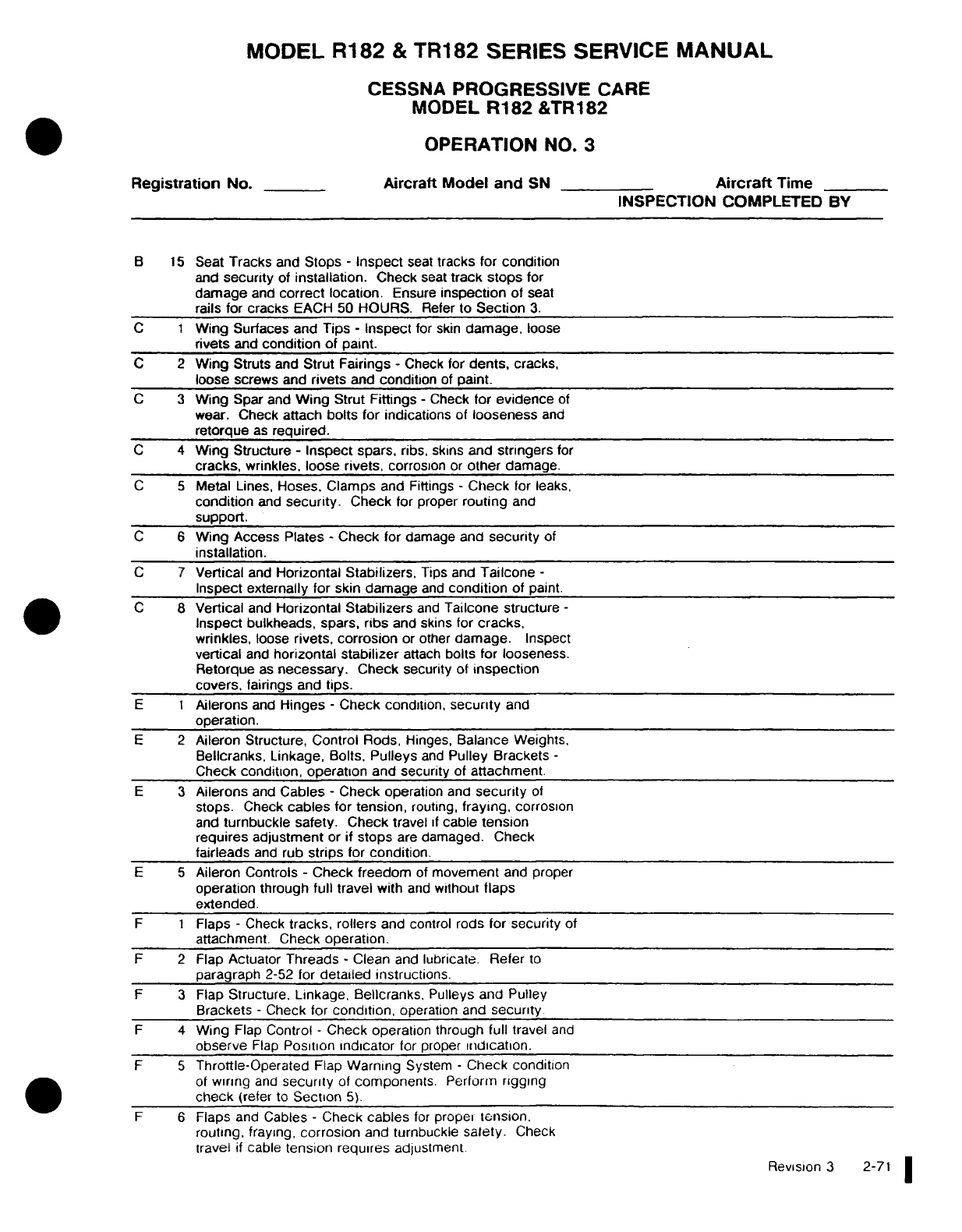
MODEL
R182
&
TR182
SERIES
SERVICE
MANUAL
CESSNA
PROGRESSIVE
CARE
MODEL
R182
&TR182
OPERATION
NO.
3
Registration
No.
Aircraft Model and
SN
Aircraft
Time
INSPECTION
COMPLETED
BY
B
15
Seat
Tracks
and
Stops
-
Inspect
seat
tracks
for
condition
and
security
of
installation.
Check
seat
track
stops
for
damage
and
correct
location.
Ensure
inspection
of
seat
rails
for
cracks
EACH
50 HOURS.
Refer
to
Section
3.
C 1
Wing
Surfaces and
Tips
-
Inspect
for
skin
damage,
loose
rivets
and
condition
of
paint.
C 2
Wing
Struts
and
Strut
Fairings
-
Check
for
dents,
cracks,
loose
screws
and
rivets
and
condition
of
paint.
C 3
Wing
Spar and
Wing
Strut Fittings
-
Check
for
evidence
of
wear.
Check
attach
bolts for
indications
of
looseness
and
retorque
as
required.
C
4
Wing
Structure
-
Inspect
spars,
ribs,
skins
and
stringers
for
cracks,
wrinkles, loose
rivets,
corrosion
or
other
damage.
C 5
Metal
Lines,
Hoses.
Clamps
and
Fittings
-
Check
for
leaks,
condition
and
security.
Check
for
proper
routing
and
support.
C 6
Wing Access Plates
-
Check
for
damage
and
security
of
installation.
C 7
Vertical
and
Horizontal
Stabilizers,
Tips and
Tailcone
-
Inspect
externally
for skin damage
and
condition
of paint.
C
8
Vertical
and
Horizontal
Stabilizers
and
Tailcone structure
-
Inspect
bulkheads,
spars,
ribs
and
skins for
cracks,
wrinkles,
loose
rivets, corrosion
or
other
damage.
Inspect
vertical
and
horizontal
stabilizer
attach
bolts
for
looseness.
Retorque
as
necessary.
Check
security of
inspection
covers,
fairings
and
tips.
E 1
Ailerons
and
Hinges
-
Check
condition,
security
and
operation.
E 2
Aileron
Structure,
Control
Rods,
Hinges,
Balance
Weights,
Bellcranks, Linkage,
Bolts,
Pulleys
and
Pulley
Brackets
-
Check
condition,
operation
and
security
of
attachment.
E 3
Ailerons
and
Cables
-
Check
operation
and
security
of
stops.
Check
cables
for
tension,
routing,
fraying,
corrosion
and
turnbuckle safety.
Check
travel
if
cable
tension
requires
adjustment
or
if
stops
are
damaged. Check
fairleads
and
rub
strips
for
condition.
E 5
Aileron Controls
-
Check
freedom
of
movement
and
proper
operation through
full
travel with
and
without
flaps
extended.
F 1
Flaps
-
Check
tracks,
rollers
and
control
rods
for
security
of
attachment.
Check
operation.
F 2
Flap
Actuator
Threads
-
Clean
and
lubricate. Refer
to
paragraph
2-52
for
detailed
instructions.
F 3
Flap
Structure. Linkage,
Bellcranks,
Pulleys
and
Pulley
Brackets
-
Check for
condition,
operation and
security
F
4
Wing
Flap
Control
-
Check operation
through
full
travel
and
observe
Flap
Position
indicator
for
proper
indication.
F 5
Throttle-Operated
Flap
Warning
System
-
Check condition
of
wiring
and
security
of
components.
Perform
rigging
check
(refer
to
Section
5).
F 6
Flaps
and
Cables
-
Check
cables
for
proper
tension.
routing, fraying,
corrosion
and
turnbuckle
safety.
Check
travel
if
cable
tension
requires
adjustment Revision
3
2-71
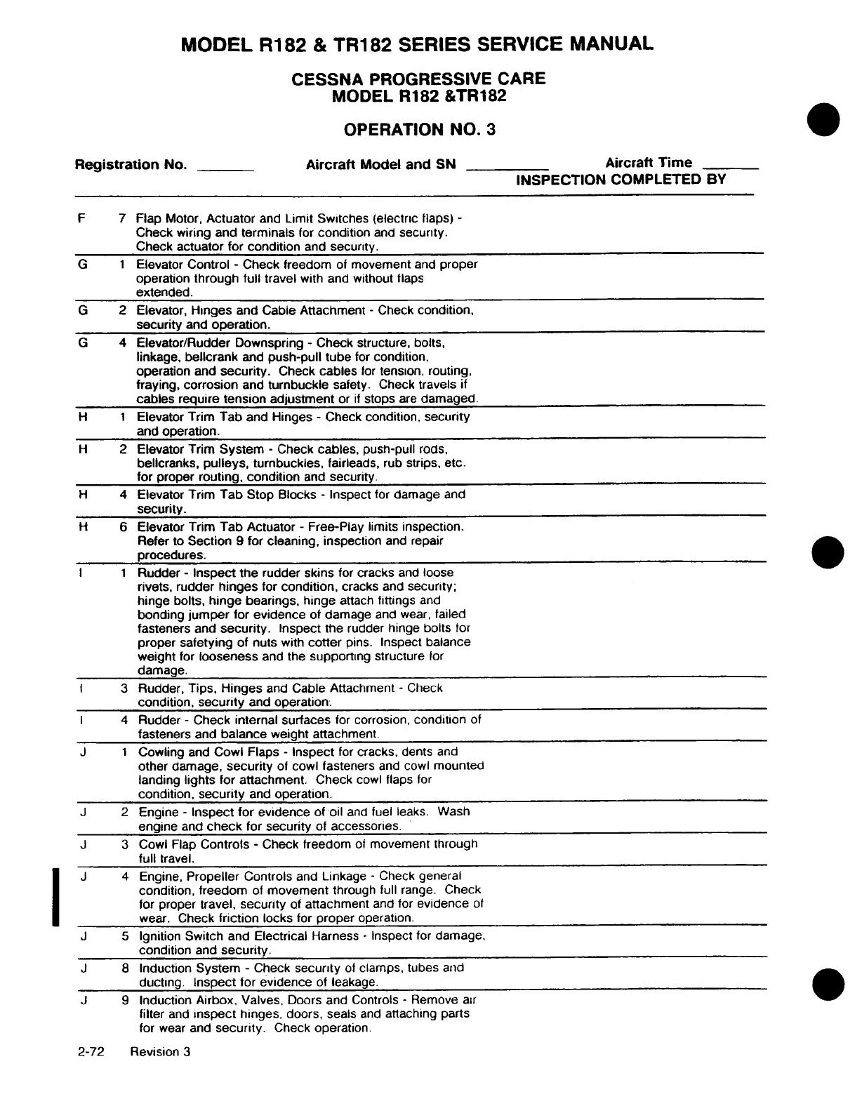
MODEL
R182
&
TR182
SERIES
SERVICE
MANUAL
CESSNA
PROGRESSIVE
CARE
MODEL
R182
&TR182
OPERATION
NO.
3
Registration
No.
Aircraft
Model
and
SN Aircraft
Time
INSPECTION
COMPLETED BY
F
7
Flap Motor,
Actuator
and
Limit Switches (electric
flaps)
-
Check
wiring
and
terminals
for
condition
and
security.
Check
actuator for
condition
and
security.
G 1
Elevator
Control
-
Check freedom
of
movement
and
proper
operation
through
full
travel
with and
without
flaps
extended.
G
2
Elevator,
Hinges
and
Cable Attachment
-
Check
condition,
security
and
operation.
G
4
Elevator/Rudder
Downspring
-
Check
structure,
bolts,
linkage,
bellcrank
and
push-pull tube
for
condition.
operation and
security.
Check
cables
for
tension,
routing,
fraying,
corrosion
and
turnbuckle
safety.
Check
travels
if
cables
require
tension adjustment
or
if
stops
are
damaged.
H 1
Elevator
Trim
Tab
and Hinges
-
Check
condition,
security
and
operation.
H
2
Elevator
Trim
System
-
Check
cables,
push-pull
rods,
bellcranks,
pulleys,
turnbuckles,
fairleads,
rub
strips,
etc.
for
proper
routing, condition
and
security.
H
4
Elevator
Trim Tab
Stop
Blocks
-
Inspect
for
damage
and
security.
H
6
Elevator
Trim Tab Actuator
-
Free-Play
limits inspection.
Refer
to
Section 9
for cleaning,
inspection
and repair
procedures.
I 1
Rudder
-
Inspect the
rudder
skins
for
cracks
and
loose
rivets,
rudder
hinges
for
condition,
cracks
and
security;
hinge bolts,
hinge
bearings,
hinge
attach
fittings
and
bonding
jumper
for
evidence
of damage
and
wear,
failed
fasteners
and
security.
Inspect
the
rudder
hinge
bolts
for
proper
safetying
of
nuts
with
cotter
pins.
Inspect
balance
weight
for
looseness
and the
supporting
structure
for
damage.
I
3
Rudder,
Tips,
Hinges
and
Cable Attachment
-
Check
condition,
security
and
operation.
I
4
Rudder
-
Check internal surfaces
for
corrosion,
condition
of
fasteners
and
balance
weight
attachment.
J 1
Cowling
and
Cowl Flaps
-
Inspect
for
cracks,
dents
and
other damage,
security
of
cowl fasteners
and
cowl
mounted
landing
lights
for attachment.
Check
cowl
flaps
for
condition,
security
and
operation.
J
2
Engine
-
Inspect
for
evidence
of
oil
and
fuel
leaks.
Wash
engine
and
check
for
security
of
accessories.
J
3
Cowl
Flap
Controls
-
Check
freedom
of
movement
through
full
travel.
J
4
Engine,
Propeller
Controls
and
Linkage
-
Check
general
condition,
freedom
of
movement
through
full
range.
Check
for
proper
travel,
security
of
attachment
and
for
evidence
of
wear.
Check
friction
locks
for
proper
operation.
J
5
Ignition
Switch
and
Electrical
Harness
-
Inspect
for
damage,
condition
and
security.
J
8
Induction
System
-
Check
security
of
clamps, tubes
and
ducting
Inspect
for evidence
of
leakage.
J
9
Induction Airbox,
Valves,
Doors
and
Controls
-
Remove
air
filter
and
inspect
hinges,
doors,
seals
and
attaching parts
for
wear
and
security.
Check
operation
2-72
Revision
3
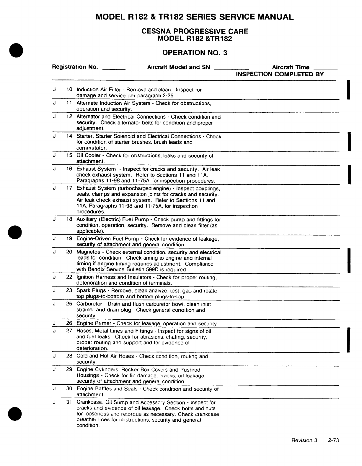
MODEL
R182
&
TR182
SERIES
SERVICE
MANUAL
CESSNA
PROGRESSIVE
CARE
MODEL
R182
&TR182
OPERATION
NO.
3
Registration
No.
Aircraft
Model
and
SN
Aircraft
Time
INSPECTION
COMPLETED
BY
J
10
Induction
Air Filter
-
Remove
and
clean.
Inspect
for
damage
and
service
per
paragraph
2-25.
J
11
Alternate
Induction
Air
System
-
Check
for obstructions,
operation
and
security.
J 12
Alternator
and
Electrical
Connections
-
Check condition
and
security.
Check
alternator
belts
for
condition
and proper
adjustment.
J
14
Starter,
Starter
Solenoid
and
Electrical
Connections
-
Check
for
condition
of
starter brushes,
brush
leads
and
commutator.
J
15
Oil
Cooler
-
Check
for
obstructions,
leaks and
security
of
attachment.
J
16
Exhaust
System
-
Inspect
for
cracks and
security.
Air
leak
check
exhaust
system.
Refer
to
Sections
11
and
11A,
Paragraphs
11-98
and
11-75A,
for
inspection
procedures.
J
17
Exhaust
System
(turbocharged
engine)
-
Inspect
couplings,
seals,
clamps
and
expansion
joints
for
cracks
and
security.
Air
leak
check
exhaust
system.
Refer
to
Sections
11
and
11
A,
Paragraphs
11-98 and
11-75A,
for
inspection
procedures.
J
18
Auxiliary
(Electric)
Fuel Pump
-
Check
pump
and
fittings
for
condition,
operation,
security.
Remove
and clean
filter
(as
applicable).
J
19
Engine-Driven
Fuel
Pump
-
Check
for
evidence
of
leakage,
security of
attachment
and
general
condition.
J
20
Magnetos
-
Check
external
condition,
security
and
electrical
leads for
condition.
Check timing
to
engine
and internal
timing
if
engine
timing
requires
adjustment. Compliance
with
Bendix Service
Bulletin
599D
is
required.
J
22
Ignition Harness
and
Insulators
-
Check
for proper
routing,
deterioration
and
condition
of
terminals.
J
23
Spark
Plugs -
Remove,
clean analyze,
test,
gap
and
rotate
top
plugs-to-bottom
and
bottom
plugs-to-top.
J
25
Carburetor
-
Drain
and
flush
carburetor
bowl,
clean
inlet
strainer and
drain
plug.
Check general
condition
and
security.
J
26
Engine
Primer
-
Check
for leakage,
operation
and
security.
J
27
Hoses,
Metal
Lines
and Fittings
-
Inspect
for
signs
of
oil
and
fuel
leaks.
Check
for abrasions,
chafing,
security,
proper
routing
and
support
and
for
evidence
of
deterioration.
J
28
Cold
and
Hot
Air
Hoses
-
Check
condition, routing
and
security.
J
29 Engine
Cylinders,
Rocker
Box
Covers
and
Pushrod
Housings
-
Check
for
fin
damage,
cracks, oil
leakage,
security
of
attachment
and general
condition.
J
30
Engine
Baffles
and
Seals
-
Check
condition
and
security
of
attachment.
J
31
Crankcase,
Oil
Sump
and
Accessory
Section
-
Inspect
for
cracks
and
evidence
of
oil
leakage.
Check
bolts
and
nuts
for
looseness
and
retorque
as
necessary.
Check crankcase
breather
lines
for
obstructions,
security
and
general
condition.
Revision
3
2-73
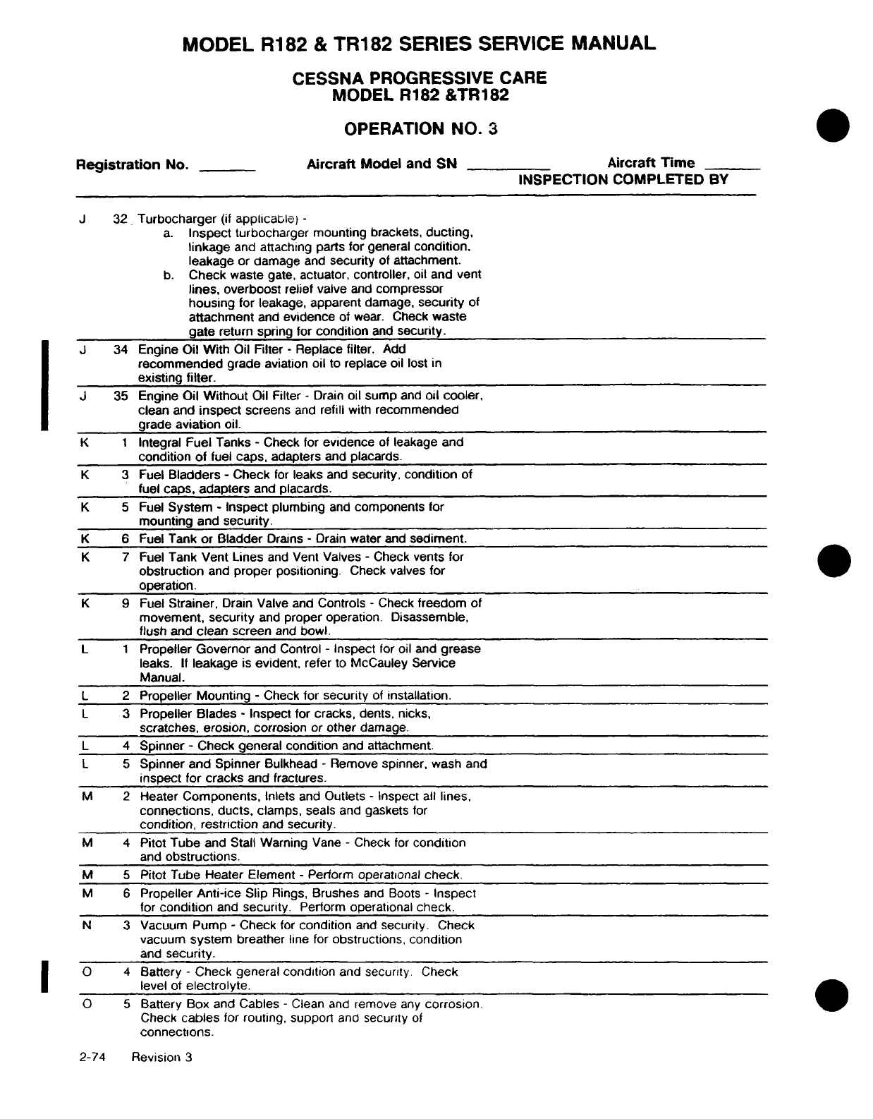
MODEL
R182
&
TR182
SERIES
SERVICE
MANUAL
CESSNA
PROGRESSIVE
CARE
MODEL
R182
&TR182
OPERATION
NO.
3
Registration
No.
Aircraft
Model
and
SN
Aircraft
Time
INSPECTION
COMPLETED
BY
J
32
Turbocharger
(if
applicable)
-
a.
Inspect
turbocharger
mounting
brackets,
ducting,
linkage
and
attaching parts
for
general
condition,
leakage
or
damage
and
security
of
attachment.
b.
Check
waste
gate,
actuator,
controller,
oil and
vent
lines,
overboost
relief
valve
and
compressor
housing
for
leakage,
apparent
damage,
security
of
attachment
and
evidence
of wear.
Check
waste
gate
return
spring
for
condition
and
security.
J 34 Engine
Oil With
Oil Filter
-
Replace
filter.
Add
recommended
grade
aviation
oil
to
replace
oil
lost
in
existing
filter.
J
35 Engine
Oil
Without
Oil Filter
-
Drain
oil
sump
and
oil
cooler,
clean
and
inspect
screens
and
refill
with
recommended
grade
aviation
oil.
K 1
Integral
Fuel Tanks
-
Check
for
evidence
of
leakage
and
condition of
fuel
caps,
adapters
and
placards.
K
3
Fuel
Bladders
-
Check
for
leaks
and
security, condition
of
fuel
caps,
adapters
and
placards.
K
5
Fuel
System
-
Inspect
plumbing
and
components
for
mounting and
security.
K
6
Fuel
Tank
or Bladder
Drains
-
Drain
water
and
sediment.
K
7
Fuel
Tank
Vent Lines
and
Vent
Valves
-
Check
vents
for
obstruction
and
proper positioning.
Check
valves
for
operation.
K
9
Fuel
Strainer,
Drain
Valve and
Controls
-
Check
freedom
of
movement,
security
and
proper
operation.
Disassemble,
flush
and
clean
screen
and
bowl.
L
1
Propeller Governor
and
Control
-
Inspect
for
oil
and
grease
leaks.
If
leakage
is
evident,
refer to McCauley
Service
Manual.
L
2
Propeller Mounting
-
Check
for security
of
installation.
L
3
Propeller
Blades
-
Inspect
for cracks,
dents,
nicks,
scratches,
erosion,
corrosion
or
other
damage.
L
4
Spinner
-
Check general
condition
and
attachment.
L 5
Spinner and Spinner
Bulkhead
-
Remove
spinner,
wash
and
inspect
for
cracks
and
fractures.
M
2
Heater
Components,
Inlets and
Outlets
-
Inspect all
lines,
connections,
ducts,
clamps,
seals
and
gaskets
for
condition,
restriction
and
security.
M
4
Pitot Tube
and
Stall
Warning
Vane
-
Check
for
condition
and
obstructions.
M
5
Pitot
Tube Heater Element
-
Perform operational
check.
M 6
Propeller
Anti-ice
Slip
Rings,
Brushes
and
Boots
-
Inspect
for
condition
and
security.
Perform
operational
check.
N
3
Vacuum Pump
-
Check
for
condition
and
security. Check
vacuum
system
breather
line
for
obstructions,
condition
and
security.
O 4
Battery
-
Check
general condition
and
security.
Check
level
of
electrolyte.
O
5
Battery
Box and
Cables
-
Clean
and
remove
any
corrosion.
Check
cables
for
routing, support
and
security
of
connections.
2-74 Revision
3
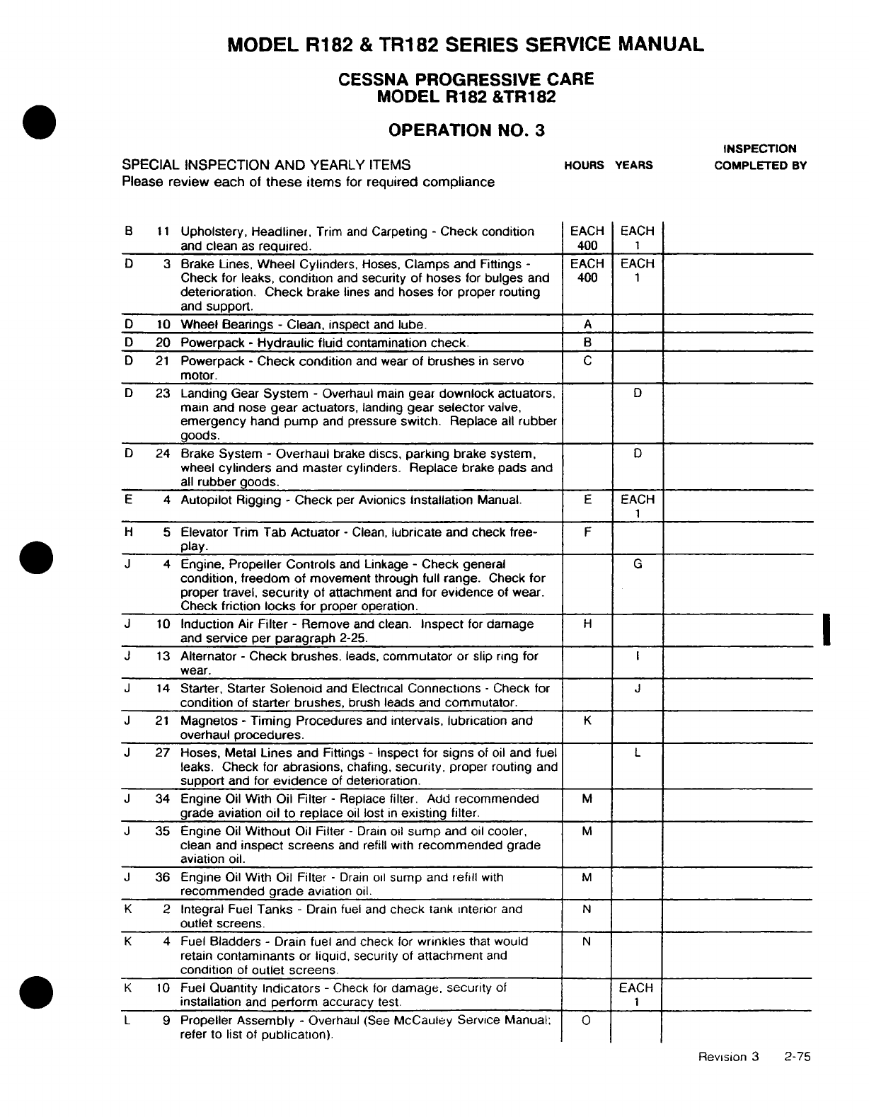
MODEL
R182
&
TR182
SERIES
SERVICE
MANUAL
CESSNA
PROGRESSIVE
CARE
MODEL R182
&TR182
OPERATION
NO.
3
INSPECTION
SPECIAL
INSPECTION
AND
YEARLY
ITEMS
HOURS
YEARS
COMPLETED
BY
Please
review each
of
these
items
for
required
compliance
B
11
Upholstery,
Headliner,
Trim
and
Carpeting
-
Check condition
EACH
EACH
and
clean
as
required.
400
1
D
3
Brake Lines,
Wheel Cylinders,
Hoses,
Clamps
and Fittings
-
EACH
EACH
Check
for leaks,
condition
and
security
of
hoses
for
bulges
and
400
1
deterioration.
Check
brake
lines
and
hoses for
proper
routing
and
support.
D
10
Wheel
Bearings
-
Clean, inspect
and
lube.
A
D
20
Powerpack
-
Hydraulic
fluid
contamination
check.
B
D
21
Powerpack
-
Check
condition
and
wear
of
brushes
in
servo
C
motor.
D
23
Landing
Gear
System
-
Overhaul
main
gear
downlock
actuators,
D
main
and
nose
gear
actuators,
landing
gear
selector
valve,
emergency
hand
pump
and
pressure
switch.
Replace
all
rubber
goods.
D
24
Brake
System
-
Overhaul
brake
discs,
parking
brake
system,
D
wheel
cylinders
and
master
cylinders.
Replace
brake
pads
and
all
rubber
goods.
E
4
Autopilot
Rigging
-
Check
per
Avionics
Installation
Manual.
E
EACH
H
5
Elevator
Trim
Tab
Actuator
-
Clean,
lubricate
and
check free-
F
play.
J
4
Engine,
Propeller
Controls
and
Linkage
-
Check
general
G
condition,
freedom
of
movement
through
full
range.
Check
for
proper
travel,
security
of
attachment and for
evidence
of
wear.
Check
friction
locks
for
proper operation.
J
10
Induction
Air
Filter
-
Remove
and
clean.
Inspect
for
damage
H
and
service
per
paragraph
2-25.
J
13
Alternator
-
Check
brushes,
leads,
commutator or
slip
ring
for
I
wear.
J
14
Starter, Starter
Solenoid
and
Electrical
Connections
-
Check
for
J
condition
of
starter brushes,
brush
leads and
commutator.
J
21
Magnetos
-
Timing
Procedures
and
intervals,
lubrication
and
K
overhaul
procedures.
J
27 Hoses,
Metal
Lines
and
Fittings
-
Inspect
for
signs
of
oil
and
fuel
L
leaks. Check for
abrasions,
chafing,
security,
proper
routing
and
support
and
for
evidence
of
deterioration.
J
34 Engine
Oil
With
Oil
Filter
-
Replace
filter.
Add
recommended
M
grade aviation
oil
to
replace
oil
lost
in
existing
filter.
J
35
Engine
Oil
Without
Oil
Filter
-
Drain
oil
sump
and
oil
cooler,
M
clean
and
inspect
screens
and
refill
with
recommended grade
aviation oil.
J
36 Engine
Oil
With
Oil
Filter
-
Drain
oil
sump
and
refill
with
M
recommended
grade
aviation
oil.
K
2
Integral
Fuel
Tanks
-
Drain
fuel and
check
tank
interior
and
N
outlet
screens.
K
4
Fuel
Bladders
-
Drain
fuel
and
check
for
wrinkles
that
would
N
retain
contaminants
or
liquid,
security
of
attachment
and
condition
of
outlet
screens.
K
10
Fuel
Quantity
Indicators
-
Check
for
damage,
security
of
EACH
installation
and
perform
accuracy
test.
1
L
9
Propeller
Assembly
-
Overhaul
(See
McCauley
Service
Manual:
O
refer
to list of
publication).
Revision
3
2-75
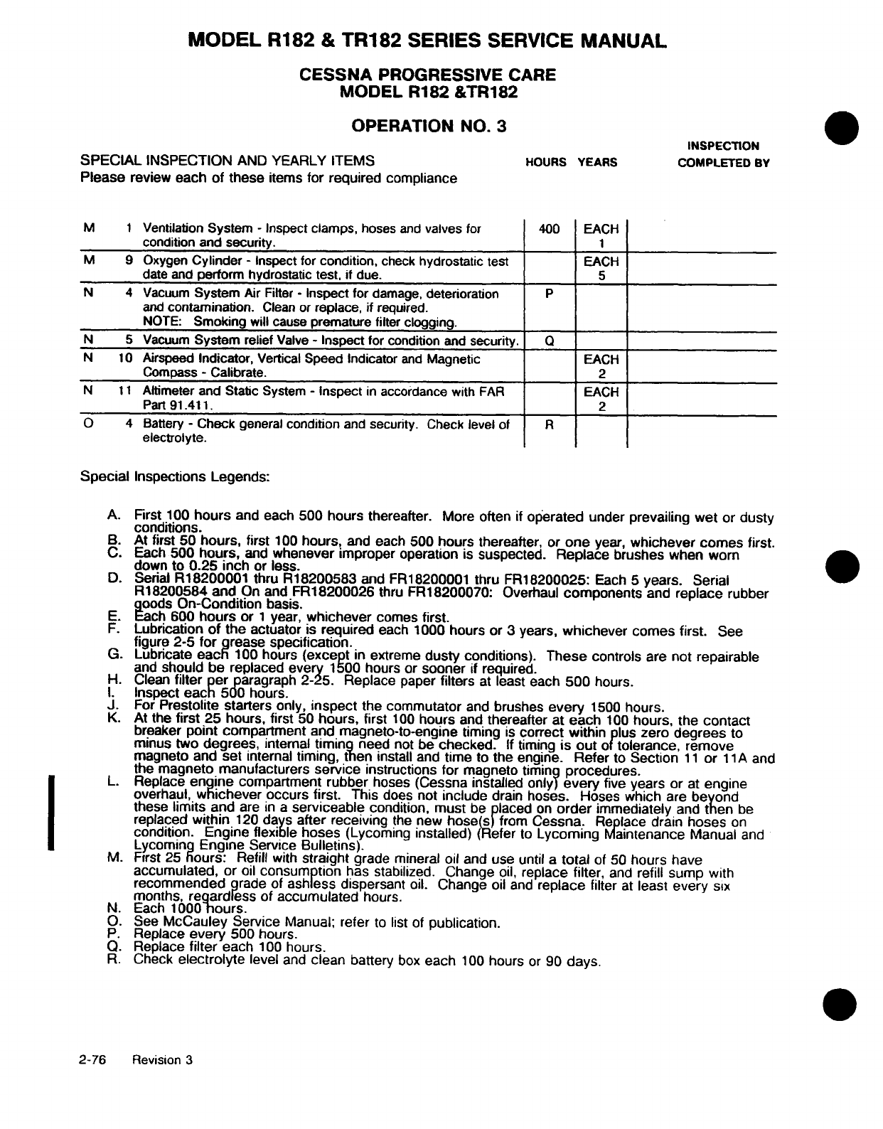
MODEL
R182
&
TR182
SERIES
SERVICE
MANUAL
CESSNA
PROGRESSIVE
CARE
MODEL
R182
&TR182
OPERATION
NO.
3
INSPECTION
SPECIAL
INSPECTION
AND YEARLY ITEMS
HOURS
YEARS COMPLETED
BY
Please
review
each
of these
items
for
required
compliance
M
1
Ventilation
System
-
Inspect
clamps,
hoses
and
valves
for
400
EACH
condition
and
security.
1
M
9
Oxygen
Cylinder
-
Inspect for
condition,
check
hydrostatic
test
EACH
date
and
perform
hydrostatic test,
if
due.
5
N
4
Vacuum
System
Air
Filter
-
Inspect for
damage,
deterioration
P
and
contamination.
Clean
or
replace, if
required.
NOTE:
Smoking
will
cause
premature filter
clogging.
N
5
Vacuum
System
relief
Valve
-
Inspect
for
condition
and
security.
Q
N
10
Airspeed
Indicator,
Vertical
Speed
Indicator
and
Magnetic
EACH
Compass
-
Calibrate.
2
N
11
Altimeter
and Static
System
-
Inspect
in
accordance with
FAR
EACH
Part
91.411.
2
O
4
Battery
-
Check general
condition
and
security.
Check
level
of
R
electrolyte.
Special
Inspections
Legends:
A.
First 100
hours
and each
500 hours
thereafter.
More
often
if
operated
under
prevailing
wet
or
dusty
conditions.
B.
At first
50
hours,
first
100
hours,
and
each
500
hours
thereafter,
or
one
year,
whichever
comes
first.
C.
Each
500
hours,
and
whenever
improper
operation
is
suspected.
Replace
brushes
when
worn
down
to
0.25
inch or
less.
D.
Serial
R18200001 thru
R18200583
and FR18200001
thru
FR18200025:
Each
5
years.
Serial
R18200584 and
On and
FR18200026
thru
FR18200070:
Overhaul
components
and
replace
rubber
goods
On-Condition
basis.
E.
Each
600
hours
or
1
year,
whichever
comes
first.
F.
Lubrication
of
the
actuator
is
required
each 1000
hours
or
3
years,
whichever
comes
first.
See
figure
2-5
for
grease
specification.
G.
Lubricate
each
100
hours
(except
in
extreme
dusty
conditions).
These
controls
are
not
repairable
and
should be
replaced
every
1500
hours or
sooner
if
required.
H. Clean
filter
per
paragraph
2-25. Replace
paper
filters
at
least
each
500
hours.
I.
Inspect
each
500
hours.
J.
For
Prestolite
starters
only,
inspect
the
commutator
and
brushes
every
1500
hours.
K.
At
the
first
25
hours,
first
50
hours,
first
100
hours
and
thereafter at
each
100
hours, the
contact
breaker
point
compartment
and
magneto-to-engine
timing
is
correct
within
plus
zero
degrees
to
minus
two
degrees,
internal
timing
need
not
be
checked.
If
timing
is
out
of
tolerance, remove
magneto and
set
internal
timing, then
install and
time to
the
engine.
Refer
to
Section
11
or
11
A
and
the
magneto manufacturers
service
instructions
for
magneto
timing
procedures.
L.
Replace
engine
compartment
rubber
hoses (Cessna
installed only)
every
five
years
or
at
engine
overhaul,
whichever
occurs
first.
This
does
not
include
drain
hoses. Hoses
which
are
beyond
these
limits
and
are
in
a
serviceable
condition,
must
be placed
on
order
immediately
and
then
be
replaced
within
120
days
after
receiving
the
new
hose(s)
from
Cessna.
Replace
drain
hoses
on
condition. Engine flexible
hoses
(Lycoming installed)
(Refer
to
Lycoming
Maintenance
Manual
and
Lycoming
Engine
Service
Bulletins).
M.
First
25
hours:
Refill
with
straight
grade mineral
oil
and
use
until
a
total
of
50
hours have
accumulated,
or
oil
consumption
has stabilized. Change
oil,
replace filter,
and
refill
sump
with
recommended
grade of
ashless
dispersant
oil.
Change
oil
and
replace
filter
at
least
every
six
months,
regardless
of
accumulated
hours.
N.
Each
1000-hours.
O.
See
McCauley Service
Manual;
refer
to
list
of
publication.
P.
Replace
every
500
hours.
Q.
Replace
filter
each
100
hours.
R.
Check
electrolyte
level
and
clean
battery
box
each
100
hours
or
90
days.
2-76
Revision
3
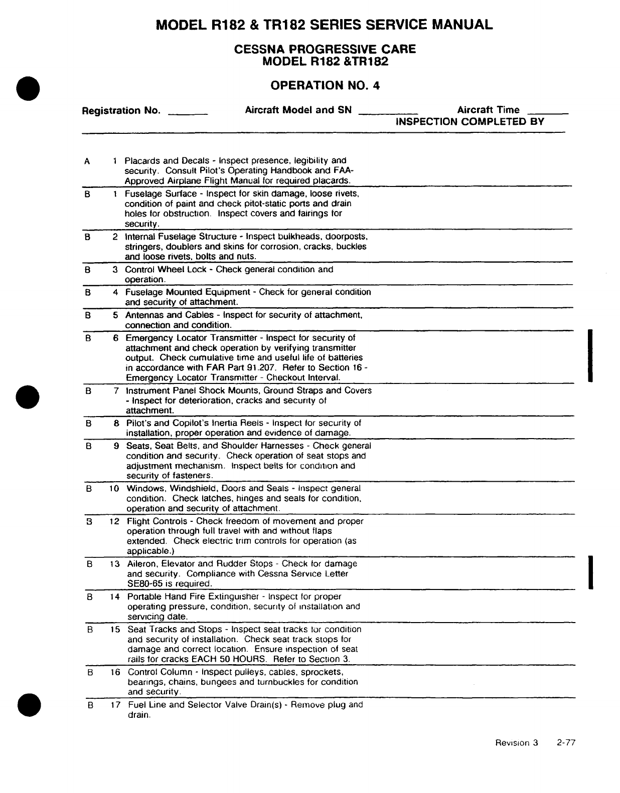
MODEL R182
&
TR182
SERIES SERVICE
MANUAL
CESSNA PROGRESSIVE
CARE
MODEL
R182
&TR182
OPERATION
NO.
4
Registration
No.
Aircraft Model and
SN
Aircraft
Time
INSPECTION
COMPLETED
BY
A 1
Placards and
Decals
-
Inspect
presence,
legibility
and
security.
Consult
Pilot's
Operating
Handbook
and
FAA-
Approved Airplane
Flight
Manual
for
required
placards.
B 1
Fuselage
Surface
-
Inspect for
skin
damage,
loose
rivets,
condition of
paint
and
check
pitot-static
ports
and
drain
holes
for
obstruction.
Inspect
covers
and
fairings
for
security.
B
2
Internal
Fuselage
Structure
-
Inspect
bulkheads,
doorposts,
stringers,
doublers
and skins
for
corrosion,
cracks,
buckles
and
loose
rivets,
bolts
and
nuts.
B
3
Control
Wheel
Lock
-
Check
general
condition
and
operation.
B
4
Fuselage
Mounted Equipment
-
Check
for
general
condition
and
security
of
attachment.
B
5
Antennas
and Cables
-
Inspect
for
security
of
attachment,
connection
and
condition.
B
6
Emergency
Locator
Transmitter
-
Inspect
for
security
of
attachment
and
check
operation
by
verifying
transmitter
output.
Check
cumulative
time
and
useful
life
of batteries
in
accordance
with
FAR
Part
91.207.
Refer
to
Section
16
-
Emergency
Locator
Transmitter
-
Checkout Interval.
B
7
Instrument
Panel
Shock
Mounts, Ground Straps
and
Covers
-
Inspect
for
deterioration,
cracks
and
security
of
attachment.
B
8
Pilot's
and
Copilot's
Inertia
Reels
-
Inspect
for
security
of
installation, proper
operation
and
evidence
of
damage.
B
9
Seats,
Seat
Belts,
and
Shoulder
Harnesses
-
Check
general
condition
and
security.
Check operation
of
seat
stops
and
adjustment mechanism.
Inspect
belts
for
condition
and
security
of
fasteners.
B
10
Windows,
Windshield,
Doors
and
Seals
-
Inspect
general
condition.
Check
latches,
hinges
and
seals
for
condition,
operation
and
security
of attachment.
B
12
Flight Controls
-
Check
freedom
of
movement
and
proper
operation through
full
travel
with
and
without
flaps
extended.
Check
electric
trim
controls
for
operation
(as
applicable.)
B
13
Aileron, Elevator
and
Rudder
Stops
-
Check
for
damage
and
security.
Compliance
with Cessna
Service
Letter
SE80-65
is
required.
B
14
Portable
Hand
Fire
Extinguisher
-
Inspect
for
proper
operating
pressure,
condition,
security
of
installation
and
servicing
date.
B
15
Seat
Tracks
and
Stops
-
Inspect
seat
tracks
tor
condition
and
security
of
installation.
Check seat
track
stops
for
damage
and
correct
location.
Ensure
inspection
of
seat
rails for
cracks
EACH
50
HOURS.
Refer
to
Section
3.
B
16
Control Column
-
Inspect pulleys,
cables,
sprockets,
bearings,
chains,
bungees
and
turnbuckles
for
condition
and
security.
B
17
Fuel
Line
and
Selector
Valve
Drain(s)
-
Remove
plug
and
drain.
Revision
3
2-77
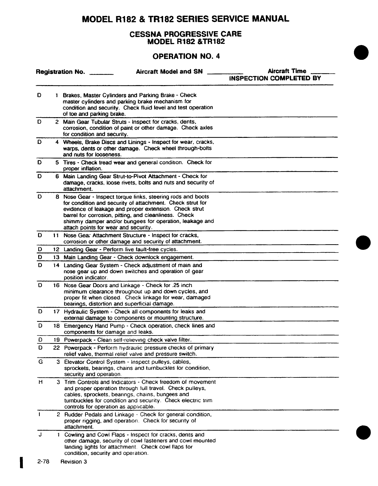
MODEL
R182
&
TR182 SERIES
SERVICE
MANUAL
CESSNA
PROGRESSIVE
CARE
MODEL
R182
&TR182
OPERATION
NO.
4
Registration
No.
Aircraft
Model
and
SN Aircraft Time
INSPECTION
COMPLETED
BY
D 1
Brakes,
Master
Cylinders
and
Parking
Brake
-
Check
master
cylinders
and
parking
brake
mechanism for
condition
and
security.
Check
fluid
level
and
test
operation
of
toe
and
parking
brake.
D
2
Main
Gear
Tubular
Struts
-
Inspect
for
cracks,
dents,
corrosion,
condition
of
paint
or
other
damage.
Check
axles
for
condition
and
security.
D
4
Wheels,
Brake
Discs
and
Linings
-
Inspect
for
wear,
cracks,
warps,
dents
or
other
damage.
Check
wheel
through-bolts
and
nuts
for
looseness.
D
5
Tires
-
Check
tread wear
and
general
condition.
Check
for
proper
inflation.
D
6
Main
Landing
Gear
Strut-to-Pivot
Attachment
-
Check
for
damage,
cracks,
loose
rivets,
bolts
and
nuts
and
security
of
attachment.
D
8 Nose
Gear
-
Inspect torque
links, steering
rods
and boots
for
condition
and
security
of
attachment.
Check
strut
for
evidence
of
leakage
and
proper extension.
Check strut
barrel
for
corrosion, pitting,
and
cleanliness.
Check
shimmy damper and/or
bungees
for
operation,
leakage
and
attach
points
for
wear
and
security.
D
11
Nose
Gea.
Attachment Structure
-
Inspect
for
cracks,
corrosion
or
other
damage
and
security
of
attachment.
D
12
Landing Gear
-
Perform five
fault-free
cycles.
D
13
Main
Landing
Gear
-
Check
downlock
engagement.
D
14
Landing
Gear
System
-
Check
adjustment
of
main
and
nose
gear
up
and
down
switches
and
operation
of
gear
position
indicator.
D
16
Nose
Gear
Doors
and
Linkage
-
Check
for
.25
inch
minimum clearance
throughout
up
and
down
cycles,
and
proper
fit
when
closed.
Check
linkage
for wear,
damaged
bearings,
distortion
and
superficial
damage.
D
17
Hydraulic
System
-
Check
all
components
for
leaks
and
external
damage
to
components
or
mounting
structure.
D
18
Emergency
Hand
Pump
-
Check operation,
check
lines
and
components
for
damage
and
leaks.
D
19
Powerpack
-
Clean
self-relieving
check
valve
filter.
D
22
Powerpack
-
Perform
hydraulic pressure checks
of
primary
relief
valve,
thermal
relief
valve
and pressure
switch.
G 3
Elevator
Control
System
-
Inspect pulleys, cables,
sprockets,
bearings, chains
and
turnbuckles
for
condition,
security
and operation.
H 3
Trim
Controls
and
Indicators
-
Check
freedom
of
movement
and
proper
operation
through
full
travel.
Check
pulleys,
cables,
sprockets,
bearings,
chains,
bungees and
turnbuckles
for
condition
and
security.
Check
electric
trim
controls
for
operation
as
applicable.
I
2
Rudder
Pedals
and
Linkage
-
Check
for
general
condition,
proper
rigging,
and
operation.
Check
for
security
of
attachment.
J
1
Cowling and
Cowl Flaps
-
Inspect
for
cracks,
dents
and
other
damage,
security
of
cowl fasteners
and
cowl
mounted
landing
lights
for attachment
Check
cowl
flaps
for
condition,
security
and
operation.
2-78
Revision
3
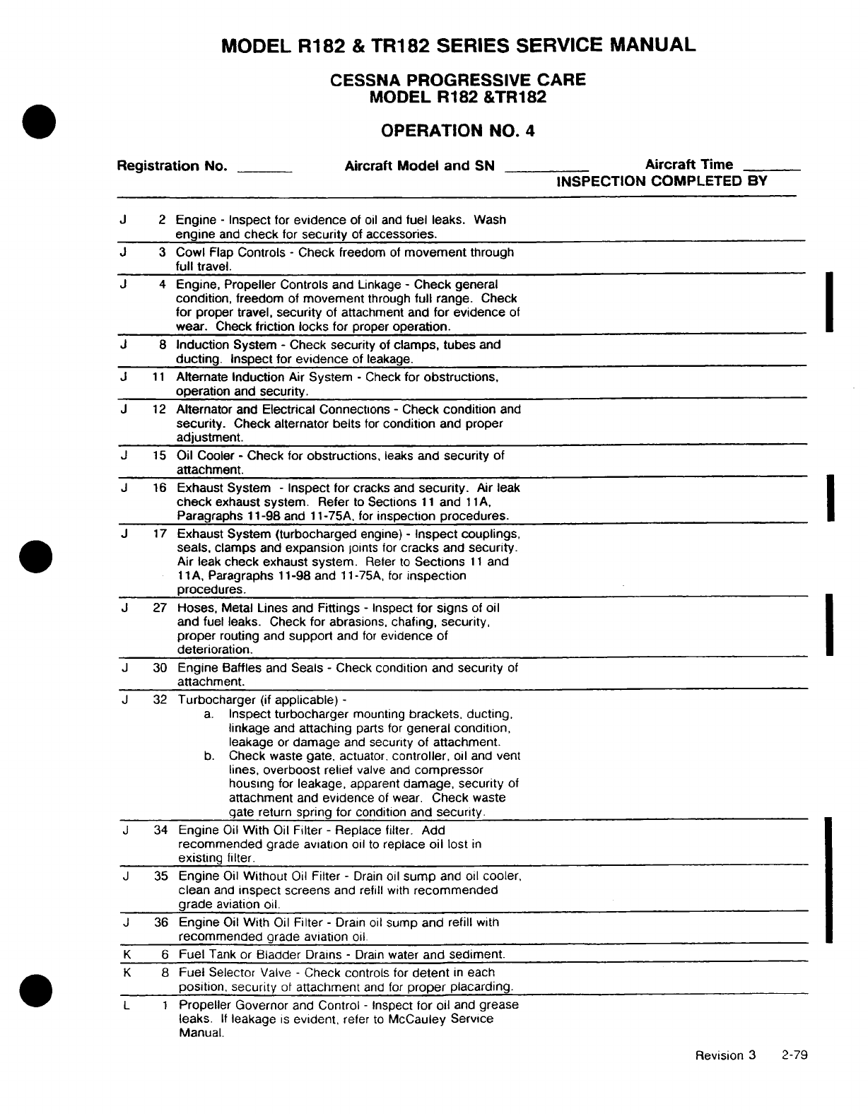
MODEL
R182
&
TR182 SERIES
SERVICE
MANUAL
CESSNA
PROGRESSIVE
CARE
MODEL
R182
&TR182
OPERATION
NO.
4
Registration
No.
Aircraft Model and
SN
Aircraft
Time
INSPECTION COMPLETED BY
J
2
Engine
-
Inspect
for
evidence
of
oil and
fuel leaks.
Wash
engine
and
check
for
security
of accessories.
J
3
Cowl
Flap
Controls
-
Check
freedom
of
movement
through
full
travel.
J
4
Engine, Propeller
Controls
and
Linkage
-
Check
general
condition,
freedom
of
movement
through
full
range.
Check
for
proper
travel,
security
of attachment
and
for
evidence
of
wear. Check
friction
locks
for
proper
operation.
J
8
Induction
System
-
Check
security
of
clamps,
tubes
and
ducting.
Inspect
for
evidence
of
leakage.
J
11
Alternate
Induction
Air
System
-
Check
for
obstructions,
operation
and
security.
J
12
Alternator
and
Electrical
Connections
-
Check
condition
and
security.
Check
alternator
belts
for
condition
and
proper
adjustment.
J
15
Oil
Cooler
-
Check
for
obstructions,
leaks
and
security
of
attachment.
J
16
Exhaust
System
-
Inspect
for
cracks
and
security.
Air leak
check
exhaust
system.
Refer
to
Sections
11
and
1
1A,
Paragraphs
11-98
and
11-75A,
for
inspection procedures.
J
17
Exhaust
System (turbocharged
engine)
-
Inspect
couplings,
seals, clamps
and
expansion
joints
for
cracks
and
security.
Air
leak
check exhaust
system.
Refer
to
Sections
11
and
11A,
Paragraphs
11-98 and
11
-75A,
for
inspection
procedures.
J 27
Hoses,
Metal Lines and
Fittings
-
Inspect
for
signs
of
oil
and
fuel
leaks. Check
for
abrasions,
chafing,
security,
proper
routing
and
support
and
for
evidence
of
deterioration.
J
30
Engine Baffles
and
Seals
-
Check
condition
and
security
of
attachment.
J
32
Turbocharger
(if
applicable)
-
a.
Inspect turbocharger
mounting
brackets, ducting,
linkage
and
attaching
parts
for
general
condition,
leakage
or
damage
and
security
of
attachment.
b.
Check
waste
gate,
actuator,
controller,
oil
and
vent
lines,
overboost
relief
valve
and
compressor
housing
for
leakage,
apparent
damage,
security
of
attachment
and
evidence
of
wear.
Check
waste
gate
return
spring for
condition and
security.
J
34
Engine
Oil
With
Oil
Filter
-
Replace filter.
Add
recommended
grade aviation
oil
to
replace
oil
lost
in
existing
filter.
J
35
Engine
Oil
Without
Oil
Filter
-
Drain
oil
sump
and
oil
cooler,
clean
and
inspect
screens
and
refill
with
recommended
grade
aviation
oil.
J
36
Engine
Oil
With
Oil
Filter
-
Drain
oil
sump
and
refill
with
recommended
grade aviation
oil.
K 6
Fuel
Tank
or
Bladder
Drains
-
Drain
water
and
sediment.
K
8
Fuel
Selector
Valve
-
Check
controls
for
detent
in
each
position, security
of
attachment
and
for
proper
placarding.
L 1
Propeller
Governor
and
Control
-
Inspect
for
oil
and
grease
leaks.
If
leakage
is
evident,
refer
to
McCauley
Service
Manual.
Revision
3
2-79
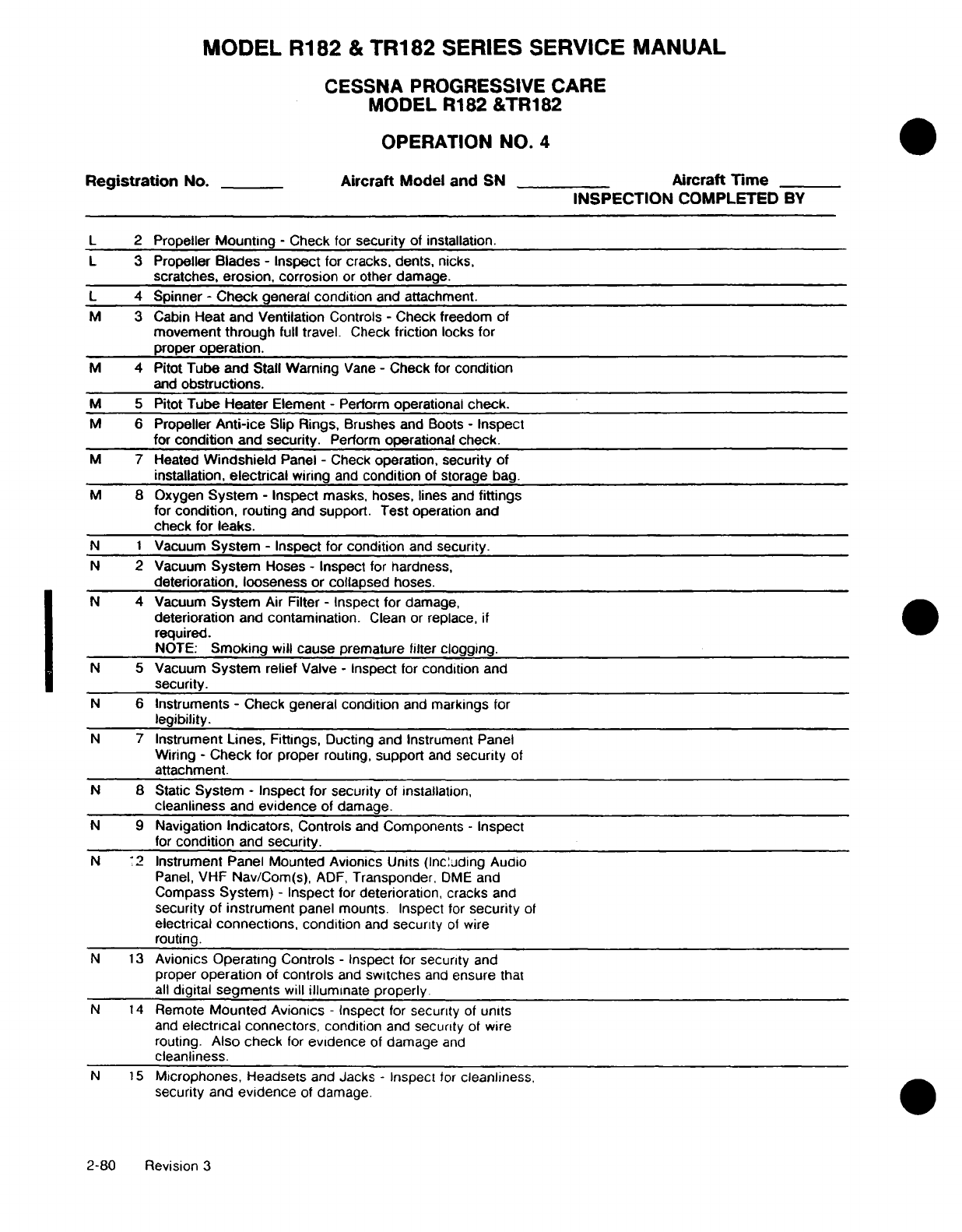
MODEL R182
&
TR182
SERIES
SERVICE
MANUAL
CESSNA
PROGRESSIVE
CARE
MODEL
R182
&TR182
OPERATION
NO.
4
Registration
No.
Aircraft
Model
and
SN
Aircraft
Time
INSPECTION
COMPLETED
BY
L
2
Propeller
Mounting
-
Check
for
security
of installation.
L
3
Propeller
Blades
-
Inspect
for
cracks, dents,
nicks,
scratches,
erosion,
corrosion
or
other
damage.
L
4
Spinner
-
Check
general
condition
and
attachment.
M
3 Cabin
Heat
and
Ventilation
Controls
-
Check freedom
of
movement
through
full
travel.
Check
friction
locks
for
proper
operation.
M
4
Pitot
Tube
and
Stall
Warning
Vane
-
Check
for
condition
and
obstructions.
M
5
Pitot
Tube
Heater
Element
-
Perform
operational
check.
M
6
Propeller
Anti-ice
Slip
Rings,
Brushes
and
Boots
-
Inspect
for
condition
and
security.
Perform
operational
check.
M
7 Heated
Windshield
Panel
-
Check
operation,
security
of
installation,
electrical
wiring
and
condition
of
storage
bag.
M
8
Oxygen
System
-
Inspect
masks,
hoses,
lines
and
fittings
for
condition,
routing
and
support.
Test
operation
and
check
for leaks.
N
1
Vacuum
System
-
Inspect
for
condition
and
security.
N
2
Vacuum
System
Hoses
-
Inspect
for
hardness,
deterioration,
looseness
or
collapsed
hoses.
N
4
Vacuum
System
Air
Filter
-
Inspect
for
damage,
deterioration
and
contamination.
Clean
or
replace,
if
required.
NOTE:
Smoking
will
cause
premature
filter
clogging.
N
5
Vacuum
System
relief
Valve
-
Inspect
for
condition
and
security.
N
6
Instruments
-
Check
general
condition
and
markings
for
legibility.
N
7
Instrument
Lines, Fittings,
Ducting
and
Instrument
Panel
Wiring
-
Check
for
proper
routing,
support
and
security
of
attachment.
N
8
Static
System
-
Inspect
for
security
of
installation,
cleanliness
and
evidence
of
damage.
N
9
Navigation
Indicators,
Controls
and
Components
-
Inspect
for
condition
and
security.
N
12
Instrument
Panel
Mounted
Avionics
Units
(Including Audio
Panel,
VHF
Nav/Com(s),
ADF,
Transponder,
DME
and
Compass
System)
-
Inspect
for
deterioration, cracks
and
security
of instrument
panel
mounts. Inspect
for
security
of
electrical
connections,
condition
and
security
of
wire
routing.
N
13
Avionics
Operating
Controls
-
Inspect
for
security
and
proper
operation
of
controls
and
switches
and
ensure
that
all
digital
segments
will
illuminate properly.
N
14
Remote
Mounted
Avionics
-
Inspect
for
security
of
units
and
electrical
connectors,
condition
and
security
of
wire
routing.
Also
check
for
evidence
of
damage
and
cleanliness.
N
15
Microphones,
Headsets
and
Jacks -
Inspect
for
cleanliness,
security
and
evidence
of
damage.
2-80
Revision
3
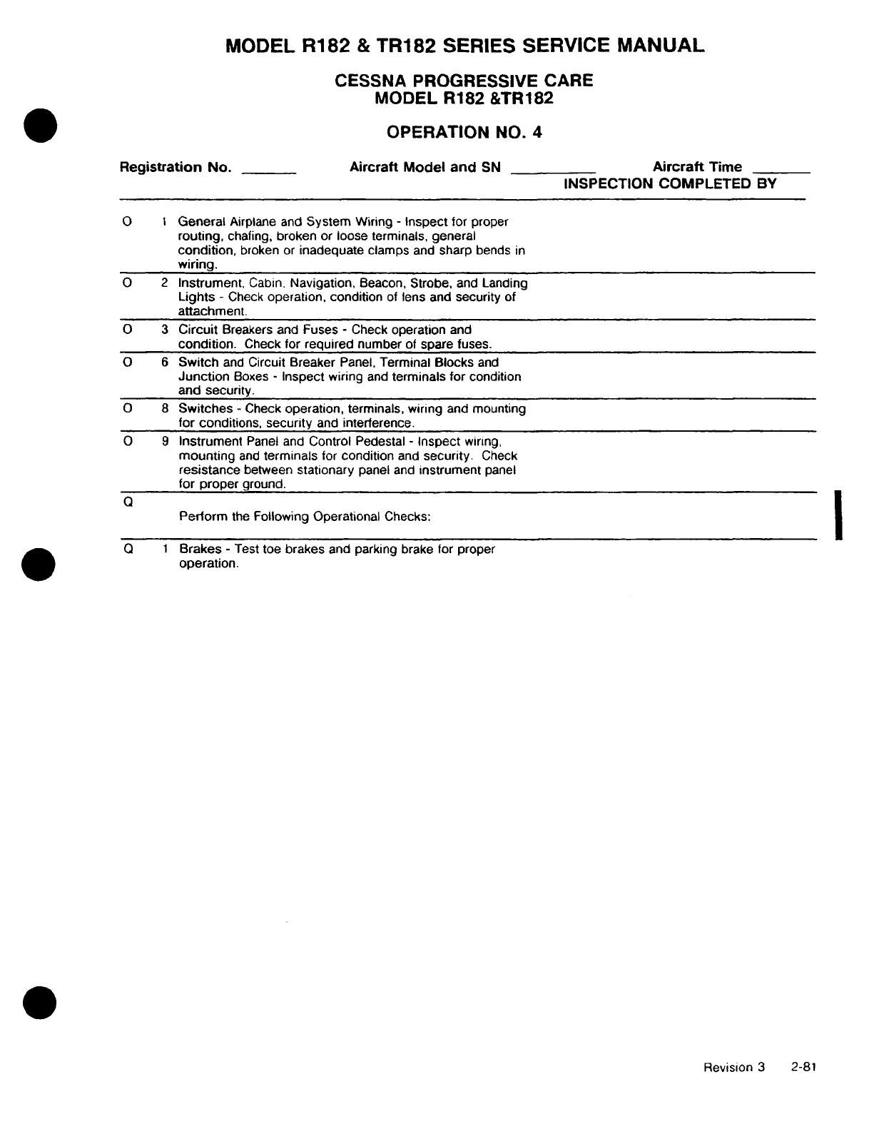
MODEL
R182
&
TR182
SERIES
SERVICE
MANUAL
CESSNA PROGRESSIVE
CARE
MODEL
R182
&TR182
OPERATION
NO.
4
Registration
No.
Aircraft
Model and
SN
Aircraft
Time
INSPECTION
COMPLETED
BY
0
1
General
Airplane
and
System
Wiring
-
Inspect
for
proper
routing,
chafing, broken or
loose
terminals,
general
condition,
broken or
inadequate
clamps
and
sharp
bends
in
wiring.
O 2
Instrument.
Cabin.
Navigation,
Beacon,
Strobe,
and
Landing
Lights
-
Check
operation, condition
of
lens
and
security
of
attachment.
O 3
Circuit
Breakers and
Fuses
-
Check
operation
and
condition.
Check
for
required
number
of
spare
fuses.
O 6
Switch
and
Circuit
Breaker
Panel,
Terminal
Blocks
and
Junction
Boxes
-
Inspect
wiring
and
terminals for
condition
and security.
O
8
Switches
-
Check
operation,
terminals,
wiring
and
mounting
for
conditions,
security
and
interference.
O 9
Instrument
Panel and
Control
Pedestal
-
Inspect
wiring,
mounting
and
terminals
for
condition
and
security.
Check
resistance
between
stationary
panel
and
instrument
panel
for
proper
ground.
Perform
the
Following
Operational
Checks:
Q 1
Brakes
-
Test
toe
brakes
and
parking brake for
proper
operation.
Revision
3
2-81
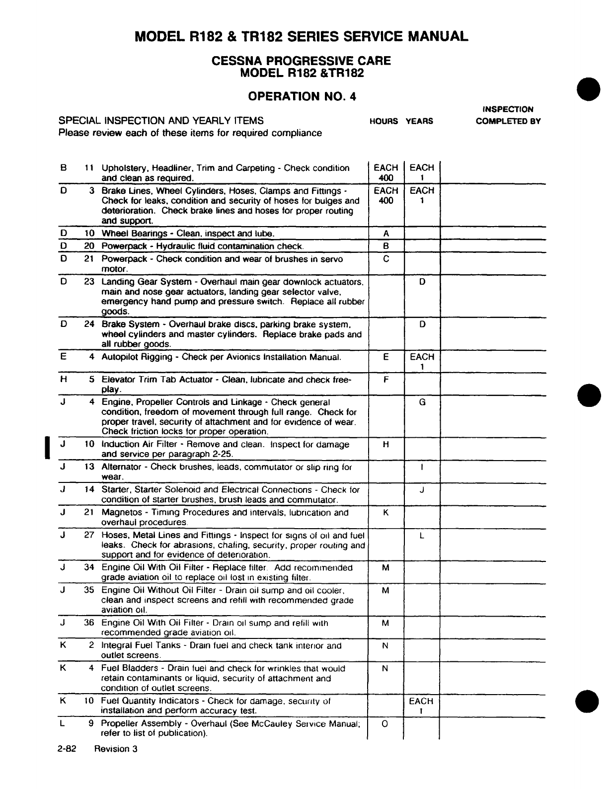
MODEL R182
&
TR182
SERIES
SERVICE
MANUAL
CESSNA
PROGRESSIVE
CARE
MODEL
R182
&TR182
OPERATION
NO.
4
INSPECTION
SPECIAL
INSPECTION
AND YEARLY
ITEMS
HOURS
YEARS
COMPLETED
BY
Please
review each
of these
items
for
required
compliance
B
11
Upholstery,
Headliner,
Trim
and
Carpeting
-
Check
condition
EACH EACH
and clean
as
required.
400
1
D
3
Brake
Lines,
Wheel Cylinders,
Hoses,
Clamps
and
Fittings
-
EACH
EACH
Check
for
leaks,
condition
and
security
of
hoses
for
bulges
and 400
1
deterioration.
Check
brake
lines
and
hoses
for
proper
routing
and
support.
D
10
Wheel
Bearings
-
Clean,
inspect
and
lube.
A
D
20
Powerpack
-
Hydraulic
fluid
contamination
check.
B
D
21
Powerpack
-
Check
condition
and
wear of
brushes
in
servo
C
motor.
D
23
Landing
Gear
System
-
Overhaul
main
gear
downlock
actuators,
D
main
and
nose
gear
actuators,
landing
gear
selector
valve,
emergency
hand
pump
and
pressure
switch. Replace all
rubber
goods.
D
24
Brake
System
-
Overhaul brake
discs,
parking
brake
system,
D
wheel
cylinders
and
master
cylinders.
Replace
brake
pads
and
all
rubber
goods.
E
4
Autopilot
Rigging
-
Check
per
Avionics
Installation
Manual.
E
EACH
1
H
5
Elevator
Trim Tab Actuator
-
Clean,
lubricate
and
check
free-
F
play.
J
4
Engine, Propeller
Controls and Linkage
-
Check
general
G
condition,
freedom
of
movement
through full
range.
Check
for
proper
travel,
security
of
attachment
and
for
evidence
of
wear.
Check
friction
locks
for proper operation.
J
10
Induction
Air
Filter
-
Remove
and
clean.
Inspect
for
damage
H
and
service
per
paragraph 2-25.
J
13
Alternator
-
Check
brushes, leads,
commutator
or
slip
ring
for
I
wear.
J
14
Starter,
Starter
Solenoid
and
Electrical
Connections
-
Check
for
J
condition
of
starter
brushes,
brush
leads
and
commutator.
J
21
Magnetos
-
Timing
Procedures
and
intervals,
lubrication
and
K
overhaul
procedures.
J
27
Hoses,
Metal
Lines
and
Fittings
-
Inspect
for
signs
of
oil
and
fuel
L
leaks.
Check
for
abrasions,
chafing,
security,
proper routing
and
support
and
for
evidence
of
deterioration.
J
34
Engine
Oil
With
Oil
Filter
-
Replace filter
Add
recommended
M
grade
aviation
oil
to
replace oil lost
in
existing
filter.
J
35
Engine
Oil
Without
Oil Filter
-
Drain
oil
sump
and
oil
cooler,
M
clean
and
inspect
screens and
refill
with
recommended
grade
aviation oil.
J
36
Engine
Oil
With
Oil
Filter
-
Drain
oil
sump and
refill
with
M
recommended
grade
aviation
oil.
K
2
Integral
Fuel
Tanks
-
Drain
fuel
and
check tank
interior
and
N
outlet
screens.
K
4
Fuel
Bladders
-
Drain
fuel
and
check
for
wrinkles
that
would
N
retain
contaminants
or
liquid,
security
of
attachment
and
condition
of
outlet
screens.
K
10
Fuel
Quantity
Indicators
-
Check
for
damage,
security
of
EACH
installation
and
perform
accuracy
test.
1
L
9
Propeller
Assembly
-
Overhaul
(See
McCauley
Service
Manual;
O
refer
to
list
of
publication).
2-82
Revision
3
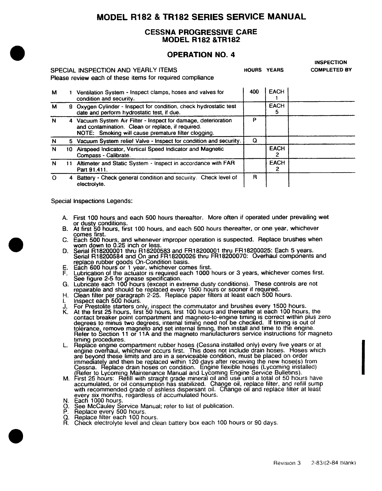
MODEL
R182
&
TR182
SERIES
SERVICE
MANUAL
CESSNA PROGRESSIVE CARE
MODEL
R182
&TR182
OPERATION
NO.
4
INSPECTION
SPECIAL INSPECTION AND YEARLY
ITEMS
HOURS
YEARS
COMPLETED
BY
Please
review
each
of
these
items
for
required
compliance
M
1
Ventilation System
-
Inspect
clamps,
hoses
and
valves
for
400
EACH
condition
and
security.
1
M
9
Oxygen Cylinder
-
Inspect
for
condition,
check hydrostatic
test
EACH
date
and
perform
hydrostatic
test,
if
due.
5
N
4
Vacuum System
Air
Filter
-
Inspect for damage, deterioration
P
and
contamination.
Clean
or
replace,
if
required.
NOTE:
Smoking
will
cause
premature
filter
clogging.
N 5
Vacuum System
relief
Valve
-
Inspect
for
condition
and
security.
Q
N
10
Airspeed Indicator, Vertical
Speed
Indicator
and
Magnetic
EACH
Compass
-
Calibrate.
2
N
11
Altimeter
and
Static System
-
Inspect
in
accordance
with FAR
EACH
Part
91.411.
2
O
4
Battery
-
Check
general condition
and
security.
Check level
of
R
electrolyte.
Special
Inspections
Legends:
A.
First
100
hours and
each 500
hours
thereafter.
More
often
if
operated
under
prevailing
wet
or
dusty conditions.
B.
At
first
50 hours,
first
100
hours,
and
each 500
hours
thereafter,
or
one
year,
whichever
comes
first.
C.
Each
500
hours,
and whenever
improper
operation
is
suspected.
Replace
brushes
when
worn
down
to 0.25 inch
or
less.
D.
Serial
R18200001
thru
R18200583
and FR18200001
thru
FR18200025:
Each
5
years.
Serial
R18200584
and
On and
FR18200026
thru
FR18200070: Overhaul
components
and
replace
rubber
goods
On-Condition basis.
E.
Each
600 hours
or 1
year,
whichever
comes
first.
F.
Lubrication
of
the
actuator
is
reguired
each
1000
hours
or
3
years,
whichever
comes
first.
See
figure
2-5
for
grease specification.
G.
Lubricate
each
100
hours
(except
in
extreme
dusty
conditions).
These
controls
are
not
repairable
and
should
be
replaced
every
1500
hours
or
sooner
if
required.
H.
Clean
filter
per
paragraph
2-25.
Replace
paper
filters
at
least
each
500
hours.
I.
Inspect
each
500
hours.
J.
For
Prestolite
starters
only,
inspect
the
commutator
and
brushes
every
1500
hours.
K.
At
the
first
25
hours,
first
50
hours,
first
100
hours
and
thereafter
at
each
100
hours,
the
contact
breaker
point
compartment
and
magneto-to-engine
timing
is
correct
within
plus
zero
degrees
to
minus
two
degrees,
internal
timing
need
not
be
checked.
If
timing
is
out
of
tolerance
remove magneto
and
set internal
timing,
then
install
and
time
to
the
engine.
Refer
to
Section
11
or
11
A
and
the
magneto
manufacturers
service
instructions
for
magneto
timing procedures.
L.
Replace engine
compartment
rubber
hoses
(Cessna
installed
only)
every five
years
or
at
engine
overhaul,
whichever
occurs
first.
This
does
not
include
drain
hoses.
Hoses
which
are
beyond
these
limits
and
are in
a
serviceable
condition, must
be
placed
on
order
immediately
and
then
be
replaced
within
120
days
after
receiving
the
new
hose(s)
from
Cessna. Replace
drain
hoses
on
condition.
Engine
flexible
hoses
(Lycoming installed)
(Refer
to
Lycoming
Maintenance
Manual
and
Lycoming Engine
Service Bulletins).
M.
First 25
hours:
Refill
with
straight
grade
mineral
oil and
use
until
a
total
of
50
hours
have
accumulated,
or
oil
consumption
has
stabilized.
Change
oil,
replace
filter,
and
refill
sump
with
recommended
grade
of
ashless
dispersant
oil.
Change
oil
and
replace
filter
at least
every
six
months,
regardless
of
accumulated
hours.
N.
Each 1000
hours.
O.
See
McCauley
Service
Manual;
refer
to
list
of
publication.
P.
Replace
every
500
hours.
Q.
Replace
filter each
100
hours.
R.
Check
electrolyte level
and
clean
battery
box
each
100
hours
or
90
days.
Revision
3
2-83/(2-84
blank)
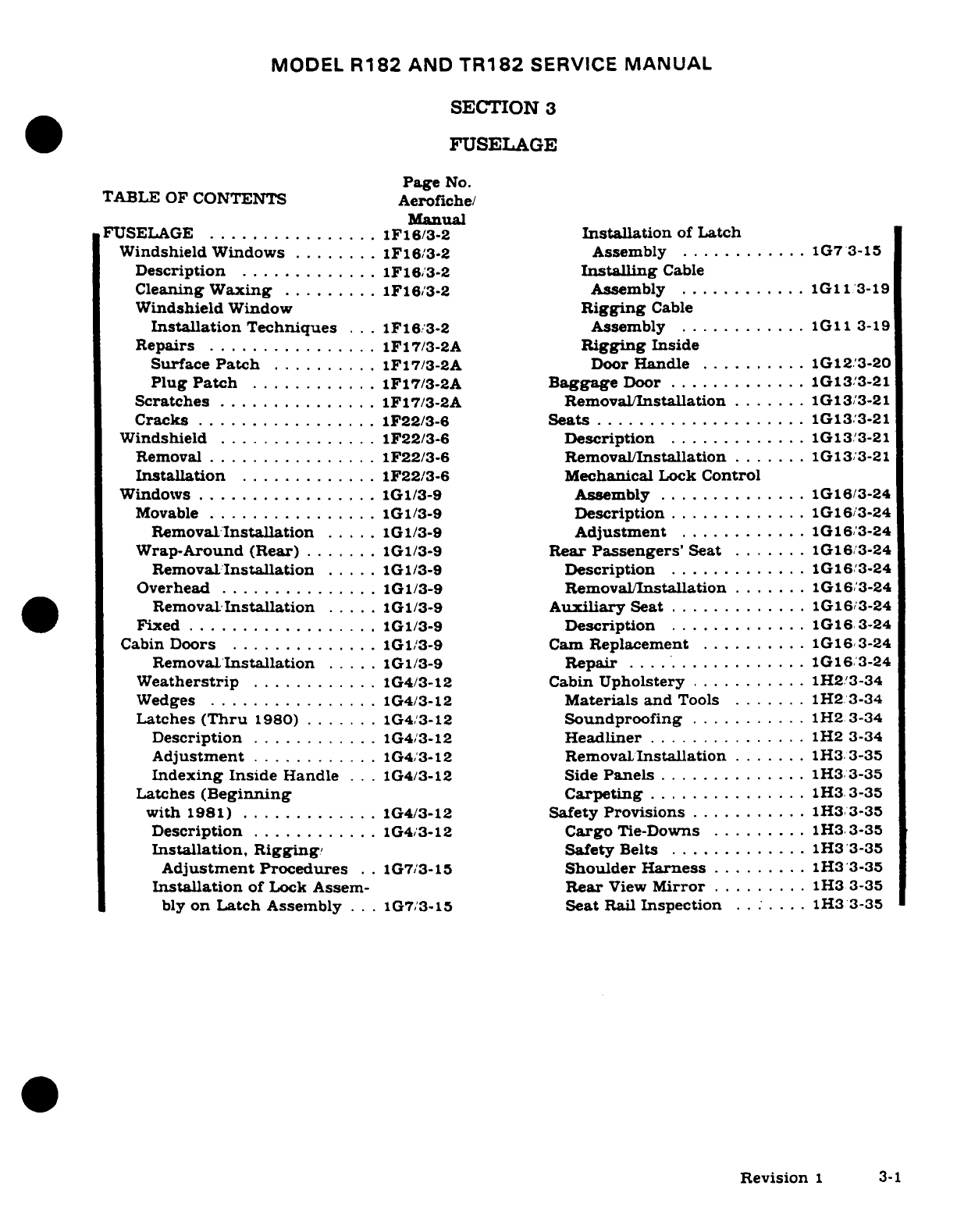
MODEL
R182
AND
TR182
SERVICE
MANUAL
SECTION
3
FUSELAGE
Page
No.
TABLE
OF
CONTENTS
Aerofiche/
Manual
FUSELAGE
................
1F16/3-2
Installation
of
Latch
Windshield Windows
........
1F16/3-2
Assembly
............
1G7
3-15
Description
.............
1F16/3-2
Installing
Cable
Cleaning
Waxing
.........
1F16/3-2
Assembly
...........
1G11/3-19
Windshield
Window
Rigging
Cable
Installation
Techniques
...
1F16/3-2
Assembly
............
1G11/3-19
Repairs
................
1F17/3-2A
Rigging
Inside
Surface
Patch
..........
1F17/3-2A
Door
Handle
..........
1G12/3-20
Plug Patch
............
1F17/3-2A
Baggage
Door
.............
1G13/3-21
Scratches
...............
1F17/3-2A
Removal/Installation
.......
1G13/3-21
Cracks
.................
1F22/3-6
Seats
....................
1G13/3-21
Windshield
...............
1F22/3-6
Description
.............
1G13/3-21
Removal
................
1F22/3-6
Removal/Installation
.......
1G13/3-21
Installation
.............
1F22/3-6
Mechanical
Lock
Control
Windows
.................
1G1/3-9
Assembly
..............
1G16/3-24
Movable
................
1G1/3-9
Description
.............
1G16/3-24
Removal
Installation
.....
1G1/3-9
Adjustment
............
1G16/3-24
Wrap-Around
(Rear)
.......
1G1/3-9
Rear
Passengers'
Seat
.......
1G16/3-24
Removal
Installation
.....
1G1/3-9
Description
.............
1G16/3-24
Overhead
...............
1G1/3-9
Removal/Installation
.......
1G16/3-24
Removal.
Installation
.....
1G1/3-9
Auxiliary
Seat
.............
1G16/3-24
Fixed
..................
1G1/3-9
Description
.............
1G163-24
Cabin
Doors
..............
1G1/3-9
Cam
Replacement
..........
1G16/3-24
RemovaL/Installation
.....
1G1/3-9
Repair
.................
1G16/3-24
Weatherstrip
............
1G4/3-12
Cabin
Upholstery
...........
1H2/3-34
Wedges
................
1G4/3-12
Materials and
Tools
.......
1H2
3-34
Latches
(Thru
1980)
.......
1G4/3-12
Soundproofing
...........
1H2
3-34
Description
......... ...
1G4/3-12
Headliner
...............
1H2
3-34
Adjustment
............
1G4/3-12
Removal/
Installation
.......
1H3.
3-35
Indexing
Inside
Handle
...
1G4/3-12
Side
Panels
..............
1H3
3-35
Latches
(Beginning
Carpeting
...............
1H3/3-35
with
1981)
.............
1G4/3-12
Safety
Provisions
..........
1H3/3-35
Description
............
1G4/3-12
Cargo
Tie-Downs
.........
1H3
3-35
Installation,
Rigging/
Safety
Belts
.............
1H3
3-35
Adjustment
Procedures
.
.
1G7/3-15
Shoulder
Harness
.........
1H33-35
Installation
of
Lock
Assem-
Rear
View
Mirror
.........
1H3
3-35
bly
on
Latch
Assembly
...
1G7/3-15
Seat
Rail
Inspection
......
1H3
3-35
Revision
1
3-1
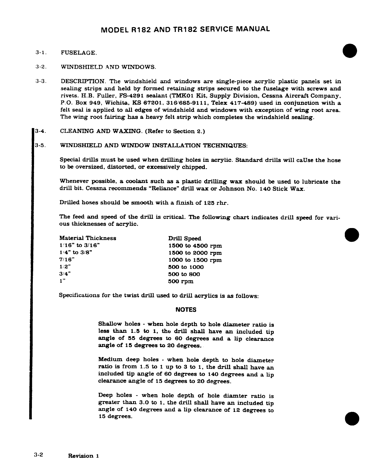
MODEL
R182
AND
TR182
SERVICE
MANUAL
3-1.
FUSELAGE.
3-2.
WINDSHIELD
AND
WINDOWS.
3-3.
DESCRIPTION.
The
windshield
and windows
are
single-piece
acrylic
plastic
panels
set
in
sealing
strips
and held
by
formed
retaining
strips
secured
to
the fuselage
with screws
and
rivets.
H.B.
Fuller,
FS-4291
sealant
(TMK01
Kit,
Supply
Division,
Cessna
Aircraft
Company,
P.O.
Box
949, Wichita,
KS
67201,
316/685-9111,
Telex
417-489)
used
in
conjunction
with
a
felt
seal
is
applied
to
all
edges
of
windshield
and
windows
with
exception
of
wing root
area.
The
wing
root
fairing has
a
heavy
felt
strip
which
completes
the windshield sealing.
3-4. CLEANING
AND
WAXING.
(Refer
to
Section
2.)
3-5.
WINDSHIELD
AND
WINDOW INSTALLATION
TECHNIQUES:
Special
drills must
be
used
when
drilling
holes
in
acrylic.
Standard
drills
will
caUse
the
hose
to
be
oversized,
distorted, or
excessively
chipped.
Whenever
possible,
a
coolant
such
as
a
plastic
drilling
wax
should
be
used
to
lubricate
the
drill
bit.
Cessna
recommends
"Reliance"
drill
wax
or
Johnson
No.
140
Stick
Wax.
Drilled
hoses
should
be
smooth
with
a
finish
of
125
rhr.
The
feed
and
speed
of
the
drill
is
critical.
The
following
chart
indicates
drill
speed
for
vari-
ous
thicknesses
of
acrylic.
Material
Thickness
Drill
Speed
116"
to
3/16"
1500
to
4500 rpm
1/4"
to
3/8"
1500
to
2000
rpm
7/16"
1000
to
1500
rpm
1/2"
500
to
1000
3/4"
500
to
800
1"
500
rpm
Specifications for
the
twist
drill
used
to
drill
acrylics
is
as
follows:
NOTES
Shallow
holes
-
when
hole
depth
to
hole
diameter
ratio
is
less
than
1.5
to
1,
the
drill shall
have
an
included
tip
angle
of
55
degrees
to
60
degrees
and
a
lip
clearance
angle
of
15
degrees
to
20
degrees.
Medium deep
holes
-
when
hole
depth
to
hole
diameter
ratio
is
from
1.5
to
1
up
to
3
to
1,
the
drill
shall
have
an
included
tip
angle
of
60
degrees
to
140
degrees
and
a
lip
clearance
angle
of
15
degrees
to 20
degrees.
Deep
holes
-
when
hole
depth
of
hole
diamter
ratio
is
greater
than
3.0
to
1,
the
drill shall
have
an
included
tip
angle
of
140
degrees
and
a
lip
clearance
of
12
degrees
to
15
degrees.
3-2
Revision
1
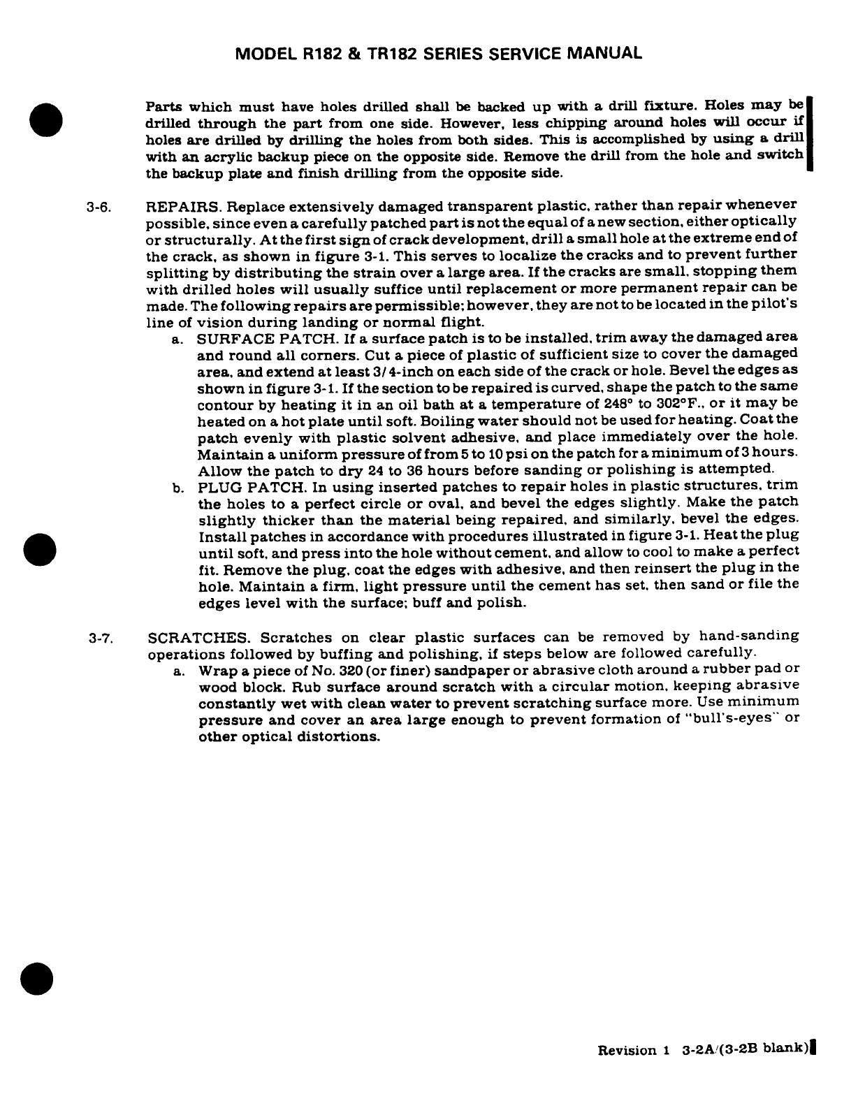
MODEL
R182
&
TR182
SERIES
SERVICE
MANUAL
Parts
which
must
have
holes
drilled
shall
be
backed
up
with
a
drill
fixture.
Holes
may
be
drilled
through
the
part
from
one
side.
However,
less
chipping
around
holes
will
occur
if
holes
are
drilled
by
drilling
the
holes
from
both
sides.
This
is
accomplished
by
using
a
drill
with
an
acrylic
backup
piece
on
the
opposite side.
Remove
the
drill
from
the
hole
and
switch
the
backup
plate
and
finish
drilling
from
the
opposite side.
3-6.
REPAIRS.
Replace
extensively
damaged
transparent
plastic,
rather
than
repair
whenever
possible,
since
even
a
carefully
patched
part
is
not
the
equal
of
a
new
section,
either
optically
or
structurally.
At
the
first sign
of
crack
development,
drill
a
small
hole
at
the
extreme
end
of
the
crack,
as
shown
in
figure
3-1.
This serves
to
localize
the cracks
and
to
prevent further
splitting
by
distributing
the
strain
over
a
large
area.
If
the
cracks
are
small, stopping
them
with
drilled
holes
will
usually
suffice
until replacement
or
more
permanent
repair
can
be
made.
The
following
repairs
are
permissible;
however,
they are
not
to
be
located
in
the
pilot's
line
of
vision during
landing
or
normal
flight.
a.
SURFACE
PATCH.
If
a
surface
patch
is
to
be
installed,
trim
away
the
damaged
area
and
round all
corners.
Cut
a
piece
of
plastic
of
sufficient
size to
cover
the
damaged
area,
and
extend
at
least
3/
4-inch
on
each
side
of
the
crack
or
hole. Bevel
the
edges
as
shown
in
figure
3-1.
If
the
section
to
be
repaired
is
curved,
shape the
patch
to
the
same
contour
by
heating
it in
an
oil
bath
at
a
temperature
of
248
°
to 302°F.,
or
it
may
be
heated
on
a
hot
plate
until
soft.
Boiling
water
should
not
be
used
for
heating.
Coat
the
patch
evenly
with
plastic
solvent
adhesive, and
place
immediately over
the
hole.
Maintain
a
uniform
pressure
of
from
5
to
10
psi
on
the
patch
for
a
minimum
of
3
hours.
Allow
the
patch
to
dry
24
to
36
hours
before
sanding
or
polishing
is
attempted.
b.
PLUG
PATCH.
In
using
inserted
patches
to
repair
holes
in
plastic
structures,
trim
the
holes
to
a
perfect circle
or
oval,
and
bevel the
edges
slightly.
Make
the
patch
slightly
thicker than
the
material
being
repaired,
and
similarly,
bevel
the
edges.
Install
patches
in
accordance
with
procedures
illustrated
in
figure
3-1.
Heat
the
plug
until
soft,
and
press
into
the
hole
without
cement,
and
allow
to
cool
to
make
a
perfect
fit. Remove
the
plug,
coat
the
edges
with
adhesive,
and
then
reinsert
the
plug
in
the
hole.
Maintain
a
firm,
light
pressure
until
the
cement
has
set,
then
sand
or
file
the
edges
level
with
the
surface;
buff
and
polish.
3-7.
SCRATCHES.
Scratches
on
clear
plastic
surfaces
can
be
removed
by
hand-sanding
operations
followed
by
buffing
and
polishing,
if
steps
below
are
followed
carefully.
a.
Wrap
a
piece
of No.
320
(or
finer)
sandpaper
or
abrasive
cloth
around
a
rubber
pad
or
wood
block.
Rub
surface
around
scratch
with
a
circular
motion,
keeping
abrasive
constantly
wet
with
clean
water
to
prevent
scratching
surface
more.
Use
minimum
pressure
and
cover an
area
large
enough
to
prevent
formation
of
"bull's-eyes"
or
other optical distortions.
Revision
1
3-2A/(3-2B
blank)
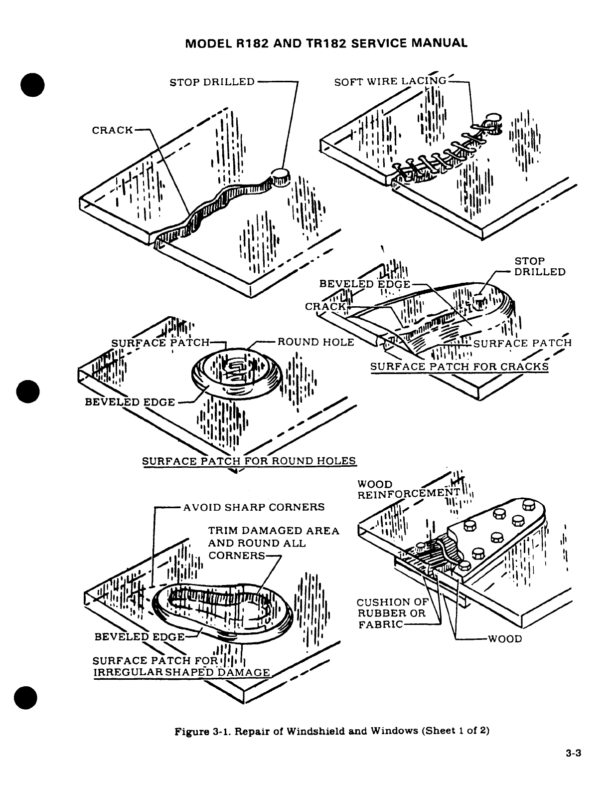
MODEL
R182
AND
TR182
SERVICE
MANUAL
STOP
DRILLED
SOFT WIRE LACING
t||\,^
^DRILLED
BEVELED
EDGE
e
SURFACE
PATCH
ROUND HOLE
SURFACE
PATCH
K;lql i lliI'
SURFACE
PATCH
FOR
CRACKS
*
BEVELED
EDGE
E
I gj
^ ^ <
"
» ^
'
'«
'|
"
[
l I[
r
,!
.,,
l
'
-
'
-'e
II1
SURFACE
PATCH
FOR
ROUND
HOLES
WOOBD
EDGE-
REINFORCEMENT
1,,
-AVOID
SHARP
CORNERS
RENC,,
!
TRIM
DAMAGED
AREA1
'
I
,
AND ROUND
ALL 9
, 1
.
111,
CORNERS
I
BEVELED
DGE
! -- ^ Ill
__WOOD
SURFACE
PATCH
FORI'i
C R
Figure
3-1.
Repair
of
Windshield
and
Windows
(Sheet
1
of
2)
3-3
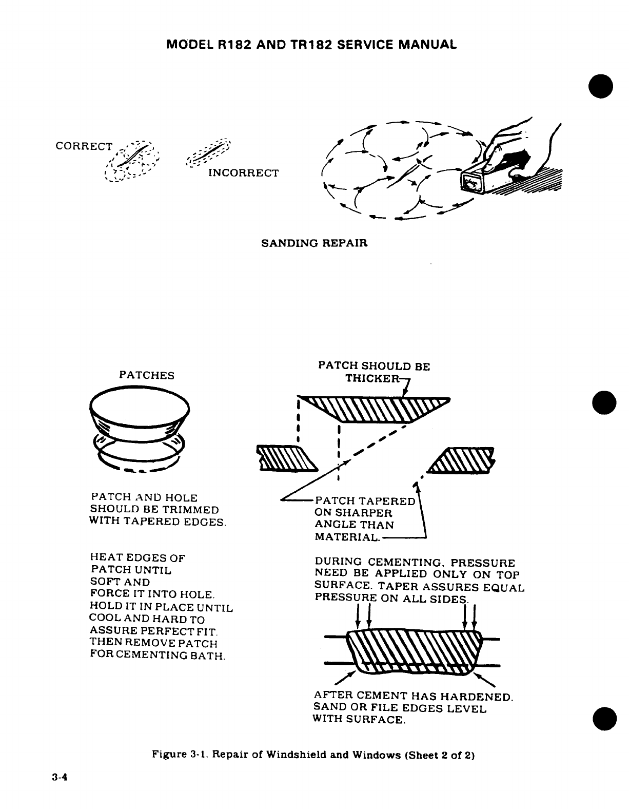
MODEL
R182
AND
TR182
SERVICE
MANUAL
CORRECT
,-
'-
/-'
INCORRECT
K
SANDING REPAIR
PATCH
SHOULD
BE
PATCHES
THICKER7
PATCH
AND
HOLE
PATCH
TAPERE
SHOULD
BE
TRIMMED
ON
SHARPER
WITH
TAPERED
EDGES.
ANGLE
THAN
MATERIAL.
HEAT
EDGES
OF
DURING
CEMENTING.
PRESSURE
PATCH UNTIL NEED
BE
APPLIED
ONLY
ON
TOP
SOFT
AND
SURFACE.
TAPER
ASSURES
EQUAL
FORCE
IT
INTO
HOLE.
PRESSURE
ON
ALL
SIDES.
HOLD
IT
IN
PLACE
UNTIL
COOL
AND
HARD
TO
ASSURE
PERFECT
FIT.
THEN
REMOVE
PATCH
FOR
CEMENTING
BATH.
AFTER CEMENT
HAS
HARDENED.
SAND
OR
FILE
EDGES
LEVEL
WITH
SURFACE.
Figure
3-1.
Repair
of
Windshield
and
Windows
(Sheet
2
of
2)
3-4
MODEL
R182
AND
TR182
SERVICE
MANUAL
CAUTION
Use
fine
grade abrasive,
No.
320
grade or
finer.
b.
Continue
sanding
operation,
using
progressively
finer
grade
abrasives
until
scratches disappear.
c.
When
scratches
have
been
removed,
wash
area
thoroughly with
clean
water
to
remove
all
gritty
particles.
The
entire
sanded
area
will
be
clouded
with
minute
scratches
which
must
be
removed
to
restore
transparency.
d.
Apply
fresh
tallow or
buffing
compound
to
a
motor-driven buffing
wheel.
Hold
wheel
against
plastic
surface,
moving
it
constantly
over damaged
area
until
cloudy
appearance
disappears.
A
2000-foot-per-minute
surface
speed
is
recommended
to
prevent
overheating
and
distortion.
(Example:
750
rpm
polishing
machine
with
a
10
inch
buffing
bonnet.)
NOTE
A
power
buffing
wheel
will
expedite
polishing
considera-
bly,
however, hand
buffing
is
acceptable
if
complete
enough
to
produce
a
quality
end
result.
e.
When
buffing
is
finished,
wash
area thoroughly
and
dry
with
a
soft
flannel
cloth.
Allow
surface
to
cool
and
inspect
area
to
determine
if
full
transparency
has
been
restored.
Apply
a
thin
coat
of
hard
wax
and
polish
surface
lightly
with
a
clean
flannel
cloth.
NOTE
Rubbing
plastic
surface
with
a
dry
cloth
will
build
up
an
electrostatic
charge
which
attracts
dirt
particles
and
may
eventually
cause
scratching
of
surface.
After
wax
has
hardened,
dissipate
this
charge
by
rubbing
surface
with
a
slightly
damp
chamois.
This will
also
remove dust
particles
which
have
collected
while
wax
is
hardening.
f.
Minute
hairline
scratches
can
often
be
removed
by
rubbing
with
commercial
automobile
body
cleaner
or
fine-grade
rubbing
compound.
Apply
with
a
soft.
clean.
dry
cloth
or
imitation
chamois.
3-5
MODEL
R182
AND
TR182
SERVICE
MANUAL
3-8.
CRACKS.
a.
When
a
crack
appears,
drill
a
hole
at
end
of
crack
to
prevent
further
spreading.
Hole
should
be
approximtely
1/8
inch
in
diameter,
depending
on
length
of
crack
and
thickness
of
material.
b.
Temporary
repairs
to
flat
surfaces
can
be
accomplished
by
placing
a
thin
strip
of
wood
over
each
side
of
surface
and
inserting small
bolts
through
the
wood
and
plastic.
A
cushion
of
sheet rubber
or
aircraft
fabric
should
be
placed
between
wood
and
plastic
on
both
sides.
c.
A
temporary
repair
can
be
made
on
a
curved
surface
by
placing
fabric patches
over
affected
areas.
Secure
patches
with
aircraft
dope.
Specification
No.
MIL-D-5549;
or
lacquer, Specification
No.
MIL-L-7178.
Lacquer
thinner,
Specification
No.
MIL-T-
6094
can
also
be
used
to
secure
patch.
d.
A
temporary
repair
can
be
made
by
drilling small
holes
along
both
sides
of
crack
1/4
to 1/8
inch
apart
and
lacing
edges
together
with
soft
wire.
Small-stranded
antenna
wire
makes
a
good
temporary
lacing
material. This
type
of
repair
is
used
as
a
temporary
measure
ONLY,
and
as
soon
as
facilities
are
available,
panel should
be
replaced.
3-9.
WINDSHIELD. (See
figure
3-2.)
3-10.
REMOVAL.
a.
Remove
wing
fairings.
b.
Remove
air
vent
tubes.
NOTE
Remove
and
tape
compass
and
outside
air
temperature
gage
clear
of
work area.
Do
not disconnect
electrical
wir-
ing.
(See
Section
16.)
CAUTION
If
windshield
is
to
be
reinstalled,
be
sure
to
protect
windshield
during
removal.
c.
With two
people
sitting
in
the airplane
placing
their
feet
against
the
windshield,
just
above
the
centerline,
press
upward
on
windshield
forcing
it
out
of
lower
retainers.
d.
Clean
sealer
from
inner
sidewalls
and
bottom of
retainers.
3-11.
INSTALLATION.
a.
If
windshield
is
to
be
reinstalled,
clean
off
old
sealer and
felt,
then
install
new
felt
around
edges
of
windshield.
b.
If
new
windshield
is
to
be
installed,
remove
protective
cover
and clean,
take
care
not
to
scratch
windshield.
c.
Apply new
felt
to
edges
of
windshield.
d.
Apply
a
strip
of
sealer
(H.B.
FULLER
FS-4291)
along
the
sides
and
bottom
of
felt.
e.
Position
bottom edge
of
windshield into
lower
retainer.
f.
Using
a
piece
of
bent
sheet
metal
(8
in.
wide
x
length
of top
edge
of
windshield)
placed
under
top
edge
of
windshield
into
upper
retainer using
bent
sheet
metal
in a
shoe
horn
effect.
g.
Install
air
vent
tubes.
h.
Install
wing
fairings.
3-6

MODEL
R182
AND
TR182
SERVICE
MANUAL
B
NOTE
1.
Windshield
2.
Overhead
Cabin
Window
3.
Fixed
Window
4.
Outer
Retainer
(
s
5.
Inner
Retainer
-
6.
Felt
Seal
6
5
NOTE
6
1
Apply
H.B.
Fuller
FS-4291
to
all edges
Detail
A
of
windshield and
windows
under
outer
retainer
(4).
Figure
3-2.
Windshield
and
Fixed
Window
Installation
(Sheet
1
of
2)
3-7
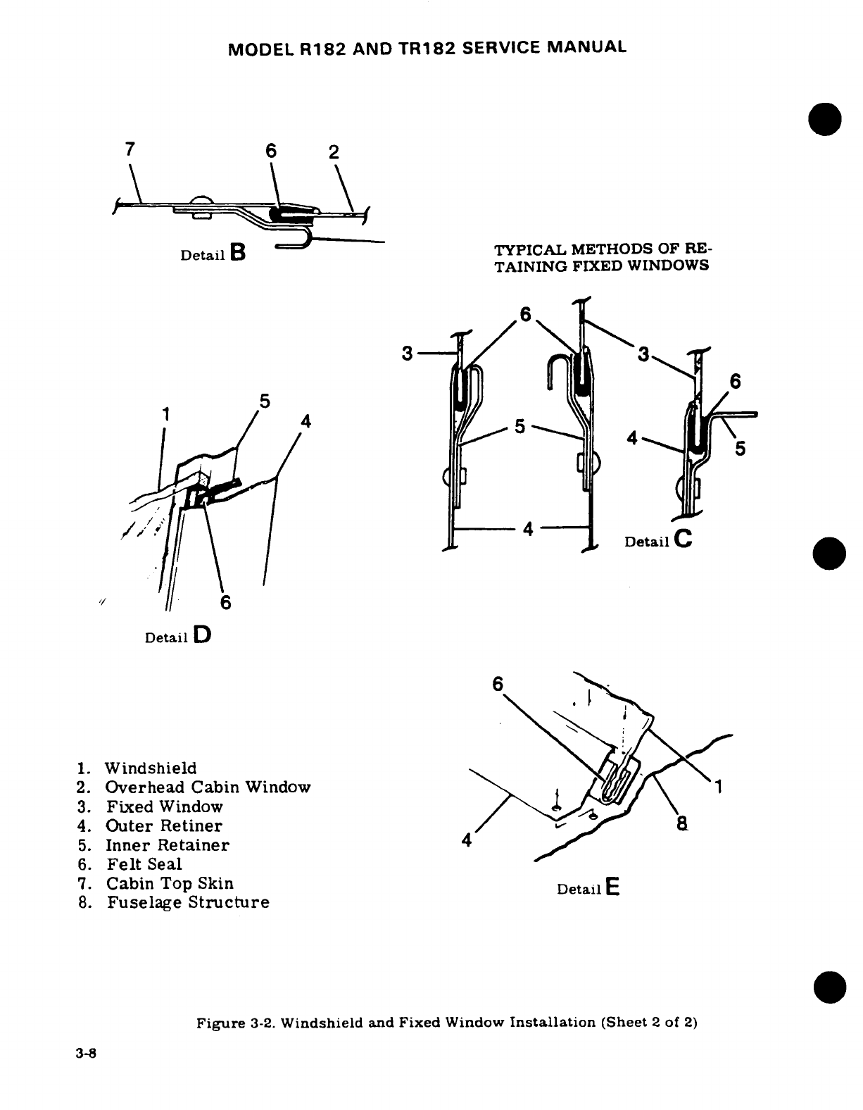
MODEL
R182
AND
TR182
SERVICE
MANUAL
7
6
2
Detail
B ~
TYPICAL
METHODS
OF
RE-
TAINING
FIXED
WINDOWS
1// \e3~Dt
C
6
IDetl
tail
Detail
D
1.
Windshield
2.
Overhead
Cabin
Window
1
3.
Fixed
Window
4.
Outer
Retiner
5.
Inner
Retainer
4
6.
Felt
Seal
7.
Cabin
Top
Skin
Detail
8.
Fuselage
Structure
Figure
3-2.
Windshield
and
Fixed
Window
Installation
(Sheet
2
of
2)
3-8
MODEL
R182
AND
TR182
SERVICE
MANUAL
.
3-12.
WINDOWS.
3-13.
MOVABLE.
(Refer
to
figure
3-3.)
A
movable
window,
hinged at
the
top,
is
installed
in
the
left
cabin
door
and
may
also
be
installed
in
the
right
cabin
door
as
optional
equipment.
A
rubber
seal
is
cemented
to
the
inside
of
the
window
frame
using
EC-880
adhesive
(3-M
Company)
or
equivalent.
3-14.
REMOVAL
AND
INSTALLATION.
a.
Disconnect
window
stop.
b.
Remove
pins
from
window
hinges
(2
and
3).
c.
Reverse
preceding
steps
for
reinstallation.
To
remove
frame
from
plastic
panel.
drill
out
blind
rivets
at
frame
splice.
When
replacing
plastic
panel
in
frame,
ensure
sealing
strip
and
an
adequate
coating
of
Presstite
No.
579.6
sealing
compound
is
used
around
all
edges
of
panel.
3-15.
WRAP-AROUND
REAR.
The
rear
window
is
a
one-piece
acrylic
plastic panel
set
in
sealing
strips
and
held
in
place
by
retaining
strips.
3-16.
REMOVAL
AND
INSTALLATION.
a.
Remove
upholstery
as
necessary
to
expose
retainer strips
inside
cabin.
b.
Drill
out
rivets
as
necessary
to
remove
retainers
on
both
sides
and
lower
edge
of
window.
c.
Remove window
by
starting
at aft
edge
and
pulling
window
into
cabin area.
d.
Reverse preceding steps for
reinstallation.
Apply
sealing
strips
and
an
adequate
coating
of
sealing
compound
to
prevent leaks.
When
installing
a
new
window,
check
fit,
use
care
not
to
crack
panel
and
file
or
grind
away
excess
plastic.
3-17.
OVERHEAD.
(See
figure
3-2.)
Overhead
cabin
windows,
located
in
the cabin
top,
may
be
installed.
These
windows
are
one-piece
acrylic
plastic
panels
set
in
sealing
strips
and
held
in
place
by
retaining
strips.
3-18.
REMOVAL
AND
INSTALLATION.
a.
Remove
headliner
and
trim
panels.
b.
Drill
out
rivets
as
necessary
to
remove
retainer strips.
c.
Reverse
preceding
steps
for
reinstallation.
Apply
felt
strip
and
sealing
compound
to
all
edges
of
window
to
prevent
leaks.
Check
fit
and
carefully
file
or
grind
away
excess
plastic.
Use
care
not
to
crack
plastic
when
installing.
3-19.
FIXED.
(See
figure
3-2.)
Fixed
windows,
mounted
in
sealing
strips
and
sealing
compound.
are
held
in
place
by
various retainer
strips.
To
replace
side
windows,
remove
upholstery
and
trim
panels
as
necessary
and
drill
out
rivets
securing
retainers.
Apply
felt
strip
and
sealing
compound
to
all
edges
of
window
to
prevent
leaks.
Check
fit
and
file
or
grind
away
excess
plastic.
Use
care
not
to
crack
plastic
when
installing.
3-20.
CABIN
DOORS.
(See
figure
3-3.)
3-21.
REMOVAL
AND
INSTALLATION.
Removal
of
cabin
doors
is
accomplished
either
by
removing
screws
which
attach
hinges
or
stops,
or
by
removing
hinge
pins,
attaching
hinges
and
door
stops.
If
permanent
hinge
pins
are
removed,
they
may
be
replaced
with
clevis
pins.
secured
with
cotter
pins.
or
new
hinge
pins
may
be
installed
by
inserting
pin
through
both
hinge halves,
and
chucking
a
rivet
set
in a
hand
drill,
hold
one
end
of
pin
and form
a
head
on
opposite
end.
Reverse
pin
and
repeat
process.
When
fitting
a
new
door
that
is
not
bonded.
some
trimming
of
door
skin
at
edges,
and
some
reforming
with
a
soft
mallet
may
be
necessary
to
achieve
a
good
fit.
Re-forming
of
bonded
door
flange
by
striking
with
a
soft
mallet,
etc.
is
NOT
permissible,
due
to
possible
damage
to
bonded
areas.
3-9
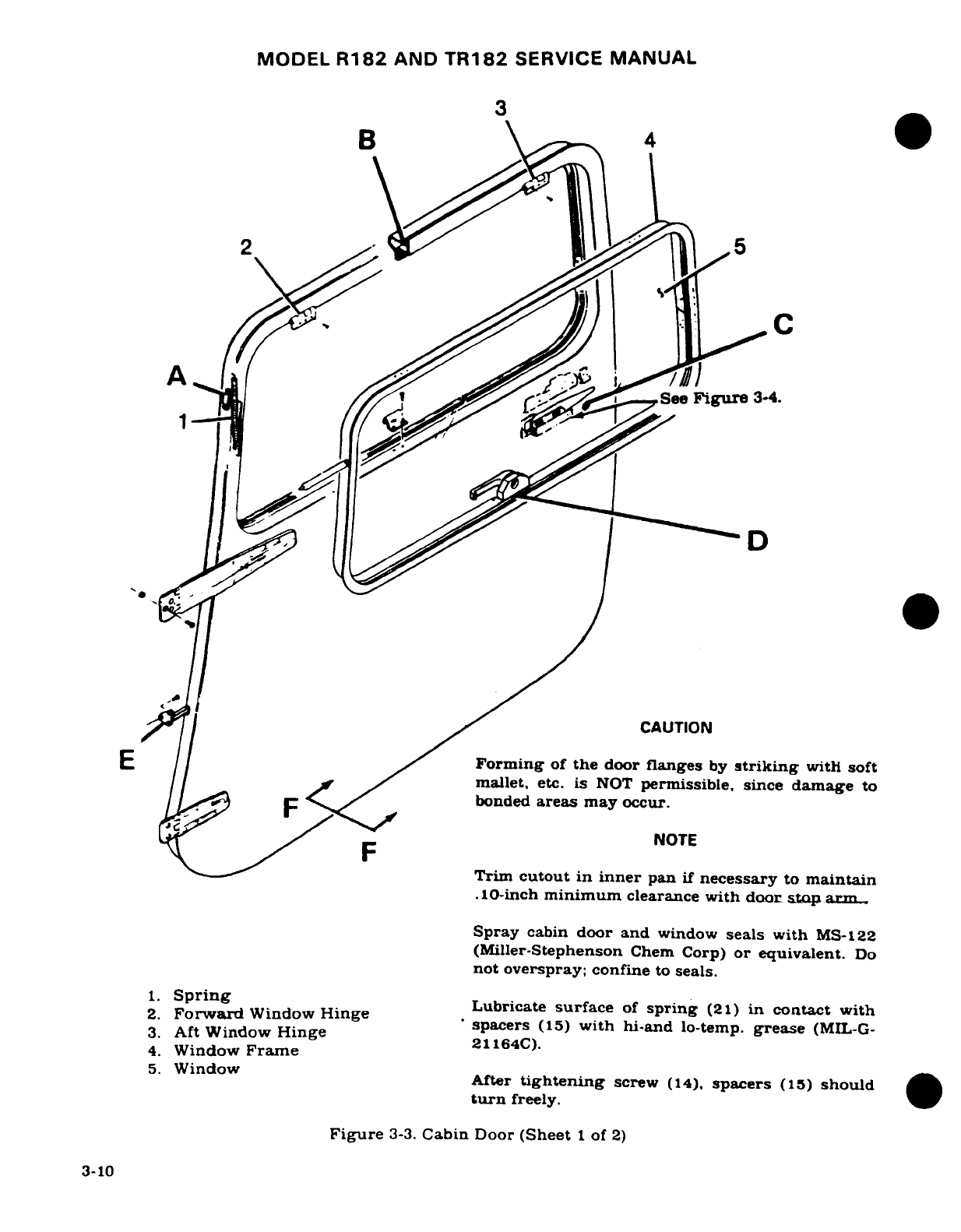
MODEL
R182
AND
TR182
SERVICE
MANUAL
3
2 5B
4
a
C
See
Figure
3-4.
_.^/J|~~~ /.^~
~
CAUTION
E
/
Forming
of
the
door
flanges
by
striking
with
soft
| |f >'
/mallet,
etc.
is
NOT
permissible, since
damage
to
F<</~
\^
*bonded
areas
may occur.
NOTE
Trim
cutout
in
inner
pan
if
necessary
to
maintain
.10-inch
minimum
clearance
with
door
stop
arm
Spray
cabin
door
and
window
seals
with
MS-122
(Miller-Stephenson
Chem
Corp)
or
equivalent.
Do
not
overspray;
confine
to
seals.
1.
Spring
2.
oSring
W
w
H
e
Lubricate
surface
of
spring
(21)
in
contact
with
2.
Forward
Window
Hinge
*
spacers
(15)
with
hi-and
lo-temp.
grease
(MIL-G-
3.
Aft
Window
Hinge
2164C).
4.
Window
Frame
5.
Window
After
tightening
screw
(14),
spacers
(15)
should
turn
freely.
Figure
3-3.
Cabin
Door
(Sheet
1
of
2)
3-10
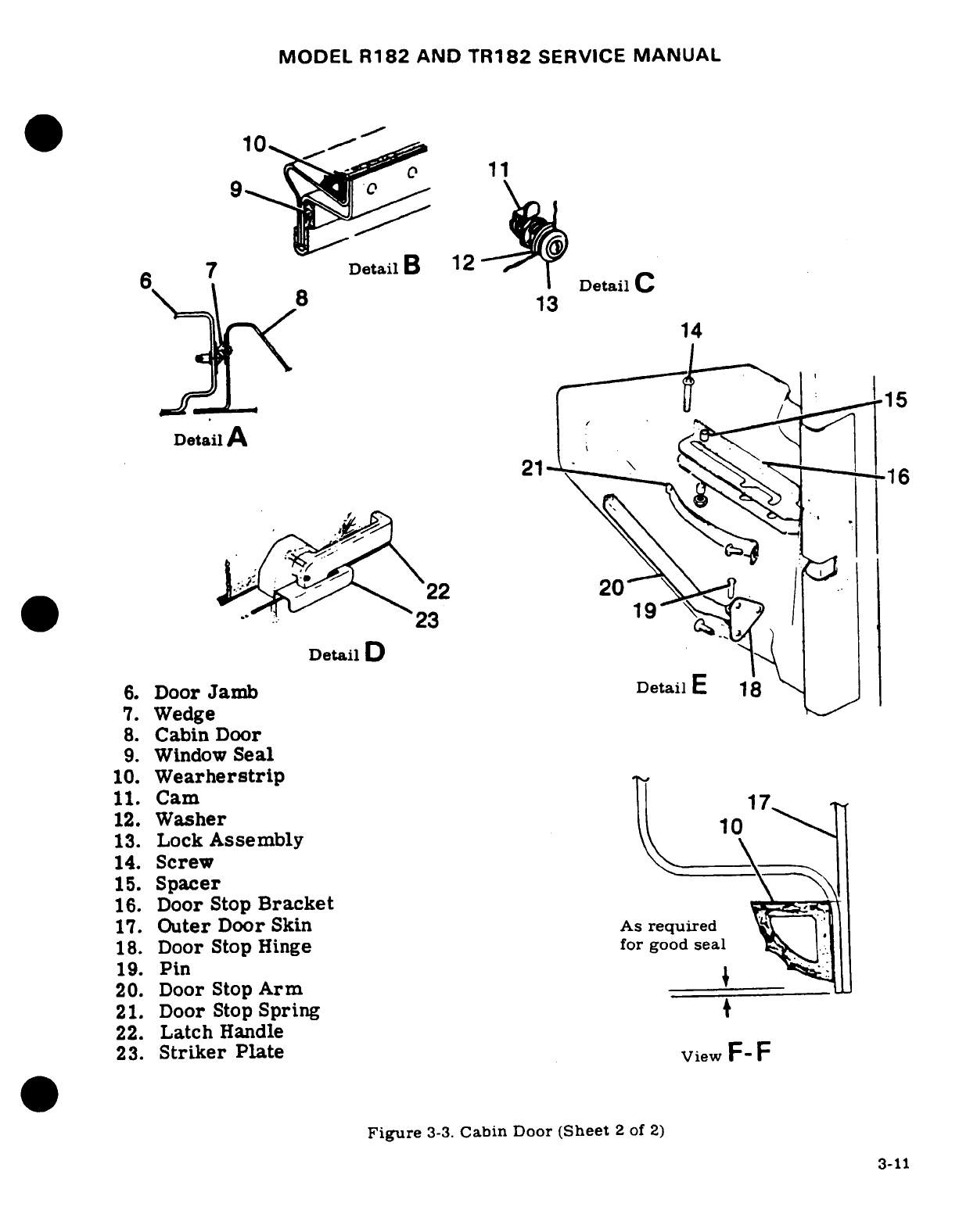
MODEL
R182
AND
TR182
SERVICE
MANUAL
10 9
11
6
7
Detail
B
1 2Detail
C
8
13
14
'15
Detail
A
21
0
J
i^ ^^
22
20
*
-:
-
h
-23
(
.2
Detail
D
6.
Door
Jamb
DetailE
18
7.
Wedge
8.
Cabin
Door
9.
Window
Seal
10.
Wearherstrip
11.
Cam
17
12.
Washer
10
13.
Lock
Assembly
14.
Screw
\
15.
Spacer
16.
Door
Stop
Bracket
17.
Outer
Door
Skin
As
required
18.
Door
Stop
Hinge
for
good
seal
19.
Pin
20.
Door
Stop
Arm
21.
Door
Stop
Spring
22.
Latch
Handle
23.
Striker
Plate
View
F-
F
Figure
3-3.
Cabin
Door
(Sheet
2
of
2)
3-11
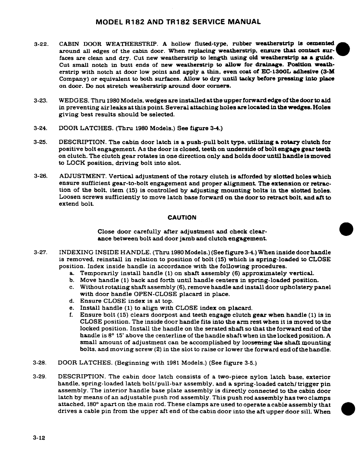
MODEL
R182
AND
TR182
SERVICE
MANUAL
3-22.
CABIN DOOR
WEATHERSTRIP.
A
hollow
fluted-type,
rubber
weatherstrip
is
cemented
around
all
edges
of
the
cabin
door.
When
replacing
weatherstrip,
ensure
that
contact
sur-
faces
are
clean
and dry.
Cut
new
weatherstrip
to
length
using
old
weatherstrip
as
a
guide.
Cut
small
notch in
butt
ends
of
new
weatherstrip
to
allow for
drainage.
Position
weath-
erstrip
with notch
at
door
low
point
and
apply
a
thin,
even
coat
of EC-1300L
adhesive
(3-M
Company)
or
equivalent
to
both
surfaces.
Allow
to
dry
until
tacky
before
pressing
into
place
on
door.
Do
not
stretch
weatherstrip
around
door
corners.
3-23.
WEDGES.
Thru
1980
Models,
wedges
are
installed
at
the
upper
forward
edge
of
the
door
to
aid
in
preventing
air
leaks
at
this
point.
Several attaching
holes
are located
in
the
wedges.
Holes
giving
best
results
should
be
selected.
3-24.
DOOR
LATCHES.
(Thru
1980
Models.)
See
figure
3-4.)
3-25.
DESCRIPTION.
The
cabin
door
latch
is a
push-pull bolt
type,
utilizing
a
rotary
clutch
for
positive
bolt
engagement.
As
the
door
is
closed,
teeth
on
underside
of
bolt
engage
gear
teeth
on
clutch.
The
clutch
gear
rotates
in
one
direction
only
and
holds
door
until
handle
is
moved
to
LOCK
position,
driving
bolt
into
slot.
3-26.
ADJUSTMENT.
Vertical adjustment
of
the rotary
clutch
is
afforded
by
slotted
holes
which
ensure
sufficient gear-to-bolt
engagement
and
proper
alignment.
The
extension
or
retrac-
tion
of
the
bolt,
item
(15)
is
controlled
by
adjusting
mounting
bolts
in
the
slotted
holes.
Loosen
screws
sufficiently
to
move
latch
base forward
on
the
door
to
retract
bolt,
and
aft
to
extend
bolt.
CAUTION
Close
door
carefully
after adjustment
and check
clear-
ance between
bolt
and
door
jamb
and
clutch engagement.
3-27.
INDEXING
INSIDE
HANDLE.
(Thru
1980
Models.) (See
figure
3-4.)
When
inside
door
handle
is
removed,
reinstall
in
relation
to
position
of
bolt
(15)
which
is
spring-loaded
to
CLOSE
position.
Index
inside
handle
in
accordance
with
the
following
procedures.
a.
Temporarily
install
handle
(1)
on
shaft
assembly
(6)
approximately
vertical.
b.
Move
handle
(1)
back
and
forth
until
handle
centers
in
spring-loaded
position.
c.
Without
rotating
shaft
assembly
(6),
remove
handle
and
install
door
upholstery
panel
with
door
handle
OPEN-CLOSE
placard
in
place.
d.
Ensure
CLOSE
index
is
at top.
e.
Install
handle
(1)
to
align
with
CLOSE
index
on
placard.
f.
Ensure
bolt
(15)
clears
doorpost
and teeth
engage clutch
gear
when
handle
(1)
is
in
CLOSE
position.
The
inside
door
handle
fits
into
the
arm
rest
when
it is
moved
to
the
locked
position.
Install
the
handle
on
the
serated
shaft
so
that
the
forward
end of
the
handle
is 8°
15'
above the
centerline
of
the
handle
shaft
when
in
the
locked
position.
A
small
amount
of
adjustment
can
be
accomplished
by
loosening
the
shaft
mounting
bolts,
and
moving
screw
(2)
in
the
slot
to
raise
or lower
the
forward
end
of
the
handle.
3-28.
DOOR
LATCHES.
(Beginning
with
1981
Models.)
(See
figure
3-5.)
3-29.
DESCRIPTION. The
cabin
door
latch
consists
of
a
two-piece
nylon
latch
base, exterior
handle,
spring-loaded
latch
bolt/pull-bar
assembly,
and
a
spring-loaded
catch/trigger
pin
assembly.
The
interior
handle
base
plate assembly
is
directly
connected
to
the
cabin
door
latch
by
means
of
an
adjustable
push
rod
assembly.
This
push
rod
assembly
has
two
clamps
attached.
180
°
apart
on
the
main
rod.
These
clamps
are
used
to
operate
a
cable
assembly
that
drives
a
cable
pin
from
the
upper
aft end
of
the
cabin
door
into
the
aft
upper
door
sill.
When
3-12
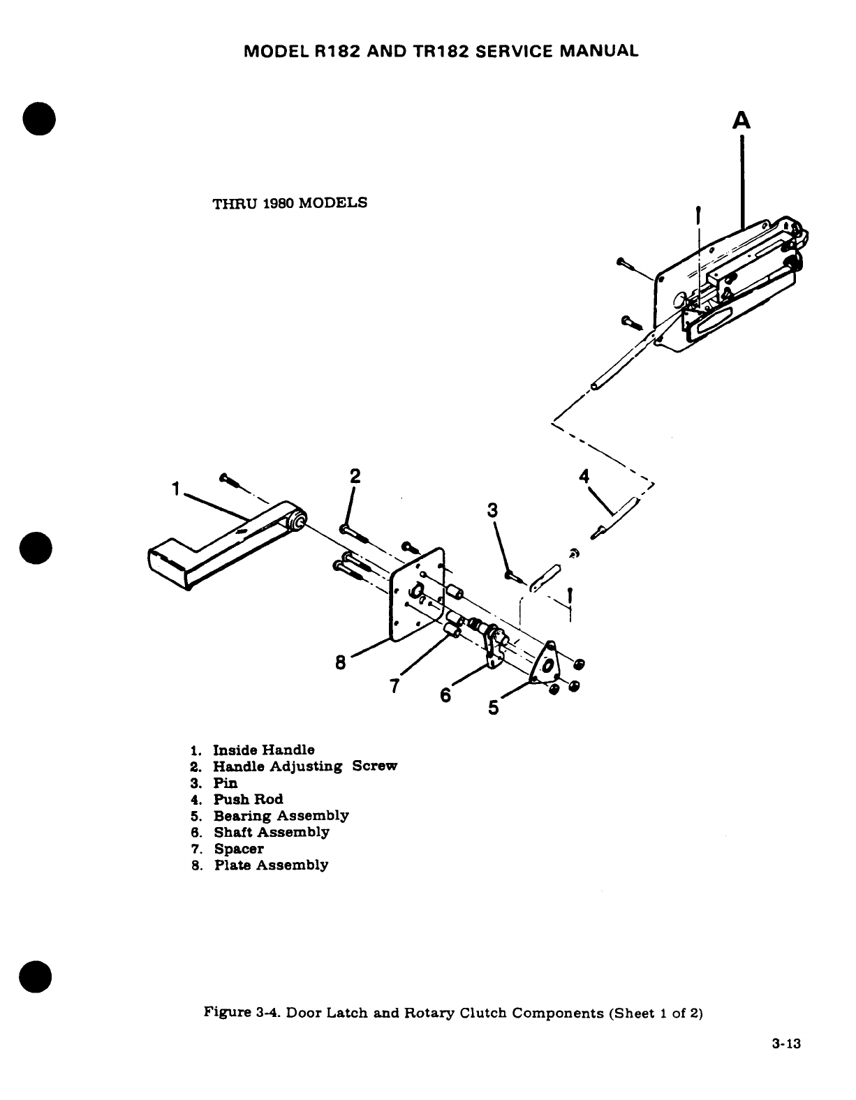
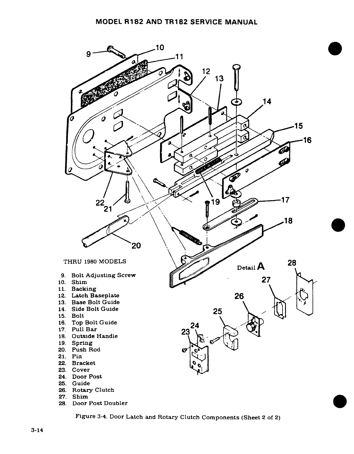
MODEL
R182
AND
TR182
SERVICE
MANUAL
10
12
./
B13
14.~ ~ Sid Bl
Gie214
15
16. T16
9-^j^L'
<
22
/
4>
'
19
17
&t2/0
\ \ \' t
8W^18
0
21
THRU
1980
MODELS
\DeailA 28
9.
Bolt
Adjusting
Screw
Sa
27
10.
Shim
l
R
11.
Backing
12.
Latch
Baseplate
26
13.
Base
Bolt Guide
14.
Side
Bolt
Guide
15.
Bolt
16.
Top
Bolt
Guide
24
17.
Pull
Bar
23
18.
Outside
Handle
19.
Spring
20.
Push
Rod
21.
Pin
|S)
22.
Bracket
23.
Cover
24.
Door
Post
25.
Guide
26.
Rotary
Clutch
27.
Shim
28.
Door
Post
Doubler
Figure
3-4.
Door
Latch
and
Rotary
Clutch
Components
(Sheet
2
of
2)
3-14
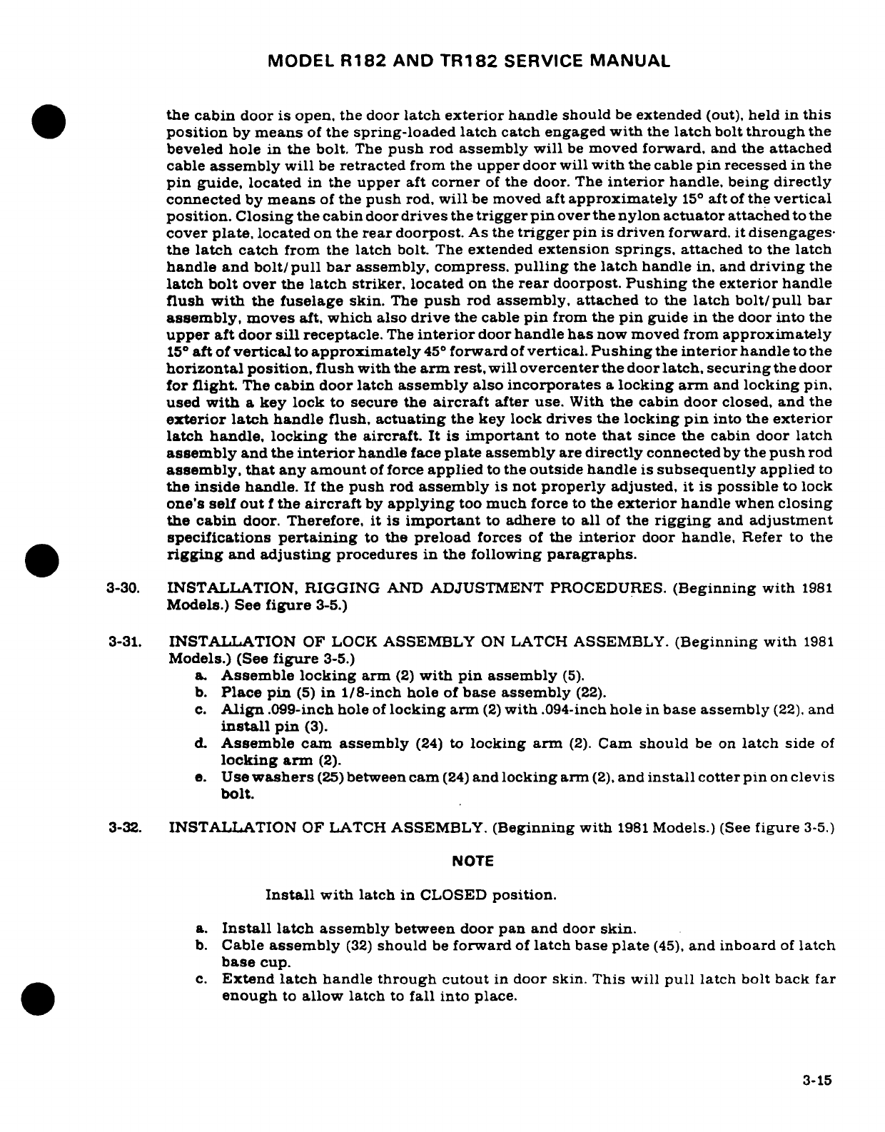
MODEL
R182
AND
TR182
SERVICE
MANUAL
the
cabin
door
is
open,
the
door
latch
exterior
handle
should
be
extended
(out),
held in
this
position
by
means
of
the spring-loaded
latch
catch
engaged
with
the
latch
bolt
through
the
beveled
hole
in
the
bolt.
The
push
rod
assembly
will
be
moved
forward,
and
the
attached
cable
assembly
will
be
retracted
from
the
upper
door
will
with
the
cable
pin
recessed
in
the
pin
guide,
located
in
the
upper
aft
corner
of
the
door.
The
interior
handle,
being
directly
connected
by
means
of
the
push
rod,
will
be
moved
aft
approximately
15°
aft
of
the
vertical
position.
Closing
the cabin
door
drives
the
trigger
pin
over
the nylon
actuator
attached
to
the
cover
plate,
located
on
the
rear
doorpost.
As
the
trigger
pin
is
driven
forward,
it
disengages-
the
latch
catch
from the
latch
bolt.
The
extended
extension
springs,
attached
to
the
latch
handle
and
bolt/pull
bar
assembly, compress,
pulling
the
latch
handle
in,
and
driving
the
latch bolt
over
the
latch
striker,
located
on
the
rear
doorpost.
Pushing
the
exterior
handle
flush with
the
fuselage
skin.
The
push
rod
assembly,
attached
to
the
latch
bolt/pull
bar
assembly,
moves
aft,
which also
drive
the
cable
pin
from
the
pin
guide
in
the
door into
the
upper
aft
door
sill
receptacle.
The
interior
door
handle
has
now
moved
from
approximately
15°
aft
of
vertical
to
approximately
45
°
forward
of
vertical.
Pushing
the
interior
handle
to
the
horizontal position, flush
with
the
arm
rest,
will
overcenter
the
door
latch,
securing
the
door
for
flight.
The
cabin
door
latch
assembly
also
incorporates
a
locking
arm
and
locking pin,
used
with
a
key
lock
to
secure the
aircraft
after
use.
With
the
cabin door
closed,
and
the
exterior
latch
handle
flush,
actuating
the
key lock
drives
the
locking
pin
into
the
exterior
latch
handle,
locking
the
aircraft.
It
is
important
to note
that
since
the
cabin door latch
assembly
and
the
interior
handle
face
plate
assembly
are
directly
connected
by
the
push
rod
assembly,
that
any amount
of
force
applied
to
the
outside
handle
is
subsequently
applied
to
the
inside
handle.
If
the push
rod
assembly
is
not
properly
adjusted,
it is
possible
to
lock
one's
self out
f
the
aircraft
by
applying
too
much
force
to
the
exterior
handle
when
closing
the
cabin
door.
Therefore,
it is
important
to
adhere
to
all
of
the
rigging
and
adjustment
specifications
pertaining
to
the
preload
forces
of
the
interior
door
handle, Refer
to
the
rigging
and
adjusting
procedures
in
the
following
paragraphs.
3-30.
INSTALLATION,
RIGGING
AND
ADJUSTMENT PROCEDURES.
(Beginning
with
1981
Models.)
See
figure
3-5.)
3-31.
INSTALLATION
OF LOCK
ASSEMBLY
ON
LATCH
ASSEMBLY.
(Beginning with
1981
Models.)
(See
figure
3-5.)
a.
Assemble
locking
arm
(2)
with
pin assembly
(5).
b.
Place pin
(5)
in
1/8-inch
hole
of
base assembly
(22).
c.
Align
.099-inch
hole
of
locking
arm
(2)
with
.094-inch
hole
in
base
assembly
(22).
and
install
pin
(3).
d.
Assemble
cam
assembly
(24)
to
locking
arm
(2).
Cam
should
be
on
latch
side
of
locking
arm
(2).
e.
Use
washers
(25)
between
cam
(24)
and
locking
arm
(2),
and
install
cotter
pin
on
clevis
bolt.
3-32.
INSTALLATION
OF LATCH
ASSEMBLY.
(Beginning with
1981
Models.)
(See
figure
3-5.)
NOTE
Install
with
latch
in
CLOSED
position.
a.
Install
latch
assembly
between
door
pan
and
door
skin.
b.
Cable
assembly
(32)
should
be
forward
of
latch
base
plate
(45),
and
inboard
of
latch
base
cup.
c.
Extend
latch
handle
through
cutout
in
door
skin.
This
will
pull
latch bolt back
far
enough
to
allow
latch
to
fall
into
place.
3-15
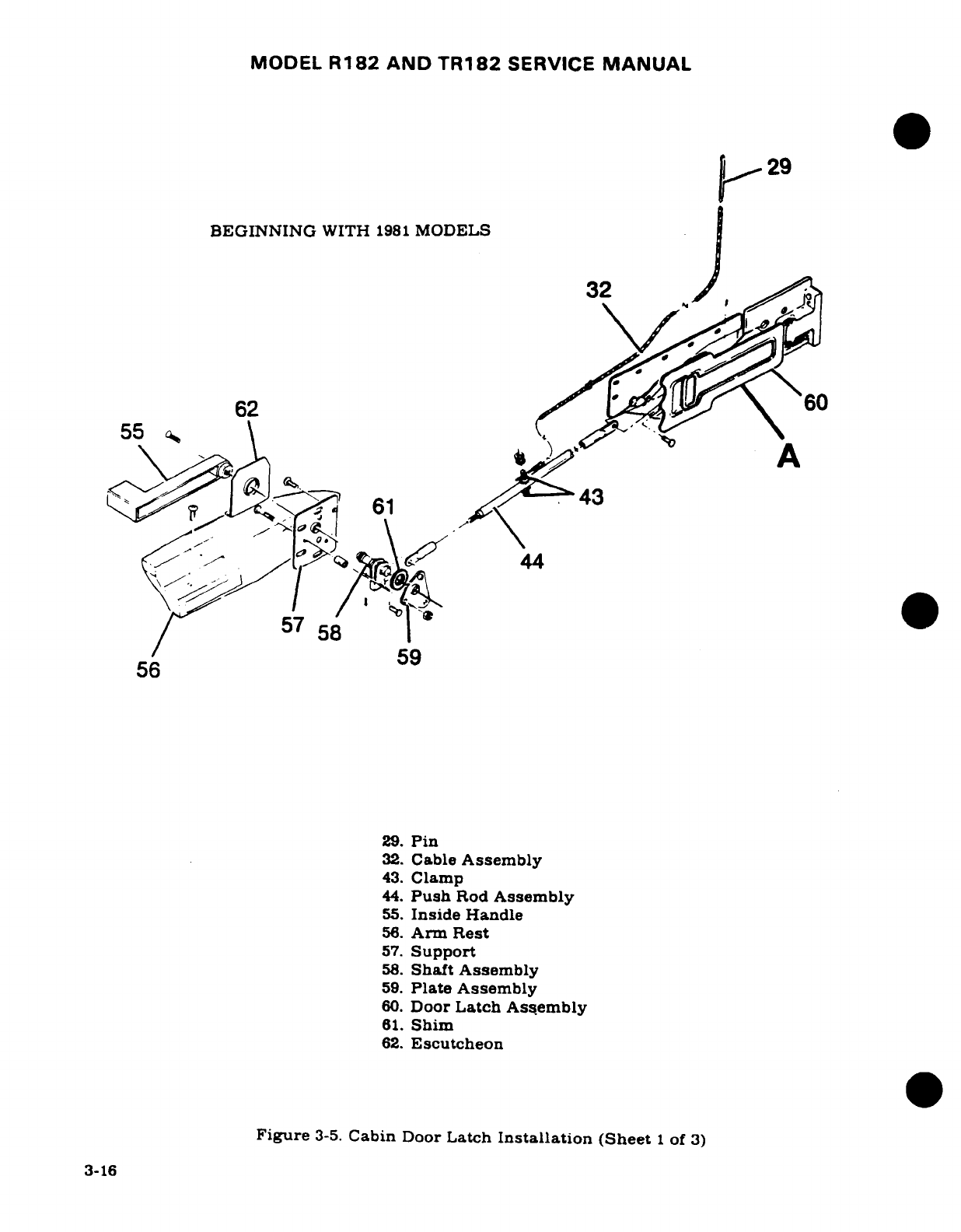
MODEL
R182
AND
TR182
SERVICE
MANUAL
V
29
BEGINNING
WITH
1981
MODELS
32
/159
55
43.
Clamp
44.Push
Rod
Assembly
55.
Inside
Handle
56.
Arm
Rest
/~57.
Support
56
7
59
29.
Pin
32.
Shaft
Assembly
43.
Clamp
44.
Push
Rod
Assembly
55.
Inside Handle
56.
Arm
Rest
57.
Support
58.
Shaft Assembly
59.
Plate
Assembly
60.
Door
Latch
Assembly
61.
Shim
62.
Escutcheon
Figure
3-5.
Cabin
Door
Latch
Installation
(Sheet
1
of
3)
3-16
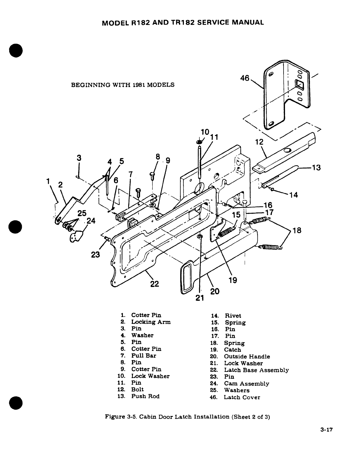
MODEL
R182
AND
TR182
SERVICE
MANUAL
46
Q
BEGINNING
WITH
1981
MODELS
. o
10
12
,4 5
"
9
-1
J/
7
</
/.·
j
13
1
2
T
!1
1.
Cotter
Pin
14.
Rivet
3. Pin
1.
Pin16
4.
Washer
17.
Pin
5
.
S24prin
6.
Cott22
P
19.
Ca
20
21
1.
Cotter Pin
14.
Rivet
2.
Locking Arm
15.
Spring
3.
Pin
16.
Pin
4.
Washer
17.
Pin
5.
Pin
18.
Spring
6.
CotterPin
19.
Catch
7.
Pull
Bar
20.
Outside
Handle
8.
Pin
21.
Lock
Washer
9.
Cotter Pin
22.
Latch
Base
Assembly
10.
Lock
Washer
23.
Pin
11.
Pin
24.
Cam
Assembly
12.
Bolt
25.
Washers
13.
Push
Rod
46.
Latch
Cover
Figure
3-5.
Cabin
Door
Latch
Installation
(Sheet
2
of
3)
3-17
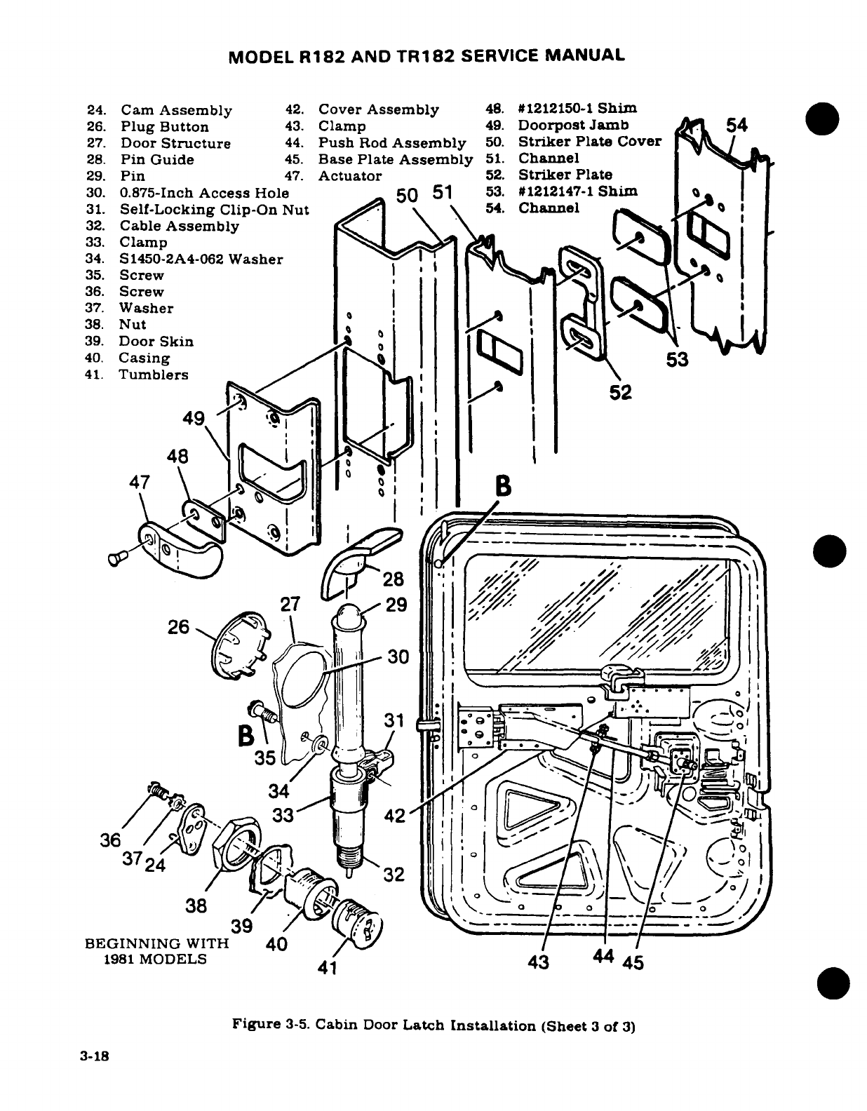
MODEL
R182
AND
TR182
SERVICE
MANUAL
24.
Cam
Assembly
42.
Cover
Assembly
48.
#1212150-1
Shim
26.
Plug
Button
43.
Clamp
49.
Doorpost
Jamb
54
27.
Door
Structure
44.
Push
Rod
Assembly
50.
Striker
Plate
Cover
28.
Pin
Guide
45.
Base
Plate
Assembly
51.
Channel
29.
Pin
47.
Actuator
52.
Striker
Plate
30.
0.875-Inch
Access
Hole
50
51
53.
#1212147-1
Shim
I
31.
Self-Locking
Clip-On
Nut
54.
Channel
32.
Cable
Assembly
\
33.
Clamp1
J
34.
S1450-2A4-062
Washer
' t , '? i
35.
Screw
36.
Screw
37.
Washer
I
S
38.
Nut
39.
Door
Skin
40.
Casing
53
41.
Tumblers
49
f
A5
\I-'l
,
47
\
B
27
'
29
(^^^30
36
1
33
42
O1
3724
/
32
39
BEGINNING
WITH
40
1981
MODELS
41
43
Figure
3-5.
Cabin
Door
Latch
Installation
(Sheet
3
of
3)
3-18
MODEL
R182
AND
TR182
SERVICE
MANUAL
d.
Push
latch
assembly
aft
so
that
bolt
(12)
and
push
rod
(13)
extend
through
their
respective
holes.
e.
Trip
push
rod
(13)
so
that
bolt
(12)
is
fully
extended
and
handle
(20)
is
flush.
f.
Secure
latch
to
door
pan
with
four
NAS220-5
screws through
base
assembly
(22)
and
two
AN525-10R6
screws
through
aft
flange
of
door
pan.
g.
Drill
eleven
.128-inch
holes
to
align
with
latch
base
(22).
NOTE
Do
not
oversize
holes
in
the
latch
base
and
do
not
rivet
base
to
skin
at
this
time.
3-33.
INSTALLING
CABLE ASSEMBLY.
(Beginning
with
1981
Models.)
(See
figure
3-5.)
NOTE
Remove
cover
assembly
(42).
a.
On
pin
end
of
cable
assembly
(32),
attach clamp
(33)
and
nut
(31),
one-inch from
end
of
casing, as
shown
in
Detail
B.
b.
Insert
pin
end
of
cable
between
door
pan
and
door
skin
at
aft
end
of
door.
Push
pin
end
of
cable to
top
of
door.
c.
Remove
plug
button
(26)
and
align
pin
on
cable
with
pin
guide
(28),
and
insert
pin
through
guide.
Access
is
gained
through
.875-inch
hole
(30).
d.
Align
clamp
on
cable
casing
with
hole
located
one-inch
below
.875-inch
hole
(30),
and
install
screw.
e.
Check
operation
of
cable.
If
sluggish
operation
of
cable
is
encountered,
add
S-1450-
24A-062
washers
(34)
to
clip-on
nut
(31)
to
facilitate
smoother
cable
operation.
NOTE
Washers
are
to
be
bonded
to
clip-on
nut
with
579.6
sealer
(Inmont
Corp.,
St. Louis,
Missouri),
or
equivalent.
3-34.
RIGGING
CABLE ASSEMBLY.
(Beginning
with
1981
Models.)
(See
figure
3-5.)
NOTE
Make
sure
door
latch
is
in
OPEN
position
before
proceed-
ing.
a.
Cut
casing
of
cable
assembly
approximately
two
inches
from
clamp
(43)
on
push
rod
assembly
(44).
b.
Insert
core
of
cable
through
clamp
(43).
c.
Pull
core
through
clamp
so
that
pin
(29)
extends approximately
1/8-inch from
door
pan
contour.
d.
Cut core
approximately
one-inch forward
of
push
rod
clamp
(43).
e.
Secure
two
nuts
to
push
rod
clamp.
f.
Operate
latch
several
times
to
ensure
latch works
freely.
If
latch
binds
up
and
will
not
work
freely,
remove
cable
core
from
clamp
(43)
and
operate
latch.
If
latch
operates
easily
without
cable
attachment,
check
cable
for
possible
adjustments
to
facilitate
ease
of
operation.
g.
After cable
operates
freely,
install
cover assembly
(42)
and
recheck
cable
for
operation.
3-19
MODEL
R182
AND
TR182
SERVICE
MANUAL
3-35.
RIGGING
INSIDE
DOOR
HANDLE.
(Beginning
with
1981
Models.)
(See
figure
3-5.)
a.
With
latch
secured
to
door
pan,
attach
push
rod
assembly
(44)
to
pull bar
(7),
and
secure with
pin
(8).
Do
not
install
cotter
pin
(9).
b.
Ensure
that
latch
is in
CLOSED
position.
c.
By
removing pin
(8)
that
connects
push
rod
to
latch base
assembly,
rotate
rod
in
or
out
(180
°)
for
adjustment.
Adjust
rod so
that
it
takes
a
load
of
6
pounds
to
12
pounds
at
the
end
of
the
inner
handle
to
move
it
from
closed
position
to
overcenter
position.
NOTE
Rod
must
be
attached
to
latch
assembly
before
rigging
can
be
accomplished.
d.
For
fine
adjustment
for
overcentering
latch assembly,
proceed
as
follows:
NOTE
Cabin
door
latch
must
be
in
OPEN
position.
Latch must
operate
smoothly
and
freely.
1.
Adjust
striker
plate
(52)
forward
by
installing
1212147-1
shims
(53)
as
required
so
that
there
is
a
minimal
clearance
between
bolt
(12)
and
striker
(52).
NOTE
This
adjustment
will
ensure
that
when
the
door
is
opened
from
the
outside,
the
bolt
will
engage
the
latch
catch,
and
the
exterior
handle
will
stay
open
until
the
door
is
closed
again.
NOTE
If
cabin
door
is
located
too
far
forward such
that
the
door
latch
will
not
operate,
this
will
not
allow
latch
assembly
push
rod
(13)
to
ride
up
on
actuator
(47)
and
trigger
the
latch
bolt
(12),
install
1212150-1
shims
(48)
as
required
beneath
actuator
(47),
located
on
cover
assembly
(50).
2.
Close
the
cabin
door
from
inside
the
aircraft.
When
latch
is
overcentered.
the
exterior
handle should
pull
flush.
If
it
does
not
pull
flush,
the
connecting
push
rod
from
the door
latch
to
the
inside
handle
assembly
should
be
adjusted
"out"
(lengthened).
NOTE
When
making
this
adjustment
on
the
overcentering
of
the
latch,
it
may
be
noticed
that
there
is a
sharp,
loud
canning
noise
when
the
inside
handle
is
pushed
down.
It
is
preferred
that
the
outside
door
handle
be
flush,
even
if
the
canning noise
is
noticeable.
3.
When
adjusting
push
rod
(44),
itmay
needonly
be
adjusted
1/2
turn.
To
accom
plish
this,
base
plate
(45)
should
be
removed.
3-20
MODEL
R182
AND
TR182
SERVICE
MANUAL
4.
To
make
1/2
turn
adjustment,
remove
smaller
end
of
push
rod
(44)
and
turn
it
over
(180°).
Then
reinstall
base
plate
assembly.
5.
When
closing
cabin
door from
the
outside,
by
using
a
large,
sharp
force
on
the
outside
handle,
it is
possible
to
overcenter
the
inside handle,
thus locking
one's
self
out.
To
prevent
this
from
occurring
when
adjusting
the
push
rod
in
step
"4".
adjust
the push
rod
so
there
is
sufficient
force
(6
to
12
pounds)
against
the
inside
handle
to
prevent
it
from
overcentering
when
closing
the
door
from
the
outside.
6.
Do
not
file,
grind
or sand
any
portion
of
the
bolt.
7.
Recheck
clamps
that
secure
cable.
There
must
not
be
any
slippage
between
cable
casing
and
clamp.
8.
After
overcenter
adjustment
has
been
made,
install
cotter
pin
(9)
in
clevis
pin
(8).
e.
Rivet
latch
base
(22)
to
door
skin
with
MS20426A4-3
rivets.
f.
Attach
lock
assembly
casing
(40)
to
door
skin
(39)
with
nut
(38)
provided.
g.
Install
tumblers
(40)
and
attach
cam
(24)
to
tumblers
with
screw
and
lock
washer
provided
(36)
and
(37).
NOTE
After
installing
cam
(24),
seal
over
head
of
screw
(36)
and
washer
(37)
with
RTV-102
(white)
or
RTV-103
(black)
silicone
rubber
sealant
(General
Electric,
Waterford,
N.
Y.).
h.
Operate lock
several
times
to'assure
that
all
parts
function
properly.
NOTE
Steps
"f"
and
"h"
apply
to
left-hand
doors
only.
3-36.
BAGGAGE
DOOR.
(See
figure
3-6.)
3-37.
REMOVAL
AND
INSTALLATION.
a.
Disconnect
door-stop
chain
(5).
b.
Remove
inside
door
handle
if
installed.
c.
Remove
screws
securing upholstery
panel
and
remove
panel.
d.
Remove
bolts
securing
door
to
hinges
or
remove
clevis
pins securing
hinges
to
brackets.
e.
Reverse
preceding
steps
for
reinstallation.
3-38.
SEATS.
(See
figure
3-7.)
3-39.
DESCRIPTION.
The
seating
arrangements
consist
of
two
individually
adjustable
four-way
or
six-way
front
seats
for
the
pilot
and
copilot,
and
a
split-backed
fixed seat
for
the
rear
passengers.
An
auxiliary
seat,
if
installed,
is
located
at
the
aft
cabin
bulkhead
behind
the
rear
seat.
3-40.
REMOVAL
AND INSTALLATION.
a.
Remove
seat stops
from
rails.
(See
figure
3-7,
sheet
8.)
b.
Disengage
seat
belts
by
slipping
buckle
ends
through
seat
belt
retainer.
c.
With
vertical
adjust
seats installed,
remove
cabin vent/carpet
retainer.
d.
Crank
vertical
adjust
seats
to
their
maximum
height.
e.
Slide
seats
forward
to
disengage
front
rollers
from
seat
rails.
f.
Slide
seats
aft
to
disengage
rear
rollers
from
seat
rails.
g.
Lift
seat out.
h.
Reverse
preceding steps
for
installation.
Ensure
all
seat
stops are
properly
installed.
3-21
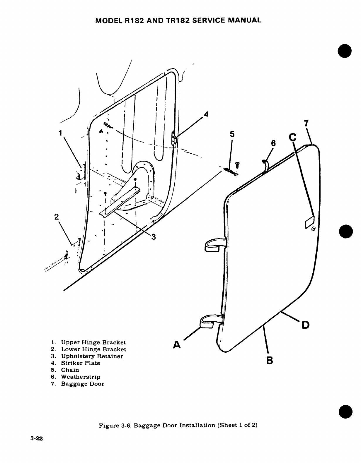
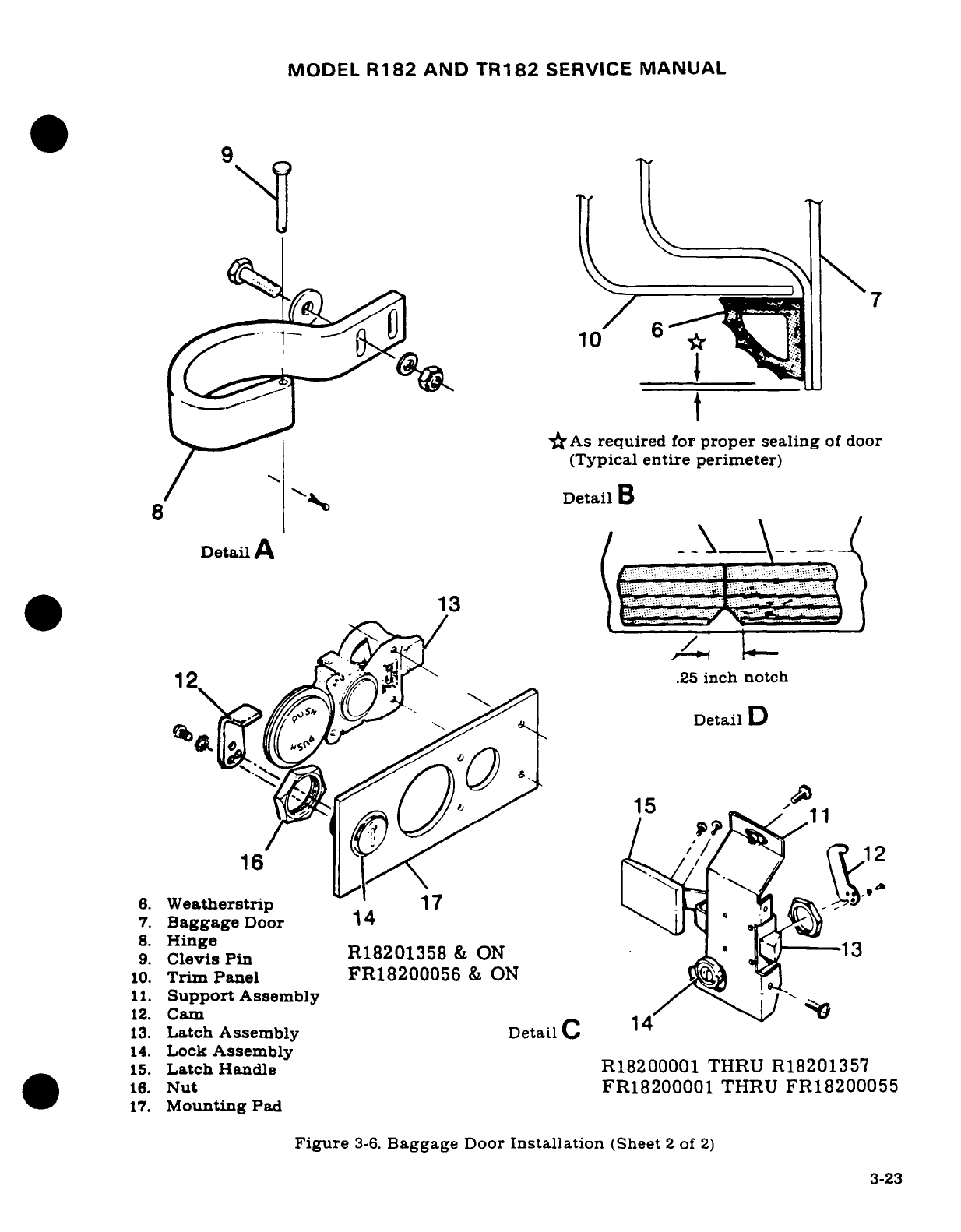
MODEL
R182
AND
TR182
SERVICE
MANUAL
9a
S
10
As
required
for
proper
sealing
of door
(Typical
entire perimeter)
Detail
B
Detail
A
i/
12
g
.25
inch notch
9.
ClevisPin
R18201358
&
ON
-
13
10.
Trim
Panel
FR18200056
&
ON j X15
11.
Support
Assembly
/
\
-/ ~
12.
Cam
16
13.
Latch
Assembly
eta
C
14.
Lock
Assembly
15.
Latch
Handle
R18200001
THRU
R18201357
16.
Nut
FR18200001
THRU
FR18200055
17.
Mounting
Pad
Figure
3-6.
Baggage
Door
Installation
(Sheet
2
of
2)
3-23
MODEL
R182
AND
TR182
SERVICE
MANUAL
WARNING
It is
extremely
important
that
the
pilot's
seat
stops
are
installed,
since
acceleration
and
deceleration could
pos-
sibly
permit
seat
to
become
disengaged
from
the
seat
rails
and
create
a
hazardous
situation,
especially
during
takeoff
and
landing.
3-41.
MECHANICAL
LOCK
CONTROL
ASSEMBLY. (See
figure
3-7,
sheets
2
and
5.)
3-42.
DESCRIPTION.
A
mechanical
lock
control assembly
is
installed
on
pilot
and
copilot
seats
and on
the
rear
seat
assembly
beginning
with
R18201314
and
FR18200064.
The
front
seat
lock
control
is
longer
than
the
rear
seat
lock
control.
The
lock
control assembly
facilitates
seat
lock
control.
The lock
control
assembly
facilitates
seat
reclining
adjustment.
When
the
control
is
activated,
an
internal
spring
is
released,
enabling
the
occupant
to
recline
the
seat
to
the
desired
angle.
When
the
control
is
released,
the
internal
spring
expands,
locking
the
seat
in
the
desired reclined position.
When
the
control
is
reactivated,
the
seat returns
to
the
original
vertical
position.
3-43.
ADJUSTMENT.
(See
figure
3-7.
sheet
2
and
5.)
Rotate
adjusting
nut
(2)
to
adjust
control
wire
(4)
output
stroke
after
seat
is
installed.
3-44.
REAR
PASSENGERS'
SEAT.
3-45.
DESCRIPTION.
The
rear
passengers' seat
consists
of
a
fixed, one-piece
seat
bottom
with
infinitely
adjustable
seat
backs.
3-46.
REMOVAL
AND
INSTALLATION.
a.
Remove
bolts
securing
seat
to
cabin
structure.
b.
Lift
seat
out.
c.
Reverse
preceding steps
for
installation.
3-47.
AUXILIARY
SEAT.
(See
figure
3-7,
sheet
7.)
3-48.
DESCRIPTION.
The
auxiliary
seat
consists
of
a
fixed,
one-piece
seat
bottom
and
a
fixed.
one-piece
seat
back.
The
seat
is
secured
to
brackets mounted
in
the
floorboard.
3-49.
CAM
REPLACEMENT.
Be
certain that
replacement
part
conforms
to
dimensions
shown
in
figure
3-8
before
installing.
Cam
replacement
consists
of
the
following
procedures:
a.
Remove
seat
from
aircraft.
b.
Remove
plastic
upholstery
panels
from
aft
side
of
seat
back,
loosen
upholstery
retaining
rings
and
material
as
necessary
to
expose
rivets retaining
old
cam
assembly.
c.
Drill
out
existing
rivets,
and
insert
new
cam
assembly. Position
seat
back
so
pawl
engages
first
cam
slot
as
illustrated.
d.
Position
cam so
each
slot
bottom
aligns
with
the
2.50"
radius
as
illustrated.
e.
Clamp
securely
in
this
position
and
check
travel
of
cam.
Pawl
must
contact
bottom
of
each
cam
slot..Using
existing
holes
in
seat
frame,
drill
through
new
cam
and
secure
with
MS20470AD6
rivets.
f.
Reinstall
upholstery,
upholstery
panels,
and
seat.
3-50.
REPAIR.
Replacement
of
defective
parts
is
recommended
in
repair
of
seats.
However,
a
cracked
framework
may
be
welded,
provided
the
crack
is
not
in
an
area
of
stress
concentra-
tion
(close
to
a
hinge
or
bearing
point).
The
square-type
framework
is
6061
aluminum,
heat-
3-24
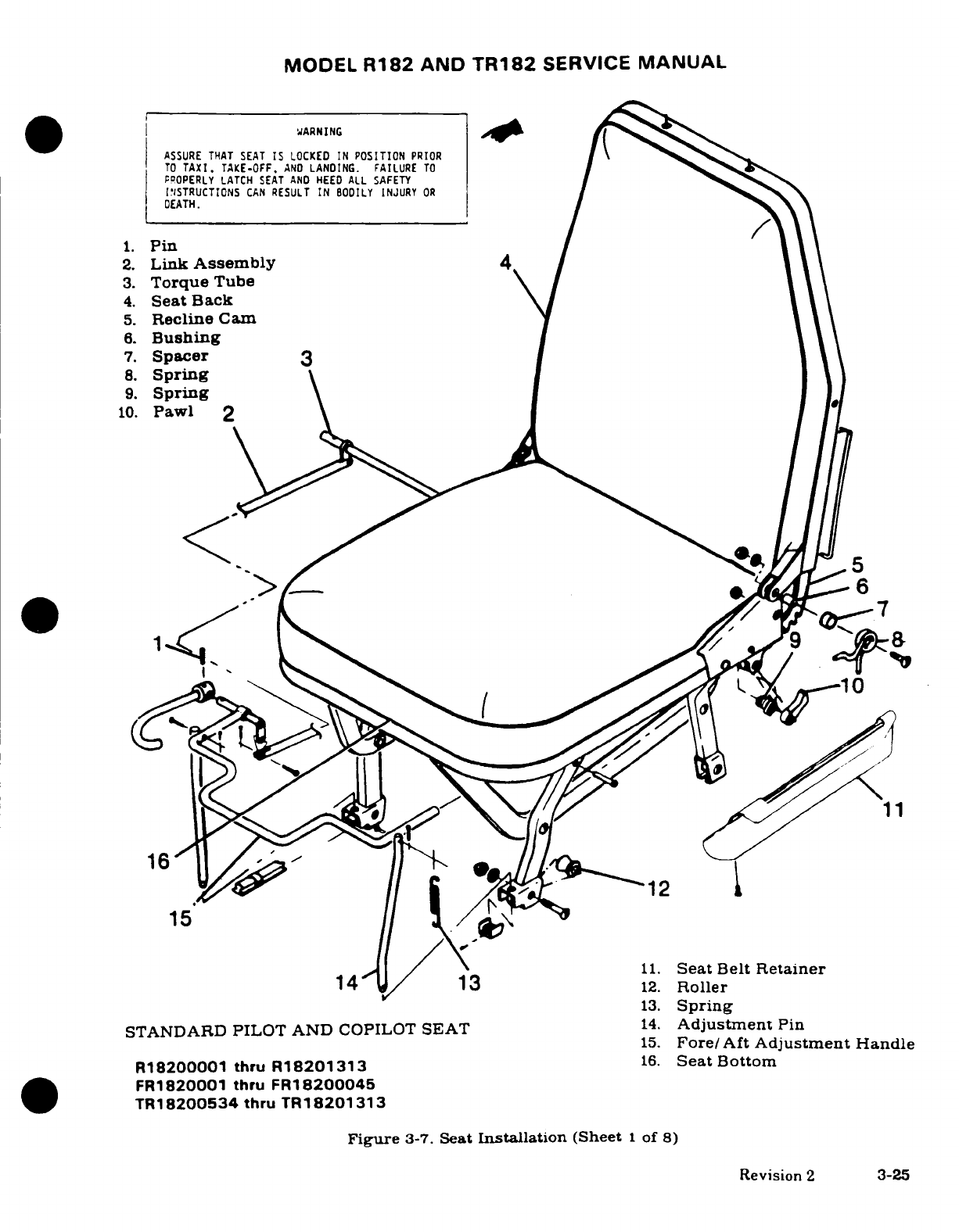
MODEL
R182
AND
TR182
SERVICE
MANUAL
WARNING
ASSURE
THAT
SEAT
IS
LOCKED
IN
POSITION
PRIOR
TO
TAXI.
TAKE-OFF.
AND
LANDING.
FAILURE
TO
PROPERLY LATCH
SEAT
AND
HEED
ALL
SAFETY
[INSTRUCTIONS
CAN
RESULT
IN
BODILY
INJURY
OR
DEATH.
1.
Pin
2.
Link
Assembly
3.
Torque
Tube
4.
Seat
Back
5.
Recline
Cam
6.
Bushing
7.
Spacer
8.
Spring
9.
Spring
10.
Pawl
2pr
o~AL~I~
6
15.
Fore/Aft
Adjustment
Handle
.~t.....~_12
15
11.
Seat
Belt
Retainer
14
/
13
12.
Roller
13.
Spring
STANDARD
PILOT AND
COPILOT
SEAT
14.
Adjustment
Pin
15.
Fore/Aft
Adjustment
Handle
R18200001
thru
R18201313
16.
Seat
Bottom
FR1820001
thru
FR18200045
TR18200534
thru
TR18201313
Figure
3-7.
Seat
Installation
(Sheet
1
of
8)
Revision
2
3-25
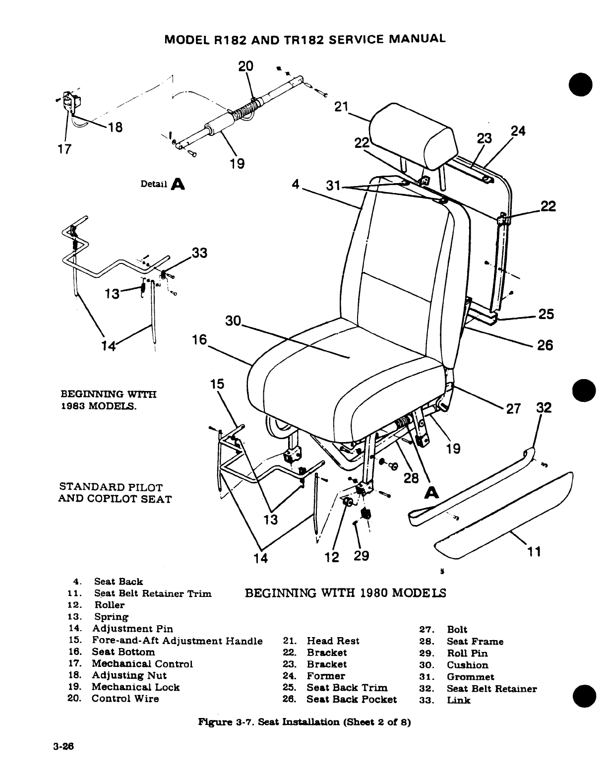
MODEL
R182
AND
TR182
SERVICE
MANUAL
20
21
--. ,
24
BEGINNIDNG
WITH\ {
<a/
17
MODELS
\
/
23
19
Detail
A 4 31
i 2-
30
25
4
"
1 1 6
26
STANDARD
PILOT
AND
COPILOT
SEAT
~~15
3
14
12
29
11
4.
Seat
Back
11
Seat
Belt
Retainer Trim
BEGINNING WITH
1980 MODELS
12.
Roller
13.
Spring
14.
Adjustment
Pin
27.
Bolt
15.
Fore-and-Aft
Adjustment
Handle
21.
Head
Rest
28.
Seat
Frame
16.
Seat
Bottom
22.
Backet
29.
Roll
Pin
17.
Mechanical
Control
23.
Bracket
30.
Cushion
18.
Adjusting
Nut
24.
Former
31.
Grommet
19.
Mechanical
Lock
25.
Seat
Back
Trim
32.
Seat
Belt
Retainer
20.
Control
Wire
26.
Seat
Back
Pocket
33.
Link
Figure
3-7.
Seat
Installation
(Sheet
2
of
8)
3-26
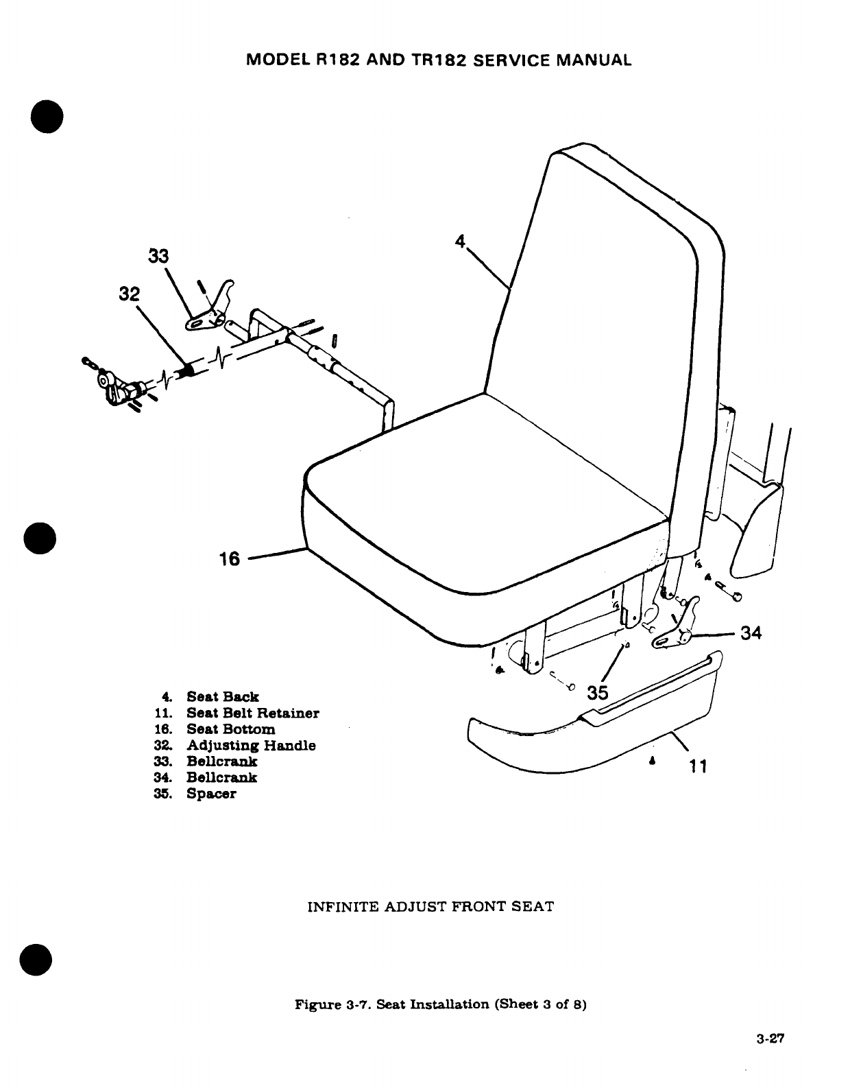
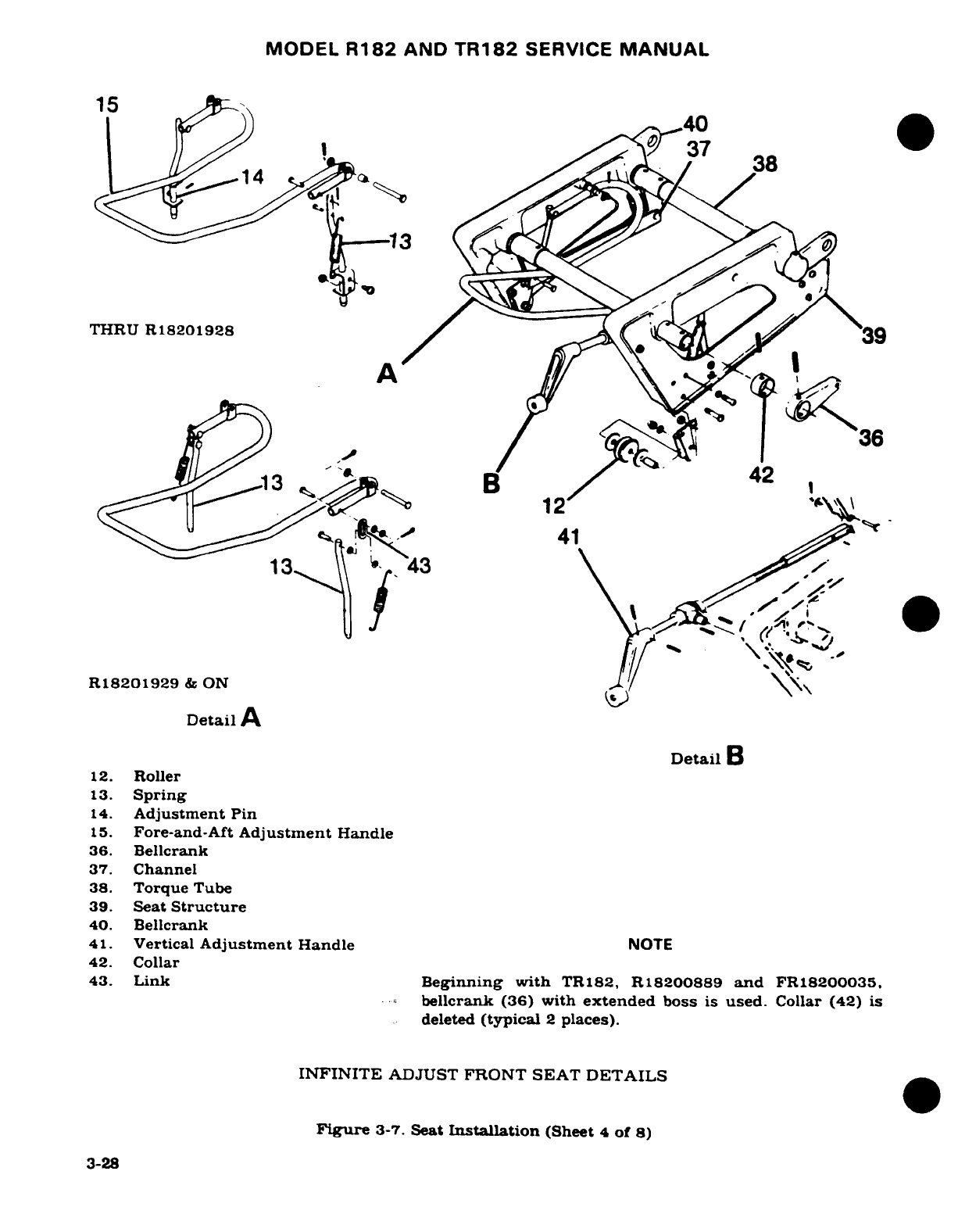
MODEL
R182
AND
TR182
SERVICE
MANUAL
15
<r
14,40
37
38
THRU
R18201928
12
41
13
S43\i
-- "i
R18201929
& ON
/
Detail
A
Detail
B
12.
Roller
13.
Spring
14.
Adjustment
Pin
15.
Fore-and-Aft
Adjustment
Handle
36.
Bellcrank
37.
Channel
38.
Torque
Tube
39.
Seat
Structure
40.
Bellcrank
41.
Vertical
Adjustment
Handle
NOTE
42.
Collar
43.
Link
Beginning
with
TR182,
R18200889
and
FR18200035.
bellcrank
(36)
with
extended
boss
is
used.
Collar
(42)
is
deleted
(typical
2
places).
INFINITE
ADJUST
FRONT
SEAT
DETAILS
Figure
3-7.
Seat
Installation
(Sheet
4
of
8)
3-28
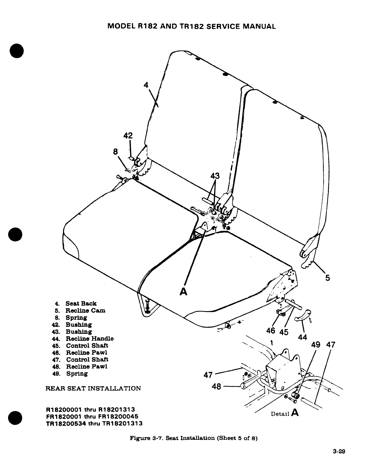
MODEL
R182
AND
TR182
SERVICE
MANUAL
4
43.
/
Bu/
43
5
4.
Seat
Back
5.
Recline
Cam
8.
Spring
42.
Bushing
Ad
/
43.
Bushing
?
46
45
44.
Recline Handle
44
45.
Control
Shaft
49
47
46.
Recline
Pawl
47.
Control
Shaft
48.
Recline
Pawl
49.
Spring
47
<
REAR SEAT
INSTALLATION
48
R18200001
thru
R18201313
/a
FR1820001
thru
FR18200045
Detail
TR18200534
thru
TR18201313
Figure
3-7.
Seat
Installation
(Sheet
5
of
8)
3-29
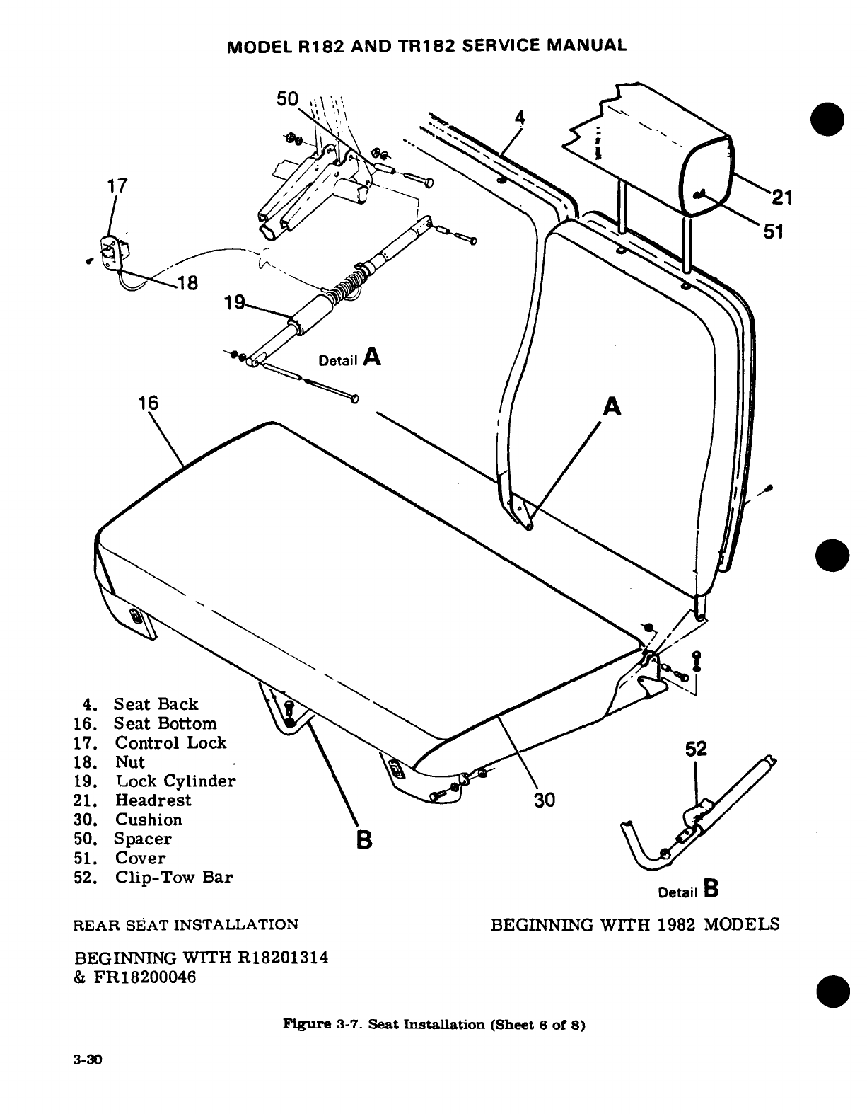
MODEL
R182
AND
TR182
SERVICE
MANUAL
50
',\
\
',.
4
17
'
\
.. . .- '
\./
-
r21''\
*<
^^
>
<^
- '
ss
-
^ 21
17-An~~1
1>\ 5
^'
18
Detail
6
etai/
AA
4.
Seat
Back
16.
Seat
Bottom
17.
Control
Lock
18.
Nut
19.
Lock
Cylinder
21.
Headrest
30
30.
Cushion
50.
Spacer
B
51.
Cover
52.
Clip-Tow
Bar
Detail
B
REAR
SEAT
INSTALLATION
BEGINNING
WITH
1982
MODELS
BEGINNING
WITH
R18201314
&
FR18200046
Figure
3-7.
Seat
Installation
(Sheet
6
of
8)
3-30
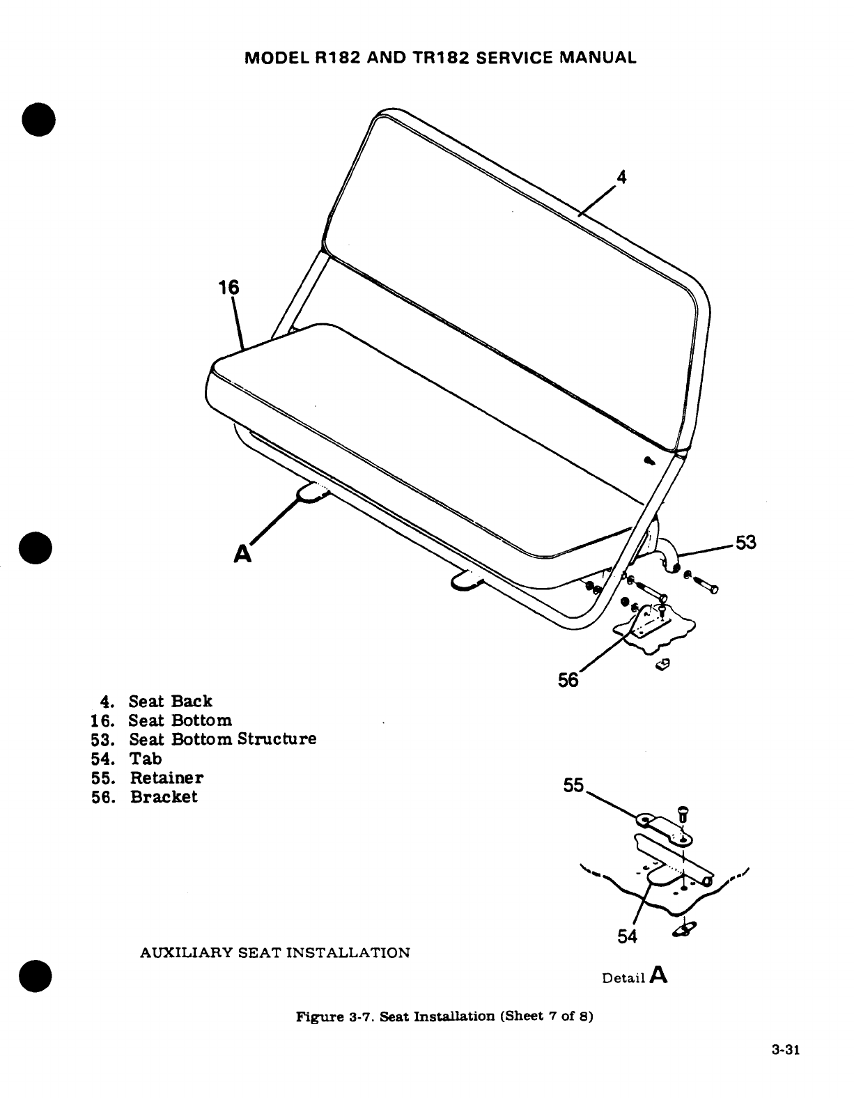
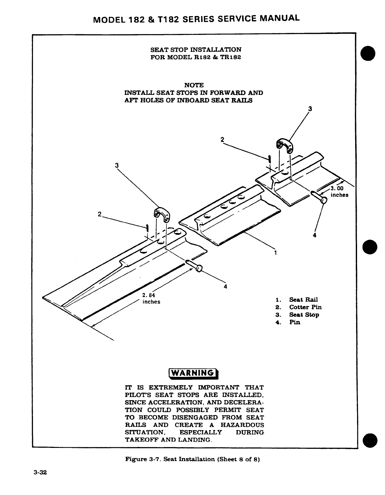
MODEL
182
&
T182
SERIES
SERVICE
MANUAL
SEAT
STOP INSTALLATION
FOR
MODEL
R182
&
TR182
NOTE
INSTALL SEAT STOPS
IN
FORWARD
AND
AFT
HOLES
OF INBOARD
SEAT
RAILS
3
2
a
3.00
inches
4
4
inches
1.
Seat
Rail
2.
Cotter
Pin
3.
Seat
Stop
4.
Pin
IWARNINGI
IT
IS
EXTREMELY
IMPORTANT
THAT
PILOTS
SEAT STOPS
ARE
INSTALLED,
SINCE
ACCELERATION,
AND
DECELERA-
TION
COULD
POSSIBLY
PERMIT
SEAT
TO
BECOME
DISENGAGED FROM SEAT
RAILS
AND
CREATE
A
HAZARDOUS
SITUATION,
ESPECIALLY
DURING
TAKEOFF
AND
LANDING.
Figure
3-7.
Seat
Installation
(Sheet
8
of
8)
3-32
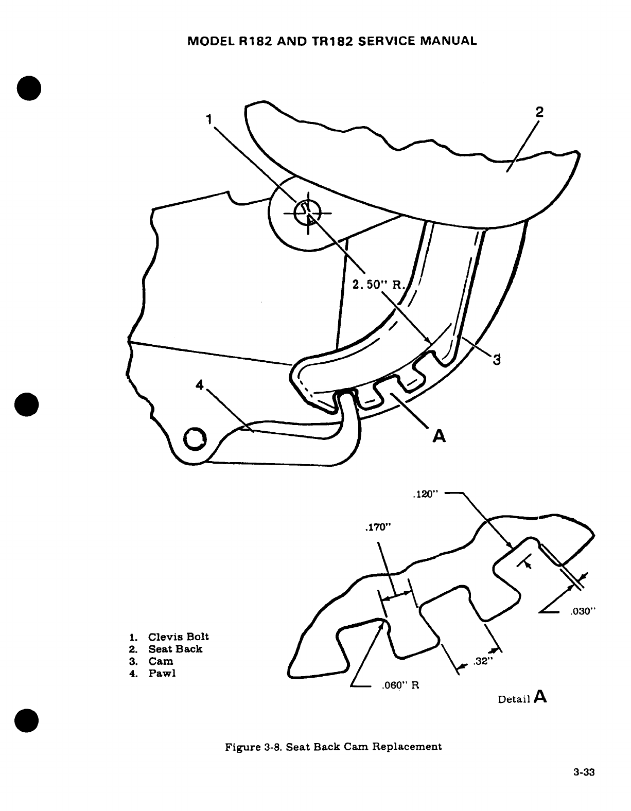
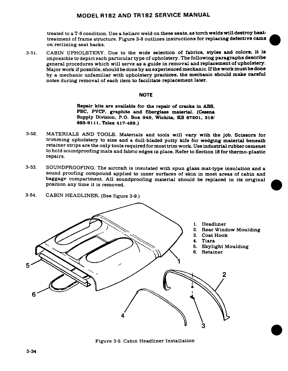
MODEL
R182
AND
TR182
SERVICE
MANUAL
treated
to
a
T-6
condition.
Use
a
heliarc
weld
on
these
seats,
as
torch
welds
will
destroy
heat-
treatment
of
frame
structure.
Figure
3-8
outlines
instructions
for
replacing
defective
cams
on
reclining
seat
backs.
3-51.
CABIN
UPHOLSTERY. Due
to
the
wide
selection
of
fabrics,
styles
and
colors,
it
is
impossible
to
depict
each
particular
type
of
upholstery.
The
following
paragraphs
describe
general procedures
which
will
serve
as
a
guide
in
removal
and
replacement
of
upholstery.
Major
work
if
possible, should
be
done
by
an
experienced
mechanic.
If
the
work
mustbe
done
by a
mechanic
unfamiliar
with
upholstery
practices,
the
mechanic
should
make
careful
notes
during
removal
of
each
item
to
facilitate replacement
later.
NOTE
Repair
kits
are
available
for
the repair
of
cracks
in
ABS,
PBC,
PVCP,
graphite and
fiberglass
material.
(Cessna
Supply
Division,
P.O.
Box
949,
Wichita,
KS
67201,
316/
685-9111,
Telex
417-489.)
3-52.
MATERIALS
AND
TOOLS.
Materials
and
tools
will
vary
with the
job.
Scissors
for
trimming
upholstery
to
size
and
a
dull-bladed
putty
kife
for
wedging
material
beneath
retainer
strips
are
the
only tools
required
for
most
trim
work.
Use
industrial
rubber
cemenet
to
hold
soundproofing
mats
and
fabric
edges
in
place.
Refer
to
Section
18
for
thermo-plastic
repairs.
3-53.
SOUNDPROOFING. The
aircraft
is
insulated
with
spun glass
mat-type
insulation
and
a
sound
proofing
compound
applied
to
inner
surfaces
of
skin
in
most
areas
of
cabin
and
baggage
compartment.
All
soundproofing
material
should
be
replaced
in
its
original
position
any
time
it is
removed.
3-54.
CABIN
HEADLINER.
(See
figure
3-9.)
1.
Headliner
2.
Rear
Window
Moulding
3.
Coat
Hook
4.
Tiara
5.
Skylight
Moulding
t^S^^C~~ yf^6.
Retainer
5
6
in
Figure 3-9.
Can
Hr
Figure
3-9.
Cabin
Headliner
Installation
3-34
MODEL
R182
AND
TR182
SERVICE
MANUAL
3-55.
REMOVAL
AND
INSTALLATION.
a.
Remove
sun
visors,
all
inside
finish
strips
and
plates,
overhead
console,
upper
doorpost
shields
and
any
other
visible
retainers
securing
headliner.
b.
Remove
molding
from
fixed
windows.
c.
Remove
screws
securing
headliner
and
carefully
take
down
headliner.
d.
Remove
spun
glass
soundproofing panels
above
headliner.
NOTE
The
lightweight
soundproofing
panels
are
held
in
place
with
industrial
rubber cement.
e.
Reverse
preceding
steps
for
reinstallation.
Before
installation,
check
all items
concealed
by
headliner
for
security.
Use
wide
cloth
tape
to
secure
loose
wires
to
fuselage
and
to
seal
openings
in
wing
roots.
3-56.
UPHOLSTERY
SIDE
PANELS.
Removal
of
upholstery
side
panels
is
accomplished
by
removing
seats
for
access.
Remove
screws,
retaining
strips,
arm
rests
and
ash
trays
as
required
to free
panels.
Automotive
type
spring
clips
attach
most
door
panels.
A
dull
putty
knife
makes
an
excellent
tool
for
prying
clips
loose.
When
installing
side
panels,
do
not
over-tighten screws.
Larger
screws
may
be
used
in
enlarged
holes
as
long
as
area
behind
hole
is
checked
for
electrical
wiring,
fuel
lines
and
other
components
which
might
be
damaged
by
using
a
longer
screw.
3-57.
CARPETING.
Some
cabin
area
and
baggage
compartment
carpeting
is
held
in-
place
by
rubber
cement,
small
sheet
metal
screws
and
retaining
strips,
some
carpeting
is
secured
by
Velcro
fasteners
for
quick-removal
and
inspection.
When
fitting
a
new
carpet,
use
the
old
one
as
a
pattern
for
trimming.
3-58.
SAFETY
PROVISIONS.
3-59.
CARGO
TIE-DOWNS.
Cargo
tie-down
eyebolts
are
used
to
retain
baggage.
Tie-downs
are
illustrated
in
figure
3-10.
A
baggage
net
can
be
used
in
conjunction with
the tie-downs,
as
straps
can
hold
luggage
secured
in
baggage area.
The
eyebolt
and
nutplate
can
be
located
at
various
points.
3-60.
SAFETY BELTS.
Safety
belts should
be
replaced
if
frayed or
cut,
latches
are
defective
or
stitching
is
broken.
Attaching
parts
should
be
replaced
if
worn
excessively
or
defective.
The
front
seat safety
belts
are
attached
to
brackets
bolted to
the
cabin
floor,
and
the
center
seat
safety
belts
are attached
to
the
seats
themselves.
The
auxiliary
seat
is
provided
with
only
one
safety
belt,
which
is
snapped into
clips
bolted to
the
aircraft
structure.
See
figure
3-11.
A
seat
belt
shortener
kit
is available
for
aircraft
serials
R18200001
thru
R18201798.
(See
SK172-76.)
3-61. SHOULDER
HARNESS.
An
individual
shoulder
harness
may
be
installed
for each
seat
ex-
cept
the
auxiliary
seat.
The
pilot
and
copilot
harnesses
are
bolted
to
the
upper
rear
door-
posts,
and the
center seat harnesses are
bolted
to
the
aft
cabin
structure.
Component
parts
should
be
replaced
as
outlined
in
paragraph
3-60.
An
inertia
reel
type
harness
may
be
in-
stalled
as
optional
equipment
for
the pilot
and
copilot
seats.
See
figure
3-11
3-62.
REAR
VIEW
MIRROR.
A
rear
view
mirror
may
be
installed
on
the
cowl
deck
above
instru-
ment panel.
Figure
3-13
shows
details
for
rear
view
mirror
installation
thru
serial
R18200583.
3-63.
SEAT
RAIL
INSPECTION.
A
special
inspection
of
seat
rails
should
be
conducted
each
50
hours.
See
figure
3-14
for
inspection
procedures.
3-35
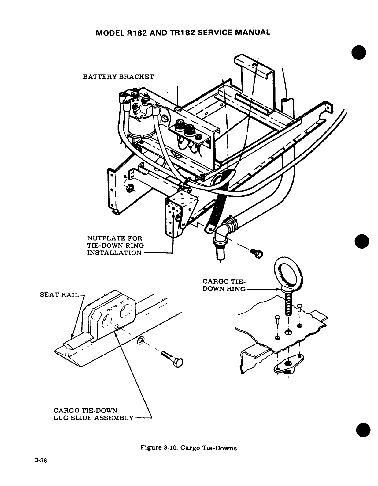
MODEL
R182
AND
TR182
SERVICE
MANUAL
BATTERY BRACKET
NUTPLATE
FOR
TIE-DOWN
RING
INSTALLATION
-----
CARGO
TIE-
j
DOWN
RING
SEAT
RAIL
CARGO
TIE-DOWN
LUG
SLIDE
ASSEMBLY
Figure
3-10.
Cargo
Tie-Downs
3-36
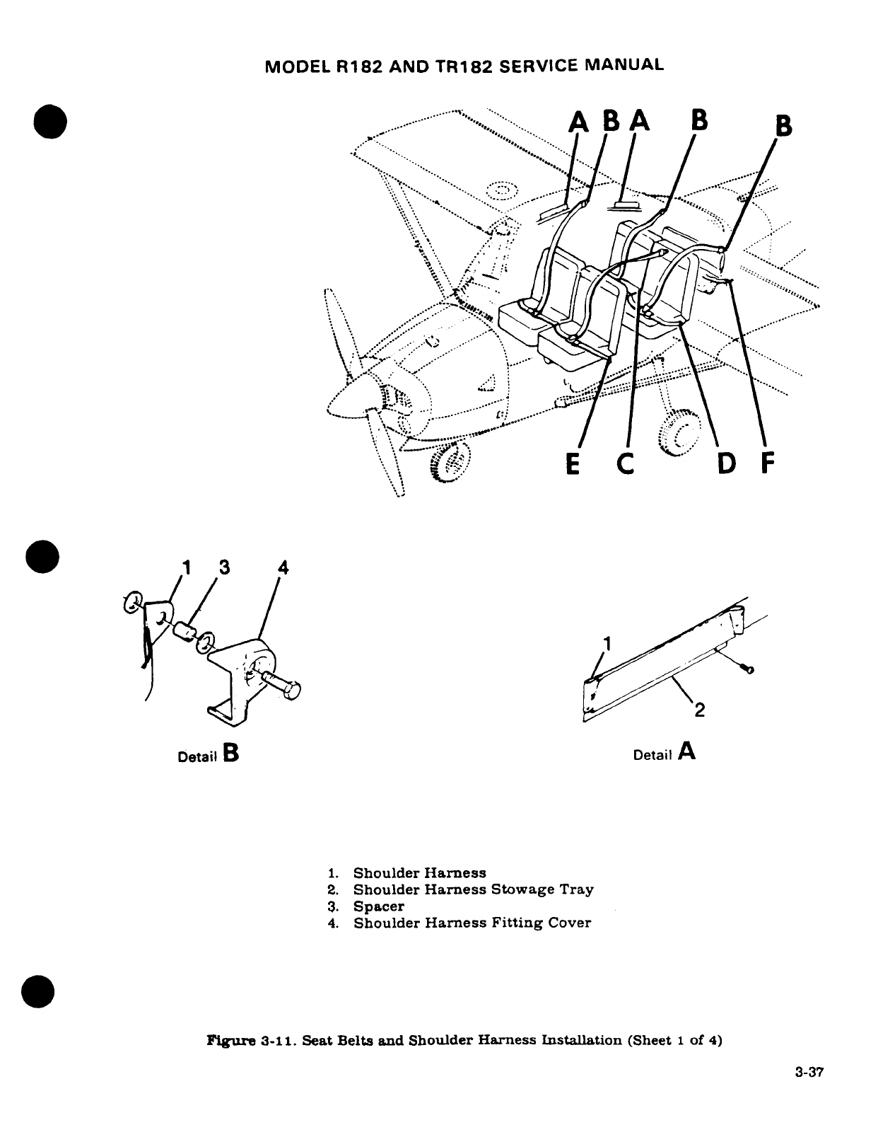
MODEL
R182
AND
TR182
SERVICE
MANUAL
....
A
BA
B
B
"X
..
.........
,-·-
1
3
4
Detail
B
Detail
A
1.
Shoulder
Harness
2.
Shoulder
Harness
Stowage
Tray
3.
Spacer
4.
Shoulder
Harness
Fitting
Cover
Figure
3-11.
Seat Belts
and
Shoulder
Harness
Installation
(Sheet
1
of
4)
3-37
a~~~~~~~~~~~~~~~~~
2~~
E
C
D'
u
. .
"%
1 3 4~~~~~~~~...-,~
,
oetailB
Oetail
A~~~~~~~~~~~~~~~~~~~~~~~~~~~~~~~~~~~~~~~~~~~~~~~~~~~~~~~~~~~~~..~
...
i. Shouldr Har
'.
2.
Shoulder
'-.'~..
x.'
,..'~a
3.~~~~~~~~~~~~~~~~~~~~~~~~~~~~~~
.......
Figure 3~~~~~~~~~~~~~~:-"
...
~
..
tBlsadSoldrHresisalain(he
f
'\ ....
............
~~~3-3
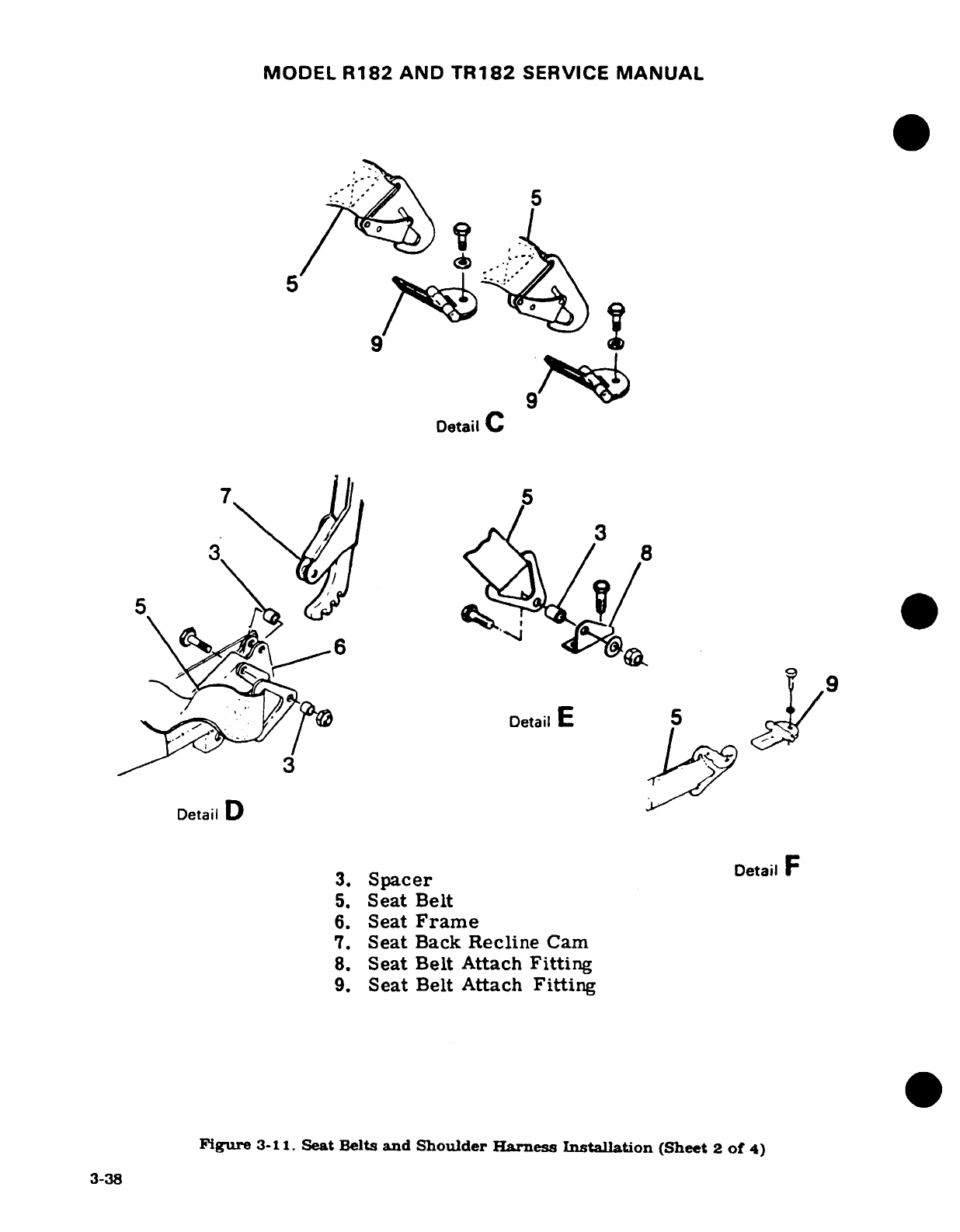
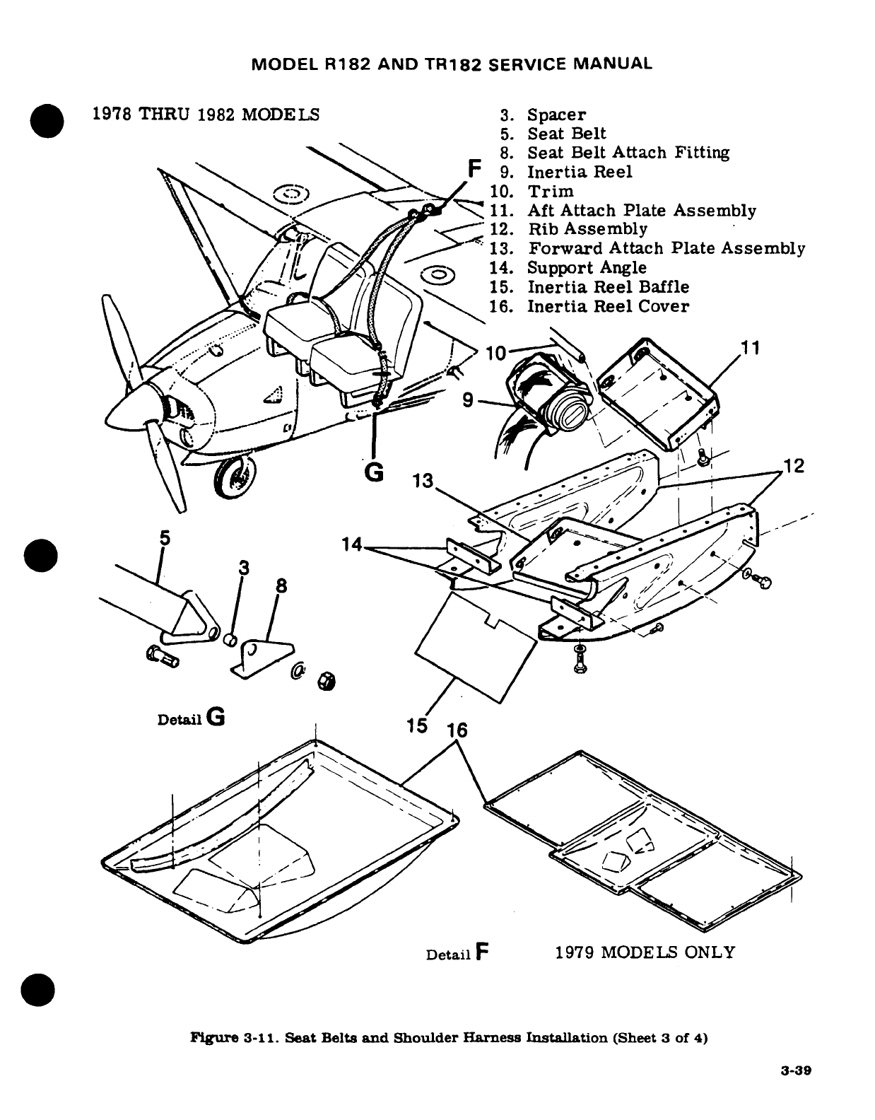
MODEL
R182
AND
TR182
SERVICE
MANUAL
1978
THRU
1982
MODELS
3.
Spacer
5.
Seat
Belt
8.
Seat
Belt
Attach
Fitting
F
9.
Inertia
Reel
10.
Trim
V\
'^ZZ
11.
Aft
Attach
Plate
Assembly
12.
Rib
Assembly
"'
,
f
,^f><
13.
Forward
Attach
Plate
Assembly
\\
/
l
14.
Support
Angle
15.
Inertia
Reel
Baffle
16.
Inertia
Reel
Cover
12
^t1l^-
,
r
'
0e0lG
DetailG
I'15
16
Detail
F
1979
MODELS
ONLY
Figure
3-11.
Seat
Belts
and
Shoulder
Harness
Installation
(Sheet
3 of 4)
3-39
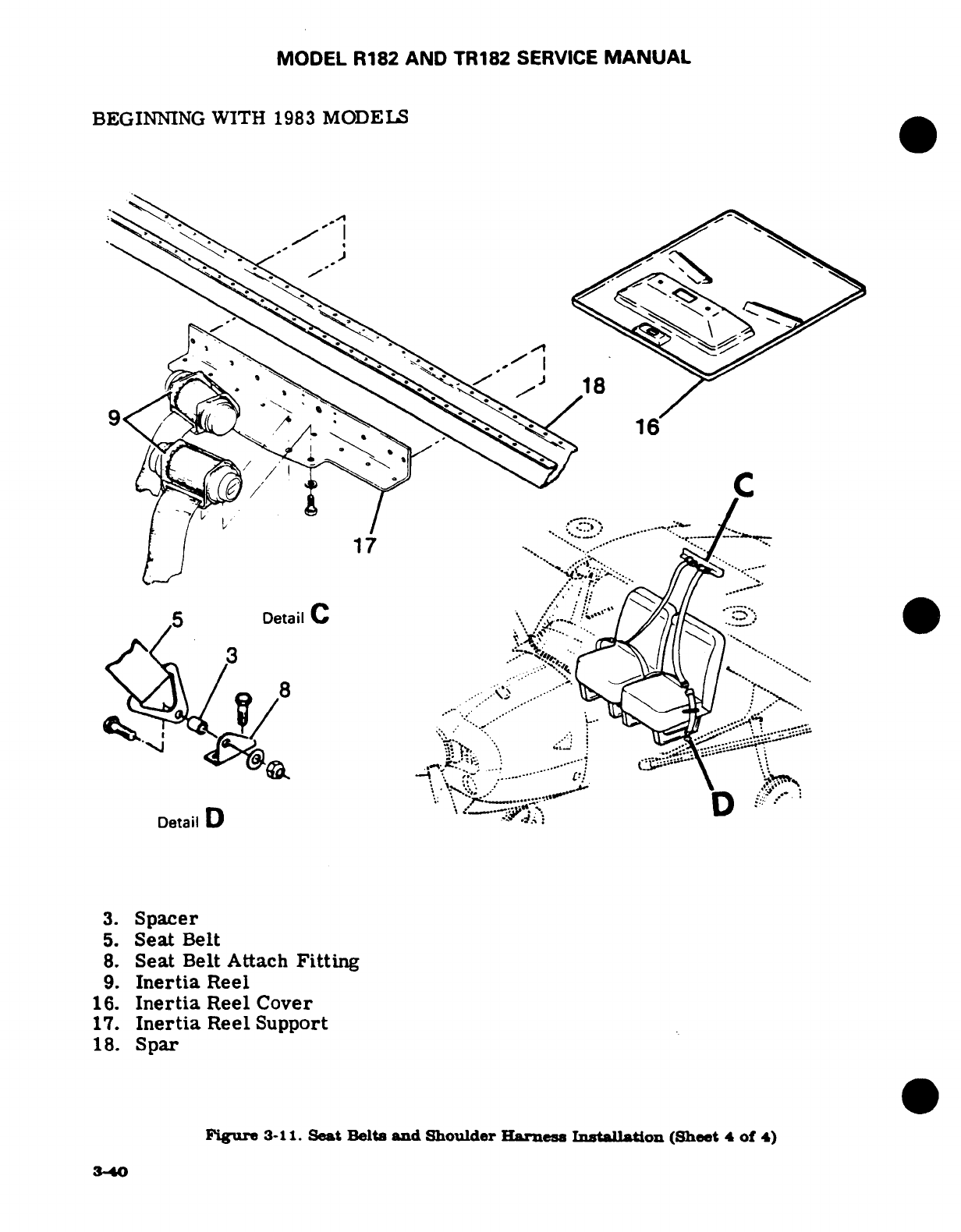
MODEL
R182
AND
TR182
SERVICE
MANUAL
BEGINNING
WITH
1983
MODELS
9
*s
18
1
7
·
5CDetail
C
3.
Spacer
5.
Seat
Belt
8.
Seat
Belt
Attach
Fitting
9.
Inertia
Reel
16.
Inertia
Reel
Cover
17.
Inertia
Reel
Support
18.
Spar
Figure
3-11.
Seat Belts
and
Shoulder
Harness
IntallAon
(Sheet
4
of
4)
3-40
8~~~~%::~//~~::
/'%/_
3
"-':,:
-'-'"'
""~~~~~~~~~~~·'':···
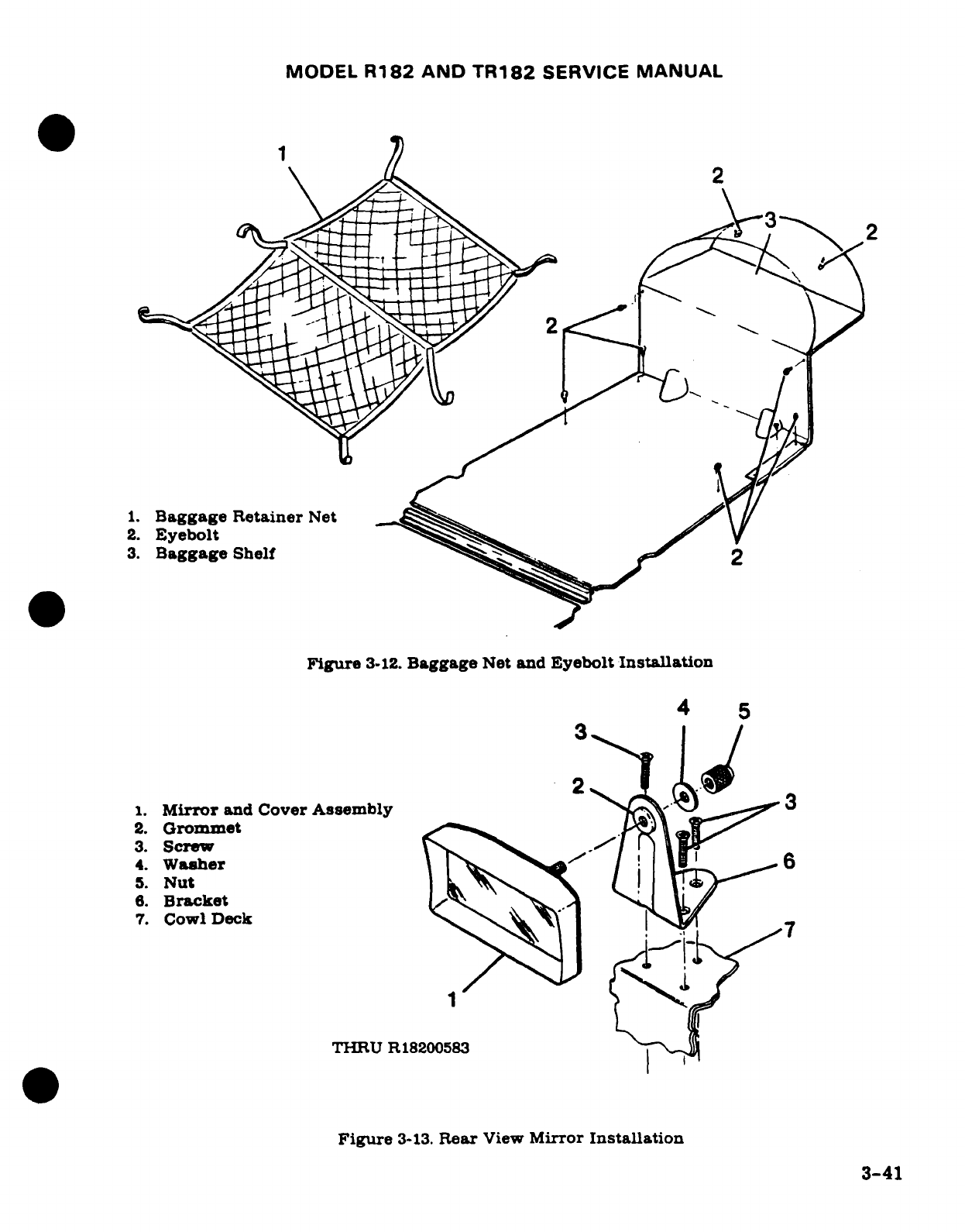
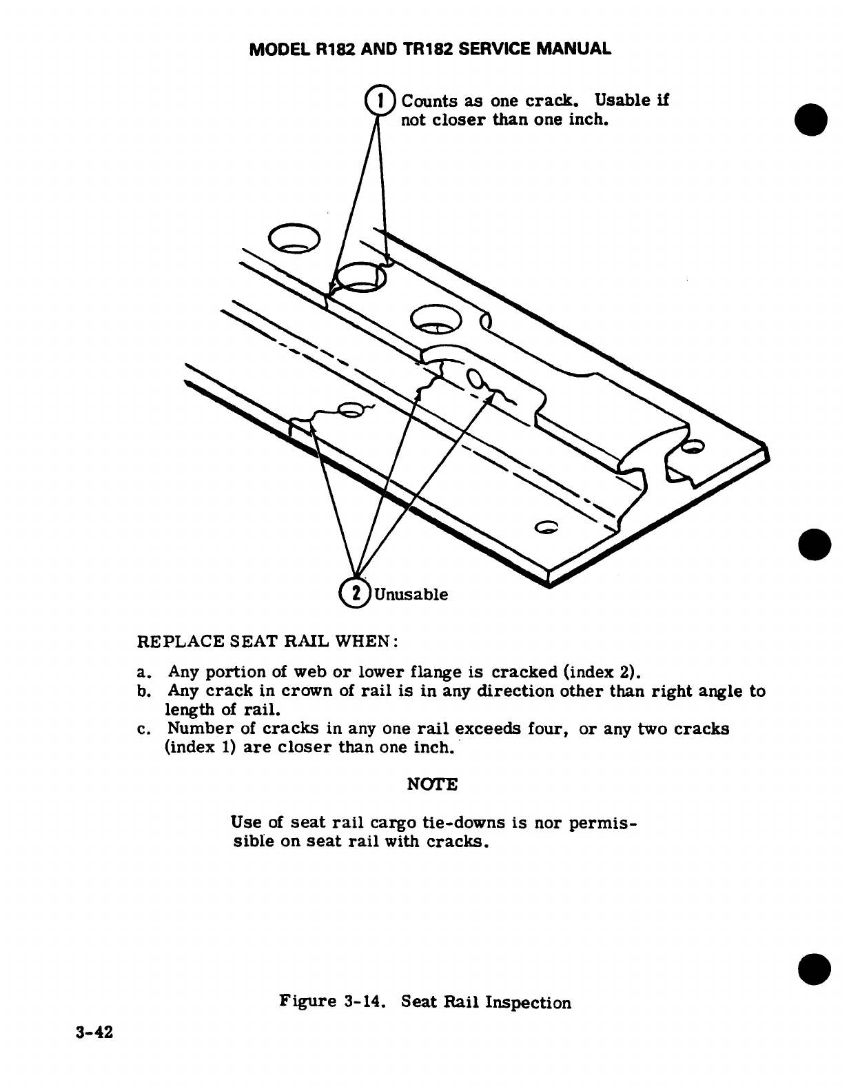
MODEL
R182
AND TR182
SERVICE
MANUAL
1
Counts
as
one
crack.
Usable
if
not
closer
than
one
inch.
Unusable
REPLACE
SEAT RAIL
WHEN:
a.
Any
portion
of
web
or
lower
flange
is
cracked
(index
2).
b.
Any
crack
in
crown
of
rail
is
in
any
direction
other
than
right
angle
to
length
of
rail.
c.
Number
of
cracks
in
any one
rail
exceeds
four,
or
any
two
cracks
(index
1)
are
closer
than
one
inch.
NOTE
Use
of
seat
rail
cargo
tie-downs
is
nor
permis-
sible
on
seat
rail
with
cracks.
Figure
3-14.
Seat
Rail
Inspection
3-42
MODEL
R182
AND
TR182
SERVICE
MANUAL
SECTION
4
WINGS
AND
EMPENNAGE
Page
No.
TABLE
OF
CONTENTS
Aerofiche/
Manual
WINGS
AND
EMPENNAGE
....
1H17/4-1
Removal
................
1I1
4-9
W
ings
...................
H17/4-1
Repair
..................
1I4
4-12
Description
.............
1H17/4-1
Installation
.............
1I4
4-12
Removal
................
1H17/4-1
Horizontal
Stabilizer
........
114
4-12
Repair
.................
1H20/4-4
Description
.............
114,4-12
Installation
........... ..
1H20/4-4
Removal
................
1I4/
4-12
Adjustment
.............
1H22/4-6
Repair
.................
1I4/4-12
Wing
Struts
..............
1H22/4-6
Installation
.............
1I4
4-12
Description
.............
1H22/4-6
Stabilizer Abrasion
Boots
.....
114/4-12
Removal
Installation
.......
1H22/4-6
Description
.............
1I4
4-12
Repair
.................
1I1/4-9
Removal
................
1I4/4-12
Fin
.....................
111/4-9
Installation
.............
1I5/4-13
Description
.............
111/4-9
4-1.
WINGS
AND
EMPENNAGE.
4-2.
WINGS. (See
figure
4-1.)
4-3.
DESCRIPTION.
Each
all-metal
wing
panel
is a
semicantilever,
semimonocoque
type,
with
two
main
spars
and
suitable
ribs
for the
attachment
of
the
skin.
Skin
panels
are
riveted
to
ribs,
spars
and
stringers
to
complete
the
structure.
An
all-metal,
piano-hinged
aileron.
flap,
and
a
detachable
wing
tip
are
mounted
on
each wing
assembly.
Navigation/
strobe
lights
are
mounted
at
each
wing
tip.
4-4.
REMOVAL. Wing
panel
removal
is
most
easily
accomplished
if
four
men
are
available
to
handle
the
wing.
Otherwise,
the wing
should
be
supported
with
a
sling
or
maintenance stand
when
the
fastenings
are
loosened.
a.
Remove
wing
root
fairings
and
fairing plates.
b.
Remove
all
wing
inspection
plates.
c.
Drain
fuel
from cell
of
wing
being
removed.
d.
Disconnect:
1.
Electrical
wires
at
wing
root
disconnects.
2.
Fuel
lines
at
wing
root.
(Observe
precautions
outlined
in
paragraph
12-3.)
e.
Reduce
aileron
cable
tension
by
loosening
turnbuckles
and
disconnect
cables
at
aileron
bellcranks. Disconnect
flap
cables
at
turnbuckles
above
headliner.
and
pull
cables
into
wing
root
area.
NOTE
To
simplify aileron
and
flap
cable
installation,
attach
an
equal
length
piece
of
guide
wire
to
each
cable
before
removal.
Leave
the
wire
inside
wing
during
maintenance
operation.
To
install,
simply attach
cables
to
correct
guide
wire, and
pull
cables
into
wing
as
the guide
wire
is
removed.
Revision
1
4-1
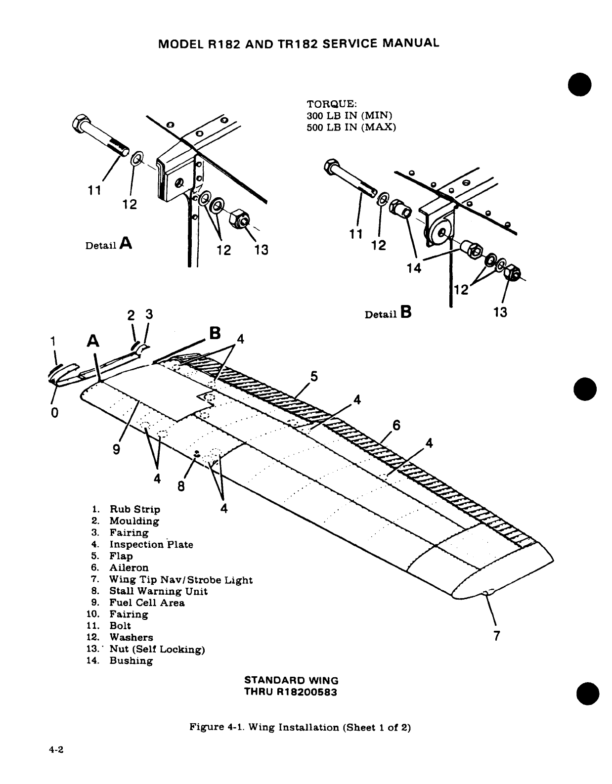
MODEL
R182
AND
TR182
SERVICE
MANUAL
TORQUE:
y^ \ A
300
LB
IN
(MIN)
ob1
W^^ "
500
LB
IN
(MAX)
12
DetailA
12 3
11
2
2
3
DetailB
13
\
A
B
4
2
4
1.
Rub
Strip
4
2.
Moulding
3.
Fairing
4.
Inspection
Plate
5.
Flap
6.
Aileron
7.
Wing
Tip
Nav/Strobe
Light
8.
Stall
Warning
Unit
9.
Fuel
Cell
Area
10.
Fairing
11.
Bolt
12.
Washers
7
13.
Nut
(Self
Locking)
14.
Bushing
STANDARD WING
THRU
R18200583
Figure
4-1.
Wing
Installation
(Sheet
1
of
2)
4-2
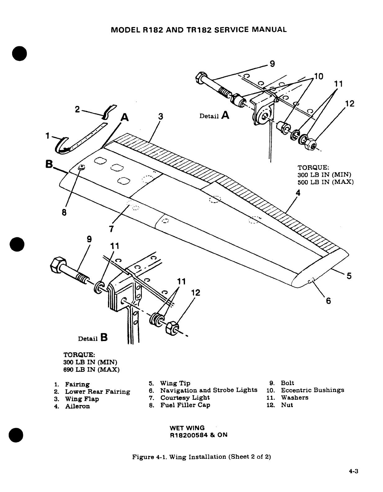
MODEL
R182
AND
TR182
SERVICE
MANUAL
12
DetaAi
D
etil
TO
Q
U
TORQUE:
30
/ j*R'.
300
LB
IN
(MIN)
(
^.
^ 690O^^500
LB
IN
(MAX)
/
11
-\46^^^1
Detail
B
TORQUE:
300
LB
IN
(MIN)
690
LB
IN
(MAX)
1.
Fairing
5.
Wing
Tip
9.
Bolt
2.
Lower
Rear
Fairing
6.
Navigation
and
Strobe
Lights
10.
Eccentric
Bushings
3.
Wing
Flap
7.
Courtesy Light
11.
Washers
4.
Aileron
8.
Fuel
Filler
Cap
12.
Nut
WET
WING
R18200584
&
ON
Figure
4-1.
Wing
Installation
(Sheet
2
of
2)
4-3
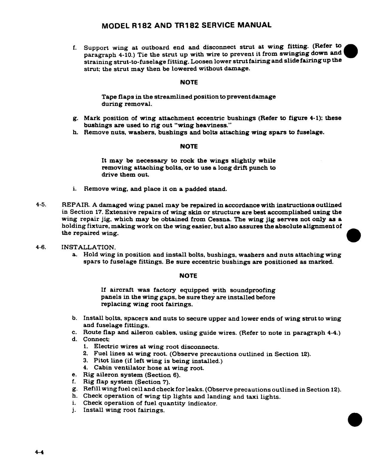
MODEL
R182
AND
TR182
SERVICE
MANUAL
f.
Support wing at outboard
end
and
disconnect
strut
at
wing fitting.
(Refer
to
paragraph
4-10.)
Tie
the
strut
up
with wire
to
prevent
it
from
swinging
down
and
straining
strut-to-fuselage
fitting.
Loosen
lower
strut
fairing
and
slide
fairing
up
the
strut;
the
strut
may
then
be
lowered without
damage.
NOTE
Tape
flaps
in
the
streamlined
position
to
prevent
damage
during
removal.
g.
Mark
position
of
wing
attachment
eccentric
bushings
(Refer
to
figure
4-1);
these
bushings are
used
to
rig
out
"wing
heaviness."
h.
Remove
nuts, washers,
bushings
and
bolts
attaching
wing
spars
to
fuselage.
NOTE
It
may
be
necessary
to rock
the
wings
slightly
while
removing
attaching
bolts,
or
to
use
a
long
drift
punch
to
drive
them
out.
i.
Remove
wing,
and
place
it
on
a
padded
stand.
4-5.
REPAIR.
A
damaged
wing
panel
may
be
repaired
in
accordance
with
instructions
outlined
in
Section
17.
Extensive
repairs
of
wing
skin or
structure
are
best
accomplished
using
the
wing
repair
jig,
which may
be
obtained
from
Cessna.
The
wing
jig
serves
not
only
as
a
holding
fixture,
making
work
on
the
wing
easier,
but
also
assures
the
absolute
alignment
of
the
repaired
wing.
4-6.
INSTALLATION.
a.
Hold
wing
in
position
and
install
bolts,
bushings,
washers
and
nuts
attaching
wing
spars
to
fuselage
fittings.
Be
sure
eccentric
bushings
are
positioned
as
marked.
NOTE
If
aircraft
was
factory
equipped
with
soundproofing
panels
in
the
wing
gaps,
be
sure
they
are
installed
before
replacing
wing
root
fairings.
b.
Install
bolts,
spacers
and
nuts
to
secure
upper
and lower
ends
of
wing
strut
to
wing
and
fuselage
fittings.
c.
Route
flap
and
aileron
cables,
using
guide
wires.
(Refer
to
note
in
paragraph
4-4.)
d.
Connect
1.
Electric
wires
at
wing
root
disconnects.
2.
Fuel
lines
at wing
root.
(Observe
precautions
outlined
in
Section
12).
3.
Pitot
line
(if
left
wing
is
being
installed.)
4.
Cabin
ventilator
hose
at
wing
root.
e.
Rig
aileron
system
(Section
6).
f.
Rig
flap
system
(Section
7).
g.
Refill
wing
fuel
cell
and
check
for
leaks.
(Observe
precautions
outlined
in
Section
12).
h.
Check
operation
of
wing
tip
lights
and
landing
and
taxi
lights.
i.
Check
operation
of
fuel
quantity
indicator.
j.
Install
wing
root
fairings.
4-4
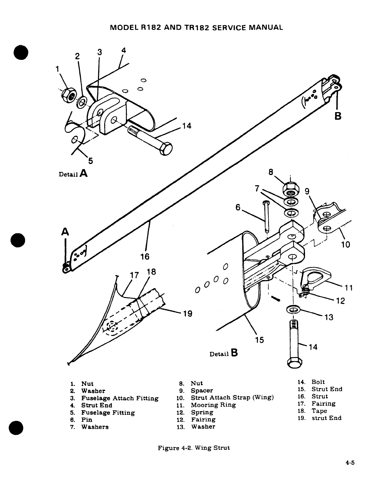
MODEL
R182
AND
TR182
SERVICE
MANUAL
3
/
~~2~~~~~~~
11
4
Detail
A
8
1A
6
0
0
19
13
15
Detail
14
1.
Nut
8.
Nut
14.
Bolt
2.
Washer
9.
Spacer
15.
Strut
End
3.
Fuselage Attach
Fitting
10.
Strut
Attach
Strap
(Wing)
16.
Strut
4.
Strut
End
11.
Mooring
Ring
17.
Fairing
5.
Fuselage
Fitting
12.
Spring
18.
Tape
6.
Pin
12.
Fairing
19.
strut
End
7.
Washers
13.
Washer
Figure
4-2.
Wing
Strut
4-5
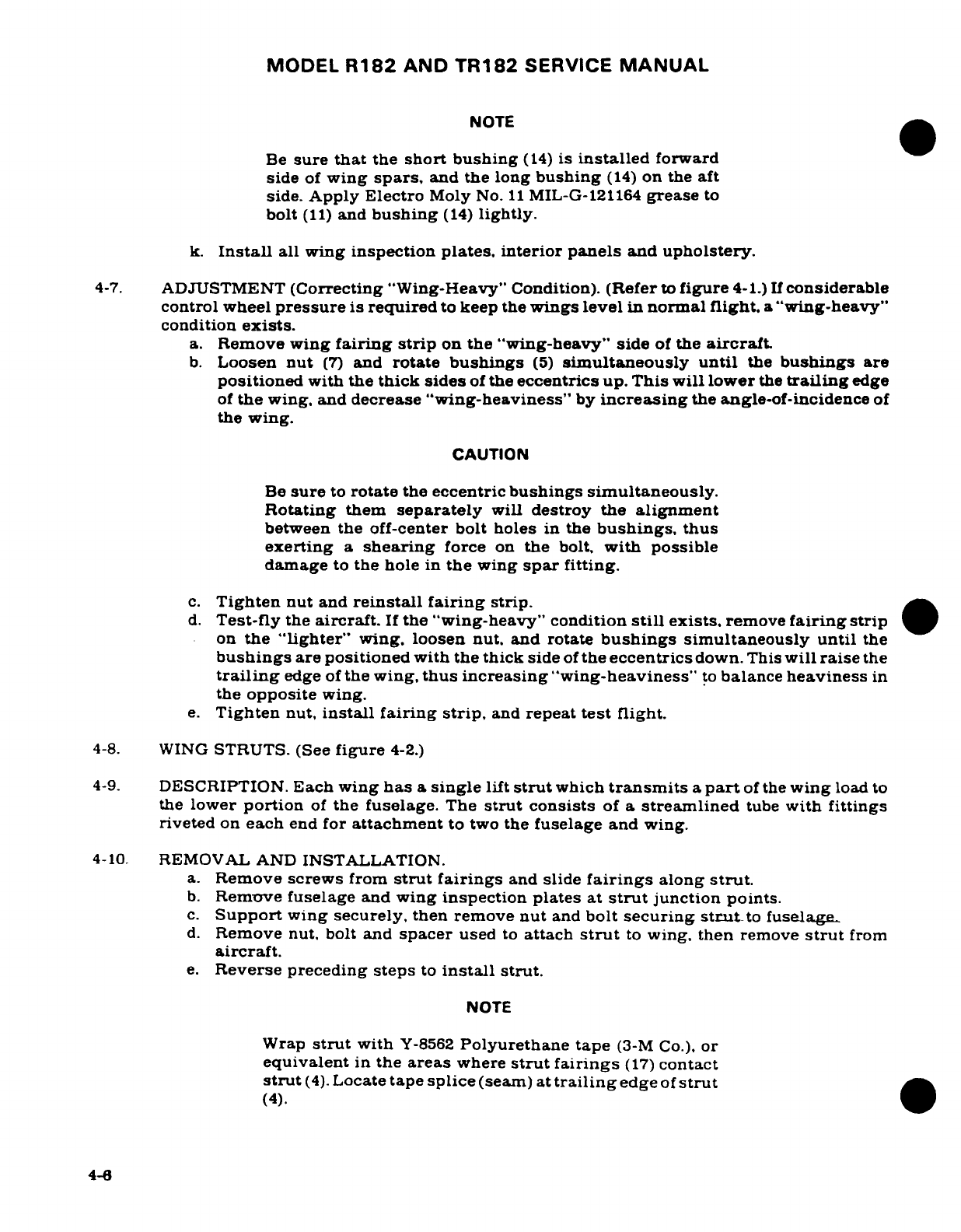
MODEL
R182
AND
TR182
SERVICE
MANUAL
NOTE
Be
sure
that
the
short
bushing
(14)
is
installed
forward
side
of
wing
spars,
and
the
long
bushing
(14)
on
the
aft
side.
Apply Electro
Moly
No.
11
MIL-G-121164
grease
to
bolt
(11)
and
bushing
(14)
lightly.
k.
Install
all wing
inspection
plates,
interior
panels
and
upholstery.
4-7.
ADJUSTMENT
(Correcting
"Wing-Heavy"
Condition).
(Refer
to
figure
4-1.)
If
considerable
control wheel
pressure
is
required
to
keep
the
wings
level
in
normal
flight,
a
"wing-heavy"
condition
exists.
a.
Remove
wing
fairing
strip
on
the "wing-heavy" side
of
the
aircraft.
b.
Loosen
nut
(7)
and
rotate
bushings
(5)
simultaneously
until
the
bushings
are
positioned
with
the
thick sides
of
the
eccentrics
up. This will
lower
the
trailing
edge
of
the
wing.
and
decrease
"wing-heaviness"
by
increasing
the
angle-of-incidence
of
the
wing.
CAUTION
Be
sure
to
rotate
the
eccentric
bushings
simultaneously.
Rotating
them
separately
will
destroy
the
alignment
between
the
off-center
bolt
holes
in
the
bushings,
thus
exerting
a
shearing
force
on
the
bolt,
with
possible
damage
to
the
hole
in
the
wing
spar
fitting.
c.
Tighten
nut
and
reinstall
fairing
strip.
d.
Test-fly
the
aircraft.
If
the
"wing-heavy" condition
still
exists,
remove
fairing
strip
on
the
"lighter"
wing.
loosen
nut,
and rotate
bushings
simultaneously
until
the
bushings
are
positioned
with
the thick
side
of
the
eccentrics
down.
This
will
raise
the
trailing
edge
of
the
wing,
thus
increasing
"wing-heaviness"
to
balance
heaviness
in
the
opposite
wing.
e.
Tighten
nut,
install fairing
strip,
and
repeat
test
flight.
4-8.
WING
STRUTS.
(See
figure
4-2.)
4-9.
DESCRIPTION.
Each
wing
has
a
single
lift
strut
which
transmits
a
part
of
the
wing
load
to
the
lower
portion
of
the
fuselage.
The
strut
consists
of
a
streamlined
tube
with
fittings
riveted
on
each
end
for
attachment
to
two
the
fuselage
and
wing.
4-10.
REMOVAL AND
INSTALLATION.
a.
Remove
screws
from
strut
fairings
and
slide
fairings
along
strut.
b.
Remove
fuselage
and
wing
inspection
plates
at
strut
junction points.
c.
Support
wing
securely,
then remove
nut
and
bolt
securing
strut
to
fuselage-
d.
Remove nut,
bolt
and
spacer
used
to
attach
strut
to
wing, then
remove
strut
from
aircraft.
e.
Reverse
preceding
steps
to
install
strut.
NOTE
Wrap
strut
with
Y-8562
Polyurethane tape
(3-M
Co.).
or
equivalent
in
the
areas
where
strut
fairings
(17)
contact
strut
(4).
Locate
tape
splice
(seam)
at
trailing
edge
of
strut
(4).
4-6
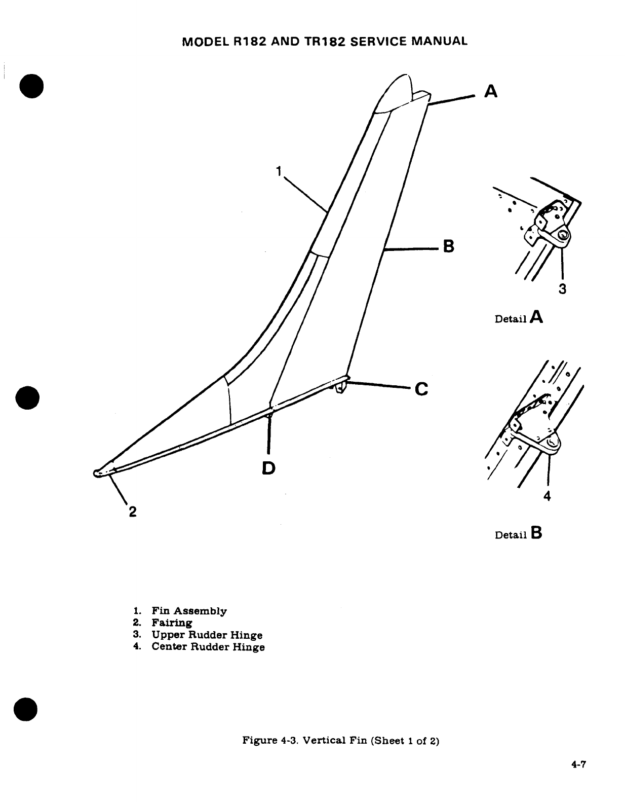
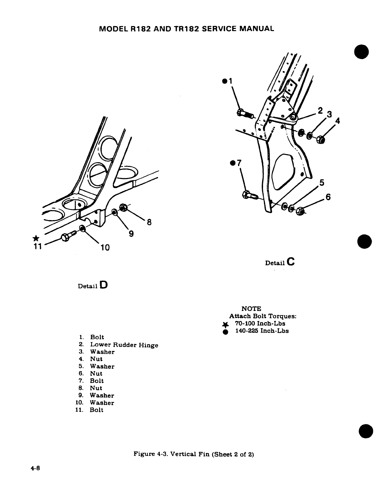
MODEL
R182
AND
TR182
SERVICE
MANUAL
4-11.
REPAIR.
Wing
strut
repair
is
limited
to
replacement
of tie-downs
and
attaching
parts.
Refer
to Section
18.
4-12.
FIN.
(See
figure
4-3.)
4-13.
DESCRIPTION.
The
vertical
fin
is
primarily
of
metal
construction,
consisting
of
ribs
and
spars
covered
with
skin. Fin tips
are
of
ABS
construction.
The
rudder
is
attached
at
the
fin
rear
spar
with
hinge
brackets.
4-14.
REMOVAL.
The
vertical
fin
may
be
removed
without
first
removing
the
rudder.
However.
for
access
and
ease
of
handling,
the
rudder
may
be
removed
by
following
procedures
outlined
in
Section
10.
a.
Remove
fairings
on
either
side
of
fin.
b.
Disconnect
flashing
beacon
lead,
tail
navigation
light
lead,
antennas
and
antenna
leads,
and
rudder
cables,
if
rudder
has
not
been
removed.
NOTE
The
flashing
beacon
power
lead
routed into
the
fuselage
should
be
cut
if
no
splice
exists.
Upon
reassembly.
install
quick
disconnects
or
suitable
splice
in
this
wire.
c.
Remove
screws
attaching
dorsal
to
fuselage.
d.
Remove
bolts
attaching
fin
rear
spar
to
fuselage
fitting.
e.
Remove
bolts
attaching
fin
front
spar
to
fuselage,
and
remove
fin.
4-9

MODEL
R182
AND
TR182
SERVICE
MANUAL
A
B
D
8
7
6
5
4
1.
Upper
Right
Fairing
2.
Elevator Pylon
Bracket
3
3.
Upper
Left
Fairing
4.
Abrasion
Boot
s
_ *
5.
Lower
Left
Moulding
6.
Lower
Right
Moulding
(
7.
Forward
Left
Fairing
8.
Forward
Right
Fairing
9.
Nut
10.
Washer
9 7
b
I
11.
Bracket
12.
Washer
1
13.
Bolt
14.
Elevator Pylon
Bracket
12
14
Detail
B
Figure
4-4.
Horizontal
Stabilizer
(Sheet
1
of
2)
4-10
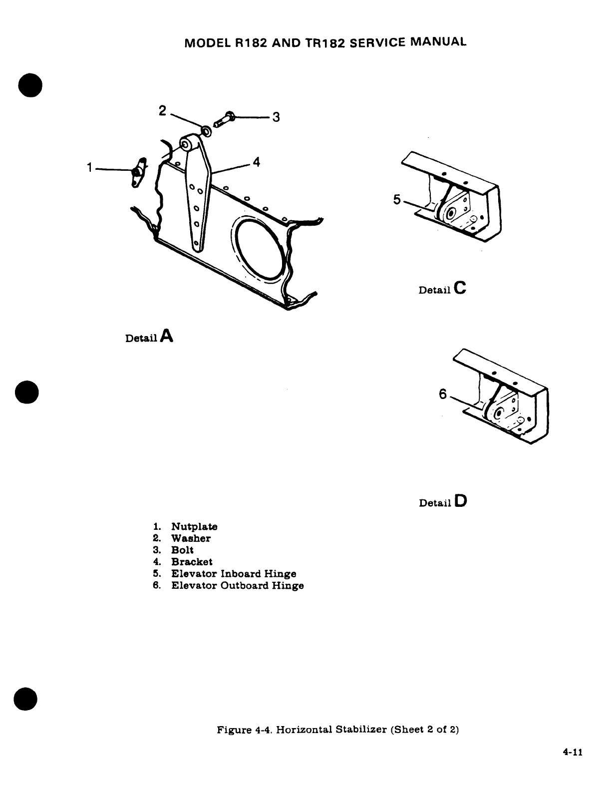
MODEL
R182
AND
TR182
SERVICE
MANUAL
4-15.
REPAIR.
Fin
repair
should
be
accomplished
in
accordance
with
applicable
instructions
outlined
in
Section
17.
4-16.
INSTALLATION.
Reverse
the
procedures
outlined
in
paragraph
4-14
to
install
the
vertical
fin.
Be
sure
to
check
and
reset rudder
and
elevator
travel.
If
any
stop
bolts
were
removed
or
settings
disturbed,
the
systems
will
have
to
be
rigged.
Refer
to
applicable
sections
in
this
manual
for
rigging
procedures.
4-17.
HORIZONTAL
STABILIZER.
(See
figure
4-4.)
4-18.
DESCRIPTION.
The
horizontal stabilizer
is
primarily
of
all-metal
construction.
consisting
of
ribs
and
spars
covered
with
skin.
Stabilizer
tips
are
of
ABS
construction.
A
formed
metal
leading
edge
is
riveted
to
the
assembly
to
complete
the
structure.
The
elevator
trim
tab
actuator
is
contained
within
the
horizontal stabilizer.
The
underside
of the
stabilizer
contains
a
covered
opening
which
provides
access
to
the
actuator.
Hinges
are
located
on
the
rear
spar
assembly
to
support
the
elevators.
4-19.
REMOVAL.
a.
Remove
elevators
and
rudder
in
accordance
with
procedures
outlined
in
Sections
8
and
10.
b.
Remove
vertical
fin
in
accordance
with
procedures
outlined
in
paragraph
4-14.
c.
Disconnect
elevator
trim
control
cables
at
cable
ends
and
turnbuckle
inside
tailcone.
Remove
stop
blocks,
then
remove
pulleys
which
route
the
aft
cables
into
horizontal
stabilizer.
Pull
cables
out
of
tailcone.
4-20.
REPAIR.
Horizontal
stabilizer
repair
should
be
accomplished
in
accordance
with
applica-
ble
instructions
outlined
in
Section
17.
4-21.
INSTALLATION.
Reverse
procedures
outlined
in
paragraph
4-19
to
install
the
horizontal
stabilizer.
Rig
elevator,
elevator trim
and rudder
systems
as
outlined
in
Sections
8,
9
and
10
consecutively.
Check
operation
of
tail
navigation light
and
flashing
beacon.
4-22.
STABILIZER ABRASION
BOOTS.
NOTE
An
Accessory
Kit
(AK182-217)
is
available
from
the
Cessna
Service
Parts
Center
for
installation
of
abrasion
boots
on
aircraft
not
so
equipped.
4-23.
DESCRIPTION.
The
aircraft
may
be
equipped
with
two
extruded
rubber
abrasion
boots,
one
on
the
leading
edge
of
each
horizontal stabilizer.
These boots
are
installed
to
protect the
stabilizer
leading
edge
from
damage
caused
by
rocks
thrown
back
by
the
propeller.
4-24.
REMOVAL.
The
abrasion
boots
can
be
removed
by
loosening
one
end
of
the
boot
and
pulling
it
off
the
stabilizer
with
an even
pressure.
Excess
adhesive
or
rubber
can
be
removed with
Methyl-Ethyl-Ketone.
4-12
MODEL
R182
AND
TR182
SERVICE
MANUAL
4-25.
INSTALLATION.
Install
abrasion
boots
as
outlined
in
the
following
procedures.
a.
Trim
boots
to
desired length.
b.
Mask
off
boot
area
on
leading
edge
of
stabilizer
with
1-inch
masking
tape, allowing
1/4-inch
margin.
c.
Clean
inside
of
abrasion
boot
with
Methyl-Ethyl-Ketone
and
a
Scotch
brite
pad
to
ensure
complete
removal
of
paraffin/talc.
Then
a
normal
wipedown
with
MEK
on
a
cloth
will leave
surface
suitable
for
bonding
to
the
aluminum.
NOTE
Boots
may
be
applied
over
epoxy
primer,
but
if
the
surface
has
been
painted,
the
paint
shall
be
removed
from
the
bond
area.
This
shall
be
done
by
wiping
the
surfaces
with
a
clean, lint-free
rag,
soaked
with
solvent,
and
then
wiping
the
surfaces dry,
before
the
solvent
has
time
to
evaporate,
with
a
clean,
dry
lint-free
rag.
e.
Stir
cement
(EC-1300
Minnesota
Mining
and
Manufacturing
Co.)
thoroughly.
f.
Apply
one
even
brush
coat
to
the metal and
the
inner
surface
of
the
boot.
Allow
cement
to
air-dry
for
a
minimum
of
30
minutes,
and
then
apply
a
second
coat
to
each
surface.
Allow
at least
30
minutes
(preferably
one-hour)
for
drying.
g.
After
the
cement
has
thoroughly
dried,
reactivate
the
surface
of
the
cement
on
the
stabilizer
and boot,
using
a
clean,
lint-free coth,
heavily
moistened
with
toluol.
Avoid
excess
rubbing
which
would
remove
the
cement
from
the
surfaces.
h.
Position
boot
against
leading
edge,
exercising
care
not
to
trap
air
between
boot and
stabilizer.
NOTE
Should
boot
be
attached
"off-course",
pull
it
up
imme-
diately
with
a
quick
motion,
and
reposition
properly.
i.
Press
or
roll
entire
surface
of
boot
to
assure
positive
contact
between
the
two
surfaces.
j.
Apply
a
coat
of
GACO
N700A
sealer,
or
equivalent,
conforming
to
MIL-C-21067,
along
the
trailing
edges
of
the
boots
to
the
surface
of
the
skin
to
form
a
neat,
straight
fillet.
k.
Remove
masking
tape
and clean
stabilizer
of
excess
material.
1.
Mask
to
the
edge
of
boot
for
painting
stabilizer.
4-13/(4-14
blank)
MODEL
R182
&
TR182
SERIES
SERVICE
MANUAL
SECTION
5
LANDING
GEAR, BRAKES
AND
HYDRAULIC
SYSTEM
WARNING
When
performing
any
inspection
or
maintenance
that
re-
quires
turning
on
the
master
switch,
installing
a
battery,
or
pulling
the
propeller
through
by
hand,
treat
the
prop-
eller as
if
the
ignition
switch
were
ON. Do
not
stand,
nor
allow
anyone
else
to
stand,
within
the
arc
of
the
propel-
ler,
since
a
loose
or
broken
wire,
or
a
component
mal-
function,
could
cause
the
propeller
to
rotate.
Page
No.
TABLE
OF
CONTENTS
Aerofiche/
Manual
LANDING
GEAR RETRACTION
Adjustment
(Thru
SYSTEM
..................
2A5/5-3
R18201541)
......... ...
2B10
5-26
Description
...............
2A5/5-3
Disassembly
(Beginning
Trouble
Shooting
...........
2A7/5-4A
with
R18201542)
........
2B10
5-26
Power
Pack
...............
2A18/5-12
Inspection/Repair
(Begin-
Description
.............
2A185-12
ning
with
R18201542)
....
2B11
5-27
Removal
...............
2A18/5-12
Reassembly
(Beginning
Disassembly with
R18201542)
........
2B11.5-27
(Thru
1978
Models)
......
2A215-15
Adjustment
(Beginning
Inspection
with R18201542)
........
2B13.5-28A
(Thru
1978
Models)
......
2A22/5-16
Hydraulic
System
Leak
Reassembly
Check
..................
2B17
5-31
(Thru
1978
Models)
......
2A22/5-16
Emergency
Hand
Pump
......
2B18
5-32
Disassembly
(Beginning
with
Description
.............
2B
185-32
1979
Models)
..........
2A23/5-17
Removal/Installation
.......
2B18.5-32
Inspection
(Beginning
with
Disassembly
.............
2B18
5-32
1979
Models)
..........
2A24/5-18
Inspection
and
Repair
......
2B19
5-33
Reassembly
(Beginning
with
Reassembly
............
2B19/5-33
1979
Models)
..........
2A24/5-18
Landing
Gear
Selector
Valve
..
2B19/5-33
Installation
.............
2B3/5-19
Description
.............
2B19
5-33
Primary
Thermal
Relief
Removal/Installation
.......
2B19
5-33
Valve
Assemblies
..........
2B3/5-19
Disassembly/Reassembly
....
2B22
5-36
Description
............
2B3/5-19
Inspection
and
Repair
......
2B22
5-36
Removal
................
2B3/5-19
Rigging
Throttle-Operated
Gear
Disassembly
.............
2B3
5-19
Warning
Horn
Microswitch
. .
2B22
5-36
Inspection
..............
2B4/5-20
Rigging
Flap-Operated
Gear
Assembly
Adjustment
......
2B4/5-20
Warning
System
..........
2C3
5-41
Installation
.............
2B7
5-23
MAIN
LANDING
GEAR
.......
2C3
5-41
Pressure
Switch
...........
2B75-23
Description
...............
2C3
5-41
Description
.............
2B7
5-23
Trouble
Shooting
...........
2C5
5-43
Removal
Installation
.......
2B8/5-24 Removal
.................
2C5
5-43
Disassembly
(Thru
Installation
...............
2C6
5-44
R18201541)
...........
2B8
5-24
Rigging
(Thru
R1820655)
....
2C6
5-44
Inspection Repair (Thru
Rigging (Beginning
with
R18201541)
...........
2B8
5-24
R1820656)
............
2C9
5-46A
Reassembly
(Thru
Main
Wheel
Tire
Assembly
....
2C
11
5-47
R18201541)
......
.....
2B95-25
Description
.............
2C11
5-47
Revision
1
5-1
MODEL
R182
AND
TR182
SERVICE
MANUAL
Removal
................
2C11
5-47 Nose
Gear
Downlock
Disassembly
.............
2C12.5-48
Mechanism
..............
2D13
5-69
Inspection and Repair
......
2C12
5-48
Description
.............
2D13
5-69
Reassembly
.............
2C12 5-48
Removal,
Installation.
Balancing
..............
2C13
5-49
Rigging
...............
2D13.5-69
Installation
.............
2C13/5-49
Nose
Gear
Actuator
.........
2D13
5-69
Alignment
..............
2C13/5-49
Description
.............
2D13/5-69
Main
Wheel
and
Axle
........
2C14/5-50
Removal
................
2D135-69
Removal
................
2C14/5-50
Disassembly
.............
2D13/5-69
Installation
.............
2C14/5-50
Inspection/Repair
.........
2D135-69
Main Gear
Actuator
.........
2C14/5-50
Assembly
...............
2D15.5-71
Removal
................
2C14/5-50
Installation
.............
2D16
5-72
Disassembly
.............
2C18/5-54
Nose
Gear
Doors
Inspection
..............
2C18/5-54
(Thru
R18201798)
.......
2D16/5-72
Parts
Repair/Replacement
...
2C18/5-54
Description
.............
2D17/5-72A
Reassembly
.............
2C18/5-54
Removal
and
Installation
Installation
.............
2C19/5-55
(Thru
R18201798)
.......
2D17
5-72A
Main
Gear
Pivot
Assembly
....
2C19/5-55 Nose
Gear
Doors
(Beginning
Removal
................
2C19/5-55
(with
R18201799)
........
2D17'5-72A
Inspectionn/
Repair
.........
2C19/5-55
Description
.............
2D17/5-72A
Installation
.............
2C20/5-56
Removal
(Beginning
with
Gear
Position
Indicator
R18201799)
.........
2D17.5-72A
Switches
................
2C20/5-56
Installation
(Beginning
Description
.............
2C20/5-56
with
R18201799)
........
2D17/5-72A
Main Gear
Downlock Nose Wheel
Steering
System
. .
2D18/5-72B
Actuator
................
2C20/5-56
Description
.............
2D18/5-72B
Description
.............
2C20/5-56
Steering
Bungee
Assembly
. .
2D18/5-72B
Removal
................
2C23/5-59
Description
.............
2D18/5-72B
Disassembly
.............
2C23/5-59
Removal
(Thru
R18201798)
.
2D18/5-72B
Inspection
..............
2C23/5-59
Installation
(Thru
Reassembly
.............
2C23/5-59
R18201798)
............
2D18/5-72B
Main
Gear
Strut
Step
........
2C24/5-60
Removal
(Beginning
with
Description
.............
2C24/5-60
R18201799)
............
2D18
5-72B
Removal
................
2C24/5-60
Installation
(Beginning
Installation
.............
2C24/5-60
with
R18201799)
........
2D22 5-74
OSE
GEAR SYSTEM
........
2D1/5-60A
Removal
and
Installation
Description
...............
2D1/5-60A
of
Nose Wheel
Steering
Operation
........... ....
2D1/5-60A
System
Components
......
2D22.5-74
Trouble
Shooting
...........
2D1/5-60A
Rigging
Nose
Wheel
Removal/Installation
........
2D2/5-60B
Steering
System
.........
2D22/5-74
Disassembly
..............
2D2/5-60B Nose Wheel
and
Tire
........
2D22
5-74
Inspection
and
Repair
.......
2D7/5-65
Description
.............
2D22
5-74
Reassembly
...............
2D7/5-65
Removal/Installation
.......
2E2
5-78
Shimmy
Damper
...........
2D7/5-65
Disassembly
(Cleveland)
....
2E2/5-78
Description
.............
2D7/5-65
Inspection/Repair
Removal
................
2D7/5-65
(Cleveland)
.............
2E2/5-78
Disassembly
.............
2D11/5-67
Reassembly
(Cleveland)
.....
2E2/5-78
Inspection
and Repair
......
2D11/5-67
Disassembly
(McCauley)
....
2E3/5-79
Reassembly
.............
2D11/5-67
Inspection/Repair
Torque
Links
.............
2D11/
5-67
(McCauley)
.............
2E3/5-79
Squat
Switch
..............
2D11/5-67
Reassembly
(McCauley)
.....
2E4/5-80
Description
........... .
2D11/5-67
Balancing
................
2E45-80
Removal
................
2D125-68
Nose
Gear
Rigging
Installation
.............
2D12/5-68
(Thru
R18201798)
.......
2E4/5-80
5-2
Revision
1
MODEL
R182
AND
TR182
SERVICE
MANUAL
Nose
Gear
Rigging
Reassembly
(Beginning
(Beginning
with with
1979
Models)
.......
2E14
5-90
R18201798)
...........
2E9
5-85
Installation
.............
2E14
5-90
BRAKE
SYSTEM
............
2E9
5-85
Hydraulic
Brake
Lines
.......
2E14
5-90
Description
.............
2E9
5-85
Description
.............
2E14
5-90
Trouble
Shooting
.........
2E10
5-86
Wheel
Brake
Assemblies
.....
2E14
5-90
Master
Cylinder
............
2E
11
5-87
Description
.............
2E14
5-90
Description
.............
2E11
5-87 Removal
................
2E14/5-90
Removal
................
2E
115-87
Disassembly
.............
2E14
5-90
Disassembly
Inspection/Repair
.........
2E15/5-91
(Thru
1978 Models)
......
2E11/5-87
Reassembly
.............
2E15/5-91
Inspection Repair
Installation
.............
2E155-91
(Thru
1978
Models)
......
2E11 5-87
Checking
Lining
Wear
.....
2E15/5-91
Reassembly
Brake
Installation
.........
2E16/5-92
(Thru
1978
Models)
......
2E11/5-87
Bleeding
...............
2E16
5-92
Disassembly
(Beginning
Parking
Brake
System
.......
2E
16
5-92
with
1979
Models)
.......
2E14/5-90
Description
.............
2E16
5-92
Inspection
Repair
Removal/Installation
.......
2e16
5-92
(Beginning
with
1979
Inspection/Repair
.........
2E17/5-93
Models)
...............
2E14/5-90
5-1.
LANDING
GEAR
RETRACTION
SYSTEM.
5-2.
DESCRIPTION.
Retraction
and
extension
of
the
landing
gear
is
accomplished
by
a
hydrauli-
cally-powered
system,
integrated
with
electrical
circuits
which
help
control
and
indicate
gear
position.
Retraction
and
extension
of
the
landing
gear incorporates
a
nose
gear
ac-
tuator
and
two
main
gear
actuators
which
control
the
main gear
struts
through
a
sector
gear
arrangement.
The
nose
gear
doors
are
mechanically-operated.
The
doors
are
closed
with
the
gear retracted
and
are
open
with the
landing
gear
extended.
The
main
gears
have
no
doors.
Hydraulic
fluid
is
supplied
to
the
landing
gear
actuating
cylinders
by
an
electri-
cally-powered
power
pack
assembly,
located
in
the
cabin,
forward
of
the
center
console.
The
hydraulic reservoir
is
an
integral part
of
the
power pack
assembly. Gear
selection
is
accom-
plished
manually
by
moving
a
gear
selector
handle,
located
immediately
left
of
center,
in
the
switch
panel. It
is
necessary
to
pull
out
on
the gear
selector
to move
the
handle up
or
down.
For
emergency
extension
of
the
gear, the
selector
handle
must
be
in
the
DOWN
position
be-
Revision
1
5-3
MODEL
R182
AND TR182
SERVICE
MANUAL
fore
the
hand
pump
will
energize
the
system.
A
pressure
switch
is
mounted
on
the
pump
body.
This
switch
opens
the
electrical
circuit
to
the
pump
solenoid
when
pressure
in
the
sys-
tem
increases
to
approximately
1500
psi.
The
pressure
switch
will
continue
to
hold
the
elec-
trical
circuit
open
until
pressure
in
the
system
drops
to
approximately
1000
psi.
This
will
occur
whether
the
gear
selector
handle
is
in
either
the
UP
or
DOWN
position.
During
a
nor-
mal
cycle,
landing
gear
extended
and
locked
can
be
detected
by
illumination
of
the
gear
DOWN
indicator
(green) light,
indication
of
gear
retracted
is
provided
by
illumination
of
the
UP
indicator
(amber)
light.
The
nose
gear
squat
switch, actuated
by
the
nose
gear,
electrical-
ly
averts
inadvertent
retraction
whenever
the
nose
gear
strut
is
compressed
by
weight
of
the
aircraft. Beginning
with
1983
models,
the
UP
indicator
(amber)
light
is
replaced
with
a
GEAR
UNSAFE
indicator
(red)
light.
The
GEAR
UNSAFE
(red)
light
is
on anytime
the
gear
is
in
transit
(retract
or
extend),
or
whenever
system
pressure
drops
below
1000
psi
with
the
safety
(squat)
switch
closed.
NOTE
It
is
possible
to
have the
red
and
green
lights
on
momen-
tarily at
the
same
time
after
the
completion
of
the
extend
cycle,
or
when
rotating
during
takeoff.
However,
if
both
stay
on
after
the
completion
of
the
extend
cycle,
or
if
the
red
light
stays
on
longer
than
5
to
7
seconds
during
re-
tract
cycle,
a
malfunction
has
occurred.
5-4
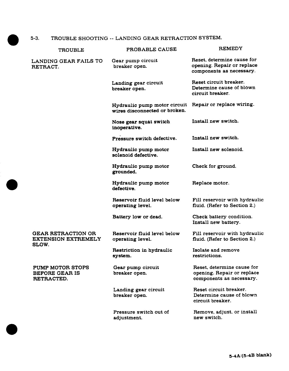
5-3.
TROUBLE
SHOOTING
--
LANDING
GEAR
RETRACTION
SYSTEM.
TROUBLE
PROBABLE CAUSE
REMEDY
LANDING
GEAR
FAILS
TO
Gear
pump
circuit
Reset,
determine
cause
for
RETRACT.
breaker
open. opening.
Repair
or
replace
components
as
necessary.
Landing
gear circuit
Reset
circuit
breaker.
breaker
open. Determine
cause
of
blown
circuit
breaker.
Hydraulic
pump
motor
circuit
Repair
or
replace
wiring.
wires
disconnected
or
broken.
Nose
gear
squat
switch
Install
new
switch.
inoperative.
Pressure
switch
defective.
Install
new
switch.
Hydraulic
pump motor
Install
new
solenoid.
solenoid
defective.
Hydraulic
pump motor
Check
for
ground.
grounded.
Hydraulic
pump
motor
Replace
motor.
defective.
Reservoir
fluid
level
below
Fill
reservoir
with
hydraulic
operating
level.
fluid.
(Refer
to
Section
2.)
Battery
low
or
dead. Check
battery
condition.
Install
new
battery.
GEAR
RETRACTION
OR
Reservoir
fluid
level
below
Fill
reservoir
with
hydraulic
EXTENSION
EXTREMELY
operating
level.
fluid.
(Refer
to
Section
2.)
SLOW.
Restriction
in
hydraulic
Isolate
and
remove
system. restrictions.
PUMP
MOTOR
STOPS
Gear
pump
circuit
Reset,
determine
cause
for
BEFORE
GEAR IS
breaker
open. opening.
Repair
or
replace
RETRACTED.
components
as
necessary.
Landing
gear circuit
Reset
circuit
breaker.
breaker
open.
Determine
cause
of
blown
circuit
breaker.
Pressure
switch
out
of
Remove,
adjust,
or
install
adjustment.
new
switch.
5-4A/(5-4B
blank)
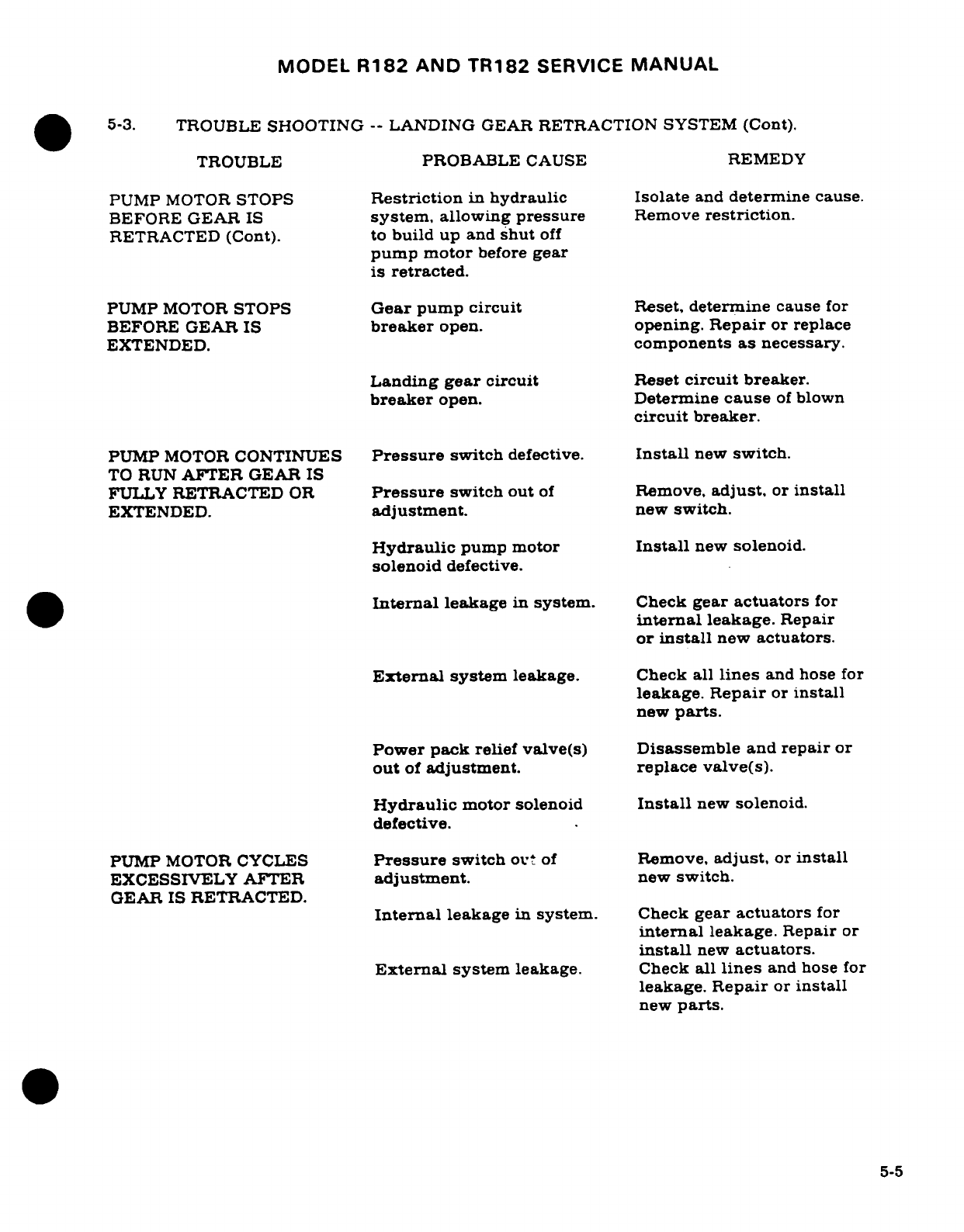
MODEL
R182
AND
TR182
SERVICE
MANUAL
5-3.
TROUBLE
SHOOTING
--
LANDING
GEAR
RETRACTION
SYSTEM
(Cont).
TROUBLE
PROBABLE
CAUSE
REMEDY
PUMP
MOTOR
STOPS
Restriction
in
hydraulic
Isolate
and
determine
cause.
BEFORE
GEAR
IS
system,
allowing
pressure
Remove
restriction.
RETRACTED
(Cont).
to
build
up
and
shut
off
pump
motor
before
gear
is
retracted.
PUMP
MOTOR
STOPS
Gear
pump
circuit
Reset,
determine
cause
for
BEFORE
GEAR IS
breaker
open.
opening.
Repair
or
replace
EXTENDED.
components
as
necessary.
Landing
gear
circuit
Reset
circuit
breaker.
breaker
open. Determine
cause
of
blown
circuit
breaker.
PUMP
MOTOR
CONTINUES
Pressure
switch
defective.
Install
new
switch.
TO
RUN
AFTER
GEAR
IS
FULLY
RETRACTED
OR
Pressure
switch
out
of
Remove,
adjust,
or
install
EXTENDED.
adjustment.
new
switch.
Hydraulic
pump motor
Install
new
solenoid.
solenoid
defective.
Internal
leakage
in
system.
Check
gear
actuators
for
internal
leakage.
Repair
or
install
new
actuators.
External
system
leakage.
Check
all
lines
and hose
for
leakage.
Repair
or
install
new
parts.
Power
pack
relief
valve(s)
Disassemble
and
repair
or
out
of
adjustment.
replace
valve(s).
Hydraulic
motor
solenoid
Install
new
solenoid.
defective.
PUMP
MOTOR
CYCLES
Pressure
switch
out
of
Remove,
adjust,
or
install
EXCESSIVELY AFTER
adjustment.
new
switch.
GEAR
IS
RETRACTED.
Internal
leakage
in
system.
Check
gear
actuators
for
internal
leakage.
Repair
or
install
new
actuators.
External
system
leakage.
Check
all
lines
and
hose
for
leakage.
Repair
or
install
new
parts.
5-5
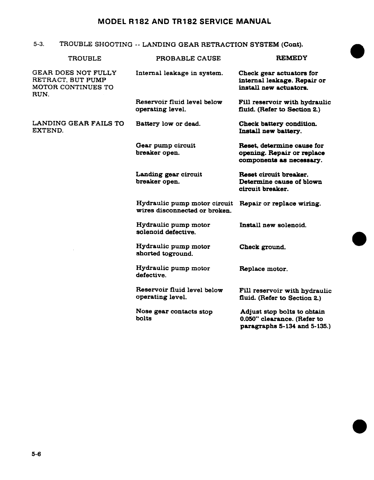
MODEL
R182
AND
TR182
SERVICE
MANUAL
5-3.
TROUBLE
SHOOTING
--
LANDING
GEAR
RETRACTION
SYSTEM
(Cont).
TROUBLE
PROBABLE
CAUSE
REMEDY
GEAR
DOES NOT FULLY
Internal
leakage
in
system.
Check
gear
actuators
for
RETRACT.
BUT
PUMP
internal
leakage.
Repair
or
MOTOR
CONTINUES
TO
install
new
actuators.
RUN.
Reservoir
fluid
level
below
Fill
reservoir
with
hydraulic
operating
level.
fluid.
(Refer
to
Section
2.)
LANDING
GEAR
FAILS
TO
Battery
low
or
dead.
Check
battery
condition.
EXTEND.
Install
new
battery.
Gear pump
circuit
Reset,
determine
cause
for
breaker
open.
opening.
Repair
or
replace
components
as
necessary.
Landing
gear
circuit
Reset
circuit
breaker.
breaker
open.
Determine
cause
of
blown
circuit
breaker.
Hydraulic
pump
motor
circuit
Repair
or
replace
wiring.
wires
disconnected
or broken.
Hydraulic
pump
motor
Install
new
solenoid.
solenoid
defective.
Hydraulic
pump
motor
Check
ground.
shorted
toground.
Hydraulic
pump
motor
Replace
motor.
defective.
Reservoir
fluid
level
below
Fill reservoir
with
hydraulic
operating
level.
fluid.
(Refer
to
Section
2.)
Nose
gear
contacts
stop
Adjust
stop
bolts
to
obtain
bolts
0.050"
clearance.
(Refer
to
paragraphs
5-134
and
5-135.)
5-6
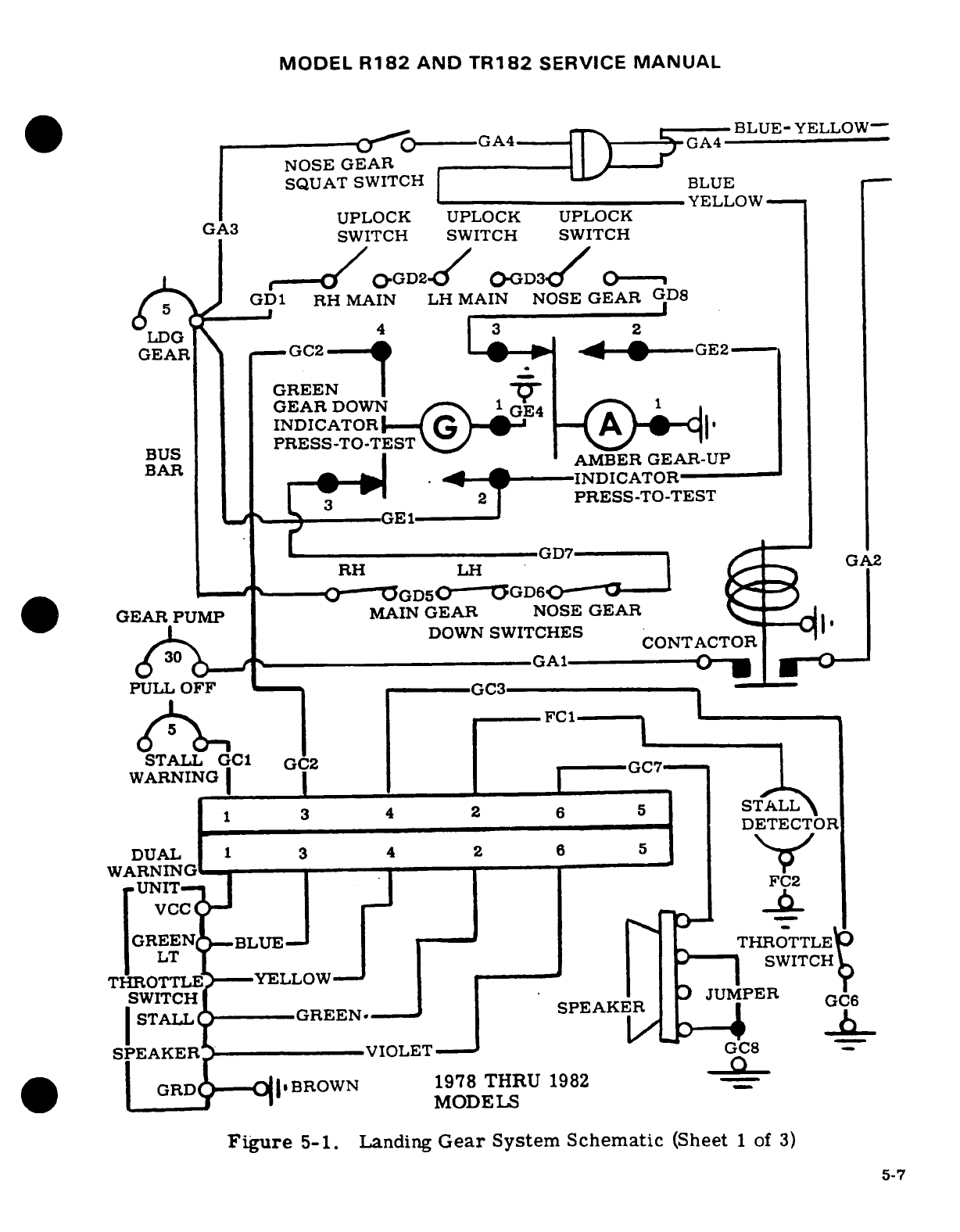
MODEL
R182
AND
TR182
SERVICE
MANUAL
BLUE-
YELLOW-
-- 0(-----GA4--- ---
NOSE
GEAR
SQUAT
SWITCH
BLUE
YELLOW
UPLOCK UPLOCK
UPLOCK
GA3
SWITCH SWITCH
SWITCH
r
1O
OGD2d0
O-GD3/
0---
J
GD1
RH
MAIN
LH
MAIN
NOSE
GEAR
GD8
54
1
3
2
LDG
GEAR
GC2-- GE2
GREEN
I
GEAR
DOWN
1
GE4
I
INDICATOR-
A ~<
i
PRESS-TO-TEST
\
BUS
R
AMBER
GEAR-UP
BAR
^ ^| · - -
INDICATOR
||
_
2
T
PRESS-TO-TEST
F ig
-
LGE1
G
RH. .GD7 _ GE1
2
RH
LH
' -- O--OGD5(0---GD60"0
GEAR PUMP
MAIN
GEAR
NOSE
GEAR
L
/^
DOWN
SWITCHES
CONTACTOR
6
30
<
GA1
_
PULL
OFF
GC3-
d15
--
FC1
STALL
GC1
G'2
GC7
WARNI:G
I I
I
I~UNIT
GREEN
BLUE
I
_
THROTTLE
LT
.... 6
SWITCH
T
ROTTLE
YELLOW
|
I
SWITCH
I
I
ISPEAKER
PER GC6
|STALL
SAGREEN.P
PEAKER
VIOLET
GC8
TO
GRDDABROWN
1978 THRU
1982__
I TL._
I
---- YELLMODELS
Figure
5-1.
Landing
Gear
System
Schematic
(Sheet
1
of
3)
5-7
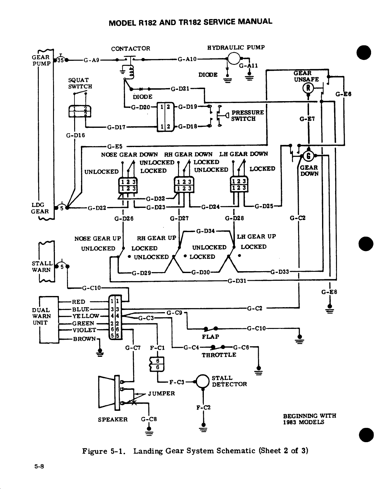
MODEL
R182
AND
TR182
SERVICE
MANUAL
s__
~
CONTACTOR
HYDRAULIC
PUMP
GEAR
___________
3GEAR
--
G-A
9
G-A 1l
PUMP
_ G DIODE
GEAR
1
SQUAT
UNSAFE
SWITCH
G-D21
._"'
G-
1LD21
G--E
.DIODE
6_
G-
,
G-D20-
1
2
G-D19--'
!
J
T
1 I2 I I r
PRESSURE
_ _17 I_
2
SWITCH
G-E7
--
G-D17-----
12
-G-D18
-
|.
G-D16
G-E5
_
NOSE
GEAR
DOWN
RH
GEAR
DOWN
LH
GEAR
DOWN
G
UNLOCKED
LOCKED
UNLOCKED
LOCKED
UNLOCKED
LOCKED
GEAR
>\I I
I I
DOWN
f
2
3
rL2
3
m
|
1231
1123
G-D32
LDGE
A
S
/-G-D22-
----
GD23
G-D24
G-D25-
GEAR
I D
G-D26
G-D27
G-D28
G-C2
-G-D34
_
NOSE
GEAR UP
RH
GEAR
UP
LH
GEAR
UP
UNLOCKED
LOCKED
UNLOCKED
LOCKED
IT *
UNLOCKED *
LOCKED
STALL
WARN
|
G-D29--
G-D30
-D33-_
G-D31
,-G-C10
-- I ,,|C
RED
---
1 1
-J
I
DUAL
--
BLUE-
3
G-C2
WARN
-YELLOW
44
G-CC91
UNIT
--
GREEN
22
--
VIOLET-
6
O6 Wi
G-C0
-------
--BROWN1
5
FLAP
G-C7
F-C1
---
C4---.--G-C6'
_
THROTTLE
j^ F. F-C3-
STALL
DETECTOR
JUMPER
F-C2
SPEAKER
G-C8
BEGINNING
WITH
1 *^~ ~
1983
MODELS
Figure
5-1.
Landing
Gear
System
Schematic
(Sheet
2
of
3)
5-8
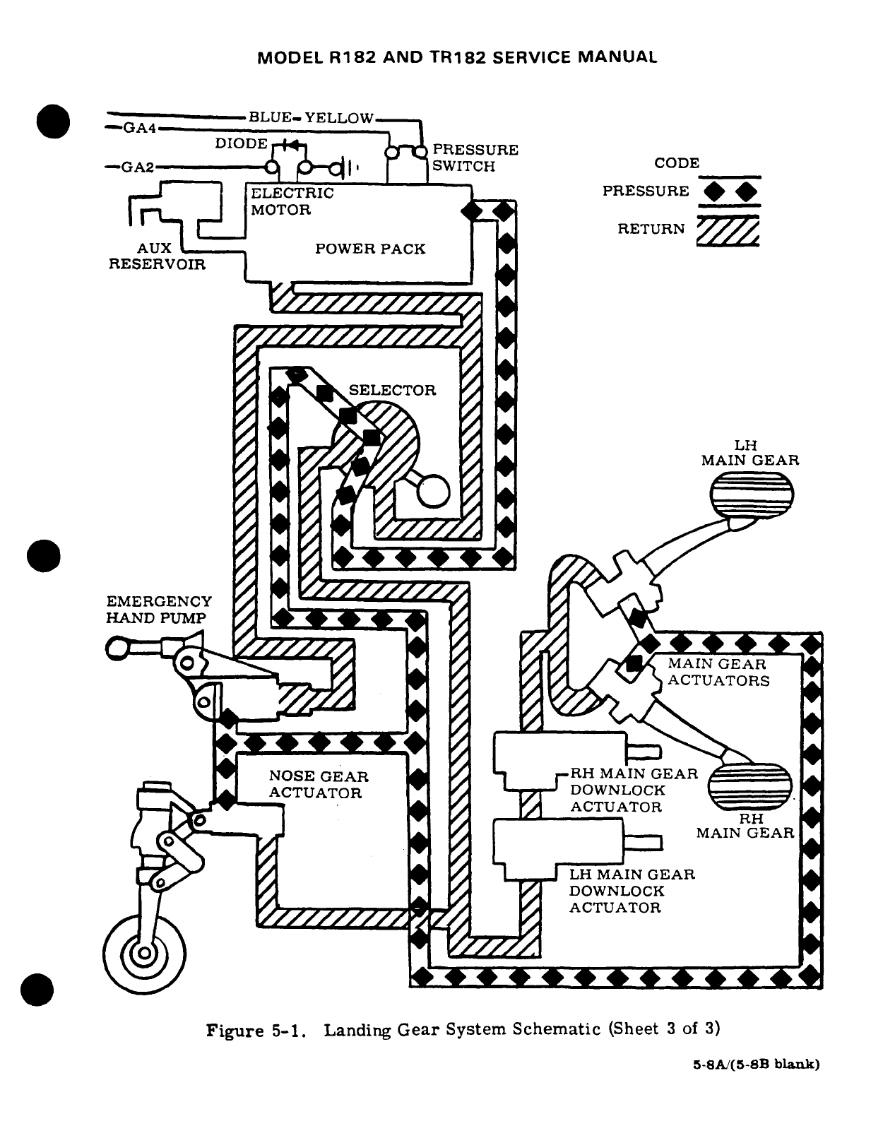
MODEL
R182
AND
TR182
SERVICE
MANUAL
-
G
-
BLUE-YELLOW
'"-GA4
'
'
\
-GA2DIODE
r-M^
'
P
PRESSURE
COD
--
GA2
A A-l»
SWITCH
ELECTRIC PRESSURE
rp
H
MOTOR
y^
C
RETURN
AUX
l
POWER
PACK
RESERVOIR
SELECTOR
LH
MAIN
GEAR
EMERGENCY
_
HAND PUMP
i
^ VPLZ--Sy
U O R1
Y/1
A
^/
\57
\
ACTUATORS
RH
MAIN
GEAR
MAIN
GEAR
Figure
5-1.
Landing
Gear
System
Schematic
(Sheet
3
of
3)
5-8A/(5-SB
blank)
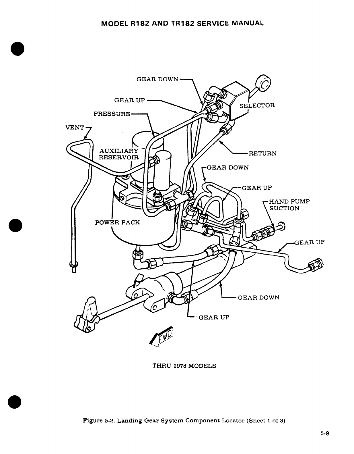
MODEL
R182
AND
TR182
SERVICE
MANUAL
GEAR
DOWN
GEAR
UP
G
DOWN
-- »GEA% R
DOWN
PRESSURE
HAND
PUMP
UCTION
POWER
PACK
EAR
UP
/?\ ok^^^^l^ ^
-GEAR
DOWN
G o-yy__
GEAR
UP
THRU
1978
MODELS
Figure
5-2.
Landing
Gear
System
Component
Locator
(Sheet
1
of
3)
5-9
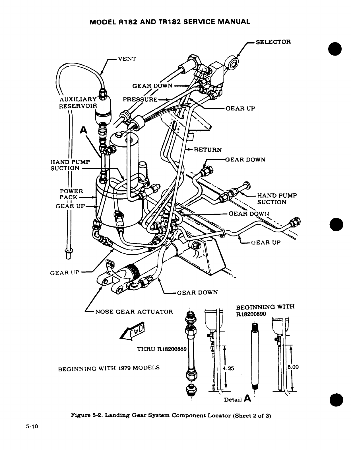
MODEL
R182
AND
TR182
SERVICE
MANUAL
SELECTOR
GEAR
DOWN
AUXILIARY
PRESSURE
RESERVOIR
RETURN
HAND
PUMP
1
l
j
z-
/-GEAR
DOWN
EAR GEARDOWN
POWi X I
~GEAR
UP
OSEGEAR
ACTUATOR
BEGINNING
WITH
THRU
R18200889
BEGINNING
WITH
1979
MODELS
4.25
5.00
GEARl
-,1L
A'
DDetail
A
Figure
5-2.
Landing Gear
System
Component
Locator
(Sheet
2
of
3)
5-10
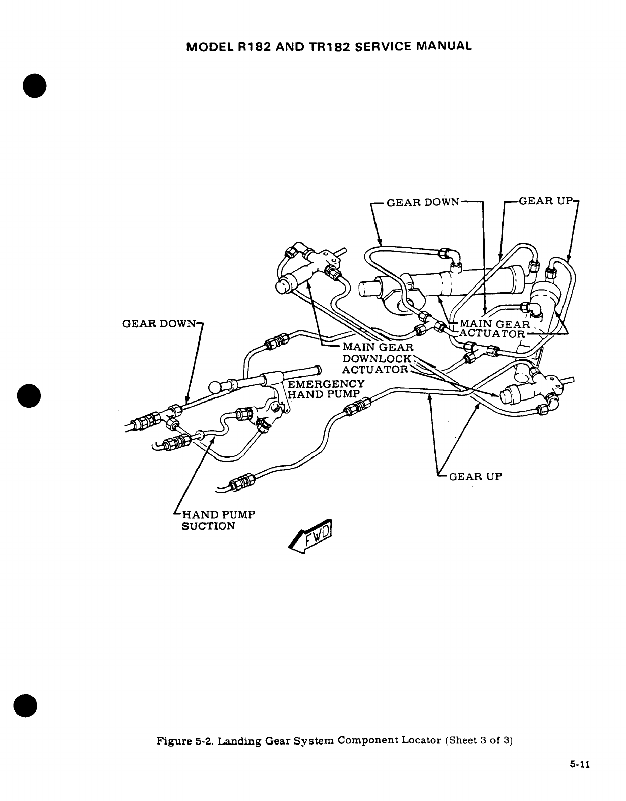
MODEL
R182
AND
TR182
SERVICE
MANUAL
GEAR
DOWN
--
GEAR
UP
GEAR
DOWN
AINEAR
1 ,^^^^ ^^MAIN
GEAR
DOWNLOCKs.
,.
I
=J^
ACTUATOR
~ /
EMERGENCY
1D
P1UM
HANDPUMP
GEAR
UP
-HAND
PUMP
SUCTION
Figure
5-2.
Landing
Gear
System
Component
Locator
(Sheet
3
of
3)
5-11
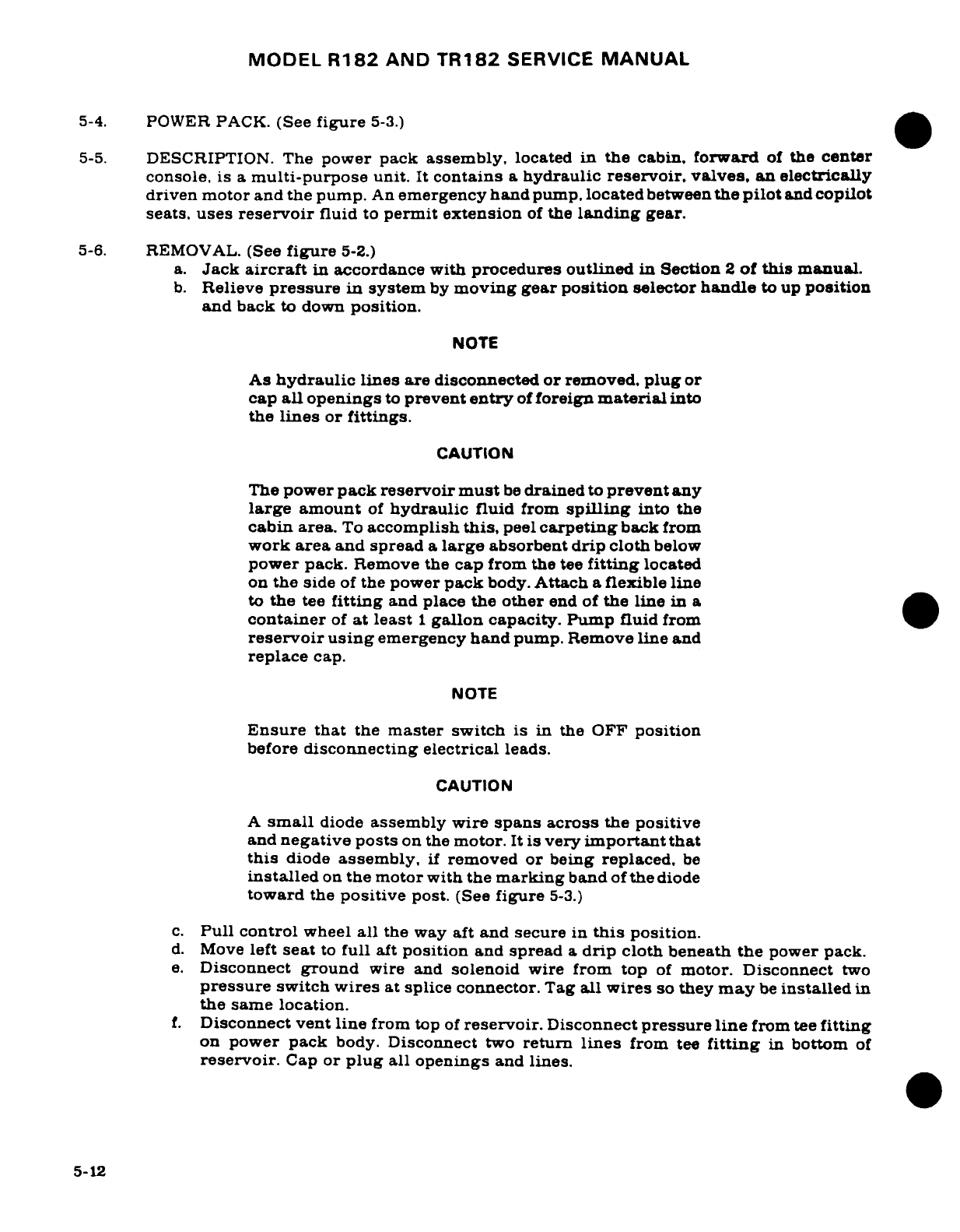
MODEL
R182
AND
TR182
SERVICE
MANUAL
5-4.
POWER
PACK.
(See
figure
5-3.)
5-5.
DESCRIPTION. The
power
pack
assembly,
located
in
the
cabin,
forward
of
the
center
console,
is
a
multi-purpose
unit.
It
contains
a
hydraulic reservoir,
valves, an
electrically
driven motor and the pump.
An
emergency
hand
pump,
located
between
the
pilot
and
copilot
seats,
uses
reservoir
fluid
to
permit
extension
of
the
landing
gear.
5-6.
REMOVAL.
(See
figure
5-2.)
a.
Jack
aircraft
in
accordance with
procedures
outlined
in
Section
2
of
this
manual.
b.
Relieve
pressure
in
system
by
moving
gear
position
selector
handle
to
up
position
and
back
to
down
position.
NOTE
As
hydraulic
lines
are
disconnected
or
removed,
plug
or
cap
all
openings
to
prevent
entry
of
foreign
material
into
the
lines
or
fittings.
CAUTION
The
power
pack
reservoir
must
be
drained
to
prevent
any
large
amount
of
hydraulic
fluid
from
spilling
into
the
cabin
area.
To
accomplish
this,
peel
carpeting
back
from
work
area
and
spread
a
large
absorbent
drip
cloth
below
power
pack.
Remove
the
cap
from
the
tee
fitting
located
on
the
side
of
the
power
pack
body.
Attach
a
flexible
line
to
the
tee
fitting
and
place
the
other
end of
the
line
in a
container
of
at
least
1
gallon
capacity.
Pump fluid
from
reservoir
using
emergency
hand
pump.
Remove
line
and
replace
cap.
NOTE
Ensure
that
the
master
switch
is in
the
OFF
position
before
disconnecting
electrical
leads.
CAUTION
A
small
diode
assembly
wire
spans
across
the
positive
and
negative
posts
on
the
motor.
It
is
very
important that
this
diode
assembly,
if
removed
or
being
replaced,
be
installed
on
the
motor
with
the
marking
band
of
the
diode
toward
the
positive
post.
(See
figure
5-3.)
c.
Pull
control
wheel
all
the
way
aft
and
secure
in
this
position.
d.
Move
left
seat
to
full
aft
position
and
spread
a
drip
cloth
beneath
the
power
pack.
e.
Disconnect
ground
wire
and
solenoid
wire
from
top
of
motor.
Disconnect
two
pressure
switch
wires
at
splice
connector.
Tag
all
wires
so
they
may
be
installed
in
the same
location.
f.
Disconnect
vent
line
from top
of
reservoir.
Disconnect
pressure
line
from
tee
fitting
on
power
pack
body.
Disconnect
two
return
lines
from
tee
fitting
in
bottom
of
reservoir.
Cap
or
plug
all
openings
and
lines.
5-12
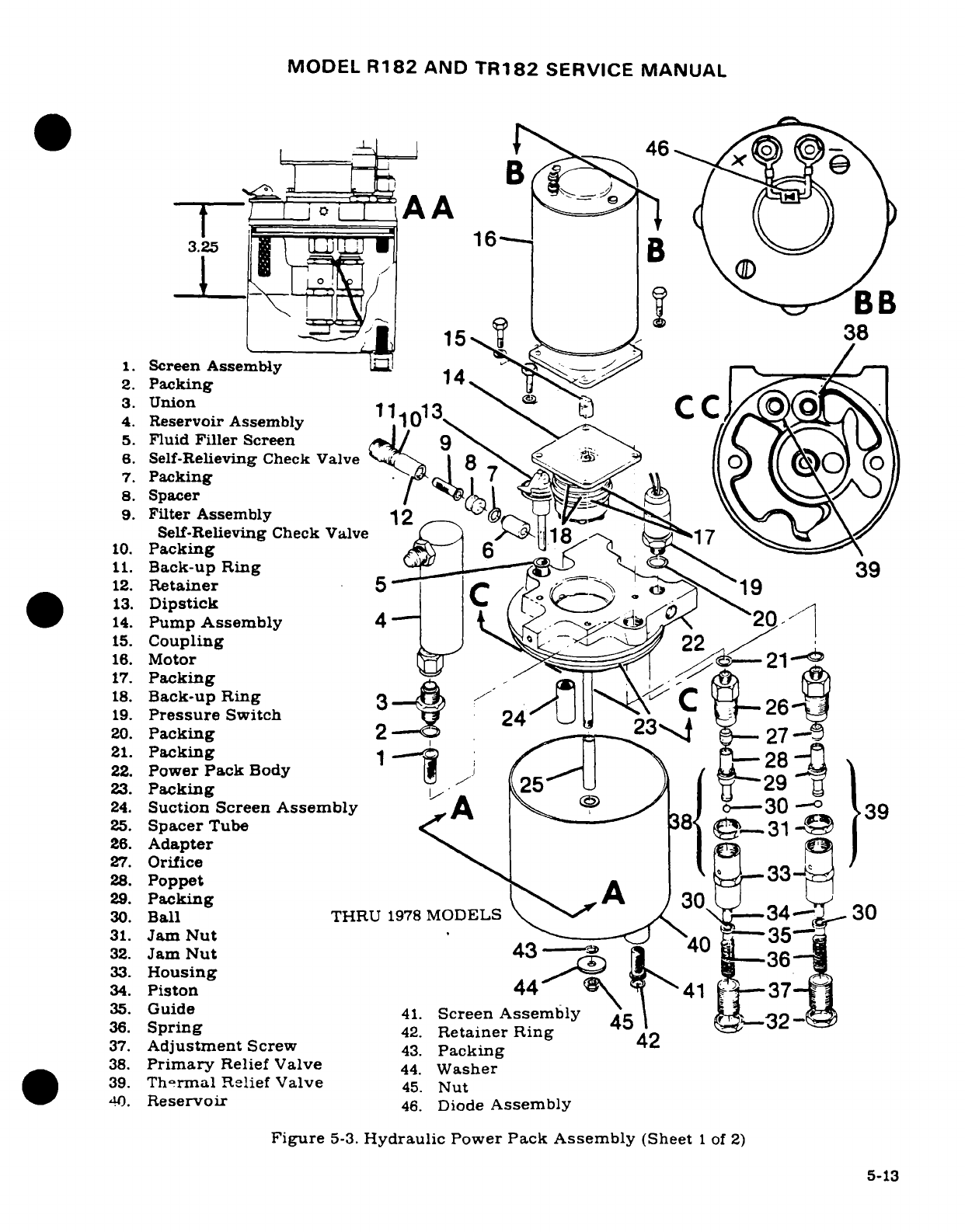
MODEL
R182
AND
TR182
SERVICE
MANUAL
0L
46
L__=AA
3.25
16
B
15
38
1.
Screen
Assembly
1
2.
Packing
3.
Union
11
13
, C
4.
Reservoir
Assembly
1
0
5.
Fluid
Filler
Screen
6.
Self-Relieving
Check
Valve
p<2
O)
)) (o
7.
Packing
8.
Spacer
9.
Filter
Assembly
12
Self-Relieving
Check
Valve
.8 17
10.
Packing
6
11.
Back-up
Ring
39
12.
Retainer
5
/
19
13.
Dipstick
/ (. ' J
14.
Pump
Assembly
4-
t
2
15.
Coupling
22
16.
Motor
21-
17.
Packing
18.
Back-up
Ring
3
C
26
19.
Pressure
Switch
2
20.
Packing
2
23-
.
27-
21.
Packing
1
28
22.
Power
Pack
Body-
29
23.
Packing
;
25-
I29
25.
Spacer
Tube
'
-31
26.
Adapter
27.
Orifice
33
/
28.
Poppet
r
3
29.
Packing
A
30
-
30.
Ball
THRU
1978
MODELS
<
.34-
2
30
31.
Jam
Nut
---- 35
32.
Jam
Nut
43
--
4
36
33.
Housing
34.
Piston
44
41
t-37
35.
Guide
41.
Screen
Assembly
45
32-
36.
Spring
42.
Retainer Ring
42
37.
Adjustment
Screw
43.
Packing
38.
Primary
Relief
Valve
44.
Washer
39.
Thermal
Relief
Valve
45.
Nut
40.
Reservoir
46.
Diode
Assembly
Figure
5-3.
Hydraulic
Power
Pack
Assembly
(Sheet
1
of
2)
5-13
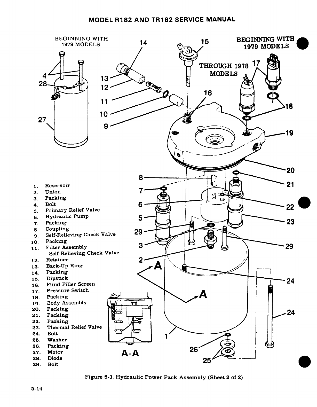
MODEL
R182
AND
TR182
SERVICE
MANUAL
BEGINNING
WITH14
BEGINNING
WITH
1979
MODELS
1
1979
MODELS
X~~ ~ ~ ~~~~~~
1979
MODELS4
1
/
(713
-^ "y
THROUGH
1978
17
4 13
MODELS
28
12
1.
Reservoir
8
!
[ } 21
2.
Union
7
-*
TT
s
3.
Packing
6^
.1
,
.
T
.q
16
27 20
1.
Reservoir
21
3.
Packing
4.
Bolt
6 ---
5.
Primary
Relief
Valve
6.
Hydraulic
Pump
5
7.
Packing
23
8.
Coupling
9.
Self-Relieving
Check Valve
29
10.
Packing
11.
Filter
Assembly
3
Self-Relieving
Check Valve
12.
Retainer
13.
Back-Up
Ring
14.
Packing
-
15.
Dipstick
16.
Fluid
Filler
Screen
24
17.
Pressure
Switch
18.
Packing
t9.
Body
Assembly
20.
Packing
21.
Packing
24
22.
Packing
23.
Thermal
Relief
Valve
24.
Bolt
25.
Washer
26.
Packing
)
27. Motor
A-A
26
28.
Diode
_
29.
Bolt
Figure
5-3.
Hydraulic
Power
Pack
Assembly
(Sheet
2
of
2)
5-14
MODEL
R182
AND
TR182
SERVICE
MANUAL
g.
Remove
two
bolts,
attaching
power
pack
to
console
assembly,
from
aft
side
of
power
pack
body.
Remove
four screws,
attaching
forward
power pack
support
to
firewall,
and
remove
power pack,
with
support
attached.
Work
over
left-hand
rudder
pedals.
5-7.
DISASSEMBLY
(THRU
1978
MODELS.)
(See
figure
5-3,
sheet
1
of
2.)
a.
Remove
retaining
ring
(42)
and
screen
assembly
(41)
from
reservoir
assembly
(40).
b.
Remove
nut
(45),
washer
(44)
and
packing
(43)
from
attaching
stud
and
remove
reservoir
(40)
from
power
pack
body
(22).
NOTE
If
reservoir
will
not
disengage
from
power
pack
body,
install
a
capped
fitting
in
the
pressure
and
return
open-
ings
of
the
power pack
assembly
and
attach
air
hose
to
vent
fitting
at
top
of
reservoir
assembly
(4).
Apply
air
pressure
(not
to
exceed
15
psi,
reservoir
proof
pressure),
and remove
reservoir.
A
strap
clamp
is
not
recom-
mended, as
clamp
may
damage
reservoir.
c.
Remove
packing
(23)
from
power
pack
body
(22).
NOTE
Disassembly
of
primary
and
thermal relief valve assem-
blies
(38)
&
(39)
is
normally
not
required.
Refer
to
paragraphs
for
specific
instructions
regarding
relief
valves.
Before
removal,
tag
each relief
valve
"primary"
or
"thermal"
to
insure
correct
installation.
Refer
to
view
C-C.
d.
Cut
safety
wire
and
remove
relief
valve
assemblies
and
spacer
tube
(25)
from
power
pack
body (22).
e.
Remove
reservoir
assembly
(4),
union
(3),
packing
(2)
and
screen
assembly
(1)
from
power
pack
body
(22).
f.
Remove
dipstick
(13)
and
fluid
filler screen
(5)
from
power
pack
body
(22).
g.
Remove
retainer
(12),
filter
assembly
(9),
packing
(7),
self-relieving
check
valve
(6)
and
spacer
(8)
from
power
pack
body
(22).
NOTE
If
spacer
(8)
and/or
self-relieving
check
valve
(6)
will
not
fall
from
hole
in
power
pack,
place
a
drift
or
punch
made
of
soft
material
into
the
pressure
opening
of
the
power
pack
body
and
tap
spacer
from
power
pack
body.
h.
Remove
pressure
switch
(19)
and
packing
(20)
from
power
pack body
(22).
i.
Remove
three
bolts
holding
motor and
pump
assembly
to body
and
remove
motor
(16),
coupling
(15),
and
pump
assembly
(14)
from
power
pack
body
(22).
5-15
MODEL
R182
AND
TR182
SERVICE
MANUAL
NOTE
The
suction screen
assembly
(24)
need
not
be
removed
from
power
pack
body
(22)
for
cleaning
or
inspection.
However,
if
suction
screen
is
damaged
or
permanently
clogged,
it
should
be
removed
as
outlined
in
step
"j"
of
this
paragraph.
observing
the
following
caution.
CAUTION
Use
extreme
caution
in
removing
suction
screen
assem-
bly
(24).
Damage
to
screen assembly
or clearance
between
screen
assembly
and
power
pack
body
(22)
will
cause
slow
gear
retraction.
j.
Working
through
center
hole
in
top
of
power
pack
body
(22),
use
a
drift
or
punch
made
of
soft
material
to
tap
suction
screen
assembly
(24)
from
power
pack
body
(22).
5-8.
INSPECTION.
(THRU
1978
MODELS.)
(See
figure
5-3,
sheet
1
of
2.)
a.
Wash
all
parts
in
cleaning
solvent
(Federal
Specification
P-S-611,
or
equivalent)
and
dry
with
filtered
air.
b.
Inspect
all
threaded
surfaces
for serviceable
condition
and
cleanliness.
c.
Inspect
all
parts
for scratches,
scores,
chips,
cracks
and
indications
of
excessive
wear.
d.
Check
to
ensure
that
all
screens
are completely
clean and
undamaged.
Refer
to
Note
and Caution
preceding
step
"j"
of
the
preceding
paragraph
for
important
information
regarding
removal
of
suction
screen
assembly
(24).
5-9.
REASSEMBLY.
(THRU
1978
MODELS.)
(See
figure
5-3,
sheet
1
of
2.)
NOTE
Use
all
new
packings
and
back
up
rings
when
reassembling
power
pack.
Assemble
parts,
lubricated
with
a
film
of
Petrolatum
W-P-236,
hydraulic
fluid
MIL-H-5606,
or
Dow
Corning
DC-7.
Do
not
use
DC-7
on
surfaces
to
be
painted.
a.
If
suction
screen
assembly
(24)
was
removed,
press
a
new
suction
screen
assembly
into
power
pack
body
(22),
observing
the
following
caution.
CAUTION
Use
extreme caution
when
installing
suction
screen
assembly
(24)
power pack
into
body
(22).
Damage
to
screen
assembly
or clearance
between
screen
assembly
and
body
will
result
in
slow
gear
retraction. Refer
to
view
A-A
for
correct
pressed
height
dimension
of
suction
screen
assembly.
b.
Using
new
packings
(17)
and
back-up
rings
(18),
install
pump
assembly
(14)
into
power
pack
body
(22)
being careful
to
match
the
painted
alignment
marks
on
pump
and
body.
5-16
MODEL
R182
AND
TR182
SERVICE
MANUAL
c.
Install coupling
(15)
on
pump
shaft
and
position motor
(16)
on
pump
assembly
being
careful
to
ensure
that
coupling
(15)
is
properly
engaged,
and painted
alignment
mark
matches
with
those
on
pump and
body.
d.
Install
and
tighten
three
bolts
and
washers
connecting
motor
(16),
pump
assembly
(14)
and power
pack
body
(22).
e.
Using
new
packing
(20)
install and
tighten pressure
switch
(19)
onto
power
pack
body
(22).
f.
Using
new
packings
(7)
and
(10)
and
back-up
ring
(11),
install
and
tighten
spacer
(8),
self-relieving
check
valve
(6)
and
retainer
(12)
into
power
pack
body
(22).
g.
Install
and
tighten
relief
valve
assemblies
(38)
and
(39)
onto
power
pack
body
(22)
with
packing
(21).
h.
Install
fluid
filler screen
(5)
and
dipstick
(13)
into
power
pack body
(22).
i.
Using
new
packing
(2),
install
screen
assembly
(1),
union
(3)
and reservoir
assembly
(4)
onto
power
pack
body
(22).
j.
Slide
spacer
tube
(25),
then
washer
onto
body
center
stud.
Loop
safety
wire
through
jam-nuts
on
relief
valves
as
shown,
then
tie
off to
spacer
tube
(25). Refer
to
view
AA.
k.
Install
screen
assembly
(41)
and
retaining
ring
(42)
into reservoir
(40).
CAUTION
It is
very
important
that
the
relief
valve
safety
wire
does
not
get
between
spacer
tube
(25)
and
power
pack
body
(22)
during
installation
of
reservoir
(40).
Refer to view
A-A.
1.
Using
new
packings
(23)
&
(43)
install
and
tighten
reservoir
(40),
washer
(44)
and
nut
(45)
onto
power
pack
body
(22).
5-10.
DISASSEMBLY.
(Beginning
with
1979
MODELS.)
(See
figure
5-3,
sheet
2
of
2.)
a.
Remove
bolts
(24),
washers
(25)
and
packing
(26)
from
reservoir
(1).
b.
Remove
reservoir
(1)
from
body
assembly
(19).
NOTE
If
reservoir
will
not
disengage
from
body,
install
a
capped
fitting
in
the
pressure
and
return
openings
of
the
power
pack
assembly
and
attach
an
air
hose
to
vent
fitting
at
top
of body
assembly
(19).
Apply
air pressure
(not
to
exceed
15
psi,
reservoir
proof
pressure),
and
remove
reservoir.
A
strap
clamp
is
not
recommended
as
clamp
may
damage
reservoir.
c.
Remove
packing
(20)
from
body
assembly
(19).
NOTE
Disassembly
of
primary
and
thermal
relief
valves
(5)
and
(23)
is
normally
not
required.
Refer
to
applicable
para-
graphs
for specific
instructions
regarding
relief
valves.
Before
removal,
tag
each
relief
valve
(primary)
or
(ther-
mal)
to
ensure
correct
reinstallation.
d.
Cut
safety
wire
and
remove
primary
and
thermal
relief
valve
assem-
blies
(5)
and
(23)
from
body
assembly
(19).
Remove
packings
(7)
and
(21)
from
relief
valves.
e.
Remove
dipstick
(15)
and
screen
(16)
from
body
assembly
(19).
5-17
MODEL
R182
AND
TR182
SERVICE
MANUAL
f.
Remove
retainer
(12),
filter
assembly
self-relieving
check
valve
(11),
back-up
ring
(13),
packing
(14),
packing
(10)
and self-relieving
check
valve
(9)
from
body
assem-
bly
(19).
NOTE
If
self-relieving
check
valve
(9)
will
not
fall
from
hole
in
body
assembly,
place
a
drift
or
punch
made
of
soft
mate-
rial
into
the
pressure
opening
of body
assembly
and
tap
spacer
from
body.
g.
Remove
pressure
switch
(17)
and
packing
(18)
from
body
assembly
(19).
h.
Remove
bolts (29)
attaching
hydraulic
pump
(6)
to
body
assembly
(19),
and remove
pump
and
coupling
(8)
from
body
assembly.
Remove
union
(2)
from
pump,
and
re-
move
packings
(3)
and
(22).
*
i.
Cut
safety
wire
and
remove
bolts
(29)
attaching
hydraulic
pump
(6)
to
body
assembly
(19),
remove
pump
and
coupling
(8)
from
body
assembly,
and
remove
packing (22).
j.
Cut
safety
wire
and
remove
bolts
(4)
from
motor
(27);
remove
motor
from
body as-
sembly
(19).
5-11.
INSPECTION.
(Beginning
with
1979
MODELS.)
(See
figure
5-3,
sheet
2
of
2.)
a.
Wash
all
parts
in
cleaning
solvent (Federal Specification
P-S-611,
or
equivalent)
and
dry
with
filtered
air.
b.
Inspect
all
threaded
surfaces
for
serviceable
condition
and
cleanliness.
c.
Inspect
all
parts
for
scratches,
scores,
chips,
cracks
and
indications
of
excessive
wear.
d.
Clean
to
ensure
that
all
screens
and filters
are
completely
clean
and
undamaged.
5-12.
REASSEMBLY.
(Beginning
with
1979
MODELS.)
(See
figure
5-3,
sheet
2
of
2.)
NOTE
Use
all
new
packings
and
back-up
rings
when
reassembl-
ing
power pack.
Assemble
parts,
lubricated with
a
film
of
Petrolatum
VV-P-236,
hydraulic
fluid
MIL-H-5606,
or
Dow
Corning
DC-7.
Do
not
use
DC-7
on
surfaces
to
be
painted.
a.
Using
new
packings
(22),
install
hydraulic
pump
(6)
and
coupling
(8)
into
body
as-
sembly
(19)
with
bolts
(29).
Install
union
(2)
and
packing
(3)
in
pump.
Torque
bolts
(29) evenly to
30
pound-inches.
*
b.
Using
new
packing
(22),
install
hydraulic
pump
(6)
and
coupling
(8)
into
body
as-
sembly
(19)
with
bolts
(29).
Torque
bolts
(29)
evenly
to
30
pound-inches
and
safety-
wire
bolts.
c.
Install
motor
(27) on
top
of
body
assembly
(19)
after
aligning
coupling
(8)
to match
mating
connection
in
motor
(27).
Secure
motor
to
body
with
bolts.
Safety-wire
bolts.
5-18
MODEL
R182
AND
TR182
SERVICE
MANUAL
d.
Install
new
packing
(18),
install
and
tighten
pressure
switch
(17)
onto
body
assem-
bly
(19).
e.
Using
new
back-up
ring
(13)
and
packings
(14)
and
(10),
install and
tighten
self-re-
lieving check
valve
(9),
filter
assembly
self-relieving
check
vavle
(11),
and
retainer
(12)
into
body
(19).
f.
Install
primary
and
thermal
relief
valve
assemblies
(5)
and
(23),
along
with
packings
(7)
and
(21)
onto
body
assembly
(19).
Safety-wire relief
valves
as
shown
in
View
A-A.
CAUTION
Ensure that
relief
valves
are installed
in
their
correct
lo-
cation.
g.
Install
fluid
filler
screen
(16)
and
dipstick
(15)
into
body
assembly
(19).
SERIAL
R182
R18200001
THRU
R18201816
TR182
R18200584
THRU
R18201816
SERIAL R182
&
TR182
R18201817
&
ON
5-18A (5-18B
blank)
MODEL
R182
AND
TR182
SERVICE
MANUAL
h.
Using
new
packing
(20),
washers
(25),
and packing
(28),
install
and
tighten
reser-
voir
(1)
onto
body
assembly
(19).
Torque
bolts
(24)
evenly
to
30-35
inch-pounds.
5-13.
INSTALLATION.
a.
Place power
pack,
with
forward
support
attached,
in
aircraft.
Attach
forward
support
to
firewall with
four
screws.
b.
Attach power pack
to
center
console
with
two
bolts
at
aft
side
of
power
pack.
NOTE
Ensure
that
master
switch
is in
OFF
position
before
connecting
electrical
leads
to
power
pack
assembly.
CAUTION
A
small
diode
assembly
wire
spans
across
the
positive
and
negative
posts
on
the
motor.
It is
very
important
that
this
diode
assembly,
if
removed
or
being
replaced,
be
installed
on
the motor
with
the
marking
band
of
the
diode
toward
the
positive
post.
Refer
to
view
B-B
on
sheet
1.
c.
Ensure
that
diode
assembly
wire
is
correctly installed
on
motor
and
connect
ground
wire
and
solenoid
wire
to
motor.
d.
Connect two
pressure
switch
wires
at
splice
connectors,
being
careful
to
match
tags
on
wires.
e.
Remove
caps or
plugs,
and connect
two
return
lines
to
tee
fitting
at
bottom
of
reservoir.
Connect
pressure
line
to
tee
fitting
on
left-hand
side
of
power
pack
body.
Connect
vent
line
to
fitting
at
top
of
reservoir.
5-14.
PRIMARY
AND
THERMAL
RELIEF
VALVE
ASSEMBLIES.
(See
figure
5-3.)
5-15.
DESCRIPTION.
The
primary
relief
valve,
located
between
the
check
valve
and
pump,
serves
to
limit
the
amount
of
pressure
which
can
be
generated
by
the
pump.
The
thermal
relief
valve, located
on
the
system
side
of
the check
valve,
serves
to
limit
the
system
pressure.
System
pressure
can
increase
due
to
thermal
expansion.
Both
valves
are identical,
the
only
difference
being
the pressure
setting.
5-16.
REMOVAL.
(See
figure
5-3,
sheet
2
of
2.)
a.
Cut
safety
wire
and remove relief
valve
assemblies
from
body
assembly
(19).
5-17.
DISASSEMBLY.
(See
figure
5-3,
sheet
1
of
2.)
NOTE
Relief
valve
assemblies
are
preset
by the
factory
and
normally
will
not
require disassembly.
Refer
to
note
following
step
(g)
in
paragraph
5-19
to
determine
if
disassembly
or
adjustment
is
necessary.
5-19
MODEL
R182
AND
TR182
SERVICE
MANUAL
a.
Remove
jam
nut
(32)
and
adjustment
screw
(37)
from
housing
(33).
b.
Remove
spring
(36).
guide
(35),
balls
(30)
and
piston
(34)
from
housing
(33).
c.
Loosen
jam
nut
(31)
and
remove
adapter
(26)
from
housing
(33).
d.
Remove
poppet
(28)
and
orifice
(27)
from
adapter
(26).
5-18.
INSPECTION.
(See
figure
5-3,
sheet
1
of
2.)
a.
Wash
all
parts
in
cleaning solvent
(Federal
Specification
P-S-611
or
equivalent)
and
dry
with
filtered
air.
b.
Inspect
all
threaded
surfaces
for
serviceable condition
and
cleanliness.
c.
Inspect
all
parts
for
scratches,
scores, chips,
cracks
and
indications
of
excessive
wear.
5-19.
ASSEMBLY
AND
ADJUSTMENT.
(See
figure
5-3.
sheet
1
of
2.)
NOTE
Use
all
new
packings
and
back
up
rings
during
reassembly.
Assemble
parts,
lubricated
with
a
film
of
Petrolatum VV-P-236,
hydraulic
fluid
MIL-H-5606,
or
Dow
Corning
DC-7.
a.
Install
orifice
(27)
and
poppet
(28)
into
adapter
(26).
(New
packing
(29)
must
be
installed
on
poppet.)
b.
Install
jam
nut
(31)
and
housing
(33)
on
adapter
(26).
c.
Tighten
adapter
(26)
into
housing
(33)
and
torque
to
100-150
lb-in.
d.
Tighten
jam
nut
(31)
against
housing
(33)
and
torque
to
100-150
lb-in.
e.
Install
one
ball
(30)
into
housing
(33),
so
that
it
rests
on
poppet
(28).
Install
piston
(34)
into
housing
(33),
then
install
remaining
ball
(30)
into
end
of
piston
(34).
f.
Insert
guide
(35)
and
spring
(36)
into
housing
(33)
making sure
that
balls
(30)
and
piston
(34)
remain
in
correct
position.
g.
Turn
adjustment
screw
(37)
into
housing
(33)
until
it
just
contacts
spring
(36),
then
turn
in
one
additional
turn.
Start
jam
nut
(32)
onto
adjustment
screw
(37)
and
snug
against
housing
(33).
THERMAL
RELIEF
VALVE
Open
...............................
2250
PSI
Maximum
Reset
.............................
,..1500
PSI
Minimum
(no
leakage)
PRIMARY
RELIEF
VALVE
Open
......... ............... .... .
1800
00
-50
PSI
Reset
...............................
1300
PSI Minimum
(no
leakage)
5-20
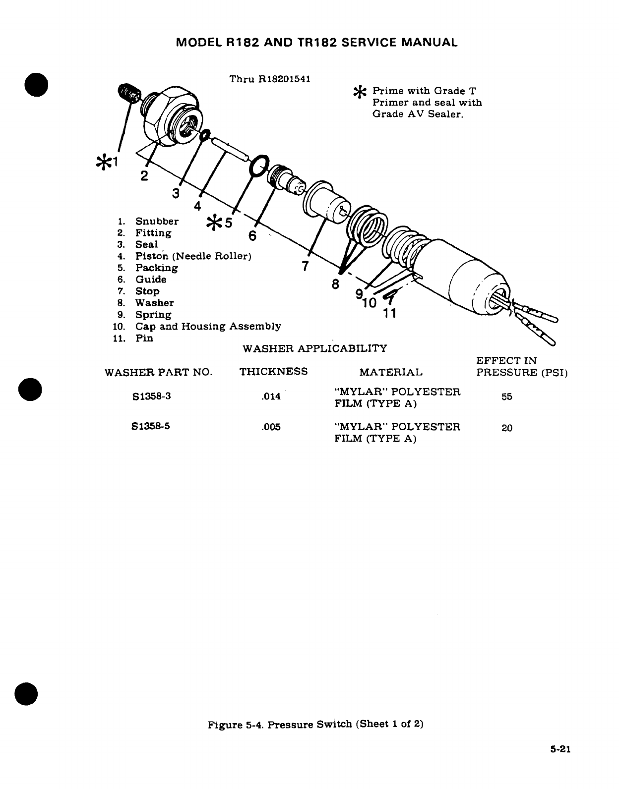
MODEL
R182
AND
TR182
SERVICE
MANUAL
Thru
R18201541
Thru*R180154
Prime
with
Grade
T
Primer
and
seal with
Grade
AV
Sealer.
1. Snubber5
5'
2.
Fitting
6
3.
Seal
4.
Piston
(Needle
Roller)
5.
Packing
7
6.
Guide
8
7.
Stop
8.
Washer
10
9.
Spring
11
10.
Cap
and
Housing
Assembly
11.
Pin
WASHER APPLICABILITY
EFFECT
IN
WASHER
PART
NO.
THICKNESS
MATERIAL
PRESSURE
(PSI)
S1358-3
.014
"MYLAR"
POLYESTER
55
FILM
(TYPE
A)
S1358-5
.005
"MYLAR"
POLYESTER
20
FILM
(TYPE
A)
Figure
5-4.
Pressure
Switch
(Sheet
1
of
2)
5-21
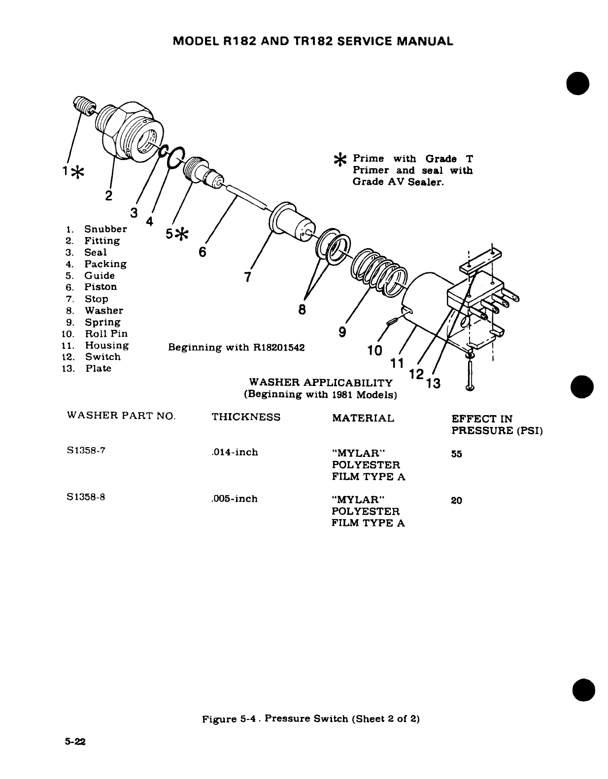
MODEL
R182
AND
TR182
SERVICE
MANUAL
/*
Prime with
Grade
T
Primer
and
seal
with
Grade
AV
Sealer.
3
4
1.
Snubber
5*
2.
Fitting
3.
Seal
6
4.
Packing
5.
Guide
7
6.
Piston
7.
Stop
8.
Washer
8 /
9.
Spring
10.
Roll
Pin
9
11.
Housing Beginning
with
R18201542
10
12.
Switch
1
/ ,
13.
Plate
WASHER
APPLICABILITY
13
(Beginning
with
1981
Models)
WASHER
PART
NO.
THICKNESS
MATERIAL
EFFECT
IN
PRESSURE
(PSI)
S1358-7
.014-inch
"MYLAR"
55
POLYESTER
FILM
TYPE
A
S
1358-8
.005-inch
"MYLAR"
20
POLYESTER
FILM
TYPE
A
Figure
5-4.
Pressure
Switch
(Sheet
2
of
2)
5-22
MODEL
R182
AND
TR182
SERVICE
MANUAL
NOTE
To
determine
if
disassembly
or
adjustment
is
necessary,
the
relief
valves
can
be
bench-tested.
The
thermal
relief
valve
can
be
tested
with
a
hand
pump,
connected
to
a
hydraulic
reservoir,
a
pressure
gage
with
2500
psi
capac-
ity
and
a
hose
with
appropriate
fittings,
connected
from
the
hand
pump
to
the
fitting
on
the
thermal relief valve.
The
thermal
relief valve
shall
be
set
not
to
open
in
excess
of
2250
psi.
If
adjustment
of
thermal
relief
valve
is
necessary,
loosen
jam-nut
(32)
and
turn
adjustment
screw
(37)
in
to
increase
pressure;
back
adjustment
screw
out
to
decrease
pressure.
Tighten
jam-nut
(32)
against
housing
(33)
and
torque jam-nut
from
100
to
150
lb.
in.
Recheck
pressure
adjustments. Testing
the
primary
relief valve
will require
a
hydraulic pump with
a
flow
rate
of
0.5
to
0.7
gal.-per-min..
connected
to
a
hydraulic
reservoir,
a
pressure
gage
with
2500
psi
capacity
and
a
hose
with
appropriate
fittings,
connected
from
the
hydraulic
pump
to
the
fitting
on
the
primary
relief
valve.
Adequate
precautions
should
be
taken
to
recover
hydrau-
lic
fluid
which will
be
expelled
from
the
primary
relief
valve
while
under
pressure.
The
primary
relief
valve
shall
be
set
to
open
at
1800,
+
0,
-50
psi.
If
adjustment
of
primary
relief
valve
is
necessary,
loosen
jam-nut
(32)
and
turn adjustment
screw
(37)
in
to
increase
pressure;
back
adjustment
screw
out
to
decrease
pressure.
Tighten
jam-nut
(32)
against
housing
(33)
and
torque
jam-nut
from
100
to
150
lb.
in
Recheck
pressure
adjustments.
5-20.
INSTALLATION.
(See
figure
5-3.)
a.
Install
primary
and
thermal
relief
valve
assemblies
along
with
packings
onto
body
assembly
CAUTION
Ensure
that primary
and
thermal
relief
valves
are
installed
in
their
correct locations
and
that
valves
are
properly
safetied.
Refer
to
view
A-A
in
appropriate
illustration.
Make
sure
applicable
illustration
is
used
for
power pack
being
installed
5-21.
PRESSURE
SWITCH.
5-22.
DESCRIPTION.
A
pressure
switch
is
located
in
the
cover
of
the
power
pack.
The
switch
opens
the
electrical
circuit
to
the
pump
solenoid
when
the
pressure
in
the
system
increases
to
approximately
1500
psi.
The
pressure
switch
will
continue
to
hold
the
electrical circuit
open
until
pressure
in
the
system
drops
to
approximtely
1000
psi,
at which
time the
pump
will
again
operate
to
build
up
pressure
to
approximately
1500
psi,
regardless
of
gear
selector
handle
position.
5-23
MODEL
R182
AND
TR182
SERVICE
MANUAL
5-23.
REMOVAL
AND
INSTALLATION.
a.
Move
left
seat
to
full
aft
position
and
spread
a
drip
cloth
beneath
the power
pack.
b.
Assure
that
master
switch
is
off,
and
disconnect
wires
from
pressure
switch.
c.
Disconnect
pressure
switch
from
power
pack.
d.
Reverse
the
preceding
steps
to
install
pressure
switch.
5-24.
DISASSEMBLY.
(Thru
R18201541.)
(See
figure
5-4,
sheet
1
of
2.)
a.
Remove
pin
(11).
b.
Unscrew
cap
and
housing
assembly
(10)
from
fitting
(2).
c.
Remove
spring
(9).
d.
Remove
washers
(8)
from
flange
of
stop
(7).
NOTE
Chart
in
figure
5-4,
sheet
1
of
2.
lists
washers
(8)
by
part
number,
thickness
and
effect
on
operating
pressure
(psi).
e.
Unscrew guide
(6)
from
fitting
(2).
CAUTION
Do
not
damage
lip
of
guide
(6).
Guide
threads
and
threads
of
fitting
(2)
are
primed
with
Loctite
Grade
T
Primer
and
sealed
with
Loctite
Grade
AV
Sealer.
f.
Remove
piston
(4).
g.
Remove
seal
(3)
and
packing
(5).
h.
Remove
snubber
(1)
from
fitting
(2).
CAUTION
Threads
of
snubber
(1)
and
fitting
(2)
are
primed
with
Loctite
Grade
T
Primer
and
sealed
with
Loctite
Grade
AV
Sealer.
5-25.
INSPECTION
AND
REPAIR.
(Thru
R18201541.)
(See
figure
5-4,
sheet
1
of
2.)
a.
Clean
sealant
from
threads
of
snubber
(1),
fitting
(2)
and
guide
(6)
with
wire
brush.
b.
Clean
all
parts
with
cleaning
solvent
(Federal
Specification
P-S-661,
or
equivalent)
and
dry
thoroughly.
c.
Discard
seal
(3)
and
packing
(5)
and
replace
with
new
parts.
d.
Inspect
all
pressure
switch
parts
for
scratches, scores,
chips,
cracks
and
indications
of
wear.
e.
All
damaged
parts
shall
be
replaced
with
new
parts.
NOTE
Thorough
cleaning
is
important.
Dirt
and
chips
are the
greatest
single
cause
of
malfunctions
in
hydraulic
sys-
tems.
Carefulness
and
proper
handling
of
parts
to
pre-
vent
damage
must
be
observed
at
all
times.
f.
Snubber
(1)
can
be
cleaned
with solvent,
then
blown
out with
high
pressure
compressed air.
g.
Assure
that
.062
vent
hole
is
open
in
stop
(7).
5-24
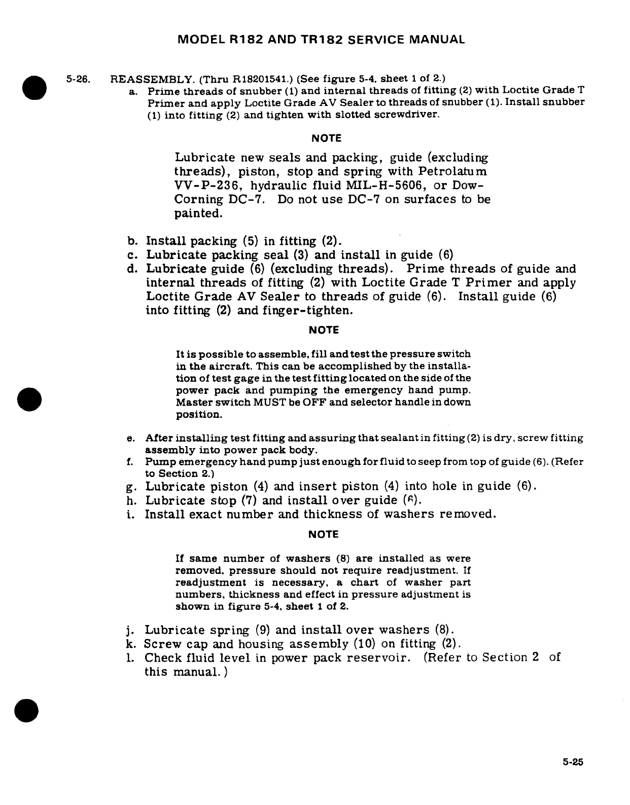
MODEL
R182
AND
TR182
SERVICE
MANUAL
5-26.
REASSEMBLY.
(Thru
R18201541.)
(See
figure
5-4.
sheet
1
of
2.)
a.
Prime
threads
of
snubber
(1)
and
internal
threads
of
fitting
(2)
with
Loctite Grade
T
Primer
and
apply
Loctite
Grade
AV
Sealer
to
threads
of
snubber
(1).
Install
snubber
(1)
into
fitting
(2)
and
tighten
with
slotted
screwdriver.
NOTE
Lubricate
new
seals
and
packing,
guide (excluding
threads),
piston,
stop
and
spring
with
Petrolatum
VV-P-236,
hydraulic
fluid
MIL-H-5606,
or
Dow-
Corning
DC-7.
Do
not
use
DC-7
on
surfaces
to
be
painted.
b.
Install
packing
(5)
in
fitting
(2).
c.
Lubricate
packing
seal
(3)
and
install
in
guide
(6)
d.
Lubricate
guide
(6)
(excluding
threads).
Prime threads
of
guide
and
internal
threads
of
fitting
(2)
with
Loctite
Grade
T
Primer
and
apply
Loctite Grade
AV
Sealer
to
threads
of
guide
(6).
Install
guide
(6)
into
fitting
(2)
and
finger-tighten.
NOTE
It is
possible
to
assemble,
fill
and
test
the
pressure
switch
in
the
aircraft.
This
can
be
accomplished
by
the
installa-
tion
of
test
gage
in
the
test
fitting
located
on
the
side
of
the
power
pack
and
pumping
the
emergency
hand
pump.
Master
switch
MUST
be
OFF and
selector
handle
in
down
position.
e.
After
installing
test
fitting
and
assuring
that
sealant
in
fitting
(2)
is
dry, screw
fitting
assembly
into power
pack
body.
f.
Pump emergency
hand
pump
just
enough
for
fluid
to
seep
from
top
of
guide
(6).
(Refer
to
Section
2.)
g.
Lubricate
piston
(4)
and
insert
piston
(4)
into
hole
in
guide
(6).
h.
Lubricate
stop
(7)
and
install
over
guide
(6).
i.
Install
exact
number
and
thickness
of
washers
removed.
NOTE
If
same
number
of
washers
(8)
are
installed
as
were
removed,
pressure
should not
require
readjustment.
If
readjustment
is
necessary,
a
chart
of
washer
part
numbers,
thickness
and effect
in
pressure
adjustment
is
shown
in
figure
5-4,
sheet
1
of
2.
j.
Lubricate
spring
(9)
and
install
over
washers
(8).
k.
Screw
cap
and
housing
assembly
(10)
on
fitting
(2).
1.
Check
fluid
level
in
power
pack
reservoir.
(Refer
to
Section
2
of
this
manual.)
5-25
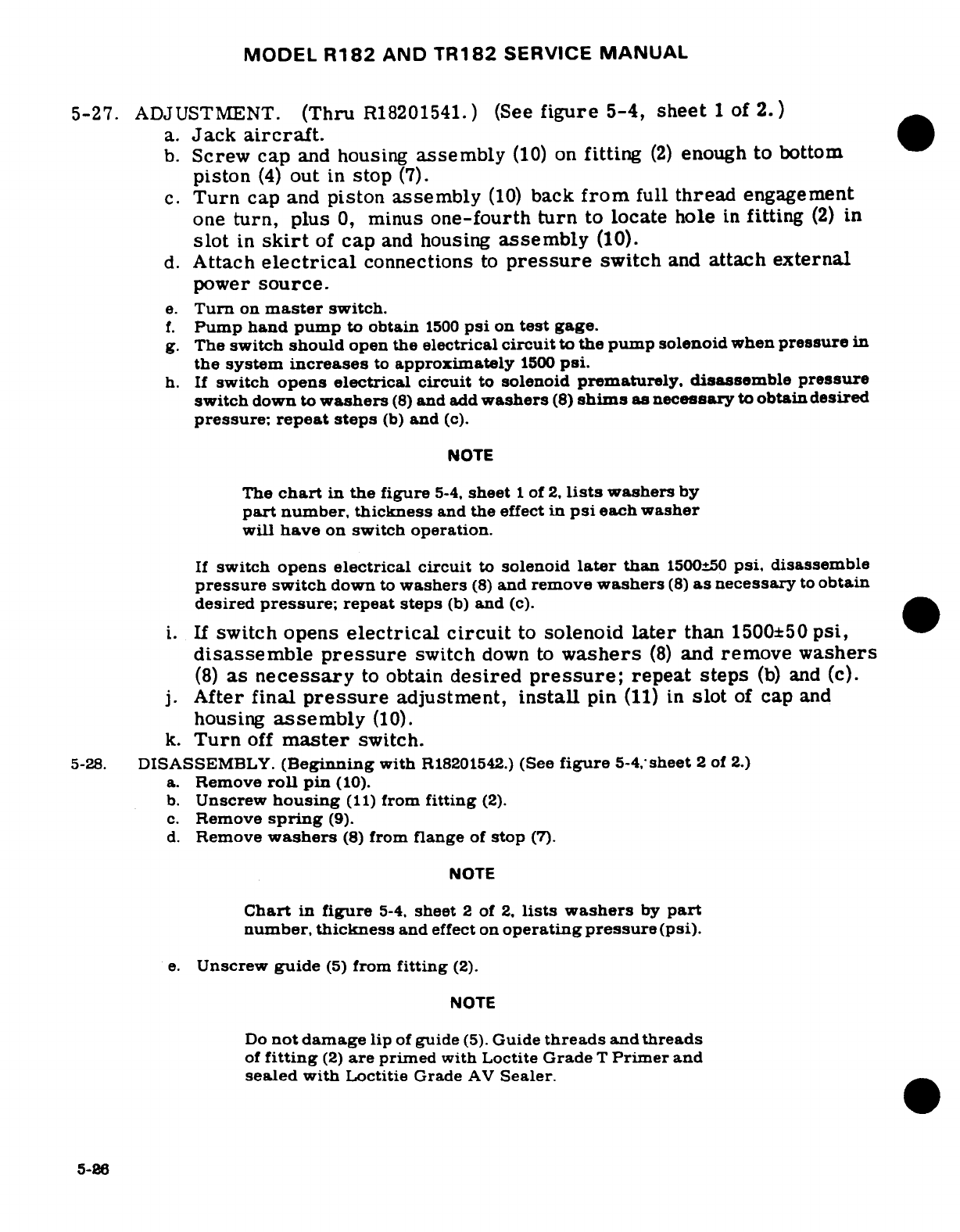
MODEL
R182
AND
TR182
SERVICE
MANUAL
5-27.
ADJUSTMENT.
(Thru
R18201541.)
(See
figure
5-4,
sheet
1
of
2.)
a.
Jack
aircraft.
b.
Screw
cap
and
housing
assembly
(10)
on
fitting
(2)
enough
to
bottom
piston
(4)
out
in
stop
(7).
c.
Turn
cap
and
piston
assembly
(10)
back
from
full
thread
engagement
one
turn,
plus
0,
minus
one-fourth
turn
to
locate
hole
in
fitting
(2)
in
slot
in
skirt
of
cap
and
housing
assembly
(10).
d.
Attach
electrical
connections
to
pressure
switch
and
attach
external
power
source.
e.
Turn
on
master
switch.
f.
Pump
hand
pump
to
obtain
1500
psi
on
test
gage.
g.
The
switch
should
open
the
electrical
circuit
to
the pump solenoid
when
pressure
in
the
system
increases
to
approximately
1500
psi.
h.
If
switch
opens
electrical circuit
to
solenoid
prematurely,
disassemble
pressure
switch
down
to
washers
(8)
and
add
washers
(8)
shims
as
necessary
to
obtain
desired
pressure;
repeat
steps
(b)
and
(c).
NOTE
The
chart
in
the figure
5-4.
sheet
1
of
2,
lists
washers
by
part
number,
thickness
and
the
effect
in
psi
each washer
will
have
on
switch
operation.
If
switch
opens
electrical
circuit
to
solenoid
later
than
1500±50
psi,
disassemble
pressure
switch
down
to
washers
(8)
and
remove
washers
(8)
as
necessary
to
obtain
desired
pressure;
repeat
steps
(b)
and
(c).
i.
If
switch opens
electrical
circuit
to
solenoid
later
than
1500±50
psi,
disassemble
pressure
switch
down
to
washers
(8)
and
remove
washers
(8)
as
necessary
to
obtain
desired
pressure;
repeat steps
(b)
and
(c).
j.
After
final
pressure
adjustment,
install
pin
(11)
in
slot
of
cap
and
housing
assembly
(10).
k.
Turn
off
master
switch.
5-28.
DISASSEMBLY.
(Beginning
with
R18201542.)
(See
figure
5-4,
sheet
2
of
2.)
a.
Remove
roll
pin
(10).
b.
Unscrew
housing
(11)
from
fitting
(2).
c.
Remove
spring
(9).
d.
Remove
washers
(8)
from
flange
of
stop
(7).
NOTE
Chart
in
figure
5-4,
sheet
2
of
2.
lists
washers
by
part
number,
thickness
and
effect on
operating
pressure
(psi).
e.
Unscrew
guide
(5)
from
fitting
(2).
NOTE
Do
not
damage
lip
of
guide
(5).
Guide
threads
and
threads
of
fitting
(2)
are
primed
with
Loctite
Grade
T
Primer
and
sealed
with
Loctitie
Grade
AV
Sealer.
5-26
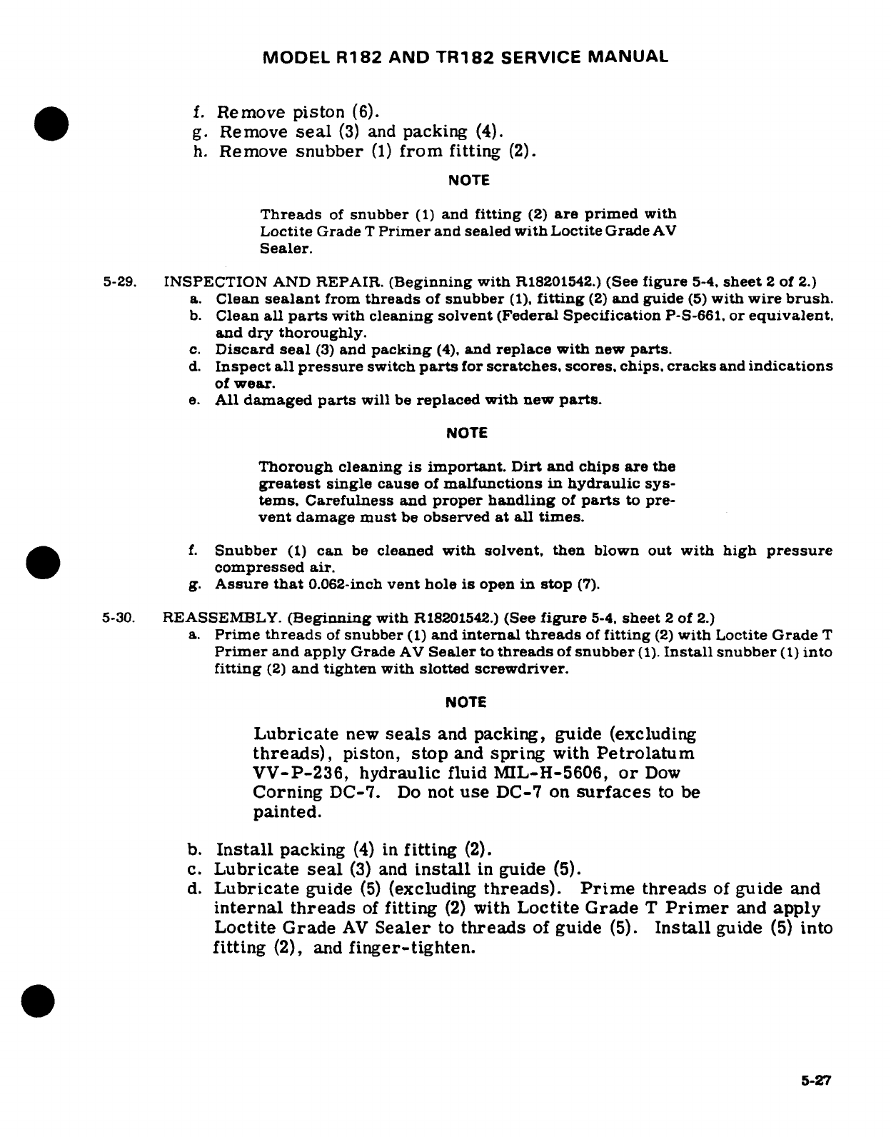
MODEL
R182
AND
TR182
SERVICE
MANUAL
f.
Remove
piston
(6).
g.
Remove
seal
(3)
and
packing
(4).
h.
Remove
snubber
(1)
from
fitting
(2).
NOTE
Threads
of
snubber
(1)
and
fitting
(2)
are
primed
with
Loctite
Grade
T
Primer
and sealed
with
Loctite
Grade
AV
Sealer.
5-29.
INSPECTION
AND
REPAIR.
(Beginning
with
R18201542.)
(See
figure
5-4.
sheet
2
of
2.)
a.
Clean
sealant
from
threads
of
snubber
(1),
fitting
(2)
and guide
(5)
with
wire
brush.
b.
Clean
all
parts
with
cleaning solvent
(Federal Specification
P-S-661,
or
equivalent.
and
dry
thoroughly.
c.
Discard
seal
(3)
and
packing
(4).
and
replace
with
new
parts.
d.
Inspect
all pressure
switch
parts
for
scratches,
scores,
chips,
cracks
and
indications
of
wear.
e.
All
damaged
parts
will
be
replaced with
new
parts.
NOTE
Thorough
cleaning
is
important.
Dirt
and
chips
are
the
greatest
single
cause
of
malfunctions
in
hydraulic
sys-
tems,
Carefulness
and
proper
handling
of
parts
to
pre-
vent
damage
must
be
observed
at
all times.
f.
Snubber
(1)
can
be
cleaned
with
solvent,
then
blown
out
with high
pressure
compressed
air.
g.
Assure
that
0.062-inch
vent
hole
is
open
in
stop
(7).
5-30.
REASSEMBLY.
(Beginning
with
R18201542.)
(See
figure
5-4.
sheet
2
of
2.)
a.
Prime
threads
of
snubber
(1)
and
internal
threads
of
fitting
(2)
with
Loctite
Grade
T
Primer
and
apply
Grade
AV
Sealer
to
threads
of
snubber
(1).
Install
snubber
(1)
into
fitting
(2)
and
tighten
with
slotted
screwdriver.
NOTE
Lubricate
new
seals
and
packing,
guide (excluding
threads),
piston,
stop
and
spring
with
Petrolatum
VV-P-236,
hydraulic
fluid MIL-H-5606,
or
Dow
Corning
DC-7.
Do
not
use
DC-7
on
surfaces
to
be
painted.
b.
Install
packing
(4)
in
fitting
(2).
c.
Lubricate
seal
(3)
and
install
in
guide
(5).
d.
Lubricate
guide
(5)
(excluding
threads).
Prime
threads
of
guide
and
internal
threads
of
fitting
(2)
with
Loctite
Grade
T
Primer
and
apply
Loctite Grade
AV
Sealer
to
threads
of
guide
(5).
Install
guide
(5)
into
fitting
(2),
and
finger-tighten.
5-27
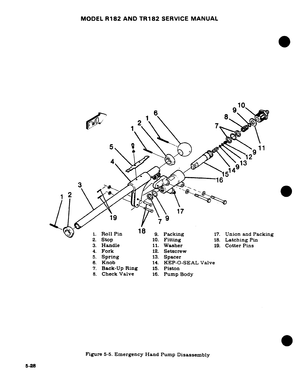
MODEL
R182
AND
TR182
SERVICE
MANUAL
2. Stop
10.
Fitting
18.
Latching
Pn10
3.
Handle
11.
Washer
19.
Cotter Pins
4.
Fork
12.
Setscrew
171~
~1
J4
13
1.
Soll
Ping
13
9.
Pa
g
17.
Union
and Packincerg
2.
Stop
10.
Fitting
18.
Latching
Pin
3.
Handle
11.
Washer
19.
Cotter
Pins
4.
Fork
12.
Setscrew
5.
Spring
13.
Spacer
6.
Knob
14.
KEP-O-SEAL
Valve
7.
Back-Up
Ring
15.
Piston
8.
Check
Valve
16.
Pump
Body
Figure
5-5.
Emergency
Hand
Pump
Disassembly
5-28
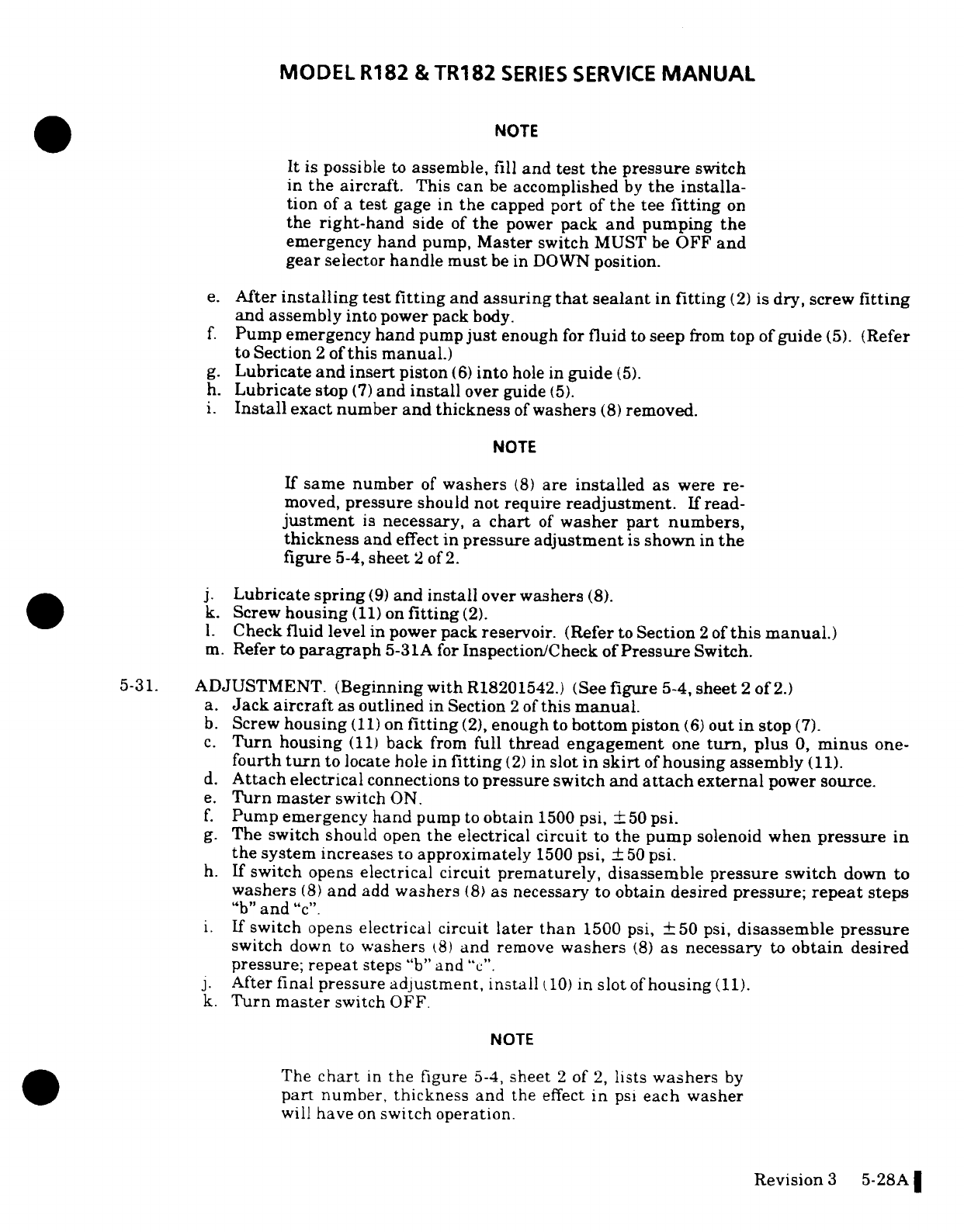
MODEL
R182
&
TR182
SERIES
SERVICE
MANUAL
NOTE
It
is
possible
to
assemble,
fill
and
test the
pressure
switch
in
the aircraft.
This
can
be
accomplished
by
the
installa-
tion
of
a
test
gage
in
the
capped
port
of
the
tee
fitting
on
the
right-hand
side
of
the
power
pack
and
pumping
the
emergency
hand
pump,
Master
switch
MUST
be
OFF
and
gear
selector
handle
must
be
in
DOWN
position.
e.
After
installing
test
fitting
and
assuring
that
sealant
in
fitting
(2)
is
dry,
screw
fitting
and assembly
into
power
pack
body.
f.
Pump
emergency
hand
pump
just
enough
for
fluid
to
seep
from
top of
guide
(5).
(Refer
to
Section
2
of
this
manual.)
g.
Lubricate
and
insert
piston
(6)
into
hole
in
guide
(5).
h.
Lubricate
stop
(7)
and
install
over guide
(5).
i.
Install
exact
number and thickness
of
washers
(8)
removed.
NOTE
If
same
number
of
washers
(8)
are
installed
as
were
re-
moved,
pressure
should
not
require
readjustment.
If
read-
justment
is
necessary,
a
chart
of
washer
part
numbers,
thickness
and
effect
in
pressure
adjustment
is
shown
in
the
figure
5-4,
sheet
2
of
2.
j.
Lubricate
spring
(9)
and
install
over
washers
(8).
k.
Screw
housing
(11)
on
fitting
(2).
l.
Check
fluid
level
in
power pack
reservoir.
(Refer
to
Section
2
of
this
manual.)
m.
Refer to
paragraph
5-31A
for
Inspection/Check
of
Pressure
Switch.
5-31.
ADJUSTMENT.
(Beginning
with
R18201542.)
(See
figure
5-4,
sheet
2
of
2.)
a.
Jack
aircraft
as
outlined
in
Section
2
of
this
manual.
b.
Screw
housing
(11)
on
fitting
(2),
enough
to
bottom
piston
(6)
out
in
stop
(7).
c.
Turn
housing
(11)
back
from
full
thread engagement
one
turn,
plus
0,
minus
one-
fourth
turn
to
locate
hole
in
fitting
(2)
in
slot
in
skirt
of
housing
assembly
(11).
d.
Attach
electrical
connections
to
pressure
switch
and
attach
external
power
source.
e.
Turn
master
switch
ON.
f.
Pump
emergency
hand
pump
to
obtain
1500
psi,
±
50
psi.
g.
The
switch
should
open
the
electrical
circuit
to
the
pump
solenoid
when
pressure
in
the
system
increases
to
approximately
1500
psi,
±
50
psi.
h.
If
switch
opens
electrical circuit
prematurely,
disassemble
pressure
switch
down
to
washers
(8)
and
add
washers
(8)
as
necessary to
obtain
desired
pressure;
repeat
steps
"b"
and
"c".
i.
If
switch
opens
electrical
circuit
later
than
1500 psi,
±
50
psi,
disassemble
pressure
switch
down
to
washers
(8)
and
remove
washers
(8)
as
necessary
to
obtain
desired
pressure;
repeat
steps
"b"
and
"c".
j.
After
final
pressure
adjustment, install
10)
in
slot
of
housing
(11).
k.
Turn
master
switch
OFF.
NOTE
The
chart
in
the
figure
5-4,
sheet
2
of
2,
lists
washers
by
part
number,
thickness
and
the
effect
in
psi
each washer
will
have
on
switch operation.
Revision
3
5-28A
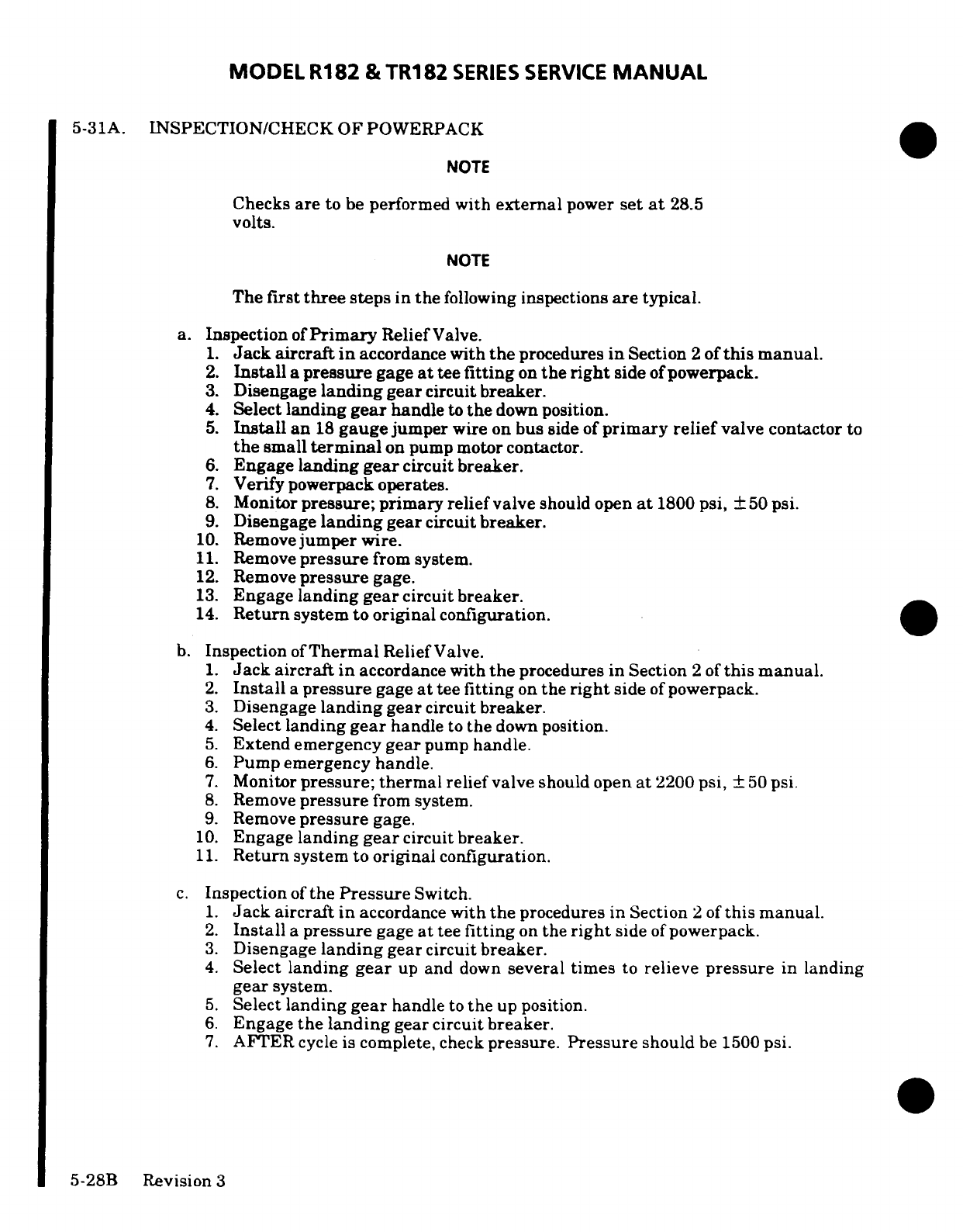
MODEL
R182
&TR182
SERIES
SERVICE
MANUAL
5-31A.
INSPECTION/CHECK OF
POWERPACK
NOTE
Checks
are
to
be
performed
with
external
power
set
at
28.5
volts.
NOTE
The
first
three
steps
in
the
following
inspections
are
typical.
a.
Inspection
of
Primary
Relief
Valve.
1.
Jack
aircraft
in
accordance
with
the
procedures
in
Section
2
of
this
manual.
2.
Install
a
pressure
gage
at
tee
fitting
on
the
right
side
ofpowerpack.
3.
Disengage
landing
gear
circuit breaker.
4.
Select
landing
gear
handle
to
the
down
position.
5.
Install
an
18
gauge
jumper
wire
on
bus
side
of
primary
relief
valve
contactor
to
the
small
terminal
on
pump
motor
contactor.
6.
Engage
landing
gear
circuit breaker.
7.
Verify
powerpack
operates.
8.
Monitor
pressure; primary relief
valve
should open
at
1800
psi,
50
psi.
9.
Disengage
landing
gear
circuit
breaker.
10.
Remove
jumper
wire.
11.
Remove
pressure
from
system.
12.
Remove
pressure
gage.
13.
Engage
landing
gear
circuit breaker.
14.
Return
system
to
original
configuration.
b.
Inspection
of
Thermal
Relief
Valve.
1.
Jack
aircraft in
accordance
with
the
procedures in Section
2
of
this
manual.
2.
Install
a
pressure
gage
at
tee
fitting
on
the
right
side
of
powerpack.
3.
Disengage
landing
gear
circuit
breaker.
4.
Select
landing
gear
handle
to
the
down
position.
5.
Extend
emergency
gear
pump
handle.
6.
Pump
emergency
handle.
7.
Monitor
pressure;
thermal
relief
valve
should
open
at
2200 psi,
50
psi.
8.
Remove
pressure
from system.
9.
Remove
pressure
gage.
10.
Engage
landing
gear
circuit
breaker.
11.
Return
system
to
original
configuration.
c.
Inspection
of
the
Pressure
Switch.
1.
Jack
aircraft
in
accordance
with
the
procedures
in
Section
2
of
this
manual.
2.
Install
a
pressure
gage
at
tee
fitting
on
the
right
side
of
powerpack.
3.
Disengage
landing
gear
circuit
breaker.
4.
Select
landing
gear
up
and
down
several
times
to
relieve
pressure
in
landing
gear
system.
5.
Select
landing
gear
handle
to
the
up position.
6.
Engage
the landing
gear
circuit
breaker.
7. AFTER
cycle is
complete,
check
pressure.
Pressure
should
be
1500
psi.
5-28B
Revision
3
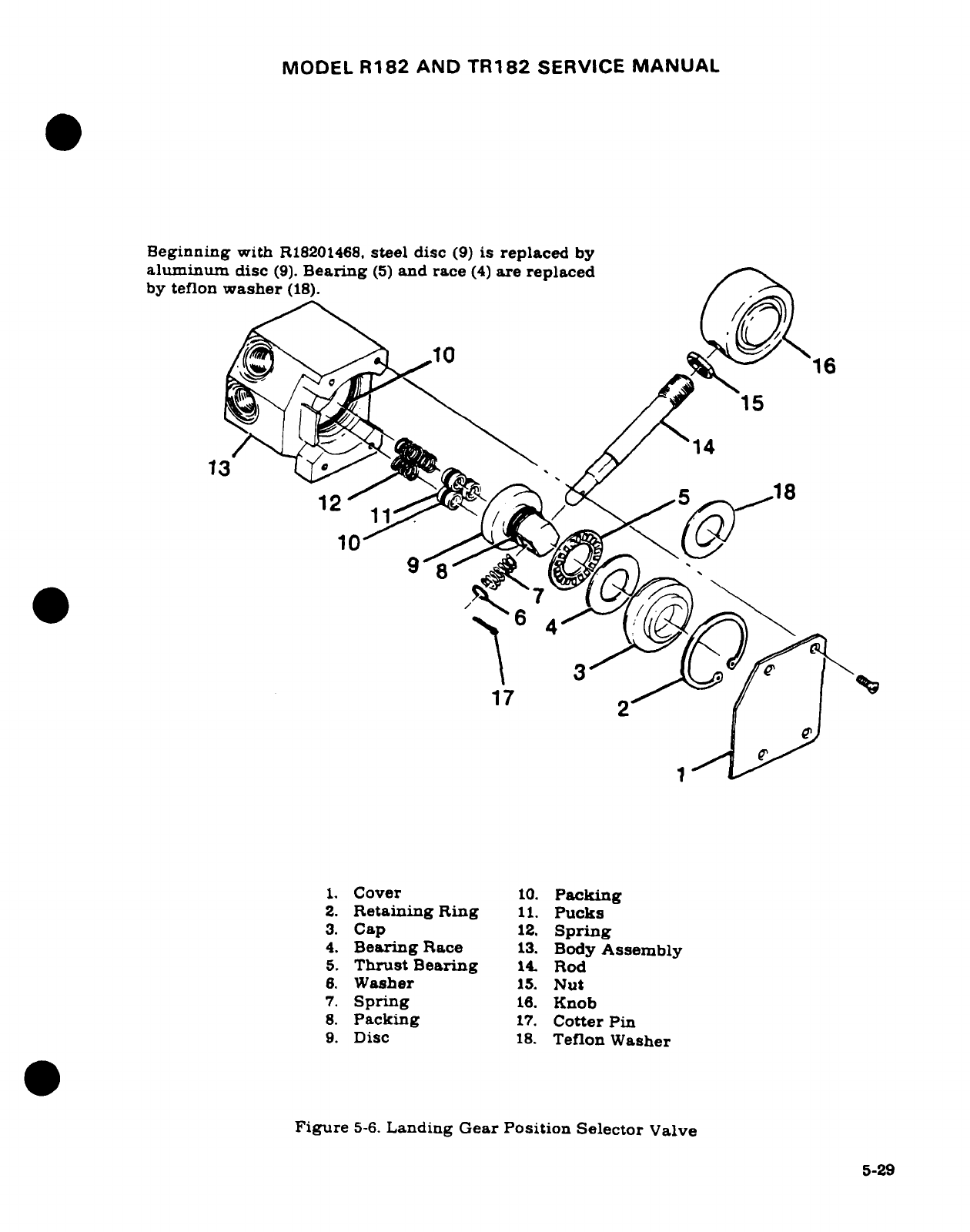
MODEL
R182
AND
TR182
SERVICE
MANUAL
Beginning
with
R18201468,
steel
disc
(9)
is
replaced
by
aluminum
disc
(9).
Bearing
(5)
and
race
(4)
are
replaced
by
teflon
washer
(18).
10
916
15
11
i 3 j'
17
1.
Cover
10.
Packing
2.
Retaining
Ring
11.
Pucks
3.
Cap
12.
Spring
4.
Bearing
Race
13.
Body
Assembly
5.
Thrust
Bearing
14.
Rod
6.
Washer
15.
Nut
7.
Spring
16.
Knob
8.
Packing
17.
Cotter
Pin
9.
Disc
18.
Teflon
Washer
Figure
5-6.
Landing Gear
Position
Selector
Valve
5-29
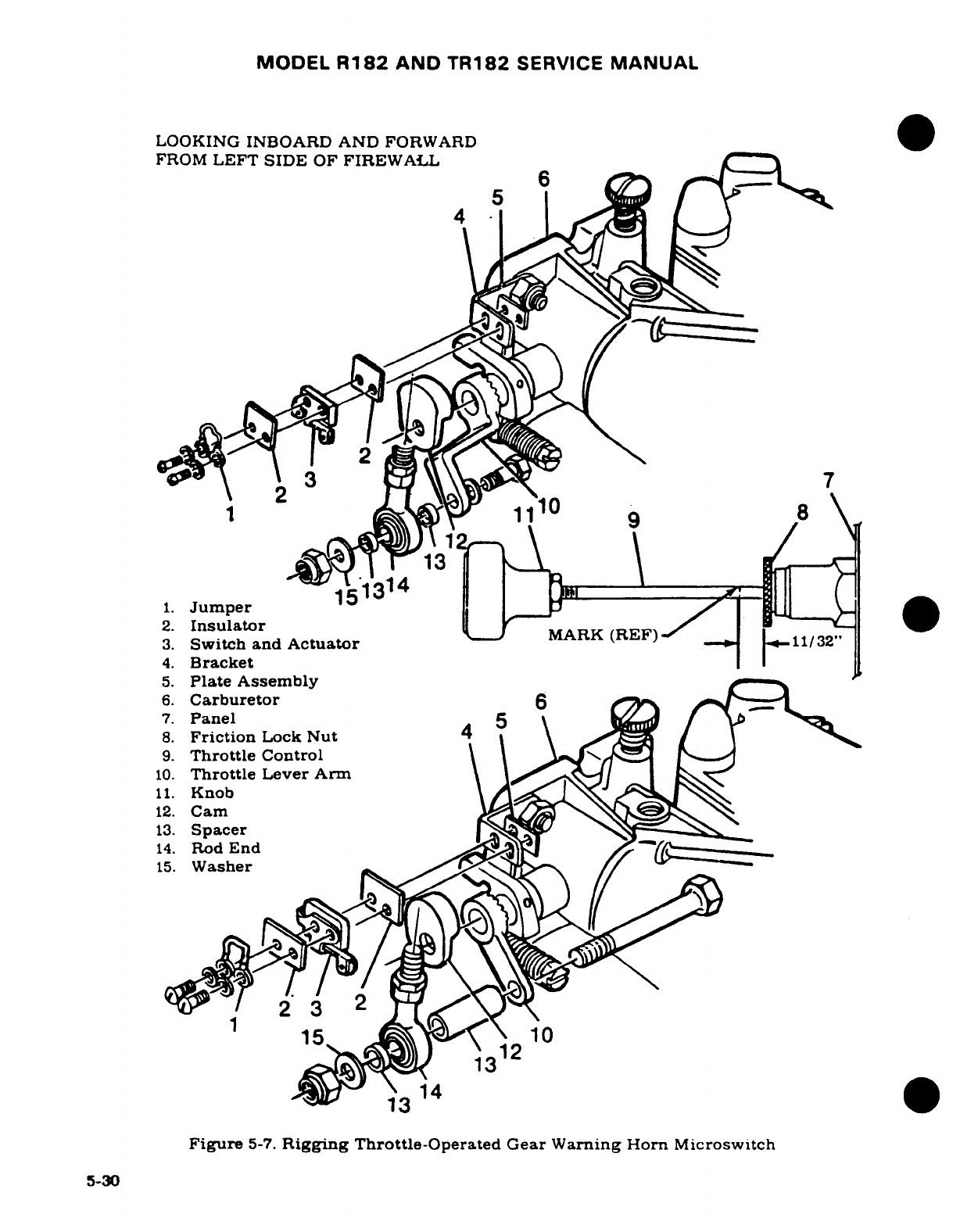
MODEL
R182
AND
TR182
SERVICE
MANUAL
LOOKING
INBOARD
AND
FORWARD
FROM
LEFT
SIDE
OF
FIREWALL
-2
7
10
8
151314
1.
Jumper
2.
Insulator
3.
Switch
and
ActuatorRK
(REF)
4.
Bracket
5.
Plate
Assembly
6.
Carburetor
6
7.
Panel
5
8.
Friction
Lock
Nut
4
9.
Throttle
Control
10.
Throttle
Lever
Arm
11.
Knob
12.
Cam
13.
Spacer
14.
Rod
End
_v
15.
Washer
2'
3
2
15
10
3
12
14
13
Figure
5-7.
Rigging
Throttle-Operated
Gear
Warning Horn
Microswitch
5-30
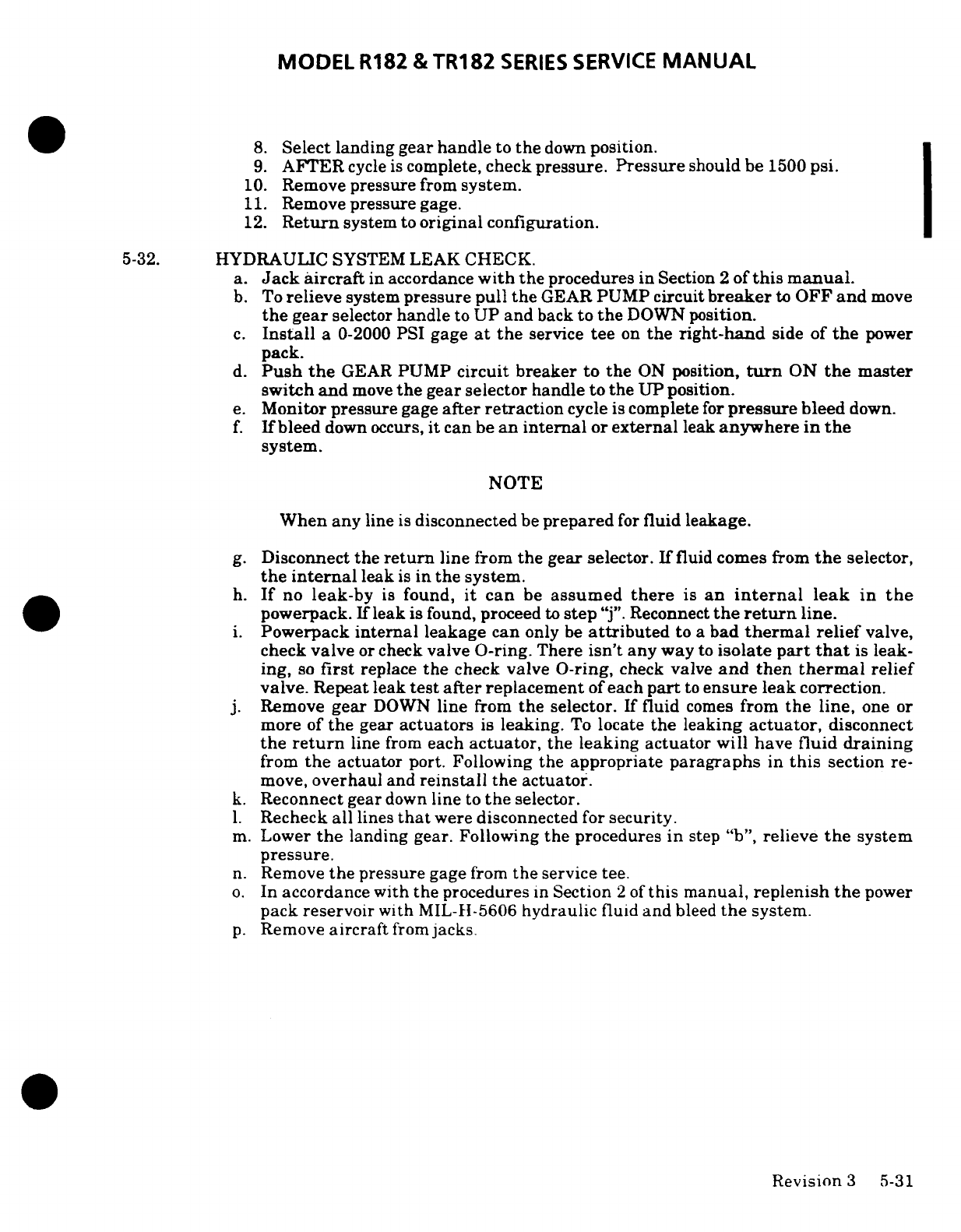
MODEL
R182
&
TR182
SERIES
SERVICE
MANUAL
8.
Select
landing
gear handle
to
the
down
position.
9.
AFTER
cycle
is
complete,
check
pressure.
Pressure
should
be
1500
psi.
10.
Remove
pressure
from
system.
11.
Remove
pressure
gage.
12.
Return
system
to
original
configuration.
5-32.
HYDRAULIC
SYSTEM
LEAK
CHECK.
a.
Jack
aircraft
in
accordance
with the
procedures
in
Section
2
of
this
manual.
b.
To
relieve
system
pressure
pull
the
GEAR
PUMP
circuit
breaker
to
OFF
and
move
the
gear
selector
handle
to
UP
and
back
to
the
DOWN
position.
c.
Install
a
0-2000
PSI
gage
at
the
service
tee
on
the
right-hand
side
of
the
power
pack.
d.
Push
the
GEAR
PUMP
circuit
breaker
to
the
ON
position,
turn
ON
the
master
switch
and
move
the
gear
selector handle
to
the
UP position.
e.
Monitor
pressure
gage
after retraction
cycle
is
complete
for
pressure
bleed
down.
f.
If
bleed
down
occurs,
it
can
be
an
internal
or
external
leak
anywhere
in
the
system.
NOTE
When
any
line
is
disconnected
be
prepared
for
fluid
leakage.
g.
Disconnect
the
return
line
from
the
gear selector.
If
fluid
comes
from
the
selector,
the
internal
leak
is
in
the system.
h.
If
no
leak-by
is
found,
it
can
be
assumed
there
is
an
internal
leak
in
the
powerpack.
If
leak
is
found, proceed
to
step
"j". Reconnect
the
return
line.
i.
Powerpack
internal
leakage
can
only
be
attributed
to
a
bad
thermal
relief
valve,
check
valve
or
check
valve O-ring.
There
isn't
any
way
to
isolate
part
that
is
leak-
ing,
so
first
replace
the
check
valve
O-ring,
check
valve
and
then
thermal
relief
valve. Repeat
leak
test
after
replacement
of
each
part
to
ensure
leak
correction.
j.
Remove
gear
DOWN
line
from
the
selector.
If
fluid
comes
from
the
line,
one
or
more
of
the
gear
actuators
is
leaking.
To
locate
the
leaking
actuator,
disconnect
the
return
line
from
each
actuator,
the
leaking
actuator
will
have
fluid
draining
from
the
actuator
port.
Following
the
appropriate
paragraphs
in
this
section
re-
move,
overhaul
and
reinstall
the actuator.
k.
Reconnect gear
down
line
to
the
selector.
1.
Recheck
all
lines
that
were
disconnected
for
security.
m.
Lower
the
landing gear.
Following
the
procedures
in
step
"b",
relieve
the
system
pressure.
n.
Remove
the
pressure
gage
from
the
service tee.
o.
In accordance
with
the
procedures
in
Section 2
of
this
manual,
replenish
the
power
pack
reservoir
with
MIL-II-5606
hydraulic
fluid
and
bleed
the
system.
p.
Remove
aircraft
from
jacks.
Revision
3
5-31
MODEL
R182
AND
TR182
SERVICE
MANUAL
5-33.
EMERGENCY
HAND
PUMP.
(See
figure
5-5.)
5-34.
DESCRIPTION.
The
emergency
hand pump
is mounted
below
the
floor
between
the
pilot
and
copilot
seats.
The
pump
handle
extends into
the
cabin
and
is
enclosed by
a
hinged
cover.
The
pump
supplies
a
flow
of
pressurized
hydraulic
fluid
to
extend the
landing
gear
in
the
event
of
normal
hydraulic
pump
failure.
5-35.
REMOVAL
AND
INSTALLATION.
a.
Remove
seats
as
required
for
access.
b.
Remove
screws
attaching
cover
over
hand
pump
and
remove
cover.
c.
Peel
back
carpet
as
required
for
access
to
pump
mounting
bolts.
d.
Wedge
cloth
under
hydraulic
fittings
to
absorb fluid,
then
disconnect
the
two
hydraulic
lines
and
plug
or
cap
open
fittings
to
prevent
entry
of
foreign material.
e.
Remove
two
bolts,
washers
and
nuts
securing
pump
to
mounting
bracket.
f.
Work
pump
from
aircraft.
g.
Install
hand
pump
by
reversing
the
preceding
steps,
bleeding
lines
and
pump
as
lines
are
connected.
h.
Fill
reservoir
as
required.
5-36.
DISASSEMBLY.
(See
figure
5-5.)
NOTE
After
emergency
hand
pump
has
been
removed
from
aircraft
and
ports
are
capped
or
plugged,
spray
with
cleaning solvent
(Federal
Specification
P-S-611,
or
equi-
valent)
to
remove
all
accumulated
dust
or
dirt.
Dry
with
filtered
compressed air.
a. Remove
handle
(3)
by
removing
latching
pins
(18)
after
removing
cotter
pins
(19).
b.
Remove
fitting
(10)
from
pump
body
(16).
c.
Push
piston
(15)
from
pump
body
(16).
d.
Remove
retaining
ring
from
end
fitting
(10)
to
remove
valve
assemblies
(8)
and
(14).
e.
Remove
and
discard
all
packings
and
back-up
rings.
5-32
MODEL
R182
AND
TR182
SERVICE
MANUAL
5-37.
INSPECTION
AND
REPAIR.
a.
Inspect seating
surfaces
of
valves.
b.
Inspect
piston
for
scores,
burrs
or scratches
which
could
cut
packings.
This
is a
major
cause
of
external
and
internal
leakage.
The
piston
may
be
polished
with
extremely
fine
emery
paper.
Never
use
paper
coarser
than
No.
600
to
remove
scratches
or
burns.
If
defects
do
not
polish
out,
replace
piston.
NOTE
Lubricate
new
seals
and
packings
with
Petrolatum
VV-P-236, hydraulic
fluid
MIL-H-5606,
or
Dow-
Corning
DC-7.
Do
not
use
DC-7
on
surfaces
to
be
painted.
5-38.
REASSEMBLY.
(See
figure
5-5.)
Assemble
the
emergency
hand
pump.
using
the
figure
as
a
guide.
Also,
for
detailed
instructions, reverse
the
procedures
outlined
in
paragraph
5-35.
During
assembly
prime
parts
with
Primer
T.
Fill
first
three threads
of
fitting
(10)
with
Loctite
Hydraulic
Sealant.
Install
fitting
in
pump
body
(16).
and
allow
parts
to
set up for
one
hour
at
72°F.
Pump
should
be
held
vertically,
with
fitting
(10)
at
top
during
setting
up
of
sealant.
5-39.
LANDING
GEAR
SELECTOR
VALVE.
(See
figure
5-6.)
.
5-40.
DESCRIPTION.
A
mechanical gear
position
selector valve
is
located
in
the switch
panel.
The
pilot
shuttles
the
valve mechanically
when
he
changes
gear
handle
position.
The
handle
must
be
pulled out
prior
to
selecting
gear position.
Moving
the selector
rod
opens
and
closes
ports
in
the
valve,
enabling
fluid
under
pressure
to
flow
to
the
various system
components
to
retract
or
extend
the
landing
gear.
5-41.
REMOVAL
AND INSTALLATION.
(See
figure
5-6.)
a.
Loosen
nut
(15)
and remove
knob
(16).
CAUTION
As
hydraulic
lines are
disconnected,
fluid
will
leak.
Precautions must
be
taken
to
prevent
excessive
leakage.
such
as spreading
drip cloths
under
fittings
and
capping
lines
and
fittings.
5-33
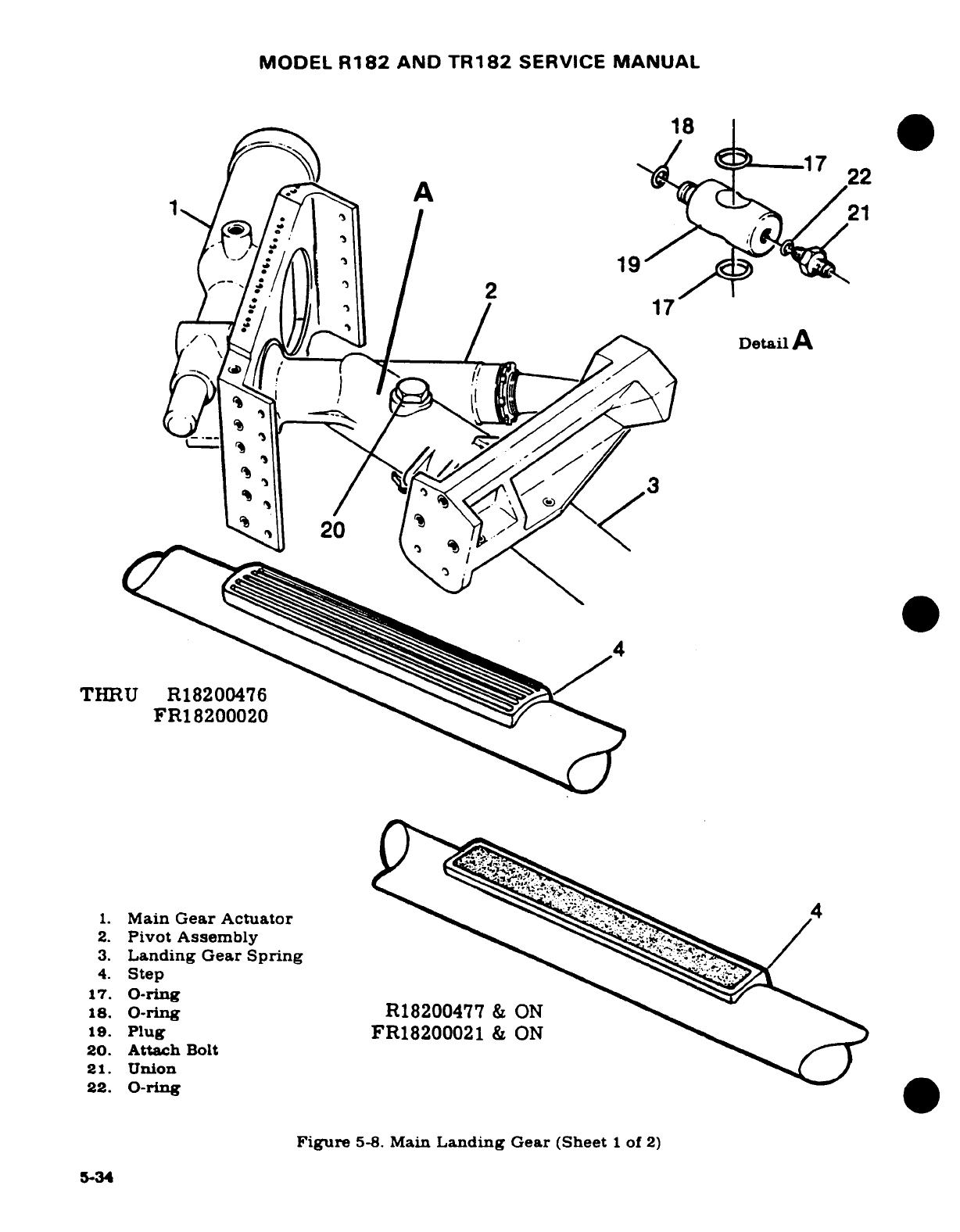
MODEL
R182
AND
TR182
SERVICE
MANUAL
X-X
118
17
22
V \> ,~/i~
I
I
/
~<^>\
~
~Detail
A
17.0-ring
17
1 uFR182000002
20
1.
Main
Gear
Actuator
4
2.
Pivot
Assembly
3.
Landing
Gear
Spring
17.
0-ring
18.
0-ring
R18200477
&
ON
19.
Plug
FR18200021
&
ON
20.
Attach
Bolt
21.
Union
22.
O-ring
Figure
5-8.
Main
Landing
Gear
(Sheet
1
of
2)
5-34
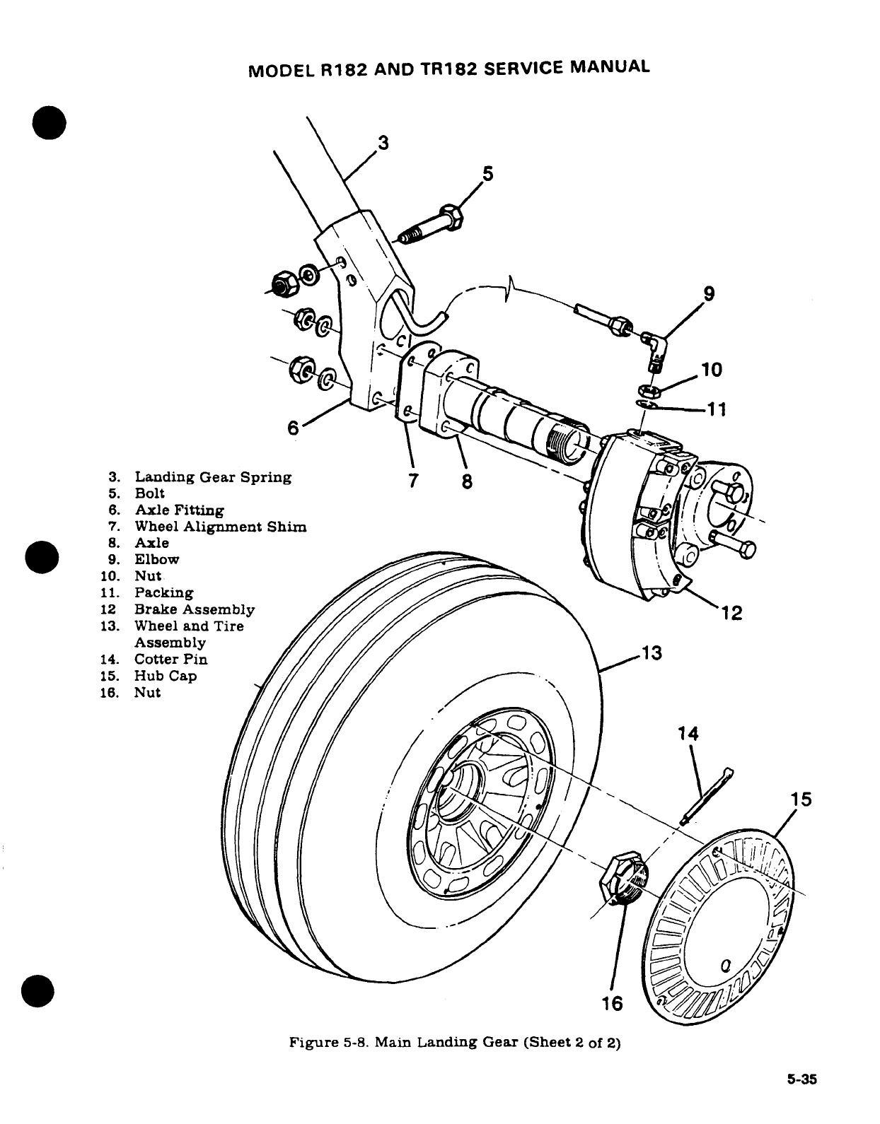
MODEL
R182
AND
TR182
SERVICE
MANUAL
b.
Disconnect four
hydraulic
lines
routed
to
valve.
c.
Remove
screws
attaching
valve
to
instrument
panel.
d.
Remove
selector valve.
e.
Reverse
preceding
steps
to
install
gear
selector
valve.
5-42.
DISASSEMBLY
AND
REASSEMBLY.
(See
figure
5-6.)
a.
Remove
cover
(1),
retaining
ring
(2),
cap
(3),
bering
race
(4)
and
thrust
bearing
(5).
b.
Remove
cotter
pin,
(17),
washer
(6)
and
spring
(7).
c.
Pull
rod
(14)
from
disc
(9);
remove
disc
(9).
d.
Remove
pucks
(11)
and
springs
(12).
e.
Reverse
preceding
steps
for
reassembly.
5-43.
INSPECTION
AND
REPAIR.
(See
figure
5-6.)
Replace
packing
(8)
and
(10).
Check
valve
for
wear,
foreign
or
abrasive
materials.
Thru Serial
R18201460,
disc
(9)
may
be
refaced
(lapped)
if
worn
or
abraded.
Beginning
with
Serial
R18201461,
disc
(9)
is
aluminum
and
should
not
be
refaced. Check
rollers
in
thrust
bearings
(5).
5-44.
RIGGING
THROTTLE-OPERATED
GEAR
WARNING
HORN
MICROSWITCH.
(See
figure
5-7.)
a.
Jack
aircraft
in
accordance
with
procedures
outlined
in
Section
2.
b.
Remove
upper
left
engine
cowling.
c.
Turn
master
switch
ON
and
retract
landing
gear,
turn
master
switch
OFF.
d.
Close
throttle
control
at
panel
(PULL
FULL
OUT.)
NOTE
Assure
that throttle
friction
locknut
is
snug
but
still
will
allow
throttle
to move.
e.
Mark
throttle
control
(9)
11/32-inch aft
of
friction locknut
(8).
f.
At
engine,
loosen
screws
attaching
switch
(3)
to
bracket.
Raise
switch
to
approxi-
mate
middle
of
slots
in
bracket;
tighten
screws.
g.
Loosen
nut
attaching
cam
(12).
Rotate
cam
to
cause
switch
to
actuate
just
as
switch
roller
breaks
over
peak
of
cam.
Tighten
cam-attach
nut.
h.
Open
throttle
(PUSH
FULL-IN)
and
turn
master
switch
ON.
i.
PUll
throttle
OUT
to
mark;
gear
warning
horn
should
sound.
j.
Readjust
if
necessary.
k.
Extend
landing
gear,
turn
master
switch
OFF
and lower
aircraft;
install
engine
cowling.
1.
Test
fly
aircraft.
At
approximately
2500
feet
pressure
altitude,
close
throttle
to
mark
on
control.
Warning
horn
should
sound
and
manifold
pressure
gage
should
indicate
11.5
to
12.5
inches
of
mercury.
NOTE
If
manifold
pressure
gage
does
not
indicate
11.5
to
12.5
inches
of
mercury
at
mark
on
throttle
control
(9),
erase
mark
and
mark
correctly
upon
closing
throttle
at
11.5
to
12.5
inches
of
mercury
in
flight.
Upon
landing readjust
microswich
in
bracket slots
or
rotate
cam
as
necessary
to
cause
switch
to
actuate
as
roller
breaks
over
peak
of
cam.
5-36
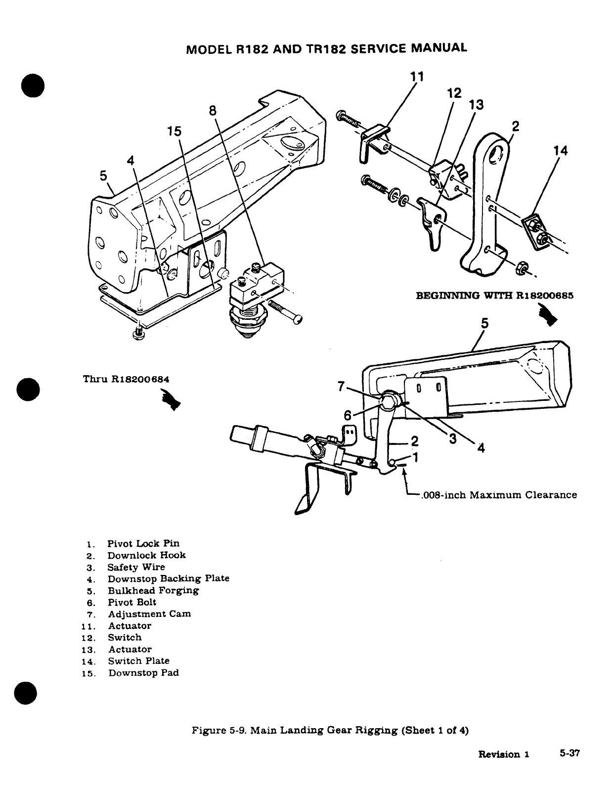
MODEL
R182
AND
TR182
SERVICE
MANUAL
11
BEGINNING
WITH
R18200685
0
12
8'~~ 5~~~13
II -I
5
/
Thru
R18200684
/
~_t~
-.
008-inch
Maximum
Clearance
1.
Pivot
Lock
Pin
2.
Downlock
Hook
3.
Safety
Wire
4.
Downstop
Backing Plate
5.
Bulkhead
Forging
6.
Pivot
Bolt
7.
Adjustment
Cam
11.
Actuator
12.
Switch
13.
Actuator
14.
Switch
Plate
15.
Downstop
Pad
Figure
5-9.
Main
Landing
Gear
Rigging
(Sheet
1
of
4)
Revision
1
5-37
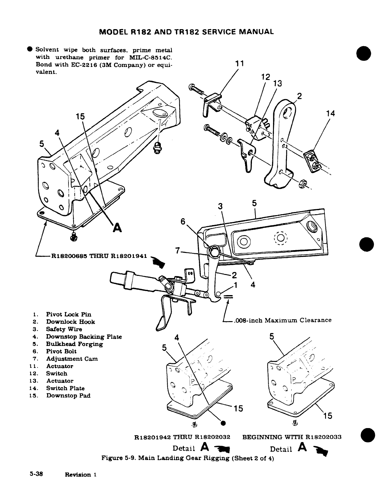
MODEL
R182
AND
TR182
SERVICE
MANUAL
Solvent
wipe
both
surfaces, prime
metal
with
urethane
primer
for
MIL-C-8514C.
Bond
with
EC-2216
(3M
Company)
or
equi-
11
valent.
12
13
152
C,
14
15
C
T
A D^ C,
6
R18200685
THRUIJ
R18201941
L_
1.
Pivot
Lock
Pin
L
2.
Downlock
Hook
/
-.
008-inch
Maximum
Clearance
3.
Safety
Wire
4.
Downstop
Backing
Plate
4 5
5.
Bulkhead
Forging
6.
Pivot
Bolt
\
7.
Adjustment
Cam\
)
.
11.
Actuator
-_
12.
Switch
13.
Actuator
-
14.
Switch
Plate
\
15.
Downstop
Pad-
15
*
R18201942
THRU
R18202032
BEGINNING
WITH
R18202033
Detail
A
a,
Detail
A
Figure
5-9.
Main
Landing
Gear
Rigging
(Sheet
2
of
4)
5-38
Revision
1
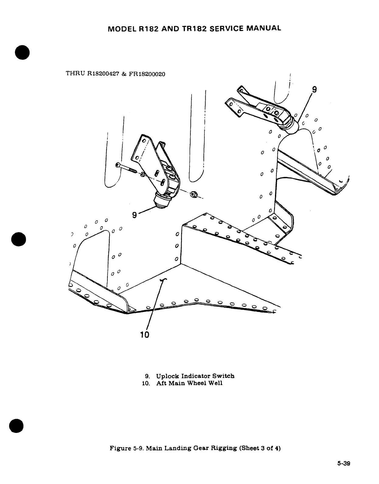
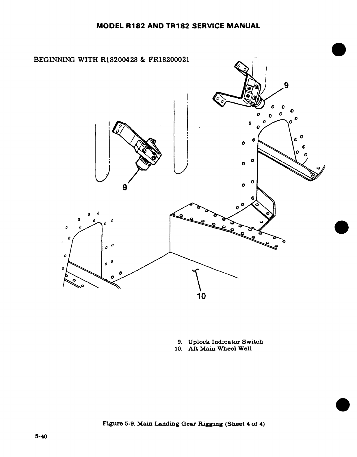
MODEL
R182
AND
TR182
SERVICE
MANUAL
m.
Test
fly
aircraft
and recheck
adjustment.
5-45.
RIGGING
FLAP OPERATED
GEAR
WARNING
SYSTEM.
NOTE
Throttle
operated
gear warning
system.
flap
control
system
and flap
follow-up
system
must
be
rigged
in
accordance
with procedures outlined
in
Sections
5
and
7
before
rigging
of
flap
warning system
can
be
accomp-
lished.
a. The
gear
warning
switch
is located
forward of
the
flap
controll
lever
behind
the
instrument
panel.
b.
Loosen
screws
attaching
gear warning
microswitch
in
slots
of
mounting
bracket.
c.
Mount
an
inclinometer
on one
flap
and
set
to
0°
(flaps
full
UP).
Turn
master
switch
ON
and
move
flap
selector
lever
to
obtain
23
°
flap
deflection.
NOTE
An
inclinometer
for
measuring
control
surfaces
travel
is
available
from
the
Cessna
Supply
Division.
d.
Rotate
microswitch
in
slots
of
mounting bracket
until
switch
contacts
are
just
closed.
and
tighten
switch mounting
screws.
e.
Move
flap
selector
lever
to
0°
position
(flaps
full
UP).
f.
Move
flap
lever
to
30
°
position
and
horn should
not
sound.
Move
flap
selector
handle
back
to
0°
position.
g.
With
throttle
full
FORWARD,
push
landing
gear
DOWN
press-to-test
button, and
move
flap
selector
handle
to
30
°
position;
horn
should
sound
as
flaps
extend
past
23
°.
Move
flap
selector
handle
back
to
20
°
position,
and
horn
should
not
sound.
h.
Readjust
switch
as
necessary
to
cause
horn
to
sound when
flaps
reach
23
°
when
press-to-test
button
is
pushed.
i.
Turn
master
switch
OFF.
remove
inclinometer,
reinstall
headliner.
5-46.
MAIN
LANDING
GEAR.
5-47.
DESCRIPTION.
The
tubular
main
gear
struts
rotate
aft
and
inboard
to
stow
the main
wheels
beneath
the
baggage
compartment.
The
main
gear
utilizes
hydraulic pressure
for
positive
uplock
and
mechanical
downlocks.
Main
gear
uplock
pressure
is
maintained
automatically
by
the
pump
assembly.
Rotation
of
the
gear
to
extend
or
retract
the
struts
is
achieved
through
pivot
assemblies
which
are
in
turn
bolted
through
a
splined
shaft.
to
the
hydraulic
rotary
actuators.
CAUTION
Use
of
recapped
tires
or
new
tires
not
listed
on
the
airplane
equipment
list
are
not
authorized
due
to
possible
interference
between
the
tire
and
structure
when
landing
gear
is
in
the
retracted
position.
Revision
2
5-41
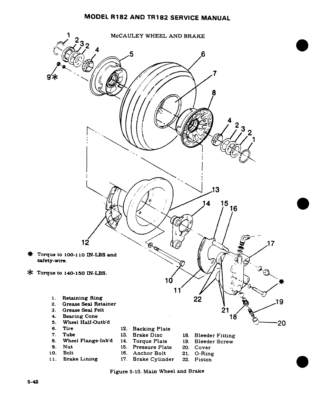
MODEL
R182
AND
TR182
SERVICE
MANUAL
I
McCAULEY
WHEEL
AND
BRAKE
<-
232
5
6
" .
//
'
51
7
,
0/
/
14
1516
12
17
Torque
to
100-110
IN-LBS
and
safety-wire.
C
Torque
to
140-150
IN-LBS.
10
*
1.
Retaining
Ring
22
9
2.
Grease
Seal
Retainer
3.
Grease
Seal Felt
21
4.
Bearing
Cone
18
5.
Wheel
Half-Outb'd
20
6.
Tire
12.
Backing
Plate
7.
Tube
13.
Brake
Disc
18.
Bleeder
Fitting
8.
Wheel
Flange-Inb'd
14.
Torque
Plate
19.
Bleeder
Screw
9.
Nut
15.
Pressure
Plate
20.
Cover
10.
Bolt
16.
Anchor
Bolt
21.
O-Ring
11.
Brake
Lining
17.
Brake
Cylinder
22.
Piston
Figure
5-10.
Main
Wheel
and
Brake
5-42
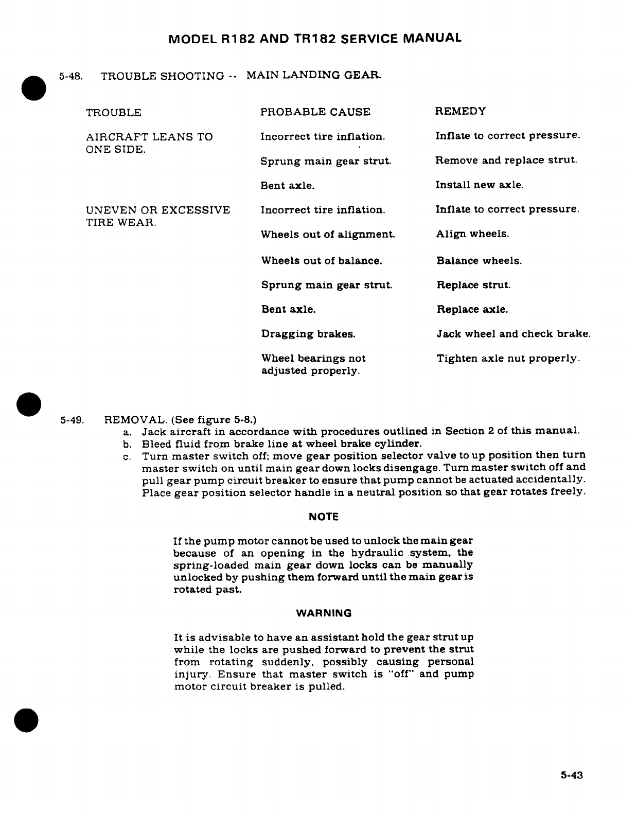
MODEL
R182
AND
TR182
SERVICE
MANUAL
5-48.
TROUBLE
SHOOTING
--
MAIN
LANDING
GEAR.
TROUBLE
PROBABLE
CAUSE
REMEDY
AIRCRAFT
LEANS
TO
Incorrect
tire
inflation.
Inflate
to
correct
pressure.
ONE
SIDE.
Sprung
main gear
strut.
Remove
and
replace
strut.
Bent
axle.
Install
new axle.
UNEVEN
OR
EXCESSIVE
Incorrect
tire
inflation.
Inflate
to
correct
pressure.
TIRE
WEAR.
Wheels
out
of
alignment.
Align
wheels.
Wheels
out
of
balance.
Balance
wheels.
Sprung
main
gear
strut.
Replace
strut.
Bent
axle.
Replace axle.
Dragging
brakes.
Jack
wheel
and
check
brake.
Wheel
bearings
not
Tighten axle
nut
properly.
adjusted properly.
5-49.
REMOVAL.
(See
figure
5-8.)
a.
Jack
aircraft
in
accordance
with
procedures
outlined
in
Section
2
of
this
manual.
b.
Bleed
fluid from
brake
line
at
wheel
brake
cylinder.
c.
Turn
master
switch
off:
move
gear
position
selector
valve
to
up
position
then
turn
master
switch
on
until
main
gear
down
locks
disengage.
Turn
master
switch
off
and
pull
gear
pump
circuit breaker
to
ensure
that
pump cannot
be
actuated
accidentally.
Place
gear
position
selector handle
in
a
neutral
position
so
that
gear
rotates
freely.
NOTE
If
the pump
motor
cannot
be
used
to
unlock
the
main
gear
because
of
an
opening
in
the
hydraulic
system.
the
spring-loaded
main
gear
down
locks
can
be
manually
unlocked
by
pushing
them
forward
until
the main
gear
is
rotated
past.
WARNING
It is
advisable
to
have
an
assistant
hold
the
gear
strut
up
while
the
locks
are
pushed
forward
to
prevent
the
strut
from
rotating
suddenly,
possibly
causing
personal
injury.
Ensure
that
master
switch
is
"off"
and pump
motor
circuit
breaker
is
pulled.
5-43
MODEL
R182
AND TR182
SERVICE
MANUAL
d.
Remove
strut-attaching
bolt
(20)
and
work
strut
(3)
and
plug
(19)
from
pivot.
e.
Disconnect
brake
line from
union
(21)
and
cap
plug
(19),
union
(21).
and
brake
line.
f.
Remove
O-rings
(17),
(18).
and
(22)
from
plug
(19)
and
union
(21).
and
clean
plug
(19)
and
strut
(3).
5-50.
MAIN
GEAR
STRUT INSTALLATION.
(See
figure
5-8.)
a.
Lubricate
new
O-rings
(17),
(18),
and
(22),
plug
(19),
and
end
of
strut
(3)
with Pet-
rolatum
VV-P-236.
hydraulic
fluid
MIL-L-5606,
or
Dow
Corning
DC-7
(keep
DC-7
away
from
areas
to
be
painted)
before
installation.
b.
Remove
cap
and plug
from
union
(21)
and brake
line,
attach
brake
line
to
union,
and
work
plug
(19)
and
strut
(3)
into
pivot
(2).
NOTE
When
installing
a
new
pivot
(2),
burnishing
the
2.100-
inch
I.D.
bore
may
be
required
to
facilitate
assembly
of
the
landing
gear
strut
(3).
c.
Align
hole
in
plug
(19)
and
holes
in
pivot
(2)
using
special
tool No.
SE
934.
NOTE
Special
tool
No.
SE
934
is
available
from
the
Cessna
Sup-
ply Division.
This
tool is
designed
to
install
the
strut
at-
taching
bolt
(20)
without
damaging
the
O-rings
(17).
d.
Install
strut-attaching
bolt
(20) by
pushing
SE
934
tool
through
aligned
holes
of
strut
(3)
and
plug
(19)
with
threaded
end
of
strut-attaching
bolt
(20).
Install
washer
and
nut
and
tighten nut
on
strut-attaching
bolt.
e.
Fill
and
bleed
brake
system
in
accordance
with
paragraph
5-159
of
this
section.
f.
Rig
landing
gear
in
accordance
with
paragraph
5-51
of
this
section.
5-51.
MAIN
GEAR RIGGING.
(Thru
R18200655.)
(See
figure
5-9.)
a.
Jack
aircraft
in
accordance with
procedures outlined
in
Section
2
of
this
manual.
b.
Move
seats
to
forward
position
and
peel
back
carpet
as
necessary
to
uncover
access
panels
above
main
gear
pivot
assemblies.
WARNING
Turn
master
switch
OFF
and
pull
gear
pump
circuit
breaker
to
prevent
accidental
extension
or
retraction
of
the
landing
gear
whenever
work
is
being performed
in
the
wheel
well
or
pivot
area.
c.
Check
clearance
between
latch
(2)
and
pivot
lock
pin
(1)
with
gear
in
down
and
locked
position.
Clearance
must
not
exceed
.008-inch.
d.
If
adjustment
of
latch
is
necessary,
work
through
access
opening
and
remove safety
wire
(3).
Loosen
latch pivot
bolt
(6)
and
turn
cam
(7)
until
clearance
is
within
tolerance,
tighten
bolt
(6).
e.
Insert
a
.025-inch
shim
between
pivot
and
support
pad
(4).
5-44
Revision
1
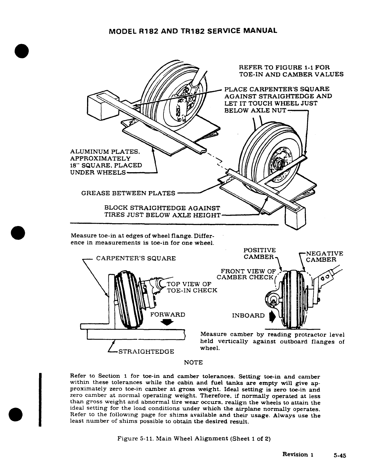
MODEL
R182
AND
TR182
SERVICE
MANUAL
REFER
TO
FIGURE
1-1
FOR
TOE-IN
AND
CAMBER
VALUES
/A
PLACE
CARPENTER'S
SQUARE
AGAINST
STRAIGHTEDGE
AND
LET
IT
TOUCH WHEEL
JUST
BELOW
AXLE
NUT
-
ALUMINUM
PLATES,
APPROXIMATELY
18"
SQUARE,
PLACED
UNDER WHEELS
GREASE
BETWEEN
PLATES
BLOCK
STRAIGHTEDGE
AGAINST
TIRES
JUST
BELOW
AXLE
HEIGHT
Measure
toe-in
at
edges
of
wheel
flange.
Differ-
ence
in
measurements
is
toe-in
for
one
wheel.
POSITIVE
P
NEGATIVE
CARPENTER'S
SQUARE CAMBER
-
CAMBER
~~\
,-^.
~~FRONT
VIEW
OF)2
^
\ _ T -
VIEWOFCAMBER
CHECK
TOP
VIEW
OF
TOE-IN
CHECK
L
FORWARD
INBOARD
M
i
Measure
camber
by
reading
protractor
level
held
vertically
against
outboard
flanges
of
LSTRAIGHTEDGE
wheel.
NOTE
Refer
to
Section
1
for toe-in
and
camber
tolerances.
Setting
toe-in
and
camber
within
these
tolerances
while
the
cabin
and
fuel
tanks
are
empty
will
give
ap-
proximately
zero
toe-in
camber
at
gross
weight.
Ideal
setting
is
zero
toe-in
and
zero
camber
at
normal
operating
weight.
Therefore,
if
normally
operated
at
less
than gross
weight
and abnormal
tire
wear
occurs,
realign
the
wheels
to
attain
the
ideal
setting
for
the
load
conditions
under
which
the
airplane
normally operates.
Refer
to
the
following
page
for
shims
available
and
their
usage.
Always
use
the
least
number
of
shims
possible
to
obtain the
desired
result.
Figure
5-11.
Main
Wheel
Alignment
(Sheet
1
of
2)
Revision
1
5-45
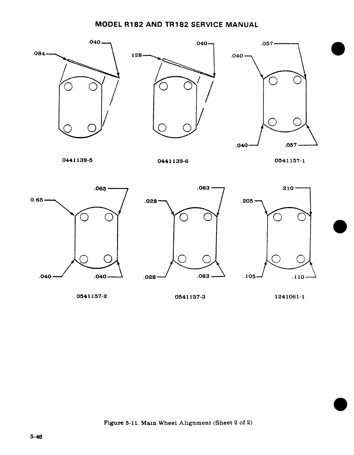
MODEL
R182
AND
TR182
SERVICE
MANUAL
.040
.040
.057
·
084 ,
.128
-
.040
^_^/
0
/0
0
.040
/
.057
0441139-5
0441139-6
0541157-1
.065-
.0637
.210
0.665
.028
/
.205
0\ /00
, A
.040-
.040
.1
.028
03
.105-
.110
0541157-2 0541157-3
1241061-1
Figure
5-11.
Main
Wheel
Alignment
(Sheet
2
of
2)
5-46
MODEL
R182
AND
TR182
SERVICE
MANUAL
WARNING
Stay clear
of
main
gear
when
making
the
following
checks.
f.
Place
gear
position
selector
handle
in
DOWN
position
and
reset
gear
pump circuit
breaker.
Turn
master
switch
ON
and allow
gear
to
rotate
to
full
down
position.
leaving
master
switch
ON.
g.
With
shim
in
place,
latch
(2)
should
not
engage
pin
(1)
and
switch
(8)
should
be
open
(light
off).
h.
With
gear
in
DOWN
and
locked
position
with
no
shim,
indicator switch
(8)
should
be
closed
(light
on).
Adjustment
can
be
made
by
moving
the
switch
up
or
down
in
the
slotted
holes
in
the
mounting
bracket.
i.
Place
gear
position
selector
handle
in
UP
position
and
allow
gear
to
retract
to
UP
position.
j.
Check
that
gear
up
indicator
switches
are
closed
(light
on),
and
some
free-travel
exists
on
switch
plunger (plunger
not
bottomed
out).
Adjust
switch
position
as
necessary.
k.
Lower
gear,
turn master
switch
OFF,
replace panels,
carpeting
and
items
removed
for
access.
Move
seats
back
to
original
positions.
1.
Remove
aircraft
from
jacks.
5-52.
MAIN
GEAR
RIGGING.
(See
figure
5-9,
sheet
2.)
(Beginning with
R18200685.)
a.
Jack
aircraft
in
accordance
with
procedures
outlined
in
Section
2
of
this
manual.
b.
Move
seats
to
forward
position
and
peel
back
carpet
as
necessary
to
uncover
access
panels
above
main
gear pivot
assemblies.
WARNING
Turn
master
switch
OFF
and
pull
gear
pump
circuit
breaker
to
prevent
accidental
extension
or
retraction
of
the
landing
gear
whenever
work
is
being
performed
in
the
wheel
well
or
pivot
area.
Revision
1
5-46A/(5-46B
blank)
MODEL
R182
AND
TR182
SERVICE
MANUAL
c.
Check
clearance
between
downlock
hook
(2)
and
pivot
lock
pin
(1)
with gear
in
down
and
locked
position.
Clearance
must
not
exceed
.008-inch.
d.
If
adjustment
of
hook
is
necessary,
work
through
access
opening
and
remove
safety
wire
(3).
Loosen
hook
pivot
bolt
(6)
and
turn
cam
(7)
until
clearance
is
within
toler-
ance:
tighten
bolt
(6).
e.
Insert
a
.025-inch
(SE997-1
or
-2)shim
between
pivot
(33),
Figure
5-12.
sheet
2)
and
support
pad
(4).
WARNING
Stay
clear
of
main
gear
when
making
the
following
checks.
f.
Place
gear
position
selector
handle
in
DOWN
position
and
reset
gear
pump
circuit
breaker.
Turn
master
switch
ON
and
allow
gear
to
rotate
to
full
down
position.
leav-
ing
master
switch
ON.
g.
With
SE997-1
or
-2
shim
in
place,
hook
(2)
should
not
engage
pin
(1)
and
light
should
be
OFF.
h.
With
gear
in
DOWN
and
locked
position
with
no
shim.
light
should
be
ON.
NOTE
No
switch
adjustment
is
necessary.
i.
Place
gear
position
selector handle
in
UP
position
and
allow
gear
to
retract
to
UP
position.
j.
Check
that
gear
up
indicator
switches are
closed
(light
on
thru
1982
Models)
or
(light
off
1983
and
on
Models),
and
some
free-travel
exists
on
switch
plunger
(plunger
not
bottomed
out).
Adjust
position
as
necessary.
k.
Lower
gear.
turn
master
switch
OFF.
replace
panels,
carpeting
and items
removed
for
access.
Move
seats
to
original
positions.
l.
Remove
aircraft
from
jacks.
5-53.
MAIN
WHEEL AND
TIRE
ASSEMBLY.
5-54.
DESCRIPTION.
This
airplane
is
equipped
with
two-piece
McCauley
wheel
and
tire
as-
semblies.
5-55.
REMOVAL.
NOTE
It
is
not necessary
to
remove
the main
wheel
to
reline
the
brakes
or
remove
brake
parts.
other
that
the
brake
disc
of
the
torque
plate.
a.
Using
an
individual
jack
pad.
jack
the
wheel
as
outlined
in
Section
2.
b.
Remove
hub
cap.
c.
Remove
cotter
pin
and
axle
nut.
d.
Remove
bolts
and washers
attaching
back
plate
to
brake
assembly and
remove
back
plate.
e.
Pull
wheel
assembly
from
axle.
Revision
2
5-47
MODEL
R182
AND
TR182
SERVICE
MANUAL
5-56.
DISASSEMBLY.
(With
hub
and
capscrews.)
(See
figure
5-10.)
a.
Remove
valve
core
and deflate
tire
and
tube.
Breaker
tire
beads
loose
from
wheel
flanges.
WARNING
Injury
can
result
from
attempting
to
remove
wheel
flanges with
the
tire
and
tube
inflated.
Avoid
damaging
wheel
flanges
when
breaking
tire
beads
loose.
A
scratch.
gouge
or
nick
in
wheel
flanges
could
cause
wheel
failure.
b.
Remove
capscrews
and
washers.
c.
Separate
wheel
flanges
from
wheel
hub.
Retain
spacers
between
wheel
flanges
and
wheel
hub.
d.
Remove
wheel
hub
from
tire
and tube.
e.
Remove
retainer
rings,
grease
seal
retainers,
grease
seal
felts
and
bearing
cones
from wheel
hub.
NOTE
The
bearing
cups
are
a
press
fit
in
the wheel
hub
and
should
not
be
removed
unless
a
new
part
is
to
be
installed.
To
remove the
bearing
cup.
heat
wheel hub
in
boiling
water
for
30
minutes,
or
in
an oven
not
to
exceed
121°C
(250°F).
Using
an
arbor
press,
if
available,
press
out
bearing
cup
and
press
in
new
bearing
cup
while
wheel
hub
is
still
hot.
-57.
INSPECTION
AND
REPAIR.
(With
hub
and
capscrews.)
(See
figure
5-10.)
a.
Clean
all
metal
parts,
grease
seal
felts
and
spacers
in
cleaning solvent
and
dry
thor-
oughly.
b.
Inspect
wheel
flanges
and
wheel
hub
for
cracks.
Discard
cracked
wheel
flanges
or
hub
and
install
new
parts.
Sand
out
nicks,
gouges
and
corroded
areas.
When
protec-
tive
coating
has
been
removed,
clean
the
area thoroughly;
prime
with
zinc
chromate.
and
paint with
aluminum
lacquer.
c.
Inspect
brakes
and
discs
per
paragraph
5-154.
d.
Carefully
inspect
bearing
cones
and
cups
for damage
and
discoloration.
After
cleaning,
pack
bearing
cones
with
clean
aircraft
wheel
bearing grease (refer
to
Section
2)
before
installing
in
wheel hub.
5-58.
REASSEMBLY.
(With
hub
and
capscrews.)
(See
figure
5-10.)
a.
Place
wheel
hub
in
tire
and
tube
with
tube
inflation
stem
in
cutout
of
wheel hub.
b.
Place
spacer
and
wheel
flange
on
inboard
side
of
wheel
hub
(opposite
of
tube
inflation
stem),
then
place washer
under
head
of
each
capscrew
and
start
capscrews
into
wheel
hub
threads.
c.
Place
spacer
and
wheel
flange
on
other
side
and
align
valve
stem
in
cutout
in
wheel
flange.
d.
Place
washer
under
head
of
each
capscrew
and
start
capscrews
into
wheel
hub
threads.
5-48
Revision
1
MODEL
R182
AND
TR182
SERVICE
MANUAL
CAUTION
Be
sure
that
spacers
and
wheel
flanges
are
seated
on
flange
of
wheel
hub.
Uneven
or
improper
torque
of
capscrews
can
cause
failure
of
capscrews,
with
resultant
wheel
failure.
e.
Tighten
capscrews
evenly
and
torque
to
190-200
lb. in.
f.
Clean
and
pack
bearing
cones
with clean
aircraft
wheel
bearing
grease.
(Refer
to
Section
2
for
grease
type.)
g.
Assemble
bearing
cones,
grease
seal
felts
and
retainers
into wheel
hub.
CAUTION
Grease
seal
retainer
(outboard)
and
grease
seal
retainers
(inboard)
are
not
interchangeable.
The
wheel
hub will
not
mount
on
the
axle
if
these
parts
are
reversed.
Grease
seal
retainer
(outboard),
grease
seal
felt
(out-
board)
and
grease seal
retainer
(outboard) are
to
be
assembled
in
the
hub
on
the
side
of
the
valve
stem
seat.
h.
Inflate
tire
to
seat
tire
beads,
then
adjust
to
correct tire pressure
specified
in
figure
1-1
of
this manual.
5-59.
BALANCING.
Since
uneven
tire
wear
is
usually
caused
by
wheel
unbalance,
replacing the
tire
will
probably
correct
this
condition.
Tire
and
tube
manufacturing
tolerances
permit
a
specified
amount
of static
unbalance.
The
light-weight
point
of
the
tire
is
marked
with
a
red
dot
on
the tire
sidewall
and the
heavy-weight
point
of
the
tube
is
marked
with
a
contrasting
color
line
(usually near
the
inflation
valve
stem).
When
installing
a
new
tire,
place
these
marks
adjacent
to each
other.
If
a
wheel
becomes
unbalanced
during
service,
it
may
be
stati-
cally
balanced.
Wheel
balancing equipment
is
available
from
Cessna
Supply
Division.
5-60.
INSTALLATION.
a.
Position
wheel
assembly
on
axle.
b.
Install
axle
nut
and
tighten until
a
slight
bearing
drag
is
obvious
when
the
wheel
is
rotated.
Back
off
nut
to
nearest
castellation
and
install
cotter
pin.
c.
Place
brake
back
plate
in
position
and secure with
washers
and
bolts.
Torque
brake
back
plate
bolts
to
100-110
inch-pounds
and
safety-wire.
d.
Install
hub
cap.
5-61.
ALIGNMENT.
Correct main
wheel
alignment
is
obtained
through
the
use
of
tapered
shims
between
the
gear
strut
fitting
and
the
flange
of
the
axle.
See
figure
5-11
for
procedures
to
be
used
in
checking
whell
alignment.
Wheel
shims
and
the
corrections
imposed
on
the
wheel
by
various
shims are
listed
in
the
illustrations.
NOTE
Failure
to
obtain acceptable
wheel
alignment
through
the
use
of
the
shims,
indictes
a
deformed
main
gear
strut
or
a
bent axle.
5-49
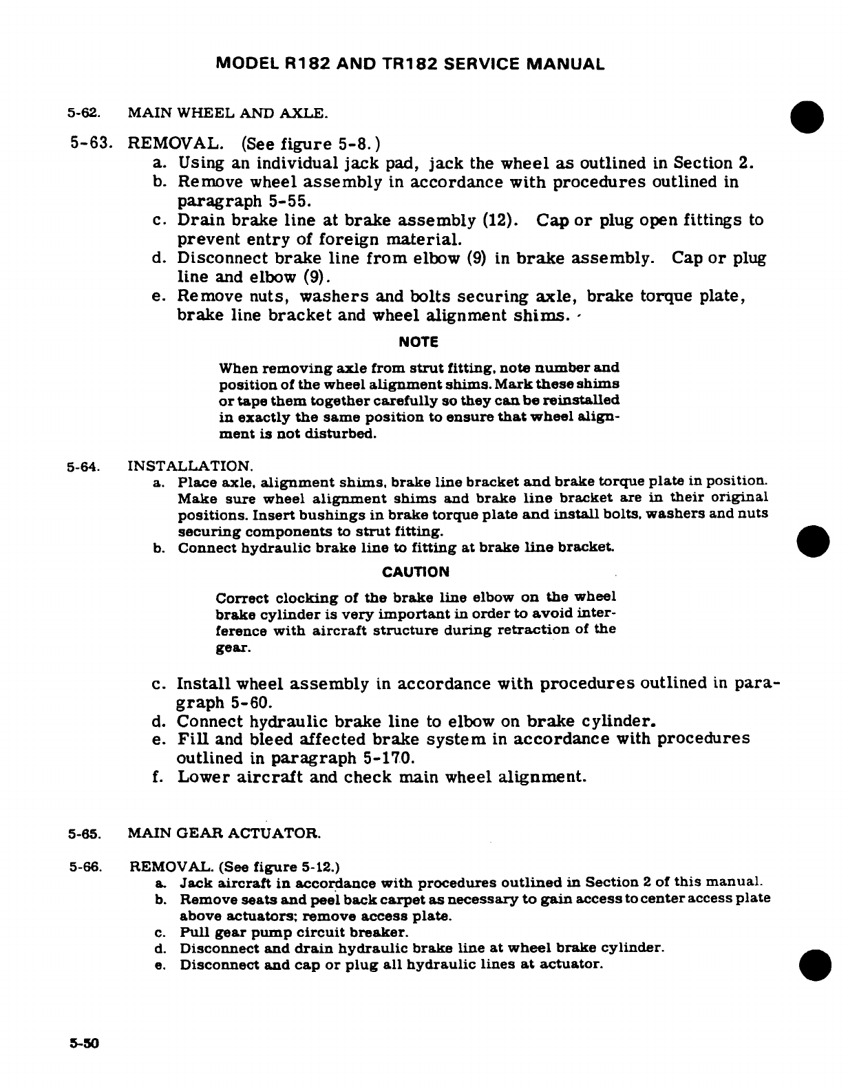
MODEL
R182
AND
TR182
SERVICE
MANUAL
5-62.
MAIN WHEEL
AND
AXLE.
5-63.
REMOVAL.
(See
figure
5-8.)
a.
Using
an
individual
jack
pad,
jack
the
wheel
as
outlined
in
Section
2.
b.
Remove
wheel
assembly
in
accordance
with
procedures
outlined
in
paragraph
5-55.
c.
Drain
brake
line
at
brake
assembly
(12).
Cap
or
plug
open
fittings
to
prevent entry
of
foreign
material.
d.
Disconnect
brake
line
from
elbow
(9)
in
brake
assembly.
Cap
or
plug
line
and
elbow
(9).
e.
Remove
nuts,
washers
and
bolts
securing
axle,
brake
torque
plate,
brake
line
bracket
and
wheel
alignment
shims.
-
NOTE
When
removing
axle
from
strut
fitting,
note
number
and
position
of
the
wheel
alignment
shims.
Mark
these
shims
or
tape
them
together carefully
so
they
can
be
reinstalled
in
exactly
the
same
position
to
ensure
that
wheel
align-
ment
is
not disturbed.
5-64.
INSTALLATION.
a.
Place
axle,
alignment
shims,
brake
line
bracket
and
brake torque
plate
in
position.
Make
sure
wheel
alignment
shims
and
brake
line
bracket
are
in
their
original
positions.
Insert
bushings
in
brake
torque
plate
and
install
bolts,
washers
and
nuts
securing
components
to
strut
fitting.
b.
Connect
hydraulic
brake
line
to
fitting
at
brake
line
bracket.
CAUTION
Correct
clocking
of
the
brake
line
elbow
on the
wheel
brake
cylinder
is
very
important
in
order
to
avoid
inter-
ference
with
aircraft
structure
during
retraction
of
the
gear.
c.
Install
wheel
assembly
in
accordance
with
procedures
outlined
in
para-
graph
5-60.
d.
Connect
hydraulic
brake
line
to
elbow
on
brake
cylinder.
e.
Fill
and
bleed
affected
brake
system
in
accordance
with
procedures
outlined
in
paragraph
5-170.
f.
Lower
aircraft
and
check
main wheel
alignment.
5-65.
MAIN
GEAR
ACTUATOR.
5-66.
REMOVAL.
(See
figure
5-12.)
a.
Jack
aircraft
in
accordance with
procedures
outlined
in
Section
2
of
this
manual.
b.
Remove
seats
and
peel back
carpet as
necessary
to
gain
access
to
center
access
plate
above
actuators;
remove
access
plate.
c.
Pull
gear
pump
circuit
breaker.
d.
Disconnect
and
drain
hydraulic
brake
line
at wheel
brake
cylinder.
e.
Disconnect
and
cap
or
plug
all
hydraulic
lines
at
actuator.
5-50
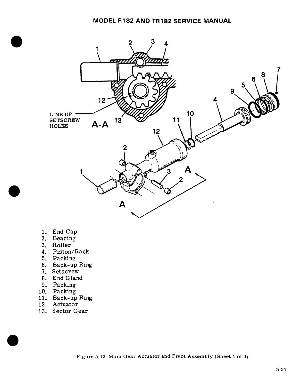
MODEL
R182
AND
TR182
SERVICE
MANUAL
*2
13
4
9
5
12
4
LINE UP
10
SETSCREW
3
11
HOLES
A-A
2
A
A^
1.
End
Cap
2.
Bearing
3.
Roller
4.
Piston/Rack
5.
Packing
6.
Back-up
Ring
7.
Setscrew
8.
End
Gland
9.
Packing
10.
Packing
11.
Back-up
Ring
12.
Actuator
13.
Sector
Gear
Figure
5-12.
Main
Gear
Actuator
and
Pivot
Assembly
(Sheet
1
of
3)
5-51
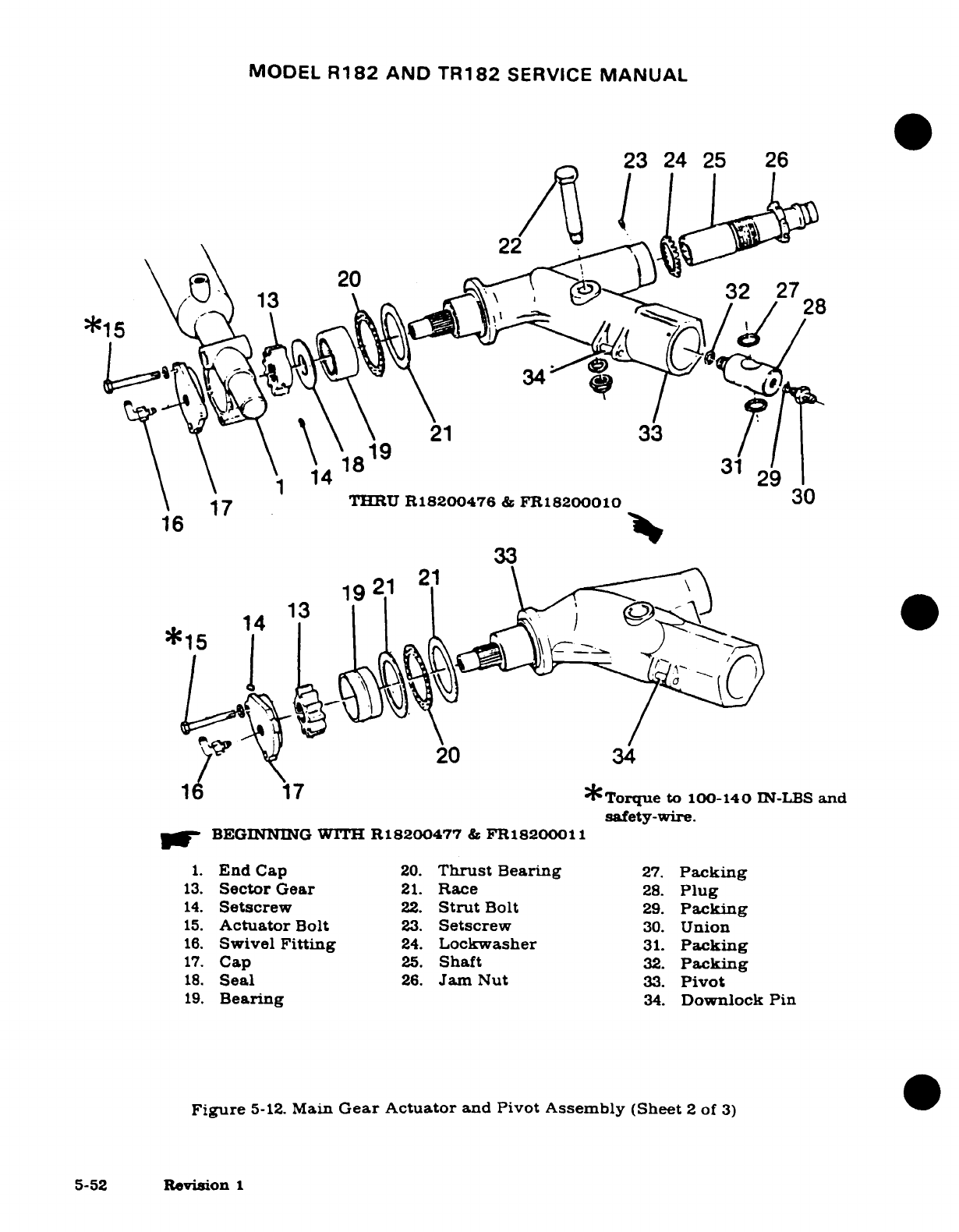
MODEL
R182
AND
TR182
SERVICE
MANUAL
23
24
25
26
22
THRU
R18200476
&
FR1820001
30
1.
C
20.
3i
27
20
13.
Sector
Gear
21.
Race
28.
Plug
14.
Setscrew
22.
Strut
Bolt
29.
Packing
15.
Actuator
Bolt
23.
Setscrew
30.
Union
16.
Swivel
Fitting
24.
Lockwasher
31.
Packing
17.
Cap
25.
Shaft
32.
Packing
18
Seal
26.
Jam
Nut
33.
Pivot
19.
Bearing
34.
Downlock
Pin
Figure
5-12.
Main
Gear
Actuator
and
Pivot Assembly
(Sheet
2
of
3)
5-52
Revision
1
16p
Ty~y
20
34
1
17
*Torque
to
100-140
IN-LBS
and
safety-wire.
VW
BEGINNING
WITH
R18200477
&
FR18200011
1.
End
Cap
20.
Thrust
Bearing
27.
Packing
13.
Sector
Gear
21.
Race
28.
Plug
14.
Setscrew
22.
Strut
Bolt
29.
Packing
15.
Actuator
Bolt
23.
Setscrew
30.
Union
16.
Swivel
Fitting
24.
Lockwasher
31.
Packing
17.
Cap
25.
Shaft
32.
Packing
18.
Seal
26.
Jam
Nut
33.
Pivot
19.
Bearing
34.
Downlock Pin
Figure
5-12.
Main
Gear
Actuator
and
Pivot Assembly
(Sheet
2
of
3)
5-52
Revision
1
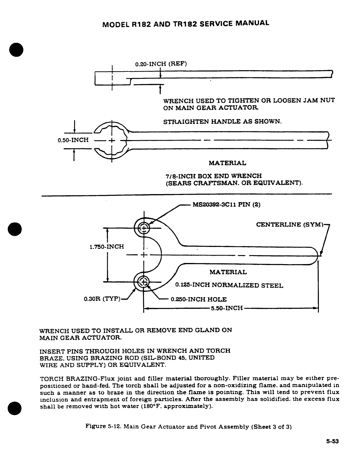
MODEL
R182
AND
TR182
SERVICE
MANUAL
0.20-INCH
(REF)
I l
t
WRENCH
USED TO
TIGHTEN
OR
LOOSEN
JAM
NUT
ON
MAIN
GEAR
ACTUATOR
STRAIGHTEN
HANDLE
AS
SHOWN.
0.50-INCH
-- _ -(
MATERIAL
7/8-INCH
BOX
END
WRENCH
(SEARS
CRAFTSMAN.
OR
EQUIVALENT).
MS20392-3C11
PIN
(2)
CENTERLINE
(SYM)
1.750-INCH
_ /
MATERIAL
y^ ^
0.125-INCH
NORMALIZED
STEEL
0.30R
(TYP)-
N--
0.250-INCH
HOLE
--
~
5.50-INCH
WRENCH
USED
TO
INSTALL
OR
REMOVE
END GLAND
ON
MAIN
GEAR
ACTUATOR.
INSERT
PINS
THROUGH
HOLES
IN
WRENCH
AND
TORCH
BRAZE.
USING
BRAZING
ROD
(SIL-BOND
45.
UNITED
WIRE
AND
SUPPLY)
OR
EQUIVALENT.
TORCH
BRAZING-Flux
joint
and
filler
material
thoroughly.
Filler
material
may
be
either
pre-
positioned
or
hand-fed.
The
torch
shall
be
adjusted
for
a
non-oxidizing
flame.
and
manipulated
in
such
a
manner
as to
braze
in
the
direction
the
flame
is
pointing. This
will tend
to
prevent
flux
inclusion
and
entrapment
of
foreign
particles.
After the
assembly
has
solidified.
the
excess
flux
shall
be
removed
with
hot
water
(180°F.
approximately).
Figure
5-12.
Main
Gear
Actuator
and
Pivot Assembly
(Sheet
3
of
3)
5-53
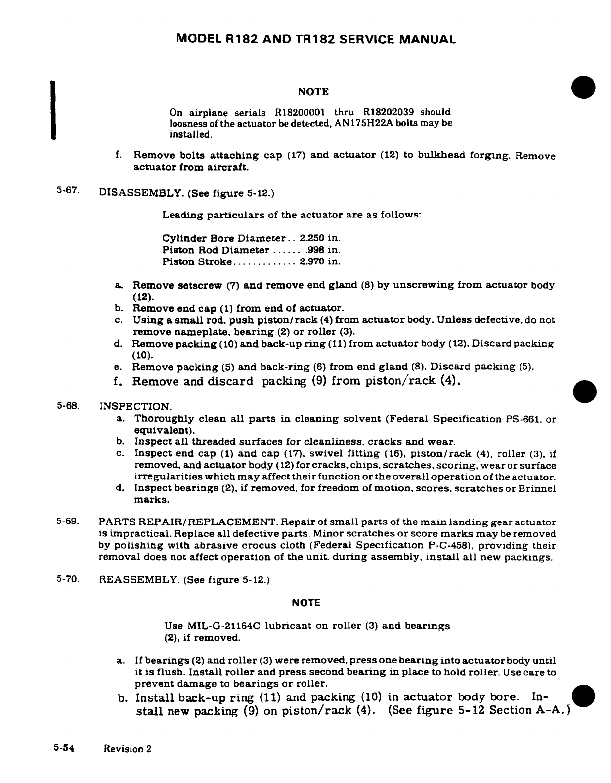
MODEL
R182
AND
TR182
SERVICE
MANUAL
NOTE
On
airplane
serials
R18200001
thru
R18202039
should
loosness
of
the
actuator
be
detected,
AN175H22A
bolts
may
be
installed.
f.
Remove
bolts
attaching
cap
(17)
and
actuator
(12)
to
bulkhead
forging.
Remove
actuator
from
aircraft.
5-67.
DISASSEMBLY.
(See
figure
5-12.)
Leading
particulars
of
the
actuator
are
as
follows:
Cylinder
Bore
Diameter..
2.250
in.
Piston
Rod
Diameter
......
.998
in.
Piston
Stroke.............
2.970
in.
a.
Remove
setscrew
(7)
and
remove
end
gland
(8)
by
unscrewing
from
actuator
body
(12).
b.
Remove end
cap
(1)
from
end
of
actuator.
c.
Using
a
small
rod,
push piston/
rack
(4)
from
actuator
body.
Unless
defective,
do not
remove
nameplate,
bearing
(2)
or
roller
(3).
d.
Remove
packing
(10)
and back-up
ring
(11)
from
actuator
body
(12).
Discard
packing
(10).
e.
Remove
packing
(5)
and
back-ring
(6)
from
end
gland
(8).
Discard packing
(5).
f.
Remove
and
discard
packing
(9)
from
piston/rack
(4).
5-68.
INSPECTION.
a.
Thoroughly clean
all
parts
in
cleaning solvent
(Federal
Specification
PS-661,
or
equivalent).
b.
Inspect
all
threaded
surfaces
for
cleanliness,
cracks
and
wear.
c.
Inspect
end
cap
(1)
and
cap
(17).
swivel
fitting
(16).
piston/rack
(4),
roller
(3).
if
removed, and
actuator
body
(12)
for
cracks,
chips,
scratches,
scoring,
wear
or
surface
irregularities
which
may
affect
their
function
or the
overall
operation
of
the
actuator.
d.
Inspect
bearings
(2),
if
removed.
for
freedom
of
motion,
scores,
scratches
or
Brinnel
marks.
5-69.
PARTS
REPAIR/REPLACEMENT.
Repair
of
small
parts
of
the
main landing
gear
actuator
is
impractical.
Replace
all
defective
parts.
Minor
scratches
or
score
marks
may
be
removed
by
polishing
with
abrasive crocus
cloth
(Federal
Specification
P-C-458),
providing
their
removal
does
not
affect
operation
of
the
unit.
during
assembly,
install
all
new
packings.
5-70.
REASSEMBLY.
(See
figure
5-12.)
NOTE
Use
MIL-G-21164C
lubricant
on
roller
(3)
and
bearings
(2),
if
removed.
a.
If
bearings
(2)
and
roller
(3)
were
removed,
press
one
bearing
into
actuator
body
until
it
is
flush.
Install
roller
and
press
second
bearing
in
place
to
hold
roller.
Use
care
to
prevent
damage
to
bearings
or
roller.
b.
Install
back-up
ring
(11)
and
packing
(10)
in
actuator
body
bore.
In-
stall
new
packing
(9)
on
piston/rack
(4).
(See
figure
5-12
Section
A-A.)
5-54
Revision
2
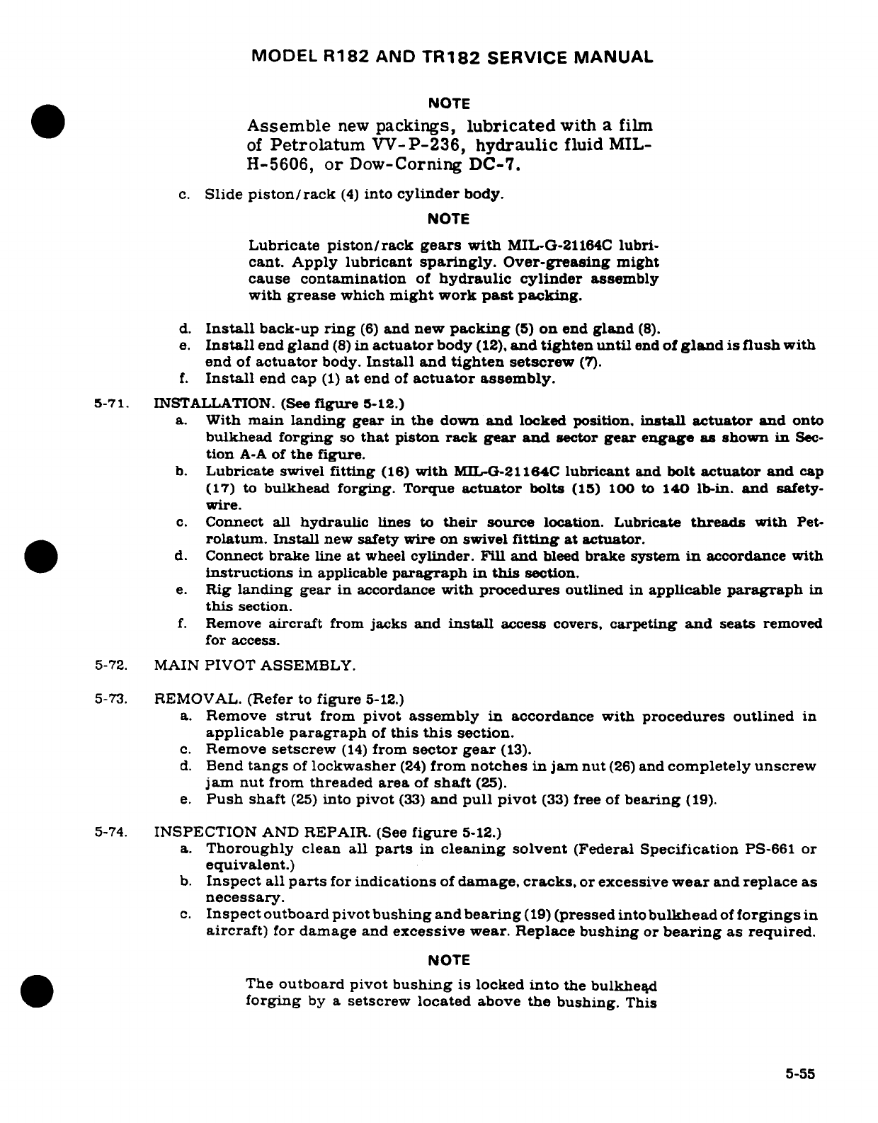
MODEL
R182
AND
TR182
SERVICE
MANUAL
NOTE
Assemble
new
packings,
lubricated
with
a
film
of
Petrolatum
VV-P-236,
hydraulic
fluid
MIL-
H-5606,
or
Dow-Corning
DC-7.
c.
Slide
piston/rack
(4)
into
cylinder
body.
NOTE
Lubricate
piston/rack
gears
with
MIL-G-21164C
lubri-
cant.
Apply
lubricant
sparingly.
Over-greasing
might
cause contamination
of
hydraulic
cylinder
assembly
with
grease
which
might
work
past
packing.
d.
Install
back-up
ring
(6)
and
new
packing
(5)
on
end
gland
(8).
e.
Install
end
gland
(8)
in
actuator
body
(12),
and
tighten until
end
of
gland
is
flush
with
end
of
actuator
body.
Install
and
tighten
setscrew
(7).
f.
Install
end
cap
(1)
at
end
of
actuator
assembly.
5-71.
INSTALLATION.
(See
figure
5-12.)
a.
With
main
landing
gear
in
the
down
and
locked
position,
install
actuator
and onto
bulkhead
forging
so
that
piston
rack
gear
and
sector
gear engage
as
shown
in
Sec-
tion
A-A
of
the figure.
b.
Lubricate
swivel
fitting
(16)
with
MIL-G-21164C
lubricant
and
bolt
actuator and
cap
(17)
to
bulkhead
forging.
Torque
actuator
bolts
(15)
100
to
140
lb-in.
and
safety-
wire.
c.
Connect
all
hydraulic
lines
to
their
source
location. Lubricate
threads
with
Pet-
rolatum.
Install
new
safety
wire on
swivel
fitting
at
actuator.
d.
Connect
brake
line
at
wheel
cylinder.
Fill
and
bleed
brake
system
in
accordance with
instructions
in
applicable
paragraph
in
this
section.
e.
Rig
landing
gear
in
accordance
with
procedures
outlined
in
applicable
paragraph
in
this
section.
f.
Remove
aircraft
from
jacks
and
install
access
covers,
carpeting
and
seats
removed
for
access.
5-72.
MAIN
PIVOT ASSEMBLY.
5-73.
REMOVAL.
(Refer
to
figure
5-12.)
a.
Remove
strut
from
pivot
assembly
in
accordance
with
procedures
outlined
in
applicable
paragraph
of
this
this
section.
c.
Remove
setscrew
(14)
from
sector gear
(13).
d.
Bend
tangs
of
lockwasher
(24)
from
notches
in
jam nut
(26)
and
completely
unscrew
jam
nut
from
threaded
area
of
shaft
(25).
e.
Push
shaft
(25)
into
pivot
(33)
and
pull
pivot
(33)
free
of
bearing
(19).
5-74.
INSPECTION
AND
REPAIR.
(See
figure
5-12.)
a.
Thoroughly
clean
all
parts
in
cleaning solvent
(Federal
Specification
PS-661
or
equivalent.)
b.
Inspect
all
parts
for
indications
of
damage,
cracks,
or excessive
wear
and
replace
as
necessary.
c.
Inspect
outboard
pivot
bushing
and
bearing
(19)
(pressed
into
bulkhead
of
forgings
in
aircraft)
for
damage
and
excessive
wear.
Replace
bushing
or
bearing
as
required.
NOTE
The
outboard pivot
bushing
is
locked
into
the
bulkhead
forging
by a
setscrew
located
above
the
bushing.
This
5-55
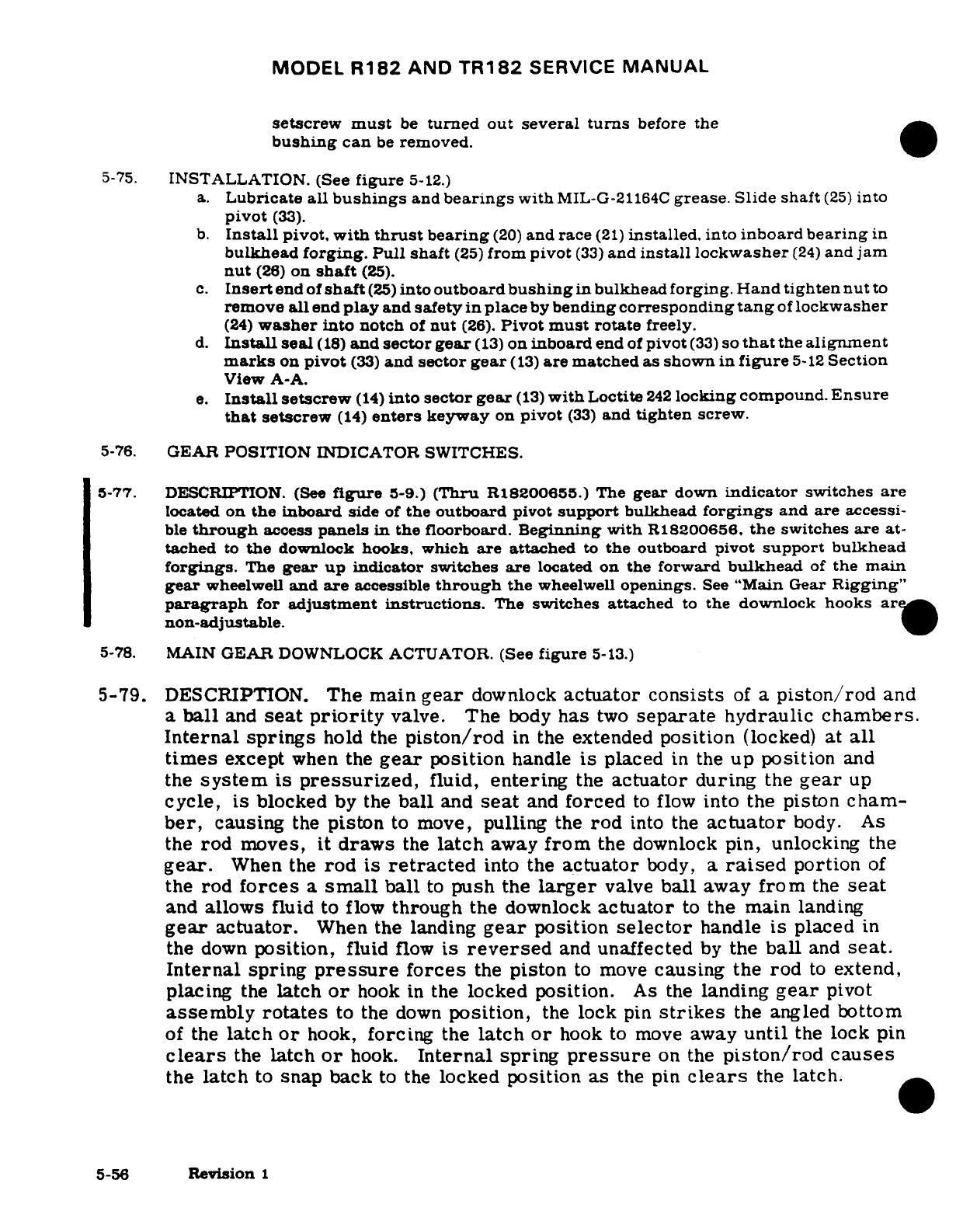
MODEL
R182
AND
TR182
SERVICE
MANUAL
setscrew
must
be
turned out
several
turns
before
the
bushing
can
be
removed.
5-75.
INSTALLATION. (See
figure
5-12.)
a.
Lubricate
all
bushings
and
bearings
with
MIL-G-21164C
grease.
Slide shaft
(25)
into
pivot
(33).
b.
Install
pivot,
with
thrust
bearing
(20)
and
race
(21)
installed.
into
inboard
bearing
in
bulkhead
forging.
Pull
shaft
(25)
from
pivot
(33)
and
install lockwasher
(24)
and
jam
nut
(26)
on
shaft
(25).
c.
Insert
end
of
shaft
(25)
into
outboard
bushing
in
bulkhead
forging.
Hand
tighten nut
to
remove
all
end
play
and
safety
in
place
by
bending
corresponding
tang
of
lockwasher
(24)
washer
into notch
of
nut
(26).
Pivot
must
rotate
freely.
d.
Install
seal
(18)
and
sector
gear
(13)
on
inboard
end
of
pivot
(33)
so
that
the
alignment
marks
on
pivot
(33)
and
sector
gear
(13)
are matched
as
shown
in
figure
5-12
Section
View
A-A.
e.
Install
setscrew
(14)
into
sector gear
(13)
with
Loctite
242
locking
compound.
Ensure
that
setscrew
(14)
enters
keyway
on
pivot
(33)
and
tighten
screw.
5-76.
GEAR
POSITION
INDICATOR
SWITCHES.
5-77.
DESCRIPTION.
(See
figure
5-9.)
(Thru
R18200655.)
The
gear
down
indicator
switches
are
located
on
the
inboard
side of
the
outboard
pivot
support
bulkhead
forgings
and
are
accessi-
ble
through
access
panels
in
the
floorboard.
Beginning
with
R18200656.
the
switches
are
at-
tached
to
the
downlock
hooks,
which
are
attached
to
the
outboard
pivot
support
bulkhead
forgings.
The
gear
up
indicator
switches
are
located
on
the
forward
bulkhead
of
the
main
gear
wheelwell
and
are
accessible
through
the
wheelwell
openings.
See
"Main
Gear
Rigging"
paragraph
for
adjustment instructions.
The
switches
attached
to
the
downlock hooks
are
non-adjustable.
5-78.
MAIN
GEAR
DOWNLOCK
ACTUATOR.
(See
figure
5-13.)
5-79.
DESCRIPTION.
The
main
gear
downlock
actuator consists
of
a
piston/rod
and
a
ball
and
seat
priority
valve.
The
body
has
two
separate
hydraulic
chambers.
Internal springs
hold
the
piston/rod
in
the
extended
position
(locked)
at
all
times
except
when
the
gear
position
handle
is
placed
in
the
up
position
and
the
system
is
pressurized,
fluid,
entering
the
actuator
during
the
gear
up
cycle,
is
blocked
by the
ball
and
seat
and
forced
to
flow
into
the
piston
cham-
ber,
causing
the
piston
to
move,
pulling
the
rod
into the
actuator
body.
As
the
rod
moves,
it
draws
the
latch
away
from
the
downlock
pin,
unlocking
the
gear.
When
the
rod is
retracted
into
the
actuator
body,
a
raised
portion
of
the
rod
forces
a
small
ball
to
push
the
larger
valve
ball
away
from
the
seat
and
allows
fluid
to
flow
through
the downlock
actuator
to
the
main
landing
gear
actuator.
When
the landing
gear
position
selector
handle
is
placed
in
the
down
position,
fluid
flow
is
reversed
and
unaffected
by
the
ball
and
seat.
Internal
spring
pressure
forces
the
piston
to
move
causing
the
rod
to
extend,
placing
the
latch
or
hook
in
the
locked
position.
As the
landing
gear
pivot
assembly
rotates
to the
down
position,
the
lock
pin
strikes
the
angled
bottom
of
the
latch
or
hook,
forcing
the
latch
or
hook
to
move
away
until
the
lock
pin
clears
the
latch
or
hook.
Internal
spring
pressure
on
the
piston/rod
causes
the
latch
to
snap back
to
the
locked
position
as
the
pin
clears
the
latch.
5-56
Revision
1
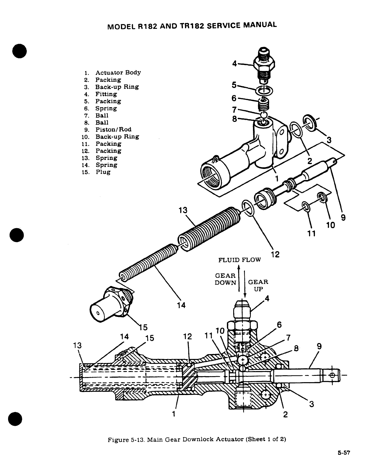
MODEL
R182
AND
TR182
SERVICE
MANUAL
4
1.
Actuator
Body
2.
Packing
3.
Back-up
Ring
5
4.
Fitting
5.
Packing
6
6.
Spring
7
7.
Ball
8.
Ball
8
9.
Piston/Rod
10.
Back-up
Ring
J
11.
Packing
12.
Packing\
13.
Spring
2
14.
Spring
15.
Plug
13
10
FLUID
FLOW
GEAR
DOWN
GEAR
UP
4
14
5
10
6
06
14
15 12
11'
7
13
/~7
9
Figure
5-13.
Main
Gear
Downlock
Actuator
(Sheet
1
of
2)
5-57
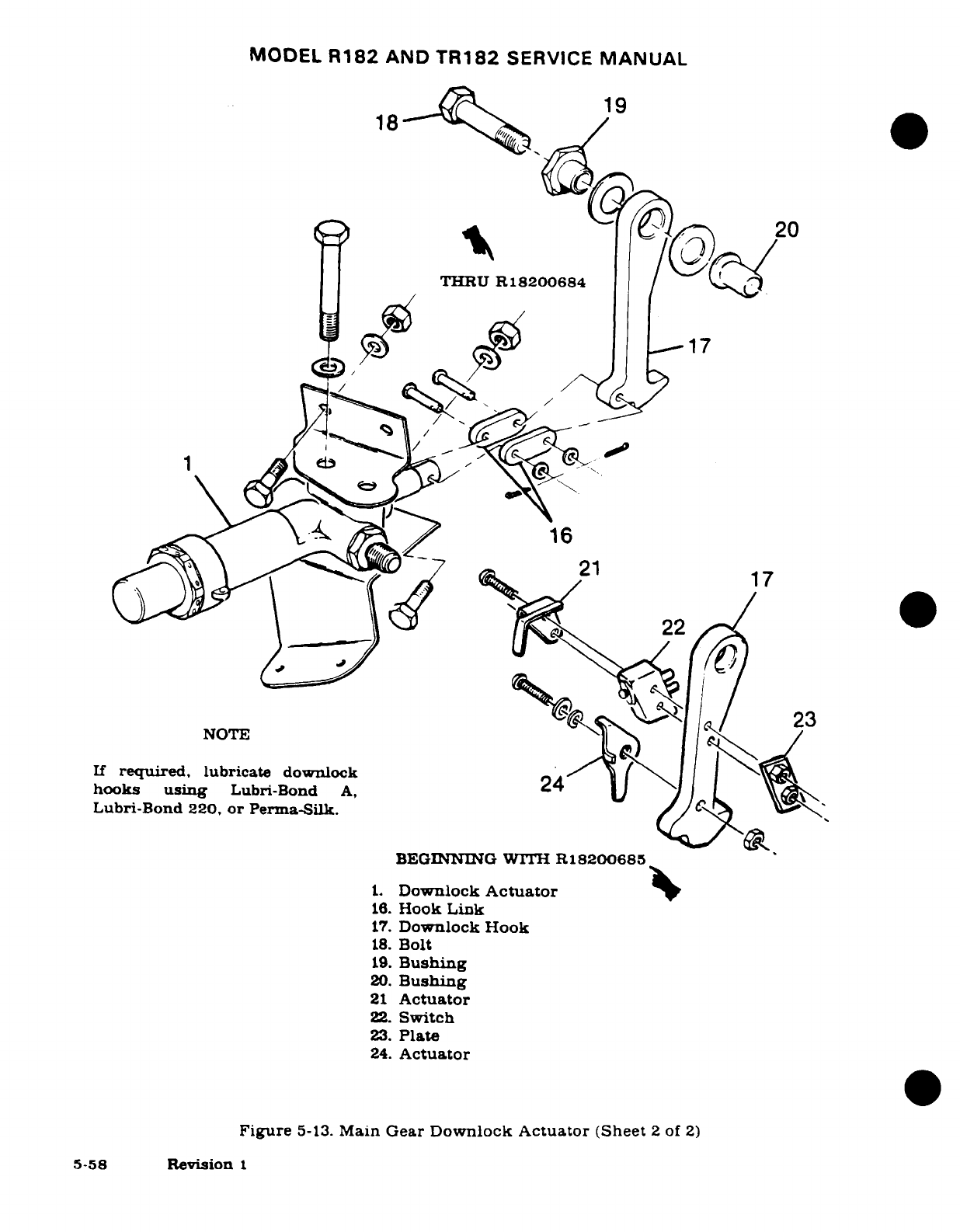
MODEL
R182
AND
TR182
SERVICE
MANUAL
19
THRU
R18200684
17
16
17
¢']~<
"1 22
NOTE
(
If
required,
lubricate
downlock
24
hooks
using
Lubri-Bond
A,2
Lubri-Bond
220,
or
Perma-Silk.
BEGINNING
WITH
R18200685
1.
Downlock
Actuator
16.
Hook
Link
17.
Downlock
Hook
18.
Bolt
19.
Bushing
20.
Bushing
21
Actuator
22.
Switch
23.
Plate
24.
Actuator
Figure
5-13.
Main
Gear
Downlock
Actuator
(Sheet
2
of
2)
5-58
Revision
1
MODEL
R182
AND
TR182
SERVICE
MANUAL
5-80.
REMOVAL.
(See
figure
5-13.)
a.
Jack
aircraft
in
accordance
with
procedures
outlined
in
Section
2
of
this
manual.
b.
Place
master
switch
in
OFF
position
and
move
gear
position
handle
to
UP
position.
c.
Turn master
switch
on
and
allow
gear
to
retract
halfway.
Turn
master
switch
off
and
pull
gear
pump
circuit
breaker
to
prevent
accidental
activation
of
the pump.
d.
Move
seat
to
forward
position
and
peel
back
carpet
as
necessary
to uncover
access
panel
above
actuator;
remove
panel.
e.
Remove
cotter
pin
and
clevis
pin
from
downlock
hook
(17).
f.
Remove two
bolts
attaching
actuator
to
mounting
brackets.
g.
Remove
and
cap
or
plug
hydraulic
lines from
actuator.
h.
Reverse
procedure
to
install
actuator.
5-81.
DISASSEMBLY.
(See
figure
5-13.)
NOTE
Leading
particulars
of
the
actuators
are
as
follows:
Cylinder
Bore
Diameter
................................................
0.749+.002,-.000
in.
Piston
Diameter
................... ..............
......
.......
0.747+.000.-.001
in.
Stroke
(to
unseat
valve)
.....................................................
0.719±.031
in.
a.
Remove
fitting
(4),
spring
(6)
and
balls
(7)
and
(8).
b.
Cut
safety
wire
and
unscrew
end
plug
(15)
from
actuator
body
(1).
c.
Remove
springs
(13)
and
(14)
and
push
piston/rod
(9)
from
actuator
body
(1).
d.
Remove
and
discard
all
packings
and
back-up
rings.
5-82.
INSPECTION.
(See
figure
5-13.)
a.
Inspect
all
threaded
surfaces
for
cleanliness
and
for
freedom
of
cracks
and
excessive
wear.
b.
Inspect
spring
(6)
for evidence
of
breaks
and
distortion.
c.
Inspect
inner
and
outer
springs
(13)
and
(14)
for
evidence
of
breaks
and
distortion.
d.
Inspect
fitting
(4).
piston
rod
(9),
actuator
body
(1),
balls
(7)
and
(8)
ball
seats
for
cracks.
scratches,
scoring,
wear or surface
irregularities
which
might
affect
their
function
or
the
overall
function
of
the
unit.
e.
Repair
of
most
parts
of
the
downlock
actuator
is
impractical.
Replace
defective
parts.
Minor
scratches
and
scores
may
be
removed
by
polishing
with
fine
abrasive
crocus
cloth
(Federal
Specification
PC-458),
providing
their
removal
does
not
affect
opera-
tion
of
the
unit.
5-83.
REASSEMBLY.
(See
figure
5-13.)
NOTE
Install
all
new
packings
and
(12)
back-up
rings
during
reassembly
of
the
actuator.
a.
Install
new
packings
(11)
and
(12)
back-up
ring
(10)
in
grooves
of
piston/
rod
(9).
b.
Install
new
packing
(2),
back-up
ring
(3)
in
grooves
of
actuator
body
(1).
c.
Slide
piston
rod
into
actuator
body
(1).
Use
care
to
prevent
damage
to
packing
(2)
and
back-up
ring
(3).
d.
Insert
springs
(13)
and
(14),
then
install
and
safety
wire
end
plug(15)
to
actuator
body.
e.
Insert
balls
(8)
and
(7) and
spring
(6)
in
actuator
body
(1).
f.
Install
new
packing
(5) on
fitting
(4).
Install
and
tighten
fitting.
Revision
1
5-59
MODEL
R182
AND
TR182
SERVICE
MANUAL
e.
Insert
balls
(8)
and
(7)
and
spring
(6)
in
barrel
and
valve
body.
f.
Install
new
packing
(5)
on
fitting
(4).
Install
and
tighten
fitting.
5-84.
MAIN
GEAR
STRUT
STEP.
5-85.
DESCRIPTION.
Thru
Serials
R18200476
and
FR18200020,
the
step
is
con-
structed
of
Uralite
3121
polyurethane
casting,
with
treads
cast
into
the
step.
Beginning
with
Serials
R18200477
and
FR18200021,
the
step
is
constructed
of
Uralite
3121
polyurethane
casting,
with
a
molded
depression
area,
located
in
the
top
of
the
step
containing
a
replaceable
tread.
To
replace
a
step
tread,
remove
old
tread
with
a
sharp
knife,
clean
pad
with
a
50-50
mixture
of
toluene
and
methyene
chloride,
and
cement
new
tread
to
pad
with
EC-776
or
EC-847
cement
(3M
Company).
5-86.
REMOVAL.
(See
figure
5-8.)
NOTE
The
step
is
bonded
to
the
landing
gear
strut
with
Uralite
3121
bonding
material.
a. Using
a
heat
gun,
heat
step
at
a
temperature
of
200
°
to
250F,
until
step
material
becomes
pliable.
b.
Using
a
sharp
knife,
remove
step
material
down
to
the
metal
strut.
c.
Clean
off
remaining
step
material
with
a
wire
wheel
and
sandpaper.
Leave
surface
slightly
rough
or
abraded.
Clean
oil
and
grease
from
strut
with
solvent,
wipe
off
excess
solvent
with
a
dry
cloth
and
let
surface
dry.
d.
Apply
Zinc
Chromate
Primer
-
green
or
yellow
to
cleaned
area
on
strut.
Dry
film
thickness
to
be
.
0003
to
.
0005
inch.
5-87.
INSTALLATION.
(Refer
to
figure
5-8.)
a.
Jack
aircraft
in
accordance
with
procedures
outlined
in
Section
2
of
this
manual.
b.
Mark
position
of
removed
step
so
new
step
will
be
installed
in
approxi-
mately
the
same
position
on
the
strut.
c.
Check
that
bonding
surfaces
are
clean
and
dry.
d.
Mix
adhesive
(Uralite
3121),
in
accordance
with
manufacturer's
direc-
tion.
Note
pot
life.
e.
Spread
a
coat
of
mixed
adhesive
on
bonding
surfaces
of
strut
and
step;
install
step
on
strut.
5-60
MODEL
R182
AND TR182
SERVICE
MANUAL
NOTE
Top
of
strut
should
be
parallel
to
the
ground
(±5°)
when
gear
is
in
down
position.
f.
Cycle landing
gear
to
check
clearance
of
step
in
tunnel.
g.
Form
a
small
fillet
of
adhesive
at
all
edges
of
bonding
surfaces.
Remove
excess
adhesive.
h.
Remove
aircraft
from
jacks.
i.
Allow
adhesive
to
thoroughly
cure according
to
manufacturer's
recom-
mendations
before
flexing
gear
spring
or
applying
loads
to
step.
j.
Paint
gear
spring
strut
and
step
after
curing
is
completed.
5-88.
NOSE
GEAR
SYSTEM.
5-89.
DESCRIPTION. The
nose
gear
consists
of
a
pneudraulic
shock
assembly,
mounted
in
a
trunnion
assembly,
a
steering
arm
and bungee,
shimmy
dampener.
nose
wheel.
tire
and
tube.
hub cap,
bearings,
seals
and
a
double-acting
hydraulic
actuator
for
extension
and
retraction.
A
claw-like
hook
on
the
actuator
serves
as
a
downlock for
the
nose
gear.
Stop bolts.
located
in
the
lower
aft
well,
prevent
inadvertent
nose
gear
collapse.
5-90.
OPERATION.
The
nose
gear
shock
strut
is
pivoted
just
forward
of
the
firewall.
Retraction
and
extension
of
the
nose
gear
is
accomplished
by
a
double-acting
hydraulic
cylinder.
the
forward
edge
of
which
contains
the
nose
gear
downlock.
Initial
action
of
the
cylinder
disengages
the
downlock
before
retraction
begins.
As the
strut
moves
into
the
gear
well.
the
forward
side
of
the nose
gear
fork
boss contacts
the
door
close
mechanism
and
pulls
the
nose
door
closed.
The
nose
gear
is
held
in
the
up
position
by
hydraulic
pressure.
5-91.
TROUBLE SHOOTING
-
NOSE GEAR
SYSTEM.
TROUBLE
PROBABLE
CAUSE
REMEDY
FLUID
LEAKAGE
FROM
Defective
strut
seals.
Install
new
seals.
STRUT.
STRUT LOSES
AIR
Defective
strut
seals.
Install
new
seals.
PRESSURE.
Defective
or
loose
air
Check
gasket;
tighten
or
filler
valve.
replace
valve.
EXCESSIVE TIRE
WEAR.
Loose
torque
links.
Add
shim
washers;
replace
links.
NOSE
WHEEL
SHIMMY
Loose
or
worn
nose
Tighten
loose
linkage or
re-
(Also
refer
to
Service
wheel
steering
linkage.
place defective
parts.
Information
Letter
SE84-21.)
Shimmy
damper
need
fluid.
Service
in
accordance
with
Sec-
tion
2.
Defective
shimmy
damper.
Repair
or replace
shimmy damper.
5-60A
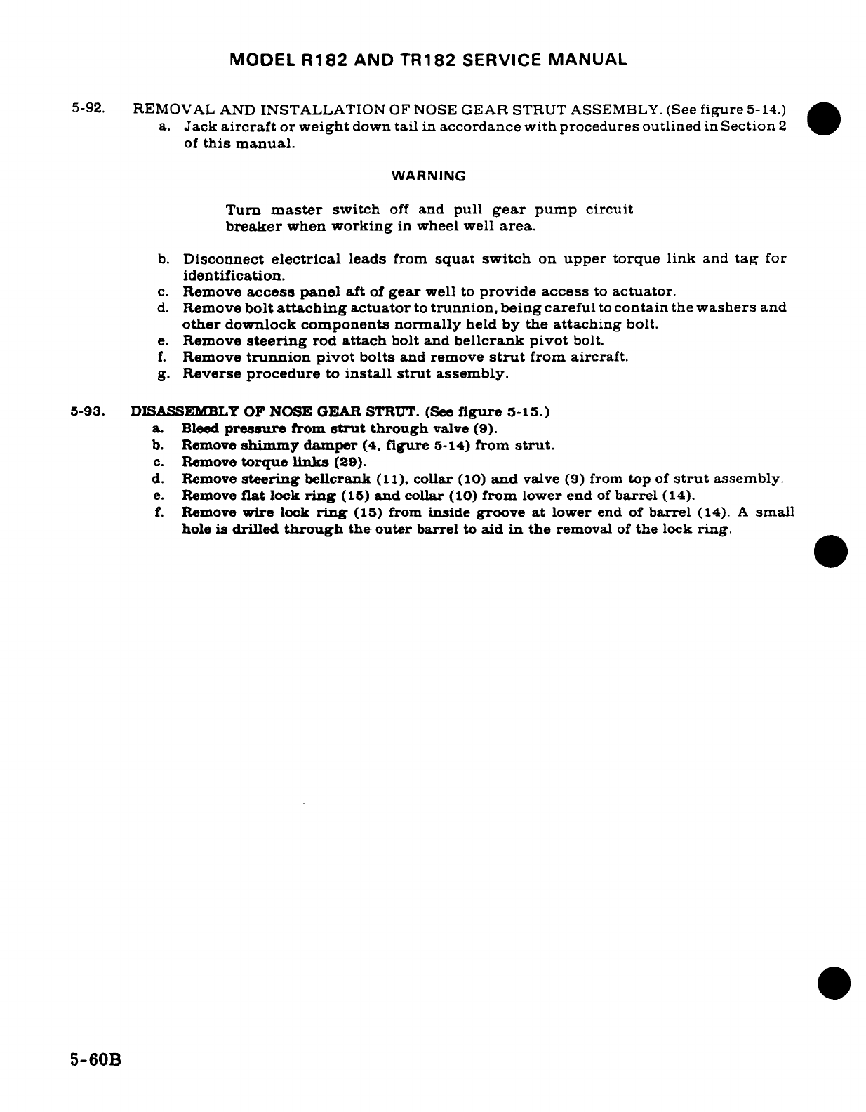
MODEL
R182
AND
TR182
SERVICE
MANUAL
5-92.
REMOVAL
AND
INSTALLATION
OF
NOSE
GEAR
STRUT
ASSEMBLY.
(See
figure
5-14.)
a.
Jack
aircraft
or
weight
down
tail
in
accordance
with
procedures
outlined
in
Section
2
of
this
manual.
WARNING
Turn
master
switch
off
and
pull
gear
pump
circuit
breaker
when
working
in
wheel well
area.
b.
Disconnect
electrical
leads
from
squat switch
on
upper
torque
link
and
tag
for
identification.
c.
Remove
access panel
aft
of
gear
well
to
provide
access
to
actuator.
d.
Remove
bolt
attaching
actuator
to
trunnion, being
careful
to
contain
the
washers
and
other
downlock
components
normally
held
by
the
attaching
bolt.
e.
Remove
steering
rod
attach
bolt
and
bellcrank
pivot
bolt.
f.
Remove
trunnion
pivot
bolts
and
remove
strut
from
aircraft.
g.
Reverse
procedure
to
install
strut
assembly.
5-93.
DISASSEMBLY
OF NOSE
GEAR
STRUT.
(See
figure
5-15.)
a.
Bleed
pressure
from
strut
through
valve
(9).
b.
Remove
shimmy
damper
(4,
figure
5-14)
from
strut.
c.
Remove
torque
links
(29).
d.
Remove
steering
bellcrank
(11),
collar
(10)
and
valve
(9)
from
top
of
strut
assembly.
e.
Remove
flat
lock
ring
(15)
and
collar
(10)
from
lower
end
of
barrel
(14).
f.
Remove
wire
lock
ring
(15)
from
inside
groove
at
lower
end
of
barrel
(14).
A
small
hole
is
drilled
through
the
outer barrel
to
aid
in
the
removal
of
the
lock
ring.
5-60B
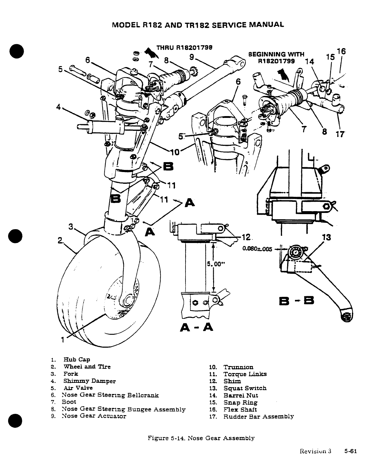
MODEL
R182
AND
TR182
SERVICE
MANUAL
*A
'THRU
R
18201798
7
.
a ^k
Q
.9
BEGINNING
WITH 1C
0
6^
®
8
2
a1
R18201799
14
1
5
11
.1
~1. HRub
Cap
00
";(
A-A
1.
Hub
Cap
2.
Wheel
and
Tire
10.
Trunnion
3.
Fork
11.
Torque
Links
4.
Shimmy Damper
12.
Shim
5.
Air
Valve
13.
Squat
Switch
6.
Nose
Gear
Steering
Bellcrank
14.
Barrel
Nut
7.
Boot
15.
Snap
Ring
8.
Nose
Gear
Steering
Bungee
Assembly
16.
Flex
Shaft
9.
Nose
Gear
Actuator
17.
Rudder
Bar
Assembly
Figure
5-14.
Nose
Gear
Assembly
Revisiun
3
5-61
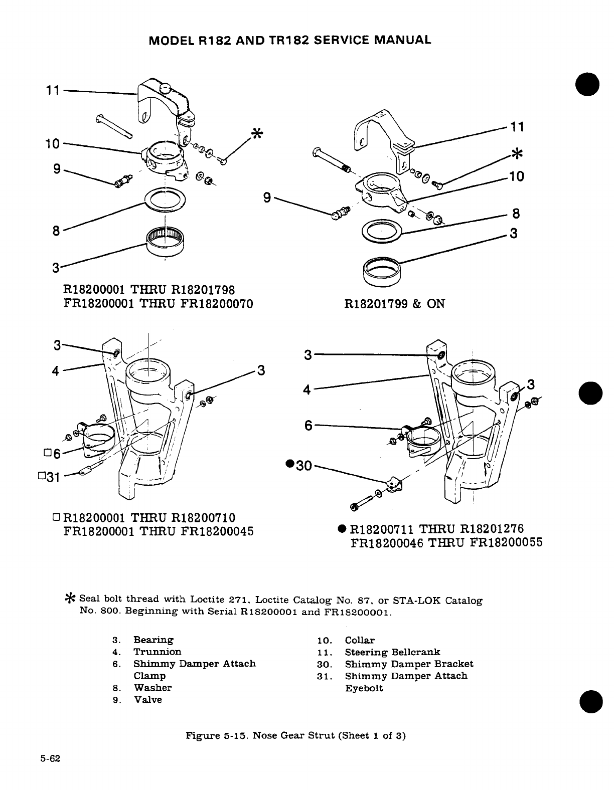
MODEL
R182
AND
TR182
SERVICE
MANUAL
11
9
=.
9
8
8
;
Q
3
R18200001 THRU
R18201798
FR18200001
THRU
FR18200070
R18201799
&
ON
] R
18206
64
031
0
R18200001
THRU
R18200710
FR18200001
THRU
FR18200045
*
R18200711
THRU
R18201276
FR18200046
THRU
FR18200055
*
Seal
bolt
thread
with
Loctite
271.
Loctite
Catalog
No.
87,
or
STA-LOK
Catalog
No.
800.
Beginning
with
Serial
R18200001
and
FR18200001.
3.
Bearing
10.
Collar
4.
Trunnion
11.
Steering
Bellcrank
6.
Shimmy Damper
Attach
30.
Shimmy
Damper
Bracket
Clamp
31.
Shimmy
Damper
Attach
8.
Washer
Eyebolt
9.
Valve
Figure
5-15.
Nose
Gear
Strut
(Sheet
1
of
3)
5-62
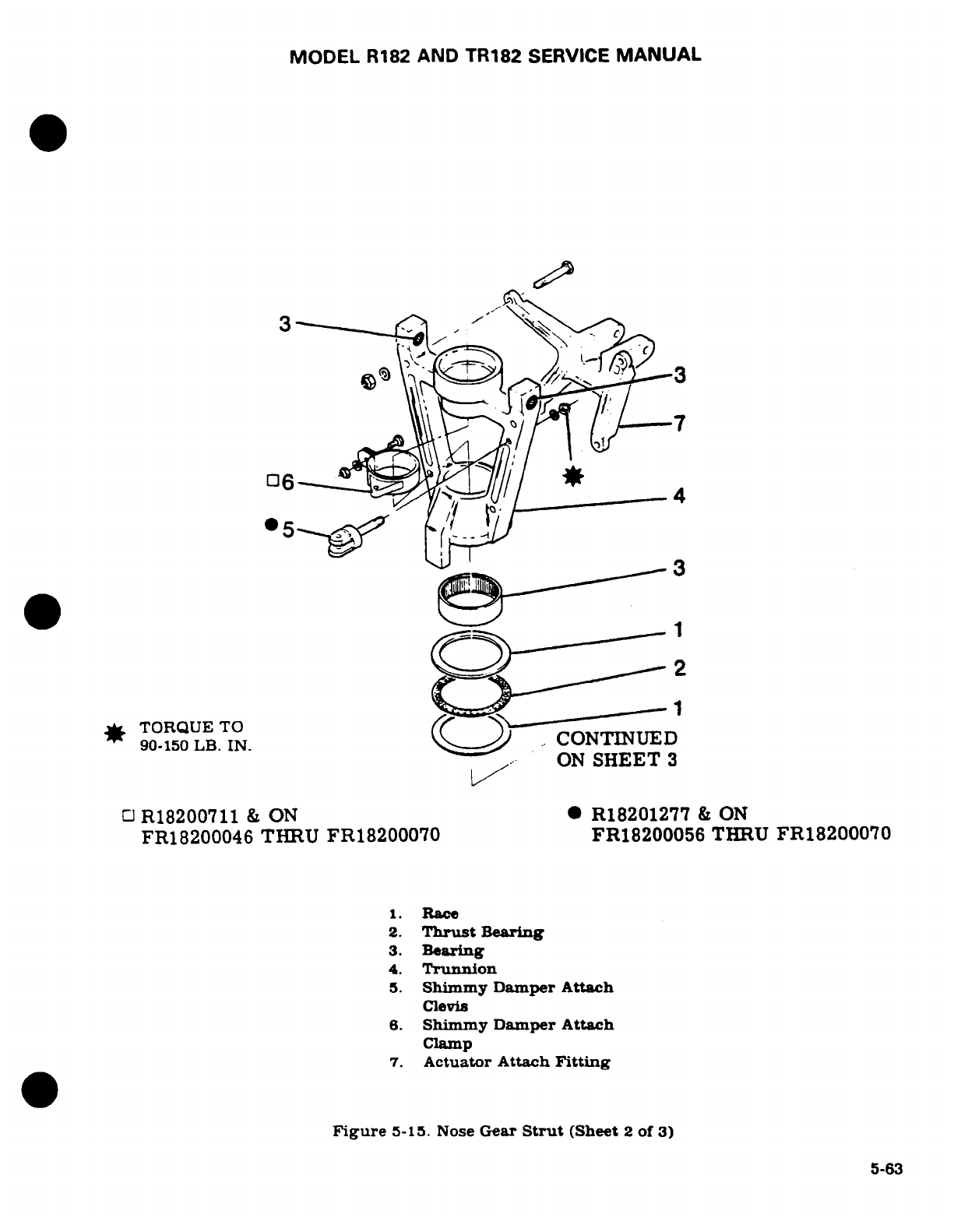
MODEL
R182
AND TR182
SERVICE
MANUAL
3
9
3
,
TORQUE
TO
90.150
LB.
IN.
...
CONTINUED
/-
/
X-
O&ON
SHEET
3
CJ
R18200711
&
ON
·
R18201277
&
ON
FR18200046
THRU
FR18200070 FR18200056
THRU
FR18200070
1.
Race
2.
Thrust
Bearing
3.
Bearing
4.
Trunnion
5.
Shimmy Damper
Attach
Clevis
6.
Shimmy
Damper
Attach
Clamp
7.
Actuator
Attach
Fitting
Figure
5-15.
Nose
Gear
Strut
(Sheet
2
of
3)
5-63
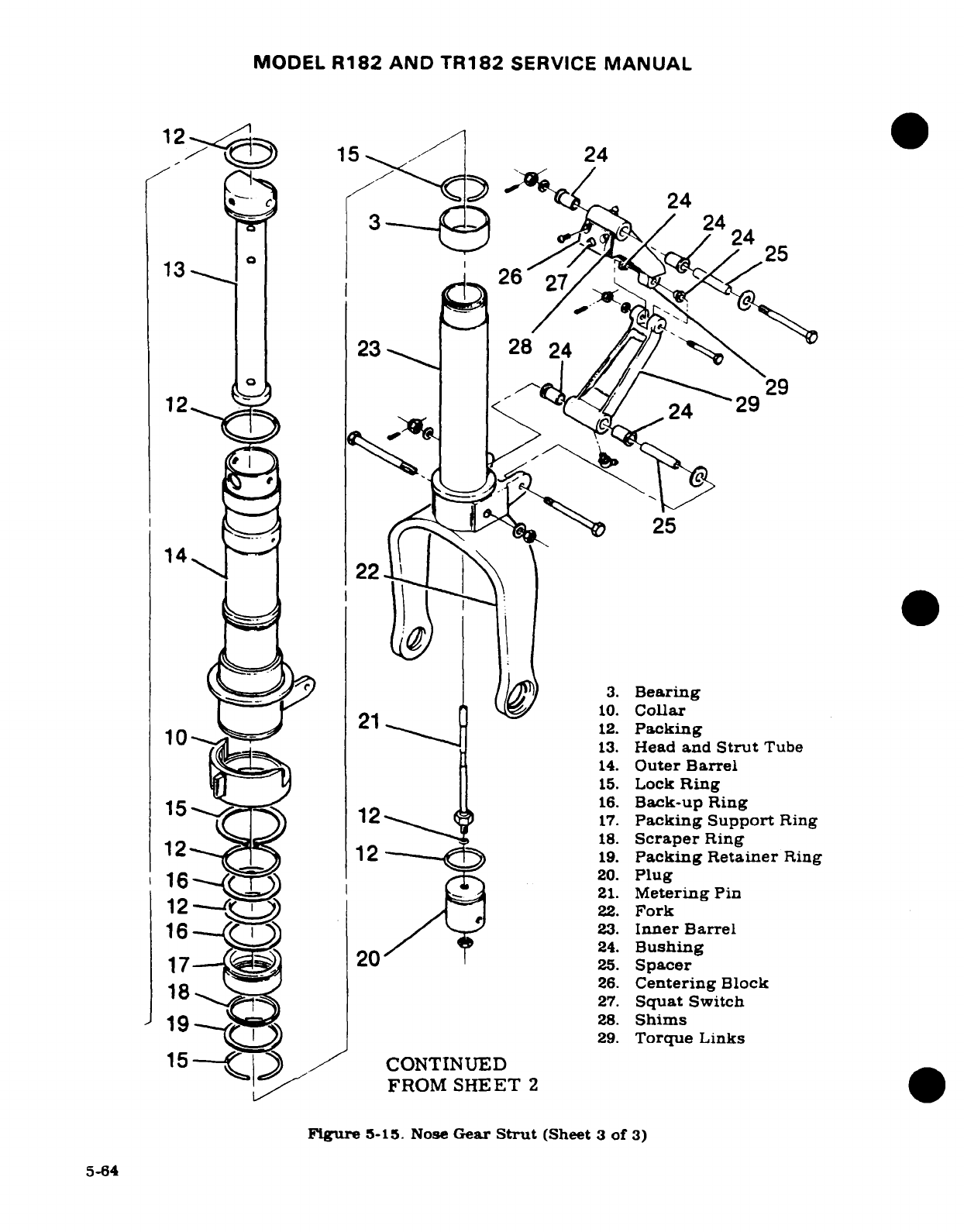
MODEL
R182
AND
TR182
SERVICE
MANUAL
1 2/x>15
-
24
24
/
24
13
26
23h I I 1
29
23
26
12
2
29
25
1422
22
-
~~~w ^ I~3.
Bearing
I[ r^ 21 1^ o10.
Collar
10
12.
Packing
13.
Head
and
Strut
Tube
14.
Outer
Barrel
15.
Lock
Ring
15_
>
ss$
1
16.
Back-upRing
1
2
1
17.
Packing Support
Ring
12in,-
12+
^ ?18.
Scraper
Ring
c
r12- <
1D2
19.
Packing Retainer
Ring
16_.f5
20.
Plug
21.
Metering
Pin
12
-
)
22.
Fork
l16~
~l Em I A23.
Inner
Barrel
24.
Bushing
17
20
25.
Spacer
18
si
26.
Centering
Block
18~:<T^ ~-~) ~~27.
Squat
Switch
I19^^B^ m28.
Shims
15 J^
CONTINUED
@29.
Torque
Links
15--
./
CONTINUED
15--/
LFROM
SHEET
2
Figure
5-15.
Nose
Gear
Strut
(Sheet
3
of
3)
5-64
MODEL
R182
AND
TR182
SERVICE
MANUAL
g.
Pull inner
barrel
(23)
from
outer
barrel
(14)
and
drain
hydraulic
fluid
from
inner
barrel.
h.
Remove
wire
lock
ring
(15)
from
groove
at
upper
end
of
inner
barrel
(23)
and
remove
bearing
(3)
and
packing
support
ring
(17)
from
inner
barrel
(23).
i.
Remove
plug
(20)
and
metering
pin
(21)
from
inner
barrel
(23)
by
removing
bolt
through
fork
(22)
inner
barrel
(23)
and
plug
(20).
Remove
metering
pin
(21)
from
plug
(20).
5-94.
INSPECTION
AND
REPAIR.
(See
figure
5-15.)
a.
Thoroughly
clean
all
parts
in
cleaning
solvent,
and
examine
parts
carefully.
b.
Install
all
new
packings
and
back-up
rings.
c.
Sharp
metal
edges
should
be
smoothed
with
No.
400
emery
paper,
then
thoroughly cleaned
with
solvent.
d.
If
outer
barrel
(14)
was
removed
from
trunnion
(4),
lubricate
needle
bearings
in
accordance
with
the
lubrication
chart
in
Section
2
of
this
manual.
e.
Lubricate
all
packings
and
back-up
rings,
and
all other
internal
parts
with a
film
of
Petrolatum
VV-P-236,
hydraulic
fluid
MIL-H-5606,
or
Dow-Corning
DC-7
during
reassembly.
5-95.
REASSEMBLY.
(See
figure
5-15.)
a.
Lubricate
and
install
all
new
packings
and
back-up
rings.
b.
Lubricate
bearings
as
required
with
MIL-G-23827A
grease or
equivalent.
c.
Reassemble
strut
using
reverse
procedure
of
disassembly
instructions
outlined
in
paragraph
5-93.
NOTE
Do
not
overtighten
nut
at
clamp
(6)
to
cause
ex-
cessive
bending
of
clamp
ears.
Lubricate
outer
surface
of
strut
tube
(13),
packing
(12)
and lock
ring
(15)
with
a
protective film
of
Petrolatum
VV-P-236,
hydraulic
fluid
MIL-H-5606,
or
Dow-
Corning
DC-7.
Tighten
nut
on
bolt
attaching
upper
and
lower torque links
(29)
snug,
plus
one
additional
castellation.
5-96.
SHIMMY
DAMPER.
(See
figure
5-16.)
5-97. DESCRIPTION.
The
shimmy
damper
is
a
self-contained
hydraulic
cylinder
which
acts
as
a
restrictor.
When
the
steering
system
reacts
too
rapidly,
the
shimmy
damper
maintains
pres-
sure
against
the
steering
arm
by
means
of
a
piston
which
permits
a
restricted
flow
of
hy-
draulic
fluid
from
either
end
of
the
cylinder
to
the
other
through
an orifice
in
the
piston.
5-98.
REMOVAL. (See
figure
5-14.)
a.
Remove
setscrew and
bracket,
eyebolt
or
clevis
bolt
securing
shimmy
damper
to
trunnion.
b.
Remove
bolt
attaching
damper
to
bracket
on nose
gear
strut.
c.
Remove
shimmy
damper
from
aircraft.
5-65
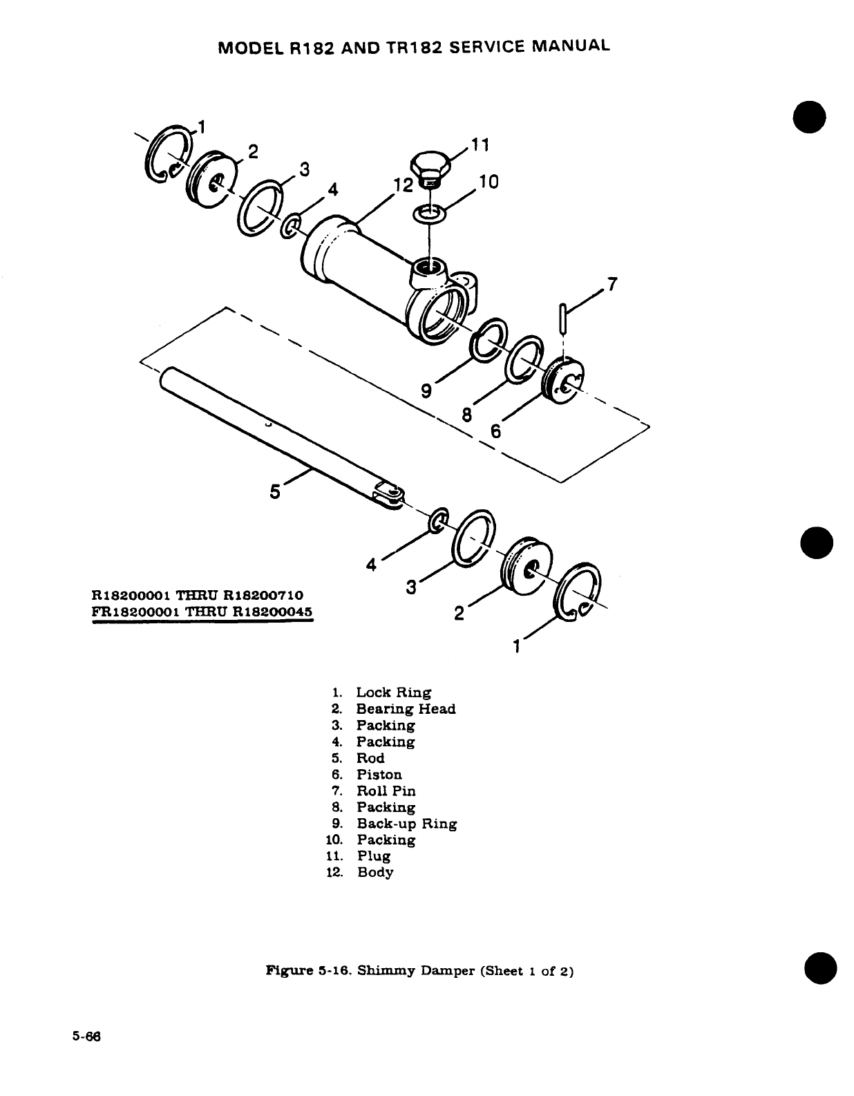
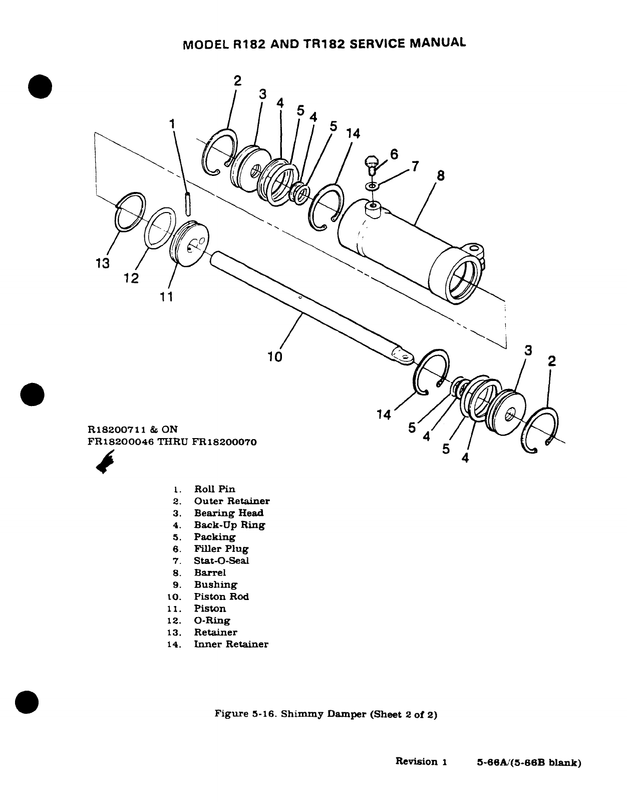
MODEL
R182
AND
TR182
SERVICE
MANUAL
~~2
3
1
4
4
R18200711
&
ON
e
5
/6
FR18200046
THIRU
FR18200070
5
1.
Roll
Pin
2.
Outer
Retainer
3.
Bearing
Head
4.
Back-Up
Ring
5.
Packing
6.
Filler
Plug
7.
Stat-O-Seal
8.
Barrel
9.
Bushing
o10.
Piston
Rod
11.
Piston
12.
O-Ring
13.
Retainer
14.
Inner
Retainer
Figure
5-16.
Shimmy
Damper
(Sheet
2
of
2)
Revision
1
5-66A/(5-66B
blank)
Revision
1
5~66Ab'(5-66B
blank)
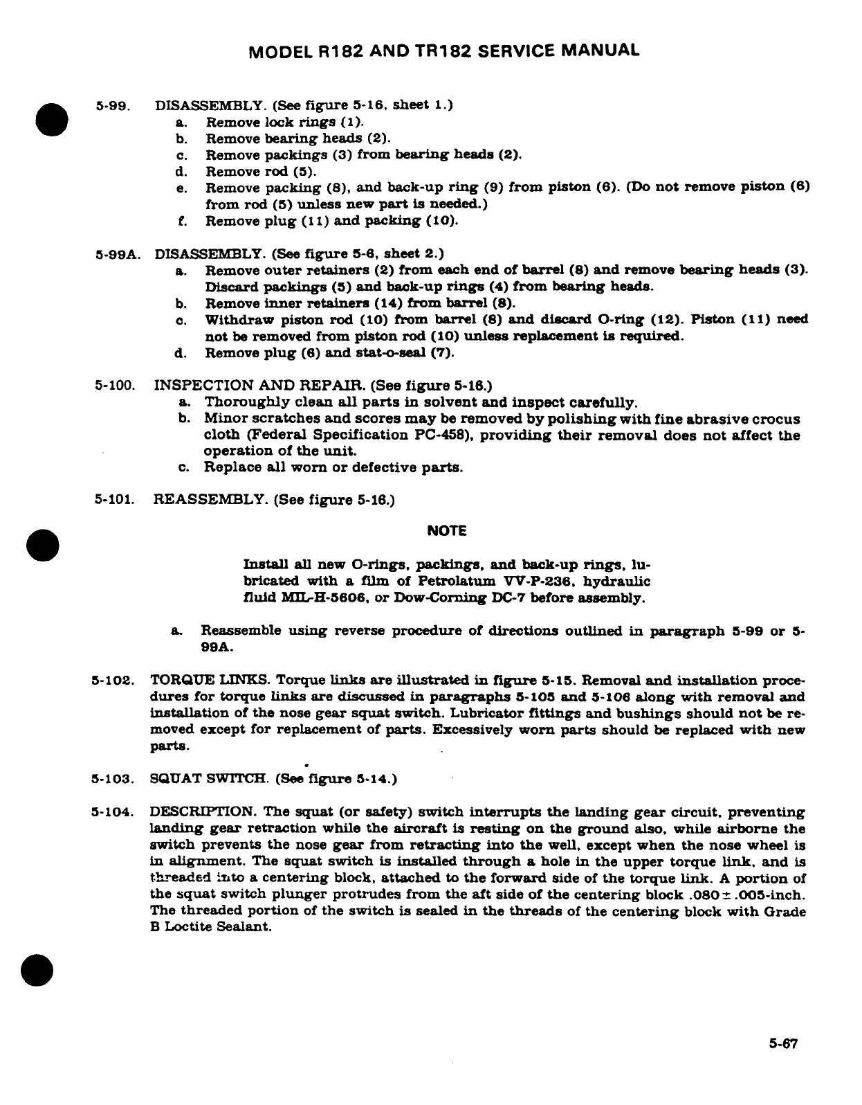
MODEL
R182
AND
TR182
SERVICE
MANUAL
5-99.
DISASSEMBLY.
(See
figure
5-16,
sheet
1.)
a.
Remove
lock
rings
(1).
b.
Remove
bearing
heads
(2).
c.
Remove
packings
(3)
from
bearing
heads
(2).
d.
Remove
rod
(5).
e.
Remove
packing
(8),
and
back-up
ring
(9)
from
piston
(6).
(Do
not
remove
piston
(6)
from
rod
(5)
unless
new
part
is needed.)
f.
Remove
plug
(11)
and packing
(10).
5-99A.
DISASSEMBLY.
(See
figure
5-6,
sheet
2.)
a.
Remove
outer retainers
(2)
from
each
end
of
barrel
(8)
and
remove
bearing
heads
(3).
Discard
packings
(5)
and
back-up
rings
(4)
from
bearing
heads.
b.
Remove
inner
retainers
(14)
from
barrel
(8).
c.
Withdraw
piston rod
(10)
from
barrel
(8)
and
discard
O-ring
(12).
Piston
(11)
need
not
be
removed
from
piston
rod
(10)
unless
replacement
is
required.
d.
Remove
plug
(6)
and
stat-o-seal
(7).
5-100.
INSPECTION
AND
REPAIR.
(See
figure
5-16.)
a.
Thoroughly
clean
all
parts
in
solvent
and
inspect
carefully.
b.
Minor
scratches
and
scores may
be
removed
by
polishing
with fine
abrasive
crocus
cloth
(Federal Specification
PC-458),
providing
their
removal
does
not
affect
the
operation
of
the
unit.
c.
Replace
all
worn
or
defective
parts.
5-101.
REASSEMBLY.
(See
figure
5-16.)
NOTE
Install
all
new
O-rings,
packings,
and
back-up
rings,
lu-
bricated
with
a
film
of
Petrolatum
VV-P-236,
hydraulic
fluid
MIL-H-5606.
or
Dow-Corning
DC-7
before
assembly.
a.
Reassemble
using
reverse
procedure
of
directions
outlined
in
paragraph
5-99
or
5-
99A.
5-102.
TORQUE
LINKS.
Torque
links
are
illustrated
in
figure
5-15.
Removal
and
installation
proce-
dures
for
torque
links
are
discussed
in
paragraphs
5-105
and
5-106
along
with
removal
and
installation
of
the
nose
gear
squat
switch.
Lubricator
fittings
and
bushings
should
not
be
re-
moved
except
for
replacement
of
parts.
Excessively
worn
parts
should
be
replaced
with
new
parts.
5-103.
SQUAT SWITCH. (See
figure
5-14.)
5-104.
DESCRIPTION.
The
squat
(or
safety)
switch
interrupts
the landing
gear circuit, preventing
landing
gear retraction
while
the
aircraft
is
resting
on
the
ground
also,
while
airborne
the
switch
prevents
the
nose
gear
from
retracting
into
the
well,
except
when the
nose
wheel
is
in
alignment.
The
squat
switch
is
installed
through
a
hole
in
the upper
torque
link,
and
is
threaded into
a
centering
block,
attached
to
the
forward
side
of
the
torque link.
A
portion
of
the
squat
switch
plunger
protrudes
from
the
aft
side of
the centering
block
.080 .005-inch.
The
threaded
portion
of
the
switch
is
sealed
in
the
threads
of
the
centering
block
with
Grade
B
Loctite
Sealant.
5-67
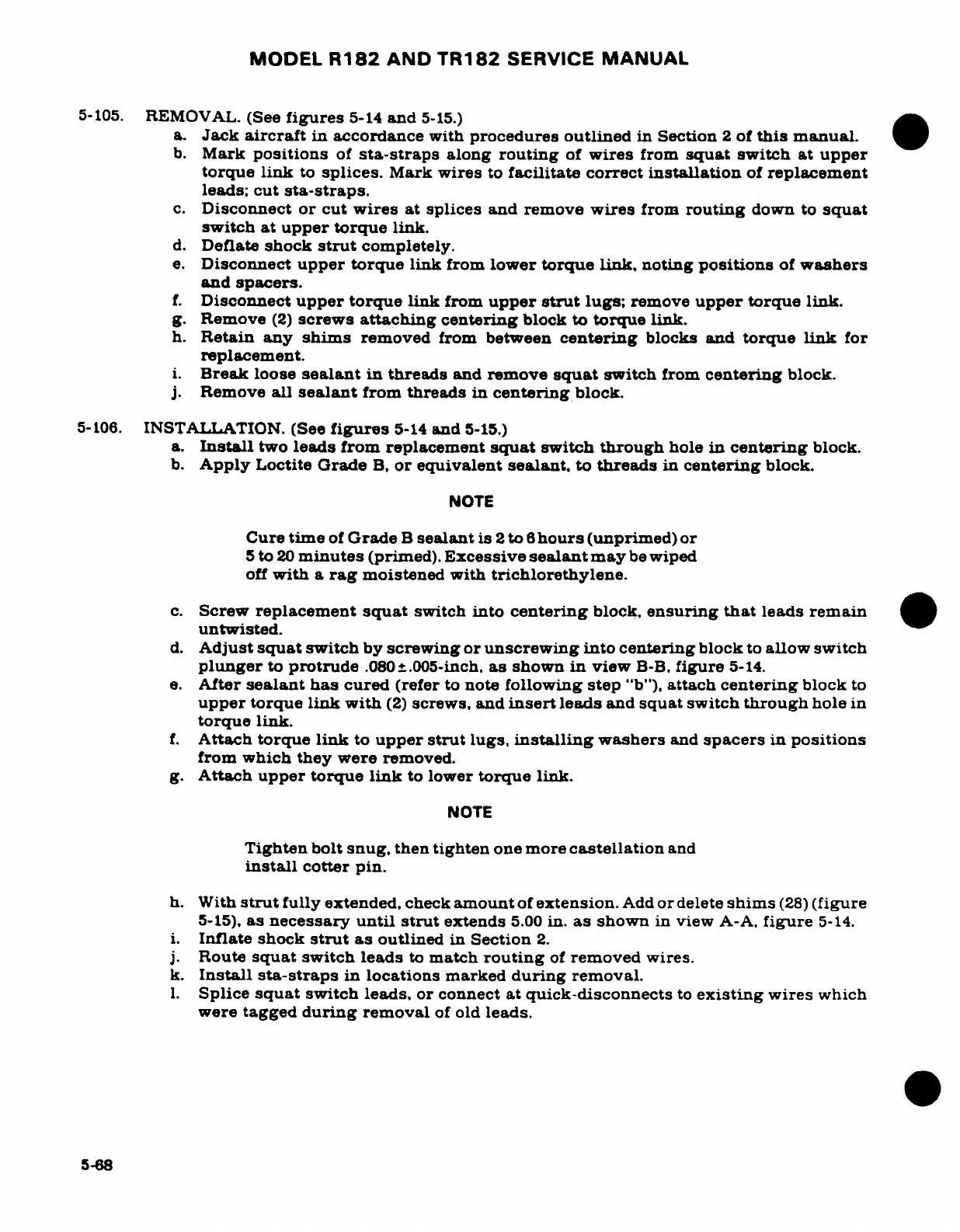
MODEL
R182
AND
TR182
SERVICE
MANUAL
5-105.
REMOVAL.
(See
figures
5-14
and
5-15.)
a.
Jack
aircraft
in
accordance
with
procedures
outlined
in
Section
2
of
this
manual.
b.
Mark
positions
of
sta-straps
along
routing
of
wires
from
squat
switch at upper
torque
link
to
splices.
Mark
wires
to
facilitate correct
installation
of
replacement
leads;
cut
sta-straps.
c.
Disconnect
or
cut
wires
at
splices and
remove
wires
from
routing
down
to
squat
switch
at
upper
torque
link.
d.
Deflate
shock
strut
completely.
e.
Disconnect
upper
torque
link
from
lower
torque
link,
noting
positions
of
washers
and
spacers.
f.
Disconnect
upper
torque
link
from
upper
strut
lugs;
remove
upper
torque
link.
g.
Remove
(2)
screws
attaching
centering
block to
torque link.
h.
Retain
any
shims
removed
from
between
centering
blocks and
torque
link
for
replacement.
i.
Break
loose
sealant
in
threads
and
remove
squat
switch
from
centering
block.
j.
Remove
all
sealant
from
threads
in
centering
block.
5-106.
INSTALLATION.
(See
figures
5-14
and
5-15.)
a.
Install
two
leads
from replacement
squat
switch
through
hole
in
centering
block.
b.
Apply
Loctite
Grade
B,
or
equivalent
sealant,
to
threads
in
centering
block.
NOTE
Cure
time
of
Grade
B
sealant
is
2
to
6
hours
(unprimed)
or
5
to
20
minutes
(primed).
Excessive
sealant
may
be
wiped
off
with
a
rag
moistened with
trichlorethylene.
c.
Screw
replacement
squat
switch
into
centering
block,
ensuring
that
leads
remain
untwisted.
d.
Adjust
squat
switch
by
screwing or
unscrewing
into centering
block
to
allow
switch
plunger
to
protrude
.080
+.005-inch,
as
shown
in
view
B-B,
figure
5-14.
e.
After
sealant
has
cured
(refer
to
note
following
step
"b"),
attach
centering
block
to
upper
torque
link with
(2)
screws,
and
insert
leads
and
squat
switch
through
hole
in
torque link.
f.
Attach
torque link
to
upper
strut
lugs,
installing
washers
and
spacers
in
positions
from which they
were
removed.
g.
Attach
upper torque
link
to
lower
torque
link.
NOTE
Tighten
bolt
snug,
then
tighten
one
more
castellation
and
install
cotter
pin.
h.
With
strut
fully
extended,
check
amount
of
extension.
Add
or
delete
shims
(28)
(figure
5-15),
as
necessary
until
strut
extends
5.00
in.
as
shown
in
view
A-A,
figure
5-14.
i.
Inflate
shock
strut
as
outlined
in
Section
2.
j.
Route
squat
switch
leads
to
match
routing
of
removed
wires.
k.
Install
sta-straps
in
locations
marked
during
removal.
1.
Splice
squat
switch
leads,
or
connect
at quick-disconnects
to
existing
wires
which
were
tagged
during
removal
of
old
leads.
5-68
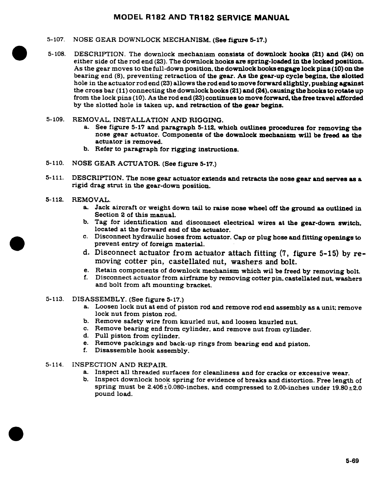
MODEL
R182 AND
TR182
SERVICE
MANUAL
5-107.
NOSE GEAR
DOWNLOCK
MECHANISM. (See
figure
5-17.)
5-108.
DESCRIPTION.
The
downlock
mechanism
consists
of
downlock
hooks
(21)
and
(24)
on
either
side
of
the
rod end
(23).
The
downlock
hooks
are spring-loaded
in
the
locked
position.
As
the
gear
moves
to
the
full-down
position,
the
downlock
hooks
engage
lock
pins
(10)
on
the
bearing
end
(8),
preventing
retraction
of
the
gear.
As
the
gear-up
cycle
begins,
the
slotted
hole
in
the
actuator
rod
end
(23)
allows
the
rod end
to move forward
slightly,
pushing
against
the
cross
bar
(11)
connecting
the
downlock
hooks
(21)
and
(24),
causing the
hooks
to rotate
up
from
the
lock
pins
(10).
As
the
rod
end
(23)
continues
to
move
forward,
the
free
travel
afforded
by
the
slotted
hole
is
taken
up,
and
retraction
of
the
gear
begins.
5-109.
REMOVAL,
INSTALLATION
AND
RIGGING.
a.
See
figure
5-17
and
paragraph
5-112,
which
outlines
procedures
for
removing
the
nose
gear actuator.
Components
of
the downlock
mechanism
will
be
freed
as
the
actuator
is
removed.
b.
Refer
to
paragraph
for
rigging
instructions.
5-110.
NOSE
GEAR
ACTUATOR. (See
figure
5-17.)
5-111.
DESCRIPTION. The
nose
gear
actuator
extends
and
retracts
the
nose
gear
and
serves
as
a
rigid
drag
strut
in
the
gear-down
position.
5-112.
REMOVAL.
a.
Jack
aircraft
or
weight
down
tail
to
raise
nose
wheel
off
the
ground
as
outlined
in
Section
2
of
this
manual.
b.
Tag
for
identification
and
disconnect
electrical
wires at the
gear-down
switch.
located
at
the forward
end
of
the
actuator.
c.
Disconnect
hydraulic
hoses
from
actuator.
Cap
or
plug
hose
and
fitting
openings
to
prevent
entry
of
foreign
material.
d.
Disconnect
actuator
from
actuator
attach
fitting
(7,
figure
5-15)
by
re-
moving
cotter
pin,
castellated
nut,
washers
and
bolt.
e.
Retain
components
of
downlock
mechanism
which
wil
be
freed
by
removing
bolt.
f.
Disconnect
actuator
from
airframe
by
removing
cotter
pin,
castellated
nut,
washers
and
bolt
from
aft
mounting
bracket.
5-113.
DISASSEMBLY.
(See
figure
5-17.)
a.
Loosen
lock
nut
at
end
of
piston
rod
and
remove
rod
end
assembly
as
a
unit;
remove
lock
nut
from
piston
rod.
b.
Remove
safety
wire
from
knurled
nut,
and
loosen
knurled
nut.
c.
Remove
bearing
end
from
cylinder,
and
remove
nut
from
cylinder.
d.
Pull
piston
from
cylinder.
e.
Remove
packings
and
back-up
rings
from
bearing
end and
piston.
f.
Disassemble
hook
assembly.
5-114.
INSPECTION
AND
REPAIR.
a.
Inspect
all
threaded
surfaces
for
cleanliness
and
for
cracks
or
excessive wear.
b.
Inspect
downlock
hook
spring
for
evidence
of
breaks
and
distortion.
Free
length
of
spring must
be
2.406±0.080-inches,
and
compressed
to
2.00-inches
under
19.80±2.0
pound
load.
5-69
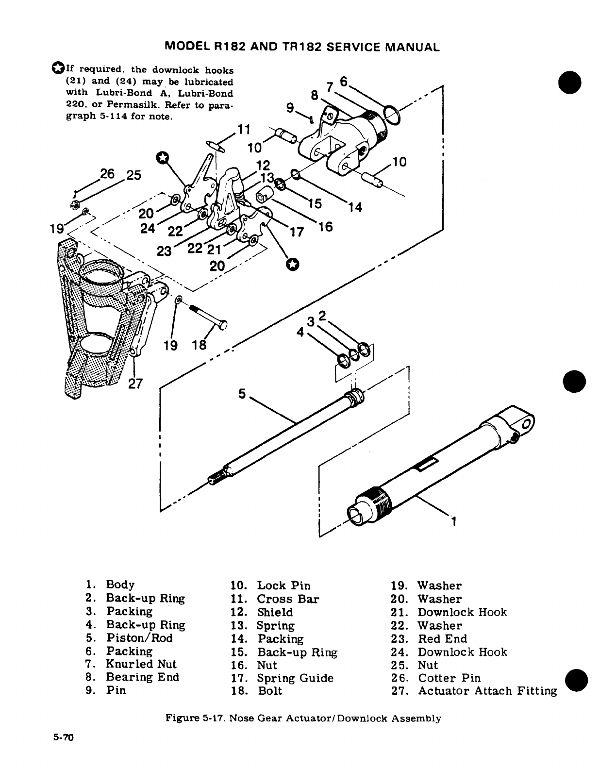
MODEL
R182
AND
TR182
SERVICE
MANUAL
If
required,
the
downlock
hooks
(21)
and
(24)
may
be
lubricated
7
6
with
Lubri-Bond
A,
Lubri-Bond
8
,
220,
or Permasilk.
Refer
to para-
9
'-
graph
5-114
for
note.
11
^^--^o-^^A^^^
14
2625
t
_
5
1
197
16
919
1
-i -zu5
1.
Body
10.
Lock
Pin
19.
Washer
2.
Back-up
Ring
11.
Cross
Bar
20.
Washer
3.
Packing
12.
Shield
21.
Downlock
Hook
4.
Back-up
Ring
13.
Spring
22.
Washer
5.
Piston/Rod
14.
Packing
23.
Red
End
6.
Packing
15.
Back-up
Ring
24.
Downlock
Hook
7.
Knurled
Nut
16.
Nut
25.
Nut
8.
Bearing
End
17.
Spring
Guide
26.
Cotter
Pin
9.
Pin
18.
Bolt
27.
Actuator
Attach
Fitting
Figure
5-17.
Nose
Gear
Actuator/
Downlock
Assembly
5-70
MODEL
R182
AND
TR182
SERVICE
MANUAL
c.
Inspect hooks,
spring
guide,
bearing
end,
piston,
cylinder
and
bushing
for
cracks,
chips.
scratches,
scoring,
wear
or
surface
irregularities
which
may
affect
their
function
or
the
overall
function
of
the
nose
gear
actuator.
d.
Repair
of
most
parts
of
the
actuator assembly
is
impractical.
Replace
defective
parts
with
serviceable
parts.
e.
Minor
scratches
and
scores may
be
removed
by
polishing
with
fine
abrasive
crocus
cloth
(Federal
Specification
PC-458),
providing
their
removal
does not
affect
opera-
tion
of
the
unit.
NOTE
The
downlock
hooks
may
be
field
lubricated
with
Lubri-
Bond
A,
Lubri-Bond
220,
or
Permasilk.
These
products
may
be
secured
from
the
following
companies.
Lubri-Bond
A,
and
Lubri-Bond
220:
Electro-Film
Inc.
7116 Laurel
Canyon
Blvd.
Hollywood,
CA.
91605
Permasilk:
Everlube
Corp. P.O.
Box
2200
Hi-Way
52
N.W.
West
Lafayette,
IND.
47906
After.
application
of
either
lubricant,
allow
parts
to
air
dry
for
six
hours,
or
dry
for
one
hour
at
120°F.
5-115.
ASSEMBLY.
(See
figure
5-17.)
NOTE
When
reassembling
actuator,
install
new
pack-
ings
lubricated
with
a
film
of
Petrolatum
VV-P-
236,
hydraulic
fluid
MIL-H-5606,
or
Dow-Corning
DC-7.
5-71
MODEL
R182
AND
TR182
SERVICE
MANUAL
a.
Install
packing
(6)
in
bearing
end
(8).
b.
Install
packing
(3),
and
back-up
rings
(2)
and
(4)
on
piston/rod
(5).
c.
Insert
piston/rod
(5)
rod
into
body
(1).
Do
not damage
back-up
rings
and
packing
when
inserting
piston
rod.
d.
With
knurled
nut
(7)
on
body
(1),
install
bearing
end
(8)
on
body
(1).
Use care
to
avoid
damage
to
packing
and
back-up
rings
when
installing
bearing
end on
body
(1).
NOTE
Centerlines
of
lock
pins
(10)
and
bushing
hole
in
body
(1)
must
be
parallel
within 0.005-inch
with
actuator
assem-
bled
to
a
length
of
13.58"
+
0.03-inches,
measured
from
cen-
terline
of
pins
to
centerline
of
bushing
in
cylinder
at
cylinder
anchor
end.
e.
Tighten
and
safety
wire
knurled
nut
(7).
f.
Install
nut
(16)
on
end
of
piston/rod
(5).
g.
Assemble
and
install
hook
assembly
on
actuator
attach
fitting
(27).
5-116.
INSTALLATION.
NOTE
Before
installing
nose
gear actuator,
check
condition
of
fit
and
attaching
bolts
and
bushings.
Replace
any
defec-
tive
parts.
Fill
actuator
with hydraulic
fluid.
a.
Attach aft
end
of
actuator
to
fuselage
structure
with
bolt,
washer
and
nut. Safety
nut with
cotter
pin.
b.
Assemble
and
attach
nose
gear
downlock
mechanism
to
actuator
attach
fitting
as
shown
in
figure
5-17.
c.
Connect
hydraulic
lines
to
actuator
and
connect
electrical
leads
to
gear-down
switch.
d.
See "Nose
Gear
Rigging"
paragraph
for
adjustment
and
checking
of
downlock.
5-117.
NOSE
GEAR
DOORS.
(Thru
R18201798.)
(See
figure
5-18.)
5-72
Revision
1
MODEL
R182
AND
TR182
SERVICE
MANUAL
.
5-118.
DESCRIPTION.
The
nose
gear
door
system
consists
of
a
left and
right
hand
door.
intercon-
nected
by a
crossover actuator
assembly.
As
the
gear
is
retracted,
the
forward
side
of
the
nose
gear
fork
boss
contacts
the
actuator
crossover.
causing
the
doors
to
close. Overcenter-
ing
springs,
attached
to
the
actuator,
serve
to
hold
the
doors
in
the
full-open
or
closed
position.
5-119.
REMOVAL
AND
INSTALLATION.
(Thru
R18201798.)
(See
to
figure
5-18.)
a.
Remove
hinge
bolts
and
reated
nuts
washers and
bushings
(6).
b.
Disconnect
adjusting
rod
(9)
from
center
hinge
and
remove
door.
c.
Disconnect
springs
(7)
and
remove
actuator
pivot
bolts
and
related
nuts,
washers
and
bushings
(5);
remove
actuator.
d.
Reverse
procedure
to
install
doors.
5-120.
NOSE
GEAR DOORS.
(Beginning
with
R18201799.)
(See
figure
5-19.)
5-121.
DESCRIPTION.
The
nose
gear
door
system
is
comprised
of
a
left
and
right-hand
door.
interconnected
by
a
crossover
actuator
assembly.
As
the
gear
is
retracted.
the forward
side
of
the
nose
gear
fork
boss
contacts
the
actuator
crossover,
causing
the
doors
to
close.
Overcentering
springs,
attached
to
the
actuator
crossover,
serve
to
hold
the
doors
in
the full
open
or closed
position.
5-122.
REMOVAL.
(Beginning with
R18201799.)
(See
figure
5-19.)
a.
Remove
hinge
bolts
and
related
nuts,
washers
(8),
(9)
and
bushings
(10).
b.
Disconnect adjusting
rod
assemblies
(11)
from
center
hinges
and
re-
move
doors.
c.
Disconnect
springs
(7),
and
remove
actuator
pivot
bolts
and
related
nuts,
washers
and
bushings
(6).
5-123.
INSTALLATION.
(Beginning
with
R18201799.)
(See
figure
5-19.)
Reverse
procedures
outlined
in
paragraph
5-122
to
install
doors.
NOTE
Thru
serial
R18201899,
check
clerance
between
nose
gear
doors
and
lower
cowl
skin
to
be.
10
± .
06/.00
inch.
Safety
wire
rod
assemblies
to
fair
nose
gear
doors
in
closed
position.
Adjust
stop
bolts
(14)
on
brackets
(13)
to
contact
bushings
(5)
when
nose
gear
doors
are
in
full
open
position.
5-124.
DELETED.
Revision
2
5-72A
MODEL
R182
AND
TR182
SERVICE
MANUAL
5-125.
NOSE
WHEEL
STEERING
SYSTEM.
(See
figure
5-19.)
5-125.
DESCRIPTION.
The
nose wheel
steering
system
links
the
rudder
pedals
to
the
nose
wheel
fork.
affording
steering
control
through
use
of
the
rudder
pedals.
Kinematics
of
the
system
automatically
straighten
the
nose wheel
as
the
landing
gear
is
retracted. During
retraction
the
centering
block
on
the
upper
torque link aligns
and
locks
the
nose
wheel
in
the
neutral
position.
Continued
free
movement
of
the
rudder
pedals
is
assured
by
the
steering
bungee.
(See
figure
5-14.)
5-126.
STEERING
BUNGEE ASSEMBLY.
(See
figure
5-19.)
5-127.
DESCRIPTION. The
steering
bungee
assembly
is
spring-loaded.
and
should
not
be
disas-
sembled
internally.
The
steering
bungee
is
connected
to
the
steering
bellcrank
on
the
nose
gear
strut
by
a
bearing
end
assembly,
and
to
the
rudder
bar
assembly
by a
rod
assembly
thru
R18201798.
Beginning
with
R18201799.
the
steering
bungee
assembly
is
connected
to
the
steering bellcrank
on
the
nose
gear
strut
by
a
bearing
end
assembly.
and
to
the
rudder
bar
assembly
by
a
barrel
nut
and
two
snap rings.
5-128.
REMOVAL.
(Thru
R18201798.)
(See
figure
5-19.)
a.
Disconnect
bearing
end
assembly
from
steering bellcrank
(8)
on
nose
gear
strut.
b.
Disconnect
rod
end
assembly from
rudder
bar
assembly
(2).
c.
Remove
sprocket
(4)
from
chain
assembly
(3);
remove
steering
bungee
assembly
(5).
5-129.
INSTALLATION.
(Thru
R18201798.)
(See
figure
5-19.)
a.
Install
chain
assembly
(3)
on
sprocket
(4).
b.
Connect
rod
end
assembly
to
rudder
bar
assembly
(2).
c.
Connect
bearing
end
assembly
to
steering
bellcrank
(8)
on
nose
gear
strut.
5-130.
REMOVAL.
(Beginning
with
R18201799.)
(See
figure
5-19.)
a.
Disconnect bearing
end
assembly
from
steering
bellcrank
(8)
on
nose
gear
strut.
b.
Remove
pin
(14)
and
flex
shaft
(11)
from shaft
of
steering
bungee
assembly
(5).
c.
Remove
snap
rings
(13)
and
barrel
nut
(12)
securing
steering
bungee
(5)
to
ears
of
rudder
bar
assembly
(2).
d.
Disconnect
bearing
end
assembly
from
steering
bungee
assembly
(5).
5-72B
Revision
2
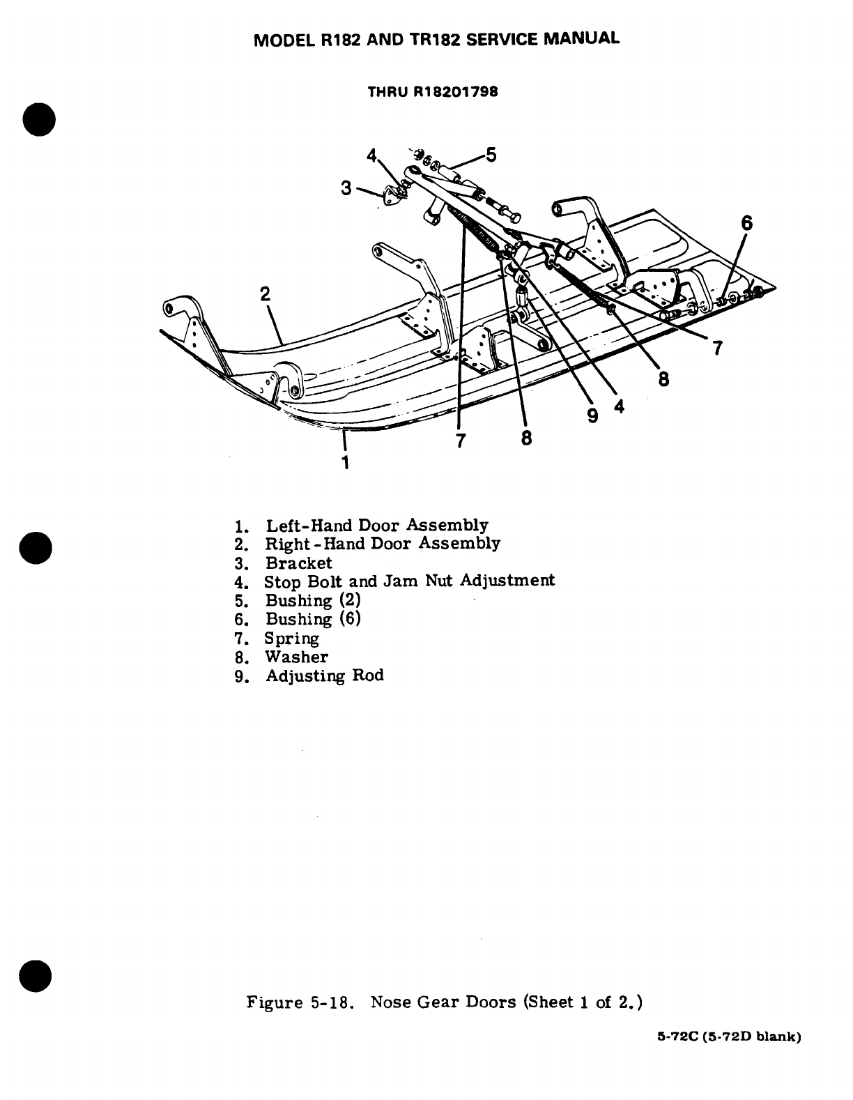
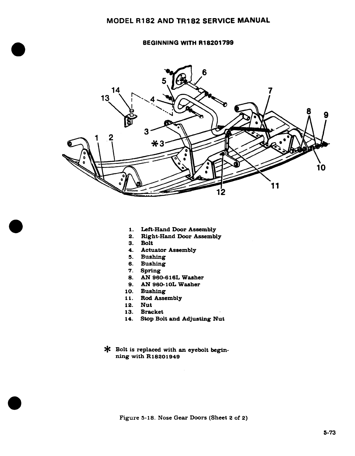
MODEL
R182
AND
TR182
SERVICE
MANUAL
BEGINNING
WITH
R18201799
14
7
1.
Left-Hand
Door
Assembly
2.
Right-Hand
Door Assembly
3.
Bolt
4.
Actuator
Assembly
5.
Bushing
6.
Bushing
7.
Spring
8.
AN
960-616L
Washer
9.
AN
960-10L
Washer
10.
Bushing
11.
Rod
Assembly
12.
Nut
13.
Bracket
14.
Stop
Bolt
and Adjusting
Nut
C
Bolt
is
replaced
with
an
eyebolt
begin-
ning
with
R18201949
Figure
5-18.
Nose
Gear
Doors
(Sheet
2
of
2)
5-73
MODEL
R182
AND
TR182
SERVICE
MANUAL
5-131.
INSTALLATION.
Beginnink
with
R18201799.)
(See
figure
5-19).
a.
Install
steering
bungee
(5)
such
that
shaft
is
positioned
between
ears
of
rudder
bar
assembly
(2).
b.
Install
barrel
nut
(12)
and
two
snap
rings
(13).
c.
Connect
bearing
end
assembly
to
steering
bellcrank
(8)
on
nose
gear
strut.
d.
Install
flex
shaft
(11)
over
shaft
of
steering
bungee
assembly
(5);
install
pin
(14).
5-132.
REMOVAL
AND
INSTALLATION
OF
NOSE
WHEEL
STEERING
SYSTEM
COMPO-
NENTS.
(See
figure
5-19.)
Use
the
figure
as
a
guide
in
determining
system
component
relationship
and
for
removal
and
installation
of
system
components.
5-133.
RIGGING
NOSE WHEEL
STEERING
SYSTEM.
Since
the
nose
wheel
steering
system
is
connected with the
rudder
control
system, adjustment
to
one
system
would
directly
affect
the
other.
Refer
to
Section
10
of
this
manual
for
rigging
procedures
for
the
rudder system
and
the
nose wheel
steering
system.
5-134.
NOSE
WHEEL
AND
TIRE
ASSEMBLY.
5-135.
DESCRIPTION.
The
aircraft
may
be
equipped
with
either
Cleveland
or
McCauley
wheel
assemblies.
Separate
disassembly,
inspection
and
re-
assembly
instructions
are
provided
for
each
type.
Basic
difference
of
the
two
types
are
shown
in
figure
5-20.
CAUTION
Use
of
recapped
tires
or
new
tires
not
listed
on
the
aircraft
equipment
list
are
not
recommended
due to
possible
interference
between
the
tire
and
structure
when
landing
gear
is in
the
retracted
position.
5-74
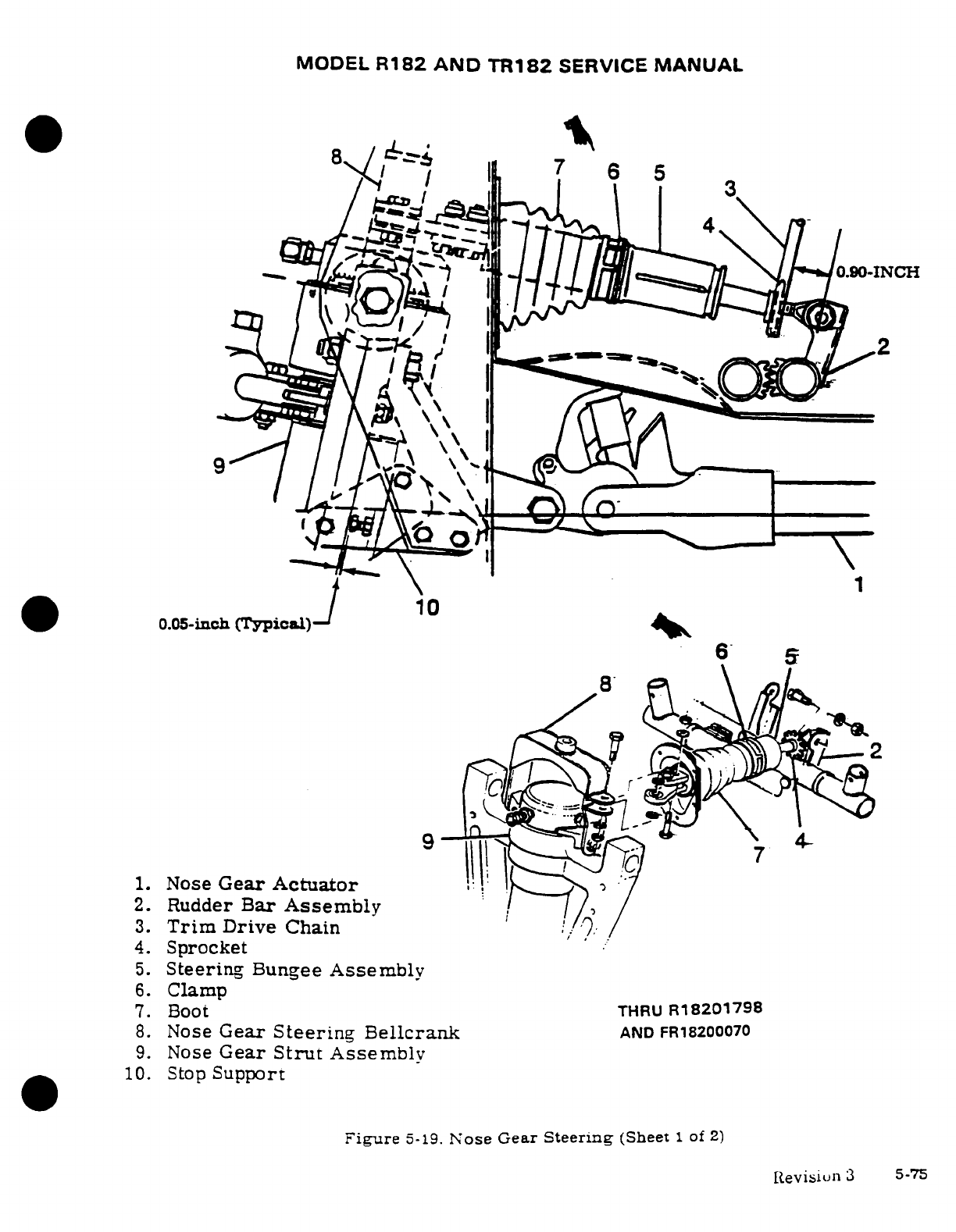
MODEL
R182
AND
TR182
SERVICE
MANUAL
0 10
./
67
6
53
:~cr3
r1.
Nose
Gear
Actuator
*|Is_^
!
;
~4. Sprocket
6.
Clamp
7. Boot THRU
R18201798
1.
Nose
Gear
Actuator
2.
Rudder
Bar
Assembly
3.
Trim
Drive
Chain
4.
Sprocket
5.
Steering
Bungee
Assembly
6.
Clamp
7. Boot
THRU
R18201
7 9 8
8.
Nose
Gear
Steering
Bellcranrik
AND
FR18200070
9.
Nose
Gear
Strut
Assembly
10.
Stop
Support
Figure
5-19.
Nose
Gear
Steering
(Sheet
1
of
2)
Revisiun
3
5-75
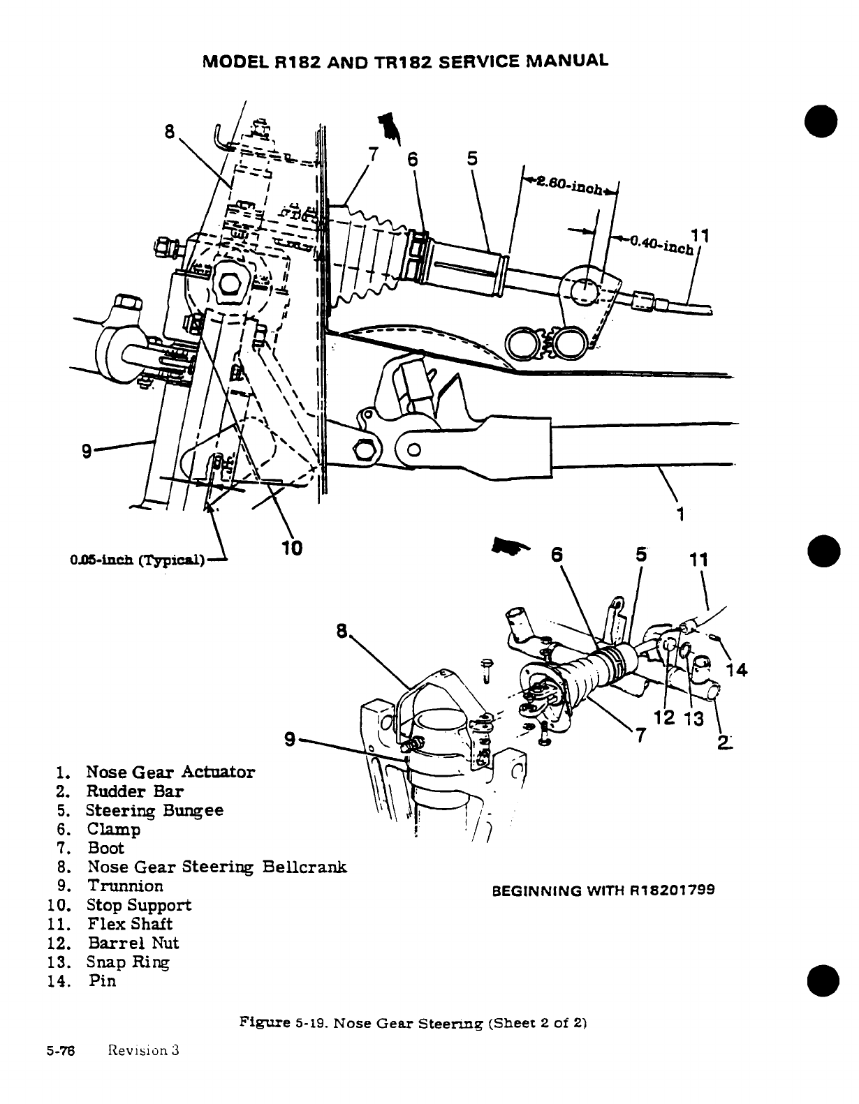
MODEL
R182
AND
TR182
SERVICE
MANUAL
_?'-1
°
_
-..
8
1
i=1077
6
51
w=c~i~·~~tif-.
TjJii^40-i
005-inch
(Typical)
10
11
1.
Nose
Gear
Actuator
2.
Rudder
Bar
5.
Steering
Bungee
' .
6.
Clamp
7
/
7.
Boot
8.
Nose
Gear Steering
Bellcrank
9.
Trunnion
BEGINNING
WITH
R182017
99
10.
Stop
Support
11.
Flex
Shaft
12.
Barrel
Nut
13.
Snap
Ring
14.
Pin
Figure
5-19.
Nose
Gear
Steerng
(Sheet
2
of
2)
5-76
Revision
3
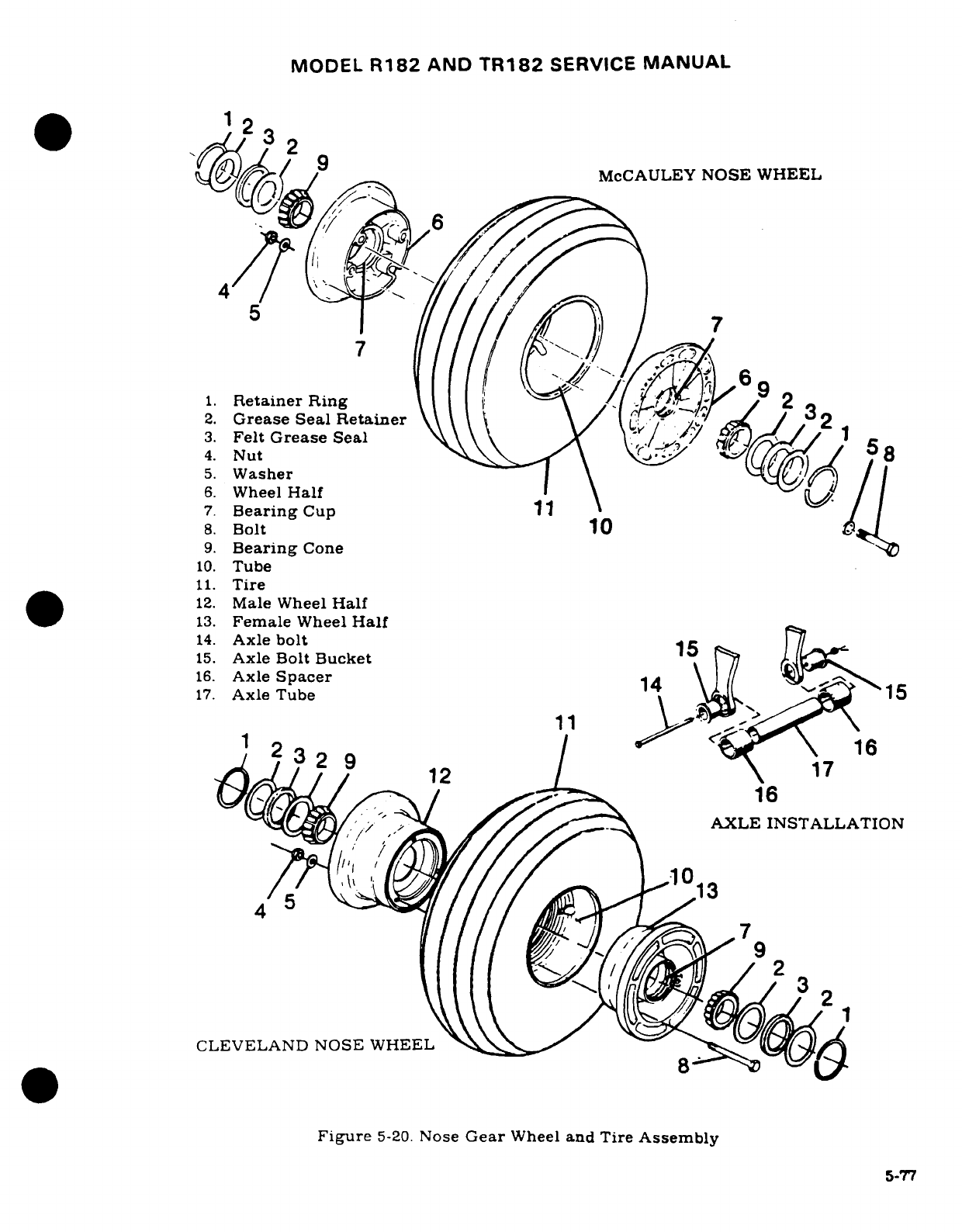
MODEL
R182
AND
TR182
SERVICE
MANUAL
23
^0)//^
/
McCAULEY
NOSE
WHEEL
7
1.
Retainer
Ring
2
2.
Grease
Seal
Retainer
\\\ \
/ /' / ,
2
3.
Felt
Grease
Seal
\ //
4.
Nut
5
5.
Washer
6.
Wheel
Half
\
7.
Bearing
Cup
1
8.
Bolt
10
A
9.
Bearing
Cone
10.
Tube
11.
Tire
12.
Male
Wheel
Half
13.
Female
Wheel
Half
14.
Axle
bolt
15.
Axle
Bolt Bucket
16.
Axle
Spacer4
\
17.
Axle Tube
15
11
2
16
ail
22
12
/
\ 17
16
/^-f~liW / ^
, ,/AXLE
INSTALLATION
CLEVELAND NOSE
WHEEL
Figure
5-20.
Nose
Gear
Wheel
and
Tire
Assembly
5-77
MODEL
R182
AND
TR182
SERVICE
MANUAL
5-136.
REMOVAL AND
INSTALLATION.
a.
Weight
or
tie-down
tail
of
aircraft
to
raise
the
nose
wheel
off
the
floor.
b.
Remove
nose
wheel
axle
bolt.
c.
Use
a
rod
or
long
punch
inserted
through
one
axle
bolt
ferrule
to
tap
the
opposite
ferrule
out
of
the
fork.
Remove
both
ferrules
and
pull
the
nose
wheel
from
the
fork.
d.
Remove
spacers
and
axle
tube
from
the nose
wheel.
e.
Reverse
the
preceding
steps
to
install
the
nose
wheel.
Tighten
axle
bolt
until
a
slight
bearing
drag
is
obvious
when
the
wheel
is
turned.
Back the
nut
off to
the
nearest
castellation
and
install
cotter
pin.
5-137.
DISASSEMBLY
OF
CLEVELAND
NOSE
WHEEL
AND
TIRE
ASSEMBLY.
(See
figure
5-20.)
a.
Remove
hub
cap,
completely
deflate
tire
and
break
tire
beads
loose
from
wheel
rims.
WARNING
Injury
can
result
from
attempting
to
separate
wheel
halves
with
the
tire
inflated.
Avoid
damaging
wheel
flanges
when
breaking
tire
beads
loose.
Do
not
use
impact
wrenches
on
thru-bolts
or
nuts.
b.
Remove
thru-bolts
and
separate
wheel
halves.
c.
Remove
tire
and
tube
from
wheel
halves.
d.
Remove
bearing
retaining
rings, grease
seals,
and
bearing
cones.
NOTE
The
bearing
cups
are
a
press
fit
in
the
wheel
halves
and
should
not
be
removed
unless
installation
of
new
cups
is
necessary.
To
remove,
heat
wheel
half
in
boiling
water
for
15
minutes.
Using
an
arbor
press
if
available, press
out
the
bearing
cup and
press
in
the
new
one
while
the
wheel
is
still
hot.
5-138.
INSPECTION
AND
REPAIR
OF
CLEVELAND
WHEEL
AND
TIRE
ASSEMBLY.
a.
Clean
all metal
parts
and
the
grease
seal
felts
in
cleaning
solvent
and
dry
thoroughly.
b.
Inspect
wheel
halves
for
cracks.
Cracked
wheel
halves must
be
rejected
and
new
parts
installed.
Sand out
nicks,
gouges,
and
corroded
areas.
When
the
protective
coating
has
been
removed,
the
area
should
be
cleaned
thoroughly,
primed
with zinc
chromate
and
painted
with
aluminum
lacquer.
c.
Bearing
cups
and
cones
must
be
inspected
carefully
for
damage and
discoloration.
After
cleaning,
repack
cones
with
clean
aircraft
wheel
bearing
grease
before
installation
in
the
wheel
half.
5-139.
REASSEMBLY
OF
CLEVELAND
NOSE
WHEEL
AND
TIRE
ASSEMBLY.
(See
figure
5-20.)
a.
Insert
tube
in
tire,
aligning
index
marks
on
tire
and
tube.
b.
Place
tire
and
tube
on
wheel
half
and
position
valve
stem
through
hole
in wheel half.
c.
Insert
thru-bolts,
position
other
wheel
half,
and
secure
with
washers
and
nuts. Take
care
and
avoid
pinching
tube
between wheel
halves.
Torque
thru-bolts
evenly
to
140-
150
lb
in.
CAUTION
Uneven
or
improper
torque
on
thru-bolt
nuts
may
cause
bolt
failure
with
resultant
wheel
failure.
5-78
Revision
1
MODEL
R182
AND
TR182
SERVICE
MANUAL
d.
Clean
and
repack
bearing
cones
with
clean
aircraft
wheel
bearing
gree.
e.
Assemble
bearing
cones,
seals,
and
retainers
into
wheel
halves.
f.
Inflate
tire
to
seat
tire
beads,
then
adjust
to
correct
pressure.
g.
Install
hub
caps
and
install
wheel
in
accordance
with
paragraph
5-125.
5-140.
DISASSEMBLY
OF
McCAULEY
NOSE
WHEEL AND
TIRE
ASSEMBLY.
NOTE
Serious
damage
can
result
from
attempting
to
separate
wheel
halves
with
tire
and
tube
inflated.
a.
Completely
deflate
tire
and
tube
and
break
loose
tire
beads.
Extreme
care
must
be
exercised
to
prevent
tire
tool
damage
when
removing
tire
from
wheel
halves.
b.
Remove
nuts
and
washers.
c.
Remove
thru-bolts
and
washers.
d.
Separate
and
remove
wheel
halves
from
tire
and
tube.
e.
Remove
retaining
ring,
grease
seal retainer
felt
grease
seal,
grease
retainer
and
bearing
cone
from
each
wheel
half.
NOTE
Bearing
cups (races)
are
a
press
fit
in
the
wheel
halves
and
should
not
be
removed
unless
a
new
part
is
to
be
installed.
To
remove
bearing
cups,
heat
wheel
half
in
boiling
water
for
30
minutes
or
in
an
oven
not
to
exceed
121°C
(250°F).
Using
an
arbor press,
if
available,
press
out
bearing
cup and
press
in
new
bearing
cup
while
wheel
half
is
still
hot.
5-141.
INSPECTION
AND
REPAIR
OF
McCAULEY
NOSE
WHEEL
AND
TIRE
ASSEMBLY.
a.
Clean
all
metal
parts
and
felt
grease seals
in
Stoddard
solvent,
or
equivalent,
and
dry
thoroughly.
NOTE
A
soft
bristle
brush
may
be
used
to
remove hardened
grease,
dust
or
dirt.
b.
Inspect
wheel
halves
for
cracks
or
damage.
c.
Inspect
bearing
cones, cups,
retaining
rings
and
seals
for
wear
or
damage.
d.
Inspect
thru-bolts
and
nuts
for
cracks
in
threads
or
cracks
in
radious under
bolt
head.
e.
Replace
cracked
or
damaged
wheel
halves.
f.
Replace
damaged
retaining
rings
and
seals.
g.
Replace
any worn or
cracked
thru-bolts
or
nuts.
h.
Replace
any worn or
damaged
bearing
cups
or
cones.
i.
Remove
any
corrosion
or
small
nicks.
j.
Repair
reworked
areas
of
wheel
by
cleaning thoroughly,
then
applying
one
coat
of
clear
lacquer.
k.
Pack
bearings
with
grease
specified
in
Section
2
of
this
manual.
5-79
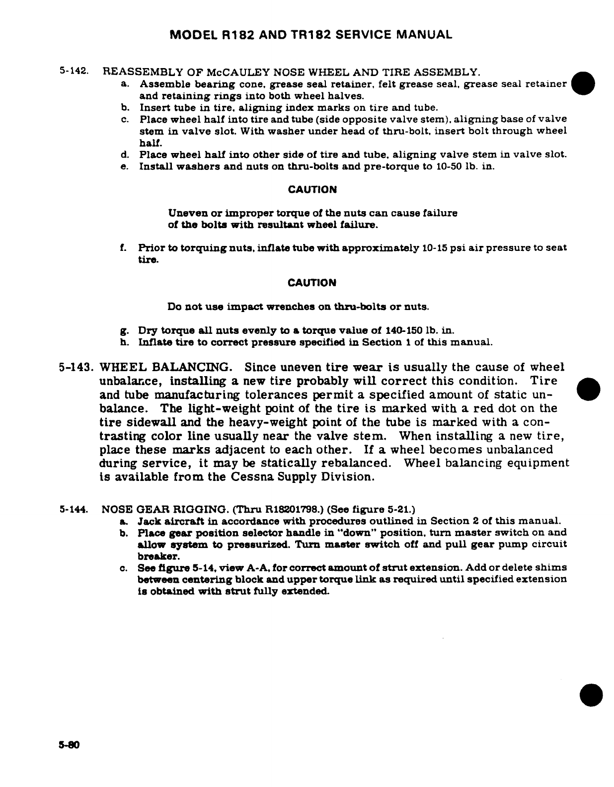
MODEL
R182
AND
TR182
SERVICE
MANUAL
5-142.
REASSEMBLY
OF
McCAULEY
NOSE
WHEEL
AND
TIRE
ASSEMBLY.
a.
Assemble
bearing
cone,
grease
seal
retainer,
felt
grease
seal,
grease
seal
retainer
and
retaining rings
into
both
wheel
halves.
b.
Insert
tube
in
tire, aligning
index
marks
on
tire
and
tube.
c.
Place
wheel
half
into
tire
and
tube
(side
opposite
valve
stem),
aligning
base
of
valve
stem
in
valve
slot.
With
washer
under
head
of
thru-bolt.
insert
bolt
through
wheel
half.
d.
Place
wheel
half
into
other
side
of
tire
and
tube,
aligning
valve
stem
in
valve
slot.
e.
Install
washers
and
nuts
on
thru-bolts
and
pre-torque
to
10-50
lb.
in.
CAUTION
Uneven
or
improper
torque
of
the
nuts
can
cause
failure
of
the bolts
with
resultant
wheel
failure.
f.
Prior
to
torquing
nuts,
inflate tube
with
approximately
10-15
psi
air
pressure
to
seat
tire.
CAUTION
Do
not
use impact
wrenches on
thru-bolts
or
nuts.
g.
Dry
torque
all
nuts
evenly
to
a
torque
value
of
140-150
lb.
in.
h.
Inflate
tire
to
correct
pressure
specified
in
Section
1
of
this
manual.
5-143.
WHEEL
BALANCING.
Since
uneven
tire
wear
is
usually
the
cause
of
wheel
unbalance,
installing
a
new
tire
probably
will
correct
this
condition.
Tire
and
tube
manufacturing
tolerances
permit
a
specified
amount
of
static
un-
balance.
The
light-weight
point
of
the
tire
is
marked
with
a
red
dot
on
the
tire
sidewall
and
the
heavy-weight
point
of
the
tube
is marked
with
a
con-
trasting
color
line
usually
near
the
valve
stem.
When
installing
a
new
tire,
place
these
marks
adjacent
to
each
other.
If
a
wheel
becomes
unbalanced
during
service,
it
may
be
statically
rebalanced.
Wheel
balancing equipment
is
available
from
the
Cessna
Supply
Division.
5-144.
NOSE
GEAR
RIGGING.
(Thru
R18201798.)
(See
figure
5-21.)
a.
Jack
aircraft
in
accordance
with
procedures
outlined
in
Section
2
of
this
manual.
b.
Place
gear
position
selector handle
in
"down"
position, turn
master
switch
on
and
allow
system
to
pressurized. Turn
master
switch
off
and
pull
gear
pump
circuit
breaker.
c.
See
figure
5-14,
view
A-A,
for
correct
amount of
strut
extension.
Add
or
delete
shims
between
centering
block
and
upper
torque
link as
required
until
specified
extension
is
obtained
with
strut
fully
extended.
5-80
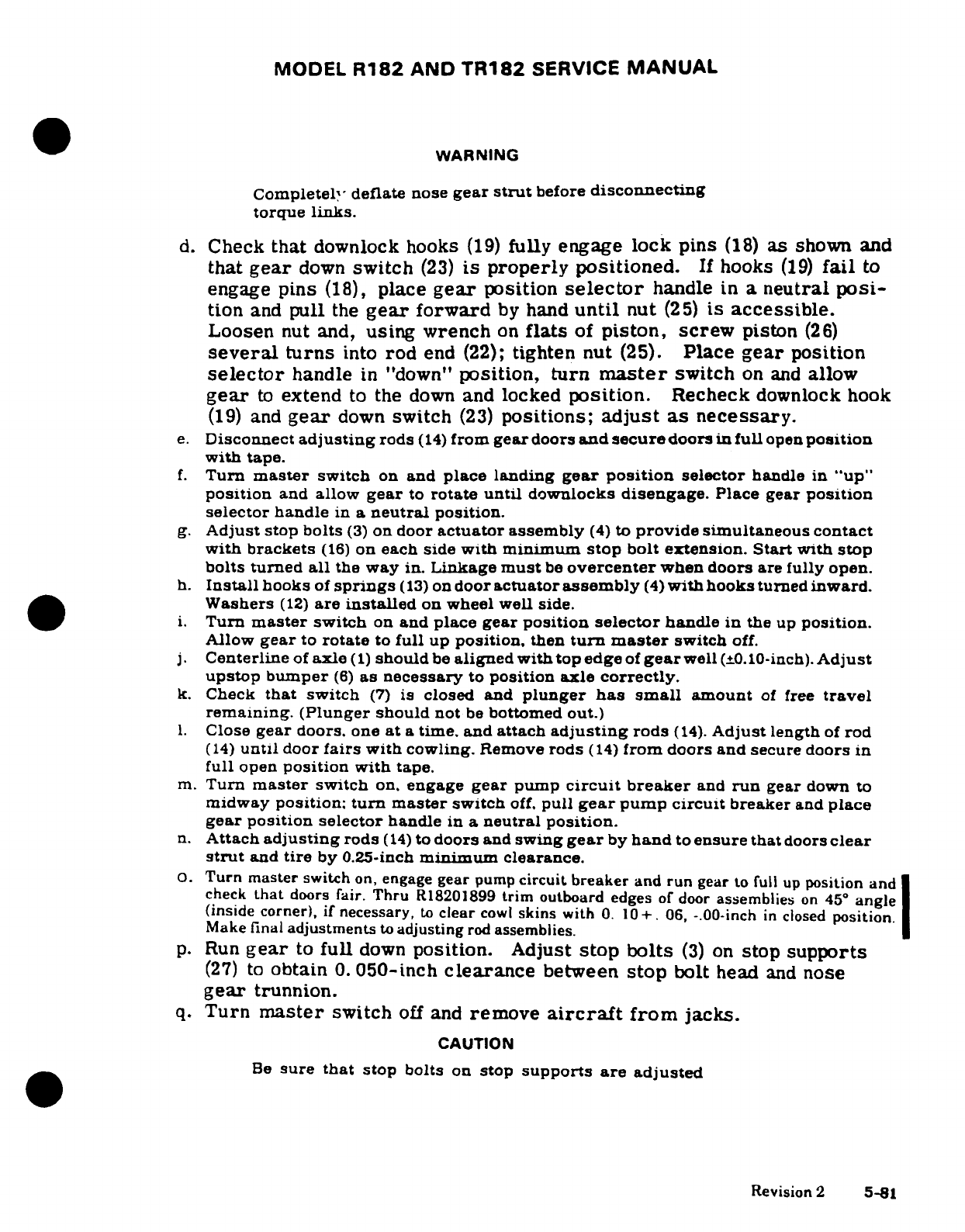
MODEL
R182
AND
TR182
SERVICE
MANUAL
WARNING
Completely
deflate
nose
gear
strut
before
disconnecting
torque
links.
d.
Check
that
downlock hooks
(19)
fully engage
lock pins
(18)
as
shown
and
that
gear
down
switch
(23)
is
properly
positioned.
If
hooks
(19)
fail
to
engage
pins
(18),
place
gear
position
selector
handle
in
a
neutral
posi-
tion
and
pull
the
gear
forward
by
hand
until
nut
(25)
is
accessible.
Loosen
nut and,
using
wrench
on
flats
of
piston,
screw
piston
(26)
several
turns
into
rod
end
(22);
tighten
nut
(25).
Place
gear
position
selector
handle
in
"down"
position,
turn
master
switch
on and
allow
gear
to
extend
to the
down
and
locked
position.
Recheck
downlock
hook
(19)
and
gear
down
switch
(23)
positions;
adjust as
necessary.
e.
Disconnect
adjusting
rods
(14)
from
gear
doors
and
secure
doors
in
full
open
position
with tape.
f.
Turn
master
switch
on
and
place
landing
gear position
selector
handle
in
"up"
position
and
allow
gear
to
rotate
until
downlocks
disengage.
Place
gear
position
selector
handle
in a
neutral
position.
g.
Adjust
stop bolts
(3)
on
door
actuator
assembly
(4)
to
provide
simultaneous
contact
with
brackets
(16)
on
each
side
with
minimum
stop
bolt
extension.
Start
with
stop
bolts
turned
all
the
way
in.
Linkage
must
be
overcenter
when
doors
are
fully
open.
h.
Install
hooks
of
springs
(13)
on
door
actuator
assembly
(4)
with
hooks
turned
inward.
Washers
(12)
are
installed
on
wheel
well
side.
i.
Turn
master
switch
on
and
place
gear
position
selector
handle
in
the
up
position.
Allow
gear
to
rotate
to
full
up
position,
then
turn
master
switch
off.
j.
Centerline
of
axle
(1)
should
be
aligned
with
top edge
of
gear
well
(±0.10-inch).
Adjust
upstop bumper
(6)
as
necessary
to
position
axle
correctly.
k.
Check
that
switch
(7)
is
closed
and
plunger
has
small
amount
of
free
travel
remaining.
(Plunger
should
not
be
bottomed
out.)
l.
Close
gear
doors,
one
at
a
time,
and
attach
adjusting
rods
(14).
Adjust
length
of
rod
(14)
until
door
fairs
with
cowling.
Remove
rods
(14)
from
doors and
secure
doors
in
full
open
position
with
tape.
m.
Turn
master
switch
on,
engage
gear
pump
circuit
breaker
and
run
gear
down
to
midway
position:
turn
master
switch
off.
pull
gear
pump
circuit
breaker
and
place
gear
position selector
handle
in a
neutral
position.
n.
Attach
adjusting
rods
(14)
to
doors
and
swing
gear
by
hand
to
ensure
that
doors
clear
strut
and
tire
by
0.25-inch
minimum
clearance.
O.
Turn
master
switch
on,
engage
gear
pump
circuit
breaker
and
run
gear
to
full up
position
and
check
that
doors
fair.
Thru
R18201899
trim
outboard
edges
of
door
assemblies
on
45°
angle
(inside
corner),
if
necessary,
to
clear
cowl
skins
with
0.
10+.
06,
-.
00-inch
in
closed
position.
Make
final
adjustments
to
adjusting
rod
assemblies.
p.
Run
gear
to
full
down
position. Adjust
stop
bolts
(3)
on
stop
supports
(27)
to
obtain
0.
050-inch
clearance
between
stop
bolt
head
and
nose
gear
trunnion.
q.
Turn
master
switch
off
and
remove
aircraft
from
jacks.
CAUTION
Be
sure
that
stop
bolts
on
stop
supports
are adjusted
Revision
2
5-81
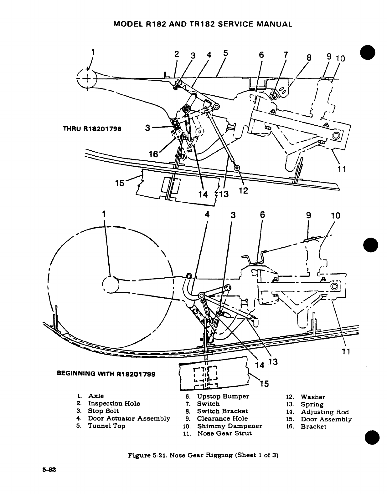
MODEL
R182
AND
TR182
SERVICE
MANUAL
THRUR1S2179B
3
1 42
3
6
9
10
-
/^"^e
4
.L
151
13
12
4 3 6
9
10
BEGINNING
WITH
R18201799
i \
15
1.
Axle
6.
Upstop
Bumper
12.
Washer
2.
Inspection
Hole
7.
Switch
13.
Spring
3.
Stop
Bolt
8.
Switch
Bracket
14.
Adjusting
Rod
4.
Door
Actuator
Assembly
9.
Clearance
Hole
15.
Door
Assembly
5.
Tunnel
Top
10.
Shimmy Dampener
16.
Bracket
11.
Nose
Gear
Strut
Figure
5-21.
Nose
Gear
Rigging
(Sheet
1
of
3)
5-82
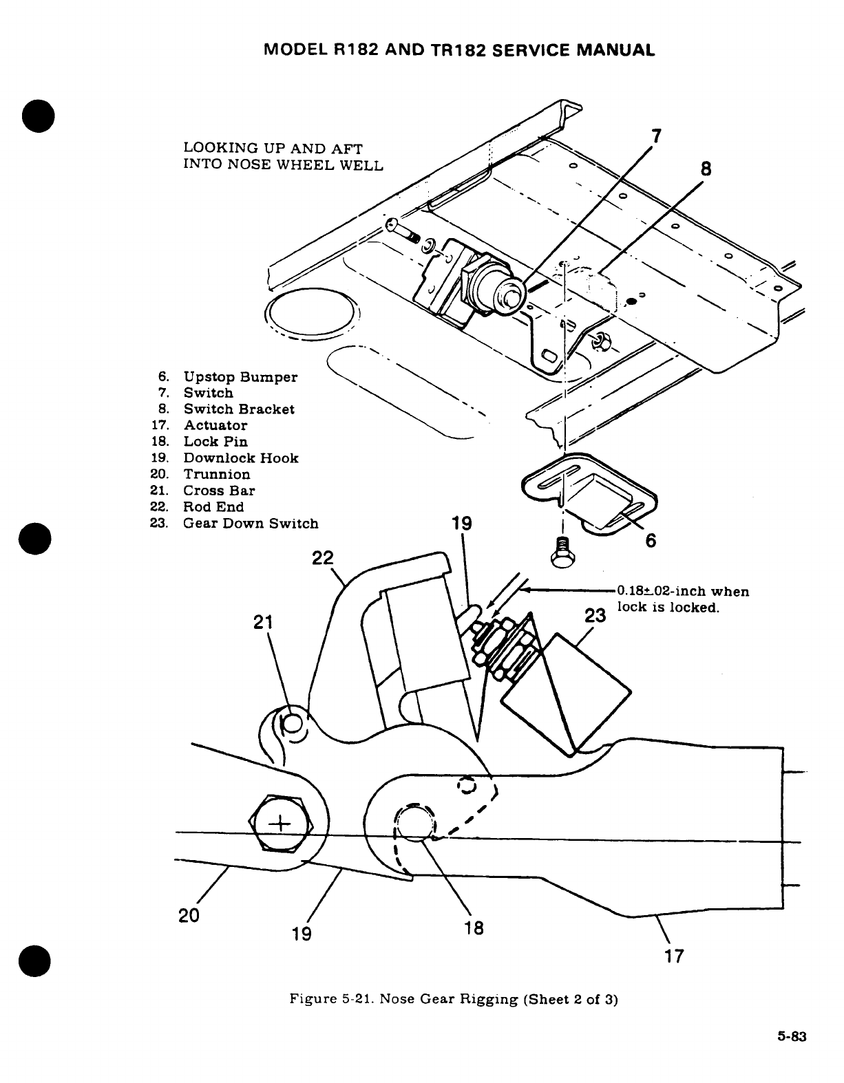
MODEL
R182
AND
TR182
SERVICE
MANUAL
LOOKING UP AND
AFT
INTO
NOSE WHEEL
WELL
8
6.
Upstop Bumper
7.
Switch
8.
Switch
Bracket
-
17.
Actuator
18.
Lock
Pin
19.
Downlock
Hook
20.
Trunnion
21.
Cross
Bar
22.
Rod
End
23.
Gear
Down
Switch
19
22
|----2
0.18+-02-inch
when
lock
is
locked.
0
21
19 18\
17
Figure
5-21.
Nose
Gear
Rigging
(Sheet
2
of
3)
5-83
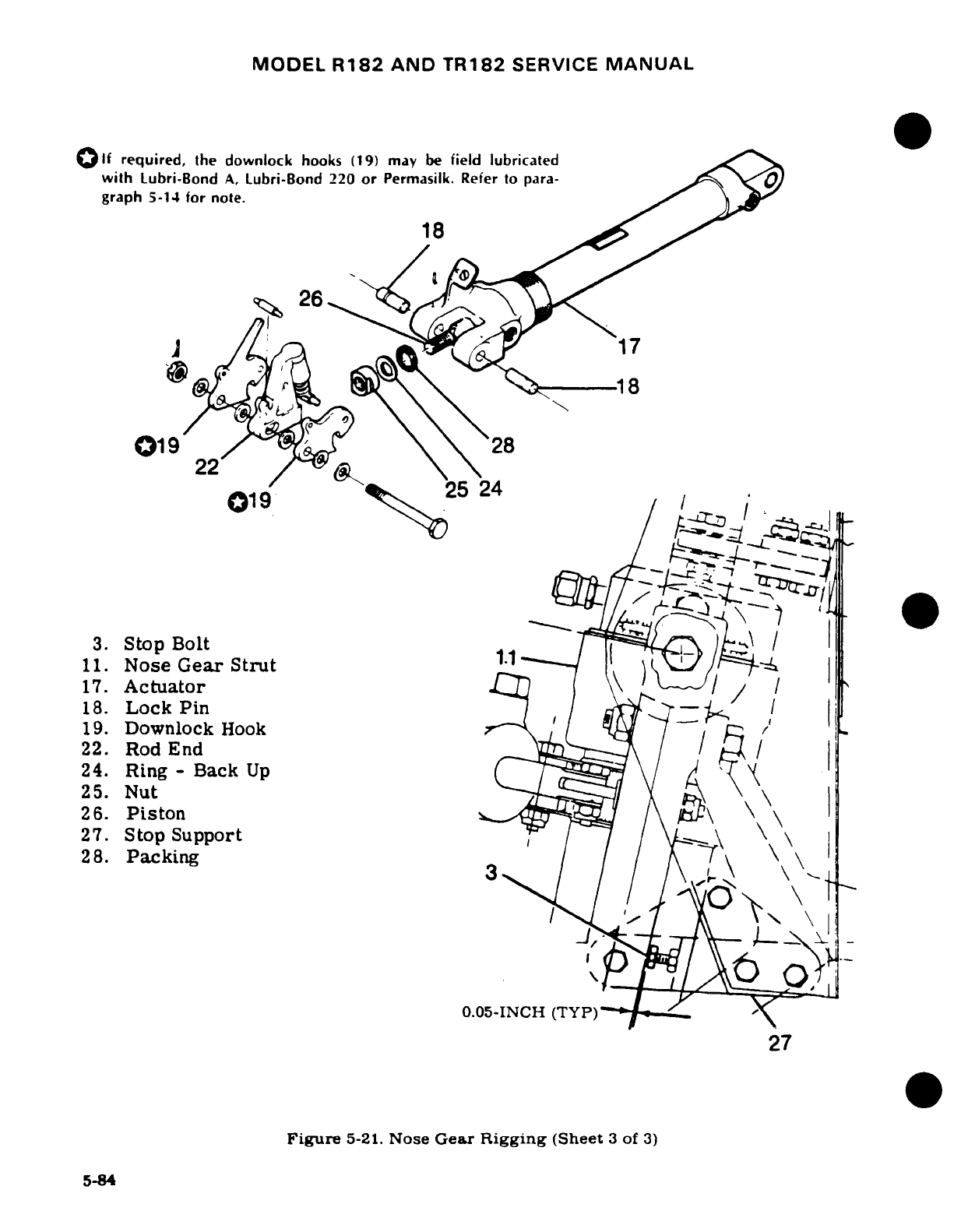
MODEL
R182
AND
TR182
SERVICE
MANUAL
lf
required,
the
downlock
hooks
(19)
may
be
field
lubricated
with
Lubri-Bond
A,
Lubri-Bond
220
or
Permasilk.
Refer
to
para-
graph
5-14
for
note.
18
,~ 26
j~
!17
22
28
019
28
3.
Stop
Bolt
11.
Nose
Gear
Strut
1
-
17.
Actuator
18.
Lock
Pin
19.
Downlock
Hook
f
22.
Rod
End
/ ' /
24.
Ring
-
Back
Up
25.
Nut
26.
Piston
\
27.
Stop
Support
/
28.
Packing
3
3
,1
0.05-INCH
(TYP)
27
Figure
5-21.
Nose
Gear
Rigging
(Sheet
3
of
3)
5-84
MODEL
R182
AND
TR182
SERVICE
MANUAL
correctly.
If
stop
bolts are
not
properly
adjusted,
nose
gear will
not
extend
fully
and
lock.
5-145.
NOSE
GEAR
RIGGING.
(Beginning
with
R18201799.)
(See
figure
5-21.)
a.
Jack
aircraft
in
accordance
with
procedures outlined
in
Section
2
of
this
manual.
b.
Place
gear
selector
handle
in
"down"
position,
turn
master
switch
on,
and
allow
system
to
pressurize.
Turn
master
switch
off
and
pull
gear
pump
circuit
breaker.
c.
See
figure
5-14,
view
A-A,
for
correct
amount
of
strut
extension.
WARNING
Completely
deflate nose
gear
strut
before
disconnecting
torque
links.
d.
Check
that
downlock
hooks
(19)
fully
engage
lock
pins
(18)
as
shown
and
that
gear
down
switch
(23)
is
properly
positioned.
If
hooks
(19)
fail
to
engage
pins
(18),
place
gear
position
selector
handle in
a
neutral
posi-
tion
and
pull
the
gear
forward
by
hand
until
nut
(25)
is
accessible.
Loosen
nut
and,
using
wrench
on
flats
of
piston,
screw
piston
(26)
several
turns
into
rod
end
(22);
tighten
nut
(25).
Place
gear
position
selector
handle
in
"down"
position,
turn
master
switch
on
and
allow
gear
to
extend
to
the
down
and
locked
position.
Recheck
downlock
hook
(19)
and
gear
down
switch
(23)
positions;
adjust
as necessary.
e.
Disconnect
adjusting
rods
(11)
from
gear
doors,
and
secure
doors
in
full
open
position
with
tape.
f.
Turn
master
switch
"on"
and
place
landing
gear
selector
handle
in
"up"
position.
g.
Close
gear
doors,
one
at
a
time,
and
attach
adjusting
rods
(11).
Adjust
length
of
rods
until
doors
fair
with
cowling.
Remove
rods
from
doors,
and secure
doors
in
full
open
position
with
tape.
h.
Run
gear
down
to
midway
position.
Turn
master
switch
off.
i.
Attach
adjusting
rods
(14)
to
doors
and
swing
gear
by
hand
to
ensure
that
doors
clear
any
part
of
the
nose
gear
assembly
by
a
minimum
of
0.25-inch
clearance.
Check
clearance
between
nose
gear
door
and
lower
cowl
skin
to
be
.10
*
.06,
-.
00
inch.
j.
Run
gear
to
full
"up"
position
and
check
that
doors
fair.
If
necessary,
make
final
adjustments
to
adjusting
rods
(14).
Tighten
nuts
on
rods. Safety
wire
rod
assemblies.
Check
that gear
up
indicator
actuates
and
up
light
illuminates.
k.
Run
gear
to
full
"down"
position
and
turn master
switch
"off".
Adjust
stop
bolts
(3)
to
provide
simultaneous
contact with
door
actuator
(4)
on
each
side
with
minimum
stop
bolt extension.
Start
with
stop bolts
turned all the
way
in.
Linkage
must
be
overcenter
when
doors
are
fully
open.
1.
Cycle
gear
several
times,
using
ship's
power
pack,
and
at
least
twice,
using
the
system's
emergency
hand
pump.
A
28-volt
DC,
60-amp
electrical
power
supply
may
be
used.
m.
Run
gear
to
full
"down"
position
and
remove
aircraft
from
jacks.
5-146.
BRAKE SYSTEM.
(See
figure
5-24.)
5-147.
DESCRIPTION.
The
hydraulic
brake
system
is
comprised
of
two
master
cylinders,
located
immediately
forward
of
the
rudder pedals,
brake
lines connecting
each
master
cylinder
to
its
wheel
brake
cylinder,
and
the
single-disc,
floating
cylinder-type
brake
assembly,
located
at
each
main
landing
gear
wheel.
5-85
MODEL
R182
AND
TR182
SERVICE
MANUAL
5-148.
TROUBLE
SHOOTING
-
BRAKE
SYSTEM.
TROUBLE
PROBABLE
CAUSE
REMEDY
DRAGGING
BRAKES.
Brake pedal
binding.
Lubricate
pivot
points:
replace
or
repair
defective
parts.
Weak
or
broken
piston
Repair
or
replace
master
return
spring
in
master
cylinder.
cylinder.
Parking
brake
control
Adjust
properly.
improperly
adjusted.
Insufficient
clearance
be-
Adjust
clearance
per
tween
lock-O-seal
and
paragraph
5-142.
piston
in
master
cylinder.
Restriction
in
hydraulic
Remove
restrictions:
flush
lines or
in
passage
in
brake
system
with hydraulic
master
cylinder
compen-
fluid.
Repair
or
replace
sating
sleeve.
master
cylinder.
Warped
or
badly
scored
Replace
disc
and
linings.
brake
disc.
Damage
or
accumulated
Clean
and
repair
or
replace
dirt restricting
free
move-
brake
parts.
ment
of
wheel
brakes.
BRAKES
FAIL
TO
Fluid
low
in
master
cy-
Fill
system
and
bleed
OPERATE.
linder
or
wheel
cylinder.
brake
parts.
Faulty
O-rings
in
master
Replace
O-rings.
cylinder
or
wheel
cylinder.
Faulty
lock-O-seal
in
Replace
lock-O-seal.
master
cylinder.
Excessive
clearance
Adjust clearance
per
between lock-O-seal
paragraph
5-143.
and
piston.
Internal
damage
to
hose
Replace
damaged parts.
and
O-rings
due
to
use
Flush
system
with
de-
of
wrong
type
of
hydrau-
natured
alcohol.
Fill
and
lic
fluid.
bleed
brake
system.
Pressure
leak
in
system.
Tighten
connection:
repair
or
replace
faulty parts.
Brake
linings
worn
out.
Replace
linings.
Oil
or
grease
on
brake
Clean
linings
with
carbon
linings
or
new
linings
tetrachloride.
just
installed.
5-86

MODEL
R182
AND
TR182
SERVICE
MANUAL
5-149.
BRAKE
MASTER
CYLINDER.
(See
figure
5-22.)
5-150.
DESCRIPTION.
The
brake
master
cylinders,
located immediately
forward
of
thepilot's
rudder
pedals,
are actuated
by
applying
pressure
at
the
top
of
the
rudder
pedals.
A
small
reservoir
is
incorporated
into
each
master
cylinder
for the
fluid
supply.
When
dual brakes
are
installed,
mechanical
linkage
permits
the
copilot
pedals
to
operate
the
master cylinders.
5-151.
REMOVAL.
a.
Remove
bleeder
screw
at
wheel
brake
assembly
and
drain
hydraulic
fluid
from
brake
cylinders.
b.
Remove
front
seats
and
rudder
bar
shield
for access
to
brake
master
cylinders.
c.
Disconnect
parking
brake
linkage
and
disconnect
brake-master
cylinders
from
rudder pedals.
d.
Disconnect
hydraulic
hose
from
brake
master
cylinders
and
remove
cylinders.
5-152.
DISASSEMBLY.
(Thru
1978
Models.)
(See
figure
5-22.
Sheet
1
of
2.)
a.
Unscrew
clevis
(1)
and
jamb
nut
(2).
b.
Remove
screw
(18).
c.
Remove
filler
plug
(17)
and setscrew
(5).
d.
Unscrew cover
(4)
and
remove
up
over
piston
rod
(3).
e.
Remove
piston
rod
(3)
and
compensating
sleeve
(16).
f.
Slide
sleeve
(16)
up
over
rod
(3).
g.
Unscrew
nut
(12)
from
threads
of
piston
rod
(3).
h.
Remove
piston
spring
(13)
and O-ring
(9)
from
piston
(14).
i.
Remove
Lock-O-Seal
(15).
5-153.
INSPECTION
AND
REPAIR.
(Thru
1978
Models.) (See
figure
5-122,
Sheet
2
of
2.)
Repair
is
limited
to
installation
of
new
parts,
cleaning
and
adjusting.
(Refer
to
assembly
paragraph
for
adjustment.)
Use
clean
hydraulic
fluid
(MIL-H-5606)
as
a
lubricant
during
reassembly
of
the
cylinders.
Inspect
Lock-O-Seal
(Parker
Seal
Co.
(P/N
800-001-6)
and
replace
if
damaged.
Replace
all
O-rings.
Filler
plug
must
be
vented
so
pressure
cannot
build
up
in
the
reservoir
during
brake
operation.
Remove
plug
and
drill
1/16-inch
hole.
30
°
from
vertical,
if
plug
is
not vented.
5-154.
REASSEMBLY.
(Thru
1978
Models.)
(See
figure
5-22.
Sheet
1
of
2.)
a.
Install
Lock-O-Seal
(15)
at bottom
of
piston
rod
(3).
b.
Install
O-ring
(9)
in
groove
in
piston
(14);
insert
piston
spring
(13)
into
piston.
and
slide
assembly
up
on
bottom
threaded
portion
of
piston
rod
(3).
c.
Run
nut
(12)
up
threads
to
spring
(13).
Tighten
nut
enough
to
obtain
0.040+0.005-inch
clearance
between
top
of
piston
and
bottom
of Lock-O-Seal,
as
shown
in
the
figure
d.
Install
piston
return
spring
(11)
into
cylinder
(10)
portion
of
body
(7).
e.
Install
piston
rod
(3)
through
spring
(11).
f.
Slide
compensating
sleeve
(16)
over
rod
(3).
g.
Install
cover
(4)
and screw
(18).
h.
Install
jam
nut
(2)
and
clevis
(1).
i.
Install filler
plug
(17),
making
sure
vent
hole
is
open.
j.
Install
setscrew
(5).
5-87
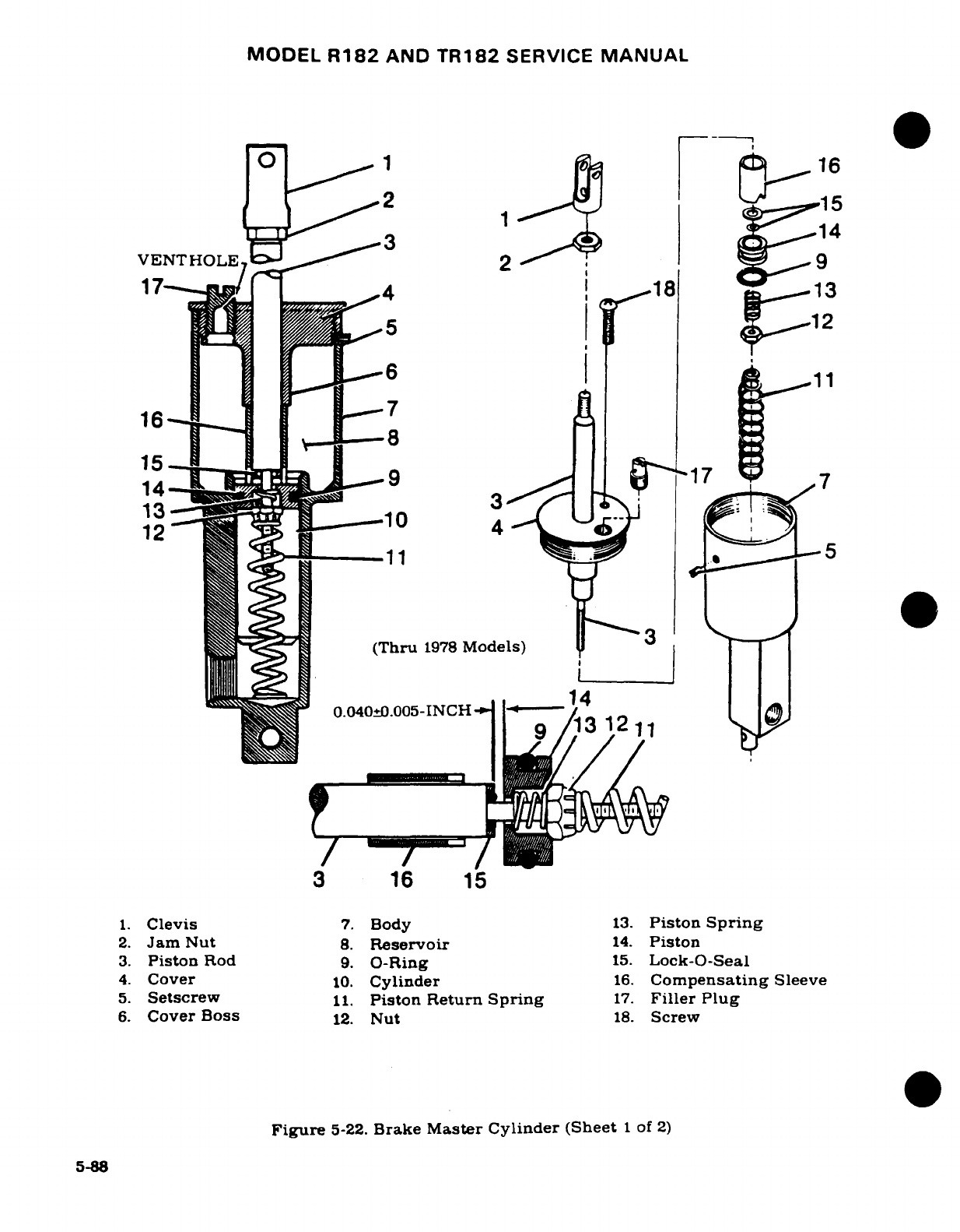
MODEL
R182
AND
TR182
SERVICE
MANUAL
2 1 16
12 16
7~~~~~~
~14
VENT
HOLE
2
1
^ r15 f ^ -,9
17
1
7
^^^^
:|
(Thru
1978
Models)
3
-1_1
3
1211
3
16
15
1.
Clevis
7.
Body
13.
Piston
Spring
2.
Jam
Nut
8.
Reservoir
14.
Piston
3.
Piston
Rod
9.
O-Ring
15.
Lock-O-Seal
4.
Cover
10.
Cylinder
16.
Compensating
Sleeve
5.
Setscrew
11.
Piston
Return
Spring
17.
Filler
Plug
6.
Cover
Boss
12.
Nut
18.
Screw
Figure
5-22.
Brake
Master
Cylinder (Sheet
I
of
2)
5-88
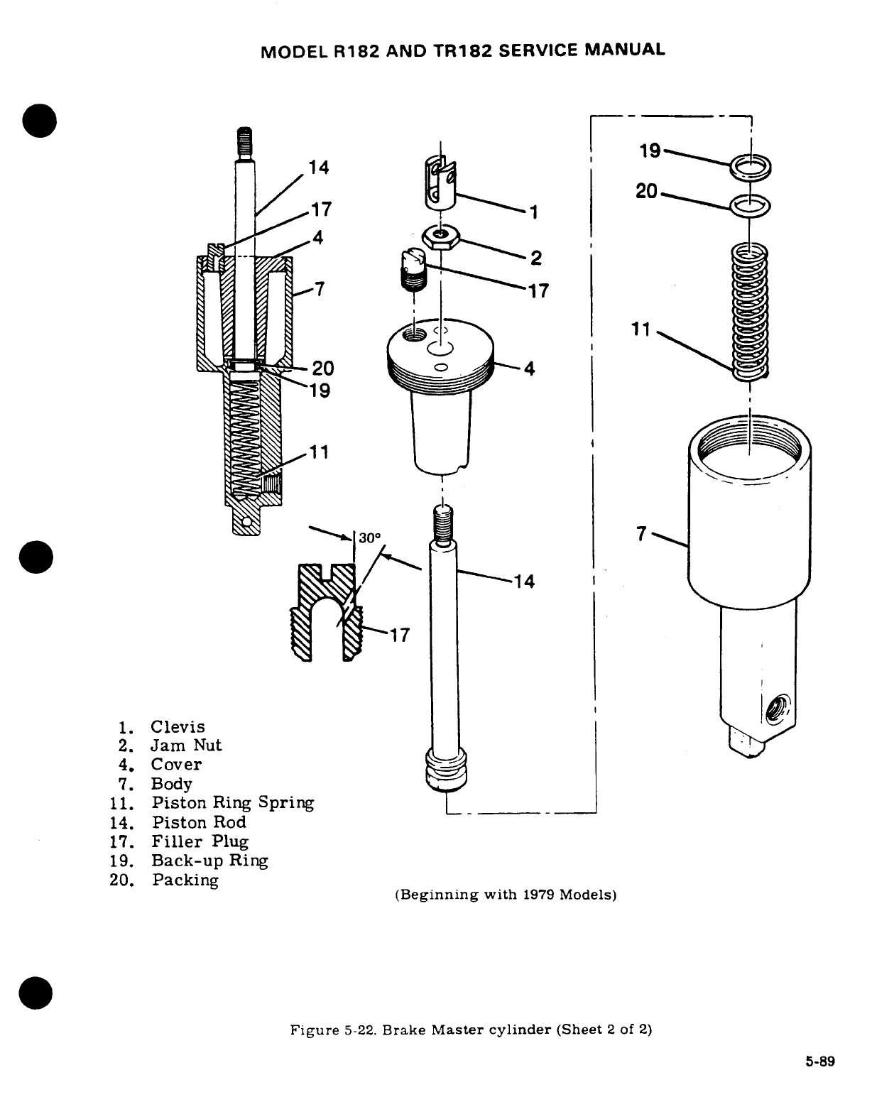
MODEL
R182
AND
TR182
SERVICE
MANUAL
5-155.
DISASSEMBLY.
(Beginning
with
1979
Models.)
(See
figure
5-22,
sheet
2.)
a.
Unscrew
clevis
(1)
and
jam
nut
(2).
b.
Remove
filler
plug
(17).
NOTE
A
special
tool,
brake
master
cylinder
wrench
No.
34-101
is available
from
the
Cessna
Supply
Division
to
accom-
plish
the
following
step.
c.
Unscrew
cover
(4)
and
remove
up
over
piston
(14).
d.
Remove
piston
(14)
and
spring
(11).
e.
Remove
packing
(20)
and
back-up
ring
(19)
from
piston
(14).
5-156.
INSPECTION
AND
REPAIR.
(Beginning
with
1979
Models.)
(See
figure
5-22,
Sheet
2
of
2.)
Repair
is
limited
to
installation
of new
parts
and
cleaning.
Use
clean
hydraulic
fluid
(MIL-H-
5606)
as
a
lubricant
during
reassembly
of
the cylinder.
Replace
packing
and
back-up
ring.
Filler plug
(17)
must
be
vented
so
pressure
cannot
build
up
during
brake
operation.
Remove
plug
and
drill
1/16-inch
hole
30
°
from
vertical,
if
plug
is
not
vented.
Refer
to
view
A-A
for
location
of
hole.
5-157.
REASSEMBLY.
(Beginning
with
1979
Models.)
(See
figure
5-22,
Sheet
2
of
2.)
a.
Instal
spring
(11)
into
cylinder
body
(7).
b.
Install
back-up
ring
(19)
and
packing
(20)
in
groove
of
piston
(14).
c.
Install
piston
(14)
in
cylinder
body
(7).
d.
Install
cover
(4)
over
piston
(14)
and
screw
cover into
cylinder
body
(7).
e.
Install
nut
(2)
and
clevis
(1).
f.
Install
filler plug
(17),
making
sure
vent
hole
is
open.
5-158.
INSTALLATION.
a.
connect
hydraulic
hoses
to
brake
master
cylinders
and
install
cylinders.
b.
Connect
brake
master
cylinders
to
rudder
pedals
and
connect
parking
brake
linkage.
c.
Install
rudder
bar
shield
and
install
front
seats.
d.
Install
bleeder
screw at
wheel
brake
assembly
and
fill
and
bleed
brake
system
in
accordance
with
applicable
paragraph
in
this
section.
5-159.
HYDRAULIC
BRAKE
LINES.
5-160.
DESCRIPTION. The
brake
lines
are
of
rigid tubing,
except for
flexible
hose
used
at
the
brake
master.cylinders.
A
separate
line
is
used
to
connect
each
brake
master
cylinder
to
its
corresponding
wheel
brake
cylinder.
5-161.
WHEEL
BRAKE
ASSEMBLIES.
(See
figure
5-10.)
5-162.
DESCRIPTION.
The
wheel
brake
assemblies
employ
a
floating
brake
assembly
and
a
disc
which
is
attached
to
the
main
wheel.
5-163.
REMOVAL.
(See
figure
5-8.)
Disconnect
and
drain
brake
line
and
remove
brake
back
plate.
The
brake
disc
is
removed
after
the wheel
is
removed
and
disassembled.
To
remove
torque
plate,
remove
wheels
and
axles.
5-164.
DISASSEMBLY.
See
figure
5-10
for
a
breakdown
of
wheel
brake
parts.
This
figure
may
be
used
as
a
guide
for
disassembling
the
wheel
brakes.
5-90
MODEL
R182
AND
TR182
SERVICE
MANUAL
5-165.
INSPECTION
AND
REPAIR.
a.
Clean
all
parts
except
brake
linings
and
packings
in
dry
cleaning
solvent
and
dry
thoroughly.
b.
Install
all
new
packings.
If
packing
reuse
is
necessary,
wipe
with
a
clean cloth
satu-
rated
in
hydraulic
fluid
and
inspect
for
damage.
NOTE
Thorough
cleaning
is
important.
Dirt
and
chips
are
the
greatest
single
cause of
malfunctions
in
the
hydraulic
brake
system.
c.
Check
brake
lining
for
deterioration
and
wear.
d.
Inspect
brake
cylinder
bore
for
scoring.
A
scored cylinder
will
leak
or
cause
rapid
packing
wear.
Install
a
new
brake
cylinder
if
the
bore
is
scored.
e.
If
the anchor
bolts
on
the
brake
assembly
are
nicked
or
gouged, they should
be
sanded smooth to
prevent
binding
with the
pressure
plate
or
torque
plate.
When
new
anchor
bolts
are
to
be
installed,
press
out
old
bolts
and
install
new
bolts
with
a
soft
mallet.
f.
Inspect
wheel
brake
disc
for
a
minimum
thickness
of
.33
inch. If
brake
disc
is
below
minimum
thickness,
install
a
new disc.
5-166.
REASSEMBLY.
(See
figure
5-8.)
NOTE
Assemble
parts,
lubricated
with
a
film
of
Petrolatum
VV-
P-236,
hydraulic
fluid
MIL-H-5606,
or
Dow-Corning
DC-
7.
a.
See
figure
5-8
as
a
guide
while
reassembling
wheel
brakes.
5-167.
INSTALLATION.
a.
Place
brake assembly
in
position
with
pressure
plate
in
place.
NOTE
If
torque
plate
was
removed,
install
as
the
axle is
instal-
led,
or
install
on
axle.
If
the brake
disc
was
removed,
in-
stall
as
wheel
is
assembled.
CAUTION
Correct
clocking
of
the
brake
line
elbow
on
the
wheel
brake
cylinder
is
very
important
in
order
to
avoid
inter-
ference
with
aircraft
structure
during
retraction
of
the
gear.
5-168.
CHECKING BRAKE
LINING
WEAR. New
brake
lining
should
be
installed
when
the
existing
lining
has
worn
to
a
thickness
of
3/32-inch.
A
3/32-inch
thick
strip
of
material
held
adjacent
to
each
lining
can
be
used
to
determine
amount
of
wear.
The
shank
end
of
a
drill
bit
of
the correct
size can
also
be
used
to
determine
wear
of
brake
linings.
Revision
1
5-91
MODEL
R182
&
TR182
SERIES
SERVICE
MANUAL
5-169.
BRAKE INSTALLATION.
(Refer
to
figure
5-10.)
a.
Remove bolts
securing
back
plate
and
remove
back
plate.
b.
Pull
brake
cylinder
out
of
torque
plate and
slide
pressure plate
off
anchor
bolts.
c.
Place
back
plate
on
a
table
with
lining
side
down
flat.
Center
a 9/64-inch
(or
slightly
smaller)
punch
in
the
rolled
rivet
and
hit
the
punch
sharply with
a
hammer.
Punch
out
all
rivets
securing
the
linings
to
the
back
plate
and
the
pressure plate
in
the
same
manner.
NOTE
A
rivet
setting kit,
Part
No.
199-00100,
is
available
from
the
Cessna
Parts
Distribution
(CPD
2).
This
kit
consists
of
an
anvil
and
punch.
d.
Clamp
the
flat
side
of
the
anvil
in
a
vise.
e.
Align
new
lining
on
back
plate
and
place
brake
rivet
in
hole
with
rivet
head
in
the
lining.
Place
the
head
against
the
anvil.
f.
Center rivet
setting
punch
on
lips
of
rivet.
While
holding
back
plate
down
firmly
against
lining,
hit
punch
with
hammer
to
set
rivet.
Repeat
blows
on
punch
until
lining
is
firmly
against
back
plate.
g.
Realign
the lining
on
the
back
plate
and
install
and
set rivets
in
the
remaining
holes.
h.
Install
a
new
lining
on
pressure
plate
in
the
same
manner.
i.
Position
pressure plate
on
anchor
bolts
and
place
cylinder
in
position
so
that
anchor
bolts
slide
into
the
torque
plate.
j.
Install
back
plate
with
bolts
and
washers,
torque
bolts
to
110-120
in.-lbs.
5-170.
BRAKE
SYSTEM
BLEEDING.
NOTE
Bleeding
with
a
clean
hydraulic
pressure
source
connected
to
the
wheel
cylinder
bleeder
is
recommended.
a.
Remove
brake
master
cylinder
filler plug and
screw
flexible
hose
with
appropriate
fitting
into
the
filler
hole
at
the
top
of
the
brake
master
cylinder.
b.
Immerse
opposite end
of
flexible
hose
into
a
container
with
enough
hydraulic
fluid
to
cover
end
of
the
hose.
c.
Connect
a
clean
hydraulic
pressure
source,
such
as
a
hydraulic
hand
pump
or
Hydro-
Fill
unit
to
the
bleeder
valve
in
the
wheel
cylinder.
d.
As
fluid
is
pumped
into
the
system, observe
the
immersed
end
of
the
hose
at
the
mas-
ter
brake
cylinder
for
evidence
of
air
bubbles
being
forced
from
the
brake
system.
When bubbling
has
ceased,
remove
bleeder
source
from
wheel
cylinder
and
tighten
the
bleeder
valve.
5-171.
BRAKE
LINING
BURN-IN.
5-172.
DESCRIPTION.
The
brake
pads
are equipped
with
either
a
non-asbestos organic
lining
or
an
iron based
metallic
lining.
These
materials
must
be
properly
conditioned
(glazed)
in
order
to
provide
maximum
performance
and
service
life.
This
is
accomplished
by
a
brake
burn-in.
a.
Non-asbestos
organic
lining.
1.
Taxi
airplane
for
1500
feet
with
engine
at
1700
RPM
applying
brake
pedal
force
as
needed
to
develop
a
5
to
9
knots
taxi
speed.
2.
Allow
brakes
to
cool
for
10
to
15
minutes.
5-92
Revision
3
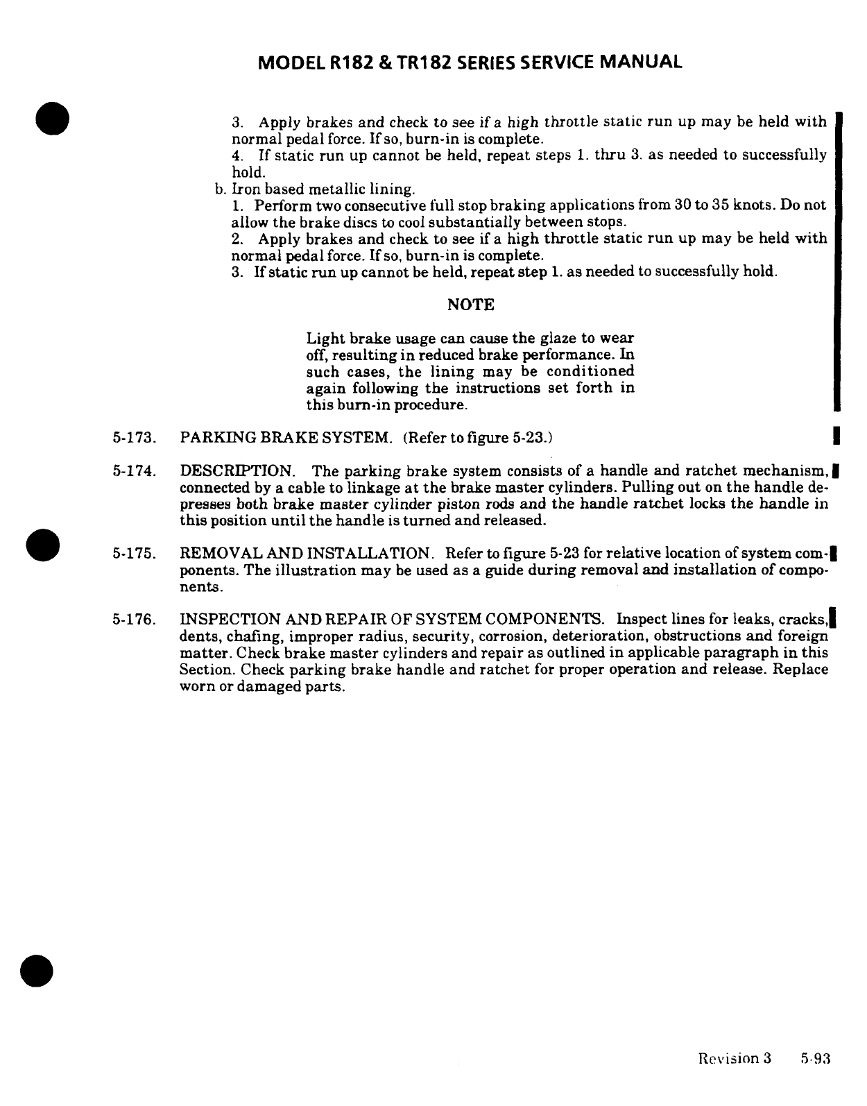
MODEL
R182
&
TR182
SERIES
SERVICE
MANUAL
3.
Apply
brakes
and
check
to
see
if
a
high
throttle
static
run
up may
be
held
with
normal
pedal
force.
If
so,
burn-in
is
complete.
4.
If
static
run
up
cannot
be
held,
repeat
steps 1.
thru
3.
as
needed
to
successfully
hold.
b.
Iron
based
metallic
lining.
1.
Perform
two
consecutive
full
stop
braking
applications
from
30
to
35
knots.
Do
not
allow
the
brake
discs
to
cool
substantially
between
stops.
2.
Apply
brakes
and
check
to
see
if
a
high
throttle
static
run
up
may
be
held
with
normal
pedal
force.
If
so,
burn-in
is
complete.
3.
If
static
run
up
cannot
be
held,
repeat step
1.
as
needed
to
successfully
hold.
NOTE
Light
brake
usage
can
cause
the
glaze
to
wear
off,
resulting
in
reduced brake performance.
In
such cases,
the lining
may be
conditioned
again
following
the
instructions
set
forth
in
this
burn-in
procedure.
5-173.
PARKING
BRAKE
SYSTEM.
(Refer
to
figure
5-23.)
5-174.
DESCRIPTION.
The
parking
brake
system
consists
of
a
handle
and
ratchet
mechanism,
connected
by
a
cable
to
linkage
at
the
brake
master
cylinders.
Pulling
out
on
the
handle
de-
presses
both
brake
master
cylinder
piston
rods
and
the
handle
ratchet
locks
the handle
in
this
position
until
the
handle
is
turned
and
released.
5-175.
REMOVAL
AND
INSTALLATION.
Refer
to
figure
5-23
for
relative
location
of
system
com-
ponents.
The
illustration
may
be
used as
a
guide
during
removal
and
installation
of
compo-
nents.
5-176.
INSPECTION
AND
REPAIR
OF
SYSTEM
COMPONENTS.
Inspect lines
for
leaks,
cracks,
dents,
chafing, improper
radius,
security,
corrosion,
deterioration,
obstructions
and
foreign
matter.
Check
brake
master
cylinders and
repair
as outlined in
applicable
paragraph
in
this
Section.
Check
parking
brake handle
and
ratchet
for
proper
operation
and release.
Replace
worn
or
damaged
parts.
Revision
3
5-93
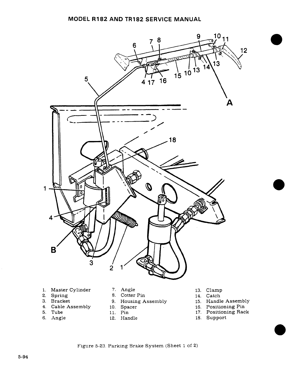
MODEL
R182
AND TR182
SERVICE
MANUAL
9
10
6
812
1. Master Cylinder
7.
Angle
13.
Clamp
3.
Bracket
9.
Housing
Assembly
15.
Handle
Assembly
4.
Cable
Assembly
10.
Spacer
16.
Positioning
Pin
5.
Tube
11.
Pin
17.
Positioning
Rack
6.
Angle
12.
Handle
18.
Support
18
0
2
1
1.
Master
Cylinder
7.
Angle
13.
Clamp
2.
Spring
8.
Cotter
Pin
14.
Catch
3.
Bracket
9.
Housing
Assembly
15.
Handle
Assembly
4.
Cable
Assembly
10.
Spacer
16.
Positioning
Pin
5.
Tube
11.
Pin
17.
Positioning
Rack
6.
Angle
12.
Handle
18.
Support
Figure
5-23.
Parking
Brake
System
(Sheet
1
of
2)
5-94
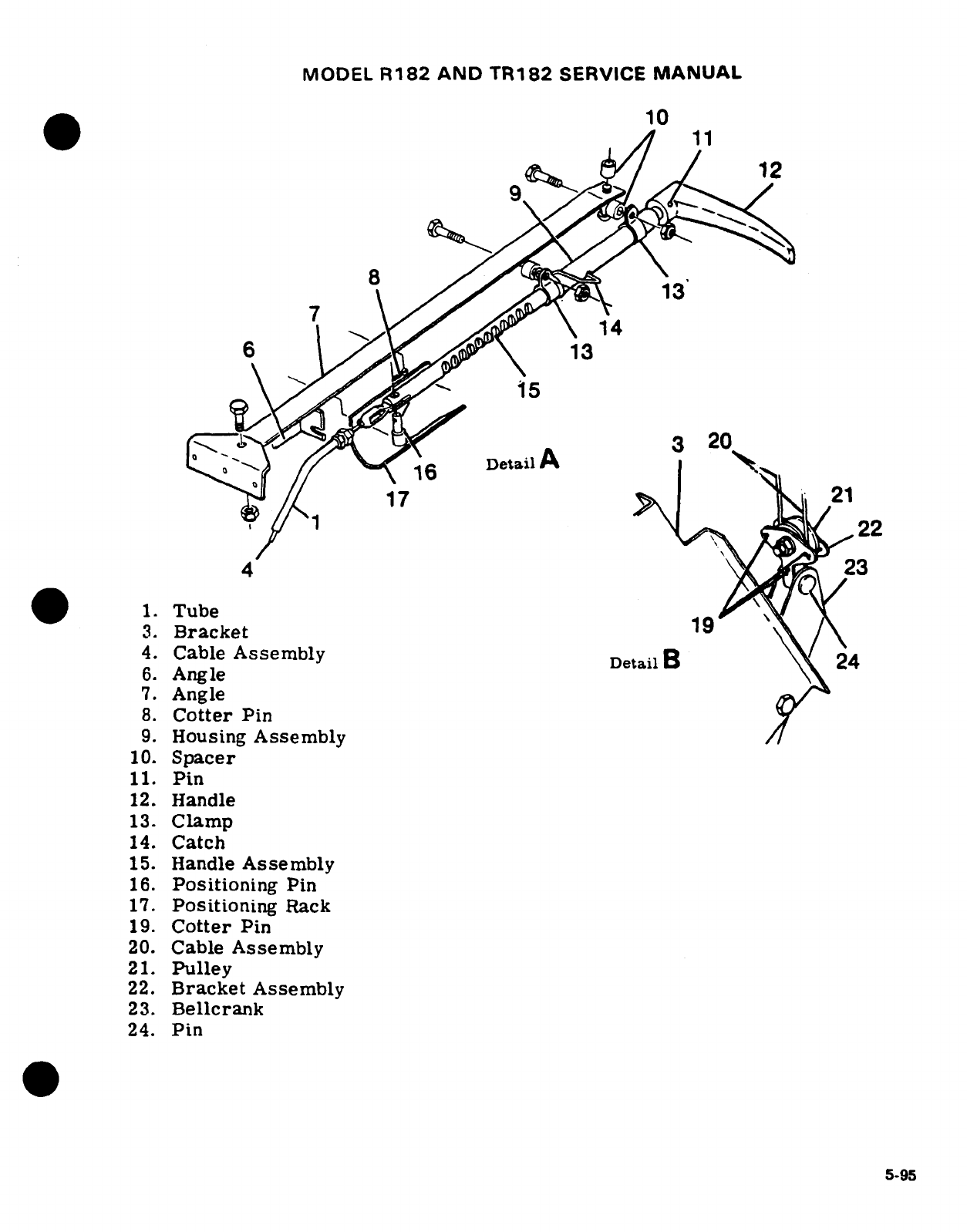
MODEL
R182
AND
TR182
SERVICE
MANUAL
10
12
13
1
Tube13
3.
Bracket
19
4.
Cable
Assembly DetailB
4
6.
Angle
7.
Angle
8.
Cotter
Pin
9.
Housing
Assembly
10.
Spacer
11.
Pin
12.
Handle
13.
Clamp
14.
Catch
15.
Handle
Assembly
16.
Positioning
Pin
17.
Positioning
Rack
19.
Cotter
Pin
20.
Cable
Assembly
21.
Pulley
22.
Bracket
Assembly
23.
Bellcrank
24.
Pin
5-95
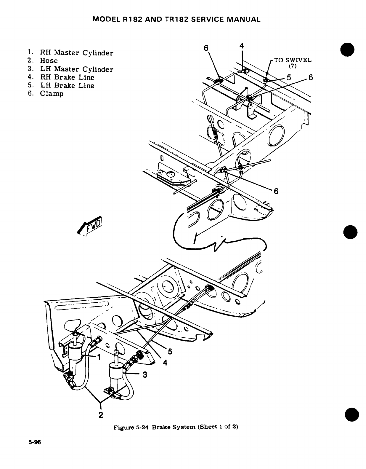
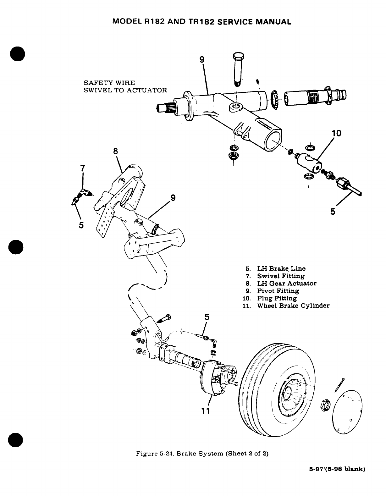
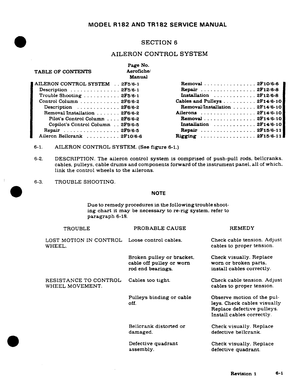
MODEL
R182
AND
TR182
SERVICE
MANUAL
SECTION
6
AILERON
CONTROL
SYSTEM
Page
No.
TABLE
OF
CONTENTS
Aerofiche/
Manual
AILERON CONTROL SYSTEM
..
2F5/6-1
Removal
................
2F10/6-6
Description
...............
2F5/6-1
Repair
.................
2F12/6-8
Trouble
Shooting
...........
2F5/6-1
Installation
.............
2F12/6-8
Control
Column
............
2F6/6-2 Cables
and
Pulleys
..........
2F14/6-10
Description
............
2F6/6-2
Removal/Installation
.......
2F14/6-10
Removal/Installation
.......
2F6/6-2
Ailerons
............... .
2F14/6-10
Pilot's Control
Column
....
2F6/6-2
Removal
...............
2F14/6-10
Copilot's
Control
Column
..
2F9/6-5
Installation
.............
2F14/6-10
Repair
................
2F9/6-5
Repair
.................
2F15/6-11
Aileron
Bellcrank
..........
2F10/6-6
Rigging
.................
2F15/6-11
6-1.
AILERON
CONTROL SYSTEM.
(See
figure
6-1.)
6-2.
DESCRIPTION.
The
aileron
control
system
is
comprised
of
push-pull
rods.
bellcranks.
cables.
pulleys.
cable
drums
and
components
forward
of
the
instrument
panel. all
of
which.
link
the
control
wheels
to
the
ailerons.
6-3.
TROUBLE
SHOOTING.
NOTE
Due to
remedy
procedures
in
the
following
trouble
shoot-
ing
chart
it
may
be
necessary
to
re-rig
system.
refer
to
paragraph
6-18.
TROUBLE
PROBABLE CAUSE
REMEDY
LOST
MOTION
IN
CONTROL
Loose
control cables.
Check
cable
tension.
Adjust
WHEEL.
cables
to
proper
tension.
Broken
pulley
or
bracket.
Check
visually.
Replace
cable
off
pulley
or
worn
worn
or
broken
parts.
rod
end
bearings. install
cables correctly.
RESISTANCE
TO
CONTROL
Cables too
tight.
Check
cable
tension.
Adjust
WHEEL
MOVEMENT.
cables to
proper tension.
Pulleys
binding
or
cable
Observe
motion
of
the
pul-
off.
leys.
Check
cables
visually
Replace
defective
pulleys.
Install
cables
correctly.
Bellcrank
distorted
or
Check
visually.
Replace
damaged.
defective
bellcrank.
Defective
quadrant
Check
visually.
Replace
assembly.
defective
quadrant.
Revision
1
6-1
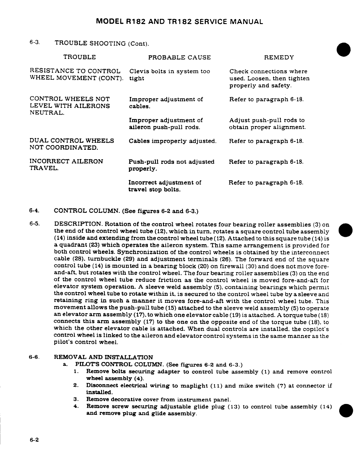
MODEL
R182
AND
TR182
SERVICE
MANUAL
6-3.
TROUBLE
SHOOTING
(Cont).
TROUBLE
PROBABLE
CAUSE REMEDY
RESISTANCE
TO
CONTROL
Clevis
bolts
in
system
too
Check
connections
where
WHEEL MOVEMENT
(CONT).
tight
used.
Loosen.
then
tighten
properly
and
safety.
CONTROL
WHEELS
NOT
Improper
adjustment
of
Refer
to
paragraph
6-18.
LEVEL
WITH
AILERONS
cables.
NEUTRAL.
Improper
adjustment
of
Adjust
push-pull
rods
to
aileron
push-pull
rods.
obtain proper
alignment.
DUAL
CONTROL
WHEELS
Cables
improperly
adjusted.
Refer
to
paragraph
6-18.
NOT
COORDINATED.
INCORRECT
AILERON
Push-pull
rods
not
adjusted
Refer
to
paragraph
6-18.
TRAVEL.
properly.
Incorrect
adjustment
of
Refer
to
paragraph
6-18.
travel
stop
bolts.
6-4.
CONTROL
COLUMN.
(See
figures
6-2
and
6-3.)
6-5.
DESCRIPTION.
Rotation
of
the
control
wheel
rotates
four
bearing
roller
assemblies
(3)
on
the
end of
the
control
wheel
tube
(12),
which
in
turn,
rotates
a
square
control
tube
assembly
(14)
inside
and
extending
from
the
control
wheel
tube
(12).
Attached
to
this square
tube
(14)
is
a
quadrant
(23)
which
operates
the
aileron
system.
This
same
arrangement
is
provided
for
both
control
wheels.
Synchronization
of
the control
wheels
is
obtained
by
the
interconnect
cable
(28).
turnbuckle
(29)
and
adjustment
terminals
(26).
The
forward
end
of
the
square
control tube
(14)
is
mounted
in
a
bearing
block
(20)
on
firewall
(30)
and
does
not
move
fore-
and-aft.
but
rotates
with
the control
wheel.
The
four
bearing
roller
assemblies
(3)
on
the
end
of
the
control
wheel
tube
reduce
friction
as
the
control
wheel
is
moved
fore-and-aft
for
elevator
system operation.
A
sleeve
weld
assembly
(5),
containing
bearings
which
permit
the
control
wheel
tube to
rotate
within
it.
is
secured
to
the
control
wheel
tube
by
a
sleeve
and
retaining
ring
in
such
a
manner
it
moves
fore-and-aft
with
the
control
wheel
tube. This
movement allows the
push-pull
tube
(15)
attached
to
the
sleeve
weld
assembly
(5)
to
operate
an
elevator
arm
assembly
(17).
to
which
one
elevator
cable
(19)
is
attached.
A
torque
tube
(18)
connects
this
arm
assembly
(17)
to
the one
on
the
opposite
end
of
the
torque
tube
(18).
to
which
the
other
elevator
cable
is
attached.
When
dual
controls
are
installed.
the
copilot's
control
wheel
is
linked
to
the
aileron
and
elevator
control
systems
in
the
same manner
as
the
pilot's
control
wheel.
6-6. REMOVAL
AND
INSTALLATION
a.
PILOTS
CONTROL
COLUMN.
(See
figures
6-2
and
6-3.)
1.
Remove
bolts
securing
adapter
to
control
tube
assembly
(1)
and
remove
control
wheel
assembly
(4).
2.
Disconnect
electrical
wiring
to
maplight
(11)
and
mike
switch
(7)
at
connector
if
installed.
3.
Remove
decorative
cover
from
instrument
panel.
4.
Remove
screw
securing
adjustable
glide
plug
(13)
to
control tube
assembly
(14)
and
remove
plug
and
glide
assembly.
6-2
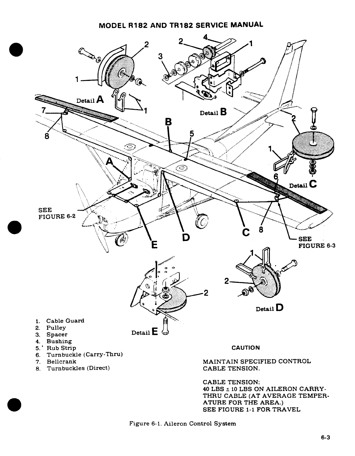
MODEL
R182
AND
TR182
SERVICE
MANUAL
2
2
.',tail
D A
Deta<lB
"''o}etil
FIGURE
6-2
-..
S\ t~~8}
-SEE
,\
v;
E
.
FIGURE
6-3
Detail
D
1.
Cable
Guard
2.
Pulley
Det
3.
Spacer Detail
4.
Bushing
5.'
Rub
Strip
CAUTION
6.
Turnbuckle (Carry-Thru)
7.
Bellcrank
MAINTAIN
SPECIFIED
CONTROL
8.
Turnbuckles
(Direct)
CABLE
TENSION.
CABLE
TENSION:
40
LBS
±
10
LBS
ON
AILERON
CARRY-
THRU
CABLE (AT
AVERAGE
TEMPER-
ATURE
FOR
THE
AREA.)
SEE
FIGURE
1-1
FOR
TRAVEL
Figure
6-1.
Aileron
Control
System
6-3
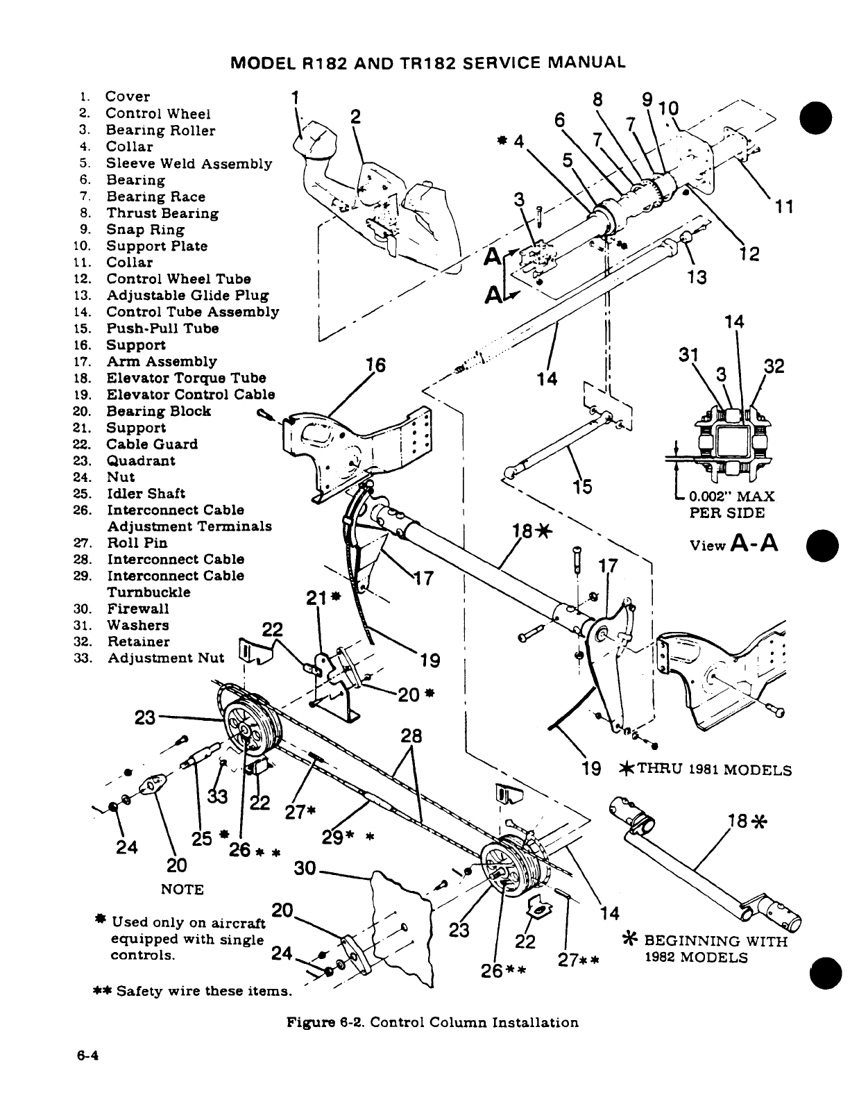
MODEL
R182
AND
TR182
SERVICE
MANUAL
1.
Cover
1
8
9
2.
ControlWheel
2
10
3.
Bearing
Roller
;
7
\
.
4.
Collar
J \4
7
\
5.
Sleeve
Weld
Assembly
5\
6.
Bearing
7.
Bearing
Race
3
1
8.
Thrust
Bearing
11
9.
Snap
Ring
\
10.
Support
Plate
2
It.
Collar
A
12
12.
Control
Wheel
Tube
13
13.
Adjustable
Glide
Plug
14.
Control
Tube
Assembly
/
-
14
15.
Push-Pull
Tube
16.
Support
17.
Arm
Assembly
1
../
|
31
32
18.
Elevator
Torque
Tube
14
3
19.
Elevator
Control
Cable
/
20.
Bearing
Block
21.
Support
J
22.
Cable
Guard'
-i
23.
Quadrant
-, , \
24.
Nut
l. :
| A-
25.
Idler
Shaft
5
0.002"
MAX
26.
Interconnect
Cable
PER
SIDE
Adjustment
Terminals
18*
27.
Roll
Pin
/
iew
A
A
28.
Interconnect
Cable
29.
Interconnect
Cable
-17
Turnbuckle
i
~
30.
Firewall
31.
Washers
22
>
, I
32.
Retainer
0
'
33.
Adjustment
Nut
19
90
10
23
28
,-*
ago/$
^
A',
<
19
*THRU
1981
MODELS
20*
1
*
Used
only
on
aircraft
equipped
with
single
22
|
$
BEGINNING
WITH
controls.
24
X
27**
1982
MODELS
-s
265C
*
**
Safety
wire
these items.
Figure
6-2.
Control
Column
Installation
6-4
MODEL
R182
AND
TR182
SERVICE
MANUAL
5.
Disconnect
push-pull
tube
(15)
at
sleeve
weld
assembly
(5).
6.
Remove
screws
securing support
plate
(10)
at
instrument
panel.
NOTE
To
ease
removal
of
control
wheel
tube
assembly
(12),
snap
ring
(9)
may
be
removed
from
its
locking
groove
to
allow
sleeve
weld
assembly
(5)
additional
movement.
7.
Using
care,
pull
control
wheel
tube
assembly
(12)
aft
and
work
assembly
out
through
instrument
panel.
NOTE
If
removal
of
control
tube
assembly
(14)
or
quadrant
(23)
is
necessary,
proceed
to
step
8.
8.
Remove
safety
wire
and
relieve
direct
cable
tension
at
turnbuckles
(index
8,
figure
6-1).
9.
Remove
safety
wire
and
relieve
interconnect
cable
tension
at
turnbuckle
(30).
10.
Remove
safety
wire
and remove
roll
pin
(27)
through quadrant
(23)
and
control
tube
assembly
(14).
11.
Remove
pin,
nut
(24)
and
washer
from
control
tube
assembly
(14)
protruding
through bearing
block
(21)
on
forward
side
of
firewall
(30).
12.
Using
care,
pull
control
tube
assembly'(14)
aft
and
remove
quadrant
(23).
13.
Reverse
the
preceding
steps
for
reinstallation.
Safety
wire
all
items
previously
safetied,
check
rigging
of
aileron
and
elevator
control
systems
and
rig,
if
necessary,
in
accordance
with
paragraph
6-18
and
Section
8,
respectively.
Use
figure
6-2
as
a
guide
for
reassembly
and
observe the
following notes.
NOTES
Referring
to
figure
6-2,
allow
0.030"
minimum
clearance
between
bearing
block
(20)
and
nut
(24)
after
tightening.
Adjust
interconnect
cables
(28)
to
40
LBS
±
10
LBS.
Washers
(31)
are
of
various
thicknesses
and
are
used
to
obtain
dimension
shown
in
VIEW
A-A.
Referring
to
figure
6-3,
torque
bolt
(12)
to
30
inch-pounds.
b.
COPILOT'S
CONTROL
COLUMN.
1.
Complete
steps
1,
2, 3,
4, 5,
6, 8,
9,
10
and
11
of
subparagraph
"a".
2.
Using
care,
pull
control
tube
assemblies
(12
and
14)
aft
and
remove
quadrant
(23).
3.
Remove
radios, radio
dust
covers,
cooling
pans
and
associated
equipment
as
necessary
to
work
control
wheel
tube
assembly
(12)
out
from
under
instrument
panel.
4.
Complete
step
13
of
subparagraph
"a".
6-7.
REPAIR.
Worn,
damaged
or
defective
shafts,
bearings,
drums,
cables
or other components
should
be
replaced.
Refer
to
Section
2
for
lubrication
requirements.
6-5
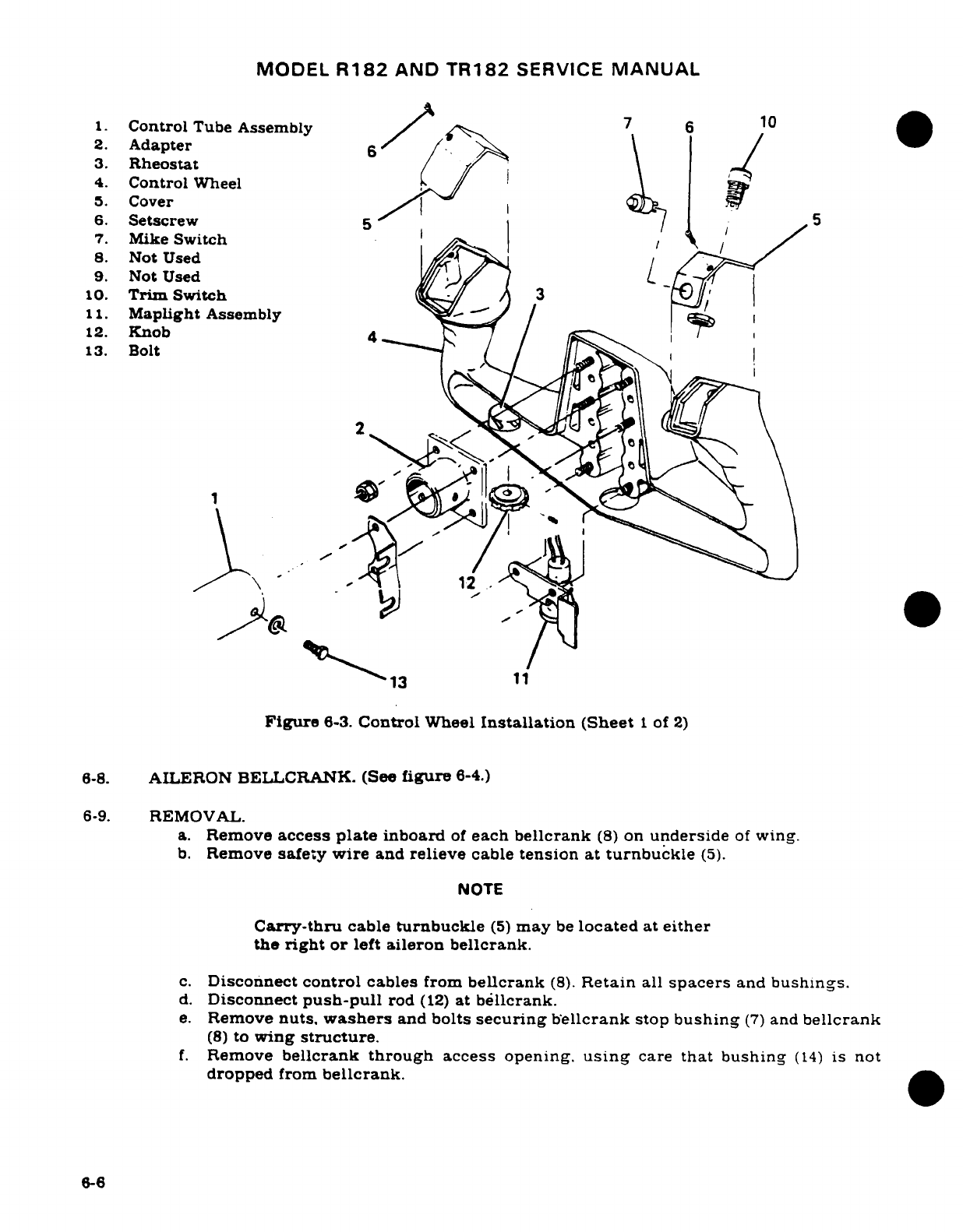
MODEL
R182
AND
TR182
SERVICE
MANUAL
1.
Control
Tube
Assembly
7
6
10
2.
Adapter
6
3.
Rheostat
4.
Control
Wheel
5.
Cover
6.
Setscrew
5
1 5
7.
Mike
Switch
8.
Not
Used
9.
Not
UsedL
10.
Trim
Switch
3
11.
Maplight
Assembly
12.
Knob
4
13.
Bolt
MX
'
y
"'
a
*
./
\, 1.2 11
13
11
Figure
6-3.
Control
Wheel
Installation
(Sheet
1
of
2)
6-8.
AILERON BELLCRANK.
(See
figure
6-4.)
6-9.
REMOVAL.
a.
Remove
access
plate
inboard
of
each
bellcrank
(8)
on
underside
of
wing.
b.
Remove
safety
wire
and
relieve
cable
tension
at turnbuckle
(5).
NOTE
Carry-thru
cable
turnbuckle
(5)
may
be
located
at
either
the
right
or
left
aileron
bellcrank.
c.
Disconnect
control
cables
from
bellcrank
(8).
Retain
all
spacers
and
bushings.
d.
Disconnect
push-pull
rod
(12)
at
bellcrank.
e.
Remove
nuts,
washers
and
bolts
securing bellcrank
stop
bushing
(7)
and
bellcrank
(8)
to
wing
structure.
f.
Remove
bellcrank through
access
opening.
using
care
that
bushing
(14)
is
not
dropped
from
bellcrank.
6-6
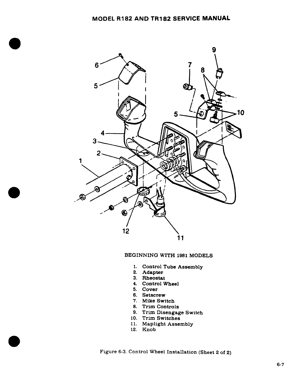
MODEL
R182
AND
TR182
SERVICE
MANUAL
9
6 7
8
10
12
11
BEGINNING
WITH
1981
MODELS
1.
Control
Tube
Assembly
2.
Adapter
3.
Rheostat
4.
Control
Wheel
5.
Cover
6.
Setscrew
7.
Mike
Switch
8.
Trim
Controls
9.
Trim Disengage
Switch
10.
Trim
Switches
11.
Maplight Assembly
12.
Knob
Figure
6-3.
Control
Wheel
Installation
(Sheet
2
of
2)
6-7
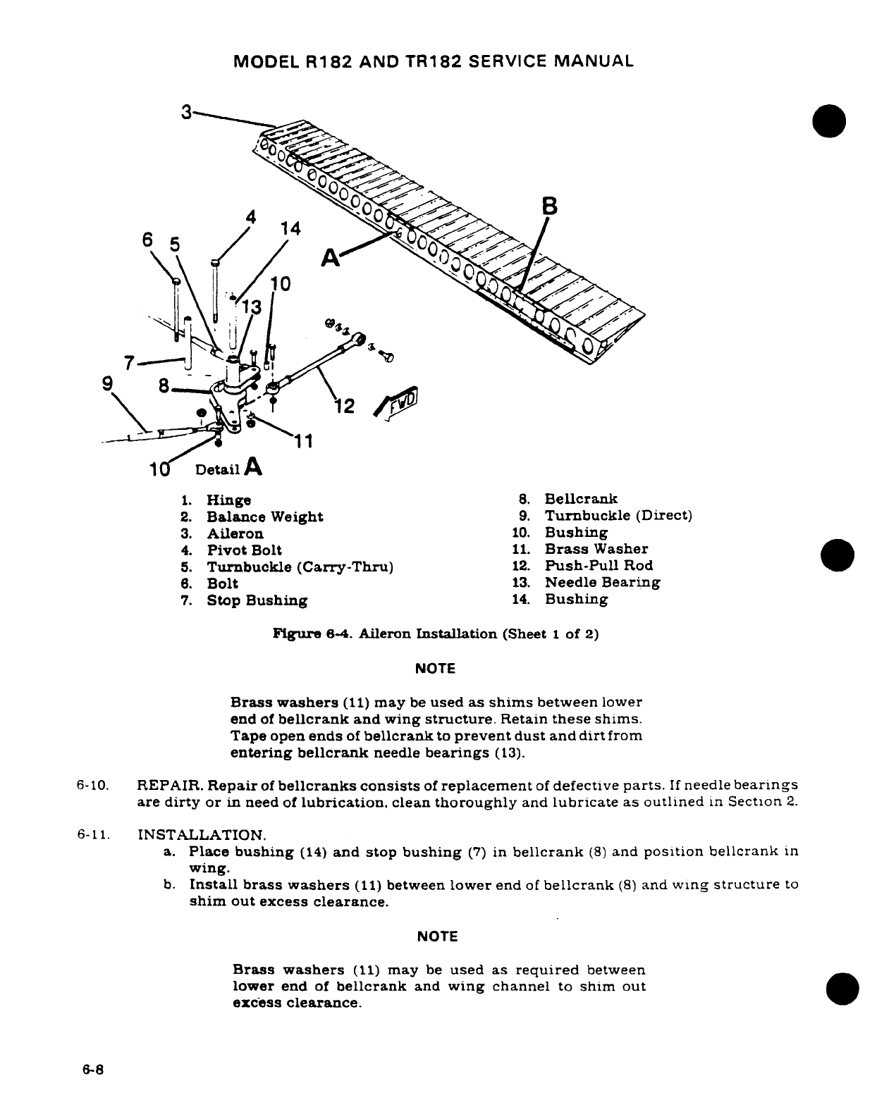
MODEL
R182
AND
TR182
SERVICE
MANUAL
6.
10
Detail
A
1.
Hinge
8.
Bellcrank
2.
Balance
Weight
9.
Turnbuckle
(Direct)
3.
Aileron
10.
Bushing
4.
Pivot
Bolt
11.
Brass
Washer
5.
Turnbuckle
(Carry-Thru)
12.
Push-Pull
Rod
6.
Bolt
13.
Needle
Bearing
7.
Stop
Bushing
14.
Bushing
Figure
6-4.
Aileron
Installation
(Sheet
1
of
2)
NOTE
Brass
washers
(11)
may
be
used
as
shims
between
lower
end
of
bellcrank
and
wing
structure.
Retain
these
shims.
Tape
open
ends
of
bellcrank
to
prevent
dust
and
dirt
from
entering
bellcrank
needle
bearings
(13).
6-10.
REPAIR.
Repair
of
bellcranks consists
of
replacement
of
defective
parts.
If
needle
bearings
are
dirty
or
in
need
of
lubrication.
clean
thoroughly
and
lubricate
as
outlined
in
Section
2.
6-11.
INSTALLATION.
a.
Place
bushing
(14)
and
stop
bushing
(7)
in
bellcrank
(8)
and
position bellcrank
in
wing.
b.
Install brass
washers
(11)
between
lower
end
of
bellcrank
(8)
and
wing
structure
to
shim
out excess clearance.
NOTE
Brass
washers
(11)
may
be
used
as
required
between
lower
end
of
bellcrank
and
wing channel
to
shim
out
excess
clearance.
6-8
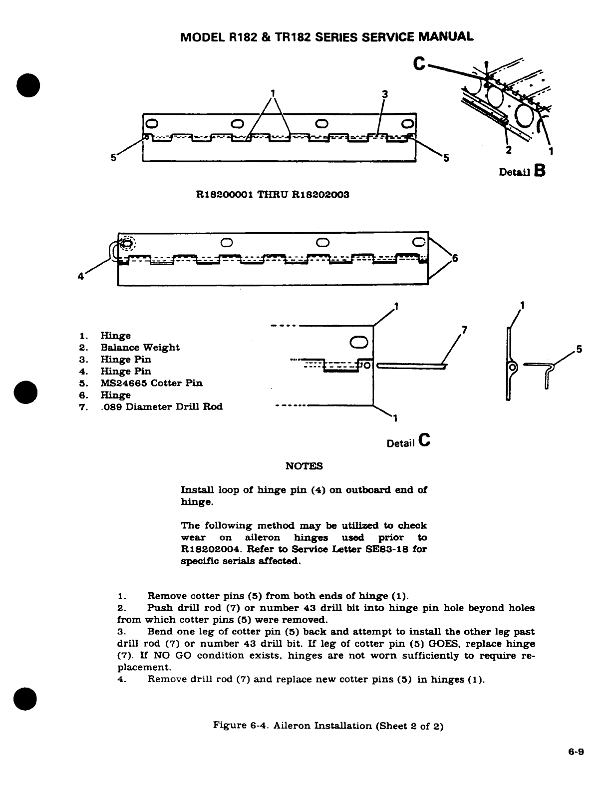
MODEL
R182
&
TR182
SERIES
SERVICE
MANUAL
A
3
5
2
Detail
B
R18200001
THRU
R18202003
~~~42-^~~~~~~~~~ ^"^^"^""^"^/6
1
Hinge
/7
2.
Balance
Weight
/
5
3.
Hinge
Pin
--
4.
Hinge
Pin
5.
MS24665
Cotter
Pin
6.
Hinge
7.
.089
Diameter Drill
Rod
-
1
Detail
C
NOTES
Install
loop
of
hinge pin
(4)
on
outboard
end
of
hinge.
The
following
method may
be
utilized
to
check
wear
on
aileron
hinges
used
prior
to
R18202004.
Refer to
Service
Letter
SE83-18
for
specific
serials
affected.
1.
Remove
cotter
pins
(5)
from
both
ends
of
hinge
(1).
2.
Push
drill
rod
(7)
or
number
43
drill
bit
into hinge
pin
hole
beyond holes
from
which
cotter
pins
(5)
were
removed.
3.
Bend
one
leg
of
cotter pin
(5)
back
and
attempt
to
install
the
other
leg
past
drill
rod
(7)
or number
43
drill
bit.
If
leg
of
cotter
pin
(5)
GOES,
replace
hinge
(7).
If
NO
GO
condition
exists,
hinges
are
not
worn
sufficiently
to
require
re-
placement.
4.
Remove
drill
rod
(7)
and
replace
new
cotter
pins
(5)
in
hinges
(1).
Figure
6-4.
Aileron
Installation
(Sheet
2
of
2)
6-9
MODEL
R182
AND
TR182
SERVICE
MANUAL
c.
Install
bellcrank
pivot
bolt
(4).
d.
Position
bellcrank
stop-bushing
(7)
and
install
attaching
bolt
(6).
NOTE
Stop
bushing
(7)
should
be
centered
in
slots
of
aileron
bellcrank
(8)
in
each
wing
when
control
wheels
are
neutral,
with
correct
tension
on
aileron
carry-thru
cable
(5).
Push-pull
rods
(12)
are
then
adjusted
to
rig
the
ailerons
neutral.
e.
Connect
control
cables
to
bellcrank.
f.
Connect
push-pull
rod
(12)
to
bellcrank.
g.
Re-rig aileron
system
in
accordance
with
paragraph
6-18.
safety
turnbuckle
(5)
and
reinstall
all
items
removed
for
access.
6-12.
CABLES
AND
PULLEYS.
(See
figure
6-1.)
6-13.
REMOVAL
AND INSTALLATION.
a.
Remove
access
plates,
wing
root
fairings
and
upholstery
as
required.
b.
Remove
safety
wire
and
relieve
cable
tension
at turnbuckles
(8).
c.
Disconnect cables
from
aileron
bellcranks
(7)
and
quadrants
(index
23.
figure
6-2.)
d.
Remove
cable
guards
and
pulleys as
necessary
to
work cables
free
of
aircraft.
NOTE
To
ease
routing
of
cables,
a
length
of
wire
may
be
attached
to
end of
cable
before
being
withdrawn
from
aircraft.
Leave
wire
in
place,
routed
through
structure;
then
attach
cable
being
installed
and
use
to
pull
cable
into
position.
e.
After cable
is
routed
in
position.
install
pulleys
and
cable
guards.
Ensure
cable
is
positioned
in
pulley
groove
before
installing
guard.
f.
Re-rig
aileron
system
in
accordance
with
paragraph
6-18.
safety
turnbuckles
and
install
access
plates,
fairings
and
upholstery
removed
in
step
"a".
6-14.
AILERONS.
(See
figure
6-4.)
6-15.
REMOVAL.
a.
Disconnect
push-pull
rod
(12)
at
aileron.
b.
Remove
screws
and
nuts
attaching
aileron
hinges
(1)
to
trailing
edge
of
wing.
c.
Using care,
pull
aileron
out
and
down
to
slide
hinges
from
under wing skin
and
auxiliary
spar
reinforcements.
6-16.
INSTALLATION.
a.
Position
aileron
hinges
between
skin
and
auxiliary
spar
reinforcements
and
install
screws
and
nuts
attaching
hinges
to
trailing
edge
of
wing.
b.
Attach
push-pull
rod
(12)
to
aileron.
NOTE
If
rigging
was correct
and
push-pull
rod
adjustment
was
not
disturbed,
it
should
not
be
necessary
to
re-rig
system.
6-10
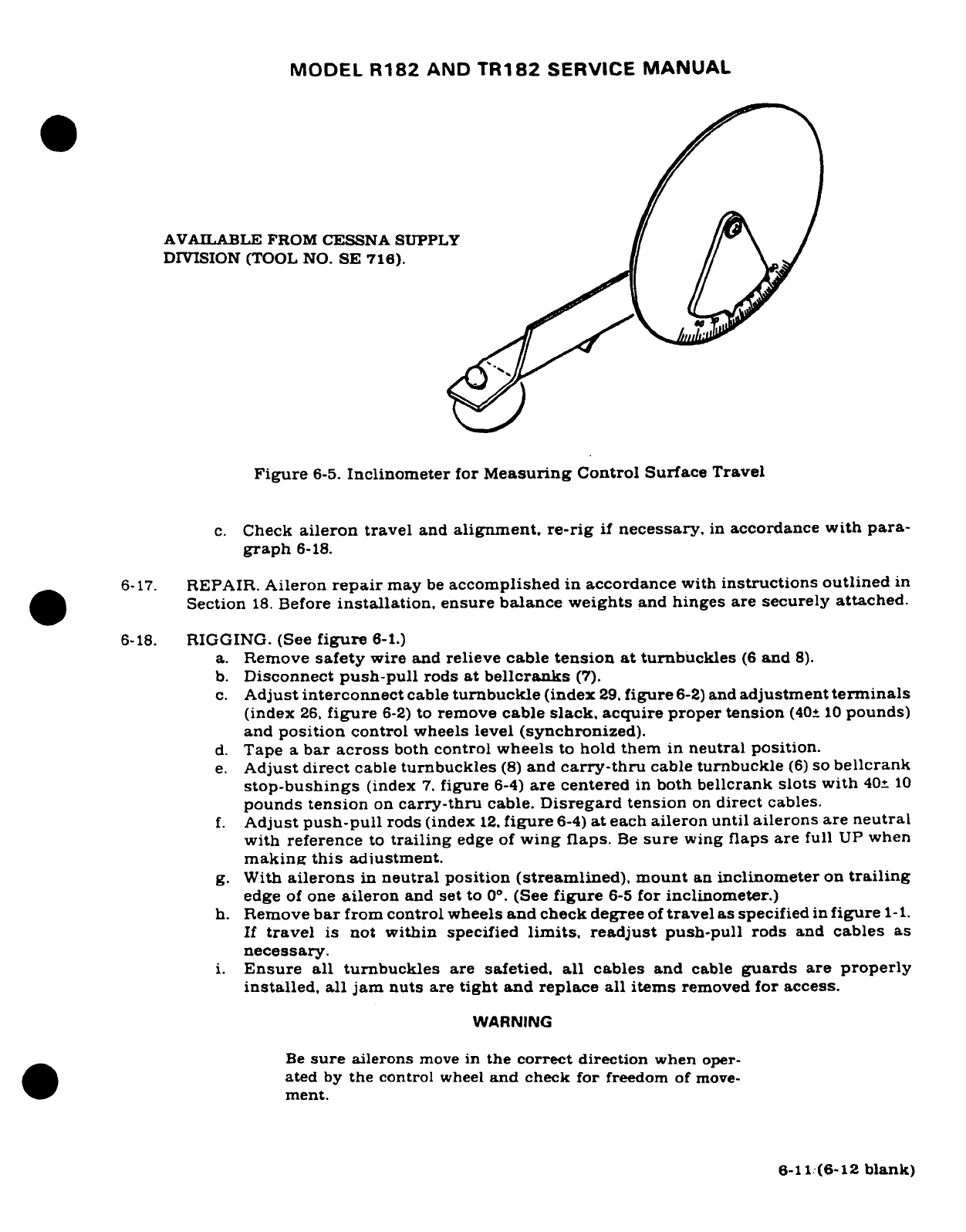
MODEL
R182
AND
TR182
SERVICE
MANUAL
AVAILABLE
FROM
CESSNA SUPPLY
DIVISION
(TOOL
NO.
SE 716).
Figure
6-5.
Inclinometer
for
Measuring
Control Surface
Travel
c.
Check
aileron
travel
and
alignment,
re-rig
if
necessary,
in
accordance
with para-
graph
6-18.
6-17.
REPAIR.
Aileron
repair
may
be
accomplished
in
accordance
with
instructions
outlined
in
Section
18.
Before
installation,
ensure balance
weights
and
hinges
are
securely
attached.
6-18.
RIGGING.
(See
figure
6-1.)
a.
Remove
safety
wire
and
relieve
cable
tension at
turnbuckles
(6
and
8).
b.
Disconnect
push-pull
rods
at
bellcranks
(7).
c.
Adjust
interconnect
cable
turnbuckle
(index
29.
figure
6-2)
and
adjustment
terminals
(index
26,
figure
6-2)
to
remove
cable
slack,
acquire
proper
tension
(40±
10
pounds)
and
position
control
wheels
level
(synchronized).
d.
Tape
a
bar
across
both
control
wheels
to
hold them
in
neutral
position.
e.
Adjust
direct
cable
turnbuckles
(8)
and
carry-thru
cable
turnbuckle
(6)
so
bellcrank
stop-bushings
(index
7.
figure
6-4)
are centered
in
both
bellcrank
slots
with
40±
10
pounds
tension
on
carry-thru
cable.
Disregard
tension
on
direct
cables.
f.
Adjust
push-pull
rods
(index
12.
figure
6-4)
at
each
aileron
until
ailerons
are
neutral
with
reference
to
trailing
edge
of
wing
flaps.
Be
sure
wing
flaps are
full
UP
when
making
this
adjustment.
g.
With
ailerons
in
neutral
position (streamlined), mount
an
inclinometer
on
trailing
edge
of
one
aileron
and
set
to
0°.
(See
figure
6-5
for
inclinometer.)
h.
Remove
bar
from
control
wheels
and
check degree
of
travel
as specified
in
figure
1-1.
If
travel
is
not
within
specified
limits,
readjust
push-pull
rods
and
cables
as
necessary.
i.
Ensure
all
turnbuckles
are
safetied,
all
cables
and
cable
guards
are
properly
installed, all
jam
nuts
are
tight
and
replace
all
items
removed
for
access.
WARNING
Be
sure
ailerons
move
in
the correct
direction
when
oper-
ated
by
the
control
wheel
and
check
for
freedom
of
move-
ment.
6-11
(6-12
blank)
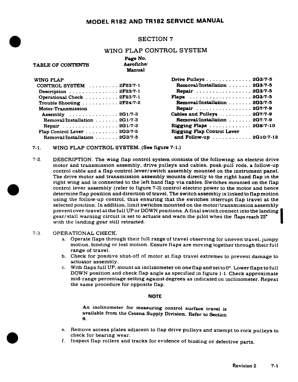
MODEL
R182
AND
TR182
SERVICE
MANUAL
SECTION
7
WING
FLAP
CONTROL
SYSTEM
Page
No.
TABLE OF
CONTENTS
Aerofiche/
Manual
WING
FLAP
Drive
Pulleys
..............
2G3/7-5
CONTROL
SYSTEM
.........
2F23/7-1
Removal/Installation
.......
2G3/7-5
Description
...............
2F23/7-1
Repair
.................
2G3/7-5
Operational
Check
..........
2F23/7-1
Flaps
...................
2G3/7-5
Trouble
Shooting
..........
2F24/7-2
Removal/Installation
.......
2G3/7-5
Motor/Transmission
Repair
.................
2G7/7-9
Assembly
...............
2G1/7-3
Cables
and
Pulleys
..........
2G7/7-9
Removal/Installation
.......
2G1/7-3
Removal/Installation
.......
2G7/7-9
Repair
.................
2G1/7-3
Rigging
Flaps
.............
2G8/7-10
Flap
Control
Lever
..........
2G3/7-5
Rigging
Flap
Control
Lever
Removal/Installation
.......
2G3/7-5
and Follow-up
............
2G10/7-12
7-1.
WING
FLAP
CONTROL SYSTEM.
(See
figure
7-1.)
7-2.
DESCRIPTION. The
wing
flap control system
consists
of
the
following:
an
electric drive
motor
and
transmission
assembly, drive pulleys
and cables.
push-pull
rods.
a
follow-up
control
cable
and
a
flap
control
lever/switch
assembly
mounted
on
the
instrument
panel.
The
drive motor
and
transmission
assembly
mounts
directly
to
the
right
hand
flap
in
the
right
wing
and
is
connected
to
the
left
hand
flap
via
cables.
Switches mounted
on
the
flap
control
lever
assembly
(refer
to
figure
7-3)
control
electric
power
to
the
motor
and
hence
determine flap
position
and
direction
of
travel.
The
switch
assembly
is
linked
to
flap
motion
using
the
follow-up
control,
thus
ensuring that
the
switches
interrupt
flap
travel
at
the
selected
position.
In
addition,
limit
switches mounted
on
the
motor/transmission
assembly
prevent
over-travel
at
the
full
UP
or
DOWN
positions.
A
final
switch
connect
into
the
landing
gear/
stall
warning
circuit
is
set
to
actuate
and
warn
the
pilot
when
the
flaps reach
25
with
the
landing
gear
still
retracted.
7-3.
OPERATIONAL
CHECK.
a.
Operate
flaps through
their
full
range
of
travel
observing
for
uneven
travel.jumpy
motion,
binding
or
lost
motion.
Ensure
flaps
are
moving
together
through
their
full
range
of
travel.
b.
Check
for
positive
shut-off
of
motor
at
flap
travel
extremes
to
prevent
damage
to
actuator
assembly.
c.
With
flaps full
UP.
mount
an
inclinometer
on
one
flap
and
set
to
0°.
Lower
flaps
to
full
DOWN
position
and
check
flap
angle
as
specified
in
figure
1-1.
Check
approximate
mid-range percentage
setting
against
degrees
as
indicated
on
inclinometer.
Repeat
the
same
procedure
for
opposite
flap.
NOTE
An
inclinometer
for
measuring
control surface
travel
is
available
from the
Cessna
Supply
Division.
Refer
to Section
6.
e.
Remove
access
plates
adjacent
to
flap
drive
pulleys
and
attempt
to
rock
pulleys
to
check for
bearing
wear.
f.
Inspect
flap
rollers
and
tracks
for
evidence of
binding
or
defective
parts.
Revision
2
7-1
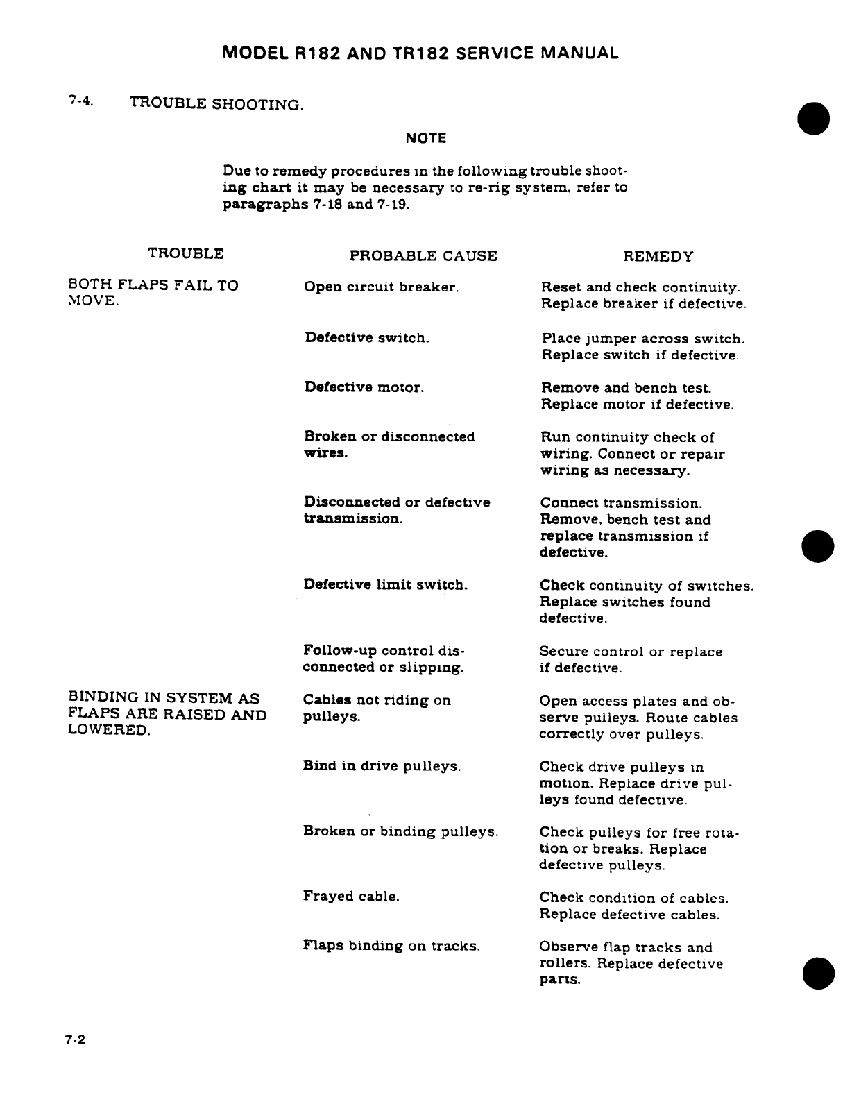
MODEL
R182
AND
TR182
SERVICE
MANUAL
7-4.
TROUBLE
SHOOTING.
NOTE
Due
to
remedy
procedures
in
the
following
trouble
shoot-
ing
chart
it
may
be
necessary
to
re-rig
system.
refer
to
paragraphs
7-18
and
7-19.
TROUBLE
PROBABLE
CAUSE
REMEDY
BOTH
FLAPS
FAIL
TO
Open
circuit
breaker.
Reset
and
check
continuity.
MOVE.
Replace
breaker
if
defective.
Defective
switch.
Place
jumper
across
switch.
Replace
switch
if
defective.
Defective motor.
Remove
and
bench
test.
Replace
motor
if
defective.
Broken
or
disconnected
Run
continuity
check
of
wires.
wiring.
Connect
or
repair
wiring
as
necessary.
Disconnected
or
defective
Connect
transmission.
transmission.
Remove,
bench
test
and
replace
transmission
if
defective.
Defective
limit
switch.
Check
continuity
of
switches.
Replace
switches
found
defective.
Follow-up
control
dis-
Secure
control
or
replace
connected
or
slipping.
if
defective.
BINDING
IN
SYSTEM AS
Cables
not
riding
on
Open
access
plates
and
ob-
FLAPS
ARE
RAISED
AND
pulleys.
serve
pulleys. Route
cables
LOWERED.
correctly
over
pulleys.
Bind
in
drive
pulleys.
Check
drive
pulleys
in
motion.
Replace
drive
pul-
leys
found
defective.
Broken
or
binding
pulleys.
Check
pulleys
for
free
rota-
tion
or
breaks.
Replace
defective
pulleys.
Frayed
cable.
Check
condition
of
cables.
Replace
defective
cables.
Flaps
binding
on
tracks.
Observe
flap
tracks
and
rollers.
Replace
defective
parts.
7-2
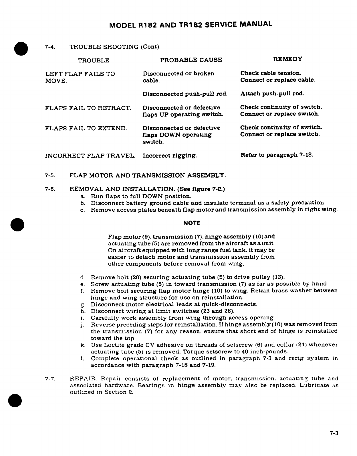
MODEL
R182
AND
TR182
SERVICE
MANUAL
.
7-4.
TROUBLE
SHOOTING
(Cont).
TROUBLE
PROBABLE
CAUSE
REMEDY
LEFT FLAP
FAILS
TO
Disconnected
or
broken
Check
cable
tension.
MOVE.
cable. Connect
or
replace
cable.
Disconnected
push-pull
rod.
Attach
push-pull
rod.
FLAPS
FAIL
TO
RETRACT.
Disconnected
or
defective
Check
continuity
of
switch.
flaps
UP
operating
switch.
Connect
or
replace
switch.
FLAPS
FAIL
TO
EXTEND.
Disconnected
or
defective
Check
continuity
of
switch.
flaps
DOWN
operating
Connect
or
replace
switch.
switch.
INCORRECT
FLAP
TRAVEL.
Incorrect
rigging.
Refer
to
paragraph
7-18.
7-5.
FLAP
MOTOR
AND
TRANSMISSION
ASSEMBLY.
7-6.
REMOVAL
AND
INSTALLATION.
(See
figure
7-2.)
a.
Run
flaps
to
full
DOWN
position.
b.
Disconnect
battery
ground cable
and
insulate
terminal
as
a
safety
precaution.
c.
Remove
access
plates
beneath
flap
motor
and
transmission
assembly
in
right
wing.
NOTE
Flap motor
(9),
transmission
(7),
hinge assembly
(10)
and
actuating
tube
(5)
are
removed
from
the
aircraft as
a
unit.
On
aircraft
equipped
with
long
range
fuel
tank,
it
may
be
easier
to
detach
motor
and
transmission
assembly
from
other
components
before
removal
from
wing.
d.
Remove
bolt
(20)
securing
actuating
tube
(5)
to
drive
pulley
(13).
e.
Screw
actuating
tube
(5)
in
toward
transmission
(7)
as
far
as
possible
by
hand.
f.
Remove
bolt
securing
flap
motor
hinge
(10)
to
wing.
Retain
brass
washer
between
hinge
and
wing
structure
for use
on
reinstallation.
g.
Disconnect
motor
electrical
leads
at
quick-disconnects.
h.
Disconnect
wiring
at
limit
switches
(23
and
26).
i.
Carefully
work
assembly
from
wing
through
access
opening.
j.
Reverse
preceding
steps
for
reinstallation.
If
hinge
assembly
(10)
was
removed
from
the
transmission
(7)
for
any
reason,
ensure that
short
end
of
hinge
is
reinstalled
toward
the
top.
k.
Use
Loctite
grade
CV
adhesive
on
threads
of
setscrew
(6)
and
collar
(24)
whenever
actuating
tube
(5)
is
removed.
Torque
setscrew
to
40
inch-pounds.
l.
Complete
operational
check
as
outlined
in
paragraph
7-3
and
rerig system
in
accordance
with
paragraph
7-18
and
7-19.
7-7.
REPAIR.
Repair
consists
of
replacement
of
motor.
transmission.
actuating
tube
and
associated
hardware. Bearings
in
hinge
assembly
may
also
be
replaced.
Lubricate
as
outlined
in
Section
2.
7-3
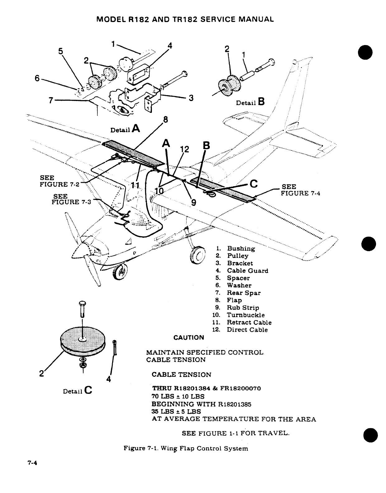
MODEL
R182
AND
TR182
SERVICE
MANUAL
F5S2
1
4
.I
6
w
"
Q..;./
' -W
7 DtDetailA
.i. 'i* ...........
.
;* "::::-":'*
...
8"'
D......ea.. .i ""-.... ,.::
...
.......
SEE
FIGURE
7-2
C
M
SEE
/SEE
^*. *I /-
CABLE
TENSION
\ e^' !^ ^FIGURE
7-4
FIGURE
7-3
...
/
/
2.
Pulley
I
3.
Bracket
5B.
''
.Spacer
BEGININ
6.
Washer
7.
Rear
Spar
35:
LBS
t
5
LB.
8.
Flap
9.
Rub
Strip
10.
Turnbuckle
11.
Retract
Cable
~,~ ~ .~':::,:~"-
'---^...^s.' ;'..'
12.
Direct
Cable
CAUTION
1-. .. '...'.
MAINTAIN
SPECIFIED
CONTROL
/
®CABLE
TENSION
2
4
CABLE
TENSION
Detail
C
THRU
R18201384
&
FR18200070
Det ~ail
C70
LBS
i
10
LBS
BEGINNING
WITH
R18201385
35
LBS
±5
LBS
AT
AVERAGE
TEMPERATURE
FOR
THE
AREA
SEE FIGURE
1-1
FOR
TRAVEL.
Figure
7-1.
Wing
Flap
Control
System
7-4
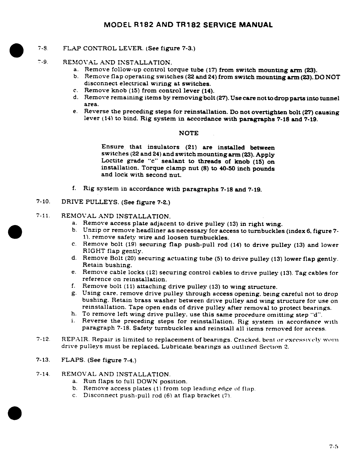
MODEL
R182
AND
TR182
SERVICE
MANUAL
7-8.
FLAP
CONTROL
LEVER.
(See
figure
7-3.)
7-9.
REMOVAL
AND
INSTALLATION.
a.
Remove follow-up
control
torque
tube
(17)
from
switch
mounting
arm
(23).
b.
Remove
flap
operating
switches
(22
and
24)
from
switch
mounting
arm
(23).
DO
NOT
disconnect electrical
wiring
at switches.
c.
Remove
knob
(15)
from
control
lever
(14).
d.
Remove
remaining
items
by
removing
bolt
(27).
Use
care
not
to
drop
parts
into
tunnel
area.
e.
Reverse the
preceding
steps
for
reinstallation.
Do
not
overtighten
bolt
(27)
causing
lever
(14)
to
bind.
Rig
system
in
accordance
with
paragraphs
7-18
and
7-19.
NOTE
Ensure
that
insulators
(21)
are
installed
between
switches
(22
and
24)
and
switch mounting
arm
(23).
Apply
Loctite
grade
"c"
sealant
to
threads
of
knob
(15)
on
installation.
Torque
clamp nut
(8)
to
40-50
inch
pounds
and
lock
with
second
nut.
f.
Rig
system
in
accordance
with
paragraphs
7-18
and
7-19.
7-10.
DRIVE
PULLEYS.
(See
figure
7-2.)
7-11.
REMOVAL
AND
INSTALLATION.
a.
Remove
access plate adjacent
to
drive
pulley
(13)
in
right
wing.
b.
Unzip
or remove
headliner
as
necessary
for
access
to
turnbuckles
(index
6,
figure
7-
1).
remove safety
wire
and
loosen
turnbuckles.
c.
Remove
bolt
(19)
securing flap push-pull
rod
(14)
to
drive
pulley
(13)
and
lower
RIGHT
flap
gently.
d.
Remove
Bolt
(20)
securing
actuating
tube
(5)
to
drive
pulley
(13)
lower
flap
gently.
Retain
bushing.
e.
Remove
cable locks
(12)
securing
control cables
to
drive
pulley
(13).
Tag
cables
for
reference
on
reinstallation.
f.
Remove
bolt
(11)
attaching
drive
pulley
(13)
to
wing
structure.
g.
Using care.
remove
drive
pulley
through
access
opening.
being
careful
not
to drop
bushing.
Retain
brass
washer
between
drive
pulley
and
wing
structure
for
use
on
reinstallation.
Tape
open
ends
of
drive
pulley
after removal
to
protect
bearings.
h.
To
remove
left
wing drive
pulley.
use
this
same
procedure
omitting
step
"d".
i.
Reverse
the
preceding
steps
for
reinstallation.
Rig
system
in
accordance with
paragraph
7-18.
Safety
turnbuckles
and
reinstall
all
items
removed
for
access.
7-12.
REPAIR.
Repair
is
limited
to
replacement
of
bearings.
Cracked.
bent
or
excessively
worn
drive pulleys
must
be
replaced.
Lubricate
bearings
as outlined
Section
2.
7-13.
FLAPS.
(See
figure
7-4.)
7-14.
REMOVAL
AND
INSTALLATION.
a.
Run
flaps
to
full
DOWN
position.
b.
Remove
access
plates
(1)
from
top
leading
edge
of
flap.
c.
Disconnect
push-pull
rod
(6)
at
flap
bracket
(7)
7-5
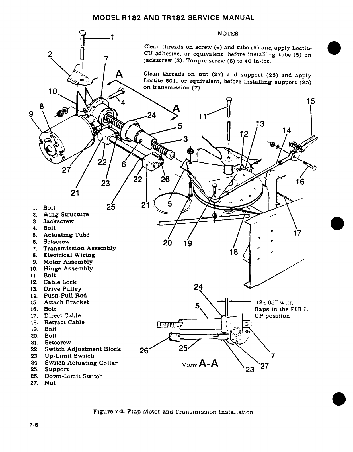
MODEL
R182
AND
TR182
SERVICE
MANUAL
_I-Cj~ R 1NOTES
Clean
threads
on
screw
(6)
and
tube
(5)
and
apply
Loctite
2
0l CU
adhesive,
or
equivalent.
before
installing
tube
(5)
on
I
7
jackscrew
(3).
Torque
screw
(6)
to
40
in-lbs.
^
/
^A
Clean
threads
on
nut
(27)
and
support
(25)
and apply
',®^
' |
>
g
Loctite
601,
or
equivalent,
before
installing
support
(25)
on
transmission
(7).
2.
Wing
Structure
J )_b,, Gy\<
3.
Jackscrew
/
<
^\
4.
Bolt
/ / f
e 17
5.
Actuating
Tube
/ / I o
00
0
'4
6.
Setscrew
20
19
/
4
7.
Transmission
Assembly
18
/
o
o
8.
Electrical
Wiring
b
o
9.
Motor
Assembly
>
/
10.
Hinge
Assembly
/
12.
Cable
Lock
24
<
14
23
16
13.
Drive
Pulley
2
14.
Push-Pull
ctureod
\
15.
Attach
Bracket
ew5 \-.05-
with
16.
Bolt
\ \
laps
in
the
FULL
17.
Direct
Cable
\
>
_
f
UP
position
18.
Retract
Cable
________
|a_ J__\
19.
Bolt
17
22.
Switch
Adjustment
Block
26
'
\
\
23.
Up-Limit
Switch
\
24.
Switch
Actuating
CollariewA-A \
27
25.
Support
26.
Down-Limit Switch
27.
Nut
21.
Setscrew
Figure
7-2.
Flap
Motor and
Transmission
Installation
7-6
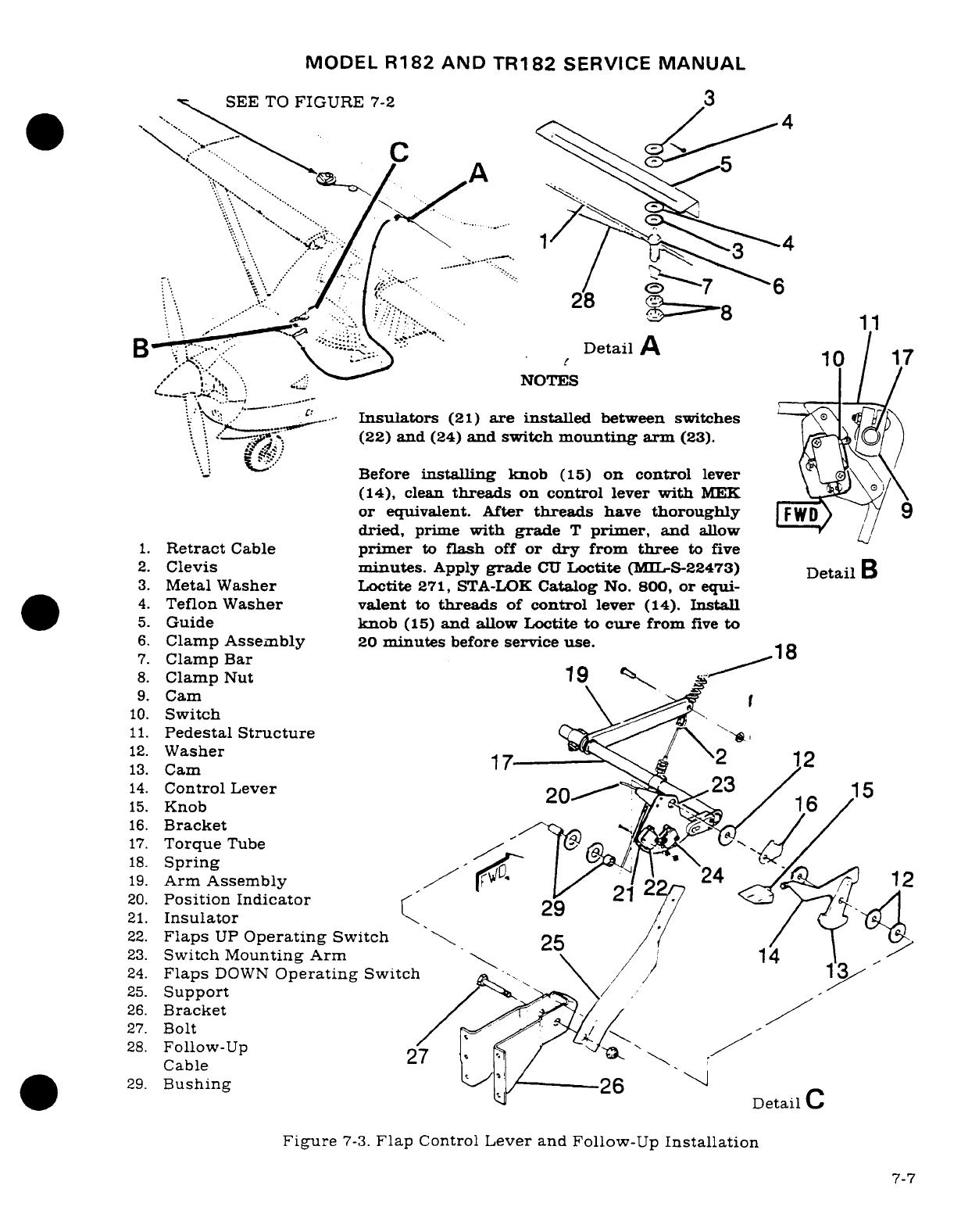
MODEL
R182
AND
TR182
SERVICE
MANUAL
SEE
TO
FIGURE
7-2
3
*< --
<
<A,
-4
..... 6'
::::.
6
.
':/ ".'-:
'
....
..- . . '
8'%.
.
\',...".-
.-' ..
28
.1
^By
5^\^^ ........
. .
.....
Detail
A
,'
'. "
-"
NOTES
Insulators
(21)
are
installed
between
switches
-\ ' , ----
'. - -
(22)
and
(24)
and switch
mounting
arm
(23).
\*-*~
'! "
Before
installing
knob
(15)
on
control
lever
(14),
clean
threads
on
control
lever
with
MEK
\L
or
equivalent. After
threads
have
thoroughly
FWD)
9
dried,
prime
with
grade
T
primer,
and
allow
1.
Retract
Cable
primer
to
flash
off
or
dry
from
three
to
five
2.
Clevis
minutes.
Apply
grade
CU
Loctite
(ML-rS-22473)
Detail
B
3.
Metal
Washer
Loctite
271,
STA-LOK
Catalog
No.
800,
or
equi-
4.
Teflon
Washer
valent
to
threads
of
control
lever
(14).
Install
5.
Guide
knob
(15)
and
allow
Loctite
to
cure
from
five
to
6.
Clamp
Assembly
20
minutes
before
service use.
7.
Clamp
Bar
8.
Clamp
Nut
19
9.
Cam
I
10.
Switch
11.
Pedestal
Structure
12.
Washer
2
12
13.
Cam
1
14.
Control
Lever
203
/
15
15.
Knob
/
16.
Bracket
I ; / /
17.
Torque
Tube
18.
Spring
19.
Arm
Assembly
22n
A
12
20.
Position
Indicator/
b
21.
Insulator
22.
Flaps
UP
Operating
Switch
25
23.
Switch
Mounting
Arm
14
24.
Flaps
DOWN
Operating
Switch
/
25.
Support
26.
Bracket
27.
Bolt
/
28.
Follow-Up
27/
.
.
"-
Cable
29.
Bushing
26
Detail
C
Figure
7-3.
Flap
Control
Lever
and Follow-Up
Installation
7-7
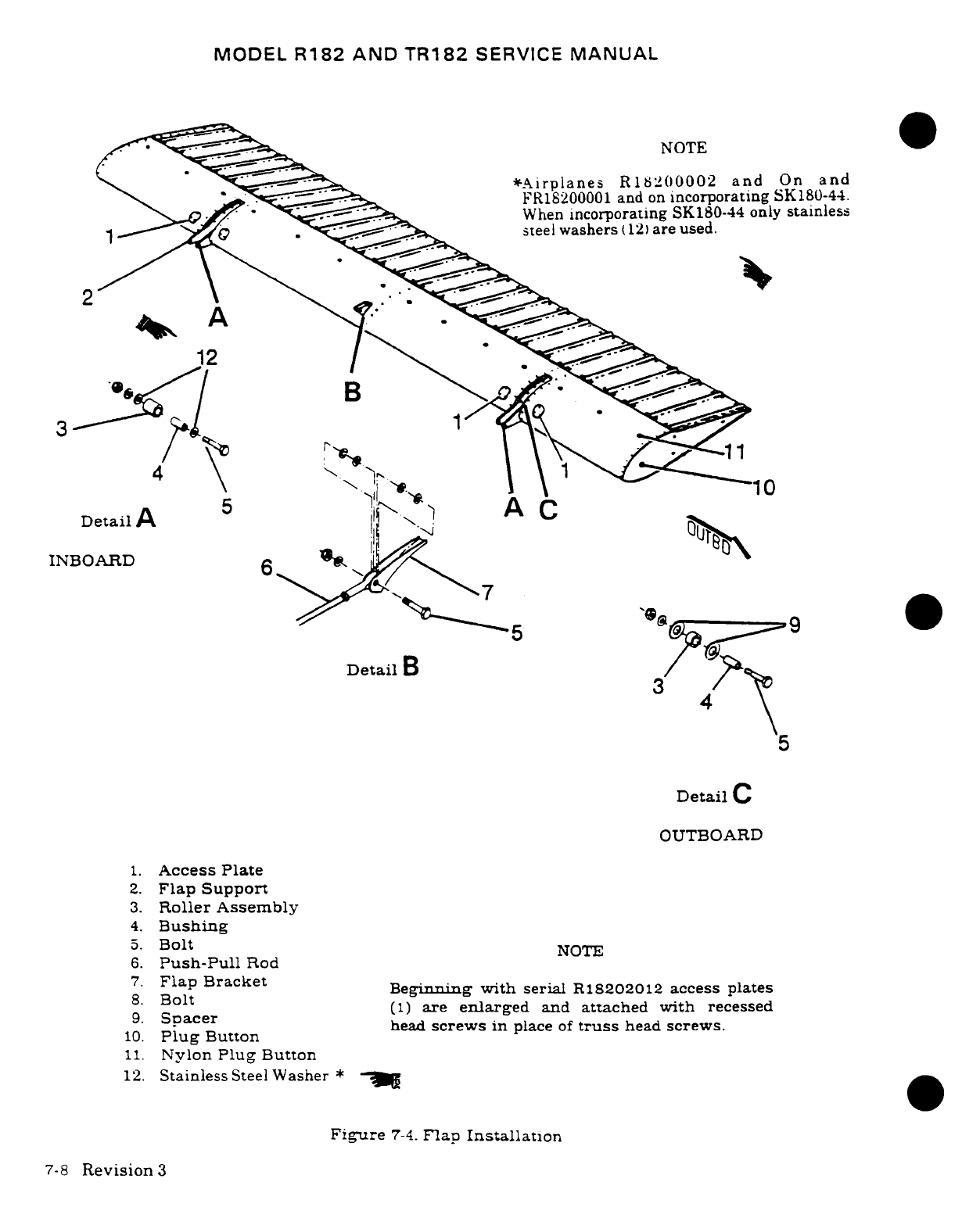
MODEL
R182
AND
TR182
SERVICE
MANUAL
NOTE
*Airplanes
R18200002
and
On
and
FR18200001
and
on
incorporating
SK180-44.
"_0>-<7/^ ' ^^i
~
When
incorporating
SK180-44 only
stainless
steel
washers
(12)
are
used.
3 11
4
\
" . ..
~.
Detail
A
5
"
A
C
INBOARD
i
Detail
B
3
A
x
3
4
Detail
C
OUTBOARD
1.
Access
Plate
2.
Flap
Support
3.
Roller Assembly
4.
Bushing
5.
Bolt
NOTE
6.
Push-Pull
Rod
7.
Flap
Bracket
.
Flap
Bracket
Beginning
with
serial
R18202012
access
plates
9.
acer
(1)
are
enlarged
and
attached
with
recessed
10.
PlugButton
head
screws
in
place
of
truss
head
screws.
11.
Nylon
Plug
Button
12.
Stainless
Steel
Washer
*
Figure
7-4.
Flap
Installation
7-8
Revision
3
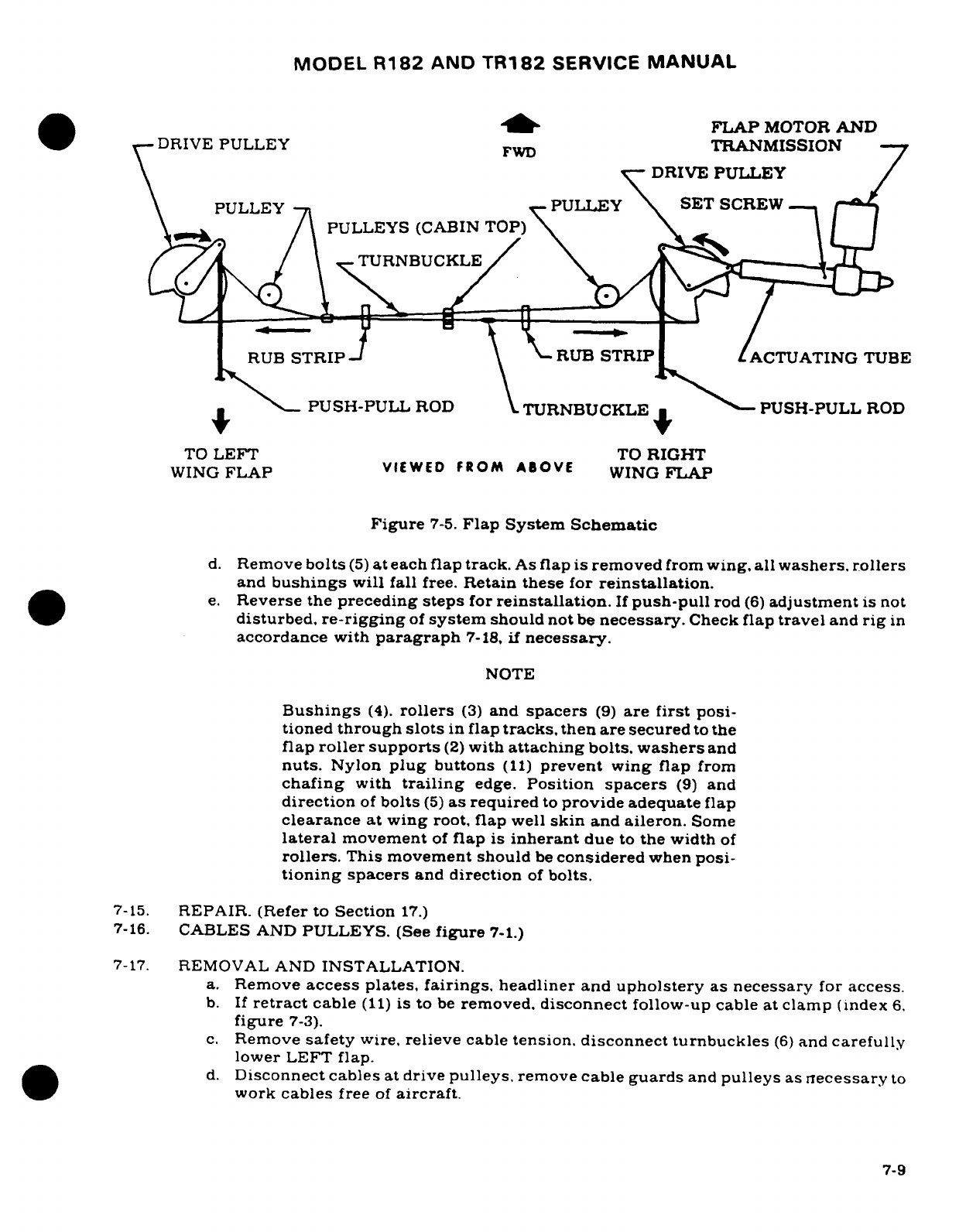
MODEL
R182
AND
TR182
SERVICE
MANUAL
D P-
FLAP
MOTOR
AND
v-DRIVE
PULLEY
FWD
TRANMISSION
DRIVE
PULLEY
PULLEY
PULLEY
SET
SCREW.
--
Ask/
\
PULLEYS (CABIN
TOP)\ .\ I
4
\
NTURNBUCK
LE
RUB
STRIP
\
RUB
STRIP
ACTUATING
TUBE
*PUSH-PULL
ROD
TURNBUCKLE
PUSH-PULL
ROD
TO
LEFT
TO
RIGHT
WING
FLAP
VIEWED
FROM
ABOVE
WING
FLAP
Figure
7-5.
Flap System
Schematic
d.
Remove
bolts
(5)
at
each
flap
track.
As flap
is removed
from
wing,
all washers,
rollers
and
bushings
will
fall
free.
Retain these for
reinstallation.
e.
Reverse the
preceding
steps
for
reinstallation.
If
push-pull
rod
(6)
adjustment
is
not
disturbed,
re-rigging
of
system
should
not
be
necessary.
Check
flap
travel
and
rig
in
accordance
with
paragraph
7-18,
if
necessary.
NOTE
Bushings
(4).
rollers
(3)
and
spacers
(9)
are
first
posi-
tioned
through
slots
in
flap
tracks,
then are
secured
to
the
flap
roller supports
(2)
with
attaching
bolts.
washers
and
nuts.
Nylon
plug
buttons
(11)
prevent
wing
flap
from
chafing
with
trailing
edge.
Position
spacers
(9)
and
direction
of
bolts
(5)
as
required
to
provide adequate
flap
clearance
at wing
root,
flap
well
skin
and
aileron.
Some
lateral
movement
of
flap is
inherant
due
to
the
width
of
rollers.
This
movement should
be
considered
when
posi-
tioning
spacers
and
direction
of
bolts.
7-15.
REPAIR.
(Refer
to
Section
17.)
7-16.
CABLES
AND
PULLEYS.
(See
figure
7-1.)
7-17.
REMOVAL
AND
INSTALLATION.
a.
Remove
access plates,
fairings.
headliner
and
upholstery
as necessary
for
access.
b.
If
retract
cable
(11)
is to
be
removed,
disconnect
follow-up cable at
clamp
(index
6.
figure
7-3).
c.
Remove
safety
wire,
relieve
cable
tension.
disconnect
turnbuckles
(6)
and
carefully
lower
LEFT
flap.
d.
Disconnect
cables
at
drive
pulleys,
remove
cable
guards
and
pulleys
as
necessary
to
work
cables
free
of
aircraft.
7-9
MODEL
R182
AND TR182
SERVICE
MANUAL
NOTE
To
ease
routing
of
cables,
a
length
of
wire may
be
attached
to
the
end
of
cable being
withdrawn
from
aircraft.
Leave
wire
in
place.
routed
through sturcture:
then
attach
the
cable
being
installed
and
use
wire
to
pull
cable into
position.
e.
Reverse
the
preceding steps
for
reinstallation.
f.
After
cables are
routed
in
position,
install
pulleys
and
cable
guards.
Ensure
cables
are
positioned
in
pulley
grooves
before
installing
guards.
g.
Re-rig
flap
system
in
accordance
with
paragraph
7-18
and
safety
turnbuckles.
h.
Re-rig
follow-up
system
in
accordance
with
paragraph
7-19
and
reinstall
all
items
removed
in
step
"a".
7-18.
RIGGING
FLAPS.
(See
figure
7-2.)
a.
Unzip
or
remove
headliner
as necessary
for
access
to
turnbuckles
(index
10.
figure
7-
1).
b.
Remove
safety
wire,
relieve
cable
tension,
disconnect
turnbuckles
and
carefully
lower
LEFT
flap.
c.
Disconnect
push-pull
rods
(14)
at
drive
pulleys
(13)
in both
wings
and
lower
RIGHT
flap gently.
d.
Disconnect
actuating
tube
(5)
from
drive
pulley
(13).
NOTE
If
control
cables
are
not
connected
to
left
and
right
drive
pulleys,
actuating
tube
(5)
and
push-pull
rods
(14)
must
be
disconnected
before
installing
cables.
If
drive
pulleys
(13)
are
not
installed,
attach
control
cables
before
install-
ing
drive
pulleys
in
the
wings
as
illustrated
in
figure
7-5.
e.
The 3/32
inch
retract
cable connects
to
the
forward
side
of
the
right
drive
pulley
and
to
the
aft
side
of
the
left
drive
pulley.
The
1/8
inch
direct
cable
connects
to
the
aft
side
of
the
right
drive
pulley
and
to the
forward side
of
the
left
drive
pulley.
f.
Adjust
both
push-pull
rods
(14)
to
8.83
.
12
inches
between
centers
of
rod
end
bearings
and
tighten
locknuts
on
both
ends.
Connect
push-pull
rods
to
flaps
and
drive pulleys.
NOTE
Temporarily
connect
cables
at
turnbuckles
(index
10,
figure
7-1)
and
test
flaps
by
hand
to
ensure
both
flaps
extend
and
retract
together.
If
they
will
not.
the
cables
are
incorrectly attached
to the
drive
pulleys. Ensure
that
the
right
drive
pulley
rotates
clockwise,
when
viewed
from
below,
as
the
flaps
are
extended. Tag
cables
for
reference
and
disconnect
turnbuckles
again.
g.
Screw
actuating
tube
(5)
IN
toward
transmission
(7)
by
hand
to.
12
.05
inches
between
switch
actuating
collar
(24)
and
transmission
as
illustrated
in
VIEW
A-A.
Loosen
setscrew
(6)
securing
actuating
tube
(5)
to
switch
actuating
collar
(24).
hold
actuating
collar
to
maintain
.12±.05
inches,
hold
RIGHT
flap
in
the
full
UP
position
and
adjust
actuating
tube
(5)
IN
or
OUT
as
necessary
to
align
with
attachment
hole
in
drive
pulley
(13).
Tighten
setscrew
(6)
in
accordance with
procedures outlined
in
the
following
note
and
secure
tube
to
drive
pulley
with
bolt
(20).
7-10
MODEL
R182
AND
TR182
SERVICE
MANUAL
NOTE
Apply
Loctite
grade
CV
sealant
to
threads
of
setscrew
(6)
and
torque
to
40
inch-pounds.
If
actuating
tube
(5)
is
too
long
to
allow
attachment
to
drive
pulley
after
completion
of
step
"g".
proceed
to
step
"h".
h.
Disconnect
push-pull
rod
(14)
at
drive
pulley
(13).
then
connect
actuating
tube
(5)
to
drive
pulley.
i.
Manually
hold RIGHT
flap
in
full
UP
position
and
readjust
push-pull
rod
(14)
to
align
with
attachment
hole
in
drive
pulley. Connect
push-pull
rod
and
tighten locknuts.
NOTE
The
right
flap
and
actuator
must
be
correctly
rigged
before
cables and
left
flap can
be
rigged.
j.
Mount
an
inclinometer
on
trailing
edge
of
RIGHT
flap.
NOTE
An
inclinometer for
measuring
control
surface
travel
is
available
from
the
Cessna
Supply
Division.
Refer
to
Section
6.
k.
With
RIGHT
flap
in
full
UP
position,
loosen
setscrew
(21)
and
slide
UP
limit
switch
(23)
and adjustment
block (22)
on
support
(25)
to
activate
switch
and
shut
off
electri-
cal power
to
motor
at
this
position.
Tighten
setscrew
(21).
l.
Run
RIGHT
flap
full
DOWN
position
and
adjust
DOWN
limit
switch
(26)
to
activate
and
shut
off
motor
at
degree
of
travel
specified
in
figure
1-1.
Tighten
setscrew
(21).
m.
Run
RIGHT
flap
to
full
UP
position,
manually
hold
LEFT
flap
full
UP
and
connect
control
cables
at
turnbuckles
(index
10,
figure
7-1).
Remove
reference
tags
previ-
ously
installed
in
step
"f"
as
turnbuckles
are
connected.
n.
With flaps
full
UP,
adjust
turnbuckles
to
obtain
70±
10
pounds tension
on
cables
thru
R18201384
and
FR18200070.
Beginning
with
R18201385
and
on.
maintain
35
±
5
pounds
cable
tension.
NOTE
Ensure
cables
are
positioned
in
pulley
grooves
and
cable
ends are
positioned
correctly
at
drive
pulleys
before
tight-
ening
turnbuckles.
o.
Disconnect
push-pull
rod
at
left
drive
pulley.
Run
motor
to
extend
flaps
approxi-
mately
20
°
and
check
tension on
each flap
cable.
If
necessary,
readjust
turnbuckles
to
maintain
70
±
10
pounds
tension
thru
R18201384
and
FR18200070.
Beginning
with
R18201385
and
on,
maintain
35
±
5
pounds
cable
tension.
p.
Fully
retract
right
flap.
Manually
hold
left
flap
in
full
up
position and
readjust
push-
pull
rod
to
align
with
attaching
hole
in
drive
pulley.
Connect
push-pull
rod
and
tighten
locknuts.
q.
After
completion
of
steps
"a"
thru
"p",
operate
flaps
and
check
for
positive
shut
off
of
flap
motor
through
several cycles.
Check
for
specified
flap
travel
with
inclinometer
mounted
on
each
flap
separately.
7-11
MODEL
R182
AND
TR182
SERVICE
MANUAL
NOTE
Since
the flap
rollers
may
not
bottom
in
the flap
tracks
with
flaps
fully
extended,
some
free
play may
be
noticed
in
this
position.
7-19.
RIGGING-FLAP
CONTROL
LEVER
AND
FOLLOW-UP.
(See
figure
7-3.)
NOTE
Flaps must
be
rigged
per
paragraph
7-18
prior
to
rigging
flap
follow-up
system.
a.
Run
flaps
to
full
UP
position.
b.
Remove
upholstery
and
headliner
as
necessary.
c.
Disconnect
follow-up
cable
(28)
from
flap
retract
cable
(1)
at
clamp
(6).
d.
With
position
indicator
(20)
in
full
UP
position,
pull
all
slack
from
follow-up
control
cable
(28)
and secure
follow-up
cable
(28)
to
retract
cable
(1)
with
clamp
assembly
(6).
Torque
clamp
nut
(26)
to
40-50
inch-pounds
and
lock
with
second
nut.
e.
With
control lever
(14)
in
full
up
position. adjust
switches
(22
and
24)
in
slotted
holes
until
cam
(13)
is
centered
between
switch
rollers.
f.
Mount
an
inclinometer
on
trailing
edge
of
one
flap
and
set
to
0°.
Turn master
switch
ON
and
move
control lever
to
10
°
position.
If
flap
travel
is
more
than
10°
.2
°,
adjust
flaps
DOWN
operating
switch
(24)
away
from cam
(13)
and
recycle
flaps.If
flap
travel
is
less
than
10
°±2 ° .
adjust
flaps
DOWN
operating
switch
(24)
closer
to
cam
(13)
and
recycles.
NOTE
An
inclinometer
for
measuring
control
surface
travel
is
available
from
the
Cessna
Supply
Division.
Refer
to
fig-
ure
Section
6.
g.
Repeat
step
"f"
for
20
°
flap
position
(flap
travel:
20°
2°).
h.
Adjust
flaps
UP
operating
switch
(22)
in
slotted
holes
for.062
inch
clearance
between
switch
roller
and
cam
(13)
when
the
flaps
DOWN
operating switch
has
just
opened
in
the
10
°
and
20
position.
NOTE
Flap
travel
on
UP
cycle
may
deviate
a
maximum
of
4°
from
indicated
position.
i.
Adjust
flap/landing
gear
warning
switch
cam
(9)
on
torque
tube
(17)
to
close
switch
(10)
with
flaps
down
25
°.
j.
Run
flaps
through
several
complete
cycles
and
check
indicator
(20)
for
smoothness
of
operation.
k.
Reinstall all items
removed for
access.
7-12 Revision
2
MODEL
R182
AND
TR182
SERVICE
MANUAL
SECTION
8
ELEVATOR
CONTROL
SYSTEM
Page
No.
TABLE
OF
CONTENTS
Aerofiche/
Manual
ELEVATOR
CONTROL SYSTEM
.
2G17/8-1
Bellcrank
................
2G22/8-6
Description
..............
2G17/8-1
Removal/Installation
.......
2G22/8-6
Trouble
Shooting
...........
2G17/8-1
Arm
Assembly
.............
2G238-7
Control Column
............
2G18/8-2
Removal/Installation
.......
2G23/8-7
Elevators
.................
2G18/8-2
Cables
and
Pulleys
..........
2G23/8-7
Removal
Installation
.......
2G18/8-2
Removal/Installation
.......
2G23/8-7
Repair
.................
2G22/8-6
Rigging
.................
2G24/8-8
8-1.
ELEVATOR
CONTROL
SYSTEM.
(Refer
to
figure
8-1.)
8-2.
DESCRIPTION.
The
elevators
are operated
by
power
transmitted through
fore-and-aft
movement
of
the
pilot
or
copilot
control
wheels.
The
system
is
comprised
of
control
columns.
an
elevator torque
tube,
cables
and
pulleys.
The
elevator
control
cables.
at
their
aft
ends, are
attached
to
a
bellcrank
mounted
on
a
bulkhead
in
the
tailcone.
A
push-pull
tube
connects
this
bellcrank
to
the
elevator
arm
assembly,
installed
between
the
elevators.
An
elevator trim
tab
is
installed
in
the
trailing
edge
of
the
right
elevator
and
is
described
in
Section
9.
8-3.
TROUBLE
SHOOTING.
NOTE
Due
to
remedy
procedures
in
the
following
trouble
shoot-
ing
chart
it
may
be
necessary
to
re-rig
system,
refer
to
paragraph
8-14.
TROUBLE
PROBABLE
CAUSE REMEDY
NO
RESPONSE
TO
CONTROL
Forward
or
aft end
of
push-
Attach
push-pull
tube
WHEEL
FORE-AND-AFT
pull
tube
disconnected.
correctly.
MOVEMENT.
Cables
disconnected.
Attach cables
and
rig
system
in
accordance
with
para-
graph
8-14.
Revision
1
8-1
MODEL
R182
AND
TR182
SERVICE
MANUAL
8-3.
TROUBLE
SHOOTING
(Cont).
TROUBLE PROBABLE
CAUSE REMEDY
BINDING
OR
JUMPY
Defective
bellcrank
or
Replace
defective
parts.
MOTION
FELT
IN
arm
assembly
pivot
bear-
MOVEMENT
OF
ELE-
ings
or
push-pull
tube
VATOR SYSTEM.
attach
bearings.
Cables
slack.
Adjust
to
tension
specified
in
figure
8-1.
Cables
not
riding
cor-
Route
cables
correctly
rectly
on
pulleys.
over pulleys.
Nylon
grommet
on
instru-
Replace
grommet.
ment
panel
binding.
Defective
control
column
Replace
defective
rollers.
bearing
rollers.
Defective
control
column
Replace
defective
bearings.
torque
tube
bearings.
Control
guide
on
aft
end
Loosen screw
and
tapered
of
control square
tube
plug
in end
of
control
adjusted
too
tightly.
tube
enough
to
eliminate
binding.
Defective
elevator
hinges.
Replace
defective
hinges.
Defective
pulleys
or
cable
Replace
defective
parts
and
guards.
install
guards
properly.
ELEVATORS
FAIL
TO
Stops
incorrectly
set.
Rig
in
accordance
with
ATTAIN
PRESCRIBED
paragraph
8-14.
TRAVEL.
Cables
tightened
unevenly.
Rig
in
accordance
with
paragraph
8-14.
Interference
at
instrument
Rig
in
accordance with
panel.
paragraph
8-14.
8-4.
CONTROL
COLUMN.
(Refer
to
Section
6.)
Section
6
outlines
removal.
installation
and
repair
of
control
column.
8-5.
ELEVATORS.
(Refer
to
figure
8-2.)
8-6. REMOVAL
AND
INSTALLATION.
a.
Remove
stinger.
b.
Disconnect
trim
tab
push-pull
tube
(6)
at
tab
actuator.
8-2
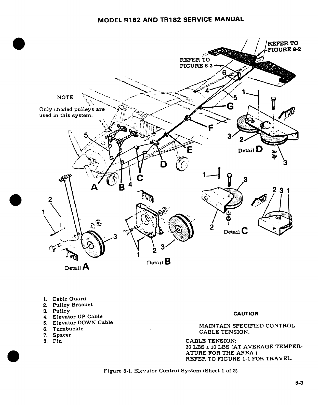
MODEL
R182
AND
TR182
SERVICE
MANUAL
/
/REFER
TO
.,-'IU.,/FIGURE
8-2
REFER
TO
'
'-
NOTE
Y
:
-
-.....
.......
Only
shaded
pulleys
are
'
..
^
used
in
this
system.
'?
A7··j
Detail
Dai
<
y\\
X
4
?
C"
Ji
i
.
3
*A
2
3
^
Detail
B
Detail
A
1.
Cable
Guard
2.
Pulley
Bracket
3.
Pulley
4.
Elevator
UP
Cable
CAUTION
5.
Elevator
DOWN
Cable
6.
v
Turnbuckle
ONCMAINTAIN
SPECIFIED
CONTROL
7.
Spacer
CABLE
TENSION.
8.
Pin
CABLE
TENSION:
30
LBS
_
10
LBS
(AT
AVERAGE
TEMPER-
ATURE FOR
THE
AREA.)
REFER
TO
FIGURE
1-1
FOR
TRAVEL.
Figure
8-1.
Elevator
Control
System
(Sheet
1 of
2)
8-3
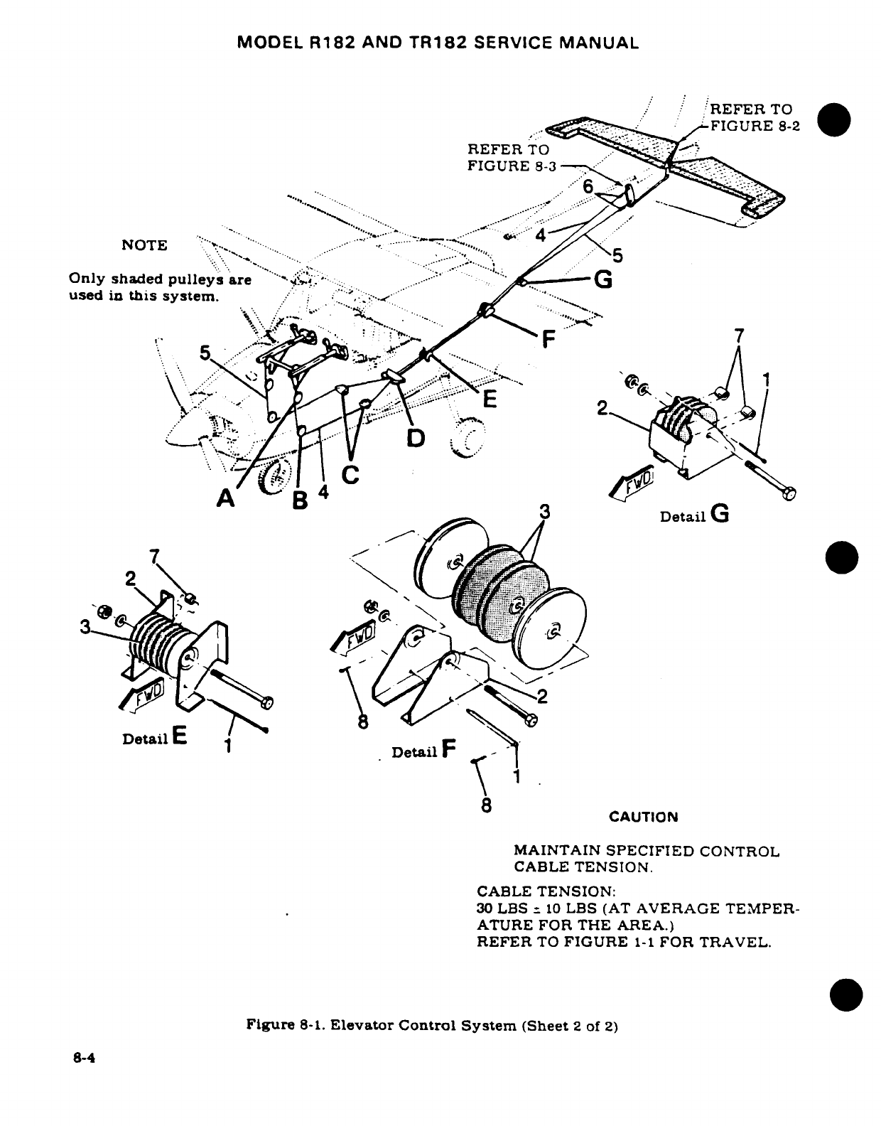
MODEL
R182
AND
TR182
SERVICE
MANUAL
, /
REFER
TO
..:.., -"-_:.~,,
:FIGURE
8-2
REFER
TO
.
FIGURE
8-3
.
NOTE
"'";\*^
""****...;
.. .- " .,"
....
" ...
used
in
this
system.
; "
D
X
8
,
DetailE
1
8
CAUTION
MAINTAIN
SPECIFIED
CONTROL
CABLE
TENSION.
CABLE
TENSION:
30
LBS
-
10
LBS
(AT
AVERAGE TEMPER-
ATURE
FOR
THE
AREA.)
REFER
TO
FIGURE
1-1
FOR TRAVEL.
Figure
8-1.
Elevator
Control System
(Sheet
2
of
2)
8-4
"\:
. , . .
3
-~,,:-
.
·.......... :,
·
w
~~~~~~~~~~~~~~~~;,
":~
..
,"
F~~~~~~~~~~~~~~~c
....
,. . ..
Tc~
'. .....i."
~ '..~! ..: ...
.. C . ~
~ ~ ~
~~~~CATO
•'..~
~ ~ ~ ~ ~~ANTI
-,.IIE .'.."'-~:::~.'
8-4~
~
~ ~ ~~~:
..
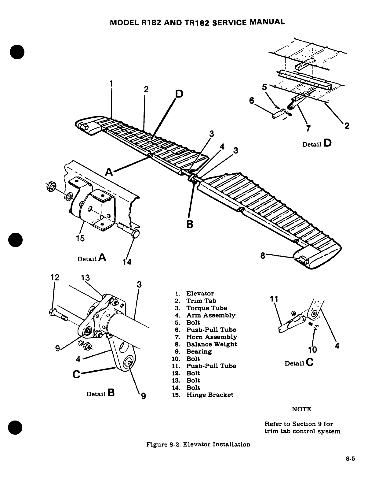
MODEL
R182
AND
TR182
SERVICE
MANUAL
Detail
A
12
13
1.
Elevator
2.
Trim
Tab
1 1
///
4/ .\e
I
3.
Torque
Tube
0+2t6/O
<,
4.
Arm
Assembly
-
\
5.
Bolt
6.
Push-Pull
Tube
7.
Horn
Assembly
8.
Balance
Weight
4
9 X \\ 9.
Bearing
4-" \\ /)10.
Bolt
Detail
C
11.
Push-Pull
Tube
Detail
C
fC
' \
12.
Bolt
\ 113.
Bolt
\ 514.
Bolt
DetailB
915.
Hinge
Bracket
NOTE
Refer
to
Section
9
for
trim
tab control
system.
Figure
8-2.
Elevator
Installation
8-5
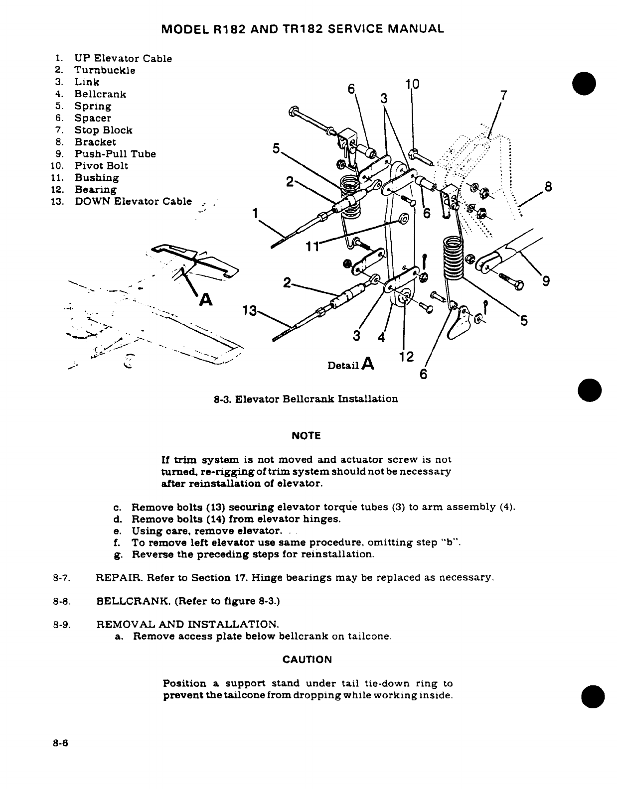
MODEL R182
AND
TR182
SERVICE
MANUAL
1.
UP
Elevator
Cable
2.
Turnbuckle
3.
Link
10
4.
Bellcrank
6
5.
Spring
6.
Spacer
7.
Stop
Block
8.
Bracket
.
:.
9.
Push-Pull
Tube
5
.
:'.
:
10.
Pivot
Bolt^
11.
Bushing
;
12.
Bearing
8
'~ >"
"
o.
A
-
1
3
Detail
A
12
8-3.
Elevator
Bellcrank
Installation
NOTE
If
trim
system
is
not
moved
and
actuator
screw
is
not
turned,
re-rigging
of
trim
system
should not
be
necessary
after
reinstallation
of
elevator.
c.
Remove
bolts
(13)
securing
elevator
torque
tubes
(3)
to
arm
assembly
(4).
d.
Remove
bolts
(14)
from
elevator
hinges.
e.
Using
care,
remove
elevator..
f.
To
remove
left
elevator
use
same
procedure,
omitting
step
"b".
g.
Reverse
the
preceding
steps
for
reinstallation.
8-7.
REPAIR.
Refer
to
Section
17.
Hinge
bearings
may
be
replaced
as
necessary.
8-8.
BELLCRANK.
(Refer
to
figure
8-3.)
8-9.
REMOVAL
AND
INSTALLATION.
a.
Remove
access
plate
below
bellcrank
on
tailcone.
CAUTION
Position
a
support
stand under tail
tie-down
ring
to
prevent
the tailcone
from
dropping
while
working
inside.
8-6
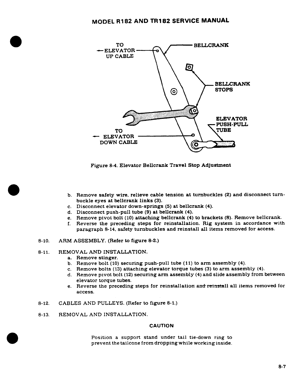
MODEL
R182
AND
TR182
SERVICE
MANUAL
TO
-
BELLCRANK
-
ELEVATOR
/
UP
CABLE
BELLCRANK
\ ® \
/
STOPS
-
ELEV'ATO
ELEVATOR
~\ \
PUSH-PULL
TO
\TUBE
"
ELEVATOR
DOWN
CABLE
Figure
8-4.
Elevator
Bellcrank
Travel
Stop
Adjustment
b.
Remove
safety
wire,
relieve
cable
tension
at
turnbuckles
(2)
and
disconnect turn-
buckle
eyes
at
bellcrank
links
(3).
c.
Disconnect
elevator
down-springs
(5)
at
bellcrank
(4).
d.
Disconnect
push-pull
tube
(9)
at
bellcrank
(4).
e.
Remove
pivot
bolt
(10)
attaching
bellcrank
(4)
to
brackets
(8).
Remove
bellcrank.
f.
Reverse
the
preceding
steps
for
reinstallation.
Rig system
in
accordance
with
paragraph
8-14,
safety
turnbuckles
and
reinstall
all items removed
for
access.
8-10.
ARM
ASSEMBLY.
(Refer
to
figure
8-2.)
8-11.
REMOVAL
AND
INSTALLATION.
a.
Remove
stinger.
b.
Remove
bolt
(10)
securing
push-pull
tube
(11)
to
arm
assembly
(4).
c.
Remove
bolts
(13)
attaching
elevator
torque
tubes
(3)
to
arm
assembly
(4).
d.
Remove
pivot
bolt
(12)
securing
arm
assembly
(4)
and
slide
assembly
from between
elevator torque
tubes.
e.
Reverse
the
preceding
steps
for
reinstallation
and-reinstall
all
items
removed
for
access.
8-12.
CABLES
AND
PULLEYS.
(Refer
to
figure
8-1.)
8-13.
REMOVAL
AND
INSTALLATION.
CAUTION
Position
a
support stand
under
tail
tie-down
ring
to
prevent
the
tailcone
from
dropping
while working
inside.
8-7
MODEL
R182
AND
TR182
SERVICE
MANUAL
CAUTION
Maintain
specified
control
cable
tension.
which
is
30
Lbs
10
Lbs
(at
average
temperature
for
the
area).
a.
Remove
seats.
upholstery
and
access
plates
as
necessary.
b.
Remove
safety wire
and
relieve
cable
tension
at
turnbuckles
(6).
c.
Disconnect cables
at
control
column
arm
assemblies
(index
18.
figure
6-2).
d.
Disconnect
cables
at bellcrank
links
(index
3,
figure
8-3).
e.
Remove
cable
guards
and
pulleys
as
necessary
to
work cables
free
of
aircraft.
NOTE
To
ease
routing
of
cables,
a
length
of
wire
may
be
attached
to
the
end
of
cable
being
withdrawn
from
aircraft.
Leave
wire
in
place,
routed
through
structure;
then
attach
the
cable
being
installed
and
pull
cable
into
position.
f.
After
cable
is
routed
in
position,
install
pulleys
and
cable
guards. Ensure
cable
is
positioned
in
pulley
groove
before
installing
guards.
g.
Re-rig
system
in
accordance
with
paragraph
8-14.
safety
turnbuckles
and
reinstall
all
items
removed
in
step
"a".
8-14.
RIGGING. (Refer
to
figure
8-3.)
CAUTION
Position
a
support
stand
under
tail
tie-down
ring
to
prevent the
tailcone
from
dropping
while
working
inside.
CAUTION
Maintain
specified
control
cable
tension,
which
is
30
Lbs
10
Lbs
(at
average temperature
for the
area).
a.
Install
control column
neutral
position
rigging
tool.
(Refer
to
figure
8-5.)
b.
Holding
elevator
in
neutral
position (streamlined
with
horizontal stabilizer). adjust
turnbuckles
(Index
2,
figure
8-3)
equally
to
obtain
cable tension.
c.
Remove
neutral
position rigging
tool
from
control
column.
d.
Streamline
elevators,
mount
an
inclinometer
on
one
elevator
and
set
to
0° .
NOTE
An
inclinometer
for
measuring
control
surface
travel
is
available
from the
Cessna
Supply
Division.
Refer
to
Section
6.
e.
(Refer to
figure
8-3.)
Adjust
bellcrank
stop
blocks
(7)
at
brackets
(8)
to
degree
of
travel
specified
in
figure
1-1.
8-8
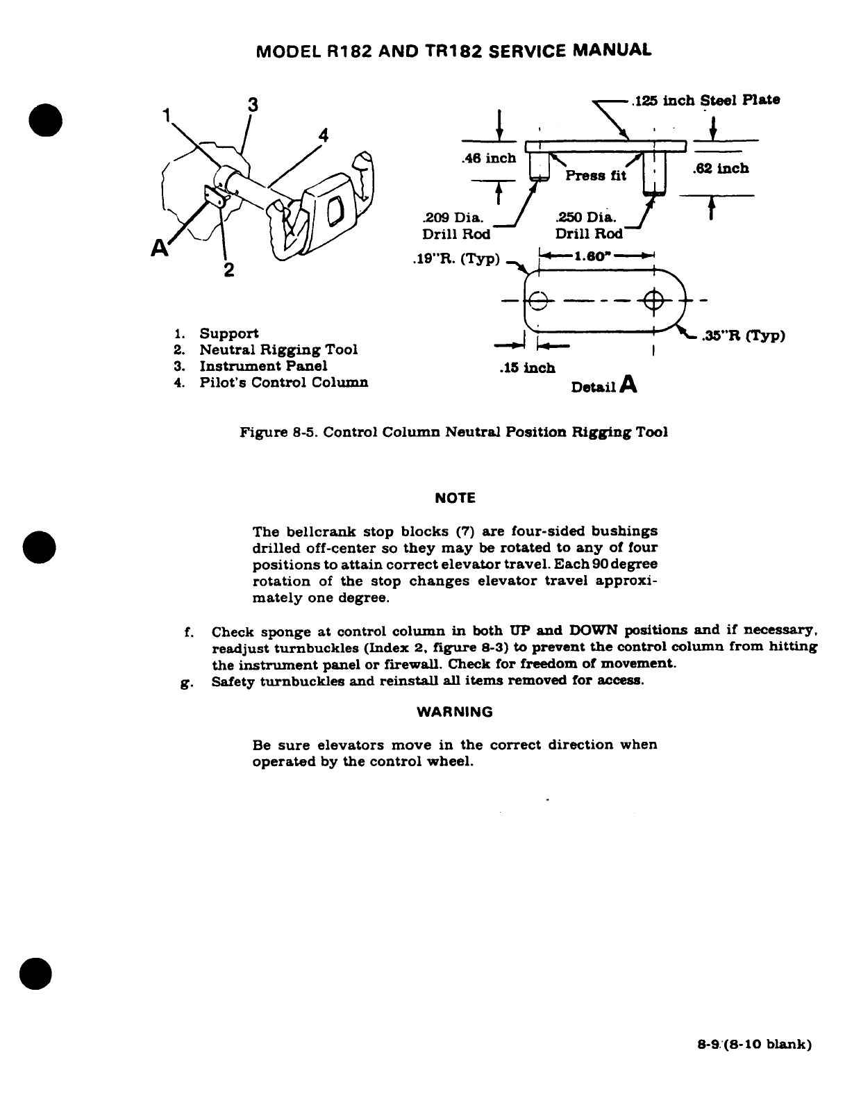
MODEL
R182
AND
TR182
SERVICE
MANUAL
-3
.125
inch
Steel
Plate
\1
4
*,
l
1.
Support
"R(Typ)
2.
Neutral
Rigging
Tool
.46
inchI
3.
Instrument
Panel
.62
inch
^y^ I/ (K/^
^J09
Dia.
.250
Dia.
t
A/ \,./
( ^//.^
~
Drill
Rod
Dril
Rod
.19"R.
(Typ)
I
i 60"W
1.
Support
-n-------·L.35"R
(Typ)
2.
Neutral
Rigging
Tool
3.
Instrument
Panel
.15
inch
4.
Pilot's
Control
Column
DetailA
Figure
8-5.
Control
Column
Neutral
Position Rigging
Tool
NOTE
The
bellcrank
stop
blocks
(7)
are
four-sided
bushings
drilled
off-center
so
they
may
be
rotated
to
any
of
four
positions
to
attain
correct
elevator
travel.
Each
90
degree
rotation
of
the
stop
changes elevator
travel
approxi-
mately
one
degree.
f.
Check
sponge
at
control
column
in
both
UP
and
DOWN
positions
and
if
necessary,
readjust
turnbuckles
(Index
2,
figure
8-3)
to
prevent
the
control
column from
hitting
the
instrument
panel
or
firewall.
Check
for
freedom
of
movement.
g.
Safety
turnbuckles
and
reinstall
all
items
removed
for
access.
WARNING
Be
sure
elevators
move
in
the correct
direction
when
operated
by
the
control
wheel.
8-9
(8-10
blank)
MODEL
R182
AND
TR182
SERVICE
MANUAL
SECTION
9
ELEVATOR
TRIM
TAB
CONTROL
SYSTEM
Page
No.
TABLE
OF
CONTENTS
Aerofiche/
Manual
ELEVATOR
TRIM
TAB
Cables
and
Pulleys
..........
2H18/9-11
CONTROL
SYSTEM
........
2H9/9-1
Removal/Installation
.......
2H18/9-11
Description
...............
2H9/9-1
Pedestal
Cover
.............
2H20.9-12
Trouble
Shooting
..........
2H9/9-1
Removal/Installation
.......
2H20.9-12
Trim
Tab
.................
2H11/9-3
Rigging
.................
2H20/9-12
Removal
Installation
.......
2H
1/9-3
Electric
Trim
Assist
Tab
Actuator
.............
2H11.
9-3
Installation
.............
2H21/9-13
Removal
Installation
.......
2H
11/9-3
Description
.............
2H21/9-13
Disassembly
.............
2H11/9-3
Trouble
Shooting
.........
2H22/9-14
Cleaning,
Inspection
and
Removal/Installation
.......
2H22/9-14
Repair
................
2H16/9-8
Clutch
Adjustment
........
2H22/9-14
Reassembly
.............
2H17/'9-9
Rigging
Electric
Trim
Trim
Tab
Free-Play
Assist
.................
212/9-18
Inspection
.............
2H18/9-10
Voltage
Regulator
Tab
Control
Wheel
.........
2H18/9-11
Adjustment
............
2I2/9-20
Removal
Installation
.......
2H18/9-11
9-1.
ELEVATOR
TRIM
TAB
CONTROL
SYSTEM.
9-2.
DESCRIPTION.
The
elevator
trim
tab,
located
on
the
trailing
edge
of
the
right
elevator,
is
controlled
by
a
trim
wheel
mounted
in
the
pedestal. Power
to
operate
the
tab
is
transmitted
from
the
trim
control
wheel
by
means
of
roller chains,
cables,
an
actuator
and
a
push-pull
tube.
A
mechanical
pointer,
adjacent
to
the
trim
wheel,
indicates
tab
position.
A
"nose-up"
setting
results
in
a
tab-down
position.
An
electric
trim
assist
system may
also
be
installed.
This
system
is
described
in
paragraph
9-19.
9-3.
TROUBLE
SHOOTING.
NOTE
Due
to
remedy
procedures
in
the following
trouble
shoot-
ing
chart
it
may
be
necessary
to
re-rig
system,
refer
to
paragraph
9-18.
Revision
1
9-1
MODEL
R182
AND
TR182
SERVICE
MANUAL
TROUBLE
PROBABLE
CAUSE
REMEDY
TRIM
CONTROL
WHEEL
Cable
tension
too
high.
Check
and
adjust
tension
as
MOVES
WITH
EXCESSIVE
specified
in
figure
9-1.
RESISTANCE.
Pulleys
binding
or
Open
access
plates
and
rubbing.
check
visually.
Install
cables correctly.
Cables
not
in
place
on
Open
access
plates
and
pulleys.
check
visually. Install
cables correctly.
Trim
tab
hinge
binding.
Disconnect
actuator
and
move
tab
to
check
resistance.
Lubricate
or
replace
hinge
as
necessary.
Defective
trim
tab
actuator.
Remove
chain
from
actuator
sprocket
and
operate
actuator
manually.
Replace
actuator
if
defective.
Rusty
chain.
Check
visually.
Replace
chain.
Damaged sprocket.
Check
visually.
Replace
sprockets.
Bent
sprocket
shaft.
Observe motion
of
sprockets.
Replace
bent
sprocket
shafts.
LOST
MOTION
BETWEEN
Cable
tension
too low.
Check
and
adjust
tension
CONTROL
WHEEL
AND
as
specified
in
figure
9-1.
TRIM
TAB.
Broken
pulley.
Open
access
plates
and
check
visually.
Replace
defective
pulley.
Cable
not
in
place
Open
access
plates
and
on
pulleys.
check
visually. Install
cables
correctly.
Worn
trim
tab
actuator.
Remove
and
replace
worn
actuator.
Actuator attachment
loose.
Check
actuator
for
security.
Tighten
as
necessary.
TRIM
INDICATOR FAILS
Indicator incorrectly
en-
Check
visually
and
reset
TO
INDICATE
CORRECT
gaged
on
wheel
track.
indicator
as
necessary.
TRIM
POSITION.
INCORRECT
TRIM
TAB
Stop
blocks
loose
or
incor-
Adjust
stop
blocks
on
cables.
TRAVEL.
rectly adjusted.
Refer
to
figure
9-3.
9-2
MODEL
R182
AND
TR182
SERVICE
MANUAL
9-4.
TRIM
TAB.
9-5.
REMOVAL
AND
INSTALLATION.
(Refer
to
figure
9-2.)
a.
Disconnect
push-pull
tube
(15)
from
horn
assembly
(16).
NOTE
If
trim
system
is
not
moved
and
actuator
screw
is
not
turned,
re-rigging
of
system
should
not
be
necessary
after
installation
of
tab.
b.
Drill
out
rivets
securing
trim
tab
hinge
to
elevator and
remove
trim
tab.
NOTE
After
tab
has
been
removed
and
if
hinge
pin
is
to
be
removed,
it is
necessary
to
spread
the
crimped
ends
of
the
hinge
before
driving
out
pin.
When
a
pin
has
been
installed,
crimp
ends
of
hinge
to
prevent pin
from
work-
ing
out.
c.
Reverse the preceding
steps
for
reinstallation.
Rig system
if
necessary
in
accor-
dance
with
paragraph
9-18.
9-6.
TRIM TAB
ACTUATOR.
9-7.
REMOVAL
AND
INSTALLATION.
(Refer
to
figure
9-2.)
a.
Relieve cable
tension at
turnbuckle
(index
5,
figure
9-1.).
CAUTION
Position
a
support
stand
under
the
tail
tiedown
ring
to
prevent
tailcone
from
dropping
while
working
inside.
b.
Disconnect
push-pull
tube
(15)
at
actuator
(11).
c.
Remove
access plate
beneath
actuator.
d.
Remove
chain
guard
(10)
and
disengage
chain
from
actuator
sprocket
(7).
e.
Remove
screws
attaching
clamps
(12)
to
bracket
(9)
and remove
actuator
(11)
through
access
opening.
f.
Reverse
the
preceding
steps
for
reinstallation.
Rig
system
in
accordance with
paragraph
9-18,
safety
turnbuckle
and
reinstall
all items
removed
for
access.
9-8.
DISASSEMBLY.
(Refer
to
figure
9-4.)
a.
Remove
actuator
in
accordance with
paragraph
9-7.
b.
Disassemble
actuator assembly
(1)
as
illustrated
in
Detail
A
as
follows:
1.
Remove
chain guard
(3)
if
not
previously
removed
in
step
"e"
of
paragraph
9-7.
2.
Using
suitable
punch
and
hammer, remove
roll
pins
(8)
securing
sprocket
(5)
to
screw
(9)
and
remove
sprocket
from
screw.
3.
Unscrew
threaded
rod
end
(15)
and
remove
rod
end
from
actuator.
4.
Remove
roll
pins
(10)
securing
bearings
(6
and
14)
at
the
housing
ends.
5.
Lightly
tap
screw
(9)
toward
the
sprocket
end
of
housing.
remove
bearing
(6)
and
collar
(7).
6.
Lightly
tap
screw
(9)
in
the
opposite
direction
from
sprocket
end.
remove
bearing
(14),
O-ring
(13)
and
collar
(7).
7.
It is
not
necessary
to
remove
retaining
rings
(11).
9-3
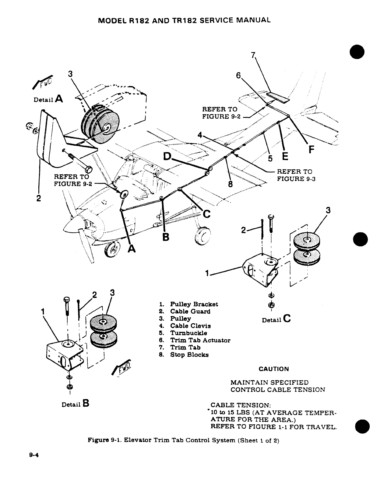
MODEL
R182
AND
TR182
SERVICE
MANUAL
7
0
\3
6
DetailA
-/
\bRREFER
TOEFER
TO
.FIGURE
9-82
" .
FIGURE
9-3
*--,
.....
...
23j~~~~~~
F^~
-~1
U 1
/'
2.
Cable
Guard
''
\
' ' '
mii
,
4.
Cable
Clevis
EF\
I
,lER?
5.
Turnbuckle
5^\^ Sp
6.
Trim
Tab
Actuator
..".,
7.
TrimTab
REEMAINTAIN
SPECIFIED
T
CONTROL CABLE
TENSION
Detail
B
CABLE
TENSION:
'10
to
15
LBS
(AT
AVERAGE
TEMPER-
ATIGURRE
FOR
THE
AREA.)92
REFER
TO
FIGURE
1-.
F.:
0.
Figure
9-1.
Elevator
Trim
Tab
Control
System
(Sheet
1
of 2)
9-4
7.
Trim
Tab
8.
Stop
Blocks
CAUTION
MAINTAIN
SPECIFIED
CONTROL CABLE
TENSION
Detail
a
CABLE
TENSION:
'10
to
15
LBS
(AT
AVERAGE
TEMPER-
ATURE
FOR
THE AREA.)
REFER
TO
FIGURE
1-1
FOR
TRAVEL.
Figure
9-1.
Elevator Trim
Tab
Control
System
(Sheet
1
of
2)
9-4
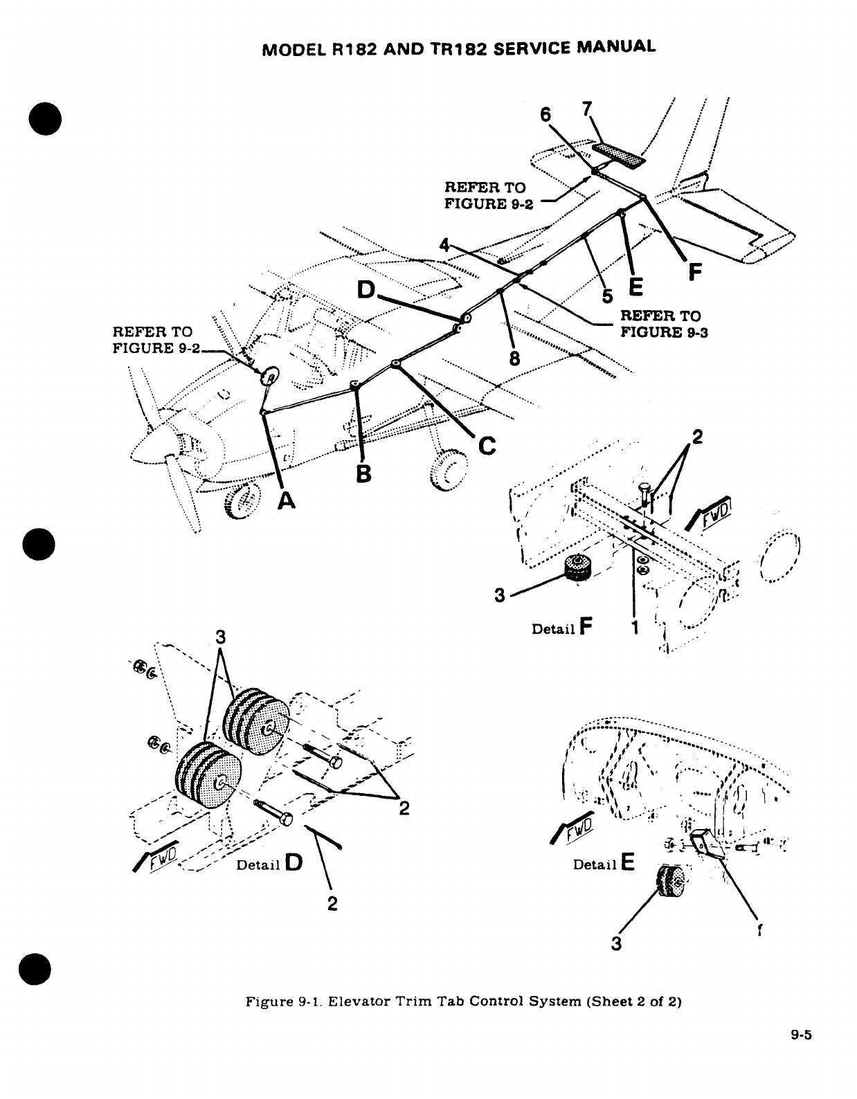
MODEL
R182
AND
TR182
SERVICE
MANUAL
6
'
/1
REFER
TO
FIGURE
9-2
i': "
R rn
REFER
TO
REFER
TO
-, ," ..... .........
..
~~~~~~~~.....FIGURE
9-2-
..
:
.
..
.:..'FIGURE
9-3
D ':
·...
.....
~--
.. ..
: .;.:
... ... . .
* ·' .
v
-...
v.'"
.. '..
"I ' .FE
3
"
f
/
;^-
F
IG
U
RE
9
-
1.
El
eta ilr
m .C S
'(h
e
2
o
2
·
~~~.,;^ ,,^~
·
,.%
.
"'--..~, ;-,
Detail
Detail
E
*-
Figure
9-1.
Elevator
Trim
Tab
Control
System
(Sheet
2
of
2)
/~~~~~~~~~~~~~~~'
.. -
~'
~
~-:
,'.:
.....
'~- ..... 4
",
','
....
.
....
,,'.
-....
oetoO.~,s,~eJl
Fgr
-1.,
?...-..;~..
TrmTB
otl
ye
(h
t
......
.~,......~~~~~~~~~~~9-
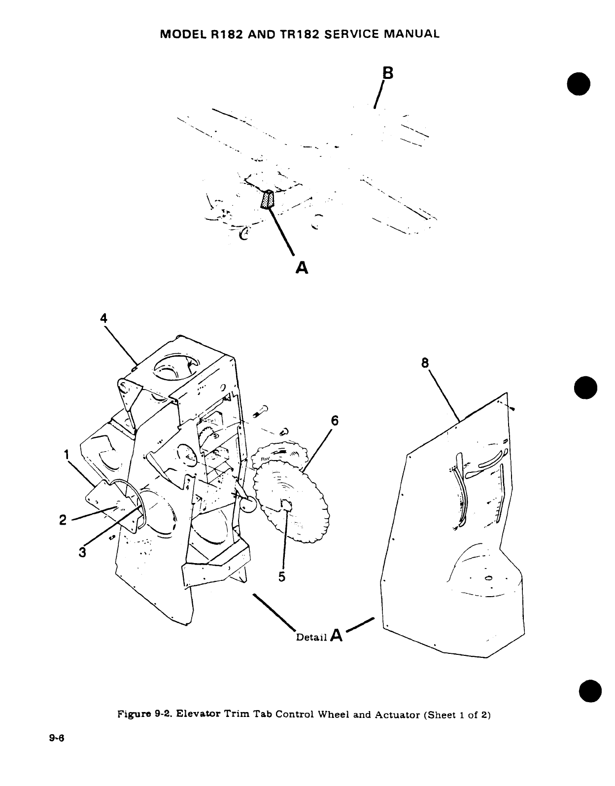
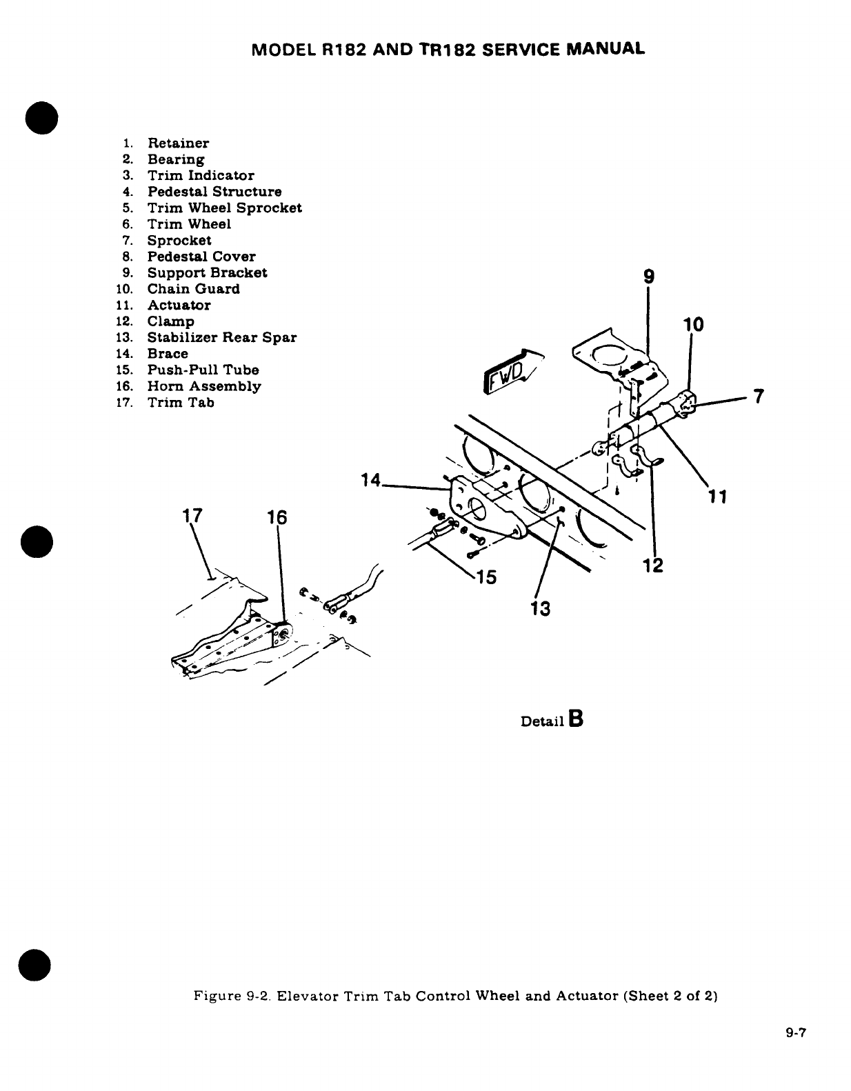
MODEL
R182
AND
TR182
SERVICE
MANUAL
1.
Retainer
2.
Bearing
3.
Trim
Indicator
4.
Pedestal
Structure
5.
Trim
Wheel
Sprocket
6.
Trim
Wheel
7.
Sprocket
8.
Pedestal
Cover
9.
Support
Bracket
9
10.
Chain
Guard
11.
Actuator
12.
Clamp
10
13.
Stabilizer Rear Spar
14.
Brace
15.
Push-Pull
Tube
K
|
16.
Horn
Assembly
17.
Trim
Tab
7
*14
-
17
16
1^- ^ ~~13
Detail
B
Figure
9-2.
Elevator
Trim
Tab
Control
Wheel
and
Actuator (Sheet
2
of
2)
9-7
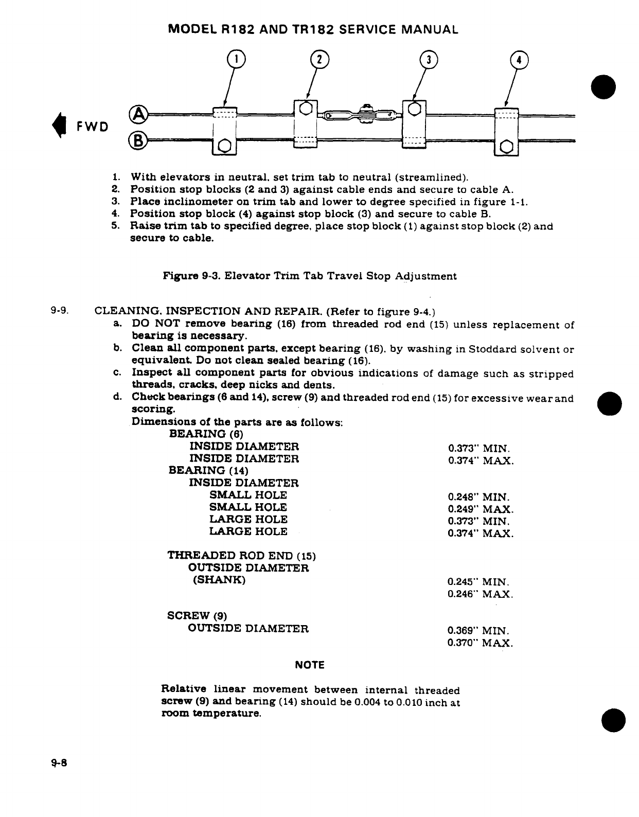
MODEL
R182
AND
TR182
SERVICE
MANUAL
| FWD
1.
With
elevators
in
neutral,
set
trim
tab
to
neutral
(streamlined).
2.
Position
stop blocks
(2
and
3)
against
cable
ends and secure
to
cable
A.
3.
Place
inclinometer
on
trim
tab
and
lower
to
degree
specified
in
figure
1-1.
4.
Position
stop
block
(4)
against
stop
block
(3)
and
secure
to
cable
B.
5.
Raise
trim
tab
to
specified
degree,
place
stop
block
(1)
against
stop block
(2)
and
secure
to
cable.
Figure
9-3.
Elevator
Trim
Tab
Travel
Stop
Adjustment
9-9.
CLEANING.
INSPECTION
AND
REPAIR.
(Refer
to
figure
9-4.)
a.
DO
NOT
remove
bearing
(16)
from
threaded
rod
end
(15)
unless
replacement
of
bearing
is
necessary.
b.
Clean
all
component
parts,
except
bearing
(16),
by
washing
in
Stoddard
solvent
or
equivalent.
Do
not clean
sealed
bearing
(16).
c.
Inspect
all
component
parts
for
obvious
indications
of
damage
such
as
stripped
threads,
cracks,
deep
nicks
and
dents.
d.
Check
bearings
(8
and
14),
screw
(9)
and
threaded
rod
end
(15)
for
excessive wear
and
scoring.
Dimensions
of
the
parts
are
as
follows:
BEARING
(6)
INSIDE
DIAMETER
0.373"
MIN.
INSIDE
DIAMETER
0.374"
MAX.
BEARING
(14)
INSIDE
DIAMETER
SMALL
HOLE
0.248"
MIN.
SMALL
HOLE
0.249"
MAX.
LARGE
HOLE
0.373"
MIN.
LARGE
HOLE
0.374"
MAX.
THREADED
ROD END
(15)
OUTSIDE
DIAMETER
(SHANK)
0.245"
MIN.
0.246"
MAX.
SCREW
(9)
OUTSIDE
DIAMETER
0.369"
MIN.
0.370"
MAX.
NOTE
Relative
linear
movement
between
internal
threaded
screw
(9)
and
bearing
(14)
should
be
0.004
to
0.010
inch
at
room
temperature.
9-8
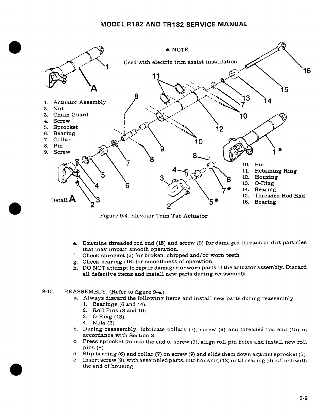
MODEL
R182 AND
TR182
SERVICE
MANUAL
*NOTE
Used
with
electric
trim
assist
installation
16
4A 1115
8
13
1.
Actuator
Assembly
/ \
2.
Nut
3.
Chain Guard
10
4.
Screw
5.
Sprocket
12
6.
Bearing
7.
Collar
-\ J
8.
Pin
9.
Screw
8
\ \ \
7
10.
Pin
i,-\ \- \ 4"---~A'
x\
11.
Retaining
Ring
3/'x\ 5\ 3o
"y \\
12.
Housing
4
I \ \
sa
\ 8
u13
O-Ring
\
xe\
4 6
~ \
7*
14.
Bearing
~\ \-~ k :~it~'-"/. \ ~
15.
Threaded
Rod
End
Detail
A
2
3
2/
5
16.
Bearing
Figure
9-4.
Elevator
Trim
Tab
Actuator
e.
Examine threaded
rod end
(15)
and
screw
(9)
for
damaged
threads
or
dirt
particles
that
may
impair
smooth
operation.
f.
Check
sprocket
(5)
for
broken,
chipped
and/or
worn
teeth.
g.
Check
bearing
(16)
for
smoothness
of
operation.
h.
DO
NOT
attempt
to
repair
damaged
or
worn
parts
of
the
actuator
assembly. Discard
all
defective
items
and
install
new
parts
during
reassembly.
9-10.
REASSEMBLY.
(Refer
to
figure
9-4.)
a.
Always
discard
the
following
items
and
install
new
parts
during
reassembly.
1.
Bearings
(6
and
14).
2.
Roll
Pins
(8
and
10).
3.
O-Ring
(13).
4.
Nuts
(2).
b.
During
reassembly, lubricate
collars
(7),
screw
(9)
and
threaded
rod
end
(15)
in
accordance
with
Section
2.
c.
Press
sprocket
(5)
into
the
end
of
screw
(9).
align
roll
pin
holes
and
install
new
roll
pins
(8).
d.
Slip
bearing
(6)
and
collar
(7)
on
screw
(9)
and
slide
them
down
against
sprocket
(5).
e.
Insert
screw
(9).
with
assembled
parts.
into
housing
(12)
until
bearing
(6)
is
flush
with
the
end
of
housing.
9-9
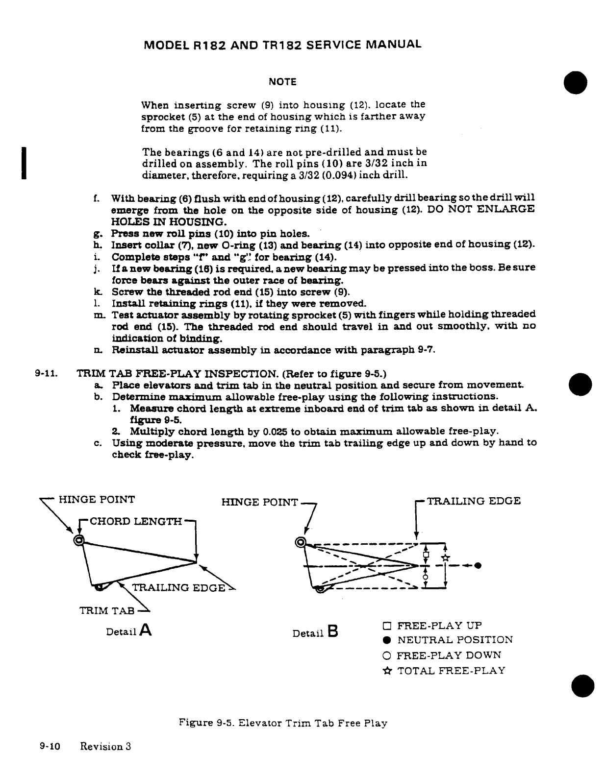
MODEL
R182
AND
TR182
SERVICE
MANUAL
NOTE
When
inserting
screw
(9)
into
housing
(12).
locate
the
sprocket
(5)
at
the
end
of
housing
which
is
farther
away
from the
groove
for
retaining
ring
(11).
The
bearings
(6
and
14)
are
not
pre-drilled
and
must
be
drilled
on
assembly.
The
roll
pins
(10)
are
3/32
inch
in
diameter,
therefore,
requiring
a
3/32
(0.094)
inch
drill.
f.
With
bearing
(6)
flush
with
end
of
housing
(12),
carefully
drill
bearing
so
the
drill
will
emerge
from the
hole
on
the
opposite side
of
housing
(12).
DO
NOT
ENLARGE
HOLES
IN
HOUSING.
g.
Press
new
roll
pins
(10)
into
pin
holes.
h.
Insert
collar
(7),
new
O-ring
(13)
and
bearing
(14)
into
opposite
end
of
housing
(12).
i.
Complete
steps
"f"
and
"g"
for
bearing
(14).
j.
If
a
new
bearing
(16)
is
required,
a
new
bearing
may
be
pressed into
the
boss.
Be
sure
force
bears
against
the
outer
race
of
bearing.
k.
Screw
the
threaded
rod
end
(15)
into
screw
(9).
1.
Install
retaining
rings
(11),
if
they
were
removed.
m.
Test
actuator assembly
by
rotating
sprocket
(5)
with
fingers
while
holding
threaded
rod
end
(15).
The
threaded
rod
end
should
travel
in
and
out
smoothly,
with
no
indication
of
binding.
n.
Reinstall actuator
assembly
in
accordance
with
paragraph
9-7.
9-11.
TRIM TAB
FREE-PLAY
INSPECTION.
(Refer
to
figure
9-5.)
a.
Place
elevators
and
trim
tab
in
the
neutral
position
and
secure
from
movement.
b.
Determine
maximum
allowable
free-play
using
the
following
instructions.
1.
Measure
chord
length
at extreme
inboard
end of
trim
tab
as
shown
in
detail
A.
figure
9-5.
2.
Multiply
chord
length
by
0.025
to
obtain maximum
allowable
free-play.
c.
Using
moderate
pressure,
move
the
trim
tab
trailing
edge
up
and down
by
hand
to
check
free-play.
HINGE
POINT HINGE POINT
TRAILING
EDGE
CHORD
LENGTH
7
-
TRIM
TAB
Detail
A
DetailB
FREE-PLAY
UP
*
NEUTRAL
POSITION
O
FREE-PLAY
DOWN
-
TOTAL
FREE-PLAY
Figure
9-5.
Elevator Trim
Tab Free
Play
9-10
Revision
3
MODEL
R182
AND
TR182
SERVICE
MANUAL
NOTE
Measure
free-play at
same
point
on
trim
tab
that
chord
length was measured.
Total
free-play
must
not
exceed
maximum
allowable.
Refer
to
detail
B,
figure
9-5.
d.
If
the
trim tab
free-play
is
less
than
the
maximum
allowable,
the system
is
within
prescribed
limits.
e.
If
the
trim tab
free-play
is more
than
the
maximum
allowable, check
the
following
items
for
looseness
while
moving
the
trim
tab
up
and
down.
1.
Check
push-pull
tube
to
trim
tab
horn
assembly
attachment
for
looseness.
2.
Check
push-pull
tube
to
actuator
assembly
threaded
rod
end
attachment
for
looseness.
3.
Check
actuator
assembly
threaded
rod
end
for
looseness
in
actuator
assembly
with
push-pull
tube
disconnected.
f.
If
looseness
is
apparent
while
checking
steps
e-1
and
e-2.
repair
by
installing
new
parts.
g.
If
looseness
is apparent
while checking
step
e-3,
refer
to
paragraphs
9-6
through
9-10.
Recheck
trim
tab
free-play.
9-12.
TRIM
TAB
CONTROL
WHEEL.
9-13.
REMOVAL
AND
INSTALLATION.
(Refer
to
figure
9-2.)
a.
Relieve
cable
tension
at
turnbuckle
(index
10,
figure
9-1.)
CAUTION
Position
a
support
stand
under
the
tail
tiedown
ring
to
prevent
tailcone
from
dropping
while
working
inside.
b.
Remove
pedestal
cover
(8)
in
accordance
with
paragraph
9-17.
c.
Remove
screws
attaching
control
wheel
retainer
(1)
to
left
side
of
pedestal
structure
(4).
d.
Remove
retainer
(1)
and
indicator
(3),
using
care
not
to
drop
control
wheel
(6).
e.
Disenengage
roller
chain
from
sprocket
(7)
and
remove
control
wheel
(6).
NOTE
Removal
of
the
sprocket
(7)
from
control
wheel
shaft
is
not
recommended except
for
replacement
of
parts.
f.
Reverse
the
preceding
steps
for
reinstallation.
Rig
system
in
accordance
with
paragraph
9-18,
safety
turnbuckle
and
reinstall
all
items
removed
for
access.
9-14.
CABLES
AND
PULLEYS.
9-15.
REMOVAL AND
INSTALLATION.
(Refer
to
figure
9-1.)
a.
Remove
seats,
upholstery,
pedestal
cover and
access
plates
as necessary.
CAUTION
Position
a
support
stand
under
the
tail
tiedown
ring
to
prevent
tailcone
from
dropping
while
working
inside.
9-11
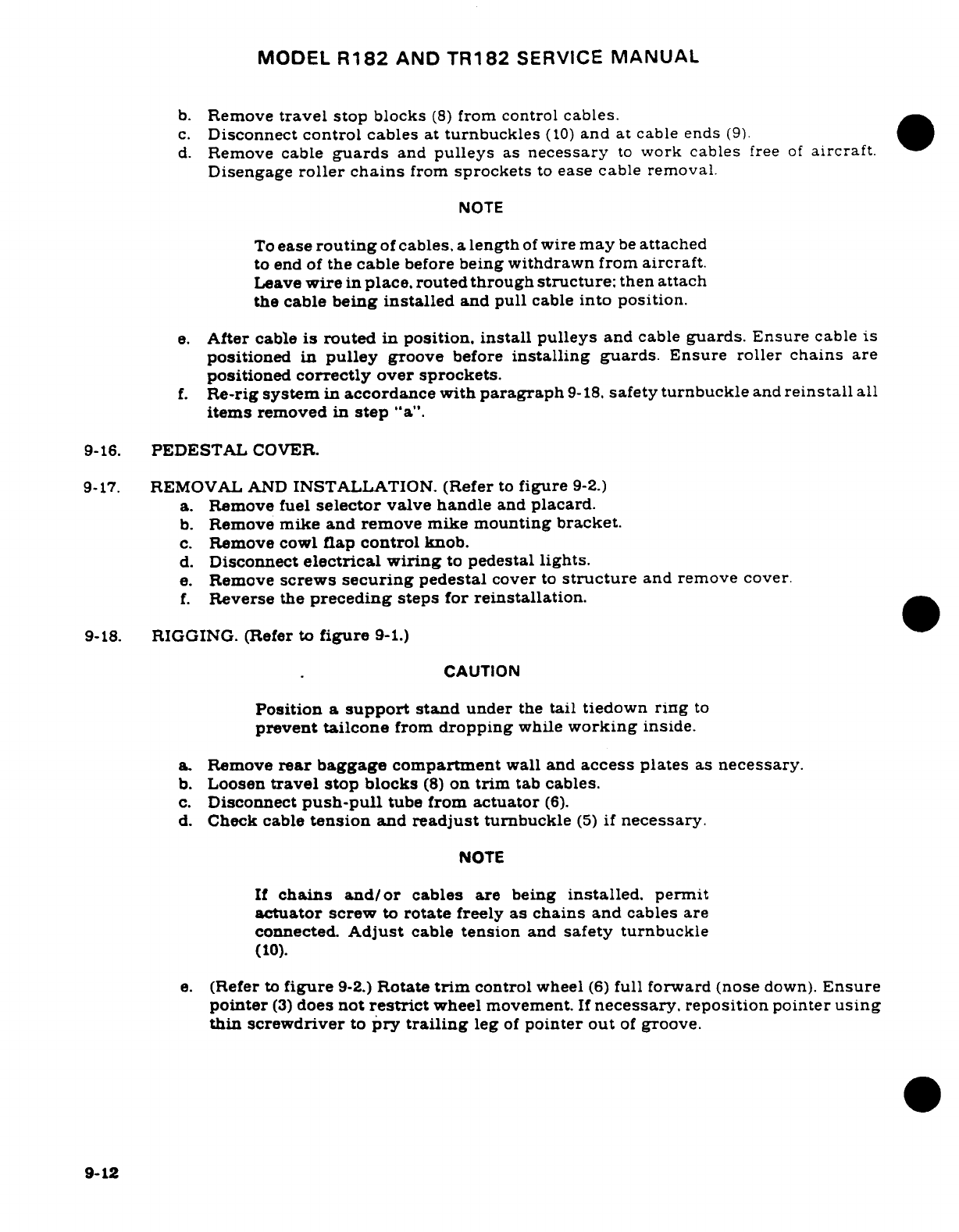
MODEL
R182
AND
TR182
SERVICE
MANUAL
b.
Remove
travel
stop
blocks
(8)
from
control
cables.
c.
Disconnect
control
cables
at
turnbuckles
(10)
and
at cable
ends
(9).
d.
Remove
cable
guards
and
pulleys
as
necessary
to
work
cables
free
of
aircraft.
Disengage
roller
chains
from
sprockets
to
ease
cable
removal.
NOTE
To
ease
routing
of
cables,
a
length
of
wire
may
be
attached
to end
of
the
cable
before
being
withdrawn
from
aircraft.
Leave
wire
in
place.
routed
through
structure;
then
attach
the cable
being
installed
and
pull
cable
into
position.
e.
After
cable
is
routed
in
position.
install
pulleys
and cable
guards.
Ensure
cable
is
positioned
in
pulley
groove
before
installing
guards.
Ensure
roller chains
are
positioned
correctly
over sprockets.
f.
Re-rig
system
in
accordance with
paragraph
9-18.
safety
turnbuckle
and
reinstall
all
items
removed
in
step
"a".
9-16.
PEDESTAL
COVER.
9-17.
REMOVAL
AND
INSTALLATION.
(Refer
to
figure
9-2.)
a.
Remove fuel
selector
valve handle
and
placard.
b.
Remove
mike
and
remove mike
mounting
bracket.
c.
Remove cowl
flap
control
knob.
d.
Disconnect
electrical wiring
to
pedestal
lights.
e.
Remove
screws
securing
pedestal
cover
to
structure
and
remove
cover.
f.
Reverse
the
preceding
steps
for
reinstallation.
9-18.
RIGGING.
(Refer
to
figure
9-1.)
CAUTION
Position
a
support
stand
under
the
tail
tiedown
ring
to
prevent
tailcone
from
dropping
while
working
inside.
a.
Remove
rear
baggage
compartment
wall
and
access plates
as
necessary.
b.
Loosen
travel
stop
blocks
(8)
on
trim
tab
cables.
c.
Disconnect
push-pull
tube
from
actuator
(6).
d.
Check
cable
tension
and
readjust
turnbuckle
(5)
if
necessary.
NOTE
If
chains
and/or
cables
are being
installed,
permit
actuator
screw
to
rotate
freely
as
chains
and
cables
are
connected.
Adjust
cable
tension
and
safety
turnbuckle
(10).
e.
(Refer
to
figure
9-2.)
Rotate
trim
control
wheel
(6)
full
forward
(nose
down).
Ensure
pointer
(3)
does
not
restrict
wheel movement.
If
necessary, reposition
pointer
using
thin screwdriver
to
pry
trailing
leg
of
pointer out
of
groove.
9-12
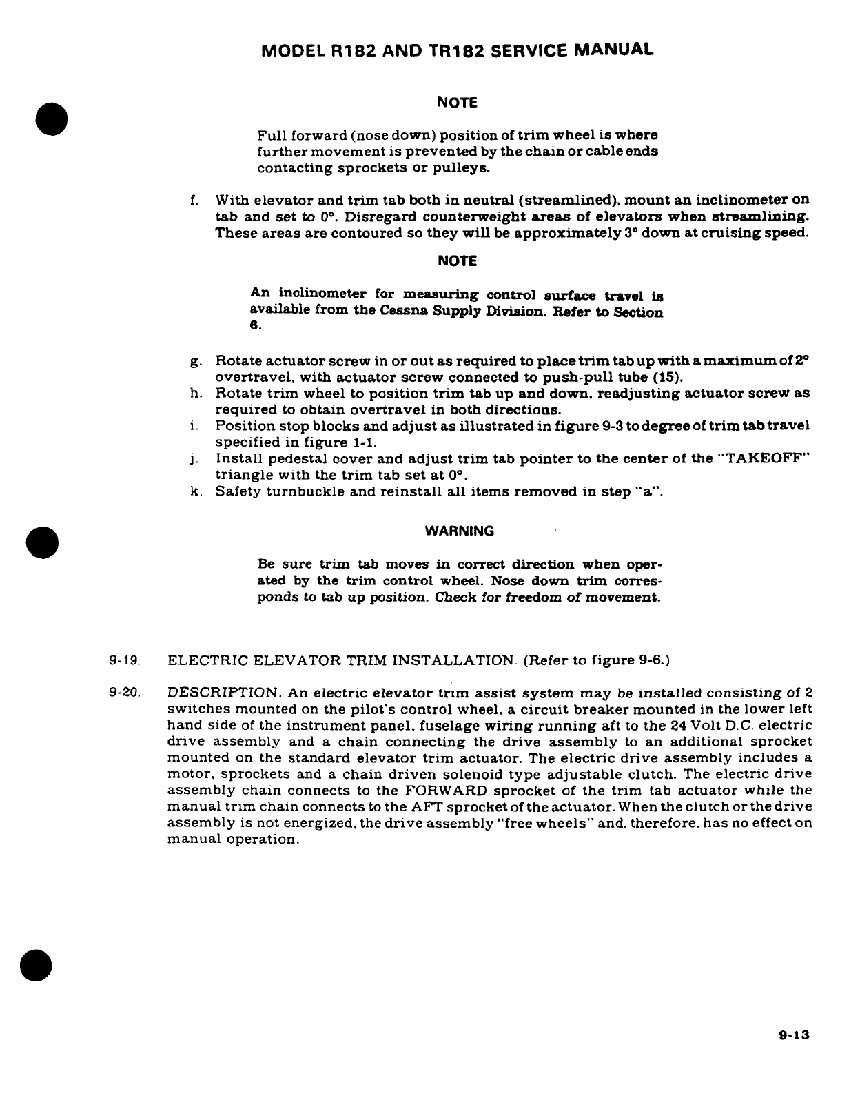
MODEL
R182
AND
TR182
SERVICE
MANUAL
NOTE
Full
forward
(nose down)
position
of
trim
wheel
is
where
further
movement
is
prevented
by
the
chain
or
cable
ends
contacting
sprockets
or
pulleys.
f.
With
elevator
and
trim
tab
both
in
neutral
(streamlined),
mount
an
inclinometer
on
tab
and
set
to
0°.
Disregard
counterweight
areas
of
elevators
when
streamlining.
These
areas
are
contoured
so
they
will
be
approximately
3°
down
at
cruising
speed.
NOTE
An
inclinometer
for
measuring
control
surface
travel
is
available
from
the
Cessna
Supply
Division.
Refer
to
Section
6.
g.
Rotate
actuator
screw
in
or out
as
required
to
place
trim
tab
up
with
a
maximum
of
2°
overtravel,
with
actuator
screw
connected to
push-pull
tube
(15).
h.
Rotate
trim
wheel
to
position
trim
tab
up
and
down.
readjusting
actuator
screw
as
required
to
obtain
overtravel
in
both
directions.
i.
Position
stop
blocks
and
adjust
as
illustrated
in
figure
9-3
to
degree
of
trim
tab
travel
specified
in
figure
1-1.
j.
Install
pedestal cover
and
adjust
trim
tab
pointer
to
the
center
of
the
"TAKEOFF"
triangle
with
the
trim
tab
set
at
0°.
k.
Safety
turnbuckle
and
reinstall
all
items
removed
in
step
"a".
WARNING
Be
sure
trim
tab
moves
in
correct
direction
when
oper-
ated
by
the
trim
control
wheel.
Nose
down
trim
corres-
ponds
to
tab
up position.
Check
for freedom
of
movement.
9-19.
ELECTRIC
ELEVATOR
TRIM
INSTALLATION.
(Refer
to
figure
9-6.)
9-20.
DESCRIPTION.
An
electric
elevator
trim
assist
system
may
be
installed
consisting
of
2
switches
mounted
on
the
pilot's
control
wheel,
a
circuit
breaker
mounted
in
the
lower
left
hand
side
of
the
instrument
panel,
fuselage
wiring
running
aft
to
the
24
Volt
D.C.
electric
drive
assembly
and
a
chain
connecting
the
drive
assembly
to
an
additional sprocket
mounted
on
the
standard elevator trim
actuator.
The
electric
drive
assembly
includes
a
motor,
sprockets
and
a
chain
driven
solenoid
type
adjustable
clutch.
The
electric drive
assembly
chain connects
to
the
FORWARD
sprocket
of
the trim
tab
actuator
while
the
manual
trim
chain
connects
to
the
AFT
sprocket
of
the
actuator.
When
the
clutch
or
the
drive
assembly
is
not
energized,
the
drive
assembly
"free
wheels"
and,
therefore,
has
no
effect
on
manual
operation.
9-13
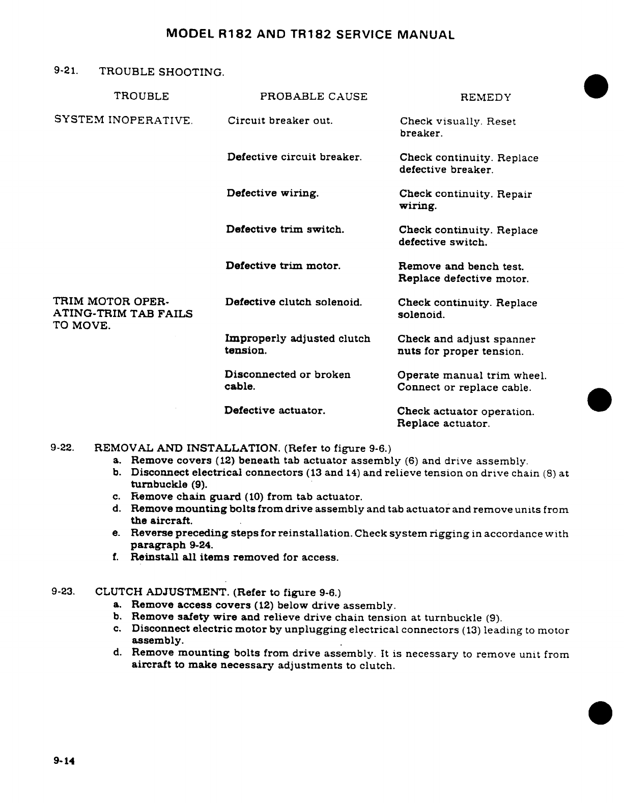
MODEL
R182
AND
TR182
SERVICE
MANUAL
9-21.
TROUBLE
SHOOTING.
TROUBLE
PROBABLE
CAUSE
REMEDY
SYSTEM
INOPERATIVE.
Circuit
breaker
out.
Check
visually.
Reset
breaker.
Defective
circuit
breaker.
Check
continuity.
Replace
defective
breaker.
Defective
wiring.
Check
continuity.
Repair
wiring.
Defective
trim
switch.
Check
continuity.
Replace
defective
switch.
Defective
trim
motor.
Remove
and
bench test.
Replace defective
motor.
TRIM
MOTOR
OPER-
Defective
clutch
solenoid.
Check
continuity.
Replace
ATING-TRIM
TAB
FAILS
solenoid.
TO
MOVE.
Improperly
adjusted
clutch
Check
and
adjust
spanner
tension.
nuts
for
proper
tension.
Disconnected
or
broken Operate
manual
trim
wheel.
cable.
Connect
or
replace
cable.
Defective
actuator.
Check
actuator
operation.
Replace
actuator.
9-22.
REMOVAL
AND
INSTALLATION.
(Refer
to
figure
9-6.)
a.
Remove
covers
(12)
beneath
tab
actuator
assembly
(6)
and
drive
assembly.
b.
Disconnect
electrical
connectors
(13
and
14)
and
relieve
tension
on
drive
chain
(8)
at
turnbuckle
(9).
c.
Remove
chain
guard
(10)
from
tab
actuator.
d.
Remove
mounting
bolts
from
drive
assembly
and
tab
actuator
and
remove
units
from
the
aircraft.
e.
Reverse
preceding
steps
for
reinstallation.
Check
system
rigging
in
accordance
with
paragraph
9-24.
f.
Reinstall
all items
removed
for
access.
9-23.
CLUTCH
ADJUSTMENT.
(Refer
to
figure
9-6.)
a.
Remove
access
covers
(12)
below
drive
assembly.
b.
Remove
safety
wire
and
relieve
drive
chain
tension
at
turnbuckle
(9).
c.
Disconnect
electric motor
by
unplugging
electrical
connectors
(13)
leading
to
motor
assembly.
d.
Remove
mounting
bolts
from
drive assembly.
It
is
necessary
to
remove
unit
from
aircraft
to
make
necessary
adjustments
to
clutch.
9-14
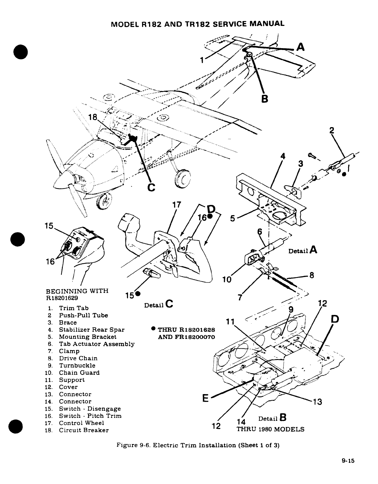
MODEL
R182
AND
TR182
SERVICE
MANUAL
Be
A
*
118
'.
2,../.... :
..
:.
/ '
?
8,,-;;,
--
-.... ;--~- ....
/ B
'. -- -.
:^
-..
: ..... '"-^
"
~
2
/~~/
\:'
.
.
i
-" .
:" "--.
'
**)"-*'
\Y.:
" ..
~-"", '.' .... ..--
..
>
4
:
/
*1.·.
3
Brac
l- l
'
arev}
/
BEGINNING
WITH
./
/ ."-
1. DTrim
Tab
Dai
C Da
1
3.
Brace
1
, '
4.
Stabilizer
Rear
Spar
*
THRU
R18201628
5.
Mounting
Bracket
AND
FR18200070
-
6.
Tab
Actuator
Assembly
7.
Clamp
/
9.
Turnbuckle
12.
Cover
13.
Connector
14.
Connector
E
13
15.
Switch
-
Disengage
/ /
16.
Switch
-
Pitch
Trim
/
/
Detail
B
17.
Control
Wheel
14
18.
Circuit
Breaker
THRU
1980
MODELS
Figure
9-6.
Electric
Trim
Installation
(Sheet
1
of
3)
9-15
9-15
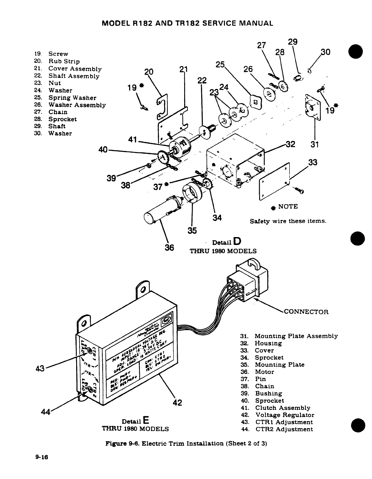
MODEL
R182
AND
TR182
SERVICE
MANUAL
27
29
19.
Screw
28
2
20.
Rub
Strip
25
21.
Cover
Assembly
20
226
22.
Shaft
Assembly
23.
Nut
22
\ \ \
24.
Washer
19*
2
24
25.
Spring
Washer
\
26.
Washer
Assembly
27.
Chain-
1
28.
Sprocket
-'
29.
Shaft
30.
Washer
40
2
31
33
39
I/
38
37
.. ..
*
NOTE
34'
|Safety
wire
these
items.
35
x.\
Detail
D
36
THRU
1980
MODELS
CONNECTOR
'AtO~~ s.,~~
^^^<
^31.
Mounting
Plate
Assembly
E^^^^^ ^ Ax32.
Housing
S^2:~~:1~ K ^ *^33.
Cover
v
j
g'Ap
Cw
42
4.34.
Sprocket
, .....
.
.,
4 1
*..,lp,35.
Mounting
Plate
434 oilltg
Regu
36.
Motor
37.
Pin
38.
Chain
39.
Bushing
^^^-^^ ^^
42
40.
Sprocket
41.
Clutch
Assembly
44
42.
Voltage
Regulator
Detail
E
43.
CTR1
Adjustment
THRU
1980
MODELS
44.
CTR2
Adjustment
Figure
9-8.
Electric
Trim
Installation
(Sheet
2
of
3)
9-16
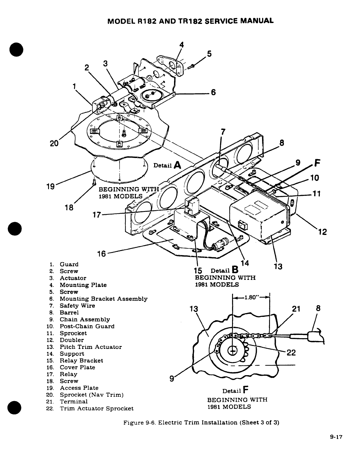
MODEL
R182
AND
TR182
SERVICE
MANUAL
4
6
200
8
1981
MODELS
-
1/
1
18
12
1.
Guard
14
2.
Screw
15
Detail
3.
Actuator
BEGINNING
WITH
4.
Mounting
Plate
1981
MODELS
5.
Screw
6.
Mounting
Bracket
Assembly
-1.80"-
7.
Safety
Wire
1
8
8.
Barrel
9.
Chain
Assembly
10.
Post-Chain
Guard
11.
Sprocket
12.
Doubler
13.
Pitch Trim
Actuator
14.
Support
22
15.
Relay
Bracket
16.
Cover
Plate
17.
Relay
18.
Screw
9
19.
Access
Plate
Detail
20.
Sprocket
(Nav
Trim)
21.
Terminal
BEGINNING
WITH
22.
Trim
Actuator
Sprocket
1981
MODELS
Figure
9-6.
Electric Trim
Installation
(Sheet
3
of
3)
9-17
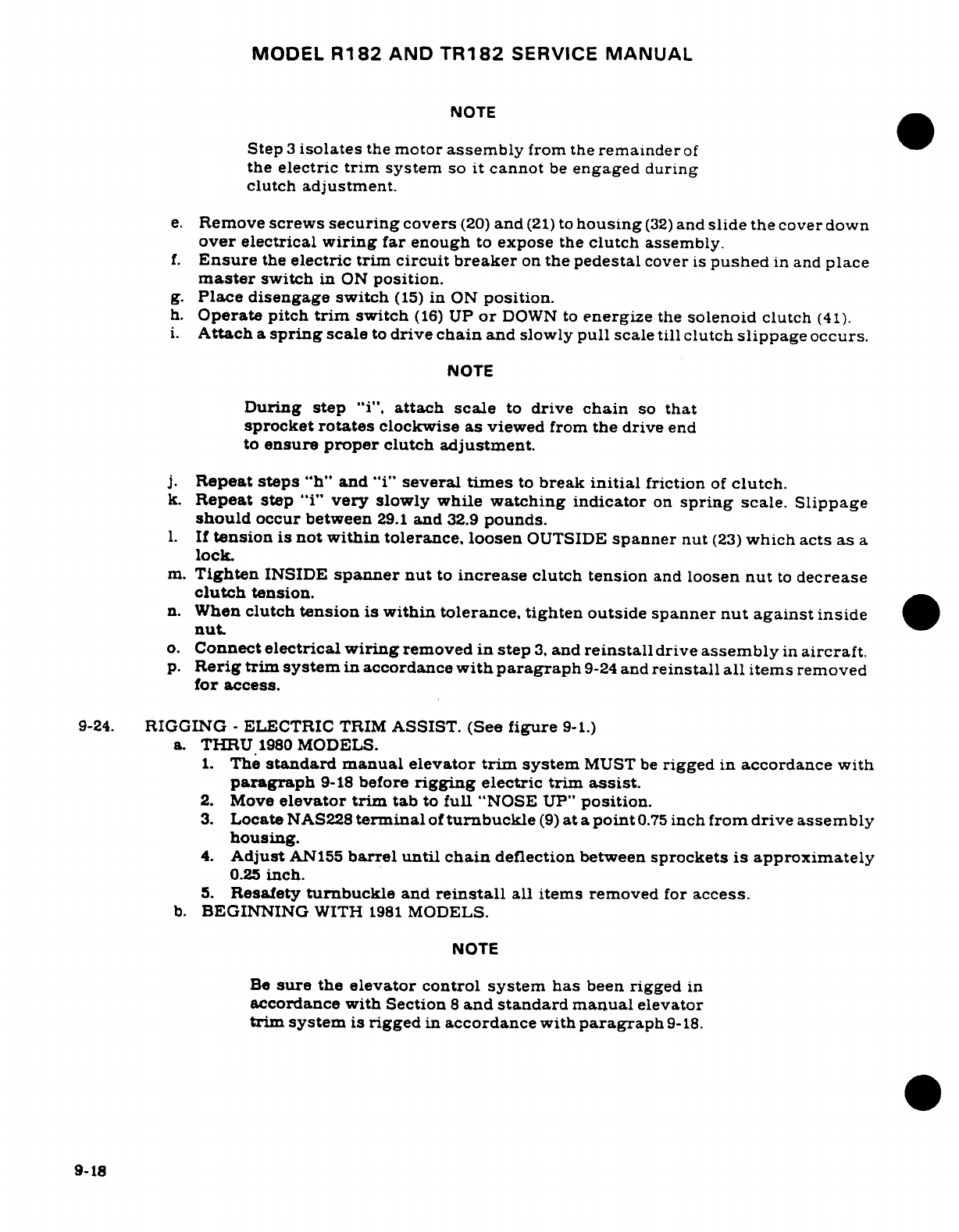
MODEL
R182
AND
TR182
SERVICE
MANUAL
NOTE
Step
3
isolates
the
motor
assembly
from the
remainder
of
the
electric
trim
system
so
it
cannot
be
engaged
during
clutch
adjustment.
e.
Remove
screws
securing
covers
(20)
and
(21)
to
housing
(32)
and
slide
the
cover
down
over
electrical
wiring
far
enough
to
expose
the
clutch
assembly.
f.
Ensure
the
electric
trim
circuit
breaker
on
the
pedestal
cover
is
pushed
in and
place
master
switch
in
ON
position.
g.
Place
disengage switch
(15)
in
ON
position.
h.
Operate pitch
trim
switch
(16)
UP
or
DOWN to
energize
the
solenoid
clutch
(41).
i.
Attach
a
spring
scale
to
drive
chain
and
slowly
pull
scale
till
clutch
slippage
occurs.
NOTE
During step
"i",
attach
scale
to
drive
chain
so
that
sprocket
rotates
clockwise
as
viewed
from
the
drive
end
to
ensure
proper
clutch
adjustment.
j.
Repeat
steps
"h"
and
"i"
several
times
to
break
initial
friction
of
clutch.
k.
Repeat
step
"i"
very
slowly while
watching
indicator
on
spring
scale.
Slippage
should
occur
between
29.1
and
32.9
pounds.
l.
If
tension
is
not
within
tolerance,
loosen
OUTSIDE
spanner
nut
(23)
which acts
as
a
lock.
m.
Tighten
INSIDE
spanner
nut
to
increase
clutch
tension
and
loosen
nut
to
decrease
clutch
tension.
n.
When
clutch
tension
is
within
tolerance,
tighten
outside
spanner
nut
against
inside
nut.
o.
Connect
electrical
wiring
removed
in
step
3,
and
reinstall
drive
assembly
in
aircraft.
p.
Rerig
trim system
in
accordance
with
paragraph
9-24
and
reinstall
all
items
removed
for
access.
9-24.
RIGGING
-
ELECTRIC
TRIM
ASSIST.
(See
figure
9-1.)
a
THRU
1980
MODELS.
1.
The
standard manual
elevator
trim
system
MUST
be
rigged
in
accordance
with
paragraph
9-18
before
rigging
electric
trim
assist.
2.
Move
elevator
trim
tab
to
full
"NOSE
UP"
position.
3.
Locate
NAS228
terminal
of
turnbuckle
(9)
at
a
point
0.75
inch
from
drive
assembly
housing.
4.
Adjust
AN155
barrel until
chain
deflection
between
sprockets
is
approximately
0.25
inch.
5.
Resafety
turnbuckle
and
reinstall
all
items
removed
for
access.
b.
BEGINNING
WITH
1981
MODELS.
NOTE
Be
sure
the
elevator
control
system
has
been
rigged
in
accordance
with
Section
8
and
standard
manual
elevator
trim
system
is
rigged
in
accordance
with
paragraph
9-18.
9-18
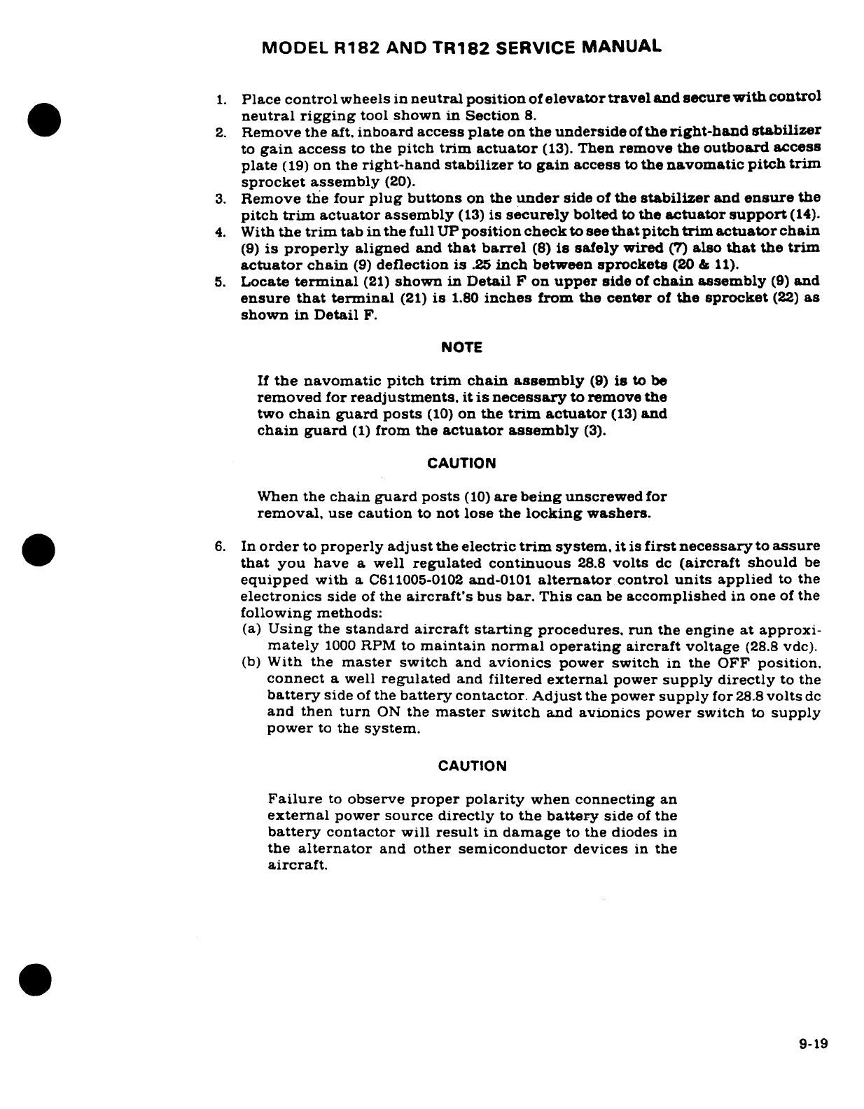
MODEL
R182
AND
TR182
SERVICE
MANUAL
1.
Place
control
wheels
in
neutral position
of
elevator
travel
and
secure
with
control
neutral
rigging
tool
shown
in
Section
8.
2.
Remove
the
aft,
inboard
access
plate
on
the
underside
of
the
right-hand
stabilizer
to
gain
access
to
the
pitch
trim
actuator
(13).
Then
remove
the
outboard
access
plate
(19)
on
the
right-hand
stabilizer
to
gain
access
to
the
navomatic
pitch
trim
sprocket
assembly
(20).
3.
Remove
the
four
plug
buttons
on
the
under
side
of
the
stabilizer
and
ensure
the
pitch
trim
actuator
assembly
(13)
is
securely
bolted
to
the
actuator
support
(14).
4.
With
the
trim
tab
in
the
full
UP
position
check
to
see
that
pitch
trim
actuator
chain
(9)
is
properly
aligned
and
that
barrel
(8)
is
safely
wired
(7)
also
that
the
trim
actuator
chain
(9)
deflection
is
.25
inch
between
sprockets
(20
&
11).
5.
Locate
terminal
(21)
shown
in
Detail
F
on
upper
side
of
chain
assembly
(9)
and
ensure
that
terminal
(21)
is
1.80
inches
from
the
center
of
the
sprocket
(22)
as
shown
in
Detail
F.
NOTE
If
the
navomatic
pitch
trim
chain
assembly
(9)
is
to
be
removed
for
readjustments.
it is
necessary
to remove
the
two
chain
guard
posts
(10)
on
the
trim
actuator
(13)
and
chain
guard
(1)
from
the
actuator
assembly
(3).
CAUTION
When
the
chain
guard
posts
(10)
are
being
unscrewed
for
removal,
use
caution
to
not
lose
the
locking
washers.
6.
In
order
to
properly
adjust
the
electric
trim
system,
it is
first
necessary
to
assure
that
you
have
a
well
regulated
continuous
28.8
volts
dc
(aircraft
should
be
equipped
with
a
C611005-0102
and-0101
alternator
control
units
applied
to
the
electronics
side
of
the
aircraft's
bus
bar.
This
can
be
accomplished
in
one
of
the
following
methods:
(a)
Using
the
standard aircraft
starting
procedures.
run
the
engine
at approxi-
mately
1000
RPM
to
maintain normal
operating
aircraft
voltage
(28.8
vdc).
(b)
With
the
master
switch
and
avionics
power switch
in
the
OFF
position.
connect
a
well
regulated
and
filtered
external
power
supply directly
to
the
battery
side
of
the
battery
contactor.
Adjust
the power
supply
for
28.8
volts
dc
and
then
turn
ON
the
master
switch
and
avionics
power
switch
to
supply
power
to
the
system.
CAUTION
Failure
to
observe
proper
polarity
when
connecting
an
external
power
source
directly
to
the battery
side
of
the
battery
contactor
will
result
in
damage
to the
diodes
in
the
alternator
and
other
semiconductor
devices
in
the
aircraft.
9-19
MODEL
R182
AND
TR182
SERVICE
MANUAL
7.
With
28.8
volts
dc
applied
to
the
electronics
bus.
use
trim
switches
on
control
and
rotate
the
pitch
command
wheel
to
the
full
"NOSE-DOWN"
position.
8.
Place
a
piece
of
tape
or
a
mark
on
the
very
top
of
the
airplane's
ELEVATOR
TRIM
command
wheel
so
a
full
revolution
of
the
ELEVATOR
TRIM
command
wheel
may
be
observed
and timed
with
a
stop
watch.
9.
Observe and
time
stop
to
stop
of
the
aircraft
ELEVATOR
TRIM
command
wheel
by
placing
the
trim
switches
on
the
control
wheel
in
the
UP
position
and
ensure
you obtain
a
timing
of
33
3
seconds for
one
complete
rotation
of
the
aircraft
ELEVATOR
TRIM
command
wheel.
Reverse
this
porcedure
and
ensure
that
you
are
getting
a
reading
of
33
3
seconds
for
one
full
rotation
of
the
ELEVATOR
TRIM
command
wheel
in
the
"NOSE-DOWN"
position.
If
the
rate
of
travel
for
one
full
rotation
does
not
agree
with the aforementioned
travel
time
limits,
then
use
the
following
procedures
to
obtain the desired
rate
of
pitch
trim
tab
travel.
10.
Turn
avionics
power
switch,
and
aircraft master
switch
to
the
OFF
position.
11.
Remove
the
neutral
rigging
tool
installed
in
Step
1,
replace
the access
plates
removed
in
Step
2,
replace the
plug
buttons
removed
in
step
3.
remove
the
external
power source
installed
in
step
6.
NOTE
For
Air
Load
Test
and
Mechanical
Clutch Torque Adjust-
ment,
refer
to
the
Avionics
Service/Parts
Manual.
9-25.
VOLTAGE
REGULATOR
ADJUSTMENT.
(Refer
to
figure
9-6.)
a.
Remove
access
cover
(39).
b.
Connect
an
external
power
source
of
27.5
volts
DC
continuous
to
the
aircraft
electrical
system, or
if
an
external
power
supply
is
not
available,
run
the
aircraft
engine
at
approximately
1000
RPM
to
maintain
the
normal
operating aircraft
voltage.
c.
Disconnect
the
electrical
power
leads
to
the
motor
by
unplugging
the
connectors
installed
in
the
RED
and
BLACK
wire
leading
to
the
motor
assembly.
d.
Connect
one
lead
of
a
DC
voltmeter
capable
of
measuring
the
aircraft
voltage
to
either
the
RED
or
BLACK
wire
leading
to
the
motor
and the
other
voltmeter
lead
to
a
good
aircraft ground.
9-20
MODEL
R182
AND TR182
SERVICE
MANUAL
e.
Operate
the
electric
trim switch
to
the
Nose
UP
and
Nose
DOWN
positions
and
check
voltage
present
at the
RED
and
BLACK
wires.
f.
Adjust
CTR
1
and
CTR
2
adjustment
screws
on
the
voltage
regulator
counterclockwise
(CCW),
then
slowly
turn
adjustment
screws
clockwise
(CW)
until
a
13.5
volt output
is
obtained for
both
(RED
and
BLACK)
leads.
g.
Remove
voltmeter
and
reconnect
the
motor
assembly
power leads.
Be
sure
to
connect
RED
to
RED
and
BLACK
to
BLACK
when
reconnecting
leads.
h.
Check
to
see
if
full
"NOSE
UP" to
full
"NOSE
DOWN"
and
full
"NOSE
DOWN"
to
full
"NOSE
UP"
cycle
time
is
50±3
seconds.
CAUTION
The
trim
motor
should
be
allowed
to
cool
between
voltage
regulator
adjustments
for
approximately
5
minutes
if
several
actuations
of
the
motor
become
necessary
during
adjustment.
i.
Readjust
voltage
regulator
as
required
to
obtain
50±3
seconds
cycle
time.
NOTE
If
trim
tab
travel
time
exceeds
53
seconds,
lubricate
and
"free
up"
elevator
trim
system as
required
per
section
2.
j.
Check
trim system
for
proper
operation
and
reinstall
all
items removed
for
access.
9-21/(9-22
blank)
MODEL
R182
AND
TR182
SERVICE
MANUAL
SECTION
10
RUDDER
AND
RUDDER
TRIM
CONTROL
SYSTEMS
Page
No.
TABLE
OF
CONTENTS
Aerofiche/
Manual
RUDDER
CONTROL
SYSTEM
. ..
2113/10-1
Cables
and
Pulleys
..........
2119/10-7
Description
...............
2113/10-1
Removal/Installation
.......
2I119/10-7
Trouble
Shooting
..........
2113/10-1
Rigging
.................
2119/10-7
Rudder
Pedal Assembly
......
2114/10-2
RUDDER
TRIM/NOSE
WHEEL
Removal/Installation
.......
2114/10-2
STEERING
SYSTEM
.......
2I20/10-8
Rudder
..............
2I18/10-6
Description
...............
2120/10-8
Removal
Installation
.......
2118/10-6
Trouble
Shooting
...........
2120/10-8
Repair
............
.
2119/10-7
Rigging
.................
2124
10-12
10-1.
RUDDER
CONTROL
SYSTEM.
(Refer
to
figure
10-1.)
10-2.
DESCRIPTION.
Rudder
control
is
maintained
through
use
of
conventional
rudder
pedals
which
also control
nosewheel
steering.
The
system
is
comprised
of
the
rudder pedals.
cables
and
pulleys,
bellcranks
and
the
nosewheel
steering
bungee.
10-3.
TROUBLE
SHOOTING.
NOTE
Due to
remedy
procedures
in
the
following
trouble
shooting
chart
it
may
be
necessary
to
re-rig
system.
refer
to
paragraph
10-11.
TROUBLE
PROBABLE
CAUSE
REMEDY
RUDDER DOES
NOT
Broken
or
disconnected
Open
access
plates
and
check
RESPOND
TO
PEDAL
cables.
visually.
Connect
or
replace
MOVEMENT.
cables.
BINDING
OR
JUMPY
Cables
too
tight.
Refer
to
figure
10-1
for
MOVEMENT
OF
RUDDER
cable
tension.
Rig
system
PEDALS.
in
accordance
with
paragraph
10-11.
Cables
not
riding
properly
Open
access
plates
and
on
pulleys.
check
visually.
Route
cables
correctly over pulleys.
Binding,
broken
or
Open
access
plates
and
defective
pulleys
check
visually.
Replace
or
cable
guards.
defective
pulleys
and
install
guards properly.
Revision
1
10-1
MODEL
R182
AND
TR182
SERVICE
MANUAL
10-3.
TROUBLE
SHOOTING
(Cont).
TROUBLE PROBABLE
CAUSE
REMEDY
Pedal
bars
need
Refer
to
Section
2.
lubrication.
Defective
rudder
bar
If
lubrication
fails
to
bearings.
eliminate
binding.
Replace
bearing
blocks.
Defective
rudder
hinge
Check
visually.
Replace
bushings.
defective
bushings.
Clevis
bolts
too
tight.
Check
and
readjust
bolts
to
eliminate
binding.
Steering
rods
improperly
Rig
system
in
accordance
adjusted.
with
paragraph
10-11.
LOST
MOTION
BETWEEN
Insufficient
cable
tension.
Refer
to
figure
10-1
for
RUDDER
PEDALS
AND
cable tension.
Rig
system
RUDDER.
in
accordance
with
para-
graph
10-11.
INCORRECT RUDDER
Incorrect
rigging.
Rig
in
accordance
with
TRAVEL.
paragraph
10-11.
10-4.
RUDDER
PEDAL ASSEMBLY.
10-5.
REMOVAL
AND
INSTALLATION.
(Refer
to
figure
10-2.)
a.
Remove
carpeting,
shields
and
soundproofing
from
the
rudder pedal
and
tunnel
areas
as
necessary
for access.
b.
Disconnect
brake
master
cylinders
(15)
and
parking
brake
cables
at
pilot's
rudder
pedals.
NOTE
Brake
links
(5),
bellcranks
(17),
brake
torque
tubes
(14)
and
attaching
parts
are
not
required
unless
dual controls
ARE
installed.
When
dual
controls
ARE
NOT
installed.
hubs
(18)
are
attached
to
each
end
of
rudder
bars.
c.
Remove
rudder
pedals
.(2)
and
brake
links
(5).
d.
Remove
fairing
from
either
side
of
vertical
fin.
remove
safety wire
and
relieve
cable
tension
by
loosening
turnbuckles
(index
10,
figure
10-1).
e.
Disconnect
cables
(6
and
7)
from
rudder
bar
arms
(8).
f.
Disconnect
steering
bungee
rod
end
(12)
from
rudder
bar
arm
(13)
(figure
10-5).
g.
Remove
bolts
securing
bearing
blocks
(10)
and
carefully
work
rudder
bars out
of
tunnel
area.
10-2
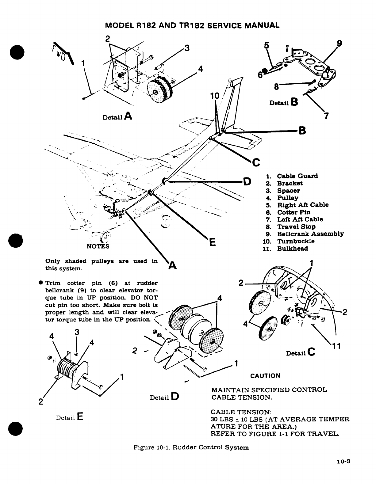
MODEL
R182
AND
TR182
SERVICE
MANUAL
2
9
>1^-^i io/j/
8
'-
Detail
A
B7
A ....
.--.
L.....C
·
v
--
;:'
.,
a
...-. __
-
/.__1.
Cable
Guard
D
2.
Bracket
r*<
-***
'
?
i
->X^'
^
"-2
3.
Spacer
': Do'>
- .-.
^^
'
-----
4.
Pulley
5.
Right
Aft
Cable
V\-
-
*^te
't^^'' N^
:--- -
6.
Cotter
Pin
: -^
-, \'
N^
7.
Left
Aft Cable
--
^ r' ^' i \>\
^
8.
Travel
Stop
*- ^' \/ ..
9.
Bellcrank
Assembly
tO^
S
E
10.
Turnbuckle
NOTES
\
11.
Bulkhead
Only
shaded
pulleys
are
used
in
\A
this
system.
..
*
Trim
cotter
pin
(6)
at
rudder
2
bellcrank
(9)
to
clear
elevator
tor-
que
tube
in
UP
position.
DO
NOT
4
cut
pin
too
short.
Make
sure
bolt
is
proper
length and
will
clear
eleva-
..
1te
^_-
2
'-2
tor
torque tube
in
the
UP
position.
i
4
4
3
.... \& >/
2
.... 2.B
rackDetail C
<p^ /^' 1 \^^'^
CAUTION
MAINTAIN
SPECIFIED
CONTROL
2
"Detail
D
CABLE
TENSION.
CABLE
TENSION:
Detail
E
30
LBS
±
10
LBS
(AT
AVERAGE
TEMPER
ATURE
FOR THE AREA.)
REFER
TO
FIGURE
1-1
FOR
TRAVEL.
Figure
10-1.
Rudder
Control
System
10-3
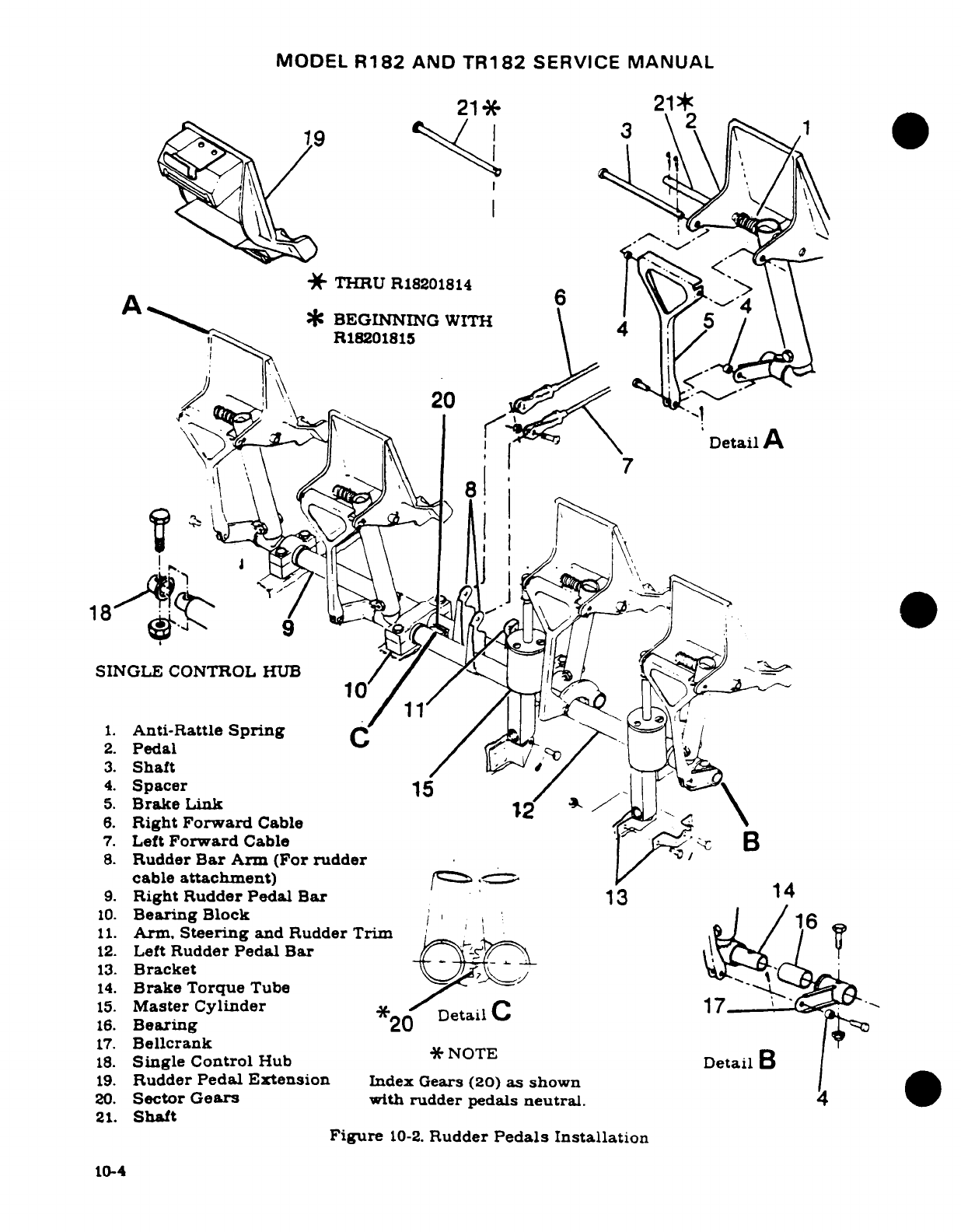
MODEL
R182
AND
TR182
SERVICE
MANUAL
21*
21
19
0
*
THRU
R18201814
A
6j
A
*
BEGINNING
WITH
5
A
~~
:::
^^
R18201815
X! Be^ I^\ I V /,Detail
A
I\ s
7
,,
h1\ \
-
:
'
18
SINGLE
CONTROL
HUB
10
1.
Anti-Rattle
Spring
C
2.
Pedal
3.
Shaft
/
4.
Spacer
15
5.
Brake
Link
12
6.
Right
Forward
Cable
7.
Left
Forward
Cable
B
8.
Rudder
Bar
Arm
(For
rudder
cable
attachment)
9.
Right
Rudder
Pedal Bar
13
14
10.
Bearing
Block
1
11.
Arm.
Steering
and Rudder Trim
12.
Left
Rudder
Pedal
Bar
13.
Bracket
14.
Brake
Torque
Tube
15.
Master
Cylinder
17
16.
Bearing
*20
Detail
17.
Bellcrank
18.
Single Control
Hub
*
NOTE
Detail
B
19.
Rudder
Pedal
Extension
Index
Gears
(20)
as
shown
20.
Sector
Gears
with
rudder
pedals
neutral.
21.
Shaft
Figure
10-2.
Rudder
Pedals Installation
10-4
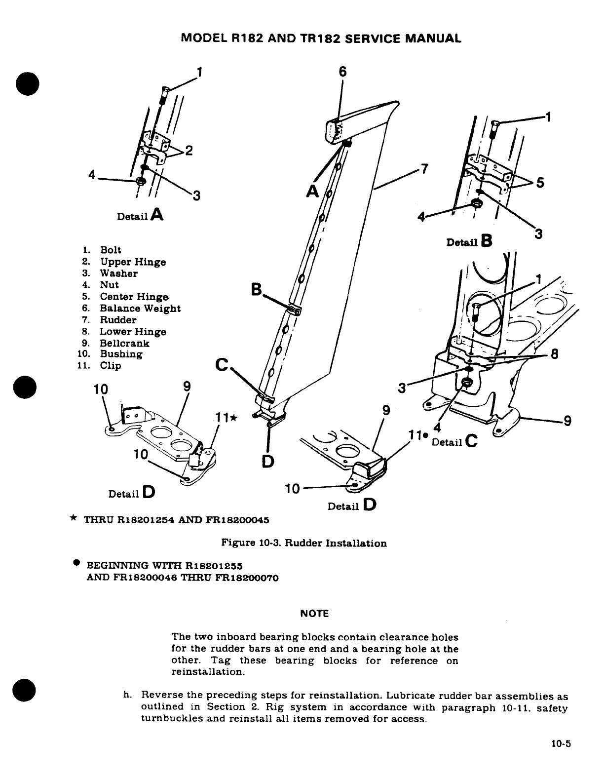
MODEL
R182
AND
TR182
SERVICE
MANUAL
1
6
Detail
A
/a1
/
4
D
I
///
/
Detail
D
1.
Bolt
Detail
2.
Upper
Hinge
3.
Washer
1
A
4.
Nut
5.
Center
Hinge
6.
Balance Weight
If
7.
Rudder
I
8.
Lower
Hinge
/
9.
Bellcrank
W// R12 2
11.
Clip
C
/
10
/9
3i
,
X
Detail
C
D
Detail
D
10
---
Detail
D
*
THRU
R18201254
AND
FR18200045
Figure
10-3.
Rudder
Installation
*
BEGINNING
WITH
R18201255
AND
FR18200046
THRU
FR18200070
NOTE
The two
inboard
bearing
blocks
contain
clearance
holes
for
the
rudder
bars
at
one end
and
a
bearing
hole
at
the
other.
Tag
these
bearing
blocks
for
reference
on
reinstallation.
h.
Reverse
the
preceding steps
for
reinstallation.
Lubricate
rudder
bar
assemblies
as
outlined
in
Section
2.
Rig
system
in
accordance
with
paragraph
10-11.
safety
turnbuckles
and
reinstall
all
items
removed
for access.
10-5
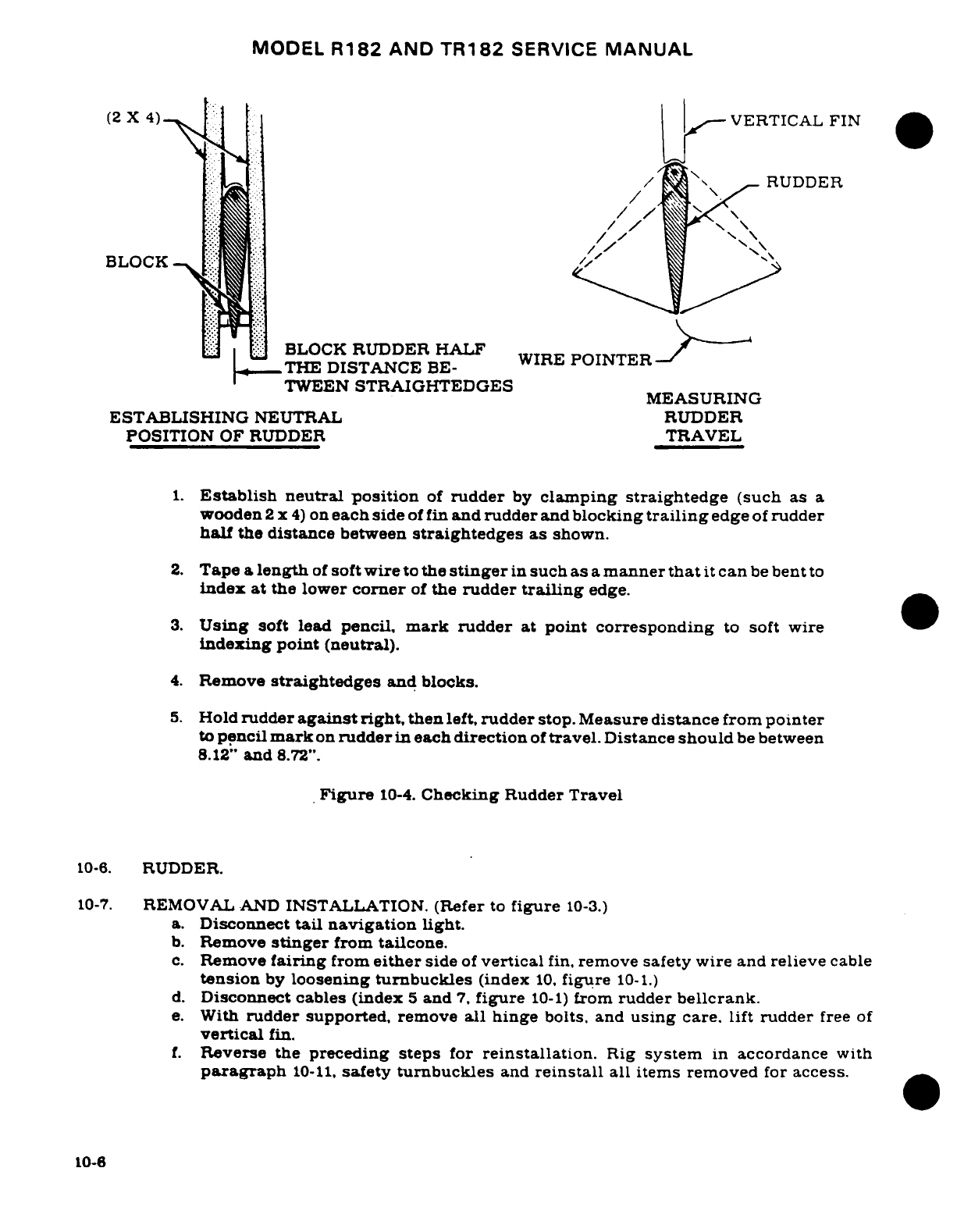
MODEL
R182
AND
TR182
SERVICE
MANUAL
(2
X
4)
.
VERTICAL
FIN
'*/ 9"
Hi
RUDDER
*:'**
S
/
[
'
\--
BLOCK
-t
L
BI
BLOCK
RUDDER
HALF
IRE
POI
THE
DISTANCE
BE-
TWEEN
STRAIGHTEDGES
MEASURING
ESTABLISHING
NEUTRAL RUDDER
POSITION
OF
RUDDER
TRAVEL
1.
Establish
neutral
position
of
rudder
by
clamping
straightedge
(such
as
a
wooden
2
x
4)
on
each
side
of
fin
and
rudder
and
blocking
trailing
edge
of
rudder
half
the
distance
between
straightedges
as
shown.
2.
Tape
a
length
of
soft
wire
to
the
stinger
in
such
as
a
manner
that
it
can
be
bent
to
index at
the
lower
corner
of
the
rudder
trailing
edge.
3.
Using
soft
lead
pencil,
mark
rudder
at
point
corresponding
to
soft
wire
indexing
point (neutral).
4.
Remove
straightedges
and blocks.
5.
Hold
rudder
against
right,
then
left,
rudder
stop.
Measure
distance
from
pointer
to
pencil
mark
on
rudder
in
each
direction
of
travel.
Distance
should
be
between
8.12"
and
8.72".
Figure
10-4.
Checking
Rudder
Travel
10-6.
RUDDER.
10-7.
REMOVAL
AND
INSTALLATION.
(Refer
to
figure
10-3.)
a.
Disconnect
tail
navigation
light.
b.
Remove
stinger
from
tailcone.
c.
Remove
fairing
from
either
side
of
vertical
fin,
remove safety wire
and
relieve
cable
tension
by
loosening
turnbuckles
(index
10,
figure
10-1.)
d.
Disconnect
cables (index
5
and
7,
figure
10-1)
from
rudder
bellcrank.
e.
With
rudder
supported,
remove
all
hinge
bolts, and
using
care. lift rudder
free
of
vertical
fin.
f.
Reverse
the
preceding
steps
for
reinstallation.
Rig
system
in
accordance
with
paragraph
10-11,
safety
turnbuckles
and
reinstall
all
items
removed
for
access.
10-6
MODEL
R182
AND
TR182
SERVICE
MANUAL
10-8.
REPAIR.
Repair
may
be
accomplished as outlined
in
Section
18.
10-9.
CABLES
AND
PULLEYS.
(Refer
to
figure
10-1.)
10-10.
REMOVAL
AND
INSTALLATION.
a.
Remove
seats,
upholstery
and
access
plates
as
necessary.
b.
Relieve cable
tension
at turnbuckles
(10)
and
disconnect
cables.
c.
Disconnect
cables
(index
6
and
7,
figure
10-2)
from
rudder
bar
arms.
d.
Remove
cable
guards
and
pulleys
as
necessary
to
work
cables
free
of
aircraft.
NOTE
To
ease
routing
of
cables,
a
length
of
wire
may
be
attached
to
end of
the cable
before
being
withdrawn
from
aircraft.
Leave
wire
in
place,
routed
through
structure;
then attach
cable
being
installed
and
pull
the
cable
into
position.
e.
Reverse the
preceding
steps
for
reinstallation.
f.
After
cable
is
routed
in
position,
install
pulleys
and
cable
guards.
Ensure
cable
is
positioned
in
pulley
grooves
before
installing
guards.
NOTE
Trim
cotter
pin
(6)
at
rudder
bellcrank
(9)
to
clear elevator
torque
tube
in
UP
position.
DO
NOT
cut pin
too
short.
(Refer
to
figure
10-1.)
g.
Re-rig
system
in
accordance
with
paragraph
10-11,
safety
turnbuckles
and
reinstall
items removed
in
step
"a".
10-11.
RIGGING.
(Refer
to
figure
10-5).
a.
Establish
neutral
position
of
rudder
by
clamping
straightedge
(such
as
wooden
2
x
4)
on
each
side
of
fin
and
rudder
and
blocking
trailing
edge
of
rudder
half
the
distance
between
strightedges
as shown
in
figure
10-4.
b.
Tape
a
length
of
soft
wire
to
the
stinger
in
such
a
manner
that
it
can
be
bent
to
index
at
the
lower
corner
of
the
rudder
trailing
edge.
c.
Using
soft lead pencil,
mark
rudder
at
point
corresponding
to
soft wire indexing
point
(neutral).
d.
Remove
strightedges
and blocks.
e.
Hold
rudder
against right,
then
left,
rudder
stop.
Measure
distance
from
pointer
to
pencil
mark
on
rudder
in
each
direction
of
travel.
Distance
should
be
between
8.12"
and
8.72".
f.
Adjust
travel
stop
bolts
(index
8.
figure
10-1)
to
attain
correct
rudder
travel
as
specified
in
figure
1-1.
g.
Disconnect
steering
bungee
adjustable
rod
end
(12)
from
arm
(13).
h.
Disengage chain
(10)
from
sprocket
(15).
i.
Remove
fairing
from
either
side
of
vertical
fin,
remove
safety wire
and
relieve
cable
tension
at turnbuckles
(index
10,
figure
10-1).
j.
With
rudder
pedals
clamped
in
neutral
position,
adjust
turnbuckles
(index
10,
figure
10-1)
to
specified
tension with
the
rudder
offset
one
degree
to
the
right,
(5
16
inch
at
lower
trailing
edge).
Safety
turnbuckles.
Remove
rudder
pedal
clamps.
k.
Operate
system
and
check for
proper
travel and
freedom
of
movement.
10-7
MODEL
R182
AND
TR182
SERVICE
MANUAL
NOTE
After
completing
the
preceding
steps.
the
rudder
control
system
is
rigged.
The
rudder
system
MUST
be
correctly
rigged
prior
to
rigging
the
rudder
trim
and
nosewheel
steering
system.
Refer
to
paragraph
10-15
for
rigging
the
rudder
trim
and
nosewheel
steering
system.
10-12.
RUDDER
TRIM
AND
NOSEWHEEL
STEERING
SYSTEM. (Refer
to
figure
10-5.)
10-13.
DESCRIPTION.
A
sprocket-operated
screw
mechanism
to
provide
rudder
trim
is
incorpo-
rated at
the
aft end of
the
steering
bungee
(19).
The
trim
system
is
operated
by
a
trim control
wheel
(4).
mounted
in
the
pedestal.
Nosewheel
steering
is
accomplished
through
use
of
the
rudder pedals.
The
steering
bungee
(19)
links
the
nose
gear
to
the
rudder bar
arm
(13).
NOTE
The
rudder
control system,
rudder
trim control
system
and
nosewheel
steering
systems
are
interconnected.
Adjustments
to
any
one
of
these
systems will
affect
the
others.
For
maintenance
to
the
nose
gear
steering,
other
than
rigging,
refer
to
Section
5.
10-14.
TROUBLE
SHOOTING.
NOTE
This
trouble
shooting chart
should
be
used
in
conjunction
with
the
trouble shooting
chart
in
paragraph
10-3.
NOTE
Due
to
remedy
procedures
in
the
following
trouble
shooting
chart
it
may
be
necessary
to
re-rig
system.
refer
to
paragraph
10-15.
TROUBLE
PROBABLE
CAUSE
REMEDY
FALSE
READING
ON
TRIM
Improper
rigging.
Refer
to
paragraph
10-15.
POSITION
INDICATOR.
Worn,
bent
or
discon-
Check
visually.
Repair
or
nected
linkage,
replace
parts
as
necessary.
HARD
OR
SLUGGISH
Worn,
bent
or
binding
Check
visually.
Repair
or
OPERATION
OF
TRIM
linkage,
replace
parts
as
necessary.
WHEEL.
Incorrect
rudder
cable
Check
and
adjust
rudder
tension.
cable
tension.
FULL
TRIM
TRAVEL
Rudder
trim
system
Refer
to
paragraph
10-15.
NOT
OBTAINED.
improperly
rigged.
10-8
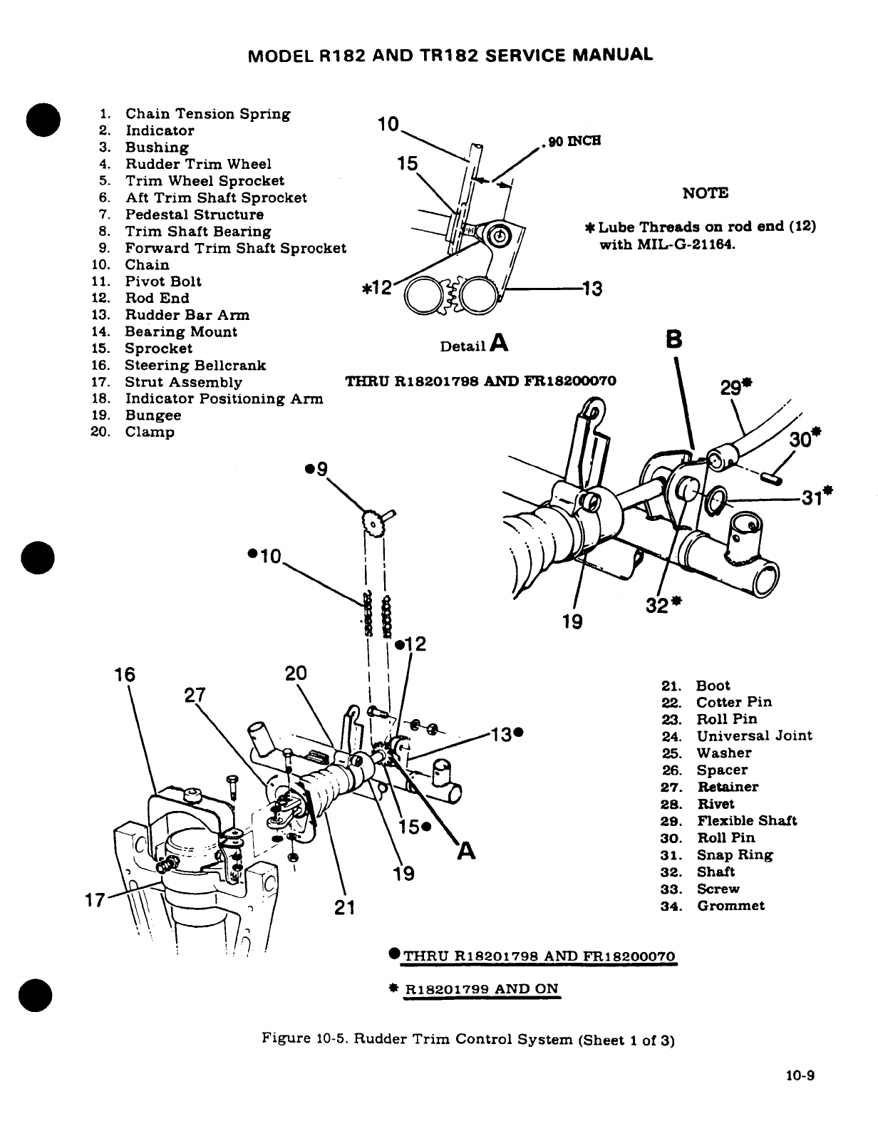
MODEL
R182
AND
TR182
SERVICE
MANUAL
1.
Chain
Tension
Spring
2.
Indicator
1
3.
Bushing
.90
INCH
4.
Rudder
Trim
Wheel
15
,
5.
Trim
Wheel
Sprocket
6.
Aft
Trim
Shaft Sprocket
NOTE
7.
Pedestal
Structure
8.
Trim
Shaft
Bearing
*Lube
Threads
on
rod
end
(12)
9.
Forward
Trim
Shaft
Sprocket with
MILG-21164.
10.
Chain
11.
Pivot
Bolt
*12
N- 3
12.
Rod
End
13.
Rudder
Bar
Arm
14.
Bearing
Mount
B
15.
Sprocket
Detail
A
16.
Steering
Bellcrank
17.
Strut
Assembly
THRU
R18201798
AND
FR18200070
2
18.
Indicator Positioning
Arm
19.
Bungee
20.
Clamp^ \
·
4
319
010
II el
2
1
20
1 I
/
21.
Boot
\
27
\\ l l
1
22.
Cotter
Pin
23.
Roll
Pin
\ \ \ \
130
24.
Universal
Joint
25.
Washer
26.
Spacer
27.
Retainer
28.
Rivet
^^,1^1 \^ jL f1Q(\1\\ \
158
^*29.
Flexible
Shaft
nnL~ a ; T^ \
\1
5-~\A
30.
Roll
Pin
\ -S v\ A\
31.
Snap
Ring
1 7-^^ss~l~f^ X \
1
9
32.
Shaft
33.
Screw
17
\\\\
\
21
34. Grommet
THRU
R18201798
AND
FR18200070
*
R18201799
AND
ON
Figure
10-5.
Rudder
Trim
Control
System
(Sheet
1
of
3)
10-9
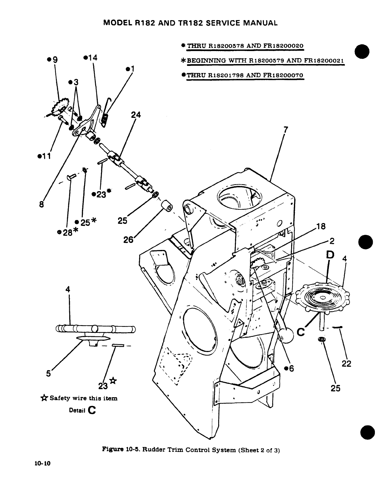
MODEL
R182
AND
TR182
SERVICE
MANUAL
*
THRU
R18200578
AND
FR18200020
*9
@14
*BEGINNING
WITH
R18200579
AND
FR18200021
.1
OTHRU
R18201798
AND
FR18200070
*3
k!^ 24
I/
/
*3
A SC^7
D
r11
0-
'F0
@
25*
25
/^
1
@*28*
/
^\( ^"-
^s$oi
^2
26'
.^-^ Cg 1' e6
4
23^
\
"
I^^^C^
-lJ
25
'
Safety
wire
this
item
|
Detail
C
Figure
10-5.
Rudder
Trim Control
System
(Sheet
2
of
3)
10-10
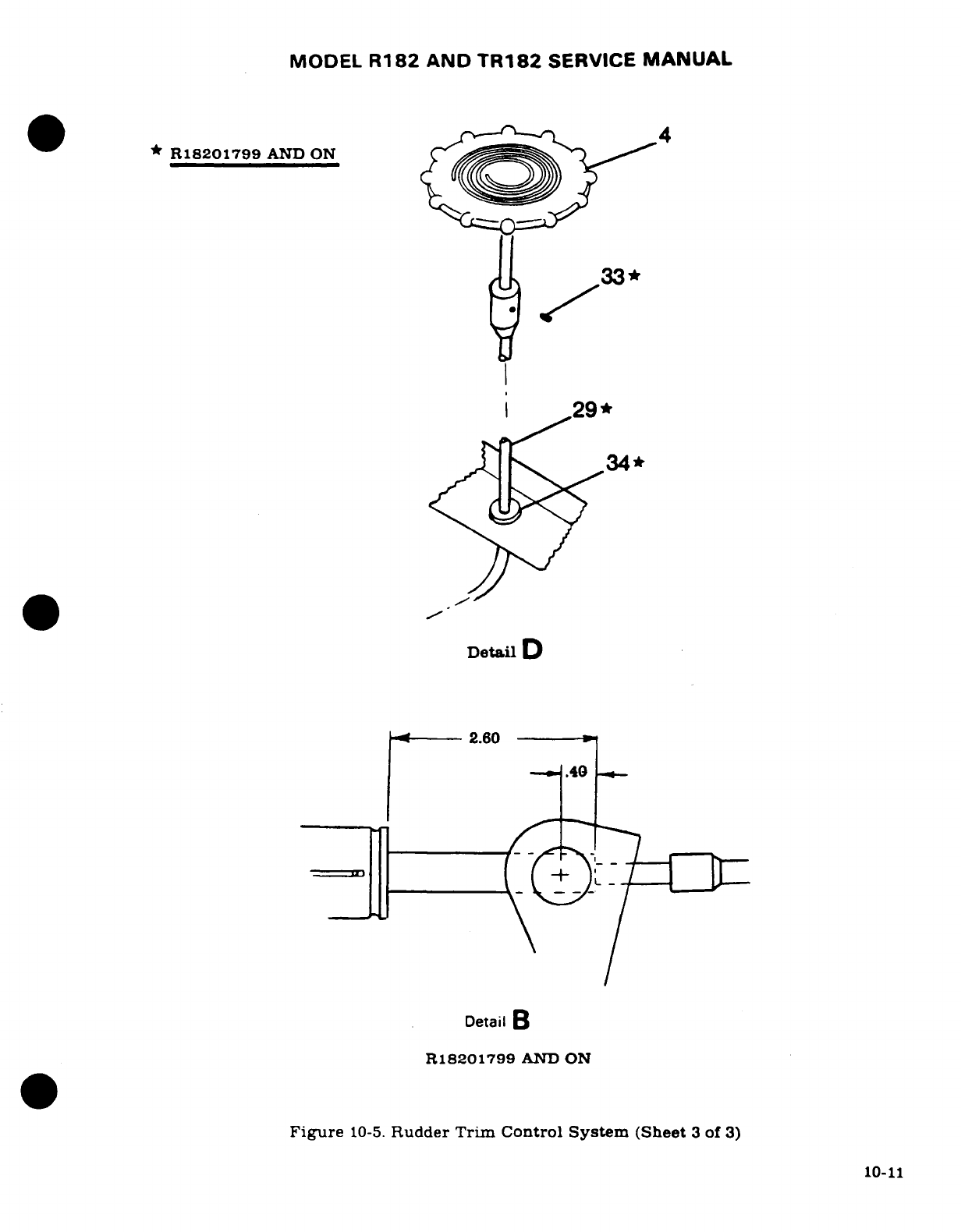
MODEL
R182
AND
TR182
SERVICE
MANUAL
10-15.
RIGGING. (Refer
to
figure
10-5.)
a.
THRU
1981
MODELS.
NOTE
The
rudder
control
system
MUST be
rigged in
accordance
with
paragraph
10-11
prior
to
rigging
the
rudder
trim
and
nosewheel
steering
system.
1.
After
completing
step
"j"
of
paragraph
10-11.
tie
down
or
weight
tail
to
raise
nosewheel
free of
ground.
2.
Extend
strut
and
ensure
nose
gear
is
centered
against external centering
stop.
(Refer
to
Section
5.)
3.
Rotate
trim
control
wheel
(4)
until
indicator
(2)
is
centered
in
pedestal
slot
(neutral).
4.
With
rudder
pedals
clamped
in
neutral
position,
adjust
steering
bungee
rod
end
(12)
.90
inch
from
bolt hole
center
to
aft
face
of
sprocket
(15).
Maintaining
this
adjustment,
rotate
sprocket
(15)
IN
or
OUT
as
required
to
align
rod
end
(12)
with
attaching
hole
in
rudder
bar
arm
(13).
NOTE
When
connecting
rod end
(12)
to
arm
(13)
with
chain
(10)
engaged,
it
is
necessary
to
pull
rod
end
(12)
down
with
enough
force
to
overcome
tension
on
spring
(1).
5.
Without
rotating
sprocket
(15)
or
moving
trim
indicator
(2)
engage chain
(10)
on
sprocket
(15)
and
connect
rod
end
(12)
to
rudder bar
arm
(13).
8.
Lower
nose wheel
to
ground,
remove
clamps
from
rudder
pedals,
tighten
all
jam
nuts
and
reinstall
all
items
removed
for
access.
NOTE
Make
sure
rudder
moves in
the
correct direction
when
operated
by
the
rudder
pedals
and
the
trim
control
wheel.
10-12
MODEL R182
AND
TR182
SERVICE
MANUAL
b.
BEGINNING
WITH
1982
MODELS.
1.
After
completing
step
"j"
of
paragraph
10-11,
tie
down
or
weight
tail
to
raise
nosewheel
free
of
ground.
2.
Extend
strut
and
ensure
nose
gear
is
centered
against
external
centering
stop.
(Refer
to
Section
5.)
3.
With
rudder
pedals
clamped
in
neutral position,
adjust
bungee
shaft
and
barrel
nut
to
dimensions
shown
in
detail
B.
Maintaining
this
position,
slip
flex
shaft
end
on
bungee
rod
end
and
secure with
roll
pin.
Safety
roll pin.
4.
Loosen
setscrew
(33)
and
position rudder
trim
wheel
so
that
indicator
is in
center
track
and aligned
with ends
of
outer
and
inner
tracks.
5.
Install
setscrew
(33)
so dog
engages
hole
in
shaft
of
trim
tab
control
wheel.
Seal
with
Locktite
242
or
equivalent.
6.
Center
indicator
with
respect
to
console
cover
by
bending
wire
pointer.
Do
not
cause
wire
to
"jump
tracks."
7.
Lower
nosewheel
to
ground,
remove
clamps
from
rudder
pedals,
tighten
all
jam
nuts,
and
reinstall
all
items
removed
for access.
WARNING
Make
sure
rudder
moves
in
the
correct direction
when
operated
by
the
rudder
pedals
and the
trim
control
wheel.
10-13/(10-14
blank)
MODEL
R182
AND
TR182
SERVICE
MANUAL
SECTION
11
ENGINE
(NORMALLY
ASPIRATED)
WARNING
When
performing any inspection
or
maintenance that
requires
turning
on
the
master
switch,
installing
a
battery,
or
pulling
the
propeller
through
by
hand,
treat
the
propeller
as
if
the
ignition
switch
were
ON.
Do
not
stand,
nor
allow
anyone
else
to
stand,
within
the
arc
of
the
propeller,
since
a
loose
or
broken
wire,
or
a
component
malfunction,
could
cause
the
propeller
to
rotate.
Page
No.
TABLE
OF
CONTENTS
Aerofiche/
Manual
ENGINE
COWLING
..........
2J11/11-3
OIL
SYSTEM
...............
2K4
11-20
Description
...............
2J11/11-3
Description
...............
2K4
11-20
Removal
Installation
.......
2J11/11-3
Trouble
Shooting
...........
2K4/11-20
Cleaning
Inspection
.........
2J11/11-3
Full-Flow
Oil
Filter
...........
2K9
11-23
Repair
...................
2J11/11-3
Description
...............
2K9/11-23
COWL
FLAPS
...............
2J11/11-3
Removal
.................
2K9
11-23
Description
...............
2J11/11-3
Installation
...............
2K9/11-23
Removal
Installation
........
2J11/11-3
Oil
Cooler
................
2K9
11-23
Rigging
.................
2J13/11-5
Description
.............
2K9
11-23
ENGINE
...................
2J13/11-5
FUEL
SYSTEM
..............
2K9
11-23
Description
...............
2J13/11-5
Description
..........
2K9
11-23
Time
Between
Overhaul
(TBO)
.
2J13/11-5
Carburetor
..........
2K9
11-23
Overspeed
Limitations
.......
2J13/11-5 RemovaL'Installation
.......
2K9
11-23
Engine
Data
.............
2J14/11-6
Idle
Speed/Mixture
Trouble
Shooting
......... ..
2J15.11-7
Adjustments
.............
2K10
11-24
Static
Run-Up
Procedures
. .
2J19
11-11
INDUCTION
AIR
SYSTEM
.....
2K10
11-24
Removal
........
.........
2J19.11-1
1
Description
...............
2K10
11-24
Cleaning
.................
2J21
11-13
Installation
of
Induction
Accessories
Removal
........
2J21/11-13
Air
System
Ducts
..........
2K11
11-25
Inspection
.......
.........
2J22/11-14
Airbox
..................
2K11
11-25
Build-Up
.................
2J22/11-14
Removal/Installation
.......
2K11
11-25
Installation
...............
2J22/11-14
Cleaning/Inspection
.......
2K11
11-25
Flexible
Fluid
Hoses
........
2J24/11-16
Induction
Air
Filter
.........
2K11
11-25
Leak
Test
...............
2J24/11-16
Description
.............
2K11
11-25
Replacement.
...........
2J24/11-16
Removal
Installation
.......
2K11
11-25
Engine
Baffles
...........
2J24
11-16
Cleaning/Inspection
.......
2K12
11-26
Description
........... .
2J24
11-16
IGNITION
SYSTEM
..........
2K12
11-26
Cleaning
Inspection
.......
2J24
11-16
Description
...............
2K12
11-26
Removal
Inspection
........
2J24
11-16
Trouble
Shooting
...........
2K12
11-26
Repair
.................
2K1/11-17
Magnetos
................
2K13
11-27
Engine
Mount
............
2K1
11-17
Description
...........
2K13
11-27
Description
.. ..........
2K1/11-17
Removal
Installation
.......
2K13
11-27
Removal
Installation
.......
2K1
11-17
Internal
Timing
..........
2K14
11-28
Repair
.............
2K1
11-17
Magneto-to-Engine-Timing
. .
2K14
11-29
Painting
.......... .......
2K1
11-17
Maintenance
.............
2K17
11-31
Engine
Shock-Mo-nt
Pads
....
2K1
11-17
Magneto
Check
..........
2K18
11-32
Revision
1
11-1
MODEL
R182
AND
TR182
SERVICE
MANUAL
Page
No.
TABLE
OF
CONTENTS
Aerofiche/
MANUAL
Spark
Plugs
.............
2K19
11-33
EXHAUST
SYSTEM
..........
2L1
11-39
ENGINE
CONTROLS
.........
2K19/11-33
Description
...............
2L1
11-39
Description
.............
2K19/11-33
Economy
Mixture
Rigging
.................
2K19/11-33
Indicator
(EGT)
............
2L1
11-39
Throttle
Control
..........
2K20/11-34
Removal/Installation
........
2L1
11-39
Mixture
Control
..........
2K20/11-34
Inspection
................
2L1
11-39
Carburetor
Heat
Control
....
2K22/11-36 EXTREME
WEATHER
Propeller
Control
.........
2K22/11-36
MAINTENANCE
............
2L3.11-41
STARTING
SYSTEM
..........
2K22/11-36
Cold
Weather
..............
2L3/
11-41
Description
...............
2K22/11-36
Seacoast/Humid
Areas
.......
2L4,11-42
Primary
Maintenance
.......
2K23/11-37
Ground
Service
Receptacle
....
2L4/11-42
Starter
Motor
.............
2K23/11-37
Removal/Installation
.......
2K23/11-37
Trouble
Shooting
...........
2K24/11-38
11-2
Revision
1
MODEL
R182
AND
TR182
SERVICE
MANUAL
11-1.
ENGINE
COWLING.
11-2.
DESCRIPTION.
The
engine
cowling
is
divided
into
two
major
removable
segments.
The
upper
RH
segment
has
an
access
door
which
provides
access
to
the
engine
oil
dipstick
and
remote
fuel
strainer
drain
control.
The
upper
center
cowl
skin
has
an
access
door
which
provides
access
to
the
oil
filler
neck.
Controllable
cowl
flaps
are
attached
to
the
trailing
edge
of
the
lower
cowl
segment
to
aid
in
controlling
engine
temperature.
Screws
fasten
the
upper
center
and
lower
segments
at
the
nose
cap.
Quick-release
fasteners
are
used along the
parting
surfaces
and
at the
aft
end,
allowing
the
removal
of
either
segment
individually.
Cowl-mounted
landing
and
taxi
lights
are
mounted
in
the
lower
cowling
nose
cap.
11-3.
REMOVAL
AND
INSTALLATION.
a.
Remove
screws
securing upper
center
and
lower
cowling
segments
to
the
nose cap.
b.
Release
the
quick-release
fasteners
attaching
the
cowling
to
the
fuselage
and
at
the
parting
surfaces
of
the
center
and
lower
segments.
c.
Disconnect
the
landing
and
taxi
light
wires
at
the
quick-disconnects
and
carefully
re-
move
cowling.
d.
Reverse
the
preceding
steps
for
reinstallation.
Ensure
the
baffle
seals
are
turned
in
the
correct
direction
to
confine
and
direct
air
flow
around
the engine.
The
vertically
installed seals
must
fold
forward
and
the
side
seals
must
fold
upwards.
11-4.
CLEANING
AND
INSPECTION.
Wipe
the
inner
surfaces
of
the
cowling
segments
with
a
clean
cloth
saturated
with
cleaning
solvent
(Stoddard
or
equivalent).
If
the
inside
surface
of
the
cowling
is
coated
heavily
with
oil
or
dirt,
allow
solvent
to
soak
until
foreign
material
can
be
removed.
Wash
painted
surfaces
of
the
cowling
with
a
solution
of
mild
soap
and
water
and
rinse thoroughly.
After
washing,
a
coat
of
wax
may
be
applied
to
the
painted
surfaces
to
prolong
paint
life.
After
cleaning,
inspect
cowling
for
dents,
cracks,
loose
rivets
and
spot
welds.
Repair
all defects
to
prevent
spread
of
damage.
11-5.
REPAIR.
(Refer
to
Section
17.)
11-6.
COWL
FLAPS.
11-7.
DESCRIPTION.
Cowl
flaps
are
provided
to
aid
in
controlling
engine
temperature.
Two
cowl
flaps,
operated
by
a
single
control
in
the
cabin,
are
located at
the
aft
edge
of
the
lower
cowl
segment.
NOTE
Refer
to
Section
2
for
cowl
flap
hinge
inspection
fre-
quency.
11-8.
REMOVAL
AND
INSTALLATION.
(See
figure
11-1.)
a.
Place
cowl
flap
control
lever
(11)
in
the
OPEN
position.
b.
Disconnect
cowl
flap
control clevises
(6)
from
cowl
flap
shock-mounts
(7).
c.
Remove
safety
wire
securing
hinge
pins
to
cowl
flaps.
pull
pins
and
remove flaps.
d.
Reverse
the
preceding
steps
for
reinstallation.
Rig
cowl
flaps.
if
necessary.
in
accordance with
paragraph
11-9.
11-3

MODEL
R182
AND
TR182
SERVICE
MANUAL
.. '*~~ ' '"-- -,1.
Pedestal
2.
Cowl
Flap
Control
· "''..*~~
'3.
Clamp
""-*- '...... .
"4.
Retainer
-^;~~ .' , '"
~
~5.
Cowl
Flaps
::':"':-. .- "
::" 6.
Clevis
:'"...":"::'"
7.
Shock-Mount
..
1'
8.
Bracket
A
9.
Position
Bracket
10.
Clevis
__
___B
11.
Control
Lever
\.^^, D '*~~
*12.
Bushing
ir 4.
c 2.:;'
2
DetailA
2
10
<^ WC\-1
DetailC
8
Detail
B
Figure
11-1.
Cowl
Flap
Installation
11-4
MODEL
R182
AND
TR182
SERVICE
MANUAL
11-9.
RIGGING.
(See
figure
11-1.)
a.
Disconnect
cowl
flap control
clevises
(6)
from
cowl
flap
shock-mounts
(7).
b.
Check
to
make
sure
that
the
flexible
controls
reach
their
internal
stops
in
each
direction.
Mark
controls
so
that
full
travel
can
be
readily
checked
and
maintained
during
the
remaining
rigging
procedures.
c.
Place
cowl
flap
control lever
(11)
in
the
CLOSED
position.
If
the
control
lever
cannot
be
placed
in
the
closed
position,
adjust
controls
at upper
clevis
(10)
to
position
control
lever
in
bottom
hole of
position bracket
(9).
d.
With
the
control lever
in
CLOSED
position,
hold
one
cowl
flap
closed.
streamlined
with
trailing
edge
of
lower
cowl. Loosen
jam
nut
and
adjust
clevis
(6)
on
the
control
to
hold cowl
flap
in
this
position.
Retighten
jam
nut
and
install
bolt
through
clevis
and
shock-mount.
NOTE
Be
sure threads
are
visible
in
clevis inspection
holes.
e.
Repeat
the
preceding
step
for the
opposite
cowl
flap.
f.
Check
that
all
clamps
and
jam nuts
are tight.
g.
Check
for
ease
of
operation.
11-10.
ENGINE.
11-11.
DESCRIPTION.
An
air
cooled,
wet-sump,
six-cylinder,
horizontally-opposed.
direct-drive.
carbureted
Avco
Lycoming
0-540
series
engine,
driving
a
constant-speed
propeller.
is
used
to
power
the
aircraft.
The
cylinders,
numbered
from
front
to
rear,
are
staggered
to
permit
a
separate
throw
on
the
crankshaft
for
each
connecting
rod.
The
right
front
cylinder
is
number
1
and
cylinders
on
the
right
side
are
identified
by
odd
numbers
1,
3
and
5.
The
left
front
cylinder
is
number
2
and
the
cylinders
on
the
left
side
are
identified
as
number
2.
4
and
6.
Refer
to
paragraph
11-12
for
engine
data.
For
repair
and
overhaul
of
the
engine.
accessories
and
propeller,
refer
to
the
appropriate
publications issued
by
their
manufacturers.
These
publications
are
available
from
Cessna
Service
Parts
Centers.
11-12.
TIME
BETWEEN
OVERHAUL
(TBO).
Avco
Lycoming
recommends
engine
overhaul
at
2000
hours
operating
time
for
the
0-540-J
series
engines.
Refer
to
Avco
Lycoming Service
Instruction
1009AB,
and
to
any
superseding
instructions,
revisions
or
supplements
thereto,
for
further
recommendations.
At
the time
of
overhaul,
engine
accessories
should
be
overhauled.
Refer
to
Section
13
for
propeller
and
governor
overhaul
periods.
11-13.
OVERSPEED LIMITATIONS. The
engine
must
not
be
operated
above
specified
maximum
continuous
RPM.
However,
should
inadvertent
overspeed
occur.
refer
to
Avco
Lycoming
Service
Bulletin
369D,
and
to
any
superseding
bulletins,
revisions
or
supplements
thereto.
for
further
recommendations.
11-5
MODEL
R182
AND
TR182
SERVICE
MANUAL
11-14.
ENGINE
DATA.
AIRCRAFT
Series
R182
SKYLANE
MODEL
(Lycoming)
O-540-J
Rated
Horsepower
at
RPM
235
at
2400
Number
of
Cylinders
6
Horizontally-Opposed
Displacement
541.5
Cubic
Inches
Bore
5.125
Inches
Stroke
4.375
Inches
Compression
Ratio
8.5:1
Magnetos
Bendix
D6LN-2031
Right
Magneto
Fires
23
°
BTC,
Upper
Left.
Lower
Right
Left
Magneto
Fires
23
°
BTC.
Lower
Left.
Upper
Right
Firing
Order
1-4-5-2-3-6
Spark
Plugs
18mm
(Refer
to
Avco
Lycoming
Service
Instruction
No.
1042
for
factory
approved
spark
plugs
and
required
gap.)
Torque
330
±
30
LB-IN.
Carburetor
(Marvel)
HA-6
Tachometer
Mechanical Drive
Oil
Sump
Capacity
8
U.S.
Quarts
With
External
Filter
9.
U.S.
Quarts
Oil
Pressure
(PSI)
Normal
60-90
Minimum
Idling
25
Maximum
(Cold
Oil
Starting)
100
Oil
Temperature
Normal
Operating
Within
Green
Arc
Maximum
Red
Line
(245°F)
Probe
Location
Accessory Housing
Cylinder
Head
Temperature
Normal
Operating
Within
Green
Arc
Maximum
Red
Line
(500°F)
Probe
Location Lower
side
of
Number
5
Cylinder
Economy Mixture
Indicator
(EGT)
Probe
Location
Left
Hand
Exhaust
Collector
Direction
of
Crankshaft
Rotation
(Viewed
from
Rear)
Clockwise
Dry Weight-With
Accessories
387
LB
(Weight
is
approximate
and
will
vary
with
optional
accessories
installed-)
11-6
MODEL
R182
AND
TR182
SERVICE
MANUAL
11-15.
TROUBLE
SHOOTING.
TROUBLE
PROBABLE
CAUSE
REMEDY
ENGINE
WILL NOT
Improper
use
of
starting
Refer
to
Pilot's
Operating
START.
procedure.
Handbook.
Fuel
cells empty.
Visually
inspect
cells.
Fill
with
proper
grade
and
quantity
of
gasoline.
Mixture control
in
the
Move
control
to
the
full
IDLE CUT-OFF
position.
RICH
position.
Fuel
selector
valve
in
Place
selector valve
in
the
OFF
position.
ON
position
to
a
cell
known
to
contain
gasoline.
Defective
carburetor.
Repair
or replace carburetor.
Carburetor
screen
or
fuel
Remove
carburetor
and
strainer
plugged.
clean
thoroughly.
Refer
to
Section
12
for
fuel
strainer
cleaning.
Vaporized
fuel.
(Most
Refer
to
Pilot's
Operating
likely
to
occur
in
hot
Handbook.
weather
with
a
hot
engine.)
Engine
flooded.
Refer
to
Pilot's
Operating
Handbook.
Water
in
fuel
system.
Open
fuel
strainer
drain
and
check
for
water.
If
water
is
present,
drain
fuel
cell
sumps, lines.
strainer
and
carburetor.
Defective
aircraft
fuel
Refer
to
section
12.
system.
Fuel
contamination.
Drain all
fuel and
flush
out
fuel
system-
Clean
all
screens,
fuel
lines,
strainer
and
carburetor.
Defective
ignition
system.
Refer
to
paragraph
11-64.
11-7
MODEL
R182
AND
TR182
SERVICE
MANUAL
11-15.
TROUBLE
SHOOTING
(Cont).
TROUBLE
PROBABLE
CAUSE
REMEDY
ENGINE
WILL
NOT
Defective
magneto
switch
Check
continuity.
Repair
or
START.
(Cont).
or
grounded
magneto replace
switch
or
leads.
leads.
Spark
plugs
fouled.
Remove,
clean
and
regap
plugs.
Test
harness
cables
to
persistently
fouled
plugs.
Replace
if
defective.
ENGINE
STARTS
BUT
Idle
stop
screw
or
idle
Refer
to
paragraph
11-46.
DIES, OR
WILL
NOT
mixture
incorrectly
IDLE.
adjusted.
Carburetor
idling
jet
Clean
carburetor
and
fuel
plugged.
strainer.
Refer
to Section
12
for
fuel
strainer.
Spark
plugs
fouled
or
Remove,
clean
and
regap
improperly
gapped.
plugs.
Replace
if
defective.
Water
in
fuel
system.
Open
fuel
strainer
drain
and
check
for
water.
If
water
is
present,
drain
fuel
cell
sumps,
lines,
strainer
and
carburetor.
Defective
ignition
system.
Refer
to
paragraph
11-64.
Vaporized
fuel.
(Most
Refer
to
Pilot's
Operating
likely
to
occur
in
hot
Handbook.
weather
with
a
hot
engine.)
Induction
air
leaks.
Check
visually.
Correct
the cause
of
leaks.
Manual
primer
leaking.
Disconnect
primer
outlet
line.
If
fuel
leaks through
primer,
repair
or
replace
primer.
11-8
MODEL
R182
AND
TR182
SERVICE
MANUAL
11-15.
TROUBLE
SHOOTING
(Cont).
TROUBLE
PROBABLE
CAUSE
REMEDY
ENGINE
STARTS
BUT
Leaking
float valve
or
Perform
an
idle
mixture
DIES.
OR
WILL
NOT
float
level
set
too
check.
Attempt
to
remove
IDLE.
(Cont).
high.
any
rich
indication
with
the
idle
mixture
adjustment.
If
the
rich
indication
cannot
be
removed,
the
float
valve
is
leaking
or
the
float
level
is
set
too
high.
Replace
defective
parts,
reset float
level.
Defective
carburetor.
If
engine
will
start
when
primed
but
stops
when
priming
is
discontinued.
with
mixture
control
in
full
RICH
position, the
carburetor
is
defective.
Repair
or
replace
carburetor.
Defective
engine.
Check
compression.
Listen
for
unusual
engine
noises.
Engine
repair
is
required.
Propeller
control
set
in
Use
low
pitch (high
RPM)
high
pitch
position
position
for
all
ground
(low
RPM).
operation.
Defective
fuel
system.
Refer
to
Section
12.
ENGINE
RUNS
ROUGHLY,
Restriction
in
aircraft
Refer
to
Section
12.
WILL
NOT
ACCELERATE fuel
system.
PROPERLY,
OR
LACKS
POWER.
Worn
or improperly
Check
visually.
Replace
rigged
throttle
or
worn
linkage.
Rig
mixture
control.
properly.
Spark
plugs
fouled
or
Remove,
clean
and-
regap
improperly
gapped.
plugs.
Replace
if
defective
Defective
ignition
system.
Refer
to
paragraph
11-64.
Defective
or
badly
adjusted
Check
setting
of
accelerating
accelerating
pump
in
pump
linkage
and
adjust
carburetor.
as
necessary.
Float
level
set
too
low.
Check
and
reset
float
level.
11-9
MODEL
R182
AND
TR182
SERVICE
MANUAL
11-15.
TROUBLE
SHOOTING
(Cont).
TROUBLE PROBABLE
CAUSE
REMEDY
ENGINE
RUNS
ROUGHLY,
Defective
carburetor.
If
engine
will
start
when
WILL
NOT
ACCELERATE
primed
but
stops
when
PROPERLY.
OR
LACKS
priming
is
discontinued.
POWER. (Cont.)
with mixture
control
in
full
RICH
position.
the
carburetor
is
defective.
Repair
or
replace
carburetor.
Defective
engine.
Check
compression.
Listen
for
unusual
engine
noises.
Engine
repair
is
required.
Restricted
carburetor
air
Check
visually.
Clean
in
filter.
accordance
with
Section
2.
Cracked engine
mount.
Inspect
and
repair
or
re-
place mount
as
required.
Defective
mounting
Inspect
and
install
new
bushings.
bushings
as
required.
Propeller
control
in
high
Use
low
pitch
(high
RPM)
pitch
(low
RPM)
position
for
all ground
position.
operations.
Fuel
contamination.
Check
all
screens
in
fuel
system.
Drain
all
fuel
and
flush
out
system.
Clean
all
screens.
lines,
strainer
and
carburetor.
POOR
IDLE
CUT-OFF.
Worn
or
improperly
Check
that
idle
cut-off
rigged mixture
control.
stop
on
carburetor
is
contacted.
Replace
worn
linkage.
Rig
properly.
Manual
primer
leaking.
Disconnect
primer
outlet
line.
If
fuel
leaks through
primer.
it
is
defective.
Repair
or
replace primer.
Defective
carburetor. Repair
or
replace
carburetor.
11-10
MODEL
R182
AND
TR182
SERVICE
MANUAL
11-16.
STATIC
RUN-UP
PROCEDURES.
In
a
case
of
suspected
low
engine
power,
a
static
RPM
run-up
should
be
conducted as
follows:
a.
Run
up
engine,
using
takeoff
power
and
mixture
settings.with
the
aircraft
facing
90
right
and
then
left
to
the
wind
direction.
b.
Record
the
RPM
obtained
in
each
run-up position.
NOTE
Daily
changes
in
atmospheric
pressure,
temperature
and
humidity
will have
a
slight
effect
on
static
run-up.
c.
Average
the
results
of
the
RPM
obtained,
it
should
be
within
50
RPM
of
2380
RPM.
d.
If
the
average
results
of
the
RPM
obtained are
lower
than
stated
above,
the
following
recommended
checks
may
be
performed
to
determine
a
possible
deficiency.
1.
Check
governor
control
for
proper
rigging.
It
should
be
determined
that
the
governor
control
arm
travels
to
the
high
RPM
stop
on
the
governor
and
that
the
high
RPM
stop
screw
is
adjusted properly.
(Refer
to
Section
13
for
procedures.)
NOTE
If
verification
of
governor operation
is
necessary,
the
governor
may
be
removed from the
engine
and
a
flat
plate
installed
over
the
engine
pad.
Run
up
engine
to
determine
that
governor
was
adjusted
properly.
2.
Check
carburetor
heat control
for
proper
rigging.
If
partially
open
it
would
cause
a
slight
power
loss.
3.
Check
magneto
timing,
spark
plugs
and
ignition
harness
for
settings
and
condition.
4.
Check
condition
of
induction
air
filter.
Clean
if
required.
5.
Perform
an
engine
compression
check.
Refer
to
engine
manufacturer's
service
manual.
11-17.
REMOVAL. If
an
engine is
to
be
placed in
storage
or
returned
to
the
manufacturer
for
overhaul,
proper
preparatory
steps
should
be
taken
for
corrosion
prevention
prior
to
beginning
the
removal
procedure.
Refer
to
Section
2
for
storage
preparation.
The
following
engine
removal
procedure is
based
upon
the
engine
being
removed
from the
aircraft
with
the
engine
mount
attached
to
the
firewall.
NOTE
Tag
each
item
when
disconnected
to
aid
in
identifying
wires,
hoses,
lines
and
control
linkages
when
engine
is
reinstalled.
Likewise,
shop
notes
made
during
removal
will
often
clarify
reinstallation.
Protect openings,
exposed
as
a
result
of
removing
or
disconnecting
units.
against
entry
of
foreign
material
by
installing
covers
or
sealing
with
tape.
a.
Attach
a
tail
stand
of
suitable
capacity.
b.
Place
all
cabin
switches
in
the
OFF
position.
c.
Place
fuel
selector
valve
in
the
OFF
position.
d.
Remove
engine
cowling
in
accordance
with
paragraph
11-3.
e.
Disconnect
battery
cables
and
insulate
terminals
as
a
safety
precaution.
f.
Drain
fuel
strainer
and
lines
with
strainer
drain
control.
11-11
MODEL
R182
AND
TR182
SERVICE
MANUAL
NOTE
During
the following procedures, remove
any
clamps
or
lacings
which
secure
controls,
wires,
hoses
or lines
to
the
engine,
engine
mount
or
attached
brackets,
so
they
will
not
interfere
with
engine
removal.
Some
of
the
items
listed
can
be
disconnected at more
than
one
place.
It
may
be
desirable
to
disconnect
some
of
these
items
at
other
than
the
places
indicated.
The
reason
for
engine
removal
should
be
the governing
factor
in
deciding
at
which
point
to
disconnect
them.
Omit
any
of
the items
which
are
not
present
on
a
particular
engine
installation
.
g.
Drain
the
engine
oil sump
and
oil
cooler.
h.
Disconnect
magneto
primary
lead
wires
at
magnetos.
WARNING
The
magnetos
are
in
a
SWITCH
ON
condition
when
the
switch
wires
are
disconnected.
Ground
the
magneto
points
or
remove
the
high
tension
wires
from
the
magne-
tos
or
spark
plugs
to
prevent accidental
firing.
i.
Remove
the
spinner
and
propeller
in
accordance
with
Section
13.
Cover
exposed
end
of
crankshaft
flange
and
propeller
flange
to
prevent
entry
of
foreign
material.
j.
Disconnect
throttle
and
mixture
controls
at
carburetor.
Remove
clamps
attaching
controls
to
engine
and
pull controls
aft
clear
of
engine.
Use
care
to
avoid
bending
controls
too
sharply.
Note
EXACT
position,
size
and
number
of
attaching
washers
and
spacers
for
reference
on
reinstallation.
k.
Disconnect
propeller
governor
control
at
governor.
Note
EXACT
position,
size and
number
of
attaching
washers
for
reference
on
reinstallation.
Remove
clamps
attaching
control
to
engine
and
pull
control
aft
clear
of
engine.
l.
Disconnect
all
hot
and
cold
air
flexible
ducts
and
remove.
m.
Remove
exhaust
system
in
accordance
with
paragraph
11-83.
n.
Disconnect
carburetor
heat control
from
arm
on
airbox.
Remove
clamps
and
pull
control
clear
of
engine.
o.
Disconnect
wires
and cables
as
follows:
1.
Disconnect
tachometer
drive
shaft
at
adapter.
CAUTION
When
disconnecting
starter
cable
do
not
permit
starter
terminal
bolt
to
rotate.
Rotation
of
the
bolt
could break
the
conductor
between
bolt
and field
coils
causing
the
starter
to
be
inoperative.
2.
Disconnect
starter
electrical
cable
at
starter.
3.
Disconnect
cylinder
head
temperature
wire
at
probe.
4.
Disconnect
carburetor
air
temperature
wires
at
quick-disconnects.
5.
Disconnect
electrical
wires
and
wire
shielding
ground
at
alternator.
6.
Disconnect
exhaust
gas
temperature
wire
at quick-disconnect.
7.
Remove
all
clamps
and
lacings
attaching
wires
or
cables
to
engine
and
pull
wires
and
cables
aft
to
clear
engine.
11-12
MODEL
R182
AND
TR182
SERVICE
MANUAL
p.
Disconnect
lines
and
hoses as follows:
1.
Disconnect
vacuum
hose
at vacuum
pump.
2.
Disconnect
oil
breather
vent
lines
where secured
to
the
engine.
WARNING
Residual
fuel
and oil
draining
from disconnected
lines
and
hoses
constitutes
a
fire
hazard.
Use
caution
to
prevent
accumulation
of
such
fuel and oil
when
lines
or
hoses
are
disconnected.
3.
Disconnect
oil
temperature
bulb.
4.
Disconnect
primer
line
at
engine
fitting.
5.
Disconnect
fuel
supply
hose
at
fuel
strainer.
6.
Disconnect
oil
pressure
line at engine
fitting.
7.
Disconnect
manifold
pressure
line
at
engine.
q.
Carefully
check the
engine
again
to
ensure
ALL
hoses,
lines,
wires,
cables,
clamps
and
lacings
are
disconnected
or
removed
which
would
interfere
with the
engine
removal.
Ensure
all
wires,
cables
and
engine
controls
have
been
pulled aft
to
clear
the engine.
CAUTION
Place
suitable
stand
under
tail
tie-down
ring
before
removing
engine.
The
loss
of
engine
weight
will
cause
the
aircraft
to
be
tail
heavy.
r.
Attach
a
hoist
to
the
lifting
lug at
the top
center
of
the
engine
crankcase.
Lift
engine
just
enough
to
relieve
the
weight
from
the
engine
mount
pads.
s.
Remove
bolts
attaching
engine
to
engine mount
pads
and slowly
hoist
engine
and
pull
it
forward.
Check
for
any
items
which
would
interfere
with
the
engine
removal.
Balance
the
engine
by
hand
and
carefully
guide
the
disconnected
parts
out
as
the
engine
is removed.
t.
Remove
engine
shock-mount
pads
and
bonding
straps.
11-18.
CLEANING.
Clean
engine
in
accordance with
instructions
in
Section
2.
11-19.
ACCESSORIES
REMOVAL.
Removal
of
engine
accessories
for
overhaul
or
for
engine
replacement involves
stripping
the
engine
of
parts,
accessories
and
components
to
reduce
it
to
the
bare
engine.
During
the removal
process,
removed
items
should
be
tagged
for
repair
or
replacement
with
new
components.
NOTE
Items
easily
confused
with
similar
items
should
be
tagged
to
provide
a
means
of
identification
when
being
installed
on a
new
engine.
All
openings
exposed
by
the
removal
of
an
item
should
be
closed
by
installing
a
suitable
cover or
cap
over
the
opening.
This
will
prevent
entry
of
foreign
material.
If
suitable
covers
are
not
available,
tape
may
be
used
to
cover the
openings.
11-13
MODEL
R182
AND
TR182
SERVICE
MANUAL
11-20.
INSPECTION.
For
specific
items
to
be
inspected,
refer
to
the
engine
manufacturer's
manual.
a.
Visually
inspect
the
engine
for
loose
nuts.
bolts.
cracks
and
fin
damage.
b.
Inspect
baffles,
baffle
seals
and
brackets
for
cracks.
deterioration
and
breakage.
c.
Inspect all
hoses
for
internal
swelling,
chafing
through
protective
plys.
cuts.
breaks.
stiffness,
damaged
threads
and loose
connections.
Excessive
heat
on
hoses
will
cause
them
to
become
brittle
and
easily
broken.
Hoses
and
lines
are
most
likely
to
crack
or
break
near
the
end
fittings
and
support
points.
d.
Inspect
for
color bleaching
of
the
end
fittings
or
severe
discoloration
of
the
hoses.
NOTE
Avoid
excessive
flexing
and
sharp
bends
when
examin-
ing
hoses
for
stiffness.
e.
Refer
to
Section
2
for
replacement
intervals
for
flexible
fluid
carrying
hoses
in
the
engine
compartment.
f.
For
major engine
repairs,
refer
to
the
engine
manufacturer's
overhaul
and
repair
manual.
11-21.
BUILD-UP.
Engine build-up
consists
of
installation
of
parts,
accessories
and
components
to
the
basic engine
to
build
up
an
engine
unit
ready
for
installation
on
the
aircraft.
All
safety
wire,
lockwashers,
nuts,
gaskets
and
rubber connections
should
be
new
parts.
11-22.
INSTALLATION.
Before
installing
the engine
on
the
aircraft,
install
any
items
which
were
removed from
the
engine
or
aircraft
after
the
engine
was
removed.
NOTE
Remove
all
protective
covers,
plugs,
caps
and
identifica-
tion
tags
as
each
item
is
connected
or
installed.
Omit
any
items
not
present
on
a
particular
engine
installation.
a.
Hoist
the
engine
to
a
point
near
the
engine mount.
b.
Install
engine
shock-mount pads as
illustrated
in
figure
11-2.
c.
Carefully
lower
engine
slowly
into
place
on
the
engine
mount.
Route
controls.
lines,
hoses
and
wires
in
place
as
the
engine
is
positioned
on
the
engine
mount
pads.
NOTE
Be
sure
engine
shock-mount
pads,
spacers
and
washers
are
in
place
as
the engine
is
lowered
into
position.
d.
Install
engine-to-mount
bolts, then remove
the
hoist
and
support stand
placed
under
tail
tie-down
fitting.
Torque
bolts
to
450-500
lb-in.
e.
Route
throttle, mixture
and
propeller controls
to
their
respective
units
and
connect.
Secure
controls
in
position
with
clamps.
f.
Route
carburetor
heat
control
to
airbox
and
connect.
Secure
control
in
position
with
clamps.
11-14
MODEL
R182
AND
TR182
SERVICE
MANUAL
NOTE
Throughout
the
aircraft
fuel
system,
from
the
fuel
cells
to
the
carburator,
use
NS-40
(RAS-4)
(Snap-On-Tools
Corp.,
Kenosha,
Wisconsin),
MIL-T-5544
(Thread
Compound
Antiseize,
Graphite Petrolatum),
USP
Petrolatum
or
engine oil
as
a
thread
lubricator
or
to
seal
a
leaking
connection. Apply
sparingly
to
male
threads,
exercising
extreme
caution
to
avoid
"stringing"
sealer
across
the
end
of
the
fitting.
Always
ensure
that
a
compound,
the
residue
from
a
previously
used
compound,
or
any
other
foreign
material
cannot
enter
the
system.
g.
Connect
lines
and
hoses
as
follows:
1.
Connect
manifold
pressure
line
at
engine
fitting.
2.
Connect
oil
pressure
line
at
engine
fitting.
3.
Connect
fuel
supply
hose
at
fuel
starter.
4.
Connect
primer
line
at
engine
fitting.
5.
Connect
oil
temperature
bulb.
6.
Connect
oil
breather
vent
line
where
secured
to
the
engine.
7.
Connect
vacuum
hose
at
vacuum pump.
h.
Connect
wires
and
cables
as
follows:
1.
Connect
electrical
wires
and
wire
shielding
ground
at
alternator.
2.
Connect
cylinder
head
temperature
wire
at
probe.(Do
not
exceed
4
lb-in
torque.)
CAUTION
When
connecting
starter
cable,
do
not
permit
starter
terminal
bolt
to
rotate.
Rotation
of
the
bolt
could
break
the
conductor
between bolt
and
field
coils
causing
the
starter
to
be
inoperative.
3.
Connect
starter
electrical
cable
at
starter.
4.
Connect
tachometer
drive
shaft
at
adapter.
Be
sure
drive
cable
engages drive
in
adapter.
Torque
housing
attach
nut
to
100
lb-in.
5.
Connect
exhaust
gas
temperature
wire
and
carburetor
air
temperature wires
at
quick-disconnects.
6.
Install
clamps
and
lacings
securing
wires
and
cables
to
engine,
engine
mount
and
brackets.
i.
Install exhaust
system
in
accordance
with
paragraph
11-83.
j.
Connect
all
hot
and
cold
air
flexible
ducts.
k.
Install
propeller
and
spinner
in
accordance
with
instructions
outlined
in
Section
13.
l.
Complete
a
magneto
switch
ground-out
and
continuity
check.
then connect
primary
lead
wires
to
the
magnetos.
Remove
the
temporary
ground
or
connect
spark
plug
leads,
whichever
procedure was
used
during
removal.
WARNING
Be
sure
magneto
switch
is in
OFF
position
when
connect-
ing
switch
wires
to
magnetos.
m.
Clean and
install
induction
air
filter
in
accordance
with
Section
2.
n.
Service
engine
with
proper
grade
and
quantity
of
engine
oil.
Refer
to
Section
2
if
engine
is
new,
newly
overhauled
or
has
been
in
storage.
11-15
MODEL
R182
AND
TR182
SERVICE
MANUAL
o.
Check
all
switches are
in
the
OFF
position
and
connect
battery
cables.
p.
Rig
engine
controls
in
accordance
with
paragraphs
11-69.
11-70. 11-71
and
11-72.
q.
Inspect
engine
installation
for
security,
correct
routing
of
controls, lines,
hoses
and
electrical
wiring,
proper
safetying
and
tightness
of
all
components.
r.
Install
engine
cowling
in
accordance with
paragraph
11-3.
Rig
cowl
flaps
in
accordance
with
paragraph
11-9.
s.
Perform
an
engine
run-up
and
make
final
adjustments
on
the
engine
controls.
11-23.
FLEXIBLE
FLUID
HOSES.
11-24.
LEAK
TEST.
Refer to
Section
2
for
leak
test
interval.
Perform
leak
check
as
follows:
a.
Examine
the
exterior
of
hoses
for
evidence
of
leakage
or
wetness.
b.
Hoses
found
leaking
should
be
replaced.
c.
Refer
to
paragraph
11-20
for
detailed
inspection
procedures
for
flexible
hoses.
11-25.
REPLACEMENT.
a.
Hoses
should
not
be
twisted
on
installation.
Pressure
applied
to
a
twisted
hose
may
cause
failure
or
loosening
of
the
nut.
b.
Provide
as
large
a
bend
radius as
possible.
c.
Hoses
should
have
a
minimum
of
one-half inch clearance
from
other
lines,
ducts,
hoses
or
surrounding
objects
or
be
butterfly
clamped
to
them.
d.
Rubber hoses
will take
a
permanent
set during
extended use
in
service.
Straighten-
ing
a
hose
with
a
bend
having
a
permanent
set
will
result
in
hose
cracking.
Care
should
be
taken
during
removal
so
that
hose
is
not
bent
excessively,
and
during
reinstallation
to
assure
hose
is
returned
to
its
original
position.
e.
Refer
to
AC
43.13-1,
Chapter
10,
for
additional
installation
procedures
for
flexible
fluid
hose
assemblies.
11-26.
ENGINE BAFFLES.
11-27.
DESCRIPTION. The
sheet
metal
baffles
installed
on
the
engine
direct
the
flow
of
air
around
the
cylinders
and
other
engine
components
to
provide optimum
cooling.
These
baffles
incorporate
rubber-asbestos
composition
seals
at
points
of
contact
with
the
engine
cowling
and
other
engine
components
to
help confine
and
direct
the
airflow
to
the
desired
area.
It
is
very
important
to
engine
cooling
that
the baffles
and
seals
are
in
good
condition
and
installed
correctly.
The
vertical
seals
must
fold
forward
and
the
side
seals
must
fold
upwards.
Removal
and
installation
of
the
various
baffle
segments
is
possible
with
the
cowling
removed.
Be
sure
that
any
new
baffles
seal properly.
11-28.
CLEANING
AND
INSPECTION. The
engine
baffles
should
be
cleaned with
a
suitable
solvent
to
remove
oil
and
dirt.
NOTE
The
rubber-asbestos
seals
are
oil and
grease
resistant
but
should not
be
soaked
in
solvent
for long
periods.
Inspect
baffles
for
cracks
in
the
metal
and
for
loose
and/or
torn
seals.
Repair
or
replace
any
defective
parts.
11-29.
REMOVAL
AND
INSTALLATION.
Removal
and
installation
of
the
various
baffle
segments
are
possible
with
the cowling
removed.
Be
sure
that
any replaced
baffles
and
seals
are
installed
correctly
and
that
they
seal
to
direct
the
airflow
in
the
correct direction.
Various
lines,
hoses,
wires and
controls
are
routed
through
some baffles.
Make
sure
that
these
parts
are
reinstalled
correctly
after
installation
of
baffles.
11-16
MODEL
R182
AND
TR182
SERVICE
MANUAL
11-30.
REPAIR.
Repair
of
an
individual
segment
of
engine
baffle
is
generally impractical, since.
due
to
the
small
size
and
formed
shape
of
the
part.
replacement
is
usually
more
economical.
However,
small
cracks
may
be
stop-drilled
and
a
reinforcing
doubler
installed.
Other
repairs
may
be
made
as long
as
strength
and
cooling
requirements
are
met. Replace
sealing
strips
if
they
do
not
seal
properly.
11-31.
ENGINE
MOUNT.
(See
figure
11-2.)
11-32.
DESCRIPTION.
The
engine
mount
is
composed
of
sections
of
steel
tubing
welded
together
and
reinforced
with
gussets.
The
mount
is
fastened
to
the fuselage
at
four points.
The
engine
is
attached
to
the
engine
mount with
shock-mount
assemblies
which
absorb
engine
vibrations.
Each
engine
mount
pad
has
a
small
hole
for
a
locating
pin
which
serves as
a
locating
dowel
for
the
engine
shock-mounts.
11-33.
REMOVAL
AND
INSTALLATION.
a.
Remove
engine
in
accordance with
paragraph
11-17.
b.
Remove
bolts
from
upper
and
lower
mount-to-fuselage
structure
and
carefully
remove
engine mount.
c.
Reverse
the
preceding steps
for
reinstallation.
Reinstall
engine
in
accordance
with
paragraph
11-22.
NOTE
Torque
engine-to-mount
bolts
to
450-500
lb-in.
Torque
mount-to-firewall
bolts
to
160-190
lb-in.
11-34.
REPAIR. (Refer
to
Section
17.)
11-35.
PAINTING.
(Refer
to
Section
18.)
11-36.
ENGINE
SHOCK-MOUNT
PADS. (See
figure
11-2.)
The
bonded
rubber
and
metal
shock-
mounts
are
designed
to
reduce
transmission
of
engine
vibrations
to the
airframe.
The
rubber
pads
should
be
wiped
clean
with
a
clean
dry
cloth.
NOTE
Do
not
clean
the
rubber
pads
and
dampener
assembly
with
any
type
of
cleaning
solvent.
Inspect
the
metal
parts
for
cracks
and
excessive
wear
due
to
aging
and
deterioration.
Inspect
the
rubber
pads
for
separation
between the pad and
metal backing.
swelling.
cracking
or
a
pronounced
set
of
the
pad.
Install
new
parts
for
all
parts
that
show
evidence
of
wear
or
damage.
11-17
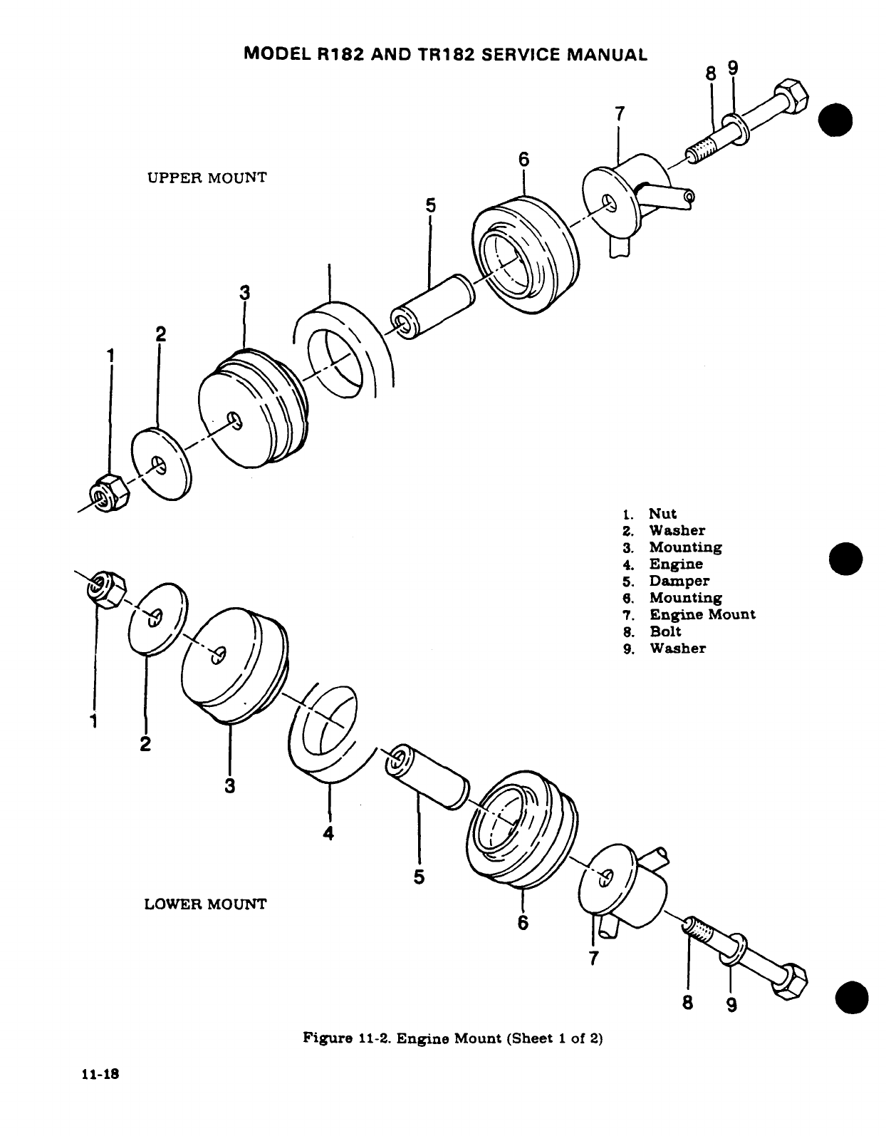
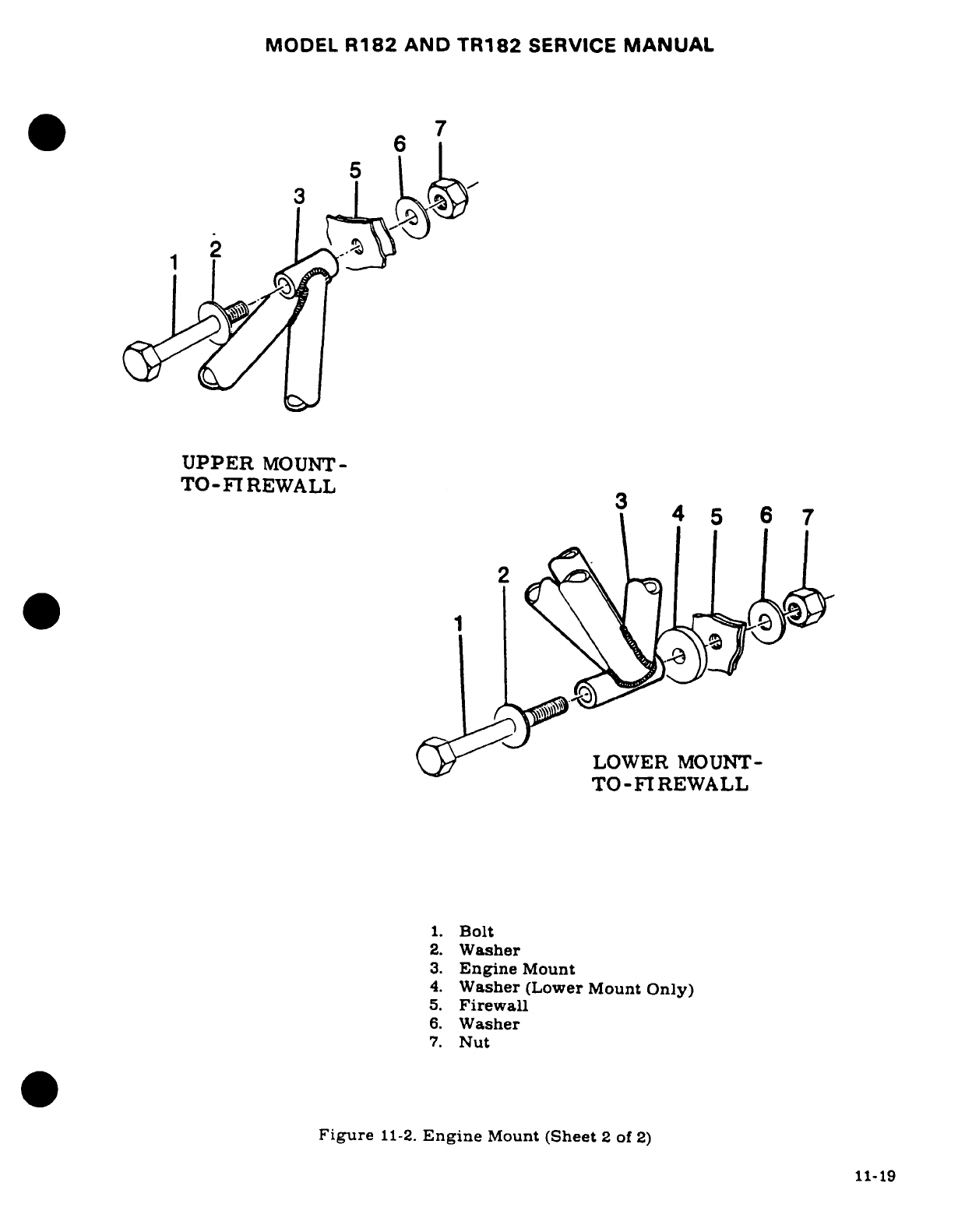
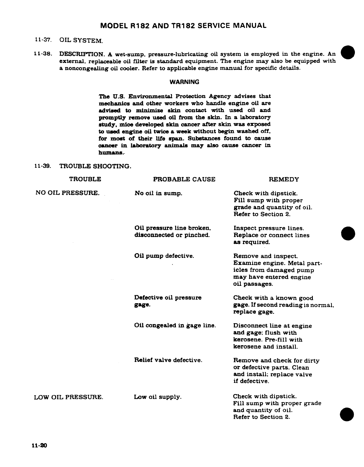
MODEL
R182
AND
TR182
SERVICE
MANUAL
11-37.
OIL
SYSTEM.
11-38.
DESCRIPTION.
A
wet-sump,
pressure-lubricating
oil
system
is
employed
in
the
engine.
An
external,
replaceable
oil
filter
is
standard
equipment.
The
engine
may
also
be
equipped with
a
noncongealing
oil
cooler.
Refer
to
applicable
engine
manual
for
specific
details.
WARNING
The
U.S.
Environmental Protection
Agency
advises
that
mechanics
and other
workers
who
handle
engine
oil
are
advised to
minimim
skin
contact
with
used
oil
and
promptly
remove
used
oil
from
the
skin.
In a
laboratory
study,
mice
developed
skin
cancer
after
skin
was
exposed
to
used
engine
oil
twice
a
week
without begin
washed
off,
for
most
of
their
life
span.
Substances
found
to
cause
cancer
in
laboratory animals
may
also
cause
cancer
in
humans.
11-39.
TROUBLE
SHOOTING.
TROUBLE
PROBABLE
CAUSE
REMEDY
NO
OIL
PRESSURE.
No
oil
in
sump.
Check
with
dipstick.
Fill
sump
with
proper
grade
and
quantity
of
oil.
Refer
to
Section
2.
Oil
pressure
line
broken,
Inspect
pressure
lines.
disconnected
or
pinched.
Replace
or
connect
lines
as
required.
Oil
pump
defective.
Remove
and
inspect.
Examine engine.
Metal
part-
icles
from
damaged
pump
may
have
entered
engine
oil
passages.
Defective
oil
pressure
Check
with
a
known
good
gage.
gage.
If
second
reading
is
normal.
replace
gage.
Oil
congealed
in
gage
line.
Disconnect line
at
engine
and
gage;
flush
with
kerosene. Pre-fill
with
kerosene
and
install.
Relief
valve
defective.
Remove
and
check
for
dirty
or
defective
parts.
Clean
and
install;
replace
valve
if
defective.
LOW
OIL
PRESSURE.
Low
oil
supply.
Check
with
dipstick.
Fill
sump
with
proper
grade
and
quantity
of
oil.
Refer
to
Section
2.
11-20
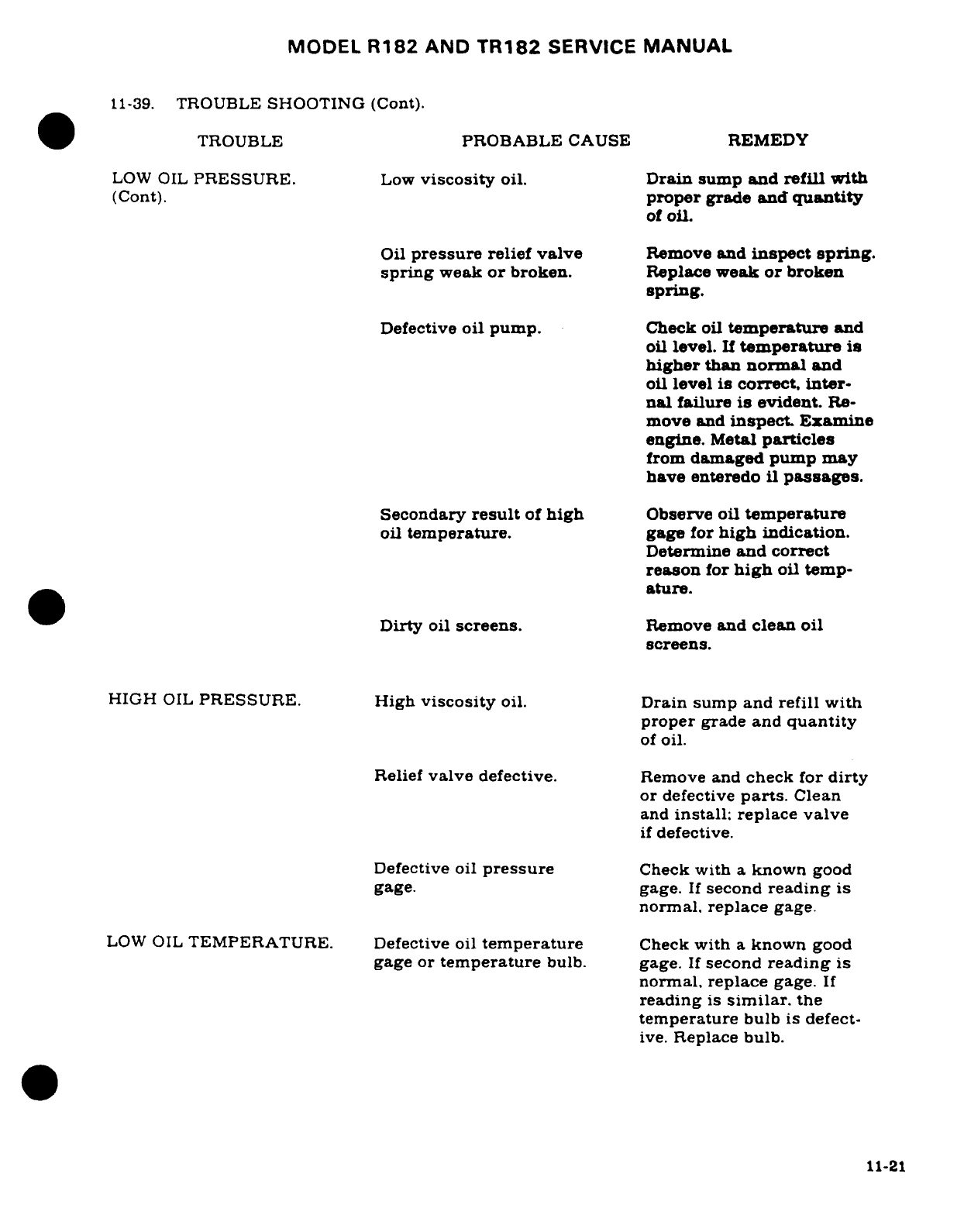
MODEL
R182
AND
TR182
SERVICE
MANUAL
11-39.
TROUBLE
SHOOTING
(Cont).
TROUBLE
PROBABLE
CAUSE REMEDY
LOW
OIL
PRESSURE.
Low
viscosity
oil.
Drain
sump
and
refill with
(Cont).
proper
grade
and
quantity
of
oil.
Oil
pressure
relief
valve
Remove
and
inspect
spring.
spring
weak
or
broken.
Replace
weak
or broken
spring.
Defective
oil
pump.
Check oil
temperature
and
oil
level.
If
temperature
is
higher
than
normal
and
oil
level
is
correct.
inter-
nal
failure
is
evident.
Re-
move
and
inspect. Examine
engine.
Metal
particles
from
damaged
pump
may
have
enteredo
il
passages.
Secondary
result
of
high
Observe
oil
temperature
oil
temperature.
gage
for
high
indication.
Determine
and
correct
reason
for
high
oil
temp-
ature.
Dirty
oil
screens.
Remove
and
clean
oil
screens.
HIGH
OIL
PRESSURE.
High
viscosity
oil.
Drain sump and
refill with
proper
grade and
quantity
of
oil.
Relief
valve
defective.
Remove
and
check
for
dirty
or
defective
parts.
Clean
and
install;
replace
valve
if
defective.
Defective
oil
pressure
Check
with
a
known
good
gage. gage.
If
second
reading
is
normal,
replace
gage.
LOW
OIL
TEMPERATURE. Defective
oil
temperature
Check
with
a
known
good
gage
or
temperature
bulb.
gage.
If
second
reading
is
normal, replace
gage.
If
reading
is
similar.
the
temperature
bulb
is
defect-
ive.
Replace
bulb.
11-21
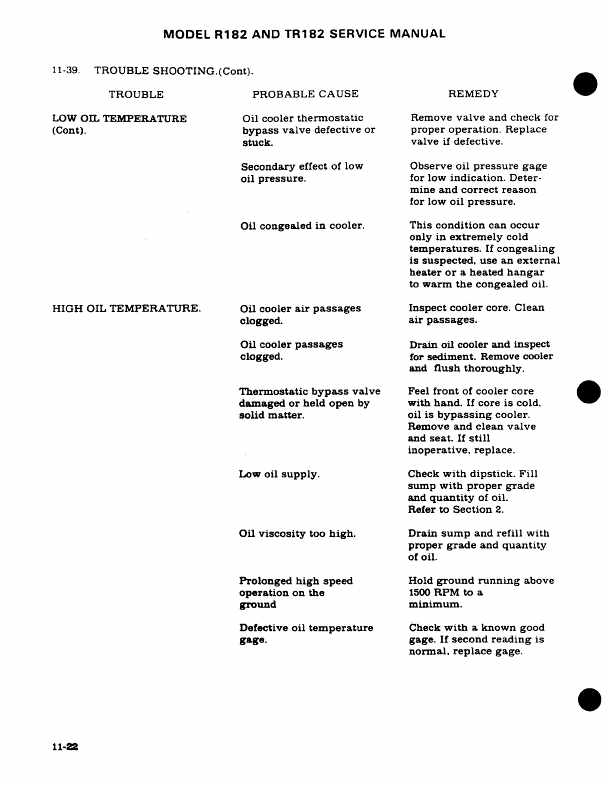
MODEL
R182
AND
TR182
SERVICE
MANUAL
11-39.
TROUBLE
SHOOTING.(Cont).
TROUBLE PROBABLE
CAUSE
REMEDY
LOW
OIL
TEMPERATURE
Oil
cooler
thermostatic
Remove
valve
and
check
for
(Cont).
bypass
valve
defective
or
proper operation.
Replace
stuck.
valve
if
defective.
Secondary
effect
of
low
Observe
oil
pressure
gage
oil
pressure.
for
low
indication.
Deter-
mine
and
correct
reason
for
low
oil
pressure.
Oil
congealed
in
cooler.
This
condition
can occur
only
in
extremely
cold
temperatures.
If
congealing
is
suspected.
use
an
external
heater
or
a
heated
hangar
to
warm the
congealed
oil.
HIGH
OIL
TEMPERATURE. Oil
cooler
air passages
Inspect
cooler
core.
Clean
clogged.
air
passages.
Oil
cooler
passages
Drain
oil
cooler
and
inspect
clogged.
for
sediment.
Remove
cooler
and
flush
thoroughly.
Thermostatic
bypass
valve
Feel
front
of
cooler
core
damaged
or
held
open
by
with
hand.
If
core
is
cold.
solid
matter.
oil
is
bypassing
cooler.
Remove
and
clean
valve
and
seat.
If
still
inoperative,
replace.
Low
oil
supply.
Check
with
dipstick.
Fill
sump
with
proper
grade
and
quantity
of
oil.
Refer
to
Section
2.
Oil
viscosity
too
high.
Drain
sump
and
refill
with
proper
grade
and
quantity
of
oil.
Prolonged
high
speed
Hold
ground
running
above
operation
on
the
1500
RPM
to
a
ground minimum.
Defective
oil
temperature
Check
with
a
known
good
gage.
gage.
If
second
reading
is
normal.
replace
gage.
11-22
MODEL
R182
AND
TR182
SERVICE
MANUAL
11-39.
TROUBLE
SHOOTING
(Cont).
TROUBLE
PROBABLE
CAUSE REMEDY
HIGH
OIL
TEMPERATURE
Defective
oil
temperature
Check
for
correct
oil pres-
(Cont).
bulb.
sure,
oil
level
and
cylinder
head
temperature.
If
they
are
correct,
check
oil
temp-
erature
gage
for
being
de-
fective;
similar
reading
is
observed,
bulb
is
defective.
Replace bulb.
OIL
LEAK
AT
FRONT
OF
Damaged
crankshaft
seal.
Replace.
Also
refer
to
Service
ENGINE.
Newsletter
SNL85-8.
OIL
LEAK
AT
PUSH
ROD
Damaged
pushrod
housing
Replace.
HOUSING.
oil
seal.
11-22A.(
11-22B
blank)
MODEL
R182
AND TR182
SERVICE
MANUAL
11-39A.
FULL-FLOW OIL
FILTER.
11-39B.
DESCRIPTION.
A
disposable
spin-on
oil
filter
attaches
to
a
threaded
fitting
on
the
oil
pump
casting.
The
filter contains
an
internal
bypass
valve.
11-39C.
REMOVAL.
a.
Remove
engine
cowl
in
accordance
with
paragraph
11-3.
b.
Cut
safety wire
and
turn
filter
counterclockwise
to
remove
if
from
the
adapter.
NOTE
Before
discarding
filter,
remove
filter
element
from
can
and
cut
off
both
ends.
Carefully
unfold
the
element
and
inspect
for
evidence
of
internal
engine
damage
such
as
chips or
metal
from
bearings.
In
new
or
newly
over-
hauled
engines
chips
and
bearing
metal
may
be
found,
and
generally
are
of
no
consequence.
However,
particles
produced
by
impact,
abrasion,
or
pressure
are
evidence
of
internal
engine
damage and
justify
further
examination
to
determine
the
cause.
11-39D.
INSTALLATION.
a.
Lightly
lubricate filter
gasket
with engine
oil
or
Dow-Corning
compound
(DC-4).
b.
Turn
filter
clockwise
until
filter
gasket contacts
base
of
adapter;
then
tighten
3/4
to
1
turn
or
torque
to
15/20
FT/LBS.
and
safety
wire.
c.
Start
engine,
check
for
proper
oil
pressure.
Warm
up
engine and
check
filter
for
leaks.
d.
Check
that
engine
torque
does
not
cause
filter
to
contact
adjacent
parts.
e.
Replace
engine
cowl
in
accordance with
paragraph
11-3.
f.
Check oil
level
and
filter
leakage
after
operating
engine
at
high
power
setting,
or
after
a
flight
around
the
field.
11-40.
OIL
COOLER.
11-41.
DESCRIPTION.
The
external
oil
cooler
is
mounted on
the
left
forward
engine
baffle.
Flexible
hoses
carry
the
oil
to
and
from
the
cooler.
Ram
air
passes
through
the
cooler
coil
and
is
discharged
into
the
engine
compartment.
At
each
engine
oil
change.
drain
the oil cooler.
Refer
to
Section
2
for
servicing
instructions.
11-42.
FUEL
SYSTEM.
11-43.
DESCRIPTION.
The
engine
is
equipped
with
a
carburetor
mounted
on
the
lower
aft
end
of
the
engine.
The
carburetor
has
a
manual
altitude
mixture
control.
For
overhaul
and
repair
of
the
carburetor,
refer
to
the
manufacturer's
overhaul
and
repair
manual.
11-44.
CARBURETOR.
11-45.
REMOVAL
AND
INSTALLATION.
a.
Place
fuel
selector
valve
in
the
OFF
position.
11-23
MODEL
R182
AND
TR182
SERVICE
MANUAL
b.
Remove
engine
cowling
in
accordance with
paragraph
11-3.
c.
Drain
fuel
from
strainer
and
lines
with
strainer
drain
control.
d.
Remove
bolts
attaching
air
box
ducting
to
carburetor,
and
remove
air
box
ducting.
e.
Disconnect
throttle
and
mixture
controls
at the
carburetor.
Note
EXACT
position.
size
and
number
of
attaching
washers
and
spacers
for
reference
on
reinstallation.
f.
Disconnect
and
cap
or
plug
fuel
line
at
carburetor.
g.
Remove
safety
wire,
nuts
and
washers attaching
carburetor
to
engine,
and
remove
carburetor
and
mounting
gasket.
h.
Reverse
the
preceding
steps
for
reinstallation.
Use
new
gaskets
when
installing
carburetor.
Rig
controls
in
accordance
with
paragraphs
11-70. 11-71
and
11-72.
(Check
carburetor throttle
arm
to
idle
stop
arm
attachment
for
security
and
proper
safetying
at
each
normal
engine
inspection
in
accordance
with
figure
11-3.)
11-46.
IDLE
SPEED
AND
MIXTURE ADJUSTMENTS.
Idle
speed
and
mixture adjustment
should
be
accomplished
after
the
engine
has
been
warmed
up.
Since
idle
RPM
may
be
affected
by
idle
mixture
adjustment,
it
may
be
necessary
to
readjust
idle
RPM
after setting
the
idle
mixture
correctly.
a.
Set
the
throttle
stop
screw (idle
RPM)
to
obtain
600±25
RPM,
with
throttle control
pulled
full
out
against
idle
stop.
NOTE
Engine idle speed
may
vary
among different
engines.
An
engine
should
idle
smoothly,
without
excessive
vibration
and
the idle speed should
be
high
enough
to
maintain
idling oil
pressure
and to
preclude
any
possibility
of
engine
stoppage
in
flight
when the
throttle
is
closed.
b.
Advance
throttle
to
increase
engine
speed
to
approximately
1000
RPM.
c.
Pull
mixture
control
knob
slowly
and
steadily
toward
the
idle
cut-off
position.
observing
tachometer,
then
return
control
full
IN
(RICH)
position
before
engine
stops.
d.
Adjust
mixture
adjusting
screw
at
upper
end
of
carburetor
intake
throat
to
obtain
a
slight
and
momentary
gain
of
25
RPM
maximum
at
1000
RPM
engine
speed
as
mixture
control
is
moved
from
full
IN
(RICH)
toward
idle
cut-off
position.
Return
control
to
full
IN
(RICH)
to
prevent
engine
stoppage.
e.
If
mixture
is
set
too
LEAN,
engine
speed
will
drop
immediately,
thus
requiring
a
richer mixture.
Turn
adjusting
screw
OUT
(counterclockwise)
for
a
richer
mixture.
f.
If
mixture
is
set
too
RICH,
engine
speed
will
increase
above
25
RPM.
thus
requiring
a
leaner
mixture.
Turn
adjusting
screw
IN
(clockwise)
for
a
leaner
mixture.
NOTE
After
each
adjustment
to
the
idle
mixture,
run
engine
up
to
approximately
2000
RPM
to
clear
engine
of
excess
fuel
to
obtain
a
correct
idle
speed.
11-47.
INDUCTION
AIR
SYSTEM.
11-48.
DESCRIPTION.
Ram
air
enters
the
induction
air
system
through
an
intake port
and
a
filter
on
the
left
aft
side
of
the
cowling,
and
is
ducted
to
the
airbox
near
the
firewall. From
the
induction
airbox
the
filtered
air
is
ducted
to
the
inlet
of
the
carburetor
mounted
on
the lower
aft
end
of
the
engine,
through
the
carburetor,
where
the fuel
is
mixed
with the
air
to
the
intake
11-24

MODEL
R182
AND
TR182
SERVICE
MANUAL
manifold. From
the
intake
manifold,
the
fuel-air
mixture
is
distributed
to
each
cylinder
by
separate
intake pipes.
The
intake
pipes
are
attached
to
the
manifold
with
hoses
and
clamps
and
to
the
cylinder
with
a
four
bolt
flange
sealed
with
a
gasket.
A
butterfly
valve,
located
in
the
airbox,
may
be
operated
manually
from
the
cabin
to
permit
the
selection
of
either
cold
or
heated
air.
When
the
induction
air
door
is
closed, heated
air
is
drawn
from
a
shroud
on
the
left
exhaust
stack
assembly.
11-48A.
INSTALLATION OF INDUCTION
AIR
SYSTEM
DUCTS.
When
cutting
induction
air system
ducts
to
length,
the
support
wire
should
be
cut
back
far
enough
to
bend
back
(minimum
bend
radius,
1/8
inch)
under
the
clamp
and
protrude
1/4
inch.
Do
not
break
the
bond
be-
tween the wire
and
the
fabric.
Before
tightening
clamps, make
sure
there
is
no
twist
or
tor-
que on
the
duct.
If
the
duct
is
supported
with
MIL-Y-1140
cord
in
place
of
wire,
the
preced-
ing
installation
applies
except:
MILY-1140
cord
has
no
minimum bend
radius
requirements.
The
minimum
installed
bend
radii
for
wire-supported
ducts
in
plane
of
bend,
measured
from
the
wall
of
the
duct,
are
as
follows:
a.
Neoprene
-
one
ply,
1/4
diameter
of
the
maximum
duct
dimension.
b.
Neoprene
-
two
ply,
and
silicone
one
ply,
1/3
diameter
of
the
maximum
duct
dimen-
sion.
c.
Silicone
-
two
ply,
1/2
diameter
of
the
maximum
duct
dimension.
NOTE
Duct
carrying
filtered
induction
air
may
not
have
local
areas
hand-formed
to
a
different
cross
section.
11-49.
AIRBOX.
.
11-50.
REMOVAL
AND
INSTALLATION.
a.
Remove
upper
left
engine
cowl
in
accordance
with
paragraph
11-3.
b.
Disconnect
flexible
duct
from
forward
end
of
airbox.
c.
Disconnect
flexible
duct
from
carburetor
adapter
assembly.
d.
Disconnect
carburetor
heat
control
arm
on
the
forward
side
of
the
airbox
and remove
clamp
securing
control
to
the
airbox.
e.
Remove
screw
attaching upper
airbox
support
to
firewall
stiffener.
f.
Remove
four
screws
and
washers
attaching
airbox
to
the
firewall
and
carefully
remove
airbox.
g.
Reverse
the
preceding
steps
for
reinstallation.
Rig
carburetor
heat
control
in
accordance
with
paragraph
11-72.
11-51.
CLEANING
AND
INSPECTION.
Clean
metal
parts
of
the induction
airbox
with
Stoddard
solvent
or
equivalent.
Inspect
for
cracks,
dents,
loose
rivets,
etc.
Minor
cracks
may
be
stop-
drilled.
In
case
of
continued
or
severe
cracking,
replace airbox.
Inspect
gaskets
and
install
new
gaskets,
if
damaged.
Check
manually-operated
air
door
for
ease
of
operation
and
proper
rigging.
11-52.
INDUCTION
AIR
FILTER.
11-53.
DESCRIPTION.
An
induction
air
filter,
mounted
on
the
induction
airbox
on
the
left
aft
side
of
the
engine
compartment,
removes
dust
particles
from
the
ram
air
entering
the
engine.
11-54.
REMOVAL
AND
INSTALLATION.
a.
Release
the
four
quick-release
fasteners
securing
the
filter
assembly
to
the
airbox.
b.
Reverse
the
preceding
step
for
reinstallation.
11-25
MODEL
R182
AND
TR182
SERVICE
MANUAL
11-55.
CLEANING
AND
INSPECTION.
Clean
and
inspect
filter
in
accordance
with
instructions
in
Section
2.
NOTE
If
air
filter
gasket
becomes
loose,
bond
with
EC-1300L
or
equivalent.
11-56.
IGNITION SYSTEM.
11-57.
DESCRIPTION.
The
ignition
system
is
comprised
of
dual
magnetos
in
one
housing.
two
spark
plugs
in
each
cylinder,
an
ignition
wiring
harness,
an
ignition
switch
mounted
on
the
instrument
panel
and
required
wiring
between
the
ignition
switch
and
magnetos.
11-58.
TROUBLE
SHOOTING
TROUBLE
PROBABLE
CAUSE
REMEDY
ENGINE
FAILS
TO
Defective
ignition
switch.
Check
switch
continuity.
START.
Replace
if
defective.
Spark
plugs
defective.
Clean.
regap
and
test
plugs.
improperly
gapped
or
Replace
if
defective.
fouled
by
moisture
or
deposits.
Defective
ignition
harness.
If
no
defects
are
found
by
a
visual
inspection.
check
with
a
harness
tester.
Re-
place
defective
parts.
Magneto
"P"
lead Check
continuity.
"P"
lead
grounded.
should
not
be
grounded
in
the
ON
position.
but
should
be
grounded
in
OFF
position.
Repair
or
replace
"P"
lead.
Failure
of
impulse
Impulse
coupling
pawls
coupling.
should
engage
at
cranking
speeds. Listen
for
loud
clicks
as
impulse
couplings
operate.
Remove
magnetos
and
deter-
mine
cause.
Replace
defective
magneto.
Defective magneto.
Refer
to
paragraph
11-64.
Broken
drive gear.
Remove
magneto
and
check
magneto
and
engine
gears.
Replace
defective
parts.
Make
sure
no
pieces
of
damaged
parts
remain
in
engine
or engine
disassembly
will
be
required.
11-26
MODEL
R182
AND
TR182
SERVICE
MANUAL
11-58.
TROUBLE
SHOOTING
(Cont).
TROUBLE
PROBABLE
CAUSE
REMEDY
ENGINE
WILL
NOT
Spark
plugs
defective,
im-
Clean,
regap
and
test
plugs.
IDLE
OR
RUN
properly
gapped
or
fouled
Replace
if
defective.
PROPERLY:
by
moisture
or
deposits.
Defective
ignition
If
no
defects
are
found
by
a
harness.
visual
inspection,
check
with
a
harness
tester.
Replace
defective
parts.
Defective
magneto.
Refer
to
paragraph
11-64.
Impulse
coupling
pauls
Listen
for
loud
clicks
as
remain
engaged.
impulse coupling operates.
Remove
magneto
and
determine cause.
Re-
place
defective
magneto.
Spark
plugs
loose.
Check
and
install
properly.
11-59.
MAGNETOS.
11-60.
DESCRIPTION.
The
Bendix
D-2000
series
magneto
consists
of
two
electrically
independent
ignition circuits
in one
housing.
A
single
four
pole
rotor
provides
the
magnetic
energy
for
both
circuits.
The
magneto
uses
an
impulse
coupling
to
provide
reliable
ignition at
engine
cranking
speed.
Suppression
of
breaker
contact
point
arcing
is
accomplished
by
feed-thru
type
capacitors
mounted
in
the
magneto cover
which
forms
a
part
of
the
magneto
harness
assembly.
11-61.
REMOVAL
AND
INSTALLATION.
WARNING
The
magneto
is in a
SWITCH
ON
condition
when
the
switch wire
is
disconnected.
Therefore,
ground
the
breaker
contact
points
or
disconnect
the
high-tension
wires
from
magneto
to
spark plugs.
a.
Remove
engine
cowling
in
accordance with
paragraph
11-3.
b.
Remove
the
eight
screws
securing
the
high-tension outlet
cover
to
the
magneto.
The
"P"
leads
may
be
disconnected
for
additional
clearance
if
necessary.
NOTE
It
is
a
good
practice
to
position
No.
1
cylinder
at its
approximate
advanced
firing
position
before
removing
the
magneto.
11-27
MODEL
R182
AND
TR182
SERVICE
MANUAL
c.
Remove
nuts,
washers
and
clamps
attaching
the
magneto
to
the
engine
accessory
housing.
Note
the
approximate
angular
position
at
which
the
magneto
is
installed.
then
remove
the
magneto.
d.
Reverse
the
preceding
steps
for
reinstallation
and
time
magneto-to-engine
in
accordance
with
paragraph
11-63.
11-62.
INTERNAL TIMING.
(MAGNETO
REMOVED
FROM
ENGINE.)
NOTE
A
magneto.
correctly
timed
internally,
will
have
the
red
painted
tooth
of
the
large
distributor gears
approxi-
mately
centered
in
the
timing
windows, the
L
("E"
gap)
mark
on
the rotor
shaft
in
alignment
with
the
pointer
and
both
sets
of
breaker
contacts
opening,
all
at
the
same
time.
a.
Remove
breaker
contact
point
assembly
cover,
if
installed,
by
removing
the
cover
screws,
pulling
cover
directly
aft
away
from
housing
and
disconnecting
both
capacitor
leads
from
breaker
contact
assemblies.
b.
Remove
timing
inspection
hole
plugs
from
magneto.
c.
Slowly
turn
the rotor
shaft
until
the
red
painted
tooth
of
the
large
distributor
gear
for
each
side
is
approximately
centered
in
the
inspection
windows
with
the
L("E"
gap)
mark
on
the
rotor
aligned with
the
pointer.
Lock
the rotor
in
this
EXACT
position
using
Bendix
Rotor
Holding
Tool,
Part
No.
11-8465
or
equivalent.
NOTE
Position the
11-8465
Rotor
Holding
Tool
on
drive
end
of
rotor
shaft
in
the
4
o'clock
position
so
that
any
shaft
deflection
caused
by
clamping
action will
be
in
a
plane
parallel
to
the
breaker
contacts.
d.
Connect
the
timing
light
(Bendix
Part
No.
11-9110
or
equivalent) black
lead
to
any
unpainted
surface
of
the
magneto.
Connect
the red
lead
to
the
left
breaker
contact
terminal
and
the
green
lead
to
the
right
breaker
contact
terminal.
e.
Carefully
adjust
the
LEFT
breaker
contacts
to
just
begin
to
open
(light
will
go
out)
with
the
timing
pointer
within
the
width
of
the
L
("E"
gap)
mark.
f.
Repeat
step
"e"
for
the
RIGHT
breaker
contacts.
g.
Loosen
the
rotor
holding
tool
and
turn
rotor
shaft
in
normal direction
of
rotation until
cam
followers
of
contact
assemblies
are
on
the
high
point
of
cam
lobes. Contact
point
clearance
should
be
0.016±0.002
inch
and
0.016±0.004
inch
on
LEFT
and
RIGHT
contacts
respectively.
If
dimensions
do
not
fall
within
limits,
readjust
contact
points
and
recheck
to
be
sure
the
points
just
begin
to
open
when
the
timing
pointer
is
within
the width
of
the
L
("E"
gap)
mark.
11-28
MODEL
R182
AND
TR182
SERVICE
MANUAL
NOTES
Wire
feeler
gages
are recommended
when
checking
contact
point
clearance.
No
attempt
should
be
made
to
stone
or
dress
contact
points.
If
the
above
conditions
are
met
and
within
the
tolerance.
the
magneto
is
timed
internally
and
ready for
installa-
tion.
If
the
above
conditions
are
not
within
tolerance.
proceed
to
step
"h".
h.
While
holding
the
rotor
shaft,
loosen
the
screw
securing
breaker
contact
cam
to
rotor
shaft
and
back
screw
out
approximately
half
way.
Place
the
end
of
a
broad
bladed
screwdriver
between
the bottom
of
the
cam
and
housing.
Strike
the
screwdriver
handle
with
a
sharp
downward
blow
to
"pop"
the
cam
loose
from
taper
of
shaft.
i.
Rotate cam
until
breaker
contact
cam
followers
are
on
the
high
point
of
cam
lobes.
Adjust
breaker
points
to
obtain
a
clearance
of
0.016±0.004
inch
on
LEFT
and
RIGHT
contacts
respectively.
Tighten
breaker
contact
securing
screws
to
20-25
lb-in.
j.
Repeat
step
"c."
k.
While
holding
rotor
shaft
in
this
EXACT
position, rotate
the
breaker
contact
cam
in
the
opposite
direction
of
rotation
a
few
degrees
BEYOND
where
the
breaker
contacts
close,
then
rotate
cam
in
the
normal
direction
of
rotation
until the
breaker
contacts
just
begin
to
open.
Point
opening
should
be
determined
by
the
use
of
a
timing
light.
(Bendix
Part
No.
11-9110
or
equivalent.)
l.
While
holding
cam
in
this
EXACT
POSITION,
push
cam
on
rotor
shaft
as
far
as
possible
with
the
fingers. Tighten
cam
securing
screw
thereby
drawing
the
cam
down
evenly
and
tightly.
Torque cam
securing
screw
to
16-20
lb-in.
NOTE
Extreme
care
must
be
exercised
in
this
operation.
If
cam
adjustment
is
changed
in
the
slightest
degree,
the
timing
of
the
magneto
will
be
thrown
off.
Do
not drive
cam
on
rotor
shaft
with
a
mallet or
other instrument.
m.
Recheck
timing
to
make
sure
both
sets
of
breaker
contacts
begin
to
open
within
the
width
of
the
L
("E"
gap)
mark
and
that
the
contact point
clearance
is
in
accordance
with
dimensions
in
step
"g".
NOTE
When
reinstalling
the
inspection
hole
plugs,
make
sure
the
ventilated
plugs
are
installed
in
the
ends
of
the
magneto.
Torque
plugs
to
12-15
lb-in.
11-63.
MAGNETO-TO-ENGINE-TIMING.
The
magneto
must
be
installed
with its
timing
marks
carefully
aligned,
with
number
one
cylinder
on
its
compression
stroke
and
with
the
number
one
position
at
its
advanced
firing
position.
Refer
to
paragraph
11-14
for
the
advanced
firing
position
of
number
one
piston.
To
locate
the
compression
stroke
of
the
number
one
cylinder.
remove
the
lower
spark
plug
from
number
2, 3.
4.5.
and
6
cylinders.
Remove
the
upper
spark
11-29
MODEL
R182
AND
TR182
SERVICE
MANUAL
plug
from
number
1
cylinder.
Place
the
thumb
of
one
hand
over the
spark
plug
hole
of
number
one
cylinder
and
rotate
crankshaft
in
the
direction
of
normal
rotation
until
the
compression
stroke
is
indicated
by
positive
pressure
inside
the
cylinder
lifting
the
thumb
off
the
spark
plug
hole.
After
the
compression
stroke
is
attained.
locate
number
one
piston
at
its
advanced
firing
position.
Locating
the
advanced
firing
position
of
number
one
piston
may
be
obtained
by
rotating
the
crankshaft
opposite
to
its
normal
direction
of
rotation until
it
is
approximately
30
degrees
before
top
dead
center
(BTC) on
the
compression
stroke
of
number
one
cylinder.
Rotate
crankshaft
in
a
normal
direction
to
align
the
timing
mark
on
the
front
face
of
the
starter
ring
gear
support
with
the drilled
hole
in
the
starter.
making sure
the
final
motion
of
the
ring
gear
is in
the
direction
of
normal rotation.
NOTE
An
accurate
top
center
indicator
which screws
into
a
spark
plug
mounting
hole,
and
a
pendulum
pointer
mounted
on
a
360-degree
timing
disc
may
also
be
used
to
locate
the
advanced
firing position.
The
timing
disc
should
be
adapted
to
fit
over
the
end
of
the
propeller
spinner
in
such
a
manner
that
it
may
be
rotated
as
necessary.
In
all
cases,
it
must
be
definitely
determined
that
the
number
one
cylinder
is
at
the
correct
firing
position
and
on
the
compression
stroke
when
the
engine
is
turned
in
its
normal
direction
of
rotation.
After
the
engine
has
been
placed
in
the
correct
firing
position.
install
the magneto
to the
engine
in
the
following
manner:
a.
Remove
the
timing
window
plug
from
the
most
convenient side
of
the
magneto
housing.
b.
Remove
the
rotor
viewing
location
plug
from
the
top
center
of
the
housing.
c.
Turn
the
rotating
magnet
drive shaft
in
the
normal
direction
of
magneto
rotation
until
the red
painted
tooth
of
the
large
distributor
gear
is
centered
in
the
timing
hole
(hole
at
each
side
of
magneto).
d.
Also
observe
at
this
time
that
the
built
in
pointer
just
ahead
of
the rotor viewing
window
aligns
with
the
L
("E"
gap)
mark
on
the
rotor.
e.
Install
the
magneto-to-engine
gasket
on
the
magneto
flange.
WARNING
Do
not
attach
harness
spark
plug
leads
to
the
spark
plugs
until
all
magneto-to-engine
timing
procedures
are
com-
pleted
and
the switch
leads
("P"
leads)
are
connected.
f.
Remove
the
engine-to-magneto
drive
gear train
backlash
by
turning
magneto
drive
opposite
to
normal
rotation
as
far
as
possible.
g.
With
the
No.
1
cylinder
at
its
correct
firing
position
and
on
the
compression
stroke.
hold
the magneto
as
close
to
its
No.
1
firing
position
as possible
(red
tooth
in
center
of
window
and
pointer
over
L
("E"
gap)
mark
on
rotor
and
install magneto
to
the
engine.
Loosely
tighten
magneto
in
position.
11-30
MODEL
R182
AND
TR182
SERVICE
MANUAL
NOTE
To
facilitate
connection
of
a
timing
light
to
the
switch
lead
("P"
lead)
terminals,
short
adapter
leads
may
be
fabricated.
These can
be
made
by
using
two
switch
lead
terminals
and
two
short
pieces
of
insulated
wire.
Install
the
fabricated adapter leads
in
the
switch
lead
outlet
terminals
of
the
cover.
h.
Attach
the red
lead
of
the
timing light
(Bendix
Part
No.
11-9110
or
equivalent)
to
the
left
switch
lead
adapter,
the
green
lead
of
the
timing
light
to
the
right
switch
lead
adapter
and
the black
lead
of
the
timing
light
to
the
magneto
housing
(common
ground).
NOTE
An
internal
timing
tolerance
is
allowed
when
adjusting
the
two
main
breakers.
Therefore,
one
of
the
main
break-
ers
may
open
slightly
before
the
other.
Magneto-to-
engine
timing
should
be
accomplished
using
the first
main
breaker
to
open
as
the
reference
point
when
the
engine
is in
the
firing
position
for
No.
1
cylinder.
This
will
ensure
that
ignition
created
by
either
spark
plug
will
not
occur
prior
to
the
desired
engine
firing
point.
i.
Turn
the
entire
magneto
in
direction
of
rotor rotation
until
the
timing
lights
are
on.
j.
Turn
magneto
in
direction
of
rotor
rotation,
right-hand
rotation
to
right
and
left-hand
rotation
to
left,
until
one
of
the
timing lights
just
goes
off.
Then
tighten
the
magneto
mounting
clamps
evenly
in
this
position.
k.
Back
the
engine
up
approximately
10
°
and
then
carefully
"bump"
the
engine forward
while
observing
the
timing
lights.
l.
At
the
No.
1
cylinder
firing position,
one
of
the
timing
lights
should
go off.
Continue
turning
the
engine
in
its
normal
direction
of
rotation until
the
other
timing
light
goes
off.
This
should
be
not
more
than
3
engine
degrees
later
than
the
first
light.
If
not.
repeat
steps
"i"
thru
"k"
until
these
conditions
are
obtained.
m.
Make
sure
the
magneto
clamps
are tightened
securely,
recheck
timing
once
more
and
remove
timing
equipment.
n.
Reinstall
inspection
plugs
and
torque
plugs
to
12-15
lb-in.
11-64.
MAINTENANCE.
At
the
first
25-hour
inspection,
first
50-hour
inspection,
first
100-hour
inspection
and
thereafter
at
each
100-hour
inspection,
the
contact
breaker
point
compart-
ment
and
magneto-to-engine
timing
should
be
inspected
and checked.
If
magneto-to-engine
timing
is
correct
within plus
zero
and
minus
two
degree,
internal
timing
need
not
be
checked.
If
timing
is
out
of
tolerance,
remove
magneto
and
set
internal
timing
(paragraph
11-62),
then
install
and
time
to
engine.
NOTE
If
engine
operating
troubles
develop
which
appear
to
be
caused
by
the
ignition
system,
it is
advisable
to
check
the
spark plugs
and
ignition
harness first
before
working
on
the
magnetos.
If
the
trouble
appears
definitely
associated
with
a
magneto.
the
following
may
be
used
to
help
disclose the
source
of
trouble
without
overhauling
the
magneto.
11-31
MODEL
R182
AND
TR182
SERVICE
MANUAL
a.
Moisture
check.
1.
Remove
contact
breaker
point assembly
cover
and
inspect
cover,
cables
and
capacitor
for
moisture
in
the
area.
2.
Inspect
distributor
block
high
tension
outlets
for
moisture.
3.
If
any
moisture
is
evident,
lightly
wipe
with
a soft.
dry,
clean, lint-free
cloth.
CAUTION
Do
not
use
gasoline
or
any
other
solvent,
as
these
will
remove
the
wax
coating
on
some
parts
and
cause
an
electrical
leak.
b.
Breaker contact
compartment
check.
1.
Check
all
parts
of
the
contact
breaker
assembly
for
security.
Check
distributor
block
high-tension
outlet
springs
for
evidence
of
spark
erosion
and
proper
height.
The
end
of
spring
should
not
be
more
than
0.422
inch
from
top
of
tower.
2.
Check
breaker
contact
assembly
points
for
excessive
wear,
burning,
deep
pits
and
carbon
deposits.
Breaker
points
may
be
cleaned
with
a
hard
finish
paper.
If
breaker
points
are
found
defective,
install
a
new
assembly.
Make
no
attempts
to
stone
or
dress
breaker
points.
Clean
new
breaker points
with
clean
unleaded
gasoline
and
hard
finish
paper
before
installing.
3.
Check
condition
of
the
cam
follower
felt.
Squeeze
felt
between
thumb
and
finger.
If
fingers
are
not
moistened
with
oil,
re-oil
using
2
or
3
drops
of
lubricant
(Bendix
Part
No.
10-86527
or
equivalent).
Allow
approximately
30
minutes
for
felt
to
absorb
the
lubricant.
Blot
off
excess
lubricant
with
a
clean,
lint-free
cloth.
Too
much
lubricant
could
foul
breaker points
and
cause
excessive
burning.
4.
Check
capacitors
for
looseness
in
the magneto
cover
of
the
harness
assembly
and
for
any
physical
damage.
If
equipment
is
available,
check the
capacitors
for
leakage,
series
resistance
and
capacitance.
The
capacitance should
be
0.34
to
0.41
microfarads.
NOTE
Spring
in
capacitor
outlet
may
cause
an
indication
of
a
short
to
ground
if
an
adapter
lead
is
not
used.
c.
If
the
trouble
has
not
been
corrected
after
accomplishing
the
moisture
and
breaker
contact
compartment
check,
check
magneto-to-engine
timing
in
accordance
with
paragraph
11-63.
If
timing
is
incorrect,
remove
magneto
and
adjust
internal
timing
in
accordance
with
paragraph
11-62.
d.
Reinstall
magneto
and
time
to
engine
in
accordance
with
paragraph
11-63.
e.
If
the
trouble
has
not
been
corrected,
magneto
overhaul
or
replacement
is
indicated.
11-65.
MAGNETO
CHECK.
a.
Start
and
run
engine
until
the
oil
and
cylinder
head
temperatures
are
in
the
normal
operating ranges.
b.
Advance
engine
speed
to
1700
RPM.
c.
Turn
the
ignition
switch
to
the
"R"
position
and
note
the
RPM
drop.
then
return
the
switch
to
the
"BOTH"
position
to
clear
the
opposite
set
of
plugs.
d.
Turn the
switch
to
the
"L"
position
and
note
the
RPM
drop,
then
return
the
switch
to
the
"BOTH"
position.
11-32
MODEL
R182
AND TR182
SERVICE
MANUAL
e.
The
RPM
drop
should
not
exceed
175
RPM on
either
magneto
setting
or
show
greater
than
50
RPM
differential
between magneto
settings.
A
smooth
RPM
drop-off
past
normal
is
usually
a
sign
of
a
too
lean
or
too
rich
mixture.
A
sharp
RPM
drop-off
past
normal
is
usually
a
sign
of
a
fouled
plug,
a
defective
harness
lead
or
a
magneto
out
of
time.
If
there
is
doubt
concerning
operation
of
the
ignition
system.
RPM
checks
at
a
leaner mixture
setting
or
at
higher
engine
speeds
will
usually
confirm
whether
a
deficiency
exists.
NOTE
An
absence
of
RPM
drop
may
be
an
indication
of
faulty
grounding
of
one
side
of
the
ignition
system,
a
discon-
nected
ground
lead
at
magneto
or
possibly
the
magneto
timing
is
set
too
far
in
advance.
11-66.
SPARK
PLUGS.
Two
18-mm
spark
plugs
are
installed
in
each
cylinder
and
screw
into
helicoil
type
thread
inserts.
The
spark
plugs
are
shielded
to
prevent
spark
plug
noise
in
the
radios
and
have
an
internal
resistor
to
provide
longer
terminal
life.
Spark plug
life
will
vary
with
operating
conditions.
A
spark
plug
that
is
kept
clean
and
properly
gapped
will give
better
and
longer
service
than
one
that
is
allowed
to
collect
lead
deposits
and
is
improperly
gapped.
NOTE
Refer
to
Section
2
for
inspection interval.
Remove,
clean.
inspect
and
regap
all
spark
plugs at
each
inspection.
Install
lower
spark plugs
in
upper
portion
of
cylinders
and
install
upper
spark
plugs
in
lower
portion
of
cylin-
ders.
Since
deterioration
of
lower
spark
plugs
is
usually
more
rapid
than
that
of
the
upper
spark
plugs,
rotating
helps
prolong
spark
plug
life.
11-67.
ENGINE
CONTROLS.
11-68.
DESCRIPTION.
The
throttle,
mixture
and
carburetor heat
controls
are
of
the
push-pull
type.
The
mixture
control
is
equipped
to
lock
in
any
position
desired.
To
move
the
control,
the
spring-loaded
button,
located
in
the
end
of
the
control
knob,
must
be
depressed.
When
the
button
is
released,
the
control
is
locked.
The
mixture
control
also
has
a
vernier
adjustment.
Turning
the
knob
in
either
direction
will
change
the
control
setting.
The
vernier
is
primarily
for
precision
control
setting.
The
throttle
control
has
neither
a
locking
button
nor
a
vernier
adjustment,
but
contains
a
knurled
friction
knob
which
is
rotated
for
more
or less
friction
as
desired.
The
friction
knob
prevents
vibration
induced
"creeping"
of
the
control.
The
carburetor
heat
control
has
no
locking
device.
11-69.
RIGGING.
When
adjusting
any
engine
control,
it
is
important
to
check
that
the
control
slides
smoothly
throughout its
full
range
of
travel,
that
it
locks
securely
if
equipped
with
a
locking
device
and
the
arm
or
lever
it
operates
moves
through
its
full arc
of
travel.
CAUTION
Whenever
engine
controls
are
being
disconnected,
pay
particular
attention
to
the
EXACT
position,
size
and
number
of
attaching
washers
and
spacers.
Be
sure
to
install
attaching
parts
as
noted
when
connecting
con-
trols.
11-33
MODEL
R182
AND
TR182
SERVICE
MANUAL
11-70.
THROTTLE
CONTROL.
(See
figure
11-3.)
NOTE
Before
rigging
throttle
control,
check
that
control
end
(13)
is
secure.
If
any
indication
of
looseness
or
breakage
is
apparent,
replace
the
throttle
control.
a.
Screw
friction
lock
nut
(2)
into
threads
of
barrel
(7).
b.
Ensure
washer
(5)
and
nut
(6)
on
forward
side
of
panel
are secure.
c.
Push
knob
assembly
(1)
full
in
against
friction
lock
nut
(2),
then
pull
knob
assembly
out
approximately
1/8-inch
to
obtain "cushion".
d.
Tighten friction
lock
nut
(2)
against
barrel
(7).
e.
At
the
carburetor,
attach
throttle
arm
hardware to
rod
end
(16).
NOTE
Ensure
palnut
(17)
is
on
threads
of
plunger
(18)
before
installing
rod
end
(16).
f.
Screw
rod
end
(16)
up
threads
of
plunger
(18)
until
throttle
arm contacts
full
power
stop;
secure
with
palnut
(17).
NOTE
Ensure
that
rod end
(16)
is
threaded
on
to
plunger
(18)
so
that
.020-inch
safety wire cannot
be
installed
through
drilled
hole
in
rod
end.
g.
Check
control
end
(13)
clamping
in
bracket
(12)
and
clamp
(15).
h.
Pull
knob
assembly
full
out and
check
that
idle
stop
on
carburetor
is
contacted.
i.
Work
throttle
control
in
and
out
several
times
to
check
for
binding.
11-71.
MIXTURE
CONTROL.
a.
Push
mixture
control
full
in,
then
pull
it
out
approximately
1/8
inch
for
cushion.
b.
Loosen
clamp
securing
the
control
to
the
engine.
c.
Shift
control
housing
in
the
clamp
so
that
the
mixture
arm
on
the
carburetor
is
in
the
full
open
position
(RICH).
Tighten
the clamp
in
this
position.
d.
Unlock
and
pull
mixture
control
full
out.
Check
that
idle
mixture
arm
on
carburetor
is
full
closed
(IDLE
CUT-OFF).
e.
Check
that
the
bolt
and
nut
at the
mixture
arm
on
carburetor
secures
the
control
wire
and
that
the
bolt
will
swivel
in
the
arm.
11-34
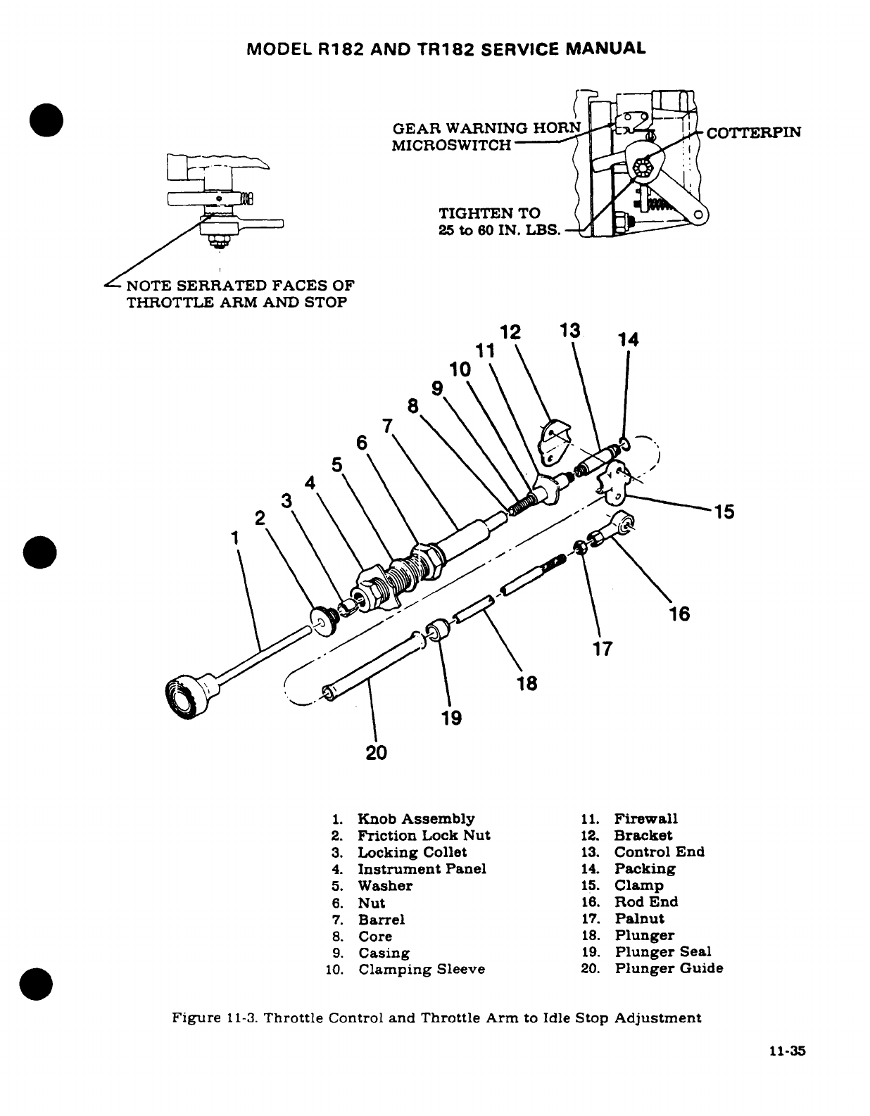
MODEL
R182
AND
TR182
SERVICE
MANUAL
GEAR
WARNING
HORN
COTERPIN
MICROSWITCH/
l
TIGHTEN
TO
25
to
60
IN. LBS.
NOTE
SERRATED
FACES
OF
THROTTLE
ARM
AND
STOP
12
13
14
11
10
2
\ \ \
Clamp
15
\
\
\
6. \
16
17
18
19
20
1.
Knob
Assembly
11.
Firewall
2.
Friction
Lock
Nut
12.
Bracket
3.
Locking
Collet
13.
Control
End
4.
Instrument
Panel
14.
Packing
5.
Washer
15.
Clamp
6.
Nut
16.
Rod
End
7.
Barrel
17.
Palnut
8.
Core
18.
Plunger
9.
Casing
19.
Plunger
Seal
10.
Clamping
Sleeve
20.
Plunger
Guide
Figure
11-3.
Throttle
Control
and
Throttle
Arm
to
Idle
Stop
Adjustment
11-35
MODEL
R182
AND
TR182
SERVICE
MANUAL
f.
Bend
the
wire
tip
90
degrees
to
prevent
it
from
being
withdrawn
if
the
attaching
nut
should
become
loose.
g.
When
installing
a
new
control,
it
may
be
necessary
to
shorten
the
wire
and/
or
control
housing.
h.
The
mixture
arm
on
the
carburetor
must
contact
the stops
in
each
direction,
and
the
control should
have approximately
1/8
inch
cushion
when
pushed
in.
NOTE
Refer
to
the inspection
chart
in
Section
2
for
inspection,
lubrication
and/or
replacement
interval
for
the
mixture
control.
11-72.
CARBURETOR
HEAT
CONTROL.
a.
Loosen
clamp
securing
the
control
to
the
bracket
on
engine.
b.
Push
control
full
in,
then
pull
it
out
approximately
1/8
inch
from
panel
for
cushion.
c.
Shift
control
housing
in
its
clamp
so
that
the
valve
in
the
airbox
is
seated
in
the
full
open
position.
Tighten
clamp
in
this
position.
d.
Pull
out
on
the
control
and
check
that
the
air
valve
inside
the
airbox
seats
in the
opposite
direction.
e.
Check
that
bolt
and
nut
on
the
air
valve lever secures
the
control
wire
and
that
the
bolt
will
swivel
in
the
lever.
f.
Bend
the
wire
tip
90
degrees
to
prevent
it
from
being
withdrawn
if
the
attaching
nut
should
become
loose.
NOTE
Refer
to
the inspection
chart
in
Section
2
for
inspection,
lubrication
and/or
replacement
interval
for the
carbure-
tor heat control.
11-73.
PROPELLER
CONTROL.
(Refer
to
Section
13.)
11-74.
STARTING
SYSTEM.
11-75.
DESCRIPTION.
The
starting
system
employs
an
electrical
starter
motor
mounted
at
the
front
(propeller
end)
lower
left
side
of
the
engine.
A
starter
solenoid
is
activated
by the
ignition
key
on
the
instrument
panel.
When
the
solenoid
is
activated,
its contacts
close
and
electrical
current energizes
the
starter
motor.
Initial
rotation
of
the
starter
armature
shaft,
engaged
with
the
reduction
gear,
drives
the
Bendix
shaft
and
pinion.
When
the
armature
turns
the
reduction
gear,
the
Bendix
drive pinion
meshes
with
the
crankshaft
ring
gear
assembly
by
inertia
and action
of
the screw
threads
within
the
Bendix
sleeve.
A
detent
pin
engages
in
a
notch
in
the
screw
threads
which
prevents
demeshing
if
the
engine
fails
to
start
when
the
starting
circuit
is
de-energized.
When
the
engine
reaches
a
predetermined
speed.
centrifugal
action
forces the
detent
pin
out
of
the
notch
in
the
screw
shaft
and
allows
the
pinion
to
demesh
from
the
ring
gear.
11-36
MODEL
R182
AND
TR182
SERVICE
MANUAL
CAUTION
Never
operate
the
starter
motor
more
than
12
seconds at
a
time.
Allow
starter
motor
to
cool
between
cranking
periods
to
avoid
overheating.
Longer
cranking
periods
without
cooling time
will
shorten
the
life
of
the
starter
motor.
11-76.
PRIMARY
MAINTENANCE.
The
starting
circuit
should
be
inspected
at
regular
intervals.
the
frequency
of
which
should
be
determined
by
the
service
and
conditions
under
which
the
equipment
is
operated.
Inspect
the
battery
and
wiring.
Check
battery
for
fully
charged
condition,
proper
electrolyte
level
with
approved
water
and
terminals
for
cleanliness.
Inspect
wiring
to
be
sure
that
all
connections
are
clean
and
tight
and
that
the
wiring
insulation
is
sound.
Check
that
the
brushes
slide
freely
in
their
holders
and
make
full
contact
on
the
commutator.
When
brushes
are
worn
to
one-half
of
their
original
length,
install
new
brushes
(compare
brushes
with
new
ones).
Check
the
commutator
for
uneven
wear.
excessive
glazing
or
evidence
of
excessive
arcing.
If
the
commutator
is
only
slightly
dirty.
glazed
or
discolored,
it
may
be
cleaned
with
a
strip
of
No.
00
or
No.
000
sandpaper.
If
the
commutator
is
rough
or
worn,
it
should
be
turned
in a
lathe
and
the
mica
undercut.
Inspect
the
armature
shaft
for
rough
bearing
surfaces.
New
brushes
should
be
properly
seated
when
installing
by
wrapping
a
strip
of
No.
00
sandpaper
around
the
commutator
(with
sanding
side
out)
1-1/4
to
1-1/2
times maximum.
Drop
brushes
on
sandpaper
covered
commutator
and
turn
armature
slowly
in
the
direction
of
normal
rotation.
Clean
sanding
dust
from
motor
after
sanding.
11-77.
STARTER
MOTOR.
.
11-78.
REMOVAL
AND
INSTALLATION.
a.
Remove
engine
cowling
in
accordance
with
paragraph
11-3.
CAUTION
When
disconnecting
or
connecting
the
starter
cable.
do
not
permit
starter
terminal
bolt
to
rotate.
Rotation
of
the
bolt
could
break the
conductor
between
terminal
and
field
coils
causing
the
starter
to
be
inoperative.
b.
Disconnect
electrical
cable
at
starter
motor.
Insulate
the
disconnected
cable
terminal
as
a
safety
precaution.
c.
Remove
three
nuts
and
washers
and
one
bolt
securing
starter
to
crankcase.
Work
starter
from engine.
d.
To
install
starter,
position
starter
on
mounting
pad,
aligning
dowel
pins
in
starter
mounting
pad with
holes
in
mounting
pad
on
engine.
e.
Secure
starter
with
washer,
lockwasher
and
nut
in
three
places
and
install
bolt
and
washers.
f.
Tighten
nuts
and
bolt
evenly
to
a
torque
value
of
150
lb-in.
g.
Connect
electrical
cable
to
starter
terminal
and
install
engine
cowling.
11-37
MODEL
R182
AND
TR182
SERVICE
MANUAL
11-79.
TROUBLE SHOOTING.
TROUBLE
PROBABLE
CAUSE
REMEDY
STARTER
WILL NOT
Defective
master
switch
Check
continuity
of
mas-
OPERATE.
or
circuit.
ter
switch
and
circuit.
Install
new
switch
or
wires.
Defective
starter
switch
Check
continuity
of
switch
or
switch
circuit.
and
circuit.
Install
new
switch
or
wires.
Defective
starter
motor.
Check
voltage
to
starter.
If
voltage
is
present.
re-
move,
repair or
install
new
starter
motor.
STARTER
MOTOR
RUNS,
Defective
Bendix drive.
Remove
starter
and
in-
BUT
DOES NOT
TURN
spect
Bendix
drive.
CRANKSHAFT.
Replace
defective
parts.
Damaged
starter
pinion Inspect
starter
pinion
gear
gear
or
ring
gear.
and
ring
gear.
Replace
defective
parts.
STARTER
MOTOR
DRAGS.
Low
battery.
Check
battery. Charge
or
install
new
battery.
Starter
switch
or
relay
Install
serviceable
unit.
contacts
burned
or
dirty.
Defective
starter
motor
Inspect
cable.
power
cable.
Install
new
cable.
Loose
or
dirty
Inspect
connections.
connections.
Remove,
clean and
tighten
all terminal
connections.
Defective
starter
motor.
Check
starter
motor
brushes.
brush
spring
ten-
sion.
thrown
solder
on
brush
cover.
Repair
or
install
new
starter
motor.
Dirty
or
worn
Inspect commutator.
commutator.
Clean
and
turn
commutator.
STARTER
EXCESSIVELY
Worn
starter
pinion gear
Inspect
starter
pinion
gear
NOISY.
or
broken
teeth
on
ring
and
ring
gear.
Replace
gear.
defective
parts.
11-38
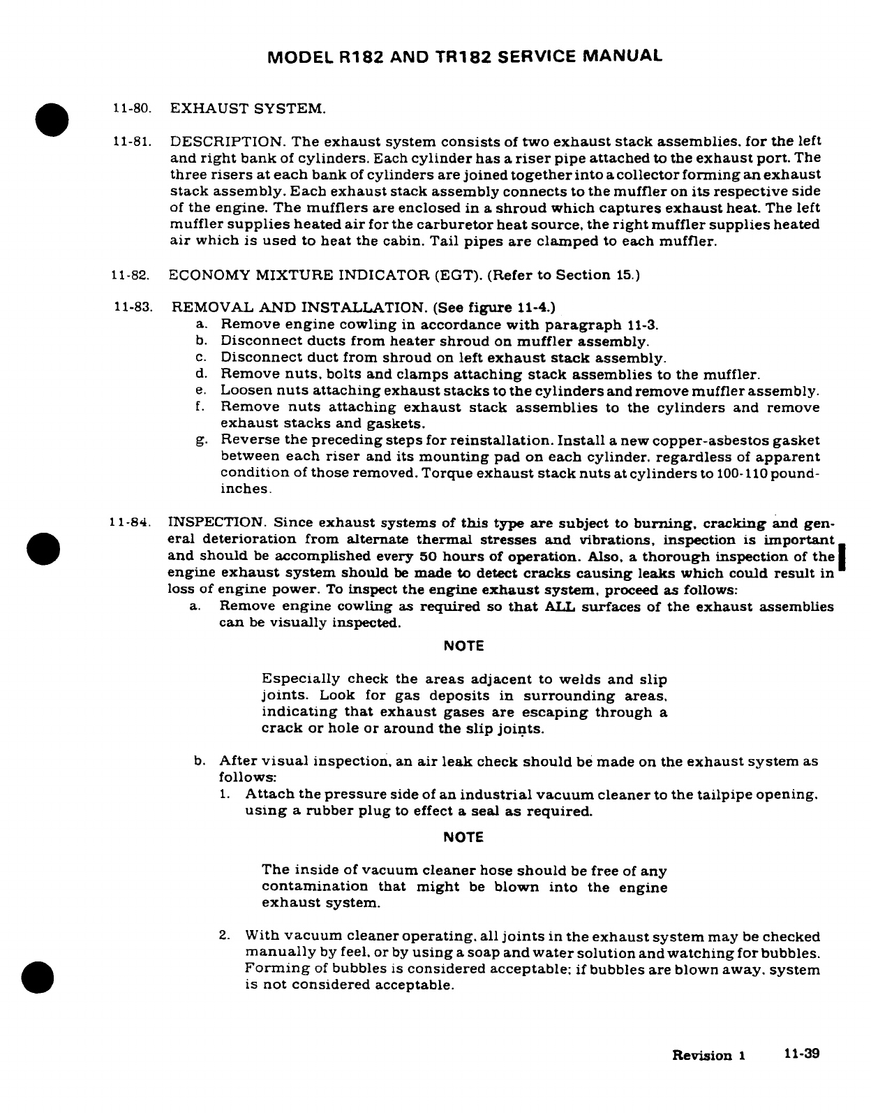
MODEL
R182
AND
TR182
SERVICE
MANUAL
11-80.
EXHAUST
SYSTEM.
11-81.
DESCRIPTION.
The
exhaust
system
consists
of
two
exhaust
stack
assemblies.
for
the
left
and
right
bank
of
cylinders.
Each
cylinder
has
a
riser
pipe attached
to
the
exhaust
port.
The
three
risers
at each
bank
of
cylinders
are
joined
together
into
a
collector
forming an
exhaust
stack
assembly.
Each
exhaust
stack
assembly connects
to
the
muffler
on
its
respective
side
of
the
engine.
The
mufflers
are
enclosed
in
a
shroud
which
captures
exhaust
heat.
The left
muffler
supplies
heated
air
for
the
carburetor
heat source,
the
right
muffler
supplies
heated
air
which
is
used
to
heat
the
cabin.
Tail
pipes
are
clamped
to
each
muffler.
11-82.
ECONOMY
MIXTURE
INDICATOR (EGT).
(Refer
to
Section
15.)
11-83.
REMOVAL
AND
INSTALLATION. (See
figure
11-4.)
a.
Remove
engine
cowling
in
accordance
with
paragraph
11-3.
b.
Disconnect
ducts
from
heater
shroud
on
muffler
assembly.
c.
Disconnect
duct
from
shroud
on
left
exhaust
stack
assembly.
d.
Remove
nuts,
bolts
and
clamps
attaching stack
assemblies
to
the muffler.
e.
Loosen
nuts
attaching
exhaust
stacks
to
the
cylinders
and
remove muffler
assembly.
f.
Remove
nuts
attaching
exhaust
stack
assemblies
to
the
cylinders
and
remove
exhaust
stacks
and
gaskets.
g.
Reverse
the
preceding
steps
for
reinstallation.
Install
a
new
copper-asbestos
gasket
between
each
riser
and
its
mounting
pad
on
each
cylinder.
regardless
of
apparent
condition
of
those
removed.
Torque
exhaust
stack
nuts
at
cylinders
to
100-110
pound-
inches.
11-84.
INSPECTION.
Since
exhaust
systems
of
this
type
are
subject
to
burning,
cracking
and
gen-
eral
deterioration
from
alternate
thermal stresses
and
vibrations, inspection
is
important
and
should
be
accomplished
every 50
hours
of
operation.
Also,
a
thorough
inspection
of
the
engine
exhaust
system
should
be
made
to
detect
cracks
causing
leaks
which
could
result
in
loss
of
engine
power.
To
inspect
the
engine
exhaust
system,
proceed
as
follows:
a.
Remove
engine
cowling as
required
so
that
ALL
surfaces
of
the
exhaust
assemblies
can
be
visually
inspected.
NOTE
Especially
check
the
areas
adjacent
to
welds
and
slip
joints.
Look
for
gas deposits
in
surrounding
areas,
indicating
that
exhaust
gases
are
escaping
through
a
crack
or
hole
or
around
the
slip
joints.
b.
After
visual
inspection,
an
air
leak
check
should
be
made
on
the
exhaust
system
as
follows:
1.
Attach
the
pressure
side
of
an
industrial
vacuum
cleaner
to
the
tailpipe
opening.
using
a
rubber
plug
to
effect
a
seal
as
required.
NOTE
The
inside
of
vacuum
cleaner
hose
should
be
free
of
any
contamination
that
might
be
blown into
the
engine
exhaust
system.
2.
With
vacuum
cleaner
operating,
all
joints
in
the
exhaust
system
may
be
checked
manually
by feel,
or
by
using
a
soap
and
water
solution
and
watching
for bubbles.
Forming
of
bubbles
is
considered
acceptable:
if
bubbles
are
blown
away. system
is
not considered
acceptable.
Revision
1
11-39
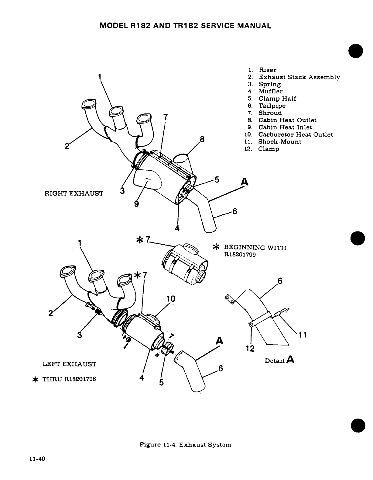
MODEL
R182
AND
TR182
SERVICE
MANUAL
1.
Riser
~~~~~~~1 ~~2.
Exhaust
Stack
Assembly
3.
Spring
4.
Muffler
5.
Clamp
Half
0\^=s\n~~~ \s=\
~6.
Tailpipe
0r \ (-~^\ ,oi- 77.
Shroud
7 \ \
8.
Cabin
Heat
Outlet
9.
Cabin
Heat Inlet
10.
Carburetor
Heat
Outlet
8
11.
Shock-Mount
2
12.
Clamp
/6
RIGHT
EXHAUST
3/
·
17~
'~I
^
*
:BEGINNING
WITH
R18201799
10
2E
EXAST/\1t
et
12
LEFT
EXHAUST
Detail
/ / \ '
*
THRU
R18201798
4
Figure
11-4.
Exhaust
System
11-40
MODEL
R182
AND
TR182
SERVICE
MANUAL
c.
Where
a
surface
is
not accessible
for
a
visual
inspection. or
for
a
more
positive
test.
the
following procedure
is
recommended.
1.
Remove
exhaust
stack
assemblies.
2.
Use
rubber
expansion
plugs
to
seal
openings.
3.
Using
a
manometer
or gage,
apply
approximately
1-1/2
psi
(3
inches
of
mercury)
air
pressure
while
each
stack
assembly
is
submerged
in
water.
Any
leaks
will
appear
as
bubbles
and
can
be
readily
detected.
4.
It
is
recommended
that
exhaust
stacks
found
defective
be
replaced
before
the
next
flight.
d.
After
installation
of
exhaust
system
components
perform
the
inspection
in
step
"b"
of
this
paragraph
to
ascertain
that
system
is
acceptable.
11-85.
EXTREME
WEATHER
MAINTENANCE.
11-86.
COLD
WEATHER.
Cold
weather
starting
is
made
easier
by
the
use
of
the
engine
primer
system
and
installation
of
a
ground
service
receptacle.
The
primer
system
is
manually
operated
from
the
cabin.
Fuel
is
supplied
by
a
line
from
the
fuel
strainer
to
the
plunger.
Operating
the
primer
forces
fuel
to
the
engine.
With
an
external
power
receptacle
installed.
an
external
power source
may
be
connected
to
assist
in
cold
weather
starting.
Refer
to
Section
16
for
use
of
the
external
power
receptacle.
The
following may
also
be
used
to
assist
engine
starting
in
extreme
cold
weather.
After
the
last flight
of
the day,
drain
the engine
oil
into
a
clean
container
so
the
oil
can
be
preheated.
Cover
the
engine
to
prevent
ice
or
snow
from
collecting
inside
the
cowling.
When
preparing
the
aircraft
for
flight
or
engine runup
after
these conditions
have
been
followed,
preheat
the
drained
engine
oil.
WARNING
Do
not
heat
the
oil
above
121°C
(250°F).
A
flash fire
may
result.
Before
pulling
the
propeller through,
ascertain
that
the
magneto
switch
is
in
the
OFF
position
to
prevent
accidental
firing
of
the
engine.
After
preheating
the
engine
oil,
gasoline
may
be
mixed
with the
heated
oil
in
a
ratio
of
1
part
gasoline
to
12
parts
engine
oil
before
pouring
into
the
engine
oil
sump.
If
the
free
air
temperature
is
below
minus
29°C
(-20°F),
the
engine
compartment
should
be
preheated
by
a
ground
heater.
Pre-heating
the
engine
compartment
is
accomplished
by
inducing
heated
air
up
through
the
engine
cowl
flap
openings,
thus
heating
both
the
cylinder
and
oil.
After
the
engine
compartment
has
been
preheated.
inspect
all
engine
drain
and
vent
lines
for
presence
of
ice.
After
this
procedure has
been
complied
with,
pull
propeller
through
several
revolutions
by
hand
before
attempting
to
start
the
engine.
CAUTION
Due
to
the
desludging
effect
of
the
diluted
oil,
engine
operation
should
be
observed
closely
during
the
initial
warm-up
of
the
engine.
Engines
that
have
considerable
amount
of
operational
hours
accumulated
since
their
last
dilution
period may
be
seriously
affected
by
the
dilution
process.
This
will
be
caused
by
the
diluted
oil
dislodging
sludge
and
carbon deposits
within
the
engine.This
11-41
MODEL
R182
AND
TR182
SERVICE
MANUAL
residue
will
collect
in
the oil
sump
and
possibly
clog
the
screened
inlet
to
the
oil sump.
Small
deposits
may
actually
enter
the
oil
sump
and
be
trapped
by
the
main
oil
filter
screen.
Partial
or
complete
loss
of
engine
lubrica-
tion
may
result
from
either
condition.
If
these
conditions
are
anticipated
after
oil
dilution,
the
engine should
be
run
for
several
minutes
at
normal
operating
temperatures
and
then
stopped
and
inspected
for
evidence
of
sludge
and
carbon
deposits
in
the oil
sump
and
oil
filter
screen.
Future occurrence
of
this
condition can
be
prevented
by
diluting the
oil
prior
to
each
engine
oil
change. This
will
also
prevent
the
accumulation
of
the
sludge
and
carbon
deposits.
11-87.
SEACOAST
AND
HUMID
AREAS.
In
salt
water
areas special
care
should
be
taken
to
keep
the
engine,
accessories
and
airframe
clean
to
prevent
oxidation.
In
humid
areas,
fuel
and
oil
should
be
checked
frequently
and
drained
of
condensation
to
prevent
corrosion.
11-88.
GROUND
SERVICE
RECEPTACLE.
With
the
ground
service
receptacle
installed,
the
use
of
an
external
power
source
is
recommended
for
cold
weather
starting,
and
lengthy
mainte-
nance
of
the
aircraft
electrical
system.
Refer
to
Section
16
for
additional information.
11-42
MODEL
R182
AND
TR182
SERVICE
MANUAL
SECTION
11A
ENGINE
(TURBOCHARGED)
WARNING
When
performing
any
inspection
or
maintenance
that
required
turning
on
the
master
switch,
installing
a
battery,
or
pulling
the
propeller
through
by
hand,
treat
the
propeller
as
if
the
ignition
switch
were
ON.
Do
not
stand,
nor
allow
anyone
else
to
stand,
within
the
arc
of
the
propeller,
since
a
loose
or
broken
wire,
or
a
component
malfunction,
could
cause
the
propeller
to
rotate.
NOTE
For
additional
information
covering
turbocharger
and
component
maintenance,
overhaul
and
trouble-shooting
refer
to
manufacturer's
overhaul
manual.
Page
No.
TABLE
OF
CONTENTS
Aerofiche/
Manual
ENGINE
COWLING
..........
3A4/11A-2
Description
.............
3A18/11A-16
Description
..............
3A4/11
A-2
Removal/Installation
.......
3A18/11A-16
Removal/Installation
........
3A4/11A-2
Repair
.................
3A18/11A-16
CleaningInspection
.........
3A4/11A-2
Painting
.................
3A18/11A-16
Repair
...................
3A4/11A-2
Shock-Mount
Pads
..........
3A18/11A-16
COWL
FLAPS
...............
3A4/11A-2
OIL
SYSTEM
...............
3A18/11A-16
Description
...............
3A4/11A-2
Description
...............
3A18/11A-16
Removal
Installation
........
3A4/11A-2
Trouble
Shooting
...........
3A1911A-16A
Rigging
............... .
3A4/11A-2
Trouble
Shooting
(Oil
Leak)
..
.3A1911/A-16A
ENGINE
...................
3A4/11A-2
Oil
Cooler
................
3A21
11A-17
Description
..........
.....
3A4/11A-2
Description
.............
3A21
11A-17
Engine
Data
..............
3A5/11A-3 FUEL
SYSTEM
..............
3A21/11A-17
Time
Between
Overhaul
(TBO)
.
3A7/11A-5
Description
...............
3A21
11A-17
Overspeed
Limit
...........
3A7/11A-5
Carburetor
...............
3A21
11A-17
Trouble
Shooting
...........
3A7/11A-5
Removal/Installation
.......
3A21
11A-17
Static
Run-Up
Procedures
....
3A12/11A-10
Idle
Speed
and
Mixture
Removal
................
3A12/11A-10
Adjustments
..........
3A21/11A-17
Cleaning
...............
3A14/11A-12
INDUCTION
AIR SYSTEM
.....
3A22/11A-18
Accessories
Removal
.......
3A14/11A-12
Installation
of
Induction
Inspection
.............
3A15/11A-13 Air
System
Ducts
.........
3A22
11A-18
Build-Up
..............
3A15/11A-13
Filter
Removal/Installation
....
3A2211 A-18
Installation
............
3A15
11A-13
Cleaning/Inspection
.......
3A22/11A-18
Flexible
Fluid
Hoses
........
3A17/11A-15
Airbox
Removal/Installation
.. .
3A23
11A-19
Leak
Test
...............
3A17/11A-15
Cleaning/Inspection
.......
3A23
11A-19
Replacement
.............
3A17
11A-15
IGNITION
SYSTEM
..........
3A23/11A-19
Engine
Baffles
.............
3A17
11A-15
Description
...............
3A23
11A-19
Description
.............
3A17
11A-15
Trouble
Shooting
...........
3A23
11A-19
Cleaning Inspection
.......
3A17
/
11A-15
Magnetos
................
3A23
11A-19
Removal
Installation
.......
3A18
11A-16
Description
............
3A23'11A-19
Repair
................
3A18
11A-16
Removal/Installation
.......
3A23
11A-19
Engine
Mount
.............
3A18
11A-16
Timing
Internal
..........
3B1
llA-21
Revision
11A-1
MODEL
R182
AND
TR182
SERVICE
MANUAL
Timing
to
Engine
.........
3B1
11A-21
Description
...............
3B5/11A-25
Maintenance
.............
3B.
11A-21
Removal/Installation
........
3B5
11A-25
Check
.................
3B1/11A-21
Inspection
................
3B5
11A-25
Spark
Plugs
..............
3B1/11A-21
TURBOCHARGER
...........
3B8/11A-28
ENGINE
CONTROLS
.........
3B1/11A-21
Description
...............
3B8
11A-28
Throttle
Control
Removal/Installation
........
3B12
11A-32
(TR18201628)
.............
3B1/11A-21
ECONOMY
MIXTURE
Throttle
Control
INDICATOR
(EGT)
..........
3B
12
11A-32
(TR18201629
&
ON)
........
3B4/11A-24 EXTREME WEATHER
Mixture
Control
...........
3B5/11A-25
MAINTENANCE
............
3B12
11A-32
Carburetor
Heat
Control
.....
3B5/11A-25
Cold
Weather
..............
3B12 11A-32
Propeller
Control
..........
3B5/11A-25
Seacoast/Humid
Areas
.......
3B13
11A-33
STARTING
SYSTEM
..........
3B5/11A-25
GROUND
SERVICE
EXHAUST
SYSTEM
..........
3B5/11A-25
RECEPTACLE
.............
3B13
11A-33
11A-1.
ENGINE
COWLING.
11A-2.
DESCRIPTION.
The
engine
cowling
is
divided
into
major
removable
segments.
The
upper
RH
segment
has
an
oil
dipstick
and
remote
fuel
strainer
drain
control
access door.
The
upper
center
cowl
skin
has
the
oil
filler
neck
access
door,
and
the
lower
LH
panel
contains
the
turbocharger
access
door. Controllable
cowl
flaps
are
integral
with
the
lower
trailing
edge
of cowl
skin.
They
are
hinged
at
the
front
edge,
and
controlled
manually
to
maintain
efficient
engine
operating
temperature.
The
upper
center
and
lower
cowl
segments
are
screw
fastened
at
the
nose
cap,
but
RH
and
LH
segments
use
quick
release
fasteners
all
around
for
easy
access.
Cowl
mounted landing
and
taxi
lights
are
mounted
in
the
nose
cap
lower
cowling.
11A-3.
REMOVAL
AND
INSTALLATION.
(Refer
to
Section
11.)
11A-4.
CLEANING
AND
INSPECTION.
(Refer to
Section
11.)
11A-5.
REPAIR.
(Refer
to
Section
17.)
11A-6.
COWL
FLAPS.
11A-7.
DESCRIPTION.
Cowl
flaps
are provided
to
aid
in
controlling
efficient
engine
temperature.
Two
cowl
flaps,
operated
by
a
single
control
in
the
cabin,
are
located
at the
aft
edge
of
the
lower
cowl
segment.
11A-8.
REMOVAL
AND
INSTALLATION.
(Refer
to
Section
11.)
11A-9.
RIGGING.
(Refer to
Section
11.)
11A-10.
ENGINE.
11A-11.
DESCRIPTION.
An
air
cooled,
wet-sump,
six-cylinder, horizontally-opposed,
direct-drive.
carbureted,
turbocharged
Avco
Lycoming
O-540-L
series
engine,
driving
a
constant-speed
propeller
is
used
to
power
the
aircraft.
Refer
to
paragrpah
11A-12
for
engine performance
data.
Repair
and
overhaul
of
the engine,
turbocharger
controls, accessories,
and
propeller
are
covered
in
the
appropriate
publications,
which
are
issued
by
the
respective manufactur-
ers.
These
publications
are available
from
Cessna
Service
Parts
Center.
11A-2
Revision
1
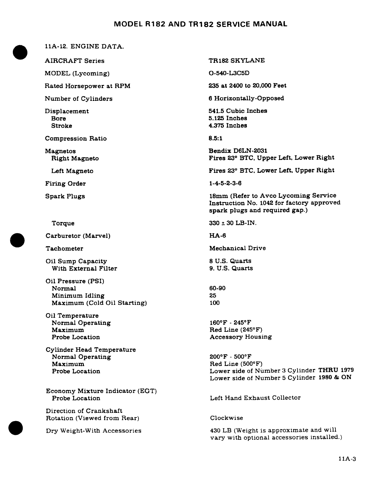
MODEL
R182
AND
TR182
SERVICE
MANUAL
11A-12.
ENGINE
DATA.
AIRCRAFT
Series
TR182
SKYLANE
MODEL
(Lycoming)
O-540-L3C5D
Rated
Horsepower at
RPM
235
at
2400
to
20,000
Feet
Number
of
Cylinders
6
Horizontally-Opposed
Displacement
541.5
Cubic
Inches
Bore
5.125
Inches
Stroke
4.375
Inches
Compression
Ratio
8.5:1
Magnetos
Bendix
D6LN-2031
Right
Magneto
Fires
23
°
BTC,
Upper
Left,
Lower
Right
Left
Magneto
Fires
23
°
BTC,
Lower
Left,
Upper
Right
Firing
Order
1-4-5-2-3-6
Spark Plugs
18mm
(Refer
to
Avco
Lycoming
Service
Instruction
No.
1042
for
factory
approved
spark
plugs
and
required
gap.)
Torque
330
+
30
LB-IN.
Carburetor
(Marvel)
HA-6
Tachometer
Mechanical
Drive
Oil
Sump
Capacity
8
U.S.
Quarts
With
External
Filter
9.
U.S.
Quarts
Oil
Pressure
(PSI)
Normal
60-90
Minimum
Idling
25
Maximum
(Cold
Oil
Starting)
100
Oil
Temperature
Normal
Operating
160
F
-
245°F
Maximum
Red
Line
(245°F)
Probe
Location
Accessory
Housing
Cylinder
Head
Temperature
Normal
Operating
200
F
-
500
F
Maximum
Red
Line
(500°F)
Probe
Location
Lower side
of
Number
3
Cylinder
THRU
1979
Lower
side
of
Number
5
Cylinder
1980
&
ON
Economy
Mixture
Indicator
(EGT)
Probe
Location
Left
Hand
Exhaust
Collector
Direction
of
Crankshaft
Rotation
(Viewed
from
Rear)
Clockwise
Dry
Weight-With
Accessories
430
LB
(Weight
is
approximate
and
will
vary
with
optional
accessories
installed.)
11A-3
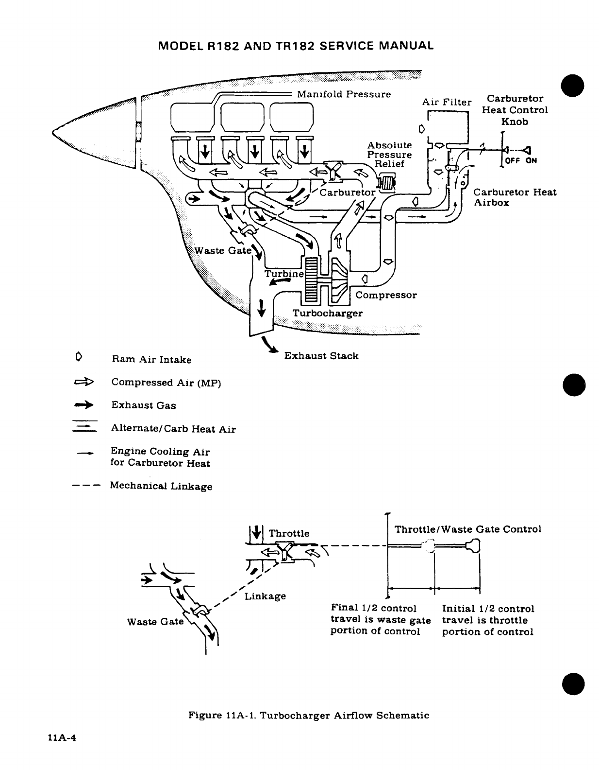
MODEL
R182
AND
TR182
SERVICE
MANUAL
Manifold
Pressure
Air
Filter
Carburetor
^-^ "I (
=)-- f(---
1(---- <^ H^
vHeat
Control
Knob
< T r
' TAbsolute
v:
It-
a _ .
Relief
OFF
ON
-CCarburetori
Carburetor
Heat
^^--
Carbueor
_
HeaAirbox
:Waste
Gate^l
J
L I
i\ii
....
Turbine
Compressor
' +
|..
Turbocharger
O
Ram
Air
Intake
Exhaust
Stack
cL=>
Compressed
Air
(MP)
<-0
Exhaust
Gas
Alternate/Carb
Heat
Air
Engine
Cooling
Air
for
Carburetor
Heat
---
Mechanical
Linkage
\
Throttle
;Throttle/Waste
Gate
Control
/\^l ,
Linkage
/^;z-
Final
1/2
control
Initial
1/2
control
Waste
Galte\»\ Lnatravel is
waste gate
travel
is
throttle
Wa~st~e~ Gatportion
of
control
portion
of
control
Figure
11A-1.
Turbocharger
Airflow
Schematic
11A-4
MODEL
R182
AND
TR182
SERVICE
MANUAL
11A-13.
TIME
BETWEEN
OVERHAUL
(TBO).
AvcoLycoming
recommends
engine
overhaul
at
2000
hours
operating
time
for
the
O-540-L3C5D
series
engines.
Refer
to
Avco
Lycoming
Service
Instruction
1009AA,
and
to
any
superseding
instructions,
revisions
or
supplements
thereto,
for
further
recommendations.
At
the
time
of
overhaul,
engine
accessories
should
be
overhauled.
Refer
to
Section
13
for
propeller
and
governor
overhaul
periods.
11A-14.
OVERSPEED
LIMITATIONS.
The
engine
must
not
be
operated
above
specified
maximum
continuous
RPM.
If
inadvertent
overspeed
occurs,
refer
to
Avco
Lycoming
Bulletin
369F,
and any
superseding
bulletins,
revisions,
or
supplements
for
complete
coverage.
11A-15.
TROUBLE
SHOOTING.
TROUBLE
PROBABLE CAUSE
REMEDY
ENGINE
WILL
NOT
Improper
starting
Refer
to
Pilot's
Operating
START.
procedure.
Handbook.
Fuel
tanks
empty.
Visually inspect
cells.
Fill
with
proper
grade
and
quantity
of
gasoline.
Mixture
control
in
the
Move
control
to
the
full
IDLE
CUT-OFF
position.
RICH
position.
Fuel
selector
valve
in
Place
selector
valve
in
the
OFF
position.
ON
position
to a
cell
known
to
contain
gasoline.
Engine
flooded.
Refer
to
Pilot's
Operating
Handbook.
Water
in
fuel
system.
Open
fuel
strainer
drain
and
check for
water.
If
water
is
present, drain
fuel
cell
sumps,
lines,
strainer
and
carburetor.
Carburetor
screen
or
fuel
Remove
carburetor
and
strainer
plugged.
clean
thoroughly.
Refer
to
Section
12
for
fuel
strainer
cleaning.
Fuel
contamination.
Drain
all
fuel and
flush
out
fuel
system.
Clean
all
screens,
fuel
lines,
strainer
and
carburetor.
Defective
carburetor. Repair
or
replace
carburetor.
11A-5
MODEL
R182
AND
TR182
SERVICE
MANUAL
11A-15.
TROUBLE
SHOOTING
(Cont).
TROUBLE
PROBABLE
CAUSE
REMEDY
ENGINE
WILL
Vaporized
fuel.
(Most
Refer
to
Pilot's
Operating
NOT
START
(Cont).
likely
to
occur
in
hot
Handbook.
weather
with a
hot
engine.)
Defective
aircraft
fuel
Refer
to
Section
12.
system.
Defective
ignition
system.
Refer
to
paragraph
11-64.
Defective
magneto
switch
Check
continuity.
Repair
or
grounded
magneto
or
replace
switch
or
leads.
leads.
Spark
plugs
fouled.
Remove,
clean
and
regap
plugs.
Test
harness
cables
to
persistently
fouled
plugs.
Replace
if
defective.
ENGINE
STARTS
BUT
Water
in
fuel
system.
Open
fuel
strainer
drain
and
DIES,
OR
WILL
NOT
and
check
for
water.
If
IDLE.
water
is
present,
drain
fuel
cell
sumps,
lines,
strainer
and
carburetor.
Propeller
control
set
in
Use
low
pitch
(high
RPM)
high
pitch
position
position
for
all
ground
(low
RPM).
operation.
Vaporized
fuel.
(Most
Refer
to
Pilot's
Operating
likely
to
occur
in hot
Handbook.
weather
with
a
hot
engine.)
Induction
air
leaks.
Check
visually.
Correct
the
cause
of
leaks.
Idle
stop
screw
or
idle Refer to
paragraph
11A-46.
mixture
incorrectly
adjusted.
Carburetor idling
jet
Clean
carburetor
and
fuel
plugged.
strainer.
Refer to
Section
12
for
fuel
strainer.
Spark
plugs
fouled
or
Remove,
clean and
regap
improperly
gapped.
plugs.
Replace
if defective.
11A-6
MODEL
R182
AND
TR182
SERVICE
MANUAL
11A-15.
TROUBLE
SHOOTING (Cont).
TROUBLE
PROBABLE
CAUSE
REMEDY
ENGINE
STARTS
BUT
Manual
primer
leaking.
Disconnect
primer
outlet
DIES.
OR
WILL
NOT
line.
If
fuel
leaks through
IDLE
(Cont).
primer,
repair
or
replace
primer.
Defective
ignition
system.
Refer
to
paragraph
11-64.
Fuel
boost
pump.
Check
fuel
pressure.
Leaking
float
valve
or
Perform
an
idle
mixture
float
level
set
too
check.
Attempt
to
remove
high.
any
rich
indication
with
the
idle
mixture
adjustment.
If
the
rich indication
cannot
be
removed,
the
float
valve
is
leaking
or
the
float
the
level
is
set
too
high.
Re-
place
defective
parts,
reset
float
level.
Defective
carburetor.
If
engine
will
start
when
primed
but
stops
when
priming
is
discontinued,
with
mixture
control
in
full
RICH
position,
the
carburetor
is
defective.
Repair
or
replace
car-
buretor.
Defective
fuel
system.
Refer
to
Section
12.
Turbocharger
wheels
Replace
turbocharger.
rubbing.
Improperly
adjusted
or
Refer
to
paragraph
11A-64
defective
waste
gate. or
11A-65.
Leak
in
turbocharger
Correct
cause
of
leaks.
Re-
discharge
pressure
pair
or
replace
damaged
system.
parts.
Malfunctioning
turbo-
Check
operation, listen
for
charger.
unusual
noise.
Check
oper-
ation
of
waste
gate
valve
and
for
exhaust
system
defects.
Tighten
loose
con-
nections.
Defective
engine.
Check
compression.
Listen
for
unusual
engine
noises.
Engine
repair
is
required.
11A-7
MODEL
R182
AND
TR182
SERVICE
MANUAL
11A-15.
TROUBLE
SHOOTING
(Cont).
TROUBLE
PROBABLE
CAUSE
REMEDY
ENGINE
RUNS
ROUGHLY,
Restriction
in
aircraft
Refer
to
Section
12.
WILL
NOT
ACCELERATE
fuel
system.
PROPERLY,
OR
LACKS
POWER.
Worn
or
improperly
Check
visually.
Replace
rigged
throttle or worn
linkage. Rig
properly.
mixture
control.
Fuel
pump
output
low.
Check
fuel
pressure.
Restricted
induction
air
Check
visually.
Clean
in
filter.
accordance
with
Section
2.
Propeller
control
in
high
Use
low
pitch
(high
RPM)
pitch
(low
RPM)
posi-
position
for
all
ground
tion.
operations.
Fuel
contamination.
Check
all
screens
in
fuel
system.
Drain
all
fuel
and
flush
out
system.
Clean
all
screens,
lines,
strainer
and
carburetor.
Low
upper
deck
Check
absolute
pressure
pressure.
relief
valve.
Float
level
set
too
low.
Check
and
reset
float
level.
Spark
plugs
fouled
or
Remove,
clean
and
regap
improperly
gapped.
plugs.
Replace
if
defective.
Defective
ignition
system. Refer
to
paragraph
11-64.
Defective
carburetor.
If
engine
will
start
when
primed
but
stops
when
priming
is
discontinued.
with mixture
control
in
full
RICH
position,
the
carburetor
is
defective.
Re-
pair
or
replace carburetor.
Cracked
engine
mount.
Inspect
and
repair
or
re-
place
mount
as
required.
11A-8
MODEL
R182
AND
TR182
SERVICE
MANUAL
11A-15.
TROUBLE
SHOOTING
(Cont).
TROUBLE
PROBABLE
CAUSE
REMEDY
ENGINE
RUNS
ROUGHLY,
Defective
mounting
Inspect and
install
new
WILL
NOT
ACCELERATE
bushings.
bushings
as
required.
PROPERLY.
OR
LACKS
POWER.
(Cont.)
Defective
engine.
Check
compression.
Listen
for
unusual
engine
noises. Engine
repair
is
required.
POOR
IDLE
CUT-OFF.
Worn
or
improperly
Check
that
idle
cut-off
rigged
mixture
control. stop
on
carburetor
is
contacted.
Replace
worn
linkage.
Rig
properly.
Manual
primer
leaking.
Disconnect
primer
outlet
line.
If
fuel
leaks
through
primer,
it is
defective.
Re-
pair
or
replace
primer.
Defective
carburetor.
Repair
or
replace
car-
buretor.
ENGINE
LACKS
POWER,
Carburetor heat
on.
Check
control.
REDUCTION
IN
MAXIMUM
MANIFOLD
PRESSURE.
Improperly
adjusted
Refer
to
paragraph
11A-64
waste
gate.
or
11A-65.
Loose
or
damaged
ex-
Inspect
entire
exhaust
sys-
haust
system.
tern
to
turbocharger
for
cracks
and
leaking
connec-
tions,
replace
damaged
parts.
Refer
to
paragraph
11A-73.
Malfunctioning
turbo-
Check
for
unusual
noise
in
charger
turbocharger.
If
malfunction
is
suspected,
remove
exhaust
and/or
air
inlet
connections
and
check
turbine
and
com-
pressor
wheels
for
damaged
blades.
Check
shaft bearing.
Replace
turbocharger
if
dam-
age
is
noted.
Leak
in
induction
Check
visually.
Correct the
system.
cause
of
leaks.
11A-9
MODEL
R182
AND
TR182
SERVICE
MANUAL
11A-16.
STATIC
RUN-UP
PROCEDURES.
If
low
engine
RPM
is
encountered
or
suspected,
a
static
run-up
should
be
conducted according
to
the
following procedures.
a.
Run
engine,
using
takeoff
power
and
mixture
settings.
first
with
airplane
facing
90
°
right
to
prevailing
wind,
and
second
with
airplane
facing
90
°
left
to
prevailing
wind
direction.
b.
Record
the
maximum
RPM
obtained
in
each
instance,
for
analysis.
NOTE
Daily
changes
in
atmospheric
pressure,
temperature,
and
humidity
will
have
a
slight
affect
on
static
run-up.
c.
Average
the
results
of
the
RPM
readings.
The
average
should
be
within
50
RPM
of
2350
RPM.
d.
If
the
average
reading
is
lower
than
minimum
limit,
the
following
checks
may
be
performed
to
determine
probable
discrepancy.
1.
Check
condition
of
induction
air
filter:
clean
if
required.
2.
Check
carburetor
heat
control
for
proper
adjustment.
If
it
is
partially
open.
it
would
cause
RPM
drop
(slight
power loss).
3.
Check
governor
control
for
proper rigging.
The
control
arm
should
be
limited
by
high
RPM
stop
on
governor
and
the
high
RPM
stop
screw
adjusted
so
the
above
average
RPM
is
within
tolerance.
Refer
to
Section
13
for
adjustment
procedures.
NOTE
If
verification
of
governor
operation
is
necessary,
the
governor
may
be
removed
from
the
engine,
and
a
flat
plate
installed
over
mount pad. Run
up
engine
to
deter-
mine
that
governor
was
adjusted
properly.
4.
Check
magneto
timing,
spark
plugs,
and
ignition
harness
for
settings
and
condition.
5.
Perform
an
engine
compression
check.
Refer
to
engine
manufacturer's
service
manual
for
procedures
and
requirements.
11A-17.
REMOVAL.
If
an
engine
is
to
be
placed
in
storage
or
returned
to
the
manufacturer
for
overhaul,
proper
preparatory
steps
should
be
taken for corrosion
prevention
prior
to
beginning
the
removal procedure.
Refer
to
Section
2
for
storage
preparation.
The
following
engine
removal
procedure
is
based upon
the engine
being
removed
from
the
aircraft
with
the
engine
mount
attached
to
the
firewall.
NOTE
Tag
each
item
when
disconnected
to
aid
in
identifying
wires,
hoses,
lines
and
control
linkages
when
engine
is
reinstalled.
Likewise,
shop
notes
made
during
removal
will
often
clarify reinstallation.
Protect
openings,
exposed
as
a
result
of
removing
or
disconnecting units.
against
entry
of
foreign
material
by
installing
covers
or
sealing
with
tape.
11A-10
MODEL
R182
AND
TR182
SERVICE
MANUAL
a.
Attach
a
tail
stand
of
suitable
capacity.
b.
Place
all
cabin
switches
in
the
OFF
position.
c.
Place
fuel
selector valve
in
the
OFF
position.
d.
Remove
engine
cowling
in
accordance
with
paragraph
11-3.
e.
Disconnect battery
cables
and
insulate
terminals
as
a
safety
precaution.
f.
Drain
fuel
strainer
and
lines
with
strainer
drain
control.
NOTE
During
the following
procedures, remove any
clamps
or
lacings
which
secure
controls, wires,
hoses
or
lines
to
the
engine,
engine
mount
or
attached
brackets,
so
they
will
not
interfere
with
engine
removal.
Some
of
the
items
listed
can
be
disconnected
at
more
than
one
place.
It
may
be
desirable
to
disconnect
some
of
these
items
at
other
than
the
places
indicated.
The
reason
for
engine
removal
should
be
the
governing
factor
in
deciding
at
which
point
to
disconnect
them.
Omit
any
of
the
items
which
are
not
present
on
a
particular
engine
installation.
g.
Drain
the
engine
oil
sump
and
oil
cooler.
h.
Disconnect
magneto
primary
lead
wires
at
magnetos.
WARNING
The
magnetos are
in a
SWITCH
ON
condition
when
the
switch wires
are
disconnected.
Ground
the
magneto
points
or
remove
the
high
tension
wires
from
the
magne-
tos
or
spark
plugs
to
prevent accidental
firing.
i.
Remove the
spinner
and
propeller
in
accordance with
Section
13.
Cover
exposed
end
of
crankshaft
flange
and
propeller
flange
to
prevent
entry
of
foreign
material.
j.
Disconnect
throttle
and
mixture controls
at
carburetor.
Remove
clamps
attaching
controls
to
engine
and
pull
controls
aft
clear
of
engine.
Use
care
to
avoid
bending
controls
too
sharply.
Note
EXACT
position,
size
and
number
of
attaching
washers
and
spacers
for
reference
on
reinstallation.
k.
Disconnect
propeller
governor
control at
governor.
Note
EXACT
position,
size
and
number
of
attaching washers
for
reference
on
reinstallation.
Remove
clamps
attaching
control
to
engine
and
pull
control
aft
clear
of
engine.
l.
Disconnect all
hot
and
cold
air
flexible
ducts
and
remove.
m.
Remove
exhaust
system
in
accordance
with
paragraph
11A-72.
n.
Disconnect
carburetor
heat
control
from
arm
on
airbox.
Remove
clamps
and
pull
control clear
of
engine.
o.
Disconnect
wires
and
cables
as
follows:
1.
Tachometer
drive shaft at
adapter.
CAUTION
When
disconnecting
starter
cable
do
not
permit
starter
terminal
bolt
to
rotate.
Rotation
of
the
bolt
could
break
the
conductor
between
bolt
and field
coils
causing
the
starter
to
be
inoperative.
11A-11
MODEL
R182
AND
TR182
SERVICE
MANUAL
2.
Starter
electrical
cable
at
starter.
3.
Cylinder
head
temperature
wire
at
probe.
4.
Carburetor
air
temperature
wires at
quick-disconnects.
5.
Electrical
wires
and
wire
shielding
ground
at
alternator.
6.
Exhaust
gas
temperature
wire
at
quick-disconnect.
7.
Remove
all
clamps
and
lacings
attaching
wires
or
cables
to
engine,
and
pull
wires
and
cables
aft
to
clear
engine.
p.
Disconnect
lines
and
hoses
as
follows:
1.
Vacuum
hose
at
vacuum
pump.
2.
Oil
breather
vent
lines
where
secured
to
the
engine.
WARNING
Residual
fuel
and oil
draining
from
disconnected lines
and
hoses
constitutes
a
fire
hazard.
Use
caution
to
prevent
accumulation
of
such
fuel
and
oil
when
lines
or
hoses
are
disconnected.
3.
Oil
temperature
bulb.
4.
Primer
line at
engine
fitting.
5.
Fuel
supply
hose
at
fuel
strainer.
6.
Oil
pressure
line
at
engine
fitting.
7.
Manifold
pressure
line
at
engine.
q.
Carefully
check
the
engine
again
to
ensure
ALL
hoses,
lines,
wires,
cables,
clamps
and
lacings
which
would
interfere
with
the
engine
removal
are
disconnected
or
removed.
Ensure
all
wires.
cables
and
engine
controls
have
been
pulled
aft
to
clear
the
engine.
CAUTION
Place
suitable
stand
under
tail
tie-down
ring
before
removing
engine.
The
loss
of
engine
weight
will cause
the
aircraft
to
be
tail
heavy.
r.
Attach
a
hoist
to
the
lifting lug
at
the
top
center
of
the
engine
crankcase.
Lift
engine
just
enough
to
relieve
the
weight
from the
engine
mount
pads.
s.
Remove
bolts
attaching
engine
to
engine
mount pads
and
slowly
hoist
engine
and
pull
it
forward.
Check
for any
items
which
would
interfere with
the
engine
removal.
Balance
the engine
by
hand and
carefully
guide
the
disconnected
parts
out
as
the
engine
is
removed.
t.
Remove
engine shock-mount
pads
and
bonding
straps.
11A-18.
CLEANING.
Clean
engine
in
accordance
with
instructions
in
Section
2.
11A-19.
ACCESSORIES
REMOVAL.
Removal
of
engine accessories
for
overhaul
or
for
engine
replacement
involves
stripping
parts,
accessories
and
components
from the
engine
to
reduce it
to
the
bare
engine.
During
the
removal process, items
removed
should
be
tagged
for
repair
or
replacement
as
required.
11A-12
MODEL
R182
AND
TR182
SERVICE
MANUAL
NOTE
Items
easily
confused
with
similar
items
should
be
tagged
to
provide
a
means
of
identification
when
being
installed
on
a
new
engine.
All
openings
exposed
by
the
removal
of
an
item
should
be
closed
by
installing
a
suitable
cover,
cap,
or
tape
over
the
opening.
This
will
prevent
entry
of
foreign
material.
11A-20.
INSPECTION.
For
specific
items
to
be
inspected,
refer
to
the
engine
manufacturer's
manual.
a.
Visually
inspect
the
engine
for
loose
nuts,
bolts,
cracks
and
fin
damage.
b.
Inspect
baffles,
baffle
seals
and
brackets for
cracks,
deterioration
and
breakage.
c.
Inspect
all
hoses
for
internal
swelling,
chafing
through
protective
plys,
cuts,
breaks,
stiffness,
damaged
threads
and loose
connections.
Excessive heat
on
hoses
will
cause
them
to
become
brittle
and
easily
broken. Hoses
and
lines
are
most likely
to
crack
or
break
near
the
end
fittings
and
support
points.
d.
Inspect
for
color
bleaching
of
the
end
fittings
or
severe
discoloration
of
the
hoses.
NOTE
Avoid
excessive
flexing
and
sharp
bends
when
examin-
ing
hoses
for
stiffness.
e.
Refer
to
Section
2
for
replacement
intervals
for
flexible
fluid
carrying
hoses
in
the
engine
compartment.
f.
For
major
engine
repairs,
refer
to
the
engine
manufacturer's
overhaul
and
repair
manual.
11A-21.
BUILD-UP.
Engine
build-up
consists
of
installation
of
parts,
accessories
and
components
to
the
basic
engine
to
build
up
an
engine
unit
ready
for
installation
on
the
aircraft.
All
safety
wire,
lockwashers,
nuts,
gaskets
and
rubber connections should
be
new
parts.
11A-22.
INSTALLATION.
Before
installing
the engine
on
the
aircraft, install
any items which
were
removed
from
the
engine
or
aircraft
after
the
engine
was
removed.
NOTE
Remove
all
protective covers,
plugs,
caps
and
identifica-
tion
tags
as
each
item
is
connected
or
installed.
Omit
any
items
not
present
on
a
particular
engine
installation.
a.
Hoist the
engine
to
a
point
near
the
engine mount.
b.
Install
engine
shock-mount
pads
as
illustrated
in
figure
11-2.
c.
Carefully
lower
engine
slowly
into
place
on
the
engine
mount.
Route
controls,
lines.
hoses
and
wires
in
place
as
the
engine
is
positioned
on
the
engine
mount
pads.
NOTE
Be
sure
engine
shock-mount pads.
spacers
and
washers
are
in
place
as
the
engine
is
lowered
into
position.
11A-13
MODEL
R182
AND
TR182
SERVICE
MANUAL
d.
Install
engine-to-mount bolts,
torque
bolts
to
450-500
lb-in.,
then
remove
the
hoist
and
support
stand placed
under
tail
tie-down
fitting.
e.
Route
throttle,
mixture
and
propeller
controls
to
their
respective
units
and
connect.
Secure controls
in
position
with
clamps.
f.
Route
carburetor heat
control
to
airbox
and
connect.
Secure
control
in
position
with
clamps.
NOTE
The
manufacturer
recommends
that
NS-40
(RAS-4)
(Snap-On-Tools
Corp.,
Kenosha,
Wisc.),
MIL-T-5544
(Thread
Compound
Antiseize,
Graphite
Petrolatum),
USP
Petrolatum
or
engine
oil
be
used
as
a
thread
lubri-
cant
and
to
seal
fittings.
Apply
sparingly
to
male
threads
omitting
first
two
threads
on
the fitting.
Use
care
so
lubricant
does
not
string
across
the
opening.
Be
sure
area
is
clean
to
prevent
fuel
contamination.
g.
Connect
lines
and
hoses
as
follows:
1.
Manifold
pressure
line
at
engine
fitting.
2.
Oil
pressure
line
at
engine
fitting.
3.
Fuel
supply
hose
at
fuel
strainer.
4.
Primer
line
at
engine
fitting.
5.
Oil
temperature
bulb.
6.
Oil
breather
vent
line
where secured
to
the
engine.
7.
Vacuum
hose
at
vacuum
pump.
h.
Connect
wires
and
cables
as
follows:
1.
Electrical
wires
and
wire
shielding
ground
at
alternator.
2.
Cylinder
head
temperature
wire
at
probe.(Do
not
exceed
4
lb-in
torque.)
CAUTION
When
connecting
starter
cable,
do
not
permit starter
terminal
bolt
to
rotate. Rotation
of
the
bolt
could
break
the
conductor
between
bolt
and field
coils
causing
the
starter
to
be
inoperative.
3.
Starter
electrical
cable
at
starter.
4.
Tachometer
drive
shaft
at
adapter.
Be
sure
drive
cable
engages drive
in
adapter.
Torque
housing
attach
nut
to
100
lb-in.
5.
Exhaust
gas
temperature
wire
and
carburetor
air
temperature
wires
at
quick-
disconnects.
6.
Install clamps
and
lacings
securing
wires
and
cables
to
engine,
engine
mount
and
brackets.
i.
Install
exhaust system
in
accordance with
paragraph
11A-72.
j.
Connect
all hot
and
cold
air
flexible ducts.
k.
Install
propeller
and
spinner
in
accordance
with
instructions
outlined
in
Section
13.
l.
Complete
a
magneto
switch
ground-out
and
continuity
check,
then
connect
primary
lead wires
to
the
magnetos.
Remove
the
temporary
ground
or
connect
spark
plug
leads,
whichever procedure
was
used
during
removal.
11A-14
MODEL
R182
AND
TR182
SERVICE
MANUAL
WARNING
Be
sure
magneto
switch
is in
OFF
position
when connect-
ing
switch
wires
to
magnetos.
m.
Clean
and
install
induction
air
filter
in
accordance
with
Section
2.
n.
Service
engine
with
proper
grade and
quantity
of
engine
oil.
Refer
to
Section
2
if
engine
is
new,
newly
overhauled or
has
been
in
storage.
o.
Be
sure
all
switches
are
in
the
OFF
position,
and
connect
battery
cables.
p.
Rig engine
controls
in
accordance
with
paragraphs
11A-64,
11A-65,
11A-66
and
11A-
67.
q.
Inspect
engine
installation
for
security,
correct
routing
of
controls,
lines,
hoses
and
electrical
wiring,
proper
safetying
and
tightness
of
all
components.
r.
Install
engine cowling
in
accordance with
paragraph
11A-3.
Rig
cowl
flaps
in
accordance with
paragraph
11A-9.
s.
Perform
an
engine run-up
and make
final
adjustments
on
the
engine
controls.
11A-23.
FLEXIBLE
FLUID
HOSES.
11A-24.
LEAK
TEST.
Refer
to
Section
2
for
leak
test
interval.
Perform
leak
check
as
follows:
a.
Examine
the
exterior
of
hoses
for
evidence
of
leakage
or
wetness.
b.
Hoses
found
leaking
should
be
replaced.
c.
Refer
to
paragraph
11-20
for
detailed
inspection
procedures
for
flexible
hoses.
11A-25.
REPLACEMENT.
a.
Hoses
should
not
be
twisted
on
installation. Pressure
applied
to
a
twisted
hose
may
cause
failure
or
loosening
of
the
nut.
b.
Provide
as
large
a
bend
radius
as
possible.
c.
Hoses
should
have
a
minimum
of
one-half
inch
clearance
from
other
lines,
ducts,
hoses
or
surrounding
objects
or
be
butterfly
clamped
to
them.
d.
Rubber
hoses
will
take
a
permanent
set
during
extended
use
in
service.
Straighten-
ing
a
hose
with
a
bend
having
a
permanent
set
will
result
in
hose
cracking.
Care
should
be
taken
during
removal
so
that
hose
is
not
bent excessively,
and
during
reinstallation
to
assure
hose
is
returned
to
its
original
position.
e.
Refer to
Advisory
Circular
43.13-1,
Chapter
10,
for
additional
installation
procedures
for
flexible
fluid
hose
assemblies.
11A-26.
ENGINE
BAFFLES.
11A-27.
DESCRIPTION. The
sheet
metal
baffles
installed
on
the
engine direct
the
flow
of
air
around
the
cylinders
and
other
engine
components
to
provide optimum
cooling.
These
baffles
incorporate rubber-asbestos
composition
seals
at
points
of
contact with
the
engine
cowling
and
other
engine components
to
help
confine
and
direct
the
airflow
to
the
desired-area.
It
is
very
important
that
the baffles
and
seals
are
in good
condition
and
installed
correctly.
The
vertical
seals
must
fold
forward
and
the
side
seals
must
fold
upwards.
Removal
and
installation
of
the
various
baffle
segments
is
possible
with
the cowling
removed.
Be
sure
that
any
new
baffles
seal
properly.
11A-28.
CLEANING
AND
INSPECTION.
The
engine
baffles
should
be
cleaned
with
a
suitable
solvent
to
remove
oil
and
dirt.
NOTE
The
rubber-asbestos
seals
are
oil
and
grease
resistant
but
should
not
be
soaked
in
solvent
for
long periods.
11A-15
MODEL
R182
AND
TR182
SERVICE
MANUAL
Inspect
baffles
for
cracks
in
the
metal
and
for
loose and/
or
torn seals.
Repair
or replace
any
defective
parts.
11A-29.
REMOVAL
AND
INSTALLATION.
Removal
and
installation
of
the
various
baffle
segments
are possible
with
the
cowling
removed.
Be
sure
that
any
replaced baffles
and
seals
are
installed
correctly
and
that
they
seal
to
direct
the
airflow
in
the
correct
direction.
Various
lines,
hoses,
wires
and
controls
are routed
through
some
baffles.
Make
sure
that
these
parts
are
reinstalled correctly
after
installation
of
baffles.
11A-30.
REPAIR.
Repair
of
an
individual
segment
of
engine
baffle
is
generally
impractical,
due
to
the
small
size and
formed
shape
of
the
part,
replacement
is
usually
more
economical.
However,
small
cracks
may
be
stop-drilled
and
a
reinforcing doubler installed.
Other
repairs
may
be
made
as long
as
strength
and
cooling
requirements
are
met.
Replace
sealing
strips
if
they
do
not seal
properly.
11A-31.
ENGINE
MOUNT.
(See
figure
11-2.)
11A-32.
DESCRIPTION.
The
engine
mount
is
composed
of
sections
of
steel
tubing
welded
together
and
reinforced
with
gussets.
The
mount
is
fastened
to
the
fuselage
at
four
points.
The
engine
is
attached
to
the
engine
mount with
shock-mount
assemblies
which
absorb
engine
vibrations.
Each
engine mount pad
has
a
small
hole
for
a
locating
pin
which serves
as
a
locating
dowel
for
the
engine
shock-mounts.
11A-33.
REMOVAL AND
INSTALLATION.
(Refer
to
paragraph
11-33.)
NOTE
Torque
engine-to-mount
bolts
to
450-500
lb-in.
Torque
mount-to-firewall
bolts
to
160-190
lb-in.
11A-34.
REPAIR.
(Refer to
Section
17.)
11A-35.
PAINTING.
(Refer
to
Section
18.)
11A-36.
ENGINE
SHOCK-MOUNT
PADS.
(Refer
to
paragraph
11-36.)
11A-37.
ENGINE
OIL
SYSTEM.
11A-38.
DESCRIPTION.
A
wet-sump,
pressure-lubricating
oil
system
is
employed
in
the
engine.
An
external,
replaceable
oil
filter
is
standard
equipment.
The
engine
is
equipped
with
a
noncongealing
oil
cooler. Refer
to
applicable engine
manual
for
specific
details.
WARNING
The
U.S.
Environmental
Protection
Agency
advises
that
mechanics
and
other
workers
who
handle
engine
oil
are
advised
to
minimize
skin
contact
with
used
oil
and
promptly
remove
used
oil
from
the
skin.
In a
laboratory
study,
mice
developed
skin
cancer
after
skin
was
exposed
to
used
engine
oil
twice
a
week
without
begin
washed
off,
for
most
of
their
life
span.
Substances
found
to
cause
cancer
in
laboratory
animals
may
also
cause
cancer
in
humans.
11A-16
MODEL
R182
&
TR182
SERIES
SERVICE
MANUAL
11A-39.
TROUBLE
SHOOTING.
(Refer
to
Section
11).
11A-39A.
TROUBLE
SHOOTING.
(OIL
LEAK)
(R18200584
thru
R18201973).
The
source
of
oil
leakage
which
appears
in
this
area
can
generally
be
isolated
easily
by
ac-
complishing
the
following.
a.
Remove
cowling
and
wash
engine
with
approved
solvents.
b.
Reinstall
cowling and
run
the
engine.
c.
Remove
cowling and
inspect
for
oil
leak
sources
such
as
rocker
arm
covers,
push
rod
tubes,
turbocharger
oil
supply
lines,
return
lines,
gaskets, fittings,
connecting
flanges,
and
bolts.
11A-16A/(16B
blank)
MODEL
R182
AND
TR182
SERVICE
MANUAL
11A-40.
OIL COOLER.
11A-41.
DESCRIPTION.
On
aircraft
through
serial
R18201313
the
external
oil
cooler
is
mounted
on
the
left
forward
engine
baffle.
Beginning
with
aircraft
serial
R18201314
the
external
oil
cooler
is
mounted
on
the firewall.
Flexible hoses
carry
the
oil
to and
from the
cooler.
Ram
air
passes
through
the cooler
coil
and
is
discharged
into
the
engine
compartment. At
each
engine
oil change,
drain
the oil
cooler.
Refer
to
Section
2
for
servicing
instructions.
11A-42.
ENGINE FUEL
SYSTEM.
11A-43.
DESCRIPTION.
The
engine
is
equipped with
a
carburetor
mounted
on
the
lower
aft end
of
the
engine.
The
carburetor
has
a
manual altitude
mixture
control.
For
overhaul
and
repair
of
the
carburetor,
refer
to
the
manufacturer's
overhaul
and
repair
manual.
11A-44.
CARBURETOR.
11A-45.
REMOVAL
AND INSTALLATION.
a.
Place
fuel
selector
valve
in
the
OFF
position.
b.
Remove
engine
cowling
in
accordance
with
paragraph
11A-3.
c.
Drain
fuel
from
strainer
and
lines
with
strainer
drain
control.
d.
Disconnect
throttle
and
mixture
controls
at
the
carburetor.
Note
EXACT
position.
size
and
number
of
attaching washers
and
spacers
for
reference
on
reinstallation.
e.
Disconnect
and
cap
or
plug
fuel
line
at
carburetor.
f.
Remove
safety
wire,
nuts
and
washers
attaching
carburetor
to
engine,
and
remove
carburetor
and
mounting gasket.
g.
For
overhaul
and cleaning
procedures,
refer
to
the
manufacturer's
overhaul
and
repair
manual.
h.
Reverse the
preceding steps
for
reinstallation, using
new
gaskets.
Rig
controls
in
accordance
with
paragraphs
11A-64,
11A-65, 11A-66
and
11A-67.
11A-46.
IDLE
SPEED
AND
MIXTURE
ADJUSTMENTS.
Idle
speed
and
mixture
adjustment
should
be
accomplished
after
the
engine
has
been
warmed
up.
Since
idle
RPM
may
be
affected
by
idle
mixture
adjustment,
it
may
be
necessary
to
readjust
idle
RPM
after setting
the
idle
mixture correctly.
a.
Set
the
throttle
stop
screw (idle
RPM)
to
obtain
600
25
RPM,
with
throttle
control
pulled
full
out
against
idle
stop.
NOTE
Engine
idle speed
may
vary
among different
engines.
An
engine
should
idle
smoothly,
without
excessive vibration
and
the
idle
speed
should
be
high
enough
to
maintain
idling
oil
pressure
and
to
preclude
any
possibility
of
engine
stoppage
in
flight
when
the
throttle
is
closed.
b.
Advance
throttle
to
increase
engine
speed
to
approximately
1000
RPM.
c.
Pull
mixture
control
knob
slowly
and
steadily
toward
the idle cut-off
position.
observing
tachometer,
then
return
control full
IN
(RICH)
position
before
engine
stops.
d.
Adjust
mixture
adjusting
screw
at
upper
end
of
carburetor
intake
throat
to
obtain
a
slight
and
momentary
gain
of
25
RPM
maximum
at
1000
RPM
engine
speed
as
mixture control
is
moved
from
full
IN
(RICH)
toward
idle
cut-off
position.
Return
control
to
full
IN
(RICH)
to
prevent
engine stoppage.
11A-17
MODEL
R182
AND
TR182
SERVICE
MANUAL
e.
If
mixture
is
set
too LEAN,
engine speed
will
drop
immediately,
thus
requiring
a
richer
mixture.
Turn
adjusting
screw
OUT
(counterclockwise)
for
a
richer
mixture.
f.
If
mixture
is
set
too
RICH,
engine
speed
will
increase
above
25
RPM,
thus
requiring
a
leaner
mixture.
Turn
adjusting
screw
IN
(clockwise)
for
a
leaner
mixture.
NOTE
After
each
adjustment
to
the
idle
mixture,
run
engine
up
to
approximately
2000
RPM
to
clear
engine
of
excess
fuel
to
obtain
a
correct
idle
speed.
11A-47.
INDUCTION
AIR SYSTEM.
Ram
air
enters
the
induction
air
system
through
an
intake
port
and
a
filter
on
the
aft
left
side
of
the
cowling.
It is
ducted
to
the
airbox,
and
onward
to
the
turbocharger
compressor
section,
located
under
and
to
the
left
of
engine.
After
compression,
the
air
is
forced
through
the
carburetor,
where
fuel
is
intermixed
and
then
to
the
intake
manifold
through
the
throttle
valve.
The
mixture
is
distributed
to
each
cylinder as
demanded
through
separate
intake
pipes.
A
butterfly
valve,
located
in
the
airbox
may
be
operated
manually
from
the
cockpit
to
permit
selection
of
carburetor
heated
air,
which
in
this
application
is
also
alternate
air
selection.
When
carburetor
heat
is
selected,
heated
air
is
drawn
from
a
shroud
on
the
left
exhaust
stack
assembly.
11A-47A. INSTALLATION
OF
INDUCTION
AIR
SYSTEM
DUCTS.
When
cutting
induction air
system
ducts
to
length, the
support
wire should
be
cut
back
far
enough
to
bend
back
(minimum
bend
radius,
1/8
inch)
under
the
clamp
and
protrude
1/4
inch.
Do
not
break
the
bond
be-
tween
the
wire
and
the
fabric.
Before
tightening
clamps,
make
sure there
is
no
twist or
tor-
que
on
the
duct.
If
the
duct
is
supported
with
MIL-Y-1140
cord
in
place of
wire,
the
preced-
ing
installation
applies
except:
MIL-Y-1140
cord
has
no
minimum
bend
radius
requirements.
The
minimum
installed
bend
radii
for
wire-supported
ducts
in
plane
of
bend,
measured
from
the
wall
of
the
duct,
are
as
follows:
a.
Neoprene
-
one
ply,
1/4
diameter
of
the maximum duct
dimension.
b.
Neoprene
-
two
ply,
and
silicone one
ply,
1/3
diameter
of
the
maximum
duct
dimen-
sion.
c.
Silicone
-
two
ply,
1/2
diameter
of
the maximum
duct
dimension.
NOTE
Duct
carrying
filtered
induction
air
may
not
have local
areas
hand-formed
to
a
different cross section.
11A-48.
FILTER
REMOVAL
AND
INSTALLATION.
a.
Remove
upper
left
cowling
according
to
paragraph
11A-3.
b.
Release
the
four
quick-release
fasteners
securing
the filter
assembly
to
the
airbox.
c.
Reverse
the
preceding
steps
for
installation.
11A-49.
CLEANING
AND
INSPECTION. Clean
and
inspect
filter
in
accordance
with
instructions
in
Section
2.
NOTE
If
filter gasket
becomes loose,
bond
with
EC-1300L
or
equivalent.
11A-18
MODEL
R182
AND
TR182
SERVICE
MANUAL
11A-50.
AIRBOX
REMOVAL
AND
INSTALLATION.
a.
Remove
upper
left
cowl
according
to
Section
11.
b.
Disconnect
flexible
compressor
inlet
(upper)
duct
at
airbox.
c.
Disconnect
flexible
carburetor heat
(lower)
duct
from airbox.
d.
Disconnect
carburetor
heat control
wire
from
control
arm
on
airbox, and remove
clamp.
e.
Remove
clamp
attaching
air
filter
box
to
air
box.
f.
Remove
screw
attaching
upper
airbox
support
to
firewall
stiffener.
g.
Remove
four
screws
attaching
airbox
to
firewall
and
remove airbox,
retaining
washers
for
installation.
h.
Reverse
the
preceding
steps
for
reinstallation.
Rig
carburetor
heat
control
according
to
paragraph
11A-67.
11A-51.
CLEANING
AND
INSPECTION.
Clean
metal
parts
of
the
induction
airbox
with Stoddard
solvent
or
equivalent. Inspect
for
cracks,
dents,
loose
rivets,
etc.
Minor
cracks
may
be
stop-
drilled.
In
case
of
continued
or
severe
cracking,
replace
airbox.
Inspect
gaskets
and
install
new
gaskets,
if
damaged.
Check
manually-operated
air
door
for
ease
of
operation
and
proper
rigging.
11A-52.
IGNITION
SYSTEM.
11A-53.
DESCRIPTION. The
ignition
system
is
comprised
of
dual
magnetos
in
one
housing,
two
spark plugs
in
each
cylinder,
an
ignition wiring
harness,
an
ignition switch
mounted
on
the
instrument
panel
and
required
wiring
between
the
ignition
switch
and
magnetos.
11A-54.
TROUBLE
SHOOTING.
(Refer
to
Section
11.)
11A-55.
MAGNETOS.
11A-56.
DESCRIPTION.
The
Bendix
D-2000
series
magneto
consists
of
two
electrically
independent
ignition
circuits
in
one
housing.
A
single
four
pole
rotor
provides
the magnetic
energy
for
both
circuits.
The
magneto
uses
an
impulse
coupling
to
provide
reliable
ignition
at
engine
cranking
speed.
Suppression
of
breaker
contact
point
arcing
is
accomplished
by
feed-thru
type
capacitors
mounted
in
the
magneto
cover
which
forms
a
part
of
the magneto
harness
assembly.
11A-57.
REMOVAL
AND
INSTALLATION.
WARNING
The
magneto
is in
a
SWITCH
ON
condition
when the
switch
wire
is
disconnected.
Therefore,
ground
the
breaker
contact
points
or
disconnect
the
high-tension
wires
from
magneto
to
spark
plugs.
a.
Remove
engine
cowling
in
accordance
with
paragraph
11A-3.
b.
Remove
the eight
screws
securing
the
high-tension
outlet
cover
to
the magneto.
The
"P"
leads
may
be
disconnected
for
additional
clearance
if
necessary.
NOTE
It is
a
good
practice
to
position
No.
1
cylinder
at
its
approximate
advanced
firing
position
before
removing
the magneto.
11A-19
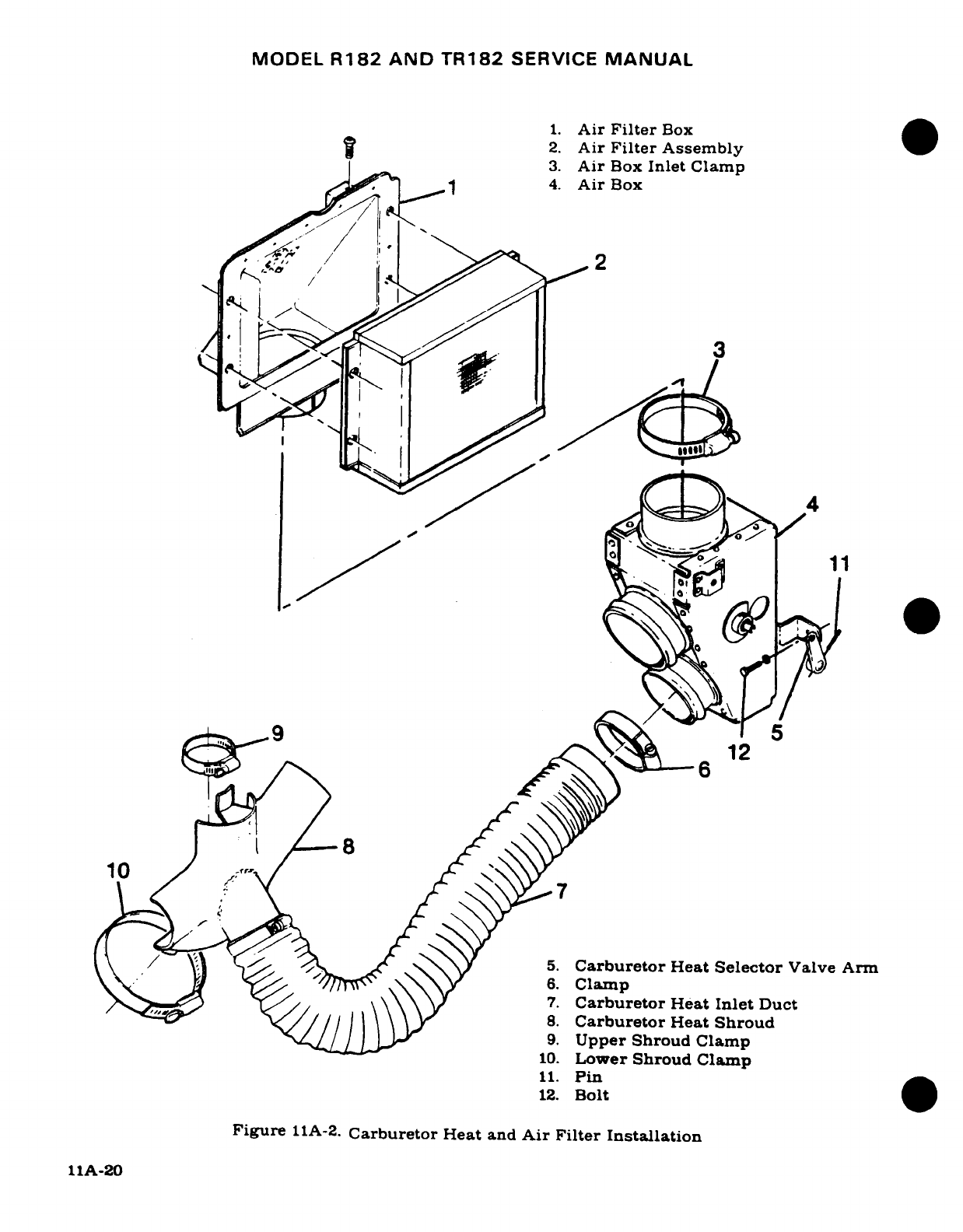
MODEL
R182
AND
TR182
SERVICE
MANUAL
1.
Air
Filter
Box
2.
Air
Filter
Assembly
3.
Air
Box
Inlet
Clamp
tf <(
1
4.
Air
Box
-"2*'^
^12
~~~~~10~
5.
Carburetor
Heat
Selector
Valve Arm
6.
Clamp
e L/ ~\
\\ \ v7.
Carburetor
Heat
Inlet
Duct
'/
s~/ l~
//
\ \ \g~ ~8.
Carburetor
Heat
Shroud
9.
Upper
Shroud
Clamp
10.
Lower
Shroud Clamp
11.
Pin
12.
Bolt
Figure
11A-2.
Carburetor
Heat
and
Air Filter
Installation
11A-20
MODEL
R182
AND
TR182
SERVICE
MANUAL
c.
Remove
nuts,
washers
and
clamps
attaching
the
magneto
to
the
engine
accessory
housing.
Note
the
approximate
angular
position
at which
the
magneto
is
installed,
then
remove
the magneto.
d.
Reverse
the
preceding steps
for
reinstallation
and
time
magneto-to-engine
in
accordance
with
paragraph
11-62.
11A-58.
INTERNAL
TIMING.
(MAGNETO REMOVED FROM
ENGINE.)
(Refer
to
Section
11.)
11A-59.
MAGNETO-TO-ENGINE-TIMING.
(Refer
to
Section
11.)
11A-60.
MAINTENANCE.
(Refer
to
Section
11.)
11A-61.
MAGNETO
CHECK.
(Refer
to
Section
11.)
11A-62.
SPARK
PLUGS.
(Refer to
Section
11.)
11A-63.
ENGINE
CONTROLS.
11A-64.
RIGGING
THROTTLE AND
WASTE
GATE
CONTROL
ASSEMBLY.
(THRU
TR18201628)
(See
figure
11A-3.)
a.
With
throttle valve
fully
open,
position
arm
(5)
at
the
2:30
o'clock
position,
that
is
between
7°
30'
and
22
°
30'
up
from
horizontal
casting
line
(2)
on
carburetor
throat.
b.
Install throttle
shaft
extension
(30)
finger
tight
and
roll pin
(31)
so
it
doesn't
protrude
beyond
edge
of
extension.
c.
Assemble
bolt
(6)
through levers
(9),
(11),
and
(12)
using
washers
(7)
and
bushings
(8)
in
the
order
shown
in
figure
11A-3,
and
screw
throttle
control
rod
end
(14)
on
bolt
(6)
with
lock
nut
to hold.
d.
In
above
step
be
sure that washers
(16)
and
(19),
cam
(18),
and
castellated
nut
(15)
are
properly
installed.
NOTE
Index cam
according
to
Section
5.
After completion
of
this
rigging
procedure.
e.
Install
throttle
arm
bolt
(10)
through
throttle
arm
(5)
and
lever
(9),
while
throttle
is
full
open,
torque
bolt
(10)
to
20-30
in/lbs.
f.
Assemble
support
(33)
and
mount
(35)
using
bolts
(34),
do
not
tighten
until
entire
unit
is
assembled
and
free
movement
ascertained.
g.
Install
switch
bracket
(27)
bolt
(17)
and
(22),
do
not
tighten until
entire
unit
is
as-
sembled
and
free
movement
ascertained.
h.
Install
switch
(25)
using
insulator
(26)
and
nut
plate
(28).
Rig
in
accordance
to
Sec-
tion
5.
i.
Install
waste
gate
control
(23)
with
bolts
(22)
and
(24).
Waste
gate
control
arm
(10)
must
be
against
maximum
stop
screw
adjustment
(8)
(refer
to
figure
11A-6),
and
wire
must
not
be
bent.
Ensure
0.072"
clearance
exists
between
butterfly
valve
and
throat
while
arm
rests
against
the
adjustable
stop.
j.
Install
throttle
control
(13)
so
approximatley
1/8"
cushion
exists
at
each
end
of
travel
of
the
cockpit
throttle
control.
11A-21
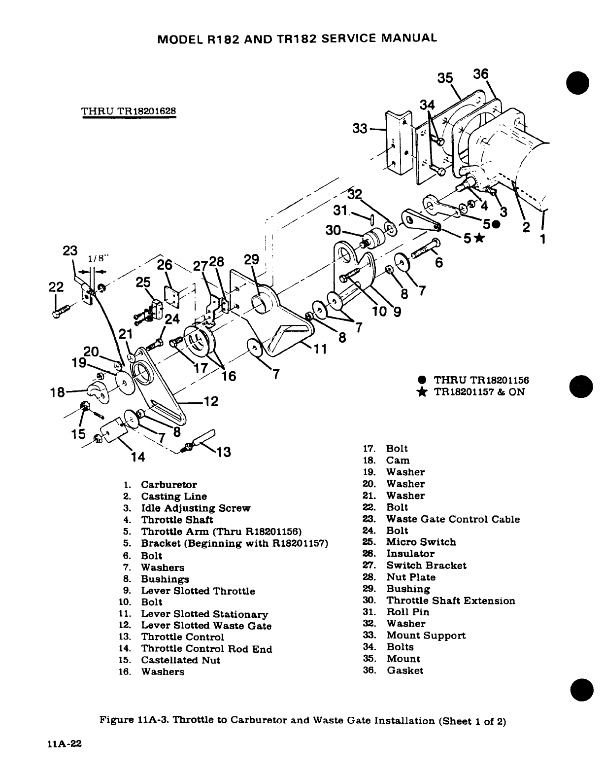
MODEL
R182
AND
TR182
SERVICE
MANUAL
35
36
THRU
TR18201628
131
Ca
.
,,"
^^30
~
5®
2
23.
Cab
r
e
6
2728
29
22
25
2V
;)..
109
19
2
-
5.-^^^^^16 Trtl
A2*
THRU
TR18201156
5. Bracket (Beginn *
TR18201157
&
ON
14Bolt
213
17.
Bolt
4* r~~~~~
18.
Cam
19.
Washer
1.
Carburetor
20.
Washer
2.
Casting
Line
21.
Washer
3.
Idle
Adjusting
Screw
22.
Bolt
4.
Throttle Shaft
23.
Waste
Gate Control
Cable
5.
Throttle
Arm
(Thru
R18201156)
24.
Bolt
5.
Bracket
(Beginning
with
R18201157)
25.
Micro
Switch
6.
Bolt
26.
Insulator
7.
Washers
27.
Switch
Bracket
8.
Bushings
28.
Nut
Plate
9.
Lever
Slotted
Throttle
29.
Bushing
10.
Bolt
30.
Throttle Shaft
Extension
11.
Lever
Slotted
Stationary
31.
Roll
Pin
12.
Lever
Slotted
Waste
Gate
32.
Washer
13.
Throttle
Control
33.
Mount
Support
14.
Throttle
Control
Rod
End
34.
Bolts
15.
Castellated
Nut
35.
Mount
16.
Washers
36.
Gasket
Figure
11A-3.
Throttle
to
Carburetor
and
Waste
Gate
Installation
(Sheet
1
of
2)
11A-22
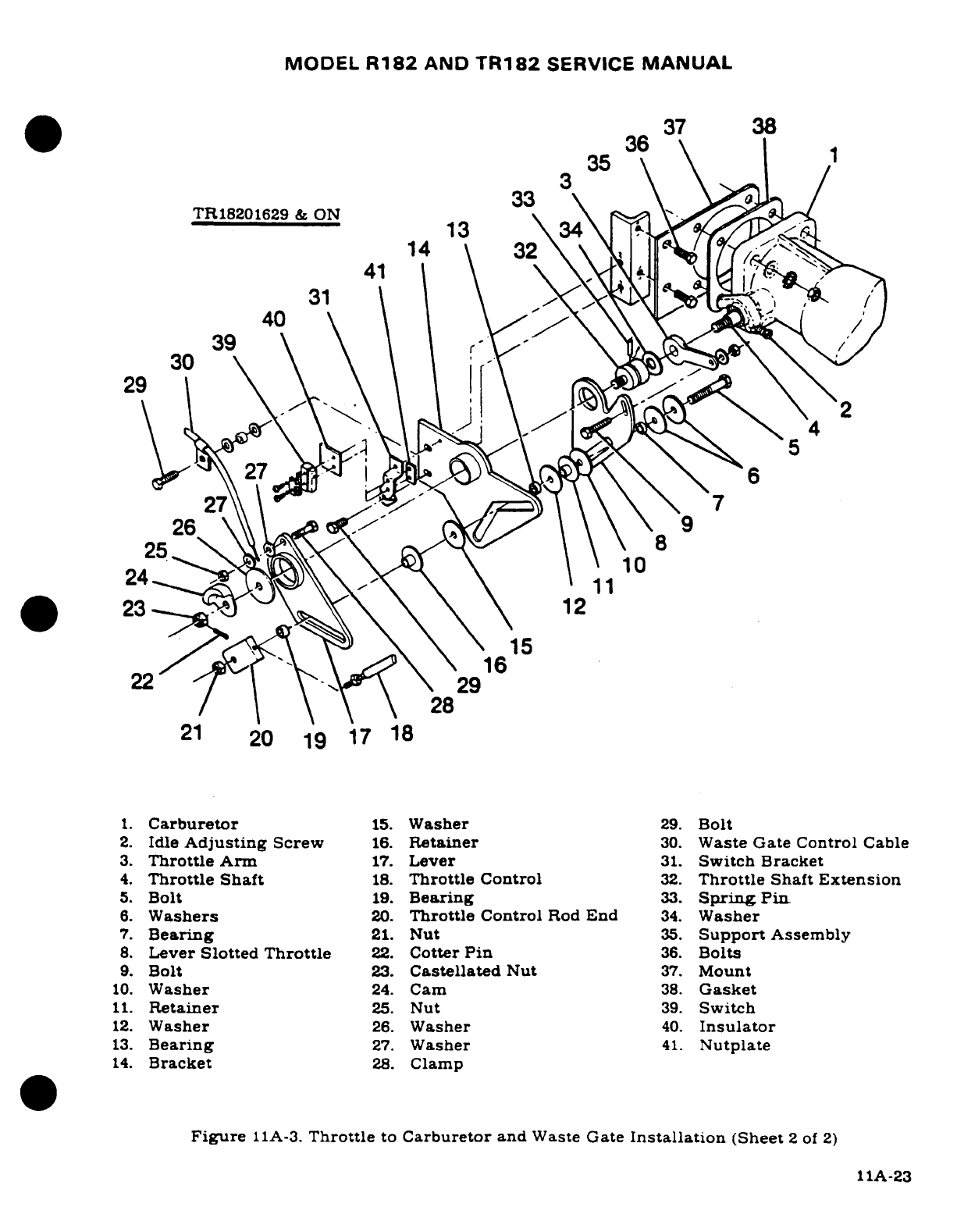
MODEL
R182
AND
TR182
SERVICE
MANUAL
36
37
38
35
TR18201629
&
ON
13
\
31
29
1.
Carburetor
15.
Washer
29.
Bolt
,.
23
-6
27
\ \
7
7
26
9
24 11
23,
,"~'-
\ \ \12
16
22
29
28
21
20
19
17
18
1.
Carburetor
15.
Washer
29.
Bolt
2.
Idle
Adjusting
Screw
16.
Retainer
30.
Waste
Gate
Control
Cable
3.
Throttle
Arm
17.
Lever
31.
Switch
Bracket
4.
Throttle Shaft
18.
Throttle
Control
32.
Throttle
Shaft
Extension
5.
Bolt
19.
Bearing
33.
Spring Pin
6.
Washers
20.
Throttle
Control
Rod
End
34.
Washer
7.
Bearing
21.
Nut
35.
Support
Assembly
8.
Lever
Slotted
Throttle
22.
Cotter
Pin
36.
Bolts
9.
Bolt
23.
Castellated
Nut
37.
Mount
10.
Washer
24.
Cam
38.
Gasket
11.
Retainer
25.
Nut
39.
Switch
12.
Washer
26.
Washer
40.
Insulator
13.
Bearing
27.
Washer
41.
Nutplate
14.
Bracket
28.
Clamp
Figure
11A-3.
Throttle
to
Carburetor
and
Waste
Gate
Installation
(Sheet
2
of
2)
11A-23
MODEL
R182
AND
TR182
SERVICE
MANUAL
NOTE
Slots
are
provided
to
allow
free
movement
alignment.
tighten
bolts
in
proper
sequence
to
prevent
binding.
If
after
complete
assembly,
the
return
spring
will
not
return
arm,
readjustment
is
necessary.
k.
After
free
movement
is
obtained.
follow
the
following
bolt
tightening
sequence:
1.
Tighten
throttle
arm
bolt
(10),
torque
20-30
lbs.
2.
Throttle
rod
bolt.
tightened
as
soon
as all
levers
(9,11.
and
12)
bushings
(8
and
29).
and
washers
(7.
16,
and
19)
are
installed.
3.
Castellated
nut
(15)
tighten
after
throttle
rod bolt.
4.
Stationary
lever mount
bolts
(17
and
22)
tighten
before
support
mount
bolts.
5.
Support
mount
(33)
retaining
bolts
(34)
tighten
last.
only
after adjustment
is
complete
and
free
movement
ascertained.
11A-65.
RIGGING
THROTTLE
AND
WASTE
GATE
CONTROL
ASSEMBLY.
(TR18201629
&
ON)
(See
figure
11A-3.)
a.
Install
washer
(34)
and
throttle
shaft
extension
(32)
on
throttle
shaft
(4)
tighten
finger
tight,
then
install spring
pin
(33)
making
certain
it
does
not
protrude
beyond the
edge
of
the
extension.
b.
Assemble
bolt
(5)
through levers
(8,
14
and
17)
in
the
exact
order
as
shown
in
figure
11A-3.
and
screw
throttle
control
rod end
(20)
on
bolt
(5)
with
lock
nut.
NOTE
Make
sure
nylon
washers
are
on
retainer
and
not
between
AN960
washers
and
retainers.
c.
Be
sure
that
washers
(26).
cam
(24)
and
castellated
nut
(23)
are
properly
installed.
d.
Install throttle
arm
bolt
(9)
through
lever
(8)
and
throttle
arm
(3).
e.
Assemble
support
(35)
and
mount
(37)
using
bolts
(36),
do
not
tighten until
entire
unit
is
assembled
and
freedom
of
movement
is
assured.
f.
Install
switch bracket
(31)
bolt
(29),
do
not
tighten
until
entire
unit
is
assembled
and
free
movement
is
ascertained.
g.
Install
switch
(39)
using
insulator
(40)
and
nutplate
(41).
Rig
in
accordance
to
Section
5.
NOTE
Lubricate
waste
gate control
cable
(30)
with
molybdenum
disulfide
(MIL-M-7866)
suspended
in
petroleum
distilate.
h.
Install
waste
gate
control
(30)
with
bolts
(28
and
29).
i.
See
figure
11A-6.
Waste
gate
contorol arm
(10)
must
be
against
maximum
stop
screw
adjustment
(8)
and
wire
must
not
be
bent.Ensure
0.072"
clerance
exists
between
butterfly
valve
and
throat
while
arm
rests
against
the
adjustable
stop.
j.
Install
throttle
control
(18)
so
approximately
1/8"
cushion
exists
at
each
end
of
travel
of
the
cockpit
throttle
control.
NOTE
Slots
are
provided
to
allow
free
movement
alignment,
tighten
bolts
in
proper
sequence
to
prevent
binding.
If
after
complete
assembly
the
return spring
will
not
return
the
arm,
readjustment
is
necessary.
11A-24
Revision
2
MODEL
R182
AND
TR182
SERVICE
MANUAL
k.
After
free
movement
is
obtained,
follow
the
following
bolt
tightening
sequence.
1.
Tighten
throttle
arm
bolt
(9),
torque
20-30
in-lbs.
2.
Throttle
rod
bolt
(5)
tighten
as
soon
as
all
levers
(8,
14
and
17),
washers
(6,
10,
12
and
15),
bearings
(7.
13
and
19)
and
retainers
(11
and
16)
are
installed.
3.
Tighten
castellated
nut
(23)
and
install
cotter
pin
(22)
after
throttle
rod
bolt.
4.
Tighten
stationary
lever bolts
(29)
before
support
mount
bolts.
5.
Tighten
support
mount
bolts
(36)
only
after
adjustment
is
complete
and
free
movement
is
assured.
11A-66.
MIXTURE
CONTROL.
(Refer
to
Section
11.)
11A-67.
CARBURETOR
HEAT
CONTROL.
(Refer to
Section
11.)
11A-68.
PROPELLER
CONTROL.
(Refer
to
Section
13.)
11A-69.
STARTING
SYSTEM.
(Refer
to
Section
11.)
11A-70.
EXHAUST
SYSTEM.
11A-71.
DESCRIPTION. The
exhaust
system
consists
of
a
single
pipe
for
each
cylinder,
two
short
stacks,
a
crossover
tube,
a
Y
connector,
the
turbine
section
of
the turbocharger,
a
waste
gate,
and
a
single
exhaust
oulet.
The
single pipes
collect
exhaust
gases
from
each
respective
cylinder,
and
route
it
to
the two
stacks,
one
for
the
set
of
odd
numbered
cylinders
and
one
for
the
set
of
even
numbered
cylinders.
The
left bank,
even
numbered,
exhaust
gases
are
used
to
drive
the
turbine
wheel
of
the
turbocharger,
which
in
turn
drives
the
compressor
wheel.
The
right
bank,
odd
numbered,
exhaust
is
routed
through
the
crossover
around
the
front
of
the
engine
to
the
Y
connection,
which
directs
exhaust
to
the
waste gate. All
excess
exhaust
gases
bypass
the
turbine
wheel
of
the
turbocharger
through
the
waste
gate.
Manual
linkage
connects
the
waste
gate
valve
to
the
carburetor
throttle
linkage.
As
the
throttle
is
moved
toward
the
open
position,
the
waste gate
is
operated
mechanically
to
ensure
that
proper
manifold
pressure
is
maintained.
11A-72.
REMOVAL
AND
INSTALLATION. (See
figure
11A-4.)
a.
Remove
engine
cowling
in
accordance
with
paragraph
11-3.
b.
Disconnect ducts
from
heater shroud
on
muffler
assembly.
c.
Disconnect
duct from
shroud
on
left
exhaust
stack
assembly.
d.
Remove
nuts,
bolts
and
clamps
attaching
stack
assemblies
to
the
turbocharger.
e.
Remove
nuts
attaching exhaust stack
assemblies
to
the
cylinders
and
remove
exhaust
stacks
and
gaskets.
f.
Reverse
the
preceding
steps
for
reinstallation.
Install
a
new
copper-asbestos
gasket
between
each
riser
and
its
mounting
pad
on
each
cylinder,
regardless
of
apparent
condition
of
those
removed.
Torque
exhaust
stack nuts
at
cylinders
to
100-110
pound-
inches.
11A-73.
INSPECTION.
Since
exhaust
systems
of
this
type
are
subject
to
burning,
cracking
and
general deterioration
from
alternate
temperatures
extremes
and
vibrations,
inspection
is
important
and
should
be
accomplished every
50
hours
of
operation.
To
inspect
the engine
exhaust
system,
proceed
as
follows:
a.
Remove
engine
cowling
as
required
so
that
ALL
surfaces
of
the
exhaust
assemblies
can
be
visually
inspected.
11A-25
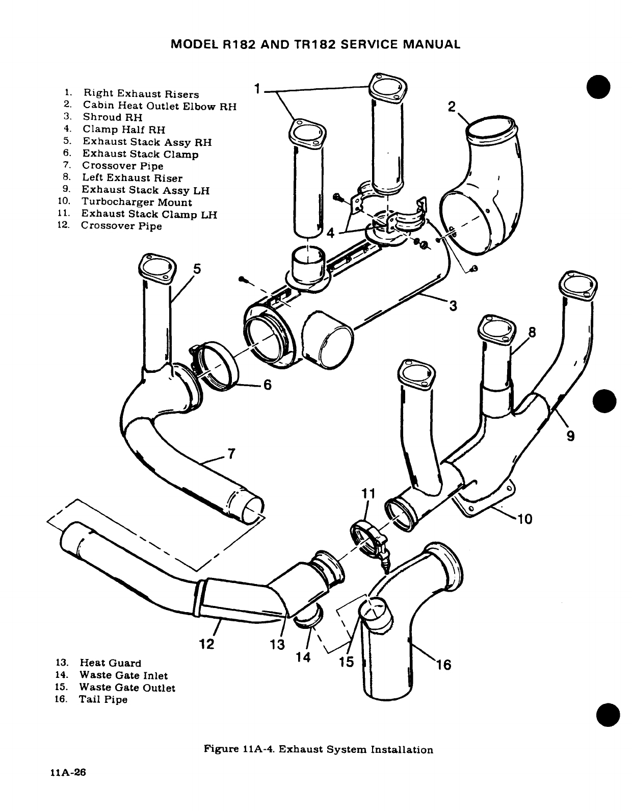
MODEL
R182
AND
TR182
SERVICE
MANUAL
1.
Right
Exhaust
Risers
2.
Cabin
Heat
Outlet
Elbow
RH
\ 2
3.
Shroud
RH
4.
Clamp
Half
RH
5.
Exhaust
Stack
Assy
RH
6.
Exhaust
Stack
Clamp
7.
Crossover
Pipe
8.
Left
Exhaust
Riser
9.
Exhaust
Stack
Assy
LH
10.
Turbocharger
Mount
11.
Exhaust
Stack
Clamp
LH
\
\
12.
Crossover
Pipe
4
6
12
13
11
13.
Heat
Guard
14
r5
16
14.
Waste
Gate
Inlet
15.
Waste
Gate
Outlet
16.
Tail
Pipe
Figure
11A-4.
Exhaust System
Installation
11A-26
MODEL
R182
AND
TR182
SERVICE
MANUAL
NOTE
Especially
check
the
areas
adjacent
to
welds and
slip
joints.
Look
for gas
deposits
in
surrounding
areas,
indicating
that
exhaust
gases
are
escaping
through
a
crack
or hole
or
around
the
slip
joints.
b.
After
visual
inspection,
an
air
leak
check
should
be
made
on
the
exhaust
system
as
follows:
1.
Attach
the
pressure
side
of
an
industrial
vacuum cleaner
to
the
tailpipe opening,
using
a
rubber
plug
to
effect
a
seal
as
required.
NOTE
The
inside
of
vacuum
cleaner
hose
should
be
free
of
any
contamination that
might
be
blown
into
the
engine
exhaust
system.
2.
With
vacuum cleaner
operating,
all
joints
in
the
exhaust
system
may
be
checked
manually
by
feel,
or
by
using
a
soap
and
water
solution
and
watching
for
bubbles.
Forming
of
bubbles
is
considered
acceptable;
if
bubbles
are
blown
away,
system
is
not considered
acceptable.
c.
Where
a
surface
is
not
accessible
for
a
visual
inspection,
or
for
a
more
positive
test,
the
following procedure
is
recommended.
1.
Remove
exhaust
stack
assemblies.
2.
Use
rubber expansion
plugs
to
seal
openings.
3.
Using
a
manometer
or
gage,
apply
approximately
1-1/2
psi
(3
inches
of
mercury)
air pressure
while
each
stack assembly
is
submerged
in
water.
Any
leaks
will
appear
as
bubbles
and
can
be
readily
detected.
4.
It is
recommended
that
exhaust
stacks
found
defective
be
replaced
before
the
next
flight.
d.
After
installation
of
exhaust
system components
perform
the
inspection
in
step
"b"
of
this
paragraph
to
ascertain
that
system
is
acceptable.
11A-27
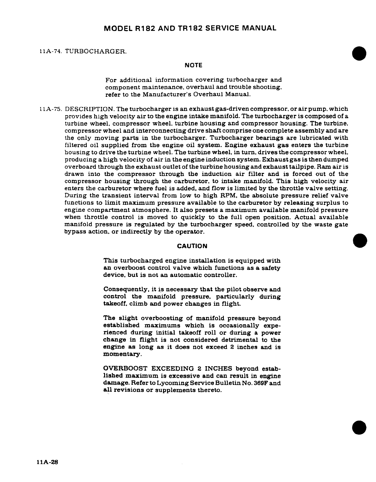
MODEL
R182
AND
TR182
SERVICE
MANUAL
11A-74.
TURBOCHARGER.
NOTE
For
additional
information
covering turbocharger
and
component
maintenance,
overhaul
and
trouble
shooting.
refer
to
the
Manufacturer's
Overhaul
Manual.
11A-75.
DESCRIPTION.
The
turbocharger
is
an
exhaust
gas-driven
compressor, or
air
pump.
which
provides
high
velocity
air
to
the
engine
intake
manifold.
The
turbocharger
is
composed
of
a
turbine
wheel,
compressor
wheel,
turbine
housing
and
compressor
housing.
The
turbine.
compressor
wheel
and
interconnecting
drive
shaft
comprise
one
complete
assembly
and
are
the
only
moving
parts
in
the
turbocharger.
Turbocharger
bearings
are
lubricated with
filtered
oil
supplied
from the
engine
oil
system.
Engine
exhaust
gas
enters
the
turbine
housing
to
drive
the
turbine
wheel.
The
turbine
wheel,
in
turn,
drives
the
compressor
wheel.
producing
a
high
velocity
of
air
in
the
engine
induction
system.
Exhaust
gas
is
then
dumped
overboard
through
the
exhaust
outlet
of
the
turbine housing
and
exhaust tailpipe.
Ram
air
is
drawn
into
the
compressor
through
the
induction
air
filter
and
is
forced
out
of
the
compressor
housing
through
the
carburetor,
to
intake
manifold.
This
high
velocity
air
enters
the
carburetor
where
fuel
is
added,
and
flow
is
limited
by
the
throttle
valve setting.
During
the
transient
interval
from
low
to
high
RPM,
the
absolute
pressure
relief
valve
functions
to
limit
maximum
pressure
available
to
the
carburetor
by
releasing
surplus
to
engine
compartment
atmosphere.
It
also
presets
a
maximum
available
manifold
pressure
when
throttle
control
is
moved
to
quickly
to
the
full
open
position.
Actual available
manifold
pressure
is
regulated
by
the
turbocharger
speed,
controlled
by
the
waste
gate
bypass
action,
or
indirectly
by
the
operator.
CAUTION
This
turbocharged
engine
installation
is
equipped with
an
overboost
control
valve
which
functions as
a
safety
device,
but
is
not
an
automatic controller.
Consequently,
it is
necessary
that
the
pilot
observe and
control
the manifold
pressure,
particularly
during
takeoff,
climb
and
power
changes
in
flight.
The
slight
overboosting
of
manifold
pressure
beyond
established
maximums
which
is
occasionally
expe-
rienced
during
initial
takeoff
roll
or
during
a
power
change
in
flight
is
not
considered
detrimental
to
the
engine
as
long
as
it
does
not
exceed
2
inches
and
is
momentary.
OVERBOOST
EXCEEDING
2
INCHES
beyond
estab-
lished
maximum
is
excessive
and can
result
in
engine
damage.
Refer
to
Lycoming
Service Bulletin
No.
369F
and
all
revisions
or supplements
thereto.
11A-28
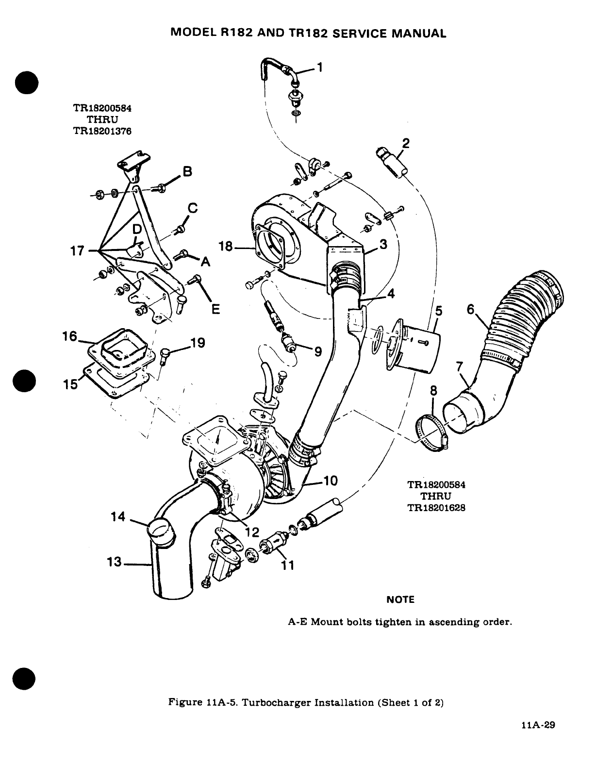
MODEL
R182
AND
TR182
SERVICE
MANUAL
TR18200584
THRU
TR18201376
//
^Bu
J, ^/
^
/
THRU
TR18201628
A-E
Mount
bolts
tighten
in
ascending
order.
Figure
11A-5.
Turbocharger
Installation
(Sheet
1
of
2)
5 11 8A-29
TR18200584
THRU
TR18201628
13
13
NOTE
A-E
Mount
bolts
tighten
in
ascending
order.
Figure
11A-5.
Turbocharger
Installation
(Sheet
1
of
2)
IIA-29
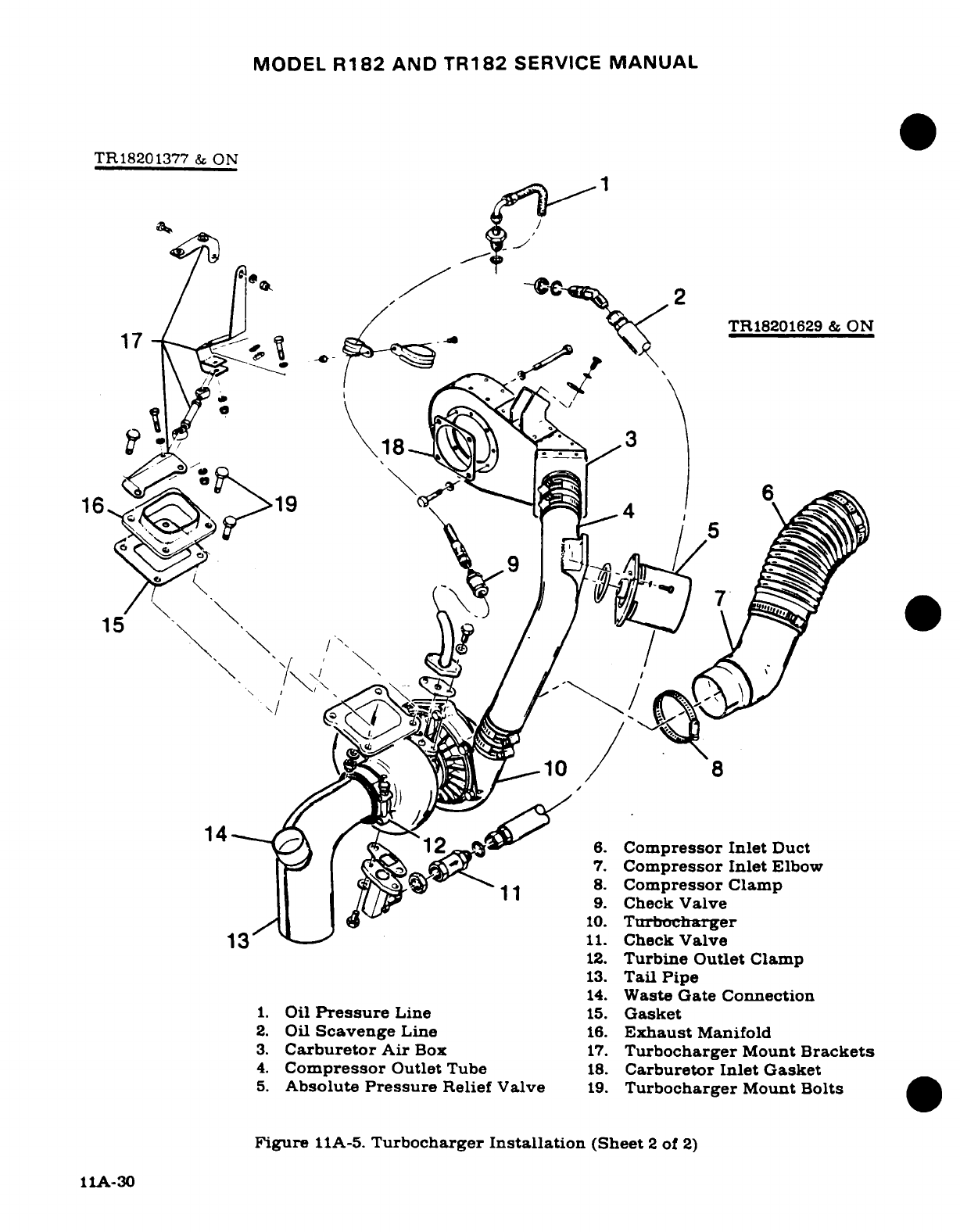
MODEL
R182
AND
TR182
SERVICE
MANUAL
TR18201377
&
ON
2
18
..-,
X
g J^ _/ Y\
TR18201629
&
ON
15
7
'
'''n
^)14 12^S.
1
6'.
Compressor Inlet
Duct
7.
Compressor Inlet
Elbow
1
8.
Compressor
Clamp
/I"/~ ~A,
9.
Check
Valve
10.
Turbocharger
13
t
11.
Check
Valve
12.
Turbine Outlet
Clamp
13.
Tail
Pipe
14.
Waste
Gate Connection
1.
Oil
Pressure
Line
15.
Gasket
2.
Oil
Scavenge
Line
16.
Exhaust
Manifold
3.
Carburetor
Air
Box
17.
Turbocharger
Mount
Brackets
4.
Compressor
Outlet
Tube
18.
Carburetor
Inlet
Gasket
5.
Absolute
Pressure
Relief
Valve
19.
Turbocharger
Mount
Bolts
Figure
11A-5.
Turbocharger
Installation
(Sheet
2
of
2)
11A-30
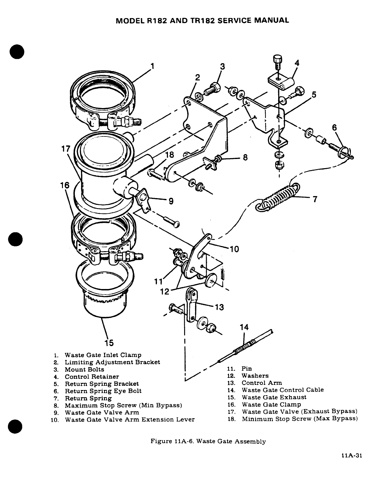
MODEL
R182
AND
TR182
SERVICE
MANUAL
1
4
~ 3~5
171
16
0'^--'-^
·
t
-
10
12
13
14
15
1.
Waste
Gate
Inlet
Clamp
2.
Limiting
Adjustment
Bracket
3.
Mount
Bolts
,
11.
Pin
4.
Control
Retainer
12.
Washers
5.
Return
Spring
Bracket
13.
Control Arm
6.
Return
Spring
Eye
Bolt
14.
Waste
Gate
Control
Cable
7.
Return
Spring
15.
Waste
Gate
Exhaust
8.
Maximum
Stop
Screw
(Min
Bypass)
16.
Waste
Gate
Clamp
9.
Waste
Gate
Valve
Arm
17.
Waste
Gate
Valve
(Exhaust
Bypass)
10.
Waste
Gate
Valve
Arm
Extension
Lever
18.
Minimum
Stop
Screw
(Max
Bypass)
Figure
11A-6.
Waste
Gate
Assembly
11A-31
MODEL
R182
AND
TR182
SERVICE
MANUAL
11A-76.
REMOVAL
AND
INSTALLATION.
(See
figure
11A-5.)
a.
Remove
engine
cowling
as required.
b.
Remove
waste gate
to
tailpipe
clamp
at
(14).
c.
Loosen
clamp
(12)
at
turbine
exhaust
outlet
and
work
tailpipe
(13)
from
turbine
outlet,
and
cover
to
prevent
entrance
of
foreign
material.
d.
Loosen
clamps
(8)
and remove
air
inlet,
elbow
(7)
and duct
(6)
from
turbocharger
compressor
section
(10),
and
cover
both
parts
to
prevent
damage.
e.
Disconnect
oil
pressure
(1)
and
scavenge
lines
(2)
from
turbocharger
(10),
plug
and
cap
all
openings.
Remove
all
clamps
and
ties
as
necessary.
f.
Remove
four
bolts
(19)
attaching
turbine
to
LH
exhaust
manifold
(16).
g.
Carefully
remove
turbocharger
from
engine
compartment,
at
aft
LH
side
near
the
firewall.
h.
Reverse the
preceding
steps
for
reinstallation.
Always
use
a
new
gasket
between
turbocharger
and
exhaust
manifold.
NOTE
Install
all
hardware
in
exact
removal
sequence.
i.
If
mount
bolts
were removed
or
loosened,
retighten
in
sequence
of
ascending
order
as
shown
in
figure
11A-5.
j.
Refer
to
paragraph
11A-64
or
11A-65,
for
waste
gate
control linkage
installation
and
adjustment.
11A-77.
ECONOMY
MIXTURE
INDICATOR
(EGT).
(Refer
to
Section
15.)
11A-78.
EXTREME
WEATHER
MAINTENANCE.
11A-79.
COLD
WEATHER.
Cold
weather
starting
is
made
easier
by
the
use
of
the
engine
primer
system
and
installation
of
a
ground
service
receptacle.
The
primer
system
is
manually
operated
from
the
cabin.
Fuel
is
supplied
by
a
line
from
the
fuel
strainer
to
the
plunger.
Operating
the
primer
forces
fuel
to the
engine.
With
an
external
power
receptacle installed.
an
external
power
source
may
be
connected
to
assist
in
cold
weather
starting.
Refer
to
Section
16
for
use
of
the
external
power
receptacle.
The
following may
also
be
used
to
assist
engine
starting
in
extreme
cold
weather.
After
the
last
flight
of
the
day,
drain
the
engine
oil
into
a
clean
container
so
the
oil
can
be
preheated.
Cover
the
engine
to
prevent
ice
or
snow
from
collecting
inside
the
cowling.
When
preparing
the
aircraft
for
flight or
engine
runup
after
these
conditions have
been followed,
preheat
the
drained
engine
oil.
WARNING
Do
not
heat
the
oil above
121°C
(250°F).
or
a
flash
fire
may
result.
Before
pulling
the
propeller
through,
ascertain
that
the
magneto
switch
is in
the
OFF
position,
or
that
primary
lead
is
grounded
to
prevent accidental
firing
of
the
engine.
11A-32
MODEL
R182
AND
TR182
SERVICE
MANUAL
After
preheating
the
engine
oil,
gasoline
may
be
mixed
with the
heated
oil
in a
ratio
of
1
part
gasoline
to
12
parts
engine
oil
before
pouring
into
the
engine
oil
sump.
If
the
free
air
temperature
is
below
minus
29°C
(-20°F),
the
engine compartment should
be
preheated
by
a
ground heater. Pre-heating
the
engine
compartment
is
accomplished
by
inducing
heated
air
up
through
the
engine
cowl
flap
openings,
thus
heating
both
the
cylinders
and
oil.
After
the
engine
compartment
has
been
preheated,
inspect
all
engine
drain
and
vent
lines
for
presence
of ice.
After
this
procedure
has
been
complied
with,
pull
propeller
through
several
revolutions
by
hand
before
attempting
to
start
the
engine.
CAUTION
Due
to
the
desludging
effect
of
the
diluted
oil,
engine
operation
should
be
observed
closely
during
the
initial
warm-up
of
the
engine.
Engines
that
have
considerable
amount
of
operational
hours
accumulated
since
their
last
dilution
period
may
be
seriously
affected by
the
dilution
process.
This
will
be
caused
by
the
diluted
oil
dislodging
sludge
and carbon
deposits within
the
engine.This
residue
will
collect
in
the
oil
sump
and
possibly
clog
the
screened
inlet
to
the
oil
sump.
Small deposits
may
actually
enter
the
oil
sump
and
be
trapped
by
the
main
oil
filter
screen.
Partial
or
complete
loss
of
engine
lubrica-
tion
may
result
from
either
condition.
If
these
conditions
are
anticipated
after
oil
dilution,
the
engine
should
be
run
for
several
minutes
at
normal
operating
temperatures
and
then
stopped
and
inspected
for
evidence
of
sludge
and
carbon
deposits
in
the oil
sump
and oil
filter
screen.
Future
occurrence
of
this
condition
can
be
prevented
by
diluting
the oil
prior
to
each
engine
oil
change.
This
will
also
prevent
the
accumulation
of
the
sludge
and carbon
deposits.
11A-80.
SEACOAST
AND
HUMID
AREAS.
In
salt
water
areas
special
care
should
be
taken
to keep
the
engine,
accessories
and
airframe
clean
to
prevent
oxidation.
In
humid areas,
fuel
and
oil
should
be
checked
frequently,
and
condensation
drained
to
prevent
corrosion.
11A-81.
GROUND
SERVICE
RECEPTACLE.
With
the
ground
service
receptacle
installed,
the
use
of
an
external
power
source
is
recommended for
cold
weather
starting,
low
battery
starting
and
lengthy
maintenance
of
the
aircraft electrical
system.
Refer
to
Section
16
for
additional
information.
11A-33/(11A-34
blank)
MODEL
R182
AND
TR182
SERVICE
MANUAL
SECTION
12
FUEL
SYSTEM
Page
No.
TABLE
OF
CONTENTS
Aerofiche/
Manual
FUEL
SYSTEM
..............
3B18/12-2
Description
...............
3C15/12-21
Description
...............
3B18/12-2
Removal/Installation
........
3C15/12-21
Precautions
...............
3B18/12-2
Disassembly
.......
.....
3C15/12-21
Trouble
Shooting
...........
3B19/12-3
Cleaning,
Inspection/Repair
.. .
3C21/12-26A
FUEL
CELLS
...............
3B20/12-4
Reassembly
...............
3C21/12-26A
Description
...............
3B20/12-4
FUEL
STRAINER
............
3C24/12-28
General
Precautions
........
3B20/12-4
Description
..............
3C24/12-28
Removal
.................
3C2/12-10
Removal/Installation
........
3C24/12-28
Repair
...................
3C5.12-13
Disassembly/Assembly
.......
3C24/12-28
Installation
...............
3C5.12-13
PRIMING
SYSTEM
...........
3C24/12-28
VENTED
FUEL
FILLER
Description
...............
3C2412-28
CAPS
....................
3C5
12-13
Removal/Installation
........
3C24/12-28
Description
...............
3C5,
12-13
TR182 (Opt)
..............
3D1/12-29
Metal
"Flush-Type"
Description
.............
3D1/12-29
Filler
Caps
...............
3C6/12-14
AUXILIARY
ELECTRICAL
Inspection
..............
3C6
12-14 FUEL
PUMP
...............
3D1/12-29
Cleaning
...............
3C7/12-15
Description
...............
3D1/12-29
Reassembly
.............
3C7.'12-15
Removal/Installation
........
3D1/12-29
Checking
Filler
Caps
......
3C7 12-15
Turbocharged
Airplanes
.....
3D1/12-29
Red
Plastic "Flush-Type"
Description
.............
3D1/12-29
Filler
Caps
...............
3C7
12-15
Removal/Installation
.......
3D4;12-32
Cleaning
LSE
Fuel
INTEGRAL
FUEL
BAY
........
3D4/12-32
Filler
Caps
.............
3C9
12-17
Description
...............
3D4/12-32
Inspection
..............
3C10
12-18
Fuel Leak
Classification
......
3D4/12-32
Cleaning
Metal
or
Red
Fuel Bay
Purging
..........
3D4/12-32
Plastic
Caps
............
3C10
12-18
Integral
Fuel Bay
Sealant
...
3D612-34
Reassembly
............
3C10
12-18
Mixing
Sealant
...........
3D6
12-34
Leak
Testing
Metal
or
Red
Sealing
During
Structural
Plastic
Filler
Caps
.........
3C11
12-18A
Repair
...........
.....
3D6
12-34
FUEL
QUANTITY
Sealing
Fuel
Leaks
........
3D10
12-38
TRANSMITTERS
..........
3C13
12-19
Normal
Cure
Time
.........
3D10
12-38
FUEL
VENTS
..............
3C13
12-19
Normal
Work
Time
.......
3D10
12-38
Description
...............
3C13
12-19
Testing
Integral
Checking
................
3C14
12-20
Fuel Bay
...............
3D10
12-38
Adjustment
......... ....
3C14 12-20
FUEL
QUANTITY
FUEL
SELECTOR
VALVE
......
3C15
12-21
TRANSMITTERS
...........
3D11
12-39
Revision
1
12-1
MODEL
R182
&
TR182
SERIES
SERVICE
MANUAL
12-1.
FUEL
SYSTEM.
12-2.
DESCRIPTION.
A
rubberized
bladder-type
fuel
(cell)
tank,
or
an
integral
fuel
tank
is
located
in
the
inboard
bay
of
each
wing. When
the
fuel
system
is in
operation,
depending
upon
the
air-
plane's
configuration,
gravity,
an
electric
or
engine-driven
fuel
pump,
draws
the
fuel
from
the
tanks
through
the
tank
strainers,
a
selector
valve,
fuel
strainer,
electric
or
engine-driven
fuel
pump
to
the
carburetor.
In
the
1977
thru
1978
Models,
system
ventilation
is
provided
by
vent-
ed
fuel
caps
and
a
vent
line
and
check
valve
extends
from
the
left
wing
tank
and
emerges
through
the
lower
wing
skin
adjacent
to
the
wing
strut.
Beginning
with
the
1979
Models,
a
vent
line
and
check
valve
is
also
used
on
the
right
wing
tank.
The
forward
fuel
lines
from
the
right
and
left
tanks are
also
utilized
as
vapor
return
lines
and
are
teed
into
a
tank
crossover
vent
line
connected
to
the
right
and
left
vent
lines. The fuel
strainer
has a
quick-drain
valve
on
the
bottom
and
is
used
to
remove
water
and
sediment
from
the
system.
Fuel
sump
drain
valves
(one
in
each
tank),
are
located
in
the
bottom,
inboard
end
of
each
tank
and
are
provided
for
draining trapped
water
and
sediment.
Integral
fuel
tank
equipped
airplanes
R18200584
and
On,
incorporating
SK182-100
have
four
additional
quick-drain
valves
installed
in
each
bay.
12-3.
PRECAUTIONS.
Observe
the
following
general precautions
and
rules
during
fueling,
defueling,
tank
or
integral
fuel
bay
purging,
repairing,
assembly
or
disassembly
of
system
components
and
electrical
system
checks
and
repairs
on
the
airplane
fuel
system.
WARNING
During
all fueling
procedures,
fire
fighting
equipment
must
be
available.
Attach
a
ground
wire
from
approved
ground
stakes
to
the
mooring
eyebolt
on
LH
and
RH
wing
struts
or
mooring
ring
on LH
and
RH
wings. Ground
fuel
nozzle
to
airplane
during
fueling
operations.
a.
Plugs
or
caps
should
be placed
on
all
disconnected
hoses,
lines
and
fittings
to
pre-
vent
residual
fuel
drainage,
thread
damage,
or
entry
of
dirt
or
foreign
materials
into
the
fuel system.
WARNING
ASSURE
THAT
ALL
CONTAMINATES,
INCLUDING
WATER.
ARE
REMOVED
FROM
FUEL
AND
FUEL
SYSTEM
BEFORE
FLIGHT
FAILURE
TO
ASSURE
CONTAMINATE
FREE FUEL
AND
HEED
ALL
SAFETY
INSTRUCTIONS
AND
OWNER
ADVISORIES PRIOR
TO
FLIGHT
CAN
RESULT
IN
BODILY
INJURY
OR
DEATH.
PLACARD
0705098-1
12-2
Revision
3
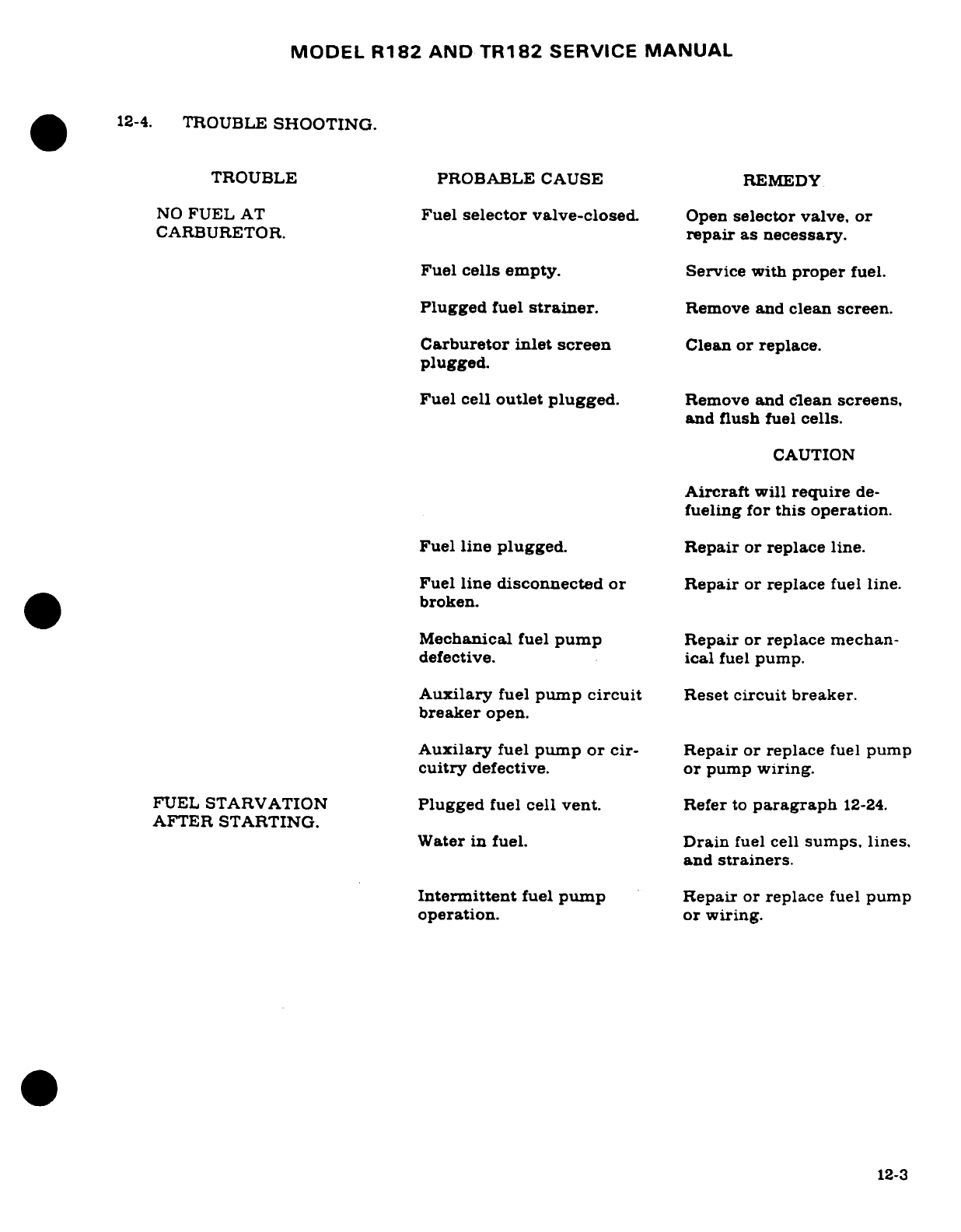
MODEL
R182
AND
TR182
SERVICE
MANUAL
12-4.
TROUBLE
SHOOTING.
TROUBLE PROBABLE
CAUSE
REMEDY
NO
FUEL
AT
Fuel
selector
valve-closed.
Open
selector
valve,
or
CARBURETOR.
repair
as
necessary.
Fuel
cells
empty.
Service
with
proper
fuel.
Plugged
fuel
strainer.
Remove
and
clean screen.
Carburetor
inlet
screen
Clean
or replace.
plugged.
Fuel
cell
outlet plugged.
Remove
and
clean
screens,
and
flush
fuel
cells.
CAUTION
Aircraft
will
require
de-
fueling for
this
operation.
Fuel
line plugged.
Repair
or
replace
line.
Fuel
line disconnected
or
Repair
or replace
fuel
line.
broken.
Mechanical
fuel
pump
Repair
or
replace
mechan-
defective.
ical
fuel
pump.
Auxilary
fuel
pump
circuit
Reset
circuit
breaker.
breaker
open.
Auxilary
fuel
pump
or
cir-
Repair
or replace
fuel
pump
cuitry
defective.
or
pump
wiring.
FUEL
STARVATION
Plugged
fuel
cell
vent.
Refer
to
paragraph
12-24.
AFTER
STARTING. Water
in
fuel.
Drain
fuel
cell
sumps.
lines.
and
strainers.
Intermittent
fuel
pump
Repair
or
replace
fuel
pump
operation. or
wiring.
12-3
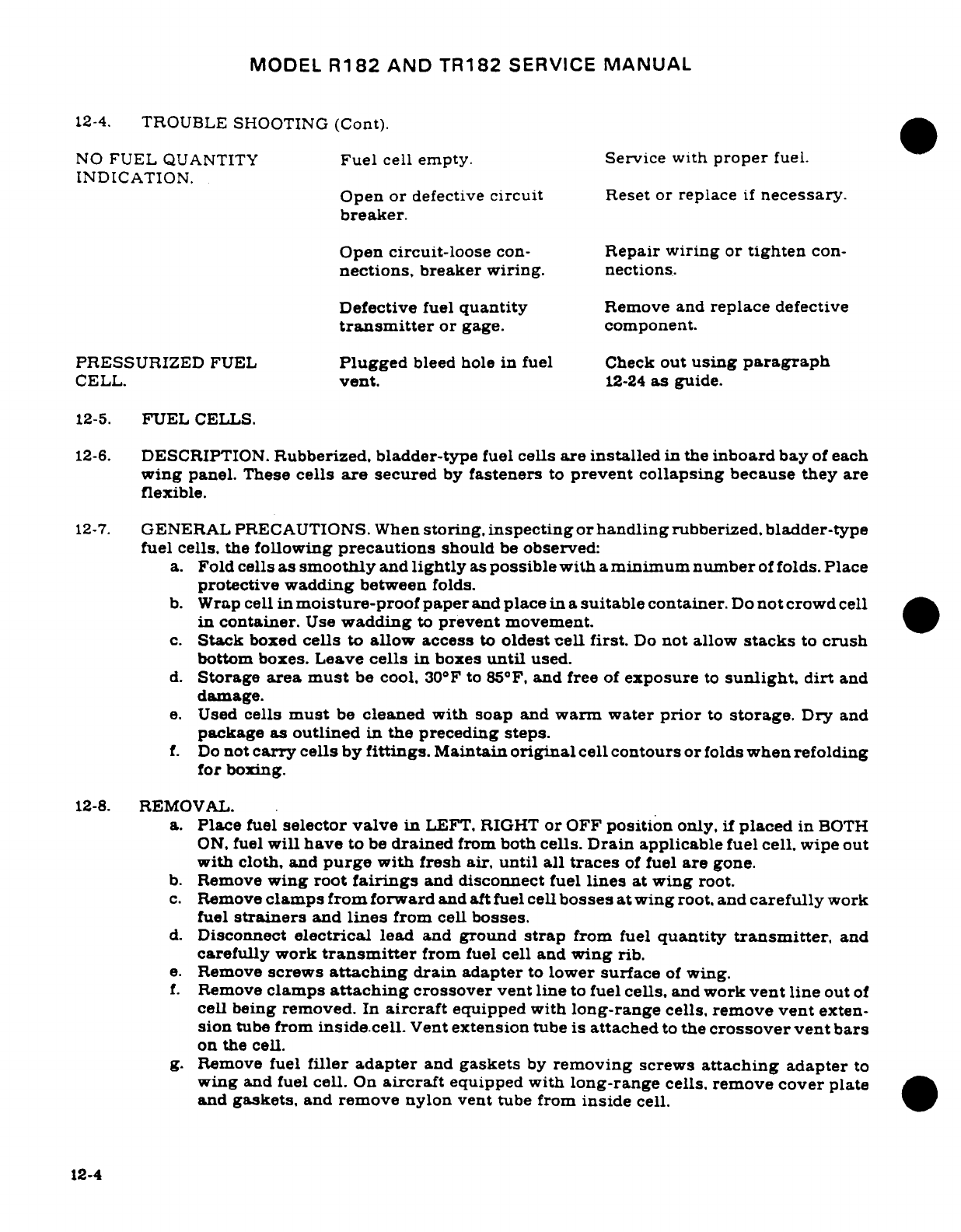
MODEL
R182
AND
TR182
SERVICE
MANUAL
12-4.
TROUBLE SHOOTING
(Cont).
NO
FUEL
QUANTITY
Fuel
cell
empty.
Service
with
proper
fuel.
INDICATION.
Open
or
defective
circuit
Reset or
replace
if
necessary.
breaker.
Open
circuit-loose
con-
Repair
wiring
or
tighten
con-
nections,
breaker
wiring.
nections.
Defective
fuel
quantity
Remove
and
replace
defective
transmitter
or
gage.
component.
PRESSURIZED
FUEL
Plugged
bleed
hole
in
fuel
Check
out
using
paragraph
CELL.
vent.
12-24
as
guide.
12-5.
FUEL
CELLS.
12-6.
DESCRIPTION.
Rubberized, bladder-type
fuel
cells
are installed
in
the
inboard
bay
of
each
wing
panel.
These
cells
are
secured
by
fasteners
to
prevent
collapsing
because they
are
flexible.
12-7.
GENERAL
PRECAUTIONS.
When
storing, inspecting
or
handling
rubberized,
bladder-type
fuel
cells, the
following
precautions
should
be
observed:
a.
Fold
cells
as
smoothly
and
lightly
as
possible with
a
minimum number
of
folds.
Place
protective wadding
between
folds.
b.
Wrap
cell
in
moisture-proof
paper
and
place
in a
suitable
container.
Do
not
crowd
cell
in
container.
Use
wadding
to
prevent
movement.
c.
Stack
boxed
cells
to
allow
access
to
oldest
cell
first.
Do
not
allow
stacks
to
crush
bottom boxes.
Leave
cells
in
boxes
until
used.
d.
Storage
area
must
be
cool.
30F
to
85°F,
and
free
of
exposure
to
sunlight,
dirt
and
damage.
e.
Used
cells
must
be
cleaned with soap
and
warm water
prior
to
storage.
Dry
and
package
as
outlined
in
the
preceding steps.
f.
Do
not
carry
cells
by
fittings.
Maintain
original
cell contours or
folds
when refolding
for
boxing.
12-8.
REMOVAL.
a.
Place
fuel
selector
valve
in
LEFT, RIGHT
or
OFF
position
only,
if
placed
in
BOTH
ON,
fuel
will have
to
be
drained
from
both
cells.
Drain
applicable
fuel
cell,
wipe
out
with
cloth,
and
purge
with
fresh air,
until
all
traces
of
fuel
are
gone.
b.
Remove
wing root
fairings
and
disconnect
fuel
lines
at
wing
root.
c.
Remove
clamps
from forward
and aft fuel cell
bosses
at
wing root,
and
carefully
work
fuel
strainers
and
lines
from
cell
bosses.
d.
Disconnect
electrical
lead
and
ground
strap
from
fuel
quantity
transmitter,
and
carefully
work
transmitter
from
fuel
cell and
wing
rib.
e.
Remove
screws
attaching
drain
adapter
to
lower
surface
of
wing.
f.
Remove
clamps
attaching
crossover
vent
line
to
fuel
cells,
and
work
vent
line
out
of
cell
being
removed.
In
aircraft
equipped
with
long-range
cells,
remove
vent
exten-
sion
tube
from
inside.cell.
Vent
extension
tube
is
attached
to
the
crossover
vent
bars
on
the
cell.
g.
Remove
fuel
filler
adapter
and
gaskets
by
removing
screws
attaching
adapter
to
wing
and
fuel
cell.
On
aircraft
equipped with
long-range
cells,
remove
cover
plate
and
gaskets,
and
remove nylon
vent
tube
from
inside
cell.
12-4
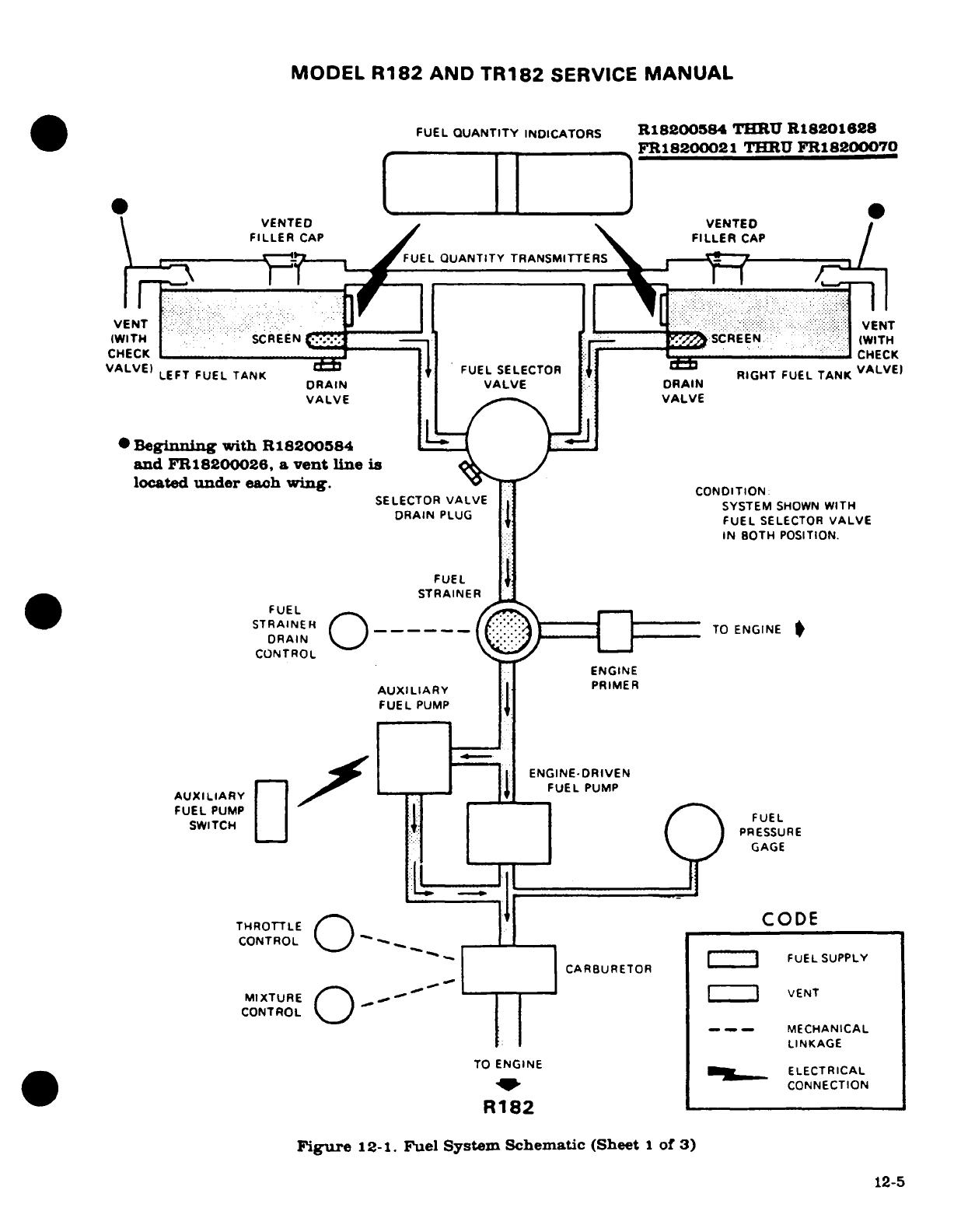
MODEL
R182
AND
TR182
SERVICE
MANUAL
FUEL
QUANTITY
INDICATORS
R18200584
THRU
R18201628
____________
FR18200021
THRU
FR18200070
1 I
VENTED
VENTED
FILLER
CAP
I \ FILLER
CAP
__I
OT
FUEL
QUANTITY
TRANSMITTERS
FLFU
~~VN
^ :
..
TRINRV ENTT
IWT
.
: :
SCREEN
.. . ..
.-..........
IWITH
SIWITH
WIT
SCREEN
Li--:-__
^SCREEN
:
(WITH
CHECK
:T
R
L-
-
CHECK
VALVE)
EaFUELSELECTOR amVA)FUEL
SUPLY
LEFT^
FUEL
TANK
DRAIN
VALVEDRAIN
RIGHT
FUEL
TANKALVEI
VALVE
VALVE
*
Beginning
with
R18200584
and
FR18200026,
a
vent
line
is ~
located
under
each
wing.
CONDITION
SELECTOR
VALVE
el
SYSTEM
SHOWN
WITH
O~D~~RAIN PLUG
7
FUEL
SELECTOR
VALVE
IN BOTH
POSITION.
FUEL
STRAINER
FUEL
STRAINER
-----
TO
ENGINE
CONTROL
T EN
TO
ERENGINE
FUEL
PUMP
F
UE
| _IGAGE
THROTTLE
O
CODE
CONTROL
TO
ENGINE
CONTROL
PUM
TO
ENGINE
W |LF
ELECTRICAL
^B "^~~~~~~~~~-
CONNECTION
R182
Figure
12-1.
Fuel
System
Schematic
(Sheet
1
of
3)
12-5
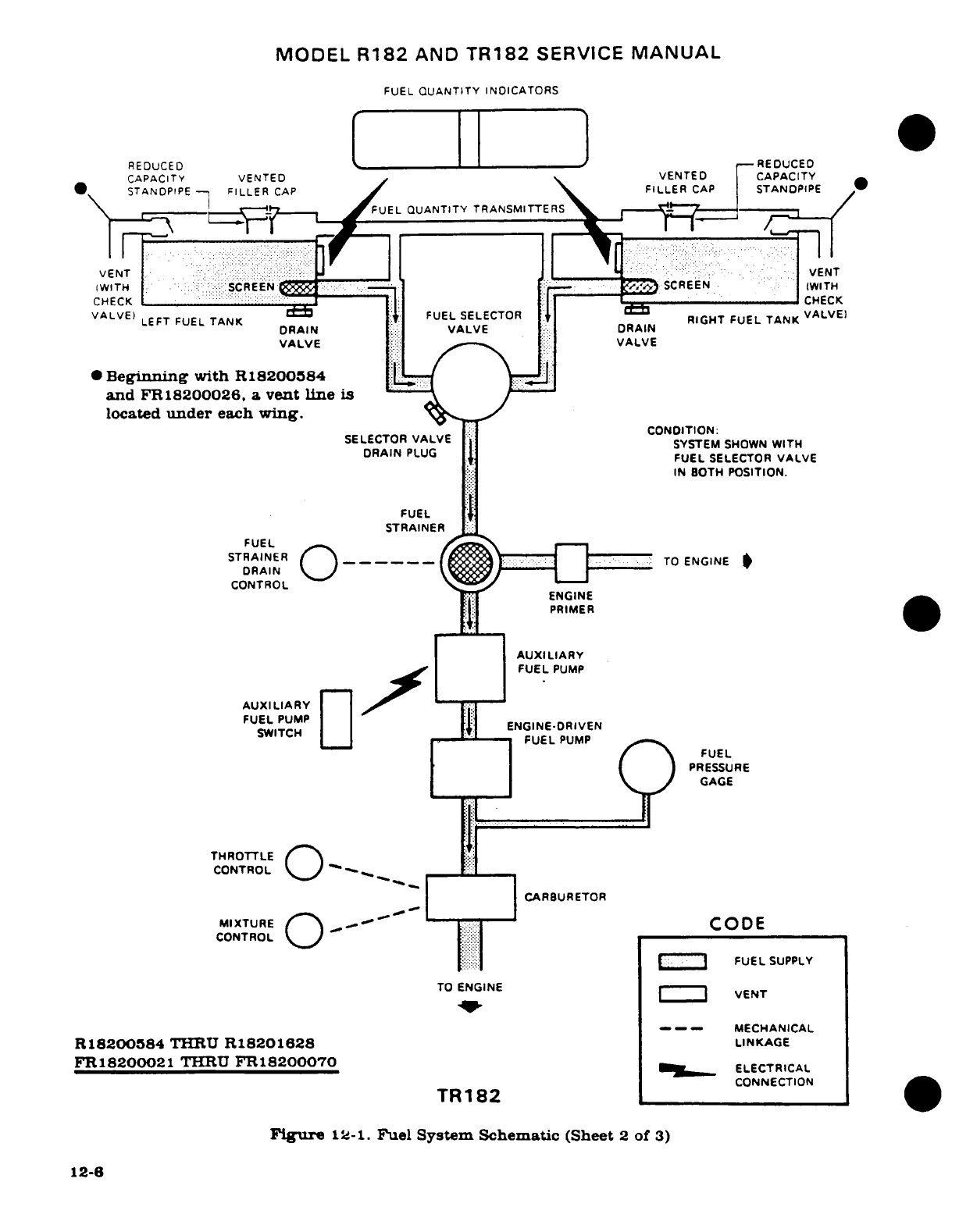
MODEL
R182
AND
TR182
SERVICE
MANUAL
FUEL
QUANTITY
INDICATORS
REDUCED
--
1
-REDUCED
CAPACITY VENTED
VENTED CAPACITY
*
STANDPIPE
FILLER
CAP
FILLER
CAP
STANOPIPE
~\ t jt.~~~ r
--
-F-
--
FUEL
QUANTITY
TRANSMITTERS
-
r ;.
.
S
}f~.
.. .
....
VENT
: ::::;V.::: :
:::::
:
:::J_::_: :.;
i
:.:
VENT
IWITH 7
:. : :
:-:
SCREEN
::::
:
-
SCREEN
(WITH
CHECK
I
I it
----
_--------
CHECK
RIGHT FUEL TANK
DRAIN
VALVE
...
DRAIN
VALVE
|;|
/-
|:
VALVE
0
Beginning
with
R
18200584.
i
and
FR18200026,
a
vent
line
is
located
under
each
wing.
SELECTOR
VALVE
CONDITION:
DR
L I
SYSTEM
SHOWN
WITH
DRAIN PLUG
/
FUEL SELECTOR
VALVE
IN BOTH
POSITION.
FUEL
STRAINER
H
FUEL
STRAINER
(
TO
ENGINE
*
DRAIN
CONTROL
.
:
:-ENGINE
_ l
PRIMER
AX
LIAUXILIARY
F FUEL
PUMP
AUXILIARY
FUEL
PUMP
SWITCH
4
ENGINE-DRIVEN
SWITCH
FUEL
PUMP
FUEL
PRESSURE
GAGE
THROTTLE
:
CONTROL
-_
CARBURETOR
MIXTURE
_T
CODE
CONTROL
'!
:.:
""
FUEL
SUPPLY
TO
ENGINE
VE
VENT
-- -
MECHANICAL
R18200584
THRU
R18201628
LINKAGE
FR18200021
THRU
FR18200070
ELECTRICAL
ELECTRICAL
~~~~~TR182
~CONNECTION
TR182
Figure
12-1.
Fuel
System
Schematic
(Sheet
2
of
3)
12-6
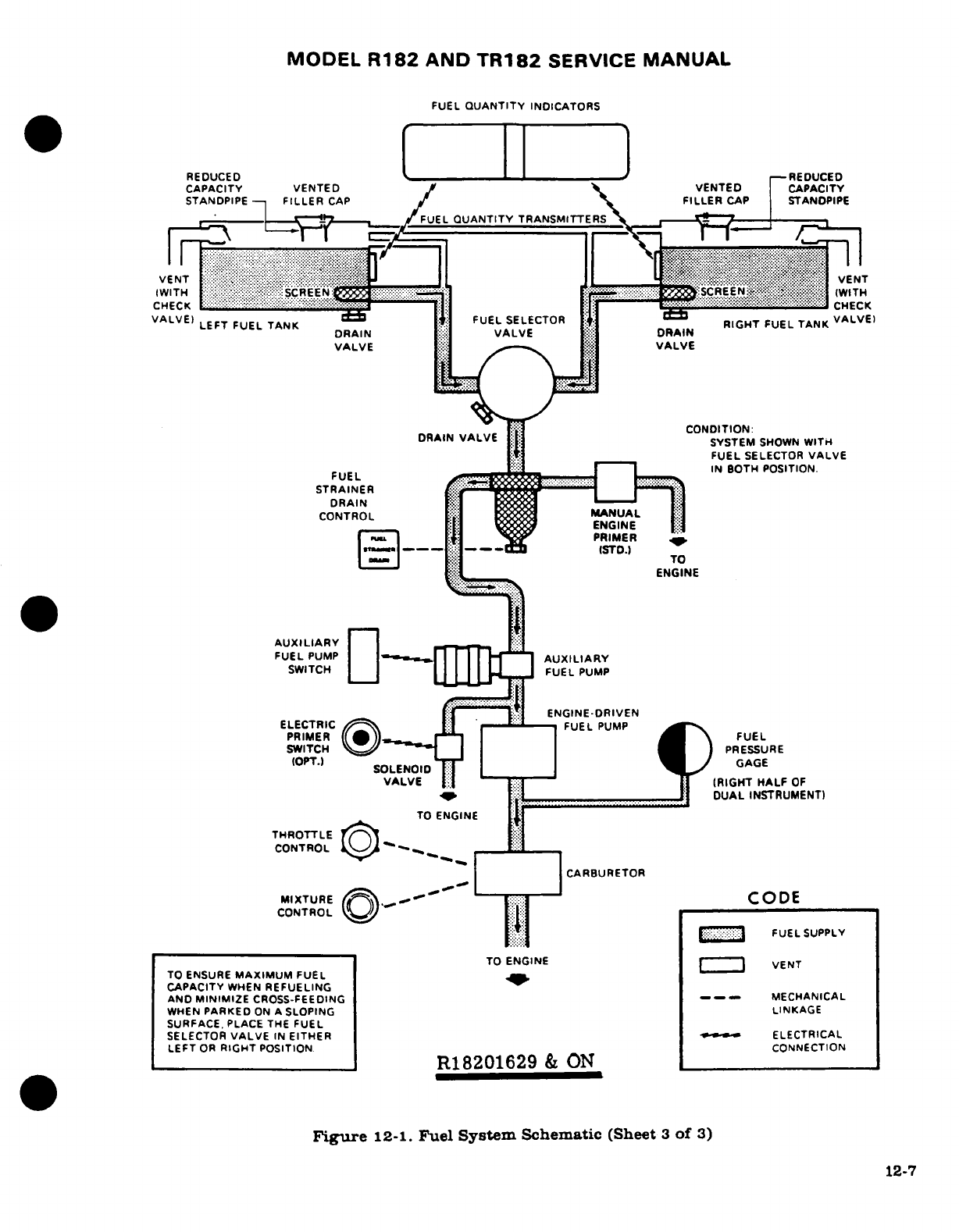
MODEL
R182
AND
TR182
SERVICE
MANUAL
FUEL
QUANTITY
INDICATORS
REDUCED
[- i
-REDUCED
CAPACITY VENTED
VENTED
CAPACITY
STANDPIPE-
F
FILLER
CAPLLER
CAP
STANDPIPE
FUEL
QUANTITY
TRANSMITTERS
V
NT VENT
IWT
H
(WITH
CHECK
CHECK
VALVE)
LEFT
FUEL
TANK
FUEL
SELECTOR RIGHT
FUEL
TANK
VALVE
LEFT
FUEL
TANK
RIGHT
FUEL TANK
LVE
DRAIN
VALVE DRAI
VALVE
.
VALVE
DRAIN
VALVE
| [S ...........
SYSTEM
SHOWN
WITH
FUEL
SELECTOR
VALVE
FU..E..L..
a
i ____
IN
BOTH
POSITION.
FUEL
STRAINER
DRAIN
CONTROL
MA
NUAL
TO
ENGINE
AUXILIARY
FUEL
PUMP
__
AUXILIARY
SWITCH
FUEL
PUMP
l ]:i"
ENGINE-DRIVEN
ELECTRIC
FUEL
PUMP
PRIMER
(*)
-
FUEL
SWITCH
_
PRESSURE
(OPT.)
SOLENOID GAGE
VALVE
([
-ll
,,
i
IRIGHT
HALF
OF
I9- ;.i _____ J DUAL
INSTRUMENT)
TO
ENGINE
VE
THROTTLE
t>
I
CONTROL
--
t::
CARBURETOR
MIXTURE I - -
CODE
CONTROL
t
1*|1
|:::
FUEL
SUPPLY
TO
ENGINE
|
VENT
TO
ENSURE
MAXIMUM
FUEL
_
CAPACITY
WHEN
REFUELING
AND
MINIMIZE
CROSS-FEEDING
---
MECHANICAL
WHEN
PARKED
ON
A
SLOPING
LINKAGE
SURFACE.
PLACE
THE
FUEL
SELECTOR
VALVE
IN
EITHER
|
ELECTRICAL
LEFT
OR
RIGHT
POSITION
CONNECTION
I__________________
IR18201629
&
ON
___
Figure
12-1.
Fuel
System
Schematic
(Sheet
3
of
3)
12-7
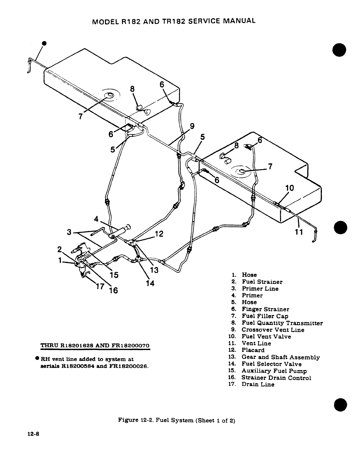
MODEL
R182
AND
TR182
SERVICE
MANUAL
3
11
13
715
1.
Hose
~7
1^*14
2.
Fuel
Strainer
1'
6
3.
Primer
Line
4.
Primer
5.
Hose
6.
Finger
Strainer
7.
Fuel
Filler
Cap
8.
Fuel
Quantity
Transmitter
9.
Crossover
Vent
Line
10.
Fuel
Vent-Valve
THRU
R18201628
AND
FR18200070
11.
Vent
Line
12.
Placard
RH
vent
line
added
to
system
at
13.
Gear and
Shaft
Assembly
serials
R18200584
and
FR18200026.
14.
Fuel
Selector
Valve
15.
Auxiliary
Fuel
Pump
16.
Strainer
Drain
Control
17.
Drain
Line
Figure
12-2.
Fuel
System
(Sheet
1
of
2)
12-8
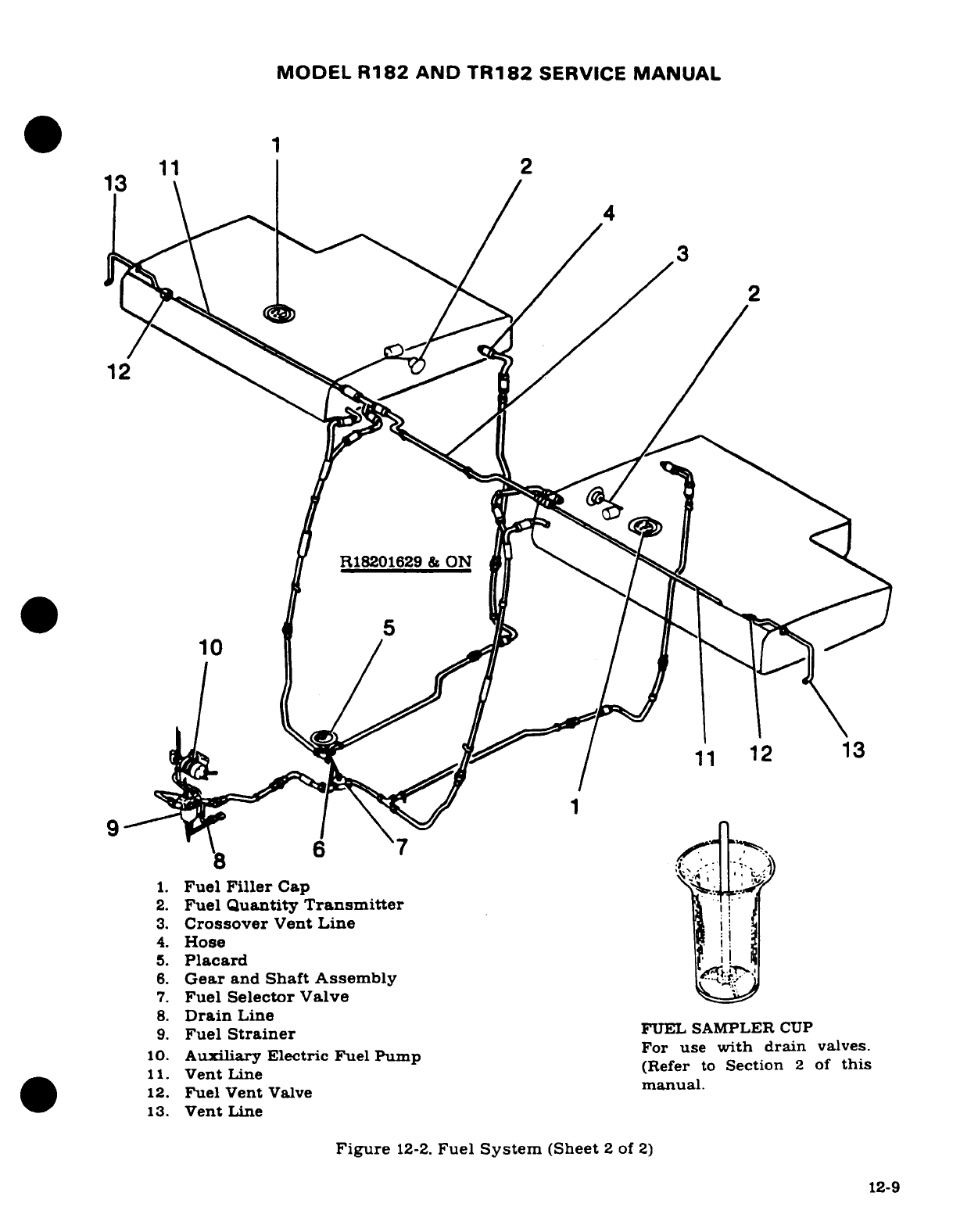
MODEL
R182
AND
TR182
SERVICE
MANUAL
2
13
11
2
12
't'4 13
R18201629
&
ON
j
.I
1.
Fuel
Filler
Cap
2.
Fuel
Quantity
Transmitter
3.
Crossover
Vent
Line
4.
Hose
5.
Placard
6.
Gear
and
Shaft Assembly
7.
Fuel
Selector Valve
8.
Drain
Line
9.
Fuel
Strainer
FUEL SAMPLER
CUP
For
use
with
drain
valves.
10.
Auxiliary
Electric Fuel
Pump
For
use
wth
drain
valves.
11.
VentLine
(Refer
to
Section
2
of
this
12.
Fuel
Vent
Valve
manual.
13.
Vent
Line
Figure
12-2.
Fuel
System
(Sheet
2
of
2)
12-9
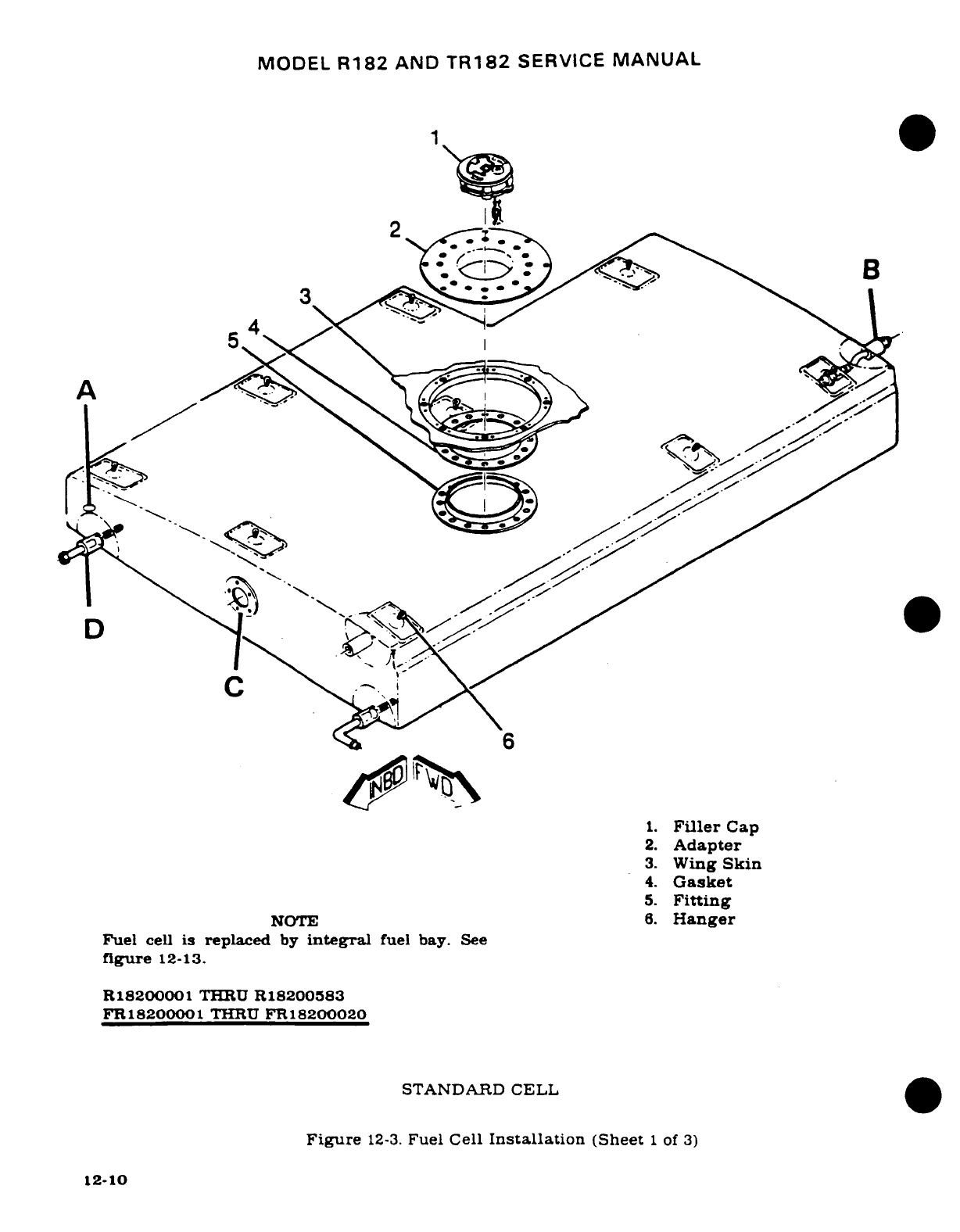
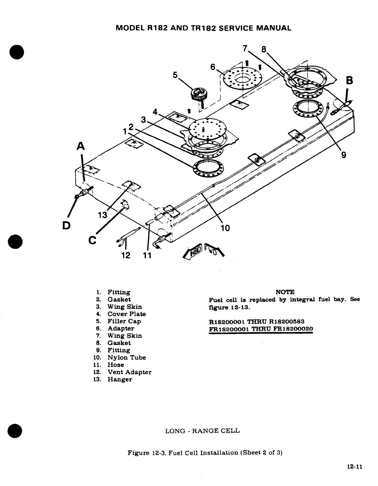
MODEL
R182
AND
TR182
SERVICE
MANUAL
7
8
6
.
5
B
12
11
4 ^\
1.
Fitting
NOTE
2.
Gasket
Fuel
cell
is
replaced
by
integral
fuel
bay.
See
3.
Wing
Skin
figure
12-13.
4.
Cover
Plate
5.
Filler
Cap
R18200001
THRU
R18200583
6.
Adapter
FR18200001
THRU
FR18200020
7.
Wing
Skin
8.
Gasket
9.
Fitting
10.
Nylon
Tube
11.
Hose
12.
Vent
Adapter
13.
Hanger
LONG
-
RANGE
CELL
Figure
12-3.
Fuel
Cell
Installation
(Sheet
2
of
3)
12-11
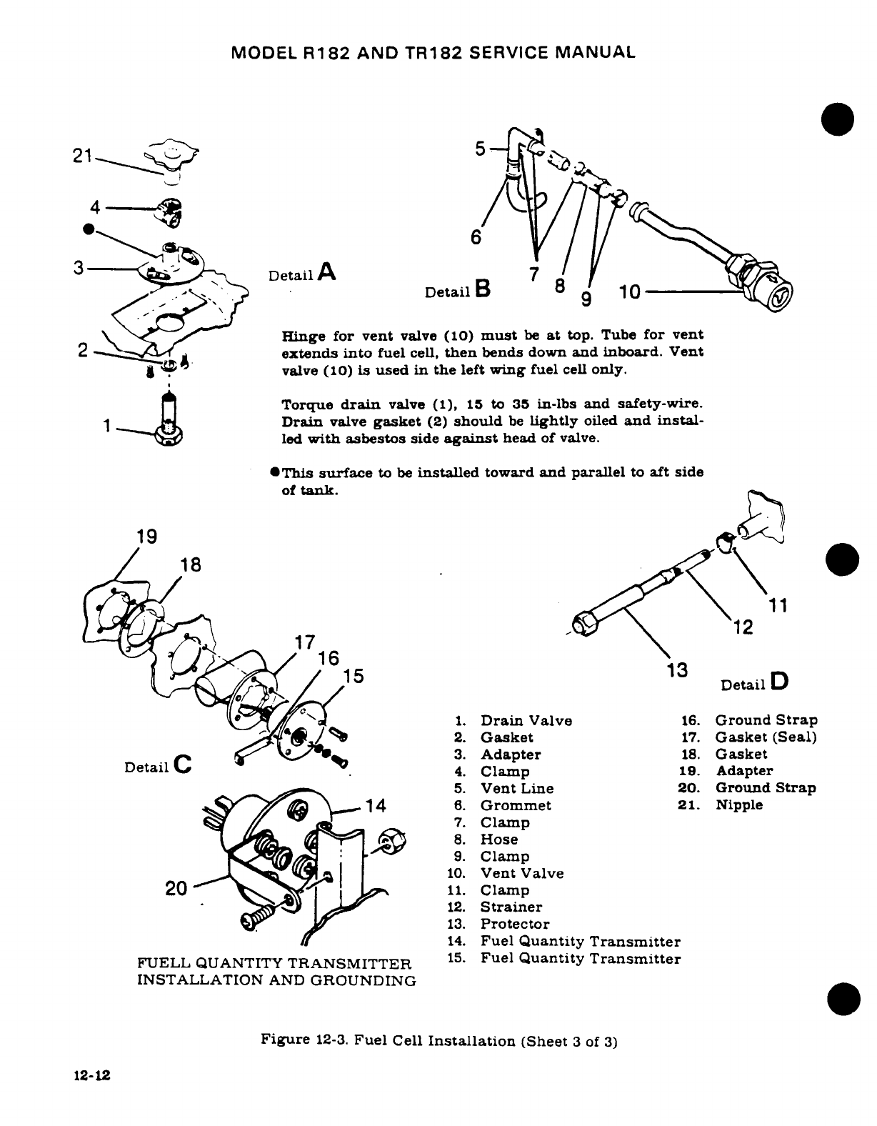
MODEL
R182
AND
TR182
SERVICE
MANUAL
21
5
6
3Wi tDetailA
7
DetailB
8
9
10
Hinge for vent
valve
(10)
must
be
at
top.
Tube
for
vent
2,:!Iextends
into
fuel
cell,
then
bends
down
and
inboard.
Vent
valve
(10)
is
used
in
the
left
wing
fuel
cell
only.
Torque
drain
valve (1),
15
to
35
in-lbs
and safety-wire.
Drain
valve
gasket
(2)
should
be
Lightly
oiled
and
instal-
led
with
asbestos
side
against
head
of
valve.
*This
surface
to
be
installed
toward
and
parallel
to
aft side
of
tank.
19
18
11
ii
.
1712
16
13
615
13
Detail
D
1.
Drain
Valve
16.
Ground
Strap
2.
Gasket
17.
Gasket
(Seal)
Detail~ ~C ~v
W
3.
Adapter
18.
Gasket
4.
Clamp
19.
Adapter
5.
Vent
Line
20.
Ground
Strap
614
6.
Grommet
21.
Nipple
7.
Clamp
8.
Hose
9.
Clamp
10.
Vent
Valve
20
n
A^
11.
Clamp
12.
Strainer
13.
Protector
14.
Fuel
Quantity
Transmitter
FUELL
QUANTITY
TRANSMITTER
15.
Fuel
Quantity
Transmitter
INSTALLATION
AND
GROUNDING
Figure
12-3.
Fuel
Cell
Installation
(Sheet
3
of
3)
12-12
MODEL
R182
AND
TR182
SERVICE
MANUAL
h.
Working
through
filler
neck
opening,
loosen
snap
fasteners.
Tilt
snap
fasteners
slightly
when
pulling
cell
free,
to
prevent
tearing
rubber.
i.
Collapse
and
carefully
fold
cell
for
removal,
then
work
cell
out
of
fuel
bay
through
filler
opening
in
upper
wing
surface.
Use
care
when
removing
to
prevent
damage
to
cell.
j.
Unfold
cell
and
remove
fittings,
snap
fasteners
and
fuel
sump
drain
adapter.
12-9.
REPAIR.
NOTE
For
fuel
cell
repair
information, refer
to
Cessna
Service
News
Letter
dated
August
28, 1970.
For
minor
repair,
a
fuel
cell
repair
kit
is
available
from
Goodyear,
complete
with
required
materials
and
instructions.
12-10.
INSTALLATION.
a.
Clean
all
filings,
trimmings,
loose
washers,
bolts,
nuts,
etc.
from
cell
compartment.
b.
Round
all
sharp
edges
or
rivets,
and
tape over
them
to
protect
bladder.
c.
Inspect
cell
compartment
just prior
to
installation
of
a
cell
for
conditions
noted
in
the
preceding
steps.
d.
Install
fuel
drain adapter
and
snap
fasteners.
e.
Check
to
insure
cell
is
warm
enough
to
be
flexible
and
fold
as
necessary
to
fit
through
fuel
cell
access
opening.
f.
Place
cell
in
compartment,
develop
it
out
to
full
size
and
attach
fasteners,
then
reverse
procedures
outlined
in
preceding
paragraph
for
installation. Install
all
new
gaskets
when
installing
cell.
g. On
aircraft
equipped
with
long-range
cells,
install
nylon
vent
tube
inside
cell,
inserting
tube
through
four
hangers
in
top
of
cell.
If
a
replacement
cell
is
being
installed,
use
nylon
vent
tube removed
from
old
cell
and/or
order tube
from
applicable
Parts
Catalog.
h.
When
tightening
screw-type
clamps
on
standard
fuel
cell
(BTC-39)
construction),
apply
a
maximum
of
torque
of
20
inch-pounds
to
clamp
screws.
On
the
extended
range
fuel
cell
(BTC-67
construction),
apply
a
maximum
torque
of
30-35
inch-pounds
to
clamp
screws.
A
light application
of
#
10
engine
oil
to
metal
tube
aids
installation
into
nipple
fittings.
i.
When
installing
filler
adapter,
cover
plate
and
fuel
quantity
transmitter
to
the
wing
and fuel
cell,
tighten attaching
screw
evenly.
The
sealing
or
compression
surfaces
must
be
assembled
when
absolutely
dry
(NO
SEALING
PASTE
IS
TO
BE
USED).
j.
After
installation
has
been
completed,
cell should
be
inspected
for
final
fit
within
compartment,
making certain
that
cell
is
extended
out
to the
structure
and
no
corners
are
folded
in.
k.
The
final
inspection,
prior
to
closing
the
cell,
should
be
a
close
check
to
insure that
cell
is
free
of
foreign
matter
such
as
lint,
dust,
oil
or
any
installation
equipment.
If
a
cell
is
not
thoroughly
clean,
it
should
be
cleaned
with
a
lint-free
cloth,
soaked
in
water,
alcohol,
or
kerosene.
NO
OTHER
SOLVENT
SHALL
BE
USED.
12-11.
VENTED
FUEL FILLER
CAPS.
12-12.
DESCRIPTION.
The
filler
cap
assemblies
may
be
constructed
of
either
metal
or
red
plastic.
Both
cap
assemblies
incorporate
a
vent
safety
valve
that
provides
vacuum
and
positive
pres-
sure
relief for
their
respective
fuel
tanks.
It
is
important
that
both
type
caps
be
cleaned
on
an
as
required
basis,
if
proper
filler
cap
sealing
is
to
be
maintained.
12-13
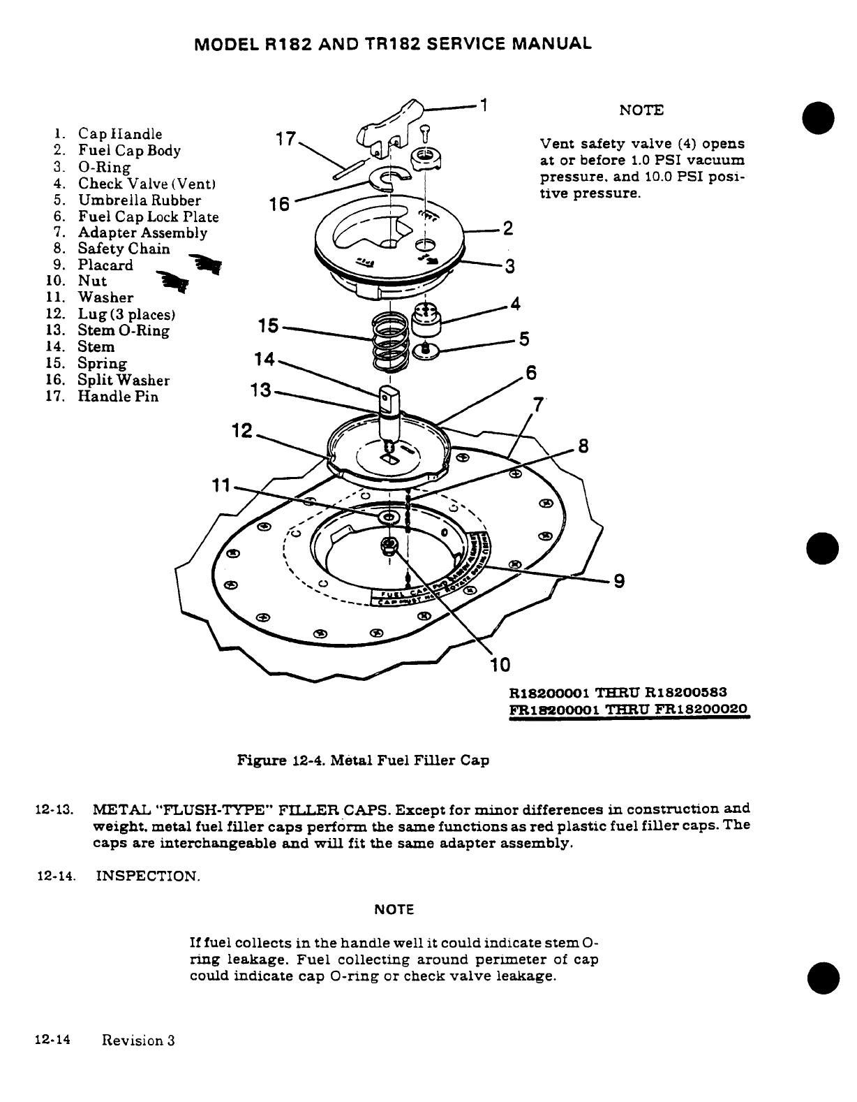
MODEL
R182
AND
TR182
SERVICE
MANUAL
-
1
NOTE
1.
Cap
Iandle
NT
2.
Fuel
CapBody
17
.
Vent
safety
valve
(4)
opens
3.
O-Ring
at
or
before
1.0
PSI
vacuum
4.
Check
Valve
(Vent)
pressure,
and
10.0
PSI
posi-
5.
Umbrella
Rubber
16
tive
pressure.
6.
Fuel
Cap
Lock
Plate
7.
Adapter
Assembly
2
8.
Safety
Chain
9.
Placard
-r
3
10.
Nut
11.
Washer
12.
Lug
(3
places)
^^
13.
Stem
O-Ring
1
5
14.
Stem
15.
Spring
14
16.
Split
Washer
6
17.
Handle
Pin
13
12
-4.
Metal Fuel
Filler
Cap
11
10
R18200001
THERU
R18200583
FRle200001
THRU
FR18200020
Figure
12-4.
Metal
Fuel
Filler
Cap
12-13.
METAL
"FLUSH-TYPE"
FI.TER
CAPS.
Except for
minor
differences
in
construction
and
weight,
metal
fuel
filler
caps
perform
the
same
functions
as
red
plastic
fuel
filler
caps.
The
caps
are
interchangeable
and
will
fit
the
same
adapter
assembly.
12-14.
INSPECTION.
NOTE
If
fuel
collects
in
the
handle
well
it could
indicate
stem
O-
ring
leakage.
Fuel
collecting around
perimeter
of
cap
could
indicate
cap O-ring
or
check
valve
leakage.
T
12-14
Revision
3
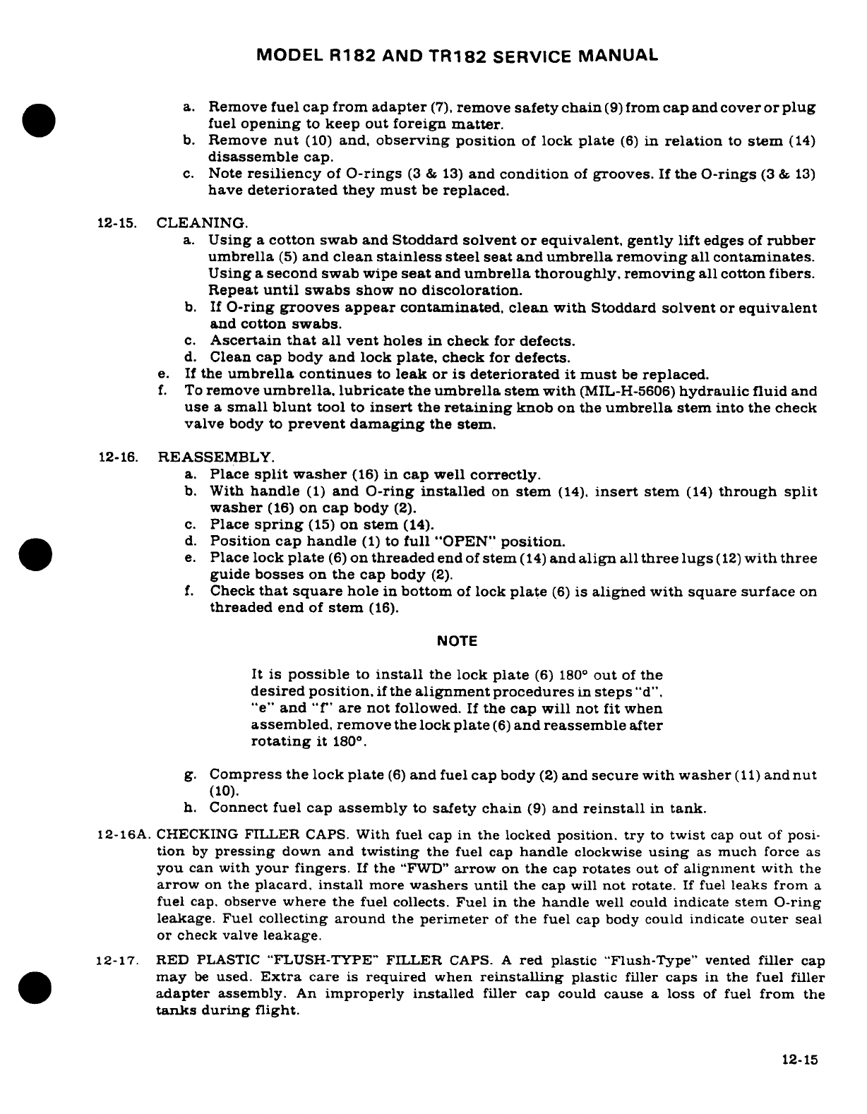
MODEL
R182
AND
TR182
SERVICE
MANUAL
a.
Remove
fuel cap
from
adapter
(7),
remove
safety
chain
(9)
from
cap
and
cover
or plug
fuel
opening
to
keep out
foreign
matter.
b.
Remove
nut
(10)
and,
observing position
of
lock
plate
(6)
in
relation
to
stem
(14)
disassemble
cap.
c.
Note
resiliency
of
O-rings
(3
&
13)
and
condition
of
grooves.
If
the
O-rings
(3
&
13)
have
deteriorated
they
must
be
replaced.
12-15.
CLEANING.
a.
Using
a
cotton
swab and
Stoddard
solvent
or
equivalent, gently
lift
edges
of
rubber
umbrella
(5)
and
clean
stainless
steel seat and
umbrella removing
all
contaminates.
Using
a
second swab
wipe
seat
and
umbrella
thoroughly, removing
all
cotton
fibers.
Repeat
until
swabs
show
no
discoloration.
b.
If
O-ring
grooves
appear
contaminated, clean
with
Stoddard
solvent
or
equivalent
and
cotton
swabs.
c.
Ascertain
that
all
vent
holes
in
check
for
defects.
d.
Clean
cap
body
and lock
plate,
check
for
defects.
e.
If
the
umbrella continues
to
leak
or
is
deteriorated
it
must
be
replaced.
f.
To
remove
umbrella,
lubricate
the
umbrella
stem
with
(MIL-H-5606)
hydraulic
fluid
and
use
a
small
blunt
tool
to
insert
the
retaining
knob
on
the
umbrella
stem
into
the
check
valve
body
to
prevent
damaging
the
stem.
12-16.
REASSEMBLY.
a.
Place
split
washer
(16)
in
cap
well
correctly.
b.
With
handle
(1)
and
O-ring
installed
on
stem
(14),
insert
stem
(14)
through
split
washer
(16)
on
cap
body
(2).
c.
Place
spring
(15)
on
stem
(14).
d.
Position cap
handle
(1)
to
full
"OPEN"
position.
e.
Place
lock
plate
(6)
on
threaded
end
of
stem
(14)
and
align
all
three
lugs
(12)
with
three
guide
bosses
on
the cap
body
(2).
f.
Check
that
square
hole
in
bottom
of
lock
plate
(6)
is
aligned
with square
surface
on
threaded
end
of
stem
(16).
NOTE
It
is
possible
to
install
the lock
plate
(6)
180
°
out
of
the
desired
position,
if
the
alignment
procedures
in
steps
"d",
"e"
and
"f"
are
not
followed.
If
the
cap
will
not fit
when
assembled,
remove
the lock
plate
(6)
and
reassemble
after
rotating
it
180
° .
g.
Compress
the
lock
plate
(6)
and
fuel
cap
body
(2)
and
secure with
washer
(11)
and
nut
(10).
h.
Connect
fuel
cap
assembly
to
safety
chain
(9)
and
reinstall
in
tank.
12-16A. CHECKING
FILLER
CAPS.
With
fuel
cap
in
the
locked
position.
try
to
twist
cap
out
of
posi-
tion
by
pressing
down
and
twisting
the
fuel
cap
handle
clockwise
using
as
much
force as
you
can
with
your
fingers.
If
the
"FWD"
arrow
on
the
cap
rotates
out
of
alignment
with
the
arrow
on
the
placard,
install
more
washers
until
the
cap
will
not
rotate.
If fuel
leaks
from
a
fuel
cap,
observe
where the
fuel
collects.
Fuel
in
the handle
well
could
indicate stem
O-ring
leakage.
Fuel
collecting
around
the
perimeter
of
the
fuel
cap
body
could indicate
outer
seal
or
check
valve
leakage.
12-17.
RED
PLASTIC
"FLUSH-TYPE"
FILLER
R
CAPS.
A
red
plastic
"Flush-Type"
vented
filler
cap
may
be
used.
Extra
care
is
required
when
reinstalling
plastic
filler
caps
in
the fuel
filler
adapter
assembly.
An
improperly
installed
filler
cap
could
cause
a
loss
of
fuel
from
the
tanks
during
flight.
12-15
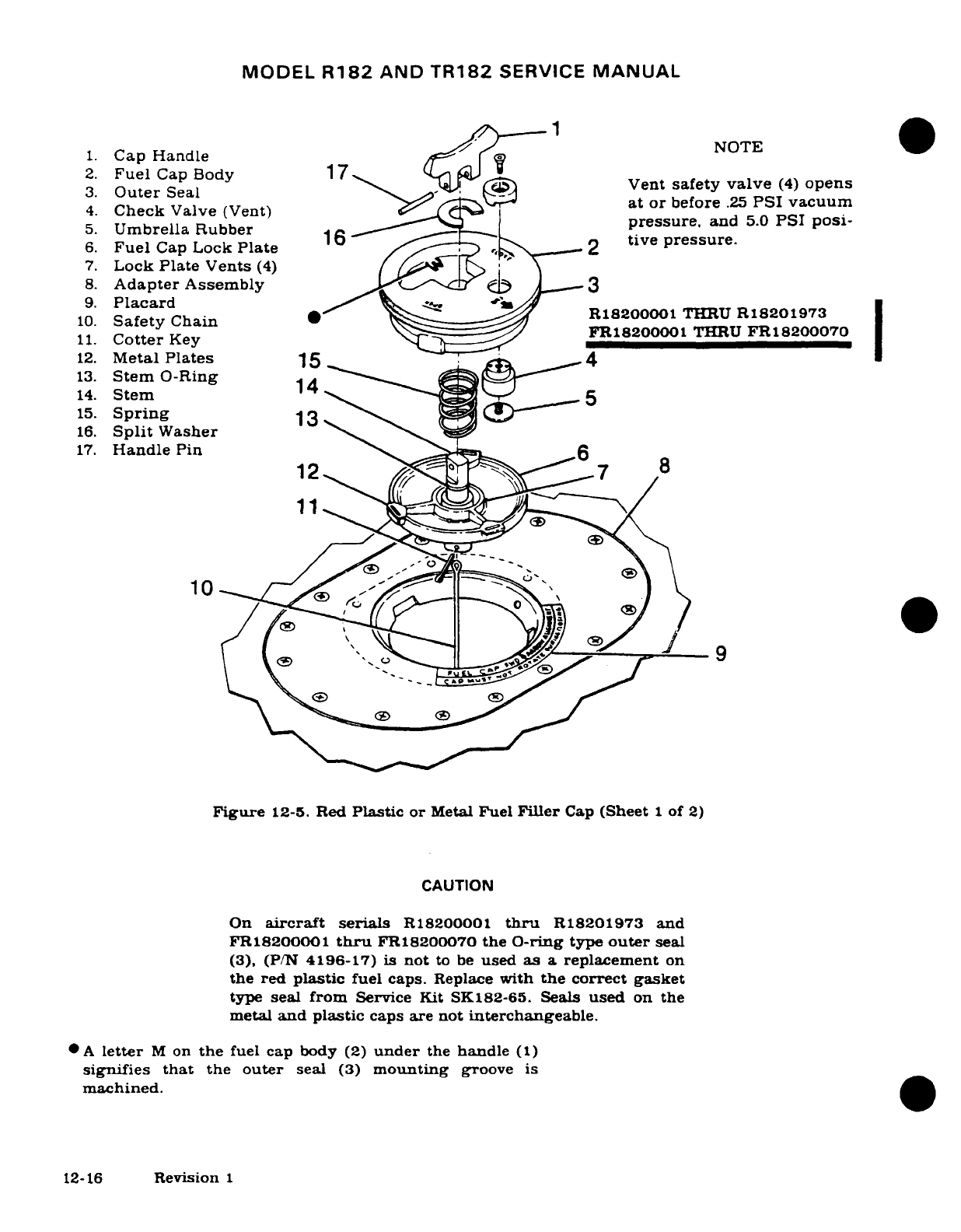
MODEL
R182
AND
TR182
SERVICE
MANUAL
1.
Cap Handle
2.
Fuel
Cap
Body
2.
Fuel
Cap Body
1
7
Vent
safety
valve
(4)
opens
3.
Outer
Seal
4.
Check
Valve
(Vent)
at
or
before
.25
PSI vacuum
5.
Umbrella
Rubber
pressure.
and
5.0
PSI
posi-
16
tive
pressure.
6.
Fuel
Cap
Lock
Plate
lo
2
tive
pressure.
7.
Lock
Plate
Vents
(4)
8.
Adapter
Assembly
3
9.
Placard
n10.
Safety
Chain
0^" ^ f
FR18200001
THRU
R18201973
11.
Cotter
Key
11.
Cotter
Key
FR18200001
THRU
FR18200070
12.
Metal
Plates
15
-
m
4
13.
Stem
O-Ring
14
14.
Stem
5
15.
Spring
13
16.
Split
Washer
17.
Handle
Pin
6
12- 7-
8
10
7
Figure
12-5.
Red
Plastic
or
Metal
Fuel
Filler
Cap
(Sheet
1
of
2)
CAUTION
On
aircraft
serials
R18200001
thru
R18201973 and
FR18200001
thru
FR18200070
the
O-ring
type
outer
seal
(3),
(P/N
4196-17)
is
not
to
be
used
as
a
replacement
on
the red
plastic
fuel
caps.
Replace
with
the
correct gasket
type
seal
from
Service Kit SK182-65.
Seals
used
on
the
metal
and
plastic
caps
are not
interchangeable.
*A
letter
M
on
the
fuel
cap body
(2)
under
the
handle
(1)
signifies
that
the
outer
seal
(3)
mounting
groove
is
machined.
12-16
Revision
1
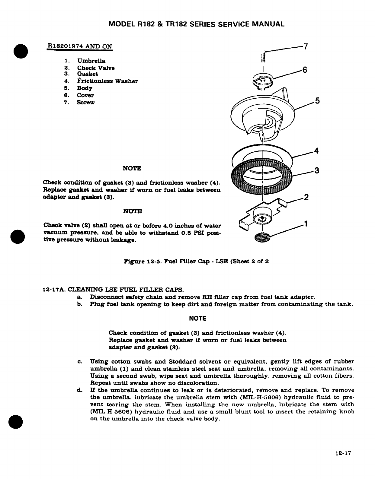
MODEL
R182
&
TR182
SERIES
SERVICE
MANUAL
R18201974
AND
ON
1.
Umbrella
2.
Check
Valve
3.
Gasket
4.
Frictionless
Washer
5.
Body
6.
Cover
7.
Screw
5
NOTE
3
Check
condition of
gasket
(3)
and
frictionless
washer
(4).
Replace
gasket
and
washer
if
worn
or
fuel
leaks
between
adapter
and
gasket
(3).
2
NOTE
Check
valve
(2)
shall
open
at
or
before
4.0
inches
of
water
vacuum
pressure,
and
be
able
to
withstand
0.5
PSI
posi-
tive
pressure
without
leakage.
Figure
12-5.
Fuel
Filler
Cap
-
LSE
(Sheet
2
of
2
12-17A.
CLEANING
LSE
FUEL FILLER
CAPS.
a.
Disconnect
safety
chain
and
remove
RH
filler
cap from
fuel
tank
adapter.
b.
Plug
fuel
tank
opening
to keep
dirt
and
foreign matter
from
contaminating the
tank.
NOTE
Check
condition
of
gasket
(3)
and frictionless
washer
(4).
Replace
gasket
and
washer
if
worn
or
fuel
leaks
between
adapter
and
gasket
(3).
c.
Using
cotton
swabs
and Stoddard
solvent
or
equivalent, gently
lift
edges
of
rubber
umbrella
(1)
and
clean
stainless
steel seat
and
umbrella, removing
all
contaminants.
Using
a
second
swab,
wipe
seat
and
umbrella
thoroughly,
removing
all
cotton
fibers.
Repeat
until
swabs
show
no
discoloration.
d.
If
the
umbrella
continues
to
leak or
is
deteriorated,
remove
and
replace.
To
remove
the umbrella,
lubricate the
umbrella
stem
with
(MIL-H-5606)
hydraulic
fluid
to
pre-
vent
tearing
the stem.
When
installing
the
new
umbrella,
lubricate
the
stem
with
(MIL-H-5606)
hydraulic
fluid
and use
a
small
blunt
tool
to
insert
the
retaining
knob
on
the
umbrella
into
the
check
valve
body.
12-17
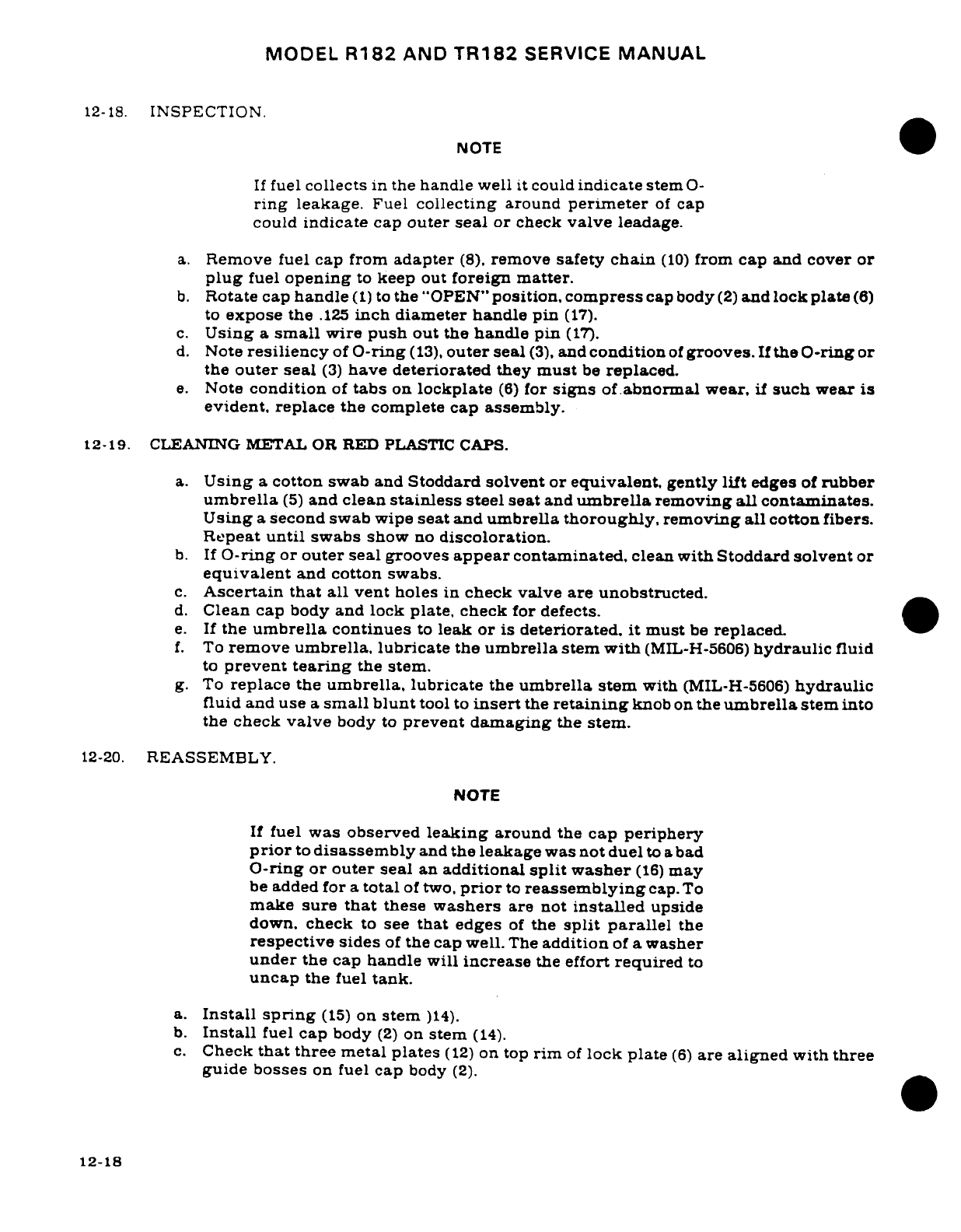
MODEL
R182
AND
TR182
SERVICE
MANUAL
12-18.
INSPECTION.
NOTE
If
fuel
collects
in
the
handle well
it
could
indicate
stem
O-
ring
leakage.
Fuel
collecting
around
perimeter
of
cap
could
indicate
cap
outer
seal
or
check
valve
leadage.
a.
Remove
fuel cap
from
adapter
(8),
remove
safety
chain
(10)
from
cap
and
cover
or
plug
fuel
opening
to
keep
out
foreign
matter.
b.
Rotate
cap
handle
(1)
to
the
"OPEN"
position,
compress
cap
body
(2)
and
lock
plate
(6)
to
expose
the
.125
inch
diameter
handle
pin
(17).
c.
Using
a
small
wire
push
out
the
handle
pin
(17).
d.
Note
resiliency
of
O-ring
(13),
outer
seal
(3),
and
condition
of
grooves.
If
the
O-ring
or
the
outer
seal
(3)
have
deteriorated
they
must
be
replaced.
e.
Note
condition
of
tabs
on
lockplate
(6)
for
signs
of
abnormal
wear,
if
such
wear
is
evident,
replace
the complete
cap
assembly.
12-19.
CLEANING
METAL
OR
RED
PLASTIC
CAPS.
a.
Using
a
cotton
swab
and
Stoddard
solvent
or
equivalent,
gently
lift
edges
of
rubber
umbrella
(5)
and
clean
stainless
steel
seat
and
umbrella
removing
all
contaminates.
Using
a
second
swab
wipe
seat
and
umbrella
thoroughly,
removing
all
cotton
fibers.
Repeat
until
swabs
show
no
discoloration.
b.
If
O-ring
or
outer
seal
grooves
appear
contaminated,
clean
with Stoddard
solvent
or
equivalent
and
cotton
swabs.
c.
Ascertain
that
all
vent
holes
in
check
valve
are
unobstructed.
d.
Clean
cap
body
and lock
plate,
check
for
defects.
e.
If
the
umbrella
continues
to
leak
or
is
deteriorated,
it
must
be
replaced.
f.
To
remove
umbrella, lubricate
the
umbrella
stem
with
(MIL-H-5606)
hydraulic
fluid
to
prevent
tearing
the
stem.
g.
To
replace
the
umbrella,
lubricate
the
umbrella
stem
with
(MIL-H-5606)
hydraulic
fluid
and
use
a
small
blunt
tool
to
insert
the
retaining
knob
on
the
umbrella
stem
into
the check
valve
body
to
prevent
damaging
the
stem.
12-20.
REASSEMBLY.
NOTE
If
fuel
was observed
leaking
around
the
cap
periphery
prior
to
disassembly
and
the
leakage
was
not
duel
to
a
bad
O-ring
or
outer
seal
an
additional
split
washer
(16)
may
be
added
for
a
total
of
two,
prior
to
reassemblying
cap.
To
make
sure
that
these
washers
are
not
installed
upside
down,
check
to
see
that
edges
of
the
split
parallel
the
respective
sides
of
the cap
well.
The
addition
of
a
washer
under
the
cap
handle
will
increase
the
effort
required
to
uncap
the
fuel
tank.
a.
Install spring
(15)
on
stem
)14).
b.
Install
fuel
cap
body
(2)
on
stem
(14).
c.
Check
that
three
metal
plates
(12)
on
top
rim
of
lock
plate
(6)
are
aligned
with
three
guide
bosses
on fuel
cap
body
(2).
12-18
MODEL
R182
AND
TR182
SERVICE
MANUAL
CAUTION
It is
possible
to
install
the
handle
pin
in
the
pin
hole
180
°
out
of
the
desired
position,
if
the
alignment
procedures
in
step
"c"
is
not
followed.
If
the
handle
(1)
is
not
installed
properly
the
FWD
arrow
on
the cap
will
not
align
with
the
arrow
on
the
placard
(9)
when
the
cap
is
reinstalled.
d.
Compress
cap
body
(2)
and
lock
plate
(6),
install
split
washer(s)
(16)
as
required.
e.
Install
cap
handle
(1)
on
stem
(14)
so
that
the
handle
(1)
will
be
in
the
open
position.
f.
Insert
handle
pin
(17)
through
handle
(1)
and
stem
(14).
g.
Connect
fuel
cap
assembly
to
safety
chain
(10)
and
reinstall
fuel
cap.
Make
certain
that
the
arrow
on
the
fuel
cap
body
(2)
and
the
arrow
on
the
placard
(9)
align.
12-20A. LEAK
TESTING
METAL
OR
RED
PLASTIC
FILLER
CAPS.
The
following
procedure
may
be
used
to
detect
fuel
filler
cap
leakage.
a
Service
the
aircraft
with
approved
fuel
filling
each
bay.
b.
Place
the
fuel
selector
in
the
OFF
position.
c.
Plug
one
of
the
fuel
bay
vent
lines
(where
it
protrudes
beneath
the
wing)
with
a
small
rubber
plug
or
tape.
d.
Connect
a
rubber
hose
to
the
other
vent.
Then
tee
into
this
hose
a
pressure
measur-
ing
device,
such
as
a
water
manometer,
manifold
pressure
gage,
or
airspeed
indi-
cator.
e.
Blow
into
the
open
end
of
the
hose.
The
pressure
must
not
exceed
.7
psi
which
equals
20
inches
of
water
on
a
water
manometer,
or
1.43
inches
Hg
on
a
manifold
pressure
gage,
or
174
Kts
on
an
airspeed
indicator.
WARNING
Do
not
inhale
fuel
vapor
while
blowing
into
the
rubber
hose.
f. It
may
take
several
applications
of
pressure
to
bring
the
bay
to
the
desired
pressure
level.
WARNING
Do
not
apply
regulated
or
unregulated
air pressure
from
an
air
compressor
to
the
fuel
vent.
Over
inflation
and
major
structural
damage
will
occur
if more
than
.7
psi
is
applied.
g.
Pinch
or
close
the
rubber
hose
to
sustain
pressure
in
the
fuel
bay.
h.
Apply
a
soap
solution
to
the
fuel
filler
caps
and
inspect
for
leakage
around
the rub-
ber
seal
to
filler neck
junction,
the
fuel
cap
vent,
and
the
fuel
cap
handle
stem.
Load
the
cap
sideways
in
all
directions
by
pressing
on
the
fuel
cap
vent
housing
by
hand.
NOTE
No
leakage
is
permissible.
If
leaks
are present,
replace
the
cap
with
a
new
unit
or
repair
in
accordance
with
Cessna
Service
Information
Letter
SE
80-59
Supplement
No.
1,
dated
June
23,
1980.
12-18A/(12-18B
blank)
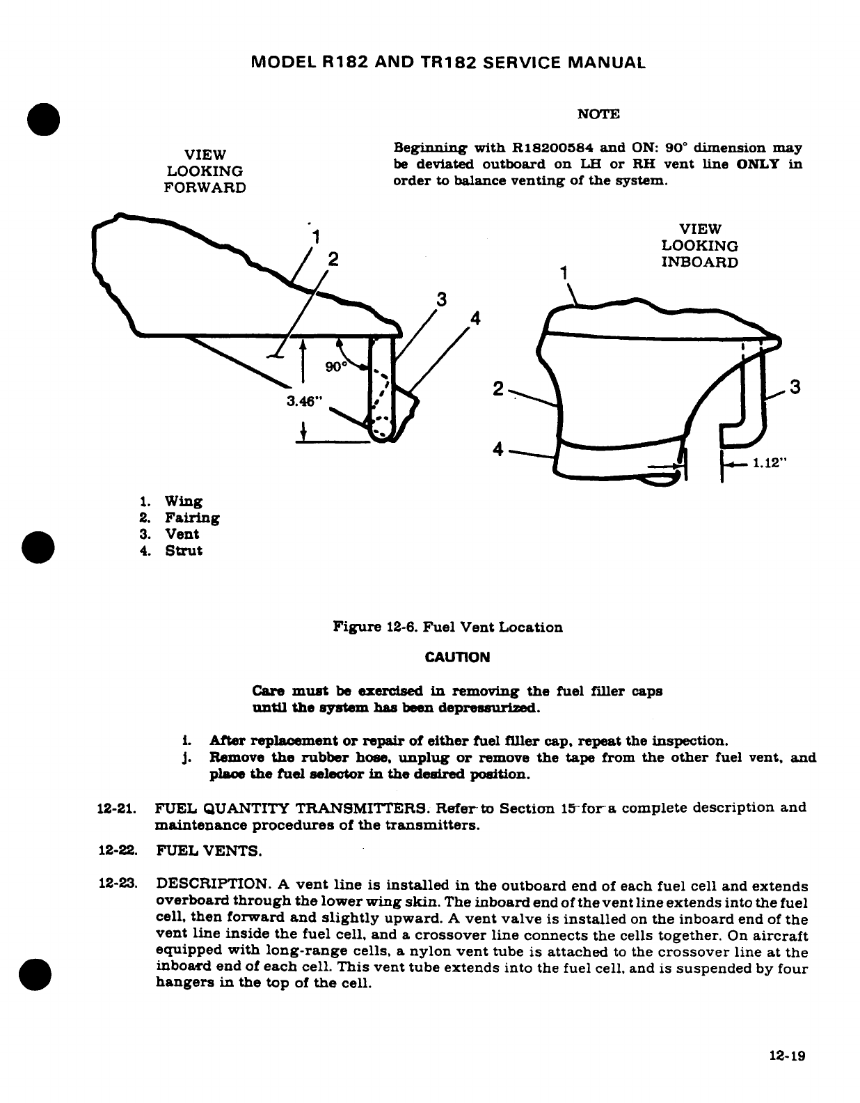
MODEL
R182
AND
TR182
SERVICE
MANUAL
NOTE
VIEW
Beginning
with
R18200584
and
ON:
90
°
dimension
may
LOOKING
be
deviated
outboard
on
LH
or
RH
vent
line
ONLY
in
FORWARD
order
to
balance
venting
of
the
system.
VIEW
LOOKING
>/
2 1INBOARD
3
S
900
3
3.46"
4
1.
Wing
2.
Fairing
3.
Vent
4.
Strut
Figure
12-6.
Fuel
Vent
Location
CAUTION
Care
must
be
exercised
in
removing
the
fuel
filler
caps
until
the
system has
been
depressurized.
i.
After
replacement
or
repair
of
either
fuel
filler
cap,
repeat
the
inspection.
J.
Remove
the
rubber
hose,
unplug
or
remove
the
tape
from
the
other
fuel
vent,
and
place
the
fuel
selector
in
the
desired position.
12-21.
FUEL
QUANTITY
TRANSMITTERS.
Refer
to
Section
15for-a
complete
description
and
maintenance
procedures
of
the
transmitters.
12-22.
FUEL
VENTS.
12-23.
DESCRIPTION.
A
vent
line
is
installed
in
the
outboard
end
of
each
fuel cell and
extends
overboard
through
the
lower
wing
skin.
The
inboard
end
of
the
vent line
extends
into
the
fuel
cell,
then
forward
and
slightly
upward.
A
vent
valve
is
installed
on
the inboard
end
of
the
vent
line
inside
the
fuel
cell,
and
a
crossover
line
connects
the
cells
together.
On
aircraft
equipped with
long-range
cells,
a
nylon
vent
tube
is
attached
to
the
crossover
line
at
the
inboard
end
of
each
cell.
This
vent tube
extends
into
the fuel
cell,
and
is
suspended
by four
hangers
in
the
top
of
the
cell.
12-19
MODEL
R182
AND
TR182
SERVICE
MANUAL
12-24.
CHECKING.
The
following
procedure
may
be
used
to
check
the
vent and
bleed hole
in
the
valve
assembly.
a.
Attach
a
rubber
tube
to
the
end
of
vent
line
beneath the
wing.
b.
Plug
vent
on
opposite
wing
from
one
being
tested.
c.
With
a
.5
psi
MAX
air
pressure
source,
slightly
pressurize
cell,
if
air
can
be
blown
into
cell,
vent line
is
open.
d.
After
cell
is
slightly
pressurized,
insert
end
of
rubber
tube into
a
container
of
water
and
watch
for
a
continuous stream
of
bubbles,
which
indicates
the
bleed
hole
in
valve
assembly
is
open
and
relieving
pressure.
e.
After
completion
of
step
"c",
again
slightly
pressurize
the cell.
Crimp
rubber
tube
to
retain
pressure
within
the
cell.
Loosen,
but
do
not
remove
filler
cap
on
opposite wing
to
check
cell
crossover
line.
If
pressure
escapes
from
filler
cap,
crossover
line
is-
open.
Remove
rubber
tube
from
end
of
vent
line beneath the
wing
after
completion
of
check.
NOTE
Remember
that
a
plugged
vent
line
or
bleed
hole
can
cause
either
fuel
starvation
or
the
pressurization
of
bays
by
fuel
expansion.
f.
Repeat
procedures
for opposite
fuel
bay.
NOTE
The
fuel
vent
line
protruding
beneath
the
wing
near
the
wing
strut
must
be
correctly aligned
to
avoid
possible
icing. Dimensions
are
shown
in
figure
12-6.
12-24A.
ADJUSTMENT.
On
aircraft
serials
R18200584
and
on,
uneven fuel
flow
from
the
integral
fuel
bays,
when
the
aircraft
fuel
selector
valve
is
positioned
to feed
from
both fuel
bays, can
be
caused
by
unequal
pressures
in
the
fuel
venting
system.
When
uneven
fuel
flow
is
observed.
the
venting
system may
be
checked
and
unequal
pressures
in
the
system
corrected
by
using
the following
procedures:
NOTE
The
following
procedure
should
be
accomplished
during
a
sequence
of
routine
flight
operations.
Special
flights
for
the
sole
purpose
of
checking
and
adjusting
fuel
tank
feed
rates
are
not
recommended.
a.
Inspect
the
venting
system
to
ensure
the
lines
are
open,
connections
secure
and
that
the
system
is
functioning
properly.
b.
Park
the
aircraft
on
a
level
surface
and
select
the
BOTH
position
on
the
fuel
selector.
Leave
the
aircraft
parked
until
the
tank
levels
are
equal
or
fill
both
tanks.
c.
With
the
fuel
selector
in
the
BOTH
position,
take
off
and
climb
to
an
altitude
where
the
air
is
smooth.
d.
Trim
the
aircraft
for
straight
and
level
flight.
Make
sure
the
aircraft
is
free
of
any
yaw
by
trimming
the
rudder
to
center
the
ball.
Cruise
at
the
top
of
the green
band
on
manifold
pressure
for
a
period
of
at
least
on
hour.
e.
At
the
end
of
the
hour
and
while
still
in
straight
and
level
flight,
take
note
of
the
fuel
tank
levels
and
indicated
on
the fuel
gage.
12-20
MODEL
R182
AND
TR182
SERVICE
MANUAL
f.
If
the
fuel
tank
levels
are
greater
than
5
gallons
apart,
land
the
aircraft
and
perform
the
following
procedure.
1.
Bend
the
underwing
vent
of
the
tank
which
had
the
highest
level outboard
1/4
inch.
2.
Bend
the underwing
vent
of
the
tank
which
had
the
lowest
level inboard
1/4
inch,
providing
the
vent
is
not
squarely
behind
the
strut.
Repeat
the
first
five
steps.
CAUTION
At
least
one
of
the vent
tubes
should
remain
behind
the
strut
to
ensure
that
icing
cannot
block
both
vents.
3.
No
adjustment
need
be
performed
when
satisfactory
equalization
of
fuel
tank
feeding
is
obtained.
12-25.
FUEL
SELECTOR
VALVE.
(See
figure
12-7.)
12-26.
DESCRIPTION.
A
four
position
fuel
selector
valve
is
located
beneath the floorboard
just
aft
and
slightly
to
the
left
of
the pedestal
structure.
A
shaft
incorporating
two
meshing
gears
links
the
valve
to
a
handle
and
shaft
assembly
mounted
on
the
pedestal structure.
The
positions
of
the
handle
are
labeled
OFF,
LEFT,
BOTH
ON
AND
RIGHT.
Valve
repair
is
limited
to
replacement
of
component
parts
only.
12-27.
REMOVAL
AND
INSTALLATION.
a.
Drain
all
fuel
from
wing
tanks,
fuel
strainer,
lines
and
selector
valve,
observing
precautions
outlined
in
paragraph
12-3.
b.
Remove
selector valve
handle
(1)
and
pedestal
cover.
c.
Peel
back
carpet
as
required
to
gain access
to
inspection
plates
aft
of
pedestal
structure.
d.
Disconnect
drive shaft
assembly
(4)
at
selector
valve
(6).
e.
Disconnect
and
cap
inlet
and
outlet
fuel
lines
to
valve.
f.
Remove
screws
attaching
valve
to
mounting
bracket
(10)
and
withdraw
valve.
g.
Reverse
preceding
steps
for
installation.
Service
aircraft
in
accordance with
Section
2,
turn
fuel
selector
valve
to
ON
position
and
check
for
leaks.
h.
Replace
items
removed
for
access.
12-28.
DISASSEMBLY.
a.
Remove
fuel
selector valve
in
accordance
with
paragraph
12-27.
b.
Remove
screws securing
cover
(2)
to
valve
body
(8)
and
carefully
remove
cover.
Discard
O-rings
(3)
and
(16),
but
retain
ball
(4)
and
spring
(5)
for
reinstallation.
c.
Slowly
withdraw
rotor
(6)
from
valve
body.
NOTE
Removal
of
rotor
(6)
will
allow
seal
(9),
O-ring
(10),
washer
(11)
and
spring
(12)
(one
each
installed
in
both
inlet
ports)
to
spring
free.
d.
Remove
washer
(7),
plug
(14),
and
O-ring
(13).
12-21
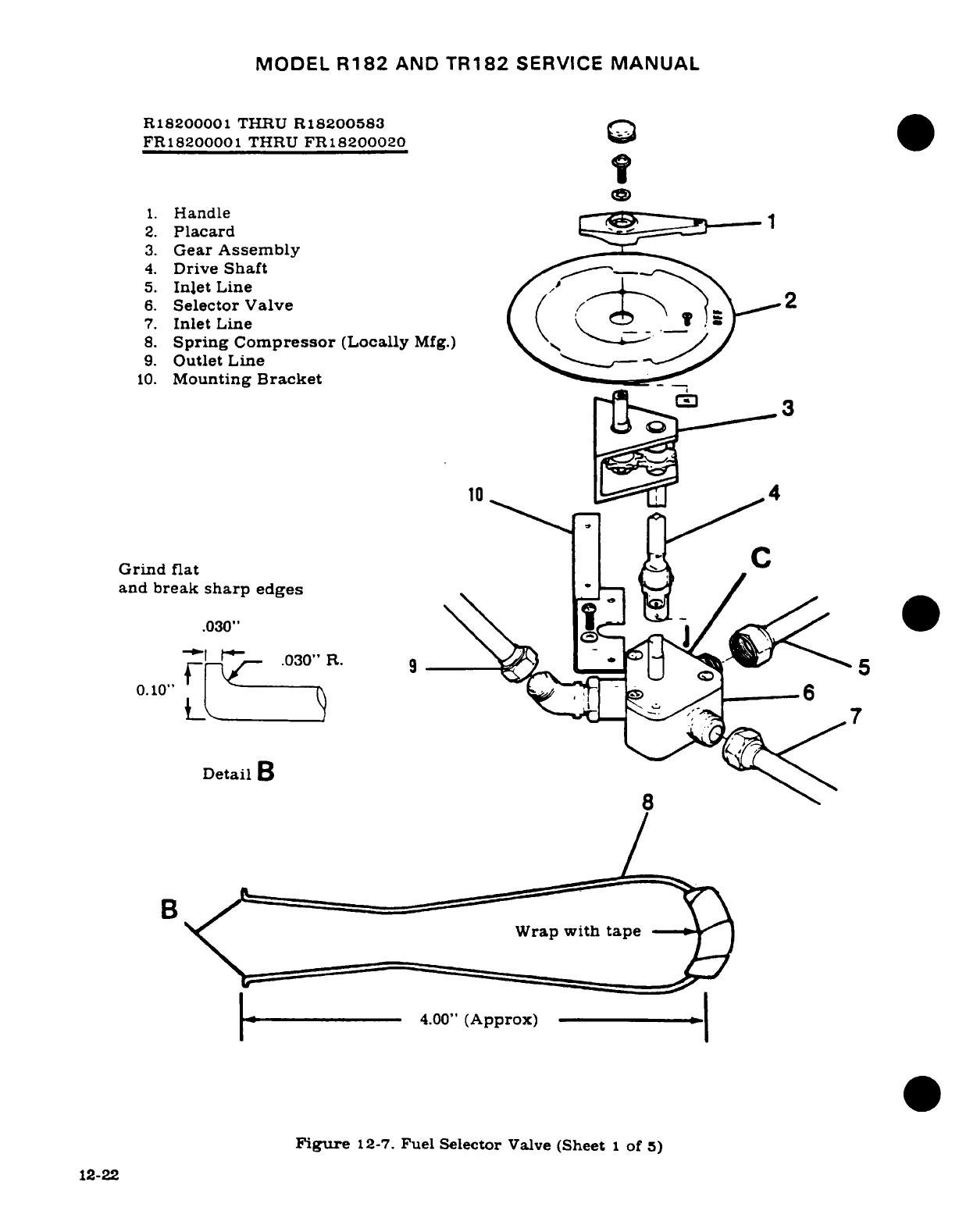
MODEL
R182
AND
TR182
SERVICE
MANUAL
R18200001
THRU
R18200583
<
FR18200001
THRU
FR18200020
1.
Handle
2.
Placard
3.
Gear
Assembly
4.
Drive
Shaft
5.
Inlet
Line
6.
Selector Valve
2
7.
Inlet
Line
8.
Spring
Compressor
(Locally
Mfg.)
9.
Outlet Line
10.
Mounting
Bracket
loC_
3
Grind
flat
and
break
sharp
edges
.030"
0.10"-
4.00"
(Approx)
Figure
12-7.
Fuel
Selector
Valve
(Sheet
1
of
5)
12-22
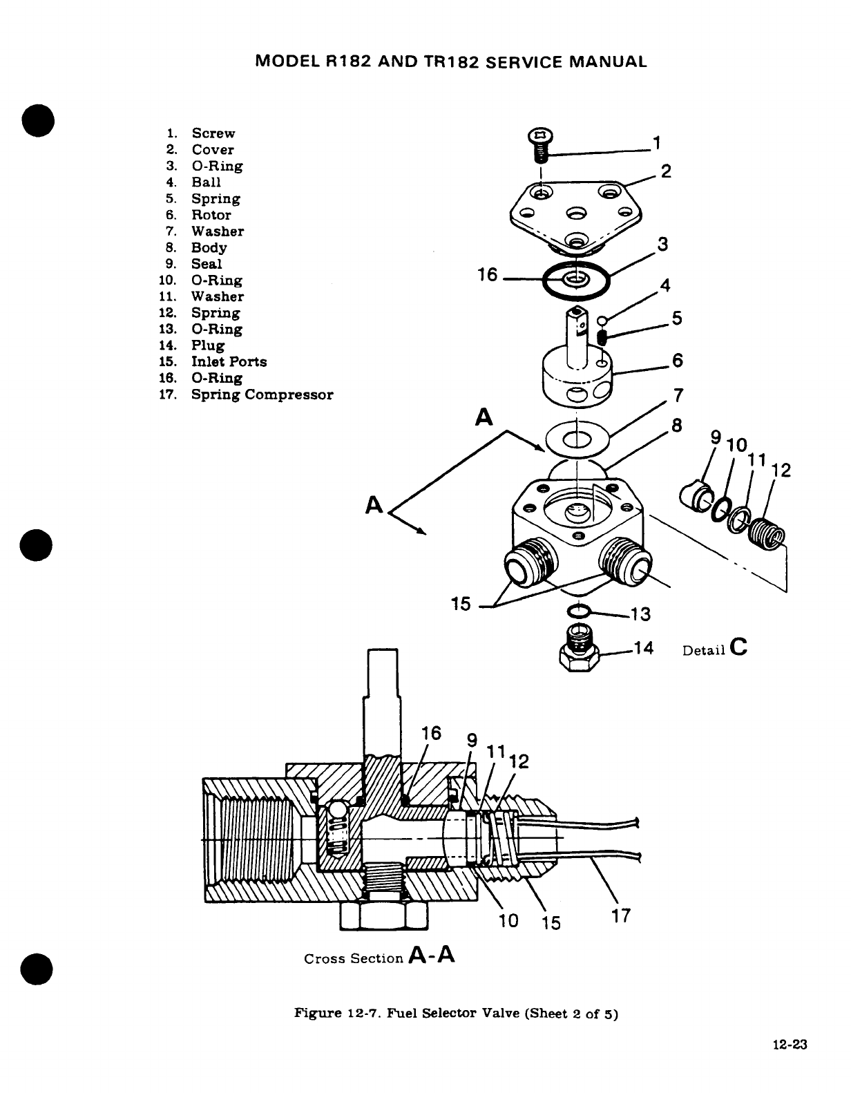
MODEL
R182
AND
TR182
SERVICE
MANUAL
1.
Screw
2.
Cover
3.
O-Ring
4.
Ball
2
5.
Spring
6.
Rotor
Q
G
7.
Washer
8.
Body
3
9.
Seal
10.
O-Ring
16
4
11.
Washer
12.
Spring
5
13.
O-Ring
i
14.
Plug
15.
Inlet
Ports
6
16.
O-Ring
17.
Spring
Compressor
7
10
15
1
15
(
0----l3
e1
1
4
Detail
C
16
9
11
10
15
17
Cross
Section
A-A
Figure
12-7.
Fuel
Selector
Valve
(Sheet
2
of
5)
12-23
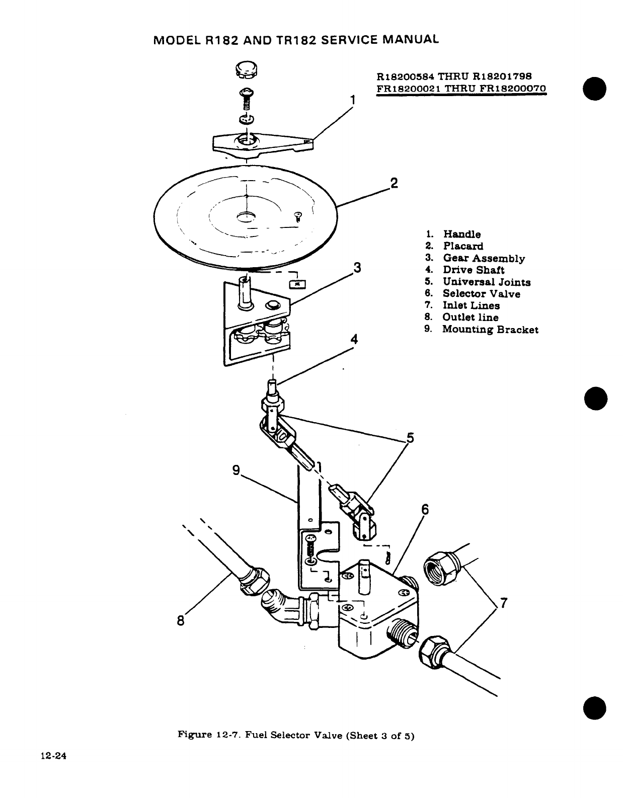
MODEL
R182
AND
TR182
SERVICE
MANUAL
0Q
R18200584
THRU
R18201798
1
FR18200021
THRU
FR18200070
1
1.
Handle
2.
Placard
3.
Gear
Assembly
m
5a
*3
4.
Drive
Shaft
_ \ rs~
/
5.
Universal
Joints
6.
Selector
Valve
:<2 63> <Q
^ 7
7.
Inlet
Lines
8.
Outlet
line
9.
Mounting
Bracket
9.,
/
~
4
56
Figure
12-7.
Fuel
Selector
Valve
(Sheet
3
of
5)
12-24
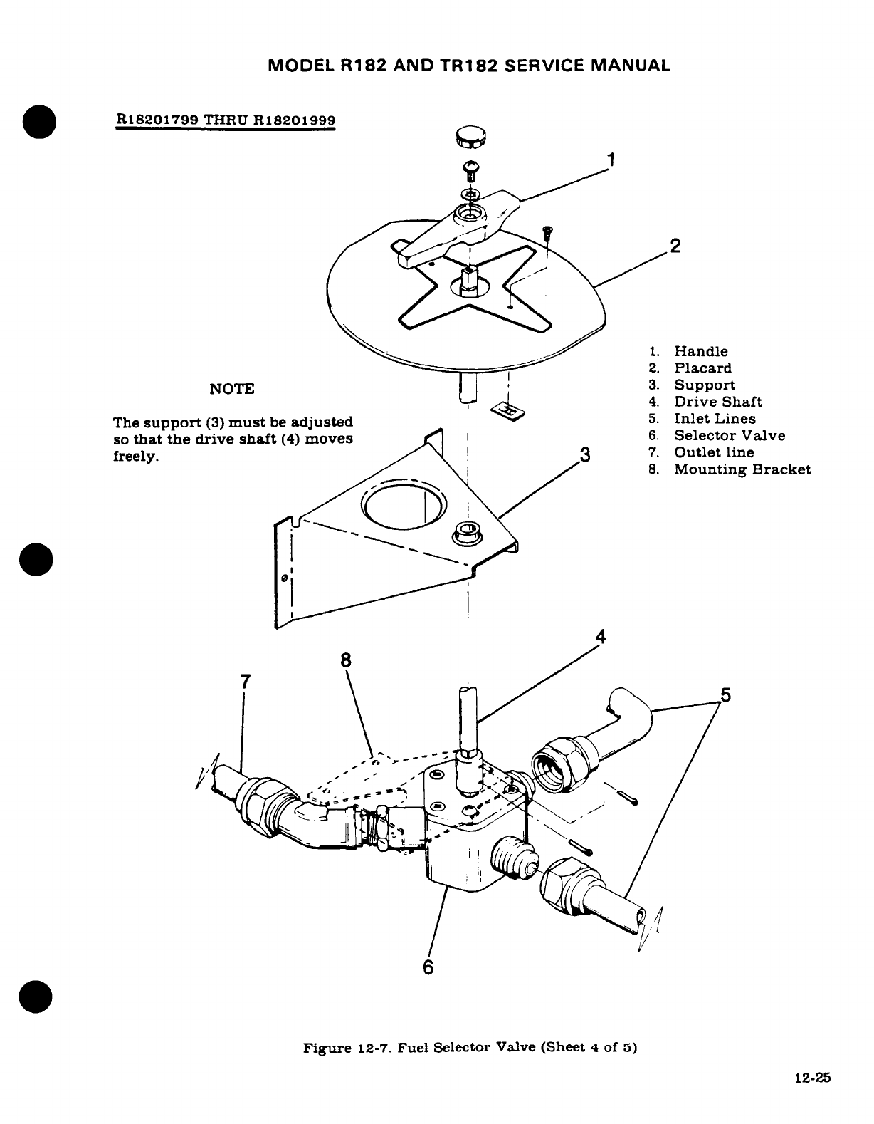
MODEL
R182
AND
TR182
SERVICE
MANUAL
R18201799
THRU
R18201999
0
:
2
1.
Handle
2.
Placard
NOTE
3
Support
4.
Drive
Shaft
The
support
(3)
must
be
adjusted
5.
Inlet
Lines
so
that
the
drive
shaft
(4)
moves
6.
Selector
Valve
freely.
\ 3
7.
Outlet
line
8.
Mounting
Bracket
4
8
/
Figure
12-7.
Fuel Selector
Valve
(Sheet
4
of
5)
12-25
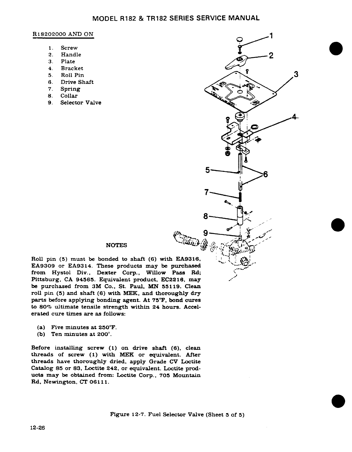
MODEL
R182
&
TR182
SERIES
SERVICE
MANUAL
R18202000
AND
ON
1.
Screw
2.
Handle
3.
Plate
4.
Bracket
5.
Roll
Pin
6.
Drive
Shaft
7.
Spring
<>,
8.
Collar
9.
Selector
Valve
7
-I~~
NOTES
Roll
pin
(5)
must
be
bonded
to
shaft
(6)
with
EA9316,
EA9309
or
EA9314.
These
products
may
be
purchased
from
Hystol
Div.,
Dexter
Corp.,
Willow
Pass
Rd;
Pittsburg,
CA
94565.
Equivalent
product,
EC2216,
may
be
purchased
from
3M
Co.,
St.
Paul,
MN
55119.
Clean
roll
pin
(5)
and
shaft
(6)
with
MEK,
and
thoroughly
dry
parts
before
applying
bonding agent.
At
75"F,
bond
cures
to
80%
ultimate tensile
strength
within
24
hours.
Accel-
erated cure
times
are
as
follows:
(a)
Five
minutes
at
250°F.
(b)
Ten
minutes
at
200
°.
Before
installing
screw
(1)
on
drive
shaft
(6),
clean
threads
of
screw
(1)
with
MEK
or
equivalent.
After
threads
have
thoroughly
dried, apply
Grade
CV
Loctite
Catalog
85
or
83,
Loctite
242,
or
equivalent.
Loctite
prod-
ucts
may
be
obtained
from:
Loctite Corp., 705
Mountain
Rd,
Newington,
CT
06111.
Figure
12-7.
Fuel
Selector
Valve
(Sheet
5
of
5)
12-26
MODEL
R182
AND
TR182
SERVICE
MANUAL
12-29.
CLEANING. INSPECTION
AND
REPAIR.
NOTE
Repair
of
damaged
or
worn
parts
of
the
selector valve
assembly
is
NOT
authorized,
therefore,
is
limited
to
replacement
of
component
parts
only.
a.
Clean
disassembled
parts
by
washing
in
Stoddard
solvent
or
equivalent.
Blow
dry
parts
using
clean
compressed
air.
b.
Inspect all
parts
for
obvious
wear
or
damage
as
follows:
1.
Check
detent
holes
in
cover
(2)
for
excessive
wear
and
examine bearing
surfaces
of
rotor
(6).
2.
Inspect shaft
and
bearing surfaces
of
rotor
(6)
for
removal
of
black anodized
finish
indicating
wear.
Check
for
internal
corrosion
of
drilled passages.
3.
Examine
valve
body
(8)
for
wear, cracks,
distortion
and
internal
corrosion.
Any
damage
to
thread surfaces
at
inlet
and
outlet
ports
or
cover
attach
screw
holes
is
cause for rejection.
12-30.
REASSEMBLY.
NOTE
Mount
selector valve
in
a
vise
or
equivalent
bench
support,
making
sure
that
valve
body
(8,
figure
12-7),
is
protected
from
damage.
Fabricate
two
spring
compres-
sors
(21,
figure
12-7),
to
aid
assembly.
Stock
is
1/16
inch
diameter
#1
OX-WELD
AC
welding
rod
(or
equivalent)
according
to
dimensions
shown.
Replace
O-rings
(10,
and
16,
figure
12-7)
each
time
valve
rotor
is
removed
from
body.
a.
Ensure
all
component
parts
are
clean,
and
coat
sparingly
with
lightweight
engine
oil.
b.
Insert washer
(11)
and
springs
(12)
into
body
(8).
c.
With
spring
compressors
(17)
in
place
as shown
in
Section
A-A.
figure
12-7,
compress
springs
(12)
and
install
washers
(11),
new
O-rings
(10)
and
seals
(9)
into
inlet
ports.
d.
Holding
springs
compressed,
carefully
insert
rotor
(6)
into
valve
body
(8).
Release
spring
compressors
and
check for
proper
seating
of
seals
to
rotor.
e.
Insert
new
O-ring
(3)
into
recess
at
top
of
valve
body
(8).
f.
Place
new
O-ring
over
shaft
of
rotor.
g.
Lubricate
spring
(5)
and
ball
(4)
with
lubricant
conforming
to
Military
Specification
VV-P-236
(USP
Petrolatum
or equivalent),
inserting
spring
into
hole
in
top
of
rotor.
h.
Place
ball
on
spring
and
turn
rotor
as
required
to
index
one
of
the
detent holes
in
cover
(2).
i.
Attach cover
(2)
and
test
rotation
of
rotor
shaft
for
ease
of
operation
and
positive
detent
engagement.
j.
Replace
plug
(14)
using
new
O-ring
(13).
k.
Reinstall
selector
valve
in
accordance
with
paragraph
12-27.
12-26A
(12-26B
blank)
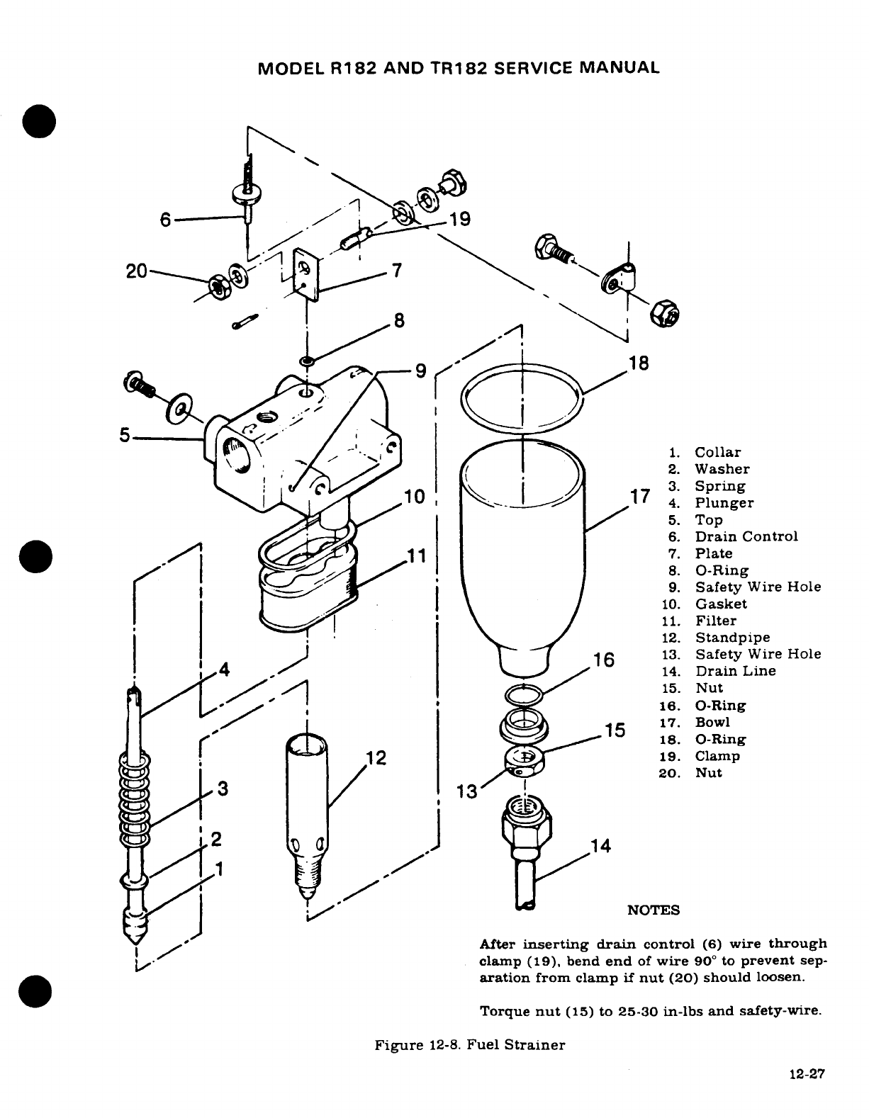
MODEL
R182
AND
TR182
SERVICE
MANUAL
6
/
>19
18
2.
Washer
C10173
Spring1
_17
.4
Plunger
~~~~5~~~~~~~~5.
Top
6.
Drain
Control
.1 2~ ~~7.
Plate
*~ ' C~~~~~8
3.
-Spring
'0 1 9 1 /1
1
l \
jl
~9.
Safety
Wire Hole
, \ 11.Ft114.
Pluner
12.
Standpipe
14.
Drain
Line
<9/,/lql15.
Nut
/ J^ '
/|'^ X
158
~..Co.16.
O-Ring
-t
insertin
1
10. Gasketro
rI~ ~ ~ ~ Fgr 12-8=1.
11.
Filter
T ^12.
Standpipe
J-4 F'
16
-j
13.
Safety
Wire
Hole
14.
Drain
Line
20.
Nut
3
,13
1
2
19.
ClpJ 14
14
NOTES
After
inserting
drain
control
(6)
wire
through
clamp
(19),
bend
end
of
wire
90
°
to
prevent
sep-
aration
from
clamp
if
nut
(20)
should
loosen.
Torque
nut
(15)
to
25-30
in-lbs
and
safety-wire.
Figure
12-8.
Fuel
Strainer
12-27
MODEL
R182
AND
TR182
SERVICE
MANUAL
12-31.
FUEL
STRAINER.
(See
figure
12-8.)
12-32.
DESCRIPTION. The
fuel
strainer
is
mounted at
the
firewall
in
the lower
engine
compart-
ment
and
is
equipped
with
a
quick-drain valve
which
provides
a
means
of
draining
trapped
water
and
sediment
from
the
fuel
system.
The
quick-drain
control
is
located
adjacent
to
the
oil
dipstick
and
is
accessible
through
the
oil
dipstick
door.
NOTE
The
fuel
strainer
can
be
disassembled,
cleaned
and
reassembled
without removing
the
assembly
from
the
aircraft.
12-33.
REMOVAL
AND
INSTALLATION.
a.
Remove
cowling
as
necessary
to
gain
access
to
strainer.
b.
With
selector
valve
in
OFF
position,
drain
fuel
from
strainer
and
lines
with
strainer
quick-drain control.
c.
Disconnect
and
cap
or
plug all
fuel
lines
and
control
from
strainer.
(Observe
precautions
in
paragraph
12-3.)
d.
Remove
bolts
attaching
assembly
to
firewall,
and
remove
strainer.
e.
Reverse
the
preceding
steps
for
installation.
With
selector
valve
in
ON
position.
check for
leaks
and
proper
operation
of
quick-drain
valve.
12-34.
DISASSEMBLY
AND ASSEMBLY.
a.
With
selector
valve
in
OFF
position,
drain
fuel
from
bowl
and
lines
with
quick-drain
control.
b.
Remove
drain
tube,
safety
wire,
nut,
and
washer
at
bottom
of
filter
bowl
and
remove
bowl.
c.
Carefully
unscrew standpipe
and
remove.
d.
Remove
filter
screen
and
gasket.
Wash
filter
screen
and
bowl
with
solvent
(Federal
Specification
P-S-661,
or
equivalent)
and
dry
with
compressed
air.
e.
Using
a
new
gasket
between
filter
screen
and
top
assembly,
install
screen
and
standpipe.
Tighten
standpipe
only
finger
tight.
f.
Using
all
new
O-rings,
install
bowl.
Note
that
step-washer
at
bottom
of
bowl is
installed
so
that
step
seats
against
O-ring.
Connect
drain
tube.
g.
With
selector
valve
in
ON
position,
check
for
leaks
and
proper
operation
of
quick-
drain
valve.
h.
Safety
wire bottom
nut
to
top
assembly.
Wire
must
have
right
hand wrap,
at
least
45
degrees.
12-35.
PRIMING
SYSTEM.
12-36.
DESCRIPTION.
The
priming
system
is
comprised
of
a
plunger-type manually-operated
primer,
which
draws
fuel from
the
strainer
and
forces
it
through-a
tee
fitting
to
each
of
the
rear
four
cylinders, no's.
3,
4, 5
&
6.
12-37.
REMOVAL
AND
INSTALLATION.
a.
With
selector valve
in
the
OFF
position,
drain
fuel
from
strainer
and
lines
with
quick-
drain
control.
b.
Disconnect
and
cap or
plug
all
fuel
lines
at
primer.
(Observe
precautions
in
paragraph
12-3.)
c.
Unscrew
knurled
nut,
and
remove
plunger
from
pump
body.
d.
Remove
pump
body from
instrument
panel.
12-28
MODEL
R182
AND TR182
SERVICE
MANUAL
12-37A.
PRIMING
SYSTEM
(TR182
OPTIONAL)
12-37B.
DESCRIPTION.
The
optional
electric
primer
consists
of
a
solenoid
valve,
switch,
circuit
breaker, and necessary
plumbing.
The
solenoid
valve is
mounted
on
a
tee
attached
to
the
outlet
side
of
the
auxiliary
fuel
pump.
A
line
to
the
engine-driven
pump
is
attached
to
the
other
side
of
the
tee.
The
primer functions
in
conjunction
with
the
auxiliary
electric
fuel
pump.
With
the
auxiliary
electric
fuel
pump
on,
and
the
primer
switch
depressed,
the
sol-
enoid
valve
opens,
allowing
fuel
to
flow
to
the
cylinders.
NOTE
Visually inspect
primer
lines
for
crushed. kinked
or
broken
condition.
Insure
proper clamping
to
prevent
fatigue
due
to
vibration
and
chafing.
12-38.
AUXILIARY
ELECTRIC
FUEL
PUMP.
12-39.
DESCRIPTION.
An
electrically
driven
auxiliary
fuel
pump
is
mounted
on
the
firewall,
and
is
connected
in
parallel
with
fuel
flow
of
the
primary
pump.
This
pump
is
designed
to
be
used
if
the
primary
pump
should
fail.
It is
controlled
by
the
Auxiliary
Fuel
Pump
Switch located
adjacent
to
Master
Switch.
As
the
fuel
pressure
and
plunger
spring
tension
become
equal,
the
pumping
action
is
automatically
reduced
due
to
limited
plunger
movement
which
maintains
low
tolerance
output
pressure.
12-40.
REMOVAL
AND
INSTALLATION.
a.
Place
fuel
selector
valve
in
OFF
position.
b.
Make
sure
that
Master
Switch
and
Auxiliary
Fuel
Pump
Switch
are
OFF.
c.
Remove
fuel
lines
from
pump, observing
precautions
in
paragraph
12-3.
d.
Disconnect
wire
at
connector.
e.
Remove
two
mount
bolts,
retaining
hardware
for
reinstallation.
f.
Reverse
preceding
steps for
installation,
and
check
pump
operation
when
repair
is
completed.
12-41.
TURBOCHARGED
AIRPLANES.
12-42.
DESCRIPTION.
On
turbocharged
airplanes
a
high pressure
fuel
pump
is
used
to
ensure
ade-
quate
fuel
flow.
12-29
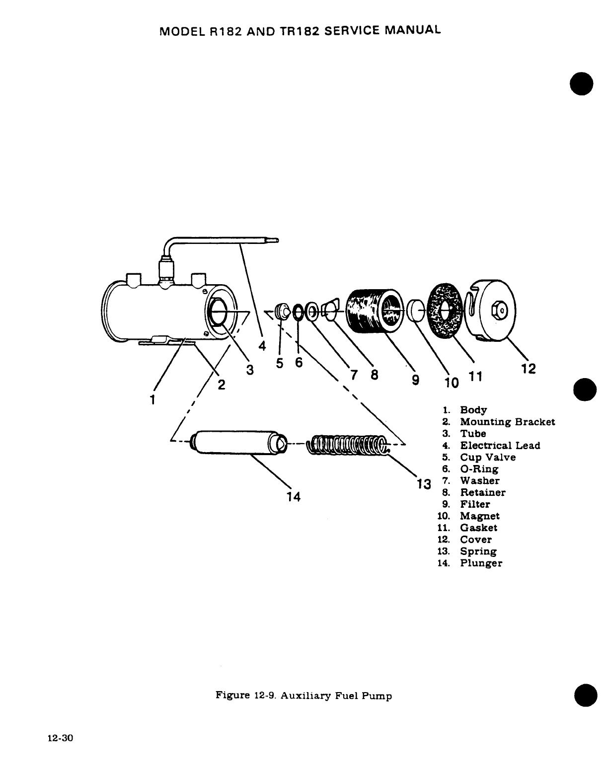
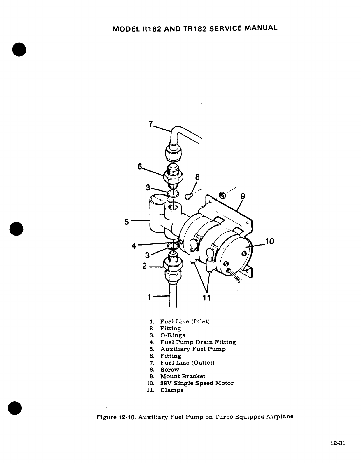
MODEL
R182
AND
TR182
SERVICE
MANUAL
12-43.
REMOVAL AND
INSTALLATION.
a.
Place Fuel
Selector
Valve in
OFF
position.
b.
Be
sure that
Master
Switch
and
Auxiliary
Fuel
Pump
switch
are
OFF.
c.
Remove
fuel
lines
from
pump.
observing
precautions
in
paragraph
12-3.
d.
Disconnect
wire
at
connector.
e.
Remove
two
mount
bolts,
retaining
hardware
for
reinstallation.
f.
Reverse
preceding
steps
for
installation,
check
pump
operation
when
repair
is
com-
pleted.
12-44.
INTEGRAL
FUEL
BAY.
12-44A.
DESCRIPTION.
Beginning
serial
R18200584
and
FR18200021.
The
integral
fuel
bay
is a
sealed
portion
of
the
inboard
wing
structure
between
the
wing
spars,
extending
approxi-
mately
five
feet
into
each
wing. This
type
construction
reduces
weight
as
well
as
increasing
the
strength
of
the
wing
member,
and
extends the
operable
range
of
the
airplane
consider-
ably.
12-45.
FUEL
LEAK
CLASSIFICATION.
Fuel
leaks which
do
not
constitute
a
flight
hazard
are
stains,
seeps,
and
heavy seeps
NOT
in
an
enclosed
area.
All
leaks
should
be
repaired
when
the
airplane
is
grounded
for
other
maintenance.
Fuel
leaks
that
constitute
a
flight
hazard
are
running
leaks
in
any
area,
seeps,
heavy
seeps,
or
stains
in
an
enclosed
area,
such
as
the
wing
leading
edge,
sections
of
wing inboard
of fuel
bay,
and
the
area
between the
rear
fuel
spar
and
trailing
edge.
This
type
leak
must
be
repaired
prior
to
flight.
A
wet
or
stained
spot
on
the
wing
is
the
visual
indication
of
leak
intensity.
Classification
of
fuel
leakage
is
shown
in
figure
12-11.
NOTE
Stains
and
seeps
that
are not
considered
a
flight
hazard
must
be
inspected
after
each
flight
to
ensure that
they
have
not
increased.
If
a
flight
hazard
leak
should
be
identified
at
a
field
where no
repair
facilities are
available.
We
recommend
that
the
applicable
bay
be
drained,
a
temporary
patch placed
over
the
leak
to
prevent
escaping
fumes,
and
fly
to
nearest
facility
that
can
complete
repair
action.
Switch
fuel
selector
to
opposite
bay,
and
fly
aircraft
normally
to
repair
facility.
12-46.
FUEL
BAY
PURGING.
WARNING
Purge
fuel
bays
with
an
inert
gas
prior
to
repairing
fuel
leaks,
to
preclude
the
possibility
of
explosions.
The
following
procedure
may
be
used
to
purge
the
bay
with
argon
or
carbon
dioxide.
a.
Ground
airplane
to
suitable
ground
stake.
b.
Place
fuel
selector
in
OFF
position.
c.
Drain
all
fuel from
applicable
bay,
observing
precautions
in
paragraph
12-3.
d.
Remove
access
door
and
insert
inert
gas
supply hose
into
bay.
e.
Allow
gas
to
flow
into
bay
for
several minutes
to
remove
all
fuel
vapors.
Since
argon
or
carbon
dioxide are
heavier than
air,
these
gases
will
remain
in
the
bay
during
the
repair.
Non-sparking
tools
shall
be
used
to
make
repair,
(air
motors,
plastic
scrapers.
etc.)
12-32
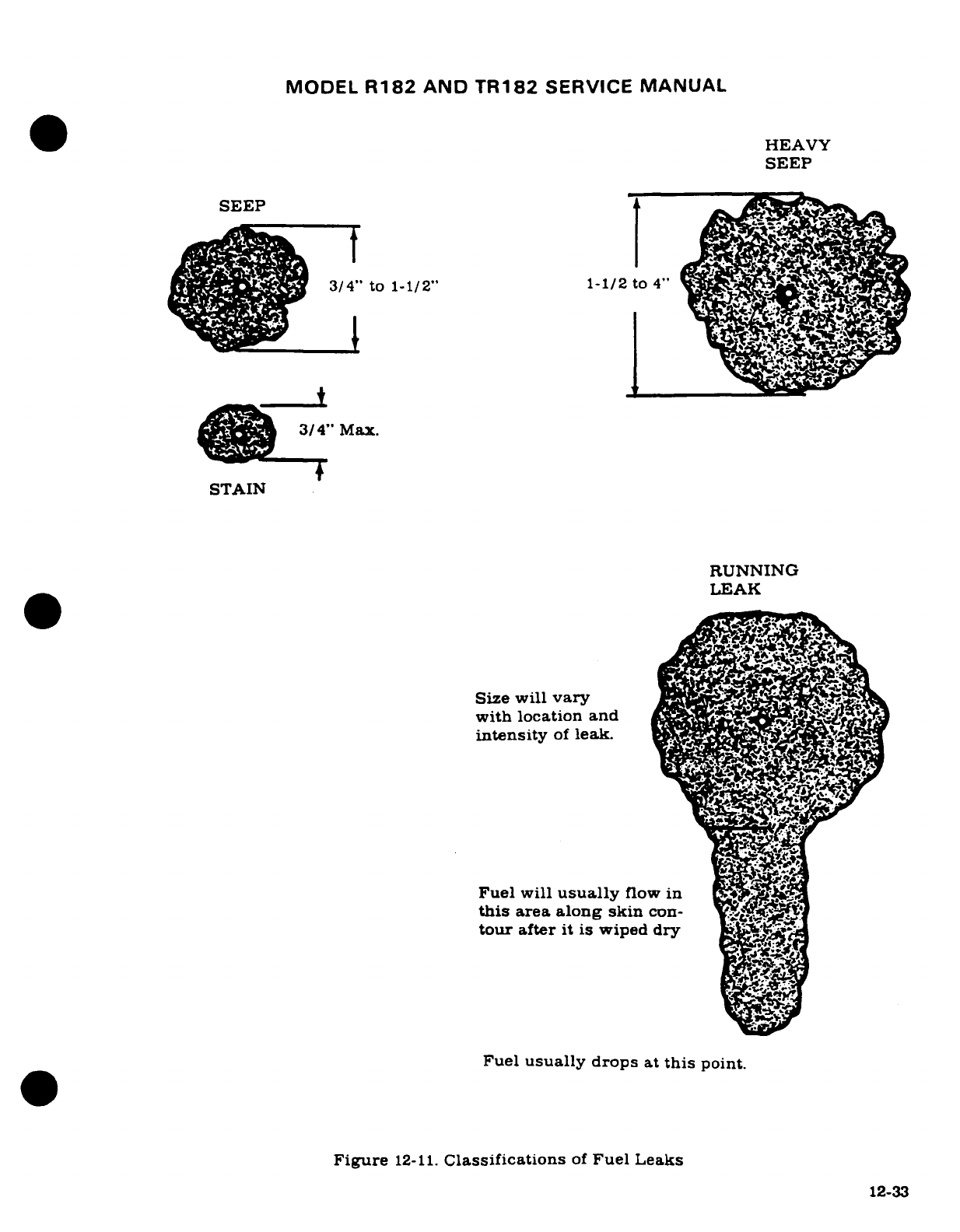
MODEL
R182
AND
TR182
SERVICE
MANUAL
HEAVY
SEEP
SEEP
3/4"
to
1-1/2"
1-1/2
to
4
___t
3/4"
Max.
STAIN
RUNNING
LEAK
Size
will
vary
with
location
and
AIS
intensity
of
leak.
Fuel
will
usually
flow
in
this
area
along skin
con-
tour
after
it is
wiped
dry
Fuel
usually
drops
at
this
point.
Figure
12-11.
Classifications
of
Fuel
Leaks
12-33
MODEL
R182
AND
TR182
SERVICE
MANUAL
NOTE
Portable
vapor
detectors
are
available
to
determine
presence
of
explosive
mixtures
and
are
calibrated
for
leaded
fuel.
These detectors can
be
used
to
determine
when
it
is
safe
to
make
repairs.
12-47.
INTEGRAL
FUEL
BAY
SEALANT. Two
kinds
of
sealants
are
used,
one
to
seal
the
bay
and
the
other
to
seal
the
access
doors
and
fuel
quantity
transmitter
adapter.
The
access
door
sea-
lant
is
more
pliable,
and
will
not
adhere
to
metal
so
firmly
as
the
bay
sealant
does.
This
per-
mits
the
access
doors
and
fuel
quantity
transmitter
adapter
to
be
removed
without damage
to
them.
Service
Kits
SK210-56
(8-ounce
tube)
and.
SK210-101
(2.5-ounce
tube),
which
are
available
from
the
Cessna
Supply
Division,
contain
these
sealants
with the
proper
quantity
of
accelerator
for
each
sealant.
The
sealants
can
be
identified
by
color. The
bay
sealant
is
white,
and
its
accelerator
is
a
black
paste.
The
access
door
sealant
is
gray,
and
its
ac-
celerator
is
a
clear
liquid.
WARNING
Keep
sealants
away from
heat
and
flame.
Use
only
in a
well
ventilated area.
Avoid
skin
and
eye
contact.
WEAR
EYE
SHIELDS.
In
case
of
eye
contact,
flush
generously
with
clean
water,
and
secure
prompt
medical
attention.
12-48.
MIXING
SEALANT.
Use
all
the
accelerator
and
sealant
in
the
container
when
mixing,
to
ensure
the
proper
ratio
of
accelerator
to
sealant. Stir
the
accelerator
to
absorb
all
floating
liquid
before
it is
mixed
with
the
sealant.
The
accelerator
can
then
be
poured
into
the
container
of
sealant
for
mixing,
otherwise,
a
wax-free
container
must
be
used.
Stir
accelerator
and
sealant
until
it
becomes
a
uniform
mixture.
Do
not
stir
air
into
mixture
so
it
forms blubbles,
if
bubbles
appear
they
must
be
removed.
12-49.
SEALING
DURING
STRUCTURAL
REPAIR.
CAUTION
Protect
drain holes
and
fuel
outlet
screens
when
applying
sealants.
Any
repair
that
breaks
the
fuel bay
seal
will
necessitate
resealing
that
bay
area. Repair
parts
that
need
sealing
must
be
installed
during
the
sealing operations.
All
joints
within
the
boundary
of
the
bay,
but
do
not
provide
a
direct
fuel
path
out
of
the
bay,
as
such
fuel
spar
flanges,
and
rib flanges
which
must
be
fay
surface
sealed
and fillet
sealed
on
the
fuel side.
Fay
surface
sealing
is
applying
sealant
to
one
mating
part
before
assembly.
Enough
sealant
must
be
applied
so
it
will
squeeze
out
completely
around
joint
when
the
parts
are
fastened
together.
The
fillet
seal
is
applied
after
the
joint
is
fay
surface
sealed and
fastened.
Sealer
is
(fillet)
applied
to
the
edge
of
all
riveted
joints,
joggles,
bend
reliefs,
voids,
rivets,
or
fasteners.
All
boundaries
are
sealed,
and
any
other
place
that
could become
a
fuel
leak.
The
fay
sealant
need
not
be
cured
before
applying
the
fillet
sealer,
however,
the fay
sealant
must
be
free of
dirt
or
other
contaminants
before
applying
fillet
seal.
Fillets
laid
on
intersecting
joints
shall
be
joined
together
to
produce
a
continuous
seal.
Sealant
must
be
pressed
into the
joint
to
displace
any
entrapped
air
bubbles.
Use
an
extrusion
gun
to
lay
a
bead
along
joint.
and work
out
all
entrapped
air
with
a
small
paddle
to
eliminate
bubbles.
12-34
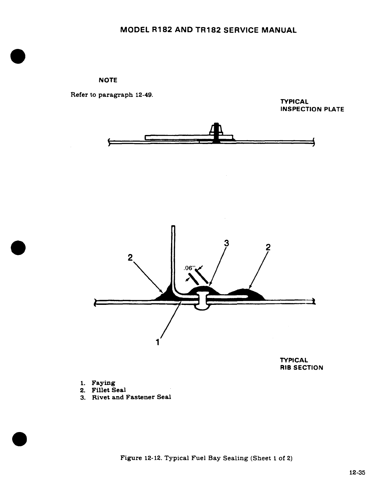
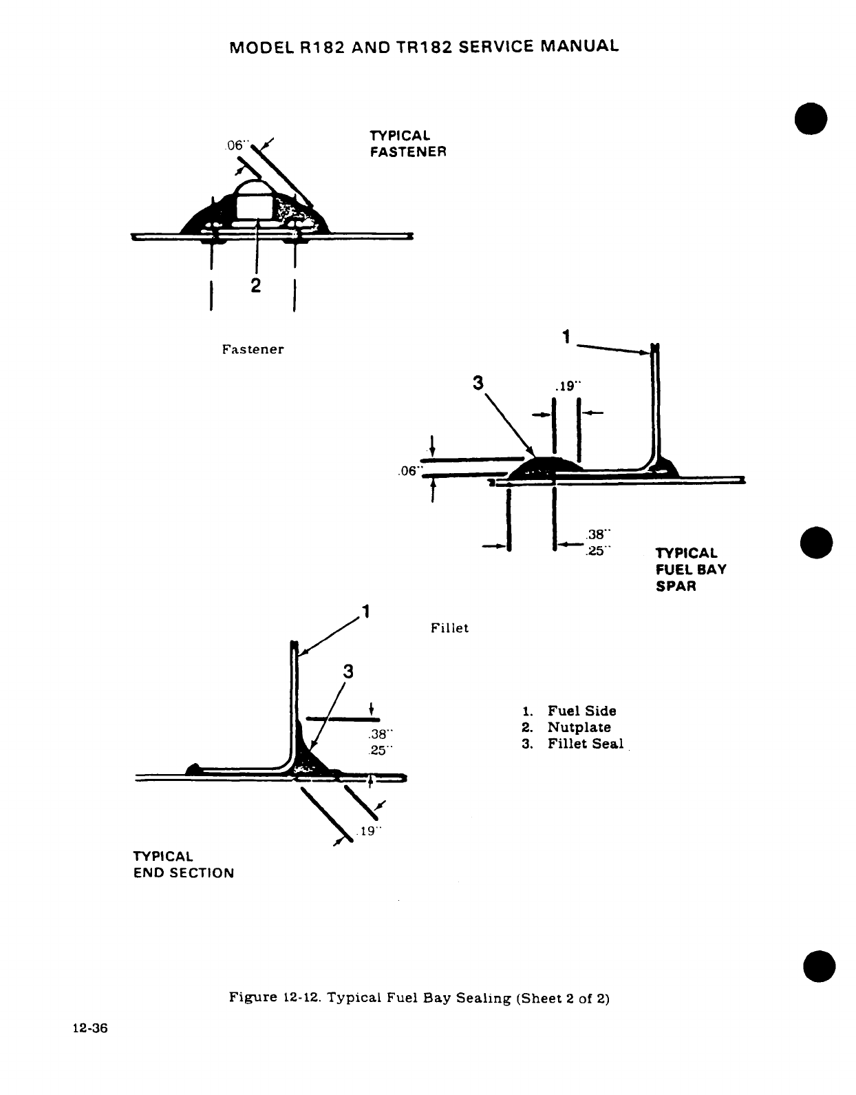
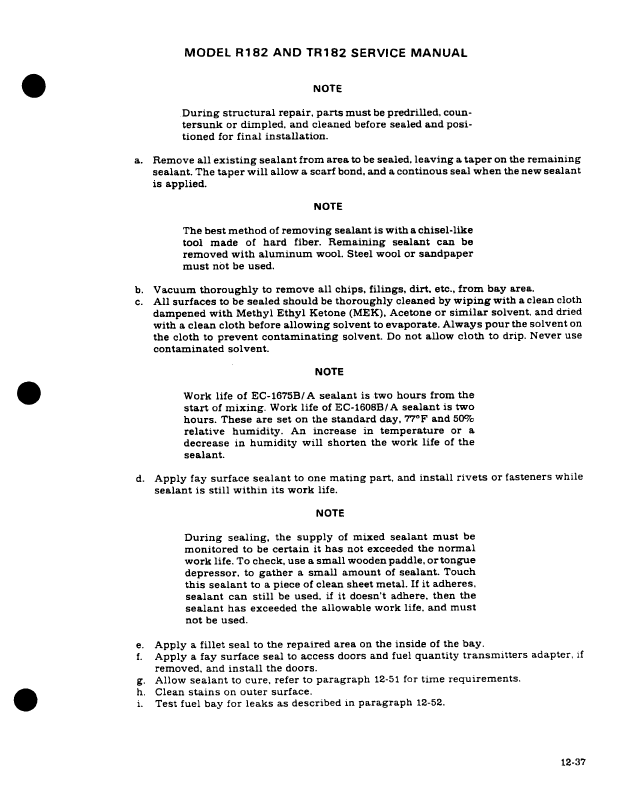
MODEL
R182
AND
TR182
SERVICE
MANUAL
NOTE
During
structural
repair, parts
must
be
predrilled,
coun-
tersunk
or
dimpled, and
cleaned
before
sealed
and
posi-
tioned
for
final
installation.
a.
Remove
all
existing
sealant
from
area
to
be
sealed,
leaving
a
taper
on
the
remaining
sealant.
The
taper
will
allow
a
scarf
bond,
and
a
continous
seal when
the new
sealant
is
applied.
NOTE
The
best
method
of
removing sealant
is
with
a
chisel-like
tool
made
of
hard
fiber.
Remaining
sealant
can
be
removed
with
aluminum
wool.
Steel
wool
or
sandpaper
must
not
be
used.
b.
Vacuum
thoroughly
to
remove
all
chips,
filings,
dirt.
etc.,
from
bay
area.
c.
All
surfaces
to
be
sealed
should
be
thoroughly
cleaned
by
wiping
with
a
clean
cloth
dampened
with
Methyl
Ethyl
Ketone
(MEK),
Acetone
or
similar
solvent,
and
dried
with
a
clean
cloth
before
allowing
solvent
to
evaporate.
Always
pour
the
solvent
on
the
cloth
to
prevent contaminating
solvent.
Do
not
allow
cloth
to
drip. Never
use
contaminated
solvent.
NOTE
Work
life
of
EC-1675B/A
sealant
is
two
hours
from
the
start
of
mixing.
Work
life
of
EC-1608B/A
sealant
is
two
hours.
These
are
set
on
the
standard
day,
77°F
and
50%
relative
humidity.
An
increase
in
temperature
or
a
decrease
in
humidity
will
shorten
the
work
life
of
the
sealant.
d.
Apply
fay
surface
sealant
to one
mating
part,
and
install
rivets
or
fasteners
while
sealant
is
still
within
its
work
life.
NOTE
During sealing,
the
supply
of
mixed
sealant must
be
monitored
to
be
certain
it
has
not
exceeded
the
normal
work
life.
To
check,
use
a
small
wooden
paddle,
or
tongue
depressor,
to
gather
a
small
amount
of
sealant.
Touch
this
sealant
to
a
piece
of
clean
sheet
metal.
If
it
adheres,
sealant
can
still
be
used,
if
it
doesn't
adhere,
then
the
sealant
has
exceeded
the
allowable
work
life,
and
must
not
be
used.
e.
Apply
a
fillet
seal
to
the
repaired
area
on
the
inside
of
the
bay.
f.
Apply
a
fay
surface
seal
to
access
doors
and fuel
quantity
transmitters
adapter,
if
removed,
and
install
the
doors.
g.
Allow
sealant
to
cure,
refer
to
paragraph
12-51
for
time
requirements.
h.
Clean
stains
on
outer
surface.
i.
Test
fuel
bay
for
leaks
as
described
in
paragraph
12-52.
12-37
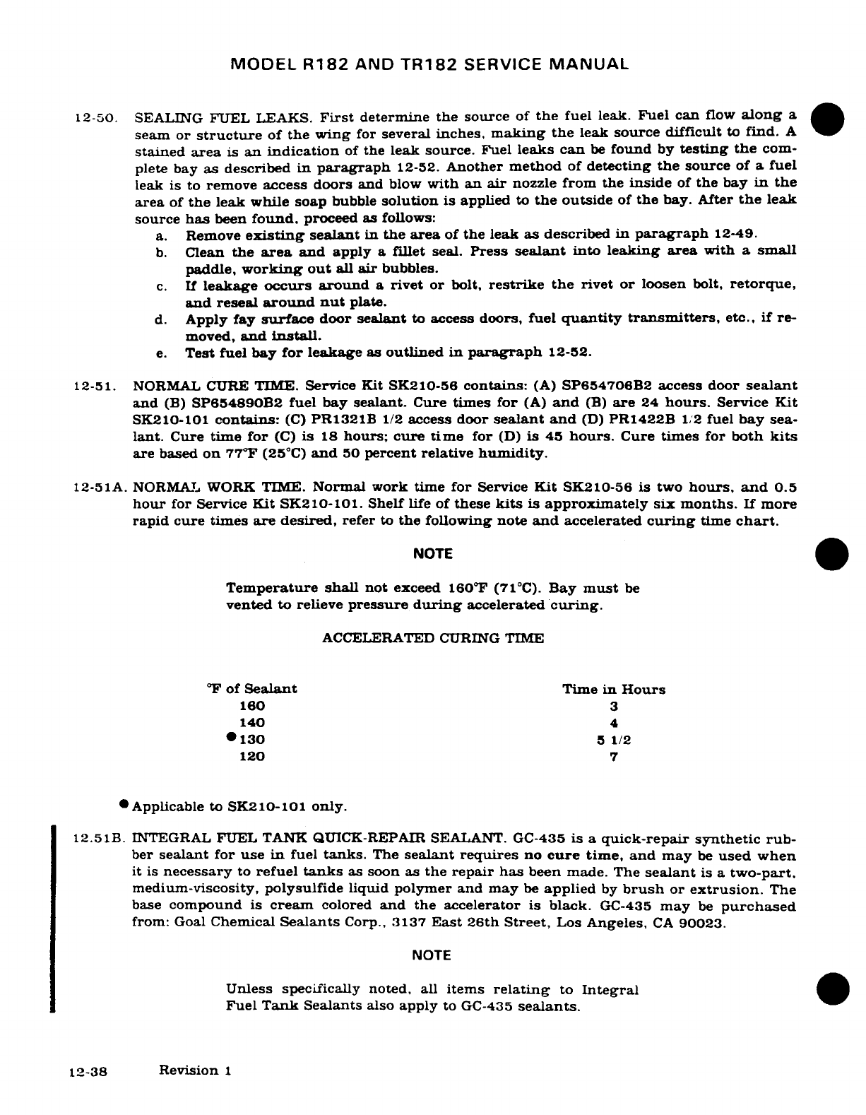
MODEL
R182
AND
TR182
SERVICE
MANUAL
12-50. SEALING
FUEL LEAKS.
First
determine the
source
of
the
fuel
leak.
Fuel
can
flow
along
a
seam
or
structure
of
the
wing
for
several
inches,
making
the
leak
source difficult
to
find.
A
stained
area
is
an
indication
of
the
leak
source.
Fuel
leaks can
be
found
by
testing
the
com-
plete
bay
as described in
paragraph
12-52.
Another
method
of
detecting
the
source
of
a
fuel
leak
is
to
remove
access
doors
and
blow
with an
air
nozzle
from
the
inside
of
the
bay
in
the
area
of
the
leak while
soap
bubble
solution
is
applied
to
the
outside
of
the
bay.
After
the
leak
source
has
been
found,
proceed
as
follows:
a.
Remove
existing
sealant
in
the area
of
the
leak
as
described
in
paragraph
12-49.
b.
Clean
the
area
and
apply
a
fillet
seal.
Press
sealant
into
leaking area
with
a
small
paddle,
working
out
all
air
bubbles.
c.
If
leakage
occurs
around
a
rivet
or
bolt,
restrike
the
rivet
or
loosen
bolt,
retorque,
and
reseal
around
nut
plate.
d.
Apply
fay
surface
door
sealant
to
access
doors,
fuel
quantity
transmitters,
etc.,
if re-
moved,
and
install.
e.
Test fuel
bay
for
leakage
as
outlined
in
paragraph
12-52.
12-51. NORMAL
CURE
TIME.
Service
Kit
SK210-56
contains:
(A)
SP654706B2
access
door
sealant
and
(B)
SP654890B2 fuel
bay
sealant.
Cure
times for
(A)
and
(B)
are
24
hours.
Service
Kit
SK210-101
contains:
(C)
PR1321B
1/2
access
door
sealant
and
(D)
PR1422B
1/2
fuel
bay
sea-
lant.
Cure
time
for
(C) is
18
hours;
cure
time
for
(D)
is
45
hours.
Cure
times
for
both
kits
are
based
on
77°F
(25°C)
and
50
percent relative
humidity.
12-51A.
NORMAL
WORK
TIME.
Normal
work
time
for
Service
Kit
SK210-56
is
two
hours,
and
0.5
hour
for
Service
Kit
SK210-101.
Shelf
life
of
these
kits
is
approximately
six
months.
If
more
rapid
cure
times
are
desired,
refer
to
the
following
note
and
accelerated
curing
time
chart.
NOTE
Temperature
shall
not
exceed
160
°
F
(71°C).
Bay
must
be
vented
to
relieve
pressure
during
accelerated
curing.
ACCELERATED
CURING
TIME
°F
of
Sealant
Time
in
Hours
160
3
140
4
*
130
5
1/2
120
7
*Applicable
to
SK210-101
only.
12.51B.
INTEGRAL
FUEL
TANK
QUICK-REPAIR
SEALANT.
GC-435
is
a
quick-repair synthetic
rub-
ber
sealant
for
use
in
fuel
tanks.
The
sealant
requires
no
cure
time,
and
may
be
used
when
it
is
necessary
to
refuel
tanks
as soon as
the
repair has
been
made.
The
sealant
is
a
two-part.
medium-viscosity,
polysulfide
liquid
polymer
and
may
be
applied
by
brush
or
extrusion.
The
base
compound
is
cream
colored
and
the
accelerator
is
black.
GC-435
may
be
purchased
from:
Goal
Chemical
Sealants
Corp.,
3137
East
26th
Street,
Los
Angeles,
CA
90023.
NOTE
Unless
specifically
noted,
all
items
relating
to
Integral
Fuel
Tank
Sealants
also
apply
to
GC-435
sealants.
12-38
Revision
1
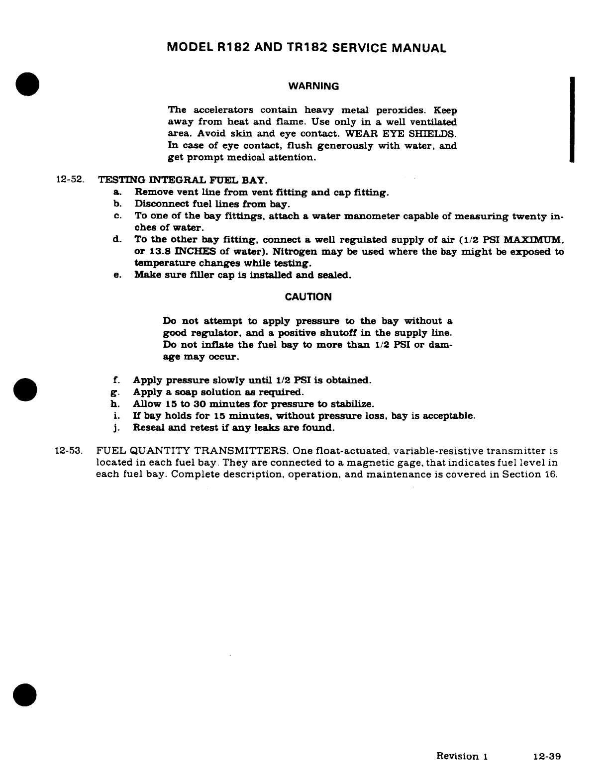
MODEL
R182
AND
TR182
SERVICE
MANUAL
WARNING
The
accelerators contain
heavy
metal
peroxides.
Keep
away
from
heat
and
flame.
Use
only
in
a
well
ventilated
area.
Avoid
skin
and
eye
contact.
WEAR
EYE
SHIELDS.
In
case
of eye
contact,
flush
generously
with
water,
and
get prompt
medical
attention.
12-52.
TESTING
INTEGRAL
FUEL
BAY.
a.
Remove
vent
line
from
vent
fitting
and
cap
fitting.
b.
Disconnect fuel
lines
from
bay.
c.
To
one
of
the
bay
fittings,
attach
a
water
manometer
capable
of
measuring
twenty
in-
ches
of
water.
d.
To
the
other
bay
fitting,
connect
a
well
regulated
supply
of
air
(1/2
PSI
MAXIMUM,
or
13.8
INCHES
of
water).
Nitrogen
may
be
used
where
the
bay
might
be
exposed to
temperature
changes
while
testing.
e.
Make
sure
filler
cap
is
installed and
sealed.
CAUTION
Do
not attempt
to
apply
pressure
to
the
bay
without
a
good
regulator,
and
a
positive
shutoff
in
the
supply
line.
Do
not
inflate
the
fuel
bay
to
more
than
1/2
PSI
or
dam-
age
may
occur.
f.
Apply
pressure
slowly
until
1/2
PSI
is
obtained.
g.
Apply
a
soap
solution
as
required.
h.
Allow
15
to
30
minutes
for
pressure
to
stabilize.
i.
If
bay
holds
for
15
minutes,
without
pressure
loss,
bay
is
acceptable.
j.
Reseal
and
retest
if
any
leaks
are
found.
12-53.
FUEL
QUANTITY
TRANSMITTERS.
One
float-actuated,
variable-resistive
transmitter
is
located
in
each
fuel
bay.
They
are connected
to a
magnetic
gage,
that
indicates
fuel
level
in
each
fuel
bay.
Complete
description.
operation,
and
maintenance
is
covered
in
Section
16.
Revision
1
12-39
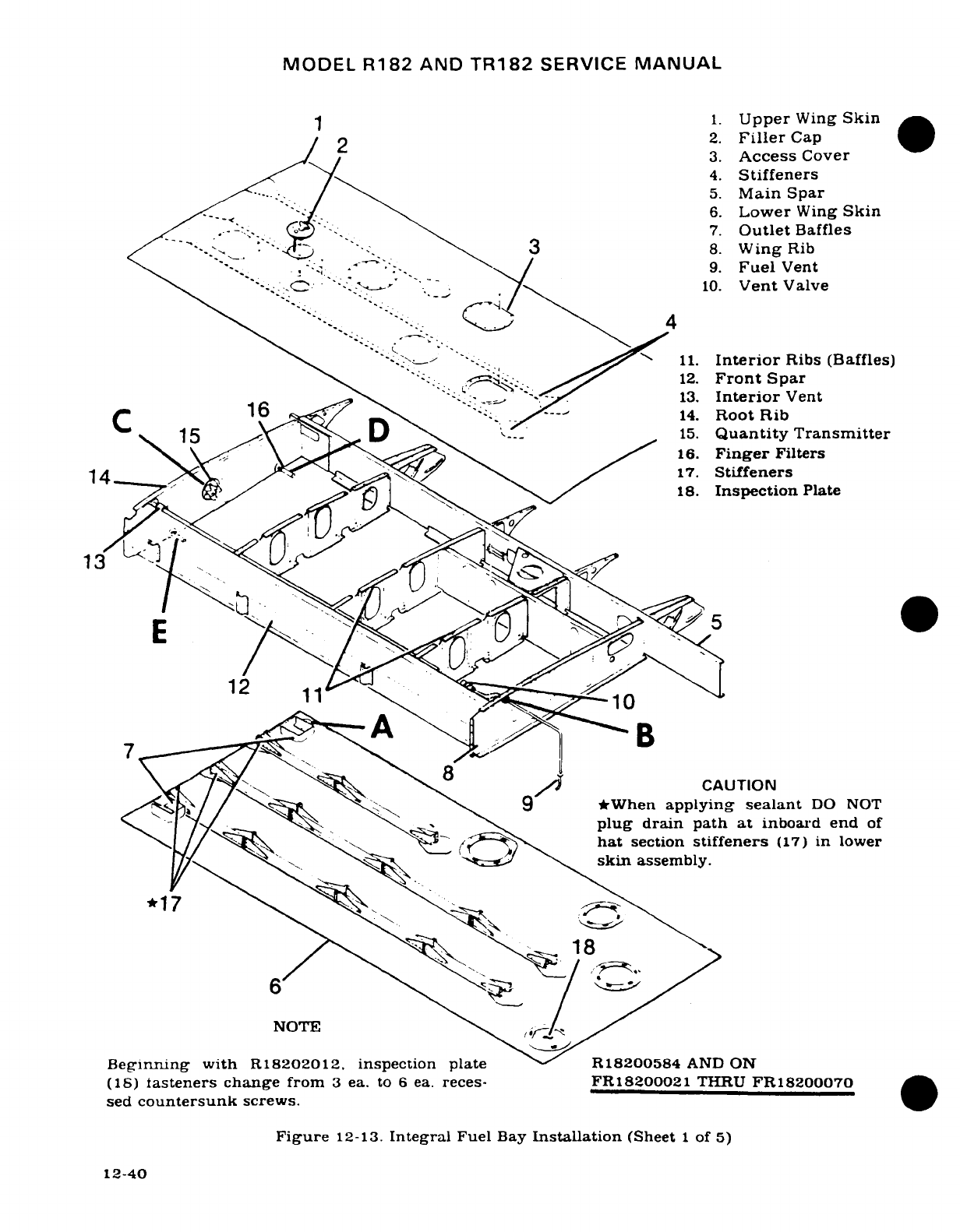
MODEL
R182
AND
TR182
SERVICE
MANUAL
1
1.
Upper
Wing
Skin
/2
2.
Filler
Cap
3.
Access
Cover
4.
Stiffeners
5.
Main
Spar
'~-:/:""^. \''-/. 66.
Lower
Wing
Skin
>// ._-.-~-. -~ -- (M)~
.\7.
Outlet
Baffles
-.
":.
"*
S
-.
.
\
3
8.
Wing
Rib
\^
'"-.,.
.,^
i
-~: '
:-.
.- '^/
9.
Fuel
Vent
" .-:-.. .
":
-'Z
.
'A_-\'
".-_;
.10.
Vent
Valve
'\ ' ;-^ --. .^ _
11.
Interior
Ribs
(Baffles)
12.
Front
Spar
c - 16,_ \ -. ;
13.
Interior
Vent
C
1
(
14.
Root
Rib
15
..
TD
15.
Quantity Transmitter
16.
Finger
Filters
14
\ ,\
17.
Stiffeners
18.
Inspection
Plate
3
A
n
-
B
\^^\- /i/ /^CAUTION
9
/ \ \
*When
applying
sealant
DO NOT
.--
/
_ \S
plug
drain
path
at
inboard
end
of
^\ /~/ [\ ---
A
hat
section
stiffeners
(17)
in
lower
*/7\
~ 1'~ ~ ~
~
^^^^?\
'^^.mtf-'skinl
assembly.
18
6
T
Eat
Beinng
wit
h
R18NOTE
R182004
AD
Beginning
with
R18202012,
inspection
plate
R18200584
AND
ON
(IS)
fasteners
change
from
3
ea.
to
6
ea.
reces- FR18200021
THRU
FR18200070
sed
countersunk
screws.
Figure
12-13.
Integral
Fuel
Bay
Installation
(Sheet
1
of
5)
12-40
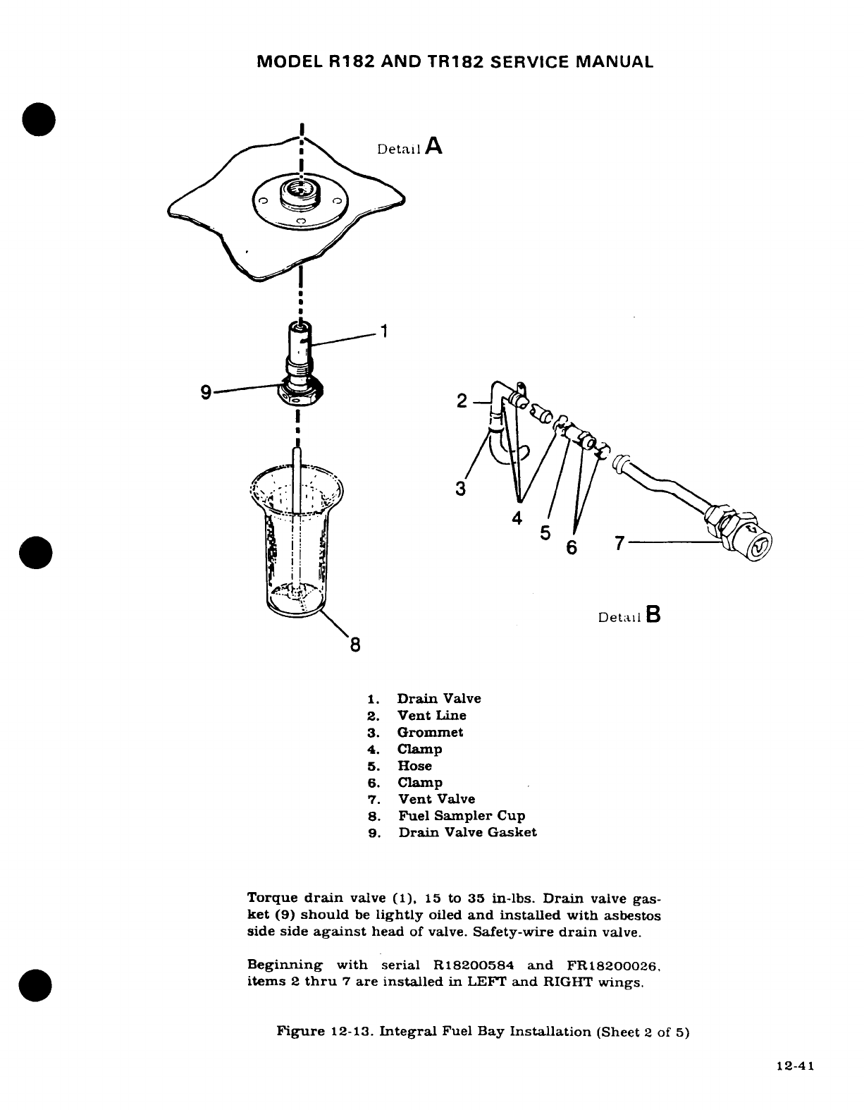
MODEL
R182
AND
TR182
SERVICE
MANUAL
.^-*-~~" \'
'Deta
Detail
A
I j
S
8
1.
Drain
Valve
2.
Vent
Line
3.
Grommet
4.
Clamp
5.
Hose
6.
Clamp
7.
Vent
Valve
8.
Fuel Sampler
Cup
9.
Drain
Valve
Gasket
Torque
drain
valve
(1),
15
to
35
in-lbs.
Drain
valve
gas-
ket
(9)
should
be
lightly
oiled
and
installed
with
asbestos
side
side
against
head
of
valve.
Safety-wire
drain
valve.
Beginning
with
serial
R18200584
and
FR18200026.
items
2
thru
7
are installed
in
LEFT
and
RIGHT
wings.
Figure
12-13.
Integral
Fuel Bay
Installation
(Sheet
2
of
5)
12-41
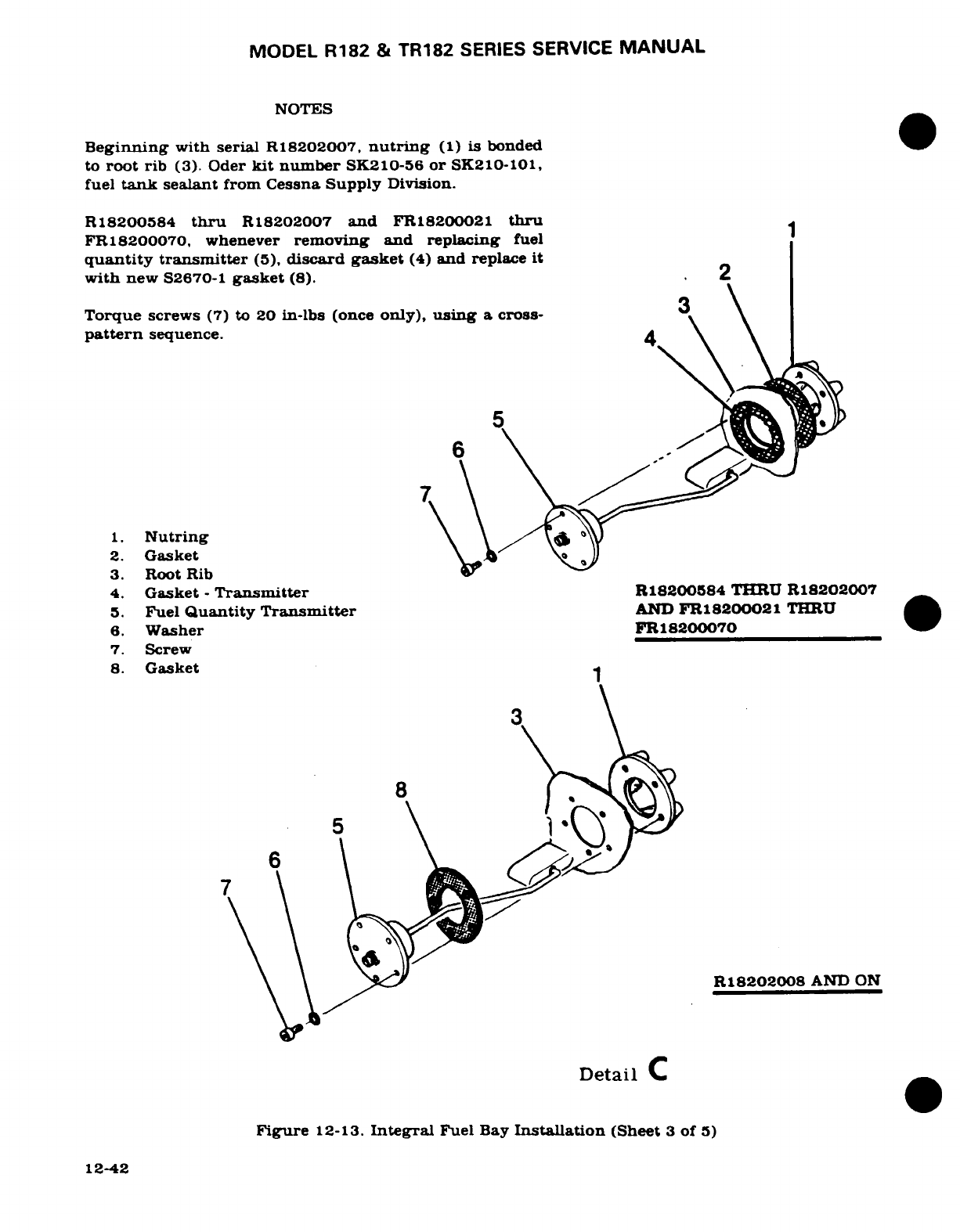
MODEL R182
&
TR182
SERIES
SERVICE
MANUAL
NOTES
Beginning
with
serial
R18202007,
nutring
(1)
is bonded
to
root
rib
(3). Oder
kit
number
SK210-56
or
SK210-101,
fuel
tank
sealant
from Cessna
Supply
Division.
R
18200584
thru
R18202007
and
FR18200021
thru
FR18200070,
whenever
removing and
replacing
fuel
quantity
transmitter
(5),
discard
gasket
(4)
and
replace
it
with
new
S2670-1
gasket
(8).
2
Torque
screws
(7)
to
20
in-lbs
(once
only),
using
a
cross-
pattern
sequence.
4
5 ·
1.
Nutring
\ \
2.
Gasket
3.
Root
Rib
4.
Gasket
-
Transmitter
R18200584
THRU
R18202007
5.
Fuel
Quantity
Transmitter
AND
FR18200021
THRU
6.
Washer
FR18200070
7.
Screw
8.
Gasket
8
R18202008
AND
ON
Detail
C
Figure
12-13.
Integral
Fuel
Bay
Installation
(Sheet
3
of
5)
12-42
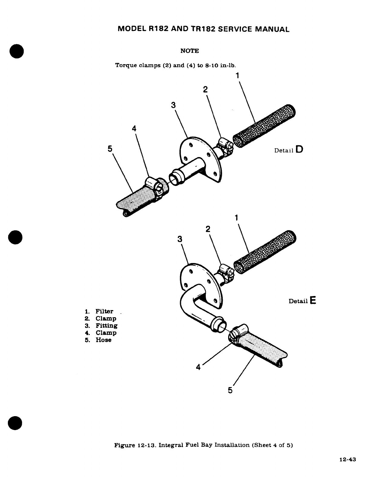
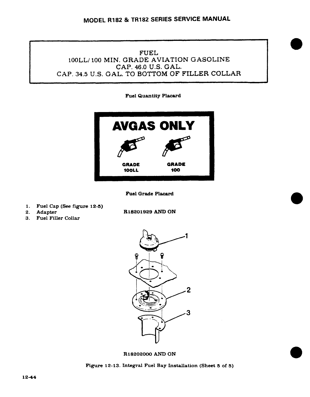
MODEL
R182
&
TR182
SERIES
SERVICE
MANUAL
FUEL
100LL/
100
MIN.
GRADE
AVIATION
GASOLINE
CAP.
46.0
U.S.
GAL.
CAP.
34.5
U.S.
GAL.
TO
BOTTOM
OF
FILLER
COLLAR
Fuel
Quantity
Placard
AVGAS
ONLY
GRADE
GRADE
100LL
100
Fuel
Grade
Placard
1.
Fuel
Cap
(See
figure
12-5)
2.
Adapter
R18201929
AND
ON
3.
Fuel
Filler
Collar
<
R18202000
AND
ON
Figure
12-13.
Integral
Fuel
Bay
Installation
(Sheet
5
of
5)
12-44
MODEL
R182
AND
TR182
SERVICE
MANUAL
SECTION
13
PROPELLER
AND
GOVERNOR
WARNING
When
performing any
inspection
or maintenance
that
requires
turning
on
the
master
switch,
installing
a
battery,
or
pulling
the
propeller
through
by
hand.
treat
the
propeller
as
if
the
ignition
switch
were
ON. Do
not
stand, nor
allow anyone
else
to
stand,
within
the
arc
of
the
propeller,
since
a
loose
or broken
wire,
or
a
component
malfunction,
could
cause
the
propeller
to
rotate.
Page
No.
TABLE
OF
CONTENTS
Aerofiche/
Manual
PROPELLER
DESCRIPTION
....
3D21/13-1
GOVERNOR DESCRIPTION
....
3E5/13-9
Trouble
Shooting
..........
3D22/13-2
Trouble
Shooting
...........
3E6/13-10
Repair
...................
3D23/13-3
Removal
.................
3E7'13-11
Removal
(Thru
R18201313)
. .
.3D23/13-3
Installation
...............
3E7.13-11
Installation
(Thru
R18201313)
.
3E3/13-7
High
RPM
Stop
Adjustment
. . .
3E7
13-11
Removal
(R18201314
&
ON)
..
3E4/13-8
Rigging
.................
3E8
13-12
Installation
(R18201314
&
ON).
3E4/13-8
Time Between
Overhaul
......
3E8
13-12
Time
Between
Overhaul
......
3E5/13-9
13-1.
PROPELLER
DESCRIPTION.
The
constant-speed
propeller
is
a
single acting
unit. where
governor
regulated
oil
pressure
opposes
the
centrifugal
twisting
moment
of
the
rotating
blades
and
spring
force
to
obtain the
correct
blade
pitch
for
engine
load.
Engine
lubricating
oil
is
supplied
to
the
power
piston
in
the
propeller
hub
through
the
engine
crankshaft.
The
amount
and
pressure
of
the
engine
oil
used
is
controlled
by
the
propeller
governor.
An
increase or
decrease
in
throttle setting
or
a
change
in
aircraft
attitude
will
affect
the
balance
to
maintain
the
most
efficient
and
economical
RPM,
which
the
pilot
has
previously
selected.
If
the
throttle
is
opened more,
or
the
aircraft
speed
is
increased,
the
engine
RPM
will
also
begin
to
increase.
This change
is
sensed
by
the
propeller
governor,
and
it
directs
oil
pressure
to
the
forward
side
of
the
piston.
The
blades
will move
to
a
higher
pitch
to
load
the
engine.
thereby
maintaining
constant
RPM.
Conversely,
if
the
throttle
is
closed
somewhat.
or
aircraft
speed
is
decreased,
the
engine
RPM
will
try
to
decrease.
The
governor
senses
this.
and
it
allows
oil
to
drain
from
the
forward
side
of
the
piston.
Spring tension
and
centrifugal
twisting
moment
will
move
the
propeller
blades
to
a
lower
pitch
to
maintain
selected
engine
speed.
Revision
1
13-1
MODEL
R182
AND
TR182
SERVICE
MANUAL
13-2.
TROUBLE
SHOOTING.
TROUBLE
PROBABLE
CAUSE
REMEDY
FAILURE
TO
CHANGE
Governor control
discon- Check
visually.
Connect
or
PITCH.
nected
or
broken.
replace
control.
Governor
not
correct
for
Check
that correct governor
propeller.
(Sensing
wrong.)
is
installed.
Replace
governor.
Defective
governor.
Refer
to
paragraph
13-10.
Defective
pitch
changing
Propeller
repair
or
replace-
mechanism inside
pro-
ment
is
required.
peller
or
excessive
pro-
peller
blade
friction.
FAILURE
TO
CHANGE
Improper
rigging
of
Check
that
governor
control
PITCH
FULLY.
governor
control.
arm
and
control
have
full
travel.
Rig
control
and
arm
as
required.
Defective
governor.
Refer
to
paragraph
13-10.
SLUGGISH
RESPONSE
TO
Excessive friction
in
pitch
Propeller repair
or
replace-
PROPELLER
CONTROL.
changing
mechanism
inside
ment
is
required.
propeller
or
excessive
blade
friction.
STATIC
RPM
TOO
HIGH
Improper
propeller
gov-
Perform static
RPM
check.
OR
TOO
LOW.
ernor
adjustments.
Refer
to
Section
11
and
11A
for
procedures.
ENGINE
SPEED
WILL
Sludge
in
governor.
Refer
to
paragraph
13-10.
NOT
STABILIZE.
Air
trapped
in
propeller
Trapped
air
should
be
purged
actuating
cylinder.
by
exercising
the
propeller
several
times
prior
to
take-
off
after
propeller has
been
reinstalled
or
has
been
idle
for an extended
period.
Excessive friction
in
pitch
Propeller
repair
or
replace-
changing
mechanism
inside ment
is
required.
propeller
or
excessive
blade
friction.
Defective
governor.
Refer
to
paragraph
13-10.
13-2
MODEL
R182
AND
TR182
SERVICE
MANUAL
13-2.
TROUBLE
SHOOTING
(Cont).
TROUBLE PROBABLE
CAUSE
REMEDY
OIL
LEAKAGE
AT
Damaged
O-ring
and
seal
Check
visually.
Remove
pro-
PROPELLER
MOUNT-
between
engine
crankshaft
peller
and
install
O-ring
ING FLANGE.
flange
and
propeller.
seal.
Foreign
material
between
Remove
propeller
and
clean
engine
crankshaft
flange
mating
surfaces:
install
new
and
propeller
mating
O-ring
and
tighten
mounting
surfaces or
mounting nuts
evenly
to
torque
value
nuts
not
tight.
in
figure
13-1.
OIL
LEAKAGE
AT
ANY
Defective
seals,
gaskets, Propeller
repair
or
replace-
OTHER
PLACE.
threads,
etc.,
or
incor- ment
is
required.
rect
assembly.
13-3.
REPAIR.
Metal
propeller
repair
is
a
two
step operation. First.
the
damage
must
be
evaluated.
Second,
a
determination
of
degree
of
the
damage
must
be
made
under
criteria
contained
in
Federal Aviation
Regulations,
Part
43
(FAR
43)
and
Federal
Aviation
Agency
Advisory
Circular
No
43.14
(FAA
AC
43.13).
These
instructions
must
be
served
anytime
repairs
or
alterations
are
being
made,
because
they
authorize
the
level
of
repair
for
each
action.
NOTE
For
information
not
covered
in
this section, refer
to
the
applicable
McCauley
Service
Manual
and
supplements
thereto.
13-4.
REMOVAL. (THRU
R18201313)
(See
figure
13-1.)
WARNING
Be
sure
magneto
is
grounded
before
turning
propeller.
a.
Remove
spinner
dome.
b.
Remove
safety
wire, back
off
bolts
attaching
propeller
to
engine
crankshaft
about
one-fourth
inch,
and
pull
propeller
forward.
NOTE
Bolts
will
have
to
be
backed
out
evenly
so
propeller
can
be
pulled
forward
(approximately
1/4
inch
each
time)
until
all
bolts
are
disengaged
from
engine
crankshaft
flange.
As
the
propeller
is
separated
from
the
engine
crankshaft,
oil
will
drain
from
the
propeller
and
engine
crankshaft
cavities.
c.
Pull
propeller
from
engine
crankshaft.
d.
If
necessary
to
remove
the
aft
spinner
bulkhead,
remove
bolts,
washers,
and nuts
attaching
bulkhead
to
starter
ring
gear
support.
but
retain
shims
for
use
in
reinstallation.
13-3
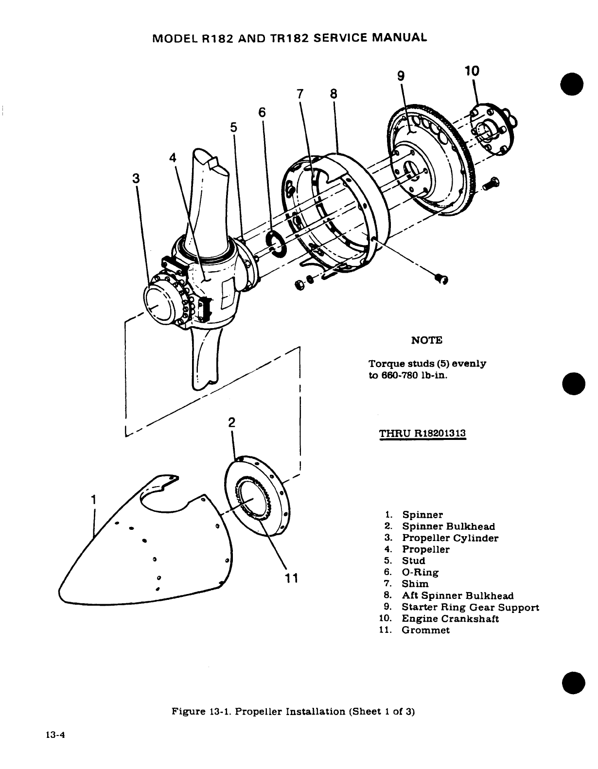
MODEL
R182
AND
TR182
SERVICE
MANUAL
9
10
6
5
NOTE
([I
>^g
/
|
Torque
studs
(5)
evenly
to
660-780
lb-in.
I~"'
THRU
R18201313
1.
Spinner
2.
Spinner
Bulkhead
3.
Propeller
Cylinder
4.
Propeller
5.
Stud
o/ o _11 6.
O-Ring
7.
Shim
8.
Aft
Spinner
Bulkhead
9.
Starter
Ring
Gear
Support
10.
Engine
Crankshaft
11.
Grommet
Figure
13-1.
Propeller
Installation
(Sheet
1
of
3)
13-4
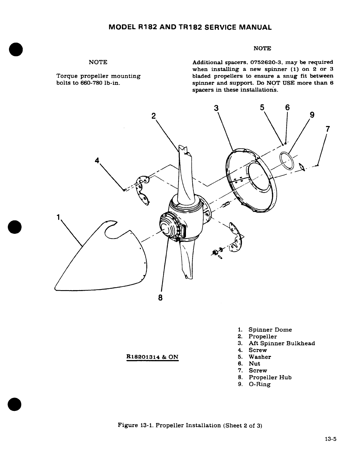
MODEL
R182
AND
TR182
SERVICE
MANUAL
NOTE
NOTE
Additional
spacers,
0752620-3,
may
be
required
when
installing
a
new
spinner
(1)
on
2
or
3
Torque
propeller mounting
bladed
propellers
to
ensure
a
snug
fit
between
bolts
to
660-780
lb-in. spinner
and
support.
Do
NOT
USE
more
than
6
spacers
in
these
installations.
3
5
6
2
9
8
1.
Spinner
Dome
2.
Propeller
3.
Aft
Spinner
Bulkhead
4.
Screw
R18201314
&
ON
5.
Washer
6.
Nut
7.
Screw
8.
Propeller
Hub
9.
O-Ring
Figure
13-1.
Propeller
Installation
(Sheet
2
of
3)
13-5
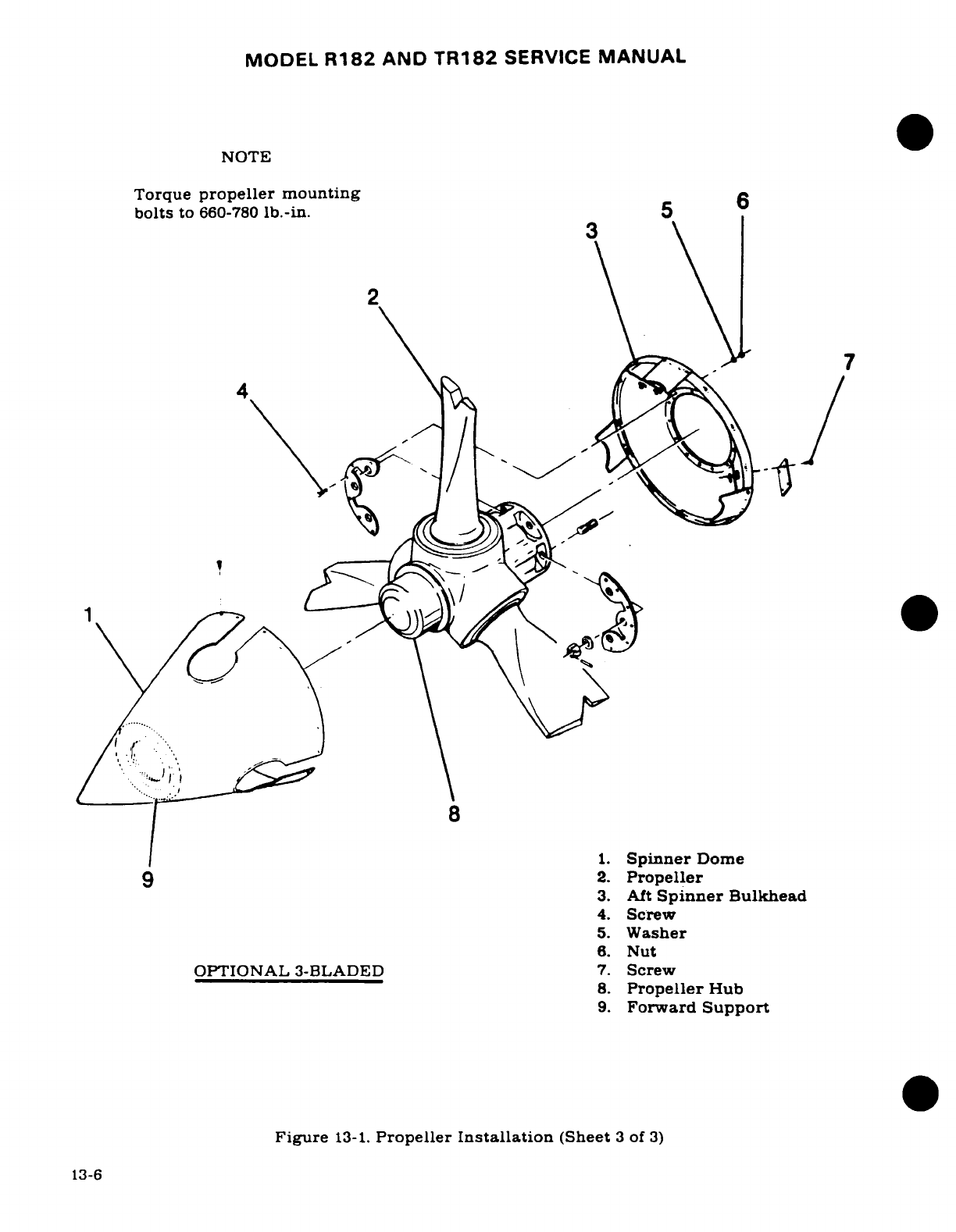
MODEL
R182
AND
TR182
SERVICE
MANUAL
NOTE
After
removing
the
propeller,
the
starter
ring
gear
assembly
may
be
removed
from
the
engine crankshaft
to
allow
easier
access
to
the
aft
spinner
bulkhead
attaching
bolts.
Loosen
alternator
adjusting
arm
and
disengage
drive
belt
from
pulley
on
aft
face
of
starter
ring
gear
support
assembly.
13-5.
INSTALLATION.
(THRU
R18201313)
(See
figure
13-1.)
WARNING
Be
sure
magneto
is
grounded
before
turning
propeller.
a.
If
aft
spinner
bulkhead
was
removed.
reinstall
on
ring
gear
support.
using
bolts.
nuts,
and
shims,
as
shown
in
figure
13-1.
b.
If
starter
ring
gear
support
and
aft
spinner
bulkhead
were
removed,
clean
mating
surfaces
of
support
assembly
and
engine
crankshaft
flange.
c.
Place
alternator
drive
belt
in
pulley
groove
of
starter
ring
gear
support. Fit
starter
ring
gear
over
propeller
flange
bushings
on
crankshaft.
NOTE
Make
sure
bushing
hole
in
ring
gear support.
marked
O.
is
assembled
adjacent
to
O
mark
on
crankshaft
flange
bushing.
The
starter ring
gear
must
be
located
correctly
to
assure
proper
alignment
of
the
timing
mark
on
the
ring
gear.
d.
Clean
propeller
hub
cavity
and
mating surfaces
of
propeller
hub
and
ring
gear
support.
e.
Lightly
lubricate
new
O-ring
and
crankshaft
pilot
with
clean
engine
oil.
and
install
O-ring
in
the
propeller
hub.
f.
Align
propeller
mounting
bolts
with
proper
holes
in
engine
crankshaft
flange.
and
slide
propeller
carefully
over
crankshaft
pilot
until
bolts
can
be
started
in
crankshaft
flange
bushing.
Position
propeller
blades
to
extend
through
aft
spinner
bulkhead
with
ample
clearance.
g.
Tighten bolts
evenly,
and
work
propeller
aft
on
crankshaft
flange.
Torque
bolts
per
figure
13-1.
h.
Install
.040
inch
diameter
corrosion
resistant
safety
wire
through
bolts
in
pairs.
i.
Adjust
alternator
drive
belt
tension
as
outlined
in
Section
16.
j.
Install
spinner
dome.
13-7
MODEL
R182
AND
TR182
SERVICE
MANUAL
13-6.
REMOVAL.
(R18201314
&
ON)
WARNING
Be
sure
magneto
is
grounded
before
turning
propeller.
a.
Remove
spinner
dome
(1).
b.
Remove
safety
wire, back
off
bolts
attaching
propeller
to
engine
crankshaft
about
one-fourth
inch.
and
pull
propeller
forward.
NOTE
Bolts
will
have
to
be
backed
out
evenly
so
propeller
(2)
can
be
pulled
forward
(approximately
1/4
inch
each time)
until all
bolts
are
disengaged
from
engine
crankshft
flange.
As
the
propeller
is
separated
from
the
engine
crankshaft,
oil
will
drain
from
the
propeller
and
engine
crankshaft
cavities.
c.
If
necessary,
the
aft
spinner
bulkhead
(3)
can
be
removed
by
removing
screws
(4),
washers
(5),
and
nuts
(6)
attaching
bulkhead
to
the
propeller.
Then
remove
screws
(7)
to
separate
bulkhead halves.
d.
Pull
propeller
from
engine
crankshaft.
13-7.
INSTALLATION.
(R18201314
&
ON)
(See
figure
13-1.)
WARNING
Be
sure
magneto
is
grounded
before
turning
propeller.
a.
If
aft
spinner
bulkhead
was
removed,
reinstall
on
ring
gear
support
using
bolts,
nuts,
and
shims
as
shown
on
figure
13-1.
b.
If
starter
ring
gear
support
and
aft
spinner
bulkhead
were
removed,
clean
mating
surfaces
of
support
assembly
and
engine
crankshaft
flange.
c.
Place
alternator
drive
belt
in
pully
groove
of
starter
ring
gear
support.
Fit
starter
ring
gear
over
propeller
flange
bushings
on
crankshaft.
NOTE
Make
sure
bushing
hole
in
right
gear
support,
marked
"O",
is
assembled
adjacent
to
"O"
mark
on
crankshaft
flange
bushing.
The
starter
ring
gear must
be
located
correctly
to
assure
proper alignment
of
the
timing mark
on
the
right
gear.
d.
Clean
propeller
hub
cavity
and
mating
surfaces
of
propeller
hub
and
ring
gear
support.
e.
On
the
standard
2
bladed
propeller,
lightly
lubricate
new
O-ring
(9)
and
crankshaft
pilot
with
clean
engine
oil,
and
install
O-ring
in
the
propeller
hub.
f.
Align
propeller mounting
bolts
with
proper
holes
in
engine
crankshaft
flange, and
slide
propeller
carefully
over
crankshaft
pilot
until
bolts
can
be
started
in
crankshaft
flange
bushing. Position
propeller
blades
to
extend
thru
aft
spinner
bulkhead
with
ample
clearance.
13-8
Revision
1
MODEL
R182
AND
TR182
SERVICE
MANUAL
g.
Tighten
bolts
evenly,
and
work
propeller
aft
on
crankshaft
flange.
Torque
bolts
per
figure
13-1.
h.
Install
.040
inch
diameter
corrosion
resistant
safety wire
through
bolts
in
pairs.
i.
Adjust
alternator
drive
belt
tension
as
outlined
in
Section
16.
j.
Install
0752620-3 spacer
(if
required
and
spinner
support
on
propeller
cylinder
(8).
If
spacers
are
not
centered
mechanically (piloted),
visually
center
and
hold
them
until
spinner
support
is
forced
firmly
in
place.
k.
Hold
spinner
(1)
snug
against
spinner
support
and
check
alignment
of
holes
in
spin-
ner
(1)
with
holes
in
spinner
bulkhead
(3).
Add
or
remove
0752620-3
spacers
from
propeller cylinder
(8)
until
holes
are
within
.050
of
alignment.
1.
Push
hard
on
spinner
(1)
to
align
holes
and
install
screws
and washers
(if
required)
in
three
(3)
or
more equal spaces
around
the bulkhead
(3).
Relax
pressure
on
spinner
and
install
remaining
screws
and
washers
(if
required)
in
spinner
(1).
m.
Tighten
all
screws
uniformly
around
the
spinner.
NOTE
When
replacing
optional
three
bladed
propeller
assembly
(2),apply
Y8560
Polyurethane
Film
(3M
Company),
a
minimum
of
one
wrap
on
propeller
hub
(8),
then
as
required
to
obtain
asnug
fit
of
forward
support
(9)
to
propeller
hub
(8).
13-8.
TIME
BETWEEN
OVERHAUL
(TBO).
Propeller
overhaul
shall
coincide
with
engine
overhaul,
but
interval
between
overhauls
of
propeller
shall
not
exceed
1500
hours.
Refer
to
Section
11
&
11A
for
engine
time
between
overhaul
(TBO)
periods.
13-9.
GOVERNOR
DESCRIPTION. The
engine
mounted,
centrifugal, single-acting
propeller
governor
is
mounted
on
the
upper
left
side
of
engine
just
forward
of
number
two
cylinder.
The
term
"single-acting"
refers
to
the
way engine
oil
is
directed
to
the
propeller
to
effect
pitch
change.
This
governor directs
oil
pressure
to
increase
blade
pitch.
Decreased
blade
pitch
is
caused
by
centrifugal
twisting
moment
of
rotating
propeller
blades
and
the
force
of
an
internal
spring,
as
oil
pressure
is
relieved.
When
oil
is
relieved
by
the
governor,
it
returns
to
the oil
sump
through
governor
pilot
spool
valve
action.
Basically
the
governor
consists
of
an
engine
driven
gear
pump,
pressure
relief
valve,
rotating
flyweights.
a
pilot
spool
valve.
and
a
control
lever
to
vary
spring
load
on
flyweights.
which
presets
engine
load
through
blade
pitch.
NOTE
Outward
physical appearance
of
specific
governors
is
the
same,
but
internal
parts
determine
the
action
of
oil
pressure
output:
i.e.,
oil
pressure
to
increase
or
decrease
blade
pitch.
Always
be
sure
the
correct
governor
is used
with
the
propeller.
Revision
2
13-9
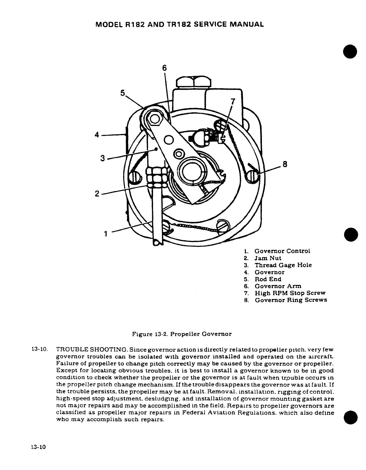
MODEL
R182
AND
TR182
SERVICE
MANUAL
6
2
1.
Governor
Control
2.
Jam
Nut
3.
Thread
Gage
Hole
4.
Governor
5.
Rod
End
6.
Governor
Arm
7.
High
RPM
Stop
Screw
8.
Governor
Ring
Screws
Figure
13-2.
Propeller
Governor
13-10.
TROUBLE
SHOOTING.
Since
governor
action
is
directly
related
to
propeller pitch.
very
few
governor
troubles
can
be
isolated
with
governor
installed
and
operated
on
the
aircraft.
Failure
of
propeller
to
change
pitch
correctly
may
be
caused
by
the
governor or propeller.
Except
for
locating obvious
troubles.
it
is
best
to
install
a
governor
known
to
be
in
good
condition
to
check
whether
the
propeller
or
the
governor
is
at
fault
when
trouble
occurs
in
the
propeller
pitch
change
mechanism.
If
the
trouble
disappears
the
governor
was
at
fault.
If
the
trouble
persists.
the
propeller
may
be
at
fault.
Removal.
installation.
rigging
of
control.
high-speed
stop
adjustment.
desludging.
and
installation
of
governor
mounting gasket
are
not
major
repairs
and
may
be
accomplished
in
the
field.
Repairs
to
propeller governors are
classified
as
propeller
major
repairs
in
Federal
Aviation
Regulations.
which
also
define
who
may
accomplish
such
repairs.
13-10
MODEL
R182
AND
TR182
SERVICE
MANUAL
13-11.
REMOVAL.
a.
Remove
engine
cowling
as
required
for
access.
b.
Disconnect control
from
arm
or
governor
and
from
bracket.
c.
Remove
nuts
and
washers
securing
governor
to
engine
crankcase.
d.
Remove
governor
and
mount
gasket.
13-12.
INSTALLATION.
WARNING
Be
sure
magneto
is
grounded
before
turning
propeller.
a.
Wipe
governor
and
adapter
mounting
pad
clean.
b.
Install
new
gasket
with
screen
facing governor
(outward).
c.
Position
governor
on
mount
studs,
aligning
governor
pump
drive
splines
with
engine drive
splines,
and
install
nuts
and
washers.
Do
not
force
spline
engagement.
Rotate
crankshaft
slightly,
and
splines
will
mesh
smoothly
when
properly
aligned.
d.
Install
mount
washers
and
nuts
in
removal
sequence.
e.
Connect
control
bracket
to
engine,
and
control
end
to
governor
arm.
Rig
per
paragraph
13-14.
f.
Install
engine
cowling
previously
removed
for
access
in
removal
sequence.
13-13.
HIGH
RPM
STOP
ADJUSTMENT.
(See
figure
13-2.)
a.
Remove
engine
cowling as
necessary
for
access.
b.
Loosen
high-speed
stop
screw lock
nut.
c.
Turn
stop
screw
IN
for
decrease
in
RPM,
and
OUT
to
increase
maximum
RPM.
One
complete
turn
will
cause
a
change
of
approximately
25
RPM.
d.
Tighten
lock
nut,
and
adjust
linkage
as
necessary
to
maintain
full
travel.
Insure
that
governor
arm contacts
stop
screw
in
both
maximum
and
minimum
settings,
and
that
a
cushion
exists
on
control
in
both
positions.
e.
Install
cowling
and
test-operate
governor-propeller
combination.
NOTE
It is
possible
for
either
the
propeller
low
pitch
stop
or
the
governor
high
RPM
stop
to
be
the
limiting
factor.
It
is
desirable
for
the
governor high
RPM
stop
to
limit
the
engine
speed at
the
maximum
rated
RPM
for
a
particular
aircraft.
Due
to
climate
conditions,
field
elevation,
low
pitch
propeller
blade
angle,
and
other
factors,
an
engine
may
not
reach
rated
RPM
on
the
ground.
It
may
be
necessary
to
readjust
the governor
stop
after
test
flying
to
obtain
maximum
rated
RPM
when
airborne.
13-11
MODEL
R182
AND
TR182
SERVICE
MANUAL
13-14.
RIGGING.
NOTE
The
result
of
rigging
of
the
governor control
is
full travel
of
the
governor
control
arm
(bottomed
out
against
both
high
and
low
pitch
stops)
with
some
"cushion"
at
both
ends
of
the
control
travel.
a.
Disconnect
control
from
governor
arm.
b.
Place
control,
in
cockpit, full
forward, then
pull
back
approximately
1/8"
and
lock
in
this
position.
This
will allow
"cushion"
to
assure
full
contact
with
governor
high
RPM
stop
screw.
c.
Place
governor
arm
against
high
RPM
stop screw.
d.
Loosen
jam
nuts
on
control
rod
end,
and
adjust
rod
end
to
align
with
arm.
Be
sure
sufficient
thread engagement
is
maintained,
it
may
be
necessary
to
adjust
control
in
mount
bracket,
to
achieve
proper
alignment
and
thread
engagement.
e.
Attach control
rod end to
governor
arm,
tighten previously
loosened
jam
nuts,
and
safety wire.
f.
Operate
the
propeller
control
to
see
that
governor
arm
has
full
travel,
and
contacts
stops
in
both
directions with
proper
"cushion".
13-15.
TIME
BETWEEN
OVERHAUL
(TBO).
Propeller
governor
overhaul
shall
coincide
with
engine
overhaul,
but
interval
between
governor
overhauls shall
not
exceed
1800
hours.
Refer
to
Section
11
for
engine
overhaul
frequency
requirements.
The
McCauley
Service
Manual
is
available
from
Cessna
Service
Parts
Center.
13-12
MODEL
R182
AND
TR182
SERVICE
MANUAL
SECTION
14
UTILITY SYSTEMS
Page
No.
TABLE
OF
CONTENTS
Aerofiche/
Description
............
3E23/14-11
Manual
Removal/Installation
.....
3E24/14-12
UTILITY
SYSTEMS
...........
3E14/14-2
Outlet
Valve
Assemblies
....
3E24/14-12
Heating
System
............
3E14/14-2
Description
............
3E24/14-12
Description
............
3E14/14-2
Removal
of
Passengers'
Operation
...............
3E14/14-2
Outlet
Valve
Assembly
...
3E24/14-12
Trouble
Shooting
.........
3E14/14-2
Installation
of
Passengers'
Removal,
Installation
and
Outlet
Valve
Assembly
...
3E24/14-12
Repair
................
3E14/14-2 Removal
of
Pilot
and/
Defroster
System
...........
3E14/14-2
or
Copilot
Outlet
Valve
Description
.............
3E14/14-2
Assembly
............
3E24
14-12
Operation
...............
3E14/14-2
Installation
of
Pilot
and/
Trouble
Shooting
.........
3E14/14-2
or
Copilot
Outlet
Valve
Removal,
Installation
and
Assembly
............
3F1/14-13
Repair
................
3E15/14-3
Inspection/Test
of
Ventilating
System
.........
3E15/14-3
Oxygen
Outlet
Valve
Description
.............
3E15.'14-3
Assemblies
...........
3F1/14-13
Operation
...............
3E15/14-3
Oxygen
System
Trouble
Shooting
.........
3E15/14-3
Functional
Test
........
3F1/14-13
Removal,
Installation
and Oxygen
Gage
.........
3F2.14-14
Repair
................
3E15.14-3
Description
.......... .
3F2/14-14
Oxygen
System
............
3E15/14-3 Removal
..............
3F2.14-14
Description
.............
3E15/14-3
Installation
............
3F2/14-14
Trouble
Shooting
.........
3E16/14-4
Inspection
.............
3F2'14-14
Maintenance
Precautions
. . .
3E
16
14-4
Oxygen
Masks
...........
3F2/14-14
Oxygen
Cylinder
General
Description
............
3F3
14-15
Information
............
3E18'14-6
Inspection
.............
3F3
14-15
Cylinder-Regulator
........
3E18/14-6
Cleaning
..............
3F3
14-15
Servicing
Oxygen
Cyl-
Functional
Test
........
3F3
14-15
inder-Regulator
........
3E18
14-6
Propeller
De-ice
System
Removal
of
Oxygen
Cyl-
(2-Bladed)
...........
3F11
14-23
inder-Regulator
(Thru
Description
..........
3F11 14-23
1981
Models)
..........
3E20
14-8
Trouble
Shooting
.........
3F11 14-23
Installation
of
Oxygen
Cyl-
Timer
Test
..............
3F12
14-24
inder-Regulator
(Thru
Slip
Ring
Alignment
.......
3F12
14-24
1981
Models)
..........
3E20/14-8
Installation
&
Alignment
Removal
of
Oxygen
Cylin-
of
Brush
Block
Assembly
.
.3F13
14-25
der-Regulator (Beginning
Boot
Replacement
.........
3F13
14-25
with
1982
Models)
......
3E20/14-8
Propeller
De-ice
System
Installation
of
Oxygen
Cyl-
(3-Bladed)
...............
3F18
14-30
inder-Regulator
(Begin-
Description
.............
3F18
14-30
ning
with
1982 Models)
. .
3E2114-9
Trouble
Shooting
.........
3F19
14-31
Inspection
of
Oxygen
Cyl-
Timer
Test
..............
3F20
14-32
inder-Regulator
........
3E21
14-9
Slip
Ring
Alignment
.......
3F20
14-32
Oxygen
Filler
Valve
.......
3E23/14-11
Installation
&
Alignment
Description
..........
3E23
14-11
of
Brush
Block
Assembly
..
3F24
14-36
Removal
(Thru
1981
Boot
Replacement
.........
3F24
14-37
Models)
..............
3E23
14-11
Heated
Windshield
Panel
Installation
(Thru
1981
(Removable)
.............
3F24
14-37
Models)
.............
3E23
14-11
Description
.............
3F24
14-37
Removal
(Beginning
Removal
Installation
.......
3F24
14-37
with
1982 Models)
......
3E23
14-11
Control
Surface
Dischargers
.
3G4
14-40
Installation (Beginning
Description
...........
3G4
14-40
with
1982 Models)
.....
3E23
14-11
Resistance
Check
........
3G4 14-40
Oxygen
Lines
...........
3E23
14-11
Revision
1
14-1
MODEL
R182
AND
TR182
SERVICE
MANUAL
14-1.
UTILITY
SYSTEMS.
14-2.
HEATING
SYSTEM.
14-3.
DESCRIPTION.
The
heating system
is
comprised
of
the
heat
exchange
section
of
the
exhaust
muffler,
a
shut-off
valve
mounted
on
the
right
forward
side
of
the
firewall.
a
push-
pull
control
on
the
instrument
panel.
outlets
and
flexible
ducting
connecting
the
system.
14-4.
OPERATION.
Ram
air
is
ducted
through
engine
baffle
inlets
and
heat
exchange
section
of
the
exhaust
muffler,
to
the
shut-off
valve
at
the
firewall.
The
heated
air
flows
from the
shut-
off
valve
into
a
duct
across
the
aft
side
of
the
firewall,
where
it
is
distributed
into the
cabin.
The
shut-off valve,
operated
by a
push-pull
control
labeled
"CABIN
HEAT".
located
on the
instrument
panel,
regulates
the volume
of
heated
air
entering
the
system.
Pulling
the
control
full out
supplies
maximum
flow
and
pushing
control
in
gradually
decreases
flow.
shutting
off
flow
completely
when
the
control
is
pushed
full
in.
14-5.
TROUBLE
SHOOTING.
Most
of
the
operational
troubles
in
the
heating
and
defrosting
systems
are caused
by
sticking
or
binding
valves
and
their
controls,
damaged
air
ducting
or
defects
in
the
exhaust
muffler.
In
most
cases,
valves
or
controls
can
be
freed
by
proper
lubrication.
Damaged
or broken
parts
must
be
repaired
or
replaced.
When
checking
controls.
ensure
valves
respond
freely
to
control
movement,
that
they
move
in
the
correct
direction.
that
they
move
through
their
full
range
of
travel
and
seal
properly.
Check
that
hoses
are
properly
secured
and
replace
hoses
that
are
burned, frayed
or crushed.
If
fumes
are
detected
in
the
cabin.
a
thorough
inspection
of
the
exhaust
system
should
be
accomplished.
Refer
to
applicable
paragraph
in
Section
11
or
11A
for
this
inspection.
Since
any
holes
or cracks
may
permit exhaust
fumes
to
enter
the
cabin,
replacement
of
defective
parts
is
imperative
because
fumes
constitute
an
extreme
danger.
Seal any
gaps
in
heater
ducts
across
the
firewall
with
Pro-Seal
#700
(Coast
Pro-Seal
Co.,
Los
Angeles.
California)
compound
or
equivalent
compound.
14-6.
REMOVAL,
INSTALLATION
AND
REPAIR.
Figure
14-1
may
be
used
as
a
guide
during
removal,
installation
and
repair
of
heating
system
components.
Burned.
frayed
or
crushed
hoses
must
be
replaced
with
new
hoses,
cut
to
length
and
installed
in
the
original
routing.
Trim
hose
winding
shorter than
the
hose
to
allow
clamps
to
be
fitted.
Defective
air
valves
must
be
repaired
or
replaced.
Check
for
proper
operation
of
valves
and
their
controls
after
repair
or
replacement.
14-7.
DEFROSTER
SYSTEM.
14-8.
DESCRIPTION.
The
defrosting system
is
comprised
of
a
duct
across
the
aft
side
of
the
firewall,
a
defroster
outlet
and
shut-off
valve
assembly
mounted
on
the
left
side
of
the
cowl
deck
immediately
aft
of
the
windshield,
a
shutoff valve
control
on
the
instrument
panel
and
flexible
ducting
connecting
the
system.
14-9.
OPERATION.
Air
from
the
duct
across
the
aft
side
of
the
firewall
flows
through
a
flexible
duct
to
the
defroster
outlet.
The
temperature
and
volume
of
this
air
is
controlled
by
the
settings
of
the
heater
system
control.
14-10.
TROUBLE
SHOOTING.
Since
the
defrosting
system
depends
on
proper
operation
of
the
heating
system,
refer
to
paragraph
14-5
for
trouble
shooting
the
defrosting
system.
14-2
MODEL
R182
AND
TR182
SERVICE
MANUAL
.
14-11.
REMOVAL,
INSTALLATION
AND
REPAIR.
Figure
14-1
may
be
used
as
a
guide
during
removal,
installation
and
repair
of
defrosting
system
components.
Cut
hose
to
length
and
install
in
the
original
routing. Trim
hose
winding
shorter
than
the
hose
to
allow
clamps
to
be
fitted.
A
defective
defroster
outlet
must
be
repaired
or
replaced.
14-12.
VENTILATING
SYSTEM.
14-13.
DESCRIPTION.
The
ventilating
system
is
comprised
of
two
airscoops
mounted
in
the
inboard
leading
edge
of
each
wing,
a
manually-adjustable ventilator
installed
on
each
side
of
the
cabin
near
the
upper
corners
of
the
windshield,
two
plenum
chambers
mounted
in
the
rear
cabin
wing root
areas,
a
fresh
airscoop
door
on
the
right
side
of
the
fuselage
just
forward
of
the
copilot's
seat,
a
control
knob
on
the
instrument
panel
and
flexible
ducting
connecting
the
system.
14-14.
OPERATION.
Air
received
from
scoops
mounted
in
the
inboard
leading
edges
of
the
wing
is
ducted
to
adjustable ventilators
mounted
on
each
side
of
the
cabin
near
the
upper
corners
of
the
windshield.
Rear
seat
ventilation
is
provided
by
plenum
chambers
mounted
in
the
left
and
right rear
cabin wing
root
areas.
These
plenum
chambers
receive
ram
air
from
the
airscoops
in
the
inboard leading
edges
of
the
wings.
Each
plenum chamber
is
equipped
with
a
valve which
meters
the incoming
cabin
ventilation
air.
This
provides
a
chamber
of
expansion
of
cabin
air
which
greatly
reduces
inlet
air
noise.
Filters
at
the
air
inlets
are
primarily
noise
reduction
filters.
Forward
cabin
ventilation
is
provided
by
a
fresh airscoop
door
mounted
on
the
right
side
of
the
fuselage,
just
forward
of
the copilot
seat.
The
scoop
door
is
operated
by
a
control
in
the
instrument
panel
marked
"CABIN
AIR."
Fresh
air
from
the
scoop
door
is
routed
to
the
duct
across
the
aft
side
of
the
firewall.
where
it
is
distributed
into
the
cabin.
As
long
as
the
"CABIN
HEAT"
control
is
pushed
in,
no
heated
air
can
enter
the
firewall
duct;
therefore,
when
the
"CABIN
AIR"
control
is
pulled
out.
only
fresh
air
from
the
scoop
will
flow
through
the
duct
into
the
cabin.
As
the
"CABIN
HEAT"
control
is
gradually
pulled
out,
more
and
more
heated
air
will
blend
with
the
fresh
air
from the
scoop and
be
distributed
into
the
cabin.
Either
one,
or
both
of
the
controls
may
be
set
at
any
position
from
full
open
to
full
closed.
14-15.
TROUBLE
SHOOTING. Most
of
the operational
troubles
in
the
ventilating
system
are
caused
by
sticking
or
binding
of
the
inlet
scoop
door
or
its
control.
Check
the
airscoop
filter
elements
in
the
wing
leading
edges
for
obstructions.
The
elements
may
be
removed
and
cleaned
or
replaced.
Since
air
passing
through
the
filters
is
emitted
into
the
cabin,
do
not use
a
cleaning
solution
which
would
contaminate
the
air.
The
filters
may
be
removed
to
increase
air
flow.
However,
their
removal
will
cause
a
slight
increase
in
noise
level.
14-16.
REMOVAL,
INSTALLATION
AND
REPAIR.
Figure
14-2
may
be
used
as
a
guide
during
removal,
installation
and
repair
of
the
ventilating
system
components.
A
defective
ventila-
tor
or
scoop
must
be
repaired
or
replaced.
Check
for
proper
operation
of
ventilating
controls
after
installation
or repair.
14-17.
OXYGEN
SYSTEM.
(See
figure
14-3.)
14-18.
DESCRIPTION.
The
oxygen
system
consists
of
an
oxygen
cylinder,
pressure
gage,
regulator
assembly,
control
assembly,
filler
valve,
pressure
lines,
outlets
and
oxygen
masks
with
line assemblies.
The
pilot's
mask
is
designed
to
provide
a
greater
flow
of
oxygen
than
the
passengers'
oxygen
masks.
The
masks
are
color-coded
with
a
sleeve
adjacent
to
the
quick-connect
adapter
to
indicate
altitude
ratings.
Pilot's
color
code
is
red,
and
the
passengers'
color
code
is
orange.
The
volume
of
oxygen
is
controlled
by
an
orifice
in
the
connector.
A
built-in
flowmeter
provides
a
visual
indication
of
correct oxygen
flow.
The
pilot's
mask
is
equipped with
a
microphone
that
is
keyed
by
a
switch
button
on
the
pilot's
14-3
MODEL
R182
AND
TR182
SERVICE
MANUAL
control
wheel.
Oxygen
valve
outlets
are
located
overhead
of
each
station.
Low-pressure
oxygen
is
provided
to
each
mask
when
mask
line
is
connected
to
an
oxygen
valve
outlet.
A
gage
to
measure
pressure
of
oxygen
in
cylinder
is
located
immediately adjacent
to
the
oxygen
valve
outlet
in
the
overhead
console.
The
control
assembly
consists
of
a
knob-cable
apparatus
which
turns
the
oxygen supply
on
and
off.
The
control
is
located
in
the
overhead
console.
The
control
is
connected
to
the
cylinder-regulator assembly
by
a
control
cable.
Thru
R18201798,
the
oxygen
cylinder
is
mounted
on
the
aft
side
of
bulkhead
station
140.00.
Beginning
with
R18201799,
the
oxygen
cylinder
is
mounted
fore-and-aft,
on
the
left
side
of
the
tallcone.
between
bulkhead
stations
140.00
and
156.00.
A
circular
access
plate,
located
on
the left-hand side
of
the
fuselage,
provides access
to
the
oxygen
filler
valve
assembly.
14-19.
TROUBLE
SHOOTING
--
Oxygen System.
TROUBLE
PROBABLE CAUSE
REMEDY
NO
PRESSURE
INDICATION
Leak
at
capillary
line
Correct
leakage.
ON
PRESSURE
GAGE
connection.
(Oxygen
Not Depleted)
Crimped
or
damaged
capillary
Replace line.
line.
OXYGEN
DURATION
IS
Defective
pressure
gage.
Replace
gage.
TOO
SHORT.
Leak
in
system.
Locate
and
tighten
loose
fittings.
Defective
part.
Functionally
test
system.
Replace defective
part.
PRESSURE
INDICATION
Defective
cylinder
regulator.
Replace
cylinder regulator.
NORMAL,
BUT
NO FLOW OF
OXYGEN
WITH
CYLINDER
Crimped
or
damaged
lines.
Replace
damaged
lines.
REGULATOR
ON.
Damaged control
cable.
Replace
control
cable.
14-20.
MAINTENANCE
PRECAUTIONS.
NOTE
Before
any
maintenance
is
performed
on
the oxygen
system, personnel
should
read and
thoroughly
under-
stand
the
following.
Careful
adherence
to
these
instruc-
tions
will
aid
in
maintaining
a
trouble-free
oxygen
sys-
tem.
WARNING
Do
not
permit smoking
or open
flame
near
aircraft
while
maintenance
is
being
performed
on
the
oxygen
system.
Assure
all
electrical
power
is
disconnected
and
that
the
aircraft
is
properly
grounded.
In
addition,
oils, grease.
and
solvents
may
burn
or
explode
spontaneously
when
contacted
by
oxygen
under
pressure.
14-4
MODEL
R182
AND
TR182
SERVICE
MANUAL
a.
Use
extreme
caution
to
assure
every
port
on
the
system
is
kept
thoroughly
clean
and
free
of
water,
oil,
grease,
and
solvent contamination.
b.
Cap
all
openings
immediately
upon
removal
of
any
component.
Do
not
use
tape
or
caps
which
will
induce
moisture.
c.
Lines
and
fittings
shall
be
clean
and
dry.
One
of
the
following
methods
may
be
used
to
clean
lines.
CAUTION
Most
air
compressors
are
oil-lubricated
and
a
small
amount
of
oil
may
be
carried
by
the
airstream
into
the
system.
A
water-lubricated
compressor
can
be
used
to
blow
tubing
clean
only
when
nitrogen
or
argon
are
not
available.
However,
air
flow
from
such
a
compressor
must
be
clean, dry,
and
filtered.
1.
Wash
with
a
vapor-degreasing
solution
of
stabilized
trichloroethylene
conform-
ing
to
MIL-T-7003,
followed
by
blowing
tubing
clean
and
dry
with
a
jet
of
nitrogen
gas
(BB-N-411)
Type
1,
Class
1,
Grade
A
or Technical Argon
(MIL-A-18455).
2.
Flush
with
naphtha
conforming
to
Specification
TT-N-95;
then
blow
clean
and
dry
with
clean,
dry,
filtered
air. Flush
with
anti-icing
fluid
conforming
to
MIL-F-
5566
or anyhydrous
ethyl
alcohol.
Rinse
thoroughly
with
fresh
water
and
dry
with
a
jet
of
nitrogen
gas
(BB-N-411)
Type
1.
Class
1,
Grade
A
or
Technical
Argon
(MIL-A-18455).
2.
Flush with
hot
inhibited
alkaline
cleaner until
free
from
oil
and
grease.
Rinse
with
fresh
water
and
dry
with
a
jet
of
nitrogen
gas
(BB-N-411)
Type
1,
Class
1,
Grade
A
or
Technical Argon
(MIL-A-18455).
NOTE
Cap
all
lines
immediately
after
drying.
d.
Fabrication
of
pressure
lines
is
not recommended.
Lines
should
be
replaced
from
factory
by
part
number.
e.
Use
only
S1465
Teflon
lubricating
tape
on
threads
of
male
fittings.
No
lubricating
tape
is
used
on
coupling
sleeves
or
outside
of
flares.
f.
Maintenance
personnel must assure that their
hands
are
free
of
dirt
and
grease
prior
to
installation
of
oxygen
tubing
or
fittings.
WARNING
Use
nonsparking
tools.
CAUTION
With
oxygen cylinder
charged,
do
not
pull control
to
"ON"
position
with
outlet ports
(low
pressure)
open
to
atmosphere.
Damage
to
regulator
metering
poppet
may
occur.
CAUTION
Whenever
a
component
of
the
oxygen
system
has
been
removed,
reinstalled,
replaced
or
the
system
has
been
disassembled
for
any
reason,
the
oxygen system
must
be
leak
checked
and
purged.
14-5
MODEL
R182
AND
TR182
SERVICE
MANUAL
g
All
tools used
for
installing
of
oxygen tubes or
fittings
must
be
free
of
dirt,
grease.
and
oils.
14-21.
OXYGEN
CYLINDER
GENERAL
INFORMATION.
The
following
information
is
perman-
ently
stamped
on
the
shoulder.
neck
or
top
head
of
the
oxygen
cylinder
to
aid
in
proper
identification.
a.
Cylinder specification
followed
by
service
pressure
such
as
"ICCorDOT-3AA1800".
NOTE
Effective
1
January,
1970,
all
newly-manufactured
cylin-
ders
are
stamped
"DOT"
(Department
of
Transportation),
rather
than
"ICC"
(Interstate
Commerce
Commission).
An
example
of
the
new
designation
would
be:
"DOT-
3AA1800".
b.
Cylinder
serial
number
is
stamped
below
or
directly
following
cylinder
specifica-
tion.
The
symbol
of
the
purchaser,
user
or maker,
if
registered
with
the
Bureau
of
Explosives,
may
be
located
directly
below
or
following
the
serial
number.
The
cylinder
serial
number
may
be
stamped
in
an
alternate
location
on
the
cylinder
top
head.
c.
Inspector's
official
mark
near
serial
number.
d.
Date
of
manufacture:
This
is
the
date
of
the
first
hydrostatic
test
(such
as
8-81
for
August
1981).
The
dash
between
the
month
and
the
year
figures
may
be
replaced
with
the
mark
of
the
testing
or
inspection
agency
(e.g.
8L81).
e.
Hydrostatic
test
date:
The
dates
of
subsequent hydrostatic tests
shall
be
steel
stamped
(month
and
year)
directly
below
the
original
manufacturer
date.
The
dash
between
the
month
and
year
figures
can
be
replaced
with
the
mark
of the
testing
agency.
f.
A
Cessna
identification
placard
is
located
near the
center
of
the
cylinder
body.
g.
Halogen
test
stamp:
"Halogen
Tested",
date
of
test
(month,
day and
year) inspector's
mark
appears directly
underneath
the
Cessna
identification
placard.
14-22.
CYLINDER-REGULATOR.
The
cylinder-regulator
assembly
consists
of
a
48.0
cubic
foot
capacity
cylinder
with
a
factory-assembled,
non
field-servicable
regulator.
The
cylinder
is
classified
as
lightweight
DOT-3AA1800
and
is
subject
to
periodic
inspections.
Standard
weight
DOT-3AA1800
cylinders
must
be
hydrostatically
tested
to
5/3
their
working
pressure
every
five
years,
commencing
with
the
date
of
the
last
hydrostatic
test.
Standard
weight
DOT-3AA1800
cylinders
have
no
age
life
limitations
and
may
continue
to
be
used
until
they
fail
hydrostatic
test.
NOTE
These
test periods
and
life
limitations
are
established
by
the
Interstate
Commerce
Commission
Code
of
Federal
Regulations.
Title
49,
Chapter
1.
Para.
73.34.
14-23.
SERVICING
OXYGEN
CYLINDER-REGULATOR.
A
circular
access
plate
is
provided
on
the
left
side
of
the
fuselage,
just
aft
of
bulkhead
station
140.00.
This
provides
access
to
the
oxygen
system
filler valve
assembly.
14-6
MODEL
R182
AND
TR182
SERVICE
MANUAL
WARNING
Oil,
grease
or
other
lubricants,
in
contact
with
high-
pressure
oxygen,
create
a
serious
fire
hazard,
and
such
contact
should
be
avoided.
Do
NOT
permit
smoking
or
open
flame
in
or
near
aircraft
while
work
is
being
performed
on
oxygen
systems.
a.
Breathing
oxygen conforming
to
MIL-O-27210D
must
be
used.
b.
Check
oxygen
system
pressure
gage.
WARNING
Be
sure
to
ground
aircraft
and
ground
servicing
equip-
ment
before
charging
oxygen
system.
c.
Do
not
attempt
to
charge
oxygen
cylinders
if
servicing equipment
fittings
or
filler
valve
are
corroded
or
contaminated.
If
in
doubt,
clean with
stabilized trichlorethy-
lene
and
let
air
dry.
Do
not allow solvent
to
enter
any
internal parts.
d.
If
cylinder
is
completely
empty,
do
not
charge,
as
the
cylinder must
be
removed,
inspected
and
cleaned.
CAUTION
A
cylinder
which
is
completely
empty
may
well
be
contaminated.
The
regulator-cylinder
assembly
must
then
be
disassembled,
inspected
and
cleaned
by
an
FAA-
approved
facility,
before
filling.
Contamination,
as
used
here,
means
dirt,
dust
or any
other
foreign
material,
as
well
as
ordinary
air
in
large
quantities.
If
a
gage
line
or
filler
line
is
disconnected
and
the
fittings
capped imme-
diately,
the
cylinder
will
not
become
contaminated
unless
temperature
variation
has
created
a
suction
within
the
cylinder.
Ordinary air
contains
water
vapor
which
could
condense
and
freeze.
Since
there
are
very
small
orifices
in
the
system,
it is
very
important
that
this
condition
not
be
allowed
to
occur.
e.
Connect
cylinder valve
outlet
or
outside
filler
valve
to
manifold
or portable
oxygen
cascade.
f.
Slowly
open
valve
on
cascade
cylinder
or
manifold
with
lowest
pressure,
as
noted
on
pressure
gage,
allow
pressure
to
equalize,
then
close
cascade
cylinder
valve.
g.
Repeat
this
procedure,
using
a
progressively higher
pressure
cascade
cylinder,
until
system
has
been
charged
to the
pressure
indicated
in
the
chart
immediately
following
step
"h".
h.
Ambient
temperature
listed
in
the
chart
is
the
air
temperature
in
the
area
where
the
system
is
to
be
charged.
Filling
pressure
refers
to
the
pressure
to
which
aircraft
cylinders
should
be
filled.
This
table gives
approximations
only,
and
assumes
a
rise
in
temperature
of
approximately
25°F.
due
to
heat
of
compression.
This table
also
assumes
the
aircraft
cylinder
will
be
filled
as
quickly
as
possible
and
that
it
will
only
be
cooled by
ambient
air;
no
water
bath
or
other
means
of
cooling
be
used.
14-7
MODEL
R182
AND
TR182
SERVICE
MANUAL
TABLE
OF
FILLING
PRESSURES
Ambient
Filling
Ambient
Filling
Temp
Press
Temp
Press.
°F
psig
°F
psig
0
1600
70
1925
10
1650
80
1950
20
1675
90
2000
30
1725
100 2050
40
1775
110
2100
50
1825 120
2150
60
1875
130
2200
14-24.
REMOVAL
OF
OXYGEN
CYLINDER-REGULATOR
(Thru
1981
Models.)
(See
figure
14-3.)
a.
Remove
aft
baggage
partition
to
gain
access
to
oxygen
cylinder-
regulator
assembly.
b.
Straighten
cable
end
of
ON-OFF
control
(11)
at
regulator
(13).
c.
Loosen cable
clamp
and
remove
control
(11)
from
regulator
(13).
d.
Remove
and
cap
the
high
pressure
gage
line
(17)
at
tee
(16).
e.
Remove
and
cap
low
pressure
line
(15)
at
regulator
(13).
f.
Break
safety
wire
and
loosen
clamps
securing
oxygen
cylinder
(14),
and
remove
oxygen
cylinder.
14-25.
INSTALLATION
OF
OXYGEN
CYLINDER-REGULATOR.
(Thru
1981
Models.)
(See
figure
14-3.)
a.
Slip
clamps
over
cylinder,
ensuring
that
orientation
is
correct
for
in-
stallation
of
lines
(15)
and
(18)
and
control
(11).
Secure
oxygen
cylin-
der
and
safety
wire
clamps.
b.
Uncap
and
install
low
pressure
line
(15)
at
regulator
(13).
c.
Uncap
and
install
high
pressure
gage
line
(17)
at tee
(16).
d.
Insert
ON-OFF
control
(11)
in
cable
clamp
and
cable housing
clamp
at
regulator
(13).
e.
Test
operate
oxygen
system
to
ensure
that
lever
(32)
will
function
properly.
f.
Bend
cable
end
of
ON-OFF
control
(11)
90
°
g.
Reinstall
aft
baggage
partition.
14-26.
REMOVAL
OF
OXYGEN
CYLINDER-REGULATOR.
(Beginning
with
1982
Models.)
(See
figure
14-3.)
a. Remove
access
cover
from
left
side
of
tailcone
to
gain
access
to
oxygen
cylinder-regulator
assembly.
WARNING
Ensure
that
battery
cover
and
contactor
cover
are
installed.
When
removing
or
installing
oxygen
cylinder-
regulator
assembly,
avoid
contacting
battery,
contactor,
or
wiring
with cylinder
or
regulator.
14-8
MODEL
R182
AND
TR182
SERVICE
MANUAL
b.
Straighten
cable
end of
ON-OFF
control
(11)
at
regulator
(13).
c.
Loosen
cable clamp
and
cable
housing
clamp.
Remove
control
(11)
from
regulator
(13).
d.
Remove
and
cap
high
pressure
gage
line
(10)
at
tee
(9).
e.
Remove
and
cap
low
pressure
line
(15)
at
regulator
(13).
f.
Break
safety
wire
and
loosen
clamps
securing
oxygen
cylinder
(14).
f.
Remove
oxygen
cylinder.
14-27.
INSTALLATION
OF
OXYGEN
CYLINDER-REGULATOR.
(Beginning
with
1982
Models.)
(See
figure
14-3.)
a.
Slip
clamps
over
oxygen
cylinder
(14),
ensuring
that
orientation
is
correct
for
installation
of
lines
(8)
and
(15)
and
control
(11).
Secure
oxygen
cylinder
and
safety
wire
clamps.
b.
Uncap and
install
low
pressure
line
(15)
at
regulator
(13).
c.
Uncap
and
install
gage
line
(10)
at
tee
(9).
d.
Insert
ON-OFF
control
(11)
in
cable clamp
and
cable
housing
clamp
at
regulator
(13).
e.
Test
operate
oxygen
system
to
ensure
that
lever
(32)
will
function
properly.
f.
Bend
cable
end
of
ON-OFF
control
(11)
90
° .
g.
Reinstall
access
cover
on
left
side
of
tailcone.
14-28.
INSPECTION
OF
OXYGEN CYLINDER-REGULATOR.
a.
A
careful
visual
inspection
of
the
oxygen cylinder
should
be
performed
during
routine
maintenance
and
periodic
inspections.
If
any
bad
dents,
scratches
or
areas
of
corrosion
are
found,
the
cylinders
must
be
checked
in
accordance
with
the
following
chart,
Inspection
Criteria
for Acceptance
of
Oxygen
Cylinders.
NOTE
If
the
acceptability
of
the
cylinder
is
questionable
after
using
inspection
criteria,
return
cylinder
to
manufac-
turer.
Discrepancies
Tolerance
(in)
See
Note
Isolated
Pitting
or
Corrosion
(Depth)
0.010
1 2
Local
Pitting
or
Corrosion
or
Line
Corrosion(Depth)
0.005
2
3
General
Corrosion
Not
Allowed
4
Cuts,
Digs, Gouges (Depth)
0.005
5
Dents
(Depth)
0.031
6
Fire
Damage
Not
Allowed
7
.
Bulges
Not
Allowed
8
14-9
MODEL
R182
AND TR182
SERVICE
MANUAL
NOTES
1.
Isolated pits
of
small cross
section
involving
loss
of
wall
thickness
by
corrosive
media.
Small
isolated
pits
with
a
maximum depth
as
shown
are acceptable.
2.
If
depth
exceeds
figure
shown,
cylinder
must
be
returned
to
the
manufacturer
for
disposition.
3.
Local
pitting
or
corrosion
or
line
corrosion
involving
loss
of
wall
thickness
by
corrosive
media
with
a
pattern
of
pits
which
are
connected to
others
in a
band
or
line.
A
small
area
with
a
minimum
depth
as
shown
is
acceptable.
Areas
extending
beyond
3
inches
in
diameter
or
4
inches
long
shall
be
considered
general
corrosion.
4.
General
corrosion (sometimes
accompanied
by
pitting)
involving
loss
of
wall thickness
by
corrosive media
covering
a
considerable area.
Cylinder
must
be
returned
to
the
manufacturer
for
hydrostatic
testing.
5.
Deformations
caused
by
contact
with
a
sharp
object
cutting or
upsetting
the
material
of
the
cylinder
must
be
returned
to
the
manufacturer
for
removal
of
defects
and
verification
of
cylinder
strength
by
hydrostatic
testing.
6.
Deformations
caused
by
contact
with
blunt
objects
in
such
a
manner
that
the
thickness
of
the
metal
is
not
impaired.
The
major diameter
of
the
dent
must
be
equal
to
or
greater than
32
times
the
depth
of
the
dent.
Sharper
dents
(or
deeper
dents)
than
this
are
considered
too
abrupt
and
must
be
returned
to
the
cylinder
manufacturer
for
disposition.
7.
Fire damage
is
indicated
by
charring
or
burning
or
sintering
of
the
metal,
charring
or
burning
of
the
paint, distortion
of
the
cylinder,
functioned
safety
relief
devices,
melting
of
valve
parts,
etc.
Cylinders
must
be
returned
to
the
cylinder
manufacturer
for
disposition.
8.
Bulged
cylinders
are
not
acceptable.
Cylinders
must
be
returned
to
the
cylinder
manufacturer
for
disposition.
NOTE
The
preceding
data
must
be
used
to
determine
that
oxygen
cylinders
are
acceptable
for
service.
This
criteria
should
be
used
prior
to
charging
cylinders.
b.
Regulator
shall
be
removed
and
overhauled
by
manufacturer
or
an
FAA-approved
facility
during
hydrostatic
testing.
c.
Actuate
regulator
controls
and
valve
to
check
for
ease
of
operation.
CAUTION
Damage
to
regulator
will occur
if
the
control
of
a
charged
oxygen
cylinder
is
turned
ON
with
the
low
pressure
side
of
the
regulator
open
to
the
atmosphere.
d.
Pressurize
the
system
and
check
for
leaks.
14-10
MODEL
R182
AND
TR182
SERVICE
MANUAL
14-29.
OXYGEN
FILLER
VALVE. (See
figure
14-3.)
14-30.
DESCRIPTION.
The
oxygen
filler
valve
is
mounted
on
the
left
fuselage
skin,
aft
of
bulkhead
station
140.
00
(aft
of
station
156.00
on
1983
Models).
14-31.
REMOVAL.
(Thru
1981
Models.)
(See
figure
14-3.)
a.
Remove
access
plate
(1)
from
fuselage
skin.
b.
Remove
filler
line
(20)
from
filler
valve
(3);
cap
filler
line.
c.
Remove
screws
attaching
filler
valve
(3)
to
adaptor
assembly
(4).
d.
Remove
filler
valve
(3)
from
adapter
assembly
(4).
e.
Remove
spacer
(2).
14-32.
INSTALLATION.
(Thru
1981
Models.)
(See
figure
14-3.)
a.
Install
filler
valve
(3)
in
adapter
assembly
(4)
and
secure
with
screws.
b.
Install
adapter
assembly
(4)
and
spacer
(2).
c.
Install
access
plate
(34)
to
fuselage
skin
and
adapter
assembly
(2)
with
screws.
d.
Uncap
filler
line
(20)
and
attach
to
filler
valve
(3).
14-32A.REMOVAL.
(Beginning
with
1982
Models.)
(See
figure
14-3.)
a.
Remove
access
plate
(19)
from
fuselage
skin.
b.
Remove
filler
line
(17)
from
(22);
cap
filler
line.
c.
Remove
screws
attaching
filler
valve
(21)
to
adaptor
assembly
(22).
d.
Remove
filler
valve
(21)
from adapter
assembly
(22).
e.
Remove
spacer
(20).
14-32B.INSTALLATION.
(Beginning with
1982
Models.)
(See
figure
14-3.)
a.
Install
filler
valve
(21)
in
adapter
assembly
(22)
and
secure
with
screws.
b.
Install
adapter
assembly
(22)
and
spacer
(20).
c.
Install
cover
(19)
to
fuselage
skin
and
adapter
assembly
(22)
with
screws.
d.
Uncap
filler
line
(17)
and
attach
to
adapter
(22).
14-33.
OXYGEN
LINES.
(See
figure
14-3.)
14-34.
DESCRIPTION.
A
pressure
line
is
routed
from the
oxygen
cylinder
regulator
to
the
pressure
gage, located
in
the
overhead
console,
above the
pilot
and
copilot
stations.
A
line
is
routed
from
the
oxygen
cylinder
regulator
to
a
tee,
adjacent
to
the
regulator.
A
line
is
routed
from
the
tee
to
the
oxygen
filler
valve.
A
line
is
routed
from the
tee
to
a
union,
located
along
the
right
fuselage
sidewall.
A
line
is
routed
from
the
union
to
a
cross,
installed
above
the
cabin
headliner
at
fuselage
station
77.50.
Two
lines
are
routed
from
the
cross,
one
to
the
left
passenger
oxygen
supply
outlet,
and
one
to
the
right
passenger
oxygen
outlet
valve
assembly.
A
line
is
routed
from
the
cross
to
a
tee,
located at
the
aft
end
of
the
overhead
console.
Two
lines
are
routed
from
the
tee,
one
to
the
pilot's
oxygen
outlet
valve
assembly,
and
one
to
the
copilot's
oxygen
outlet
valve
assembly,
both
installed
in
the
overhead
console.
14-11
MODEL
R182
AND
TR182
SERVICE
MANUAL
14-35.
REMOVAL
AND
INSTALLATION.
(See
figure
14-3.)
Assure
that
the
oxygen
control
is
off.
Access
to
the
various
lines
is
gained
by
removing
the
cabin
headliner
and/or
appropriate
upholstery
sidepanels depending
on
line location.
Removal
and
installation
procedures
for
cabin
headliner
and
upholstery
side
panels
are
outlined
in
Section
3
of
this
manual.
Lines
are
secured
by
clamps and/
or
nylon
ties.
Whenever
ties are
removed,
replace
with
new
ties.
NOTE
Observe
all
cautions,
warnings,
precautions
and
proce-
dures
outlined
in
paragraph
14-20
when
removing
or
installing
oxygen
lines.
14-36.
OUTLET
VALVE
ASSEMBLIES.
(See
figure
14-3.)
14-37.
DESCRIPTION.
The
pilot
and
copilot
outlet valve
assemblies
are mounted
in
the
overhead
console.
Passenger
outlet
valve assemblies
are
mounted overhead
and
outboard
of
each
passenger
station.
14-38.
REMOVAL
OF
PASSENGER
OUTLET
VALVE
ASSEMBLY.
(See
figure
14-3.)
NOTE
Ensure
oxygen
control
is
OFF.
a.
Remove
lock
ring
(19)
and
cover
(10).
b.
Remove
window
moulding.
c.
Remove
cabin
headliner as
outlined
in
Section
3
of
this
manual.
d.
Remove nut
(28).
e.
Remove
outlet
(35)
from
bracket
(20).
f.
Disconnect
oxygen
line
(22)
from
outlet
(10),
and
cap
line.
g.
Remove
nut
(28)
from
outlet
(35).
14-39.
INSTALLATION
OF
PASSENGER
OUTLET
VALVE
ASSEMBLY.
(See
figure
14-3.)
a.
Install
nut
(28)
on
threads
of
outlet
valve
assembly
(35)
and
install
outlet
valve
assembly
in
mounting hole
of
bracket
(20);
install
and
tighten
outer
nut
(28)
on
outlet
(35).
b.
Uncap and
connect
oxygen
line
(22)
to
outlet
valve
assembly
(35).
c.
Install
bracket
(20)
to
sidewall
of
aircraft.
d.
Turn
oxygen
control
ON
and
test
connection
for
leaks.
e.
Install
cabin
headliner
as
outlined
in
Section
3 of
this
manual.
f.
Install
window
moulding.
g.
Install
cover
(20)
and
lock ring
(19)
14-40.
REMOVAL
OF
PILOT
AND/OR
COPILOT
OUTLET
VALVE
ASSEMBLY.
(See
figure
14-3.)
NOTE
Ensure
oxygen
control
is
OFF.
14-12
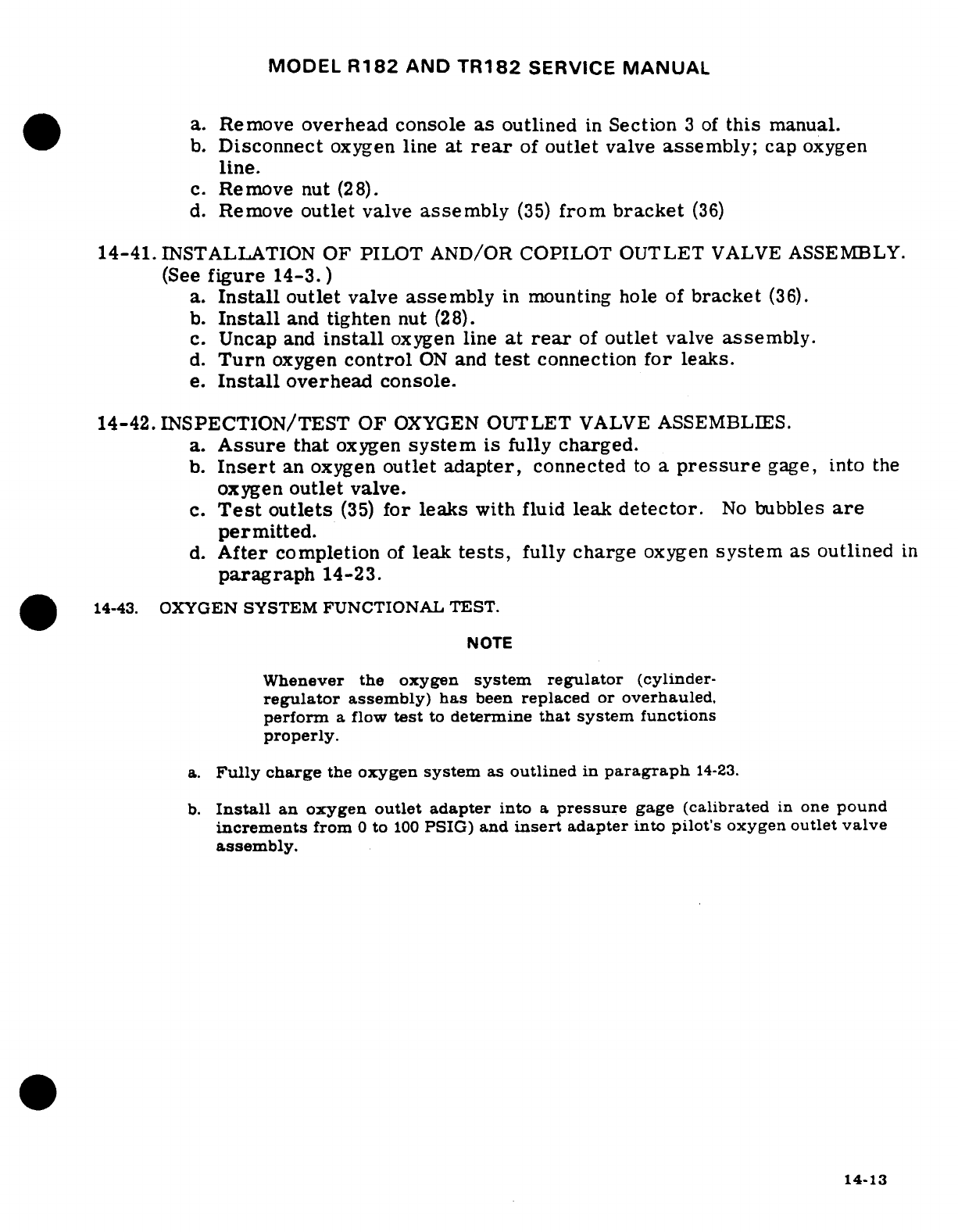
MODEL
R182
AND
TR182
SERVICE
MANUAL
a.
Remove
overhead
console
as
outlined
in
Section
3
of
this
manual.
b.
Disconnect
oxygen
line
at
rear
of
outlet
valve
assembly;
cap oxygen
line.
c.
Remove
nut
(28).
d.
Remove
outlet
valve
assembly
(35)
from
bracket
(36)
14-41.
INSTALLATION
OF
PILOT
AND/OR
COPILOT
OUTLET
VALVE
ASSEMBLY.
(See
figure
14-3.)
a.
Install
outlet
valve
assembly
in
mounting
hole
of
bracket
(36).
b.
Install
and
tighten
nut
(28).
c.
Uncap
and
install
oxygen
line
at
rear
of
outlet
valve
assembly.
d.
Turn
oxygen
control
ON
and
test
connection
for
leaks.
e.
Install
overhead
console.
14-42.
INSPECTION/TEST
OF
OXYGEN
OUTLET
VALVE
ASSEMBLIES.
a.
Assure
that
oxygen
system
is
fully
charged.
b.
Insert
an
oxygen
outlet
adapter,
connected
to
a
pressure
gage,
into
the
oxygen
outlet
valve.
c.
Test
outlets
(35)
for leaks
with
fluid
leak
detector.
No
bubbles
are
permitted.
d.
After
completion
of
leak
tests,
fully
charge
oxygen
system
as
outlined
in
paragraph
14-23.
14-43.
OXYGEN
SYSTEM
FUNCTIONAL TEST.
NOTE
Whenever the
oxygen
system
regulator
(cylinder-
regulator
assembly)
has
been
replaced
or
overhauled,
perform
a
flow
test
to
determine
that
system
functions
properly.
a.
Fully
charge
the
oxygen
system
as
outlined
in
paragraph
14-23.
b.
Install
an
oxygen
outlet adapter
into
a
pressure
gage
(calibrated
in
one
pound
increments
from
0
to
100
PSIG)
and
insert
adapter
into
pilot's
oxygen
outlet
valve
assembly.
14-13
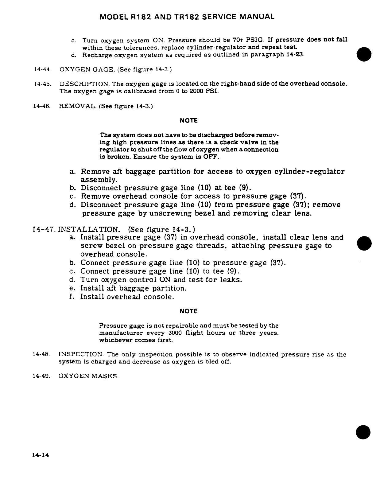
MODEL
R182
AND
TR182
SERVICE
MANUAL
c.
Turn
oxygen
system
ON.
Pressure
should
be
70t
PSIG.
If
pressure
does
not
fall
within
these
tolerances.
replace
cylinder-regulator
and
repeat
test.
d.
Recharge
oxygen
system
as
required
as
outlined
in
paragraph
14-23.
14-44.
OXYGEN GAGE.
(See
figure
14-3.)
14-45.
DESCRIPTION.
The
oxygen
gage
is
located
on
the
right-hand
side
of
the
overhead console.
The
oxygen
gage
is
calibrated
from
0
to
2000
PSI.
14-46.
REMOVAL.
(See
figure
14-3.)
NOTE
The
system
does
not
have
to
be
discharged
before
remov-
ing
high
pressure
lines
as
there
is a
check
valve
in
the
regulator
to
shut
off
the
flow
of
oxygen
when
a
connection
is
broken.
Ensure
the
system
is
OFF.
a.
Remove aft
baggage
partition
for
access
to
oxygen
cylinder-regulator
assembly.
b.
Disconnect
pressure
gage
line
(10)
at tee
(9).
c.
Remove
overhead
console
for
access
to
pressure
gage
(37).
d.
Disconnect
pressure
gage
line
(10)
from
pressure
gage
(37);
remove
pressure
gage
by
unscrewing
bezel
and
removing
clear
lens.
14-47.
INSTALLATION.
(See
figure
14-3.)
a.
Install
pressure
gage
(37)
in
overhead
console,
install
clear
lens
and
screw
bezel
on
pressure
gage
threads,
attaching
pressure
gage
to
overhead
console.
b.
Connect
pressure
gage
line
(10)
to
pressure
gage
(37).
c.
Connect
pressure
gage
line
(10)
to
tee
(9).
d.
Turn
oxygen
control
ON
and
test
for
leaks.
e.
Install
aft
baggage
partition.
f.
Install
overhead console.
NOTE
Pressure
gage
is
not
repairable
and
must
be
tested
by
the
manufacturer
every
3000
flight
hours
or
three
years.
whichever comes
first.
14-48.
INSPECTION.
The
only
inspection
possible
is
to
observe
indicated
pressure
rise
as
the
system
is
charged
and
decrease
as
oxygen
is
bled
off.
14-49.
OXYGEN
MASKS.
14-14
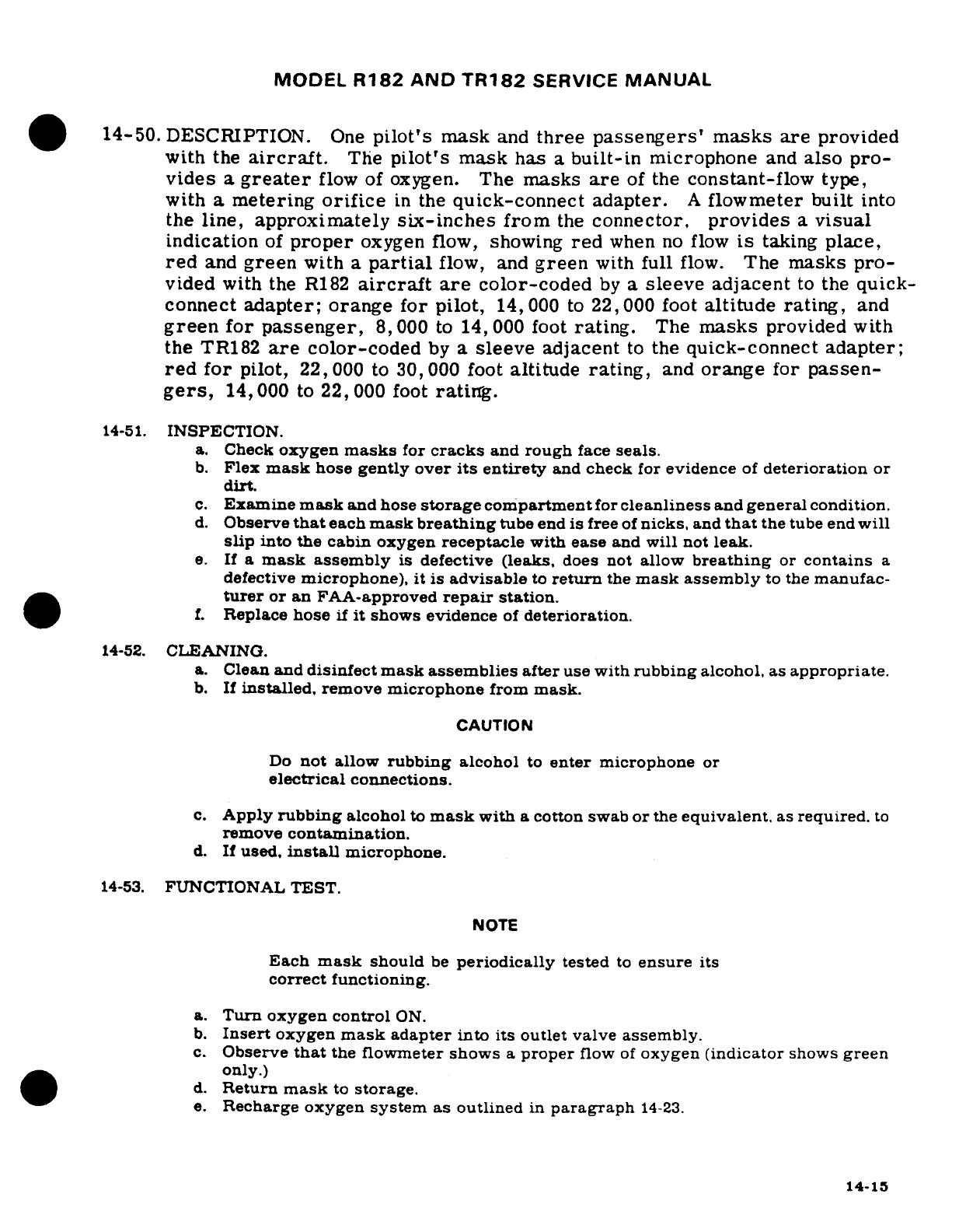
MODEL
R182
AND
TR182
SERVICE
MANUAL
14-50.
DESCRIPTION.
One
pilot's
mask
and
three
passengers'
masks are
provided
with
the
aircraft.
The
pilot's
mask
has
a
built-in
microphone
and
also pro-
vides
a
greater
flow
of
oxygen.
The
masks
are
of
the
constant-flow
type,
with
a
metering
orifice
in
the
quick-connect adapter.
A
flowmeter
built
into
the
line,
approximately
six-inches
from
the
connector,
provides
a
visual
indication
of
proper
oxygen
flow,
showing
red
when
no
flow
is
taking
place,
red
and
green
with
a
partial
flow,
and
green
with
full
flow.
The
masks
pro-
vided
with
the
R182
aircraft
are
color-coded
by
a
sleeve
adjacent
to
the
quick-
connect
adapter;
orange
for
pilot,
14,000
to
22,000
foot
altitude
rating,
and
green
for
passenger,
8,000
to
14,
000
foot
rating.
The
masks
provided
with
the
TR182
are
color-coded
by
a
sleeve
adjacent
to
the
quick-connect
adapter;
red
for
pilot,
22,000
to
30,
000
foot
altitude
rating,
and
orange
for
passen-
gers,
14,000
to
22,000
foot
rating.
14-51.
INSPECTION.
a.
Check
oxygen
masks
for
cracks
and
rough
face
seals.
b.
Flex
mask
hose
gently
over
its
entirety
and
check
for
evidence
of
deterioration
or
dirt.
c.
Examine
mask
and hose
storage
compartment
for
cleanliness
and
general
condition.
d.
Observe
that
each
mask
breathing
tube
end
is
free
of
nicks,
and
that
the
tube
end
will
slip
into
the cabin
oxygen
receptacle
with
ease
and
will
not
leak.
e.
If
a
mask assembly
is
defective
(leaks,
does
not
allow
breathing
or
contains
a
defective
microphone),
it
is advisable
to
return
the
mask
assembly
to the
manufac-
turer
or
an
FAA-approved
repair
station.
f.
Replace
hose
if
it
shows evidence
of
deterioration.
14-52.
CLEANING.
a.
Clean
and
disinfect
mask assemblies
after
use with
rubbing
alcohol, as
appropriate.
b.
If
installed,
remove
microphone
from
mask.
CAUTION
Do
not
allow
rubbing
alcohol
to
enter
microphone
or
electrical
connections.
c.
Apply
rubbing
alcohol
to
mask
with
a
cotton swab
or
the
equivalent,
as
required.
to
remove
contamination.
d.
If
used,
install
microphone.
14-53.
FUNCTIONAL TEST.
NOTE
Each
mask
should
be
periodically
tested
to
ensure
its
correct
functioning.
a.
Turn oxygen
control
ON.
b.
Insert
oxygen
mask
adapter
into
its
outlet
valve
assembly.
c.
Observe
that
the
flowmeter
shows
a
proper
flow
of
oxygen
(indicator
shows
green
only.)
d.
Return
mask
to
storage.
e.
Recharge
oxygen
system
as
outlined
in
paragraph
14-23.
14-15
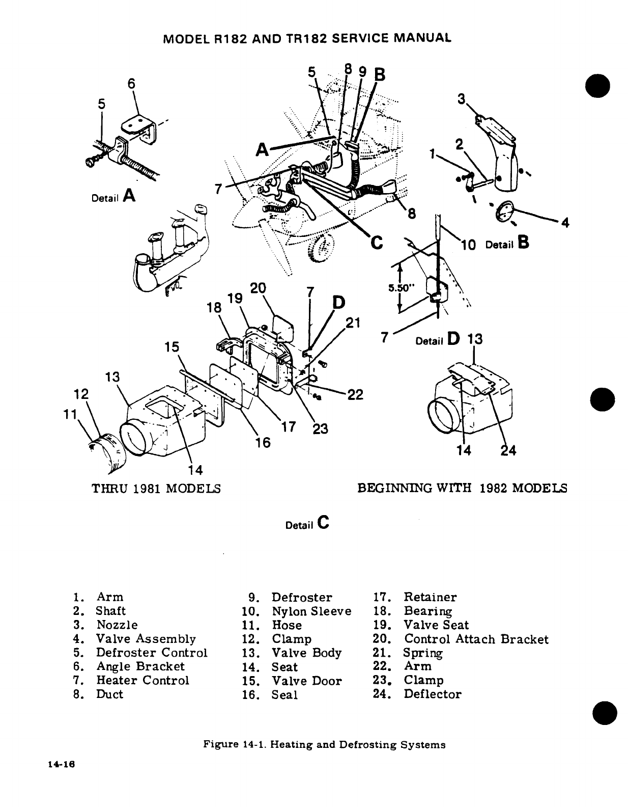
MODEL
R182
AND
TR182
SERVICE
MANUAL
Detail
A
4
Det
ail···'':l% C'\
10
Detail
B
1
20
1819
21
13
12
'.
22
17
23
16
14
THRU
1981
MODELS
BEGINNING
WITH 1982
MODELS
Detail
C
1.
Arm
9.
Defroster
17.
Retainer
2.
Shaft
10.
Nylon
Sleeve
18.
Bearing
3.
Nozzle
11.
Hose
19.
Valve Seat
4.
Valve
Assembly
12.
Clamp
20.
Control Attach
Bracket
5.
Defroster
Control
13.
Valve
Body
21.
Spring
6.
Angle
Bracket
14.
Seat
22.
Arm
7.
Heater Control
15.
Valve
Door
23.
Clamp
8.
Duct
16.
Seal
24.
Deflector
Figure
14-1.
Heating
and
Defrosting
Systems
14-16
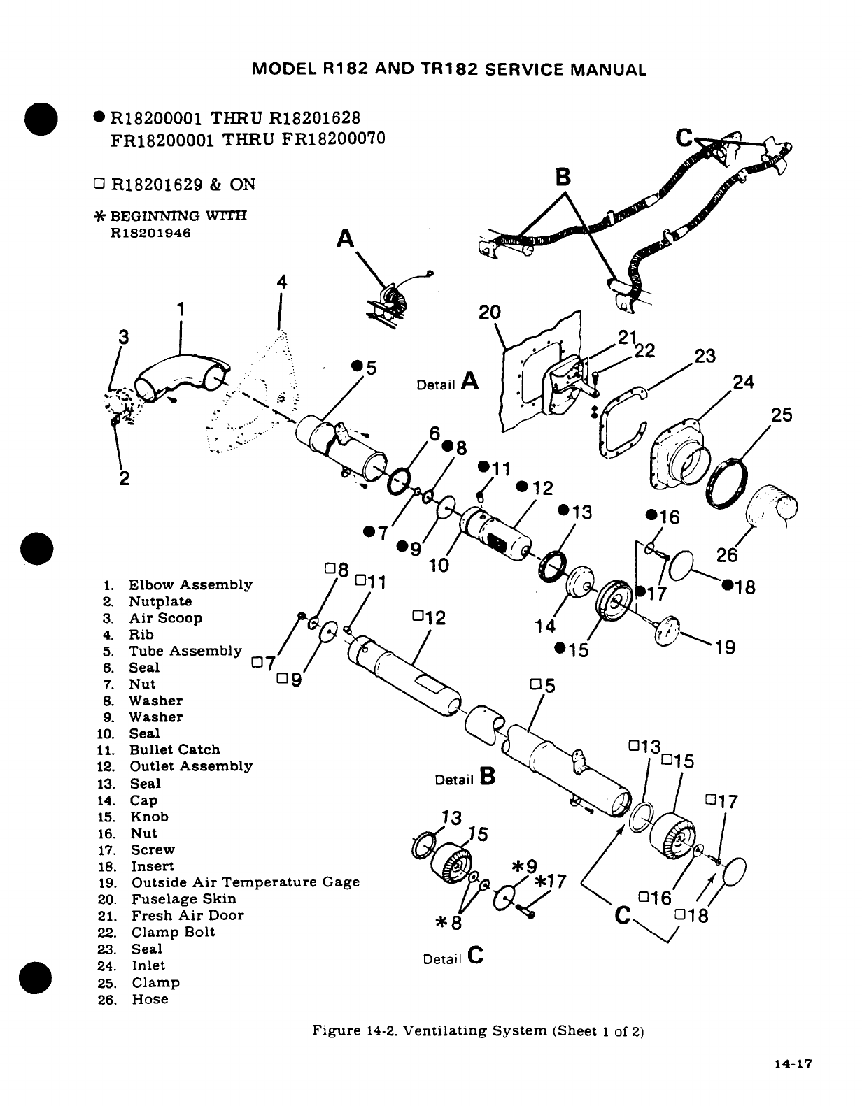
MODEL
R182
AND
TR182
SERVICE
MANUAL
R18200001
THRU
R18201628
FR18200001
THRU
FR18200070
O
R18201629
&
ON
B
*
BEGINNING
WITH
R18201946
A
1 |
's~l
20
3
r
\
21
5. Euboe
Assembly
*5
22
123
6:.
Seal
°7
/
·
!
DetailA
s1
24
2.
Nutplate
I7
11
1.
Elbow
Assembly
/
1-1
18
2.
Nutplate
/17
18
3.
Air
Scoop
012
4.
Rib
14
5.
Tube
Assembly
15
1
6.
Seal
7
/
0
7.
Nut
09
8.
Washer
9.
Washer
10.
Seal
11.
Bullet
Catch
"
013
12.
Outlet
Assembly
015
13.
Seal
Detail
B
14.
Cap
017
15.
Knob
3
16.
Nut
75
17.
Screw
A
Do
18.
Insert
*9
19.
Outside
Air
Temperature
Gage
*1
7
20.
Fuselage
Skin
016
21.
Fresh
Air
Door
0
22.
Clamp
Bolt
23.
Seal
24.
Inlet
Detail
C
25.
Clamp
26.
Hose
Figure
14-2.
Ventilating
System
(Sheet
1
of
2)
14-17
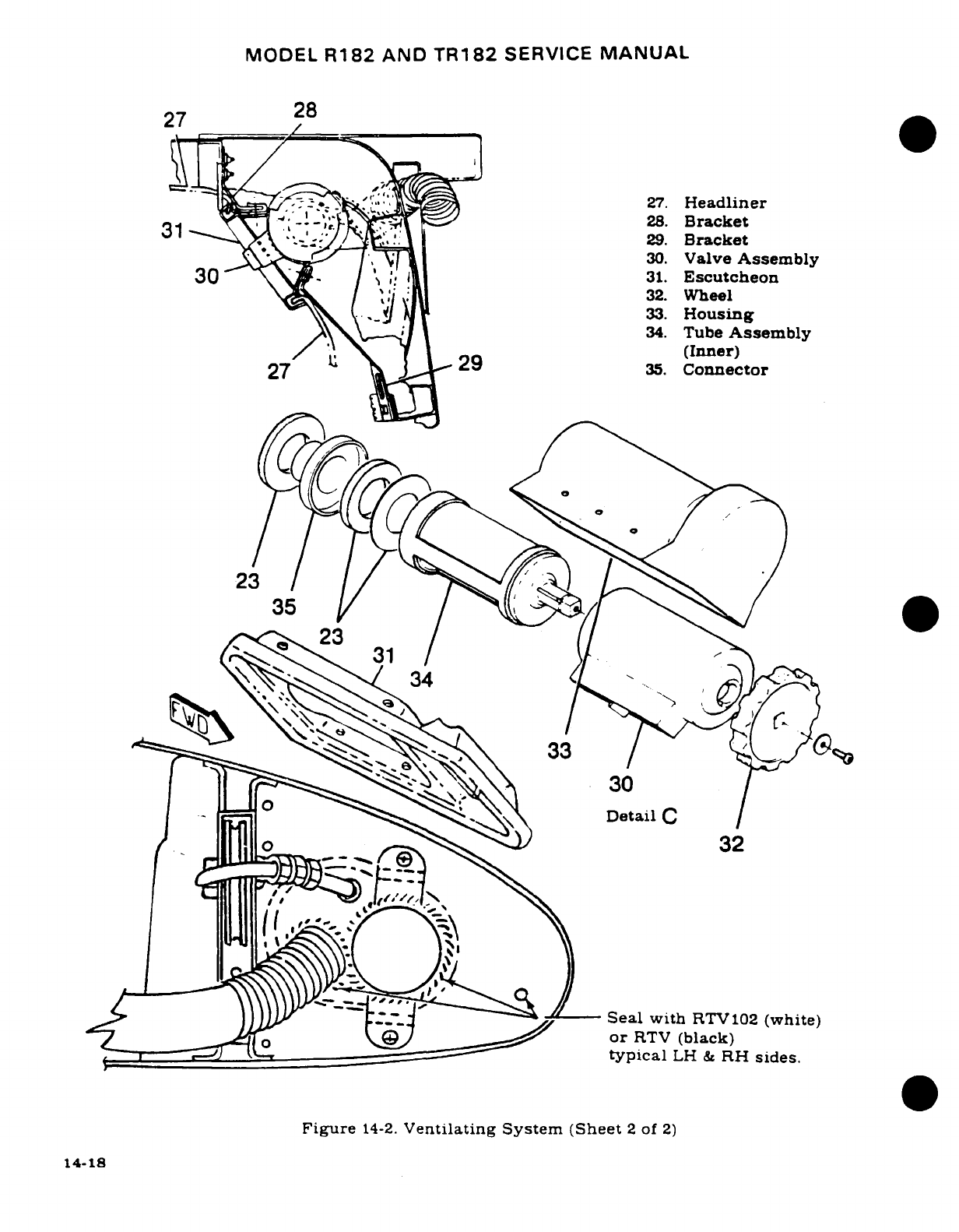
MODEL
R182
AND
TR182
SERVICE
MANUAL
27
28
27.
Headliner
~31 IX^\ ; , --.^~f;T I28.
Bracket
^"^ .-- V,~-/ r:_1
j29.
Bracket
30.
Valve
Assembly
30 \W~ oat ;~
''! ~31.
Escutcheon
32.
Wheel
\\&^_,1qk~ \-33.
Housing
/6\ -; \> L ~34.
Tube
Assembly
1; U V T I 29
(Inner)
27
a rkr35.
connector
23
3
1
33
30
o
<
Detail
C
Seal
with
RTV102
(white)
~
Ts
or
RTV
(black)
typical
LH
&
RH
sides.
Figure
14-2.
Ventilating
System (Sheet
2
of
2)
14-18
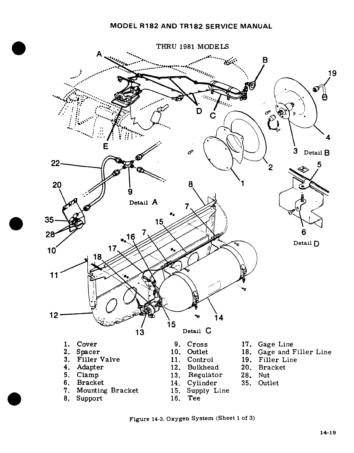
MODEL
R182
AND
TR182
SERVICE
MANUAL
THRU
1981
MODELS
A
......
..
..
.B--Detail
D
1~3
Detai
..
'.20.'.:.-:, ~ .r\"---:.
\'
8X \L
S
4.
Adapter
12.
Bulkhead
20.
Bracket
16.
Bracketail
14.
Cylinder
35.
Outlet
6.3Braket
14.Cylinder35.Outt14-19
2.
Supcr1t 16. Gee
3.DtaFillr
e
11.
COnStro
19
oF
L
7.
Mouning
Bakt1. CrsupplyG
Ling
-
14-1(
i ii~~~~~~~~~~~~~~~~
~~~~41
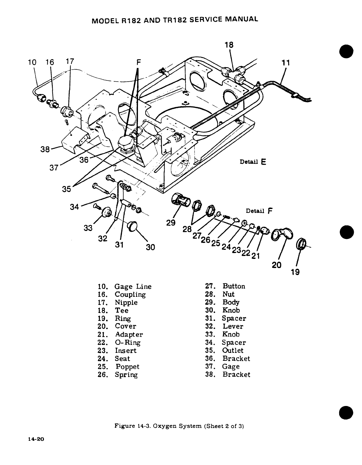
MODEL
R182
AND
TR182
SERVICE
MANUAL
18
34
/
lJO
Detail
F
10.
Gage
Line
27.
Button
1
3
16.
Coupling
28.
Nu
32
2242
19
10.
Gage
Line
27.
Button
16.
Coupling
28.
Nut
17.
Nipple
29.
Body
18.
Tee
30.
Knob
19.
Ring
31.
Spacer
20.
Cover
32.
Lever
21.
Adapter
33.
Knob
22.
O-Ring
34.
Spacer
23.
Insert
35.
Outlet
24.
Seat
36.
Bracket
25.
Poppet
37.
Gage
26.
Spring
38.
Bracket
Figure
14-3.
Oxygen
System
(Sheet
2
of
3)
14-20
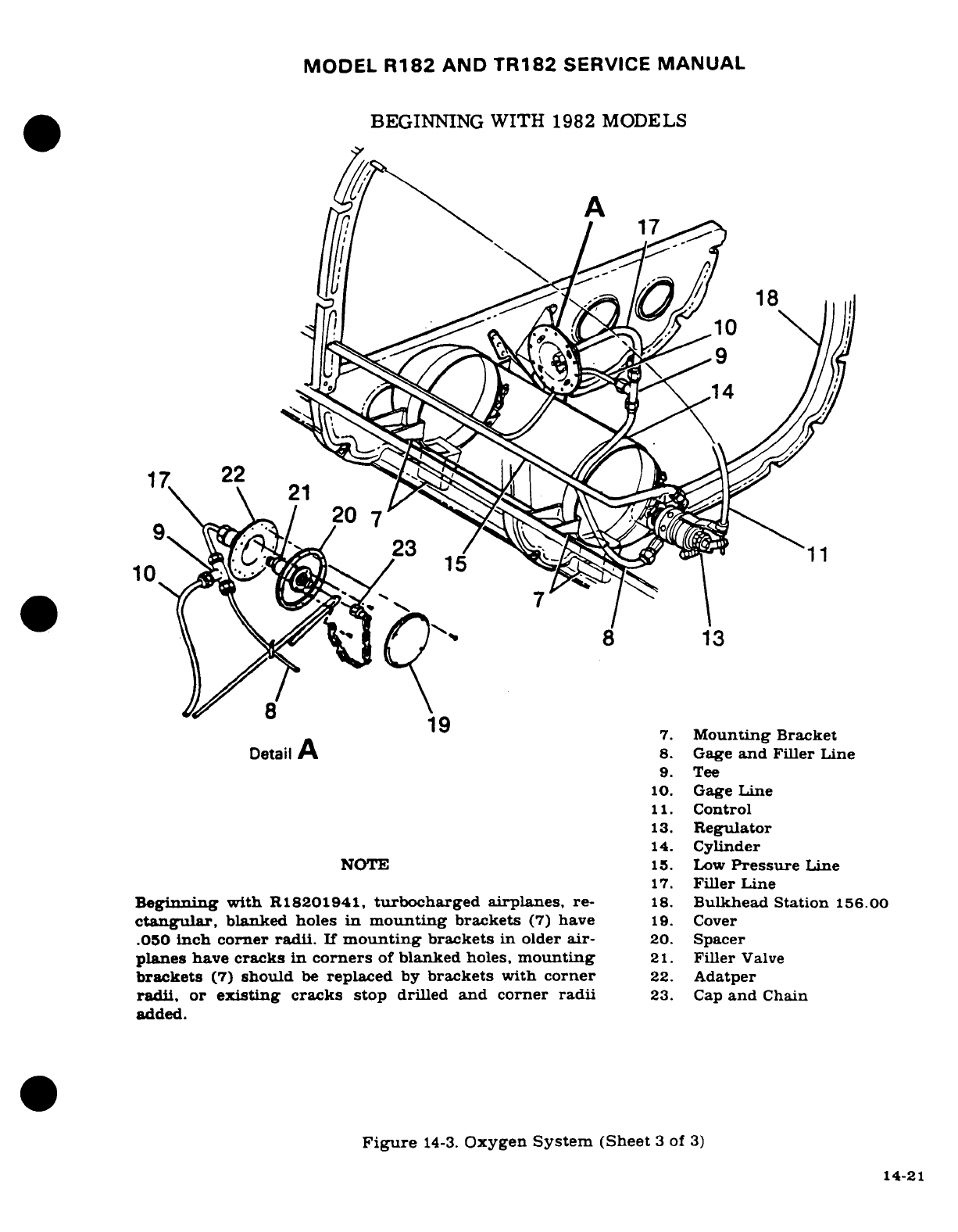
MODEL
R182
AND
TR182
SERVICE
MANUAL
BEGINNING
WITH 1982 MODELS
A
19
14
1
7.
Mounting
Bracket
Detail
A
8.
Gage
and
Filler
Line
~~~~~~~17.~~~9.
Tee
~~~~~10 ~10.
Gage
Line
11.
Control
13.
Regulator
.
CylountindeBracket
DeNOTE A .
Gag
e
and
Filler
Line
9.
Tee
10.
Gage
Line
11.
Control
13.
Regulator
14.
Cylinder
NOTE
15.
Low
Pressure
Line
17.
Filler
Line
Beginning
with
R18201941,
turbocharged
airplanes,
re-
18.
Bulkhead
Station
156.00
ctangular,
blanked
holes
in
mounting
brackets
(7)
have
19.
Cover
.050
inch
corner
radii.
If
mounting
brackets
in
older
air-
20.
Spacer
planes
have
cracks
in
corners
of
blanked
holes,
mounting
21.
Filler
Valve
brackets
(7)
should
be
replaced
by
brackets with
corner
22.
Adatper
radii, or
existing
cracks
stop
drilled
and
corner
radii
23. Cap
and
Chain
added.
Figure
14-3.
Oxygen
System
(Sheet
3
of
3)
14-21
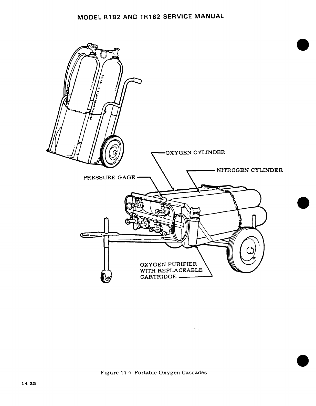
MODEL
R182
AND
TR182
SERVICE
MANUAL
X-^J
X
//:[C^/)-OXYGEN
CYLINDER
--
NITROGEN
CYLINDER
PRESSURE
GAGE
OXYGEN
PURIFIER
WITH
REPLACEABLE
CARTRIDGE
Figure
14-4.
Portable Oxygen
Cascades
14-22
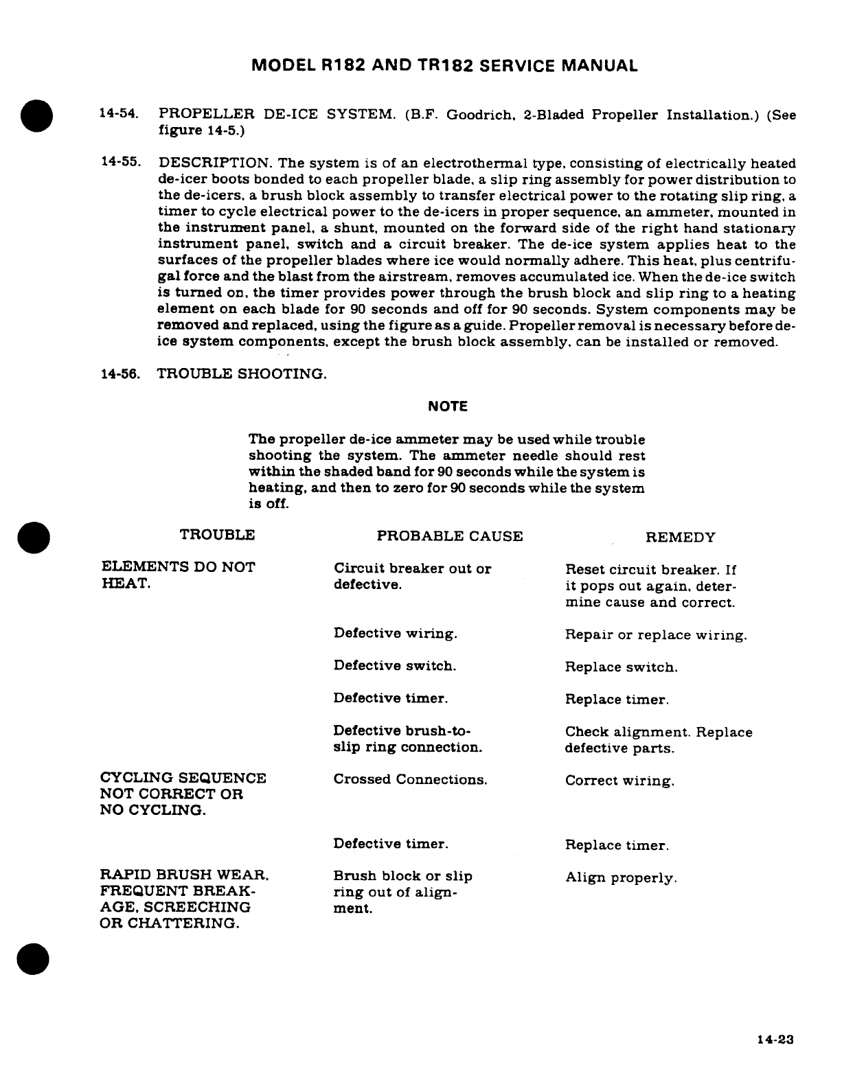
MODEL
R182
AND
TR182
SERVICE
MANUAL
14-54.
PROPELLER
DE-ICE
SYSTEM.
(B.F.
Goodrich,
2-Bladed
Propeller Installation.)
(See
figure
14-5.)
14-55.
DESCRIPTION.
The
system
is
of
an
electrothermal
type,
consisting
of
electrically
heated
de-icer
boots
bonded
to
each
propeller
blade,
a
slip ring
assembly
for
power
distribution
to
the
de-icers,
a
brush
block
assembly
to
transfer
electrical
power
to
the
rotating
slip
ring,
a
timer
to
cycle
electrical
power
to
the
de-icers
in
proper
sequence,
an
ammeter,
mounted
in
the
instrument
panel,
a
shunt,
mounted
on
the
forward
side
of
the
right
hand
stationary
instrument
panel, switch
and
a
circuit
breaker.
The
de-ice
system
applies
heat
to
the
surfaces
of
the
propeller
blades where
ice
would
normally
adhere.
This
heat,
plus
centrifu-
gal
force and
the
blast
from
the
airstream,
removes accumulated
ice.
When the
de-ice
switch
is
turned
on,
the
timer
provides
power
through
the brush
block
and
slip
ring
to
a
heating
element
on
each
blade
for
90
seconds
and
off
for
90
seconds.
System
components
may
be
removed
and
replaced,
using
the
figure
as
a
guide.
Propeller
removal
is
necessary
before
de-
ice
system
components,
except
the
brush
block
assembly,
can
be
installed
or
removed.
14-56.
TROUBLE
SHOOTING.
NOTE
The
propeller
de-ice
ammeter
may
be
used while trouble
shooting
the
system.
The
ammeter
needle
should rest
within
the
shaded
band
for
90
seconds
while
the
system
is
heating,
and
then
to
zero for
90
seconds
while
the
system
is
off.
TROUBLE
PROBABLE
CAUSE
REMEDY
ELEMENTS
DO
NOT
Circuit
breaker
out or Reset
circuit breaker.
If
HEAT.
defective.
it
pops
out
again,
deter-
mine cause
and
correct.
Defective
wiring.
Repair
or
replace wiring.
Defective
switch.
Replace
switch.
Defective
timer.
Replace
timer.
Defective
brush-to-
Check
alignment.
Replace
slip
ring
connection.
defective
parts.
CYCLING
SEQUENCE
Crossed
Connections.
Correct
wiring.
NOT
CORRECT
OR
NO
CYCLING.
Defective
timer.
Replace
timer.
RAPID
BRUSH
WEAR,
Brush
block
or
slip
Align
properly.
FREQUENT BREAK-
ring
out
of
align-
AGE,
SCREECHING
ment.
OR
CHATTERING.
14-23
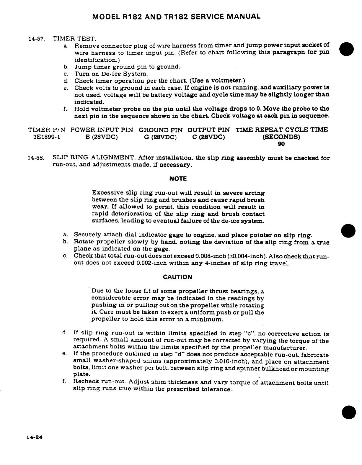
MODEL
R182
AND
TR182
SERVICE
MANUAL
14-57.
TIMER TEST.
a.
Remove
connector
plug
of
wire
harness
from
timer
and
jump
power
input
socket
of
wire
harness
to
timer
input
pin. (Refer
to
chart
following
this
paragraph
for
pin
identification.)
b.
Jump
timer
ground
pin
to
ground.
c.
Turn
on
De-Ice
System.
d.
Check
timer
operation
per
the
chart.
(Use
a
voltmeter.)
e.
Check
volts
to
ground
in
each
case.
If
engine
is
not
running,
and
auxiliary
power
is
not
used,
voltage
will
be
battery
voltage
and
cycle
time
may
be
slightly
longer
than
indicated.
f.
Hold
voltmeter
probe
on
the pin
until
the
voltage drops
to
0.
Move
the
probe
to
the
next
pin
in
the
sequence
shown
in
the
chart.
Check
voltage
at
each
pin
in
sequence.
TIMER
P/N
POWER
INPUT
PIN
GROUND
PIN
OUTPUT
PIN
TIME
REPEAT
CYCLE
TIME
3E1899-1
B
(28VDC)
G
(28VDC)
C
(28VDC)
(SECONDS)
90
14-58.
SLIP
RING ALIGNMENT.
After
installation, the
slip
ring
assembly
must
be
checked
for
run-out,
and
adjustments
made,
if
necessary.
NOTE
Excessive
slip
ring
run-out
will
result
in
severe
arcing
between
the
slip
ring
and
brushes
and
cause
rapid brush
wear.
If
allowed
to
persit,
this
condition
will
result
in
rapid
deterioration
of
the
slip
ring
and
brush
contact
surfaces,
leading
to
eventual
failure
of
the
de-ice
system.
a.
Securely
attach dial
indicator
gage
to
engine,
and
place
pointer
on
slip
ring.
b.
Rotate
propeller
slowly
by
hand,
noting
the
deviation
of
the
slip
ring
from
a
true
plane
as
indicated
on
the
gage.
c.
Check
that total
run-out
does
not
exceed
0.008-inch
(±0.004-inch).
Also
check
that
run-
out
does
not
exceed
0.002-inch
within any
4-inches
of
slip
ring
travel.
CAUTION
Due
to
the
loose
fit
of
some
propeller
thrust
bearings,
a
considerable
error
may
be
indicated
in
the
readings
by
pushing
in
or
pulling
out
on
the
propeller
while
rotating
it.
Care
must
be
taken
to
exert
a
uniform
push
or
pull
the
propeller
to
hold
this
error
to
a
minimum.
d.
If
slip
ring run-out
is
within
limits
specified
in
step
"c",
no
corrective action
is
required.
A
small
amount
of
run-out
may
be
corrected
by
varying
the
torque
of
the
attachment
bolts
within
the
limits
specified
by
the
propeller
manufacturer.
e.
If
the
procedure
outlined
in
step
"d"
does
not produce acceptable
run-out, fabricate
small
washer-shaped shims
(approximately
0.010-inch),
and
place
on
attachment
bolts,
limit
one
washer
per
bolt,
between
slip ring
and
spinner
bulkhead
or
mounting
plate.
f.
Recheck
run-out. Adjust
shim
thickness
and
vary
torque
of
attachment
bolts
until
slip
ring
runs
true
within
the
prescribed tolerance.
14-24
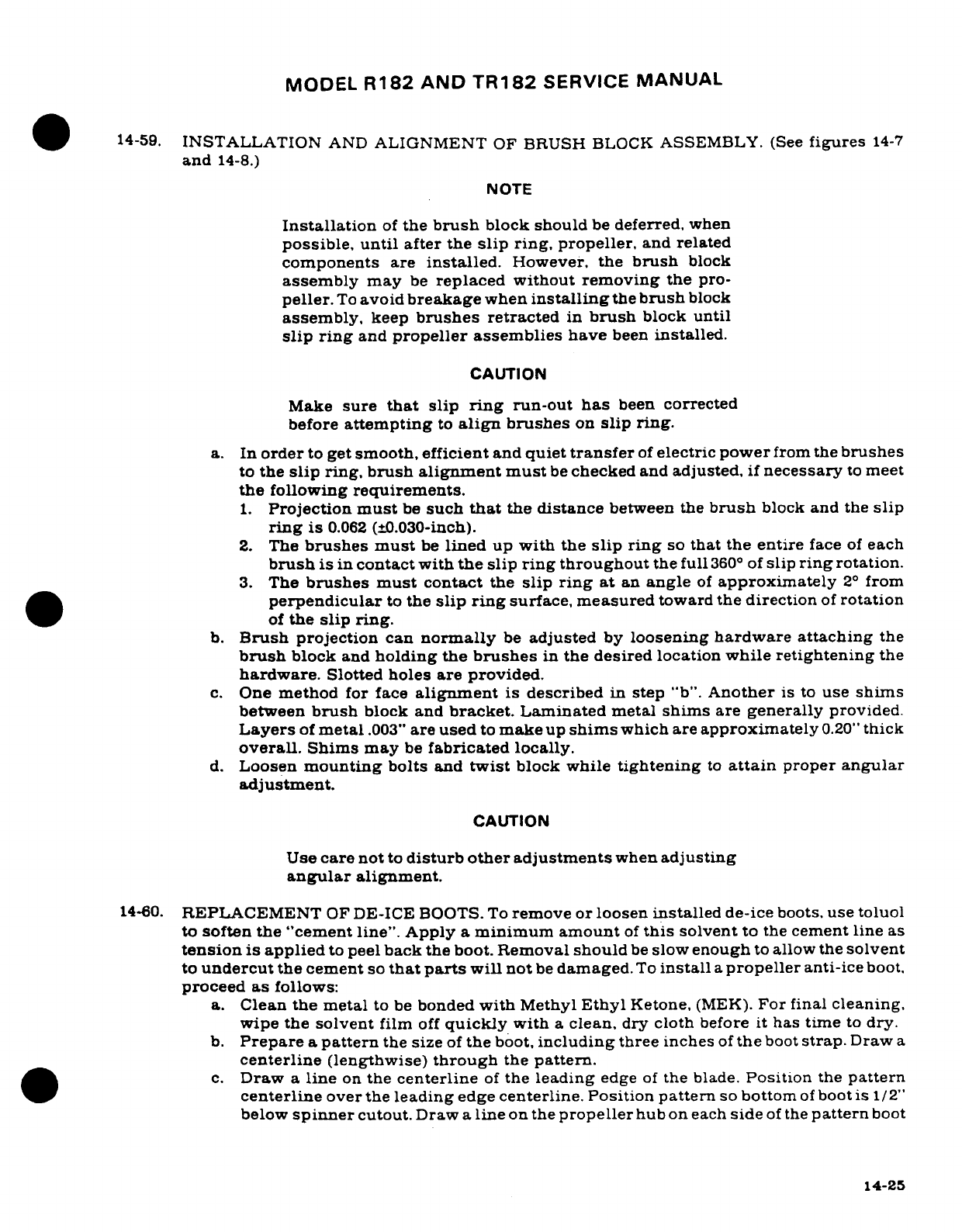
MODEL
R182
AND
TR182
SERVICE
MANUAL
14-59.
INSTALLATION
AND
ALIGNMENT
OF
BRUSH
BLOCK
ASSEMBLY.
(See
figures
14-7
and
14-8.)
NOTE
Installation
of
the
brush
block should
be
deferred,
when
possible, until
after
the
slip
ring,
propeller,
and
related
components
are
installed.
However, the
brush
block
assembly
may
be
replaced without
removing
the
pro-
peller.
To
avoid
breakage
when
installing
the
brush
block
assembly,
keep
brushes
retracted
in
brush
block
until
slip
ring
and
propeller
assemblies
have
been
installed.
CAUTION
Make
sure
that
slip
ring
run-out
has
been
corrected
before
attempting
to
align
brushes
on
slip
ring.
a. In
order
to
get
smooth, efficient
and
quiet
transfer
of
electric
power
from the
brushes
to
the
slip
ring,
brush
alignment
must
be
checked
and
adjusted,
if
necessary
to
meet
the
following
requirements.
1.
Projection
must
be
such
that
the
distance
between
the
brush
block
and
the
slip
ring
is
0.062
(±0.030-inch).
2.
The
brushes
must
be
lined
up
with
the
slip
ring
so
that the
entire
face
of
each
brush
is in
contact with
the
slip
ring
throughout
the full
360
°
of
slip
ring
rotation.
3.
The
brushes
must
contact
the
slip
ring
at
an
angle
of
approximately
2°
from
perpendicular
to
the
slip
ring
surface,
measured
toward
the
direction
of
rotation
of
the
slip
ring.
b.
Brush
projection
can
normally
be
adjusted
by
loosening
hardware
attaching
the
brush
block
and
holding the
brushes
in
the
desired
location
while retightening
the
hardware.
Slotted
holes
are provided.
c.
One
method
for
face
alignment
is
described
in
step
"b".
Another
is
to
use
shims
between
brush
block
and
bracket. Laminated
metal
shims
are
generally
provided.
Layers
of
metal
.003"
are
used
to
make
up
shims
which
are
approximately
0.20"
thick
overall. Shims
may
be
fabricated
locally.
d.
Loosen
mounting
bolts
and
twist
block
while
tightening
to
attain
proper
angular
adjustment.
CAUTION
Use
care
not
to
disturb other adjustments
when
adjusting
angular
alignment.
14-60.
REPLACEMENT
OF
DE-ICE
BOOTS.
To
remove or loosen
installed
de-ice
boots,
use toluol
to
soften
the
"cement
line".
Apply
a
minimum
amount
of
this
solvent
to
the
cement
line
as
tension
is
applied
to
peel
back
the
boot.
Removal
should
be
slow
enough
to
allow
the
solvent
to
undercut
the
cement
so
that
parts
will
not
be
damaged.
To
install
a
propeller
anti-ice
boot.
proceed
as
follows:
a.
Clean
the
metal
to
be
bonded
with
Methyl
Ethyl
Ketone,
(MEK).
For
final
cleaning,
wipe
the
solvent
film
off
quickly
with
a
clean,
dry
cloth
before
it
has
time
to
dry.
b.
Prepare
a
pattern
the
size
of
the
boot,
including
three
inches
of
the
boot
strap.
Draw
a
centerline
(lengthwise)
through
the
pattern.
c.
Draw
a
line
on
the
centerline
of
the
leading
edge
of
the
blade.
Position
the
pattern
centerline
over
the
leading
edge
centerline.
Position
pattern
so
bottom
of
boot
is
1/2"
below
spinner
cutout.
Draw
a
line
on
the
propeller
hub
on
each
side
of
the
pattern
boot
14-25
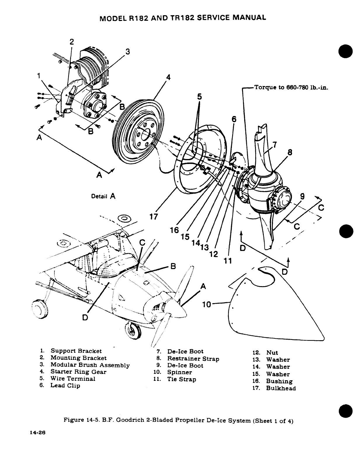
MODEL
R182
AND
TR182
SERVICE
MANUAL
2
~1~~
,, 3
6
A
'16
//// \\\1
C1
I-1
\I 13
.S
-....
B~ .1
2
13
*.-/. p... \
1.
Support
Bracket
7.
De-Ice Boot
12.
Nut
2.
Mounting
Bracket
8.
Restrainer
Strap
13.
Washer
3.
Modular
Brush
Assembly
9.
De-Ice Boot
14.
Washer
4.
Starter
Ring
Gear
10.
Spinner
15
Washer
5.
Wire
Terminal
11.
Tie
Strap
16. Bushinger
6.
Lead
Clip
17.
Bulkhead
Figure
14-5.
B.F.
Goodrich
2-Bladed
Propeller
De-Ice
System
(Sheet
1
of
4)
14-26
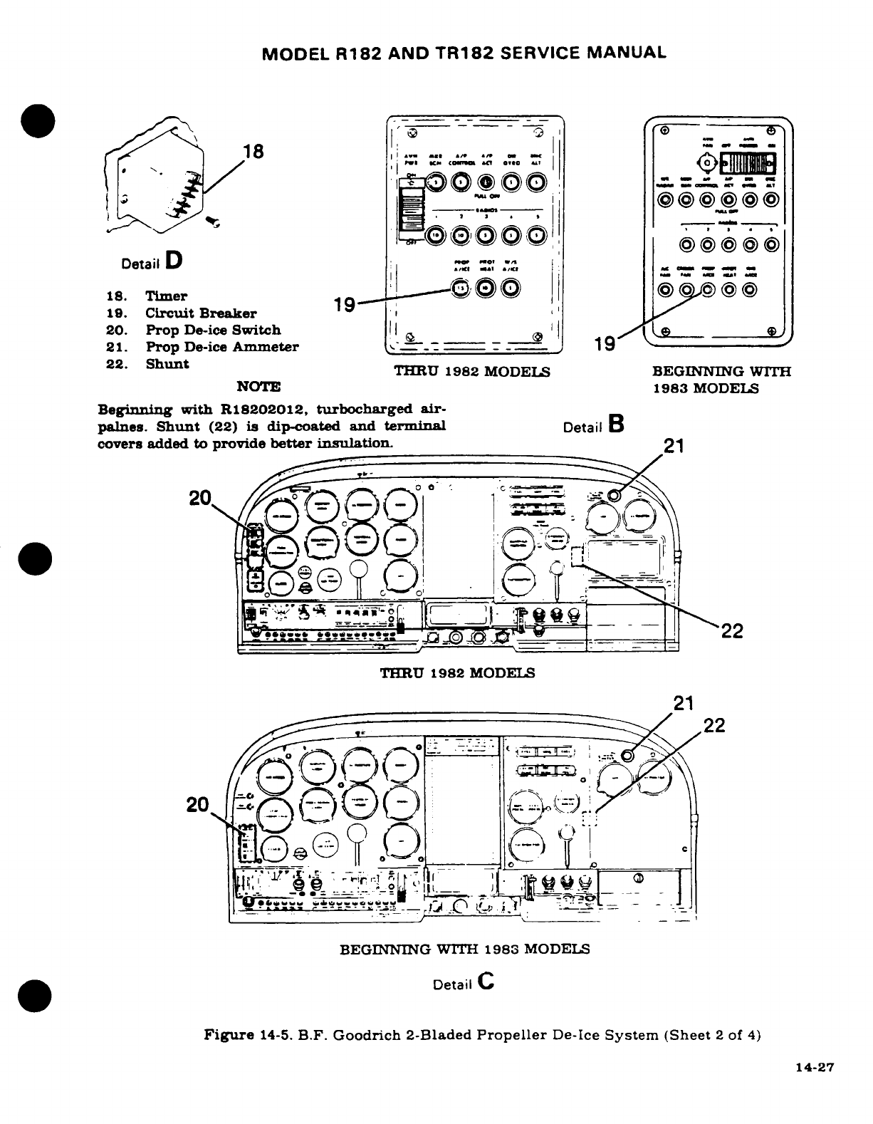
MODEL
R182
AND
TR182
SERVICE
MANUAL
r^ 41 |.
o-e|.-|- _I
>
_
tL8e IEA-,-.
.
...
>({){"I
H
__
_
,
__
Detail
Ds
18.
Timer
1
-----
'
O
19.
Circuit
Breaker
19
'
20.
Prop
De-ice
Switch_ !
,
21.
Prop
De-ice
Ammeter
'
--
19
22.
Shunt
THRU
1982
MODELS
BEGINNING
WITH
NOTE
1983
MODELS
Beginning
with
R18202012,
turbocharged
air-
palnes.
Shunt
(22)
is
dip-coated
and
terminal
Detail
B
covers
added to
provide
better
insulation.
21
210=
QQ
^TO
*
!
v^*Tzt ^1-11 >'~22
THRU
1982
MODELS
21
20--2 ^-
^^
, -
(22
22
20
-
;7ii
s!1;
;
_,.·
~~.^
,,,. __~ Ir---'
"-
~..~?t
-'
:
-1
BEGINNING
WITH
1983
MODELS
Detail
C
Figure
14-5.
B.F.
Goodrich
2-Bladed
Propeller
De-Ice
System
(Sheet
2
of
4)
14-27
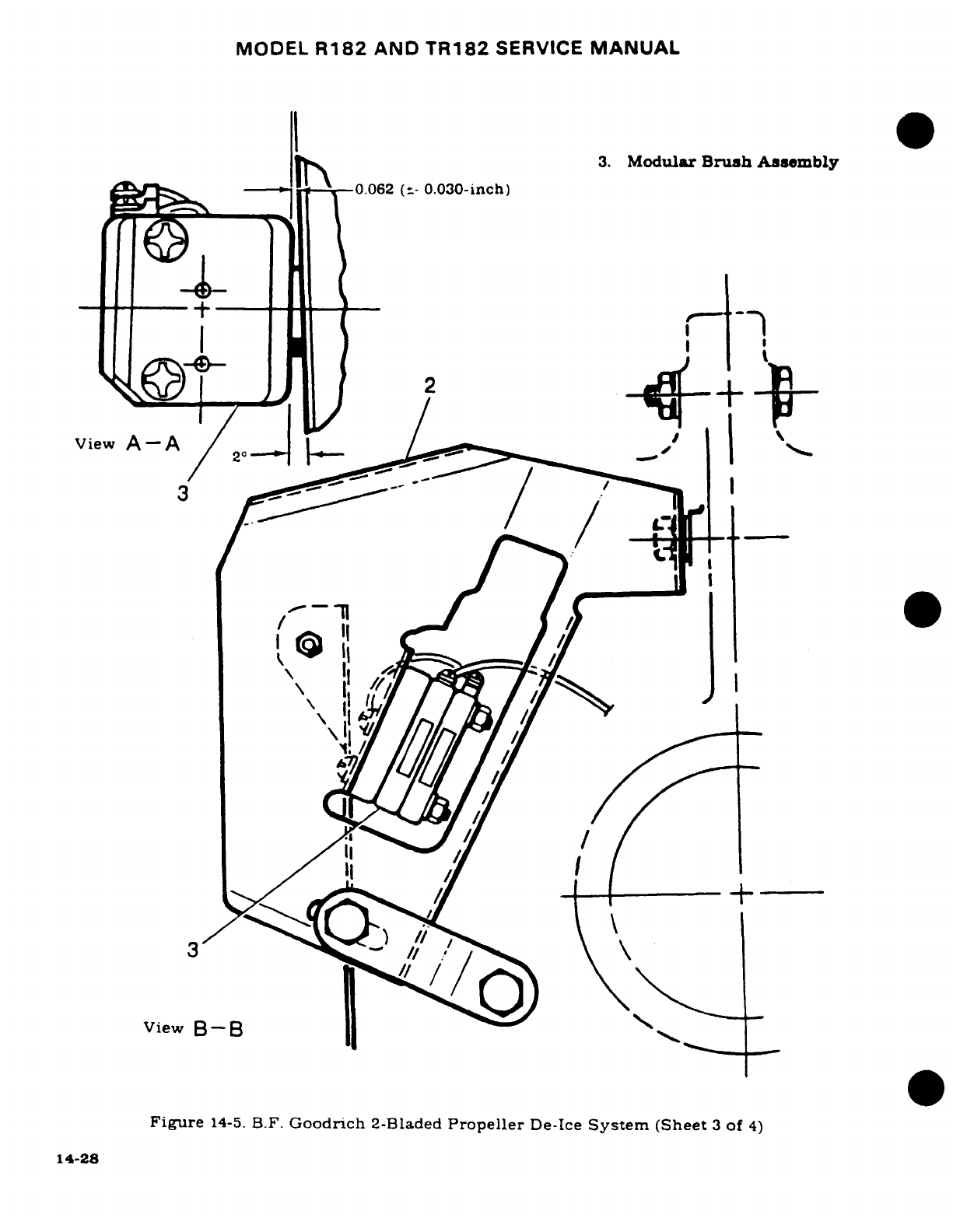
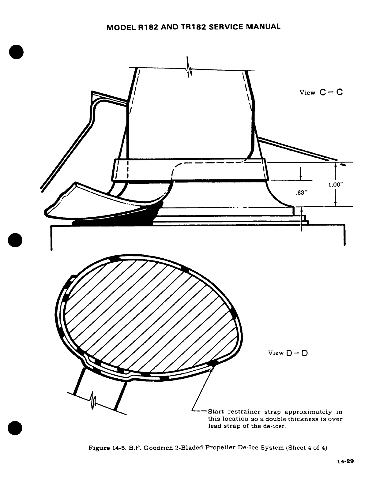
MODEL
R182
AND
TR182
SERVICE
MANUAL
I
-
bi/ ft/ -
\
View
C-
C
i ,/---
*
X
m
1.00"
I>7~~~~ i<~~~~~~
[63"
View
D-
D
Start
restrainer
strap
approximately
in
this
location
so
a
double
thickness
is
over
lead
strap
of
the
de-icer.
Figure
14-5.
B.F.
Goodrich
2-Bladed
Propeller
De-Ice
System
(Sheet
4
of
4)
14-29
MODEL
R182
AND
TR182
SERVICE
MANUAL
strap
where
it
crosses
the hub.
Check
boot
strap
position
by
fitting
restraining
strap
on
the
hub
and
comparing
its
position
with
the
marked
position
of
the
strap.
d.
Mask
off
an
era
1/2" from
each
side
and
outer
end
of
the
pattern.
and
remove
the
pattern.
NOTE
Apply
cement
at
room
temperature
(65°-75°F).
For
best
results,
allow
to
air
dry for
a
minimum
of
one
hour
at
50F
or
above
when
relative
humidity
is
less
than
75%.
If
the
humidity
is
75%
and
90%,
allow
additional
drying
time.
Do
not
apply
cement
if
relative humidity
is
higher
than
90%
or
if
the
temperature
is
below
50°F.
Allow
12
hours
cement
curing
time
before
starting
engine.
Allow
24
hours
cement
curing
time
before
operating
the
de-icers.
e.
Mix
EC-1300L
cement
(Minnesota Mining
&
Mfg.
Co.)
thoroughly.
Surfaces
shall
be
65°F
prior
to
applying
cement.
During
periods
of
high
humidity, care
shall
be
taken
to
prevent
moisture
condensation
due
to
the
cooling
effect
of
the
evaporating solvent.
This can
be
done
by
warning
the
area
with
a
heat
gun
or
heat
lamp.
Apply
one
even
brush
coat
of
EC-1300L
cement
to
the
cleaned
metal
surface.
Allow
the
air
dry
for
a
minimum
of
one
hour.
Allow
to
air
dry
for
a
minimum
of
one
hour
and
then
apply
a
second
even
brush
coat
of
EC-1300L
cement.
f.
Moisten
a
cloth
with
Methyl
Ethyl
Ketone
and
clean the unglazed
back
surface
of
the
boot,
changing
cloths
frequently
to
avoid
contamination
of
the cleaned
area.
g.
Apply
one
even
coat
of
EC-1300L
cement
to
back
surface
of
boot.
It is
not
necessary
to
cement more
than
1/2"
of
the
boot
strap.
h.
Using
a
silver-colored
pencil,
mark
a
centerline
along
the
leading
edge
of
the
propeller
bade
and
a
corresponding
centerline
on
the
cemented
side
of the
boot.
i.
Reactivate
the
surface
of
the
cement
using
a
clean,
link-free cloth,
heavily
moistened
with
toluol.
Avoid
excessive
rubbing
of
cement,
which would
remove
the
cement.
j.
Position
the
boot
centerline
on
the
propeller leading
edge.
starting
at
the
hub
end
at
the
position
marked.
Make
sure
that
boot
strap
will
fall
in
the
position
marked.
Tack
the
boot
centerline
to
the
leading
edge
of
the
propeller
blade.
If
the
boot
is
allowed
to
get
off-center,
pull
up
with
a
quick
motion
and replace
properly.
Roll
firmly
along
centerline
with
a
rubber
roller.
k.
Gradually
tilting
the
roller,
work
the
boot
carefully
over
either
side
of
the
blade
contour
to
avoid
trapping
air
in
pockets.
1.
Roll
outwardly
from
the
centerline
to
the
edges
tends
to
form
wrinkles,
workthem
out
smoothly
and
carefully
with
fingers.
m.
Apply
one
even
coat
of
EC-539
(Minnesota
Mining
&
Mfg.
Co.).
mixed
per
manufac-
turer's
instructions,
around
the edges
of
the
installed
boot.
n.
Remove
masking
tape
from the
propeller
and
clean
the
surface
of
the
propeller
by
wiping
with
a
clean
cloth
dampened
with
toluol.
o.
Install
restrainer
strap
as
shown
in
detail
in
figure
14-5,
sheet
4.
Start
strap
approximately
in
location
shown
in
detail
so
a
double
thickness
is
over
lead
strap
of
the de-icer.
The
lead
strap
must
not
be
twisted
more
than
one
turn
(180
°)
in
lining
up
the
respective
leads.
Trim
restrainer
strap
so
it
will
end
approximately
as
shown
in
the
detail.
p.
Secure
electrical
leads
of
restrainer
strap
with
screws,
washers
and
sleeves.
14-61.
PROPELLER
DE-ICE
SYSTEM.
(McCauley,
3-Bladed
Propeller
Installation.)
(See
figure
14-
6.)
14-62.
DESCRIPTION.
The
system
is
of
an
electrothermal
type,
consisting
of
electrically
heated
14-30
MODEL
R182
AND
TR182
SERVICE
MANUAL
de-icers
bonded to
each
propeller
blade,
a
slip
ring
assembly
for
power
distribution
to
the
propeller
de-icers,
a
brush
block
assembly
to
transfer
electrical
power
to
the
rotating
slip
ring,
a
timer
to
cycle
electric
power
to
the
de-icers
in
proper
sequence,
an
ammeter,
mounted
in
the
instrument panel,
a
shunt,
a
switch
and
a
circuit
breaker.
The
de-ice
system applies
heat
to
the
surfaces
of
the
propeller
blades
where
ice
would
normally
adhere.
This heat,
plus
centrifugal
force
and
the
blast
from
the
airstream,
removes
accumulated
ice.
Each
de-icer
has
two
separate
electrothermal heating
elements, an
inboard
section
and
an
outboard
section.
When
the
switch
is
turned
on,
the
timer provides
power
through
the
brush
block and
slip
ring
to
outboard
elements
for
approximately
20
seconds,
reducing
ice
and
adhesion
in
these areas.
Then the
timer
switches
power
to
inboard
heating
elements
for
approximately
20
seconds.
It
then
returns
to
the
outer
elements
and
continues
cycling
action.
This
outboard-
inboard
sequence
is
very
important
since the loosened
ice,
through centrifugal
force
moves
outboard.
Heating may
begin
at
any
phase
in
the
cycle,
depending
on
timer
position
when
the
switch
was
turned
off
from
previous
use.
Ground
checkout
of
the
systems
is
permitted
when
the engine
is
not
running.
System
components may
be
removed
and
replaced,
using
the
figure
as
a
guide.
Propeller
removal
is
necessary
before
de-ice
components,
except
brush
block
assembly,
can
be
installed
or
removed.
14-63.
TROUBLE
SHOOTING.
NOTE
The
propeller
anti-ice
ammeter
may
be
used while
trou-
ble
shooting
the
system.
The
ammeter
needle
should
rest
within
the
shaded
band
except
for
"flickers" approxi-
mately
20
seconds
apart,
as
the
step
switch
of
the
timer
operates.
The
ammeter
will
also
reflect
a
bad
connection
or
open
circuit
by
reading
below
normal
or
zero.
A
high
reading
indicates
a
short
circuit.
TROUBLE
PROBABLE
CAUSE
REMEDY
ELEMENTS
DO
NOT
Circuit
breaker
out Reset
circuit
breaker.
If
HEAT.
or
defective.
it
pops
out
again,
deter-
mine
cause
and
correct.
Replace
defective
parts.
Defective
wiring.
Repair
or
replace
wiring.
Defective
switch.
Replace
switch.
Defective
timer.
Replace
timer.
Defective
brush-to-
Check
alignment.
Replace
slip
ring
connection.
defective
parts.
SOME
ELEMENTS
DO
Incorrect
wiring.
Correct
wiring.
NOT
HEAT.
Defective
wiring.
Repair
or
replace
wiring.
Defective
timer.
Replace
timer.
14-31
MODEL
R182
AND
TR182
SERVICE
MANUAL
14-63.
TROUBLE
SHOOTING
(Cont).
TROUBLE
PROBABLE
CAUSE
REMEDY
SOME
ELEMENTS
DO
Defective
brush-to-
Check
alignment.
Replace
NOT
HEAT
(CONT).
slip
ring
connection.
defective
parts.
Defective
element.
Replace
element.
CYCLING
SEQUENCE
Crossed
connections.
Correct
wiring.
NOT
CORRECT
OR
NO
CYCLING.
Defective
timer.
Replace
timer.
RAPID
BRUSH
WEAR.
Brush
block
or
slip
Align
properly.
FREQUENT
BREAKAGE.
ring
out
of
align-
SCREECHING
OR
ment.
CHATTERING.
14-64.
TIMER
TEST.
a.
Remove
connector
plug
of
wire
harness
from
timer
and
jump
power
input
socket
of
wire
harness
to
timer
input
pins.
(Refer
to
chart
following
this
paragraph
for
pin
identification.)
b.
Jump
timer
ground pin
to
ground.
c.
Turn
on
de-icing
system.
d.
Check
timer
operation
per
the
chart.
(Use
a
voltmeter.)
e.
Check
volts
to
ground
in
each case.
If
engine
is
not
running,
and
auxiliary
power
is
not
used,
voltage will
be
battery
voltage
and
cycle
time
may
be
slightly
longer
than
indicated.
f.
Hold
voltmeter
probe
on
pin
until voltage
drops
to
0.
Move
probe
to
next pin
in
the
sequence shown
in
the
chart.
Check
voltage
at
each
pin
in
sequence.
When
correct-
ness
of
the
cycling
sequence
is
established,
turn
propeller
de-ice
switch
off
at
the
beginning
of
one
of
the
on-time
periods,
and
record
the number
of
the
pin
at
which
the
voltage
supply
is
present.
TIMER
P/N
POWER
INPUT
PIN
GROUND
PIN
OUTPUT
SEQUENCE
TIME
REPEAT
C40171
1
(24VDC)
5
(24VDC)
(TIME)
CYCLE
TIME
Three.
20
seconds
each
(SECONDS)
60
14-65.
SLIP
RING
ALIGNMENT.
After
installation,
the
slip
ring
assembly
must
be
checked
for
run-out,
and
adjustments
made,
if
necessary.
NOTE
Excessive
slip
ring
run-out
will
result
in
severe
arcing
between
the
slip
ring
and
brushes,
and
cause
rapid
brush
wear.
If
allowed
to
persist,
this
condition
will
result
in
rapid deterioration
of
the
slip
ring
and
brush
contact
surfaces,
and
lead
to
the
eventual
failure
of
the
De-Icing
System.
14-32
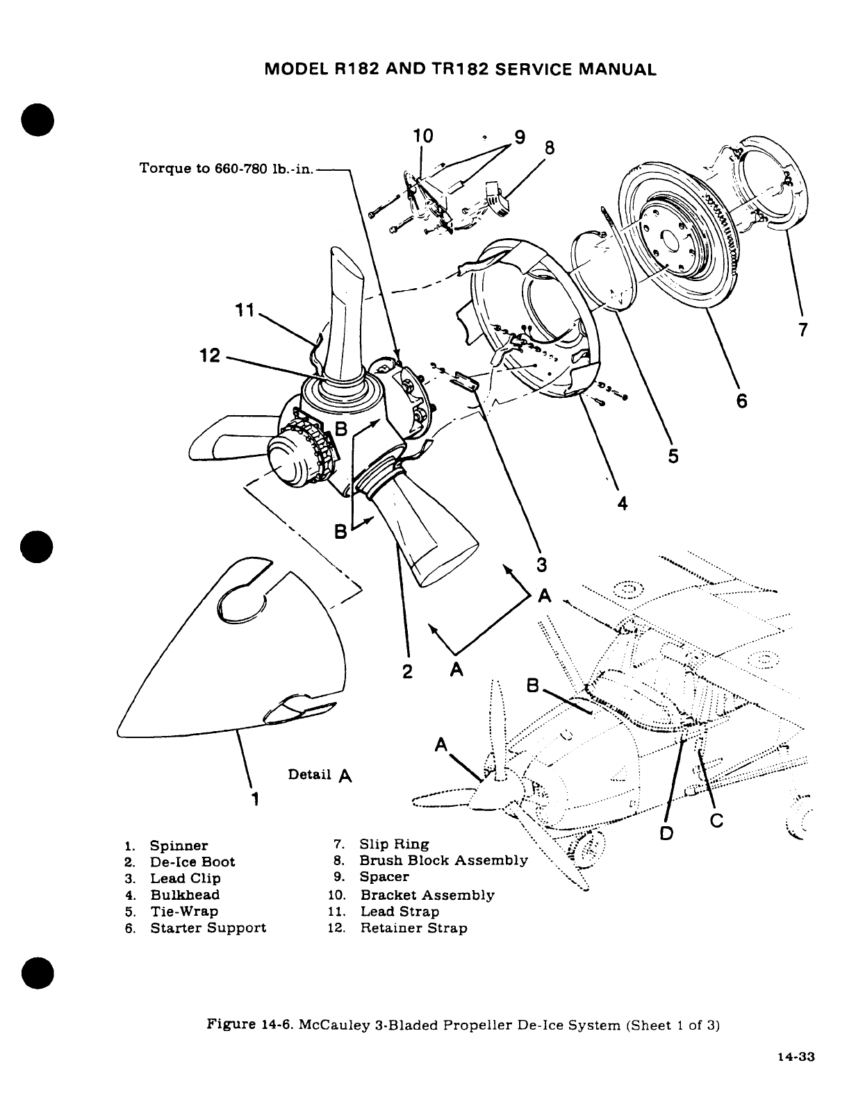
MODEL
R182
AND
TR182
SERVICE
MANUAL
10
9
8
Torque
to
660-780
lb.-in.
1
.
6
4
2
',
\A
/:2
A.?.--.:"''!.~""-..'
2.
De-Ice
Boot
"8.
Brush
Block
Asse"mbly
-
\
Detail
A :",-'.,
......
:.
" ..
:':""
1.
Spinner
7.
Slip
Ring
**..
'
2.
De-Ice
Boot
8.
Brush
Block
Assembly
"-
"..':;
3.
Lead Clip
9.
Spacer
4.
Bulkhead
10.
Bracket
Assembly
5.
Tie-Wrap
11.
Lead
Strap
6.
Starter
Support
12.
Retainer
Strap
Figure
14-6.
McCauley 3-Bladed
Propeller
De-Ice
System
(Sheet
1
of
3)
14-33
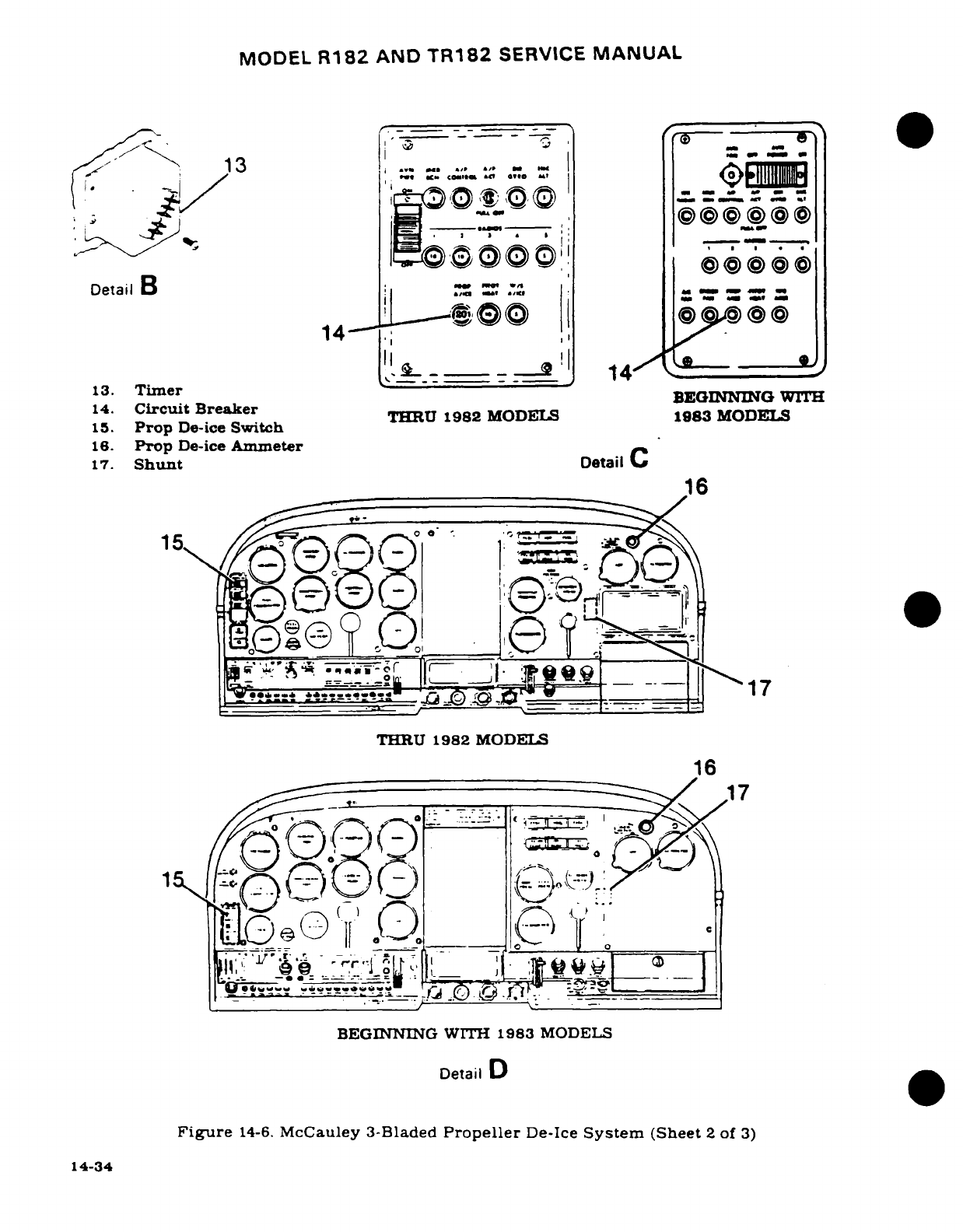
MODEL
R182
AND
TR182
SERVICE
MANUAL
<
'
E
-~13 *f r
'
.....
- a
'
.---
-
-^-"~- ----
-----
'
1O
)Oft
,
,,'
_
.
Detail
B
i
.
14-
!.'-^-
===
r __a
'
14
/~
o~
13.
Timer
~~~~~13. Timu~er ~BEGINNING
WITH
14.
Circuit
Breaker
BEGNING
W
14. Circ
Beaer
THRU
1982
MODELS
1983
MODELS
15.
Prop
De-ice
Switch
16.
Prop
De-ice
Ammeter
17.
Shunt
Detail
C
16
~../ _
f-
(
(
-=:=_
1
7o
,4'^^
-.
".j,
t[I-_^U
?
_
A
'r g.·
1"
THRU
1982
MODEIS
16
·
:
7
'
[L
--
-"-
;.
"
.- ,
<3
.
BEGINNING
WITH
1983
MODELS
Detail
D
Figure
14-6.
McCauley 3-Bladed
Propeller
De-Ice
System
(Sheet
2
of
3)
14-34
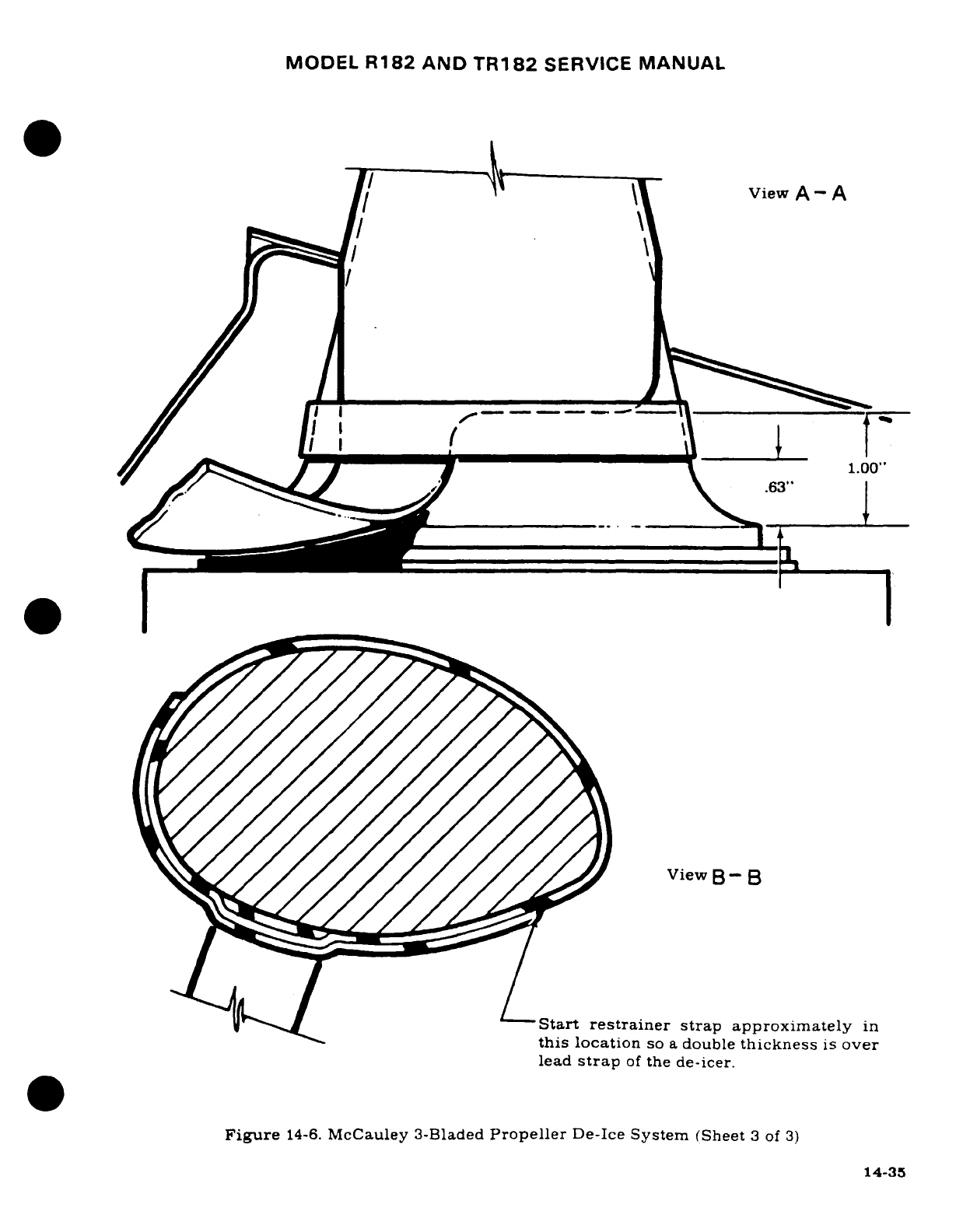
MODEL
R182
AND
TR182
SERVICE
MANUAL
\~ yView
A-
A
1.00"
.63'.
View
B-
B
Start
restrainer
strap
approximately
in
this
location
so
a
double
thickness
is
over
lead
strap
of
the
de-icer.
Figure
14-6.
McCauley
3-Bladed
Propeller
De-Ice
System
(Sheet
3
of
3)
14-35
MODEL
R182
AND
TR182
SERVICE
MANUAL
a.
Securely
attach
dial
indicator
gauge
to
the
engine,
and
place
the
pointer
on
the
slip
ring.
b
Rotate
propeller
slowly
by
hand,
noting
the
deviation
of
the
slip
ring
from
a
true
plane
as
indicated
on
the
gauge.
c.
Check
that
total
run-out
does
not
exceed
0.008-inch
(0.004-inch).
Also
check
that
run-
out
does
not
exceed
0.002-inch
within
any
4
inches
of
slip
ring
travel.
CAUTION
Due to
the
loose
fit
of
some
propeller
bearings,
a
consid-
erable
error
may
be
indicated
in
the
readings
by
pushing
in
or
pulling
out
on
the
propeller
while
rotating
it. Care
must
be
taken
ot
exert
a
uniform
push
or
pull
on
the
propeller
to
hold
this error
to
a
minimum.
d.
If
slip
ring
run-out
is
within
the
limits
specified,
no
corrective
action
is
required.
A
small
amount
of
run-out
may
be
corrected
by
varying
the
torque
of
the
attachment
bolts
within
the
limits
specified
by
the
propeller manufacturer.
e.
If
the
procedure
outlined
in
step
"d"
does
not
produce acceptable
run-out,
fabricate
small
washer
shaped shims
(approximately
.010
inch),
and
place
on
attachment
bolts,
limit
one
washer
per
bolt,
between
slip
ring
and
spinner
bulkhead
or mounting
plate.
f.
Recheck
run-out.
Adjust
shim
thickness
and
vary torque
of
attachment
bolts
until
slip
ring
runs
true
within
the
prescribed
tolerance.
14-66.
INSTALLATION
AND
ALIGNMENT
OF
BRUSH
BLOCK
ASSEMBLY.
(See
figures
14-7
and
14-8.)
NOTE
Installation
of
the
brush
block
should
be
deferred,
when
possible,
until
after
the
slip
ring,
propeller,
and
related
components
are
installed.
However,
the
brush
block
assembly
may
be
replaced
without
removing
the
pro-
peller.
To
avoid breakage
when
installing
the
brush
block
assembly,
keep
brushes
retracted
in
brush
block
until
slip
ring
and
propeller
assemblies
have
been
installed.
CAUTION
Make
sure
that
slip
ring
run-out
has
been
corrected
before
attempting
to
align
brushes
on
slip
ring.
a.
In
order
to
get
smooth,
efficient
and quiet
transfer
of
electric
power
from
the
brushes
to
the
slip
ring,
brush
alignment
must
be
checked
and
adjusted,
if
necessary
to
meet
the following
requirements.
1.
Length
of
brushes
from
slip
ring
to
brush
block
housing
to
be
0.063
(*0.015-inch).
2.
The
brushes must
be
lined
up with
the
slip
ring
so
that
the
entire
face
of
each
brush
is in
contact
with
the
slip
ring
throughout
the
full
360
°
of
slip
ring
rotation.
3.
The
brushes must
contact
the
slip
ring
at
an
angle
of
approximately
2°
from
perpendicular
to
the
slip
ring
surface,
measured
toward
the
direction
of
rotation
of
the
slip
ring.
14-36
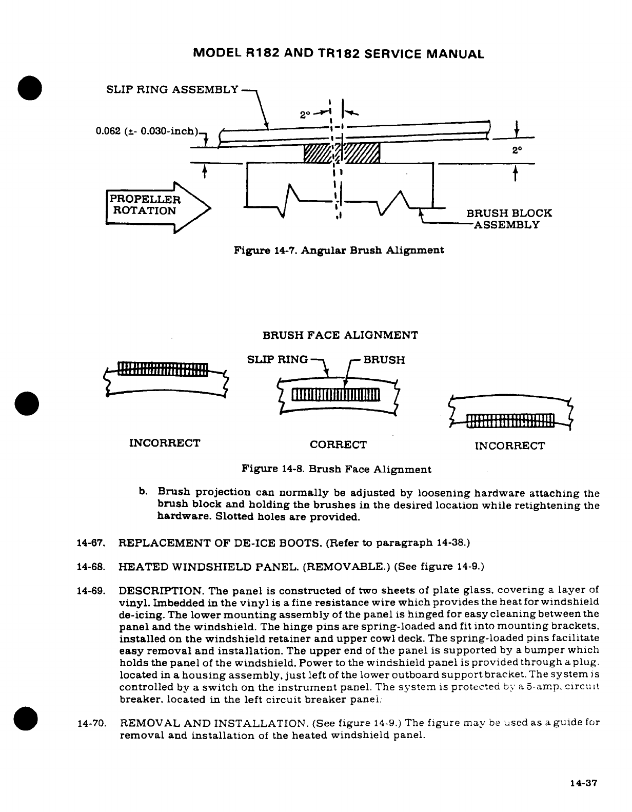
MODEL
R182
AND
TR182
SERVICE
MANUAL
SLIP
RING ASSEMBLY
0.062
(+-
0.030-inch)
--
'
"
= j
+
;<
t
PROPELLER
.
ROTATION
BRUSH
BLOCK
I -------- \^ ' ------
~ASSEMBLY
Figure
14-7.
Angular
Brush Alignment
BRUSH
FACE
ALIGNMENT
INCORRECT
CORRECT INCORRECT
Figure
14-8.
Brush
Face
Alignment
b.
Brush projection
can
normally
be
adjusted
by
loosening
hardware
attaching
the
brush
block
and
holding
the
brushes
in
the desired location
while
retightening
the
hardware.
Slotted
holes
are provided.
14-67.
REPLACEMENT
OF
DE-ICE
BOOTS.
(Refer
to
paragraph
14-38.)
14-68.
HEATED
WINDSHIELD
PANEL.
(REMOVABLE.)
(See
figure
14-9.)
14-69.
DESCRIPTION.
The
panel
is
constructed
of
two
sheets
of
plate
glass,
covering
a
layer
of
vinyl.
Imbedded
in
the
vinyl
is
a
fine
resistance
wire which
provides
the
heat
for
windshield
de-icing.
The
lower
mounting
assembly
of
the
panel
is
hinged
for
easy
cleaning
between
the
panel
and
the
windshield.
The
hinge
pins
are
spring-loaded
and
fit
into
mounting brackets.
installed
on
the
windshield
retainer
and
upper
cowl
deck.
The
spring-loaded
pins facilitate
easy
removal
and
installation.
The
upper
end
of
the
panel
is
supported
by
a
bumper
which
holds
the
panel
of
the
windshield.
Power
to
the
windshield
panel
is
provided
through
a
plug.
located
in
a
housing
assembly,
just
left
of
the
lower
outboard
support
bracket.
The
system
is
controlled
by
a
switch
on
the
instrument
panel.
The
system
is
protected
bty
a
5-arr.p.
circuit
breaker, located
in
the
left
circuit breaker
panel;
.
,14-70.
REMOVAL
AND
INSTALLATION.
(See
figure
14-9.)
The
figure
mav
be
used
as
a
guide
for
removal
and
installation
of
the
heated
windshield
panel.
14-37
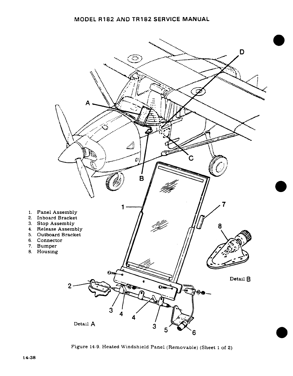
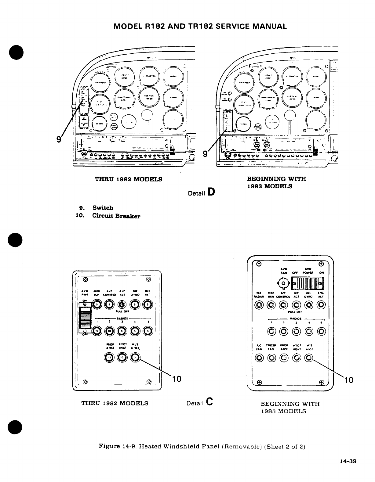
MODEL
R182 AND
TR182
SERVICE
MANUAL
*
^ s_ v_**v *bc.-=-,m
^^Z-__
-
c
-
~
*;-
/
THRU
1982
MODELS
BEGINNING
WITH
1983
MODELS
Detail
D
9.
Switch
10.
Circuit
Breaker
AV SlR C&A/Pt A/P WX
°t,
YeeeO
eee
e
SAUI
I
$-
RA0
-0
FX
ff01
W/$
Ax,
CNOS5
RO
ProT
W'S
I
e
__
_
_
,
10
Jje
10
THRU
1982
MODELS
Detail
C
BEGINNIIN
G
WITH
1983
MODELS
Figure
14-9.
Heated
Windshield
Panel
(Removable)
(Sheet
2
of
2)
14-39
14-39
MODEL
R182
AND
TR182
SERVICE
MANUAL
14-71.
CONTROL
SURFACE DISCHARGERS.
14-72.
DESCRIPTION.
Wick
type
static
dischargers
may
be
installed
on
the
trailing
edge
surfaces
of
the
ailerons,
elevators,
and
rudder
of
the
aircraft.
One
type
discharger
is
fabricated
with
the
wick
and
base
combined
into
an
integral
unit;
in
the
other
type,
the
wick
is
attached
to
the
base
by
a
threaded
fitting,
and
may
be
replaced
without
removing
the
base
from
the
air-
craft.
The
installation
of
static dischargers
reduces
the
build-up
of
static
electricity
on
the
airframe
as
a
consequence
of
flying
through
haze,
dust,
rain,
snow
or
ice
crystals.
In
some
cases,
if
dischargers
are
not
installed or
not
functioning
as
a
result
of
age
or
repeated
expo-
sure
static
electricity,
static
build-up can
result
in
the
loss
of
usable
radio
signals
on
all
communication
and
navigation
equipment.
Whenever
static
dischargers
are
installed,
re-
placed,
and
at
regular
intervals
during
their
service
life,
resistance
checks
should
be
per-
formed
to
determine
their
effectiveness
in
reducing
static
build-up.
14-73.
RESISTANCE
CHECK.
Since
static
dischargers
lose
their
effectiveness
with
age
and expo-
sure
to
static
electricity,
they
should
be
checked
with
a
500
to
1000
volt
capacity
megohm-
meter
every
500
hours
or
annually;
whichever
occurs
first.
Megohmmeters may
be
pur-
chased
from
the following
source:
James
G.
Biddle
Co.
Plymouth
Meeting,
PA
19462
NOTE
A
GOOD
aircraft
ground
must
be
established
in
order
to
perform
RELIABLE
resistance
checks
on
the control
sur-
face
dischargers.
Perform
the
following
resistance
checks on
each
control
surface
discharger
and replace
those
which
do
not
conform
to
the
resistance
requirements.
a.
If
the
wick
and
base
of
the
discharger are
an
integral
unit,
the
resistance
from
the
base of
the
discharger
to
a
good
aircraft
ground
should
check
2.5
milliohms
maxi-
mum.
b.
If
the
wick
can
be
separated
from
the
base,
the
resistance
from
the
base
to
a
good
air-
craft
ground
should
check
1.0
ohm
maximum.
c.
Connect
the
EARTH
terminal
of
Megger
tester
to
the
base
of
the
discharger.
Check
resistance
at
tip
of
discharger using
the
500-volt
scale
of
the
Megger.
If
scale
checks
less
than
1
megohhm
or
greater
than
100
megohms,
replace
the
wick.
WARNING
Do
not
bend
the
wick
during
the
preceding
check,
since
wicks
have
a
higher
resistance
when
bent.
14-40
MODEL
R182
&
TR182
SERIES
SERVICE
MANUAL
SECTION
15
INSTRUMENTS
AND
INSTRUMENT
SYSTEMS
Page
No.
Page
No.
TABLE
OF CONTENTS
Aerofiche/Manual
TABLE
OF CONTENTS
Aerofiche/Manual
INSTRUMENTS/INSTRUMENT
Description
............
3H13/15-23
SYSTEMS
...............
3G13/15-3
Manifold
Pressure/Fuel
General
...............
3G13/15-3
Pressure
Gage
.........
3H13/15-23
Instrument
Panel
......
3G13/15-3
Description
..............
3H13/15-23
Description
...........
3G13/15-3
Dampening
Adjustment
...
3H13/15-23
Removal/Installation
..
3G13/15-3
Trouble
Shooting
-
Manifold
Shock-Mounts
.........
3G14/15-4
Pressure
Gage
.........
3H14/15-24
Instruments
..........
3G14/15-4
Trouble Shooting
-
Fuel
Removal ............
3G14/15-4
Pressure
Gage
.........
3H15/15-25
Installation
.........
3G14/15-4
Cylinder
Head
Temperature
Pitot
Static
............
3G14/15-4
Gage
..................
3H15/15-25
Description
...........
3G14/15-4
Description
............
3H15/15-25
Maintenance
..........
3G18/15-8
Trouble
Shooting
.......
3H16/15-26
Static
System
Inspection/
Oil
Pressure
Gage
........
3H16/15-26
Leakage
Test
........
3G18/15-8
Description
............
3H16/15-26
Pitot
System Inspection/
Trouble
Shooting
.......
3H17/15-27
Leakage
Test
........
3G19/15-9
Oil
Temperature
Gage
....
3H18/15-28
Blowing
Out Lines
.....
3G19/15-9
Description
............
3H18/15-28
Removal/Installation
Carburetor
Air
Temperature
of
Components
.......
3G20/15-10
Gage ..................
3H18/15-28
Trouble
Shooting
......
3G20/15-10
Description
............
3H18/15-28
True
Airspeed
Trouble
Shooting
.......
3H18/15-28
Indicator
............
3G20/15-10
Fuel
Quantity
Indicating
Trouble
Shooting
....
3G22/15-12
System
................
3H19/15-29
Trouble
Shooting
-
Description
............
3H19/15-29
Altimeter
...........
3G22/15-12
Removal/Installation
Trouble
Shooting
-
Vertical
of
Transmitter
.......
3H19/15-29
Speed
Indicator
......
3G23/15-13
Trouble
Shooting
.......
3H20/15-30
Trouble Shooting
-
Pitot
Transmitter
Calibration
3H20/15-30
Tube
Heater
.........
3G23/15-13
Hourmeter
...............
3H23/15-31
Vacuum
System
........
3H1/15-15
Description
............
3H23/15-31
Description
...........
3H1/15-15
Economy
Mixture
Trouble
Shooting
......
3H1/15-15
Indicator
..............
3H23/15-31
Trouble
Shooting
-
Gyros
3H2/15-16
Description
............
3H23/15-31
Trouble
Shooting
-
Trouble
Shooting
.......
3H23/15-31
Vacuum Pump
.......
3H3/15-17
Calibration
............
3H23/15-31
Maintenance
Practices
.
3H3/15-17
Removal/Installation
...
3H24/15-32
Removal
............
3H3/15-17
Magnetic
Compass
........
3H24/15-32
Mounting
Pad
Description
............
3H24/15-32
Inspection
..........
3H4/15-18
Stall
Warning
System/
Cleaning
............
3H5/15-19
Transmitter
...........
3H24/15-32
Low-Vacuum
Warning
Description
............
3H24/15-32
Light
...............
3H5/15-19
Turn
Coordinator
.........
3H24/15-32
Vacuum
Relief
Valve
Description
............
3H24/15-32
Adjustment
.........
3H5/15-19
Trouble
Shooting
.......
313/15-35
Standby
Vacuum
System
3H10/15-22B
Turn-and-Slip
Description
...........
3H10/15-22B
Indicator
..............
3I3/15-35
Trouble
Shooting
......
3H10/15-22B
Description
............
313/15-35
Removal
.............
3H10/15-22B
Trouble
Shooting
.......
3I4/15-36
Installation
...........
3H10/15-22B
Electric
Clock
............
314/15-36
Engine
Indicators
.....
3H13/15-23
Description
............
314/15-36
Tachometer
...........
3H13/15-23
Outside
Air
Temperature
Description
..........
3H13/15-23
Gage ..................
314/15-36
Manifold
Pressure
Gage
3H13/15-23
Description
..........
3H13/15-23
Fuel
Pressure
Gage
....
3H13/15-23
Revision
3
15-1
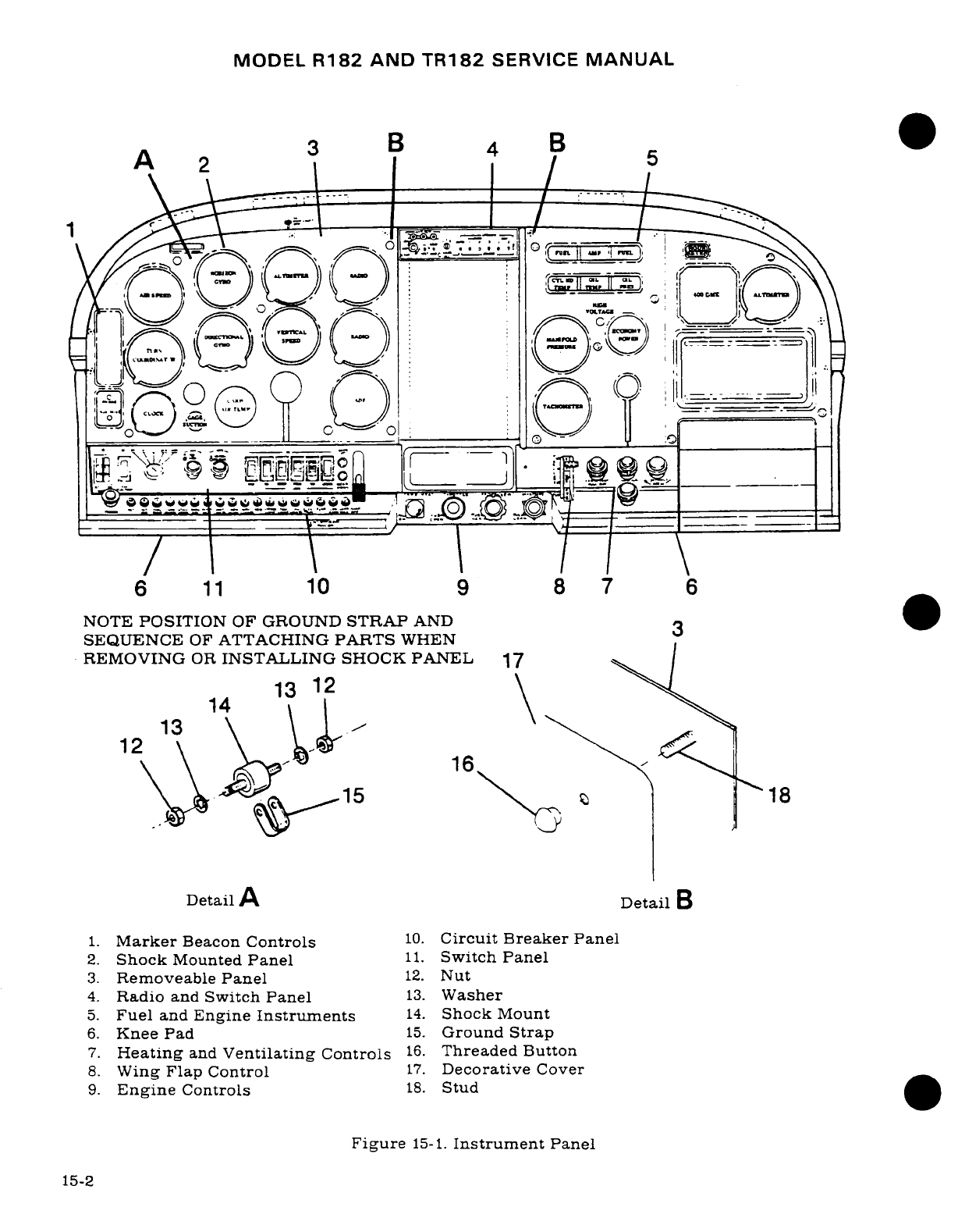
MODEL
R182
AND
TR182
SERVICE
MANUAL
A 3
3
B
4
B
5
0 2
5
r ^,i···^
"
b-:^; o7t==-
-', -
___-B0 __
.!9-I-
n
e
a
=_=
6
11
10
98
7
6
NOTE
POSITION
OF
GROUND
STRAP
AND
3
SEQUENCE
OF
ATTACHING
PARTS
WHEN
REMOVING
OR
INSTALLING
SHOCK
PANEL
17
1
4
13
12
14
13
12
\ \ \\
16
\ \
S
-15
18
Detail
A
Detail
B
1.
Marker
Beacon
Controls
10.
Circuit Breaker
Panel
2.
Shock
Mounted
Panel
11.
Switch
Panel
3.
Removeable
Panel
12.
Nut
4.
Radio
and
Switch
Panel
13.
Washer
5.
Fuel
and
Engine
Instruments
14.
Shock
Mount
6.
Knee
Pad
15.
Ground
Strap
7.
Heating
and
Ventilating
Controls
16.
Threaded
Button
8.
Wing
Flap
Control
17.
Decorative
Cover
9.
Engine
Controls
18.
Stud
Figure
15-1.
Instrument
Panel
15-2
MODEL
R182
AND
TR182
SERVICE
MANUAL
15-1.
INSTRUMENTS
AND
INSTRUMENT SYSTEMS.
15-2.
GENERAL.
This section describes
typical
instrument
installations
and
their
respective
operating
systems.
Emphasis
is
placed
on
trouble
shooting
and
corrective
measures
only.
It
does
NOT
deal
with
specific
instrument repairs
since
this
usually
requires
special
equipment
and
data
and
should
be
handled
by
instrument
specialists.
Federal
Aviation
Regulations
require
malfunctioning
instruments
be
sent
to
an
approved
instrument
overhaul
and
repair
station
or
returned
to
manufacturer
for
servicing.
Our
concern
here
is
with
preventive
maintenance
on
various
instrument
systems
and
correction
of
system
faults
which
result
in
instrument
malfunctions.
The
descriptive
material,
maintenance
and
trouble
shooting
information
in
this
section
is
intended
to
help
the
mechanic
determine
malfunctions
and
correct
them, up
to
the defective
instrument
itself,
at
which
point
an
instrument
technician
should
be
called
in.
Some
instruments,
such
as
fuel
quantity
and
oil
pressure
gages,
are
so
simple
and
inexpensive,
repairs
usually
will
be
more costly
than
a
new
instrument.
On
the
other
hand,
aneroid
and
gyro
instruments
usually
are
well
worth
repairing.
The
words
"replace
instrument"
in
the
text,
therefore, should
be
taken
only
in the
sense
of
physical
replacement
in
aircraft.
Whether
replacement
is
to
be
with
a
new
instrument,
an
exchange
one,
or
original instrument
is
to
be
repaired
must
be
decided
on
basis
of
individual
circumstances.
15-3.
INSTRUMENT
PANEL.
(See
figure
15-1.)
15-4.
DESCRIPTION.
The
instrument
panel assembly
consists
of
a
stationary
panel.
a
removable
flight
instrument
panel
and
a
shock-mounted
panel.
The
stationary
panel.
containing
fuel
and
engine
instruments
is
secured
to
the
engine
mount
stringers
and
a
forward
fuselage
bulkhead.
The
removeable
panel,
containing flight
instruments
such
as
airspeed,
vertical
speed
and
altimeter
is
secured
to
the
stationary
panel
with
screws.
The
shock-mounted
panel,
containing major
flight
instruments
such
as
the
horizontal
and
directional
gyros
is
secured
to
the
removable
panel
with
rubber
shock-mounted
assemblies.
Most
of
the
instruments
are
screw
mounted
on
the
panel.
15-5.
REMOVAL
AND
INSTALLATION.
a.
Flight
Instrument
Panel.
1.
Unscrew
threaded
buttons
and
remove
decorative
cover.
Disconnect
post
light
wiring
if
installed.
2.
Tag
and
disconnect
plumbing
and
wiring.
Cap
plumbing.
3.
Remove
screws
securing flight
instrument
panel
to
stationary
panel
and
pull
straight
back
to
remove.
4.
To
install,
place
panel
in
position
and
install
screws.
5.
Install
flight instruments
in
panel.
6.
Uncap
plumbing
and
connect
plumbing
also
wiring.
Do
not
over-tighten
connec-
tions.
Refer
to
note
in
paragraph
15-9.
b.
Shock-Mounted
Panel.
NOTE
Due
to the
difficulty
encountered
when
removing
the
shock-mounted
panel
with
the
gyros
installed.
it
is
recommended
that
the
directional
gyro
be
disconnected
and
removed
prior
to
removal
of
the shock-mounted
panel.
15-3
MODEL
R182
AND
TR182
SERVICE
MANUAL
i
Unscrew
threaded
buttons
and
remove
decorative
cover.
Disconnect
post
light
wiring
if
installed.
2.
Tag, disconnect
and
cap gyro
plumbing.
3.
Remove
directional
gyro mounting screws
and
remove gyro from
panel.
4.
Remove
shock-mount
nuts
and
washers
then
work panel
out
from
behind
flight
instrument
panel.
The
horizon
gyro
may
also
be
removed
from
panel
if
desired.
5.
To
install
shock-mounted
panel,
place
panel
over
shock mount
studs.
Be
sure
the
ground
strap
is
installed
in
the
proper
position,
if
removed,
then
install
nuts
and
washers.
6.
Install
gyros,
uncap
and
install
plumbing.
Refer
to
note
in
paragraph
15-9.
7.
Install
decorative
cover.
15-6.
SHOCK-MOUNTS.
Service
life
of
shock-mounted
instruments
is
directly
related
to
ade-
quate
shock-mounting
of
the
panel.
If
removal
of
shock-mounted
panel
is
necessary,
check
mounts
for
deterioration
and
replace
as
necessary.
15-7.
INSTRUMENTS.
(See
figure
15-1.)
15-8.
REMOVAL.
Most
instruments
are
secured
to
the
panel
with
screws
inserted
through
the
panel
face,
under
the
decorative
cover.
To
remove an
instrument,
remove
decorative
cover.
disconnect
wiring
or
plumbing
to
instrument,
remove
mounting
screws
and
take
instrument
out
from
behind,
or
in
some
cases,
from
front
of
panel.
Instrument clusters
are
installed
as
units
and
are secured
by
a
screw at
each
end.
A
cluster must
be
removed
from
panel
to
replace
an
individual
gage.
In
all
cases
when
an
instrument
is
removed,
disconnected
lines
or
wires
should
be
protected. Cap
open
lines
and
cover
pressure
connections
on
instrument
to
prevent thread
damage
and
entrance
of
foreign matter.
Wire
terminals
should
be
insulated
or
tied
up to
prevent
accidental grounding
or
short-circuiting.
15-9.
INSTALLATION.
Generally,
installation
procedure
is
the
reverse
of
removal
procedure.
Ensure
mounting
screw
nuts are
tightened firmly,
but
do
not over-tighten,
particularly
on
instruments having
plastic
cases.
The
same
rule
applies
to
connecting
plumbing
and
wiring.
NOTE
All
instruments
(gages
and
indicators),
requiring
a
thread
seal
or
lubricant,
shall
be
installed
using
teflon
tape on
male
fittings
only.
This
tape
is
available
through
the
Cessna
Supply
Division.
When
replacing
an
electrical
gage
in
an
instrument
cluster
assembly.
avoid
bending
pointer
or
dial
plate.
Distortion
of
dial
or back
plate
could
change
the
calibration
of
gages.
15-10.
PITOT
AND
STATIC
SYSTEMS.
15-11.
DESCRIPTION.
The
pitot
system
conveys
ram
air
pressure
to
the
airspeed
indicator.
The
static
system
vents
vertical
speed
indicator,
altimeter
and
airspeed
indicator
to
atmos-
pheric
pressure
through
plastic
tubing
connected
to
static
ports.
A
static
line
sump
is
installed
at
each
source
button
to
collect
condensation
in
static
system.
A
pitot
tube heater
may
be
installed.
The
heating
element
is
controlled
by
a
switch
at
the
instrument
panel
and
15-4
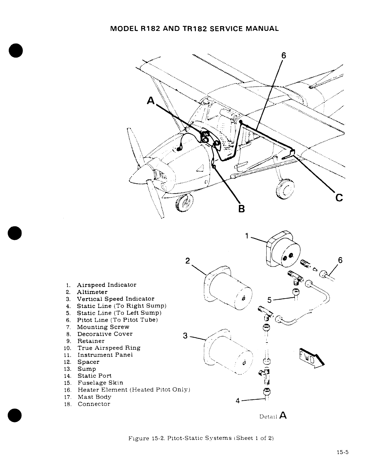
MODEL
R182
AND
TR182
SERVICE
MANUAL
.
A
r..sd- -'*... ****.r. 6--
....
>I:
, ... .- *
\\
.' ' ...
~~·".
2.
.. m
-.. ..
..
....
;
;~·
1.
Airspeed
Indicator
2.
Altimetero
3.
Vertical
Speed
Indicator
/
5))
4.
Static
Line
(To
Right
Sump)
\<
5.
Static
Line
(To
Left
Sump)
A
6.
Pitot
Line
(To
Pitot
Tube)
(
7.
Mounting
Screw
8.
Decorative
Cover
3
^
9.
Retainer
".-< "'-.
10.
True Airspeed
Ring
/ ....
11.
Instrument
Panel
/
12.
Spacer
^
S ,
e
/
13.
Sump
14.
Static
Port
s---
<34
15.
Fuselage
Skin
16.
Heater
Element
(Heated
Pitot
Only)
17.
Mast
Body
18.
Connector
4
,,. . . .. iDetal A
Figure
15-2.
Pitot-Static Systems
(Sheet
1
of
2)
15-5
C--J~
5
"~~~~~~5-
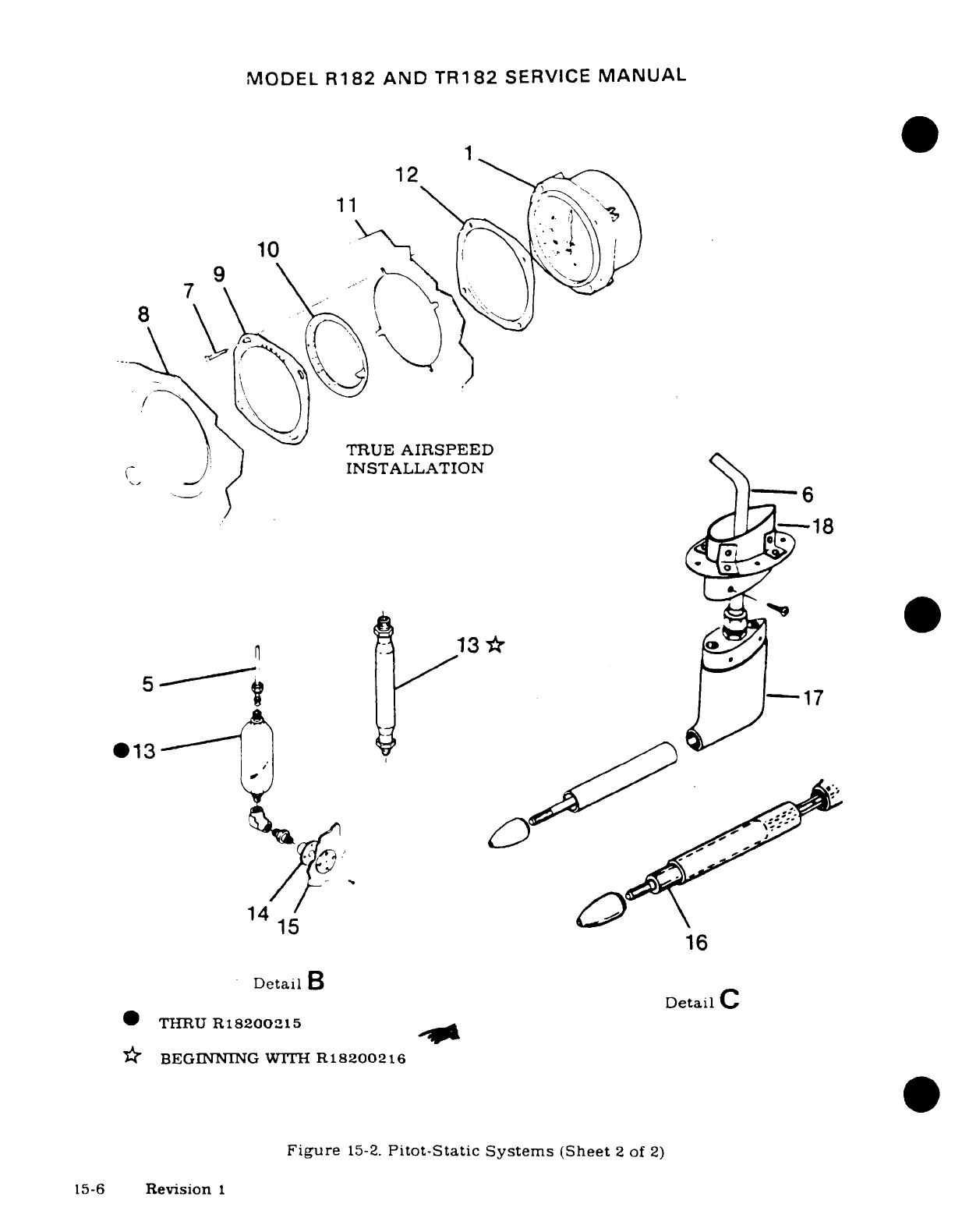
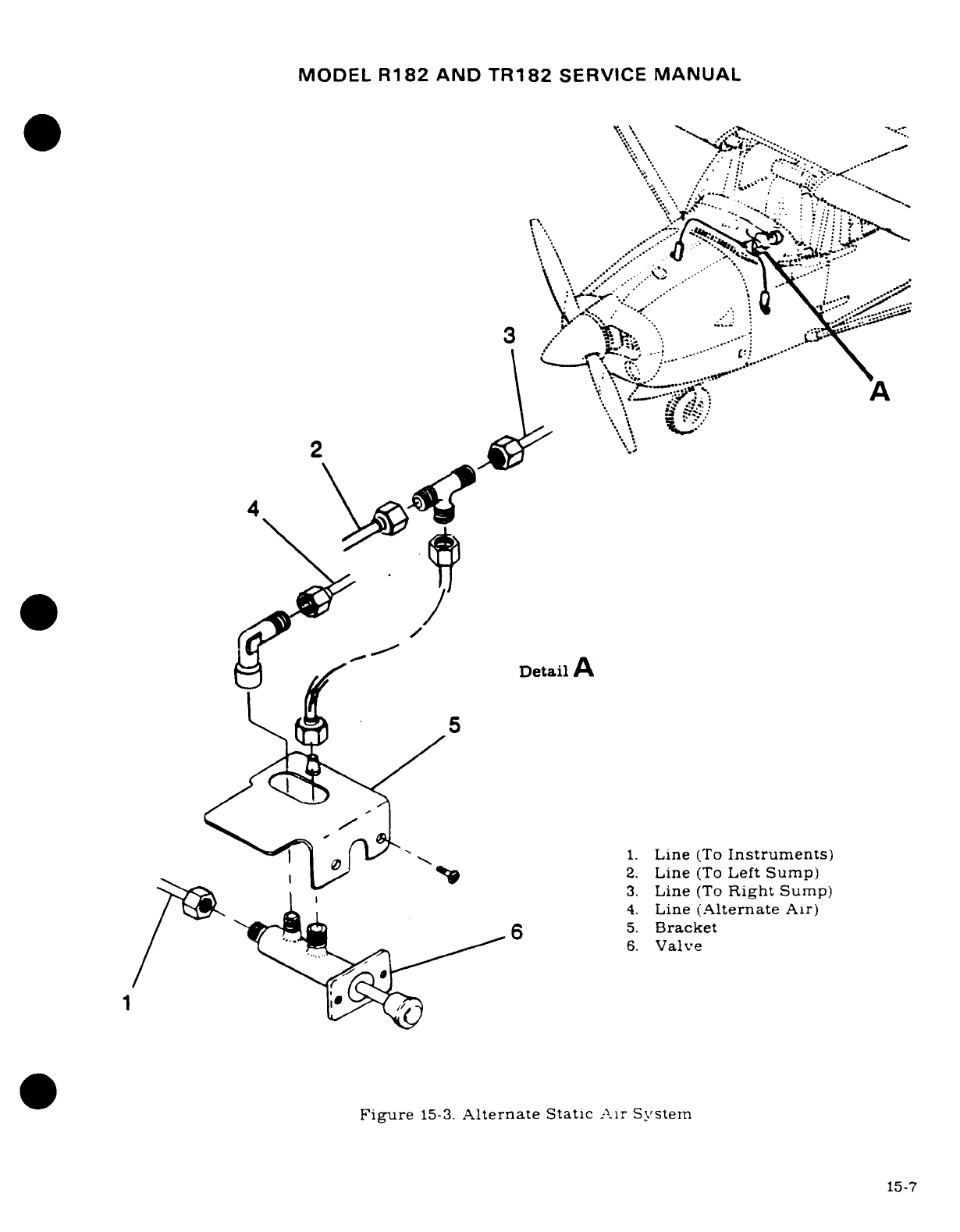
MODEL
R182
AND
TR182
SERVICE
MANUAL
*
*^
^^....
·
-... ~
.'
.
Detail
A..
'
,,-,
5.. .-...
,:----
1.
Line
(To
Instruments)
It > >
2.
Line
(To
Left
Sump)
? .·
Detai
l
Bracket
5* ^-
7~~~~~~~~~15-7
1.
Line
(To
Instruments)
92
1 0^
^2.
Line
(To
Left
Sump)
3.
Line
(To
Right
Sump)
4.
Line
(Alternate
Air)
/(
I6
5.
Bracket
.... ,"' 7C^
.^
^^~6.
Valve
Figure
15-3.
Alternate
Static
Air
System
15-7
MODEL
R182
AND
TR182
SERVICE
MANUAL
powered
by
the
electrical
system.
A
static
pressure alternate
source
valve may
be
installed
in
the
static
system
for
use
when
the
external
static
source
is
malfunctioning. This
valve
also
permits
draining
condensate
from
the
static lines.
Refer
to
PILOT'S
OPERATING
HANDBOOK
for
flight
operation using
alternate
static
source
pressure.
The
encoding
altimeter
supplies
an
altimeter
reading
to
the
optional
300
or
400
transponder
for
signal
transmission.
The
standby
altimeter
is
connected
to
the
static
system
by
a
tube
to
the
vertical
speed
indicator.
The
static
tube
installation
will vary
when
an
alternate
static
source
is
installed.
15-12.
MAINTENANCE.
Proper
maintenance
of
pitot
and
static
system
is
essential
for
proper
operation
of
altimeter, vertical
speed
and
airspeed
indicators.
Leaks,
moisture
and
obstruc-
tions
in
pitot
system
will
result
in
false
airspeed
indications,
while
static
system
malfunc-
tions
will
affect
readings
of
all
three
instruments.
Under
instrument
flight
conditions,
these
instrument
errors
could
be
hazardous. Cleanliness
and
security
are
the
principal
rules
for
system
maintenance.
The
pitot
tube
and
static
ports
MUST
be
kept
clean
and
unobstructed.
15-13.
STATIC
PRESSURE
SYSTEM INSPECTION
AND
LEAKAGE
TEST.
The
following
proce-
dure
outlines
inspection
and
testing
of
static
pressure
system, assuming altimeter
has
been
tested
and
inspected
in
accordance
with
current
Federal
Aviation Regulations.
a.
Ensure
static
system
is
free
from
entrapped
moisture
and
restrictions.
b.
Ensure
no
alterations
or
deformations
of
airframe
surface
have
been made
which
would
affect
the
relationship
between
air
pressure
in
static
pressure
system
and
true
ambient
static air
pressure
for
any
flight
configuration.
c.
Seal
one
static
source
port
with
pressure sensitive
tape.
This
seal
must
be
air
tight.
d.
Close
static
pressure
alternate
source
valve,
if
installed.
e.
Attach
a
source
of
suction
to
the
remaining
static
pressure
source
opening.
Figure
15-5
shows
one
method
of
obtaining
suction.
f.
Slowly
apply
suction
until
altimeter
indicates
a
1000-foot
increase
in
altitude.
CAUTION
When
applying
or
releasing
suction,
do
not
exceed
range
of
vertical
speed
indicator or
airspeed
indicator.
g.
Cut
off
suction
source
to
maintain
a
"closed"
system
for
one
minute.
Leakage
shall
not
exceed
100
feet
of
altitude
loss
as
indicated
on
altimeter.
h.
If
leakage
rate
is
within
tolerance,
slowly
release
suction
source
and
remove tape
from
static
port.
NOTE
If
leakage rate
exceeds
the
maximum
allowable.
first
tighten
all
connections.
then
repeat leakage
test.
If
leakage
rate
still
exceeds
the
maximum
allowable.
use
following
procedure.
i.
Disconnect
static
pressure
lines
from
airspeed
indicator
and
vertical
speed
indica-
tor.
Use
suitable
fittings
to
connect
lines together
so
altimeter
is
the
only
instrument
still
connected into
static
pressure
system.
15-8
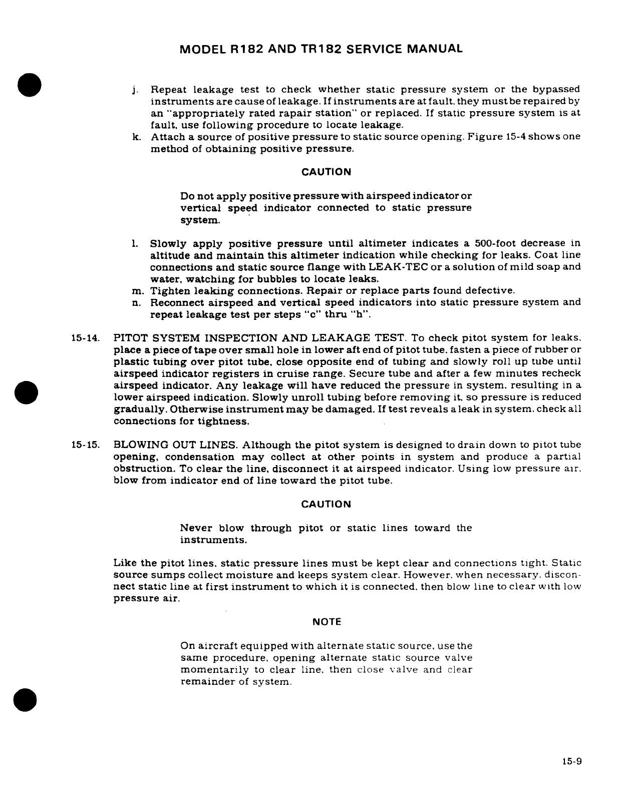
MODEL
R182
AND
TR182
SERVICE
MANUAL
j.
Repeat
leakage
test
to
check
whether
static
pressure
system
or the
bypassed
instruments
are
cause
of
leakage.
If
instruments
are
at
fault.
they
must
be
repaired
by
an
"appropriately
rated
rapair
station"
or
replaced.
If
static
pressure
system
is
at
fault,
use
following
procedure
to
locate
leakage.
k.
Attach
a
source
of
positive
pressure
to
static
source
opening.
Figure
15-4
shows
one
method
of
obtaining
positive
pressure.
CAUTION
Do
not
apply
positive
pressure
with
airspeed
indicator
or
vertical
speed
indicator
connected
to
static pressure
system.
1.
Slowly
apply
positive
pressure until
altimeter
indicates
a 500-foot
decrease
in
altitude
and
maintain
this
altimeter
indication
while
checking
for
leaks.
Coat
line
connections
and
static
source
flange
with
LEAK-TEC
or
a
solution
of
mild
soap
and
water,
watching
for
bubbles
to
locate
leaks.
m.
Tighten
leaking
connections.
Repair
or
replace
parts
found
defective.
n.
Reconnect
airspeed
and
vertical
speed
indicators
into
static
pressure
system
and
repeat
leakage
test
per
steps
"c"
thru
"h".
15-14.
PITOT
SYSTEM
INSPECTION
AND
LEAKAGE TEST.
To
check
pitot
system
for
leaks.
place
a
piece
of
tape
over
small
hole
in
lower
aft end
of
pitot
tube,
fasten
a
piece
of
rubber
or
plastic
tubing
over pitot
tube,
close
opposite
end
of
tubing
and
slowly
roll
up tube
until
airspeed
indicator
registers
in
cruise
range. Secure
tube
and
after
a
few
minutes
recheck
airspeed
indicator.
Any
leakage
will
have
reduced
the
pressure
in
system,
resulting
in
a
lower
airspeed
indication.
Slowly
unroll
tubing
before
removing
it,
so
pressure
is
reduced
gradually.
Otherwise
instrument
may
be
damaged.
If
test
reveals
a
leak
in
system.
check
all
connections
for
tightness.
15-15.
BLOWING
OUT
LINES.
Although the
pitot
system
is
designed
to
drain
down
to
pitot
tube
opening, condensation
may
collect
at
other
points
in
system
and
produce
a
partial
obstruction.
To
clear
the
line,
disconnect
it at
airspeed indicator.
Using
low
pressure
air.
blow
from
indicator
end
of
line
toward
the
pitot
tube.
CAUTION
Never
blow
through
pitot
or
static
lines
toward
the
instruments.
Like
the
pitot
lines,
static
pressure
lines
must
be
kept
clear
and
connections
tight.
Static
source
sumps
collect
moisture
and
keeps
system clear.
However.
when
necessary.
discon-
nect
static
line
at
first
instrument
to
which
it
is
connected,
then
blow
line
to
clear
with
low
pressure
air.
NOTE
On
aircraft
equipped with
alternate static
source,
use
the
same
procedure, opening
alternate
static
source
valve
momentarily
to
clear
line.
then
close
valve
and
clear
remainder
of
system.
15-9
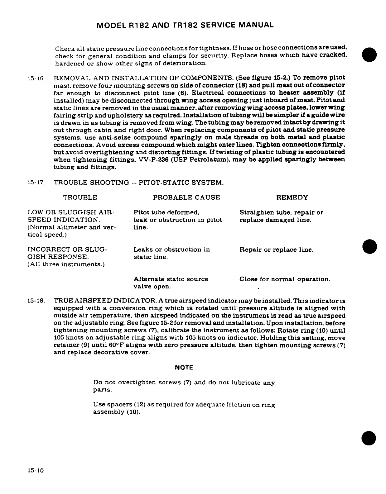
MODEL
R182
AND
TR182
SERVICE
MANUAL
Check
all
static
pressure
line
connections
for
tightness.
If
hose
or
hose
connections
are
used,
check
for
general
condition
and
clamps
for
security.
Replace hoses
which
have
cracked,
hardened
or
show
other
signs
of
deterioration.
15-16.
REMOVAL
AND
INSTALLATION
OF
COMPONENTS.
(See
figure
15-2.)
To
remove
pitot
mast.
remove
four
mounting
screws
on
side
of
connector
(18)
and
pull
mast
out
of
connector
far
enough
to
disconnect pitot
line
(6).
Electrical
connections
to
heater
assembly
(if
installed)
may
be
disconnected
through
wing
access
opening
just
inboard
of
mast. Pitot
and
static lines
are removed
in
the
usual
manner, after
removing
wing access
plates,
lowerwing
fairin
g
strip
and
upholstery
as
required.
Installation
of
tubing
will
be
simpler
if a
guide
wire
is
drawn
in
as
tubing
is
removed
from
wing.
The
tubing
may
be
removed
intact
by
drawing
it
out
through
cabin
and
right
door.
When
replacing
components
of
pitot
and
static
pressure
systems,
use
anti-seize
compound
sparingly
on
male
threads
on
both
metal
and
plastic
connections.
Avoid
excess
compound
which
might
enter
lines.
Tighten
connections
firmly,
but
avoid
overtightening
and
distorting
fittings.
If
twisting
of
plastic
tubing
is
encountered
when
tightening
fittings,
VV-P-236
(USP
Petrolatum),
may
be
applied
sparingly
between
tubing
and
fittings.
15-17.
TROUBLE
SHOOTING
--
PITOT-STATIC
SYSTEM.
TROUBLE
PROBABLE
CAUSE
REMEDY
LOW
OR
SLUGGISH AIR-
Pitot
tube
deformed,
Straighten
tube,
repair
or
SPEED
INDICATION.
leak
or
obstruction
in
pitot
replace
damaged
line.
(Normal
altimeter
and
ver- line.
tical
speed.)
INCORRECT
OR
SLUG-
Leaks or
obstruction
in
Repair
or
replace
line.
GISH RESPONSE.
static
line.
(All
three
instruments.)
Alternate
static
source
Close
for
normal
operation.
valve
open.
15-18.
TRUE
AIRSPEED
INDICATOR.
A
true
airspeed
indicator
may
be
installed.
This
indicator
is
equipped
with
a
conversion ring
which
is
rotated
until
pressure
altitude
is
aligned
with
outside
air
temperature,
then
airspeed
indicated
on
the
instrument
is
read
as
true
airspeed
on
the
adjustable
ring.
See
figure
15-2
for
removal
and
installation.
Upon
installation,
before
tightening mounting
screws
(7),
calibrate
the
instrument
as
follows:
Rotate
ring
(10)
until
105
knots
on
adjustable ring aligns
with
105
knots
on
indicator.
Holding
this
setting,
move
retainer
(9)
until
60°F
aligns
with
zero
pressure
altitude,
then
tighten
mounting
screws
(7)
and
replace
decorative
cover.
NOTE
Do
not
overtighten
screws
(7)
and
do
not
lubricate
any
parts.
Use
spacers
(12)
as
required
for
adequate friction
on
ring
assembly
(10).
15-10
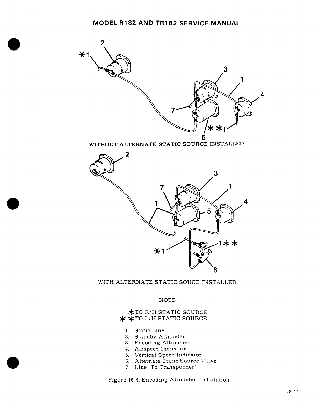
MODEL
R182
AND
TR182
SERVICE
MANUAL
2
34
5
WITHOUT
ALTERNATE
STATIC
SOURCE INSTALLED
2
7
1
,1
4
WITH
ALTERNATE
STATIC
SOUCE
INSTALLED
NOTE
*TO
R/H
STATIC
SOURCE
*
*
TO
L/H
STATIC
SOURCE
1.
Static
Line
2.
Standby
Altimeter
3.
Encoding
Altimeter
4.
Airspeed
Indicator
5.
Vertical
Speed
Indicator
6.
Alternate
Static
Source
Valve
7.
Line
(To
Transponder)
Figure
15-4.
Encoding
Altimeter Installation
15-11
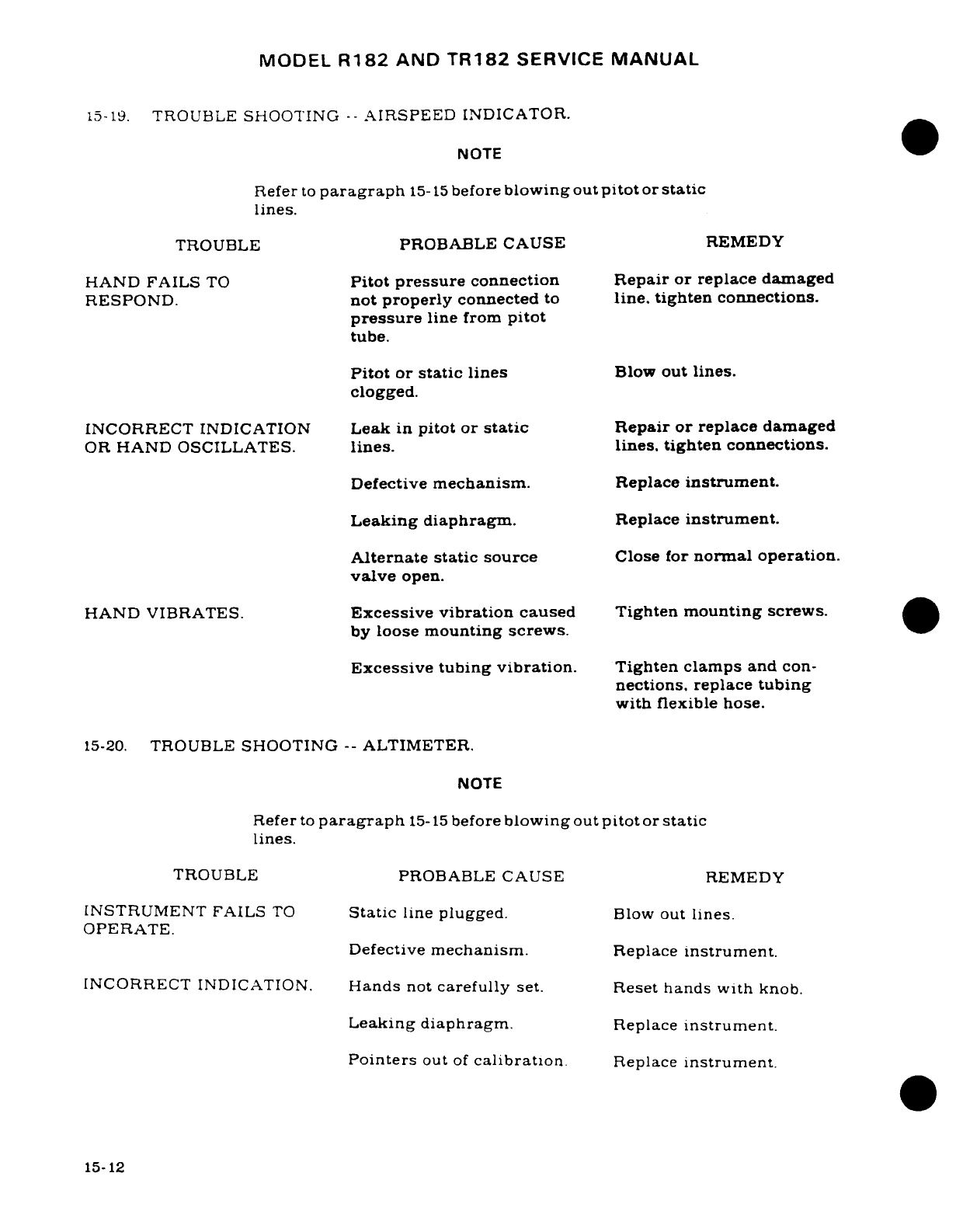
MODEL
R182
AND
TR182
SERVICE
MANUAL
15-19.
TROUBLE
SHOOTING
--
AIRSPEED
INDICATOR.
NOTE
Refer
to
paragraph
15-15
before
blowing
out
pitot
or
static
lines.
TROUBLE
PROBABLE
CAUSE
REMEDY
HAND
FAILS
TO
Pitot
pressure
connection
Repair or
replace damaged
RESPOND.
not
properly
connected
to
line.
tighten
connections.
pressure
line
from
pitot
tube.
Pitot
or
static
lines
Blow
out
lines.
clogged.
INCORRECT
INDICATION
Leak
in
pitot
or
static
Repair
or
replace
damaged
OR
HAND
OSCILLATES.
lines.
lines.
tighten
connections.
Defective
mechanism.
Replace
instrument.
Leaking
diaphragm.
Replace
instrument.
Alternate static
source
Close
for
normal
operation.
valve
open.
HAND VIBRATES.
Excessive
vibration
caused Tighten
mounting screws.
by
loose
mounting screws.
Excessive tubing
vibration.
Tighten clamps
and
con-
nections.
replace
tubing
with
flexible
hose.
15-20.
TROUBLE
SHOOTING
--
ALTIMETER.
NOTE
Refer
to
paragraph
15-15
before
blowing
out
pitot
or
static
lines.
TROUBLE
PROBABLE
CAUSE
REMEDY
INSTRUMENT FAILS
TO
Static
line
plugged.
Blow
out
lines.
OPERATE.
Defective
mechanism.
Replace
instrument.
INCORRECT
INDICATION.
Hands
not
carefully
set.
Reset
hands
with
knob.
Leaking
diaphragm.
Replace
instrument.
Pointers
out
of
calibration.
Replace
instrument.
15-12
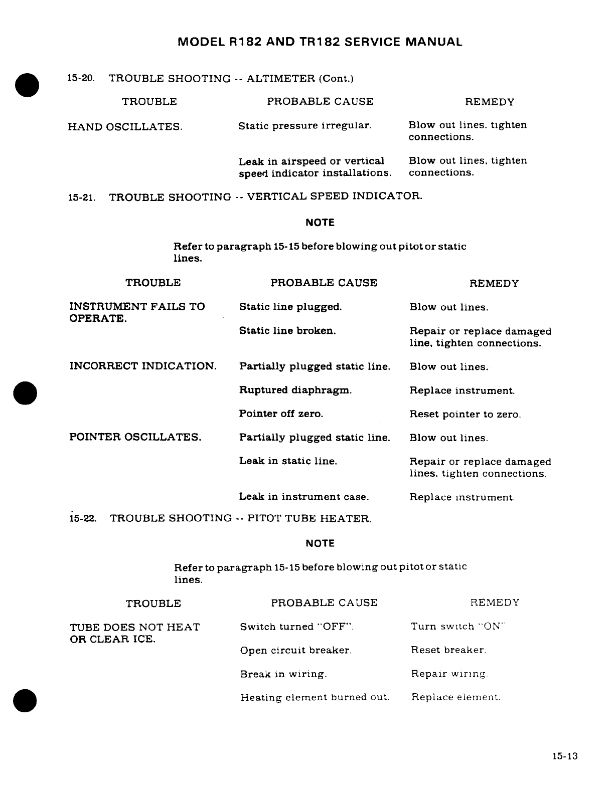
MODEL
R182
AND
TR182
SERVICE
MANUAL
15-20.
TROUBLE
SHOOTING
--
ALTIMETER
(Cont.)
TROUBLE
PROBABLE
CAUSE
REMEDY
HAND
OSCILLATES.
Static
pressure irregular.
Blow
out
lines.
tighten
connections.
Leak
in
airspeed
or
vertical
Blow
out
lines,
tighten
speed
indicator
installations.
connections.
15-21.
TROUBLE
SHOOTING
--
VERTICAL
SPEED
INDICATOR.
NOTE
Refer
to
paragraph
15-15
before
blowing
out
pitot
or
static
lines.
TROUBLE
PROBABLE
CAUSE
REMEDY
INSTRUMENT
FAILS
TO
Static line
plugged.
Blow
out
lines.
OPERATE.
Static
line broken.
Repair
or
replace
damaged
line,
tighten
connections.
INCORRECT
INDICATION.
Partially
plugged
static
line.
Blow
out
lines.
Ruptured
diaphragm.
Replace
instrument.
Pointer
off
zero.
Reset
pointer
to
zero.
POINTER
OSCILLATES.
Partially
plugged
static
line.
Blow
out
lines.
Leak
in
static
line.
Repair
or
replace
damaged
lines,
tighten
connections.
Leak
in
instrument
case.
Replace
instrument.
15-22.
TROUBLE
SHOOTING
--
PITOT
TUBE
HEATER.
NOTE
Refer
to
paragraph
15-15
before
blowing
out
pitot
or
static
lines.
TROUBLE
PROBABLE
CAUSE
REMEDY
TUBE
DOES
NOT
HEAT
Switch
turned
"OFF".
Turn
switch
"ON"
OR
CLEAR
ICE.
Open
circuit
breaker.
Reset
breaker.
Break
in
wiring.
Repair
wiring.
Heating
element
burned out. Replace element.
15-13
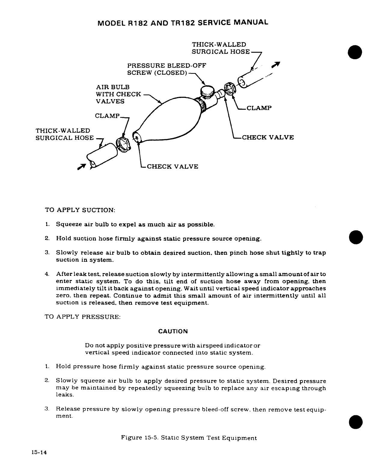
MODEL
R182
AND
TR182
SERVICE
MANUAL
THICK-WALLED
SURGICAL HOSE
PRESSURE
BLEED-OFF
/
SCREW
(CLOSED)
-~ -
AIR
BULB
WITH
CHECK
VALVES
CACLAMP
/
THICK-WALLED
/
SURGICAL
HOSE
CHECK
VALVE
O " L
CHECK
VALVE
TO
APPLY
SUCTION:
1.
Squeeze
air
bulb
to
expel
as
much
air
as
possible.
2.
Hold
suction
hose
firmly
against
static
pressure
source
opening.
3.
Slowly
release
air
bulb
to
obtain
desired suction,
then
pinch
hose
shut
tightly
to
trap
suction
in
system.
4.
After
leak
test,
release
suction
slowly
by
intermittently
allowing
a
small amount
of
air
to
enter static
system.
To
do
this,
tilt
end
of
suction
hose
away
from
opening,
then
immediately
tilt
it
back
against
opening.
Wait
until
vertical
speed
indicator
approaches
zero.
then
repeat.
Continue
to
admit
this
small
amount
of
air
intermittently
until
all
suction
is
released. then
remove
test
equipment.
TO
APPLY
PRESSURE:
CAUTION
Do
not
apply
positive pressure
with
airspeed
indicator
or
vertical
speed
indicator
connected into
static
system.
1.
Hold
pressure
hose
firmly
against
static
pressure
source
opening.
2.
Slowly
squeeze
air
bulb
to
apply
desired
pressure
to
static
system.
Desired
pressure
may
be
maintained
by
repeatedly
squeezing
bulb
to
replace
any
air
escaping
through
leaks.
3.
Release
pressure
by
slowly
opening
pressure
bleed-off
screw,
then
remove
test
equip-
ment.
Figure
15-5.
Static System
Test
Equipment
15-14
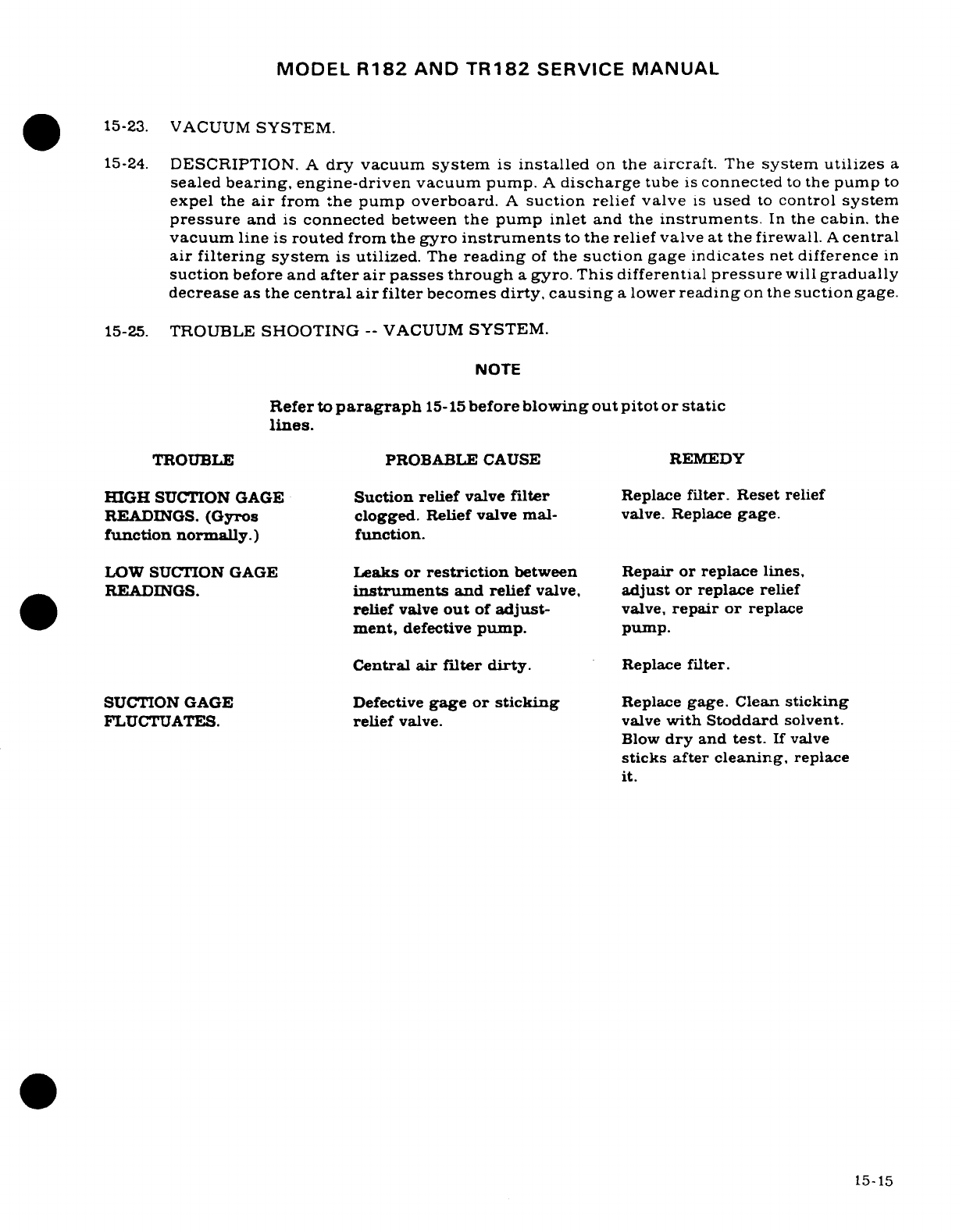
MODEL
R182
AND
TR182
SERVICE
MANUAL
15-23.
VACUUM
SYSTEM.
15-24.
DESCRIPTION.
A
dry
vacuum
system
is
installed
on
the
aircraft.
The
system
utilizes
a
sealed
bearing,
engine-driven
vacuum
pump.
A
discharge
tube
is
connected
to
the
pump
to
expel
the
air
from
the
pump
overboard.
A
suction
relief
valve
is
used
to
control
system
pressure
and
is
connected
between
the pump
inlet
and
the
instruments.
In
the
cabin.
the
vacuum
line
is
routed
from
the
gyro
instruments
to
the
relief
valve at
the
firewall.
A
central
air
filtering
system
is
utilized.
The
reading
of
the
suction
gage
indicates
net
difference
in
suction
before
and
after air
passes through
a
gyro. This
differential
pressure
will
gradually
decrease
as
the
central
air
filter
becomes
dirty,
causing
a
lower
reading
on
the
suction
gage.
15-25.
TROUBLE
SHOOTING
--
VACUUM
SYSTEM.
NOTE
Refer
to
paragraph
15-15
before
blowing
out
pitot
or
static
lines.
TROUBLE PROBABLE
CAUSE
REMEDY
HIGH
SUCTION GAGE
Suction relief
valve
filter
Replace
filter.
Reset
relief
READINGS.
(Gyros
clogged.
Relief
valve mal-
valve.
Replace
gage.
function
normally.)
function.
LOW SUCTION
GAGE
Leaks
or
restriction
between
Repair
or
replace
lines,
READINGS.
instruments
and relief
valve,
adjust
or
replace
relief
relief
valve
out
of
adjust-
valve,
repair
or
replace
ment,
defective
pump.
pump.
Central
air filter
dirty.
Replace
filter.
SUCTION
GAGE
Defective
gage
or
sticking
Replace
gage.
Clean
sticking
FLUCTUATES.
relief valve.
valve
with
Stoddard
solvent.
Blow
dry
and
test.
If
valve
sticks after
cleaning,
replace
it.
15-15
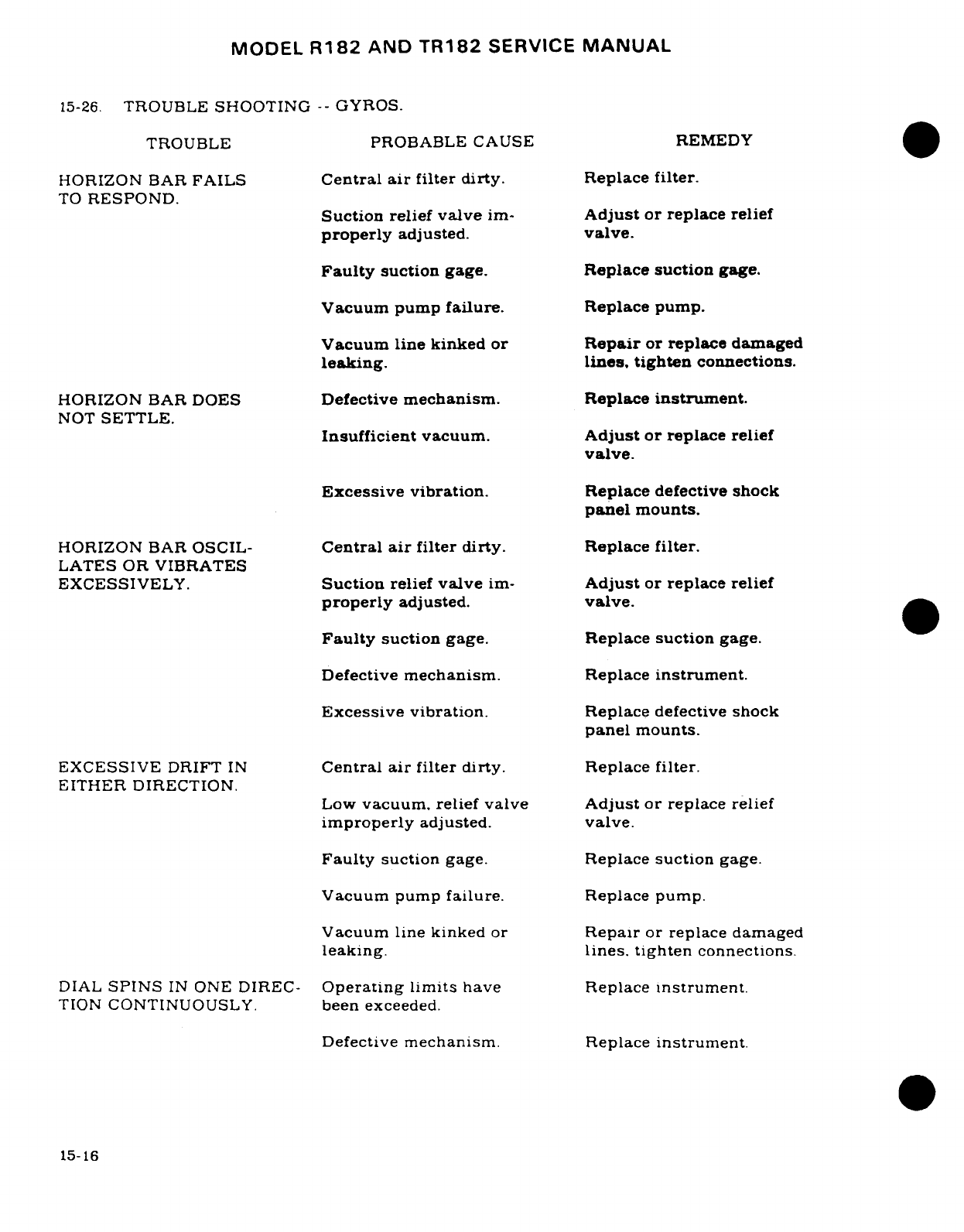
MODEL
R182
AND
TR182
SERVICE
MANUAL
15-26.
TROUBLE
SHOOTING
--
GYROS.
TROUBLE PROBABLE CAUSE
REMEDY
HORIZON BAR
FAILS
Central
air
filter
dirty. Replace
filter.
TO
RESPOND.
Suction relief
valve
im-
Adjust
or
replace
relief
properly
adjusted.
valve.
Faulty
suction
gage.
Replace
suction
gage.
Vacuum pump
failure.
Replace
pump.
Vacuum line kinked
or
Repair
or
replace
damaged
leaking.
lines,
tighten
connections.
HORIZON
BAR
DOES
Defective
mechanism.
Replace
instrument.
NOT
SETTLE.
Insufficient
vacuum.
Adjust
or
replace
relief
valve.
Excessive
vibration.
Replace
defective
shock
panel
mounts.
HORIZON
BAR
OSCIL-
Central
air
filter
dirty.
Replace
filter.
LATES
OR
VIBRATES
EXCESSIVELY.
Suction
relief
valve
im-
Adjust
or
replace
relief
properly
adjusted.
valve.
Faulty
suction
gage.
Replace
suction
gage.
Defective
mechanism.
Replace
instrument.
Excessive
vibration.
Replace
defective
shock
panel
mounts.
EXCESSIVE
DRIFT
IN
Central
air
filter dirty.
Replace
filter.
EITHER
DIRECTION.
Low
vacuum,
relief
valve
Adjust
or
replace
relief
improperly
adjusted.
valve.
Faulty
suction
gage.
Replace
suction
gage.
Vacuum
pump
failure.
Replace pump.
Vacuum
line
kinked
or
Repair
or
replace damaged
leaking.
lines.
tighten
connections.
DIAL
SPINS
IN
ONE
DIREC-
Operating
limits
have
Replace
instrument.
TION
CONTINUOUSLY.
been exceeded.
Defective
mechanism.
Replace
instrument.
15-16
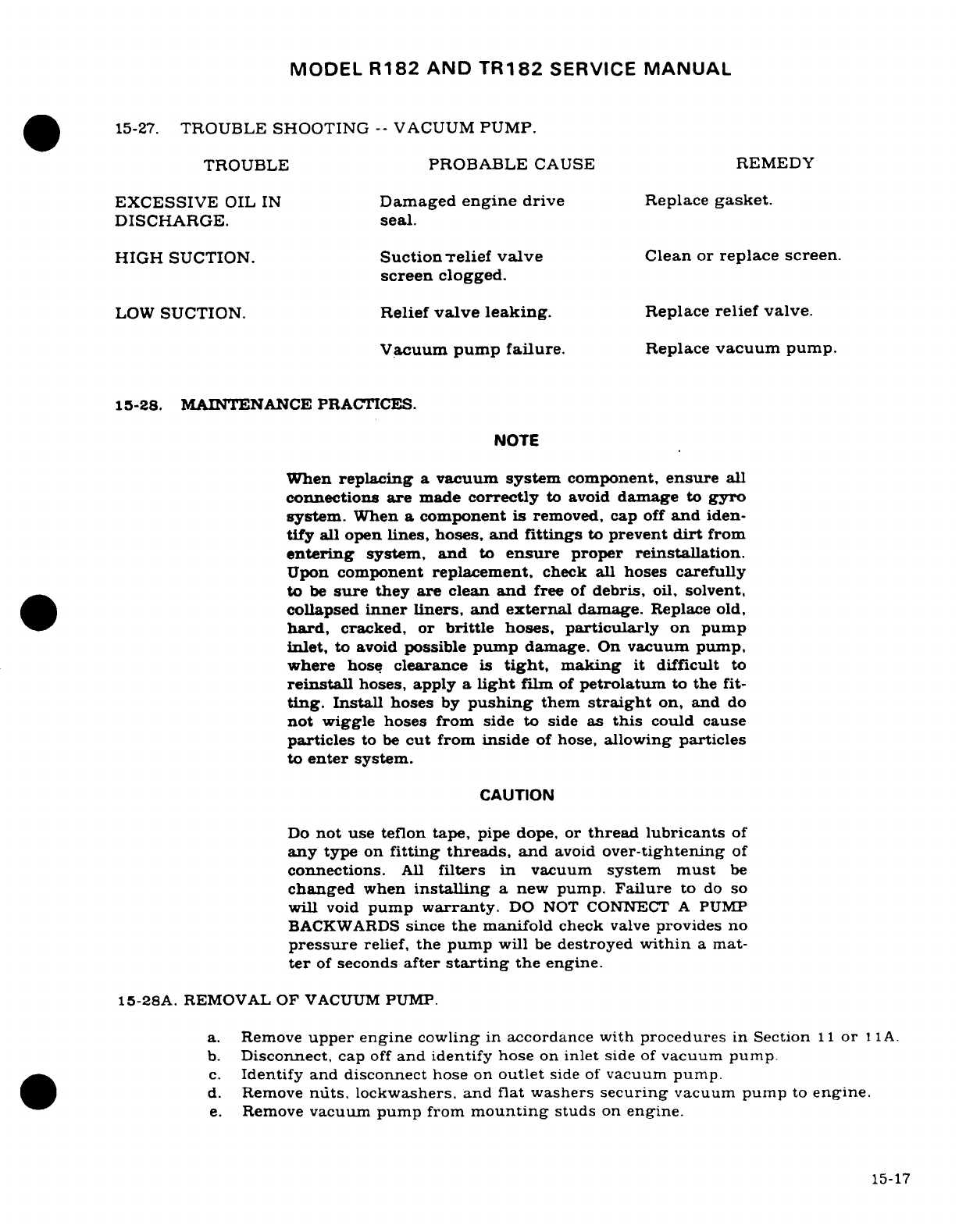
MODEL
R182
AND
TR182
SERVICE
MANUAL
15-27.
TROUBLE
SHOOTING
--
VACUUM
PUMP.
TROUBLE
PROBABLE
CAUSE
REMEDY
EXCESSIVE
OIL
IN
Damaged
engine
drive
Replace
gasket.
DISCHARGE.
seal.
HIGH
SUCTION.
Suction
relief
valve
Clean
or
replace screen.
screen
clogged.
LOW
SUCTION.
Relief
valve leaking.
Replace
relief
valve.
Vacuum
pump
failure.
Replace
vacuum
pump.
15-28.
MAINTENANCE
PRACTICES.
NOTE
When
replacing
a
vacuum
system
component,
ensure
all
connections
are
made
correctly
to
avoid
damage
to
gyro
system.
When
a
component
is
removed,
cap
off
and
iden-
tify
all open
lines, hoses,
and
fittings
to
prevent
dirt
from
entering
system,
and
to
ensure
proper
reinstallation.
Upon
component
replacement,
check
all
hoses
carefully
to
be
sure
they
are
clean
and
free
of
debris,
oil,
solvent,
collapsed
inner
liners,
and
external
damage.
Replace
old,
hard,
cracked,
or
brittle
hoses,
particularly
on
pump
inlet,
to
avoid
possible
pump
damage.
On
vacuum pump,
where
hose
clearance
is
tight,
making
it
difficult
to
reinstall
hoses,
apply
a
light
film
of
petrolatum
to
the
fit-
ting.
Install
hoses
by
pushing
them
straight
on, and
do
not
wiggle hoses
from
side
to
side
as
this
could
cause
particles
to
be
cut
from
inside
of
hose,
allowing
particles
to
enter
system.
CAUTION
Do
not
use
teflon tape,
pipe
dope,
or
thread lubricants
of
any
type
on
fitting
threads,
and
avoid
over-tightening
of
connections.
All
filters
in
vacuum
system
must
be
changed
when
installing
a
new
pump.
Failure
to
do
so
will
void
pump
warranty.
DO
NOT
CONNECT
A
PUMP
BACKWARDS
since
the
manifold
check
valve
provides no
pressure
relief,
the
pump
will
be
destroyed
within
a
mat-
ter
of
seconds
after
starting
the
engine.
15-28A.
REMOVAL
OF
VACUUM
PUMP.
a.
Remove
upper
engine
cowling
in
accordance
with
procedures
in
Section
11
or
11A.
b.
Disconnect,
cap
off
and
identify
hose
on
inlet
side
of
vacuum
pump.
c.
Identify
and
disconnect
hose
on
outlet
side
of
vacuum
pump.
d.
Remove
nuts,
lockwashers,
and flat
washers
securing
vacuum
pump
to
engine.
e.
Remove
vacuum pump from
mounting
studs
on
engine.
15-17
MODEL
R182
AND
TR182
SERVICE
MANUAL
f.
Remove
fittings
from
pump and
retain
if
they
are reusable.
Discard
any
twisted
fit-
tings
and
damaged
nuts
and
lockwashers.
15-28B.
MOUNTING
PAD
INSPECTION.
a.
Check
condition
of
the
AND
20000
pad
seal.
If
the
seal
shows
any
signs
of
oil
leak-
age, replace
the
seal.
Replace
seal if
there
is
any
doubt
as
to
its
serviceability.
15-28C.
INSTALLATION OF
VACUUM
PUMP.
a. Before
installing
a
new
vacuum
pump
purge
all
lines
in
the
system
to remove
carbon
particles
or
pump components
that
may
have
been
deposited
in
the lines
by
a
previ-
ous
pump.
b.
Consult the
applicable
Parts
Catalog,
the
pump
vendor's
application
list,
or
the
PMA
label
on
the
pump
box
to
verify
that
the pump
is
the
correct
model
for
the
engine
and/or
system.
NOTE
Before
installing
vacuum
pump
on
engine,
ensure
that
mating
surfaces
are
clean
and
free
of
any
old
gasket
ma-
terial.
c.
Position
vacuum
pump
in a
jaw-protected
vise,
with
drive
coupling downward.
CAUTION
Pump
housing
should
never
be
placed
directly
in
a
vise,
since
clamping
across
center
housing
will
cause
an
inter-
al
failure
of
carbon
rotor.
Protect
pump
mounting
flange
with
soft
metal
or
wood.
NEVER
INSTALL
a
pump
that
has
been
dropped.
NOTE
Do
not
use
teflon tape,
pipe
dope,
or
thread
lubricants
of
any
type,
and
avoid
over-tightening
of
connections.
d.
Install
elbow
in
pump;
hand-tighten
only.
NOTE
Use
only
a box
wrench
to
tighten
fittings
to
desired
posi-
tion.
Do
not
make
more
than
one
and
one
half
(1-1.2)
turns
beyond
hand-tighten
position.
e.
Position
new
mounting
pad
gasket
on
mounting
studs
on
engine.
f.
Position vacuum
pump
on
mounting
studs.
g.
Secure
pump
to
engine
with
flat
washers,
new
lockwashers,
and
nuts.
CAUTION
Always
replace
lockwashers with
new
ones
when
instal-
ling
a
new
vacuum
pump.
Tighten
all
four mounting
nuts
50-70 in.
lbs.
15-18
MODEL
R182
AND
TR182
SERVICE
MANUAL
h.
Connect
hose
to
inlet
side
of
vacuum
pump.
i.
Install
upper engine
cowling
in
accordance
with
the
procedures
in
Section
11
or
11A.
15-29.
CLEANING.
Low
pressure,
dry
compressed
air
should
be
used
in
cleaning
vacuum
system
components.
Remove
and
discard
suction
relief
valve
filter;
suction relief
valve
should
be
washed
with
Stoddard
solvent
then
dried
with
low-pressure
air.
Install
new
filter.
Refer
to
Section
2
for central
air
filter.
Check
hose for collapsed
inner
liners
as
well
as
external
dam-
age.
CAUTION
Never
apply
compressed
air
to
lines
or
components
instal-
led
in
aircraft.
The
excessive
pressures
will
damage
gyros.
If
an
obstructed line
is
to
be
blown
out,
disconnect
at
both
ends
and
blow
from instrument
panel
out.
15-29A.
LOW-VACUUM
WARNING
LIGHT.
A
red
low-vacuum
warning
light
is
installed
on
the
in-
strument
panel.
The
light
is
controlled
by
a
vacuum
switch which
is
teed
into
the
line
be-
tween
the
suction gage
and the
directional
gyro.
The
switch contacts
are
normally
closed.
The
light
may
be
checked
by
turning
ON
the
master
switch.
With
the
engine
running,
the
light
should
illuminate
when
the
vacuum
drops
below
3
-
.5
inches
Hg.
15-30.
VACUUM
RELIEF
VALVE ADJUSTMENT.
A
suction
gage
reading
of
5.3 inches
of
mercury
is
desirable
for
gyro
instruments.
However,
a
range
of
4.6
to
5.4
inches
of
mercury
is
ac-
ceptable.
To
adjust
relief
valve,
remove
central
air
filter,
run
engine
to
1900
RPM
on
ground
and
adjust
relief
valve
to
5.3
±
.1
inches
of
mercury.
CAUTION
Do
not
exceed
maximum engine
temperature.
NOTE
If
vacuum
drops
noticeably
after
replacing
central
air
fil-
ter,
remove
and
replace
existing
filter with
a
new
filter.
15-30A. STANDBY
VACUUM
SYSTEM.
15-30B.
DESCRIPTION.
A
standby
vacuum
system
may
be
installed
in
the
airplane.
The
system
con-
sists
of
an
electric
motor
drive
vacuum
pump,
a
vacuum
relief
valve,
a
manifold
valve
and
associated
hoses.
The
vacuum
pump
and
motor
assembly
are mounted
on the aft side
of
the
firewall.
A
circuit
breaker
switch
on
the
instrument
panel
controls
and
protects the
system.
Revision
1
15-19
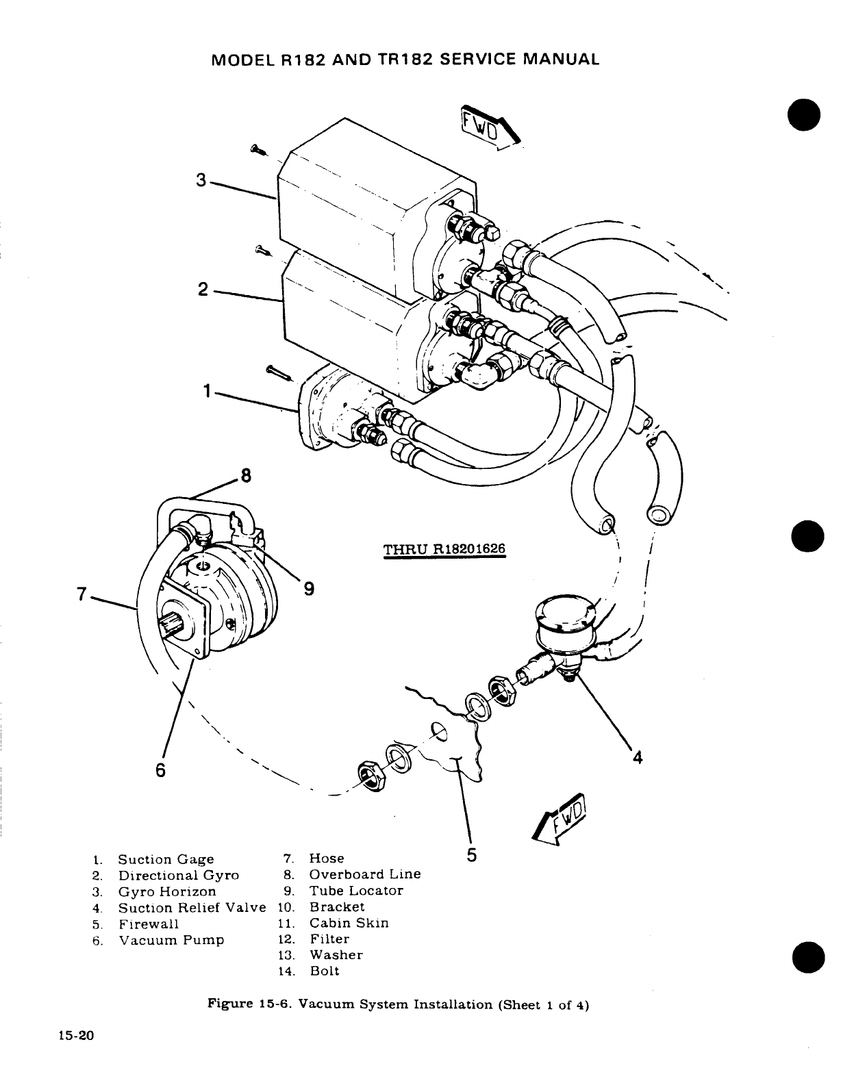
MODEL
R182
AND
TR182
SERVICE
MANUAL
Q \/
'N..
THRU
R18201626
/'
6 "'\ \
-
4/
9
6
1.
Suction
Gage
7.
Hose
5
2.
Directional
Gyro
8.
Overboard
Line
3.
Gyro Horizon
9.
Tube
Locator
4.
Suction
Relief Valve
10.
Bracket
5.
Firewall
11.
Cabin
Skin
6.
Vacuum
Pump
12.
Filter
13.
Washer
14.
Bolt
Figure
15-6.
Vacuum System
Installation
(Sheet
1
of
4)
15-20
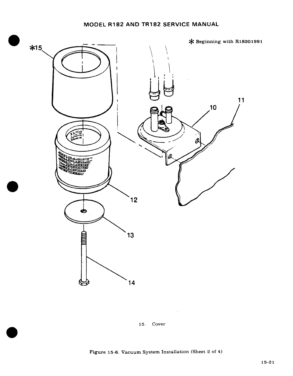
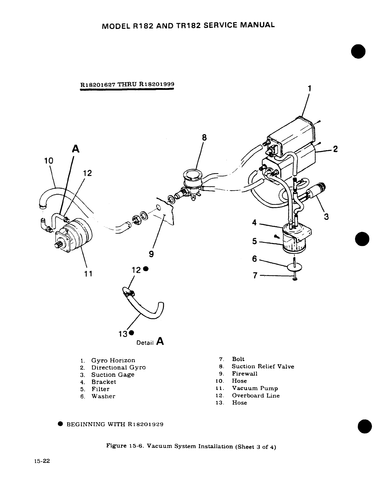
MODEL
R182
AND
TR182
SERVICE
MANUAL
R18201627
THRU
R18201999
A
2
10
/
12
130
Detail
A
1.
Gyro
Horizon
7.
Bolt
2.
Directional
Gyro
8.
Suction
Relief
Valve
3.
Suction
Gage
9.
Firewall
4.
Bracket
10.
Hose
5.
Filter
11.
Vacuum
Pump
6.
Washer
12.
Overboard
Line
13.
Hose
*BEGINNING
WITH
R18201929
Figure
15-6.
Vacuum
System
Installation
(Sheet
3
of
4)
15-22
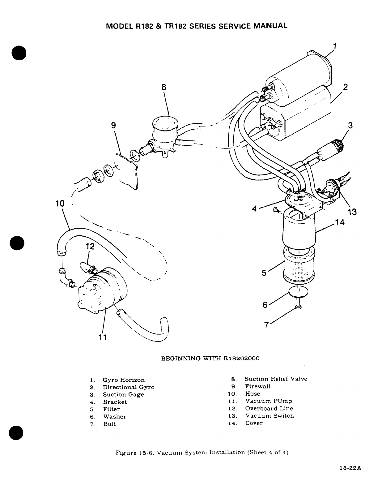
MODEL
R182
&
TR182
SERIES
SERVICE
MANUAL
~~~/
~~~~~~~~~1
10
,
14
*EGININ '~
R
11
)
7
BEGINNING
WITH
R
18202000
1.
Gyro
Horizon
8.
Suction
Relief
Valve
2.
Directional
Gyro
9.
Firewall
3.
Suction
Gage
10.
Hose
4.
Bracket
11.
Vacuum
PUmp
5.
Filter
12.
Overboard
Line
6.
Washer
13.
Vacuum
Switch
7.
Bolt
14.
Cover
Figure
15-6.
Vacuum
System
Installation
(Sheet
4
of
4)
15-22A
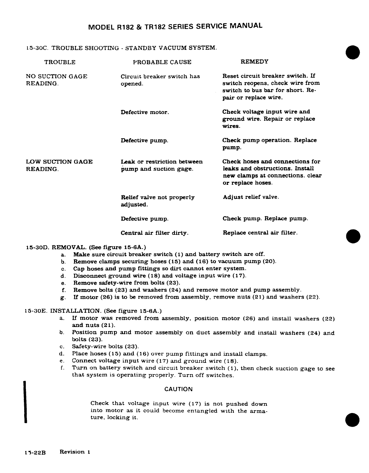
MODEL
R182
&
TR182
SERIES
SERVICE
MANUAL
15-30C.
TROUBLE
SHOOTING
-
STANDBY
VACUUM
SYSTEM.
TROUBLE
PROBABLE
CAUSE
REMEDY
NO
SUCTION
GAGE
Circuit
breaker
switch
has
Reset
circuit
breaker
switch.
If
READING.
opened.
switch
reopens,
check wire
from
switch
to
bus
bar
for
short.
Re-
pair
or
replace wire.
Defective
motor.
Check
voltage
input
wire
and
ground
wire.
Repair
or
replace
wires.
Defective
pump.
Check
pump operation.
Replace
pump.
LOW
SUCTION GAGE
Leak
or
restriction
between
Check hoses
and connections
for
READING.
pump
and
suction
gage.
leaks
and obstructions. Install
new
clamps
at
connections.
clear
or
replace
hoses.
Relief
valve
not
properly Adjust
relief
valve.
adjusted.
Defective
pump.
Check
pump.
Replace
pump.
Central
air
filter
dirty.
Replace
central
air
filter.
15-30D.
REMOVAL.
(See
figure
15-6A.)
a.
Make
sure
circuit
breaker
switch
(1)
and
battery
switch
are
off.
b.
Remove
clamps
securing
hoses
(15)
and
(16)
to
vacuum
pump
(20).
c.
Cap
hoses
and
pump
fittings
so
dirt
cannot enter
system.
d.
Disconnect
ground
wire
(18)
and
voltage
input
wire
(17).
e.
Remove
safety-wire from
bolts
(23).
f.
Remove
bolts
(23)
and washers
(24)
and
remove
motor
and
pump
assembly.
g.
If
motor
(26)
is
to
be
removed
from
assembly,
remove
nuts
(21)
and
washers
(22).
15-30E.
INSTALLATION.
(See
figure
15-6A.)
a.
If
motor
was
removed
from
assembly,
position
motor
(26)
and
install
washers
(22)
and
nuts
(21).
b.
Position
pump
and motor
assembly
on
duct
assembly
and
install
washers
(24)
and
bolts
(23).
c.
Safety-wire bolts
(23).
d.
Place
hoses
(15)
and
(16)
over
pump
fittings
and
install
clamps.
e.
Connect
voltage
input
wire
(17)
and
ground
wire
(18).
f.
Turn
on
battery
switch
and
circuit
breaker
switch
(1),
then
check
suction
gage
to
see
that
system
is
operating
properly.
Turn
off
switches.
CAUTION
Check
that
voltage
input
wire
(17)
is
not
pushed
down
into
motor
as
it
could
become
entangled
with
the
arma-
ture,
locking
it.
15-22B
Revision
1
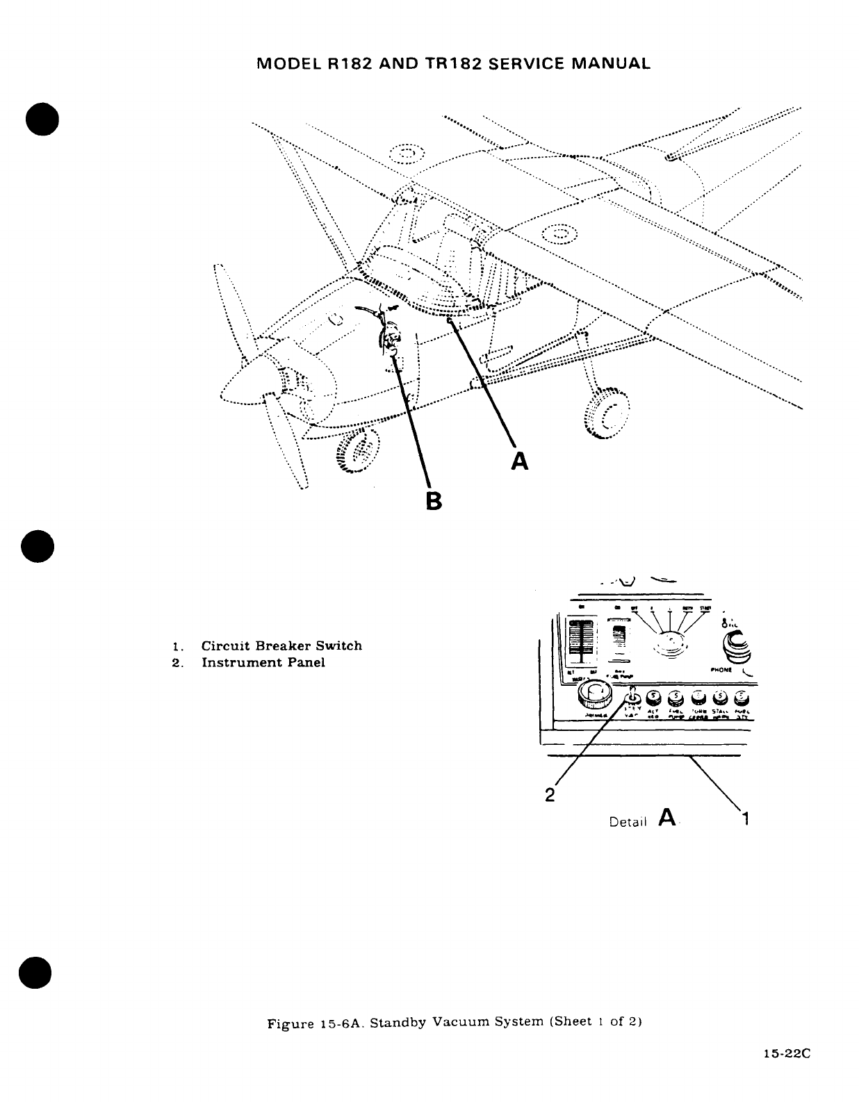
MODEL
R182
AND
TR182
SERVICE
MANUAL
. ...
.
................
......
..........
..
.-
--..
....
....
.....
*-,
.. .
.
....
..-
:
,
-\
, -.
B
1.
Circuit
Breaker
Switch
-o
i
2.
Instrument
Panel
*
z..
ON'~,
K
Figure
15-6A.
Standby
Vacuum
System
(Sheet
I
of
2)
15-22C
i-
_...
/
\ ^ "t' **<*.
'tjtf
ST~i*
» t..
., '
-i
' -- ,' " ,"
2
:
'~
·
D
A
B
15-22C
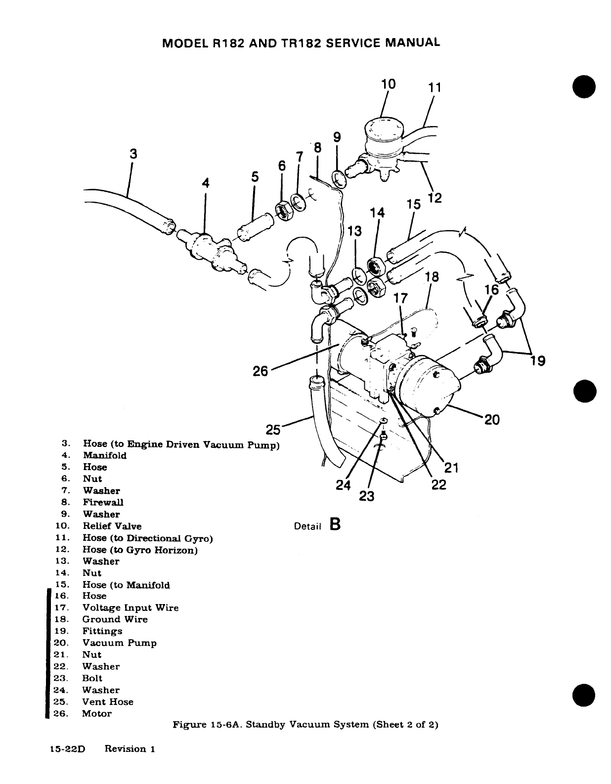
MODEL
R182
AND
TR182
SERVICE
MANUAL
10
11
3
7
12
14
15
1419
26
3.
Hose
(to
Engine
Driven
Vacuum
Pump)
4.
Manifold
5.
Hose
21
6.
Nut
24
22
7.
Washer
23
8.
Firewall
9.
Washer
10.
Relief
Valve
Detail
B
11.
Hose
(to
Directional
Gyro)
12.
Hose
(to
Gyro
Horizon)
13.
Washer
14.
Nut
15.
Hose (to
Manifold
16.
Hose
17.
Voltage
Input
Wire
18.
Ground
Wire
19.
Fittings
20.
Vacuum
Pump
21.
Nut
22.
Washer
23. Bolt
24.
Washer
25.
Vent
Hose
26.
Motor
Figure
15-6A.
Standby
Vacuum
System
(Sheet
2
of
2)
15-22D
Revision
1
MODEL
R182
AND
TR182
SERVICE
MANUAL
15-31.
ENGINE
INDICATORS.
15-32.
TACHOMETER.
15-33.
DESCRIPTION.
The
tachometer
is a
mechanical indicator
driven
at
half
crankshaft
speed
by
a
flexible
shaft.
Most
tachometer difficulties
will
be
found in
the
drive-shaft.
To
function
properly,
the
shaft
housing
must
be
free
of
kinks,
dents
and
sharp
bends.
There
should
be
no
bend
on
a
radius
shorter
than
six
inches
and
no
bend
within
three inches
of
either
terminal.
If
a
tachometer
is
noisy
or
the
pointer
oscillates,
check cable
housing
for
kinks,
sharp
bends
and damage.
Disconnect
cable
at
tachometer
and
pull
it
out
of
housing.
Check cable
for
worn
spots,
breaks
and
kinks.
NOTE
Before
replacing
a
tachometer
cable
in
housing,
coat
lower
two
thirds
with
AC
Type
ST-640
speedometer
cable
grease
or
Lubriplate
No.
110.
Insert
cable
in
housing
as
far
as
possible,
then slowly
rotate
to
make
sure
it
is
seated
in
the engine
fitting.
Insert
cable
in
tachometer,
making
sure
it is
seated
in
drive
shaft,
then
reconnect
housing
and
torque
to
50
pound-inches (at instrument).
15-34.
MANIFOLD
PRESSURE
GAGE.
THRU
R1821433,
and
TR1821430.
15-35.
DESCRIPTION.
The
manifold
pressure
gage
is a
barometric
instrument
which
indicates
absolute
pressure
in
the
intake manifold
in
inches
of
mercury.
15-36.
FUEL
PRESSURE
GAGE.
THRU
R18201430
and
R18201432.
15-37.
DESCRIPTION.
The
1.25
inch
diameter
fuel
pressure
gage
is
a
pressure
instrument
calibrated
in
PSI
indicating
approximate
fuel
pressure
to
the
engine.
Pressure
for
operating
the
indicator
is
obtained
through
a
hose
from
the
fuel
manifold
valve.
15-38.
MANIFOLD
PRESSURE/FUEL
PRESSURE
GAGE.
R18201434
&
ON.
and
TR18201431.
TR18201433
&
ON.
15-39.
DESCRIPTION.
The
manifold
pressure
and
fuel
pressure
gage
are
in
one
instrument
case.
However,
each
instrument
operates
independently.
The
manifold
pressure
gage
is
a
baromet-
ric
instrument
which indicates
absolute
pressure
in
the
intake
manifold
in
inches
of
mer-
cury.
The fuel
pressure
gage
is
a
pressure
instrument
calibrated
in
PSI
indicating
approxi-
mate fuel
pressure
to
the engine.
Pressure
for
operating
the
indicator
is obtained
through
a
hose
from
the
fuel
manifold
valve.
The
manifold
pressure
and
fuel
pressure
gage
on
the
Model
R182
is
equipped
with
a
dampening
screw
located
on
the
back
of
the
gage.
15-39A.
DAMPENING ADJUSTMENT
(R182).
Evacuate the
instrument
to
10
IN
HG.
absolute,
release
the
vacuum
abruptly
and
check
time
required
for
needle
to
pass
from
-10
INHG.
to
25
IN
HG.
Set
the
dampening
screw
so
time
required
for
needle
to
pass
from
10 IN
HG.
to
25
IN
HG
checks
2.0
-
1.0
seconds.
15-23
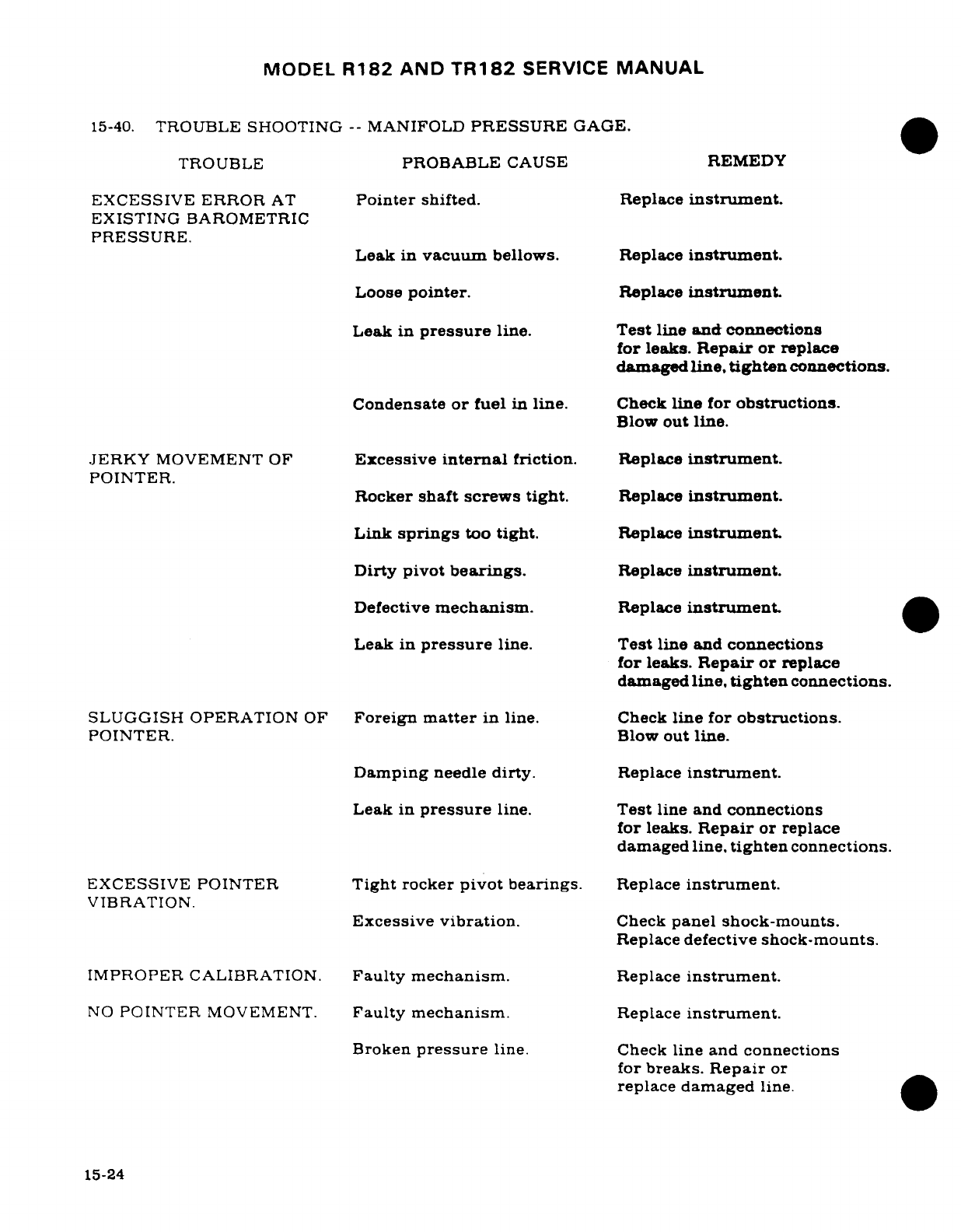
MODEL
R182
AND
TR182
SERVICE
MANUAL
15-40.
TROUBLE
SHOOTING
--
MANIFOLD
PRESSURE
GAGE.
TROUBLE
PROBABLE
CAUSE
REMEDY
EXCESSIVE
ERROR
AT
Pointer
shifted.
Replace
instrument.
EXISTING
BAROMETRIC
PRESSURE.
Leak
in
vacuum
bellows. Replace
instrument.
Loose
pointer.
Replace
instrument
Leak
in
pressure
line.
Test
line
and
connections
for leaks.
Repair
or
replace
damaged
line,
tighten
connections.
Condensate
or
fuel
in
line.
Check
line
for
obstructions.
Blow
out
line.
JERKY
MOVEMENT
OF
Excessive
internal
friction.
Replace
instrument.
POINTER.
Rocker
shaft screws
tight.
Replace
instrument.
Link
springs
too
tight.
Replace
instrument.
Dirty pivot
bearings.
Replace
instrument.
Defective
mechanism.
Replace
instrument.
Leak
in
pressure
line.
Test
line
and
connections
for
leaks.
Repair
or
replace
damaged
line,
tighten
connections.
SLUGGISH
OPERATION
OF
Foreign
matter
in
line.
Check
line
for
obstructions.
POINTER.
Blow
out
line.
Damping
needle
dirty.
Replace
instrument.
Leak
in
pressure
line.
Test
line and
connections
for
leaks.
Repair
or
replace
damaged
line,
tighten
connections.
EXCESSIVE POINTER
Tight
rocker
pivot
bearings.
Replace
instrument.
VIBRATION.
Excessive
vibration.
Check
panel
shock-mounts.
Replace
defective
shock-mounts.
IMPROPER
CALIBRATION.
Faulty
mechanism.
Replace
instrument.
NO
POINTER
MOVEMENT.
Faulty
mechanism.
Replace
instrument.
Broken
pressure
line.
Check
line
and connections
for
breaks.
Repair
or
replace
damaged
line.
15-24
MODEL
R182
AND
TR182
SERVICE
MANUAL
15-41.
TROUBLE
SHOOTING
--
FUEL
PRESSURE
GAGE.
TROUBLE
PROBABLE
CAUSE
REMEDY
DOES
NOT
REGISTER.
Pressure
line
clogged.
Check
line
for
obstructions.
Blow
out
line.
Pressure
line
broken.
Check
line
for
damage
or
leaks.
Repair
or
replace
damaged
line.
Fractured
bellows
or
Replace
instrument.
damaged
mechanism.
Clogged
snubber orifice.
Replace
instrument.
Pointer
loose
on
shaft.
Replace
instrument.
POINTER
FAILS
TO
Foreign
matter
in
line.
Check
line
for
obstructions.
RETURN
TO
ZERO.
Blow
out
line.
Clogged
snubber
orifice.
Replace
instrument.
Damaged
bellows
or
Replace
instrument.
mechanism.
INCORRECT
OR
ERRATIC
Damaged
or
dirty
Replace
instrument.
READING.
mechanism
Pointer
bent,
rubbing
on
Replace
instrument.
dial
or
glass.
Leak
or
partial
obstruc-
Check
line
for
obstructions
tion
in
pressure
or
vent
or
leaks.
line.
Blow
out
dirty
line.
repair
or
tighten
loose
connections.
15-42.
CYLINDER HEAD
TEMPERATURE
GAGE.
15-43.
DESCRIPTION.
The
temperature
sending
unit
regulates
electrical
power
through
the
cylinder
head
temperature
gage.
The
gage
and
sending
unit
require
little
or
no
maintenance
other
than
cleaning,
making
sure
lead
is
properly
supported
and
all
connections
are
clean,
tight
and
properly
insulated.
The
Rochester
and
Stewart Warner
gages
are
connected
the
same,
but
the
Rochester
gage
does
not
have
a
calibration
pot
and
cannot
be
adjusted.
Refer
to
Table
2,
page
15-30B
when
trouble
shooting
the
cylinder
head
temperature
gage.
NOTE
A
Cylinder
Head
Temperature
Gage
Calibration
Unit
(SK182-
43)
is
available
for
Stewart
Warner
gages
and
may
be
ordered
through
the
Cessna
Service
Parts
Center.
Rochester
gages
are
not
adjustable.
Revision
3
15-25
MODEL
R182
AND
TR182
SERVICE
MANUAL
15-44.
TROUBLE
SHOOTING
--
CYLINDER
HEAD
TEMPERATURE
GAGE.
TROUBLE
PROBABLE
CAUSE
REMEDY
GAGE
INOPERATIVE.
No
current
to
circuit.
Repair
electrical
circuit.
Defective
gage,
bulb
or
Repair
or
replace
defective
circuit.
items.
GAGE
FLUCTUATES
Loose
or
broken
wire
per-
Repair
or
replace
defective
RAPIDLY.
mitting
alternate
make
and
wire.
break
or
gage
circuit.
GAGE
READS
TOO
HIGH
High
voltage.
Check
"A"
terminal.
ON
SCALE.
Gage
off
calibration.
Replace
gage.
GAGE
READS
TOO
LOW
Low
voltage.
Check
voltage
supply
and
ON
SCALE.
"D"
terminal.
Gage
off
calibration.
Replace
gage.
GAGE
READS
OFF
SCALE
Break
in
bulb.
Replace
bulb.
AT
HIGH
END.
Break
in
bulb
lead.
Replace
bulb.
Internal
break
in
gage.
Replace
gage.
OBVIOUSLY
INCORRECT
Defective
gage
mechanism.
Replace gage.
READING.
Incorrect calibration.
Calibrate
system.
15-45.
OIL
PRESSURE
GAGE.
15-46.
DESCRIPTION.
The
Bourdon tube-type oil
pressure
gage
is
a
direct-reading
instrument.
operated
by
a
pressure
pickup line
connected
to
the
engine
main
oil
gallery.
The
oil
pressure
line
from
the
instrument
to
the
engine
should
be
filled with
kerosene.
especially
during
cold
weather
operation,
to
attain
an
immediate
oil
indication.
15-26
MODEL
R182
AND
TR182
SERVICE
MANUAL
15-47.
TROUBLE
SHOOTING
--
OIL
PRESSURE
GAGE
TROUBLE
PROBABLE
CAUSE
REMEDY
GAGE
DOES
NOT
Pressure
line
clogged.
Clean
line.
REGISTER.
Pressure
line
broken. Repair
or
replace
damaged
line.
Fractured
Bourdon
tube.
Replace
instrument.
Gage
pointer
loose
on
staff.
Replace
instrument.
Damaged
gage
movement.
Replace
instrument.
GAGE
POINTER
FAILS
Foreign
matter
in
line.
Clean
line.
TO
RETURN
TO
ZERO.
Foreign
matter
in
Bourdon
Replace
instrument.
tube.
Bourdon
tube
stretched.
Replace
instrument.
GAGE
DOES
NOT
REG-
Faulty
mechanism.
Replace
instrument.
ISTER
PROPERLY.
GAGE
HAS
ERRATIC
Worn
or
bent
movement.
Replace
instrument.
OPERATION.
Foreign
matter
in
Bourdon
Replace
instrument.
tube.
Dirty
or
corroded
movement.
Replace
instrument.
Pointer
bent
and
rubbing
on
Replace
instrument.
dial,
dial
screw
or
glass.
Leak
in
pressure
line.
Repair
or
replace
damaged
line.
15-27
MODEL
R182
AND
TR182
SERVICE
MANUAL
15-48.
OIL
TEMPERATURE
GAGE.
15-49.
DESCRIPTION.
On
some
airplanes,
the
oil
temperature
gage
is
a
Bourdon
tube
type
pressure
instrument
connected
by
armored capillary
tubing
to
a
temperature
bulb
in
the
engine.
The
temperature
bulb,
capillary
tube
and
gage
are
filled
with
fluid
and
sealed.
Expansion
and
contraction
of
fluid
in
the
bulb
with
temperature
changes
operates
the
gage.
Checking
capillary
tube
for
damage
and fittings
for
security
is
the
only
maintenance
required.
Since
the
tubes
inside
diameter
is
small,
small
dents
and
kinks,
which
would
be
acceptable
in
larger
tubing,
may
partially
or
completely
close
off
the
capillary,
making
the
gage
inoperative.
Some
airplanes
are
equipped
with
gages
that
are
electrically
actuated
and
are
not
adjustable.
Refer
to
Table
1,
page
15-30A
when-
trouble
shooting
the
oil
temperature
gage.
15-50.
CARBURETORAIRTEMPERATURE
GAGE.
15-51.
DESCRIPTION. The
carburetor
air
temperature
gage
is
of
the
resistance-bridge
type.
Changes
in
electrical
resistance
of
the
element
are
indicated
by
the
gage,
calibrated
for
temperature.
The
system
requires
power
from
the
airplane
electrical
system
and
operates
only
when
the
master
switch
is
on.
Although
both
instrument
and
sensing bulb
are
grounded,
two
leads
are
used to
avoid
possibility
of
instrument
error,
induced
by poor
electrical
bonds
in
the
airframe.
15-52.
TROUBLE
SHOOTING
--
CARBUREOR
AIR
TEMPERATURE
GAGE.
TROUBLE
PROBABLE
CAUSE
REMEDY
GAGE
POINTER
STAYS
OFF
Popped
circuit
breaker.
Reset
breaker.
LOW
END
OF
SCALE. Master
switch
"OFF"
or
Replace
defective
switch.
switch
defective
Broken
or
grounded
leads
Repair or
replace
defective
between gage
and
sensing
wiring.
unit.
Defective
gage
or
sensing
Replace-gage
or
sensing
unit.
unit.
15-28
Revision
3
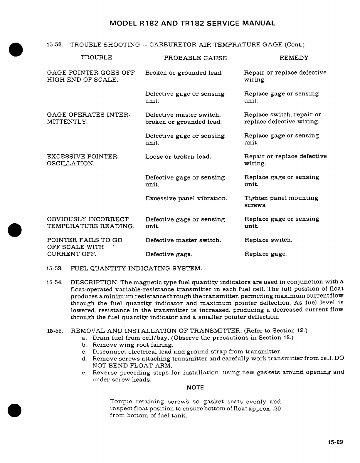
MODEL
R182
AND
TR182
SERVICE
MANUAL
15-52.
TROUBLE
SHOOTING
--
CARBURETOR
AIR
TEMPRATURE
GAGE (Cont.)
TROUBLE
PROBABLE
CAUSE
REMEDY
GAGE
POINTER
GOES
OFF
Broken
or
grounded
lead.
Repair
or
replace
defective
HIGH
END
OF
SCALE.
wiring.
Defective
gage
or
sensing
Replace
gage
or
sensing
unit.
unit.
GAGE
OPERATES
INTER-
Defective
master
switch,
Replace
switch.
repair
or
MITTENTLY.
broken
or grounded
lead.
replace
defective
wiring.
Defective
gage
or sensing
Replace
gage
or
sensing
unit.
unit.
EXCESSIVE
POINTER
Loose
or
broken
lead.
Repair
or
replace
defective
OSCILLATION.
wiring.
Defective
gage
or
sensing
Replace
gage
or
sensing
unit.
unit.
Excessive panel
vibration.
Tighten
panel mounting
screws.
OBVIOUSLY
INCORRECT
Defective
gage
or
sensing
Replace
gage
or
sensing
TEMPERATURE
READING.
unit.
unit.
POINTER
FAILS
TO
GO
Defective
master
switch.
Replace
switch.
OFF
SCALE
WITH
CURRENT
OFF.
Defective gage. Replace gage.
15-53.
FUEL
QUANTITY
INDICATING
SYSTEM.
15-54.
DESCRIPTION.
The
magnetic
type
fuel
quantity
indicators
are used
in
conjunction
with
a
float-operated
variable-resistance
transmitter
in
each
fuel
cell.
The full
position
of
float
produces
a
minimum
resistance
through
the
transmitter,
permitting
maximum
current
flow
through
the
fuel
quantity
indicator
and
maximum
pointer
deflection.
As
fuel
level
is
lowered,
resistance
in
the
transmitter
is
increased,
producing
a
decreased
current
flow
through
the
fuel
quantity
indicator
and
a
smaller
pointer
deflection.
15-55.
REMOVAL
AND
INSTALLATION
OF
TRANSMITTER.
(Refer
to
Section
12.)
a.
Drain
fuel from
cell/bay.
(Observe
the
precautions
in
Section
12.)
b.
Remove
wing root
fairing.
c.
Disconnect
electrical
lead
and
ground
strap
from
transmitter.
d.
Remove
screws
attaching
transmitter
and
carefully
work
transmitter
from cell.
DO
NOT
BEND
FLOAT
ARM.
e.
Reverse
preceding
steps
for
installation,
using
new
gaskets
around
opening
and
under
screw
heads.
NOTE
Torque
retaining
screws
so
gasket
seats
evenly
and
inspect
float
position
to
ensure
bottom
of
float
approx.
.20
from bottom
of
fuel
tank.
15-29
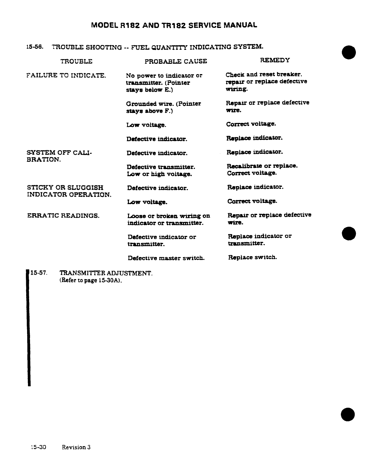
MODEL
R182
AND
TR182
SERVICE
MANUAL
15-56.
TROUBLE
SHOOTING
--
FUEL
QUANTITY
INDICATING
SYSTEM.
TROUBLE
PROBABLE
CAUSE
REMEDY
FAILURE
TO
INDICATE.
No
power
to
indicator
or
Check
and
reset
breaker.
transmitter.
(Pointer
repair
or
replace
defective
stays
below
E.)
wiring.
Grounded
wire.
(Pointer
Repair
or
replace
defective
stays
above
F.)
wire.
Low
voltage.
Correct
voltage.
Defective
indicator.
Replace
indicator.
SYSTEM OFF
CALI-
Defective
indicator.
Replace
indicator.
BRATION.
Defective
transmitter.
Recalibrate
or
replace.
Low
or
high
voltage.
Correct
voltage.
STICKY
OR
SLUGGISH
Defective
indicator.
Replace
indicator.
INDICATOR
OPERATION.
Low
voltage.
Correct
voltage.
ERRATIC
READINGS.
Loose
or
broken
wiring
on
Repair
or
replace
defective
indicator
or
transmitter.
wire.
Defective
indicator
or
Replace
indicator
or
transmitter.
transmitter.
Defective
master
switch.
Replace
switch.
15-57. TRANSMITTER
ADJUSTMENT.
(Refer
to
page
15-30A).
15-30
Revision
3
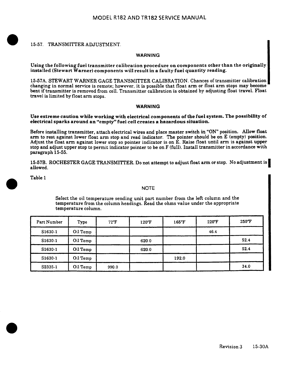
MODEL
R182
AND
TR182
SERVICE
MANUAL
15-57.
TRANSMITTER
ADJUSTMENT.
WARNING
Using
the
following fuel
transmitter
calibration procedure
on
components
other
than
the
originally
installed
(Stewart
Warner)
components
will
result
in
a
faulty
fuel
quantity
reading.
15-57A.
STEWART
WARNER
GAGE
TRANSMITTER CALIBRATION.
Chances
of
transmitter
calibration
changing
in normal
service
is
remote; however,
it
is
possible
that
float
arm
or
float
arm
stops
may
become
bent
if
transmitter
is removed
from
cell.
Transmitter
calibration
is
obtained
by
adjusting
float
travel.
Float
travel
is
limited
by
float
arm
stops.
WARNING
Use
extreme
caution
while
working
with
electrical components
of
the
fuel
system. The
possibility
of
electrical
sparks
around an
"empty"
fuel
cell
creates
a
hazardous
situation.
Before
installing
transmitter,
attach
electrical
wires
and
place
master
switch
in
"ON"
position.
Allow
float
arm
to
rest
against
lower
float
arm
stop
and
read
indicator.
The
pointer
should
be
on
E
(empty)
position.
Adjust
the
float
arm
against
lower
stop
so
pointer
indicator
is
on
E.
Raise
float
until
arm
is
against
upper
stop
and
adjust
upper
stop
to
permit
indicator
pointer
to
be
on
F
(full).
Install
transmitter
in
accordance
with
paragraph
15-55.
15-57B.
ROCHESTER
GAGE
TRANSMITTER.
Do
not
attempt
to
adjust
float
arm
or
stop.
No
adjustment
is
allowed.
Table
1
NOTE
Select
the
oil
temperature
sending
unit
part
number
from the
left
column
and
the
temperature
from
the
column
headings.
Read
the
ohms
value
under
the
appropriate
temperature
column.
Part
Number
Type
72°F
120
F
165
F
220°F
250°F
S1630-1
Oil
Temp
46.4
S1630-1
Oil
Temp
620.0
52.4
S1630-1
Oil
Temp
620.0
52.4
S1630-1
Oil
Temp
192.0
S2335-1
Oil
Temp
990.0
34.0
Revision
3
15-30A
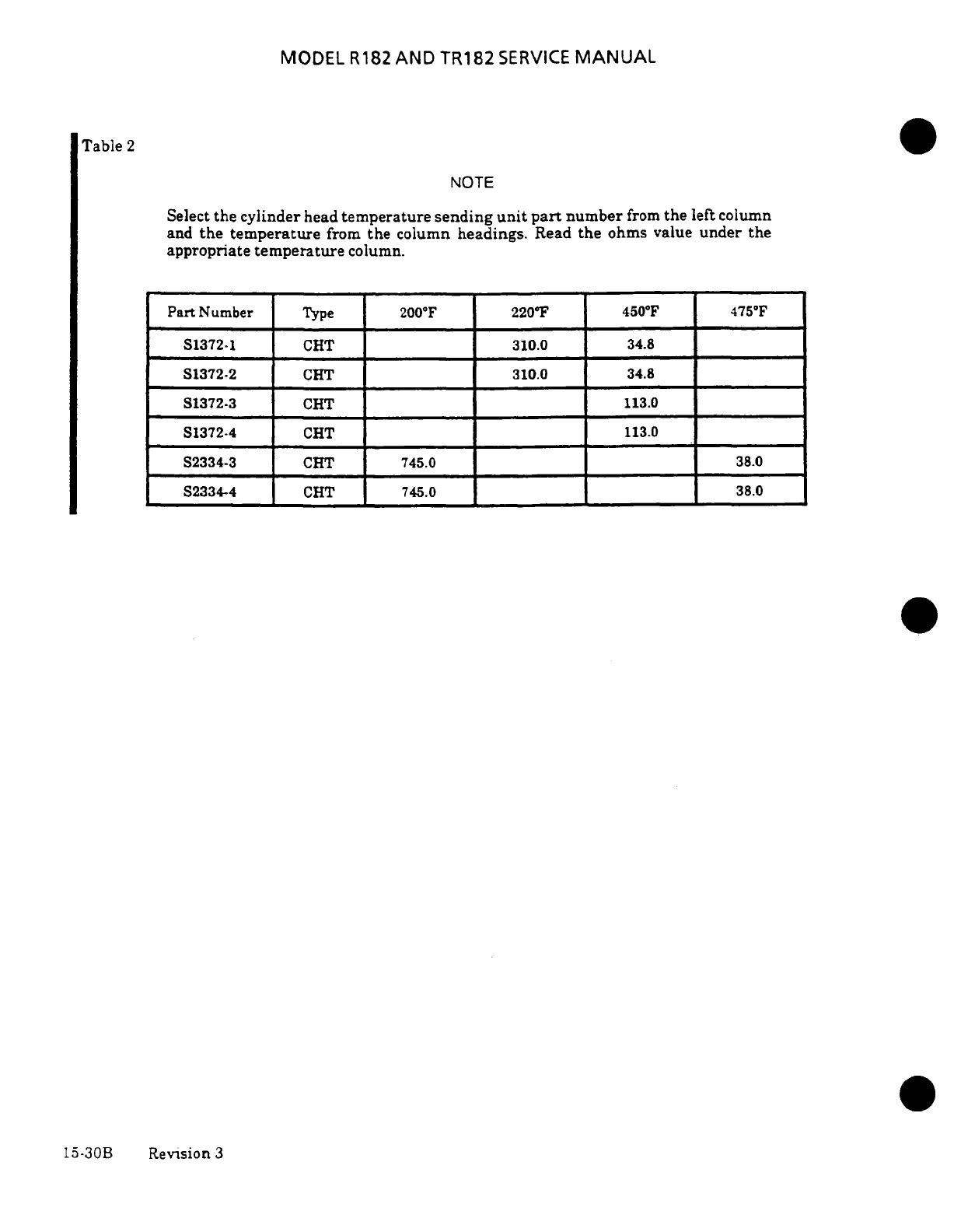
MODEL
R182
AND
TR182
SERVICE
MANUAL
Table
2
NOTE
Select
the cylinder
head
temperature
sending
unit
part
number
from
the
left
column
and
the temperature
from
the
column
headings.
Read
the
ohms
value
under
the
appropriate
temperature
column.
Part
Number
Type
200°F 220
F
450°F
475
F
S1372-1
CHT 310.0
34.8
S1372-2
CHT
310.0
34.8
S1372-3
CHT
113.0
S1372-4
CHT
113.0
S2334-3 CHT
745.0
38.0
S2334-4 CHT
745.0
38.0
15-30B
Revision
3
MODEL
R182
&
TR182
SERIES
SERVICE MANUAL
15-57C.
FUEL
QUANTITY
INDICATING SYSTEM
OPERATIONAL
TEST.
WARNING:
REMOVE
ALL
IGNITION
SOURCES
FROM THE
AIRPLANE
AND
VAPOR
HAZARD
AREA.
SOME
TYPICAL
EXAMPLES OF
IGNITION
SOURCES
ARE STATIC
ELECTRICITY,
ELECTRICAL
POWERED
EQUIPMENT
(TOOLS
OR
ELECTRONIC TEST
EQUIPMENT
-
BOTH
INSTALLED
ON THE
AIRPLANE
AND
GROUND SUPPORT
EQUIPMENT),
SMOKING
AND
SPARKS
FROM
METAL
TOOLS.
WARNING:
OBSERVE
ALL
STANDARD FUEL
SYSTEM
FIRE
AND
SAFETY PRACTICES.
1.
Disconnect
all
electrical
power from
the
airplane.
Attach
maintenance
warning
tags to
the
battery
connector
and
external
power
receptacle
stating:
DO
NOT CONNECT
ELECTRICAL
POWER,
MAINTENANCE
IN
PROGRESS.
2.
Electrically
ground
the
airplane.
3.
Level
the
airplane
and drain
all
fuel
from wing
fuel
tanks. Refer
to
Section
2,
Ground
Handling,
Servicing,
Cleaning,
Lubrication,
And
Inspection
as
required.
4.
Gain
access
to each
fuel
transmitter
float
arm
and actuate
the
arm
through
the
transmitter's
full
range
of
travel.
A.
Ensure
the
transmitter float
arm
moves
freely
and
consistently
through
this range
of
travel.
Replace
any
transmitter
that
does
not
move
freely
or
consistently.
WARNING:
USE
EXTREME
CAUTION
WHILE
WORKING
WITH
ELECTRICAL COMPONENTS
OF
THE
FUEL
SYSTEM. THE
POSSIBILITY
OF ELECTRICAL
SPARKS
AROUND AN
"EMPTY"
FUEL
CELL
CREATES
A
HAZARDOUS SITUATION.
B.
While
the
transmitter float
arm
is
being
actuated,
apply
airplane battery electrical power
as
required
to
ensure
that
the
fuel
quantity indicator
follows
the movement
of
the
transmitter
float
arm.
If
this
does
not
occur,
troubleshoot,
repair
and/or replace
components
as
required until
the
results are
achieved as stated.
NOTE:
Stewart
Warner
fuel quantity
indicating systems
can
be
adjusted. Refer
to
paragraph
15-57A
for
instructions for
adjusting
Stewart
Warner
fuel indicating
systems.
Rochester
fuel
quantity
indicating
system
components
are
not adjustable,
only
component
replacement or standard
electrical
wiring
system maintenance
practices are
permitted.
5.
With
the
fuel
selector
valve
in
the
"OFF"
position,
add
unusable
fuel quantity
to each
fuel tank.
6.
Apply
electrical
power
as
required
to
verify
the
fuel
quantity
indicator indicates
"EMPTY".
A.
If
"EMPTY"
is
not
indicated,
adjust,
troubleshoot,
repair and/or
replace fuel-indicating
components
as
required
until
the
"EMPTY"
indication
is
achieved.
NOTE:
Stewart
Warner
fuel
quantity
indicating
systems
can
be
adjusted.
Refer
to
paragraph
15-57A
for
instructions for adjusting Stewart
Warner
fuel
indicating
systems.
Rochester
fuel
quantity
indicating
system components
are
not adjustable,
only
component
replacement
or standard
electrical
wiring
system
maintenance practices
are
permitted.
Temporary
Revision
Number
6
7
July
2003
©
Cessna
Aircraft
Company
15-30C
MODEL
R182
&
TR182
SERIES
SERVICE
MANUAL
7.
Fill
tanks
to
capacity, apply
electrical
power
as
required and
verify fuel
quantity
indicator indicates
"FULL".
A.
If
"FULL"
is
not
indicated,
adjust,
troubleshoot,
repair
and/or
replace
fuel
indicating
components
as
required
until
the
"FULL"
indication
is
achieved.
NOTE:
Stewart
Warner
fuel
quantity
indicating
systems
can
be
adjusted.
Refer
to paragraph
15-57A
for
instructions
for
adjusting
Stewart
Warner
fuel indicating
systems.
Rochester
fuel
quantity
indicating
system
components
are not
adjustable,
only
component
replacement or
standard
electrical
wiring
system
maintenance practices
are
permitted.
8.
Install
any
items
and/or
equipment
removed
to
accomplish
the
Fuel
Quantity
Indicating System
Operational
Test,
remove
maintenance
warning
tags
and
connect
the
airplane battery.
Temporary
Revision
Number
6
©
Cessna
Aircraft
Company
7
July
2003
15-30D
MODEL
R182
AND
TR182
SERVICE
MANUAL
.
15-58.
HOURMETER.
(See
figure
15-7.)
15-59.
DESCRIPTION. The
hourmeter
is
an
electrically
operated
instrument,
actuated
by
a
pressure
switch
in
the
oil
pressure
gage line.
Electrical
power
is
supplied
through
a
one-
amp fuse
from
the
electrical
clock
circuit,
and
therefore
will
operate
independent
of
the
master
switch.
A
diode
incorporated
into
the
meter
prevents
interruption
of
avionics
operation.
This
type hourmeter
is
identified
by a
white
+
above
the
positive terminal.
NOTE
When
installing
the
hourmeter,
the
positive
(red)
wire
must
be
connected
to
the
white
+
terminal.
Connecting
wires
incorrectly will
damage
the
meter.
15-60.
ECONOMY
MIXTURE
INDICATOR.
15-61.
DESCRIPTION.
The
economy
mixture
indicator
is
an
exhaust
gas
temperature
(EGT)
sensing
device
which
is
used
to
aid
the
pilot
in
selecting
the
most
desirable
fuel-air
mixture
for
cruising
flight
at
less
than
75%
power.
Exhaust
gas temperature
(EGT)
varies
with
ratio
of
fuel-to-air
mixture
entering
the
engine
cylinders.
Refer
to
the
PILOT'S
OPERATING
HANDBOOK
for
operating
procedure
of
the
system.
15-62.
TROUBLE
SHOOTING
--
ECONOMY
MIXTURE
INDICATOR.
TROUBLE
PROBABLE
CAUSE
REMEDY
.
GAGE
INOPERATIVE.
Defective
gage, probe
or
Repair
or
replace
defective
circuit.
part.
INCORRECT
READING.
Indicator
needs
Calibrate
indicator
in
accor-
calibrating.
dance
with
paragraph
15-61.
FLUCTUATING
READING.
Loose,
frayed
or
broken Tighten
connections
and
lead,
permitting alternate
repair
or
replace
defective
make
and
break
of
current.
leads.
15-63.
CALIBRATION. When
a
new
EGT
gage
or probe
is
installed accomplish
the
following steps:
a.
Before
flight
remove
the
decorative
cover
on
right
hand
instrument
panel
and
temporarily
install
the
EGT
indicator
with
one
screw.
b.
Test
fly
the
airplane
and
establish
75%
power
in
level
flight.
Carefully
lean
the
fuel
mixture
to
achieve
peak
EGT.
Remove
the
EGT
indicator
from
the
panel
and
adjust
the
screw
on
the
back
of
the
instrument
beneath
the
plastic cap
with
a
small
blade
screwdriver
to
place
the
EGT
indicator
hand
over
the
4/5
scale
increment
of
the
indicator
scale.
Turning
the
screw
clockwise
increases
the
reading
and
counter-
clockwise
decreases
the
reading.
The
adjusting
screw
has
an
adjustment
range
of
approximately
600°F
or
2
increments
in
either
direction.
Stops
are
provided
on
the
adjust
screw which
control
the
above
and should
not
be
forced
past
stops
as
it will
affect
calibration
of
the
Unit Scale.
15-31
MODEL
R182
AND
TR182
SERVICE
MANUAL
NOTE
The
4/5
scale
increment
setting
provides
the reference
indicator
point
for
relative
temperature
indications
for
normal
cruise
power
settings
within range
of
instrument
scale.
c.
After
flight
reinstall
indicator
and
decorative
cover.
The
yellow
adjustable
hand
on
indicator
is
for
use
to
mark
a
reference
temperature
setting.
15-64.
REMOVAL
AND
INSTALLATION.
Removal
of
the
indicator
is
accomplished
by
removing
the
mounting
screws
and
disconnecting
the
leads.
Tag
leads
to
facilitate
installation.
The
thermocouple
probe
is
secured
to
the
exhaust
stack
with
a
clamp.
When
installing
probe.
tighten
clamp
to
45
pound-inches
and
safety
as
required.
Refer
to
Section
11
for
exhaust
system
installation.
15-65.
MAGNETIC
COMPASS. (See
figure
15-7.)
15-66.
DESCRIPTION.
The
magnetic
compass
is
liquid-filled.
with
expansion provisions
to
compensate
for
temperature
changes.
It
is
equipped
with
compensating
magnets
adjustable
from
the
front
of
the
case.
The
compass
is
internally
lighted, controlled
by
the
instrument
lights
rheostat
switch.
No
maintenance
is
required
on
the
compass
except
an
occasional
check
on a
compass
rose
and
replacement
of
lamp.
The
compass
mount
is
attached
by
three
screws
to
a
base
plate
which
is
bonded
to
windshield
with
methylene
chloride.
A
tube
containing
the
compass
light
wires
is
attached
to
the metal
strip
at
the
top
of
the
windshield.
Removal
of
the
compass
is
accomplished
by
removing
the
screw
at
forward
end
of
compass
mount.
unfastening
the
metal
strip
at
the
top
of
windshield
and
cutting
the
two
wire
splices.
Removal
of
the
compass
mount
is
accomplished
by
removing
three
screws
attaching
mount
to
the
base plate. Access
to
the
inner
screw
is
gained
through
a
hole
in
the
bottom
of
mount.
through
which
a
thin
screwdriver
may
be
inserted.
When
installing
the
compass.
it
will
be
necessary
to
splice
the
compass
light
wires.
15-67.
STALL
WARNING
HORN
AND
TRANSMITTER.
15-68.
DESCRIPTION.
The
stall
warning
horn
is
contained
in
the
dual
warning
unit
mounted
on
the
right
hand
wing
root
rib.
It
is
electrically
operated
and
controlled
by
a
stall
warning
transmitter
mounted
on
the
leading
edge
of
the
left
wing.
For
further
information
on
the
warning
horn
and
transmitter,
refer
to
Section
16.
15-69.
TURN
COORDINATOR.
15-70.
DESCRIPTION. The
turn
coordinator
is
an
electrically
operated.
gyroscopic. roll-turn
rate
indicator.
Its
gyro
simultaneously
senses
rate
of
motion
roll
and
yaw
axis
which
is
projected
on
a
single
indicator.
The
gyro
is
a
non-tumbling
type
requiring
no
caging
mechanism
and
incorporates
an
ac
brushless
spin
motor with
a
solid
state
inverter.
15-32
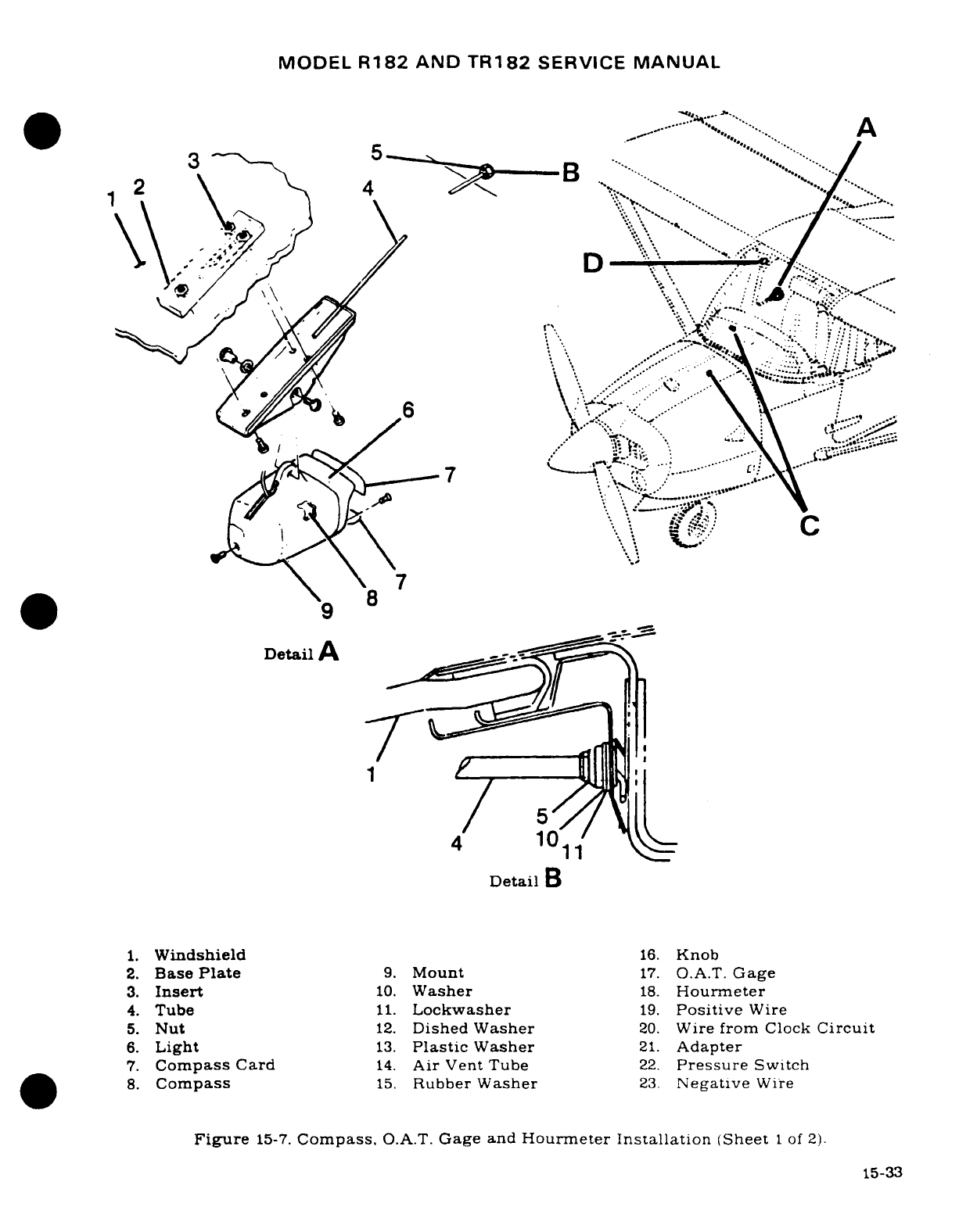
MODEL
R182
AND
TR182
SERVICE
MANUAL
~~~~~~~~~~~~~~~~~~Detail"'
A
3
*
~ ~,.2. Base Plate
9.
Mount
17.
O...
.
Gag
.:;
3.
Insert
10.
Washer
1
.
Hourmeter
*\ 8
Detail
A -,....
4
10
Detail
B
1.
Windshield
16.
Knob
2.
Base
Plate
9.
Mount
17.
O.A.T.
Gage
3.
Insert
10.
Washer
18.
Hourmeter
4.
Tube
11.
Lockwasher
19.
Positive
Wire
5.
Nut
12.
Dished
Washer
20.
Wire
from
Clock
Circuit
6.
Light
13.
Plastic
Washer
21.
Adapter
7.
Compass
Card
14.
Air
Vent
Tube
22.
Pressure
Switch
8.
Compass
15.
Rubber Washer
23.
Negative
Wire
Figure
15-7.
Compass.
O.A.T.
Gage
and
Hourmeter
Installation
(Sheet
1
of
2).
15-33
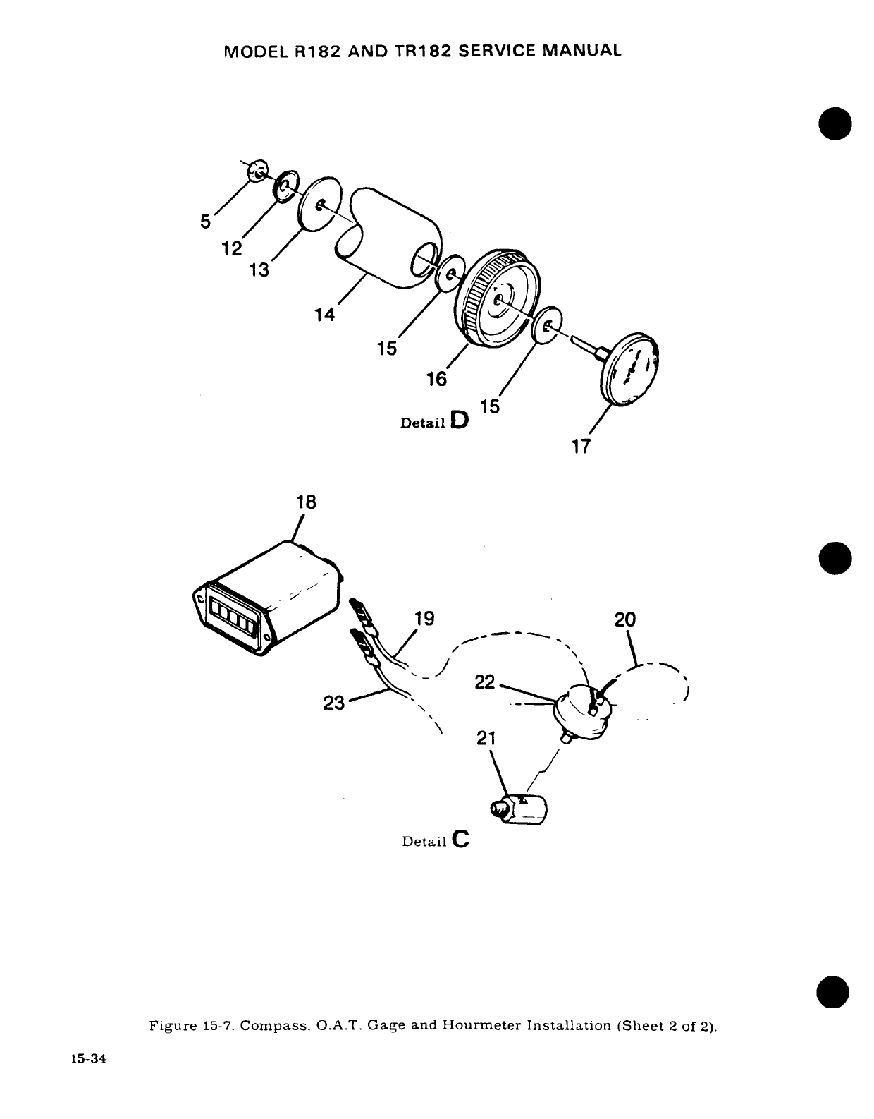
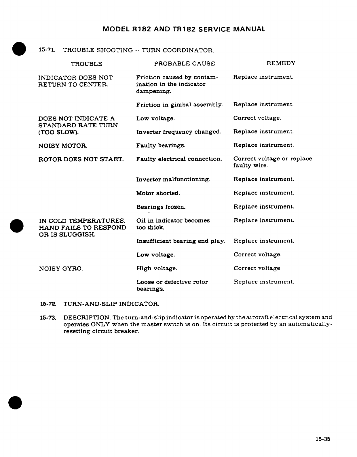
MODEL
R182
AND
TR182
SERVICE
MANUAL
15-71.
TROUBLE
SHOOTING
--
TURN
COORDINATOR.
TROUBLE
PROBABLE
CAUSE
REMEDY
INDICATOR
DOES
NOT
Friction
caused
by
contam-
Replace
instrument.
RETURN
TO
CENTER.
ination
in
the
indicator
dampening.
Friction
in
gimbal
assembly.
Replace
instrument.
DOES
NOT
INDICATE
A Low
voltage. Correct
voltage.
STANDARD
RATE
TURN
(TOO
SLOW).
Inverter
frequency changed. Replace
instrument.
NOISY
MOTOR.
Faulty
bearings.
Replace
instrument.
ROTOR
DOES
NOT
START.
Faulty
electrical
connection.
Correct
voltage
or
replace
faulty
wire.
Inverter
malfunctioning.
Replace
instrument.
Motor
shorted.
Replace
instrument.
Bearings
frozen.
Replace
instrument.
.
IN
COLD
TEMPERATURES, Oil
in
indicator
becomes
Replace
instrument.
HAND
FAILS
TO
RESPOND
too
thick.
OR
IS SLUGGISH.
Insufficient
bearing
end
play.
Replace
instrument.
Low
voltage. Correct
voltage.
NOISY
GYRO.
High
voltage.
Correct
voltage.
Loose
or
defective
rotor
Replace
instrument.
bearings.
15-72.
TURN-AND-SLIP
INDICATOR.
15-73.
DESCRIPTION.
The
turn-and-slip
indicator
is
operated
by
the
aircraft
electrical
system
and
operates
ONLY
when
the
master
switch
is
on.
Its
circuit
is
protected
by
an
automatically-
resetting
circuit
breaker.
15-35
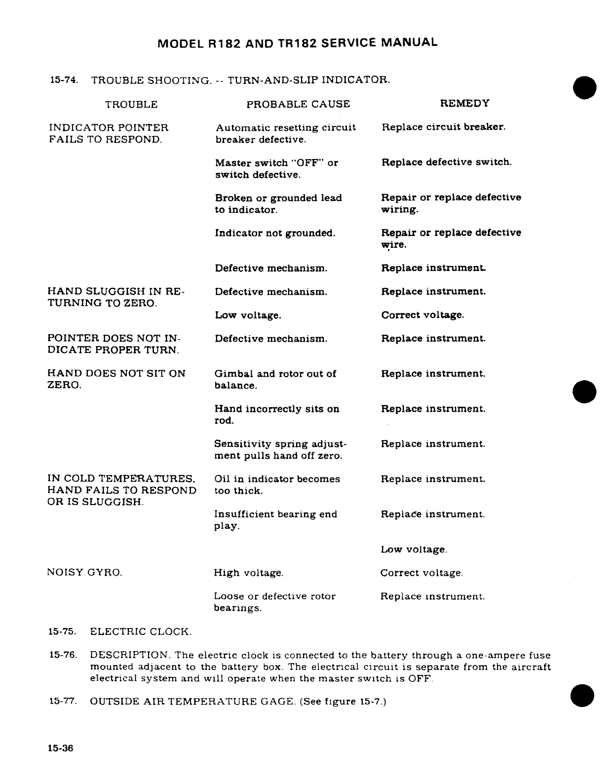
MODEL
R182
AND
TR182
SERVICE
MANUAL
15-74.
TROUBLE
SHOOTING.
--
TURN-AND-SLIP
INDICATOR.
TROUBLE
PROBABLE
CAUSE REMEDY
INDICATOR
POINTER
Automatic
resetting
circuit
Replace
circuit
breaker.
FAILS
TO
RESPOND.
breaker
defective.
Master
switch
"OFF"
or
Replace defective
switch.
switch
defective.
Broken
or
grounded lead
Repair
or
replace
defective
to
indicator.
wiring.
Indicator
not
grounded.
Repair
or replace
defective
wire.
Defective
mechanism.
Replace
instrument.
HAND
SLUGGISH
IN
RE-
Defective
mechanism.
Replace
instrument.
TURNING
TO
ZERO.
Low
voltage.
Correct
voltage.
POINTER
DOES NOT
IN-
Defective
mechanism.
Replace
instrument.
DICATE PROPER
TURN.
HAND
DOES
NOT
SIT
ON
Gimbal
and
rotor
out
of
Replace
instrument.
ZERO.
balance.
Hand
incorrectly
sits
on
Replace
instrument.
rod.
Sensitivity
spring
adjust-
Replace
instrument.
ment
pulls
hand
off
zero.
IN
COLD
TEMPERATURES.
Oil
in
indicator
becomes
Replace
instrument.
HAND FAILS
TO
RESPOND
too
thick.
OR
IS
SLUGGISH.
Insufficient
bearing
end
Replace
instrument.
play.
Low
voltage.
NOISY
GYRO.
High
voltage.
Correct
voltage.
Loose
or
defective
rotor
Replace
instrument.
bearings.
15-75.
ELECTRIC
CLOCK.
15-76.
DESCRIPTION.
The
electric
clock
is
connected
to
the
battery
through
a
one-ampere
fuse
mounted
adjacent
to
the
battery
box.
The
electrical
circuit
is
separate
from
the
aircraft
electrical
system
and
will
operate
when
the
master
switch
is
OFF.
15-77.
OUTSIDE
AIR
TEMPERATURE
GAGE.
(See
figure
15-7.)
15-36
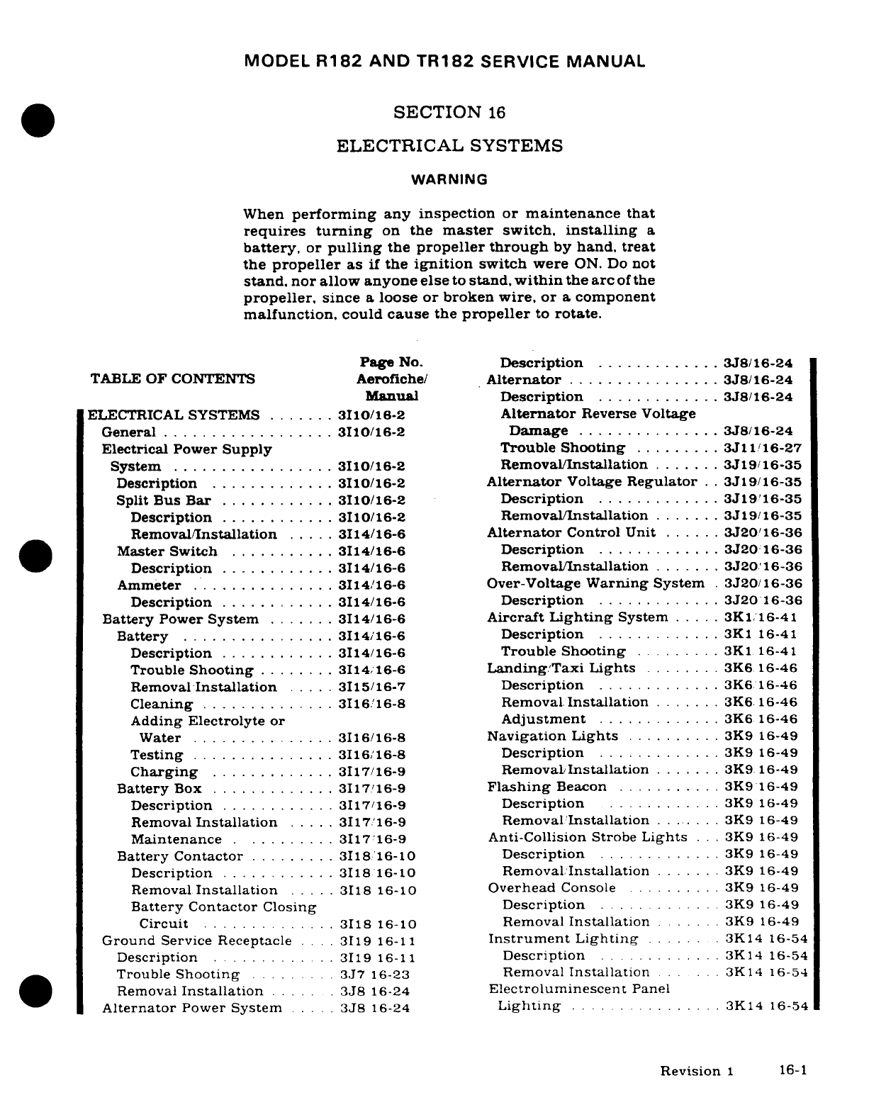
MODEL
R182
AND
TR182
SERVICE
MANUAL
SECTION
16
ELECTRICAL
SYSTEMS
WARNING
When
performing
any inspection or
maintenance
that
requires
turning
on
the
master
switch,
installing
a
battery,
or
pulling
the
propeller through
by
hand,
treat
the
propeller
as
if
the
ignition
switch
were
ON.
Do
not
stand.
nor
allow
anyone
else
to
stand,
within
the
arc
of
the
propeller,
since
a
loose
or
broken
wire, or
a
component
malfunction,
could
cause
the
propeller
to
rotate.
Page
No.
Description
.............
3J8/16-24
TABLE
OF
CONTENTS
Aerofiche/
Alternator
................
3J8/16-24
Manual
Description
.............
3J8/16-24
ELECTRICAL
SYSTEMS
.......
3110/16-2
Alternator
Reverse
Voltage
General
..................
3110/16-2
Damage
...............
3J8/16-24
Electrical Power
Supply Trouble
Shooting
.........
3J11/16-27
System
.................
3110/16-2
Removal/Installation
.......
3J19/16-35
Description
.............
3I10/16-2
Alternator
Voltage
Regulator
. .
3J19/16-35
Split
Bus
Bar
............
3110/16-2
Description
.............
3J19/16-35
Description
............
3I10/16-2
Removal/Installation
.......
3J19/16-35
Removal/Installation
.....
3114/16-6
Alternator
Control
Unit
......
3J20/16-36
Master
Switch
..........
3I14/16-6
Description
.........
3J20
16-36
Description
............
3I14/16-6
Removal/Installation
.......
3J20'16-36
Ammeter
...............
3I14/16-6 Over-Voltage
Warning
System
.
3J20/16-36
Description
............
3114/16-6
Description
.............
3J20
16-36
Battery
Power
System
.......
3I14/16-6
Aircraft
Lighting
System
.....
3K1/16-41
Battery
................
3I14/16-6
Description
.............
3K1
16-41
Description
............
3114/16-6
Trouble
Shooting
.........
3K1
16-41
Trouble
Shooting
......
3I14/16-6
Landing/Taxi
Lights
........
3K6 16-46
Removal
Installation
.....
3115/16-7
Description
.............
3K6
16-46
Cleaning
..............
3I16.16-8
Removal
Installation
.......
3K6
16-46
Adding
Electrolyte
or
Adjustment
.........
3K6
16-46
Water
...............
3I16/16-8
Navigation
Lights
.........
3K9
16-49
Testing
...............
3I16/16-8
Description
.
............
3K9
16-49
Charging
.............
3117/16-9
Removal/Installation
.......
3K9 16-49
Battery
Box
.............
3117/16-9
Flashing
Beacon
.........
3K9
16-49
Description
............
3117/16-9
Description
............
3K9
16-49
Removal
Installation
.....
3117/16-9
Removal/Installation
.......
3K9
16-49
Maintenance
..........
3117/16-9
Anti-Collision
Strobe
Lights
. . .
3K9
16-49
Battery
Contactor
.........
3I18
16-10
Description
.............
3K9
16-49
Description
............
3I18
16-10
Removal.Installation
.......
3K9
16-49
Removal
Installation
.....
3118
16-10
Overhead
Console
..........
3K9
16-49
Battery
Contactor
Closing
Description
.............
3K9
16-49
Circuit
..............
3118
16-10
Removal
Installation
.......
3K9
16-49
Ground
Service Receptacle
....
3119
16-11
Instrument
Lighting
...... .
3K14
16-54
Description
........ ...
3119 16-11
Description
............
3K14
16-54
Trouble
Shooting
.........
3J7
16-23
Removal
Installation
.. ...
3K14
16-54
Removal
Installation
.....
.
3J8
16-24
Electroluminescent
Panel
Alternator
Power
System
....
3J8
16-24
Lighting
...............
3K14
16-54
Revision
1
16-1
MODEL
R182
AND
TR182
SERVICE
MANUAL
Description
.............
3K14
16-54
Stall
Warning
Unit
.........
3K21
16-59
Removal
Installation
.......
3K14
16-54
Description
............
3K21
16-59
Instrument
Post
Lighting
....
3K14
16-54
Removal/Installation
.......
3L4/16-66
Description
.............
3K14
16-54
Stall
Warning
Switch
........
3L4/16-66
Trouble
Shooting
.........
3K15
16-54A
Description
.............
3L4/16-66
Transistorized
Light Dimming
.
3K16
16-54B
Removal/Installation
.......
3L4/16-66
Description
.............
3K16
16-54B
Courtesy
Lights
............
3L4/16-66
Removal/Installation
.......
3K16/16-54B
Description
.............
3L4/16-66
Trouble
Shooting
Transis-
Removal/Installation
.......
3L4/16-66
torized
Heat
Sink........
3K16/16-54B
Pitot/Stall
Warning
Dome
Light
...............
3K16/16-54B
Heaters
............. ..
3L4/16-66
Description
.............
3K16/16-54B
Description
.............
3L4/16-66
Removal/Installation
.......
3K16/16-54B
Cigar
Lighter
.............
3L4/16-66
Map
Light
................
3K21/16-59
Description
.............
3L4/16-66
Description
...........
3K21/16-59
Removal/Installation
.......
3L4/16-66
Removal/Installation
.......
3K21/16-59
Emergency
Locator
Control
Wheel
Map
Light
.....
3K21/16-59
Transmitter
..............
3L8/16-70
Description
.............
3K21/16-59
Description
.............
3L8/16-70
Removal/Installation
.......
3K21/16-59
Operation
...............
3L8/16-70
Landing
Gear
Indicator
Lights
.
3K21/16-59
Checkout
Interval
.........
3L8/16-70
Description
.............
3K21/16-59
Removal/Installation
of
Removal/Installation
.......
3K21/16-59
Transmitter
...........
3L9/16-71
Compass
and
Radio
Dial
Removal/Installation
of
Lights
..................
3K21/16-59
Antenna
...............
3L9/16-71
Description
.............
3K21/16-59
Removal/Installation
of
Pedestal
Lighting
..........
3K21/16-59
Battery
Pack
..........
3L14/16-76
Description
.............
3K21/16-59
Trouble
Shooting
.........
3L15/16-77
Removal/Installation
.......
3K21/16-59
Electrical
Load
Analysis
Chart
.................
3L16/16-78
16-1.
ELECTRICAL
SYSTEMS.
16-2.
GENERAL.
This
section
contains
service
information
necessary
to
maintain
the
Aircraft
Electrical
Power
Supply
System. Battery
and
External
Power
Supply
System. Alternator
Power
System.
Aircraft
Lighting
System.
Pitot
Heater.
Stall
Warning.
Cigar
Lighter.
and
Electrical
Load
Analysis.
16-3.
ELECTRICAL
POWER
SUPPLY
SYSTEM.
16-4.
DESCRIPTION.
Energy
for
the
aircraft
is
supplied
by
a
28-volt,
direct-current, single wire.
negative
ground
electrical
system.
A
24-volt
battery
supplies
power for
starting
and
furnishes
a
reserve
in
event
of
alternator
failure.
An
alternator
is
the
normal
source
of
power
during flight
and
maintains
a
battery charge
controlled
by
a
voltage
regulator/
alter-
nator
control
unit.
An
external
power
source receptacle may
be
installed
to
supplement
the
battery
alternator
system
for
starting
and
ground
operation.
16-5.
SPLIT
BUS
BAR.
16-6.
DESCRIPTION.
Electrical
power
is
supplied
through
two
bus
bars.
One
bus
bar
is
located
on
the
lower
left
hand side
of
the
instrument
panel.
This
bar
supplies
power
to
the
electrical
equipment.
The
other
bus
bar
powers
the
electronic equipment,
and
is
located
on
the
left
hand
cabin
side
forward
of
the
cabin door.
Power
is
transmitted
from
the
electrical
bus
to
the
electronic
bus
through
an
avionics
master
switch
installed
on
the
electronic
bus.
16-2
Revision
1
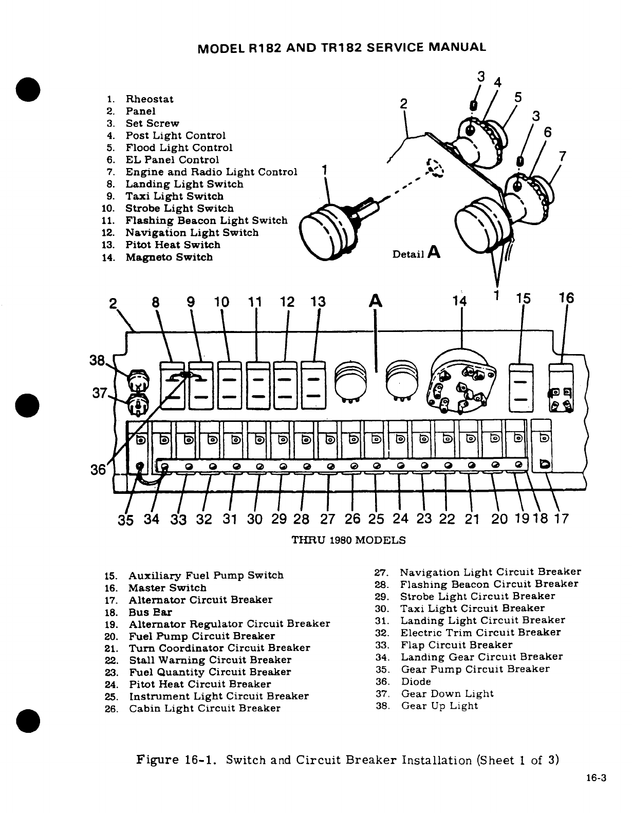
MODEL
R182
AND TR182
SERVICE
MANUAL
34
1.
Rheostat
5
2.
Panel
2
3.
Set
Screw
3
4.
Post
Light Control
6
5.
Flood
Light
Control
6.
EL
Panel
Control
7
7.
Engine
and
Radio
Light
Control
1
8.
Landing
Light
Switch
9.
Taxi
Light
Switch
10.
Strobe
Light
Switch
C
11.
Flashing
Beacon
Light
Switch
12.
Navigation
Light
Switch
13.
Pitot
Heat
Switch
14.
Magneto
Switch
DetailA
~
2
8
9
10
11
12
13
A
14
1
15
16
36
i
o
0 o
o
o
o
r./~
/
X. X'
X'
"
X'X1..\
fH\\
,\.
35
34
33
32
31
30
29
28
27
26 25 24
23
22
21
20
1918
17
THRU
1980
MODELS
15.
Auxiliary
Fuel
Pump
Switch
27.
Navigation
Light
Circuit
Breaker
16.
Master Switch
28.
Flashing
Beacon
Circuit Breaker
17.
Alternator
Circuit
Breaker
29.
Strobe
Light
Circuit
Breaker
18.
Bus
Par
30.
Taxi
Light
Circuit
Breaker
19.
Alternator
Regulator
Circuit
Breaker
31.
Landing
Light
Circuit
Breaker
20.
Fuel
Pump
Circuit
Breaker
32.
Electric Trim
Circuit
Breaker
21.
Turn
Coordinator
Circuit
Breaker
33.
Flap
Circuit
Breaker
22.
Stall
Warning
Circuit
Breaker
34.
Landing
Gear
Circuit
Breaker
23.
Fuel
Quantity
Circuit
Breaker
35.
Gear
Pump
Circuit
Breaker
24.
Pitot
Heat
Circuit
Breaker
36.
Diode
25.
Instrument
Light
Circuit
Breaker
37.
Gear
Down
Light
26.
Cabin
Light Circuit
Breaker
38.
Gear
Up
Light
Figure
16-1.
Switch
and
Circuit
Breaker
Installation
(Sheet
1
of
3)
16-3
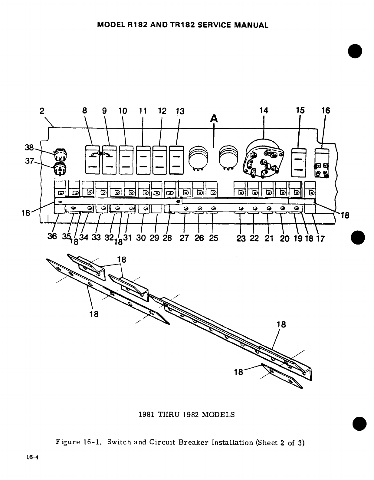
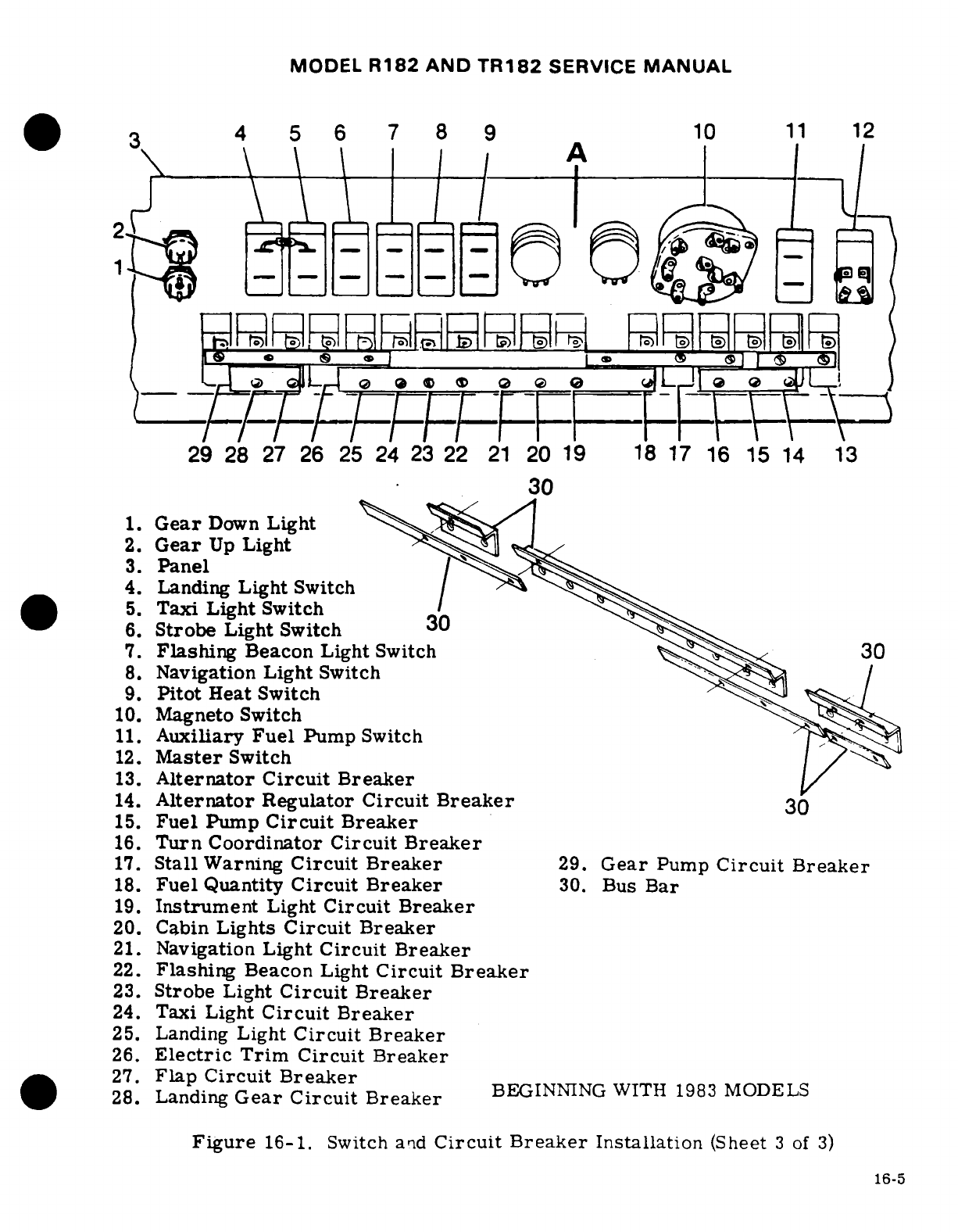
MODEL
R182
AND
TR182
SERVICE
MANUAL
3 4
5 6
7
8 9 10
11
12
2. s
Gear
U
Ligh
3. Panel2i
L,..-L.,,
__.~~
e»
,> c, I
.I
®
el
.
(UJ1
~
,_
29 28
27
26
25
24
23
22
21
20
19
18
17 16
15
14
13
30
1.
Gear
Down
Light
S
2.
Gear
Up
Light
S
3.
Panel
4.
Landing
Light
Switch
5. Taxi
Light
Switch
6.
Strobe
Light
Switch
30i
7.
Flashing
Beacon Light
Switch
8. Navigation
Light
Switch
9.
Pitot
Heat
Switch
10.
Magneto
Switch
11.
Auxiliary
Fuel
Pump
Switch
12.
Master
Switch
13.
Alternator
Circuit
Breaker
14.
Alternator
Regulator
Circuit
Breaker
30
15.
Fuel
Pump
Circuit
Breaker
16.
Turn
Coordinator
Circuit Breaker
17.
Stall
Warning
Circuit
Breaker
29.
Gear
Pump
Circuit
Breaker
18.
Fuel
Quantity
Circuit
Breaker
30.
Bus Bar
19.
Instrument
Light
Circuit
Breaker
20.
Cabin
Lights
Circuit
Breaker
21.
Navigation
Light
Circuit
Breaker
22.
Flashing
Beacon
Light
Circuit
Breaker
23.
Strobe
Light
Circuit
Breaker
24.
Taxi
Light
Circuit
Breaker
25.
Landing
Light
Circuit
Breaker
26.
Electric
Trim Circuit
Breaker
.
*27.
Flap
Circuit
Breaker
28.
Landing
Gear
Circuit
Breaker
BEGINNING
WITH
1983
MODELS
Figure
16-1.
Switch
and
Circuit
Breaker
Installation
(Sheet
3
of
3)
16-5
MODEL
R182
AND
TR182
SERVICE
MANUAL
16-7.
REMOVAL
AND
INSTALLATION.
(See
figure
16-1.)
16-8.
MASTER
SWITCH.
16-9.
DESCRIPTION. The
operation
of
the
battery
and
alternator
systems
is
controlled
by
a
master
switch.
The
switch
is
an
interlocking
split
rocker
with
the
battery
mode
on
the
right-
hand
side
and
the
alternator
mode
on
the
left-hand
side.
This
arrangement
allows
the
battery
to
be
on
the
line
without
the
alternator,
however,
operation
of
the
alternator
without
the
battery
on
the
line
is
not
possible.
The
switch
is
labeled
"BAT"
and
"ALT"
below
the switch
and
is
located
on
the left-hand
side
of
the
switch
panel.
16-10.
AMMETER.
16-11.
DESCRIPTION.
The
ammeter
is
connected
between
the
battery
and the
aircraft
bus.
The
meter indicates
the
amount
of
current
flowing
either
to
or
from
the
battery.
With
a
low
battery
and
the engine
operating
at
cruise
speed
the
ammeter
will
show
the
full
alternator
output
when
all
electrical
equipment
is
off.
When
the
battery
is
fully
charged
and
cruise
RPM
is
maintained
with
all
electrical
equipment
off,
the
ammeter
will
show
a
minimum
charging
rate.
16-12.
BATTERY
POWER
SYSTEM.
16-13.
BATTERY.
16-14.
DESCRIPTION.
A
24-volt
battery
with
an
approximate
12.75
ampere-hour
capacity
is
installed
as
standard equipment,
and
a
15.5
ampere-hour battery
as
optional
equipment.
Thru
1979
models
the
battery
is
mounted
on
the
forward
right
side
of
the
firewall
and
is
equipped
with
non-spill type
filler
caps.
Beginning
with
1980
models
the
battery
is
mounted
in
the
tailcone
on
the
left
hand
side
thru
1981
models
and
on
the
right
hand
side
beginning
with
1982
models.
16-15.
TROUBLE
SHOOTING
--
BATTERY.
TROUBLE
PROBABLE
CAUSE
REMEDY
BATTERY
WILL
NOT
Battery
discharged.
1.
Measure
voltage
at
"BAT"
SUPPLY
POWER
TO BUS
terminal
of
battery
contactor
OR
IS
INCAPABLE
OF
with
master
switch
and
a
suit-
CRANKING
ENGINE.
able
load
such
as
a
taxi
light
turned
on.
Normal
battery
will
indicate
23
volts.
If
voltage
is
low
proceed
to
step
2.
If
voltage
is
normal
proceed
to
step
3.
Battery
faulty.
2.
Check fluid
level
in
cells
and
charge
at
28
volts
for
ap-
proximately
30
minutes
or
until
battery
voltage
rises
to
28
volts.
If
tester
indi-
cates
a
good
battery.
the
malfunction may
be
assumed
to
be
a
discharged
battery.
If
tester
indicates
a
faulty
battery. replace
the
battery.
16-6
MODEL
R182
AND
TR182
SERVICE
MANUAL
.
16-15.
TROUBLE
SHOOTING
--
BATTERY
(Cont.)
TROUBLE
PROBABLE CAUSE
REMEDY
BATTERY
WILL
NOT
Faulty
contactor
or
wiring
3.
Measure
voltage
at
master
SUPPLY
POWER
TO
BUS
between
contactor
and
switch
terminal
(smallest)
on
OR
IS
INCAPABLE OF
master
switch.
contactor
with
master
switch
CRANKING
ENGINE.
(Cont.)
closed.
Normal
indication
is
zero
volts.
If
voltage reads
zero,
proceed
to
step
4.
If
a
voltage
reading
is
obtained.
check
wiring
between
con-
tactor
and
master
switch.
Also
check
master
switch.
Open
coil
on
contactor.
4.
Check
continuity
between
"BAT"
terminal
and
master
switch
terminal
of
contactor.
Normal
indication
is
50-70
ohms.
If
ohmmeter indicates
an
open
coil.
replace
con-
tactor.
If
ohmmeter
indicates
a
good
coil,
proceed
to
step
5.
Faulty
contactor contacts.
5.
Check
voltage
on
"BUS"
side
of
contactor
with
master
switch
closed.
Meter
nor-
mally
indicates
battery
voltage.
If
voltage
is
zero
or
intermit-
tent,
replace
contactor.
If
voltage
is
normal,
proceed
to
step
6.
Faulty
wiring
between
con-
6.
Inspect
wiring
between
tactor
and
bus.
contactor
and
bus.
Repair
or
replace
wiring.
16-16.
REMOVAL
AND
INSTALLATION
OF
THE
BATTERY.
(See
figure
16-2.)
CAUTION
Always
remove
the
ground
cable
first
and
connect
it
last
to
prevent
accidentally
shorting
the
battery
to
the
air-
frame
with tools.
a.
Thru
1978
Models.
1.
To
gain
access
to
the
battery,
remove
the
upper
right
half
of
the
engine
cowl.
2.
Remove the
battery
box
lid
and
disconnect
the
battery
ground
cable.
3.
Disconnect
the
positive
cable
from
the
battery
and
remove the
battery
from
the
aircraft.
4.
To
install
a
battery, reverse
this
procedure.
b.
1979
Models.
1.
To
gain
access
to
the
battery,
remove
upper
right
half
of
engine
cowl.
16-7

MODEL
R182
AND
TR182
SERVICE
MANUAL
2.
Disconnect
battery
ground
cable.
3.
Cut
sta-strap
and remove
terminal
cover,
then
remove
positive
cable.
4.
Remove
battery
mounting
bolts
and
cover.
5.
Disconnect
battery
drain
tube
then
remove
battery.
6.
To
install
battery,
reverse
this
procedure.
c.
Beginning
With
1980
Models.
1.
To
gain
access
to
the
battery
remove
access
door
on
right
hand
side
of
the
tailcone.
2.
Disconnect
battery
ground
strap.
3.
Cut
sta-strap
and remove
terminal
cover,
then
remove
positive
cable.
4.
Remove
battery
mounting
bolts
and
cover.
5.
Disconnect
battery
drain
tube,
then remove
battery.
6.
To
install
battery,
reverse
this
procedure.
16-17.
CLEANING
THE
BATTERY.
For
maximum
efficiency,
the
battery
and
connections
should
be
kept
clean
at
all times.
a.
Remove
the
battery
in
accordance
with
preceding
paragraph.
b.
Tighten
battery
cell
filler
caps
to
prevent
the
cleaning solution
from
entering
the
cells.
c.
Wipe
battery
cable
ends, battery
terminals
and
entire
surface
of
the
battery
with
a
clean
cloth moistened
with
a
solution
of
bicarbonate
of
soda
(baking soda)
and
water.
d.
Rinse
with
clear
water,
wipe
off
excess
water
and allow
battery
to
dry.
e.
Brighten
up
cable
ends
and
battery
terminals
with
emery
cloth
or
a
wire
brush.
f.
Install
the
battery
in
accordance
with
the
preceding
paragraph.
g.
Coat
the
battery
terminals
and
the cable
ends
with
petroleum
jelly.
16-18.
ADDING
ELECTROLYTE
OR
WATER
TO
THE
BATTERY.
A
battery
being
charged
and
discharged with
use
will
decompose
the
water
from the
electrolyte
by
electrolysis.
When
the
water
is
decomposed,
hydrogen
and
oxygen
gases
are
formed
which
escape
into
the
atmosphere
through
the
battery
vent
system.
The
acid
in
the
solution
chemically
combines
with
the
plates
of
the
battery
during
discharge
or
is
suspended
in
the
electrolyte
solution
during
charge.
Unless the
electrolyte
has
been
spilled
from
a
battery,
acid
should
not
be
added
to
the
solution.
The
water
will
decompose
into
gases
and
should
be
replaced
regularly.
Add
distilled
water
as
necessary
to
maintain
the
electrolyte
level
even
with the
horizontal
baffle
plate inside
the
battery.
When
"dry
charged"
batteries
are
put
into
service,
fill
as
directed
with
electrolyte.
However,
as
the
electrolyte level
falls
below
normal
with
use
add
only
distilled
water
to
maintain
the
proper
level.
The
battery
electrolyte
contains
approxi-
mately
25%
sulphuric
acid
by
volume.
Any
change
in
this
volume
will
hamper
the
proper
operation
of
the
battery.
CAUTION
Do
nto
add
any
type
of
"battery
rejuvenator"
to
the
electrolyte.
When
acid
has
been
spilled
from
a
battery,
the
acid
balance
may
be
adjusted
by
following
instructions
published
by
the
Association
of
American
Battery
Manu-
facturers.
16-19.
TESTING
THE
BATTERY.
The
specific
gravity
check method
of
testing
the
battery
is
preferred
when the
condition
of
the
battery
is in a
questionable
state-of-charge.
However.
when the
aircraft
has
been
operated
for
a
period
of
time
with
an
alternator
output voltage
which
is
known
to
be
correct,
the
question
of
battery capability
may
be
answered more
correctly
with
a
load
type
tester.
If
testing
the
battery
is
deemed
necessary,
the
specific
gravity
should
be
checked
first
and
compared
with the
following
chart.
16-8

MODEL
R182
AND
TR182
SERVICE
MANUAL
BATTERY HYDROMETER
READINGS
1.280
Specific
Gravity
100%
Charged
1.250
Specific
Gravity
75%
Charged
1.220
Specific
Gravity
50%
Charged
1.190
Specific
Gravity
25%
Charged
1.160
Specific
Gravity
Practically
Dead
NOTE
All
readings
shown
are
for
an
electrolyte
temperature
of
80
°
Fahrenheit.
For
higher temperatures
the
readings
will
be
slightly
lower.
For
cooler
temperatures
the
read-
ings
will
be
slightly
higher.
Some
hydrometers
have
a
built-in
temperature
compensation
chart
and
a
ther-
mometer.
If
this
type
tester
is
used,
disregard
this
chart.
If
the
specific
gravity reading
indicates
the
battery
is
not
fully
charged
the
battery
should
be
charged
at
approximately
10
amperes
for
30
minutes
or
until
the
battery
voltage
rises
to
28-
volts.
16-20.
CHARGING
THE
BATTERY.
When
the
battery
is
to
be
charged.
the
level
of
electrolyte
should
be
checked
and
adjusted
by
adding
distilled
water
to
cover
the
tops
of
the
internal
battery
plates.
The
battery
cables
and
connections
should
be
clean.
WARNING
When
a
battery
is
charging,
hydrogen
and
oxygen
gases
are
generated.
Accumulation
of
these
gases
can create
a
hazardous explosive
condition.
Always
keep
sparks
and
open
flame away
from
the
battery.
Allow
unrestricted
ventilation
of
the
battery
area
during
charging.
The
main
points
of
consideration
during
a
battery
charge
are
excessive battery
temperature
and
violent
gassing.
Under
a
reasonable
rate
of
charge.
15
amperes
or
less.
the
battery
temperature
should
not
rise
over
120°F.,
nor
should
gassing
be
so
violent
that
acid
is
blown
from the
vents.
16-21.
BATTERY
BOX.
(THRU
1978
MODELS.)
16-22.
DESCRIPTION.
The
battery
is
completely
enclosed
in
an
acid-proof
box.
The
box
has
a
vent
tube
which
protrudes
through
the
bottom
of
the
engine
cowl.
allowing gases
and
spilled
electrolyte
to
escape.
The
battery
box
is
held
in
place
on
a
support
bracket
by
a
channel
assembly
and
two
bolts.
16-23.
REMOVAL
AND
INSTALLATION.
(See
figure
16-2.)
The
battery
box
is
held
in
place
by
a
channel
across
the
top
of
the
box
and
two
bolts.
16-24.
MAINTENANCE.
The
battery
box
should
be
inspected
and
cleaned
periodically.
The
box
and
cover
should
be
cleaned
with
a
strong
solution
of
bicarbonate
of
soda
(baking
soda)
and
water.
When
all
depositis
have
been
removed
from
the
box.
flush
thoroughly
with
clean
water.
16-9
MODEL
R182
AND
TR182
SERVICE
MANUAL
WARNING
Do
not
allow acid
deposits
to
come
in
contact
with
skin
or
clothing.
Serious
acid
burns
may
result
unless
the
affected
area
is
washed immediately
with
soap
and
water.
Clothing
will
be
damaged
upon
contact
with
acid.
Inspect the
cleaned
box
and
cover
for
physical
damage.
A
badly
damaged
box
should
be
replaced.
16-25.
BATTERY
CONTACTOR.
16-26.
DESCRIPTION.
Thru
1979
Models
the
battery
contactor
is
bolted
to
the
battery
box
support
below
the
box.
Beginning
with
1980
Models
the
contactor
is
mounted
fwd
of
the
battery
on
the
main
wheel
well
aft bulkhead.
The
contactor
is
a solenoid
plunger
type, which is
ac-
tuated
by
turning
the
master
switch
on.
When
the
master
switch
is
off,
the
battery
is
discon-
nected
from
the
electrical
system.
A
silicon
diode
is
used
to
eliminate
spiking
of
the
transis-
torized
radio
equipment.
The cathode
(-)
terminal
of
the
diode connects
to
the
battery
termi-
nal of
the
battery contactor.
The
anode
( + )
terminal
of
the
diode
connects
to
the
same
termi-
nal
as
the
master
switch
wire. This
places
the
diode
directly
across
the
contactor
solenoid
coil
so
that
inductive
spikes
originating
in
the
coil
are
clipped
when
the
master
switch
is
opened.
16-27.
REMOVAL
AND
INSTALLATION.
(See
figure
16-2.)
a.
1.
Thru
1978
Models
remove
battery
box
cover
and
disconnect
ground
cable
from
negative
battery terminal.
Pull
cable
free
of
battery
box.
2.
Beginning with
1979
Models,
disconnect
ground
cable
from
negative
battery
terminal.
3.
Remove
sta-strap.
cover,
nut
and
washer
securing
battery
positive
cable
to
battery
contactor, then
remove cable
and
fuse
wire.
4.
If
ground
service
is
installed
remove
sta-straps,
covers,
nuts,
and
washers
securing
bus
bar, jumper
cable
and
wire
to
diode
from
battery contactor
and
ground
service
contactor.
5.
When
ground
service
is
not
installed,
remove
sta-strap,
cover,
nut
and
washer
securing
jumper
cable
and
wire
to
diode.
6.
Remove
nipple,
nut
and
washer
securing
the
master
switch
wire
to
the
battery
contactor.
7.
Remove
the bolt
securing
each
side
of
the
contactor
to
the
battery
box
support
and
remove
contactor.
8.
To
install
the
contactor,
reverse
the
preceding
steps.
b.
1.
Beginning with
1980
Models.
remove
aft
flood
of
baggage
compartment
to
gain
access
to
the
contactor.
2.
Disconnect
ground
strap
from
negative
terminal
of
the
battery.
3.
Cut
sta-straps
and
remove
contactor
cover.
4.
Remove
nuts
and
lockwashers
from
contactor
ports.
5.
Remove and
tag
wires
for
identification
for
reinstallation,
be
sure
to
note
position
of
ground
wire
and
diode.
6.
Remove
bolts
and
washers
securing
contactor
to
bulkhead
and
remove
contactor.
7.
For
installation,
reverse
the
preceding
steps.
16-28.
BATTERY
CONTACTOR CLOSING CIRCUIT.
(See
figure
16-2.)
This
circuit
consists
of
a
5-
amp
fuse,
a
resistor
and
a
diode
mounted
on
the
ground
service
receptacle
bracket.
This
16-10
Revision
1
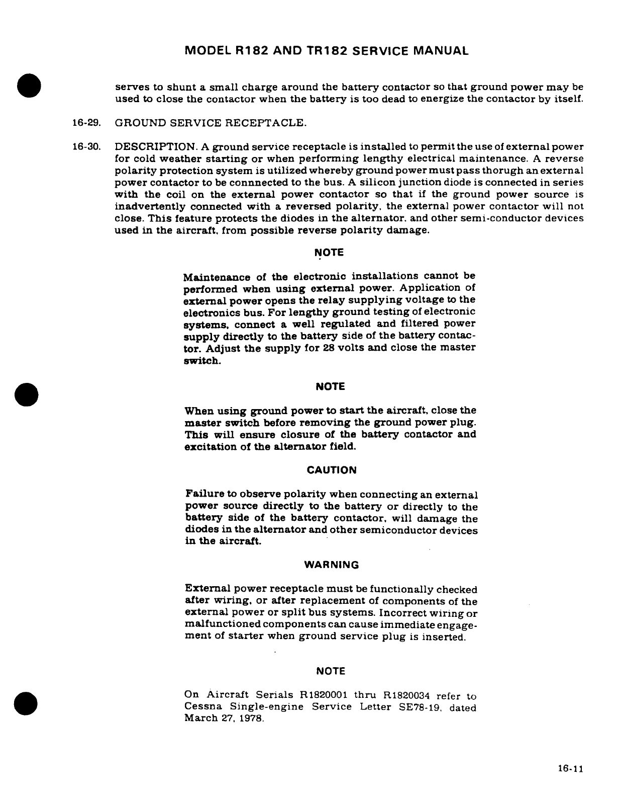
MODEL
R182
AND
TR182
SERVICE
MANUAL
serves
to
shunt
a
small
charge
around
the
battery
contactor
so
that ground
power
may
be
used
to
close
the
contactor
when
the
battery
is
too
dead
to
energize
the
contactor
by
itself.
16-29.
GROUND
SERVICE
RECEPTACLE.
16-30.
DESCRIPTION.
A
ground
service receptacle
is
installed
to
permit
the
use
of
external
power
for
cold
weather
starting
or
when
performing
lengthy
electrical
maintenance.
A
reverse
polarity
protection system
is
utilized
whereby
ground
power
must
pass
thorugh
an
external
power
contactor
to
be
connnected
to
the
bus.
A
silicon
junction
diode
is
connected
in
series
with
the
coil
on
the
external
power
contactor
so
that
if
the
ground
power
source
is
inadvertently
connected
with
a
reversed
polarity,
the
external
power
contactor will
not
close.
This
feature
protects
the
diodes
in
the
alternator,
and
other
semi-conductor
devices
used
in
the
aircraft,
from
possible
reverse
polarity
damage.
NOTE
Maintenance
of
the
electronic
installations
cannot
be
performed
when
using
external
power.
Application
of
external
power
opens the
relay
supplying
voltage
to
the
electronics
bus.
For
lengthy
ground
testing
of
electronic
systems,
connect
a
well
regulated
and
filtered
power
supply
directly
to
the
battery
side
of
the
battery
contac-
tor.
Adjust
the
supply
for
28
volts
and
close
the
master
switch.
NOTE
When
using
ground power
to
start
the
aircraft,
close
the
master
switch
before
removing
the
ground
power
plug.
This
will
ensure
closure
of
the
battery
contactor
and
excitation
of
the
alternator
field.
CAUTION
Failure
to
observe
polarity
when
connecting
an
external
power source
directly
to
the
battery
or
directly
to
the
battery
side
of
the
battery contactor,
will damage
the
diodes
in
the
alternator
and
other
semiconductor
devices
in
the
aircraft.
WARNING
External
power receptacle
must
be
functionally
checked
after
wiring,
or
after
replacement
of
components
of
the
external
power
or
split
bus
systems.
Incorrect
wiring
or
malfunctioned components
can
cause
immediate
engage-
ment
of
starter
when
ground service
plug
is
inserted.
NOTE
On
Aircraft
Serials
R1820001
thru
R1820034
refer
to
Cessna Single-engine
Service
Letter
SE78-19,
dated
March
27,
1978.
16-11
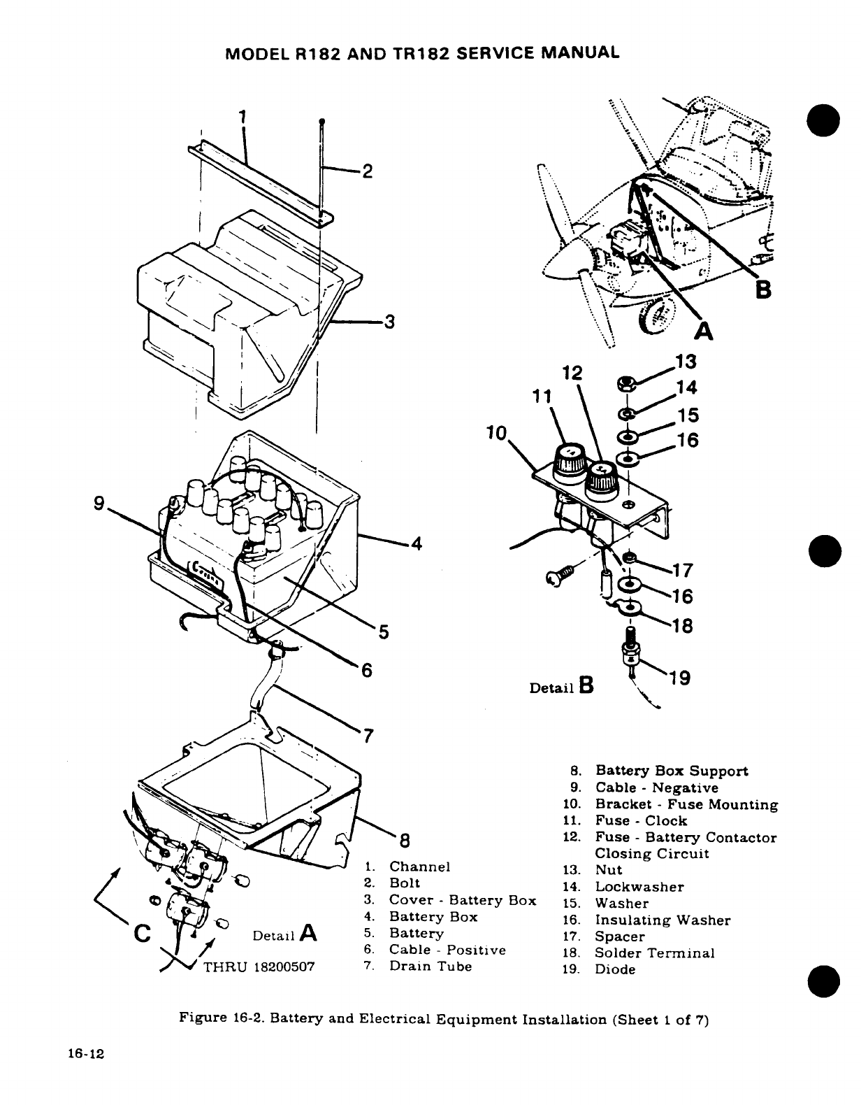
MODEL
R182
AND
TR182
SERVICE
MANUAL
H\,
...
.
«/
/
| \
8.
Battery
Su*
p
port
2~ ~ ~12
\· \ - _
.:
Cb
--
Ne
^
'
ifc^^ ^
s. ^5;~~~ A
^18
.)ClosingCircuitDetail
B
8.
Battery
Box
Support
9.
Cable
-
Negative
10.
Bracket
-
Fuse
Mounting
11.
Fuse
-
Clock
4.
Battery
Box
16.
Insulating
Washer
C
Detail
5.
Battery
17.
Spacer
6.
Cable
-
Positive
18.
Solder
Terminal
/
THRU
18200507
7.
Drain
Tube
19.
Diode
Figure
16-2.
Battery
and
Electrical Equipment
Installation
(Sheet
1
of
7)
16-12
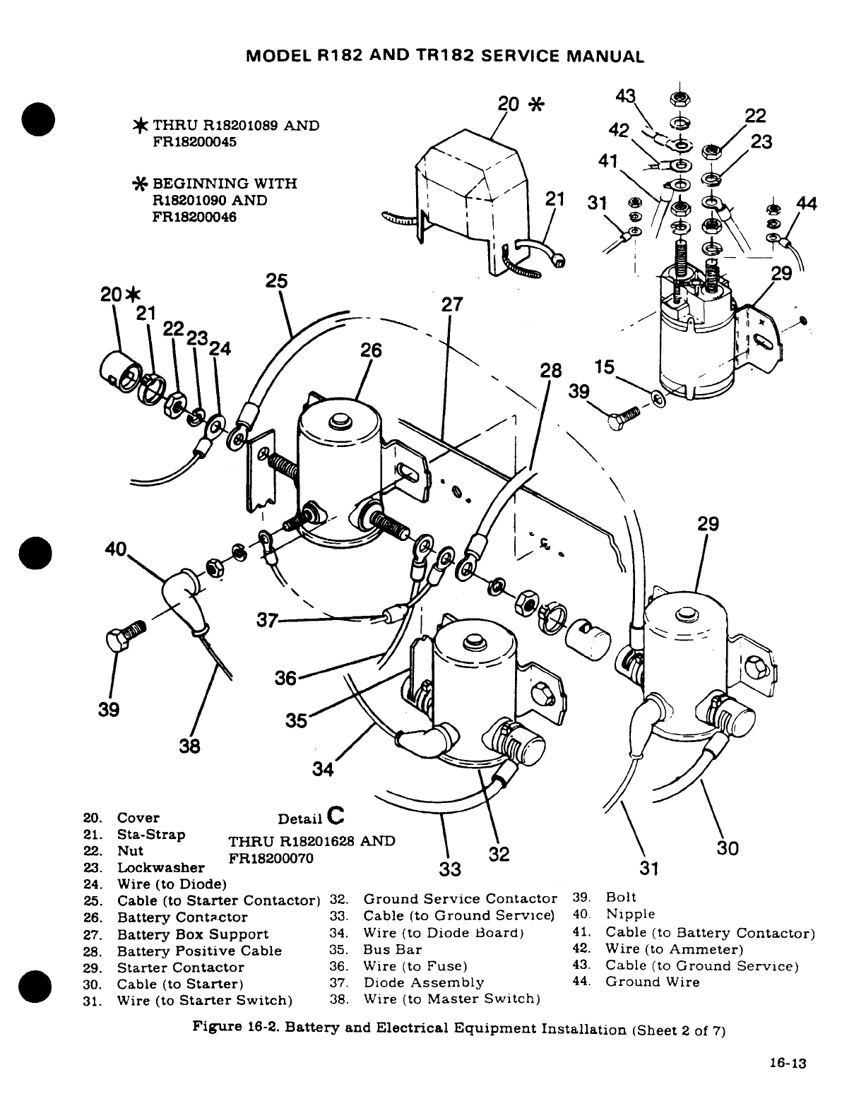
MODEL
R182
AND
TR182
SERVICE
MANUAL
20
43
*
THRU
R18201089
AND
42
22
FR18200045
2
*'
BEGINNING
WITH
\
^
R18201090
AND
-
21
3
44
FR18200046
25
29
20*
25
27
21
~-- A27
24
26
29
O
40.
*
39
39
3,,.5
34
20.
Cover
Detail
C
21.
Sta-Strap
THRU
R18201628
AND
\ \
22.
Nut
22.
Nut
,
FR18200070
32
30
23.
Lockwasher
33
31
24.
Wire
(to
Diode)
25.
Cable
(to
Starter
Contactor)
32.
Ground
Service
Contactor
39.
Bolt
26.
Battery
Cont.ctor
33.
Cable
(to
Ground
Service)
40.
Nipple
27.
Battery
Box
Support
34.
Wire
(to
Diode Board)
41.
Cable
(to
Battery
Contactor)
28.
Battery
Positive
Cable
35.
Bus
Bar
42.
Wire
(to
Ammeter)
29.
Starter
Contactor
36.
Wire
(to
Fuse)
43.
Cable
(to
Ground
Service)
30.
Cable
(to
Starter)
37.
Diode
Assembly
44.
Ground
Wire
31.
Wire (to
Starter
Switch)
38.
Wire
(to
Master
Switch)
Figure
16-2.
Battery
and
Electrical Equipment
Installation
(Sheet
2
of
7)
16-13
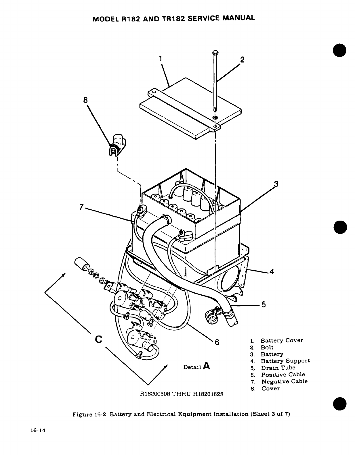
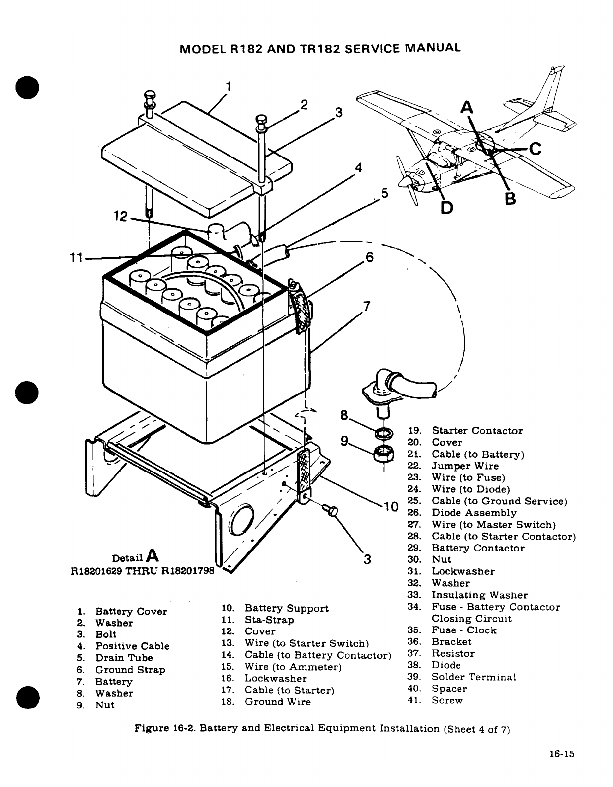
MODEL
R182
AND
TR182
SERVICE
MANUAL
1
2
3
12
f002
C'abl
(to
19.
Starter
Contactor
-R18216
THRU
R180
97
3 20.
Cover
1. Battery Cover
10.
Batte
Sup21.
Cable
(to
Battery)
82.
Wa^sher
11.
Sta-St
22
Jumper
Wire
4 Posie
23.
Wire
(to
Fuse)
8
G nd/
W.
24.
Wire (to
Diode)
26.
Diode
Assembly
L9 (^ / /
^ \,
27.
Wire
(to
Master Switch)
28.
Cable
(to
Starter
Contactor)
29.
Battery
Contactor
Detail
A 3
30.
Nut
R18201629
THRU
R18201798
31.
Lockwasher
32.
Washer
33.Insulating
Washer
10.
Battery
Support
34.
Fuse
-
Battery
Contactor
.
Battery
Cover11.
Sta-Strap
Closing
Circuit
3.
Bolt
| / Ax Ax/ . A 2.
WCover
(
35Fuse-Clock
4.
Positive
Cable
13.
Wire
(to
Starter
Switch)
36.
Bracket
5.
DrainTube
14.
Cable
(to
Battery
Contactor)
37.
Resistor
6 Ground
St15.
Wire
(to
Ammeter)
38.Diode
67
Batry
ud t a
16.
Lockwasher
39.
Solder
Terminal
S.*~ Washer
17.
Cable
(to
Starter)
40.Spacer
93
Bout
18.
Ground
Wire
41.
Screw
Figure
16-2.
Battery
and
Electrical
Equipment
Installation
(Sheet
4
of
7)
16-15
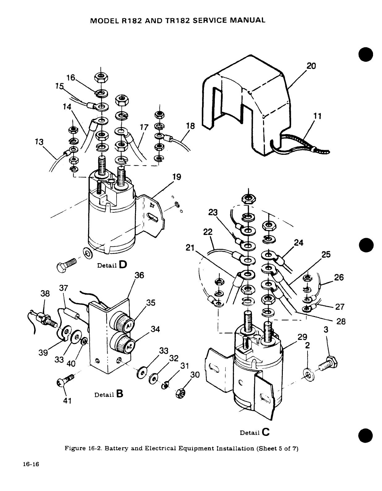
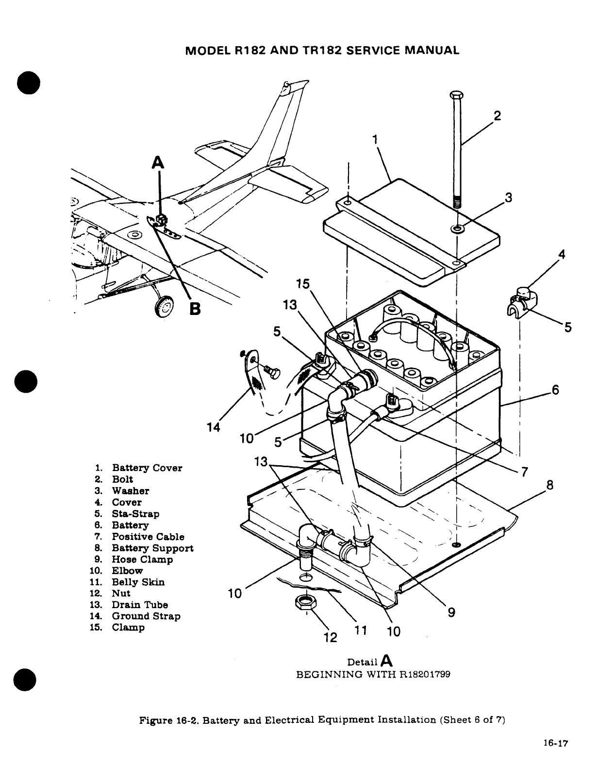
MODEL
R182 AND
TR182
SERVICE
MANUAL
2
~~~~~15~
A
-
-~5
14 105
5
1.
Battery
Cover
7
2.
Bolt
6
3.
Washer
H
\1
.
-
4.
Cover
5.
Sta-Strap
8.
Battery
C
7.
Positive
Cable
8.
Battery
Support
9.
Hose
Clamp
10.
Elbow
11.
Belly
Skin
12.
Nut
10
B
13.
Drain
Tube
14.
Ground
Strap
\
\
15.
Clamp1
Detail
A
BEGINNING
WITH
R18201799
Figure
16-2.
Battery
and
Electrical Equipment
Installation
(Sheet
6
of
7)
16-17
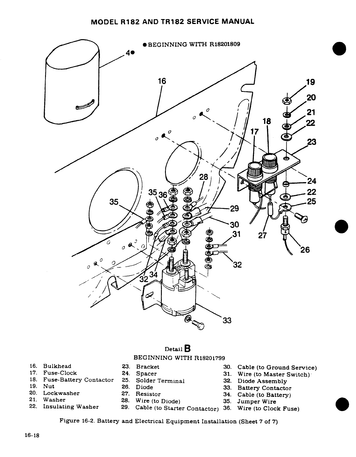
MODEL
R182
AND
TR182
SERVICE
MANUAL
4
*BEGINNING
WITH
R18201809
16
I 19
^ /^^
20
BEGNNI1G8 W22
/^--
/ ,.
X
~ I23
°/~~~
~~~
2- S, 3224
3
3
32
16.
Bulkhead
23.
Bracket
30.
Cable
(to
Ground
Service)
17.
Fuse-Clock
24.
Spacer
31.
Wire (to
Master
Switch)
18.
Fuse-Battery
Contactor
25.
Solder
Terminal
32.
Diode
Assembly
0
-
31
22
19.
Nut
26.
Diode
33.
Battery
Contactor
4
j
21.
Washer
28.
Wire
(to
Diode)
35.
Jumper
Wire
itch)
22.
Insulating
Washer
29.
Cable
(to
Starter
Contactor)
36.
Wire
(to
Clock
Fuse)
0
Figure
16-2.
Battery
and
Electrical
Equipment
Installation
(Sheet
7
of
7)
16-18
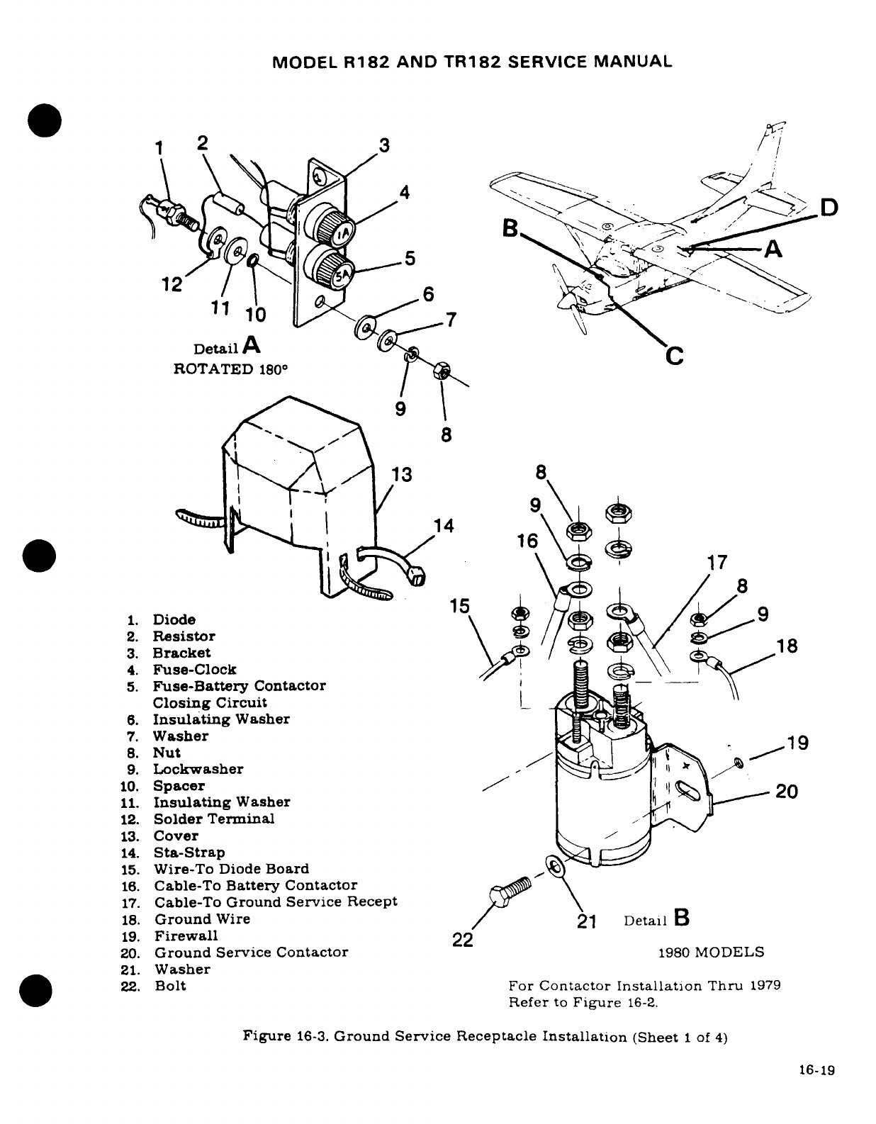
MODEL
R182
AND
TR182
SERVICE
MANUAL
1
2
3
/
12 1•
DetailA
A
ROTATED
180°
9
8
8
'
12
13
8
16
17
8
1.
Diode
15
2.
Resistor
\
3.
Bracket
/
18
4.
Fuse-Clock
5.
Fuse-Battery
Contactor
Closing
Circuit_
6.
Insulating
Washer
7.
Washer
8.
Nut
19
9.
Lockwasher
10.
Spacer
11.
Insulating
Washer
12.
Solder
Terminal
.
13.
Cover
14.
Sta-Strap
15.
Wire-To
Diode
Board
16.
Cable-To
Battery
Contactor
17.
Cable-To
Ground
Service
Recept
18.
Ground
Wire
21
DetailB
19.
Firewall
22
20.
Ground
Service
Contactor
1980
MODELS
21.
Washer
22.
Bolt
For
Contactor
Installation
Thru
1979
Refer
to
Figure
16-2.
Figure
16-3.
Ground
Service
Receptacle
Installation
(Sheet
1
of
4)
16-19
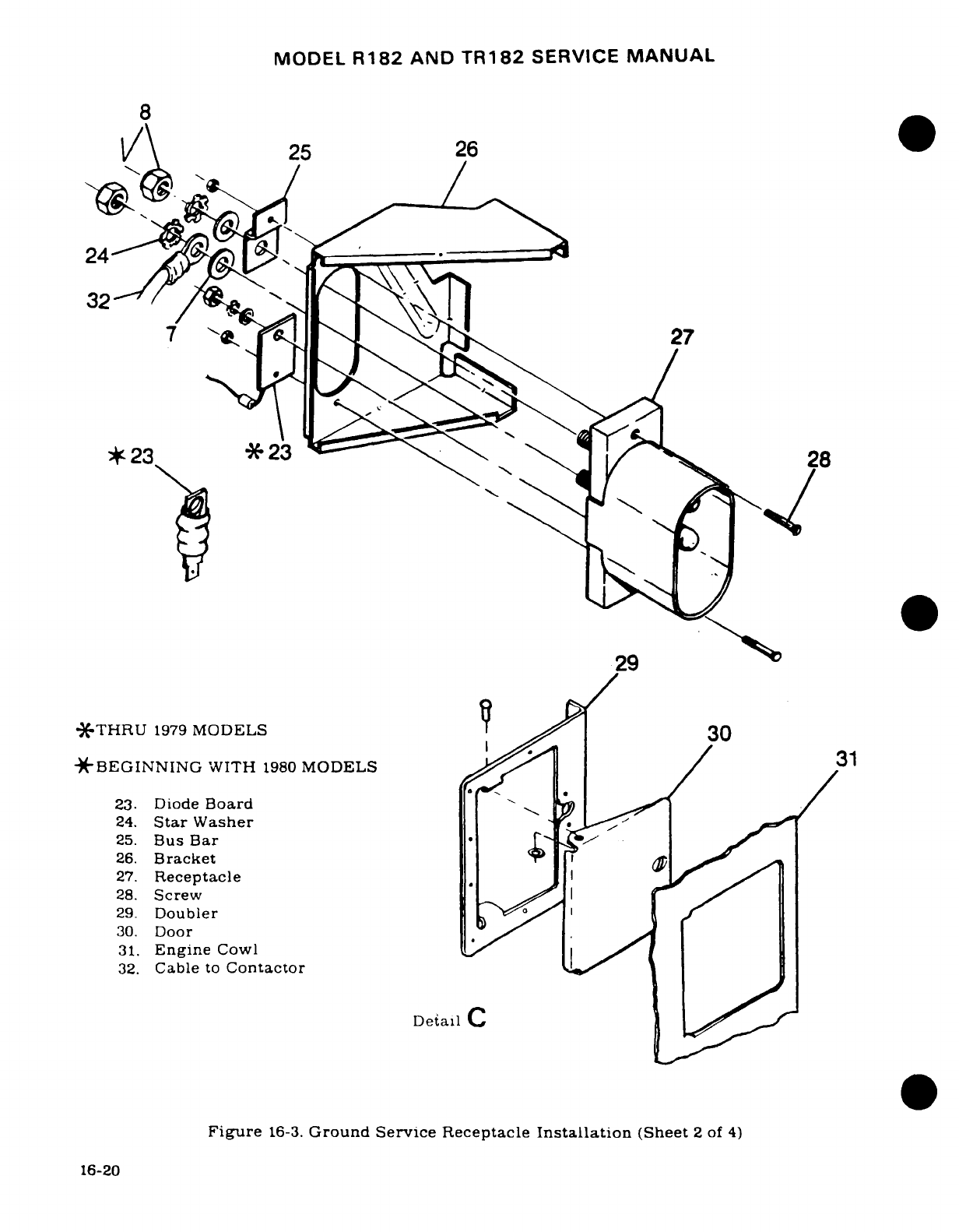
MODEL
R182
AND
TR182
SERVICE
MANUAL
8
A\
25
26
7 ~~27
23
-X-23
29
*THRU
1979
MODELS
3
*'BEGINNING
WITH
1980
MODELS
/3
23.
Diode
Board
24.
Star
Washer
25.
Bus
Bar
.
26.
Bracket
27.
Receptacle
28.
Screw
29.
Doubler
30.
Door
31.
Engine
Cowl
32.
Cable
to
Contactor
Detail
C
Figure
16-3.
Ground
Service
Receptacle
Installation
(Sheet
2
of
4)
16-20
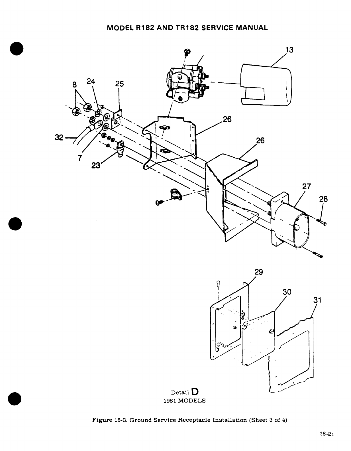
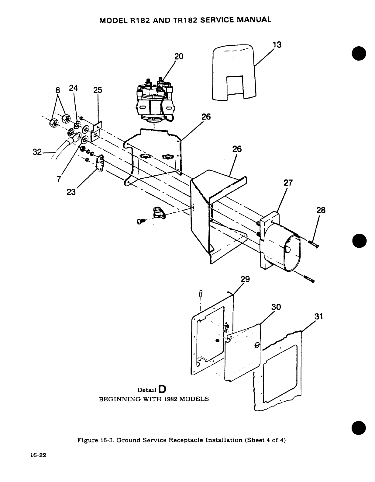
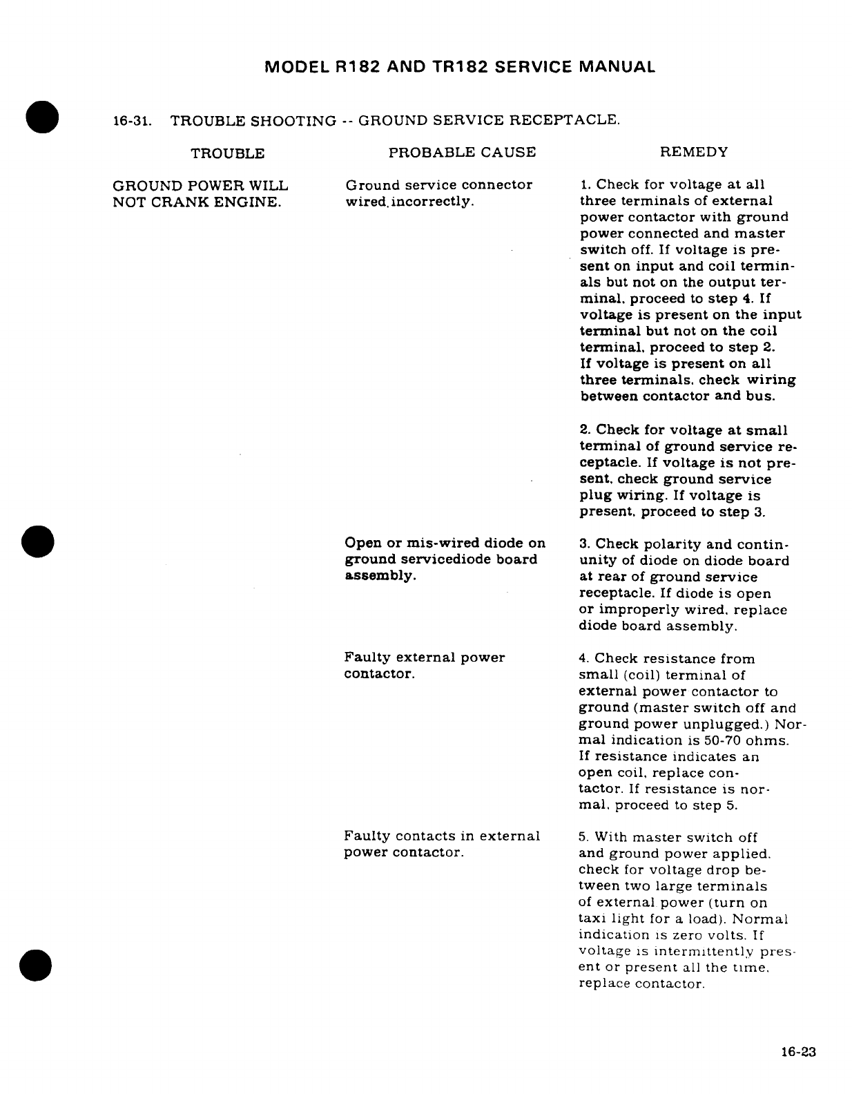
MODEL
R182
AND
TR182
SERVICE
MANUAL
16-31.
TROUBLE
SHOOTING
--
GROUND
SERVICE
RECEPTACLE.
TROUBLE
PROBABLE
CAUSE
REMEDY
GROUND
POWER
WILL
Ground
service connector
1.
Check
for
voltage
at
all
NOT
CRANK
ENGINE.
wired.
incorrectly.
three
terminals
of
external
power
contactor
with
ground
power
connected
and
master
switch
off.
If
voltage
is
pre-
sent
on
input
and
coil
termin-
als
but
not
on
the
output ter-
minal.
proceed
to
step
4.
If
voltage
is
present
on
the
input
terminal
but
not
on
the
coil
terminal,
proceed
to
step
2.
If
voltage
is
present
on
all
three terminals.
check
wiring
between
contactor
and
bus.
2.
Check
for
voltage
at
small
terminal
of
ground
service
re-
ceptacle.
If
voltage
is
not
pre-
sent,
check
ground
service
plug
wiring.
If
voltage
is
present.
proceed
to
step
3.
Open
or
mis-wired
diode
on
3.
Check
polarity
and
contin-
ground
servicediode
board unity
of
diode
on
diode
board
assembly.
at
rear
of
ground
service
receptacle.
If
diode
is
open
or
improperly
wired,
replace
diode
board
assembly.
Faulty
external
power
4.
Check
resistance
from
contactor.
small
(coil)
terminal
of
external
power
contactor
to
ground
(master
switch
off
and
ground
power
unplugged.)
Nor-
mal
indication
is
50-70
ohms.
If
resistance
indicates
an
open
coil,
replace
con-
tactor.
If
resistance
is
nor-
mal,
proceed
to
step
5.
Faulty contacts
in
external
5.
With
master
switch
off
power
contactor.
and
ground
power
applied.
check
for
voltage
drop
be-
tween
two
large
terminals
of
external
power
(turn
on
taxi light
for
a
load).
Normal
indication
is
zero
volts.
If
voltage
is
intermittently
pres-
ent
or
present
all
the
time.
replace contactor.
16-23
MODEL
R182
AND
TR182
SERVICE
MANUAL
16-32.
REMOVAL
AND
INSTALLATION.
(See
figure
16-3.)
a.
Thru
1978
Models
open
the
battery
box
and
disconnect
the
ground
cable
from
the
negative
terminal
of
the
battery
and
pull
the
cable
free
of
the
box.
Beginning
with
1979
Models,
remove
negative
ground
strap.
b.
Remove the
nuts,
washers,
ground
strap,
bus
bar
and
diode
board
from the
studs
of
the
receptacle
and
remove
battery
cable.
c.
Remove
the
screws
and
nuts
holding
the
receptacle,
ground
strap
will
then
be
free
from
bracket.
d.
To
install
a
ground
service
receptacle,
reverse
this
procedure.
16-33.
ALTERNATOR
POWER
SYSTEM.
16-34.
DESCRIPTION.
The
alternator
system
consists
of
an
engine
driven
alternator,
a
voltage
regulator/
alternator
control
unit
and
a
circuit
breaker located
on
the
instrument
panel.
The
system
is
controlled
by
the
left
hand
portion
of
the
split
rocker,
master
switch
labeled
ALT.
Thru
1978
Models
an
over-voltage sensor
switch
and
red
warning
light,
labeled
HIGH
VOLTAGE
are
incorporated
to
protect
the
system.
Beginning
with
1979
Models
an
over-
voltage
sensor,
an
under-voltage
sensor
and
a
red
warning
light,
labeled
LOW
VOLTAGE
are
incorporated
to
protect
the
system.
The
aircraft
battery
supplies
the
source
of
power
for
excitation
of
the
alternator.
16-35.
ALTERNATOR.
16-36.
DESCRIPTION.
The
60-ampere
alternator
used
on
the
aircraft
is
three-phase, delta-
connected
with
integral
silicon
diode
rectifiers.
The
alternator
is
rated
at
28
volts
at
60
amperes
continous
output.
Beginning
with
1981
models,
a
28-volt 95-ampere
alternator
is
offered
as
optional
equipment
NOTE
Thru
R18201798,
a
2201074-1
balance
weight
is
installed
on
tailcone bulkhead
station
230.187
when
the
95-ampere
alternator
is
installed.
16-37.
ALTERNATOR
REVERSE
VOLTAGE
DAMAGE.
The
alternator
is
very
susceptible
to
reverse
polarity
damage
due
to
the
very
low
resistance
of
the
output
windings
and
the
low
resistance
of
the
silicon
diodes
in
the
output.
If
a
high
current
source,
such
as
a
battery
or
heavy
duty
ground
power
cart
is
attached
to
the
aircraft
with
the
polarity
inadvertently
reversed,
the
current through
the
alternator
will
flow
almost
without
limit
and
the
alternator
will
be
immediately
damaged.
16-24
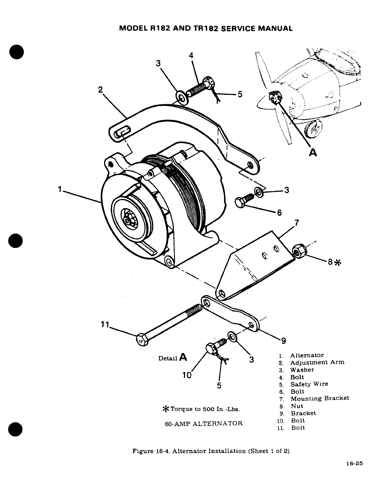
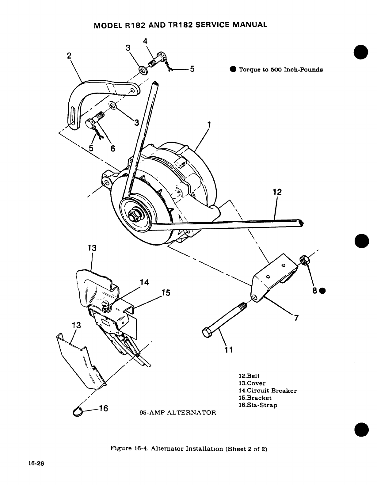
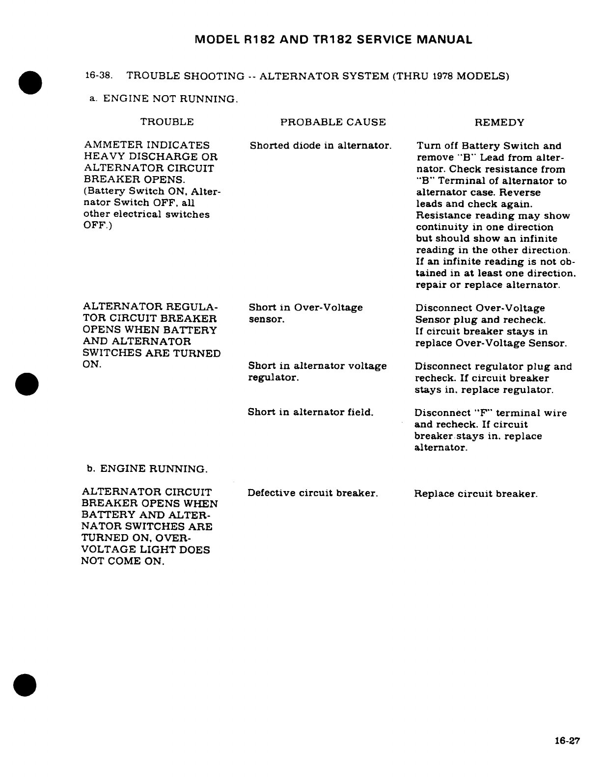
MODEL
R182
AND
TR182
SERVICE
MANUAL
16-38.
TROUBLE
SHOOTING
--
ALTERNATOR
SYSTEM
(THRU
1978
MODELS)
a.
ENGINE
NOT
RUNNING.
TROUBLE
PROBABLE
CAUSE REMEDY
AMMETER
INDICATES
Shorted
diode
in
alternator.
Turn
off
Battery
Switch
and
HEAVY
DISCHARGE
OR
remove
"B"
Lead
from
alter-
ALTERNATOR
CIRCUIT
nator.
Check
resistance
from
BREAKER
OPENS.
"B"
Terminal
of
alternator
to
(Battery Switch
ON,
Alter-
alternator
case. Reverse
nator
Switch
OFF,
all leads
and
check
again.
other
electrical
switches
Resistance
reading
may
show
OFF.)
continuity
in
one
direction
but
should
show
an
infinite
reading
in
the
other
direction.
If
an
infinite
reading
is
not
ob-
tained
in
at
least
one
direction.
repair
or
replace
alternator.
ALTERNATOR
REGULA-
Short
in
Over-Voltage
Disconnect Over-Voltage
TOR
CIRCUIT
BREAKER
sensor.
Sensor
plug
and
recheck.
OPENS
WHEN
BATTERY
If
circuit
breaker
stays
in
AND
ALTERNATOR
replace
Over-Voltage
Sensor.
SWITCHES
ARE
TURNED
ON.
Short
in
alternator
voltage
Disconnect
regulator
plug
and
regulator.
recheck.
If
circuit
breaker
stays
in.
replace
regulator.
Short
in
alternator
field.
Disconnect
"F"
terminal
wire
and
recheck.
If
circuit
breaker
stays
in.
replace
alternator.
b.
ENGINE
RUNNING.
ALTERNATOR
CIRCUIT
Defective
circuit
breaker.
Replace
circuit
breaker.
BREAKER OPENS
WHEN
BATTERY
AND
ALTER-
NATOR
SWITCHES
ARE
TURNED
ON,
OVER-
VOLTAGE
LIGHT
DOES
NOT
COME
ON.
16-27
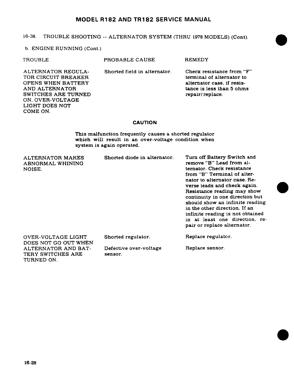
MODEL
R182
AND
TR182
SERVICE
MANUAL
16-38.
TROUBLE
SHOOTING
--
ALTERNATOR
SYSTEM
(THRU
1978
MODELS)
(Cont).
b.
ENGINE
RUNNING (Cont.)
TROUBLE
PROBABLE
CAUSE
REMEDY
ALTERNATOR
REGULA-
Shorted
field
in
alternator.
Check
resistance
from
"F"
TOR
CIRCUIT
BREAKER
terminal
of
alternator
to
OPENS
WHEN
BATTERY
alternator
case.
if
resis-
AND
ALTERNATOR
tance
is
less
than
5
ohms
SWITCHES ARE
TURNED
repair/replace.
ON.
OVER-VOLTAGE
LIGHT
DOES
NOT
COME
ON.
CAUTION
This
malfunction
frequently
causes
a
shorted
regulator
which
will
result
in
an
over-voltage
condition
when
system
is
again
operated.
ALTERNATOR
MAKES
Shorted
diode
in
alternator.
Turn
off
Battery Switch
and
ABNORMAL
WHINING
remove
"B"
Lead
from
al-
NOISE.
ternator.
Check
resistance
from
"B"
Terminal
of
alter-
nator
to
alternator
case.
Re-
verse
leads
and
check
again.
Resistance
reading
may
show
continuity
in
one
direction
but
should show
an
infinite
reading
in
the
other direction.
If
an
infinite
reading
is
not
obtained
in
at
least
one
direction.
re-
pair
or
replace
alternator.
OVER-VOLTAGE
LIGHT
Shorted
regulator.
Replace
regulator.
DOES
NOT
GO
OUT
WHEN
ALTERNATOR
AND
BAT-
Defective
over-voltage
Replace
sensor.
TERY
SWITCHES
ARE
sensor.
TURNED
ON.
16-28
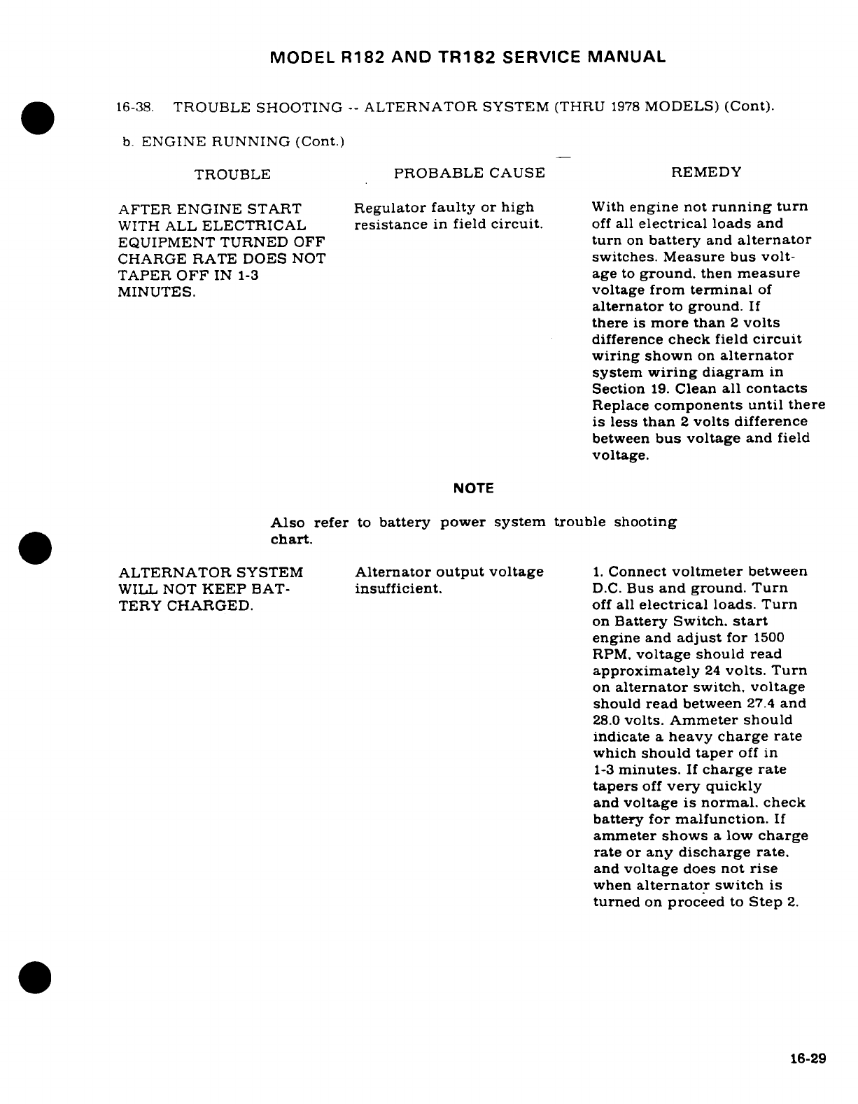
MODEL
R182
AND
TR182
SERVICE
MANUAL
16-38.
TROUBLE SHOOTING
--
ALTERNATOR
SYSTEM
(THRU
1978
MODELS)
(Cont).
b.
ENGINE
RUNNING (Cont.)
TROUBLE
PROBABLE
CAUSE
REMEDY
AFTER
ENGINE
START
Regulator
faulty
or
high
With
engine
not
running
turn
WITH
ALL
ELECTRICAL
resistance
in
field
circuit.
off
all
electrical
loads
and
EQUIPMENT TURNED
OFF
turn
on
battery
and
alternator
CHARGE
RATE
DOES
NOT
switches. Measure
bus
volt-
TAPER
OFF
IN
1-3
age
to
ground.
then
measure
MINUTES.
voltage
from
terminal
of
alternator
to
ground.
If
there
is
more
than
2
volts
difference
check
field
circuit
wiring shown
on
alternator
system
wiring
diagram
in
Section
19.
Clean
all
contacts
Replace
components
until
there
is
less
than
2
volts
difference
between
bus voltage
and
field
voltage.
NOTE
Also refer
to
battery
power
system
trouble
shooting
chart.
ALTERNATOR
SYSTEM
Alternator
output
voltage
1.
Connect
voltmeter
between
WILL
NOT
KEEP
BAT-
insufficient.
D.C.
Bus
and
ground.
Turn
TERY
CHARGED.
off
all
electrical
loads.
Turn
on
Battery Switch.
start
engine
and
adjust
for
1500
RPM.
voltage
should
read
approximately
24
volts.
Turn
on
alternator
switch,
voltage
should
read
between
27.4
and
28.0
volts. Ammeter
should
indicate
a
heavy
charge
rate
which
should
taper
off
in
1-3
minutes.
If
charge rate
tapers
off
very
quickly
and
voltage
is
normal.
check
battery for
malfunction.
If
ammeter
shows
a
low
charge
rate
or
any
discharge
rate.
and
voltage
does
not
rise
when
alternator
switch
is
turned
on
proceed
to
Step
2.
16-29
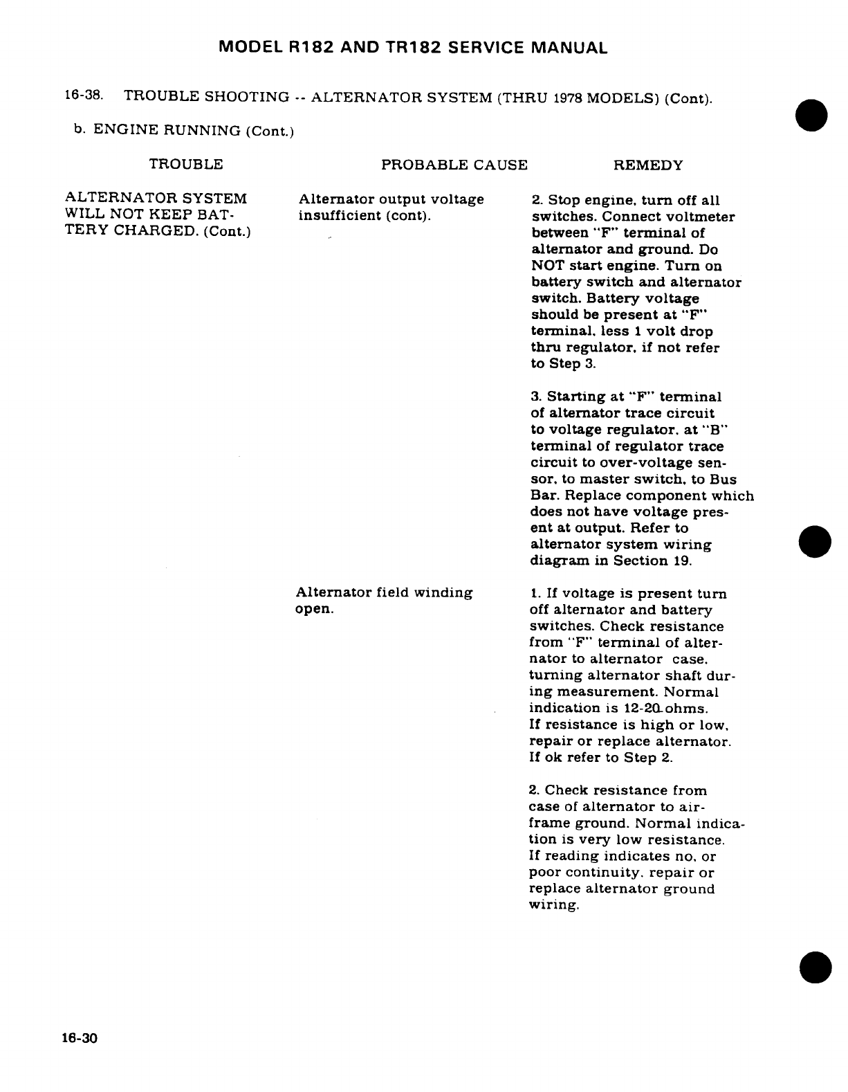
MODEL
R182
AND
TR182
SERVICE
MANUAL
16-38.
TROUBLE
SHOOTING
--
ALTERNATOR
SYSTEM
(THRU
1978
MODELS)
(Cont).
b.
ENGINE
RUNNING (Cont.)
TROUBLE
PROBABLE
CAUSE
REMEDY
ALTERNATOR
SYSTEM
Alternator
output
voltage
2.
Stop
engine,
turn
off
all
WILL
NOT
KEEP
BAT-
insufficient
(cont).
switches. Connect
voltmeter
TERY CHARGED.
(Cont.)
between
"F"
terminal
of
alternator
and
ground.
Do
NOT
start
engine.
Turn
on
battery
switch
and
alternator
switch.
Battery
voltage
should
be
present
at
"F"
terminal,
less
1
volt
drop
thru
regulator,
if
not
refer
to Step
3.
3.
Starting at
"F"
terminal
of
alternator trace
circuit
to
voltage
regulator,
at
"B"
terminal
of
regulator
trace
circuit
to
over-voltage
sen-
sor.
to
master
switch,
to
Bus
Bar.
Replace
component
which
does
not
have
voltage
pres-
ent
at
output.
Refer
to
alternator system wiring
diagram
in
Section
19.
Alternator
field
winding
1.
If
voltage
is
present
turn
open.
off
alternator
and
battery
switches.
Check
resistance
from
"F"
terminal
of
alter-
nator
to
alternator
case.
turning
alternator
shaft
dur-
ing
measurement.
Normal
indication
is
12-20-ohms.
If
resistance
is
high
or
low,
repair
or
replace
alternator.
If
ok
refer
to
Step
2.
2.
Check
resistance
from
case
of
alternator
to
air-
frame
ground.
Normal
indica-
tion
is
very
low
resistance.
If
reading
indicates
no.
or
poor
continuity.
repair
or
replace
alternator
ground
wiring.
16-30
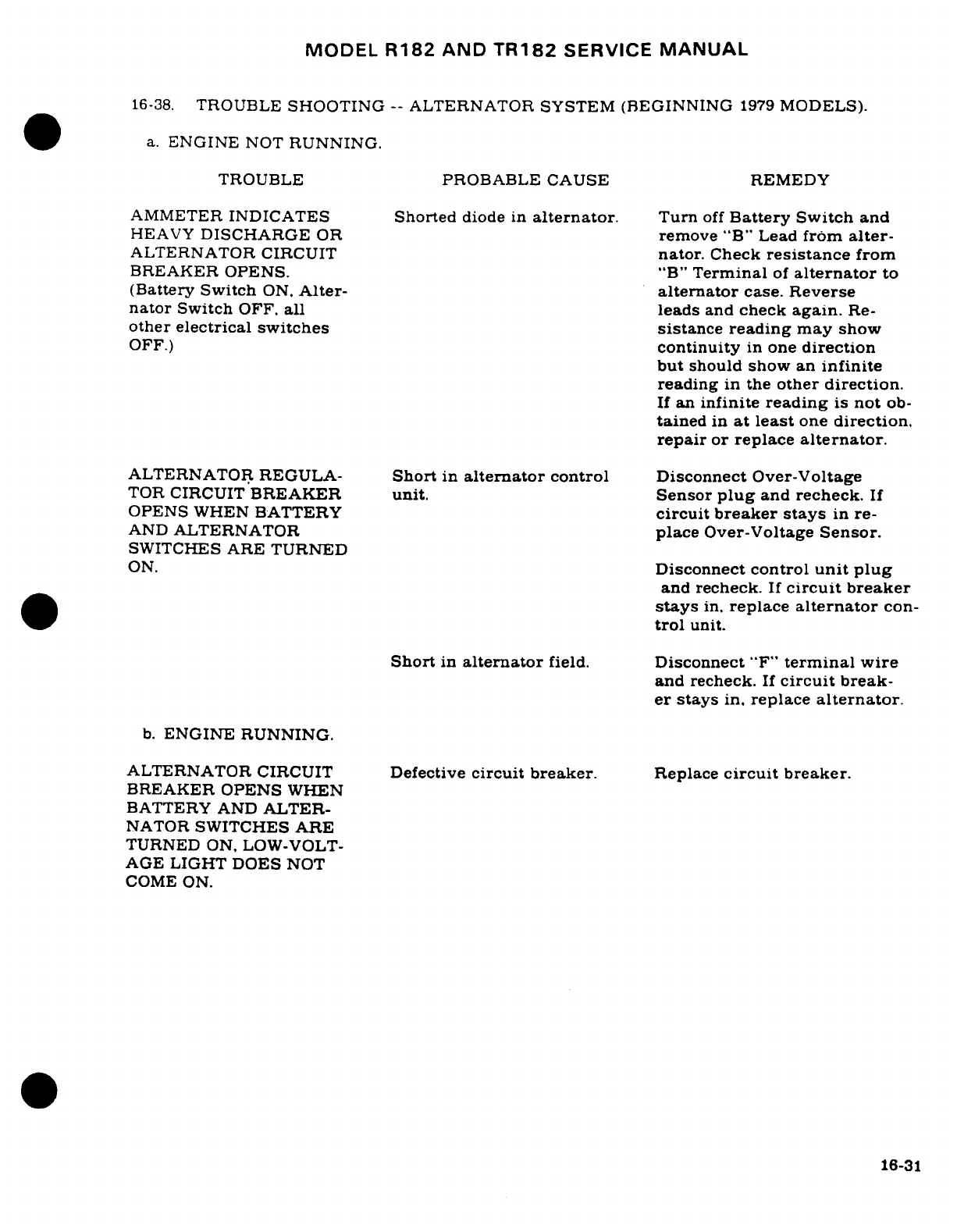
MODEL
R182
AND
TR182
SERVICE
MANUAL
16-38.
TROUBLE
SHOOTING
--
ALTERNATOR SYSTEM
(BEGINNING
1979
MODELS).
a.
ENGINE
NOT
RUNNING.
TROUBLE
PROBABLE CAUSE
REMEDY
AMMETER
INDICATES
Shorted
diode in
alternator.
Turn
off
Battery
Switch
and
HEAVY
DISCHARGE
OR
remove
"B"
Lead
from
alter-
ALTERNATOR CIRCUIT
nator.
Check
resistance
from
BREAKER OPENS.
"B"
Terminal
of
alternator
to
(Battery
Switch
ON.
Alter-
alternator
case.
Reverse
nator
Switch
OFF,
all leads
and
check
again.
Re-
other electrical
switches
sistance
reading
may
show
OFF.)
continuity
in
one
direction
but
should
show
an
infinite
reading
in
the
other
direction.
If
an
infinite
reading
is
not
ob-
tained
in
at
least
one
direction.
repair
or
replace
alternator.
ALTERNATOR
REGULA-
Short
in
alternator
control
Disconnect Over-Voltage
TOR
CIRCUIT
BREAKER
unit.
Sensor
plug
and
recheck.
If
OPENS
WHEN
BATTERY
circuit
breaker
stays
in
re-
AND
ALTERNATOR
place
Over-Voltage
Sensor.
SWITCHES ARE
TURNED
ON.
Disconnect
control
unit
plug
and
recheck.
If
circuit
breaker
stays
in.
replace
alternator
con-
trol
unit.
Short
in
alternator
field.
Disconnect
"F"
terminal
wire
and
recheck.
If
circuit
break-
er
stays
in,
replace
alternator.
b.
ENGINE
RUNNING.
ALTERNATOR
CIRCUIT
Defective
circuit
breaker.
Replace
circuit
breaker.
BREAKER
OPENS
WHEN
BATTERY AND
ALTER-
NATOR
SWITCHES
ARE
TURNED
ON,
LOW-VOLT-
AGE
LIGHT DOES
NOT
COME
ON.
16-31
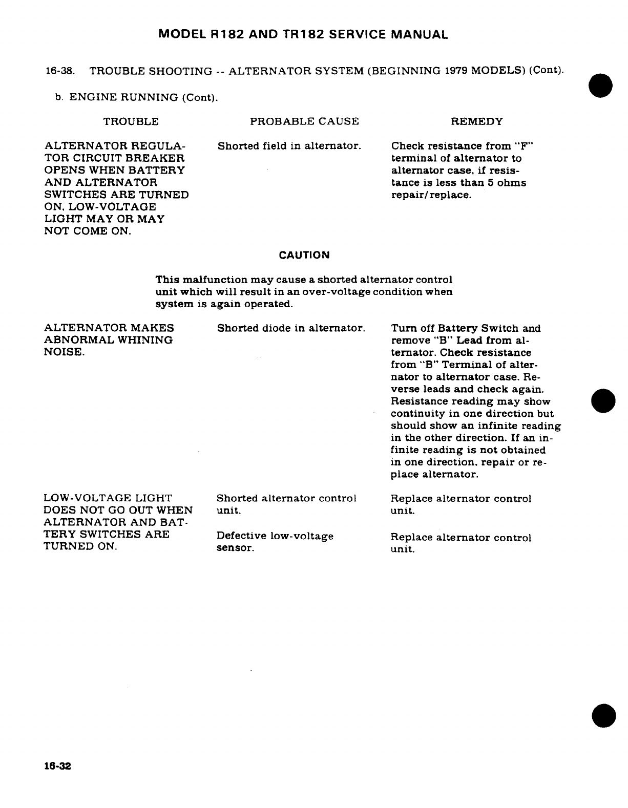
MODEL
R182
AND
TR182
SERVICE
MANUAL
16-38.
TROUBLE
SHOOTING
--
ALTERNATOR
SYSTEM (BEGINNING
1979
MODELS)
(Cont).
b.
ENGINE
RUNNING
(Cont).
TROUBLE
PROBABLE CAUSE
REMEDY
ALTERNATOR
REGULA-
Shorted
field
in
alternator.
Check
resistance
from
"F"
TOR CIRCUIT
BREAKER
terminal
of
alternator
to
OPENS
WHEN
BATTERY
alternator
case,
if
resis-
AND ALTERNATOR
tance
is
less
than
5
ohms
SWITCHES
ARE
TURNED
repair/replace.
ON. LOW-VOLTAGE
LIGHT
MAY
OR
MAY
NOT
COME
ON.
CAUTION
This
malfunction
may
cause
a
shorted
alternator
control
unit
which
will
result
in
an
over-voltage
condition
when
system
is
again
operated.
ALTERNATOR
MAKES
Shorted
diode
in
alternator.
Turn
off
Battery
Switch
and
ABNORMAL WHINING
remove
"B"
Lead
from
al-
NOISE.
ternator.
Check
resistance
from
"B"
Terminal
of
alter-
nator
to
alternator
case.
Re-
verse
leads
and
check
again.
Resistance
reading
may
show
continuity
in
one
direction
but
should
show
an
infinite
reading
in
the
other
direction.
If
an
in-
finite
reading
is
not
obtained
in
one
direction.
repair
or
re-
place
alternator.
LOW-VOLTAGE
LIGHT
Shorted
alternator
control
Replace
alternator
control
DOES
NOT
GO
OUT
WHEN
unit.
unit.
ALTERNATOR
AND
BAT-
TERY
SWITCHES
ARE
Defective
low-voltage
Replace
alternator
control
TURNED
ON.
sensor.
unit.
16-32
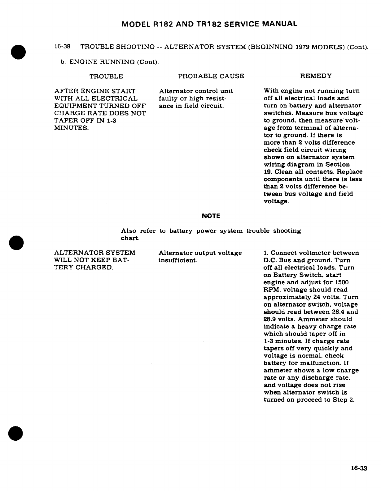
MODEL
R182
AND
TR182
SERVICE
MANUAL
16-38.
TROUBLE
SHOOTING
--
ALTERNATOR
SYSTEM
(BEGINNING
1979
MODELS)
(Cont).
b.
ENGINE
RUNNING
(Cont).
TROUBLE
PROBABLE
CAUSE
REMEDY
AFTER ENGINE
START
Alternator
control
unit
With
engine
not
running
turn
WITH
ALL
ELECTRICAL
faulty
or
high
resist-
off
all
electrical
loads and
EQUIPMENT
TURNED OFF
ance
in
field
circuit. turn
on
battery
and
alternator
CHARGE
RATE
DOES
NOT
switches. Measure
bus
voltage
TAPER
OFF
IN
1-3
to
ground.
then
measure
volt-
MINUTES.
age
from
terminal
of
alterna-
tor
to
ground.
If
there
is
more
than
2
volts
difference
check
field
circuit
wiring
shown
on
alternator
system
wiring
diagram
in
Section
19.
Clean
all
contacts.
Replace
components
until there
is
less
than
2
volts
difference
be-
tween
bus
voltage
and
field
voltage.
NOTE
Also
refer
to
battery
power
system trouble
shooting
chart.
ALTERNATOR SYSTEM
Alternator
output
voltage
1.
Connect
voltmeter
between
WILL
NOT
KEEP
BAT-
insufficient.
D.C.
Bus
and
ground. Turn
TERY
CHARGED.
off
all
electrical
loads.
Turn
on
Battery
Switch,
start
engine
and
adjust
for
1500
RPM,
voltage should read
approximately
24
volts.
Turn
on
alternator
switch,
voltage
should
read
between
28.4
and
28.9
volts. Ammeter
should
indicate
a
heavy
charge
rate
which
should
taper
off
in
1-3
minutes.
If
charge rate
tapers
off
very quickly
and
voltage
is
normal,
check
battery
for
malfunction.
If
ammeter
shows
a
low
charge
rate
or
any
discharge
rate,
and
voltage
does
not
rise
when
alternator
switch
is
turned
on
proceed
to
Step
2.
16-33
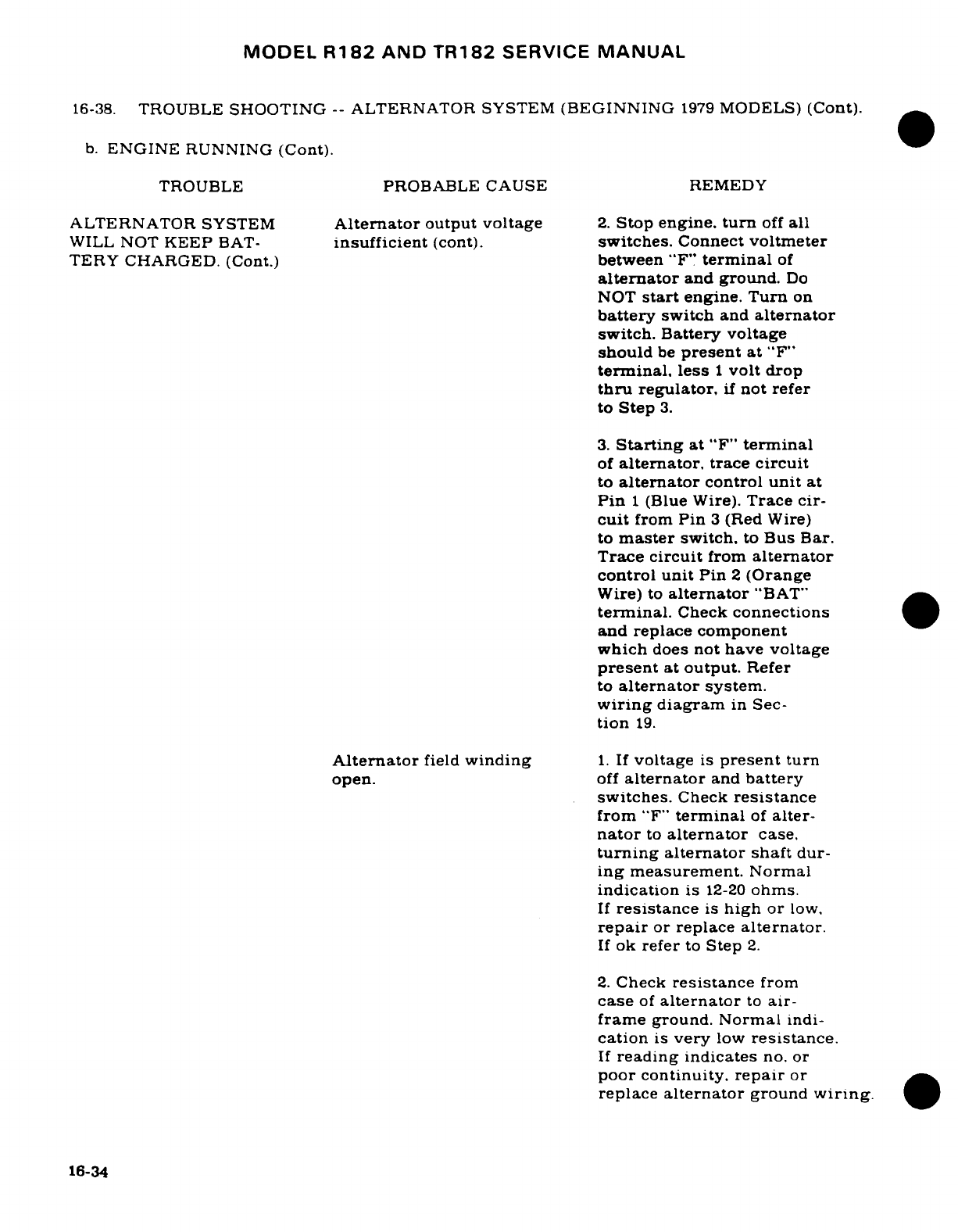
MODEL
R182
AND
TR182
SERVICE
MANUAL
16-38.
TROUBLE
SHOOTING
--
ALTERNATOR
SYSTEM
(BEGINNING
1979
MODELS)
(Cont).
b.
ENGINE
RUNNING
(Cont).
TROUBLE
PROBABLE CAUSE
REMEDY
ALTERNATOR
SYSTEM
Alternator
output voltage
2.
Stop
engine.
turn
off
all
WILL
NOT
KEEP
BAT-
insufficient
(cont).
switches.
Connect
voltmeter
TERY
CHARGED.
(Cont.)
between "F"
terminal
of
alternator
and ground.
Do
NOT
start
engine.
Turn
on
battery
switch
and
alternator
switch.
Battery voltage
should
be
present
at
"F"
terminal,
less
1
volt
drop
thru
regulator,
if
not
refer
to
Step
3.
3.
Starting
at
"F"
terminal
of
alternator,
trace
circuit
to
alternator
control
unit
at
Pin
1
(Blue
Wire).
Trace
cir-
cuit
from
Pin
3
(Red
Wire)
to
master
switch,
to
Bus
Bar.
Trace
circuit
from
alternator
control
unit
Pin
2
(Orange
Wire)
to
alternator
"BAT"
terminal.
Check
connections
and replace
component
which
does
not
have voltage
present
at
output.
Refer
to
alternator
system.
wiring
diagram
in Sec-
tion
19.
Alternator
field
winding
1.
If
voltage
is
present
turn
open.
off
alternator
and
battery
switches.
Check
resistance
from
"F"
terminal
of
alter-
nator
to
alternator
case.
turning
alternator
shaft
dur-
ing
measurement.
Normal
indication
is
12-20
ohms.
If
resistance
is
high
or
low,
repair
or
replace
alternator.
If
ok
refer
to
Step
2.
2.
Check
resistance
from
case
of
alternator
to
air-
frame
ground.
Normal
indi-
cation
is
very
low
resistance.
If
reading
indicates
no.
or
poor
continuity.
repair
or
replace
alternator
ground
wiring.
16-34
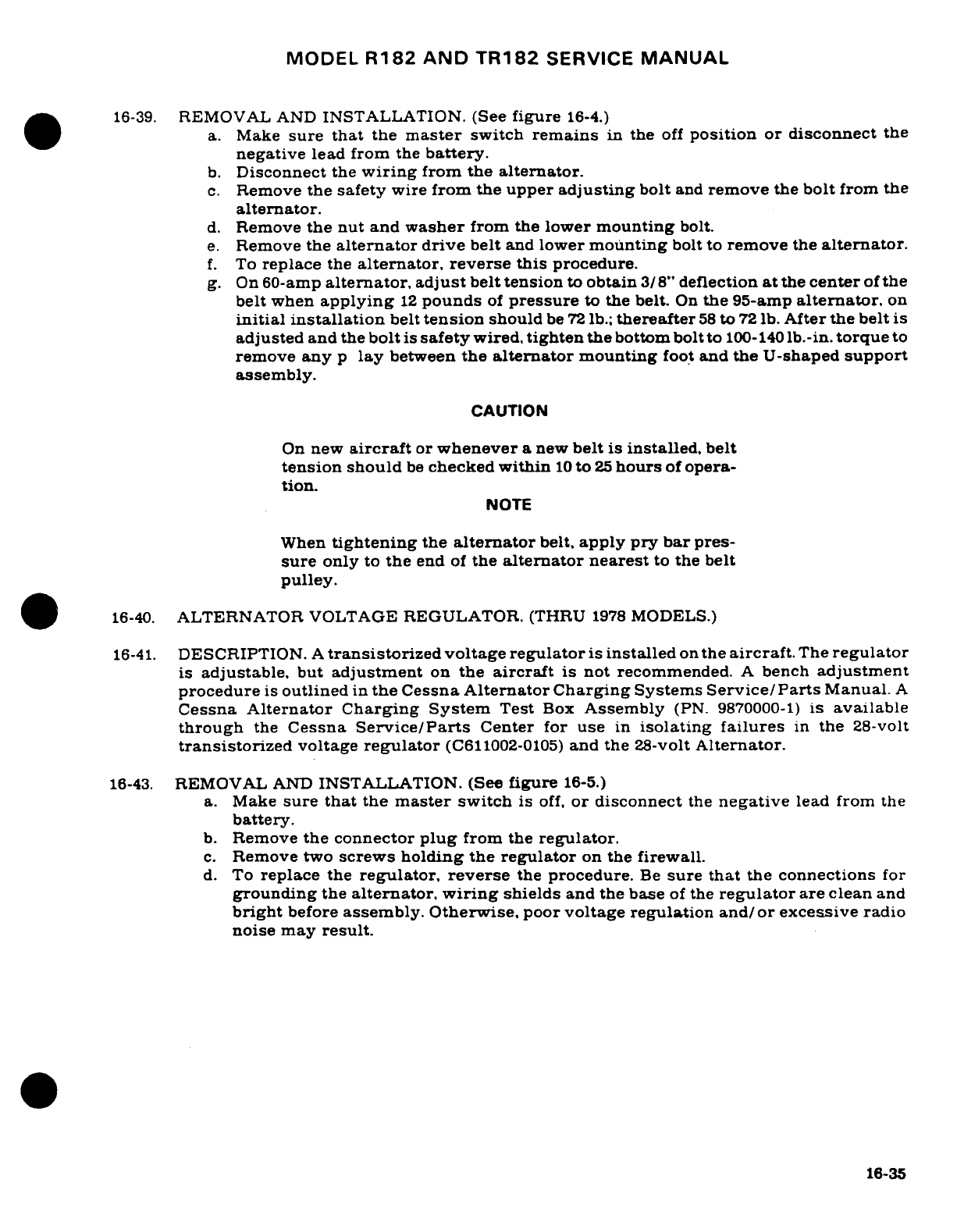
MODEL
R182
AND TR182
SERVICE
MANUAL
16-39.
REMOVAL
AND
INSTALLATION.
(See
figure
16-4.)
a.
Make
sure
that
the
master
switch
remains
in
the
off
position
or disconnect
the
negative
lead from
the
battery.
b.
Disconnect
the
wiring
from
the
alternator.
c.
Remove
the
safety
wire
from
the
upper
adjusting
bolt
and
remove
the
bolt
from
the
alternator.
d.
Remove
the
nut and
washer
from the
lower
mounting
bolt.
e.
Remove the
alternator
drive
belt
and
lower
mounting
bolt
to
remove
the
alternator.
f.
To
replace
the
alternator, reverse
this
procedure.
g.
On
60-amp
alternator,
adjust
belt
tension
to
obtain
3/8"
deflection
at
the
center
of
the
belt
when
applying
12
pounds
of
pressure
to
the
belt.
On
the
95-amp
alternator,
on
initial
installation
belt
tension
should
be
72
lb.;
thereafter
58
to
72
lb.
After
the
belt
is
adjusted
and the
bolt
is
safety
wired,
tighten
the
bottom
bolt to
100-140
lb.-in.
torque
to
remove
any
p
lay
between
the
alternator
mounting
foot
and
the
U-shaped
support
assembly.
CAUTION
On
new
aircraft
or
whenever
a
new
belt
is
installed,
belt
tension
should
be
checked
within
10
to
25
hours
of
opera-
tion.
NOTE
When
tightening
the
alternator
belt,
apply
pry
bar
pres-
sure
only
to
the
end
of
the
alternator
nearest
to
the
belt
pulley.
16-40.
ALTERNATOR
VOLTAGE
REGULATOR.
(THRU
1978
MODELS.)
16-41.
DESCRIPTION.
A
transistorized
voltage regulator
is
installed
on
the
aircraft.
The
regulator
is
adjustable,
but
adjustment
on
the
aircraft
is
not
recommended.
A
bench
adjustment
procedure
is
outlined
in
the Cessna
Alternator Charging
Systems
Service/Parts
Manual.
A
Cessna
Alternator Charging System
Test
Box
Assembly
(PN.
9870000-1)
is
available
through
the
Cessna
Service/Parts
Center
for
use
in
isolating
failures
in
the
28-volt
transistorized
voltage
regulator
(C611002-0105)
and
the
28-volt
Alternator.
16-43.
REMOVAL
AND
INSTALLATION.
(See
figure
16-5.)
a.
Make
sure
that
the
master
switch
is
off,
or
disconnect
the
negative
lead from
the
battery.
b.
Remove
the
connector
plug
from
the
regulator.
c.
Remove
two
screws
holding the
regulator
on
the
firewall.
d.
To
replace
the
regulator,
reverse
the
procedure.
Be
sure
that
the
connections
for
grounding
the
alternator,
wiring
shields
and
the
base
of
the
regulator
are clean
and
bright
before
assembly.
Otherwise,
poor
voltage
regulation
and/or
excessive
radio
noise
may
result.
16-35
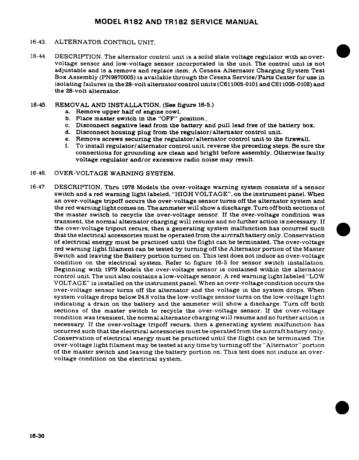
MODEL
R182
AND
TR182
SERVICE
MANUAL
16-43.
ALTERNATOR
CONTROL
UNIT.
16-44.
DESCRIPTION. The
alternator
control
unit
is
a
solid
state
voltage
regulator
with
an
over-
voltage
sensor
and low-voltage
sensor
incorporated
in
the
unit.
The
control
unit
is
not
adjustable
and
is a
remove
and
replace
item.
A
Cessna
Alternator
Charging
System
Test
Box
Assembly
(PN9870005)
is
available
through
the
Cessna
Service/Parts
Center
for
use
in
isolating
failures
in
the
28-volt
alternator
control
units
(C611005-0101
and
C611005-0102)
and
the
28-volt
alternator.
16-45.
REMOVAL
AND
INSTALLATION. (See
figure
16-5.)
a.
Remove
upper
half
of
engine
cowl.
b.
Place
master
switch
in
the
"OFF"
position..
c.
Disconnect
negative
lead from
the
battery
and
pull
lead
free
of
the
battery
box.
d.
Disconnect
housing
plug
from
the
regulator/alternator
control
unit.
e.
Remove
screws
securing
the
regulator/alternator
control
unit
to
the
firewall.
f.
To
install
regulator/alternator
control
unit,
reverse
the preceding
steps.
Be
sure
the
connections
for
grounding
are
clean
and
bright
before
assembly. Otherwise
faulty
voltage
regulator
and/or
excessive
radio
noise
may
result.
16-46.
OVER-VOLTAGE WARNING SYSTEM.
16-47.
DESCRIPTION.
Thru
1978
Models
the
over-voltage
warning
system
consists
of
a
sensor
switch
and
a red
warning
light
labeled,
"HIGH
VOLTAGE",
on
the
instrument
panel.
When
an
over-voltage
tripoff
occurs
the
over-voltage
sensor
turns
off
the
alternator
system and
the
red
warning
light
comes
on. The
ammeter
will show
a
discharge.
Turn
off
both
sections
of
the
master
switch
to
recycle
the
over-voltage
sensor.
If
the over-voltage condition
was
transient,
the
normal
alternator
charging
will resume
and
no
further
action
is
necessary.
If
the
over-voltage
tripout
recurs,
then
a
generating system
malfunction has
occurred
such
that
the
electrical
accessories
must
be
operated
from the
aircraft
battery
only
Conservation
of
electrical
energy
must
be
practiced
until
the
flight
can
be
terminated.
The
over-voltage
red
warning
light
filament
can
be
tested
by
turning
off
the
Alternator
portion
of
the
Master
Switch
and
leaving
the
Battery portion
turned
on.
This
test
does
not induce
an
over-voltage
condition
on
the
electrical
system.
Refer
to
figure
16-5
for
sensor
switch
installation.
Beginning
with
1979
Models
the
over-voltage
sensor
is
contained
within the
alternator
control unit.
The
unit
also
contains
a
low-voltage
sensor.
A
red
warning
light
labeled
"LOW
VOLTAGE"
is
installed
on
the
instrument
panel.
When
an
over-voltage condition
occurs
the
over-voltage
sensor
turns
off
the
alternator
and
the
voltage
in
the
system
drops.
When
system
voltage
drops
below
24.8
volts
the
low-voltage
sensor
turns
on
the
low-voltage
light
indicating
a
drain
on
the
battery
and
the
ammeter
will show
a
discharge. Turn
off
both
sections
of
the
master
switch
to
recycle the
over-voltage
sensor.
If
the
over-voltage
condition
was
transient,
the
normal
alternator
charging
will
resume
and
no
further
action
is
necessary.
If
the
over-voltage tripoff
recurs,
then
a
generating
system
malfunction
has
occurred
such
that
the
electrical
accessories
must
be
operated
from
the
aircraft
battery
only.
Conservation
of
electrical
energy must
be
practiced
until
the flight
can
be
terminated.
The
over-voltage
light
filament
may
be
tested
at
any
time
by
turning
off
the
"Alternator"
portion
of
the
master
switch
and
leaving
the
battery
portion
on.
This
test
does
not
induce
an
over-
voltage
condition
on
the
electrical system.
18-36
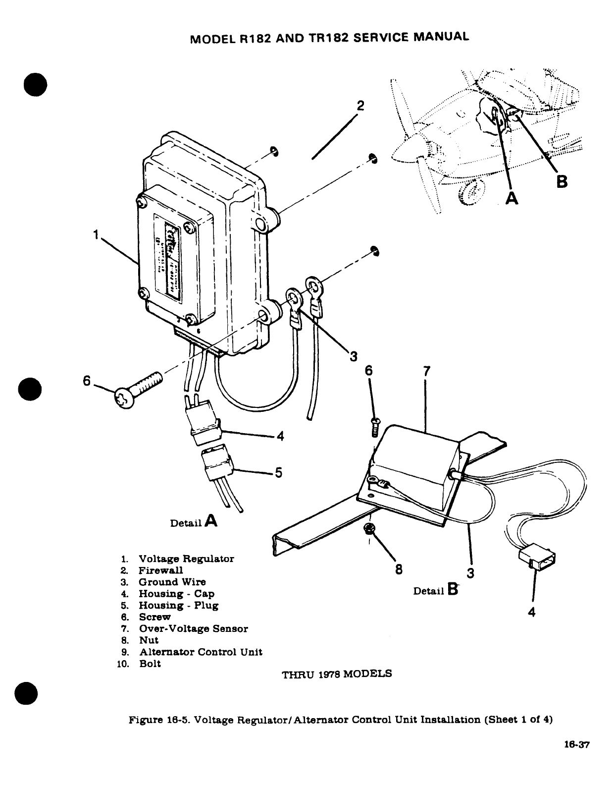
MODEL
R182
AND
TR182
SERVICE
MANUAL
1 -
Voltage
Regulator.
.
32 Ground Wire
I
4.
Housing
-
Cap
Detail
1 --.-.
"
..
8.
Screw
4
*..
'::^^
Y-.
·
1
.
Over-Voltage
Sengulator
.
NutFirewall
3.
Ground
Wire
;
.
16-37
4.
Housing
-
Cap
Detail
B
5.
Housing
-
Plug
6.
Screw
4
7.
Over-Voltage
Sensor
8.
Nut
9.
Alternator
Control
Unit
10.
Bolt
THRU
1978
MODELS
Figure
16-5.
Voltage
Regulator/
Alternator
Control
Unit
Installation
(Sheet
1
of
4)
16-37
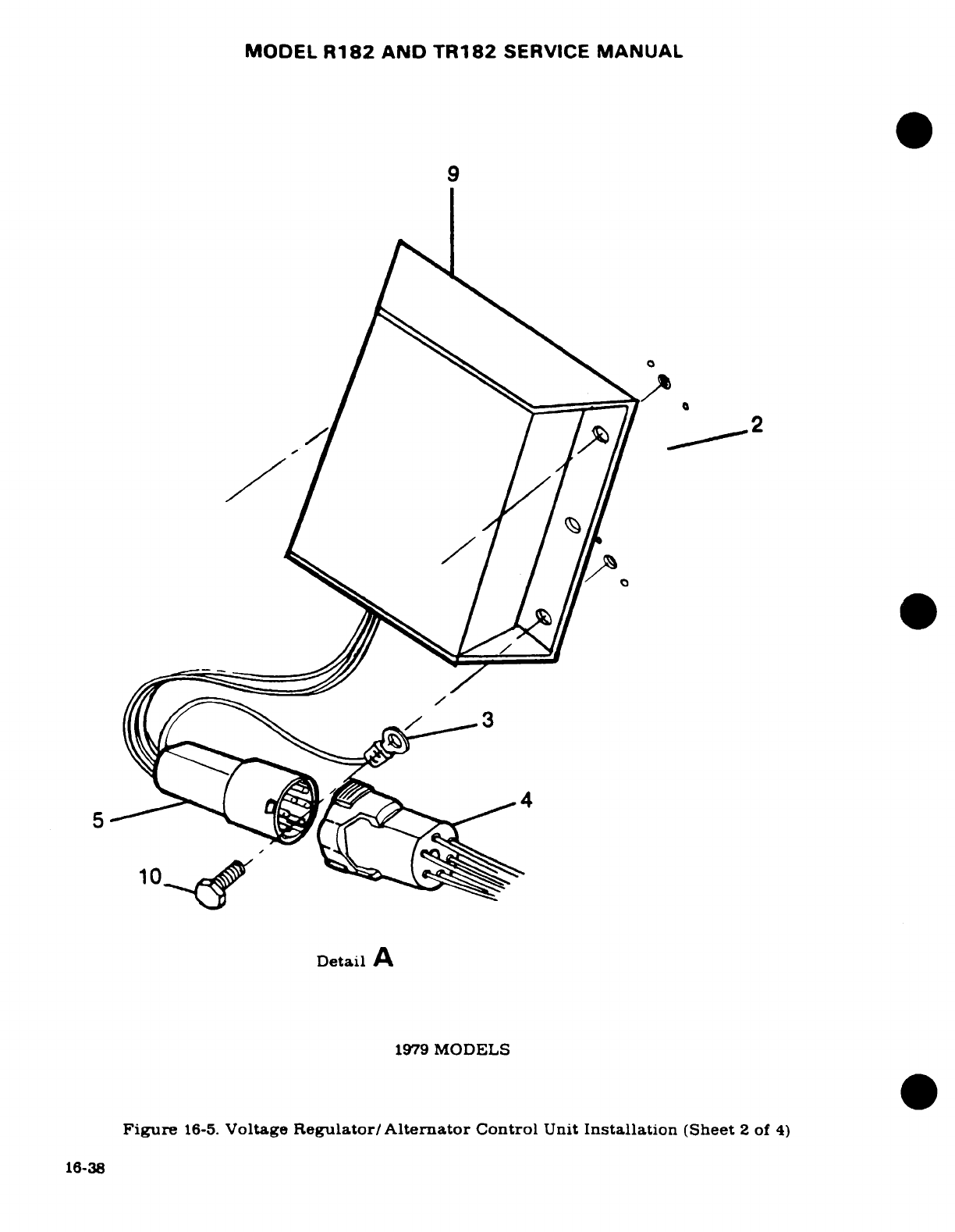
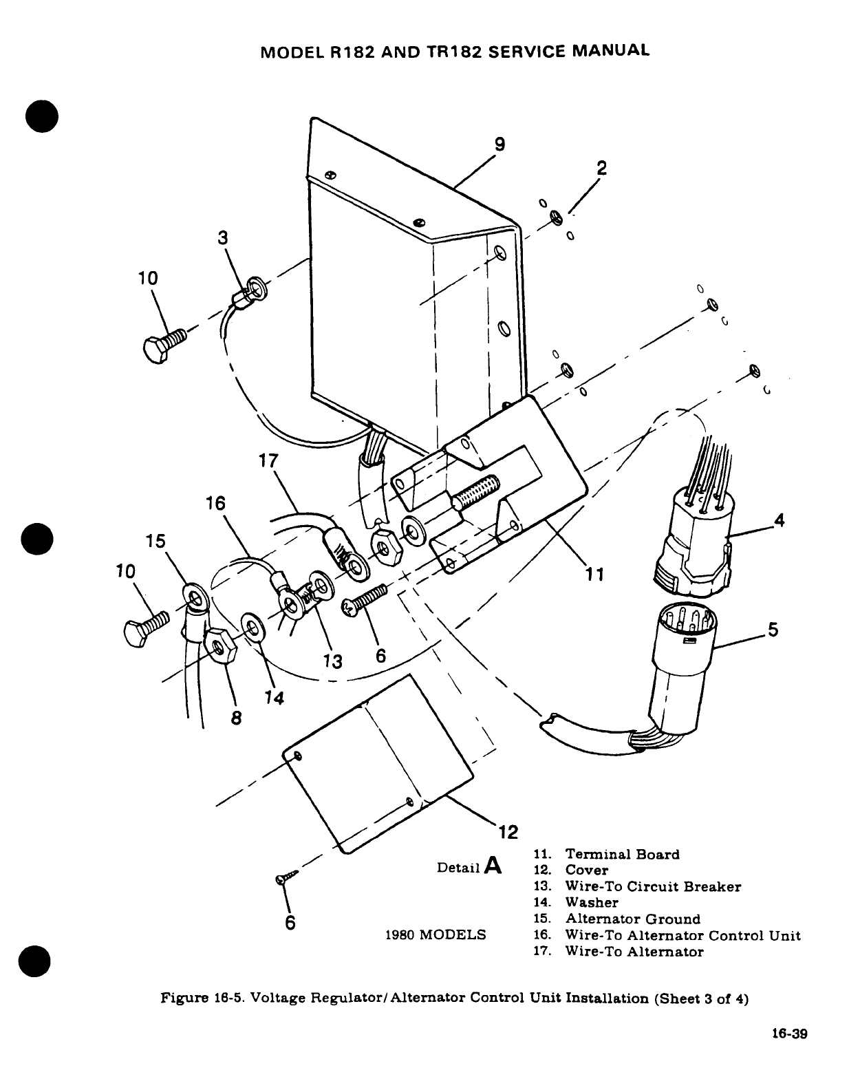
MODEL
R182
AND
TR182
SERVICE
MANUAL
3*^
9
\ ^ 14.Washer~2
10
14\
4
12
11.
Terminal
Board
DetailA
12.
Cover
13.
Wire-To
Circuit
Breaker
6 15~~~~15.
Alternator
Ground
1980
MODELS
16.
Wire-To
Alternator
Control
Unit
17.
Wire-To
Alternator
Figure
16-5.
Voltage
Regulator/Alternator
Control
Unit
Installation
(Sheet
3
of
4)
16-39
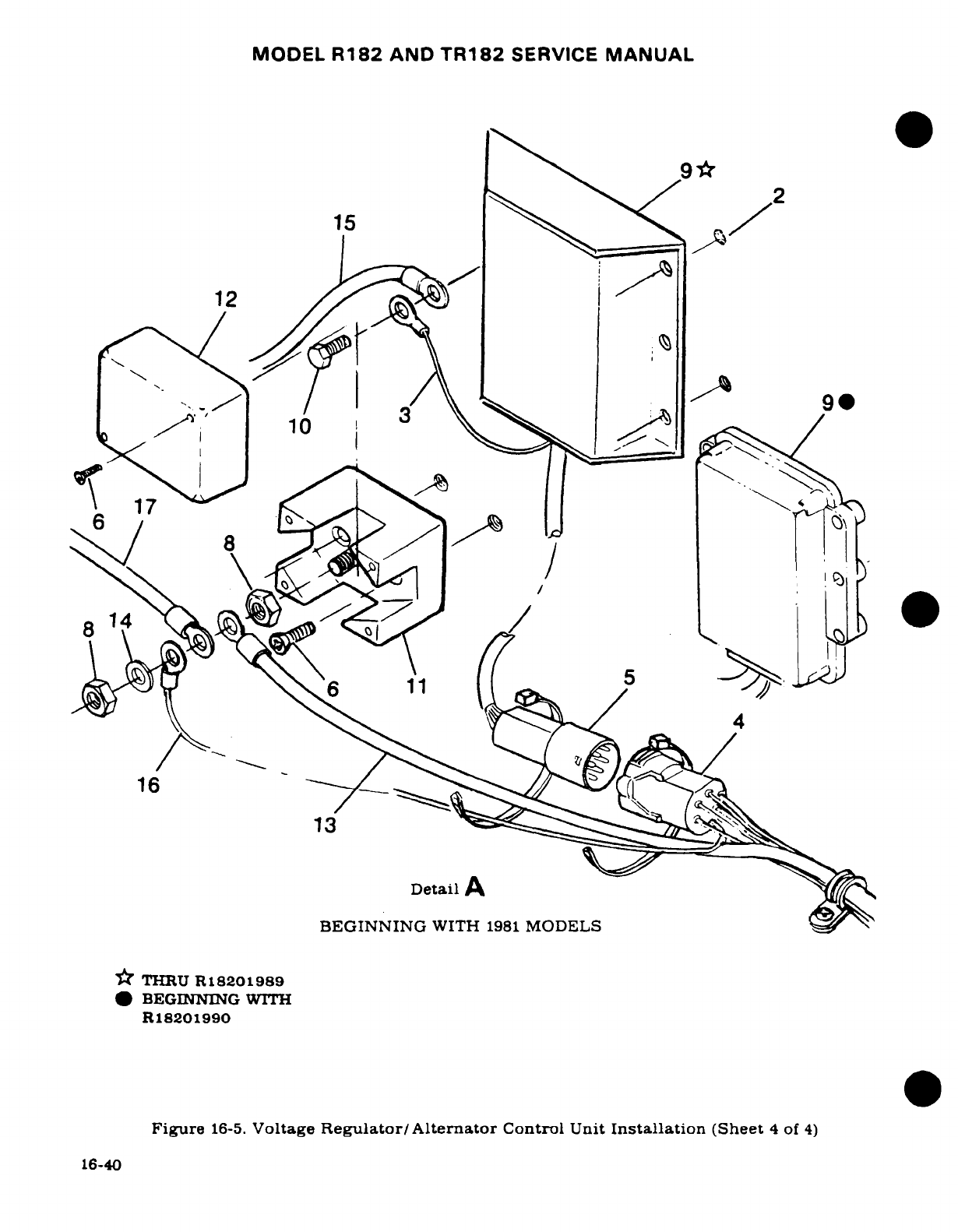
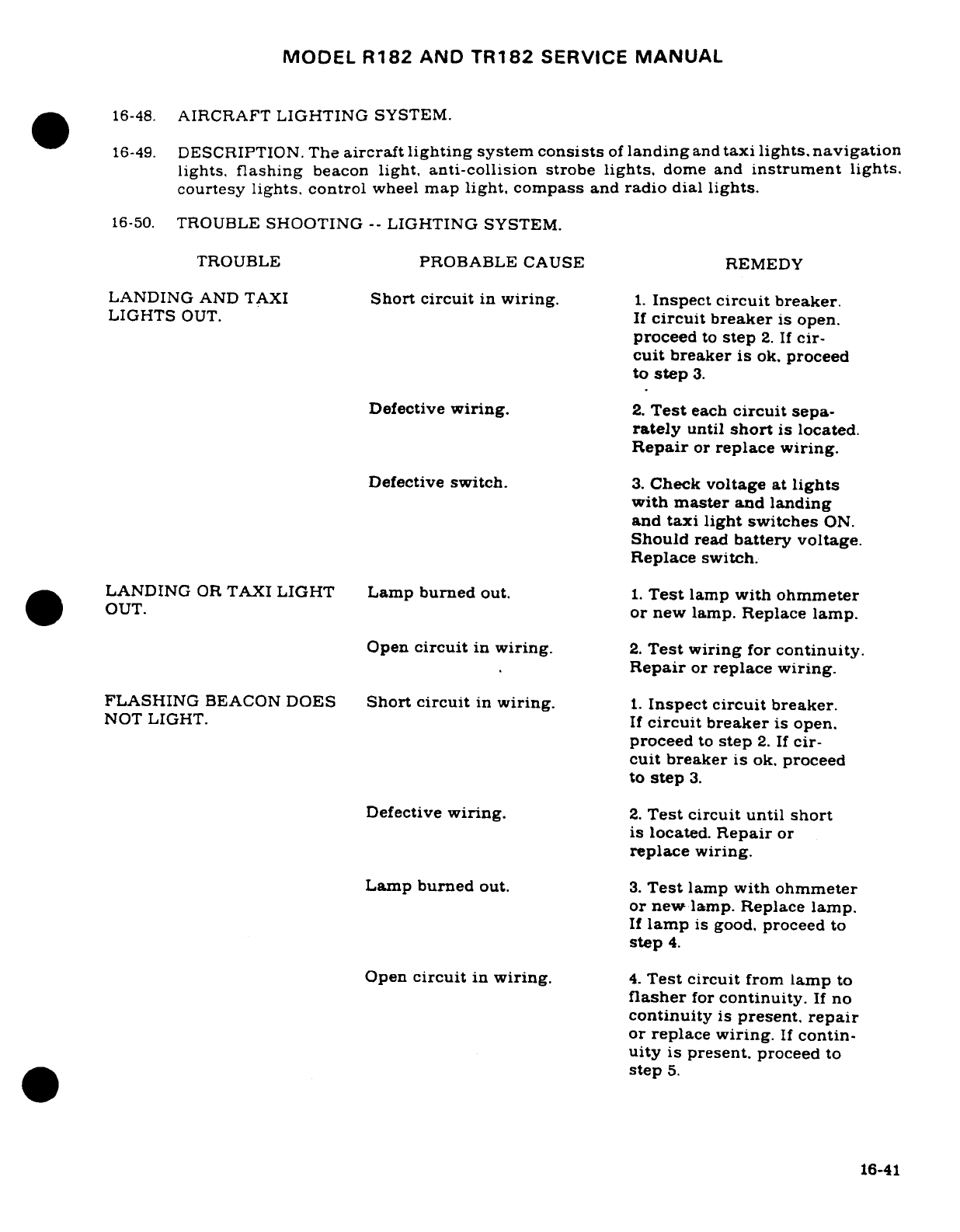
MODEL
R182
AND
TR182
SERVICE
MANUAL
16-48.
AIRCRAFT
LIGHTING
SYSTEM.
16-49.
DESCRIPTION.
The
aircraft
lighting
system
consists
of
landing
and
taxi
lights,
navigation
lights,
flashing
beacon
light,
anti-collision
strobe
lights,
dome
and
instrument
lights.
courtesy
lights.
control
wheel
map
light,
compass
and
radio
dial
lights.
16-50.
TROUBLE
SHOOTING
--
LIGHTING
SYSTEM.
TROUBLE
PROBABLE
CAUSE
REMEDY
LANDING
AND TAXI
Short
circuit
in
wiring.
1.
Inspect
circuit
breaker.
LIGHTS
OUT.
If
circuit
breaker
is
open.
proceed
to
step
2.
If
cir-
cuit
breaker
is
ok.
proceed
to
step
3.
Defective
wiring.
2.
Test
each
circuit
sepa-
rately
until
short
is
located.
Repair
or
replace
wiring.
Defective
switch.
3.
Check
voltage
at
lights
with
master
and
landing
and
taxi light
switches
ON.
Should
read
battery voltage.
Replace switch.
LANDING
OR
TAXI
LIGHT
Lamp
burned
out.
1.
Test
lamp
with
ohmmeter
OUT.
or
new lamp.
Replace
lamp.
Open
circuit
in
wiring.
2.
Test
wiring
for
continuity.
Repair
or
replace
wiring.
FLASHING
BEACON
DOES
Short
circuit
in
wiring.
1.
Inspect
circuit
breaker.
NOT
LIGHT. If
circuit
breaker
is
open.
proceed
to
step
2.
If
cir-
cuit
breaker
is
ok.
proceed
to
step
3.
Defective
wiring.
2.
Test
circuit until
short
is
located.
Repair
or
replace
wiring.
Lamp
burned
out.
3.
Test
lamp
with
ohmmeter
or
new
lamp.
Replace lamp.
If
lamp
is
good,
proceed
to
step
4.
Open
circuit
in
wiring.
4.
Test circuit
from
lamp
to
flasher
for
continuity.
If
no
continuity
is
present,
repair
or
replace
wiring.
If
contin-
uity
is
present.
proceed
to
step
5.
16-41
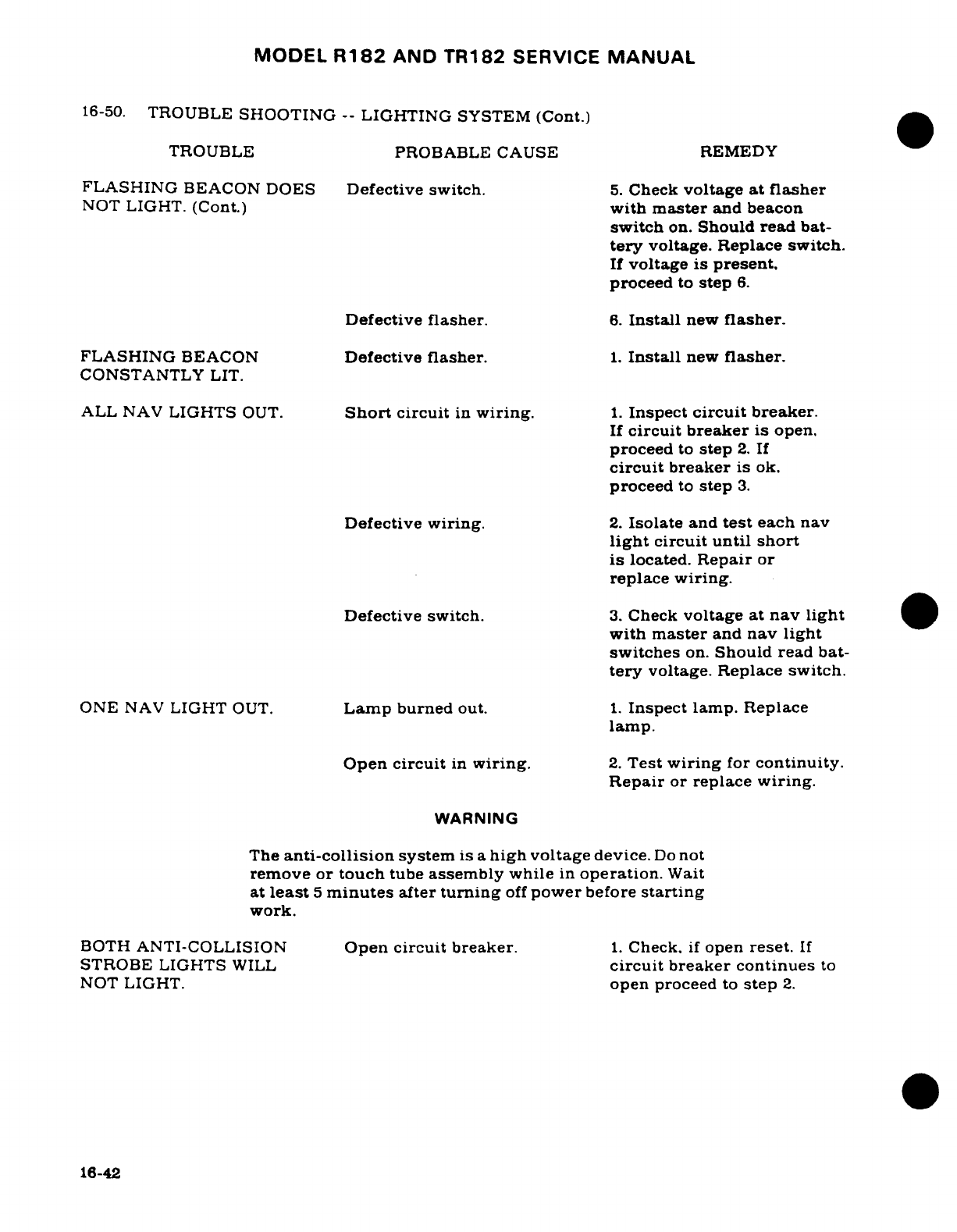
MODEL
R182
AND
TR182
SERVICE
MANUAL
16-50.
TROUBLE
SHOOTING
--
LIGHTING
SYSTEM
(Cont.)
TROUBLE
PROBABLE
CAUSE
REMEDY
FLASHING
BEACON DOES
Defective
switch.
5.
Check
voltage
at flasher
NOT
LIGHT.
(Cont.)
with
master
and
beacon
switch
on.
Should
read
bat-
tery
voltage. Replace
switch.
If
voltage
is
present.
proceed
to
step
6.
Defective
flasher.
6.
Install
new
flasher.
FLASHING
BEACON
Defective
flasher.
1.
Install
new
flasher.
CONSTANTLY
LIT.
ALL
NAV
LIGHTS
OUT.
Short
circuit
in
wiring.
1.
Inspect
circuit
breaker.
If
circuit breaker
is
open.
proceed
to
step
2.
If
circuit
breaker
is
ok.
proceed
to
step
3.
Defective
wiring.
2.
Isolate
and
test
each
nav
light
circuit
until
short
is
located.
Repair
or
replace
wiring.
Defective
switch.
3.
Check
voltage
at
nav
light
with
master
and
nav
light
switches
on.
Should
read bat-
tery
voltage. Replace switch.
ONE
NAV
LIGHT
OUT.
Lamp
burned
out.
1.
Inspect lamp.
Replace
lamp.
Open
circuit
in
wiring.
2.
Test
wiring
for
continuity.
Repair
or replace wiring.
WARNING
The
anti-collision
system
is
a
high
voltage
device.
Do
not
remove or
touch
tube
assembly
while
in
operation.
Wait
at
least
5
minutes
after
turning
off
power
before
starting
work.
BOTH
ANTI-COLLISION
Open
circuit
breaker.
1.
Check.
if
open
reset.
If
STROBE
LIGHTS
WILL
circuit
breaker continues
to
NOT
LIGHT.
open
proceed
to
step
2.
16-42
MODEL
R182 AND TR182
SERVICE
MANUAL
16-50.
TROUBLE
SHOOTING
--
LIGHTING
SYSTEM
(Cont.)
TROUBLE
PROBABLE
CAUSE
REMEDY
BOTH
ANTI-COLLISION
Open
circuit
breaker
2.
Disconnect
red
wire
be-
STROBE
LIGHTS
WILL
tween
aircraft
power
supply
NOT
LIGHT.
(Cont.)
(battery/external
power)
and
strobe
power
supplies,
one
at
a time.
If
circuit breaker
opens
on
one
strobe
power
supply,
replace
strobe
power
supply.
If
circuit
breaker
opens
on
both
strobe
power
supplies
proceed
to
step
3.
If
circuit
breaker
does
not
open
proceed
to
step
4.
3.
Check
aircraft
wiring.
Repair
or
replace
as
necessary.
4.
Inspect
strobe power
sup-
ply
ground
wire
for
contact
with wing
structure.
CAUTION
Extreme
care
should
be
taken
when
exchanging
flash
tube.
The
tube
is
fragile
and
can
easily
be
cracked
in a
place
where
it
will
not
be
obvious
visually.
Make
sure
the
tube
is
seated
properly
on
the
base
of
the
nav
light
assembly
and
is
centered
in
the
dome.
NOTE
When
checking
defective
power
supply
and
flash
tube,
units
from
opposite wing
maybe used.
Be
sure
power
leads
are
protected
properly
when
unit
is
removed
to
prevent
short
circuit.
ONE
ANTI-COLLISION
Defective
Strobe
Power
1.
Connect
voltmeter
to
red
STROBE
LIGHT
WILL
Supply,
or
flash
tube.
lead
between
aircraft
power
NOT
LIGHT. (Cont.)
supply
(battery/external
power)
and
strobe
power
supply
con-
necting
negative
lead
to
wing
structure.
Check for
24
volts.
If
ok,
proceed
to
step
2.
If
not,
check
aircraft
power
supply
(battery/external
power).
16-43
MODEL
R182
AND
TR182
SERVICE
MANUAL
16-50.
TROUBLE
SHOOTING
--
LIGHTING
SYSTEM
(Cont.)
TROUBLE PROBABLE
CAUSE
REMEDY
ONE
ANTI-COLLISION
Defective
strobe
power
2.
Replace
flash
tube
with
STROBE LIGHT
WILL
Supply,
or
flash
tube.
known
good
flash
tube.
If
NOT
LIGHT.
(Cont.)
system
still
does
not
work.
replace strobe power
supply.
DOME
LIGHT
TROUBLE.
Short
circuit
in
wiring.
1.
Inspect
circuit
breaker.
If
circuit breaker
is
open.
proceed
to
step
2.
If
cir-
cuit
breaker
is
ok,
proceed
to
step
3.
Defective
wiring.
2.
Test
circuit
until
short
is
located.
Repair
or
re-
place
wiring.
3.
Test
for
open
circuit.
Repair
or
replace
wiring.
If
no
short
or open
circuit
is
found,
proceed
to
step
4.
Lamp
burned
out.
4.
Test
lamp with
ohmmeter
or
new
lamp.
Replace
lamp.
Defective switch.
5.
Check
for
voltage at
dome
light
with
master
and
dome
light
switch
on.
Should
read
battery
voltage.
Replace
switch.
INSTRUMENT
LIGHTS
Short
circuit
wiring.
1.
Inspect
circuit
breaker.
WILL
NOT
LIGHT.
If
circuit
breaker
is
open.
proceed
to
step
2.
If
cir-
cuit
breaker
is
ok,
proceed
to
step
3.
Defective
wiring.
2.
Test
circuit
until short
is
located.
Repair
or
replace
wiring.
3.
Test
for
open
circuit.
Repair
or
replace
wiring.
If
no
short
or
open
circuit
is
found,
proceed
to
step
4.
16-44
MODEL
R182
AND
TR182
SERVICE
MANUAL
16-50.
TROUBLE
SHOOTING
--
LIGHTING
SYSTEM
(Cont.)
TROUBLE
PROBABLE
CAUSE
REMEDY
INSTRUMENT
LIGHTS
Faulty section
in
dim-
4.
Lights
will
work
when
WILL
NOT
LIGHT.
(Cont.)
ming
potentiometer.
control
is
placed
in
position.
Replace
potentiometer.
Faulty
light
dimming
5.
Test
both
transistors
with
transistor.
new
transistor.
Replace
faulty
transistor.
Faulty
selector
switch.
6.
Inspect.
Replace
switch.
INSTRUMENT
LIGHTS
Open
resistor
or
wiring
1.
Test
for
continuity.
WILL
NOT
DIM.
in
minimum
intensity
end
Replace
resistor
or
repair
of
potentiometer.
wiring.
Shorted
transistor.
2.
Test
transistor
by
sub-
stitution.
Replace
defective
transistor.
CONTROL
WHEEL
MAP
Nav
light
switch
turned
1.
Nav
light
switch
has
to
be
LIGHT
WILL
NOT
LIGHT.
off.
ON
before
map
light
will
light.
Short
circuit
in
wiring.
2.
Check
lamp
fuse
on
ter-
minal
board
located
on
back
of
stationary
panel
with
ohm-
meter.
If
fuse
is
open.
pro-
ceed
to
step
3.
If
fuse
is
ok.
proceed
to
step
4.
Defective
wiring.
3.
Test
circuit
until
short
is
located.
Repair
or
replace
wiring.
4.
Test
for
open
circuit.
Repair
or
replace
wiring.
If
a
short
or
open
circuit
is
not
found.
proceed
to
step
5.
Defective
map
light
5.
Check
voltage
at
map
light
assembly.
assembly
with
master
and
nav
light
switches
on.
If
battery
voltage
is
present.
replace
map
light
assembly.
16-45
MODEL
R182
AND
TR182
SERVICE
MANUAL
16-51.
LANDING
AND
TAXI
LIGHTS.
16-52.
DESCRIPTION.
The
landing
and
taxi
lights
are
mounted
in
the
lower
half
of
the
engine
cowl.
Both
lights
are
used
for
landing
but
only
the
left
hand
for
taxi.
Power
for
the
lights
is
supplied
through
a
circuit
breaker
located
on
the
primary
bus
bar.
Two
rocker
switches
control
the
lights.
The
switches
are
interconnected
by a
diode:
when
the
taxi
light
switch
is
actuated
only
the
left
hand
light
is
illuminated.
When
the
landing
light
switch
is
actuated
power
is
supplied
to
the
landing
light,
and
through
the
diode
around
the
taxi
light
switch
to
the taxi
light
so
both
lights
are
illuminated.
16-53.
REMOVAL
AND
INSTALLATION.
(See
figure
16-6.)
a.
Remove
the lower
cowl
and
disconnect
wires
from
the
landing
and
taxi
lights.
b.
Remove
screws
(8)
securing
lamp
assembly
to
support
(2)
and
remove lamp
assembly.
Note
number
and
position
of
washers
between
plate
(3)
and
support
(2)
for
reinstallation.
c.
Remove
screws
(7)
securing
bracket
(6)
to
plate
(3)
and
remove
lamp
(5)
and
gasket
(4).
d.
To
install,
place
lamp
(5)
in
bracket
(6)
and
install
gasket
(4)
and
plate
(3)
using
screws
(7).
NOTE
A
minimum
of
one
gasket
(4)
and
a
maximum
of
two
gaskets
may
be
used
to
secure
lamp
(5)
between
bracket
(6)
and
plate
(3).
e.
Using
screws
(8)
secure
lamp
assembly
to
support
(2)
installing
washers,
in
the
proper position,
removed
in
step
(b).
NOTE
A
maximum
of
two
washers
may
be
used
between sup-
port
(2)
and
plate
(3)
for
adjustment.
f.
Connect
wires
to
lamps
and
install
cowl.
g.
Check
lights
for
operation.
16-54.
ADJUSTMENT
OF
LANDING
AND
TAXI
LIGHTS.
(See
figure
16-6.)
Adjustment
of
the
landing
and
taxi
lights
is
pre-set
at
the
factory.
If
further adjustment
is
desired
proceed
as
follows:
a.
Remove
the
lower
engine
cowl
and
disconnect
wires
from
the
landing
and
taxi
lights.
b.
Remove
screws
(8)
securing
lamp
assembly
to
support
(2).
c.
Add
or
remove
washers
between
lamp
assembly and
support
(2).
NOTE
A
maximum
of
two
washers
may
be
used
between
sup-
port
(2)
and
plate
(3)
for
adjustment.
d.
Using
screws
(8)
secure
lamp
assembly
to
support
(2).
e.
Connect
wires
to
lamps
and
install
cowl.
f.
Check
lights
for
operation
and
direction.
16-46
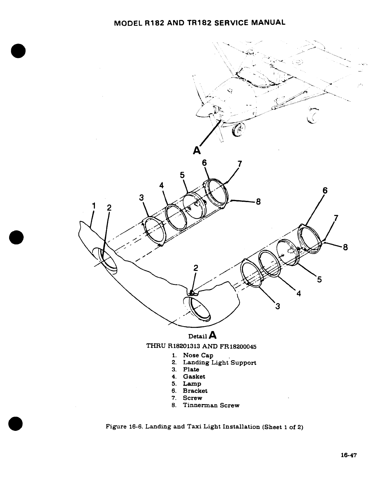
MODEL
R182
AND
TR182
SERVICE
MANUAL
.... *
*..
",
....
.
.1........ .... ..........
· " .
:*"-*-...,
, .
.::
3
" .
P. a
- .. '
X
..
:".:.
4
-.
Gask
t-
.~
..,
5., Lamp,.
,.¥::
A
6
7
Detail
A
THRU
R18201313
AND
FR18200045
1.
Nose
Cap
2.
Landing
Light
Support
3.
Plate
4.
Gasket
5.
Lamp
6.
Bracket
7.
Screw
8.
Tinnerman
Screw
Figure
16-6.
Landing
and
Taxi
Light
Installation
(Sheet
1
of
2)
16-47
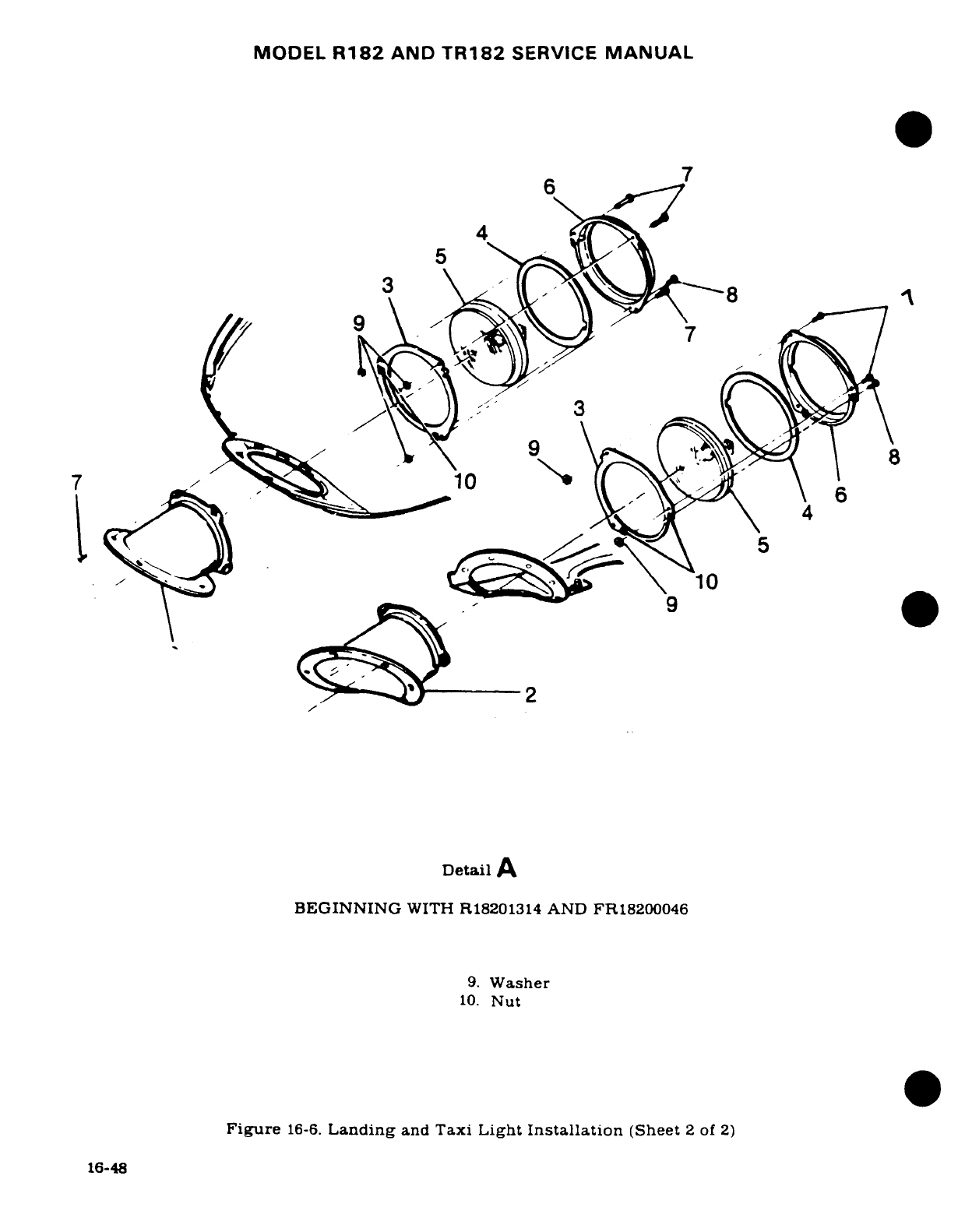
MODEL
R182 AND
TR182
SERVICE
MANUAL
16-55.
NAVIGATION LIGHTS.
16-56.
DESCRIPTION.
The
navigation
lights
are
installed
on
each
wing
tip
and
the
stinger.
The
lights
are
controlled
by
a
switch
located
on
the
instrument
panel.
16-57.
REMOVAL AND
INSTALLATION.
For
removal
and
installation
of
the
navigation
lights.
see
figure
16-7.
16-58.
FLASHING
BEACON.
16-59.
DESCRIPTION.
The
flashing
beacon
light
is
attached
to
the
vertical
fin
tip.
The
flashing
beacon
is
an
iodine-vapor
lamp
electrically
switched
by
a
solid-state
flasher
assembly.
The
flasher
assembly
is
located
in
the
vertical
fin
under
the fin
tip.
Switching
frequency
of
the
flasher
assembly operates
the
lamp
at
approximately
45
flashes
per
minute.
A
1.5
ohm
resistor
is
installed
to
provide
a
dummy
load
to
eliminate
a
"pulsing"
effect on
the cabin
lighting
and
ammeter.
16-60.
REMOVAL
AND
INSTALLATION.
(See
figure
16-8.)
CAUTION
When
inserting
lamp
into
socket
always
use
a
handker-
chief
or
a
tissue
to
prevent
getting
fingerprints
on
the
lamp.
NOTE
Fingerprints
on
lamp
may
shorten
the
life
of
the
lamp.
16-61.
ANTI-COLLISION
STROBE
LIGHTS.
16-62.
DESCRIPTION.
A
white
strobe
light
is
installed
on each
wing
tip.
These
lights
are
vibration
resistant
and
operate
on
the
principle
of
a
capacitor discharge
into
a
xenon
tube,
producing
an
extremely
high intensity
flash.
Energy
is
supplied
to
the
strobe
lights
from
power
supplies
mounted
on
each
wing
tip
rib.
16-63.
REMOVAL
AND INSTALLATION. (See
figure
16-7.)
WARNING
This
anti-collision
system
is
a
high
voltage
device.
Do
not
remove or
touch
tube
assembly
while
in
operation.
Wait
at
least
5
minutes
after
turning
off
power
before
starting
work.
16-64.
OVERHEAD
CONSOLE.
16-65.
DESCRIPTION.
The
overhead
console
contains
the
instrument
flood
lights
which
also
may
be
used
as
map
lights
by
moving
the
slide
covers
below
the
lamps.
The
intensity
of
the
lights
is
controlled
by
a
rheostat
mounted
on
the
instrument
panel.
16-66.
REMOVAL
AND
INSTALLATION. (See
figure
16-9.)
16-49
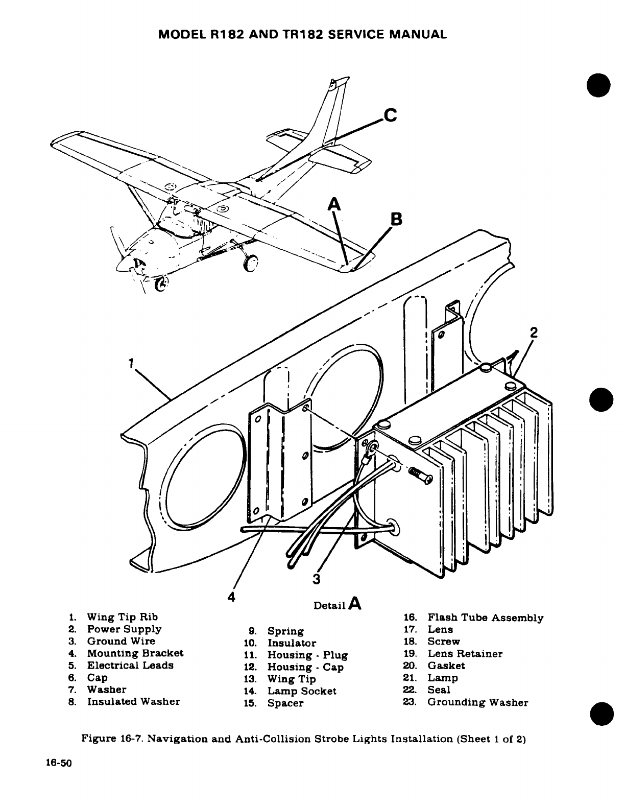
MODEL
R182
AND
TR182
SERVICE
MANUAL
A
B
2.
Power
Supply
9.
Spring
17.
Lens
/
3.
Ground
Wire
10.
Insulator
18.
Screw
4. Mounting
Bracket.
Housing
-
Plug
19.
Lens
Retainer
1.
Wing
Tip
Rib
16.
Flash
Tube
Assembly
2.
Power
Supply
9.
Spring
17.
Lens
3.
Ground
Wire
10.
Insulator
18.
Screw
4.
Mounting
Bracket
11.
Housing
-
Plug
19.
Lens
Retainer
5.
Electrical
Leads
12.
Housing
-
Cap
20.
Gasket
6.
Cap
13.
Wing
Tip
21.
Lamp
7.
Washer
14.
Lamp
Socket
22.
Seal
8.
Insulated
Washer
15.
Spacer
23.
Grounding
Washer
Figure
16-7.
Navigation
and Anti-Collision
Strobe
Lights
Installation
(Sheet
1
of
2)
16-50
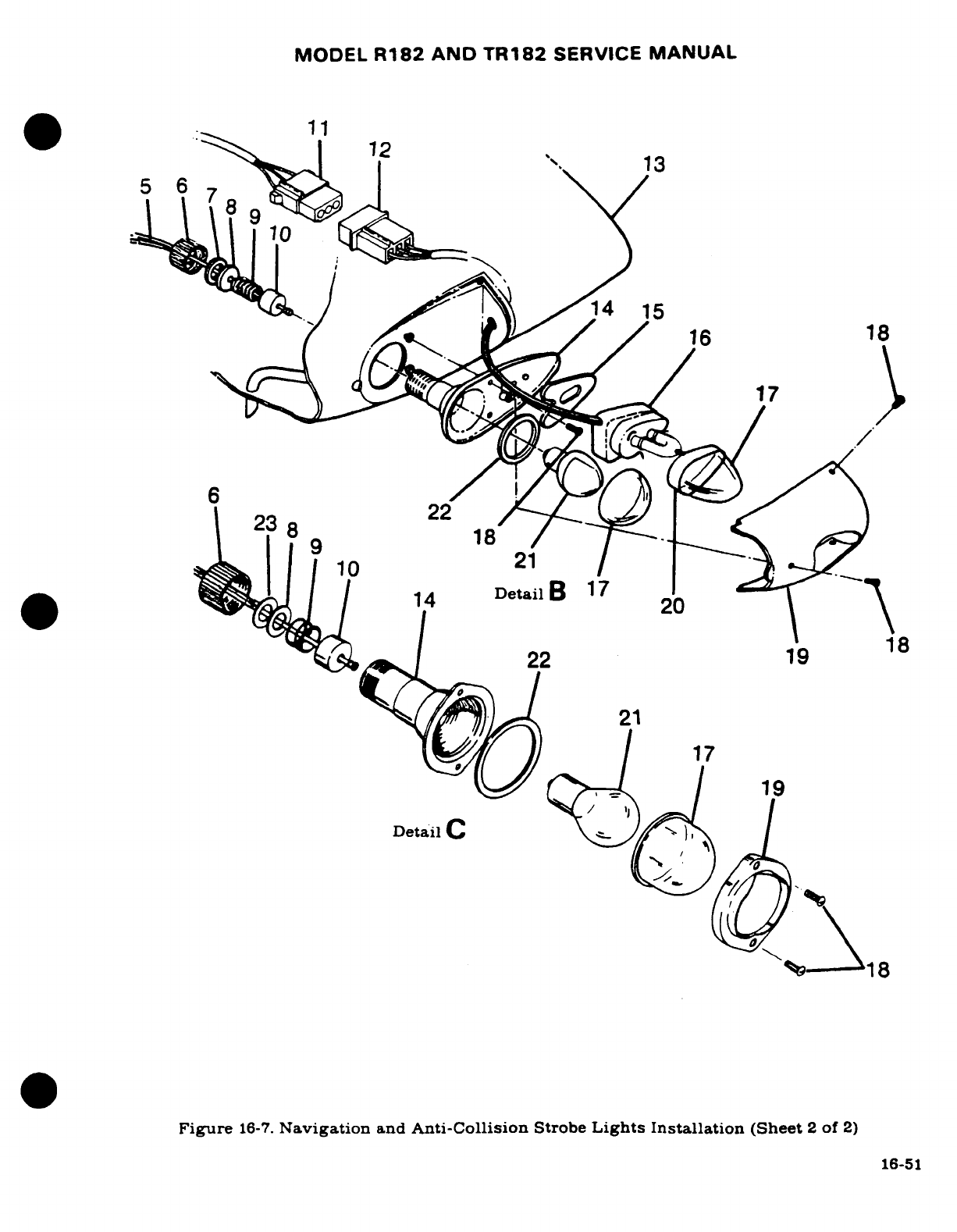
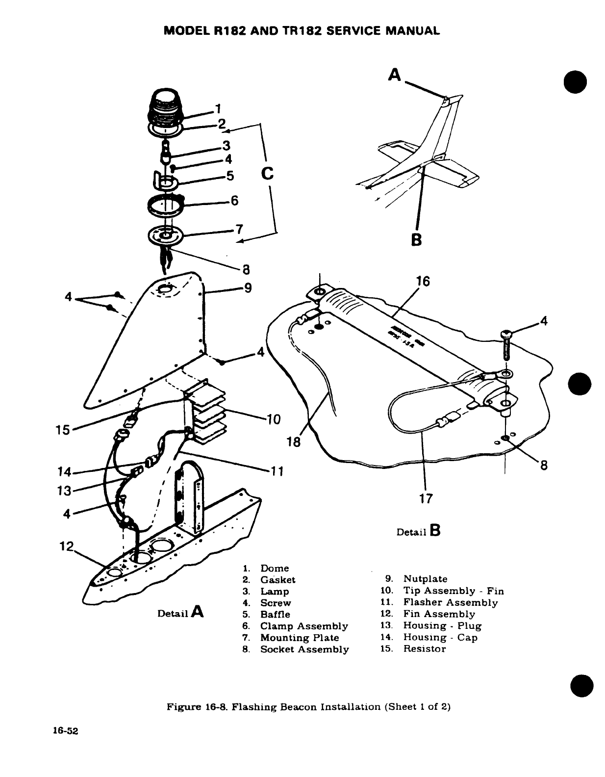
MODEL
R182
AND
TR182
SERVICE
MANUAL
A
11_9
<-^16
14
11
13
44
Detail
B
12
6
.^s.^^^
Or^^
1.
Dome
Add·*
^^
2.
Gasket
9.
Nutplate
· / '
_^/^
3.
Lamp
10.
Tip
Assembly
-
Fin
.,.<- <
"^
4.
Screw
11.
Flasher
Assembly
Detail
A
5.
Baffle
12.
Fin
Assembly
6.
Clamp
Assembly
13.
Housing
-
Plug
7.
Mounting
Plate
14.
Housing
-
Cap
8.
Socket
Assembly
15.
Resistor
Figure
16-8.
Flashing
Beacon
Installation
(Sheet
1
of
2)
16-52
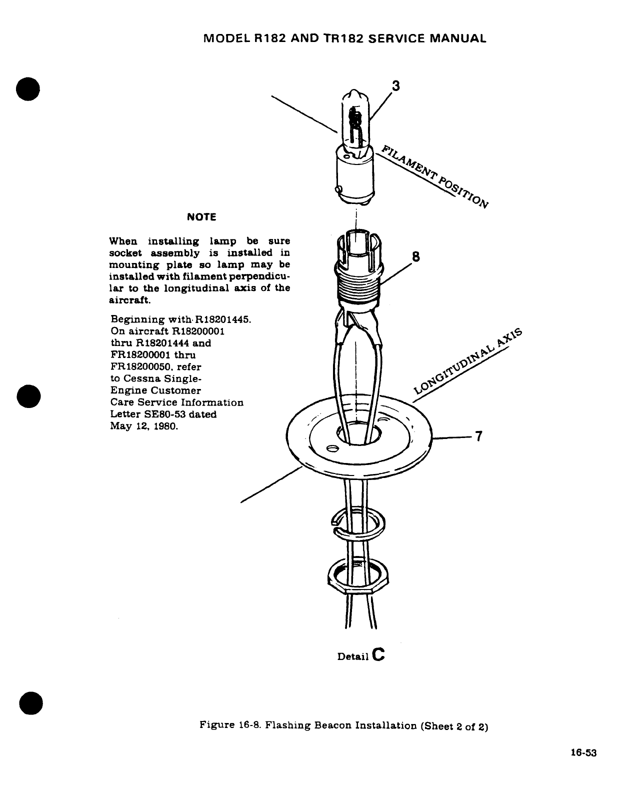
MODEL
R182
AND
TR182
SERVICE
MANUAL
NOTE
When
installing
lamp
be
sure
socket
assembly
is
installed
in
8
mounting
plate
so
lamp
may
be
installed
with
filament
perpendicu-
lar
to
the
longitudinal
axis
of
the
aircraft.
Beginning
with
R18201445.
On
aircraft
R18200001
\
thru
R18201444
and
FR18200001
thru
| i
FR18200050.
refer
j| l
to
Cessna
Single-
Engine
Customer
Care
Service
Information
Letter
SE80-53
dated
May
12,
1980.
Detail
C
Figure
16-8.
Flashing
Beacon
Installation
(Sheet
2
of
2)
16-53
MODEL
R182
AND
TR182
SERVICE
MANUAL
16-67.
INSTRUMENT
LIGHTING.
16-68.
DESCRIPTION. The
instrument
panel
lighting
consists
of
two
separate
sections.
The
lower
two-thirds
of
the
panel
is
illuminated
by
two
lights
mounted
in
the
overhead
console.
The
lighting
for the
upper
one-third
of
the
panel
is
provided
by
four
lights
mounted
in
the
instrument
panel
glare
shield.
The
intensity
of
the
lighting
is
controlled
by
the
instrument
light
dimming
rheostat
located
on
the
switch
panel.
16-69.
REMOVAL
AND
INSTALLATION.
(See
figure
16-9
and
16-10.)
16-70.
ELECTROLUMINESCENT
PANEL
LIGHTING.
16-71.
DESCRIPTION.
The
electroluminescent
lighting
consists
of two
"EL"
panels:
the
switch
panel and
the
comfort
control
panel.
The ac
voltage
required
to
drive
the
"EL"
panels
is
supplied
by a
small
invertapak
(power
supply)
located
behind
the
instrument
panel
on
the
glove
box.
The
intensity
of
the
"EL"
panel
lighting
is
controlled
by
a
rheostat
located
on the
instrument
switch
panel.
16-72.
REMOVAL
AND
INSTALLATION.
(See
figure
16-11.)
a.
Disconnect
positive
cable
from
battery.
b.
Disconnect
and
tag
all
electrical
leads
from
panel.
c.
Remove
knobs,
decorative nuts,
and
switches.
d.
Remove
screws
securing
panel
to
stationary
panel
and
remove
panel.
e.
For
installation
reverse
the
preceding
steps.
After
installation,
check
all
switches
for
operation.
16-73.
INSTRUMENT
POST LIGHTING.
16-74.
DESCRIPTION.
Individual
post
lighting
may
be
installed
to
provide
non-glare
instrument
lighting.
The
post
light
consists
of
a
cap
and
a
clear
lamp assembly
with
a
tinted
lens.
The
intensity
of
the post
lights
is
controlled
by
the
instrument
light-dimming
rheostat
on
the
switch panel.
NOTE
When
installing
postlight
assemblies,
assemblies
shall
be
coated
with
RTV-102,
General
Electric,
Waterford,
New
York,
on
forward
side
of
panel where
postlight
could
come
in
contact
with
sheet
metal
subpanel.
This
coating
shall
insulate
postlight
assembly
from
contact
with
air-
plane
structure.
Maximum
coating
thickness
to
be
.03.
16-54
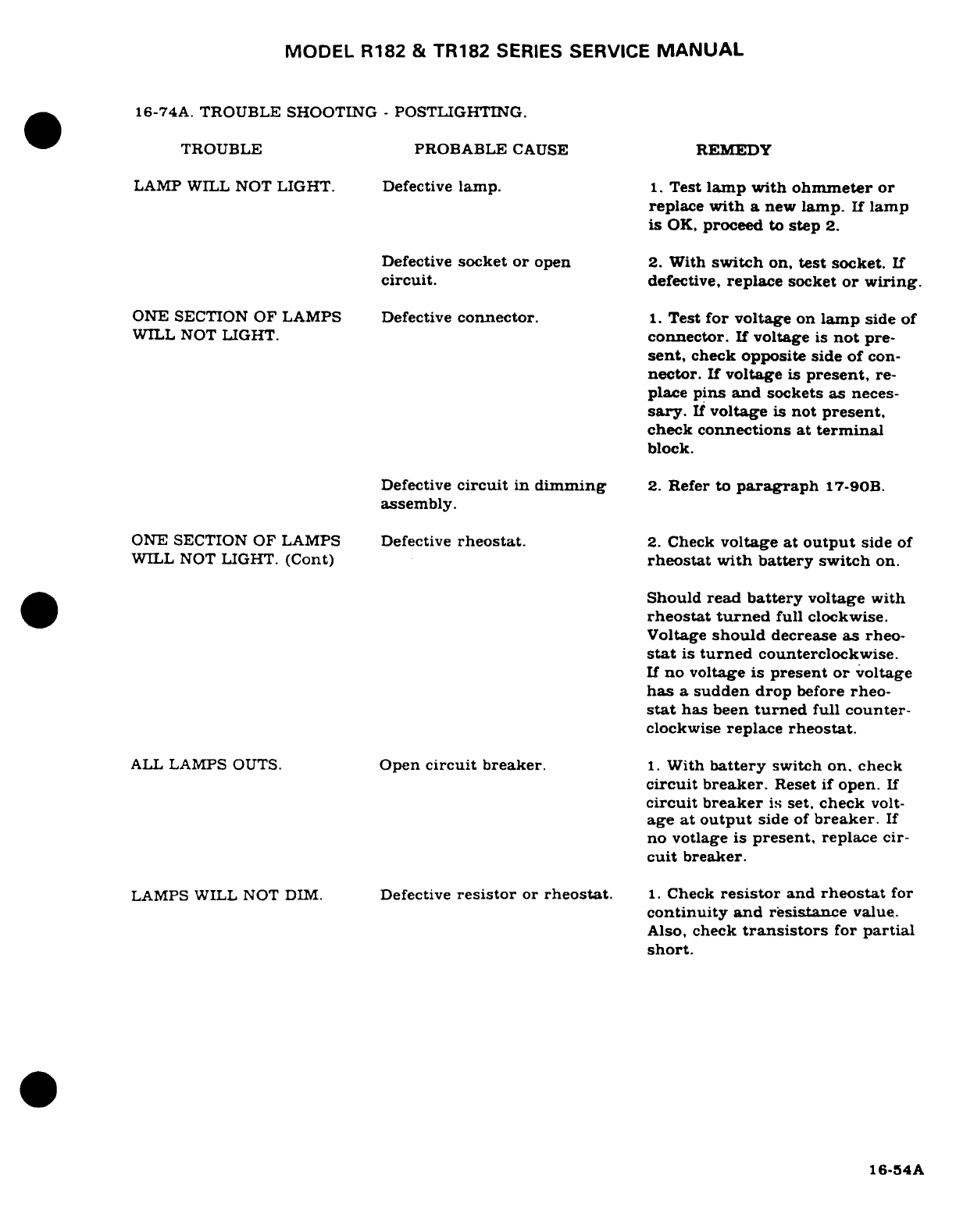
MODEL
R182
&
TR182
SERIES
SERVICE
MANUAL
16-74A.
TROUBLE
SHOOTING
-
POSTLIGHTING.
TROUBLE
PROBABLE
CAUSE REMEDY
LAMP WILL
NOT
LIGHT.
Defective
lamp.
1.
Test
lamp with
ohmmeter
or
replace
with
a
new
lamp.
If
lamp
is
OK,
proceed
to
step
2.
Defective
socket
or
open
2.
With
switch
on,
test
socket.
If
circuit.
defective,
replace
socket
or wiring.
ONE
SECTION
OF
LAMPS
Defective
connector.
1.
Test
for
voltage
on
lamp
side
of
WILL
NOT
LIGHT.
connector.
If
voltage
is
not
pre-
sent,
check opposite side of
con-
nector.
If
voltage
is
present,
re-
place
pins
and
sockets
as
neces-
sary.
If
voltage
is
not
present,
check
connections
at
terminal
block.
Defective
circuit
in
dimming
2.
Refer
to
paragraph
17-90B.
assembly.
ONE
SECTION
OF LAMPS
Defective
rheostat.
2.
Check
voltage
at
output
side
of
WILL NOT
LIGHT.
(Cont)
rheostat
with battery
switch
on.
Should
read
battery
voltage
with
rheostat
turned
full
clockwise.
Voltage
should
decrease
as
rheo-
stat
is
turned
counterclockwise.
If
no
voltage
is
present
or
voltage
has
a
sudden drop
before
rheo-
stat
has
been
turned
full
counter-
clockwise
replace
rheostat.
ALL
LAMPS
OUTS.
Open
circuit
breaker.
1.
With
battery
switch
on.
check
circuit breaker.
Reset
if
open.
If
circuit
breaker
is
set,
check
volt-
age
at
output
side
of
breaker.
If
no
votlage
is
present,
replace
cir-
cuit
breaker.
LAMPS WILL NOT
DIM.
Defective
resistor
or
rheostat.
1.
Check
resistor
and
rheostat
for
continuity
and resistance
value.
Also,
check
transistors
for
partial
short.
16-54A
MODEL
R182
&
TR182
SERIES SERVICE
MANUAL
16-75.
TRANSISTORIZED
LIGHT
DIMMING.
16-76.
DESCRIPTION.
The
light-dimming
circuit
consists
of
a
two-circuit
transistorized
dimming
assembly,
mounted
on
the
right
hand
side
of
the
cabin
forward
of
the
instrument
panel,
and
two
controls
on
the
lower
left
hand
side
of
the
panel.
The
left
control
is
a
dual
rheostat
with
a
concentric
knob
arrangement.
The
center
portion
controls
lower
panel
lighting,
the
outer
portion
controls
engine
instrument
and
radio
lighting.
The
right
hand
is
a
single
rheostat
and
controls
instrument
lighting,
this
includes,
glare
shield
lights,
instrument
flood
lights.
compass
light
and
post
lighting
if
installed.
16-77.
REMOVAL
AND
INSTALLATION.
(See
figure
16-11.)
16-77A.
TROUBLE
SHOOTING
-
TRANSISTORIZED
HEAT
SINK.
Remove
heat
sink
from
airlane.
Check
transistors
for
opens
and
shorts,
check
transistor
sockets
for
evidence
of
shorting
out
against
heat
sink,
especially
on
the
bottom
side.
Check
that
legs
of
transistor
socket
have
not
been
bent
up
against
heat
sink.
If
this
has
happened,
you
may
see
burned
spot
on
the
socket
leg.
If
the
transistor
sockets and
wiring
appear
to
be in
good
condition,
install
trans-
istor
back
in
heat
sink
and
make
a
continuity
check.
Attach
one
lead
of
an
ohmmeter
to
the
heat
sink
then
check
every
pin
of
the
pigtail
plug
with
the
other
lead
for
continuity.
(These
should not
be
continuity).
If
continuity
is
found, this
will
burn
out
transistors
immediately.
16-78.
DOME
LIGHT.
16-79.
DESCRIPTION.
The
dome
light
is
mounted
aft
of
the
overhead
console.
The
assembly
consists
of
a
housing,
a
socket
and
lamp
and
a
cover.
The
light
is
controlled
by
a
slide
switch
mounted
on
the
cover
aft
of
the
light.
16-80.
REMOVAL AND
INSTALLATION.
(See
figure
16-9.)
16-81.
MAP
LIGHT.
16-82.
DESCRIPTION.
A
light
assembly
is
installed
in
the
instrument
panel
glare
shield
above
the
pilot's
control
wheel.
The
light has
blue
lens.
A
switch
located
forward
of
the
light
controls
the
light.
16-83.
REMOVAL
AND
INSTALLATION.
(See
figure
16-10.)
16-54B
Revision
1
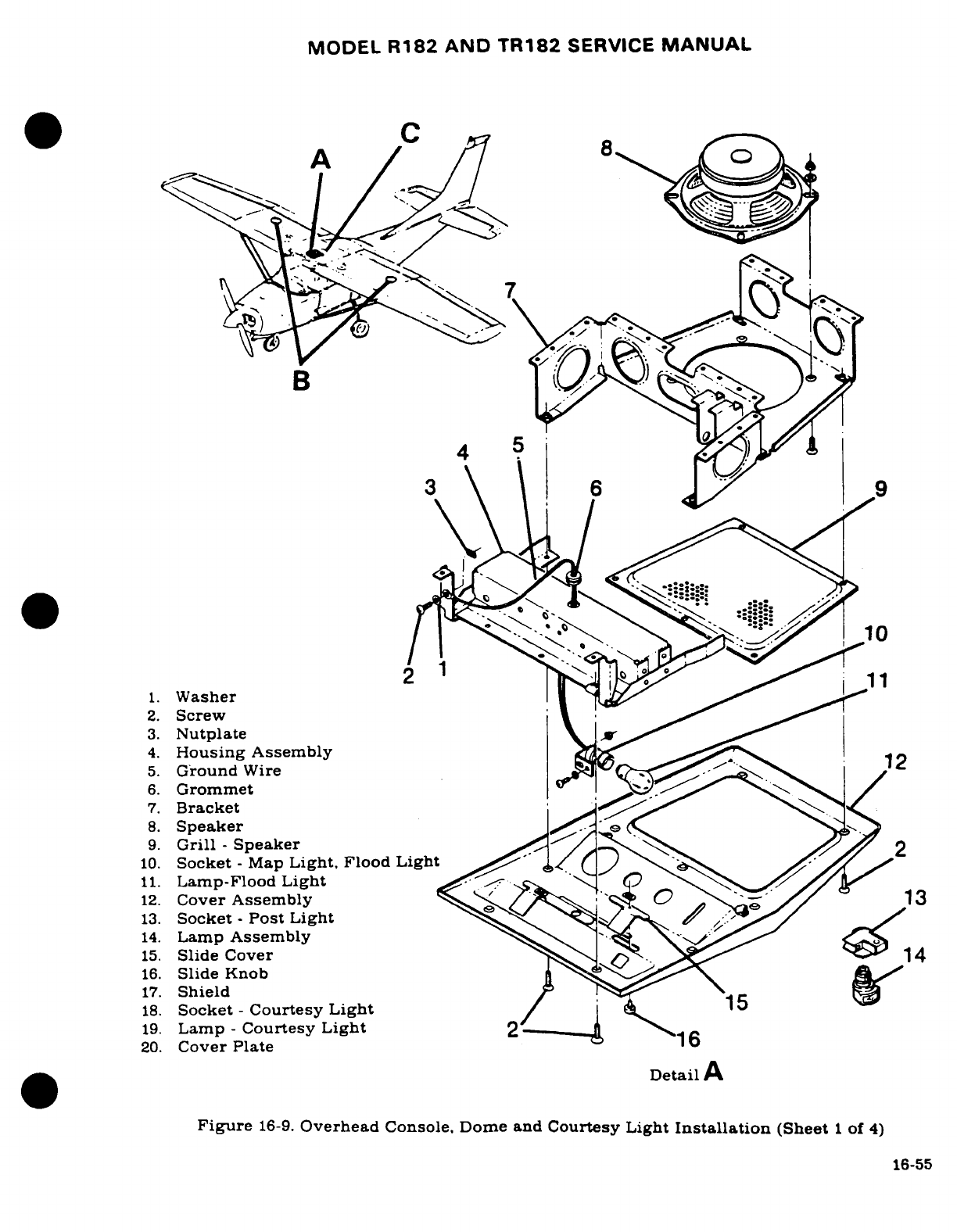
MODEL
R182 AND TR182
SERVICE
MANUAL
C
A
B
w
4
5
~~\ \^"^ \*^ I^~ ^10
I1 1.
1.
Washer
I 1
2.
Screw
3.
Nutplate
\ A
4.
Housing Assembly
12
5.
Ground
Wire
6.
Grommet
7.
Bracket
8.
Speaker
(
9.
Grill
-
Speaker
2
10.
Socket
-
Map
Light,
Flood
Light
11.
Lamp-Flood
Light
12.
Cover
Assembly
/ 13
13.
Socket
-
Post
Light
/
14.
Lamp
Assembly
15.
Slide
Cover
14
16.
Slide
Knob
17.
Shield
18.
Socket
-
Courtesy
Light
/
19.
Lamp
-
Courtesy Light
2
20.
Cover
Plate
Detail
A
Figure
16-9.
Overhead
Console,
Dome
and
Courtesy
Light
Installation
(Sheet
1
of
4)
16-55
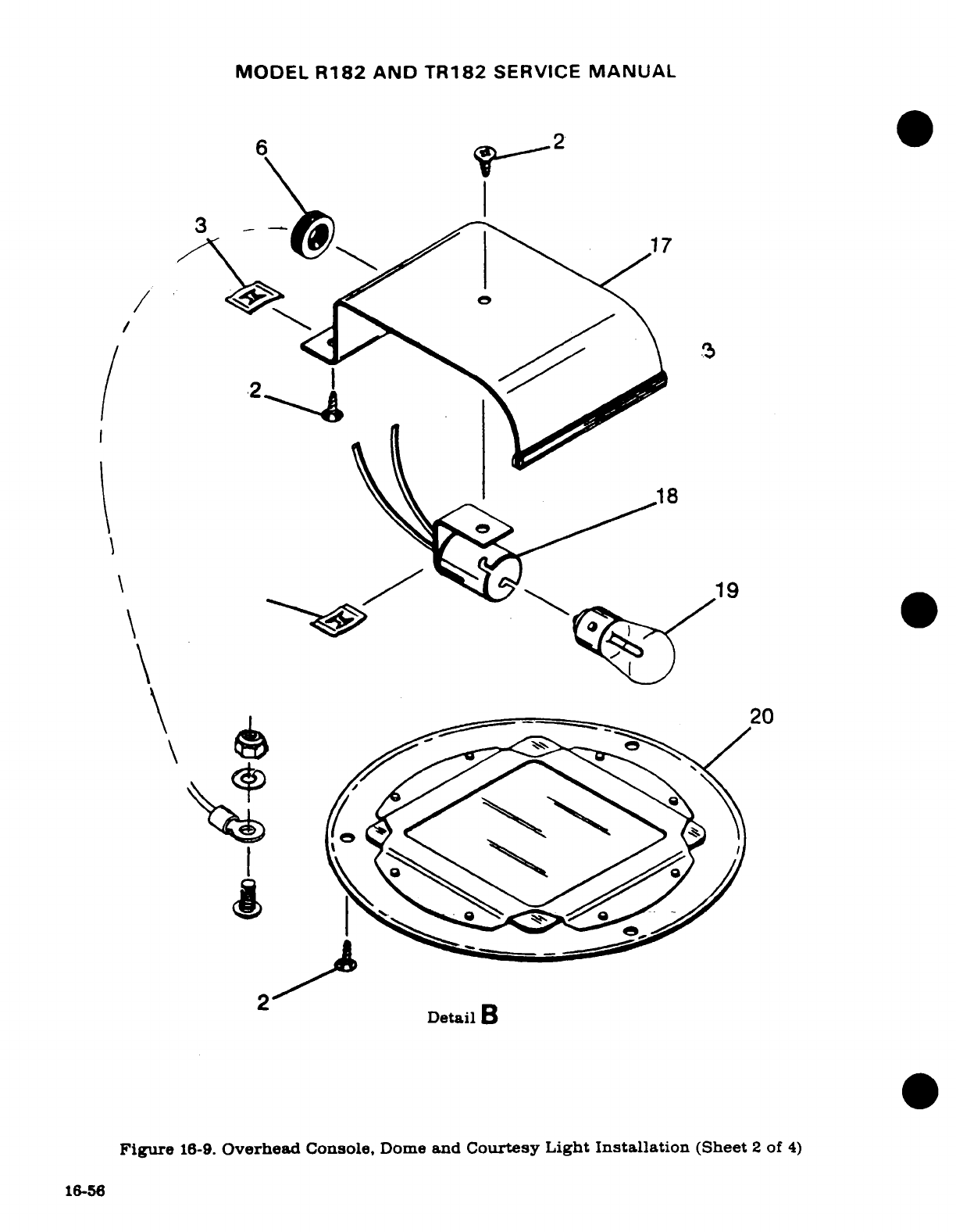
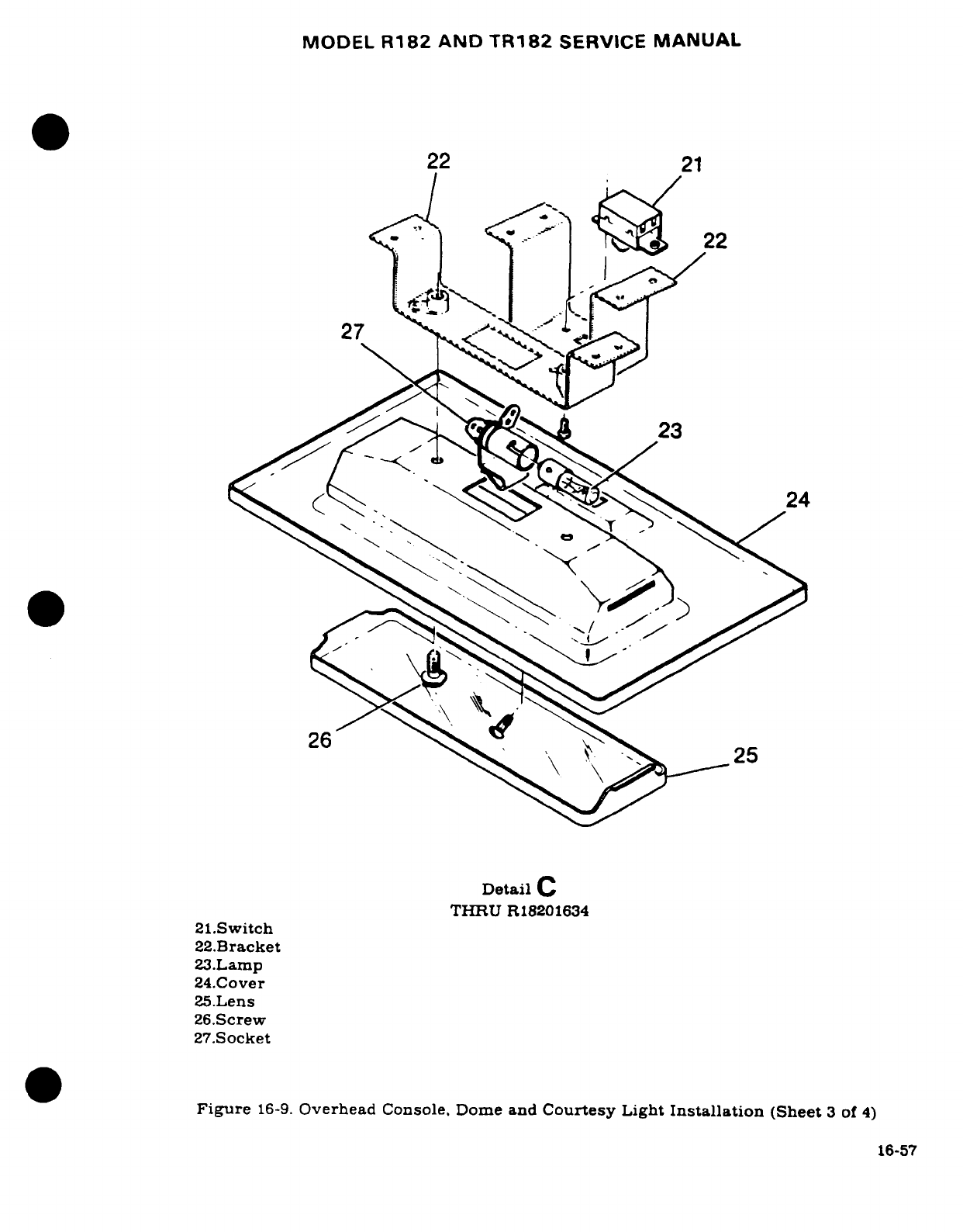
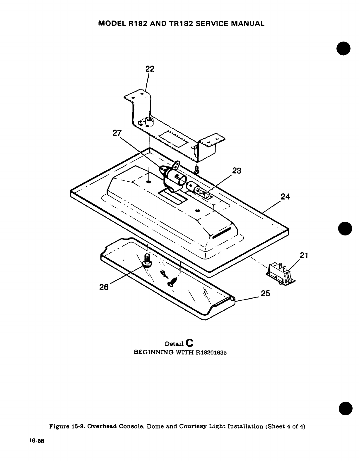
MODEL
R182
AND
TR182
SERVICE
MANUAL
16-84.
CONTROL
WHEEL
MAP LIGHT.
16-85.
DESCRIPTION.
The
control
wheel
map
light
is
internally
mounted
in
the
control
wheel.
A
rheostat
located
on
the
lower
right
hand
side
of
the
wheel
controls
the
light.
16-86.
REMOVAL
AND
INSTALLATION.
(See
figure
16-12.)
To
remove,
push
upward
on
the lamp
and
turn.
The
lamp
and
reflector
are
replaced
as
a
unit.
16-87.
LANDING GEAR
INDICATOR
LIGHTS.
16-88.
DESCRIPTION.
Thru
1982
models,
the
position
of
the
landing
gear
is
indicated
by
two
press-to-test
lamp
assemblies
mounted
on
the
right
side
of
the
switch
panel.
The
green
light
is
on
when
all
three
gears
are
down
and
locked,
the
amber
is on
when
all
three
gears
are
up
and
locked.
If
any
gear
assumes
an
intermediate position
of
neither
up
and
locked
or
down
and
locked,
both
lights
will
be
dark.
The
hood
of each
light
is
removable
for
bulb
replace-
ment,
and has
a
dimming
shutter.
Beginning
with
1983
models,
the
gear
indicating
lights
are
red
and
green,
press-to-test
light
assemblies.
The
green
light
indicates
that
all
three
gears
are
down
and
locked.
The
red
light
indicates
that
the
gears
are
in
transition.
The
red
light
goes
out when
the
gears
are
fully
retracted
or
extended.
The
red
light
will
illuminate
when
the
gears
are
fully
retracted
should
the
system
pressure
drop
below
1000
PSI,
except
when
the
nose
gear
squat
switch
is
open.
It
is
possible
to
have both
lights
on
at
the
same
time. Under
normal
circumstances, this
will
occur
only momentarily.
However,
anytime
both
lights
stay
on
or
the
red
light
does
not
go
out,
a
malfunction
has
occurred.
16-89.
REMOVAL
AND
INSTALLATION.
a.
Remove
the hood
on
either
light
by
unscrewing
counterclockwise.
The
lamp
is
in
the
hood
and
may
be
replaced
by
pulling
it
out
and
inserting
a
new
lamp.
b.
To
remove
the lamp
socket
assembly,
remove
the nut
from
the
assembly
on
the
front
side
of
the
panel.
c.
Tag
and
unsolder
the
wires
from
the
socket
assembly.
d.
To
replace
a
lamp
socket
assembly,
reverse
the
above procedure.
16-90.
COMPASS
AND
RADIO
DIAL
LIGHTS.
16-91.
DESCRIPTION.
The
compass
and
radio
dial
lights
are
contained
within
the
individual
units.
The
light
intensity
is
controlled
by
the
instrument
light-dimming
rheostat
mounted
on
the
lower
left
side
of
the
instrument
panel.
16-92.
PEDESTAL
LIGHTING.
16-93.
DESCRIPTION.
The
pedestal
lighting
consists
of
two
lights:
one
on
the
upper
portion
of
the
pedestal
for
lighting
of
the
trim
wheels
and
the cowl
flap
control,
and
one
on
the
lower
portion
for
lighting
of
the
fuel
selector.
Light
dimming
is
controlled by
the
transistorized
light
dimming
circuit.
16-94.
REMOVAL
AND
INSTALLATION.
For
removal
and
installation
of
the
lamps,
see
figure
16-
13.
16-95.
STALL
WARNING
UNIT.
16-96.
DESCRIPTION.
A
solid
state
warning
unit
is
installed
on
the
left
hand root
rib.
The
warning
signal
is
transmitted
through
the
radio
speaker
in
the
overhead console.
Revision
1
16-59
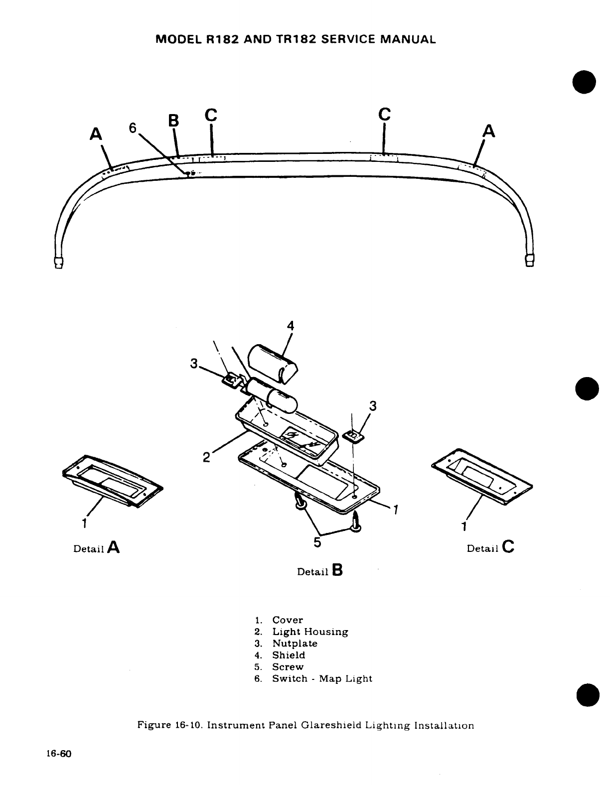
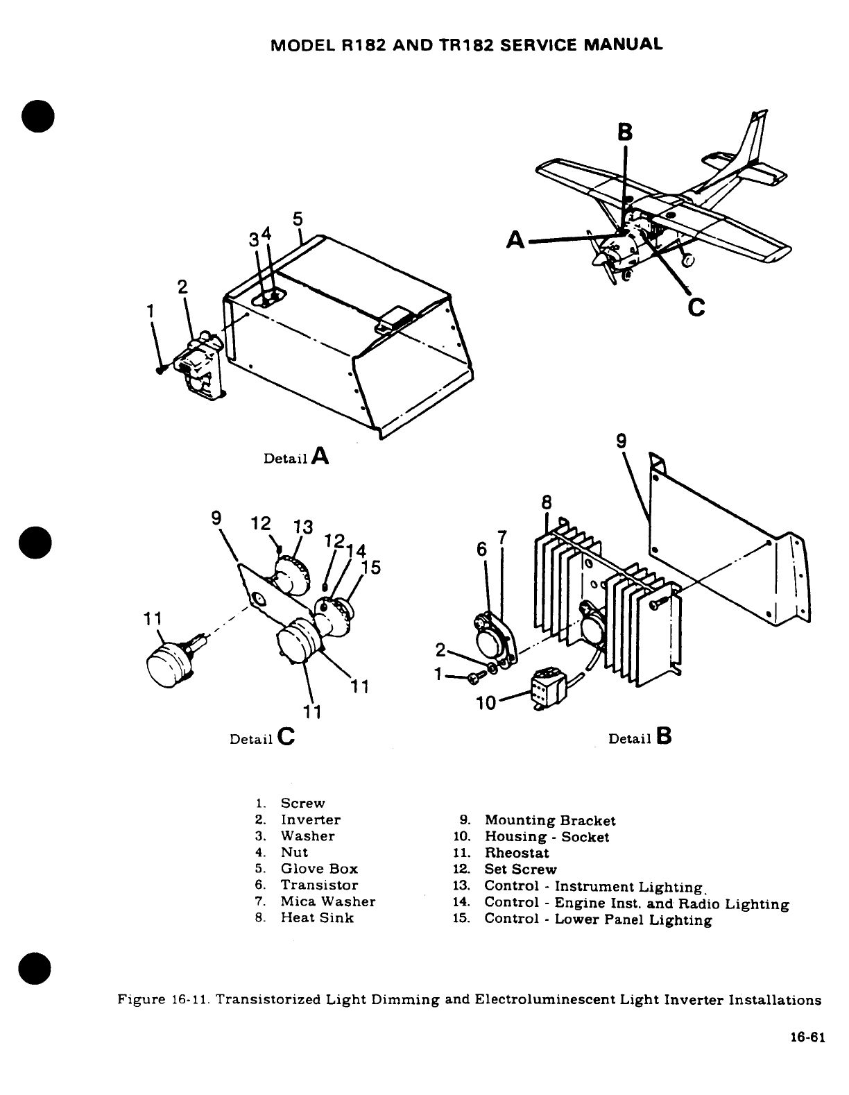
MODEL
R182
AND
TR182
SERVICE
MANUAL
5
34
A
2
Detail
A
9
12
1312
14
6
*
//15
1111
N
1
11
Detail
C
Detail
B
1.
Screw
2.
Inverter
9.
Mounting
Bracket
3.
Washer
10.
Housing-
Socket
4.
Nut
11.
Rheostat
5.
Glove
Box
12.
Set
Screw
6.
Transistor
13.
Control
-
Instrument
Lighting.
7.
Mica
Washer
14.
Control
-
Engine
Inst.
and
Radio
Lighting
8.
Heat
Sink
15.
Control
-
Lower
Panel
Lighting
Figure
16-11.
Transistorized
Light
Dimming
and
Electroluminescent
Light
Inverter
Installations
16-61
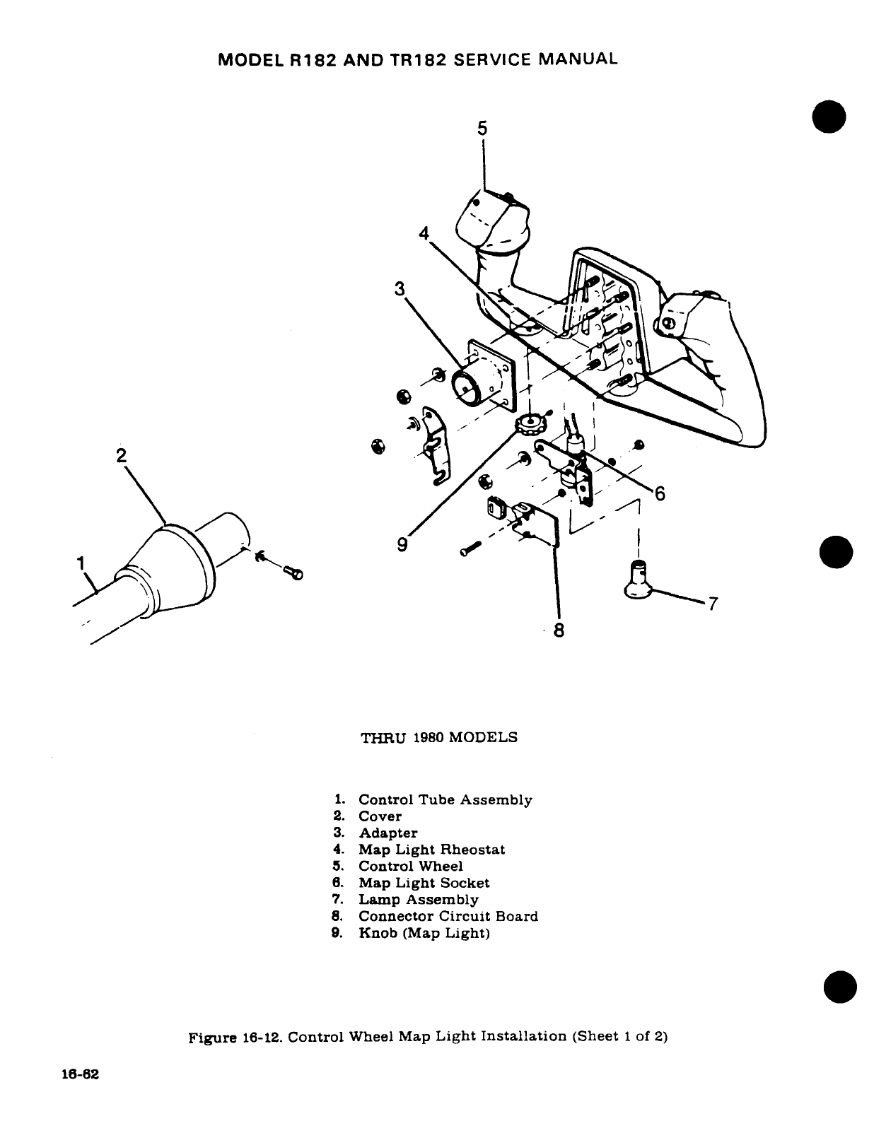
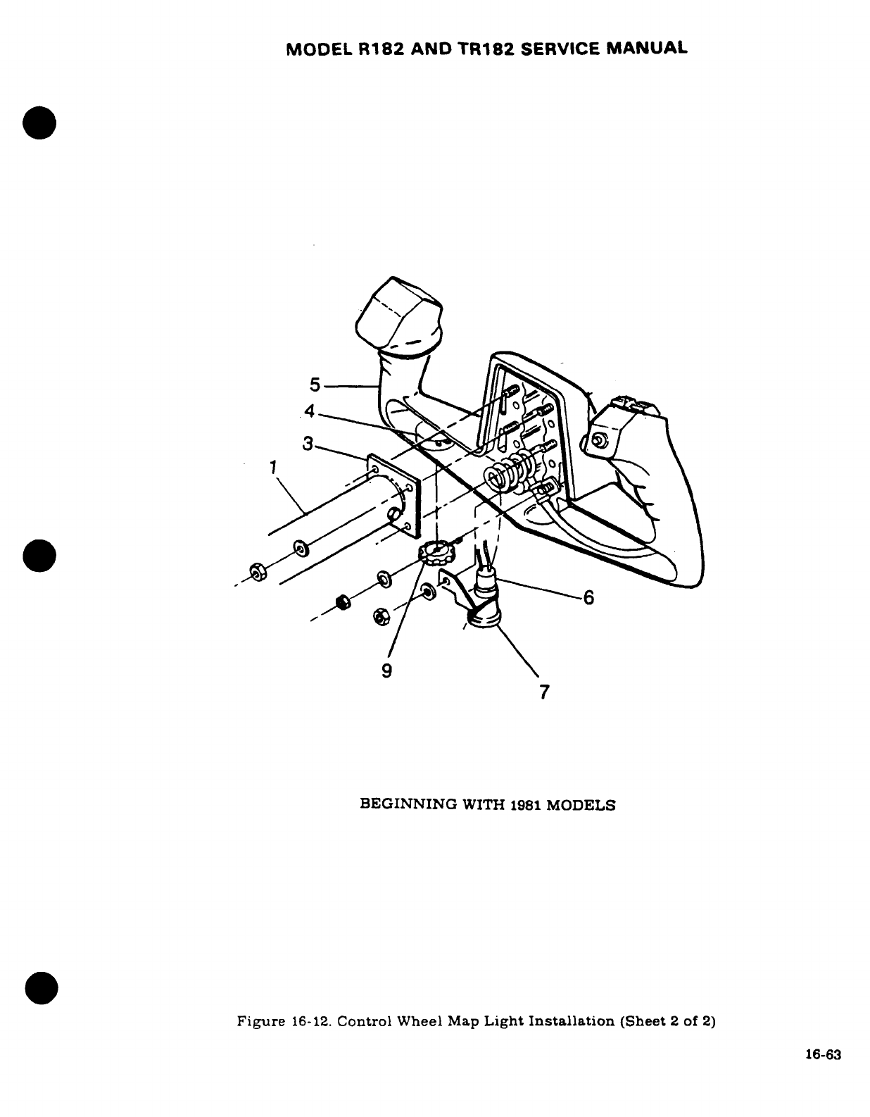
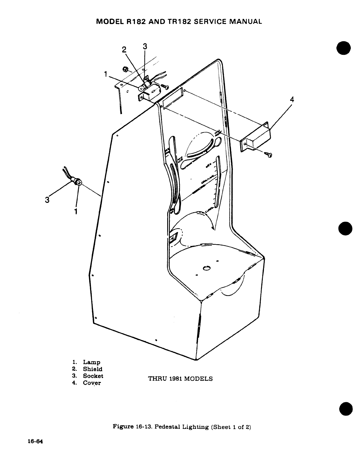
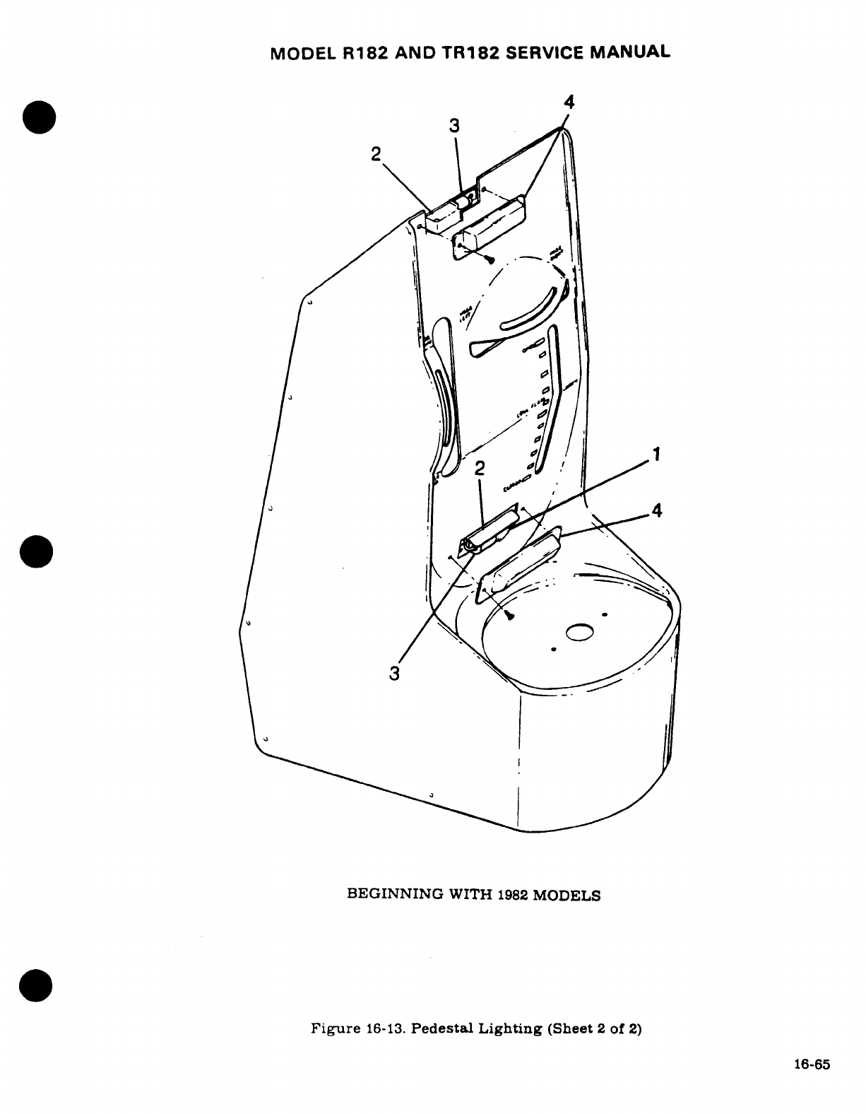
MODEL
R182
AND
TR182
SERVICE
MANUAL
NOTE
If
false
signals
are
experienced,
refer
to
Cessna
Single-
engine Service
Letter
SE78-50.
dated
August
7. 1978.
16-97
REMOVAL
AND
INSTALLATION.
(See
figure
16-14.)
16-98..
STALL
WARNING
SWITCH.
16-99.
DESCRIPTION.
The
stall
warning
switch
is
installed
in
the
leading
edge
of
the
left
wing
and
is
actuated
by
airflow
over
the
surface
of
the
wing.
The
switch
will close
as
a
stall
condition
is
approached,
actuating
the
stall
warning
horn.
The
horn
should
sound
at
approximately
five
to
ten
miles
per
hour
above
actual
stall
speed.
Initial installation
of
the switch
should
be
with the
lip
of
the
warning
switch
approximately
one
sixteenth
of
an
inch
below
the
center
line
of
the
wing
skin
cutout.
Test-fly
the
aircraft
to
determine
if
the
horn
sounds
at
the
desired speed.
If
the
horn
sounds
too
soon.
move
the
unit
down
slightly;
if too
late.
move
the
unit
up
slightly.
16-100.
REMOVAL
AND
INSTALLATION. (See
figure
16-14.)
16-101.
COURTESY
LIGHTS.
16-102.
DESCRIPTION.
The
lights
consist
of
one
light
located
on
the
under side
of
each
wing
to
provide
ground
lighting
around
the
cabin
area.
The
courtesy
lights
have
clear
lenses
and
are
controlled
by
a
single
slide
switch
labeled
"Utility
Lights",
located
on
the
left
rear
door
post.
16-103.
REMOVAL AND
INSTALLATION.
(See
figure
16-9.)
16-104.
PITOT AND
STALL WARNING
HEATERS.
16-105.
DESCRIPTION.
Electrical
heater units
are
incorporated
in
some
pitot
tubes and
stall
warning
switch
units.
The
heaters
offset
the
possibility
of
ice
formations
on
the
pitot
tube
and
stall
warning
actuator
switch.
The
heaters
are
integrally
mounted
in
the
pitot
tube
and
the
stall
warning
actuator
switch.
Both
heaters
are
operated
by
the
pitot
heat switch.
16-106.
CIGAR
LIGHTER.
(THRU
R18201798.)
16-107.
DESCRIPTION.
The
cigar
lighter
(located
on
the
instrument
panel)
is
equipped
with
a
thermal-actuated
circuit
breaker
which
is
attached
to
the
rear
of
the
cigar
lighter.
The
circuit
breaker
will
open
if
the
lighter
becomes
jammed
in
the
socket
or
held
in
position
too
long.
The
circuit
breaker
may
be
reset
by
inserting
a
small
probe
into
the
.078
diameter
hole
in
the
back
of
the
circuit
breaker
and
pushing lightly until
a
click
is
heard.
CAUTION
Make
sure
the
master
switch
is
OFF
before
inserting
probe
into the
circuit
breaker
on
cigar
lighter
to
reset.
16-108.
REMOVAL AND
INSTALLATION.
(See
figure
16-15.)
a.
Ensure
that
the
master
switch
is
OFF.
b.
Remove
the
cigar
lighter
element.
c.
Disconnect
wire
on
back
of
lighter.
d.
Remove
shell
that
screws
on
socket back
of
panel.
e.
The
socket
will
then
be
free
for
removal.
f.
To
install
a
cigar
lighter,
reverse
this procedure.
16-66
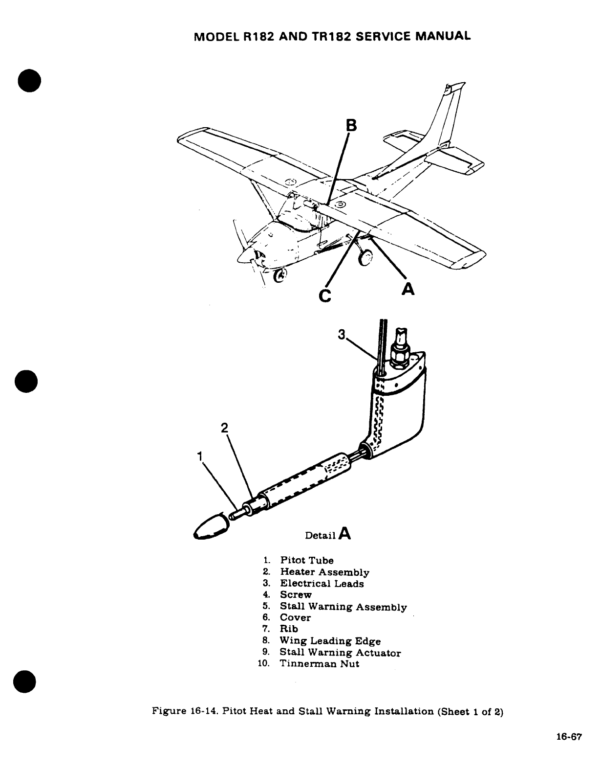
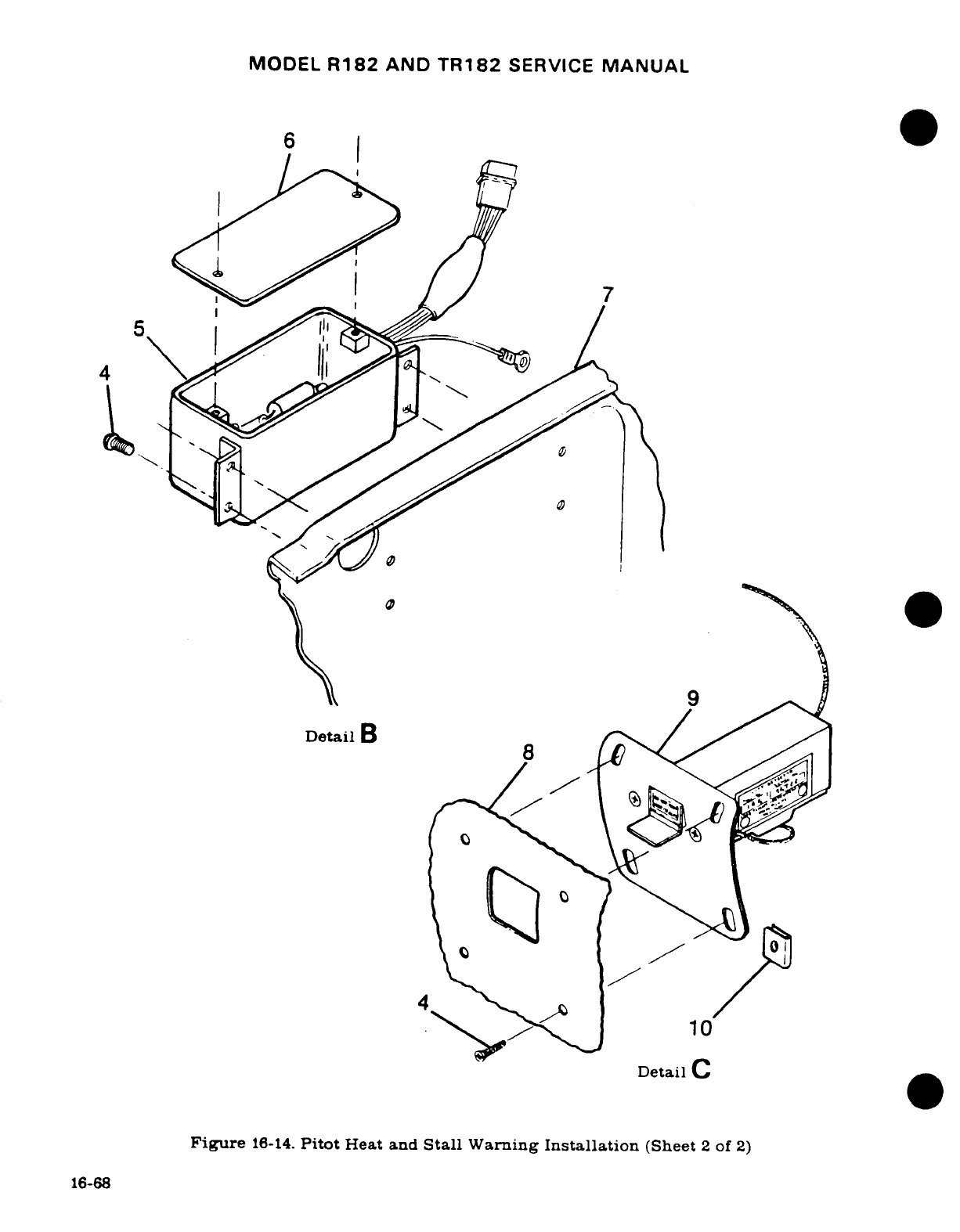
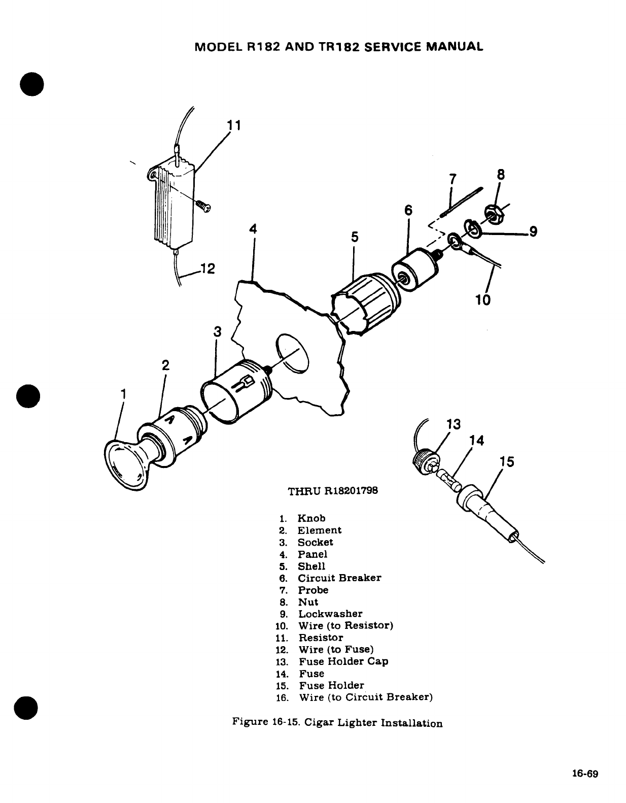
MODEL
R182
AND
TR182
SERVICE
MANUAL
11
'--
7
8
11 Rei15
THRU
R18201798
1.
Knob
2.
Element
F
3.
Socket
4.
Panel
5.
Shell
6.
Circuit
Breaker
7.
Probe
8.
Nut
9.
Lockwasher
10.
Wire
(to
Resistor)
11.
Resistor
12.
Wire
(to
Fuse)
13.
Fuse
Holder
Cap
14.
Fuse
15.
Fuse
Holder
16.
Wire
(to
Circuit
Breaker)
Figure
16-15.
Cigar
Lighter
Installation
16-69
MODEL
R182
AND
TR182
SERVICE
MANUAL
16-109.
EMERGENCY
LOCATOR
TRANSMITTER.
16-110.
DESCRIPTION.
The
ELT is
a
self-contained,
solid
state
unit,
having
its
own
power
supply,
with an
externally
mounted
antenna.
The
unit
is
mounted
in
the
tailcone.
aft
of
the
baggage
curtain
on
the
left
hand
side.
The
transmitters
are
designed
to
provide
a
broadcast
tone
that
is
audio
modulated
in a
swept
manner
over
the
range
of
1600 to 300
Hz
in
a
distinct,
easily
recognizable
distress
signal
for
reception
by
search and
rescue
personnel
and
others
moni-
toring
the
emergency
frequencies.
The
ELT
exhibits
line
of
sight
transmission
characteris-
tics
which
correspond
approximately
to
100
miles
at
a
search altitude
of
10,000
feet.
The
C589511-0103
transmitter,
and
the
C589511-0104
transmitter
on
aircraft
with
Canadian
re-
gistry,
are
used
thru
R18200583
.The C589511-0117
transmitter,
and
the
C589511-0113
transmitter
on
aircraft
with
Canadian
registry,
are
used
thru
R18200584
thru
R18201933.
Beginning
with
R18201934
the
C589512-0103
transmitter
is
used
on
all
aircraft.
The
C589511-0104
transmits
on
121.5
MHz
at
25
mw
rated
power
output
for
100
continu-
ous
hours
in
the
temperature
range
of
-40°F
(-40°C
to
+
55°C).
The
C589511-0113
transmits
on
121.5
MHz
at
25
mw
rated
power
output
for
100
continuous
hours
in
the
temperature
range
of
-4°F
to
+
131°F
(-20°C
to
+55°C).
The
C589511-0103
transmits
on
121.5
and
243.0
MHz
simultaneously
at
75
mw
rated
power
output
for
48
continuous
hours
in
the
tempera-
ture range
of
-40°F
to
+131°F
(-40°C
to
+55°C).
The
C589511-0117
and
C589512-0103
transmits
on
121.5
and
343.0
MHz
at
75
mw
rated
power
output
for
48
continuous
hours
in
the
temperature
range
of
-4°F
to
+
131°F
(-20°C
to
+55°C).
Power is
supplied
to
the
transmitter
by
a
battery-pack.
The
C589511-0104
and
C589511-
0103
ELT's
equipped
with
a
lithium
battery-pack
must
be
modified
by
SK185-20
as
outlined
in
Avionics
Service
Letter
AV78-31,
dated
20
November
1981,
to
incorporate
alkaline
bat-
tery-packs.
The
C589511-0114
alkaline battery-packs
have
the
service
life
of
the
battery-
pack
stamped on
the
battery
pack,
on
the
end
of
the
transmitter
below
the
switch
and
on
top
of
the
transmitter.
The
C589512-0107
alkaline battery-packs
have
the
replacement
date
and
date
of
installation
on
the
battery-pack
and
the
replacement
date
on
the
top
of
the
transmit-
ter.
16-111.
OPERATION.
A
three-position
switch
on
the forward
end
of
the
unit
controls
operation.
Placing
the switch
in
the
ON
position
will
energize
the
unit
to
start transmitting
emergency
signals.
In
the
OFF
position,
the
unit
is
inoperative.
Placing
the
switch
in
the
ARM
position
will
set the
unit
to
start
transmitting
emergency
signals
only
after
the
unit
has
received
a
5g
(tolerances
are
+
2g
and
-Og)
impact
force,
for
a
duration
of
11-16
milliseconds.
CAUTION
Do
not
leave
the
emergency
locator
transmitter
in
the
ON
position
longer
than
1
second
(3
sweeps of
the
warble
tone)
or
you
may
activate
downed
aircraft
procedures
by
CAP,
DOT
or
FAA
personnel.
16-112.
CHECKOUT
INTERVAL:
100
HOURS
OR
THREE
MONTHS,
WHICHEVER
COMES
FIRST.
a.
Turn
aircraft
master
switch
ON.
b.
Turn aircraft
transceiver
ON
and
set frequency
on receiver
to
121.5
MHz.
c.
Remove
the ELTs
antenna
cable
from
the
ELT
unit.
16-70
MODEL
R182
AND
TR182
SERVICE
MANUAL
d.
Place
the
ELTs function
selector switch
in
the
ON
position
for
1
second
or
less.
Im-
mediately
replace
the
ELT
function
selector
switch
in
the
ARM
position
after
testing
ELT.
e.
Test
should
be
conducted
only
within
the
time
period
made
up
of
the
first
five
min-
utes
after
any
hour.
CAUTION
Tests
with
the
antenna
connected
should
be
approved and
confirmed
by
the nearest
control
tower.
The
FAA/DOT
al-
lows
free
space transmission
tests from
the
aircraft
any
time
within
five
minutes after
each
hour.
The
test
time
allowed
is
generally
three
sweeps of
the
warble
tone,
or
approximately
one
second.
The
control
tower should
be
notified
that
a
test
is
about
to
be
performed.
NOTE
Without
its
antenna
connected,
the
ELT
will
produce
sufficient
signal
to
reach your
receiver,
yet
it
will
not
disturb
other
communications
or
damage
output
circui-
try.
NOTE
After
accumulated
test
or
operation
time
equals
1
hour,
battery-pack replacement
is
required.
f.
Check
calendar
date
for
replacement
of
battery-pack.
This
date
is
supplied
on
a
sticker
attached
to
the
outside
of
the
ELT
case
and
to
each
battery.
16-113.
REMOVAL
AND
INSTALLATION
OF
TRANSMITTER.
(See
figure
16-16.)
a.
Remove
baggage
curtain
to
gain
access
to
the
transmitter
and
antenna.
b.
Disconnect
co-axial
cable
from
end
of
transmitter.
c.
Remove
the
two
#10
screws
from the
baseplate
of
the
ELT
and remove
ELT.
d.
To
reinstall
transmitter,
reverse
preceding
steps.
CAUTION
Ensure
that
the
direction
of
flight
arrows
(placarded
on
the
transmitter)
are
pointing
towards
the
nose
of
the
aircraft.
16-114.
REMOVAL
AND
INSTALLATION
OF
ANTENNA.
(See
figure
16-16.)
a.
Disconnect co-axial
cable from
base
of
antenna.
b.
Remove
the
nut
and
lockwasher
attaching the
antenna
base
to
the
fuselage
and
the
antenna
will
be
free
for
removal.
c.
To
reinstall
the
antenna,
reverse
the
preceding steps.
NOTE
Upon
reinstallation
of
antenna,
cement
rubber
boot
(14)
using
RTV102.
General
Electric
Co.
or
equivalent,
to
antenna
whip
only;
do
not apply
adhesive
to
fuselage
skin
or
damage
to
paint
may
result.
16-71
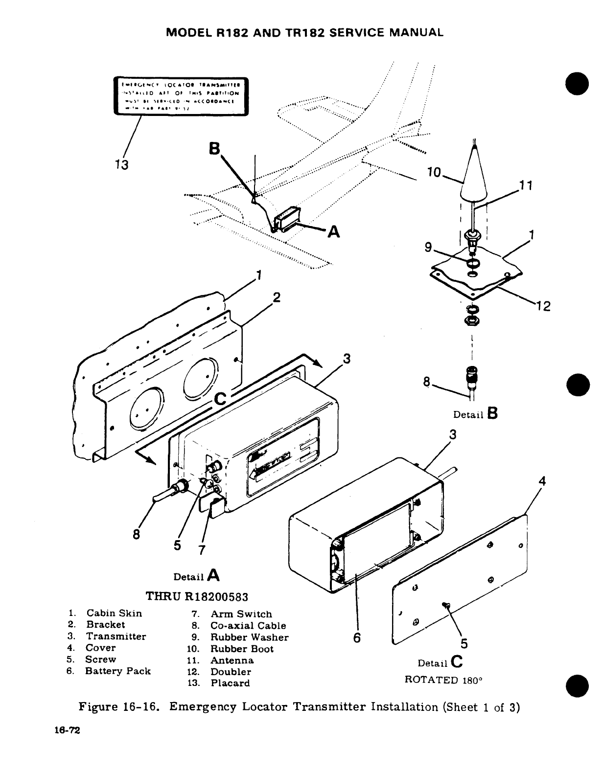
MODEL
R182
AND
TR182
SERVICE
MANUAL
.. ..
1 3-
H-,1
0
l^t t
OF
I1 0S i
I
.'.'
/
'
II \~11·.(.10
q ¢(O~l~a(l
12
Dt:i: A...Dt
_ 1
·
t· '-I
All
C<
>0'C
* . '-
.''''
'-'-':-,.
'.::.'
3.
Transmitter
9.
Rubber
Washer
.5..
4.
Cover
10.
Rubber
Boot
5.
Screw
11.
Antenna
Detail
C
6.
Battery
Pack
12.
Doubler.. ...
13.
Placard
ROTATED
180
: Detail
B
THRU
R18200583
1.
Cabin
Skin
7.
Arm
Switch
2.
Bracket
8.
Co-axial
Cable
3.
Transmitter
9.
Rubber
Washer
6
4.
Cover
10.
Rubber
Boot
5
5.
Screw
11.
Antenna
DetailC
6.
Battery
Pack
12.
Doubler
13.
Placard
ROTATED
180
°
Figure
16-16.
Emergency
Locator
Transmitter
Installation
(Sheet
1
of
3)
16-72
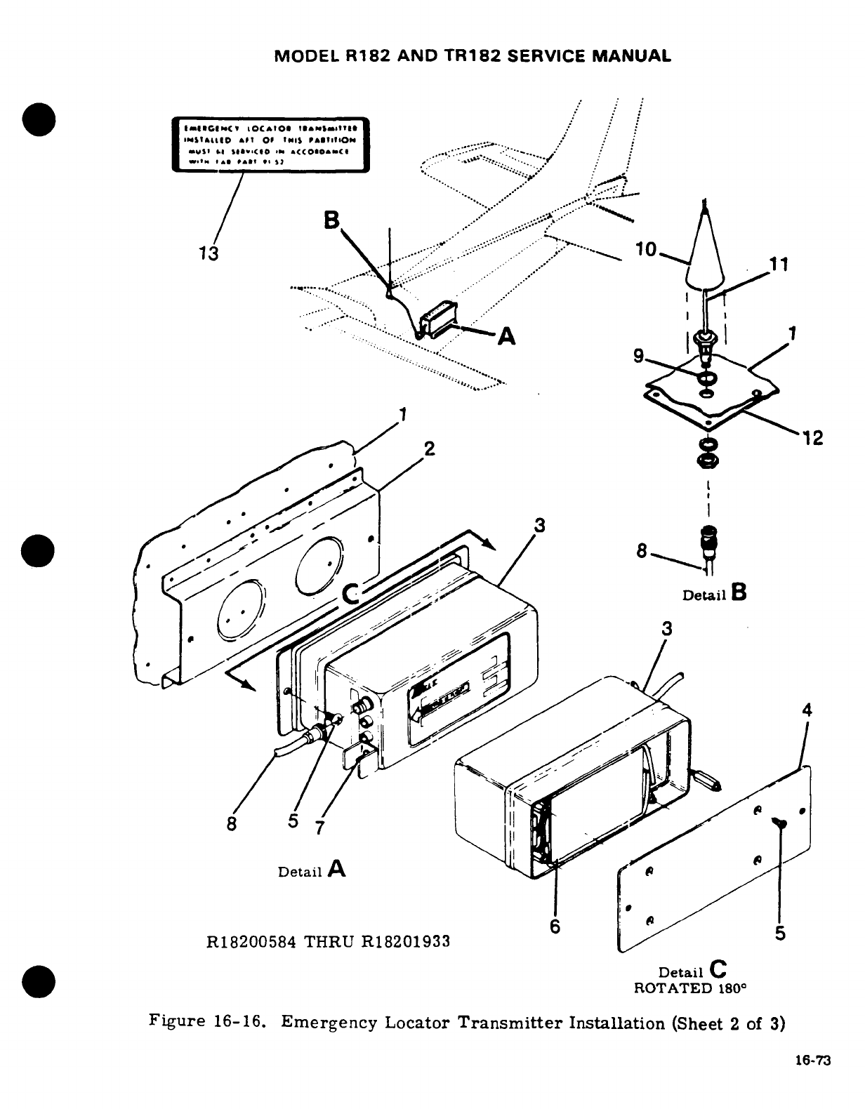
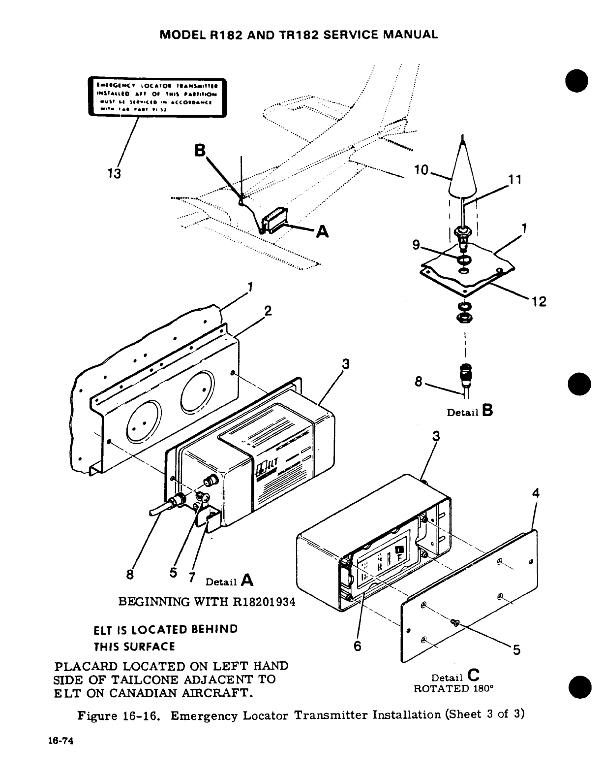
MODEL
R182
AND
TR182
SERVICE
MANUAL
a"Z~czz.
toc~o
t.^,I of,,.is ,,.-4
,10.
4*
.
H
se-clo t
01t
o'
...
.^'.C.
| Z~t' tils i >o
"
*c<~coneo*~-c
.«~. ~.:::"*
--
_ ,~."
. '
*
'""«
* '*
»i » ;
',
-" '
A '"'
....
.
13
1
....//' ":'Y
62
V
12
^^^
"
.... 0
THIS
SURFACE
6
. . 5
PLACARD LOCATED
ON
LEFT
HAND
SIDE
OF
TAILCONE
ADJACENT
TO
Detail
C.
ELT
ON
CANADIAN
AIRCRAFT.
ROTATED
180°
Figure
16-16.
Emergency
Locator
Transmitter
Installation
(Sheet
3
of
3)
16-74
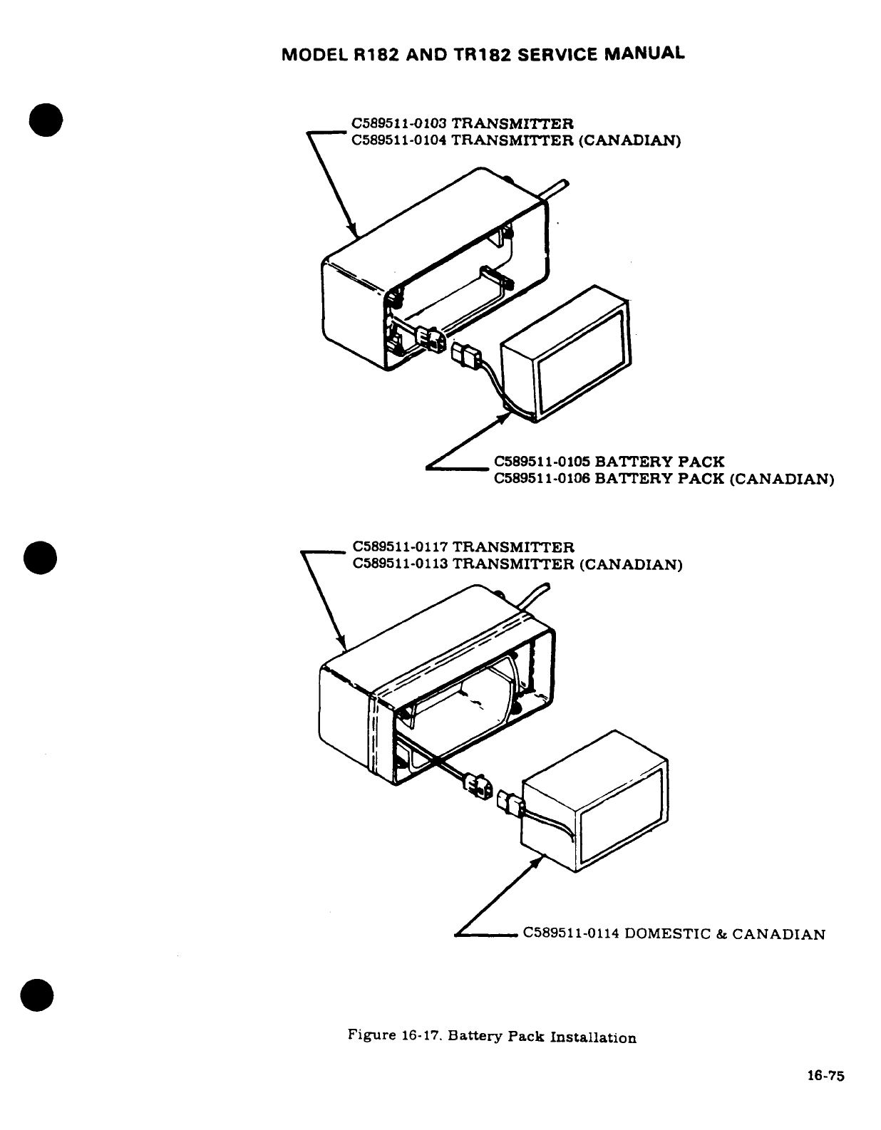
MODEL
R182
AND TR182
SERVICE
MANUAL
C589511-0103
TRANSMITTER
C589511-0104
TRANSMITTER
(CANADIAN)
j
C589511-0105
BATTERY
PACK
C589511-0106
BATTERY
PACK
(CANADIAN)
C589511-0117
TRANSMITTER
C589511-0113
TRANSMITTER
(CANADIAN)
C589511-0114
DOMESTIC
&
CANADIAN
Figure
16-17.
Battery
Pack
Installation
16-75

MODEL
R182
AND
TR182
SERVICE
MANUAL
CAUTION
The
C589511-0111
and
C589511-0119
co-axial
cable
must
be
installed
as indicated
on
the
cable
sleeve.
Cable
end
marked
"TO
ANT"
must
be
connected
to
the
ELT
antenna.
and
the
end
marked
"TO
ELT"
must
be
connected
to
the
C589511-0113/
-0117
and
C589511-0103/
-0104
transmitters.
16-115.
REMOVAL
AND
INSTALLATION
OF
BATTERY-PACK.
(See
figure
16-17).
CAUTION
Lithium
battery-pack
must
be
replaced
with
alkaline
battery-packs
per
SK185-20.
NOTE
Transmitters
equipped with
the
C589511-0105
or
C589511-
0106
battery-packs
can
only
be
replaced
with
another
C589511-0114
after
modification
by
SK185-20
has
been
completed.
a.
After
the
transmitter
has
been
removed
from
aircraft
in
accordance
with
para
16-113,
place
the
transmitter
switch
in
the
OFF
position.
b.
Remove
the
four
screws
attaching
the
cover
to
the
case
and
then remove
the
cover
to
gain
access
to
the
battery-pack.
c.
Disconnect
the
battery-pack
electrical
connector
and
remove
battery-pack.
d.
Place
new
battery-pack
in
the
transmitter
with
four
batteries
as shown
in
the
case
in
figure
16-17.
e.
Connect
the
electrical
connector
as
shown
in
figure
16-17.
NOTE
Before
installing
the
battery
pack,
check
to
ensure
that
its
voltage
is
7.5
volts
or
greater.
f.
Replace
the
transmitter
baseplate
on
the
unit
and
pressing
the
baseplate
and
unit
together
attach
baseplate
with
four
Nylok
patch
screws.
g.
Stamp
the
new
replacement
date
on
the outside
of
the
ELT.
The
date
should
be
noted
on
the
switching nameplate
on
the
side
of
the
unit
as
well
as
on
the
instruction
nameplate
on
top
of
the
unit.
WARNING
The
battery-pack
has
pressurized
contents.
Do
not
recharge,
short
circuit
or
dispose
of
in
fire.
CAUTION
Be
sure
to
enter
the
new
battery-pack expiration
date
in
the
aircraft
records.
It
is
also
recommended
this
date
be
placed
in
your
ELT
Owner's
Manual
for
quick
reference.
16-76
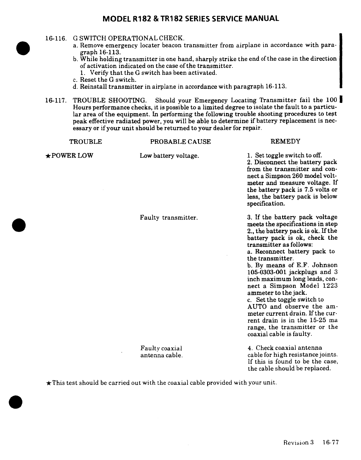
MODEL
R182
&TR182
SERIES
SERVICE
MANUAL
16-116.
G
SWITCH
OPERATIONAL
CHECK.
a.
Remove
emergency
locater
beacon
transmitter
from
airplane
in
accordance
with
para-
graph
16-113.
b.
While
holding
transmitter
in one
hand,
sharply
strike
the
end
of
the
case
in
the
direction
of
activation
indicated
on
the
case
of
the
transmitter.
1.
Verify
that
the
G
switch
has
been
activated.
c.
Reset
the
G
switch.
d.
Reinstall
transmitter
in
airplane
in
accordance
with paragraph
16-113.
16-117.
TROUBLE
SHOOTING.
Should
your Emergency Locating
Transmitter
fail
the
100
Hours performance
checks,
it
is
possible to
a
limited
degree
to
isolate
the
fault
to
a
particu-
lar
area
of
the
equipment.
In
performing
the
following
trouble
shooting
procedures
to
test
peak
effective
radiated
power, you
will
be
able
to
determine
if
battery
replacement
is
nec-
essary
or
if
your
unit
should
be
returned
to
your
dealer
for
repair.
TROUBLE
PROBABLE
CAUSE REMEDY
*POWER
LOW
Low
battery
voltage.
1. Set toggle
switch
to
off.
2.
Disconnect
the battery
pack
from
the
transmitter
and
con-
nect
a
Simpson
260
model
volt-
meter and
measure
voltage.
If
the
battery
pack
is
7.5
volts
or
less,
the
battery
pack
is
below
specification.
Faulty
transmitter.
3.
If
the
battery
pack
voltage
meets
the
specifications
in
step
2.,
the
battery
pack
is
ok.
If
the
battery
pack
is
ok,
check
the
transmitter
as
follows:
a.
Reconnect
battery
pack to
the
transmitter.
b.
By
means
of
E.F.
Johnson
105-0303-001
jackplugs
and
3
inch
maximum
long
leads,
con-
nect
a
Simpson
Model
1223
ammeter
to
the
jack.
c.
Set
the
toggle
switch
to
AUTO
and
observe
the
am-
meter
current
drain.
If
the
cur-
rent
drain
is
in
the
15-25
ma
range,
the
transmitter
or
the
coaxial
cable
is
faulty.
Faulty
coaxial
4.
Check
coaxial
antenna
antenna
cable.
cable
for
high
resistance
joints.
If
this
is
found
to be
the
case,
the
cable
should
be
replaced.
*This
test
should
be
carried
out
with
the
coaxial cable provided
with
your
unit.
Revision
3
16-77
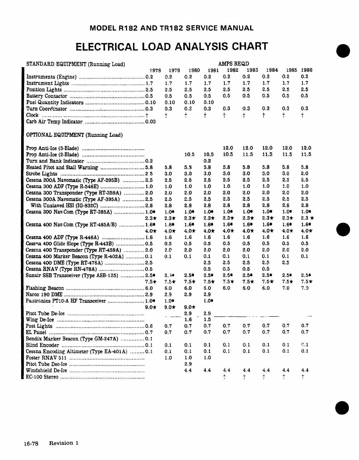
MODEL
R182
AND TR182
SERVICE
MANUAL
ELECTRICAL
LOAD
ANALYSIS
CHART
STANDARD
EQUIPMENT
(Running
Load)
AMPS
REQD
1978
1979
1980
1981
1982 1983
1984
1985
1986
Instruments
(Engine)
........................................
0.2
0.2
0.2
0.2 0.2
0.2
0.2
0.2
0.2
Instrument
Lights
........................................
1.7
1.7
1.7
1.7
1.7
1.7
1.7
1.7
1.7
Position
Lights
........................................
2.5
2.5
2.5
2.5
2.5
2.5
2.5
2.5
2.5
Battery
Contactor
................................................
0.5
0.5
0.5 0.5
0.5
0.5
0.5
0.5
Fuel
Quantity
Indicators
......................................
0.
0.10
0.10
0.10
Turn
Coordinator
.........................................
0.3
0.3
0.3
0.3 0.3
0.3
0.3
0.3
0.3
Clock
.................................................................
t t t
t
Carb
Air Temp
Indicator
......................................
0.03
OPTIONAL
EQUIPMENT
(Running
Load)
Prop
Anti-Ice
(3-Blade)
........................................
12.0 12.0 12.0
12.0
12.0
Prop
Anti-Ice
(2-Blade)
........................................
10.5
10.5 10.5
11.5
11.5
11.5
11.5
Turn and
Bank
Indicator
.....................................
0.2
0.2
Heated
Pitot
and
Stall
Warning
............................
5.8
5.8
5.8
5.8 5.8
5.8
5.8
5.8
5.8
Strobe
Lights
........................................
2
5
3.0
3.0
3.0 3.0
3.0
3.0
3.0
2.0
Cessna 200A
Navomatic
(Type AF-295B)
..............
2.5
2.5
2.5
2.5 2.5
2.5
2.5
2.5
2.5
Cessna
300
ADF
(Type
R-546E)
............................
1.0
1.0
1.0
1.0 1.0
1.0
1.0
1.0
1.0
Cessna
300
Transponder
(Type RT-359A)
.............
2.0
2.0
2.0
2.0
2.0
2.0 2.0
2.0
2.0
Cessna
300A
Navomatic
(Type AF-395A)
..............
2.5
2.5
2.5
2.5 2.5
2.5
2.5
2.5
2.5
With
Unslaved
HSI
(IG-832C)
............................
2.8
2.8
2.8
2.8 2.8
2.8
2.8
2.8
2.8
Cessna
300
Nav/Com
(Type
RT-385A)
...................
1.0
1.0
1.0
1.0 1.0 1.0
1.0
1.0
2.3*
2.3*
2.3*
2.3*
2.3*
2.3*
2.3*
2.3*
2.3
*
Cessna
400
Nav/Com
(Type
RT-485A/B)
................
1.6
1.6
1.6
1.6 1.6 1.6
.
1.6
1.6
4.0*
4.0*
4.0*
4.0*
4.0* 4.0*
4.0*
4.0*
4.0*
Cessna
400
ADF
(Type
R-446A)
...........................
1.6
1.6
1.6
1.6
1.6
1.6
1.6
1.6
1.6
Cessna
400
Glide
Slope (Type
R-443B)
..................
0.5
0.5
0.5
0.5 0.5
0.5
0.5
0.5
0.5
Cessna
400
Transponder
(Type RT-459A)
............. 2.
0
2.0
2.0
2.0
2.0
2.0
2.0
2.0
Cessna
400
Marker
Beacon
(Type
R-402A)
............
0.1
0.1
0.1
0.1
0.1 0.1 0.1
0.1
0.1
Cessna
400
DME
(Type
RT-476A)
.........................
2.5
2.5
2.5
2.5
2.5
2.5
Cessna
RNAV
(Type
RN-478A)
.............................
0.5
0.5
0.5
0.5
0.5
Sunair
SSB
Transceiver
(Type
ASB-125)
...............
2.5
2.
2.5
2.5
2.5
2.5 2.5
2.5
2.5
7.5*
7.5*
7.5*
7.5*
7.5*
7.5*
7.5*
7.5*
7.5*
Flashing
Beacon
........................
................
.6.0
6.0
6.0
6.0
6.0 6.0
7.0
7.0
Narco 190
DME
...................................................
2.9
2.9
2.9
2.9
Pantronics
PT10-A
HF
Transceiver
.......................
1.0
1.0
1.0
9.0* 9.0*
9.0*
Pitot
Tube
De-Ice
.............................................
2.9
2.9
Wing
De-Ice
........................................
1.6
1.5
Post
Lights
.........................................................
0.6 0.7
0.7
0.7
0.7 0.7 0.7
0.7
0.7
EL
Panel
.............................................................
0.7
0.7
0.7
0.7
0.7 0.7 0.7
0.7
0.7
Bendix
Marker
Beacon
(Type
GM-247A)
...............
0.1
Blind
Encoder
.....................................................
0.1
0.1
0.1
0.1
0.1
0.1
0.1
0.1
O.1
Cessna
Encoding
Altimeter
(Type EA-401A)
.........
0.1
0.1
0.1
0.1 0.1
0.1 0.1
0.1
0.1
Foster
RN
AV 511
................................................
1.0
1.0
1.0
Pitot
Tube
Dec-Ice
................................................
2.9
W
indshield
De-Ice
................................................
4.4
4.4
4.4
4.4
4.4
4.4
4.4
EC-100
Stereo
......................................................
16-78
Revision
1
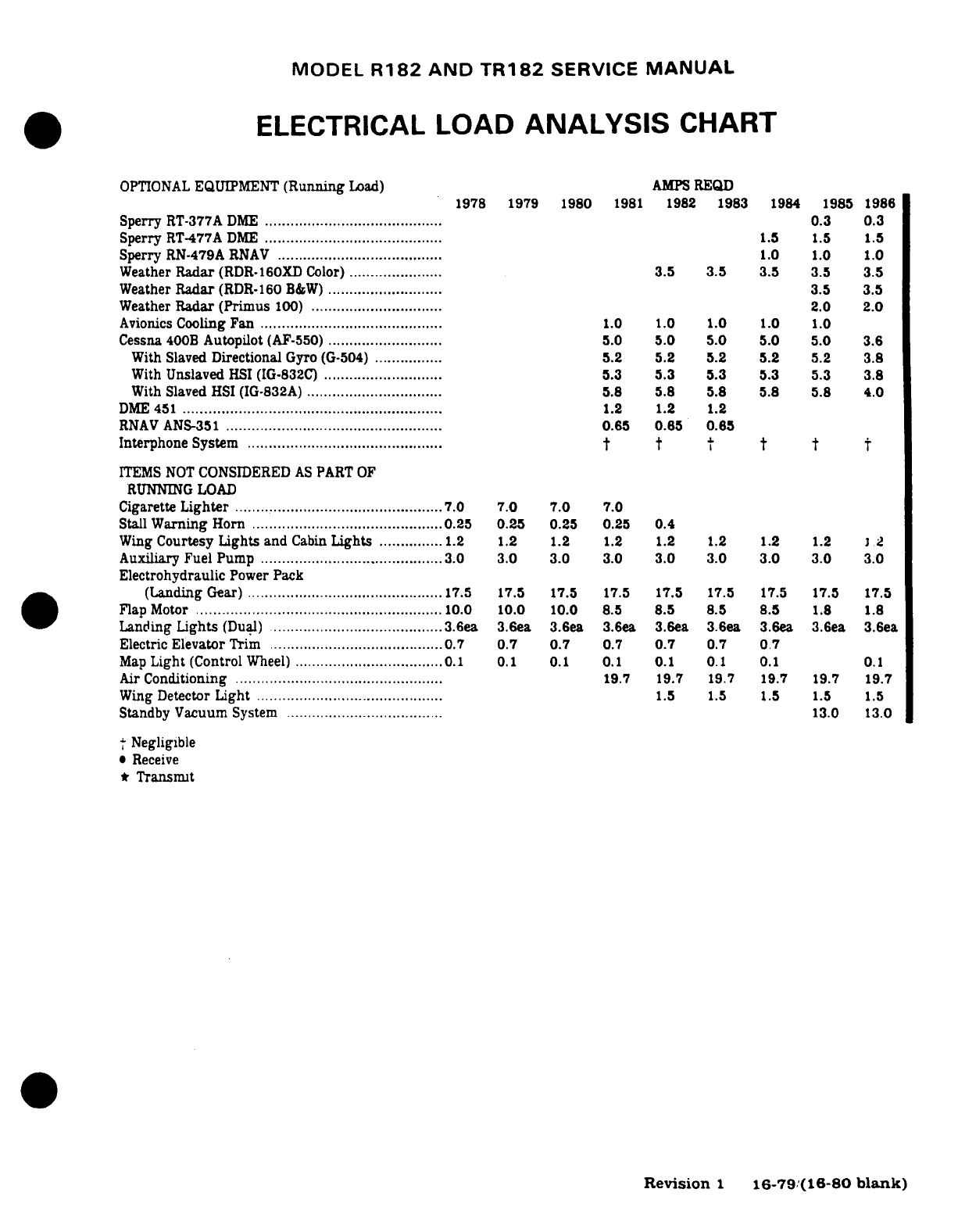
MODEL
R182
AND
TR182
SERVICE
MANUAL
ELECTRICAL
LOAD
ANALYSIS
CHART
OPTIONAL
EQUIPMENT
(Running
Load)
AMPS
REQD
1978 1979
1980
1981
1982
1983
1984
1985
1986
Sperry
RT-377A
DME
.........................................
0.3
0.3
Sperry
RT-477A
DME
.........................................
1.5
1.5
1.5
Sperry
RN-479A
RNAV
.......................................
1.0 1.0
1.0
Weather
Radar
(RDR.160XD
Color)
......................
3.5 3.5
3.5
3.5
3.5
Weather
Radar
(RDR-160
B&W)
...........................
3.5
3.5
Weather
Radar
(Primus
100)
...............................
2.0
2.0
Avionics
Cooling
Fan
...........................................
1.0
1.0 1.0 1.0
1.0
Cessna
400B
Autopilot
(AF-550)
...........................
5.0
5.0 5.0
5.0 5.0
3.6
With
Slaved
Directional
Gyro
(G-504)
................
5.2 5.2
5.2 5.2
5.2
3.8
With
Unslaved
HSI
(IG-832C)
............................
5.3
5.3 5.3
5.3
5.3
3.8
With
Slaved
HSI (IG-832A)
................................
5.8 5.8 5.8 5.8 5.8
4.0
DM
E
451
.............................................................
1.2
1.2 1.2
RNAV
ANS-351
...................................................
0.65
0.65
0.65
Interphone
System
..............................................
ITEMS NOT
CONSIDERED
AS
PART
OF
RUNNING LOAD
Cigarette
Lighter
.................................................
7.0
7.0 7.0
7.0
Stall
Warning
Horn
........................................
25
0.25
0.25
0.25
0.4
Wing
Courtesy
Lights
and
Cabin
Lights
................
2
1.2
1.2
1.2 1.2 1.2
1.2
1.2
1 .2
Auxiliary Fuel
Pump
........................................
3.0
3.0 3.0
3.0
3.0 3.0
3.0
3.0
3.0
Electrohydraulic
Power
Pack
(Landing
Gear)
..............................................
17.5 17.5 17.5
17.5
17.5
17.5
17.5
17.5
17.5
Flap
M
otor
..........................................................
10.0 10.0
10.0 8.5
8.5
8.5
8.5
1.8
1.8
Landing
Lights
(Dual)
........................................
3.6ea
3.6ea
3.6ea
3.6ea
3.6ea
3.6ea
3.6ea 3.6ea
3.6ea
Electric
Elevator
Trim
........................................
0.7
0.7
0.7
0.7
0.7
0.7
Map
Light
(Control
Wheel)
...................................
0.1
0.1 0.1
0.1
0.1
0.1 0.1
0.1
Air
Conditioning
.................................................
19.7
19.7
19.7
19.7 19.7
19.7
W
ing
Detector
Light
............................................
1.5
1.5 1.5 1.5
1.5
Standby
Vacuum
System
.....................................
13.0
13.0
Negligible
*
Receive
*
Transmit
Revision
1
16-79/(16-80
blank)
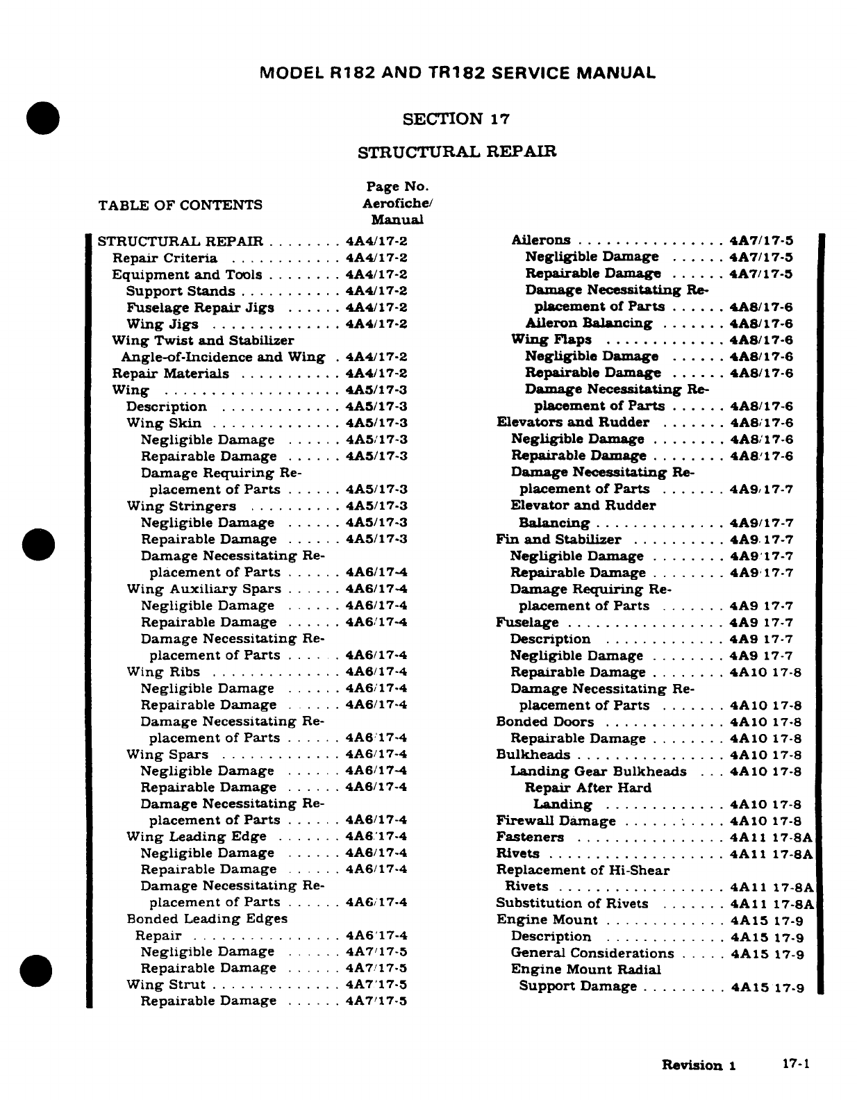
MODEL
R182 AND
TR182
SERVICE
MANUAL
SECTION
17
STRUCTURAL
REPAIR
Page
No.
TABLE
OF
CONTENTS
Aerofiche/
Manual
STRUCTURAL
REPAIR
........
4A4/17-2
Ailerons
................
4A7/17-5
Repair
Criteria
............
4A4/17-2
Negligible
Damage
......
4A7/17-5
Equipment and
Tools
........
4A4/17-2
Repairable
Dama
......
4A7/17-5
Support
Stands
...........
4A4/17-2
Damage
Necessitating
Re-
Fuselage
Repair
Jigs
......
4A4/17-2
placement
of
Parts
......
4A8/17-6
Wing
Jigs
..............
4A4/17-2
Aileron
Balancing
.......
4A8/17-6
Wing
Twist
and
Stabilizer Wing
Flaps
.............
4A8/17-6
Angle-of-Incidence
and
Wing
.
4A4/17-2
Negligible
Damage
......
4A8/17-6
Repair
Materials
...........
4A4/17-2
Repairable
Damage
......
4A8/17-6
Wing
...................
4A5/17-3 Damage
Necessitating
Re-
Description
.............
4A5/17-3
placement
of
Parts
......
4A8/17-6
Wing
Skin
..............
4A5/17-3
Elevators
and
Rudder
.......
4A8/17-6
Negligible Damage
......
4A5/17-3
Negligible
Damage
........
4A8/17-6
Repairable
Damage
......
4A5/17-3
Repairable
Damage
........
4A817-6
Damage
Requiring
Re-
Damage
Necessitating
Re-
placement
of
Parts
......
4A5/17-3
placement
of
Parts
.......
4A9
17-7
Wing
Stringers
.........
4A5/17-3
Elevator
and
Rudder
Negligible
Damage
......
4A5/17-3
Balancing
..............
4A9/17-7
Repairable
Damage
......
4A5/17-3
Fin
and
Stabilizer
..........
4A9
17-7
Damage
Necessitating
Re-
Negligible
Damage
........
4A9
17-7
placement
of
Parts
......
4A6/17-4
Repairable
Damage
........
4A9
17-7
Wing
Auxiliary
Spars
......
4A6/17-4
Damage
Requiring
Re-
Negligible
Damage
.....
4A6/17-4
placement
of
Parts
.......
4A9
17-7
Repairable
Damage
......
4A6/17-4
Fuselage
.................
4A9
17-7
Damage
Necessitating
Re-
Description
.............
4A9
17-7
placement
of
Parts
......
4A6/17-4
Negligible
Damage
........
4A9
17-7
Wing
Ribs
..............
4A6/17-4
Repairable
Damage
........
4A10
17-8
Negligible
Damage
......
4A6/17-4
Damage
Necessitating
Re-
Repairable
Damage
.....
4A6/17-4
placement
of
Parts
.......
4A10
17-8
Damage
Necessitating
Re-
Bonded
Doors
.............
4A10
17-8
placement
of
Parts
......
4A6/17-4
Repairable
Damage
........
4A10
17-8
Wing
Spars
.............
4A6/17-4
Bulkheads
................
4A10
17-8
Negligible
Damage
......
4A6/17-4
Landing
Gear
Bulkheads
. . .
4A10
17-8
Repairable
Damage
......
4A6/17-4
Repair After
Hard
Damage
Necessitating
Re-
Landing
.............
4A10
17-8
placement
of
Parts
......
4A6/17-4
Firewall
Damage
......
....
4A10
17-8
Wing
Leading
Edge
.......
4A6/17-4
Fasteners
................
4A11
17-8A
Negligible Damage
......
4A6/174
Rivets
...................
4A1
17-8A
Repairable Damage
......
4A6/17-4
Replacement
of
Hi-Shear
Damage
Necessitating
Re-
Rivets
..................
4A11
17-8A
placement
of
Parts
......
4A6/17-4
Substitution
of
Rivets
.......
4A11
17-8A
Bonded
Leading
Edges
Engine
Mount
.............
4A15
17-9
Repair
................
4A6'17-4
Description
.............
4A15
17-9
Negligible
Damage
......
4A7/17-5
General
Considerations
.....
4A15
17-9
Repairable
Damage
......
4A7/17-5
Engine
Mount
Radial
Wing
Strut
...........
4A7/17-5
Support
Damage
.........
4A15
17-9
Repairable
Damage
......
4A7/17-5
Revision
1
17-1
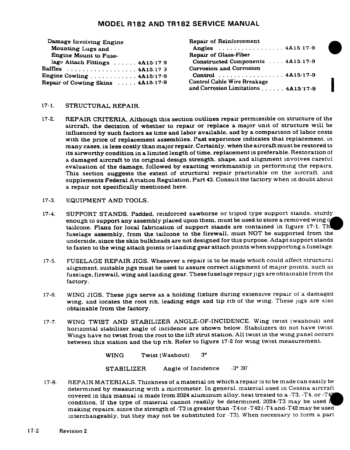
MODEL
R182
AND
TR182
SERVICE
MANUAL
Damage
Involving
Engine
Repair
of
Reinforcement
Mounting
Lugs
and
Angles
.................
4A15
17-9
Engine
Mount
to
Fuse-
Repair
of
Glass-Fiber
lage
Attach
Fittings
......
4A15/17
9
Constructed
Components
....
4A15/17-9
Baffles
.................
4A15/17
9
Corrosion
and
Corrosion
Engine
Cowling
............
4A15/17-9
Control
.................
4A15/17-9
Repair
of
Cowling
Skins
.....
4A15/17-9
Control Cable
Wire
Breakage
and
Corrosion
Limitations
......
4A15/17-9
17-1.
STRUCTURAL
REPAIR.
17-2.
REPAIR
CRITERIA.
Although
this
section
outlines repair permissible
on
structure
of
the
aircraft,
the
decision
of
whether
to
repair
or
replace
a
major
unit
of
structure
will
be
influenced
by
such
factors as
time
and
labor
available,
and
by a
comparison
of
labor
costs
with
the
price
of
replacement assemblies.
Past
experience indicates
that
replacement.
in
many
cases,
is
less
costly
than
major
repair.
Certainly,
when
the
aircraft
must
be
restored
to
its
airworthy
condition
in a
limited
length
of
time.
replacement
is
preferable.
Restoration
of
a
damaged
aircraft
to
its
original
design
strength.
shape.
and
alignment
involves
careful
evaluation
of
the
damage,
followed
by
exacting
workmanship
in
performing
the
repairs.
This
section
suggests
the
extent
of
structural
repair
practicable
on
the
aircraft.
and
supplements
Federal
Aviation
Regulation.
Part
43.
Consult
the
factory
when
in
doubt
about
a
repair
not
specifically
mentioned
here.
17-3.
EQUIPMENT
AND
TOOLS.
17-4.
SUPPORT
STANDS.
Padded,
reinforced
sawhorse
or
tripod
type
support
stands.
sturdy
enough
to
support
any
assembly
placed
upon them.
must
be
used
to
store
a
removed wing
tailcone.
Plans
for
local
fabrication
of
support
stands
are
contained
in
figure
17-1. Th
fuselage
assembly,
from
the
tailcone
to
the
firewall.
must
NOT
be
supported
from
the
underside,
since
the
skin
bulkheads
are
not
designed
for
this
purpose.
Adapt
support
stands
to
fasten
to
the
wing
attach points
or
landing
gear
attach
points
when
supporting
a
fuselage.
17-5.
FUSELAGE
REPAIR
JIGS.
Whenever
a
repair
is
to
be
made
which
could
affect
structural
alignment,
suitable
jigs
must
be
used
to
assure
correct
alignment
of
major
points,
such
as
fuselage,
firewall, wing
and
landing
gear.
These
fuselage
repair
jigs
are
obtainable
from
the
factory.
17-6.
WING
JIGS.
These
jigs
serve
as
a
holding
fixture
during
extensive
repair
of
a
damaged
wing,
and
locates the
root
rib,
leading
edge
and
tip
rib
of
the
wing.
These
jigs
are
also
obtainable
from the factory.
17-7.
WING
TWIST
AND
STABILIZER
ANGLE-OF-INCIDENCE.
Wing
twist
(washout)
and
horizontal
stabilizer
angle
of
incidence
are
shown
below.
Stabilizers
do
not
have
twist.
Wings
have
no
twist
from
the
root
to
the
lift
strut
station.
All
twist
in
the
wing
panel
occurs
between
this
station
and
the
tip
rib.
Refer
to
figure
17-2
for
wing
twist
measurement.
WING
Twist
(Washout)
3°
STABILIZER
Angle
of
Incidence
-3°
30'
17-8.
REPAIR
MATERIALS.
Thickness
of
a
material
on
which
a
repair
is
to
be
made
can
easily
be
determined
by
measuring
with
a
micrometer.
In
general.
material
used
in
Cessna
aircraft
covered
in
this
manual
is
made
from
2024
aluminum
alloy,
heat
treated
to
a
-T3.
-T4.
or
-T42
condition.
If
the type
of
material cannot
readily
be
determined.
2024-T3
may
be
used
if
making
repairs.
since
the
strength
of
-T3
is
greater
than
-T4
or
-T42
(-T4
and-T42
may
be
used
interchangeably,
but
they
may
not
be
substituted
for
-T3).
When
necessary
to
form
a
part
17-2
Revision
2
MODEL
R182
AND
TR182
SERVICE
MANUAL
with
a
smaller
bend
radius
than the
standard
cold
bending
radius
for
2024-T4.
use
2024-0
and
heat
treat
to
2024-T42
after
forming.
The
repair
material
used
in
making
a
repair
must
equal
the
gauge
of
the
material
being
replaced
unless
otherwise
noted.
It
is
often
practical
to
cut
repair
pieces
from
service
parts listed
in
the
Parts
Catalog.
A
few
components
(empennage
tips,
for
example)
are
fabricated
from
thermo-formed
plastic
or
glass-fiber
constructed
material.
17-9.
WING.
17-10.
DESCRIPTION. The
wing
assemblies
are
a
semicantilever
type
employing semimoncoque
type
of
structure.
Basically,
the
internal structure
consists
of
built-up
front and
rear
spar
assemblies,
a
formed
auxiliary
spar
assembly
and
formed
sheet
metal
nose.
intermediate.
and
trailing
edge
ribs.
Stressed
skin,
riveted
to
the
rib
and
spar
structures.
completes
the
rigid
structure.
Access
openings
(hand
holes
with
removable
cover
plates)
are
located
in
the
underside
of
the
wing
between
the
wing
root
and
tip
section.
These
openings
afford
access
to
aileron bellcranks,
flap
bellcranks. electrical
wiring,
strut
attach
fittings,
control
cables
and
pulleys.
and
control
disconnect
points.
17-11.
WING
SKIN.
17-12.
NEGLIGIBLE
DAMAGE.
Any
smooth
dents
in
the
wing
skin
that
are
free
from
cracks.
abrasions
and
sharp
corners,
which
are
not
stress
wrinkles
and
do
not
interfere
with
any
internal
structure
or
mechanism,
may
be
considered
as
negligible
damage.
In
areas
of
low
stress
intensity,
cracks.
deep
scratches,
or
deep,
sharp
dents.
which
after
trimming
or
stop-
drilling
can
be
enclosed
by
a
two-inch
circle,
can
be
considered negligible
if
the
damage
area
is
at
least
one
diameter
of
the
enclosing
circle
away
from
all
existing
rivet
lines
and
material
edges.
Stop
drilling
is
considered
a
temporary
repair
and
a
permanent
repair must
be
made
as
soon
as
practicable.
17-13.
REPAIRABLE
DAMAGE.
Figure
17-4
outlines
typical repair
to
be
employed
in
patching
skin.
Before
installing
a
patch.
trim
the
damaged
area
to
form
a
retangular
pattern,
leaving
at
least
a
one-half
inch
radius
at
each
corner,
and
de-burr.
The
sides
of
the
hole
should
lie
span-wise
or chord-wise.
A
circular
patch
may
also
be
used.
If
the
patch
is
in
an
area
where
flush
rivets
are used,
make
a
flush
patch
type
of
repair;
if in
an
area
where
flush
rivets
are
not
used,
make
an
overlapping
type
of
repair.
Where
optimum
appearance
and
airflow
are
desired,
the flush
patch
may
be
used.
Careful
workmanship
will
eliminate
gaps
at
butt-
joints:
however,
an
epoxy
type
filler
may
be
used
at
such
joints.
17-14.
DAMAGE
NECESSITATING
REPLACEMENT
OF
PARTS.
If
a
skin
is
badly
damaged.
repair
must
be
made
by
replacing
an
entire
skin
panel.
from
one
structural
member
to
the
next.
Repair seams
must
be
made
to
lie along
structural
members and
each
seam
must
be
made
exactly
the same
in
regard
to
rivet
size,
spacing
and
pattern
as
the
manufactured
seams
at
the
edges
of
the
original
sheet.
If
the
manufactured
seams
are
different.
the
stronger
must
be
copied.
If
the
repair
ends
at
a
structural
member
where
no
seam
is
used.
enough
repair
panel
must
be
used
to
allow
an
extra
row
of
staggered
rivets.
with
sufficient
edge
margin,
to
be
installed.
17-15.
WING
STRINGERS.
17-16.
NEGLIGIBLE
DAMAGE.
(Refer
to
paragraph
17-13.)
17-17.
REPAIRABLE
DAMAGE.
Figure
17-5
outlines
a
typical
wing
stringer
repair.
Two
such
repairs
may
be
used
to
splice
a
new
section
of
stringer
material
in
position,
without
the
filler
material.
17-3
MODEL
R182
AND
TR182
SERVICE
MANUAL
17-18.
DAMAGE
NECESSITATING
REPLACEMENT
OF
PARTS.
If
a
stringer
is
so
badly
damaged
that
more
than
one
section
must
be
spliced,
replacement
is
recommended.
17-19.
WING
AUXILIARY
SPARS.
17-20.
NEGLIGIBLE
DAMAGE.
(Refer
to
paragraph
17-13.)
17-21.
REPAIRABLE
DAMAGE.
Figure
17-8
illustrates
a
typical
auxiliary
spar
repair.
17-22.
DAMAGE
NECESSITATING
REPLACEMENT
OF
PARTS.
If
damage
to
an
auxiliary spar
would
require
a
repair
which
could
not
be
made
between
adjacent
ribs.
the
auxiliary spar
must
be
replaced.
17-23.
WING
RIBS.
17-24.
NEGLIGIBLE
DAMAGE.
(Refer
to
paragraph
17-13.)
17-25.
REPAIRABLE
DAMAGE.
Figure
17-6
illustrates
a
typical
wing
rib
repair.
17-26.
DAMAGE
NECESSITATING
REPLACEMENT
OF
PARTS.
Leading
and
trailing
edge
ribs
that
are
extensively
damaged can
be
replaced.
However, due
to
the
necessity
of
unfastening
an
excessive
amount
of
skin
in
order
to
replace
the
rib.
they
should
be
repaired
if
practicable.
Center
ribs,
between
the
front
and
rear
spar
should
always
be
repaired
if
practicable.
17-27.
WING
SPARS.
17-28.
NEGLIGIBLE
DAMAGE.
Due
to
the
stress
which wing
spars
encounter
very
little
damage
can
be
considered negligible.
All
cracks,
stress
wrinkles,
deep
scratches.
and
sharp
dents
must
be
repaired.
Smooth
dents,
light
scratches
and
abrasions
may
be
considered
negligible.
17-29.
REPAIRABLE
DAMAGE.
Figure
17-7.
illustrates
typical
spar
repairs.
It
is
often
practical
to
cut
repair
pieces
from
service
parts
listed
in
the
Parts
Catalog.
Service Kits
are
available
for
certain
types
of
spar
repairs.
17-30.
DAMAGE
NECESSITATING
REPLACEMENT
OF
PARTS.
Damage
so
extensive
that
repair
is
not
practicable
requires
replacement
of
a
complete
wing
spar. Also
refer
to
paragraph
17-2.
17-31.
WING
LEADING
EDGES.
17-32.
NEGLIGIBLE
DAMAGE.
(Refer
to
paragraph
17-12.)
17-33.
REPAIRABLE
DAMAGE.
Wing
skin
repairs,
outlined
in
paragraph
17-13.
may
be
used
to
repair leading
edge
skins, although
the
flush-type patches
should
be
used.
To
facilitate
re-
pair,
extra
access
holes
may
be
installed
in
locations noted
in
figure
17-13.
If
the
damage
would
require
a
repair
which
could
not
be
made
between
adjacent
ribs,
refer
to
the
following
paragraph.
17-34.
DAMAGE
NECESSITATING REPLACEMENT
OF
PARTS.
Where
extreme
damage
has
occurred,
complete
leading
edge
skin
panels
should
be
replaced.
Extra
access holes may
be
installed
(refer
to
figure
17-13)
to
facilitate
replacement.
17-35.
BONDED
LEADING
EDGES
REPAIR.
17-4
Revision
1
MODEL
R182
AND
TR182
SERVICE
MANUAL
17-36.
NEGLIGIBLE
DAMAGE.
(Refer
to
paragraph
17-12.)
17-37.
REPAIRABLE
DAMAGE.
(Refer
to
figure
17-11.)
Cut
out
damaged
area,
as
shown.
to
the
edge
of
undamaged
ribs.
Using
a
corresponding section
from
a
new
leading
edge
skin.
overlap ribs
and
secure
to
wing
using
rivet
pattern
as
shown
in
the
figure.
17-37A.
WING STRUT.
17-37B.
REPAIRABLE
DAMAGE.
a.
For
grooves
in
wing
strut
caused
by
strut
fairings,
the
following
applies.
1.
If
groove exceeds
.010
inch
in
depth
and
is
less
than
.75
inch
from
a
rivet
center,
the
strut
should
be
replaced.
2.
If
groove
exceeds .025
inch
in
depth
and
is
more
than
.75
inch
from
a
rivet
cen-
ter.
the
strut
should
be
replaced.
3.
If
groove
depth
is
less
than
.025
inch
and
is
more
than
.75
inch
from
a
rivet
cen-
ter,
strut
should
be
repaired
by
tapering gradually
to
the
original surface
and
burnishing
out
to
a
smooth
finish.
The
local
area
should
be
checked
with
dye
penetrant
to
ensure
that
no
crack
has
developed.
b.
The
following
applies
to
wing
struts
with
grooves worn
in
the
lower
trailing
edge.
This
type
damage
can
occur
after
extensive
cabin
door
usage
with
a
missing
or
im-
properly
adjusted
door
stop
which allows
the
door
to
bang
against
the
aft
edge
of
the
strut
at the
lower
end.
NOTE
Struts
with
a
groove deeper
than
50%
of
the original
ma-
terial
thickness
should
be
replaced.
Lesser damage may
be
repaired
as
follows:
1.
Without
making
the
damage
deeper,
remove
strut
material
on
each
side
of
groove
to
reduce
notch
effect
of
damage.
Smooth
and
blend
the
surface
to
provide
a
gradual transition
of
strut
tube
material
thickness
in
damaged
area.
The
local
area
should
be
checked
with
dye
penetrant
to
ensure
that
no
crack
has
developed.
2.
Apply
brush
alodine
or
zink chromate
primer
and
repaint area.
3.
Rerig
the
door
stop
and/or
reform
the
lower
portion
of
the
door pan
and
skin
in-
board
to
prevent
the door
from
rubbing the
strut
tube.
If
these
actions
prove
to
be
ineffective,
install
some
form
of
protective
bumper, either
on
strut
or
lower
pro-
tion
of
door,
to
prevent
further
damage.
A
short
hard
rubber
strip
bonded
to
the
trailing
edge
of
the
strut
where the
door
comes
close
to
strut
is
a
possibility.
c.
Tie-downs
and
attaching
parts
may
be
replaced.
If
a
wing
strut
is
badly
dented.
cracked
or
deformed,
it
should
be
replaced.
17-38.
AILERONS.
17-39.
NEGLIGIBLE
DAMAGE.
(Refer
to
paragraph
17-12.)
17-40.
REPAIRABLE
DAMAGE.
The
repair
shown
in
figure
17-9
may
be
used
to
repair
damage
to
aileron leading
edge
skins. Figure
17-4
may
be
used as
a
guide
to
repair
damage
to flat
surface
between
corrugations,
when
damaged
area
includes
corrugations
refer
to
figure
17-
12.
It
is
recommended
that material
used for
repair
be
cut
from
spare
parts
of
the
same
guage
and
corrugation
spacing.
Following
repair
the
aileron must
be
balanced.
Refer
to
paragraph
17-43
for
balancing.
If
damage
would
require
a
repair
which
could
not
be
made
between
adjacent ribs,
refer
to
paragraph
17-41.
17-5
MODEL
R182
AND
TR182
SERVICE
MANUAL
17-41.
DAMAGE
NECESSITATING
REPLACEMENT
OF
PARTS.
If
the
damage
would
require
a
repair
which could not
be
made
between
adjacent ribs. complete
skin
panels
must
be
replaced.
Ribs
and
spars
may
be
repaired,
but
replacement
is
generally
preferable.
Where
extensive
damage
has
occurred,
replacement
of
the
aileron
assembly
is
recommended.
After
repair
and/or
replacement, balance
aileron
in
accordance with
paragraph
17-42
and
figure
17-3.
17-42.
AILERON
BALANCING.
Following
repair,
replacement
or
painting,
the
aileron
must
be
ba-
lanced.
A
flight
control
surface
balancing
fixture
kit
is
available
(P
N
5180002-1).
See
figure
17-3
for
procedures
pertaining
to
the
use
of
this kit.
17-43.
WING
FLAPS.
17-44.
NEGLIGIBLE
DAMAGE.
(Refer
to
paragraph
17-12.)
17-45.
REPAIRABLE
DAMAGE.
Flap
repairs
should
be
similar
to
aileron
repairs
discussed
in
paragraph
17-41.
Since
the
flap
is
not
considered
a
movable
control
surface.
no
balancing
is
required.
17-46.
DAMAGE
NECESSITATING
REPLACEMENT
OF
PARTS.
Flap
repairs
which
require
replacment
of
parts
should
be
similar
to
aileron
repairs discussed
in
paragraph
17-41.
Since
the
flap
is
not
considered
a
movable control
surface,
no
balancing
is
required.
17-47.
ELEVATORS
AND
RUDDER.
17-48.
NEGLIGIBLE
DAMAGE.
Refer
to
paragraph
17-12.
The
exception
to
negligible
damage
on
the
elevator
surfaces
is
the
front
spar,
where
a
crack
appearing
in
the
web
at
the
hinge
fittings
or
in
the
structure
which
supports
the
overhanging
balance
weight
is
not
considered
negligible.
Cracks
in
the
overhanging
tip
rib,
in
the
area
at
the
front
spar
intersection
with
the
web
of
the rib,
also
cannot
be
considered
negligible.
17-49.
REPAIRABLE
DAMAGE.
Skin
patches
illustrated
in
figure
17-4
may
be
used
to
repair
skin
damage
between
corrugations.
For
skin
damage
which
includes
corrugations
refer
to
figure
17-12.
Following
repair
the
elevator/rudder
must
be
balanced.
Refer
to
figure
17-3
for
balancing.
If
damage
would
require
a
repair
which
could
not
be
made
between
adjacent
ribs.
see
paragraph
17-50.
17-6
MODEL
R182
AND
TR182
SERVICE
MANUAL
17-39A.
CRACKS
IN
CORRUGATED
AILERON
SKINS
(Continued
from
page
17-5)
1. It
is
permissible
to stop
drill
crack(s)
that
originate
at
the trailing
edge of
the control
surface provided the
crack
is
not
more
than
2
inches
in
length.
2.
Stop drill
crack
using
a
#30
(.128
inch) drill.
3.
A
crack
may
only
be
stop
drilled
once.
NOTE:
A
crack
that passes
through
a
trailing
edge
rivet and
does
not
extend
to
the
trailing
edge
of
the
skin
may
be
stop
drilled
at
both ends
of
the
crack.
4.
Any
control
surface that
has
a
crack
that
progresses
past
a
stop drilled
hole shall
be
repaired.
Refer
to
paragraphs
17-39, -40,
and
-41
as
applicable
for
repair
information.
5.
A
control
surface
that
has
any
of
the following
conditions
shall have
a
repair
made
as
soon
as
practicable:
A.
A
crack that
is
longer
than
2
inches.
B.
A
crack
that
does
not
originate
from
the trailing
edge or
a
trailing
edge
rivet.
C.
Cracks
in
more
than
six
trailing
edge rivet
locations
per
skin.
Refer
to
paragraphs
17-39,
-40,
and
-41
as
applicable
for
repair
information.
6.
Affected
control
surfaces
with corrugated skins
and
having a
stop
drilled
crack
that
does
not
extend past
the
stop
drilled
hole, may
remain
in
service
without
additional
repair.
17-44A. CRACKS
IN
CORRUGATED
FLAP
SKINS
(Continued
from
page
17-6)
1. It
is
permissible
to
stop
drill crack(s)
that
originate
at
the
trailing edge
of
the
control surface
provided
the
crack
is
not
more
than
2
inches
in
length.
2.
Stop
drill
crack
using
a
#30
(.128
inch)
drill.
3.
A
crack
may
only
be
stop
drilled once.
NOTE:
A
crack
that
passes
through
a trailing
edge
rivet and
does
not extend
to
the
trailing
edge
of the
skin
may
be
stop
drilled
at
both
ends of
the
crack.
4.
Any control surface
that
has
a
crack
that
progresses
past
a
stop
drilled
hole
shall
be
repaired.
Refer
to
paragraphs
17-44,
-45,
and
-46
as
applicable for
repair information.
5.
A
control
surface
that
has
any
of
the following
conditions
shall have
a
repair
made
as
soon
as
practicable:
A.
A
crack
that
is
longer
than
2
inches.
B.
A
crack
that
does
not
originate from
the
trailing
edge or
a
trailing
edge
rivet.
C.
Cracks
in
more
than
six
trailing
edge
rivet
locations per
skin.
Refer
to
paragraphs
17-44, -45,
and -46 as
applicable
for
repair information.
6.
Affected
control surfaces
with
corrugated
skins
and
having
a
stop
drilled
crack that
does
not
extend past
the
stop
drilled
hole,
may remain
in
service
without
additional repair.
Temporary Revision
Number
5
-
17-6A
7
January
2000
MODEL
R182
AND
TR182
SERVICE
MANUAL
17-48A. C'-
S IN
CORRUGATED
ELEVATOR
SKINS
(Continued
from
page
17-6)
1. It
is
possible
to
stop
drill
crack(s)
that
originate
at
the
trailing
edge
of
the
control surface provided
the
crack
is
not
more
than
2
inches
in
length.
2.
Stop
drill
crack
using
a
#30
(.128
inch)
drill.
3.
A
crack
may
only
be
stop
drilled
once.
NOTE:
A
crack
that
passes
through
a
trailing edge rivet
and
does
not
extend
to
the trailing
edge of the
skin
may
be
stop drilled
at
both
ends
of
the
crack.
4.
Any
control
surface
that
has
a
crack
that
progresses
past
a
stop
drilled
hole
shall be
repaired.
Refer
to
paragraphs
17-48,
-49,
and
-50
as
applicable
for
repair information.
5.
A
control
surface
that
has
any
of
the
following
conditions
shall
have
a
repair
made
as
soon
as
practicable:
A.
crack
that
is
longer than
2
inches.
B.
A
crack
that does
not
originate
from
the
trailing
edge
or
a
trailing
edge
rivet.
C.
Cracks
in
more
than six trailing
edge
rivet
locations
per skin.
Refer to
paragraphs
17-48,
-49,
and
-50
as
applicable
for
repair
information.
6.
Affected control
surfaces
with
corrugated
skins
and
having a
stop
drilled
crack
that
does
not
extend
past
the
stop
drilled
hole, may remain
in
service without
additional
repair.
17-6B
Temporary Revision
Number
5
7
January
2000
MODEL
R182
AND
TR182
SERVICE
MANUAL
17-50.
DAMAGE
NECESSITATING
REPLACEMENT
OF
PARTS.
If
the damaged
area
would
require
a
repair
which
could not
be
made between
adjacent
ribs,
complete
skin
panels
must
be
replaced.
Ribs
and
spars
may
be
repaired,
but
replacement
is
generally
preferable.
Where
extensive
damage
has
occurred,
replacement
of
the entire
assembly
is
recommended. After
repair
and/or
replacement,
balance
elevators
and
rudder
in
accordance with
paragraph
17-
51
and
figure
17-3.
17-51.
ELEVATOR
AND
RUDDER
BALANCING.
Following
repair,
replacement
or
painting, the
ele-
vators
and
rudder
must
be
balanced.
A
flight
control
surface balancing
fixture
kit
is
avail-
able
(P
N
5180002-1).
See
figure
17-3
for
procedures
pertaining
to
the
use
of
this
kit.
17-52.
FIN
AND
STABILIZER.
17-53.
NEGLIGIBLE
DAMAGE.
(Refer
to
paragraph
17-12.)
17-54.
REPAIRABLE
DAMAGE.
Skin
patches
illustrated
in
figure
17-4
may
be
used
to
repair
skin
damage.
Access
to
the
dorsal
area
of
the
fin
may
be
gained
by
removing
the
horizontal
closing
rib
at
the
bottom
of
the
fin.
Access
to
the
internal
fin
structure
is
best
gained
by
removing skin
attaching
rivets
on one
side
of
the
rear spar
and
ribs,
and
springing
back
the
skin.
Access
to
the
stabilizer structure
may
be
gained
by
removing
skin
attaching
rivets
on
one
side
of
the
rear
spar
and
ribs,
and
springing
back
the
skin.
If
the
damaged
area
would
require
a
repair
which
could
not
be
made
between
adjacent ribs,
or
a
repair
would
be
located
in
an
area
with
compound
curves,
see
the
following
paragraph.
17-55.
DAMAGE
NECESSITATING
REPLACEMENT
OF
PARTS.
If
the
damaged
area
would
require
a
repair
which
could
not
be
made
between
adjacent
ribs,
or
the
repair
would
be
located
in
an
area
with compound
curves,
complete
skin
panels
must
be
replaced.
Ribs
and
spars
may
be
repaired,
but
replacement
is
generally
preferable.
Where
damage
is
extensive.
replacement
of
the
entire
assembly
is
recommended.
17-56.
FUSELAGE.
17-57.
DESCRIPTION. The
fuselage
is
of
semimonocoque construction.
consisting
of
formed
bulkheads,
longitudinal
stringer,
reinforcing
channels,
and
skin
panels.
17-58.
NEGLIGIBLE
DAMAGE.
Refer
to
paragraph
17-12.
Mild
corrosion
appearing
upon
alclad
surfaces
does
not
necessarily
indicate
incipient
failure
of
the
base
metal.
However.
corrosion
of
all
types
must
be
carefully
considered,
and
approved
remedial
action
taken.
Small
cans
appear
in
the
skin
structure
of
all
metal
aircraft.
It
is
strongly
recommended
however,
that wrinkles
which
appear
to
have
originated
from
other
sources.
or
which
do
not
follow
the
general appearance
of
the
remainder
of
the
skin
panels.
be
thoroughly
investi-
gated.
Except
in
the
landing
gear
bulkhead areas,
wrinkles
occurring
over
stringers
which
disappear
when
the
rivet
pattern
is
removed. may
be
considered
negligible.
However,
the
stringer
rivet
holes
may
not
align perfectly
with
the
skin
holes
because
of
a
permanent
"set"
in
the
stringer.
If
this
is
apparent,
replacement
of
the
stringer
will
usually restore
the
original
strength characteristics
of
the
area.
NOTE
Wrinkles
occurring
in
the
skin
of
the
main
landing
gear
bulkhead
areas
must
not
be
considered
negligible.
The
skin
panel
must
be
opened
sufficiently
to
permit
tho-
rough
examination
of
the
lower portion
of
the
landing
gear
bulkhead
and
its
tie-in
structure.
17-7
MODEL
R182
AND
TR182
SERVICE
MANUAL
Wrinkles
occurring
in
open
areas
which
disappear
when
the
rivets
at
the
edge
of
the
sheet
are
removed, or
a
wrinkle
which
is
hand
removable,
may
often
be
repaired
by
the addition
of
a
1
2
x
1
2
x
.060
inch
2024-T4
extruded
angle,
riveted over
the
wrinkle and
extended
to
within
1
16
to
1.8
inch
of
the
nearest
structural
members.
Rivet
pattern
should
be
identical
to
existing
manufactured
seam
at
edge
of
sheet.
Negligible damage
to
stringers,
formed
skin
flanges. bulkhead
channels,
and
like
parts
is
similar
to
that
for
the
wing skin. given
in
paragraph
17-12.
17-59.
REPAIRABLE
DAMAGE.
Fuselage
skin
repairs
may
be
accomplished
in
the
same
manner
as
wing
skin
repairs
outlined
in
paragraph
17-13.
Stringers,
formed
skin flanges,
bulkhead
channels
and
similar
parts
may
be
repaired as
shown
in
figure
17-5.
17-60.
DAMAGE
NECESSITATING
REPLACEMENT
OF
PARTS.
Fuselage
skin
major
repairs
may
be
accomplished
in
the
same
manner as
the
wing
repairs
outlined
in
paragraph
17-13.
Damaged
fittings
must
be
replaced.
Seat
rails
serve
as
structural
parts
of
the
fuselage
and
must
be
replaced
if
damaged.
17-61.
BONDED
DOORS.
17-62.
REPAIRABLE
DAMAGE.
Bonded
doors
may
be
repaired
by
the
same
methods
used
for
riveted
structure.
Rivets
are
a
satisfactory
substitute
for
bonded
seams
on
these
assemblies.
The
strength
of
the
bonded
seams
in
doors
may
be
replaced
by
a
single
3/32.
2117-AD
rivet
per
running
inch
of
bond
seam.
The
standard
repair
procedures
outlined
in
AC43.13-1
are
also
applicable
to
bonded
doors.
17-63.
BULKHEADS.
17-64.
LANDING
GEAR
BULKHEADS.
Since
these
bulkheads
are highly
stressed
members.
irregularly
formed
to
provide clearance for
control
cables.
fuel
lines.
etc..
the
patch-type
repairs
will
be,
for
the
most
part, impractical.
Minor
damage,
consisting
of
small
nicks
or
scratches,
may
be
repaired
by
dressing
out
the
damaged
area,
or
by
replacement
of
rivets.
Any
other
damage
must
be
repaired
by
replacing
the
landing
gear
support
assembly
as
an
aligned
unit.
17-65.
REPAIR
AFTER
HARD LANDING.
Buckled
skin
or floorboards,
and
loose
or
sheared
rivets
in
the
area
of
the
main
gear support
will
give
evidence
of
damage
to
the
structure
from
an
extremely
hard
landing.
When
such
evidence
is
present,
the
entire
support
structure
must
be
examined,
and
all
support
forgings
must
be
checked
for
cracks, using
a
dye
penetrant
and
proper
magnification.
Bulkheads
in
the
damaged
area
must
be
checked
for
alignment.
and
deformation
of
the
bulkhead
webs
must
be
determined
with
the
aid
of
a
straightedge.
Damaged
support
structure,
buckled
floorboards
and
skins,
and
damaged
or
questionable
forgings
must
be
replaced.
17-66.
FIREWALL
DAMAGE.
Firewall
sheets
may
be
repaired
by
removing
the
damaged
material
(.016-inch
aluminumized
iron
sheet),
and
splicing
in a
new section.
The
new
portion
must
be
lapped over
the
old
material,
sealed
with
Pro-Seal
No.
700
(Coast Pro-Seal
Co.,
Chemical
Division,
2235
Beverly
Blvd.,
Los
Angeles,
California), compound
or equivalent,
and
secured
with
MS16535
(steel)
or
MS20613
(corrosion-resistant
steel)
rivets.
The
heater
valve
assem-
bly
is
attached
with
MS16535
and
MS20613
rivets.
Carburetor
heat
and
mixture
control
doubler,
firewall
plates,
firewall doublers
and
nutplates are
attached
to
the
firewall
with
MS20470
(aluminum) rivets.
17-8
Revision
1
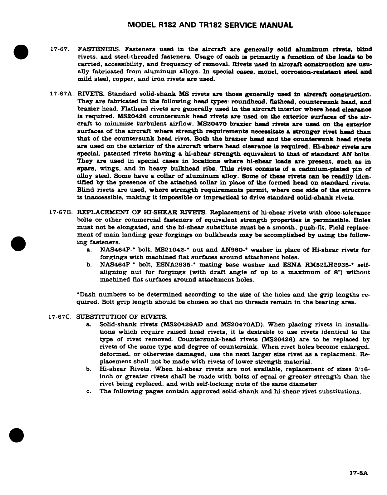
MODEL
R182
AND
TR182
SERVICE
MANUAL
17-67.
FASTENERS.
Fasteners
used
in
the
aircraft
are
generally
solid
aluminum
rivets,
blind
rivets,
and
steel-threaded
fasteners.
Usage of
each
is
primarily
a
function
of
the
loads
to
be
carried,
accessibility,
and
frequency
of
removal.
Rivets
used
in
aircraft
construction
are
usu-
ally
fabricated from
aluminum
alloys.
In
special
cases,
monel,
corrosion-resistant
steel
and
mild
steel, copper,
and
iron
rivets
are used.
17-67A.
RIVETS.
Standard
solid-shank
MS
rivets are those
generally
used
in
aircraft
construction.
They
are
fabricated
in
the
following
head
types:
roundhead,
flathead,
countersunk
head,
and
brazier
head.
Flathead
rivets
are
generally
used
in
the
aircraft interior
where
head clearance
is
required.
MS20426
countersunk
head
rivets
are
used
on
the
exterior
surfaces
of
the
air-
craft
to
minimize
turbulent
airflow.
MS20470
brazier
head
rivets
are
used
on
the
exterior
surfaces
of
the
aircraft
where
strength
requirements
necessitate
a
stronger
rivet
head
than
that
of
the
countersunk
head
rivet.
Both
the
brazier
head
and
the
countersunk
head
rivets
are
used
on
the
exterior
of
the
aircraft
where
head
clearance
is
required.
Hi-shear rivets
are
special,
patented
rivets
having
a
hi-shear
strength
equivalent
to
that
of
standard
AN
bolts.
They
are used
in
special
cases
in
locations
where hi-shear
loads
are
present,
such as
in
spars,
wings,
and
in
heavy
bulkhead
ribs.
This
rivet
consists
of
a
cadmium-plated
pin
of
alloy
steel.
Some
have
a
collar
of
aluminum
alloy.
Some
of
these
rivets
can
be
readily
iden-
tified
by
the
presence
of
the
attached
collar
in
place
of
the
formed
head
on
standard
rivets.
Blind
rivets are used,
where
strength
requirements
permit,
where
one
side
of
the
structure
is
inaccessible,
making
it
impossible
or
impractical
to
drive
standard solid-shank
rivets.
17-67B.
REPLACEMENT
OF
HI-SHEAR
RIVETS.
Replacement
of
hi-shear
rivets
with
close-tolerance
bolts
or
other
commercial
fasteners
of
equivalent
strength
properties
is
permissible.
Holes
must
not
be
elongated,
and the
hi-shear
substitute must
be
a
smooth,
push-fit.
Field
replace-
ment
of
main
landing
gear
forgings
on
bulkheads
may
be
accomplished
by
using
the
follow-
ing
fasteners.
a.
NAS464P-*
bolt,
MS21042-*
nut
and
AN960-*
washer
in
place
of
Hi-shear rivets
for
forgings
with
machined
flat
surfaces
around
attachment
holes.
b.
NAS464P-*
bolt,
ESNA2935-*
mating
base
washer
and
ESNA
RM52LH2935-*
self-
aligning
nut
for
forgings
(with
draft
angle
of
up
to
a
maximum
of
8°)
without
machined
flat
surfaces
around
attachment
holes.
"Dash
numbers
to
be
determined
according
to
the
size
of
the
holes
and
the
grip
lengths
re-
quired.
Bolt
grip
length
should
be
chosen
so
that
no
threads
remain
in
the
bearing
area.
17-67C.
SUBSTITUTION
OF
RIVETS.
a.
Solid-shank
rivets
(MS20426AD
and
MS20470AD).
When
placing
rivets
in
installa-
tions
which
require
raised
head
rivets,
it is
desirable
to
use rivets
identical
to
the
type
of
rivet
removed.
Countersunk-head
rivets
(MS20426)
are
to
be
replaced
by
rivets
of
the
same
type
and
degree
of
countersink.
When
rivet
holes
become
enlarged,
deformed,
or
otherwise
damaged,
use
the
next
larger
size
rivet
as
a
replacment.
Re-
placement
shall
not
be
made
with
rivets
of
lower
strength
material.
b.
Hi-shear
Rivets. When
hi-shear
rivets
are
not
available,
replacement
of
sizes
3/16-
inch
or
greater
rivets
shall
be
made
with
bolts
of
equal
or
greater strength
than
the
rivet
being
replaced,
and
with
self-locking
nuts
of
the
same
diameter
c.
The
following
pages
contain
approved
solid-shank
and
hi-shear
rivet
substitutions.
17-8A
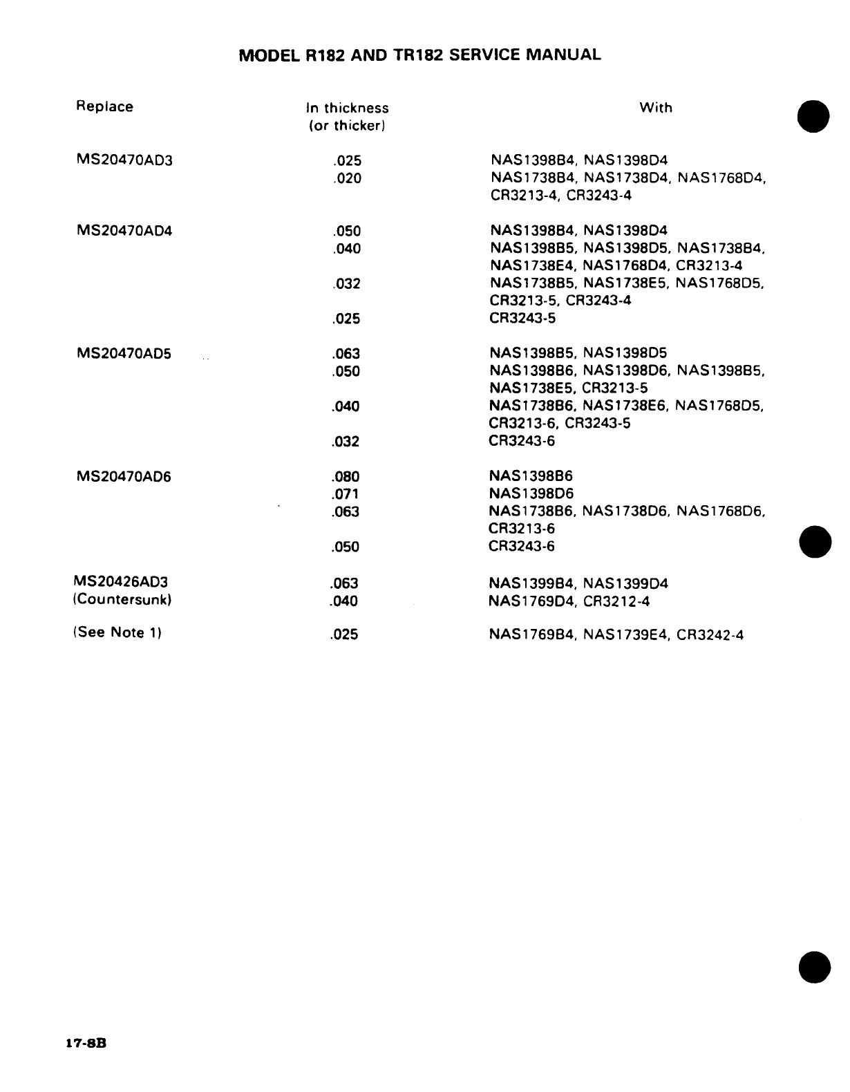
MODEL
R182
AND
TR182
SERVICE
MANUAL
Replace
In
thickness
With
(or thicker)
MS20470AD3
.025
NAS1398B4, NAS1398D4
.020
NAS1738B4, NAS1738D4, NAS1768D4,
CR3213-4,
CR3243-4
MS20470AD4
.050
NAS1398B4,
NAS1398D4
.040
NAS1398B5,
NAS1398D5.
NAS1738B4,
NAS1738E4, NAS1768D4,
CR3213-4
.032
NAS1738B5,
NAS1738E5,
NAS1768D5,
CR3213-5,
CR3243-4
.025
CR3243-5
MS20470AD5
.063
NAS1398B5,
NAS1398D5
.050
NAS1398B6,
NAS1398D6,
NAS1398B5,
NAS1738E5,
CR3213-5
.040
NAS1738B6,
NAS1738E6,
NAS1768D5,
CR3213-6,
CR3243-5
.032 CR3243-6
MS20470AD6
.080
NAS1398B6
.071
NAS1398D6
.063
NAS1738B6,
NAS1738D6,
NAS1768D6,
CR3213-6
.050 CR3243-6
MS20426AD3
.063
NAS1399B4,
NAS1399D4
(Countersunk)
.040
NAS1769D4,
CR3212-4
(See
Note
1)
.025
NAS1769B4,
NAS1739E4,
CR3242-4
17-8B
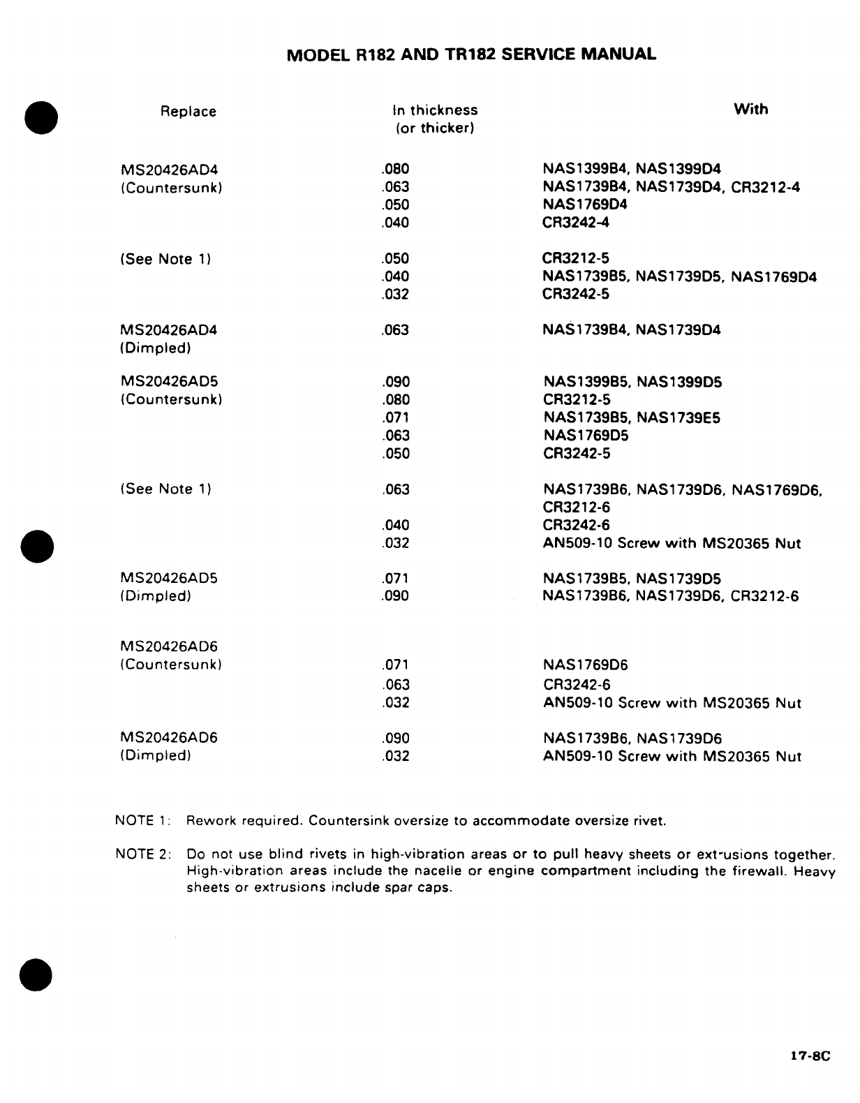
MODEL
R182
AND
TR182
SERVICE
MANUAL
Replace
In
thickness With
(or
thicker)
MS20426AD4
.080
NAS1399B4,
NAS1399D4
(Countersunk)
.063
NAS1739B4,
NAS1739D4,
CR3212-4
.050
NAS
1769D4
.040
CR3242-4
(See
Note
1)
.050
CR3212-5
.040
NAS1739B5,
NAS1739D5,
NAS1769D4
.032
CR3242-5
MS20426AD4
.063
NAS1739B4, NAS1739D4
(Dimpled)
MS20426AD5
.090
NAS1399B5,
NAS1399D5
(Countersunk)
.080
CR3212-5
.071
NAS1739B5,
NAS1739E5
.063
NAS1769D5
.050
CR3242-5
(See
Note
1)
.063
NAS1739B6,
NAS1739D6,
NAS1769D6,
CR3212-6
.040
CR3242-6
.032
AN509-10
Screw
with
MS20365
Nut
MS20426AD5
.071
NAS1739B5,
NAS1739D5
(Dimpled)
.090
NAS1739B6,
NAS1739D6,
CR3212-6
MS20426AD6
(Countersunk)
.071
NAS1769D6
.063
CR3242-6
.032
AN509-10
Screw
with
MS20365
Nut
MS20426AD6
.090
NAS1739B6,
NAS1739D6
(Dimpled)
.032
AN509-10
Screw
with
MS20365
Nut
NOTE
1:
Rework
required.
Countersink
oversize
to
accommodate
oversize
rivet.
NOTE
2:
Do
not
use
blind
rivets
in
high-vibration
areas
or
to
pull
heavy
sheets
or
ext-usions
together.
High-vibration
areas
include
the
nacelle
or
engine compartment
including
the
firewall.
Heavy
sheets
or
extrusions
include
spar
caps.
17-8C
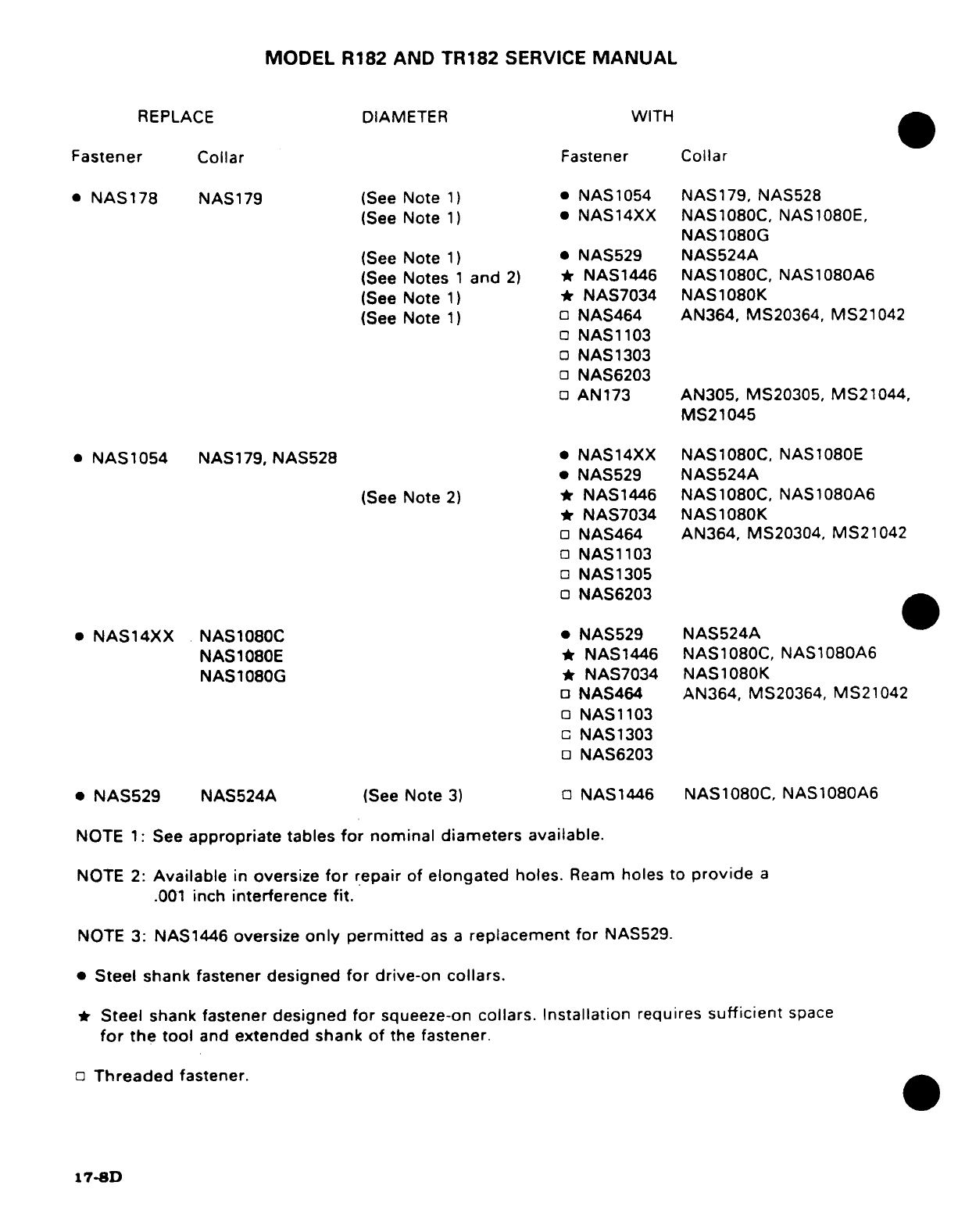
MODEL
R182
AND
TR182
SERVICE
MANUAL
REPLACE
DIAMETER
WITH
Fastener
Collar
Fastener Collar
*
NAS178
NAS179
(See
Note
1)
*
NAS1054
NAS179,
NAS528
(See
Note
1)
*
NAS14XX
NAS1080C,
NAS1080E,
NAS1080G
(See
Note
1)
*
NAS529
NAS524A
(See
Notes
1
and
2)
*
NAS1446
NAS1080C,
NAS1080A6
(See
Note
1)
*
NAS7034 NAS1080K
(See
Note
1)
NAS464
AN364,
MS20364,
MS21042
NAS1103
NAS1303
NAS6203
AN173
AN305,
MS20305,
MS21044,
MS21045
*
NAS1054
NAS179,
NAS528
*
NAS14XX NAS1080C,
NAS1080E
*
NAS529
NAS524A
(See
Note
2)
*
NAS1446 NAS1080C,
NAS1080A6
*
NAS7034 NAS1080K
NAS464
AN364,
MS20304,
MS21042
NAS1103
NAS1305
NAS6203
*
NAS14XX
NAS1080C
*
NAS529
NAS524A
NAS1080E
*
NAS1446 NAS1080C,
NAS1080A6
NAS1080G
*
NAS7034
NAS1080K
NAS464
AN364, MS20364,
MS21042
NAS1103
NAS1303
NAS6203
*
NAS529
NAS524A
(See
Note
3)
NAS1446
NAS1080C,
NAS1080A6
NOTE
1:
See
appropriate
tables
for
nominal diameters available.
NOTE
2:
Available
in
oversize
for
repair
of
elongated
holes.
Ream
holes
to
provide
a
.001
inch
interference
fit.
NOTE
3:
NAS1446
oversize
only
permitted
as
a
replacement
for
NAS529.
*
Steel
shank
fastener
designed
for
drive-on
collars.
*
Steel
shank
fastener
designed
for
squeeze-on
collars.
Installation
requires
sufficient
space
for
the tool
and
extended
shank
of
the
fastener.
Threaded
fastener.
17-8D
MODEL
R182
AND
TR182
SERVICE
MANUAL
17-68.
ENGINE
MOUNT.
17-69.
DESCRIPTION.
The
engine
mount
is
constructed
of
4130
chrome molybdenum
steel
tubing.
The
mount
is
composed
of
sections
of
steel
tubing,
welded
together and
reinforced
with
gussets.
The
mount
is
fastened
to
the
fuselage
at
four points.
Refer to
Section
11.
17-70.
GENERAL CONSIDERATIONS.
All
welding
on
the engine
mount
must
be
of
the
highest
quality
since
the
tendency
of
vibration
is
to
accentuate any
minor
defect
present
and
cause
fatigue
cracks. Engine
mount
members
are
preferably
repaired
by
using
a
larger
diameter
replacement
tube,
telescoped
over
the
stub
of
the
original
member
using
fishmouth
and
rosette type
welds. However,
reinforced
30-degree
scarf
welds
in
place
of
the
fishmouth
welds
are
considered
satisfactory
for
engine
mount
repair
work.
17-71.
ENGINE
MOUNT
RADIAL
SUPPORT
DAMAGE.
Minor
damage such
as
a
crack
adjacent
to
an
engine
attaching
lug
may
be
repaired
by
rewelding
the
support
tube
and
extending
a
gusset
past
the
damaged
area.
Extensively
damaged
parts
must
be
replaced.
17-72.
DAMAGE
INVOLVING
ENGINE
MOUNTING
LUGS
AND
ENGINE
MOUNT
TO
FUSE-
LAGE
ATTACHING
FITTINGS.
Engine
mounting
lugs
and
engine
mount-to-fuselage
attaching fittings
should
not
be
repaired
but
must
be
replaced.
Refer
to
Section
18
for
painting
engine
mount.
17-73.
BAFFLES.
Baffles
ordinarily require
replacement
if
damaged
or
cracked. However.
small
plate
reinforcements
riveted
to
the
baffle
will
often
prove
satisfactory
both
to
the
strength
and
cooling
requirements
of
the
unit.
17-74.
ENGINE
COWLING.
17-75.
REPAIR
OF
COWLING
SKINS.
If
extensively
damaged.
complete
sections
of
cowling
must
be
replaced.
Standard insert-type
skin
patches, however.
may
be
used
if
repair
parts
are
formed
to
fit.
Small cracks
may
be
stop-drilled
and
dents
straightened
if
they
are
reinforced
on
the
inner
side
with
a
doubler
of
the
same
material.
17-76.
REPAIR
OF
REINFORCEMENT
ANGLES.
Cowl
reinforcement
angles,
if
damaged,
must
be
replaced.
Due to
their
small
size
they are
easier
to replace
than
to
repair.
17-77.
REPAIR
OF
GLASS-FIBER
CONSTRUCTED
COMPONENTS.
Glass-fiber
constructed
compo-
nents
on
the
aircraft
may
be
reapired
as
stipulated
in
instructions
furnished
in
Service
Kit
SK182-12.
Observe
the
resin manufacturer's
recommendations concerning
mixing
and
ap-
plication
of
the
resin.
Epoxy
resins
are
preferable
for
making repairs,
since
epoxy
com-
pounds are
usually
more
stable
and
predictable
than
polyester
and,
in
addition,
give
better
adhesion.
In
addition, repair
kits
are
also
available
for
the
repair
of
cracks
in
ABS. PBC.
PVPC,
graphite
and
fiberglass
material.
These
kits
P/N's
51543
thru
51548
are
available
from
the
Cessna
Supply
Division.
17-78.
CORROSION
AND CORROSION CONTROL.
NOTE
For information
on
corrosion
and
corrosion
control
for
aircraft,
refer
to
FAA
Advisory
Circular
AC43-4.
17-9
MODEL
R182
AND
TR182
SERVICE
MANUAL
17-79.
CONTROL
CABLE
WIRE
BREAKAGE
AND
CORROSION
LIMITATIONS.
Control
cable
assemblies
are
subject
to
a
variety
of
enviromental
and
forms
of
deterioration
that
ultimately
may
be
easy
to
reconize
such as
wire/strand
breakage,
or
the
not
so
readily visible
types
of
deterioration
including
corrosion
and/or
distortion.
The
following
information
will
aid
in
detecting
these
cable
condition.
a.
Examine
cables
for
broken
wires
by
passing
a
cloth
along length
of
cable.
This
will
detect
broken
wires,
if
cloth snags
on
cable.
Critical
areas
for
wire
breakage
are
those
sections
of
cable
which
pass
through
fairleads,
across
rub blocks,
and
around
pulleys.
If
no
snags
are
found,
then
no
further
inspection
is
required.
If
snags
are
found
or
brocken
wires
are
suspected,
then
loop
to
confirm
broken
wires
(refer
to
Figure
17-1).
Loosen
or
remove
cable
to
allow
it
to
be
bent
in
a
loop
as
shown.
While
rotating
cable,
inspect
bent
area
for
broken
wires.
b.
Wire
breakage
criteria
for
cables
in
flap,
aileron,
rudder,
and
elevator systems
are,
individual
broken
wires
are
acceptable
in
primary
and secondary
control
cables
at
random
locations
when
there
are
no
more
than
six
broken
wires
in
any given
ten-inch
cable
length.
c.
Carefully examine
any
cable
for
corrosion
that
has
a
broken
wire
in
a
section
not
in
contact
with
wear-producing
airframe
components
such
as
pullys, fairleads,
rub
blocks, ect.
It
may
be
necessary
to
remove
and
bend cable
to
properly
inspect it
for
internal
strand
corrosion
as
this
condition
is
usually
not
evident
on
outer
surface
of
cable.
Replace
cable
if
internal
corrosion
is
found.
If
a cable
has
been
wiped
clean
of
its
corrosion-preventive
lubricant
and
metal-
brightened,
the cable
shall
be
examined
closely
for
corrosion.
For
description
of
control
cable
corrosion,
refer
to
Chapter
17,
Corossion
and
Corrosion
Control
17-10
Revision
2
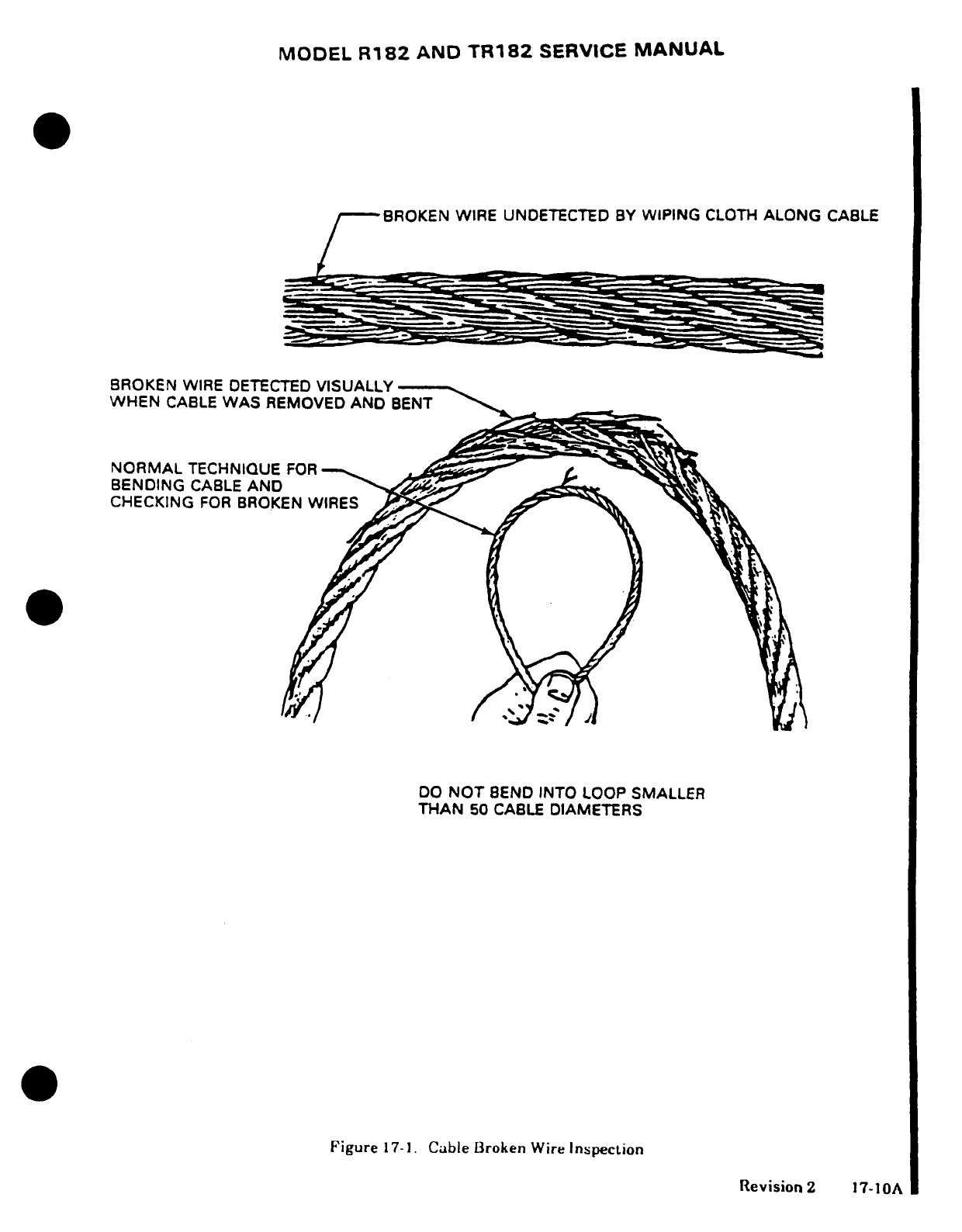
MODEL
R182
AND
TR182
SERVICE
MANUAL
BROKEN WIRE
UNDETECTED
BY
WIPING
CLOTH
ALONG
CABLE
BROKEN
WIRE
DETECTED
VISUALLY
WHEN
CABLE
WAS
REMOVED
AND
BENT
NORMAL
TECHNIQUE
FOR
BENDING
CABLE
AND
CHECKING
FOR
BROKEN
WIRES
DO
NOT
BEND
INTO
LOOP
SMALLER
THAN
50
CABLE
DIAMETERS
Figure
17-1.
Cable
Broken
Wire
Inspection
Revision
2
17-10A
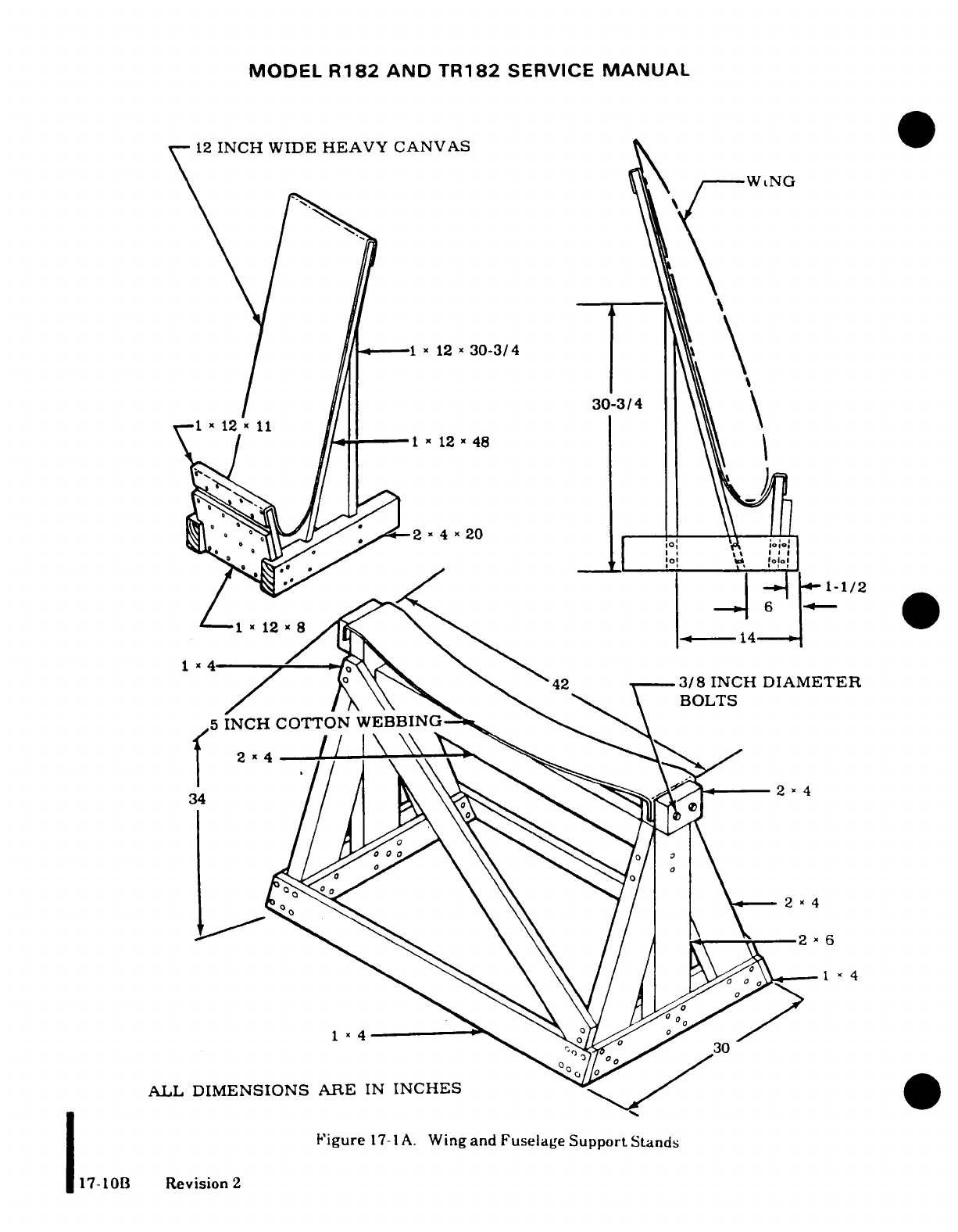
MODEL
R182
AND
TR182
SERVICE
MANUAL
12
INCH
WIDE
HEAVY
CANVAS
--
WNG
1
12
a
30-3/4
T-l~~ x 12 x*~ 11
I30-3/4
\ / // ' ----11 x
12
x
48
I
/^i^^0
oi
|-l1-1/2
/\ \S\ \S.
42.
'
SN
^
\ BOLTS
, 2xx2 0
/1~~-
X
43
5 INCH COTTON
WEBBIN
^3/8
INCH
DIAMETER
1214~~~~~"
ALL
DIMENSIONS
ARE
IN
INCHES
0
,,
Figure
17-1A.
WingandFuselageSupportStands
17-lOB
Revision
2
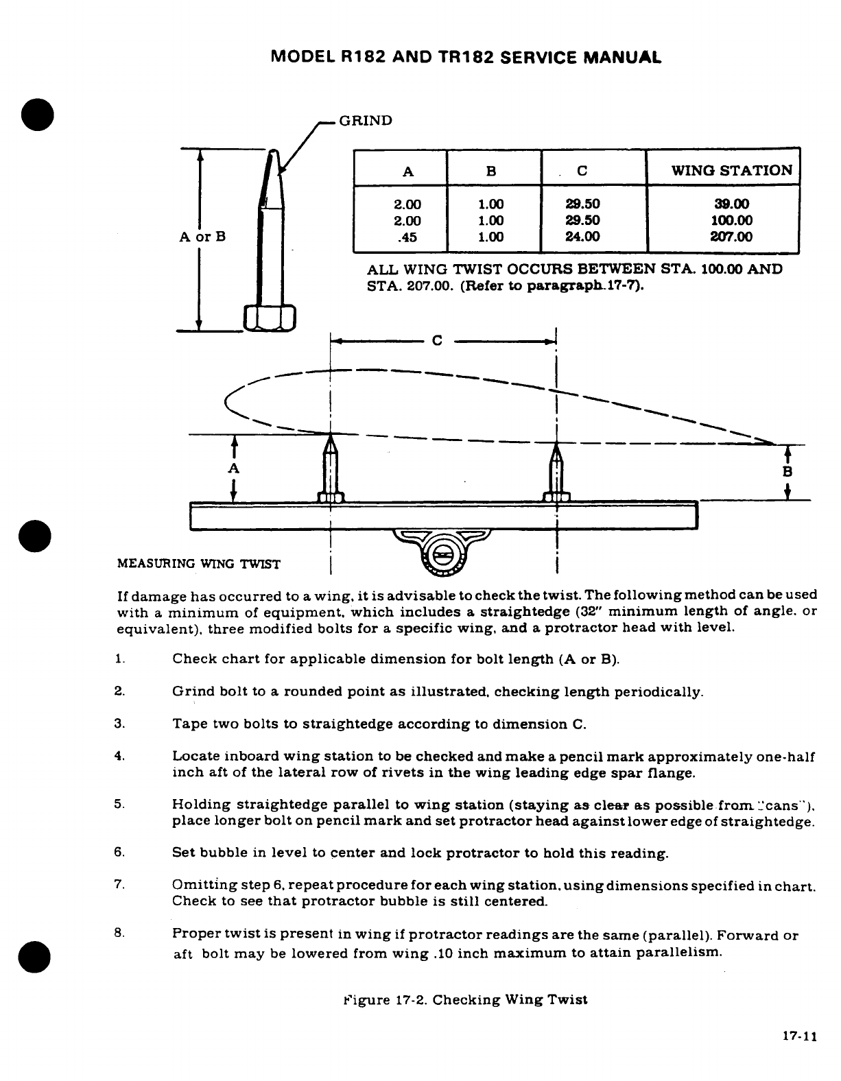
MODEL
R182
AND
TR182
SERVICE
MANUAL
GRIND
A
B C
WING
STATION
2.00
1.00
29.50
39.00
2.00
1.00
29.50
100.00
A
or
B
.45
1.00
24.00
207.00
ALL
WING
TWIST
OCCURS
BETWEEN
STA.
100.00
AND
STA.
207.00.
(Refer
to
paragraphl17-7).
-_C:]L~~~C
-,
c
,{
A
B-
MEASURING
WING
TWIST
If
damage
has
occurred
to
a
wing.
it is
advisable
to
check
the
twist.
The
following
method
can
be
used
with
a
minimum
of
equipment,
which
includes
a
straightedge
(32"
minimum
length
of
angle.
or
equivalent),
three
modified
bolts
for
a
specific
wing,
and
a
protractor
head
with
level.
1.
Check
chart
for
applicable
dimension
for
bolt
length
(A
or
B).
2.
Grind
bolt
to a
rounded
point
as illustrated,
checking length
periodically.
3.
Tape
two
bolts
to
straightedge
according
to
dimension
C.
4.
Locate
inboard
wing
station
to
be
checked
and
make
a
pencil
mark
approximately
one-half
inch
aft
of
the
lateral
row
of
rivets
in
the
wing
leading
edge
spar
flange.
5.
Holding
straightedge parallel
to
wing
station
(staying
as
clear
as
possible
from.
"cans").
place
longer
bolt
on
pencil
mark
and
set
protractor
head
against
lower
edge
of
straightedge.
6.
Set
bubble
in
level
to
center
and
lock
protractor
to hold
this
reading.
7.
Omitting
step
6,
repeat
procedure
for each
wing
station,
using
dimensions
specified
in
chart.
Check
to
see
that
protractor
bubble
is
still
centered.
8.
Proper twist
is
present
in
wing
if
protractor
readings
are
the
same
(parallel). Forward
or
aft
bolt
may
be
lowered
from
wing
.10
inch
maximum
to
attain parallelism.
'igure
17-2.
Checking
Wing
Twist
17-11
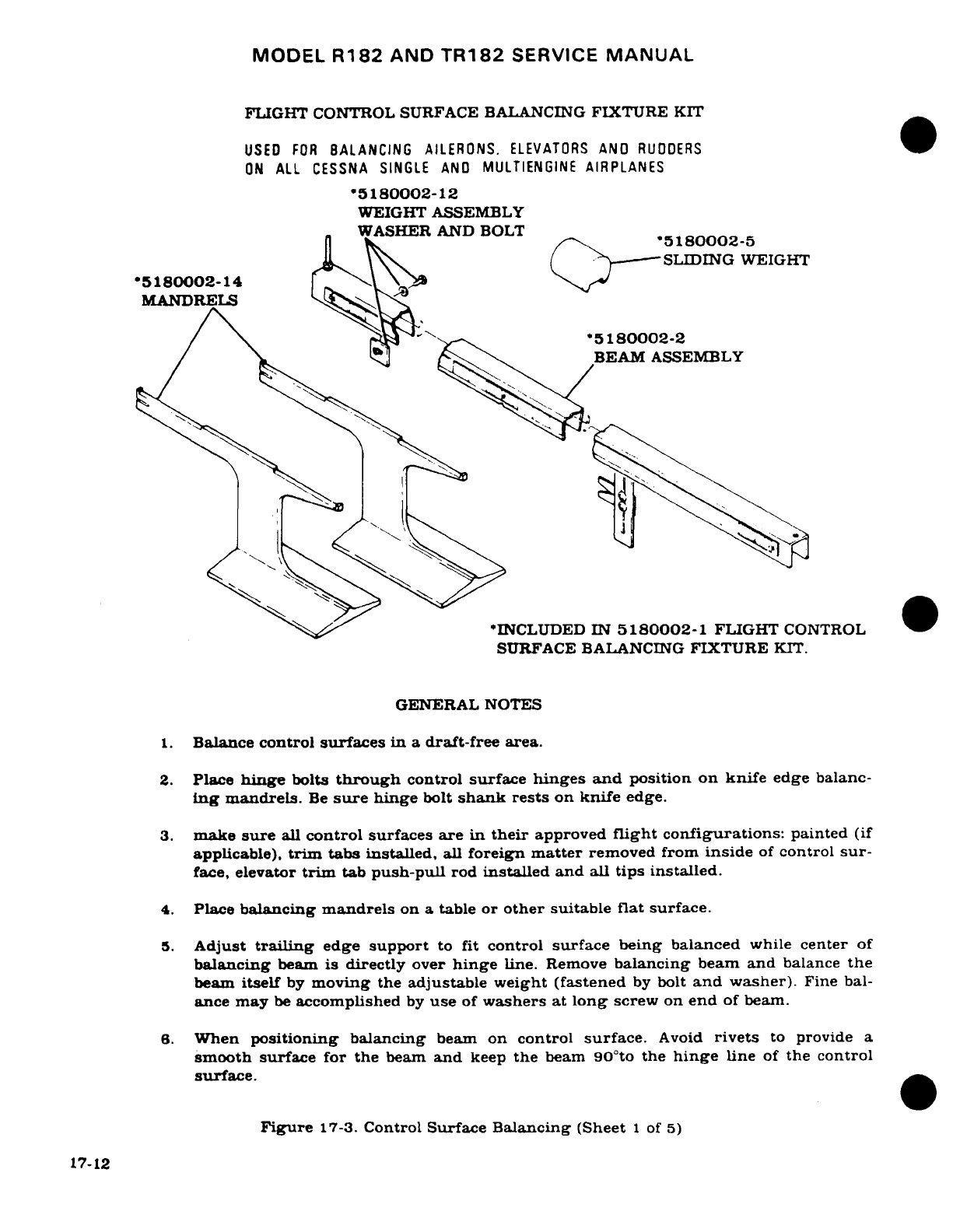
MODEL
R182
AND
TR182
SERVICE
MANUAL
FLIGHT
CONTROL
SURFACE
BALANCING
FIXTURE
KIT
USED
FOR
BALANCING
AILERONS.
ELEVATORS
AND
RUDDERS
ON
ALL CESSNA SINGLE
AND
MULTIENGINE
AIRPLANES
*5180002-12
WEIGHT
ASSEMBLY
WASHER
AND
BOLT
ln~ K»^".
*5180002-5
SLIDING
WEIGHT
*5180002-14
l\9 \
MANDRELS
*5180002-2
BEAM
ASSEMBLY
*INCLUDED
IN
5180002-1
FLIGHT
CONTROL
SURFACE
BALANCING
FIXTURE
KIT.
GENERAL
NOTES
1.
Balance
control
surfaces
in
a
draft-free
area.
2.
Place
hinge
bolts
through
control
surface
hinges
and
position
on
knife
edge balanc-
ing
mandrels.
Be
sure
hinge
bolt
shank
rests
on
knife
edge.
3.
make
sure
all
control
surfaces
are
in
their
approved
flight
configurations:
painted
(if
applicable),
trim
tabs
installed,
all
foreign
matter
removed
from
inside
of
control
sur-
face,
elevator
trim
tab
push-pull
rod
installed and
all
tips
installed.
4.
Place
balancing
mandrels
on a
table
or
other
suitable
flat
surface.
5.
Adjust
trailing
edge
support
to
fit
control
surface
being
balanced
while
center
of
balancing
beam
is
directly
over
hinge
line.
Remove
balancing
beam
and
balance
the
beam
itself
by
moving
the
adjustable weight (fastened
by
bolt
and
washer).
Fine bal-
ance
may
be
accomplished
by
use
of
washers
at
long
screw on
end
of
beam.
6.
When
positioning
balancing
beam
on
control
surface.
Avoid
rivets
to
provide
a
smooth
surface for the
beam
and
keep
the
beam
90°to
the
hinge
line
of
the control
surface.
Figure
17-3.
Control
Surface
Balancing
(Sheet
1
of
5)
17-12
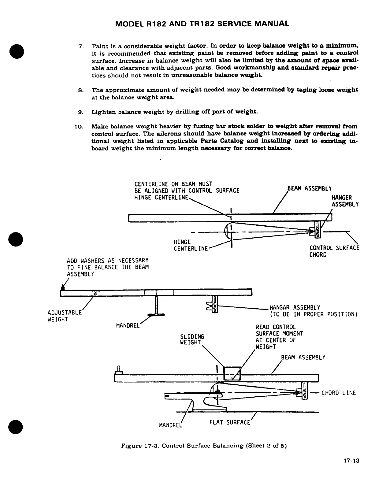
MODEL
R182
AND
TR182
SERVICE
MANUAL
7.
Paint
is
a
considerable
weight
factor.
In
order
to
keep balance
weight
to
a
minimum,
it
is
recommended
that
existing
paint
be
removed
before
adding
paint
to
a
control
surface. Increase
in
balance
weight
will
also
be
limited
by
the
amount
of
space
avail-
able
and clearance
with adjacent
parts.
Good
workmanship
and
standard
repair
prac-
tices
should
not
result
in
unreasonable
balance weight.
8.
The
approximate
amount
of
weight
needed
may
be
determined
by
taping
loose
weight
at
the
balance
weight
area.
9.
Lighten
balance
weight
by
drilling
off
part
of
weight.
10.
Make
balance
weight
heavier
by
fusing
bar stock
solder
to
weight
after
removal
from
control
surface.
The
ailerons
should
have
balance
weight
increased
by
ordering
addi-
tional weight
listed
in
applicable
Parts
Catalog
and
installing
next
to
existing
in-
board
weight
the
minimum
length
necessary
for
correct
balance.
CENTERLINE
ON
BEAM
MUST
BE
ALIGNED
WITH
CONTROL
SURFACE
BEAM
ASSEMBLY
ASSEMB^ ~/ LASSEMBLY
:---==wi: ,="'
HINGE
CENTERLINE
CONTROL SURFACE
CHORD
ADD
WASHERS
AS
NECESSARY
TO
FINE
BALANCE
THE
BEAM
ASSEMBLY
/ Xjr--- ---
L_
HANGAR
ASSEMBLY
ADJUSTABLE
(TO
BE
IN
PROPER
POSITION)
WEIGHT MANDREL
READ
CONTROL
SLIDEING
,,SURFACE
MOMENT
WEIGH~
T
AT
CENTER
OF
WEIGHT
\ /
EBEAM
ASSEMBLY
E_______ __ -^]
--
CHORD
LINE
MANDREL
FLAT
SURFACE
Figure
17-3.
Control
Surface
Balancing
(Sheet
2
of
5)
17-13
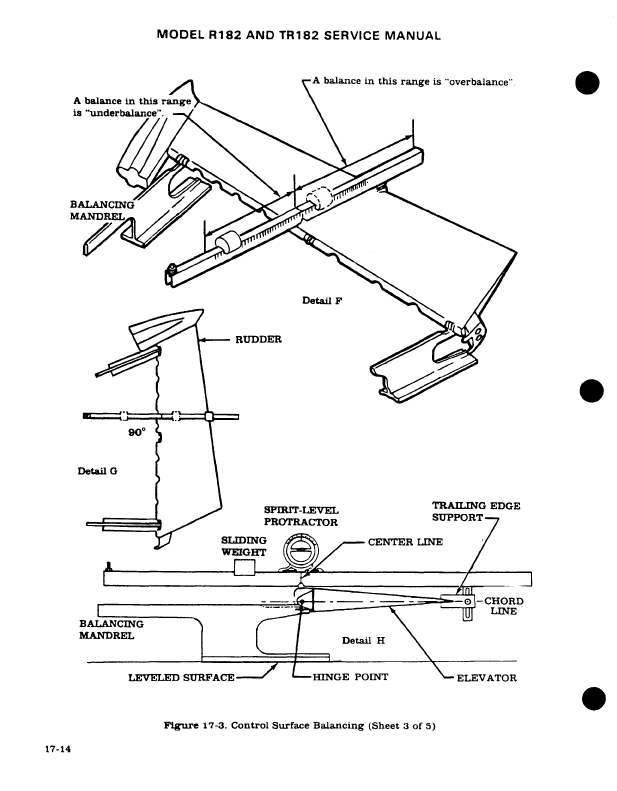
MODEL
R182
AND
TR182
SERVICE
MANUAL
A
balance
in
this
range
is
"overbalance".
A
balance
in
this
range
is
"underbalance".
BALANCING
/
MANDREL
Detail
F
RUDDER
900
a
I
Detail
G
SPIRIT-LEVEL
TRA
GEDGE
e
7
C
PROTRACTOR
SUPPORT
7
y
SLIDING
A
CENTER
LINE
/
WEIGHT
/ /
---
|-
--
-^.-^
__
-CHORD
I|
.-
^ -----
_.
i
^~\-~~
l'^
~LINE
BALANCING
\
MANDREL
Detail
H
LEVELED
SURFACE
- - - -/
LHINGE
POINT
\-ELEVATOR
Figure
17-3.
Control
Surface
Balancing
(Sheet
3
of
5)
17-14
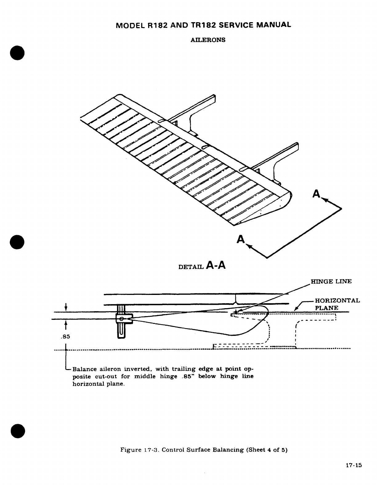
MODEL
R182
AND
TR182
SERVICE
MANUAL
AILERONS
A
~~~~~~*
A
DETAIL
A-A
HINGE
LINE
HORIZONTAL
__
______II.
__
_
lll
-- "1^^ . r
-
PLANE
.85
.---------- /
I
..... .............................................................
...
.E
..
............ ..........................
Balance
aileron
inverted,
with
trailing
edge
at
point
op-
posite
cut-out
for
middle
hinge
.85"
below
hinge
line
horizontal
plane.
Figure
17-3.
Control
Surface Balancing
(Sheet
4
of
5)
17-15
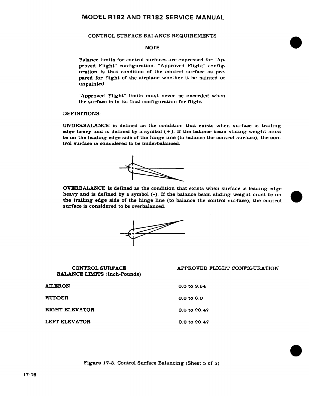
MODEL
R182
AND
TR182
SERVICE
MANUAL
CONTROL
SURFACE BALANCE
REQUIREMENTS
NOTE
Balance
limits
for
control
surfaces
are
expressed
for
"Ap-
proved
Flight"
configuration.
"Approved
Flight"
config-
uration
is
that
condition
of
the
control surface
as
pre-
pared for
flight
of
the
airplane
whether
it
be
painted
or
unpainted.
"Approved
Flight"
limits
must
never
be
exceeded
when
the
surface
is
in
its
final
configuration
for
flight.
DEFINITIONS:
UNDERBALANCE
is
defined
as
the
condition
that
exists
when
surface
is
trailing
edge
heavy
and
is
defined
by
a
symbol
(+ ).
If
the
balance
beam
sliding
weight must
be
on
the
leading
edge
side
of
the
hinge
line
(to
balance
the
control
surface),
the
con-
trol
surface
is
considered
to
be
underbalanced.
OVERBALANCE
is
defined as
the
condition
that
exists
when
surface
is
leading edge
heavy
and
is
defined
by
a symbol
(-).
If
the
balance
beam
sliding
weight
must
be on
the
trailing
edge side
of
the
hinge
line
(to
balance
the control
surface),
the
control
surface
is
considered
to
be
overbalanced.
CONTROL
SURFACE
APPROVED
FLIGHT CONFIGURATION
BALANCE LIMITS
(Inch-Pounds)
AILERON
0.0
to
9.64
RUDDER
0.0
to
6.0
RIGHT
ELEVATOR
0.0
to
20.47
LEFT
ELEVATOR
0.0
to
20.47
Figure
17-3.
Control
Surface
Balancing
(Sheet
5
of
5)
17-16
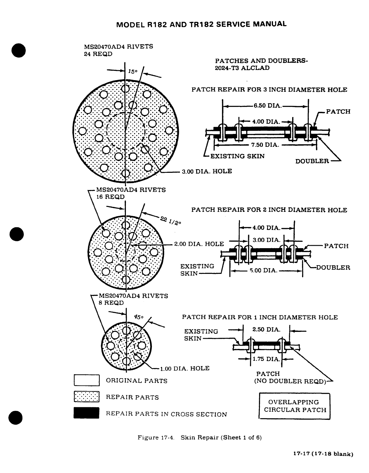
MODEL
R182
AND
TR182
SERVICE
MANUAL
MS20470AD4
RIVETS
24
REQD
PATCHES
AND
DOUBLERS-
2024-T3
ALCLAD
::):^.'
.'/;-^
PATCH
REPAIR
FOR
3
INCH
DIAMETER
HOLE
.-. . . !.'
.....
'
.-.-
.- .-.
-_ **.
- -. . -\
.. ':o:
:(Z2
\: :::.:
.i:::::::/\
.6.50
DIA.-
-
}:g::-O-.-
*3,.-Q:::-\ /
PATCH
....... : :-
-*.-.
EXISTING
SKIN
..-.- - - .-.-.-. * .*.. --.-. -...
_DOUBLER
-
t:::1:::Y:
::::-!
?--:. v
3.00
DIA.
HOLE
MS20470AD4
RIVETS
16
REQD
PATCH
REPAIR
FOR
2
INCH
DIAMETER
HOLE
7 1y '-\
/20
<--4.ooDIA.-
*--::-::-,---:
.
-z-
.
73.00
DIA.
* *.
0'".:")
·
".:.
I-
MS20470AD4
RIVETS
8
REQD
5\ ' ..
PATCH
REPAIR
FOR
1
INCH
DIAMETER
HOLE
y^
^\ ~EXISTING
2.50
DIA.
r3)
~SKIN
1.00
DIA.
HOLE
2.0 PATCPATCH
*
ORIGINAL
PARTS
(NO
DOUBLER
REQD)-
-- ' RREPAIR
PARTS
OVERLAPPING
REPAIR
PARTS
IN
CROSS
SECTION
CIRCULAR PATCH
Figure
17-4.
Skin
Repair
(Sheet
1
of
6)
17-17(17-18
blank)
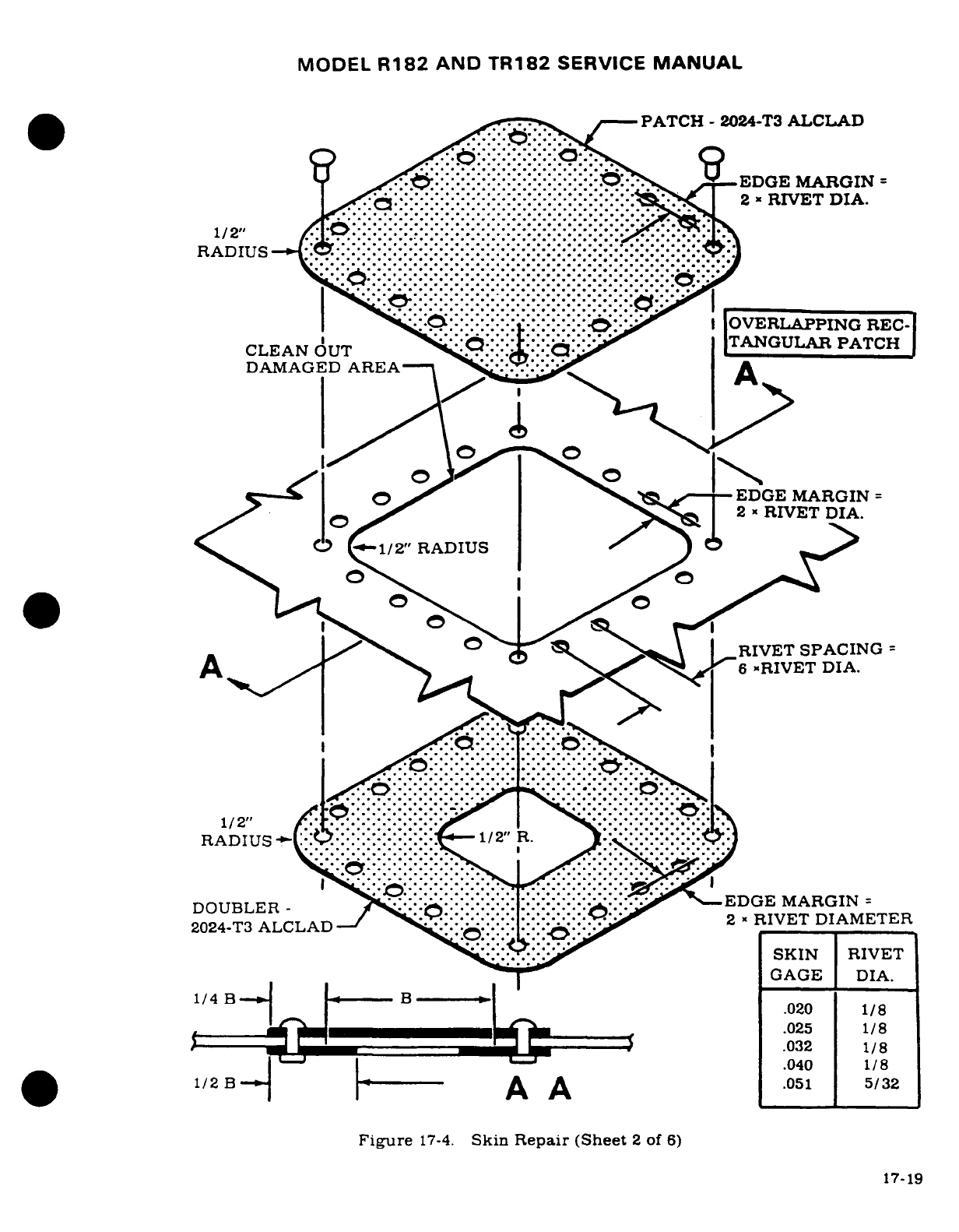
MODEL
R182
AND
TR182
SERVICE
MANUAL
PATCH
-
2024-T3
ALCLAD
.. .. . . . . . ..
.
.....
:.:...
.....
..................
__EDGE
MARGIN
=
.. ......................
;_.---------------------
2
RIVET
DIA.
........................... ...
1/2"
.........................
RADIUS
:
::::::::
::................
.........:::::
OsR
-
2
.:::::::::: ::::::A.::ER:::::::::::::RA.
'
":'--:-:-:-
;::---
-:-:.::;:
I:
OVERLAPPING
REC-
CLEAN
OUT
--
TANGULAR
PATCH
DAMAGED
AREATC H _
A
^_-_O w_-EDGE
MARGIN
=
Fiur 17-4.
Skin
Rer
2
x
RIVET
DIA.
0
-1/2"
RADIUS
/
O O/
-w _tS ;Q r_ \A
RIVET
SPACING
=
A· >^ "*. S*
6
-RIVET
DIA.
,
,,,,~
*
-'*....
:
' .
.....
-....
:
. .
:...."
.. I
...
:.........
......
::::::::::::::.-
::....
U I ^i,:,,
r....-
:iii"*
^^
* ** * ** *
**^..i i
" " ...
RADIUS
I/
2IA.
DOUBLER-.-...-.
-.-
1
.-.
032EDGE
MARGIN/8
2024-T3
ALCLAD
......... ...... 2
x
_,
., _
le
1/2
B
I-- A A
.051
5/32
Figure
17-4.
Skin
Repair
(Sheet
2
of
6)
17-19
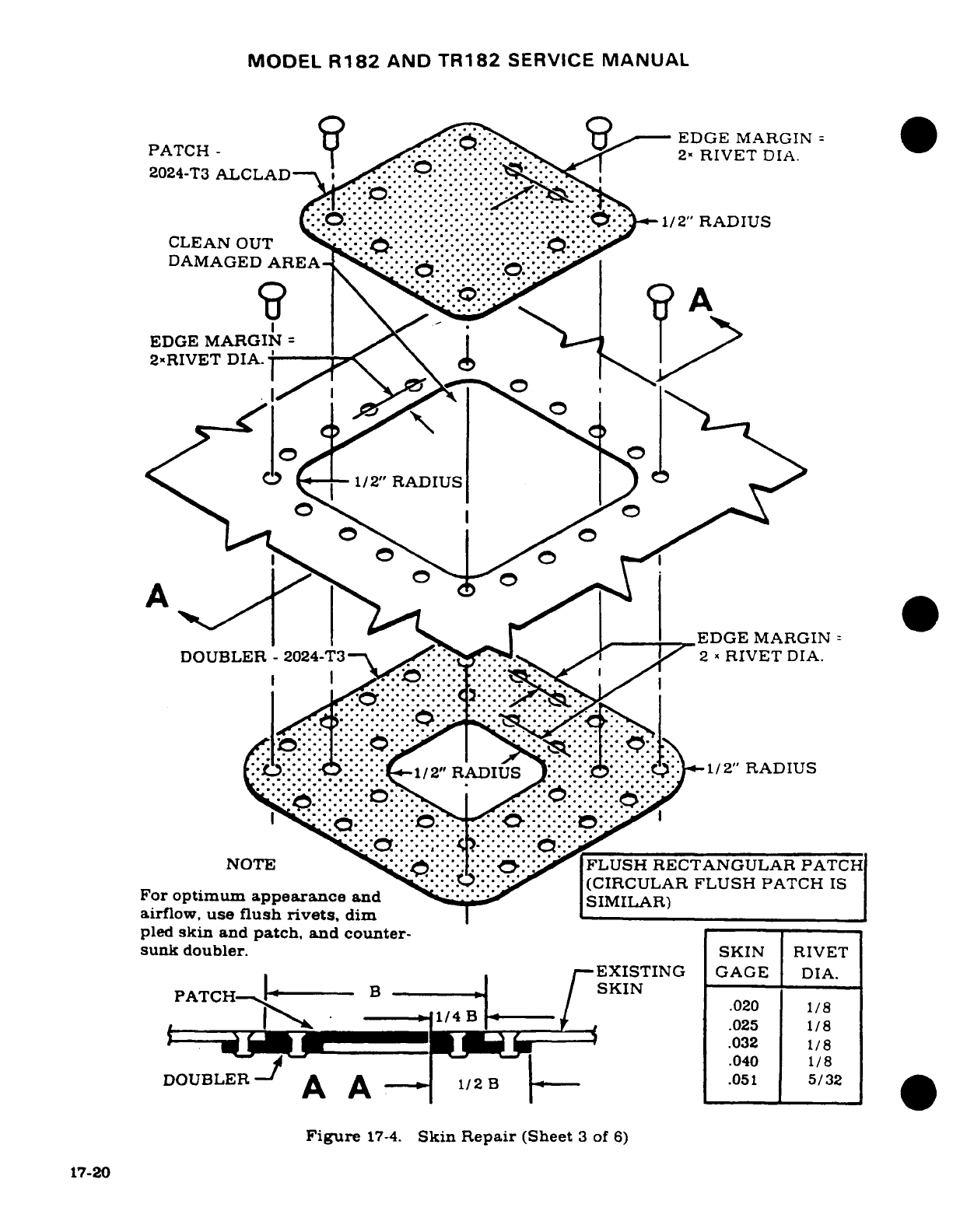
MODEL
R182
AND
TR182
SERVICE
MANUAL
U9 9
EDGE
MARGIN
=
PATCH
--
......--
::.
2"
RIVET
DIA.
2024-T3
ALCLAD
'' "-... *
.·::0.''
··
:
::::::::::::
.'*:
:
:
:<
.1/2"
RADIUS
CLEAN
OUT
' *''.: .
.:::::
- -. * :.: '':'"
DAMAGED
AREA
.. .- .-
EDGE
MARGIN
2-RIVET
DIA.
A
O
o
DB '
'......EDGE
MARGIN
=
DOUBLER
-
2024-T3
/: /
2
»
RIVET
DIA.
: ::::1/2"
RADIUS
:1/2"
RADIUS
-..
: i::::::::::::
^.::::
.
:.:-:.<:.^:::::
..
:.:.:.c·
:::::
::.:i:.:·''o::::::
:1..
:
R...........
NOTE
..==.
'========
:::::.::::::FLUSH
RECTANGULAR
PATCH
'..:-:-..:.:.,
'
(CIRCULAR
FLUSH
PATCH
IS
For
optimum
appearance
and
SIMILAR)
airflow,
use
flush rivets.
dim
pled
skin
and
patch,
and
counter-
sunk
doubler.
SKIN
RIVET
EXISTING
GAGE
DIA.
PATCHI
B
-
SKIN
PATC--
1/4
B
1/KI .
lB020
1/8
____I_.
.. - ---
»1/4B
---.
025
1/8
DOUBLER
A A
B.040
1/8
Figure
17-4.
Skin
Repair
(Sheet
3
of
6)
17-20
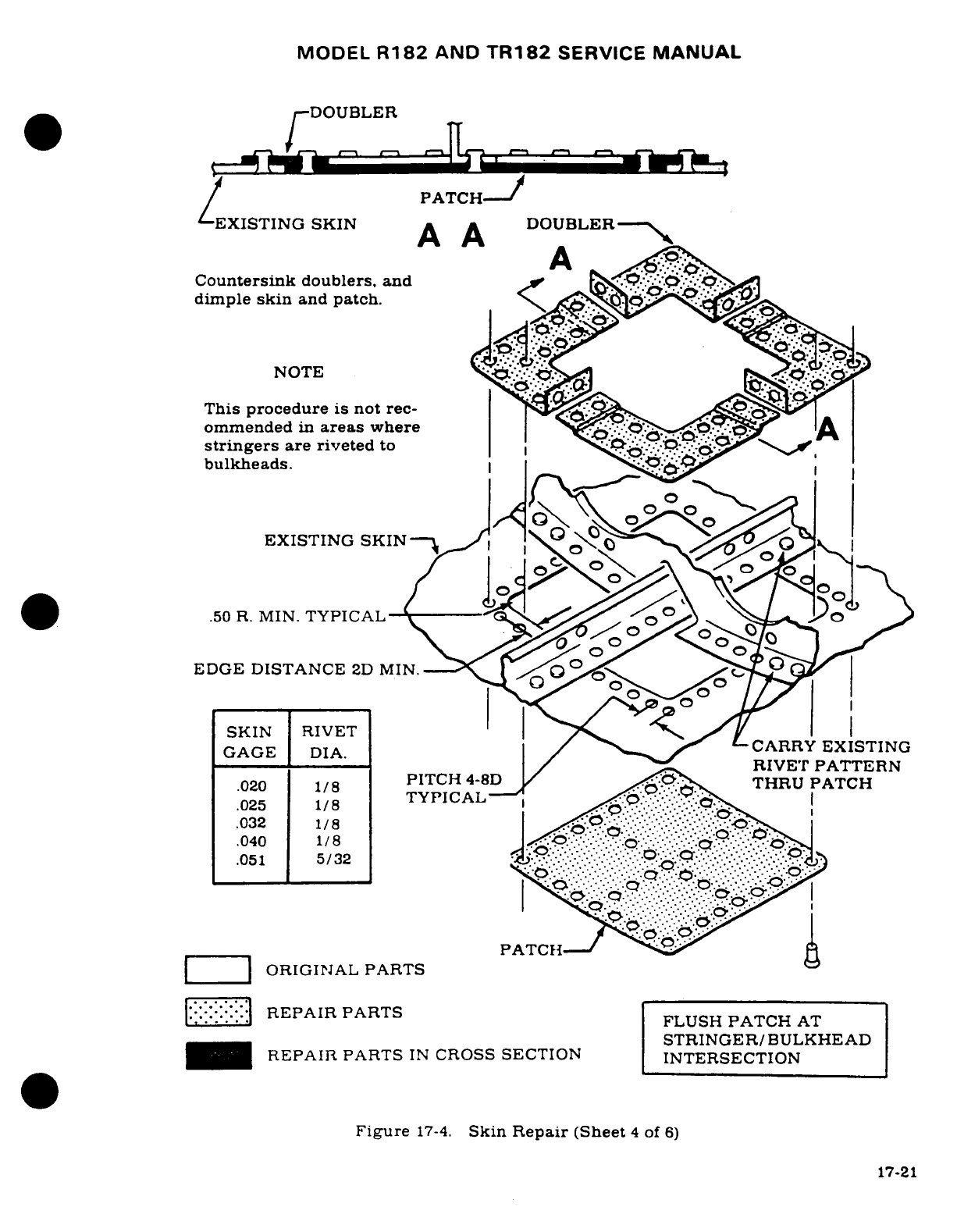
MODEL
R182
AND
TR182
SERVICE
MANUAL
DOUBLER
/
PATCH--
EXISTING
SKIN
A A
DOUBLER
-
,
A
A
Countersink
doublers, and
.
.
dimple
skin
and
patch.
'N,
NOTE
.,
This
procedure
is
not
rec-
ommended
in
areas
where
.
stringers
are riveted
to
bulkheads.
i
EXISTING
SKIN
ad o \ -
.50
R.
MIN.
TYPICAL
>_
EDGE
DISTANCE
2D
MI
N. ,|
SKIN
RIVET
GAGE
IDIA.
/
CARRY
EXISTING
D--A./ _
RIVET
PATTERN
.020
1/8
PITCH
4-8D
THRU PATCH
.025
1/8
PATCH
.032
1/8
|
.:.. ..
.040
1/8
*
.051
5/32
|
|
ORIGINAL
PARTS
::i:i::l
REPAIR
PARTS
FLUSH
PATCH
AT
STRINGER/BULKHEAD
REPAIR
PARTS
IN
CROSS
SECTION
INTERSECTION
Figure
17-4.
Skin
Repair
(Sheet
4
of
6)
17-21
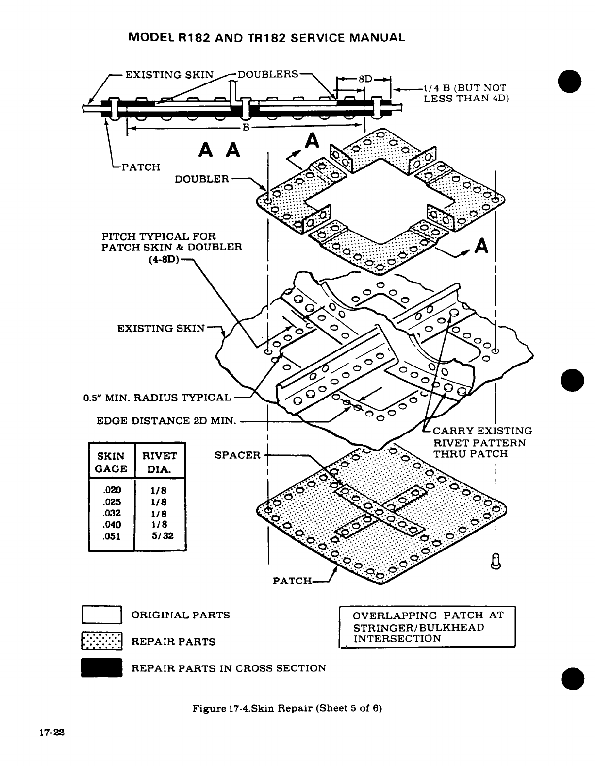
MODEL
R182
AND
TR182
SERVICE
MANUAL
EXISTING
SKIN
DOUBLERS
8D
Z 5 \= 4 t
/4
B
(BUT
NOT
LESS
THAN
4D)
AA
A
PATCH
|
,
DOUBLER
'
|
PITCH
TYPICAL
FOR
IS,
t
PATCH
SKIN
&
DOUBLER
.: -..-
A
(4-8D)
A
EXISTING
SKIN
0.5"
MIN.
RADIUS TYPICAL
/V
EDGE
DISTANCE
2D
MIN.
__
.- ___,___
-
CARRY
EXISTING
~~~~~~~~SKIN RTW-T
SOA/-RIVET
PATTERN
SKIN
RIVET
SPACER
-
THRU
PATCT
GAGE
DIA.
LR A
.040
1/8
.K.I.-.-.
oc~r,<rSTRINGER/BULKHEAD
:::
REPAIR
PARTS
INTERSECTION
_
~REPAIR
PARTS
IN
CROSS
SECTION
Figure
17-4.Skin
Repair
(Sheet
5
of
6)
17-22
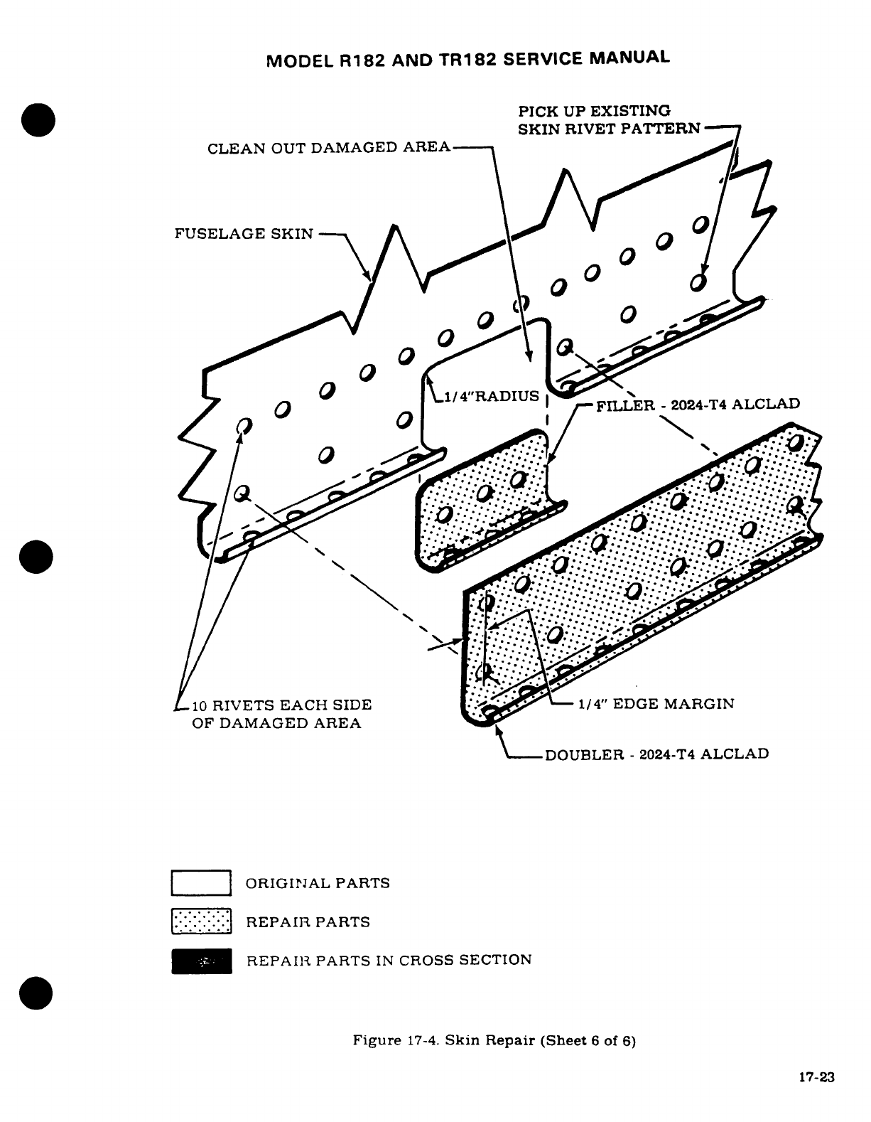
MODEL
R182
AND
TR182
SERVICE
MANUAL
PICK
UP
EXISTING
SKIN
RIVET
PATTERN
CLEAN
OUT
DAMAGED
AREA
0
_0
FUSELAGE
SKIN
-- j o
\
0
C
-
°
/ {l1/4"R ADIUS ~-
OF
DAMAGED
AREA
DOUBLER
-
2024-T4
ALCLAD
::'::
REPAIR
PARTS
-_
REPAIR
PARTS
IN
CROSS
SECTION
R-PA0
IRIES
PATES
SI
CROSS
SECIDON
Figure
17-4.
Skin
Repair
(Sheet
6
of
6)
17-23
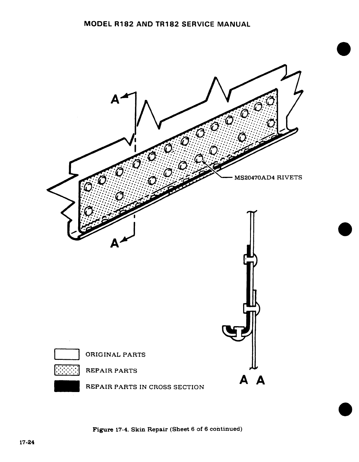
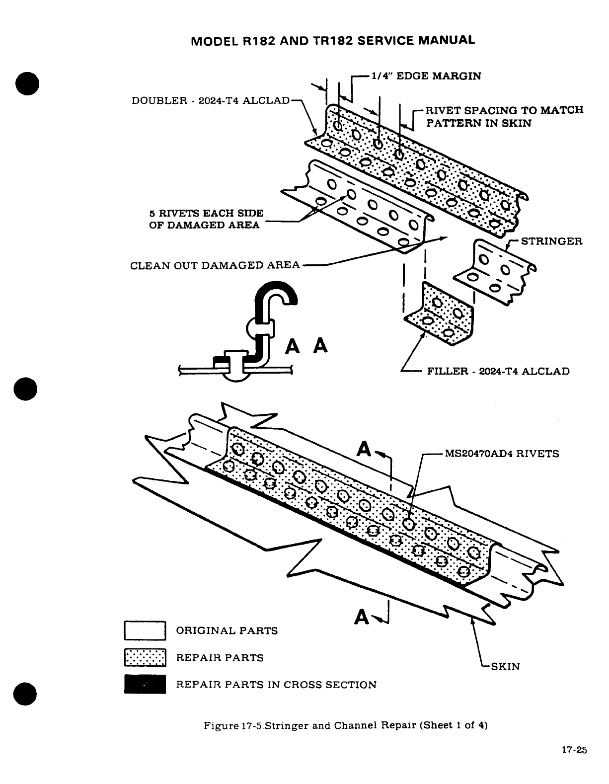
MODEL
R182
AND
TR182
SERVICE
MANUAL
1/4"
EDGE
MARGIN
DOUBLER
-
2024-T4
ALCLAD-
_
-RIVET
SPACING
TO MATCH
PATTERN
IN
SKIN
5
RIVETS
EACH
SIDE-
O 'T' <'<
OF
DAMAGED
AREA
^^sQ^-^
r
STRINGER
CLEAN
OUT
DAMAGED
AREA
I
I^s^-.'d
A
A
FILLER
-
2024-T4
ALCLAD
\<^' ^'$
:y{'^^>^^^
I--MS20470AD4
RIVETS
|
ORIGINAL
PARTS
i:i:-:-:--
REPAIR
PARTS
\'
SKIN
_I
REPAIR
PARTS
IN
CROSS
SECTION
Figure
17-5.Stringer
and
Channel
Repair
(Sheet
1
of
4)
17-25
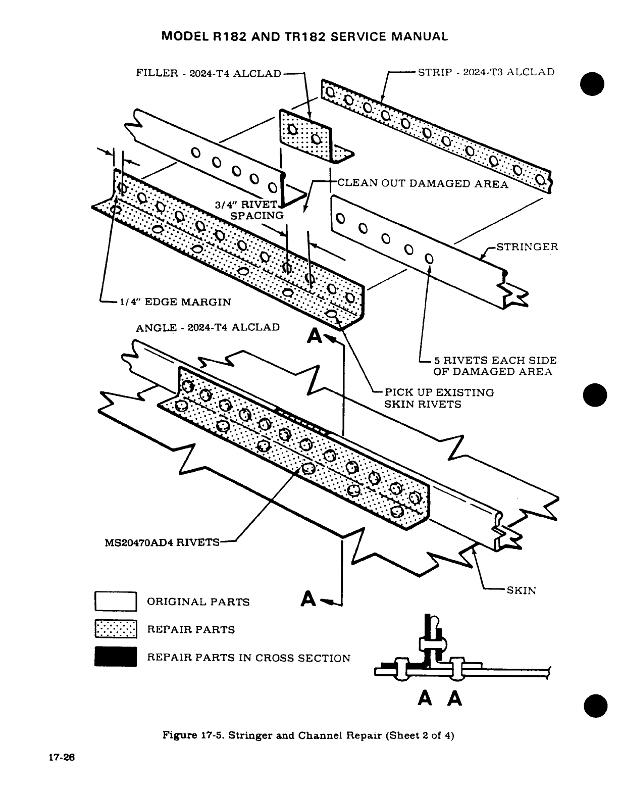
MODEL
R182
AND
TR182
SERVICE
MANUAL
FILLER
-
2024-T4
ALCLAD
-STRIP
-
2024-T3
ALCLAD
^ ^"CLEAN
OUT
DAMAGED
AREA
>-/S^
3/4"
RIVET
SPACING
REPI PANGERR
1/4"
EDGE MARGIN
ANGLE
-
2024-T4
ALCLAD
A
-
PR
PARS--
I
S\ SC I5
RIVETS
EACH
SIDE
l< F~ ^"-^^7~ \<~ ~OF
DAMAGED AREA
Bow-^'./*-.'^^. ivys. >
PICK
UP
EXISTING
MS20470AD4
RIVETS
SKIN
-SSKIN
|
ORIGINAL
PARTS
ASKI
|:-::-::
:-|REPAIR
PARTS
M04
0REPAIR
PARTS
IN
CROSS
SECTION
A
A
Figure
17-5.
Stringer
and
Channel
Repair (Sheet
2
of
4)
17-26
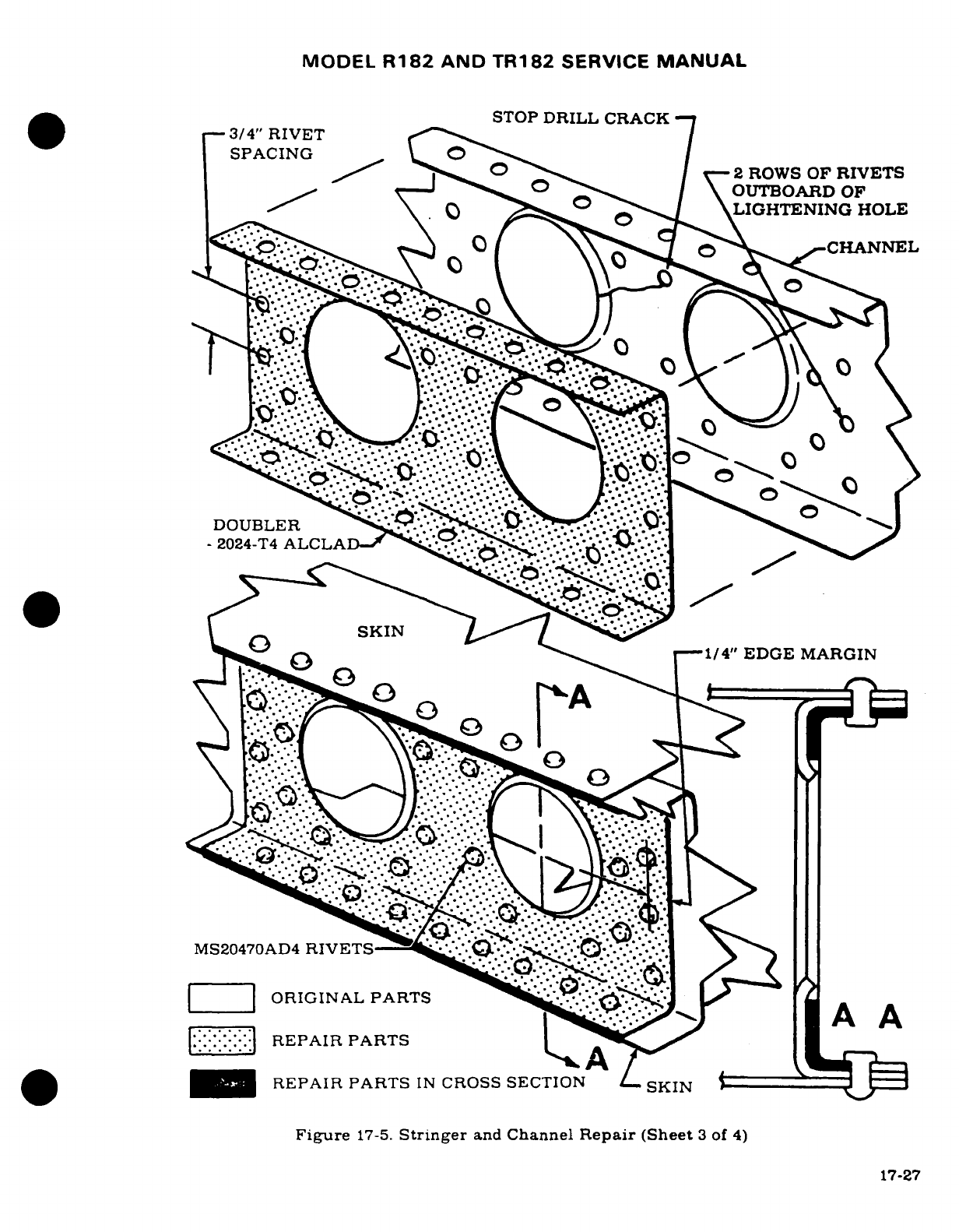
MODEL
R182
AND
TR182
SERVICE
MANUAL
STOP
DRILL
CRACK
3/4"
RIVET
SPACING
/^ ° ^ | v
2
ROWS
OF
RIVETS
v ' ^° -
O|\OUTBOARD
OF
^ \ 0 o^^ O\^
LIGHTENING
HOLE
%
\
DOUBLREPAIR
PARTS
.. ·
REPAIR
PARTS
IN
CROSS
SECTI
Figure
17-5.
Stringer
and
Channel
Repair
(Sheet
3
of
4)
17-27
1^'·'0 r\
"^^^
1/4" EDGE
MARGIN
MS20470AD
o R-''
i-
2024--i
^^'^/*'*/*'*S^''^-^
,,
O RIGIN AL· P A
RTS
^ ^
^
^ '*'**" G y ^ ^ 'i
l-^
V
.:.:.0:.:
?:
|>
-':'""--,-/,: ':.- -....'.':-* RPI
'AT
' "
^
'-~...-'~
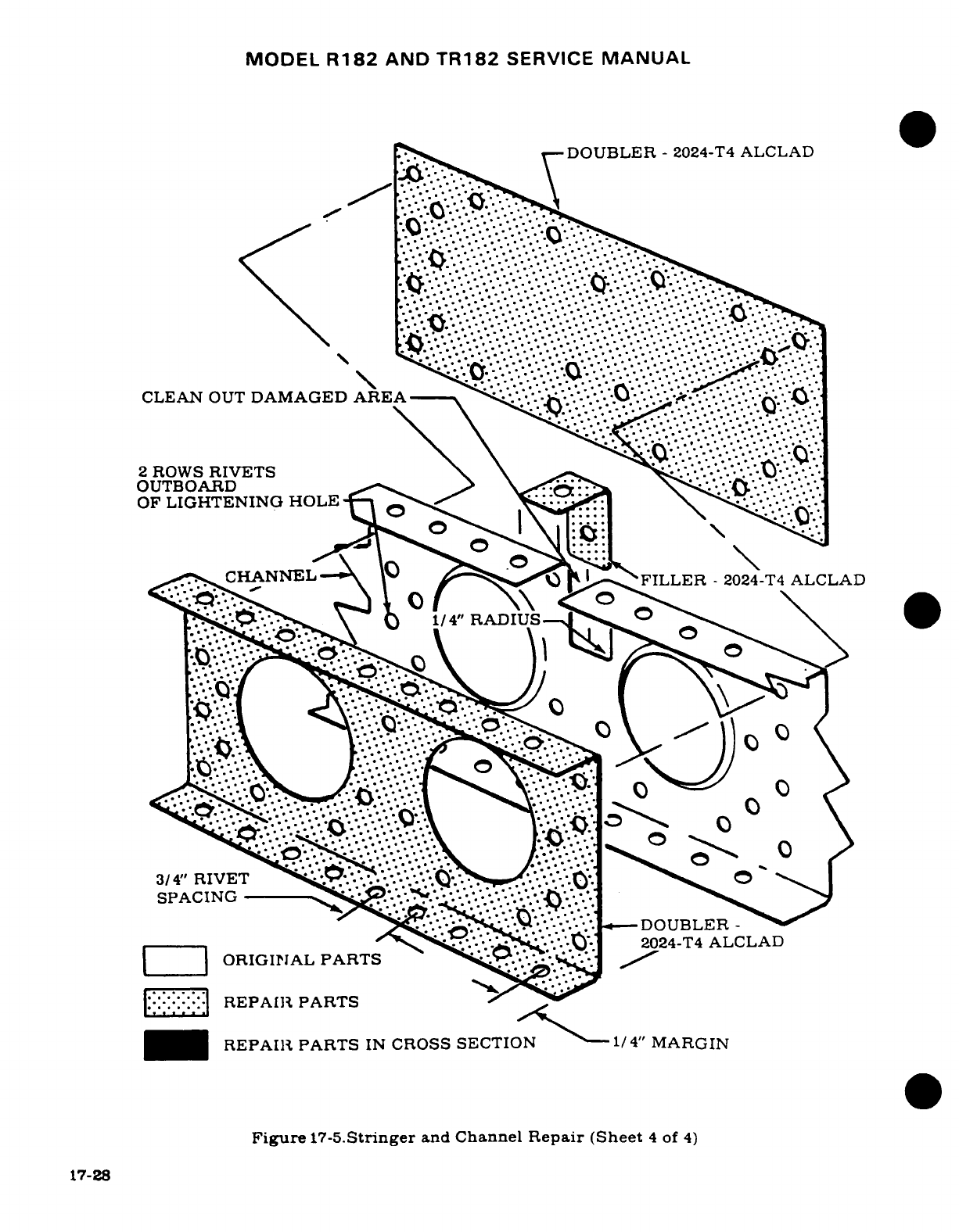
MODEL
R182
AND
TR182
SERVICE
MANUAL
DOUBLER
-
2024-T4
ALCLAD
CLEAN
OUT
DAMAGED
AREA
2
ROWS
RIVETS
OUTBOARD
OF
LIGHTENING
HOLE
...
^-~CHANNELA~ 1
mFILLER
-
2024- T4
ALCLAD
|:-
-|REPAIR
PARTSI
S
S
I
/4
MR1/4"
RADIUS
.<\§^^'.
--
~_,DOUBL
| ----- I
^
^? S
S^'*'*\'(.-f<^^*'*..:'**
:-2024-T4
ALCLAD
ORIGINAL
PARTS
/
r'
^
\/.<-\
REPAIRT
PARTS
'~J
^
_H
L
REPAIR PARTS
IN
CROSS
SECTION
I/4"
MARGIN
Figure
17-5.Stringer
and
Channel
Repair
(Sheet
4
of
4)
17-28
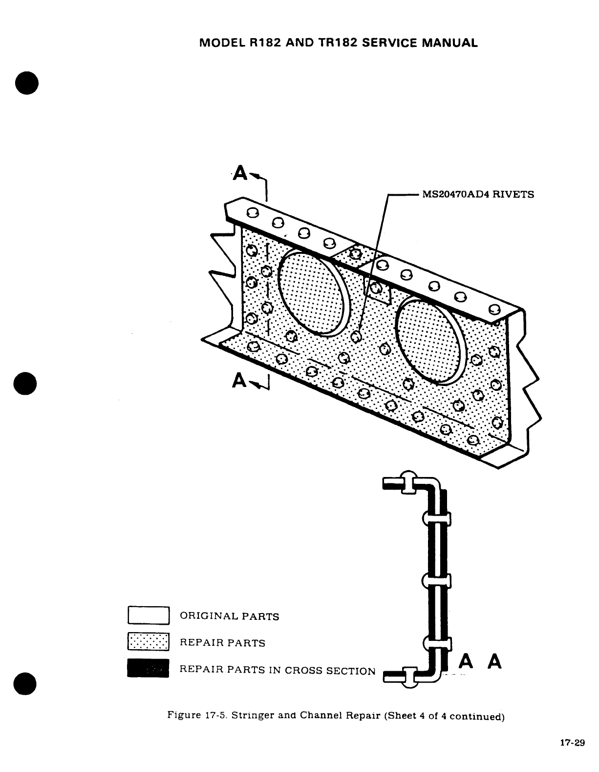
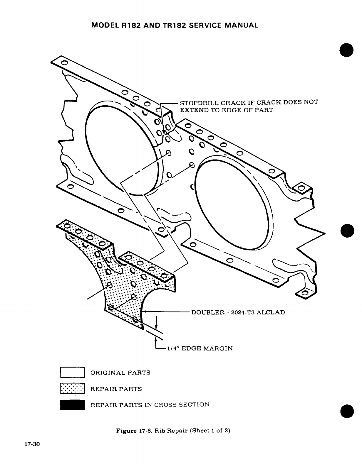
MODEL
R182
AND
TR182
SERVICE
MANUAL
I a \^-- \
STOPDRILL
CRACK
IF
CRACK
DOES
NOT
EXTEND
TO
EDGE
OF
PART
~' 1 --
DOUBLER
-
2024-T3
ALCLAD
1/4"
EDGE
MARGIN
ORIGINAL PARTS
l:
:'. '
.:
REPAIR
PARTS
-_J
REPAIR PARTS
IN
CROSS
SECTION
Figure
17-6.
Rib
Repair (Sheet
1
of
2)
17-30
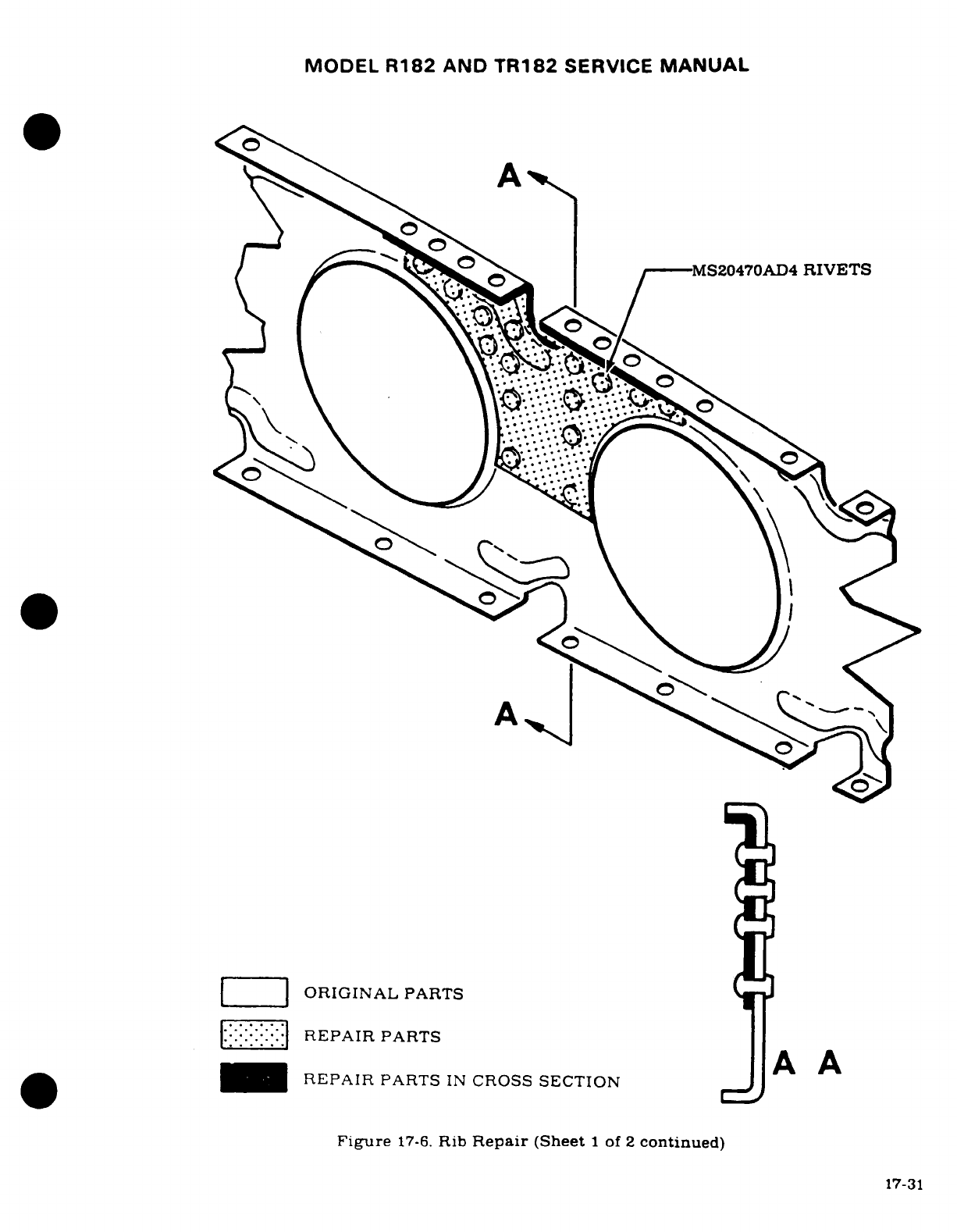
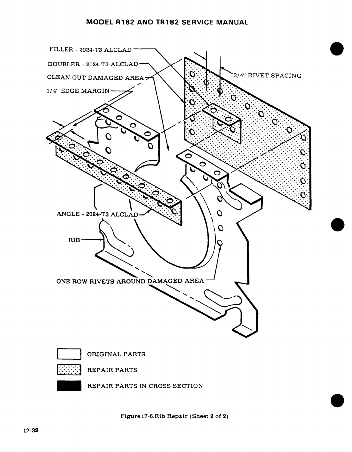
MODEL
R182
AND
TR182
SERVICE
MANUAL
FILLER
-
2024-T3
ALCLAD
DOUBLER
-
2024-T3
ALCLAD--
X"*3/4"
RIVET
SPACING
CLEAN
OUT
DAMAGED
AREA'
\ N..
kid,
ONE
ROW
RIVETS
AROUND
DAMAGED
AREA
1/4"
EDGE
MARGINAL
PARTS
::: IJ
REPAIR
PARTS
REPAIR
PARTS
IN
CROSS
SECTION
Figure
17-6.Rib
Repair
(Sheet
2
of
2)
17-32
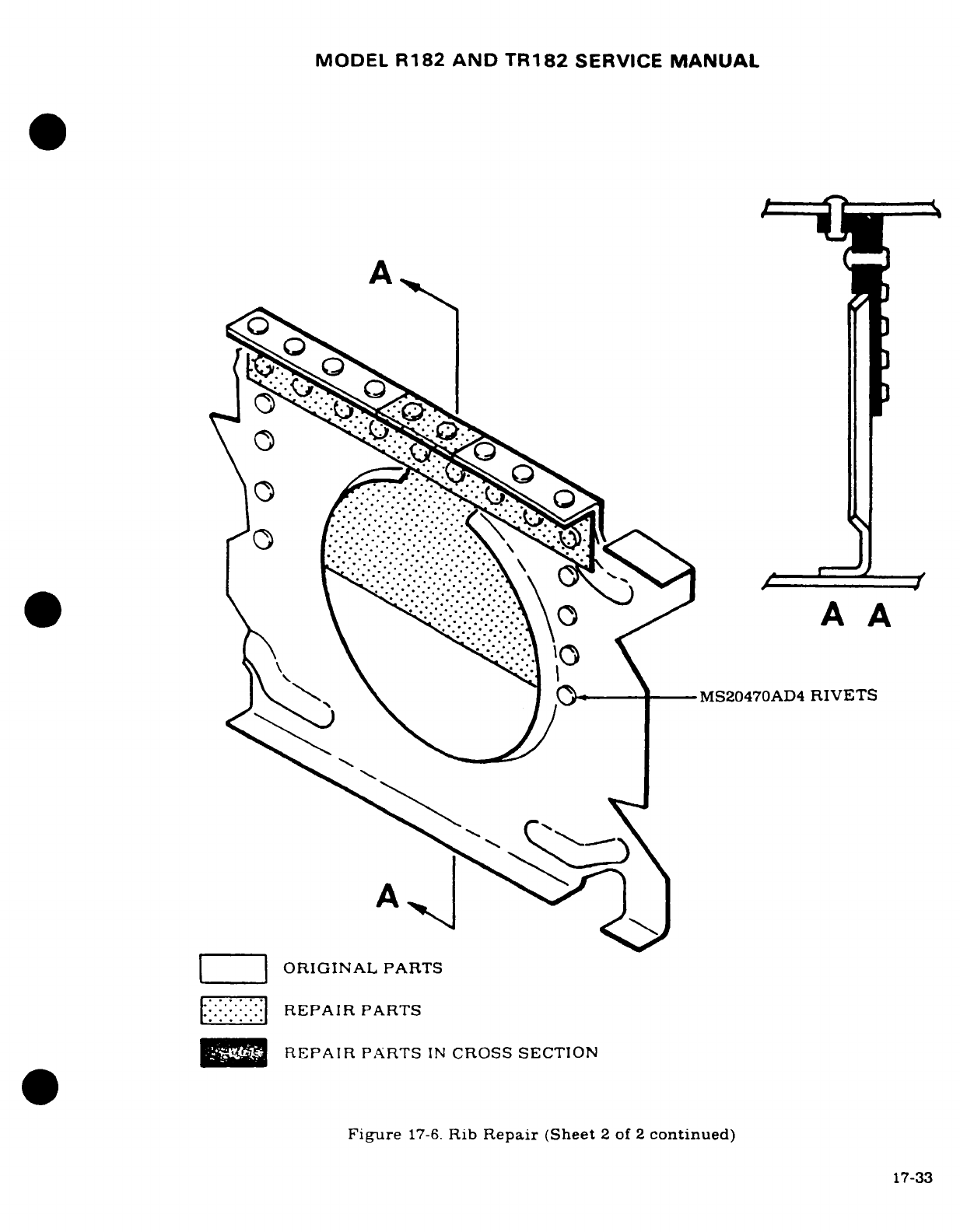
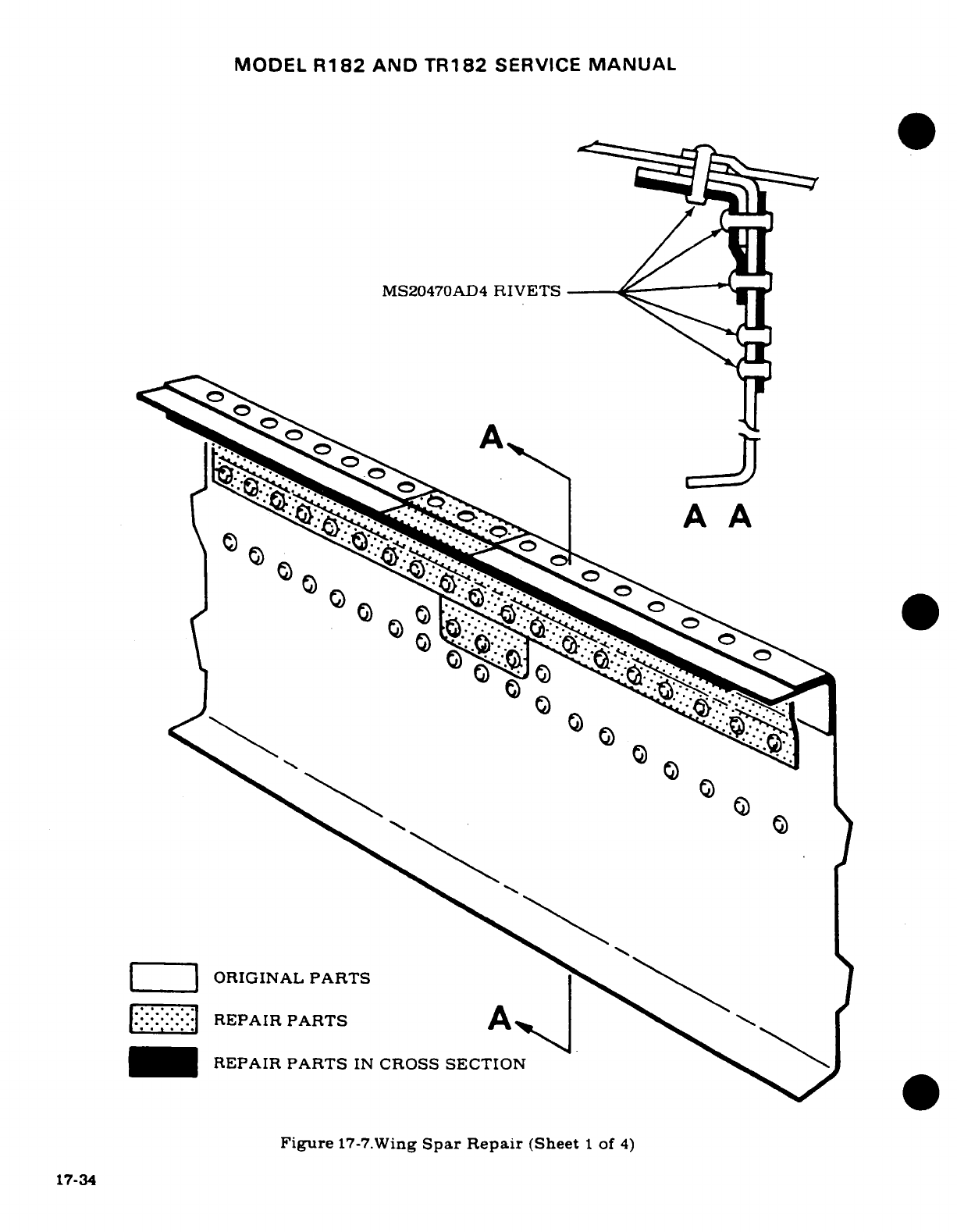
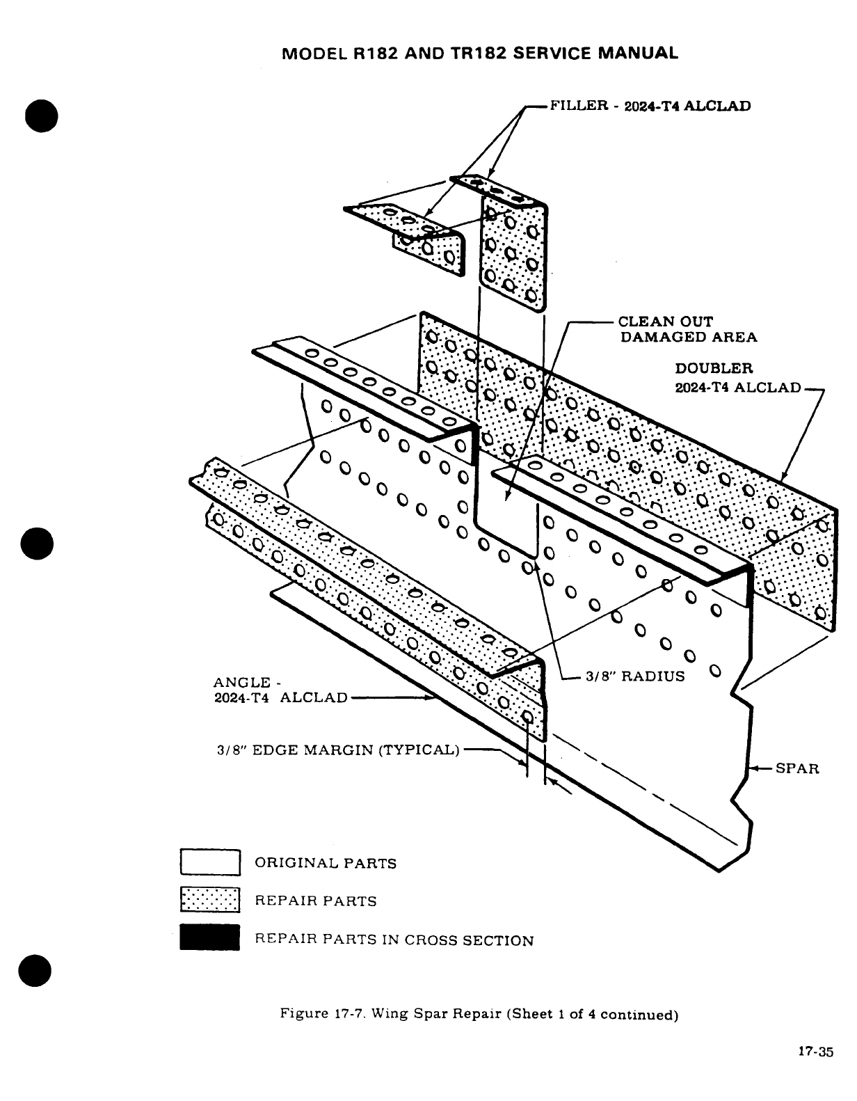
MODEL
R182
AND
TR182
SERVICE
MANUAL
FILLER
-
2024-T4
ALCLAD
l*
..
*^
(--CLEAN
OUT
DAMAGED AREA
-e
.
LDOUBLER
^^^. ^^"...... -'
'
\o 0,,-'T,
, ^
~~.~2024-T4
ALCLAD,"----.
.'
'- "
3/8" EDGE
MARGIN
(TYPICAL)
---- '..
-
Z
ORIGINAL
PARTS
::::::
REPAIR
PARTS
_H
REPAIR
PARTS
IN
CROSS
SECTION
Figure
17-7.
Wing
Spar
Repair
(Sheet
1
of
4
continued)
17-35
·
....-..
~.
"-"~'"
' "
"""'
'
.-
~-"-.".i--
_cic~
o
.
~·::~T~I I5q
~ ~~,
-~.."..
:i?--
~
O O
°
17-35
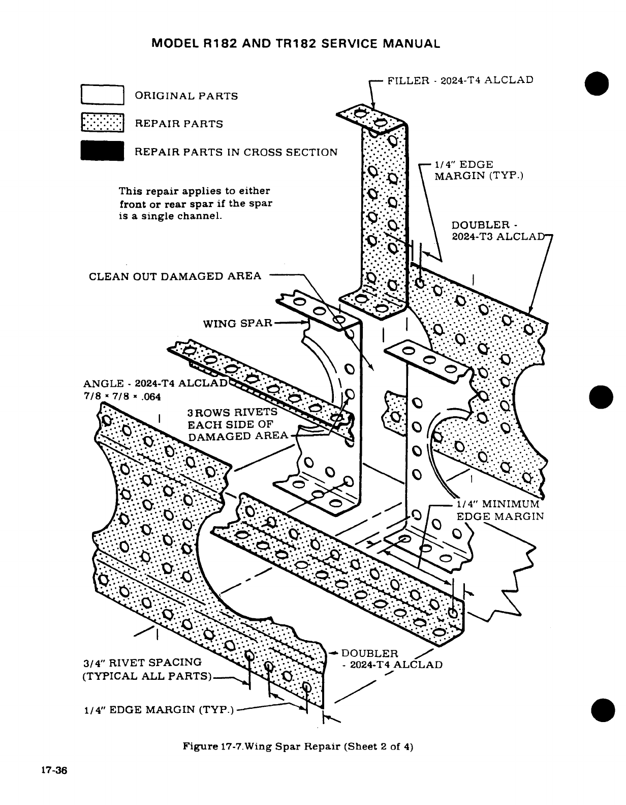
MODEL
R182
AND
TR182
SERVICE
MANUAL
FILLER
-
2024-T4
ALCLAD
[
|
ORIGINAL
PARTS
REPAIR
PARTS
REPAIR PARTS
IN
CROSS
SECTION
1/4"
EDGE
MARGIN
(TYP.)
This
repair
applies
to
either
\
front or
rear
spar
if
the
spar
:Q*
is a
single
channel.
DOUBLR..
...
~.-.'..
\
DOUBLER-
2024-T3
ALCLA
CLEAN
OUT
DAMAGED
AREA
WING
SPAR
|
.... '""""
0
ANGLE
-
2024-T4
ALCLADi
.
7/8
/
78
.064
~s'~
s
l
t0
'
gS3
,
ROWS
RIVETS
&
.DO
R
EACH
SIDE
OF
7
v
GS ]DAMAGEDAREA
/*/.'*^^.'*'*^'*'*^*'*^^
/^''^S^^^^ 0^ ^ I- 1/4"
N^^^UM
/ *'
EDGE
MARGIN
'DOUBLER
3/4"
RIVET
SPACING
2024.:DOUBLER
ALCLAD
(TYPICAL
ALL
PARTS)--
1/4"
EDGE
MARGIN
(TYP.)
--- ~
Figure
17-7.Wing
Spar
Repair
(Sheet
2
of
4)
17-36
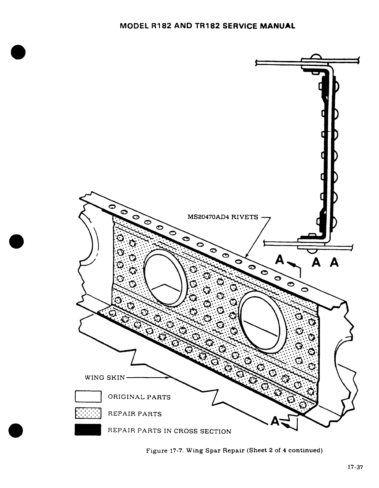
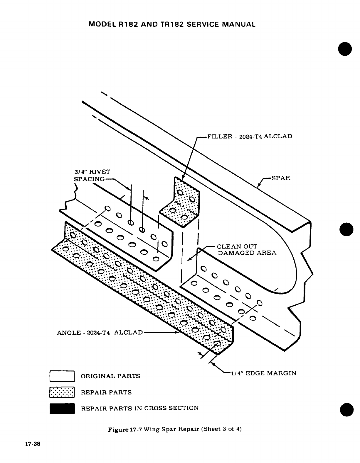
MODEL
R182
AND
TR182
SERVICE
MANUAL
--
FILLER
-
2024-T4
ALCLAD
3/4"
RIVET
SPACING
/- '
-SPAR
_.."., O
'~CLEAN
OUT
a^*'* ."v^ °
DAMAGED
AREA
ANGLE
-
2024-T4
ALCLAD
LI|
ORIGINAL
PARTS
1/4"
EDGE
MARGIN
l:::.::
|REPAIR
PARTS
_H
REPAIR PARTS
IN
CROSS SECTION
Figure
17-7.Wing
Spar
Repair
(Sheet
3
of
4)
17-38
t7-38
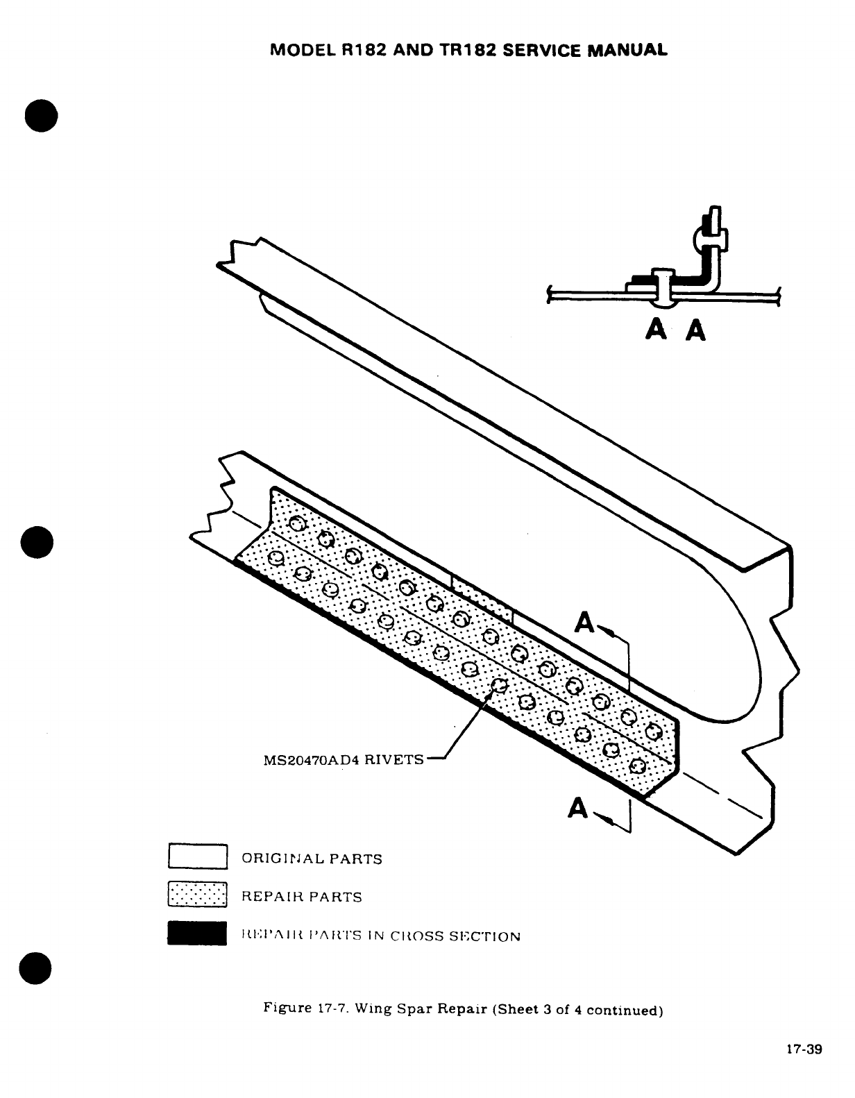
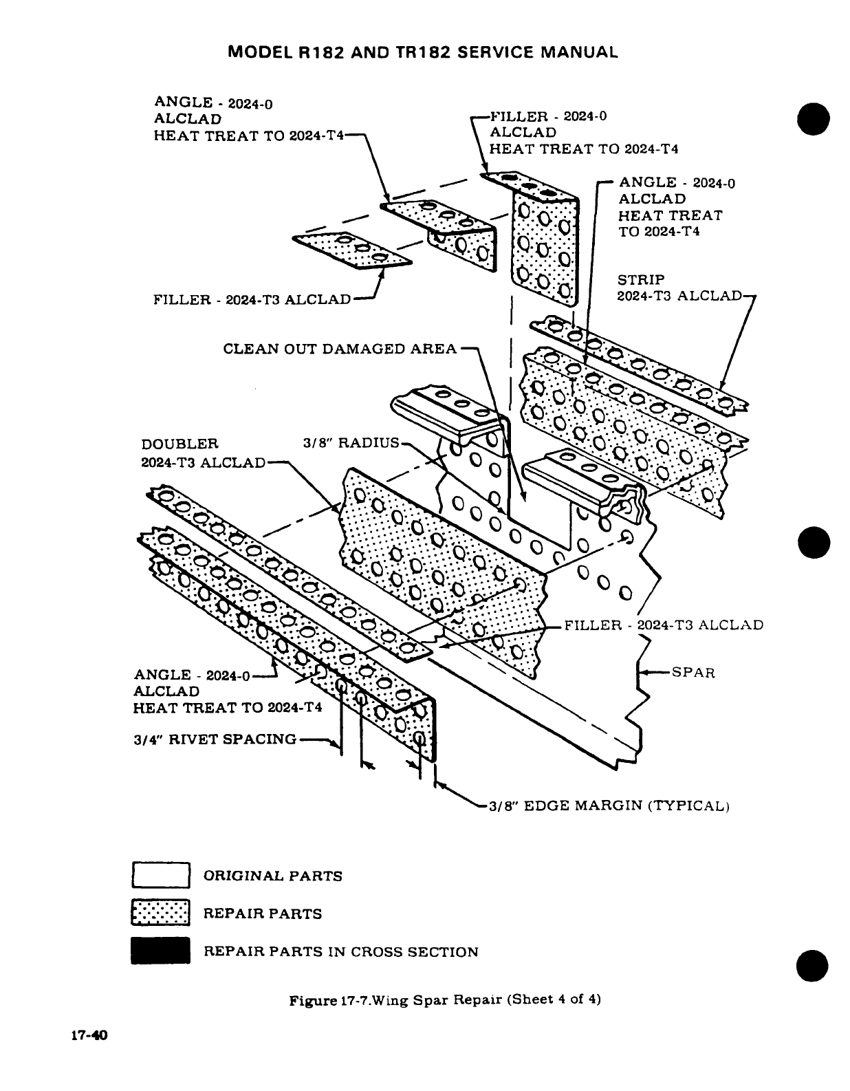
MODEL
R182
AND
TR182
SERVICE
MANUAL
ANGLE
-
2024-0
ALCLAD
F--ILLER
-
2024-0
HEAT
TREAT
TO
2024-T4-
\ALCLAD
HEAT
TREAT
TO 2024-T4
\ --- -^ ^>^
f-
ANGLE
-
2024-0
ALCLAD
/
*'
s
**'
-
t0-(Q>*
fHEAT
TREAT
TO
2024-T4
STRIP
FILLER
-
2024-T3
ALCLAD-
2024-T3
ALCLAD
CLEAN
OUT
DAMAGED
AREA
S
DOUBLER
3/8"
RADIUS
.--_::
2024-T3
ALCLAD
,
"' ~F I L.O. ~
"~"~"''-FILLER
-2024-T3
ALCLAD
ANGLE
-
2024-0-
.. '. -
-SPAR
ALCLAD
t,
HEAT TREAT
TO
2024-T4
' \
3/4"
RIVET
SPACING--
-J
3/8"
EDGE
MARGIN
(TYPICAL)
ORIGINAL
PARTS
REPAIR
PARTS
-_
REPAIR
PARTS
IN
CROSS
SECTION
Figure
17-7.Wing
Spar
Repair (Sheet
4
of
4)
17-40
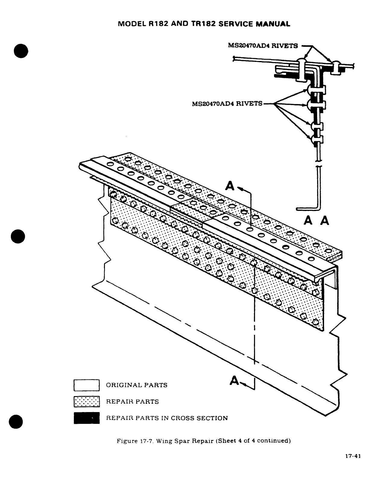
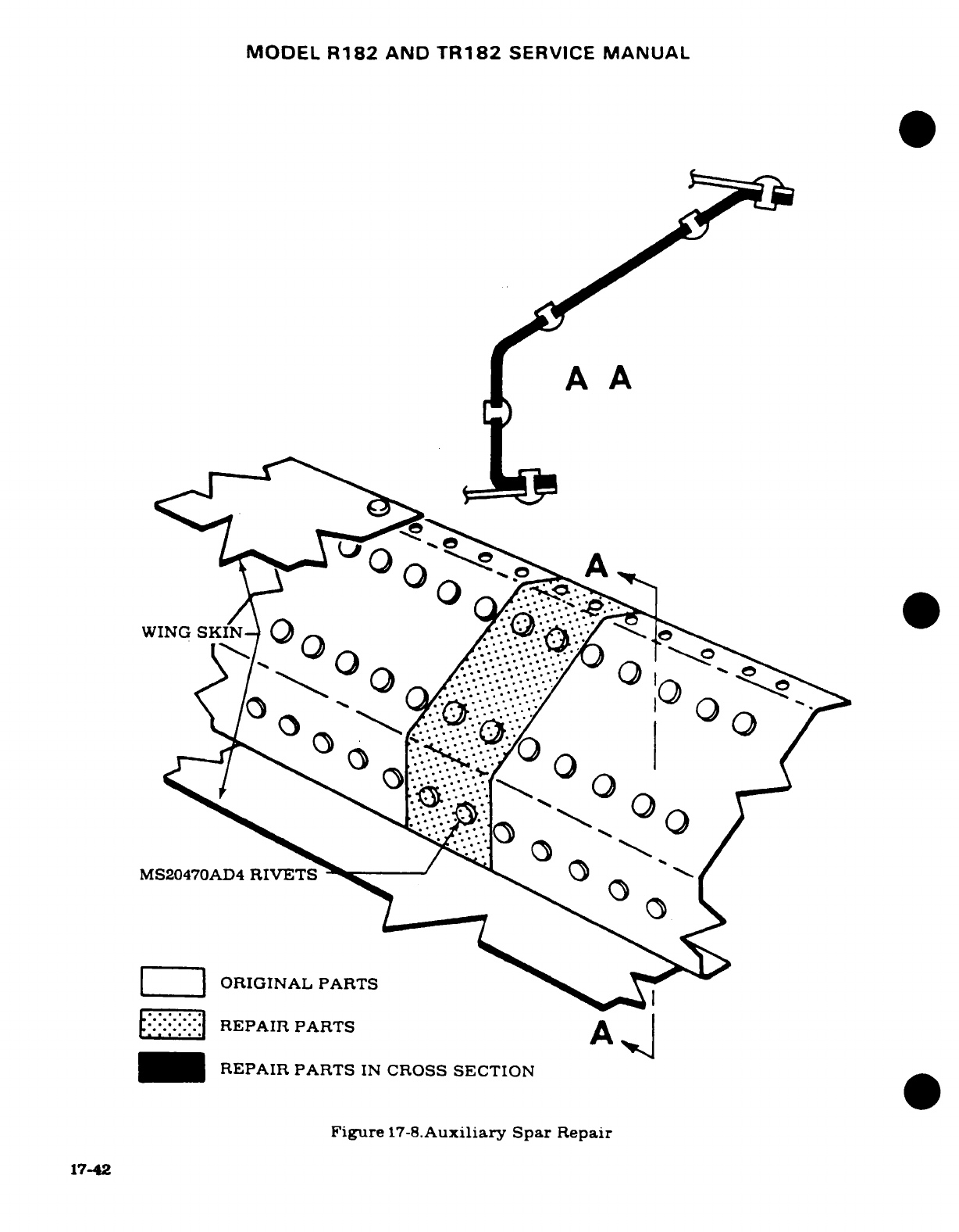
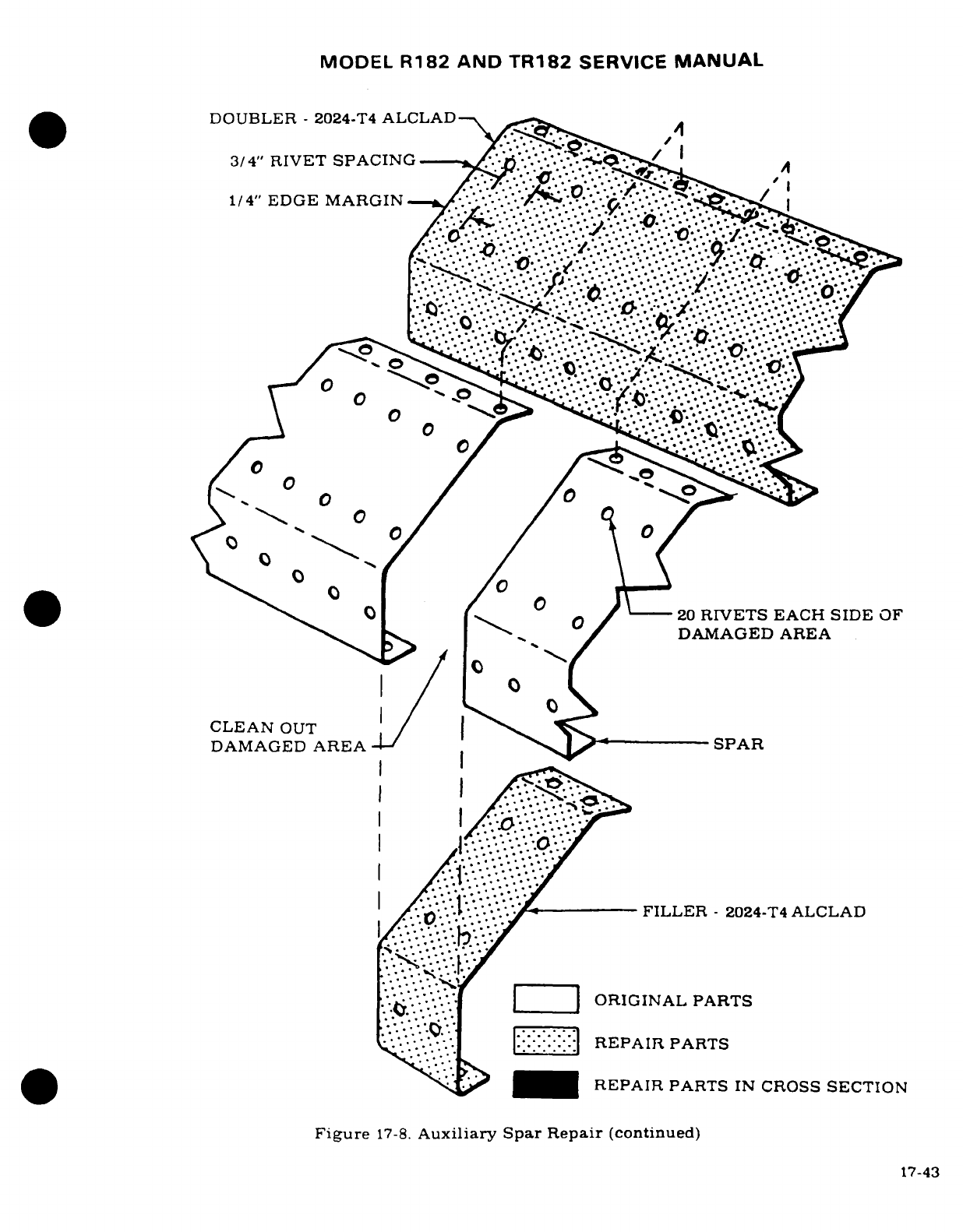
MODEL
R182
AND
TR182
SERVICE
MANUAL
DOUBLER
-
2024-T4
ALCLAD
3/4"
RIVET
SPACING
^
1/4"
EDGE
MARGIN--'
.-.. //
v
O
/
20
RIVETS
EACH
SIDE
OF
i(:
-~k
-
°
O::
---
:=
0 0¢
ORI
L
20
RIVETS
EACH
SIDE
OF
\*s^ >
"^
/
^ ^
DAMAGED
AREA
CLEAN
OUT
/
|
^^s ^
DAMAGED
AREA
l/- 1--- SSPAR
I ,/-1e
'
.:
-
FILLER
-
2024-T4
ALCLAD
*-.6
*'*.'* |
|
ORIGINAL
PARTS
* .
o
:I. |:::::|
REPAIR
PARTS
_*
<
^
REPAIR
PARTS
IN
CROSS
SECTION
Figure
17-8.
Auxiliary
Spar
Repair
(continued)
17-43
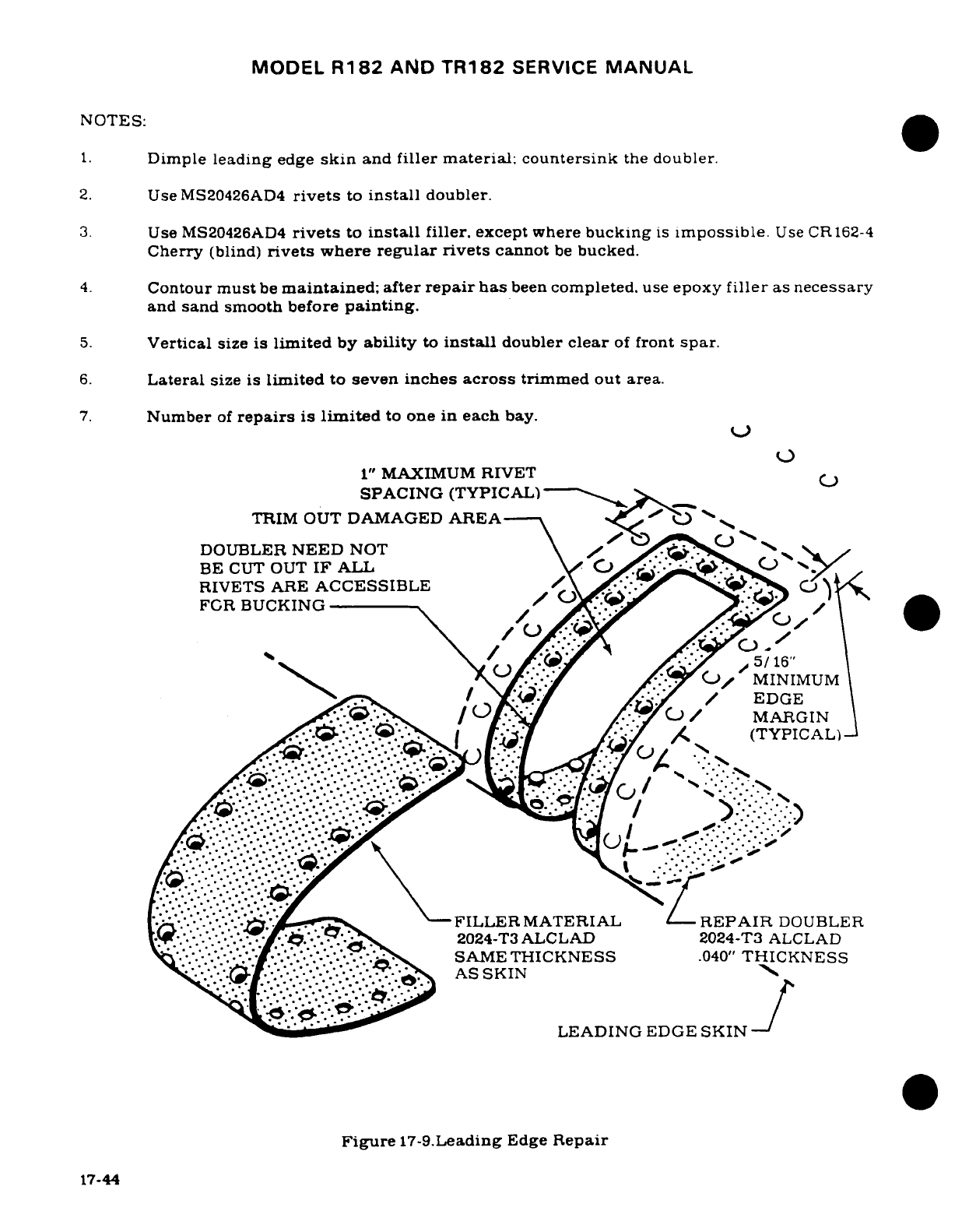
MODEL
R182
AND
TR182
SERVICE
MANUAL
NOTES:
1.
Dimple
leading
edge
skin
and
filler material; countersink
the
doubler.
2.
Use
MS20426AD4
rivets
to
install
doubler.
3.
Use
MS20426AD4
rivets
to
install
filler,
except
where
bucking
is
impossible.
Use CR162-4
Cherry
(blind)
rivets
where
regular rivets
cannot
be
bucked.
4.
Contour
must
be
maintained; after
repair
has
been
completed.
use
epoxy
filler
as
necessary
and
sand smooth
before
painting.
5.
Vertical
size
is
limited
by
ability
to
install
doubler
clear
of
front
spar.
6.
Lateral
size
is
limited
to
seven inches
across
trimmed out
area.
7.
Number
of
repairs
is
limited
to
one
in
each
bay.
1"
MAXIMUM
RIVET
SPACING
(TYPICAL)----
.
TRIM
OUT
DAMAGED
AREA
DOUBLER
NEED
NOT
/
C
BE
CUT OUT
IF
ALL
\, >y-..
C-
y
RIVETS
ARE
ACCESSIBLE
FCR
BUCKING
/
s>/
MINIMUM
\ ^-Y. / Of/^.'-/A'-Y
/
EDGE
/> /°)/ V /.(-J /
MARGIN
c[:AL. I'AL1 A2
./
(TYPICAL)
'- '-
<S^
-
N
.FILLER
MATERIAL
LREPAIR
DOUBLER
it.
. .
:-!
a{¢2024-T3ALCLAD
2024-T3
ALCLAD
.i- ..
.-.
.SAME
THICKNESS
.040"
THICKNESS
AS
SKIN
s
As
-
^^LEADING
EDGE
SKIN
Figure
17-9.Leading
Edge
Repair
17-44
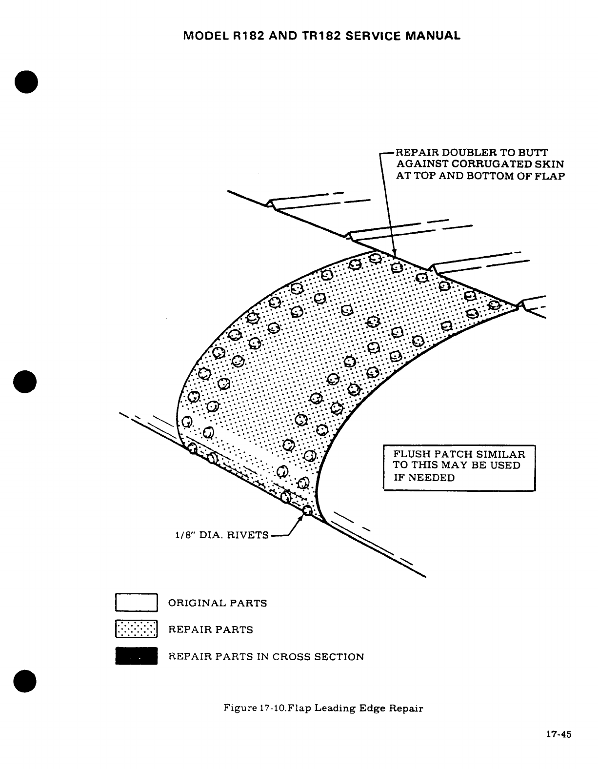
MODEL
R182
AND
TR182
SERVICE
MANUAL
REPAIR
DOUBLER
TO
BUTT
AGAINST
CORRUGATED
SKIN
AT
TOP
AND
BOTTOM
OF
FLAP
.___.__:-i-FLUSH
PATCH
SIMILAR
TO
THIS
MAY
BE
USED
IF
NEEDED
· '~--I '. '. '' '
1/8" DIA.
RIVETSJ
2
ORIGINAL PARTS
::|REPAIR
PARTS
-
REPAIR
PARTS
IN
CROSS
SECTION
Figure
17-10.Flap
Leading
Edge
Repair
17-45
17-45
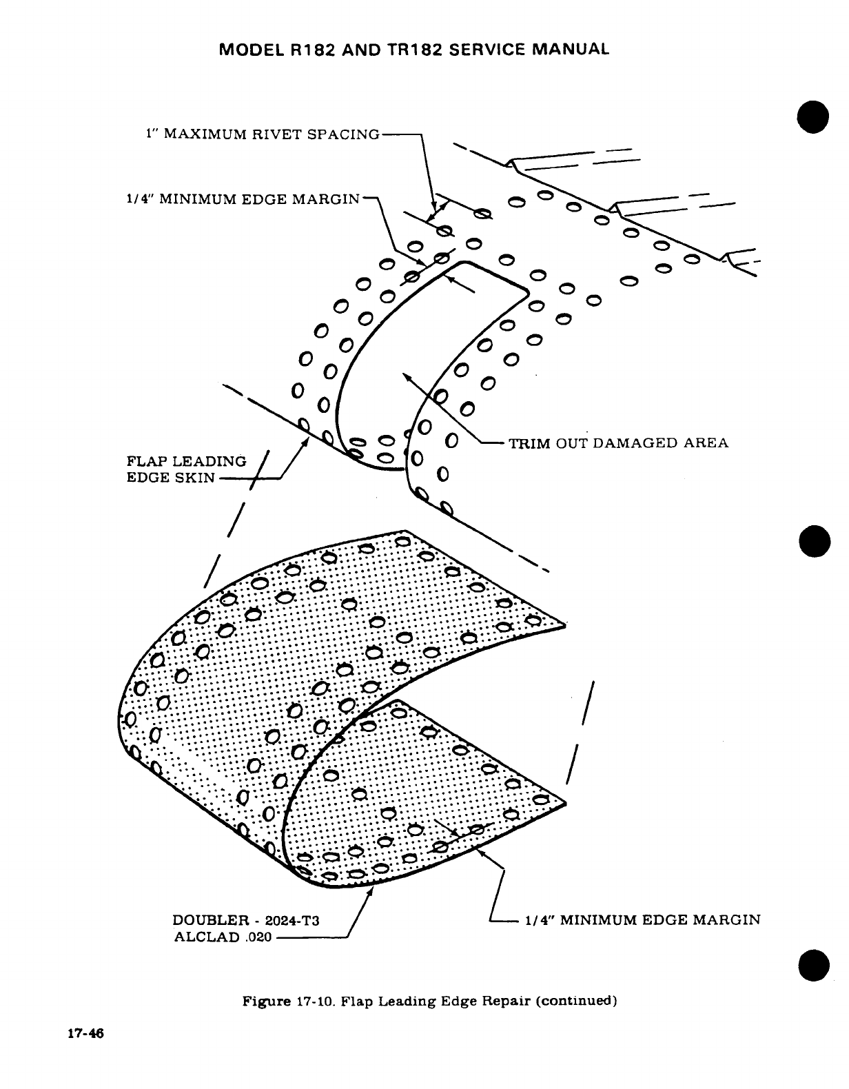
MODEL
R182
AND
TR182
SERVICE
MANUAL
1"
MAXIMUM
RIVET SPACING
1/4"
MINIMUM
EDGE
MARGIN
0 0 /°
°
y'^
0
?0
TRIM
OUT
DAMAGED
AREA
FLAP
LEADING
/
/
EDGE
SKIN
0
.
.
... d
..
.".
--......
."
/
DOUBLER
-
2024-T3
1/4"
MINIMUM
EDGE
MARGIN
ALCLAD
.020
Figure
17-10.
Flap
Leading
Edge
Repair
(continued)
17-46
..--. ....
..-
:-..-~.
.....
?......-~ii/.ii-_i-f.i.-o
O
a~~i'"-'~
;i-.~~
I
.,._._
·O
~~~Fiue7-0FpLeadigEdg
Rear
cninud
17-46
~ ~
~
,.
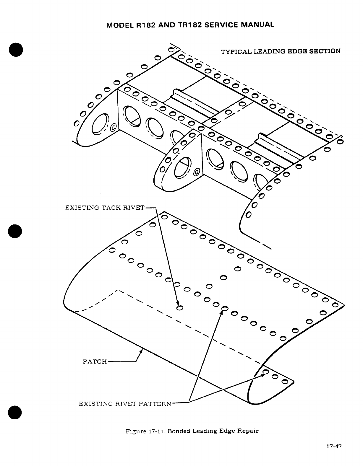
MODEL
R182
AND
TR182
SERVICE
MANUAL
TYPICAL
LEADING
EDGE
SECTION
0
0
0
EXISTING
TACK
RIVET-
.a~>-
PATCH
EXISTING
RIVET
PATTERN
Figure
17-11.
Bonded
Leading
Edge
Repair
^^ /~~~~~~EXISTING j.A~RIVET PATTERN--17-47-
Fi
r
1-1Bne
Lai
E
a~~~~~~~~~~~~~~~~~74
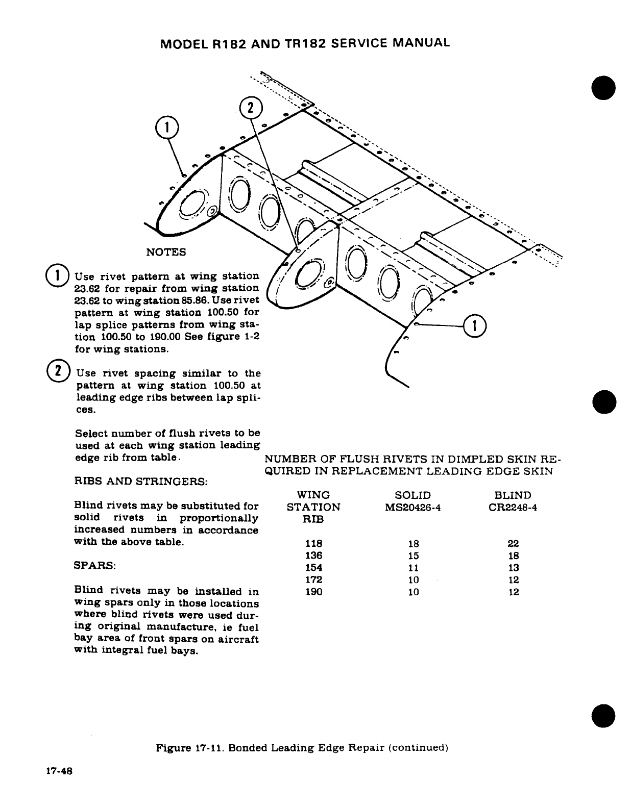
MODEL
R182
AND
TR182
SERVICE
MANUAL
s. S%
2
,
NOTES
O(
Use
rivet
pattern
at wing
station
23.62
for
repair
from
wing
station
23.62
to
wing
station
85.86.
Use
rivet
pattern
at
wing
station
100.50
for
lap
splice
patterns
from
wing
sta-
tion
100.50
to
190.00
See
figure
1-2
for
wing
stations.
~O
Use
rivet
spacing
similar
to
the
pattern
at
wing
station
100.50
at
leading
edge
ribs
between
lap
spli-
ces.
Select number
of
flush
rivets
to
be
used
at
each
wing
station
leading
edge
rib
from
table.
NUMBER
OF
FLUSH
RIVETS
IN
DIMPLED
SKIN
RE-
QUIRED IN
REPLACEMENT
LEADING
EDGE
SKIN
RIBS
AND
STRINGERS:
WING
SOLID
BLIND
Blind
rivets
may
be
substituted
for
STATION
MS20426-4
CR2248-4
solid
rivets
in
proportionally
RIB
increased
numbers
in
accordance
with
the
above
table.
118
18
22
136
15
18
SPARS:
154
11
13
172
10
12
Blind
rivets
may
be
installed
in
190
10
12
wing
spars
only
in
those
locations
where
blind
rivets
were
used
dur-
ing
original
manufacture,
ie
fuel
bay
area
of
front
spars
on
aircraft
with
integral
fuel
bays.
Figure
17-11.
Bonded
Leading
Edge
Repair
(continued)
17-48
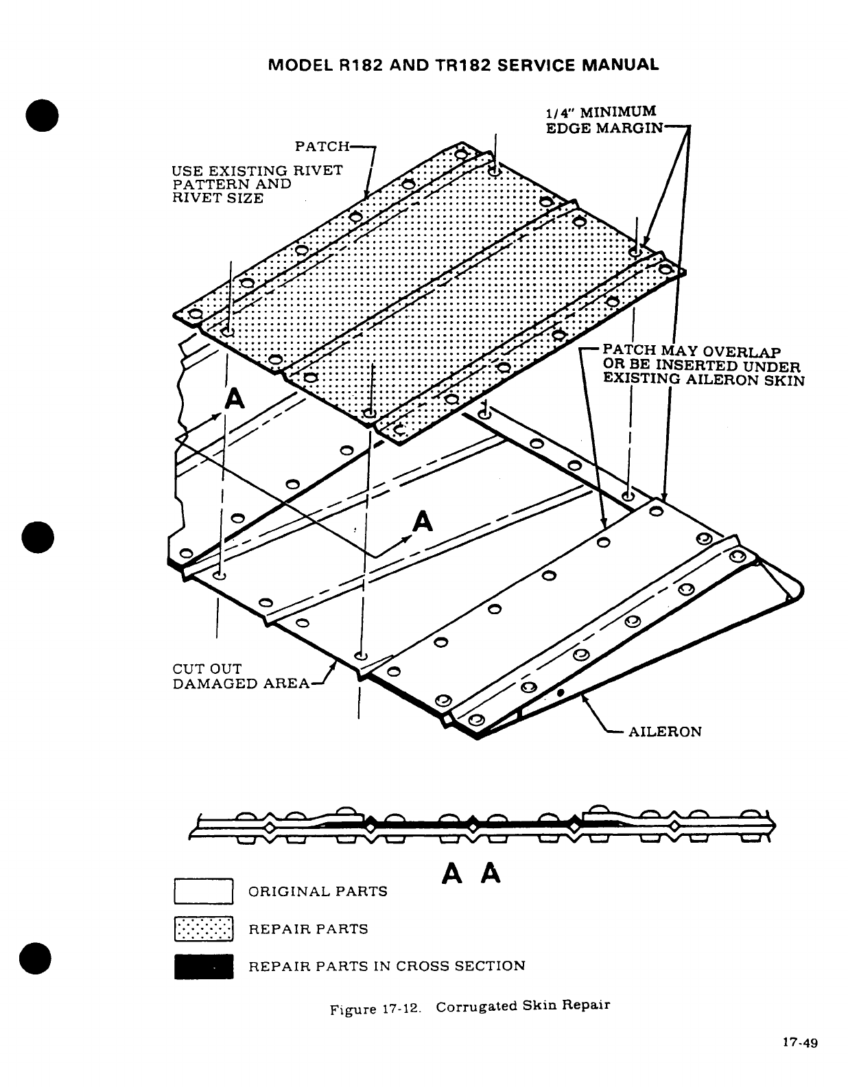
MODEL
R182 AND
TR182
SERVICE
MANUAL
1/4"
MINIMUM
EDGE
MARGIN-
PATCH-
M
E
USE
EXISTING
RIVET
PATTERN
AND
*E P I R P
T.S
... N...
C:O
.S:: C I
::O
,~
......
..............
::::::::::: EXISTING:::::::::: AILERON
SKIN
---
-JI-74-C--C-N-C---CTC--C
-C--C
-C---Ce_------------ 7
--
AILERON
--
A
A
___
ORIGINAL
PARTS
^9 ------
REPAIR
PARTS
IN
CROSS
SECTION
Figure
17-12.
Corrugated
Skin
Repair
17-49

MODEL
R182
AND
TR182
SERVICE
MANUAL
Establish
exact
location
for
inspection
cover
and
inscribe
centerlines.
-1443-1
Do
/,\<~~
z
ga^s
S-1443-1
Doubler
Determine
position
of
doubler
on
wing
skin
and
center
over
centerlines.
Mark
the
ten
rivet
hole
locations
and
drill
to
size
shown.
Cut
out access
hole.
using
dimensions
shown.
A |
#40
(0.098-inch)
Hole
e^^^
Gods^
-
=:=:
=
:::
==s
<?
(10
required)
Flex
doubler
and
insert
through
Lower
Wing
Skin
access
hole.
and
)
3
f
,
go//
(reference)
rivet
in
place.
V
ok
/ ,
/®
)
Position
cover
and
secure,
using
screws
as
shown.
5.
062-inch
Diameter
F
S-225-4F
Cover
VIEWED
FROM
INSIDE
WING
LOOKING
DOWN
AT
TOP
OF
LOWER
WING
MS20426AD3
Rivets
SKIN.
PARTS
ARE
AVAILABLE
FROM
THE
CESSNA
SUPPLY
DIVISION.
SUPPLY
DIVISION.
i!-S-1022Z-8-6
Screws
1.
Add
the
minimum
number
of
access
holes
necessary.
2.
Any
circular
or
rectangular
access
hole
which
is
used
with
approved
optional
equipment
installations
may
be
added
in
lieu
of
the
access
nole
illustrated.
3.
Use
landing
light
installations
instead
of
adding access
holes
where possible.
Do
not
add
access
holes
at
outboard
end
of
wing;
remove
wing
tip
instead.
4.
Do
not
add
an
access
hole
in
the
same
bay
where
one
is
already
located.
5.
Locate
new
access
holes
near
the
center
of
a
bay
(spanwise).
6.
Locate
new
access
holes
forward
of
the
front
spars
as
close
to
the
front
spar
as
practicable.
7.
Locate new
access
holes
aft
of
the
front
spar
between
the
first
and
second
stringers
aft
of
the
spar.
When
installing
the
doubler,
rotate
it
so
the
two
straight
edges
are
closest
to
the
stringers.
8.
Alternate
bays.
with
new
access
holes
staggered
forward
and aft
of
the
front
spar.
are
preferable.
9.
A
maximum
of
five
new
access
holes
in
each
wing
is
permissible:
if
more
is
required.
contact
the
Cessna Service
Department.
10.
When
a
complete
leading
edge
skin
is
being
replaced.
the
wing
should
be
supported
in
such
a
manner
so
that
wing
alignment
is
maintained.
Figure
17-13.
Access
Hole
Installation
17-50
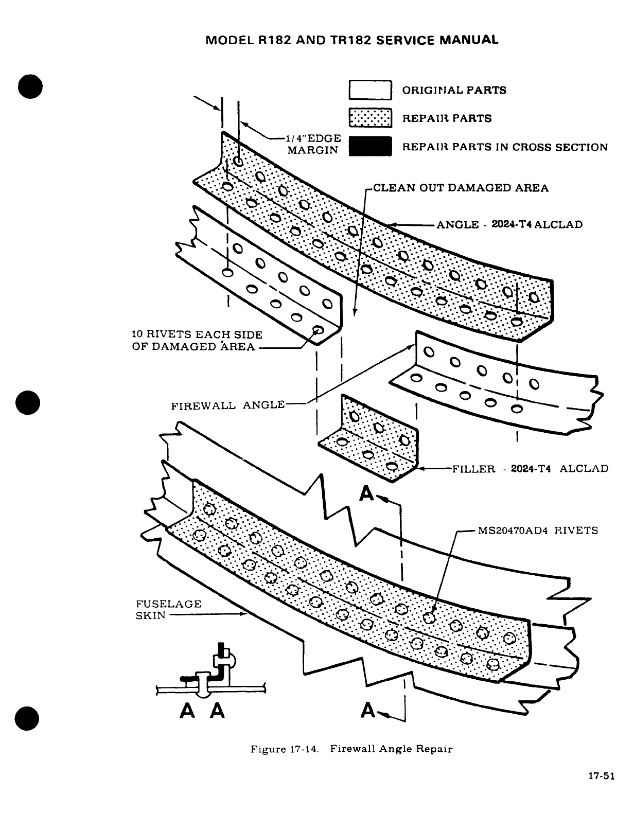
MODEL
R182
AND
TR182
SERVICE
MANUAL
Z
|
ORIGINAL
PARTS
I:.:-':-:-:'
REPAIR
PARTS
-- 1/
4"EDGE
MARGIN
REPAIR
PARTS
IN
CROSS
SECTION
Ss.'^/^.^.^^^^^^
r-CLEAN
OUT
DAMAGED
AREA
~< CLA
ANGLE
-
2024-T4
ALCLAD
10
RIVETS
EACH
SIDE
__a
-
OF
DAMAGED
XREA
-
\
f'
FIREWALL
ANGLE--
B y^<a~
-FILLER
-
2024-T4
ALCLAD
<''^*'*< <:
^:ts^ \R
CVE
IMS20470AD4
RIVETS
FUSELAGE
/S-
*
A
A
A.|.
Figure
17-14.
Firewall
Angle
Repair
17-51
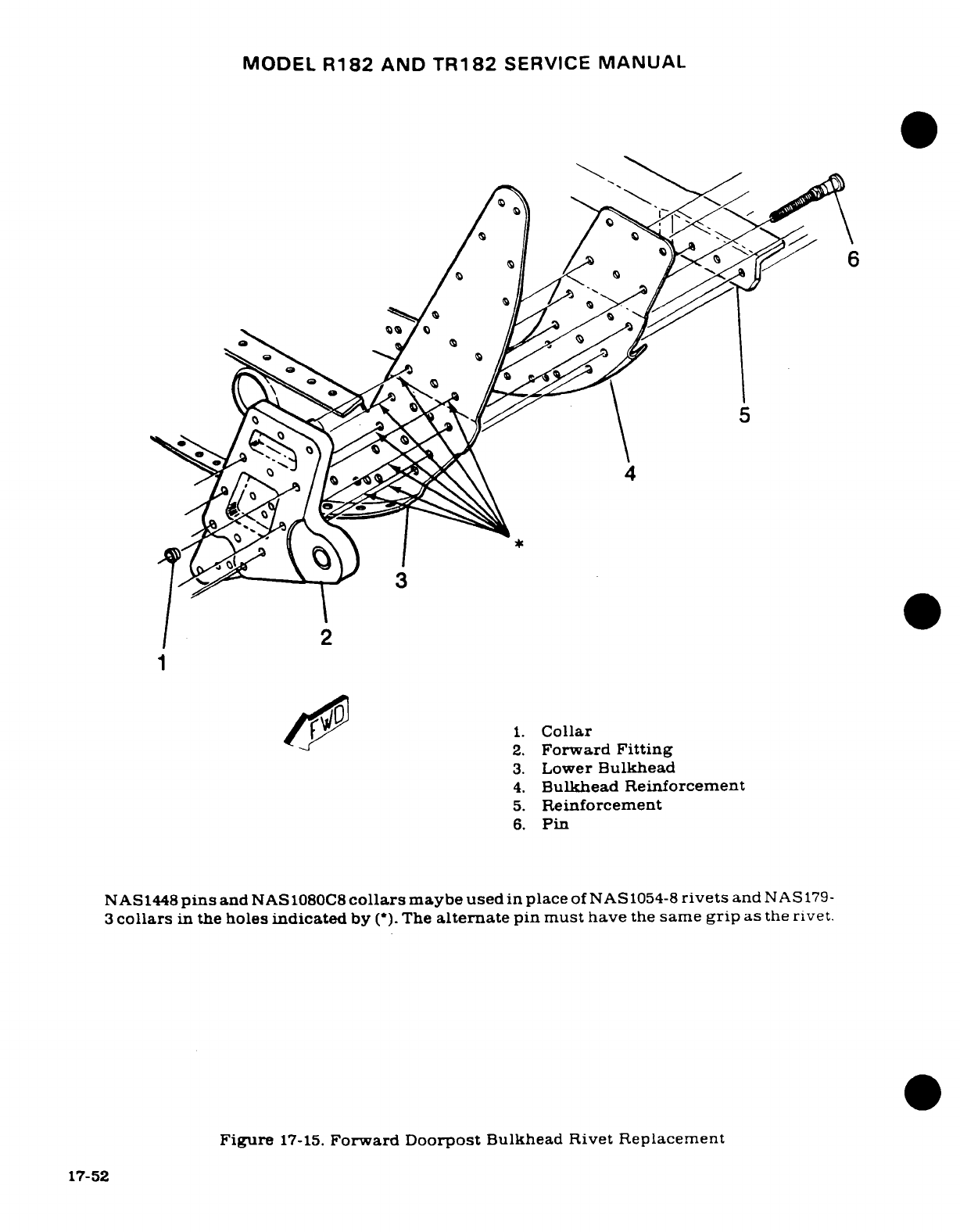
MODEL
R182
AND
TR182
SERVICE
MANUAL
6
3
4
2
1
N 4 i n S C or
y
sc
1.
Collar
2.
Forward
Fitting
3.
Lower
Bulkhead
4.
Bulkhead Reinforcement
5.
Reinforcement
6.
Pin
NAS1448
pins
and
NAS
1080C8
collars
maybe
used
in
place
of NAS1054-8
rivets
and
NAS
179-
3
collars
in
the
holes
indicated
by
(*).
The
alternate
pin
must
have
the
same
grip
as
the
rivet.
Figure
17-15.
Forward
Doorpost
Bulkhead
Rivet Replacement
17-52
MODEL
R182
AND
TR182
SERVICE
MANUAL
SECTION
18
PAINT
Page
No.
TABLE OF
CONTENTS
Aerofiche/
Manual
Facility
...................
4C18/18-2
Painting
Overall
....
........
.
4C20/18-4
Clean-up
..................
4C19/18-3
Masking
.................
4C20/18-4
Prepriming
................
4C19/18-3
Touch-up
................
4C21/18-5
Priming
...................
4C19/18-3
Repair
of
Dents
.......... .
4C21/18-5
Prepainting
................
4C20/18-4
Refinishing
Eng. Mounts
.....
4C21.18-5
NOTE
This
section
contains
standard
factory
materials
listing
and
area
of
application.
For
paint
num-
ber
and
color,
refer
to
Aircraft
Trim
Plate
and
Parts
Catalog.
In
all
cases
determine
the
type
of
paint
on
the
aircraft
as
some
types
of
paint
are
not
compatible.
Materials
may
be
obtained
from
the
Cessna
Supply
Division.
NOTE
Do
not
paint
pitot
tube, gas
caps.
or
aileron
gap
seals.
Also
do
not
paint
antenna
covers which
were
not
painted
at
the
factory.
IMRON
MODIFIED
URETHANE
MATERIAL
NO/TYPE
AREA
OF
APPLICATION
PAINT
IMRON
ENAMEL
Used
as
corrosion proof
topcoat
IMRON
192S
Activator
Catalyst
for
Imron
Enamel
PRIMER
WASH
PRIMER
P60G2
Used
to
prime
aircraft
for
Imron
Enamel
REDUCER/
IMRON
Y8485S
Reducer
Used
to
thin
Imron
Enamel
THINNER
Catalyst
Reducer
R7K44
Used
to
reduce
P60G2
Revision
1
18-1
MODEL
R182
AND
TR182
SERVICE
MANUAL
REQUIRED
MATERIALS
MATERIAL
NO/TYPE
AREA
OF
APPLICATION
STRIPPER
Strypeeze
Stripper
Used
to
strip
primer overspray
CLEANER
Technical
Materials
Form
Tech
Used
to
clean
aircraft
exterior.
AC
Cleaner
plexiglas
windows
and
to
remove
grease.
bug
stains,
etc.
Klad
Polish
Used
to
clean
aluminum
finish
808
Polishing
Compound
Used
to rub
out
overspray
SOLVENT
(MEK)
Methyl
Ethyl
Ketone
Used
to
tack
aircraft
prior
to
topcoat
CLOTH
HEX
Wiping
Cloth
Used
with
solvent
to
clean
aircraft
exterior
FILLER
White
Streak
Used
to
fill
small
dents
MASKING
Class
A
Solvent
Proof
Paper
Used
to
mask areas
not
to
be
painted
Tape
Y218
Used
for
masking
small
areas
Tape
Y231
Used
for
masking
small
areas
18-1.
FACILITY.
Painting facilities
must
include
the
ability
to
maintain
environmental
control
to
a
minimum
temperature
of
65°F.,
and
a
positive
pressure
inside
to
preclude
the
possibility
of
foreign
material
damage.
All
paint
equipment
must
be
clean,
and
accurate
measuring
containers
available
for
mixing
protective
coatings.
Modified
Urethane
has
a
pot
life
of
four
to
eight
hours, depending
on
ambient
temperature
and
relative
humidity.
Use
of
approved
respirators
while
painting
is
a
must,
for
personal
safety.
All
solvent
containers
should
be
grounded
to
prevent
static
build-up.
Catalyst
materials
are
toxic,
therefore,
breathing
fumes
or
allowing contact
with
skin
can
cause
serious irritation.
Material stock
should
be
rotated
to
allow
use
of
older
materials
first,
because
its
useful
life
is
limited.
All
supplies
should
be
stored
in
an
area
where
temperature
is
higher
than
50°F.,
but
lower
than
90°F.
Storage
at
90°F.
is
allowable
for
no
more
than
sixty
days
providing
it is
returned
to
room
temperature
for
mixing
and use.
Modified
urethane
paint
requires
a
minimum
of
seven
days
to
cure
under
normal
conditions.
if
humidity
and
temperature
are
lower,
curing
time will
be
extended
to
a
maximum
of
14
days.
During
the
curing
period,
indiscriminate
use
of
masking
tape.
abrasive
polishes.
or
cleaners
can
cause
damage
to
finish.
Desirable
curing
temperature
for
modified
urethane
is
60°F.
for
a
resulting
satisfactory
finish.
18-2
MODEL
R182
AND
TR182
SERVICE
MANUAL
18-2.
CLEAN
UP.
a.
Inspect
airplane
for
any
surface
defects,
such
as
dents
or
unsatisfactory
previous
repairs,
and
correct according
to
Paragraph
18-9.
b.
Wipe
excess
sealer
from
around
windows and
skin
laps
using
TM-AC
solvent.
Mask
windows.
ABS
parts.
and
any
other
areas
not
to
be
primed,
with
3M
tape
and
Class
A
Solvent
Proof
Paper.
Care
must
be
exercised
to
avoid
cuts,
scratches
or
gouges
by
metal
objects
to
all
plexiglass
surfaces,
because cuts
and
scratches
may
contribute
to
crazing
and
failure
of
plexiglass
windows.
Do
not
use
Methyl
Ethyl
Ketone
(MEK)
on
windows.
c.
Methyl
Ethyl
Ketone
(MEK)
solvent
should
be
used
for
final
cleaning
of
airplanes
prior
to
painting.
The
wiping
cloths
shall
be
contaminant
and
lint
free
HEX.
Saturate
cloth
in
the
solvent
and
wring
out
so
it
does
not drip.
Wipe
the
airplane
surface
with
the
solvent
saturated
cloth
in
one
hand,
and
immediately
dry
with
aclean
cloth
in
the
other
hand.
It
is
important
to
wipe
dry solvent
before it
evaporates.
When
an
airplane
has paint
or
zinc
chromate
overspray
on
the
exterior,
stripper
may
be
used
to
remove
the
overspray.
The
stripper
may
be
applied
by
brush
and
will
require
a
few
minutes
to
soften
the
overspray.
Heavy
coatings
may
require
more
than
one
application
of
the
stripper.
Use
extreme
care
to
prevent
stripper
from
running
into
faying
surfaces
on
corrosion
proofed
airplanes.
After
surfaces
of
the
overspray,
clean
the
airplane
with
Methyl
Ethyl
Ketone
(MEK)
solvent
in
the
prescribed
manner.
WARNING
Use
explosion
proof
containers
for
storing
wash
solvents
and
other
flammable
materials.
18-3.
PRE-PRIMING.
a.
Aircraft
will
receive
Sherwin-Williams
Wash
Primer
P60G2,
DuPont
Imron
Enamel
for overall
color
and
stripes.
Mix
one
part
P60G2
primer with
one
and
one
half
R7K44
catalyst
reducer
by
volume.
Mix
only
in
stainless
steel
or
lined
containers.
After
mixing,
allow
thirty
(30)
minutes
set
time for
primer
before
spraying.
Pot
life
of
mixed
primer
is
six
hours,
therefore,
all
mixed material
must
be
discarded
at this
time
limit.
Pot
pressure
for
spraying
should
be
approximately
10-
psi.
Air
pres-
sure
should
be
40
to
50
psi
at
the
gun.
Blow
loose
contaminant
from
airplane
surface
with
a
jet
of
clean,
dry
air.
Check
all tapes
to
insure
adhesion.
Cover
flap
tracks
and
nose
gear
strut
and
tape wheels
and
shimmy
dampener
rod
ends.
ABS
parts
and
other
pre-primed
parts
do
not
receive
wash
primer.
WARNING
AIRCRAFT
SHOULD
BE
GROUNDED
PRIOR
TO
PAINTING
TO
PREVENT
STATIC
ELECTRICITY
BUILD-UP
AND
DISCHARGE.
18-4.
PRIMING.
a.
Apply
primer
in
one
wet
even
coat.
Dry
film
thickness
to
be .0003
to
.0005
inches.
Do
not
topcoat
until
sufficiently
cured.
When
scratching
with
firm
pressure
of
the
fingernail
does
not
penetrate
the
coating,
the
primer
is
cured.
Primer
should
be
topcoated
within
four
hours
after
application.
18-3
MODEL
R182
AND
TR182
SERVICE
MANUAL
18-5.
PREPAINTING.
a.
Thoroughly
mix
the
required
amount
of
Imron
with
Imron
192S
Activator
in
a
three
to one
ratio.
Imron
should
be
sprayed
immediately,
because
there
is
no
induction
time. Imron
shall
be
thinned
with
Y8485S
Imron
Reducer
to
obtain
a
spraying
viscosity
of
18
to
22
seconds
on
a
No.
2
Zahn
Cup.
Viscosity
should
be
checked
after
four
hours,
and
adjusted
if
necessary.
b.
When
applying
modified
urethane finishes,
the
painter
should
wear
an
approved
respirator,
which
has
a
dust
filter
and
organic
vapor
cartridge,
or
an
air
supplied
respirator.
All
modified
urethane
finishes contain
some
isocyanate.
which
may
cause
irritation
to
the
respiratory
tract
or
an
allergic
reaction.
Individuals may
become
sensitized
to
isocyanates.
c.
The
pot
life
of
the
mixture
is
approximately
6-8
hours
at
75
°
F.
Pot
pressure
should
be
approximately
12
psi
during
application.
Air
pressure
at
the
gun
should
be
40
to
50
psi.
d.
Scuff
sand
the
primer
only
where
runs
or
dirt
particles
are
evident.
Minor
roughness
or
grit
may
be
removed
by
rubbing
the
surface
with
brown
Kraft
paper
which
has
been
thoroughly
wrinkled.
Unmask
ABS
and
other
preprimed
parts
and
check
tapes.
Clean
surface
with
a
jet
of
low
pressure-dry
air.
18-6.
PAINTING
ALL-OVER
WHITE
OR
COLOR.
a.
Complete
painting
of
the plane
should
be
done
with
2
or
3
wet,
even coats.
Dry
coats
will
not reflow,
and
will
leave
a
grainy
appearance.
b.
Allow
5
minute
period
for the
finish
to
flash
off
before
moving
aircraft
to
the
oven.
c.
Move
to
the
force
dry
oven
and
dry
for
approximately
1
1/2
hours
at
120°F
to
140°
F.
d.
Dry
film
thickness
of
the
overall
color
should
be
between
1.3
and
2.0
mils.
Films
in
excess
of
3.0
mils
are
not
desirable.
18-7.
MASKING
FOR
STRIPES.
a.
Remove
airplane
from
the
oven.
Allow
airplane
to
cool
to
room
temperature
before
masking.
b.
Mask
stripe
area
using
3M
Tape
Y231
or
3M
Tape
Y218
and
Class
A
solvent
proof
paper.
Double
tape
all
skin
laps
to
prevent
blow
by.
c.
Airplanes
which
will
have
a
stripe
only
configuration
shall
be
masked.
cleaned. and
primed,
in
stripe
area
only.
d.
If
the
base
coat
is
not
over
72
hours
old,
the
stripe
area
does
not
require
sanding.
If
sanding
is
necessary
because
of
age
or
to
remove surface
defects,
use
#400
or
#600
sandpaper.
Course
paper
will
leave sand
marks
which
will
decrease
gloss
and
depth
of
gloss
of
the
finish.
The
use
of
power
sanders
should
be
held
to
a
minimum:
but
if
used,
exercise
care
to
preclude
sanding through
the
white base coat.
Wipe
surface
to
be
striped
with
a
tack
cloth
and check
all
tapes.
e.
Stripe
colors
to
be
Imron
Enamel,
mixed
as
directed
in
paragraph
18-5.
f.
Painting
of
the
stripe
should
be
done
with
2
or
3
wet-even
coats.
Dry
coats
will
not
reflow,
and
will
leave
a
grainy
appearance.
Stripes
may
be
force
dried
or
air
dried.
Film
thickness
of
a
stripe
is
approximtely
1.0
mil.
g.
Do
not
remove
masking
tape
and
paper until
the
paint
has dried
to
a
"dry
to
touch"
condition.
Care
should
be
exercised
in
removal
of
the
masking
to
prevent
damage
to
the
finish.
h.
Modified
urethane finishes
are
sensitive
to
moisture,
therefore,
should
be
stored
out
of
rain until
cured.
18-4
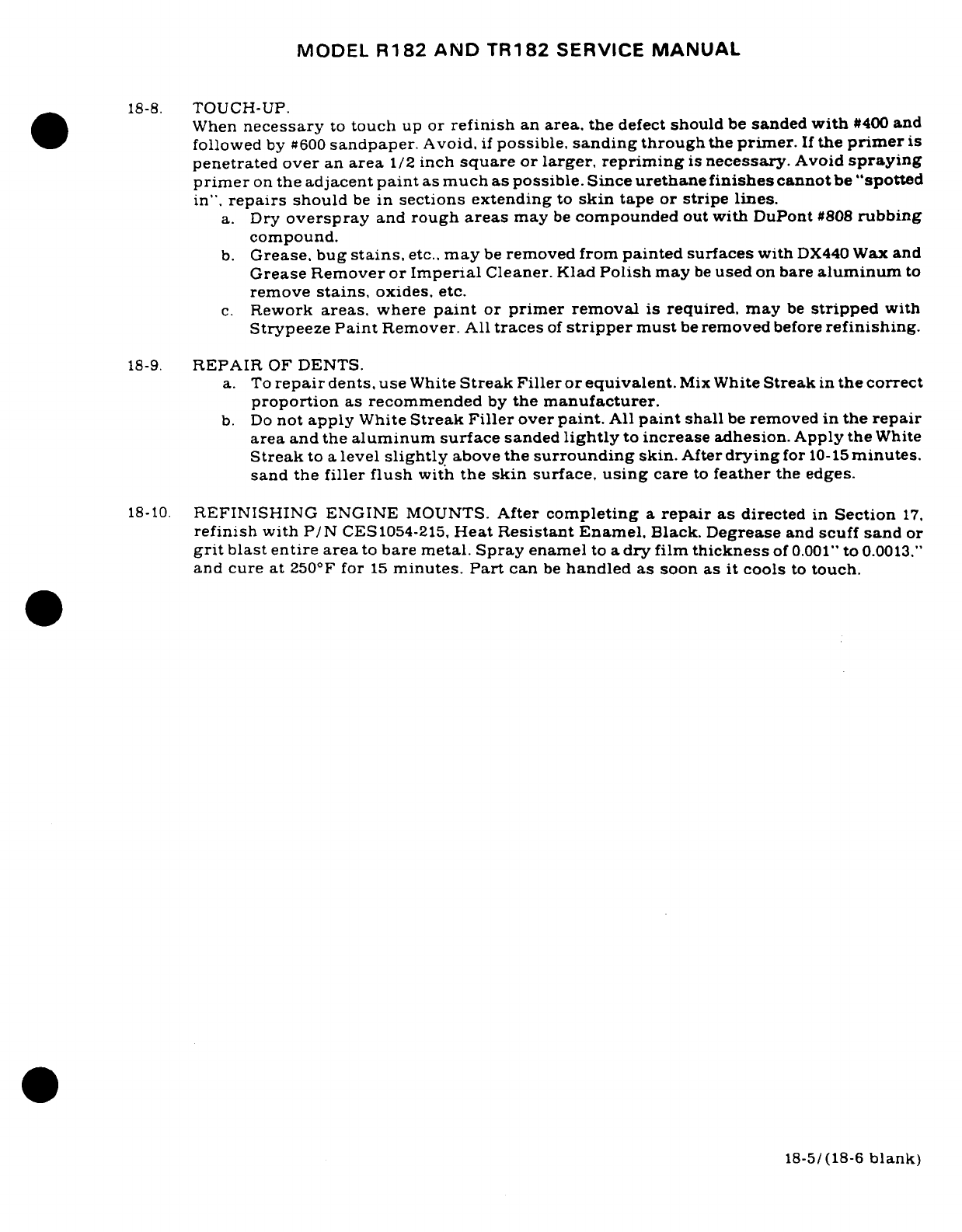
MODEL
R182
AND
TR182
SERVICE
MANUAL
18-8.
TOUCH-UP.
When
necessary
to
touch
up
or
refinish
an
area,
the
defect
should
be
sanded
with
#400
and
followed
by
#600
sandpaper.
Avoid,
if
possible,
sanding
through
the
primer.
If
the
primer
is
penetrated over
an
area
1/2
inch
square
or
larger, repriming
is
necessary.
Avoid
spraying
primer
on
the
adjacent
paint
as
much as possible.
Since
urethane
finishes
cannot
be
"spotted
in".
repairs
should
be
in
sections extending
to
skin
tape
or
stripe
lines.
a.
Dry
overspray
and
rough
areas
may
be
compounded
out
with
DuPont
#808
rubbing
compound.
b.
Grease, bug
stains,
etc..
may
be
removed from
painted
surfaces
with
DX440
Wax
and
Grease
Remover
or
Imperial
Cleaner.
Klad
Polish
may
be
used
on
bare
aluminum
to
remove
stains,
oxides,
etc.
c.
Rework
areas,
where
paint
or
primer
removal
is
required.
may
be
stripped
with
Strypeeze
Paint
Remover.
All
traces
of
stripper
must
be
removed
before
refinishing.
18-9.
REPAIR
OF
DENTS.
a.
To
repair
dents, use
White
Streak Filler
or
equivalent.
Mix
White
Streak
in
the
correct
proportion
as
recommended
by
the
manufacturer.
b.
Do
not
apply
White
Streak
Filler
over
paint.
All
paint
shall
be
removed
in
the
repair
area
and
the
aluminum surface
sanded
lightly
to
increase
adhesion. Apply the
White
Streak
to
a
level
slightly
above
the
surrounding
skin.
After
drying
for
10-15
minutes.
sand
the
filler
flush
with
the
skin
surface,
using
care
to
feather
the
edges.
18-10.
REFINISHING
ENGINE
MOUNTS.
After
completing
a
repair
as
directed
in
Section
17.
refinish
with
P/N
CES1054-215,
Heat
Resistant
Enamel.
Black.
Degrease
and
scuff
sand
or
grit
blast entire
area
to
bare
metal.
Spray
enamel
to
a
dry
film
thickness
of
0.001"
to
0.0013."
and cure at
250°F
for
15
minutes.
Part
can
be
handled
as
soon
as
it
cools
to
touch.
18-5/(18-6
blank)
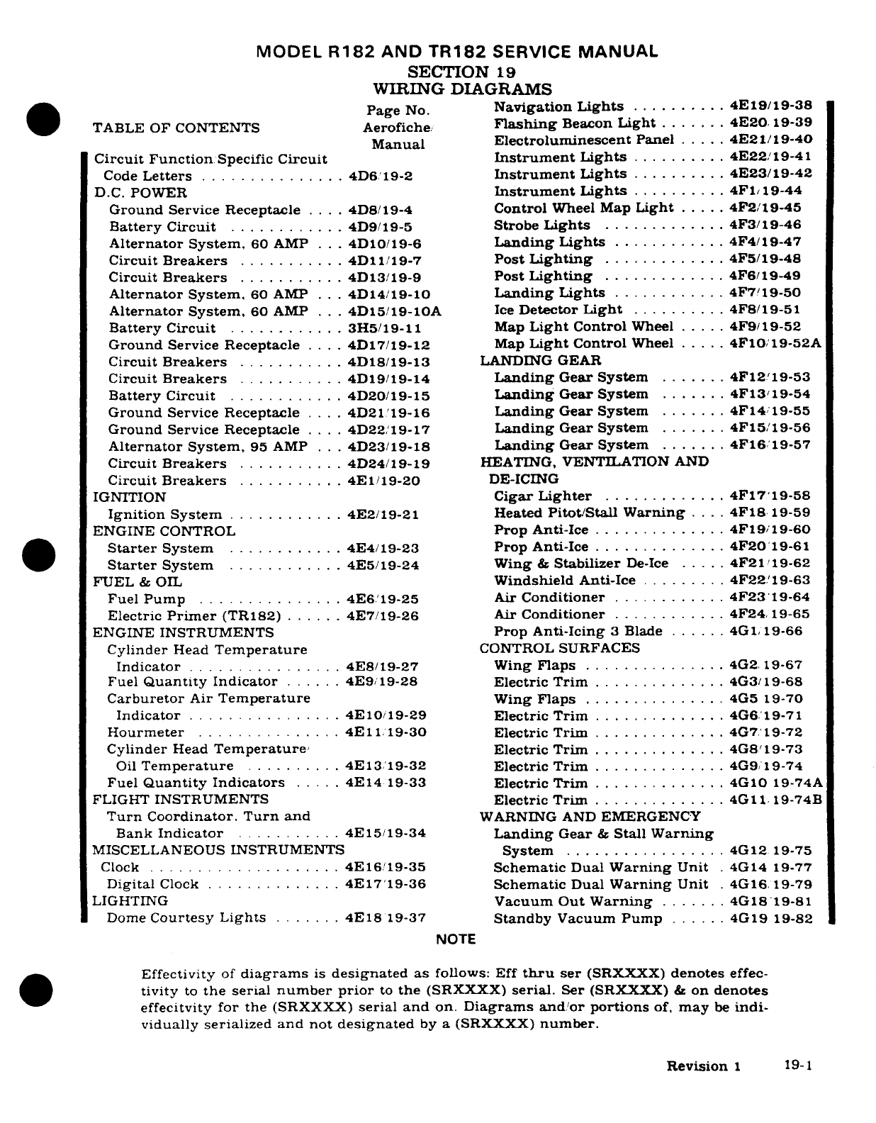
MODEL
R182
AND
TR182
SERVICE
MANUAL
SECTION
19
WIRING
DIAGRAMS
Page
No.
Navigation
Lights
..........
4E
19/19-38
TABLE
OF
CONTENTS
Aerofiche
Flashing
Beacon
Light
.......
4E20
19-39
Manual
Electroluminescent
Panel
.....
4E21/19-40
Circuit
Function
Specific
Circuit
Instrument
Lights
..........
4E22/19-41
Code
Letters
...............
4D6./19-2
Instrument
Lights
..........
4E23/19-42
D.C.
POWER
Instrument
Lights
..........
4F1/19-44
Ground
Service Receptacle
....
4D8/19-4
Control
Wheel
Map
Light
.....
4F2/19-45
Battery Circuit
............
4D9/19-5
Strobe
Lights
......... ....
4F3/19-46
Alternator
System.
60
AMP
. ..
4D10/19-6
Landing Lights
............
4F4/19-47
Circuit
Breakers
...........
4D11/19-7
Post
Lighting
.............
4F5/19-48
Circuit
Breakers
...........
4D13/19-9
Post
Lighting
.............
4F6/19-49
Alternator
System.
60
AMP
.. .
4D14/19-10
Landing
Lights
............
4F7/19-50
Alternator
System,
60
AMP
..
4D15/19-10A
Ice
Detector
Light
..........
4F8/19-51
Battery Circuit
............
3H5/19-11
Map
Light
Control
Wheel
.....
4F9/19-52
Ground
Service
Receptacle
....
4D17/19-12
Map
Light
Control
Wheel
.....
4F10/19-52A
Circuit
Breakers
...........
4D18/19-13
LANDING
GEAR
Circuit
Breakers
...........
4D19/19-14
Landing
Gear
System
.......
4F12'19-53
Battery
Circuit
............
4D20/19-15
Landing
Gear
System
.......
4F13/19-54
Ground
Service Receptacle
....
4D21
19-16
Landing
Gear
System
.......
4F14
19-55
Ground
Service
Receptacle
....
4D22/19-17
Landing
Gear
System
.......
4F15/19-56
Alternator
System,
95
AMP
. .
4D23/19-18
Landing
Gear
System
.......
4F16
19-57
Circuit
Breakers
..........
4D24/19-19
HEATING, VENTILATION
AND
Circuit
Breakers
...........
4E1/19-20
DE-ICING
IGNITION
Cigar
Lighter
.............
4F17/19-58
Ignition
System
............
4E2/19-21 Heated
Pitot/Stall
Warning
....
4F18
19-59
ENGINE
CONTROL
Prop
Anti-Ice
..............
4F19/19-60
Starter
System
............
4E4/19-23
Prop
Anti-Ice
..............
4F20
19-61
Starter
System
............
4E5/19-24
Wing
&
Stabilizer
De-Ice
.....
4F21/19-62
FUEL
&
OIL
Windshield
Anti-Ice
.........
4F22/19-63
Fuel
Pump
...............
4E6/19-25
Air
Conditioner
............
4F23/19-64
Electric
Primer
(TR182)
......
4E7/19-26
Air
Conditioner
............
4F24/19-65
ENGINE
INSTRUMENTS
Prop Anti-Icing
3
Blade
......
4G1/ 19-66
Cylinder
Head
Temperature
CONTROL
SURFACES
Indicator
................
4E8/19-27
Wing
Flaps
...............
4G2
19-67
Fuel
Quantity
Indicator
......
4E9
19-28
Electric
Trim
..............
4G3/19-68
Carburetor
Air
Temperature
Wing
Flaps
...............
4G5
19-70
Indicator
...............
4E10/19-29
Electric Trim
..............
4G6.19-71
Hourmeter
...............
4E
11
19-30
Electric Trim
..............
4G7/19-72
Cylinder
Head
Temperature,
Electric
Trim
..............
4G8/19-73
Oil
Temperature
.........
4E13/19-32
Electric Trim
..............
4G9/19-74
Fuel
Quantity Indicators
.....
4E14
19-33
Electric
Trim
..............
4G10
19-74A
FLIGHT
INSTRUMENTS
Electric
Trim
..............
4G11 19-74B
Turn
Coordinator.
Turn
and
WARNING
AND
EMERGENCY
Bank
Indicator
...........
4E15/19-34
Landing
Gear
&
Stall
Warning
MISCELLANEOUS
INSTRUMENTS
System
.................
4G12
19-75
Clock
....................
4E16/19-35
Schematic
Dual
Warning
Unit
.
4G14
19-77
Digital
Clock
..............
4E17/19-36
Schematic
Dual
Warning
Unit
.
4G16.19-79
LIGHTING
Vacuum
Out
Warning
.......
4G18/19-81
Dome
Courtesy
Lights
.......
4E18
19-37
Standby
Vacuum
Pump
......
4G19
19-82
NOTE
Effectivity
of
diagrams
is
designated
as
follows: Eff
thru
ser
(SRXXXX)
denotes
effec-
tivity
to
the
serial
number
prior
to
the
(SRXXXX)
serial.
Ser
(SRXXXX)
&
on
denotes
effecitvity
for the
(SRXXXX)
serial
and
on.
Diagrams
and/or
portions
of,
may
be
indi-
vidually
serialized
and
not
designated
by
a
(SRXXXX)
number.
Revision
1
19-1
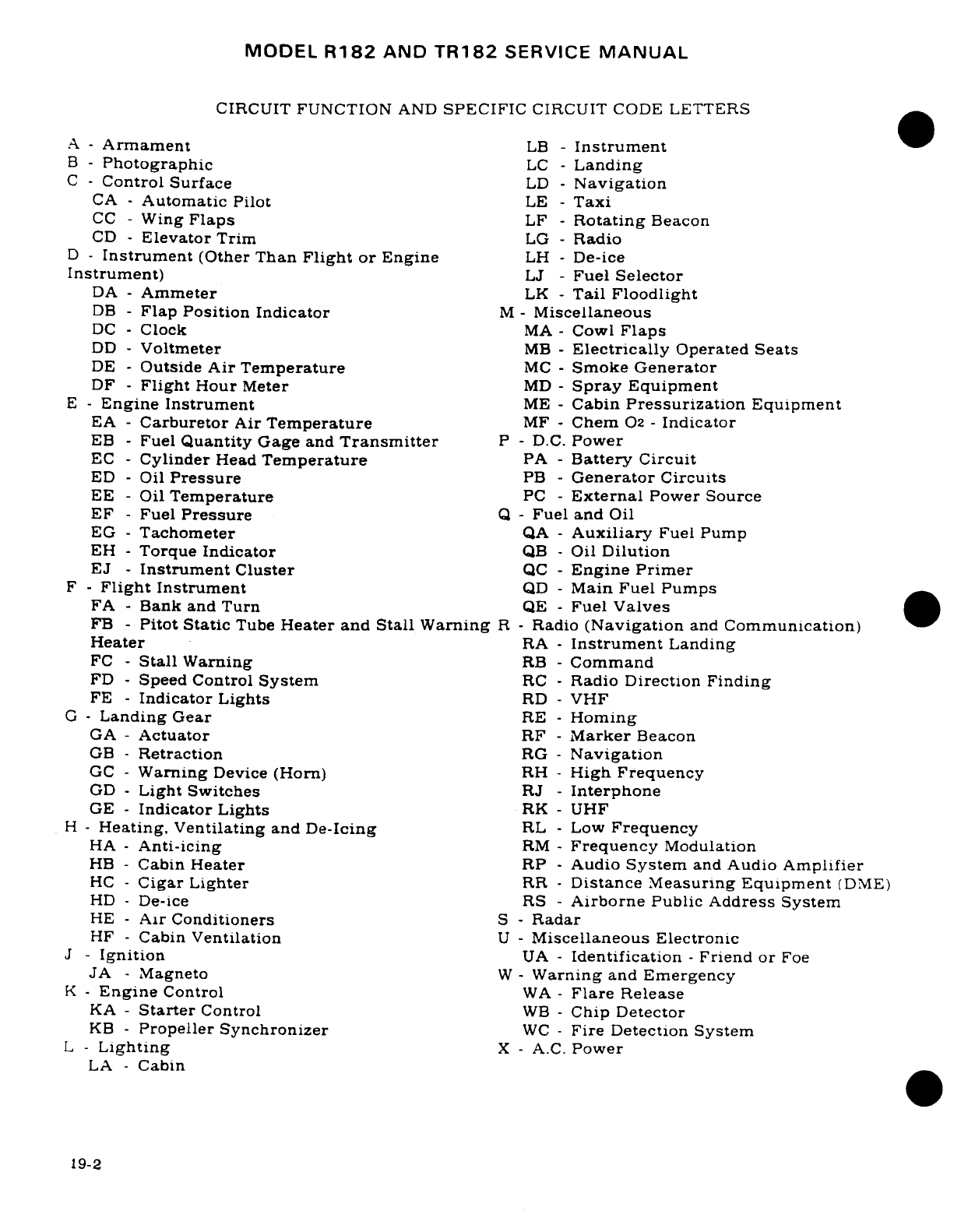
MODEL
R182
AND
TR182
SERVICE
MANUAL
CIRCUIT
FUNCTION
AND
SPECIFIC
CIRCUIT
CODE
LETTERS
A
-
Armament
LB
-
Instrument
B
-
Photographic
LC
-
Landing
C
-Control Surface
LD
-
Navigation
CA
-
Automatic
Pilot
LE
-
Taxi
CC
-
Wing
Flaps
LF
-
Rotating
Beacon
CD
-
Elevator
Trim
LG
-
Radio
D
-
Instrument
(Other
Than
Flight
or
Engine
LH
-
De-ice
Instrument)
LJ
-
Fuel
Selector
DA
-
Ammeter
LK
-
Tail
Floodlight
DB
-
Flap
Position Indicator
M
-
Miscellaneous
DC
-
Clock
MA
-
Cowl
Flaps
DD
-
Voltmeter
MB
-
Electrically
Operated
Seats
DE
-
Outside
Air
Temperature
MC
-
Smoke
Generator
DF
-
Flight
Hour
Meter
MD
-
Spray
Equipment
E
-
Engine
Instrument
ME
-
Cabin
Pressurization
Equipment
EA
-
Carburetor
Air
Temperature
MF
-
Chem
02
-
Indicator
EB
-
Fuel
Quantity
Gage
and
Transmitter
P
-
D.C.
Power
EC
-
Cylinder
Head
Temperature
PA
-
Battery
Circuit
ED
-
Oil
Pressure
PB
-
Generator
Circuits
EE
-
Oil
Temperature
PC
-
External
Power
Source
EF
-
Fuel
Pressure
Q
-
Fuel
and
Oil
EG
-
Tachometer
QA
-
Auxiliary
Fuel
Pump
EH
-
Torque
Indicator
QB
-
Oil
Dilution
EJ
-
Instrument
Cluster
QC
-
Engine Primer
F
-
Flight
Instrument
QD
-
Main
Fuel
Pumps
FA
-
Bank and Turn
QE
-
Fuel
Valves
FB
-
Pitot
Static
Tube
Heater
and
Stall
Warning
R
-
Radio
(Navigation
and
Communication)
Heater
RA
-
Instrument
Landing
FC
-
Stall
Warning
RB
-
Command
FD
-
Speed
Control
System
RC
-
Radio
Direction Finding
FE
-
Indicator
Lights
RD
-
VHF
G
-
Landing
Gear
RE
-
Homing
GA
-
Actuator
RF
-
Marker
Beacon
GB
-
Retraction
RG
-
Navigation
GC
-
Warning
Device
(Horn)
RH
-
High
Frequency
GD
-
Light
Switches
RJ
-
Interphone
GE
-
Indicator
Lights
RK
-
UHF
H
-
Heating, Ventilating
and
De-Icing
RL
-
Low
Frequency
HA
-
Anti-icing
RM
-
Frequency
Modulation
HB
-
Cabin
Heater
RP
-
Audio
System
and
Audio
Amplifier
HC
-
Cigar
Lighter
RR
-
Distance Measuring
Equipment
(DME)
HD
-
De-ice RS
-
Airborne
Public
Address
System
HE
-
Air
Conditioners
S
-
Radar
HF
-
Cabin
Ventilation
U
-
Miscellaneous
Electronic
J
-
Ignition
UA
-
Identification
-
Friend or
Foe
JA
-
Magneto
W
-
Warning
and
Emergency
K
-
Engine
Control
WA
-
Flare
Release
KA
-
Starter
Control
WB
-
Chip Detector
KB
-
Propeller
Synchronizer
WC
-
Fire Detection System
L
-Lighting
X
-
A.C.
Power
LA
-
Cabin
19-2

MODEL
R182
AND
TR182
SERVICE
MANUAL
BASE
FUNCTION COLOR
STRIPE
CIRCUITS
GAUGE
(or
solid)
COLOR
A
+
Power
16
Red None
18
Red
Black
Red
White
20
Red Green
22
Red
Yellow
Ground
16
Black
None
18
Black
White
Mike
Ground
22
Black
None
Radio
Lights
Dim
18
Yellow
None
Mike
Audio
22
Tan
None
Tan
(Shielded)
None
Mike
Key
22
White
Black
Radio
Speaker
20
Green
None
Headphones
22
Blue
None
Dev
+ *
22
Gray
Red
Dev
- *
22
Gray
Green
*"Dev+"
and
"Dev-"
circuits
are
for
use
in
Nav-o-matic
300
autopilots
and
any associated
omni
indicator
circuit
to
which
it
connects.
NOTE
All
other
color
coded
wires
are
for
general
use
in
multi-
conductor radio
and
autopilot
harness
assemblies.
CROSS
REFERENCE
LISTING
OF
SERIAL
REQUEST
NUMBERS LISTED
ON
DIAGRAMS
VS.
AIRCRAFT
SERIAL
NUMBERS.
SR. NO.
AIRCRAFT SERIAL
NO.
SR.
NO.
AIRCRAFT
SERIAL
NO.
SR8462
R18200001
-
FR18200001
SR9554
R18201470
SR8782
R18200584
-
FR18200026
SR9583
R18201230
SR8970
R18200004
-
FR18200001
SR9632
R18201629
SR8982
R18200584
SR9738
R18201542
SR8995
R18200428
-
FR18200021 SR9799
R18201629
-
TR1822006
SR9087
R18200508
SR9828 R18201752
SR9112
R18201314
-
FR18200046
SR9853
R18201696
SR9140
R18200509
SR9951
R18201799
SR9187
R18200584
SR10003
R18201799
SR9195
R18200670
SR10068
R18201799
SR9215
R18201090
-
FR18200046
SR10099
R18201929
SR9369
R18204520
-
FR18200021
SR10122
R18201799
SR9429
R18200961
SR10152
R18201799
SR9437
R18200800
-
FR18200046
SR10213
R18201809
SR10415
R18202000
SR10837
R18202009
19-3
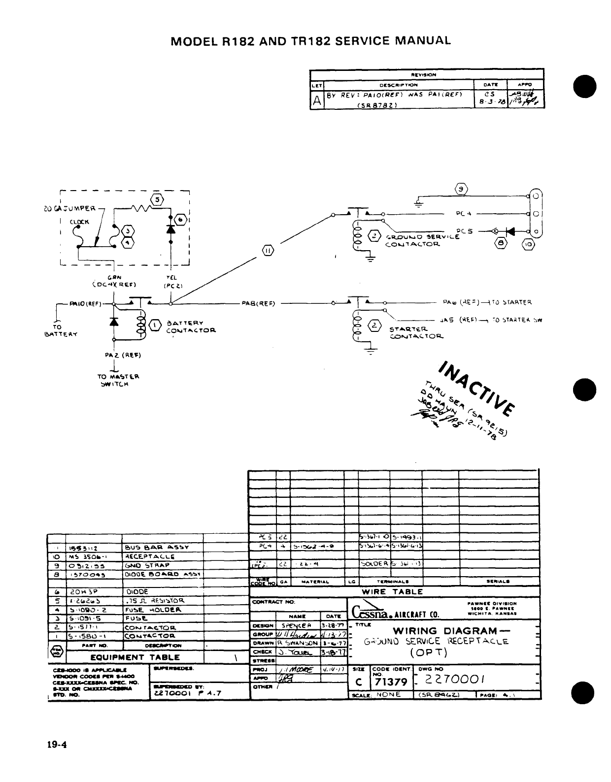
MODEL
R182
AND
TR182
SERVICE
MANUAL
REVISION
LET
D(SCRtPTON
DATI APP|
8Y
REV:
PAIO(RcF)
NA5
PAt(REF)
CS
..
,/?os
A
(SR878Z)
j 8-3-_
.1/
''8
…--1
--
....
t
-- ~ 0 c A
--
o
a
(C
CI
_ I
c
_
oc
-1 _
8
,
>
,
v
jA.T
L…-
/
CRaJN EL
(.DC4)X
r)
(PCl
/
--
IO(REF)-
cPA8(RE;)
PAw
-E)-ITO TSART
TR
in
C
S
^TTERY
E
--------
d5^5~s (?F,% -O iTAaTEA
S
e>A''~
TE
,
COt'ToR
T^
Ot
o
TO
f T.;
1,,T
TOM
5",A...,ar
TO
%AST 1.M 1
'
""
~" ~
~bW'V~:\~~TLC
[ G-A
ATRI&AL
L4G T
L
ze
-3
2
?
1
GA
..
Tt"'A*L
LG
TIMN
AL
S9
tIAL§
(.
MSaOP
OOODE
_ __
WIRE
TABLE
5
*
S(ii
.15
Q
PI-'OR
______
'
COTRACT
POO:
-
Aw
N
--
,05
-
5
S
FU
AM
DAT
C
ina
ACIAFT
CO.
w.CHITA
A
..
2
-
15-Bo-\
COhTCTO4Fl.
2
CU/. 1-7u
WIRING
DIAGRAM-
PANT NO.
---
AW--R
SAIN1 1-6-7NDN
7I-
G-j)NO
SERVICE
ZCEPTAAC-E.
A--\
r *o. 1 c~lror allu ~-Yo~CH1Cx
-fJc l
k
(OPT)
EQUIPMENT
TABLE
'y
3
2
(
OP
T)
Crr-00C
AS
APUCJ
_UAR..E
.
p"
n
J
j ./1
MO
ql.,Vu- 7
Sz
coo.
IOINT
DWO
NO
ss-X
oo
CNoS
--
xxxx-C-m
--
1
C
71379
Z
7000
1
S-KXXZEUSHA
'
T:
SOTC
/ ,
Im
OT..
.270001
ooo
A
.7
aSCALE:
NONE.
(sp.-
Alz-i
PAGE!
^.\.
19-4
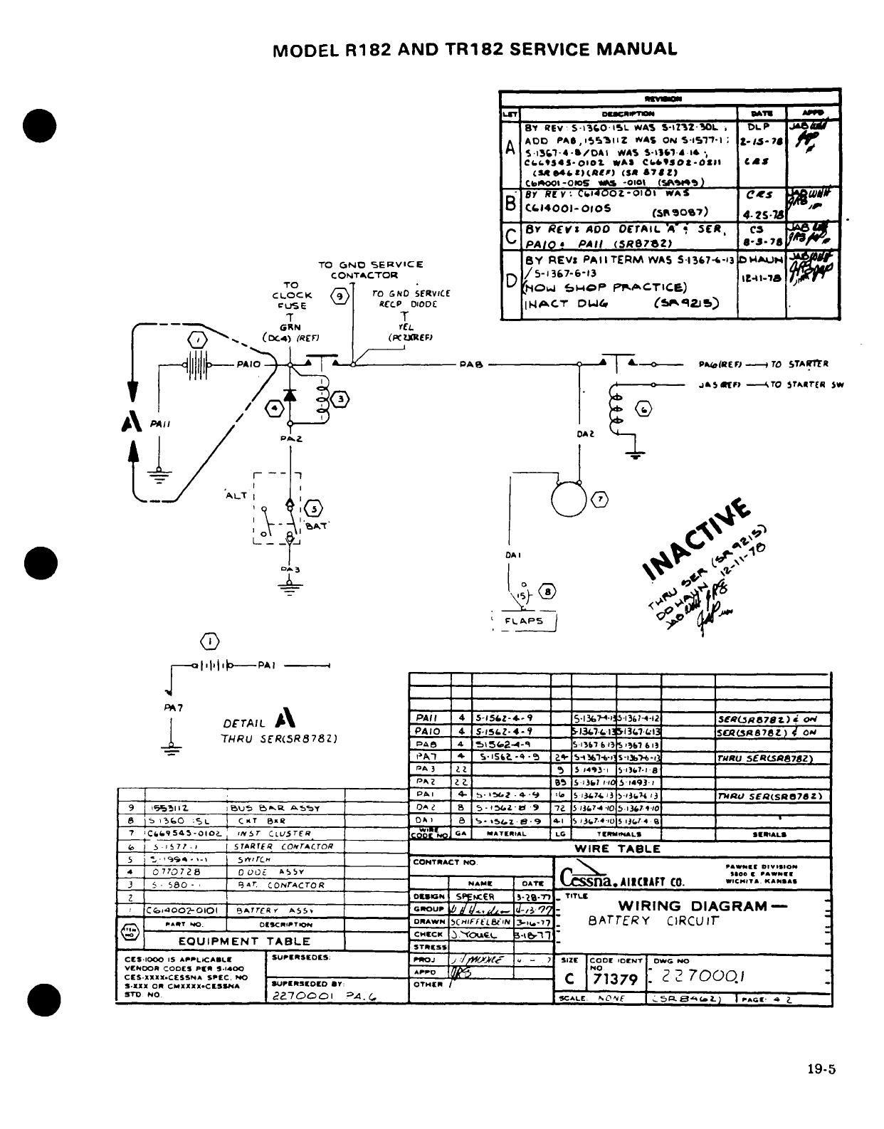
MODEL
R182
AND
TR182
SERVICE
MANUAL
rLT DBCWPnON D7U |^
h
BY
REV S-
1sc0ISL
WAS
S-lZZ3
OL
,
DLP
ADD
PA6,
^r'l1
Z
WAS
ON
S-S1
'
-1 ;
7
A
S5rt1-4-b/DAl
WAS
S-iG31.
d.14.
Cb,.(Sl45-OIo
WAS
CLfbSOXt-OII,
CtI
(M4.4Ct)(Rt(F)
CSi
&7Lz)
Cbtool1-0oos
*OS -OIO0 (5FAI9)
BY
RCV-
CnI40OZ-01O1
WAS
(
Ce
_8
Rv:
,.140oz-orm
w^s
tS
i
B
C(14001-O105
(S^r07)
4-.2S.-»
c
By
RVct
ADO
orrAIL
'A'
SCE,
CS
PA/O
PAIl
(SR87sZ)
s-J-78
TO
6NO
SERVICE
BY
REVS
PA
l
TERM
WAS
5-13&7-.-13
D4AUN
CONT^CTOrR
n
/
5-1367-6-13
It41-1&
TO
.
rOP :C
F
TICE)
CLOCK
<5"
ro
GND
SfRVICE
cUSE
V <RECCP
DIODE
I
m^CT
ODW
(S9^ilS)
-r T
rG--R^
GN
YEL
)
-^ (DC4)
(REn
(PCzREF)
---
+j
-PAIO
|PA
PAI(REF7
-7TO
STARftR
1111+F ~
~ ~ ~ ~~ ~jV -.----
Q
,T
I
-7
I P/J(
C
J
iF>
-
TO
STA»rER
W
A
3
DA
I
04L
®
-
PAe
I
_
l-~ ~
~ ~ ~ ~ ~ ~ ~ ~ ~ ~
'
isst -4-5
S-
5
61-6
-13076-13
rRU
5-ERSA878Z)
PA
3
7 7 _
S 3493'
$137-1a
I ~ .Of~
.FAIL~ A\PAI 4. 5-152-4-l 9
bS
l74. 13
5-i3?74
g3
AV
SERs878Z)
9
555111
.
I 95U.'S
bP:,
A 5,Y7 D")A 2
a
5-15i.Z-4
9 7
5.
13.74
'.
5
1313 '10
.
_ _________ ___3
_______________
--
SMALLS
*
11e
3 9
80
-
l-
.
Cr A5R
_________
0 a-
AIRCRAFT
CO.
loPAWNEE
3G,
5
S807-,
i $,-1
_
r_
TerE
coNr^croR
.AM_
AT
WIRE
TA
BLESS
Q EOI«
U-
IH _
PIE
CONT RAC
T
NO.
CHECK
I
O»ISN
SlEA
NC
-.'
-
TITLt
,
C4#E-.oo4-,ii9'trAs
~_.
q9
WIRING
DIAGRAM-
STU-^~~~~ N .O »N
--
O
AWN
tIiFFEL&'tN
3-1.-7
'
BATER
Y
CiRCU
IT
Illl)
~lCHCK
~
.'"05...
cS O1000
IS
APPLICABLE
SUPEtSEDES;
POJ
J
.'
/,tf-'
-
7'
SIZE
CODE
'DENT
OWG
NO
c
S
XXXX
CCSSNA
SPEC.
NO
---------------------------
ro
\'W
----
--- -
C
"
71379
|
?
2
'70()00
1
S.XXX
Oq CMXXXX-CHISS/A
PI MIIrOID
**
y
:
OTHER
-
'___
)rD
w
..
_227000o1
?,XA.(
,_
SCALE
; f
1)5L t'4 1
PAGE
,4
i
19-5
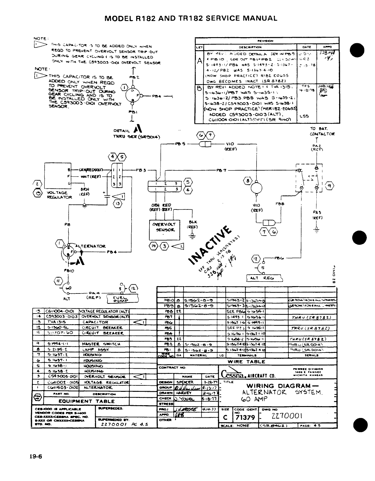
MODEL
R182
AND
TR182
SERVICE
MANUAL
NOTE.
-
4
A.:>TR
,
TO
v
AODLD
3NLN
uHEN
D
rH
5
IM,-,APA^;TOR
5
TO
BES
ADDE.D
ONl4M
-HEN
LET
OE(SCRIPTKON DATE APV
tEQD
TO
PREVeNT
OVERtOLT
SEN5OR
TR\%
-OUT _
?
-
I0ED
DETUA
BUER
-J-e
-
rBI _Z
RIN6
eR CCr ,NG S IS
TO
SB
INSTALLED
OT
.
ONLN
wITK
THE C.-5q3003
-00 1
OVW.OLT
SeNSiO
A
-P8
`
PS
P4e.Z
.
.-
1
,
S
-
AS
14q3I/P8B6
AS
1S493-Z
.37 -37-
NTE
4-1z/PB_
WAS
S-i
51.7-4-IO
jID>THIl
CAPACITOR
15
TO
5E P cNOW
SNOP
PF^CT'CE)
RI_
EO(,SS
ADOED
ONLY
WHEN
REQD
L
DG BECOMES
INrACT
(SR
87Z)
TO
IE"VENT
OVER\KOLT
,/,
.
REV
E
DDeD
NOTE
I C
TA
1315
.
TFS
jA-eDlw
fEN50R
TRIP
OUT
Cl C-.31-I/P7
S
-.
i o- t
ADDED ONLY B iE
RE"':
kooeo
NOT"_ ¢
TvA
11i
TFS
12'
CE
AR
C.YCLING
ANO
S
TO
F5-1- P55 WA5 S-i35
98e
INSTALLEDC
ONLY
WiTH
5'-
lo35-2/=r:.3
PB5
5-1t35-Z
E
CS9q300-Ooi
COV5-ERXT
7;
.-
%3-2 53c-oo,-oo
w',5
5-""=S6-1
5'SOR I NOW
SHOP PRACTLCE
('EKItSZ-eObs53
ToHUK It (SO
4)
-
C-ONTILTOC
SI CD,--,
vlo
-: pIz
(KEF)
I
(CRE
St.N
D _
K
_
P5
F
VOLTAGE
4 p
F)
_
-REG0LA'tTR cR
TI
PS
OVEPVOLT
L
'REF)
(EF)OF)
=(F) PI
-
^ P54®
lb
-' .
..
A.
.
o AL.- w¥
TO
E UI PM ENT TALEe
,_T
co.r.F.)
_
15
TVA,131S
o*1r(^ ,CTR
(
,11I 4
SA-1,
IT 6-IN S
CICCU I'1Pe
EWEk
5)EIL
_
SF._
'
3
l
,
1 d%
.i
I
|3
IC6E040101
aC1SAGE
REjSULA1OR (ALT)
VP5 ^
tt
.
SEE
Pel
7
l'VaS
I
i
5-
-rO
-
.O
Ci'Ur
EAF
P54
__
EI(
.
",I
ga.7
137
_ ___ ________ Pi
Z1
_________
Sn.B<-2
',U.1..-I
______ rmu f
(TRA7t)
|
q
IC5*^-'
-i 01H03 ',w rcIO
S2(7
Pb7
6
S-l-.Z--
5
ICi.:-4
'
i (.7-4
IrA
C
aao4
1 9 ZlI-6
LAMP
&.»Y_ _______
P51
&
|-
.z-i _
1
|
n
____v_
_
= 47 4
1418
T7 I
-
I57-t
W j
|
CIR
A
MATrIALs
|
LG
M
ATERAL
L
TtR
ALS
IL_
(
LR
| 6 I
51-
57-
IgUG ______
WIRE
TABLE
s 1^
.56-i
____"___
CONTRACT
NO:
P-E-
O
1* 4I
16H56
2I
L
_
I
"OELT
I
*Km 0 o -*NiE
C
(45CI5-OlI
ovE.voL
<L
I
|
I
|
ONTA |
'SSrclna
AIRClAFT
CO.
-W.CHIT.
NNAS
2l.1002t
-
o010
VOl.sTCf
etLucLTor
.I |SPKR
S
3-Sl--nr
TITLE
C
ct'0o-5ooz
A
*LeE.NPLTO
IK.
oroup
tdUlli
,
w
I4-
s>~-
WIRING
DIAGRAM-
.
N
PAO.
TNc|pT
D-A-W-
~
vWSef
|3A
ALTERMNATOK.
SYTEPM,
EQUIPMENT
TABLE
IC.
s
Ll-1|
(00
1P
_
0999'
j
I
4..
s.. IrIONl ILS4.Z
PAGIs
45
U
C|U-000
C U
AF9LCADUL
UPRDES.
P|oJ
A4Coo14e
$
»4?;
SIZE
CODE
IDNT.
OWO
NO
VWOR
COOCa
544
00
APRO
Cf
--
N~u
,lAP
I*_XXK
OR
_
C"
Kdf
os
m
Ang
c
1
71379
-
ZZ70001
*-
No.
14 Z70001 PAE
4.5_ I
Z
II:
ON6
xz)
L
PLAU
45
19-6
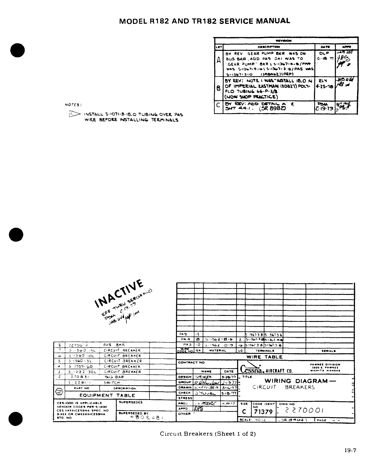
MODEL
R182
AND
TR182
SERVICE
MANUAL
.uvw
Lr
DsCmPTIw
| AIW
|
BY REV
(EAR
PUMP
B'R
WAS
ON
OLP
jA
I
A
BUS
BARADD
PA9
DAl
wVAS
TO
.0-tt
TI
fR
cGEAR
UMP-"
eBKR ;
5-1i37.~4-S/P00
if
wNs
s-li.
-4--
5-s3p1-
i
-tt/
elP
S
5-i37-3-1o
(
cb46U _)_
3
BY
UiYv:
NtSIL
I
s%-IMuALL
1.0
N
eL
*L'v
B
OF
IMP'tItL
ULAsMAw
(o'n)
POC-
4-
5-
-' '
FLO
tuSIbLM&
f.f-P-3/8
(IIOW
mUDP
PWtTIC.L)
WIEU
BEFOPLE
lI57TLLttNGCW TALNLSE
A5_
0
i
5
67
"-
3
0
16
I
a
___3____ }
3-15______
L S-f1^33 ____________
5
-.
3 0 -;
L
ClRCur
Bi
AqR
___ _
COCn
7p C
MATEIAL
LO TL
lsRNAus
qk.
jo
-134ov
|L
CIcuir
BREAtER
___
WIRE
TABLE
S
5-
(C
C-
L I
CiRCUi
T
3REAK
___
CONTRACT
NO
W
DIIIO
4
170'7-
'0
CI
CLVIT
BIEAKER
___oo
PAW[ET
3
5
i
232
30L
ciRCUr
BREAKER
NAME DATE
l
na
AIRCRAFT
tCO.
CTA
K^S
I2
708
3 1
5U.,
BA
R
DCSGN
!Ci2
3-T,-17
T
lTLE
5 2t8Z-
5v-
TrcH
CXROUP
2
/ -/
WIRING
DIAGRAM-
-
AT
NO
|
oScR..ToI.
DRAWN
-C-,iFt8£,
3I..'-)
_
CIRC
rIT
BREAKERS
EQUIPMENT
TABLE
STRSS
_____
CES-1000
i
APPLICABLE
SUPERSEDES.
ProJ
,/
mt
-,-17
SIZE CODE
IDENr oWG
NO
'END
RCOOES
PESO
A400
NO
7
0
CE
XXXXCESSNA
SPEC
.
NO.
Ar
C
71379
2
2
70001
S.xxx
OR CMXXXX
CESSNA
SUPRtD
OTHER
i _
_i
STO.
NO.
4 SCALLE 0
'-
:
R
.
I4
>
CE-
-
'
Circuit
Breakers
(Sheet
1
of
2)
19-7
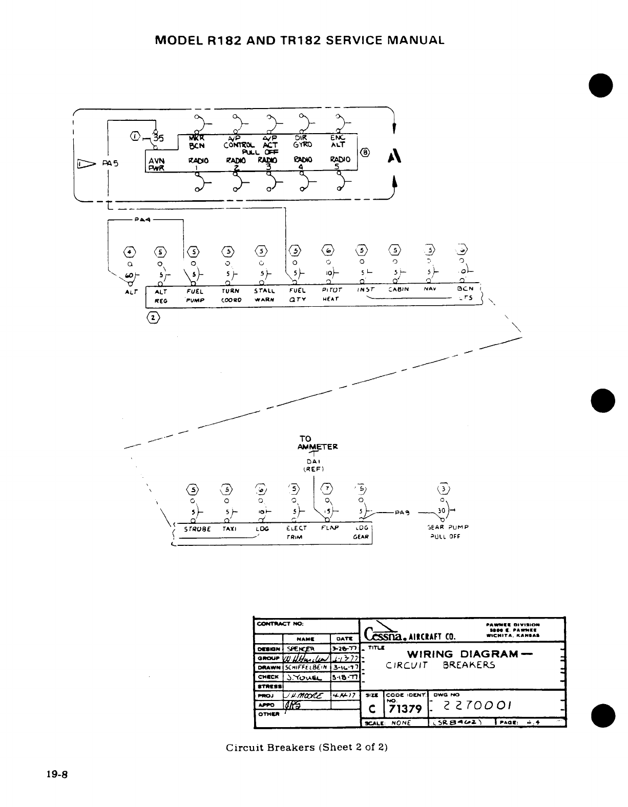
MODEL
R182
AND
TR182
SERVICE
MANUAL
r
--
>WK
AP
'vP
OIR
ENM
BCN
CONTSZOL
ACT
Gy$O ALT
-
PWK
i_ ~Z
3
4
5
REG
PUMP
(OOO
WARN
TY
1(Ar S
_- t_ _ -__TO
AMMETERI
(REF)
0 0 0
,0
0
0
'
- -
\
)
5^
50-
l
-
.10
5 5P AL
(Ar
SAtrIE
rNTA LS L
LECT
FLAP
.DG
A
EAR
PUMP
rREM GECARO UALL EOF
C-
CIONTACT
NO:
WII*AIII'Nl"
01V
IS114m
w Q ~~O3
I
M
O O
l
S
'J OTIL \OO* C. PAW9kI[I
|
NAM
|
DATt
C
Ssna,
AIICIAFT
CO. _
.CHITA.
K
.ANS
o,,ar,
,tTJ. ~^-
.-
WIRING
DIAGRAM-
DOAw
xSHCIFFItBE0C
3E-rL-v
CIRCUIT
BREAKERS
*DoJ
JA//i
Hi
LC'HLi-
7 SIZUI Coo iDENC GW NO
AOTM
U
C
71379
7 7O00
SCALE:
NONE
I a
a
P
AEi
4.4
.+
Circuit
Breakers
(Sheet
2
of
2)
19-8
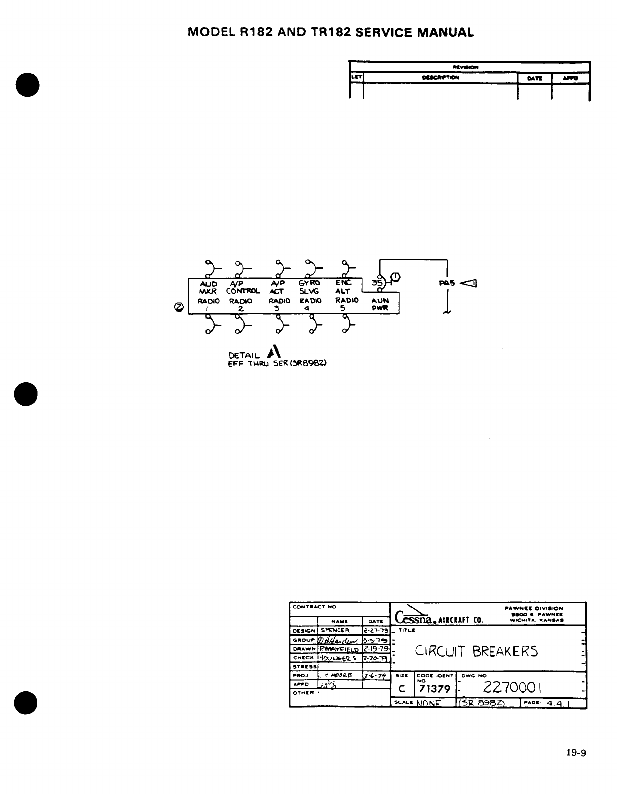
MODEL
R182
AND TR182
SERVICE
MANUAL
LCT
O_ OATIR
A_
*
ILETI
I
L
m
I
AULID
AP
/p
GYRO
ENc
P
-I 0g
IJR
CONTROL
ACT
SLVG
ALT
RADIO
RADIO
RADO
rDO
RAtDO
A.UN
<S
I Z 3 4 5
PWR
DETAIL
\
EFF
TW.Ru
5ER
(R89BZ)
CONTRACT
NO.
PAWNEE
DIVISION
______ __^_____
5^-.11S00
I
PAWNEE
NAME
DATE .CS
AIICIAFT
CO.
WICHITA.
ANSA.
OEuSGN
SPENCER 2--'7--7
.
TITLE
rourw
,
I,.L
,,
-1 -,79
DR^PWN prI..
Z,19-79
CIRCUIT
BREAKERS
STRESS
ROJ
.
It
HM.el
3-6-7-7
S1, Z
COOC
'DONT
OWG
hO
OT.
_
c
71379
Z270I00
-SCALE
(N5g
I7NP
8982')
|
C.:
q
4
19-9
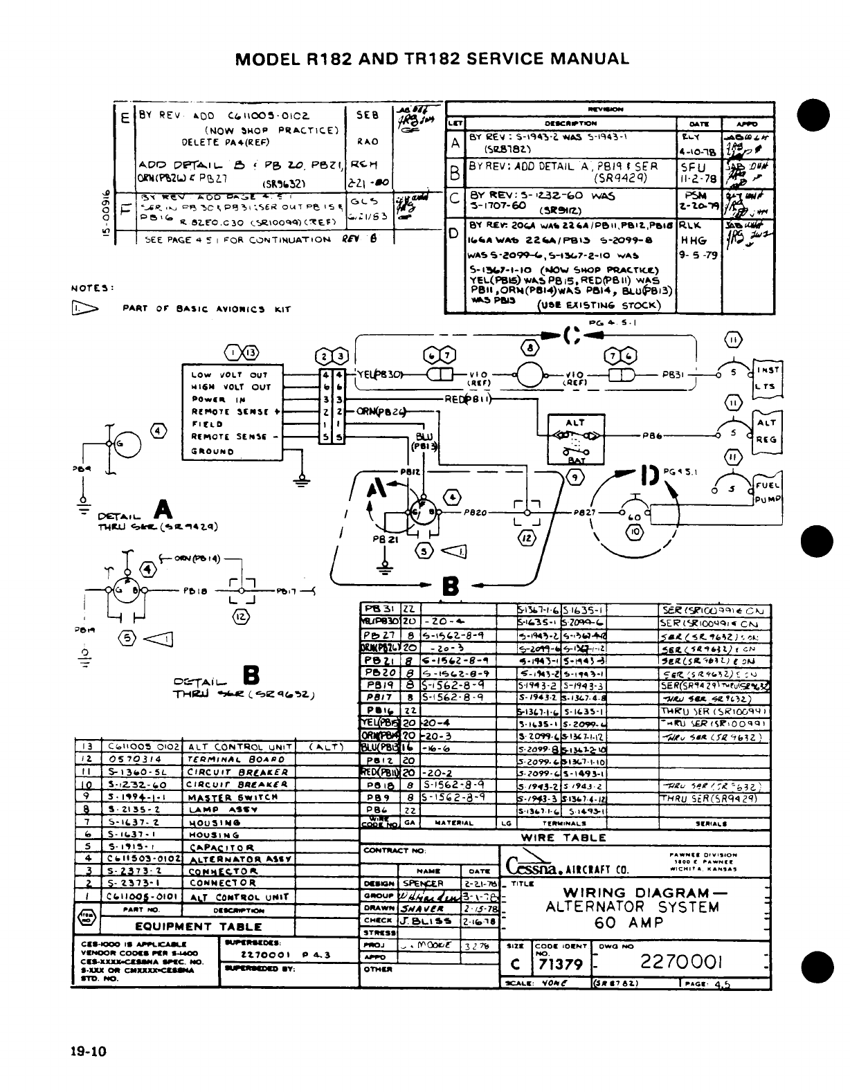
MODEL
R182
AND
TR182
SERVICE
MANUAL
E
BY
REV
D00
Cil100l5-OIC2
5Ee E -T l-l | |
I
(NOW
SHbOP
PRACTICE)
S C -1 AS
-i 4-aIP
O--<
0Fa
DELETE
PA4(REF)
AO
A
(Aay18tR
4
40-19
iA&
AO
p6P-riL-
25
P
LOZ,
P6ZI,
RC
,
BY
REV:
ADD
DETAIL
A,
PBIq
I
S-R
5FU
¶A
',
Oi(PrMi
CJ
PIZ1
(S&652
B1 B
($Rq42q)
Il--78
/ 7
1S
_ !>
^
0 0 f G
g
-
D
O
'-,
-
E
C
eY
REV:
S-
L3Z--60
wAS
P4
; F -<
->
C
P
3C
q
Pe
3
S
ouT
pe
^
'
-
5S-
1707-60
/c
R
0
D(
-
.0
82?.EO.C30
(C.
o00q')('
[F)
_,,11
_
REY
20C.A
WAbLa4A/P6IIPBI.,PI
ld
14K
"
5EE
PACE
4
E
I
FOR
CONTINUATIOt4N
fEV
6
IAWAb
Za2A
3
-2099-
H
H
WAS5
9S-o099,-t.7-2-00
WA&b
9- 5
-79
S-I|,7--10o
(*JOW
SHOP
PQACTKC)
YEL(PB15)
wAS
PBI5.RED(PB
l)
WAS
NOrES:
PII
,OR%4(PB14)WAS P514,
BLUoBi3)
WS
Pros
(tie
FXmSTIN&
STOCK)
[j::>
PART
or
BASIC
AVIONICS KIT
__
^_5
PM
(J
EA15TI_.6
STOCK)
PC~
..
S.I
Oe
G
5-
1
LOw
VOLT
OUT
=4
4
-t
FYEL
0Q CVI c-<
0,-
E-
PB3
C
°
S
W,,.
VOLT
OUT
(RI-F)----
"
_ _ _IE___
. .
Powne
I[p
3
RECBi)
/I
Ro(07.l
S
+1---!f
l_
Z
Z--,---
r
lfLD
,
,'0
--
'1
ALT
I
ALT
RfMOTEt
SENSE
-
5 ------ 0
__
G
-
*
TI
<'A
PI20
P
27
-0
L.J
(-6-- -P 1.
I
rLJ
PB31
ZZ
_________
-1S.-1-
.
S
l35-1
___
R
(SR(IC)'iu*
C
kj
;Z 057t T £~UPB30
ZO
-
ZO-.
_-i.35-1
SZ.-I.____
SER('g1
tq*.
CMt
-t ; < P Ll 8 <-L 5Z>-\
-> -S-\ = S-ii
'-tL
.J C5&s
K.t
I
4Z_,):_
\I o
/
J
m-~,OllT.
20
-Zo-3'_.
-
is-l
-s:____ S-*4t cIN
Pezi
Is
18-
-e
^*I'SiZ-S _ S5 S _____
5EtL
-)
sut
9FJ
B
PBZO
I
9
^S-l'sez-ea
|s-i 5-tss- f
_-1
I
______i _
5__s__Z)_:
_
Dr
TAiL.
B
PBq 1
8
S-i562-8-q1
5
3
'
2
5-1943-2
s-_3-3
ER___
(SR'14
ZI'-fuY
'
T-H
J 1t
c
-.
,
e
,
C.-2)
Pe17
8
S-1562-8-q9
IS-'1943-
-1t 5.74-
A_-H___U
w
CserZ)
Psi
122 __ _
I-137-l-C
S-3-I
_______
T4U
-ER
(SRIO.96ql
EL-PBe
20
20-4
U*-iL.3s-i s-
zo-
j. -__iU
'ElR
(sr00qq,
______________________
O4
?O
-20-
3
s-zo99-.
s13L7-i.i
Z v
__
R
g'eibZz)
13
CTallOOS
0102
ALT
CONTROL
UNIT
(A
_LT) PLU(tPBlI -e- S
-
Z099-
8 iG. _____
_
1,
0570314
rTECQr4AL
8OAS0
I______ pZ 0
.
2099-..
LT-10
_____
11
S-13.0-5L
CIRCUIT
BRCAlxEt
________
(
ZO
-20-2
5zoP99-F
s-1493-I
___
10
S-i3Z.-3.z-O
CILcuir
o^AKfC__ I
P
aBI 8
S-1562-8-89
5
s-/93-
z
s94j-3
-v2u
3ez
'
Z'j)
|
9
3.1!9-1.1
I
.S
I
|ASTER
SWITCH
_
P99
8
S-1562-8a9
1 56-/943- 3t-l _______
HRU
SER(SRq42
|)
|a
S|Z135-
Z
LAnP
^ASW
v
P98
ZZ
IS13.
l1-_
5
14'l __ __
7
s5-IL37-
t
OUSIMS
.A
GAI
WAT EIRAL
LA
TEtr
MALS
E
9IALS:
|
S5-i.37-I
OHOUSING
|
-
WIRE
TABLE
5
S-1915-
I
CAPACITOR
I
T
kCOTAC
-
T
*w
NO1
r
O
DlSoi
4
CCllISO3-OIO
AITCRNATOR
AY_____
o
z 5-2373-1
COWNECITOR
o____ €
SDPEER
i A-LI-)
TITLE
I
C.II
os-0101
ALT
CONTROL
UNrT
GoouP
3
-
WIRING
DIAGRAM-
PART
N0D.
0EI--14
DRAWN
.5A Cle
2
I5-78
-
ALTERNATOR
SYSTEM
Q
-
EQUIPMENT
TABLE
CHC.JBc
L
J
L\S5
-1sI
60
AMP
_c
__1_-
__i_ u _
_1__
I_ _€__€»
rJoE
_
.
l__lo_ 3_7_ _ _I_: cool _IO T ISoESS
6
Cvrno-
o o Ux
A70L001
| #3 rroJ--SP
DES3
---
..
c
32
7
SIZE
C
O
7ONT
WG
N
c¢S-XXCXcA
SPA EC.P
P
.
-
o
-.
<|
C
71379
2270001
|-.XXX
CM
CMXXXX-.__ _ __A
1_iUP" D_0 mY : OTH0 r r
'
._
mT0.
NO.
I CAL V0O* a(t»76L
)
I
AGrg
4.5
19-10
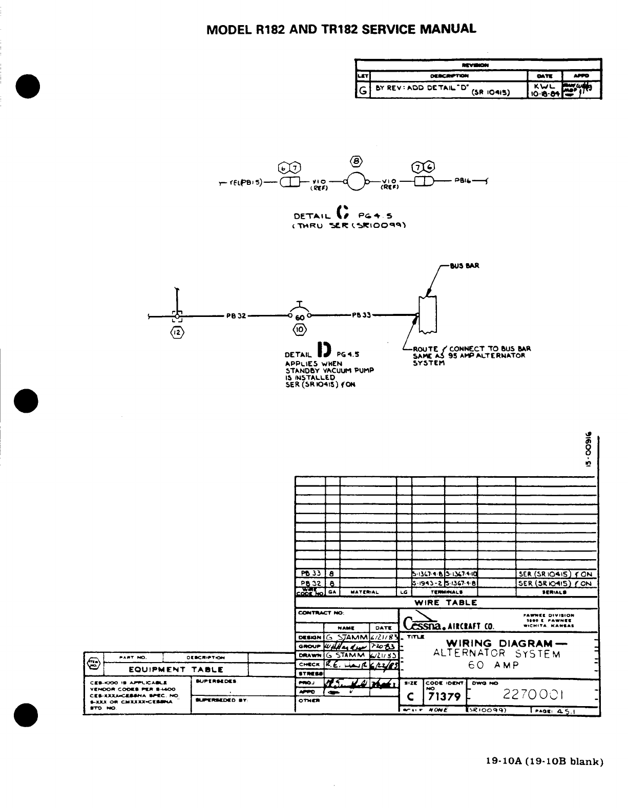
MODEL
R182
AND
TR182
SERVICE
MANUAL
BY
REV: ADD
DETAIL-D'
KWL
GI(SR
10415)
I
10
e-8
FLet 5)-W-
p
,
°)
.-
-
,-
D
oPBI-
DETAIL.
L( P.
' 5
(THRU
5ER
(t1IOOq99
BUS
BAR
L- 0PB32 O-----
P!33
®
TAI^
IROCUT~E
f
CONNECT
TO
BUS
BAR
DETAIL
L,
PGC4.
SAME
A
95
AMP
ALTERNATOR
APPLIE5
WHEN
SYSTEM
STANDBY
VACUUM
PUMP
IS
INSTALLED
ER
(SR
10415)
CON
0
Pt
33
8l I
5-l3M-t
5-i347410
SER
(SR
10415)
ON
P P32 SI
5
1943-
1.7-$ _____
SER
(SR
0415)
f
ON
0
CISA i WMATEiRIIAL LC TTE 0MILALS S RI.AL&
WIRE
TABLE
CONTCT
.C
NO:
c».mucr
no;
\ ,^,ll
DIIIOi
NAME
ATE
AIICIAFT
CO. .cI
..
CsI-ON
GC
STAMM
/ZIB/g
_
TITIE
WIRING
DIAGRAM-
AA'T I
OKDCRIPT^
DR^uA
G
S7TAM
^/3 ALTERNATOR
SYSTEM
EQUIPMENT
TABLE
60
AMP
CES-O
3 AtCA
PLI-D«»
PJ
SIZ
E
"
COOT
IDeT
OWO
PO
VIMrOOA
COOII
*D
No
S
.- r
CI-Xr.XX
CWA
CU
.
C ^-
- -
"
C
71379
22
70
;001C
M
-XX
C
CUNXXXItCESA
IUWDECD
T:
OT:R
C
370
No
i-
v.«-
,,
eO
.
A0oq9
)
I
.0.,
4a.5.1
19-10A
(19-10B
blank)
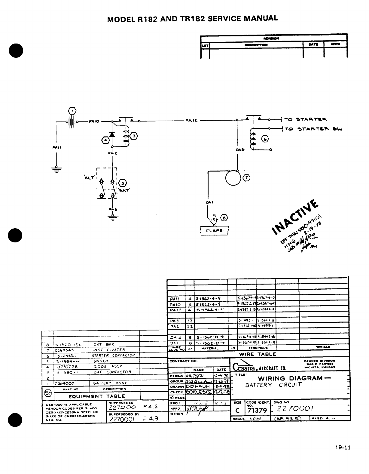
MODEL
R182
AND
TR182
SERVICE
MANUAL
·
iIo
I
TO
% "
'1'~1~Tt1~
.
!t I®4I
ol-
I'
pL
OA_
.J,"
1 r
--
rl
I f W
1
PAI
I
4
-15&
z
9
_
5-130o-4-"
5
--
2
PA
3 2_ 5 31473
-lJ0
5367.1-8
P
A
15
5
3-
-5C-4
-9
S
13f74-li
5447--
_
sB
!5
1o360
L
CKT
BSR
DAI
8 s-1-e-9
5 13t-
4
5-C
______ _______1
7
ICS#9
54
5
:INST
CLUSTER
fRCOD'E 'N 0 MATERIkAL LG
TEtMINAL
S S
IALS
|
5-<3i4~-1
STARTER
conrtATOR
WIRE
TABLE
---
----
s
--
.---
14994-
---- 1.
Sr/0rCH
(CONTRACT
NO:
PAWS"IN
DIVISloN
*
077007Z8
D3OOE
A y5Y
'
ooa
P«N"(I
3
5-
550
-
BrA.
CONrACTOR
NAME
DATE
na.A
IRAFT
CO.
I
C.T
KASA
2
Otsicn
WI
'3- V-7
T
KNS
A
o14o002
o
BATERYfi'I
I
GROU
SjiU
/e
d
l-p
_~-
WIRING
DIAGRAM-
PA.T
--.
DRE,,o.N
ODRAWN
DPD4AUN
12-lu-'-8
BATTERY
CIRCU
IT
EQUIPMENT
TABLE
CHCK
r
ss
\sA
-
CCS-IOOO
IS
APPLICASLE
SUPERSEDoES
PrOJ
/, -
SIZE COO
IDENT.
OWG NO
VEND.O
CODES
PER
5.1400
227C0001
P4.2 AP.rD 7
CES-XXXX.CESSNA
SPrEC.
NO
.
71379
2
7000/
SX.XXX
OR
CMXXXX-CESSNA
C
UPERWOEDD BY:
OTHER
ST.
NO.
2270001
r
4.9
NS:
,ONE
3 q
>
,.
PE
--
: 4.l,
19-11
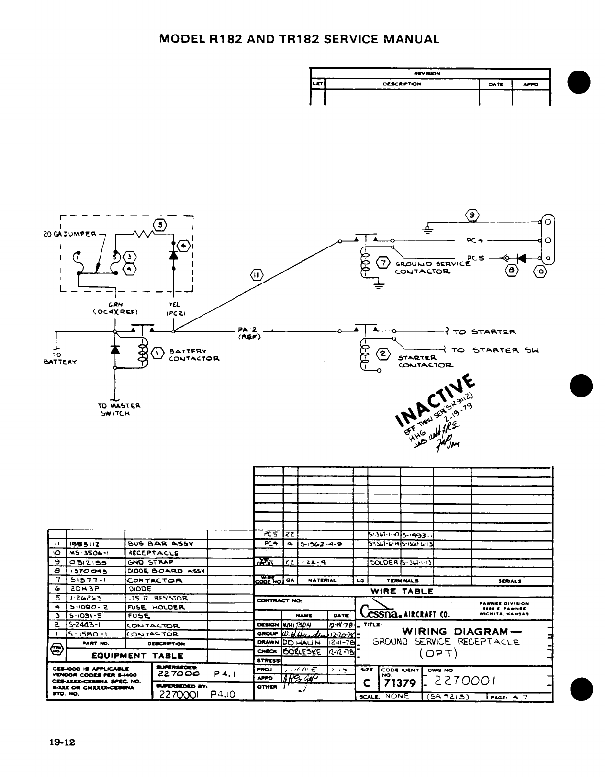
MODEL
R182
AND
TR182
SERVICE
MANUAL
LIET
DEZCRlPTION
DATI|
A
o
r
"---
-
9
4E
0
20 A P
u
'UO
SERVICE
-
C.OC4X
REF)
(PC2)
'T--O ; CB
ATrTERY
['
/
TO
5TKTPT:
S4
ATT
^
0 ~<5a'4 COT,
T^CTOR
OP \(/
5TAR._-
5-"
EAl ,1T____)WE I CJ
TAB.C.O.E
-0
MS-350-1
rECEPTACS
: r
=
9 Olzlj55
GINO
STRAP
5
Z
L-'qER
_-_-
1-13i
a 45Wroo -S
OIOO.T.Oa.
/
_ ~_o_
'
_. _r_ __
7
5bis5
-
I
-
Cor
T-I.TO
G^T
Wn
GCl.A
MATU.IAL
*-LG T
IM-fIALS
IRI IA LIS
6(
20E
P
OIPOE
NWIRE
TABLE
5
-
?
f1a
.15
S
REbIT04O
Co-nRCT
NO:
4
5-1090-
Z
FjUSE
_ _OLO/t
'
_700ris PA..
3
5-,09\-s
FU«t
-
r__
A
NAME
DATE
CSSn
AIICRAFT
.CITA.
KANSA.
2
S-Z44-l
_____
Fo
TC_-_o_ _ _ _ _ _
ON
__W__ _-_7
-
T_
_ s-5BO->
(
oTAC-TO_____ c
-
WIRING
DIAGRAM-
Arr^AT
N.
NO
Ouu».p
'
_ _
-AWN
DD
"AU
N
i2-i
-76
GRCANO
SERVCE
RECEPTc\E
EQUIPMENT
TABLE
-
g
_
(OPT)
C-iWO
ID
APuCAIU
P
I'RO
1
J
J ,i
'
e
7.
SIZ
CODCo
IDCNT
owC
NO
VMOAm
CooMS
D
9m
2270001
P
4.1
--
N
-
22-7000
CEu-XXXXZucNA
SPC.
NO.
._
*:ro
71379
2 7000
C
S-XiX
OS
CMXXXXX.C--SA
*U mO
*:
OTR
7I I
379
ST. PrO. 2270001
P4.O1
SCAL:
NONE
CS,
s-
a ) I
PA,
:
^..7
19-12
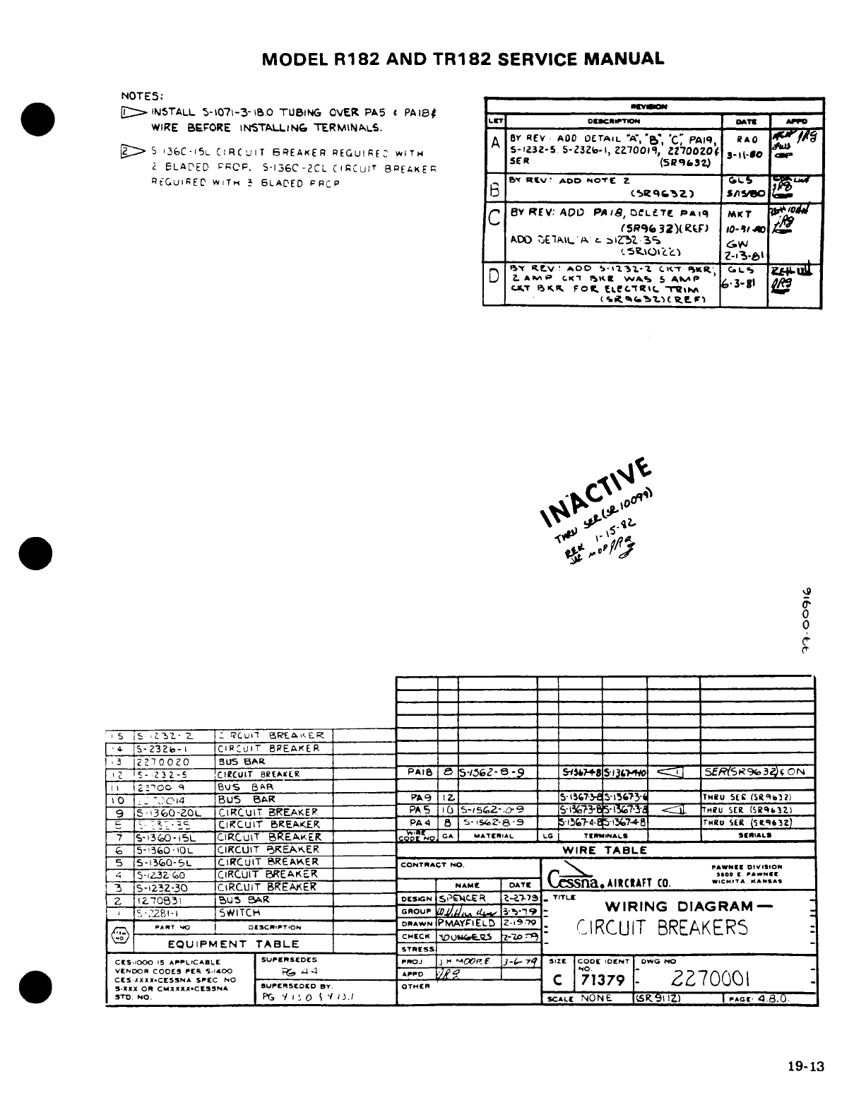
MODEL
R182
AND
TR182
SERVICE
MANUAL
NOTES:
[
INTITALL
5-1071-3-B1.0
TUBING
OVER
PA5
c
PAI8
-
wva
WIRE BEFORE
IN5TALLING
TERMINALS.T CcT
*D
A
r
REV
AOD
ETrAIL'A','A,
*'
C
P'AIq
RAO
'r"I/
>S
136C-i5L CIRCUIT
BREAKER
REGUIRE:
WITH
A5-1Z32-5
5-2323-Il,
2L27001,
2,70oZO
.
31J-80o
2
ELAPED FROP.
S-136C-2CL
CIRCUIT
BIEAKER
_ ER(5R93
RtGuiREC
WITH
1 6LACED
FPCP
,
e*
Rlv:
ADD
NOTE
z
G
b _ (5csg z)
s/i
so
C
Y
REV:
A?
)
PAlS,
DCLFTC
Piq
MLKT
04
(SR9
32')(
P.F)
O-1l
'/4
ADO
~jE1A\L
^
l
zZ".Z
S35
.
______
'-St.\OKL'<,
5
v..O
.
D
SY
stV
ADO
S-'13-.1-
CK<T
%KR.
C.LS
2.
L*
M C.K1
f>I
AS
SA, 5
A"^P
1
*I
Ck-¶T
(SKPB
FOO.
ELC.TRC.
-
__3-8
1
_
____<.enCo4
1'
It oR.e
F)
.9
0
0
(-
I S
'
3Z
-7
2
r|Cuil
5REA
ER
___ _____
S
'-
S-Z3Z2o-I
CIR'UIT
BREAKER
__
|3
2270020
BUS
BAR
I
-
Z32-5
CIRCUIT
B8EAKELR PA-I e
5-/S62-
-
-9 = S254
513
L <R SRx.
3SII
0
N
II
2''OC
_
BuS
BR_
_
0
.
::O4
BUs
BAR
PA9
IC Zp_
S-IT
15-67
-3-t
THiu
SE
(SRqa
72)
9
~-136-0ZOL
CIRCUIT
BREAKER
_
PA5
0
s5-562-,o-9
_S-1373-6e
5-l1j'37-
Hcu
SER
(SRg43Z)
;
.- -.
Zc
CiRCUIT
BREAKERI.
PA4
5 5-,SZ-8-9 _
5I7-.
l45-17 ____
THRU
SER
(S9tq3Z)
7
5-1360-15L
CIRCUIT
BREAKER
___
COD
NO
GA
MATEIIAL
LG
TIRNALS
SER IALS
6
5-!'365OiO
CIRCUIT
BREAKER
_
WIRE
TABLE
5
5-13G0-5L
CIRCUIT
BREAKER____
CONTRACT
NO:
PIW-
o.-
4
5-i3Zi
O
CIRCUIT
BREAKER
N Da
t.
PA
We.
~3
5-123Z-30
CIRCUIT BREAKER
|
NAME
DATE
|SSnaIACIAFT
C.
WICHtT
KANSA.
2
1IZ7Qa83l
bus
BAR
DES5KN
Si|E4LER
Z-Zi
-
759
TlTUL
i
-z^28l-l
SWITCH
GROUP,
/
_U, 13-R9
-
WIRING
DIAGRAM
-
7:~ A».T'^otsc~r~o -,-
DRAWN
PMAYFI'ELD
Z-
9-'.9
,@
BT
-o
IENT
--------
CHECK
;MBLES
--
z- CD r
IRCUIT BREAKERS
EQUIPMENT
TABLETRSS
CSOO1000 IS
APPLICABLE SUPERSEDES
prtJ IJ
Y-
MOP
f
34-
7
SIZE
CODE
IDENT
ODWG
N
CS*aXX.CESSNA
SPEC
oO
_PPD CI
71
\\
CES..XXX-CESS.A
SPEC CO
71379
'70001
5.XXX
OR
CMXXXXCESSNA
SUPERSEDED
BY.
OTHER
STD
NO.
P
'IO 'I
J
l
SCALE
NONE
I
ER.1
IZ)
I
PAG
4.8.0.
19-13
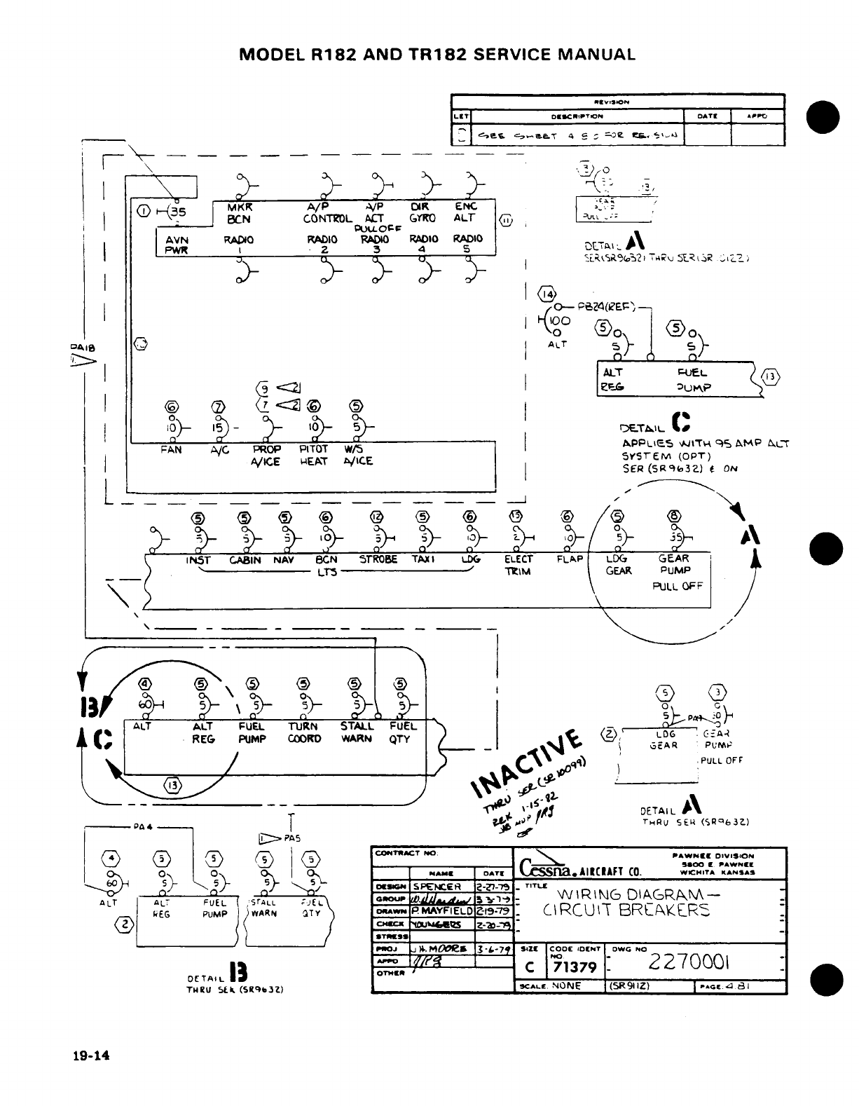
MODEL
R182
AND
TR182
SERVICE
MANUAL
I (j
C3c-5
MKR
A/P
VAP
D1R
ENC
-
--
=BCN CONTROL
ACT GYRO
ALT
-:
AVN
RADIO RADIO
RADO
RADIO
RADIO
A
PWR I
2.
3__
4 5
.At-,AI
;
/0-
PZ4(LEp^
041~Ad~~~~8 0
~ALT
ALT
FPUEL
I
1^)
l|-
-
I-°
1) -r
TwIL
C(
FAN
A/C
PROP
PITOT
WS/
AI
|PPLIE5
AJITH
9
5
AMP
aLT
A/ICE
IEAT
A'/ICE
YSvrEM
(OPT)
SER
(5RS.3Z)
f ON
O
<5>O
@
Q (< ® O /) ( \
> ~
~o°-
~ ~ ^1O-
;
,} c
5
°
A
iNST
CABIN
NAV
BCN
5TROBE
TAXI
LDG
ELECT
FLAP
LDC
GEAR
)'------
LT5
-
T\M
GEAR
PUMP
•~~~~~~\
(,R~~~~~~~~~ \ PULL
OFF
0 ~ ~ ~ ~ O
O
13
'\0>
5
<>
®
_)
p PI
C
ALT
ALT
FUEL
TURN
STALL
FUEL
0
LOG,
C--
A _
REG
PUMP
COO
WARN
QTY
/
t
-D6
R.
c.-/ ,_. _.\S ~3
_--R
PULL
OFF
O['iJ ~T
O!
DETAIL
A
9--oPA414
4
T
f»'
T1HRU
SEU
(SRqe3Z)
D.PA5
__
2>
@
23 (O C5
CONTACT
HIO:
\
oPAWNEE
DIVISION
> 0 0 O0s Y -NIAMU DOATE
CSSlna.
AIRCIAFT
CO.
WICHITA
KANSAS
ouua'0. SPE.CEtR
-
TITLE
ALT
AL
FUEL
s
rALL
JEL
iOUiP
t 5 r-WI
R\ING
DIARAN-
-
EG
PUMP
IARrN
!TY
DoW*
PMAYFIELD
-979
-
CIRCUIT
BRLAKELR
O |(
/
<»«c^CHEC Z S Z-Im-m
-__
POJ
).
MOOCe1
3 -S-7 IZEc
CODE
DENT
OWG
NO
DETAI
13
OTHE
c
71379
:
2270001
:
TWRU
SLk
(SR§b3Z)
SCALE
NONE
(5R911Z)
|
«oT
a
-adl
19-14
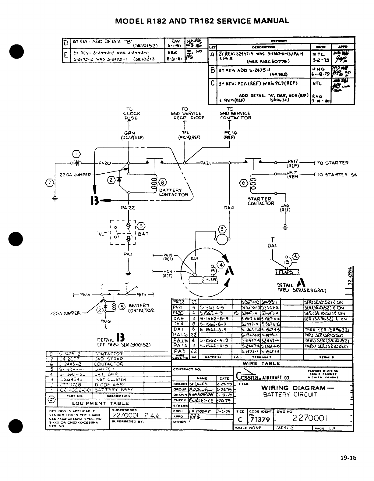
MODEL
R182
AND
TR182
SERVICE
MANUAL
D
E
Bf
RE:
ADD
DEIAR
_'B'
w |Io.
(Se.I0152)
5-l4
gY
^-T
otL
R
E
br
REwA
5-1f--
s^A
a
S.Z3-13 Rs
'A
"
A
or-
v:SZr.-
At
is^-3/PA4
L V
TtL
_ W-21-Z
5
.5-275-1I
(MOI.13
8-31-so
t_
PAIS
(mtlt
pfI
EOT77)
S-
-1
B
681
Elt
ADD
5-2475-l
1-
?
S
C
BY
RCV
'
PC\\(E
nW s P
L1(RE
L)
WrL
ADO
DErAIL
'A',
A5,HC.4(R)
IAO
4
](l(EF)
(SA"9
4) 3-14
-
o
TO
TO
TO
CLOCK
GND
SERVICE
GND
SERVICE
FUSE
RECP
DIODE
CONTACTOR
T T
T
GRfN
TEL
PC
I(
(DC\l\YREC
(PcIRE)
(RtF)
C3
-P-
17/-
i----al13-- -PAZ
--
20-^ T--P
A
Z
-
(I
-EF)-
'TO
STARTER
22
GA
JUMPER-
<-- \ <
-
----
(TO
STARTER
SWS
BATTERY
L_ *?
---
~
CONTACTOR
_
a
-
11 ^__ ____J__ ^
STARTER
CiONTACTOR
PA
2
DA4
CRA)
ALT'
1
I
BAT
T
L9 ~~J ~DA
I
PA3
-
PA 1
/
(REF)
DA5
T d ~ Y~~--~~~
cc
\
-
<DThIL
A
-
,P\4 1 TTih5U 5 EcLS(9032)
=
oI
22
Z-\·
\O
I3-
I
S1
5E'i\52-)
-O-
/^f|
<8>
Bn1TER"
PAZPI
41
S5-IS(2-A.-C
_3(3
24-4
_____
R I 02) f_
0
i2GAMCIPER
-
4c
PA20
4
-I562 4-9 1
5
S44Z-
4-4
SZ4
_____-4 StuOz
a
)(ON
DA5
B
5-1562-8-q
5-1l3b7-4-10
5-1-4-
__
SER
(SA'632)
t ON
DA
4 8
5-15%2-8-9
_
52^1)-t
SlLL
____1
DA
I
8
5-1562-8-9
-3-.4
5.Fi,?-4
____
7Tu
SER
(S«R%..3Z
|1&~AI~ IPA \o
22
-136______7-1i
C65-14353-1
T)- L______ f
5S
DETrAL
13
PA
S
4
5-l562-4-9
_
-^-474
S-447-4
lRSU
4(S.g\0O\52)
LFF
THEU
RILEOt52)
PA
)
4
5-5,Z-4-
_
S-Z-47
5.1.-4i1
T___ WE
JVE"fo5aZ)
a 5.Z475-|
CONTACTOR
PA
________ _S3-
l 07
:G4lN07
6HD
ST~RaP
GA
~TtCODI
N
"
TIAL
LG
TERtlNALS
SER.ALS
,
5
-2443-2
CONTACTOR
I
WIRE
TABLE
5
~-,-3'4-.-i
5VV
TC-
CONTNACT
O:r
|
5
|
-5
-
S94
--1
| w
,
,TC,1
1
COINTRACT
40:
|PAWNEE
DIVISION
4
5-.
50-,5L
CKT
BK
1-
-Iloo
OO*A"IW
~3 |..9545
1S5T
CJ-TER
H NAMI
OATE
Sna«AIIC»AFT
CO.
".C"TA
K"ANSA
I
7I7023a
DIODE
A5SY
I
D[SGNPEKE
Z--751
_
TITEu
c
I;402-:,C0I
aO
TERY
ASs
GouNp
ro.SMCIf
It-24-
-
WIRING
DIAGRAM-
.....
T
.0 I
DI.CI
.
IlPO
DRAWN
R/Im
tz.
19-7.1
BATTERY
CIRCUIT
CHECK
'LES$E
-
2079
EQUIPMENT
TABLE
STRESS
CES
1000
IS
APPLICABLE
SUPCRSEDES
PROJ
i H
r
--
7q
SIZE CODE
IDENT
OWG
NO
CES.XXXX-CESSNA
SPEC. NO
22
01
4
A
27000
STI
_________O. ____________CALE
NONE
(g
PAG
.
19-15
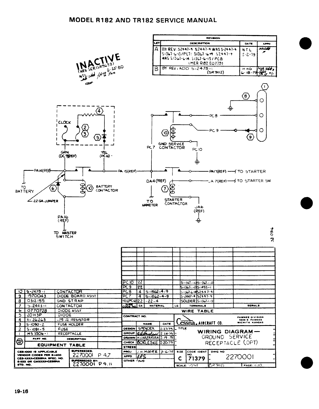
MODEL
R182
AND
TR182
SERVICE
MANUAL
LTr
OCCt
IOrl oATEw A PP
o
A
BY
REV:52*47-i
S244-4WASS-2+47-4
Nr
L
?
5131l-t.--/PCl.:
S13L.7-b-4*
%2447-+
-
-19
.
T,
*AS
%
1l-.-*
.
i131.-(.-I3
/
PCA
!
A i^. »>7,) _ I_,__.
MER
P182
E079,)
l* 59; T-BO b°B
BY
REV:
ADD
S-z24-75-
^
c
6
:
wi
/W
ss
L
_K _1
(S12)
j i
1-
B-I
-
0:©
i-----------
1
lI^VW~s
7
0
---- i [A
--
I
0
---
DC
a-
C
0
CLOCK
I'
l
I
p0s
<
0
p,
L -___ _____ _
t
6ND
SERVICE
PC
7
CONTACTOR
pC
0
GRN
Yl
(KCJ]E)
(PC6)
* |
r
PAl4(RP
T
PA
15(REF)
,
T
PAI-lREF)
--
TO
5TARTER
DA4(REF)
jA
7(REF)--
TO
STARTER
SW
TO
/
A
-rTERY
BATTERY
CONTACTOR
M
Z2
GA
JL4PER
TO
STARTER
AMMETER
CONTACTOR
|~~~~~~~(RE~ F)~(REF)
PA16
'
TO
MASTER
SWITCH
0
-PC9
22.
__5-1357...
QS--I
____
to
s-Z475-I
ZCON-TACTCR
___
PC8
4
5-1562-4-9
_.
--
k 7-4-____- ______
1570043
DIODE
BOARD
AS'-T'
PC
7
4 5-15.2-4-9
5-2447-4
52%47-
_
8
0312155
GND
STRAP
_______
YEUfPC.2_
-22-4
.
_
OLDER
S-37--
__
7
'-
244
-
CONTACTOR
:_,_ GA*
MATRIAIL
LG TERMINI*ALS SRIL
~b
0770728
DIODE
AsST
=
WIRE
TABLE
5
2O
H
P
DIODE
CON.TACTr o:PN
Ms 350(0 _ RECEPTALLE
'GouPP~I
z.
WIRING
DIAGRAM
4
x-
2(e4
3
.15
12
,^E¶~iSToR
___10 Z2______ ___
-.
S-no«
7
,-,;c;
0
MS5
-50-l
RECEPTACLE_
O
CUP
2zZ
-
WIR4.I
D
-
,(
5CD57
_
PAR,,,T O
DOE.R.
RM
. ,
'CUAW'N
H.-;HAZARIAN
I--9
i
GROUND
SERVICE
8)
OhIZcwcTECK
1Z
E
-
-20-79
RECEPTACL
(OPT)
EQUIPMENT
TABLE
ASS
T
W-RE
CEPTACLE
OPT
CIC4000
19
APujCA
SUPIERSIEDE
POJ
3jP.D10H.O
E
3E---7
SIZE
CODE
IOCNT
owG
O
VEOOR
CO
-400
2270001
P4.7 An
O
22,70001
C,-1XuUXXX.C"-0A
IPGOC.
O.
.
C
-
71379
2
^2
I
24CXXO
CS SXXXX-C.MA UOil0
E
Y:
OTHER
/It. I
-
r.
19-16.270001
Pq.1%
AL
o
F ;RO)
I.
C
19-16
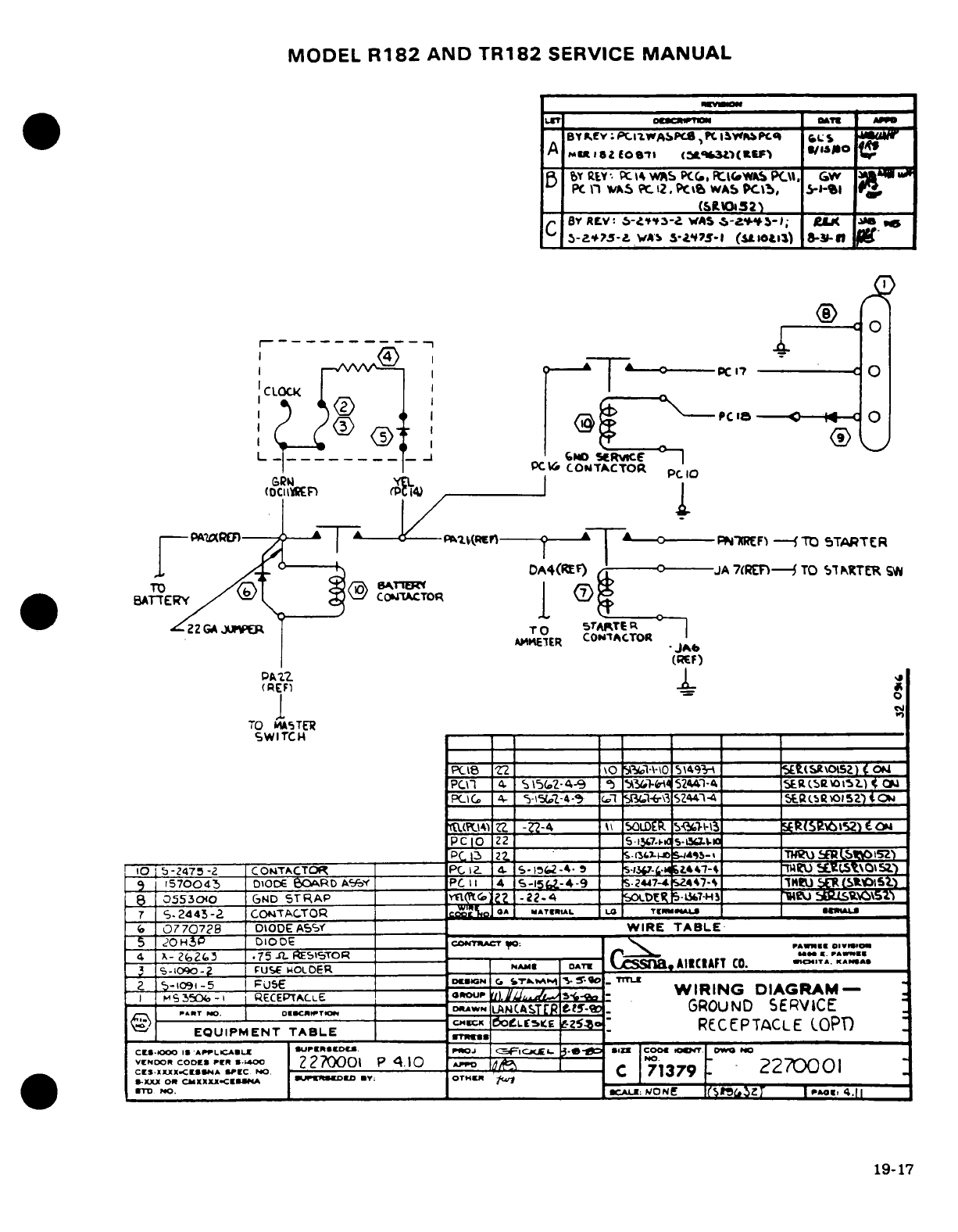
MODEL
R182
AND
TR182
SERVICE
MANUAL
_r
B
ykev:
Pc
I1WO
,^J
I
PC
If"wPo
CI
S
A tu a
oe
o3
(
» vUo lo
BY
EY
:
1X
4WAS
PC,
R
I.-WAPCq
.
G
YS
PC
ln
WAS
t
2
.PctWA
PCwb,
3--b
A
'
,
_
soi(S10Z
32)
C
BY
REV:
s-f3-
wS
.-
A.s-- ; e+
-Z
5--?JA9
w*>
S-AtYj-)
(SIi10)
s-3sn
f
---------- 0 T
7
CLOCKO
c
IT_
LZ^1Qf1
'
0@PC In
GPM
yn.
I
PC
lB
._ ¢TrERYC
C0
c
OANTACTOR
pcCTO
DAE4(EF)
JA
7CRET
TO
TNRCTER
W
A8iTiE1ER
CONIACTOR
JAF)
I(RF)
-(
1
o
TO
IkSTER
SWITCH
-
PCi8
Z2
O
515-\-\Q
5\4\\49\F
~m
)
Om
(
V
CS
o
PC
I1
.4
s5(2-4-9
`9
Yb1M-4
52441-4
i____
5RCOIS)
<
Q
PCIC
4-
5-(,pZ-4-
9
SI14-\Zi\3244-4
____
S
(.
L
gSoZ)t
ItUPC10
ZZ
-Z2-4 \T
)LDER
OSmCb3
R(5e\>5)€
PCIO
22
_
5.i7.
s-L
__
_C
1
22..
-_____
__
.FR3-S
____
'S.
THU
fRI
S')
10
1
5-2475
-2
COTACTOR
__PC
IZ- 4.
S-16_2-4_9-
5
-5
*-
U
.LStO
5z.)
9
1570043
DIODE
0E
RD
AfF_
PC
I
4
S-15&2-4-9
_ U.447447-4
IBJ
a _atStOS)
8
055300
GND
STRAP
____i G
-22.4
_ 0EsDE- -H1_a i____ u
Jt\VS1
7
'S
2445-2
CON4TACTOR
co 'L
MATIRIAL
LO
TKimi"J
UOAtU
a
07707278
DIODE
ASS_
WIRE
TABLE-
Z
2OH5P
D100DE
.-
cOOTACT
O:
-PAWE
0DIV
4
x-
2(e2.5
.75
R
51STOR
r
"
X.
PA IE
~5-10o--.
FUSE
NOLDER
N AME__.
^
DATE
AIICIAFT
CO. ,ITA..,
KA.re
-1091-5
;USE mami .
CrI
m
5
S
TrL·
2
S15b3-I
5ECEPTCLE
rour
U
T^^
WIRING
DIAGRAM-
...
T
M
.-
O. EC.TO--
DWN
ltNCASTR tt-:.
GROUND
SERVICE
EQUIPMENT
TABLE
CrcK
OL
Z
-
RECEPTACLE
(OPT
ctS-I.oo
.I
AP.LCAL
*
uPIO.€
p,
,L
,-sfI.
*
O CS lcoa COw O.
VNDOR CODES.
PER.00
2270001
P
4.10
Po POCO.
2270001
CI..I<x<E*
'I
N-C
Cr-
C
71379
2
-XXX Or
CMXXXX.CEUA
iK[ED
D
OT:
OTHE[
_
19-17
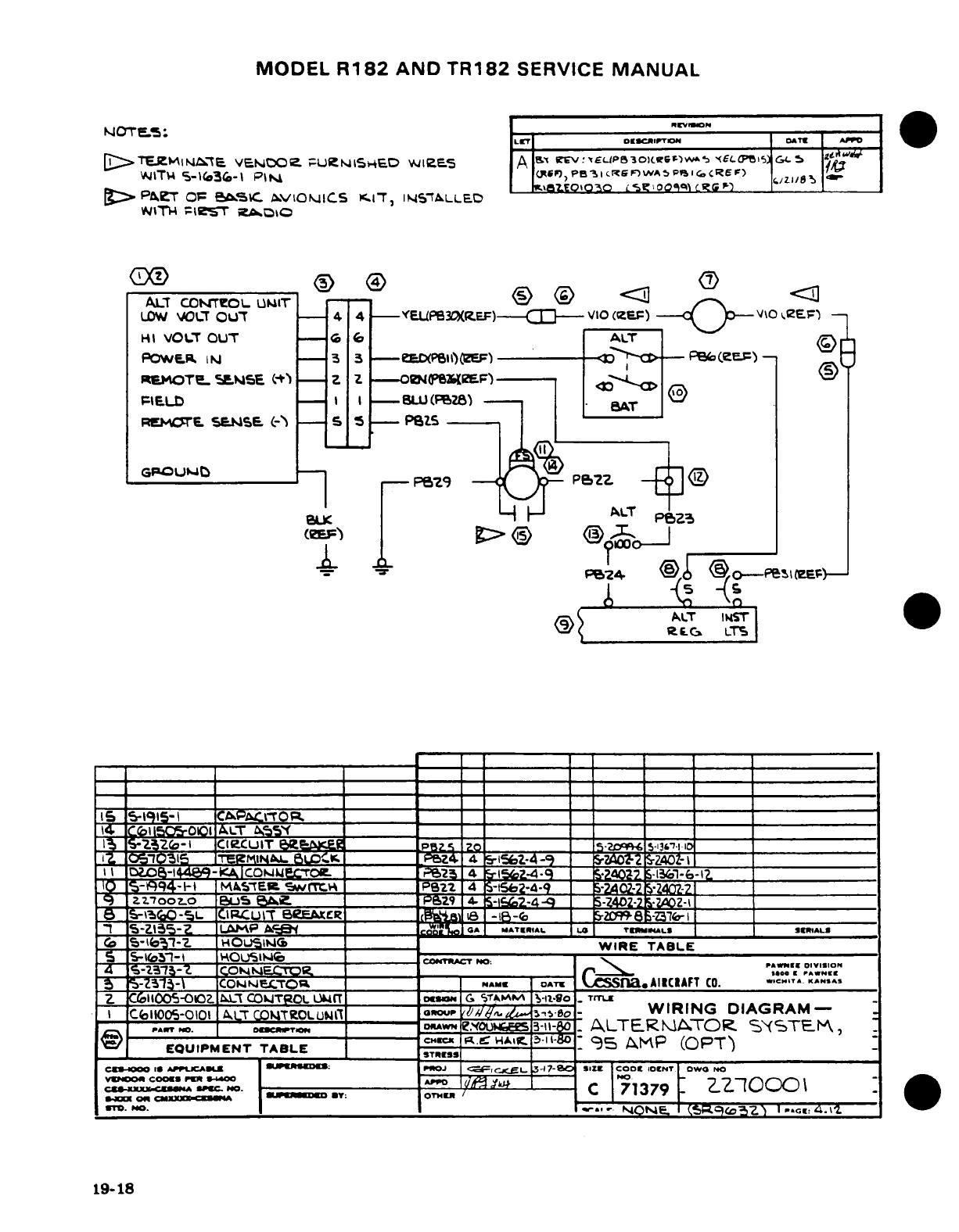
MODEL
R182
AND
TR182
SERVICE
MANUAL
NOTE5:
,EV
--
,,
[>TEZMlHiNt3E
VENDOoe
i
UeLSr6ED
vWlZeS
A
SL
1ExpeotscSlr
s
EL5
5 oi
v4ITt4
S-1o36-I
Psi
PC.),peB
aSic6MnwsAp^'.sCREF
)
r.i/,ZI/
>
PA^e
O
SBC.
-VONJICS
c.1T,
INS'ALLED
WITI
-eITr
2^ADI
CKD®
® CD
AILT
COWTO
.® ®
UI
T
LOW
VOCT
OU'T
-
44
-EEUPe3CXREF)-Ct--
V10
(IZE-)
-V\0
,
2EF1
V
HI
VOLT
OUT
6 6
ALT"
POW&ER
I
-
3
3
-eED(P)
------
EF)-
(E)- (Q>
R4OTeL
SES
(
Z
Z
--
OBN"(PEF')
Q
FIELD
-I I
--
U
(28)
-t
REMOTE
SaSE.
C--
S
S1
-
PtS
GPCOU
M
W
P8Z9
e2Z
BLK
ALT
4U: ^ 1
LC
ALT
LP
T
(_
.. ,
L_-fZ4
______
/
T1
.65
r
-
_ _
-ocff
_
_
eEp
..
UT^- _ _
-
_ _
GT
w
e1915-144e9
KA1oTOv ~
-----
_g~rfen5C6-00
A>LT
^S^
_____
___
__-______ _ _ _
---
~_-zo-_
CUIT 6g.__
P-2S
2-
-,.____,__________
1Z0-5015
TgT
BLOCK.R__
LT8 _
-
_
_________________
15
-Z135-Z
ILAMP
UIAj
_AL MAT.SDAL m TERMW4AL« SIA
LS
:
Ez'-
HOUs.it
P,9
4I .R-i
Z-4
WIE
TAZE
2__
R-
S
CO2E-c"(
.~TA- __'_., _L_ _
;;|;._
NO:
_ "1^_
_l°_
s°o.
5
S-Z31i3-\
COkie
a MAMILTOP.
.
DAT
oT css-a.AIKcIAFT CO. CH....
K..s^5
Z
C61oOOS-OlOZ.
0
L
COI'TROL
OUT
____
at
G
S*
,
-So
_
TrT
I
I
CeIIO-0101
ALT
CO4TCOLU0Nt'
ou
,la..
.
.^s,-o-
WIRING
DIAGRAM-
.^T
"D.
,
OeT
o,
NrMe.o0Ls3-3-l0.-
ALTERA.TOR.
SY.STE_,
EQUIPMENT
TABLE
.-
AIR12
95
MP (SPT)T
c
C 0oES Ir Ai mjCAj |UK ;
PROJ
G I L
34
7-
SIZE
COOt
IOcINT
OWO
NO
s
c
--
rc
C
_u-NE
A ^
,O
,.
C
71379
*40
Ol
~
XXKXWA
| Zl_ *Y:
OTH"
/
'
E
o.
no.
r__
__q cOZ)
1 9-ec s4..t.
19-18
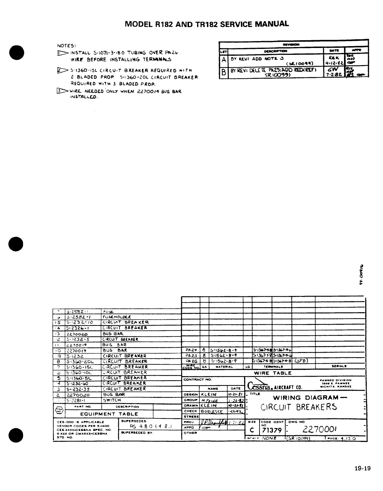
MODEL
R182
AND
TR182
SERVICE
MANUAL
NOTES:
rvamI
[E>
INSTALL
5-1071-3-180
TUBING
O'ER
PaZ
o.camo
_
WIRE
BEFORE
INSTALLING
TERIMNALS
A
Or
Ui:
ADD NOTrL
3
j
(bselooq)
4-12-i-t
IMP
-1
S-360-15L
CiRCUrT
BREAKER REQUIRED
wi'T
BY
RE.
DEL
PK^5-OD
ED(EF
)
w
2
BLADED
PROP
S-l360-2OL
CIRCUIT
BREAKER
_
S.(IOO99)
7-Z-BL
REQusiRD
wvitw
3
BLADED
PROP.
[>._lie.
NE.OD
'ONLY
WHEN
227004
BUS aIAR
INSrALLLD.
-;
1.S-.Z5,
IIFU 1.:1
'
f-~8z-I
_____________
______|-= _ _______________
i5
S-12
3L2--,/
CCLAT
REPKER
_
13
2?700
0 e
us
8As_
I$
SC2I2C1
UiBnT
,RE/(..ERP
_________
________________________
:2
5-
T32-5l
CIRCUIT
BREAKE___
a.
700
oo
BuS
BA
_
,0 2Z7001_OO
BUS
AR
R
PA2.,
S-iSF
-B-9_ S-7. &-i- ____
_
-q
-
ia5-.
CIRCUIT
BRFAKERfE
PAta
8
S-/SI
.-
8-_ =
13.
?-1
5-L.S-
L_____
e
s-3eGo0-aoL
CiRCurT
BREAKER
0P26
a
5-15(
2-8-9_
-51?4-
S--8
(S)
____A
(rD)
7
S-13
0
-15L
CIRCUIT
BREAKER
-C
GA MATER.IA-L LG
TI
-
rlMLS SERIALStm
b
5-13.O-IOL
,IRCuiT
aREAPER
WIRE
TABLE
5
5-13l0-5L
CiRCUIT
8REAKER
-
ONTIRAT
0N40:PAW --
T4
-
1232--
CiRCUIT
BREAKER
-..
oo
-
Ca i.N
3
5-,23Z-35
CIRCUIT
BREAKER
NAME
DATE
AIICIAFT
CO. CC..T^A
^.SA
.
2a700ao
BUS
BAR
D
ESIGN
KLE.I
1O-2-l
.
TrTIE
=
gi.-I
5W-
'
,i2o8urTC,
-
GROur .'-, j.-_
WIRING
DIAGRAM-
@
..
NO.
.u.»^
C.H C
o,:
,
"'__ :.
CIRCUIT
BREAKERS
EQUIPMENT
TABLE
STRESS
CE.1000
IS
APPLCABL[
SUEPERSEDES:
PIROJ
J
/
.
SIZE
CODE IDENT
OWG
NO
VENDOR
CODES
PER
S4400
0,
I
..
-NO-
CE
-0XXXX.COESS A
SPEC
NC
.
C. 71379
-
z70001
S.XX
OR
CMXXXX.CEISNA
SUPERSEDED
BY.
OTH
IER
|STo
No____
_ v
ON
I(SR
I)009)
|--G.
34.1
O
19-19
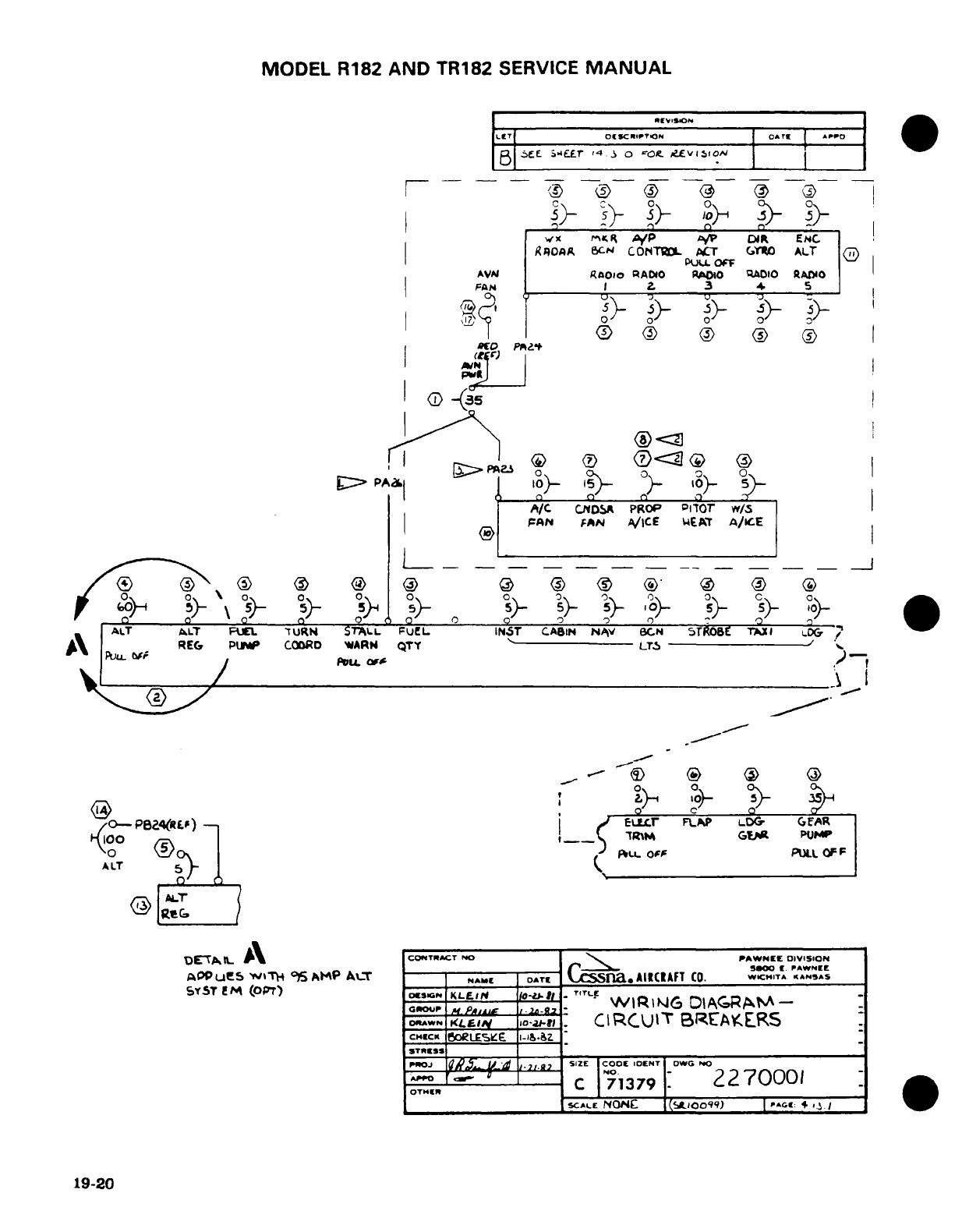
MODEL
R182
AND
TR182
SERVICE
MANUAL
..
E
..
E. t
_4_
3
0REVISION
|LIT
|octscm
TOron
|
o
rs
|
«pro
I^^
|
B
6jE
Sikur
,t3
o
r-on.
REvIiO
1o0A
I r---o
/
(
®
-
(-
-0
1 5} sf 3
1°0f
>
°
vx
m
R
Nl
/P
-/P
DUR
ENC
I
RAOAA
c'N
CONTDL
APC
GYVRO
ALT
O
PUL.
OC'F
AVN
RaoDI
RADIO
RAO
qAO10
RADIO
FaN
I
.
3
4.
5
(D @ @ <
®
/
wo
PR^a
K P
>
PAa
Gb
)-
s
4
AI
N
II
>
PA
5
lo-
J\ _
.
RE6.
Plrl-
CO0RD
WARN
QT¥
""
LTS,
/D
'7
|
(A/C
CNSA
PROP
CToT
wS5
r
)
p
\
5
5)o 5
Y-
5)-
0
)-
>
o
AA
T
ALT
FUEL.
URN
TL
FUEL
INST
CABiN
NAv
GCN
-5ROBE
T
--G
REG
PUMP
COORD
'EARM
N--
LQA
-
/0-
P24(R
Ef)
-
;
ELLCr
FLAP
LDGi
GAR
F1100
A
i__
)R\M
GlEg
PUMP
A
LT
0
pi:u
of
PUtt
OFF
ALT
DEPTAIL
A\
CONTRACT
PNO
PAWNEE
DIVISION
A
Q P U W I T
4 9'
AM~h1L~
-
_ _ _ _
-
SidCX0
E.
PAW N
EE
AOP
uP-s
W%>1
95
AIMP
A
|x
.
NAME
DATE
o E
na.
AI»CIAFT
CO.
WC^ITA
KANS
SY5T
EM
(OPT)
CSIG
KLEIN
-
WRIG
DATLM-
-
GROUtP
/
lJP.4dr I
,
2.
WIRIN
DIAGRAM.
SIAWN
1fIiftL
1ota
CI
RCUIT
BREAKEIRS
CHlCK
5o
tES-E
I-&.&Z
STRESS
,0oJ
I S.
n -d ~ 7
SIZE COOE
IDENT
DW-
4c
^ 1
PPa C
1379:
270001
OTHEr,
C
71
79
19-.^^^
20 ~
SCALE
NON
('100So) | ra4.
+./
19-20
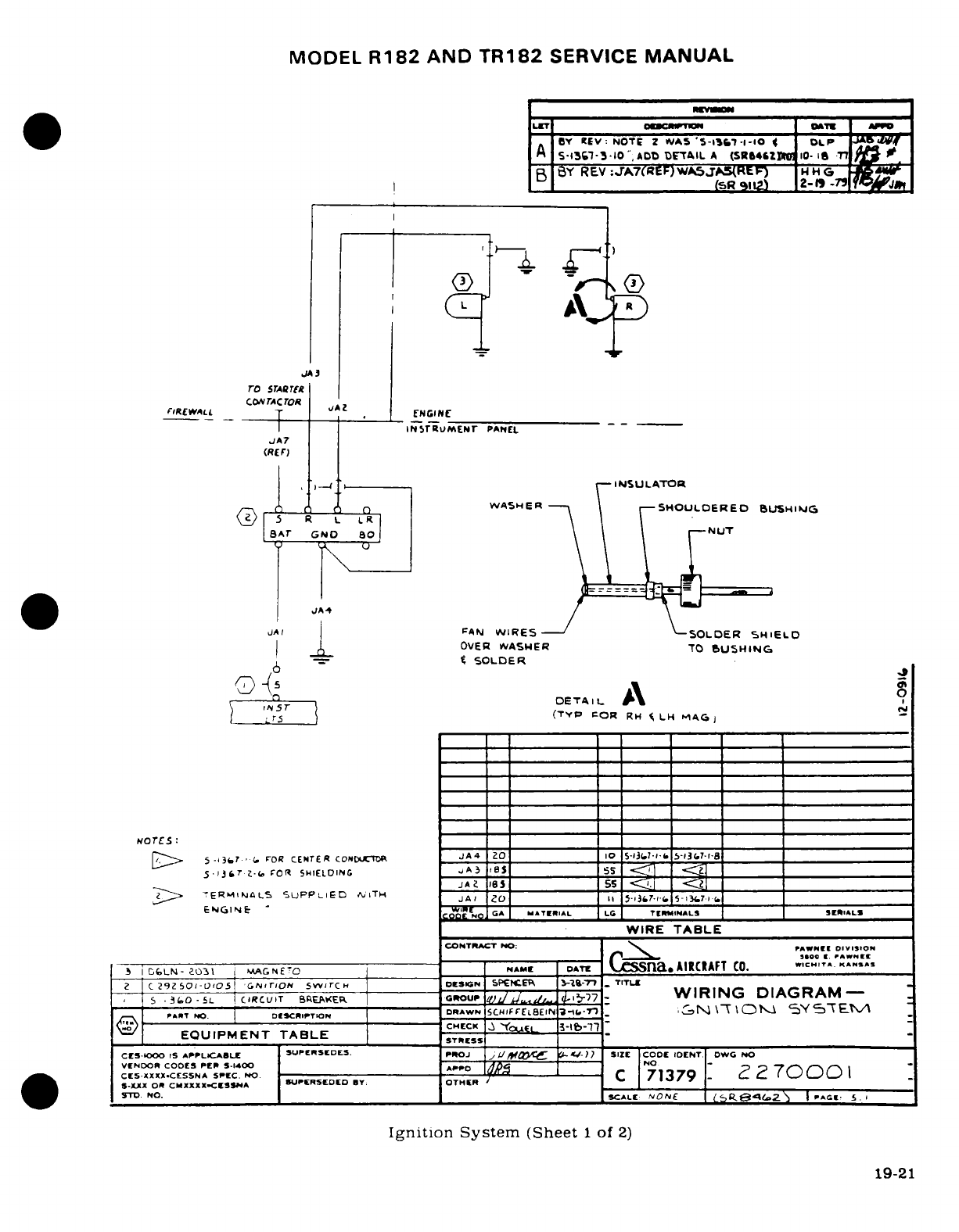
MODEL
R182
AND
TR182
SERVICE
MANUAL
LET
O-DCRIPNTR
DATw
A
'o
BY
REV:
NOTE
2
NAS
'5-tI
.1-l-I0
4
DLP.
f
A
S-1307-3-10"
ADO
DETAIL
A
(SR64"ILg
10- i1
-T
!
BY
REV:-rA7(REF)WA5jA5(EF)
14
H
G
.
m
B
W
R91J
2-1
-79
JA3
ro
STAwRT[
CO,
TACTOR
A
FIRE WALL
(
.
CNCIN
_ _ I
_
|INSTrRUMENr
PANEL
JA7
(RE
r)
INSULATOR
.
fl r) E OWASHER 7
SHOULDERED
BUSHING
>-
5R
L
LR
\
'
BAT
GND
0
\
JA/
\
J_ FPAN
WIRES
SOLDER
SHIELD
I 1
OVER
WASHER
T0
SUSHING
6
-=
%
SOLDER
n DA LDETAL \
A
N
5Tr
(TYP
POR
RH
%
LH
MAGj
NOTES:
--
/D
5-,
3'"r FLO0R
CENTER
CONTO
JA4
ZO
R
5-3I
-I-
5-13R7
R___
5
j367
-
COR
SHIELDIN3 I
5
S
TERliNALS
SUPPLIED
:
iTH
JA:
ZO
I5 ___rI(
5-37
____
E
NGINE
A
G
MATILAL
L
C
T
CIMINALS
SER*ALS
WIRE
TABLE
CONTRACT NO:
fPAWN DIO
l
SO-
s0oo
I. 1AWNMC
-
i[
CLN-
ao3l ME -C'-
|
E
DATE
Cssna.
AIRCRAFT
CO. C
.ITA.
..
SAS
2
C
297
SO-D'05
'C.NrON
SvvITCCH
|
E*r
SONIPEEK
-19mI-r
n
TITLE
PIT
NO.
DESCRlITION
RN\
NA
-Y-
-
/^.S--
--.
o---
CH'ECK
.IRIN IAR-AM-l
'
EQUIPMENT
TABLE
YSTE
c
S-1S-
CES-lo00o
APPLIC.ABLE
SUPERSEDES.
PROJ
j4Ia
s-?)
SIZE
|COE
DENT|
W
NO
VENDOR
COOES
PER
S.400
P 71379
.2
CE5ZXX.CESSNA
SPEC.
NO
C
71379
-
7cDOC)I
S-xotSXXXXxCESSNA
S.
-
SUPERSEDED
BY
OTHER
SD.o
NO.
|
.
c__ALE:
NO/ R8Z- E.
Ignition System
(Sheet
1
of
2)
19-21
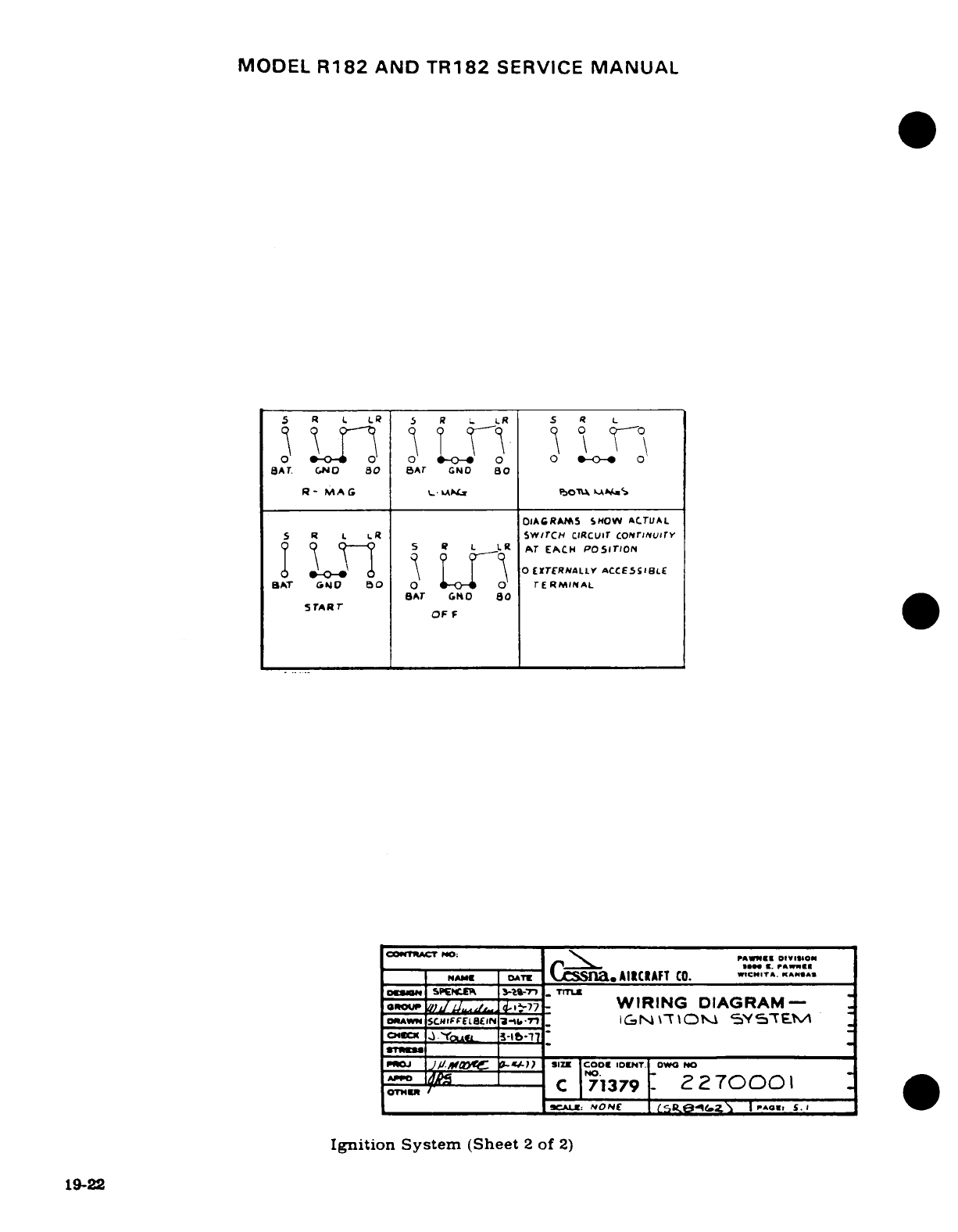
MODEL
R182
AND
TR182
SERVICE
MANUAL
5
R L L
5
R L
LR
S
R
L
*--*
O
-
00
0
SAT.
GNO
80
BAT
GNO
80
R
-
MAG
C
bI PbOTULA u*S
OIAGRAMS
SHOW
ACTUAL
S
R
L
LR
SWITrH
CIRCUITr
CONrIuIrY
°
°\
'
s
L LRR
AT
EACH
POSITION
oI
ot »
0
\
|0
EXTERNALLY
ACCE5SIBLE
BAT
GA
O
BO
rERMINAL
BAT G&O
80
START
OF
F
CONTACT
NO:
PAWNE
DIVIIO
|NA
|
oATE
css
AIRCIAFT
CO.
cH.TA
K..
OmaNw
SPECE
-t%-TI7
TriT
eo,
7
^~/lzdT-,,
-.
WIRING
DIAGRAM-
__ _
NO.
C:Hfc
JYCX"CL
3-1b-'T
7
OTK
uf,
C
71379
2
70001
CAL:
NONE
lcslZ.e^Z\
I a S.
I
Ignition System
(Sheet
2
of
2)
19-22
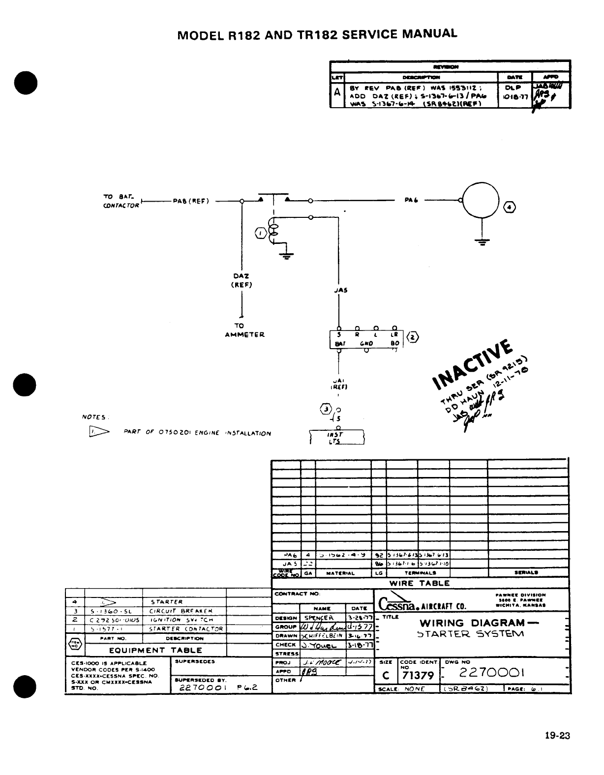
MODEL
R182
AND
TR182
SERVICE
MANUAL
L"T
0fcMlui0n
OATK
I
APPD
A
BY
rev
PA^
(tIEF)
WAS
15IiZb ;
OLP
ADD
OAZ
(REF)
S-13'Sb'--13/PI
0-16-17-
__
w1
K
-l't7-<-K
tSRfbt{fc(6
___
rOrACrOR
PA-
(PEF)
--
PA
r
_
DAZ
(REF)
BAT wNo
80
NOTE
S:
5m
PARr
OF
0750201
ENG/NE
',SrALLATlON
\
m
-
rr
,'A(,
4
'
~.1'
2
4
S,2
5,J3('li
-
3lSi)7
'131
JA
5
.'"
_ -l,' it.
I
.
131 I 10I
_
W GA
MATERlAL
LG
TERMINALLS
SE
ImALS
_______
_WIRE
TABLE
CONTRACT
NO:
PAWNMK
DIV1I1O0
~~~~~~~.4
STARrER
-
5500 CI
.
PAWNEI
2 C
292
so'
0s
'0
IC.N
IT/Or
S Cr-,i
SPEN
EP7i
1-'
T
-
TR-LE
1-77-,
START^ER
(O
tOAC'OR
GRIOU
W
/
dli .7
WIRING
DIAGRAM-
PANT
No.
oli-.,PT.OT
DRAWN
-- ---
IFF'LBi£f
31-..71.
bTARTEV-
SYSTM
, :
W
)
-------------------------------------- ----------- CHECK
T
.YO~;et-,
LCl-
T
'-
*
EQUIPMENT
TABLE
STRHES
CES-IOOO
IS
APPLICABLE
SUPERSEDES
pnOJ
J,
.'
/OJ
-IT'-I,
SIZE CODE
IDENTI
DWG
NO
VENDOR
CODES
PER
S-14,00
-
-o
AO "P
70
CES.XXXX-CESSNA SPEC.
NO.
C
3727000
S-XXX
OR
CMXXXX-CESSNA
SUPIEREDED
BY.
OTHER
/
STO.
NO.
° 270001 PI.I (.2. SCALE:
NONEC
c
R-
0
.
2 I AGE:
(.
I
19-23
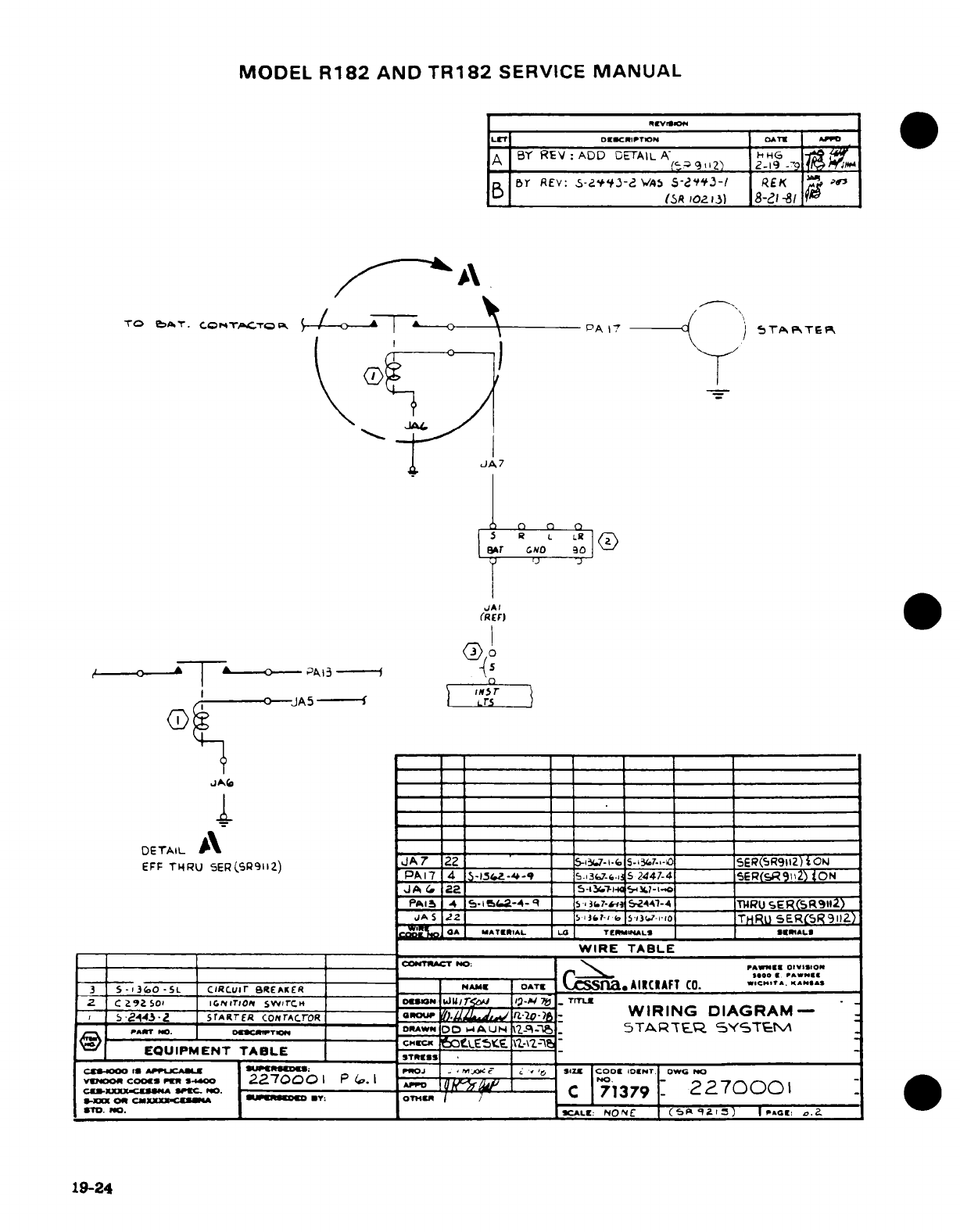
MODEL
R182
AND
TR182
SERVICE
MANUAL
LT
DEBSCRIPTION | OATT | Jw
BY
REV:
ADD
DETAIL
A'6 92
HG
A _(,____9''12')
2-19
-9
n
B
Br
REV:
V5-2A'3-d
VAS
S-.'i'3-/
REK
[SR
IO
1i)
8-21-81
TO
i^rT.
COn4TrATOPk
{ _ A
I i---
- --
p(
--
^ TE
v
JA4
5
R
a
L R
(
BATr
No
30
JAI
(REF)
T z--
A
aA--3
-
,
15
JA5
Lr5
r
I
i
I
I I I_1_111
DETAIL
A\
-
EFF
THRU
5ER(C59112)
JA7
22
1
I
2i7 -6
5-1
______7 SER(SR9112)tOIJ
PA17
4
5-154Z-A-
=4-q
-3,7-
e.:
5
2447-4
5_ER(S_9_i2)
ON
JA
f
22
5-_________
S,
i-t..
-
PA.,
4 ;-ia<.2-4-9 s 3.
7-
-244-A
-4__ TWRU
SERC(SRI
)
JA
5
J22
= _SI_ j3tf-i
'
15-i36s7-i-
:
THRU
SER
(
R9HZ1
GO
oA
,MA^TI'AL
LO
TeI
nMALS
SER.ILS
WIRE
TABLE
----
--
T--CON
CT
NO:
-'w
f
»
olvIVIIO
____^_ ^________
~ ~ ~ ~
~O 160H PAWNSA
3 5 -1 3
i(o
-
SL
cIRcuir
REAKER
NAME
OATE
a
AIRICAFT
CO. ,cA.eo
.
O .*^.
.
2 C
Z9Z
soL
IGNITION
swircH
O
SISON
U 1/"r<' I-/ 7t
TITLU
_
Z,
143-Z
srARTER
coNrAcrR
aGouP
./ .-
l0-_
-
WIRING
DIAGRAM
-
rPAT
o.
DCanwTIp-
DoAWN
DOAUN
.-
g
5TARTEQR
SYSTE
EQUIPMENT
TABLE
S TRES
tLEStE
\________
CJOOo IA A WJMJ: UOJ
.
M
Pc L < 'C,
size
CODE
IDoNT
oDWC
NO,
CVmo Ccoo2
r
D.1-o
2270001
P
(P.
I O-
No.
-
C
"
"
2
2
tconm-xxxX-c&
«
.,-
o
/
71379 2:70001
-.
No.
o
CALE
NO
E
(2 ka l4)
|
-A
.
.
19-24
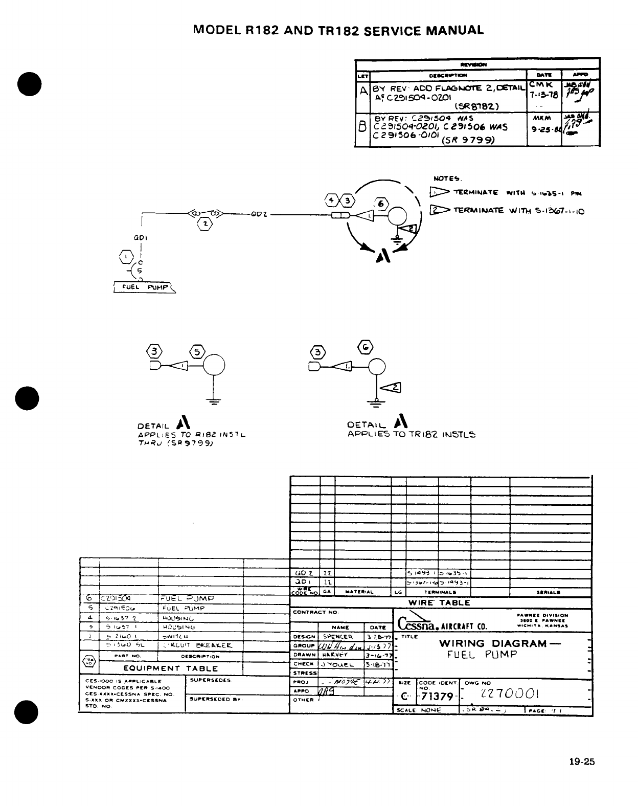
MODEL
R182
AND
TR182
SERVICE
MANUAL
LE'IT
] __
Ot
II__ CIm»pTII III-rOMNA
-Pl
_
BY
REV
ADD
FLAC.,mE
?,ETAI
nA,
C?_154
-OZ
7-
048
-.
_______1sR'et)
..
BY
REV:
C'
25504 WAS
M5M
A
.f
B
C
1504-OZOI,
CZ
3,506
WAS
9,?s
C291
5
06
-OiOl
(SR
9799)
NOT
ES.
/-\/-^
>\
D
"
EREHI4
ATE
lrlTU
3
.5-1
P1
--
<S
-O7>o 2 _ _l I
:>TlRMIJATE
IT
S-17-i-iO
CUEL
vI;P\ A
-. A
DETAIL
A
OETAIL
A
APPLIES
TO
Rli,
tilST7
APPLIES
TO TR182
ISJ5TLt
THRuj
(S
,9799)
_____ LO
5
I49
i 3
.3-l
G Z- t z z-r
--
tL
5 M. J -P
-cCO wDE
NO,
GA I ^
ATIR
IAL LG
T1RMiNALS
SERIALS
;Czo
E~
I'uEL
IIJMP
-S-
--
r^ p
-
---- -------------
USWIRE-
TABLE
---- _ ~
,
--------
-UEL
-'L--M-
CONTRACT
NO:
Wo
5 i5 1
U
lR
I1L-~
NAMETEOA'TC
Q
ssna.AlltRAFT
Co.
ICC.'
T.
^",,S
;i D Z
i 0
I -lL r, '_ _I1.
.
-
Dti
O
GN
SP.NCte 3-2T
E
TITLE
{-,O
sL
-LU'T
e; ECft.--r
GROUp
_
,_
.- /
7
-.
WIRING
DIAGRAM-
..
RT
rO. _
oC TR:,
ON
O ,.:RAWN h^t
,--
FUEL
PLIMP
EQUIPMENT
TABLE
CECK
-OAe
5
l6.l1
+---
--
-- -- --
--
_
STRlrSS
CES-IOO 1S
APPLICAIBL SUPERSEDES
IPRO.- _
'
t
SIZE
CODE
OElNT
OWG
NO
VENDORI CODES
PER
S-
AD
NO
S.XX
oS.EC.....
NO-
C-
71379--C
CES
««..CESS**
tCLN.
NO.
HE
W07
(Ol
S-.XX
oRx
C:MXXX.CSS
NA
SUPERSEDED
BY:
OTHER
"
71379
-
STD
NO
SCALE: F
'
rr
-
T1P
9-
I
19-25
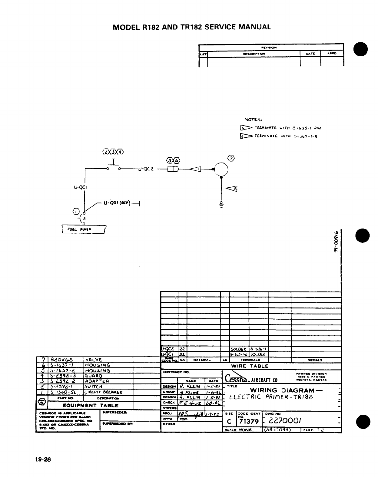
MODEL
R182
AND TR182
SERVICE
MANUAL
1
LIT
oDs c
rr I
P
TION OAT[r A
Dio
/,,orE
la:
D[
7Lt
INATL
WITH
s-5-i.s-I
PN
T '.l N^TI IATr WITH
,
-1--
T
U-C
I
o
u-QcI
Q
u-Qol
(Krn)-(
I
FUUL
: PAWE
I
7
,BDPXG
."
VA
LVaE A
MATERIAL
.
T MINIALS _SERIALS
5-
-.
37-
HOUSING
_______
WIRE
TABLE
_5_ 5-0.^7-Z
HOUSI(NG
------------
CDONTRAT
POO: ----------- ;^
"---------------».AN
oV,,,oN
4 S-5192-3
(UAO
.______
1
J3
A-d
OAPTER
~ _ __
NA
ME
OATE
fa.AIAlfT
c
.
cAIRCFT
CO.
a
*.59
-1
SWITC
ITI____
oCZS
R.
LL
KUA
I-
5--
TITL-
$
S-0t,
0-5'L
,eC.uITr
aA.ERL
GROUP
An
PAIne
Ia--
WIRING
DIAGRAM
PAr?
m. DomrRAWN
---
E.
.If
/-*?.
ELECTRIC
PRIM
ER-T
RIS8_r
EQUIPMENT TABLE
-
CES-EJIA!*
A
SPECA.U NO---DM:
MIOJ
^i'r^
l^.i) l~POW
SlIE
COCE
IOENT
Owo
"O
YD
C2s01 §
PIER
.A
r <~
F
~i~
lO.4
2--- o oftI Ao^pr
wam
my
OTHER
C
171379
?2O000/
To.
NO.
________LE
NONE.
_-t E (6CQ
10099)
E
|
r.
19-26
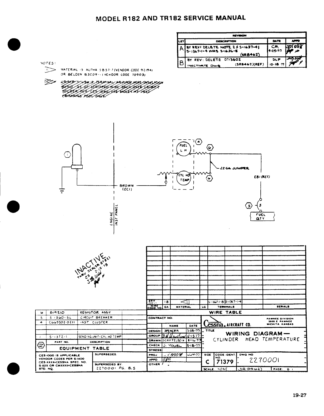
MODEL
R182
AND
TR182
SERVICE
MANUAL
A
RtW
I
DELLTL
NOTE
t f -S1c7-4; c
Cm
7 051
5- l3I
7-I-'
tWA
S
-1&36-6
» -1- p -r'1
_
(sftS4*2
,
BSY
REV: DELETE
01302
DLP
-
'"o rE5
B
Mc'W,.d~T
Ow
q
(.SR8462)(rEr)
0l-18
T77
I
c >
,
MA
rE
RIAL
i5
ALPHA
5S
7.
(VENOOR
CODE
9
194)
OR
ELDEON
3CO9-
,(
VENOOR
CODE
70903)
_ _ _ _ _ _ _
1
_
_
1
_ __
W R
TA
L
1
BRO
N
I
I
\-f00S~ I I
FUL
NA D C. TEMIALSKASA
5-
_
?-
4_ _ _
R
O
I
EQU914210
PMENl~Tor
T
A,-BLy
WIRE
TABLE
CES-AZXR.CESSNA
S N
.
79-1"
SNXME
DAT
OR CMXXXaAIXUT
CSPO.EED
.C.
O HE
ST.NQ. _ _ _ _0I 1
3
TTL
_______________________
_r-CYL _ C Ao·NO GA
MATlRIAL
LG
TIHNAL
P
W
IRING
DIAG
RRAM
L
ATN
|
D.:C.T0I.
DRAWN
5<HIPaFELBiAbI
t-11,7,_
CYLINDER
HEAD
TEMPERATURE
_ EOQUIPMENT
TABLE
CHTEts
_
_
CF;S-1000 1
APPLICABLE
SUPL
SEtDS.
Pro
J _oO i-07-12
SIZE
CODE
IOCNT
R NW O
NO
VENSDO CODEC
PER
1S-l00
ppo
.
7
0 01
C5-
XXXXCf
SSNXA
SPXC.
Nr
SUPEDSEDED
BY: OTHE[
C
Z7
0
'
$
-1
STD.
N
"2
ZI7000I
PG
B.
S_
Z
,SCALE.
NONE
.
AI-4Ao2.T)
i
...
B
19-27
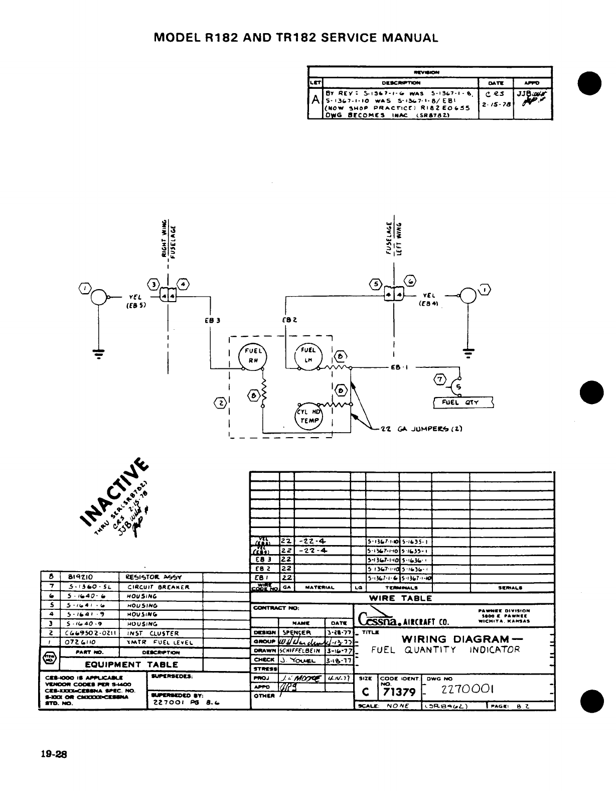
MODEL
R182
AND
TR182
SERVICE
MANUAL
,- --
Wv
I
I
LCT
DESC0ir TIONi IrATE AP
|
BY
REV:
S5-i17-i-.
wAS
S-i37-
--
C
.
5
JJe8$
A
s-I3'7--iO
WAS
S-13.67-'-I/EIB'
i
(Now
SHOP
PRACTricC
RilaZEO.
55
_
oWG
BECO
ME
INAC
(SRa7a.)
Is II
I
^
vEL
4 E
EL
((8
5)
(ED
4
E3
CS
i
FEL
FUEL
_ I
----
<D
A
o^~A _> f
FUEL
OTYr
|I
.
M
v
.
'*22L
GA
JUMPEIL.
'L)
E8
2
22
5
13(T7-i-Ic
i
.-
a
is1zio
Ee'MisTOR.
A.'*v
C
I
22
_5-iM-'
5
-
3
-
-
'7
_-GIAO
-
SL Cl Ur C EAKEO
MATERIAL
LA
TERMINAI.S
S mRIAL
C5
-
05.40-
HOUSING
_______WIRE
TABLE
5
S
-',(4
.*
<.
HOUSIhNG
CONTRTCT
NO
4
5
-
4
*
-
Hou5I.
I______ )O
·
PlWNlS1
3
5
-..
40
9
HOUSING
NA.M
DATE
CS
a.
AIRCAFT
CO.
.WCHT.
TAS,
Z
C.1.9502-OZII
INST
CLUSTER
D
IOGN SP
NCEp
T-T11-
._
TT
072-(.110
T
rR
FuEL
LEVEL
0GROUP
VI
d
d-
WIRING
DIAGRAM-
PA^
T
NO.
O«CmTV4
DN
SCN
FFfLBEISN
3-1'.77
FUEL
aUANTITY
INDICATOR
EQUIPMENT
TABLE
3STE
_
CO000
I,
A1P4UCA
B
ULWESoD:
DoJ
JWI
Mpsses I/-7
V-7
SIZE
COD
ID-NT
DWG
NO
CV
-
^
COO
D P
-
00
A.
71379NO
-
227000
1
mX
ON
00
CL
or
PG
ffm*
No.
_ 2 2___ZZ700.*
Pe
8.&6
XSCALME:
NON~E
cS$L: ^ bL)
|.pGc. a
e
19-28
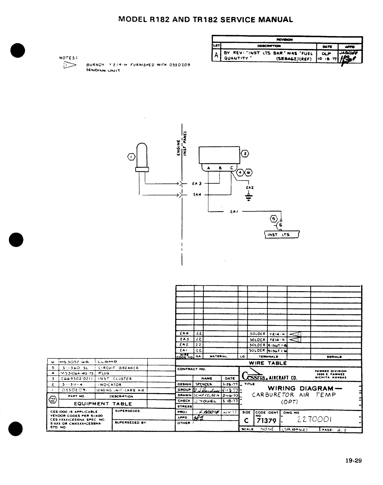
MODEL
R182
AND
TR182
SERVICE
MANUAL
*LET
IDaOUIWTiN
I
T
E
I
P
A
BY
REV:
'INST
LTS
BKR*WAS
'FUEL
OP
W#
NorEs
-
QUALJTITY'
(rsitZ)(rEr) io 17
l:~>
6URNOY
Y Z
4
-H
IruN(lSEO
wrm
0550209
O
~CEOIl>>l
UMIT
>-
EA3
-
LA
I
j
INST
LTS
J
EA4
ZST
---
50""""^ '^'
iOLDER
fti4-m
*<^
EA3
;. _______ __
MOLOER
YZIdL4
-
'.
_ I I'-I
_ _
501.
Ot
1
EA4
22.
55OLDE
lR
i14.
I
L
EA3
2L2
SOLDER
YIl4
·
1
L
EAtI
2
=
SOLDER
IST
_____I
WCOC N CGA
MATERIAL
LG TE IINALS
SERIALS
ir
o-30o7- I cMo _
WIRE
TABLE
5
S
'I
3b
SL
CIRCUIr
E3REAKER CONTRACT
NO.
~
PAW"l
DIVISION
4
MS3IOI.A-1i.7·
75
PLUSG
r-0i0-
A WNS
I
a
3i
CS.i9502-021
IN
fS
CLUSTEr
NAME
DATE
Sna
.AIRCAFT
Co.
WCHTA ANA
5
-
.311+
NOICArOR
DESIGN
I
S(p.f
3-2%-7'1' TITLE
5Oh-.
.I
.
D.
GROUJG
JPlITCNRS
AIR
WIRING
DIAGRAM-
R,.T
NO.
_CICPTIONE
DRwN
-C^,-FuEL,
3-,17
CARBURE
OR
AIR
TEMP
^^ --------------------------
CHECK
YouLE-
s.
IS-;7
(OPT)
EQUIPMENT
TABLE
STRESS
-
CES-IOOO
IS
APPLICABLE
SUPERSEDES
PrOJ
/.
?/.
['F
-_V. ~
SIZE
CODE
IDENT
DWG
NO
VENDOR
CODES
PER
S-IA00
OAP-
NO
7C
-S'JCX
OR CMXXXX"I¢ESSNA
71
Z70001
CES.XXX.CESSNA
SPEC
NO.
AD 71379 z10
0
SXXX
OR
CMXXXX.CESSNA
SUPrERSEDED
BY:
OTHER
STD
NO
SCALE
NOIjE
r
3e4I.zI
I
PAGE-
. 3
19-29
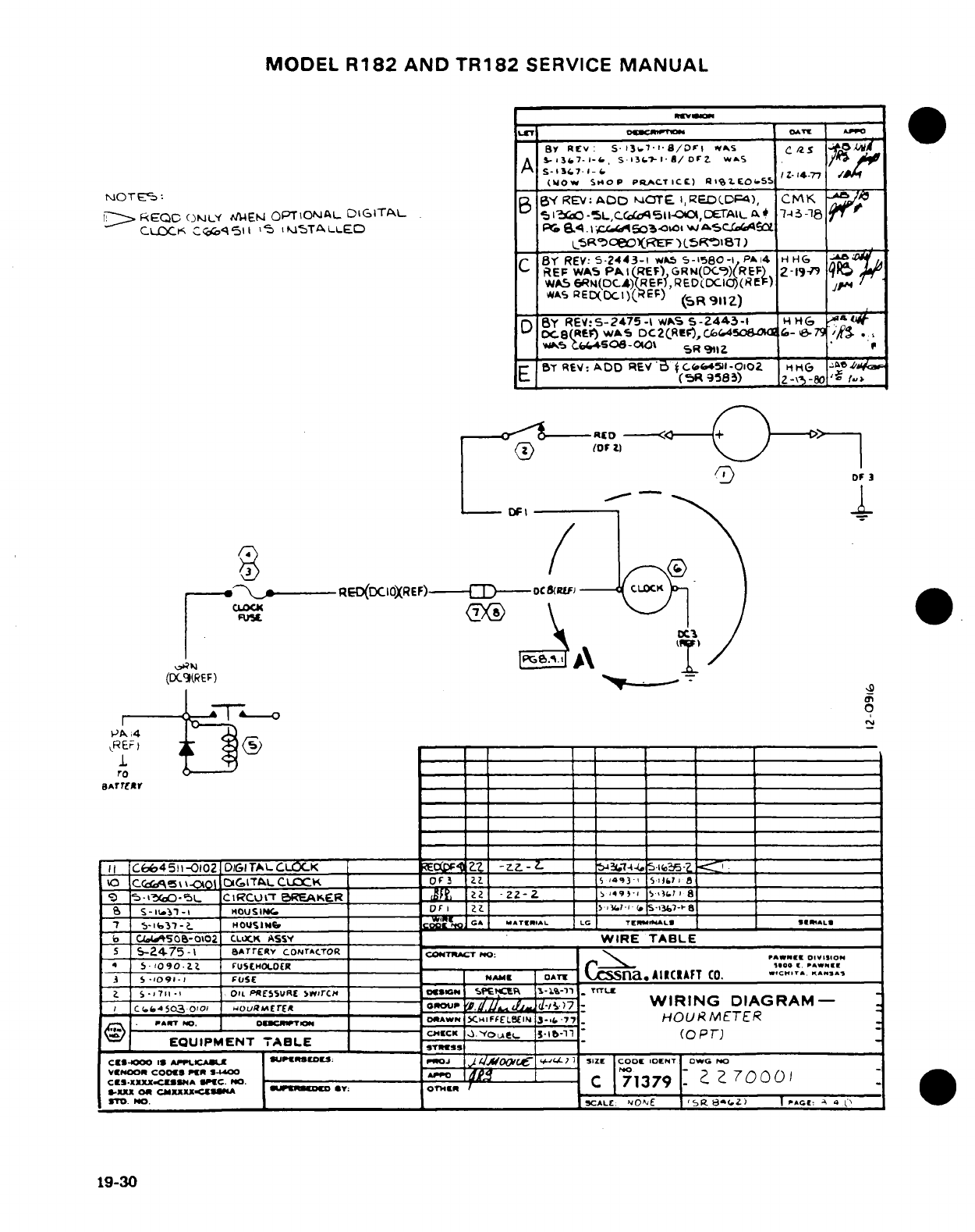
MODEL
R182
AND
TR182
SERVICE
MANUAL
urlr1.
1
o-l8l~
n.M"'
B
3tv7-
-
S-i3 l
5-1-a8/Drz
WAS
.
A
S
-7-1-
IZ--a/4rz
w
(WOW
SHOP
PIQACTIC
)
BR i
%.ECO.
55
^OTE-:
B
YREV:ADDO
OTE
l,RED(DF4),
CMK
A&
Ik
REQC
ONLY
M4ENW
OPTION
A L
-
DIGITAL
IC, I
-O-SL.,Cc5l-,DETAaI
.
714
:-18
r
CLOCK
Cr
o
511
ll
'
IKMSTALLED
P
&<l..1.503.
l
wAsc
_
s5R'tOeOREF
)
(.SR8)
___
_
C
B REV:
S-2443-1
wkS
5-1580-i1
P
A
4
H HG
REP
WAS
PkAI(REF)
GRI(DC-)(REF)
2-19-9
9
WAS
6RN(OC4)(REF
,RED(DCIC)(RE
)
;
/j
wAS
RED(DCc)(EF)
(SR911Z)
D
BY
REV:5-2475
-I
wS
5-2443
5-
HHG
DC8(
tF)
WAS
DC2(REf)0,Cr.4506,a,
cC-179
/, .
'
IK5
.i
t4.5S-:a-Ot
591R
'IZ
sT
REV:
ADD
REV'
(Ce45-01,02Ho
6
,z
(5R9
58)
2-8 -8V
.
-RD
---
I-
DF
3
DFI
\
/
X3
/
c'N\-"X
,_
RED(DCIOXREF)
)----D
oc
&U)
V? >A
RE
(DC
EF)
elrT___ 0___
Ir
C6o45i1-0102
DIGITALCLOCK
~ ](;)I:?_
.
-7.
-.-i
C0 rCi\ \ G-OIOt
DG16TALCL
CK
OF3
Z?
S
1493
)SI
L0
0
9
I5-{3
i-r L
CI
RCULtT
BREAKER
__ Iz
-
2Z2
Z
49'
=7 8 ____ __ __18
s-13'
-
I
H
OUSI
C.
oF
Z 1 _________1-1& (P
S.13,78
___
5!7 S I*31
N
e
H
OUS
9IC
Mr.
GA
ATIA
LG TLC
T
EL
r*A
L
S
!IALS
b
C.4A50b6-o02
CLCX.
ASS
Y
WIRE
TABLE
5
--
2475
-1 rATrERY
CONTACTOR
COT:lCTl
-
NTO;
O
4
S-
lO90g
Zz
FUStHOLOER
r
--
o
.00
Pw»
i
7 S
-.
091o-; I
FUSE
"
---
NAMAE
AT
CS
na
AIICIAFT
CO.
"C".,
".'A.
S
-
7n
11
OIL
PRESSURE
SwrC4H
0SSH
SSSt
-
TLP
_
TrrLT
I
C.o4503
0o'-I
OURErE
oouraErE
GROUP
..
d-1)7
-
WIRING
DIAGRAM
-
PART&
NO. uCOmcnsM--oe
OSAWN
XHIFFELBEIN
3-iS&
7
.
HOURMETER
VS
-- --
^-. I
-- -
^
--
c--
-
'OJICK
e
I
l-ib-1n
'
(OPTr
EQUIPMENT
TABLE
___
CYS-oo
1
S
_
I
XS
IO"D :
Jo0
0JtJ O1I _v
|
SIZE
cCOOl
OENT
CweG
NO
CSOO-XX COXX SINA
S1C.
NO.
79
ZZ
SXIXX
CO
CMXXXX.Cgu[A
uiBwr
*y:
OTHR
jOT.
1O.
SCALE:
NOAE
I
SR
8(.Z)
I
C:
^
4
l
'
19-30
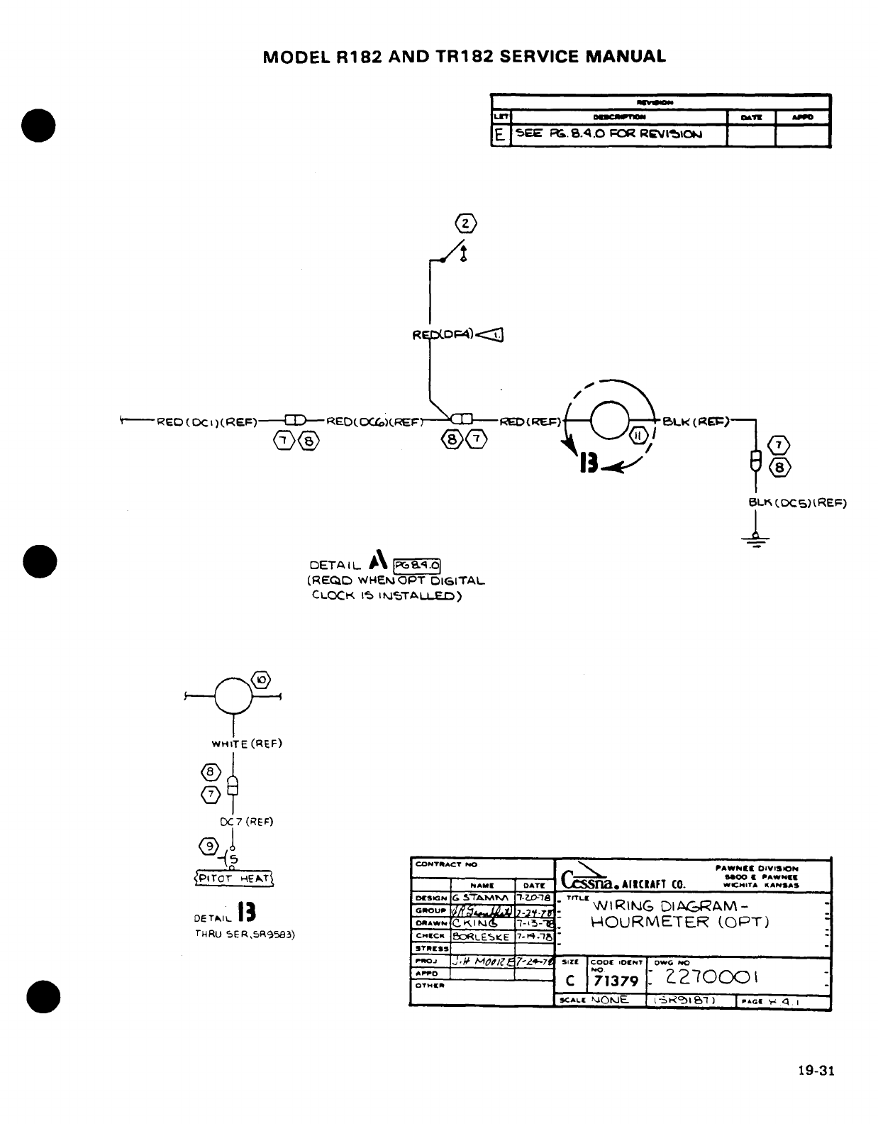
MODEL
R182
AND
TR182
SERVICE
MANUAL
IlZI
|clw"I Ima-u |
_
E
SEE
M.
8.4.0
FOR
REVIICOJ
R6
DCF4)
<-
---
REO
(DCi
)X
(REF)E
RED
OC()
F
D
(REF)
BLK(REF)-
BLI%
(DC)CREF)
DETA
I
L
\ 1P
.
CLOCK
15
It
STAI
FrLLED)
WHITE
(REF)
®
OC
7
(REF)
q-(5
__
CONfTRACT
NO PAWkttCI
01VISION
PEroT
NETA
DATE
ress
AIIRAFT
CO.
.CHTA
WAN^.s
DoeSN
G&
5TM>A
l-8
TrTLl,
DE|I13
~
,*5^3!
S v-
WlRi7G
DIA(ARAM-
DE
TA^IL
13
Eo,.,G.r
,
H-
OURMETER
(OPT)
THRU
5ER,5R9583)
CHrECK
BOcLES.E
7-.4.1
STRIE$S
_
,.,o.
J
M~
~o/7&
7-zt-s-,z
o,.0G 0
0
"'"°ER
^
C
713
79
?2'0o)oI
19-31
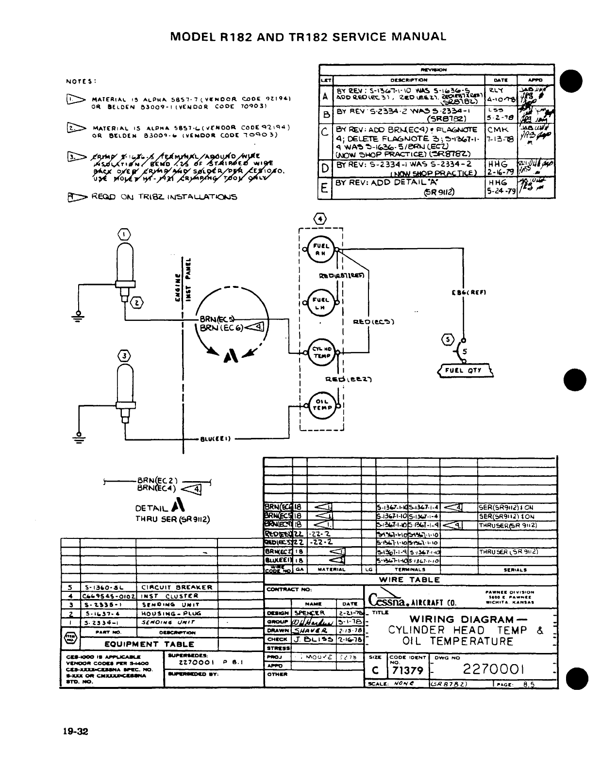
MODEL
R182
AND
TR182
SERVICE
MANUAL
NMOTES:
ESLSrT
D
iCRIPTIIMN
DATE
AP
MqD
_"
-
Du
:
S-
>
^-M-
\O
\
Jo
5-1i<»a_-&5
ze x
Xf
^
^
MATERIAL
I5
ALPHA
5
7--7
(VCENOOR
CO0E
9Z'I94)
A
WDO
ELeSE M-'3IS
SO
I
6P.S
,
5-p 5'
A->S0.
6
OR
BELDON
53009-1
(VENDOR
CODE
70903)
BY
j~
By
REV
.S- /.5.~-: W4
. .
Z3]-I LSt,
(SR8182)
5-
Z
-78
?@>[
MATERIAL
15
ALPIHA
5s857-.
(Vf
OOR
CODE2
1<
)
VA
EC<pL
CMK
'I
oR
BELDEN
3 9-
(
COR
EN
300-
vtDO
O
)
C
FLAoTO
C
;-i 7-I-a13
Ct
q W'
A-16SIoa,-
5/eRiJ
ECZ)
(3> /0t > teX-' ^^^^
L/A^duwo.^lrfC
_
(IAO^
5WP
PRACrICE-)
MR97gZ)
>
XrlN<gt>ID
*T
n F n r
liMC/
E wivg
BY
REV:
5-2334-1
WAS
S-Z334-2
HIG
4I-
l
it~pa*'CC
,
/AX pPAL)
2-i-79
.
<,r^^^xftyR aO9Y 9
/ /
.9LV BY
REV:
ADD
DETAIL'K
HHG
"
REQD
EQ
m
TRzj .M TAU^TLS
E
OR9112)
5-24
-9
(3
-- *' ---
BLU(C
E
-)
X _ If _ I I
icSsX RA r}
D
I
I
/
F9CL
QT7
.J
THRU
SE1R(R
i j3Pjj.jWRK-
)
SE-1Q-
B
CI-O
GA
dATEIIAL,
L
TIEi4INA
M.iL.
1A ~~~~~~~~~WIRE
T
_ABLE
4
C(O-IS--O-o
-.
B
i#r C LUSTER
(ENl)*
C...,IE
-
S
U NIT
N
ACAFT .
.. ..
~
DETA2l
_ \ 5RFJ(63 4 _ 5-liO7-I
GC51P3U7-1.4
~£R(5R'2)s
CFJ
I~THRU
ER
R914-2)
soEC~
18
oAJ
k_=-l-es
7l-1
WIRING
DIAGRAM92
:O
PART. MO
w
.
/
,
.,8 C. |CYLINDER
HEAD
-11 l.|
TRuEMP
&9)
C=\
__ __ 8_ =c
_7 1j
_
a
~
-/a-i,,
THRU
CiHECR 911-I
\ME
EOUIPMENT
TABLE
'
T_
OIL
TEMPERATURE
_99-1 II _ IUAPPN'E4EOIr:
PRoj
·
U
_ 7
g
-
£/'7
_
S17lE
COOE
rOENT
O-G
NO
5
S-13O-L
CICUIT
BREAKER
_ uc4
ZWIRE0-
-
o.oNo
4 CfcS5t-02.
Nonsr
C5rg
By:r
_
C_
7'
2270o1001
Z
So-ft
7-*
10VSl1f
-
P
mT
VC
10_-IN
SFtNMB.
i-
,
_
-
Ct-X.X1 CO4
P«
IO. Z-----
*
P-- C I7
1-
227000
1
!
.
NO.
S
CALTE; V/ODV-e
I.5878Z.)
I
PAGE
8.5
19-32
19-32
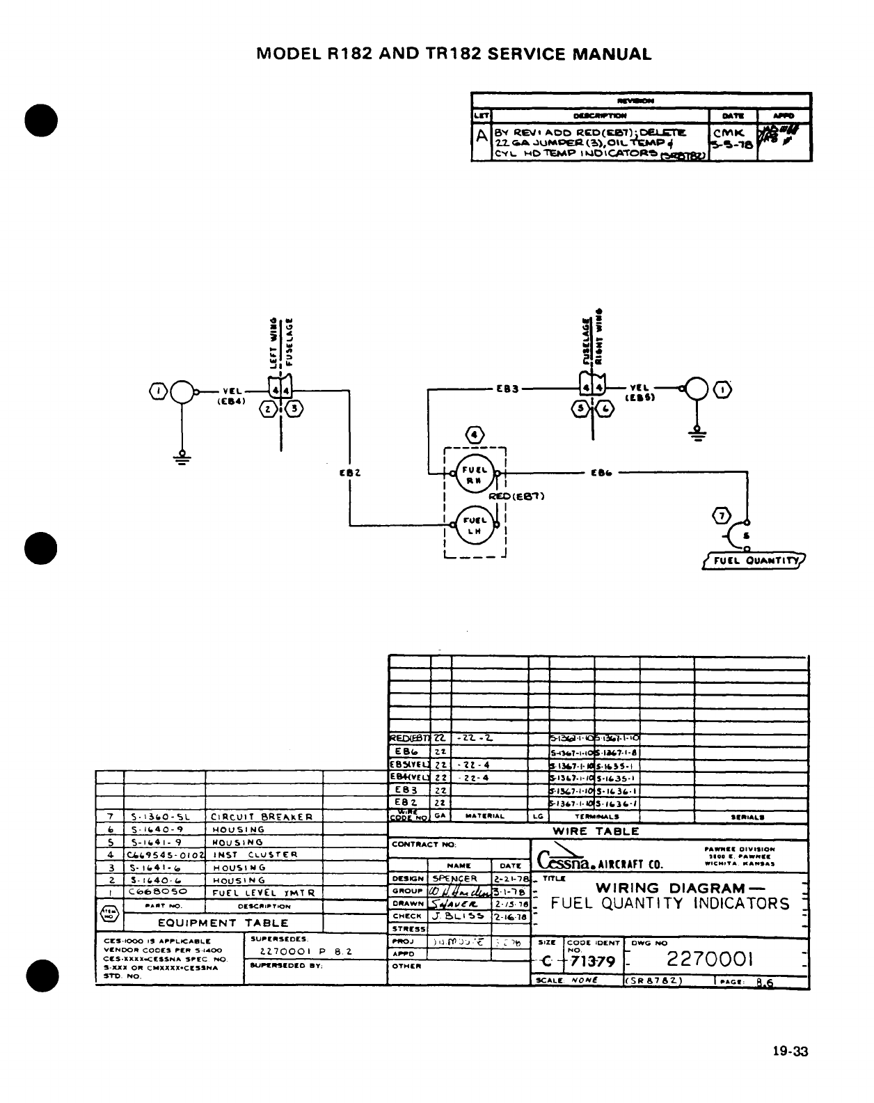
MODEL
R182
AND
TR182
SERVICE
MANUAL
LET
_
OCRTION
I
A
A
Bj
lQev
ADD
RCD(BET)
DELrl
CfK
A
2^
G2.
JUPMGe.R
(),0
T -AP
5--
v AO
CfL.
H:'TIEMP
ll4PtCATORt
LB
SI
VEL
83
vtL
I 11@ I
I
I
2
FL
_
ru
U
IED.EB
-:
2
2
- " ,
1.,"".
LO
ES_
EL
Z?
-2Z-4
I
7-I
S-
I
E4(VEL
Z2
-
Z-4
_ 13?7..1
-
IS-1&3S.I
E83
22
_
lY4,7-I
5.IO
1.
3.
1
EBZ
Z _-_-_
-
13-7-
-
I
'3-I3-I
7 I5-. 3 O-
SL
CIRCUIT
BRE"AKER
G
i
A MA"TERIAL LG
Tr
MnALS
S
E
IAL
(
S-
I40-9
HOUSING
_
WIRE
TABLE
C5- I 4i- 9
HOUSING
CONTRACT
NO:
P
4 C.4.9545-010
O
INST
CLUSTER
.
r
_.
'Aw"
_
C.66s050
FUEL
LEVEL
IHT
R
GRO.UP
a
.
3-
'-
WIRING DIAGRAM-
..
_ T
.0.
ODESCPT.O
DRAWN
S
Ai
2-
/'
.
FUEL
QUANTITY
INDICATORS
CHECK
J. I
-
.55
2-1.18
EQUIPMENT
TABLE_____
CIES·.0
NXX
APPLO
CArNLE
SUEDES
PrrO
)-
u-S
LjJ -4
.
Et
SIZE
CODE
IDENT
1OWC
NO
VENDOR
CODES
PER
S.-Oo
'"E
'DN
2
700N
O
82 01
WYO.______
_NO.__
ESCALE: NONU (lS(876 R
C
Z
i
P:
19-33
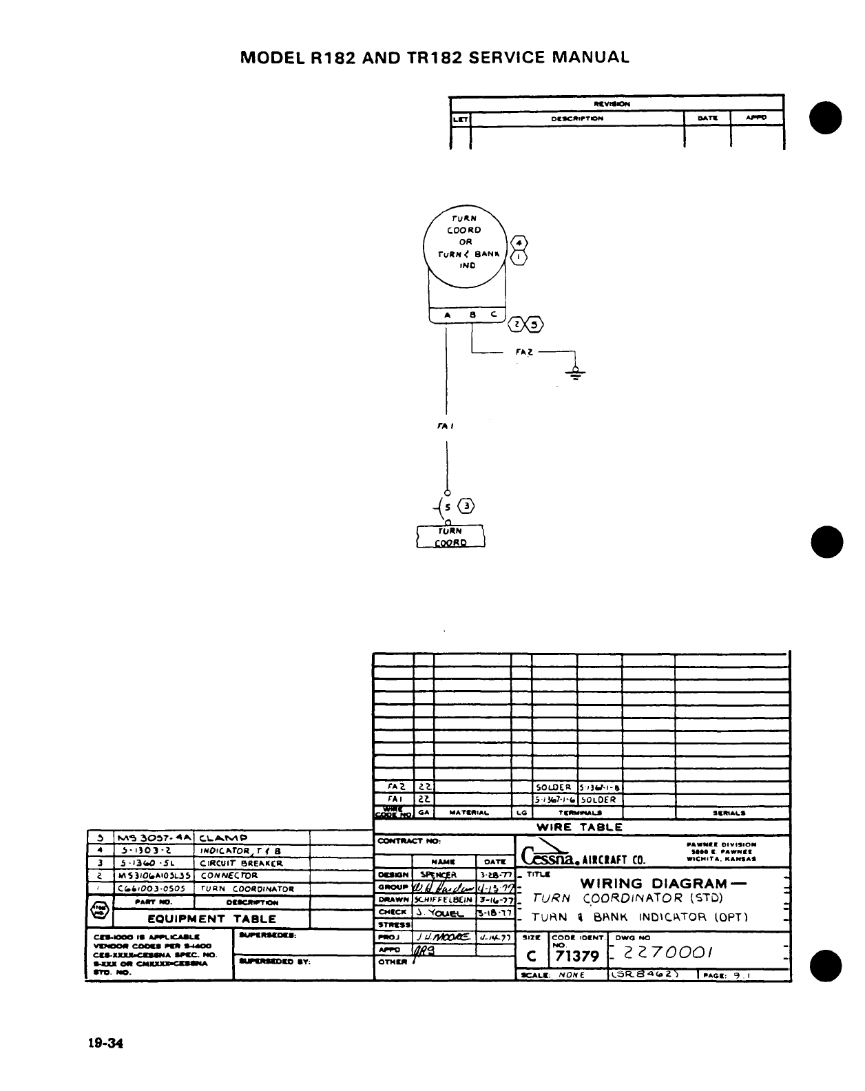
MODEL
R182
AND
TR182
SERVICE
MANUAL
JLET
10
gg^
1
\p 1
*~v~o~N
j~~T~jA~REISI*
.R
r
(.
'IN
VA. ?
.
SOLDER
5
l
'-l-
VAI 1-
53(.7-1-(.
5,LOER
I
A
MATERIAL
LG
TrNUMmALs
26h1SALS
___A____
WIRE
TABLE
MI
5
30?7.
4A.
CL.A.tiP
_C:
OTRACT
NO:--
PAWN-E
01----
4
'-1
i03)O i'o. ArORITpr 8 a "Go I[ PAWNEE
3
5-13o0
-5L
CIRCUIT
eREAKc
NAME--
___ N
OATE
AIRCAFT
CO.
WICH.TA.
KANSAS
I A /0OfeAI
OSL.S
CONNECrOR
I__
MIN
spNyl
3-t.-7
.
TITLE
(6.&,0oo3-oso5
ruaN
coooINATroR
GRoup
'.d
//.'-/l.
-
WIRING
DIAGRAM-
_-._o__-(.
FF.
7-K8-T7
TURN
COORDINATOR
(STD)
PANT
N
*-7
_ _ _ t
L
NSOaDE= 521P-E- _.
EQUIPMENT
TABLE
STutN
BPNK
INDlCTOR
(TOPT)
AL
cE-iCOC
1s
APV.LCAgu
LUPEB-O":
P"OJ
J
U//)ooXw
-
/-14oL
SIZE
CODE
GENT.
DWO
NO
4
S-X'.ClE-
A SPEC0
3
.
---
T 1B _ r2
?
7
0
4 CS310XCoLn
CONNECmR
N
go
3
K
_
TITU7
_379
O.
D
"
CAL:O.C
NONE
Re-a4(2)
I
AaE:
9
19-34
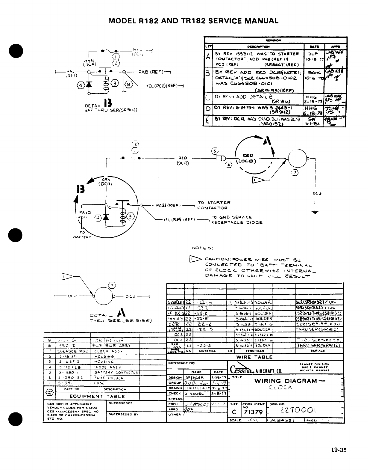
MODEL
R182
AND
TR182
SERVICE
MANUAL
R~YE(P2)I~F
T
-
IT -O
-
OT
IA
OE.A-IO13C
A
D
f
REV
155311
WASTO
STARTIER
HLt
1"S
,RO \,( :
CO7TACTOR'
ADD
PAS
(RE
r
)
10
1
177
[opC4)
\'
PCZ
(TEi)
(SR8*CZ)I(Rif)
(--
;4
---
T P-
-a(REF)-
B
Bv
Ev:
DD
jD C:_irl;
~.r.
/>X
1),
,R
I ^ /\ \t
oernlLA
c.
.
.,ci5,0so-oCoZ ,o-,.-'e f,
a)A
,(
3
<8YEL(PCZ)(6F)/
wAb
C^ 4'SOe
-OO1
133
~
Q
¥EL(PC2)iREF)--f
C
BY
Ri.,:
ADD
DE'3.Le
H.6
'ASdu
_Fr
THRU
SER(SR,112Z)
DBY
REV:
5-2475-1
WAS
5
2443-1
HH6
_
Bl
tmV
iCl
*AS
DCUO
0,
itmSA
O-r-
G
JWIl
*
vELb4(E
D
.-
_
S
-ERL e_
I RED-- \
D-C')
/
LR1
1I
---
I\
1} (DtclD
DC
J
<
E90
IYEL(;' 4 (RE F )
70
Oi,
_ND SRE RC ___IC
8ArrR
Y
NOT-,:
D>
cCAurToU):
caowLC
we£
VIT-T
C.QusJcCTEo
TO
"C
a)rr
~
er
w.*L
Ocr
CL-OC
c O _T- _ew_ _ Twlt. jT-k^
t T T r r I
T
Ir
____-A_^_ ^\ ___ '__(_22 -2ZZ
-
S-._l_-1.
50LUDER
P 52)
2,>
I_____ 2_5OIiL?
-_-CJ.^ 5C"£ e.E:
5
.;
9
)
:* ^
2E
-I2-5-
_
5_?,3 j0 mOLLER
[SR9%1)ToIUl5tIa0SZJ
g.y ZZ -Z2.-4_ _..?,-n.s 5lE:~~, '<.7~ Sc~e
_._ i^.
2.2
-Z
.
-WRU
5ER(CSR9Z2)
3_ I ____________
~
O
C_________0(
3
2 2 _
,5
, ,
?
,
, )
513
367
I
9
.
--.
;. 5-, _KTA\(_ O.l'D 5,)_ _
5-'l.»
i -> i.f.%
t
-
e
. -
~
e
z
.,O
6 :-_
z
-
C
a ASSY
,
22
-22-2
_ S
'1.36-I
SOLOR
__
THRUER(SRZ
o
SCoo a0SO-0102 C L O K A
___________
c 'OI
*A
MATlERIAL LG
TIErlMIALS
EIi»lALS
S
1
-
l37., 7SouSinG
=
=
WIRE
TABLE
5
5
i
37
Z
_I-OLISIIG__
CONTRACT
NO:
P
-RsE
DIVISIo
4
O
7707
7B
')ODOE
AS
S Y r_ lO
PA
DII
3
5- ,SBo i IA Arrtr
COhrc
roRa R
NAME
D
5ATE
SSna.»
AIRCIAFT
CO. IC.T
A.»S
S
%
090
-
i_
.
FUS. -OLO£R
E
DiSCN
|P$
(-R,
'',
-
7i-
1-7
TITLE
s-OS,
GI-
s
cROUP
0/JL/.i
Jd. 7
WIRING
DIAGRAM-
PRT
.
O
oDCRITION
DRAWN
5CIFFEFft
.,
7.
C CYO
..
1
EQUIPMENT
TABLE
STRESS
CES-IOOO
13
APPLICABLE SUPrRSEDES.
PROJ
,
/y//
l/
"
?J L SIZ
r
CODE
IDENT
OWG
NO
VENDOR
CODES
PER
A-1400 APPD t
NO
7.7
CES
XXXX.CESSNA SPEC
NO
C
7137
S-XXX OR
CMXXXX.CESSNA
I»UPIRSEDID
BY
OTHIER
~
STD
-NO.
I
SCALUr
'D
sE
|1(P~Z I
aX
)
1 :
19-35
19-35
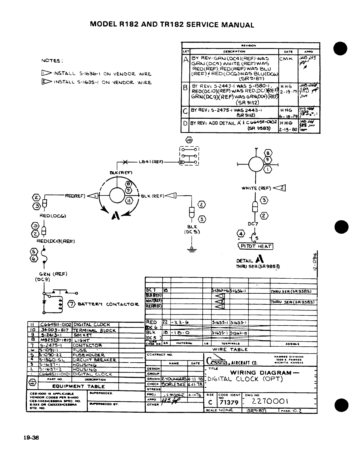
MODEL
R182
AND
TR182
SERVICE
MANUAL
olurtrlor I
Wv'0
I
LET
O
!CPCPTtN
AP^AT
*P
OE:
A
BY
REV:C
GRI
(X4)RE)
w
T
CMK
^~N~OT~ES ;~:
*(3GR.J
CDCq)
AU
iITE
(REF)Wrv
AS
RED(REF),
*EDLREF)
/WAS
BLLJ
,
>
INsrTALL
S-1636-
ON
vEIDO.
WIR.E.
CREF).
RED(OCC)WA-5
BLU(DC
;
g>
INSTALL
5-IG35
1
ON
(EkX5ORC
WIRE.
_
T
BY
REV:
5-2443-1
WAS
5-1580-1,
HG
RED(DCIO)(REF)WAS
RED
DCl)(EF
2-19
-73
n9
GRII(DC9)(REF)
WAS
GRNkDCE4
(REF
(SR
9112)
C
BY
REV:
5-2475-1
WAS
2443-1
H
HG
c _ ______ 05____R
9112)
6-
18-79
D
BY
REV:
ADD
DETAIL
A
*
C
4511t-OI02
H
H6
C,
(5R
953)
Z-,3-ao
.
^-
LB41
(EF)-°
\
LK
(R
m
/
I
wT
WHITE
(REF)
<
Z
b-RE~eE)
BL
(SEF)3-
I
REODOC_4)
Q\
DC7
SLL
RED(D
.CR;F)
L
«eDUX^^)
J.PITOT
HEATr
DETAIL
\
o
(TeN
IREF)
THRU
SER(&R985)
gN
R)
,
B TT_ EW
C
OTCFTO
THRU
5JR(-SR95-3)
;
t
$.,,55-ORE~5..1.3;
=-,
II
CC(64511-0102
DIGITAL
CLOCKED
2
--
__
_
_
I
10
3+003-817
TERMINAL
-LOCK
BLk
Ie
-
o
=
-
----
I----
sac
v
LK
--
Mt52-Z
g19
LG-r
C'
____ __ __-
t
.
-2475-1
COITaC'Ot
coo
TABL
____R_____L
4_
_
-o109I-
=SLi5E
WiRE
TABLE
5
-iOO-Z2
Fu,
O.OER.
C
'TlACFT
uo; NO:
DIs
S'3('O-~.. Cj~.Cu~',
?.rc.A,.EL
-.
C-~-.
1000!
aWN!!
Ts13-S0-
^
I.OU
--
,NAME
DATE| |-
C^ina.AIRCRAFT
CO.
.WC.
,
A ....
^S
L
5-131-2
.
NOLUs
NG
DESIGNC
.
TfTLru
L
Co45o11-o
-O10
1IT._ cc.
LOc
GROUP
WIRING
DIAGRAM-
__
_ __o_-
---
rWN
ZYouwei
4-
l_ l__
-0ZwNU-$
T
IsI
t
oiTAcL
CLOCK
(OPT)
EQUIPMENT
TABLE
~ OLt
£
4
IRESS
C-1000
IIS Ia'L.A"J UIslDlS:
ProJ
Aj. iPPLCAlO_
.,
I 1'E
CODE
IOENT
OWG
NO
,,,
J
,,,
x, Q0 ,,
¢,SIE, I
,
VENOOR
co
R
-
-O
-
7E
"
A
CZ.XXXX.CSNA
SPC.
Po.
-
-
O
C
71379
2270001
*-IUX
O
CMJCXXXX-CIA
mUIOlO
IT. OTHR
·
T.
O.
-
SCALE
OONE
I
se91l7
I|
^.c
10.
2
19-36
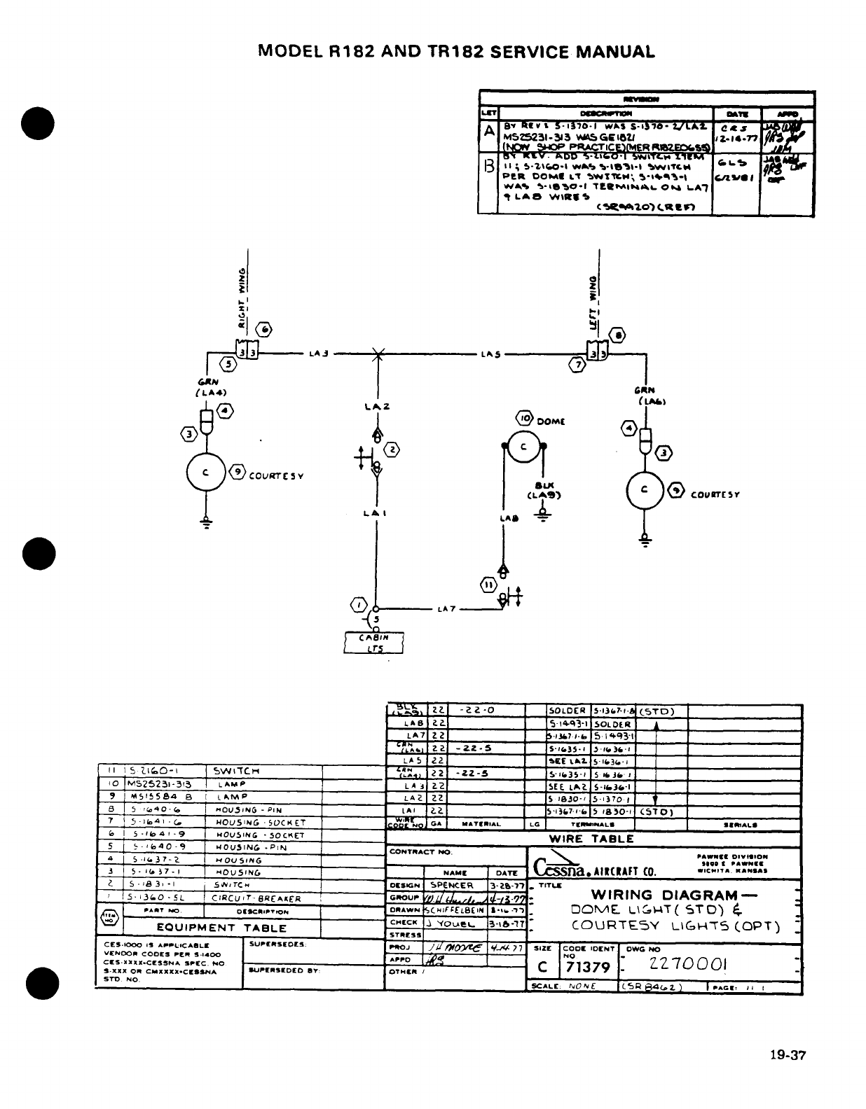
MODEL
R182
AND
TR182
SERVICE
MANUAL
uml
000Qown
UAVE
A
y
REv
I
5-1370-1
-
WAS
CS-I C0-
LA
.
MSZ5231-
33
WSAGEi5UI
i-Z.I
-77
(NON
,
ACt'~RWM60
a0
-,;
5-7\90b
WA%
sog. l- Lw
.
PER
OO« L-T
4W'ITt,*;
5'-1^*
-1
C6Vwel
WA^ 1-teO-l
Ttmtml*^-
Ol
LA^
t
LAa
W\l1Rg
Jr.*^io)
t It"
z
j
LAJ- LA5
GAN
(LA4)
'~I9) SLIC
o
T
2®~A
2
_
C5T_
i ZZk2.SS
I
~LAS
--
I_ _.
) 1
LA
II I S L16D-
X
SWIXCH
4RA7)
22
-ZZ-5
_.I'-51 I
|
5
40-
OUS
-
PN
LA
22
CO TCSV5
37
*
S
AI
E5O)
_
"LV,
'"'
.
SOL.ER
5-130?-.1
(.TD)
17 5-l41 -> I 1U5ij_. C-1 JA
MT
AL
LDE T
LS
RLS
1.fi~~ I S ~4 ~ 9
w~O~U~~SIN ~C"KLA17ET _ __.WIRE
TABLE31
*
I S ,I3 3
*
I S ~,
rc
H
DE5UN
SPENCER
13-a%-'r7
TITI
T
1 15.340
-5L
I
CIRCLJ:7BRAE^ER
GROUP
~hL/X8-
.q-/3-I77L
WIRING
DIAGRAM-
RLAN
CiL2
SE
|
ScvE
143 L.B
[
-:T
(
SIT
0)
4.
I0
ECMUIP523lN-33
T
IL AMP __
LA
C
j
CC
2
SEE._
-A
|
COURT__5Y
L
Z (-iFOPT)-
Ct9
S-S
55aa
aIS
LA_
Z
R Ar
I
D LAi
SCS i 1R3O-
5-
1
37
0
-
Ia
ix 40-o ~
Lou3ING
-
PIN
LAI
__
52l7-'I'7.15
1Y
aO-1
(/s.TO)
647 I
^*b4-
i OUO51MNG
*
OCKET
IA
cd"
o*
MT»»IAL
LG TIrCNIMMALS EI
«IAL
I
5-If>41,9
HOUSING
-SOCKET
_
WIRE
TABLE
5
S E
'
0'
OU1
.-
P.N,
CONTRACT
NOPAE.
:
,,
I
5
.(-l43]7-_
HOUSINmle
__________________
HO
1C'- AW»*
N9l9
19
5- ib
-
7-
.
NAME
DAu5
,
^
,, .
L
sAIRCRAFT
CO. .C.,TA. ANSA»I
Z S
3-
55-_-1
~ITC'
DEr_
SIGN
SPENCER
3-Z-7'7
.
TIT"l
I
-
53o-5L
CIRCU,'BeCAKEFB
GRouPU._r_
-~
WIRING
DIAGRAM-
X PART NO.
'
t9-
-----
O.DAWN
.
CHJF
FLBE
IN
ClO./E..
D0VE.
L,2T
(
STD')
.
CHECK
.~
'YC)LeoL-:3,b-.7T
COURT'~ly
'?GH' "(OPT)
EQUIPMENT
TABLE
SES
CES.IOOO
1i
APILICASLE
SUPCISE D S:
ISUOJ
EURSEDES
q--
77
SIZE
COOE
IDENT
OWG
NO
VCNDOI
COOD
ESA
SPEC.4-0
io
-
C
NO7
CIS-XXXCX.CESNA
C.
O
-
1379-
z 70001
*.-XXX
OR
C.XXHXX.ClNAL
WJPEISEDED
BY:
OTHER
/7137
'*s~~T oD NH~~~~O__________
_________ __
ISCALC:
,NONE
SR
C5
4.Z.
IPAG'r I,
19-37
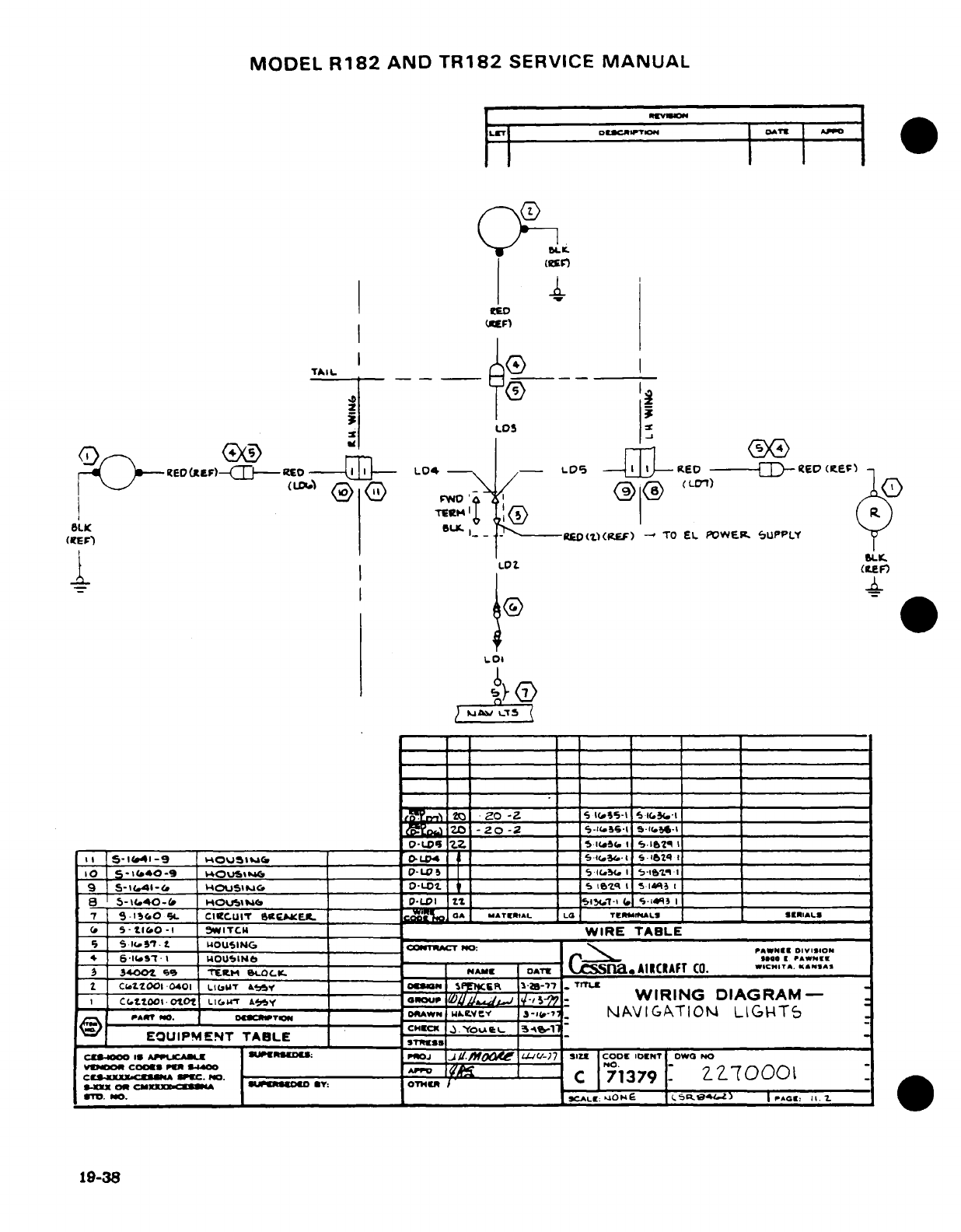
MODEL
R182
AND
TR182
SERVICE
MANUAL
LT
'
DCRIPTION
0I
(REV)
-I
OwL
LOS
--
KE!> ~
rED
(~E
rBLK
EURL
_1°'> ®
J
R
(ItE
)
L_._
-
-LO(lrt
(REF)
-
TO
EL
POWER.
3SUPPLY
_
-
SI.
LD(p
(
E"_
tI
o
~Lt)~----
~Lo
-1 I
5W
WIRE
-
a
TABLE
_____
9
S-I(.41
-9
t-
t
OU.IN.jC
LO'S- -q I I4_
_ _ _ _ _
_
=rrOH~~~$ ItI P
ccIAWNER
Ce
.'lo01
0401
LiWOUS"F-&
A&emps r
S
___
___[
T_-20
Z__
__5_
2SM O S
-E
-OC
iU
_o
8
S -Z
I
-
S- -PAR
N
OUF.
.
oD-L
W _ =L.Ve
__
-
3JAVIGTIO
LIGHT5
:1.
5
EQ
t0-UIPMENT
TABLE
11ml
C.S
'S
I...m.t
iUSINGl
.
j
W.cTO.:
..
,--
,-
wm
C
71379,-,
o
~* 6-H» ~ 1 t
~
Hz~OU~~luNt'O __
-e
s
o > I »,WNE
--
^ r^r ~ o v M7SA-----
E^
lw
3-04^-7
_u
1
A
I
T
I
O
L
I
&
H
T5
@
EQUIP-
ENT
TAELE
C
I
Y
t
O
^ ^ g
-
3-____________
_
_
-
ON
CMX:XS
A
0
C
I
OO
*Y:
OThEC
|
7
7
|
I
"
_ °
l
Sirr'.
Mo
__. _SALE: '^
O
£E
.5R
4, l I PAGEC 11. 2-
19-38
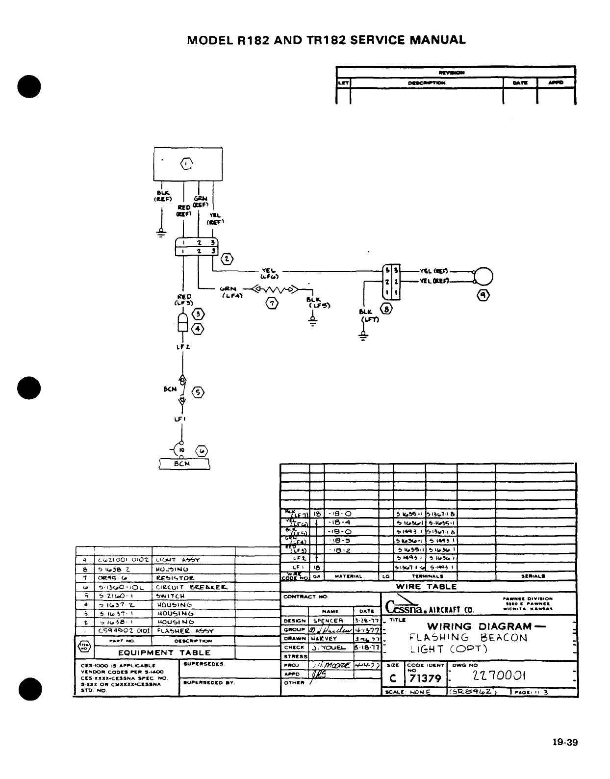
MODEL
R182
AND
TR182
SERVICE
MANUAL
(ILF)
G
I
I I (rL
LFI
I
(EO
(LF4',
Q
BLI
'~,, .(,,O',OL C.~,
'
eEkt._ E
...
WIRE
TABLE$4
.
_ 7 Zi(.0- I IIt
N
PAWN2E
O.V1_5ON
1
Ie')
'7 '
loc
a
*A.Nlr
,
s
L
5~
5'T-
t
t'[015
_t G
IlO0
KANSAS
f
)
nt iul4 1w
NAME
DNT[
AItCIAF
(0.
ws,
T-"&
.
BCtq4o oio
-,uA
O
w/U,..'7
WIRING
DQIAGRAM
0ErNOOR
CEOEIOfS
PE -1-
SAPPO
NO
CL
7 3 7
1OO
LbEUIPM WIEN
TABLE
~lr,
c
o o
l. -i.,o
A,..o
___l___
1
lO1
6
M
U
CRA
FI
(0.
--------- -------- --
11
9
-
3
9
__
c'<tl
O~l~iOT.
Lil0UT
W>Y
______b _
-________
-:_
__
-
-
--------
-
7. j ^r^
I(A58
I
WOUIer
I
D-
*T ('q4',02
040-
-Lo^b^E~. ~. __
oue
WIRING
DIAGRAM-
:
vENDOR
CODE
I
PER
5.1400
A_______________________
0
PO
(
71 77.
0
wTO
no
S_________________
JCALE
IMO0NE
(Sere
l
C.)
|
>»oi:
11
3
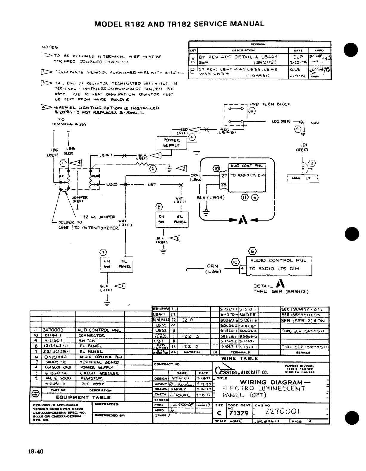
MODEL
R182
AND
TR182
SERVICE
MANUAL
revISION
QJOTE
LET
DESCRIPTION
OATE
APPO
i
TO
6.E
ZETi.4EC
.;
TEIE4RMINAL
vNIeE
MLT'
BE
BY
REV
ADD
ETAIL
A
,LB44
CLP
Z
TRIFpEcPC
ue-LEC
T*WISTED
A
s5e
(SR91
i2
2.tO79
'
^
-
rE
rEPrE F;E3H VwE e.
MODLE
r---- -1 FW TEIHM BL0OCK
y> >4<^E0
QL
U^TliC OPTrOI,
-
l|»^ D a-
/-\
_
o7R o
-
Po-
aeprkLcs
%
s9
OF
uTAM \rP/
TIE
(
e
I
_
A^y LD^2.
-EF)
-- I
/
\
t
lJUMPER
wu
BL<(LB44)
<H)
(
/
\1SUPPL I
1
i
LOS
LBB
-
(I(El:')
EF/
L
226^A4
J
0UP E
(L
EL
L
L
OL.DER
TO
TUO
5l
P»E
OL ;\
CAE
'TO
lOTE4NTOMETEl
-
.
(RE
l
_1__
I
I
BLX.H ;:L
-
---- (CEF)g6(
) .. ...
ZZ
jH Elpm
CH
EAUDI
L
el
Cl
ODETAIL
A\
4II
?4W0003
AUD
CO1TRfOL
PNL
_
LaB3
,-l'-0I
SO.OI.
THUIu
b[g
IbR5ESI)
I0 ,T7 1441 I
CON
NEThg._ ___T_.
_
.
-22-3
__
aESLB
B5
LT
DIO
LTS
_DIM
CRfF)
rHRU
SER
(SR9112)
4< i-2I(631
«)»<IiTLM
_
___~____
1! | | -_
153173°-I
|
___ (B
5
9 S\) _ i
5
I
,
30I9-I1
EL
=P&I _AIIL. W27N GA MATERIA1L L1 TES-IIASLOEl |S
SRSIIAON
_2
l n
z
o
_ 85969-6
51367-lS|
ISER
(SR9112)
EON
=L435
22l = ISOtDr
-aSEE
L17
11
2470003
AUD
CC0rTROL
PNL
LO31
s
_5 -I
O
I
SOc'ork
ITIRU
SERR
ISR'4SI?
10
.57144
1
CONlTOR
r
l
-22-3
_,ES4L
8594|
S
-
EL
KNEL *7 7- _
s-17-
5-13)0-
(a
53?'00442.
MOL10O
CJ4TEOL
PNLL
WIRE
TABLE
_S
3O4Z *%
E-t5 -AEPFIML
5----
CONrit
ACT
NO--: r^R
DV.,,O
4
CtI,0)Ul
OIq
04E01
9UPR
I
we. t ____ r__
5
6
150LO-
L
CICUIT
ERLE e I
NAME
L
DAT
.
AIRCRAFT
CO.
wICHTA
KANA,
'2
VAL
6
000
gEI£lTOt.L
OON|
SPNCER
13-.a-7
_
TITEU
S
,.l
,PIT
A'
GROUP
i J,
-
i-
7-
WIRING
DIAGRAM-
-
PART
W. DC,.
.DR.AWN
jAVtw
Y
^S-C.-7
-.
ELECTRO
LLIUIME5-CET
:
EQUIPMENT
TABLE
CHC
PA
L (OPT)ST
CES-1000
AtPuCAUL
t
POJ
|
J
//.1 a/O |JF17j |
SIZE
CODE
IOENT
OWO
NO
VENOOt
COOs.
PER
-00
N0. 0A1r
-
7
_
CS
-.
XXXX.C
SS-A
OPC.
PO.
7
C
13
79
S-xxl
on
CMXXX=-.CUEMSA
MIJSUDEO
my:
OTHERI
11C.
NO.
| 9CAL:
OI-
|S- 4*(4Z
.)
PI 'AG
4
19-40
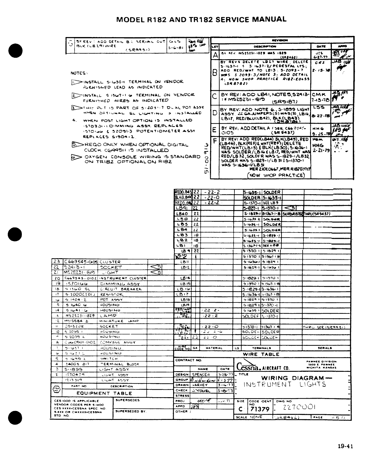
MODEL
R182
AND
TR182
SERVICE
MANUAL
ST
Z tLv
*
AOO
OET
a OC CR..i
LI
OuT
|G-'
Cdl |1_
*I
.L<
(l-Bsll/vlBE
„,
(
A *:"' M5252O1AY "W 1n 5
125
J'
By
RaivS
DEoccrE
LO.1
WIE
DL:
OLTCE
JA
S-i--1 «
.5
sJ37 -l./PCDCSrAr
LrS
n
ADD
RID/WMT rO
Lei3
'.
5-03-7 S-
iNOTEtS:
D
WiS
$
?Zo
3/more
3, ADDOO
DErT
4-
NOw
5#OlP
PRACrICE
q10dt-lO&5
plEIST
LL
5.1
·
r-.
7TEKtMINAL
ON
VEN0O
.tc^782)
F;uLNi',s
D
LEAD
AS
iNDtCA.T
[D
VIN4TALOL
S
11-1
-l
TERMINAL
ON
'EtNV'PO.
C
3Y
REV:
AOO
6B
14
,N
NOTE5,5Z^l3-
CMK
po/
FUt.LHSEc
AliEnS
S*>
1OICKA)TED
IA
*
cAE5V
I I
-1'Sl
5sR»»6 7
-151
84
r
J 4I->T"W
P-T
,5
PWA.T
CF
5*-Zo-)7
D-x
-
07
AL5
BY
REV:
ADD
NOTE
(.,
5->
i59
LIHT
L
J^.MH
ST-^«N.«.
F_
I
,NU
,
i,7Tt^D
D
A55Y
2^AU«PFTtPSV9^*(a
Llh
BZZ
rs
e
4.
WH13'J
P05T
L>I1,T
OPT101
15
lA5-^LtO
LBI.,
RELD/BLUC(LBZ, B-'(LB
'Sm'101~-10'
la.
"~ ,JLPL
5I701,.
5MM0Ia-3
POnTC.
'L E-PA.
E
BY
REV
ADDCDETAILA
1
bL
C66--'-
I.HC
I6'
,70'@-./
f,
5Z0S\-3
EPiOTEKOMEAS«.
C
,0105
(S9 43
7)
9'
7
^
LB46),
BLK(REF)
L
wmr(R'eF);
DELETEr
H
RE.Pt^
L
S«°0«
-W.
F
BY
REV
ADOD
REDt-B44)
BL-K(L4S),RED
^;
,
M*
gIR>EQO
OrL'"
WtEN
OPTIONAL
OIGITAL
9 REDH4T(1)BL HHK
'A-
1
CLOCK
C('451.l
L5
M5TAL._.C"
R./w*HT(.L~,)i
BLIK(LbC));5-.Vo~1
-IA;
CLOCK CQ II5
I-S
ISTALLED
"
WAS
SOLDER/LI(L1i7,
REVD/wT
WJS
L-L21-79
_>
OXYGCEN
CONSOLE
wvI\RtG
'5
5TA.ODARD
o
RED/LB32,SOLDFRWA
5;-I829-I/LB32,
ON
TR182
OPTIONAL
OJ
RIZ8
0
$OLDOR
WAS
5-1829-I/LB
It
31-1370-1
WAS
5-
I&f3-1/LB-S5
MER
ZIEOb6,7,MER
Rl8E2Ecr7
Uw _
(
'NOWJ
tHOP
PRaCTICE)
ED(LB4522
-22-2
5-5-
5OLDER
BLK(
221
-22-0
1
ODER
5-*35-1
ED(l4B
22
--
2-2
I
5-ii370-1
,EEL69
LP13q
a
.l7*
_ _-_ _
5__-_510-1
_
LB&O
21z ___ S-I8t_
-
13tS77-sla
SERteAg
ITHRu(sR9437)
L
P8
22
I
__
5.UiS.
SOR
_
LB5
22 ____ _ Ss-l
SOL.DR
____
L
B4
Z2
____ _
ZiS
OLDCR
___
8_
=____ 5-1 ____ __1__1_
LBl 1 '16 I .1 u10 'z I
--
sI
2
3
IC669545-OiO51
CLU7TER
I
_
LBII
I
| |
4S l1B V5 lt 1I __ __
2Z
IBZqI3-1
I
CCKET
_ IC51 L1
I
lb
'LBII
_____
iSq-i5L
I_ __
ZA fAzzi-
Sq
:GHT
___
__"_"
____
_;G
20
C.44954S.-
Iozi
ZNSrRuMENT
CLUSTCR
_____
Lll4-
|
b-l8Z9-l
|
51
- I
19
|,'701 s
j I IMI _ _L, i) i
5(1.-
1
:
|
__I_ I___l
17
'is C
OSL
|c:
LUII
B.EOKE-k.
LeB
I ~
15Ile2s
-Ils- -i ____ __
|i
2000CZ~01J
i"eEs'l,
L
|b 1 |
15
f
O-1 31L'
1
,
I<-AC4
-
2
| FPOT ,l6b
f''
l
|
\t I
1510
I
I 1( 404
I
.
OJ40UINL,
L|
,q
I
5-37C
-I
14
1 I41
-C |
UO LINO
22
2,1
I
SOLDER
_ _ __5-'370
I I~__
2ISZc2-18Z9
|
L
A.r\P-
-M22- __
bOLDEtF
1-1370-1
____
|
2S|i05
Z
a
II:
SOC.
K
ET
Z2 -o
1
-1310-1l
71i1
4 _____
-u
Sf
5
q5i
10
1Z
O-Z,
iUIluiNC,_
-C
I
5
i.
-I _
I50LDE
50IOEI__ __
-'
'Z
o s
L
I U 0 2
Hu
I,=
0e__
I
cx
-____-
O
I
IcEIE-_
l
I
|* t
@ IrOUS_ c __ j Of O. MATGRIAf
L
.
LG
TERINAL-S
SEPrIA lLS
i
U_
I
e | I
|0U L
WIRE
TABLE
I- S I
--
tc-
I--W----
I
CONTRACT
NO
.
PAWCNE
OIVISON
4 '14003
*311
I
-EMN
L
57^.K
1_ ,.0W
Io I HIl
3-
S-8699
LIGCT
,55Y
NAME
DATE
LSna.
AIICIAFT
CO.
ASAT
""S
1
11104-74
'
WiWT
i..
eY
7
DECS'N
SPENCER
-2%-77
-_
TITLL
-I'-
I5Tiq
I L|IW7I Y-b--
o
I7~
J
7^- _
=
_
WIRING
DIAGRAM-
7
PArT
xO |
DESCRIPTION
DORAWN |
L2REY
3*-i-,
71 IN- I UMENT
L
C-H-T
S
DoCHECK AU,
Ifr.r..
EQUIPMENT
TABLE
SE
____
____
CES
1000
IS
APPLICABLE
SUPERSEDES
PROJ
C
4¢
f
r
T n4
SzIE
CODE
iDENT OWG
NO
VENDOR
CODES
PER
5.1400
AP-
D
I
NO
-
CESXIXX.-CESSNA
SPEO
C
N71379 L
S-XXX
0R
CMXXXXX.CESSNA
SUPERSEDED
BY.
OTHER
I
ITO
NO.______
SCALE
qO NE
I
4
L)
I G 11
C
19-41
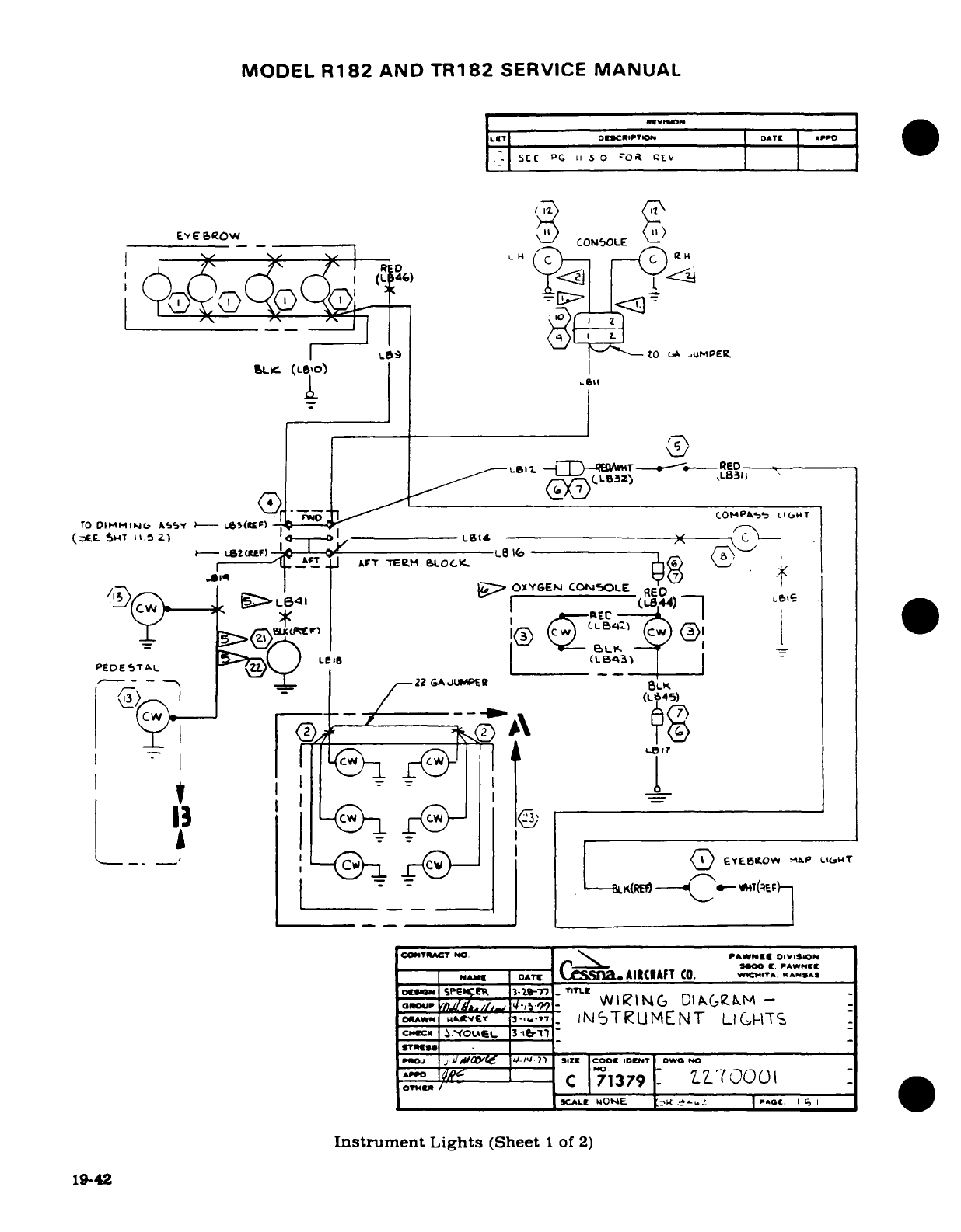
MODEL
R182
AND
TR182
SERVICE
MANUAL
LET
T
OSCIwTllO
DATE
& ·
PPO
SEE
PG
11
5
0
rOi
[EV
EYE
BROW
CONO5LE
IL59
P
tO
LA
uMPEIe
SL.c (L0o)
LSI.
-
--
I -T
---
RED
--
r P*'4O
COOMPAb,
L.IHT
rO
DIMrMIjNc
A^S'
--
L6(
CF)
(AF- S".F
I%.,%
tf
*-HT
11 v---I
/I,
i-
LSCRF)
LB
16
,1~~~43*
AFT
TEE"M
B
EI
0C
I&,__~\ C(~-'). {, >
OXYGEN
CON5OLE
RE
/^^)--,, gLe l R--
f \)
-
.'
5---;
-
c^ J iF ^-22
GA(iJUPE
R4B
I- I ~C
I
_ _e_
_
CONTmAT
NO
PAWNE
O(LVII)
1N
NAME
oD
ATE
Nn
AIACIAFT
CO.
WIC.ITA.
KANSAS
r-
.
r3-2.~- t
.
'IT Br
,,. .ki*,,
,-,17
lNjTiUMENT
LIG
-rvTS
L .'OLA_
3.i
erl
paJ
j iJ A
' -
ZE
COO -DENT
OWC NO
_
=_
,
N Ko
l(?EF
OeOA
SP
IZEF
3-ia7.7
TTLL
oS^r
ZnY./42A/_
1-iw
_
WIRING
DIAGRIM
-
otrtAH^tVteYr
3.T,7
INSTRUMENT
LI
GCHTS
ATo-
CC 71379 t
IZT000I
_SCALE
UONE
'I- 1
I P«Gt.:
I C,
I
Instrument
Lights
(Sheet
1
of
2)
19-42
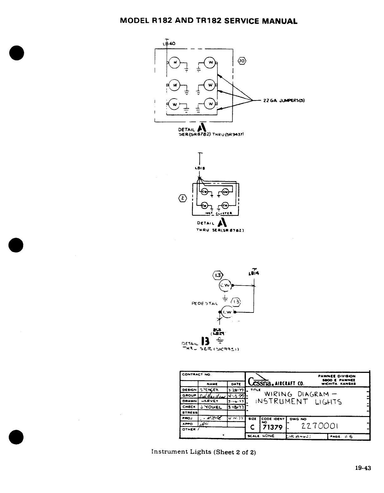
MODEL
R182 AND
TR182
SERVICE
MANUAL
L
40
,
,'1
.
I ./*-- /; 3^--22
GA
JUPERS(5)
DETAIL
A
aER(sR6782)
THRu
R
9437)
r
1-
LBI
_
LQ
±L
J
IL
THRU
SER(5sR8762)
(LBZ9'
CONTRACT
NO.
PAWN'[
O"VISION
sew00·
PAWNEE
NAME
DATE
,,AIUICAFT
CO.
WCHITA
KANSAS
PE0SGN TLE
ER
T
DRAWN
....
JEY
-,,.-7
TNSTIUMENT
LVGH]%
1
-
COTRSSACO PAW1I OVIO
IN4AMI
DATI
aCs.na»c(ll
iAFT
CO.
*cM.TA
^^"s*,
Instrument
Lights
(Sheet
2
of
2)tL
C=A-our s?,zR
J,-2E
_
,
WIRING
DIGRKM
-
o*^,.
utr
, - .7-^7
INSTRUMENT
LI
Gt5S
~
OTRe/s
ZYO?_EL
3
Iin_
_
rWOJ
i_
·'
^'lf U W/ 1 1
5IZZ
CODZ
IOINT
DWC
NO
oTJ^Z
;
C
71379
70
I
,^
.
____ 5cAHL
HONE
,CRtA L8C» |l
|
1
j
Instrument
Lights
(Sheet
2
of
2)
19-43
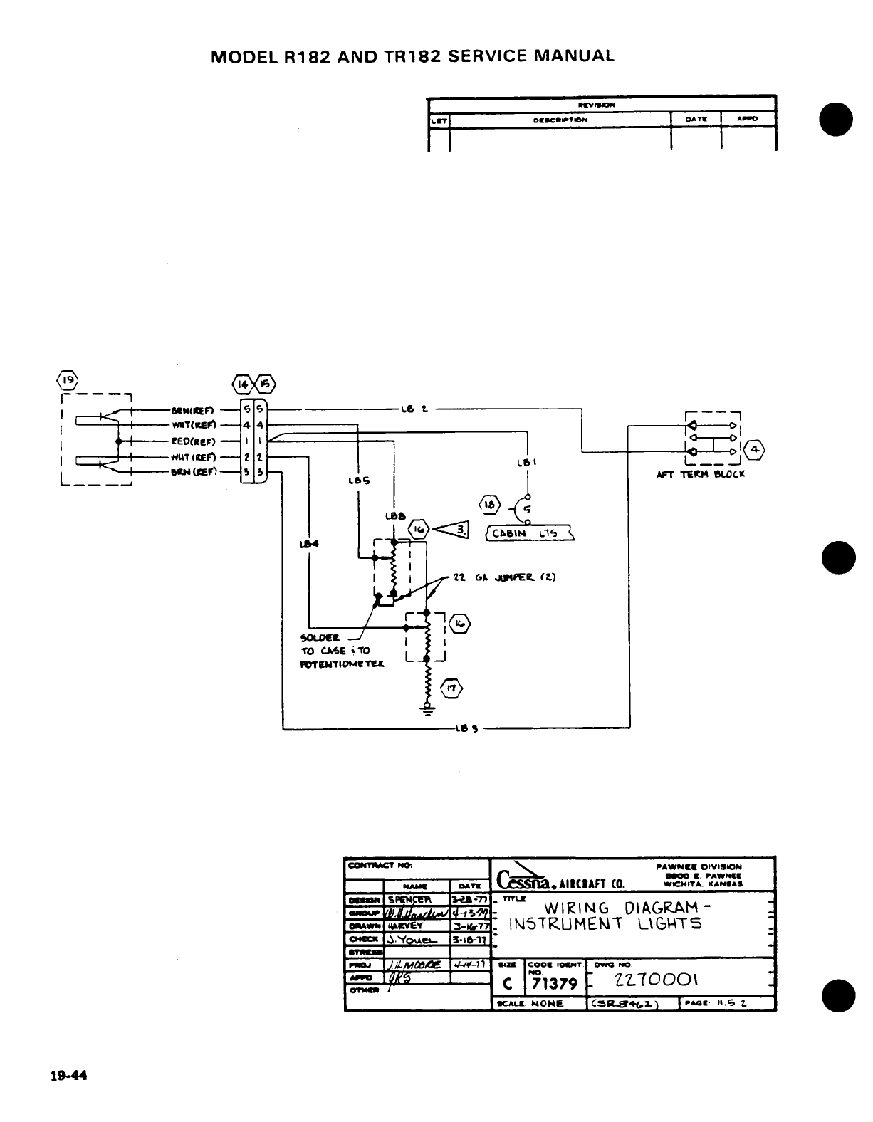
MODEL
R182
AND
TR182
SERVICE
MANUAL
iLiT __ Dg[IKcrTTOM OATYT APP
4
| ED(RteF)-l o
_
-
rj1
L
L______
---
vE&-T
No.
PAWNEi
VI
-SION
A,,
CATE
AIICIRAFT
CO.
WCITA.
KANGA|
W
N
TUACT
^ N'','
PAW,'E-
.IVIS.ON
..-
C_________ f
if.
PAWN?_
O
M
0*
SnaACAFT
CO. wiA.
KN»A
QF
BBAKW
=-15-22
WIRING
DIAGRAM-
DRAW
v
AtRVEY
3-&7:-
IN5TRUMEMCT
UG
TSE
____
'l'-77
-n
coo.
0o6t
owc
NO
_
#
C
7C
71379
:
UL
70001
__ ____ ____
CALI
MOME
C
'Z.
)
I
PA41:
II.G
1t.
19-44
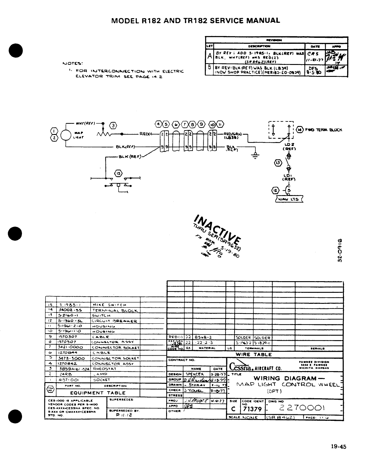
MODEL
R182
AND
TR182
SERVICE
MANUAL
LIT
0DIm
T
'
N| DATN Aol
BY
REV
ADO
5-1985-1i
BLK(RCr)
WAS
CRS
Af
BLK.
wwr(Rf)
wAS
RD(2
)
h
PO
J
TE
'
_
(5-8-
--
4,Z)-f0
(,( r) 0
-;
B
BY
REV:BL.REF')
WkS
BLK
(L83Y)
DFS
*J.
f
I
VOR
i»jT6OMM£T>OM
WlIT
ELE£C5TRC
INOV
ShOP
:PRCTICE)(MERI2-£0
-l29)
8-5-0
ELEVATOR
TRI.M
SEE
C.&C. 14
2.
-4.
.-
^rwn^ r^: ADOj
(c>)
(0 1F
-'l
®
(E:,G
®(Z~®/ 11 ,~
w
2U..
¥8
""'
II I I t1-S
LK
(RF-
,F
*,
1<5 59 I
MIKE
Sw7rC_
5.i934
0
0Z -5 S 1 ---- 1 3
-
-_ _ _ _ ___
P7 .341-OO~OC C..~jA.hLTO
o.b GA,
"ATR'.AL
., T
12_
-l705A4
CI
RC
____
WIRE
TABLE
1
385-19<A-I
5-iA
R"tEOSrT
NAME DATE
na.
AIRCRAFT
CO.-
.
_
z
2-4
1
GAMP
DESIGN
S
-P
l
-
3-O9-v
-
TITLE
4157-'00
OCt ____________O__ _____WIRING
DIAGRAM
a
1570507
___
Cosmt~wi-o-.
22^5 ;1 -22
.-
5
_
s5i*
s-iay»-2 1%-1-
7
3421-000
CO
EO. kRLA.Wt_.T _l.a_ w4:_.
C, GQ A L&TEK CTNRIOAL«
L
T(.Ii
C.ON
R [
R.1L«
EQUP MIZ7 ET
TCaBL
~
cCHWIREC TABLE
C
.
3473
-
sC AOO
Co.SUPERSEDES.
PRT
SIZE
o
CONTRACT
NOW
N
No
1270C4OOK
COSX-OR
LCSf
I
F
,*"X
4157-001
SOCXKET
OitOUP
oil
/^it1-#i9
-
WIRING
DIAGRAM-
",,.T
.
o,^Co.T,-N
O--
WN,_.STO"6.
-": ?;.
MAP
LIE~'T
CONTROL
W[._:.
CESXIODO S
ArPLl.CABLf
5Ur
DEDS:
PCOJ
,i
U.A1laZ
i
-7
SIZC
CODl
IONT
DW
379
VENDOR
CODE
PER -14OP
(IO,
5.-.
-
?
,
7rN,-\
,-\
1-1
\
CE-XXXXCESNASPEC.
NO
-
,
-
C
71379
-
c
7
0
S.XXX
On
CMXXXX.CFSSNA
IUPLIEAEDED
BY.
OTHER
/
ST'.
NO
P
.
1i
2
_
ALE
kO
c
E:
$
8 a
e
I
Z
)
|I
.
r
-
I
..
SCALE
'
.E
P
GE
19-45
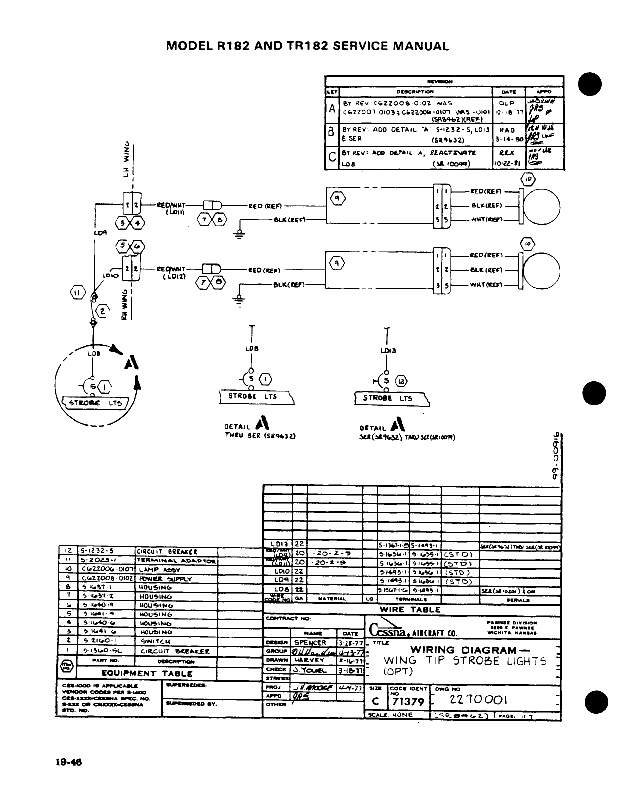
MODEL
R182
AND
TR182
SERVICE
MANUAL
~~grl NE CZJREVISO
LST
OESCRIPTION
DATE APPT
W
A_ eY
t6v
CfZzoo
OtOZ
as
OLP
S
A
c.zzoo7
010o3;C.ZL0CX-oCoz
,
5-,,o
10
l6
17
,
B
BY
REV ADO
DETAIL
A,
S-3123Z-
,
LOI13
RAO
M
lF
_
SER
(SRb,32)
3-1*4-S80
_
ZC |c C,,,,:.,~ 0Leby
RET.v:
ACO
OLrTIL
A,;
eLAC.TZ.AT
eL
? i-oas~~~~~~~~~
_____~LDJ
oA
too")
10-Zz-1f
IE~tITRE
IL~f) RED=t
i
SU(ItEr)
_
F)
i-'-mo
.
rLmET-(F---o.] t
2
LK(.KP)
.
..
f
Yr T^- -
-----
' z
-
if
)B
T
T
~LT
7T
LDL
(X
E~A
s
A
--
/
(I
I
_ I
DETAILI
rIAIL
fl4RU
SEE
(sBqk3z)
W*(519."
TMra (Si0tWr',)
2z
S-1232-5
CIRCUIT
EAKXCL I___
L
to -t20- Z
-
7 Z 1
315?to
5-11.
-
ST)
_____CO|
_
5-20i3-i
t«RH8^^ »ovtC_______ _D
Zn
.20Oa
-9 2 I05 (.14
5
iVI
CST
____"
o1
CC2.00oo
-oi00o
LAMP
AfY
___
LDIO
___ZZ_ _
i4qI-'
l4.i
(STD)
q
cC.zt2oos
oio0
owelt
-,UPLy
_
LOq
2
____ _ s
1451
IC.5
-l
(STD)
a
s
.51 -1
wUOUSING
_
LOba
l.
I
_
HT-i-.
s
.Iq- I
(SLa,
(a
o,)
4o
1
S
1
i5 T.1 I4OU5Ilh
S
146 MAoITERuIAL LO
TEI
R
A
LS
._
_*JL.
7
_41wi.a____________WR TE SLERIALS
-
_
ll+o
.44 I
0U
5,I _V
7
WIRE
TABLE
---
51.41.4
b--
---
~
b
--
-----
-
-------
---
TNTM
NO
: _ PaWner
DIVI!ION
S
5
11.40
__ S40
L5.6
C
w
*w
4
s
i,4
.l I<
Ol.1
NAME DATE
O
C
a.
AIRCIAFT
CO.
^C.-
,
< A.
ASAS
Z
S
21iC0
e
wl'tC4
OlD0aN
SPre
CER
3-21g-7
.
TITLE
I
tI,15.o.
cL
LI.UIT
ebSCEAKet
nGou
e-
WIRING
DIAGRAM-
PAT
NO.
o.SCNoPTN.- DlRAWN
uv
l-.-VEY
WVING
TIP
5TROBE
LIGHIT5
EQUIPMENT TABLE
A..
|-
i1
(OPT)
STRIKESS
____EN
AE__________________________
CE11100O
IS
APPUCASI
mecca:
PROJ
j
coc.a
.7) SIZE
cooE
'DNT
DINO
____
VmoO0,
c00048
pan
<
1*00
-
iz
70
001
0rI. NO.
_
I
B
_ __Y_:
SUPEROTSEEOE b L
P
.9-4
^6
:
ONE
6,e
-CZ
I
PACG:
1
19-46
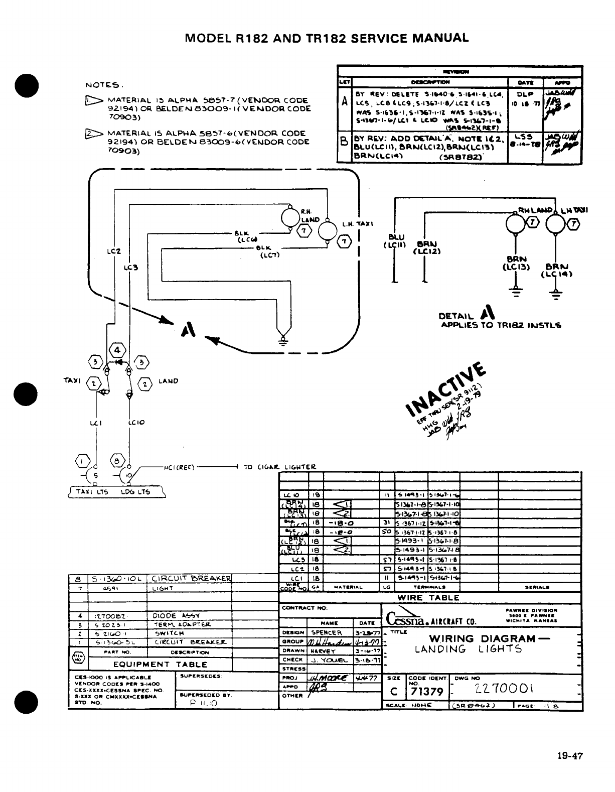
MODEL
R182
AND
TR182
SERVICE
MANUAL
NOTES.
L_-
&PM-
BY
EV:
DELETE
S-lfW40
S.-141-
.LC4
LP
dlM
D
MATERIAL
I
ALLPHA
58E57-7
(VENDOR
CODE
A
LCS,
LCS
LC
9;
-1361-I
8/LCZ
4
LC3
10
77
/Jo
92194)
O1R
BELDEr,
83009-
(
V
EDOR
CODE
SCIW,.IW
S
*S-A;
/C~~~~~~aOS ~~ ~ ~w)
S$S»<-l-I/CI
,.
t-tI1
WAIS
$-IC%-l-
,
70903)
>
MATERIAL
15
ALPWA
5857-6(VENOOR,
CODE
(5
92194)
OR
BELDEfs
83009-6(VE1DORR
CODE
BY RE.V:
DD
CXETAIL',
'ANOT
I
*.
Z,
5
70903)
BLULC
II),
bRJ(LCI2
),5RS(LC3'
.
r
BRJ(LCI14)
(SRBT2)'
I
SWI
l._ I
-
RMLAb
wJI
MI
LAUD
L.H
AXL
'M
TAX
'T
L
(L
KC (|BN
/I
LC2 (LC'7)
9L
L)
:RkkN
~~~~~LCZ
~
IcS 6u(LCIZ)
LC3
[
(C15)
B
tp
_^^~ ~~~~I IT----
OETA»IL
A
_A-'~ ^\~ A~ IAPPLIES
TO
TRI82
IJSTLS
.3 r
_
000
TAv
0
LAND
LLUI
LCIO
0*
''
-,(
C
Ci(RE
r)---
TO
CIGKC.
L16WTER.
IZ
|Tv^
t
LT5
LTS LL(
f
t 10 I_ _ S 3-i 57
13A. _I_
_
8
I S 13
-1-8
1
i
7-1-10I
S
<~
_
_51307-i-
l\wa-IC
a
8
-ig8O
31
_ S
3
12
z
1l-lzfl
.^
la
-g- S'
513-671-
________
_
L3
iS
__t__________
S5-14-l-t
S--1367 0- ________
_____________
LCI
18
_
n
s5-1443-1
S-
4-i
___
8 5- 3- 10 L
CIRCU\T
'6REAx.ER__
L*CI
i _____
__
ii
-1
A- _1
I
7
4q1i
L*IGM(1T _
CDS?
GA
MATERIAL
LG
TrIANNALS
I SE
IIIAL»
4
:'UTOO_________OQ
__________
|___=___ _fiŽ____ 3WIRE
TABLE
____ ___I___________ --------------- ------------
CONTRACT
NOW PAWNEE
OIVISION
4
:7001b
DIOOE
tAl
___
.
_____
.
___
'-
-0o
IrI ra
pAW
ll
3
I T o c l 0 1-- i NPA M
E D A T
~ ___N »a
*
T
A
I
R
C
R
A F
T
C O
..* " *
T A
,
A N
S
Z
SbVO
I
5WltCH
T _
DDNI
SPEtCER
3-iI71-
TETLcl
-
',i 5iL
CICUlt
BV
EIE
_ DoW
Rour
I,
r^.'l- DWIRING DIAGRAM--
,..- IT,,.
.
A
IT-.
ART
NO.
:
cTN
O--C
DRAWN
UIVEY
3-.-T7
LANDING
LIGHT5
CHECK
..
'.0 5-k-1
EQUIPMENT
TABLE
CES-000
I
APP1LCABLE
SUPISEDES
PROJ
C
144.M&C I77
SIZE
ICODC
IDENT
DWG
NO
VENDOR
CODES
PER
3-1400
A
-- -
NO.
-
1' 0
(
\
CES-XXXX.CESSNA
SPEC.
C.
rr
C
1
71379
700
S
.XXX
On
CMXXXX-CESSNA
SUtPEREDED
BY.
OTHER
/ ' , -
W S
O N.
S
P
I S.
.
CALKE
"O"
I
»
CS
-2
)
I PAGEC
U
I1
19-47
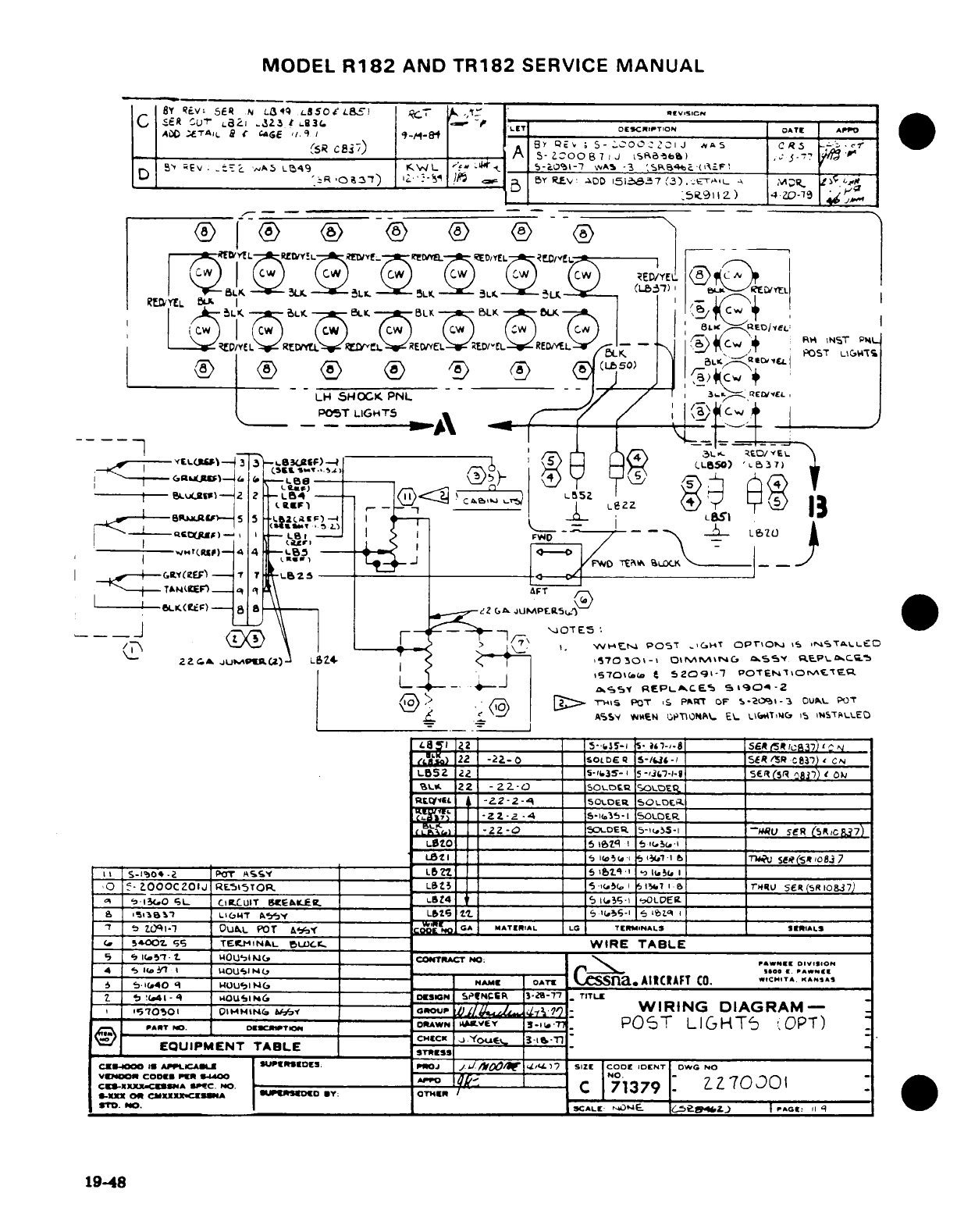
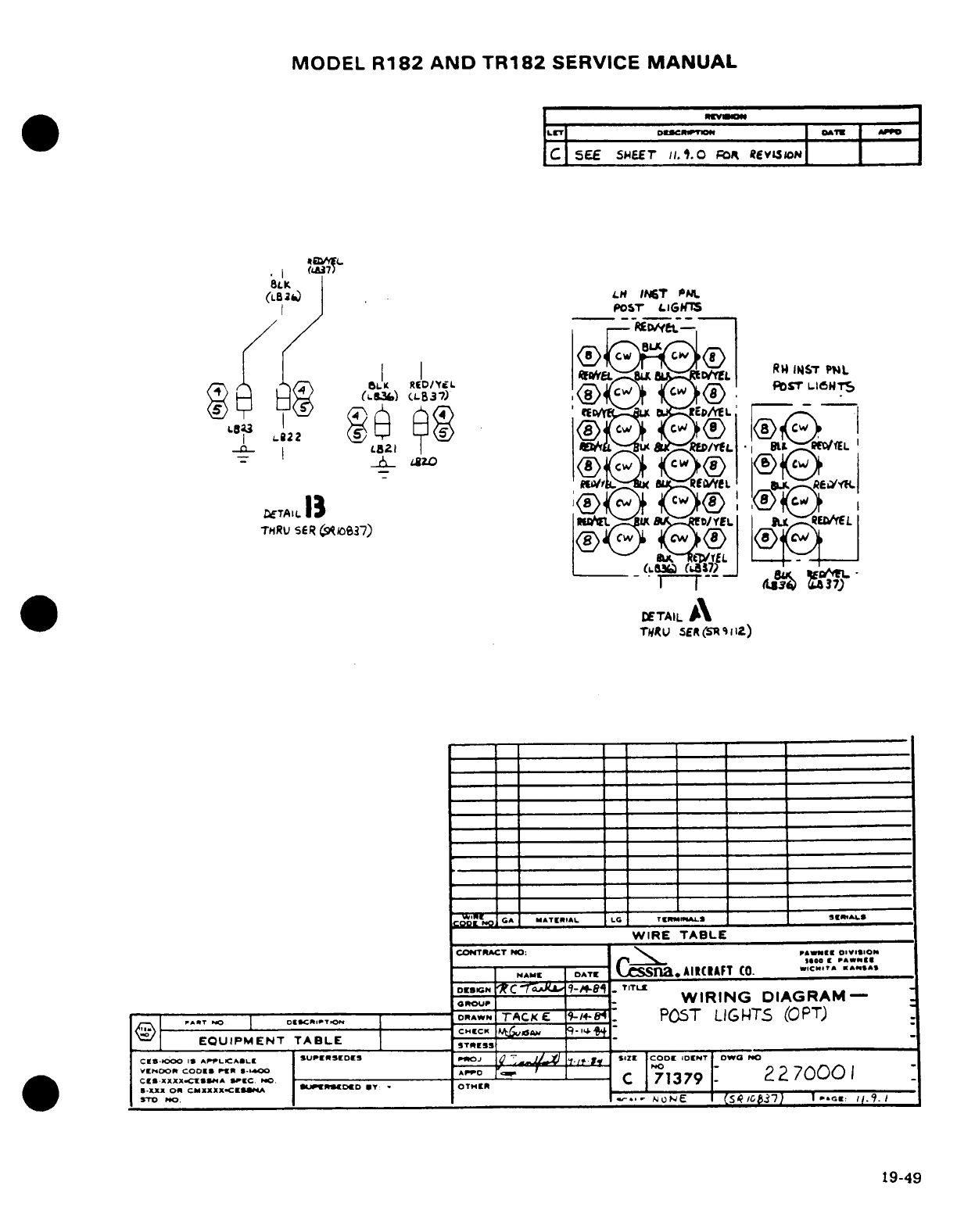
MODEL
R182
AND TR182
SERVICE
MANUAL
ILETI
DESCRIPTION
AT
_»D
C
SEE
SHEET
jI.
.O Fo
RevLsgoNw
.I (I
s
SLK
(LB2)
LH
INtT
PNL
|I~ J
Posr'
POST
LIGwTS
Lga B I)c~~ l3T
<8
RIEDML
POST
L16NTS'
~TAL 3II
I
TMR
Uy
C
<!SER
)
i
1(
1
-
ED
L/YeL
TLHRV $R037) 63) 8
DETAIL
A
TNRU
£ER(SR
Sl2)
_- _________
-
T- E R
A
CA
MATERIAL L TCRMWL
L
WIRE
TABLE
CONTIRCT
OO:
'
,
o..n 11
--
NS
|
DATE
Cesna.
AIICIAFT
Co.
C"..
A.S".
DreSGN
NC ___7-
__aJ 1
-TITLE
G
~ROUPhtgC
1
^WIRING
DIAGRAM-
|
.*T
0
|-
DSCR..^T
DRAW
rTACK
: g4P
POST
LIGHTS
(OPT)
L'-'
EQUIPMENT
TABLE
TE
CES-IOO
IS
APf)LCAPLIE
SUPERSEDES
PROSj
SIE
I/~l
.
S
CODl
IDIENT OO
NO
CES.AXXXEXISSA
m*rC
MNO -C
_ ----
__C
713
_
22
7000
1
S -XEX
OR
CMAXXXXICELSSA *UPwS€D
D
UT OTMHER
SrD
POO.
O___E C._s_
_/C___7)_
1
..
CG_
/S9.
1
19-49
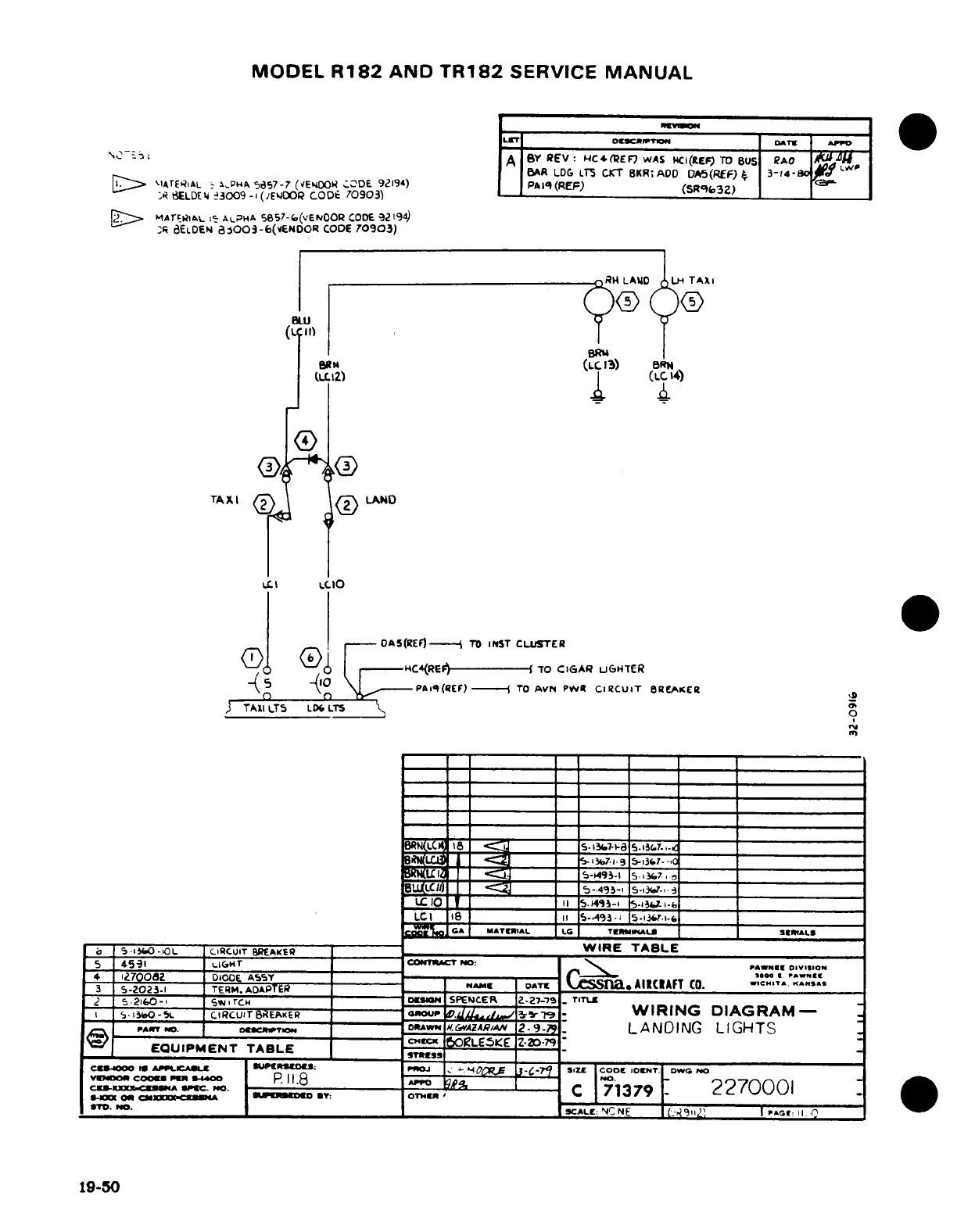
MODEL
R182
AND
TR182
SERVICE
MANUAL
LET
:otwcrlmp DATE A'»
PPD
oN'",~^~~~~~--i,~~ ~A
BY
REV:
HC4*(REF
WAS
NCI(LEF
TO
8US
RAO
LA
BAR
LDG
LT5
CKT
BKR;
ADD
DA5(REF)
3-
14-
DI
~
-IATERiAL
-
&%PHA
3557-7
(VENOOO
;ODE
92194)
PAq
(REF)
(SR9b3Z)
,R
dELDE
4
3009-
(IEJOOR?
CODE
70903)
2~>
~MATrRIAlL
,-
ALPHA
5657-f(vENOOR
CODE
9219)
8R
dELDEN
a8OO:-6(VENDOR
CODE
70903)
BRU
em.
(Lc.i3)
OR"
(L t12Z) _
LC
4)
TAXI
<
LAND
LIO
ITNI
OAS(REF)--
TO
INST
CLUSTER
(i
-
r-
DHC4(REE)1-------
TO
CIGAR
UGHTER
5
t,
-PAl4(REF)
-
TO
AVNt PWtR
CIRCUIT
BRCAKER
TAXI
T
LDT
LTS
*n
B
llMaTER
alC
TEI MINA-lI
5.
-IS7..ll
iU<Ldrt
~_ ~_ <3 _____ __ ^-li-i
9-i3f7
_______________
1LCII
_ _ 4II- 514-i
-
______
______________
LCI
18
______ll
5-A
93-
5-i37.i-
____________________
C MATRTIAL LC
TEMINAL
SE«RALS
~-
S-IO-,OL.
CICUIT
BREAKER
_~_
WIRE
TABLE
5
4591
LiCjHT
CONTwACT
PNO:
PAWN.E
OIVISI.O
L
J700082
DIODE
A5Y
_a-AE-
Cessna.
ICFT
0.
WcI.
43 $-0238
TERM.
ADAPTER
= NE DATEN
AIICIAFT
Co.
.c.'T
,
£
5
F-216(0- v ,rTCH
-
'mrN
SPENCER
ZZ7-'.
TrITl
,1
sI
..
O-5i
CIRCUIT
BREAKER
LRU- lPO l
-7-
WIRING
DIAGRAM-
PrART
'.
D TO
G
p-DRAWN
H.WAZARIA,.
2-
9-z,
LANDING
LIGHTS
__
EQUIPMENT
TABLE
S
tORLEES
Z
vwwom
COOu
PER
24
P.
11.8
OsPR
,
m cc-a--,-IO .,-C 71379
2270001
*TO.
aNo. ______. .C1_
^ _ _
-
_ _-
»c*SL.: NC
NE
(i911:'
l
PaGE:
11
19-50
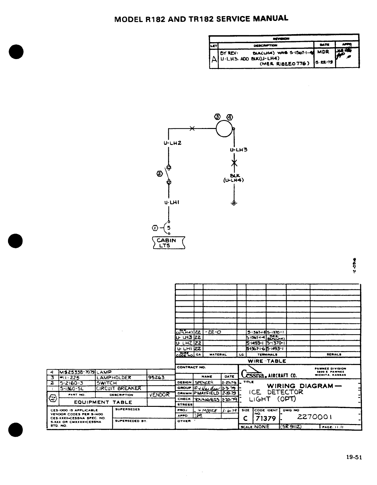
MODEL
R182
AND
TR182
SERVICE
MANUAL
-
_I
LET
DATS
|
_
_Y
U1:
OULML4)
WA
S
-156e7-l
MODR
A
U-LH2..
BXOI-
L4)
_ U-L!
(Mt
R.
t..EOtT
)
5
-
U-LWZ
U-LH3
LK
(U-LH4)
U-LHI
(-
u-U4.
1
5
CABIN
LT5
Uc4-l
Z
-22-0
.
9--7-i
"51' 1O5-_ 1
I
U-
LH32Z
__________
__
il,-4 t
_______
________________
U-
LH2.2
_ __-1493-I
5-1370-1
U-LHtI
Z_____
1i-l
5-493-1_____
NIT NO <
MATRIAL
L6
T Ir
INAL
I I IIIAL
I
___________WR
AB2If
S
[
D_
__I
Ii__
_
WIRE
-TABLE
CONTRACT
NO:
\ AWNER
DiVSoN
4
M$Z5338-770?9
LAMP
-0
-oo
I
PAWNSr""
3
-:ii-225
LAMPHOLDER
95Zr3D
NAME
D
.AIRCRAFrT
C.
(".T.
K.ANSA
2
5-2i160-3
SWITCH
D»ESiN
CER
-rT
I
5-1360-5L
CIRCUIT
BREAKE~OU
.
-
WIRING
DIAGRAM--
~ -T
O..
..
o.SCRIPTION
o...
RAWNi
PMAYFIELD
2-1-79
I
CE
DETECTOR
EQUIPMENT
TABLE
CHEK
-
LIGHT
(OPT)
CES-1000
IS
APPLICAILE
SUPERSEDES
PROJ
[, -1.
^OuT
3-.7
SIZE
1COD
DENT OWO
NO
VENDOR
CODES
PELI
S-1400
A-
O-
-
ZiZ70
2
,CE
XXICD5
X
tLCA
EC.
NO.
0jC
D
CS
.XXX
<ES8NA
SpC
N
aPD
1
71379
2Z7000
1
S.xX
OR
CIXXXXX.CIESSNA SUPERSEDED
SY.
OTHER
' ' _
-
TO
No.
SCALE
NONE
(5S
91
1Z)
I
PAG:
I .I
II
19-51
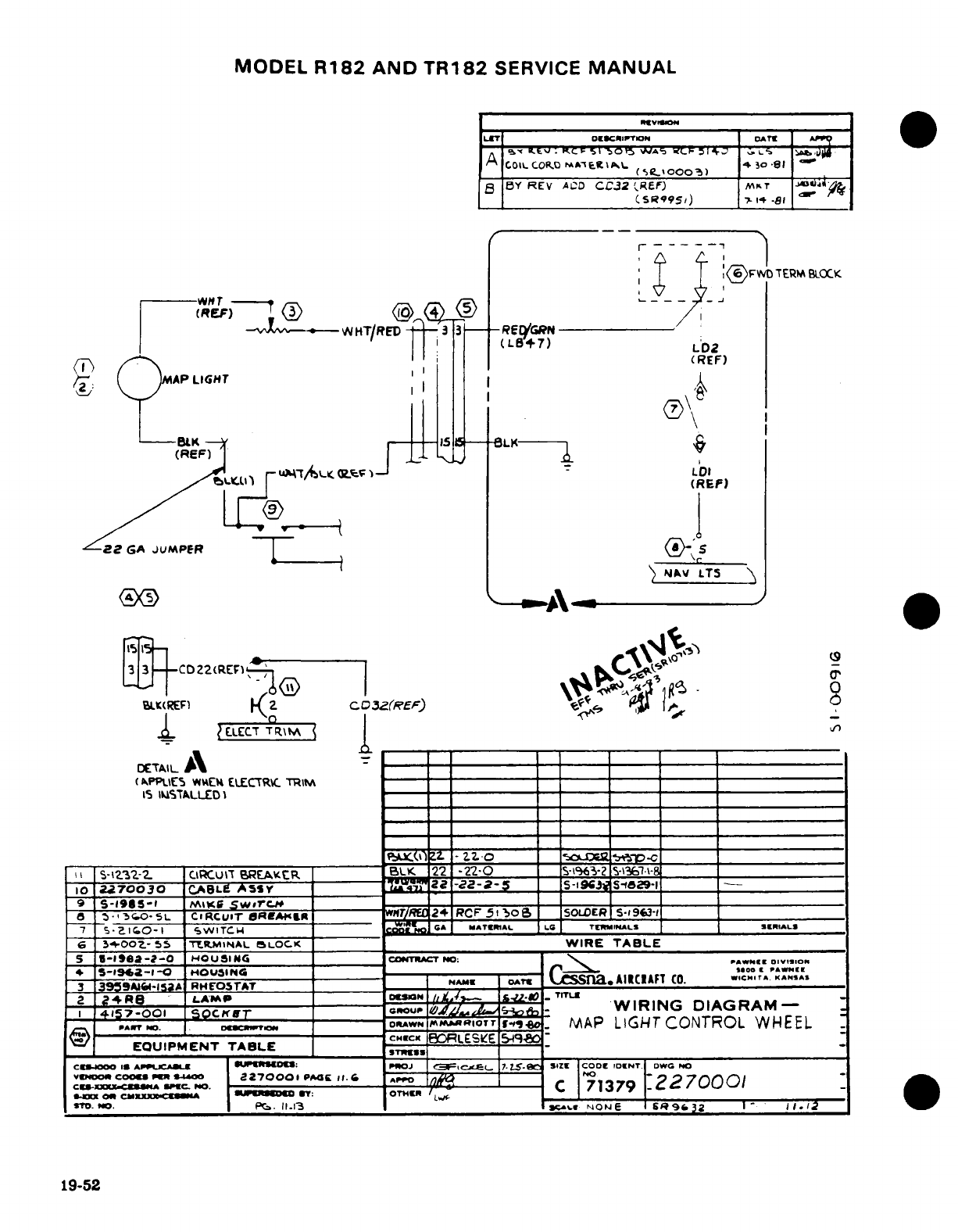
MODEL
R182
AND
TR182
SERVICE
MANUAL
N,[tvltON
LET
Oe
XiR'oN
IAT
-
e.
^
^.
t pK. ^ c F 5 r
0
tA VV S I
'
J
G.s
- ,
L.
A
CO
LCO(tCIL
,
^ t ,ooo,)
I
5
BY
REV
A0D
CC32
t'REF)
Mfr
P
1i
_
(R995,)
.
-
-81
L
M
HT
\\
K R
---
-L
-vA5- IHT/U EDD33-Rs---
NAVL
* '
tL8+7)
LD2
WCD22(R Fn |^ iv
(REF)
^LL
AP,
LIG
M T
-
NAV LTS
BL(REF)
2
CD
32(REf) E WR
3 ,o A7oo- AESr 'I_%_L.
'-
(WP\LIE
WEt
ELECTR--
TRIM
15
IlSTALLED-
I_
_
2 <i 24R8
LAMP
_____
M)
__
-
oLE
-
ESE3T2-2-
CTCuLT
REA-tR
BLK
22-220 _S-3-2
S-
C10 2|70030
_IL9
ASSY
I-
-ZZ
-
2-5-1S
1
3
5 fi
E
OW O
-
9
S-1915-1
,mi;1 9w2rc.
-
8
-,3r
o-S0-
CiRCuiT
bEK rC 2
RCF
5o 1 Po
C
S
9OLDERS 1 591
'7
S-Zc.I
O-
'
svITC
:I CA
MATEIAL
IL
-
-l"-IALS
ERiALS
G ,-(Pooz.-
55
'ERMiNAL
I
LOCK
WIRE
TABLE
5
-I
IT-a--0
D
HOUSIlN
C-NTRACT
NO;:
PN-
-
DOIVtISIO
~ l
S-IC2)a
-A
' "
> |
D
L <
DJ '
2.5i SZIN
|-8
CODC
PA-NEE|DWG
v o
S-
2-1-0
I-4W
G
MAN
,cN O
T.A
AIACToFT
A
C
O.
7.
c.".-,..
^
.
A
7 -»H60 IS>P ____ _
GnOU,,
T.L./~.,e.
WIRING
DIAGRAM-
!TO
4
57-001
S-
gnou>
y;Aif
40se
1 WI~ir
a
OCKA
o
19-52
Mo,
Of
.u.----o,
Tf.,,.6.I
MAP
LIGHT
CONTROL
WHEEL
8
r•)
no.
I.
arnrra
c.fcx
[BO'RLESIE.549M80
EQUIPMENT
TABLE
-- S
cCs400
IS
APjcLCAWK
SUPCISOK:
PHOJ
I3F =,cxg
17LS-Wa
SIZE
COoD
IDENT.
DWG
NO
VENDOR
COOKS
*Pa N.0
2-70001-
--
AP-PO-1'-
C
71379
-'U
04=
OK
CAOXXXX-CUIA
9L»
D€B3
'T:
OTMWH
r
/,/
TO.
NO.
f~._
11.13
NI_
" '
»c>.«
pNO
E
IsR
96C32
I
'
J.l
19-52
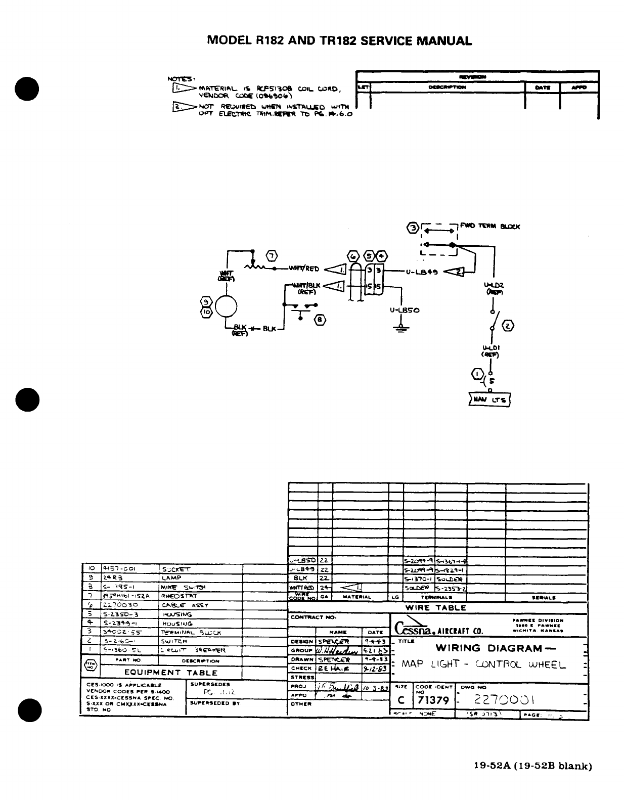
MODEL
R182
AND
TR182
SERVICE
MANUAL
*[ )o
T-?_
.-
o
-
OPT
ELECTK*L
TIP0-.REF
ro
Pb
.M-W.c0
W/f/RM -r ~~-
C
u
'
l^I-CDI
U-LOI
(Ef
o
10
.'5
-C
01
SLCFT
I -LI-B
ZZ
.S-i-
-I i-i ______It
'o
2-7000
Cse= A=S _ L
WIRE
TABLE
J __LS
--
Z
*-J'S
__
--
CONTRACT
POO: N-----
.
0,,.,0I
3
,CCZ
TF-M-NAL
'L;CK-
NAME
OATE
CSSna.AIllCAFT
CO.
»IC'""
ZZ E-SG'
-
;.,TrLM
DESIGN
spe
f °-t-f3
-
TITL1
I
-k-,
L
bo-
1ITr
-
f
_.er_ I
gROU
,u,./A
.lI
,b>
,
WIRING
DIAGRAM-
I&=7 _ A-
____ __
or'.'lo.r
_____:
M~p
LIGHT-
ONTROL
LHEEL
:
CPI5cX
&F
it 3ML53
./z
-3
EQUIPMENT TABLE
CES-1OOO
IS
APPLICALE
SUPERSLEDS PROJ
'/ -
3- :
.12t
COO
IDENT' Ow
NO
VENOOR
COOES
Pr
«.1-€00
P
L,.
,1APPO
------
' '
C-0 -
70
0 3
1
4CES-xx«
.CESSNA
SP-C
NO.
-OTR
)-
CPI
-
7
1379
.
2
0
3.XXX
O0
CMI
-IX-.C[-,N
A
UPl
RED°
I Iy OTSIUR
STO)
No
NONE
IEN
T\
19-52A
(19-52B
blank)
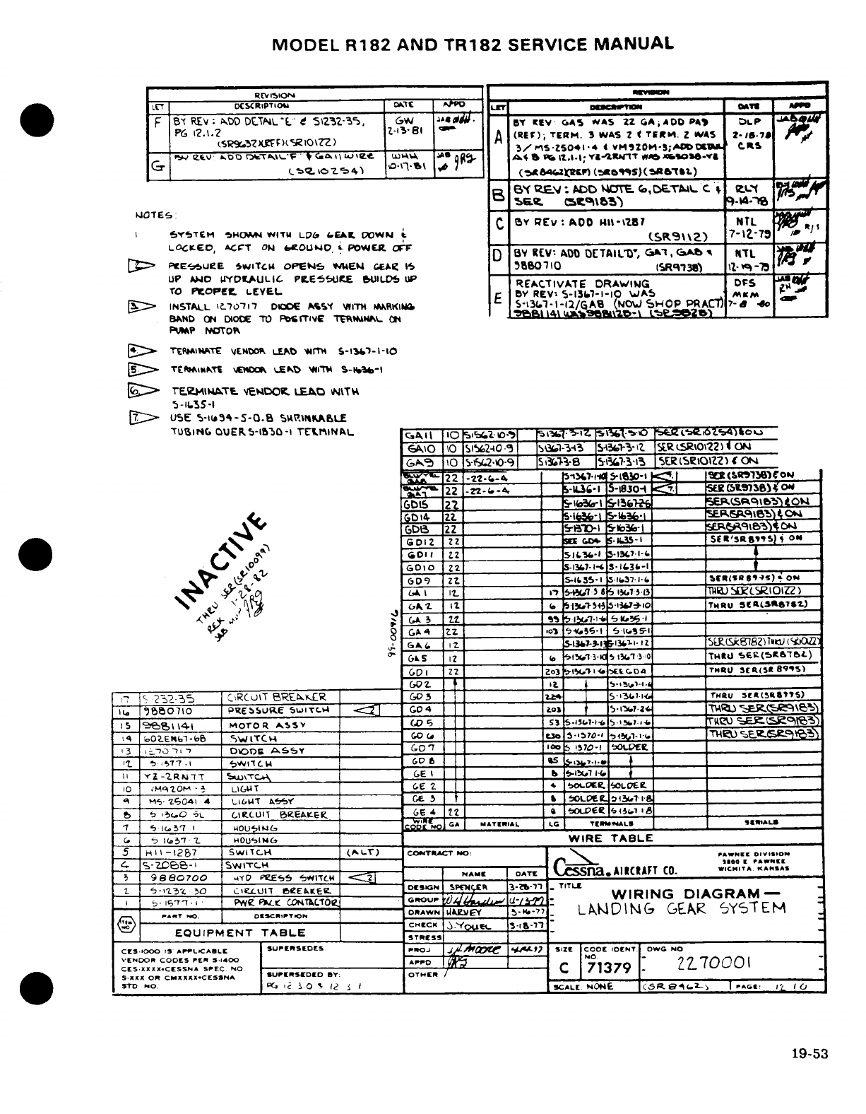
MODEL
R182 AND
TR182
SERVICE
MANUAL
REV ISIONP
_
LT7 DCStRIPTIoU Iat gL.
irI 1_4: r M__
F
Bx
R£V:
0DD
D
ThL-'L" 5'23Z-%5,
GW
^4
0^.
By
lv:
c.AS
.VAS
ZZ
GA
AODD
PA
OLP
-WA4
P6
1?..<2
XiF)lO--81 _
A
(RED);
TERM.
3
WAS
2M
TtER.
Z
WAS
2-15-7
r
5/
S-ZS041.4
¢ vM420M-39,O
3,OlMc
_ ZILVU
A.oo
rc-T
A>--
Izw
F
G at Ii4 F u
%
w4 l^
W.AI%;A YI4nT «%« x6«O*a-rA&
(
_ c-DQ__\O254)__' \1*'V01
SF
7'
(rKrma4c2
c~f(tts)(i*ftT-)
;
_
_
BY
eEV:J
PAD
MOTE
<,DET(4L
C
L(E
Bs.tg
artcmas)
9-.-
r-
.JOTEG:
C
B
REV
AOO
Hit-tZ?7
NTL
I
S'nTEM
SHc1t4
WITM
LO&
6EA2.
0OWN
t
(SRP9\\2)
7-12-79
'
LOCKEO, AT
OF 0^0,
WER
F
BD
BY
REV:
ADO
OETAIL
'O,
GC^',
*,
1 PTL
I
D>
PtEzUoebE
SWIITC4
OPE*N5
WMkEI
Jee
I
I
4a6010 EIASR7381)
12
-7
-B
UP
WND
UYDILAULIC
PI.ES.UtE
)UILDS
UP
REACTIVATE
DRAWING
DFS
TO
PTOPFtEL
LEVEL
E
BY
REV:
5-137--1O0
WAS
MKM
.O
_
~[S>
INSTAL
L'0l71'
DIOOE
WSE
1
I^RV S-KI"
-l--/AO (N hOPWACf
7-a
%o
BAND
ON DIOOE
TO
'PS
TIE
TI--R-LNF
O1hI
PUMIP
NOTOI
·
7*
TTIRAiTE
EHNDOe,
LEAD
*41t
S-lsi-il-O1
[>
TEFMO&NKTI
YMl \E^D WK T 5__lS-V
[>6
TE7-ZMIATE.
'ETDOt
LEAD
NITH
5
-1155-I
[~
USE
I-it93--O.508
SRP\t.KABLE
TUBING
OU
QER
5-IBQ
-I
TFI-IINAL
GA
117
10
r41a1.i0--
»s1t
>-'Z
5131b
\| egzO)*e-
€AI0
@1
O
51692-40
0
9
_
SS1-343 354361T3-'Z
1ETSRTOZt
ON
~
G69
10
Sfg(21O-90
51i38
'-1
ISi3 1
5ER
(SEIOZZ)
f
ON
)22
I22--4
_ _[5171~ CON1
89
_: ?22
-2
-C-4.-
-IL3-I
1830-i
Om.
S-
t)
yIoN
_D
IS
ZZ-
_
9af1
5-1
7IS61____
EPS~oIEO
<G
614l Z _
5-H
S-Z?3_l
5PgP6 91O
A
Da3
?2
2
_ SrI
5ll036-
l __ E&a
2h1
A
GDIZ
2Z
__ S ?S-I fstr',ag.t __..)"_
MEN (0
___T__
Z_2_
S.13
*IL3-1
131-
____
-
0 I
Z
__________
__ 5-13-1* S3-l
_______
__
_l__l
- 609
ZtX
S-
_ 35ESIIE-.
;15 l
______
BTBSl
(5)
0
V.^A~ GDy,)'^ AIt. IT
- .
5-t>d1 w51.p
a O______TW)igLSRIOIZZ
bG\5
I2t
.
7'11413
-1341o
___
T4RU
SEC
(faSa67T)
I
,
?c
23235
|
C2RCU\T
52ES<R
|
COt
T
__ _
3-K
_
'3
-
rHu
5(5a)
Ib I9 '950710 P0 bSURE'5^ 5T
| C 0 4
T
__ IGO
4 f5
724
igl
|_5
'
tes14%i
MNorTOR
1
^S T
S
(S7 5 5 £
1
5,_____ ___7-1 _ r__ __
E
04
O2Em(1-bB
SWITC"
0
Cal h
.
o-
)
5,
1 o3
I -70 7-,
*
| D00
AssY
1
T
s
1570-I
O..
__t
|
-
1 _-77 .1
(
CWI1CL
B
cca T4
s.
,.
I Y
-ZRA7TT
0i\TC C
.
GE
NA t
-.
____
_
|0
|M'
Z^tOM -B|
LIGUT
G
C.
~ _ 3
'o
LOFI.
____
i i t1 iH9,
4
Ll&IUT
SP
6
ce
5
*
&o 31.ae 7 _____1
|
!
M
|
Os ? i
-
L7t |
T
(L
EA
K
S
T |
CE
4 22
4
f e
$
o1p5
.
______
1
Mr
~i5~ZC
t
'4 LUI¶E
fl
~ __________ B
»LPE'.,a3wu
_______
·
______________-
|T |
1io'
7
1 I
4OUISIN
G-
MATERIAL
LG
TEMNALS
TA
6|
1(.5'
z
|
HOull4_6
_ _
WIRE
TABLE
5
H
I I
-1287
SWITC.
H
(^.L)
CONTRACT
NO:
P »»II*
DIVIlION
I
-
oCo
-Z,
~WITCH I CI
ssna.Ai
ARCRFT
5
9880700
i4YO
PIeE5
5w*ITc
NAME
DIATE
na
AIT
CO.
W.cRI.TA
AASAS
2
.
4
' '
30 lo
IcTl
bRE*LEP
ON D
3PR7CE
3-lb-l
-
TITLE
I I
-
-^
wo
civix WEb-.KTh (OpFitt^
_
TGUTL€-
WIRING
DIAGRAM-
I- IT.
,-n
I Pwz vt Ct
coNTkLToe
GROUP
NAIO--.
DESCRIPTON
DRAWN
"lIEY
b-H.-"
LAWCDING
GEAR
6YSTEM
(e
= y
EQUIPMENT
TABLE
ETRs
CESIO0O
19
APrLTCABLE
SUPERSEDES
PROJ
|
C I4,
7
SIZE
COOD
IDNhT
oDW
NO
VENDOR CODES
PER
5.1400
AP
P NOr [
77
70001
CES
XXXX.CESSNA
SPEC
NO
Ar
-B--------
7
379
-
2
700
-
XXX
OR
CIMXXXX.CESSNA
SUPERSEDD
BY.
OTHER
/
7
-
STD NO.
PG "?
o0
s
12z
I
SCALE
NONE
C(SR75 4.
-
I
PAGE,
I'
10
19-53
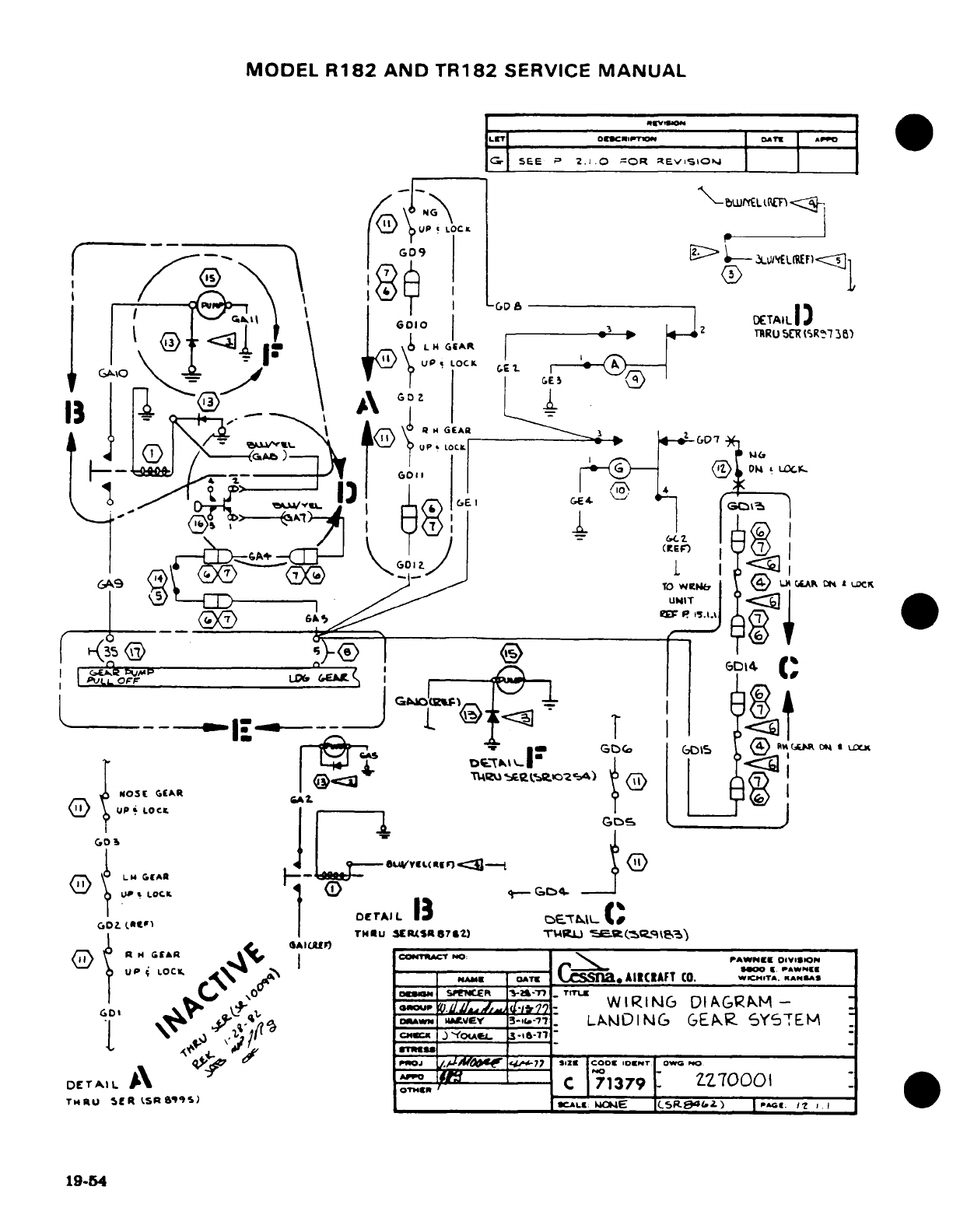
MODEL
R182
AND
TR182
SERVICE
MANUAL
SEE
P
2.1.0
=OR
EtEviSWIO
UP
I
LOCt
1
,
~' Z_ |+
F'
\°
}o
~:WEL .F!
G09
I
\
\
c
I
CDG
1
Y-^ ,,^
'_010
O2
DETAILI)
^
-.
] r
GIA
TRRUL4(R
36)
4„
.'C .9. \ i UP
,
LOt.
C-E
,
GA1
0
'
. ,C
-
o
{ <
. .
I_, ,T
,
i
® ~
r
N
I
To
W<:i--
.l
p
(
I
I L'
4:
GDZ.c~~~~~~~~~~~~~~~~~GD
4
-
U
.
X
L @ <-
I t3
e
1 °
.-
^
^
^
X
.
DE
J
'
1
t
1]® (
*
E1l E f)
-OS-
G-AR
tt t
Y
@
AAI
_
TO
WEN
L
K____
__ A
_ __
_DET
LO*P DrI ___ _
_
uf + Q ^p
1P
I
CO
TPW
O NiO
D
UP
LOCK
GA
i
ta
GJ>~t +t
t+4>~.E.,CNTA POaO': WING
DDIAG/ISM
I
-
-
C
71379
-
Z--------
.
Tb4RU
"
OKR
LSRS
&S)
3"L:
|
.Cz
E
A
LRAFT C.
)
|I.
A;1
I
1g-54
DETAL
A\
A.
71379
72700
0 1
T64RU
SER
Oobt
s
«CALIL:
Mo4E
CSlrsB".e
)
\ IT
1.1
1 ^^r
19-54
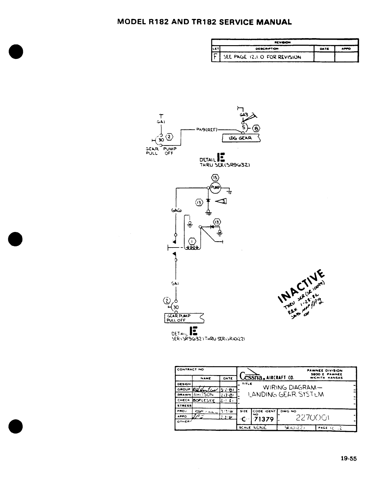
MODEL
R182
AND
TR182
SERVICE
MANUAL
IET
'CaOES0 PT.CIO. j
ATE
APO
F
SE.
PAG^E
2.1.
FOR
REVIStON
T <_
~1 i =. r--9(
.2) ->
.EAkR
PUMP
PULL
OFF
DTAL
DUTAlLE|
7WRU
SF.(R5R9(,3Z
GALD
'1
\
GE*AR
PLIM
SER
-RC5o32&K)E SCC ti
2,
r|--
--
lA fl,.J0 E
PAWNEE
CoNraCT
NO
PAWNEE
DIV'S
ON
_
,NAME
OATE
CSSa.AlCAFT CO.
-
WC..T
,
KANSAS
OESIGN
TITLE
'5S
u
nC."OUL IY
^
I
_
WIRlWG
DIAGRAM-
-
D*.w^N
f.. 'S.0 ^-Z-N .I
_AiJDINL-
G(EAR
'rSYTLt
C.tCK
BEStc BOE
,
STRESS
PROJ g-
-
_,
SIZE
CODE
lOENT
DWG
NO
O T
ER/
7
--
-1
379
22
70()
SCALE
klj(Jt \L
l
|
«G€
\C
.C19-5
19-55
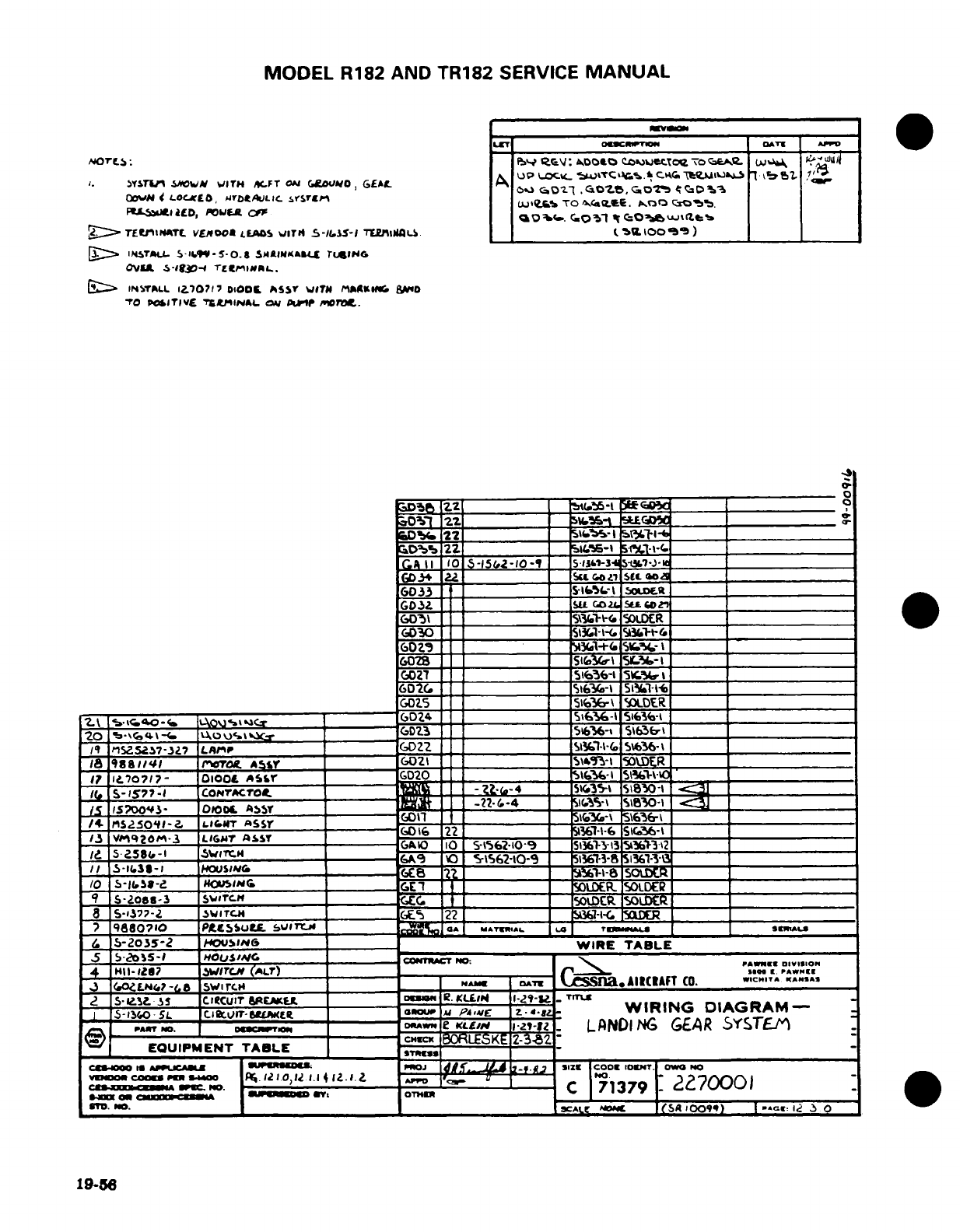
MODEL
R182
AND
TR182
SERVICE
MANUAL
LETI
P "'Sc
="
.T A
PA
GOWvN
<
LOCjL,
NrobtkLIic
LrSrut
TO
N
9atc.
ioo 0E T.
b
FPSIt&LLD,
U4POft OC
G,0
1
'it t
Q
Oafude '
g
TElfttINMT.
VEAOO0
LEADS
WIT4
S-I.$S-I
TiiNSS-
iaII
_ (I0 oo)
_
)
:>
IfSWTA.L
5.I9-5-1
0.8
SMllINKABW
rIlN6
OVIU
&-S3-
TLErtMIHL.
|:> SINSTALL
17)071
7
DOD0L
ASI
TN
T
MA^Ik.
aWID
TO
Po)ITIVE
TtLj6IN
IN
,v
PA ir oro..
Ia
,D
22
_ S.*- w.t ~
0
D
2Z
_X-1
51I
033fI
22________S-i
6fr-t
5oc-______________
j II0
5-152-10
-9
,13&W-3
O 57
-.
GD30 __SuG. SOLGO
LDG ___.__
6D 3l
_
_
_51
+(.
9-
0SoUER_
GD30
51-I I% SLWll
-i
60Z9
3(.i-t-(.
SI%.-
|______
GOZ8
__ Si-t
SL
______
GD27
-
_____
6DIG
_. 6-l
51Sl-
_
GD1S025 _ 5_l6-5
\
IOLDER
2,1
Gs*
tco--
0-----
-
6DZ-4
-__ =
5\i36-1
5163i-
__
20
-
\\64\ r Cr
GDZ3
SD6%-
5163r
Iq
n15.SZ.7?-3J LAMrP
D
9?ZZ __ _ =
1_-\-(
156)*6-\
ISss is8
4
ro
P
srOT. AY
GO
31
50WER
I?
iL.70717-
O100
ASfr
G20
i1
S10
S5-1577-1
comrtcro.
-4
=31
5I
S850-1
/4.
iS2151~0q1--.
-7t
Asa r ~ 0aSSY3
____-_______
3 ns0'
Pi
-3
Li
tG-r
Ass-Y
--
DI16
22
0
_Ts--\6
Sr36
-\
I.~
v/qO/M.-
ULIGMT
aSST-
1/,_
5?
Z58t,-1
--
WTC.1
---------
4GAO 1v0
5-1562-10O9
13633-
S%361-3___
/I S-l631-C #C
=
l'8
~/0 $S-1~J-.'
H~
CE£1
IS=SD\.R. SOLR562-10-
/0o
T-yso-t
HOusa
_ _ _ ~~
9
S-Zoas-3
I5virc.
LDCR
~
- --
8
s-137-2
5WITCH
22
________
7
9880710
PteISum.
______ MATNTIAWi. L TAlJ
1_
aILJ
e.
5-2o5S-2
'oSIN6 ______=
WIRE
TABLE
5 bI-25-
HOUSAl
_
.
OIG
T
4
.11-1,z7
w1r'cm
(A^r)
_ r
.
PAWNIE
J
oZLEN7
-
SWIT
swir
_
NAME
DATE
C.
a.AImCAFT
CO. WCHIT.A
.ASSA
. S-Ie....:S icuIT
RErL lo.DIM. R,.
KLI
11-29- _
TruLE
-
S-3-0
5L
C.IBIT-Lra[mt
raOuWIJ
P.,ME
IZ-
W-
_
WIRING
DIAGRAM-
-PAW'o.
0
T
ODRAWN
le
KLEI
1-2Z-12
LANDING
GEAR
SYSTEM
EQUIPMENT
TABLE
I gBg :_
_
ic inaoo A»ue«Au §U
_
JSKI Mz lCod
OuET.
Oo
O.
r
o
XXco~
oo" 11"I 110
.
OTH1
cI
I'Cm
2?7000I
1on
GM11 c
flv
OTHER
C
7913
D.
o. i
At
e
(SArixO-) IO
7I9
1
19-56
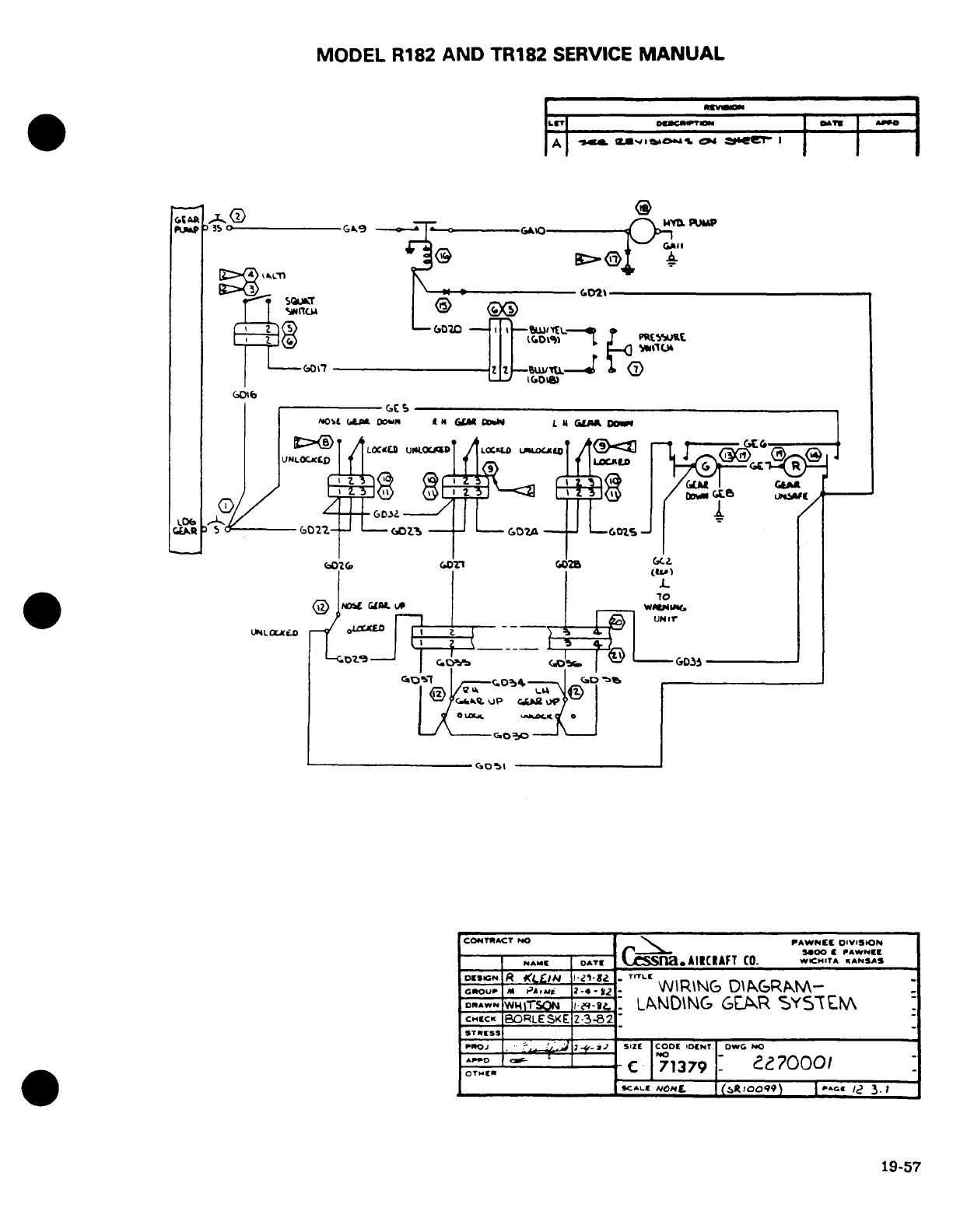
MODEL
R182
AND
TR182
SERVICE
MANUAL
Xpuw
,» o-- -----
sN^9
-GAADOWTZa ----
mm
L
--
·-'
I I1 >
lfl1 ~
/
L- '-I
IG02
L. ,
®
flm
f
( '
l~ J t
t
-
-r=-'
0.~
co
Q.u
--
LlA
O-L
(A.- 00
-- --
6tL I W L
U
4
GLR-
G
0
I'
T
RL0L
uPr
DI
/CONTLACT
L
0 PAWN[[U
OIVISH
~ ~4~OO
·
PAWN.
r
U--&--
I
C s----1
S
-------
IIIOt
| C
R
| 6I
A
|
ANNo
-AT[
(pi
a.AIRCIAFT
CO. WCH.T^
^"ASAS
D[SGN
)1/
K/,.(~/d4
E:1.
/ -.
TITL-
G*OL)P
M
5AAfj
--
4
_l-i-
WI
I-IRINJGE
D-I
-
O
-N-
S
fa0ic GDRAWN1
W
MTSOIB G-e,
LDN
GR
SYST
oT.,,
C
71379
2.2
70001
~SCALIe ('RooL) Ut ...
e 3.
1
19-57
/
I~Y
G~I-- L3^
UNIr
UcLOCK^o
r-/ o^""-
---
Lr
-D
CONTRACT
NO
PAWNER
DIVISION
I
ESIGN
I*TI
·
LLIM
¶-5r
-
TrT
ROUPCT
NO
PAWNMi
W
ING
DIVGRSAO-
CNECK
BCRLESKE
2-3-82
-
^ ^:. 1^ I
-- -
C
^1379
[
c70001
0^B
S^.---
-^__
____
CA1LE N/O~g.
sftlOOf)
PA| E
>«OI
3.>
19-57
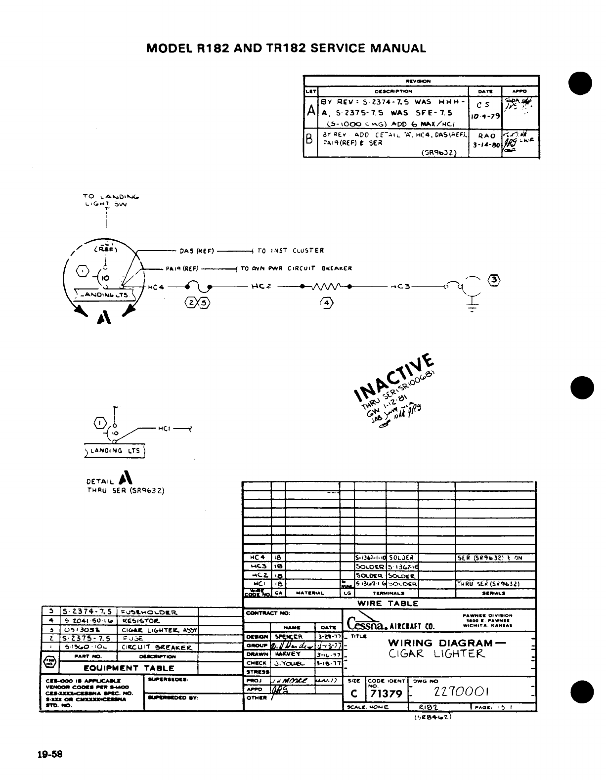
O
MODEL
R182
AND
TR182
SERVICE
MANUAL
LET
DISCIIPTlON DATE API
P
BY
REV:
S
Z374-7.5
WAS
HwH-
C
^
-
A
A,
5-Z375-7.5
WAS
SFE-7.5
104-79'
_
(.5-000
c
"G)
iDD
G MAX/4C-
aByREr B
ADO
CEA
li
A,
HC4
DAS
TEFF).
QAO
d.
PAIl
(R£F)
SER
3-14-8O
LLI
B_~~~_ (SR_3(SRq9
3Z)
T'O
eAsD'
TT
L.,GT 5,
//
O1 \
-
OAS
(REF)--
To
INST
CLUSrER
0
pA~ l
, /. -
PAiq
(REF)
- (
TO
aVN
PWR
CIRCUIT
SKEAKER
Q^
*
OETAIL
A
- - -
THRU
SER
(SRqb3Z)
-
2
HC4
18
_ _
I
S-3)&1-I-'0
SO
L[)Ei
5ER
(591b37.
t; ON
HC-.3
%
____
_
_
SOLDE
5
13(.7-
______
-__*________
5oUcua
5OiLDc
______
________________
MC.I
S
l
.,1-7
TwRU
S R(SO l3Z)
CO II GA M cATEBIAL LGt _ r EsP
INAL
Sl E AALS
_ _____ _
________
WIRE
TABLE
3 S-
-374-7.5
;Qt-o«^~ot
COeMTACT
NO:
WIRE
TABLE.
Do
4 3
_*_-_01(_ _ElstiTOR_
r_ rwN00
.
O
51
30SI
Cl(AE
L/UTE.
a~5yI
NAM[
oT'
ssn.
AIICIAFT
CO.
.*C..TA.
9.AS*S
Z. s-
2375-
7.
5
FJE.-
O€
sp3efm
3-2-"1
-
TITLE
_
e,,.o-
o.
c-I
CUI-
ecEAKe
~rouP
V,U,
L
L
dIE, -7
WIRING
DIAGRAM-
_
^A'T
,o. 0€oA.TWN D*,WMw
,vEY
_
3-,
.-
,7
ClGAP<
LIGHTEK
EQUIPMENT
TABLE
S
CES-oOO
I
X
jCAU USIo:
ImOJ
.j
Z
ElOsIW -P.)
SIZ
rIcoo
r
IEONT
oDW
NO
YvKo
COMOKB
Cn
»*O
'--
no
-
ZZ?000I
cu.XX
C-..A.OC
D
C
71379
ZZ70001
*-X
O0CXXMZ-*
U»«€ll
CT.
OT"aR
/-.'~_
3rl. 7
lj.
SCAL
MONE
[PAGE: I15
'1
19-58
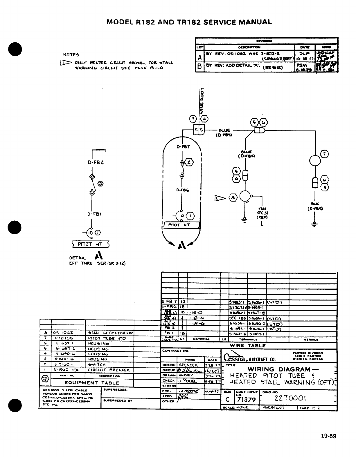
MODEL
R182
AND
TR182
SERVICE
MANUAL
>omT
6
ES
A
_____r______(sr»*szm)
e o-N
n
A
.L
J
YN#1IN<
IIClUIiT
Ese
PM»C
15.1.0 _
(
t1*w t ail
i0(
Y
byR v:O I
:
CT
I A '
A".
0i7
~~~~D-FSZ~&~ ~
(|
D-2
i
1
.
U M /7-
|o ((D^t /'I
8
D-FBI
'FC
)
.,P I
1
I
OT
Ut
L
PITOT
HT
S
DETUIL
A
EFF
THIU
SER
(5R
9112)
U-FB
7 1
-
5-"93-1
I
S
r-16,
LTO5
J-FBc
18
_
_S-13
5-.4
'4-93-1
_
L.A-4
'ae
-i8-0
=
E5-i.SS (-..-l t_____
B_
"
-_I.t 1eE FBr.3
5_."-_
.
(S-TO")
=_ _ __ -i=
-
isti (bt5_'
t_ 5TD)_
6
051
i10
2
5TALL
ETECTO.TC
4T'
F
I
s
51"1-b
514R5-
__I
7 072110Cti _
PITOT
7UeE
UTOT
Tu
Qc
G Ao
MATERIAL
LG
TERMI
ILS *RAMLS
_i
S
J517-1
14OU51NO__ _____
WIRE
TABLE
J__ 'i- IL
HOU'3IH4b______________CONTRBAC7NO:
S l'
"
HWOUSI
CONTRACT
NO
:
PAWNEE
oIVIsIOn
*
4 I(i,-4
-
H4OUi'IWG
_ _______ r_
__
O I__W__
d& l
IJ44.)'(1~*
OUOLSINC
NAME
I
ISaco
I
t00
.
PAWNEE
.5
S(ic4'!
.(
4ll5)I~
_bL
NAMI
DATE
C
n.AIR
CRAFT
CO. SCM.ITA
KNSAS
t
'
I(.O
-
WtlH
DESCN SPENCEp
-N
-T
3
-7-7
TrTL
,
-Il.o-Io
C
ciclurT
6eEIK..
GROUP
0 ./
-
-
WIRING
DIAGRAM-
PART
NO.
DoESCRIPTION- ODRAWN
kUVEY
'
3-.
7)
.
HEATED
PITOT
TUBE
i
EQUIPMENT
TABLE
CHCCK
.Yvoue
l-,t-l
4EATED
5TALL
WARNING
(OPT)
_
.
STRESS
_
CLS-lKX0
I APPLICA
Lr|CtCLDl S
PIrOJ
U
J Mf7 121 COOC
IDNT
l
DW
NO
,SENNO.
.
COCl»
SDENT.
OWO
NO
-
ECNDOR
CODES
SX
PERXCA
SPr.
O.
'
71379
ZZ700
0
S-XJXX
O
CNXXXX-CCSNA
SwEIRSDOD
mY:
OTHIE
71379/
'
|SYD
NO.
|/S____
S_-
^
--
CALIE
NOWE
("-9
4Ct./
)
P
AGEC: 15
19-59
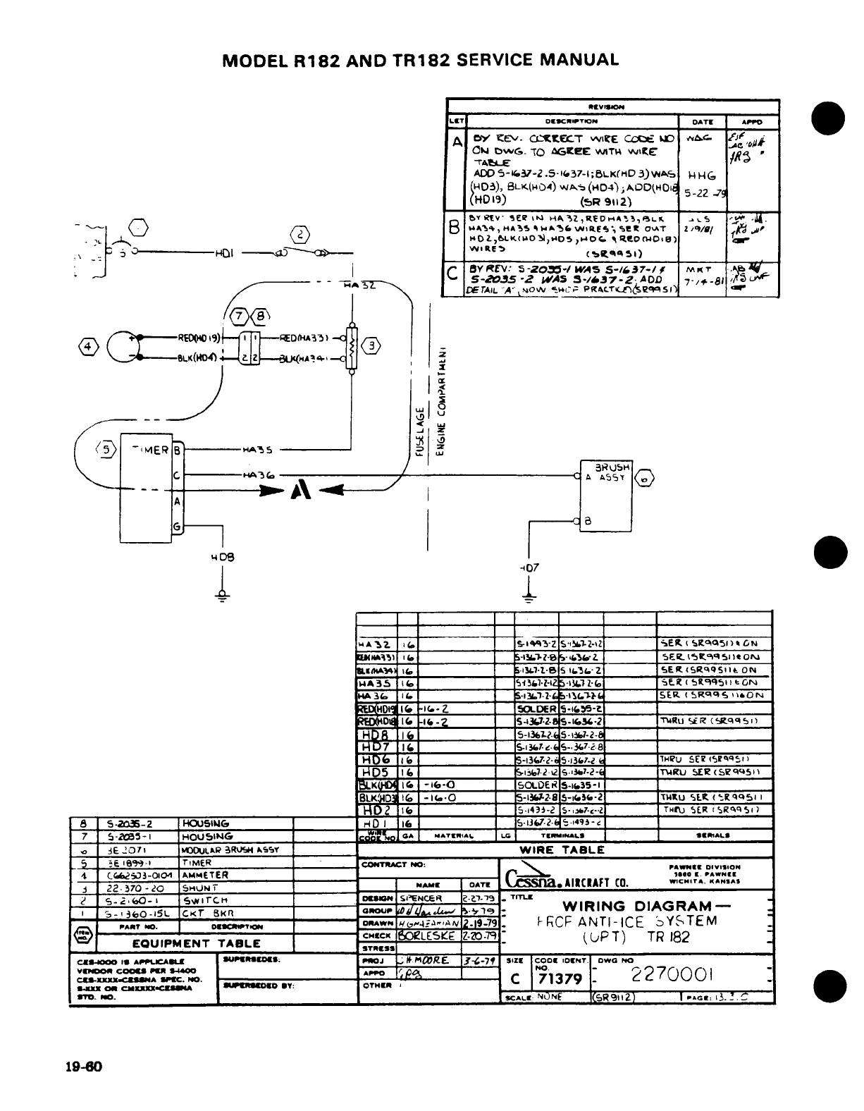
MODEL
R182
AND
TR182
SERVICE
MANUAL
LE
T
OEICKOPTIOm
OATE
APPO
A
bY
E'v-
C
IZE
CC.f.ET UDlE jt MA A
l
N0w
DwG.
-TO
AGCeE
WAlTIH
wE IC
-
'TAHLE
ADD
5--37-2
.5-
'.37-i;BLK(HM
3)wv
c
N
N
HD3)),
BLK(H04)
WA/,(HD4)
,AOD(HOI
5-22
0
(HD
19)
__
R
(,R 9125-22
,9
0-
_
I!&Y(iV
5e?
iiWi
CA
ZR»,ic»7iA^',>s
e.s .y .AI
.
__:1; 0----HOI
--
J1
W~E"--
ci--: 1('
)
'
B^
„4-4,HA- -~ O_
-&_ WS-2035-Z
WIAS
3-/37-Z;AOD
7-/+-3-U A
OD
\_AIL
'A".4*NOW
c,-
PR/CTKCngqSil
)
/O
j
i
<Cs
/^~>1»----
WO(i9
E3.e
));-[7]
)- I
I _
_9IC
H
(
1_1 _
-13_7-2-
5-J3.
7-2
-
1ieu
SER
(q
I
*GN)
"D5
l 6__
-11L7
-..
S.3.J-c
-
|
T%4U
E-R
(SIW4.5
)
BLK03G
I_
5I-3(7-2-s
.I5--
_.__ __
SER
S___qQ
S
I
RHDIi_
-I
I
_
A3
TorD I s-lhaf,-e
5-- R_-2 !._USII_ _HD
_ 5-1316 S-I,1-e-2 -l _-_493-
o:E
-O71
MO0ULAR 3RUSH
kss
WIRE
TAB3LE
wHKO
_(
-i_ 0 _
5-DiESSi
S-,35B T-T
___IT ESg qs«
EQ UI- TIMENTR TABLA
CONITRA
iCT
K
,i-7-B 5
T
182:
ON
SUPERSEDE
.,E
1,
,
_^ArE_
CS-aO.
AI2CR)AFT
CO.
SwCN.
..
n.
TCCS~
~
~~~~~~ou NCR.?_X.CS
2-. 2-O.
2270
01
5
2E0(Hrl'
SI'ENC-ZE
_ _
p
SOLDR7
HD7
1I6
__ _
S-i
fa^-.,4-.^za
_____ _____________
I
7_,~eo-,0
C0r
4<r
GROP/-/
c
/T^;
_
-TT-
WIRING
DIAGRAMU
(S
,^N? ~m. e~,~
o~.w,
'
PA -O. ~ _25-l1tg-79
R-
ICF
ANTI-ICE YSTEM
<5
7 5
.2035
-1I
HOU51N&
________ ________ C ODI-¢.O
o*
RL
.
L.'
(
pT
TR
1
8
2
:
__ »
I
o
3JE
'Q7UI
TKAUBR
3RVSH
ASY
| _
WIRE
TABLEL
T
C=
-
ia-C T,
_--
COPTICT
P: |7\ 7^9O DISElOE
N
4U
CM
g
XXOICIES
MNA RETER
a
OTHER
r71379
j
|
22-370-o0
SHUFINT
-
|
_
"A"
|
OATT
|CS
.
a.ATlAFT
tO.
W.CMIT^.«
1
s-2.
60-~
| 1 C_ ____c.
sl'ENCe4
7 le-
.9
TITI
-
I -,o0-
i5L
KT
8Kn-
0
Clin
I»T9
Rl0
s-
WIRING DIAGRAM-_
IT
Ir^^v. I o.--
--
o"^Wull
o
-^VT79:
^FCF
ANTI-ICE
cYSTEM
|
EQUIPMENT
TABLE
-
^^cA
|LESKE
|SgI: Z3:PT)
TR182
-
|««
to
,
*^uctj^
|
*url-io.
rKoJ
,lS
-
MgRE£
J--7T
1zr
|
cool
IODCNT|
OD»
*o
C19-c
.
,,,80
C
8071379
0
TIr O. .^ :
I
O
ALt
E l5R91Z) I
-,C:
3.
'.C
19-60
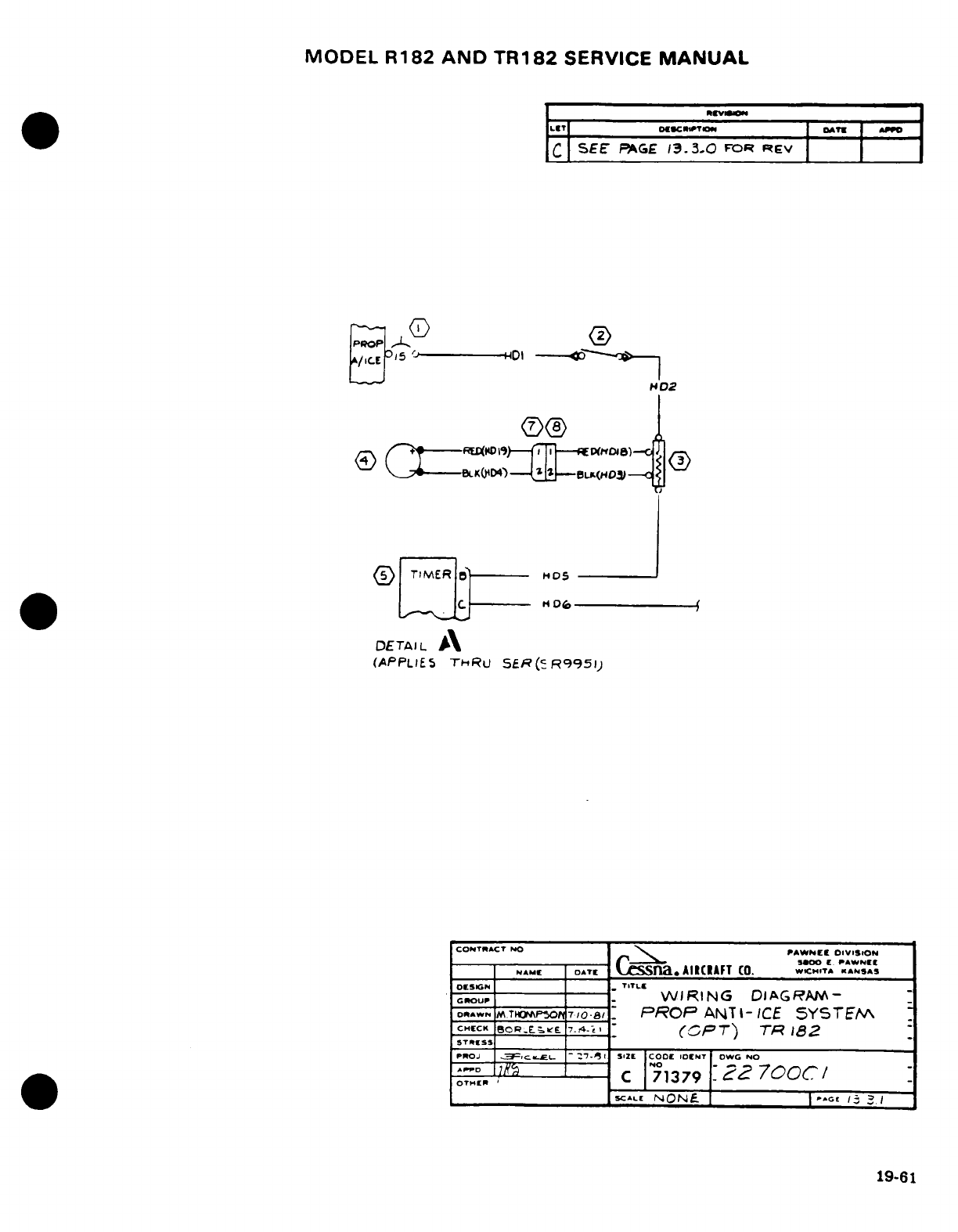
MODEL
R182
AND
TR182
SERVICE
MANUAL
.·
clurm*
I
v
LCT
D ODATE
ATPO
C
SEE
PAGE
13.3.0
FOR
REV
s'J
HDI
2
<i)
/- ---
E
Ho.,)_9TTT-
6)C rj
TIMERB
H05
--
DETAIL
A
(APPLIES
THRU
SER(cR9951)
CONTRACT
NO
.
PAWNE
ODIVISION
$i,00
[.
PAWNEE
NAIME OAT
C
Lsna
AIRCRAFT
CO.
ICH.TA
ANSAS
OESUGN
-
TITLE
WRING
DIAGRAM-
GrOUP
WI
RI
NG
DIAG
RAV
_
-
oRAWN
M.TrHOP'o
7/O.
i8,.
PROP
ANTI-
ICE
SYSTEM
CHmc EOREtrCK
L
B
7C4-Ki
'
(5PT')
TR
182
STRESS
PROJ
C-3 1CLe
--
I
7- 51
Sat
COOD
IDENT
DWG NO
oT . . ..
C
7
1379
-
22
700 /
SCALI
NONE
IGCE
1
I31
19-61
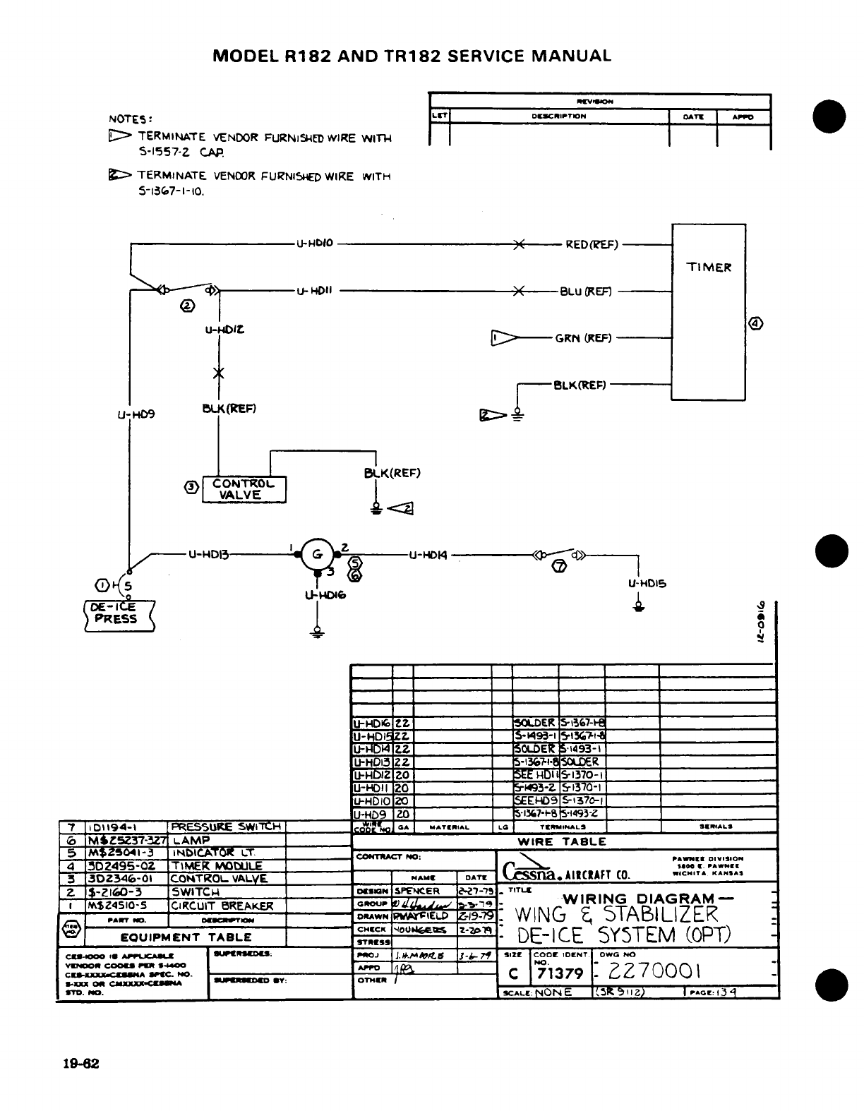
MODEL
R182
AND
TR182
SERVICE
MANUAL
NOTE5:
L
-r
DECDPTI ON
oATT
AI^O
TERMINATE
VENDOR
FURNIS5ED
WIRE
WITlI-
S-1557-Z
CAP.
D
TERMINATE
VENOOR
FURNISHED
WIRE
WITH
5-1367-
1-
10.
U-HbIO
,
RED(REF)
U-
4OII
BLU
EF)
N ~
E--
-GRN
(REF)
,
{-
BLK(REF)
U-.H9
.
L<(:EP)
_--
BLK(REF)
'V |VALVE
^----U-DID13
r
-U-HD
--
>--
C
^V5
s4D1U-HD15
(DE-ICE
9/
4
9
PRESS
1
U-HDFI 6Z
5OLDER
5-i567-
_
U-HDWi
ZZ 5-,- ___
_
U--Iz2
-
501iDER
5'1493-
-- -
U-HD13
ZZ
__5-136-I
SOLDER__
_______________
J-HDIZ
Z0
SEE
HDI
5-.1370-
U-HDII
20
_
193-Z
5-1370-1
U-HDIOZO
EEHD9
-1370-i
_________
______________
___JU-HD9
Z0
1-i%7--
S-1493-Z
_____
_____
7
01194-I
PRESSURE
SWITCH
_______
c.oa
*
MITIIAL
LG-
TEmINIALS
IA..LS,
6
M;Z5Z37-3Z7
LAMP__
WIRE
TABLE
5
M$5041-3
INblCATOR
LT.
COCT
NO
oo
4
5DZ495-OZ
TIMER
IODULE
r
O
.,,
A*".
3
3DZ346-01
COHTROL
VALVE
NAMc
DATC
^
SSnaAIICIAFT
CO. C,..CT
A
KAN.IAS
Z
$-ZI60-3
5WITCW
D____N
SPENCER
27-75
TITL
PAIZ4510-5
CIRCUIT
BREAKER
GRC
2OUP
.
-WIRING
DIAGRAM-
_
RT
,D
T
DAWN
PW,,
FIEL
z-
5-
WING
t
5TABILIZER
EQUIPMENT
TABLE
Dj°i"
zo
DE-ICE
SYSTEM
(OPT)
CW-1000
C
APP
jCAE
W :
PTOJ
J.J*.0tS
3}4-.f.
SIZE
COOC
IDENT|
OWG NO
fCAX
AC
^=LV-O---5
-ID
C
71379-Z
270001
5-m
lc c0;I
dXXII3-c/
lt9
BYf: OTdrnl
Tm.
No.
SCA^ LE:
NON
E
|'5R
IZ) I
Por
3:
1962
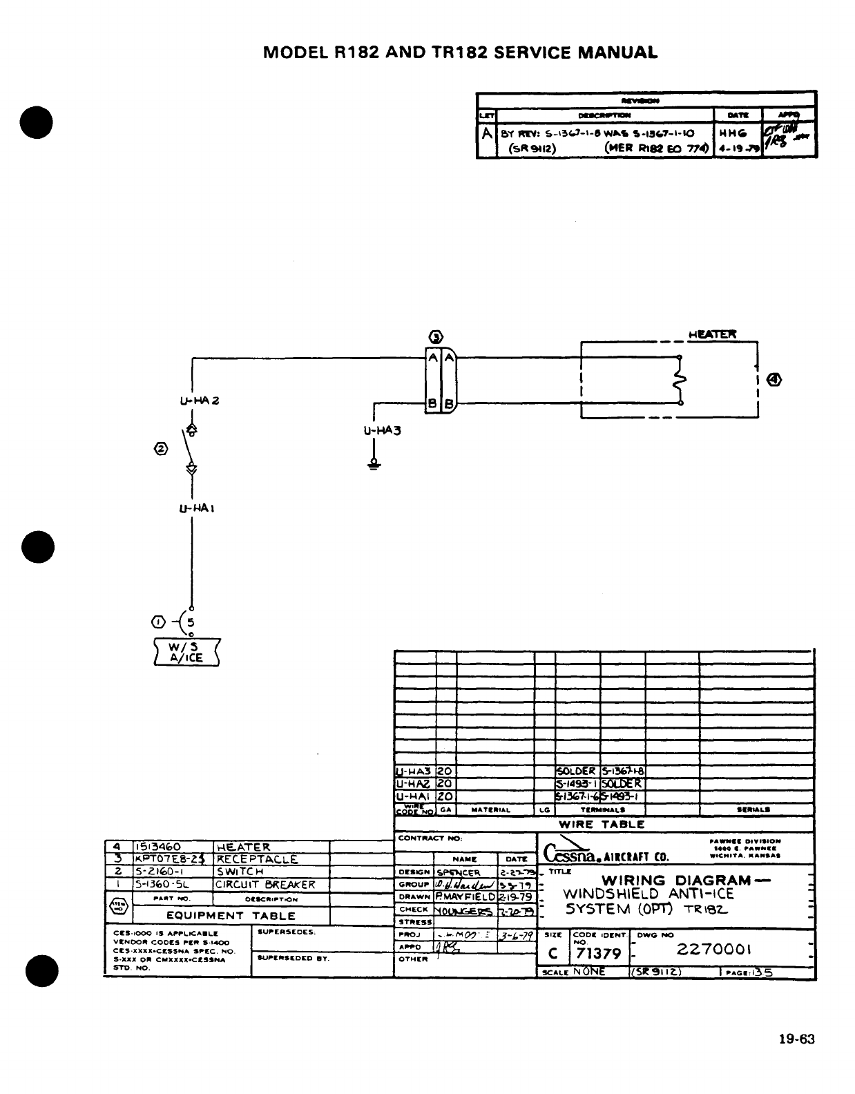
MODEL
R182
AND
TR182
SERVICE
MANUAL
A
BI
S-53:7^-I-8
W,
S1.3s7-I-IO
l
H
HI'G
('sR 9112)
(HER
R182
EO
774)
4-19
1 jA
LL-
HA
2
H-B-
8
\^Q'~~
U-HA3
0
1
w/3
U-WA3
20
ALER ___
U-H/I
20
___49- I
E
_
D A
ATErlAL
LG
TERMINALS
SERIALS
WIRE
TABLE
~5J
KPT07E8-
KECEPTAC.LE
------
___
NAME
W
.
20
_ C.
NSA_
2
5-z2lo0-1 SWITCH
DESIGN
-i
WIR-IN
._ TDIAGRUBA
I
5-l3.o0-5L
CIRCUIT
BREAKE
nou
tEAKER
GO
/J
U.-
WIRING
DIAGRAM--
.P.A R.
.
OF
S.CR.PT..oN
DRAWN
PMAYFIELD
Z-9-79
WINDSELD
ANT-CE
U--- o«,T
- --
APMF
gf.
WIND)SZIELD
ANTI-ICE
:
I
CHECK
5<
ENA
(OPT)
Tnki3
L
EQUIPMENT
TABLE
--- ' -
S'
SYSTEM
(OPT)
TAL
CS-151000
5
APPLICALE
SIUPERSEDES:
I
J
L.
r 3
-
SIZE -CODE
IDENT
DWG
V2NDOR
CODES
PE-
S
Wl
-A0
-_ T70Z07
CESXXXXICESSNA
SPEC
NO.
C
7137
CE5
XXX
X.Ct55N
I
S 1400
rro
C
71379
227000-
S.XXX
OR
CMXXXX-CESSNA SUPERSEDED
BY.
OTHER
_
I
.STD
NO____ _ _ ___ __.
X____
_
SCALE
N
ONE
(5t
911
)
1
PAG
13
5
19-63
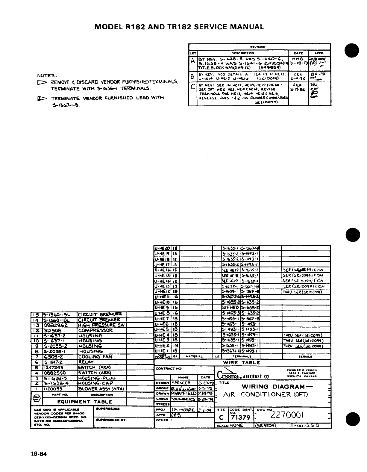
MODEL
R182
AND
TR182
SERVICE
MANUAL
LET
UJCRIPTOT DATE APPO
A
BY
REV:
s-K.S8-5
*s
5-6.40-(.,
HG
W
5-l58
-4
WAS S-
l41-4F
45R9554)IN
, -
I-7
'
TTLE
BLOCK
wA's911R2)
(SR'9954)
'
NOTE5:
Bn
68
ELV:
aDO
OETAIL
A
'
E.I.
4
U-HI.,l
et£K
1
../r
_5.-uL*,
u-U-'s
Li5-m.LI
(hioco~1
, .-
4-~4
,,,;0
-y
EI
REMOVE
D
DISCARD
VENDOR
FURKN5BTED>1MINAL5,
b-
.-. ,
u-MS ^7t
(',o,,q)
N
.-
4-U
TEICMINATE
W'TH
5-tf6S(o-i
TERMINALS.
c
5.A
CUT
H Ec, 4,, wL4 .. ,CIJ,
L.vlEo
3-il.
A.o
tl..f4t 0e. 4ll,
Ct
H
,.15(
.
St./,
W,
>
TEKMINXTE
VENOOR
FPUNISHED LEAD
WlM
REvtWeM
E
N
/
4 lZ
ON
ULiWatI
L
G-156T7-I-b.
U-ME2O
8
_
-13S$-l
,5-134{-
u-H
____ 1s-ii35-2 S-Iq.3
_
U-EI18
I__
5-.3S-2
5-I^3-
___
U-Ia
I
_________
__
-2
5-1,3-
_____
U-l171
_ _5 SEll1S-2I S-If'flI __ ________
U-H4I
lb
I
__SEE
.17
5-I5S-I
_____
L
&
(SAt99l)
ON
u-HIE.5
_ __=
SC
WEI
S-ii.
15-
So-t
(-t
00:99-
) I
U-HE4
1+i _________ __5 Wq
S-,
-eS-
E
(elO 4
ON
U-RtLI
It _ 5-/
-35-
5-13Y.7-1-8
E
'
Et
(SI>100
9
9)
4 0N
uE1
t
_________
i5-il
5-
ua7
ER.eo
U-HEII
16
__
S-LT-
2-
S-9a __
5--£
0 I-_
S
_.- I
lfc35-
____
___
U-HE
9
10 16
SEF
.
aE
-5-
S-Z_
I15
-13460I
5L
CIRCCUIT
BW6KRM
U-E
6
16o _ S9-
S-
t635-2
14
IG-1360-mOL
C-ACCU.ITI
BRKEI
4
I -~r
,
1
-%--H
3I
-
SZ.zZ
iIGTC
FPESSultE
5W U-l
HEG
8
_
5-
193-
i5-1493-_
I
5S50o
COMPRE.SOR
LE5
t8
_5-1493-1
5-1493-1
__
II S-1
57-Z
cOUSINGt
E
IE4 IE
a
_5-i43S-
5-1493-I
t r______i't S(tq
10
S-1'37-I
HOUSING
____
U-HE
Il ___I_ _
le5-5-1493-
1 r___ S ?Cw
19)
9
S-2035-2
-0OUSINGC
U
-E 1Z I_____
5-1
5-l
S1493-1
'___
Rv
TJ(Wl(iooqt)
5S-Z035-1
"OUSWltcw
U-WE
I
18
_________ 31-
5-1493-1
__
7
6303-2
COOLING
FAN
t
c'
MATERIAL
LO
TRYI|AL»
ll*
(
5-1917-Z
KE.AY
I
WIRE
TABLE
51247243
SWITCiH
(AXA
CONTRACT
O-:. A
DVSO
4
068z590
SWITCH
(A.)
rr6
\ o
r
.
^.
35-1&O38-5
IHOUIN6-PLUG
NA
DATE
CSS
la.
AIRCAFT
CO.
WIC.IT.
,*,.
Z
5-.38-4
WOUSINC-CAP
oor
I9
5PEWCEI
2-2
_
TITLE
I
I
IZ0059
BUSLER
A55Y
(ArA)
erU
t.l
/
-9
WIRING
DIAGRAM-
,,PA,
,.
I.
oAWN
PMAYFiED
Z9--79
AIR
CONDITIONER
(OPT)
EQUIPMENT
TABLE
STRESS
cS-
Ooo
o
umjCAulx
| atP
ROtS
nJ
JIt.r^O
3-L--
si
CODE
DEiNT
owC
NO
VW400
cooCe
0pe
S*4oo
_7S--*
NO.
-
Cis-XxI»C*wA
-C°
1N. C----
C
71379
1
2270001
XXKX
OnA CMXXX-COU -I09
*Y:
OTHER
I
-
ITO.
O.
SCALE:
NONE
,
s)
5
t .o:
i3
*
0
.
o
19-84
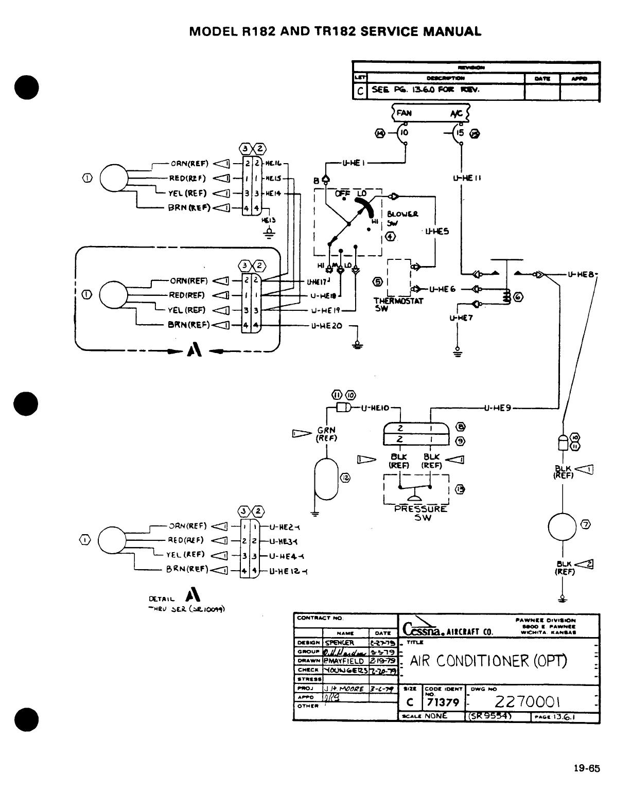
MODEL
R182
AND
TR182
SERVICE
MANUAL
I
-ORN(REF)
c<-
2
Z
*-lt.-
U
HE
I
ED
R
BDEP(RF
-
)
-<3 -I
U-EII
VEL(REF)
<3
-
3
EI -C
- - L
i3Ftrrt;fF)
[:::
::>
4
___-- _L
_T__
>J
I
.
Q
®©
I wl r -m O
L
_a4E-
ORN(REF)
X
-
2 _ _ -L1 ..--
L
RED(REF)
3-
.
_-
-<94
E
J
THERM0T&T
V-EL(RE)
<1-3
3
U
-
-H-19
SW
BRN
(REF)-j
4
_
U-WE20
/
@0
..
C.^-UMEO-
.
AT
-rU-F^E9
--- /
:"
GRN
. -
ORN(REF)
<.C -i
.
I
-U-NHE-
(
o
(EO
(RE
F)
-,
2
2-U-.L3
-'
YEL(AEF)
-<
33
-U-
ME4-4 BLK
--BRN(RFF)c3-
4
U-HE
1?
<
(REF)
~~~Ot-L~~~~~~~TAII-~~~~I
I L**
CONTRACT
NO:
PAWNEE
O#VSKSON
oc053G
SPE4C7ER
C
-Z-p.
TITLE
oA^^WNrPAYFIELD
2-
AIR
CONDITIONER
(OPT)
CHECK
r
'
t5
-
P02J
|J
J4
OORE
t.-L--t *al2 COOt
1OcT
|DWC
NO
^ OTg C
71379
227000
SCAE
NONE
P(SR9554) c13.9
.
19-65
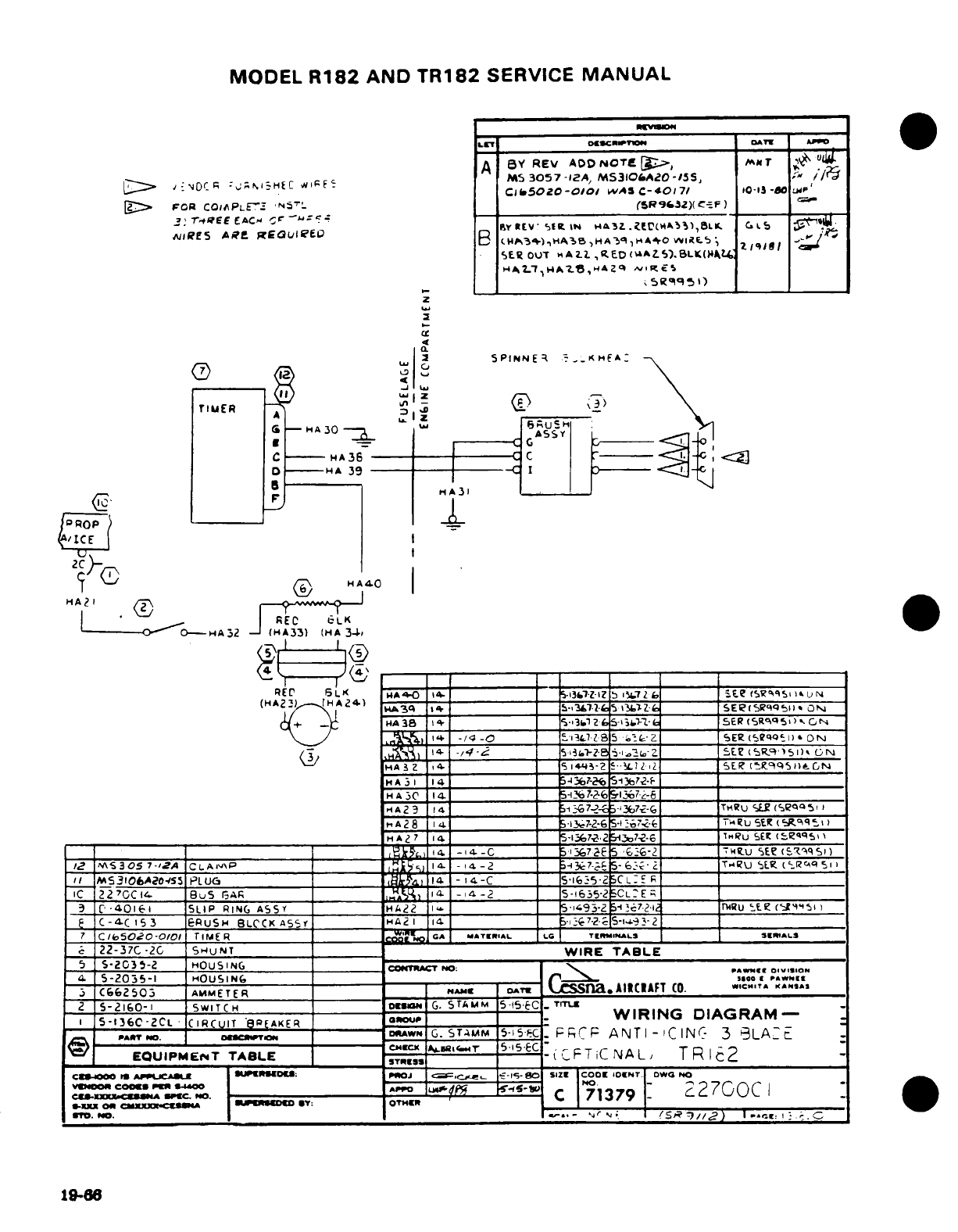
MODEL
R182
AND
TR182
SERVICE
MANUAL
LT
I''
O(CUCIIETcN
IAT
AP
A
BY
REv
ADD
NOTFE
g.,
MT
,
,
"
D,
,-
-
-~-HtJ
C M53O57,5
3057
-12A,
MS310iAZO-155,
, //
0~
r-:NOCR
--
^M.nEC *RF-
Cl
I.5020-0101
WAS
C-40171
10-1I5
-OP
FOR
COI|FPLEF
'_N-_ _
(SR9s3c)(g-
F)
:
,
'T',E-
EE
ACM
r='
J
.-
'
r4 ^EE EAC,-
^-' -_-
--
rYRV 1
I
IN
H
Z
.
EV(CCd
A
^)
,BLK.
C.
L
N^IE5
AR.
REauiPeE
B ^1HA.3 3
,H
A3^A^O
H*A
%
It.
SER
OUT
A2.zL
,RED
(0
AZ5')..BLK(4Jk,
z
4
i
SPINNE~
%-.;KIHA:
i
--
_--|---
I5P
i
N
E
~-
-_
_
\S
_
S
-HA3o
4
W C s^ _
__<
1
--
A
-- ---
C
----
3
-
9 |, <
]
HA3
C
HHA
31
(<
F
i
ICEI
: 8
HR
40
Ti
/
Z
HA4O
I
*.A
R
_
fiEC
LiLK
-
O-A0--
HA2
-
(HA33)
(HA
34-
RE
,
W-0
1'
I |
-
I I-
-
I-----_
RED
6LK
o^-I- ___________ 53l-IZ b 7ZZ
.
-
____
e
<SgS
iN
(HA^2-HA241
,I4A3
q b1
_5-,372-(e 5 t- (____
SEi(5R9b511i
ON
+
_)
HA
38
513__ Zf_ 5_CL.36
SE
SEPSR 5 qi CN
/j %.4 I-+
-/
-0 .13 ,'7..
B 5
,
____ a
SER
(5Rq 1')
*
ON
(w/
____
-14
,
-
._
-2
i-
l-
5E.'2 (Rq-) t,'I)
-N
FHA
Z
4-
_142
-
L-..
1
,
SER
(t.9qQ5
I. GN
HA3
I
14
_
-
3 ______ _______________
HA5C
14.
__________ -l72-6
_
HA23
1 4 ___R___ ;TU 5Eg7
-
____ eqq5_
I
H
A28
1 _41_ S
137--6
-l7.<- ________I
T-u
SE'R
__
HA
7
14.
5-1lj6.
-72
3to7?--6
____ u SEI
(
qq^q'
14
-14-C
=
1.E7Ce
-5
G6-
____
-U
SE.
(IS'Z'qSO)
|t2
\S3305
7-'A
CLAI
A
I 1
-14-2
3-.1;-7-.
5-6
:-c-
_ T,' U SE.
.
(l'Rc_.Cq
I
/
M53106A20-/55
P
LU
____ I
14
-
14-C
5 6l:-5
2
CL:C
IC 22'7
CI4
BuS
IAr
14
-4-u
5
S-
3
15
-1-65-2
CL-ER
3
C'
O01E
1
SLIP
RING
ASSY
|
HA,22
i_
5
-193-2
5-1 7.-2.1 _
ITRU
r.e
(-
t'454 i)
E
C-4.C
153
ERUSH
8LCCK
AS5Y
FA2I 14 ___ :__I
7-2-c
S-.-33-
2
C7
ClIbSOO-0,01
TIMER
___ w ;1 GA
MATIRIAIL
LG
Tt
IIM.NLS
.
.IALS
e
22-37C
-2C
SHUNT
WIRE
TABLE
5| S-2035 -2
HOUSING
____
CO
NO TnCT: \ PA OIV911O
4.
5-2035-1
HOUSIN
_________ s agI rO.
n
,
C1662o503
AMMETER
I
I A
I'
D t
.AIICAFT
CO.
iC"-.A^ S...
-
·
3
S-2160-1
SWITCH
o
GIoN
G.
STAMM
5-t.
-EC
Tr'l,
I
5-.36C
ZCL-
CRCUIT
SPEAKER
|__
ou
-_:
WIRING
DIAGRAM-
PAR--T.,,.
--
0.. DA,,,m
T
---
oAwN
G.
S
TAuM
5-S1-eC_
F F
ANTI-
CIN
C-
3
eLA:
._ 5"s':~c'E
C C,
T&iCa.4
T
Ec
-12
EQUIPMEFtT TABLE
~ST_
Cm1
_FTC
FTiCNALJ
TRC
2
Cu-ooom
10
Ap
m itCA*L
1UEI: _OJ
|igpo_ c
.l5-8rO
SIZ«E COOD
IODNT
DGa
NO
VuorCi
COOK
PER
-440
APPO
,-
CM-2
^SLSSL^
'
o;.
--
_-
-
-t**
E
"
NC
71379
27GOCI
I*-XX
0n
c-MXX--z
I
*,oW SY:
OwTHR
__
31.0
.
NI
I___
N,;
,
-s ,/,) I.
c'-l
, .C
19-66
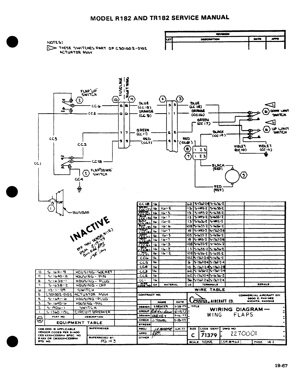
MODEL
R182
AND
TR182
SERVICE
MANUAL
i~
FLp'UP '
I
s
TES
CC(
81
c
-
._
C I
C.C
_
BL4kN
I
0
A ^ ----- ^ ----- a a
--
(cccc
--
3
---
jW
BLUE -
)(7 CCCI-)
(cc
17.--
CC5,
5-
mc
4
CC]
_ 9
'
<7)
(
II
~~~CC
~.
IC>
CL
-
(1- 35>r:i t6l*
lb
-i2 (___
____
1J
ila-
IS
'-14,3-2
*,.1-_ _,S-?.
atbI i.
-
_ :5-- -'5-.
4 \^
(
5-3
oq
_, \C 5 WIRZ TA5
352'
d~. ~- IJU52wAR I
-
/,,.13 .A-23"- 2
,.t/
-
_
A
*S" 1-- -ioS-O
ia -b2 ___-_
Cs
(o
-
b
SSb 2 5lZ
'?q~ i _
c\-
54
-/Cal a05 I\'
C
"
Ala
.-
2
5
11.32
.
E U IPs MEN
i
1T 'TCi5
z
C
W
I TABLE7-Z
4(
ea-i).Ai-Lo
^4ci'
ra
"
_a 0
*t0Cl-24
«rw
______________
|,I,,ooR
o
,
|
WIR
DA-RA
II
t
S
Z-
,4S>
M
¢,4-
PA3T,
-=.
, ,
jtA.W.
,,
o.
WING
FLAPS
C'ar
w (^
%
___3____-
I I3- O ABEITCA
_
_____ O
WIRE TABLE
_
|_5_|_CZ0\
oa
C
-O___________O_
____
_____
_
COEThCT
NO
|
COCIAL
AIRRFT
DIV.|
S-X
I
I
OR
PIN
C.JIXX
..
X K
XC
I"
Nr
Sl
[EDD
BY:
OTHER
C
1
9J
3
L-
NA1D40-A
|DUMS\Ij-
E
CI
|
__|_ ts na. l
\IECAFT
>
co.
WI
_TA.
KASA
I
I \ 15
\b-t5L
VOU\
tA<
-
P> 7___
____
_
C
o
______ <«2r
S-^LT-2-4
.b-b...
WIRING
DIAGRAM
-
-
PART
NA
.
|
DXX
ltT
lDECIP~lUE
I 7
_
W
ING
FLA
PS
|
-EQUIPMENT TABLEC ______
SRESS
WIRE TABLE___________
CEDOOD
0
S
APPLICABLE
C UTU
PERED"
ESl CONT1J
10:
'cOcLC SIL CIcT DA
ovO
|VDOR
CODEI-
S
rA- M OU4
\ -PUb
PERD __ c.
C.M
A 7 9I
C|
--
I-
CE
---------- ----
S
oSTr
SSSNC A( l AF
T CO.
wUOCrC.
SANY
O
STo
NO.
EUIPMENT
TABLE
L
Ot 5. o
14
1
S.X 01xZO RCMXXXXmoaCE4AU I
CDID
B:
OTHCR
/ -
'*19-67S
^^H
«TO.
NrO. ___________ ___
P5
14
3 __ __
aALt:
3NSt
CSP-Q0b'L(
.Z
POE:
i4|
19-67
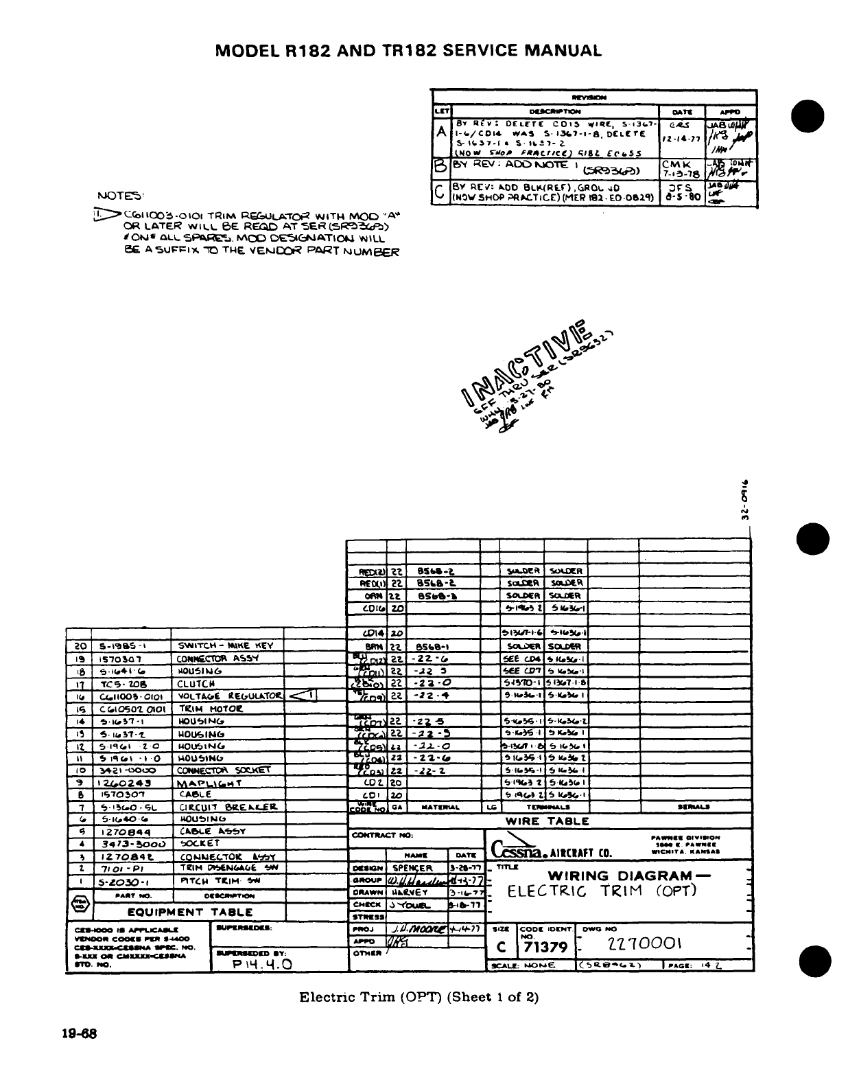
MODEL
R182
AND
TR182
SERVICE
MANUAL
LET
o*DucTawv,
OATE
o
APO
___^______O_______________ 17-A A18
P'v7
1dO1e
OkLL
SPARL-.
K¥
DER(I
AC-T
O&.i
WILL
F A
5U1FFI,
70
Twp
VEmCJf
PART
NUL)MEFR
AO·J
isI (A
122-//COI&-
WSc
S
3-I..1
_l-a _ _ _
T_,
_
5 lq(.1 -I 0
mou'51"U
1S-l
22$37
·
I(-
I 1 1rl
2.3
;LNoI
s'
___
F/_'
cr/cg)
,;1g&
£ce,.s
,__
_
20
S-I
e9S-I.
SWITCH-r R:
OD
L.(R..
.
40D
'F
I S
I'3es-
I o
I7I-5a
C
IOVscO
AO I RTICc )(MEL 9a -2
.O
c
)
I-N
LI
__-
'
O
a*,4C.
SouAW..
5O _
D -5=ATlO
',
oIR TALLL
c120844
CLuTCH
o 2 -23-0
____CONTRACTNO:
.1(i
CI1100
-10I
dOLT*A(C
E
I
E
bULL7
Oe.
,
I~[
/m')
A.~
-22-4A
5.14,.-i
ST-
I
C
el AouF7o
01
T
TM E vOl E PT M.
t i1
of
-t U0UICIM
_______
E
.-
3
-26-In
II
Si'IG.
1'O 1uO
.Jc,
-I
10
,4a
-O3o0L
C.mOEC'"
T
,,o
_2_
-35-2
.
-_
rI.N
G
-
sDIA
A
MRI_
0
121,043
S'L
C.s
_ _
A
WN
20_ as.LCa 5ic.
_ _
=(SPTS)
P"7
5'O·C.0-,L
CIC'
UIT
BUE.PKLE
__ _
Clt_ A
MA
L
_ _4 SERC
2L
S
=.
.
6-sc-L-c.X _140UN
TAL__ EWIRE
TABLE
4
I270844 CCOOK LE
A51
cO
Z -t
-no
Af
e
Elct
-ic
9Sh-
_
>7 ELECTRT
C
TRIM
(OPT)IWo2
'87 S 1@41
fi
vOUIPpTo
4
-'2
SI_
CE
NOLWO
NO
c~uns~am'
-o.7O
IQ[
C
,~71379"
?i1QOO
Electric
_
Trm
(OP
(Sheet
1
of
2)
C.
S L :SbK-l 2 _ S..
5l
5,¢
O1
.:
»
l~
EUIPMENTOW TABLE
_
o2 708T. 4D.
t _______ _
L
DAW
a
AI«A
O
C___ ____
Electric Trim
(OPT)
(Sheet
1
of
2)
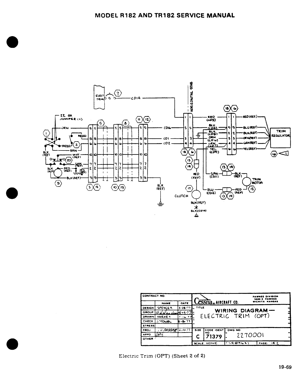
MODEL
R182
AND
TR182
SERVICE
MANUAL
f-.JUP~~~~ ~ASLSKW)
S
Ft-°,, 3 ---- c^
ll-------
,EAAT
,,
(a
_C--. ;- -
1
/<®
BLK I
I
C)ii
_(
^ (cV6)
B
L
-
-----
--
tt--1
CONTR-C--T
NO
N
---
pAWE
--
I
VS
IU\
-O
laDE -701
)«
;-
-
L
CTRC
T
R
11
(OPT)
)
B1 ^ V^^Be^^Ba--j-as---.0,---3K3 -£-^»CHECK
-
--
'
b
*(
IRD-STR
---
E-SS_
, - -
^
j
^
-
0
7G7
O
ER'
CI
7
7
t 3 7
97
01
A AEfae
AlC
WVAF)
T
c,,.,RIM
t
(G X
%EFN
.
)
BLU-n,-'
--
TIit
Eltric Trim (OPT) (ht 2
of
2)
d
CLIUTCH
esF19-69
BLK(CO'O)
CONTRACT
NO:
^^
PAWNCI0
MICINO
orsiAN
SPE
iE_
3
")"-29-1'l'
TITLE
_
GROUP
Zi
WIRING
DIAGRAM-
DRAN
L^f. -^:
ELECTRIC
TRIM
(OPT)
CHECK
-
~DUgt
b~lb.n9
STRESS
::OJ j
-
SIZE
CODL
IOCNT
DWG NO
OTHER
C
171379
ZZ70001
SCALUt
WO"E.
e ->BPe0
(
x)
)
|r
g
Gto
4
Z_
Electric
Trim
(OPT)
(Sheet
2
of
2)
19-69
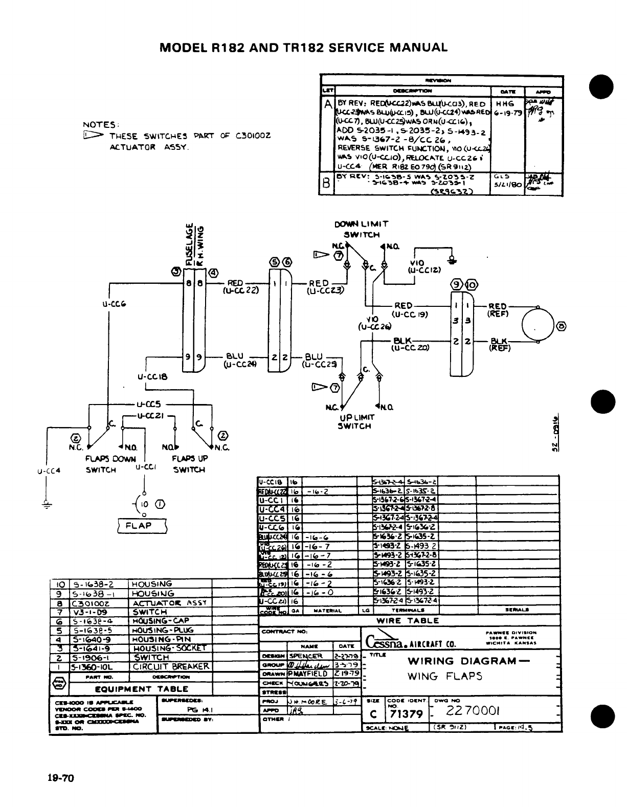
MODEL
R182
AND
TR182
SERVICE
MANUAL
A
BYREV:
RED(c22).^S
BLULU-Cc3),RED
HH6G
PI< 8uCJw(B
u-ClS),U(-CC24)aI
RE
Ca-19-79
7
¶
NOTES:
(U-C7),
BU(U
C-2Wk50R(uS (-CCtl),
THESE
SWITCHES
PART
OF
C30100Z
A,
-2035-l
.5203-2
5-C493
,
ACTUATOR
A5SY.
REVERSE
SWITCH
FUNCTION,
ov0(-<
WAS
VIO(U--CCl),
RELOCATE
U-CC6Z
i
_U-CC4.
(HER
RiZEO
79Td(SR9iaZ)
B
fv:
RC-
5-l,5,-S
W
i
S-oL "5-
Z
G
B0IB·
*^.e-»
«
t-Zo3C
I
5/18
0
_
uj
D(ON
LIMIT
-
IZ
SWITCH
-
8
8-RED
-RED
U
(u-22)
(U-CCZ
EDT RE
u-:CC
I\--
LRED
-- I ,I
-RED,1
Jo
(U-CC
19)
(REF)
-LK
Z2-
BU<K·
(U-CC
O)
(REF)
939
9-
BLU
--
Z-
BLU
(U-CC24
_
(L(-CC2
23
u-cC
_
U-CC
Is
*--·I5--
-) / I
u-5
MC-
D
U-
C21
UP
LIMIT
/-- C 11--
C.
iSWITCH
N.C.
O.
N
FLAPS
DOW
FLAPS
UP
U-CC4 SWITCH
U-CCI
SWITC
U-CCI
b
-b
,
-2
L__
_ _ _
S-_,S-
6 Sat.-.
lb,
-te-ZS.-l3.
S-l3g-.____________________
r-j
--
2
~
J IeU-CC I I
________
__
-5726
-i-4_____
-iko FLAP \ j-ctfelU-CC4
16
-
S2
i___-___________
UCLAP
-4
___UCC
1
_2
FLAr 1C
-K-
3243 ________
-iS6_-1-4
,_________________
16
-I(*-(,
IG5--Z
io35-,Z.
)
1
-16-
7
5-1493Z
5-Z
493
2
H.KC I
-l1b-
7
_ _
S-93-Z
S3.7-Z-8
Rd1u.C~
16
-1 -2
5-193-Z
5-10.5-1
.,___________ tLa
16
--
6
_
193-Z
5
35-5-2
__
1G
5-
638-Z
HOUSING
__ ____ La -_ -6
-
2
S-iafeZ
5-I493L
9
5-1(
38___
o
-I
HU-O _
SiG
Z
S-1493-Z
_
a
C50
oloo
ACTUATOt
ASSt
J-CCl
_
____- _
I6Z-4
15-s7-4
7
V3-1-D9
SWITCH
'o
MATRIAL 1G TEL
RWLS
'|M"AL|
6
S-l63e-4-
HOUSING-CAP
_____
WIRE
TABLE
5
5-163e-5
HOUSING-PL
UG
COI
: DI:O
4
5-i,40-9
HOUSING-PIN
__
_
.......O
,".
~3-
I-1-9
HOUSING
-SCKET
|M
I
OATE
L
SS
AIRCIAFT
(C.
W
.I... ST
2
5-1906-1
SWITCH
^i
W
-I
AT
TTL
R
I
5-1360-IOL
CIRCUIT
BREAKER
oo
4 l39
WIRING
DIAGRAM-
PArT
0..
o.Se~T
RWN
PIMYFIE
LD
Z
1-79
WING FLAP5
C?/)~~ 04E-- *^ ^-
CHCK
"
O
Gu,
'
I[-TJD-"W
EQUIPMENT
TABLE
IC MO
&
|
0csooo
r-
|pCl
*C
«* *IUw·Io1 I+.j P. )POJ-E
.
4-71
|i9|
COol
IOENT
OWO
NO
B orucoo~m ~PO,
4s1
AO
Tla |I Cl_ *:O
C
71379
2270001
*,P. no.
*
w-- __^ct--^ BY--T- I
SCALE
IgJE (So
1iZ)
PAg»;
.E
19-.
70
.
:
(
19-70
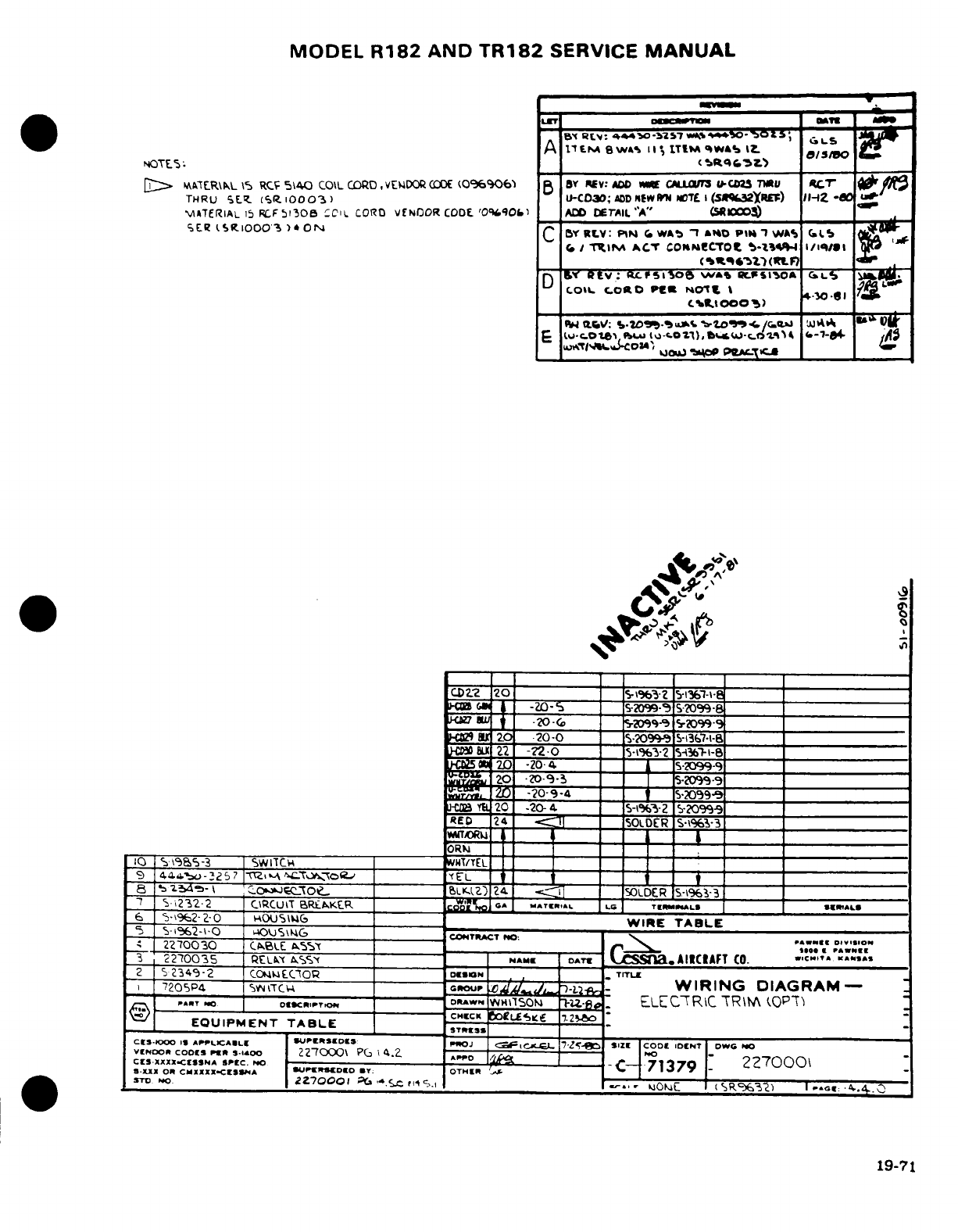
MODEL
R182
AND
TR182
SERVICE
MANUAL
LET
GVE
-
A
1t1sA
Swa IIs,
ITIM
T
WA%
I> 0/s/
NOTE%: _
%t
C.5
)
D
^'TCER\h
L
»S
RCF
S 540
COIL
CORD,
VEVADOR
CODE
(O0%906 5 B
BY
REV:
AD
CALLWS
U-CMU TW7U
ACT
.
THRU St 5(R
10003)
U-C030;
ADD
T
PW
.
TL
(SCu2IY
)
IH-I
-
MATERIAL
i5
RF
5l308
;CIL
CORO
VENDOR
CODOE
'Oq90l
ADrD
^r
AIL
"A"
cOOO=
_
SER
SRAIOOO3
)
ON
C
BY
RLV:
PIN
W
*O
4
1
^
W1S
PIM
Ii
**3
C.
I
1Ini
ACT
coNM!cTot
&-1i4i iq1/1i
-20 (-C^t^
(V
I
..
_M
__
____ _
-
S
,i
t
v;
ftcfIA>o
w BIA
r5~
'a
L'
2
LOL
0C0«0
P-t
NOt
I
2o9
IlI
_Tc. 5.ot; %;4/
¢ s".
)
a,"fFT_.R.0I~ ~._,
_-2,:0-S-A
=
'
Ci :: ___p
Z)
-I8
T2CH
-20-20S4.
-I-2
S?09-
______
___4_
=
,'
_- _-
7 TZ~
-
o r"~:TAIL_
"A"________)
,-
RED
24
-?2iDER
S-13-3
-3
5[N
2'0
-20'
*^
"
_
N
5-2099-9
I[=
I N W & "___
I___.
_
SieSr~o *?0_____
______________
wCB
t201
-20-
4
S-I_'
CO
099-9ICT
-?'ql
10
5
95~-3
I
SWITC.
wl/T
EL
_
9
414&6.o-3257
IToC oL
L
~ ~ i _ _
_
8 = zi.- 1 'O b1a kTeZ) 24 iT C_ _SODER
5-\%
-3_,.sER
t7
'
i232*2
CiRCUIT
BRtAKXR
GA ccAT'I
f
AL
LO
TEBIALS
*S"^AL
6
S-962-2-0
iOUSlu
_____
WIRE
TABLE
5
S-1962-'
0 PcOOU¶
SG4
COTrCT
NO:
rll, -.
o,.,so0
22T0030
CkBLE
ks
___ ___0
--
1A.l*"
3
2270035
RELkl
AS
M
OATE
CcSnal.CAIIAFT
CO.
..
CC.IT
..
N.S^
2
2349-2
CO4ECTBo
DES_____IGN
-
TrTL
i
7205P4
_S___TC_
_
crou=P
)72
-
WIRING
DIAGRAM-
__-__
f^AT
o.
---
R---- ADWN
WH*S10m
hu-d
FLEC7TRC
TRM
A(OP-T
EQUIPMENT
TABLE
STL
ESS
_
CIS-
000
IS
APTPLCABL
|JWPRTSCOD:
PoJ
Ncf C 17 S- SAIZl
COOt
IDCNr
DW
rO
vErooR
cOMS
Pr
s3-l4OO,
227000\
PIG
I4.2
A-
71379
T
C
S-XXX:I[CSSNA
SPFC.
3O o C--
71
79 2270001
«.X1X
OR CMXXXX.CISSA
IsUWMWDEO
Y:
OTHIII
I
7-
*m
STDO
|Z_
_,2270001
-C.
.C.c
l,
5.,
I '.--
JOiC
R
I
(S
3C)
.
-c
.4..
19-71
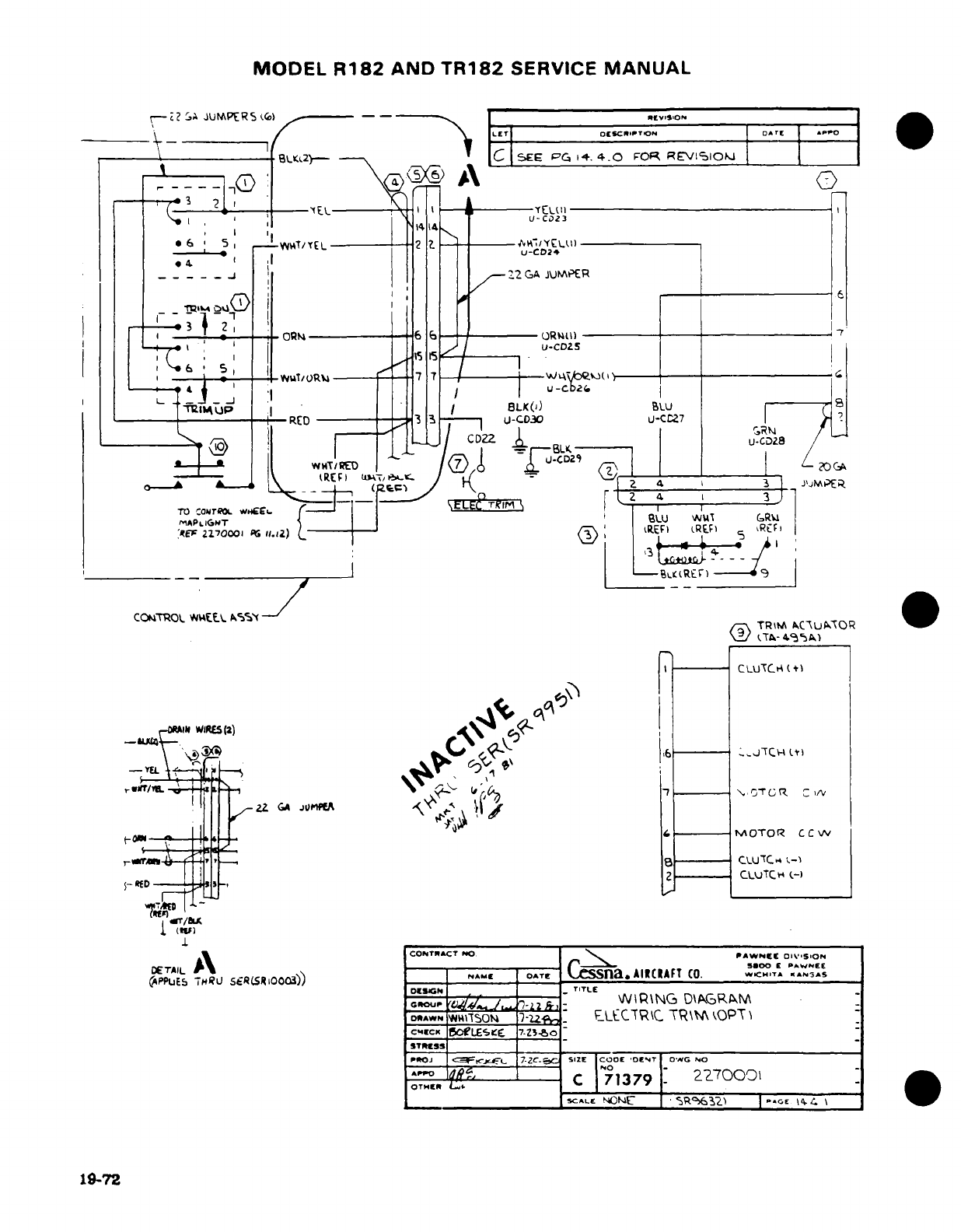
MODEL
R182
AND
TR182
SERVICE
MANUAL
;-> 2
AJUMPERS
<
--- '
mvso.
1- 1 n
LET
ow|vo or
OESC
I APPO
____
-\
-
B32- -C I
SEE
PG
14.
4.0
FOR
REVI>lIOkj
i
i-
C2
3--
i6_ 5,
_WATYE
L
2 tZ I
_C
r\» ~I l
S
OQ
6
6 _
~
U-CD23
I '1
I
I
*
u-CD28
_Ii
2
GA
2JUKER
T^PlIG
Okl
I
t
OR4I)
R7
'
t : ,.,=, X
-- -
<
' .-
co,.)
u-
c
( I
-A
RED
3
-.
TU 9
-C030
LU-CC27
CzTR O cwrT ROL
w
.---
L; |
.
CONTROL
W
-E/L
Aics%' TTROLA
AC\UAOR
W
TA-
44
A
'i.)A
CLUUTCI (4+
ofiii~r=Ft2 Gz
*vnff
-fi
7
-MOTOR
CC
Iv
,./ ^.r a
le
0-
uTc_
c
I
1
(,
f-
DETAIL
sIs|oo| NAME
|AE
Cessna.
AICRAFT
CO.
CHTA
^
s
OESIGN
TITLE
|ccouw
^^Tl4
J.3-
2S.1-
\NIP\NG
D\AGRA
GRtOUP
It'2
P,
o*R^A
^WSOiN4
)-z^z:
ELCTR\C
TR\
\kOPT\
|
[CMCK
5BoLESeCF
7-.Z34o
|STREcsS
____ ___ __
P*OJ
a< ~ltrxg
7-ZC-
c SIZE COOCE
'OENT
D0G
NO
I
I
-2C
71379-
2r0001
-)
_^^ ^ _____ ^^^^
SCALE
--
M{~
*
ERG^ I E \
*
HG
E
E
19-72
Ig-72~~~~~~~~~~~~~~~~*
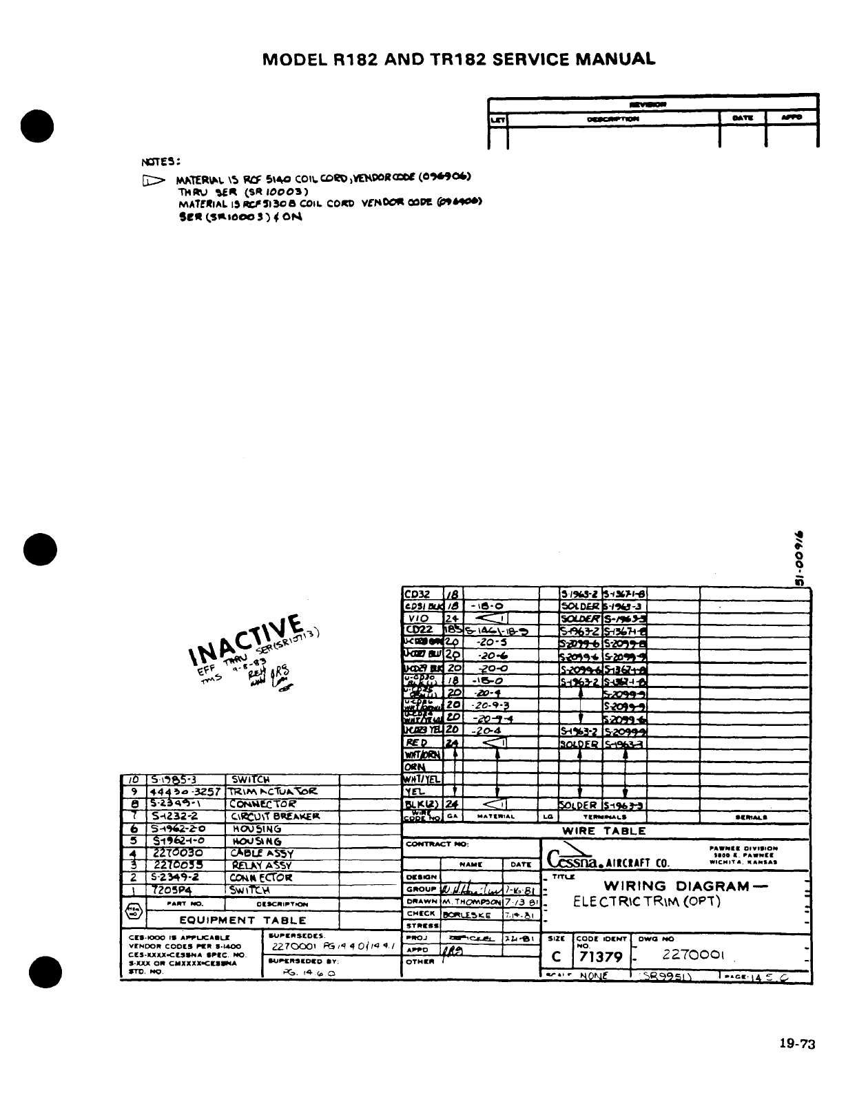
MODEL
R182
AND
TR182
SERVICE
MANUAL
MSTE;5:
[0>
INtEREI,.
\5
Wf
5\40
C01i
CDD)VEOWDOROCZE
(0(O'0t)
THR.U
ltR
(SR
10003)
MATERlAL
5IRS.F5l3o
COIL
CO0o
VmNOOK
00
D
(p
90)
git
(S111000)
4C
0
S
0
cIpO
a2 4I_
-
'o o
.
513..ISO____
_r___-3
.
^
vDo
2+
8
|
o
S-zM
_____
*A 4CJ^
3
'vs9'<'
--
_> -r ___<______-Zo
-
_S
tg-+
+
^ be -e204_
.2o
-20-9-
ZOfL ZO
-Zo-9-3
= I____5n___ __.
t
o
20
-20-4
_%S 5- _ __
o1 5.~$M-3 SWiTC#1 EIo __1
-
r,,
AIC=AFT
CO.
9
44
4o
-3Z57
7R\P
scTu^
_ _ _
I I I I I I I
I
e5-
S-39-\
IC^-
C .CTOT
XC')I
24
SI ROcPERTuS
-S4232-2
C\eO\T
Bat£ __
ccSg1o
'
«tmI.»
, .
__
*tuLs
·^
~S ~'S 20^9
-Z-O
HOU5o N 6 ______ _______ _______W
IRE
TABLE
+
27ITUo3-0
cAPLE
ASSY
NAME
DATX
ClEna.AiCA(cFT
C0.
X"-", .SAS%
T2
0osP4
--
O
C GOl
__
C
OUP
.IL:-/
:
e
-
WIRING
DIAGRAM-
D-ipAWN
M
TM-P-oma
7./3
ae ELECTRICTR\M
(OPT)
V
)
_.
- -
CHCK
Bi
HEC
t FLSK ,l 7-1E _1_
EQUIPMENT
TABLE
STRSS
CELS-KO I 1
APrUCAIL.
ISrIPRSCDES.
m*OJ
;ZC--E
L
1
SIZE
CODO
IOENT
OW|D
NO
vt
DON.
CODES'
54
4.OO
270001
FGRS
4
0^
/
A»
-
.D
Dr
~
cCE-ux
-cuOr *"C PEO ------
-
C
71379
2270001
S-XXX
OR
CmXXXX-ClrU&
SUJPERlDEO
BY:
OTMIHR
[
XSTO. No0
S
.O4
M1bt
O
5R5
l-
|N
~
rON-E Rt 19-73
4
_
19-73
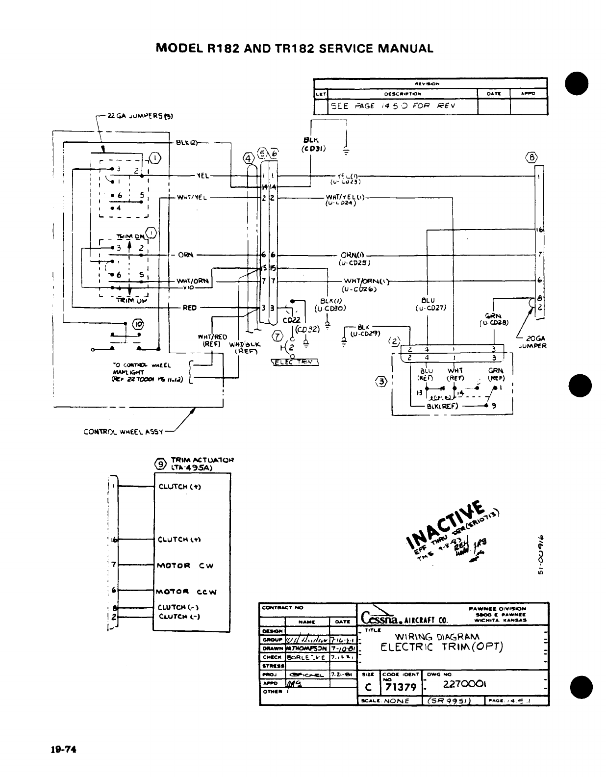
MODEL
R182
AND
TR182
SERVICE
MANUAL
E2
E
E
AGE
;4
5.
FOa
REV
I-^7^ 2 R (..)
_
_
I
.
6,4
10
(u-
-Loa,)
-
+
_I
-
_-R0 ?
-
7
7-
-T
-o
(u-
-Sz)
|"
--
bJvL
.
(
a uCTDSR
Ir*
up|~ '%___ T
"
,i
.
_____
_,
FBL
KO/)
6LU
-----
G
1
__RED (kU 0
(R)
9)
n(CD-32-^ p^^)
4
7 -^
---
i
KK~F)
-
coN*rR(x. waJEEY
*S5'~
-CDf
GA
--.----
,&-ERE r :) w2 *lz~LK
'4
1G U
[P
~wi
---
70
-----
11.--- (RE
-BIK
REF)
----
* )
CONT'ROL
WvHEE[ A%~sf-- '
KIE)-/
<
TRIM
ACTUA^QI;
L
-4
95A)
j
1
__._
CLUTCH
(*)
7
P0OT1p
CW
'G
in
Ot;
6 C.Ot
cCW
*
----
CUTCt
(
-)
COMTKACT
NO
--
PAWNI
OIVIION
1I 2
----
CLUTC4
(-)
.
_ 00. PNWOiS
NAME
_ OT
A AlCIAfT
CO.
WKC.,T^.
K^(t.AS
---
~" --------------
OaWM
, '
-
-
-
..
TITLE
ou
r
-.......-
WIR\G
DJIAGRAM_
LE
.THOP5
7
-/J,-
:
ELECTRIC
TRIFA(OPT)
PoJ
i.c-
7.
Z- St ZZ COOs .Ora OWO NO
scALE-
NONE
(SR
995)
5,
PAcG.
4.
19-74
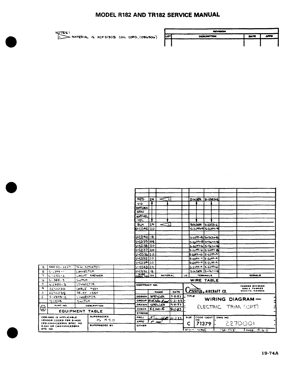
MODEL
R182
AND
TR182
SERVICE
MANUAL
NOTE'
' |
E
-MATERIAL
IS
RCF
5S30B
COIL.
COR
(o096.04)
|LII
| "cln |1
-
RED
__ _ _ ______.-
'YE'I
10
_ r
_
_
I
2 0_
5ZL
__
BL$
_4
_S ____ ____
_______
________________
-
JCB
20
______
SOZiCR
&-?S3-Z
______
________________
U*E3b _ S-r:____ SIOWh-C
NO
_
U
_
3-
zo_ _______ _
ASIR
s-A«FT
_O
U-<Z37
2o
_ I-z^--@
S-1c9
-a
U-COtN
201
I
I '
o "
I
S
-to-^
'
U-W35
zo
_
S-zq-9
s-Zql>_9
_
zo11
5-u
-
5
-
L3t3jo
-
|I
C-,,^
ON trcR ;-CbI3R AW _ N_
S5o-
S- < 174 17
7
S-I
Z3
2.
-
Z. ___u__ ___
iTWfWIRET L
LC
TERAtL^LLS S"L§
E'
T-
36s--i
sCI4AC
=
____WIRE
TABLEL______
Z.'S 50
r--
I ----------
CO:T.ACT
_
O:
| \
,
,g
DBIISION
3
~ zzloa-s
ReENY
4SY ~
NAME
1ATC
USSina.AllCAFT
CO.
W§CZAIT
K^""
2 S -w 2.r")
-
2
::4.eC.T-
R
DESIGN
|
SIfceR
I
I
Y-Y
7
TITLZ
=
4~~0j23
0
-Zs 4C,.T
!T
~
o
G
OUP,
WIRING
DIAGRAM-
I
)'
EOUIPs--
ENT
TABLE-
E
STDO
I |
-
NONE I''I-.
I
REc«:
».
O
ES E'$NA··CT).I(I .C.E
*Q
·
YLIx C..
·
I:
*rrr,
r c 71379'[C
N~19-74A
*-]lX
OXI CMX.IrSP-EC. NO
-_
~
(D
0
C0
I
"TDO. MCNONE ,W-,a
-.
""": 14."."
19-74A
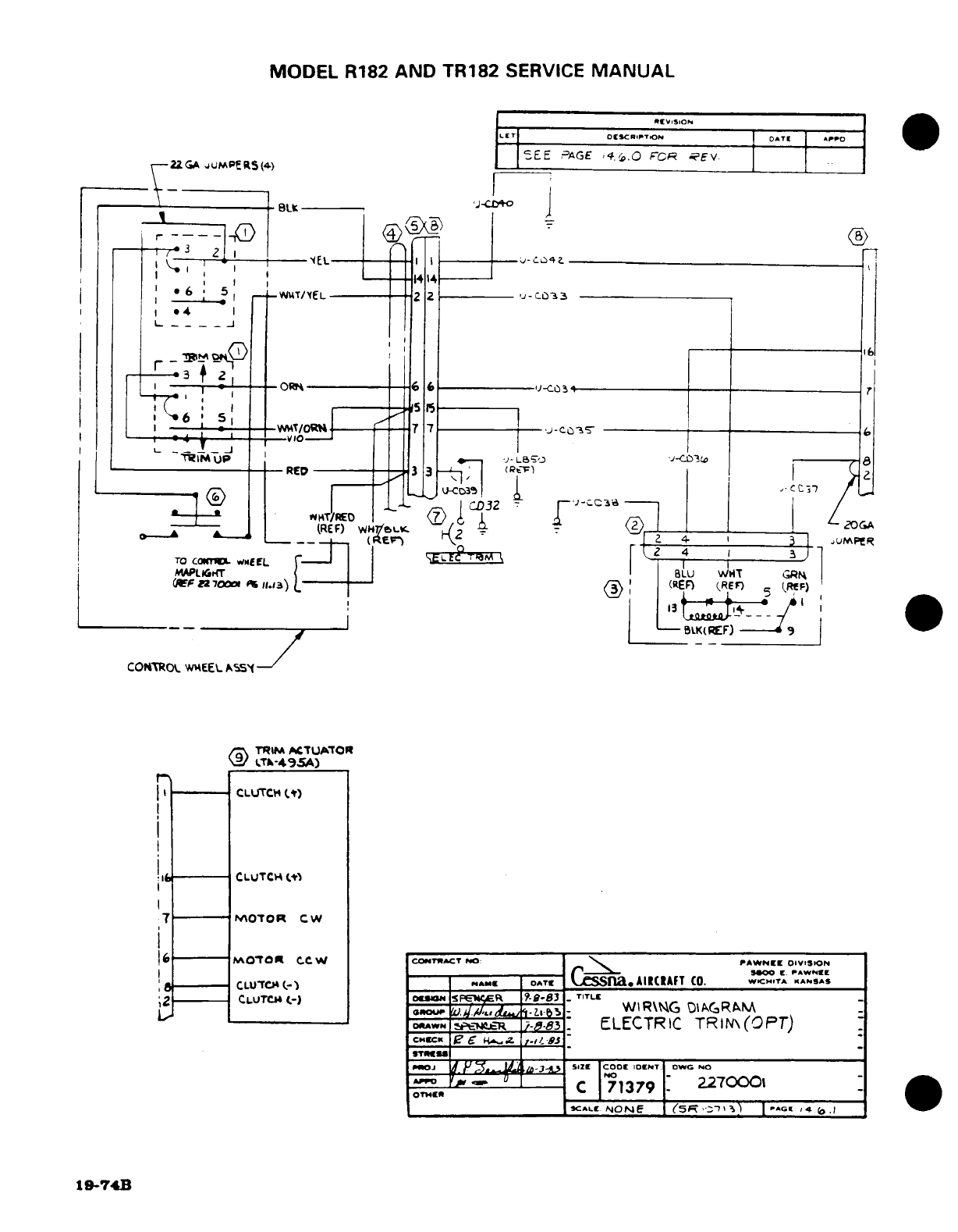
MODEL
R182
AND
TR182
SERVICE
MANUAL
tcv,,soI
ILEt'
OI[SC
RP'r
,0 OATE
APPO
,~2ZGA ~uN~PE K~.) ~SEE
PAGE
i4.,.O
FCR
?EV.
r-22GA
JUMPERS(4)
_
I3
21
i
-
I i 2
1-.414
---
EL-
*4
r
~iU
-RED
3
I3
3
U -C
-
i3
LI--r
(REF)
wGALK.
J
TO
CamICL
wtEL
Ie
z
4
MAPL^IG'T
BLU
IT
GR
G'WFf
z70
r1.3) _2
70)
(REF)
(REF)
(RfF)
-Ifii t*6 1
4
I_--_
.
I ,.-
--
0BLK(REF)
-
COMTo.,
wgEEL
As5Y
G
TrRI
ACTUATOR
-T--4A95A)
CLUTCH
(*)
7
M-~COUTOR
CW
6(0
moToo
c*-w
COTRACT
NO:
PAWNEE
DIVISION
ISOO
E.
PAWNES
CLUC(-)
I
A(
I *E
IO^TE
CSn.
AIRCRAFT
CO.
WICHT^
ANSS
ZL I
CLuCb
C.-) S
--
83
TITLE
IOU
' .
WIR\G
DiAGRAM
IoDWN
I-t~
I
----
83
ELECTRIC
TRIN\
(OPT)
IC"l U
(
I'/i.-
,- '
O
CIrOJ 1
fJ
ss-3dZD-34n
51L
|oIZo
IODDET Dowc
No
--
F.
.
~7C
|71379
2
270001
1
9I-7'14B
t
~
~
I
---
CLUCH
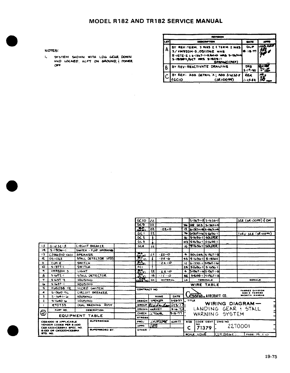
MODEL
R182
AND
TR182
SERVICE
MANUAL
^^LET
DO-CInVM
ATU
MCMES!A *NA
BY
YCV:
tRM.
3
WAS
t
(
TEM
2
WAS
OL.P
E
3/VN20MO-3;Oi05lIZ
wAs
*
ls
-,
I.
&W5TEM
t4lOWN
W11M
LDO
&CAL
DOaMN
S
-I1Z
--
I,
-
I-Iz it S,-1rlb-16
V*
&M
LD^CKD.
ON
,
eLICD 09
OD* P
_
S-(tM,
4R
)(SR
K)
.
..
op~~~r cs~ R~B
BY
REV:
REACTIVATE
DRAWIING6
Ds~
C
Br
RLv:
AOb
DLTA*.
A;
ADO
3-Ua3LJ-
CL
GClo
1
l | 1
'
1 s1a-'O-'1 S-
_sjll
_Lk
(.%q0099)
ON
[Cio l'I
I~"~-'i'"
[I
~" "
.I4 ~
Itjt(soo
) { CXK
cF
2t b_ if (.C. _______O__I
J£
2at.
-at_-o
is
i/,5-
-s--
,
______
CC
I
.
.it L-____ _ .v.-i TS"
He5
(F
1,0D)
GLC
5
__3 )K.-l _6.i 1it s-l
1J
5-1_3L-5
CTirlE _______
8t
GC4 22
1
50
I~ __._I
,OLDEtt
14
s-I90b-1
sw'H
-
FLAP
WRmi4i
_
_
13
C:39o10
-co
SP.AK.R
.
2.2
*2-0
O
4-
,oLo.
a
L
LD
.
5
I7-1-8_
r.
osiof.z
5TULL
CE-TECTOK
(uI)
___/_ ,^
-2z-t
^
"S
i
'-i
___tt, ___-_.il-
II1
tLL-E
"*ITUL~ Ib
--
13s-Ll-
-
____-O ____bl
10
.
1511-i
SWITLC.
FCI
_~
*1,1LM,-I
K5- _____
-
vMqtoM-5
LIGTT
2.1
.2
·.
_-
4.
1. 6-C.
i
1- 1 ___ ___-
6 'i5
iZ-.-I
TLL
Tl.
-
ETECITO5
I
'_. 6
-
IA _______S
tSa-I
6
Y.T -zt
LuOU'I
V4
t4
a7 OA MA*TIIAAL
La
TK
ALS
rs1
*
tAl€U
(.
S U5<-i
1
oulN0bC
______
WIRE
TABLE
-- ---
50r t
--
YE
H-ICO
lCI
COTtACT
NO:
B
4
S-,i.O
-';L
C.IrCUIT
EbtL
E,____ __to ,., o«zI.
3 s
-
itI-o uOUISNt. NA.M
DAT
'CSSra.
AIICIAFT
CO.
C..T^
..
,^.
Z
,-I
.40
-*
LOtlHb
0
Dms
IN IFfct -it-Wt7
-.
TrITL
i
~t0ro7-r35
PI. kLN tb
V
E
oGour
OUP
t.
~-
.
WIRING DIAGRAM-
-
^.,T
OO.
o
.9CRIPTO--
DRAowN
U_.M-EY
3-1*L.
LANDING
GE6AR
L
5TALL
EQUIPMENT
TABLE
IS
TRS
WANING
SYSTEM
CU-1o00
Is
ArPLiCAEiL
ISUPRiSDou:
PNOJ
JL
lttn
.
-
oo IDocrET
owa
No
VENDoR
coos
r".
*,1 ,--.
r-o
-
Z[7
100\
C
oE-xxCxtxuSNA
SP-EC.
NO.
-:
rr
C
71379.
-000
ORs-XXXO CO
XXXXCE--MA
SUP.tERlmO
*T:
OTHIER
/
'rT.
NO.
HDSCALE,,:
W0.-l
CC-Q
z )
4
,.o:
I'.
o
19-75
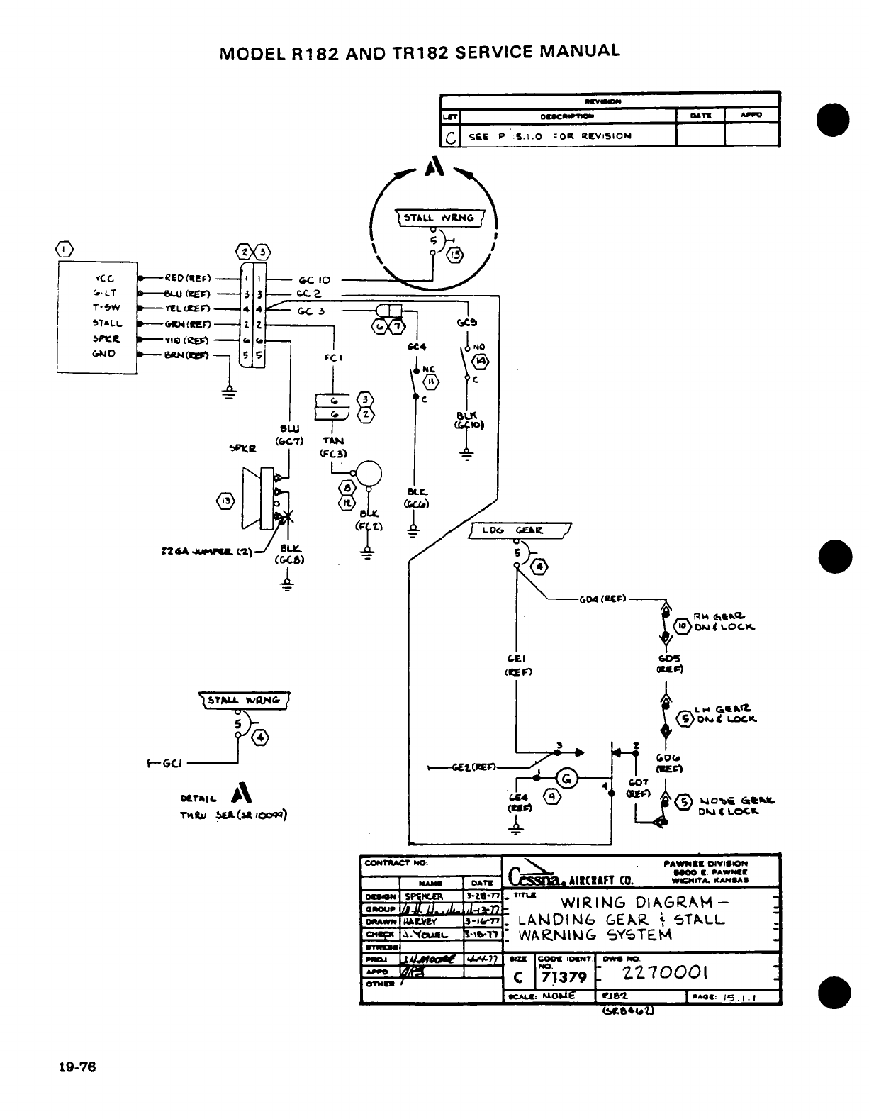
MODEL
R182
AND
TR182
SERVICE
MANUAL
C
SEE
P
5.1.0
FOR
REVISION
A
ST 5TLL CREI
-6
C3 ___
(
O \ S
@
j
vCC
.--
ED(E)--I
I-
-C
10
I
.X
LT
--
(KE) va NW CCZ
o-(C
s
c7)
TAN
T--W I-- YlL(CE
n_----_
4 (..
,
.=FC
.
ST»LL
»--(rr
H<»E"---
I,
&04
¢I.F
sPVrK U I--1\Oi.iIZe4
(ter.)
- --
--
GCI L
r...~-4
(R'
F)
l
oks
t LoJS
/-^
>-1
_ 2
'-
t-~r~urrr
<
&ca
C.O(
.^
ara 1 F
A 6oA
COPTRACT
0
PA
DIVIS
OCN
_l
QLI
0^tE
CE
K
1
L.
.
STN.AM
DAT
CO.
WCH4TA. KANSA
l
;N.o.p
WIRING
Cl
AG-RA
-
DRAW
;MY
3=j&-,en
LAN[DING6
GEAR/
'
TkLL
5*f )AWO \4A&77 ll)0
LOCK.
oC 27
270001
1 9 (~-7CI---___
__
^*. O paa
&
.69_ M o t I
-
1
e
19-76
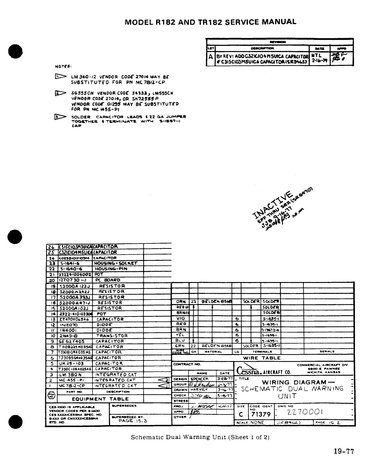
MODEL
R182
AND
TR182
SERVICE
MANUAL
A
BYREV:
ADOC32ICIOn4SUICA
CAPACITOR
NITL
4rC_3l5CIOM5UICACAPACJTOIRSR9^iS1
2-?-I
NOTLeS:
0[-
LM340-12
VCNDOR
CODF
27014
MAY
BC
SUBSTITUTEO
FOR
PN
MC7812-CP
g-
SG55SC-N
VENDOR
CODC
34333,
LM555CM
VFNOOR
CODE
27014,
OR
Sn172555
P
VENDOR
CODr
012S5
MAY
rB Sue5srTuTrD
FOR
Pi
MC
145-PI
[
SOLDER
CAPACITOR
LiAOS
C
22
CsA JUMPAl
TOGIeTIB.R
4
T6.
RMIIIATl
W'ITM
S-IS5'-I
CAP
A"
Z
L
1CSISCItn3U11
CAPACITOR
25
C3ZICI04sM5UIC CAPACITOR
24
COZ35BOilO13M
CAPCITTORO
13
S-1641i6
IOUSINC-SOC-
T __S__
22
5-1640-6
IWOUSINC-PIN
21
2122+'005002
POT
20
12707
30
-
PC
BOARD
19
SI2OO0A
122J
RESISTOR
_
l9
S2oOAa.4»J
RrwIST7OR
17
S2000A393J
RESISTOR_ _ _ ___
16
S2000A471J
RESISTOR
ORN
21'.
BCLDg
ee
SOL
DER
SOLDCX__
15
S2000AI02J
RESISTOR
REOw
u
m
i
_
i _
_SOLDfR
14
Z322-410*-33
POT
BRNOt
___
soLDE
13
ET47XOS.3AA
CAPACITOR VIO
_
S-i3-I
_____
12
IN-ZoX)
DIODE
RED
6
_
5-43-
II
I
N4J00
DODE
8RN
___
6
5-i2-4
10
244918
TRANSISTOR
L
6
_____ ____
9
&E6aF405
CAPACITOR
BLUV ____ 6___ _____6-
T310Bl
'SK03o
CAPAC-ITOR
OR
G
CRN
22
BCLDOhE-Na
6
SOLDR
5-1635-1
7
T3308il04035AS
CAPACITOR
A clO.
MATERIAL LG
TiRMINALS
^IAL
6
T330B564K035Sl CAPACITOR
WIRE
TABLE
5 Ul
2
-
103
CAPAClTr
R
COFTRA*CT
NO. COMMIRCIAL
AIRCRAFT
DIV
4
T33OCiO6KO2SAS
CAPACITOR
-
-
MOO
l
PAWNEI
3
L
BO38N
NTEGRATED
CKT
NAME
DATE
CS
Sn.
AlIAFT
CO.
WICHITA.
KANSAS
2
MC
455
-Pl
IN71r6ATrD
CKT
D.ESIN
SPENCE
3-e-77.
TITLE
I M
7812-CP
.'rrGRATED
CKT
ROUP
G
.
J.__i
%
-
..
,~
WIRING
DIAGRAM-
DRAWN
"4EVE.
3-16-1.
SCH
EMATIC
DUAL
NARNFING
-
II. --------------------
CK
wrr
X0o:
-j
1-8-1:UI&
_
T
EOQUIPMENT
TABLE
i
CHtCK
O
.-
3
-o
UNIT
CES-0
IS 15
AP-UCAU|E
SUPCIRISDS.
ProJ
J.,
IS A CA 7
/
51E
|COD
IOENT
DWG
NO
VENDOR
CODES
PS4400 APPO NO
7
C0 00
1
CES-XXXX-CeSSNA
SPEc.
NO.
--
t
C
71379
-
.70001
SCALE
N5.3
rONE
S
8; e.L) *A~r:&G£
2.
STD.
NO.
PAGE
15.
.3
SCALE
,NONE
|
a
_
C,2)
| C.C.
G
2Z
Schematic
Dual
Warning
Unit
(Sheet
1
of
2)
19-77
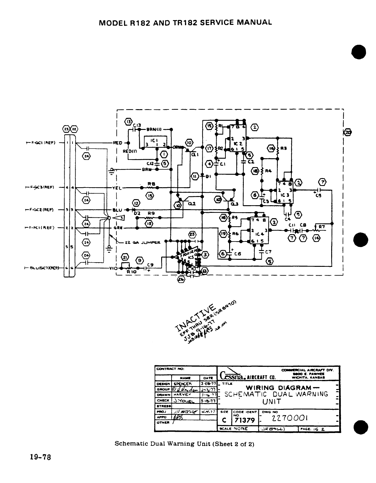
MODEL
R182
AND
TR182
SERVICE
MANUAL
-- -- -- ------ - - - - - -- - - - ----
R40
P-EpicstPkeF)
-
--------- 3 2--
z
PP)
I
-ED
---
rG
$
:
C
~-;--B_
_ _
-
::'
F-GCZ(R^F)
-
4
-* _
-
-F
-
(EF)
'2
-
2-
2Z_ T
a.
,. .
o
A
<
ICAFT
CO.
W
N,
I.
AJUMPS
.l;
S
IER
3.S'77
Tr-
cou
,
-
- - --,
WIRING
DIAGRAM-
-
ORAWN
^Ae
VE.,-
-
SCHEMATIC
DUAL
WARNING
_,_
.-.
Yoe.
s3.,
-
UNIT
STRESS
rQOJ
1
./2I J, < -i)
SIZE
CODE
IOINT.
DWG
NO
NO.
OT.ll
/'
C
71379
71
-
0001
tlXSC^__
ALE:
NONCE
.a
)
|
PA
<;
Schematic
Dual
Warning
Unit
(Sheet
2
of
2)
19-78
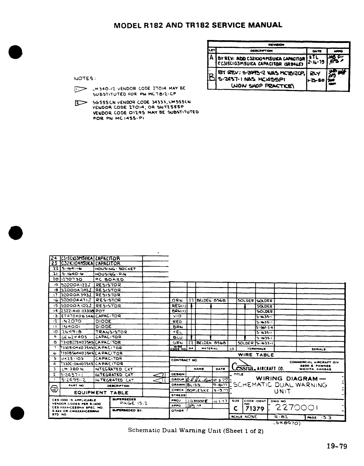
MODEL
R182
AND
TR182
SERVICE
MANUAL
*
LS^ ll________atucsn~~~tVH__rr o:l
I
A
Bv
Ewv
AtO
cauioosu_
A
cicn
L
X
S
-CIasClO03suICA
CAPACITOR
(5W4 -e.-1
Bt
Q(ZEV:
s-
12
W-lAS
KMJb
ZCP,
01
~OTE-:
5-7.A'4%-I1
Ne%
IC.taSPI
w-bo
,
.
WIOW
5tP
PACTYE^r
_[~-
M340-1Z
vENDOa
CODE
27014
MAV BE
-
SU5bTiTUTED
FOR
PM
MC.BT11-CP
f.[
G5,555CN
vENOO
CODE
3
,4333,LM555(.
VEMDOR
CODE
Z7014,
OR 5b755SP
VENDOR
CODE
OiLqS
MY
BE
SUtSTTUTED
0R
PN
MC
1455
-
PI
24
C315C1303UICnA
CAPA111O~
3
|C321C104n5UICAK
CAPACITOR
22
s.5-ic641-6
Ua
iou>
-
SOCKEC
21
5-
(40(o
O
SiUG-P ___
20
1o'10~o 0
PC
b0A.OD
,~152000A12J
REI1SO
_
_7
52000A3q3J
E'5i5TOQ __
_
200OOOA47
J
qEtiSTOR
OQU
2_1
6ELD0EV4
5%8
'_oLoEFQ
OLDER
,5
2S000A
oJ
RESTsro
:
REO(I'
5)DI '.PE
--
14
2322-410-033
POT
o
(l)
S
OLDER
13
ET470XOf3Ab
CAPACIT
R _ _ _
---
_
-
12
1N20-O0
DIODE
_
ED
_ _ '
*1
'
-
II
N14001
OIOOE
DU Da1--4E
10
c2i
.
,'o
[q I -
I
a I ! I I ! I 1,,. I
10
ZJUc96 rrR^i8l5Og ____ El _ _
T___=A_ =
----
:---- S_
_
--
l-i--
~ SGE
(2 F 05
CAPACLTO
___.__
I
. ...
1__ _ b 5I
.35-
_
7'3102?5K035Ab
CAPAC--R
____
(,Rw
22
SBLDEN
8583
5OLDEP
-635-1
T7 3704<03^5A
^P«CA.ITOR
S
C'G'.o
-T..AL
LC
T
* --
^^LS
_
35,o5tO4*OrAc
LAPA.C.ITOR
WIRE
TABLE
5
u'c25-
103
CAPACI-TOa
CONTRACT
rYD
|
COMMICIAL
AIKCRAFT
DIV
4 30Cb25
C
Aoo5s
CAP
ITOSr C| Sa.
AIRCRAFT
.CA., *
~Lh 380 l
1TEGrUTE'D
C-T
IAra
lATE
C59inaAIRCA) A CO.
W^CHITA
IANSAS
2
5-Z43i-1
IITCEGRATXE.D
CA.T
2
E
oCGN
TITLE
'
2439-2.
,1uk&TDGUTC0
LT
GROUP
,
WIRING
DIAGRAM-
-
A_5249-.2
IGRoATO
CCT.RAWN
Lt,
,O
-
SCHEMAT-C
DUAL
WARNING
CHECK
|
RLEKS
EI
EQUIPMENT
TABLE
UTSs
CS
1000
15
APPL.CAOLC
|uwroSc
P*OJ
|o
OCR
.7
SIZE
COD
IDOENT DIowa
N
VCLcsXXODX
c
r 0
N PE 5.2Cz AO
o
-
C
71379
2270
0
1
CLS-X
OR
CNXACJXl
.SC
NO
.Y OTHE.
/
5,TD
NC
CALE
OUE
eBZ
| CO.: 5.3
Nr
6I70
)
Schematic
Dual
Warning
Unit
(Sheet
1
of
2)
19-79
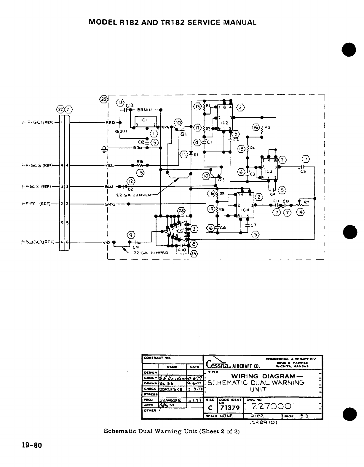
MODEL
R182
AND
TR182
SERVICE
MANUAL
(
@B
) --
-IN( l
l
0
--.
6-GC_3
(REF)-
4
YEL
*,,
i-F( ((R)Ep)
<r9
t 3'
4_C3_
_5
F-~- Z (~F)--3§ 1
C
1
A
JUMPE5
J
P
,
(IE.FJC I
(RE
)
2
'C2 I"
0
6F-G C2 ----
)I
-
(.
vi-
s s I
z?
.
C-A1
," C c4
T2
GA
Ju
JUMPE
R
a
COCRACT
1NO:
COMIELCIAL
AINCRAIT
OIV.
(0.
C
E.
PAWNEE
NAME
,
AT,
AIRCRAFT
WICHITA.
wANSAS
|ESIN
.
TITLE
GROUP
G'
/ ,
------9-
WIRING
DIAGRAM-I
M
DRAWN
._
q-i6-i
-1SCHEMATIC
DUALWA&RNINC
CHECK
ORLEKE
S
-
5
T
N
|T
v"w
EW J*0
-7
SIZE
COOC
IOENT
OWC
No
OT"
E-
,
C
71379
_-700 1_
sCALE:
MONE
-q
1G-
!
:
C:
5.03
5R8,7O)
Schematic
Dual
Warnirg
Unit
(Sheet
2
of
2)
19-80
Ss ~
~
~
~ ~ ~
C«KBOISE*-3n'U
I
19-80
~ ~ ~
~
GOCI~y
dLCO~?71
IIG ICA-
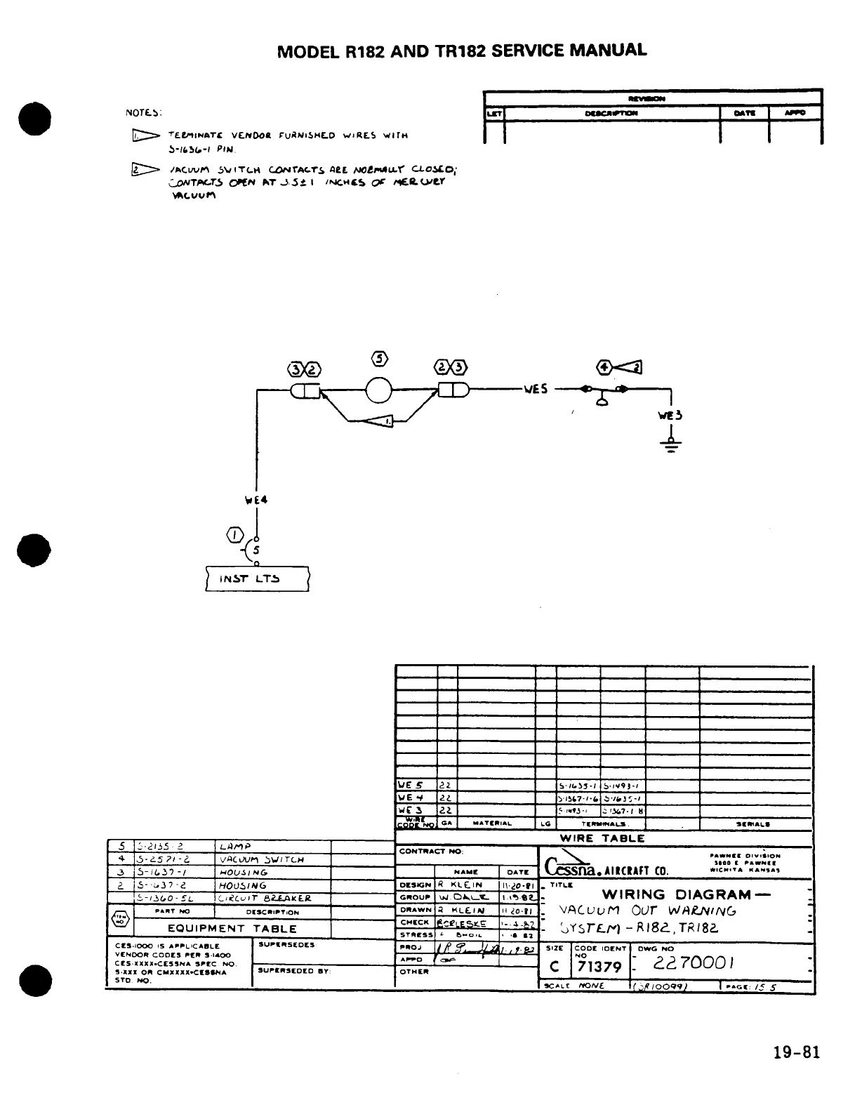
MODEL
R182
AND
TR182
SERVICE
MANUAL
NOTre:
i.7l ourAm
|
_
[:
Te-r.INATC
VENOOt
FUANiSHEL.
wlRELS WITH
,S-5IG-I
PIN.
'
/ACwvv
5VITCH
CONrAfcTS
FL
.
NO
U-uLLr
CLOaO;
oNTpfT3rs
O»CN
PT
-3
.
I
N/C
EcS
Or
e,.t rWY
<O-
OO
<
^
E4S
lC~
Ih
*o
E4
<[
5 2.[ 5 ,~95-, c
u~?.l
td
IGA
ATI
EIAL
LG
TENUM/ALS
.
S IAL
__ _ _
__
_ _ _
WIRE
TABLE
WE
Y
_v_____________
7-
3
-
5
--
2i55
2
LA,
C CONTRWACT
NO:
--
"-
OIV-S-ON
5
6-25
?'I-<^
\/Q~tU^
^\^IT-H
_____ _________^_____
_
VA(
O~ 1
D
.
A....I(
J
5-i?37-/
OUI/,
IGNAME
OATE
CSnaAIClAFT CO.
*C".T'
KA"A".
a
5-.
3
7-e
HOUSING
DCSIGN
I
KLEIN
I-2.O-fl
TITLEC
5'-30-
-5CL
ccvr
8iAKEg
OouP
Iw
.jp_T
.
I.e-
t
WIRING
DIAGRAM-
*-rT
NOC
DSCftPON
DRAWN
A KLl II O-20-1
VACuuM
Our
VJLvr/cNING
"
EQUIPMENT
TABLE
sCHCK
s-LE5-. '--T ?srr)
-Rl8,
TR18a
STRESS
el-.L 's
32
CES.IOOCD IS
APPLICABLE SUPERSEDES
PROJ
/-
J-.
.
SIZE
CODE
IDENT
DWG
NO
VENDO
Co.,E,, *o,..,o
CESNDXXO
CESNA
PC
S O
A
X
C
71]379
7
S XXX 0OR
CMXXXX
.CESSA
SUPSEDED
B:
OTHER
STD
NO.
CALE
OE
(
j
OOQV
100I
»:01
/5
S
19-81
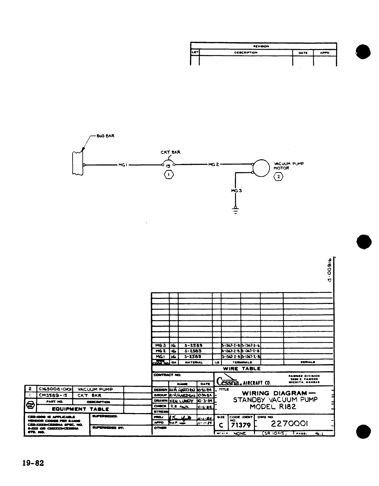
LIT
o NClC-IPTION
OATE
APPOI
OU5 AR
Dp/-^g ~
~CKT
BKR
MG
I O----
MG
Z
-
~
A
w,
CUUM
PUMP
1
OTOR
U Q
,--I
Q
GD
(D
o. I
I0I
I
iMG
I
0
_MCG3
_
a6
-
Zsa&
=
i--i?- 13
$-
1347--
*
~
Ir
1
S-t
S6
_
-it7-z-S
1-3
i
-t-8
i1 I1 5-5
2-
X
______ _____.Z- L 'I-.-
GA
MATERmAL
L4
TrmNNALS
h
*UJ
_ __ __ _WIRE
TABLE
ccunwcr
Mt.
rrrCss oACATI
o.
Im S PAWlNE
NMAN
oAT
C
.AIRCAFT
CO. '*'I
A
2
C.00S5-011
VACUUM
PUMP
uA
-
l
.Trmz
I
CM3589-i
CKTr
aKtR
GROo
WIRING
DIAGRAM-
., rAO. o...-. -'"r--iCf
LoUIy
iWo-3-
STANDBY
VACUUM
PUMP
EQUIPMENT
TABLE
C
g1J*
MODEL
R18Z
CINNOR
n Z "-* A"y FS
.
b
::;
,
.°
*°IZT
t
OI PMbI
G'.
--
SaNMV^ .n.. C
71379
:
2270001
9-8
.
m*
OC
CSR
10415'
1
P.OE:
I.
19-82
