Bridge Design Manual M 23 50 Chapter 10 Signs, Barriers,Approach Slabs, And Utilities 2001 3.2 TL Chapter10
User Manual: 2001 3.2 TL
Open the PDF directly: View PDF ![]() .
.
Page Count: 68
- Chapter 10 Signs, Barriers, Approach Slabs, and Utilities
- Contents
- 10.1 Sign and Luminaire Supports
- 10.2 Bridge Traffic Barriers
- 10.3 At Grade Concrete Barriers
- 10.4 Bridge Traffic Barrier Rehabilitation
- 10.5 Bridge Railing
- 10.6 Bridge Approach Slabs
- 10.7 Traffic Barrier on Bridge Approach Slabs
- 10.8 Utilities Installed with New Construction
- 10.9 Utility Review Procedure for Installation on Existing Bridges
- 10.10 Drilled Anchors For Permanent Attachments
- 10.11 Drainage Design
- 10.12 Bridge Security
- 10.13 Temporary Bridges
- 10.14 Bridge Standard Drawings
- 10.15 References

WSDOT Bridge Design Manual M 23-50.17 Page 10-i
June 2017
Chapter 10 Signs, Barriers,
Approach Slabs, and Utilities Contents
10.1 Sign and Luminaire Supports ..............................................10-1
10.1.1 Loads ...........................................................10-1
10.1.2 Bridge Mounted Signs ...............................................10-3
10.1.3 Monotube Sign Structures Mounted on Bridges..............................10-7
10.1.4 Monotube Sign Structures .............................................10-8
10.1.5 Foundations ......................................................10-12
10.1.6 Truss Sign Bridges: Foundation Sheet Design Guidelines......................10-15
10.2 BridgeTracBarriers ...................................................10-16
10.2.1 General Guidelines .................................................10-16
10.2.2 Bridge Railing Test Levels ...........................................10-17
10.2.3 Available WSDOT Designs ...........................................10-17
10.2.4 Design Criteria....................................................10-21
10.3 AtGradeConcreteBarriers ...............................................10-26
10.3.1 DierentialGradeConcreteBarriers ....................................10-26
10.3.2 TracBarrierMomentSlab ..........................................10-27
10.3.3 Precast Concrete Barrier .............................................10-31
10.4 BridgeTracBarrierRehabilitation ........................................10-32
10.4.1 Policy ..........................................................10-32
10.4.2 Guidelines .......................................................10-32
10.4.3 Design Criteria....................................................10-32
10.4.4 WSDOT Bridge Inventory of Bridge Rails ................................10-33
10.4.5 AvailableRetrotDesigns ............................................10-33
10.4.6 AvailableReplacementDesigns ........................................10-34
10.5 BridgeRailing ..........................................................10-35
10.5.1 Design..........................................................10-35
10.5.2 Railing Types .....................................................10-35
10.6 BridgeApproachSlabs ..................................................10-36
10.6.1 NotestoRegionforPreliminaryPlan ....................................10-36
10.6.2 Bridge Approach Slab Design Criteria ...................................10-37
10.6.3 Bridge Approach Slab Detailing........................................10-37
10.6.4 Skewed Bridge Approach Slabs ........................................10-38
10.6.5 Approach Anchors and Expansion Joints .................................10-39
10.6.6 BridgeApproachSlabAdditionorRetrottoExistingBridges ..................10-40
10.6.7 Bridge Approach Slab Staging .........................................10-42
10.7 TracBarrieronBridgeApproachSlabs ...................................10-43
10.7.1 Bridge Approach Slab over Wing Walls, Cantilever Walls or Geosynthetic Walls .....10-43
10.7.2 Bridge Approach Slab over SE Walls ....................................10-45
10.8 UtilitiesInstalledwithNewConstruction ....................................10-46
10.8.1 General Concepts ..................................................10-46
10.8.2 Utility Design Criteria...............................................10-49
10.8.3 Box/Tub Girder Bridges .............................................10-51
10.8.4 TracBarrierConduit ..............................................10-51
10.8.5 Conduit Types ....................................................10-52
10.8.6 Utility Supports ...................................................10-52

Contents
Page 10-ii WSDOT Bridge Design Manual M 23-50.17
June 2017
10.9 UtilityReviewProcedureforInstallationonExistingBridges...................10-54
10.9.1 Utility Review Checklist .............................................10-55
10.10 DrilledAnchorsForPermanentAttachments ................................10-57
10.11 Drainage Design ........................................................10-58
10.12 BridgeSecurity .........................................................10-59
10.12.1 General .........................................................10-59
10.12.2 Design..........................................................10-59
10.12.3 Design Criteria....................................................10-60
10.13 TemporaryBridges ......................................................10-61
10.13.1 General .........................................................10-61
10.13.2 Design..........................................................10-61
10.13.3 NBIRequirements .................................................10-62
10.13.4 SubmittalRequirements .............................................10-62
10.14 BridgeStandardDrawings................................................10-64
10.15 References ............................................................10-66

WSDOT Bridge Design Manual M 23-50.17 Page 10-1
June 2017
Signs, Barriers,
Chapter 10 Approach Slabs, and Utilities
10.1 Sign and Luminaire Supports
10.1.1 Loads
A. General
Thereferenceusedindevelopingthefollowingocecriteriaisthe
AASHTO LRFD Standard Specications for Structural Supports for Highway
Signs, Luminaires, and Trac Signals, First Edition dated 2015 and shall be the
basis for analysis and design.
B. Design Life (Section 11.5, AASHTO 2015)
1. AnInnitelifefatiguedesignwillbeusedforluminairesupports,overhead
signstructures,andtracsignalstructures.Thenumberofcyclesastructure
mustwithstandwillbebasedontheADTTofa75yeardesignlifewith
each truck inducing one cycle in accordance with AASHTO LRFD Standard
Specications for Structural Supports for Highway Signs, Luminaires, and
Trac Signals First Edition,dated2015includinginterims.
2. Roadside sign structures will use a 10 year design life.
C. Dead Loads
Sign(includingpanelandwindbeams,doesnotincludevert.bracing) 3.25lbs/ft2
Luminaire(eectiveprojectedareaofhead=3.3sqft) 60lbs/each
Fluorescent Lighting 3.0 lbs/ft
Standard Signal Head 60 lbs/each
Mercury Vapor Lighting 6.0 lbs/each
Sign Brackets Calc.
StructuralMembers Calc.
5footwidemaintenancewalkway
(Includingmountingbracketsandhandrail) 160lbs/ft
Signal Head w/3 lenses
(Eectiveprojectedareawithbackingplate=9.2sqft) 60lbs/each
D. Live Load
A live load consisting of a single load of 500 lb distributed over 2.0 feet
transverselytothemembershallbeusedfordesigningmembersforwalkwaysand
platforms.Theloadshallbeappliedatthemostcriticallocationwhereaworkeror
equipmentcouldbeplaced,seeAASHTO2015,Section3.6.
E. Wind Loads
A 3 second gust wind speed shall be used in the AASHTO wind pressure equation.
The3secondwindgustmapinAASHTOisbasedonthewindmapinANSI/
ASCE 7-10.

Signs, Barriers, Approach Slabs, and Utilities Chapter 10
Page 10-2 WSDOT Bridge Design Manual M 23-50.17
June 2017
Basicwindspeedof115mphshallbeusedincomputingdesignwindpressure
using equation 3.8.1-1 of AASHTO Section 3.8.1. This is based on the high risk
categorywithameanrecurrenceintendedof1700yearsperAASHTOTable3.8-1.
The Alternate Method of Wind Pressures given in Appendix C of the AASHTO
2009Specicationsshallnotbeused.
F. Fatigue Design
FatiguedesignshallconformtoAASHTOSection11withtheexceptionoftube
shape. AASHTO does not provide fatigue calculations for shapes with less than 8
sides. Therefore,calculatingtheConstantAmplitudeFatigueThreshold,DT (Table
11.9.3.1-2,AASHTO2015)wastakentobethelargerouterattoatdistance
of the rectangular tube. Fatigue Categories are listed in Table 11.6-1. Overhead
CantileverandBridgeSignandsignalstructures,highmastluminaires(HMLT),
poles,andbridgemountedsignbracketsshallconformtothefollowingfatigue
categories.
FatigueCategoryI:Overheadcantileversignstructures(maximumspanof35feet
andnoVMSinstallation),overheadsignbridgestructures,highlevel(highmast)
lightingpoles80feetortallerinheight,bridge-mountedsignbrackets,andall
signal bridges. Gantry or pole structures used to support sensitive electronic
equipment(tolling,weigh-in-motion,transmitter/receiverantennas,transponders,
etc.)shallbedesignedforFatigueCategoryI,andshallalsomeetanydeection
limitationsimposedbytheelectronicequipmentmanufacturers.
Fatigue Category II: For structures not explicitly falling into Category I or III.
Fatigue Category III: Lighting poles 50 feet or less in height with rectangular,
squareornon-taperedroundcrosssections,andoverheadcantilevertracsignals
atintersections(maximumcantileverlength65feet).
Sign bridges, cantilever sign structures, signal bridges, and overhead cantilever
tracsignalsmountedonbridgesshallbeeitherattachedtosubstructureelements
(e.g.,crossbeamextensions)ortothebridgesuperstructureatpierlocations.
Mounting these features to bridges as described above will help to avoid resonance
concerns between the bridge structure and the signing or signal structure.
The“XYZ”limitationshowninTable 10.1.4-2shallbemetforMonotube
Cantilevers.The“XYZ”limitationconsistsoftheproductofthesignarea(XY)
andthearmfromthecenterlineofthepoststothecenterlineofthesign(Z).See
Appendix 10.1-A2-1 for details.
G. Ice and Snow Loads
A3psficeloadmaybeappliedaroundallthesurfacesofstructuralsupports,
horizontalmembers,andluminaires,butappliedtoonlyonefaceofsignpanels
(Section3.7,AASHTO2015).
Walk-through VMS shall not be installed in areas where appreciable snow loads
mayaccumulateontopofthesign,unlesspositivestepsaretakentopreventsnow
build-up.
Chapter 10 Signs, Barriers, Approach Slabs, and Utilities
WSDOT Bridge Design Manual M 23-50.17 Page 10-3
June 2017
10.1.2 Bridge Mounted Signs
A. Vertical Clearance
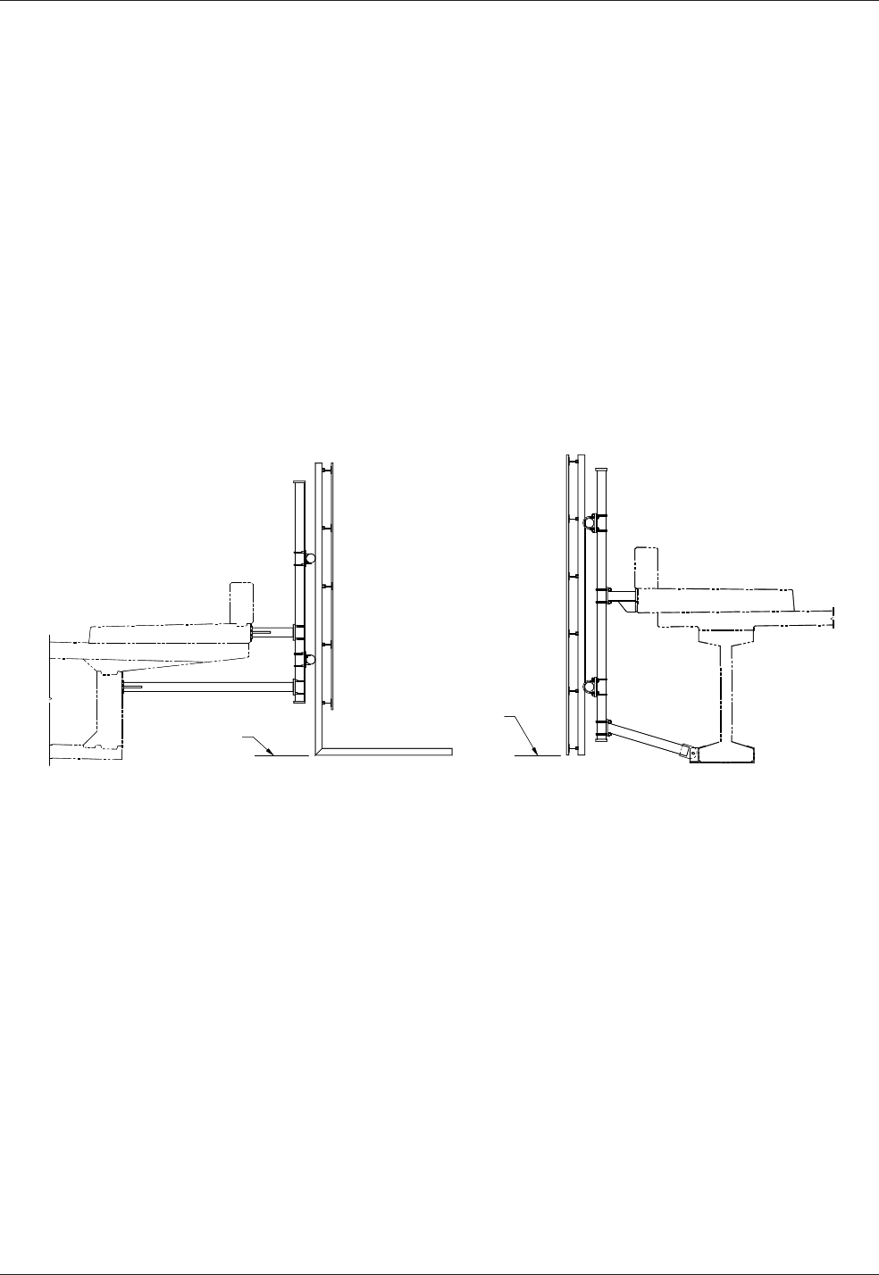
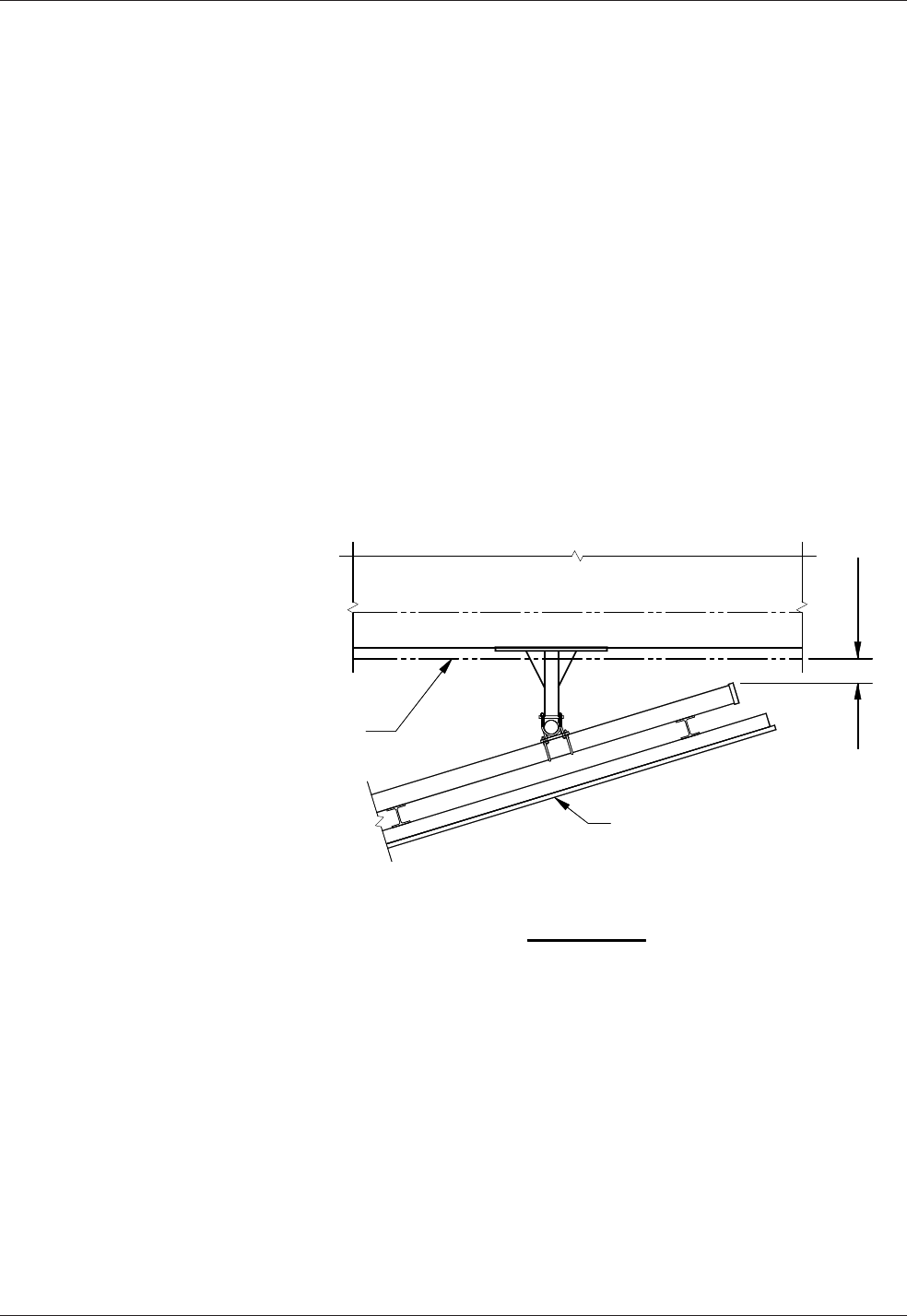
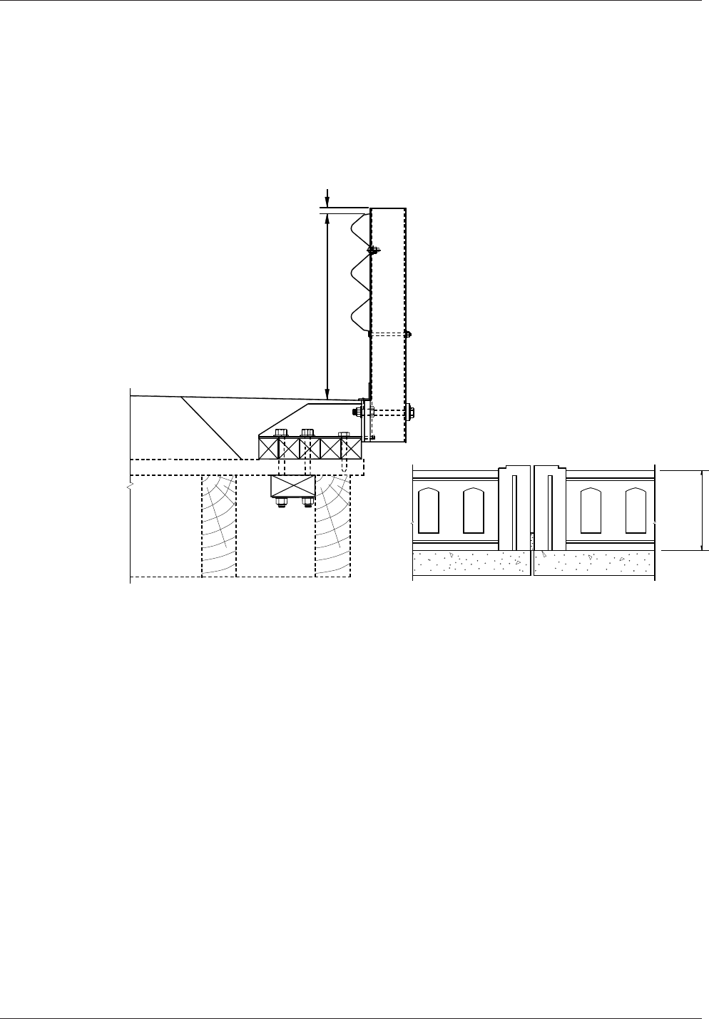
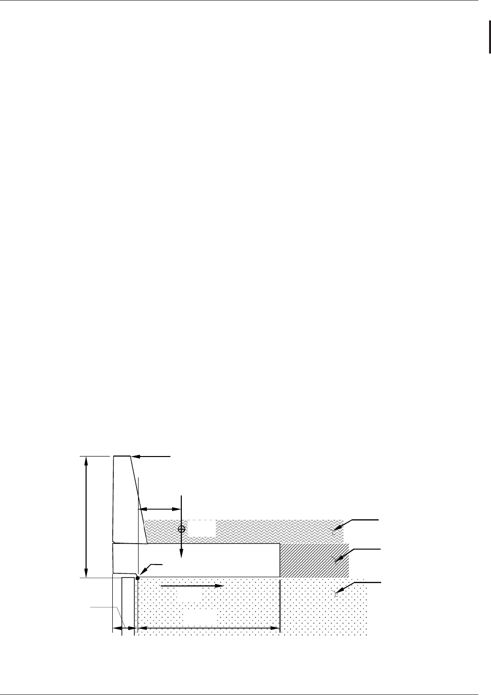
Allnewsignsmountedonbridgestructuresshallbepositionedsuchthatthe
bottomofthesignorlightingbracketdoesnotextendbelowthebottomofthe
bridge as shown in Figure 10.1.2-1. The position of the sign does not need to allow
forthefutureplacementoflightsbelowthesign.Iflightsaretobeaddedinthe
futuretheywillbemountedabovethesign.Toensurethatthebottomofthesign
orlightingbracketisabovethebottomofthebridge,thedesignershallmaintain
atleastanominal2inchdimensionbetweenthebottomofthesignorlightingand
thebottomofthebridgetoaccountforconstructiontolerancesandbracketarmsag.
MaximumsignheightshallbedecidedbytheRegion.Ifthestructureistoohigh
above the roadway, then the sign shall not be placed on the structure.
Bridgemountedsignbracketsshallbedesignedtoaccountfortheweightofadded
lights,andforthewindeectsonthelightstoensurebracketadequacyiflighting
is attached in the future.
SignVerticalClearance
Figure 10.1.2-1
Signs, Barriers, Approach Slabs, and Utilities Chapter 10
Page 10-4 WSDOT Bridge Design Manual M 23-50.17
June 2017
B. Geometrics
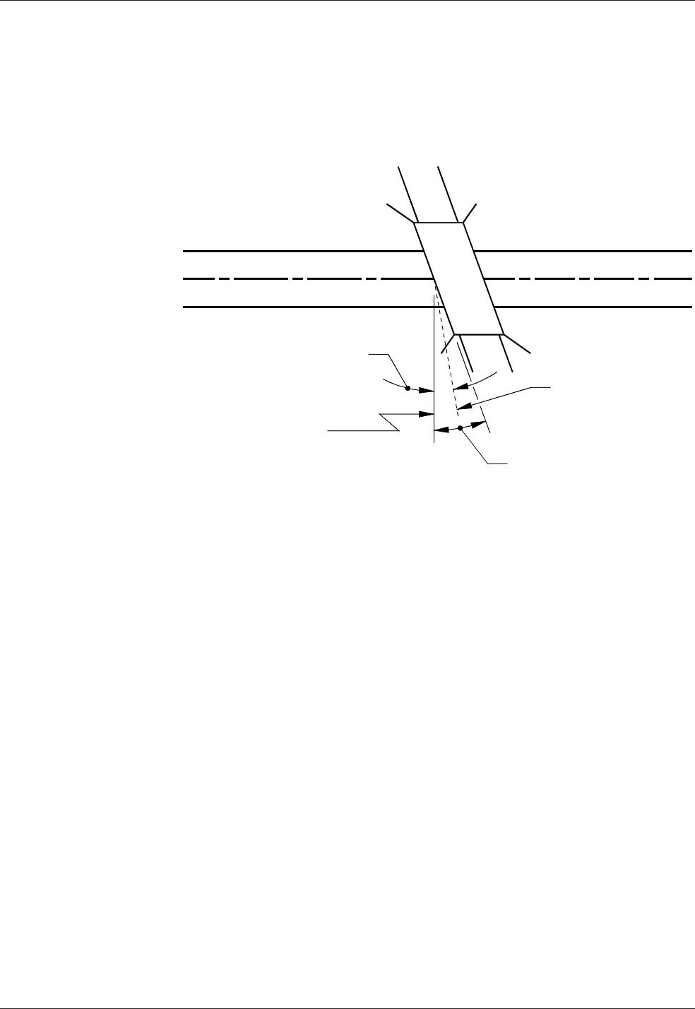
1. Signsshallbeinstalledatapproximaterightanglestoapproachingmotorists.
For structures above a tangent section of roadway, signs shall be designed
toprovideasignskewwithin5°fromperpendiculartothelowerroadway
(see Figure 10.1.2-2).
SignSkewonTangentRoadway
Figure 10.1.2-2
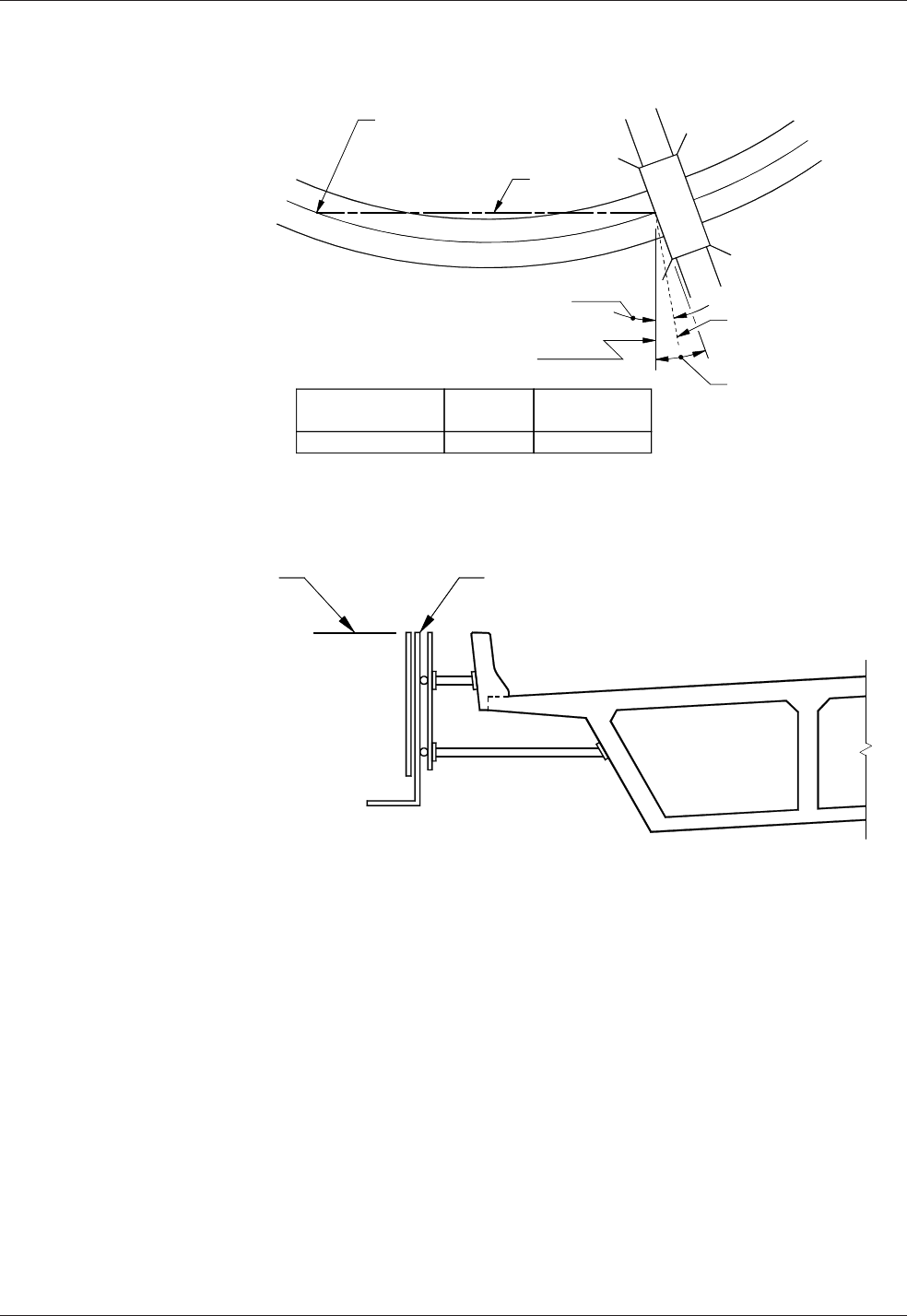
2. Forstructureslocatedonorjustbeyondahorizontalcurveofthelower
roadway, signs shall be designed to provide a sign chord skew within 5°
fromperpendiculartothechord-pointdeterminedbytheapproachspeed(see
Figure 10.1.2-3).
Chapter 10 Signs, Barriers, Approach Slabs, and Utilities
WSDOT Bridge Design Manual M 23-50.17 Page 10-5
June 2017
3. The top of the sign shall be level.
SignSkewonCurvedRoadway
Figure 10.1.2-3
Figure 10.1.2-4
Signs, Barriers, Approach Slabs, and Utilities Chapter 10
Page 10-6 WSDOT Bridge Design Manual M 23-50.17
June 2017
C. Aesthetics
1. Thesupportstructureshallnotextendbeyondthelimitsofthesignunlessthe
extension is unavoidable.
2. Thesignsupportshallbedetailedinsuchamannerthatwillpermitthesign
and lighting bracket to be installed level.
3. When the sign support will be exposed to view, special consideration is
requiredindeterminingmembersizesandconnectionstoprovideaspleasing
an appearance as possible.
D. Sign Placement
1. Signs shall not be placed under bridge overhangs. This causes partial shading
orpartialexposuretotheelementsandproblemsinliftingthematerialinto
positionandmakingtherequiredconnections.Signsshallneverbeplaced
directlyunderthedrip-lineofthestructure.Theseconditionsmayresultin
unevenfading,discoloring,anddicultyinreading.
2. Aminimumof2inchesofclearanceshallbeprovidedbetweenbacksideofthe
sign support and edge of the bridge. See Figure 10.1.2-5.
SignHorizontalLocation
Figure 10.1.2-5

Chapter 10 Signs, Barriers, Approach Slabs, and Utilities
WSDOT Bridge Design Manual M 23-50.17 Page 10-7
June 2017
E. Installation
1. Resin bonded anchors or cast-in-place ASTM F593 Group 1 Condition A
anchor rods shall be used to install the sign brackets on the structure. Size
andminimuminstallationdepthshallbegivenintheplansorspecications.
Theresinbondedanchorsshallbeinstallednormaltotheconcretesurface.
Resinbondedanchorsshallnotbeplacedthroughthewebsorangesof
prestressed or post-tensioned girders unless approved by the WSDOT Bridge
Design Engineer. Resin bonded anchors shall not be used at overhead locations
otherthanwithhorizontalhole/anchoralignment.
2. Bridgemountedsignstructuresshallnotbeplacedonbridgeswithsteel
superstructures unless approved by the WSDOT Bridge Design Engineer.
F. Installing/Replacing New Sign on Existing Bracket Supports
When installing a new sign on existing bracket supports, the following shall
be required:
1. All hardware shall be replaced per the current Standard Specications.
2. The new sign area shall not exceed the original designed sign area.
3. The inspection report for the bracket shall be reviewed to ensure that the
supports are in good condition. If there is not an inspection report, then an
inspectionshallbeperformedonthebracket.
10.1.3 Monotube Sign Structures Mounted on Bridges
A. Design Loads
Design loads for the supports of the Sign Bridges shall be calculated based on
assuminga12-foot-deepsignovertheentireroadwaywidth,underthesignbridge,
regardless of the sign area initially placed on the sign bridge. For Cantilever design
loads,guidelinesspeciedinSection10.1.1shallbefollowed.Thedesignloads
shallfollowthesamecriteriaasdescribedinSection10.1.1.Loadsfromthesign
bridge shall be included in the design of the supporting bridge.
Incaseswhereasignstructureismountedonabridge,thesignstructure,from
the anchor bolt group and above, shall be designed to AASHTO LRFD Standard
Specications for Structural Supports for Highway Signs, Luminaires, and Trac
SignalsFirstEdition,dated2015includinginterims.Theconcretetheanchorbolt
groupandtheconnectingelementstothebridgestructureshallbedesignedtothe
specicationsinthismanualandAASHTOLRFD.TheappropriateLRFDload
combinationsfromthesignstructuredesigncodeshallbeusedwiththesame
LRFDloadcombinationsfromthebridgedesigncode.
B. Vertical Clearance
VerticalclearanceforMonotubeSignStructuresshallbe20′-0″minimumfrom
thebottomofthelowestsigntothehighestpointinthetraveledlanes.See
Appendix 10.1-A1-1, 10.1-A2-1, and 10.1-A3-1forsamplelocationsofMinimum
Vertical Clearances.

Signs, Barriers, Approach Slabs, and Utilities Chapter 10
Page 10-8 WSDOT Bridge Design Manual M 23-50.17
June 2017
C. Geometrics
Signstructuresshallbeplacedatapproximaterightanglestoapproaching
motorists.DimensionsanddetailsofsignstructuresareshownintheStandard
Plans G-60.10, G-60.20, G-60.30, G-70.10, G-70.20, G-70.30 and Appendix
10.1-A1-1, 10.1-A1-2, and 10.1-A1-3 and 10.1-A2-1, 10.1-A2-2, and 10.1-A2-
3.Whenmaintenancewalkwaysareincluded,refertoStandardPlansG-95.10,
G-95.20, G-95.30.
10.1.4 Monotube Sign Structures
A. Sign Bridge Conventional Design
Table10.1.4-1providestheconventionalstructuraldesigninformationtobeused
for a Sign Bridge Layout, Appendix 10.1-A1-1; along with the Structural Detail
sheets, which are Appendix 10.1-A1-2 and Appendix 10.1-A1-3; General Notes,
Appendix 10.1-A5-1; and Miscellaneous Details, Appendix 10.1-A5-2.
B. Cantilever Conventional Design
Table 10.1.4-2providestheconventionalstructuraldesigninformationtobeused
for a Cantilever Layout, Appendix 10.1-A2-1; along with the Structural Detail
sheets, which are Appendix 10.1-A2-2 and Appendix 10.1-A2-3; General Notes,
Appendix 10.1-A5-1; and Miscellaneous Details, Appendix 10.1-A5-2.

Chapter 10 Signs, Barriers, Approach Slabs, and Utilities
WSDOT Bridge Design Manual M 23-50.17 Page 10-9
June 2017
STANDARDMONOTUBESIGNBRIDGES
SPAN
LENGTH POSTS ¦BEAM A ¦BEAM B ¦BEAM C ¦BEAM D ¦CAMBER
"S" "H" "A" "B" "T1" "L1" "B" "C" "T2" "L2" "B" "C" "T2" "L3" "B" "C" "T2"
LESS
THAN
60'-0"
30'-0"
OR
LESS
1'-6" 2'-0" ½" 6'-0" 2'-0" 2'-0" ½" 0'-0" 2'-0" 2'-0" ½"
13'-0"
TO
48'-0"
2'-0" 2'-0" ½" - - - - 2¾"
60'-0"
TO
75'-0"
30'-0"
OR
LESS
1'-6" 2'-3" ⅝" 6'-0" 2'-3" 2'-0" ⅝"
9'-0"
TO
14'-0"
2'-3" 2'-0" ⅝"
30'-0"
TO
35'-0"
2'-3" 2'-0" ⅝" - - - - 3¾"
+75'-0"
TO
90'-0"
30'-0"
OR
LESS
1'-6" 2'-3" ⅝" 6'-0" 2'-3" 2'-0" ⅝"
14'-0"
TO
19'-0"
2'-3" 2'-0" ⅝"
35'-0"
TO
40'-0"
2'-3" 2'-0" ⅝" - - - - 5"
+90'-0"
TO
105'-0"
30'-0"
OR
LESS
1'-9" 2'-6" ⅝" 6'-0" 2'-6" 2'-3" ⅝"
19'-0"
TO
26'-6"
2'-6" 2'-3" ⅝" 40'-0" 2'-6" 2'-3" ⅝" - - - - 6"
+105'-0"
TO
120'-0"
30'-0"
OR
LESS
1'-9" 2'-6" ⅝" 6'-0" 2'-6" 2'-3" ⅝"
26'-6"
TO
34'-0"
2'-6" 2'-3" ⅝" 40'-0" 2'-6" 2'-3" ⅝" - - - - 7½"
+120'-0"
TO
135'-0"
30'-0"
OR
LESS
2'-0" 2'-6" ⅝" 6'-0" 2'-6" 2'-6" ⅝"
34'-0"
TO
41'-6"
2'-6" 2'-6" ⅝" 40'-0" 2'-6" 2'-6" ⅝" - - - - 8½"
+135'-0"
TO
150'-0"
30'-0"
OR
LESS
2'-0" 2'-6" ⅝" 6'-0" 2'-6" 2'-6" ⅝"
41'-6"
TO
49'-0"
2'-6" 2'-6" ⅝" 40'-0" 2'-6" 2'-6" ⅝" - - - - 10½"
+150'-0"
TO
165'-0"
30'-0"
OR
LESS
2'-0" 2'-8" ¾" 6'-0" 2'-8" 2'-8" ⅝" 27'-0" 2'-8" 2'-8" ⅝"
18'-5"
TO
25'-6"
2'-8" 2'-8" ⅝" 48'-0" 2'-8" 2'-8" ⅝" 13¾"
+165'-0"
TO
180'-0"
30'-0"
OR
LESS
2'-0" 2'-8" ¾" 6'-0" 2'-8" 2'-8" ⅝" 30'0" 2'-8" 2'-8" ⅝"
22'-6"
TO
30'-0"
2'-8" 2'-8" ⅝" 48'-0" 2'-8" 2'-8" ⅝" 15¾"
SPAN
LENGTH POST BASE ¦
BOLTED SPLICE #1
L1 TO L2 AND L1 TO L3
BOLTED SPLICE #2
L2 TO L3
BOLTED SPLICE #3
L3 TO L4
MAX
SIGN
AREA"S" "D1" "S5" "S6" "T3" "T6" "S1" "S2" "S3" "S4" "T4" "T5" "S1" "S2" "S3" "S4" "T4" "T5" "S1" "S2" "S3" "S4" "T4" "T5"
LESS
THAN
60'-0"
1½" 4 4 3" ¾" 5 - 5 - 2" ⅝" ------------600 SQ.
FT.
60'-0"
TO
75'-0"
1¾" 4 4 3" ¾" 6 - 5 - 2" ⅝" 6 - 5 - 2¼" ¾" - - - - - - 700
SQ FT.
+75'-0"
TO
90'-0"
1¾" 4 4 3" ¾" 6 - 5 - 2" ⅝" 6 - 5 - 2¼" ¾" - - - - - - 800 SQ.
FT.
+90'-0"
TO
105'-0"
1¾" 4 5 3" 1" 7 - 6 - 2" ⅝" 7 5 6 4 2½" 1" - - - - - - 900 SQ.
FT.
+105'-0"
TO
120'-0"
1¾" 4 5 3" 1" 7 - 6 - 2" ⅝" 7 5 6 4 2½" 1" - - - - - - 900 SQ.
FT.
+120'-0"
TO
135'-0"
2" 4 5 3" 1" 7 5 7 5 2" ⅝" 7 5 7 5 2½" 1" - - - - - - 900 SQ.
FT.
+135'-0"
TO
150'-0"
2" 4 5 3" 1" 7 5 7 5 2" ⅝" 7 5 7 5 2½" 1" - - - - - - 900 SQ.
FT.
+150'-0"
TO
180'-0"
2" 4 5 3" 1" 7 5 7 5 2" ⅝" 7 5 7 5 2½" 1" 7 5 7 5 2½" 1" 900 SQ.
FT.
¦ NOTE: DENOTES MAIN LOAD CARRYING TENSILE MEMBERS OR TENSION COMPONENTS OF FLEXURAL MEMBERS.
Table 10.1.4-1

Signs, Barriers, Approach Slabs, and Utilities Chapter 10
Page 10-10 WSDOT Bridge Design Manual M 23-50.17
June 2017
STANDARDMONOTUBECANTILEVERS
Span Length Posts ¦Beam A ¦Beam B ¦
Camber"S" "H" "A" "B" "T1" "L1" "B" "C" "T2" "L2" "B" "C" "T2"
Less Than
20'-0"
30'-0"
or Less 1'-6" 2'-0" ½" 6'-0" 2'-0" 2'-0" ½" 14'-0" 2'-0" 2'-0" ½" 2"
20'-0" to
35'-0"
30'-0"
Or Less 1'-6" 2'-0" ½" 6'-0" 2'-0" 2'-0" ½"
14'-0"
TO
29'-0"
2'-0" 2'-0" ½" 3½"
Span Length Post Base ¦Bolted Splice Maximums
"S" "D1" "S5" "S6" "T3" "T6" "S1" "S2" "S3" "S4" "T4" "T5"
Sign
Area "XYZ" "Z"
Less Than
20'-0" 1½" 4 4 2" ¾" 5 - 5 - 2" ⅝" 194 SQ.
FT.
2920
C.F. 15'-0"
20'-0" to
30'-0" 2" 4 4 3" ¾ " 5 3 5 3 2½" ⅝" 330 SQ.
FT.
5363
C.F. 20'-0"
+30'-0" to
35'-0" 2" 4 4 3" ¾ " 5 3 5 3 2½" ⅝" 235 SQ.
FT.
5924
C.F. 25'-0"
¦ Note: Denotes Main Load Carrying Tensile Members Or Tension Components Of Flexural Members.
Table 10.1.4-2
C. Balanced Cantilever Conventional Design
Appendix 10.1-A3-1; along with the Structural Detail sheets, Appendix 10.1-A3-2
and 10.1-A3-3, General Notes, Appendix 10.1-A5-1; and Miscellaneous Details,
Appendix 10.1-A5-2,providestheconventionalstructuraldesigninformationto
be used for a Balanced Cantilever Layout. Balanced Cantilevers are typically for
VMSsignapplicationsandshallhavethesigndeadloadbalancedwithamaximum
dierenceof one-third to two-thirds distribution.
D. VMS Installation
1. VMS units shall not be installed on unbalanced cantilever structures.
2. VMS installation on Sign Bridge structures designed in accordance with
AASHTO 2015 shall be installed in accordance with the following:
a. Onspans120ftandgreateruptotwoVMSunitsmaybeinstalledwith
amaximumweightof4,000lbseach.Maintenancewalkwaysmaybe
installedbetweenVMSunits,butmaynotexceed160lbs/ft,orexceed
50 percent of the structure span length.
b. Onspanslessthan120ft.uptothreeVMSunitsmaybeinstalledwith
amaximumweightof4,000lbs.each.Maintenancewalkwaysmaybe
installedbetweenVMSunits,butmaynotexceed160lbs/ft.
3. ThenumberofVMSinstalledonSignBridgestructuresdesignedpriorto
AASHTO2015shallbereducedbyoneasdenedinD.2-aandb.

Chapter 10 Signs, Barriers, Approach Slabs, and Utilities
WSDOT Bridge Design Manual M 23-50.17 Page 10-11
June 2017
E. Monotube Sheet Guidelines
The following guidelines apply when using the Monotube Sign Structure Appendix
10.1-A1-1, 10.1-A1-2, and 10.1-A1-3; 10.1-A2-1, 10.1-A2-2, and 10.1-A2-3;
10.1-A3-1, 10.1-A3-2, and 10.1-A3-3; 10.1-A4-1, 10.1-A4-2, and 10.1-A4-3;
and 10.1-A5-1, 10.1-A5-2, and 10.1-A5-3.
1. Each sign structure shall be detailed to specify:
a. SignstructurebaseElevation,Station,andNumber.
b. Type of Foundation 1, 2, or 3 shall be used for the Monotube Sign
Structures, unless a non-conventional design is required. The average
Lateral Bearing Pressure for each foundation shall be noted on the
Foundationsheet(s).
c. If applicable, label the Elevation View “Looking Back on Stationing.”
2. Designersshallverifythecross-referencedpagenumbersanddetailsare
correct.
F. Monotube Quantities
Quantities for structural steel are given in Table 10.1.4-3.
SignStructureMaterialQuantities
ASTMA572GR.50or
ASTM588
Cantilever Sign Bridge
20’ <
20’
to
30’ Balanced 60’ <
60’
to
75’
75’
to
90’
90’
to
105’
105’
to
120’
120’
to
135’
135’
to
150’
150’
to
180’
Post (plf) 132 132 132 132 176 176 204 204 215 215 267
Base PL (lbs./ea) 537 806 806 672 735 735 888 888 978 978 1029
Beam, near Post (plf) 152 152 152 152 202 202 228 228 240 240 257
Span Beam (plf) 152 152 152 152 202 202 228 228 240 240 257
Corner Sti . (lbs./ea set) 209 209 115 218 272 272 354 354 376 376 425
Splice Pl #1 (lbs/pair) 592 706 706 578 650 650 826 826 1116 1116 1295
Splice Pl #2 (lbs/pair) -- -- -- -- 730 730 1002 1002 1116 1116 1295
Splice Pl #3 (lbs/pair) -- -- -- -- -- -- -- -- -- -- 1295
Brackets (lbs./ea) 60 60 60 60 65 65 69 69 70 70 70
6” Hand Hole (lbs./ea) 18 18 18 18 18 18 18 18 18 18 18
6” x 11” Hand Hole (lbs./ea) 30 30 30 30 30 30 18 30 30 30 30
Anchor Bolt PL (lbs./ea) 175 175 175 175 185 185 311 311 326 326 326
Cover Plates (lbs./ea) 65 65 65 -- -- -- -- -- -- -- --
SignStructureSteelQuantities
Table 10.1.4-3

Signs, Barriers, Approach Slabs, and Utilities Chapter 10
Page 10-12 WSDOT Bridge Design Manual M 23-50.17
June 2017
10.1.5 Foundations
A. Monotube Sign Structure Foundation Types
The foundation type is to be used shall be based on the geotechnical investigation
performedandgeotechnicalreportcompletedbythegeotechnicalengineerof
record. Standard foundation designs for standard plan truss-type sign structures
are provided in WSDOT Standard Plans G-60.20 and G-60.30 and G-70.20
andG-70.30.MonotubesignstructurefoundationsareBridgeDesignOce
conventional designs and shall be as described in the following paragraphs:
1. Foundation Type 1, is the preferred foundation type. A foundation Type 1
consists of a drilled shaft with its shaft cap. The design of the shaft depths
shown in the Sign Bridge Standard Drawings are based on a lateral bearing
pressure of 2,500 psf. The designer shall check these shaft depths using
AASHTO LRFDmethodology.ForType1foundationdetailsandshaft
depths see Sign Bridge Standard Drawings 10.1-A4-1 and 10.1-A4-2. The
Geotechnical report for Foundation Type 1 should include the soil friction angle,
soilunitweight,allowablebearingpressureandtemporarycasingifrequired.
TemporarycasingshallbeproperlydetailedinallFoundationType1sheetsif
theGeotechnicalEngineerrequiresthem.
2. Foundation Type 2 is an alternate to Type 1 when drilled shafts are not suitable
to the site. Foundation Type 2 is designed for a lateral bearing pressure of
2,500 psf. See Appendix 10.1-A4-3 for Foundation Type 2 Bridge Design
Oceconventionaldesigninformation.The designer shall check these shaft
depths using LRFDmethodology.
3. Foundation Type 3 replaces the foundation Type 2 for poor soil conditions
where the lateral bearing pressure is between 2,500 psf and 1,500 psf. See
Bridge Standard Drawing 10.1-A4-3 for Type 3 Foundation Bridge Design
Oceconventionaldesigninformation.The designer shall check these shaft
depths using LRFDmethodology.
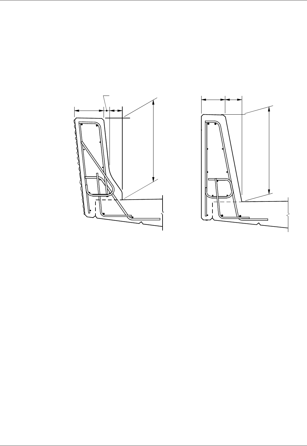
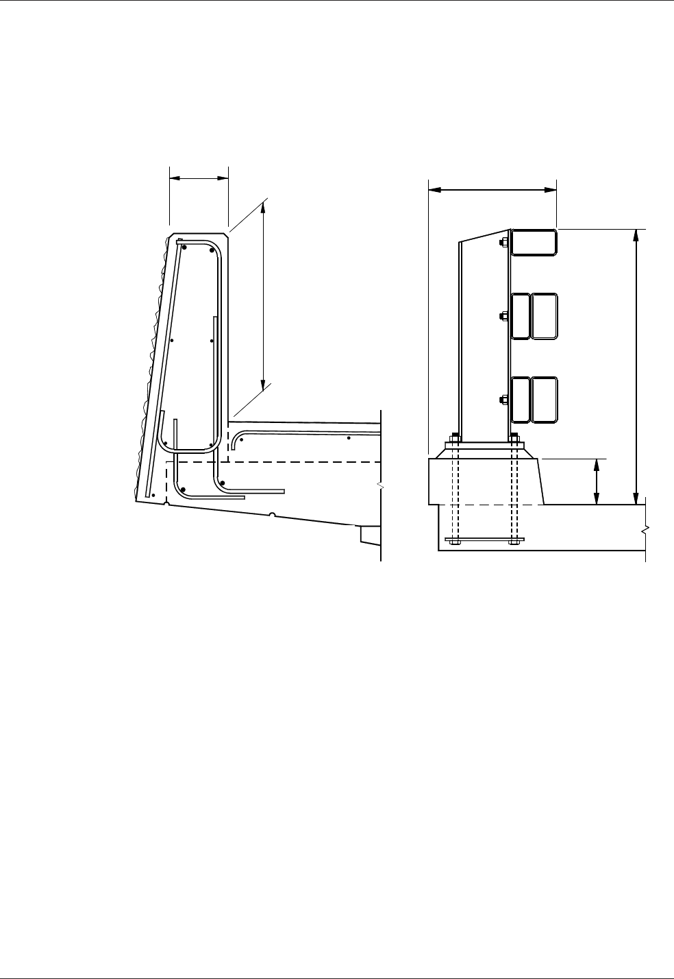
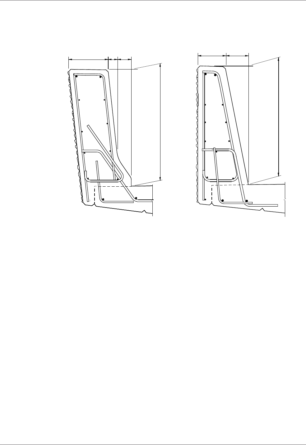
4. Barrier Shape Foundations are foundations that include a barrier shape cap on
the top portion of Foundation Types 1, 2, and 3. Foundation details shall be
modiedtoincludeBarrierShapeCapdetails.Appendix 10.1-A5-1 details a
single slope barrier.
B. Luminaire, Signal Standard, and Camera Pole Foundation Types
LuminairefoundationoptionsareshownonStandardPlanJ-28.30.SignalStandard
andCameraPolefoundationoptionsareprovidedonStandardPlansJ-26.10and
J-29.10 respectively.
C. Foundation Design
Shaft type foundations constructed in soil for sign bridges, cantilever sign
structures,luminaires,signalstandardsandstrainpolesshall be designed in
accordance with the current edition of the AASHTO LRFD Standard Specications
for Highway Signs, Luminaires, and Trac Signals; Section 13.6 Drilled Shafts.

Chapter 10 Signs, Barriers, Approach Slabs, and Utilities
WSDOT Bridge Design Manual M 23-50.17 Page 10-13
June 2017
No provisions for foundation torsional capacity are provided in Section 10.13 of
the AASHTO LRFD Standard Specications for Highway Signs, Luminaires, and
Trac Signals. The following approach can be used to calculate torsional capacity
ofsignstructure,luminaire,andsignalstandardfoundations:
Torsional Capacity, φTn,
Tn=F*tanφD 10.1.5(1)
Where:
F =Totalforcenormaltoshaftsurface(kip)
D =Diameterofshaft(feet)
φ =Soiltofoundationcontactfrictionangle(degree),usesmallestfor
variable soils
1. Monotube Sign Structures Foundation Type 1 Design
Thestandardembedmentdepth“Z”,showninthetableonMonotube
Sign Structure Standard Drawing 10.1-A4-1,shallbeusedasaminimum
embedmentdepthandshallbeincreasediftheshaftisplacedonasloped
surface,oriftheallowablelateralbearingpressuresarereducedfromthe
standard2500psf.Thestandarddepthassumedthatthetop4feetofthe
C.I.P. cap is not included in the lateral resistance (i.e., shaft depth “D” in the
codementionedabove),butisincludedintheoverturninglengthofthesign
structure. The sign structure shaft foundation GSPs under Section 8-21 in the
RFP Appendix shall be included with all Foundation Type 1 shafts.
2. Monotube Sign Structures Foundation Type 2 and 3
ThesefoundationdesignsareBridgeDesignOceconventionandshallnot
beadjustedorredesigned.TheyareusedinconditionswhereaFoundation
Type1(shaft)wouldbeimpracticalduetodicultdrillingorconstruction
andwhentheGeotechnicalEngineerspeciestheiruse.Theconceptisthat
thefoundationexcavationwouldmaintainaverticalfaceintheshapeofthe
FoundationType2or3.Contractorsoftenrequesttoover-excavateandbackll
thehole,afterformworkhasbeenusedtoconstructthisfoundationtype.Thisis
onlyallowedwiththeGeotechnicalengineer'sapproval,iftheformingmaterial
iscompletelyremoved,andifthebackllmaterialiseitherCDForconcrete
class 3000 or better.
3. Monotube Sign Structures Non-Conventional Design Foundations
The Geotechnical Engineer of record shall identify conditions where the
foundationtypes(1,2,or3)willnotwork.Inthiscase,thedesignforcesare
calculated, using the AASHTO LRFD Standard Specications for Structural
Supports for Highway Signs, Luminaires, and Trac Signals, and applied
atthebottomofthestructurebaseplate.Theseforcesarethenconsidered
service loads and the non-conventional design foundation is designed with
theappropriateService,Strength,andExtremeLoadCombinationLimit
StatesandcurrentdesignpracticesoftheAASHTOLRFDandthismanual.
Someexamplesofthesefoundationsarespreadfootings,columnsandshafts
thatextendabovegroundadjacenttoretainingwalls,orconnectionstotrac
barriersonbridges.TheanchorrodarrayshallbeusedfromTables10.1.4-1

Signs, Barriers, Approach Slabs, and Utilities Chapter 10
Page 10-14 WSDOT Bridge Design Manual M 23-50.17
June 2017
and10.1.4-2andshallbelongenoughtodeveloptherodsintotheconned
concretecoreofthefoundation.Therodlengthandthereinforcementfor
concreteconnement,showninthetopfourfeetoftheFoundationType1,
shallbeusedasaminimum.
4. Signal Foundation Design
ThetracsignalstandardGSPsunderSection8-20shallapplyforfoundations
in substandard soils.
D. Foundation Quantities
1. BarrierquantitiesareapproximateandcanbeusedforallFoundationTypes:
Class4000Concrete 7.15CY(overshaftfoundation)
Grade 60 Rebar 372 lbs
2. Miscellaneoussteelquantities(anchorrods,anchorplate,andtemplate)forall
MonotubeSignStructurefoundationtypesarelistedbelow(perfoundation).
Quantities vary with span lengths as shown.
60feetandunder = 1,002pounds
61feetto90feet = 1,401pounds
91feetto120feet = 1,503pounds
121feetto180feet Barriermountedsignbridgenotrecommended
for these spans.
3. Monotube Sign Structure Foundation Type 1-3 quantities for concrete, rebar
and excavation are given in Table 10.1.5-1. For Sign Bridges, the quantities
shown below are for one foundation and there are two foundations per Sign
Bridge. If the depth “Z” shown in the table on Bridge Standard Drawing 10.1-
A4-1 is increased, these values should be recalculated.
CantileverSigns Sign Bridges
ConcreteCl.4000
(cu.yard)
20′and
Under 20′–30′ 30'–35'
60′and
Under 60′–90′ 90′–120′ 120′–180′
Type 1 6.3 7.5 9.4 7.7 9.4 10.6 11.4
Type 2 8.0 10.5 12.2 10.0 12.2 14.1 15.0
Type 3 11.1 14.1 16.1 13.0 16.1 18.6 20.0
Rebar Gr. 60 Pounds
Type 1 685 1,027 2,251 1,168 2,251 3,256 4,255
Type 2 772 1,233 1,724 1,190 1,724 2,385 2,838
Type 3 917 1,509 2,136 1,421 2,136 2,946 3,572
Excavation (cu. yard)
Type 1 9.8 10.9 12.8 10.9 12.8 14.1 14.9
Type 2 20.7 25.7 29.0 24.6 29.0 32.9 34.6
Type 3 29.0 34.6 39.0 32.9 39.0 44.0 47.8
SignStructureFoundationMaterialQuantities
Table 10.1.5-1

Chapter 10 Signs, Barriers, Approach Slabs, and Utilities
WSDOT Bridge Design Manual M 23-50.17 Page 10-15
June 2017
10.1.6 Truss Sign Bridges: Foundation Sheet Design Guidelines
If a Truss sign structure is used, refer to Standard Plans for foundation details. There
arefouritemsthatshouldbeaddressedwhenusingtheStandard Plans, which are
outlined below. For details for F-shape barrier details not shown in Standard Plans
contactBridgeOcetoaccessarchivedBridgeOcedetails.
1. Determineconduitneeds.Ifnoneexist,deleteallreferencestoconduit.Ifconduit
is required, verify with the Region as to size and quantity.
2. Showsignbridgebaseelevation,number,dimensionandstation.
3. The concrete barrier transition section shall be in accordance with the
Standard Plans.
4. The quantities shall be based on the Standard Plans details as needed.

Signs, Barriers, Approach Slabs, and Utilities Chapter 10
Page 10-16 WSDOT Bridge Design Manual M 23-50.17
June 2017
10.2 BridgeTracBarriers
10.2.1 General Guidelines
Thedesigncriteriafortracbarriersonstructuresshallbeinaccordancewith
Section13oftheAASHTOLRFD.Thefollowingguidelinessupplementthe
requirementsinAASHTOLRFD.
TheWSDOTBridgeandStructuresstandardfortracbarriersonnewbridgesand
bridge approach slabs shall be a 42 inch Single Slope concrete barrier for all interstate
routes,majorhighwayroutes,andoverNationalHighwaySystem(NHS)routesunless
specialconditionsapply.The42inchrequirementisinaccordancewiththe“Fall
Protection”requirementsoftheWashingtonStateDepartmentofLaborandIndustries,
(WAC 296-155-24609 and WAC 296-155-24615 2a),andtheJuly2014AASHTO
resolution for Fall Protection.
The WSDOT Bridge and Structures standard for existing bridges, bridge rehabilitation
projects,StructuralEarthWallandGeosyntheticwalltracbarriers,retainingwalls,
andmedianbarriershallbea34inchor42inchSingleSlopetracbarrier.
Useofa32inchor42inchFShapeconcretebarriershallbelimitedtolocationswhere
there is F Shape concrete barrier on the approach grade to a bridge or for continuity
within a corridor.
Useofa32inchPedestrianconcretebarriershallbelimitedtolocationswithsidewalk.
Useofa42inchor54inchcombinationbarrier(32inchor34inchconcretebarrier
increasedbymetalrailing)arelesseconomical,requiremoremaintenance,andshall
belimitedforpurposessuchasscenicroads.Foradditionalrequirementsforpedestrian
and bicycle/pedestrian railings, see Section 10.5.1.
ItshallbetheBridgeandStructuresOcepolicytodesigntracbarriersfornew
structuresusingminimumTestLevel4(TL-4)designcriteriaregardlessoftheheight
of the barrier safety shape. The Test Level shall be indicated in the Bridge General
NotesorGeneralNotes.ATestLevel5(TL-5)tracbarriershallbeusedonnew
structures under the following conditions:
• “T” intersections on a structure.
• Barriers on structures with a radius of curvature less than 500 ft, TL-4 is adequate
for the barrier on the inside of the curve.
• Greaterthan10percentAverageDailyTruckTrac(ADTT)whereapproach
speedsare50mphorgreater(e.g.,freewayo-ramps).
• Accident history suggests a need.
• Protectionofschools,business,orotherimportantfacilitiesbelowthebridge.
See AASHTO LRFD Section 13 for additional Test Level selection criteria.
A list of crash tested barriers can be found through the FHWA website at:
https://safety.fhwa.dot.gov/roadway_dept/countermeasures/reduce_crash_severity/
listing.cfm?code=long

Chapter 10 Signs, Barriers, Approach Slabs, and Utilities
WSDOT Bridge Design Manual M 23-50.17 Page 10-17
June 2017
10.2.2 Bridge Railing Test Levels
Itmustberecognizedthatbridgetracbarrierperformanceneedsdiergreatlyfrom
sitetosite.Barrierdesignsandcostsshouldmatchfacilityneeds.Thisconceptis
embodiedintheAASHTOLRFD.Sixdierentbridgerailingtestlevels,TL-1thruTL-
6,andassociatedcrashtest/performancerequirementsaregiveninAASHTOLRFD
Section13alongwithguidancefordeterminingtheappropriatetestlevelfor
a given bridge.
10.2.3 Available WSDOT Designs
A. Service Level 1 (SL-1) Weak Post Guardrail (TL-2)
Thisbridgetracbarrierisacrashtestedweakpostrailsystem.Itwasdeveloped
by Southwest Research Institute and reported in NCHRP Report 239 for low-
volumeruralroadwayswithlittleaccidenthistory.Thisdesignhasbeenutilizedon
anumberofshortconcretespansandtimberbridges.Afailuremechanismisbuilt
intothisrailsystemsuchthatupona10kipappliedimpactload,thepostwillbreak
awayfromthemountingbracket.Thethriebeamguardrailwillcontainthevehicle
byvirtueofitsribbonstrength.Toensureminimalornodamagetothebridgedeck
andstringers,thebreakawayconnectionmaybemodiedforalowerimpactload
(2kipminimum)withapprovaloftheBridgeDesignEngineer.The2kipminimum
equivalentimpactloadisbasedonevaluationofthewoodrailpoststrengthtested
in NCHRP Report 239. The appropriate guardrail approach transition shall be a
Case14placementasshownonWSDOTStandard Plan C-2h.Forcompletedetails
see Appendix 10.4-A1.
Signs, Barriers, Approach Slabs, and Utilities Chapter 10
Page 10-18 WSDOT Bridge Design Manual M 23-50.17
June 2017
B. Texas T-411 Aesthetic Concrete Baluster (TL-2)
Texas developed this standard for a section of highway that was considered to
beahistoriclandmark.Theexistingdecientconcretebalusterrailwasreplaced
withamuchstrongerconcretebalusterthatsatisfactorilypassedthecrashtest
performancecriteriasetforthbytheNCHRPReport230.Fordetails,visit
TXDOT’s Bridge and Structures website at
www.txdot.gov/inside-txdot/division/bridge.html.
SL-1WeakPost TexasT-411
Figure 10.2.3-1
C. Trac Barrier – 32″ Shape F (TL-4)
Thiscongurationwascrashtestedinthelate1960s,alongwiththeNewJersey
Shape, under NCHRP 230 and again at this test level under NCHRP 350. The
steeper vertical shape tested better than the New Jersey face and had less of
aninclinationtorollvehiclesoveruponimpact.Forfuturedeckoverlays,an
encroachmentof2.0in.,leavinga1.0in.liphasbeensatisfactorilytestedforsafety
shapes,seeAASHTOArticleC13.7.3.2.ForcompletedetailsseeBridgeStandard
Drawings 10.2-A1 and 10.2-A2.
Chapter 10 Signs, Barriers, Approach Slabs, and Utilities
WSDOT Bridge Design Manual M 23-50.17 Page 10-19
June 2017
D. Trac Barrier – 34″ Single Slope (TL-4)
ThisconcretetracbarriersystemwasdesignedbythestateofCaliforniainthe
1990stospeedupconstructionbyusingthe“slipforming”methodofconstruction.
ItwastestedunderNCHRP350.WSDOThasincreasedtheheightfrom32″to34″
tomatchtheapproachtracbarrierheightandtoallowtheplacementofoneHMA
overlay.Duetoinherentproblemswiththe“slipforming”methodoftracbarrier
constructionWSDOThasincreasedtheconcretecoveronthetracsidefrom1½″
to2½″.Forcompletedetails,seeBridge Standard Drawing 10.2-A3.
32″F-Shape 34″SingleSlope
Figure 10.2.3-2
E. Pedestrian Barrier (TL-4)
Thiscrashtestedrailsystemoersasimpletobuildconcretealternativetothe
NewJerseyandF-Shapecongurations.Thissystemwascrashtestedunder
bothNCHRP230and350.Sincethetracfacegeometryisbetterforpedestrians
andbicyclists,WSDOTusesthissystemprimarilyinconjunctionwithasidewalk.
Forcompletedetails,see Bridge Standard Drawing 10.2-A4.
Signs, Barriers, Approach Slabs, and Utilities Chapter 10
Page 10-20 WSDOT Bridge Design Manual M 23-50.17
June 2017
F. Oregon 3-Tube Curb Mounted Trac Barrier (TL-4)
Thisisanothercrashtestedtracbarrierthatoersalightweight,see-through
option.ThissystemwascrashtestedunderbothNCHRP230and350.Arigidthrie
beamguardrailtransitionisrequiredatthebridgeends.Fordetails,seetheOregon
Bridge and Structure website at www.oregon.gov/ODOT/HWY/ENGSERVICES/
Pages/bridge_drawings.aspx.
32″Vertical Oregon3-Tube
Figure 10.2.3-3
G. Trac Barrier – 42″ Shape F (TL-4 and TL-5)
Thisbarrierisverysimilartothe32″F-shapeconcretebarrierinthattheslopeof
thefrontsurfaceisthesameexceptforheight.Forcompletedetails,seeBridge
Standard Drawing 10.2-A6.
Chapter 10 Signs, Barriers, Approach Slabs, and Utilities
WSDOT Bridge Design Manual M 23-50.17 Page 10-21
June 2017
H. Trac Barrier – 42″ Single Slope (TL-4 and TL-5)
ThisoptionoersasimpletobuildalternativetotheShapeFconguration.For
completedetailsseeBridge Standard Drawing 10.2-A6.
42″F-Shape 42″SingleSlope
Figure 10.2.3-4
10.2.4 Design Criteria
A. Design Values
AASHTOLRFDAppendixA13shallbeusedtodesignbridgetracbarriersand
theirsupportingelements(i.e.thedeck).
Concretetracbarriersshallbedesignedusingyieldlineanalysisasdescribedin
AASHTOLRFDA13.3.1.Theimpactloadsontracbarriersshallbeappliedat
theheightspeciedforintendedTestLevelsinaccordancetotheAASHTOLRFD
Table A13.2-1 “Design Forces for Trac Railing (32-inch for TL-4, and 42-
inchforTL-5)”.WSDOTStandardFShapeandSingleSlopebarriersmeet
theserequirements.
Deckoverhangssupportingtracbarriersshallbedesignedinaccordancewith
AASHTOLRFDA13.4.ForconcretetracbarriersinDesignCase1,AASHTO
requires MS,thedeckoverhangexuralresistance,tobegreaterthanMc of
theconcretetracbarrierbase.Thisrequirementisconsistentwithyieldline
analysis(seeAASHTOLRFDCA13.3.1),butresultsinoverconservativedeck
overhang designs.

Signs, Barriers, Approach Slabs, and Utilities Chapter 10
Page 10-22 WSDOT Bridge Design Manual M 23-50.17
June 2017
Inordertopreventthisunnecessaryoverdesignofthedeckoverhang,thenominal
tracbarrierresistancetotransverseloadRW(AASHTOLRFDA13.3.1)
transferredfromthetracbarriertodeckoverhangshallnotexceed120percent
of the design force Ft(AASHTOLFRDTableA13.2-1)requiredforatrac
barrier.Thedeckoverhangshallbedesignedinaccordancewiththerequirements
ofAASHTOLRFDA13.4.2toprovideaexuralresistanceMs, acting coincident
with the tensile force T. At the inside face of the barrier Msmaybetakenas:
foraninteriorbarriersegment–Ms=
Rw · H
LC + 2 · H
andforanendbarriersegment–Ms= Rw · H
LC + H
However, Ms need not be taken greater than Mc at the base. T shall be taken as:
foraninteriorbarriersegment–T= Rw
LC + 2 · H
andforanendbarriersegment–T=
Rw
LC + H
Theendsegmentrequirementmaybewaivedifcontinuitybetweenadjacent
barriers is provided.
When an HMA overlay is required for initial construction, increase the weight for
ShapeFtracbarrier.SeeSection 10.2.4.C for details.
B. Geometry
Thetracfacegeometryispartofthecrashtestandshallnotbemodied.
ContacttheWSDOTBridgeandStructureOceBridgeRailSpecialistfor
further guidance.
Thickeningofthetracbarrierispermissibleforarchitecturalreasons.Concrete
clearcovermustmeetminimumconcretecoverrequirementsbutcanbeincreased
toaccommodaterusticationgroovesorpatterns.
C. Standard Detail Sheet Modications
Whendesigninganddetailingabridgetracbarrieronasuperelevatedbridge
deck the following guidelines shall be used:
• Forbridgedeckswithasuperelevationof8percentorless,thetrac
barriers(andthemedianbarrier,ifany)shallbeorientedperpendiculartothe
bridge deck.
• Forbridgedeckswithasuperelevationofmorethan8percent,thetrac
barrieronthelowsideofthebridge(andmedianbarrier,ifany)shallbe
oriented perpendicular to an 8 percent superelevated bridge deck. For this
situation,thetracbarrieronthehighsideofthebridgeshallbeoriented
perpendicular to the bridge deck.

Chapter 10 Signs, Barriers, Approach Slabs, and Utilities
WSDOT Bridge Design Manual M 23-50.17 Page 10-23
June 2017
Thestandarddetailsheetsaregenericandmayneedtobemodiedforeach
project.Thepermissiblemodicationsare:
• Removaloftheelectricalconduit,junctionbox,anddeectionttingdetails.
• Removalofdesignnotes.
• Ifthetracbarrierdoesnotcontinueontoawall,removeW1andW2rebar
references.
• Removalofthenon-applicableguardrailendconnectiondetailsandverbiage.
• Ifguardrailisattachedtothetracbarrier,useeitherthethriebeamend
section“DesignF”detailorthew-beamendsection“DesignF”detail.Ifthe
tracbarriercontinuesothebridge,approachslab,orwall,removethe
following:
• Guardraildetailsfromallsheets.
• Conduitendaredetail.
• ModiedendsectiondetailandR1AorR2Arebardetailsfromallsheets.
• End section bevel.
• Increasethe3″toedimensionoftheShapeFtracbarriersupto6″to
accommodateHMAoverlays.

Signs, Barriers, Approach Slabs, and Utilities Chapter 10
Page 10-24 WSDOT Bridge Design Manual M 23-50.17
June 2017
Table 10.2.4-1
Interior End* Interior End* Interior End* Interior End* Interior End* Interior End*
Average Mc (ft-kips/ft) 20.55 20.55 19.33 19.33 25.93 25.93 22.42 22.42 25.93 25.93 22.42 36.04
Mc at Base (ft-kips/ft) 27.15 27.15 26.03 26.03 32.87 32.87 30.66 30.66 32.87 32.87 30.66 49.52
M
w
(ft-kips) 42.47 46.04 46.01 43.16 72.54 71.72 60.66 57.26 98.23 96.93 83.85 79.12
Lc (ft) 8.62 4.76 9.30 4.81 10.77 5.32 10.63 5.21 15.05 9.39 14.99 8.87
Rw (kips) 132.82 73.31 126.92 65.69 159.62 78.83 136.17 66.81 223.00 139.20 192.02 182.61
Ft (kips) 54.00 54.00 54.00 54.00 54.00 54.00 54.00 54.00 124.00 124.00 124.00 124.00
1.2*F
t
(kips) 64.80 64.80 64.80 64.80 64.80 64.80 64.80 64.80 148.80 148.80 148.80 148.80
Design Rw (kips) 64.80 64.80 64.80 64.80 64.80 64.80 64.80 64.80 148.80 139.20 148.80 148.80
Rw*H/(Lc+aH) (ft-kips/ft)** 12.39 23.28 12.27 24.01 9.72 19.59 9.80 19.83 23.62 37.79 23.69 42.11
Design Ms (ft-kips/ft) 12.39 23.28 12.27 24.01 9.72 19.59 9.80 19.83 23.62 32.87 23.69 42.11
Design T (kips/ft) 4.65 8.73 4.33 8.47 3.65 7.35 3.68 7.44 6.75 10.80 6.77 12.03
A
s
required (in2/ft) 0.29 0.57 0.29 0.59 0.17 0.35 0.20 0.41 0.43 0.60 0.49 0.91
As provided (in2/ft) 0.41 0.62 0.41 0.62 0.41 0.62 0.41 0.62 0.59 0.89 0.59 0.97
S1 Bars #5 @ 9 in #5 @ 6 in #5 @ 9 in #5 @ 6 in #5 @ 9 in #5 @ 6 in #5 @ 9 in #5 @ 6 in #6 @ 9 in #6 @ 6 in #6 @ 8 in #6 @ 5.5 in
*Traffic barrier cross sectional dimensions and reinforcement used for calculation of end segment parameters are the same as interior segments (except TL-5 Single Slope 42 in. barrier
where end section reinforcement differs from interior segments). Parameters for modified end segments shall be calculated per AASHTO-LRFD article A13.3, A13.4, and the WSDOT BDM.
**a = 1 for an end segment and 2 for an interior segment
Loads are based on vehicle impact only. For deck overhang design, the designer must also check other limit states per LRFD A13.4.1.
f
v
= 60 ksi
f'c= 4 ksi
BarrierImpactDesignForcesonTrafficBarrier&DeckOverhang
(TL-5)
(TL-5)
Traffic Barrier
Design
Deck
Overhang
Design
Type F 42 in. Single Slope 42 in.
Deck to
Barrier
Reinforcement
Parameters
Type F 32 in. Single Slope 34 in.
Single Slope 42 in.
(TL-4)
(TL-4)
(TL-4)
Type F 42 in.
(TL-4)

Chapter 10 Signs, Barriers, Approach Slabs, and Utilities
WSDOT Bridge Design Manual M 23-50.17 Page 10-25
June 2017
D. Miscellaneous Design Information
• Showthebackofpavementseatinthe“Plan–TracBarrier”detail.
• Atroadwayexpansionjoints,showtracbarrierjointsnormaltocenterline
except as shown on sheets Appendix 9.1-A1-1 and 9.1-A2-1.
• Whenanoverlayisrequired,the2′-8″minimumdimensionshowninthe
“TypicalSection–TracBarrier”shallbereferencedtothetopoftheoverlay.
• When bridge lighting is part of the contract, include the lighting bracket
anchorage detail sheet.
• Approximatequantitiesforthetracbarriersheetsare:
BarrierType ConcreteWeight(lb/ft) SteelWeight(lb/ft)
32″ F-shape (3″ toe) 460 18.6
32″ F-shape (6″ toe) 510 19.1
34″ Single Slope 490 16.1
42″ F-shape (3″ toe) 710 25.8
42″ F-shape (6″ toe) 765 28.4
42″ Single Slope 670 22.9
32″ Pedestrian 640* 14.7
Using concrete class 4000 with a unit weight of 155 lb/ft3
*with 6″ sidewalk, will vary with sidewalk thickness
• SteelReinforcementBars:
S1 & S2 or S3 & S4 and W1 & W2bars(ifused)shallbeincludedintheBarList.
S1, S3, and W1 bars shall be epoxy coated.

Signs, Barriers, Approach Slabs, and Utilities Chapter 10
Page 10-26 WSDOT Bridge Design Manual M 23-50.17
June 2017
10.3 AtGradeConcreteBarriers
10.3.1 DierentialGradeConcreteBarriers
Thetopofthedierentialgradeconcretebarriershallhaveaminimumwidthof6″.
Ifaluminaireorsignistobemountedontopofthedierentialgradeconcretebarrier,
thenthewidthshallbeincreasedtoaccommodatethemountingplateand6″ofclear
distanceoneachsideoftheluminaireorsignpole.Thetransitionarerateshallfollow
the Design Manual M 22-01.
A. Dierential Grade Concrete Barriers
Concretebarriersatgradearesometimesrequiredinmedianareaswithdierent
roadway elevations on each side. The standard Single Slope barrier can be used for
agradedierenceupto10″fora2′-10″safetyshapeandupto6″fora3′-6″safety
shape. See Standard Plans C-70.10 and C-80.10 for details.
Ifthedierenceingradeelevationsis4′-0″orless,thentheconcretebarrier
shallbedesignedasarigidsysteminaccordancewithAASHTOLRFDwiththe
followingrequirements:
1. All applicable loads shall be applied in accordance to AASHTO LRFD
Section3.Thestructuralcapacityofthedierentialgradeconcretebarrier
andsupportingelementsshallbedesignedfortherequiredTestLevelvehicle
impactdesignforcesinaccordancewithAASHTOLRFDSections5and13.
Anysectionalongthedierentialgradebarrierandsupportingelementsshall
notfailinshear,bending,ortorsionwhenthebarrierissubjectedtotheTL
impactforces.
2. Forsoilloadswithoutvehicleimpactloads,theconcretebarriershall
be designed as a retaining wall (barrier weight resists overturning and
sliding).Passivesoilresistancemaybeconsideredwithconcurrencebythe
geotechnical engineer.
3. Vehicleimpactloadsshallbeappliedonthesideoftheconcretebarrier
retainingsoilifthereistraconbothsides.Thevehicleimpactloadsshallbe
appliedattheheightspeciedforintendedTestLevelsinaccordancetothe
AASHTO LRFD Section 13, Table A13.2-1 “Design Forces for Trac Railing
(32-inchforTL-4,and42-inchforTL-5)”.
4. Forsoilloadswithvehicleimpactloads,theAASHTOLRFDExtremeEvent
loading for vehicular collision shall also be analyzed. Equivalent Static Load
(ESL)perNCHRPReport663maybeappliedasthetransversevehicleimpact
load for evaluating sliding, bearing, and overturning only. For TL-3 and TL-4
barriersystems,theESLshallbe10kipsandforTL-5,theESLshallbe
23 kips. The point of rotation for overturning shall be taken at the toe of barrier.
Sliding resistance factor shall be 0.8 and overturning resistance factor shall be
0.5(supersedesAASHTO10.5.5.3.3).
Chapter 10 Signs, Barriers, Approach Slabs, and Utilities
WSDOT Bridge Design Manual M 23-50.17 Page 10-27
June 2017
5. The eective length of the concrete barrier required for stability shall be no
morethan10timestheoverallheight, but not to exceed the length between
barrierexpansionjoints(oroneprecastsection).Thebarriershallactasarigid
body behavior and shall be continuous throughout this length of barrier. Any
couplingbetweenadjacentbarriersectionsorfrictionthatmayexistbetween
free edges of barrier and the surrounding soil shall be neglected.
6. Aspecialimpactanalysisshallbeperformedatthebarrierendsifthebarrier
terminateswithoutbeingconnectedtoarigidobjectordowelledtoanother
barrier.Dierentialbarrierdeectionfrombarrierimpactmaycauseavehicle
to“snag”ontheundeectedbarrier.Thebarrierdepthmayneedtobeincreased
attheendtopreventthisdeection.
7. Thedierentialgradetracbarriershallhavedummyjointsat8to12foot
centersbasedonprojectrequirements.
8. Fulldepthexpansionjointswithsheardowelsatthetopwillberequiredat
intervalsbasedonanalysisbutnottoexceeda120′-0″maximumspacing.
9. Barrierbottomshallbeembeddedaminimum6″belowroadway.Roadway
subgradeandballastshallbeextendedbelowwholewidthofdierentialgrade
barrier.
Mediantracbarrierswithagradedierencegreaterthan4′-0″shallbedesigned
asstandardplanretainingwallswithatracbarrieratthetopandabarriershape
at the cut face.
10.3.2 TracBarrierMomentSlab
A. General
The guidelines provided herein are based on NCHRP Report 663 with the
exceptionthataresistancefactorof0.5shallbeusedtodeterminerotational
resistance.ThisguidelineisapplicableforTL-3,TL-4,andTL-5barriersystemsas
denedinSection13ofAASHTOLRFD Bridge Design Specications.
Ls = 23 K Static Equivalent for
TL5 Barriers
ha = Moment Arm
Top of Barrier to
Point of Rotations
Ls = 10 K Static Equivalent for
TL3 and TL4 Barriers
L
a
Varies with Wall Type
Compacted Backfill
Roadway Base Course
Pavemen
t Overburden
P
A = Point of Rotation
C.G.
W
Lw
GlobalStabilityofBarrier–MomentSlabSystem
Figure 10.3.2-1

Signs, Barriers, Approach Slabs, and Utilities Chapter 10
Page 10-28 WSDOT Bridge Design Manual M 23-50.17
June 2017
B. Guidelines for Moment Slab Design
1. Structural Capacity
Thestructuralcapacityofthebarrierandconcretemomentslabshallbe
designedusingimpulseloadsatappropriateTestLevel(TL-3,TL-4,TL-
5)appliedtothetopofthebarrierinaccordancewithSections5and13of
AASHTOLRFD.Anysectionalongthemomentslabshallnotfailinshear,
bending,ortorsionwhenthebarrierissubjectedtothedesignimpactloads.
Thetorsioncapacityofthemomentslabmustbeequaltoorgreaterthanthe
tracbarriermomentgeneratedbythespeciedTLstaticequivalentofthe
vehicleimpulseload.
Themomentslabshallbedesignedasadecksupportingbarrierinaccordance
toAASHTOLRFDA13.4.2asmodiedbyBDMSection10.2.4.A.The
momentslabreinforcementshallbedesignedtoresistcombinedforces
fromthemomentMS(kip-ft/ft)andthetensileforceT(kip/ft).MS and T are
determinedfromthelesseroftheultimatetransverseresistanceofbarrierRW
(kip)and120percentoftransversevehicleimpactforceFT (kip).MS is not to
beexceededbytheultimatestrengthofbarrieratitsbaseMC (kip-ft/ft).
2. Global Stability
Bearingstress,sliding,andoverturningstabilityofthemomentslabshallbe
basedonanEquivalentStaticLoad(ESL)appliedattheheightspeciedfor
intended Test Levels in accordance to the AASHTO LRFD Section 13, Table
A13.2-1 “Design Forces for Trac Railing (32-inch for TL-4, and 42-inch for
TL-5)”.ForTL-3andTL-4barriersystems,theESLshallbe10kips.ForTL-5
barriersystems,theESLshallbe23kips.
TheEquivalentStaticLoad(ESL)isassumedtodistributeoverthelength
ofcontinuousmomentslabthroughrigidbodybehavior.Barriershallalso
be continuous or have shear connections between barrier sections if precast
throughoutthislengthofmomentslab.Anycouplingbetweenadjacentmoment
slabsorfrictionthatmayexistbetweenfreeedgesofthemomentslabandthe
surrounding soil should be neglected.
3. Minimum and Maximum Dimensions
Momentslabsshallhaveaminimumwidthof4.0feetmeasuredfromthepoint
ofrotationtotheheeloftheslabandaminimumaveragedepthof0.83feet.
Momentslabsmeetingtheseminimumrequirementsareassumedtoprovide
rigidbodybehavioruptoalengthof60feetlimitedtothelengthbetween
momentslabjoints.
Rigidbodybehaviormaybeincreasedfrom60feettoamaximumof120feet
ifthetorsionalrigidityconstantofthemomentslabisproportionatelyincreased
andthereinforcingsteelisdesignedtoresistcombinedshear,moment,and
torsionfromTLstaticequivalentofthevehicleimpulseloads.
Forexample:RigidBodyLength=(J’/J60)x(60ft.)<120feet

Chapter 10 Signs, Barriers, Approach Slabs, and Utilities
WSDOT Bridge Design Manual M 23-50.17 Page 10-29
June 2017
Thetorsionalrigidityconstantformomentslabsshallbebasedonasolid
rectangleusingthefollowingformula:
Where:
2a = total width of moment slab
2b = average depth of moment slab
For example:
Minimum Moment Slab Width = 48 inches: a = 24 inches
Minimum Moment Slab Average Depth = 10 inches: b = 5 inches
J = J60 = 13,900 in4
4. Sliding of the Barrier
The factored static resistance to sliding (φP)ofthebarrier-momentslabsystem
along its base shall satisfy the following condition (Figure 2).
φP≥γLs (1)
Where:
Ls = Equivalent Static Load (10 kips for TL-3 or TL-4, 23 kips for TL-5)
φ = resistance factor (0.8) Supersedes AASHTO 10.5.5.3.3—
Other Extreme Limit States
γ = load factor (1.0) for TL-3 and TL-4 [crash tested extreme event]
load factor (1.2) for TL-5 [untested extreme event]
P = static resistance (kips)
P shall be calculated as:
P=Wtanφr
(2)
Where:
W = weight of the monolithic section of barrier and moment slab between
joints or assumed length of rigid body behavior whichever is less,
plus any material laying on top of the moment slab
φr = friction angle of the soil on the moment slab interface (°)
Ifthesoil-momentslabinterfaceisrough(e.g.,castinplace),φr is equal to the
friction angle of the soil φs.Ifthesoil-momentslabinterfaceissmooth(e.g.,
precast),tanφr shall be reduced accordingly (0.8 tan φs).

Signs, Barriers, Approach Slabs, and Utilities Chapter 10
Page 10-30 WSDOT Bridge Design Manual M 23-50.17
June 2017
5. Overturning of the Barrier
Thefactoredstaticmomentresistance(φM)ofthebarrier-momentslabsystem
to over-turning shall satisfy the following condition (Figure 1).
Thefactoredstaticmomentresistance(φM)ofthebarrier-momentslabsystem
to overturning shall satisfy the following condition (Figure 1).
φM≥γLs ha(3)
Where:
A = point of rotation, where the toe of the moment slab makes contact
with compacted backll adjacent to the fascia wall
Lw = width of moment slab
Ls = Equivalent Static Load (10 kips for TL-3 and TL-4) (23 kips for TL-5)
φ = resistance factor (0.5) Supersedes AASHTO 10.5.5.3.3—
Other Extreme Limit States and NCHRP Report 663
γ = load factor (1.0) for TL-3 and TL-4 [crash tested extreme event]
load factor (1.2) for TL-5 [untested extreme event]
ha = moment arm taken as the vertical distance from the point of impact
due to the dynamic force (top of the barrier) to the point of rotation A
M = static moment resistance (kips-ft)
M shall be calculated as:
M = W (La) (4)
W = weight of the monolithic section of barrier and moment slab between
joints or assumed length of rigid body behavior whichever is less,
plus any material laying on top of the moment slab
La = horizontal distance from the center of gravity of the weight W
to point of rotation A
Themomentcontributionduetoanycouplingbetweenadjacentmomentslabs,
shearstrengthoftheoverburdensoil,orfrictionwhichmayexistbetweenthe
backsideofthemomentslabandthesurroundingsoilshallbeneglected.
C. Guidelines for the Soil Reinforcement
DesignofthesoilreinforcementshallbeinaccordancewiththeGeotechnical
Design Manual Chapter 15.
D. Design of the Wall Panel
Thewallpanelsshallbedesignedtoresistthedynamicpressuredistributionsas
denedintheGeotechnical Design Manual Chapter 15.
Thewallpanelshallhavesucientstructuralcapacitytoresistthemaximum
designruptureloadforthewallreinforcementdesignedinaccordancewiththe
Geotechnical Design Manual Chapter 15.
The static load is not included because it is not located at the panel connection.

Chapter 10 Signs, Barriers, Approach Slabs, and Utilities
WSDOT Bridge Design Manual M 23-50.17 Page 10-31
June 2017
10.3.3 Precast Concrete Barrier
A. Concrete Barrier Type 2
“Concrete Barrier Type 2” (see Standard Plan C-8)maybeusedonbridges
formedianapplicationsorfortemporarytraccontrolbasedonthe
following guidelines:
1. Fortemporaryapplications,noanchorageisrequiredifthereis2feetor
greaterslidedistancebetweenthebackofthetracbarrierandanobjectand
3feetorgreatertotheedgeofthebridgedeckoraseveredropo(seeDesign
Manual M22-01).
2. Forpermanentapplicationsinthemedian,noanchoragewillberequiredif
thereisa3footorgreaterslidedistancebetweenthetracbarrierandthe
traclane.
3. Fortemporaryapplications,thetracbarriershallnotbeplacedcloserthan
9inchestotheedgeofabridgedeckorsubstantialdrop-oandshallbe
anchored (see Standard Plans K-80.35 and K-80.37).
4. Thetracbarriershallnotbeusedtoretainsoilthatisslopedorgreaterthan
thebarrierheightorsoilthatsupportsatracsurcharge.
B. Concrete Barrier Type 4 and Alternative Temporary Concrete Barrier
“Concrete Barrier Type 4 (see the Standard Plan C-8a),isnotafreestanding
tracbarrier.Thisbarriershallbeplacedagainstarigidverticalsurfacethatis
atleastastallasthetracbarrier.Inaddition,AlternativeTemporaryConcrete
BarrierType4–NarrowBase(Standard Plan K-80.30)shallbeanchoredtothe
bridge deck as shown in Standard Plan K-80.37. The “Concrete Barrier Type 4 and
AlternativeTemporaryConcreteBarrier”arenotdesignedforsoilretention.

Signs, Barriers, Approach Slabs, and Utilities Chapter 10
Page 10-32 WSDOT Bridge Design Manual M 23-50.17
June 2017
10.4 BridgeTracBarrierRehabilitation
10.4.1 Policy
Thebridgetracbarrierretrotpolicyis:“tosystematicallyimproveorreplace
existingdecientrailswithinthelimitsofroadwayresurfacingprojects.”Thisis
accomplishedby:
• Utilizinganapprovedcrashtestedrailsystemthatisappropriateforthesiteor
• Designingatracbarriersystemtothestrengthrequirementssetforthby
Section 2 of AASHTO Standard Specications for Highway Bridges, 17th edition.
10.4.2 Guidelines
Astrengthandgeometricreviewisrequiredforallbridgerailrehabilitationprojects.If
thestrengthoftheexistingbridgerailisunabletoresista10kipbarrierimpactdesign
loadorhasnotbeencrashtested,thenmodicationsorreplacementwillberequiredto
improveitsredirectionalcharacteristicsandstrength.Bridgesthathavedecientbridge
tracbarriersweredesignedtooldercodes.
TheAASHTOLFDloadof10kipsshallbeusedintheretrotofexistingbridgetrac
barriersystemsconstructedpriortotheyear2000.
TheuseoftheAASHTOLRFDcriteriatodesignbridgetracbarrierrehabswill
resultinabridgedeckthathasinsucientreinforcementtoresistmomentfrom
atracbarrierimpactloadandwillincreasetheretrotcostduetoexpensive
deckmodications.
Ifthedesignofthebridgerehabilitationincludesotherbridgecomponentsthatwill
bedesignedusingAASHTOLRFDthenthefollowingminimumequivalentExtreme
Event(CT)tracbarrierloadingcanbeused:
Flexure=(1.3)*(1.67)*(10kip)/(0.9)=24.10kip
Shear=(1.3)*(1.67)*(10kip)/(0.85)=25.54kip
10.4.3 Design Criteria
Standardthriebeamguardrailpostspacingis6′-3″exceptfortheSL-1WeakPost,
which is at 8′-4″.Postspacingcanbeincreasedupto10′-0″ifthethriebeamguardrail
isnested(doubledup).
Gaps in the guardrail are not allowed because they produce snagging hazards. The
exceptions to this are:
• Movablebridgesattheexpansionjointsofthemovablesections.
• Attracgatesanddropdownnetbarriers.
• At stairways.
Design F guardrail end sections will be used at the approach and trailing end of
these gaps.
ForBridgeTracBarrierRehabilitationthefollowinginformationwillbeneeded
fromtheRegionDesignoce:
• BridgeSiteDataRehabilitationSheet–DOTForm235-002A.
• Photos,preferablydigitalJPEGformat.

Chapter 10 Signs, Barriers, Approach Slabs, and Utilities
WSDOT Bridge Design Manual M 23-50.17 Page 10-33
June 2017
• Layoutwithexistingdimensions.
• StandardPlanthriebeamguardrailtransitions(selectedbyRegionDesignoce)
tobeusedateachcornerofthebridge(contactbridgesandstructuresocefor
thriebeamheight).
• Location of any existing utilities.
• MeasurementsofexistingACPtotopofcurbatthefourcorners,midpoints
andthelocationsofminimumandmaximumdierence(velocationseachside
asaminimum).
• DiagramofthelocationofType3anchors,ifpresent,includingaplanviewwith
verticalandhorizontaldimensionsofthelocationoftheType3anchorconnection
relativetotheintersectingpointofthebackofpavementseatwiththecurbline.
• Theproposedoverlaytype,quantitiesofremovalandplacement.
• Fortimberbridges,theeldmeasurementofthedistancefromtheedgeofbridge
decktotherstandsecondstringerisrequiredformountingplatedesign.
PlacementoftheretrotsystemwillbedeterminedfromtheDesign Manual
M22-01.Exceptionstothisarebridgeswithsidewalkstrengthproblems,
pedestrianaccessissues,orvehiclesnaggingproblems.
10.4.4 WSDOT Bridge Inventory of Bridge Rails
TheWSDOTBridgePreservationOcemaintainsaninventoryofallbridgesinthe
state on the State of Washington Inventory of Bridges.
Concretebalustersaredecientforcurrentlateralloadcapacityrequirements.
Theyhaveapproximately3kipsofcapacitywhereas10kipsisrequired.
Thecombinationhigh-baseconcreteparapetandmetalrailmayormaynotbe
consideredadequatedependingupontherailtype.ThemetalrailTypeR,S,andSB
attached to the top of the high-base parapet are considered capable of resisting the
required 5 kips of lateral load. Types 3, 1B, and 3A are considered inadequate. See the
Design ManualM22-01forreplacementcriteria.
10.4.5 AvailableRetrotDesigns
A. Washington Thrie Beam Retrot of Concrete Balusters
Thissystemconsistsofthriebeamguardrailstieningofexistingconcrete
balusterrailswithtimberblockouts.TheSouthwestResearchInstituteconducted
full-scalecrashtestsofthisretrotin1987.Resultsofthetestsweresatisfactory
andcompliedwithcriteriaforaTestLevel2(TL-2)categoryintheGuide
Specications.ForcompletedetailsseeBridge Standard Drawing 10.4-A1-1.
B. New York Thrie Beam Guardrail
Thiscrashtestedrailsystemcanbeutilizedatthetopofaraisedconcretesidewalk
toseparatepedestriantracfromthevehiculartracorcanbemounteddirectlyto
thetopoftheconcretedeck.ForcompletedetailsseeThrieBeamRetrotConcrete
Curb in Appendix 10.4-A1-3.
C. Concrete Parapet Retrot
ThisissimilartotheNewYorksystem.Forcompletedetailssee
Appendix 10.4-A1-2.

Signs, Barriers, Approach Slabs, and Utilities Chapter 10
Page 10-34 WSDOT Bridge Design Manual M 23-50.17
June 2017
D. SL-1 Weak Post
Thisdesignhasbeenutilizedonsomeshortconcretespansandtimberbridges.
Afailuremechanismisbuiltintothisrailsystemsothatuponimpactwitha10kip
loadthepostwillbreakawayfromthemountingbracket.Thethriebeamguardrail
willcontainthevehiclebyvirtueofitsribbonstrength.Toensureminimaldamage
tothebridgedeckandstringers,thebreakawayconnectionmaybemodiedfora
lowerimpactload(2kipminimum)withapprovaloftheBridgeDesignEngineer.
Forcompletedetails,seeBridge Standard Drawing 10.4-A1-4.
10.4.6 AvailableReplacementDesigns
A. Trac Barrier – Shape F Retrot
ThisisWSDOT’spreferredreplacementofdecienttracbarriersandparapetson
highvolumehighwayswithalargetruckpercentage.Allinterstatehighwaybridges
shallusethistypeofbarrierunlessspecialconditionsapply.Forcompletedetails
see Bridge Standard Drawing 10.4-A2.

Chapter 10 Signs, Barriers, Approach Slabs, and Utilities
WSDOT Bridge Design Manual M 23-50.17 Page 10-35
June 2017
10.5 BridgeRailing
10.5.1 Design
WSDOT pedestrian and bicycle/pedestrian railings are designed in accordance with
Chapter 13 in the AASHTO LRFD. The AASHTO LRFDcallsforaminimumof42″
forbicyclerailingswhereasWSDOTrequiresaminimumheightof54″onstructures.
The railings in Section 10.5.2 arenotdesignedforvehicularimpactloadsassuming
locationislowspeed,locationisoutsideofDesignClearZoneasdenedintheDesign
ManualChapter1600,orlocationhasminimalsafetyconsequencefromcollapse
ofrailing.Railingsforotherlocationsshallbedesignedforvehicularimpactloads
in accordance with Chapter 13 and/or 15 in the AASHTO LRFD.Emergencyand
maintenanceaccessshallbeconsidered.
Pedestrian and bicycle railings shall be designed using a Live Load factor of 1.75.
FallProtectionrailingshallmeettherequirementsofWAC296-155-24609.
10.5.2 Railing Types
A. Bridge Railing Type Pedestrian
Thispedestrianrailingisdesignedtositontopofthe32″and34″tracbarriers
andtomeetpedestrianheightrequirementsof42″.ForcompletedetailsseeBridge
Standard Drawing 10.5-A1.
B. Bridge Railing Type BP and S-BP
TheserailingsaredesignedtomeetWSDOT’sminimumbicycleheight
requirementsof54″,andsitontopofthe32″and34″tracbarriers.
There are two versions—the BP and S-BP. The BP is the standard railing and is
madeoutofaluminum.TheS-BPisthesteelversiondesignedforuseinrural
areasbecauseofaluminumtheft.ForcompletedetailsseeBridge Standard
Drawing 10.5-A2 and 10.5-A3.
C. Pedestrian Railing
This railing is designed to sit on top of a six-inch curb on the exterior of a bridge
sidewalk.Itmeetsthebicycleheightrequirementsof54″.Forcompletedetailssee
Appendix 10.5-A4.
D. Bridge Railing Type Chain Link Snow Fence and Bridge Railing Type
Snow Fence
Thisrailingisdesignedtopreventlargechunksofplowedsnowfromfalling
othebridgeontotracbelow.ForcompletedetailsseeAppendix10.5-A5-1
through 10.5-A5-3.
E. Bridge Railing Type Chain Link Fence
Thisrailingisdesignedtominimizetheamountofobjectsfallingothebridgeon
totracbelow.ForcompletedetailsseeAppendix10.5-A5-4.

Signs, Barriers, Approach Slabs, and Utilities Chapter 10
Page 10-36 WSDOT Bridge Design Manual M 23-50.17
June 2017
10.6 BridgeApproachSlabs
Bridgeapproachestypicallyexperiencetwotypesofsettlement,globalandlocal.
Globalsettlementisconsolidationofthedeepernaturalfoundationsoils.Local
settlementismainlycompressionofllmaterialsdirectlybeneaththeapproach
pavementduetoconstruction.Thecombinationofglobalandlocalsettlements
adjacenttothebridgeendpiersformthecharacteristic“bump”inthepavementat
thebridge.Theapproachslabsignicantlyreduceslocalsettlementandwillprovide
atransitiontothelongtermroadwaydierentialsettlements.Generally,abutments
withadeepfoundationwillhavegreaterdierentialroadwaysettlementsthanspread
footing foundations.
When Are Bridge Approach Slabs Required–Bridgeapproachslabsarerequired
for all new and widened bridges, except when concurrence is reached between the
GeotechnicalBranch,theRegionDesignProjectEngineerOce,andtheBridge
andStructuresOce,thatapproachslabsarenotappropriateforaparticularsite.In
accordance with Design Manual M 22-01, the State Geotechnical Engineer will include
arecommendationinthegeotechnicalreportforabridgeonwhetherornotbridge
approach slabs should be used at the bridge site. Factors considered while evaluating
theneedforbridgeapproachslabsincludetheamountofexpectedsettlementandthe
type of bridge structure.
Standard Plan A-40.50–TheStandard Plan A-40.50 is available for the Local
Agencies(orothers)touseorreferenceinacontract.BridgeandStructuresOce
designswillprovidedetailedinformationinacustomizedapproachslabPlanViewand
show the approach slab length on the Bridge Layout Sheet.
Bridge Runo–Bridgerunoattheabutmentsshallbecarriedoandcollectedat
least 10 feet beyond the bridge approach slab. Drainage structures such as grate inlets
and catch basins shall be located in accordance with Standard Plan B-95.40 and the
recommendationsoftheHydraulicsBranch.
Approach Pay Item–Allcostsinconnectionwithconstructingbridgeapproachslabs
are included in the unit contract price per square yard for “Bridge Approach Slab.”
Thepayitemincludessteelreinforcingbars,approachslabanchors,concrete,and
compressionseals.
10.6.1 NotestoRegionforPreliminaryPlan
Allbridgepreliminaryplansshallshowapproachslabsattheendsofthebridges.
IntheNotestoRegionintherstsubmittalofthePreliminaryPlantotheRegion,
the designer shall ask the following questions:
1. Bridge approach slabs are shown for this bridge, and will be included in the Bridge
PS&E.Doyouconcur?
2. Theapproachendsofthebridgeapproachslabsareshownnormaltothesurvey
line(a)withor(b)withoutsteps(thedesignershallproposeonealternative).
Doyouconcur?
3. Pleaseindicatethepavementtypefortheapproachroadway.

Chapter 10 Signs, Barriers, Approach Slabs, and Utilities
WSDOT Bridge Design Manual M 23-50.17 Page 10-37
June 2017
Dependingonthetypeandnumberofotherroadwayfeaturespresentatthebridge
site (such as approach curbs and barriers, drainage structures, sidewalks, utilities
andconduitpipes)orspecialconstructionrequirementssuchasstagedconstruction,
otherquestionsintheNotestoRegionpertainingtothebridgeapproachslabsmay
be appropriate.
Specialstagingconditionsexistwhentheabutmentskewisgreaterthan30°andfor
wideroadwaywidths.Thisincludesbridgewideningswith(orwithout)existing
bridgeapproachslabs.Thepreliminaryplanshouldincludedetailsshowinghowthese
conditions are being addressed for the bridge approach slabs, and the designer shall
include appropriate questions in the Notes to Region asking for concurrence with the
proposed design.
10.6.2 Bridge Approach Slab Design Criteria
The standard bridge approach slab design is based on the following criteria:
1. The bridge approach slab is designed as a slab in accordance with
AASHTOLRFD.(StrengthLimitState,IM=1.33,noskew).
2. Thesupportattheroadwayendisassumedtobeauniformsoilreactionwith
abearinglengththatisapproximately⅓thelengthoftheapproachslab,or
25′/3=8′.
3. TheEectiveSpanLength(Se),regardlessofapproachlength,isassumedtobe:
25′approach–8′=17′
4. Longitudinalreinforcingbarsdonotrequiremodicationforskewedapproaches
upto30degreesorforslablengthsgreaterthan25′.
5. Theapproachslabisdesignedwitha2″concretecovertothebottomreinforcing.
10.6.3 Bridge Approach Slab Detailing
Thebridgeapproachslabandlengthalongcenterlineofprojectshallbeshowninthe
Plan View of the Bridge Layout sheet. The Bridge Plans will also include approach
slabinformationasshownin Bridge Standard Drawings 10.6-A1-1, 10.6-A1-2, and
10.6-A1-3.TheApproachSlabPlansheetsshouldbemodiedasappropriatetomatch
thebridgesiteconditions.ApproachslabPlanViewsshallbecustomizedforthe
specicprojectandallirrelevantdetailsshallberemoved.
PlanViewdimensionsshalldenetheplanareaoftheapproachslab.Theminimum
dimensionfromthebridgeis25′.Ifthereareskewedends,thendimensionsshall
be provided for each side of the slab, or a skew angle and one side, in addition to
thewidth.Forslabsonacurve,thelengthalongtheprojectlineandthewidthshall
be shown.
SimilartoBridgeTracBarrierdetailing,approachslabsteeldetailingshallshow
size,spacing,andedgeclearance.Thenumberandtotalspacescanbedeterminedby
thecontractor.Ifapplicable,thetracbarrierAS1andAS2alongwiththeextratop
transverse bar in the slab shall be shown in the Plan View. AS1 bars shall be epoxy
coated.AlsorememberthatthespacingoftheAS1barsdecreasesnearjoints.When
the skew is greater than 20 degrees, then AP8 bars shall be rotated at the acute corners
of the bridge approach slab.
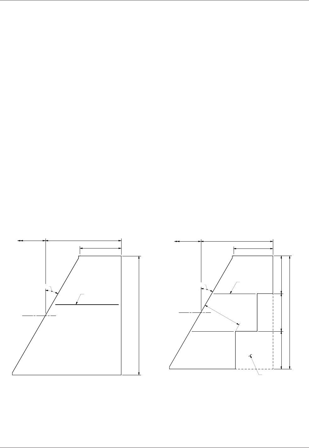
Signs, Barriers, Approach Slabs, and Utilities Chapter 10
Page 10-38 WSDOT Bridge Design Manual M 23-50.17
June 2017
Bendingdiagramsshallbeshownforallcustomreinforcement.AllBridgeApproach
SlabsheetswillhavetheAP2andAP7bars.Ifthereisatracbarrier,thenAP8,AS1,
and AS2 bars shall be shown.
Additionallayoutanddetailsmayberequiredtoaddressspecialroadwayfeaturesand
constructionrequirementssuchas:roadwaycurbsandbarriers,sidewalks,utilitiesand
conduitsandstaging.Thismeans,ifsidewalksandinteriorbarriers(suchastrac-
pedestrianbarriers)arepresent,specialdetailswillberequiredintheBridgePlansto
show how the sidewalks and interior barriers are connected to and constructed upon
the bridge approach slab. If the bridge construction is staged, then the approach slabs
will also require staged construction.
10.6.4 Skewed Bridge Approach Slabs
Forallskewedabutments,theroadwayendofthebridgeapproachslabshallbe
normaltotheroadwaycenterline.TheBridgeDesignEngineershallbeconsulted
when approach slab skew is greater than 30 degrees. Skews greater than 20 degrees
requireanalysistoverifythebottommatreinforcement,andmayrequireexpansion
jointmodications.
Theroadwayendoftheapproachmaybesteppedtoreducethesizeortoaccommodate
stagingconstructionwidths.Ageneralruleofthumbisthatiftheapproachslabarea
canbereducedby50SYormore,thentheslabshallbestepped.Atnopointshallthe
roadwayendoftheapproachslabbecloserthan25′tothebridge.Thesecriteriaapply
to both new and existing bridge approach slabs. If stepped, the design shall provide
theabsoluteminimumnumberofstepsandthelongitudinalconstructionjointshallbe
locatedonalaneline.SeeFigure10.6.4-1forclarication.
SkewedApproach~Typical SkewedApproach~Stepped
SkewedApproach
Figure 10.6.4-1
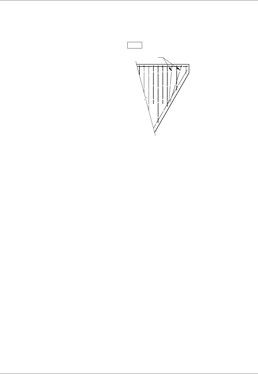
Chapter 10 Signs, Barriers, Approach Slabs, and Utilities
WSDOT Bridge Design Manual M 23-50.17 Page 10-39
June 2017
Inaddition,forbridgeswithtracbarriersandskewsgreaterthan20degrees,the
AP8 bars shall be rotated in the acute corners of the bridge approach slabs. Typical
placementisshowninthearedcornersteeldetail,Figure10.6.4-2.
FlaredCornerSteel
Figure 10.6.4-2
10.6.5 Approach Anchors and Expansion Joints
Forsemi-integralabutmentsorstubabutments,thejointdesignshallbecheckedto
ensuretheavailablemovementofthestandardjointisnotexceeded.Ingeneral,the
approachslabisassumedtobestationaryandthejointgapisdesignedtovarywiththe
bridgemovement.ApproachSlabSheets10-A1-3andStandardPlanA-40.50detaila
typical2½″compressionseal.Forapproachslabswithbarrier,thecompressionseal
shall extend into the barrier.
ApproachslabanchorsinstalledatbridgeabutmentsshallbeasshownintheBridge
Plans.Forbridgeswithsemi-integraltypeabutments,thiscanbeaccomplishedby
showingtheapproachslabanchorsintheEndDiaphragmorPavementSeatdetails.
L Type Abutments – Ltypeabutmentsdonotrequireexpansionjointsorapproach
anchorsbecausetheabutmentandbridgeapproachslabarebothconsideredstationary.
Apinnedconnectionispreferred.TheLtypeabutmentanchordetail,asshownsign
inFigure10.6.5-1,shallbeaddedtotheabutmentplansheets.Thepinnedanchorfor
bridgeswithLtypeabutmentsshallbea#5baratonefootspacing,bentasshown,
with1′-0″embedmentintoboththepierandthebridgeapproachslab.Thisbarshallbe
included in the bar list for the bridge substructure.
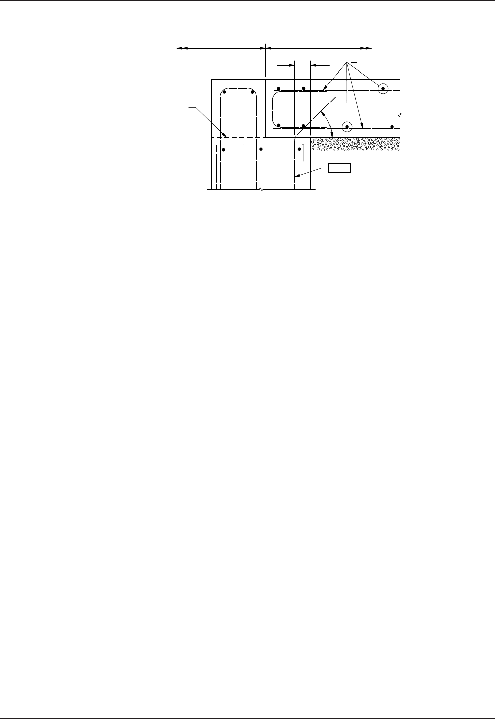
Signs, Barriers, Approach Slabs, and Utilities Chapter 10
Page 10-40 WSDOT Bridge Design Manual M 23-50.17
June 2017
LTypeAbutmentAnchorDetail
Figure 10.6.5-1
10.6.6 BridgeApproachSlabAdditionorRetrottoExistingBridges
When bridge approach slabs are to be added or replaced on existing bridges,
modicationmayberequiredtothepavementseats.Eitherthenewbridgeapproach
slabwillbepinnedtotheexistingpavementseat,orattachedwithapproachanchors
withawidenedpavementseat.Pinningisabenecialoptionwhenapplicable
asitreducestheconstructioncostandtime.
Thepinningoptionisonlyallowedonsemi-integralabutmentsasabridgeapproach
slabadditionorretrottoanexistingbridge.Figure10.6.6-1showsthepinningdetail.
Asthisdetaileliminatestheexpansionjointbetweenthebridgeapproachslaband
thebridge,themaximumbridgesuperstructurelengthislimitedto150′.TheBridge
DesignEngineermaymodifythisrequirementonacasebycasebasis.Additionally,
iftheroadwayendofthebridgeapproachslabisadjacenttoPCCProadway,thenthe
detailshowninFigure10.6.6-2applies.PCCPdoesnotallowforasmuchmovement
asHMAandajointisrequiredtoreducethepossibilityofbuckling.
When pinning is not applicable, then the bridge approach slab shall be attached to the
bridgewithapproachanchors.Iftheexistingpavementseatislessthan10inches,
theseatshallbemodiedtoprovideanacceptable,widerpavementseat.TheBridge
DesignEngineermaymodifythisrequirementonasite-specicbasis.Generic
pavementseatrepairdetailsareshowninAppendix10.6-A2-1foraconcreterepair
andAppendix10.6-A2-2forasteelT-sectionrepair.Thesesheetscanbecustomized
fortheprojectandaddedtotheBridgePlans.
Whenabridgeapproachslabisaddedtoanexistingbridge,thenalgradeofthe
bridgeapproachslabconcreteshallmatchtheexistinggradeoftheconcretebridge
deck,includingbridgeswithasphaltpavement.Theexistingdepthofasphaltonthe
bridge shall be shown in the Plans and an equal depth of asphalt placed on a new
bridgeapproachslab.Iftheexistingdepthofasphaltisincreasedordecreased,thenal
grade shall also be shown on the Plans.
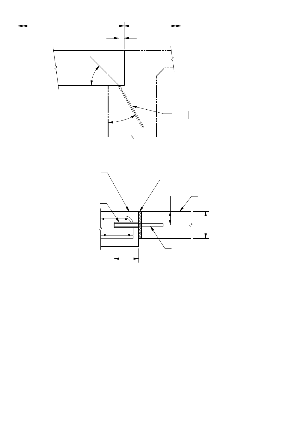
Chapter 10 Signs, Barriers, Approach Slabs, and Utilities
WSDOT Bridge Design Manual M 23-50.17 Page 10-41
June 2017
PinnedApproachSlabDetail
Figure 10.6.6-1
PCCPRoadwayDowelBarDetail
Figure 10.6.6-2
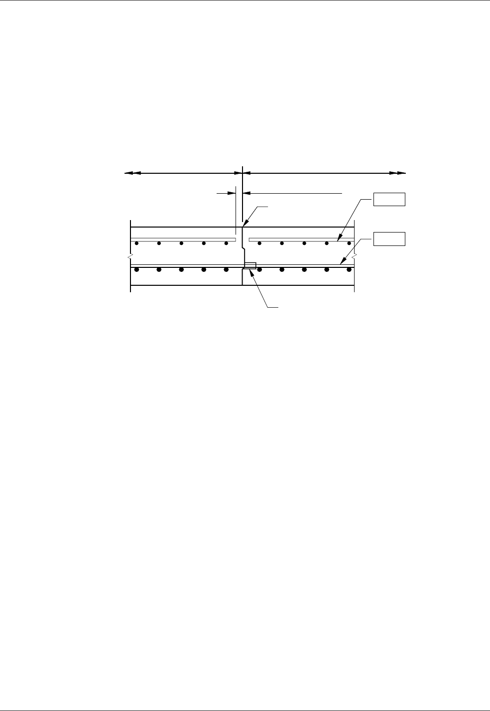
Signs, Barriers, Approach Slabs, and Utilities Chapter 10
Page 10-42 WSDOT Bridge Design Manual M 23-50.17
June 2017
10.6.7 Bridge Approach Slab Staging
Stagingplanswillmostlikelyberequiredwhenaddingorretrottingapproachslabs
on existing bridges. The staging plans shall be a part of the bridge plans and shall be
ontheirownsheet.CoordinationwiththeRegionisrequiredtoensureagreement
betweenthebridgestagingsheetandtheRegiontraccontrolsheet.Thelongitudinal
constructionjointsrequiredforstagingshallbelocatedonlanelines.Astheremaynot
beenoughroomtoallowforalapspliceinthebottomtransversebars,amechanical
spliceoptionshallbeadded.Ifalapspliceisnotfeasible,thenonlythemechanical
splice option shall be given. See Figure 10.6.6-3.
AlternateLongitudinalJointDetail
Figure 10.6.6-3
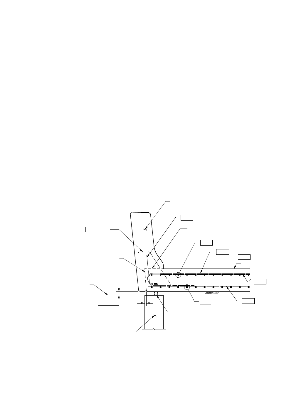
Chapter 10 Signs, Barriers, Approach Slabs, and Utilities
WSDOT Bridge Design Manual M 23-50.17 Page 10-43
June 2017
10.7 TracBarrieronBridgeApproachSlabs
Placingthetracbarrieronthebridgeapproachslabisbenecialforthe
following reasons.
• Thebridgeapproachslabresiststracimpactloadsandmayreducewingwall
thickness
• Simpliedconstructionandconduitplacement
• Bridgerunoisdivertedawayfromtheabutment
Mostbridgeswillhavesomelong-termdierentialsettlementbetweentheapproach
roadwayandtheabutment.Therefore,agapbetweenthebridgeapproachslaband
wing(orwall)shallbeshowninthedetails.Theminimumgapistwicethelong-term
settlement,or2inchesasshowninFigure 10.7-1. A 3 inch gap is also acceptable.
Whenthetracbarrierisplacedonthebridgeapproachslab,thefollowingbarrier
guidelines apply.
• Barrier shall extend to the end of the bridge approach slab
• Conduitdeectionorexpansionttingsshallbecalledoutatthejoints
• Junction box locations shall start and end in the approach
• Thetoptransversereinforcingintheslabshallbesucienttoresistatracbarrier
impactload.A6′-0″(hooked)#6epoxycoatedbarshallbeaddedtotheapproach
slab as shown in Figure 10.7-1.
Figure 10.7-1
10.7.1 Bridge Approach Slab over Wing Walls, Cantilever Walls or
Geosynthetic Walls
All walls that are cast-in-place below the bridge approach slab should continue the
barriersotlinetograde.Thisincludesgeosyntheticwallsthathaveacast-in-place
fascia. Figure 10.7.1-1showsagenericlayoutatanabutment.NotethesectionalGap
Detail, Figure 10.7-1 applies.
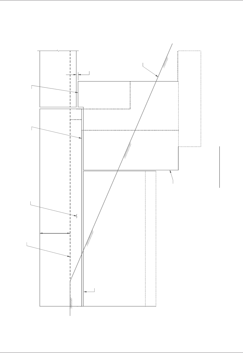
Signs, Barriers, Approach Slabs, and Utilities Chapter 10
Page 10-44 WSDOT Bridge Design Manual M 23-50.17
June 2017
Figure 10.7.1-1
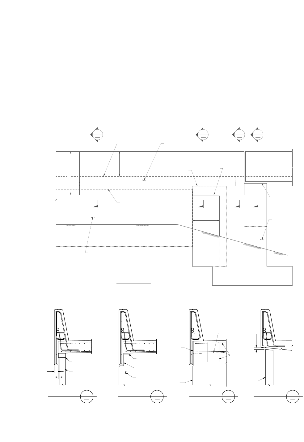
Chapter 10 Signs, Barriers, Approach Slabs, and Utilities
WSDOT Bridge Design Manual M 23-50.17 Page 10-45
June 2017
10.7.2 Bridge Approach Slab over SE Walls
Thetopsofstructureearth(SE)wallsareunevenandshallbecoveredwithafascia
toprovideasmoothsotline.UsuallySEwallsextendwellbeyondtheendofthe
approachslabandrequireamomentslab.SinceSEWbarrieristypically5′-0″deep
fromthetopofthebarrier,thesotoftheSEWbarrierandbridgebarrierdonot
match.Thetransitionpointforthesotlineshallbeatthebridgeexpansionjointas
shown in Figure 10.7.2-2. This requires an extended back side of the barrier at the
approach slab to cover the uneven top of the SE wall.
Batteredwallsystems,suchasblockwalls,useathickenedsectionofthecurtainwall
tohidesomeofthebatter.TheStateBridgeandStructuresArchitectwillprovide
dimensionsforthistransitionwhenrequired.
Figure 10.7.2-1
Figure 10.7.2-2

Signs, Barriers, Approach Slabs, and Utilities Chapter 10
Page 10-46 WSDOT Bridge Design Manual M 23-50.17
June 2017
10.8 UtilitiesInstalledwithNewConstruction
10.8.1 General Concepts
The utilities included under this section are those described in Standard Specications
Section6-01.10.TheBridgedesignershalldetermineiftheutilitymaybeattachedto
thestructureandthelocation.Bridgeplansshallincludeallhardwarespecications
anddetailsfortheutilityattachmentasprovidedinanywrittencorrespondence
withtheutilityandtheutilityagreementcoordinatedbytheWSDOTRegionUtility
Engineer with the associated utility.
Responsibilities of the Utility Company – TheRegionorutilitycompanywill
initiateutilityinstallationsandprovidedesigninformation.Theutilitycompanyshall
be responsible for calculating design stresses in the utility and design of the support
system.UtilitysupportdesigncalculationswithaStateofWashingtonProfessional
Engineerstamp,signedanddated,shallbesubmittedtotheBridgeandStructures
Oceforreview.Thefollowinginformationshallbeprovidedbytheutilitycompany
andshowninthenalBridgePlans.
• Locationoftheutilityoutsidethelimitsofthebridgestructure
• Numberofutilities,type,size,andweight(orClass)ofutilitylines
• Utilityminimumbendingradiusfortheconduitorpipelinespecied
Utility General Notes and Design Criteria are stated in Form224-047. See
Figure 10.8.1-1.Thisformoutlinesmostofthegeneralinformationrequiredbythe
utilitycompanytodesigntheirattachments.TheBridgeOcewillgenerallyprovide
thedesignforlightweighthangersystems,suchaselectricalconduits,attachedto
new structures.
Conned Spaces – Aconnedspaceisanyplacehavingalimitedmeansofexit
thatissubjecttotheaccumulationoftoxicorammablecontaminantsoranoxygen
decientenvironment.Connedspacesincludebutarenotlimitedtopontoons,box
girder bridges, storage tanks, ventilation or exhaust ducts, utility vaults, tunnels,
pipelines,andopen-toppedspacesmorethan4feetindepthsuchaspits,tubes,vaults,
and vessels.
Coating and Corrosion Protection – Whenthebridgeistoreceivepigmentedsealer,
considerationshallbegiventopaintinganyexposedutilitylinesandhangerstomatch
thebridge.Whenapigmentedsealerisnotrequired,steelutilityconduitsandhangers
shall be painted or galvanized for corrosion protection. The special provisions shall
specify cleaning and painting procedures.

Chapter 10 Signs, Barriers, Approach Slabs, and Utilities
WSDOT Bridge Design Manual M 23-50.17 Page 10-47
June 2017
GeneralNotesandDesignCriteriaforUtilityInstallationstoExistingBridges
WSDOTForm224-047
Figure 10.8.1-1
Permit/Franchise
Exhibit
Page of
" "
DOT
Form 224-047 EF
Revised 5/10
General Notes and Design Criteria for
Utility Installations to Existing Bridges
General Notes
All materials and workmanship shall be in accordance with the requirements of the state of
Washington, Department of Transportation, Standard Specifications for Road, Bridge, and
Municipal Construction, current edition. The utility conduits shall be labeled in accordance with
Section 6-01.10.
All steel in utility supports, including fastenings and anchorages, shall be galvanized in accordance
with AASHTO M-111 or M-232 (ASTM A-123 or A-153 respectively).
All utilities and utility support surfaces, including any galvanized utilities, shall be given a primer
coat of state standard formula A-6-86 and two coats of state standard formula C-9-86. The final
coat shall match the bridge color.
Galvanized metal or aluminum utilities completely hidden from public view may be exempted from
the above painting requirements.
Any painted surfaces damaged during construction shall be cleaned and painted as noted above.
Any paint splatters shall be removed from the bridge.
Appearance of the utility installation shall be given serious consideration in all cases. Where
possible, the utility installation shall be hidden from public view.
The notes and criteria explained here are presented as a guide only. Each proposed utility
installation shall be submitted to the Department of Transportation for approval on an
individual basis. Compliance with these criteria does not assure approval, nor does
variance from these criteria, for reasonable cause, necessarily exclude approval.
Design Criteria
1. Pipelines carrying volatile fluids through a bridge superstructure shall be designed by the
utility company in accordance with WAC 480-93, Gas Companies - Safety, and Minimum
Federal Safety Standard, Title 49 Code of Federal Regulations (CFR) Section part 192. WAC
468-34-210, Pipelines - Encasement, describes when casing is required for carrying volatile
fluids across structures. Generally, casing is not required for pipelines conveying natural gas
per the requirements of WAC 468-34-210. If casing is required, then WAC 468-34-210 and
WAC 480-93-115 shall be followed
.
2. Utilities shall not be attached above the bridge deck nor attached to railing or rail posts
.
3. Utilities shall not extend below bottom of superstructure
.
4. The utilities shall be provided with suitable expansion devices near bridge expansion joints
and/or other locations as required to prevent temperature and other longitudinal forces from
being transferred to bridge members
.
5. Rigid conduit shall extend 10 feet (3 meters) minimum, beyond the end of the bridge
abutment.
6. Utility supports shall be designed such that neither the conduit, the supports, nor the bridge
members are overstressed by any loads imposed by the utility installation
.
7. Utility locations and supports shall be designed so that a failure (rupture, etc.) will not result in
damage to the bridge, the surrounding area, or be a hazard to traffic
.
8. Conduit shall be rigid
.
(Items 1 through 8 may be cross-referenced with Bridge Design Manual, Utilities Section.)
9. Lag screws may be used for attaching brackets to wooden structures. All bolt holes shall meet
the requirements of Sections 6-04.3(4) and 6-04.3(5) of the Washington State Department of
Transportation Standard Specifications for Road, Bridge, and Municipal Construction, current
edition
.
10. Welding across main members will not be permitted. All welding must be approved
.
11. Utilities shall be located to minimize bridge maintenance and bridge inspection problems
.
12. Attach conduits or brackets to the concrete superstructure with resin bond anchors. Lag
screws shall not be used for attachment to concrete
.
13. Drilling through reinforcing steel will not be permitted. If steel is hit when drilling, the
anchorage location must be moved and the abandoned hole filled with nonshrink grout
conforming to the requirements of Section 9-20.3(2) and placement shall be as required in
Section 6-02.3(20) of the Washington State Department of Transportation Standard
Specifications for Road, Bridge, and Municipal Construction, current edition
.
14. There shall be a minimum of 3 inches (80 millimeters) edge distance to the center line of bolt
holes in concrete
.
15. All utilities and utility supports shall be designed not only to support their dead load but to
resist other forces from the utility (surge, etc.) and wind and earthquake forces. The utility
company may be asked to submit one set of calculations to verify their design forces
.
16. Drilling into prestressed concrete members for utility attachments shall not be allowed
.
17. Water or sewer lines to be placed lower than adjacent bridge footings shall be encased if
failure can cause undermining of the footing.
Permit/Franchise
Exhibit
Page
of
"
"
DOT
Form 224-047 EF
Revised 5/10

Signs, Barriers, Approach Slabs, and Utilities Chapter 10
Page 10-48 WSDOT Bridge Design Manual M 23-50.17
June 2017
GeneralNotesandDesignCriteriaforUtilityInstallationstoExistingBridges(continued)
WSDOTForm224-047
Figure 10.8.1-1
Permit/Franchise
Exhibit
Page
of
"
"
DOT
Form 224-047 EF
Revised 5/10
General Notes and Design Criteria for
Utility Installations to Existing Bridges
General Notes
All materials and workmanship shall be in accordance with the requirements of the state of
Washington, Department of Transportation, Standard Specifications for Road, Bridge, and
Municipal Construction, current edition. The utility conduits shall be labeled in accordance with
Section 6-01.10.
All steel in utility supports, including fastenings and anchorages, shall be galvanized in accordance
with AASHTO M-111 or M-232 (ASTM A-123 or A-153 respectively).
All utilities and utility support surfaces, including any galvanized utilities, shall be given a primer
coat of state standard formula A-6-86 and two coats of state standard formula C-9-86. The final
coat shall match the bridge color.
Galvanized metal or aluminum utilities completely hidden from public view may be exempted from
the above painting requirements.
Any painted surfaces damaged during construction shall be cleaned and painted as noted above.
Any paint splatters shall be removed from the bridge.
Appearance of the utility installation shall be given serious consideration in all cases. Where
possible, the utility installation shall be hidden from public view.
The notes and criteria explained here are presented as a guide only. Each proposed utility
installation shall be submitted to the Department of Transportation for approval on an
individual basis. Compliance with these criteria does not assure approval, nor does
variance from these criteria, for reasonable cause, necessarily exclude approval.
Design Criteria
1. Pipelines carrying volatile fluids through a bridge superstructure shall be designed by the
utility company in accordance with WAC 480-93, Gas Companies - Safety, and Minimum
Federal Safety Standard, Title 49 Code of Federal Regulations (CFR) Section part 192. WAC
468-34-210, Pipelines - Encasement, describes when casing is required for carrying volatile
fluids across structures. Generally, casing is not required for pipelines conveying natural gas
per the requirements of WAC 468-34-210. If casing is required, then WAC 468-34-210 and
WAC 480-93-115 shall be followed
.
2. Utilities shall not be attached above the bridge deck nor attached to railing or rail posts
.
3. Utilities shall not extend below bottom of superstructure
.
4. The utilities shall be provided with suitable expansion devices near bridge expansion joints
and/or other locations as required to prevent temperature and other longitudinal forces from
being transferred to bridge members
.
5. Rigid conduit shall extend 10 feet (3 meters) minimum, beyond the end of the bridge
abutment.
6. Utility supports shall be designed such that neither the conduit, the supports, nor the bridge
members are overstressed by any loads imposed by the utility installation
.
7. Utility locations and supports shall be designed so that a failure (rupture, etc.) will not result in
damage to the bridge, the surrounding area, or be a hazard to traffic
.
8. Conduit shall be rigid
.
(Items 1 through 8 may be cross-referenced with Bridge Design Manual, Utilities Section.)
9. Lag screws may be used for attaching brackets to wooden structures. All bolt holes shall meet
the requirements of Sections 6-04.3(4) and 6-04.3(5) of the Washington State Department of
Transportation Standard Specifications for Road, Bridge, and Municipal Construction, current
edition
.
10. Welding across main members will not be permitted. All welding must be approved
.
11. Utilities shall be located to minimize bridge maintenance and bridge inspection problems
.
12. Attach conduits or brackets to the concrete superstructure with resin bond anchors. Lag
screws shall not be used for attachment to concrete
.
13. Drilling through reinforcing steel will not be permitted. If steel is hit when drilling, the
anchorage location must be moved and the abandoned hole filled with nonshrink grout
conforming to the requirements of Section 9-20.3(2) and placement shall be as required in
Section 6-02.3(20) of the Washington State Department of Transportation Standard
Specifications for Road, Bridge, and Municipal Construction, current edition
.
14. There shall be a minimum of 3 inches (80 millimeters) edge distance to the center line of bolt
holes in concrete
.
15. All utilities and utility supports shall be designed not only to support their dead load but to
resist other forces from the utility (surge, etc.) and wind and earthquake forces. The utility
company may be asked to submit one set of calculations to verify their design forces
.
16. Drilling into prestressed concrete members for utility attachments shall not be allowed
.
17. Water or sewer lines to be placed lower than adjacent bridge footings shall be encased if
failure can cause undermining of the footing.
Permit/Franchise
Exhibit
Page of
" "
DOT
Form 224-047 EF
Revised 5/10

Chapter 10 Signs, Barriers, Approach Slabs, and Utilities
WSDOT Bridge Design Manual M 23-50.17 Page 10-49
June 2017
10.8.2 Utility Design Criteria
AllutilitiesshallbedesignedtoresistStrengthandExtremeEventLimitsStates.This
includesandisnotlimitedtodeadload,expansion,surge,andearthquakeforces.
Designers shall review WSDOT Form224-047 “General Notes and Design Criteria
for Utility Installations to Existing Bridges”andtheitemsinthissectionwhen
designingautilitysystemorprovidingareviewforanexistingbridgeattachment.
See Figure 10.8.1-1.
The Bridge Engineer shall review the utility design to ensure the utility support
systemwillcarryalltransverseandverticalloading.Loadingwillinclude(andisnot
limitedto):deadload,temperatureexpansion,dynamicaction(waterhammer),and
seismicinertialload.Positiveresistancetoloadsshallbeprovidedinalldirections
perpendicular to and along the length of the utility as required by the utility engineer.
Wherepossible,dynamicuidactionloadsshallberesistedoofthebridge.If
theseloadsmustberesistedonthebridge,theutilityengineershallbeinvolved
inthedesignofthesesupports.Theutilityengineershalldeterminethesedesign
forces being applied to the bridge. Realize these forces can be generated in any pipe
supportingmovinguids,whichmayinclude,butarenotlimitedto:water,sewer,and
stormwater.
Whereutilitiesareinsulated,theinsulationsystemshallbedesignedtoallowthe
intendedmotionrangeofthehardwaresupportingtheutility.Thiswillprevent
unanticipatedstressesfrombeingaddedtothehangerintheeventtheinsulationbinds
up the hardware.
Utility Location – Utilities shall be located, such that a support failure will not result
indamagetothebridge,thesurroundingarea,orbeahazardtotrac.Inmostcases,
the utility shall be installed between girders. Utilities and supports shall not extend
belowthebottomofthesuperstructure.Utilitiesshallbeinstallednolowerthan1foot
0inchesabovethebottomofthegirders.Insomecaseswhenappurtenancesare
required(suchasairreleasevalves),careshallbetakentoprovideadequatespace.The
utilityinstallationshallbelocatedsoastominimizetheeectontheappearanceof
the structure. Utilities shall not be attached above the bridge deck nor attached to the
railings or posts.
Termination at the Bridge Ends – Utilityconduitandencasementsshallextend
10feetminimumbeyondtheendsofthestructureinordertoreduceeectsof
embankmentsettlementontheutilityandprovideprotectionincaseoffuturework
involvingexcavationnearthestructure.Thisrequirementshallbeshownontheplans.
Utilitiesothebridgemustbeinstalledpriortopavingofapproaches.Thisshouldbe
stated in the Special Provisions.
Utility Expansion – Theutilitiesshallbedesignedwithasuitableexpansionsystem
asrequiredtopreventlongitudinalforcesfrombeingtransferredtobridgemembers.
Watermainsgenerallyremainaconstanttemperatureandareanchoredintheground
attheabutments.However,thebridgewillmovewithtemperaturechangesandseismic
forces.Pipesupportsystemsshallbedesignedtoallowforthebridgemovements.For
shortbridges,thisgenerallymeansthebridgewillmoveandtheutilitywillnotsince
itisanchoredattheabutments.Forlongbridgesthatrequirepipeexpansionjoints,
designshallcarefullylocatepipeexpansionjointsandthecorrespondinglongitudinal
load-carrying support.

Signs, Barriers, Approach Slabs, and Utilities Chapter 10
Page 10-50 WSDOT Bridge Design Manual M 23-50.17
June 2017
Electrical conduits that use PVC shall have an expansion device for every 100 foot of
pipeduetothehighercoecientofexpansion.Ifmorethantwojointsarespecied,a
cableorexpansionlimitingdeviceisrequiredtokeeptheendsfromseparating.
Utility Blockouts – Blockoutsshallbeprovidedinallstructuralmembersthat
prohibitthepassageofutilities,suchasgirderenddiaphragms,piercrossbeams,
andintermediatediaphragms.Theseblockoutsshallbelargeenoughtotdeection
ttings,andshallbeparalleltotheutility.Formultipleutilities,anoteshallbeadded
totheplansthatthedeectionttingsshallbestaggeredsuchthatnottingislocated
adjacenttoanother,ortheblockoutsshallbedesignedtotbothttings.Expansion
ttingsshallbestaggered.
Gas Lines or Volatile Fluids–Pipelinescarryingvolatileuidsthroughabridge
superstructureshallbedesignedbytheutilitycompanyinaccordancewithWAC
480-93,GasCompanies—Safety,andMinimumFederalSafetyStandard,Title 49
CodeofFederalRegulations(CFR)Sectionpart192.WAC 468-34-210, Pipelines—
Encasement,describeswhencasingisrequiredforcarryingvolatileuidsacross
structures. Generally, casing is not required for pipelines conveying natural gas per the
requirementsofWAC 468-34-210. If casing is required, then WAC 468-34-210 and
WAC 480-93-115 shall be followed.
Water Lines – Transverse support or bracing shall be provided for all water lines to
carryStrengthandExtremeEventLateralLoading.Firecontrolpipingisaspecial
casewhereunusualcaremustbetakentohandletheinertialloadsandassociated
deections.TheUtilityEngineershallbeinvolvedinthedesignofsupportsresisting
dynamicactionloadsanddeections.
Inboxgirders(closedcell),aruptureofawaterlinewillgenerallyoodacell
beforeemergencyresponsecanshutdownthewatermain.Thisshallbedesigned
forasanExtremeEventIIloadcase,wheretheweightofwaterisadeadload(DC).
AdditionalweepholesoropengratingshallbeconsideredtoosetthisExtremeEvent
(see Figure 10.8.3-1).Fulllengthcasingextending10-feetbeyondtheendofthe
bridge approach slab shall be considered as an alternate to additional weep holes or
open grating.
Sewer Lines – Normally,anappropriateencasementpipeisrequiredforsewerlines
onbridges.Sewerlinesshallmeetthesamedesigncriteriaaswaterlines.Seetheutility
agreementortheHydraulicSectionfortypesofsewerpipematerialtypicallyused.
Electrical (Power and Communications) –Telephone,televisioncable,andpower
conduitshallbegalvanizedRigidMetalConduit(RGS)orRigidPolyvinylChloride
Conduit(PVC).Wheresuchconduitisburiedinconcretecurbsorbarriersorhas
continuous support, such support is considered to be adequate. Where hangers or
bracketssupportconduitatintervals,themaximumdistancebetweensupportsshallbe
5 feet.
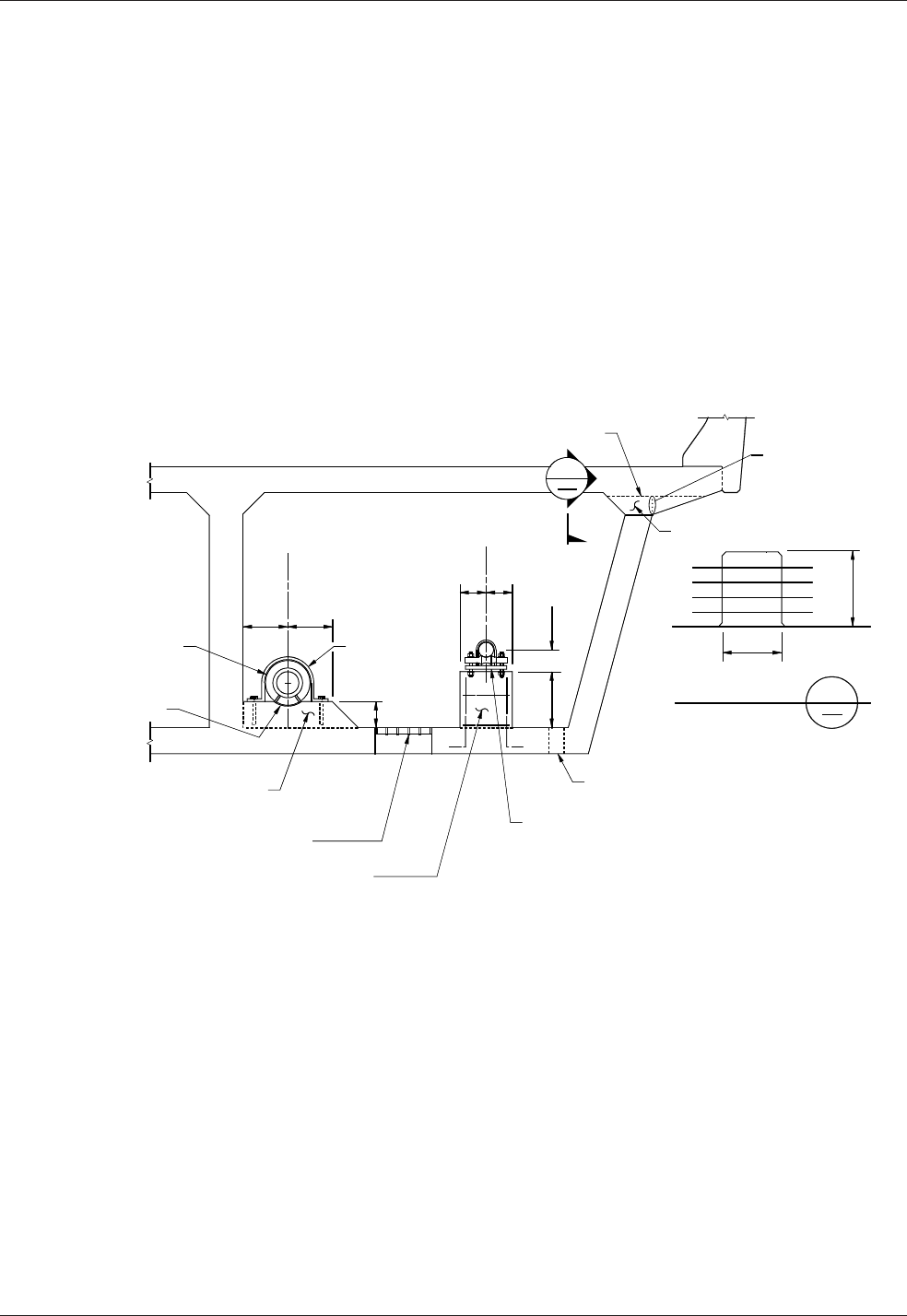
Chapter 10 Signs, Barriers, Approach Slabs, and Utilities
WSDOT Bridge Design Manual M 23-50.17 Page 10-51
June 2017
10.8.3 Box/Tub Girder Bridges
Utilities shall not be placed inside reinforced concrete box girders less than 4 feet
inside clear height and all precast prestressed concrete tub girders because reasonable
access cannot be provided. Utilities shall be located between girders or under bridge
decksotinthesecases.Inspectionlighting,accessandventilationshallalwaysbe
provided in girder cells containing utilities. Refer to the concrete and steel chapters for
additional details.
Continuous Support and Concrete Pedestals–Specialutilities(suchaswateror
gasmains)inboxgirderbridgesshalluseconcretepedestals.Thisallowstheutility
to be placed, inspected, and tested before the deck is cast. Concrete pedestals consist
ofconcretesupportsformedatsuitableintervalsandprovidedwithsometypeof
clampingdevice.Continuoussupportsshallbeavoidedduetotheveryhighcostand
additional dead load to the structure.
ConcreteUtilitySupports
Figure 10.8.3-1
10.8.4 TracBarrierConduit
All new bridge construction shall install two 2-inch galvanized Rigid Metal Conduit
(RGS)orRigidPolyvinylChlorideConduit(PVC)inthetracbarriers.These
conduitsgenerallycarrywiringforTracSignals(TS)andLighting(LT).Other
wiringmaybeinstalledortheconduitmaybeusedforfutureapplications.PVC
conduitmaybeusedonlyinstationary-formbarriers,andwillconnecttoRGSusing
aPVCadaptorwhenexitingthebarrier.RGSconduitmaybeusedinstationary-form
barriers,butitshallbeusedinslipformbarriers.
Eachconduitshallbestubbed-outintoitsownconcretejunctionboxateachcorner
ofthebridge.TheBridgePlansmustshowtheplacementoftheconduitstoclearthe
structure or any foreseeable obstructions.

Signs, Barriers, Approach Slabs, and Utilities Chapter 10
Page 10-52 WSDOT Bridge Design Manual M 23-50.17
June 2017
The galvanized steel conduit shall be wrapped with corrosion resistant tape at least one
footinsideandoutsideoftheconcretestructure,andthisrequirementshallbesostated
on the plans. The corrosion resistant tape shall be 3M Scotch 50, Bishop 5, Nashua
AVI10,orapprovedequal.Theusuallocationoftheconduitthroughouttheremainder
ofthebridgeshouldbeinthetracbarrier.
Pull boxes shall be provided within the barrier for each conduit at each end of the
bridgeandatamaximumspacingof180feet.Forberopticsonly,spacingshallnot
exceed360feet.ThepullboxsizeshallconformtothespecicationsoftheNational
ElectricCodeorbeaminimumof8inchesby8inchesby18inchestofacilitate
pullingofwires.Galvanizedsteelpullboxes(orjunctionsboxes)shallmeetthe
specicationsofthe“NEMAType4X”standardforstationary-formbarrier,shallmeet
thespecicationsofthe“NEMA3R”andbeadjustableindepthforslipformbarrier,
andtheNEMAjunctionboxtypeshallbestatedontheplans.Stainlesssteelpullboxes
maybeusedasanoptiontothegalvanizedsteel.
In the case of existing bridges, an area 2 feet in width shall be reserved for conduit
beginning at a point either 4 feet or 6 feet outside the face of usable shoulder. The
fastening for and location of attaching the conduit to the existing bridge shall be
workedoutonajob-by-jobbasis.
10.8.5 Conduit Types
AllelectricalconduitsshallbegalvanizedRigidMetalConduit(RGS)orRigid
PolyvinylChlorideConduit(PVC).
Steel Pipe –Allpipeandttingsshallbegalvanizedexceptforspecialuses.
PVC Pipe – PVCpipemaybeusedwithsuitableconsiderationsfordeection,
placementofexpansionttings,andoffreezingwaterwithintheconduits.PVCpipe
shallnotbeplacedinconcretetracbarrierswhentheslipformmethodisuseddueto
damageandpipeseparationthatoftenoccursduringconcreteplacement.
10.8.6 Utility Supports
The following types of supports are generally used for various utilities. Selection of
a particular support type shall be based on the needs of the installation and the best
economy.Allutilityinstallationsshalladdresstemperatureexpansioninthedesignof
thesystemorexpansiondevices.
Utilitysupportsshallbedesignedsothatafailurewillnotresultindamagetothe
bridge,thesurroundingarea,orbeahazardtotrac.Utilitysupportsshallbedesigned
sothatanyloadsimposedbytheutilityinstallationdonotoverstresstheconduit,
supports,bridgestructure,orbridgemembers.
Designsshallprovidelongitudinalandtransversesupportforloadsfromgravity,
earthquakes,temperature,inertia,etc.Itisespeciallyimportanttoprovidetransverse
andlongitudinalsupportforinsertsthatcannotresistmoment.
TheBridgeEngineershallrequestcalculationsfromtheutilitycompanyforany
attachmentdetailthatmaybequestionable.Utilityattachments,whichexertmoments
orlargeforcesatthesupports,shallbeaccompaniedbyatleastonesetofcalculations
fromtheutilitycompany.Bridgeattachmentsdesignedtoresistsurgeforcesshall
alwaysbeaccompaniedbycalculations.

Chapter 10 Signs, Barriers, Approach Slabs, and Utilities
WSDOT Bridge Design Manual M 23-50.17 Page 10-53
June 2017
Concrete Embedment – This is the best structural support condition and oers
maximum protection to the utility. Its cost may be high for larger conduit and the
conduit cannot be replaced.
Pipe Hangers – Utility lines shall be suspended by means of cast-in-place inserts,
whenever possible. This is the most common type of support for utilities to be hung
under the bridge deck. This allows the use of standard cast-in-place inserts and is
very exible in terms of expansion requirements. For heavy pipes over trac (10″
water main or larger), a Safety Factor of 1.5 should be used to resist vertical loads
for Strength Design. This is to avoid complete failure of the utility hanger system by
failure of one hanger. Vertical inserts will not provide resistance to longitudinal forces.
Longitudinal and transverse supports shall be provided for ITS conduits. Vertical
supports shall be spaced at 5 foot maximum intervals for telephone and power
conduits, and at a spacing to resist design loads for all other utilities.
When 3/4″ or 7/8″ diameter hanger rods are suspended from cast-in-place inserts, at
least three of the following inserts shall be identied: Cooper B-Line B22-I Series,
Unistrut 3200 Series, Powerstrut 349 Series, Halfen HT5506 or similar. The specic
cast-in-place insert within each series shall be identied based on the required length
of insert. The cast-in-place insert shall be at least 6″ long and hot dipped galvanized
in accordance with AASHTO M 111 or AASHTO M 232.
The insert shall not interfere with reinforcement in the bridge deck. The inserts shall
be installed level longitudinally and transversely. When the superelevation of the
roadway is not signicant, a single, long insert may be used to support multiple hanger
rods. When the superelevation becomes signicant, a single insert may be used for
each hanger.
Occasionally large diameter utilities require pipe rolls that only t on 1″ diameter
hanger rods. When 1″ diameter hanger rods are required, the Anvil Fig. 286
and Unistrut P3246 insert shall be used. The designer shall only specify this insert
when absolutely necessary.
The Bridge Engineer shall verify that the cast-in-place insert has sucient capacity
to support the loads from the hanger rod.
Transverse supports may be provided by a second hanger extending from a girder or
by a brace against the girder. The Bridge Standard Drawing 10.8-A1-1 and 10.8-A1-2
depict typical utility support installations and placement at abutments and diaphragms.
Transverse supports shall, at a minimum, be located at every other vertical support.

Signs, Barriers, Approach Slabs, and Utilities Chapter 10
Page 10-54 WSDOT Bridge Design Manual M 23-50.17
June 2017
10.9 UtilityReviewProcedureforInstallationonExistingBridges
It is the responsibility of the Region Utilities Engineer to forward any proposed
attachmentstoexistingbridgestotheBridgePreservationOce.TheBridge
PreservationOceisresponsibleforreviewingonlythosedetailspertainingtothe
bridgecrossingsuchasattachmentdetailsortrenchingdetailsadjacenttobridgepiers
orabutments.
TheBridgePreservationOcereviewsproposedutilityattachmentsandeither
approvestheattachmentorreturnsforcorrection(RFC).Acurrentleformostutility
attachmentsismaintainedintheBridgePreservationOce.Theturnaroundtimefor
reviewing the proposals should not exceed four weeks.
TheRegiondeterminesthenumberofcopiestobereturned.MostRegionssend
vecopiesoftheproposedutilityattachment.Iftheproposalisapproved,Bridge
Preservationwillleonecopyintheutilityleandreturnfourmarkedcopies.Ifit
hasbeenreturnedforcorrectionornotapproved,onecopyisplacedintheutilityle
andtwomarkedcopiesarereturned,thrutheRegion,totheutility.SeeSection10.9.1,
“Utility Review Checklist.”
Utilityattachments,whichexertmomentsorlargeforcesatthesupports,shallbe
accompaniedbyatleastonesetofcalculationsfromtheutilitycompany.Bridge
attachmentsdesignedtoresistsurgeforcesshallalwaysbeaccompaniedby
calculations. The connection details shall be designed to successfully transfer all forces
tothebridgewithoutcausingoverstressintheconnectionsortothebridgemembers
to which they are attached. For large utilities, the bridge itself shall have adequate
capacitytocarrytheutilitywithoutaectingtheliveloadcapacity.
Theengineermayrequestcalculationsfromtheutilitycompanyforanyattachment
detailthatmaybequestionable.Allplans,details,andcalculationsshallbestamped,
signed, and dated by a Professional Engineer licensed in the State of Washington.
Additionally,forheavierutilities,suchaswaterlinesorsewerlines,theengineermay
requestaloadratingofthestructure,whichshallbestamped,signed,anddatedbya
licensed professional engineer in the state of Washington to follow the guidelines of
Chapter 13. The ratings shall be based solely on the engineer of record calculations.
Guidelines for Utility Companies
Detailingguidelinesforutilitycompaniestofollowwhendesigningutilityattachments
arelistedinWSDOTForm224-047,“General Notes and Design Criteria for Utility
Installations to Existing Bridges.” See Figure 10.8.1-1. See Section 10.8 for other
requirements,whichinclude,butarenotlimitedto:designofutility,materialused,and
spacing of supports.
Water lines and sewer lines installed within box girders shall have full length casing
extending 10-feet beyond the end of the bridge approach slab. The casing shall be
sucienttopreventtheoodingofacelluponautilitylinerupture.

Chapter 10 Signs, Barriers, Approach Slabs, and Utilities
WSDOT Bridge Design Manual M 23-50.17 Page 10-55
June 2017
Guidelines for Column Attachments
Thefollowingguidelinesshallbefollowedforinstallingattachmentstocolumns.
• Attachmentsonroundcolumnsmaybeeitherdrilledandboltedorbanded.
• Attachmentsonnon-circularcolumnshapesshallbedrilledandbolted.
• Onlypercussiondrillingmethodsshallbeallowedonbridgecolumns,andonly
forsmalldiameterresinbondedanchorinstallation(0.50″diametermax.).Drilling
willnormallyresultinblindholes,andtheseholesshallbepatchedwithmaterial
conformingtoStandard SpecicationsSection6-02.3(20).
• Drillingintoprestressedorpost-tensionedconcreteelementsisnotpermitted.
SomeWSDOTbridgesutilizeprestressedcolumns.
Any proposed conduit installation on a WSDOT bridge structure shall be reviewed
andapprovedbytheRiskReductionEngineerintheBridgePreservationOce.Ifthe
conduit installation originates via a change order, then the Headquarters Construction
Ocemayprovideapproval,andshallinformtheRiskReductionEngineerof
the decision.
10.9.1 Utility Review Checklist
Thischecklistappliestoallproposedutilityattachmentstoexistingbridges.
1. Completecursorychecktobecomefamiliarwiththeproposal.
2. Determinelocationofexistingutilities.
a. Check Bridge Inspection Report for any existing utilities.
b. CheckBridgePreservation’sutilityleforanyexistingutilitypermitsor
franchises and possible as-built plans.
c. Anyexistingutilitiesonthesamesideofthestructureastheproposedutility
shall be shown on the proposal.
3. Reviewthefollowingwithallcommentsinred:
a. Layoutthatincludesdimension,directions,SRnumberandbridgenumber.
b. Adequate spacing of supports.
c. Adequatestrengthofsupportsasattachedtothebridge(calculationsmay
benecessary).
d. Maximumdesignpressureandregularoperatingpressureforpressure
pipesystems.
e. Adequatelateralbracingandthrustprotectionforpressurepipesystems.
f. Doestheutilityobstructmaintenanceoraccessibilitytokeybridge
components?
g. Checklocation(elevationandplanview)oftheutilitywithrespecttopier
footingsorabutments.Iftrenchlimitsencroachwithinthe45°envelopefrom
the footing edge, consult the Materials Lab.
h. Forcemainsorwaterowsystemsmayrequireencasementiftheyarein
excavationsbelowthebottomofafooting.

Signs, Barriers, Approach Slabs, and Utilities Chapter 10
Page 10-56 WSDOT Bridge Design Manual M 23-50.17
June 2017
4. WritealetterofreplyoremailtotheRegionsoacopywillbereturnedtoyou
indicating the package has been accepted and sent out.
5. Stampanddatetheplansusingthesamedateasshownontheletterofreply
oremail.
6. Createalefolderwiththefollowinginformation:
a. Bridgeno.,name,utilitycompanyorutilitytype,andfranchiseorpermit
number.
b. One set of approved plans and possibly one or two pages of the original
designplansifnecessaryforquickfuturereference.Previoustransmittals
and plans not approved or returned to correction should be discarded to avoid
unnecessaryclutteroftheles.
c. Includetheletterofsubmittalandacopyoftheletterofreplyoremailafter
it has been accepted.
7. GivethecompletepackagetotheDesignUnitManagerforreviewandplacethe
folderintheutilityleafterthereview.

Chapter 10 Signs, Barriers, Approach Slabs, and Utilities
WSDOT Bridge Design Manual M 23-50.17 Page 10-57
June 2017
10.10 DrilledAnchorsForPermanentAttachments
WSDOTallowsconventionaldrilledanchorssystems(resinbondedanchorsand
undercutanchors)forpermanentattachmentsinmanyaspectsofbridgedesign,
includingthepermanentcyclicalorsustainedtensionapplicationslistedbelow.
• Signstructuresmountedtothesidesofbridgeswithamaximumcantileverlength
or total span of 10 feet.
• Lightstandardswithamaximumcantileverlengthof16feet.
• Signstructureswithasupporting,roundorrectangular,postorbeamwith
amaximumdimensionof8inches.
• Retrottedcorbelsforbridgeapproachslabs.
• Supporting utilities under bridges, including water pipes, electrical conduit and
otherutilitypipingsystems.
Forresinbondedanchorsusedinpermanentsustainedtensionapplications,the
adhesiveanchorsystemsshallhavesuccessfullycompletedtestingforlongterm
sustainedloadperformanceinaccordancewithACI 355.4.Dependingonthespecic
applicationofthepermanentattachment,additionalqualityassuranceperformance
measuressuchaseldprooftestingofproductionanchorsinaccordancewith
ACI 355.4 should be included in the design. Resin bonded anchors shall not be
usedinmonotubesignstructure,signstructuretruss,andmastarmtypesignal
standard applications.
Fastsetresinbondingmaterialsshallnotbeusedforresinbondedanchors.
For carbon steel undercut anchors, hot-dipgalvanizedcomponentsarepreferred,
butnotcurrentlyavailablefromsuppliers.Undercutanchorswithelectroplatedzinc
coatings are not considered equivalent or better and shall not be used. Therefore,
stainlesssteelundercutanchorsarethepreferredoption.Dependingonthespecic
applicationofthepermanentattachment,additionalqualityassuranceperformance
measuressuchaseldprooftestingofproductionanchorsinaccordancewithACI
355.2 should be included in the design.
The design procedure for adhesive and undercut anchors shall be in accordance with
ACI 318 Chapter 17,andsystemqualicationtestingrequirements in accordance with
ACI 355.4 and ACI 355.2, respectively.
Expansionanchorsandmechanicalanchorsarenotallowedforanypermanent
applications,exceptforspecicconnectiondetailspreviouslyapprovedbytheBridge
andStructuresOceforprecastconcretepanelfacedstructuralearthwallsaslow
risk applications.
Cast-in-placeconcreteanchorsremainthepreferredoptionforbridgeapplications.

Signs, Barriers, Approach Slabs, and Utilities Chapter 10
Page 10-58 WSDOT Bridge Design Manual M 23-50.17
June 2017
10.11 Drainage Design
Even though it is rare that poor drainage is directly responsible for a structural failure,
itstillmustbeaprimaryconsiderationinthedesign.Poordrainagecancauseproblems
suchaspondingontheroadway,erosionofabutments,anddeteriorationofstructural
members.Collectingtherunoandtransportingitawayfromthebridgecanprevent
mostoftheproblems.Propergeometricsduringthepreliminarystageisessentialin
ordertoaccomplishthis.TheHydraulicsBranchrecommendsplacingthebridgedeck
drainageoofthestructure.Therefore,theBridgeDesignSectionhasadoptedthe
policythatallexpansionjointsshallbewatertight.
Geometrics
Bridgesshallhavesucienttransverseandlongitudinalslopestoallowthewater
torunquicklytothedrains.Atransverseslopeof.02′/ftandlongitudinalslopeof
0.5percentforminimumvalvesarerequired.Avoidplacingsagverticalcurvesand
superelevation crossovers on the structure that could result in hydroplaning conditions
or,incoldclimates,sheetsoficefrommeltingsnow.Theuseofunsymmetricalvertical
curvesmayassistthedesignerinshiftingthelowpointothestructure.
Hydrology
Hydrologicalcalculationsaremadeusingtherationalequation.A10-yearstormevent
witha5-minutedurationistheintensityusedforallinletsexceptforsagvertical
curveswherea50-yearstormintensityisrequired.
On Bridge Systems
Drainsshallonlybeplacedonbridgestructureswhenrequired.Ifrequired,therst
preferenceistoplace5-inchdiameterpipedrainsthathavenobarsanddropstraight
totheground.Atothertimes,suchasforsteelstructures,thestraightdropdrainis
unacceptableandapipingsystemwithbridgedrainsisrequired.Theminimumpipe
diametershallbe6incheswithnosharpbendswithinthesystem.TheHydraulics
Branchshallbecontactedtodeterminethetypeofdrainrequired(preferablyNeenah).
Construction
BridgedeckshaveastriatednishinaccordancewiththeStandard Specications
Section6-02.3(10)D5,however,theguttershaveanuntexturednish(steeltrowel)for
adistanceof2feetfromthecurb.Thisuntexturedareaprovidesforsmoothgutterow
and a Manning n value of .015 in the design.

Chapter 10 Signs, Barriers, Approach Slabs, and Utilities
WSDOT Bridge Design Manual M 23-50.17 Page 10-59
June 2017
10.12 BridgeSecurity
10.12.1 General
Securitybasedbridgedesignanditsdirectcorrelationtomodernsocialissuesis
addressedinthissection.Criminalactivity,illegalencampments,grati,hindrance
toeconomicdevelopmentandpubliceyesorecreateunwantedexpensive.Theyalso
pose public health concerns and safety hazards for State Maintenance and Operations
practices. The issue exists in urban areas as well as rural and recreational locales.
Bridgesaredominantstructuresinlandscapes.Theyareheldtoahigherstandardof
designduetotheirinuenceoncommunities,whereeconomicandsocialsettingsare
aectedbytheirquality.Initialprojectcostsavingsmayquicklybeovershadowedby
increasedexternalizedcosts.Theseexternalizedcostsarebornbylocalmunicipalities
andbusinessesaswellasotherdepartmentswithinWSDOT.
WSDOT bridge inspectors are required to inspect all bridges at least once every
24months.Thepresenceoftheillegalencampments,aswellasgarbage,hypodermic
needles,andfecesoftenmakesitimpossibletodoaclose,hands-oninspectionofthe
abutmentsandbearingsofbridges.TheBridgePreservationOcehasrequestedthat
maintenancecleanuptransientcampswhenitbecomesdicultorimpossibletodo
anadequateinspectionofthebridges.Campressetbythehomelesshavealsocaused
damagetobridges.
BridgeMaintenanceCrewsalsofacethesamedicultywhentheyneedtodorepair
workonbridgesintheurbanarea.Cleanuprequires(perlaw)postingthebridge
seventy-two hours prior to any work. Material picked up is tagged, bagged, and stored
forretrieval.Oftentheoendersarebackthenextday.
10.12.2 Design
Designisdeterminedonacasebycasebasisusingtwostrategies.Thesestrategiesare
universallyacceptedbestpractices.Therst,CrimePreventionthroughEnvironmental
Design(CEPTD),isamulti-disciplinaryapproachtodeterringcriminalbehavior.
Thesecond,ContextSensitiveDesign(CSS),isalsomulti-disciplinaryandfocuses
onprojectdevelopmentmethods.Multi-disciplinaryteamsconsistofengineersand
architectsbutmayincludelawenforcement,localbusinesses,socialserviceproviders,
and psychologists.
A. CPTEDprincipalsarebaseduponthetheorythattheproperdesignandeective
useofthebuiltenvironmentcanreducecrime,reducethefearofcrime,and
improvethequalityoflife.BuiltenvironmentimplementationsofCPTED
seektodissuadeoendersfromcommittingcrimesbymanipulatingthebuilt
environmentinwhichthosecrimesproceedfromoroccur.Thesixmainconcepts
areterritoriality,surveillance,accesscontrol,image/maintenance,activitysupport
andtargethardening.Applyingallofthesestrategiesiskeywhenpreventingcrime
in any neighborhood or right-of-way.
Naturalsurveillanceandaccesscontrolstrategieslimittheopportunityforcrime.
Territorialreinforcementpromotessocialcontrolthroughavarietyofmeasures.
Thesemayincludeenhancedaestheticsorpublicart.Image/maintenanceand
activitysupportprovidethecommunitywithreassuranceandtheabilitytostop

Signs, Barriers, Approach Slabs, and Utilities Chapter 10
Page 10-60 WSDOT Bridge Design Manual M 23-50.17
June 2017
crimebythemselves.Targethardeningstrategiesmayinvolvefencingorconcrete
enclosuresortheymayincludealltechniquestoresolvecrimeorchronictrespass
intoonenalstep.
B. WSDOTimplementsFHWA’sCSSdesigndevelopmentprinciplesthrough
ExecutiveOrderE1028.TheCSSmethodsrequiredesignerstoconsiderthe
physical,economic,andsocialsettingofaproject.Stakeholder’sinterestsaretobe
accounted for; including area residents and business owners.
10.12.3 Design Criteria
Newbridgesneedtoaddressdesignfortheenvironmentbybasiccriteria:
• Slopes under bridges need to be steep; around a 1:1 slope, and hardened with
somethinglikesolidconcretesothatatareascannotbecarvedintothehillside.
Flat areas under bridge superstructures attract inappropriate uses and should
beomitted.
• Illegalurbancampershavebeenknowntobuildsheltersbetweentheconcrete
girders.Abutmentwallsneedtobehighenoughthattheydenyaccesstothe
superstructureelements.Whenitisnotfeasibletodesignfordeterrencethe
sites need to be hardened with fencing buried several feet into the soil or with
solid concrete walls. See Figures 14.2.3a and 14.2.3b for high security fence and
concretewallexamples.
• Regularchainlinkiseasycut,thereforestoutermaterialneedstobespecied.
• Landscape design should coordinate with region or headquarters landscape
architects.Areasneedtobevisibletolawenforcement.
‘Highsecurity’proprietaryfencedesignsmaybeemployed,oruniquecase-by-case
customdesignsmayberequired.Whererequired,coordinatewiththeStateBridgeand
Structures Architect.

Chapter 10 Signs, Barriers, Approach Slabs, and Utilities
WSDOT Bridge Design Manual M 23-50.17 Page 10-61
June 2017
10.13 TemporaryBridges
10.13.1 General
Temporarybridgesaredenedasbridgesthatareinservicefor5yearsorless.Any
bridgethatisexpectedtobeinserviceformorethanveyearsshallbedesignedusing
therequirementsforpermanentstructures.Theserequirementsapplytoalltemporary
bridgesregardlessofthedeliverycontractingmethods.
Theapproachestothetemporarybridge,includingbutnotlimitedto,slopes,reinforced
slopes, and retaining walls, shall be designed in accordance with the WSDOT
Geotechnical Design Manual M 46-03.
10.13.2 Design
Temporarybridgesshallbedesignedinaccordancewiththerequirementsofthe
current editions of:
AASHTOLRFDandinterims
AASHTO SEISMIC
WSDOT Bridge Design ManualM23-50,includingalldesignmemorandums
WSDOT Geotechnical Design Manual M 46-03
A. Design Requirements
Thedesignofthetemporarybridgeshallnotincludeanadditionalfutureoverlay
of 25 pound per square foot.
Theliveloadingofthetemporarybridgemaybereducedto75percentofthe
HL-93 loading, except the deck design shall us 100 percent of the HL-93 loading.
B. Seismic Design Requirements
Theseismicdesignoftemporarybridgesshallbeinaccordancewiththe
requirementsofthecurrenteditionofAASHTOSEISMIC,exceptthedesign
response spectra shall be reduced by a factor not greater than 2.5.
Theminimumsupportlengthprovisionsshallapplytoalltemporarybridges.
TheSeismicDesignCategory(SDC)ofthetemporarybridgeshallbeobtained
onthebasisofthereduced/modiedresponsespectrumexceptthatatemporary
bridgeclassiedinSDCB,C,orDbasedontheunreducedspectrumcannotbe
reclassiedtoSDCAbasedonthereduced/modiedspectrum.
C. Deck Design Requirements
Tracbarriersfortemporarybridgesshallbedesignedinaccordancewiththe
requirementsofthecurrenteditionofAASHTOLRFD,butnotlessthanTL-3
collisionloadrequirements.TheTLdemandmaybeadjustedonacase-by-case
basis for vehicle size and speed per AASHTO LRFD Tables 13.7.2-1 and 2.
ThefallrestraintspecicationsofWAC 296-155-24615 Section 2a requiring
minimumverticalheightofthirty-nineinchesfortracbarriersshallbeconsidered
fortemporarybridges.
Concretebridgedeckthicknessmaybereducedto7inchesforconcrete
superstructure,andto7½inchesforsteelsuperstructures.

Signs, Barriers, Approach Slabs, and Utilities Chapter 10
Page 10-62 WSDOT Bridge Design Manual M 23-50.17
June 2017
Epoxycoatingrequirementforbridgedeckreinforcementmaybewaivedfor
temporarybridgeswith2inchmincoverforthetopmatofreinforcement.
Thedrivingsurfaceofthetemporarybridgeshallbedurable,skidresistantdeck,
withaninitialskidnumberofatleast35andmaintainingaskidnumberof26
minimum,inaccordancewithAASHTO T 242.TheContractorshallmaintainthe
temporarybridge,includingthedrivingsurface,forthelifeofthetemporarybridge
intheproject.
D. Superstructure Design Requirements
A3inchminimumHMAoverlaycouldbeusedfortemporarybridgesmadeof
adjacentprecastconcretemembers.
Steeltemporarybridgesneednotbepainted.
Fatigueneednotbecheckedfortemporarybridgeswithsteelsuperstructure.
Allwelding,repairwelding,andweldinginspection,ofsteelcomponentsofthe
temporarybridgeshallconformtotheStandard SpecicationsSection6-03.3(25)
and6-03.3(25)Arequirementsspeciedforsteelbridges.
Allowabletensilestressforprecast-prestressedconcretegirdersunderservicelimit
stateloadcombinationsperAASHTOLRFDArticle5.9.4.2.2maybeusedinlieu
ofthosespeciedinSection5.2.1C.
E. Foundation Design Requirements
Piletypessuchasprecast,prestressedconcretepiles,steelHpiles,timberpiles,
micropilesandsteelpipepilesmaybeusedfortemporarybridges.
Soldierpilewallwithtreatedtimberlaggingmaybeusedfortemporarybridges.
10.13.3 NBIRequirements
Temporaryorre-commissionedbridgesusedasadetourandin-servicelongerthe90
days shall receive full NBIS (all SI&A data; ex., NBIS inspection, load ratings and
scourevaluation).AllSI&AdatashallbesubmittedtotheWashingtonStateNBI
databasewithin90daysofopeningtovehicletrac.An“open”bridgeisdenedas
abridgethatisnearsubstantialcompletionwithgeneralhighwaytracaccessing/
operatingonthebridgeinacongurationthatisthenalplannedconguration.
Phasedconstructionstages,ifcarryingtracfor90daysorlongershallfallintothese
criteria.
Bridges open less than 90 days will need regular “safety” type inspections to ensure the
safeoperationoftraconthebridge.
Contracts are to clearly identify the owner and who is responsible for all of this
NBIS criteria.
Loadratingsforlegaltrucksandspecialhaulingvehiclesarerequiredfortemporary
andbridgesconstructedinphasedstages.Theminimumratingfactorshallnotbeless
than 1.0.
10.13.4 SubmittalRequirements
TheContractorshallsubmitdrawingsandcopiesofsupportingdesigncalculations
ofthetemporarybridgetotheEngineerforapprovalinaccordancewithStandard

Chapter 10 Signs, Barriers, Approach Slabs, and Utilities
WSDOT Bridge Design Manual M 23-50.17 Page 10-63
June 2017
SpecicationsSection6-01.9.Thesubmittalshallincludeanerectionplanand
procedure in accordance with Standard SpecicationsSection6-03.3(7)A.
Submittalsfortemporarybridgeswithtotallengthofmorethan200ftshallbestamped
andsignedbyaWashingtonStateregisteredStructuralEngineer(SE)inaccordance
withtherequirementsofWAC 196-23.
TheContractorshallconstructthetemporarybridgeinaccordancewiththeworking
drawingsanderectionplanasapprovedbytheEngineer,environmentalpermit
conditionsspeciedinSection1-07.5assupplementedintheSpecialProvisionsand
as shown in the Plans, and in accordance with the details shown in the Plans.

Signs, Barriers, Approach Slabs, and Utilities Chapter 10
Page 10-64 WSDOT Bridge Design Manual M 23-50.17
June 2017
10.14 BridgeStandardDrawings
10.1-A1-1 Monotube Sign Bridge Layout
10.1-A1-2 Monotube Sign Bridge Structural Details 1
10.1-A1-3 Monotube Sign Bridge Structural Details 2
10.1-A2-1 Monotube Cantilever Layout
10.1-A2-2 Monotube Cantilever Structural Details 1
10.1-A2-3 Monotube Cantilever Structural Details 2
10.1-A3-1 Monotube Sign Structure Balanced Cantilever Layout
10.1-A3-2 Monotube Balanced Cantilever Structural Details 1
10.1-A3-3 Monotube Balanced Cantilever Structural Details 2
10.1-A4-1 Monotube Sign Structures Foundation Type 1 Sheet 1 of 2
10.1-A4-2 Monotube Sign Structures Foundation Type 1 Sheet 2 of 2
10.1-A4-3 Monotube Sign Structures Foundation Types 2 and 3
10.1-A5-1 General Notes
10.1-A5-2 Monotube Sign Structure Miscellaneaous Details
10.1-A5-3 MonotubeSignStructureSingleSlopeTracBarrierShaftCap
10.1-A6-1 BridgeMountedSignBracketExampleLayout
10.1-A6-2 BridgeMountedSignBracketGeometry
10.1-A6-3 Bridge Mounted Sign Bracket Details 1 of 3
10.1-A6-4 Bridge Mounted Sign Bracket Details 2 of 3
10.1-A6-5 Bridge Mounted Sign Bracket Details 3 of 3
10.2-A1-1 TracBarrier–ShapeF Details1of3
10.2-A1-2 TracBarrier–ShapeF Details2of3
10.2-A1-3 TracBarrier–ShapeF Details3of3
10.2-A2-1 TracBarrier–ShapeFFlatSlab Details1of3
10.2-A2-2 TracBarrier–ShapeFFlatSlab Details2of3
10.2-A2-3 TracBarrier–ShapeFFlatSlab Details3of3
10.2-A3-1 TracBarrier–SingleSlope Details1of3
10.2-A3-2 TracBarrier–SingleSlope Details2of3
10.2-A3-3 TracBarrier–SingleSlope Details3of3
10.2-A4-1 Pedestrian Barrier Details 1 of 3
10.2-A4-2 Pedestrian Barrier Details 2 of 3
10.2-A4-3 Pedestrian Barrier Details 3 of 3
10.2-A5-1A TracBarrier–ShapeF42″ Details1of3(TL-4)
10.2-A5-1B TracBarrier–ShapeF42″ Details1of3(TL-5)
10.2-A5-2 TracBarrier–ShapeF42″ Details2of3
10.2-A5-3 TracBarrier–ShapeF42″ Details3of3
10.2-A6-1A TracBarrier–SingleSlope42″ Details1of3(TL-4)
10.2-A6-1B TracBarrier–SingleSlope42″ Details1of3(TL-5)

Chapter 10 Signs, Barriers, Approach Slabs, and Utilities
WSDOT Bridge Design Manual M 23-50.17 Page 10-65
June 2017
10.2-A6-2 TracBarrier–SingleSlope42″ Details2of3
10.2-A6-3 TracBarrier–SingleSlope42″ Details3of3(TL-4andTL-5)
10.2-A7-1 TracBarrier–ShapeFLuminaireAnchorageDetails
10.2-A7-2 TracBarrier–SingleSlopeLuminaireAnchorageDetails
10.2-A7-3 PedestrainBarrierLuminaireAnchorageDetails
10.4-A1-1 ThrieBeamRetrotConcreteBaluster
10.4-A1-2 ThrieBeamRetrotConcreteRailbase
10.4-A1-3 ThrieBeamRetrotConcreteCurb
10.4-A1-4 WPThrieBeamRetrotSL1 Details1of2
10.4-A1-5 WPThrieBeamRetrotSL1 Details2of2
10.4-A2-1 TracBarrier–ShapeFRehabilitation Details1of3
10.4-A2-2 TracBarrier–ShapeFRehabilitation Details2of3
10.4-A2-3 TracBarrier–ShapeFRehabilitation Details3of3
10.5-A1-1 Bridge Railing Type Pedestrian Details 1 of 2
10.5-A1-2 Bridge Railing Type Pedestrian Details 2 of 2
10.5-A2-1 Bridge Railing Type BP Details 1 of 2
10.5-A2-2 Bridge Railing Type BP Details 2 of 2
10.5-A3-1 Bridge Railing Type S-BP Details 1 of 2
10.5-A3-2 Bridge Railing Type S-BP Details 2 of 2
10.5-A4-1 Pedestrian Railing Details 1 of 2
10.5-A4-2 Pedestrian Railing Details 2 of 2
10.5-A5-1 Bridge Railing Type Chain Link Snow Fence
10.5-A5-2 Bridge Railing Type Snow Fence Details 1 of 2
10.5-A5-3 Bridge Railing Type Snow Fence Details 2 of 2
10.5-A5-4 Bridge Railing Type Chain Link Fence
10.6-A1-1 Bridge Approach Slab Details 1 of 3
10.6-A1-2 Bridge Approach Slab Details 2 of 3
10.6-A1-3 Bridge Approach Slab Details 3 of 3
10.6-A2-1 PavementSeatRepairDetails
10.6-A2-2 PavementSeatRepairDetails
10.8-A1-1 Utility Hanger Details
10.8-A1-2 Utility Hanger Details
10.11-A1-1 BridgeDrainModication
10.11-A1-2 BridgeDrainModicationforTypes2thru5

Signs, Barriers, Approach Slabs, and Utilities Chapter 10
Page 10-66 WSDOT Bridge Design Manual M 23-50.17
June 2017
10.15 References
AASHTOGuideSpecicationforLRFD Seismic Bridge Design, 2ndEdition(2011),
Washington DC.
AASHTO, 1st Edition(2015),WashingtonDC.
AASHTO Standard Specications for Highway Bridges, 17th Edition(2002),
Washington DC.
ACI318-14(2014)“BuildingCodeRequirementsforStructuralConcreteand
Commentary,”AmericanConcreteInstitute,FarmingtonHills,MI.
ACI355.2-07(2007)“QualicationofPost-InstalledMechanicalAnchorsinConcrete
andCommentary,”AmericanConcreteInstitute,FarmingtonHills,MI.
ACI355.4-11(2014)“QualicationofPost-InstalledAdhesiveAnchorsinConcrete
andCommentary,”AmericanConcreteInstitute,FarmingtonHills,MI.
NCHRPReport230,“RecommendedProceduresfortheSafetyPerformance
Evaluation of Highway Appurtenances”, Transportation Research Board, 1991,
Washington DC.
NCHRPReport350,“RecommendedProceduresfortheSafetyPerformance
Evaluation of Highway Features”, Transportation Research Board, 1993,
Washington DC.
NCHRPReport663,“DesignofRoadsideBarrierSystemsPlacedonMSERetaining
Walls”,NCHRPProject22-20,TransportationResearchBoard,2010,WashingtonDC.
WSDOT Design Manual M 22-01
WSDOT Geotechnical Design Manual M 46-03
WSDOT Standard Plans M 21-01
WSDOT Standard Specications for Road, Bridge, and Municipal Construction
(Standard Specications) M 41-10
WSDOT E 1028 Context Sensitive Solutions Executive Order
Newman,O.DefensibleSpace:CrimePreventionThroughUrbanDesign.NewYork:
Macmillan.1972.
Jacobs,Jane.TheDeathandLifeofGreatAmericanCities.NewYork:
RandomHouse.1961.
