Chip SHOUTER User Manual
User Manual:
Open the PDF directly: View PDF ![]() .
.
Page Count: 67

i
Last Update: July 13/2018
© 2018 NewAE Technology Inc. All rights reserved. Specifications are subject to
change without notice. All product names are trademarks of their respective compa-
nies. ChipSHOUTER is a registered trademark of NewAE Technology Inc.
NewAE Technology Inc. makes no representations or warranties with respect to the ac-
curacy or completeness of the contents of this document and reserves the right to
make changes to specifications and product descriptions at any time without notice.
NewAE Technology does not make any commitment to update the information contained
herein. NewAE Technology products are not intended, authorized, or warranted for use
as components in applications intended to support or sustain life. NewAE Technology
products are designed solely for teaching purposes.
ii
LIMITED WARRANTY AND LIMITATION OF LIABILITY
Each NewAE Technology Inc product is warranted to be free from defects in material
and workmanship under normal use and service. The warranty period is one year
and begins on the date of shipment. This warranty extends only to the original
buyer or end-user customer of a NewAE Technology Inc authorized reseller, and
does not apply to probes (including EMFI injection tips), exposed circuit boards,
fault injection targets, or to any product which, in NewAE Technology Inc's
opinion, has been misused, altered, neglected, contaminated, or damaged by ac-
cident or abnormal conditions of operation or handling (including failing to
observe required ESD handling procedures).
Authorized resellers shall extend this warranty on new and unused products to
end-user customers only but have no authority to extend a greater or different
warranty on behalf of NewAE Technology Inc. NewAE Technology Inc.'s warranty
obligation is limited, at NewAE Technology Inc.'s option, to refund of the
purchase price, free of charge repair, or replacement of a defective product
which is returned to a NewAE Technology Inc. within the warranty period. To
obtain warranty service, contact NewAE Technology Inc.
If NewAE Technology Inc. determines that failure was caused by neglect, misuse,
contamination, alteration, accident, or abnormal condition of operation or han-
dling, including failures caused by use outside the product’s specified rating,
or normal wear and tear of mechanical components, NewAE Technology Inc will
provide an estimate of repair costs and obtain authorization before commencing
the work.
THIS WARRANTY IS BUYER'S SOLE AND EXCLUSIVE REMEDY AND IS IN LIEU OF ALL OTHER
WARRANTIES, EXPRESS OR IMPLIED, INCLUDING BUT NOT LIMITED TO ANY IMPLIED WARRANTY
OF MERCHANTABILITY OR FITNESS FOR A PARTICULAR PURPOSE. NEWAE TECHNOLOGY INC
SHALL NOT BE LIABLE FOR ANY SPECIAL, INDIRECT, INCIDENTAL OR CONSEQUENTIAL
DAMAGES OR LOSSES, INCLUDING LOSS OF DATA, ARISING FROM ANY CAUSE OR THEORY.
Since some countries or states do not allow limitation of the term of an implied
warranty, or exclusion or limitation of incidental or consequential damages, the
limitations and exclusions of this warranty may not apply to every buyer. If any
provision of this Warranty is held invalid or unenforceable by a court or other
decision-maker of competent jurisdiction, such holding will not affect the va-
lidity or enforceability of any other provision.
NewAE Technology Inc.
1083 Queen St., Suite 196
Halifax, NS. Canada
sales@newae.com

iii
Revision
Release Date
Changes
0.2
14-JULY-2018
• Add troubleshooting section
0.1
13-JULY-2018
• Pre-Pre-Release

iv
Introduction.................................................... 5
Safety Information ............................................. 7
Packing Information ........................................... 10
High Voltage Warnings ......................................... 13
Background and Quick Start Guide .............................. 15
Device Architecture ........................................... 16
Specifications................................................. 18
General Specifications ...................................... 18
I/O Characteristics ......................................... 19
High Voltage Characteristics ................................ 19
Pulse Source Characteristics ................................ 20
Inserted Pulse Characteristics .............................. 20
External Connections .......................................... 23
SMA High Voltage Output ..................................... 23
Attaching/Removing SMA Connectors ......................... 24
SMB Trigger Input ........................................... 24
DC Power Jack ............................................... 26
RJ12 Expansion Connector .................................... 26
Oscilloscope Probe Connectors ............................... 27
Pulse Generation .............................................. 28
Generated Pulse vs. Inserted ................................ 28
Active-High vs. Active-Low Inputs ........................... 28
Basic Pulse Generator ....................................... 29
Programmable Pulse Generator ................................ 29
Simple EMFI Target (CW322) .................................... 31
Ballistic Gel EMFI Target (CW522) ............................. 34
Injection Tip Usage ........................................... 37
Avoiding Spark Discharge .................................... 37
Oscilloscope Pulse Shape Monitoring ........................... 39
Adjusting for Oscilloscope Setting .......................... 41
Forced-Air Cooling ............................................ 43
Fault Modes.................................................... 46
Probe Disconnected Fault .................................... 47
Over-Temperature Fault ...................................... 48
Triggered when Disarmed ..................................... 49
Trigger Length Invalid ...................................... 49
Internal Faults ............................................. 49
Serial Interface .............................................. 51
Command List ................................................ 51
USB Interface ............................................... 60

v
Python API Interface .......................................... 62
XY(Z) Table Connection ........................................ 63
Troubleshooting ............................................... 64
Figure 1: Overview of ChipSHOUTER device architecture. ........ 16
Figure 2: 4mm tip pulse width ................................. 21
Figure 3: 1mm tip pulse width ................................. 22
Figure 4: External connectors on the ChipSHOUTER. ............. 23
Figure 5: RJ12 Connector on ChipSHOUTER Panel. ................ 26
Figure 6: CW322 Simple Target ................................. 31
Figure 7: CW522 Ballistic Gel ................................. 34
Figure 8: Inserted pulse viewed on oscilloscope screen. ....... 39
Figure 9: Tuning oscilloscope probe. .......................... 41
Figure 10: Example calibration waveform. ...................... 42
Figure 11: Removing blanking plug. ............................ 44
Figure 12: Adding air inlet adapter. .......................... 44
Figure 13: USB Interface for ChipSHOUTER ...................... 60
The CW520 (ChipSHOUTER) is a fully-featured Electromagnetic
Fault Injection platform that can be used to discover and
characterize vulnerabilities in embedded systems. ChipSHOUTER
makes EMFI available to test labs, engineering development
firms, educators, and embedded enthusiasts. With a flexible
API and bundled practice targets the system is a platform for
experimentation and education right out of the box. Paired
with an X-Y table and some basic python scripting the Chip-
SHOUTER becomes a fully automatable EMFI platform capable of
precision testing and fault characterization. This manual
will give a basic background for the principles behind the

ChipSHOUTER Users Manual: Introduction
6
device, using it safely, and example injections on included
targets. Users will also be directed to further reading on
advanced uses, where professionals and researchers can take
advantage of the modular design to further fine tune their
processes and experiments.

ChipSHOUTER Users Manual: Safety Information
7
CAREFULLY READ BOTH THE FOLLOWING GENERAL SAFTEY INFORMATION,
AND SAFTEY INFORMATION IN THE SECTION ENTITLED “HIGH VOLTAGE
WARNINGS”:
• This product generates strong electronic and mag-
netic fields:
o DO NOT use around persons with implanted or
attached medical devices such as pacemakers,
implanted defibrillators, or medication
pumps.
o DO NOT use around safety-critical devices,
or anything were interruption of device
function would be undesirable.
• DO NOT touch the injection tip or high voltage
connector when device is armed or discharging.
• DO NOT aim or position the injection tip onto a
person or other living tissue.
• This product is capable of PERMANENTLY DESTORYING
devices under test.
• This product is capable of PERMANENTLY DAMAGING
devices under test. NEVER return a tested device
to service, even if it appears operational, as the
functionality of this device could be affected.
• DO NOT operate the product with covers removed or
the case open. Hazardous voltage exposure is pos-
sible.
• IF you hear or notice electrical discharge, imme-
diately discontinue operation and remove power
from the ChipSHOUTER by unplugging the power

ChipSHOUTER Users Manual: Safety Information
8
source. Check connections are secure and for dam-
age to the probe. If probe is damaged destroy and
discard it, and replace with an undamaged probe.
• IF you notice smoke or unusual odors emitted from
the ChipSHOUTER, immediately discontinue operation
and remove power from the ChipSHOUTER by unplug-
ging the power source. Store the device where it
cannot accidently be used, and contact us for re-
pair or replacement information.
• DO NOT operate the product with the air inlet cover
removed without connecting an air hose. If an air
hose is removed immediately replace the air inlet
cover.
• Repairs must only be performed by an approved tech-
nician.
• DO NOT expose the ChipSHOUTER to water or other
liquids, DO NOT submerge the ChipSHOUTER in water
or any liquid, and do not use ChipSHOUTER as a
bath toy under ANY circumstances.
• Keep ChipSHOUTER away from children and especially
smart dogs.
• DO NOT use ChipSHOUTER or any accessories if they
appear damaged in any way, paying careful atten-
tion to the insulation on the injection tips.
• CAREFULLY READ the high voltage warnings section.
• Familiarize yourself with the warning and label
pictures from the table below.
ChipSHOUTER Users Manual: Safety Information
9
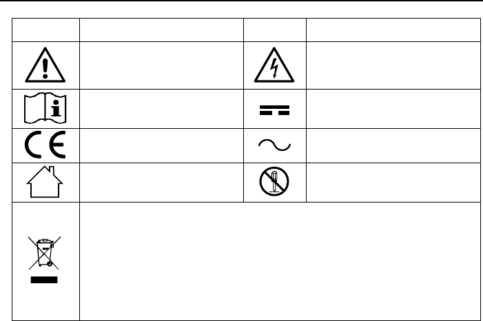
Symbol
Description
Symbol
Description
WARNING. RISK OF DANGER.
WARNING. HAZARDOUS
VOLTAGE. Risk of electric
shock.
Consult user documenta-
tion.
DC (Direct Current)
Conforms to European Un-
ion directives.
AC (Alternating Current)
For indoor use only.
Do not disassemble unit.
This product complies with the WEEE directive marking require-
ments. The affixed label indicates that you must not discard
this electronic product in domestic household waste. Product
Category: With reference to the equipment types in the WEEE Di-
rective Annex I, this product is classed as category 9
“Monitoring and Control Instrumentation” product. Do not dis-
pose of this product as unsorted municipal waste. Please
contact us to dispose/recycle this product.
ChipSHOUTER Users Manual: Packing Information
10
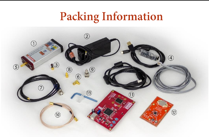
①
ChipSHOUTER CW520 Main Unit
⑧
SMB to SMA adapter
②
19V / 3.4A Power Adapter
⑨
SMB to BNC adapter
③
Injection probe/tips (1mm, 4mm)
⑩
SMB Cable
④
Isolated USB Adapter + RJ12 Cable
+ Micro USB Cable
⑪
CW521 Ballistic Gel SRAM
Target + USB Cable
⑤
SMA Saver (Installed)
⑫
CW322 Simple EMFI Target
+ CR2032 Battery
⑥
SMA Right angle adapter
⑬
Cooling air adapter and
4mm wrench
⑦
Oscilloscope Probe Adapter (x2)

ChipSHOUTER Users Manual: Packing Information
11
1. The ChipSHOUTER CW520 main unit is the EMFI fault in-
jection platform itself.
2. The 19V power supply provides DC power to the Chip-
SHOUTER.
3. The injection probe tips must be added onto the end of
the ChipSHOUTER before using the device. Do not touch
the probes during operation.
4. The Isolated USB adapter provides a computer interface
to the ChipSHOUTER.
5. The SMA Saver is a sacrificial SMA male to female
adapter. It is added onto the ChipSHOUTER to save wear
and tear on the ChipSHOUTER SMA connector. The SMA Saver
can easily be replaced in case it is damaged.
6. The SMA right angle adapter is used in combination with
a horizontal mount XY table.
7. The oscilloscope probe adapter allows monitoring of the
pulse inserted at the tip of the ChipSHOUTER itself.
8. The SMB to SMA adapter allows interfacing the external
trigger input with the ChipWhisperer trigger outputs,
or other equipment with logic-level SMA outputs.
9. The SMB to BNC adapter allows interfacing the external
trigger input with regular lab equipment.
10. The SMB cable is used to connect the external trigger.
11. The Ballistic Gel SRAM target provides detailed infor-
mation about the effectiveness of a fault injection
pattern.
12. The Simple EMFI target allows quick validation that a
fault injection probe is working.

ChipSHOUTER Users Manual: Packing Information
12
13. The cooling air adapter allows you to insert dry high-
pressure air into the ChipSHOUTER for cooling. The
adapter may look different or be of different material
thank shown here.
We are continuously improving our products. Some of the ac-
cessories or the device may look different than the photos
used for this manual, but this is part of our continuous
refinement of the product. If you have questions about the
parts received please contact us.
ChipSHOUTER Users Manual: High Voltage Warnings
13
In addition to the safety warnings regarding the Chip-
SHOUTER operation, there are some specific additional
warnings related to the high voltage circuitry. Please care-
fully read both the “Safety Information” in addition to these
“High Voltage Warnings”. All users of the ChipSHOUTER must be
aware of these warnings.
• ChipSHOUTER can generate high magnetic and elec-
trical field strength. DO NOT use around safety-
critical equipment, and DO NOT allow a person with
an implanted or on-body medical device near the
ChipSHOUTER.
• The SMA center pin has hazardous voltage present.
DO NOT touch or otherwise expose this connection.
• DO NOT touch the injection probe or high voltage
connector when device is armed or discharging.
• DO NOT attempt to arm the ChipSHOUTER without a
EMFI injection probe attached.
• DO NOT use the ChipSHOUTER to generate a spark-gap
discharge. In addition to exposing hazardous volt-
ages, this may generate U.V. light and other
ChipSHOUTER contains hazardous voltages. It is
very important everyone who will be operating the
ChipSHOUTER carefully reads and understands
this manual and the warning instructions. If you
have questions about these warnings please con-
tact us immediately.

ChipSHOUTER Users Manual:
14
dangerous radiation. ChipSHOUTER will also be se-
verely damaged during the discharge process, as
the spark-gap discharge exceeds allowed dv/dt rat-
ings of the driver circuit.
• The insulation on the injection probes must be
unbroken for your protection. Carefully inspect
the probes for damage to the insulation, and de-
stroy (to prevent accidental reuse) and discard
any damaged probes.
• DO NOT position the injection probes in such a
manner they will scrape conductive areas of the
device under test.
• The SMA connector shell is NOT connected to the
enclosure (chassis). Do not short the SMA con-
nector shell to the enclosure or ground, as
otherwise high voltages and currents could pass
through this connection.
• Do not connect anything besides a EMFI injection
probe or included accessory to the ChipSHOUTER
output.

ChipSHOUTER Users Manual: Background and Quick Start Guide
15
Electromagnetic Fault Injection (EMFI) is a way of injecting
transient faults into electronic systems without direct elec-
trical contact. This is accomplished by generating a rapidly
changing magnetic field that induces a voltage in the Device
under Test (DuT). Changing magnetic fields cause induced cur-
rents in the DuT, resulting in changing voltage levels on
internal signals. These changing voltage levels can cause
incorrect read (or write) operations, affecting results of
latches, registers, and more. Corrupting memory, resetting
lock bits, skipping instructions, and inserting faults into
cryptographic operations are all applications of EMFI. This
can be used for embedded security research, validating fault-
tolerance of algorithms, and validating fault-tolerance of
entire systems.
To use the ChipSHOUTER in its simplest configuration you
need only three things: the ChipSHOUTER itself, the included
19V power adapter, and one of the included injection tips.
Attach the tip to the high voltage output of the device, and
the power adapter to the DC input. Holding the ARM button
arms the device and pressing pulse generates a fault. Pressing
ARM again will disarm the device. Application of the device
and more detail on performing injections is included in the
sections pertaining to the included targets.
ChipSHOUTER Users Manual: Device Architecture
16
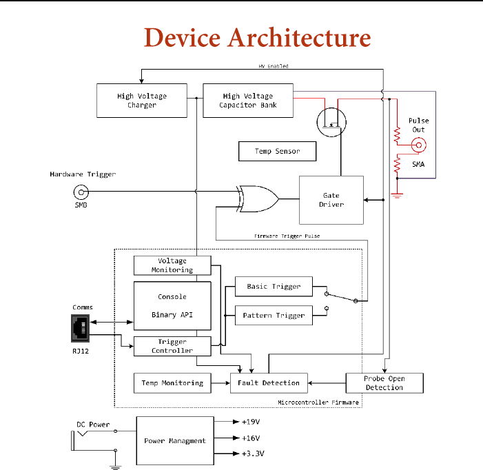
Figure 1: Overview of ChipSHOUTER device architecture.
Fundamentally, the ChipSHOUTER provides a high voltage charge
that is discharged through an inductor (the “injection tip”).
This injection tip generates a powerful magnetic field that
can be used to induce faults in a target device.
To make using the device easier, the ChipSHOUTER includes
a microcontroller that controls device operation. This in-
cludes detection of fault conditions such as over-temperature
or invalid operational requests. Once a fault is active, the

ChipSHOUTER Users Manual: Device Architecture
17
device will prevent “arming” (turning on the high-voltage
circuit) until the condition is cleared, and possibly acknowl-
edged by the user.
This microcontroller can also generate pulse waveforms.
These waveforms can either be basic pulses of a specified
lengths, or more complicated patterns involving switching the
high voltage on/off the injection tip on 21nS time-steps.
To reduce the delay between a trigger event and the pulse
injection, a special hardware trigger is also present that
directly drives the high-voltage switch. This hardware trig-
ger allows entirely arbitrary on/off pulses to be sent into
the injection tip. This hardware trigger can be used with
general-purpose test equipment or specific power analysis
equipment such as the ChipWhisperer.
The output connector is a SMA connector jack. For safety
reasons the device uses “high-side” switching, which means
the high voltage is present ONLY during the pulse operation
itself. The output includes two current-limiting resistors to
prevent device destruction even when discharging into a direct
short, and two catch diodes to absorb the reverse voltage
spike generated by the collapsing magnetic field.

ChipSHOUTER Users Manual: Specifications
18
Power supply (ChipSHOUTER DC Input) ... 19V DC ±10%, 3.4A
Power consumption (standby) ........... 0.4W Typical
Power consumption (armed) ............. 5W Typical
Power consumption (charging/pulsing) .. 5W to 50W Typical
Power supply (AC-DC adapter) .......... 100–240VAC, 50/60Hz, 1.5A
Size (ChipSHOUTER main unit) .......... 130 x 55 x 25 mm
Weight (ChipSHOUTER main unit) ........ 180 g
Altitude
Operating......................... 2000 m
Storage........................... 12 000 m
Storage Temperature ................... -40°C to 60°C
Operating Temperature ................. 5°C to 40°C
Relative Humidity ..................... Noncondensing
0 % to 80 % @ 5°C to 30°C
Decreasing linearly to 50 % @ 40°C
Safety
EN 61010-1:2010 .................. Pollution Degree 2
Electromagnetic Compatibility
International .................... EN 61326-1: Portable Electromagnetic
Environment; EN 61326-2-2 CISPR 11: Group 2, Class A
Group 2: This equipment intentionally generates RF en-
ergy that is used in electromagnetic coupling,
inductive coupling, and capacitive coupling for mate-
rial analysis or inspection.
Class A: This equipment is suitable for use in all
establishments other than domestic and those directly
connected to the public low voltage power supply net-
work that supplies buildings used for domestic
purposes.
There may be potential difficulties in ensuring elec-
tromagnetic compatibility in other environments due to
conducted and radiated disturbances.
Emissions that exceed the levels required by CISPR 11
can occur when the equipment is connected to a test

ChipSHOUTER Users Manual: Specifications
19
object. The equipment may not meet the immunity re-
quirements of this standard when test leads and/or test
probes are connected.
USA (FCC) ........................ 47 CFR 15 subpart B. This product is
considered and exempt device per clause
15.103.
Operation is subject to the following two conditions:
(1) this device may not cause harmful interference and
(2) this device must accept any interference received,
including interference that may cause undesired oper-
ations. You must discontinue use of this device if it
causes interference to another user, and remedy the
interference before continuing operation of this de-
vice.
Serial command interface .............. 3.3V CMOS Serial, 115200 baud, 8N1
Protocol ............................. (1) ASCII command prompt
(2) Binary
Serial connection ..................... RJ12 connector with GND, TX/RX,
3.3V output, and switchable pulse/arm
pin.
Hardware trigger connector type ...... SMB connector, center-positive
Hardware trigger threshold ........... 2V
Hardware trigger absolute max ratings -0.5V to 6.5V
Hardware trigger impedance ............ 50Ω / 1.8KΩ (Switchable)
Hardware trigger level ................ Active-high / Active-Low (Switchable)
Injected waveform monitor ............. BNC connector for mating with standard
1MΩ || 10-25pF oscilloscope input. Ad-
justable compensation trimmer for fine-
tuning match.
Voltage monitor attenuation ........... 20x attenuation
Voltage monitor output range .......... ±25V into properly matched oscilloscope
input
Characteristic
Min
Typ
Max
Units
Programmable voltage range
150
500
V
Charge rate
30
40
V/ms
Charge energy
625
mJ

ChipSHOUTER Users Manual: Specifications
20
Measured voltage accuracy via digital in-
terface
±(5% + 10V)
Pulse generator source ................ (1) Internal pulse generator, basic
(2) Internal pulse generator,
programmable pattern
(3) External hardware trigger
Characteristic
Min
Typ
Max
Units
Basic pulse generator
Pulse width range
80
960
nS
Pulse width resolution
80
nS
Pulse width jitter
350
pS std-dev
Pulse dead-time (between repeats)
1
1000
mS
Pulse repetition count (per
Trigger event)
1
10000
Programmable pattern generator
Pulse width resolution (time-
steps)
20.83
nS
Time-steps per pulse
1
5000
Time-steps
Total pulse width
0.0208
100
uS
Pulse output state per time-steps
1/0
Pulse width jitter
tested pulse width of 80nS
350
pS std-dev
Hardware Input Trigger
Delay
Tested high voltage 150V to 500V
75
nS
Delay jitter
Tested high voltage 150V to 500V
150
pS std-dev
Width jitter
Tested high voltage 150V to 300V
800
pS std-dev
Width jitter
Tested high voltage 300V to 500V
220
pS std-dev
Characteristic
Min
Typ
Max
Units
Pulse width into 1mm injection tip
15
80
TYPICAL nS
Pulse width into 4mm injection tip
24
480
TYPICAL nS
ChipSHOUTER Users Manual: Specifications
21
Characteristic
Min
Typ
Max
Units
Minimum consecutive pulse spacing
Tested with 4mm injection tip at
voltage setting of 500V
2 Pulses
100
ns
3 Pulses
175
ns
4 Pulses
250
ns
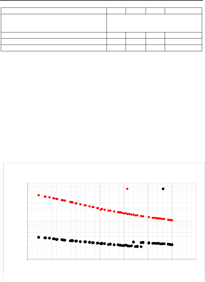
While the pulse generator characteristics show that a wide
variety of pulses can be applied to the injection tip, the
actual resulting pulse characteristics will depend consider-
ably on the tip properties itself. It is not possible to
achieve every injection result on every tip.
The following figures (Figure 2 and Figure 3) can be used
to understand a possible range of pulses that can be achieved
on the provided 1mm and 4mm tips.
These figures were generated by using the external hardware
trigger to sweep a range of input pulse widths over a range
10
100
1000
100 150 200 250 300 350 400 450
Pulse Width (ns)
Peak Output Voltage (Measured)
4mm Tip Pulse Width Limits
Maximum Minimum
Figure 2: 4mm tip pulse width
ChipSHOUTER Users Manual: Specifications
22
of set capacitor bank voltages. They represent typical (not
guaranteed) characteristics, taken at 25C.
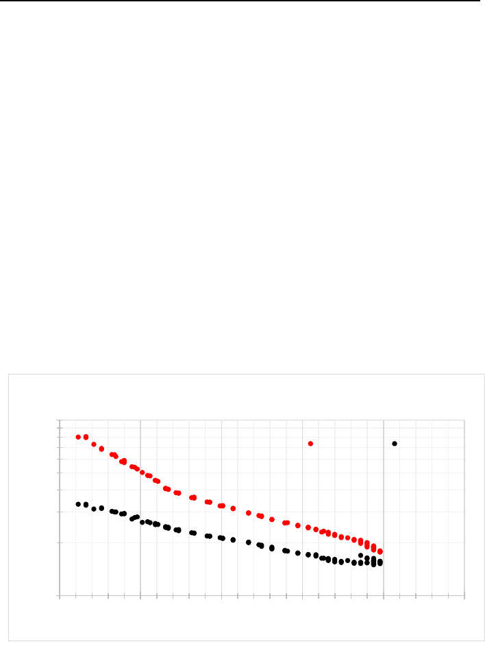
The allowable range is between the minimum and maximum
width values at a given voltage. Note the smaller (1mm) tip
almost always generates a narrow pulse, regardless of input
pulse duration. This is especially apparent at high charge
voltage values.
The larger (4mm) tip allows a wider range of possible
pulse widths, and more closely follows the commanded input
width. It is extremely important to use the oscilloscope mon-
itoring outputs to see the actual pulse injected into your
target probe, or use an external H-Field probe to monitor it.
The actual number of consecutive pulses is limited almost
entirely by probe characteristics, and not the ChipSHOUTER
itself. This can be seen in that inserting more consecutive
pulses often requires more delay between them.
10
100
100 150 200 250 300 350
Pulse Width (ns)
Peak Output Voltage (Measured)
1mm Tip Pulse Width Limits
Maximum Minimum
Figure 3: 1mm tip pulse width

ChipSHOUTER Users Manual: External Connections
23
The SMA high voltage output is where injection tips are
attached. The outer shell does not directly connect to chassis
ground, so you MUST NOT attach the outer shell via a metal
clamp or similar to any other electrical connecting during
operation.
Note the SMA connector will wear over time, and a loosely
attached injection tip can cause arcing which will permanently
damage the connector, reducing performance. To avoid this,
your ChipSHOUTER comes with a “SMA Saver” attached, which is
Figure 4: External connectors on the ChipSHOUTER.

ChipSHOUTER Users Manual: External Connections
24
a SMA male to female adapter. Do not remove the SMA saver
under normal circumstances, and instead attach injection tips
to the SMA saver output.
If the SMA saver becomes worn or damaged, remove the SMA
saver and replace with a new one. These can be purchased from
us, or you can use a high-quality SMA male to female adapter
such as Amphenol 132171.
To attach or remove a SMA connector (such as the probe
tip), you should note that ONLY the outer connector nut is
designed to rotate. The center pin of the SMA connector should
not be rotated during the removal or attachment process, as
rotating this pin can cause damage to both sides.
Instead, you should hold the body of the item being re-
moved firmly, while spinning the connector nut (using a 8mm
wrench if needed) to remove or attach. If you simply rotate
the connector nut without holding the body stationary, it is
easy to rotate the body of the SMA connector and thus also
rotate the internal contact pin.
To achieve repeatable connections, a torque wrench is
recommended. SMA connectors are typically tightened to 1 Nm
/ 8 lb-in.
The SMB connector is a hardware trigger input. As explained
in the device architecture, this trigger input is connected
directly to the high-voltage switch without being routed
through the controller.
This connection ensures the highest-speed and most direct
control of the pulse shape is possible. The input is designed

ChipSHOUTER Users Manual: External Connections
25
for 3.3V LVCMOS signal levels, but can accept up to a 6.5V
input signal safely.
The SMB trigger input can be configured in one of three
modes:
• Active-low pulse, high-impedance (approx. 2KΩ).
• Active-high pulse, high-impedance (approx. 2KΩ).
• Active-high pulse, 50Ω impedance (DEFAULT).
A suitable pulse for this input can be generated by a
laboratory pulse generator, a custom FPGA or other board, or
the ChipWhisperer.
If interfacing with ChipWhisperer, the recommended method
is to use the HS-OUT SMA connector on the CW506 advanced
breakout board. This requires you to configure that the glitch
out is routed to the HS-OUT pin.
You can also use the active-low pulse method with the
ChipWhisperer “glitch” connector, by enabled the LP-glitch
crowbar output. The ChipSHOUTER has an internal pull-up on
the hardware trigger input, allowing the LP-glitch crowbar
output to serve as an open-drain output. See the online doc-
umentation for more details.
Note that internally this hardware trigger is also routed
to the microcontroller. The microcontroller needs to know when
a fault is being inserted, as this (a) resets the arm timeout
count, and (b) tells the microcontroller to ignore invalid
temperature readings that occurring during a discharge event
due to noise on the temperature sensor. If your input voltage
does not have a strong enough drive, it may be sufficient to
trigger the actual fault injection without the microcontrol-
ler being aware.

ChipSHOUTER Users Manual: External Connections
26
This typically results in (1) the device automatically
disarming during use, and (2) a “temperature sensor error”
fault. Ensure you are driving to proper 3.3 LVCMOS levels, if
you are using the 50Ω termination mode you can disable this
to increase drive levels as a test.
The ChipSHOUTER uses a 4.75mm x 1.7mm center-positive barrel
connector (EIAJ-03), with a 19VDC ± 10% input voltage. During
standby (not armed) the ChipSHOUTER draws approximately 20mA,
during armed state it draws approximately 250mA, and during
discharge draws between 0.3A-3.3A.
Use only the provided DC power supply with the Chip-
SHOUTER, which has a rating of 19V/3.42A.
The ChipSHOUTER can be controlled using asynchronous serial
through the RJ12 port on the device. DO NOT connect this cable
to general use ports on other devices like ethernet or phone
ports. Connection to a computer can be easily made by using
the USB interface board and a micro-USB cable. The pinout
found on that board can be used by more advanced users to
interface with the ChipSHOUTER using other specialized equip-
ment. The USB adapter board requires FTDI VCP drivers to be
Figure 5: RJ12 Connector on ChipSHOUTER Panel.

ChipSHOUTER Users Manual: External Connections
27
installed. The serial configuration of the ChipSHOUTER is
115200 baud 8N1.
The pinout of the RJ12 jack is shown in . More information
on the USB adapter board is provided on page 60.
Both the voltage and current at the output of the ChipSHOUTER
can be monitored via two probe connections on the top side of
the device. Adapter cables are included for connecting to an
oscilloscope, use only matching NewAE cables for this purpose.
The external portions of these two probes are identical and
can be plugged in to either socket. These are described in
more detail on page 39 in the section Oscilloscope Pulse Shape
Monitoring.

ChipSHOUTER Users Manual: Pulse Generation
28
The ChipSHOUTER involves an advanced pulse trigger system.
This can be used to build a pattern for injecting a fault
into a target device, or working with existing laboratory
equipment. This section describes some of the pulse generation
architecture to help you understand the capabilities of the
ChipSHOUTER.
One of the most critical points to understand that the gen-
erated pulse will not the same as the inserted pulse. This is
for several reasons, primarily due to (1) saturation and fun-
damental physical limits of the injection tips, and (2)
limitations of the ChipSHOUTER. The physical limitations of
the injection tips provide the most critical limitations, as
typically issues such as the core material saturating result
in limits regarding how many pulses can be inserted in quick
succession.
The ChipSHOUTER oscilloscope probe monitoring points can
be used to monitor the actual inserted pulse. Typically you
can use this to tune the generated pulse to more closely match
a desired inserted pulse.
The ChipSHOUTER can internally switch between active-high and
active-low trigger operation. This is done because the exter-
nal input can be switched from active-high to active-low,
which internally inverts the entire trigger system logic.
The basic pulse generator takes care of this for you, but
the programmable trigger does not. When using the programmable

ChipSHOUTER Users Manual: Pulse Generation
29
trigger be sure to switch the external input to “active-high”
mode.
Note you may see small differences between active-high
and active-low mode. The ChipSHOUTER remains an electronic
device and is sensitive to the very high-power fields being
generated. Active-high and active-low modes show slightly
different susceptibility to various noise and pulses.
The basic pulse generator is used to generate a single or
multiple pulses, with relatively large spacing between them.
The programmable pulse generator can be used to generate com-
plex patterns, including multiple pulses and delays. It also
provides a much shorter time resolution than the basic pulse
generator.
The pattern is recorded as a binary pattern, where each
digit represents a time-step. For example to generate two 60nS
pulses with a 80nS delay (approximately), you would write the
pattern 011100001110 into the pulse generator memory.
You must end the pattern with an inactive-state. If the
device is in active-high mode, this means you must end the
pattern with a ‘0’. Failure to do this will result in a trigger
error or other problems.
Note you will often find that the second (and later)
pulses require a longer trigger pattern to generate the in-
tended injected pulse. Thus in reality you may find
0111000011110 is needed (an extra ‘1’ on the second pulse).

ChipSHOUTER Users Manual: Pulse Generation
30
CAUTION: When writing a pattern, ensure you end
with an inactive state. It is suggested to also
start the pattern with an inactive state for sym-
metry.
The programmable trigger still uses the repeat and dead-
time parameters. You may wish to set repeat to ‘1’ to avoid
repeating the pattern unexpectedly.
ChipSHOUTER Users Manual: Simple EMFI Target (CW322)
31
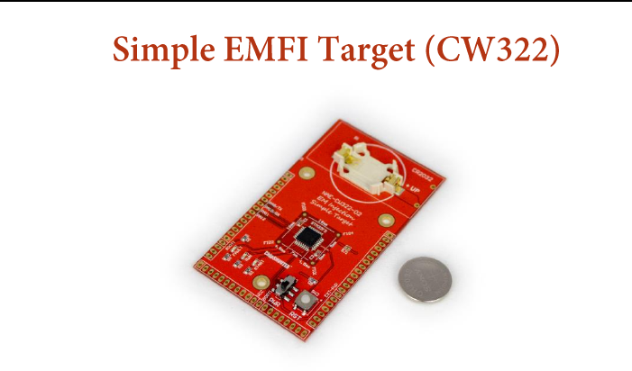
Figure 6: CW322 Simple Target
The CW322 (Simple Target) is an easy to use target with the
ChipSHOUTER platform, and a good first introduction to EMFI.
The board features an STM32F303K8T6 that is pre-programmed
with very simple firmware, the important part shown in Listing
1. The microcontroller simply uses two loops to multiply 300
by 300 and check the result. The board features 3 LEDs that
indicate the state of the device.
The START LED shows when the device begins code execution
and will light whenever the device is reset. The RUN LED
blinks as the code is properly executed, if this light stops
blinking the device has frozen. The FAULT LED blinks whenever
the multiplication returns an incorrect value. This normally
never happens, but this abnormal behaviour can be reliably
induced by the ChipSHOUTER.

ChipSHOUTER Users Manual: Simple EMFI Target (CW322)
32
For this experiment, you will need the ChipSHOUTER, the in-
cluded 19v power adapter, one of the included 4mm injection
tips, and the simple target board.
1. To start the simple target board, slide the PWR switch
up. The START light should briefly flash, followed by
a steady blink from the RUN light.
2. Place the simple target on a flat surface and plug the
ChipSHOUTER into the included 19v power adapter. The
#define RUN_CNT 2000
#define OUTER_LOOP_CNT 300
#define INNER_LOOP_CNT 300
void glitch_loop(void)
{
volatile uint32_t i, j;
volatile uint32_t cnt;
uint32_t blink_status = 1;
uint32_t run_cnt = 0;
uint32_t glitch_cnt = 0;
for(run_cnt = 0; run_cnt < RUN_CNT; run_cnt++){
//run led on
HAL_GPIO_WritePin(GPIOB, GPIO_PIN_4, blink_status);
blink_status ^= 1;
cnt = 0;
for(i = 0; i < OUTER_LOOP_CNT; i++) {
for(j=0; j < INNER_LOOP_CNT; j++){
cnt++;
}
}
//look for glitch
if (i != OUTER_LOOP_CNT || j != INNER_LOOP_CNT ||
cnt != (OUTER_LOOP_CNT * INNER_LOOP_CNT) ) {
//if glitched, reset the run count and blink the fault LED
HAL_GPIO_WritePin(GPIOB, GPIO_PIN_3, SET);
delay100ms(3);
HAL_GPIO_WritePin(GPIOB, GPIO_PIN_3, RESET);
run_cnt = 0;
}
}
}
Listing 1: EMFI Simple code example

ChipSHOUTER Users Manual: Simple EMFI Target (CW322)
33
STATUS, FAULT, and OPEN LEDs on the ChipSHOUTER should
light up.
3. Screw one of the 4mm injection tips onto the High volt-
age output connector of the ChipSHOUTER, this should
cause the FAULT and OPEN lights to go off.
4. Hold the ARM button until the arming chime sounds and
release the button. The system is now armed and ready
on inject a glitch.
5. Hold the probe very close to the chip on the Simple
Target and press the PULSE button on the ChipSHOUTER to
inject a field pulse.
6. Move the probe across the chip while holding the PULSE
button and observe the effect on the LEDs.
In some locations the chip will reset or stop working. In
others the chip will blink the fault LED, indicating that the
multiplication operation has been corrupted. This shows a
successful fault injection where the intended output of the
device has been changed without directly interfacing with the
device in any way. This is the heart of EMFI.
CAUTION: Observe proper ESD handling require-
ments with the board.
CAUTION: Fault injection can permanently de-
stroy the injection target. Always start at a
further distance and move towards the target until
you see fault interactions.
ChipSHOUTER Users Manual: Ballistic Gel EMFI Target
(CW522)
34
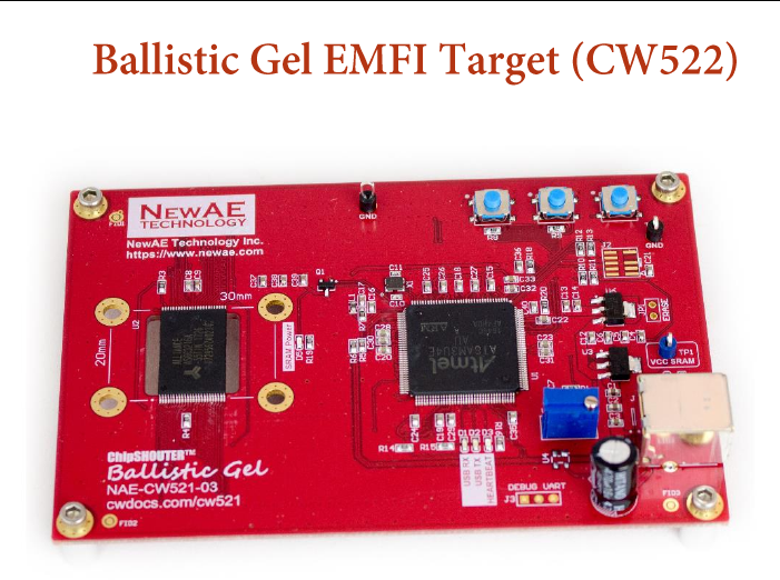
Figure 7: CW522 Ballistic Gel
The CW522 (Ballistic Gel Target) is an SRAM board with a
microcontroller for control and connectivity. The target is
called the Ballistic Gel because it records an imprint of the
magnetic field injected into it, like a ballistic gel block
leaves an imprint of a projectile. This acts as an example of
memory corruption, and this process demonstrates some of the
ChipSHOUTER pulse settings.
14. Attach one of the 1mm injection tips to the high voltage
output of the ChipSHOUTER.
15. Plug the Ballistic Gel target into your computer using
a USB cable and place the target on a flat surface. The
required drivers can be downloaded from ChipSHOUTER.com.

ChipSHOUTER Users Manual: Ballistic Gel EMFI Target
(CW522)
35
16. Connect the ChipSHOUTER to your computer by first using
an RJ12 cable to connect the ChipSHOUTER to the USB
interface board, and then connecting the interface board
to your computer using a micro-USB cable.
17. If drivers for the interface are not installed, install
the universal FTDI VCP driver from the FTDI website. The
interface should connect as a virtual com port, which
can be confirmed using your computers device manager.
18. Start a terminal session using your favorite terminal
program. PuTTY works well for this. The serial config-
uration of the ChipSHOUTER is 115200 baud 8N1
19. Connect the 19V power adapter to the ChipSHOUTER. If
your terminal was configured correctly a welcome message
should be displayed as the device boots.
20. Test connectivity with the shouter by sending a question
mark (?) to the device. This should return the serial
command list.
21. In a separate command line or python interpreter, run
WHATISTHISSCRIPTCALLED.py to connect to the ballistic
gel target.
22. Arm the ChipSHOUTER by sending the command arm over the
serial link. You should hear the arm chime.
23. Hold the injection tip over the center of the SRAM chip
on the ballistic gel target. Press the pulse button on
the ChipSHOUTER or send the command pulse over the se-
rial link.
24. Disarm the ChipSHOUTER by pressing the arm button or by
sending the disarm command over the serial link.
25. Press enter in the Ballistic Gel script terminal to read
the injected fault pattern.

ChipSHOUTER Users Manual: Ballistic Gel EMFI Target
(CW522)
36
26. Change the pulse settings on the ChipSHOUTER using se-
rial commands. set voltage 300 will set the capacitor
bank voltage to 300V. set pulse width 160 will set the
output pulse width to 160ns. set pulse repeat 10 will
send 10 pulses on a single pulse command. set pulse
deadtime 10 will set the delay between pulses to 10ms.
Use these settings for the next test.
27. Repeat steps 9-12 with the new pulse settings. You can
adjust these settings more to see how each one affects
the injected corruption. More data on these effects can
be found on the ChipWhisperer wiki.
You should now have a basic grasp of the ChipSHOUTER config-
uration options. There are many more advanced options
documented on the ChipWhisperer wiki and in ChipSHOUTER ap-
plication notes.
CAUTION: Observe proper ESD handling require-
ments with the board.
CAUTION: Fault injection can permanently de-
stroy the injection target. Always start at a
further distance and move towards the target until
you see fault interactions.

ChipSHOUTER Users Manual: Injection Tip Usage
37
There are four injection tips included with the ChipSHOUTER.
Two 4mm tips and two 1mm tips, each with both negative and
positive polarity versions. The size of the tips refers to
the diameter of the ferrite core inside the coil, and the
polarity refers to the direction of the magnetic field created
during operation. Following the right hand rule for solenoids,
our positive tips generate magnetic field lined pointing out
of their ends, while our negative tips generate field lines
pointing into their ends.
The larger 4mm tips are more powerful and better for
manual use and insensitive targets. They generate a wide field
that is good for discovering new vulnerabilities and they have
the best chance to disrupt a circuit in some way. The smaller
1mm tips are better for precision work, as they generate a
narrower field and can be positioned more precisely. These
tips are good for characterising known faults where location
is critical, and for dealing with sensitive targets.
The tip size will affect your actual pulse inserted, it
is always suggested to use the pulse shape monitoring output
to better understand the injected pulse. You can see addi-
tional documentation and examples of the pulse shapes from
the app-notes on our website.
The ChipSHOUTER is designed as primarily a magnetic field
generation device, and is not designed to generate spark dis-
charge events. A spark discharge event causes a very high

ChipSHOUTER Users Manual: Injection Tip Usage
38
dV/dT, which can permanently destroy the output stage of the
ChipSHOUTER.
When attaching tips, ensure they are tight. A loose tip
may spark during discharge, which will (a) cause substantial
pitting and mechanically damage the contacts, and (b) can
electrically damage the output stage.
Likewise, ensure there is never damage to insulation of
discharge tips. This is especially important if using 3rd party
tips, as it is possible for closely wound coils to discharge
between windings. This can also cause damage to the Chip-
SHOUTER.
ChipSHOUTER Users Manual: Oscilloscope Pulse Shape
Monitoring
39
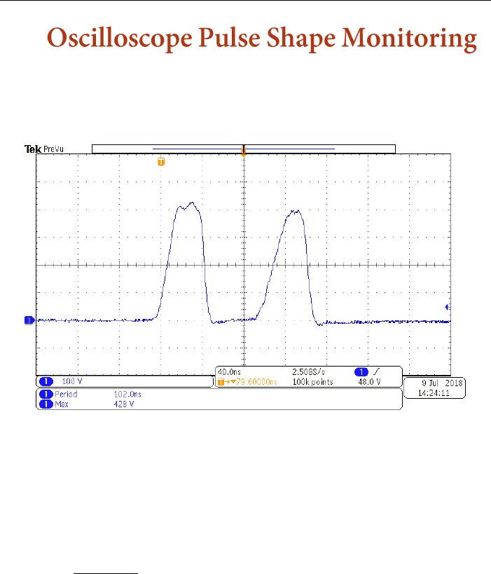
To monitor the injected pulse, two oscilloscope adapter probes
are included. These adapters are based on standard oscillo-
scope probes, but with the business end of the probe built
into the ChipSHOUTER itself.
This allows you to monitor the high-voltage output without
risk of exposing yourself to high voltages. These probes are
designed only for usage with a standard 1MΩ||10-25pF oscil-
loscope input.
CAUTION: Usage with any other input type (in-
cluding higher or lower impedance) can result in
damage to your device and exposure to high voltages.
Figure 8: Inserted pulse viewed on oscilloscope screen.

ChipSHOUTER Users Manual: Oscilloscope Pulse Shape
Monitoring
40
Be sure to carefully review the voltage limits dis-
cussed here and ensure any connected oscilloscopes
will meet the voltage limits.
To use the probe, simply connect the MCX connector into
the ChipSHOUTER front connection. There are two front connec-
tions: a “voltage” monitor, and a “current” monitor.
The voltage monitor provides a 20:1 attenuation, so using
this means setting your oscilloscope up with a 20:1 attenua-
tion rating. Note that at a peak 500V pulse voltage, the 20:1
attenuation means your oscilloscope front-end will see 25V at
the 1MΩ input.
CAUTION: Confirm your oscilloscope 1MΩ maximum
voltage rating is at least 25V. Due to ringing at
the tip voltages may exceed 500V, so a ±30V rating
is recommended. NewAE Technology Inc. cannot accept
any liability for damage to your oscilloscope or
other connected equipment, and you use this monitor
at your own risk.
The current monitor provides a 10:1 attenuation, but this
is not a calibrated current monitoring output. Instead it is
used to provide general information on pulse shape.
The current is monitored across a pulse-tolerant thick-
film resistor. This resistor is used as part of the current
limiting and back e.m.f. absorption circuit.
ChipSHOUTER Users Manual: Oscilloscope Pulse Shape
Monitoring
41
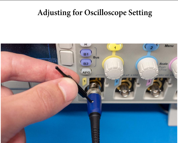
You will need to adjust the probe for your specific oscillo-
scope. This can be done by adjusting the small compensation
trimmer that is located on the BNC body (see Figure 9).
Figure 9: Tuning oscilloscope probe.
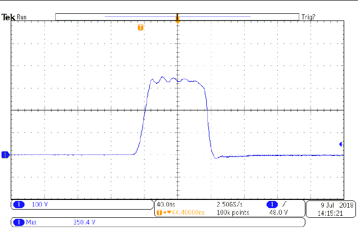
For calibration the 4mm injection tip should be connected
to the shouter and the pulse output should be set to simple
mode with a pulse width of 80 (ns), a deadtime of 10 (ms) and
a voltage of 400v. This process is made easier by setting
pulse repeats to a high number (100 works well) and using the
average mode on your oscilloscope with a low number of samples
(8 works well). While pulsing the ChipSHOUTER adjust the small
trimmer in the probe body until the maximum pulse amplitude
reads 350 volts. Your probe is now calibrated.
ChipSHOUTER Users Manual: Oscilloscope Pulse Shape
Monitoring
42
Figure 10: Example calibration waveform.

ChipSHOUTER Users Manual: Forced-Air Cooling
43
During regular operation, the ChipSHOUTER will heat up if
using continuous discharge. When internal temperatures reach
a set point, the device will go into a thermal shut-down and
wait for natural cooling to take the device into safe oper-
ating range.
If using ChipSHOUTER in high duty cycle operation, or at
elevated local temperature, you may wish to use forced-air
cooling to improve performance.
ChipSHOUTER provides a M8x1.25 threaded hole, into which
the a tube adapter may be inserted. Dry room-temperature
forced air may be inserted into the ChipSHOUTER from this
port.
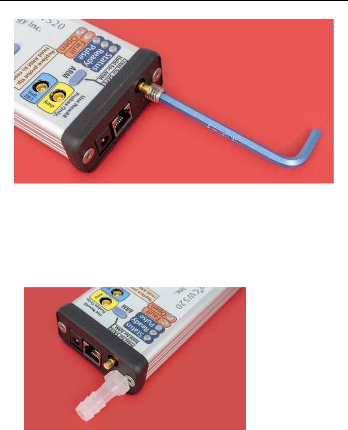
To use this port, you will need to use a 4 mm hex wrench
(provided) to remove the blanking port. Once you have removed
the blanking port, you can insert the tube adapter into this
port and attach your air source. Use a maximum of 3 bar (40
PSI) and 10 CFM.
Use ONLY dry filtered air or an inert gas such as
nitrogen. Compressed air normally includes both
oil and water vapour. If using compressed air an in-
line filter must be used to remove condensate,
failure to do so may cause shock danger due to
condensation inside unit, or cause permanent dam-
age of the ChipSHOUTER. Never use a flammable
or explosive gas.
ChipSHOUTER Users Manual: Forced-Air Cooling
44
The blanking plug is a M8x1.25 x 16mm set screw, and if
the blanking plug is lost a M8x1.25 bolt can be used until
the proper replacement is procured. The air inlet must never
be left open.
Figure 12: Adding air inlet adapter.
Figure 11: Removing blanking plug.

ChipSHOUTER Users Manual: Forced-Air Cooling
45
While dried compressed air can be used, a normal air compres-
sor is not suitable for use in an office or lab environment.
Instead a small air pump can be found that operates from your
local power supply.
Examples of such air pumps include aquarium air pumps
(look for very high-flow) used for aerators. Various linear
piston air pumps (sometimes called “electromagnetic air
pumps” due to use of electromagnets to oscillator piston) are
available which are reasonably quiet, small, and with suffi-
cient flow to cool the ChipSHOUTER during long operations.
When a hose is not connected, connect either a
blanking port to the hose connection OR remove
the hose adapter and replace with the blanking port
screw. Failure to do so leaves high voltage exposed
through the cooling hole, and you must never oper-
ate the device without the blanking plug or hose
present.
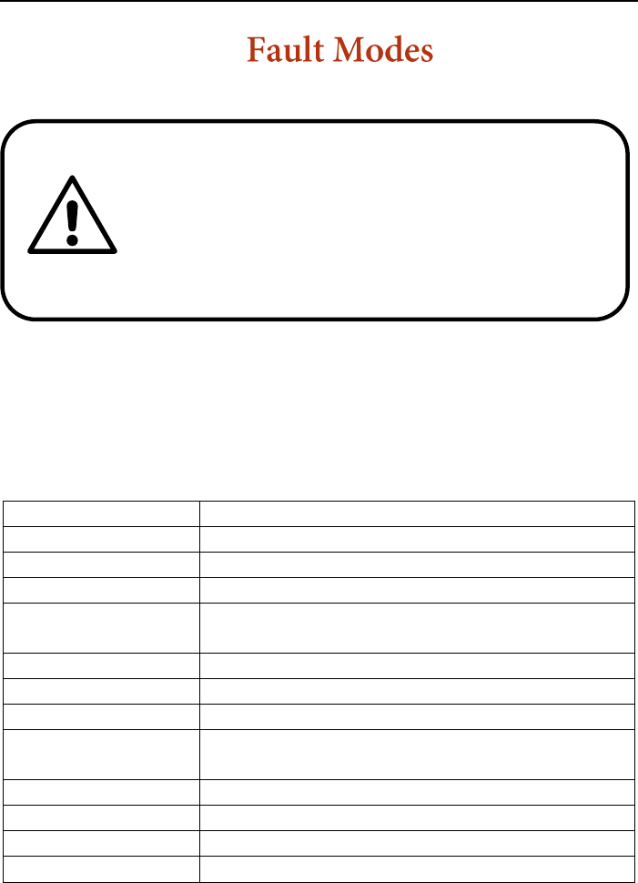
ChipSHOUTER Users Manual: Fault Modes
46
ChipSHOUTER has several possible faults. The specific faults
can be determined via the serial interface (described in an-
other section), however the most common faults are also
described with special blink patterns and indicators on the
LEDs.
Fault
Fault Description
Probe
Probe disconnected or damaged (open).
Overtemp
Internal temperatures too high.
Panel Open
Front panel removed or not secure.
High Voltage Er-
ror
Measured high-voltage is higher/lower
than expected.
RAM CRC
RAM CRC failed.
EEPROM CRC
EEPROM CRC failed.
GPIO
GPIO state does not match expected.
Charge Error
Charge circuit error, likely input volt-
age out-of-spec.
Trigger
Trigger too long or invalid.
Hardware Exc
Internal hardware failure detected.
Trigger Glitch
Device triggered while disarmed.
Over Voltage
Charge voltage higher than expected.
ChipSHOUTER faults indicate unexpected operat-
ing conditions. If faults occur, carefully read and
understand this section of the user manual to take
the proper corrective action. If it is not clear what
fault has occurred, please discontinue use of the
device and contact us immediately.

ChipSHOUTER Users Manual: Fault Modes
47
Sensor Fault
Temperature sensors not communicating,
possibly trigger occurring too frequency
without arm ready check.
Any active fault will prevent the ChipSHOUTER from arming
(prevents the high voltage charge from becoming active), and
the fault condition must be fixed before you attempt to arm
the device.
When a fault is active, the “FAULT” LED will be on. Do
not attempt to arm the device when a fault is active. Some
faults will also trigger a fault tone to make the error con-
dition clear.
If a device is already armed when certain critical faults
occur, the fault will latch and the device will disarm. In
this case it not enough to simply fix the condition. In ad-
dition you must clear the latched fault after fixing the error
condition. This latch prevents the ChipSHOUTER from automat-
ically re-arming when an error occurs.
The latched fault can be cleared in two ways:
1. Hold the “ARM” button down for 8 seconds, the Chip-
SHOUTER will either have 3 short beeps (fault cleared
OK) or one long tone (fault could not clear as condition
has not been fixed).
2. Using the serial port, the command set fault none.
The ChipSHOUTER looks for a low-impedance connection on the
SMA connector. This connection is used to detect that a fault
injection probe is attached.

ChipSHOUTER Users Manual: Fault Modes
48
If the ChipSHOUTER is armed when a probe is removed, this
immediately causes a latched fault. As the probe SHOULD NEVER
be removed from the ChipSHOUTER when armed, this is a serious
fault condition. When switching probe tips, note it is much
quicker to disarm the ChipSHOUTER, switch tops, and re-arm
it. The latched fault condition is by design slow to clear,
as during probe changes you should always disarm the Chip-
SHOUTER first.
The ChipSHOUTER contains three temperature sensors. These
sensors are on the MOSFET (electronic switch), the e.m.f.
catch diodes, and the transformer used to generate the high
voltage.
If any of these devices are over-temperature, the Chip-
SHOUTER will shut down. This fault condition automatically
clears once the device cools down.
The temperature sensors cannot be read during the dis-
charge event. If using the external hardware trigger in quick
succession, you may also get an error indicating a temperature
sensor fault. This occurs when the ChipSHOUTER is unable to
check the device temperatures for a predetermined time.
If using the external trigger, it is recommended to also
send the triggersafe command over the serial interface during
times the trigger is known to be inactive. This command tells
ChipSHOUTER that it can perform the required self-checks (in-
cluding temperature checks), and will not be interrupted by
the discharge event.
See the API documentation (online) for more details of
this, or the serial interface documentation on page 51.

ChipSHOUTER Users Manual: Fault Modes
49
The external trigger input should not be triggered when the
device is disarmed. If this occurs, a fault tone sounds in
addition to the fault LED blinking.
It is expected the external user is gating the trigger
input, as otherwise triggers could occur during the arming
process (resulting in malformed pulses).
The error tone will sound (without the fault LED blinking)
if you attempt to use the PULSE button or pulse command over
the serial interface while disarmed.
The external hardware trigger should be used only to insert
short pulses, as the internal capacitor bank does not have
sufficient energy storage for long pulses.
This error typically means the external interface has the
wrong polarity setting. The external interface can be set for
active-low or active-high operation to interface with a wide
variety of standard lab equipment.
If the ChipSHOUTER is set for active-low operation, this
error could occur when the attached equipment is turned off
or disconnected while the ChipSHOUTER is still armed. Instead
you must first disarm the ChipSHOUTER before turning off the
trigger generation device.
The device has a variety of internal faults. If these faults
become persistent it indicates a likely hardware failure that
requires repair of the ChipSHOUTER. Internal faults include:

ChipSHOUTER Users Manual: Fault Modes
50
• RAM CRC error, FLASH CRC error, or firmware sig-
nature verification error.
• Measured capacitor bank voltage differs from set
voltage.
• Permanent failure of ability to measure tempera-
ture (sensor failure).
• Input power supply (19V DC) is out of-spec, either
too high or too low. This most often occurs if
power supply browns-out during operation.
• High-voltage charge circuit error (over-voltage,
over-temp, or input voltage out-of-spec).
• Enclosure has been opened (interlock switch acti-
vated).
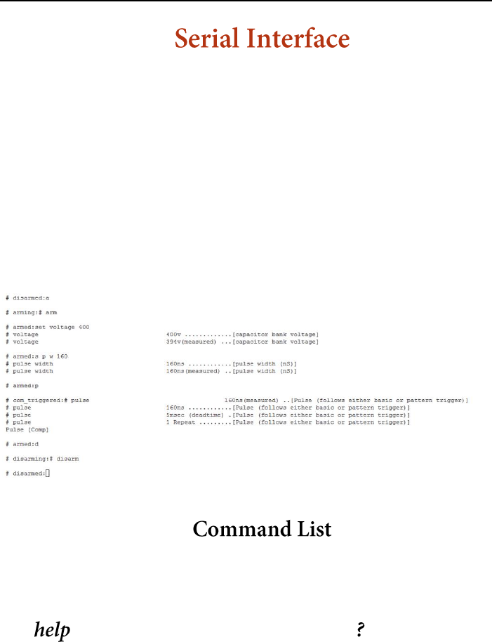
ChipSHOUTER Users Manual: Serial Interface
51
The ChipSHOUTER has a simple 3.3V TTL serial interface, which
you can connect to at 115200 baud, 8N1. The serial interface
presents a console that includes the current state of the
device. This is useful to watch for the device entering a
fault state indicating device errors are occurring. The con-
sole format is shown below:
# armed : get voltage
Note the ‘armed’ indicates a state, and ‘get voltage’ is a
command to the device. The following screenshot shows a typ-
ical interaction with the ChipSHOUTER console:
The commands available are listed below. A similar list can
be generated at any time by sending the word help to the
ChipSHOUTER interface.
Prints the help menu.

ChipSHOUTER Users Manual: Serial Interface
52
Print board ID (required for firmware updates).
Print arm of device (arm/disarmed/fault).
Print current or set value for capacitor charge
voltage. If the device is in the armed state, the
(actual) measured voltage will also be reported.
When device is disarmed the high-voltage is not
turned on, so reported measure voltages are invalid.
Example:
# disarmed: set voltage 150
# voltage 500v ........[capacitor bank voltage]
# voltage 21v(measured)[capacitor bank voltage]
# disarmed: s v 500
Print current or set value for pulse width in nS.
Using this method has a coarse pulse width of 80nS,
so the value will be reported as being mapped to
the nearest possible value in the ‘measured’ result.
If better resolution is needed see the programmable
trigger option.
Example:
# disarmed: set pulse width 120
# pulse width 120ns ...........[pulse width (nS)]
# pulse width 80ns(measured) ..[pulse width (nS)]
# disarmed: s p w 200
# pulse width 200ns ...........[pulse width (nS)]

ChipSHOUTER Users Manual: Serial Interface
53
# pulse width 160ns(measured) .[pulse width (nS)]
# armed: g p w
# pulse width 200ns ...........[pulse width (nS)]
# pulse width 160ns(measured) .[pulse width (nS)]
Print or set value for number of pulses per trigger,
the trigger being the ‘pulse’ command, the front-
panel button, or the RJ12 firmware pulse pin when
enabled.
Example:
#: set pulse repeat 1
#: s p r 5
Print or set value for time between pulses in mS,
the total pulse waveform will be repeat * deadtime
long.
Print or set value for the automatic disarm timer
in minutes. The disarm time automatically happens
when no pulse has occurred in the arm_timeout
minutes, and is used to reduce temperature in the
ChipSHOUTER along with improving safety.
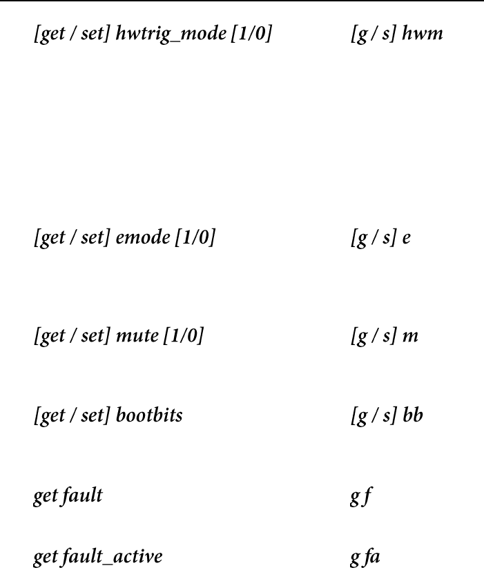
Configure hardware trigger (SMB connector) as high
impedance [0] or 50Ω [1]. The 50Ω impedance option
puts a 50Ω resistor to ground. If you are not using
the hardware trigger it is suggested to set this
ON, as it will reduce potential noise on the hard-
ware trigger causing glitches.
ChipSHOUTER Users Manual: Serial Interface
54
Configure hardware trigger (SMB connector) as ac-
tive high [1] or active low [0]. When configured as
active low ensure the pin is externally driven high
during operation to prevent false triggers.
This command switches the entire internal trigger
logic. When switching hwtrig_mode and using the
pattern trigger, you will need to invert the pattern
trigger logic.
Use pin 2 on RJ112 connector as either arm [0] or
firmware trigger [1]. Note this pin is NOT the hard-
ware trigger input.
Mute the internal buzzer, good for automated testing
and avoiding beeping driving you crazy.
Configure bootloader mode, only for firmware up-
grades.
Print the current state of all faults.
Print any active faults, for example the current
state of the probe open detection.

ChipSHOUTER Users Manual: Serial Interface
55
Print any latched faults, which may not be currently
active but occurred once and must be cleared manu-
ally.
Get the state of a specific fault, current or
latched. <type> is the fault type, and <t> is the
associated shorthand. Table of <type> options be-
low.
Details on fault mean-
ings and troubleshooting
can be found in the
faults section of this
manual.
Print temperature reading from one of the sensors.
Sensors are mosfet, xformer, and diode with associ-
ated shorthand versions m, x, and d.
Fault
Shorthand
probe
p
overtemp
ot
open
o
highv
hv
ramcrc
rc
eecrc
e
gpio
g
charge
cf
trigger
t
hw
h
trig_g
tg
overvoltage
ov
temp_sensor
ts

ChipSHOUTER Users Manual: Serial Interface
56
Print confirmation that device is ready to be trig-
gered. When triggering externally using the
hardware trigger input at fast repeat counts, it is
recommended to run this command in-between trigger
attempts. Running the command allows the Chip-
SHOUTER to perform needed safety self-checks that
cannot be performed during the trigger event.
If the needed safety checks cannot be performed for
a certain length of time, the device will enter
fault mode.
Configure maximum time the temperature sensors can
be skipped for. The temperature sensors cannot be
read during pulse events, and the ChipSHOUTER keeps
a timer of how old the last temperature reading is.
The timer is reset during routine self-checks (if
triggers are not coming in quickly), or in response
to the triggersafe command.
Configure whether trigger caused by pulse command,
front-panel button, or firmware trigger input is
simple [0] or pattern [1].
Configure pulse pattern, takes binary string as in-
put. There is a maximum length of 67 characters due
to internal buffers, you can extend the wave further
using the pat_append command. If using long pattern

ChipSHOUTER Users Manual: Serial Interface
57
triggers the API allows easier downloading of com-
plex waveforms.
Note the pattern trigger “active” value depends on
the setting of hwtrig_mode. If the external hardware
trigger is set to active-low, the pattern trigger
will follow this (a ‘0’ causes a pulse).
The pattern trigger MUST END WITH AN INACTIVE VALUE
to prevent a trigger error, for example ending with
a ‘0’ when the ChipSHOUTER is in active-high trigger
mode (the default).
Examples:
#: set pat_wave 0111000
#: set pat_wave 01111000000000000111111000
Adds input string of binary values to trigger pat-
tern. Useful to extend waveform past allowed length
that can be sent in one message.
Examples:
#: set pat_wave 0111
#: set pat_append 00000011100
# armed: g w
# pat_wave 011100000011100
Clear latched faults, if an active fault is present
the fault will still prevent arming.
Arms device (charges high voltage capacitor bank).
If no trigger occurs the device will automatically
disarm after arm_timeout seconds.

ChipSHOUTER Users Manual: Serial Interface
58
If arming fails, the device may have an active
fault. Check active and latched faults with the get
fault command.
Clears latched faults and arms device, equivalent
to running set fault none followed by arm. This
command is useful when using the external trigger,
as you may need to quickly clear a latched fault
and arm the device.
Disarms device (turns off high voltage and dis-
charges capacitor bank internally).
See disarm.
Triggers simple or pattern pulse according to set-
tings.
Resets configuration to product default, will cause
EEPROM CRC error on next boot.
Reboots the board, maintains most settings.

ChipSHOUTER Users Manual: Serial Interface
59
ChipSHOUTER Users Manual: Serial Interface
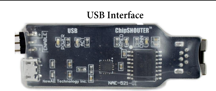
60
Figure 13: USB Interface for ChipSHOUTER
The provided USB to serial interface provides a simple method
of using the ChipSHOUTER, the USB interface is shown in Figure
13. This figure shows the following USB interface features:
1. Isolation provides protection both from ground loops and
potential voltage spikes due to ChipSHOUTER malfunction.
2. LED shows when ChipSHOUTER is connected and powered.
3. LED shows when the ChipSHOUTER is armed.
4. LED shows when the USB cable is present and power is
being supplied to the USB interface from the computer.
5. LED shows when data is being transmitted (TX/RX).
6. Enable/Pulse pin allows you to arm/disarm the Chip-
SHOUTER via GPIO, or send the ‘pulse’ command. This
requires software setup on the ChipSHOUTER to configure
this pin. You can also mount a jumper to arm the Chip-
SHOUTER without the serial command interface.
The USB interface uses a FTDI FT230X chip. To ensure
maximum cross-platform compatibility, the default FTDI
VID/PID has been maintained. Drivers for almost any system


ChipSHOUTER Users Manual: Python API Interface
62
The ChipSHOUTER can be manipulated via python which
allows the device to be incorporated into more complex test
setups. By writing custom python scripts the ChipSHOUTER can
be used in conjunction with the chipwhisperer platform, os-
cilloscopes, and anything else that can be hooked into python.
Below is a usage example for the Python API. For further
examples and full documentation visit
https://github.com/newaetech/ChipSHOUTER and see the Python
API.
from chipshouter import ChipSHOUTER
#Configure ChipSHOUTER connection
cs = ChipSHOUTER("com3")
#Configure ChipSHOUTER pulse settings
cs.pulse.width = 80
cs.pulse.repeat = 1
cs.pulse.deadtime = 10
cs.voltage = 500
#arm and pulse
cs.armed = 1
cs.pulse = 1
#disarm
cs.armed = 0

ChipSHOUTER Users Manual: XY(Z) Table Connection
63
Todo.

ChipSHOUTER Users Manual: Troubleshooting
64
Symptom
Possible Cause
Solution
Arming fails.
• Active fault condi-
tion.
• Check faults via se-
rial port or API.
• Check temperature of
unit.
• Check for toggling
signal on external in-
puts.
Device resets during
use.
• During high-current
discharge, sufficient
noise can cause self-
reset of the device.
• Change voltage set-
tings and/or increase
pulse width.
• Using API to detect
device reset, recover
from fault.
Excessive “sensor
faults” when using
external trigger.
• Insufficient time
for self-checks to
occur between trig-
gers.
• Send “triggersafe”
command before each ex-
ternal trigger event.
• Slow down external
triggers.
Excessive “sensor
faults” when using
external trigger.
--or--
Device disarms dur-
ing use, even though
external trigger
used to pulse de-
vice.
• External trigger
level is insuffi-
cient, causing
triggering of MOSFET
but the system moni-
tor is unaware.
• Confirm level of trig-
ger input. If using 50-
ohm termination tempo-
rarily turn this off to
increase drive level.
Charge fault occurs.
• Power supply is in-
sufficient.
• Use different wall
outlet.
• Replace 19V AC-DC
power supply.

ChipSHOUTER Users Manual: Troubleshooting
65
Symptom
Possible Cause
Solution
Device does not boot
(check serial out-
put).
• Internal FLASH cor-
ruption.
• Perform firmware up-
date/recovery with
unique per-device firm-
ware image.
Odd smells or sounds
from ChipSHOUTER.
• Internal damage
• DISCONTINUE USE OF
DEVICE IMMEDIATELY.
Arcing sound from
injection tip.
• Injection tip not
tight, or injection
damaged.
• Check injection tip
connections with device
disarmed.
• Replace injection tip.
USB interface driv-
ers do not load.
• Drivers are not be-
ing loaded.
• Check FTDI website for
latest VCP drivers.
• Use different USB
port.
Continuous trigger
faults.
• External trigger
pin is being pulled
to active state.
• Check if hardware
trigger is set to active
high or active low.
• Enable 50-ohm termina-
tion with active-high
hardware trigger mode.
ChipSHOUTER goes
into thermal shut-
down.
• Excessive heat due
to continuous opera-
tion.
• Reduce trigger rate.
• Disarm ChipSHOUTER in-
between trigger events.
• Use external air inlet
to improve cooling.
Pattern trigger not
working as expected.
• Pattern trigger
does not match hard-
ware trigger
polarity.
• Probe characteris-
tics mean injected
output does not match
• Check hwtrig_mode is
set active-high.
• Modify pattern trigger
to achieve desired out-
put.

ChipSHOUTER Users Manual: Troubleshooting
66
Symptom
Possible Cause
Solution
the programmed pat-
tern.

ChipSHOUTER Users Manual: Troubleshooting
67
