Cipher_Tape Cipher Tape
User Manual: Cipher_Tape
Open the PDF directly: View PDF ![]() .
.
Page Count: 55
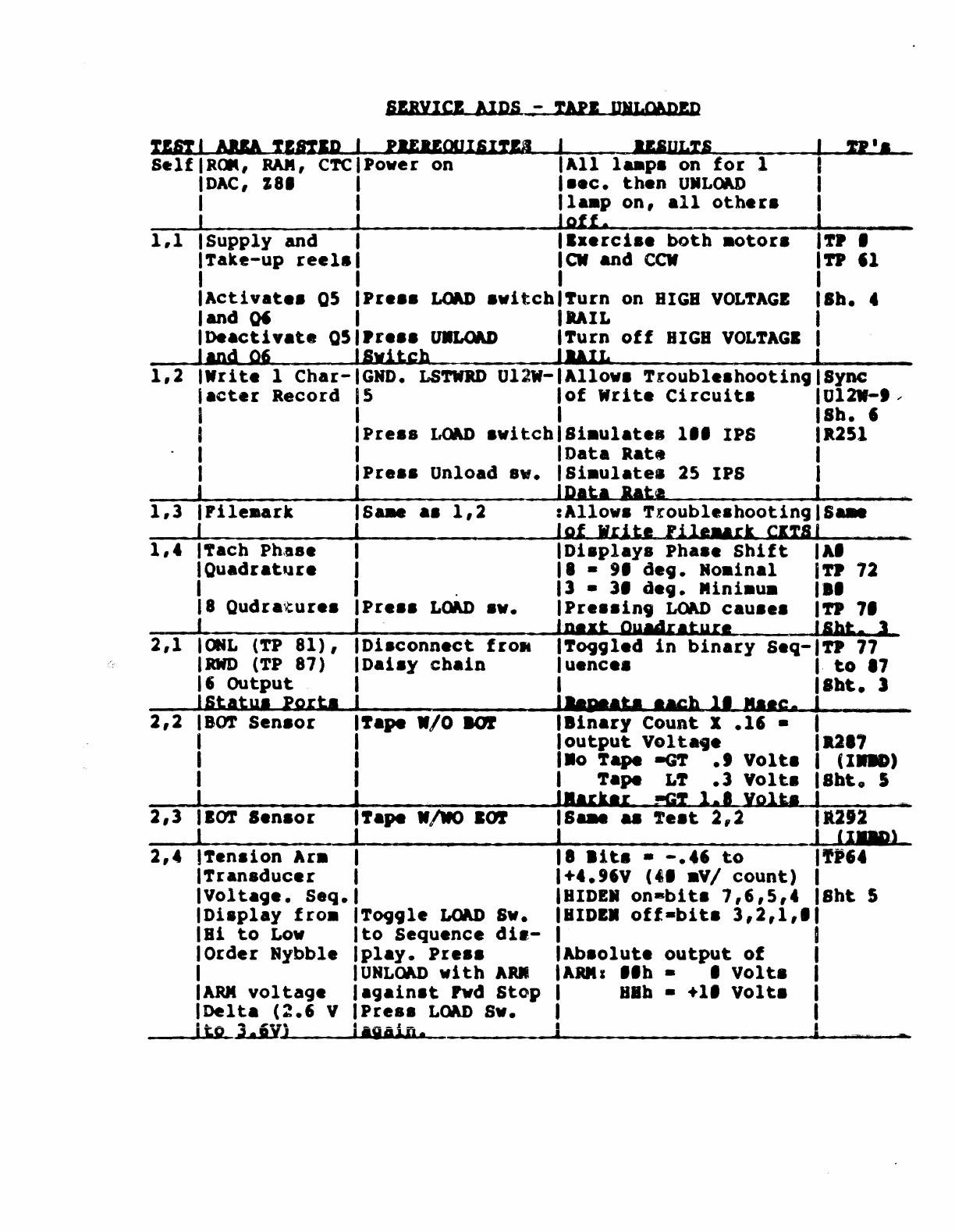
SlRYICI
AlDS -TAli UIL06P1D
TIft
I AlIA
TlnlA
I
PIEUOOIIIUI
SelfiROM,
RAM,
CTCIPover on
IDAC,
18.
I
I I
I I
1,1
ISupply and I
prake-up
reel.
I
II'ULTS
All
l
..
p.
on
for
1
••
e.
then
UMLOlD
la.p
on,
all
other.
Aff.
Ix.rei..
both
.otora
ar
and
CCW
U'.
IActivat
••
Q5
P,
•••
LOAD
.witeh
~urn
on
BIGB
VOL~AGI
land
0'
loeaetiYatft
Q5
JlAd
06
1,2
I_rite
1
Char-
tact.,
Record
I
I
I
I
I
1,3
Irile.ark
I
1,
t
"ach
Ph,sse
Quad,at'l'.
2,1
2,2
2,3
2,4
8
Qudralture.
<»IL
(TP
81),
RWD
(TP
87)
,
Output
Statu.
Port.
BOT
Sen.o,
'fen8ion
Ar.
Transducer
Voltage.
Seq.
Display
fro.
Bi
to
Low
Order
Nybble
ARM
voltage
Delta
(~.6
V
tAIL
.r...
u.LOAD
~urn
off
BIGB
VOL~AGI
Switch
JMIL
GND.
LSTWRD
Ul2W-
Allow.
Trouble.hooting
Sync
Ul2W-'
.-
Sb.
,
5
of
Write
Circuit.
Pre
••
LOAD
.witch
Pre
••
Unload
.v.
Sa..
a.
1,2
Pre
••
LOU)
•••
Di,connect
frolt
Dai.y
cbain
Si.ulate.
1..
IPS
Data
Ratel
ai.ulatell
25
IPS
Data
lAt.
I
.251
Allow.
Tlouble.hootingIS
...
of
Write
'iI'WArk
CITSI
ni.plays
Ph
••
e
Shift
IA'
I -
9.
d.t.
Roainal
ITt
72
1 -
31
de,.
Mini.u.
18'
Pr.aaint
LOAD
cau...
I~
7.
'n,xt
Qyadraturl
ISht.
1
I~oggled
in
binary
Seq-ITP
77
luenc..
I
to
.7
I
Ilbt.
J
'''88
4
&.1
'AGh
1.
"Ie.
I
l-rape
W/O
aor
I
'8inary
Count X
.1'
•
loutput
Velta,e
Il.'
1_0
~ape
-aT
••
Volta
(I.-D)
I
I
J
"ape
-/110
101
Toggle
LaM)
Iv.
to
Sequence
dia-
play.
Pre
••
URL(w)
with
AU
against
Fwd
Stop
Pres.
LaM)
Sw.
I
~ape
L~
.1
Volta
8ht.
5
'ark,r
~!
1.'
Yolta
s...
..
If
••
t
2,2
•
lita
--.t'
to
+t."V
(4'
.VI
count)
HIDE.
on-bits
7,6,5,.
BIOI.
off-bits
3,2,1,.
Absolute
output
of
ARM
I
I.b.
•
Volta
Bab -
+1'
Volta
lt212
'I'M)
Sht
5
____
~t~Q~3.iy~j
____
~.~-g~j.iNn~.~.
________
_4
____________________
~I
________
•
TIft
I
ARIA
TESTED
I
PUUOOISITU
"'OLl' I
U'
••
3,1
Irile
Protect,l.e.l.
lI%
ainl
IReel
S.at.
IBMl'
U%
at
..
-rape 1n
Path
la
..
l •
l'ft
Senaor.
I
1'17,
11
u.LOAD
L
..
p • 1
rla.b,la]'2
) ••
'1
. I
(0U'f""'~
-ID"")
U.LOAD
L
..
p • 2
rla.b-I"
,.
I
e.,
) .1V. I
(laID)
.l%a
'.IV
to
'.1'1
ISbt
5
l'fIP
LOAD
L
..
p
08
•
'.25
tol
I
2·21·
I -
3,2
Bub.
Door
Lock
1 Door.
I
Door.
Clo.ed
lIa.entary
Lock
lIP
7.
own
(»J
LIU
LMP
0Jl
1ft
.75
..•
3.3
Qoor/lnt.r-
IEnt.r
DilgnQ.ti,.'Di'&b11.
InterlKka
I
Irre
••
r~n
.v.
'LOID
LeeR
•
110wer
An
'r27.
PlponlC:
11ft
1,,",11"
-
"'I
LQN)IQ
1,1
IInject
Read
Enter
DiagnoatlclApproa
••
2VPP,
.5
1111
It.
5
IRols.
I
'Ala.
I
1.2
IDisable.
1,1
I J
1,3
IInject
+SV
Bnter
Diagno.tic
IAppro
••
+/-
.2'59
AC
111'.'
(lipp1.
Iligpl.
to
tsync
181&.
I .
1.'
Ini'abl
••
1.~
I I
2,1
la.ad
In.tall
Writ.
ILOAD
•
UMLOAD
L..,-
I"
14
l-rbIe.bold
Inable
Ring
Irla.bin,
Equallr
18ht.
7
I
Adju.t
11
15
J'
1
2,2
IServo
Exer-
IEnter
Diagno.tic
IS.,yo.
25'/111IPI/a.y.llbt
••
..
lei
••
,
Ar.
J
175'/251
••
"',
~~
I
ILi.it
Displayl
l'fen.ioa
•
.ina"
I
J J
Irla.biD,
I
1 I
.,'
JDi.plg
• >5.
lar/lJlD
I
. ;
2,3
,Write
1 BlocklLOAD BV. •
25IP8
IGnd.
L8~
(U12.-5)
-119
••
lor
Reaa 1
IU.LOAD·
11'1
••
IPr.a.bl.,
1
char.,
I
IBlock
if
rP!'
IBID~
•
SPEBD·
IPoata.bl..
I
I ".y.r.. J I
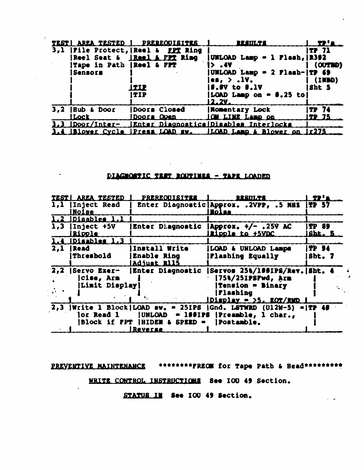
lBIYEl!IYJ IAINTINAlCI
·***··**FRlOI
for
~ape
Path
•
Bead**··*·*·~
WBITE
COtaROL
IlstBUctllll'
S
••
IOU
.,
Section.
8'1"""
II
I
..
100
.,
'.ction.
•
f
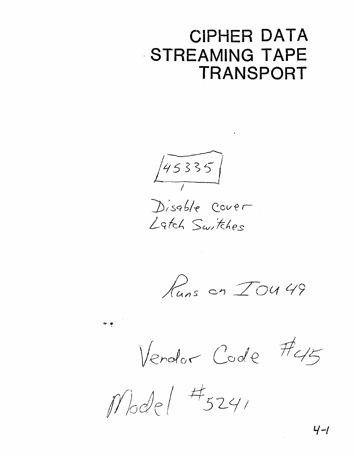
CIPHER DATA
. STREAMING TAPE
TRANSPORT
~,
L~_5_3
S 5 j
I
""j);sc;b!-f
C.o
v€
r-
LctkL.
S't:vl
fc~es
'i
( •
/)
A
-tit""
/L:
Vl2
h
ofor"
Code
IJ
/.{-/
4
$e/Y7
--
VJ<"f.
c;
500
(
D
jUow
35
a
.K~
41
0
r,,(.13
n'
/,
-~J
~'t'
(:-
\
\_>
({l
P
t-
.
c.r€
ur
I v
-('1.0
IA
l...f
9)
£0{/,52-
~/'S(
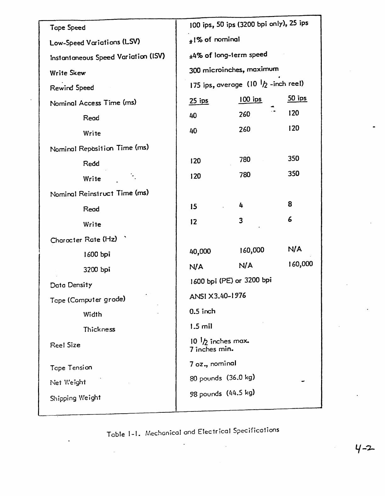
Tope
Speed
Low-Speed
Variations
(LSV)
Ins1an1oneous
Speed
Variation
(lSV)
Write
Skew
Rew
i
rd
Speed
Nominal
Access
Time
(ms)
Read
Write
Nominal
Reposiiion
Time
(ms)
Redd
Write
Nominal
Reins1ruct
Time
(ms)
Read
Write
Character
Rate
(Hz)
..
1600
bpi
3200
bpi
Data
Density
Tape
(Comp.J1er
grade)
Width
Thickness
Reel
Size
Tape
Tension
Net
V:eight
Shipping VJeight
100
ips,
SO
ips
(3200
bpi
only), 25
ips
%1%
of
nominal
:4%
of
long-1erm
speed
300
microinches,
maximum
.
175
ips,
overage
(10
112
-inch
reel)
25 ips
40
40
120
120
15
12
40,000
N/A
100
ips
260
260
780
780
4
3
160,000
N/A
1600
bpi
(pE)
or
3200 bpi
ANSI
X3.40-1976
0.5
inch
105
mil
10
'/2.
inches
max.
7
inches
min.
7
oz.,
nomi
nat
80 pounds (36.0
kg)
98
pounds
(44.5
kg)
SO
ips
120
120
350
350
8
6
N/A
160,000
Table
I-I.
fl~echGn
icaJ
and
Electrical
S;>ecifications
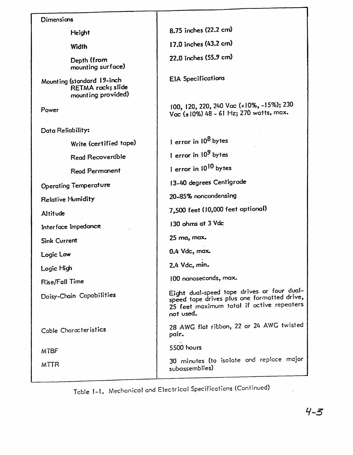
Dimensions
Height
Width
Depth
(from
mounting
surface)
Mount ing
(standard
19-inch
RETMA
rack;
slide
mounting
provided)
Power
Data
Reliability:
Write
(certified
tape)
Read
Recoverable
Read
Perrnment
Operating
Temperature
Relative
Humidity
Altitude
Interface
Impedance,
Sink
Current
Logic
Low
Logic Hig,
Rise/Fall
Time
Daisy-Chain
Capabilities
Cable
Characteristics
MTBF
MTTR
8.75 inches (22.2
cm)
17.0
inches
(43.2
em)
22.0 inches (55.9
cm)
EIA
Specifications
100, 120, 220, 240
Vae
(+10%, -15%); 230
Vac
(:!:IO%) 48 -
61
Hz;
270
watts,
max.
1
error
in
10
8
bytes
I
error
in
10
9
bytes
I
error
in
10
10
bytes
13-40
degrees
Centigrade
20-85% noncondensing
7,500
feet
(10,000
feet
optional)
130
ohms
at
3 Vdc
25
rna,
max.
0.4 Vde,
max.
2.4 V
dc,
min.
100
nanoseconds,
max.
Eight
dual-speed
tape
drives
or
four
dual-
speed
tope
drives
plus
one
formatted
drive,
25
feef
maximum
10tal
if
active
repeaters
nof
used.
28
AWG
fiat
ribbon,
22
or
24
AWG
twisted
pair.
5500 hours
30
minutes
(to
isolate
and
replace
major
subassemblies)
Table
I-I.
fliechanicaJ
and
Electrical
Specifications
(Continued)
4-5
INTRODUCTION
TO
STREAMING
TAPE
OPERATION
Streaming
tape
operation
is simply writing
data
to
tape
without stopping and
starting
between
each
record block.
Interblock
gaps, as required in
the
ANSI
format,
are
inserted
automatically
"on
the
fly". This
concept,
although
not
new, was focused on in
IBM's
Model 8809 in
late
1978. All
tape
drives
currently
being
manufactured
have
the
capability
of
streaming.
So what is
so
special
about
the
Cipher
Model F880
Microstreamer?
It
is
manufactured
specifically
for
streaming
tape
operation
under a design
concept
in which a
severe
design
constraint,
that
of
start/stop
time,
has been
greatly
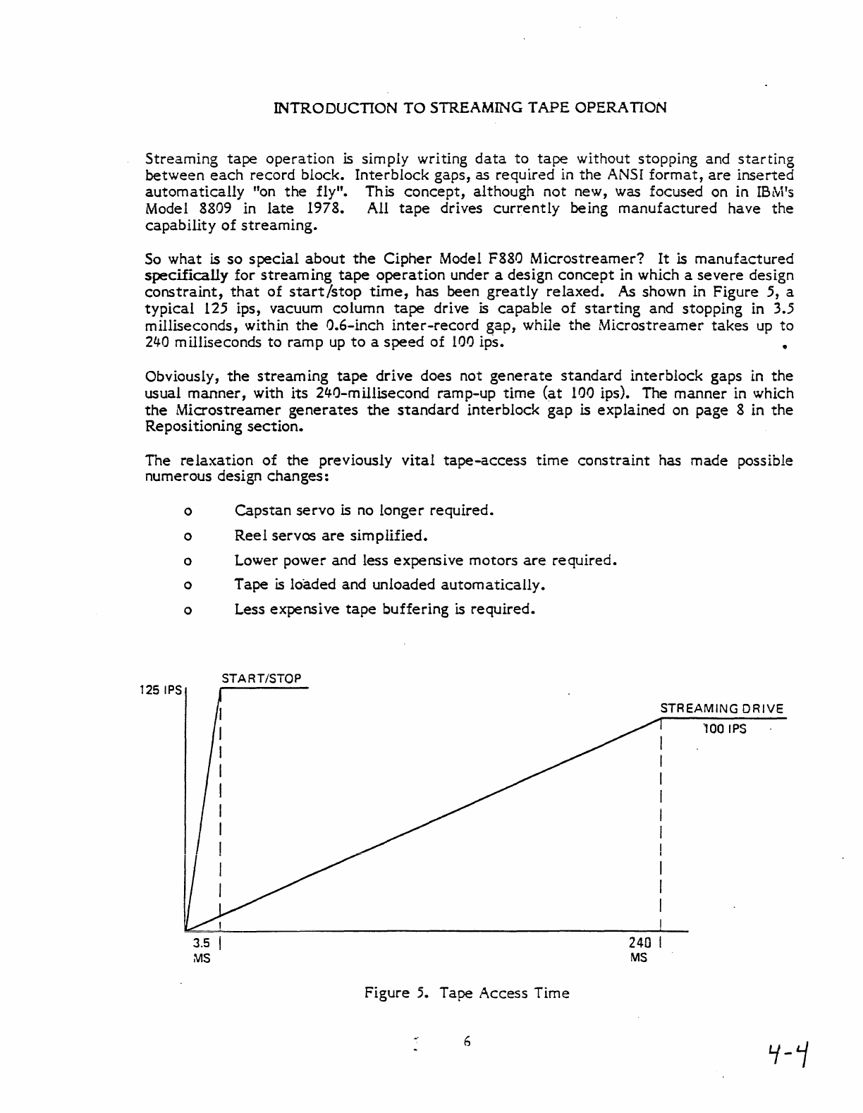
relaxed.
As shown in Figure 5, a
typical
125 ips, vacuum column
tape
drive is
capable
of
starting
and stopping in 3.5
milliseconds, within
the
G.6-inch
inter-record
gap, while
the
Microstreamer
takes
up
to
24-0
milliseconds
to
ramp
up
to
a
speed
of
100
ips. •
Obviously,
the
streaming
tape
drive
does not
generate
standard
interblock
gaps in
the
usual
manner,
with
its
24-0-millisecond ramp-up
time
(at
100 ips). The
manner
in which
the
Microstreamer
generates
the
standard
interblock
gap
is
explained on page 8 in
the
Repositioning
section.
The
relaxation
of
the
previously
vital
tape-access
time
constraint
has
made
possible
numerous design changes:
125
IPS
o
Capstan
servo
is no longer required.
o
Reel
servos
are
simpIlfied.
o Lower power and less expensive motors
are
required.
o Tape
is
loaded and unloaded
automatically.
o Less expensive
tape
buffering
is
required.
3.5
MS
START/STOP
Figure 5. Tape Access Time
6
240
MS
STREAMING
DRIVE
100
IPS
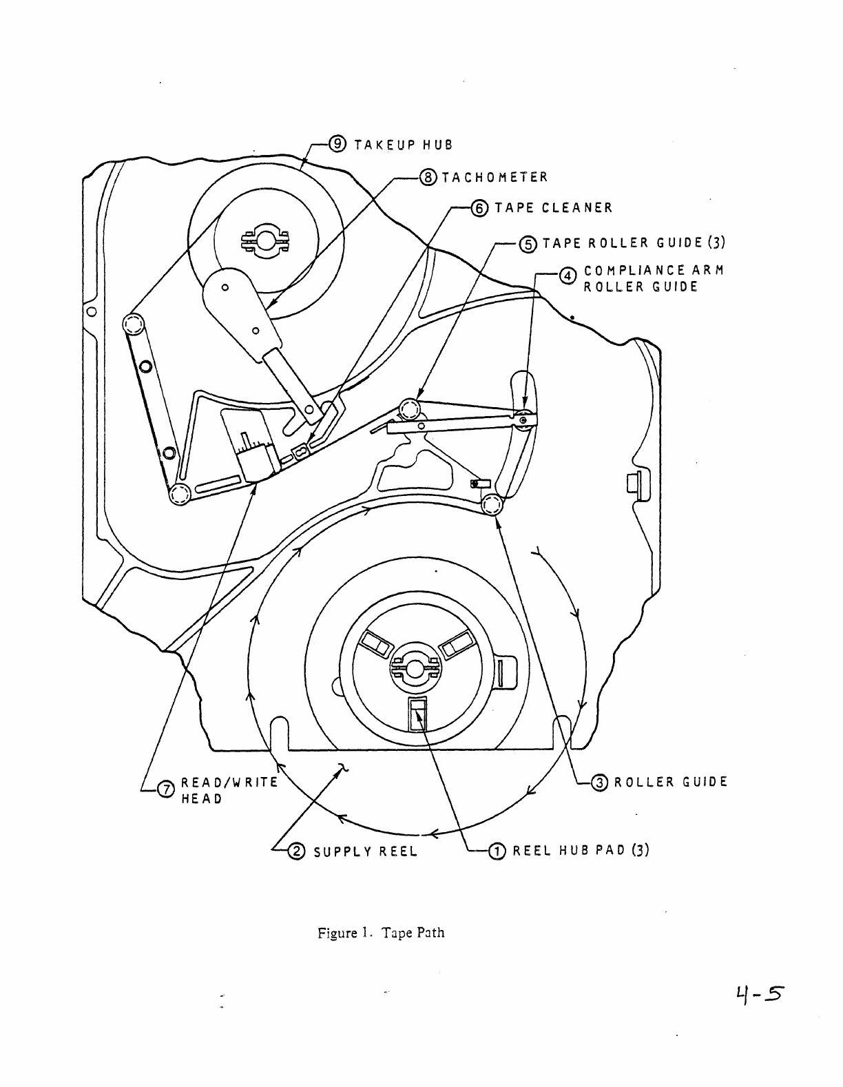
Figure
1.
Tape
P:Jth
TAPE
CLEANER
@TAPE
ROLLER
GUIDE
(3)
o
COMPLIANCE
ARM
ROLLER
GUIDE
LJ-5
I
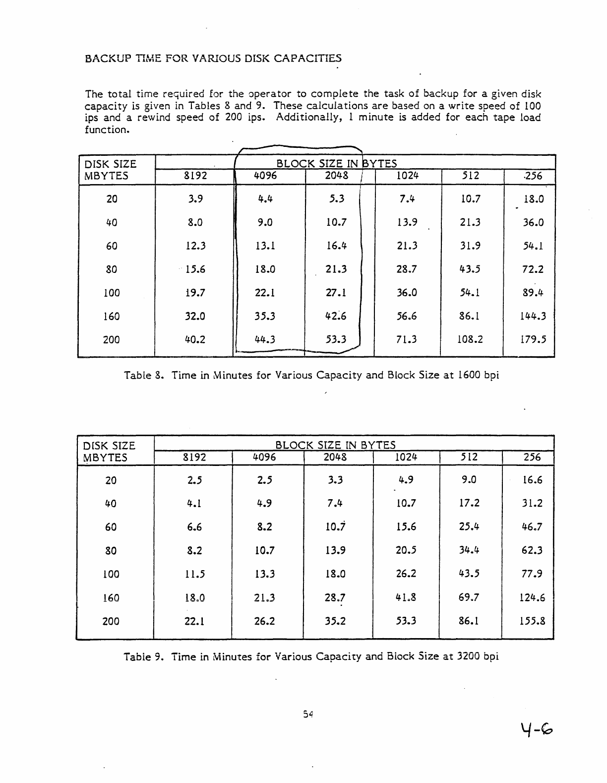
BACKUP
TIME
FOR
VARIOUS DISK
CAPACITIES
The
total
time
rectuired
for
the
aperator
to
complete
the
task
of
backup
for
a
given
disk
capacity
is
given
in
Tables
8
and
9.
These
calculations
are
based
on
a
write
speed
of
100
ips
and
a
rewind
speed
of
200
ips.
Additionally,
1
minute
is
added
for
each
tape
load
function.
-
r-
'"
DISK SIZE I
BLOCK
SIZE
IN BYTES
MBYTES
8192
4096
2048
/ 1024
512
·256
20
3.9
4.4-
5.3
,
7.4
10.7 18.0
.
40
8.0
9.0
10.7
13.9
21.3
36.0
60 12.3 13.1
16.4
21.3
31
..
9 54,,1
80
·15.6
18.0
21.3
28.7
4-3
..
5
72.2
100 19.7 22.1
27.1
36.0
54.1 89.4-
160
32.0
35.3
4-2~6
56
..
6 86.1 14-4.3
200
4-0.2
44.3
53.3
71.3
108.2
179.5
Table
8.
Time
in
Minutes
for
Various
Capacity
and
Block
Size
at
1600 bpi
DISK SIZE
BLOCK
SIZE
IN
BYTES
MBYTES
8192
4096 2048 1024
512
256
20 2
..
5
2.5
3.3
4.9
9.0
16.6
40
4.1
4.9
7.4
10.7
17.2
31.2
60
6.6
8
..
2
10.7
15.6
25.4
46.7
80
8.2
10.7
13.9
20.5
34.4
62.3
100 11.5 13.3
18.0
26.2
43.5
77.9
160
18,,0
2L3
28,,7
4L8
69,,7
124.6
200
22.1
26.2
35.2
53.3
86.1
155.8
Tabie
9.
Time
in
Minutes
for
Various
Capacity
and
Siock
Size
at
3200
bpi
54
y-~
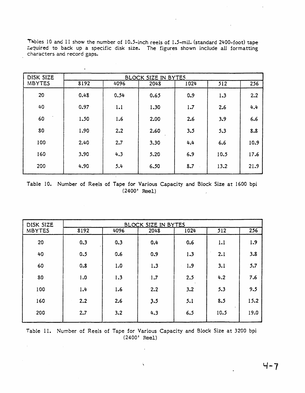
"'~bles
1 0 and
11
show
the
number of 1
0.5-inch
reels
of
1.5-mil.
(standard
2400-foot)
tape
!:cquired
to
back
up a
specific
disk
size.
The
figures
shown include
all
formatting
characters
and
record
gaps.
DISK SIZE BLOCK SIZE
IN
BYTES
MBYTES 8192 4096 2048 1024 512 256
20 0.48 0.54 0.65 0.9 1.3
2~2
40 0.97 1.1 1.30 1.7 2.6 4.4
60 1.50 1.6 2.00 2.6 3.9 6.6
80 1.90 2.2 2.60 3.5 5.3 8.8
100 2.40 2.7 3.30 4.4 6.6 10.9
160 3.90 4.3 5
..
20 6.9 10
..
5 17.6
200 4.90 5.4 6.50 8.7 13.2 21.9
Table
10. Number
of
Reels
of
Tape
for
Various
Capacity
and Block Size
at
1600 bpi
(2400'
Reel)
DISK SIZE BLOCK SIZE
IN
BYTES
MBYTES 8192 4096 2048 1024 512 256
20 0.3 0.3 0.4 0.6
1.1
1.9
40 0.5 0.6 0.9 1.3 2.1 3.8
60 0.8 1.0 1.3 1.9 3.1 5.7
80 1.0 1.3 1.7 2.5 4.2 7.6
100 1.4 1.6 2.2 3.2 5.3 9.5
160 2.2 2.6
~.5
5.1 8.5 15.2
200 2.7 3.2
403
6.5 10.5
19,,0
Table
11. Number
of
Reels
of
Tape
for
Various
Capacity
and Block Size
at
3200 bpi
(2400'
Reel)
'-/-7
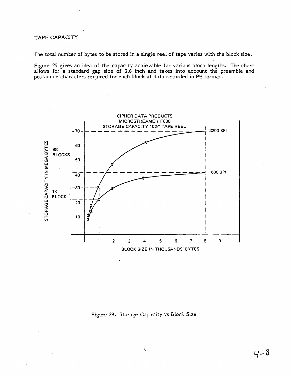
TAPE
CAPACITY
The
total
number of bytes
to
be
stored
in a
single
reel
of
tape
varies with
the
block
size.
Figure
29
gives an
idea
of
the
capacity
achievable
for
various block lengths. The
chart
allows for a
standard
gap
size
of
0.6 inch and
takes
into
account
the
preamble and
postamble
characters
required
for
each
block
of
data
recorded
in PE
format.
en
w
I-
>
CD
«
(!)
w
~
z
>
I-
U
e:(
a..
«
CJ
w
(!)
«
a:::
0
I-
en
CIPHER
DATA
PRODUCTS
MICROSTREAMER
F8aO
STORAGE
CAPACITY
10%"
TAPE REEL
-70-
- -
.-
- -
--
---
--
- - - - - - -
--=...;;;:-----.,
60
8K
BLOCKS 50
40-
-30-
1K {
BLOCK·
__
20
10
2 3 4 5 6 7 8
BLOCK SIZE
IN
THOUSANDS'
BYTES
Figure 29.
Storage
Capacity
vs Block Size
3200
BPI
1600
BPI
9
NOUS
A.
IIIEw
lou
..
MI'lIlacl
..
1I
,
.....
_la
.....
I.
IIIWU
loo.alA'III,,, '.1111
OA
."
..
Ia"h !un'.ldl.
o.
tlIP'"d."
I.
'IP'
'OIlIl~II.lIlnap",.
IN.
hi
.....
fI.pu"uDn
lI.h
.. I
....
'utl"l
'''I11III
COlRmtntl.
FLASH
FRONT
PANEL
LOAD
LIGHT
FLASH
fRONT
PANEL
UNLOAD
LIGHT
SET
UP
TACH
fOR
SHEeTED
SPEED
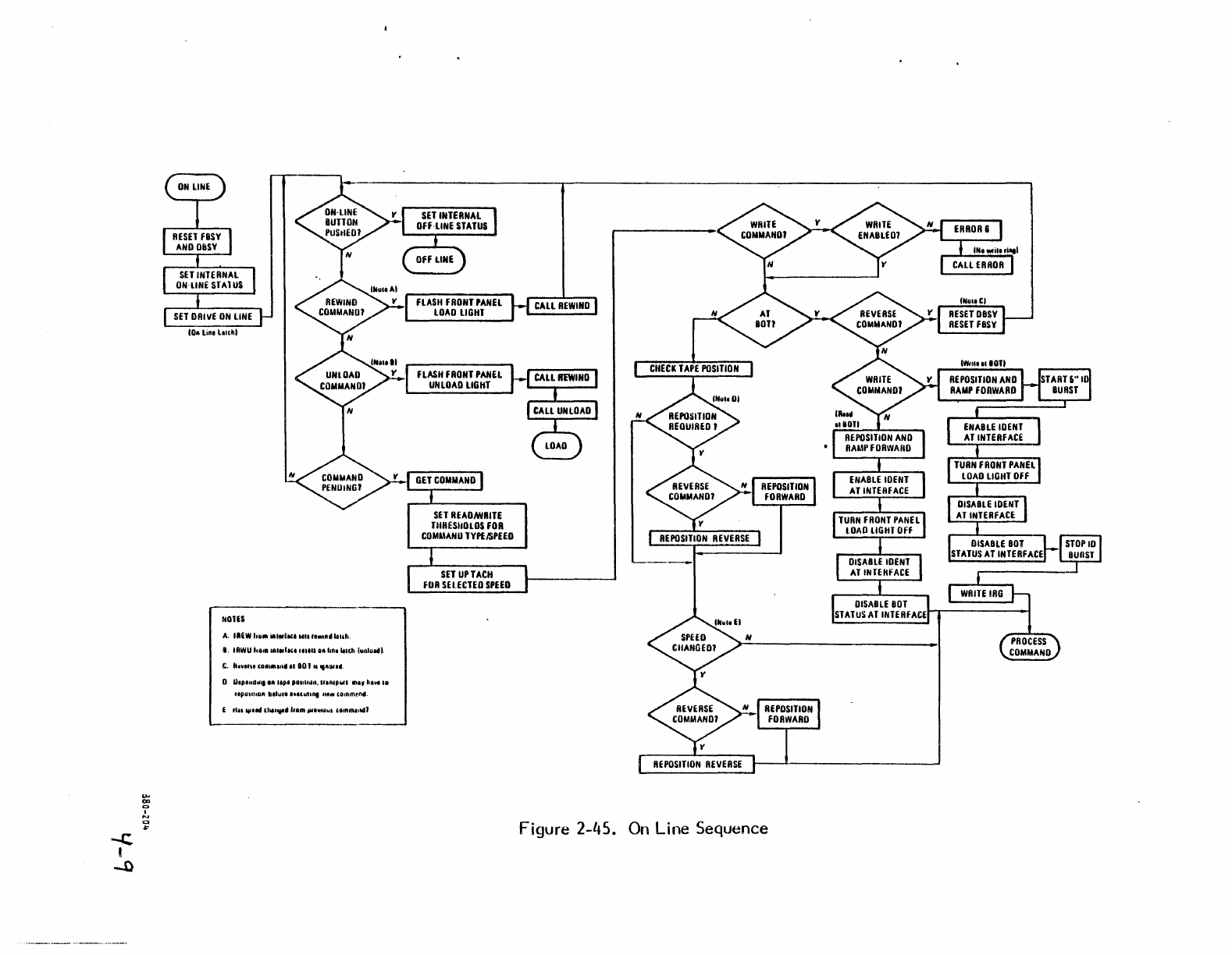
Figure 2-45.
On
Line Sequence
-C
,
-
o
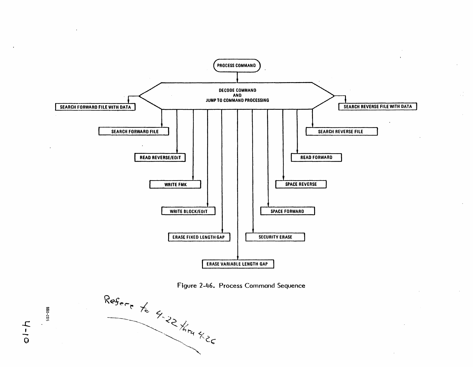
~ROCESS
COMMANO
OECOOE
COMMANO
AND
JUMP
TO
COMMAND
PROCESSING
I
SEARCH
I:ORWARD
FILE
WITH
DATA
I r
SEARCH
REVERSE
FILE
WITH
DATA
I
C
SEARCH
FORWARD
FILE
1 1
SEARCH
REVERSE
FILE
1
r
READ
REVERSE/EDIT
I I
READ
FORWARD
I
I
WRITE
FMK
I
I·
SPACE
REVERSE
I
WRITE
BLOCK/EDIT
I 1
SPACE
FORWARD
I
I
ERASE
FIXED
LENGTH
GAP
J I
SECURITY
ERASE
I
I
ERASE
VARIABl.E
LENGTH
GAP
I
Figure
2-1.6.
Process
Command
Sequence
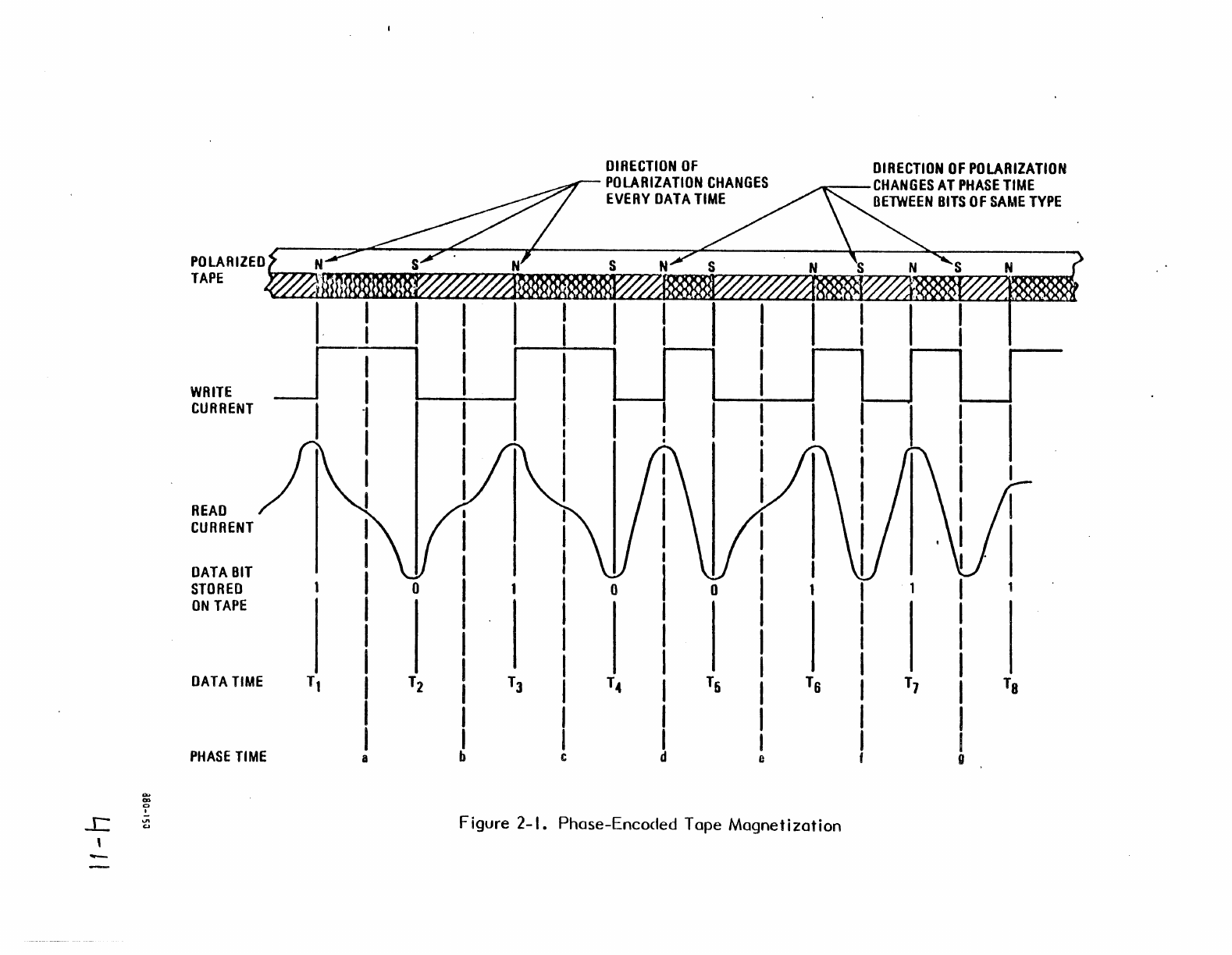
POLARIZED
TAPE
WRITE
CURRENT
READ
CURRENT
DATA
BIT
STORED
ON
TAPE
DATA
TIME
PHASE
TIME
I I
I
SI
I
_I
o
DIRECTION
OF
POLARIZATION
CHANGES
EVERY
DATA
TIME
S
o o
DIRECTION
OF
POLARIZATION
.__--
CHANGES
AT
PHASE
TIME
BETWEEN
BITS
OF
SAME
TYPE
Figure 2-1. Phose-Encoded Tope
Magnetization
0>
-C.
Ol
0
I
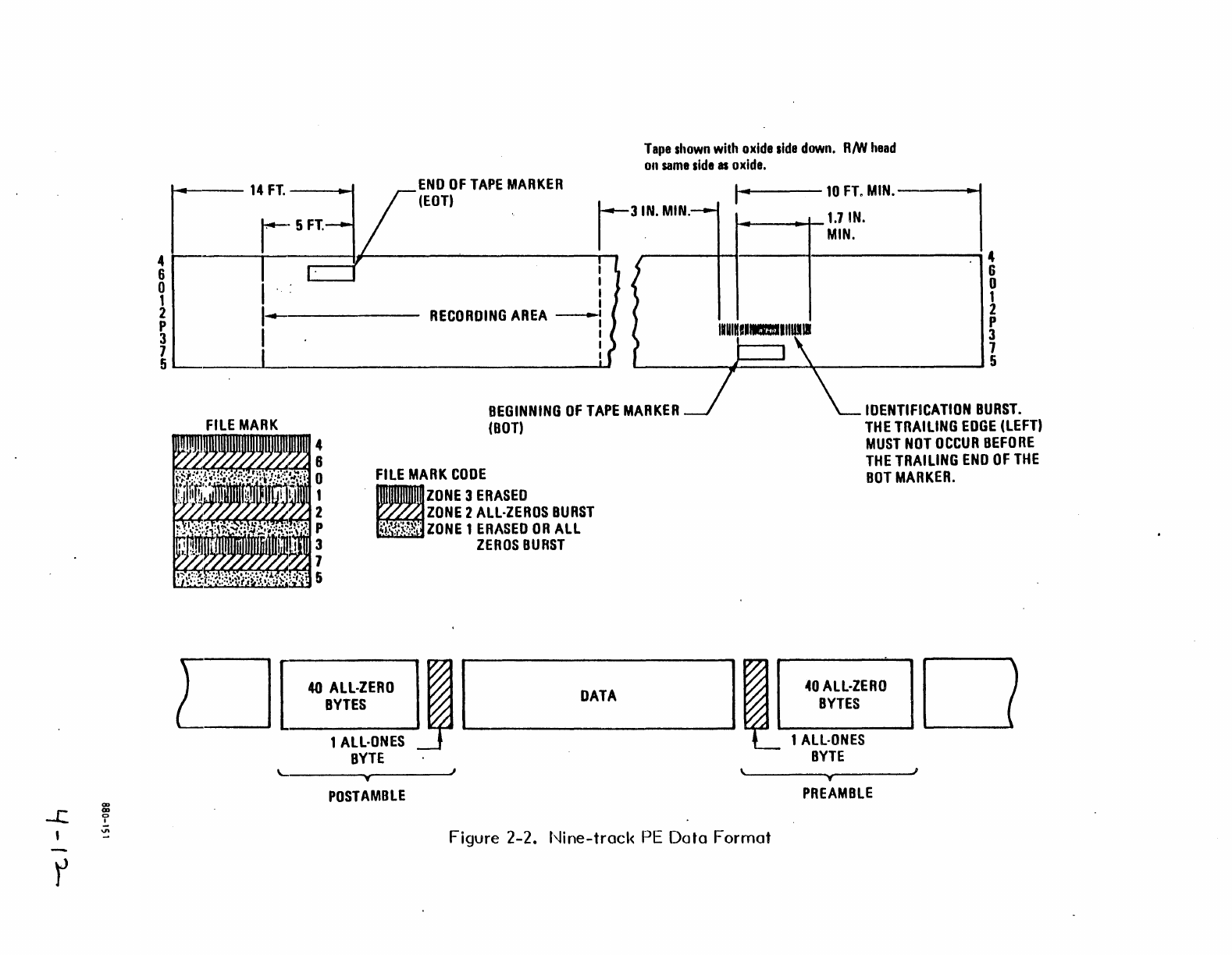
'"
r
Tape
shown
with
oxide
side
down.
RNI
head
on
same
side
as
oxide.
r
14
FT
END
OF
TAPE
MARKER
--.
(EDT)
!-3IN.
MIN.
I·
SFT
. I '
a~------~I---------~·----------~------------~'-
~
I .: i
2
1---,------
RECORDING
AREA
----:
~
I I
10
FT.
MIN'
I
~_--tII-+-1.7
IN.
MIN.
. 4
6
o
1
2
p
IUUIKIIIaIIIIUlII
3
1
~
I :
L-
____
-J==~~
__________
~S
FILE
MARK
D[
'-
BEGINNING
OF
TAPE
MARKER
(OOT)
FILE
MARK
CODE
ZONE
3
ERASED
~~ZONE
2
ALL·ZEROS
OURST
~
ZONE
1
ERASED
OR
ALL
ZEROS
BURST
40
ALL·ZERO
~I
DATA
BYTES
1
ALL·ONES
BYTE
..,
POSTAMBLE
I~
\
Figure 2-2.
Nine-track
PE
Data
Format
IDENTIFICATION
BURST.
THE
TRAILING
EDGE
(LEFT)
MUST
NOT
OCCUR
BEFORE
THE
TRAILING
END
OF
THE
BOT
MARKER.
40
ALL·ZERO
0
BYTES
1
ALL·ONES
BYTE
..,
I
PREAMBLE
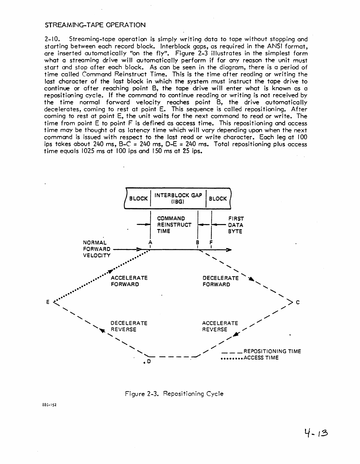
STREAIIIING-TAPE OPERATION
2-10.
Streaming-tape
operation
is
simply
writing
data
to
tape
without
stopping and
starting
between
each
record
block. Interblock
gaps,
as
required
in
the
ANSI
format,
are
inserted
automatically
"on
the
fly".
Figure
2-3
illustrates
in
the
simplest
form
what
a
streaming
drive
will
automatically
perform
if for any reason
the
unit
must
start
and
stop
after
each
block.
As
can
be
seen
in
the
diagram,
there
is a period
of
time
called
Command
Reinstruct
Time.
This is
the
time
after
reading
or
writing
the
lost
character
of
the
last
block in which
the
system
must
instruct
the
tape
drive
to
continue
or
after
reaching
point
B,
the
tape
drive
will
enter
what
is known
as
a
reposition
ing
cycle.
If
the
command
to
continue
reading
or
writing
is
not
received
by
the
time
normal
forward
velocity
reaches
point
B,
the
drive
automatically
decelerates,
coming
to
rest
at
point
E. This
sequence
is
called
repositioning.
After
coming
to
rest
at
point
E,
the
unit
waits
for
the
next
command
to
read
or
write.
The
time
from point E
to
point
F is
defined
as
access
time.
This repositioning and
access
time
may
be
thought
of
as
latency
time
which will vary ciepending upon when
the
next
command
is
issued
with
respect
to
the
last
read
or
write
character.
Each
leg
at
100
ips
takes
about
240
ms,
B-C
= 240 ms, D-E = 240 ms. Total repositioning plus
access
time
equals
1025 ms
at
100 ips
and
150
ms
at
25 ips.
..
E ••
"'-
aaC-i52
BLOCK I
INTER BLOCK GAP I BLOCK
(IBG)
~~~~~~3CT
LjL
~~;I
TIME
I
BYTE
NORMAL
A B F
FORWARD
___
043>>-~
•
.'
______
....;J""III!<:~..;.f_~~.
VELOCITY
••••
••
..
..
..
.,
..
..
" "
......
,
......
."
."
..
•••••
ACCELERATE
•••••
FORWARD
DECELERATE'
"
FORWARD
......
,
..
......
......
......
, DECELERATE
.......
~
REVERSE
......
,
....... .......
.......
'--
----...."",
40
ACCELERATE
//
REVERSE
./
,./¥
,./
,
......
./
./
./
>c
,./
/
___
REPOSITIONING TIME
••••••••
ACCESS
TI
ME
Figure
2-3. Repositioning
Cycle
'-/
...
18
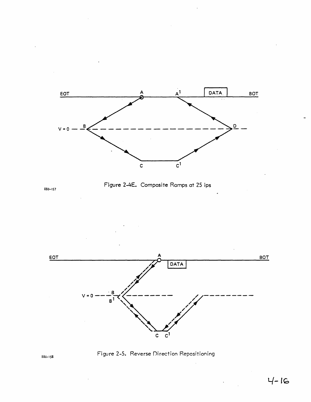
forward
direction
than
in
the
reverse
direction
and
sliqhtly
more
time
is
required
to
accelerate
in
the
reverse
direction
than
in
the
forwa-rd
direction.
This
causes
the
graph
to
become
distorted,
as
shown in
Figure
2-4 E.
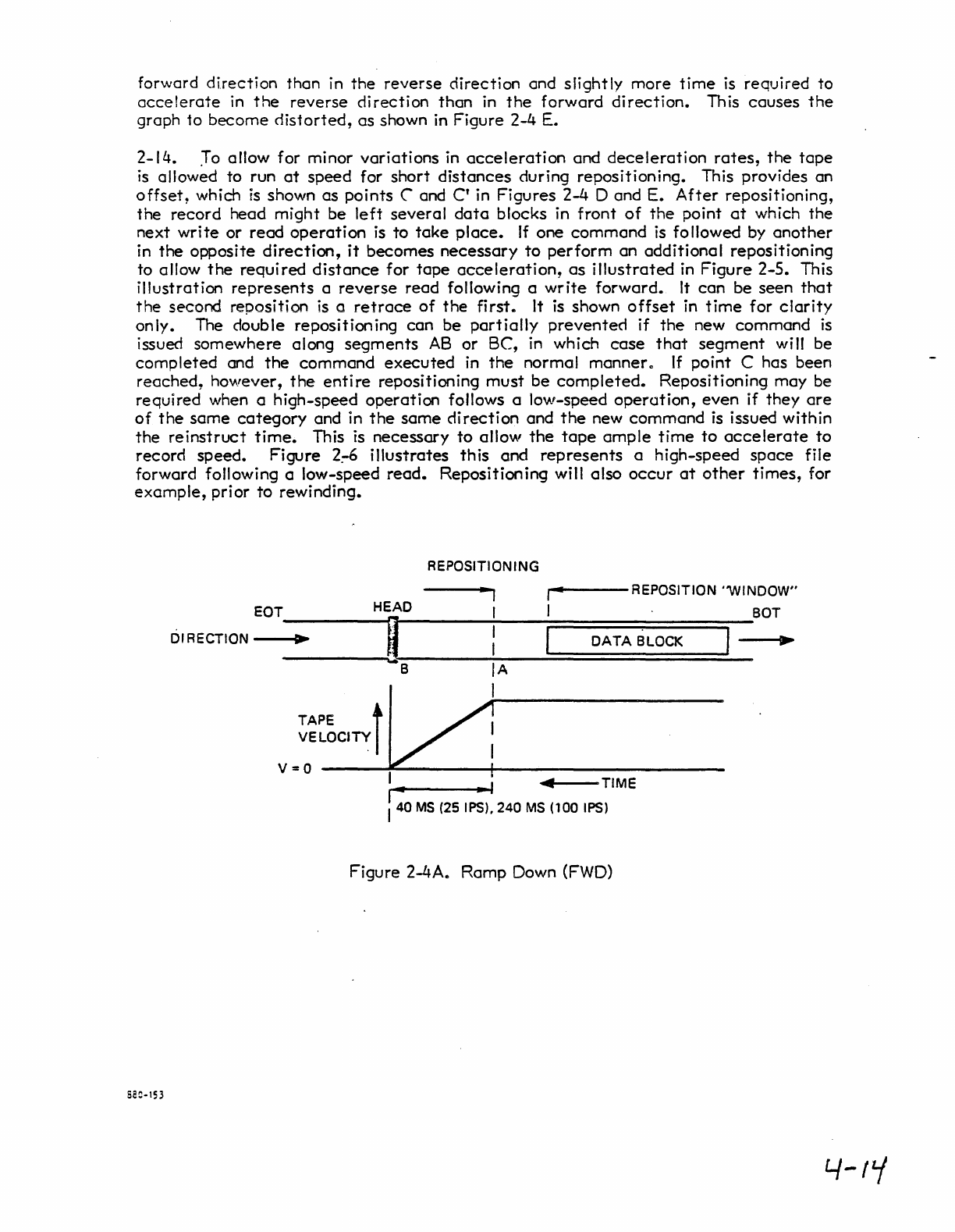
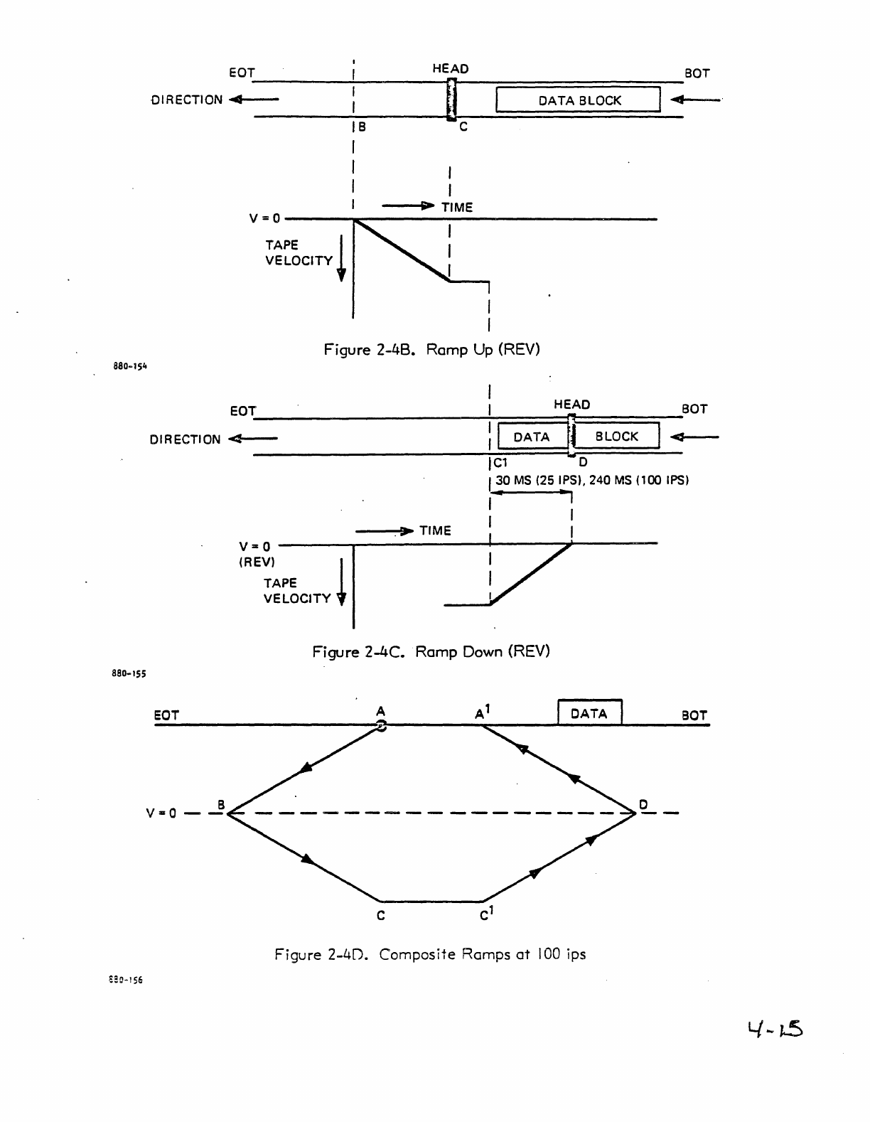
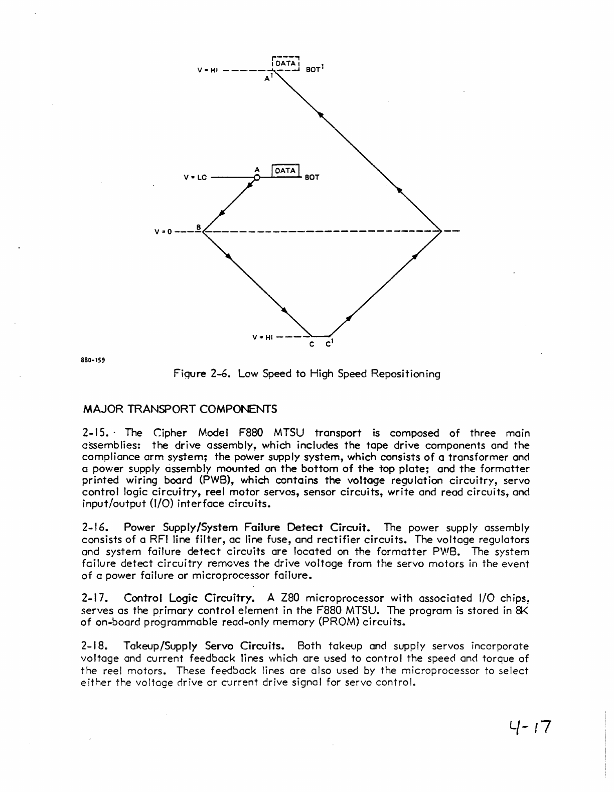
2-14.
:r
0 allow for minor
variations
in
acceleration
and
deceleration
rates,
the
tape
is allowed
to
run
at
speed
for
short
distances
during
repositioning.
This provides an
offset,
which
is
shown
as
points
("
and
C'
in
Figures
2-4 D and E.
After
repositioning,
the
record
head
might
be
left
several
data
blocks in
front
of
the
point
at
which
the
next
write
or
read
operation
is
to
take
place.
If
one
command
is followed by
another
in
the
opposite
direction,
it
becomes
necessary
to
perform
an
additional
repositioning
to allow
the
required
distance
for
tape
acceleration,
as
illustrated
in
Figure
2-5.
This
illustration
represents
a
reverse
read
following a
write
forward.
It
can
be
seen
that
the
second reposition
is
a
retrace
of
the
first.
It is shown
offset
in
time
for
clarity
only. The double repositioning
can
be
partially
prevented
if
the
new
command
is
issued
somewhere
along
segments
AB
or
Be,
in which
case
that
segment
will
be
completed
and
the
command
executed
in
the
normal manner"
If
point
C has been
reached,
however,
the
entire
repositioning
must
be
completed.
Repositioning
may
be
required
when a high-speed
operation
follows a low-speed
operation,
even
if
they
are
of
the
same
category
and in
the
same
direction
and
the
new
command
is issued within
the
reinstruct
time.
This is
necessary
to
allow
the
tape
ample
time
to
accelerate
to
record
speed.
Figure
2:-6
illustrates
this
and
represents
a
high-speed
space
file
forward following a low-speed
read.
Repositioning will
also
occur
at
other
times,
for
example,
prior
to
rewinding.
REPOSITIONING
-I
Figure
2-4Ae
Ramp
Down (FWD)
S20-153
4-1,-/
880-155
EOT
DIRECTION
~"I---
HEAD
BOT
~~~====D=A=TA=B=L=O=CK==~I~~-
IB
I
I
I
C
---I
....
TIME
V=o------~~----------------------------
TAPE
I
VELOCITY
+
Figure
2-48.
Ramp Up (REV)
I
EaT I
HEAD
BOT
DIRECTION
<4~~~------~----------~--t:~I=D=A=T=A~~~~~B=LO=C=K~~~-
----------------------~IC=l====~w~D~====~--
eaT
B
V=Q
--
I 30
MS
(25 IPS)' 240
MS
(100
IPS)
..
..,
I I
I I
----5.
~.
TIME
V = 0
------r--------Io---~~----
(REV)
~
TAPE
VELOCITY
Figure 2-4C. Ramp Down (REV)
Figure
2-4D.
Composite
Ramps
at
100
ips
o
BOT
880-157
EOT
B
V=o
--
EOT
880-158
BOT
o
Figure 2-4E. Composite Ramps
at
25
ips
A
BOT
Figure
2-5.
Reverse
IJirection
Repositioning
L/-
r~
j---'
I
DATAl
V
~
HI
-
----
---'
BOT'
At
Va
LO
----<J~~-
...
880-159
Fiqure
2-6.
Low Speed
to
High Speed Reposition ing
MAJOR TRANSPORT COMPONENTS
2-15.·
The
Cipher
Model F880
MTSU
transport
is
composed
of
three
main
assemblies:
the
drive
assembly,
which includes
the
tape
drive
components
and
the
compliance
arm
system;
the
power supply
system,
which
consists
of
a
transformer
and
a
power
supply
assembly
mounted
on
the
bottom
of
the
top
plate;
and
the
formatter
printed
wiring
board
(PWB), which
contains
the
voltage
regulation
circuitry,
servo
control
logic
circuitry,
reel
motor
servos,
sensor
circuits,
write
and
read
circuits,
and
input/output
(I/O)
interface
circuits.
2-16.
Power
Supply/System
Failure
Detect
Circuit.
The power supply assembly
consists
of
a RFI line
filter,
ac
line fuse, and
rectifier
circuits.
The
voltage
regulators
and
system
failure
detect
circuits
are
located
on
the
formatter
P'NB. The
system
failure
detect
circuitry
removes
the
drive
voltage
from
the
servo
motors
in
the
event
of
a power
failure
or
microprocessor
failure.
2-17.
Control
Logic
Circuitry.
A Z80
microprocessor
with
associated
I/O chips,
serves
as
the
primary
control
element
in
the
F880 MTSU. The
program
is
stored
in
8K
of
on-board
programmable
read-only
memory
(PROM)
circuits.
2-18.
Takeup/Supply Servo
Circuits.
Both
takeup
and supply
servos
incorporate
voltage
and
current
feedback
lines which
are
used
to
control
the
speed and
torque
of
the
reel
motors.
These
feedback
lines
are
also
used by
the
microprocessor
to
select
either
the
voltage
drive or
current
drive signal for
servo
control.
l/-
17
WRITE
COMMAND REVERSE WRITE FILEMARK EDIT ERASE
Read
Forward
0 0 0 0 0
Read
Reverse
1 0 0 0 0
Read
Reverse
Edit 1 0 0 1 0
Write
0 1 0 0 0
Write
Edit
0 1 0 1 0
\Vrite
File
Mark 0 1 1 0 0
Erase
Variable
Length
0 1 0 0 1
Erase
Fixed
Length
0 1 1 a 1
Security
Erase
0 1 1 1 1
Space
Forward
0 0 0 0 1
Space
Reverse
1 0 0 0 1
File
Search
Forward
0 0 1 0 0
File
Search
Forward
0 0 1 0 1
(Ignore
Data)
File
Search
Reverse
1 0 1 0 0
File
Search
Reverse
1 0 1 0 1
(Ignore
Data)
No
Operation
Decode
0 0 0 1 1
3200 bpi* 1 0 1 1 1
1600 bpi (PE)* 0 0 1 1 I
Diagnostic
Routine
0 0 1 1 0
Cycle
Servos
0 0 a 0 0
Exit
Test
22 Any
Command
Read
Logic Margin
Test
1 0 0 0 0
+5
Vcc
Circuit
Margin
Test
0 1 0 0 0
Reset
Margin
Tests
1 1 0 0 0
Extended
Status
0 0 1 0 0
*Microstreamer
2 only
Table
3.
Command
Decoding
y-l
g
IREW
IFEN
IRWU
ITADO
ITAD1
IFAD
IREV
IWRT
IEDIT
IERASE
IWFM
(HISP
-
-
-
-
-
P1
20
P2
P1
46
,.!1
18
I--
~
~
~
42
a-
P2
50
.!l
IGO
ILWO
IW4
rwo
IW1
IWP
IW7
-~
IW3
IW6
IW2
IW5
-
-
-
-
-
-
-
-
-
-
~
6
io-
...!i
..!!.
.B.
~
~
28
r-
~
32
"'--
INTERFACE INPUT
INTERFACE
STATUS
REGISTERS
FSEL i
ADDRESS TRANSPORT
DECODE CONTROL
LOGIC
READ
FORMATTER
I
t ENRD
READ
WRITE
COMMAND
SPACE
DECODE ERASE READIWRITE
SEARCH CONTROL
HI DEN LOGIC
NO·OP
DIAGNOSTIC
ENRO·
•
WRITE
FORMATTER
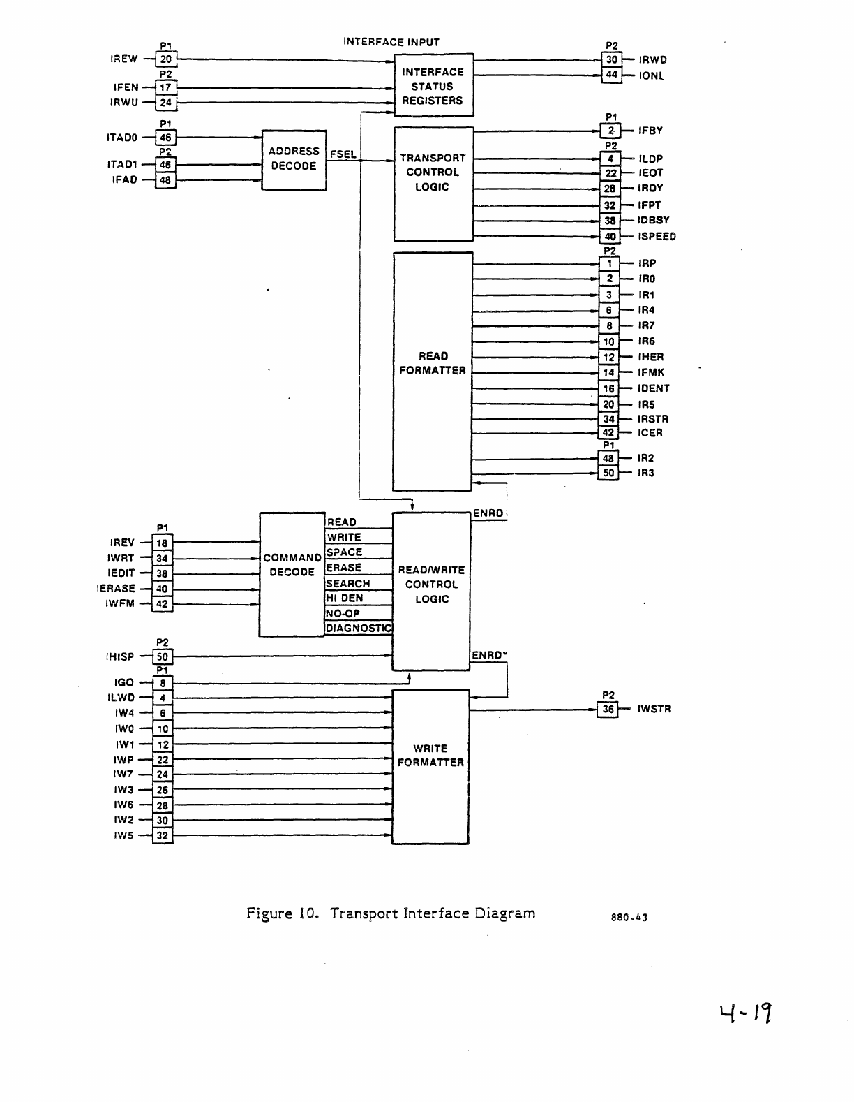
Figure
1
0..
Transport
Interface
Diagram
P2
$
1
!0-
f--
2t--
~
+
!--
!--
~
8~
"'--
10
~
---
~
"-
14
-
-16 -
-
20~
~
34~
~"-
P1
48
50
P2
36
IRWO
IONl
IFBY
ILDP
IEOT
IROY
IFPT
lOSSY
ISPEED
IRP
IRO
IR1
IR4
IR7
IR6
IHER
IFMK
IOENT
IRS
IRSTR
ICER
IR2
IR3
IWSTR
880.43
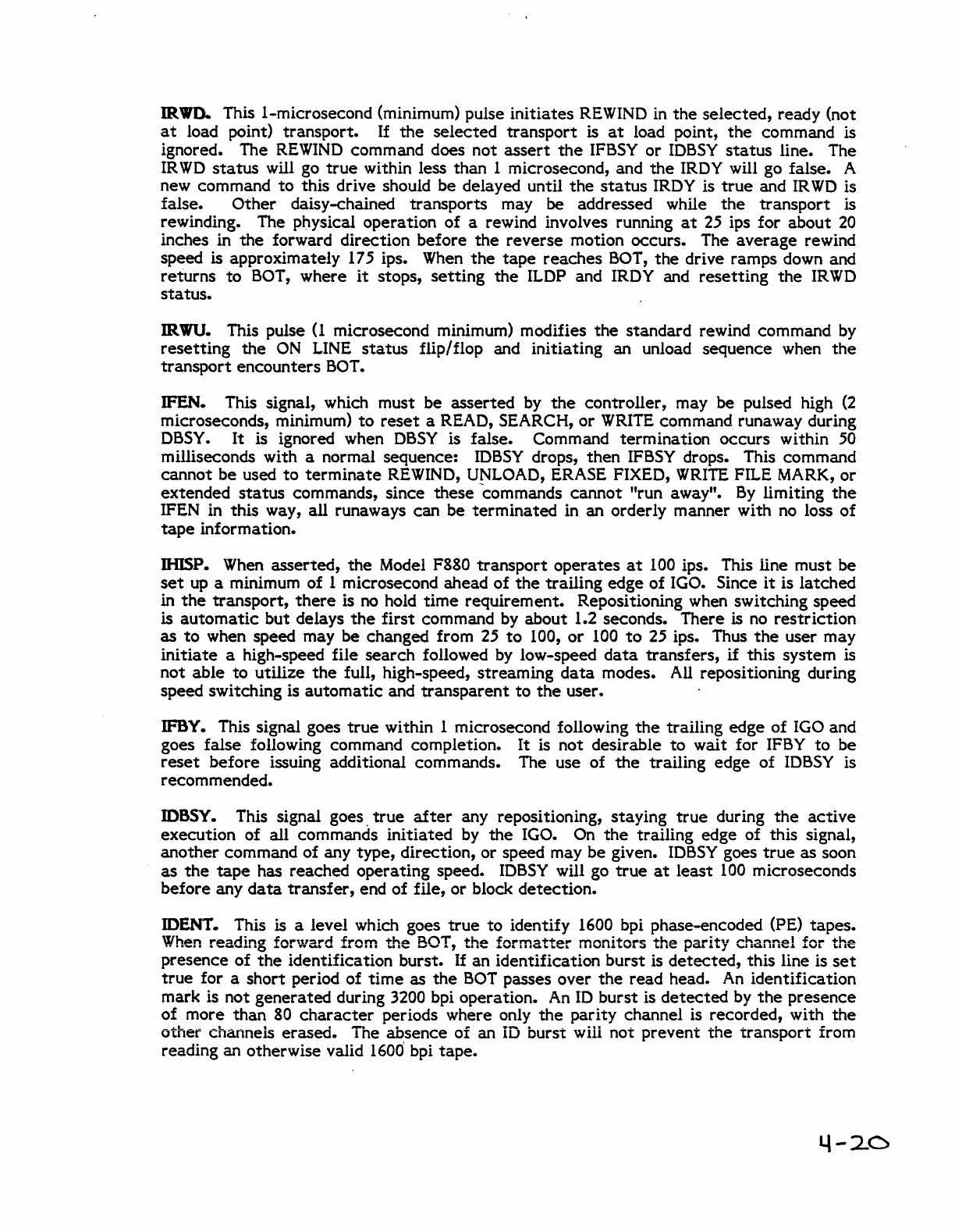
IRWD..
This I-microsecond (minimum) pulse
initiates
REWIND in
the
selected,
ready (not
at
load point)
transport.
If
the
selected
transport
is
at
load point,
the
command is
ignored. The
REWIND
command does
not
assert
the
IFBSY
or
IDBSY
status
line. The
IRWD
status
will go
true
within less
than
1 microsecond, and
the
IRDY will go false. A
new command
to
this drive should
be
delayed until
the
status
IRDY is
true
and
IRWD
is
false.
Other
daisy-chained
transports
may be addressed while
the
transport
is
rewinding. The pl)ysical
operation
of
a rewind involves running
at
25
ips for
about
20
inches in
the
forward
direction
before
the
reverse
motion occurs. The
average
rewind
speed is approximately 175 ips. When
the
tape
reaches
BOT,
the
drive ramps down and
returns
to
BOT,
where
it
stops,
setting
the
ILDP and IRDY and
resetting
the
IRWD
status.
IRWU. This pulse
(I
microsecond minimum) modifies
the
standard
rewind command by
resetting
the
ON
LINE
status
flip/flop and
initiating
an unload
sequence
when
the
transport
encounters
BOT.
IFEN. This signal, which must
be
asserted
by
the
controller,
may be pulsed high
(2
microseconds, minimum)
to
reset
a READ, SEARCH,
or
WRITE
command runaway during
DBSY.
It
is ignored when
DBSY
is false. Command
termination
occurs
within 50
milliseconds with a normal sequence:
IDBSY
drops,
then
IFBSY drops. This command
cannot
be
used
to
terminate
REWIND, UNLOAD, ERASE FIXED,
WRITE
FILE MARK,
or
extended
status
commands, since
these
commands
cannot
"run away".
By
limiting
the
IFEN in this way,
all
runaways
can
be
terminated
in
an
orderly manner with no loss
of
tape
information.
IHISP. When
asserted,
the
Model F880
transport
operates
at
100 ips. This line must
be
set
up a minimum of 1 microsecond ahead
of
the
trailing
edge
of
IGO. Since
it
is
latched
in
the
transport,
there
is
no
hold
time
requirement.
Repositioning when switching speed
is
automatic
but
delays
the
first
command by
about
1.2 seconds.
There
is no
restriction
as
to
when speed may
be
changed from 25
to
100,
or
100
to
25 ips. Thus
the
user
may
initiate
a high-speed file
search
followed by low-speed
data
transfers,
if
this
system
is
not
able
to
utilize
the
full, high-speed,
streaming
data
modes. All repositioning during
speed switching is
automatic
and
transparent
to
the
user.
IFBY. This signal goes
true
within 1 microsecond following
the
trailing edge
of
IGO and
goes
false
following command completion.
It
is
not
desirable
to
wait
for IFBY
to
be
reset
before
issuing additional commands. The use of
the
trailing
edge
of
IDBSY
is
recommended.
lOSSY. This signal goes.
true
after
any repositioning,
staying
true
during
the
active
execution
of all commands
initiated
by
the
IGO. On
the
trailing edge
of
this signal,
another
command of any
type,
direction,
or speed may
be
given.
IDBSY
goes
true
as
soon
as
the
tape
has
reached
operating
speed.
IDBSY
will go
true
at
least
100 microseconds
before
any
data
transfer,
end
of
file,
or
block
detection.
IDENT. This is a level which goes
true
to
identify 1600 bpi phase-encoded (PE)
tapes.
When
reading forward from
the
BOT,
the
formatter
monitors
the
parity
c..'1annel
for
the
presence
of
the
identification
burst.
If an
identification
burst
is
detected,
this line is
set
true
for a
short
period of
time
as
the
BOT
passes over
the
read
head. An
identification
mark is
not
generated
during 3200 bpi operation. An
ID
burst
is
detected
by
the
presence
of
more
than
80
character
periods where only
the
parity
channel is
recorded,
with
the
other
channels
erased.
Tne
absence
of an iD
burst
w iii
not
prevent
the
transport
from
reading an otherwise valid
1600'
bpi
tape.
4-2<:::>
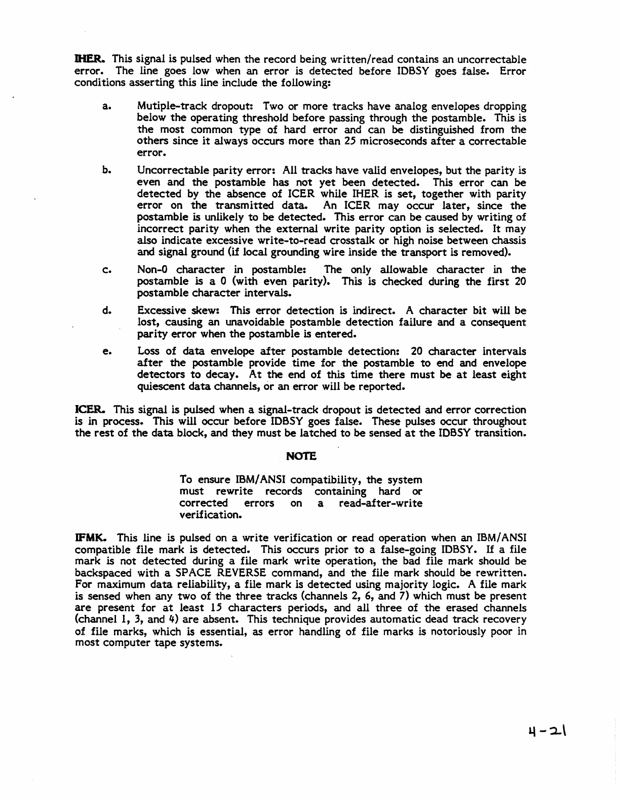
DIER. This signal is pulsed when
the
record being
written/read
contains an uncorrectable
error.
The line goes low when an
error
is
detected
before lOSSY goes false. Error
conditions asserting this line include
the
following:
a. Mutiple-track dropout: Two or more
tracks
have analog envelopes dropping
below
the
operating threshold before passing through
the
postamble. This is
the
most common type
of
hard
error
and can be distinguished from
the
others
since
it
always occurs more
than
25
microseconds
after
a
correctable
error.
b. Uncorrectable
parity
error:
All
tracks
have valid envelopes, but the parity is
even and
the
postamble has not
yet
been
detected.
This
error
can be
detected
by
the
absence of ICER while IHER is
set,
together with parity
error
on
the
transmitted
data.
An
ICER may occur
later,
since
the
postamble is unlikely
to
be
detected.
This
error
can
be caused
by
writing
of
incorrect
parity when
the
external
write parity option is selected.
It
may
also indicate excessive
write-to-read
crosstalk or high noise between chassis
and signal ground
(if
local grounding wire inside
the
transport is removed).
c.
Non-O
character
in postamble: The only allowable
character
in the
postamble is a 0 (with even parity). This is checked during
the
first
20
postamble
character
intervals.
d. Excessive skew: This
error
detection
is indirect. A
character
bit will be
lost, causing an unavoidable postamble
detection
failure and a consequent
parity
error
when
the
postamble is
entered.
e.
Loss
of
data
envelope
after
postamble detection:
20
character
intervals
after
the
postamble provide
time
for
the
postamble
to
end and envelope
detectors
to
decay_
At
the
end
of
this
time
there
must
be
at
least
eight
quiescent
data
channels,
or
an
error
will be reported.
leER.
This signal is pulsed when a signal-track dropout is
detected
and
error
correction
is in process. This will occur before lOSSY goes false. These pulses occur throughout
the
rest
of
the
data
block, and they must
be
latched
to
be
sensed
at
the
lOSSY transition.
NOTE
To
ensure IBM/ANSI compatibility,
the
system
must rewrite records containing hard or
corrected
errors on a
read-after-write
verification.
IFMK. This line is pulsed on a write verification or read operation when an ISM/ANSI
compatible file mark is
detected.
This occurs prior
to
a false-going lOSSY.
If
a file
mark is not
detected
during a file mark write operation,
the
bad file mark should be
backspaced with a SPACE
REVERSE
command, and
the
file mark should be
rewritten.
For maximum
data
reliability, a file mark is
detected
using majority logic. A file mark
is sensed when any two of
the
three
tracks
(channels 2, 6, and 7) which must
be
present
are
present for
at
least
15
characters
periods, and all
three
of
the
erased channels
(channel
I,
3, and
4)
are
absent. This technique provides
automatic
dead
track
recovery
of
file marks, which is essential, as
error
handling of file marks is notoriously poor in
most computer
tape
systems.
IRDY.
This level indicates
that
tape
is tensioned and is not rewinding,
off
line, loading,
or
unloading. In
the
event
of
a hard fault shutdown,
the
drive goes
off
line and not
ready. This line should be used
to
precondition any
tape
drive command.
IONL.
This level indicates
that
transport
on-line flip-flop is
set.
The
transport
may be
placed on line during
or
after
tape
load whenever
the
drive was
off
line. This will
go
false within 1 microsecond
of
the
reception
of
an UNLOAD command.
When
IONL
is
faJse, IRDY will be false.
IRYD.
This level indicates
that
the
transport
is
in rewind
to
beginning
of
tape
sequence. The
status
goes
true
within 1 microsecond
of
the
REWIN
0 command and
stays
true
until
the
tape
returns
to
BOT. IRDY
is
false while
the
drive
is
rewinding.
IFPT. This level indicates
that
the
loaded
reel
has
no
write
permit ring, hence
the
write
electronics
are
disabled, and write commands
are
prohibitedo This
status
goes
true
during
the
tape-load sequence before
the
transport goes ready. This
status
is
valid
at
all
times when
tape
is
loaded. .
D..DP.
This level
is
true
when
the
load-point
reflective
marker is logically
at
the
sensor. Since normal operation
of
the
transport requires long ramps and repositions,
when a command
is
executed
at
BOT,
the
ILDP
status
will remain
true
during
the
repositions. This is especially noticeable
at
100
ips, when ILDP will remain
true
for 0.5
seconds
after
a command.
If
a REVERSE command runs into BOT, a command
reset
occurs with ILDP being
set.
If
an illegal reverse command occurs
at
BOT, ILDP will
remain
true,
but
IFBY
and
IDBSY
will sequence quickly (in less than
10
milliseconds) in
order
to
retain
compatibility with
other
commands.
In
order
to
erase
Model F880
interface
design,
ILDP
goes
true
only
at
the
end of a
REWIND
and
is
not
set
even when
crossed over physically by
the
transport
if
it
is
"repositioning" and is not logically
at
the
BOT
marker.
1E0T.
This level indicates
that
the
end-of-tape marker is
past
the
read/write
head. This
signal will
go
false
either
on a rewind
or
by backing
up
over
the
EOT
marker. This signal
should be considered ac;curate only
to
a few inches.
ISPEED. This signal
is
asserted when
the
transport
is operating in
the
high-speed mode.
It
is valid
after
100
Y goes
true
for
the
associated command and
is
latched until
the
next
IGO
command.
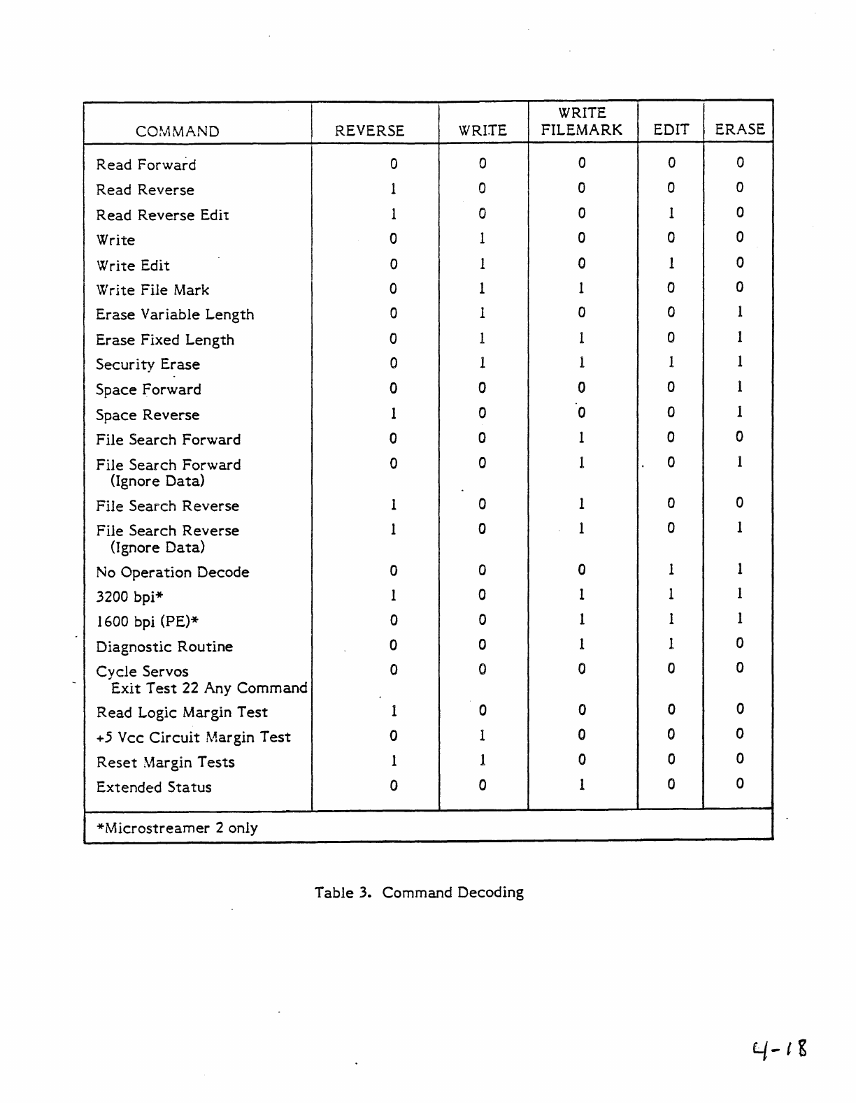
COMMAND DECODE
Basic
transport
commands
are
derived
by
decoding
the
REVERSE,
WRITE,
WRITE
FILE
MARK, EDIT,
and
ERASE
interface
lines.
When
a command
is
issued
to
the
transport
from
the
controller,
the
transport
asserts
the
IFBY line and performs all
timing
and
control functions necessary for
the
execution of
the
command.
The command lines
are
transferred
to
the
command registers on
the
trailing edge
of
the
IGO pulse.
Any
errors occurring during
the
execution of
the
command
are
reported
to
the
controller via
the
IHER
or
leER
interface
lines. Upon completion of
the
command,
the
IDBSY
interface
line goes false, notifying
the
controller
that
it
may issue
another
command. All legal combinations
of
the
interface
lines
are
listed in Table 3. The
interface
lines used for
COfnmaoo
decoding are defined as follows:
4-2"2
a.
REVERSE
(IREV).
This is a level which, when
true,
specifies reverse
tape
motion and when false, specifies forward
tape
motion.
be
WRITE
(IWRT).
This is a level which, when
true,
specifies
the
write mode of
operation and when false, specifies
the
read mode of operation.
c.
WRITE
FILE
MARK
(IWFM).
This is a level which, when
true
and
IWRT
is
also
true,
causes a file mark to be
written
on
the
tape.
d.
EDIT
(IEDIT).
When
this level is
true
and
IWRT
is
true,
the
transport
operates
in
the
edit
mode.
e.
ERASE (IERASE). This is a level which when
true
in conjunction with a
true
level
on
the
IWRT
line, causes
the
transport to
execute
an erase variable
length command. The transport will be conditioned to
execute
a normal
write command but
no
data
will be recorded. A length of
tape,
as
defined by
ILWD,
will be erased. Alternately, if IERASE,
IWRT,
and
IWFM
command
lines
are
true,
the
transport is conditioned
to
execute
a dummy
write
file
mark command. A fixed length of
tape
of approximately 3.75 inches will be
erased.
When
command lines
IWRT,
IWFM,
IEDIT, and IERASE
are
true
the
transport is conditioned to
execute
a security
erase
operation. A length of
tape,
from
the
point where
the
command was issued to 5
feet
beyond EOT,
will be erased.
IGO. This is a guIse with a minimum duration of I microsecond. The trailing edge
initiates
tape
motion
of
the
selected
ready transport, and latches the command into
the
formatting
register. The
formatter
address lines must be held constant from
the
leading
edge
of
IGO
until
IFB
Y goes false.
EXTENDED INTER-RECORD GAPS. During
the
write operation,
if
successive write
commands cannot be issued within
the
normal
reinstruct
times,
the
Microstreamer may
be commanded to continue running forward
at
the
selected
speed and not
enter
a
repositioning cycle. This is accomplished
by
setting
up
the
command lines for a normal
write operation and asserting and holding
the
IGO
interface
signal in
the
true
state
until
data
is available
at
the
interface.
The IRG will be extended to
no
more than 100
inches; otherwise,
the
original gap will reposition automatically.
If
an
IRG
extension
must be cancelled without a new
WRITE
command, a NO-OP command should be placed
on
the
command lines before
IGO
is dropped. This will sequence
IFBY
and
IDBSY
but will
not
generate
a
tape
command.
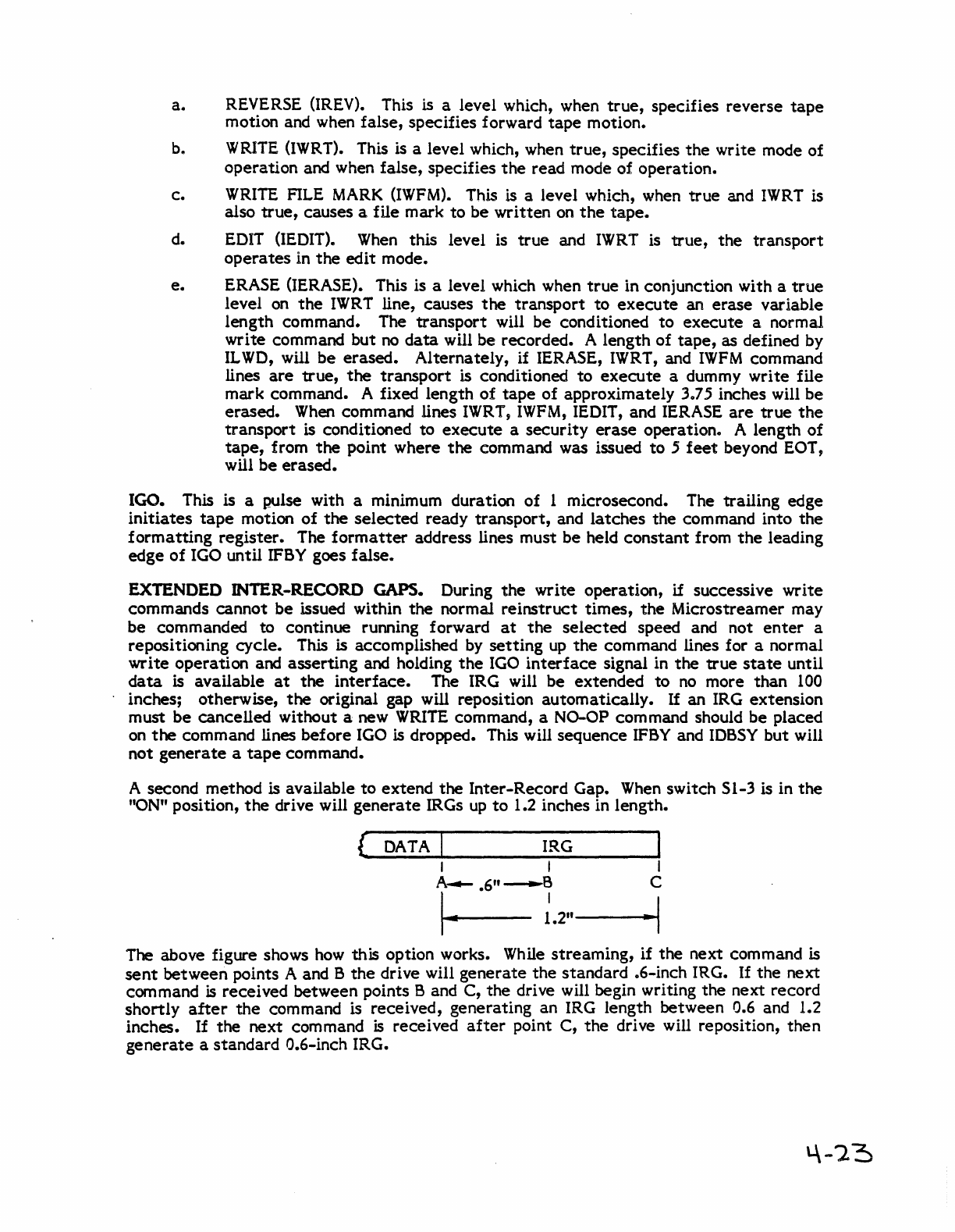
A second method is available
to
extend the Inter-Record Gap.
When
switch SI-3 is in
the
"ON" position,
the
drive will
generate
IRGs
up
to
1.2 inches in length.
(
DATA
I IRG
I I I
r.-
.6";.2"
__
---I·~1
The above figure shows
how
this
option works.
While
streaming, if
the
next command is
sent
between points A and B
the
drive will
generate
the standard .6-inch IRG.
If
the
next
command
is
received between points
Band
C, the drive will begin writing the next record
shortly
after
the
command is received, generating an IRG length between 0.6 and 1.2
inches.
If
the next command
is
received
after
point C,
the
drive will reposition, then
generate
a standard 0.6-inch IRG.
The following
are
the
basic commands
that
can be
executed
by
the
Model F880
tape
transport. These commands
are
strobed by IGO:
READ. The Model F880
tape
transport
reads
data
records
of
file marks in
either
a
forward or reverse direction, generating output
data
(eight lines plus parity) and
data
strobes
to
the controller. A read reverse into load point clears
the
formatter
in
the
same
way as does an IFEN
reset.
A read forward operation will be
terminated
if
it
occurs
more than
15
feet
beyond EOT. This prevents transport operation, which could cause
the
tape
to
run
off
the
end
of
the
supply hub. Recovery threshold
is
automatically lowered
during a read operation in order
to
provide additional reliability. The write threshold
is
approximately
2596,
while
the
read threshold drops
to
10%. The beginning
of
a
data
block
is
detected
by
the
presence
of
two or more
data
channel envelopes which exceed
the
threshold for
15
to
20
consecutive
character
intervals. For purposes of End-of-Block
detection,
the
presence of less
than
two channels for
15
to
20
consecutive
character
intervals generates Gap
Detect
and drops
IDBSY.
During
the
read operation,
error
detection,
data
transfer,
and file mark search occur. These lOSSY lines may be strobed
by
the
trailing edge
of
IDBSY.
They remain valid for
at
least
1 and
no
longer
than
100
microseconds.
SPACE (Forward and Reverse). This operation is identical
to
a standard Read,
except
-
that
Read Strobe and
error
flags
are
not generated.
FILE SEARCH. This signal initiates a space operation in
either
the
forward or
the
reverse direction. The read
data
lines may be
deactivated
during file search operation,
thereby ignoring any
data
that
is
written
on
the
tape.
The File Search command is
terminated
when:
a.
A file mark is encountered.
b. Load point
is
encountered in a reverse direction.
c.
The
formatter
is externally
cleared.
d. The
tape
is
past EOT
by
15
feet
or more.
WRITE
(Forward only). The Microstreamer
tape
transport
starts
tape
and generates
the
proper delay before transferring
the
data
character,
ensuring the generation
of
com patible inter-record gaps.
When
writing from load point,
the
dual-speed
tape
drive
always generates
the
required PE identification burst.
When
lOSSY goes
true,
it
indicates
that
the
first
IWSTR
(write strobe) will occur no sooner than
40
character
intervals
later.
The write operation continues until
ILWD
(Last
Word)
is received
by
the
transport, which indicates
the
last
character
in
the
data
block.
True write operations (not erase)
generate
an
automatic
read verification with
the
signals
activated
as in read commands,
except
that
signal thresholds
are
higher (25%).
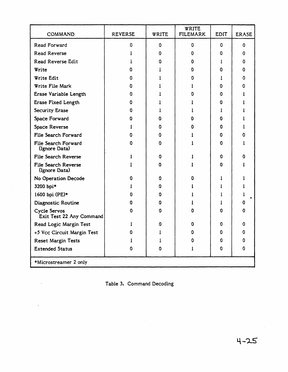
WRITE
COMMAND REVERSE
WRITE
FILEMARK EDIT ERASE
Read Forward 0 0 0 0 0
Read
Reverse
1 0 0 0 0
Read
Reverse
Edit 1 0 0 1 0
Write 0 1 0 0 0
Write Edit 0 1 0 1 0
Write
File
Mark 0 1 1 0 0
Erase
Variable Length 0 1 0 0 1
Erase
Fixed Length 0 1 1 0 1
Security
Erase
0 1 1 1 1
Space Forward 0 0 0 0 1
Space
Reverse
1 0 0 0 1
File
Search
Forward 0 0 1 0 0
File
Search
Forward 0 0 1 0 1
(Ignore Data)
File
Search
Reverse
1 0 1 0 0
File
Search
Reverse
1 0 1 0 1
(Ignore
Data)
No
Operation
Decode 0 0 0 1 1
3200 bpi* 1 0 1 1 1
1600 bpi (PE)* 0 0 1 1 1 .
Diagnostic Routine 0 0 1 1 0
Cycle
Servos 0 0 0 0 0
Exit
Test
22 Any Command
Read Logic Margin
Test
1 0 0 0 0
+5
Vcc
Circuit
Margin
Test
0 1 0 0 0
Reset
Margin
Tests
1 1 0 0 0
Extended
Status
0 0 1 0 0
*Microstreamer
2 only
Table 3. Command Decoding
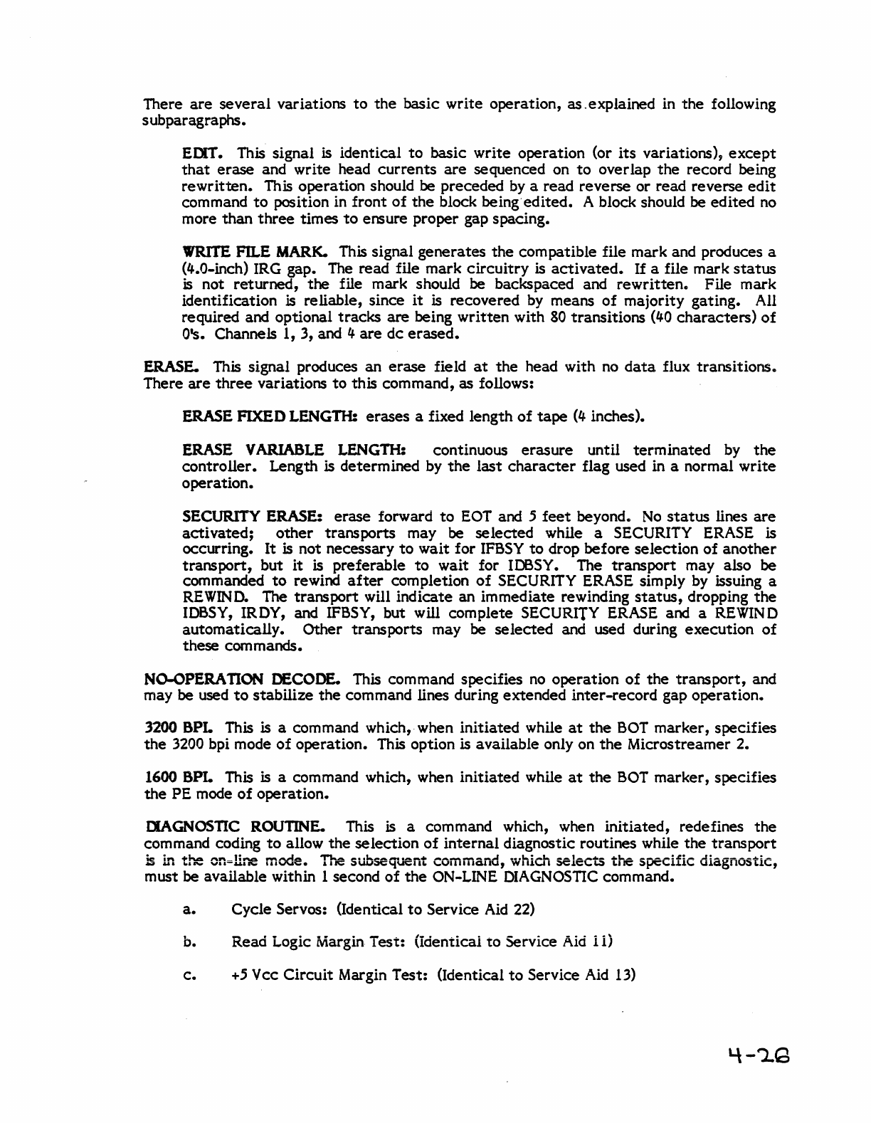
There
are
several
variations
to
the
basic write operation, as . explained in
the
following
subparagraphs.
EDIT. This signal
is
identical
to
basic write operation (or
its
variations),
except
that
erase and write head
currents
are
sequenced on
to
over lap
the
record being
rewritten.
This operation should
be
preceded
by
a read reverse or read reverse
edit
command
to
position in front
of
the
block being'edited. A block should be edited
no
more than
three
times
to
ensure proper gap spacing.
VIRlTE
FILE
MARK.
This signal generates
the
compatible file mark and produces a
(4.0-mch) IRG gap. The read file mark
circuitry
is
activated.
If
a file mark
status
is not returned,
the
file mark should
be
backspaced and
rewritten.
File mark
identification
is
reliable, since
it
is
recovered
by
means
of
majority gating. All
required and optional
tracks
are being
written
with
80
transitions
(40
characters)
of
O's. ChanneJs 1, 3, and 4
are
dc
erased.
ERASE. This signal produces an
erase
field
at
the
head with no
data
flux transitions.
There
are
three
variations
to
this command,
as
follows:
ERASE FIXED LENGTH: erases a fixed length
of
tape
(4
inches).
ERASE V ARIABLE LENGTH: continuous erasure until
terminated
by
the
controller. Length is determined
by
the
last
character
flag used in a normal
write
operation.
SECURITY ERASE: erase forward
to
EOT
and 5
feet
beyond.
No
status
lines
are
activated;
other
transports may be selected while a SECURITY ERASE is
occurring.
It
is not necessary
to
wait for
IFBSY
to
drop before selection
of
another
transport, but
it
is preferable
to
wait for IDBSY. The transport may also be
commanded
to
rewind
after
completion
of
SECURITY ERASE simply
by
issuing a
REWIND.
The transport will indicate an immediate rewinding
status,
dropping
the
IDBSY,
IRDY, and IFBSY, but will complete SECURITY ERASE and a REWIND
automatically. Other transports may be
selected
and used during execution
of
these com mands.
NO-OPERA
nON
DECODE. This command specifies
no
operation
of
the
transport,
and
may be used
to
stabilize
the
command lines during extended inter-record gap operation.
3200 BPL This is a command which,· when initiated while
at
the
BOT
marker, specifies
the
3200 bpi mode
of
operation. This option is available only on
the
Microstreamer 2.
1600
BPL
This is a command which, when initiated while
at
the
BOT
marker, specifies
the
PE mode
of
operation.
DIAGNOSTIC
ROUTINE.
This is a command which, when initiated, redefines
the
command coding
to
allow
the
selection
of
internal diagnostic routines while
the
transport
~
L.,
the
cn=line mode.
Tr.e
subsequent command, which
seleCts
tr.e specific diagnostic,
must be available within 1 second
of
the
ON-LINE
DIAGNOSTIC
command.
a.
Cycle Servos: (Identical
to
Service
Aid
22)
b. Read Logic Margin Test: (identicai
to
Service
Aid
i
i)
c.
+5
Vcc Circuit Margin Test: (Identical
to
Service
Aid
13)
d.
Reset
Margin
Tests:
(Identical
to
Service Aid
12)
e.
Extended
Status:
The
transport
will
output
128 bytes
of
information
in
the
form
of
256
nybbles (half-bytes) with
the
low nybble
of
each
byte
first.
The
user
must
pack
the
nybbles
to
restore
the
byte
information.
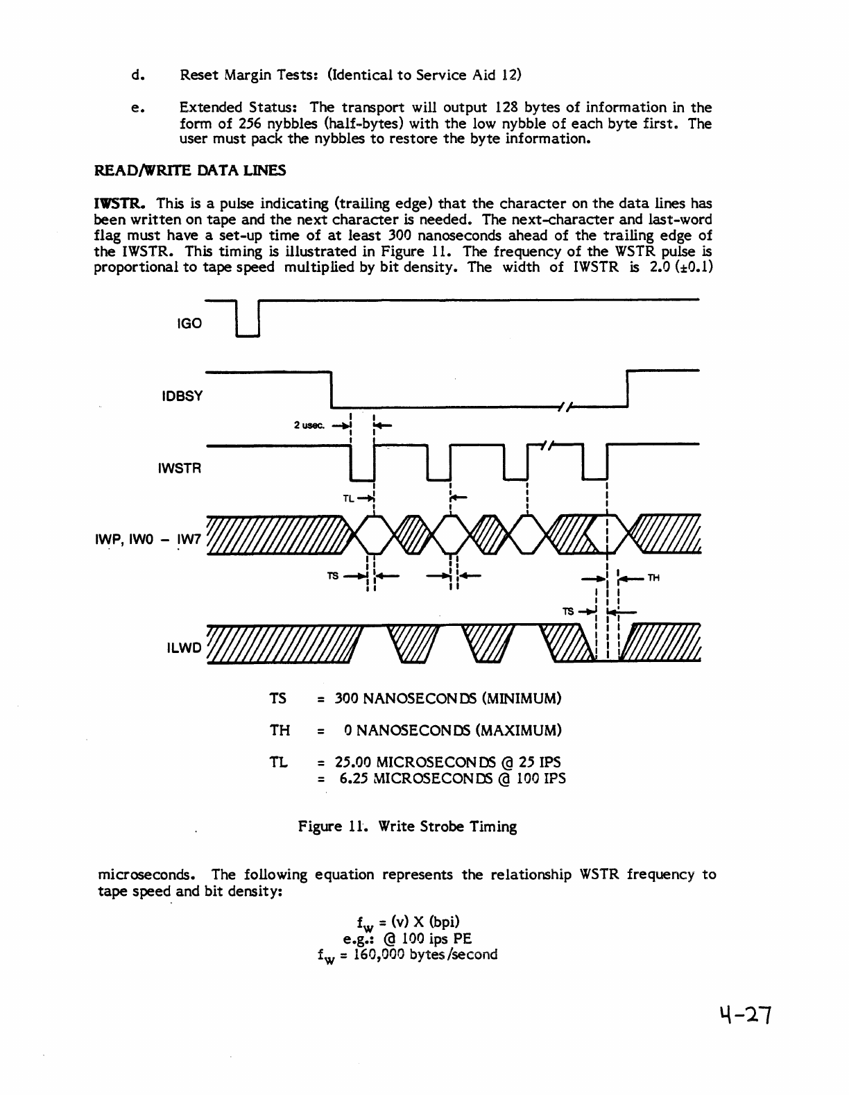
READI\VRITE DATA LINES
IWSTR. This is a pulse indicating (trailing edge)
that
the
character
on
the
data
lines has
been
written
on
tape
and
the
next
character
is needed. The
next-character
and last-word
flag
must
have a
set-up
time
of
at
least
300 nanoseconds ahead
of
the
trailing
edge
of
the
IWSTR. This timing is
illustrated
in Figure 11. The frequency
of
the
WSTR
pulse is
proportional
to
tape
speed multiplied by
bit
density. The width
of
IWSTR
is
2.0
(:1:0.1)
IGOU
IOBSY
~----------------------~/,~'-----
IWSTR
ILWD
,.;////////!/
o/IJ
TS
= 300 NANOSECONDS
(MINIMUM)
TH = 0 NANOSECONDS
(MAXIMUM)
TL
= 25.00 MICROSECON
OS
@ 25 IPS
= 6.25 MICROSECONDS @
100
IPS
Figure
11".
Write Strobe Timing
microseconds. The following
equation
represents
the
relationship
WSTR
frequency
to
tape
speed and
bit
density:
fw = (v) X (bpi)
e.g.:
@
100
ips PE
.c
,
L'
n
nl'\n
b'"
I
-d
loW
=
J.O·J,·Jij'J
YLes,seCon
4-21
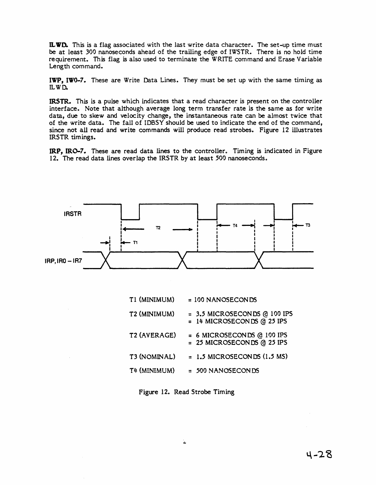
awn. This is a flag
associated
with
the
last
write
data
character.
The
set-up
time
must
be
at
least
300 nanoseconds
ahead
of
the
trailing
edge
of
IWSTR.
There
is no hold
time
requirement.
This flag
is
also
used
to
terminate
the
WRITE command and
Erase
Variable
Length
command.
IWP, 1'1'0-7. These
are
Write
Data
Lines. They
must
be
set
up with
the
same
timing
as
ILWD.
IRSTR. This is a pulse which
indicates
that
a
read
character
is
present
on
the
controller
interface.
Note
that
although
average
long
term
transfer
rate
is
the
same
as
for
write
data,
due
to
skew
and
velocity
change,
the
instantaneous
rate
can
be
almost
twice
that
of
the
write
data.
The
fall
of
lOSSY should be used
to
indicate
the
end
of
the
command,
since
not
all
read
and
write
commands will
produce
read
strobes.
Figure
12
illustrates
IRSTR
timings.
IRP,
1R0-7. These
are
read
data
lines
to
the
controller.. Timing is
indicated
in
Figure
12. The
read
data
lines
overlap
the
IRSTR by
at
least
500 nanoseconds"
IRSTR
I I I I
I
1.-
T4
I
~T3
I
T2
~
~
I c • I I
I I I I
I I I I I
I
I.-n
I I I I
...
-I I I I
I I I I I
I I -X
I I
IRP,IRO-IR7
=ox
X I
T 1 (MINIMUM) = 100 NANOSECONDS
T2 (MINIMUM) = 3.5 MICROSECON
DS
@ 100 IPS
= I", MICROSECONDS @ 25 IPS
T2 (AVERAGE) = 6 MICROSECONDS @ 100 IPS
= 25 MICROSECONDS @ 25 IPS
T3
(N
OMIN
AL) = 1.5 MICROSECONDS
0.5
MS)
T4
(MINIMUM) -
500
NANOSECONDS
Figure
12.
Read
Strobe
Timing
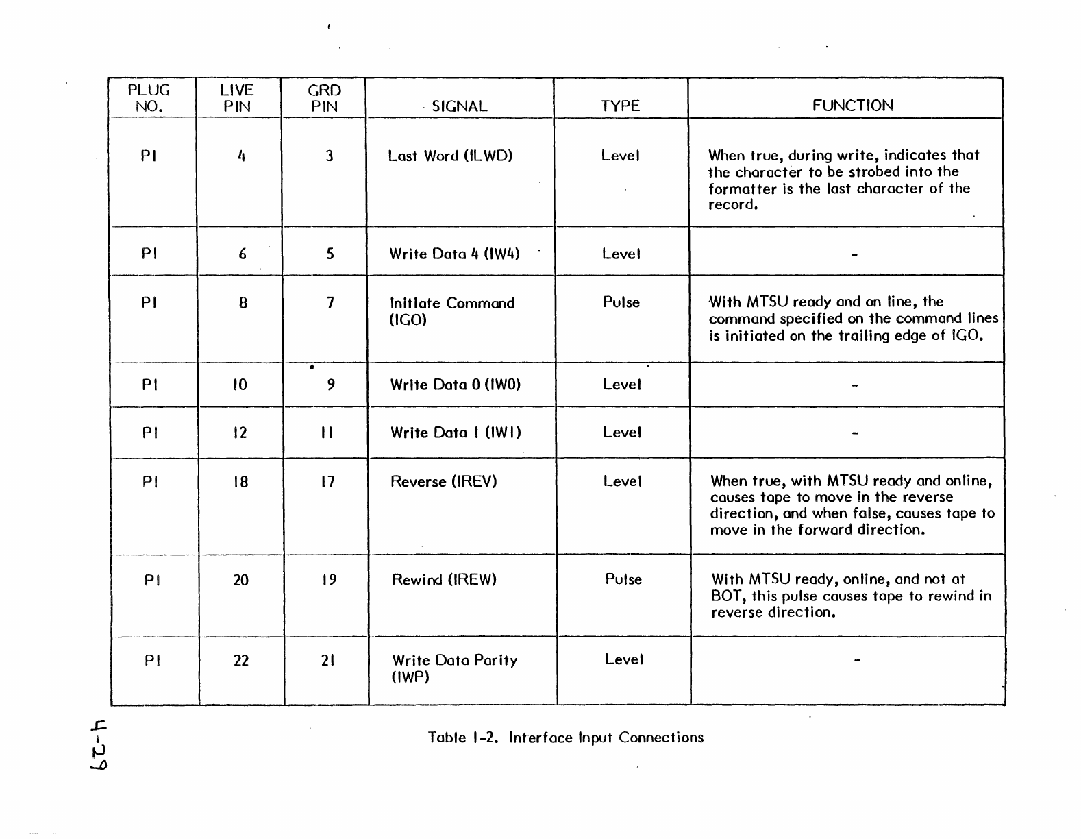
PLUG LIVE GRD
NO. PIN PIN . SIGNAL TYPE FUNCTION
PI I, 3
Last
Word (lLWD) Level When
true,
during
write,
indicates
that
the
character
to
be
strobed
into
the
formatter
is
the
last
character
of
the
record.
PI 6 5 Write
Data
4 (lW4) Level -
PI B 7
Initiate
Command
Pulse
·With
MTSU
ready
and on line,
the
(lGO)
command
specified
on
the
command
lines
is
initiated
on
the
trailing
edge
of
IGO
•
•
PI
10
9 Write
Data
0
(lWO)
Level -
PI
12
II
Write
Data
1
(lW
I ) Level -
PI
IB
17
Reverse
(tREV) Level When
true,
with
MTSU
ready
and online,
causes
tape
to
move
in
the
reverse
direction,
and when folse,
causes
tape
to
move
in
the
forward
di
rection.
1---
PI 20
19
Rewind (lREW) Pulse With
MTSU
ready,
online,
and not
at
BOT,
this
pulse
causes
tape
to
rewind in
reverse
direction.
PI
22
21
Write
Data
Parity
Level -
(lWP)
Table
1-2.
Interface
Input
Connections
J:.
,
lJI
o
PLUG
NO.
PI
PI
PI
PI
PI
PI
PI
PI
P2
LIVE GRD
PIN PIN
24
23
26
25
28
27
30 29
32
31
34 33
40 . 39
42
41
18
17
SIGNAL TYPE FUNCTION
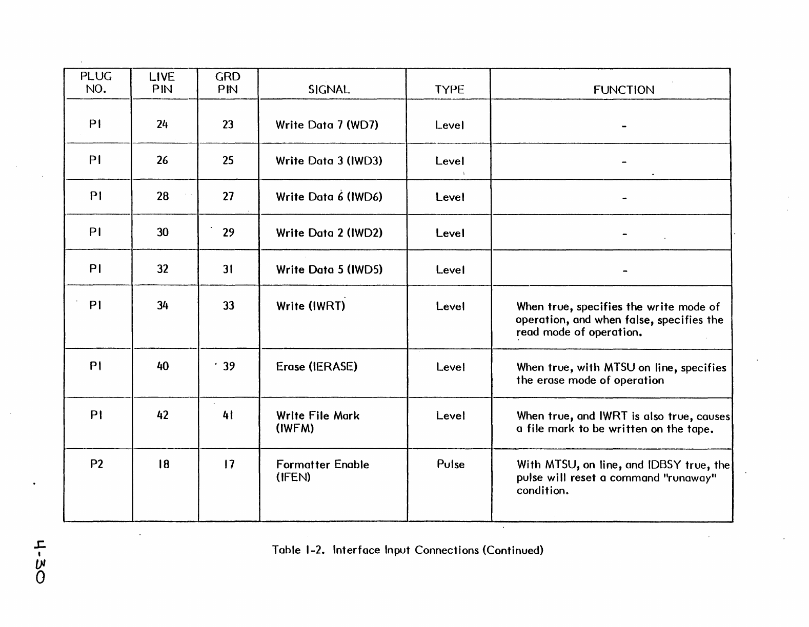
Write
Data
7 (WD7) Level -
Write
Data
3 (tWD3) Level -
\
Write
Data
6 (tWD6) Level -
Write
Data
2 (tWD2) Level -
Write
Data
5 (tWOS) Level -
Write (lWRT) Level When
true,
specifies
the
write
mode
of
operation,
and when folse,
specifies
the
~ead
mode
of
operation.
Erose
(lERASE) Level When
true,
with
MTSU
on line,
specifies
the
erose
mode
of
operation
Write Fi Ie Mark Level When
true,
and
IWRT
is
also
true,
causes
(lWFM) a file
mark
to
be
written
on
the
tope.
Formatter
Enable
Pulse
With MTSU, on line, and
IDBSY
true,
the
(lFEN) pulse
wi
II
reset
a
command
"runaway"
condition.
Table
1-2.
Interface
Input
Connections
(Continued)
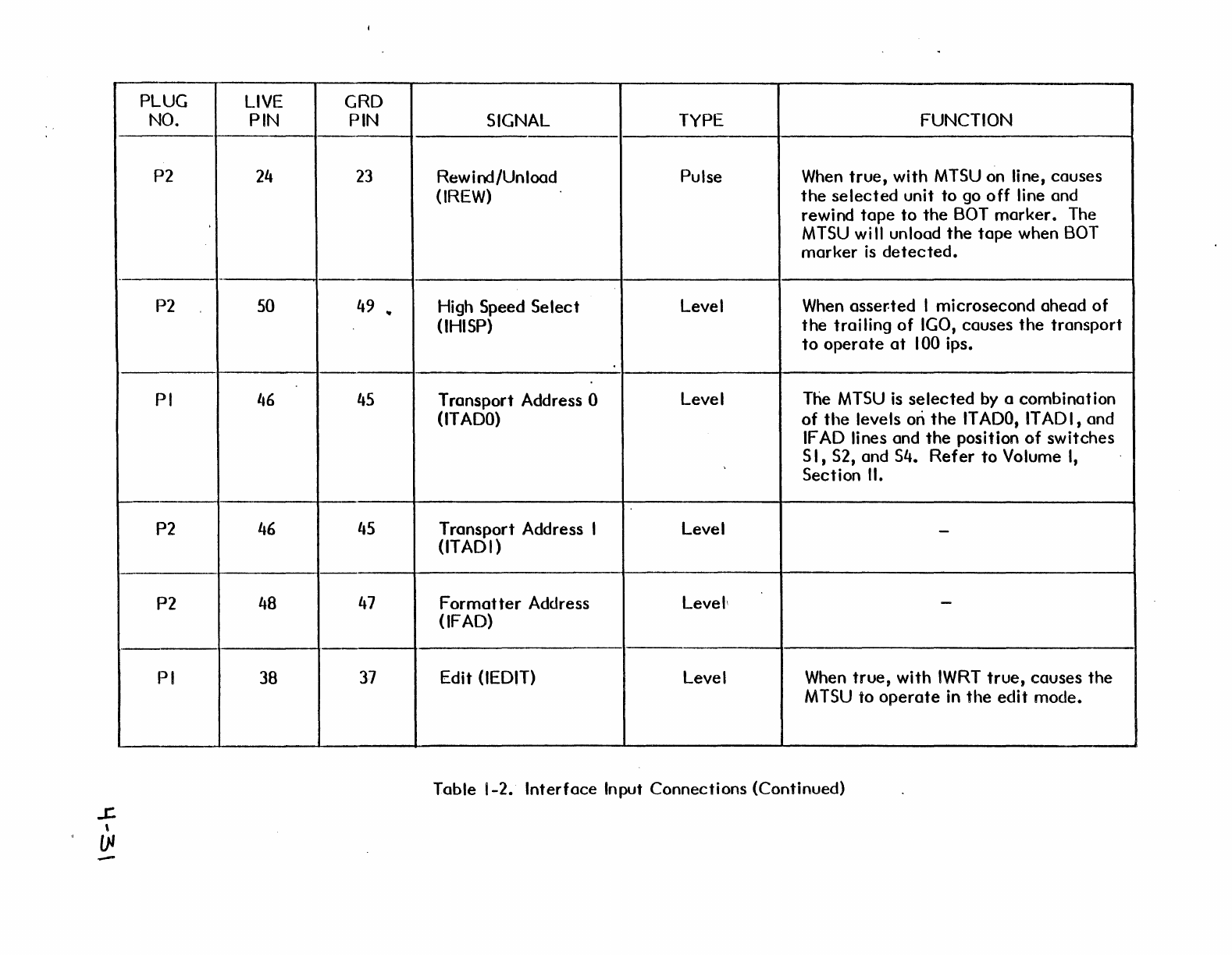
PLUG
LIVE
GRD
NO. PIN PIN SIGNAL
TYPE
FUNCTION
P2
24
23
Rew i nd/Un load Pulse When
true,
with
MTSU
on line,
causes
(IREW)
the
selected
unit
to
go
off
line and
rewind
tape
to
the
BOT
marker.
The
MTSU
will unload
the
tape
when BOT
marker
is
detected.
-
P2 50 49
..
High Speed
Select
Level When asser-ted I microsecond ahead
of
(lHISP)
the
trailing
of
IGO, causes
the
transport
to
operate
at
100
ips.
PI
46
45
Transport Address 0 Level The
MTSU
is
selected
by a combination
(lTADO)
of
the
levels on
the
IT
ADO,
IT
AD
I, and
IF
AD
lines and
the
position
of
switches
5 I, 52, and 54.
Refer
to
Volume
I,
Section
II.
-"
P2
46
45
Transport Address I Level -
(lTADI)
P2 48
47
Format
ter
Address Levell -
(IF AD)
PI 38
37
Edit (lEOIT) Level When
true,
with
IWRT
true,
causes
the
M
TSU
to
operate
in
the
edit
mode.
Table 1-2.
Interface
Input Connections (Continued)
-
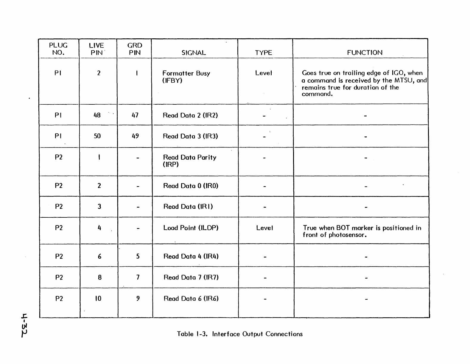
PLUG LIVE GRD
NO.
PIN'
PIN SIGNAL TYPE FUNCTION
-----
PI 2 I
Formatter
Busy Level Goes
true
on
trailing
edge
of
IGO, when
(lFBY) a
command
is
received
by
the
MTSU, and
remains
true
for
duration
of
the
commande
-
PI 48
47
Read
Data
2 (lR2) --
PI 50 49 Read
Data
3 (lR3) --
-
P2 I -
Read
Data
Parity
--
(IRP)
P2 2 -
Read
Data
0 (lRO) --
P2 3 -Read
Data
(IR I ) --
P2 4 -Load
Point
(lLDP) Level True when BOT
marker
is
positioned in
front
0 f photosensor.
P2 6 5 Read
Dato
4 (lR4) --
P2 8 7 Read
Dota
7 (lR7) - -
P2
10
9 Reod Doto 6 (lR6) --
Tobie 1-3.
Interfoce
Output
Connections
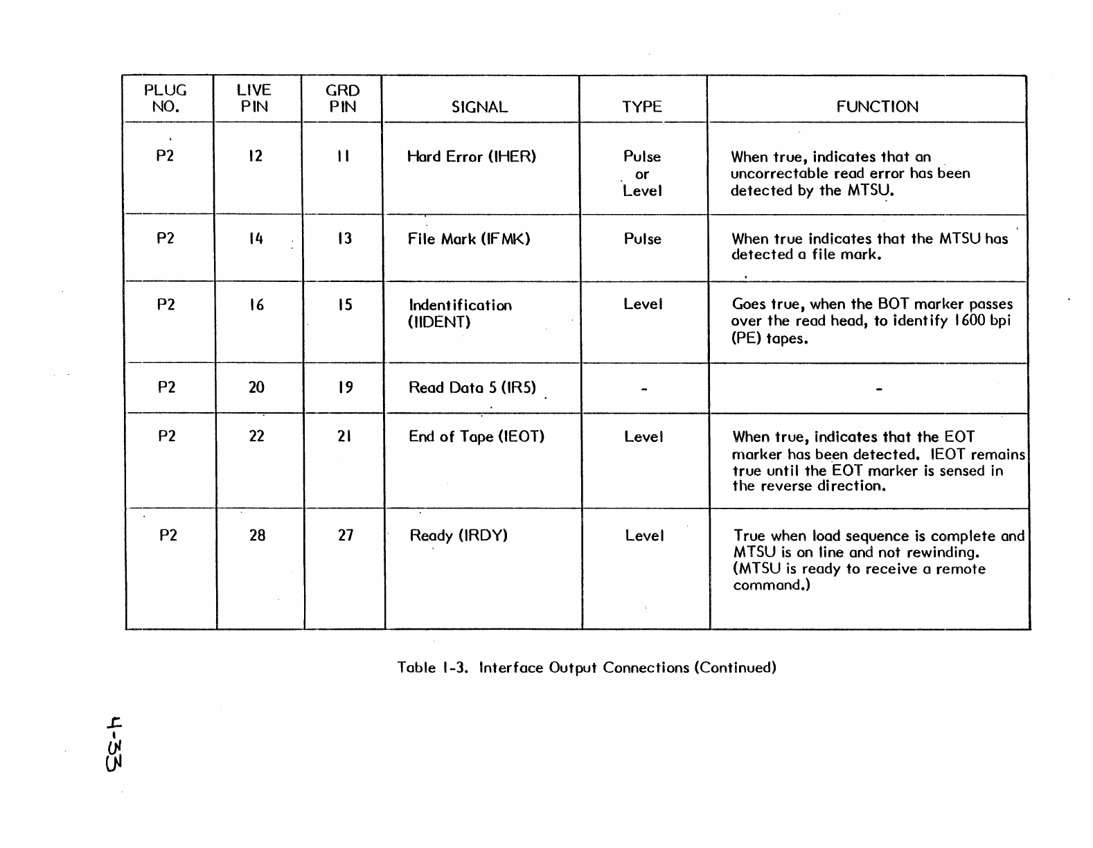
PLUG
LIVE
GRD
NO. PIN PIN SIGNAL TYPE FUNCTION
P2
12
II
Hard Error (IHER) Pulse When
true,
indicates
that
on
or
uncorrectable
read
error
has
been
Level
detected
by
the
MTS~.
P2
14
13
File Mark (IF
MK)
Pulse When
true
indicates
that
the
MTSU
has
detected
a
fi
Ie
mark.
P2
16
15
Indent
ification
Level Goes
true,
when
the
BOT
marker
passes
(IIDENT)
over
the
read head,
to
ident ify 1600 bpi
(PE)
tapes
•
..
P2 20
19
Read
Data
5 (IRS) - -
P2
22
21
End
of
Tape (IEOT) Level When
true,
indicates
thot
the
EOT
nlarker
has been
detected.
IEOT remains
true
until
the
"EOT
marker
is
sensed in
the
reverse
di
rection.
P2 28
27
Ready (IRDY) Level T rue when load
sequence
is
complete
and
MTSU
is
on line and not rewinding.
(MTSU
is
ready
to
receive
a
remote
command.)
Table 1-3.
Interface
Output
Connections (Continued)
L
•
~
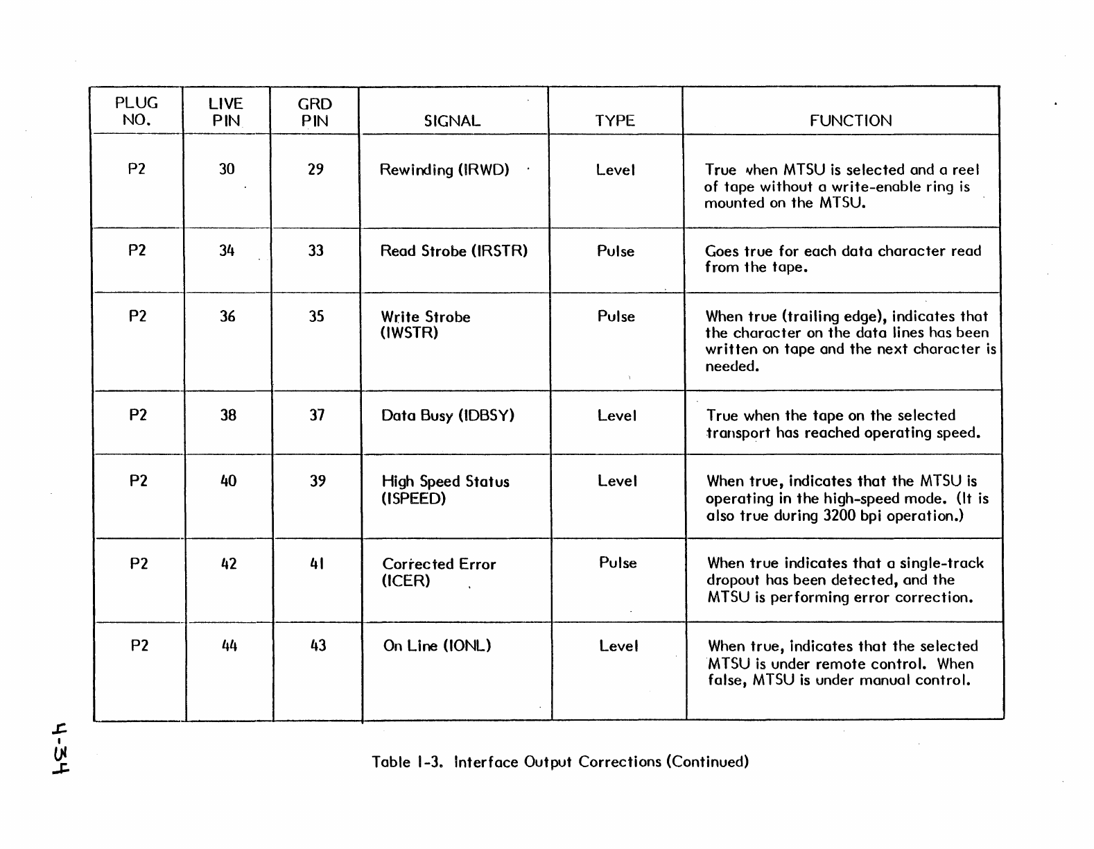
PLUG
LIVE
GRD
NO. PIN PIN SIGNAL TYPE FUNCTION
P2 30 29 Rewirding (lRWD) Level True vhen
MTSU
is
selected
and a reel
of
tape
without a
write-enable
ring
is
mounted on
the
M TSU.
--
P2
34 33
Read
Strobe
(lRSTR) Pulse Goes
true
for
each
data
character
read
from
the
tape.
P2 36
35
Write Strobe Pulse When
true
<trailing edge), indicates
that
(lWSTR)
the
character
on
the
data
lines has been
written
on
tape
and
the
next
character
is
needed.
P2 38
37
Data
Busy (lDBSY) Level T rue when
the
tape
on
the
se
lected
transport
has
reached
operating
speed.
P2 40 39 High Speed
Status
Level When
true,
indicates
that
the
MTSU
is
(I SPEED)
operating
in
the
high-speed mode. (It
is
also
true
during 3200 bpi
operation.)
-
P2 42
41
Corrected
Error Pulse When
true
indicates
that
a
single-track
(lCER) dropout has been
detected,
and
the
MTSU
is
performing
error
correction.
-
P2
44 43
On
Line (lONL) Level When
true,
indicates
that
the
selected
"MTSU
is
under
remote
control.
When
folse,
MTSU
is
under manual
control.
Table
1-3..
Interface
Output
Corrections
(Continued)
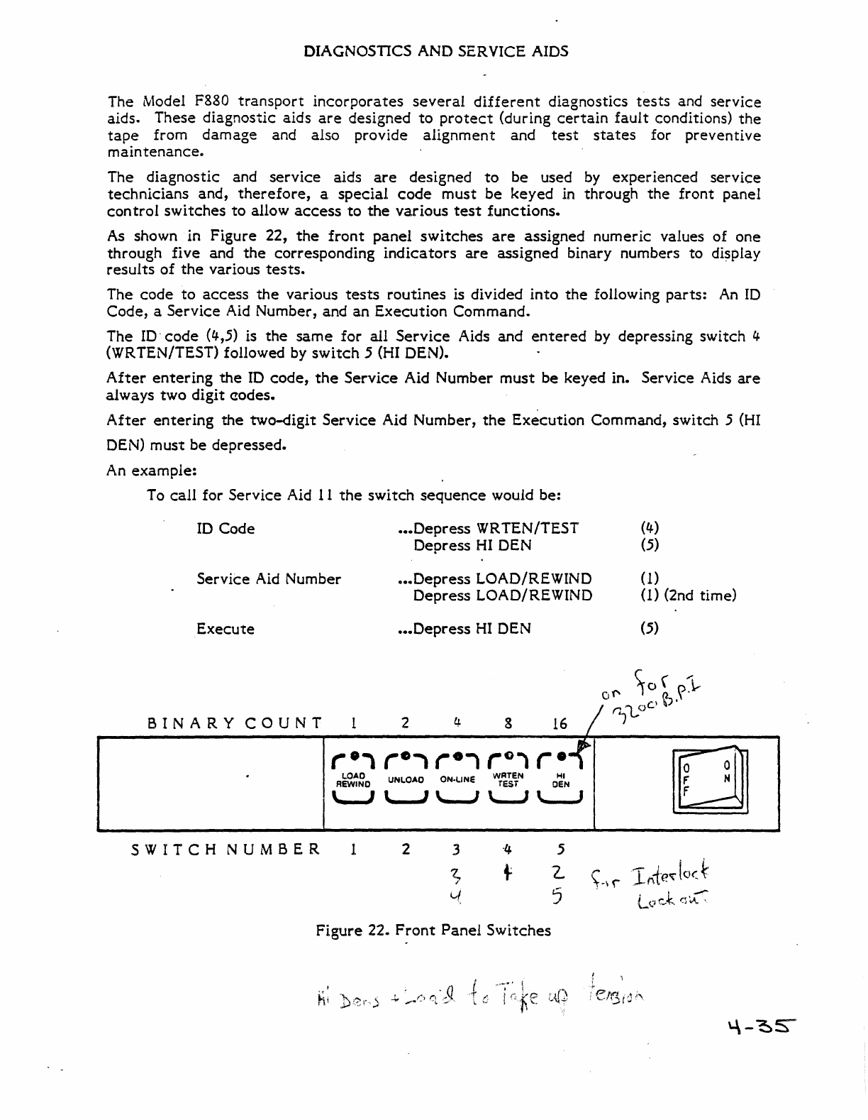
DIAGNOSTICS AND SERVICE AIDS
The Model F880
transport
incorporates
several
different
diagnostics
tests
and
service
aids. These
diagnostic
aids
are
designed
to
protect
(during
certain
fault
conditions)
the
tape
from
damage
and also provide
alignment
and
test
states
for
preventive
maintenance.
The
diagnostic
and
service
aids
are
designed
to
be
used
by
experienced
service
technicians
and,
therefore,
a
special
code
must
be
keyed
in through
the
front
panel
control
switches
to
allow
access
to
the
various
test
functions.
As shown in
Figure
22,
the
front
panel
switches
are
assigned
numeric
values
of
one
through
five
and
the
corresponding
indicators
are
assigned
binary numbers
to
di~play
results
of
the
various
tests.
The
code
to
access
the
various
tests
routines
is divided
into
the
following
parts:
An
10
Code,
a
Service
Aid Number, and
an
Execution
Command.
The
10-
code
(4,5) is
the
same
for
all
Service
Aids
and
entered
by depressing
switch
4
(WRTEN/TEST) followed by
switch
5 (HI DEN).
After
entering
the
ID
code,
the
Service
Aid
Number
must
be
keyed in.
Service
Aids
are
always
two
digit
erodes.
After
entering
the
two-digit
Service
Aid
Number,
the
Execution
Command,
switch
5
(HI
DEN)
must
be
depressed.
An
example:
To
call
for
Service
Aid
11
the
switch
sequence
would be:
ID
Code
•••
Depress
WRTEN/TEST
Depress
HI
DEN (4)
(5)
Service
Aid Number
...
Depress
LOAD/REWIND
Depress
LOAD/REWIND (1)
(1) (2nd time)
Execute
•••
Depress
HI
DEN
(5)
BINARY
COUNT
1 2
4-
8
16
/ f1,l,o
r·i
re'i
r·1
r
Cl
, r
.-t
OJ
L.OAD
UNLOAD
ON·LINE
WATEN
'"'I
REWIND
TEST
OEN
\....J
L..J
\......J
L..J
L....J
SWITCH
NUMBER
1 2 3
-4
5
7..
+
z..
I"
~
5
Figure
22.
Front
Panel
Switches
F'
N
f
\-,\ 1
hi-e~
l
Q(
~.
k
.~
l(,.
...
r'~
_
t;~~,
t
efI3i;;:;'
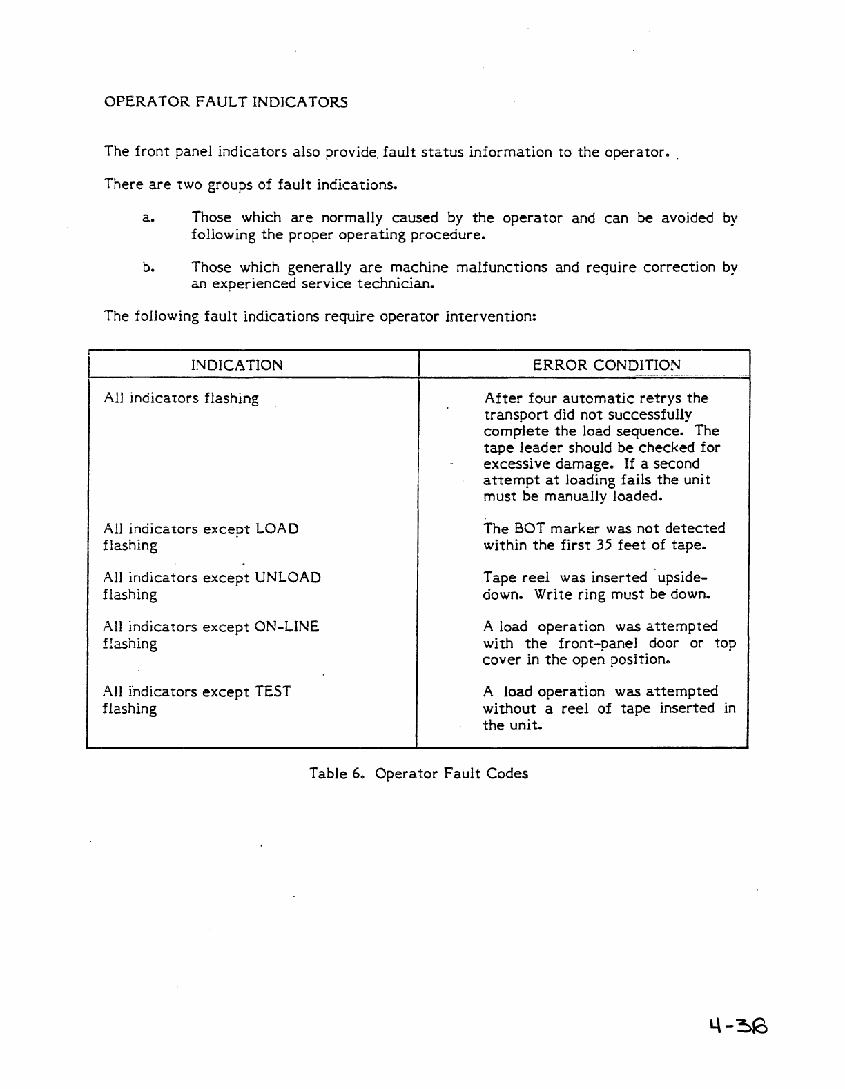
OPERA
TOR
F AUL T INDICA TORS
The
front
panel
indicators
also provide.
fault
status
information
to
the
operator
•.
There
are
two groups
of
fault
indicationsc
a.
Those which
are
normally
caused
by
the
operator
and
can
be avoided
by
following
the
proper
operating
procedure.
b. Those which
generally
are
machine
malfunctions
and
require
correction
by
an
experienced
service
technician.
The following
fault
indications
require
operator
intervention:
INDICATION
All
indicators
flashing
All indica
tors
except
LOAD
flashing
All
indicators
except
UNLOAD
flashing
All
indicators
except
ON-LINE
flashing
All
indicators
except
TEST
flashing
ERROR
CONDITION
After
four
automatic
retrys
the
transport
did
not
successfully
comp"lete
the
load
sequence.
The
tape
leader
should
be
checked
for
excessi
ve
damage..
If
a second
attempt
at
loading
fails
the
unit
must
be
manually
loaded.
The
BOT
marker
was
not
detected
within
the
first
35
feet
of
tape.
Tape
reel
was
inserted
. upside-
down. Write ring
must
be
down.
A load
operation
was
attempted
with
the
front-panel
door or
top
cover
in
the
open
position
..
A load
operation
was
attempted
without
a
reel
of
tape
inserted
in
the
unit.
Table 6.
Operator
Fault
Codes
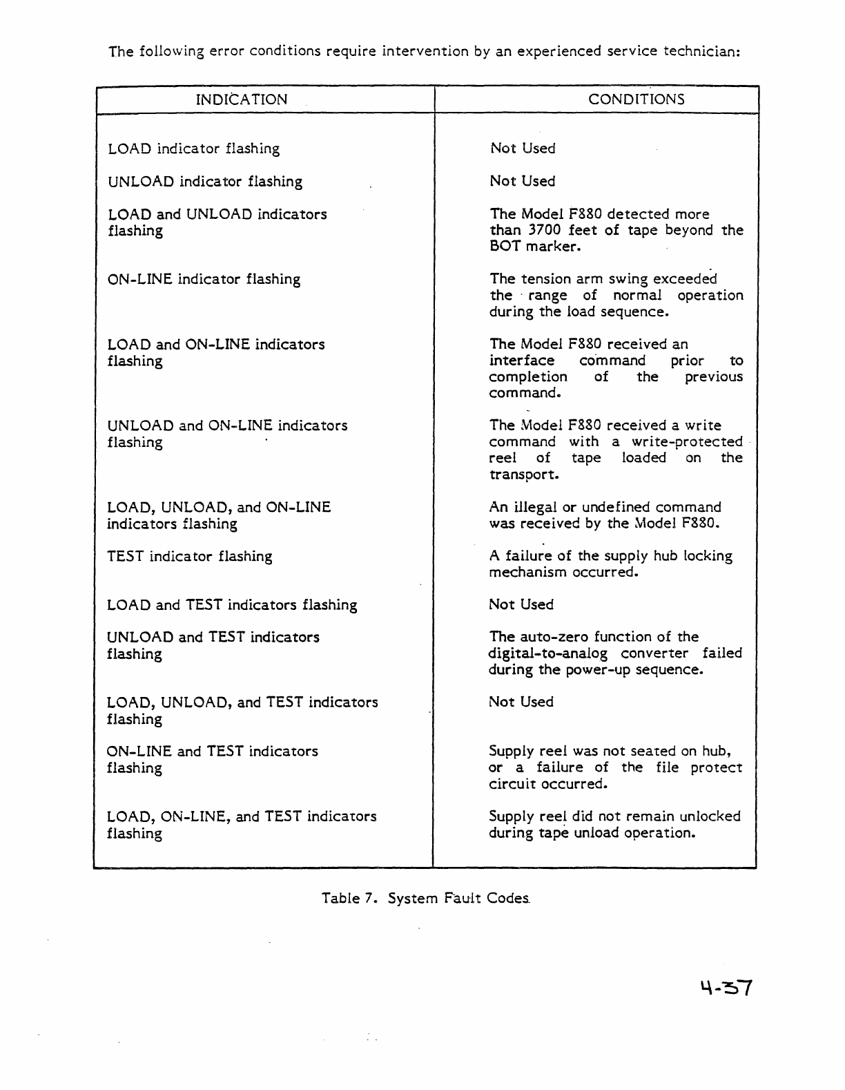
The following
error
conditions
require
intervention
by
an
experienced
service
technician:
INDICATION
LOAD
indicator
flashing
UNLOAD
indicator
flashing
LOAD
and
UNLOAD
indicators
flashing
ON-LINE
indicator
flashing
LOAD
and
ON-LINE
indicators
flashing
UNLOAD and ON-LINE
indica
tors
flashing
LOAD, UNLOAD, and ON-LINE
indica
tors
flashing
TEST
indica
tor
flashing
LOAD and TEST
indicators
flashing
UNLOAD and TEST
indicators
flashing
LOAD, UNLOAD, and TEST
indicators
flashing
ON-LINE and TEST
indicators
flashing
LOAD, ON-LINE, and TEST
indicators
flashing
CONDITIONS
Not
Used
Not
Used
The
Model F880
detected
more
than
3700
feet
of
tape
beyond
the
BOT
marker.
The
tension
arm
swing
exceeded
the"
range
of
normal
operation
during
the
load
sequence.
The
Model F880
received
an
interface
co"m
mand prior
to
completion
of
the
previous
command.
The
Model F880
received
a
write
command
with a
write-protected·
reel
of
tape
loaded on
the
transport.
An illegal
or
undefined
command
was
received
by
the
Ntodel F880.
A
failure
of
the
supply hub locking
mechanism
occurred.
Not
Used
The
auto-zero
function
of
the
digital-to-analog
converter
failed
during
the
power-up
sequence.
Not
Used
Supply
reel
was
not
seated
on hub,
or
a
failure
of
the
file
protect
circuit
occurred.
Supply
reel
did
not
remain
unlocked
during
tape
unload
operation.
Table
7..
System
Fault
Codes

INDICATION
UNLOAD, ON-LINE,
and
TEST
indicators
flashing
LOAD, UNLOAD, ON-LINE, and TEST
indicators
flashing
HI
DEN
indicator
flashing
LOAD and
HI
DEN
indicators
flashing
UNLOAD and
HI
DEN
indicators
flashing
CONDITIONS
Because
of a
controller
error,
tape
travel
. beyond
the
EOT
marker
exceeded
18
feet
..
Not
Used
Not
Used
The supply
servo
tension
arm
has
exceeded
its
free
travel
limits
during any
operation
except
those
functions
of
the
load and unload
sequence
where
tape
tension is
not
under
arm
control.
Tape
.speed
variations
in
excess
of
the
ANSI maximum of ± 1
096
deviation
from
the
normal
operating
speed
occurred.
This
test
is also
performed
as
part
of
the
power-up
diagnostic
routine
and
may
be
bypassed
to
allow
access
to
other
diagnostic
tests
by
depressing
the
TEST
switch
for
5
seconds
during
power
up.
Table 7.
System
Fault
Codes (continued)
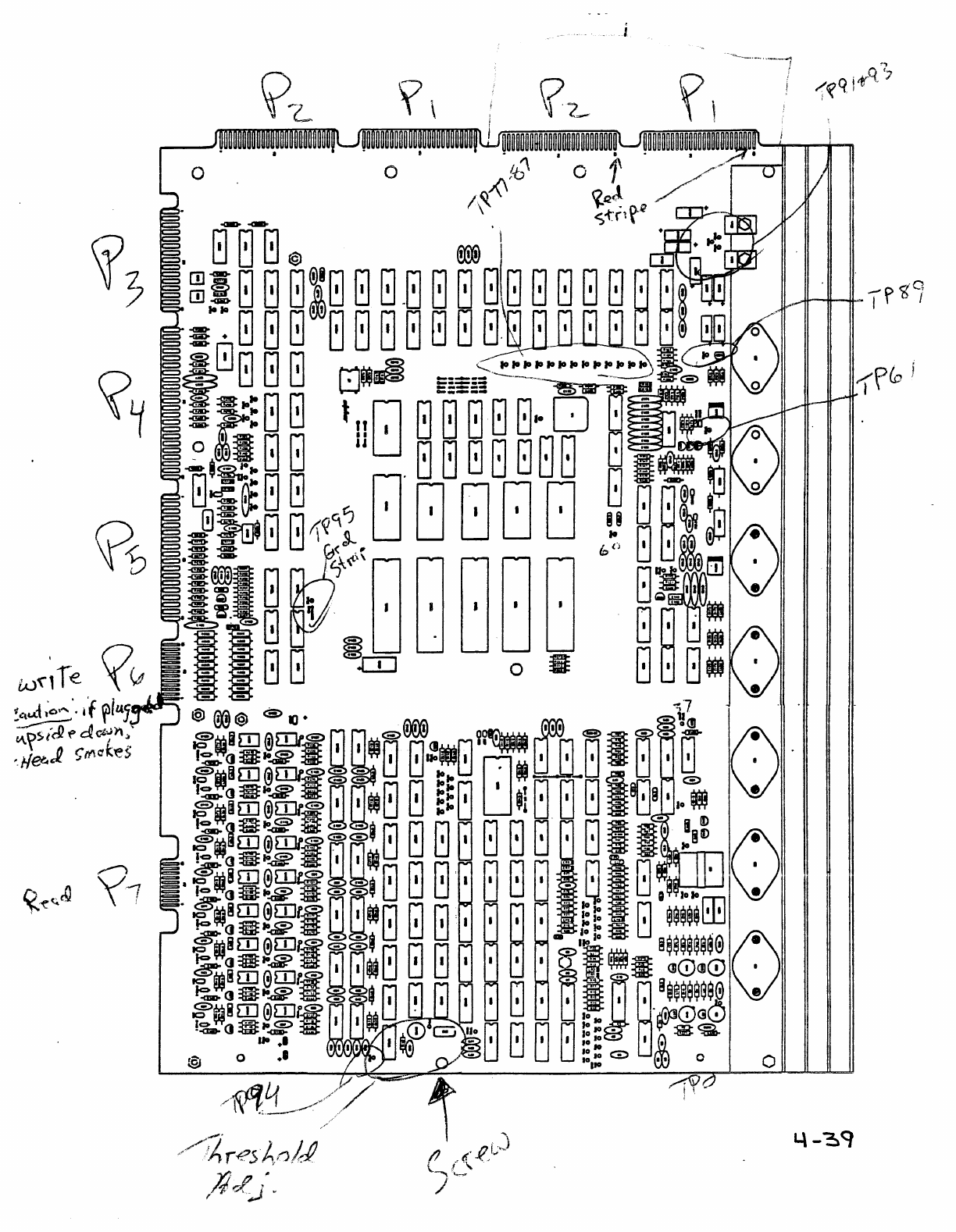
,..,
'i't(q
j~q
'7
o
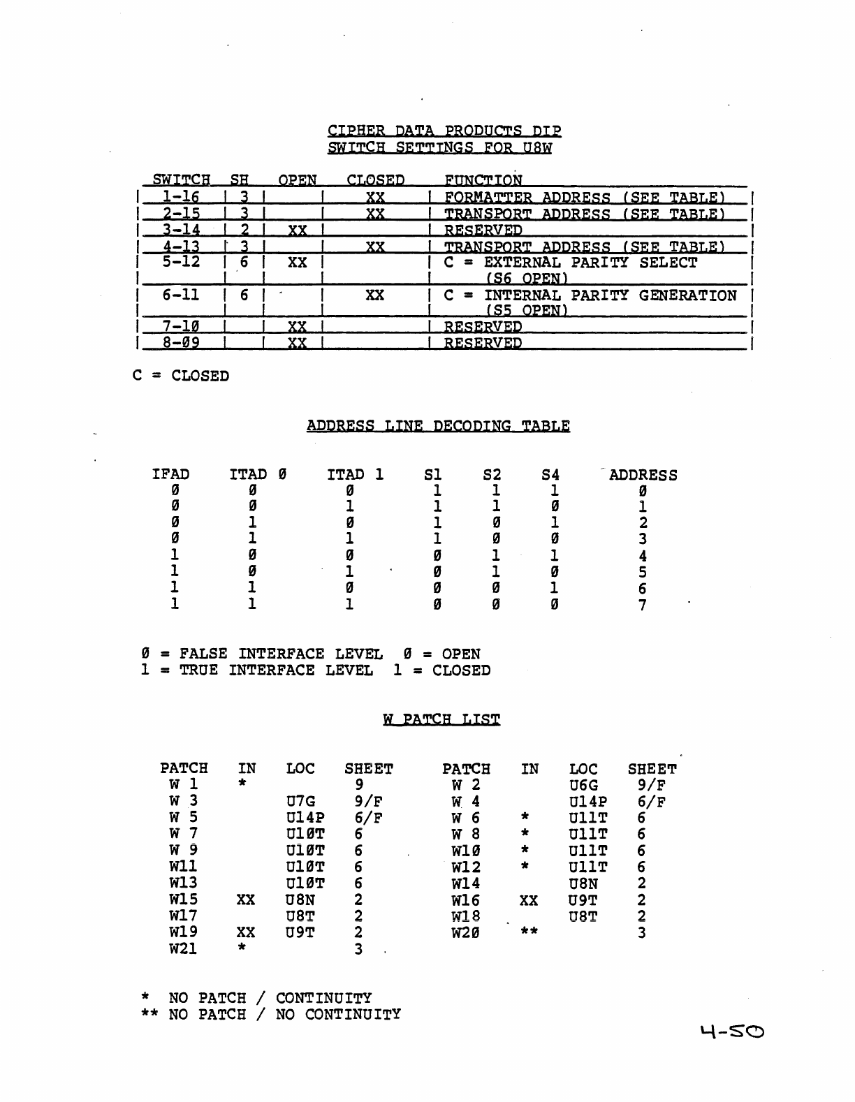
c
0
1
SNI~CB
sa
l-lg
I J
2-l5 I J
J-1~
I 2
~-lJ
I"
J
5-12
I 6
I
6-11
I 6
I
7-1~
I
8-09
I
=
CLOSED
IFAD
I
TAD
0 0
0 0
0 1
0 I
1 0
1 0
1 I
I I
Q~~H
XX
XX
XX
XX
CIPHER
DATA
PRODUCTS
DIP
SWITCH
SETTINGS
FOR
USW
CLQS~D
fImCTIQH
XX
EQBHA~~R
ACDRf:SS
XX
~RANSPOR~
AIlDBESS
RES~RV~D
xx
TRANsmR~
ADDB~SS
(SEE
~A13Lf:l
(SEE
~A13LEl
(SEE
TA13L~l
C =
EXTERNAL
PARITY
SELECT
(Sg
Q~EHl
xx
C =
INTERNAL
PARITY
GENERATION
(S5
QfEHl
RESERVED
RESERVEP
ADDRESS
LINE
Pf:COPING
TA13LE
0 I
TAD
1
Sl
S2 S4
ADDRESS
0 1 1 1 0
1 1 1 0 1
0 1 0 I 2
I I 0 0 3
0 0 I I 4
I 0 I 0 5
0 0 0 I 6
I 0 0 0 7
=
FALSE
INTERFACE
LEVEL
o =
OPEN
=
TRUE
INTERFACE
LEVEL
I =
CLOSED
Ii
;eA~CB
LIS~
PATCH
IN
LOC
SHEET
PATCH
IN
LOC
SHEET
W I * 9 W 2
U6G
9/F
W 3
U7G
9/F
W 4 Ul4P
6/F
W 5 Ul4P
6/F
W 6 * UIIT 6
w 7 Ul0T 6 W 8 * UIIT 6
W 9
U10T
6
WI0
*
UllT
6
Wll
U10T
6
W12
* UIIT 6
W13
U10T
6
W14
USN
2
W1S
XX
U8N
2
W16
XX
U9T
2
Wl7
oaT
2
W18
uaT
2
Wl9
XX
U9T
2
W20
** 3
W21
* 3
*
NO
PATCH
/
CONTINUITY
**
NO
PATCH
/
NO
CONTINUITY
4-5"0
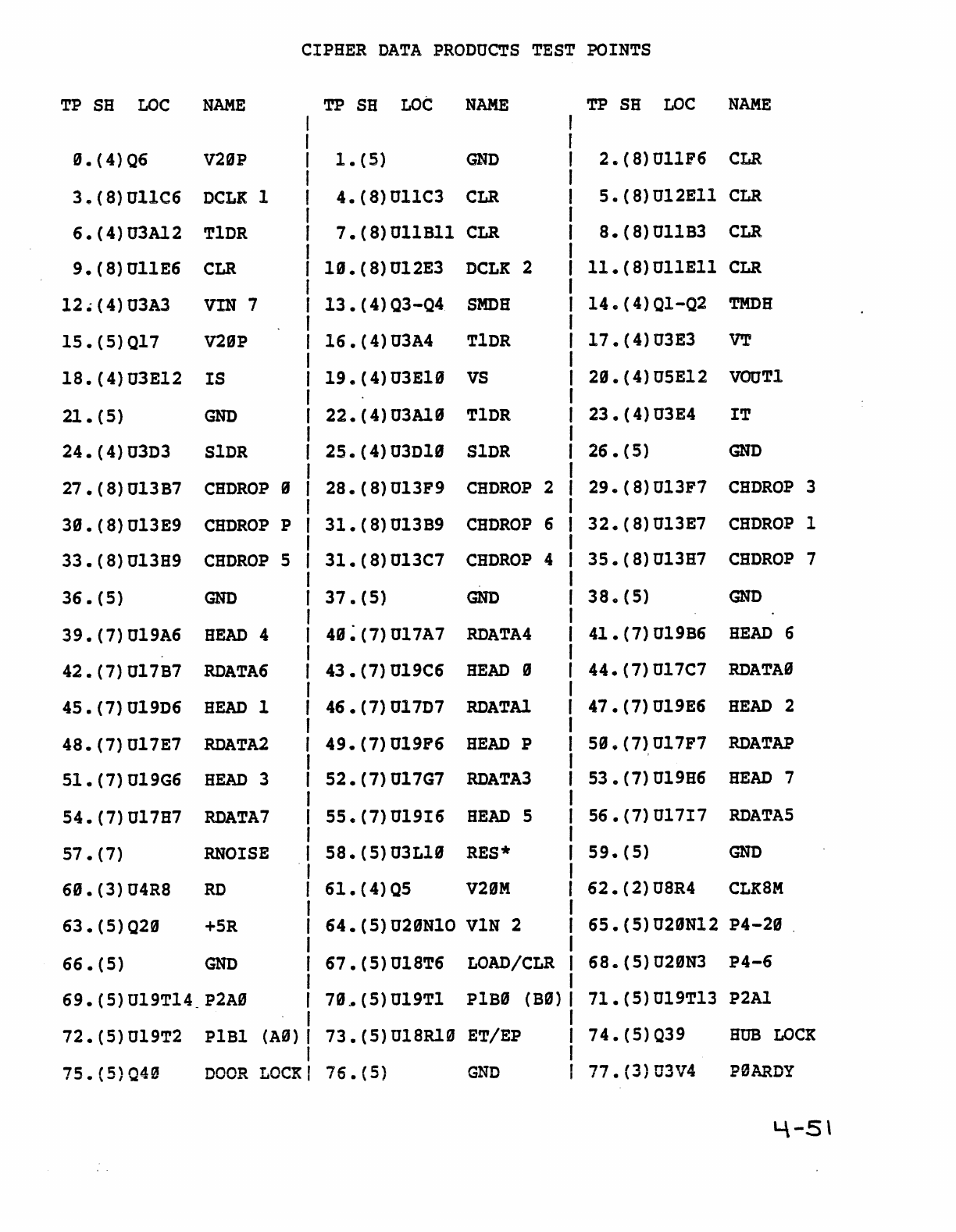
TP
S8
LOC
NAME
0.(4)06
V20P
3.(8)011C6
DCLK
1
6.(4)03Al2
T1DR
9.
(8) 011E6
CLR
12.(4)03A3
VIN
7
15.(5)017
V29P
18.
(4) 03E12
IS
21.(5)
GND
24.
(4)03D3
27
• (8) 013B7
39.
(8) 013E9
33.
(8) 013H9
36.
(5)
SlDR
CHDROP
9
CHDROP
P
CHDROP
5
GND
39.
(7)019A6
HEAD
4
42.(7)017B7
RDATA6
45.(7)019D6
HEAD
1
48.(7)017E7
RDATA2
51.
(7)019G6
HEAD
3
54.(7)017H7
RDATA7
57.(7)
RNOISE
69.
(3) 04R8
RD
63.
(5) 029
+5R
66.(5)
GND
69.(5)019T14_P2AS
72.(5)019T2
P1B1
(A0)
CIPHER
DATA
PRODUCTS
TEST
POINTS
TP
SH
LOC
NAME
1.(5)
GND
4.(8)U11C3
CLR
7.
(8) 011B11
CLR
I9.(8)012E3
DCLK
2
13.(4)03-04
SMDH
16.(4)03A4
TIDR
19.
(4)
03EI0
VS
22.
(4)03Al9
TIDR
25.
(4)03DI0
SIDR
28.
(8)013F9
CHDROP
2
31.(8)013B9
CHDROP
6
31.(8)013C7
CHDROP
4
37.(5)
GND
49~(7)017A7
RDATA4
43.(7)019C6
HEAD
9
46.(7)017D7
RDATAl
49.(7)019F6
HEAD
P
52.(7)017G7
RDATA3
55.(7)019I6
HEAD
5
58.
(5)03LI9
RES·
61.(4)05
V29M
64.
(5)029N10
VIN
2
67.
(5)018T6
LOAD/CLR
79~(5)U19T1
p1B9 (B9)
73.(5)018Rl0
ET/EP
TP
SH
LOC
NAME
2.(8)U11F6
CLR
5.
(8}012E11
CLR
8.
(8)
U11B3
CLR
II.(8)011E11
CLR
14.(4)01-Q2
TMDH
1 7 • (
4)
U3
E3
VT
29.(4)U5E12
VOUTI
23
• (4) 03
E4
IT
26.
(5)
GND
29.(8)UI3F7
CHDROP
3
32.(8)UI3E7
CHDROP
1
35.(8)013B7
CHDROP
7
38.(5)
GND
41.
(7)U19B6
HEAD
6
44.(7)U17C7
RDATAS
47.(7)019E6
HEAD
2
59.(7)017F7
53
• (7) 019H6
56
• (7) U17I7
59.
(5)
RDATAP
HEAD
7
RDATA5
GND
62.(2)U8R4
CLK8M
65.
(5)
U29N12
P4-29
.
68.(5)U29N3
P4-6
71.(5)019T13
P2A1
74.(5)039
HUB
LOCK
75.(5)040
DOOR
LOCK
76.(5)
GND
77.
(3)03V4
P9ARDY
'-\-5\

~Tna~~
n~m~
n~~n"~~
~~.U~~
~n~n .~v~uv~~
m"
~m
TV"\
T'Tm~
~J;!Q~
.rV~:L"~';;'
TP
SH
LOC
NAME
TP
SH
LOC
NAME
TP
SH
LOC
NAME
78.
(3)
07V5
ILDP
79.
(3)
06V2
W21
89.
(3)
06V12
ONLSEL
81.
(3)
02V6
IONL
82.
(3)
07V7
IRDY
83.
(3)
07Vl2
IFPT
84.
(3)
07VlS
IFBY
85.
(3)
07V2
IEOT
86.
(3)
07V15
IDBSY
87
•
(3)
OlSVa
IRWD
88.
(5)
GND
89.(5)07
+5V
9S.
(5)VRl
-12V
91 •
(5)
GND
92.
(5)
VR2
+12V
93.
(9)
09F8
PECLK
94.
(7)
Rl15
VOOTB
95.(
)CHASSIS
GND
'-\-5').....
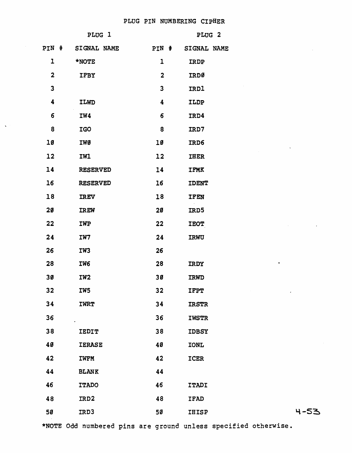
PLUG
PIN
NUMBERING
CIPHER
PLUG
1
PLUG
2
PIN i
SIGNAL
NAME
PIN
t
SIGNAL
NAME
1
*NOTE
1
IRDP
2
I;FBY
2
IRD9
3 3 IRDl
4
lLWD
4 lLDP
6
lW4
6
lRD4
8
lGO
8
IRD7
19
IWS
19
IRD6
12
IWl
12
lHER
14
RESERVED
14
lFMK
16
RESERVED
16
lDENT
18
IREV
18
lPEN
2S
IREW
2S
IRD5
22
lWP
22
IEOT
24
lW7
24
IRW
26
lW3
26
28
lW6
28
IROY
39
lW2
39
IRWD
32
IW5
32 lPPT
34
lWRT
34
IRSTR
36 36
IWSTR
38 lEDlT 38
lDBSY
49
lERASE
49
lONL
42
lWFM
42
lCER
44
BLANK
44
46
lTADO
46
lTADI
48
IRD2
48
I
FAD
59
IRD3
59
lHlSP
'-\
-53:-
*NOTE
Odd
numbered
pins
are
ground
unless
specified
otherwise.
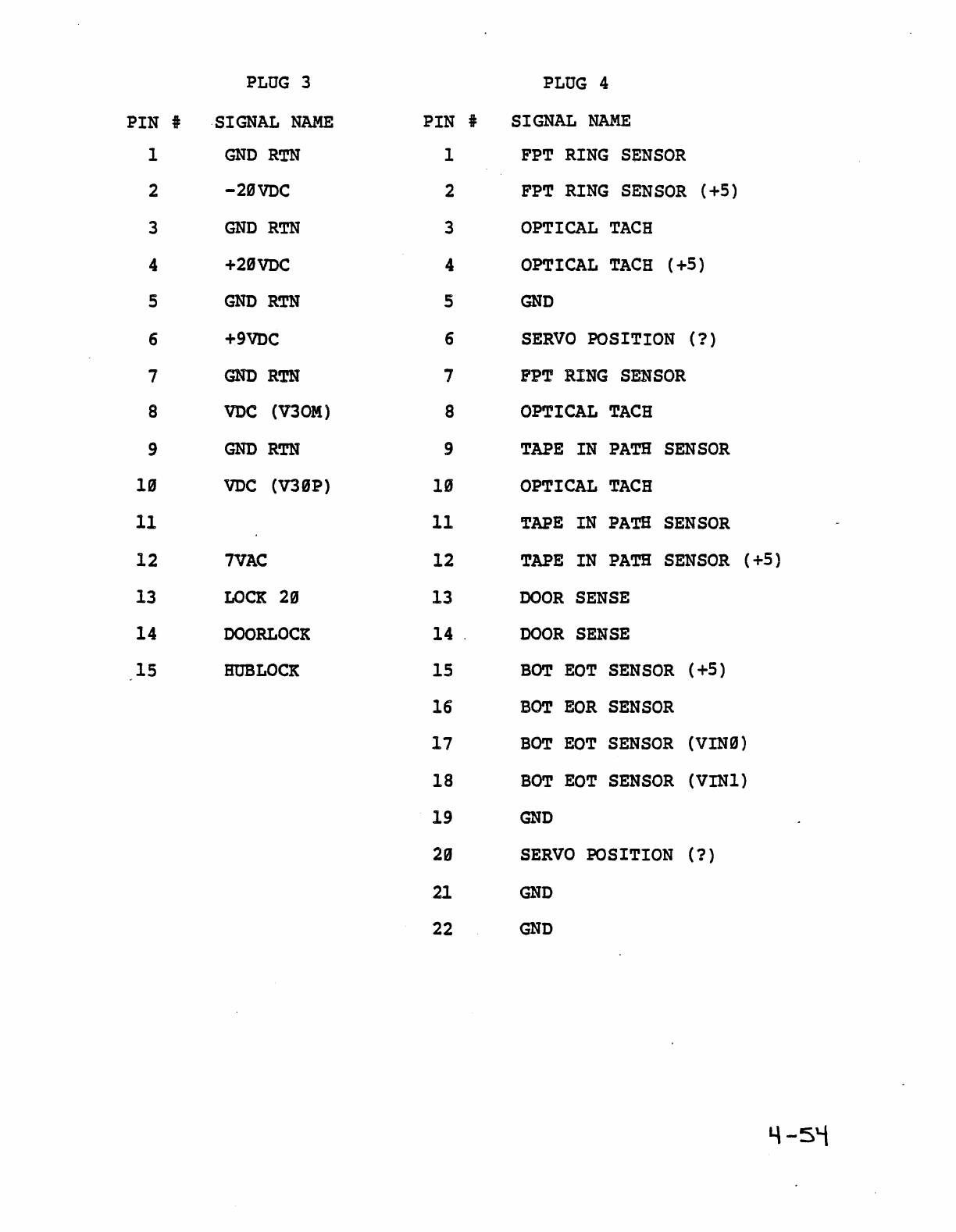
PLUG
3
PLUG
4
PIN i
·SIGNAL
NAME
PIN
i
SIGNAL
NAME
1
GNDRTN
1
FPT
RING
SENSOR
2
-20VDC
2
FPT
RING
SENSOR
(+5)
3
GNDRTN
3
OPTICAL
TACH
4 +29vnC 4
OPTICAL
TACH
(+5)
5
GND
RTN
5
GND
6
+9VDC
6
SERVO
POSITION
(1)
7
GND
RTN
7
FPT
RING
SENSOR
8
VDC
(V3OM)
8
OPTICAL
TACH
9
GND
RTN
9
TAPE
IN
PATH
SENSOR
10
VDC
(V39P) IS
OPTICAL
TACH
11 11
TAPE
IN
PATH
SENSOR
12
7VAC
12
TAPE
IN
PATH
SENSOR
(+5)
13
LOCK
20
13
DOOR
SENSE
14
DOORLOCK
14 .
DOOR
SENSE
15
HUB
LOCK
15
BOT
EaT
SENSOR
( +5)
16
BOT
EOR
SENSOR
17
BOT
EaT
SENSOR
(VINe)
18
BOT
EaT
SENSOR
(VIN1)
19
GND
2e
SERVO
POSITION
(1)
21
GND
22
GND
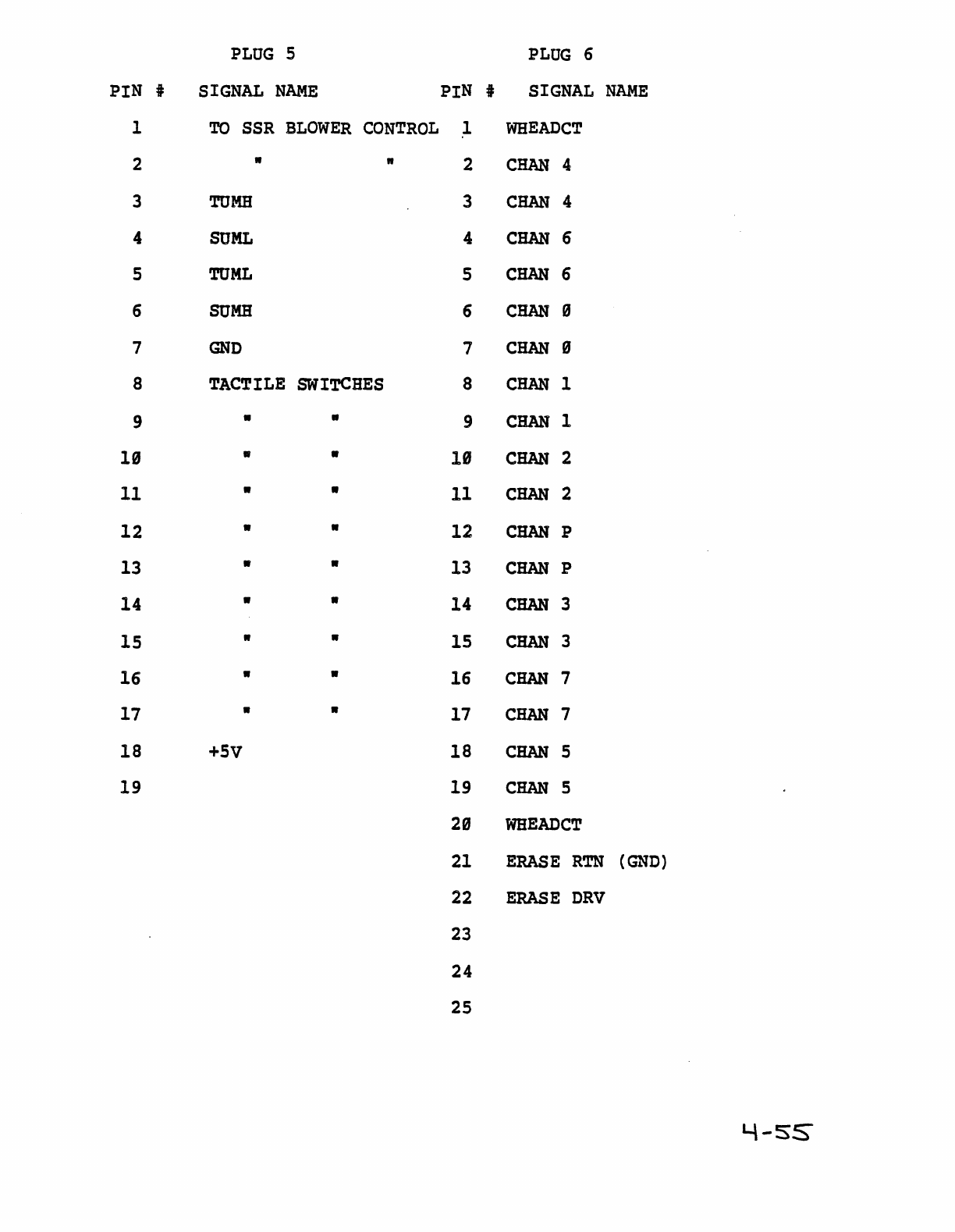
PLUG
5
PLUG
6
PIN i
SIGNAL
NAME
PIN
i
SIGNAL
NAME
1
TO
SSR
BLOWER
CONTROL
1
WHEADCT
2 " " 2
CHAN
4
3
TOMB
3
CHAN
4
4
SUML
4
CHAN
6
5
TOML
5
CHAN
6
6
50MB
6
CHAN
9
7
GND
7
CHAN
9
8
TACTILE
SWITCHES
8
CHAN
1
9 • • 9
CHAN
1
19 • •
18
CHAN
2
11 • • 11
CHAN
2
12
• • 12
CHAN
P
13 • " 13
CHAN
P
14 • • 14
CHAN
3
15 • • 15
CHAN
3
16 " • 16
CHAN
7
17 • " 17
CHAN
7
18
+5V
18
CHAN
5
19 19
CHAN
5
29
WHEADCT
21
ERASE
RTN
(GND)
22
ERASE
DRV
23
24
25
L\-SS
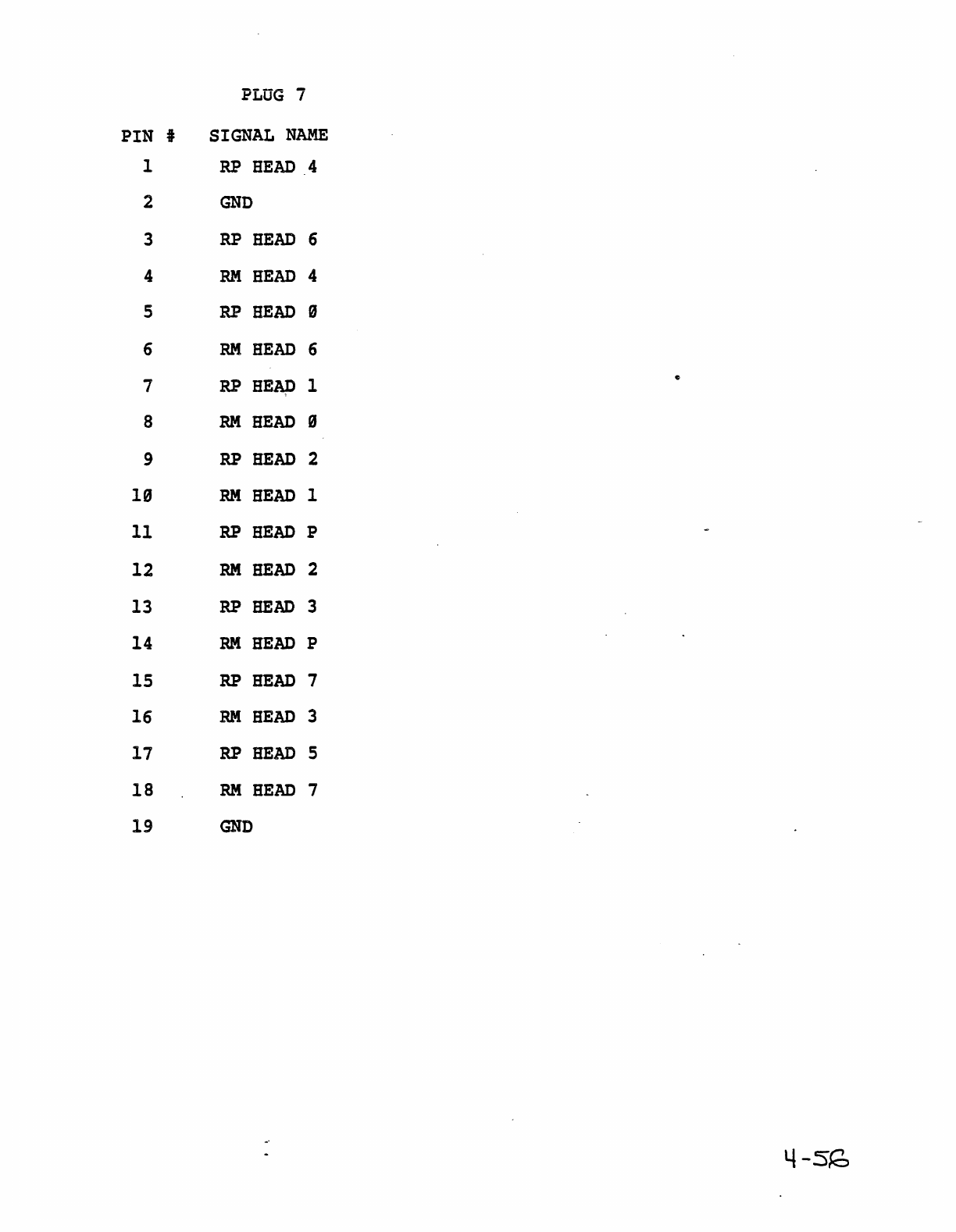
PLUG
7
PIN
#
SIGNAL
NAME
1 RP
HEAD
4
2
GND
3
RP
HEAD
6
4
RM
HEAD
4
5
RP
BEAD
9
6
RM
HEAD
6
7
RP
HEAP 1
8
RM
HEAD
9
9
RP
BEAD 2
19
RM
HEAD
1
11
RP
HEAD
P
12
RM
HEAD
2
13
RP
HEAD
3
14
RM
BEAD P
15
RP
BEAD 7
16
RM
HEAD
3
17
RP
HEAD
5
18
RM
HEAD
7
19
GND
4
-sf2=,
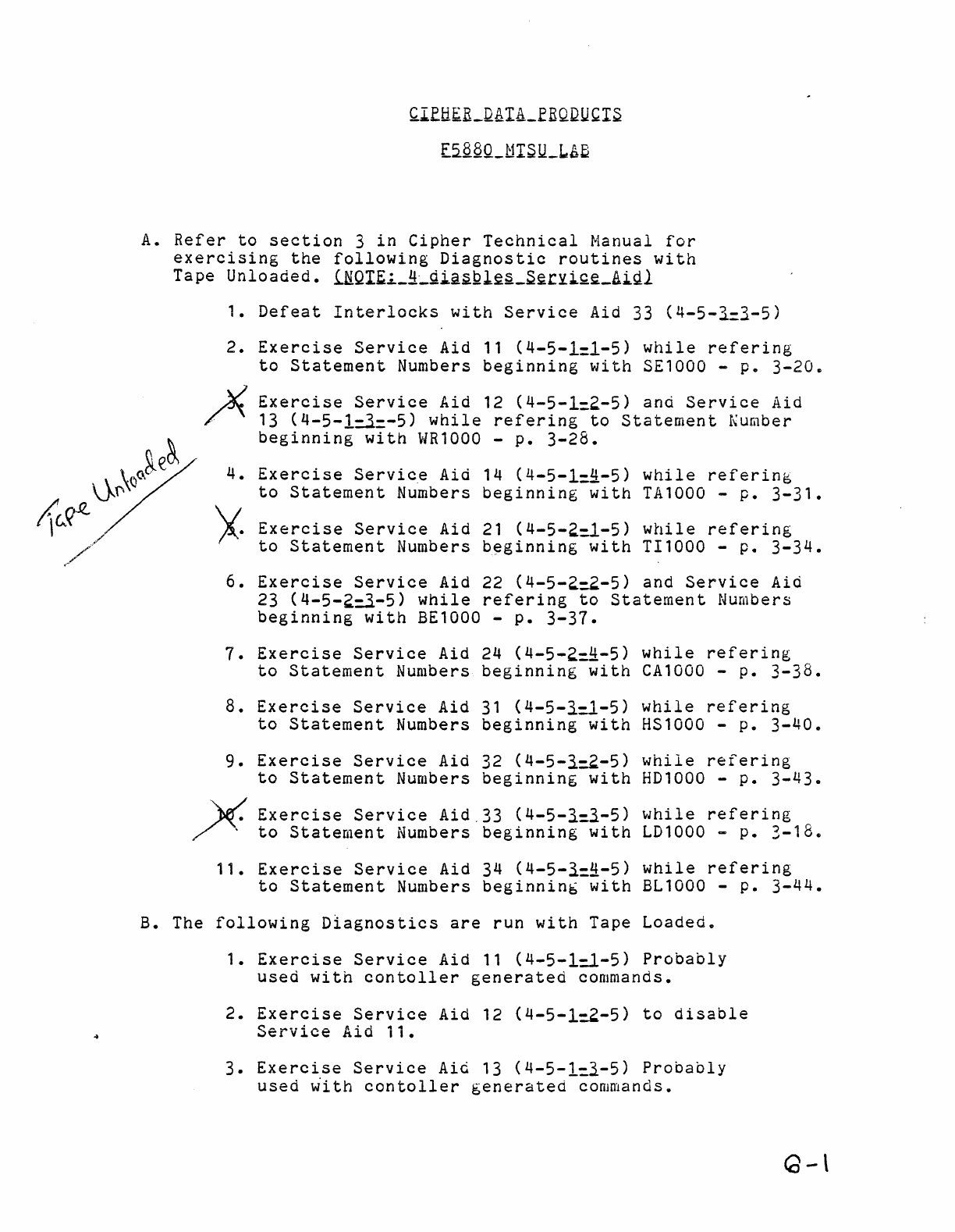
~rfti~R_QAIA_£EQQU~IS
E5.§.aQ_MISll_~Aa
A.
Refer
to
section
3
in
Cipher
Technical
Manual
for
exercising
the
following
Diagnostic
routines
with
Tape
Unloaded.
i.NQI~i._!l_gi.22Ql~§_S~rYi.Q~_A1Jil
1.
Defeat
Interlocks
with
Service
Aid 33
(4-5-1=}-5)
2.
Exercise
Service
Aid
11
(4-5-1=1-5)
while
refering
to
Statement
Numbers
beginning
with
S£1000 -
p.
3-20.
Exercise
Service
Aid 12
(4-5-1:2-5)
and
Service
Aid
13
(4-5-1=.3.=-5)
while
refering
to
Statement
I":umber
beginning
with
WR1000
-
p.
3-28.
Exercise
Servic.e
Aid 14
(4-5-1:!l-5)
while
referinb
to
Statement
Numbers
beginning
with
TA1000 -
p.
3-31.
Exercise
Service
Aid
21
(4-5-2:1-5)
while
refering
to
Statement
Numbers
beginning
with
TI1000
-
p.
3-34.
6.
Exercise
Service
Aid 22
(4-5-2:2-5)
and
Service
Aid
23
(4-5-2=.3.-5)
while
refering
to
Statement
Numbers
beginning
with
BE1000 -
p.
3-37.
1.
Exercise
Service
Aid 24
(4-5-2:!l-5)
while
refering
to
Statement
Numbers
beginning
with
CA1000
-
p.
3-38.
8.
Exercise
Service
Aid
31
(4-5-3.:1-5)
while
refering
to
Statement
Numbers
beginning
with
HS1000 -
p.
3-40.
9.
Exercise
Service
Aid 32
(4-5-3.:2-5)
while
refering
to
Statement
Numbers
beginning
with
HD1000
-
p.
3-43.
X
Exercise
Service
Aid.33
(4-5-3.:3.-5)
while
refering
to
Statement
Numbers
beginning
with
LD1000
...
p •
3-18"
11.
Exercise
Service
Aid 34
(4-5-3.:~-5)
while
refering
to
Statement
Numbers
beginnin&
with
BL1000 -
p.
3-44.
B. The
following
Diagnostics
are
run
with
Tape
Loaded.
1.
Exercise
Service
Aid
11
(4-5-1:1-5)
Probably
used
with
contoller
generated
commands.
2.
Exercise
Service
Aid 12
(4-5-1:2-5)
to
disable
Service
Aid
ii.
3.
Exercise
Service
Aid
13
(4-5-1:l-5)
Probably
used
~ith
contoller
generated
commands.
G-
\
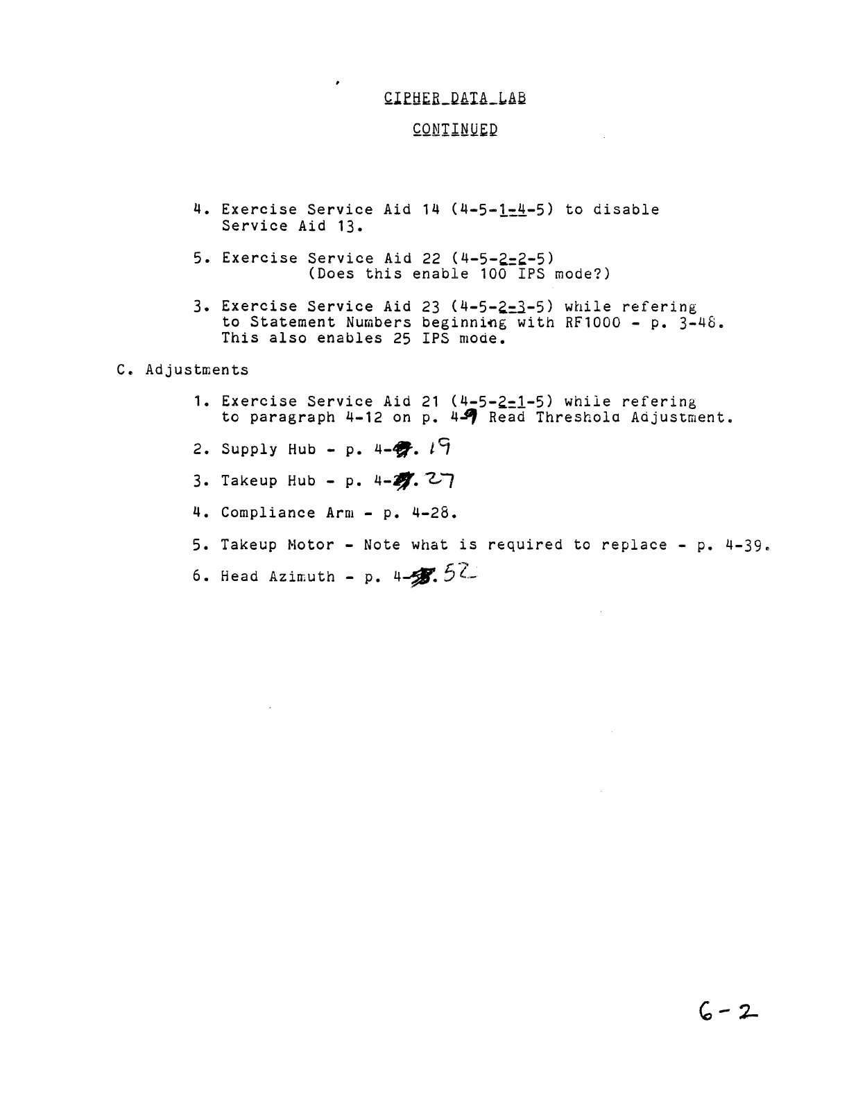
~lftl£R_QAIA_LA~
~QNllttUEQ
4.
Exercise
Service
Aid 14
(4-5-1~~-5)
to
disable
Service
Aid
13.
5.
Exercise
Service
Aid 22
(4-5-2=2-5)
(Does
this
enable
100 IPS mode?)
3.
Exercise
Service
Aid 23
(4-5-2=.3-5)
while
refering
to
Statement
Numbers
beginniflg
with
RF1000 -
p.
3-48.
This
also
enables
25
IPS
mode.
c.
Adjustments
1.
Exercise
Service
Aid
21
(4-5-2=1-5)
while
refering
to
paragraph
4-12
on
p.
4.PJ
Read
Threshola
Adjustment
..
2.
Supply
Hub
-
p.
4-ff·
t9
3.
Takeup
Hub
-
p.
4-'lj/.~1
4.
Compliance
Arm
-
p.
4-28.
5.
Takeup Motor -Note
what
is
required
to
replace
-
p.
4-3ge
6.
Head
Azimuth
-
p.
4-'f1'.
5~l-
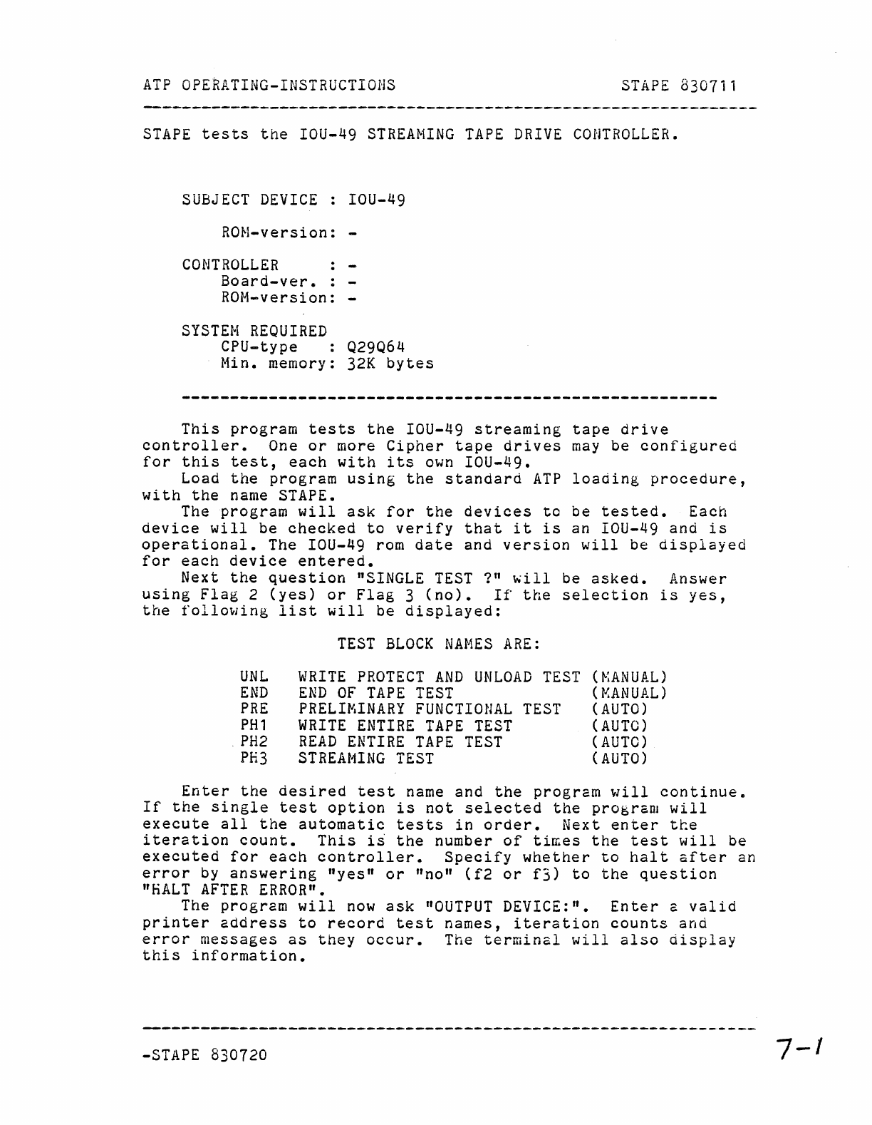
ATP
OPEaATING-INSTRUCTIONS
STAPE
8307ii
STAPE
tests
the
IOU-49
STREAMING
TAPE
DRIVE
CONTROLLER.
SUBJECT
DEVICE
: IOU-49
RON-version:
-
CONTROLLER
Board-ver.
ROM-version:
-
SYSTEN
REQUIRED
CPU-type
Q29Q64
Min. memory:
32K
bytes
This
program
tests
the
IOU-49
streaming
tape
drive
controller.
One
or
more
Cipher
tape
drives
may
be
configured
for
this
test,
each
with
its
own
IOU-49.
Load
the
program
using
the
standard
ATP
loading
procedure,
with
the
name STAPE.
The
program
will
ask
for
the
devices
to
be
tested.
Each
device
will
be
checked
to
verify
that
it
is
an IOU-49
and
is
operational.
The IOU-49 rom
date
and
version
will
be
displayed
for
each
device
entered.
Next
the
question
"SINGLE
TEST
1"
~ill
be
asked.
Answer
using
Flag
2
(yes)
or
Flag
3
(no).
If
the
selection
is
yes,
the
following
list
will
be
displayed:
UNL
END
PRE
PH1
.
PH2
PH3
TEST
BLOCK
NAMES
ARE:
WRITE
PROTECT
AND
UNLOAD
TEST
END
OF
TAPE
TEST
PRELIMINARY
FUNCTIONAL
TEST
WRITE
ENTIRE
TAPE
TEST
READ
ENTIRE
TAPE
TEST
STREAMING
TEST
(NANUAL)
(r~ANUAL
)
(AUTO)
(AUTO)
(AUTO)
(AUTO)
Enter
the
desired
test
name
and
the
program
will
continue.
If
the
single
test
option
is
not
selected
the
program
will
execute
all
the
automatic
tests
in
order.
Next
enter
tee
iteration
count.
This
is
the
number
of
ti~es
the
test
will
be
executed
for
each
controller.
Specify
whether
to
halt
after
an
error
by
answering
"yes"
or
"no"
(f2
or
f3)
to
the
question
"HALT
AFTER
ERROR".
The
program
will
now
ask
"OUTPUT
DEVICE:".
Enter
a
valid
printer
address
to
record
test
names,
iteration
counts
and
.o
....
"""'n
....
n,oc.o~~r-:a~
-.~
i-Ir-\~."
",..""'1',,..
'T'l.-,r\.
.....
~
...
..,.
•
..;
""",-1
..
.,.;"
.......
1
~'"
,..;;;
c.-.
.......
1
""''11
...
, • ..."
...
,,;,wwQC";;W
Qw
",uO;;;J
v'"''''''''',.
.LLlo;;;
"'0;;;'
lU~1JQ..L.
VII.J...L..J.
Q,LwV
"".J.W}J.J.QJ
this
information.
-STAPE 830720
7-
1
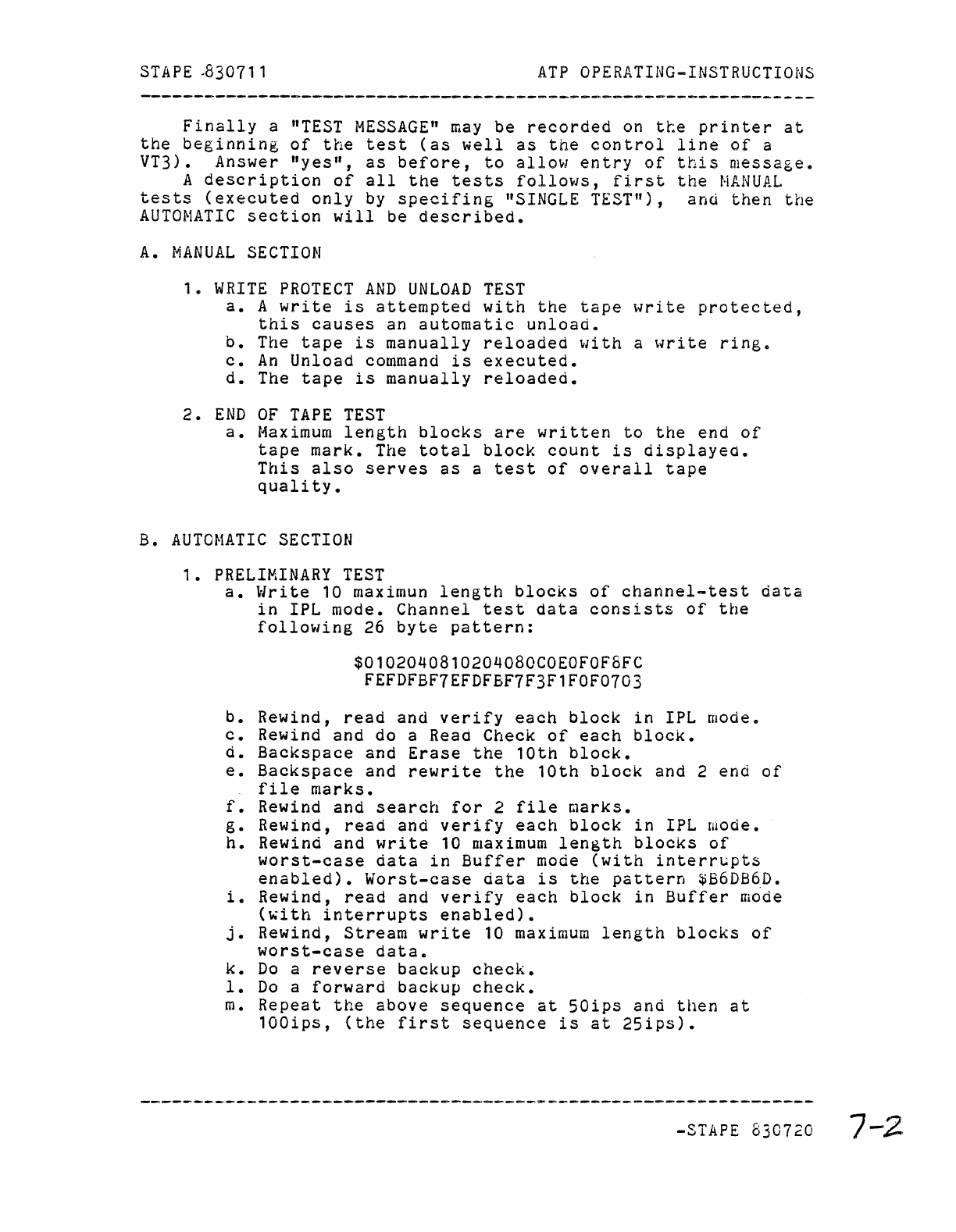
S
TAP
E .83071 1
ATP
OPERATING-INSTRUCTIONS
Finally
a
"TEST
MESSAGE"
may
be
recorded
on
tte
printer
at
the
beginning
of
the
test
(as
well
as
the
control
line
of
a
VT3). Answer
"yes",
as
before,
to
allow
entry
of
this
message.
A
description
of
all
the
tests
follows,
first
the
MANUAL
tests
(executed
only
by
specifing
"SINGLE
TEST"),
and
then
the
AUTOMATIC
section
will
be
described.
A.
MANUAL
SECTION
1.
WRITE
PROTECT
AND
UNLOAD
TEST
a.
A
write
is
attempted
with
the
tape
write
protected,
this
causes
an
automatic
unload.
b.
The
tape
is
manually
reloaded
with
a
write
ring.
c.
An
Unload
command
is
executed.
d.
The
tape
is
manually
reloaded.
2.
END
OF
TAPE
TEST
a.
Maximum
length
blocks
are
written
to
the
end
of
tape
mark.
The
total
block
count
is
displayed.
This
also
serves
as
a
test
of
overall
tape
quality.
B.
AUTOMATIC
SECTION
1.
PRELIMINARY
TEST
a.
Write
10
maximun
length
blocks
of
channel-test
data
in
IPL mode.
Channel
test
data
consists
of
the
following
26
byte
pattern:
$0102040810204080COEOFOF8FC
FEFDFBF7EFDFBF7F3F1FOF0703
b.
Rewind,
read
and
verify
each
block
in
IPL mode.
c.
Rewind and do a Read Check
of
each
block.
d.
Backspace
and
Erase
the
10th
block.
e.
Backspace
and
rewrite
the
10th
block
and 2 end
of
file
marks.
f.
Rewind and
search
for
2
file
marks.
g.
Rewind,
read
and
verify
each
block
in
IPL wode.
h.
Rewind
and
write
10
maximum
length
blocks
of
worst-case
data
in
Buffer
mode
(with
interrupts
enabled).
Worst-case
data
is
the
pattern
$B6DB6D.
i.
Rewind,
read
and
verify
each
block
in
Buffer
mode
(~ith
interrupts
enabled).
j.
Rewind,
Stream
write
10
maximum
length
blocks
of
worst-case
data.
k.
Do
a
reverse
backup
check.
1.
Do
a
forward
backup
check.
m.
Repeat
the
above
sequence
at
50ips
and
then
at
100ips,
(the
first
sequence
is
at
25ips).
-STAPE 830720
7-2
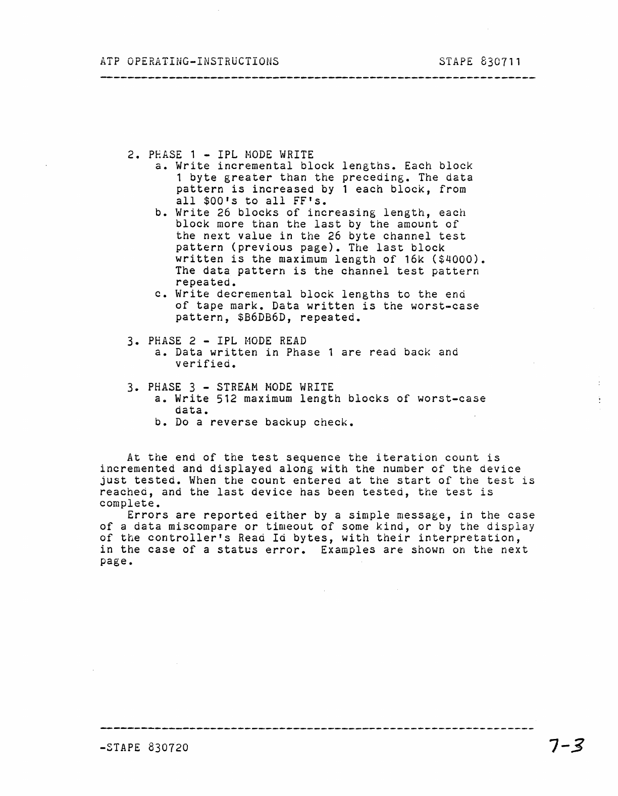
ATP
OPERATING-INSTRUCTIONS
SlAPE
830711
2.
PHASE
1 - IPL
MODE
WRITE
a.
Write
incremental
block
lengths.
Each
block
1
byte
greater
than
the
preceding.
The
data
pattern
is
increased
by 1
each
block,
from
all
$OO's
to
all
FF's.
b.
Write
26
blocks
of
increasing
length,
each
block
more
than
the
last
by
the
amount
of
the
next
value
in
the
26
byte
channel
test
pattern
(previous
page).
The
last
block
written
is
the
maximum
length
of
16k
($4000).
The
data
pattern
is
the
channel
test
pattern
repeated.
c.
Write
decremental
block
lengths
to
the
end
of
tape
mark.
Data
written
is
the
worst-case
pattern,
$B6DB6D,
repeated.
3.
PHASE
2 - IPL
MODE
READ
a.
Data
written
in
Phase
1
are
read
back
and
verified.
3.
PHASE
3 -
STREAM
MODE
WRITE
ao
Write
512
maximum
length
blocks
of
worst-case
data.
b.
Do
a
reverse
backup
check.
At
the
end
of
the
test
sequence
the
iteration
count
is
incremented
and
displayed
along
with
the
number
of
the
device
just
tested.
When
the
count
entered
at
the
start
of
the
test
is
reached,
and
the
last
device
has
been
tested,
the
test
is
complete.
Errors
are
reported
either
by a
simple
message,
in
the
case
of
a
data
miscompare
or
timeout
of
some
kind,
or
by
the
display
of
the
controller's
Read
Id
bytes,
with
their
interpretation,
in
the
case
of
a
status
error.
Examples
are
shown
on
the
next
page.
-STAPE
830720
7-3
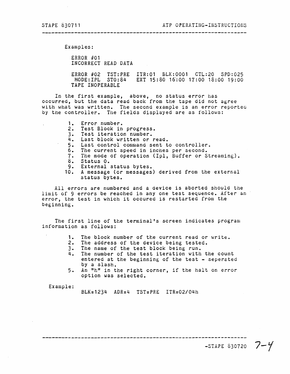
STAPE
830711
ATP
OPERATING-INSTRUCTIOnS
Examples:
ERROR
/101
INCORRECT
READ
DATA
ERROR
#02 TST:PRE
NODE:IPL STO:84
TAPE
INOPERABLE
ITR:Ol
BLK:OOOl
CTL:20 SPD:025
EXT
15:80
16':00
17:00
18:00
19:00
In
the
first
example,
above,
no
status
error
has
occurred,
but
the
data
read
back
from
the
tape
did
not
agree
with
what
was
written.
The
second
example
is
an
error
reportea
by
the
controller.
The
fields
displayed
are
as
follows:
1.
Error
number.
2.
Test
Block
in
progress.
3.
Test
iteration
number.
4.
Last
block
written
or
read.
5.
Last
control
command
sent
to
controller.
6.
The
current
speed
in
inches
per
second.
7.
The mode
of
operation
(Ipl,
Buffer
or
Streaming).
8.
Status
o.
9.
External
status
bytes.
10.
A
message
(or
messages)
derived
from
the
external
status
bytes.
All
errors
are
numbered and a
device
is
aborted
should
the
limit
of
9
errors
be
reached
in
anyone
test
sequence.
After
an
error,
the
test
in
which
it
occured
is
restarted
from
the
beginning.
The
first
line
of
the
terminal's
screen
indicates
program
information
as
follows:
1.
The
block
number
of
the
current
read
or
write.
2.
The
address
of
the
device
being
tested.
3.
The name
of
the
test
block
being
run.
4.
The number
of
the
test
iteration
with
the
count
entered
at
the
beginning
of
the
test
-
seperated
by a
slash.
5.
An
"h"
in
the
right
corner,
if
the
halt
on
error
option
was
selected.
Example:
BLK=1234
ADR=4
TST=PRE
ITR=02/04h
-STAPE 830720
7-
Y
