Cisco IronPort AsyncOS 7.1.0 User Guide For Web Security Appliances Appliance With Software WSA S170 Iron Port Async OS 7 1 0
User Manual: Cisco Web Security Appliance With Software WSA S170
Open the PDF directly: View PDF ![]() .
.
Page Count: 824 [warning: Documents this large are best viewed by clicking the View PDF Link!]
- Cisco IronPort AsyncOS 7.1 for Web User Guide
- Contents
- Getting Started with the Web Security Appliance
- What’s New in This Release
- What’s New in Version 7.0
- New Feature: Cisco AnyConnect Secure Mobility
- New Feature: Application Visibility and Control
- New Feature: Safe Search and Site Content Rating Enforcement
- New Feature: Bandwidth Control for Streaming Media
- New Feature: HTTP Instant Messaging Controls
- New Feature: SaaS Access Control
- New Feature: Sophos Anti-Virus Scanning
- New Feature: Transparent User Identification for Novell eDirectory
- New Feature: Outbound Malware Scanning
- New Feature: Application Scanning Bypass
- New Feature: Allow User One Login at a Time
- New Feature: WBRS Threat Details
- New Feature: What’s New In This Release
- Enhanced: Per Identity Authentication Settings
- Enhanced: PAC File Hosting
- Enhanced: Reports
- Enhanced: Advancedproxyconfig CLI Command
- Enhanced: Logging
- How to Use This Guide
- Web Security Appliance Overview
- Using the Web Security Appliance
- Deployment
- Installation and Configuration
- Web Proxy Services
- Working with Policies
- Identities
- Access Policies
- Working with External Proxies
- Decryption Policies
- Outbound Malware Scanning
- Data Security and External DLP Policies
- Data Security and External DLP Policies Overview
- Working with Data Security and External DLP Policies
- Evaluating Data Security and External DLP Policy Group Membership
- Creating Data Security and External DLP Policies
- Controlling Upload Requests Using IronPort Data Security Policies
- Defining External DLP Systems
- Controlling Upload Requests Using External DLP Policies
- Logging
- Achieving Secure Mobility
- Controlling Access to SaaS Applications
- Notifying End Users
- Notifying End Users of Organization Policies
- Configuring General Settings for Notification Pages
- Working With IronPort End-User Notification Pages
- Working with User Defined End-User Notification Pages
- End-User Acknowledgement Page
- Configuring the End-User URL Filtering Warning Page
- Working with IronPort FTP Notification Messages
- Custom Text in Notification Pages
- Notification Page Types
- URL Filters
- URL Filters Overview
- Configuring the URL Filtering Engine
- Filtering Transactions Using URL Categories
- Custom URL Categories
- Filtering Adult Content
- Redirecting Traffic
- Warning Users and Allowing Them to Continue
- Creating Time Based URL Filters
- Viewing URL Filtering Activity
- Regular Expressions
- URL Category Descriptions
- Understanding Application Visibility and Control
- Web Reputation Filters
- Anti-Malware Services
- Authentication
- Authentication Overview
- Understanding How Authentication Works
- Working with Authentication Realms
- Working with Authentication Sequences
- Appliance Behavior with Multiple Authentication Realms
- Testing Authentication Settings
- Configuring Global Authentication Settings
- Allowing Users to Re-Authenticate
- Tracking Authenticated Users
- LDAP Authentication
- NTLM Authentication
- Supported Authentication Characters
- L4 Traffic Monitor
- Reporting
- Web Security Appliance Reports
- Web Security Appliance Reports Overview
- Overview Page
- Users Page
- Web Sites Page
- URL Categories Page
- Application Visibility Page
- Anti-Malware Page
- Client Malware Risk Page
- Web Reputation Filters Page
- L4 Traffic Monitor Data Page
- Reports by User Location Page
- Web Tracking Page
- System Capacity Page
- System Status Page
- Logging
- Configuring Network Settings
- System Administration
- Managing the S-Series Appliance
- Support Commands
- Working with Feature Keys
- Administering User Accounts
- Configuring Administrator Settings
- Configuring the Return Address for Generated Messages
- Managing Alerts
- Setting System Time
- Installing a Server Digital Certificate
- Upgrading the System Software
- Configuring Upgrade and Service Update Settings
- Command Line Interface
- IronPort End User License Agreement
- Index

THE SPECIFICATIONS AND INFORMATION REGARDING THE PRODUCTS IN THIS MANUAL ARE SUBJECT TO CHANGE WITHOUT
NOTICE. ALL STATEMENTS, INFORMATION, AND RECOMMENDATIONS IN THIS MANUAL ARE BELIEVED TO BE ACCURATE BUT
ARE PRESENTED WITHOUT WARRANTY OF ANY KIND, EXPRESS OR IMPLIED. USERS MUST TAKE FULL RESPONSIBILITY FOR
THEIR APPLICATION OF ANY PRODUCTS.
THE SOFTWARE LICENSE AND LIMITED WARRANTY FOR THE ACCOMPANYING PRODUCT ARE SET FORTH IN THE INFORMATION
PACKET THAT SHIPPED WITH THE PRODUCT AND ARE INCORPORATED HEREIN BY THIS REFERENCE. IF YOU ARE UNABLE TO
LOCATE THE SOFTWARE LICENSE OR LIMITED WARRANTY, CONTACT YOUR CISCO REPRESENTATIVE FOR A COPY.
The Cisco implementation of TCP header compression is an adaptation of a program developed by the University of California, Berkeley (UCB) as
part of UCB’s public domain version of the UNIX operating system. All rights reserved. Copyright © 1981, Regents of the University of California.
NOTWITHSTANDING ANY OTHER WARRANTY HEREIN, ALL DOCUMENT FILES AND SOFTWARE OF THESE SUPPLIERS ARE
PROVIDED “AS IS” WITH ALL FAULTS. CISCO AND THE ABOVE-NAMED SUPPLIERS DISCLAIM ALL WARRANTIES, EXPRESSED
OR IMPLIED, INCLUDING, WITHOUT LIMITATION, THOSE OF MERCHANTABILITY, FITNESS FOR A PARTICULAR PURPOSE AND
NONINFRINGEMENT OR ARISING FROM A COURSE OF DEALING, USAGE, OR TRADE PRACTICE.
IN NO EVENT SHALL CISCO OR ITS SUPPLIERS BE LIABLE FOR ANY INDIRECT, SPECIAL, CONSEQUENTIAL, OR INCIDENTAL
DAMAGES, INCLUDING, WITHOUT LIMITATION, LOST PROFITS OR LOSS OR DAMAGE TO DATA ARISING OUT OF THE USE OR
INABILITY TO USE THIS MANUAL, EVEN IF CISCO OR ITS SUPPLIERS HAVE BEEN ADVISED OF THE POSSIBILITY OF SUCH
DAMAGES.
CCDE, CCENT, CCSI, Cisco Eos, Cisco HealthPresence, Cisco IronPort, the Cisco logo, Cisco Nurse Connect, Cisco Pulse, Cisco SensorBase,
Cisco StackPower, Cisco StadiumVision, Cisco TelePresence, Cisco Unified Computing System, Cisco WebEx, DCE, Flip Channels, Flip for Good,
Flip Mino, Flipshare (Design), Flip Ultra, Flip Video, Flip Video (Design), Instant Broadband, and Welcome to the Human Network are trademarks;
Changing the Way We Work, Live, Play, and Learn, Cisco Capital, Cisco Capital (Design), Cisco:Financed (Stylized), Cisco Store, Flip Gift Card,
and One Million Acts of Green are service marks; and Access Registrar, Aironet, AllTouch, AsyncOS, Bringing the Meeting To You, Catalyst, CCDA,
CCDP, CCIE, CCIP, CCNA, CCNP, CCSP, CCVP, Cisco, the Cisco Certified Internetwork Expert logo, Cisco IOS, Cisco Lumin, Cisco Nexus,
Cisco Press, Cisco Systems, Cisco Systems Capital, the Cisco Systems logo, Cisco Unity, Collaboration Without Limitation, Continuum, EtherFast,
EtherSwitch, Event Center, Explorer, Follow Me Browsing, GainMaker, iLYNX, IOS, iPhone, IronPort, the IronPort logo, Laser Link, LightStream,
Linksys, MeetingPlace, MeetingPlace Chime Sound, MGX, Networkers, Networking Academy, PCNow, PIX, PowerKEY, PowerPanels, PowerTV,
PowerTV (Design), PowerVu, Prisma, ProConnect, ROSA, SenderBase, SMARTnet, Spectrum Expert, StackWise, WebEx, and the WebEx logo are
registered trademarks of Cisco Systems, Inc. and/or its affiliates in the United States and certain other countries.
All other trademarks mentioned in this document or website are the property of their respective owners. The use of the word partner does not imply
a partnership relationship between Cisco and any other company. (0910R)
Any Internet Protocol (IP) addresses and phone numbers used in this document are not intended to be actual addresses and phone numbers. Any
examples, command display output, network topology diagrams, and other figures included in the document are shown for illustrative purposes only.
Any use of actual IP addresses or phone numbers in illustrative content is unintentional and coincidental.
Cisco IronPort AsyncOS 7.1 for Web User Guide
© 2010 Cisco Systems, Inc. All rights reserved.

iii
Cisco IronPort AsyncOS 7.1 for Web User Guide
OL-23207-01
CONTENTS
CHAPTER
1Getting Started with the Web Security Appliance 1-1
What’s New in This Release 1-1
New Feature: Web Reporting and Web Tracking 1-2
New Feature: Centralized Reporting 1-2
New Feature: Anonymized Usernames on Reporting Pages 1-3
Enhanced: Reports 1-3
What’s New in Version 7.0 1-3
New Feature: Cisco AnyConnect Secure Mobility 1-3
New Feature: Application Visibility and Control 1-4
New Feature: Safe Search and Site Content Rating Enforcement 1-5
New Feature: Bandwidth Control for Streaming Media 1-5
New Feature: HTTP Instant Messaging Controls 1-6
New Feature: SaaS Access Control 1-6
New Feature: Sophos Anti-Virus Scanning 1-7
New Feature: Transparent User Identification for Novell eDirectory 1-7
New Feature: Outbound Malware Scanning 1-7
New Feature: Application Scanning Bypass 1-8
New Feature: Allow User One Login at a Time 1-8
New Feature: WBRS Threat Details 1-9
New Feature: What’s New In This Release 1-9
Enhanced: Per Identity Authentication Settings 1-9
Enhanced: PAC File Hosting 1-9
Enhanced: Reports 1-10
Enhanced: Advancedproxyconfig CLI Command 1-10

Contents
iv
Cisco IronPort AsyncOS 7.1 for Web User Guide
OL-23207-01
Enhanced: Logging 1-10
How to Use This Guide 1-11
Before You Begin 1-11
Typographic Conventions 1-12
Where to Find More Information 1-13
Documentation Set 1-13
IronPort Technical Training 1-13
Knowledge Base 1-13
Cisco Support Community 1-14
Cisco IronPort Customer Support 1-15
Third Party Contributors 1-15
IronPort Welcomes Your Comments 1-15
Web Security Appliance Overview 1-16
CHAPTER
2Using the Web Security Appliance 2-1
How the Web Security Appliance Works 2-1
Web Proxy 2-1
The L4 Traffic Monitor 2-2
Administering the Web Security Appliance 2-2
System Setup Wizard 2-3
Accessing the Web Security Appliance 2-3
Using the Command Line Interface (CLI) 2-4
Using an Ethernet Connection 2-4
Using a Serial Connection 2-5
The SenderBase Network 2-5
Sharing Data 2-6
Reporting and Logging 2-6
Navigating the Web Security Appliance Web Interface 2-7
Logging In 2-9

v
Cisco IronPort AsyncOS 7.1 for Web User Guide
OL-23207-01
Contents
Browser Requirements 2-10
Support Languages 2-10
Reporting Tab 2-11
Web Security Manager Tab 2-11
Security Services Tab 2-12
Network Tab 2-13
System Administration Tab 2-13
Committing and Clearing Changes 2-14
Committing and Clearing Changes in the Web Interface 2-14
Committing Changes 2-15
Clearing Changes 2-15
Committing and Clearing Changes in the CLI 2-16
CHAPTER
3Deployment 3-1
Deployment Overview 3-1
Preparing for Deployment 3-2
Appliance Interfaces 3-3
Management Interface 3-4
Data Interfaces 3-4
L4 Traffic Monitor Interfaces 3-5
Example Deployment 3-5
Deploying the Web Proxy in Explicit Forward Mode 3-6
Configuring Client Applications 3-7
Connecting Appliance Interfaces 3-7
Testing an Explicit Forward Configuration 3-7
Deploying the Web Proxy in Transparent Mode 3-7
Connecting Appliance Interfaces 3-8
Connecting the Appliance to a WCCP Router 3-8
Configuring the Web Security Appliance 3-9

Contents
vi
Cisco IronPort AsyncOS 7.1 for Web User Guide
OL-23207-01
Configuring the WCCP Router 3-9
Example WCCP Configurations 3-11
Example 1 3-11
Example 2 3-12
Example 3 3-14
Working with Multiple Appliances and Routers 3-15
Using the Web Security Appliance in an Existing Proxy Environment 3-15
Transparent Upstream Proxy 3-15
Explicit Forward Upstream Proxy 3-16
Deploying the L4 Traffic Monitor 3-16
Connecting the L4 Traffic Monitor 3-17
Configuring an L4 Traffic Monitor Wiring Type 3-18
Physical Dimensions 3-18
CHAPTER
4Installation and Configuration 4-1
Before You Begin 4-1
Connecting a Laptop to the Appliance 4-2
Connecting the Appliance to the Network 4-2
Gathering Setup Information 4-4
DNS Support 4-6
System Setup Wizard 4-6
Accessing the System Setup Wizard 4-8
Step 1. Start 4-8
Step 2. Network 4-9
Step 3. Security 4-22
Step 4. Review 4-26
CHAPTER
5Web Proxy Services 5-1
About Web Proxy Services 5-1

vii
Cisco IronPort AsyncOS 7.1 for Web User Guide
OL-23207-01
Contents
Web Proxy Cache 5-2
Configuring the Web Proxy 5-3
Working with FTP Connections 5-8
Using Authentication with Native FTP 5-9
Working with Native FTP in Transparent Mode 5-10
Configuring FTP Proxy Settings 5-11
Bypassing the Web Proxy 5-15
How the Proxy Bypass List Works 5-17
Using WCCP with the Proxy Bypass List 5-18
Bypassing Application Scanning 5-18
Proxy Usage Agreement 5-18
Configuring Client Applications to Use the Web Proxy 5-19
Working with PAC Files 5-19
PAC File Format 5-21
Creating a PAC File for Remote Users 5-22
Specifying the PAC File in Browsers 5-22
Entering the PAC File Location 5-22
Detecting the PAC File Location Automatically 5-23
Adding PAC Files to the Web Security Appliance 5-24
Specifying the PAC File URL 5-25
Uploading PAC Files to the Appliance 5-28
Understanding WPAD Compatibility with Netscape and Firefox 5-29
Advanced Proxy Configuration 5-30
Authentication Options 5-32
Caching Options 5-39
DNS Options 5-42
EUN Options 5-44
NATIVEFTP Options 5-44
FTPOVERHTTP Options 5-47

Contents
viii
Cisco IronPort AsyncOS 7.1 for Web User Guide
OL-23207-01
HTTPS Options 5-48
Scanning Options 5-49
WCCP Options 5-49
Miscellaneous Options 5-50
CHAPTER
6Working with Policies 6-1
Working with Policies Overview 6-1
Policy Types 6-3
Identities 6-3
Decryption Policies 6-4
Routing Policies 6-4
Access Policies 6-4
IronPort Data Security Policies 6-5
External DLP Policies 6-5
Outbound Malware Scanning Policies 6-6
SaaS Application Authentication Policies 6-6
Working with Policy Groups 6-6
Creating Policy Groups 6-7
Using the Policies Tables 6-7
Policy Group Membership 6-10
Authenticating Users versus Authorizing Users 6-10
Working with Failed Authentication and Authorization 6-11
Working with All Identities 6-12
Policy Group Membership Rules and Guidelines 6-12
Working with Time Based Policies 6-13
Creating Time Ranges 6-14
Working with User Agent Based Policies 6-16
Configuring User Agents for Policy Group Membership 6-16
Exempting User Agents from Authentication 6-18

ix
Cisco IronPort AsyncOS 7.1 for Web User Guide
OL-23207-01
Contents
Tracing Policies 6-18
CHAPTER
7Identities 7-1
Identities Overview 7-1
Evaluating Identity Group Membership 7-2
Understanding How Authentication Affects Identity Groups 7-4
Understanding How Authentication Affects HTTPS and FTP over HTTP
Requests 7-6
Understanding How Authentication Scheme Affects Identity Groups 7-9
Matching Client Requests to Identity Groups 7-10
Allowing Guest Access to Users Who Fail Authentication 7-13
Identifying Users Transparently 7-16
Understanding Transparent User Identification 7-17
Rules and Guidelines 7-18
Configuring Transparent User Identification 7-19
Creating Identities 7-20
Configuring Identities in Other Policy Groups 7-28
Example Identity Policies Tables 7-31
Example 1 7-31
Example 2 7-33
CHAPTER
8Access Policies 8-1
Access Policies Overview 8-1
Access Policy Groups 8-2
Understanding the Monitor Action 8-3
Evaluating Access Policy Group Membership 8-4
Matching Client Requests to Access Policy Groups 8-5
Creating Access Policies 8-7
Controlling HTTP and Native FTP Traffic 8-11

Contents
x
Cisco IronPort AsyncOS 7.1 for Web User Guide
OL-23207-01
Protocols and User Agents 8-14
URL Categories 8-15
Applications 8-15
Object Blocking 8-16
Web Reputation and Anti-Malware 8-17
Blocking Specific Applications and Protocols 8-18
Blocking on Port 80 8-18
Policy: Protocols and User Agents 8-18
Policy: URL Categories 8-20
Policy: Objects 8-21
Blocking on Ports Other Than 80 8-21
CHAPTER
9Working with External Proxies 9-1
Working with External Proxies Overview 9-1
Routing Traffic to Upstream Proxies 9-2
Adding External Proxy Information 9-3
Evaluating Routing Policy Group Membership 9-5
Matching Client Requests to Routing Policy Groups 9-6
Creating Routing Policies 9-8
CHAPTER
10 Decryption Policies 10-1
Decryption Policies Overview 10-1
Decryption Policy Groups 10-3
Personally Identifiable Information Disclosure 10-4
Understanding the Monitor Action 10-5
Digital Cryptography Terms 10-6
HTTPS Basics 10-8
SSL Handshake 10-9
Digital Certificates 10-9

xi
Cisco IronPort AsyncOS 7.1 for Web User Guide
OL-23207-01
Contents
Validating Certificate Authorities 10-10
Validating Digital Certificates 10-12
Decrypting HTTPS Traffic 10-13
Mimicking the Server Digital Certificate 10-15
Working with Root Certificates 10-16
Using Decryption with the AVC Engine 10-19
Using Decryption with AOL Instant Messenger 10-19
Converting Certificate and Key Formats 10-20
Enabling the HTTPS Proxy 10-21
Evaluating Decryption Policy Group Membership 10-27
Matching Client Requests to Decryption Policy Groups 10-28
Creating Decryption Policies 10-30
Controlling HTTPS Traffic 10-34
Importing a Trusted Root Certificate 10-37
CHAPTER
11 Outbound Malware Scanning 11-1
Outbound Malware Scanning Overview 11-1
User Experience with Blocked Requests 11-2
Outbound Malware Scanning Policy Groups 11-2
Evaluating Outbound Malware Scanning Policy Group Membership 11-3
Matching Client Requests to Outbound Malware Scanning Policy
Groups 11-4
Creating Outbound Malware Scanning Policies 11-6
Controlling Upload Requests Using Outbound Malware Scanning Policies 11-11
Logging 11-14
CHAPTER
12 Data Security and External DLP Policies 12-1
Data Security and External DLP Policies Overview 12-1
Bypassing Upload Requests Below a Minimum Size 12-3

Contents
xii
Cisco IronPort AsyncOS 7.1 for Web User Guide
OL-23207-01
User Experience with Blocked Requests 12-3
Working with Data Security and External DLP Policies 12-4
Data Security Policy Groups 12-4
External DLP Policy Groups 12-6
Evaluating Data Security and External DLP Policy Group Membership 12-7
Matching Client Requests to Data Security and External DLP Policy
Groups 12-8
Creating Data Security and External DLP Policies 12-10
Controlling Upload Requests Using IronPort Data Security Policies 12-15
URL Categories 12-17
Web Reputation 12-17
Content Blocking 12-17
Defining External DLP Systems 12-20
Controlling Upload Requests Using External DLP Policies 12-25
Logging 12-27
CHAPTER
13 Achieving Secure Mobility 13-1
Achieving Secure Mobility Overview 13-1
Working with Remote Users 13-2
Enabling Secure Mobility 13-3
Transparently Identifying Remote Users 13-5
Logging 13-6
Configuring Secure Mobility Using the CLI 13-7
CHAPTER
14 Controlling Access to SaaS Applications 14-1
SaaS Access Control Overview 14-1
Understanding How SaaS Access Control Works 14-2
Authenticating SaaS Users 14-4

xiii
Cisco IronPort AsyncOS 7.1 for Web User Guide
OL-23207-01
Contents
Authentication Requirements 14-4
Enabling SaaS Access Control 14-5
Understanding the Single Sign-On URL 14-5
Using SaaS Access Control with Multiple Appliances 14-6
Configuring the Appliance as an Identity Provider 14-7
Creating SaaS Application Authentication Policies 14-11
CHAPTER
15 Notifying End Users 15-1
Notifying End Users of Organization Policies 15-1
Configuring General Settings for Notification Pages 15-3
Working With IronPort End-User Notification Pages 15-5
Configuring IronPort Notification Pages 15-5
Editing IronPort Notification Pages 15-8
Rules and Guidelines for Editing IronPort Notification Pages 15-12
Using Variables in Customized IronPort Notification Pages 15-13
Working with User Defined End-User Notification Pages 15-14
Configuring User Defined End-User Notification Pages 15-17
End-User Acknowledgement Page 15-18
Configuring the End-User Acknowledgement Page 15-20
Configuring the End-User URL Filtering Warning Page 15-21
Working with IronPort FTP Notification Messages 15-23
Custom Text in Notification Pages 15-23
Supported HTML Tags in Notification Pages 15-23
Custom Text and Logos: Authentication, and End-User Acknowledgement
Pages 15-24
Notification Page Types 15-25
CHAPTER
16 URL Filters 16-1
URL Filters Overview 16-1

Contents
xiv
Cisco IronPort AsyncOS 7.1 for Web User Guide
OL-23207-01
Dynamic Content Analysis Engine 16-3
Uncategorized URLs 16-4
Matching URLs to URL Categories 16-4
The URL Categories Database 16-5
Configuring the URL Filtering Engine 16-5
Filtering Transactions Using URL Categories 16-6
Configuring URL Filters for Access Policy Groups 16-7
Configuring URL Filters for Decryption Policy Groups 16-10
Configuring URL Filters for Data Security Policy Groups 16-13
Custom URL Categories 16-16
Filtering Adult Content 16-20
Logging Adult Content Access 16-22
Redirecting Traffic 16-23
Warning Users and Allowing Them to Continue 16-24
User Experience When Warning Users 16-26
Creating Time Based URL Filters 16-26
Viewing URL Filtering Activity 16-27
Understanding Unfiltered and Uncategorized Data 16-28
Access Log File 16-28
Regular Expressions 16-28
Forming Regular Expressions 16-29
Regular Expression Character Table 16-30
URL Category Descriptions 16-32
CHAPTER
17 Understanding Application Visibility and Control 17-1
Controlling Applications Overview 17-1
User Experience with Blocked Requests 17-3
AVC Engine Updates 17-3
Enabling the AVC Engine 17-3

xv
Cisco IronPort AsyncOS 7.1 for Web User Guide
OL-23207-01
Contents
Understanding Application Control Settings 17-4
Working with Browse View 17-5
Working with Search View 17-7
Rules and Guidelines 17-9
Configuring Application Control Settings 17-9
Controlling Bandwidth 17-11
Configuring Overall Bandwidth Limits 17-11
Configuring User Bandwidth Limits 17-12
Configuring the Default Bandwidth Limit for an Application Type 17-13
Overriding the Default Bandwidth Limit for an Application Type 17-13
Configuring Bandwidth Controls for an Application 17-15
Controlling Instant Messaging Traffic 17-17
Viewing AVC Activity 17-19
Access Log File 17-19
CHAPTER
18 Web Reputation Filters 18-1
Web Reputation Filters Overview 18-1
The Web Reputation Database 18-1
Maintaining the Database Tables 18-2
Web Reputation Scores 18-2
Enabling Web Reputation Filters 18-3
Understanding How Web Reputation Filtering Works 18-4
Web Reputation in Access Policies 18-4
Web Reputation in Decryption Policies 18-5
Configuring Web Reputation Scores 18-5
Configuring Web Reputation for Access Policies 18-6
Configuring Web Reputation for Decryption Policies 18-7
Configuring Web Reputation for IronPort Data Security Policies 18-8
Viewing Web Reputation Filtering Activity 18-9

Contents
xvi
Cisco IronPort AsyncOS 7.1 for Web User Guide
OL-23207-01
Monitoring Filter and Scoring Activity 18-9
Access Log File 18-10
CHAPTER
19 Anti-Malware Services 19-1
Anti-Malware Overview 19-1
Malware Category Descriptions 19-2
IronPort DVS™ (Dynamic Vectoring and Streaming) Engine 19-4
Maintaining the Database Tables 19-5
Understanding How the DVS Engine Works 19-5
Working with Multiple Malware Verdicts 19-6
Different Scanning Engines 19-6
Same Scanning Engine 19-6
Webroot Scanning 19-7
McAfee Scanning 19-8
Matching Virus Signature Patterns 19-8
Heuristic Analysis 19-9
McAfee Categories 19-9
Sophos Scanning 19-10
Configuring Anti-Malware Scanning 19-10
Viewing Anti-Malware Scanning Activity 19-15
Monitoring Scanning Activity 19-15
Access Log File 19-15
CHAPTER
20 Authentication 20-1
Authentication Overview 20-1
Client Application Support 20-3
Working with Upstream Proxy Servers 20-3
Authenticating Users 20-4
Working with Failed Authentication 20-4

xvii
Cisco IronPort AsyncOS 7.1 for Web User Guide
OL-23207-01
Contents
Understanding How Authentication Works 20-5
Basic versus NTLMSSP Authentication Schemes 20-7
How Web Proxy Deployment Affects Authentication 20-8
Explicit Forward Deployment, Basic Authentication 20-9
Transparent Deployment, Basic Authentication 20-10
Explicit Forward Deployment, NTLM Authentication 20-12
Transparent Deployment, NTLM Authentication 20-13
Working with Authentication Realms 20-14
Creating Authentication Realms 20-15
Editing Authentication Realms 20-15
Deleting Authentication Realms 20-16
Working with Authentication Sequences 20-16
Creating Authentication Sequences 20-17
Editing Authentication Sequences 20-18
Deleting Authentication Sequences 20-19
Appliance Behavior with Multiple Authentication Realms 20-19
Testing Authentication Settings 20-20
Testing Process 20-21
LDAP Testing 20-21
NTLM Testing 20-21
Testing Authentication Settings in the Web Interface 20-22
Testing Authentication Settings in the CLI 20-23
Configuring Global Authentication Settings 20-23
Sending Authentication Credentials Securely 20-37
Uploading Certificates and Keys to Use with Credential Encryption and
SaaS Access Control 20-38
Accessing HTTPS and FTP Sites with Credential Encryption
Enabled 20-38
Allowing Users to Re-Authenticate 20-39
Using Re-Authentication with Internet Explorer 20-40

Contents
xviii
Cisco IronPort AsyncOS 7.1 for Web User Guide
OL-23207-01
Using Re-Authentication with PAC Files 20-41
Tracking Authenticated Users 20-42
LDAP Authentication 20-43
Changing Active Directory Passwords 20-43
LDAP Authentication Settings 20-44
LDAP Group Authorization 20-47
NTLM Authentication 20-51
Working with Multiple Active Directory Domains 20-51
NTLM Authentication Settings 20-52
Joining the Active Directory Domain 20-53
Supported Authentication Characters 20-56
Active Directory Server Supported Characters 20-56
LDAP Server Supported Characters 20-58
CHAPTER
21 L4 Traffic Monitor 21-1
About L4 Traffic Monitor 21-1
How the L4 Traffic Monitor Works 21-1
The L4 Traffic Monitor Database 21-3
Configuring the L4 Traffic Monitor 21-3
Configuring L4 Traffic Monitor Global Settings 21-4
Updating L4 Traffic Monitor Anti-Malware Rules 21-4
Configuring L4 Traffic Monitor Policies 21-5
Valid Formats 21-8
Viewing L4 Traffic Monitor Activity 21-9
Monitoring Activity and Viewing Summary Statistics 21-9
L4 Traffic Monitor Log File Entries 21-10
CHAPTER
22 Reporting 22-1
Reporting Overview 22-1

xix
Cisco IronPort AsyncOS 7.1 for Web User Guide
OL-23207-01
Contents
Working with Usernames in Reports 22-2
Report Pages 22-2
Using the Reporting Tab 22-3
Changing the Time Range 22-3
Searching Data 22-5
Working with Columns on Report Pages 22-5
Configuring Columns on Report Pages 22-8
Printing and Exporting Reports from Report Pages 22-10
Exporting Report Data 22-10
Enabling Centralized Reporting 22-12
Scheduling Reports 22-13
Adding a Scheduled Report 22-13
Editing Scheduled Reports 22-15
Deleting Scheduled Reports 22-15
On-Demand Reports 22-15
Archiving Reports 22-16
SNMP Monitoring 22-16
MIB Files 22-17
Hardware Objects 22-18
Hardware Traps 22-18
SNMP Traps 22-19
CLI Example 22-20
CHAPTER
23 Web Security Appliance Reports 23-1
Web Security Appliance Reports Overview 23-2
Overview Page 23-2
Users Page 23-5
User Details Page 23-7
Web Sites Page 23-10

Contents
xx
Cisco IronPort AsyncOS 7.1 for Web User Guide
OL-23207-01
URL Categories Page 23-12
Using The URL Categories Page in Conjunction with Other Reporting
Pages 23-16
Application Visibility Page 23-16
Anti-Malware Page 23-18
Malware Category Report Page 23-20
Malware Threat Report Page 23-21
Client Malware Risk Page 23-22
Client Detail Page 23-24
Web Reputation Filters Page 23-29
L4 Traffic Monitor Data Page 23-31
Reports by User Location Page 23-33
Web Tracking Page 23-35
System Capacity Page 23-40
How to Interpret the Data You See on System Capacity Page 23-43
System Status Page 23-44
CHAPTER
24 Logging 24-1
Logging Overview 24-1
Log File Types 24-2
Web Proxy Logging 24-8
Working with Log Subscriptions 24-9
Log File Name and Appliance Directory Structure 24-11
Rolling Over Log Subscriptions 24-11
Working with Compressed Log Files 24-12
Viewing the Most Recent Log Files 24-13
Configuring Host Keys 24-13
Adding and Editing Log Subscriptions 24-14
Deleting a Log Subscription 24-19

xxi
Cisco IronPort AsyncOS 7.1 for Web User Guide
OL-23207-01
Contents
Access Log File 24-19
Transaction Result Codes 24-23
ACL Decision Tags 24-24
Understanding Scanning Verdict Information 24-30
Web Reputation Filters Example 24-34
Anti-Malware Request Example 24-35
Anti-Malware Response Example 24-35
W3C Compliant Access Logs 24-36
W3C Log File Headers 24-37
Working with Log Fields in W3C Access Logs 24-38
Custom Formatting in Access Logs and W3C Logs 24-39
Configuring Custom Formatting in Access Logs 24-49
Configuring Custom Formatting in W3C Logs 24-50
Including HTTP/HTTPS Headers in Log Files 24-51
Malware Scanning Verdict Values 24-52
Traffic Monitor Log 24-53
Troubleshooting 24-54
CHAPTER
25 Configuring Network Settings 25-1
Changing the System Hostname 25-1
Configuring Network Interfaces 25-2
Configuring the Data Interfaces 25-3
Configuring the Network Interfaces from the Web Interface 25-5
Configuring TCP/IP Traffic Routes 25-7
Modifying the Default Route 25-7
Working With Routing Tables 25-8
Virtual Local Area Networks (VLANs) 25-9
VLANs and Physical Ports 25-11
Managing VLANs 25-11

Contents
xxii
Cisco IronPort AsyncOS 7.1 for Web User Guide
OL-23207-01
Creating a New VLAN via the etherconfig Command 25-11
Creating an IP Interface on a VLAN via the interfaceconfig
Command 25-15
Configuring Transparent Redirection 25-17
Working with WCCP Services 25-17
Working with the Assignment Method 25-18
Working with the Forwarding and Return Method 25-19
IP Spoofing when Using WCCP 25-20
Adding and Editing a WCCP Service 25-21
Deleting a WCCP Service 25-25
Configuring SMTP Relay Hosts 25-26
Configuring SMTP from the Web Interface 25-26
Configuring SMTP from the CLI 25-27
Configuring DNS Server(s) 25-28
Specifying DNS Servers 25-28
Split DNS 25-28
Using the Internet Root Servers 25-29
Multiple Entries and Priority 25-29
DNS Alert 25-30
Clearing the DNS Cache 25-30
Configuring DNS 25-30
CHAPTER
26 System Administration 26-1
Managing the S-Series Appliance 26-1
Saving and Loading the Appliance Configuration 26-2
Committing Changes to the Appliance Configuration 26-3
Support Commands 26-3
Open a Support Case 26-3
Remote Access 26-5
Packet Capture 26-6

xxiii
Cisco IronPort AsyncOS 7.1 for Web User Guide
OL-23207-01
Contents
Starting a Packet Capture 26-7
Editing Packet Capture Settings 26-7
Working with Feature Keys 26-10
Feature Keys Page 26-10
Feature Key Settings Page 26-11
Expired Feature Keys 26-12
Administering User Accounts 26-12
Managing Local Users 26-13
Adding Local Users 26-14
Deleting Users 26-15
Editing Users 26-15
Changing Passwords 26-16
Monitoring Users from the CLI 26-16
Using External Authentication 26-17
Configuring Administrator Settings 26-20
Configuring Custom Text at Login 26-20
Configuring IP-Based Administrator Access 26-20
Configuring the SSL Ciphers for Administrator Access 26-21
Configuring the Return Address for Generated Messages 26-21
Managing Alerts 26-22
Alerting Overview 26-22
Alerts: Alert Recipients, Alert Classifications, and Severities 26-23
Alert Settings 26-24
IronPort AutoSupport 26-25
Alert Messages 26-25
Alert From Address 26-25
Alert Subject 26-25
Example Alert Message 26-26
Managing Alert Recipients 26-27
Adding New Alert Recipients 26-27

Contents
xxiv
Cisco IronPort AsyncOS 7.1 for Web User Guide
OL-23207-01
Configuring Existing Alert Recipients 26-28
Deleting Alert Recipients 26-28
Configuring Alert Settings 26-29
Editing Alert Settings 26-29
Setting System Time 26-30
Selecting a Time Zone 26-30
Editing System Time 26-31
Configure NTP (Network Time Protocol) 26-31
Manually Setting System Time 26-32
Installing a Server Digital Certificate 26-32
Obtaining Certificates 26-33
Intermediate Certificates 26-34
Uploading Certificates to the Web Security Appliance 26-35
Upgrading the System Software 26-40
Upgrading AsyncOS for Web from the Web Interface 26-40
Upgrading AsyncOS for Web from the CLI 26-41
Differences from Traditional Upgrading Method 26-41
Configuring Upgrade and Service Update Settings 26-42
Updating and Upgrading from the IronPort Update Servers 26-43
Configuring a Static Address for the IronPort Update Servers 26-44
Upgrading from a Local Server 26-44
Hardware and Software Requirements for Local Upgrade Servers 26-46
Configuring the Update and Upgrade Settings from the Web Interface 26-46
Configuring the Update and Upgrade Settings from the CLI 26-51
Manually Updating Security Service Components 26-51
CHAPTER
27 Command Line Interface 27-1
The Command Line Interface Overview 27-1
Using the Command Line Interface 27-1

xxv
Cisco IronPort AsyncOS 7.1 for Web User Guide
OL-23207-01
Contents
Accessing the Command Line Interface 27-2
Working with the Command Prompt 27-2
Command Syntax 27-3
Select Lists 27-4
Yes/No Queries 27-4
Subcommands 27-4
Escaping Subcommands 27-5
Command History 27-5
Completing Commands 27-5
Configuration Changes 27-6
General Purpose CLI Commands 27-6
Committing Configuration Changes 27-6
Clearing Configuration Changes 27-7
Exiting the Command Line Interface Session 27-7
Seeking Help on the Command Line Interface 27-8
Web Security Appliance CLI Commands 27-8
APPENDIX
AIronPort End User License Agreement A-1
Cisco IronPort Systems, LLC Software License Agreement A-1
I
NDEX

Contents
xxvi
Cisco IronPort AsyncOS 7.1 for Web User Guide
OL-23207-01

CHAPTER
1-1
Cisco IronPort AsyncOS 7.1 for Web User Guide
OL-23207-01
1
Getting Started with the Web Security
Appliance
The IronPort AsyncOS for Web User Guide provides instructions for setting up,
administering, and monitoring the IronPort Web Security appliance. These
instructions are designed for an experienced system administrator with
knowledge of networking and web administration.
This chapter discusses the following topics:
•What’s New in This Release, page 1-1
•What’s New in Version 7.0, page 1-3
•How to Use This Guide, page 1-11
•Web Security Appliance Overview, page 1-16
What’s New in This Release
This section describes the new features and enhancements in AsyncOS for Web
7.1. For more information about the release, see the product release notes, which
are available on the Cisco IronPort Customer Support site at the following URL:
http://www.cisco.com/web/ironport/index.html
Note You need a Cisco.com User ID to access the site. If you do not have a Cisco.com
User ID, you can register for one here:
https://tools.cisco.com/RPF/register/register.do

Chapter 1 Getting Started with the Web Security Appliance
What’s New in This Release
1-2
Cisco IronPort AsyncOS 7.1 for Web User Guide
OL-23207-01
You might also find it useful to review release notes for earlier releases to see the
features and enhancements that were previously added.
New Feature: Web Reporting and Web Tracking
AsyncOS for Web 7.1 supports advanced web reporting and web tracking. Web
reporting and tracking aggregates information from individual security
components as well as acceptable use enforcement components and records data
that can be used to monitor your web traffic patterns and security risks. Web
reporting and tracking gives managers visibility and insight into current
operational data to help them refine policies, plan infrastructure, and measure
productivity.
You can run reports in real time to view an interactive display of system activity
over a specific period of time, or you can schedule reports and run them at regular
intervals. You can also export raw data to a file.
To use web reporting and tracking, use the Reporting > Web Tracking page.
For more information, see Web Tracking Page, page 23-35.
New Feature: Centralized Reporting
AsyncOS for Web 7.1 includes the Centralized Reporting feature which, when the
Web Security appliance is managed by a Security Management appliance, allows
you to configure the Web Security appliance so that the Security Management
appliance maintains the reports.
You might want to enable Centralized Reporting when the Security Management
appliance manages multiple Web Security appliances. This gives you a
centralized view of web traffic across all Web Security appliances on the Security
Management Appliance dashboard.
When you enable Centralized Reporting, only the System Capacity and System
Status reports are available on the Web Security appliance. To view the other
reports, connect to the Security Management appliance. The Web Security
appliance no longer stores data for the other reports.
For more information, see Enabling Centralized Reporting, page 22-12.

1-3
Cisco IronPort AsyncOS 7.1 for Web User Guide
OL-23207-01
Chapter 1 Getting Started with the Web Security Appliance
What’s New in Version 7.0
New Feature: Anonymized Usernames on Reporting Pages
AsyncOS for Web 7.1 allows you to make usernames unrecognizable in all
reports. Configure this on the Security Services > Reporting page using the
Anonymize usernames in reports setting. However, administrators always see
usernames.
Enhanced: Reports
AsyncOS for Web 7.1 includes the following new reports:
•Users
•Web Sites
•Web Tracking
It also includes updated information for many existing reports.
Due to all the reporting changes, when you upgrade to AsyncOS 7.1 for Web, all
historical data stored on the Web Security appliance for the on-box reports will be
erased. For more information, see the release notes.
For more information, see Chapter 23, `Web Security Appliance Reports'.
What’s New in Version 7.0
This section describes new features and enhancements added in the AsyncOS 7.0
for Web release.
New Feature: Cisco AnyConnect Secure Mobility
AsyncOS for Web 7.0 includes support for Cisco Secure Mobility Solution which
extends the network perimeter to remote endpoints, enabling the seamless
integration of web filtering services offered by the Web Security appliance.
Secure Mobility Solution is a collection of features across multiple Cisco
products that restores security and control in borderless networks. The Cisco

Chapter 1 Getting Started with the Web Security Appliance
What’s New in Version 7.0
1-4
Cisco IronPort AsyncOS 7.1 for Web User Guide
OL-23207-01
products that work with Secure Mobility Solution are the Cisco IronPort Web
Security appliance, Cisco ASA 5500 series adaptive security appliance, and Cisco
AnyConnect secure mobility client.
Using Secure Mobility Solution, mobile and remote users have a seamless
experience and are always protected from risks as if they were local users
connected within the network.
When Secure Mobility Solution is enabled on the Web Security appliance, you
can distinguish remote users from local users. This allows you to perform the
following tasks:
•Create Identities and other policies for remote users.
•View reports for remote traffic.
•Enable single sign-on (SSO) for remote users.
To protect remote users using always-on security, first you must enable the Secure
Mobility Solution feature on the Web Security appliance. When Secure Mobility
Solution is enabled, you can distinguish between remote users from local users
when creating Identities.
For more information, see Achieving Secure Mobility, page 13-1.
New Feature: Application Visibility and Control
AsyncOS for Web 7.0 enhances the Cisco IronPort Web Usage Controls platform
to include the Application Visibility and Control engine (AVC engine) which
enables administrators to apply deeper controls to particular application types.
The AVC engine is an acceptable use policy component that inspects web traffic
to gain deeper understanding and control of web traffic used for applications.
Application control gives you more granular control over web traffic than just
URL filtering. For example, you can block streaming media from sports sites, but
not news sites.
To control applications using the AVC engine, enable the AVC engine when you
enable Cisco IronPort Web Usage Controls, and then define application control
settings in the Access Policies.
For more information, see Understanding Application Visibility and Control,
page 17-1.

1-5
Cisco IronPort AsyncOS 7.1 for Web User Guide
OL-23207-01
Chapter 1 Getting Started with the Web Security Appliance
What’s New in Version 7.0
New Feature: Safe Search and Site Content Rating Enforcement
AsyncOS for Web 7.0 uses the AVC engine to filter adult content from some web
searches and websites. You might want to do this to allow access to these sites,
such as google.com and youtube.com, while still restricting potentially unsafe
content from reaching users.
AsyncOS for Web offers the following features to filter adult content:
•Enforce safe searches. Most search engines allow the safe search feature to
be enabled and disabled by end users. You can configure the Web Security
appliance so that outgoing search requests appear to search engines as safe
search requests. This gives the control to an administrator on the network
instead of the end user. You might want to do this to prevent users from
bypassing acceptable use policies using search engines.
•Enforce site content ratings. Many content sharing sites that serve
user-generated photos and videos classify some of their content as adult. They
allow users to restrict their own access to the adult content on these sites by
either enforcing their own safe search feature or blocking access to adult
content, or both. This classification feature is commonly called content
ratings.
To enforce safe searches and site content ratings, configure the URL filtering
settings for an Access Policy.
For more information, see Filtering Adult Content, page 16-20.
New Feature: Bandwidth Control for Streaming Media
AsyncOS for Web 7.0 uses the AVC engine to control the amount of bandwidth
used for streaming media applications. You can define an overall bandwidth limit
and per user bandwidth limits. When both the overall limit and user limit applies
to a transaction, the most restrictive option applies.
For more information, see Controlling Bandwidth, page 17-11.

Chapter 1 Getting Started with the Web Security Appliance
What’s New in Version 7.0
1-6
Cisco IronPort AsyncOS 7.1 for Web User Guide
OL-23207-01
New Feature: HTTP Instant Messaging Controls
AsyncOS for Web 7.0 uses the AVC engine to apply control settings to some
instant messenger (IM) traffic that runs on top of HTTP. You can block or monitor
the IM traffic, and depending on the IM service, you can block particular activities
(also known as application behaviors) in an IM session. For example, you can
allow an IM session with a particular IM service provider, but block file transfers
within that session.
You control IM traffic by configuring Instant Messenger application settings on
the Applications Visibility and Control page of Access Policies.
For more information, see Controlling Instant Messaging Traffic, page 17-17.
New Feature: SaaS Access Control
AsyncOS for Web 7.0 includes the SaaS Access Control feature which provides
IT administrators with seamless, secure controls necessary for managing access
to Software as a Service (SaaS) applications and enforcing security policies. SaaS
Access Control allows IT administrators to easily control authentication and
authorization for users who need to access SaaS applications.
When you enable Cisco SaaS Access Control, users log into the configured SaaS
applications using their network authentication user credentials. That means they
use the same user name and password for all SaaS applications as well as network
access. You can choose whether users are transparently signed in (single sign-on
functionality) or prompted to enter their authentication user name and password.
The SaaS Access Control solution uses the Security Assertion Markup Language
(SAML) to authorize access to SaaS applications. It works with SaaS applications
that are compliant with SAML version 2.0.
To enable SaaS Access Control, you must configure settings on both the Web
Security appliance and the SaaS application. It is very important that the settings
you configure on the appliance and SaaS application match each other
appropriately.
For more information, see Controlling Access to SaaS Applications, page 14-1.

1-7
Cisco IronPort AsyncOS 7.1 for Web User Guide
OL-23207-01
Chapter 1 Getting Started with the Web Security Appliance
What’s New in Version 7.0
New Feature: Sophos Anti-Virus Scanning
AsyncOS for Web 7.0 adds the Sophos scanning engine to the list of possible Web
Security appliance on-box anti-malware scanning engines. The Sophos engine
offers award-winning protection against known and unknown threats using their
Genotype and Behavioral Genotype Protection. The Sophos Genotype virus
detection technology proactively blocks families of viruses, and Behavioral
Genotype Protection automatically guards against zero-day threats by analyzing
the behavior of the code before it executes—offering protection from new and
existing viruses, trojans, worms, spyware, adware, and other potentially unwanted
applications (PUAs).
For more information, see Sophos Scanning, page 19-10.
New Feature: Transparent User Identification for Novell
eDirectory
AsyncOS for Web 7.0 allows you to configure the Web Security appliance so that
it identifies users by an authenticated user name transparently—that is, without
prompting the end user. You might want to do this to:
•Create a single sign-on environment so users are not aware of the presence of
a proxy on the network.
•Use authentication based policies to apply to transactions coming from client
applications that are incapable of displaying the authentication prompt to end
users.
To identify users transparently, you must define at least one LDAP authentication
realm that supports Novell eDirectory.
For more information, see Identifying Users Transparently, page 7-16.
New Feature: Outbound Malware Scanning
AsyncOS for Web 7.0 includes protects data and objects leaving the network by
providing outbound malware scanning. The IronPort Dynamic Vectoring and
Streaming (DVS) engine scans transaction requests as they leave the network in
real-time. By working with the IronPort DVS engine, the Web Security appliance
allows you to prevent users from unintentionally uploading malicious data.

Chapter 1 Getting Started with the Web Security Appliance
What’s New in Version 7.0
1-8
Cisco IronPort AsyncOS 7.1 for Web User Guide
OL-23207-01
To restrict malicious data from leaving the network, the Web Security appliance
provides the Outbound Malware Scanning policy groups. You define which
uploads are scanned for malware, which anti-malware scanning engines to use for
scanning, and which malware types to block.
For more information, see Outbound Malware Scanning, page 11-1.
New Feature: Application Scanning Bypass
AsyncOS for Web 7.0 allows administrators to easily bypass certain web
applications from being scanned by the Web Proxy by checking a checkbox. This
can prevent integration issues with web applications that do not interact well with
proxies. In version 7.0, you can bypass scanning for Cisco Webex.
For more information, see Bypassing Application Scanning, page 5-18.
New Feature: Allow User One Login at a Time
AsyncOS for Web 7.0 allows administrators to control whether or not an
authenticated user can access the Internet from multiple machines simultaneously.
You might want to restrict access to one machine to prevent users from sharing
their authentication credentials with non-authorized users. When a user is
prevented from logging at a different machine, an end-user notification page
appears. You can choose whether or not users can click a button to login as a
different username.
To restrict an authenticated user from accessing the Internet from a different
machine, configure the User Session Restrictions settings on the Network >
Authentication page.
For more information, see Configuring Global Authentication Settings,
page 20-23.

1-9
Cisco IronPort AsyncOS 7.1 for Web User Guide
OL-23207-01
Chapter 1 Getting Started with the Web Security Appliance
What’s New in Version 7.0
New Feature: WBRS Threat Details
AsyncOS for Web 7.0 now provides additional details on the threat which caused
a site to have a low reputation. This information is included in end-user
notification pages when a user is blocked due to low reputation, as well as the
access logs. There is also a new report which displays information on how many
transactions have been blocked due to each threat type.
New Feature: What’s New In This Release
AsyncOS for Web 7.0 now provides a way to easily view which features are new
or enhanced in the current version of AsyncOS. To do this, choose New in this
Release from the Support and Help menu.
Enhanced: Per Identity Authentication Settings
AsyncOS for Web 7.0 now allows you to define authentication surrogate type
settings (either cookie or IP address) per Identity instead of globally for all
Identities.
You might want to define different surrogate types for different Identities if you
want to use IP addresses for almost all users, but use cookie surrogates on systems
like kiosks which are shared among many users.
For more information, see Creating Identities, page 7-20.
Enhanced: PAC File Hosting
Effective in AsyncOS for Web 7.0, you can use any port to serve PAC files stored
on the Web Security appliance. In previous versions, you could only specify ports
for serving PAC files that were not listed as an HTTP port to proxy on the Security
Services > Web Proxy page.
For more information, see Adding PAC Files to the Web Security Appliance,
page 5-24.

Chapter 1 Getting Started with the Web Security Appliance
What’s New in Version 7.0
1-10
Cisco IronPort AsyncOS 7.1 for Web User Guide
OL-23207-01
Enhanced: Reports
AsyncOS for Web 7.0 includes the following new reports:
•Application Visibility
•Reports by User Location
•System Capacity
It also includes updated information for many existing reports.
For more information, see Application Visibility Page, page 23-16, Reports by
User Location Page, page 23-33, and System Capacity Page, page 23-40.
Enhanced: Advancedproxyconfig CLI Command
AsyncOS for Web 7.0 includes many new commands for fine tuning the Web
Proxy and how it handles transactions. For example, you can configure the Web
Proxy so that matching LDAP usernames is not case sensitive when matching
policy groups to a transaction.
For more information, see Advanced Proxy Configuration, page 5-30.
Enhanced: Logging
AsyncOS 7.0 for Web includes the following new types of log files:
•AVC Engine Logs. Records debug messages from the AVC engine.
•AVC Engine Framework Logs. Records messages related to communication
between the Web Proxy and the AVC engine.
•Mobile User Security Daemon Logs. Records the interaction between the
Web Security appliance and the AnyConnect client, including the status
check.
•SaaS Auth Logs. Records messages related to the SaaS Access Control
feature.
•Sophos Logs. Records the status of anti-malware scanning activity from the
Sophos scanning engine.

1-11
Cisco IronPort AsyncOS 7.1 for Web User Guide
OL-23207-01
Chapter 1 Getting Started with the Web Security Appliance
How to Use This Guide
•Sophos Integration Framework Logs. Records messages related to
communication between the Web Proxy and the Sophos scanning engine.
•UDS Logs. Records data about how the Web Proxy discovers the user name
without doing actual authentication. It includes information about interacting
with the Cisco adaptive security appliance for the Secure Mobility Solution
as well as integrating with the Novell eDirectory server for transparent user
identification.
Also, new log fields are available in the access logs and W3C access logs for AVC
engine and WBRS threat details.
For more information, see Chapter 24, `Logging,' on page 1.
How to Use This Guide
Use this guide as a resource to learn about the features of your IronPort appliance.
The topics are organized in a logical order. You might not need to read every
chapter in the book.
You can also use this guide as a reference book. It contains important information,
such as network and firewall configuration settings, that you can refer to
throughout the life of the appliance.
The guide is distributed in print and electronically as PDF and HTML files. The
electronic versions of the guide are available on the Cisco IronPort Customer
Support site. You can also access the HTML online help version of the book
directly from the appliance GUI by clicking the Help and Support link in the
upper-right corner.
Before You Begin
Before you read this guide, review the IronPort Quickstart Guide and the latest
product release notes for your appliance. In this guide, it is assumed that you have
unpacked the appliance, physically installed it in a rack, and turned it on.

1-12
If you have already cabled your appliance to your network, ensure that the default
IP address for the IronPort appliance does not conflict with other IP addresses on
your network. The IP address that is pre-configured on the Management port is
192.168.42.42.
Typeface Meaning Examples
AaBbCc123 The names of commands,
files, and directories;
on-screen computer
output.
Please choose an IP interface
for this Listener.
The sethostname command sets the
name of the IronPort appliance.
AaBbCc123 User input, in contrast to
on-screen computer
output.
mail3.example.com> commit
Please enter some comments
describing your changes:
[]> Changed the system hostname
AaBbCc123 Book titles, new terms,
emphasized words, and
command line variables;
for command line
variables, the italicized
text is a placeholder for
the actual name or value.
Read the IronPort Quickstart Guide.
The IronPort appliance must be able
to uniquely select an interface to
send an outgoing packet.
Before you begin, please reset
your password to a new value.
Old password: ironport
New password:
your_new_password
Retype new password:
your_new_password

1-13
IronPort offers the following resources to learn more about the Web Security
appliance.
Documentation Set
The documentation for the Web Security appliance includes the following books:
•IronPort AsyncOS for Web User Guide (this book)
•IronPort AsyncOS CLI Reference Guide
Occasionally, this book refers to the other guides for additional information about
topics.
IronPort Technical Training
Cisco IronPort Systems Technical Training Services can help you acquire the
knowledge and skills necessary to successfully evaluate, integrate, deploy,
maintain, and support IronPort security products and solutions.
Use one of the following methods to contact Cisco IronPort Technical Training
Services:
Training. For question relating to registration and general training:
•http://training.ironport.com
•training@ironport.com
Certifications. For questions relating to certificates and certification exams:
•http://training.ironport.com/certification.html
•certification@ironport.com
Knowledge Base
You can access the Cisco IronPort Knowledge Base on the Cisco IronPort
Customer Support site at the following URL:
http://www.cisco.com/web/ironport/knowledgebase.html

Chapter 1 Getting Started with the Web Security Appliance
How to Use This Guide
1-14
Cisco IronPort AsyncOS 7.1 for Web User Guide
OL-23207-01
Note You need a Cisco.com User ID to access the site. If you do not have a Cisco.com
User ID, you can register for one here:
https://tools.cisco.com/RPF/register/register.do
The Knowledge Base contains a wealth of information on topics related to Cisco
IronPort products.
Articles generally fall into one of the following categories:
•How-To. These articles explain how to do something with a Cisco IronPort
product. For example, a how-to article might explain the procedures for
backing up and restoring a database for an appliance.
•Problem-and-Solution. A problem-and-solution article addresses a
particular error or issue that you might encounter when using a Cisco IronPort
product. For example, a problem-and-solution article might explain what to
do if a specific error message is displayed when you upgrade to a new version
of the product.
•Reference. Reference articles typically provide lists of information, such as
the error codes associated with a particular piece of hardware.
•Troubleshooting. Troubleshooting articles explain how to analyze and
resolve common issues related to Cisco IronPort products. For example, a
troubleshooting article might provide steps to follow if you are having
problems with DNS.
Cisco Support Community
Cisco Support Community is an online forum for Cisco customers, partners, and
employees. It provides a place to discuss general email and web security issues,
as well as technical information about specific Cisco products. You can post
topics to the forum to ask questions and share information with other Cisco and
Cisco IronPort users.
You access the Cisco Support Community at the following URL:
https://supportforums.cisco.com

1-15
Cisco IronPort AsyncOS 7.1 for Web User Guide
OL-23207-01
Chapter 1 Getting Started with the Web Security Appliance
How to Use This Guide
Cisco IronPort Customer Support
You can request Cisco IronPort product support by phone, email, or online 24
hours a day, 7 days a week.
During Customer Support hours — 24 hours a day, Monday through Friday — an
engineer will contact you within an hour of your request.
To report a critical issue that requires urgent assistance outside of Customer
Support hours, contact Cisco IronPort using one of the following methods:
U.S. Toll-free: 1 (877) 646-4766
Support Site: http://www.cisco.com/web/ironport/index.html
If you purchased support through a reseller or another supplier, please contact that
supplier directly with your product support issues.
Third Party Contributors
Some software included within IronPort AsyncOS is distributed under the terms,
notices, and conditions of software license agreements of FreeBSD, Inc.,
Stichting Mathematisch Centrum, Corporation for National Research Initiatives,
Inc., and other third party contributors, and all such terms and conditions are
incorporated in IronPort license agreements.
The full text of these agreements can be found here:
https://support.ironport.com/3rdparty/AsyncOS_User_Guide-1-1.html.
Portions of the software within IronPort AsyncOS is based upon the RRDtool
with the express written consent of Tobi Oetiker.
Portions of this document are reproduced with permission of Dell Computer
Corporation. Portions of this document are reproduced with permission of
McAfee, Inc. Portions of this document are reproduced with permission of
Sophos Plc.
IronPort Welcomes Your Comments
The IronPort Technical Publications team is interested in improving the product
documentation. Your comments and suggestions are always welcome. You can
send comments to the following email address:

Chapter 1 Getting Started with the Web Security Appliance
Web Security Appliance Overview
1-16
Cisco IronPort AsyncOS 7.1 for Web User Guide
OL-23207-01
docfeedback@ironport.com
Please include the following part number in the subject of your message:
421-0543.
Web Security Appliance Overview
The Web Security appliance is a robust, secure, efficient device that protects
corporate networks against web-based malware and spyware programs that can
compromise corporate security and expose intellectual property. The Web
Security appliance extends IronPort’s SMTP security applications to include
protection for standard communication protocols, such as HTTP, HTTPS, and
FTP.
Malware (“malicious software”) is software designed to infiltrate or damage a
computer system without the owner’s consent. It can be any kind of hostile,
intrusive, or annoying software or program code. Web-based malware includes
spyware, system monitors, adware, phishing and pharming techniques, keystroke
(key) loggers, browser hijackers, trojan horses, and more.
Web-based malware is a rapidly growing threat, responsible for significant
corporate downtime, productivity losses and major strains on IT resources.
Additionally, companies run the risk of violating compliance and data privacy
regulations if their networks become compromised by malware. Companies run
the risk of expensive legal costs and exposure of intellectual property.
The best place to stop these threats from entering the network is right at the
gateway. The Web Security appliance provides deep application content
inspection, by offering a web proxy service and by monitoring layer 4 traffic. The
Web Proxy and Layer 4 Traffic Monitor allow organizations to ensure breadth of
coverage within their networks. The Web Security appliance provides a powerful
web security platform to protect your organization against malware that is
optimized for performance and efficacy.

CHAPTER
2-1
Cisco IronPort AsyncOS 7.1 for Web User Guide
OL-23207-01
2
Using the Web Security Appliance
This chapter contains the following topics:
•How the Web Security Appliance Works, page 2-1
•Administering the Web Security Appliance, page 2-2
•Navigating the Web Security Appliance Web Interface, page 2-7
•Committing and Clearing Changes, page 2-14
How the Web Security Appliance Works
The Web Proxy and the L4 Traffic Monitor are independent services. They are
enabled and configured separately to provide the highest level of protection
against a broad range of web-based malware threats.
The Web Proxy and L4 Traffic Monitor use data that is stored in filtering tables to
evaluate and match URL request attributes such as domain names, and IP address
path segments with locally maintained database records. If a match occurs,
Access Policy settings determine an action to block or monitor the traffic. If no
match occurs, processing continues.
Web Proxy
The Web Security appliance Web Proxy supports the following security features:
•Policy groups — Policy groups allow administrators to create groups of users
and apply different levels of category-based access control to each group.

Chapter 2 Using the Web Security Appliance
Administering the Web Security Appliance
2-2
Cisco IronPort AsyncOS 7.1 for Web User Guide
OL-23207-01
•IronPort URL Filtering Categories — You can configure how the appliance
handles each web transaction based on the URL category of a particular
HTTP request.
•Web Reputation Filters — Reputation filters analyze web server behavior and
characteristics to identify suspicious activity and protect against URL-based
malware threats.
•Anti-Malware Services — The IronPort DVS™ engine in combination with
the Webroot™ and McAfee scanning engines identify and stop a broad range
of web-based malware threats.
For detailed information about Web Proxy services, see Web Proxy Services,
page 5-1.
The L4 Traffic Monitor
The L4 Traffic Monitor is a configurable service that listens and monitors network
ports for rogue activity and blocks malware attempts to infect your corporate
network. Additionally, the L4 Traffic Monitor detects infected clients and stops
malicious activity from going outside the corporate network.
For detailed information about the L4 Traffic Monitor, see L4 Traffic Monitor,
page 21-1.
Administering the Web Security Appliance
You can manage the Web Security appliance using a web-based administration
tool. When you first access the appliance, the web interface launches the System
Setup Wizard to perform an initial configuration. After running the System Setup
Wizard, you can use the web interface or Command Line Interface (CLI) to
customize settings and maintain your configuration.
For a description of how to access the CLI and a list CLI supported commands,
see Command Line Interface, page 27-1.

2-3
Cisco IronPort AsyncOS 7.1 for Web User Guide
OL-23207-01
Chapter 2 Using the Web Security Appliance
Administering the Web Security Appliance
System Setup Wizard
The System Setup Wizard is a utility that configures basic settings and enables a
set of system defaults. The System Setup Wizard is located on the System
Administration tab. For more information about running the System Setup
Wizard, see System Setup Wizard, page 4-6.
Note Running the System Setup Wizard completely reconfigures the Web Security
appliance and resets the administrator password. Only use the System Setup
Wizard the first time you install the appliance, or if you want to completely
overwrite the existing configuration. Running the System Setup Wizard after the
appliance is already configured can also interrupt client access to the web. If you
choose to run the System Setup Wizard after performing an initial setup, use the
System Administration > Configuration File pages to print a configuration
summary and archive the current configuration file.
Accessing the Web Security Appliance
To access the appliance and launch the web-based administration utility, open a
web browser. For the list of supported web browsers, see Browser Requirements,
page 2-10.
Connect to the management interface using one of the following methods:
•IP address and port number
https://192.168.42.42:8443
-or-
http://192.168.42.42:8080
where 192.168.42.42 is the default IP address, and 8080 is the default
admin port setting for HTTP, and 8443 is default admin port for HTTPS.
•Hostname and port number
https://hostname:8443
-or-
http://hostname:8080

Chapter 2 Using the Web Security Appliance
Administering the Web Security Appliance
2-4
Cisco IronPort AsyncOS 7.1 for Web User Guide
OL-23207-01
where hostname is the name of the appliance, and 8080 is the default admin
port setting for HTTP, and 8443 is default admin port for HTTPS.
Note The hostname parameter is assigned during system setup. Before you can connect
to the management interface using a hostname, you must add the appliance
hostname and IP address to your DNS server database.
For information about how to use and navigate the web interface, see Navigating
the Web Security Appliance Web Interface, page 2-7.
Using the Command Line Interface (CLI)
To administer the appliance using the CLI, you can use one of the following
methods:
•Ethernet connection. Establish an SSH session using an Ethernet cable. For
more information, see Using an Ethernet Connection, page 2-4.
•Serial connection. Connect to the appliance COM port using a serial cable.
For more information, see Using a Serial Connection, page 2-5.
The Web Security appliance CLI supports a set of commands to access, install,
and administer the system. See Command Line Interface, page 27-1 for
information about the CLI and a list of supported commands that can be used to
access, upgrade, and administer the appliance.
Using an Ethernet Connection
You can connect the appliance to the network using an Ethernet cable from the M1
Management port to the network, and then using an SSH session from a computer
on the network to reach the appliance.
By default, the M1 Management port is assigned the IP address 192.168.42.42.
To access the Management port, the personal computer must be assigned an IP
address on the same subnet as the Management port, such as 192.168.42.43. The
subnet mask is 255.255.255.0. This is the easiest way to connect if it works with
your network configuration.

2-5
Cisco IronPort AsyncOS 7.1 for Web User Guide
OL-23207-01
Chapter 2 Using the Web Security Appliance
Administering the Web Security Appliance
Using a Serial Connection
You can connect directly to the appliance COM port using a null modem cable
(9-pin serial) to establish a command line interface (CLI) session. You might want
to do this if network connectivity to the appliance using an Ethernet cable is not
an option.
To do this, you need the following items:
•9-pin female-to-female serial cable (null modem)
•Serial console client (such as HyperTerminal or PuTTY)
The communications settings for the serial port are:
Bits per second: 9600
Data bits: 8
Parity: None
Stop bits: 1
Flow control: Hardware
The SenderBase Network
The SenderBase Network is a threat management database that tracks millions of
domains around the world and maintains a global watch list for Internet traffic.
SenderBase provides IronPort with an assessment of reliability for known Internet
domains. The Web Security appliance uses the SenderBase data feeds to improve
the accuracy of Web Reputation Scores.
Basic SenderBase Network Participation is enabled by default during system
setup. The appliance supports three levels of participation in the SenderBase
Network:
•Disabled. Participation is disabled and none of the data that the appliance
collects is sent back to the SenderBase Network servers.
•Limited. Basic participation summarizes server name information and sends
MD5-hashed path segments to the SenderBase Network servers.

Chapter 2 Using the Web Security Appliance
Administering the Web Security Appliance
2-6
Cisco IronPort AsyncOS 7.1 for Web User Guide
OL-23207-01
•Standard. Enhanced participation sends the entire URL with unobfuscated
path segments to the SenderBase Network servers. This option assists in
providing a more robust database, and continually improves the integrity of
Web Reputation Scores.
To select a level of participation in the SenderBase Network, use the Security
Services > SenderBase page.
Sharing Data
Participating in the SenderBase Network means that IronPort collects data and
shares that information with the SenderBase threat management database. This
data includes information about request attributes and how the appliance handles
requests.
IronPort recognizes the importance of maintaining your privacy, and does not
collect or use personal or confidential information such as usernames and
passwords. Additionally, the file names and URL attributes that follow the
hostname are obfuscated to ensure confidentiality. When it comes to decrypted
HTTPS transactions, the SenderBase Network only receives the IP address, web
reputation score, and URL category of the server name in the certificate.
If you agree to participate in the SenderBase Network, data sent from your
IronPort appliance is transferred securely using HTTPS. Sharing data improves
IronPort’s ability to react to web-based threats and protect your corporate
environment from malicious activity.
Reporting and Logging
The Web Security appliance provides several options for capturing data and
monitoring system activity. For detailed information about scheduling reports, see
Reporting Overview, page 22-1. For more information about working with log
files, see Logging, page 24-1.

2-7
Cisco IronPort AsyncOS 7.1 for Web User Guide
OL-23207-01
Chapter 2 Using the Web Security Appliance
Navigating the Web Security Appliance Web Interface
Navigating the Web Security Appliance Web
Interface
The Web Security appliance web interface is a web-based administration tool that
allows you to configure and monitor the appliance. The web interface allows you
to configure the appliance similar to the Command Line Interface (CLI).
However, some features available in the web interface are not available in the CLI
and vice versa. For more information about the CLI, see Command Line Interface,
page 27-1.
The Web Security appliance web interface contains multiple tabs where you can
configure or monitor the appliance. You can set up Access Policies, schedule
reports, enable features, and modify settings as necessary. The web interface also
includes two menus from which you can perform basic administration tasks.
To use the web interface, open a web browser and log in. For more details, see
Accessing the Web Security Appliance, page 2-3. For a list of supported web
browsers, see Browser Requirements, page 2-10.
For a list of supported languages, see Support Languages, page 2-10.
The web interface contains the following menus:
•Options. From this menu, you can manage your user account. You can logout
or change the password you use to log in to the web interface.
•Help. From this menu, you can access help from documentation or IronPort
Customer Support. For Help tasks, you can access the online help or the Cisco
IronPort Customer Support site. For Technical Support tasks, you can send a
support request email to IronPort Customer Support or to allow IronPort
Customer Support remote access to the Web Security appliance. For more
information about the Technical Support tasks, see Support Commands,
page 26-3.
The web interface contains the following tabs:
•Reporting. Use the pages on this tab to view reports on the appliance by that
display dynamic data on website activity and appliance activity and action.
For more information, see Reporting Tab, page 2-11.
•Web Security Manager. Use the pages on this tab to create and configure
Access Policies that define which groups can access which types of websites.
For more information, see Web Security Manager Tab, page 2-11.

Chapter 2 Using the Web Security Appliance
Navigating the Web Security Appliance Web Interface
2-8
Cisco IronPort AsyncOS 7.1 for Web User Guide
OL-23207-01
•Security Services. Use the pages on this tab to configure how the appliance
monitors and secures the network. For more information, see Security
Services Tab, page 2-12.
•Network. Use the pages on this tab to define the network in which the
appliance is located. For more information, see Network Tab, page 2-13.
•System Administration. Use the pages on this tab to configure
administrative options, such as users, alerts, system time, and more. You can
also enter keys for features you enabled during initial setup. For more
information, see System Administration Tab, page 2-13.
Each tab has a list of menu selections from which you can choose. Each menu
selection represents a different page in the web interface that further group
information and activities. Some pages are grouped together into categories. You
navigate among sections of the web interface by hovering the cursor over each tab
heading and clicking a menu option from the menu that appears.
You open up other pages in the web interface by clicking on hypertext links and
buttons. To find the various links, hover the cursor over text in the web interface.
Links appear with an underline under the text when the cursor is over them.
Figure 2-1 on page 9 shows the web interface tabs, pages, and categories. It also
shows some sample links and buttons you can click to open up other pages where
you can configure the appliance.
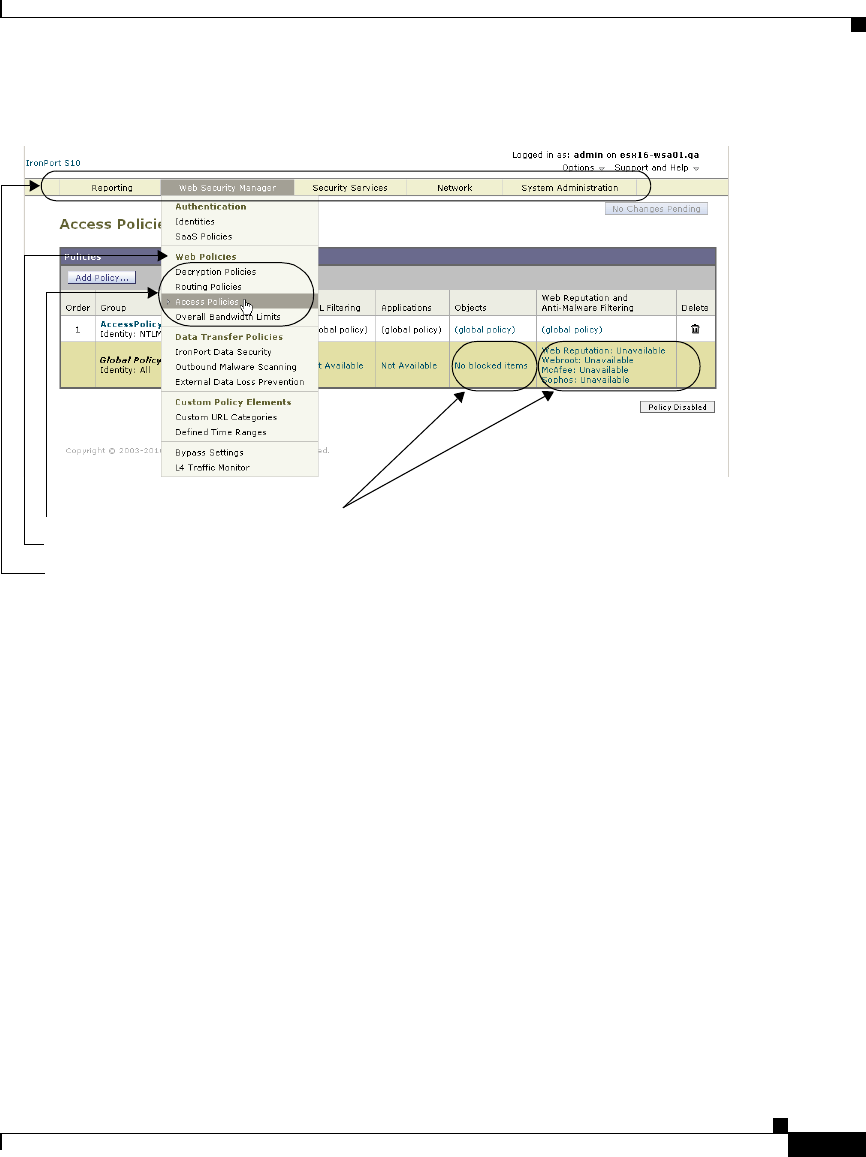
2-9
Cisco IronPort AsyncOS 7.1 for Web User Guide
OL-23207-01
Chapter 2 Using the Web Security Appliance
Navigating the Web Security Appliance Web Interface
Figure 2-1 Web Interface Tabs, Pages, and Categories
Figure 2-1 shows that the Web Security Manager tab contains the Web Proxy
category, and the Web Proxy category contains the Identities, Decryption Policies,
Routing Policies, Access Policies, and Bypass List pages. The tab also contains
the Custom Policy Elements category (with the Custom URL Categories page),
and the L4 Traffic Monitor page.
When the documentation refers to specific pages in the web interface, it uses the
tab name, following by an arrow and then the page name. For example, Web
Security Manager > Access Policies.
Logging In
All users accessing the web interface must log in. Type your username and
password, and then click Login to access the web interface. You must use a
supported web browser (see Browser Requirements, page 2-10). You can log in
with the admin account or any other user account created in the appliance. For
more information creating appliance users, see Administering User Accounts,
page 26-12.
After you log in, the Reporting > Overview page displays.
Tabs
Pages
Category
Click these links and button to open other pages.

Chapter 2 Using the Web Security Appliance
Navigating the Web Security Appliance Web Interface
2-10
Cisco IronPort AsyncOS 7.1 for Web User Guide
OL-23207-01
Browser Requirements
To access the web interface, your browser must support and be enabled to accept
JavaScript and cookies. It must be able to render HTML pages containing
Cascading Style Sheets (CSS). For example, you can use the following browsers:
•Firefox 1.0 and later
•Internet Explorer 6.02 and later (Windows only)
•Mozilla 1.76 and later
•Netscape 7.1 and later
•Safari 2.0.4 and later (Mac OS X only)
Your session automatically times out after 30 minutes of inactivity.
Some buttons and links in the web interface cause additional windows to open.
Therefore, you may need to configure the browser’s pop-up blocking settings in
order to use the web interface.
Note Only use one browser window or tab at a time to edit the appliance configuration.
Also, do not edit the appliance using the web interface and the CLI at the same
time. Editing the appliance from multiple places concurrently results in
unexpected behavior and is not supported.
Support Languages
With the appropriate license key, AsyncOS can display its GUI and CLI in any of
the following languages:
•English
•French
•Spanish
•German
•Italian
•Korean
•Japanese

2-11
Cisco IronPort AsyncOS 7.1 for Web User Guide
OL-23207-01
Chapter 2 Using the Web Security Appliance
Navigating the Web Security Appliance Web Interface
•Portuguese (Brazil)
•Chinese (zh-cn and zh-tw)
•Russian
Reporting Tab
Use the Reporting tab to monitor the appliance by viewing dynamic data on
website activity and appliance activity and action.
The Reporting tab includes the following pages:
•Overview
•Users
•Web Sites
•URL Categories
•Application Visibility
•Anti-Malware
•Client Malware Risk
•Web Reputation Filters
•L4 Traffic Monitor
•Reports by User Location
•Web Tracking
•System Capacity
•System Status
•Scheduled Reports
•Archived Reports
Web Security Manager Tab
Use the Web Security Manager tab to create and configure Access Policies that
define which groups can access which types of websites.
The Web Security Manager tab includes the following pages:

Chapter 2 Using the Web Security Appliance
Navigating the Web Security Appliance Web Interface
2-12
Cisco IronPort AsyncOS 7.1 for Web User Guide
OL-23207-01
•Identities
•SaaS Policies
•Decryption Policies
•Routing Policies
•Access Policies
•Overall Bandwidth Limits
•IronPort Data Security
•Outbound Malware Scanning
•External Data Loss Prevention
•Custom URL Categories
•Defined Time Ranges
•Bypass Settings
•L4 Traffic Monitor
Security Services Tab
Use this tab to configure how the appliance monitors and secures the network.
The Security Services tab includes the following pages:
•Web Proxy
•FTP Proxy
•HTTPS Proxy
•PAC File Hosting
•Identity Provider for SaaS
•Acceptable Use Controls
•Anti-Malware
•Data Transfer Filters
•Mobile User Security
•Web Reputation Filters
•End-User Notification

2-13
Cisco IronPort AsyncOS 7.1 for Web User Guide
OL-23207-01
Chapter 2 Using the Web Security Appliance
Navigating the Web Security Appliance Web Interface
•L4 Traffic Monitor
•SenderBase
Network Tab
Use the Network tab to describe the network in which the appliance is located and
to define the appliance’s network settings.
The Network tab includes the following pages:
•Interfaces
•Transparent Redirection
•Routes
•Internal SMTP Relay
•Authentication
•Upstream Proxy
•External DLP Servers
•DNS
System Administration Tab
Use the System Administration tab to configure administrative options, such as
users, alerts, system time, and more. You can also enter keys for features you
enabled during initial setup.
The System Administration tab includes the following pages:
•Policy Trace
•Users
•Alerts
•Log Subscriptions
•Return Addresses
•Time Zone
•Time Settings

Chapter 2 Using the Web Security Appliance
Committing and Clearing Changes
2-14
Cisco IronPort AsyncOS 7.1 for Web User Guide
OL-23207-01
•Configuration Summary
•Configuration File
•Feature Key Settings
•Feature Keys
•Upgrade and Update Settings
•System Upgrade
•System Setup Wizard
•Next Steps
Committing and Clearing Changes
When you change the configuration of the Web Security appliance, you must
commit the changes before they go into effect. Or, you can choose to clear the
changes you have made if you do not want to commit them. How you commit and
clear changes depends on the interface you use:
•Web interface
•Command Line Interface
Committing and Clearing Changes in the Web Interface
Commit changes using the Commit Changes button in the upper right corner of
the web interface. You can make multiple configuration changes before you
commit all of them. When you make a change, the Commit Changes button color
is yellow and the button text changes to “Commit Changes” as shown in
Figure 2-2.
Figure 2-2 The Commit Button: Changes Pending
When there are no changes to commit, the button color is gray and the button text
is “No Changes Pending.” Figure 2-3 shows the web interface when there are no
changes to commit.
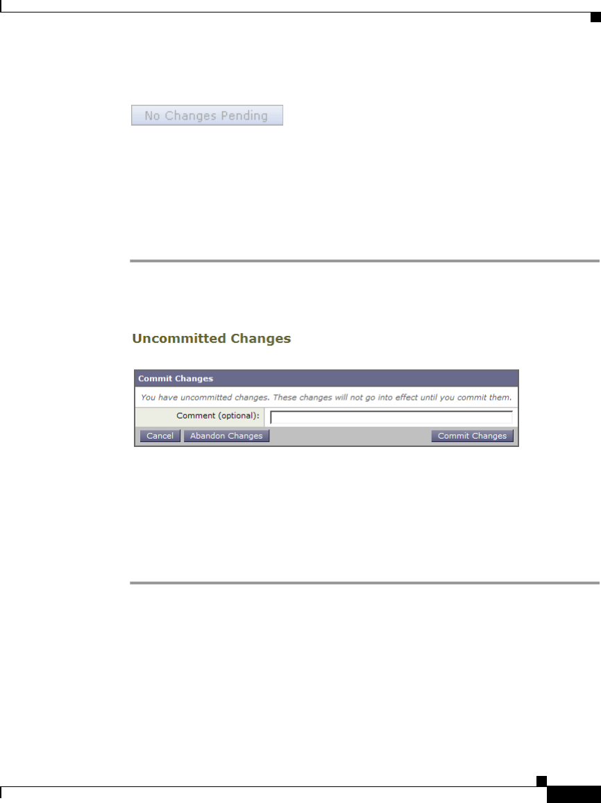
2-15
Cisco IronPort AsyncOS 7.1 for Web User Guide
OL-23207-01
Chapter 2 Using the Web Security Appliance
Committing and Clearing Changes
Figure 2-3 The Commit Button: No Changes Pending
You also use the Commit Changes button to clear the changes made since the last
commit or clear.
Committing Changes
To commit changes made in the web interface:
Step 1 Click the Commit Changes button.
The Uncommitted Changes page appears.
Step 2 Enter comments in the Comment field if you choose.
Step 3 Click Commit Changes.
Clearing Changes
To clear changes made in the web interface:
Step 1 Click the Commit Changes button.
The Uncommitted Changes page appears.
Step 2 Click Abandon Changes.

Chapter 2 Using the Web Security Appliance
Committing and Clearing Changes
2-16
Cisco IronPort AsyncOS 7.1 for Web User Guide
OL-23207-01
Committing and Clearing Changes in the CLI
Commit changes using the commit command. Most configuration changes you
make in the Command Line Interface (CLI) are not effective until you issue the
commit command. You may include comments up to 255 characters. Changes are
not verified as committed until you receive confirmation along with a timestamp.
The commit command applies configuration changes made to appliance since the
last commit or clear command issued.
For more information about using the commit command, see Committing
Configuration Changes, page 27-6.
Clear changes using the clear command. For more information about using the
clear command, see Clearing Configuration Changes, page 27-7.

CHAPTER
3-1
Cisco IronPort AsyncOS 7.1 for Web User Guide
OL-23207-01
3
Deployment
This chapter contains the following topics:
•Deployment Overview, page 3-1
•Appliance Interfaces, page 3-3
•Deploying the Web Proxy in Explicit Forward Mode, page 3-6
•Deploying the Web Proxy in Transparent Mode, page 3-7
•Connecting the Appliance to a WCCP Router, page 3-8
•Using the Web Security Appliance in an Existing Proxy Environment,
page 3-15
•Deploying the L4 Traffic Monitor, page 3-16
•Physical Dimensions, page 3-18
Deployment Overview
The Web Security appliance is typically installed as an additional layer in the
network between clients and the Internet. Depending on how you deploy the
appliance, you may or may not need a Layer 4 (L4) switch or a WCCP router to
direct client traffic to the appliance.
When you deploy the Web Security appliance, you can enable one or both of the
following features:

Chapter 3 Deployment
Deployment Overview
3-2
Cisco IronPort AsyncOS 7.1 for Web User Guide
OL-23207-01
•Secure web proxy. The appliance web proxy service monitors and scans web
traffic for malicious content. When you enable the web proxy, you can
configure it to be in transparent or explicit forward mode.
•L4 Traffic Monitor. The L4 Traffic Monitor detects and blocks rogue traffic
across all ports and IP addresses. The L4 Traffic Monitor listens to network
traffic that comes in over all ports and IP addresses on the appliance and
matches domain names and IP addresses against entries in its own database
tables to determine whether to allow outgoing traffic.
By default, both the L4 Traffic Monitor and Web Proxy are enabled in the System
Setup Wizard. If you need to disable both or one of these features, you can do so
after initial setup from the web interface.
The features you enable determine how you deploy and physically connect the
appliance to the network. For more information about how the features you enable
affect appliance deployment, see Preparing for Deployment, page 3-2. For more
information about the Ethernet ports used to physically connect the appliance to
the network, see Appliance Interfaces, page 3-3.
Preparing for Deployment
Before installing the Web Security appliance, read through the following
questions and use the responses to each question to help you decide how to deploy
the appliance and where to locate it in your network. Each response includes a
reference to a different section that covers the response in more detail.
1. Will you deploy the Web Security appliance as a transparent proxy or an
explicit forward proxy?
–
Explicit Forward Proxy. Client applications, such as web browsers, are
aware of the Web Proxy and must be configured to point to a single Web
Security appliance. This deployment requires a connection to a standard
network switch. When you deploy the Web Proxy in explicit forward
mode, you can place it anywhere in the network. For more information,
see Deploying the Web Proxy in Explicit Forward Mode, page 3-6.
–
Transparent Proxy. Clients applications are unaware of the Web Proxy
and do not have to be configured to connect to the proxy. This
deployment requires an L4 switch or a WCCP v2 router. For more
information, see Deploying the Web Proxy in Transparent Mode,
page 3-7.

3-3
Cisco IronPort AsyncOS 7.1 for Web User Guide
OL-23207-01
Chapter 3 Deployment
Appliance Interfaces
2. Does the network have an existing proxy?
If yes, it is recommended you deploy the Web Security appliance downstream
from an existing proxy server, meaning closer to the clients. The System
Setup Wizard refers to this as an upstream proxy configuration.
For more information, see Using the Web Security Appliance in an Existing
Proxy Environment, page 3-15.
3. Will you enable the L4 Traffic Monitor?
L4 Traffic Monitor deployment is independent of the Web Proxy deployment.
You can connect the L4 Traffic Monitor to a network tap or the mirror/span
port of a switch.
For more information, see Deploying the L4 Traffic Monitor, page 3-16.
Appliance Interfaces
The Web Security appliance includes six physical Ethernet ports on the back of
the system. Each Ethernet port corresponds to a different network interface. The
Ethernet ports are grouped into the following types of network interfaces:
•Management. The Management interfaces include M1 and M2. However,
only the M1 interface is enabled on the appliance. For more information, see
Management Interface, page 3-4.
•Data. The Data interfaces include P1 and P2. Use the Data interfaces for Web
Proxy data traffic. For more information, see Data Interfaces, page 3-4.
•L4 Traffic Monitor. The L4 Traffic Monitor interfaces include T1 and T2.
Use these interfaces for monitoring and blocking L4 Traffic Monitor traffic.
For more information, see L4 Traffic Monitor Interfaces, page 3-5.
Figure 3-1 shows the Ethernet ports on the back of the Web Security appliance
blade.
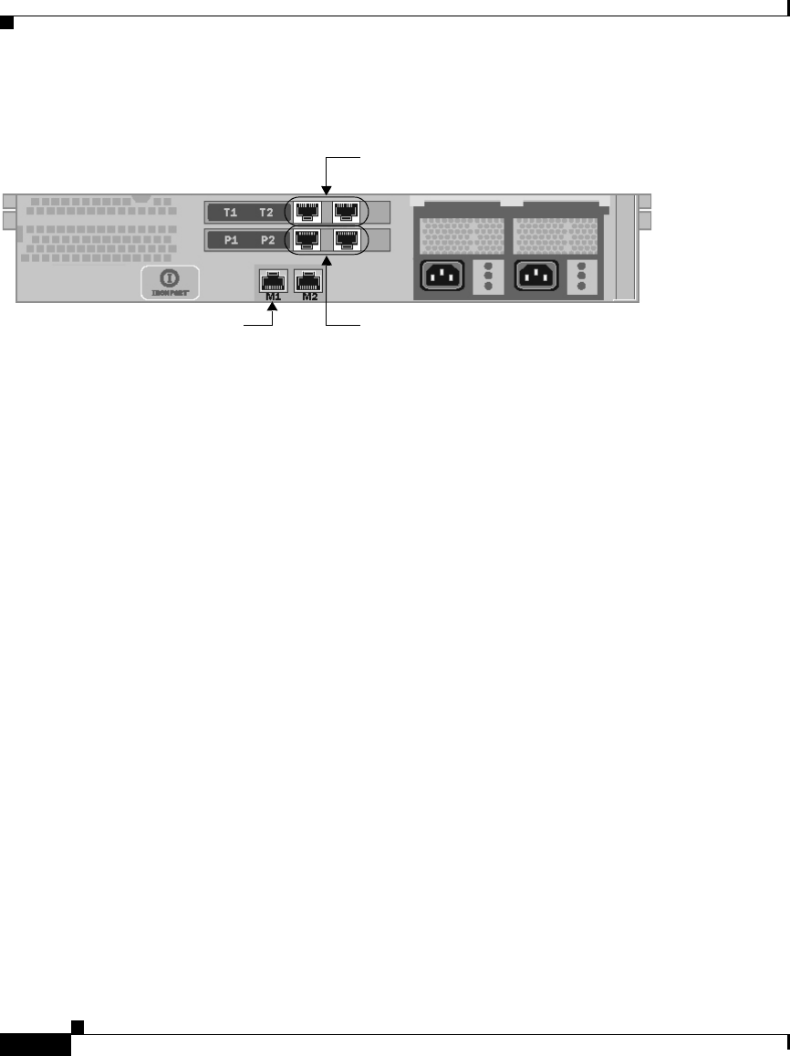
Chapter 3 Deployment
Appliance Interfaces
3-4
Cisco IronPort AsyncOS 7.1 for Web User Guide
OL-23207-01
Figure 3-1 Web Security Appliance Ethernet Ports
Management Interface
Use M1 to administer the appliance. Optionally, you can also configure the M1
interface to handle Web Proxy data traffic. You might want to use the M1 interface
for data traffic if your organization does not use a separate management network.
For more information about using the M1 port to set up and manage the appliance,
see Connecting a Laptop to the Appliance, page 4-2.
For more information about configuring the network interfaces, see Configuring
Network Interfaces, page 25-2.
Data Interfaces
The appliance uses the Data interfaces for Web Proxy data traffic. You can enable
and use just the P1 port or both the P1 and P2 ports for data traffic.
•P1 only enabled. When only P1 is enabled, connect it to the network for both
incoming and outgoing traffic.
•P1 and P2 enabled. When both P1 and P2 are enabled, you must connect P1
to the internal network and P2 toward the Internet.
Use the “T” ports for the L4 Traffic Monitor.
Use the “P” ports for the Web Proxy.Use the M1 port for administering
the appliance.

3-5
Cisco IronPort AsyncOS 7.1 for Web User Guide
OL-23207-01
Chapter 3 Deployment
Appliance Interfaces
Note You can only enable and configure the P1 interface for data traffic in the System
Setup Wizard. If you want to enable the P2 interface, you must do so after system
setup in the web interface or using the ifconfig command. For more information
about configuring the P2 interface, see Configuring Network Interfaces,
page 25-2.
How you physically connect the data interfaces to the network depends on how
you deploy the appliance. For more information, see Deploying the Web Proxy in
Explicit Forward Mode, page 3-6 and Deploying the Web Proxy in Transparent
Mode, page 3-7.
L4 Traffic Monitor Interfaces
The appliance uses the T1 and T2 interfaces for listening to traffic on all TCP
ports. You can connect just T1 or both T1 and T2 using an Ethernet cable,
depending on whether you use simplex or duplex communication.
•T1 only connected (duplex). When you configure the appliance to use
duplex communication, connect T1 to the network so it receives all incoming
and outgoing traffic.
•T1 and T2 connected (simplex). When you configure the appliance to use
simplex communication, connect T1 to the network so it receives all outgoing
traffic (from the clients to the Internet), and connect T2 to the network so it
receives all incoming traffic (from the Internet to the clients).
For more information about how to connect the L4 Traffic Monitor ports to the
network, see Deploying the L4 Traffic Monitor, page 3-16.
Example Deployment
Figure 3-2 on page 6 shows a sample deployment scenario with both the Web
Proxy and L4 Traffic Monitor enabled. In this example, the Web Proxy is
deployed in transparent mode and only the P1 port is connected to either a L4
switch or a WCCP router.
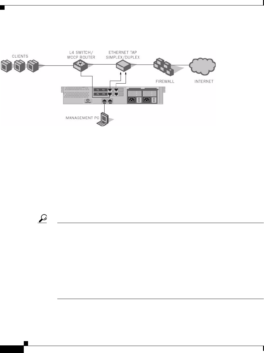
Chapter 3 Deployment
Deploying the Web Proxy in Explicit Forward Mode
3-6
Cisco IronPort AsyncOS 7.1 for Web User Guide
OL-23207-01
Figure 3-2 Web Security Appliance Deployment Scenario
Deploying the Web Proxy in Explicit Forward Mode
When the appliance is configured as an explicit forward proxy, client applications
must be configured to direct its traffic to the appliance. When you want to
configure the Web Proxy in explicit forward mode, you must configure the
following components:
•Client applications
•Appliance ports
Tip If your organization needs to use explicit forward mode now, but might need
transparent mode in the future, consider deploying the Web Proxy in transparent
mode and then choosing L4 switch as the connection type. If you do not have an
L4 switch, you can connect the appliance to the network normally and the
appliance will work in explicit forward mode. When the Web Proxy is deployed
in transparent mode, it can accept both transparently redirected and explicitly
forwarded transactions. To use transparent mode in the future, you can connect the
appliance to an L4 switch and it will work in transparent mode without needing
to change the Web Proxy mode later. However, it is easy to change the deployment
mode at any time on the Security Services > Web Proxy page.

3-7
Cisco IronPort AsyncOS 7.1 for Web User Guide
OL-23207-01
Chapter 3 Deployment
Deploying the Web Proxy in Transparent Mode
Configuring Client Applications
You must configure all client applications, such as web browsers and FTP clients,
used on the network to point to the Web Proxy. You can configure each client in
the following ways:
•Manual. Configure each client application to point the appliance Web Proxy
by specifying the appliance hostname or IP address and the port number, such
as 3128, used for listening to data traffic.
•Automatic. Configure each client application to use a PAC file to detect the
appliance Web Proxy automatically. Then you can edit the PAC file to specify
the appliance Web Proxy information. PAC files work with web browsers
only. For more information, see Working with PAC Files, page 5-19.
Connecting Appliance Interfaces
You can connect the P1 interface or both the P1 and P2 interfaces to a network
switch using an Ethernet cable. You do not need special hardware, such as a
particular switch or router. For more information about how to connect the data
interfaces (P1 and P2), see Data Interfaces, page 3-4.
Testing an Explicit Forward Configuration
If you want to test an explicit forward proxy configuration, you can separate and
forward traffic from a subset of your network infrastructure. To individually test
this configuration, clients can forward traffic to the appliance from one web
browser and connect to the Internet using another web browser. This method also
ensures an alternate path to the Internet while testing.
Deploying the Web Proxy in Transparent Mode
When the appliance is configured as a transparent proxy, client applications are
not aware that their traffic gets redirected to the appliance, and they do not need
to be configured to point to the appliance. To deploy the appliance in this mode,
you need one of the following types of hardware to transparently redirect web
traffic to the appliance:

Chapter 3 Deployment
Connecting the Appliance to a WCCP Router
3-8
Cisco IronPort AsyncOS 7.1 for Web User Guide
OL-23207-01
•WCCP v2 router. When you specify a WCCP router, you need to configure
additional settings on the appliance. For more information about using the
appliance with a WCCP router, see Connecting the Appliance to a WCCP
Router, page 3-8.
•Layer 4 switch. When you specify an L4 switch, you only need to specify
that the appliance is connected to an L4 switch when you configure the
appliance. You do not need to configure anything else on the appliance.
Typically, you configure the appliance to use an L4 switch or a WCCP v2 router
during initial system setup. However, you can configure it to use either an L4
switch or a WCCP v2 router anytime after initial setup on the Network >
Transparent Redirection page. For more information about the Network >
Transparent Redirection page, see Configuring Transparent Redirection,
page 25-17.
Connecting Appliance Interfaces
When you configure the Web Proxy in transparent mode, you can connect the P1
port or both the P1 and P2 ports to an L4 switch or WCCP router using an Ethernet
cable. For more information about how to connect the data interfaces (P1 and P2),
see Data Interfaces, page 3-4.
Connecting the Appliance to a WCCP Router
When you connect the appliance to a WCCP router, you must perform the
following tasks:
1. You must create at least one WCCP service on the appliance. For more
information, see Configuring the Web Security Appliance, page 3-9.
2. After you create a WCCP service, you must configure the router to work with
the Web Security appliance. For more information, see Configuring the
WCCP Router, page 3-9.
You can also connect an appliance to multiple WCCP routers. For more
information, see Working with Multiple Appliances and Routers, page 3-15.

3-9
Cisco IronPort AsyncOS 7.1 for Web User Guide
OL-23207-01
Chapter 3 Deployment
Connecting the Appliance to a WCCP Router
Configuring the Web Security Appliance
A WCCP service is an appliance configuration that defines a service group to a
WCCP v2 router. It includes information such as the service ID and ports used.
Service groups allow a web proxy to establish connectivity with a WCCP router
and to handle redirected traffic from the router.
Create WCCP services on the Network > Transparent Redirection page. The
WCCP services you create determine how you configure the WCCP routers. For
more information about creating WCCP services, see Adding and Editing a
WCCP Service, page 25-21.
Note You can enable the standard service (also known as the “web-cache” service)
during system setup, and you can configure different or additional WCCP service
groups after you run the System Setup Wizard.
Configuring the WCCP Router
After you create at least one WCCP service in the Web Security appliance, you
can configure the WCCP router(s) in the network.
Use the following syntax for enabling WCCP on the router:
Enter one of the following values for the service_group variable:
•web-cache. Enter “web-cache” when the appliance WCCP service uses the
standard service.
•Service ID number. Enter a number from 0 to 255 when the appliance WCCP
service uses a dynamic service ID. The number should match the service ID
number used in the appliance.
ip wccp version 2
ip wccp
service_group
interface
interface_type_number
ip wccp
service_group
redirect
direction
ip wccp
service_group
password
password

Chapter 3 Deployment
Connecting the Appliance to a WCCP Router
3-10
Cisco IronPort AsyncOS 7.1 for Web User Guide
OL-23207-01
Table 3-1 describes each part of the WCCP configuration syntax for enabling
WCCP on the router.
You can also configure a WCCP router to perform other tasks, such as the
following:
Table 3-1 WCCP Router Configuration Syntax for Enabling the Router
WCCP Configuration Description
ip wccp version 2 Defines the version of WCCP to use on the router.
You must specify version 2 to work with the Web
Security appliance.
This command is required.
ip wccp
service_group
password
password
Specifies a service group to enable on the router. It
also enables the WCCP service on the router.
This command is required.
interface
interface_type_number
Specifies an interface to configure and enters
interface configuration mode. Enter the interface
number for the interface_type_number variable.
This command is required.
ip wccp
service_group
redirect
direction
Enables WCCP redirection on the specified
interface.
Enter one of the following values for the direction
variable:
•in. Use in when you want the router to redirect
packets as they enter the router.
•out. Use out when you want the router to
redirect packets right before they leave the
router.
This command is required.
ip wccp
service_group
password
password
Sets a password on the router for the specified
service group.
This command is only required when the WCCP
service defined on the appliance has password
security enabled.

3-11
Cisco IronPort AsyncOS 7.1 for Web User Guide
OL-23207-01
Chapter 3 Deployment
Connecting the Appliance to a WCCP Router
•Configure the router from exclude redirecting traffic received on a particular
interface.
•If the network uses multiple Web Security appliances, you can configure the
router to determine which traffic should be directed to which appliance by
using an access list. You might want to redirect only some of the network
traffic to the appliance if you are evaluating the Web Security appliance.
Note The Web Security appliance does not support using a multicast address in the
WCCP service group. To use multiple routers in a service group, you must specify
the IP address of each router in the service group and configure each router
separately. You cannot register a router to a multicast address.
Example WCCP Configurations
This section shows some sample WCCP services defined in the appliance and the
corresponding WCCP configuration you should use to configure the router that
connects to the appliance.
Example 1
Suppose you have the WCCP service shown in Figure 3-3.
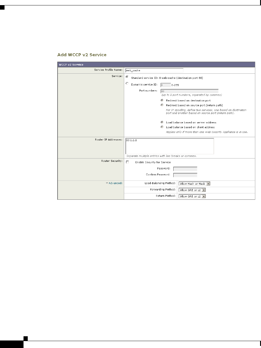
Chapter 3 Deployment
Connecting the Appliance to a WCCP Router
3-12
Cisco IronPort AsyncOS 7.1 for Web User Guide
OL-23207-01
Figure 3-3 Example WCCP Service — Standard Service, No Password
Required
In this example, the WCCP service defines the standard service group (also
known as a well known service group). The redirection basis is on the destination
port by default. Also suppose in this example that you want to configure the
ethernet1 interface on the router for this service group.
Use the following WCCP configuration for this example:
Example 2
Figure 3-4 shows a dynamic service you might create when IP spoofing is enabled
and the WCCP service shown in Figure 3-3 on page 12 is defined.
ip wccp version 2
ip wccp web-cache
interface ethernet1
ip wccp web-cache redirect in
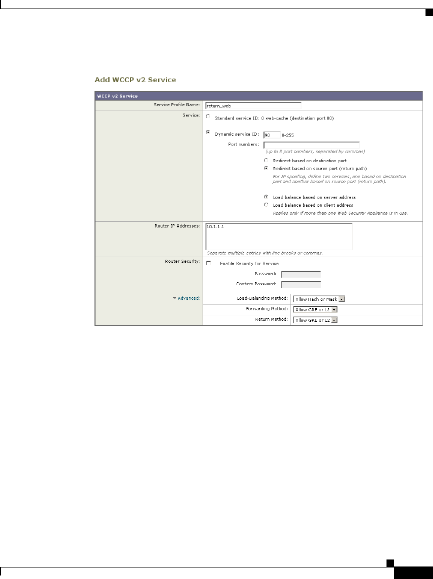
3-13
Cisco IronPort AsyncOS 7.1 for Web User Guide
OL-23207-01
Chapter 3 Deployment
Connecting the Appliance to a WCCP Router
Figure 3-4 Example WCCP Service — Dynamic Service for IP Spoofing
In this example, the WCCP service defines a dynamic service group with service
ID of 90. The redirection basis is on the source port so it can be used for the return
path with IP spoofing enabled. Suppose in this example that you want to configure
the ethernet0 interface on the router for this service group.
Use the following WCCP configuration for this example:
For more information about enabling IP spoofing when using a WCCP router, see
IP Spoofing when Using WCCP, page 25-20.
ip wccp version 2
ip wccp 90
interface ethernet0
ip wccp 90 redirect in
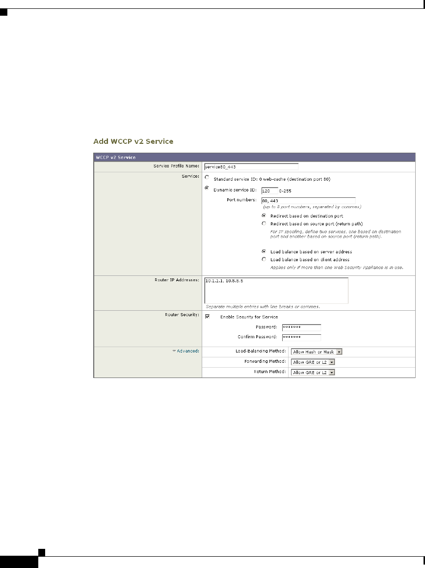
Chapter 3 Deployment
Connecting the Appliance to a WCCP Router
3-14
Cisco IronPort AsyncOS 7.1 for Web User Guide
OL-23207-01
Example 3
Suppose you have the WCCP service shown in Figure 3-5.
Figure 3-5 Example WCCP Service — Dynamic Service, Password
Required
In this example, the WCCP service defines a dynamic service group with service
ID of 120. The redirection basis is on the destination port, and it has enabled a
password for this service group of “admin99” (hidden in the appliance
configuration). Also suppose in this example that you want to configure the
ethernet0 interface on the router for this service group.
Use the following WCCP configuration for this example:
ip wccp version 2
ip wccp 120
interface ethernet0
ip wccp 120 redirect in
ip wccp 120 password admin99

3-15
Cisco IronPort AsyncOS 7.1 for Web User Guide
OL-23207-01
Chapter 3 Deployment
Using the Web Security Appliance in an Existing Proxy Environment
Working with Multiple Appliances and Routers
When you connect one or more Web Security appliances to one or more WCCP
routers, you have a cluster. You can include up to 32 appliances and up to 32
routers in a cluster. You must configure all appliances and routers in a cluster to
communicate with each other.
Using the Web Security Appliance in an Existing
Proxy Environment
The Web Security appliance is a proxy-compatible device, and is easily deployed
within an existing proxy environment. However, it is recommended that you place
the appliance downstream from existing proxy servers, meaning closer to the
clients.
You can configure the appliance to work with an existing, upstream proxy in the
System Setup Wizard or after the initial setup in the web interface. Use the
Network > Upstream Proxies page to enable an upstream proxy or to modify
existing settings.
When configuring an upstream proxy, you specify whether the existing proxy is
in transparent or explicit forward mode.
Transparent Upstream Proxy
If a transparent upstream proxy uses client IP addresses to manage user
authentication and access control, you must enable IP spoofing on the Web
Security appliance to send client IP addresses to the upstream proxy. Use the
Security Services > Web Proxy page to enable IP spoofing.
When you enable IP spoofing and connect the appliance to a WCCP router, you
must create at least two WCCP services. For more information about configuring
WCCP services when you enable IP spoofing, see IP Spoofing when Using
WCCP, page 25-20.

Chapter 3 Deployment
Deploying the L4 Traffic Monitor
3-16
Cisco IronPort AsyncOS 7.1 for Web User Guide
OL-23207-01
Explicit Forward Upstream Proxy
If the upstream proxy is in explicit forward mode, consider the following rules and
guidelines:
•You must enter the IP address or hostname and port of the upstream proxy.
•Consider whether the hostname of the upstream proxy resolves to multiple IP
addresses. The Web Security appliance only queries the DNS server for the
IP address at startup. If an IP address is added or removed from that
hostname, the proxy must restart to resolve and add the hostname to the new
set of IP addresses.
•If the upstream proxy manages user authentication or access control using
proxy authentication, you must enable the X-Forwarded-For header to send
the client host header to the upstream proxy. Use the Security Services > Web
Proxy page to enable the X-Forwarded-For header setting.
•If you want to send authentication credentials to an upstream proxy when the
Web Security appliance is deployed in explicit forward mode, you must
configure the Web Proxy to forward authorization request headers to a parent
proxy server using the advancedproxyconfig > authentication CLI
command.
Note By default, the Web Proxy does not forward proxy authorization headers
to upstream proxy servers for security reasons.
•If the upstream proxy manages client traffic using a PAC file or a login script,
you must update these files to use the IP address or hostname of the Web
Security appliance.
Deploying the L4 Traffic Monitor
L4 Traffic Monitor (L4TM) deployment is independent of the Web Proxy
deployment. When connecting and deploying the L4 Traffic Monitor, consider the
following:
•Physical connection. You can choose how to connect the L4 Traffic Monitor
to the network. For more information, see Connecting the L4 Traffic Monitor,
page 3-17.

3-17
Cisco IronPort AsyncOS 7.1 for Web User Guide
OL-23207-01
Chapter 3 Deployment
Deploying the L4 Traffic Monitor
•Network address translation (NAT). When configuring the L4 Traffic
Monitor, connect it at a point in your network where it can see as much
network traffic as possible before getting out of your egress firewall and onto
the Internet. It is important that the L4 Traffic Monitor be ‘logically’
connected after the proxy ports and before any device that performs network
address translation (NAT) on client IP addresses.
•L4 Traffic Monitor action setting. The default setting for the L4 Traffic
Monitor is monitor only. After setup, if you configure the L4 Traffic Monitor
to monitor and block suspicious traffic, ensure that the L4 Traffic Monitor and
the Web Proxy are configured on the same network so that all clients are
accessible on routes that are configured for data traffic.
Connecting the L4 Traffic Monitor
You can connect the L4 Traffic Monitor to the network in any of the following
ways:
•Network tap. When you use a network tap, you can choose the following
communication types:
–
Simplex. This communication type uses one cable for all traffic between
clients and the appliance, and one cable for all traffic between the
appliance and external connections. Connect port T1 to the network tap
so it receives all outgoing traffic (from the clients to the Internet), and
connect port T2 to the network tap so it receives all incoming traffic
(from the Internet to the clients).
–
Duplex. This mode uses one cable for all incoming and outgoing traffic.
You can use half- or full-duplex Ethernet connections. Connect port T1
to the network tap so it receives all incoming and outgoing traffic.
Note Cisco recommends using simplex when possible because it can increase
performance and security.
•Span/mirror port of an L2 switch. Connecting is similar to a simplex or
duplex tap, depending on whether the connection uses two separate devices
or one device.
•Hub. Choose duplex when you connect the L4 Traffic Monitor to a hub.
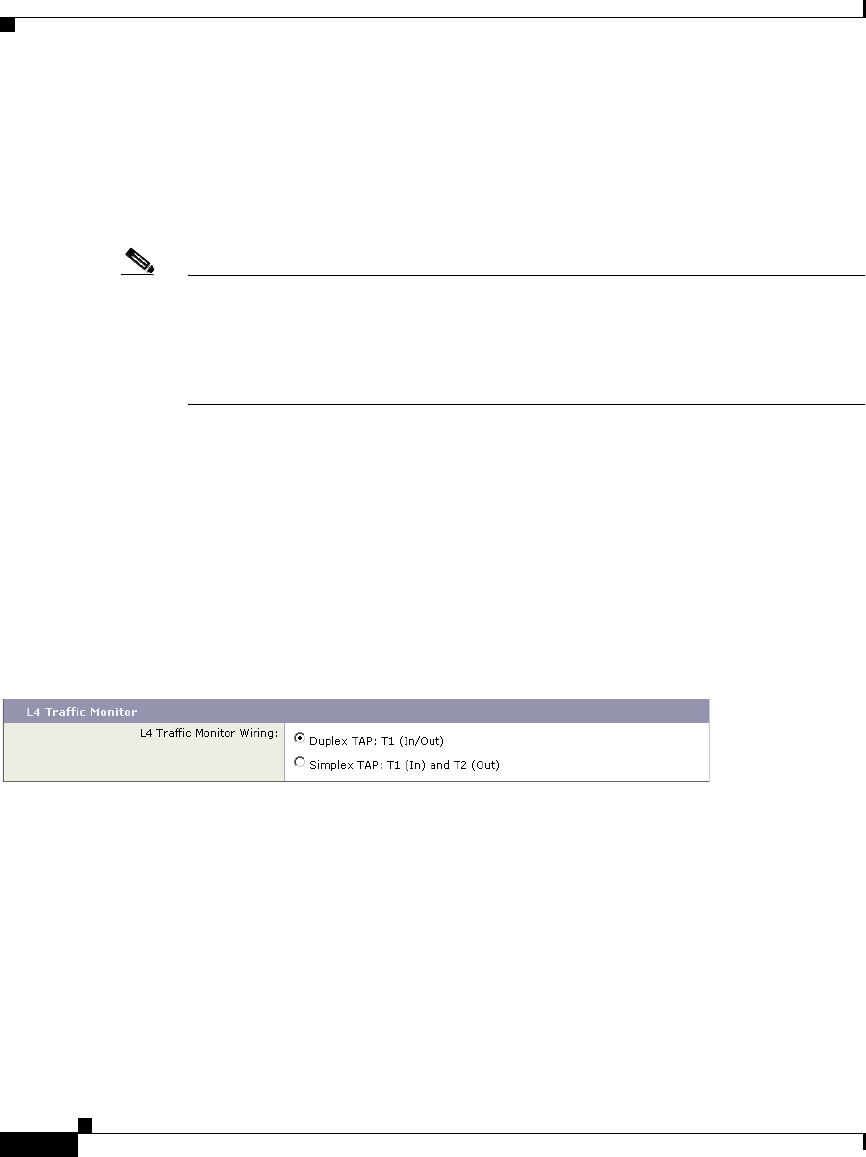
Chapter 3 Deployment
Physical Dimensions
3-18
Cisco IronPort AsyncOS 7.1 for Web User Guide
OL-23207-01
Regardless of how the appliance is connected to the network, you must configure
the wiring type. For more information, see Configuring an L4 Traffic Monitor
Wiring Type, page 3-18.
For more information about the T1 and T2 ports, see Appliance Interfaces,
page 3-3.
Note Use a network tap instead of the span/mirror port of a switch when possible.
Network taps use hardware to move packets to the L4 Traffic Monitor and span
and mirror ports of a switch use software to move packets. Hardware solutions
move packets with better performance than software solutions and are less likely
to drop packets in the process.
Configuring an L4 Traffic Monitor Wiring Type
Typically, the L4 Traffic Monitor wiring type is configured during system setup.
However, you can configure the wiring type after running the System Setup
Wizard on the Network > Interfaces page. Click Edit Settings and select a wiring
type for the T1 and T2 ports.
Figure 3-6 L4 Traffic Monitor Wiring Types
Physical Dimensions
The following physical dimensions apply to the IronPort S670 and S370 Web
Security appliances:
•Height: 8.64 cm (3.40 inches)
•Width: 48.24 cm (18.99 inches) with or without rails
•Depth: 72.06 cm (28.40 inches)
•Weight: maximum 23.59 kg (52 pounds)

3-19
Cisco IronPort AsyncOS 7.1 for Web User Guide
OL-23207-01
Chapter 3 Deployment
Physical Dimensions
The following physical dimensions apply to the IronPort S160 Web Security
appliance:
•Height: 4.2 cm (1.68 inches)
•Width: 48.26 cm (19.0 inches) with rails installed (without rails, 17.5 inches)
•Depth: 57.6 cm (22.7 inches)
•Weight: maximum 9.8 kg (21.6 pounds)

Chapter 3 Deployment
Physical Dimensions
3-20
Cisco IronPort AsyncOS 7.1 for Web User Guide
OL-23207-01

CHAPTER
4-1
Cisco IronPort AsyncOS 7.1 for Web User Guide
OL-23207-01
4
Installation and Configuration
This chapter contains the following topics:
•Before You Begin, page 4-1
•System Setup Wizard, page 4-6
Before You Begin
To use the Web Security appliance, you must run the System Setup Wizard.
However, first you must do some steps to prepare the appliance for the System
Setup Wizard.
For more information about preparing the appliance for installation, see the Web
Security appliance QuickStart Guide. You can find this guide and other useful
information about the IronPort Web Security appliance on the Cisco IronPort
Customer Support site:
http://www.cisco.com/web/ironport/index.html
Complete the following tasks before you run the System Setup Wizard:
•Deployment. Decide how you are going to configure the appliance within
your network. For details, see Deployment, page 3-1.
•Laptop network connection. Configure your laptop’s network connection to
use an IP address on the same subnet as the Web Security appliance
(192.168.42.xx). For details, see Connecting a Laptop to the Appliance,
page 4-2.

Chapter 4 Installation and Configuration
Before You Begin
4-2
Cisco IronPort AsyncOS 7.1 for Web User Guide
OL-23207-01
•Appliance physical connections. Plug the Ethernet cables into the
appropriate ports on the back panel of the appliance. For details, see
Connecting the Appliance to the Network, page 4-2.
•Setup information. Once you know how you will install the appliance in
your network, gather all the information, such as IP addresses, necessary for
the System Setup Wizard. For details, see Gathering Setup Information,
page 4-4.
•Existing proxy server. If you plan to use the Web Security appliance in a
network that has an existing proxy server, you must locate it downstream
from other proxy servers. Also, after you finish the initial setup of the
appliance, you must configure it to work with the existing proxy server. For
more information about deploying the appliance in a network with an existing
proxy, see Using the Web Security Appliance in an Existing Proxy
Environment, page 3-15.
Connecting a Laptop to the Appliance
In order to run the System Setup Wizard the first time, you must connect a
computer, such as a laptop, to the appliance. To connect to the appliance, the
laptop subnet must be the same as the appliance subnet. The Management ports
are labeled M1 and M2. The Web Security appliance only uses the M1
Management port. It does not use M2.
Configure the laptop IP address so it is on the same subnet as the appliance
(192.168.42.xx). Then, connect the laptop to the M1 port on the back of the
appliance.
Connecting the Appliance to the Network
You must plug the Ethernet cables into the appropriate ports on the back panel of
the appliance. For more information about the Ethernet ports on the appliance, see
Appliance Interfaces, page 3-3.
How you deploy the appliance determines which Ethernet cables to plug in where:

4-3
Cisco IronPort AsyncOS 7.1 for Web User Guide
OL-23207-01
Chapter 4 Installation and Configuration
Before You Begin
•Web proxy in transparent mode. If you want to use one proxy port for all
traffic, connect port P1 to an L4 switch or a WCCP router using an Ethernet
cable. If you want to use two proxy ports for traffic, connect port P2 to an L4
switch or a WCCP router using an Ethernet cable, and connect port P1 to the
internal network.
For more information about deploying the Web Proxy in transparent mode,
see Deploying the Web Proxy in Transparent Mode, page 3-7.
Note When you configure the proxy in transparent mode and connect it to a
WCCP router, you must configure the appliance after you run the System
Setup Wizard to create at least one WCCP service. For more information
about creating WCCP services, see Adding and Editing a WCCP Service,
page 25-21.
•Web proxy in explicit forward mode. If you want to use one proxy port for
all traffic, connect port P1 to a network switch using an Ethernet cable. If you
want to use two proxy ports for traffic, connect port P2 to a network switch
using an Ethernet cable, and connect port P1 to the internal network.
For more information about deploying the Web Proxy in explicit forward
mode, see Deploying the Web Proxy in Explicit Forward Mode, page 3-6.
•L4 Traffic Monitor. Connect the Traffic Monitor ports to the Ethernet tap
according to the tap communication type:
–
Ethernet tap using simplex. Connect port T1 to the Ethernet tap so it
receives all outgoing traffic (from the clients to the Internet), and connect
port T2 to the Ethernet tap so it receives all incoming traffic (from the
Internet to the clients).
–
Ethernet tap using duplex. Connect port T1 to the Ethernet tap so it
receives all incoming and outgoing traffic.
For more information about deploying the L4 Traffic Monitor, see Deploying
the L4 Traffic Monitor, page 3-16.

Chapter 4 Installation and Configuration
Before You Begin
4-4
Cisco IronPort AsyncOS 7.1 for Web User Guide
OL-23207-01
Gathering Setup Information
Once you know how you will install the appliance in your network, you can gather
the necessary information, such as IP addresses, to enter in the System Setup
Wizard. You can use the worksheet in Table 4-1 to write down the configuration
options you decide on. Then, when you run the System Setup Wizard, you can use
the information you enter in the worksheet to configure the initial setup.
Table 4-1 System Setup Worksheet
Network Settings
Default System Hostname:
See DNS Support, page 4-6 for more information.
DNS Servers: Internet root DNS servers / organization DNS servers
Organization DNS Servers:
(maximum 3)
1.
2.
3.
Network Time Protocol Server:
Time Zone Region:
Time Zone Country:
Time Zone / GMT Offset:
Network Context
Is there another proxy on the network: Yes / No
Other Proxy IP Address:
Other Proxy Port:
Interface Settings
Management Port
IP Address:
Network Mask:
Hostname:
Data Port

4-5
Cisco IronPort AsyncOS 7.1 for Web User Guide
OL-23207-01
Chapter 4 Installation and Configuration
Before You Begin
IP Address:
Network Mask:
Hostname:
Note: The Web Proxy can share the Management interface. If configured separately, the Data interface
IP address and the Management interface IP address cannot share the same subnet.
L4 Traffic Monitor
L4 Traffic Monitor Wiring Type: Simplex network tap / Duplex network tap
Routes
Management Traffic
Default Gateway:
Static Route Table Name:
Static Route Table Destination Network:
Static Route Table Gateway:
Data Traffic
Default Gateway:
Static Route Table Name:
Static Route Table Destination Network:
Static Route Table Gateway:
Transparent Connection Settings
Device Type: Layer 4 switch or No Device / WCCP Router
If WCCP v2 Router, enable standard
service:
Yes / No
Standard Service Router Addresses:
Enable Router Security? No / Yes, password: ______________________________
Note: When you connect the appliance to a WCCP router, you might need to configure the Web
Security appliance to create WCCP services after you run the System Setup Wizard. For more
information about creating WCCP services, see Adding and Editing a WCCP Service, page 25-21.
Administrative Settings
Administrator Password:
Table 4-1 System Setup Worksheet (continued)

Chapter 4 Installation and Configuration
System Setup Wizard
4-6
Cisco IronPort AsyncOS 7.1 for Web User Guide
OL-23207-01
DNS Support
To connect to the management interface using a hostname (http://hostname:8080),
you must add the appliance hostname and IP address to your DNS server database.
System Setup Wizard
The IronPort AsyncOS for Web operating system provides a browser-based
wizard to guide you through initial system configuration. This System Setup
Wizard prompts you for basic initial configuration, such as network configuration
and security settings. The System Setup Wizard is located on the System
Administration tab.
You must run the System Setup Wizard when you first install the Web Security
appliance. After you finish the System Setup Wizard, the appliance is ready to
monitor web traffic. However, you may want to make more custom configurations
Email System Alerts To:
SMTP Relay Host: (optional)
AutoSupport: Enable / Disable
SenderBase Network Participation: Enable / Disable
Participation Level: Limited / Standard
Security Services
L4 Traffic Monitor: Monitor only / Block
Acceptable Use Controls: Enable IronPort URL Filters / Enable Cisco IronPort Web
Usage Controls / Disable
Web Reputation Filters: Enable / Disable
Malware and Spyware Scanning: Enable Webroot / Enable McAfee / Enable both
Action for Detected Malware: Monitor only / Block
IronPort Data Security Filtering: Enable / Disable
Table 4-1 System Setup Worksheet (continued)

4-7
Cisco IronPort AsyncOS 7.1 for Web User Guide
OL-23207-01
Chapter 4 Installation and Configuration
System Setup Wizard
to the appliance that the System Setup Wizard does not cover. For more
information about configuration options, see most of the other chapters in this
guide.
Before you run the System Setup Wizard, see Before You Begin, page 4-1 to
verify you have all the information you need to configure the appliance. Having
this information prepared ahead of time can reduce the amount of time required
to complete the initial setup. You should also read the QuickStart Guide for more
information about product setup.
Warning
Running the System Setup Wizard completely reconfigures the Web Security
appliance and resets the administrator password. Only use the System Setup
Wizard the first time you install the appliance, or if you want to completely
overwrite the existing configuration. Running the System Setup Wizard after the
appliance is already configured can also interrupt client access to the web. If
you choose to run the System Setup Wizard after performing an initial setup, use
the System Administration > Configuration File pages to print a configuration
summary and archive the current configuration file.
Warning
The IronPort appliance ships with a default IP address of 192.168.42.42 on the
Management interface (port). Before connecting the appliance to the network,
ensure that no other device on the network has the same IP address.
If you are connecting multiple factory-configured IronPort appliances to your
network, add them one at a time, reconfiguring each IronPort appliance’s default
IP address as you go.
The System Setup Wizard includes the following tabs where you enter
configuration information:
•Start. For details, see Step 1. Start, page 4-8.
•Network. For details, see Step 2. Network, page 4-9.
•Security. For details, see Step 3. Security, page 4-22.
•Review. For details, see Step 4. Review, page 4-26.

Chapter 4 Installation and Configuration
System Setup Wizard
4-8
Cisco IronPort AsyncOS 7.1 for Web User Guide
OL-23207-01
Accessing the System Setup Wizard
To access the System Setup Wizard, open a browser and enter the IP address of
the Web Security appliance. The first time you run the System Setup Wizard, use
the default IP address:
https://192.168.42.42:8443
-or-
http://192.168.42.42:8080
where 192.168.42.42 is the default IP address, and 8080 is the default admin
port setting for HTTP, and 8443 is default admin port for HTTPS.
The appliance login screen appears. Enter the username and password to access
the appliance. By default, the appliance ships with the following username and
password:
•Username: admin
•Password: ironport
Note Your session will time out if it is idle for over 30 minutes or if you close your
browser without logging out. If this happens, you must re-enter the username and
password.
Step 1. Start
When you first start the System Setup Wizard, it displays an end user license
agreement.
Step 1 Accept the terms of the agreement by clicking the check box at the bottom of the
page.
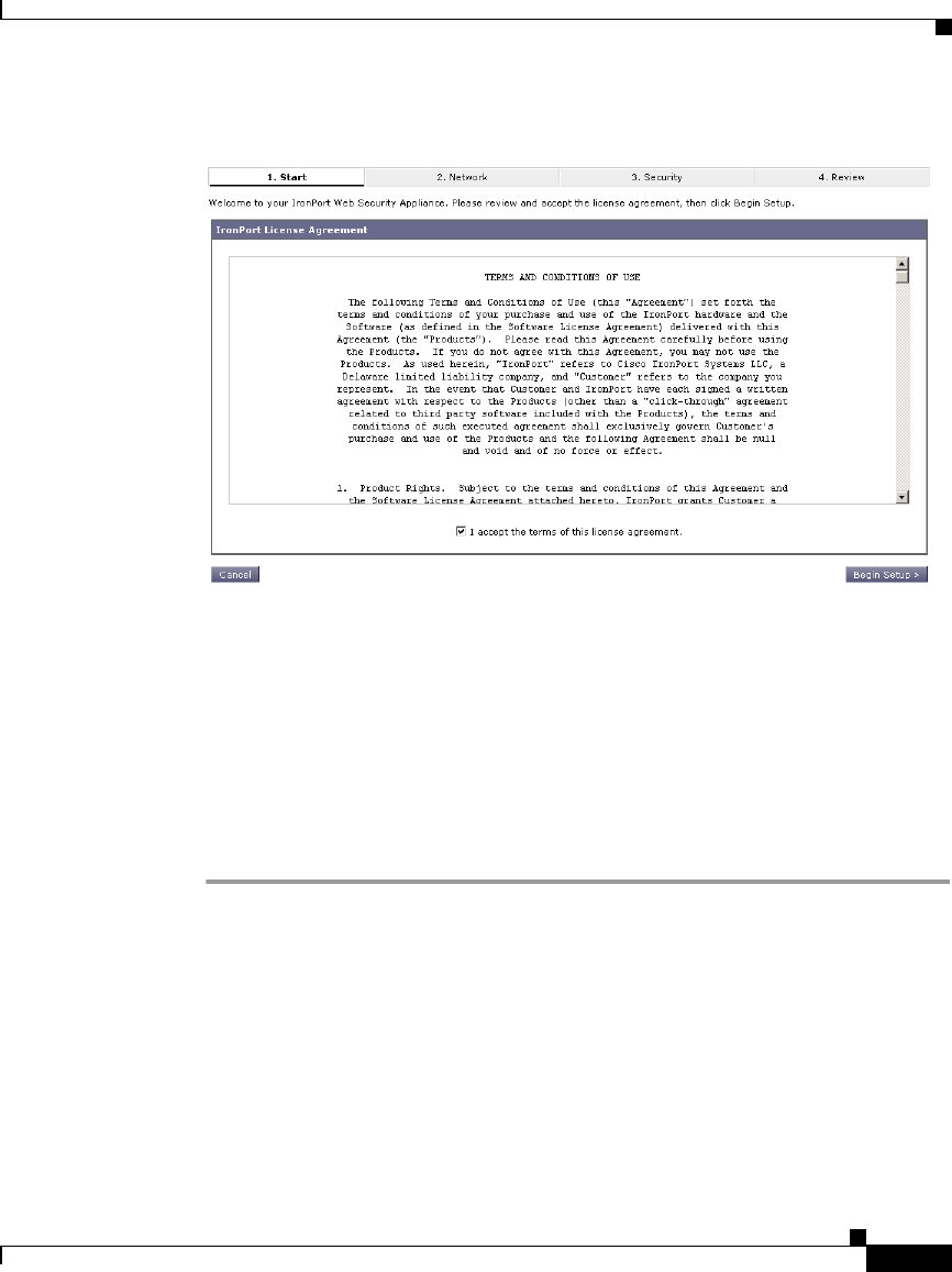
4-9
Cisco IronPort AsyncOS 7.1 for Web User Guide
OL-23207-01
Chapter 4 Installation and Configuration
System Setup Wizard
Figure 4-1 System Setup Wizard — Start Tab
Step 2 Click Begin Setup to continue.
The Network tab appears.
Step 2. Network
On the Network tab, you configure appliance system properties, such as the
appliance hostname and time zone. The first page of the Network tab is the System
Settings page.
Step 1 Verify that you are viewing the System Configuration page.
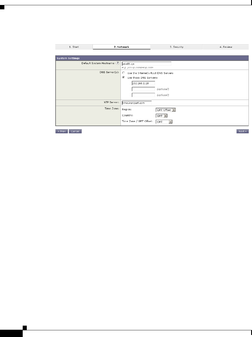
Chapter 4 Installation and Configuration
System Setup Wizard
4-10
Cisco IronPort AsyncOS 7.1 for Web User Guide
OL-23207-01
Figure 4-2 System Setup Wizard — Network Tab, System Settings
Step 2 Configure the System Setting options.

4-11
Cisco IronPort AsyncOS 7.1 for Web User Guide
OL-23207-01
Chapter 4 Installation and Configuration
System Setup Wizard
Table 4-2 describes the System Setting options.
Table 4-2 System Setting Options in System Setup Wizard
Option Description
Default System
Hostname
The fully-qualified hostname for the Web Security
appliance. This name should be assigned by your
network administrator. This hostname is used to
identify the appliance in system alerts.
DNS Server(s):
Use the Internet’s Root
DNS Servers
Configures the appliance to use the Internet root DNS
servers for domain name service lookups.
You might choose this option when the appliance does
not have access to DNS servers on your network.
The appliance requires access to a working DNS server
in order to perform DNS lookups for incoming
connections. If you cannot specify a working DNS
server that the appliance can reach while you set up the
appliance, you can configure it to use the Internet root
DNS servers or temporarily assign the IP address of
the Management interface so that you can complete the
System Setup Wizard.
For more information about configuring DNS settings,
see Configuring DNS Server(s), page 25-28.
DNS Server(s):
Use these DNS Servers
Specifies local DNS servers for domain name service
lookups. You must enter at least one DNS server, and
up to three total.
You can choose to use the Internet root DNS servers or
specify your own DNS servers.
For more information about configuring DNS settings,
see Configuring DNS Server(s), page 25-28.

Chapter 4 Installation and Configuration
System Setup Wizard
4-12
Cisco IronPort AsyncOS 7.1 for Web User Guide
OL-23207-01
Step 3 Click Next.
The Network Context page appears.
Figure 4-3 System Setup Wizard — Network Tab, Network Context Page
Step 4 Configure the Network Context options by indicating whether or not there exists
another proxy server on the network.
NTP Server Uses a Network Time Protocol (NTP) server to
synchronize the system clock with other servers on the
network or the Internet.
By default, the IronPort Systems time server
(time.ironport.com) is entered.
Time Zone Sets the time zone on the IronPort appliance so that
timestamps in message headers and log files are
correct. Use the drop-down menus to locate your time
zone or to define the time zone using the GMT offset.
For more information about the GMT offset, see
Selecting a Time Zone, page 26-30.
Table 4-2 System Setting Options in System Setup Wizard (continued)
Option Description

4-13
Cisco IronPort AsyncOS 7.1 for Web User Guide
OL-23207-01
Chapter 4 Installation and Configuration
System Setup Wizard
Note You can configure the Web Security appliance to interact with multiple
proxy servers on the network after you run the System Setup Wizard. For
more information about configuring external proxy servers, see Working
with External Proxies Overview, page 9-1.
Step 5 If there is an external proxy server on the network, configure the proxy settings.
Table 4-3 describes the proxy settings.
The System Setup Wizard creates a proxy group with the information you provide
in Table 4-3. You can edit the proxy group later to include additional proxy
servers and to configure load balancing options. You can also create additional
proxy groups after system setup.
Note When you use the Web Security appliance in a network that contains
another proxy server, it is recommended that you place the Web Security
appliance downstream from the proxy server, closer to the clients.
Step 6 Click Next.
The Network Interfaces and Wiring page appears.
The Web Security appliance has network interfaces that are associated with the
physical ports on the machine.
Table 4-3 Network Context Options in System Setup Wizard
Option Description
Proxy group name Choose a name for the proxy group.
Address Enter the address of the proxy server in your
organization network.
Port The port number of the proxy server in your organization
network.
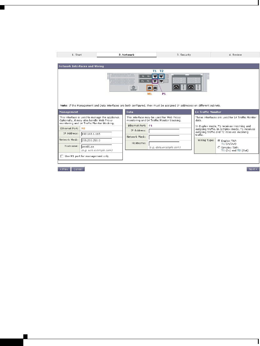
Chapter 4 Installation and Configuration
System Setup Wizard
4-14
Cisco IronPort AsyncOS 7.1 for Web User Guide
OL-23207-01
Figure 4-4 System Setup Wizard — Network Tab, Network Interfaces and
Wiring Page
Step 7 Configure the Network Interfaces and Wiring options.


Chapter 4 Installation and Configuration
System Setup Wizard
4-16
Cisco IronPort AsyncOS 7.1 for Web User Guide
OL-23207-01
Table 4-4 Network Interfaces and Wiring Options in System Setup
Wizard
Option Description
Management Enter the IP address, network mask, and hostname to use to
manage the Web Security appliance. Enter an IP address that
exists on your management network.
By default, the appliance uses the M1 interface for both
management and proxy (data) traffic (the “Use M1 port for
management only” check box is disabled).
However, optionally, you can use the M1 interface for only
management traffic by enabling the “Use M1 port for
management only” check box. You might want to do this if
your organization uses a separate management network. This
can increase security by ensuring no proxy traffic can reach
the appliance on management interface.
When you use M1 for management traffic only, you must
configure at least one data interface for proxy traffic. Also,
you must define different routes for management and data
traffic.

4-17
Cisco IronPort AsyncOS 7.1 for Web User Guide
OL-23207-01
Chapter 4 Installation and Configuration
System Setup Wizard
Step 8 Click Next.
The Routes for Management and Data Traffic page appears.
Data Enter the IP address, network mask, and hostname to use for
data traffic.
If you configure the M1 interface for management traffic only,
you must configure the P1 interface for data traffic. However,
you can configure the P1 interface even when the M1
interface is used for both management and data traffic.
You can use the Data interface for Web Proxy monitoring and
optional L4 traffic monitoring. You can also configure this
interface to support outbound services, such as DNS, software
upgrades, NTP, and traceroute data traffic.
Note: You can only enable and configure the P1 network
interface for data traffic in the System Setup Wizard. If you
want to enable the P2 interface, you must use the ifconfig
command after finishing the System Setup Wizard. For more
information about configuring the P2 interface, see
Configuring Network Interfaces, page 25-2.
L4 Traffic
Monitor
Choose the type of wired connections plugged into the “T”
interfaces:
•Duplex TAP. Choose Duplex TAP when the T1 port
receives both incoming and outgoing traffic. You can use
half- or full-duplex Ethernet connections.
•Simplex TAP. Choose Simplex TAP when you connect
the T1 port to the internal network (traffic flows from the
clients to the Internet) and you connect the T2 port to the
external network (traffic flows from the Internet to the
clients).
Cisco recommends using Simplex when possible because it
can increase performance and security.
Table 4-4 Network Interfaces and Wiring Options in System Setup Wizard
(continued)
Option Description
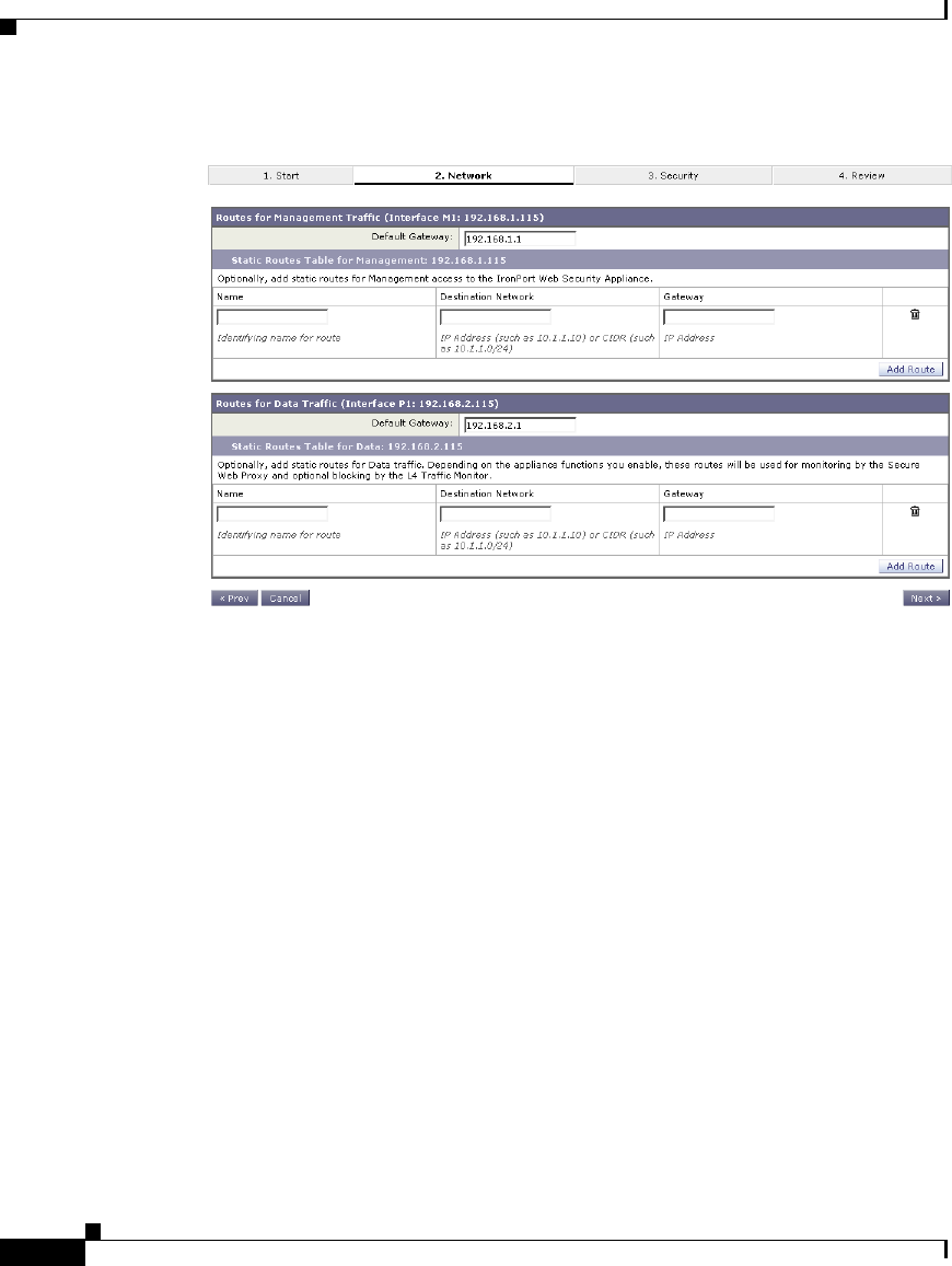
Chapter 4 Installation and Configuration
System Setup Wizard
4-18
Cisco IronPort AsyncOS 7.1 for Web User Guide
OL-23207-01
Figure 4-5 System Setup Wizard — Network Tab, Routes for Traffic Page
Step 9 Configure the Routes for Management and Data Traffic options.
The number of sections on this page depend on how you configured the “Use M1
port for management only” check box on the previous wizard page:
•Enabled. When you use the Management interface for management traffic
only, then this page includes two sections to enter gateway and static route
table information, one for management traffic and one for data traffic.
•Disabled. When you use the Management interface for both management and
data traffic only, then this page includes one section to enter gateway and
static route table information. AsyncOS uses the route information for both
management and data traffic.

4-19
Cisco IronPort AsyncOS 7.1 for Web User Guide
OL-23207-01
Chapter 4 Installation and Configuration
System Setup Wizard
Table 4-5 describes the Routes for Management and Data Traffic options.
Step 10 Click Next.
The Transparent Connection Settings page appears. By default, when you run the
System Setup Wizard, the Web Proxy is deployed in transparent mode. When the
Web Proxy is deployed in transparent mode, you must connect it to a Layer 4
switch or a version 2 WCCP router.
Table 4-5 Routes for Management and Data Traffic Options in System
Setup Wizard
Option Description
Default Gateway Enter the default gateway IP address to use for the traffic
through the Management and/or Data interface.
Static Routes
Table
Optionally, you can add one or more static routes for
management or data traffic.
To add a static route, enter a name for the route, its
destination network, and gateway IP address, and then click
Add Route. A route gateway must reside on the same
subnet as the Management or Data interface on which it is
configured.
To delete a static route you entered, click the Delete button
next to the static route entry in the table.
For more information about static routes, see Configuring
TCP/IP Traffic Routes, page 25-7.
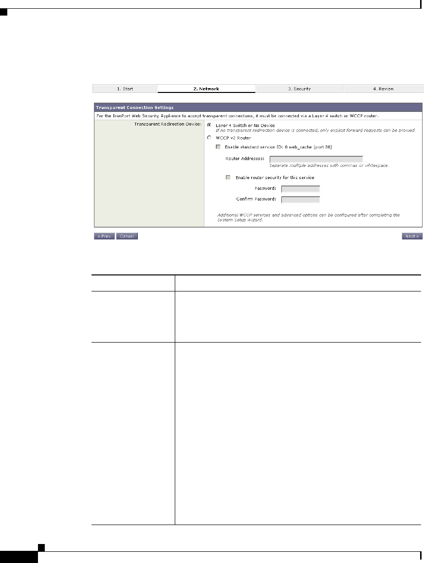
Chapter 4 Installation and Configuration
System Setup Wizard
4-20
Cisco IronPort AsyncOS 7.1 for Web User Guide
OL-23207-01
Figure 4-6 System Setup Wizard — Network Tab, Transparent Connection
Settings Page
Step 11 Choose one of the following options described in Table 4-6.
Table 4-6 Transparent Connection Options in System Setup Wizard
Option Description
Layer 4 Switch or
No Device
Choose this option when the Web Security appliance is
connected to a layer 4 switch or if you will deploy the Web
Proxy in explicit forward mode after running the System
Setup Wizard.
WCCP v2 Router Choose this option when the Web Security appliance is
connected to a version 2 WCCP capable router.
If you connect the appliance to a version 2 WCCP router,
you must create at least one WCCP service. You can enable
the standard service (also known as the “web-cache”
service) during system setup, and you can configure
different or additional WCCP service groups after you run
the System Setup Wizard.
When you enable the standard service, choose whether or
not to require a password for the standard service group. If
required, enter the password in the password fields. The
password can contain up to seven characters.
For more information about creating WCCP services, see
Adding and Editing a WCCP Service, page 25-21.
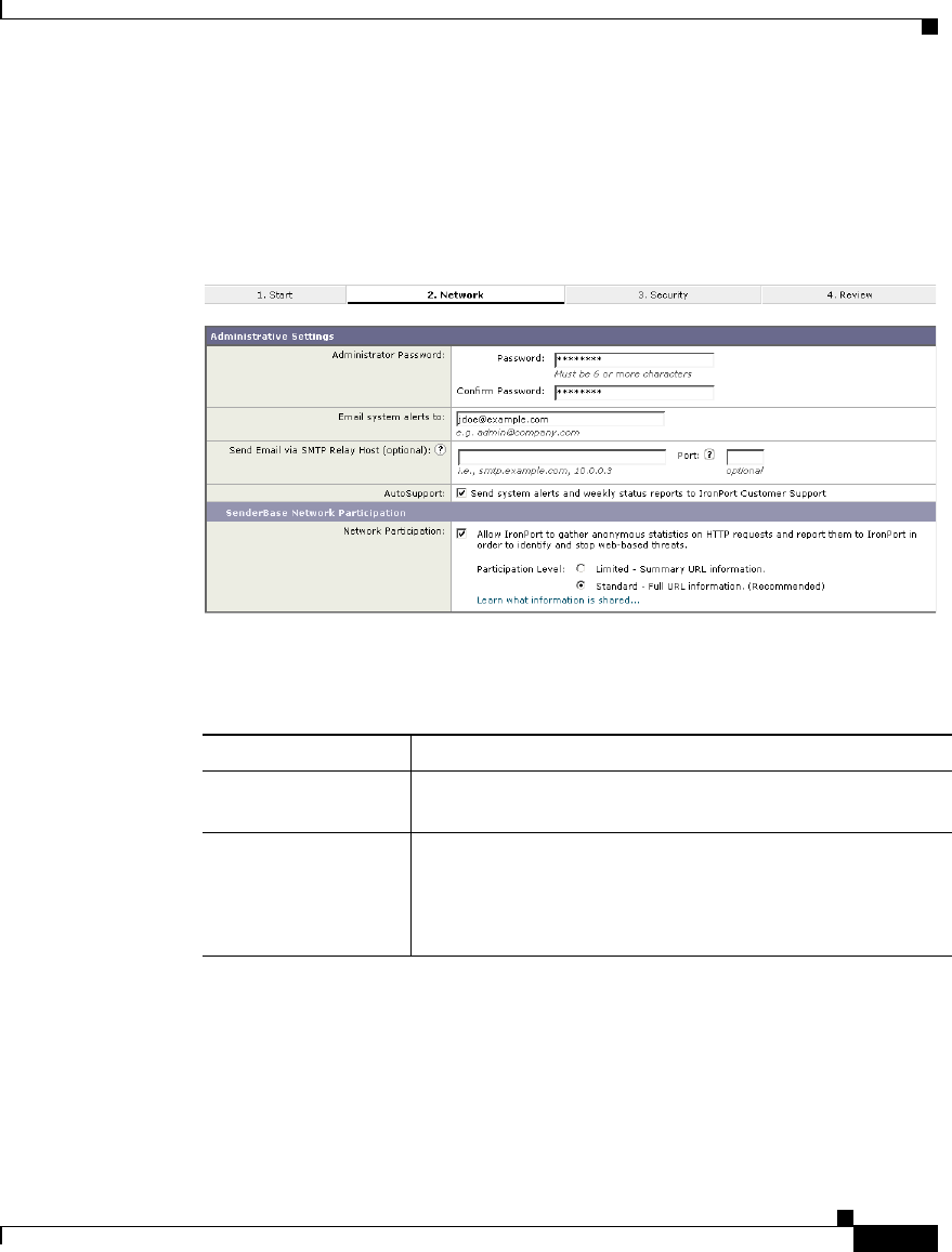
4-21
Cisco IronPort AsyncOS 7.1 for Web User Guide
OL-23207-01
Chapter 4 Installation and Configuration
System Setup Wizard
Step 12 Click Next.
The Administrative Settings page appears.
Figure 4-7 System Setup Wizard — Network Tab, Administrative Settings
Page
Step 13 Configure the Administrative Settings options.
Table 4-7 describes the Administrative Settings.
Table 4-7 Administrative Settings in System Setup Wizard
Option Description
Administrator
Password
Enter a password to access the Web Security appliance.
The password must be six characters or more.
Email System Alerts
To
Enter an email address for the account to which the
appliance sends alerts.
For more information about alerts, see Managing Alerts,
page 26-22.

Chapter 4 Installation and Configuration
System Setup Wizard
4-22
Cisco IronPort AsyncOS 7.1 for Web User Guide
OL-23207-01
Step 14 Click Next.
The Security tab appears.
Step 3. Security
On the Security tab, you can configure which security services to enable, such as
whether to block or monitor certain components. The Security tab contains one
page.
Send Email via
SMTP Relay Host
You can enter a hostname or address for an SMTP relay
host that AsyncOS uses for sending system generated
email messages.
Optionally, you can enter the port number, too. If no port
number is defined, AsyncOS uses port 25.
If no SMTP relay host is defined, AsyncOS uses the mail
servers listed in the MX record.
For more information about configuring the SMTP relay
hosts, see Configuring SMTP Relay Hosts, page 25-26.
AutoSupport Choose whether or not the appliance sends system alerts
and weekly status report to IronPort Customer Support.
SenderBase Network
Participation
Choose whether or not to participate in the SenderBase
Network. If you participate, you can configure limited or
full participation.
The SenderBase Network is a threat management database
that tracks millions of domains around the world and
maintains a global watch list for Internet traffic. When you
enable SenderBase Network Participation, the Web
Security appliance sends anonymous statistics about
HTTP requests to IronPort to increase the value of
SenderBase Network data.
For more information about the SenderBase Network, see
The SenderBase Network, page 2-5.
Table 4-7 Administrative Settings in System Setup Wizard (continued)
Option Description

4-23
Cisco IronPort AsyncOS 7.1 for Web User Guide
OL-23207-01
Chapter 4 Installation and Configuration
System Setup Wizard
Step 1 Verify that you are viewing the Security tab.
Figure 4-8 System Setup Wizard — Security Tab
Step 2 Choose the Security Services options.

Chapter 4 Installation and Configuration
System Setup Wizard
4-24
Cisco IronPort AsyncOS 7.1 for Web User Guide
OL-23207-01
Table 4-8 describes the Security options.
Table 4-8 Security Options in System Setup Wizard
Option Description
L4 Traffic Monitor Choose whether the Layer-4 Traffic Monitor should
monitor or block layer 4 traffic.
The L4 Traffic Monitor detects rogue traffic across all
network ports and stops malware attempts to bypass port
80.
You might choose to monitor traffic when you evaluate
the Web Security appliance, and block traffic when you
purchase and use the appliance.
For more information, see Configuring the L4 Traffic
Monitor, page 21-3.
Acceptable Use
Controls
Choose whether or not to enable Acceptable Use Controls
so you can choose a URL filtering engine, either Cisco
IronPort Web Usage Controls or IronPort URL Filters.
URL filtering engines allow you to control user access
based on the category of a URL in a request. Enable this
option when you want to restrict users from accessing
particular types of websites.
Note: If you enable Cisco IronPort Web Usage Controls,
the Dynamic Content Analysis engine is enabled by
default. You can edit this setting after system setup.
For more information, see URL Filters, page 16-1.

4-25
Cisco IronPort AsyncOS 7.1 for Web User Guide
OL-23207-01
Chapter 4 Installation and Configuration
System Setup Wizard
Step 3 Click Next.
Web Reputation
Filters
Choose whether or not to enable Web Reputation filtering
for the Global Policy Group. When you create custom
Access Policy groups, you can choose whether or not to
enable Web Reputation filtering.
IronPort Web Reputation Filters is a security feature that
analyzes web server behavior and assigns a reputation
score to a URL to determine the likelihood that it contains
URL-based malware.
Enable this option when you want to identify suspicious
activity and stop malware attacks before they occur.
For more information, see Web Reputation Filters,
page 18-1.
Malware and
Spyware Scanning
Choose whether or not to enable malware and spyware
scanning using Webroot, McAfee, or Sophos. If enabled,
also choose whether to monitor or block detected
malware.
You might choose to monitor malware when you evaluate
the Web Security appliance, and block malware when you
purchase and use the appliance.
You can further configure malware scanning after you
finish the System Setup Wizard. For details, see
Configuring Anti-Malware Scanning, page 19-10.
IronPort Data
Security Filtering
Choose whether or not to enable IronPort Data Security
Filters. The IronPort Data Security Filters evaluate data
leaving the network over HTTP, HTTPS, and FTP to
control what data goes where and how and by whom.
Enable this option when you want to create IronPort Data
Security Policies to block particular types of upload
requests.
For more information, see Data Security and External
DLP Policies Overview, page 12-1.
Table 4-8 Security Options in System Setup Wizard (continued)
Option Description

Chapter 4 Installation and Configuration
System Setup Wizard
4-26
Cisco IronPort AsyncOS 7.1 for Web User Guide
OL-23207-01
The Review tab appears.
Step 4. Review
The last tab of the System Setup Wizard displays a summary of the configuration
information you chose. You can edit any of the configuration options by clicking
the Edit button for each section.
Step 1 Verify that you are viewing the Review tab.

4-27
Cisco IronPort AsyncOS 7.1 for Web User Guide
OL-23207-01
Chapter 4 Installation and Configuration
System Setup Wizard
Figure 4-9 System Setup Wizard — Review Tab
Step 2 Review the configuration information. If you need to change an option, click the
Edit button for that section.
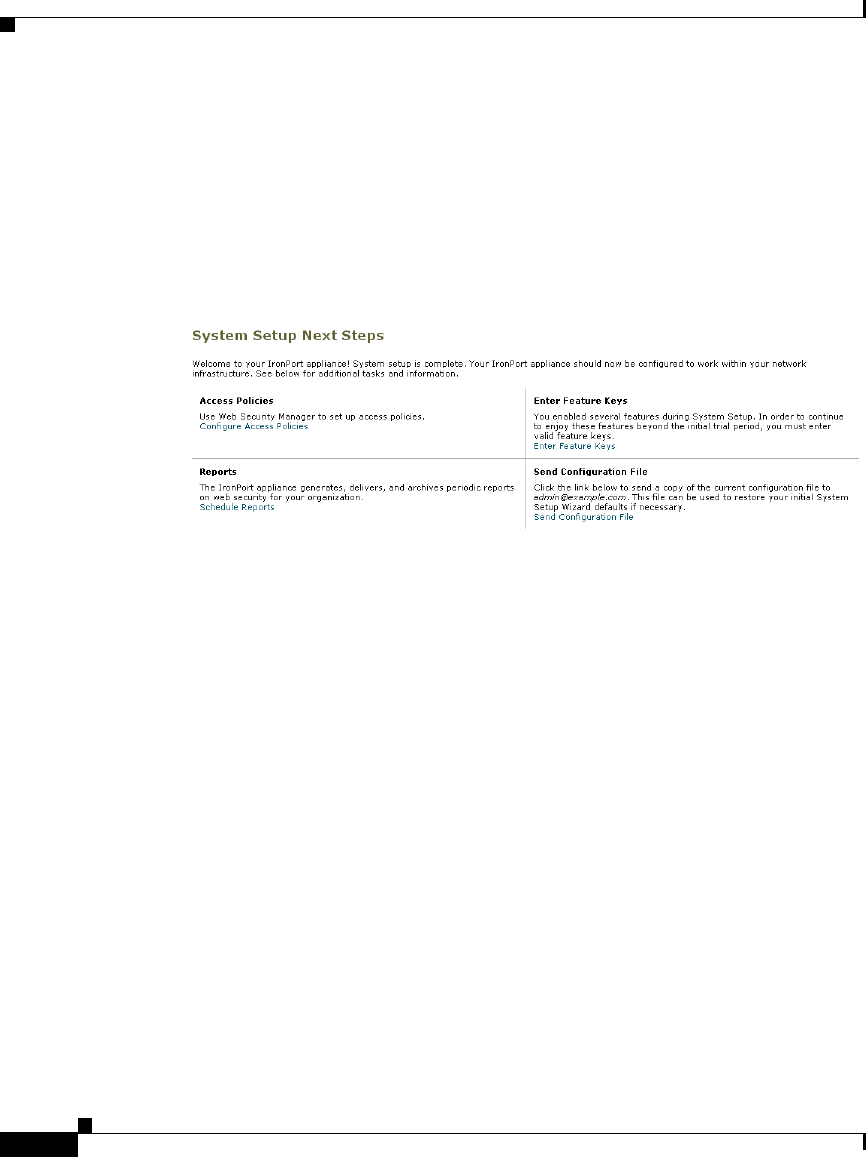
Chapter 4 Installation and Configuration
System Setup Wizard
4-28
Cisco IronPort AsyncOS 7.1 for Web User Guide
OL-23207-01
Step 3 Click Install This Configuration after you confirm the configuration is correct.
The Web Security appliance applies the configuration options you selected.
If you changed the Management interface IP address from the current value, then
clicking Install This Configuration will cause the connection to the current URL
to be lost. However, your browser will redirect itself to the new IP address. If you
did not change the IP address from the current value, the System Administration
> System Setup > Next Steps page appears.

CHAPTER
5-1
Cisco IronPort AsyncOS 7.1 for Web User Guide
OL-23207-01
5
Web Proxy Services
This chapter contains the following information:
•About Web Proxy Services, page 5-1
•Configuring the Web Proxy, page 5-3
•Working with FTP Connections, page 5-8
•Bypassing the Web Proxy, page 5-15
•Bypassing Application Scanning, page 5-18
•Proxy Usage Agreement, page 5-18
•Configuring Client Applications to Use the Web Proxy, page 5-19
•Working with PAC Files, page 5-19
•Adding PAC Files to the Web Security Appliance, page 5-24
•Advanced Proxy Configuration, page 5-30
About Web Proxy Services
A web proxy is a computer system or software that handles World Wide Web
requests of clients by making requests of other servers on the web. The Web
Security appliance can act as a web proxy if you enable the Web Proxy feature.
The Web Proxy service monitors and controls traffic that originates from clients
on the internal network. Typically, the Web Proxy-enabled Web Security
appliance is deployed between clients and the firewall where it intercepts requests
for content from clients to servers.

Chapter 5 Web Proxy Services
About Web Proxy Services
5-2
Cisco IronPort AsyncOS 7.1 for Web User Guide
OL-23207-01
You can configure the Web Proxy as one of the following types:
•Transparent Proxy. When the appliance is configured as a transparent proxy,
clients are unaware of the Web Proxy. Client applications, such as web
browsers, do not have to be configured to accommodate the appliance. You
might want to configure the appliance as a transparent proxy because it
eliminates the possibility of users reconfiguring their web browsers to bypass
the appliance without knowledge of the administrator. To configure the
appliance as a transparent proxy, you must connect it to an L4 switch or a
WCCP router.
For information about how to configure the appliance when you configure the
proxy in transparent mode, see Configuring Transparent Redirection,
page 25-17.
•Explicit Forward Proxy. In an explicit forward proxy configuration, the
appliance acts on behalf of client web browsers to handle requests for servers
on the web. Users must configure their web browsers to point to a single Web
Security appliance. You might want to configure the appliance as an explicit
forward proxy if you do not have an L4 switch or a WCCP router.
You can use the Web Security appliance in a network that includes another proxy
server. For more information about how to deploy and configure the appliance
when the network contains another proxy, see Using the Web Security Appliance
in an Existing Proxy Environment, page 3-15.
The Web Proxy handles both HTTP and native FTP transactions. For more
information about working with FTP, see Working with FTP Connections,
page 5-8.
Web Proxy Cache
By default, AsyncOS uses a web proxy cache to increase performance for users
accessing the web in some cases.
You can edit the web proxy and proxy cache in the following ways:
•Remove a URL from the cache. Use the evict subcommand of the webcache
CLI command to remove one or more URLs from the cache.
•Specify a domain or URL to never cache. Use the ignore subcommand of
the webcache CLI command to specify one or more domains or URLs that the
web proxy should never store in the proxy cache. You can include embedded
regular expression (regex) characters in the URL you specify to never cache.

5-3
Cisco IronPort AsyncOS 7.1 for Web User Guide
OL-23207-01
Chapter 5 Web Proxy Services
Configuring the Web Proxy
Each access log file entry includes transaction result codes that describe how the
appliance resolved client requests. Transaction result codes indicate whether the
transaction was served from the proxy cache or from the destination server. For
more information about transaction result codes, see Transaction Result Codes,
page 24-23.
Configuring the Web Proxy
Web Proxy settings are configured as part of an initial setup using the System
Setup Wizard. To enable Web Proxy services or modify proxy settings after an
initial configuration, use the Security Services > Web Proxy page. This page
allows you to configure basic and advanced settings to customize proxy services.
The Web Proxy settings apply to all connections that go over HTTP or HTTPS.
To configure proxy settings for native FTP connections, see Working with FTP
Connections, page 5-8.
To edit the Web Proxy settings:
Step 1 Navigate to the Security Services > Web Proxy page.
Step 2 Click Edit Settings.
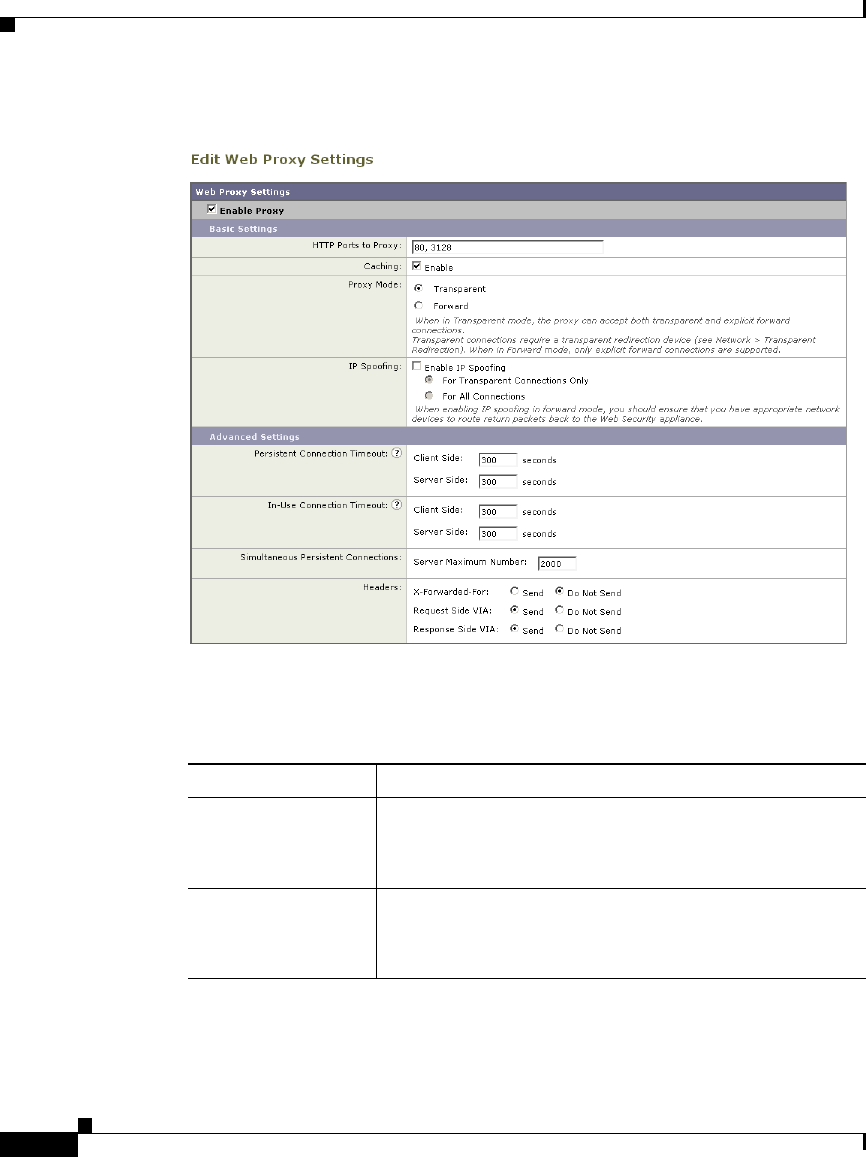
Chapter 5 Web Proxy Services
Configuring the Web Proxy
5-4
Cisco IronPort AsyncOS 7.1 for Web User Guide
OL-23207-01
Figure 5-1 Editing Web Proxy Settings
Step 3 Verify the Enable Proxy field is selected.
Step 4 Configure the basic and advanced Web Proxy settings defined in Table 5-1.
Table 5-1 Web Proxy Settings
Property Description
HTTP Ports to Proxy Enter which ports the Web Proxy monitors for HTTP
requests.
Default is 80 and 3128.
Caching Choose whether or not the Web Proxy should cache
requests and responses.
Default is enabled.

5-5
Cisco IronPort AsyncOS 7.1 for Web User Guide
OL-23207-01
Chapter 5 Web Proxy Services
Configuring the Web Proxy
Proxy Mode Choose how to deploy the Web Proxy:
•Transparent mode. Clients applications are
unaware of the Web Proxy and do not have to be
configured to connect to the proxy. In transparent
mode, the Web Proxy can accept both transparently
redirected and explicitly forwarded connections.
For more information, see Deploying the Web Proxy
in Transparent Mode, page 3-7.
•Explicit forward mode. Client applications, such as
web browsers, are aware of the Web Proxy and must
be configured to point to a single Web Security
appliance. In explicit forward mode, the Web Proxy
can only accept explicitly forwarded connections.
For more information, see Deploying the Web Proxy
in Explicit Forward Mode, page 3-6.
IP Spoofing Choose whether or not the Web Proxy should spoof IP
addresses when sending requests to upstream proxies and
servers.
When the Web Proxy is deployed in transparent mode,
you can enable IP spoofing for transparently redirected
connections only or all connections (transparently
redirected and explicitly forwarded).
When IP spoofing is enabled, requests originating from a
client retain the client’s source address and appear to
originate from the client rather than from the Web
Security appliance.
Note: When IP spoofing is enabled and the appliance is
connected to a WCCP router, configure a WCCP service
to redirect the return path.
Table 5-1 Web Proxy Settings (continued)
Property Description

Chapter 5 Web Proxy Services
Configuring the Web Proxy
5-6
Cisco IronPort AsyncOS 7.1 for Web User Guide
OL-23207-01
Persistent
Connection Timeout
Enter how long the Web Proxy keeps open a connection
to a client or server after a transaction has been
completed. Keeping a connection open allows the Web
Proxy to use it again for another request.
For example, after a client finishes a transaction with
google.com, the Web Proxy keeps the connection to the
server google.com open for the amount of time specified
in the server side persistent timeout if no other client
makes a request for google.com.
•Client side. The maximum number of seconds the
Web Proxy keeps a connection open with a client on
the network with no activity from the client.
•Server side. The maximum number of seconds the
Web Proxy keeps a connection open with a
destination server with no activity from any client on
the network to that server.
Default is 300 seconds for both client and server side
persistent timeouts.
You might want to increase the server side persistent
timeout if clients on the network frequently connect to
the same server, or if the network has a relatively slow
connection to outside servers.
Cisco recommends keeping the default values. However,
you might want to increase or decrease these values to
keep connections open longer to reduce overhead used to
open and close connections repeatedly. Consider that if
you increase the persistent timeout values, you also
reduce the ability of the Web Proxy to open new
connections if the maximum number of simultaneous
persistent connections has been reached.
Table 5-1 Web Proxy Settings (continued)
Property Description

5-7
Cisco IronPort AsyncOS 7.1 for Web User Guide
OL-23207-01
Chapter 5 Web Proxy Services
Configuring the Web Proxy
Step 5 Submit and commit your changes.
In-Use Connection
Timeout
Enter how long the Web Proxy waits for more data from
an idle client or server when the current transaction has
not been completed.
For example, if a client opens a connection and sends
only half of the request, the Web Proxy waits for the
amount of time specified for the client side reserve
timeout for the rest of the request before closing the open
connection.
•Client side. The maximum number of seconds the
Web Proxy keeps a connection open with an idle
client.
•Server side. The maximum number of seconds the
Web Proxy keeps a connection open with an idle
destination server.
Default is 300 seconds for both client and server side
reserve timeouts.
Simultaneous
Persistent
Connections (Server
Maximum Number)
Enter the maximum number of connections (sockets) the
Web Proxy keeps open with servers.
Headers •X-Forwarded-For. Choose whether or not to
forward HTTP “X-Forwarded-For” headers. Default
is Do Not Send.
Note: If the network contains an explicit forward
upstream proxy that manages user authentication or
access control using proxy authentication, you must
enable the X-Forwarded-For header to send the client
host header to the upstream proxy.
•VIA. Choose whether or not to forward HTTP “VIA”
headers in HTTP requests from clients and HTTP
responses from servers. Default is Send.
Table 5-1 Web Proxy Settings (continued)
Property Description

Chapter 5 Web Proxy Services
Working with FTP Connections
5-8
Cisco IronPort AsyncOS 7.1 for Web User Guide
OL-23207-01
Working with FTP Connections
The Web Security appliance Web Proxy provides proxy services for the File
Transfer Protocol (FTP) as well as HTTP. FTP is a protocol used to transfer data
between computers over a network. The Web Proxy can handle the following FTP
transactions:
•FTP over HTTP. Most web browsers support FTP transactions, but
sometimes the transactions are encoded inside an HTTP transaction. All
policies and configuration options that apply to HTTP transactions also apply
to FTP over HTTP transactions.
•Native FTP. FTP clients use FTP to transfer data without invoking an HTTP
connection. Native FTP connections are treated and handled differently than
HTTP connections.
The component of the Web Proxy that handles native FTP transactions is referred
to as the FTP Proxy.
Native FTP connections can be served when the Web Proxy is deployed in either
transparent or explicit forward mode.
Computers that transfer data using FTP create two connections between them.
The control connection is used to send and receive FTP commands, such as RETR
and STOR, and to communicate other information, such as the connection mode
and file properties. The data connection is used to transfer the data itself.
Typically, computers use port 21 for the control connection, and use a randomly
assigned port (usually greater than 1023) for the data connection.
The FTP Proxy supports the following connection modes:
•Passive. In passive mode, the FTP server chooses the port used for the data
connection and communicates this assignment to the FTP client. Passive
mode is typically favored in most network environments where the FTP client
is located behind a firewall and inbound connections (such as from an FTP
server) are blocked. The default for the FTP Proxy is passive mode.
•Active. In active mode, the FTP client chooses the port used for the data
connection and communicates this assignment to the FTP server.
Consider the following rules and guidelines when working with native FTP
connections:
•You can define which Identity groups apply to native FTP transactions.

5-9
Cisco IronPort AsyncOS 7.1 for Web User Guide
OL-23207-01
Chapter 5 Web Proxy Services
Working with FTP Connections
•You configure FTP Proxy settings that apply to native FTP connections. For
more information, see Configuring FTP Proxy Settings, page 5-11.
•You can configure which welcome message users see in the FTP client when
they connect to an FTP server. Configure the welcome banner when you
configure the FTP Proxy settings.
•You can define a custom message the FTP Proxy displays in IronPort FTP
notification messages when there is an error with FTP Proxy authentication.
For more information, see Working with IronPort FTP Notification
Messages, page 15-23.
•When the FTP Proxy is configured to cache native FTP transactions, it only
caches content accessed by anonymous users.
•You can configure the FTP Proxy to spoof the IP address of the FTP server.
You might want to do this when FTP clients do not allow passive data
connections when the source IP address of the data connection (FTP server)
is different than the source IP address of the control connection (FTP Proxy).
•If the connection between the FTP Proxy and the FTP server is slow,
uploading a large file may take a long time when IronPort Data Security
Filters are enabled. If the FTP client times out before the FTP Proxy uploads
the entire file, users may notice a failed transaction.
Using Authentication with Native FTP
The FTP Proxy performs user authentication to control which users can make
native FTP requests. This user authentication determines which policy groups
apply to the native FTP transaction.
However, due to the nature of FTP and FTP clients, only explicit forward
connections can authenticate users for native FTP transactions. Due to this
limitation, you must configure at least one Identity and Access Policy for native
FTP transactions that do not require authentication when the Web Proxy is
deployed in transparent mode. This allows FTP connections that are transparently
redirected to the Web Security appliance to work. If authentication is required for
all policy groups, transparently redirected native FTP transaction will fail.
You can configure the authentication format the FTP Proxy uses when
communicating with FTP clients. The FTP Proxy supports the following formats
for proxy authentication:
•Check Point. Uses the following formats:

Chapter 5 Web Proxy Services
Working with FTP Connections
5-10
Cisco IronPort AsyncOS 7.1 for Web User Guide
OL-23207-01
–
User: ftp_user@proxy_user@remote_host
–
Password: ftp_password@proxy_password
•Raptor. Uses the following formats:
–
User: ftp_user@remote_host proxy_user
–
Password: ftp_password
–
Account: proxy_password
When using authentication with native FTP, ensure that the FTP client uses the
same authentication settings configured for the FTP Proxy.
Note Be careful when requiring authentication for native FTP transactions. FTP is
inherently insecure because data (including the authentication credentials) is
transmitted directly over the wire without encryption.
Working with Native FTP in Transparent Mode
When the Web Security appliance is deployed in transparent mode, FTP clients
typically are not explicitly configured to use the FTP Proxy. Native FTP
connections are transparently redirected to the FTP Proxy and then processed.
When a native FTP request is transparently redirected to the FTP Proxy, it
contains no hostname information for the FTP server, only its IP address. Because
of this, the FTP Proxy only matches native FTP transactions with IP addresses
configured in the Access Policies.
The predefined URL categories and Web Reputation Filters block by hostname
and IP address, but for some servers, they may only have hostname information
and not the server’s IP address. For example, if the “News” predefined URL
category contains the cnn.com, but not the corresponding IP address for that
server, and if that URL category is configured to block, then native FTP
connections to cnn.com will successfully connect instead of being blocked.
Therefore, to make sure the FTP Proxy blocks native FTP connections to certain
sites, you must create custom URL categories and enter the IP addresses in the list
of sites to block or in the regular expression field.
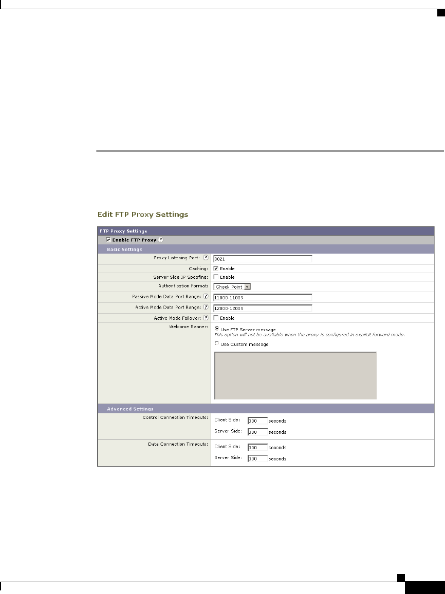
5-11
Cisco IronPort AsyncOS 7.1 for Web User Guide
OL-23207-01
Chapter 5 Web Proxy Services
Working with FTP Connections
Configuring FTP Proxy Settings
The FTP Proxy settings apply to native FTP connections. To configure proxy
settings that apply to FTP over HTTP connections, configure the Web Proxy. For
more information, see Configuring the Web Proxy, page 5-3.
To configure the FTP Proxy settings:
Step 1 Navigate to the Security Services > FTP Proxy page, and click Edit Settings.
Figure 5-2 Configuring FTP Proxy Settings
Step 2 Verify the Enable FTP Proxy field is selected.

Chapter 5 Web Proxy Services
Working with FTP Connections
5-12
Cisco IronPort AsyncOS 7.1 for Web User Guide
OL-23207-01
Step 3 Configure the basic and advanced FTP Proxy settings defined in Table 5-2.
Table 5-2 FTP Proxy Settings
Property Description
Proxy Listening Port Specify the port FTP clients should use to establish a
control connection with the FTP Proxy.
Caching Choose whether or not to cache contents of data
connections from anonymous users.
Server Side IP
Spoofing
Choose whether or not the FTP Proxy should spoof the
FTP server IP address. You might want to do this for FTP
clients that do not allow transactions when the IP address
is different for the control and data connections.
Authentication
Format
Choose the authentication format the FTP Proxy uses
when communicating with FTP clients. For more
information, see Using Authentication with Native FTP,
page 5-9.
Passive Mode Data
Port Range
Specify a range of TCP ports FTP clients should use to
establish a data connection with the FTP Proxy for
passive mode connections.
Default is 11000-11009.
Active Mode Data
Port Range
Specify a range of TCP ports FTP servers should use to
establish a data connection with the FTP Proxy for active
mode connections.
Default is 12000-12009.
You might want to increase the port range in this field to
accommodate more requests from the same FTP server.
Because of the TCP session TIME-WAIT delay (usually
a few minutes), a port does not become available again
for the same FTP server immediately after being used. As
a result, any given FTP server cannot connect to the FTP
Proxy in active mode more than n times in a short period
of time, where n is the number of ports specified in this
field.

5-13
Cisco IronPort AsyncOS 7.1 for Web User Guide
OL-23207-01
Chapter 5 Web Proxy Services
Working with FTP Connections
Active Mode
Failover
When this option is enabled, the FTP Proxy will attempt
an active mode connection with the FTP server when
passive mode fails. This option affects the connection
between the FTP Proxy and the FTP server. It does not
affect the connection between the FTP client and the FTP
Proxy.
Welcome Banner Choose which welcome message should appear in FTP
clients:
•FTP server message. The FTP server message only
displays for transparently redirected connections.
When a native FTP connection is explicitly sent to
the FTP Proxy, the FTP client displays a message
predefined by the FTP Proxy.
•Custom message. Enter a message to display for all
native FTP connections.
Table 5-2 FTP Proxy Settings (continued)
Property Description

Chapter 5 Web Proxy Services
Working with FTP Connections
5-14
Cisco IronPort AsyncOS 7.1 for Web User Guide
OL-23207-01
Control Connection
Timeouts
Enter how long the FTP Proxy waits for more
communication in the control connection from an idle
FTP client or FTP server when the current transaction has
not been completed.
For example, if an FTP client opens a control connection
and sends some requests, the FTP Proxy waits for the
amount of time specified for the client side control
connection timeout for the next request before closing the
open connection.
•Client side. The maximum number of seconds the
FTP Proxy keeps a control connection open with an
idle client.
•Server side. The maximum number of seconds the
FTP Proxy keeps a control connection open with an
idle FTP server.
Default is 300 seconds for both client and server side
control connection timeouts.
Table 5-2 FTP Proxy Settings (continued)
Property Description

5-15
Cisco IronPort AsyncOS 7.1 for Web User Guide
OL-23207-01
Chapter 5 Web Proxy Services
Bypassing the Web Proxy
Step 4 Submit and commit your changes.
Bypassing the Web Proxy
You can configure the Web Security appliance so client requests to or from
particular addresses bypass all processing by the Web Proxy. The proxy bypass
list only works for requests that are transparently redirected to the Web Proxy
using an L4 switch or a WCCP v2 router. When the appliance is deployed in
explicit forward mode, or when a client makes an explicit request to the Web
Proxy, the request is processed by the Web Proxy.
You might want to create a proxy bypass list to accomplish any of the following:
•Prevent the Web Proxy from interfering with non-HTTP-compliant (or
proprietary) protocols using HTTP ports that do not work properly when they
connect to a proxy server.
Data Connection
Timeouts
Enter how long the FTP Proxy waits for more
communication in the data connection from an idle FTP
client or FTP server when the current transaction has not
been completed.
For example, if an FTP client opens a data connection and
sends only half of the request, the FTP Proxy waits for the
amount of time specified for the client side data
connection timeout for the rest of the request before
closing the open connection.
•Client side. The maximum number of seconds the
FTP Proxy keeps a data connection open with an idle
client.
•Server side. The maximum number of seconds the
FTP Proxy keeps a data connection open with an idle
FTP server.
Default is 300 seconds for both client and server side data
connection timeouts.
Table 5-2 FTP Proxy Settings (continued)
Property Description
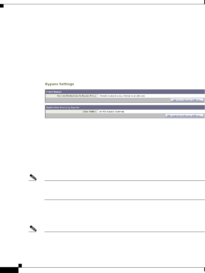
Chapter 5 Web Proxy Services
Bypassing the Web Proxy
5-16
Cisco IronPort AsyncOS 7.1 for Web User Guide
OL-23207-01
•Ensure that traffic from a particular machine inside the network, such as a
malware test machine, bypasses the Web Proxy and all its built-in security
protection.
Define the proxy bypass list on the Web Security Manager > Bypass Settings
page.
Figure 5-3 shows a sample proxy bypass list.
Figure 5-3 Proxy Bypass List
To include an address in the proxy bypass list, click Edit Proxy Bypass Settings.
You can enter multiple addresses separated by line breaks or commas. You can
enter addresses using any of the following formats:
•IP address, such as 10.1.1.0
•CIDR address, such as 10.1.1.0/24
•Hostname, such as crm.example.com
•domain names, such as example.com
Note For the proxy bypass list to work with domain names, you need to connect the T1
and T2 network interfaces to the network even if you do not enable the L4 Traffic
Monitor. For more information, see How the Proxy Bypass List Works, page 5-17.
When transactions bypass the Web Proxy, AsyncOS for Web records them in the
proxy bypass logs. For more information about logging, see Working with Log
Subscriptions, page 24-9.
Note If the proxy bypass list contains an address that is a known malware address
according to the L4 Traffic Monitor and the L4 Traffic Monitor sees a request for
that address, then the request will still be blocked by the L4 Traffic Monitor. If

5-17
Cisco IronPort AsyncOS 7.1 for Web User Guide
OL-23207-01
Chapter 5 Web Proxy Services
Bypassing the Web Proxy
you want to ensure traffic to that address is always allowed, you must also bypass
the address from the L4 Traffic Monitor. For more information, see How the L4
Traffic Monitor Works, page 21-1.
How the Proxy Bypass List Works
When the Web Proxy receives an HTTP or HTTPS request, it checks both the
source and destination IP address to see if it is in the proxy bypass list. If it is, the
packet is sent to the next hop on the network. (In some cases, the packet is sent
back to the transparent redirection device that redirected the packet, if the packet
arrived on a WCCP service using GRE.)
The proxy bypass list works by matching the IP addresses of the request to an IP
address in the proxy bypass list. When names are entered in the bypass list, the
Web Proxy must resolve them to an IP address using DNS. The Web Proxy DNS
resolves hostnames differently than domain names:
•Hostnames. Hostnames are resolved to IP addresses using DNS queries
immediately after they are entered into the proxy bypass list. (An example
hostname is www.example.com.)
•Domain names. Domain names cannot be resolved to IP addresses using
DNS queries, so the Web Proxy uses DNS snooping using the T1 and T2
network interfaces. (An example domain name is example.com, and it
matches both www.example.com and webmail.example.com.)
Because of these differences, if the proxy bypass list contains only IP addresses
and hostnames, then the Web Proxy can easily match the IP address in the request
header to the IP addresses in the proxy bypass list.
However, for the proxy bypass list to work with domain names, you must connect
both the T1 and T2 network interfaces (if using simplex mode) or just connect the
T1 network interface (if using duplex mode) to the network even if you do not
enable the L4 Traffic Monitor. However, the proxy bypass list only bypasses the
Web Proxy scanning. It does not bypass the L4 Traffic Monitor.
Note If the transparent redirection device is a WCCP router, some are intelligent
enough to not forward any other packets to the Web Proxy for the same session.
In this case, the packets are not physically sent to the Web Proxy for the rest of
the session and are truly bypassing it for the rest of the session.
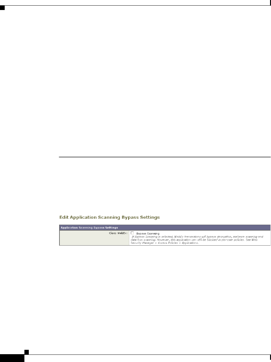
Chapter 5 Web Proxy Services
Bypassing Application Scanning
5-18
Cisco IronPort AsyncOS 7.1 for Web User Guide
OL-23207-01
Using WCCP with the Proxy Bypass List
When the Web Security appliance is configured to use a WCCP v2 router, you
must ensure that all WCCP services defined in the Web Security appliance use the
same forwarding and return method (either L2 or GRE) to work properly with the
proxy bypass list. If the forwarding and return methods do not match, some
WCCP enabled routers will act inconsistently.
For more information, see Working with the Forwarding and Return Method,
page 25-19.
Bypassing Application Scanning
To bypass an application from Web Proxy scanning:
Step 1 Navigate to the Web Security Manager > Bypass Settings page.
Step 2 Click Edit Application Bypass Settings.
The Edit Application Scanning Bypass Settings page appears.
Figure 5-4 Application Scanning Bypass Settings Page
Step 3 Enable Bypass Scanning for the application to bypass.
Step 4 Submit and commit your changes.
Proxy Usage Agreement
You can configure the Web Security appliance to inform users that it is filtering
and monitoring their web activity. The appliance does this by displaying an
end-user acknowledgement page when a user first accesses a browser after a
certain period of time. When the end-user acknowledgement page appears, users

5-19
Cisco IronPort AsyncOS 7.1 for Web User Guide
OL-23207-01
Chapter 5 Web Proxy Services
Configuring Client Applications to Use the Web Proxy
must click a link to access the original site requested or any other website. For
more information about end-user acknowledgement pages, see End-User
Acknowledgement Page, page 15-18.
Configuring Client Applications to Use the Web
Proxy
Web browsers and other user agents sometimes need to know how to connect to
the Web Proxy in order to access the World Wide Web. When you deploy the Web
Security appliance in explicit forward mode, you must configure client
applications so they use the Web Proxy. If you deploy the appliance in transparent
mode, you can choose whether or not to configure client applications to explicitly
use the Web Proxy.
You can configure client applications to explicitly use the Web Proxy by using any
of the following configuration methods:
•Manual. Manual configuration involves typing the Web Security appliance
hostname and port number, such as 3128, in each client application. If the
appliance changes, you must edit each application individually. You might
want to manually configure an application when you are testing proxy access
on a single client machine. IronPort does not recommend manually
configuring each client application to use the appliance Web Proxy.
•Proxy auto-config (PAC) file. For web browsers, you can configure each
browser to use a PAC file to find the Web Proxy. Then you can edit the PAC
file to specify the appliance Web Proxy information. For more information,
see Working with PAC Files, page 5-19.
For more information about how to configure client applications to use a proxy,
see the client application documentation.
Working with PAC Files
A proxy auto-config (PAC) file is a text file that defines how web browsers can
automatically choose the appropriate proxy server for fetching a given URL.

Chapter 5 Web Proxy Services
Working with PAC Files
5-20
Cisco IronPort AsyncOS 7.1 for Web User Guide
OL-23207-01
When you use a PAC file, you only need to configure each browser once with the
PAC file information. Then, you can edit the PAC file multiple times to add,
delete, or change Web Proxy connection information without editing each
browser. This way you can configure the proxy information about your network
in a centralized location and update it easily.
Note Once a browser has read a PAC file, it stores it in memory for the remainder of the
browser session.
You might want to use a PAC file for the following reasons:
•Centralized management. You can manage the PAC file in a single, central
location.
•Complex network environment. If the network of proxy servers is
complicated, you can create a PAC file to accommodate different server and
client needs.
•Changing network environment. If your network environment is likely to
change in the future, you can easily add, edit, or delete proxy servers in the
PAC and have the changes automatically affect all browsers.
•Failover. If you have multiple proxy servers, you can provide redundancy in
case of failure. You can either program the PAC file to be redundant, or if a
failure occurs, change the PAC file to use a different proxy server.
Note Different browsers take different amounts of time to fail over to a
secondary proxy. For example, Internet Explorer takes about 25 seconds,
and Firefox takes about 50 seconds.
•Load balancing. If you have multiple proxy servers, you can use the PAC file
to specify which requests go to which proxy server. For example, you might
want users on one subnet to use a particular proxy and users on a different
subnet to use a different proxy.

5-21
Cisco IronPort AsyncOS 7.1 for Web User Guide
OL-23207-01
Chapter 5 Web Proxy Services
Working with PAC Files
PAC File Format
The PAC file must include at least one JavaScript function,
FindProxyForURL(url, host). The JavaScript function determines the appropriate
proxy to use for each URL.
For example, if the Web Security appliance hostname is WSA.example.com, you
could create a PAC file that includes the following text:
Note The port you specify in the FindProxyForURL() function should be a proxy port
for the Web Security appliance configured on the Security Services > Web Proxy
page.
However, you can make PAC files more complex. For example, you can create a
PAC file that instructs the browser to connect directly to the website under certain
conditions, such as matching on a particular hostname or IP address, and to use
the proxy server in all other cases. You can create a PAC file that instructs
applications to go directly to the website for servers on your intranet.
For more information about creating and using PAC files, see the following
locations:
•http://en.wikipedia.org/wiki/Proxy_auto-config
•http://www.mozilla.org/catalog/end-user/customizing/enduserPAC.html
•http://wp.netscape.com/eng/mozilla/2.0/relnotes/demo/proxy-live.html
Note Common convention is to use the .pac file extension for PAC file names.
function FindProxyForURL(url, host) { return “PROXY
WSA.example.com:3128; DIRECT”; }

Chapter 5 Web Proxy Services
Working with PAC Files
5-22
Cisco IronPort AsyncOS 7.1 for Web User Guide
OL-23207-01
Creating a PAC File for Remote Users
Some laptop users connect to the Internet both from inside your organization’s
network and outside the network. For these users, you can create a PAC file that
informs the browser to connect to the Web Proxy when they are on the network,
and to connect directly to web servers when they are not on the network.
To do this, make sure the PAC file is hosted on a web server that is DNS resolvable
inside the network, but not DNS resolvable outside the network. This works
because when you enter a URL for the PAC file location, the browser will always
try to use the PAC file in the configured location. If the browser cannot resolve
the URL, such as when it is outside the network, it tries to access all web sites
directly instead. Then when the laptop connects to the network again, the browser
can access the PAC file and will use the Web Proxy to access web sites.
Specifying the PAC File in Browsers
To use a PAC file, you must publish the PAC file in a location that can be accessed
by each browser that needs to access it. When you configure a browser to use a
PAC file, you can use either of the following methods:
•Enter the PAC file location. See Entering the PAC File Location, page 5-22.
•Detect the PAC file location automatically. See Detecting the PAC File
Location Automatically, page 5-23.
Entering the PAC File Location
You can configure a browser to use a PAC file by specifying the exact location of
the file. You might want to enter the exact PAC file location for laptop users who
might need to use different proxy servers depending on their current location.
You can place the PAC file in the following locations:
•Local machine. You can place the PAC file on each client machine and
configure the browsers to use it. You might want to use a local PAC file to test
a PAC file before deploying it to the entire organization. Enter the path in the
browser configuration. The path you enter depends on the browser type.

5-23
Cisco IronPort AsyncOS 7.1 for Web User Guide
OL-23207-01
Chapter 5 Web Proxy Services
Working with PAC Files
•Web server. You can place the PAC file on a web server that each client
machine can access. For example, you can place the PAC file on an Apache
or Microsoft IIS web server. Enter the URL in the browser configuration.
•Web Security appliance. You can place the PAC file on the Web Security
appliance. You might want to put the PAC file on the Web Security appliance
to verify every client machine can access it within the network. Enter the URL
in the browser configuration.
For more information about uploading PAC files to the Web Security
appliance, see Adding PAC Files to the Web Security Appliance, page 5-24.
Detecting the PAC File Location Automatically
If a browser supports the Web Proxy Autodiscovery Protocol (WPAD), you can
configure it to automatically detect the PAC file location. WPAD is a protocol that
allows the browser determine the location of the PAC file using DHCP and DNS
lookups.
Before fetching its first page, a web browser configured to automatically detect
the PAC file location tries to find the PAC file using DHCP or DNS. Therefore, to
use WPAD, you must set up either a DHCP server or a DNS server to direct web
browser requests to the PAC file on a network server. However, not all browsers
support DHCP to find the PAC file using WPAD.
This section includes some general guidelines for using WPAD with DNS “A”
records. For more detailed information, or for information about using WPAD
with DHCP, see the following locations:
•http://en.wikipedia.org/wiki/Web_Proxy_Autodiscovery_Protocol
•http://www.wpad.com/draft-ietf-wrec-wpad-01.txt
•http://www.microsoft.com/technet/isa/2004/plan/automaticdiscovery.mspx
When you use WPAD with DNS, each domain on the network can only use one
PAC file for all users on a domain because only domain name can uniquely
identify a PAC file using DNS. For example, users on
host1.accounting.example.com and host2.finance.example.com can use different
PAC files.
To use WPAD with DNS:
Step 1 Rename the PAC file to wpad.dat.

Chapter 5 Web Proxy Services
Adding PAC Files to the Web Security Appliance
5-24
Cisco IronPort AsyncOS 7.1 for Web User Guide
OL-23207-01
Step 2 Create an internally resolvable DNS name that starts with “wpad,” such as
wpad.example.com.
Step 3 Place wpad.dat in the root directory of the website that will host the file, such as
wpad.example.com. For information about placing the file on the Web Security
appliance, see Uploading PAC Files to the Appliance, page 5-28.
Note Due to a bug in Internet Explorer 6, create a copy of wpad.dat and change
the file name to wpad.da to work with Internet Explorer 6 users. For more
information, see
http://www.microsoft.com/technet/isa/2004/ts_wpad.mspx.
Step 4 Configure the web server to set up .dat files with the following MIME type:
application/x-ns-proxy-autoconfig
Note If you place wpad.dat on the Web Security appliance, the appliance does
this for you already.
Adding PAC Files to the Web Security Appliance
You can configure browsers to explicitly use the Web Proxy by using proxy
auto-config (PAC) files. You can place PAC files on the Web Security appliance,
and then configure the browsers in one of two ways: enter the URL of a PAC file
on the appliance, or set the browsers to automatically detect the PAC file by using
the Web Proxy Autodiscovery Protocol (WPAD).
You can add multiple PAC files to the appliance. You might want to add multiple
PAC files if the appliance is used by multiple domains on the network. You can
use one PAC file for all browsers on a domain.
When you add a PAC file to the appliance, you can specify one or more ports the
appliance uses to listen for PAC file requests. For information on specifying the
PAC file URL when it is hosted on the Web Security appliance, see Specifying the
PAC File URL, page 5-25.
When a browser asks for a PAC file, the appliance sends the file using HTTP. The
PAC file is returned using MIME type application/x-ns-proxy-autoconfig.

5-25
Cisco IronPort AsyncOS 7.1 for Web User Guide
OL-23207-01
Chapter 5 Web Proxy Services
Adding PAC Files to the Web Security Appliance
Note When browsers are configured to use a PAC file on the appliance, the URL should
include the PAC file name. If the URL does not specify the PAC file name, by
default, the appliance uses default.pac if it exists and returns an error if it does not.
Or, you can configure the default PAC file to use for different hostnames or
domains on the network.
For more information about PAC files, see Working with PAC Files, page 5-19.
Specifying the PAC File URL
When you configure a browser to use a PAC file, you can specify the exact
location of the file using a URL. When the PAC file is hosted on the Web Security
appliance, you can specify the URL using any of the formats in Table 5-3.
Table 5-3 PAC File URL Formats
PAC File URL Format Description
http://hostname.domain:port/filename The PAC file filename is served if it
exists; otherwise an error is returned.
This assumes port is a configured port
on the appliance, and that hostname is
the hostname of the appliance network
interface configured for PAC file
hosting.
http://hostname.domain:port/ The PAC file default.pac is served if it
exists; otherwise an error is returned.
This assumes port is a configured port
on the appliance, and that hostname is
the hostname of the appliance network
interface configured for PAC file
hosting.

Chapter 5 Web Proxy Services
Adding PAC Files to the Web Security Appliance
5-26
Cisco IronPort AsyncOS 7.1 for Web User Guide
OL-23207-01
http://hostname:port/filename The PAC file filename is served if it
exists; otherwise an error is returned.
This assumes port is a configured port
on the appliance, and that hostname is
the hostname of the appliance network
interface configured for PAC file
hosting.
http://hostname:port/ The PAC file “default.pac” is served if
it exists; otherwise an error is returned.
This assumes port is a configured port
on the appliance, and that hostname is
the hostname of the appliance network
interface configured for PAC file
hosting.
http://IPAddress:port/filename The PAC file filename is served if it
exists; otherwise an error is returned.
This assumes port is a configured port
on the appliance, and that IPAddress is
the IP address of the appliance network
interface configured for PAC file
hosting.
http://IPAddress:port/ The PAC file “default.pac” is served if
it exists; otherwise an error is returned.
This assumes port is a configured port
on the appliance, and that IPAddress is
the IP address of the appliance network
interface configured for PAC file
hosting.
Table 5-3 PAC File URL Formats
PAC File URL Format Description

5-27
Cisco IronPort AsyncOS 7.1 for Web User Guide
OL-23207-01
Chapter 5 Web Proxy Services
Adding PAC Files to the Web Security Appliance
http://ConfiguredHostname/filename The PAC file filename is served if it is
configured on the appliance and exists;
otherwise an error is returned.
This assumes that
ConfiguredHostname is a hostname
entered in the Hostname field on the
Security Services > Proxy
Auto-Configuration File Hosting page.
http://ConfiguredHostname/ The configured default PAC file name
for ConfiguredHostname is served if
the hostname is configured on the
Security Services > Proxy
Auto-Configuration File Hosting page.
If the hostname is not configured, an
error is returned.
http://IPAddress/filename The PAC file filename is served if it is
configured on the appliance and exists;
otherwise an error is returned.
This assumes that IPAddress is an IP
address entered in the Hostname field
on the Security Services > Proxy
Auto-Configuration File Hosting page.
If the IP address is not configured, an
error is returned.
http://IPAddress/ The configured default PAC file name
for IPAddress is served if the IP
address is a configured hostname on
the Security Services > Proxy
Auto-Configuration File Hosting page.
If the IP address is not configured, an
error is returned.
Table 5-3 PAC File URL Formats
PAC File URL Format Description
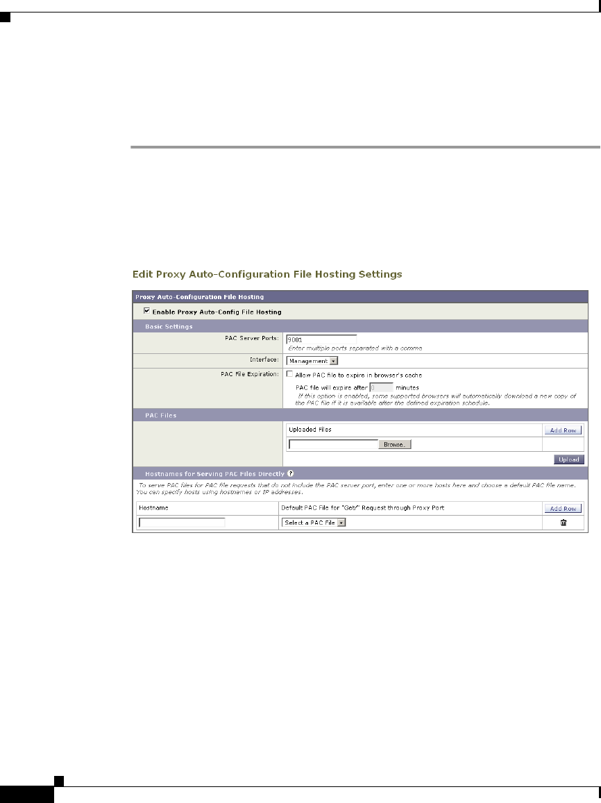
Chapter 5 Web Proxy Services
Adding PAC Files to the Web Security Appliance
5-28
Cisco IronPort AsyncOS 7.1 for Web User Guide
OL-23207-01
Uploading PAC Files to the Appliance
To store PAC files on the Web Security appliance:
Step 1 Navigate to Security Services > Proxy Auto-Configuration File Hosting, and click
Enable and Edit Settings.
The Edit Proxy Auto-Configuration File Hosting Settings page appears.
Figure 5-5 Editing the PAC File Host Settings
Step 2 In the PAC Server Ports field, enter one or more port numbers the Web Security
appliance should use to listen for PAC file requests.
Step 3 In the Interface field, select the interface the Web Proxy uses to listen for PAC file
requests. You can choose any interface that is configured for data traffic. This
field only appears when multiple interfaces are configured for data traffic.
Step 4 In the PAC File Expiration section, choose whether to allow the PAC file to expire
after a specified number of minutes in the browser’s cache.
Step 5 Click Browse to upload a PAC file from your local machine to the appliance.
Step 6 Navigate to the PAC file location, select it, and click Open.
Step 7 To add another PAC file, click Add Row, and repeat steps 5 and 6.

5-29
Cisco IronPort AsyncOS 7.1 for Web User Guide
OL-23207-01
Chapter 5 Web Proxy Services
Adding PAC Files to the Web Security Appliance
Optionally, PAC files can be served through HTTP proxy ports, such as port
80. To allow this, you must explicitly configure the hostnames that should
serve PAC files and choose a default PAC file for each hostname. The
specified default PAC file name is served when browsers do not include the
PAC file name when requesting the PAC file URL (“GET/” requests).
Otherwise, the PAC file name specified in the URL is served. If a PAC file
URL uses an IP address, you can enter the IP address as a configured
hostname.
Step 8 To configure a default PAC file name for different hostnames, in the Hostnames
field enter the Web Security appliance hostname or IP address, or any hostname
that resolves to the appliance hostname. Then choose the default PAC file name
in the Default PAC File for “Get/” Request through Proxy Port field.
For example, if you enter wsa.example.com in the Hostnames field and
pacfile1.pac in the Default PAC File for “Get/” Request through Proxy Port
field, then requests for http://wsa.example.com/ fetch pacfile1.pac and
requests for http://wsa.example.com/default.pac fetch default.pac.
Step 9 Optionally, repeat step 8 to configure a default PAC file name for all hostnames
that resolve to the Web Security appliance.
Step 10 Submit and commit your changes.
Understanding WPAD Compatibility with Netscape and Firefox
Netscape and Firefox browsers only use DNS to automatically detect PAC files
using WPAD. Therefore, if you want Netscape and Firefox browsers to
automatically detect a PAC file stored on the Web Security appliance, you must
complete the following steps:
1. Name the PAC file wpad.dat.
2. Navigate to the Security Services > Web Proxy page, and delete port 80 from
the HTTP Ports to Proxy field.
3. Use port 80 as the PAC Server Port when you upload the file to the appliance.
For more information about using WPAD, see Detecting the PAC File Location
Automatically, page 5-23.

Chapter 5 Web Proxy Services
Advanced Proxy Configuration
5-30
Cisco IronPort AsyncOS 7.1 for Web User Guide
OL-23207-01
Note These steps also work with Internet Explorer. However, for Internet Explorer
version 6, create a copy of wpad.dat and name it wpad.da.
Advanced Proxy Configuration
AsyncOS includes the advancedproxyconfig CLI command so you can configure
more advanced Web Proxy configurations, such as authentication and DNS
parameters.
The advancedproxyconfig command includes the following subcommands:
•Authentication. Configure authentication parameters, such as the number of
outstanding concurrent Basic or NTLMSSP authentication requests to be
authenticated by the authentication server and whether or not to log the
username that appears in the request URI. You can also use the
authentication subcommand to enable the user acknowledgment page. For
more information about the user acknowledgment page, see Proxy Usage
Agreement, page 5-18.
For more information, see Authentication Options, page 5-32.
•Caching. Configure advanced Web Proxy caching options, such as:
–
Whether or not to ignore client requests to not retrieve content from the
proxy cache
–
Whether or not to cache content from an untrusted server
You can configure the parameters separately by selecting “Customized
Mode,” or you can choose a predefined set of parameter values. You can
choose the following modes:
–
Safe mode. This mode uses less caching.
–
Optimized mode. This mode uses moderate caching.
–
Aggressive mode. This mode uses aggressive caching.
For more information, see Caching Options, page 5-39.
•DNS. Configure DNS-related options, such as the time to cache results of
DNS errors and whether or not the Web Proxy should issue an HTTP 302
redirection on DNS lookup failure.

5-31
Cisco IronPort AsyncOS 7.1 for Web User Guide
OL-23207-01
Chapter 5 Web Proxy Services
Advanced Proxy Configuration
For more information, see DNS Options, page 5-42.
•EUN. Configure the end-user notification page settings, such as whether to
use the standard IronPort end-user notification pages or use pages you
customize. For more information on configuring the end-user notification
pages, see Working with IronPort FTP Notification Messages, page 15-23.
For more information, see EUN Options, page 5-44.
•NATIVEFTP. Configure the FTP Proxy settings, such as the port ranges to
use for active and passive mode and the type of authentication to use for
explicit forward connections. Applies to native FTP transactions only. For
more information on configuring the FTP Proxy, see Configuring FTP Proxy
Settings, page 5-11.
For more information, see NATIVEFTP Options, page 5-44.
•FTPOVERHTTP. Configure the login name and password to use for
anonymous FTP access and whether or not to allow active mode for FTP
transfers. Applies to FTP over HTTP transactions only.
For more information, see FTPOVERHTTP Options, page 5-47.
•HTTPS. Configure the logging style for URIs used in HTTPS transactions.
You can choose to record the full URI (“fulluri”) or just a portion of the URI
with the query portion removed (“stripquery”).
For more information, see HTTPS Options, page 5-48.
•Scanning. Configure how the DVS engine handles anti-malware scanning of
web transactions.
For more information, see Scanning Options, page 5-49.
•WCCP. Configure the amount of logging detail to use to debug WCCP
related issues.
For more information, see WCCP Options, page 5-49.
•Miscellaneous. Configure whether or not the Web Proxy should respond to
health checks from L4 switches and whether or not the Web Proxy should
perform dynamic adjustment of TCP receive window sizes.
For more information, see Miscellaneous Options, page 5-50.
Each submenu command is discussed in the detail tables below. For the Default
Value column, a string means a name or list of characters such as “hello world.”

Chapter 5 Web Proxy Services
Advanced Proxy Configuration
5-32
Cisco IronPort AsyncOS 7.1 for Web User Guide
OL-23207-01
Authentication Options
Table 5-4 describes the authentication options for the advancedproxyconfig CLI
command.
Table 5-4 advancedproxyconfig CLI Command—Authentication Options
Option
Valid
Values
Default
Value
Web Proxy
Must Restart Description
When would you like to
forward authorization
request headers to a
parent proxy?
Never,
Always,
Only if not
used by
the WSA
Never Yes This setting determines whether
the Web Proxy includes the
“Proxy-Authorization” header to
upstream servers, including
proxies.
Enter the Proxy
Authorization Realm to
be displayed in the end
user authentication
dialog
String “IronPort
Web
Security
Appliance”
No Proxy Authorization Realm
displayed in the End User
Authentication dialog.
Would you like to log the
username that appears in
the request URI?
Yes, No
(Boolean)
No No If enabled, ‘<username>:xxxxx’
is logged i.e the username is
displayed and the password is
represented as a string, ‘xxxxx’.
If disabled, both username and
password are stripped. Note that
the actual password is never
displayed regardless of the value
of this variable.
Would you like to turn on
presentation of the User
Acknowledgement
page?
Yes, No
(Boolean)
No No Enable or disable
Acknowledgement page.
Enter maximum time to
remember User
Acknowledgement (in
seconds):
30 -
2678400
86400 No Maximum time to remember User
Acknowledgement. From 30
seconds to one month (2678400).

5-33
Cisco IronPort AsyncOS 7.1 for Web User Guide
OL-23207-01
Chapter 5 Web Proxy Services
Advanced Proxy Configuration
Enter maximum idle
timeout for User
Acknowledgement based
on IP Address (in
seconds):
30 -
2678400
14400 No Maximum idle timeout for User
Acknowledgement based on IP
Address. From 30 seconds to one
month (2678400).
Should the Group
Membership attribute be
used for directory
lookups in the Web UI
(when it is not used,
empty groups and groups
with different
membership attributes
will be displayed)?
Yes, No
(Boolean)
No No Choose whether or not AsyncOS
should use the group membership
attribute when doing a directory
lookup.
If you do not want to display
empty authentication groups and
fetch groups whose group
membership attribute is different,
choose Yes.
Would you like to allow
case insensitive
username matching in
policies?
Yes, No
(Boolean)
Yes Yes Choose whether or not the Web
Proxy should ignore case when
matching user names against the
policy groups.
Would you like to allow
wild card matching with
the character * for LDAP
group names?
Yes, No
(Boolean)
Yes Yes Choose whether or not to match
an asterisk as a wildcard in LDAP
group filters.
When this option is disabled,
using an asterisk (*) in the group
filters for LDAP servers works as
a literal string.
Table 5-4 advancedproxyconfig CLI Command—Authentication Options (continued)
Option
Valid
Values
Default
Value
Web Proxy
Must Restart Description

Chapter 5 Web Proxy Services
Advanced Proxy Configuration
5-34
Cisco IronPort AsyncOS 7.1 for Web User Guide
OL-23207-01
Enter the charset to be
used for basic
authentication
[ISO-8859-1/UTF-8].
ISO-8859-
1, UTF-8
ISO-8859-
1
No Choose the character encoding
that the Web Proxy should use
when reading the Basic
authentication credentials in the
HTTP request. The setting
configured here does not affect
the request content, only the
Basic authentication credentials.
You might want to use
ISO-8859-1 if most web browsers
used on your network are Internet
Explorer, Firefox, and Safari, and
UTF-8 if most web browsers on
your network are Opera and
Chrome.
Note: The Web Proxy always uses
UTF-8 when sending the Basic
authentication credentials to the
authentication server.
Would you like to enable
referrals for LDAP?
Yes, No
(Boolean)
No Yes Choose whether or not the Web
Proxy should perform LDAP
queries on a referred LDAP
server.
You might want to disable this
option if a referred LDAP server
is unavailable to the Web Security
appliance.
Table 5-4 advancedproxyconfig CLI Command—Authentication Options (continued)
Option
Valid
Values
Default
Value
Web Proxy
Must Restart Description

5-35
Cisco IronPort AsyncOS 7.1 for Web User Guide
OL-23207-01
Chapter 5 Web Proxy Services
Advanced Proxy Configuration
Would you like to enable
secure authentication?
Yes, No
(Boolean)
No Yes/No
(Web Proxy
restarts when
it needs to
listens on
fewer or
additional
ports)
Choose whether or not the Web
Proxy redirects clients to securely
pass authentication credentials to
the Web Proxy using HTTPS.
For more information on this
feature, see Sending
Authentication Credentials
Securely, page 20-37.
Enter the redirect port
for secure
authentication.
1 to 65535 443 Yes/No
(Web Proxy
restarts when
it needs to
listens on
fewer or
additional
ports)
Enter the port to use for
redirecting requests using
HTTPS. Cisco recommends using
a port greater than 1023.
For more information on
configuring this option, see
Configuring Global
Authentication Settings,
page 20-23.
Note: This option only appears
when you enable secure
authentication.
Table 5-4 advancedproxyconfig CLI Command—Authentication Options (continued)
Option
Valid
Values
Default
Value
Web Proxy
Must Restart Description

Chapter 5 Web Proxy Services
Advanced Proxy Configuration
5-36
Cisco IronPort AsyncOS 7.1 for Web User Guide
OL-23207-01
Enter the hostname to
redirect clients for
authentication.
String Appliance
hostname
No Enter the short hostname of the
network interface on which the
Web Proxy listens for incoming
connections.
When you enable secure
authentication, the Web Proxy
uses this hostname in the
redirection URL sent to clients
for authenticating users.
For more information on
configuring this option, see
Configuring Global
Authentication Settings,
page 20-23.
Enter the surrogate
timeout.
Time in
seconds
3600 No This setting specifies how long
the surrogate (IP address or
cookie) can be used before
requiring authentication
credentials again.
For more information on
configuring this option, see
Configuring Global
Authentication Settings,
page 20-23.
Table 5-4 advancedproxyconfig CLI Command—Authentication Options (continued)
Option
Valid
Values
Default
Value
Web Proxy
Must Restart Description

5-37
Cisco IronPort AsyncOS 7.1 for Web User Guide
OL-23207-01
Chapter 5 Web Proxy Services
Advanced Proxy Configuration
Enter re-auth on request
denied option [disabled /
embedlinkinblockpage]?
disabled/
embedlink
inblockpa
ge
disabled No This setting allows users to
authenticate again if the user is
blocked from a website due to a
restrictive URL filtering policy.
The user sees a block page that
includes a link that allows them to
enter new authentication
credentials. If the user enters
credentials that allow greater
access, the requested page
appears in the browser.
Note: This setting only applies to
authenticated users who are
blocked due to restrictive URL
filtering policies. It does not
apply to blocked transactions by
subnet with no authentication.
For more information, see
Allowing Users to
Re-Authenticate, page 20-39.
Would you like to send
Negotiate header along
with NTLM header for
NTLMSSP
authentication:
1, 2 1 No Choose whether or not the Web
Proxy sends “Negotiate” as an
acceptable authentication
protocol when establishing the
NTLM handshake with the Active
Directory server. Choose one of
the following values:
1. Do not send Negotiate header
2. Send Negotiate header
Table 5-4 advancedproxyconfig CLI Command—Authentication Options (continued)
Option
Valid
Values
Default
Value
Web Proxy
Must Restart Description

Chapter 5 Web Proxy Services
Advanced Proxy Configuration
5-38
Cisco IronPort AsyncOS 7.1 for Web User Guide
OL-23207-01
Enter the IP address to
user name mapping
update interval for
transparent user
identification in seconds.
Time in
seconds
600 No The amount of time that passes
before contacting the Novell
eDirectory server to obtain an
updated IP address to user name
mapping for transparent user
identification.
Table 5-4 advancedproxyconfig CLI Command—Authentication Options (continued)
Option
Valid
Values
Default
Value
Web Proxy
Must Restart Description

5-39
Cisco IronPort AsyncOS 7.1 for Web User Guide
OL-23207-01
Chapter 5 Web Proxy Services
Advanced Proxy Configuration
Caching Options
The Caching submenu provides four options to set the advanced caching mode.
Enter the maximum wait
time for transparent user
identification in seconds.
(Note: Setting this value
to 0 will disable
on-demand query to the
directory server if the
given IP address is not
found in the mapping.
WSA will still query the
directory server at fixed
intervals).
Time in
seconds
5 No Maximum time the Web Proxy
takes to query the directory server
again if the IP address to user
name mapping is not readily
available. When the query takes
more than the timeout value,
transparent user identification is
considered to have failed. This
limits the authentication delay
experienced by the end user.
Configure username and
IP address masking in
logs and reports:
1, 2, 3 3 No Choose whether or not to mask
user names and/or IP addresses in
lots and reports. Masked user
names appear as
“AUTHENTICATED_USER” in
the logs, but guest user names are
not masked.
Choose one of the following
options:
1. Mask both user names and IP
addresses in logs and reports
2. Mask only usernames and
replace them with IP addresses in
logs and reports
3. Show usernames and IP
addresses in logs and reports
Table 5-4 advancedproxyconfig CLI Command—Authentication Options (continued)
Option
Valid
Values
Default
Value
Web Proxy
Must Restart Description

Chapter 5 Web Proxy Services
Advanced Proxy Configuration
5-40
Cisco IronPort AsyncOS 7.1 for Web User Guide
OL-23207-01
Table 5-5 describes the caching options for the Customized Mode option in the
advancedproxyconfig CLI command.
Table 5-5 advancedproxyconfig CLI Command—Caching Options
Option
Valid
Values
Default
Value
Web Proxy
Must Restart Description
Would you like to allow
objects with a heuristic
expiration time to be served
as not-modified
If-Modified-Since hits
from cache?
Yes, No
(Boolean)
Yes No 0 = favor freshness on IMS to
objects with heuristic expiration
time
1 = favor bandwidth conservation
Would you like to allow
ETAG mismatch on client
revalidations?
Yes, No
(Boolean)
No No In some cases, the server might
report different ETags for the same
version of the same file. This can be
seen, for example, with clustered IIS
servers. In these cases, requiring
both a last modified time (LMT)
match and an ETag match on client
revalidations would lead to a lot of
misses, so it should be sufficient just
to match the LMT if it is given.
Note: Setting this to 1 is not
HTTP-compliant.
Would you like to allow
caching when requests are
authenticated by the origin
server?
Yes, No
(Boolean)
No Yes Allow caching for requests
authenticated by origin server.
Would you like to allow
caching from servers
whose DNS results do not
match the TCP destination
IP (not trust-worthy and
applicable only in
transparent modes)?
Yes, No
(Boolean)
No Yes Allow caching from servers whose
DNS results do not match the TCP
destination IP.

5-41
Cisco IronPort AsyncOS 7.1 for Web User Guide
OL-23207-01
Chapter 5 Web Proxy Services
Advanced Proxy Configuration
Enter the Heuristic
maximum age to cache the
document with
Last-Modified Time but no
actual caching value (in
seconds):
Time in
seconds
86400 No Heuristic maximum age to cache the
document with LMT but no actual
caching value.
Enter the Heuristic
maximum age to cache the
document without
Last-Modified Time and no
actual caching value (in
seconds):
Time in
seconds
0 No Heuristic maximum age to cache the
document without LMT and no
actual caching value.
Enter the Heuristic age to
cache errors
(HTTP_SERVICE_UNAV
AIL,
HTTP_GATEWAY_TIME
OUT etc) (in seconds):
Time in
seconds
300 No Heuristic age to cache errors
(HTTP_SERVICE_UNAVAIL,
HTTP_GATEWAY_TIMEOUT
etc).
Would you like proxy to
ignore client directive to
not fetch content from the
cache?
Yes, No
(Boolean)
No No Disable/Enable ignoring of the
client directive to not fetch content
from the cache. Enabling this is not
HTTP compliant.
Enter the time interval
during which reload
requests must be ignored
by the proxy (in seconds):
Time in
seconds
0 No Disable/Enable reload requests to be
ignored for the specified time
interval.
This allows reload requests to be
ignored for a certain amount of time,
even though it is not
HTTP-compliant.
You might want to enter a value
greater than zero to improve
bandwidth usage.
Table 5-5 advancedproxyconfig CLI Command—Caching Options (continued)
Option
Valid
Values
Default
Value
Web Proxy
Must Restart Description

Chapter 5 Web Proxy Services
Advanced Proxy Configuration
5-42
Cisco IronPort AsyncOS 7.1 for Web User Guide
OL-23207-01
DNS Options
Table 5-6 describes the DNS options for the advancedproxyconfig CLI
command.
Would you like to allow
proxy to convert reload
requests into max-age
requests?
Yes, No
(Boolean)
No No Allow reload requests to be
converted into max-age requests
(not HTTP-compliant, but may
improve bandwidth usage). This
gets its max-age value from
“ignoreReloadTime.”
Time in seconds after
which an explicit IMS
Refresh request must be
issued:
Time in
seconds
300 No Time in seconds after which an
explicit IMS Refresh request must
be issued.
Table 5-5 advancedproxyconfig CLI Command—Caching Options (continued)
Option
Valid
Values
Default
Value
Web Proxy
Must Restart Description
Table 5-6 advancedproxyconfig CLI Command—DNS Options
Option
Valid
Values
Default
Value
Web Proxy
Must Restart Description
Enter the URL format for
the HTTP 307 redirection
on DNS lookup failure:
String
with EUN
page
variables
%P//www
.%H.com/
%u
No URL format for the HTTP 307
redirection on DNS lookup
failure. See Table 15-2,
`Variables for Customized
End-User Notification Pages,' on
page 9 for the list of valid
variables.
Would you like the proxy to
issue a HTTP 307
redirection on DNS lookup
failure?
Yes, No
(Boolean)
Yes Yes Disable/Enable automatic HTTP
307 redirection on DNS lookup
failure.

5-43
Cisco IronPort AsyncOS 7.1 for Web User Guide
OL-23207-01
Chapter 5 Web Proxy Services
Advanced Proxy Configuration
Would you like proxy not to
automatically failover to
DNS results when upstream
proxy (peer) is
unresponsive?
Yes, No
(Boolean)
No Yes Disable/Enable automatic
failover to DNS results when
upstream proxy (peer) is
unresponsive.
Find web server by:
0 = use DNS answers in
order,
1 = use client supplied
address then DNS,
2 = use ONLY client
supplied address:
0, 1, 2 1 Yes Specify how the appliance
should find the location of the
requested web server.
Table 5-6 advancedproxyconfig CLI Command—DNS Options (continued)
Option
Valid
Values
Default
Value
Web Proxy
Must Restart Description

Chapter 5 Web Proxy Services
Advanced Proxy Configuration
5-44
Cisco IronPort AsyncOS 7.1 for Web User Guide
OL-23207-01
EUN Options
Table 5-7 describes the EUN options for the advancedproxyconfig CLI
command.
NATIVEFTP Options
Table 5-8 describes the NATIVEFTP options for the advancedproxyconfig CLI
command.
Table 5-7 advancedproxyconfig CLI Command—EUN Options
Option
Valid
Values
Default
Value
Web Proxy
Must Restart Description
Choose: 1, 2, 3 3 Yes Choose whether to use the
IronPort end-user notification
pages or uploaded customized
end-user notification pages.
Choose one of the following
options:
•1. Refresh EUN pages
•2. Use Custom EUN pages
•3. Use Standard EUN pages
For more information, see Editing
IronPort Notification Pages,
page 15-8.
Table 5-8 advancedproxyconfig CLI Command—NATIVEFTP Options
Option
Valid
Values
Default
Value
Web Proxy
Must Restart Description
Would you like to
enable FTP proxy?
Yes, N o
(Boolean)
Yes Yes Choose whether or not to enable
the FTP Proxy.
Enter the ports that
FTP proxy listens on.
1 to 65535 8021 Yes Specify the port FTP clients
should use to establish a control
connection with the FTP Proxy.

5-45
Cisco IronPort AsyncOS 7.1 for Web User Guide
OL-23207-01
Chapter 5 Web Proxy Services
Advanced Proxy Configuration
Enter the range of port
numbers for the proxy
to listen on for passive
FTP connections.
port1-port2
(string)
1024 -
65535
11000-
11009]
Yes Specify a range of TCP ports FTP
clients should use to establish a
data connection with the FTP
Proxy for passive mode
connections.
Enter the range of port
numbers for the proxy
to listen on for active
FTP connections.
port1-port2
(string)
1024 -
65535
12000-
12009
Yes Specify a range of TCP ports FTP
servers should use to establish a
data connection with the FTP
Proxy for active mode
connections.
Would you like to use
active mode when
passive mode fails?
Yes, N o
(Boolean)
No No When this option is enabled, the
FTP Proxy will attempt an active
mode connection with the FTP
server when passive mode fails.
Enter the
authentication format:
Check
Point,
Raptor
Check Point Yes Choose the authentication format
the FTP Proxy uses when
communicating with FTP clients.
For more information, see Using
Authentication with Native FTP,
page 5-9.
Would you like to
enable caching?
Yes, N o
(Boolean)
Yes Yes Choose whether or not to cache
contents of data connections from
anonymous users.
Would you like to
enable server IP
spoofing?
Yes, N o
(Boolean)
No Yes Choose whether or not the FTP
Proxy should spoof the FTP server
IP address. You might want to do
this for FTP clients that do not
allow transactions when the IP
address is different for the control
and data connections.
Table 5-8 advancedproxyconfig CLI Command—NATIVEFTP Options (continued)
Option
Valid
Values
Default
Value
Web Proxy
Must Restart Description

Chapter 5 Web Proxy Services
Advanced Proxy Configuration
5-46
Cisco IronPort AsyncOS 7.1 for Web User Guide
OL-23207-01
Would you like to pass
FTP server welcome
message to the clients?
Yes, N o
(Boolean)
Yes Yes Choose which welcome message
should appear in FTP clients:
•FTP server message. Enter
“Yes.” The FTP server
message only displays for
transparently redirected
connections. When a native
FTP connection is explicitly
sent to the FTP Proxy, the FTP
client displays a message
predefined by the FTP Proxy.
•Custom message. Enter
“No.” You can enter a custom
message to display for all
native FTP connections in the
next question.
Enter the customized
server welcome
message.
String N/A Yes This command appears when you
enter No for the FTP server
welcome message.
Enter the custom message to
display for all native FTP
connections.
Table 5-8 advancedproxyconfig CLI Command—NATIVEFTP Options (continued)
Option
Valid
Values
Default
Value
Web Proxy
Must Restart Description

5-47
Cisco IronPort AsyncOS 7.1 for Web User Guide
OL-23207-01
Chapter 5 Web Proxy Services
Advanced Proxy Configuration
FTPOVERHTTP Options
Table 5-9 describes the FTPOVERHTTP options for the advancedproxyconfig
CLI command.
Table 5-9 advancedproxyconfig CLI Command—FTPOVERHTTP Options
Option
Valid
Values
Default
Value
Web Proxy
Must Restart Description
Enter the login name to be
used for anonymous FTP
access:
String anonymous No Anonymous FTP login name.
Enter the password to be
used for anonymous FTP
access:
String proxy@ No Anonymous FTP login
password.
Would you like to use
active FTP transfer mode
when passive mode fails?
Yes, No
(Boolean)
No No Choose whether or not to allow
FTP transfers to use active
mode if passive mode fails.
Enter the range of port
numbers for the proxy to
bind to when making
passive FTP connections.
port1-port2
(string)
1024 -
65535
13000-
13001
No Specify a range of TCP ports
the appliance can use for
establishing a passive data
connection with an FTP server.
If a port is being used, the Web
Proxy chooses the next port in
the range until it finds an
available port.
Enter the range of port
numbers for the proxy to
listen on for active FTP
connections.
port1-port2
(string)
1024 -
65535
10000
-10001
No When you enable active mode
for FTP transfers, enter the
range of TCP ports the
appliance can use for
establishing a data connection
with an FTP server. If a port is
being used, the Web Proxy
chooses the next port in the
range until it finds an available
port.
This option only appears when
active mode is enabled.

Chapter 5 Web Proxy Services
Advanced Proxy Configuration
5-48
Cisco IronPort AsyncOS 7.1 for Web User Guide
OL-23207-01
HTTPS Options
Table 5-10 describes the HTTPS options for the advancedproxyconfig CLI
command.
Table 5-10 advancedproxyconfig CLI Command—HTTPS Options
Option
Valid
Values
Default
Value
Web Proxy
Must Restart Description
HTTPS URI Logging
Style:
fulluri or
stripquery
fulluri Yes You can log the entire URI (fulluri), or
a partial form of the URI with the query
portion removed (stripquery).
However, even when you choose to
strip the query from the URI,
personally identifiable information
may still remain.
Would you like to
decrypt
unauthenticated
transparent HTTPS
requests for
authentication
purpose?
Yes, No
(Boolean)
Yes No Choose how the Web Proxy handles
transparently redirected HTTPS
transactions it receives before an HTTP
request that was authenticated using an
identity with an IP-based surrogate.
Select one of the following options:
•Yes . Decrypt the HTTPS request
for authentication purposes.
•No. Deny the HTTPS request.

5-49
Cisco IronPort AsyncOS 7.1 for Web User Guide
OL-23207-01
Chapter 5 Web Proxy Services
Advanced Proxy Configuration
Scanning Options
Table 5-11 describes the scanning options for the advancedproxyconfig CLI
command.
WCCP Options
Table 5-12 describes the WCCP options for the advancedproxyconfig CLI
command.
Table 5-11 advancedproxyconfig CLI Command—Scanning Options
Option
Valid
Values
Default
Value
Web Proxy
Must Restart Description
Would you like the proxy
to do malware scanning
all content regardless of
content type? Note that
this will have serious
performance impact and
is not recommended.
Yes, No
(Boolean)
No No Choose whether or not the DVS
engine should scan all response
content regardless of the content
type.
Note: Enabling this setting results in
a significant performance impact for
the Web Proxy.
Table 5-12 advancedproxyconfig CLI Command—WCCP Options
Option
Valid
Values
Default
Value
Web Proxy
Must Restart Description
Enter the log level for
debugging WCCP:
1 - 5 2 Yes WCCP log level

Chapter 5 Web Proxy Services
Advanced Proxy Configuration
5-50
Cisco IronPort AsyncOS 7.1 for Web User Guide
OL-23207-01
Miscellaneous Options
Table 5-13 describes the miscellaneous options for the advancedproxyconfig
CLI command.
Table 5-13 advancedproxyconfig CLI Command—Miscellaneous Options
Option
Valid
Values
Default
Value
Web Proxy
Must Restart Description
Would you like proxy to
respond to health checks
from L4 switches (always
enabled if WSA is in L4
transparent mode)?
Yes, No
(Boolean)
No Yes Disable/Enable support for
responding to health checks from L4
switches (always enabled if WSA is
in L4 transparent mode). L4 switches
issue ‘HEAD / HTTP/1.0’ requests
directed at the proxy to ensure that it
is responding.
Would you like proxy to
perform dynamic
adjustment of TCP
receive window size?
Yes, No
(Boolean)
Yes Yes Disable/Enable dynamic adjustment
of TCP receive window size.
Enable caching of
HTTPS responses?
Yes, No
(Boolean)
No No Choose whether or not the Web
Security appliance should store
HTTPS responses in the web cache.
Enter minimum idle
timeout for checking
unresponsive upstream
proxy (in seconds).
Time in
seconds
10 No The minimum amount of time the
Web Proxy waits before checking if
an upstream proxy is still
unavailable.
Enter maximum idle
timeout for checking
unresponsive upstream
proxy (in seconds).
Time in
seconds
86400 No The maximum amount of time the
Web Proxy waits before checking if
an upstream proxy is still
unavailable.

5-51
Cisco IronPort AsyncOS 7.1 for Web User Guide
OL-23207-01
Chapter 5 Web Proxy Services
Advanced Proxy Configuration
Mode of the proxy: 1, 2, 3 2 Yes Choose how to deploy the Web Proxy
using one of the following options:
1. Explicit forward mode only
2. Transparent mode with L4 Switch
or no device for redirection
3. Transparent mode with WCCP v2
Router for redirection
For more information, see
Deployment Overview, page 3-1.
Spoofing of the client IP
by the proxy:
1, 2, 3 1 No Choose whether or not the Web
Proxy should spoof IP addresses
when sending requests to upstream
proxies and servers using one of the
following options:
1. Disable
2. Enable for all requests
3. Enable for transparent requests
only
When IP spoofing is enabled,
requests originating from a client
retain the client’s source address and
appear to originate from the client
rather than from the Web Security
appliance.
Note: When IP spoofing is enabled
and the appliance is connected to a
WCCP router, configure a WCCP
service to redirect the return path.
Table 5-13 advancedproxyconfig CLI Command—Miscellaneous Options (continued)
Option
Valid
Values
Default
Value
Web Proxy
Must Restart Description

Chapter 5 Web Proxy Services
Advanced Proxy Configuration
5-52
Cisco IronPort AsyncOS 7.1 for Web User Guide
OL-23207-01
Do you want to pass
HTTP X-Forwarded-For
headers?
Yes, No
(Boolean)
Yes No Choose whether or not the Web
Proxy retains any
“X-Forwarded-For” header included
in the requests it receives.
When set to No, the Web Proxy
removes any “X-Forwarded-For”
header from requests that enter the
Web Proxy from a downstream proxy
server. You might want to do this if
the downstream proxy server
includes client IP address in the
header and you do not want to expose
those IP addresses to servers outside
your network.
Would you like to permit
tunneling of non-http
requests on http ports?
Yes, No
(Boolean)
Yes No Choose whether or not to allow
non-HTTP traffic on ports the Web
Proxy is configured to monitor, such
as port 80. This option applies when
the Web Proxy is in transparent
mode.
Enabling this option blocks
applications that attempt to tunnel
non-HTTP traffic on ports typically
used for HTTP traffic.
Note: When a transaction is blocked
due to this setting, the ACL decision
tag for the transaction is logged as
BLOCK_ADMIN_TUNNELING.
Would you like to block
tunneling of non-SSL
transactions on SSL
Ports?
Yes, No
(Boolean)
No No Choose whether or not the Web
Proxy should block non-SSL traffic
on SSL ports.
Table 5-13 advancedproxyconfig CLI Command—Miscellaneous Options (continued)
Option
Valid
Values
Default
Value
Web Proxy
Must Restart Description

5-53
Cisco IronPort AsyncOS 7.1 for Web User Guide
OL-23207-01
Chapter 5 Web Proxy Services
Advanced Proxy Configuration
Would you like proxy to
log values from
X-Forwarded-For
headers in place of
incoming connection IP
addresses?
Yes, No
(Boolean)
No No Choose whether or not the access
logs should include the
X-Forwarded-For header value
instead of the IP address of the
incoming connection.
Do you want proxy to
throttle content served
from cache?
Yes, No
(Boolean)
Yes No Choose whether or not the Web
Proxy should apply per user
bandwidth controls to content served
from the web cache in addition to the
content served from web servers.
Applies to application types that
have bandwidth limits applied.
Table 5-13 advancedproxyconfig CLI Command—Miscellaneous Options (continued)
Option
Valid
Values
Default
Value
Web Proxy
Must Restart Description

Chapter 5 Web Proxy Services
Advanced Proxy Configuration
5-54
Cisco IronPort AsyncOS 7.1 for Web User Guide
OL-23207-01

CHAPTER
6-1
Cisco IronPort AsyncOS 7.1 for Web User Guide
OL-23207-01
6
Working with Policies
This chapter contains the following information:
•Working with Policies Overview, page 6-1
•Policy Types, page 6-3
•Working with Policy Groups, page 6-6
•Policy Group Membership, page 6-10
•Working with Time Based Policies, page 6-13
•Working with User Agent Based Policies, page 6-16
•Tracing Policies, page 6-18
Working with Policies Overview
The Web Security appliance includes an advanced policy framework to
intelligently map data policies to business processes for protection on the network
and at the endpoint. It allows you to define policies to enforce your organization’s
acceptable use policies by controlling access to the Internet. You can create
groups of users and apply different levels and types of access control to each
group.
For example, you can configure the appliance to enforce the following types of
policies:
•Users in the Marketing group can access a competitor’s website, but other
users cannot.

Chapter 6 Working with Policies
Working with Policies Overview
6-2
Cisco IronPort AsyncOS 7.1 for Web User Guide
OL-23207-01
•Guest users on customer-facing machines, such as computers in a company
store, cannot access banking sites, but employees can.
•No users can access gambling sites. Instead, when they try to view a gambling
site, they see a web page that explains the organization’s policies.
•All users trying to access a particular site that no longer exists are redirected
to a different site.
•All users except those in IT are blocked from accessing potential malware
sites, but users in IT can access them for testing purposes, and the
downloaded content is scanned for harmful objects.
•All requests for streaming media are blocked during business hours, but
allowed outside of business hours.
•All requests from a particular user agent, such as a software update program,
are allowed without requiring authentication.
•Block uploads of all Excel spreadsheet files greater than 2 MB.
•Block uploads of data to sites with a bad web reputation.
•Block uploads of data infected with malware.
To enforce organizational policies, you define different policies in the Web
Security appliance. The appliance uses different types of policies for different
functions. For more information about the types of policies, see Policy Types,
page 6-3.
When you work with policies, you create policy groups. After you create policy
groups, you can define the control settings for each group. For more information
about working with policy groups, see Working with Policy Groups, page 6-6.
After you have created policies, you can figure out which policy groups apply to
a particular client transaction for troubleshooting purposes. For example, you can
find out if user jsmith tries to open a Firefox browser to the URL
http://www.google.com, then which policy groups apply to the transaction. For
more information about tracing policies, see Tracing Policies, page 6-18.
Note The Web Security appliance is permissive by default. That is, requests are allowed
unless specifically blocked in a policy group.

6-3
Cisco IronPort AsyncOS 7.1 for Web User Guide
OL-23207-01
Chapter 6 Working with Policies
Policy Types
Policy Types
The Web Security appliance uses multiple types of policies to enforce
organizational policies and requirements.
•Identities. “Who are you?”
•Decryption Policies. “To decrypt or not to decrypt?”
•Routing Policies. “From where to fetch content?”
•Access Policies. “To allow or block the transaction?”
•IronPort Data Security Policies. “To block the upload of data?” IronPort
Data Security Policies actions are defined on the Web Security appliance.
•External DLP (data loss prevention) Policies. “To block the upload of
data?” External DLP Policies actions are defined on an external DLP
appliance.
•Outbound Malware Scanning Policies. “To block the upload of malicious
data?”
•SaaS Application Authentication Policies. “To allow this user access to the
SaaS application?”
You use the policies together to create the behavior you need or expect when
clients access the web.
To define policies, you create policy groups. After you create policy groups, you
can define the control settings for each group. For more information about
working with policy groups, see Working with Policy Groups, page 6-6.
All policy types have a global policy group that maintains default settings and
rules that apply to web transactions not covered by another policy. For more
information on global policies, see Working with Policy Groups, page 6-6.
Identities
An Identity is a policy that identifies the user making a request. This is the only
policy where you can define whether or not authentication is required. An Identity
addresses the question, “who are you?” However, Identities do not specify a list
of users who are authorized to access the web. You specify authorized users in the
other policy types after you specify the Identity to use.

Chapter 6 Working with Policies
Policy Types
6-4
Cisco IronPort AsyncOS 7.1 for Web User Guide
OL-23207-01
All other policies you create must specify an Identity.
Configure Identities on the Web Security Manager > Identities page. For more
information about Identities, see Identities, page 7-1.
Decryption Policies
Decryption Policies determine whether or not an HTTPS connection should be
decrypted, passed through, or dropped. They address the question, “to decrypt or
not to decrypt?”
The appliance uses Decryption Policies to evaluate HTTPS requests. The
Decryption Policy group that applies to an HTTPS request determines whether the
appliance drops the connection, passes it through without decryption, or decrypts
the connection and subsequently evaluate the decrypted request and response
against the defined Access Policy groups.
Configure Decryption Policy groups on the Web Security Manager > Decryption
Policies page. For more information about Decryption Policy groups, see
Decryption Policies, page 10-1.
Routing Policies
Routing Policies determine to where to pass the client request, either to another
proxy or to the destination server. They address the question, “from where to fetch
content?”
You can use this policy type to select a group of upstream proxies configured for
load balancing or failover.
Configure Routing Policies on the Web Security Manager > Routing Policies
page. For more information about Routing Policies, see Working with External
Proxies, page 9-1.
Access Policies
Access Policies determine whether to allow or block HTTP and decrypted HTTPS
transactions. They address the question, “to allow or block the transaction?”

6-5
Cisco IronPort AsyncOS 7.1 for Web User Guide
OL-23207-01
Chapter 6 Working with Policies
Policy Types
Access Policies determine how the appliance controls access to services,
applications, and objects on the web for HTTP and decrypted HTTPS requests.
The appliance uses Access Policies to evaluate and scan HTTP requests and
HTTPS requests designated for decryption.
Configure Access Policy groups on the Web Security Manager > Access Policies
page. For more information about Access Policy groups, see Access Policies,
page 8-1.
IronPort Data Security Policies
IronPort Data Security Policies determine whether or not to block a request to
upload data using logic defined on the Web Security appliance. They address the
question, “to block the upload of data?”
The Web Proxy uses IronPort Data Security Policies to evaluate and scan HTTP
requests and decrypted HTTPS requests that have any data in the request body.
Configure Data Security Policy groups on the Web Security Manager > IronPort
Data Security page. For more information about Data Security Policy groups, see
Data Security and External DLP Policies, page 12-1.
External DLP Policies
External DLP (data loss prevention) policies determine whether or not to block a
request to upload data using logic stored on an external DLP server. They address
the question, “to block the upload of data?”
The Web Proxy uses External DLP Policies to evaluate HTTP requests and
decrypted HTTPS requests that have any data in the request body and send them
to an external DLP server for scanning.
Configure External DLP Policy groups on the Web Security Manager > External
Data Loss Prevention page. For more information about External DLP Policy
groups, see Data Security and External DLP Policies, page 12-1.

Chapter 6 Working with Policies
Working with Policy Groups
6-6
Cisco IronPort AsyncOS 7.1 for Web User Guide
OL-23207-01
Outbound Malware Scanning Policies
Outbound Malware Scanning Policies determine whether or not to block a request
to upload data that contains malicious data. They address the question, “To block
the upload of malicious data?”
The Web Proxy uses Outbound Malware Scanning Policies to scan for malware
HTTP requests and decrypted HTTPS requests that have any data in the request
body.
Configure Outbound Malware Scanning Policy groups on the Web Security
Manager > Outbound Malware Scanning page. For more information about
Outbound Malware Scanning Policy groups, see Outbound Malware Scanning,
page 11-1.
SaaS Application Authentication Policies
SaaS Application Authentication Policies determine whether or not a user is
allowed access to a Software as a Service (SaaS) application. They address the
question, “to allow this user access to a SaaS application?”
SaaS Application Authentication Policies determine how the appliance controls
user access to configured SaaS applications, such as WebEx. When you enable
Cisco SaaS Access Control, users log into the configured SaaS applications using
their network authentication user credentials. That means they use the same user
name and password for all SaaS applications as well as network access.
Configure SaaS Application Authentication Policy groups on the Web Security
Manager > SaaS Policies page. For more information about SaaS Application
Authentication Policy groups, see Controlling Access to SaaS Applications,
page 14-1.
Working with Policy Groups
A policy group is an administrator defined configuration that allows you to apply
acceptable use policies to specific categories of users. After you create policy
groups, you can define the control settings for each group.

6-7
Cisco IronPort AsyncOS 7.1 for Web User Guide
OL-23207-01
Chapter 6 Working with Policies
Working with Policy Groups
You can create as many user defined policy groups as required to enforce the
proper access control. The Web Security appliance displays policy groups
together in a policies table.
All policies have a default, global policy group that applies to a transaction if none
of the user defined policy groups apply. A global policy group maintains default
settings and rules that apply to web transactions not covered by another policy.
This group appears in the last row of a policies table, and the Web Proxy applies
its rules last if no other matching occurs.
Creating Policy Groups
You can create policy groups based on combinations of several criteria, such as
client subnet or the URL category of the destination site. You must define at least
one criterion for policy group membership. When you define multiple criteria, the
client request must meet all criteria to match the policy group.
Options used to configure policy groups allow you to specify exceptions to global
policy settings and control access to services for groups of users.
For more information about creating policy groups for the different policy types,
see the following locations:
•Creating Identities, page 7-20
•Creating Access Policies, page 8-7
•Creating Decryption Policies, page 10-30
•Creating Routing Policies, page 9-8
•Creating Data Security and External DLP Policies, page 12-10
Using the Policies Tables
The policies table is an ordered list of policy groups and the settings you configure
for each filtering component. It displays policy groups by row and control settings
by column. The control settings you can define vary by policy type.
Figure 6-1 on page 8 shows the Access Policies table.
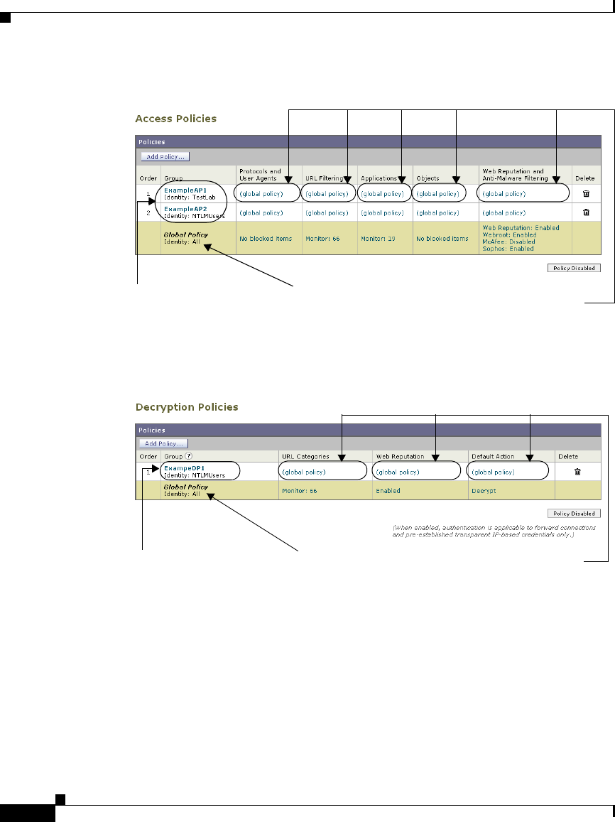
Chapter 6 Working with Policies
Working with Policy Groups
6-8
Cisco IronPort AsyncOS 7.1 for Web User Guide
OL-23207-01
Figure 6-1 Access Policies Table
Figure 6-2 shows the Decryption Policies table.
Figure 6-2 Decryption Policies Table
Any policy group that you create is added as a new row in the policies table. New
policy groups inherit global policy settings for each control setting until you
override them. To edit policy groups, click the links in each row.
When you create or configure a policy group, you define the following
components:
Click to customize policy
control settings.
Click to edit user defined
policy group membership.
Global policy group
(not editable).
Click to customize policy
control settings.
Click to edit user defined policy
group membership.
Global policy group
(not editable).

6-9
Cisco IronPort AsyncOS 7.1 for Web User Guide
OL-23207-01
Chapter 6 Working with Policies
Working with Policy Groups
•Policy group membership. Define how to group users that belong to the
policy group. For user defined policy groups, you can group by different
properties, such as client IP address, authentication group or user name, or
URL category. The properties you can define for a policy depends on the
policy type.
Click the policy group name to edit the group membership requirements, such
as client IP address and authentication requirements. A page is displayed
where you can configure membership requirements.
Note For global policies, you can only define the membership requirements for
the global Identity group and not for the global Access, Decryption, or
Routing groups. Global Access, Decryption, and Routing groups always
match all Identities.
For more information about policy group membership, see Policy Group
Membership, page 6-10.
•Policy group control settings. Define how users in the group can use the
Internet. The control settings you can define depend on the policy type. For
example, for Routing Policies, you define from which proxy group to fetch
the content, and for Access Policies, you can use the Web Security appliance
features, such as Web Reputation, anti-malware scanning, and more to
determine whether or not to allow the client request.
Click the link in the policy group row under the control setting you want to
configure, such as URL Categories or Routing Destination. When you click a
link in the table, a page is displayed where you can configure settings for that
policy group.
For more information on configuring control settings for each policy type, see
the following sections:
–
Controlling HTTP and Native FTP Traffic, page 8-11
–
Controlling HTTPS Traffic, page 10-34
–
Creating Routing Policies, page 9-8
–
Controlling Upload Requests Using IronPort Data Security Policies,
page 12-15
–
Controlling Upload Requests Using External DLP Policies, page 12-25

Chapter 6 Working with Policies
Policy Group Membership
6-10
Cisco IronPort AsyncOS 7.1 for Web User Guide
OL-23207-01
Policy Group Membership
All policy groups define which transactions apply to them. When a client sends a
request to a server, the Web Proxy receives the request, evaluates it, and
determines to which policy group it belongs. The Web Proxy applies the
configured policy control settings to a client request based on the client request’s
policy group membership.
Transactions belong to a policy group for each type of policy that is enabled. If a
policy type has no user defined policy groups, then each transaction belongs to the
global policy group for that policy type.
Policy group membership for a Routing, Decryption, Access, Data Security, and
External DLP Policies is based on an Identity and optional additional criteria.
That means that the Web Proxy evaluates Identity groups before the other policy
types. The Web Security appliance allows you to define some membership criteria
at either the Identity level or the non-Identity policy level. For more information,
see Policy Group Membership Rules and Guidelines, page 6-12.
Suppose you define an Identity by subnet 10.1.1.0/24 and then create an Access
Policy using that Identity. The Access Policy membership applies to all IP
addresses specified in the Identity by default. You can then choose to configure
the Access Policy membership so that it applies to a subset of the addresses
defined in the Identity, such as addresses 10.1.1.0-15.
For more information defining membership for each policy type, see the following
sections:
•Evaluating Identity Group Membership, page 7-2
•Evaluating Access Policy Group Membership, page 8-4
•Evaluating Decryption Policy Group Membership, page 10-27
•Evaluating Routing Policy Group Membership, page 9-5
•Evaluating Data Security and External DLP Policy Group Membership,
page 12-7
Authenticating Users versus Authorizing Users
The Web Security appliance separates where it authenticates users from where it
authorizes users.

6-11
Cisco IronPort AsyncOS 7.1 for Web User Guide
OL-23207-01
Chapter 6 Working with Policies
Policy Group Membership
Authentication is the mechanism by which the Web Proxy securely identifies a
user. It answers the following questions:
•Who is the user?
•Is the user really whom he/she claims to be?
Authorization is the mechanism by which the Web Proxy determines the level of
access the user has to the World Wide Web. It answers the following questions:
•Is this user allowed to view this website?
•Is this user allowed to connect to this HTTPS server without the connection
being decrypted?
•Is this user allowed to directly connect to the web server, or must it connect
to another proxy server first?
•Is this user allowed to upload this data?
The Web Proxy can only authorize a user to access an Internet resource after it
authenticates who the user is. The Web Proxy authenticates users when it
evaluates Identity groups, and it authorizes users when it evaluates all other policy
group types. What that means is the Identity group indicates who is making the
request, but does not indicate whether that client is allowed to make the request.
By separating authentication from authorization, you can create a single Identity
group that identifies a group of users and then you can create multiple policy
groups that allow different levels of access to subsets of users in the group in the
Identity.
For example, you can create one Identity group that covers all users in an
authentication sequence. Then you can create an Access Policy group for each
authentication realm in the sequence. You can also use this Identity to create one
Decryption Policy with the same level of access for all users in the Identity.
Working with Failed Authentication and Authorization
You can allow users another opportunity to access the web if they fail
authentication or authorization. How you configure the Web Security appliance
depends on what fails:
•Authentication. When authentication fails, you can grant guest access to the
user. Authentication might fail under the following circumstances:
–
A new hire has been provided credentials in an email but they are not yet
populated in the authentication server.

Chapter 6 Working with Policies
Policy Group Membership
6-12
Cisco IronPort AsyncOS 7.1 for Web User Guide
OL-23207-01
–
A visitor comes to the office and needs to be granted restrictive Internet
access, but is not in the corporate user directory.
For more information on configuring guest access, see Allowing Guest
Access to Users Who Fail Authentication, page 7-13.
•Authorization. A user might authenticate correctly, but not be granted access
to the web due to the applicable Access Policy. In this case, you can allow the
user to re-authenticate with more privileged credentials. To do this, enable the
“Enable Re-Authentication Prompt If End User Blocked by URL Category or
User Session Restriction” global authentication setting. For more
information, see Allowing Users to Re-Authenticate, page 20-39.
Working with All Identities
You can create a policy group that specifies “All Identities” as the configured
Identity group. “All Identities” applies to every valid client request because by
definition, every request either succeeds and has a user defined or global Identity
assigned to it or is terminated because it fails authentication (and no guest access
was provided for users failing authentication).
When you create a policy group that uses All Identities, you must configure at
least one advanced option to distinguish the policy group from the global policy
group.
Typically, you use All Identities in a policy while also configuring an advanced
option, such as a particular user agent or destination (using a custom URL
category). This allows you to create a single rule that makes an exception for a
specific case instead of creating multiple rules to make the exception for the
specific case. For example, you can create an Access Policy group whose
membership applies to All Identities and a custom URL category for all intranet
pages. Then you can configure the Access Policy control settings to disable
anti-malware filtering and Web Reputation scoring.
Policy Group Membership Rules and Guidelines
Consider the following rules and guidelines when defining policy group
membership:
•The Web Proxy evaluates Identity groups before the other policy types.

6-13
Cisco IronPort AsyncOS 7.1 for Web User Guide
OL-23207-01
Chapter 6 Working with Policies
Working with Time Based Policies
•Subnet membership criteria defined in the Identity group can be further
narrowed down in the policy group using the Identity group.
•Advanced membership criteria (proxy ports, URL categories, and user
agents) defined in the Identity group cannot be defined in the policy group
using the Identity group.
•Define Identity groups as broadly as possible. Then you can use the Identity
groups in other policy types and further narrow down membership as
necessary.
•Define fewer, more generic Decryption and Routing Policies as much as
possible.
•If you need to define membership by URL category, only define it in the
Identity group when you need to exempt from authentication requests to that
category. For other purposes, define membership by URL category in the
Access, Decryption, Routing, Data Security, or External DLP Policy group.
This can increase performance in most cases.
Working with Time Based Policies
The Web Security appliance provides the means to create time based policies by
specifying time ranges, such as business hours, and using those time ranges to
define access to the web. You can define policy group membership based on time
ranges, and you can specify actions for URL filtering based on time ranges.
You might want to use time ranges to accomplish the following tasks:
•You can block access to high bandwidth sites, such as streaming media, or
distracting sites, such as games, during business hours.
•You can route transactions to a particular external proxy after midnight when
the other proxies are being serviced.
•You can allow larger files to be downloaded on the weekends.
Define time ranges on the Web Security Manager > Defined Time Ranges page.
You can create time ranges to define concepts such as “business hours” or
“weekend shift.” Then you can use the time ranges in the following locations:
•Policy group membership for a Routing, Access, or Decryption Policy.
•URL filtering settings for Access Policies.

Chapter 6 Working with Policies
Working with Time Based Policies
6-14
Cisco IronPort AsyncOS 7.1 for Web User Guide
OL-23207-01
When you define a time range, you can specify the day(s) of the week and the time
of day. A transaction matches the time range when it occurs on one of the days
specified and during the time specified. You can also define multiple
combinations of day and time in a single time range. For example, you can define
a time range that applies to transactions that occur on Monday through Friday
from 08:00 to 17:00 or on Saturday from 09:00 to 13:00.
Policies and URL filtering actions can be defined inside or outside the defined
time ranges.
Note Because you can define time based policy group membership only for Routing,
Access, and Decryption Policies, but not Identities, you cannot create time based
policies that define when users must authenticate. Authentication requirements
are defined in Identity groups, but time based policies are defined in other policy
group types. (bug #41723)
Creating Time Ranges
To create a time range:
Step 1 Go to Web Security Manager > Defined Time Ranges.
Step 2 Click Add Time Range.
The Add Time Range page appears.
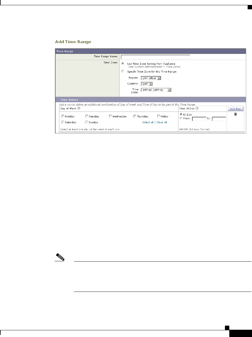
6-15
Cisco IronPort AsyncOS 7.1 for Web User Guide
OL-23207-01
Chapter 6 Working with Policies
Working with Time Based Policies
Step 3 In the Time Range Name field, enter a name to use for the time range. Each time
range name must be unique.
Step 4 In the Time Zone section, choose whether to use the time zone setting on the Web
Security appliance or a different time zone setting you configure.
Step 5 In the Time Values section, define at least one row that specifies the days of the
week and time of day to include in this time range.
a. In the Day of the Week section, select at least one day.
b. In the Time of Day section, choose All Day or enter a time range in the day
using the From and To fields.
Each time range includes the start time and excludes the end time. For
example, entering 8:00 through 17:00 matches 8:00:00 through 16:59:59, but
not 17:00:00.
Midnight must be specified as 00:00 for a start time, and as 24:00 for an end
time.
Note A transaction must occur on the day and in the time specified to match a
row in the Time Values section. That means the Day of Week and Time of
Day values have an “AND” relationship with each other within a single
row.
Step 6 Optionally, you can create additional time value rows by clicking Add Row.

Chapter 6 Working with Policies
Working with User Agent Based Policies
6-16
Cisco IronPort AsyncOS 7.1 for Web User Guide
OL-23207-01
Note When a time range includes multiple time value rows, a transaction can
occur within any of the defined time values to match the time range. That
means that multiple time value rows in a single time range have an “OR”
relationship with each other.
Step 7 Submit and commit your changes.
Working with User Agent Based Policies
The Web Security appliance provides the means to create policies to define access
to the web by the client application (user agent), such as a web browser, making
the client request. You can define policy group membership based on user agents,
and you can specify control settings based on user agents.
You might want to specify user agents to accomplish the following tasks:
•You can exempt certain user agents from authentication. You might want to
do this for client applications that cannot handle prompting users for
authentication credentials. For more information about how to do this, see
Exempting User Agents from Authentication, page 6-18.
•You can block access from particular user agents that you define.
You can configure user agents in the following locations:
•Policy group membership for all policy types, including Identities.
•Application control settings for Access Policies.
Note When the appliance is deployed in transparent mode, user agent information is not
available for Decryption Policies.
Configuring User Agents for Policy Group Membership
When you define policy group membership for any policy type, you can expand
the Advanced section to define membership by additional criteria, such as user
agent. When you click the User Agents link, the Membership by User Agent page
appears allowing you to define membership by user agent.
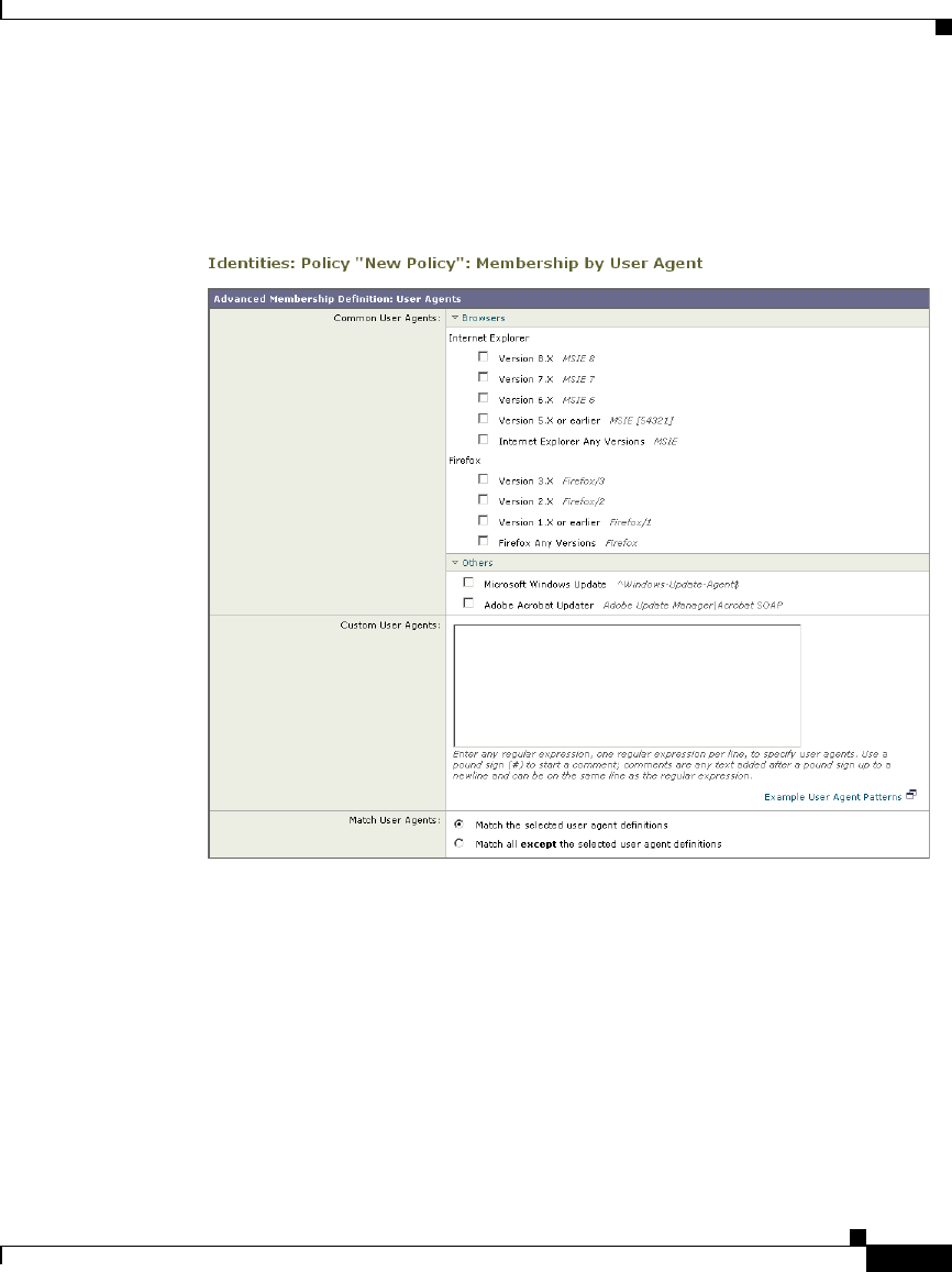
6-17
Cisco IronPort AsyncOS 7.1 for Web User Guide
OL-23207-01
Chapter 6 Working with Policies
Working with User Agent Based Policies
Figure 6-3 on page 17 shows the Membership by User Agent page for an Identity
policy group.
Figure 6-3 Defining Policy Group Membership by User Agent
On this page, you can select as many user agents as desired. The web interface
includes some of the more common user agents that you can select using a check
box. You can also type a regular expression to define any user agent necessary.
For each user agent you select in the Common User Agents section, AsyncOS for
Web creates a regular expression to define the user agent. However, if you select
the Any Versions option for each browser type, AsyncOS for Web creates a single
regular expression that represents all versions of that browser instead an
expression for each version. Creating one regular expression instead of multiple
increases performance.
For example, when you select “Version 2.X” and “Version 1.X or earlier” for
Firefox, AsyncOS for Web uses the following regular expressions:

Chapter 6 Working with Policies
Tracing Policies
6-18
Cisco IronPort AsyncOS 7.1 for Web User Guide
OL-23207-01
Firefox/2
Firefox/1
However, when you select “Firefox Any Versions,” AsyncOS uses the following
regular expression:
Firefox
Also, you can configure the policy group membership to either match the user
agents you define, or matching all other user agents than the ones defined.
Exempting User Agents from Authentication
To exempt a user agent from authentication:
Step 1 Create an Identity policy group with membership that is based on the user agent
to exempt.
For more information about creating Identities, see Creating Identities, page 7-20.
Step 2 Do not require authentication for the Identity policy group.
Step 3 Place the Identity policy group above all other Identity policy groups that require
authentication.
Step 4 Submit and commit your changes.
Tracing Policies
The Web Security appliance web interface includes a tool that traces a particular
client request and details how the Web Proxy processes the request. The Web
Proxy evaluates the request against all committed Access, Decryption, IronPort
Data Security, Outbound Malware Scanning, and Routing Policies and calculates
other attributes, such as the web reputation score.
The policy trace tool allows administrators to troubleshoot when end users ask
questions about Web Proxy behavior. It simulates client requests as if they were
made by the end users and describes Web Proxy behavior. It can be a powerful
troubleshooting or debugging tool, especially if you have combined many of the
advanced features available on the Web Security appliance.
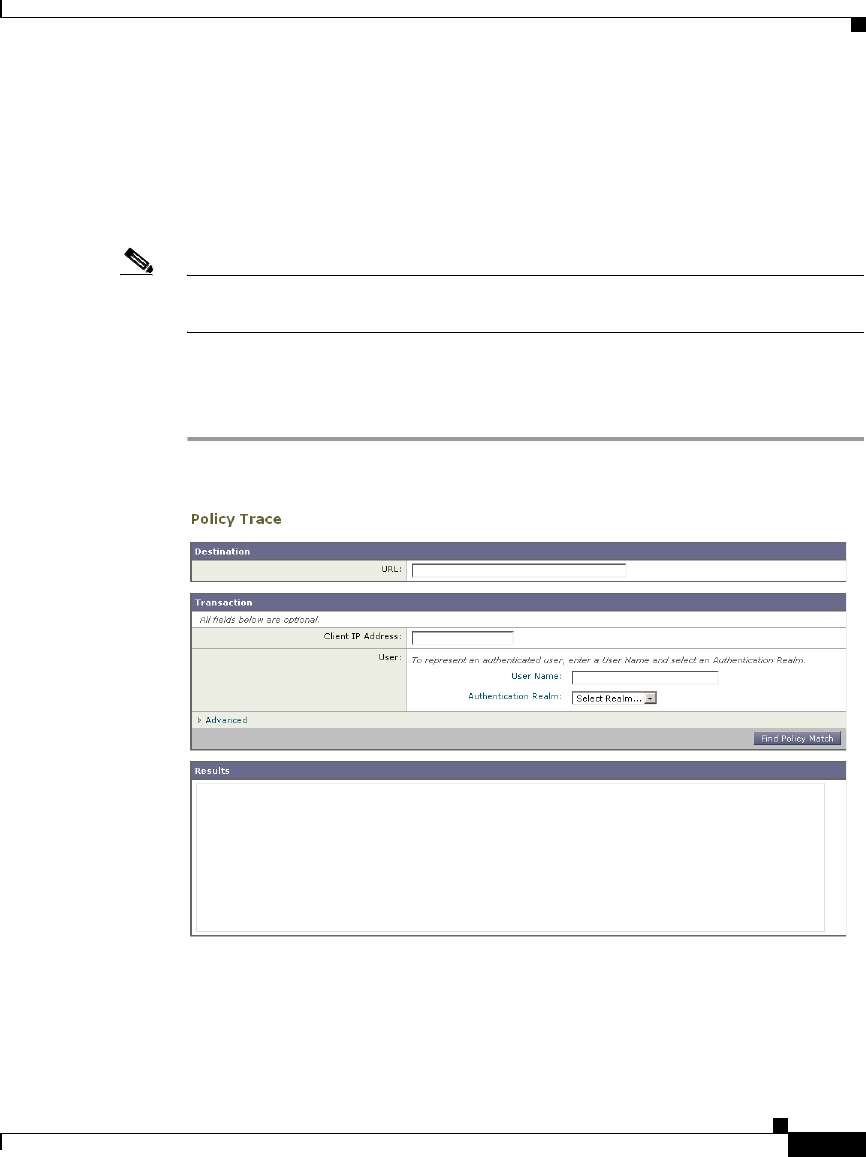
6-19
Cisco IronPort AsyncOS 7.1 for Web User Guide
OL-23207-01
Chapter 6 Working with Policies
Tracing Policies
When you use the policy trace tool, the Web Proxy does not record the requests
in the access log or reporting database.
By default, the Web Proxy simulates an HTTP GET request. However, when you
specify a file to upload in the Request Details section, the Web Proxy simulates
an HTTP POST request.
Note The policy trace tool explicitly makes requests even if the Web Security appliance
is deployed in transparent mode.
You can trace policies on the System Administration > Policy Trace page.
To trace policies:
Step 1 Navigate to the System Administration > Policy Trace page.
Step 2 In the URL field, enter the URL in the client request to simulate.
Step 3 Optionally, in the Client IP Address field, enter the IP address of the machine to
simulate.

Chapter 6 Working with Policies
Tracing Policies
6-20
Cisco IronPort AsyncOS 7.1 for Web User Guide
OL-23207-01
Note If no IP address is specified, AsyncOS uses localhost.
Step 4 Optionally, you can simulate an authentication user by entering the following
authentication requirements in the User area:
•User Name. Enter the user name of the authentication user.
•Authentication Realm. Choose an authentication realm.
Note For authentication to work for the user you enter here, the user must have
already successfully authenticated through the Web Security appliance.
Step 5 Optionally, by expanding the Advanced section, you can configure additional
settings to simulate a more specific user request that you want to trace.
Figure 6-4 shows the expanded Advanced section.
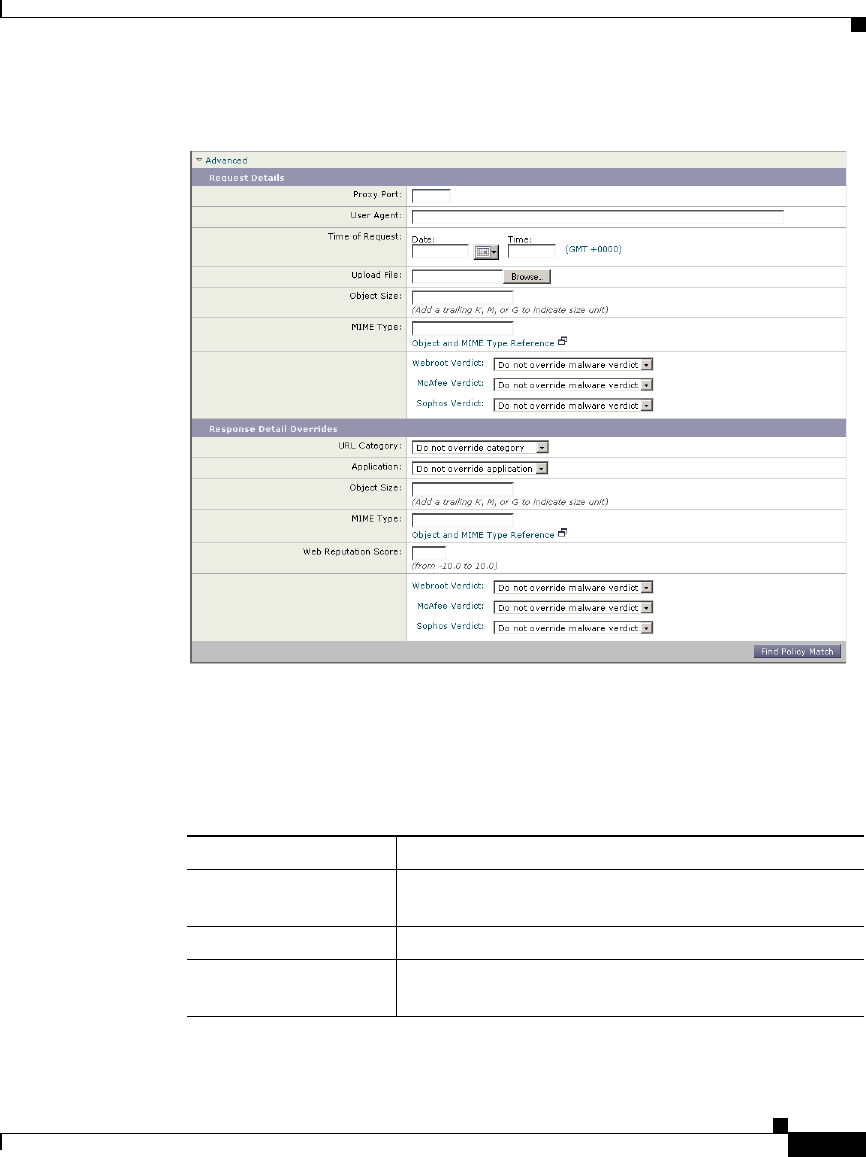
6-21
Cisco IronPort AsyncOS 7.1 for Web User Guide
OL-23207-01
Chapter 6 Working with Policies
Tracing Policies
Figure 6-4 Policy Trace Feature Advanced Section
The Advanced settings are divided into details of the transaction request to
simulate and transaction response details to override.
Step 6 Configure the transaction request information to simulate as desired. Table 6-1
describes the request side advanced settings you can configure.
Table 6-1 Policy Trace Advanced Settings for Requests
Setting Description
Proxy Port Select a specific proxy port to use for the trace request
to test policy group membership based on proxy port.
User Agent Specify the user agent to simulate in the request.
Time of Request Specify the day of week and time of day to simulate in
the request.

Chapter 6 Working with Policies
Tracing Policies
6-22
Cisco IronPort AsyncOS 7.1 for Web User Guide
OL-23207-01
Step 7 Configure the transaction response details to override as desired.
You might want to override a transaction response detail to simulate how a
different response value, such as a lower web reputation score, would affect the
policies assigned to the transaction. Table 6-2 describes the response side
advanced settings you can configure.
Upload File Choose a local file to simulate uploading in the
request.
When you specify a file to upload here, the Web Proxy
simulates an HTTP POST request instead of a GET
request.
Object Size Enter the size of the request object in bytes. You can
enter K, M, or G to represent Kilobytes, Megabytes, or
Gigabytes.
MIME Type Enter the MIME type.
Anti-malware
Scanning Verdicts
Choose whether or not to override the Webroot,
McAfee, or Sophos scanning verdicts.
Table 6-1 Policy Trace Advanced Settings for Requests (continued)
Setting Description
Table 6-2 Policy Trace Advanced Settings for Response Overrides
Setting Description
URL Category Choose whether or not to override the URL category of
the transaction response.
Application Choose an application that the Application Visibility and
Control engine can detect.
Object Size Enter the size of the response object in bytes. You can
enter K, M, or G to represent Kilobytes, Megabytes, or
Gigabytes.
MIME Type Enter the MIME type.
Web Reputation
Score
Enter the web reputation score from -10.0 to 10.0.
Anti-malware
Scanning Verdicts
Choose whether or not to override the Webroot, McAfee,
or Sophos scanning verdicts.
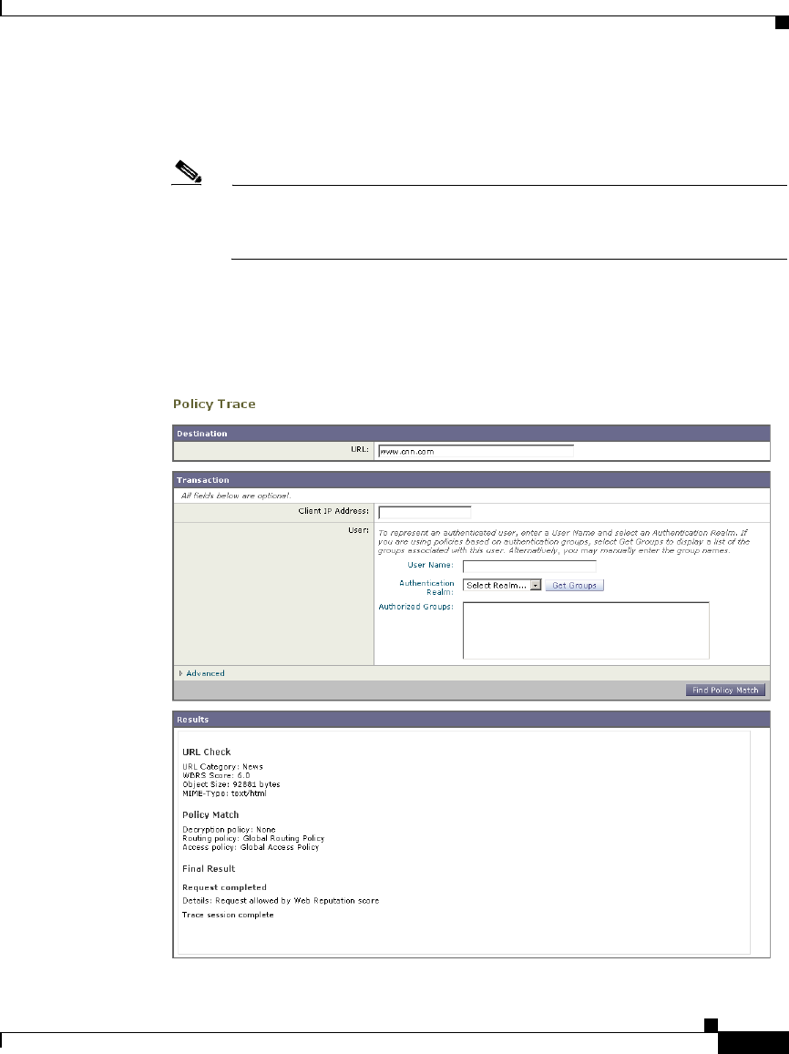
6-23
Cisco IronPort AsyncOS 7.1 for Web User Guide
OL-23207-01
Chapter 6 Working with Policies
Tracing Policies
Step 8 Click Find Policy Match.
The policy trace tool displays the results in the Results area.
Note The Find Policy Match button turns into a Cancel button while the policy
trace processes the parameters you enter. You can cancel the trace at any
time.
Figure 6-5 on page 23 shows the Policy Trace page with some results from a
policy trace.
Figure 6-5 Policy Trace Results

Chapter 6 Working with Policies
Tracing Policies
6-24
Cisco IronPort AsyncOS 7.1 for Web User Guide
OL-23207-01

CHAPTER
7-1
Cisco IronPort AsyncOS 7.1 for Web User Guide
OL-23207-01
7
Identities
This chapter contains the following information:
•Identities Overview, page 7-1
•Evaluating Identity Group Membership, page 7-2
•Matching Client Requests to Identity Groups, page 7-10
•Allowing Guest Access to Users Who Fail Authentication, page 7-13
•Identifying Users Transparently, page 7-16
•Creating Identities, page 7-20
•Configuring Identities in Other Policy Groups, page 7-28
•Example Identity Policies Tables, page 7-31
Identities Overview
To control web traffic on the network and protect your network from web based
threats, the Web Proxy needs to identify who is trying to access the web. Users
can be identified by different criteria, such as their machine address or
authenticated user name. The Web Proxy can apply different actions to
transactions based on who is submitting the request.
To identify who is accessing the web, you create Identities in the Web Security
appliance. An Identity is a policy that identifies and groups users. An Identity
addresses the question, “who are you?”

Chapter 7 Identities
Evaluating Identity Group Membership
7-2
Cisco IronPort AsyncOS 7.1 for Web User Guide
OL-23207-01
Identities are the only policy where you define whether or not authentication is
required to access the web. However, Identities do not specify a list of users who
are authorized (allowed) to access the web. You specify authorized users in the
other (non-Identity) policy types.
All other policy types use an Identity as the basis to determine which policy group
applies to the transaction. That means you can create a single Identity and use it
multiple times in the non-Identity policy groups.
You might want to group the following types of users or machines:
•A group of machine addresses in a test lab. You can create a Routing Policy
with this Identity so requests from these machines are fetched directly from
the destination server.
•All authenticated users based on the All Realms authentication sequence.
You can create a single Access Policy using this Identity, or you can create a
different Access Policy for each authentication realm and configure different
control settings for users in each realm.
•Users accessing the Web Security appliance on a particular proxy port.
You can create a Routing Policy using this Identity that fetches content from
a particular external proxy for requests that explicitly connect to the
appliance on a particular proxy port.
•All subnets trying to access a website in a user defined URL category do
not require authentication. You can create an Access Policy using this
Identity to exempt requests to particular destinations from authentication.
You might want to do this for Windows update servers.
Define Identities on the Web Security Manager > Identities page. For more
information about creating Identities, see Creating Identities, page 7-20.
Evaluating Identity Group Membership
When a client sends a request to a server, the Web Proxy receives the request,
evaluates it, and determines to which Identity group it belongs.
To determine the Identity group that a client request matches, the Web Proxy
follows a very specific process for matching the Identity group membership
criteria. During this process, it considers the following factors for group
membership:
•Subnet. The client subnet must match the list of subnets in a policy group.

7-3
Cisco IronPort AsyncOS 7.1 for Web User Guide
OL-23207-01
Chapter 7 Identities
Evaluating Identity Group Membership
•Protocol. The protocol used in the transaction, either HTTP/HTTPS or native
FTP.
•Port. The proxy port of the request must be in the Identity group’s list of
ports, if any are listed. For explicit forward connections, this is the port
configured in the browser. For transparent connections, this is the same as the
destination port.
You might want to define Identity group membership on the proxy port if you
have one set of clients configured to explicitly forward requests on one port,
and another set of clients configured to explicitly forward requests on a
different port.
Note Cisco recommends only defining Identity group membership by the proxy
port when the appliance is deployed in explicit forward mode, or when
clients explicitly forward requests to the appliance. When you define
Identity group membership by the proxy port when clients requests get
transparently redirected to the appliance, some requests might be
erroneously denied.
•User agent. The user agent making the request must be in the Identity group’s
list of user agents, if any are listed. You might want to group by user agent for
user agents that cannot handle authentication and you want to create an
Identity that does not require authentication.
•URL category. The URL category of the request URL must be in the Identity
group’s list of URL categories, if any are listed. You might want to group by
URL destination category if you create different authentication groups based
on URL categories and want to apply them to users depending on the website
categorization.
•Authentication requirements. If the Identity group requires authentication,
the client authentication credentials must match the Identity group’s
authentication requirements. For more information about how authentication
works with Identity groups, see Understanding How Authentication Affects
Identity Groups, page 7-4.
The information in this section gives an overview of how the appliance matches
client requests to Identity groups. For more details on exactly how the appliance
matches client requests, see Matching Client Requests to Identity Groups,
page 7-10.

Chapter 7 Identities
Evaluating Identity Group Membership
7-4
Cisco IronPort AsyncOS 7.1 for Web User Guide
OL-23207-01
The Web Proxy sequentially reads through each Identity group in the Identity
policies table. It compares the client request status to the membership criteria of
the first Identity group. If they match, the Web Proxy assigns the Identity group
to the transaction.
If they do not match, the Web Proxy compares the client request to the next
Identity group. It continues this process until it matches the client request to a user
defined Identity group, or if it does not match a user defined Identity group, it
matches the global Identity policy. When the Web Proxy matches the client
request to an Identity group or the global Identity policy, it assigns the Identity
group to the transaction.
If at any time during the comparison process the user fails authentication, the Web
Proxy terminates the request. For more information about how authentication
works with Identity groups, see Understanding How Authentication Affects
Identity Groups, page 7-4.
After the Web Proxy assigns an Identity to a client request, it evaluates the request
against the other policy group types. For more information, see the following
locations:
•Evaluating Access Policy Group Membership, page 8-4
•Evaluating Decryption Policy Group Membership, page 10-27
•Evaluating Routing Policy Group Membership, page 9-5
•Evaluating Data Security and External DLP Policy Group Membership,
page 12-7
Understanding How Authentication Affects Identity Groups
Requiring authentication for users can help your organization control access to
the web for groups of users. AsyncOS allows you to create multiple Identity
groups and define the membership criteria based on authentication requirements.
When authentication is required for an Identity group, a gold key icon appears
next to the Identity group name in the Policies table, as shown in Figure 7-1.
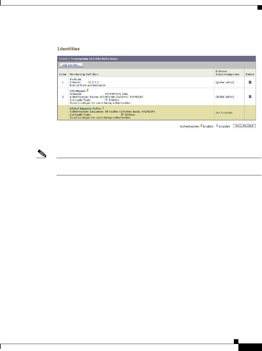
7-5
Cisco IronPort AsyncOS 7.1 for Web User Guide
OL-23207-01
Chapter 7 Identities
Evaluating Identity Group Membership
Figure 7-1 Identity Groups that Require Authentication
To define authentication requirements for an Identity group, you can choose an
authentication realm or sequence that applies to the Identity group.
Note You can specify the authorized users when you use the Identity in a non-Identity
policy group.
Consider the following rules and guidelines when creating and ordering Identity
groups:
•Identity group order. All Identity groups that do not require authentication
must be above Identity groups that require authentication.
•Cookie-based authentication. When the appliance is configured to use
cookie-based authentication surrogates, it does not get cookie information
from clients for HTTPS and FTP over HTTP requests. Therefore, it cannot get
the user name from the cookie. How HTTPS and FTP over HTTP requests are
matched against the Identity groups varies based on other factors. For more
information, see Understanding How Authentication Affects HTTPS and FTP
over HTTP Requests, page 7-6.
•Identity uniqueness. Verify the Identity group membership requirements are
unique for each Identity group. If two Identity groups require the exact same
membership, then client requests never match the lower Identity group. If any
non-Identity policy uses the lower Identity group, client requests never match
that policy.

Chapter 7 Identities
Evaluating Identity Group Membership
7-6
Cisco IronPort AsyncOS 7.1 for Web User Guide
OL-23207-01
•Global Identity policy. The global Identity policy does not require
authentication by default when you create an authentication realm. If you
want the global Identity policy to require authentication, you must assign an
authentication realm, authentication sequence, or the All Realms sequence to
the global Identity policy.
For some examples of how the Web Proxy matches client requests to an Identity
group for different Identity policies tables, see Example Identity Policies Tables,
page 7-31.
Understanding How Authentication Affects HTTPS and FTP over
HTTP Requests
How the Web Proxy matches HTTPS and FTP over HTTP requests with Identities
depends on the type of request (either explicitly forwarded or transparently
redirected to the Web Proxy) and the authentication surrogate type:
•No authentication surrogates. The Web Proxy matches HTTPS and FTP
over HTTP requests with Identity groups the same way it matches HTTP
requests. For a diagram of how this occurs, see Figure 7-2 on page 11.
•IP-based authentication surrogates and explicit requests. The Web Proxy
matches HTTPS and FTP over HTTP requests with Identity groups the same
way it matches HTTP requests. For a diagram of how this occurs, see
Figure 7-2 on page 11.
•IP-based authentication surrogates and transparent requests. The Web
Proxy matches FTP over HTTP requests with Identity groups the same way it
matches HTTP requests. But for HTTPS requests, the behavior is different,
depending on whether or not the HTTPS request comes from a client that has
authentication information available from an earlier HTTP request:
–
Information available from a previous HTTP request. The Web Proxy
matches HTTPS requests with Identity groups the same way it matches
HTTP requests. HTTPS requests are treated with the Identity associated
with the IP address.
–
No information available from a previous HTTP request. When the
Web Proxy has no credential information for the client, then it either fails
the HTTPS request or decrypts the HTTPS request in order to

7-7
Cisco IronPort AsyncOS 7.1 for Web User Guide
OL-23207-01
Chapter 7 Identities
Evaluating Identity Group Membership
authenticate the user, depending on how you configure the HTTPS Proxy.
Use the HTTPS Transparent Request setting on the Security Services >
HTTPS Proxy page to define this behavior.
For a diagram of how this occurs, see Figure 7-2 on page 11.
•Cookie-based authentication surrogates and transparent requests. When
the appliance uses cookie-based authentication, the Web Proxy does not get
cookie information from clients for HTTPS and FTP over HTTP requests.
Therefore, it cannot get the user name from the cookie. In this situation,
HTTPS and FTP over HTTP requests still match the Identity group according
to the other membership criteria, but the Web Proxy does not prompt clients
for authentication even if the Identity group requires authentication. Instead,
the Web Proxy sets the user name to NULL and considers the user as
unauthenticated. Then, when the unauthenticated request is evaluated against
the non-Identity policy groups, it matches only non-Identity groups that
specify “All Identities” and apply to “All Users.” Typically, this is the global
policy, such as the global Access Policy. For a diagram of how this occurs,
see Figure 7-3 on page 12.
•Cookie-based authentication surrogates and explicit requests. The
behavior is different, depending on whether or not credential encryption is
enabled:
–
Credential encryption enabled. The behavior is the same as
cookie-based authentication with transparent requests, as described
previously.
–
Credential encryption disabled. The Web Proxy uses no surrogates.
HTTPS and FTP over HTTP requests are authenticated and matched to
Identity groups like HTTP requests. For a diagram of how this occurs, see
Figure 7-2 on page 11.

Chapter 7 Identities
Evaluating Identity Group Membership
7-8
Cisco IronPort AsyncOS 7.1 for Web User Guide
OL-23207-01
Table 7-1 summarizes the previous information.
Table 7-1 Matching HTTPS and FTP over HTTP Requests to Identities
Surrogate
Types Explicit Requests Transparent Requests
No Surrogate HTTPS and FTP over HTTP
requests are matched like
HTTP requests.
N/A
IP-based HTTPS and FTP over HTTP
requests are matched like
HTTP requests.
FTP over HTTP requests are
matched like HTTP requests.
HTTPS requests are matched
like HTTP requests under any
of the following conditions:
•A previous HTTP request
was authenticated using an
identity with an IP-based
surrogate.
•A previous HTTP request
was not authenticated, but
the HTTPS Proxy is
configured to decrypt the
first HTTPS request.
Otherwise, if a previous HTTP
request was not authenticated
and the HTTPS Proxy is
configured to deny the request,
the HTTPS request fails.
Cookie-based The client is not prompted for
authentication.
Note: When credential
encryption is disabled, no
surrogates are used, and
HTTPS requests are matched
like HTTP requests.
The client is not prompted for
authentication.

7-9
Cisco IronPort AsyncOS 7.1 for Web User Guide
OL-23207-01
Chapter 7 Identities
Evaluating Identity Group Membership
Understanding How Authentication Scheme Affects Identity
Groups
You define the authentication scheme for each Identity group, not at each realm
or sequence. That means you can use the same NTLM realm or a sequence that
contains an NTLM realm and use it in Identity groups that use either the
NTLMSSP, Basic, or “Basic or NTLMSSP” authentication schemes.
The Web Proxy communicates which scheme(s) it supports to the client
application at the beginning of a transaction. The Identity group currently in use
determines which scheme(s) it supports. When the Web Proxy informs the client
application that it supports both Basic and NTLMSSP, the client application
chooses which scheme to use in the transaction.
Some client applications, such as Internet Explorer, always choose NTLMSSP
when given a choice between NTLMSSP and Basic. This might cause a user to
not pass authentication when all of the following conditions are true:
•The Identity group uses a sequence that contains both LDAP and NTLM
realms.
•The Identity group uses the “Basic or NTLMSSP” authentication scheme.
•A user sends a request from an application that chooses NTLMSSP over
Basic.
•The user only exists in the LDAP realm.
When this happens, the Web Proxy uses the NTLMSSP scheme to authenticate
users in this Identity group because the client requests it. However, LDAP servers
do not support NTLMSSP, so no user that exists only in the specified LDAP
server(s) can pass authentication in this Identity group.
Therefore, when you need to use an authentication sequence that contains both
LDAP and NTLM realms, consider the client applications that might try to access
a URL when you configure the authentication scheme for an Identity group. For
example, you might want to choose Basic as the only authentication scheme for
an Identity group in some cases.

Chapter 7 Identities
Matching Client Requests to Identity Groups
7-10
Cisco IronPort AsyncOS 7.1 for Web User Guide
OL-23207-01
Matching Client Requests to Identity Groups
Figure 7-2 on page 11 shows how the Web Proxy evaluates a client request against
the Identity groups when the Identity is configured to use:
•No authentication surrogates
•IP addresses as authentication surrogates
•Cookies as authentication surrogates with transparent requests
•Cookies as authentication surrogates with explicit requests and credential
encryption is enabled
Figure 7-3 on page 12 shows how the Web Proxy evaluates a client request against
the Identity groups when the Identity is configured to use cookies as the
authentication surrogates, credential encryption is enabled, and the request is
explicitly forwarded.
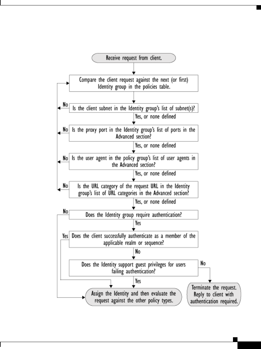
7-11
Cisco IronPort AsyncOS 7.1 for Web User Guide
OL-23207-01
Chapter 7 Identities
Matching Client Requests to Identity Groups
Figure 7-2 Policy Group Flow Diagram for Identities - No Surrogates and
IP-Based Surrogates
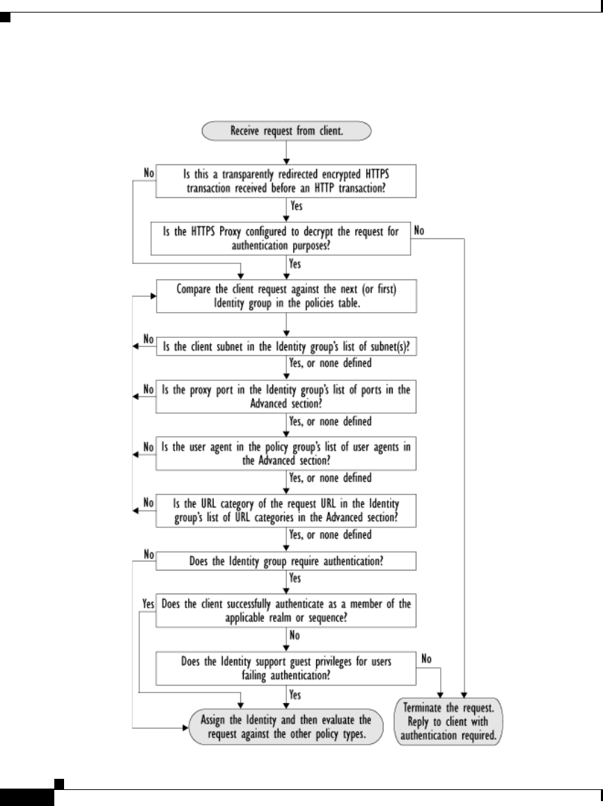
Chapter 7 Identities
Matching Client Requests to Identity Groups
7-12
Cisco IronPort AsyncOS 7.1 for Web User Guide
OL-23207-01
Figure 7-3 Policy Group Flow Diagram for Identities - Cookie-Based
Surrogates

7-13
Cisco IronPort AsyncOS 7.1 for Web User Guide
OL-23207-01
Chapter 7 Identities
Allowing Guest Access to Users Who Fail Authentication
Allowing Guest Access to Users Who Fail
Authentication
You can grant limited access to users who fail authentication due to invalid
credentials. By default, when a client passes invalid authentication credentials,
the Web Proxy continually requests valid credentials, essentially blocking access
to all Internet resources. However, when you allow guest access, the first time the
client passes invalid authentication credentials, the user is treated as a guest and
the Web Proxy does not request authentication again.
You might want to grant guest access to users in the following situations:
•A visitor comes to the office and needs to be granted restrictive Internet
access, but is not in the corporate user directory.
•An employee from another branch location (or from an acquired company)
comes to the corporate headquarters, and needs Internet access. The user
directories of the branch location (or acquired company) and corporate
headquarters are separate, so the employee’s credentials do not work in the
corporate headquarters.
•A new hire has been provided credentials in an email but they are not yet
populated in the authentication server.
•A user logs into a Windows workstation using a local account instead of a
Windows domain account and the user needs access to the Internet.
The authentication server administrator in your organization can create a guest
user account in the user directory. However, allowing guest access through the
Web Security appliance has the benefit that the administrator does not have to
communicate the guest credentials to every visitor.
To grant guest access to users who fail authentication, you create an Identity that
requires authentication, but also allows guest privileges. Then you create another
policy using that Identity and apply that policy to the guest users. When users who
fail authentication have guest access, they can access the resources defined in the
policy group that specifies guest access for that Identity.
A user who fails authentication has all transactions blocked if either of the
following conditions are true:
•Guest privileges are not provided in any Identity.
•The user does not match any Identity that provides guest privileges.

Chapter 7 Identities
Allowing Guest Access to Users Who Fail Authentication
7-14
Cisco IronPort AsyncOS 7.1 for Web User Guide
OL-23207-01
A user who fails authentication has transactions allowed when all of the following
conditions are true:
•The user matches an Identity with guest privileges.
•A non-Identity policy group uses that Identity and applies to guest users.
For example, you can create an Access or Decryption Policy that is specific to
guest users.
Note If an Identity allows guest access and there is no user defined policy group that
uses that Identity, users who fail authentication match the global policy for that
policy type. For example, if MyIdentity allows guest access and there is no user
defined Access Policy that uses MyIdentity, users who fail authentication match
the global Access Policy. If you do not want guest users to match a global policy,
create a policy group above the global policy that applies to guest users and blocks
all access.
When the Web Proxy grants a user guest access, it identifies and logs the user as
a guest in the access logs. You can specify whether the Web Proxy identifies the
user by IP address or user name. In the access logs, reports, and end-user
acknowledgement page, entries for guest users have one of the following formats:
•(unauthenticated)IP_address
•(unauthenticated)username_entered
You can enable guest access for an Identity that uses any authentication protocol
or scheme.
To grant guest access to a user:
Step 1 Define an Identity group and enable the Support Guest privileges option.
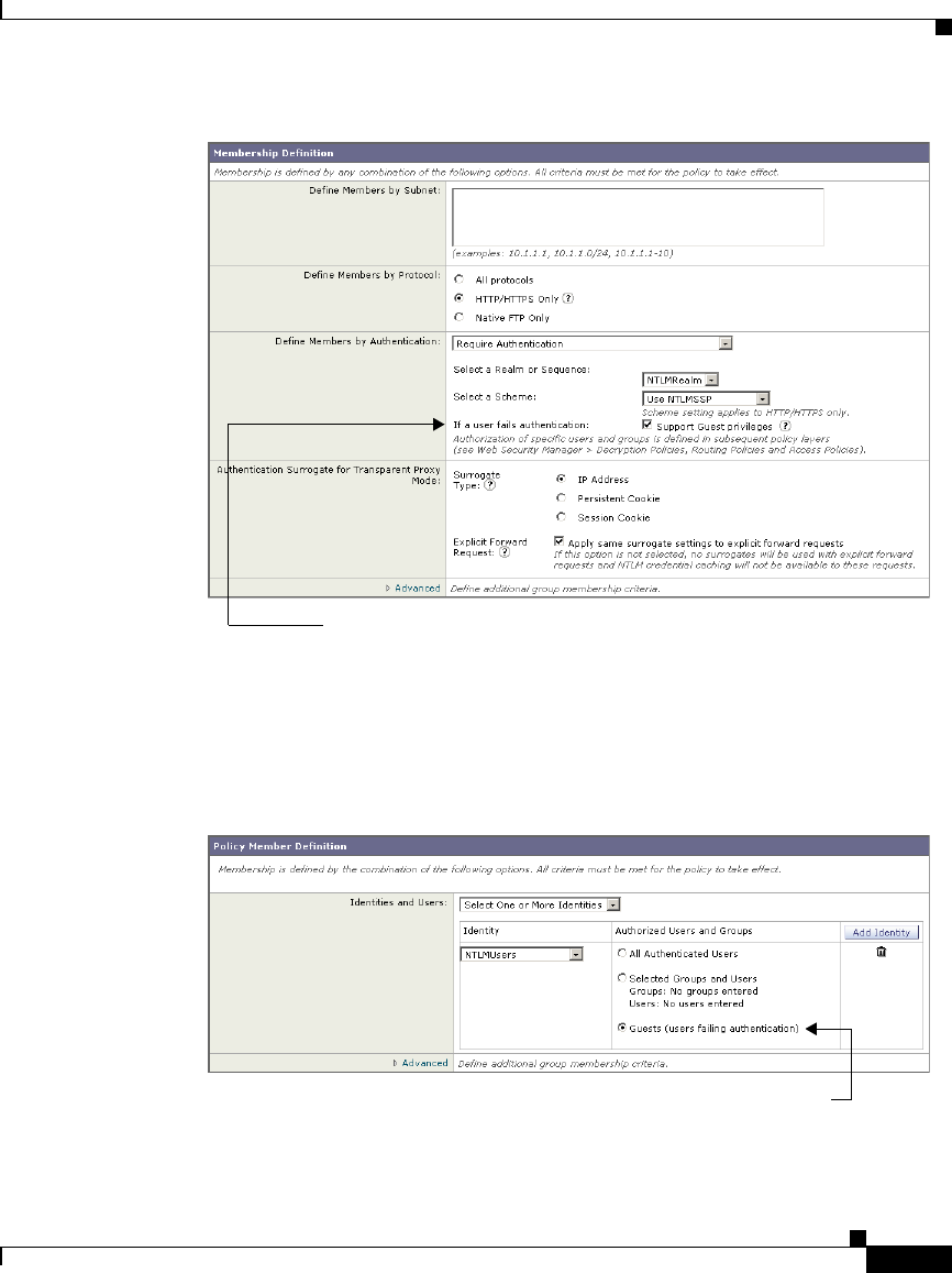
7-15
Cisco IronPort AsyncOS 7.1 for Web User Guide
OL-23207-01
Chapter 7 Identities
Allowing Guest Access to Users Who Fail Authentication
Step 2 Create an Access, Decryption, Routing, Data Security, or External DLP Policy
and select the Identity created in step 1.
Step 3 In the Access, Decryption, Routing, Data Security, or External DLP Policy group
membership, select “Guests (users failing authentication)” for the Identity in step
1.
Step 4 Submit and commit your changes.
This Identity allows guest access.
Guests of this Identity are authorized to access the web.

Chapter 7 Identities
Identifying Users Transparently
7-16
Cisco IronPort AsyncOS 7.1 for Web User Guide
OL-23207-01
Note You can configure the Web Proxy to request authentication again if an
authenticated user is blocked from a website due to restrictive URL filtering. To
do this, enable the “Enable Re-Authentication Prompt If End User Blocked by
URL Category or User Session Restriction” global authentication setting. For
more information, see Allowing Users to Re-Authenticate, page 20-39.
Identifying Users Transparently
Traditionally, users identified by an authentication user name are explicitly
prompted to enter a user name and password. The credentials the user enters are
then validated against an authentication server, and then the Web Proxy applies
the appropriate policies to the transaction based on the authenticated user name.
However, you can configure the Web Security appliance so that it identifies users
by an authenticated user name transparently—that is, without prompting the end
user. You might want to do this to:
•Create a single sign-on environment so users are not aware of the presence of
a proxy on the network.
•Use authentication based policies to apply to transactions coming from client
applications that are incapable of displaying the authentication prompt to end
users.
Identifying users transparently only affects how the Web Proxy obtains the user
name and assigns an Identity group. After it obtains the user name and assigns an
Identity, it applies all other policies normally, regardless of how it assigned the
Identity.
To identify users transparently, you must define at least one LDAP authentication
realm that supports Novell eDirectory.
Note You can also transparently identify remote users when using Secure Mobility
Solution. For more information, see Transparently Identifying Remote Users,
page 13-5.
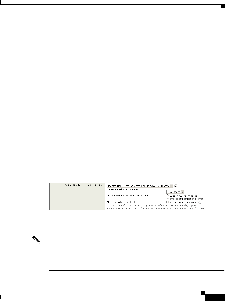
7-17
Cisco IronPort AsyncOS 7.1 for Web User Guide
OL-23207-01
Chapter 7 Identities
Identifying Users Transparently
Understanding Transparent User Identification
Novell eDirectory maintains a mapping that matches authenticated user names to
their current IP addresses. AsyncOS for Web communicates with the Novell
eDirectory server at regular intervals to maintain the current IP address to user
name mapping.
When a client makes a request for a website, the Web Security appliance receives
the request and obtains the IP address from the request. AsyncOS for Web then
checks the IP address to user name mapping stored on the Web Security appliance
to assign a user name to the client request. AsyncOS for Web also fetches the user
groups from the Novell eDirectory server at this time. Assuming it matches a user
name to the IP address, AsyncOS for Web applies policies to the transaction as
appropriate.
If the IP address does not match a user name, you can configure how to handle the
transaction. You can grant the end user guest access, or you can force an
authentication prompt to appear to the end user.
When an end user is shown an authentication prompt due to failed transparent user
identification, and the user then fails authentication due to invalid credentials, you
can choose whether to allow the user guest access. Figure 7-4 shows where you
grant user access when configuring an Identity for transparent user identification.
Figure 7-4 Granting Guest Access—Transparent User Identification
The current IP address to user name mapping is updated, by default, every 600
seconds. You can change this time interval using the advancedproxyconfig >
authentication CLI command.
Note When you enable re-authentication and a transaction is blocked by URL filtering,
an end-user notification page appears with the option to log in as a different user.
Users who click the link are prompted for authentication. For more information,
see Allowing Users to Re-Authenticate, page 20-39.

Chapter 7 Identities
Identifying Users Transparently
7-18
Cisco IronPort AsyncOS 7.1 for Web User Guide
OL-23207-01
Rules and Guidelines
Consider the following rules and guidelines when you identify users transparently
using Novell eDirectory:
•Novell Client must be installed on each client machine, and end users must
use it to authenticate against a Novell eDirectory server.
•The Novell LDAP tree used by the Novell client login must be the same
LDAP tree configured in the authentication realm.
•If the Novell clients use multiple Novell LDAP trees, create an authentication
realm for each tree, and then create an authentication sequence that uses each
Novell LDAP authentication realm.
•When you configure the LDAP authentication realm for Novell eDirectory,
you must specify a Bind DN for the query credentials.
•Novell eDirectory must be configured to update the NetworkAddress attribute
of the user object when users login. For more information on how to do this,
see the following Novell support article:
http://www.novell.com/support/php/search.do?cmd=displayKC&docTyp
e=kc&externalId=7004564&sliceId=1&docTypeID=DT_TID_1_1&dialogID=
100407203&stateId=0%200%20100405493?
Note Novell eDirectory versions 8.6, 8.7, and 8.8 can be configured to update
the NetworkAddress attribute.
•When querying Novell eDirectory, AsyncOS for Web only searches for direct
parent groups that the user belongs to. It does not search nested groups.
•If your network environment includes both Novell eDirectory and Microsoft
Active Directory and users fail to login using Novell eDirectory, they can
either log into Active Directory using Basic authentication scheme or be
granted guest access. They cannot use NTLMSSP authentication scheme.
•When using DHCP to assign IP addresses to client machines, ensure the IP
address to user name mapping is updated on the Web Security appliance more
frequently than the DHCP lease. Use the advancedproxyconfig >
authentication CLI command to update the mapping update interval.

7-19
Cisco IronPort AsyncOS 7.1 for Web User Guide
OL-23207-01
Chapter 7 Identities
Identifying Users Transparently
•If an end user logs out of a machine and another user logs in to the same
machine before the IP address to user name mapping is updated on the Web
Security appliance, then the Web Proxy logs the client as the previous user.
•You can configure how the Web Proxy handles transactions when transparent
user identification fails. It can grant users guest access, or it can force an
authentication prompt to appear to end users.
•When a user is shown an authentication prompt due to failed transparent user
identification, and the user then fails authentication due to invalid credentials,
you can choose whether to allow the user guest access.
•When the assigned Identity uses an authentication sequence with multiple
realms in which the user exists, AsyncOS for Web fetches the user groups
from the realms in the order in which they appear in the sequence.
•When you configure an Identity to transparently authenticate users, the
authentication surrogate must be IP address. You cannot select a different
surrogate type.
•You can use the “network address” field of the user in Novell eDirectory to
obtain the IP address of the workstation from where the user previously
logged in.
•You can log which users were identified transparently in the access logs and
WC3 logs using the %m and x-auth-mechanism custom fields. A value of
SSO_EDIR indicates that the user name was obtained by matching the client
IP address to an authenticated user name in Novell eDirectory. (Similarly, a
value of SSO_ASA indicates that the user is a remote user and the user name
was obtained from a Cisco ASA using the Secure Mobility Solution.)
Configuring Transparent User Identification
To use transparent user identification:
Step 1 Create an LDAP authentication realm for a Novell eDirectory server. Configure
the realm to use Version 3 and to “Support Novell eDirectory.”
For more information on configuring LDAP options, see LDAP Authentication,
page 20-43.
For more information on creating authentication realms, see Creating
Authentication Realms, page 20-15.

Chapter 7 Identities
Creating Identities
7-20
Cisco IronPort AsyncOS 7.1 for Web User Guide
OL-23207-01
Step 2 Define an Identity group that identifies users transparently using Novell
eDirectory:
a. In the “Define Members by Authentication” section, choose “Identify Users
Transparently Using Novell eDirectory.”
b. Select the LDAP authentication realm that supports Novell eDirectory.
c. Configure all other Identity options as desired.
For more information on creating Identities, see Creating Identities, page 7-20.
Step 3 Create policies that use the Identity for transparent user identification.
Creating Identities
You can create Identities based on combinations of several criteria, such as client
subnet or the URL category of the destination site. You must define at least one
criterion for Identity membership. When you define multiple criteria, the client
request must meet all criteria to match the Identity.
For more information about how the Web Proxy matches a client request with an
Identity, see Evaluating Identity Group Membership, page 7-2 and Matching
Client Requests to Identity Groups, page 7-10.
You define Identity group membership on the Web Security Manager > Identities
page.
Note Deleting an authentication realm or sequence disables Identities that depend on
the deleted realm or sequence.
To create an Identity group:
Step 1 Navigate to the Web Security Manager > Identities page.
Step 2 Click Add Identity.
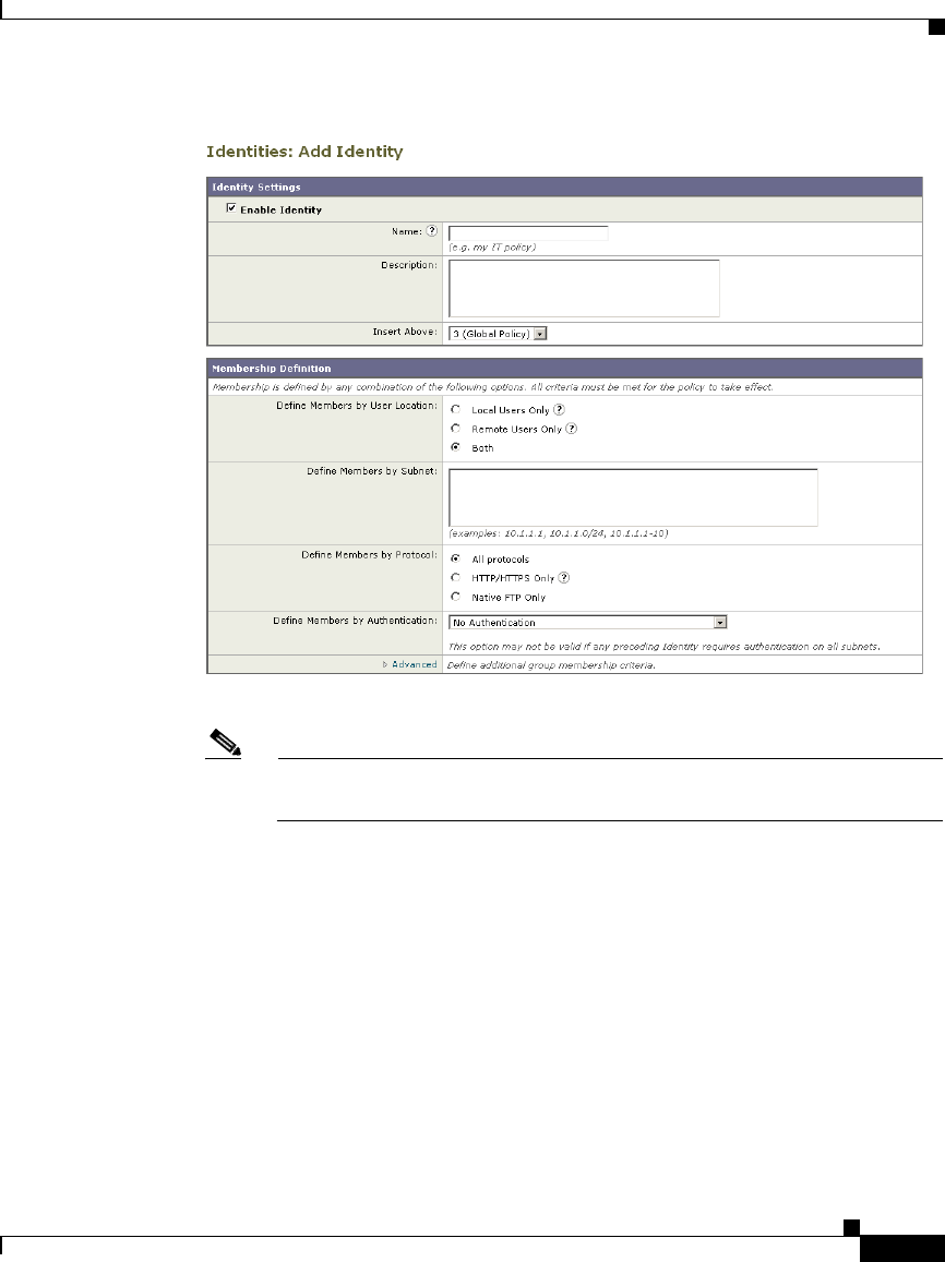
7-21
Cisco IronPort AsyncOS 7.1 for Web User Guide
OL-23207-01
Chapter 7 Identities
Creating Identities
Step 3 Enter a name for the Identity group and an optional description.
Note Each Identity group name must be unique and only contain alphanumeric
characters or the space character.
Step 4 In the Insert Above field, choose where in the policies table to place the Identity
group.
When configuring multiple Identity groups, specify a logical order for each group.
Carefully order your Identity groups to ensure that correct matching occurs.
Position groups that do not require authentication above the first policy group that
requires authentication. For more information about how authentication affects
Identity groups, see Understanding How Authentication Affects Identity Groups,
page 7-4.
Step 5 In the Define Members by User Location section, configure the Identity to apply
to local users, remote users, or both local and remote users.

7-22
The setting chosen here affects the available authentication settings for this
Identity.
This section only appears when the Secure Mobility Solution is enabled.
For more information, see Achieving Secure Mobility Overview,
page 13-1.
In the Define Members by Subnet field, enter the addresses to which this Identity
should apply.
You can enter IP addresses, CIDR blocks, and subnets. Separate multiple
addresses with commas.
If you do not enter an address in this field, the Identity group applies to
all IP addresses. For example, if you configure the Identity to require
authentication, but do not define any other settings, then the Identity acts
similarly to the Default Identity Policy with authentication required.
In the Define Members by Protocol section, choose to which protocols this
Identity should apply:
All protocols. Applies to all protocols the Web Security appliance supports.
HTTP/HTTPS Only. Applies to all requests that use HTTP or HTTPS as the
underlying protocol, including FTP over HTTP and any other protocol
tunneled using HTTP CONNECT.
Native FTP Only. Applies to native FTP requests only.
In the Define Members by Authentication section, choose whether or not this
Identity requires authentication. You can choose one of the following options:
No Authentication. The user is identified primarily by IP address. Go to
Step 15.
Require Authentication. The user is identified by the authentication
credentials entered. Go to Step 9.
Identify Users Transparently through Novell eDirectory. The user is
identified by the current IP address to user name mapping received from the
Novell eDirectory server. Go to Step 10.
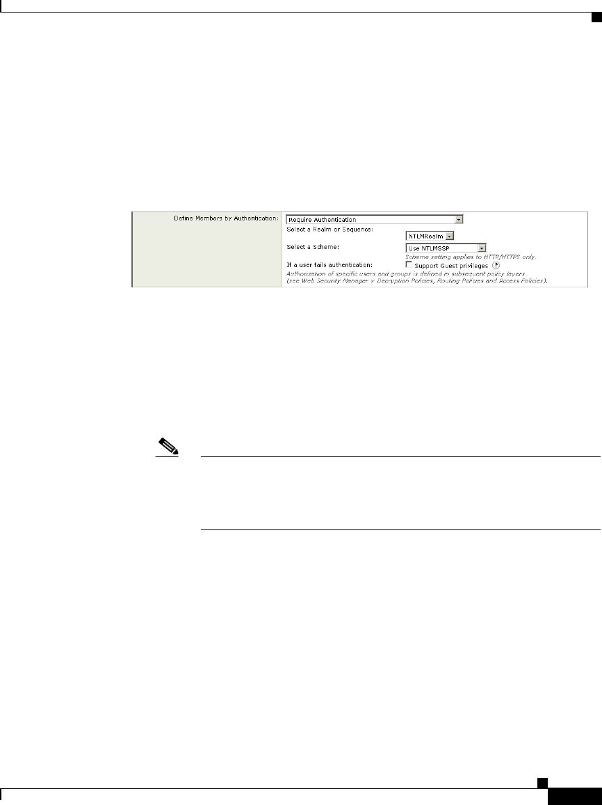
7-23
Identify Users Transparently through Cisco ASA Integration. The user is
identified by the current IP address to user name mapping received from the
Cisco adaptive security appliance (ASA). Go to Step 11.
To configure the Identity to require authentication:
In the Select a Realm or Sequence field, choose a defined authentication
realm or sequence.
If you choose an NTLM authentication realm or sequence that contains an
NTLM authentication realm, then choose an authentication scheme in the
Select a Scheme field.
To grant guest access to users who fail authentication due to invalid
credentials, select the Support Guest privileges check box.
For more information, see Allowing Guest Access to Users Who Fail
Authentication, page 7-13.
You can specify individual authenticated users or groups of users
when you use the Identity in a different type of policy group. For
more information, see Configuring Identities in Other Policy Groups,
page 7-28.
d. Go to Step 12.
Step 10 To configure the Identity to use transparent user identification with Novell
eDirectory:
a. In the Select a Realm or Sequence field, choose a defined LDAP
authentication realm that supports Novell eDirectory or sequence that
contains only LDAP realms that support Novell eDirectory.
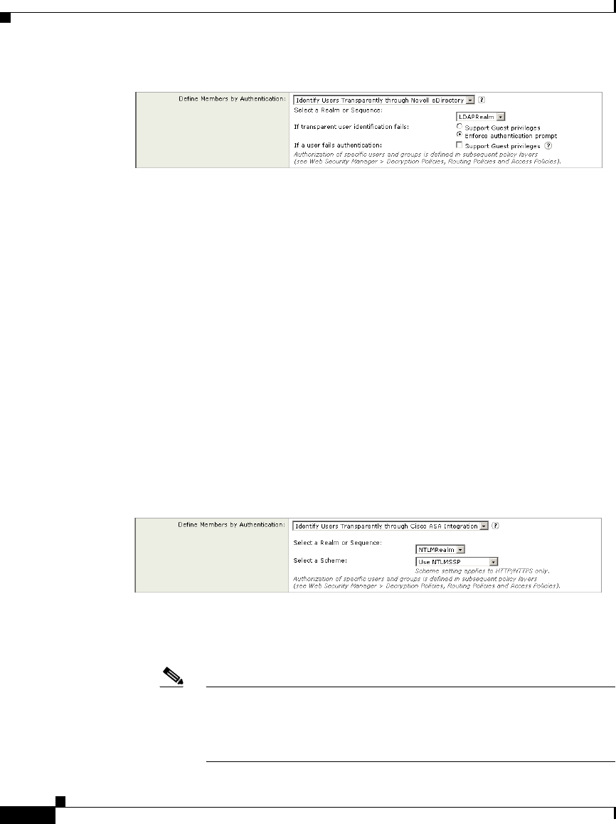
7-24
Choose how to handle transactions when transparent user identification fails:
either grant users guest access, or force an authentication prompt to appear to
end users.
Transparent user identification might fail if the Web Proxy cannot determine
the user who is currently logged in from the specified IP address. That is, if
the IP address is not in the IP address to user mapping.
Choose whether or not to allow the user guest access when a user is shown an
authentication prompt due to failed transparent user identification and the
user then fails authentication due to invalid credentials.
For more information on transparent user identification, see Identifying Users
Transparently, page 7-16.
Go to Step 12.
To configure the Identity to use transparent user identification by integrating with
a Cisco adaptive security appliance (ASA):
In the Select a Realm or Sequence field, choose a defined authentication
realm or sequence.
If you choose an NTLM authentication realm or sequence that contains an
NTLM authentication realm, then choose the authentication scheme in the
Select a Scheme field.
You can specify individual authenticated users or groups of users
when you use the Identity in a different type of policy group. For
more information, see Configuring Identities in Other Policy Groups,
page 7-28.

7-25
Go to Step 12.
View the settings in the Authentication Surrogate section.
The options vary depending on the Web Proxy deployment mode.
Choose how transactions used for authenticating the client are associated with a
user (either by IP address or by using a cookie) after the user has authenticated
successfully. Choose one of the options in Table 7-2:
Table 7-2 Surrogate Types
IP Address The Web Proxy tracks an authenticated user at a particular
IP address. To achieve transparent user identification, you
must choose IP-based authentication.
Persistent Cookie The Web Proxy tracks an authenticated user on a
particular application by generating a persistent cookie for
each user per application. Closing the application does not
remove the cookie.
Session Cookie The Web Proxy tracks an authenticated user on a
particular application by generating a session cookie for
each user per domain per application. (However, when a
user provides different credentials for the same domain
from the same application, the cookie is overwritten.)
Closing the application removes the cookie.
No Surrogate The Web Proxy does not use a surrogate to cache the
credentials, and it tracks an authenticated user for every
new TCP connection. When you choose this option, the
web interface disables other settings that no longer apply.
This option is available only in explicit forward mode and
when you disable credential encryption on the Network >
Authentication page.
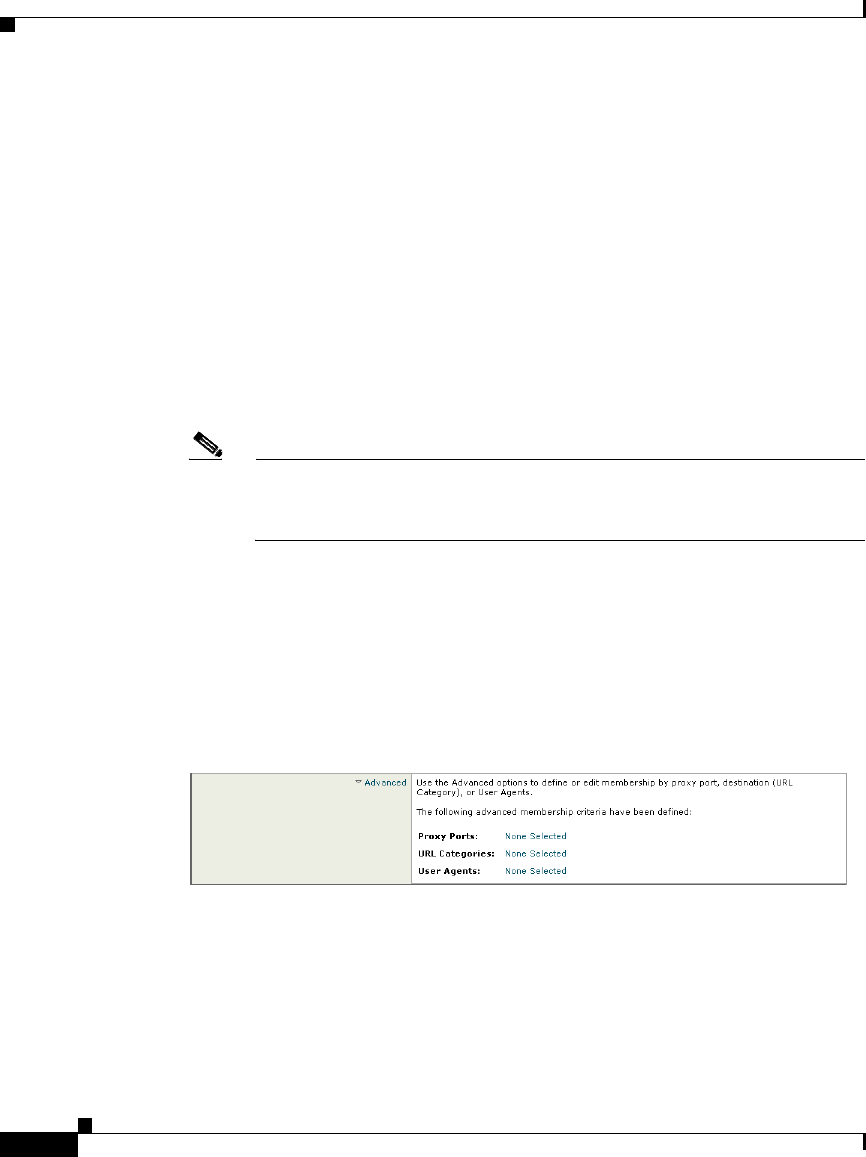
7-26
You might want to use IP-based authentication when:
There is only one user on a client machine and you want users to be able to
achieve single sign-on behavior.
You want to use transparent user identification.
You want to create an Identity that works with applications that do not work
with cookie-based surrogates, such as MSN Messenger.
You might want to choose cookie-based authentication when there are multiple
users on one machine, such as a Citrix server or a kiosk shared by many users.
For more information about which authentication surrogates are supported with
other configurations and different types of requests, see Tracking Authenticated
Users, page 20-42.
You can define a timeout value for the authentication surrogate for all
requests. For more information, see Configuring Global Authentication
Settings, page 20-23.
In the Explicit Forward Request field, choose whether or not the surrogate used
for transparent requests should also be used for explicit requests.
Enabling credential encryption automatically enables this field.
This option appears only when the Web Proxy is deployed in transparent mode.
Optionally, expand the Advanced section to define additional membership
requirements.
To define Identity group membership by any of the advanced options, click the
link for the advanced option and configure the option on the page that appears.

Cisco IronPort AsyncOS 7.1 for Web User Guide
OL-23207-01
Chapter 7 Identities
Creating Identities
Table 7-3 describes Identity group advanced options.
Step 17 Submit and commit your changes.
Table 7-3 Identity Group Advanced Options
Advanced Option Description
Proxy Ports To define policy group membership by the proxy port used
to access the Web Proxy, enter one or more port numbers in
the Proxy Ports field. Separate multiple ports with commas.
For explicit forward connections, this is the port configured
in the browser. For transparent connections, this is the same
as the destination port. You might want to define policy
group membership on the proxy port if you have one set of
clients configured to explicitly forward requests on one port,
and another set of clients configured to explicitly forward
requests on a different port.
Note: Cisco recommends defining policy group
membership by the proxy port only when the appliance is
deployed in explicit forward mode, or when clients
explicitly forward requests to the appliance. If you define
policy group membership by the proxy port when client
requests are transparently redirected to the appliance, some
requests might be denied.
URL Categories Choose the user defined or predefined URL categories.
Membership for both user defined and predefined URL
categories is excluded by default, meaning the Web Proxy
ignores all categories unless they are selected in the Add
column.
User Agents Choose whether or not to define policy group membership
by the user agent used in the client request. You can select
some commonly defined browsers, or define your own using
regular expressions. Choose whether this policy group
should apply to the selected user agents or to any user agent
that is not in the list of selected user agents.
For more information on creating user agent based policies,
see Working with User Agent Based Policies, page 6-16.

Chapter 7 Identities
Configuring Identities in Other Policy Groups
Cisco IronPort AsyncOS 7.1 for Web User Guide
OL-23207-01
Configuring Identities in Other Policy Groups
Every non-Identity policy group specifies at least one Identity group as part of its
policy group membership. You can configure a non-Identity policy group to use
multiple Identity groups, and you can specify which users or groups of users are
authorized to access the web using the policy group.
You might want to specify multiple Identity groups in a policy group under the
following circumstances:
•You have an Identity group defined for HTTP transactions and another
Identity group defined for native FTP transactions. You can create a single
non-Identity policy group that applies to both HTTP and native FTP
transactions
•Separate Identity groups are defined for each authentication realm. You want
to create one Access Policy group that defines the same access control
settings for users in multiple authentication realms.
Note You can also specify All Identities and configure the authenticated users.
Figure 7-5 shows a policy group that uses multiple Identities.
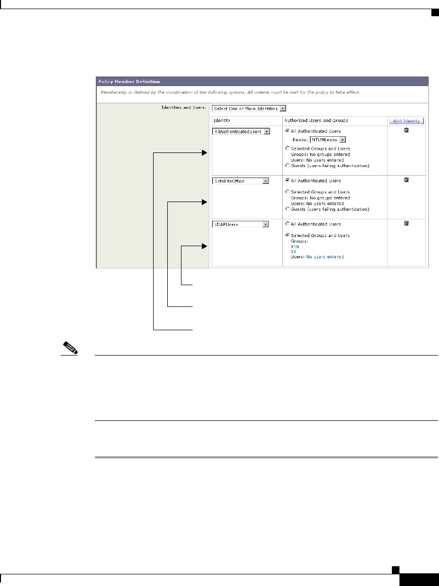
Cisco IronPort AsyncOS 7.1 for Web User Guide
OL-23207-01
Chapter 7 Identities
Configuring Identities in Other Policy Groups
Figure 7-5 Multiple Identities in a Policy Group
Note If an Identity group becomes disabled, then that Identity group is removed (not
disabled) from any non-Identity policy group that used it. If the Identity group
becomes enabled again, the non-Identity policy groups that previously used the
Identity do not automatically include the enabled Identity. Identity groups become
disabled due to a deleted authentication realm or sequence.
To configure Identity group information in a policy group:
Step 1 Create a new policy group or edit the membership of an existing policy group for
Access, Decryption, Routing, Data Security, or External DLP Policy.
Step 2 Scroll down to the Identities and Users section.
This Identity uses an authentication sequence and this policy group
applies to one realm in the sequence.
All authenticated users in this Identity are authorized for this policy
group.
The specified user groups in this Identity are authorized for this
policy group.
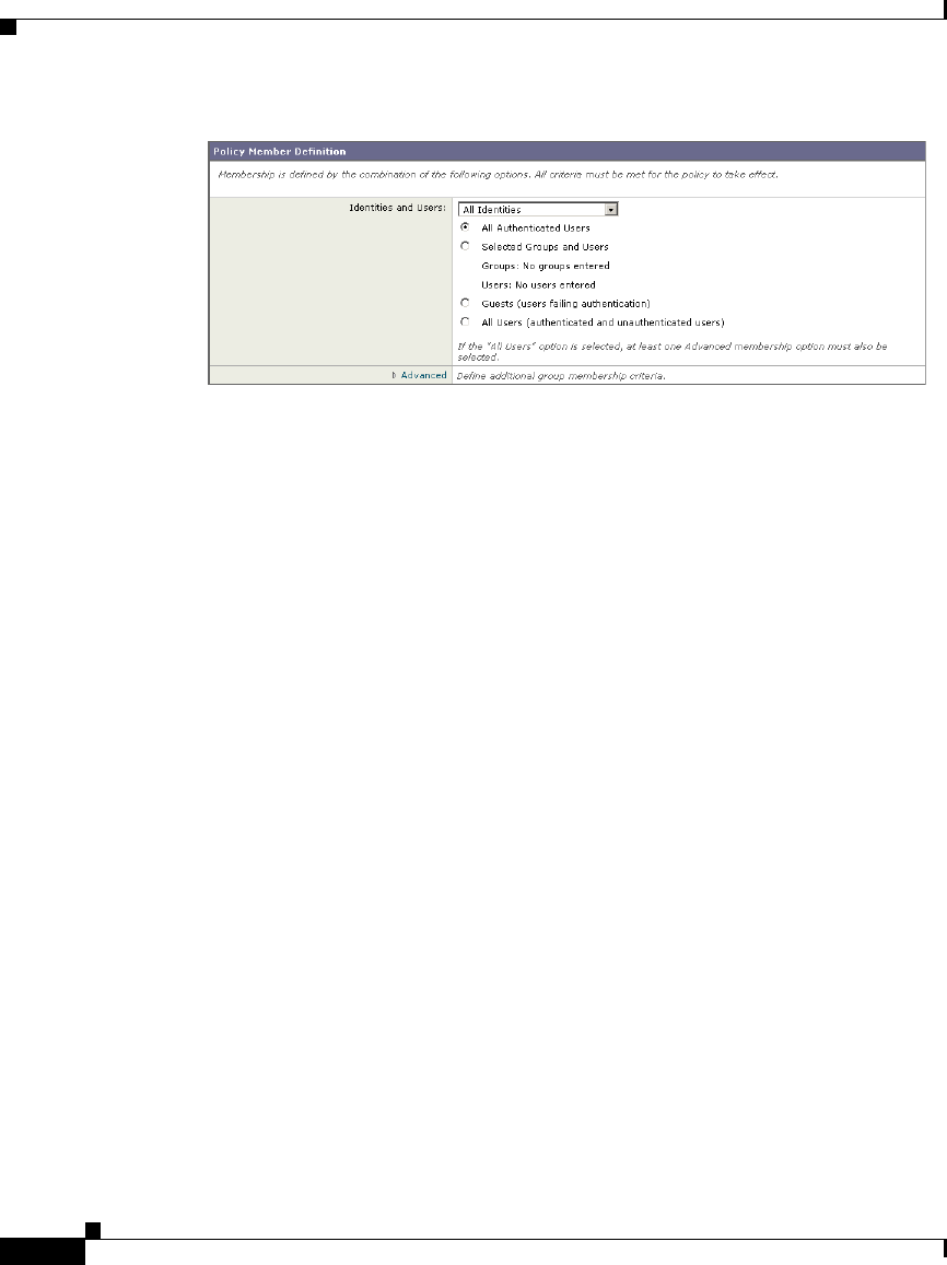
Chapter 7 Identities
Configuring Identities in Other Policy Groups
Cisco IronPort AsyncOS 7.1 for Web User Guide
OL-23207-01
Step 3 Choose one of the following options from the dropdown menu:
•Select One or More Identities. This option allows you to configure specific
Identity groups. Go to step 4.
•All Identities. This option specifies all configured Identity groups. Go to step
5.
Step 4 Under the Identity column, choose the Identity group to apply to this policy group.
Step 5 If you choose an Identity that requires authentication, you can specify which users
are authorized for this policy group. These users must authenticate. In the
Authorized Users and Groups column, choose one of the following options:
•All authenticated users. You can configure the Identity in this policy group
to apply to all users in the Identity group by default. If the Identity group
specifies an authentication sequence, you can configure this policy group to
apply to one authentication realm or all realms in the sequence.
•Selected Groups and Users. You can configure the Identity in this policy
group to apply to specific users. You can define users by group object or user
object. Click the link for either Groups or Users, and enter the group or user
information on the page that opens.
When you add groups of users for an Identity using an NTLM authentication
realm, the Edit Groups page displays the first 500 matching entries, omitting
built-in groups.
•Guests (users failing authentication). If the Identity group allows guest
access, you can configure this policy group to apply to all users who fail to
authenticate in this Identity. For more information, see Allowing Guest
Access to Users Who Fail Authentication, page 7-13.

Cisco IronPort AsyncOS 7.1 for Web User Guide
OL-23207-01
Chapter 7 Identities
Example Identity Policies Tables
•All users (authenticated and unauthenticated users). You can configure
this policy group to apply to every user in every Identity group. This option
only appears when you choose All Identities. When you apply the policy
group to all users, you must specify at least one advanced option to
distinguish this policy group from the global policy.
Step 6 Optionally, if you configured specific Identity groups, you can add another
Identity group to this policy group by clicking Add Identity.
Step 7 If you add another Identity group, repeat steps 4 through 5.
Step 8 Submit and commit your changes.
Example Identity Policies Tables
This section shows some sample Identity groups defined in an Identity policies
table and describes how the Web Proxy evaluates different client requests using
each Identity policies table.
Example 1
Table 7-4 shows an Identity policies table with three user defined Identity groups.
The first Identity group applies to a particular subnet and does not require
authentication. The second Identity group applies to all subnets and requests for
URLs in the “Proxies & Translators” category, and requires authentication on
RealmA. The third Identity group applies to all subnets, has no advanced options
defined, and requires authentication on RealmA. The global Identity policy
applies to all subnets (by definition) and does not require authentication.
Table 7-4 Policies Table Example 1
Order Subnet(s)
Authentication
Required?
Realm or
Sequence
Advanced
Options
1 10.1.1.1 No N/A none
2 All Yes RealmA URL Category
is “Proxies &
Translators”

Chapter 7 Identities
Example Identity Policies Tables
Cisco IronPort AsyncOS 7.1 for Web User Guide
OL-23207-01
The Web Proxy matches client requests to Identity groups in this scenario
differently, depending on the client’s subnet and the URL category of the request:
Any client on subnet 10.1.1.1 for any URL. When a client on subnet
10.1.1.1 sends a request for any URL, the Web Proxy evaluates the first
Identity group and determines that the client subnet matches the first Identity
group subnet. Then it determines that no authentication is required and no
advanced options are configured, so it assigns the first Identity group to the
transaction.
Any client on a subnet other than 10.1.1.1 for URLs in the “Proxies &
Translators” URL category. When a client on a subnet other than 10.1.1.1
sends a request for a URL in the “Proxies & Translators” category, the Web
Proxy evaluates the first Identity group and determines that the client subnet
is not listed in the first Identity group’s list of subnets. Therefore, it evaluates
the second Identity group, and then determines that the client subnet is listed
in the second Identity group’s list of subnets. Then it determines that the URL
in the request matches the URL category in the second Identity group’s
advanced section. Then it determines that the second Identity group requires
authentication, so it tries to authenticate the user against the authentication
server(s) defined in RealmA. If the user exists in RealmA, the Web Proxy
assigns the second Identity group to the transaction. If the user does not exist
in RealmA, AsyncOS terminates the client request because the client failed
authentication.
Any client on a subnet other than 10.1.1.1 for any URL not in the
“Proxies & Translators” URL category. When a client on a subnet other
than 10.1.1.1 sends a request for a URL, the Web Proxy evaluates the first
Identity group and determines that the client subnet is not listed in the first
Identity group’s list of subnets. Therefore, it evaluates the second Identity
group, and then determines that the client subnet is listed in the second
Identity group’s list of subnets. Then it determines that the URL in the request
3 All Yes RealmA none
Global Identity
policy
All
(by default)
No N/A N/A (none by
default)
Table 7-4 Policies Table Example 1 (continued)

does not match the URL category in the second Identity group’s advanced
section. Therefore, it evaluates the third Identity group, and then determines
that the client subnet is listed in the third Identity group’s list of subnets. The
third Identity group does not have any advanced options configured, so
continues to compare against authentication requirements. Then it determines
that the third Identity group requires authentication, so it tries to authenticate
the user against the authentication server(s) defined in RealmA. If the user
exists in RealmA, the Web Proxy assigns the third Identity group to the
transaction. If the user does not exist in RealmA, the Web Proxy terminates
the client request because the client failed authentication.
Note that in this scenario, most client requests will never match the global Identity
group because of the user defined Identity group (the third group) that applies to
all subnets, has no advanced options, and requires authentication. Any client on
the network that does not match the first or second Identity group will match the
third Identity group. The exception to this is for HTTPS requests when the
appliance is in transparent mode with cookie-based authentication. Any client on
a subnet other than 10.1.1.1 will match the global Identity group even though it
requires authentication.
Table 7-5 shows a policies table with two user defined Identity groups. The first
Identity group applies to all subnets, requires authentication, and specifies
RealmA for authentication. The second Identity group applies to all subnets,
requires authentication, and specifies RealmB for authentication. Neither Identity
group has any advanced option configured. The global Identity group applies to
all subnets, requires authentication, and specifies the All Realms sequence for
authentication.
Table 7-5 Policies Table Example 2
1 All Yes RealmA none
2 All Yes RealmB none
Global Identity
policy
All Yes All Realms N/A (none by
default)

In this scenario, when a client sends a request for a URL, the Web Proxy evaluates
the first Identity group and determines that the Identity group applies to all
subnets and has no advanced options configured. It determines that the Identity
group requires authentication and that the only realm specified in the Identity
group is RealmA. Therefore, in order for a client on any subnet to pass
authentication, it must exist in RealmA.
When a client that exists in RealmA sends a request for a URL, the client passes
authentication and the Web Proxy assigns the first Identity group to the
transaction. When a client that does not exist in RealmA sends a request for a
URL, the client fails authentication and the Web Proxy terminates the request.
Note that when a client in RealmB sends a request for a URL, the Web Proxy does
not match the client request with the second Identity group. This is because a
previous Identity group already applies to the same subnets (and the exact same
advanced options, which in this example is none) in the second Identity group and
it requires authentication, but from RealmA instead. Clients in RealmB do not
“fall through” to the second Identity group.
If you want users in RealmB to have different Access, Decryption, and Routing
Policy settings applied to them than users in RealmA, perform the following
steps:
Create an authentication sequence that contains both RealmA and RealmB. You
can choose the order of the realms in the sequence depending on your business
needs.
Create one Identity group and configure it for whichever subnets on which users
in RealmA and RealmB might exist. In this example, you would configure the
Identity group for all subnets.
Configure the Identity group to use the sequence you defined in step 1.
Create two user defined policy groups of the same type, such as Access Policies,
and configure them both to use the Identity group with the authentication
sequence you defined in step 3.
Configure the first policy group to only apply to users in one realm, such as
RealmA. You can do this by specifying a particular realm in the sequence, or by
using authentication groups, or entering specific usernames.
Configure the second policy group to only apply to users in the other realm, such
as RealmB. You can do this by specifying a particular realm in the sequence, or
by using authentication groups, or entering specific usernames.

When you configure the appliance in this way, any client that sends a request for
a URL must exist in either realm in the sequence (RealmA or RealmB) in order to
pass authentication at the Identity level. Once an Identity has been assigned to the
client request, the Web Proxy can compare the client request against the other
policy types and determine which policy group, such as an Access Policy group,
to match and then apply those control settings. In this example, the Web Proxy
matches users in RealmA with the policy group configured in step 5, and matches
users in RealmB with the policy group configured in step 6.


8
This chapter contains the following information:
Access Policies Overview, page 8-1
Evaluating Access Policy Group Membership, page 8-4
Creating Access Policies, page 8-7
Controlling HTTP and Native FTP Traffic, page 8-11
Blocking Specific Applications and Protocols, page 8-18
AsyncOS for Web uses multiple web security features in conjunction with its Web
Proxy and DVS engine to control web traffic, protect networks from web-based
threats, and enforce organization acceptable use policies. You can define policies
that determine which HTTP connections are allowed and blocked.
To configure the appliance to handle HTTP requests, perform the following tasks:
Enable the Web Proxy. To allow or block HTTP traffic, you must first enable the
Web Proxy. Usually, the Web Proxy is enabled during the initial setup using the
System Setup Wizard. For more information, see Configuring the Web Proxy,
page 5-3.

Chapter 8 Access Policies
Access Policies Overview
8-2
Cisco IronPort AsyncOS 7.1 for Web User Guide
OL-23207-01
Step 2 Create and configure Access Policy groups. After the Web Proxy is enabled,
you create and configure Access Policy groups to determine how to handle each
request from each user. For more information, see Access Policy Groups,
page 8-2.
Access Policy Groups
Access Policies define how the Web Proxy handles HTTP and FTP requests and
decrypted HTTPS connections for network users. You can apply different actions
to specified groups of users. You can also specify which ports the Web Proxy
monitors for HTTP transactions.
Note HTTP PUT and POST requests are handled by Outbound Malware Scanning,
IronPort Data Security, and External DLP Policies. For more information, see
Data Security and External DLP Policies Overview, page 12-1 and Outbound
Malware Scanning, page 11-1.
When the Web Proxy receives an HTTP request on a monitored port or a
decrypted HTTPS connection, it compares the request to the Access Policy groups
to determine which Access Policy group to apply. After it assigns the request to
an Access Policy group, it can determine what to do with the request. For more
information about evaluating policy group membership, see Policy Group
Membership, page 6-10.
The Web Proxy can perform any of the following actions on an HTTP request or
decrypted HTTPS connection:
•Allow. The Web Proxy permits the connection without interruption. Allowed
connections may not have been scanned by the DVS engine.
•Block. The Web Proxy does not permit the connection and instead displays
an end user notification page explaining the reason for the block.
•Redirect. The Web Proxy does not allow the connection to the originally
requested destination server and instead connects to a different specified
URL. You might want to redirect traffic at the appliance if your organization
published the links to an internal site, but the location of the site changed
since publication, or if you do not have control over the web server. For more
information about redirecting traffic, see Redirecting Traffic, page 16-23.

8-3
Cisco IronPort AsyncOS 7.1 for Web User Guide
OL-23207-01
Chapter 8 Access Policies
Access Policies Overview
Note The preceding actions are final actions that the Web Proxy takes on a client
request. The Monitor action that you can configure for Access Policies is not a
final action. For more information, see Understanding the Monitor Action,
page 8-3.
After the Web Proxy assigns an Access Policy to an HTTP or decrypted HTTPS
request, it compares the request to the policy group’s configured control settings
to determine which action to apply. You can configure multiple security
components to determine how to handle HTTP and decrypted HTTPS requests for
a particular policy group. For more information about the security components
that you can configure and how the Web Proxy uses Access Policy groups to
control HTTP traffic, see Controlling HTTP and Native FTP Traffic, page 8-11.
Understanding the Monitor Action
When the Web Proxy compares a transaction to the control settings, it evaluates
the settings in order. Each control setting can be configured to perform one of the
following actions for Access Policies:
•Monitor
•Allow
•Block
•Redirect
All actions except Monitor are final actions that the Web Proxy applies to a
transaction. A final action is an action that causes the Web Proxy to stop
comparing the transaction to the rest of the control settings.
The Monitor action is an intermediary action. The Web Proxy continues
comparing the transaction to the other control settings to determine which final
action to apply.
For example, if an Access Policy is configured to monitor a suspect user agent,
the Web Proxy does not make a final determination about a request from the user
agent. If an Access Policy is configured to block a particular URL category, then
any request to that URL category is blocked before fetching the content from the
server regardless of the server’s reputation score.

Chapter 8 Access Policies
Evaluating Access Policy Group Membership
8-4
Cisco IronPort AsyncOS 7.1 for Web User Guide
OL-23207-01
Note When a control setting matches Monitor and the transaction is ultimately allowed,
the Web Proxy logs the monitored setting in the access logs. For example, when
a URL matches a monitored URL category, the Web Proxy logs the URL category
in the access logs.
Figure 8-3 on page 13 shows the order that the Web Proxy uses when evaluating
control settings for Access Policies. The flow diagram shows that the only actions
applied to a transaction are the final actions: Allow, Block, and Redirect.
Note Figure 10-9 on page 36 shows the order the Web Proxy uses when evaluating
control settings for Decryption Policies and Figure 12-3 on page 16 shows the
order when evaluating control settings for IronPort Data Security Policies.
Evaluating Access Policy Group Membership
After the Web Proxy assigns an Identity to a client request, the Web Proxy
evaluates the request against the other policy types to determine which policy
group it belongs for each type. When the HTTPS Proxy is enabled, it applies
HTTP and decrypted HTTPS requests against the Access Policies. When HTTPS
Proxy is not enabled, by default, it evaluates HTTP and all HTTPS requests
against the Access Policies.
The Web Proxy applies the configured policy control settings to a client request
based on the client request’s policy group membership.
To determine the policy group that a client request matches, the Web Proxy
follows a specific process for matching the group membership criteria. During
this process, it considers the following factors for group membership:
•Identity. Each client request either matches an Identity, fails authentication
and is granted guest access, or fails authentication and gets terminated. For
more information about evaluating Identity group membership, see
Evaluating Identity Group Membership, page 7-2.
•Authorized users. If the assigned Identity requires authentication, the user
must be in the list of authorized users in the Access Policy group to match the
policy group. The list of authorized users can be any of the specified groups
or users or can be guest users if the Identity allows guest access.

8-5
Cisco IronPort AsyncOS 7.1 for Web User Guide
OL-23207-01
Chapter 8 Access Policies
Evaluating Access Policy Group Membership
•Advanced options. You can configure several advanced options for Access
Policy group membership. Some options (such as proxy port and URL
category) can also be defined within the Identity. When an advanced option
is configured in the Identity, it is not configurable in the Access Policy group
level.
The information in this section gives an overview of how the Web Proxy matches
client requests to Access Policy groups. For more details about exactly how the
Web Proxy matches client requests, see Matching Client Requests to Access
Policy Groups, page 8-5.
The Web Proxy sequentially reads through each policy group in the policies table.
It compares the client request status to the membership criteria of the first policy
group. If they match, the Web Proxy applies the policy settings of that policy
group.
If they do not match, the Web Proxy compares the client request to the next policy
group. It continues this process until it matches the client request to a user defined
policy group. If it does not match a user defined policy group, it matches the
global policy group. When the Web Proxy matches the client request to a policy
group or the global policy group, it applies the policy settings of that policy group.
Matching Client Requests to Access Policy Groups
Figure 8-1 on page 6 shows how the Web Proxy evaluates a client request against
the Access Policy groups.
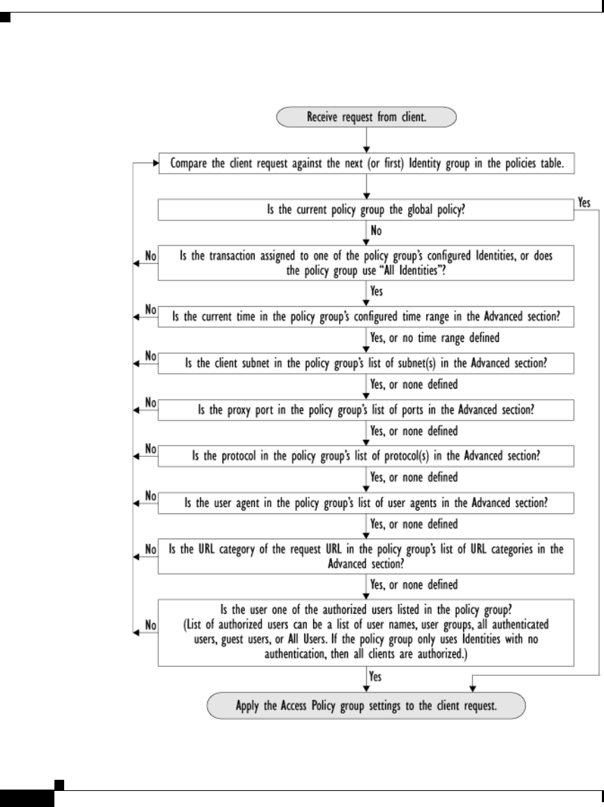
Chapter 8 Access Policies
Evaluating Access Policy Group Membership
8-6
Cisco IronPort AsyncOS 7.1 for Web User Guide
OL-23207-01
Figure 8-1 Policy Group Flow Diagram for Access Policies

8-7
Cisco IronPort AsyncOS 7.1 for Web User Guide
OL-23207-01
Chapter 8 Access Policies
Creating Access Policies
Creating Access Policies
You can create Access Policy groups based on combinations of several criteria,
such as one or more Identities or the URL category of the destination site. You
must define at least one criterion for policy group membership. When you define
multiple criteria, the client request must meet all criteria to match the policy
group. However, the client request needs to match only one of the configured
Identities.
For more information about how the Web Proxy matches a client request with a
policy group, see Evaluating Access Policy Group Membership, page 8-4 and
Matching Client Requests to Access Policy Groups, page 8-5.
You define policy group membership on the Web Security Manager > Access
Policies page.
To create an Access Policy group:
Step 1 Navigate to the Web Security Manager > Access Policies page.
Step 2 Click Add Policy.
Step 3 In the Policy Name field, enter a name for the policy group, and in the Description
field, optionally add a description.
Note Each policy group name must be unique and only contain alphanumeric
characters or the space character.
Step 4 In the Insert Above Policy field, choose where in the policies table to place the
policy group.
When configuring multiple policy groups you must specify a logical order for
each group. Carefully order your policy groups to ensure that correct matching
occurs.
Step 5 In the Identities and Users section, choose one or more Identity groups to apply
to this policy group.
For more information on how to do this, see Configuring Identities in Other Policy
Groups, page 7-28.
Step 6 Optionally, expand the Advanced section to define additional membership
requirements.
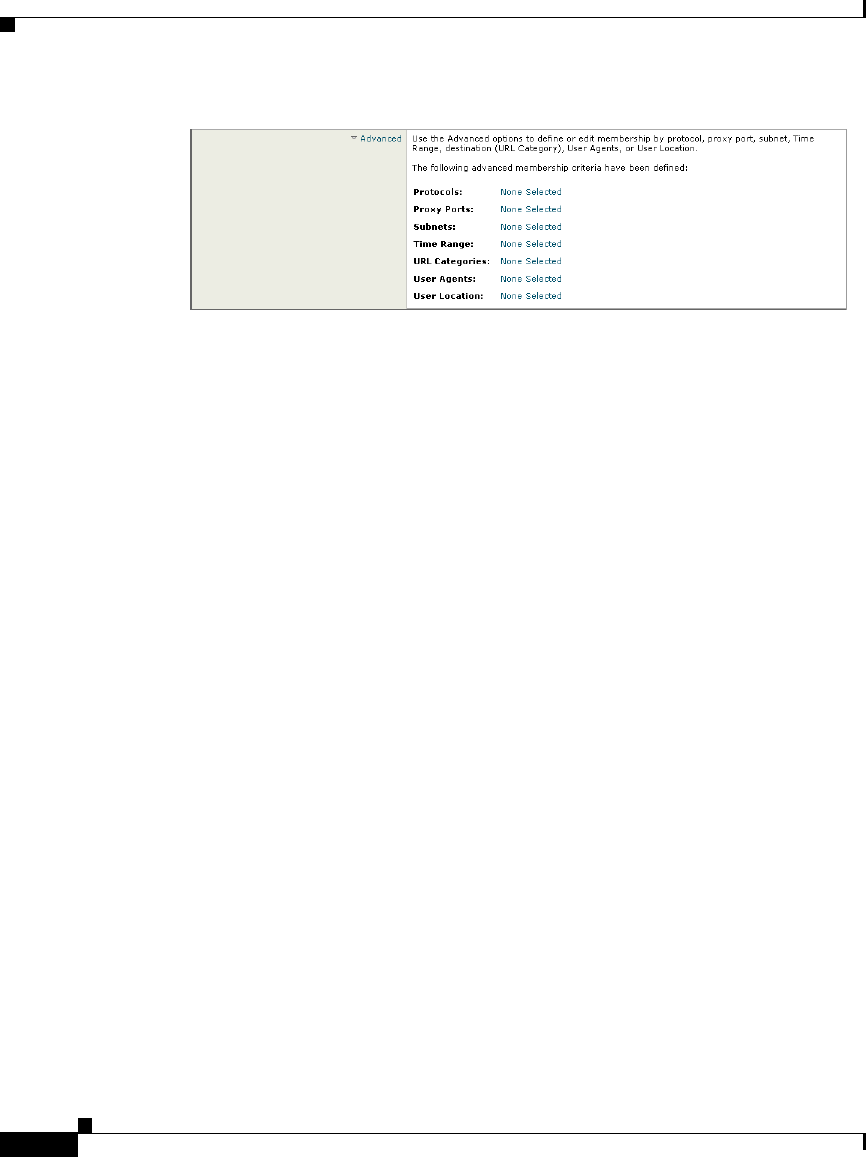
Chapter 8 Access Policies
Creating Access Policies
8-8
Cisco IronPort AsyncOS 7.1 for Web User Guide
OL-23207-01
Step 7 To define policy group membership by any of the advanced options, click the link
for the advanced option and configure the option on the page that appears.

8-9
Cisco IronPort AsyncOS 7.1 for Web User Guide
OL-23207-01
Chapter 8 Access Policies
Creating Access Policies
Table 8-1 describes the advanced options you can configure for Access Policy
groups.
Table 8-1 Access Policy Group Advanced Options
Advanced Option Description
Protocols Choose whether or not to define policy group membership by
the protocol used in the client request. Select the protocols
to include.
“All others” means any protocol not listed above this option.
Note: When the HTTPS Proxy is enabled, only Decryption
Policies apply to HTTPS transactions. You cannot define
policy membership by the HTTPS protocol for Access,
Routing, Outbound Malware Scanning, Data Security, or
External DLP Policies.
Proxy Ports Choose whether or not to define policy group membership by
the proxy port used to access the Web Proxy. Enter one or
more port numbers in the Proxy Ports field. Separate
multiple ports with commas.
For explicit forward connections, this is the port configured
in the browser. For transparent connections, this is the same
as the destination port. You might want to define policy
group membership on the proxy port if you have one set of
clients configured to explicitly forward requests on one port,
and another set of clients configured to explicitly forward
requests on a different port.
Cisco recommends only defining policy group membership
by the proxy port when the appliance is deployed in explicit
forward mode, or when clients explicitly forward requests to
the appliance. If you define policy group membership by the
proxy port when client requests are transparently redirected
to the appliance, some requests might be denied.
Note: If the Identity associated with this policy group
defines Identity membership by this advanced setting, the
setting is not configurable at the non-Identity policy group
level.

Chapter 8 Access Policies
Creating Access Policies
8-10
Cisco IronPort AsyncOS 7.1 for Web User Guide
OL-23207-01
Subnets Choose whether or not to define policy group membership by
subnet or other addresses.
You can choose to use the addresses that may be defined with
the associated Identity, or you can enter specific addresses
here.
Note: If the Identity associated with this policy group
defines its membership by addresses, then in this policy
group you must enter addresses that are a subset of the
Identity’s addresses. Adding addresses in the policy group
further narrows down the list of transactions that match this
policy group.
Time Range Choose whether or not to define policy group membership by
a defined time range. Choose the time range from the Time
Range field and then choose whether this policy group
should apply to the times inside or outside the selected time
range.
For more information on creating time based policies, see
Working with Time Based Policies, page 6-13.
For more information on creating time ranges, see Creating
Time Ranges, page 6-14.
URL Categories Choose whether or not to define policy group membership by
URL categories. Select the user defined or predefined URL
categories.
Note: If the Identity associated with this policy group
defines Identity membership by this advanced setting, the
setting is not configurable at the non-Identity policy group
level.
Table 8-1 Access Policy Group Advanced Options (continued)
Advanced Option Description

8-11
Cisco IronPort AsyncOS 7.1 for Web User Guide
OL-23207-01
Chapter 8 Access Policies
Controlling HTTP and Native FTP Traffic
Step 8 Submit your changes.
Step 9 Configure Access Policy group control settings to define how the Web Proxy
handles transactions.
The new Access Policy group automatically inherits global policy group settings
until you configure options for each control setting. For more information,
Controlling HTTP and Native FTP Traffic, page 8-11.
Step 10 Submit and commit your changes.
Controlling HTTP and Native FTP Traffic
After the Web Proxy assigns an HTTP, native FTP, or decrypted HTTPS request
to an Access Policy group, the request inherits the control settings of that policy
group. The control settings of the Access Policy group determine whether the
appliance allows, blocks, or redirects the connection.
User Agents Choose whether or not to define policy group membership by
the user agent used in the client request. You can select some
commonly defined browsers, or define your own using
regular expressions. Choose whether this policy group
should apply to the selected user agents or to any user agent
that is not in the list of selected user agents.
For more information on creating user agent based policies,
see Working with User Agent Based Policies, page 6-16.
Note: If the Identity associated with this policy group
defines Identity membership by this advanced setting, the
setting is not configurable at the non-Identity policy group
level.
User Location Choose whether or not to define policy group membership by
user location, either remote or local.
This option only appears when the Secure Mobility Solution
is enabled. For more information, see Achieving Secure
Mobility Overview, page 13-1.
Table 8-1 Access Policy Group Advanced Options (continued)
Advanced Option Description
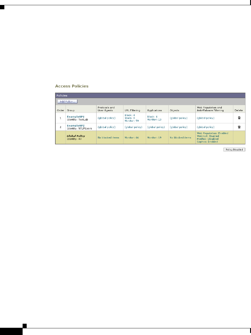
Chapter 8 Access Policies
Controlling HTTP and Native FTP Traffic
8-12
Cisco IronPort AsyncOS 7.1 for Web User Guide
OL-23207-01
Configure control settings for Access Policy groups on the Web Security Manager
> Access Policies page.
Figure 8-2 shows where you can configure control settings for the Access Policy
groups.
Figure 8-2 Creating Secure Access Policies
You can configure the following settings to determine what action to take on the
request:
•Protocols and User Agents. For more information, see Protocols and User
Agents, page 8-14.
•URL Categories. For more information, see URL Categories, page 8-15.
•Applications. For more information, see Applications, page 8-15.
•Objects. For more information, see Object Blocking, page 8-16.
•Web Reputation and Anti-Malware Filtering. For more information, see
Web Reputation and Anti-Malware, page 8-17.
After an Access Policy group is assigned to a request, the control settings for the
policy group are evaluated to determine whether to allow, block, or redirect the
request. For more information about assigning an Access Policy group to a
request, see Policy Group Membership, page 6-10.
Figure 8-3 on page 13 shows how the Web Proxy determines which action to take
on a request after it has assigned a particular Access Policy to the request.
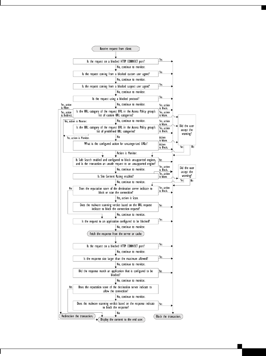
8-13
Cisco IronPort AsyncOS 7.1 for Web User Guide
OL-23207-01
Chapter 8 Access Policies
Controlling HTTP and Native FTP Traffic
Figure 8-3 Applying Access Policy Actions
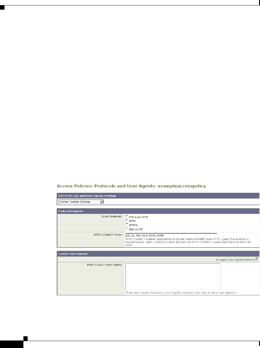
Chapter 8 Access Policies
Controlling HTTP and Native FTP Traffic
8-14
Cisco IronPort AsyncOS 7.1 for Web User Guide
OL-23207-01
Figure 8-3 on page 13 shows two different decision points that involve the web
reputation score of the destination server. The web reputation score of the server
is evaluated only once, but the result is applied at two different points in the
decision flow.
Protocols and User Agents
You can use the Protocols and User Agents settings on the Access Policies >
Protocols and User Agents page to control policy group access to protocols and
configure blocking for particular client applications (also known as user agents),
such as instant messaging clients, web browsers, and Internet phone services. You
can also configure the appliance to tunnel HTTP CONNECT requests on specific
ports. With tunneling enabled, the appliance passes HTTP traffic through
specified ports without evaluating it.
For more information about blocking user agents, see Blocking Specific
Applications and Protocols, page 8-18.
Figure 8-4 Settings for Controlling Protocols and User Agents

8-15
Cisco IronPort AsyncOS 7.1 for Web User Guide
OL-23207-01
Chapter 8 Access Policies
Controlling HTTP and Native FTP Traffic
Note When the HTTPS Proxy is enabled, you can only use Decryption Policies to
control access to HTTPS transactions. You cannot configure Access Policies on
this page to block HTTPS connections.
URL Categories
AsyncOS for Web allows you to configure how the appliance handles a
transaction based on the URL category of a particular HTTP or HTTPS request.
Using a predefined category list, you can choose to monitor or block content by
category. You can also create custom URL categories and choose to allow,
monitor, block, warn, or redirect traffic for a website in the custom category. You
can use custom URL categories to create block and allow lists based on
destination.
For information about enabling a URL filtering engine, see Configuring the URL
Filtering Engine, page 16-5. For information on configuring URL categories in
Access Policies, see Configuring URL Filters for Access Policy Groups,
page 16-7.
You can also use the Access Policies > URL Categories page to filter adult content
by enforcing safe searches and site content ratings. For more information, see
Filtering Adult Content, page 16-20.
Applications
You can use the Access Policies > Applications Visibility and Control page to
configure the Web Proxy block or allow applications by application type or a
particular application. You can also apply controls to particular application
behaviors within a particular application, such as file transfers.
Cisco IronPort Web Usage Controls includes the Application Visibility and
Control engine (AVC engine) which allows you to apply deeper controls to
particular application types. The AVC engine is an acceptable use policy
component that inspects web traffic to gain deeper understanding and control of
web traffic used for applications.

Chapter 8 Access Policies
Controlling HTTP and Native FTP Traffic
8-16
Cisco IronPort AsyncOS 7.1 for Web User Guide
OL-23207-01
For more information on enabling the AVC engine, see Enabling the AVC Engine,
page 17-3. For more information on configuring application settings in Access
Policies, see Understanding Application Control Settings, page 17-4.
Object Blocking
You can use the settings on the Access Policies > Objects page to configure the
Web Proxy to block file downloads based on file characteristics, such as file size
and file type. For more information about blocking a specific object or
MIME-type, see Blocking Specific Applications and Protocols, page 8-18.
Note When you block Microsoft Office files in the Block Object Type section, it is
possible that some Microsoft Office files will not be blocked. If you need to be
sure to block all Microsoft Office files, add application/x-ole in the Block
Custom MIME Types field. However, blocking this custom MIME type also
blocks all Microsoft Compound Object format types, such as Visio files and some
third party applications.
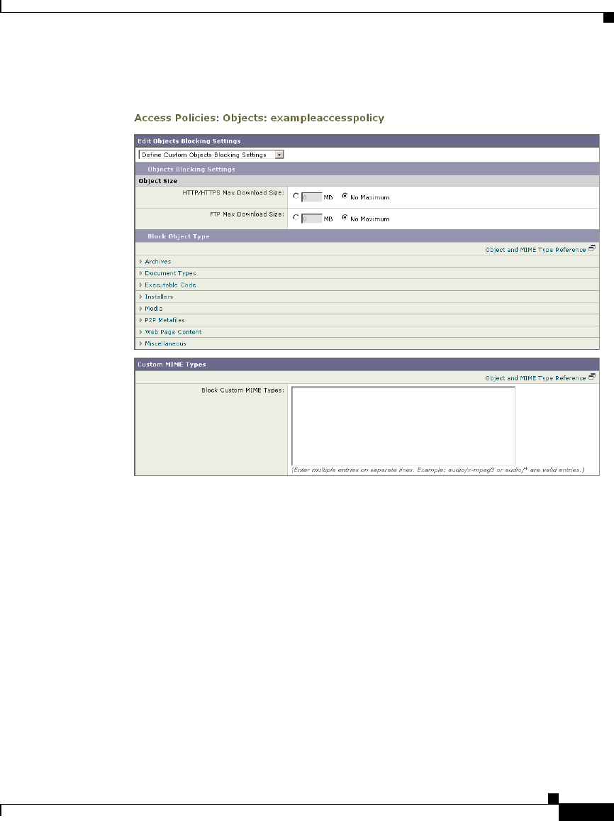
8-17
Cisco IronPort AsyncOS 7.1 for Web User Guide
OL-23207-01
Chapter 8 Access Policies
Controlling HTTP and Native FTP Traffic
Figure 8-5 Blocking Object Types
Web Reputation and Anti-Malware
The Web Reputation and Anti-Malware Filtering policy inherits global settings
respective to each component. To customize filtering and scanning for a particular
policy group, you can use the Web Reputation and Anti-Malware Settings
pull-down menu to customize monitoring or blocking for malware categories
based on malware scanning verdicts and to customize web reputation score
thresholds.
For more information about configuring web reputation scores, see Configuring
Web Reputation Scores, page 18-5.
For more information about configuring anti-malware settings, see Configuring
Anti-Malware Scanning, page 19-10.

Chapter 8 Access Policies
Blocking Specific Applications and Protocols
8-18
Cisco IronPort AsyncOS 7.1 for Web User Guide
OL-23207-01
Blocking Specific Applications and Protocols
You can configure how the appliance manages some kinds of applications based
on the port being used:
•Port 80. You can control how the Web Security appliance manages these
applications using Access Policies, but only as they are accessed via HTTP
tunneling on port 80.
•Ports other than 80. You can block these applications on other ports by using
the L4 Traffic Monitor.
Use the Web Security Manager > Access Policies page to manage access and
monitoring for these types of applications on a more granular (per policy) level.
Use the L4 Traffic Monitor to manage access and monitoring on a more global
basis.
Blocking on Port 80
To block access to these types of applications where port 80 is used, you can use
the Web Security Manager > Access Policies page. The Access Policies page
provides several methods for blocking access. You can block access by clicking
on any of the following columns for a particular policy group:
•Protocols and User Agents
•URL Categories
•Objects
You can block access to predefined URL categories such as Chat and Peer-to-Peer,
or create your own custom URL categories. You can block specific applications
based on their “agent patterns” or signatures.
You can apply some or all of these methods on various Access Policies by creating
additional Access Policy groups. For details on how to create additional Access
Policy groups, see Creating Access Policies, page 8-7.
Policy: Protocols and User Agents
You can create a rule that blocks a particular user agent based on its pattern using
Regular Expressions.
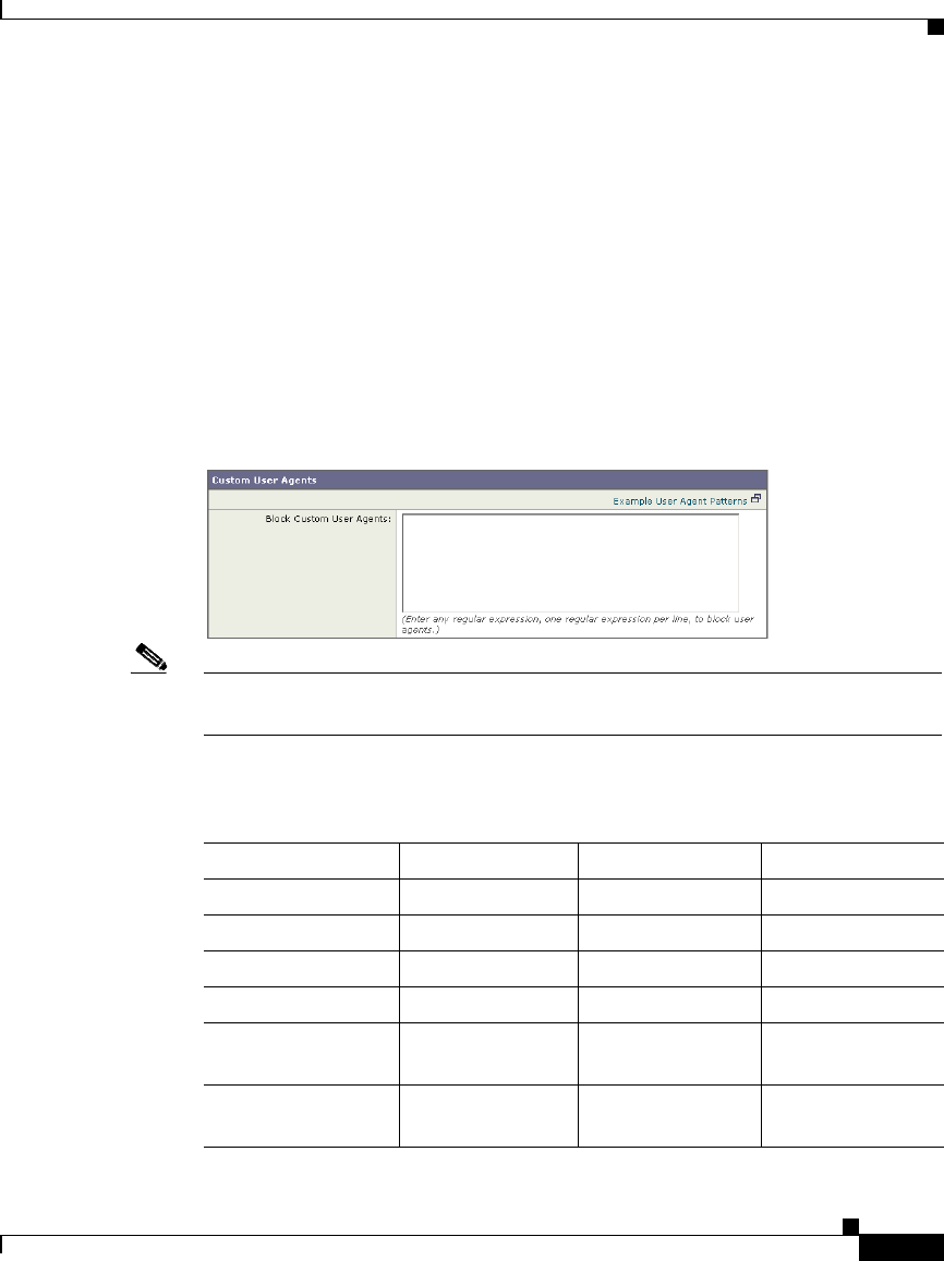
Cisco IronPort AsyncOS 7.1 for Web User Guide
OL-23207-01
Chapter 8 Access Policies
Blocking Specific Applications and Protocols
You block access to applications based on their agent pattern similarly for the
different Access Policies:
•User defined policies — On the Web Security Manager > Access Policies
page, click the value in the Protocols and User Agents column for the desired
policy. Choose Define Applications Custom Settings.
•Global Policy — On the Web Security Manager > Access Policies page, click
the value in the Protocols and User Agents column for the Global Policy.
Once you view the Access Policies: Protocols and User Agents: Policy_Name
page, add user agent patterns (also called signatures) to the Block Custom User
Agents section of the page.
Figure 8-6 Entering Agent Patterns to Block
Note You can click the Example User Agent Patterns link for a list of some example
user agent patterns.
Table 8-2 provides a list of common patterns.
Table 8-2 Common Application Agent Patterns
Application Search in Setting HTTP header Signature
AOL Messenger Request headers User-Agent Gecko/
BearShare Response header Server Bearshare
BitTorrent Request headers User-Agent BitTorrent
eDonkey Request headers User-Agent e2dk
Gnutella Request headers User-Agent Gnutella
Gnucleus
Kazaa Request headers P2P-Agent Kazaa
Kazaaclient:

Chapter 8 Access Policies
Blocking Specific Applications and Protocols
Cisco IronPort AsyncOS 7.1 for Web User Guide
OL-23207-01
This is not a comprehensive list, as signatures change occasionally, and new
applications are developed. You can find additional signatures at various websites,
including the following websites:
•http://www.user-agents.org/
•http://www.useragentstring.com/pages/useragentstring.php
•http://www.infosyssec.com/infosyssec/security/useragentstrings.shtml
Note Cisco IronPort does not maintain, verify, or support the user agent listings at any
of these websites.
Policy: URL Categories
You can specify categories of URLs to block, including the predefined
“Web-based Chat” and “Peer File Transfer” categories. You can also add specific
custom URL categories should you want to add a URL that is not already included
in the predefined categories. You may then add the custom category to the list of
blocked URLs.
For more information about using URL Categories, see URL Categories,
page 8-15.
Kazaa Request headers User-Agent KazaClient
Kazaaclient:
Kazaa Request headers X-Kazaa-Network KaZaA
Morpheus Response header Server Morpheus
MSN Messenger Request headers User-Agent MSN Messenger
Trillian Request headers User-Agent Trillian/
Windows
Messenger
Request headers User-Agent MSMSGS
Yahoo Messenger Request headers Host msg.yahoo.com
Yahoo Messenger Request headers User-Agent ymsgr
Table 8-2 Common Application Agent Patterns (continued)
Application Search in Setting HTTP header Signature

Cisco IronPort AsyncOS 7.1 for Web User Guide
OL-23207-01
Chapter 8 Access Policies
Blocking Specific Applications and Protocols
Policy: Objects
You can block some Peer-to-Peer files directly, via the Access Policies: Objects:
Global Policy page.
On the Web Security Manager > Access Policies page, click on the value in the
Objects column for the desired policy.
In the Block Object Type section, check any boxes in the P2P Metafiles group.
You can add custom MIME (Multipurpose Internet Mail Extensions) types by
entering them in the Custom MIME Types field. For example, entering the
application/x-zip signature blocks ZIP archive files.
Blocking on Ports Other Than 80
If these applications are using ports other than 80, you may want to block access
to a specific server or block of IP addresses to which the client must connect. To
manage these applications on other ports, use the L4 Traffic Monitor. The L4
Traffic monitor allows you to restrict access on specific ports. However, the
restriction is global, so it will apply to all traffic on that port.

Chapter 8 Access Policies
Blocking Specific Applications and Protocols
Cisco IronPort AsyncOS 7.1 for Web User Guide
OL-23207-01

Cisco IronPort AsyncOS 7.1 for Web User Guide
OL-23207-01
9
Working with External Proxies
This chapter contains the following topics:
•Working with External Proxies Overview, page 9-1
•Routing Traffic to Upstream Proxies, page 9-2
•Adding External Proxy Information, page 9-3
•Evaluating Routing Policy Group Membership, page 9-5
•Creating Routing Policies, page 9-8
Working with External Proxies Overview
The Web Security appliance is a proxy-compatible device, and is easily deployed
within an existing proxy environment. However, it is recommended that you place
the appliance downstream from existing proxy servers, meaning closer to the
clients.
You can configure the appliance to work with multiple existing, upstream proxies.
Use the Network > Upstream Proxies page to define upstream proxies or to
modify existing settings. You define groups of proxies, and you can configure the
appliance to use load balancing and failover features when connecting to multiple
proxies.
After defining proxy groups, you can create Routing Policies to determine
whether the Web Proxy connects to the server identified by the client or to a
member of one the proxy groups.
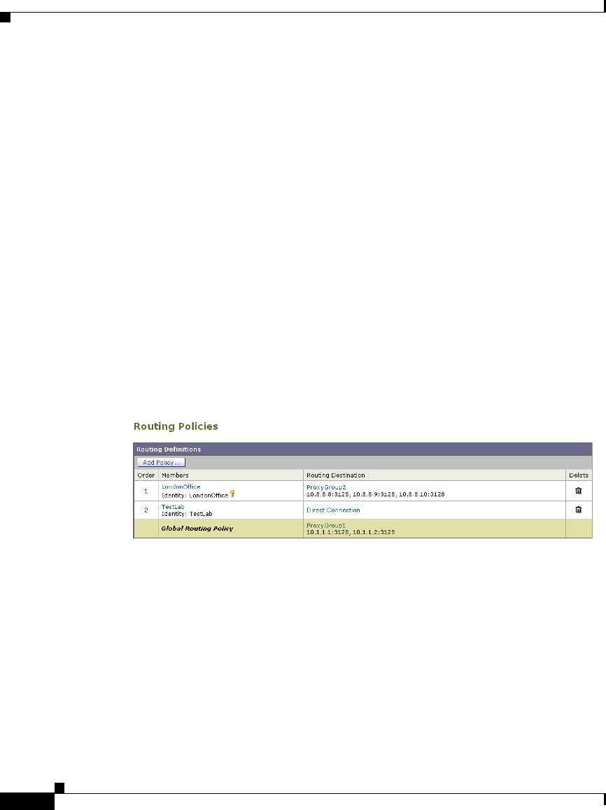
Chapter 9 Working with External Proxies
Routing Traffic to Upstream Proxies
9-2
Cisco IronPort AsyncOS 7.1 for Web User Guide
OL-23207-01
For more information about using Routing Policies to route transactions, see
Routing Traffic to Upstream Proxies, page 9-2. For more information about
defining external proxies, see Adding External Proxy Information, page 9-3.
Routing Traffic to Upstream Proxies
When the Web Proxy does not deliver a response from the cache, it can direct
client requests directly to the destination server or to an external proxy on the
network. You use Routing Policies to create rules that indicate when and to where
to direct transactions. A Routing Policy determines to where to pass the client
request, either to another proxy (as defined by the proxy group) or to the
destination server. It addresses the question, “from where to fetch content?” You
might want to create Routing Policies if you have a highly distributed network.
Figure 9-1 shows Routing Policies on the Web Security Manager > Routing
Policies page.
Figure 9-1 Routing Policies
When you define multiple external proxies in a proxy group, the Web Proxy can
use load balancing techniques to distribute requests to different proxies defined in
the group. You can choose the following load balancing techniques:
•None (failover). The Web Proxy directs transactions to one external proxy in
the group. It tries to connect to the proxies in the order they are listed. If one
proxy cannot be reached, the Web Proxy attempts to connect to the next one
in the list.
•Fewest connections. The Web Proxy keeps track of how many active requests
are with the different proxies in the group and it directs a transaction to the
proxy currently servicing the fewest number of connections.

9-3
Cisco IronPort AsyncOS 7.1 for Web User Guide
OL-23207-01
Chapter 9 Working with External Proxies
Adding External Proxy Information
•Hash based. The Web Proxy uses a hash function to distribute requests to the
proxies in the group. The hash function uses the proxy ID and URL as inputs
so that requests for the same URL are always directed to the same external
proxy.
•Least recently used. The Web Proxy directs a transaction to the proxy that
least recently received a transaction if all proxies are currently active. This
setting is similar to round robin except the Web Proxy also takes into account
transactions a proxy has received by being a member in a different proxy
group. That is, if a proxy is listed in multiple proxy groups, the “least recently
used” option is less likely to overburden that proxy.
•Round robin. The Web Proxy cycles transactions equally among all proxies
in the group in the listed order.
For information about creating Routing Policies, see Creating Routing Policies,
page 9-8.
Note If your network contains an upstream proxy that does not support FTP
connections, then you must create a Routing Policy that applies to all Identities
and to just FTP requests. Configure that Routing Policy to directly connect to FTP
servers or to connect to a proxy group whose proxies all support FTP connections.
Adding External Proxy Information
To define external proxy information, you create a proxy group. A proxy group is
an object that defines a list of proxies and their connection information and the
load balancing technique to use when distributing requests to proxies in the group.
You can create multiple proxy groups and can define multiple proxies within a
group.
AsyncOS for Web allows you to enter the same proxy server information multiple
times into the same proxy group. You might want to include the same proxy server
multiple times to allow unequal load distribution among the proxies in the proxy
group.
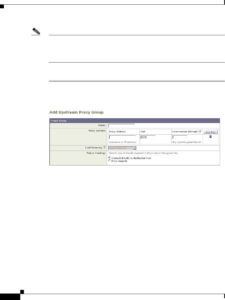
Chapter 9 Working with External Proxies
Adding External Proxy Information
9-4
Cisco IronPort AsyncOS 7.1 for Web User Guide
OL-23207-01
Note You can only specify one existing proxy during the System Setup Wizard.
AsyncOS creates a proxy group with one proxy using the information you enter
in the System Setup Wizard. You can specify additional proxies in the web
interface after initial setup.
To create a proxy group:
Step 1 Navigate to Network > Upstream Proxies, and click Add Group.
The Add Upstream Proxy Group page appears.
Step 2 Enter a name for the proxy group in the Name field.
Step 3 In the Proxy Servers section, define at least one external proxy.
a. In the Proxy Address field, enter the hostname or IP address of the proxy
server.
b. In the Port field, enter the port number used to access the proxy.
c. In the Reconnection Attempts field, enter the number of times the Web Proxy
should try to connect to the proxy server before ignoring it.
d. Optionally, you can define another proxy server by clicking Add Row.
Step 4 In the Load Balancing field, choose the method the Web Proxy should use to
distribute transactions to the proxies when the group contains multiple proxies.
For more information about the load balancing options, see Routing Traffic to
Upstream Proxies, page 9-2.
Step 5 In the Failure Handling field, choose how the Web Proxy should handle
transactions when all proxies in the group fail.

9-5
Cisco IronPort AsyncOS 7.1 for Web User Guide
OL-23207-01
Chapter 9 Working with External Proxies
Evaluating Routing Policy Group Membership
Step 6 Submit and commit your changes.
Evaluating Routing Policy Group Membership
After the Web Proxy assigns an Identity to a client request, it evaluates the request
against the other policy types to determine which policy group it belongs for each
type. Any request that does not get terminated due to failed authentication gets
evaluated against the Routing Policies to determine from where to fetch the data.
Once the Web Proxy assigns a Routing Policy group to a request, it fetches the
content from the location configured for the policy group, either from a
configured proxy group or directly from the server.
To determine the policy group that a client request matches, the Web Proxy
follows a specific process for matching the group membership criteria. During
this process, it considers the following factors for group membership:
•Identity. Each client request either matches an Identity, fails authentication
and is granted guest access, or fails authentication and gets terminated. For
more information about evaluating Identity group membership, see
Evaluating Identity Group Membership, page 7-2.
•Authorized users. If the assigned Identity requires authentication, the user
must be in the list of authorized users in the Routing Policy group to match
the policy group.
•Advanced options. You can configure several advanced options for Routing
Policy group membership. Some options (such as proxy port and URL
category) can also be defined within the Identity. When an advanced option
is configured in the Identity, it is not configurable in the Routing Policy group
level.
The information in this section gives an overview of how the appliance matches
client requests to Routing Policy groups. For more details about exactly how the
appliance matches client requests, see Matching Client Requests to Routing
Policy Groups, page 9-6.
The Web Proxy sequentially reads through each policy group in the policies table.
It compares the client request status to the membership criteria of the first policy
group. If they match, the Web Proxy applies the policy settings of that policy
group.

Chapter 9 Working with External Proxies
Evaluating Routing Policy Group Membership
9-6
Cisco IronPort AsyncOS 7.1 for Web User Guide
OL-23207-01
If they do not match, the Web Proxy compares the client request to the next policy
group. It continues this process until it matches the client request to a user defined
policy group. If it does not match a user defined policy group, it matches the
global policy group. When the Web Proxy matches the client request to a policy
group or the global policy group, it applies the policy settings of that policy group.
Matching Client Requests to Routing Policy Groups
Figure 9-2 on page 7 shows how the Web Proxy evaluates a client request against
the Routing Policy groups.
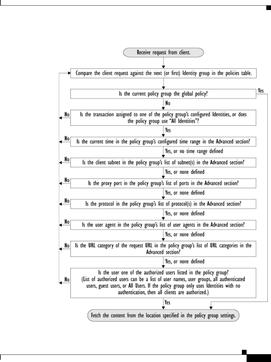
9-7
Cisco IronPort AsyncOS 7.1 for Web User Guide
OL-23207-01
Chapter 9 Working with External Proxies
Evaluating Routing Policy Group Membership
Figure 9-2 Policy Group Flow Diagram for Routing Policies

Chapter 9 Working with External Proxies
Creating Routing Policies
9-8
Cisco IronPort AsyncOS 7.1 for Web User Guide
OL-23207-01
Creating Routing Policies
You can create Routing Policy groups based on combinations of several criteria,
such as Identity or the port used to access the Web Proxy. You must define at least
one criterion for policy group membership. When you define multiple criteria, the
client request must meet all criteria to match the policy group.
For more information about how the appliance matches a client request with a
policy group, see Evaluating Routing Policy Group Membership, page 9-5 and
Matching Client Requests to Routing Policy Groups, page 9-6.
You define policy group membership on the Web Security Manager > Routing
Policies page.
To create a Routing Policy group:
Step 1 Navigate to the Web Security Manager > Routing Policies page.
Step 2 Click Add Group.
Step 3 In the Policy Name field, enter a name for the policy group, and in the Description
field, optionally add a description.
Note Each policy group name must be unique and only contain alphanumeric
characters or the space character.
Step 4 In the Insert Above Policy field, choose where in the policies table to place the
policy group.
When configuring multiple policy groups you must specify a logical order for
each group. Carefully order your policy groups to ensure that correct matching
occurs.
Step 5 In the Identities and Users section, choose one or more Identity groups to apply
to this policy group.
For more information on how to do this, see Configuring Identities in Other Policy
Groups, page 7-28.
Step 6 Optionally, expand the Advanced section to define additional membership
requirements.
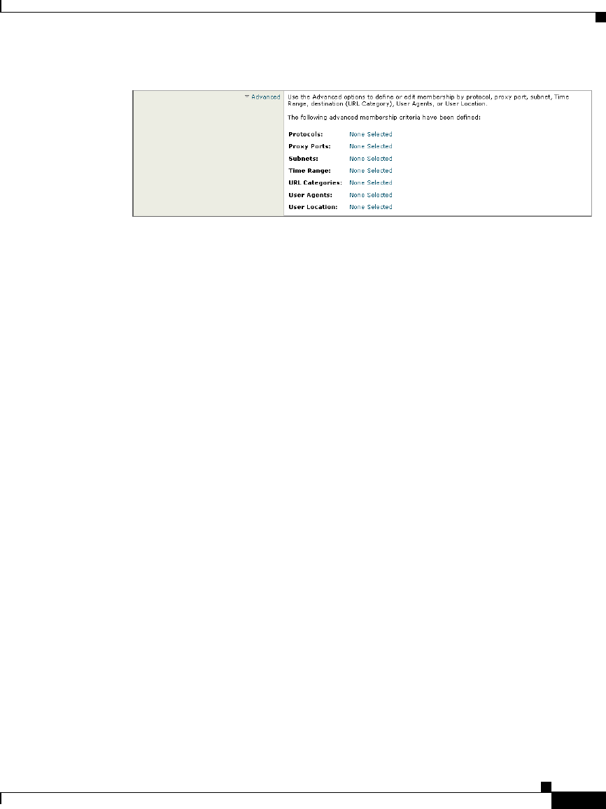
9-9
Cisco IronPort AsyncOS 7.1 for Web User Guide
OL-23207-01
Chapter 9 Working with External Proxies
Creating Routing Policies
Step 7 To define policy group membership by any of the advanced options, click the link
for the advanced option and configure the option on the page that appears.

Chapter 9 Working with External Proxies
Creating Routing Policies
9-10
Cisco IronPort AsyncOS 7.1 for Web User Guide
OL-23207-01
Table 9-1 describes the advanced options you can configure for policy groups.
Table 9-1 Policy Group Advanced Options
Advanced Option Description
Protocols Choose whether or not to define policy group membership
by the protocol used in the client request. Select the
protocols to include.
“All others” means any protocol not listed above this option.
Note: When the HTTPS Proxy is enabled, only Decryption
Policies apply to HTTPS transactions. You cannot define
policy membership by the HTTPS protocol for Access,
Routing, Outbound Malware Scanning, Data Security, or
External DLP Policies.
Proxy Ports Choose whether or not to define policy group membership
by the proxy port used to access the Web Proxy. Enter one or
more port numbers in the Proxy Ports field. Separate
multiple ports with commas.
For explicit forward connections, this is the port configured
in the browser. For transparent connections, this is the same
as the destination port. You might want to define policy
group membership on the proxy port if you have one set of
clients configured to explicitly forward requests on one port,
and another set of clients configured to explicitly forward
requests on a different port.
Cisco recommends only defining policy group membership
by the proxy port when the appliance is deployed in explicit
forward mode, or when clients explicitly forward requests to
the appliance. If you define policy group membership by the
proxy port when client requests are transparently redirected
to the appliance, some requests might be denied.
Note: If the Identity associated with this policy group
defines Identity membership by this advanced setting, the
setting is not configurable at the non-Identity policy group
level.

9-11
Cisco IronPort AsyncOS 7.1 for Web User Guide
OL-23207-01
Chapter 9 Working with External Proxies
Creating Routing Policies
Subnets Choose whether or not to define policy group membership
by subnet or other addresses.
You can choose to use the addresses that may be defined
with the associated Identity, or you can enter specific
addresses here.
Note: If the Identity associated with this policy group
defines its membership by addresses, then in this policy
group you must enter addresses that are a subset of the
Identity’s addresses. Adding addresses in the policy group
further narrows down the list of transactions that match this
policy group.
Time Range Choose whether or not to define policy group membership
by a defined time range. Choose the time range from the
Time Range field and then choose whether this policy group
should apply to the times inside or outside the selected time
range.
For more information on creating time based policies, see
Working with Time Based Policies, page 6-13.
For more information on creating time ranges, see Creating
Time Ranges, page 6-14.
URL Categories Choose whether or not to define policy group membership
by URL categories. Select the user defined or predefined
URL categories.
Note: If the Identity associated with this policy group
defines Identity membership by this advanced setting, the
setting is not configurable at the non-Identity policy group
level.
Table 9-1 Policy Group Advanced Options (continued)
Advanced Option Description

Chapter 9 Working with External Proxies
Creating Routing Policies
9-12
Cisco IronPort AsyncOS 7.1 for Web User Guide
OL-23207-01
Step 8 Submit your changes.
Step 9 Configure Routing Policy group control settings to define how the Web Proxy
handles transactions.
The new policy group automatically inherits global policy group settings until you
configure options for each control setting. For more information, see Routing
Traffic to Upstream Proxies, page 9-2.
Step 10 Submit and commit your changes.
User Agents Choose whether or not to define policy group membership
by the user agent used in the client request. You can select
some commonly defined browsers, or define your own using
regular expressions. Choose whether this policy group
should apply to the selected user agents or to any user agent
that is not in the list of selected user agents.
For more information on creating user agent based policies,
see Working with User Agent Based Policies, page 6-16.
Note: If the Identity associated with this policy group
defines Identity membership by this advanced setting, the
setting is not configurable at the non-Identity policy group
level.
User Location Choose whether or not to define policy group membership
by user location, either remote or local.
This option only appears when the Secure Mobility Solution
is enabled. For more information, see Achieving Secure
Mobility Overview, page 13-1.
Table 9-1 Policy Group Advanced Options (continued)
Advanced Option Description

CHAPTER
10-1
Cisco IronPort AsyncOS 7.1 for Web User Guide
OL-23207-01
10
Decryption Policies
This chapter contains the following information:
•Decryption Policies Overview, page 10-1
•Digital Cryptography Terms, page 10-6
•HTTPS Basics, page 10-8
•Digital Certificates, page 10-9
•Decrypting HTTPS Traffic, page 10-13
•Enabling the HTTPS Proxy, page 10-21
•Evaluating Decryption Policy Group Membership, page 10-27
•Creating Decryption Policies, page 10-30
•Controlling HTTPS Traffic, page 10-34
•Importing a Trusted Root Certificate, page 10-37
Decryption Policies Overview
HTTPS is a web protocol that acts as a secure form of HTTP. HTTPS encrypts
HTTP requests and responses before they are sent across the network. Common
thinking is that any connection to a site using HTTPS is “safe.” HTTPS
connections are secure, not safe, and they do not discriminate against malicious
or compromised servers. HTTPS is a secure way to complete legitimate
transactions, but more dangerously, it is a secure way to download malware which
can infect your network.

Chapter 10 Decryption Policies
Decryption Policies Overview
10-2
Cisco IronPort AsyncOS 7.1 for Web User Guide
OL-23207-01
Not being able to inspect HTTPS traffic makes the network vulnerable to the
following risks:
•Secure site hosting malware. Spammers and phishers can create legitimate
looking websites that are only reachable through an HTTPS connection.
Some users may mistakenly trust the web server because it requires an
HTTPS connection, resulting in intentional and unintentional downloaded
malware.
•Malware from HTTPS web applications. Some malware can infect the
network from legitimate web applications, such as secure email clients, by
downloading attachments.
•Secure anonymizing proxy. Some web servers offer a proxy service over an
HTTPS connection that allows users to circumvent acceptable use policies.
When users on the network use a secure proxy server outside the network,
they can access any website, regardless of its web reputation or malware
content.
The appliance uses both a URL filtering engine and IronPort Web Reputation
Filters to make intelligent decisions about when to decrypt HTTPS connections.
With this combination, administrators and end users are not forced to make a
trade-off between privacy and security.
You can define HTTPS policies that determine if an HTTPS connection can
proceed without examination or whether the appliance should act as an
intermediary, decrypting the data passing each way and applying Access Policies
to the data as if it were a plaintext HTTP transaction.
To configure the appliance to handle HTTPS requests, you must perform the
following tasks:
1. Enable the HTTPS Proxy. To monitor and decrypt HTTPS traffic, you must
first enable the HTTPS Proxy. For more information, see Enabling the
HTTPS Proxy, page 10-21.
2. Create and configure Decryption Policy groups. Once the HTTPS Proxy is
enabled, you can create and configure Decryption Policy groups to determine
how to handle each request from each user. For more information, see
Decryption Policy Groups, page 10-3.
3. Import custom root certificates (optional). Optionally, you can import one
or more custom root certificates so the Web Proxy can recognize additional
trusted root certificate authorities used by HTTPS servers. For more
information, see Importing a Trusted Root Certificate, page 10-37.

10-3
Cisco IronPort AsyncOS 7.1 for Web User Guide
OL-23207-01
Chapter 10 Decryption Policies
Decryption Policies Overview
This book uses many terms from digital cryptography. This book also includes
sections with background information about HTTPS and digital cryptography for
reference only. For a list of the terms and definitions used in this book, see Digital
Cryptography Terms, page 10-6. For an overview of HTTPS the protocol, see
HTTPS Basics, page 10-8.
Note Sections in this chapter that refer to a “certificate and key” imply a certificate and
private key.
Decryption Policy Groups
Decryption Policies define how the appliance should handle HTTPS connection
requests for users on the network. You can apply different actions to specified
groups of users. You can also specify which ports the appliance should monitor
for HTTPS transactions.
When a client makes an HTTPS request on a monitored secure port, the appliance
compares the request to the Decryption Policy groups to determine in which
Decryption Policy group the request belongs. Once it assigns the request to a
Decryption Policy group, it can determine what to do with the connection request.
For more information about evaluating policy group membership, see Policy
Group Membership, page 6-10.
The appliance can perform any of the following actions on an HTTPS connection
request:
•Drop. The appliance drops the connection and does not pass the connection
request to the server. The appliance does not notify the user that it dropped
the connection. You might want to drop connections to third party proxies that
allow users on the network bypass the organization’s acceptable use policies.
•Pass through. The appliance passes through the connection between the
client and the server without inspecting the traffic content. You might want to
pass through connections to trusted secure sites, such as well known banking
and financial institutions.
•Decrypt. The appliance allows the connection, but inspects the traffic
content. It decrypts the traffic and applies Access Policies to the decrypted
traffic as if it were a plaintext HTTP connection. By decrypting the
connection and applying Access Policies, you can scan the traffic for
malware. You might want to decrypt connections to third party email

Chapter 10 Decryption Policies
Decryption Policies Overview
10-4
Cisco IronPort AsyncOS 7.1 for Web User Guide
OL-23207-01
providers, such as gmail or hotmail. For more information about how the
appliance decrypts HTTPS traffic, see Decrypting HTTPS Traffic,
page 10-13.
Note The actions above are final actions the Web Proxy takes on an HTTPS request.
The “Monitor” action you can configure for Decryption Policies is not a final
action. For more information, see Understanding the Monitor Action, page 10-5.
Once the appliance assigns a Decryption Policy to an HTTPS connection request,
it evaluates the request against the policy group’s configured control settings to
determine which action to take. You can configure URL filter and web reputation
settings to determine how to handle HTTPS requests for a particular policy group.
For more information about how the appliance uses Decryption Policy groups to
control HTTPS traffic, see Controlling HTTPS Traffic, page 10-34.
Note Cisco recommends creating fewer, more general Decryption Policy groups that
apply to all users or fewer, larger groups of users on the network. Then, if you
need to apply more granular control to decrypted HTTPS traffic, use more specific
Access Policy groups. For more information about Access Policy groups, see
Access Policies, page 8-1.
For information about creating and using policy groups, see Working with
Policies, page 6-1.
Note The next two sections contain information about digital cryptography and HTTPS
for reference only.
Personally Identifiable Information Disclosure
If you choose to decrypt an end-user’s HTTPS session, then the Web Security
appliance access logs and reports may contain personally identifiable
information. Cisco recommends that Web Security appliance administrators take
care when handling this sensitive information.

10-5
Cisco IronPort AsyncOS 7.1 for Web User Guide
OL-23207-01
Chapter 10 Decryption Policies
Decryption Policies Overview
You also have the option to configure how much URI text is stored in the logs
using the advancedproxyconfig CLI command and the HTTPS subcommand. You
can log the entire URI, or a partial form of the URI with the query portion
removed. However, even when you choose to strip the query from the URI,
personally identifiable information may still remain.
Understanding the Monitor Action
When the Web Proxy evaluates the control settings against a transaction, it
evaluates the settings in a particular order. Each control setting can be configured
to one of the following actions for Decryption Policies:
•Monitor
•Drop
•Pass through
•Decrypt
All actions except Monitor are final actions the Web Proxy applies to a
transaction. A final action is an action that causes the Web Proxy to stop
evaluating the transaction against other control settings.
Monitor is an intermediary action that indicates the Web Proxy should continue
evaluating the transaction against the other control settings to determine which
final action to ultimately apply.
For example, if a Decryption Policy is configured to monitor invalid server
certificates, the Web Proxy makes no final decision on how to handle the HTTPS
transaction if the server has an invalid certificate. If a Decryption Policy is
configured to block servers with a low web reputation score, then any request to
a server with a low reputation score is dropped without considering the URL
category actions.
Figure 10-9 on page 36 shows the order the Web Proxy uses when evaluating
control settings for Decryption Policies. Looking at the flow diagram, you can see
that the only actions applied to a transaction are the final actions listed above:
Drop, Pass Through, and Decrypt.
Note Figure 8-3 on page 13 shows the order the Web Proxy uses when evaluating
control settings for Access Policies.

Chapter 10 Decryption Policies
Digital Cryptography Terms
10-6
Cisco IronPort AsyncOS 7.1 for Web User Guide
OL-23207-01
Digital Cryptography Terms
To understand how encryption and decryption works, you need to understand a
little bit about cryptographic encoding techniques. Figure 10-1 describes some
terms used in cryptography that are discussed in this chapter.
Table 10-1 Cryptography Terms and Definitions
Term Definition
Certificate authority An entity which issues digital certificates for use by
other parties.
Certificate authorities are sometimes referred to as
trusted third parties. Certificate authorities are
typically commercial companies that charge for their
services. However, some institutions and governments
have their own certificate authorities, and some offer
their services for free.
Cipher An algorithm used for encoding and decoding text to
make it unreadable to any system without the
appropriate key.
Ciphers work with keys to encode or decode text.
Ciphertext Encoded text after a cipher has been applied to it.
Digital certificate An electronic document that identifies and describes
an organization that has been verified and signed by a
trusted organization called a certificate authority.
A digital certificate is similar in concept to an
“identification card.” SSL uses certificates to
authenticate servers.
For more information about digital certificates, see
Digital Certificates, page 10-9.
Digital signature A checksum that verifies that a message was created
by the stated author and was not altered since its
creation.
Key A numeric parameter used by a cipher to encode or
decode text.

10-7
Cisco IronPort AsyncOS 7.1 for Web User Guide
OL-23207-01
Chapter 10 Decryption Policies
Digital Cryptography Terms
Plaintext or cleartext Message text in its original form, before it gets
encoded by a cipher.
Public key
cryptography
A system that uses two different keys for encoding and
decoding text where one key is publicly known and
available and the other key is private.
With public key cryptography, anyone can send an
encoded message to a server that has publicized its
public key, but only the recipient server can decode the
message with its private key.
This is also known as asymmetric key cryptography.
Public key
infrastructure (PKI)
An arrangement that binds public keys with respective
user identities by means of a certificate authority.
X.509 is a standard that is an example PKI. X.509
specifies standards for public key certificates and an
algorithm for validating certification paths.
Private key
cryptography
A system that uses the same key for encoding and
decoding text.
Because both sides of the transaction need the same
key, they need a secure way to communicate which key
to use in a particular communication session. Usually,
they set up secure communication using public key
cryptography and then generate a temporary
symmetric key to use for the rest of the session.
This is also known as symmetric key cryptography.
Root certificate A certificate that is the topmost certificate in a
certificate tree structure.
All certificates below the root certificate inherit the
trustworthiness of the root certificate.
Root certificates can be unsigned public key
certificates or self-signed certificates.
Self-signed certificate A digital certificate where the certificate authority is
the same as the certificate creator.
Table 10-1 Cryptography Terms and Definitions (continued)
Term Definition

Chapter 10 Decryption Policies
HTTPS Basics
10-8
Cisco IronPort AsyncOS 7.1 for Web User Guide
OL-23207-01
HTTPS Basics
HTTPS is a web protocol that acts as a secure form of HTTP. HTTPS is secure
because the HTTP request and response data is encrypted before it is sent across
the network. HTTPS works similarly to HTTP, except that the HTTP layer is sent
on top of a security layer using either Secure Sockets Layer (SSL) or Transport
Layer Security (TLS). SSL and TLS are very similar, so this User Guide uses
“SSL” to refer to both SSL and TLS, unless otherwise specified.
Figure 10-1 shows the different OSI network layers for HTTPS and HTTP. It
shows that HTTPS is the HTTP protocol at the application layer over SSL or TLS
at the security layer.
Figure 10-1 HTTPS and HTTP OSI Layers
The URL typically determines whether the client application should use HTTP or
HTTPS to contact a server:
•http://servername. The client application opens a connection to the server on
port 80 by default and sends HTTP commands in plaintext.
•https://servername. The client application opens a connection to the server
on port 443 by default and starts to engage in the SSL “handshake” to
establish a secure connection between the client and server. Once the secure
connection is established, the client application sends encrypted HTTP
commands. For more information about the SSL handshake, see SSL
Handshake, page 10-9.
Network interfaces
IP
TCP
SSL or TLS
HTTP Application layer
Security layer
Transport layer
Network layer
Data link layer
Network interfaces
IP
TCP
HTTP Application layer
Transport layer
Network layer
Data link layer
HTTP HTTPS

10-9
Cisco IronPort AsyncOS 7.1 for Web User Guide
OL-23207-01
Chapter 10 Decryption Policies
Digital Certificates
SSL Handshake
The SSL “handshake” is a set of steps a client and server engage in using the SSL
protocol to establish a secure connection between them. The client and server
must complete the following steps before they can send and receive encrypted
HTTP messages:
Step 1 Exchange protocol version numbers. Both sides must verify they can
communicate with compatible versions of SSL or TLS.
Step 2 Choose a cipher that each side knows. First, the client advertises which ciphers
it supports and requests the server to send its certificate. Then, the server chooses
the strongest cipher from the list and sends the client the chosen cipher and its
digital certificate.
Step 3 Authenticate the identity of each side. Typically, only the server gets
authenticated while the client remains unauthenticated. The client validates the
server certificate. For more information about certificates and using them to
authenticate servers, see Digital Certificates, page 10-9.
Step 4 Generate temporary symmetric keys to encrypt the channel for this session.
The client generates a session key (usually a random number), encrypts it with the
server’s public key, and sends it to the server. The server decrypts the session key
with its private key. Both sides compute a common master secret key that will be
used for all future encryption and decryption until the connection closes.
Digital Certificates
A digital certificate is an electronic document that identifies and describes an
organization, and that has been verified and signed by a trusted organization. A
digital certificate is similar in concept to an identification card, such as a driver’s
license or a passport. The trusted organization that signs the certificate is also
known as a certificate authority.
Certificates allow a client to know that it is talking to the organization it thinks it
is talking to. When a server certificate is signed by a well-known or trusted
authority, the client can better assess how much it trusts the server.
X.509 is a standard example of a public key infrastructure (PKI). X.509 specifies
standards for certificates and an algorithm for validating certification paths. The
Web Security appliance uses the X.509 standard.

Chapter 10 Decryption Policies
Digital Certificates
10-10
Cisco IronPort AsyncOS 7.1 for Web User Guide
OL-23207-01
X.509 certificates contain the following information:
•Subject’s identity, such as the name of a person, server, or organization
•Certificate validity period
•Certificate authority who is vouching for the certificate
•Digital signature of the certificate created by the certificate authority using its
private key
•Public key of the subject
For an example digital certificate you can view from a web browser, see Working
with Root Certificates, page 10-16.
Although anyone can create a digital certificate, not everyone can get a
well-respected certificate authority to vouch for the certificate’s information and
sign the certificate with its private key. For more information about validating the
certificate authority in a digital certificate, see Validating Certificate Authorities,
page 10-10.
Validating Certificate Authorities
The X.509 standard allows certificate authorities to issue digital certificates that
are signed by other certificate authorities. Due to this system, there is a hierarchy
of certificate authorities in a tree structure.
The top-most certificate authorities in the tree structure are called root
certificates. Root certificates are not signed by a separate certificate authority
because they are at the top of the tree structure. Therefore, by definition, all root
certificates are self-signed certificates. The certificate authority listed in the root
certificate is the certificate creator.
All certificates below the root certificate inherit the trustworthiness of the root
certificate. For example, if CertificateAuthorityABC is a trusted certificate
authority and it signs the certificate for certificate authority
CertificateAuthorityXYZ, then CertificateAuthorityXYZ is automatically a
trusted certificate authority.
Figure 10-2 shows the certification path for a certificate viewed in a web browser.
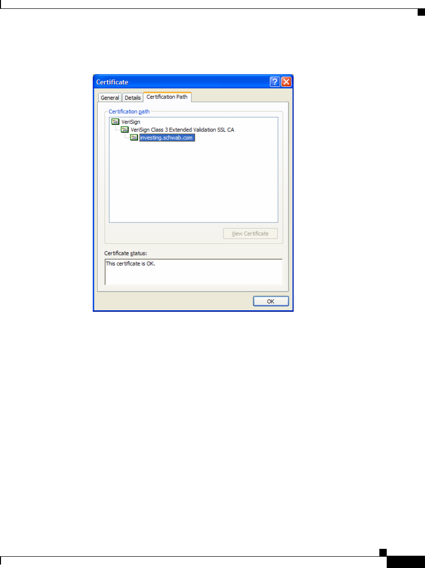
10-11
Cisco IronPort AsyncOS 7.1 for Web User Guide
OL-23207-01
Chapter 10 Decryption Policies
Digital Certificates
Figure 10-2 Certification Path Example
In Figure 10-2, the certificate for the URL investing.schwab.com was signed by
certificate authority “VeriSign Class 3 Extended Validation SSL CA,” which in
turn was signed by certificate authority VeriSign.
By definition, root certificates are always trusted by applications that follow the
X.509 standard. The Web Security appliance uses the X.509 standard.
Standard web browsers ship with a set of trusted root certificates. The list of root
certificates is updated regularly. You can view the root certificates installed on the
web browser.
For example, to view the root certificates installed with Mozilla Firefox 2.0, go to
Tools > Options > Advanced > Encryption > View Certificates. To view the root
certificates installed with Internet Explorer 7, go to Tools > Internet Options >
Content > Certificates > Trusted Root Certification Authorities.
In Figure 10-2, the VeriSign certificate is a root certificate that shipped with the
web browser.

Chapter 10 Decryption Policies
Digital Certificates
10-12
Cisco IronPort AsyncOS 7.1 for Web User Guide
OL-23207-01
The Web Security appliance also installs with a set of trusted root certificates.
However, you can upload additional root certificates that the Web Proxy deems to
be trusted. For more information about this, see Importing a Trusted Root
Certificate, page 10-37.
Validating Digital Certificates
Certificates can be valid or invalid. A certificate may be in invalid for different
reasons. For example, the current time may be before or after the certificate
validity period, the root authority in the certificate may not be recognized, or the
Common Name of the certificate does not match the hostname specified in the
HTTP “Host” header.
The Web Security appliance verifies that a server certificate is valid before it
inspects and decrypts an HTTPS connection from a server. You can configure how
the appliance handles connections to servers with invalid certificates. The
appliance can perform one of the following actions for invalid server certificates:
•Drop. The appliance drops the connection and does not notify the client. This
is the most restrictive option.
•Decrypt. The appliance allows the connection, but inspects the traffic
content. It decrypts the traffic and applies Access Policies to the decrypted
traffic as if it were a plaintext HTTP connection. For more information about
how the appliance decrypts HTTPS traffic, see Decrypting HTTPS Traffic,
page 10-13.
•Monitor. The appliance does not drop the connection, and instead it
continues comparing the server request with the Decryption Policy groups.
This is the least restrictive option.
Note When an invalid server certificate is monitored, the errors in the
certificate are maintained and passed along to the end-user.
For more information about configuring the appliance to handle invalid server
certificates, see Enabling the HTTPS Proxy, page 10-21.
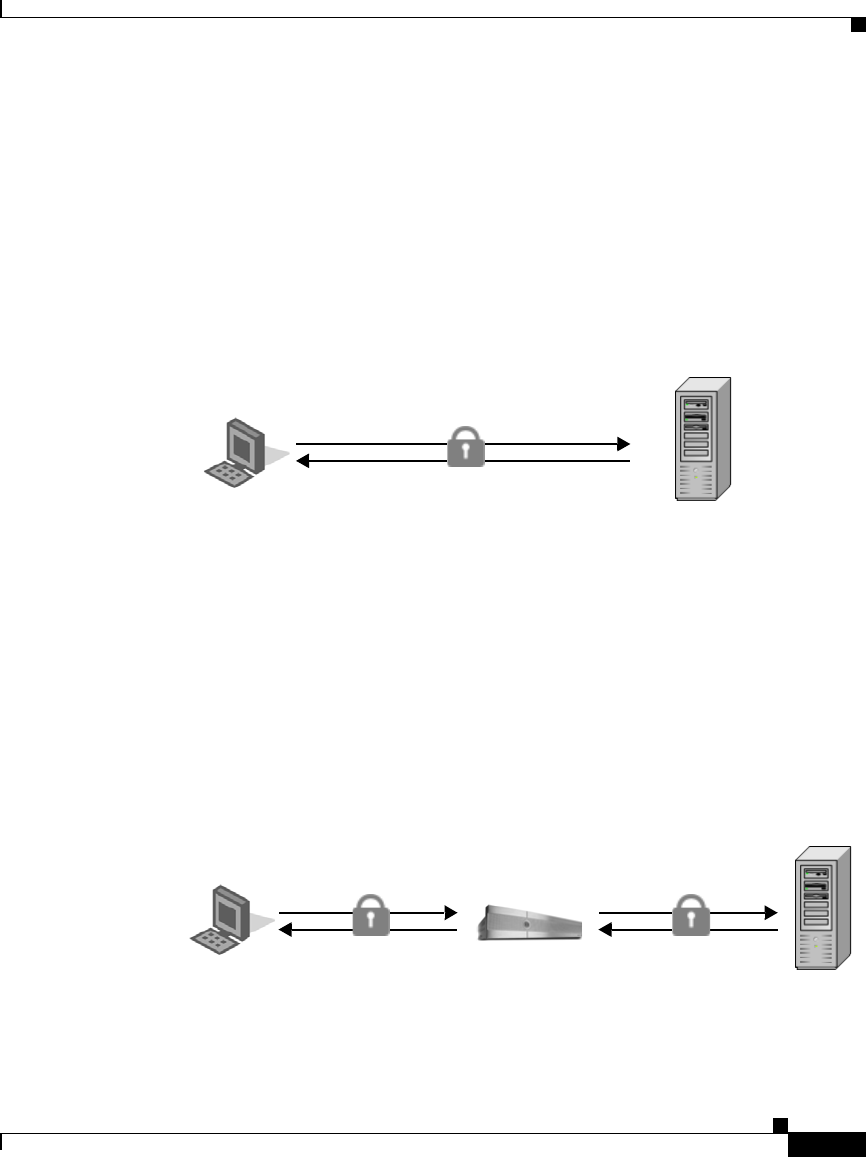
10-13
Cisco IronPort AsyncOS 7.1 for Web User Guide
OL-23207-01
Chapter 10 Decryption Policies
Decrypting HTTPS Traffic
Decrypting HTTPS Traffic
The request and response data is encrypted for HTTPS connections before it is
sent across the network. Because the data is encrypted, third parties can view the
data, but cannot decrypt it to read its contents without the private key of the
HTTPS server.
Figure 10-3 shows an HTTPS connection between a client and a HTTPS server.
Figure 10-3 HTTPS Connection
The Web Security appliance does not have access to the server’s private key, so in
order to inspect the traffic between the client and the server, it must intercept the
connection and break the connection into two separate connections. The appliance
acts as an intermediary between the client and the server pretending to be the
server to the client, and the client to the server. This is sometimes referred to as
being the “man in the middle.”
Figure 10-4 shows an HTTPS connection between a client and a HTTPS server
that goes through the Web Security appliance.
Figure 10-4 HTTPS Connection Decrypted by the Web Security Appliance
Client Server
Client Server
Web Security Appliance

Chapter 10 Decryption Policies
Decrypting HTTPS Traffic
10-14
Cisco IronPort AsyncOS 7.1 for Web User Guide
OL-23207-01
Notice that in Figure 10-4, there are two different HTTPS connections, one
between the client and the appliance, and one between the appliance and the
server. The appliance performs the SSL handshake twice, once with the client and
again with the server:
•SSL handshake with the server. When the appliance performs the SSL
handshake with the server, it acts as if it were the client sending a request to
the server. After it establishes a secure connection with the server, it can begin
receiving the encrypted data. Because it acts as the client and participates in
the SSL handshake, it has agreed upon a temporary symmetric key with the
server so it can decrypt and read the data the server sends. Also, the appliance
receives the server’s digital certificate.
•SSL handshake with the client. When the appliance performs the SSL
handshake with the client, it acts as if it were the requested server providing
data the client requests. In order to perform the SSL handshake with the
client, it must send the client its own digital certificate. However, the client
expects the certificate of the requested server, so the appliance mimics the
requested server’s certificate by specifying a root certificate authority
uploaded or configured by an appliance administrator.
For more information about how the server mimics the server’s certificate, see
Mimicking the Server Digital Certificate, page 10-15.
Note Because the appliance signs the server certificate with a different root
certificate authority and sends that to the client, you must verify the client
applications on the network recognize the root certificate authority. For
more information, see Working with Root Certificates, page 10-16.
After the two separate HTTPS connections are established, the following actions
occur:
1. Encrypted data is received from the server.
2. The temporary, symmetric key negotiated with the server is used to decrypt
the data.
3. Access Policies are applied to the decrypted traffic as if it were a plaintext
HTTP connection. For more information about Access Policies, see Access
Policies, page 8-1.

10-15
Cisco IronPort AsyncOS 7.1 for Web User Guide
OL-23207-01
Chapter 10 Decryption Policies
Decrypting HTTPS Traffic
4. Assuming the Access Policy group allows the client to receive the data, the
data is encrypted using the temporary, symmetric key negotiated with the
client.
5. Encrypted data is sent to the client.
Note No decrypted data is cached. However, access logs for decrypted HTTP
transactions are saved to disk.
Mimicking the Server Digital Certificate
When the appliance performs the SSL handshake with the client, it mimics the
server digital certificate and sends the new certificate to the client. To mimic the
server digital certificate, it reuses most field values and changes some field values.
The mimicked certificate is the same as the server certificate except for the
following fields:
•Issuer. The issuer comes from the generated or uploaded root certificate
configured in the appliance.
•Signature Algorithm. This field is always “sha1WithRSAEncryption” or
“dsaWithSHA1” depending upon on whether the root certificate the appliance
uses contains an RSA or DSA key.
•Public Key. The appliance replaces the public key in the original certificate
with a public key it generates that matches bit strength from the original
certificate and for which it has a matching private key generated as well. For
example, if the server certificate uses a 2048 bit RSA key, the appliance
generates a new 2048 bit RSA key.
•X509v3 Extensions. All X509v3 extensions are removed except for the
following:
–
Basic Constraints
–
Subject Alternative Name
–
Key Usage
–
Subject Key Identifier
–
Extended Key Usage

Chapter 10 Decryption Policies
Decrypting HTTPS Traffic
10-16
Cisco IronPort AsyncOS 7.1 for Web User Guide
OL-23207-01
For example, the appliance removes the Authority Key Identifier and the
Authority Information Access X509v3 extensions.
Working with Root Certificates
The Web Security appliance mimics the HTTPS server to which a client originally
sent a connection request. In order to establish a secure connection with the client
pretending to be the requested server, the appliance must send a server certificate
to the client signed by a root certificate authority configured in the appliance.
When you enable the HTTPS Proxy on the appliance, you can configure the root
certificate information that the appliance uses to sign its server certificates. You
can enter root certificate information in the following ways:
•Generate. You can enter some basic organization information and then click
a button so the appliance generates the rest of the certificate and a private key.
You might want to generate a certificate and key when your organization does
not have a certificate and key in use, or when it wants to create a new and
unique certificate and key.
•Upload. You can upload a certificate file and its matching private key file
created outside of the appliance. You might want to upload a certificate and
key file if the clients on the network already have the root certificates on their
machines.
The certificate and key files you upload must be in PEM format. DER format
is not supported. For more information about convert a DER formatted
certificate or key to PEM format, see Converting Certificate and Key Formats,
page 10-20.
Note The certificate you upload must contain “basicConstraints=CA:TRUE” to
work with Mozilla Firefox browsers. This constraint allows Firefox to
recognize the root certificate as a trusted root authority.
For more information about how to generate or upload a certificate and key, see
Enabling the HTTPS Proxy, page 10-21.
However, typically, the root certificate information you generate or upload in the
appliance is not listed as a trusted root certificate authority in client applications.
By default in most web browsers, when users send HTTPS requests, they will see
a warning message from the client application informing them that there is a
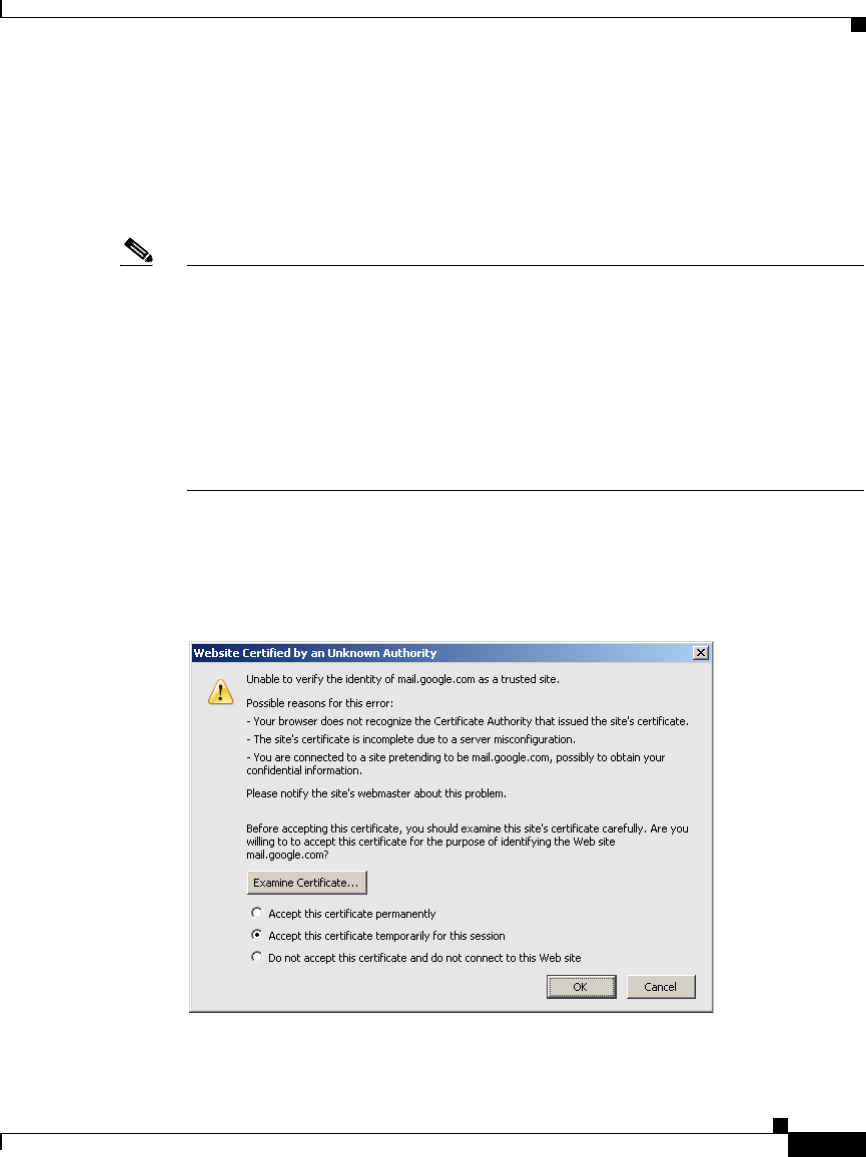
10-17
Cisco IronPort AsyncOS 7.1 for Web User Guide
OL-23207-01
Chapter 10 Decryption Policies
Decrypting HTTPS Traffic
problem with the website’s security certificate. Usually, the error message says
that the website’s security certificate was not issued by a trusted certificate
authority or the website was certified by an unknown authority. Some other client
applications do not show this warning message to users nor allow users to accept
the unrecognized certificate.
Note You can also upload an intermediate certificate that has been signed by a root
certificate authority. When the Web Proxy mimics the server certificate, it sends
the uploaded certificate along with the mimicked certificate to the client
application. That way, as long as the intermediate certificate is signed by a root
certificate authority that the client application trusts, the application will trust the
mimicked server certificate, too. You might want to upload an intermediate
certificate if your organization uses its own root certificate authority, but does not
want to upload the root certificate to the Web Security appliance for security
reasons.
Figure 10-5 on page 17 shows an example error message when a users sends an
HTTPS request through Netscape Navigator.
Figure 10-5 Unknown Certificate Authority Error Message
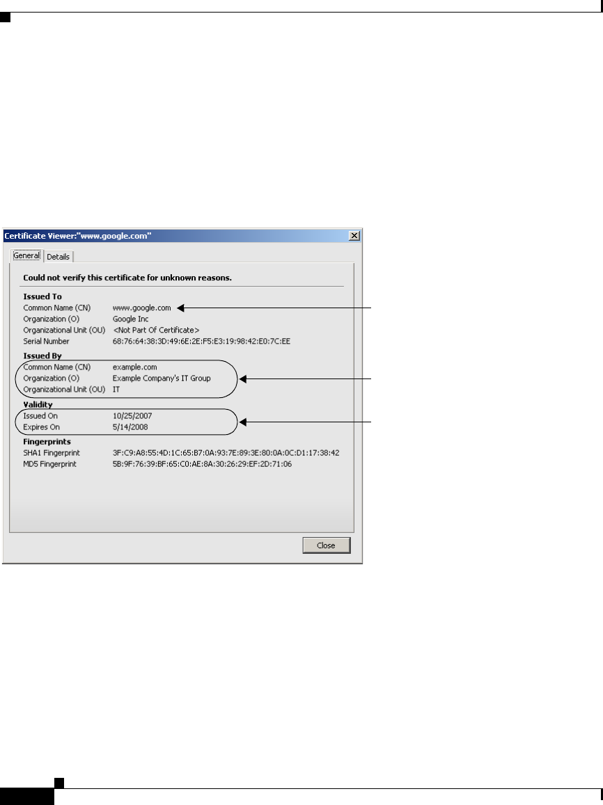
Chapter 10 Decryption Policies
Decrypting HTTPS Traffic
10-18
Cisco IronPort AsyncOS 7.1 for Web User Guide
OL-23207-01
Typically, users can view the certificate and use the information in the certificate
to choose whether or not to allow the secure connection with this website. In
Figure 10-5, you can view the certificate contents by clicking Examine
Certificate.
Figure 10-6 on page 18 shows an example root certificate issued by the appliance.
Figure 10-6 Certificate Issued by Web Security Appliance
You can choose how to handle the root certificates issued by the Web Security
appliance:
•Inform users to accept the root certificate. You can inform the users in your
organization what the new policies are at the company and tell them to accept
the root certificate supplied by the organization as a trusted source.
•Add the root certificate to client machines. You can add the root certificate
to all client machines on the network as a trusted root certificate authority.
This way, the client applications automatically accept transactions with the
root certificate. To verify you distribute the root certificate the appliance is
Root certificate information either
generated or uploaded in the Web
Security appliance.
Validity period specified in either
the generated or uploaded root
certificate.
Requested HTTPS server.

10-19
Cisco IronPort AsyncOS 7.1 for Web User Guide
OL-23207-01
Chapter 10 Decryption Policies
Decrypting HTTPS Traffic
using, you can download the root certificate from the Security Services >
HTTPS Proxy page. Click Edit Settings, and then click the Download
Certificate link for either the generated or uploaded certificate.
You might want to download the root certificate from the appliance if a
different person uploaded the root certificate to the appliance and you want
to verify you distribute the same root certificate to the client machines.
Using Decryption with the AVC Engine
Depending on how the HTTPS Proxy is configured and the configured Decryption
Policies, the HTTPS Proxy may decrypt HTTPS connections to web applications.
This allows the AVC engine to more accurately detect and block web applications
that use HTTPS. These web applications may use web browsers or other client
applications, such as instant messaging applications.
However, to ensure that all applications work properly when HTTPS connections
are decrypted, you must add the root certificate for signing to all client machines
on the network as a trusted root certificate authority. For example, on Windows
machines, you must install the root certificate into Internet Explorer for many
instant messaging client applications to work, such as Yahoo Instant Messenger,
MSN Messenger, and Google Talk.
Using Decryption with AOL Instant Messenger
Most AOL Instant Messenger (AIM) client applications do not allow you to add
root certificates to their list of trusted certificates. Because you cannot add the
appliance root certificate for signing to AIM client applications, AIM users are
unable to log into AIM when the HTTPS connection to the AIM server is
decrypted. Decryption to AIM servers might occur if the web reputation filters are
configured to decrypt traffic to servers with the reputation score equal to the AIM
server, or if a Decryption Policy is configured to decrypt all traffic.
To allow users to log into AIM, you must ensure that HTTPS traffic to the AIM
servers are never decrypted and instead are passed through.
Note Once users are logged into AIM, all instant messenger traffic uses HTTP and is
subject to the configured Access Policies.
To pass through HTTPS traffic to AIM servers:

Chapter 10 Decryption Policies
Decrypting HTTPS Traffic
10-20
Cisco IronPort AsyncOS 7.1 for Web User Guide
OL-23207-01
Step 1 Create a custom URL category in the first position of custom URL categories and
enter the following addresses:
•aimpro.premiumservices.aol.com
•bos.oscar.aol.com
•kdc.uas.aol.com
•buddyart-d03c-sr1.blue.aol.com
•205.188.8.207
•205.188.248.133
•205.188.13.36
•64.12.29.131
Step 2 Create a Decryption Policy and use the custom URL category created in Step 1 as
part of the policy group membership. Depending on the other Decryption Policies
configured, you might want to place this Decryption Policy at the top of the list.
Step 3 Configure the Decryption Policy to pass through all traffic to the custom URL
category.
Step 4 Choose pass through as the default action for the Decryption Policy.
Step 5 Submit and commit your changes.
Converting Certificate and Key Formats
The root certificate and private key files you upload to the appliance must be in
PEM format. DER format is not supported. However, you can convert certificates
and keys in DER format into the PEM format before uploading them. For
example, you can use OpenSSL to convert the format.
Use the following OpenSSL command to convert a DER formatted certificate file
to a PEM formatted certificate file:
openssl x509 -inform DER -in cert_in_DER -outform PEM -out
out_file_name
You can also convert key files in DER format into the PEM format by running a
similar OpenSSL command.
For RSA keys, use the following command:

10-21
Cisco IronPort AsyncOS 7.1 for Web User Guide
OL-23207-01
Chapter 10 Decryption Policies
Enabling the HTTPS Proxy
openssl rsa -inform DER -in key_in_DER -outform PEM -out
out_file_name
For DSA keys, use the following command:
openssl dsa -inform DER -in key_in_DER -outform PEM -out
out_file_name
For more information about using OpenSSL, see the OpenSSL documentation, or
visit
http://openssl.org.
Enabling the HTTPS Proxy
To monitor and decrypt HTTPS traffic, you must enable the HTTPS Proxy on the
Security Services > HTTPS Proxy page. When you enable the HTTPS Proxy, you
must configure what the appliance uses for a root certificate when it sends
self-signed server certificates to the client applications on the network. You can
upload a root certificate and key that your organization already has, or you can
configure the appliance to generate a certificate and key with information you
enter.
Once the HTTPS Proxy is enabled, all HTTPS policy decisions are handled by
Decryption Policies. You can no longer define Access and Routing Policy group
membership by HTTPS, nor can you configure Access Policies to block HTTPS
transactions. If some Access and Routing Policy group memberships are defined
by HTTPS and if some Access Policies block HTTPS, then when you enable the
HTTPS Proxy those Access and Routing Policy groups become disabled. You can
choose to enable the policies at any time, but all HTTPS related configurations are
removed.
Note When you upload a certificate to the Web Security appliance, verify it is a signing
certificate and not a server certificate. A server certificate cannot be used as a
signing certificate, so decryption does not work when you upload a server
certificate.
For more information about root certificates, see Working with Root Certificates,
page 10-16.
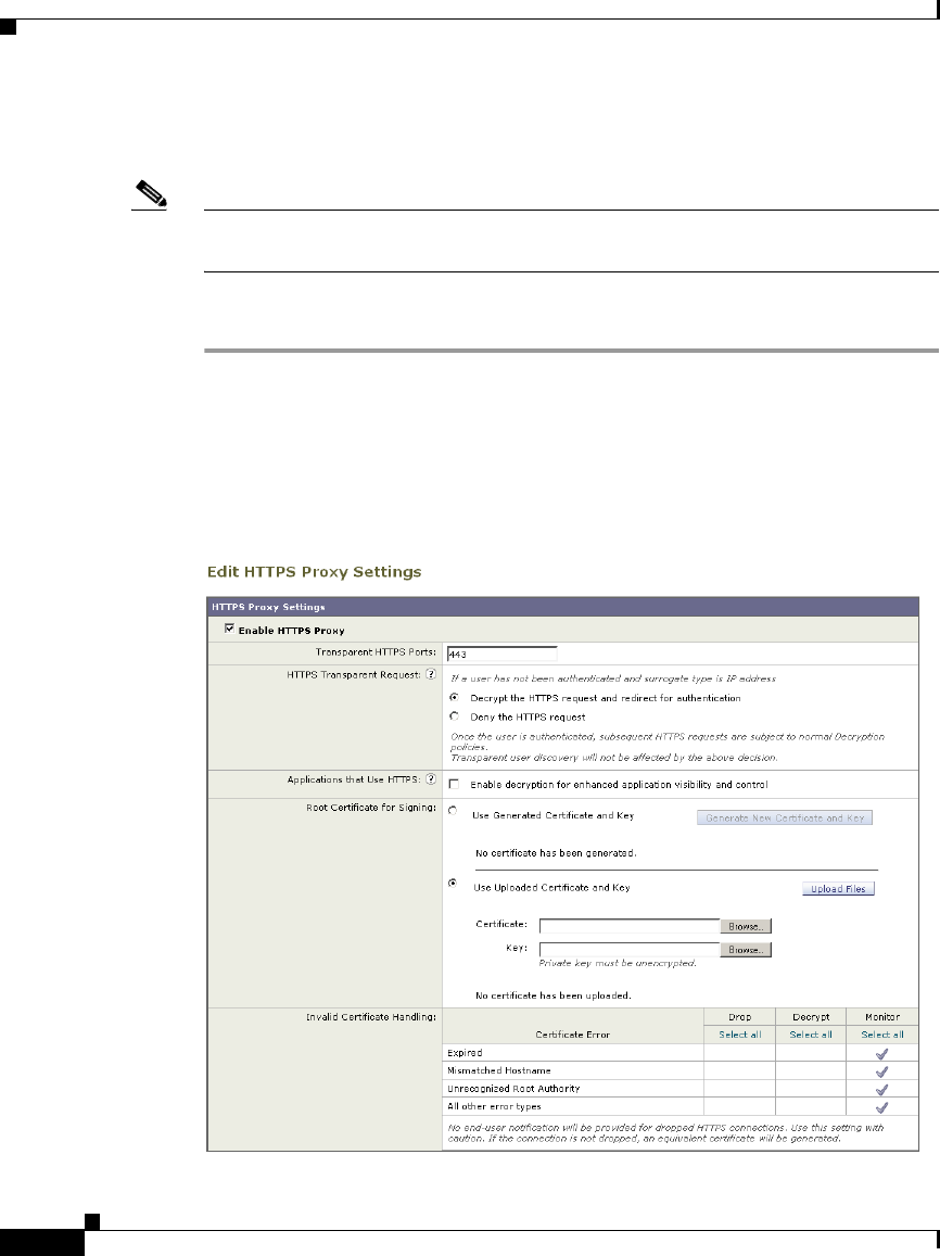
Chapter 10 Decryption Policies
Enabling the HTTPS Proxy
10-22
Cisco IronPort AsyncOS 7.1 for Web User Guide
OL-23207-01
Also on this page, you can configure what the appliance does with HTTPS traffic
when the server certificate is invalid.
Note For information on importing a custom root authority certificate, see Importing a
Trusted Root Certificate, page 10-37.
To enable the HTTPS Proxy:
Step 1 Navigate to the Security Services > HTTPS Proxy page, and click Enable and
Edit Settings.
The HTTPS Proxy License Agreement appears.
Step 2 Read the terms of the HTTPS Proxy License Agreement, and click Accept.
The Edit HTTPS Proxy Settings page appears.

10-23
Cisco IronPort AsyncOS 7.1 for Web User Guide
OL-23207-01
Chapter 10 Decryption Policies
Enabling the HTTPS Proxy
Step 3 Verify the Enable HTTPS Proxy field is enabled.
Step 4 In the Transparent HTTPS Ports field, enter the ports the appliance should check
for HTTPS traffic. Port 443 is the default port.
Note This field appears only when the appliance is deployed in transparent
mode.
Step 5 In the HTTPS Transparent Request section, choose how the Web Proxy handles
transparently redirected HTTPS transactions it receives before an HTTP request
that was authenticated using an identity with an IP-based surrogate. Select one of
the following options:
•Decrypt the HTTPS request and redirect for authentication
•Deny the HTTPS request
This setting only applies to transactions that use IP address as the authentication
surrogate and when the user has not yet been authenticated.
For more information, see Understanding How Authentication Affects HTTPS
and FTP over HTTP Requests, page 7-6.
Note This field only appears when the appliance is deployed in transparent
mode.
Step 6 In the Applications that Use HTTPS section, choose whether or not to enable
decryption for enhanced application visibility and control.
Enabling this setting allows the Web Proxy to detect applications that use HTTPS
with better accuracy. This setting supersedes the “Pass Through” decision made
by the Web Reputation Filters as configured in the Decryption Policies. However,
the URL category decision still applies.
Note Decryption may cause some applications to fail unless the root certificate
for signing is installed on the client. For more information, see Using
Decryption with the AVC Engine, page 10-19. For more information on
the appliance root certificate, see Working with Root Certificates,
page 10-16.
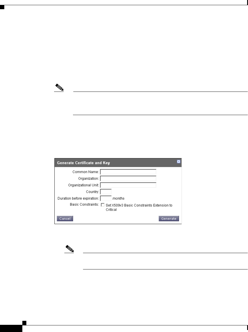
Chapter 10 Decryption Policies
Enabling the HTTPS Proxy
10-24
Cisco IronPort AsyncOS 7.1 for Web User Guide
OL-23207-01
Step 7 Choose which root certificate to use for signing self-signed certificates the
appliance sends to clients:
•Generated certificate and key. Go to step 8 on page 24.
•Uploaded certificate and key. Go to step 9 on page 25.
For more information about how the appliance uses these root certificates, see
Working with Root Certificates, page 10-16.
Note If the appliance has both an uploaded certificate and key pair and a
generated certificate and key pair, it only uses the certificate and key pair
currently selected in the Root Certificate for Signing section.
Step 8 To generate a certificate and key:
a. Click the Use Generated Certificate and Key option.
b. Click Generate New Certificate and Key.
c. In the Generate Certificate and Key dialog box, enter the information to
display in the root certificate.
Note You can enter any ASCII character except the forward slash ( / ) in the
Common Name field.
d. Click Generate. The Web Security appliance generates the certificate with
the data you entered and generates a key.
The generated certificate information is displayed on the Edit HTTPS Proxy
Settings page.

10-25
Cisco IronPort AsyncOS 7.1 for Web User Guide
OL-23207-01
Chapter 10 Decryption Policies
Enabling the HTTPS Proxy
Note After you generate the certificate and key, you can download the
generated certificate to transfer it to the client applications on the
network. Do this using the Download Certificate link in the generated
key area.
e. Go to step 10 on page 26.
Step 9 To upload a root certificate and key:
a. Click Use Uploaded Certificate and Key.
b. Click Browse for the Certificate field to navigate to the certificate file stored
on the local machine.
If the file you upload contains multiple certificates or keys, the Web Proxy
uses the first certificate or key in the file.
Note The certificate file must be in PEM format. DER format is not
supported.
c. Click Browse for the Key field to navigate to the private key file. The private
key must be unencrypted.
Note The key length must be 512, 1024, or 2048 bits. Also, the private key
file must be in PEM format. DER format is not supported.
d. Click Upload Files to transfer the certificate and key files to the Web Security
appliance.
The uploaded certificate information is displayed on the Edit HTTPS Proxy
Settings page.
Note After you upload the certificate and key, you can download the
certificate to transfer it to the client applications on the network. Do
this using the Download Certificate link in the uploaded key area.

Chapter 10 Decryption Policies
Enabling the HTTPS Proxy
10-26
Cisco IronPort AsyncOS 7.1 for Web User Guide
OL-23207-01
Step 10 In the Invalid Certificate Handling section, choose how the appliance handle
HTTPS traffic when it encounters invalid server certificates. You can drop,
decrypt, or monitor HTTPS traffic for the following types of invalid server
certificates:
•Expired. The certificate is either not yet valid, or it is currently past its valid
to date.
•Mismatched hostname. The hostname in the certificate does not match the
hostname the client was trying to access. This might happen during a “man in
the middle attack,” or when a server redirects a request to a different URL.
For example, http://mail.google.com gets redirected to
http://www.gmail.com.
Note — The Web Proxy can only perform hostname match when it is
deployed in explicit forward mode. When it is deployed in transparent mode,
it does not know the hostname of the destination server (it only knows the IP
address), so it cannot compare it to the hostname in the server certificate.
•Unrecognized root authority. The root certificate authority for the
certificate is not in the set of trusted root authorities on the appliance.
•All other error types. Most other error types are due to the appliance not
being able to complete the SSL handshake with the HTTPS server. For more
information about additional error scenarios for server certificates, see
http://www.openssl.org/docs/apps/verify.html.
Note When a certificate is both expired and has an unrecognized root authority,
the Web Security appliance performs the action specified for an
unrecognized root authority.
For more information about handling invalid server certificates, see
Validating Digital Certificates, page 10-12.
Step 11 Submit and commit your changes.

10-27
Cisco IronPort AsyncOS 7.1 for Web User Guide
OL-23207-01
Chapter 10 Decryption Policies
Evaluating Decryption Policy Group Membership
Evaluating Decryption Policy Group Membership
After the Web Proxy assigns an Identity to a client request, it evaluates the request
against the other policy types to determine which policy group it belongs for each
type. When the HTTPS Proxy is enabled, it applies HTTPS requests against the
Decryption Policies. When the HTTPS Proxy is not enabled, it evaluates HTTP
requests against the Access Policies.
When an HTTPS request gets decrypted, the Web Proxy evaluates the decrypted
request against the Access Policies. For more information about how the Web
Proxy evaluates Access Policies, see Evaluating Access Policy Group
Membership, page 8-4.
The Web Proxy applies the configured policy control settings to a client request
based on the client request’s policy group membership.
To determine the policy group that a client request matches, the Web Proxy
follows a specific process for matching the group membership criteria. During
this process, it considers the following factors for group membership:
•Identity. Each client request either matches an Identity, fails authentication
and is granted guest access, or fails authentication and gets terminated. For
more information about evaluating Identity group membership, see
Evaluating Identity Group Membership, page 7-2.
•Authorized users. If the assigned Identity requires authentication, the user
must be in the list of authorized users in the Decryption Policy group to match
the policy group.
•Advanced options. You can configure several advanced options for
Decryption Policy group membership. Some of the options (such as proxy
port, and URL category) can also be defined within the Identity. When an
advanced option is configured in the Identity, it is not configurable in the
Decryption Policy group level.
The information in this section gives an overview of how the appliance matches
client requests to Decryption Policy groups. For more details about exactly how
the appliance matches client requests, see Matching Client Requests to
Decryption Policy Groups, page 10-28.
The Web Proxy sequentially reads through each policy group in the policies table.
It compares the client request status to the membership criteria of the first policy
group. If they match, the Web Proxy applies the policy settings of that policy
group.

Chapter 10 Decryption Policies
Evaluating Decryption Policy Group Membership
10-28
Cisco IronPort AsyncOS 7.1 for Web User Guide
OL-23207-01
If they do not match, the Web Proxy compares the client request to the next policy
group. It continues this process until it matches the client request to a user defined
policy group. If it does not match a user defined policy group, it matches the
global policy group. When the Web Proxy matches the client request to a policy
group or the global policy group, it applies the policy settings of that policy group.
Matching Client Requests to Decryption Policy Groups
Figure 10-7 on page 29 shows how the Web Proxy evaluates a client request
against the Decryption Policy groups.
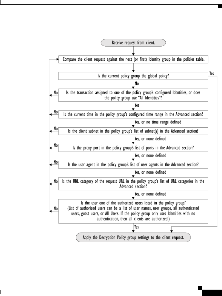
10-29
Cisco IronPort AsyncOS 7.1 for Web User Guide
OL-23207-01
Chapter 10 Decryption Policies
Evaluating Decryption Policy Group Membership
Figure 10-7 Policy Group Flow Diagram for Decryption Policies

Chapter 10 Decryption Policies
Creating Decryption Policies
10-30
Cisco IronPort AsyncOS 7.1 for Web User Guide
OL-23207-01
Creating Decryption Policies
You can create Decryption Policy groups based on combinations of several
criteria, such as Identity or the URL category of the destination site. You must
define at least one criterion for policy group membership. When you define
multiple criteria, the client request must meet all criteria to match the policy
group.
For more information about how the appliance matches a client request with a
policy group, see Evaluating Decryption Policy Group Membership, page 10-27
and Matching Client Requests to Decryption Policy Groups, page 10-28.
You define policy group membership on the Web Security Manager > Decryption
Policies page.
To create a Decryption Policy group:
Step 1 Navigate to the Web Security Manager > Decryption Policies page.
Step 2 Click Add Policy.
Step 3 In the Policy Name field, enter a name for the policy group, and in the Description
field, optionally add a description.
Note Each policy group name must be unique and only contain alphanumeric
characters or the space character.
Step 4 In the Insert Above Policy field, choose where in the policies table to place the
policy group.
When configuring multiple policy groups you must specify a logical order for
each group. Carefully order your policy groups to ensure that correct matching
occurs.
Step 5 In the Identities and Users section, choose one or more Identity groups to apply
to this policy group.

10-31
Cisco IronPort AsyncOS 7.1 for Web User Guide
OL-23207-01
Chapter 10 Decryption Policies
Creating Decryption Policies
Note If the Identity requires authentication, then authentication information
may not be available when a user tries to connect to an HTTPS server. For
more information on how HTTPS and authentication work together, see
Understanding How Authentication Affects HTTPS and FTP over HTTP
Requests, page 7-6.
For more information on how to do this, see Configuring Identities in Other Policy
Groups, page 7-28.
Step 6 Optionally, expand the Advanced section to define additional membership
requirements.
Step 7 To define policy group membership by any of the advanced options, click the link
for the advanced option and configure the option on the page that appears.

Chapter 10 Decryption Policies
Creating Decryption Policies
10-32
Cisco IronPort AsyncOS 7.1 for Web User Guide
OL-23207-01
Table 10-2 describes the advanced options you can configure for Decryption
Policy groups.
Table 10-2 Decryption Policy Group Advanced Options
Advanced Option Description
Proxy Ports Choose whether or not to define policy group membership by
the proxy port used to access the Web Proxy. Enter one or
more port numbers in the Proxy Ports field. Separate
multiple ports with commas.
For explicit forward connections, this is the port configured
in the browser. For transparent connections, this is the same
as the destination port. You might want to define policy
group membership on the proxy port if you have one set of
clients configured to explicitly forward requests on one port,
and another set of clients configured to explicitly forward
requests on a different port.
Cisco recommends only defining policy group membership
by the proxy port when the appliance is deployed in explicit
forward mode, or when clients explicitly forward requests to
the appliance. When you define policy group membership by
the proxy port when clients requests get transparently
redirected to the appliance, some requests might be denied.
Note: If the Identity associated with this policy group
defines Identity membership by this advanced setting, the
setting is not configurable at the non-Identity policy group
level.
Subnets Choose whether or not to define policy group membership by
subnet or other addresses.
You can choose to use the addresses that may be defined with
the associated Identity, or you can enter specific addresses
here.
Note: If the Identity associated with this policy group
defines its membership by addresses, then in this policy
group you must enter addresses that are a subset of the
Identity’s addresses. Adding addresses in the policy group
further narrows down the list of transactions that match this
policy group.

10-33
Cisco IronPort AsyncOS 7.1 for Web User Guide
OL-23207-01
Chapter 10 Decryption Policies
Creating Decryption Policies
Step 8 Submit your changes.
Time Range Choose whether or not to define policy group membership by
a defined time range. Choose the time range from the Time
Range field and then choose whether this policy group
should apply to the times inside or outside the selected time
range.
For more information on creating time based policies, see
Working with Time Based Policies, page 6-13.
For more information on creating time ranges, see Creating
Time Ranges, page 6-14.
URL Categories Choose whether or not to define policy group membership by
URL categories. Select the user defined or predefined URL
categories.
Note: If the Identity associated with this policy group
defines Identity membership by this advanced setting, the
setting is not configurable at the non-Identity policy group
level.
User Agents Choose whether or not to define policy group membership by
the user agent used in the client request. You can select some
commonly defined browsers, or define your own using
regular expressions. Choose whether this policy group
should apply to the selected user agents or to any user agent
that is not in the list of selected user agents.
For more information on creating user agent based policies,
see Working with User Agent Based Policies, page 6-16.
Note: If the Identity associated with this policy group
defines Identity membership by this advanced setting, the
setting is not configurable at the non-Identity policy group
level.
User Location Choose whether or not to define policy group membership by
user location, either remote or local.
This option only appears when the Secure Mobility Solution
is enabled. For more information, see Achieving Secure
Mobility Overview, page 13-1.
Table 10-2 Decryption Policy Group Advanced Options (continued)
Advanced Option Description
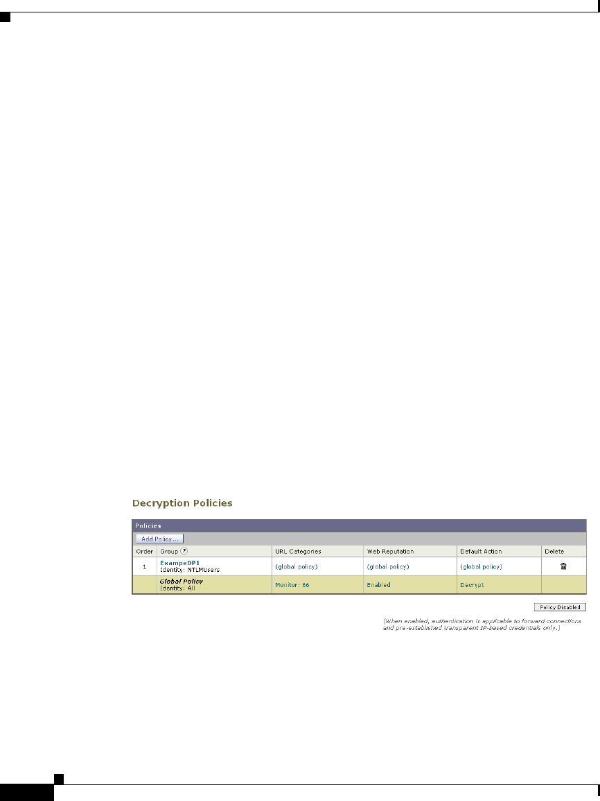
Chapter 10 Decryption Policies
Controlling HTTPS Traffic
10-34
Cisco IronPort AsyncOS 7.1 for Web User Guide
OL-23207-01
Step 9 Configure Decryption Policy group control settings to define how the Web Proxy
handles transactions.
The new policy group automatically inherits global policy group settings until you
configure options for each control setting. For more information, see Controlling
HTTPS Traffic, page 10-34.
Step 10 Submit and commit your changes.
Controlling HTTPS Traffic
After the Web Security appliance assigns an HTTPS connection request to a
Decryption Policy group, the connection request inherits the control settings of
that policy group. The control settings of the Decryption Policy group determine
whether the appliance decrypts, drops, or passes through the connection. For more
information about the actions the appliance can take on an HTTPS request, see
Decryption Policy Groups, page 10-3.
Configure control settings for Decryption Policy groups on the Web Security
Manager > Decryption Policies page.
Figure 10-8 shows where you can configure control settings for the Decryption
Policy groups.
Figure 10-8 Decryption Policies Table
You can configure the following settings to determine what action to take on the
HTTPS connection:
•URL categories. You can configure the action to take on HTTPS requests for
each predefined and custom URL category. Click the link under the URL
Categories column for the policy group you want to configure. For more

10-35
Cisco IronPort AsyncOS 7.1 for Web User Guide
OL-23207-01
Chapter 10 Decryption Policies
Controlling HTTPS Traffic
information about working with URL filters, see URL Filters, page 16-1. For
more information about configuring URL categories, see Configuring URL
Filters for Decryption Policy Groups, page 16-10.
Note If you want to block (with end-user notification) a particular URL
category for HTTPS requests instead of drop (with no end-user
notification), choose to decrypt that URL category in the Decryption
Policy group and then choose to block the same URL category in the
Access Policy group.
•Web reputation. You can configure the action to take on HTTPS requests
based on the web reputation score of the requested server. Click the link under
the Web Reputation column for the policy group you want to configure. For
more information about working with web reputation scores, see Web
Reputation in Decryption Policies, page 18-5.
•Default action. You can configure the action the appliance should take when
none of the other settings apply. Click the link under the Default Action
column for the policy group you want to configure.
Note The configured default action only affects the transaction when no
decision is made based on URL category or Web Reputation score. If Web
Reputation filtering is disabled, the default action applies to all
transactions that match a Monitor action in a URL category. If Web
Reputation filtering is enabled, the default action is used only if the
Monitor action is selected for sites with no score.
After a Decryption Policy group is assigned to an HTTPS request, the control
settings for the policy group are evaluated to determine whether to drop, pass
through, or decrypt the HTTPS connection request. For more information about
assigning a Decryption Policy group to an HTTPS request, see Policy Group
Membership, page 6-10.
Figure 10-9 on page 36 shows how the appliance determines which action to take
on an HTTPS request after it has assigned a particular Decryption Policy to the
request.
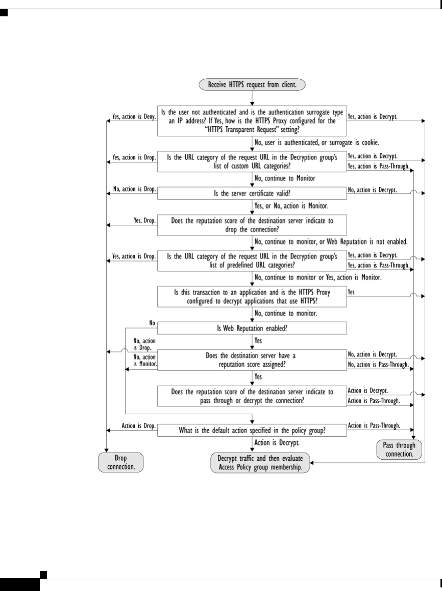
Chapter 10 Decryption Policies
Controlling HTTPS Traffic
10-36
Cisco IronPort AsyncOS 7.1 for Web User Guide
OL-23207-01
Figure 10-9 Applying Decryption Policy Actions
Figure 10-9 shows two different decision points that involve the web reputation
score of the destination server. The web reputation score of the server is evaluated
only once, but the result is applied at two different points in the decision flow.
For example, note that a web reputation score drop action overrides any action
defined for predefined URL categories.
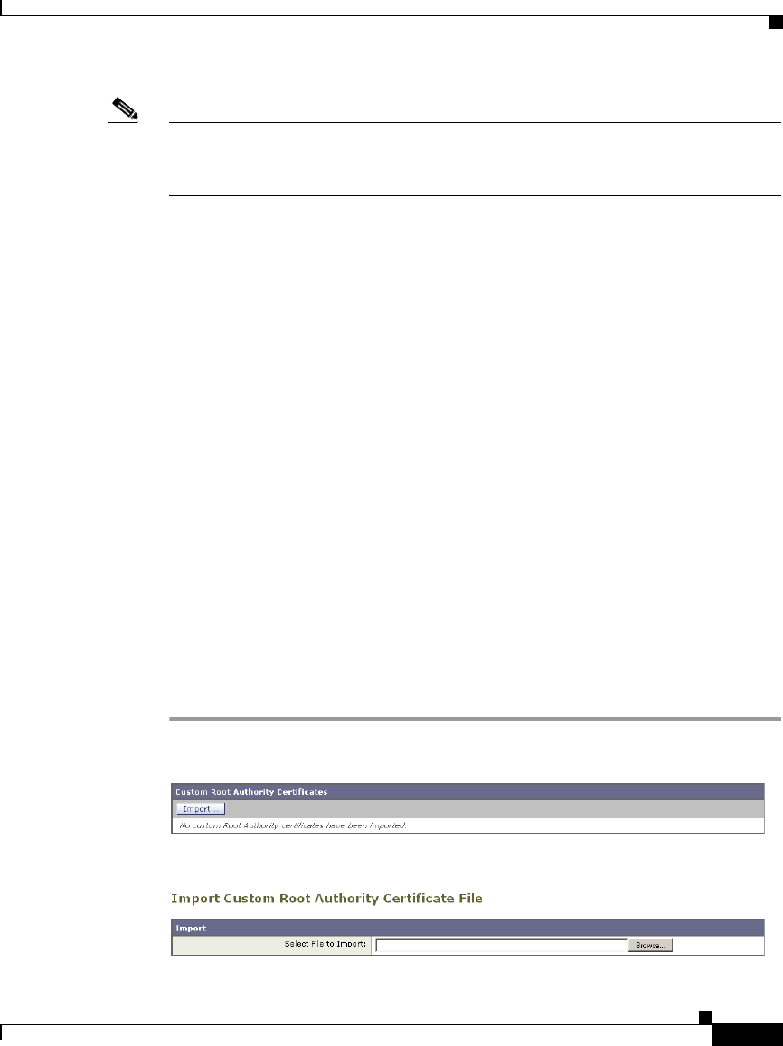
10-37
Cisco IronPort AsyncOS 7.1 for Web User Guide
OL-23207-01
Chapter 10 Decryption Policies
Importing a Trusted Root Certificate
Note The configured default action only affects the action on the HTTPS request when
web reputation filtering is not enabled, or when it is enabled and the server has no
score assigned and the action for servers with no scores is to Monitor.
Importing a Trusted Root Certificate
When the Web Proxy receives a connection request for an HTTPS server, it
validates the trustworthiness of the destination server by verifying the root
certificate authority that signed the server certificate. If the Web Proxy does not
recognize the root certificate that signed the server certificate, then it does not
trust the server certificate. This happens when the HTTPS server uses a certificate
authority that is not listed in the set of trusted certificate authorities that ship with
the Web Security appliance. This might happen if your organization uses an
internal certificate authority to sign certificates for servers on the internal
network.
To prevent the Web Proxy from potentially blocking access to servers with
unrecognized root certificate authorities, you can upload to the appliance root
certificates that your organization trusts. For example, you might want to upload
a root certificate used by the servers on your network.
You can upload multiple root certificate files to the appliance, and each file you
upload can contain multiple root certificates. However, each certificate you
upload must be a root certificate.
To import a trusted root certificate:
Step 1 Navigate to the Security Services > HTTPS Proxy page.
Step 2 In the Custom Root Authority Certificates section, click Import.

Chapter 10 Decryption Policies
Importing a Trusted Root Certificate
10-38
Cisco IronPort AsyncOS 7.1 for Web User Guide
OL-23207-01
Step 3 In the Import Custom Root Authority Certificate File, click Browse.
Step 4 Navigate to the location where the custom root authority certificate file is located
and click Open.
Step 5 Click Submit.
The uploaded root certificate is displayed in the “Custom Root Authority
Certificates” section.
Step 6 Optionally, repeat steps 2 through 5 to upload additional trusted root certificates.
Step 7 Commit your changes.

CHAPTER
11-1
Cisco IronPort AsyncOS 7.1 for Web User Guide
OL-23207-01
11
Outbound Malware Scanning
This chapter contains the following information:
•Outbound Malware Scanning Overview, page 11-1
•Evaluating Outbound Malware Scanning Policy Group Membership,
page 11-3
•Creating Outbound Malware Scanning Policies, page 11-6
•Controlling Upload Requests Using Outbound Malware Scanning Policies,
page 11-11
•Logging, page 11-14
Outbound Malware Scanning Overview
Malware is pervasive and persistent, and unfortunately, usually finds access to the
computers inside your network. Users increasingly work with customers and
partners to collaborate on projects and increase productivity. This increased
collaboration poses challenges for information security professionals to
determine how to prevent malware infections on internal systems from
accidentally infecting key partners, and therefore adversely affecting their
reputation.
The IronPort Web Security appliance provides the outbound malware scanning
feature which allows you to stop malware that is already active on computers
inside the network from escaping the network and affecting customers and
partners.

Chapter 11 Outbound Malware Scanning
Outbound Malware Scanning Overview
11-2
Cisco IronPort AsyncOS 7.1 for Web User Guide
OL-23207-01
The IronPort Dynamic Vectoring and Streaming (DVS) engine scans transaction
requests as they leave the network in real time. By working with the IronPort DVS
engine, the Web Security appliance enables you to prevent users from
unintentionally uploading malicious data.
To prevent malicious data from leaving the network, the Web Security appliance
provides the Outbound Malware Scanning policy groups. You define which
uploads are scanned for malware, which anti-malware scanning engines to use for
scanning, and which malware types to block.
For more information on anti-malware scanning, see Anti-Malware Services,
page 19-1.
User Experience with Blocked Requests
When the IronPort DVS engine blocks an upload request, the Web Proxy sends a
block page to the end user. However, not all websites display the block page to the
end user. For example, some Web 2.0 websites display dynamic content using
javascript instead of a static webpage and are not likely to display the block page.
Users are still properly blocked from uploading malicious data, but they may not
always be informed of this by the website.
Outbound Malware Scanning Policy Groups
Outbound Malware Scanning Policies define whether or not the Web Proxy blocks
HTTP requests and decrypted HTTPS connections for transactions that upload
data to a server (upload requests). An upload request is an HTTP or decrypted
HTTPS request that has content in the request body.
When the Web Proxy receives an upload request, it compares the request to the
Outbound Malware Scanning policy groups to determine which policy group to
apply. After it assigns the request to a policy group, it compares the request to the
policy group’s configured control settings to determine whether to block the
request or monitor the request. When an Outbound Malware Scanning Policy
determines to monitor a request, it is evaluated against the Access Policies, and
the final action the Web Proxy takes on the request is determined by the applicable
Access Policy.

11-3
Cisco IronPort AsyncOS 7.1 for Web User Guide
OL-23207-01
Chapter 11 Outbound Malware Scanning
Evaluating Outbound Malware Scanning Policy Group Membership
For more information on configuring Outbound Malware Scanning Policies to
block requests based on outbound malware, see Controlling Upload Requests
Using Outbound Malware Scanning Policies, page 11-11.
Note Upload requests that try to upload files with a size of zero (0) bytes are not
evaluated against Outbound Malware Scanning Policies.
Evaluating Outbound Malware Scanning Policy
Group Membership
Each client request is assigned to an Identity and is then evaluated against the
other policy types to determine to which policy group it belongs for each type.
The Web Proxy evaluates upload requests against the Outbound Malware
Scanning Policies.
The Web Proxy applies the configured policy control settings to a client request
based on the client request’s policy group membership.
To determine the policy group that a client request matches, the Web Proxy
follows a specific process for matching the group membership criteria. During
this process, it considers the following factors for group membership:
•Identity. Each client request either matches an Identity, fails authentication
and is granted guest access, or fails authentication and is terminated. For
more information about evaluating Identity group membership, see
Evaluating Identity Group Membership, page 7-2.
•Authorized users. If the assigned Identity requires authentication, the user
must be in the list of authorized users in the Outbound Malware Scanning
Policy group to match the policy group. The list of authorized users can be
any of the specified groups or users or can be guest users if the Identity allows
guest access.
•Advanced options. You can configure several advanced options for
Outbound Malware Scanning Policy group membership. Some options, such
as proxy port and URL category, can also be defined within the Identity.
When an advanced option is configured in the Identity, it is not configurable
in the Outbound Malware Scanning Policy group level.

Chapter 11 Outbound Malware Scanning
Evaluating Outbound Malware Scanning Policy Group Membership
11-4
Cisco IronPort AsyncOS 7.1 for Web User Guide
OL-23207-01
The information in this section gives an overview of how the Web Proxy matches
upload requests to Outbound Malware Scanning Policy groups. For more details
about exactly how the Web Proxy matches client requests, see Matching Client
Requests to Outbound Malware Scanning Policy Groups, page 11-4.
The Web Proxy reads sequentially through each policy group in the policies table.
It compares the upload request status to the membership criteria of the first policy
group. If they match, the Web Proxy applies the policy settings of that policy
group.
If they do not match, the Web Proxy compares the upload request to the next
policy group. It continues this process until it matches the upload request to a user
defined policy group. If it does not match a user defined policy group, it matches
the global policy group. When the Web Proxy matches the upload request to a
policy group or the global policy group, it applies the policy settings of that policy
group.
Matching Client Requests to Outbound Malware Scanning Policy
Groups
Figure 11-1 on page 5 shows how the Web Proxy evaluates an upload request
against the Outbound Malware Scanning groups.
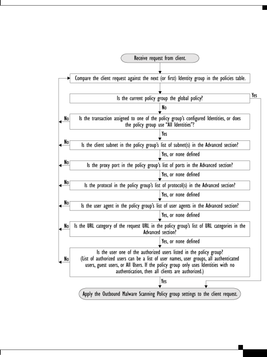
11-5
Cisco IronPort AsyncOS 7.1 for Web User Guide
OL-23207-01
Chapter 11 Outbound Malware Scanning
Evaluating Outbound Malware Scanning Policy Group Membership
Figure 11-1 Policy Group Flow Diagram for Outbound Malware Scanning
Policies

Chapter 11 Outbound Malware Scanning
Creating Outbound Malware Scanning Policies
11-6
Cisco IronPort AsyncOS 7.1 for Web User Guide
OL-23207-01
Creating Outbound Malware Scanning Policies
You can create Outbound Malware Scanning Policy groups based on
combinations of several criteria, such as one or more Identities or the URL
category of the destination site. You must define at least one criterion for policy
group membership. When you define multiple criteria, the upload request must
meet all criteria to match the policy group. However, the upload request needs to
match only one of the configured Identities.
For more information about how the Web Proxy matches an upload request with
a policy group, see Evaluating Outbound Malware Scanning Policy Group
Membership, page 11-3 and Matching Client Requests to Outbound Malware
Scanning Policy Groups, page 11-4.
To create an Outbound Malware Scanning Policy group:
Step 1 Navigate to the Web Security Manager > Outbound Malware Scanning page, and
click Add Policy.
Step 2 Enter a name and an optional description for the policy group.
Note Each policy group name must be unique and only contain alphanumeric
characters or the space character.
Step 3 In the Insert Above Policy field, select where in the policies table to place the
policy group.
When configuring multiple policy groups, you must specify a logical order for
each group. Carefully order your policy groups to ensure that correct matching
occurs.
Step 4 In the Identities and Users section, select one or more Identity groups to apply to
this policy group.
For more information, see Configuring Identities in Other Policy Groups,
page 7-28.
Step 5 Optionally, expand the Advanced section to define additional membership
requirements.

11-7
Cisco IronPort AsyncOS 7.1 for Web User Guide
OL-23207-01
Chapter 11 Outbound Malware Scanning
Creating Outbound Malware Scanning Policies
Step 6 To define policy group membership by any of the advanced options, click the link
for the advanced option and configure the option on the page that appears.

Chapter 11 Outbound Malware Scanning
Creating Outbound Malware Scanning Policies
11-8
Cisco IronPort AsyncOS 7.1 for Web User Guide
OL-23207-01
Table 11-1 describes the advanced options you can configure for Outbound
Malware Scanning Policy groups.
Table 11-1 Outbound Malware Scanning Policy Group Advanced Options
Advanced Option Description
Protocols Choose whether or not to define policy group membership
by the protocol used in the client request. Select the
protocols to include.
“All others” means any protocol not listed above this option.
Note: When the HTTPS Proxy is enabled, only Decryption
Policies apply to HTTPS transactions. You cannot define
policy membership by the HTTPS protocol for Access,
Routing, Outbound Malware Scanning, Data Security, or
External DLP Policies.
Proxy Ports Choose whether or not to define policy group membership
by the proxy port used to access the Web Proxy. Enter one or
more port numbers in the Proxy Ports field. Separate
multiple ports with commas.
For explicit forward connections, this is the port configured
in the browser. For transparent connections, this is the same
as the destination port. You might want to define policy
group membership on the proxy port if you have one set of
clients configured to explicitly forward requests on one port,
and another set of clients configured to explicitly forward
requests on a different port.
Cisco recommends defining policy group membership by the
proxy port only when the appliance is deployed in explicit
forward mode, or when clients explicitly forward requests to
the appliance. If you define policy group membership by the
proxy port when client requests are transparently redirected
to the appliance, some requests might be denied.
Note: If the Identity associated with this policy group
defines Identity membership by this advanced setting, the
setting is not configurable at the non-Identity policy group
level.

11-9
Cisco IronPort AsyncOS 7.1 for Web User Guide
OL-23207-01
Chapter 11 Outbound Malware Scanning
Creating Outbound Malware Scanning Policies
Subnets Choose whether or not to define policy group membership
by subnet or other addresses.
You can select to use the addresses that may be defined with
the associated Identity, or you can enter specific addresses
here.
Note: If the Identity associated with this policy group
defines its membership by addresses, then in this policy
group you must enter addresses that are a subset of the
addresses defined in the Identity. Adding addresses in the
policy group further narrows down the list of transactions
that match this policy group.
URL Categories Choose whether or not to define policy group membership
by URL categories. Select the user defined or predefined
URL categories.
Note: If the Identity associated with this policy group
defines Identity membership by this advanced setting, the
setting is not configurable at the non-Identity policy group
level.
Table 11-1 Outbound Malware Scanning Policy Group Advanced Options
Advanced Option Description

Chapter 11 Outbound Malware Scanning
Creating Outbound Malware Scanning Policies
11-10
Cisco IronPort AsyncOS 7.1 for Web User Guide
OL-23207-01
Step 7 Submit your changes.
Step 8 Configure Outbound Malware Scanning Policy group control settings to define
how the Web Proxy handles transactions.
The new Outbound Malware Scanning Policy group automatically inherits global
policy group settings until you configure options for each control setting. For
more information, see Controlling Upload Requests Using Outbound Malware
Scanning Policies, page 11-11.
Step 9 Submit and commit your changes.
User Agents Choose whether or not to define policy group membership
by the user agent used in the client request. You can select
some commonly defined browsers, or define your own using
regular expressions. Choose whether this policy group
should apply to the selected user agents or to any user agent
that is not in the list of selected user agents.
For more information on creating user agent based policies,
see Working with User Agent Based Policies, page 6-16.
Note: If the Identity associated with this policy group
defines Identity membership by this advanced setting, the
setting is not configurable at the non-Identity policy group
level.
User Location Choose whether or not to define policy group membership
by user location, either remote or local.
This option only appears when the Secure Mobility Solution
is enabled. For more information, see Achieving Secure
Mobility Overview, page 13-1.
Table 11-1 Outbound Malware Scanning Policy Group Advanced Options
Advanced Option Description
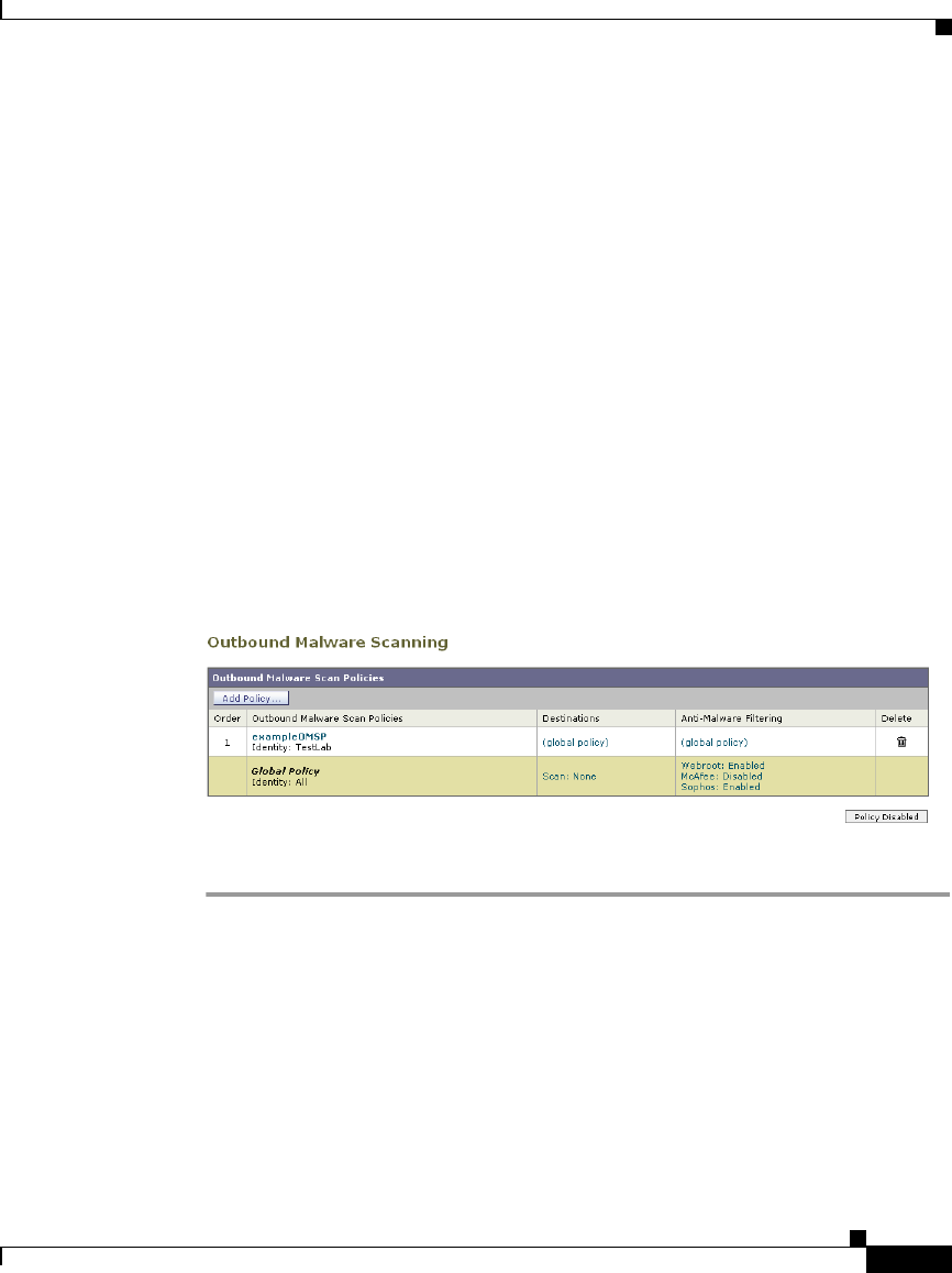
11-11
Cisco IronPort AsyncOS 7.1 for Web User Guide
OL-23207-01
Chapter 11 Outbound Malware Scanning
Controlling Upload Requests Using Outbound Malware Scanning Policies
Controlling Upload Requests Using Outbound
Malware Scanning Policies
Each upload request is assigned to an Outbound Malware Scanning Policy group
and inherits the control settings of that policy group. The control settings of the
Outbound Malware Scanning Policy group determine whether or not to scan the
upload request for malware and, if scanned, which malware types to block.
After the Web Proxy receives the upload request headers, it has all the information
necessary to decide if it should scan the request body. The DVS engine scans the
request and returns a verdict to the Web Proxy: either block or monitor (evaluate
the request against the Access Policies). The block page appears to the end user,
if applicable.
Figure 11-2 shows where you can configure control settings for the Outbound
Malware Scanning Policy groups.
Figure 11-2 Creating Outbound Malware Scanning Policies
To configure control settings for an Outbound Malware Scanning Policy group:
Step 1 Navigate to the Web Security Manager > Outbound Malware Scanning page.
Step 2 In the Destinations column, click the link for the policy group you want to
configure.
Step 3 In the Edit Destination Settings section, select “Define Destinations Scanning
Custom Settings” from the drop-down menu.
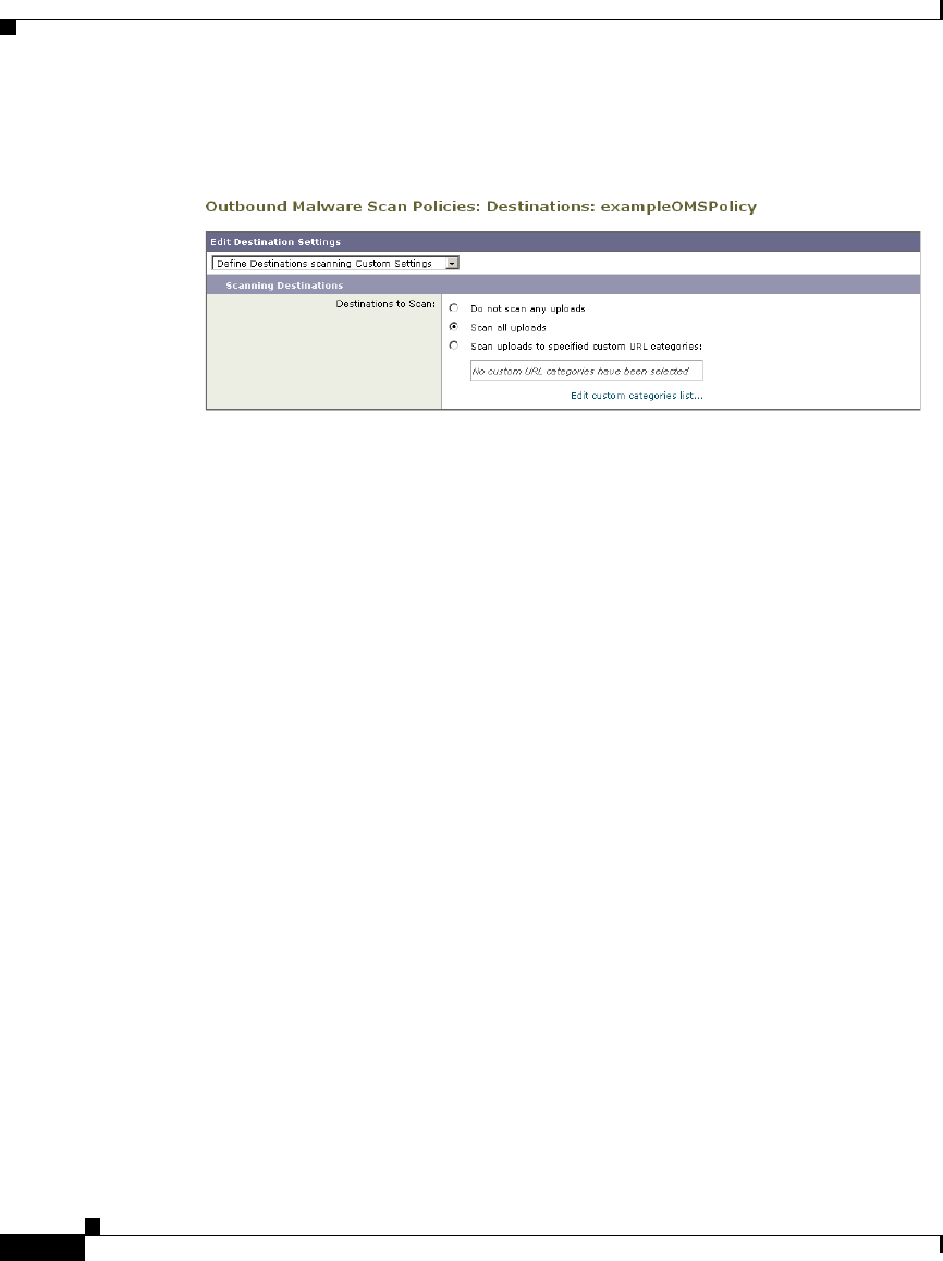
Chapter 11 Outbound Malware Scanning
Controlling Upload Requests Using Outbound Malware Scanning Policies
11-12
Cisco IronPort AsyncOS 7.1 for Web User Guide
OL-23207-01
Figure 11-3 Scanning Destinations Settings for Outbound Malware
Scanning Policies
Step 4 In the Destinations to Scan section, select one of the following options:
•Do not scan any uploads. The DVS engine scans no upload requests. All
upload requests are evaluated against the Access Policies.
•Scan all uploads. The DVS engine scans all upload requests. The upload
request is blocked or evaluated against the Access Policies, depending on the
DVS engine scanning verdict.
•Scan uploads to specified custom URL categories. The DVS engine scans
upload requests that belong in specific custom URL categories. The upload
request is blocked or evaluated against the Access Policies, depending on the
DVS engine scanning verdict. Click Edit custom categories list to select the
URL categories to scan.
Step 5 Submit your changes.
Step 6 In the Anti-Malware Filtering column, click the link for the policy group.
Step 7 In the Anti-Malware Settings section, select “Define Anti-Malware Custom
Settings” from the drop-down menu.
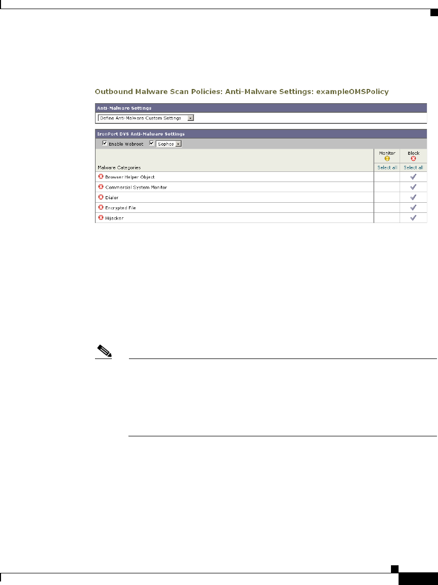
11-13
Cisco IronPort AsyncOS 7.1 for Web User Guide
OL-23207-01
Chapter 11 Outbound Malware Scanning
Controlling Upload Requests Using Outbound Malware Scanning Policies
Figure 11-4 Anti-Malware Settings for Outbound Malware Scanning
Policies
Step 8 In the IronPort DVS Anti-Malware Settings section, select which anti-malware
scanning engines to enable for this policy group.
When you enable Sophos or McAfee scanning, you can select to monitor or block
some additional categories in the Malware Categories on this page.
Step 9 In the Malware Categories section, select whether to monitor or block the various
malware categories based on a malware scanning verdict.
The categories listed in this section depend on which scanning engines you
enable.
Note URL transactions are categorized as unscannable when the configured
maximum time setting is reached or when the system experiences a
transient error condition. For example, transactions might be categorized
as unscannable during scanning engine updates or AsyncOS upgrades.
The malware scanning verdicts SV_TIMEOUT and SV_ERROR are
considered unscannable transactions.
Step 10 Submit and commit your changes.

Chapter 11 Outbound Malware Scanning
Logging
11-14
Cisco IronPort AsyncOS 7.1 for Web User Guide
OL-23207-01
Logging
The access logs indicate whether or not the DVS engine scanned an upload
request for malware. The scanning verdict information section of each access log
entry includes values for the DVS engine activity for scanned uploads. You can
also add one of the fields in Table 11-2 to the W3C or access logs to more easily
find this DVS engine activity:
When the DVS engine marks an upload request as being malware and it is
configured to block malware uploads, the ACL decision tag in the access logs is
BLOCK_AMW_REQ.
However, when the DVS engine marks an upload request as being malware and it
is configured to monitor malware uploads, the ACL decision tag in the access logs
is actually determined by the Access Policy applied to the transaction.
To determine whether or not the DVS engine scanned an upload request for
malware view the results of the DVS engine activity in the scanning verdict
information section of each access log entry, or view the results of the fields from
Table 11-2 added to the W3C or access logs.
For more information, see Understanding Scanning Verdict Information,
page 24-30.
Table 11-2 Log Fields in W3C Logs and Format Specifiers in Access Logs
W3C Log Field Format Specifier in Access Logs
x-req-dvs-scanverdict %X2
x-req-dvs-threat-name %X4
x-req-dvs-verdictname %X3

CHAPTER
12-1
Cisco IronPort AsyncOS 7.1 for Web User Guide
OL-23207-01
12
Data Security and External DLP
Policies
This chapter contains the following information:
•Data Security and External DLP Policies Overview, page 12-1
•Working with Data Security and External DLP Policies, page 12-4
•Evaluating Data Security and External DLP Policy Group Membership,
page 12-7
•Creating Data Security and External DLP Policies, page 12-10
•Controlling Upload Requests Using IronPort Data Security Policies,
page 12-15
•Defining External DLP Systems, page 12-20
•Controlling Upload Requests Using External DLP Policies, page 12-25
•Logging, page 12-27
Data Security and External DLP Policies Overview
In the Information Age, your organization’s data is one of its most prized
possessions. Your organization spends a lot of money making data available to
your employees, customers, and partners. Data is always on the move by traveling
over the web and email. This increased access poses challenges for information
security professionals to figure out how to prevent the malicious, accidental, or
unintentional loss of sensitive and proprietary information.

Chapter 12 Data Security and External DLP Policies
Data Security and External DLP Policies Overview
12-2
Cisco IronPort AsyncOS 7.1 for Web User Guide
OL-23207-01
The IronPort Web Security appliance secures your data by providing the following
capabilities:
•IronPort Data Security Filters. The IronPort Data Security Filters on the
Web Security appliance evaluate data leaving the network over HTTP,
HTTPS, and FTP to control what data goes where and how and by whom.
•Third party data loss prevention (DLP) integration. The Web Security
appliance integrates with leading third party content-aware DLP systems that
identify and protect sensitive data. The Web Proxy uses the Internet Content
Adaptation Protocol (ICAP) which is a lightweight HTTP based protocol that
allows proxy servers to offload content scanning to external systems. By
offloading the content scanning to dedicated external systems, the Web Proxy
can take advantage of the deep content scanning in other products while being
free to perform other Web Proxy functions with minimal performance impact.
By working with the IronPort Data Security Filters and external DLP systems, the
Web Security appliance allows you to protect information and intellectual
property and enforce regulatory and organization compliance by preventing users
from unintentionally uploading sensitive data. You define what kind of data is
allowed to leave the network.
To restrict data that is leaving the network, the Web Security appliance provides
the following types of policy groups:
•IronPort Data Security Policies. When you enable the IronPort Data
Security Filters, you can create IronPort Data Security Policies to enforce
business policies. For example, you can create a Data Security Policy that
prevents users from sending out Excel or zip files. For more information, see
Data Security Policy Groups, page 12-4.
•External DLP Policies. When you configure the appliance to work with an
external DLP system, you can create External DLP Policies to pass data
leaving the network to the external DLP system which scans the content and
determines whether or not to block the request. For more information, see
External DLP Policy Groups, page 12-6.
Depending on your organization’s needs, you might want to use both Data
Security and External DLP Policies. For example, you might use the IronPort
Data Security Policies to block data uploads to websites with a low reputation
score. This way, the data is never sent to the external DLP system for a deep
content scan, which improves overall performance.

12-3
Cisco IronPort AsyncOS 7.1 for Web User Guide
OL-23207-01
Chapter 12 Data Security and External DLP Policies
Data Security and External DLP Policies Overview
Bypassing Upload Requests Below a Minimum Size
Many websites are interactive, meaning users send data as well as receive data.
Users might send data when logging into a website or sending simple form data.
A lot of web traffic can consist of relatively small POST requests that are
harmless, but can take up many lines in the log files. This creates a lot of “noise”
in the logs that can make it difficult to find and troubleshoot the true data security
violations, such as users uploading company files using their personal email
account.
To help reduce the number of upload requests recorded in the log files, you can
define a minimum request body size, below which upload requests are not scanned
by the IronPort Data Security Filters or the external DLP server.
To do this, use the following CLI commands:
•datasecurityconfig. Applies to the IronPort Data Security Filters.
•externaldlpconfig. Applies to the configured external DLP servers.
The default minimum request body size is 4 KB (4096 bytes) for both CLI
commands. Valid values are 1 to 64 KB. The size you specify applies to the entire
size of the upload request body.
Note All chunk encoded uploads and all native FTP transactions are scanned by the
IronPort Data Security Filters or external DLP servers when enabled. However,
they can still be bypassed based on a custom URL category. For more information,
see Figure 12-3 on page 16.
User Experience with Blocked Requests
When the IronPort Data Security Filters or an external DLP server blocks an
upload request, it provides a block page that the Web Proxy sends to the end user.
However, not all websites display the block page to the end user. For example,
some Web 2.0 websites display dynamic content using javascript instead of a
static webpage and are not likely to display the block page. Users are still properly
blocked from performing data security violations, but they may not always be
informed of this by the website.

Chapter 12 Data Security and External DLP Policies
Working with Data Security and External DLP Policies
12-4
Cisco IronPort AsyncOS 7.1 for Web User Guide
OL-23207-01
Working with Data Security and External DLP
Policies
IronPort Data Security Policies and External DLP Policies define how the Web
Proxy handles HTTP requests and decrypted HTTPS connections for transactions
that upload data to a server (upload requests). However, IronPort Data Security
Policies use logic defined on the Web Security appliance and External DLP
Policies use logic defined on the DLP system. An upload request is an HTTP or
decrypted HTTPS request that has content in the request body.
When the Web Proxy receives an upload request, it compares the request to the
Data Security and External DLP Policy groups to determine which policy group
to apply. If both types of policies are configured, it compares the request to
IronPort Data Security Policies before external DLP Policies. After it assigns the
request to a policy group, it compares the request to the policy group’s configured
control settings to determine what to do with the request.
How you configure the appliance to handle upload requests depends on the policy
group type. For more information, see Data Security Policy Groups, page 12-4
and External DLP Policy Groups, page 12-6.
Note Upload requests that try to upload files with a size of zero (0) bytes are not
evaluated against IronPort Data Security or External DLP Policies.
Data Security Policy Groups
To configure the Web Security appliance to handle upload requests on the
appliance itself, perform the following tasks:
Step 1 Enable the IronPort Data Security Filters. To scan upload requests on the
appliance, you must first enable the IronPort Data Security Filters. Usually, the
IronPort Data Security Filters feature is enabled during the initial setup using the
System Setup Wizard. Otherwise, go to the Security Services > Data Security
Filters page to enable it.

12-5
Cisco IronPort AsyncOS 7.1 for Web User Guide
OL-23207-01
Chapter 12 Data Security and External DLP Policies
Working with Data Security and External DLP Policies
Step 2 Create and configure Data Security Policy groups. After the IronPort Data
Security Filters feature is enabled, you create and configure Data Security Policy
groups to determine how to handle upload requests from each user.
IronPort Data Security Policies use URL filtering, web reputation, and upload
content information when evaluating the upload request. You configure each of
these security components to determine whether or not to block the upload
request. For more information about the security components that you can
configure and how the Web Proxy uses Data Security Policy groups to control
upload requests, see Controlling Upload Requests Using IronPort Data Security
Policies, page 12-15.
When the Web Proxy compares an upload request to the control settings, it
evaluates the settings in order. Each control setting can be configured to perform
one of the following actions for IronPort Data Security Policies:
•Block. The Web Proxy does not permit the connection and instead displays
an end user notification page explaining the reason for the block.
•Allow. The Web Proxy bypasses the rest of the Data Security Policy security
service scanning and then evaluates the request against the Access Policies
before taking a final action.
For IronPort Data Security Policies, Allow bypasses the rest of data security
scanning, but does not bypass External DLP or Access Policy scanning. The
final action the Web Proxy takes on the request is determined by the
applicable Access Policy (or an applicable external DLP Policy that may
block the request).
•Monitor. The Web Proxy continues comparing the transaction to the other
Data Security Policy group control settings to determine whether to block the
transaction or evaluate it against the Access Policies.
For IronPort Data Security Policies, only the Block action is a final action that the
Web Proxy takes on a client request. A final action is an action that causes the Web
Proxy to stop comparing the transaction to all other control settings. The Monitor
and Allow actions are intermediary actions. In both cases, the Web Proxy
evaluates the transaction against the External DLP Policies (if configured) and
Access Policies. The Web Proxy determines which final action to apply based on
the Access Policy group control settings (or an applicable external DLP Policy
that may block the request).

Chapter 12 Data Security and External DLP Policies
Working with Data Security and External DLP Policies
12-6
Cisco IronPort AsyncOS 7.1 for Web User Guide
OL-23207-01
Figure 12-3 on page 16 shows the order that the Web Proxy uses when evaluating
control settings for IronPort Data Security Policies. The flow diagram shows that
the only actions applied to a transaction are the final actions: Block and evaluate
against the Access Policies.
For more information on the possible Access Policy actions, see Access Policy
Groups, page 8-2. For more information on the Monitor action for Access
Policies, see Understanding the Monitor Action, page 8-3.
External DLP Policy Groups
To configure the Web Security appliance to handle upload requests on an external
DLP system, perform the following tasks:
Step 1 Define an external DLP system. To pass an upload request to an external DLP
system for scanning, you must define at least one ICAP-compliant DLP system on
the Web Security appliance. Do this on the Network > External DLP Servers page.
For more information, see Defining External DLP Systems, page 12-20.
Step 2 Create and configure External DLP Policy groups. After an external DLP
system is defined, you create and configure External DLP Policy groups to
determine which upload requests to send to the DLP system for scanning.
When an upload request matches an External DLP Policy, the Web Proxy sends
the upload request to the DLP system using the Internet Content Adaptation
Protocol (ICAP) for scanning. The DLP system scans the request body content
and returns a block or allow verdict to the Web Proxy. The allow verdict is similar
to the Allow action for IronPort Data Security Policies in that the upload request
will be compared to the Access Policies. The final action the Web Proxy takes on
the request is determined by the applicable Access Policy.
For more information about configuring External DLP Policy groups, see
Controlling Upload Requests Using External DLP Policies, page 12-25.

12-7
Cisco IronPort AsyncOS 7.1 for Web User Guide
OL-23207-01
Chapter 12 Data Security and External DLP Policies
Evaluating Data Security and External DLP Policy Group Membership
Evaluating Data Security and External DLP Policy
Group Membership
Each client request is assigned to an Identity and then is evaluated against the
other policy types to determine which policy group it belongs for each type. The
Web Proxy evaluates upload requests against the Data Security and External DLP
Policies.
The Web Proxy applies the configured policy control settings to a client request
based on the client request’s policy group membership.
To determine the policy group that a client request matches, the Web Proxy
follows a specific process for matching the group membership criteria. During
this process, it considers the following factors for group membership:
•Identity. Each client request either matches an Identity, fails authentication
and is granted guest access, or fails authentication and gets terminated. For
more information about evaluating Identity group membership, see
Evaluating Identity Group Membership, page 7-2.
•Authorized users. If the assigned Identity requires authentication, the user
must be in the list of authorized users in the Data Security or External DLP
Policy group to match the policy group. The list of authorized users can be
any of the specified groups or users or can be guest users if the Identity allows
guest access.
•Advanced options. You can configure several advanced options for Data
Security and External DLP Policy group membership. Some options (such as
proxy port and URL category) can also be defined within the Identity. When
an advanced option is configured in the Identity, it is not configurable in the
Data Security or External DLP Policy group level.
The information in this section gives an overview of how the Web Proxy matches
upload requests to both Data Security and External DLP Policy groups. For more
details about exactly how the Web Proxy matches client requests, see Matching
Client Requests to Data Security and External DLP Policy Groups, page 12-8.
The Web Proxy sequentially reads through each policy group in the policies table.
It compares the upload request status to the membership criteria of the first policy
group. If they match, the Web Proxy applies the policy settings of that policy
group.

Chapter 12 Data Security and External DLP Policies
Evaluating Data Security and External DLP Policy Group Membership
12-8
Cisco IronPort AsyncOS 7.1 for Web User Guide
OL-23207-01
If they do not match, the Web Proxy compares the upload request to the next
policy group. It continues this process until it matches the upload request to a user
defined policy group. If it does not match a user defined policy group, it matches
the global policy group. When the Web Proxy matches the upload request to a
policy group or the global policy group, it applies the policy settings of that policy
group.
Matching Client Requests to Data Security and External DLP
Policy Groups
Figure 12-1 on page 9 shows how the Web Proxy evaluates an upload request
against the Data Security and External DLP Policy groups.

12-9
Cisco IronPort AsyncOS 7.1 for Web User Guide
OL-23207-01
Chapter 12 Data Security and External DLP Policies
Evaluating Data Security and External DLP Policy Group Membership
Figure 12-1 Policy Group Flow Diagram for Data Security and External DLP
Policies

Chapter 12 Data Security and External DLP Policies
Creating Data Security and External DLP Policies
12-10
Cisco IronPort AsyncOS 7.1 for Web User Guide
OL-23207-01
Creating Data Security and External DLP Policies
You can create Data Security and External DLP Policy groups based on
combinations of several criteria, such as one or more Identities or the URL
category of the destination site. You must define at least one criterion for policy
group membership. When you define multiple criteria, the upload request must
meet all criteria to match the policy group. However, the upload request needs to
match only one of the configured Identities.
For more information about how the Web Proxy matches an upload request with
a policy group, see Evaluating Data Security and External DLP Policy Group
Membership, page 12-7 and Matching Client Requests to Data Security and
External DLP Policy Groups, page 12-8.
Define Data Security Policy group membership on the Web Security Manager >
IronPort Data Security page. Define External DLP Policy group membership on
the Web Security Manager > External Data Loss Prevention page.
To create a Data Security or External DLP Policy group:
Step 1 Navigate to the Web Security Manager > IronPort Data Security page or the Web
Security Manager > External Data Loss Prevention page.
Step 2 Click Add Policy.
Step 3 In the Policy Name field, enter a name for the policy group, and in the Description
field, optionally add a description.
Note Each policy group name must be unique and only contain alphanumeric
characters or the space character.
Step 4 In the Insert Above Policy field, choose where in the policies table to place the
policy group.
When configuring multiple policy groups you must specify a logical order for
each group. Carefully order your policy groups to ensure that correct matching
occurs.
Step 5 In the Identities and Users section, choose one or more Identity groups to apply
to this policy group.
For more information on how to do this, see Configuring Identities in Other Policy
Groups, page 7-28.
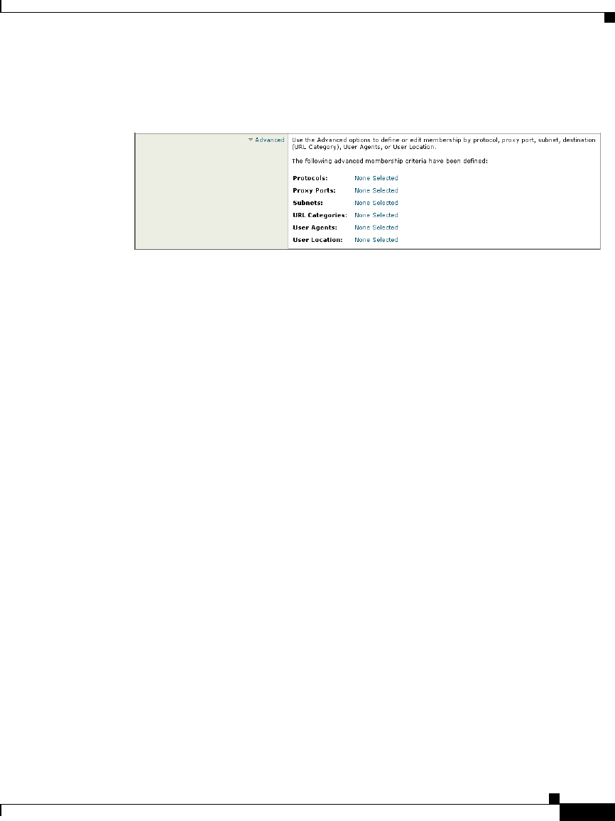
12-11
Cisco IronPort AsyncOS 7.1 for Web User Guide
OL-23207-01
Chapter 12 Data Security and External DLP Policies
Creating Data Security and External DLP Policies
Step 6 Optionally, expand the Advanced section to define additional membership
requirements.
Step 7 To define policy group membership by any of the advanced options, click the link
for the advanced option and configure the option on the page that appears.

Chapter 12 Data Security and External DLP Policies
Creating Data Security and External DLP Policies
12-12
Cisco IronPort AsyncOS 7.1 for Web User Guide
OL-23207-01
Table 12-1 describes the advanced options you can configure for Data Security
and External DLP Policy groups.
Table 12-1 Data Security and External DLP Policy Group Advanced
Options
Advanced Option Description
Protocols Choose whether or not to define policy group membership
by the protocol used in the client request. Select the
protocols to include.
“All others” means any protocol not listed above this option.
Note: When the HTTPS Proxy is enabled, only Decryption
Policies apply to HTTPS transactions. You cannot define
policy membership by the HTTPS protocol for Access,
Routing, Outbound Malware Scanning, Data Security, or
External DLP Policies.
Proxy Ports Choose whether or not to define policy group membership
by the proxy port used to access the Web Proxy. Enter one or
more port numbers in the Proxy Ports field. Separate
multiple ports with commas.
For explicit forward connections, this is the port configured
in the browser. For transparent connections, this is the same
as the destination port. You might want to define policy
group membership on the proxy port if you have one set of
clients configured to explicitly forward requests on one port,
and another set of clients configured to explicitly forward
requests on a different port.
Cisco recommends only defining policy group membership
by the proxy port when the appliance is deployed in explicit
forward mode, or when clients explicitly forward requests to
the appliance. If you define policy group membership by the
proxy port when client requests are transparently redirected
to the appliance, some requests might be denied.
Note: If the Identity associated with this policy group
defines Identity membership by this advanced setting, the
setting is not configurable at the non-Identity policy group
level.

12-13
Cisco IronPort AsyncOS 7.1 for Web User Guide
OL-23207-01
Chapter 12 Data Security and External DLP Policies
Creating Data Security and External DLP Policies
Subnets Choose whether or not to define policy group membership
by subnet or other addresses.
You can choose to use the addresses that may be defined with
the associated Identity, or you can enter specific addresses
here.
Note: If the Identity associated with this policy group
defines its membership by addresses, then in this policy
group you must enter addresses that are a subset of the
addresses defined in the Identity. Adding addresses in the
policy group further narrows down the list of transactions
that match this policy group.
URL Categories Choose whether or not to define policy group membership
by URL categories. Select the user defined or predefined
URL categories.
Note: If the Identity associated with this policy group
defines Identity membership by this advanced setting, the
setting is not configurable at the non-Identity policy group
level.
Table 12-1 Data Security and External DLP Policy Group Advanced Options
(continued)
Advanced Option Description

Chapter 12 Data Security and External DLP Policies
Creating Data Security and External DLP Policies
12-14
Cisco IronPort AsyncOS 7.1 for Web User Guide
OL-23207-01
Step 8 Submit your changes.
Step 9 If you are creating a Data Security Policy group, configure its control settings to
define how the Web Proxy handles upload requests.
The new Data Security Policy group automatically inherits global policy group
settings until you configure options for each control setting. For more
information, see Controlling Upload Requests Using IronPort Data Security
Policies, page 12-15.
Step 10 If you are creating an External DLP Policy group, configure its control settings to
define how the Web Proxy handles upload requests.
The new External DLP Policy group automatically inherits global policy group
settings until you configure custom settings. For more information, see
Controlling Upload Requests Using External DLP Policies, page 12-25.
Step 11 Submit and commit your changes.
User Agents Choose whether or not to define policy group membership
by the user agent used in the client request. You can select
some commonly defined browsers, or define your own using
regular expressions. Choose whether this policy group
should apply to the selected user agents or to any user agent
that is not in the list of selected user agents.
For more information on creating user agent based policies,
see Working with User Agent Based Policies, page 6-16.
Note: If the Identity associated with this policy group
defines Identity membership by this advanced setting, the
setting is not configurable at the non-Identity policy group
level.
User Location Choose whether or not to define policy group membership
by user location, either remote or local.
This option only appears when the Secure Mobility Solution
is enabled. For more information, see Achieving Secure
Mobility Overview, page 13-1.
Table 12-1 Data Security and External DLP Policy Group Advanced Options
(continued)
Advanced Option Description
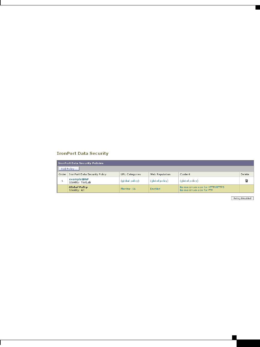
12-15
Cisco IronPort AsyncOS 7.1 for Web User Guide
OL-23207-01
Chapter 12 Data Security and External DLP Policies
Controlling Upload Requests Using IronPort Data Security Policies
Controlling Upload Requests Using IronPort Data
Security Policies
Each upload request is assigned to a Data Security Policy group and inherits the
control settings of that policy group. The control settings of the Data Security
Policy group determine whether the appliance blocks the connection or evaluates
it against the Access Polices.
Configure control settings for Data Security Policy groups on the Web Security
Manager > IronPort Data Security page.
Figure 12-2 shows where you can configure control settings for the Data Security
Policy groups.
Figure 12-2 Creating Secure IronPort Data Security Policies
You can configure the following settings to determine what action to take on
upload requests:
•URL Categories. For more information, see URL Categories, page 12-17.
•Web Reputation. For more information, see Web Reputation, page 12-17.
•Content. For more information, see Content Blocking, page 12-17.
After a Data Security Policy group is assigned to an upload request, the control
settings for the policy group are evaluated to determine whether to block the
request or evaluate it against the Access Policies. For more information about
assigning a Data Security Policy group to an upload request, see Policy Group
Membership, page 6-10.
Figure 12-3 on page 16 shows how the appliance determines which action to take
on an upload request after it has assigned a particular Data Security Policy to the
request.
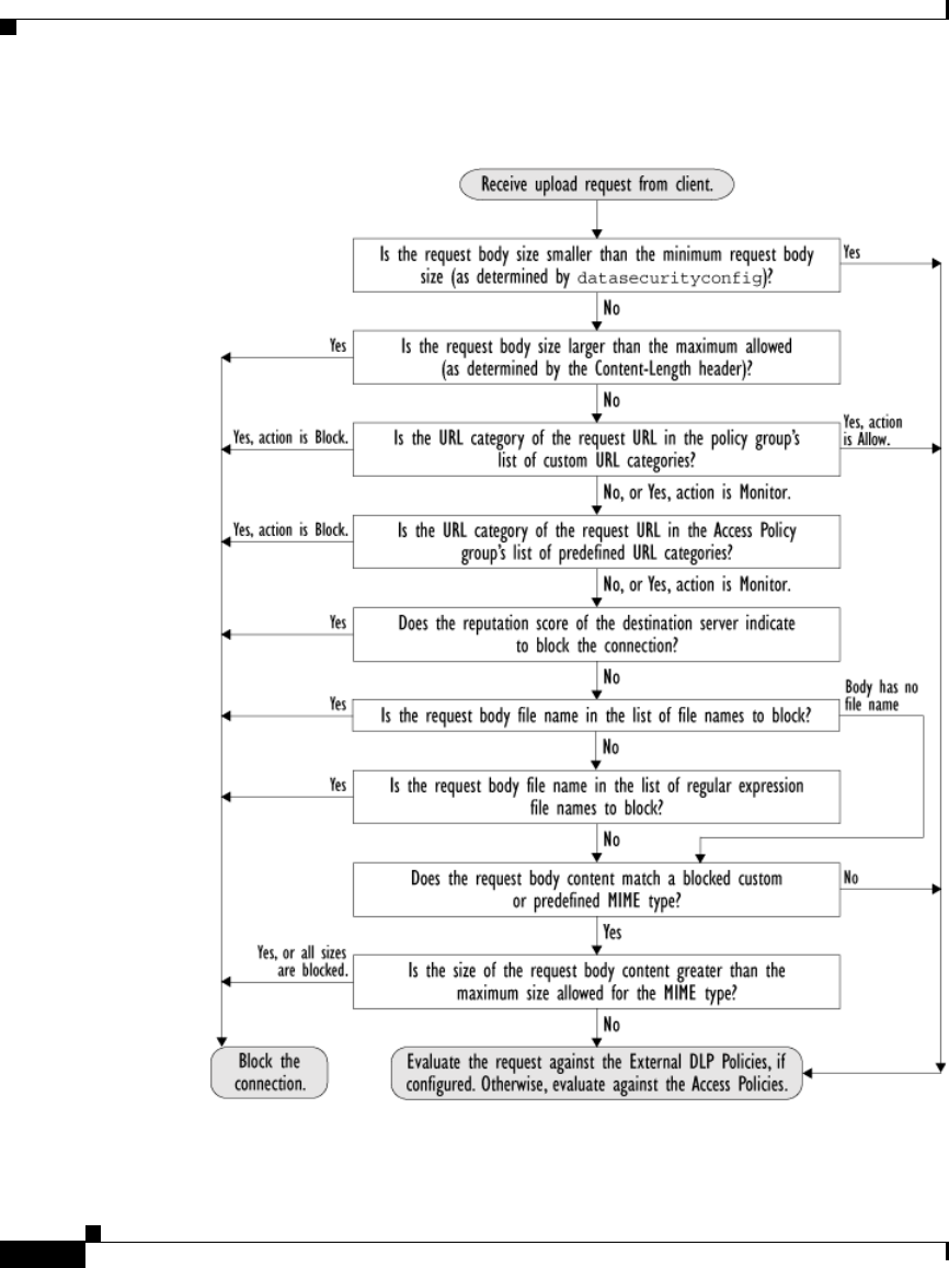
Chapter 12 Data Security and External DLP Policies
Controlling Upload Requests Using IronPort Data Security Policies
12-16
Cisco IronPort AsyncOS 7.1 for Web User Guide
OL-23207-01
Figure 12-3 Applying Data Security Policy Actions

12-17
Cisco IronPort AsyncOS 7.1 for Web User Guide
OL-23207-01
Chapter 12 Data Security and External DLP Policies
Controlling Upload Requests Using IronPort Data Security Policies
URL Categories
AsyncOS for Web allows you to configure how the appliance handles a
transaction based on the URL category of a particular request. Using a predefined
category list, you can choose to monitor or block content by category. You can
also create custom URL categories and choose to allow, monitor, or block traffic
for a website in the custom category.
For more information about working with URL categories, see Configuring URL
Filters for Data Security Policy Groups, page 16-13.
Web Reputation
The Web Reputation setting inherits the global setting. To customize web
reputation filtering for a particular policy group, you can use the Web Reputation
Settings pull-down menu to customize web reputation score thresholds.
Only negative and zero values can be configured for web reputation threshold
settings for IronPort Data Security Policies. By definition, all positive scores are
monitored.
For more information about configuring web reputation scores, see Configuring
Web Reputation Scores, page 18-5.
Content Blocking
You can use the settings on the IronPort Data Security Policies > Content page to
configure the Web Proxy to block data uploads based on the following file
characteristics:
•File size. You can specify the maximum upload size allowed. All uploads
with sizes equal to or greater than the specified maximum are blocked. You
can specify different maximum file sizes for HTTP/HTTPS and native FTP
requests.
When the upload request size is greater than both the maximum upload size
and the maximum scan size (configured in the “Object Scanning Limits” field
on Security Services > Anti-Malware page), the upload request is still
blocked, but the entry in the data security logs does not record the file name
and content type. The entry in the access logs is unchanged.

Chapter 12 Data Security and External DLP Policies
Controlling Upload Requests Using IronPort Data Security Policies
12-18
Cisco IronPort AsyncOS 7.1 for Web User Guide
OL-23207-01
•File type. You can block predefined file types or custom MIME types you
enter. When you block a predefined file type, you can block all files of that
type or files greater than a specified size. When you block a file type by size,
the maximum file size you can specify is the same as the value for the “Object
Scanning Limits” field on Security Services > Anti-Malware page. By
default, that value is 32 MB.
IronPort Data Security Filters do not inspect the contents of archived files
when blocking by file type. Archived files can be blocked by its file type or
file name, not according to its contents.
Note For some groups of MIME types, blocking one type blocks all MIME
types in the group. For example, blocking application/x-java-applet
blocks all java MIME types, such as application/java and
application/javascript.
•File name. You can block files with specified names. You can use text as a
literal string or a regular expression for specifying file names to block. For
more information on using regular expressions, see Regular Expressions,
page 16-28.
Note Only enter file names with 8-bit ASCII characters. The Web Proxy only
matches file names with 8-bit ASCII characters.
Figure 12-4 on page 19 shows the IronPort Data Security Policies > Content page
where you configure the content control settings.
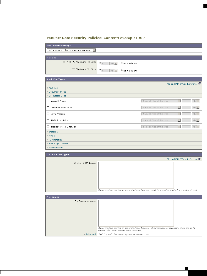
12-19
Cisco IronPort AsyncOS 7.1 for Web User Guide
OL-23207-01
Chapter 12 Data Security and External DLP Policies
Controlling Upload Requests Using IronPort Data Security Policies
Figure 12-4 IronPort Data Security Policies Content Settings
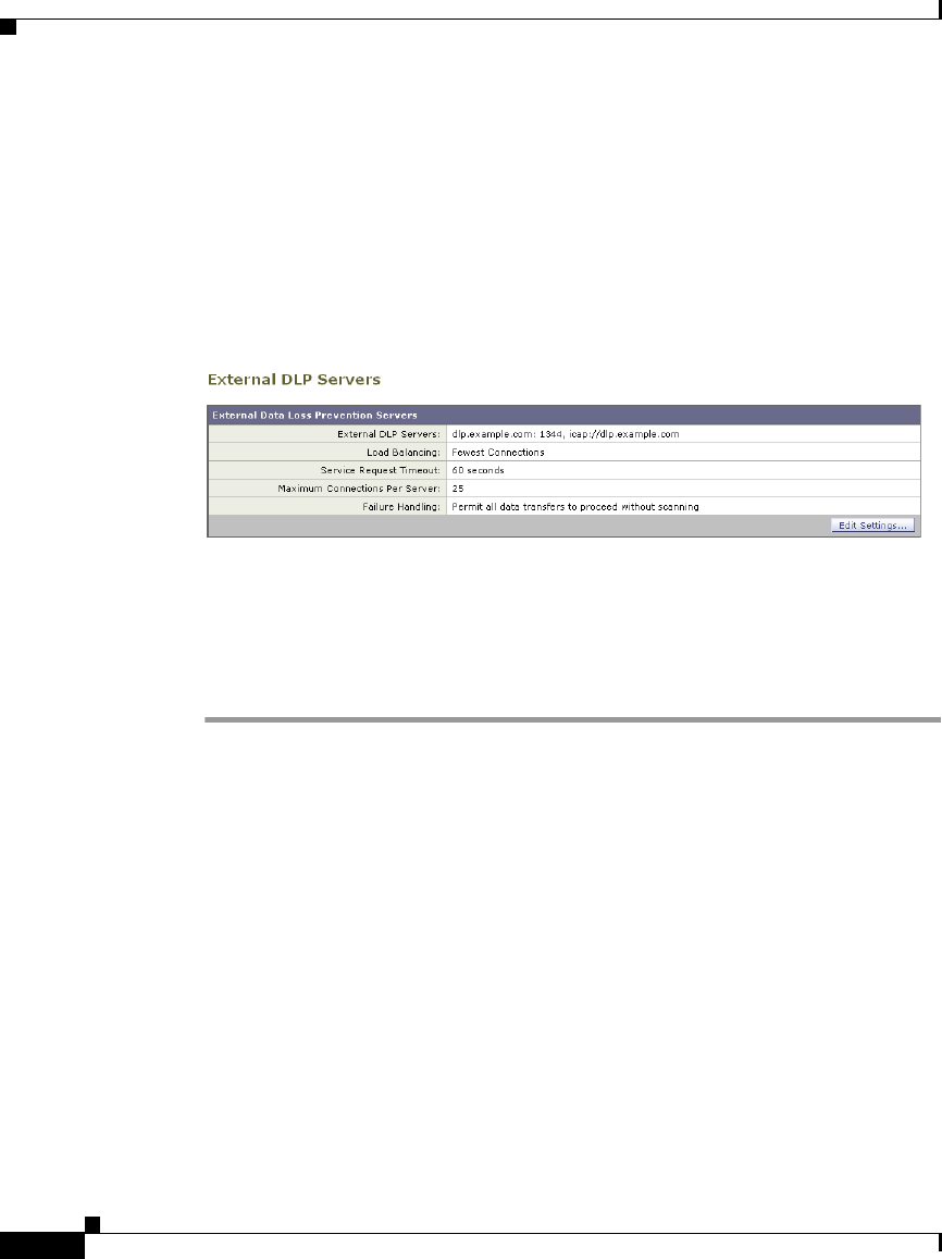
Chapter 12 Data Security and External DLP Policies
Defining External DLP Systems
12-20
Cisco IronPort AsyncOS 7.1 for Web User Guide
OL-23207-01
Defining External DLP Systems
The Web Security appliance can integrate with multiple external DLP servers
from the same vendor by defining multiple DLP servers in the appliance. Define
DLP systems and global settings that affect integration with all DLP systems on
the Network > External DLP Servers page.
Figure 12-5 Network > External DLP Servers Page
You can define the load balancing technique the Web Proxy uses when contacting
the DLP systems. This is useful when you define multiple DLP systems. For
example, the Web Proxy can contact each DLP system using round-robin or a hash
function.
To configure an external DLP server:
Step 1 Navigate to the Network > External DLP Servers page.
Step 2 Click Edit Settings.
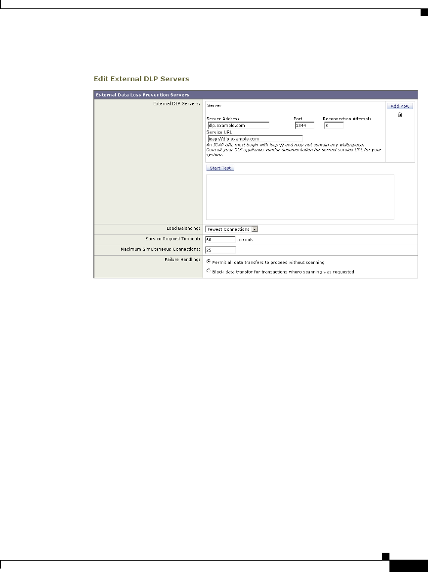
12-21
Cisco IronPort AsyncOS 7.1 for Web User Guide
OL-23207-01
Chapter 12 Data Security and External DLP Policies
Defining External DLP Systems
Figure 12-6 Configuring External DLP Servers


12-23
Cisco IronPort AsyncOS 7.1 for Web User Guide
OL-23207-01
Chapter 12 Data Security and External DLP Policies
Defining External DLP Systems
Table 12-2 External DLP Server Settings
Setting Description
External DLP Servers Enter the following information to access an ICAP
compliant DLP system:
•Server address and port. The hostname or IP
address and TCP port for accessing the DLP system.
•Reconnection attempts. The number of times the
Web Proxy tries to connect to the DLP system
before failing.
•DLP Service URL. The ICAP query URL specific
to the particular DLP server. The Web Proxy
includes what you enter here in the ICAP request it
sends to the external DLP server. The URL must
start with the ICAP protocol: icap://

Chapter 12 Data Security and External DLP Policies
Defining External DLP Systems
12-24
Cisco IronPort AsyncOS 7.1 for Web User Guide
OL-23207-01
Load Balancing If multiple DLP servers are defined, select which load
balancing technique the Web Proxy uses to distribute
upload requests to different DLP servers. You can
choose the following load balancing techniques:
•None (failover). The Web Proxy directs upload
requests to one DLP server. It tries to connect to the
DLP servers in the order they are listed. If one DLP
server cannot be reached, the Web Proxy attempts to
connect to the next one in the list.
•Fewest connections. The Web Proxy keeps track of
how many active requests are with the different
DLP servers and it directs the upload request to the
DLP server currently servicing the fewest number
of connections.
•Hash based. The Web Proxy uses a hash function to
distribute requests to the DLP servers. The hash
function uses the proxy ID and URL as inputs so
that requests for the same URL are always directed
to the same DLP server.
•Round robin. The Web Proxy cycles upload
requests equally among all DLP servers in the listed
order.
Service Request
Timeout
Enter how long the Web Proxy waits for a response from
the DLP server. When this time is exceeded, the ICAP
request has failed and the upload request is either
blocked or allowed, depending on the Failure Handling
setting.
Default is 60 seconds.
Table 12-2 External DLP Server Settings (continued)
Setting Description

12-25
Cisco IronPort AsyncOS 7.1 for Web User Guide
OL-23207-01
Chapter 12 Data Security and External DLP Policies
Controlling Upload Requests Using External DLP Policies
Step 4 Optionally, you can add another DLP server by clicking Add Row and entering
the DLP Server information in the new fields provided.
Step 5 You can test the connection between the Web Security appliance and the defined
external DLP server(s) by clicking Start Test.
Step 6 Submit and commit your changes.
Controlling Upload Requests Using External DLP
Policies
Each upload request is assigned to an External DLP Policy group and inherits the
control settings of that policy group. The control settings of the External DLP
Policy group determine whether or not to send the upload request to the external
DLP system for scanning.
Once the Web Proxy receives the upload request headers, it has all the information
necessary to decide if the request should go to the external DLP system for
scanning. The DLP system scans the request and returns a verdict to the Web
Proxy, either block or monitor (evaluate the request against the Access Policies).
The block page provided by the DLP system appears to the end user, if applicable.
Maximum
Simultaneous
Connections
Specifies the maximum number of simultaneous ICAP
request connections from the Web Security appliance to
each configured external DLP server. The Failure
Handling setting on this page applies to any request
which exceeds this limit.
Default is 25.
Failure Handling Choose whether upload requests are blocked or allowed
(passed to Access Policies for evaluation) when the DLP
server fails to provide a timely response.
Default is allow (“Permit all data transfers to proceed
without scanning”).
Table 12-2 External DLP Server Settings (continued)
Setting Description
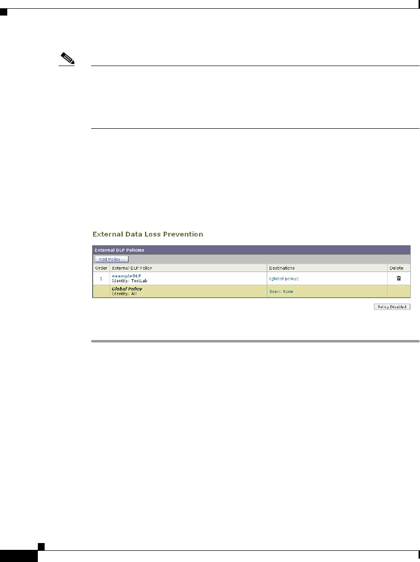
Chapter 12 Data Security and External DLP Policies
Controlling Upload Requests Using External DLP Policies
12-26
Cisco IronPort AsyncOS 7.1 for Web User Guide
OL-23207-01
Note If any Data Security Policy group applies to the upload request, the Web Proxy
evaluates the policy group’s control settings against the upload request at the same
time the external DLP system scans the request. If a Data Security Policy setting
blocks the request before the DLP system is done scanning, the Web Proxy blocks
the request and terminates the ICAP session with the DLP system.
Configure control settings for External DLP Policy groups on the Web Security
Manager > External Data Loss Prevention page.
Figure 12-7 shows where you can configure control settings for the External DLP
Policy groups.
Figure 12-7 Creating External DLP Policies
To configure control settings for an External DLP Policy group:
Step 1 Navigate to the Web Security Manager > External Data Loss Prevention page.
Step 2 Click the link under the Destinations column for the policy group you want to
configure.
Step 3 Under the Edit Destination Settings section, choose “Define Destinations
Scanning Custom Settings” from the drop down menu if it is not selected already.
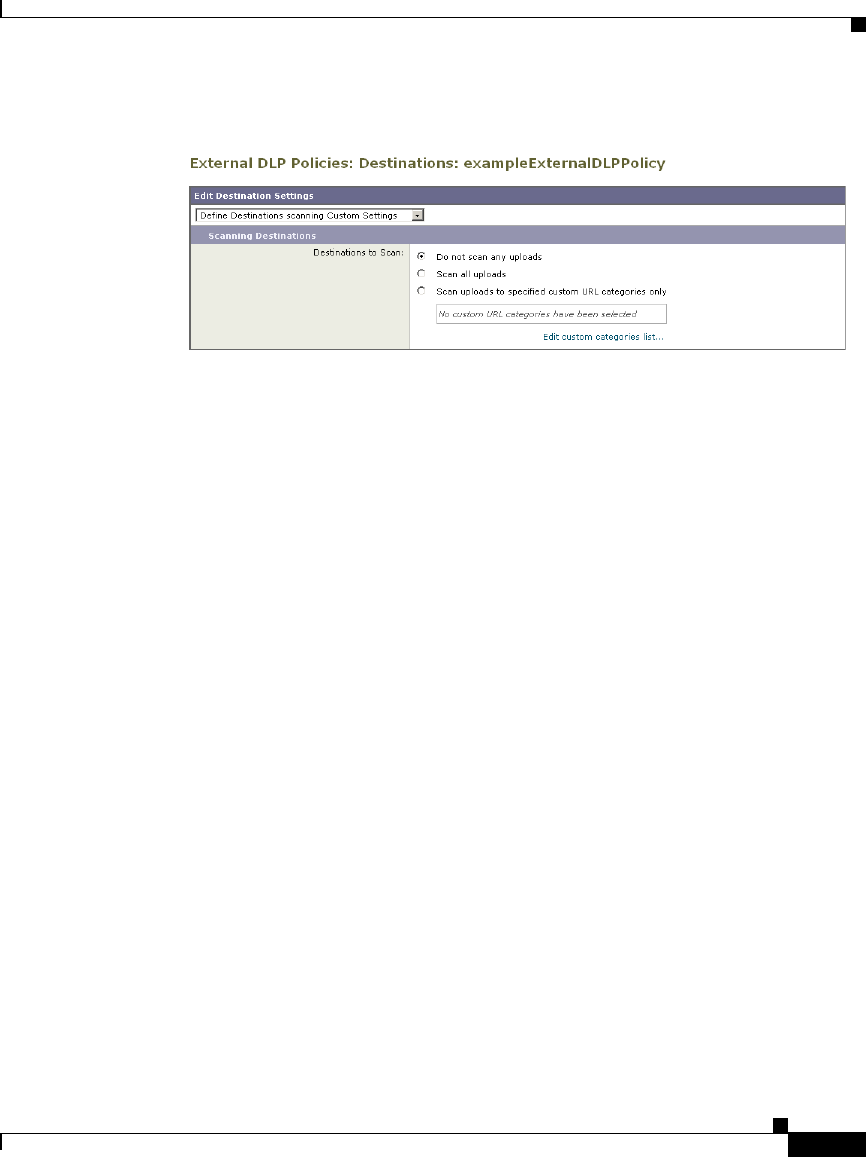
12-27
Cisco IronPort AsyncOS 7.1 for Web User Guide
OL-23207-01
Chapter 12 Data Security and External DLP Policies
Logging
Figure 12-8 Scanning Destinations Settings for External DLP Policies
Step 4 In the Destination to scan section, choose one of the following options:
•Do not scan any uploads. No upload requests are sent to the configured DLP
system(s) for scanning. All upload requests are evaluated against the Access
Policies.
•Scan all uploads. All upload requests are sent to the configured DLP
system(s) for scanning. The upload request is blocked or evaluated against the
Access Policies depending on the DLP system scanning verdict.
•Scan uploads to specified custom URL categories only. Upload requests
that fall in specific custom URL categories are sent to the configured DLP
system for scanning. The upload request is blocked or evaluated against the
Access Policies depending on the DLP system scanning verdict. Click Edit
custom categories list to select the URL categories to scan.
Step 5 Submit and commit your changes.
Logging
The access logs indicate whether or not an upload request was scanned by either
the IronPort Data Security Filters or an external DLP server. The access log
entries include a field for the IronPort Data Security scan verdict and another field
for the External DLP scan verdict based. For more information, see
Understanding Scanning Verdict Information, page 24-30.
In addition to the access logs, the Web Security appliance provides the following
log file types to troubleshoot IronPort Data Security and External DLP Policies:
•Data Security Logs. Records client history for upload requests that are
evaluated by the IronPort Data Security Filters.

Chapter 12 Data Security and External DLP Policies
Logging
12-28
Cisco IronPort AsyncOS 7.1 for Web User Guide
OL-23207-01
•Data Security Module Logs. Records messages related to the IronPort Data
Security Filters.
•Default Proxy Logs. In addition recording errors related to the Web Proxy,
the default proxy logs include messages related to connecting to external DLP
servers. This allows you to troubleshoot connectivity or integration problems
with external DLP servers.
The following text illustrates a sample Data Security Log entry:
Table 12-3 describes the Data Security Log fields.
Mon Mar 30 03:02:13 2009 Info: 303 10.1.1.1 - -
<<bar,text/plain,5120><foo,text/plain,5120>>
BLOCK_WEBCAT_DLP-allowall-DefaultGroup-DefaultGroup-NONE-DefaultRouti
ng ns server.com nc
Table 12-3 Data Security Log Fields
Field Value Description
Mon Mar 30 03:02:13 2009 Info: Timestamp and trace level
303 Transaction ID
10.1.1.1 Source IP address
-User name
-Authorized group names
<<bar,text/plain,5120><foo,text/
plain,5120>>
File name, file type, file size for each
file uploaded at once
Note: This field does not include
text/plain files that are less than the
configured minimum request body size,
the default of which is 4096 bytes. For
more information on configuring the
minimum request body size, see
Bypassing Upload Requests Below a
Minimum Size, page 12-3.
BLOCK_WEBCAT_DLP-allowall-Defaul
tGroup-DefaultGroup-NONE-Default
Routing
IronPort Data Security Policy and action
ns WBRS score

12-29
Cisco IronPort AsyncOS 7.1 for Web User Guide
OL-23207-01
Chapter 12 Data Security and External DLP Policies
Logging
Note To learn when data transfer, such as a POST request, to a site was blocked by the
external DLP server, search for the IP address or hostname of the DLP server in
the access logs.
server.com Outgoing URL
nc URL category
Table 12-3 Data Security Log Fields (continued)
Field Value Description

Chapter 12 Data Security and External DLP Policies
Logging
12-30
Cisco IronPort AsyncOS 7.1 for Web User Guide
OL-23207-01

CHAPTER
13-1
Cisco IronPort AsyncOS 7.1 for Web User Guide
OL-23207-01
13
Achieving Secure Mobility
This chapter contains the following information:
•Achieving Secure Mobility Overview, page 13-1
•Working with Remote Users, page 13-2
•Enabling Secure Mobility, page 13-3
•Transparently Identifying Remote Users, page 13-5
•Logging, page 13-6
•Configuring Secure Mobility Using the CLI, page 13-7
Achieving Secure Mobility Overview
Today, users and their devices are increasingly more mobile, connecting to the
Internet from several locations, such as the office, home, airports, or cafes.
Traditionally, users inside the network are protected from security threats, and
users outside the traditional network boundary have no acceptable use policy
enforcement, minimal protection against malware, and a high risk of data loss.
Employers want to create flexible working environments where employees and
partners can work anywhere on any device, but they also want to protect corporate
interests and assets from Internet-based threats at all times (always-on security).
Traditional network and content security solutions are great for protecting users
and assets behind the network firewall, but are useless when users or devices are
not connected to the network, or when data is not routed through the security
solutions.

Chapter 13 Achieving Secure Mobility
Working with Remote Users
13-2
Cisco IronPort AsyncOS 7.1 for Web User Guide
OL-23207-01
Cisco offers Secure Mobility Solution to extend the network perimeter to remote
endpoints, enabling the seamless integration of web filtering services offered by
the Web Security appliance. Secure Mobility Solution is a collection of features
across multiple Cisco products that restores security and control in borderless
networks. The Cisco products that work with Secure Mobility Solution are the
Cisco IronPort Web Security appliance, Cisco ASA 5500 series adaptive security
appliance, and Cisco AnyConnect secure mobility client.
Using Secure Mobility Solution, mobile and remote users have a seamless
experience and are always protected from risks as if they were local users
connected within the network.
When Secure Mobility Solution is enabled on the Web Security appliance, you
can distinguish remote users from local users. This allows you to perform the
following tasks:
•Create Identities and other policies for remote users.
•View reports for remote traffic.
•Enable single sign-on (SSO) for remote users.
For information on enabling single sign-on, see Transparently Identifying Remote
Users, page 13-5.
Note To enable Secure Mobility Solution, the appropriate license key must be installed
on the Web Security appliance.
Working with Remote Users
When Secure Mobility Solution is enabled, you can configure Identities and other
policies to apply to users by their location:
•Remote users. These users are connected to the network from a remote
location using VPN (virtual private network). Users might be located in a
home office, coffee shop, or hotel, for example. The Web Security appliance
automatically identifies remote users when both the Cisco adaptive security
appliance and Cisco AnyConnect client are used for VPN access. Otherwise,
the Web Security appliance administrator must specify remote users by
configuring a range of IP addresses.

13-3
Cisco IronPort AsyncOS 7.1 for Web User Guide
OL-23207-01
Chapter 13 Achieving Secure Mobility
Enabling Secure Mobility
•Local users. These users are connected to the network either physically or
wirelessly.
You might want to create separate policies for remote and local users. For
example, you can create Access Policies that allow access to Arts and
Entertainment sites when users are outside the office (remote users), but block
access when users are in the office (local users).
When you enable Secure Mobility Solution on the Security Services > Mobile
User Security Page, you identify remote users using one of the following methods:
•Associate by IP address. Specify a range of IP addresses that the appliance
should consider as assigned to remote devices. Typically, the Cisco adaptive
security appliance assigns these IP addresses to devices that connect using
VPN functionality. When the Web Security appliance receives a transaction
from one of the configured IP addresses, it considers the user as a remote user.
•Integrate with a Cisco ASA. Specify one or more Cisco adaptive security
appliances the Web Security appliance communicates with. The Cisco
adaptive security appliance maintains an IP address-to-user mapping and
communicates that information with the Web Security appliance. When the
Web Proxy receives a transaction, it obtains the IP address and determines the
user by checking the IP address-to-user mapping. When users are determined
by integrating with a Cisco adaptive security appliance, you can enable single
sign-on for remote users.
For information on enabling single sign-on, see Transparently Identifying
Remote Users, page 13-5.
Enabling Secure Mobility
To protect remote users using always-on security, first you must enable the Secure
Mobility Solution feature on the Web Security appliance. When Secure Mobility
Solution is enabled, you can distinguish between remote users from local users
when creating Identities.
Note You can also configure Secure Mobility Solution using the CLI. For more
information, see Configuring Secure Mobility Using the CLI, page 13-7.
To enable Secure Mobility Solution:
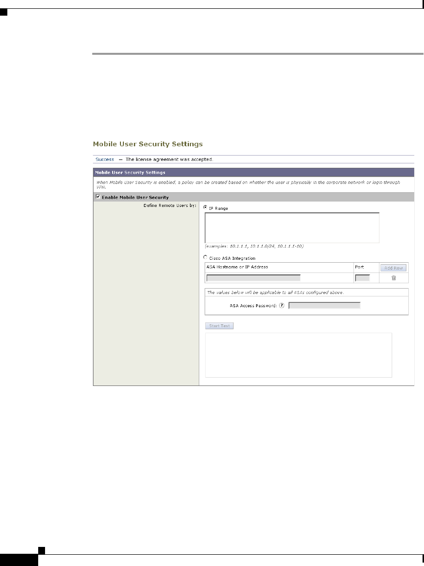
Chapter 13 Achieving Secure Mobility
Enabling Secure Mobility
13-4
Cisco IronPort AsyncOS 7.1 for Web User Guide
OL-23207-01
Step 1 Navigate to the Security Services > Mobile User Security, and click Enable.
The Mobile User Security License Agreement appears.
Step 2 Read the terms of the Mobile User Security License Agreement, and click Accept.
The Mobile User Security Settings page appears.
Step 3 Verify the Enable Mobile User Security field is enabled.
Configure how to identify remote users, by IP address or by integrating with one
or more Cisco adaptive security appliances. For more information, see Working
with Remote Users, page 13-2.
Step 4 To identify remote users by IP address, select the IP Range option, enter a range
of IP addresses in the IP Range field, and then go to step 10. Otherwise, go to step
5.
Step 5 To identify remote users by integrating with one or more Cisco adaptive security
appliances, select the Cisco ASA Integration option.

13-5
Cisco IronPort AsyncOS 7.1 for Web User Guide
OL-23207-01
Chapter 13 Achieving Secure Mobility
Transparently Identifying Remote Users
Step 6 Configure at least one Cisco adaptive security appliance by entering the Cisco
adaptive security appliance host name or IP address in the ASA Host Name or IP
Address field, and the port number used to access the ASA in the Port field. The
default port number for the Cisco ASA is 11999.
Step 7 If multiple Cisco adaptive security appliances are configured in a cluster, click
Add Row and configure each ASA in the cluster. If two Cisco adaptive security
appliances are configured for high availability, enter only one host name or IP
address for the active Cisco adaptive security appliance.
Step 8 In the ASA Access Password field, enter the access password for the Cisco
adaptive security appliances specified in steps 6 and 7. The access password must
be at least eight characters, and no more than 20 characters. The allowed
characters are:
0-9 a-z A-Z . , : ; _ / -
Note The password you enter here must match the access password configured
for the specified Cisco adaptive security appliances.
Step 9 Optionally, click Start Test to verify the Web Security appliance can connect to
the configured Cisco adaptive security appliances.
Step 10 Submit and commit your changes.
Transparently Identifying Remote Users
When the Web Security appliance integrates with a Cisco adaptive security
appliance, you can configure it to identify users by an authenticated user name
transparently—that is, without prompting the end user. You might want to do this
to achieve single sign-on for remote users.
Note You can also identify users transparently using Novell eDirectory. For more
information, see Identifying Users Transparently, page 7-16.
To configure transparent user identification for remote users:

Chapter 13 Achieving Secure Mobility
Logging
13-6
Cisco IronPort AsyncOS 7.1 for Web User Guide
OL-23207-01
Step 1 Enable Secure Mobility Solution on the Security Services > Mobile User Security
page.
For more information, see Enabling Secure Mobility, page 13-3.
Step 2 Create an Identity group that applies to remote users:
a. In the “Define Members by User Location” section, select Remote Users
Only.
b. In the “Define Members by Authentication” section, select “Identify Users
Transparently through Cisco ASA Integration.”
c. Configure all other Identity options as desired.
For more information on creating Identities, see Creating Identities,
page 7-20.
Step 3 Create policies that use the Identity for remote users.
Logging
The access logs indicate whether each transaction was made by a local or remote
user. You can also add the same custom format specifier (%l) to the existing
access logs, or you can add the equivalent W3C field (auth-user-type) to the W3C
access logs.
In addition to the access logs, the Web Security appliance provides the following
logs for troubleshooting potential Secure Mobility Solution issues.
•User Discovery Service (UDS) log. The UDS log records data about how the
Web Proxy discovers the user name without doing actual authentication. It
includes information about interacting with the Cisco adaptive security
appliance for Secure Mobility Solution as well as integrating with the Novell
eDirectory server for transparent user identification.
•Mobile User Security Daemon log. The Mobile User Security Daemon log
records the interaction between the Web Security appliance and the
AnyConnect client, including the status check.

13-7
Cisco IronPort AsyncOS 7.1 for Web User Guide
OL-23207-01
Chapter 13 Achieving Secure Mobility
Configuring Secure Mobility Using the CLI
Configuring Secure Mobility Using the CLI
Table 13-1 describes the CLI commands you can use to configure and monitor
Secure Mobility Solution.
Table 13-1 Secure Mobility CLI Commands
Command Description
musconfig Use this command to enable Secure Mobility Solution and
configure how to identify remote users, either by IP address
or by integrating with one or more Cisco adaptive security
appliances.
Note: Changes made using this command cause the Web
Proxy to restart.
For more information on enabling and configuring Secure
Mobility Solution, see Enabling Secure Mobility, page 13-3.
musstatus Use this command to display information related to Secure
Mobility Solution when the Web Security appliance is
integrated with an adaptive security appliance.
This command displays the following information:
•The status of the Web Security appliance connection with
each adaptive security appliance.
•The duration of the Web Security appliance connection
with each adaptive security appliance in minutes.
•The number of remote clients from each adaptive security
appliance.
•The number of remote clients being serviced, which is
defined as the number of remote clients that have passed
traffic through the Web Security appliance.
•The total number of remote clients.

Chapter 13 Achieving Secure Mobility
Configuring Secure Mobility Using the CLI
13-8
Cisco IronPort AsyncOS 7.1 for Web User Guide
OL-23207-01

CHAPTER
14-1
Cisco IronPort AsyncOS 7.1 for Web User Guide
OL-23207-01
14
Controlling Access to SaaS
Applications
This chapter contains the following information:
•SaaS Access Control Overview, page 14-1
•Understanding How SaaS Access Control Works, page 14-2
•Configuring the Appliance as an Identity Provider, page 14-7
•Creating SaaS Application Authentication Policies, page 14-11
SaaS Access Control Overview
Organizations are increasingly choosing to use software as a service (SaaS)
applications instead of owning and managing software applications within the
organization. SaaS applications typically reside “in the cloud” instead of
on-premise inside your network. There are many potential benefits to using SaaS
applications, such as cost savings, but there are also challenges, especially for IT
administrators who have to manage access control to the SaaS applications.
Cisco offers the SaaS Access Control feature which provides IT administrators
with seamless, secure controls necessary for managing access to SaaS
applications and enforcing security policies. SaaS Access Control allows IT
administrators to easily control authentication and authorization for users who
need to access SaaS applications.

Chapter 14 Controlling Access to SaaS Applications
Understanding How SaaS Access Control Works
14-2
Cisco IronPort AsyncOS 7.1 for Web User Guide
OL-23207-01
When you enable Cisco SaaS Access Control, users log into the configured SaaS
applications using their network authentication user credentials. That means they
use the same user name and password for all SaaS applications as well as network
access. You can choose whether users are transparently signed in (single sign-on
functionality) or prompted to enter their authentication user name and password.
Using Cisco SaaS Access Control with the proper access controls of your SaaS
application allows you to:
•Control which users can access SaaS applications and from where.
•Increase usability for end users by requiring them to remember only one
password.
•Quickly disable access to all SaaS applications when users are no longer
employed by the organization. This is sometimes referred to as “zero day
revocation.”
•Reduce the risk of phishing attacks that ask users to enter their SaaS user
credentials.
Understanding How SaaS Access Control Works
The SaaS Access Control solution uses the Security Assertion Markup Language
(SAML) to authorize access to SaaS applications. It works with SaaS applications
that are strictly compliant with SAML version 2.0.
SAML is an XML-based standard for exchanging authentication and
authorization data between different secure networks, sometimes referred to as
security domains. The main problem that SAML solves is single sign-on between
different security domains. Typically, this is users in one domain accessing a
network (a different domain) using a web browser. This is sometimes referred to
as web browser single sign-on.
To achieve web browser single sign-on, a SAML dialogue must be engaged by an
entity in each domain, which SAML defines using the following terms:
•Identity provider. An identity provider is an entity that produces SAML
assertions. The identity provider is expected to authenticate its end users
before producing a SAML assertion. The Web Security appliance is an
identity provider.

14-3
Cisco IronPort AsyncOS 7.1 for Web User Guide
OL-23207-01
Chapter 14 Controlling Access to SaaS Applications
Understanding How SaaS Access Control Works
•Service provider. A service provider is an entity that consumes SAML
assertions. The SaaS applications you configure on the Web Security
appliance are service providers. The service provider relies on the identity
provider to identify the end user and communicate that identification to the
service provider in the SAML assertion. The service provider makes an
access control decision based on the assertion.
SAML assertions are containers of information passed between identity providers
and service providers inside SAML requests and responses. Assertions contain
statements (such as authentication and authorization statements) that service
providers use to make access control decisions. Assertions start with the
<saml:Assertion> tag.
SAML dialogues are called flows, and flows can be initiated by either provider:
•Service provider initiated flow. The service provider is contacted by an end
user requesting access so it starts a SAML dialogue by contacting the identity
provider to provide identification for the user. For service provider initiated
flows, the end user accesses the service provider using a URL that contains
the service provider’s domain, such as
http://www.serviceprovider.com/<URI>.
•Identity provider initiated flow. The identity provider starts a SAML
dialogue by contacting the service provider requesting access on behalf of an
end user. For identity provider initiated flows, the end user accesses the
service provider using a URL that contains a local domain, such as
http://saas.example.com/<URI>.
SaaS applications define whether they support service provider or identity
provider initiated flows. For example, Salesforce supports identity provider
initiated flows, Google Apps supports service provider initiated flows, and Cisco
WebEx supports both.
The type of flow supported by a SaaS application determines how end users access
the application. For more information, see Understanding the Single Sign-On
URL, page 14-5.
Note This section does not provide a comprehensive discussion of SAML, nor how
identity and security providers communicate with each other. For more detailed
information, read about SAML on the web at
http://docs.oasis-open.org/security/saml/v2.0/.

Chapter 14 Controlling Access to SaaS Applications
Understanding How SaaS Access Control Works
14-4
Cisco IronPort AsyncOS 7.1 for Web User Guide
OL-23207-01
Authenticating SaaS Users
When users access a SaaS application, you can allow them to transparently sign
into the SaaS application using their local authentication credentials or always
prompt them for their local authentication credentials.
When users are prompted to authenticate, the authentication credentials are sent
to the Web Proxy using a secure HTTPS connection. The appliance uses its own
certificate and private key to create an HTTPS connection with the client by
default. Most browsers will warn users that the certificate is not valid. To prevent
users from seeing the invalid certificate message, you can upload a certificate and
key pair your organization uses. For information about uploading a certificate and
key, see Uploading Certificates and Keys to Use with Credential Encryption and
SaaS Access Control, page 20-38.
Note To achieve single sign-on behavior using explicit forward requests for all
authenticated users when the appliance is deployed in transparent mode, you must
select the “Apply same surrogate settings to explicit forward requests” setting
when you configure the Identity group.
Authentication Requirements
Some service providers require a particular authentication mechanism to allow
users to access the SaaS application. If a service provider requires an
authentication context that is not supported by an identity provider, users cannot
access the service provider using single sign-on from the identity provider.
Therefore, SaaS Access Control only works with SaaS applications that require
an authentication mechanism supported by the Web Security appliance. Currently,
the Web Proxy uses the “PasswordProtectedTransport” authentication
mechanism. You configure this value when you create a SaaS Application
Authentication Policy using the Authentication Context setting. However,
administrators typically choose “Automatic” as the Authentication Context
setting.
For more information on creating SaaS Application Authentication Policies, see
Creating SaaS Application Authentication Policies, page 14-11.

14-5
Cisco IronPort AsyncOS 7.1 for Web User Guide
OL-23207-01
Chapter 14 Controlling Access to SaaS Applications
Understanding How SaaS Access Control Works
Enabling SaaS Access Control
To enable SaaS Access Control, you must configure settings on both the Web
Security appliance and the SaaS application. It is very important that the settings
you configure on the appliance and SaaS application match each other
appropriately.
When enabling SaaS Access Control, it is easiest to keep open a connection to the
Web Security appliance and the SaaS application simultaneously. You will need
to go back and forth between both components and copy and paste information
between both.
Note For more information on configuring SaaS Access Control for particular SaaS
applications, contact your technical sales representative or search the cisco.com
website for additional information, such as white papers, knowledge base articles,
or video tutorials.
To use SaaS Access Control, follow these steps:
1. Configure the Web Security appliance as an identity provider. For more
information, see Configuring the Appliance as an Identity Provider,
page 14-7.
2. Configure the SaaS application for single sign-on. When configuring the
SaaS application, you must also upload the certificate used on the Security
Services > Identity Provider for SaaS page. For more information, see the
SaaS application documentation.
3. Create one or more SaaS Application Authentication Policies for each
SaaS application. For more information, see Creating SaaS Application
Authentication Policies, page 14-11.
Understanding the Single Sign-On URL
After you configure the Web Security appliance as an identity provider and create
a SaaS Application Authentication Policy for the SaaS application, the appliance
creates a single sign-on URL (SSO URL).
How administrators use this URL depends on the flow type:

Chapter 14 Controlling Access to SaaS Applications
Understanding How SaaS Access Control Works
14-6
Cisco IronPort AsyncOS 7.1 for Web User Guide
OL-23207-01
•Identity provider initiated flows. Administrators should make the single
sign-on URL available to end users to access this SaaS application. For
example, administrators can create an internal web page that includes this
URL as a link. After users login, the appliance redirects users to the SaaS
application.
•Service Provider initiated flows. Administrators should configure this URL
in the SaaS application. The SaaS application uses the single sign-on URL to
redirect the browser session depending on the “SaaS SSO Authentication
Prompt” setting in the policy group:
–
Always prompt SaaS users for proxy authentication. A Web Security
appliance page appears where users can enter their local authentication
credentials. After entering valid credentials, users are logged into the
SaaS application.
–
Transparently sign in SaaS users. Users are logged into the SaaS
application automatically.
The Web Security appliance uses the application name configured in the SaaS
Application Authentication Policy to generate the single sign-on URL. You can
view the single sign-on URL on the Web Security Manager > SaaS Policies page
after you submit the changes.
The single sign-on URL format is:
http://IdentityProviderDomainName/SSOURL/ApplicationName
Therefore, when the appliance Identity Provider Domain Name is
idp.example.com and the application name in the SaaS Application
Authentication Policy is GoogleApps, the single sign-on URL is:
http://idp.example.com/SSOURL/GoogleApps
Using SaaS Access Control with Multiple Appliances
When you use multiple Web Security appliances with SaaS Access Control, you
must perform the following steps:
•Configure the same Identity Provider Domain Name for each Web Security
appliance.
•Configure the same Identity Provider Entity ID for each Web Security
appliance.

14-7
Cisco IronPort AsyncOS 7.1 for Web User Guide
OL-23207-01
Chapter 14 Controlling Access to SaaS Applications
Configuring the Appliance as an Identity Provider
•Upload the same certificate and private key to each appliance on the Security
Services > Identity Provider for SaaS page. Then upload this certificate to
each SaaS application you configure.
Configuring the Appliance as an Identity Provider
When you configure the Web Security appliance as an identity provider, the
settings you define apply to all SaaS applications it communicates with. The Web
Security appliance uses a certificate and key to sign each SAML assertion it
creates. You can either upload or generate the certificate and key.
After you choose which certificate and key to use for signing SAML assertions,
you must upload the certificate to each SaaS application. You can do this using
the Download Certificate link in the Signing Certificate area. Uploading the
certificate ensures the SaaS application (service provider) has the Web Security
appliance public key in order to form a trusted relationship between the service
provider and the Web Security appliance (identity provider).
Consider the following rules and guidelines when you configure the Web Security
appliance as an identity provider:
•The identity provider domain name must be resolvable within the network.
For example, within the organization “example.com,” a transparent request to
“http://idp.example.com/” should be network routable and can reach to the
Web Security appliance within the network perimeter.
•If you intend to use multiple Web Security appliances with SaaS Access
Control, you must enter the same Identity Provider Domain Name for each
appliance and the same Identity Provider Entity ID for each appliance. For
more information, see Using SaaS Access Control with Multiple Appliances,
page 14-6.
•After you generate on or upload a certificate and key to the appliance, you
must upload the same certificate to each SaaS application with which the Web
Security appliance will communicate. You can do this by downloading the
certificate from the appliance first.
•Make note of the settings you configure when you configure the Web Security
appliance as an identity provider. Some of these settings must be used when
configuring the SaaS application for single sign-on. It is easiest to keep open
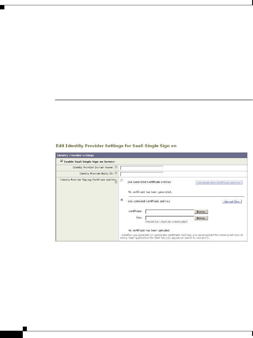
Chapter 14 Controlling Access to SaaS Applications
Configuring the Appliance as an Identity Provider
14-8
Cisco IronPort AsyncOS 7.1 for Web User Guide
OL-23207-01
a connection to the Web Security appliance and the SaaS application
simultaneously. You will need to go back and forth between both components
and copy and paste information between both
•The appliance constructs a single sign-on (SSO) login URL for each SaaS
application based on the value you enter the Identity Provider Domain Name
field and the SaaS application name configured in the SaaS policy. For more
information, see Understanding the Single Sign-On URL, page 14-5.
To configure the Web Security appliance as an identity provider:
Step 1 Navigate to the Security Services > Identity Provider for SaaS page.
Step 2 Click Edit Settings.
Step 3 In the Identity Provider Domain Name field, enter a virtual domain name to use
to access the Web Security appliance as an identity provider instance.
The identity provider domain name should be resolvable within the network. For
example, within the organization “example.com,” a transparent request to
“http://idp.example.com/” should be network routable and can reach to the Web
Security appliance within the network perimeter.

14-9
Cisco IronPort AsyncOS 7.1 for Web User Guide
OL-23207-01
Chapter 14 Controlling Access to SaaS Applications
Configuring the Appliance as an Identity Provider
Note If you intend to use multiple Web Security appliances with SaaS Access Control,
you must enter the same Identity Provider Domain Name for each Web Security
appliance. If you have only one appliance, you can use the appliance hostname as
the Identity Provider Domain Name. For more information, see Using SaaS
Access Control with Multiple Appliances, page 14-6.
Step 4 In the Identity Provider Entity ID field, enter the text you want to use that
uniquely identifies this Web Security appliance as an identity provider to all SaaS
applications it will communicate with.
A URI format based string is recommended, but you can enter any unique string.
The URI string does not have to be network accessible. Record the value you enter
here because you will need to use the same value when you configure the SaaS
application for single sign-on.
Note If you intend to use multiple Web Security appliances with SaaS Access Control,
you must enter the same Identity Provider Entity ID for each Web Security
appliance. For more information, see Using SaaS Access Control with Multiple
Appliances, page 14-6.
Step 5 Configure a signing certificate the appliance should use when it communicates
using a secure connection (in the SAML flow) with service providers. You can use
either of the following methods to configure the certificate:
•Generated certificate and key. Go to step 6 on page 9.
•Uploaded certificate and key. Go to step 7 on page 10.
Note If the appliance has both an uploaded certificate and key pair and a
generated certificate and key pair, it only uses the certificate and key pair
currently selected in the Signing Certificate section.
Step 6 To generate a certificate and key:
a. Click the Use Generated Certificate and Key option.
b. Click Generate New Certificate and Key.
c. In the Generate Certificate and Key dialog box, enter the information to
display in the signing certificate.

Chapter 14 Controlling Access to SaaS Applications
Configuring the Appliance as an Identity Provider
14-10
Cisco IronPort AsyncOS 7.1 for Web User Guide
OL-23207-01
Note You can enter any ASCII character except the forward slash ( / ) in the
Common Name field.
d. Click Generate. The Web Security appliance generates the certificate with
the data you entered and generates a key.
The generated certificate information is displayed on the Edit Identity
Provider Settings for SaaS Single Sign on page.
Note After you generate the certificate and key, you can download the
generated certificate to transfer it to the SaaS applications with which
the Web Security appliance will communicate. Do this using the
Download Certificate link in the generated key area.
e. Go to step 8 on page 11.
Step 7 To upload a root certificate and key:
a. Click Use Uploaded Certificate and Key.
b. Click Browse for the Certificate field to navigate to the certificate file stored
on the local machine.
If the file you upload contains multiple certificates or keys, the Web Proxy
uses the first certificate or key in the file.
Note The certificate file must be in PEM format. DER format is not
supported.
c. Click Browse for the Key field to navigate to the private key file. The private
key must be unencrypted.
Note The key length must be 512, 1024, or 2048 bits. Also, the private key
file must be in PEM format. DER format is not supported.
d. Click Upload Files to transfer the certificate and key files to the Web Security
appliance.

14-11
Cisco IronPort AsyncOS 7.1 for Web User Guide
OL-23207-01
Chapter 14 Controlling Access to SaaS Applications
Creating SaaS Application Authentication Policies
The uploaded certificate information is displayed on the Edit Identity
Provider Settings for SaaS Single Sign on page.
Note After you upload the certificate and key, you can download the
generated certificate to transfer it to the SaaS applications with which
the Web Security appliance will communicate. Do this using the
Download Certificate link in the generated key area.
Step 8 Submit and commit your changes.
Creating SaaS Application Authentication Policies
After you configure the Web Security appliance as an identity provider and you
configure a SaaS application for single sign-on, you can create a SaaS Application
Authentication Policy so the Web Security appliance can communicate with the
SaaS application and enable web browser single sign-on.
Consider the following rules and guidelines when you configure the SaaS
application information in a SaaS Application Authentication Policy:
•The Assertion Consumer Service Location URL must be must be resolvable
within the network.
•The appliance constructs a single sign-on (SSO) login URL for each SaaS
application based on the value you enter the Identity Provider Domain Name
field for the appliance and the SaaS application name configured in the SaaS
policy. For more information, see Understanding the Single Sign-On URL,
page 14-5.
To create a SaaS Application Authentication Policy:
Step 1 Navigate to the Web Security Manager > SaaS Policies page.
Step 2 Click Add Applications to create a new policy for a particular SaaS application.
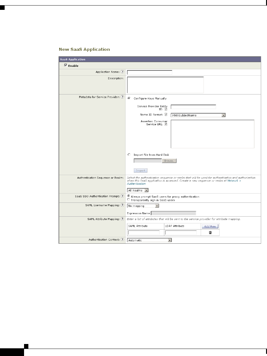
Chapter 14 Controlling Access to SaaS Applications
Creating SaaS Application Authentication Policies
14-12
Cisco IronPort AsyncOS 7.1 for Web User Guide
OL-23207-01

14-13
Cisco IronPort AsyncOS 7.1 for Web User Guide
OL-23207-01
Chapter 14 Controlling Access to SaaS Applications
Creating SaaS Application Authentication Policies
Step 3 Configure the settings defined in Table 14-1.
Property Description
Application Name Enter a name to identify the SaaS application for this
policy group. Each application name must be unique and
only contain alphanumeric characters or the space
character.
The Web Security appliance uses the application name to
generate a single sign-on URL. For more information, see
Understanding the Single Sign-On URL, page 14-5.
Description Optionally, enter a description for this SaaS application.

Chapter 14 Controlling Access to SaaS Applications
Creating SaaS Application Authentication Policies
14-14
Cisco IronPort AsyncOS 7.1 for Web User Guide
OL-23207-01
Metadata for Service
Provider
Configure the metadata that describes the service
provider referenced in this policy group. You can either
describe the service provider properties manually or
upload a metadata file provided by the SaaS application.
The Web Security appliance uses the metadata to
determine how to communicate with the SaaS application
(service provider) using SAML. Contact the SaaS
application to learn the correct settings to configure the
metadata.
When you manually configure the metadata information,
configure the following values:
•Service Provider Entity ID. Enter the text (typically
in URI format) the SaaS application uses to identify
itself as a service provider.
•Name ID Format. Enter the format the appliance
should use to identify users in the SAML assertion it
sends to service providers. The value you enter here
must match the corresponding setting configured on
the SaaS application.
•Assertion Consumer Service Location. Enter the
URL to where the Web Security appliance should
send the SAML assertion it creates. Read the SaaS
application documentation to determine that correct
URL to use. Sometimes, this is referred to as the
login URL.
Note: The metadata file is an XML document following
the SAML standard that describes a service provider
instance. Not all SaaS applications use metadata files, but
for those that do, contact the SaaS application provider
for the file.
Property Description

14-15
Cisco IronPort AsyncOS 7.1 for Web User Guide
OL-23207-01
Chapter 14 Controlling Access to SaaS Applications
Creating SaaS Application Authentication Policies
Authentication
Sequence or Realm
Choose the authentication realm or authentication
sequence the Web Proxy should use to authenticate users
accessing this SaaS application. Users must be a member
of the authentication realm or authentication sequence to
successfully access the SaaS application.
Single Sign On Choose whether to allow users to transparently sign into
the SaaS application using their local authentication
credentials, or to always prompt users for their
credentials when accessing the SaaS application.
You might want to prompt users for their credentials for
applications that store sensitive data, such as sales or HR
data, and transparently sign in users for applications that
do not store sensitive data.
For more information, see Authenticating SaaS Users,
page 14-4.
User Name
Identifier Mapping
Specify how the Web Proxy should represent user names
to the service provider in the SAML assertion.
You can pass the user names as they are used inside your
network (no mapping), or you can change the internal
user names into a different format using one of the
following methods:
•Fixed Rule mapping. The user names sent to the
service provider are based on the internal user name
with a fixed string added before or after the internal
user name. Enter the fixed string and %s for the
internal user name.
•LDAP query. The user names sent to the service
provider are based on one or more LDAP query
attributes. Enter an expression containing LDAP
attribute fields and optional custom text. You must
enclose attribute names in angled brackets. You can
include any number of attributes. For example, for
the LDAP attributes “user” and “domain,” you could
enter <user>@<domain>.com.
Property Description

Chapter 14 Controlling Access to SaaS Applications
Creating SaaS Application Authentication Policies
14-16
Cisco IronPort AsyncOS 7.1 for Web User Guide
OL-23207-01
Step 4 Submit and commit your changes.
Attribute Mapping
Options
Optionally, you can provide to the SaaS application
additional information about the internal users from the
LDAP authentication server if required by the SaaS
application. Map each LDAP server attribute to a SAML
attribute.
For example, you could map the LDAP attribute “mail”
to the SAML attribute “email.”
Authentication
Context
Specify the authentication mechanism the Web Proxy
uses to authenticate its internal users. Currently, the Web
Proxy uses “PasswordProtectedTransport,” however,
administrators typically choose “Automatic.”
Note: The authentication context informs the service
provider which authentication mechanism the identity
provider used to authenticate the internal users. Some
service providers require a particular authentication
mechanism to allow users to access the SaaS application.
If a service provider requires an authentication context
that is not supported by an identity provider, users cannot
access the service provider using single sign-on from the
identity provider.
Property Description

CHAPTER
15-1
Cisco IronPort AsyncOS 7.1 for Web User Guide
OL-23207-01
15
Notifying End Users
This chapter contains the following information:
•Notifying End Users of Organization Policies, page 15-1
•Configuring General Settings for Notification Pages, page 15-3
•Working With IronPort End-User Notification Pages, page 15-5
•Working with User Defined End-User Notification Pages, page 15-14
•End-User Acknowledgement Page, page 15-18
•Configuring the End-User URL Filtering Warning Page, page 15-21
•Working with IronPort FTP Notification Messages, page 15-23
•Custom Text in Notification Pages, page 15-23
•Notification Page Types, page 15-25
Notifying End Users of Organization Policies
The Web Security appliance helps your organization implement and enforce
policies for accessing the web. When a policy blocks a user from a website, you
can configure the appliance to notify the user why it blocked the URL request.
Web users see a webpage that explains that they were blocked from accessing a
website and why they were blocked. These pages are called end-user notification
pages. The Web Proxy can display different end-user notification pages
depending on the reason it blocked the URL request. You can use the provided
end-user notification pages or define your own.
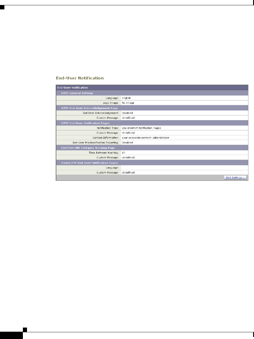
Chapter 15 Notifying End Users
Notifying End Users of Organization Policies
15-2
Cisco IronPort AsyncOS 7.1 for Web User Guide
OL-23207-01
Configure end-user notification pages on the Security Services > End-User
Notification page. Figure 15-1 shows where you configure end-user notification
settings.
You can configure the following types of notification pages and settings:
•IronPort notification pages. The Web Proxy displays different, predefined
notification pages depending on the reason for blocking the URL request. You
can customize these pages. For example, you can use your own logo or add
custom text. For more information about IronPort notification pages, see
Working With IronPort End-User Notification Pages, page 15-5.
•User defined notification pages. You can configure the Web Proxy to
redirect all HTTP end-user notification pages to a specific URL. The Web
Proxy includes parameters in the redirected URL that explain the reasons for
the block so the server in the redirected URL can customize the page it
displays. For more information about user defined notification pages, see
Working with User Defined End-User Notification Pages, page 15-14.
•End-user acknowledgement page. You can configure the Web Proxy to
inform users that it is filtering and monitoring their web activity. The Web
Proxy does this by displaying an end-user acknowledgement page when a
user first accesses a browser after a certain period of time. When the end-user
acknowledgement page appears, users must click a link to access the original

15-3
Cisco IronPort AsyncOS 7.1 for Web User Guide
OL-23207-01
Chapter 15 Notifying End Users
Configuring General Settings for Notification Pages
site requested or any other website. Language and logo settings apply to the
end-user acknowledgement page as well as the notification pages. For more
information about configuring the end-user acknowledgement page, see
End-User Acknowledgement Page, page 15-18.
•End-user URL filtering warning page. You can configure the Web Proxy to
warn users that a site does not meet the organization’s acceptable use policies
and allow them to continue if they choose. The Web Proxy does this by
displaying an end-user URL filtering warning page when a user first accesses
a website in a particular URL category after a certain period of time. You can
also configure the warning page when a user accesses adult content when the
site content ratings feature is enabled. When the warning page appears, users
can click a link to access the original site requested. Language and logo
settings apply to the end-user URL filtering warning page as well as the
notification pages. For more information about configuring the end-user URL
filtering warning page, see Warning Users and Allowing Them to Continue,
page 16-24.
•FTP notification messages. The FTP Proxy displays a different, predefined
notification messages depending on the reason for blocking a native FTP
transaction. You can customize these pages with a custom message. For more
information, see Working with IronPort FTP Notification Messages,
page 15-23.
•General notification settings. You can configure the language used in
IronPort notification pages for both HTTP and FTP. You can also configure a
logo to use for IronPort notification pages for HTTP requests. For more
information, see Configuring General Settings for Notification Pages,
page 15-3.
Configuring General Settings for Notification Pages
You can configure the following general settings:
•Language. You can configure a different language for HTTP and FTP
end-user notification pages. The HTTP language setting applies to all HTTP
notification pages (acknowledgement, IronPort end-user, end-user URL
filtering warning, and user defined end-user), and the FTP language applies
to all FTP end-user notification messages.
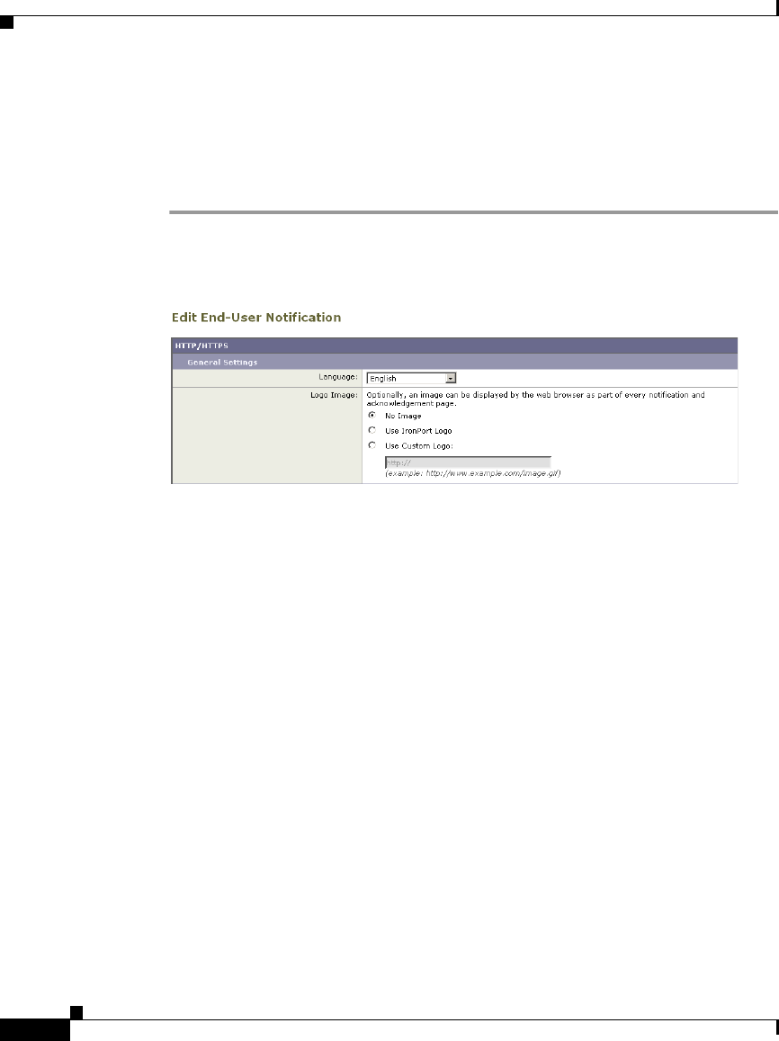
Chapter 15 Notifying End Users
Configuring General Settings for Notification Pages
15-4
Cisco IronPort AsyncOS 7.1 for Web User Guide
OL-23207-01
•Logo. You can configure a logo for HTTP end-user notification pages only.
The logo setting applies to all HTTP notification pages.
To configure the general settings for HTTP notification pages and FTP
notification messages:
Step 1 Navigate to the Security Services > End-User Notification page.
Step 2 Click Edit Settings.
Step 3 In the General Settings section under the HTTP/HTTPS section, select the
language the Web Proxy should use when displaying HTTP notification pages.
You can choose any of the following languages:
–
English
–
French
–
German
–
Italian
–
Spanish
–
Japanese
–
Korean
–
Portuguese
–
Russian
–
Thai
–
Traditional Chinese
–
Simplified Chinese

15-5
Cisco IronPort AsyncOS 7.1 for Web User Guide
OL-23207-01
Chapter 15 Notifying End Users
Working With IronPort End-User Notification Pages
Step 4 Choose whether or not to use a logo on each notification page. You can specify
the IronPort logo or any graphic file referenced at the URL you enter in the Use
Custom Logo field.
Note See Custom Text and Logos: Authentication, and End-User
Acknowledgement Pages, page 15-24 for more information about
working with custom logos.
Step 5 Submit and commit your changes.
Working With IronPort End-User Notification Pages
When you choose end-user notification pages defined by IronPort, the Web Proxy
displays a different page depending on the reason why it blocked the original
page. However, you can still customize each page to make them specific to your
organization.
You can customize the following features:
•Custom message
•Contact information
•Allow end-users to report misclassified pages to IronPort
You can also edit the IronPort notification pages stored on the Web Security
appliance. For more information about how to do this, see Editing IronPort
Notification Pages, page 15-8.
Configuring IronPort Notification Pages
To configure IronPort notification pages:
Step 1 Navigate to the Security Services > End-User Notification page, and click Edit
Settings.
The Edit End-User Notification page appears.
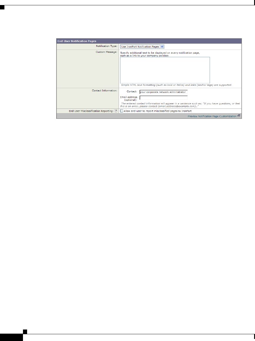
Chapter 15 Notifying End Users
Working With IronPort End-User Notification Pages
15-6
Cisco IronPort AsyncOS 7.1 for Web User Guide
OL-23207-01
Step 2 From the Notification Type field, choose Use IronPort Notification Pages.
Step 3 Configure the IronPort notification page settings.

15-7
Cisco IronPort AsyncOS 7.1 for Web User Guide
OL-23207-01
Chapter 15 Notifying End Users
Working With IronPort End-User Notification Pages
Table 15-1 describes the settings you can configure for IronPort notification
pages.
Setting Description
Custom Message Choose whether or not to include additional text you
specify on each notification page.
When you enter a custom message, AsyncOS places the
message before the last sentence on the notification page
which includes the contact information.
You can include some HTML tags in lower case to
format the text. For a list of supported HTML tags, see
Supported HTML Tags in Notification Pages,
page 15-23.
See Custom Text and Logos: Authentication, and
End-User Acknowledgement Pages, page 15-24 for
more information about working with custom messages.

Chapter 15 Notifying End Users
Working With IronPort End-User Notification Pages
15-8
Cisco IronPort AsyncOS 7.1 for Web User Guide
OL-23207-01
Step 4 Click the “Preview Notification Page Customization” link to view the current
end-user notification page in a separate browser window.
Step 5 Submit and commit your changes.
Editing IronPort Notification Pages
Each IronPort Notification page is stored on the Web Security appliance as an
HTML file. You can edit the content of these HTML pages to include additional
text or to edit the overall look and feel of each page.
Contact Information Choose whether or not to customize the contact
information listed on each notification page.
AsyncOS displays the contact information sentence as
the last sentence on a page, before providing notification
codes that users can provide to the network
administrator.
End-User
Misclassification
Reporting
Choose whether or not users can report misclassified
URLs to IronPort Systems.
When you enable this option, an additional button
appears on the IronPort notification pages for sites
blocked due to suspected malware or URL filters. This
button allows the user to report when they believe the
page has been misclassified. It does not appear for pages
blocked due to other policy settings.
When a user presses this button, data about the blocked
request gets sent to the Web Security appliance.
AsyncOS logs the information in the Feedback Log,
summarizes the data, and forwards it to IronPort.
This feature helps improve efficiency for administrators,
and the IronPort Customer Support process.
Additionally, misclassification reports improve the
efficacy of URL filtering.
Setting Description

15-9
Cisco IronPort AsyncOS 7.1 for Web User Guide
OL-23207-01
Chapter 15 Notifying End Users
Working With IronPort End-User Notification Pages
You can use variables in the HTML files to display specific information to the
user. You can also turn each variable into a conditional variable to create if-then
statements. For more information, see Using Variables in Customized IronPort
Notification Pages, page 15-13.
Table 15-2 describes the variables you can include in customized end-user
notification pages.
Variable Description
Always Evaluates
to TRUE if Used
as Conditional
Variable
%a Authentication realm for FTP No
%A ARP address Yes
%b User-agent name No
%B Blocking reason, such as BLOCK-SRC or
BLOCK-TYPE
No
%c Error page contact person Yes
%C Entire Set-Cookie: header line, or empty string No
%d Client IP address Yes
%D User name No
%e Error page email address Yes
%E The error page logo URL No
%f User feedback section No
%F The URL for user feedback No
%g The web category name, if available Yes
%G Maximum file size allowed in MB No
%h The hostname of the proxy Yes
%H The server name of the URL Yes
%i Transaction ID as a hexadecimal number Yes
%I Management IP Address Yes
%j URL category warning page custom text No

Chapter 15 Notifying End Users
Working With IronPort End-User Notification Pages
15-10
Cisco IronPort AsyncOS 7.1 for Web User Guide
OL-23207-01
%k Redirection link for the end-user
acknowledgement page and end-user URL
filtering warning page
No
%K Response file type No
%l WWW-Authenticate: header line No
%L Proxy-Authenticate: header line No
%M The Method of the request, such as “GET” or
“POST”
Yes
%n Malware category name, if available No
%N Malware threat name, if available No
%o Web reputation threat type, if available No
%O Web reputation threat reason, if available No
%p String for the Proxy-Connection HTTP header Yes
%P Protocol Yes
%q Identity policy group name Yes
%Q Policy group name for non-Identity polices Yes
%r Redirect URL No
%R Re-authentication is offered. This variable
outputs an empty string when false and a space
when true, so it is not useful to use it alone.
Instead, use it as condition variable. For more
information, see Using Variables in Customized
IronPort Notification Pages, page 15-13.
For more information on re-authentication, see
Allowing Users to Re-Authenticate, page 20-39.
No
%S The signature of the proxy No, always
evaluates to
FALSE
Variable Description
Always Evaluates
to TRUE if Used
as Conditional
Variable

15-11
Cisco IronPort AsyncOS 7.1 for Web User Guide
OL-23207-01
Chapter 15 Notifying End Users
Working With IronPort End-User Notification Pages
To edit the IronPort Notification pages:
Step 1 Use an FTP client to connect to the Web Security appliance.
Step 2 Navigate to the configuration\eun directory.
In this directory are subdirectories for each supported language for end-user
notification pages.
%t Timestamp in Unix seconds plus milliseconds Yes
%T The date Yes
%u The URI part of the URL (the URL excluding
the server name)
Yes
%U The full URL of the request Yes
%v HTTP protocol version Yes
%W Management WebUI port Yes
%X Extended blocking code. This is a 16-byte
base64 value that encodes the most of the web
reputation and anti-malware information logged
in the access log, such as the ACL decision tag
and WBRS score.
Yes
%Y Administrator custom text string, if set, else
empty
No
%y End-user acknowledgement page custom text Yes
%z Web reputation score Yes
%Z DLP metadata Yes
%% Prints the percent symbol (%) in the notification
page
N/A
Variable Description
Always Evaluates
to TRUE if Used
as Conditional
Variable

Chapter 15 Notifying End Users
Working With IronPort End-User Notification Pages
15-12
Cisco IronPort AsyncOS 7.1 for Web User Guide
OL-23207-01
Step 3 Download the language directory files for the IronPort notification pages you
want to edit.
Step 4 On your local machine, use a text or HTML editor to edit each HTML file for the
IronPort notification pages.
For a list of rules and guidelines, see Rules and Guidelines for Editing
IronPort Notification Pages, page 15-12.
Step 5 Use the FTP client to upload the customized HTML files to the same directory
from which you downloaded them in step 3.
Step 6 Open an SSH client and connect to the Web Security appliance.
Step 7 Run the advancedproxyconfig > EUN CLI command.
Step 8 Type 2 to use the custom end-user notification pages.
Note If the custom end-user notification pages option is currently enabled when
you update the HTML files, you must type 1 to refresh the custom
end-user notification pages. If you do not do this, the new files do not take
effect until the Web Proxy restarts.
Step 9 Commit your change, and close the SSH client.
Rules and Guidelines for Editing IronPort Notification Pages
Use the following rules and guidelines when editing IronPort notification pages:
•Each customized IronPort notification page file must be a valid HTML file.
For a list of HTML tags you can include, see Supported HTML Tags in
Notification Pages, page 15-23.
•The customized IronPort notification page file names must exactly match the
file names shipped with the Web Security appliance.
•Do not include any links to URLs in the HTML files. Any link included in the
notification pages are subject to the access control rules defined in the Access
Policies and users might end up in a recursive loop.
•If the configuration\eun directory does not contain a particular file with the
required name, then the appliance displays the standard IronPort notification
page.

15-13
Cisco IronPort AsyncOS 7.1 for Web User Guide
OL-23207-01
Chapter 15 Notifying End Users
Working With IronPort End-User Notification Pages
•For new IronPort notification pages to go into effect, you must first upload
the customized files to the appliance and then enable the customized files
using the advancedproxyconfig > miscellaneous CLI command.
Using Variables in Customized IronPort Notification Pages
When editing IronPort notification pages, you can include conditional variables
to create if-then statements to take different actions depending on the current
state. For example, you can create an IronPort notification page that includes a
redirect URL (%r) if re-authentication is offered (%R). In this example, you
would create a conditional variable out of %R.
Table 15-3 describes the different conditional variable formats.
Conditional Variable
Format Description
%?V This conditional variable evaluates to TRUE if the
output of variable %V is not empty.
%!VRepresents the following condition:
else
Use this with the %?V conditional variable.
%#VRepresents the following condition:
endif
Use this with the %?V conditional variable.

Chapter 15 Notifying End Users
Working with User Defined End-User Notification Pages
15-14
Cisco IronPort AsyncOS 7.1 for Web User Guide
OL-23207-01
For example, the following text is some HTML code that uses %R as a conditional
variable to check if re-authentication is offered, and uses %r as a regular variable
to provide the re-authentication URL.
Any variable included in Table 15-2, `Variables for Customized End-User
Notification Pages,' on page 9 can be used as a conditional variable. However, the
best variables to use in conditional statements are the ones that relate to the client
request instead of the server response, and the variables that may or may not
evaluate to TRUE instead of the variables that always evaluate to TRUE. For
example, the %t variable (timestamp in Unix seconds plus milliseconds) always
evaluates to TRUE, so there is little value in making an if-then statement based on
it.
Working with User Defined End-User Notification
Pages
When you choose end-user notification pages defined by someone in your
organization, by default, AsyncOS redirects all blocked websites to the URL
regardless of the reason why it blocked the original page. However, AsyncOS also
passes parameters as a query string appended to the redirect URL so you can
ensure that the user sees a unique page explaining the reason for the block.
AsyncOS passes the parameters to the web server as standard URL Parameters in
the HTTP GET request. It uses the following format:
<notification_page_url>?param1=value1¶m2=value2
%?R
<div align="left">
<form name="ReauthInput" action="%r" method="GET">
<input name="Reauth" type="button"
OnClick="document.location='%r'"
id="Reauth" value="Login as different user...">
</form>
</div>
%#R

15-15
Table 15-4 describes the parameters AsyncOS includes in the query string.
Time Date and time of the transaction.
ID Transaction ID.
Client_IP IP address of the client.
User Username of the client making the request, if available.
Site Hostname of the destination in the HTTP request.
URI URL path specified in the HTTP request.
Status_Code HTTP status code for the request.
Decision_Tag ACL decision tag as defined in the Access Log entry that
indicates how the DVS engine handled the transaction.
For more information about ACL decision tags, see ACL
Decision Tags, page 24-24.
URL_Cat URL category that the URL filtering engine assigned to the
transaction request.
For a list of the different URL categories, see URL
Category Descriptions, page 16-32.
Note: AsyncOS for Web sends the entire URL category
name for both predefined and user defined URL categories.
It performs URL encoding on the category name, so spaces
are written as “%20”.
WBRS WBRS score that the Web Reputation Filters assigned to the
URL in the request.
DVS_Verdict Malware category that the DVS engine assigns to the
transaction.
For more information about malware categories, Malware
Scanning Verdict Values, page 24-52.

15-16
AsyncOS always includes all parameters in each redirected URL. If no value
exists for a particular parameter, AsyncOS passes a hyphen (-).
When you want the user to view a different page for each reason for a blocked
website, construct a CGI script on the web server that can parse the query string
in the redirect URL. Then the server can perform a second redirect to an
appropriate page.
Consider the following rules and guidelines when entering the custom URL:
You can use any HTTP or HTTPS URL.
DVS_ThreatName The name of the malware found by the DVS engine.
Reauth_URL A URL that users can click to authenticate again if the user
is blocked from a website due to a restrictive URL filtering
policy. Use this parameter when the “Enable
Re-Authentication Prompt If End User Blocked by URL
Category or User Session Restriction” global authentication
setting is enabled and the user is blocked from a website due
to a blocked URL category.
To use this parameter, make sure the CGI script performs
the following steps:
1. Get the value of Reauth_Url parameter.
2. URL-decode the value.
3. Base64 decode the value and get the actual
re-authentication URL.
4. Include the decoded URL on the end-user notification
page in some way, either as a link or button, along with
instructions for users informing them they can click the link
and enter new authentication credentials that allow greater
access.
For more information, see Allowing Users to
Re-Authenticate, page 20-39.

15-17
The URL may specify a specific port number.
The URL may not have any arguments after the question mark.
The URL must contain a well-formed hostname.
For example, if you have the following URL entered in the Redirect to Custom
URL field:
http://www.example.com/eun.policy.html
And you have the following access log entry:
Then AsyncOS creates the following redirected URL:
To configure user defined end-user notification pages:
Navigate to the Security Services > End-User Notification page, and click Edit
Settings.
The Edit End-User Notification page appears.
From the Notification Type field, choose Redirect to Custom URL.
In the Notification Page URL field, enter the URL to which you want to redirect
blocked websites.
1182468145.492 1 172.17.0.8 TCP_DENIED/403 3146 GET
http://www.espn.com/index.html HTTP/1.1 - NONE/- -
BLOCK_WEBCAT-DefaultGroup-DefaultGroup-NONE-NONE-DefaultRouting
<IW_sprt,-,-,-,-,-,-,-,-,-,-,-,-,-,-,IW_sprt,-> -
http://www.example.com/eun.policy.html?Time=21/Jun/
2007:23:22:25%20%2B0000&ID=0000000004&Client_IP=172.17.0.8&User=-
&Site=www.espn.com&URI=index.html&Status_Code=403&Decision_Tag=
BLOCK_WEBCAT-DefaultGroup-DefaultGroup-NONE-NONE-DefaultRouting
&URL_Cat=Sports%20and%20Recreation&WBRS=-&DVS_Verdict=-&
DVS_ThreatName=-&Reauth_URL=-

15-18
You can choose whether or not to preview the URL you enter by clicking
the Preview Custom URL link.
Submit and commit your changes.
You can configure the Web Security appliance to inform users that it is filtering
and monitoring their web activity. The appliance does this by displaying an
end-user acknowledgement page when a user first accesses a browser after a
certain period of time. When the end-user acknowledgement page appears, users
must click a link to access the original site requested or any other website.
You might want to use an end-user acknowledgement page to force users to
explicitly agree to the terms and conditions for browsing the World Wide Web
from the organization’s network. This might be useful when the Web Proxy is in
transparent mode because web users will not otherwise know that their web
transactions are being filtered and monitored for security purposes.
When you configure the appliance to display an end-user acknowledgement page,
it does so for every user accessing the web using HTTP or HTTPS. It displays the
end-user acknowledgement page when a user tries to access a website for the first
time, or after a configured time interval.
Native FTP transactions are exempt from the end-user acknowledgement page.
Users are tracked by username if authentication has made a username available,
and tracked by IP address if no username is available.
When you enable the end-user acknowledgement page, you can configure the
following settings:
Time Between Acknowledgements. The Time Between Acknowledgements
determines how often the Web Proxy displays the end-user acknowledgement
page for each user. Once a user clicks the link on the end-user
acknowledgement page, the Web Proxy considers that user to have
acknowledged the proxy for the time you enter for the Time Between

15-19
Acknowledgements. This setting applies to users tracked by username and
users tracked by IP address. You can specify any value from 30 to 2678400
seconds (one month). Default is 1 day (86400 seconds).
Inactivity Timeout. The Inactivity Timeout determines how long a user
tracked and acknowledged by IP address (unauthenticated users only) can be
idle before the user is no longer considered acknowledged. You can specify
any value from 30 to 2678400 seconds (one month). Default is four hours
(14400 seconds).
Custom message. The custom message is text you enter that appears on every
end-user acknowledgement page. You can include some simple HTML tags
to format the text. For example, you can change the color and size of the text,
or make it italicized. See Custom Text in Notification Pages, page 15-23 for
more information.
You can only include a custom message when you configure the end-user
acknowledgement page in the web interface, versus the CLI.
Consider the following rules and guidelines when enabling the end-user
acknowledgement page:
When a user is tracked by IP address, the appliance uses the shortest value for
maximum time interval and maximum IP address idle timeout to determine
when to display the end-user acknowledgement page again.
The first transaction from a user must be an HTTP request, and the user must
agree to the terms for all transactions to succeed. If users try to send an
HTTPS or native FTP request before an HTTP request, the HTTPS or native
FTP request fails.
When the Web Proxy restarts, the Web Proxy considers all users to have timed
out, and it displays the end-user acknowledgement page again. The Web
Proxy may restart based on different events, such as when the Default Proxy
Log subscription changes or when changes are made to the global
authentication settings or FTP Proxy settings.
When the appliance is deployed in explicit forward mode and a user goes to
an HTTPS site, the end-user acknowledgement page includes only the
domain name in the link that redirects the user to the originally requested
URL. If the originally requested URL contains text after the domain name,
that text is truncated.
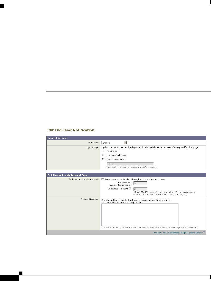
15-20
You can enable and configure the end-user acknowledgement page in the web
interface or the command line interface. However, when you configure the
end-user acknowledgement page in the web interface, you can include a custom
message that appears on each page. You can include some simple HTML tags in
the custom message, such as font color and size.
In the CLI, use advancedproxyconfig > authentication.
To configure the end-user acknowledgement page in the web interface:
Navigate to the Security Services > End-User Notification page.
Click Edit Settings.
In the End-User Acknowledgement Page section, enable the “Require end-user to
click through acknowledgement page” field. See Custom Text and Logos:
Authentication, and End-User Acknowledgement Pages, page 15-24 for
information about how this feature works with custom messages.

15-21
In the Time Between Acknowledgements field, enter the time interval the
appliance uses between displaying the end-user acknowledgement page.
You can specify any value from 30 to 2678400 seconds (one month). Default is 1
day (86400 seconds). You can enter the value in seconds, minutes, or days. Use
‘s’ for seconds, ‘m’ for minutes, and ‘d’ for days.
In the Inactivity Timeout field, enter the maximum IP address idle timeout.
You can specify any value from 30 to 2678400 seconds (one month). Default is
four hours (14400 seconds). You can enter the value in seconds, minutes, or days.
Use ‘s’ for seconds, ‘m’ for minutes, and ‘d’ for days.
In the Custom Message field, enter any text you want to appear on every end-user
acknowledgement page.
You can include some HTML tags in lower case to format the text. For a list of
supported HTML tags, see Supported HTML Tags in Notification Pages,
page 15-23.
For example:
Please acknowledge the following statements <i>before</i> accessing
the Internet.
Click the “Preview Acknowledgment Page Customization” link to view the
current end-user acknowledgement page in a separate browser window.
Submit and commit your changes.
You can configure the end-user URL filtering warning page on the Security
Services > End-User Notification page. You can include some simple HTML tags
in the custom message, such as font color and size.
To configure the end-user URL filtering warning page:
Navigate to the Security Services > End-User Notification page, and click Edit
Settings.
Scroll down to the End-User URL Filtering Warning Page section.
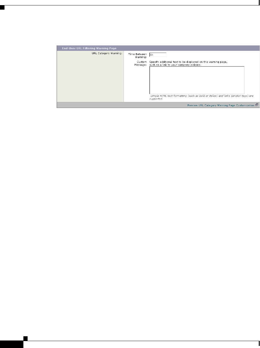
15-22
In the Time Between Warning field, enter the time interval the Web Proxy uses
between displaying the end-user URL filtering warning page for each URL
category per user.
Once a user clicks the continue link on the end-user URL filtering warning page,
the Web Proxy considers that user to have acknowledged the warning for the time
you enter here. This setting applies to users tracked by username and users tracked
by IP address.
You can specify any value from 30 to 2678400 seconds (one month). Default is 1
hour (3600 seconds). You can enter the value in seconds, minutes, or days. Use
‘s’ for seconds, ‘m’ for minutes, and ‘d’ for days.
In the Custom Message field, enter any text you want to appear on every end-user
URL filtering warning page.
You might want to include text for the organization’s acceptable use policies, or
include a link to a page that details the acceptable use policies.
You can include some HTML tags in lower case to format the text. For a list of
supported HTML tags, see Supported HTML Tags in Notification Pages,
page 15-23.
For example:
Please acknowledge the following statements <i>before</i> accessing
the Internet.
Click the “Preview URL Category Warning Page Customization” link to view the
current end-user URL filtering warning page in a separate browser window.
Submit and commit your changes.

15-23
The FTP Proxy displays a predefined notification message to native FTP clients
when there is an error with FTP Proxy authentication. You can customize this FTP
notification with a custom message.
To configure IronPort FTP notification messages:
Navigate to the Security Services > End-User Notification page, and click Edit
Settings.
Scroll down to the Native FTP section.
In the Language field, select the language to use when displaying native FTP
notification messages.
In the Custom Message field, enter the text you want to display in every native
FTP notification message.
Submit and commit your changes.
The following sections apply to custom text entered for IronPort notification and
end-user acknowledgement pages.
You can format the text in IronPort notification and end-user acknowledgement
pages using some HTML tags. Tags must be in lower case and follow standard
HTML syntax (closing tags, etc.).
You can use the following HTML tags.
<a></a>
<span></span>
<b></b>
<big></big>
<br>

15-24
<code></code>
<em></em>
<i></i>
<small></small>
<strong></strong>
For example, you can make some text italic:
Please acknowledge the following statements <i>before</i> accessing
the Internet.
With the <span> tag, you can use any CSS style to format text. For example, you
can make some text red:
<span style=”color: red”>Warning:</span> You must acknowledge the
following statements <i>before</i> accessing the Internet.
Custom Text and Logos: Authentication, and End-User
Acknowledgement Pages
All combinations of URL paths and domain names in embedded links within
custom text and the custom logo in IronPort notification, end-user
acknowledgement, and end-user URL filtering warning pages are exempted from
the following:
•User authentication
•End-user acknowledgment
•All scanning, such as malware scanning and web reputation scoring
For example, if the following URLs are embedded in custom text:
http://www.example.com/index.html
http://www.mycompany.com/logo.jpg
Then all of the following URLs will also be treated as exempt from all scanning:
http://www.example.com/index.html
http://www.mycompany.com/logo.jpg
http://www.example.com/logo.jpg

15-25
Cisco IronPort AsyncOS 7.1 for Web User Guide
OL-23207-01
Chapter 15 Notifying End Users
Notification Page Types
http://www.mycompany.com/index.html
Also, where an embedded URL is of the form:
<protocol>://<domain-name>/<directory path>/ then all sub-files and
sub-directories under that directory path on the host will also be exempted from
all scanning.
For example, if the following URL is embedded:
http://www.example.com/gallery2/ URLs such as
http://www.example.com/gallery2/main.php will also be treated as exempt.
This allows administrators to create a more sophisticated page with embedded
content so long as the embedded content is relative to the initial URL. However,
you administrators should also take care when deciding which paths to include as
links and custom logos.
Notification Page Types
Users accessing the Internet sometimes cannot access the server they want. By
default, the Web Proxy displays a notification page informing users they were
blocked and the reason for the block. This section lists and describes all possible
notification pages a user might see while accessing the Internet.
Possible reasons that cause notification pages to appear include the following:
•IronPort notification pages are enabled and the user accessed the Internet in
a way that violated an Access Policy.
•IronPort notification pages are configured to allow end-users to report
misclassified pages to IronPort and the user reported a misclassified page.
•The end-user acknowledgement page is enabled and the user accessed the
Internet for the first time since the timeout period expired.
•The HTTPS Proxy is enabled and the appliance is configured to drop HTTPS
requests to servers with invalid certificates.
•The Web Security appliance could not access the server requested due to an
external error, such as DNS failure or an unavailable server.

Chapter 15 Notifying End Users
Notification Page Types
15-26
Cisco IronPort AsyncOS 7.1 for Web User Guide
OL-23207-01
Most notification pages display a different set of codes that may help
administrators or IronPort Customer Support troubleshoot any potential problem.
Some codes are for IronPort internal use only. The different codes that might
appear in the notification pages are the same as the variables you can include in
customized notification pages, as shown in Table 15-2 on page 9.
Table 15-5 describes the different notification pages users might encounter.
File Name and
Notification Title Notification Text Notification Codes
ERR_ACCEPTED
Feedback Accepted,
Thank You
The misclassification report has been sent.
Thank you for your feedback.
N/A
ERR_ACCESS_FOR
BIDDEN
Access Forbidden
Based on your corporate Access Policies, this
web site <URL> has been blocked because it
has been determined to be a security threat to
your computer or the corporate network.
Access could also be blocked because this
request came from an unrecognized or
unauthorized machine.
<version>,
ACCESS_FORBIDDEN,
%B, %N, %i, %t, %X, %U
ERR_ADULT_CON
TENT
Policy
Acknowledgement
You are trying to visit a web page whose
content are rated as explicit or adult. By
clicking the link below, you acknowledge that
you have read and agree with the organization's
policies that govern the usage of the Internet
for this type of content. Data about your
browsing behavior may be monitored and
recorded. You will be periodically asked to
acknowledge this statement for continued
access to this kind of web page.
Click here to accept this statement and access
the Internet.
N/A
ERR_AUTH
Policy:
Authentication
Based on your corporate Access Policies,
Internet access has been blocked because the
login provided belongs to a user or group that
is not allowed Internet access.
<version>, AUTH, %B

15-27
Cisco IronPort AsyncOS 7.1 for Web User Guide
OL-23207-01
Chapter 15 Notifying End Users
Notification Page Types
ERR_AVC
Policy: Application
Controls
Based on your corporate access policies, access
to application %1 of type %2 has been blocked.
<version>, AVC, %B, %i, %t,
%X, %U
ERR_BAD_REQUE
ST
Bad Request
The system cannot process this request. A
non-standard browser may have generated an
invalid HTTP request.
If you are using a standard browser, please retry
the request.
<version>, BAD_REQUEST
ERR_BLOCK_DES
T
Policy: Destination
Based on your corporate Access Policies,
access to this web site <URL> has been
blocked.
<version>, BLOCK_DEST,
%B, %U
ERR_BLOCK_SRC
Policy: Source
Based on your corporate Access Policies,
access to this web site <URL> has been blocked
because this request came from an
unauthorized computer.
<version>, BLOCK_SRC,
%B, %d, %U
ERR_BROWSER
Security: Browser
Based on your corporate Access Policies,
requests from your computer have been
blocked because it has been determined to be a
security threat to the corporate network. Your
browser may have been compromised by a
malware/spyware agent identified as
“<malware name>”.
Please contact <contact name> <email
address> and provide the codes shown below.
If you are using a non-standard browser and
believe it has been misclassified, use the button
below to report this misclassification.
<version>, BROWSER, %B,
%b, %i, %t, %X, %U
ERR_BROWSER_C
USTOM
Policy: Browser
Based on your corporate Access Policies,
requests from your browser have been blocked.
This browser “<browser type>” is not
permitted due to potential security risks.
<version>,
BROWSER_CUSTOM, %B,
%b, %i, %t, %U
File Name and
Notification Title Notification Text Notification Codes

Chapter 15 Notifying End Users
Notification Page Types
15-28
Cisco IronPort AsyncOS 7.1 for Web User Guide
OL-23207-01
ERR_CERT_INVALI
D
Invalid Certificate
A secure session cannot be established because
the site <hostname> provided an invalid
certificate.
<version>, INVALID_CERT,
%B, %i, %t, %X, %U
ERR_CONTINUE_U
NACKNOWLEDGE
D
Policy
Acknowledgement
You are trying to visit a web page that falls
under the URL Category %g . By clicking the
link below, you acknowledge that you have
read and agree with the organization's policies
that govern the usage of the Internet for this
type of content. Data about your browsing
behavior may be monitored and recorded. You
will be periodically asked to acknowledge this
statement for continued access to this kind of
web page.
Click here to accept this statement and access
the Internet.
N/A
ERR_DNS_FAIL
DNS Failure
The hostname resolution (DNS lookup) for this
hostname <hostname> has failed. The Internet
address may be misspelled or obsolete, the host
<hostname> may be temporarily unavailable,
or the DNS server may be unresponsive.
Please check the spelling of the Internet
address entered. If it is correct, try this request
later.
<version>, DNS_FAIL, %H
ERR_EXPECTATIO
N_FAILED
Expectation Failed
The system cannot process the request for this
site <URL>. A non-standard browser may have
generated an invalid HTTP request.
If using a standard browser, please retry the
request.
<version>,
EXPECTATION_FAILED,
%U
ERR_FILE_SIZE
Policy: File Size
Based on your corporate Access Policies,
access to this web site or download <URL> has
been blocked because the download size
exceeds the allowed limit.
<version>, FILE_SIZE, %B,
%U
File Name and
Notification Title Notification Text Notification Codes

15-29
Cisco IronPort AsyncOS 7.1 for Web User Guide
OL-23207-01
Chapter 15 Notifying End Users
Notification Page Types
ERR_FILE_TYPE
Policy: File Type
Based on your corporate Access Policies,
access to this web site or download <URL> has
been blocked because the file type “<file
type>” is not allowed.
<version>, FILE_TYPE, %B,
%K, %U
ERR_FILTER_FAIL
URE
Filter Failure
The request for page <URL> has been denied
because an internal server is currently
unreachable or overloaded.
Please retry the request later.
<version>,
FILTER_FAILURE, %U
ERR_FOUND
Found
The page <URL> is being redirected to
<redirected URL>.
<version>, FOUND, %r, %U
ERR_FTP_ABORTE
D
FTP Aborted
The request for the file <URL> did not succeed.
The FTP server <hostname> unexpectedly
terminated the connection.
Please retry the request later.
<version>, FTP_ABORTED,
%U
ERR_FTP_AUTH_R
EQUIRED
FTP Authorization
Required
Authentication is required by the FTP server
<hostname>. A valid user ID and password
must be entered when prompted.
In some cases, the FTP server may limit the
number of anonymous connections. If you
usually connect to this server as an anonymous
user, please try again later.
<version>,
FTP_AUTH_REQUIRED,
%H
ERR_FTP_CONNEC
TION_FAILED
FTP Connection
Failed
The system cannot communicate with the FTP
server <hostname>. The FTP server may be
temporarily or permanently down, or may be
unreachable because of network problems.
Please check the spelling of the address
entered. If it is correct, try this request later.
<version>,
FTP_CONNECTION_FAILE
D, %H
ERR_FTP_FORBID
DEN
FTP Forbidden
Access was denied by the FTP server
<hostname>. Your user ID does not have
permission to access this document.
<version>,
FTP_FORBIDDEN, %H
File Name and
Notification Title Notification Text Notification Codes

Chapter 15 Notifying End Users
Notification Page Types
15-30
Cisco IronPort AsyncOS 7.1 for Web User Guide
OL-23207-01
ERR_FTP_NOT_FO
UND
FTP Not Found
The file <URL> could not be found. The
address is either incorrect or obsolete.
<version>,
FTP_NOT_FOUND, %U
ERR_FTP_SERVER
_ERR
FTP Server Error
The system cannot communicate with the FTP
server <hostname>. The FTP server may be
temporarily or permanently down, or may not
provide this service.
Please confirm that this is a valid address. If it
is correct, try this request later.
<version>,
FTP_SERVER_ERR, %H
ERR_FTP_SERVICE
_ U NAVA I L
FTP Service
Unavailable
The system cannot communicate with the FTP
server <hostname>. The FTP server may be
busy, may be permanently down, or may not
provide this service.
Please confirm that this is a valid address. If it
is correct, try this request later.
<version>,
FTP_SERVICE_UNAVAIL,
%H
ERR_GATEWAY_TI
MEOUT
Gateway Timeout
The system cannot communicate with the
external server <hostname>. The Internet
server may be busy, may be permanently down,
or may be unreachable because of network
problems.
Please check the spelling of the Internet
address entered. If it is correct, try this request
later.
<version>,
GATEWAY_TIMEOUT, %H
ERR_IDS_ACCESS
_FORBIDDEN
IDS Access
Forbidden
Based on your corporate data transfer policies,
your upload request has been blocked. File
details:
%Z
<version>,
IDS_ACCESS_FORBIDDEN
, %B, %N, %i, %t, %X, %U
File Name and
Notification Title Notification Text Notification Codes

15-31
Cisco IronPort AsyncOS 7.1 for Web User Guide
OL-23207-01
Chapter 15 Notifying End Users
Notification Page Types
ERR_INTERNAL_E
RROR
Internal Error
Internal system error when processing the
request for the page <URL>.
Please retry this request.
If this condition persists, please contact
<contact name> <email address> and provide
the code shown below.
<version>,
INTERNAL_ERROR, %U
ERR_MALWARE_G
ENERAL
Security: Malware
Risk
Based on your corporate Access Policies, this
web site <URL> has been blocked because it
has been determined to be a security threat to
your computer or the corporate network. This
web site has been associated with
malware/spyware.
<version>,
MALWARE_GENERAL,
%B, %N, %i, %t, %X, %U
ERR_MALWARE_S
PECIFIC
Security: Malware
Detected
Based on your corporate Access Policies, this
web site <URL> has been blocked because it
has been determined to be a security threat to
your computer or the corporate network.
Malware <malware name> in the category
<malware category> has been found on this
site.
<version>,
MALWARE_SPECIFIC, %B,
%N, %i, %t, %X, %U
ERR_MALWARE_S
PECIFIC_OUTGOIN
G
Security: Malware
Detected
Based on your corporate policy, the upload of
the file to URL (%U) has been blocked because
the file was detected to contain malware that
will be harmful to the receiving end's network
security.
Malware Name: %N
Malware Category: %n
<version>,
MALWARE_SPECIFIC_OU
TGOING, %B, %N, %i, %t,
%X, %U
ERR_MISS_ACCES
S_FORBIDDEN
Miss Access
Forbidden
This web site <URL> has been blocked because
it has been determined to be a security threat,
based on your corporate Access Policies.
<version>,
MISS_ACCESS_FORBIDDE
N, %U
File Name and
Notification Title Notification Text Notification Codes

Chapter 15 Notifying End Users
Notification Page Types
15-32
Cisco IronPort AsyncOS 7.1 for Web User Guide
OL-23207-01
ERR_NO_MORE_F
ORWARDS
No More Forwards
The request for the page <URL> failed.
The server address <hostname> may be invalid,
or you may need to specify a port number to
access this server.
<version>,
NO_MORE_FORWARDS,
%U
ERR_ONLY_IF_CA
CHED_NOT_IN_CA
CHE
Only if Cached But
Not in Cache
The page <URL> has been blocked based on
your corporate policies.
<version>,
ONLY_IF_CACHED_NOT_I
N_CACHE, %U
ERR_POLICY
Policy: General
Based on your corporate Access Policies,
access to this web site <URL> has been
blocked.
<version>, POLICY, %B, %i,
%t, %X, %U
ERR_PROTOCOL
Policy: Protocol
Based on your corporate Access Policies, this
request has been blocked because the data
transfer protocol “<protocol type>” is not
allowed.
<version>, PROTOCOL, %B,
%P, %i, %t, %U
ERR_PROXY_AUT
H_REQUIRED
Proxy Authorization
Required
Authentication is required to access the
Internet using this system. A valid user ID and
password must be entered when prompted.
<version>,
PROXY_AUTH_REQUIRED
ERR_PROXY_PRE
VENT_MULTIPLE_
LOGIN
Already Logged In
From Another
Machine
Based on your corporate policies, the request to
access the Internet was denied because this user
ID has an active session from another IP
address.
If you want to login as a different user, click on
the button below and enter a different a user
name and password.
<version>,
PROXY_PREVENT_MULTI
PLE_LOGIN
ERR_PROXY_REDI
RECT
Redirect
This request is being redirected. If this page
does not automatically redirect, click here to
proceed.
N/A
File Name and
Notification Title Notification Text Notification Codes

15-33
Cisco IronPort AsyncOS 7.1 for Web User Guide
OL-23207-01
Chapter 15 Notifying End Users
Notification Page Types
ERR_PROXY_UNA
CKNOWLEDGED
Policy
Acknowledgement
Please acknowledge the following statements
before accessing the Internet.
Your web transactions will be automatically
monitored and processed to detect dangerous
content and to enforce corporate policies. By
clicking the link below, you acknowledge this
monitoring and accept that data about the sites
you visit may be recorded. You will be
periodically asked to acknowledge the presence
of the monitoring system. You are responsible
for following corporate polices on Internet
access.
Click here to accept this statement and access
the Internet.
N/A
ERR_PROXY_UNLI
CENSED
Proxy Not Licensed
Internet access is not available without proper
licensing of the security device.
Please contact <contact name> <email
address> and provide the code shown below.
Note: To access the management interface of
the security device, enter the configured IP
address with port.
<version>,
PROXY_UNLICENSED
ERR_RANGE_NOT
_SATISFIABLE
Range Not Satisfiable
The system cannot process this request. A
non-standard browser may have generated an
invalid HTTP request.
If you are using a standard browser, please retry
the request.
<version>,
RANGE_NOT_SATISFIABL
E
ERR_REDIRECT_P
ERMANENT
Redirect Permanent
The page <URL> is being redirected to
<redirected URL>.
<version>,
REDIRECT_PERMANENT,
%r, %U
File Name and
Notification Title Notification Text Notification Codes

Chapter 15 Notifying End Users
Notification Page Types
15-34
Cisco IronPort AsyncOS 7.1 for Web User Guide
OL-23207-01
ERR_REDIRECT_R
EPEAT_REQUEST
Redirect
Please repeat your request. <version>,
REDIRECT_REPEAT_REQ
UEST
ERR_SAAS_AUTH
ENTICATION
SaaS Policy: Access
Denied
Based on your corporate policy, the request to
access %U was redirected to a page where you
must enter the login credentials. You will be
allowed to access the application if
authentication succeeds and you have the
proper privileges.
N/A
ERR_SAAS_AUTH
ORIZATION
SaaS Policy: Access
Denied
Based on your corporate policy, the access to
the SaaS application %U is blocked because
you are not an authorized user. If you want to
login as a different user, enter a different
username and password for a user that is
authorized to access this application.
N/A
ERR_SAML_PROC
ESSING
SaaS Policy: Access
Denied
The request to access %s did not go through
because errors were found during the process
of the single sign on request.
N/A
ERR_SERVER_NA
ME_EXPANSION
Server Name
Expansion
The server name <hostname> appears to be an
abbreviation, and is being redirected to
<redirected URL>.
<version>,
SERVER_NAME_EXPANSI
ON, %r, %H
ERR_SOCKS_FAIL
SOCKS Failure
The server name <hostname> could not be
processed while retrieving the page <URL>.
This could be due to a problem communicating
with the external server.
<version>, SOCKS_FAIL,
%U
ERR_URI_TOO_LO
NG
URI Too Long
The requested URL was too long and could not
be processed. This may represent an attack on
your network.
Please contact <contact name> <email
address> and provide the code shown below.
<version>,
URI_TOO_LONG
File Name and
Notification Title Notification Text Notification Codes

15-35
Cisco IronPort AsyncOS 7.1 for Web User Guide
OL-23207-01
Chapter 15 Notifying End Users
Notification Page Types
ERR_WBRS
Security: Malware
Risk
Based on your corporate access policies, this
web site %U has been blocked because it has
been determined by Web Reputation Filters to
be a security threat to your computer or the
corporate network. This web site has been
associated with malware/spyware.
Threat Type: %o
Threat Reason: %O
<version>, MALWARE, %o,
%O, %B, %i, %t, %X, %U
ERR_WEBCAT
Policy: URL Filtering
Based on your corporate Access Policies,
access to this web site <URL> has been blocked
because the web category “<category type>” is
not allowed.
<version>, WEBCAT, %B,
%i, %t, %X, %U
ERR_WWW_AUTH
_REQUIRED
WWW Authorization
Required
Authentication is required to access the
requested web site <hostname>. A valid user
ID and password must be entered when
prompted.
<version>,
WWW_AUTH_REQUIRED,
%H
File Name and
Notification Title Notification Text Notification Codes

Chapter 15 Notifying End Users
Notification Page Types
15-36
Cisco IronPort AsyncOS 7.1 for Web User Guide
OL-23207-01

CHAPTER
16-1
Cisco IronPort AsyncOS 7.1 for Web User Guide
OL-23207-01
16
URL Filters
This chapter contains the following information:
•URL Filters Overview, page 16-1
•Configuring the URL Filtering Engine, page 16-5
•Filtering Transactions Using URL Categories, page 16-6
•Custom URL Categories, page 16-16
•Filtering Adult Content, page 16-20
•Redirecting Traffic, page 16-23
•Warning Users and Allowing Them to Continue, page 16-24
•Creating Time Based URL Filters, page 16-26
•Viewing URL Filtering Activity, page 16-27
•Regular Expressions, page 16-28
•URL Category Descriptions, page 16-32
URL Filters Overview
AsyncOS for Web allows administrators to control user access based on the web
server category of a particular HTTP or HTTPS request. For example, you can
block all HTTP requests for gambling web sites, or you can decrypt all HTTPS
requests for web-based email websites.

Chapter 16 URL Filters
URL Filters Overview
16-2
Cisco IronPort AsyncOS 7.1 for Web User Guide
OL-23207-01
Using policy groups, you can create secure policies that control access to web
sites containing objectionable or questionable content. The sites that are actually
blocked, dropped, allowed, or decrypted depend on the categories you select when
setting up category blocking for each policy group.
To control user access based on a URL category, you must enable one of the
following URL filtering engines:
•Cisco IronPort Web Usage Controls. This is a multi-layered URL filtering
engine that uses domain prefixes and keyword analysis to categorize URLs,
and real-time response content analysis using the Dynamic Content Analysis
engine if no category is determined by prefixes and keywords. It includes over
65 predefined URL categories. This engine also allows end users and
administrators to report to IronPort any miscategorized URLs as well as
uncategorized URLs for future inclusion in the categorization database.
For more information, see Dynamic Content Analysis Engine, page 16-3.
•IronPort URL Filters. This URL filtering engine categorizes URLs in the
client request using domains stored in a database. It includes more than 50
predefined URL categories, and allows end users and administrators to report
to IronPort any uncategorized URLs.
You can use URL categories when performing the following tasks:
•Define policy group membership. You can define policy group membership
by the URL category of the request URL.
•Control access to HTTP, HTTPS, and FTP requests. You can choose to
allow or block HTTP and FTP requests by URL category using Access
Policies, and you can choose to pass through, drop, or decrypt HTTPS
requests by URL category using Decryption Policies. You can also choose
whether or not to block upload requests by URL category using IronPort Data
Security Policies. For more information, see Filtering Transactions Using
URL Categories, page 16-6.
In addition to the predefined URL categories included with the URL filtering
engine, you can create user defined custom URL categories that specify specific
hostnames and IP addresses. For more information, see Custom URL Categories,
page 16-16.

16-3
Cisco IronPort AsyncOS 7.1 for Web User Guide
OL-23207-01
Chapter 16 URL Filters
URL Filters Overview
Dynamic Content Analysis Engine
The Dynamic Content Analysis engine is a scanning engine called at response
time to categorize a transaction that failed categorization using only the URL in
the client request. You might want to enable Dynamic Content Analysis when
your organization’s traffic visits more of the newer, and therefore not yet
categorized, sites on the Internet.
Enable the Dynamic Content Analysis engine when you enable Cisco IronPort
Web Usage Controls on the Security Services > Acceptable Use Controls page.
After the Dynamic Content Analysis engine categorizes a URL, it stores the
category verdict and URL in a temporary cache. This allows future transactions
to benefit from the earlier response scan and be categorized at request time instead
of at response time, and it improves overall performance.
The Dynamic Content Analysis engine categorizes URLs when controlling access
to websites in Access Policies only. It does not categorize URLs when
determining policy group membership or when controlling access to websites
using Decryption or IronPort Data Security Policies. This is because the engine
works by analyzing the response content from the destination server, so it cannot
be used on decisions that must be made at request time before any response is
downloaded from the server.
Enabling the Dynamic Content Analysis engine can impact transaction
performance. However, most transactions are categorized using the Cisco
IronPort Web Usage Controls URL categories database, so the Dynamic Content
Analysis engine is usually only called for a small percentage of transactions.
Note It is possible for an Access Policy, or an Identity used in an Access Policy, to
define policy membership by a predefined URL category and for the Access
Policy to perform an action on the same URL category. In this case, it is also
possible for the URL in the request to be uncategorized when determining Identity
and Access Policy group membership, but to be categorized by the Dynamic
Content Analysis engine after receiving the server response. In this scenario,
Cisco IronPort Web Usage Controls ignores the category verdict from the
Dynamic Content Analysis engine and the URL retains the “uncategorized”
verdict for the remainder of the transaction. However, future transactions still
benefit from the new category verdict.

Chapter 16 URL Filters
URL Filters Overview
16-4
Cisco IronPort AsyncOS 7.1 for Web User Guide
OL-23207-01
Uncategorized URLs
An uncategorized URL is a URL that does not match any pre-defined URL
category or included custom URL category.
Note When determining policy group membership, a custom URL category is
considered included only when it is selected for policy group membership.
All transactions resulting in unmatched categories are reported on the Reporting
> URL Categories page as “Uncategorized URLs.” A large number of
uncategorized URLs are generated from requests to web sites within the internal
network. Because this type of internal transaction can falsely inflate reporting
data and misrepresent the efficacy of the URL filtering engine, Cisco recommends
using custom URL categories to group internal URLs and allow all requests to
internal web sites. This decreases the number of web transactions reported as
“Uncategorized URLs” and instead reports internal transactions as part of “URL
Filtering Bypassed” statistics.
For more information, see Understanding Unfiltered and Uncategorized Data,
page 16-28.
For more information about creating custom URL categories, see Custom URL
Categories, page 16-16.
Matching URLs to URL Categories
When the URL filtering engine matches a URL category to the URL in a client
request, it first evaluates the URL against the custom URL categories included in
the policy group. If the URL in the request does not match an included custom
category, the URL filtering engine compares it to the predefined URL categories.
If the URL does not match any included custom or predefined URL categories,
the request is uncategorized.
Note When determining policy group membership, a custom URL category is
considered included only when it is selected for policy group membership.
For more information about uncategorized URLs, see Uncategorized URLs,
page 16-4.

16-5
Cisco IronPort AsyncOS 7.1 for Web User Guide
OL-23207-01
Chapter 16 URL Filters
Configuring the URL Filtering Engine
The URL Categories Database
The Web Security appliance collects information and maintains its own filtering
categories database. The different URL filtering engines maintain separate
databases. The filtering categories databases periodically receive updates from the
IronPort update server (https://update-manifests.ironport.com). Server
updates are automated, and the update interval is set by the server as opposed to
the appliance. Updates to the database occur with a regular degree of frequency,
and require no administrator intervention.
Cisco IronPort Web Usage Controls shares some database components with the
Web Reputation Filters (WBRS) database. Because of this shared information,
Cisco recommends fully participating in the SenderBase Network because it
allows Cisco IronPort Web Usage Controls to validate and categorize all URLs
dynamically classified by the Dynamic Content Analysis engine, including all
URLs that could not otherwise be classified, improving overall efficacy.
For information about update intervals and the IronPort update server, see
Manually Updating Security Service Components, page 26-51.
The URL categories database includes many different factors and sources of data
internal to Cisco and from the Internet. One of the factors occasionally
considered, heavily modified from the original, is information from the Open
Directory Project.
Configuring the URL Filtering Engine
To apply predefined category settings to policy groups and configure custom
settings to manage web transactions, you must first enable and choose a URL
filtering engine, either the Cisco IronPort Web Usage Controls URL filtering
engine or the IronPort URL Filters. By default, the Cisco IronPort Web Usage
Controls URL filtering engine is enabled in the System Setup Wizard.
When you enable URL filtering, you can choose the default action the Web Proxy
should use when the URL filtering engine is unavailable, either monitor or block.
To configure the URL filtering engine:

Chapter 16 URL Filters
Filtering Transactions Using URL Categories
16-6
Cisco IronPort AsyncOS 7.1 for Web User Guide
OL-23207-01
Step 1 Navigate to the Security Services > Acceptable Use Controls page.
Step 2 Click Edit Global Settings.
The Edit Acceptable Use Controls Settings page appears.
Step 3 Verify the Enable Acceptable Use Controls property is enabled.
Step 4 In the Acceptable Use Controls Service area, choose which URL filtering engine
to enable, either IronPort URL Filters or Cisco IronPort Web Usage Controls.
Step 5 If you enable Cisco IronPort Web Usage Controls, choose whether or not to enable
the Dynamic Content Analysis Engine.
For more information on the Dynamic Content Analysis Engine, see Dynamic
Content Analysis Engine, page 16-3.
Step 6 Choose the default action the Web Proxy should use when the URL filtering
engine is unavailable, either Monitor or Block. Default is Monitor.
Step 7 Submit and commit your changes.
Filtering Transactions Using URL Categories
The URL filtering engine configured allows you to filter transactions in Access,
Decryption, and Data Security Policies. To configure URL filtering in a policy
group, click the link in the policies table under the URL Categories column for
the policy group you want to edit. For more information about the policies table,
see Using the Policies Tables, page 6-7.
When you configure URL categories for policy groups, you can configure actions
for custom URL categories, if any are defined, and predefined URL categories.
For more information about custom URL categories, see Custom URL Categories,
page 16-16.

16-7
Cisco IronPort AsyncOS 7.1 for Web User Guide
OL-23207-01
Chapter 16 URL Filters
Filtering Transactions Using URL Categories
The URL filtering actions you can configure depends on the type of policy group.
•Access Policies. See Configuring URL Filters for Access Policy Groups,
page 16-7.
•Decryption Policies. See Configuring URL Filters for Decryption Policy
Groups, page 16-10.
•IronPort Data Security Policies. See Configuring URL Filters for Data
Security Policy Groups, page 16-13.
Configuring URL Filters for Access Policy Groups
You can configure URL filtering for user defined Access Policy groups and the
Global Policy Group.
To configure URL filtering in an Access Policy group:
Step 1 Navigate to the Web Security Manager > Access Policies page.
Step 2 Click the link in the policies table under the URL Categories column for the policy
group you want to edit.
The Access Policies: URL Filtering: policyname page appears.
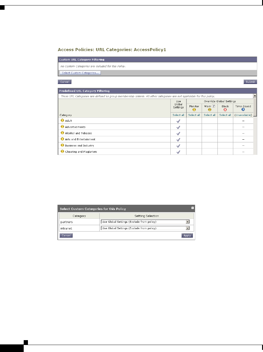
Chapter 16 URL Filters
Filtering Transactions Using URL Categories
16-8
Cisco IronPort AsyncOS 7.1 for Web User Guide
OL-23207-01
Step 3 Optionally, in the Custom URL Category Filtering section, you can add custom
URL categories on which to take action in this policy:
a. Click Select Custom Categories.
The Select Custom Categories for this Policy dialog box appears.
b. Choose which custom URL categories to include in this policy and click
Apply.
Choose which custom URL categories the URL filtering engine should compare
the client request against. The URL filtering engine compares client requests
against included custom URL categories, and ignores excluded custom URL
categories. The URL filtering engine compares the URL in a client request to
included custom URL categories before predefined URL categories.
The custom URL categories included in the policy appear in the Custom URL
Category Filtering section.

16-9
Cisco IronPort AsyncOS 7.1 for Web User Guide
OL-23207-01
Chapter 16 URL Filters
Filtering Transactions Using URL Categories
Step 4 In the Custom URL Category Filtering section, choose an action for each included
custom URL category. Table 16-1 describes each action.
Action Description
Use Global
Setting
Uses the action for this category in the Global Policy Group.
This is the default action for user defined policy groups.
Applies to user defined policy groups only.
Note: When a custom URL category is excluded in the global
Access Policy, then the default action for included custom
URL categories in user defined Access Policies is Monitor
instead of Use Global Settings. You cannot choose Use Global
Settings when a custom URL category is excluded in the global
Access Policy.
Redirect Redirects traffic originally destined for a URL in this category
to a location you specify. When you choose this action, the
Redirect To field appears. Enter a URL to which to redirect all
traffic.
For more information about redirecting traffic, see Redirecting
Traffic, page 16-23.
Allow Always allows client requests for web sites in this category.
Allowed requests bypass all further filtering and malware
scanning.
Only use this setting for trusted web sites. You might want to
use this setting for internal sites.
Monitor The Web Proxy neither allows nor blocks the request. Instead,
it continues to evaluate the client request against other policy
group control settings, such as web reputation filtering.

Chapter 16 URL Filters
Filtering Transactions Using URL Categories
16-10
Cisco IronPort AsyncOS 7.1 for Web User Guide
OL-23207-01
Step 5 In the Predefined URL Category Filtering section, choose one of the following
actions for each category:
•Use Global Settings
•Monitor
•Warn
•Block
•Time-Based
See Table 16-1 for details on these actions.
Step 6 In the Uncategorized URLs section, choose the action to take for client requests
to web sites that do not fall into a predefined or custom URL category.
Step 7 Submit and commit your changes.
Configuring URL Filters for Decryption Policy Groups
You can configure URL filtering for user defined Decryption Policy groups and
the global Decryption Policy group.
To configure URL filtering in a Decryption Policy group:
Warn The Web Proxy initially blocks the request and displays a
warning page, but allows the user to continue by clicking a
hypertext link in the warning page.
For more information, see Warning Users and Allowing Them
to Continue, page 16-24.
Block The Web Proxy denies transactions that match this setting.
Time-Based The Web Proxy blocks or monitors the request during the time
ranges you specify.
For more information about creating time based URL filtering
actions, see Creating Time Based URL Filters, page 16-26.
Action Description
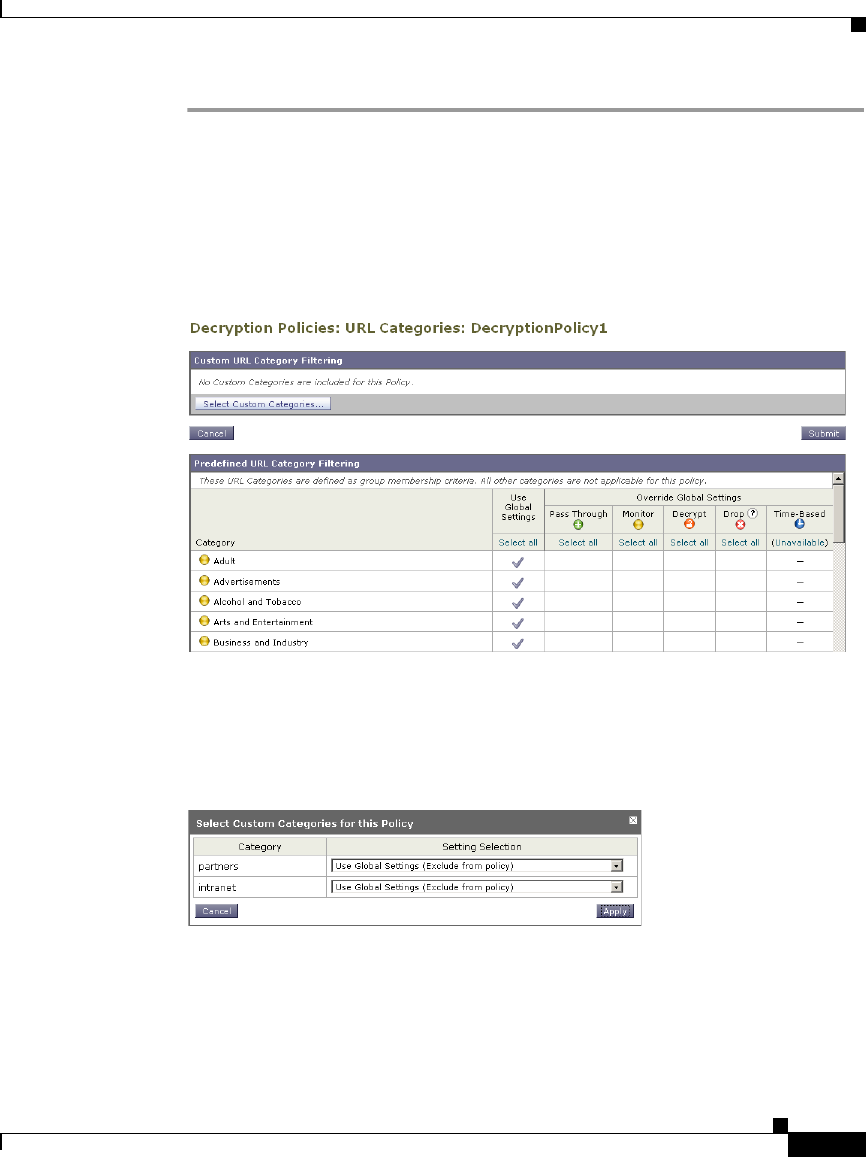
16-11
Cisco IronPort AsyncOS 7.1 for Web User Guide
OL-23207-01
Chapter 16 URL Filters
Filtering Transactions Using URL Categories
Step 1 Navigate to the Web Security Manager > Decryption Policies page.
Step 2 Click the link in the policies table under the URL Categories column for the policy
group you want to edit.
The Decryption Policies: URL Categories: policyname page appears.
Step 3 Optionally, in the Custom URL Category Filtering section, you can add custom
URL categories on which to take action in this policy:
a. Click Select Custom Categories.
The Select Custom Categories for this Policy dialog box appears.
b. Choose which custom URL categories to include in this policy and click
Apply.
Choose which custom URL categories the URL filtering engine should
compare the client request against. The URL filtering engine compares client
requests against included custom URL categories, and ignores excluded
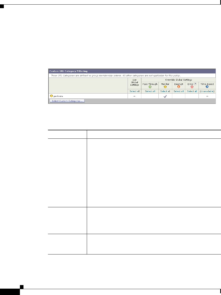
Chapter 16 URL Filters
Filtering Transactions Using URL Categories
16-12
Cisco IronPort AsyncOS 7.1 for Web User Guide
OL-23207-01
custom URL categories. The URL filtering engine compares the URL in a
client request to included custom URL categories before predefined URL
categories.
The custom URL categories included in the policy appear in the Custom URL
Category Filtering section.
Step 4 Choose an action for each custom and predefined URL category. Table 16-2
describes each action.
Action Description
Use Global
Setting
Uses the action for this category in the global Decryption
Policy group. This is the default action for user defined policy
groups.
Applies to user defined policy groups only.
When a custom URL category is excluded in the global
Decryption Policy, then the default action for included custom
URL categories in user defined Decryption Policies is
Monitor instead of Use Global Settings. You cannot choose
Use Global Settings when a custom URL category is excluded
in the global Decryption Policy.
Pass Through Passes through the connection between the client and the
server without inspecting the traffic content. You might want
to pass through connections to trusted secure sites, such as
well known banking and financial institutions.
Monitor The Web Proxy neither allows nor blocks the request. Instead,
it continues to evaluate the client request against other policy
group control settings, such as web reputation filtering.

16-13
Cisco IronPort AsyncOS 7.1 for Web User Guide
OL-23207-01
Chapter 16 URL Filters
Filtering Transactions Using URL Categories
Note If you want to block a particular URL category for HTTPS requests,
choose to decrypt that URL category in the Decryption Policy group and
then choose to block the same URL category in the Access Policy group.
Step 5 In the Uncategorized URLs section, choose the action to take for client requests
to web sites that do not fall into a predefined or custom URL category. You can
choose any action listed in Table 16-2.
Step 6 Submit and commit your changes.
Configuring URL Filters for Data Security Policy Groups
You can configure URL filtering for user defined Data Security Policy groups and
the Global Policy Group.
To configure URL filtering in a Data Security Policy group:
Step 1 Navigate to the Web Security Manager > IronPort Data Security page.
Decrypt Allows the connection, but inspects the traffic content. The
appliance decrypts the traffic and applies Access Policies to
the decrypted traffic as if it were a plaintext HTTP
connection. By decrypting the connection and applying
Access Policies, you can scan the traffic for malware. You
might want to decrypt connections to third party email
providers, such as gmail or hotmail.
For more information about how the appliance decrypts
HTTPS traffic, see Decrypting HTTPS Traffic, page 10-13.
Drop Drops the connection and does not pass the connection
request to the server. The appliance does not notify the user
that it dropped the connection. You might want to drop
connections to third party proxies that allow users on the
network bypass the organization’s acceptable use policies.
Action Description
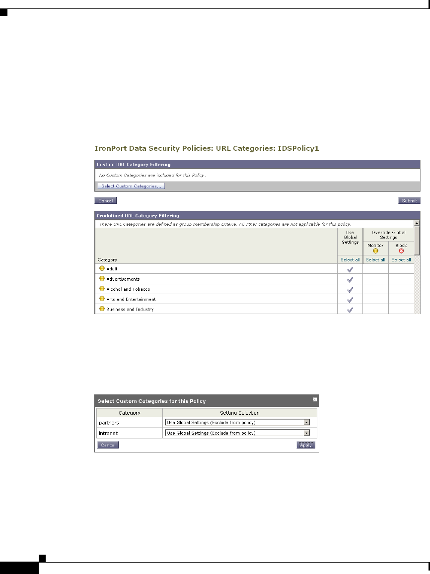
Chapter 16 URL Filters
Filtering Transactions Using URL Categories
16-14
Cisco IronPort AsyncOS 7.1 for Web User Guide
OL-23207-01
Step 2 Click the link in the policies table under the URL Categories column for the policy
group you want to edit.
The IronPort Data Security Policies: URL Categories: policyname page
appears.
Step 3 Optionally, in the Custom URL Category Filtering section, you can add custom
URL categories on which to take action in this policy:
a. Click Select Custom Categories.
The Select Custom Categories for this Policy dialog box appears.
b. Choose which custom URL categories to include in this policy and click
Apply.
Choose which custom URL categories the URL filtering engine should
compare the client request against. The URL filtering engine compares client
requests against included custom URL categories, and ignores excluded
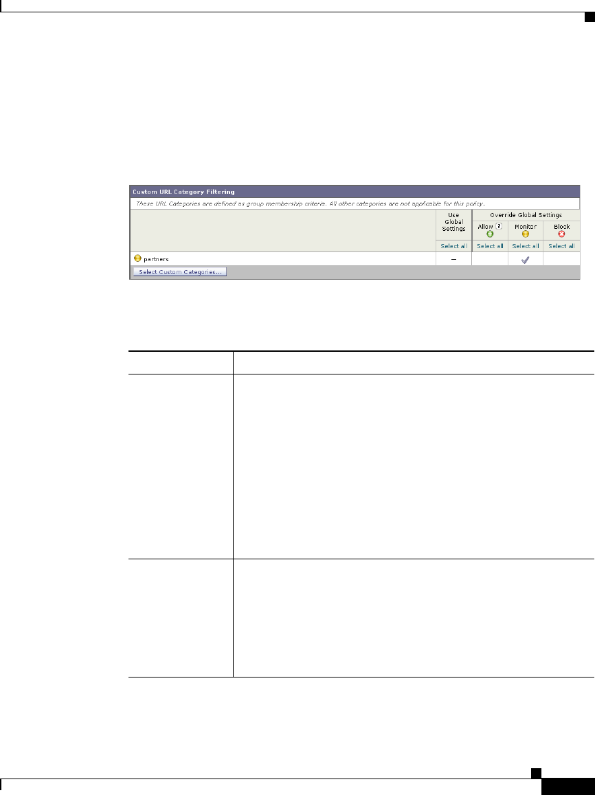
16-15
Cisco IronPort AsyncOS 7.1 for Web User Guide
OL-23207-01
Chapter 16 URL Filters
Filtering Transactions Using URL Categories
custom URL categories. The URL filtering engine compares the URL in a
client request to included custom URL categories before predefined URL
categories.
The custom URL categories included in the policy appear in the Custom URL
Category Filtering section.
Step 4 In the Custom URL Category Filtering section, choose an action for each custom
URL category. Table 16-3 describes each action.
Action Description
Use Global
Setting
Uses the action for this category in the Global Policy Group.
This is the default action for user defined policy groups.
Applies to user defined policy groups only.
When a custom URL category is excluded in the global
IronPort Data Security Policy, then the default action for
included custom URL categories in user defined IronPort
Data Security Policies is Monitor instead of Use Global
Settings. You cannot choose Use Global Settings when a
custom URL category is excluded in the global IronPort Data
Security Policy.
Allow Always allows upload requests for web sites in this category.
Applies to custom URL categories only.
Allowed requests bypass all further data security scanning
and the request is evaluated against Access Policies.
Only use this setting for trusted web sites. You might want to
use this setting for internal sites.

Chapter 16 URL Filters
Custom URL Categories
16-16
Cisco IronPort AsyncOS 7.1 for Web User Guide
OL-23207-01
Step 5 In the Predefined URL Category Filtering section, choose one of the following
actions for each category:
–
Use Global Settings
–
Monitor
–
Block
See Table 16-3 for details on these actions.
Step 6 In the Uncategorized URLs section, choose the action to take for upload requests
to web sites that do not fall into a predefined or custom URL category.
Step 7 Submit and commit your changes.
Custom URL Categories
The Web Security appliance ships with many predefined URL categories by
default, such as Web-based Email and more. However, you can also create user
defined custom URL categories that specify specific hostnames and IP addresses.
You might want to create custom URL categories for internal sites or a group of
external sites you know you can trust.
Create, edit, and delete custom URL categories on the Web Security Manager >
Custom URL Categories page.
Monitor The Web Proxy neither allows nor blocks the request. Instead,
it continues to evaluate the upload request against other policy
group control settings, such as web reputation filtering.
Block The Web Proxy denies transactions that match this setting.
Action Description
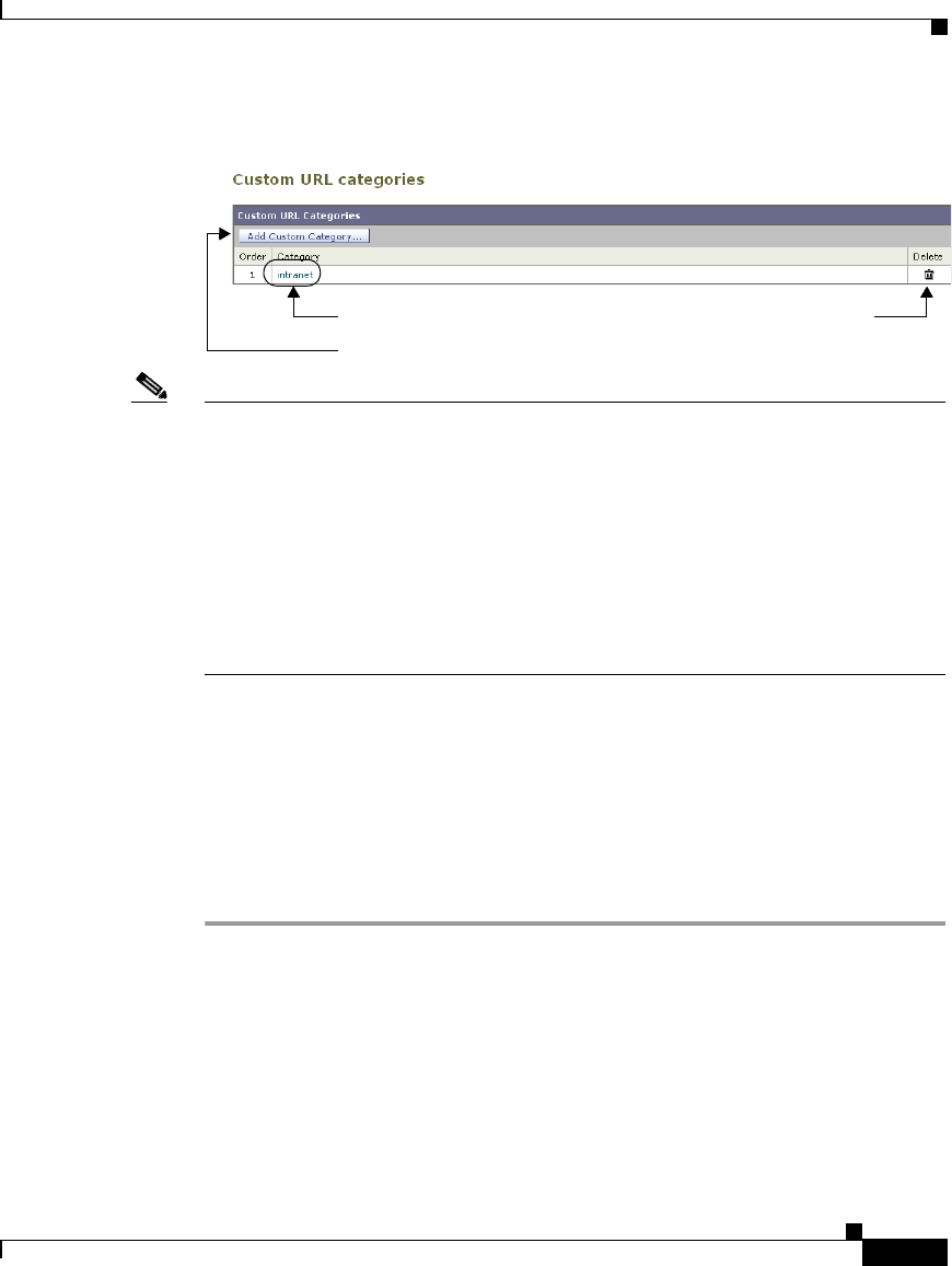
16-17
Cisco IronPort AsyncOS 7.1 for Web User Guide
OL-23207-01
Chapter 16 URL Filters
Custom URL Categories
Note The Web Security appliance uses the first four characters of custom URL category
names preceded by “c_” in the access logs. Consider the custom URL category
name if you use Sawmill for IronPort to parse the access logs. If the first four
characters of the custom URL category include a space, Sawmill for IronPort
cannot properly parse the access log entry. Instead, only use supported characters
in the first four characters if you will use Sawmill for IronPort to parse the access
logs. If you want to include the full name of a custom URL category in the access
logs, add the %XF format specifier to the access logs. For more information on
how to do this, see Custom Formatting in Access Logs and W3C Logs,
page 24-39.
It is possible to create multiple custom URL categories and include the same URL
in each category. The order of the custom URL categories matters. Categories
listed higher in the list take priority over categories listed lower. When you
include these custom URL categories in the same Access, Decryption, or IronPort
Data Security Policy group and define different actions to each category, the
action of the higher included custom URL category takes effect.
To create or edit a custom URL category:
Step 1 Navigate to the Web Security Manager > Custom URL Categories page.
Step 2 To create a custom URL category, click Add Custom Category. To edit an
existing custom URL category, click the name of the URL category.
Add a custom URL category.
Edit custom URL category. Delete custom URL category.
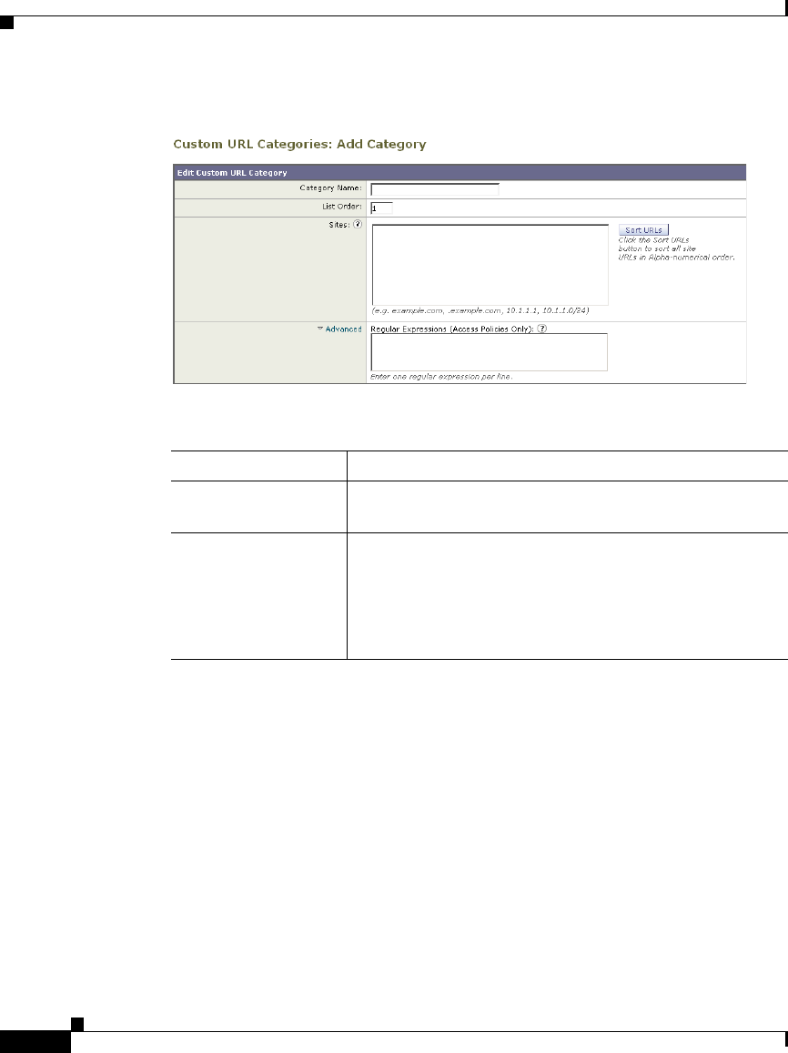
Chapter 16 URL Filters
Custom URL Categories
16-18
Cisco IronPort AsyncOS 7.1 for Web User Guide
OL-23207-01
Step 3 Enter the settings in Table 16-4 for the custom URL category.
Setting Description
Category Name Enter a name for the URL category. This name appears
when you configure URL filtering for policy groups.
List Order Choose the order in the list of custom URL categories to
place this category. Enter “1” for the topmost URL
category.
The URL filtering engine evaluates a client request
against the custom URL categories in the order specified.

16-19
Cisco IronPort AsyncOS 7.1 for Web User Guide
OL-23207-01
Chapter 16 URL Filters
Custom URL Categories
Step 4 Optionally, click Sort URLs to sort all addresses in the Sites field.
Note Once you sort the addresses, you cannot retrieve their original order.
Step 5 Submit and commit your changes.
Sites Enter one or more addresses that belong in the custom
category.
You can enter multiple addresses separated by line
breaks or commas. You can enter addresses using any of
the following formats:
•IP address, such as 10.1.1.0
•CIDR address, such as 10.1.1.0/24
•Domain name, such as example.com
•Hostname, such as crm.example.com
•Partial hostname, such as .example.com
Note: Entering a partial hostname, such as
.example.com, also matches www.example.com.
Advanced: Regular
Expressions
You can use regular expressions to specify multiple web
servers that match the pattern you enter.
Note: The URL filtering engine compares URLs with
addresses entered in the Sites field first. If the URL of a
transaction matches an entry in the Sites field, it is not
compared to any expression entered here.
For more information about using regular expressions in
the Web Security appliance, see Regular Expressions,
page 16-28.
Setting Description

Chapter 16 URL Filters
Filtering Adult Content
16-20
Cisco IronPort AsyncOS 7.1 for Web User Guide
OL-23207-01
Filtering Adult Content
You can configure the Web Security appliance to filter adult content from some
web searches and websites. You might want to do this to allow access to these
sites, such as google.com and youtube.com, while still restricting potentially
unsafe content from reaching users. For example, a school district could allow
access to educational videos on youtube.com, but block inappropriate contents for
students.
AsyncOS for Web offers the following features to filter adult content:
•Enforce safe searches. Many search engines support a filtering technology
feature that classifies inappropriate content on the web as adult. When this
filtering feature is enabled, content classified as adult is filtered from the
search results before presented to the user. This feature is commonly called
safe search. However, for most search engines, this feature is enabled and
disabled by end users. You can configure the Web Security appliance so that
outgoing search requests appear to search engines as safe search requests.
This gives the control to an administrator on the network instead of the end
user. You might want to do this to prevent users from bypassing acceptable
use policies using search engines.
•Enforce site content ratings. Many content sharing sites that serve
user-generated photos and videos classify some of their content as adult.They
allow users to restrict their own access to the adult content on these sites by
either enforcing their own safe search feature or blocking access to adult
content, or both. This classification feature is commonly called content
ratings.
You enforce safe searches and site content ratings for different users by enabling
the feature at the Access Policy level. Not all search engines or content sharing
websites are supported, but AsyncOS for Web can support additional search
engines and websites during URL filtering engine updates. The Access Policies >
URL Filtering > policyname page always lists the currently supported search
engines and websites for each feature. The list of supported search engines and
content sharing websites may increase with AVC engine updates.
Consider the following rules and guidelines when enforcing safe search and site
content ratings:
•To use the safe search and site content ratings features, AsyncOS for Web
must use the URL filtering engine included with Cisco IronPort Web Usage
Controls.
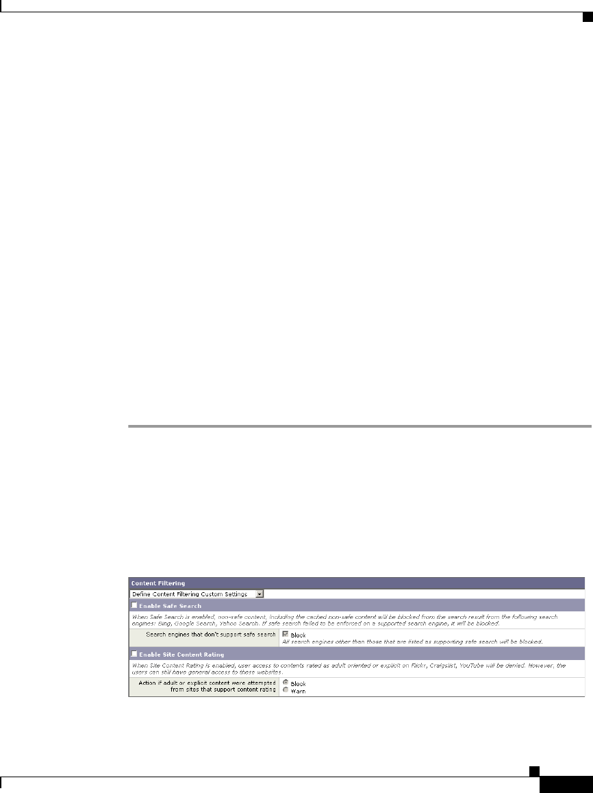
16-21
Cisco IronPort AsyncOS 7.1 for Web User Guide
OL-23207-01
Chapter 16 URL Filters
Filtering Adult Content
•The safe search feature enforces strict safe searches.
•When the URL of one of the supported search engines or supported content
ratings websites is included in a custom URL category with the Allow action
applied, then users can access that URL as if the safe search or content ratings
features were disabled. That is, no search results are blocked and all content
is visible.
•You can choose whether or not to block users from search engines that are not
currently supported by the Web Security appliance safe search feature.
•Due to the limitations inherent in youtube.com, the Web Proxy is not able to
block embedded YouTube videos from a third party website.
•When configuring the site content ratings feature, you can choose whether to
block users from adult content or to provide them with end-user URL filtering
warning page that allows them to view the adult content after clicking a link
to accept the warning message. For more information, see Warning Users and
Allowing Them to Continue, page 16-24.
•Any Access Policy that has either the safe search or site content ratings
feature enabled is considered a safe browsing Access Policy.
To enforce safe searches and site content ratings:
Step 1 Navigate to the Web Security Manager > Access Policies page.
Step 2 Click the link under the URL Categories column for an Access Policy group or
the Global Policy Group.
The Access Policies: URL Filtering: policyname page appears.
Step 3 When editing a user-defined Access Policy, choose Define Content Filtering
Custom Settings in the Content Filtering section.
Step 4 Click the Enable Safe Search check box to enable the safe search feature.

Chapter 16 URL Filters
Filtering Adult Content
16-22
Cisco IronPort AsyncOS 7.1 for Web User Guide
OL-23207-01
Step 5 Choose whether to block users from search engines that are not currently
supported by the Web Security appliance safe search feature.
Step 6 Click the Enable Site Content Rating check box to enable the site content ratings
feature.
Step 7 Choose whether to block all adult content from the supported content ratings
websites or to display the end-user URL filtering warning page.
Step 8 Submit and commit your changes.
Logging Adult Content Access
By default, the access logs include a safe browsing scanning verdict inside the
angled brackets of each entry. The safe browsing scanning verdict indicates
whether or not either the safe search or site content ratings feature was applied to
the transaction. You can also add the safe browsing scanning verdict variable to
the access logs or W3C access logs:
•Access logs: %XS
•W3C access logs: x-request-rewrite
Table 16-5 describes the safe browsing scanning verdict values.
For more information on logging, see Access Log File, page 24-19.
Value Description
ensrch The original client request was unsafe and the safe search feature
was applied.
encrt The original client request was unsafe and the site content ratings
feature was applied.
unsupp The original client request was to an unsupported search engine.
err The original client request was unsafe, but neither the safe search
nor the site content ratings feature could be applied due to an error.
- Neither the safe search nor the site content ratings feature was
applied to the client request because the features were bypassed (for
example, the transaction was allowed in a custom URL category) or
the request was made from an unsupported application.

16-23
Cisco IronPort AsyncOS 7.1 for Web User Guide
OL-23207-01
Chapter 16 URL Filters
Redirecting Traffic
Requests blocked due to either the safe search or site content rating features, use
one of the following ACL decision tags in the access logs:
•BLOCK_SEARCH_UNSAFE
•BLOCK_CONTENT_UNSAFE
•BLOCK_UNSUPPORTED_SEARCH_APP
•BLOCK_CONTINUE_CONTENT_UNSAFE
For more information on the ACL decision tags, see ACL Decision Tags,
page 24-24.
Redirecting Traffic
In addition to using the Web Security appliance to monitor and block traffic to
certain websites, you can also use it to redirect users to a different website. You
can configure the appliance to redirect traffic originally destined for a URL in a
custom URL category to a location you specify. This allows you to redirect traffic
at the appliance instead of at the destination server.
You might want to redirect traffic at the appliance if your organization published
the links to an internal site, but the location of the site changed since publication,
or if you do not have control over the web server.
Configure the appliance to redirect custom URL categories to another location
when you configure the URL categories for an Access Policy group. You can
redirect traffic for a custom Access Policy group or the Global Policy Group.
Note To redirect traffic, you must define at least one custom URL category. For more
information about creating custom URL categories, see Custom URL Categories,
page 16-16.
Note Beware of infinite loops when you configure the appliance to redirect traffic. For
example, if you redirect traffic destined for http://A.example.com to
http://B.example.com and you also inadvertently redirect traffic destined for
http://B.example.com to http://A.example.com, then you create an infinite loop.
In this case, the appliance redirects the traffic back and forth between the two
URLs indefinitely.
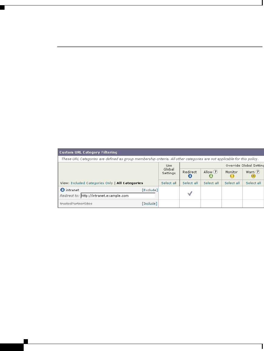
Chapter 16 URL Filters
Warning Users and Allowing Them to Continue
16-24
Cisco IronPort AsyncOS 7.1 for Web User Guide
OL-23207-01
To redirect traffic:
Step 1 Navigate to the Web Security Manager > Access Policies page.
Step 2 Click the link under the URL Categories column for an Access Policy group or
the Global Policy Group.
The Access Policies: URL Filtering: policyname page appears.
Step 3 In the Custom URL Category Filtering section, verify the custom URL category
you want to redirect is included. If the Include link displays, click it. If the
Exclude link displays, the category is already included.
Step 4 Click the Redirect column for the custom category you want to redirect.
Step 5 Enter the URL to which you want to redirect traffic in the Redirect To field for the
custom category.
Step 6 Submit and commit your changes.
Warning Users and Allowing Them to Continue
In addition to using the Web Security appliance to block traffic to certain
websites, you can also use it to warn users that a site does not meet the
organization’s acceptable use policies and allow them to continue if they choose.
You might want to warn users and allow them to continue if your organization
wants to discourage its users from accessing certain sites, but does not want to or
is not allowed by law to block access to those sites.
You can warn users and allow them to continue using one of the following
methods:
•Choose the Warn action for a URL category in an Access Policy group.

16-25
Cisco IronPort AsyncOS 7.1 for Web User Guide
OL-23207-01
Chapter 16 URL Filters
Warning Users and Allowing Them to Continue
•Enable the site content ratings feature and warn users that access adult
content instead of blocking them. For more information on the site content
ratings feature, see Filtering Adult Content, page 16-20.
When users access a URL that is configured to warn and continue, they initially
see an IronPort notification page with a warning about accessing sites of this
category or content. The end-user URL filtering warning page includes the
following elements:
•Default warning text provided by IronPort
•Custom text provided by the Web Security appliance administrator (optional)
•Notification code listing the invoked Access Policy and the URL category
being warned or the safe browsing scanning verdict.
•A hypertext link to the originally requested URL
Users are tracked in the access log by user name if authentication has made a user
name available, and tracked by IP address if no user name is available.
When you use the warn and continue feature, you can configure the following
settings that affect the end-user URL filtering warning page:
•Time Between Warning. The Time Between Warning determines how often
the Web Proxy displays the end-user URL filtering warning page for each
URL category per user. Once a user clicks the continue link on the end-user
URL filtering warning page, the Web Proxy considers that user to have
acknowledged the warning for the time you enter for the Time Between
Warning. This setting applies to users tracked by username and users tracked
by IP address. You can specify any value from 30 to 2678400 seconds (one
month). Default is 1 hour (3600 seconds).
•Custom message. The custom message is text you enter that appears on every
end-user URL filtering warning page. You might want to include text for the
organization’s acceptable use policies, or include a link to a page that details
the acceptable use policies. You can include some simple HTML tags to
format the text. For example, you can change the color and size of the text, or
make it italicized. See Custom Text in Notification Pages, page 15-23 for
more information.
Configure these settings on the Security Services > End-User Notification page.
For more information, see Configuring the End-User URL Filtering Warning
Page, page 15-21.

Chapter 16 URL Filters
Creating Time Based URL Filters
16-26
Cisco IronPort AsyncOS 7.1 for Web User Guide
OL-23207-01
Note The warn and continue feature only works for HTTP and decrypted HTTPS
transactions. It does not work with native FTP transactions.
User Experience When Warning Users
When the URL filtering engine warns users for a particular request, it provides a
warning page that the Web Proxy sends to the end user. However, not all websites
display the warning page to the end user. For example, some Web 2.0 websites
display dynamic content using javascript instead of a static webpage and are not
likely to display the warning page from the Web Proxy. When this happens, users
are blocked from the URL that is assigned the Warn option without being given
the chance to continue accessing the site anyway.
Creating Time Based URL Filters
You can configure how the Web Security appliance to handles requests for URLs
in particular categories differently based on time and day. For example, you can
block access to social networking sites, such as blogs and forums, during business
hours.
To define URL filtering actions by time you must first define at least one time
range. For information about time ranges, see Working with Time Based Policies,
page 6-13.
To create time based URL filtering actions for an Access Policy:
Step 1 Navigate to the Web Security Manager > Access Policies page.
Step 2 Click the link in the policies table under the URL Categories column for the policy
group you want to edit.
The Access Policies: URL Filtering: policyname page appears.
Step 3 Select Time-Based for the custom or predefined URL category you want to
configure based on time range.
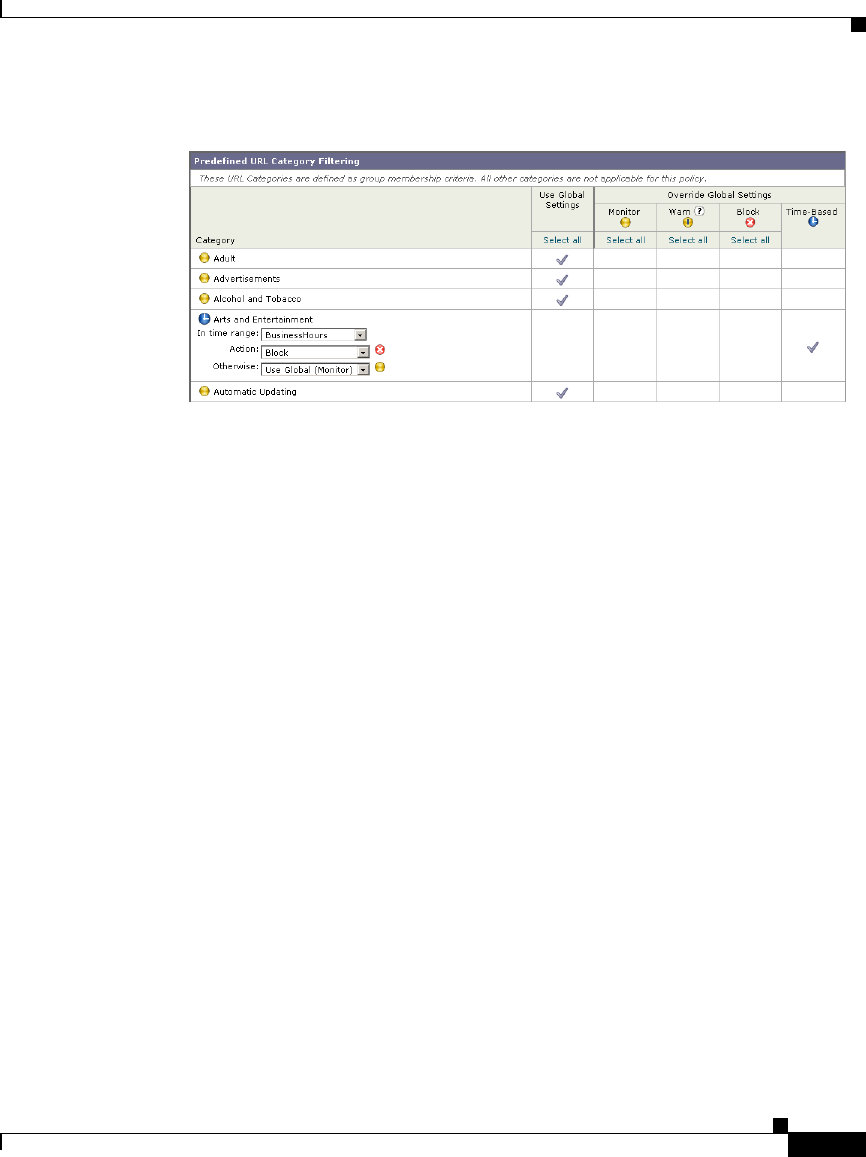
16-27
Cisco IronPort AsyncOS 7.1 for Web User Guide
OL-23207-01
Chapter 16 URL Filters
Viewing URL Filtering Activity
When you select Time-Based for the URL category, additional fields appear
under the category name where you can choose the actions.
Step 4 In the In Time Range field, choose the defined time range to use for the URL
category.
For information about defining time ranges, see Creating Time Ranges,
page 6-14.
Step 5 In the Action field, choose the action to enact on transactions in this URL category
during the defined time range.
Step 6 In the Otherwise field, choose the action to enact on transactions in this URL
category outside the defined time range.
Step 7 Submit and commit your changes.
Viewing URL Filtering Activity
The Reporting > URL Categories page provides a collective display of URL
statistics that includes information about top URL categories matched and top
URL categories blocked. Additionally, this page displays category-specific data
for bandwidth savings and web transactions. For detailed information about
monitoring and reporting functionality, see Reporting, page 22-1.

Chapter 16 URL Filters
Regular Expressions
16-28
Cisco IronPort AsyncOS 7.1 for Web User Guide
OL-23207-01
Understanding Unfiltered and Uncategorized Data
When viewing URL statistics on the Reporting > URL Categories page, it is
important to understand how to interpret the following data:
•URL Filtering Bypassed — This data represents policy, port, and admin user
agent blocking that occurs before URL filtering.
•Uncategorized URL — This data represents all transactions for which the
URL filtering engine is queried, but no category is matched.
Access Log File
The access log file records the URL category for each transaction in the scanning
verdict information section of each entry. For more information about the access
log, see Access Log File, page 24-19. For a list of each URL category, see URL
Category Descriptions, page 16-32.
Regular Expressions
Regular expressions are pattern matching descriptions that contain normal
printable characters and special characters that are used to match patterns in text
strings. For example, a text string such as “welcome” matches “welcome” or
“welcomemyfriend.” When a match occurs, the function returns true. If no match
occurs, the function returns false. Actions are executed only when a
pattern-matching expression is true.
The Web Security appliance uses POSIX extended regular expression syntax,
fully described by IEEE POSIX 1003.2. However, the appliance does not support
using a backward slash to escape a forward slash. If you need to use a forward
slash in a regular expression, type the forward slash without a backward slash.
Note Technically, AsyncOS for Web uses the Flex regular expression analyzer. For
more detailed information about how it reads regular expressions, see
http://flex.sourceforge.net/manual/Patterns.html.
You can use regular expressions in the following locations:

16-29
Cisco IronPort AsyncOS 7.1 for Web User Guide
OL-23207-01
Chapter 16 URL Filters
Regular Expressions
•Custom URL categories for Access Policies. When you create a custom
URL category to use with Access Policy groups, you can use regular
expressions to specify multiple web servers that match the pattern you enter.
For more information about creating custom URL categories, see Custom
URL Categories, page 16-16.
•Custom user agents to block. When you edit the applications to block for an
Access Policy group, you can use regular expressions to enter specific user
agents to block, such as Skype or Microsoft Internet Explorer. For more
information about using regular expressions to block user agents, see Policy:
Protocols and User Agents, page 8-18.
Note Regular expressions that perform extensive character matching consume
resources and can affect system performance. For this reason, regular expressions
should be cautiously applied.
Forming Regular Expressions
Regular expressions are rules that typically use the word “matches” in the
expression. They can be applied to match specific URL destinations or web
servers. For example, the following regular expression matches any pattern
containing blocksite.com:
\.blocksite\.com
Consider the following regular expression example:
server[0-9]\.example\.com
In this example, server[0-9] matches server0, server1, server2, ..., server9 in
the domain example.com.
In the following example, the regular expression matches files ending in .exe,
.zip, and .bin in the downloads directory.
/downloads/.*\.(exe|zip|bin)
Avoid using regular expressions strings that are redundant because they can cause
higher CPU usage on the Web Security appliance. A redundant regular expression
is one that starts or ends with “.*”.

Chapter 16 URL Filters
Regular Expressions
16-30
Cisco IronPort AsyncOS 7.1 for Web User Guide
OL-23207-01
Note You must enclose regular expressions that contain blank spaces or
non-alphanumeric characters in ASCII quotation marks.
Regular Expression Character Table
Table 16-6 describes characters that are commonly used to form regular
expressions:
Character Description
. Matches a single character.
* Matches zero or more occurrences of the preceding regular
expression.
For example:
[0-9]* matches any number of digits
“.*” matches any arbitrary string of characters
^ Matches the beginning of a line as the first character of a regular
expression.
$ Matches the end of a line as the last character of a regular
expression.
+ Matches one or more occurrences of the preceding regular
expression.
? Matches zero or one occurrence of the preceding regular
expression.
| Matches the preceding regular expression or the following regular
expression. For example:
x|y matches either x or y
abc|xyz matches either of the strings abc or xyz

16-31
Cisco IronPort AsyncOS 7.1 for Web User Guide
OL-23207-01
Chapter 16 URL Filters
Regular Expressions
Note To match the literal version of any of the special characters, the character must be
preceded by a backslash “\”. For example, to exactly match a period “.” the regular
expression must use “\.” as in “\.example\.com”. However, the appliance does not
support using a backward slash to escape a forward slash. If you need to use a
forward slash in a regular expression, type the forward slash without a backward
slash.
[ ] Matches the characters or digits that are enclosed within the
brackets.
For example:
[a-z] matches any character between a and z
[r-u] matches any of the characters r, s, t, or u
[0-3] matches any of the single digits 0, 1, 2, 3
{ } Specifies the number of times to match the previous pattern.
For example:
D{1,3} matches one to three occurrences of the letter D
( ) Group characters in a regular expression.
For example:
(abc)* matches abc or abcabcabc
“...” Literally interprets any characters enclosed within the quotation
marks.
\ Escape character.
Character Description

Chapter 16 URL Filters
URL Category Descriptions
16-32
Cisco IronPort AsyncOS 7.1 for Web User Guide
OL-23207-01
URL Category Descriptions
This section lists the URL categories for both URL filtering engines. The tables
also include the abbreviated URL category names that may appear in the in the
Web Reputation filtering and anti-malware scanning section of an access log file
entry.
Note The URL category abbreviations for Cisco IronPort Web Usage Controls include
the prefix “IW_” before each abbreviation so that the “art” category becomes
“IW_art.”
Table 16-7 lists and describes the URL categories for the Cisco IronPort Web
Usage Controls.
URL Category
Abbrevi-
ation Code Description Example URLs
Adult adlt 1006 These are sites directed to adults, not
necessarily pornographic sites. Adult
clubs: strip clubs, swingers clubs,
escort services, strippers; general
information about sex,
non-pornographic in nature; genital
piercing; adult products, adult
greeting cards; information about sex
not in the context of health or
disease.
cybereroticanews.com/
dansex.dk/
cqsex.com/
crotchrocket.us/
toperotique.com
Advertisements adv 1027 Banner and pop-up ads that often
accompany a web page; other
advertising sites that provide
advertisement content.
doubleclick.com
banners.yellowpages.co.uk
ads.msn.com
affiliateclicks.com
arc6.msn.com

16-33
Cisco IronPort AsyncOS 7.1 for Web User Guide
OL-23207-01
Chapter 16 URL Filters
URL Category Descriptions
Alcohol and
Tobacco
at 1048 Beer, wine, spirits: beer and wine
making, cocktail recipes, liquor
sellers, wineries, vineyards,
breweries; mixed drinks; tobacco;
pipes and smoking products.
smokers.com/
michiganbrewersguild.org/
johnniewalker.com/
cigaraficionado.com/
lvcwines.com/
Arts and
Entertainment
art 1002 Galleries and exhibitions; artists and
art; photography; literature and
books, publishing; movies;
performing arts and theater; music
and radio; television; celebrities and
fan sites; design; architecture;
entertainment news, venues; humor.
kidrock.com
guitarist.co.uk
entertainment.yahoo.com/
drudgereportarchives.com
nycballet.com
URL Category
Abbrevi-
ation Code Description Example URLs

Chapter 16 URL Filters
URL Category Descriptions
16-34
Cisco IronPort AsyncOS 7.1 for Web User Guide
OL-23207-01
Business and
Industry
busi 1019 Sites involved in
business-to-business transactions of
all kinds. Advertising, marketing,
commerce, corporations, business
practices, workforce, human
resources, transportation, payroll,
security, venture capital, etc; office
supplies; industrial equipment
(process equipment), machines and
mechanical systems; heating
equipment, cooling equipment;
materials handling equipment;
packaging equipment;
manufacturing: solids handling,
metal fabrication construction and
building; passenger transportation;
commerce; industrial design;
construction, building materials;
industrial design; shipping and
freight: freight services, trucking,
freight forwarders, truckload
carriers, freight/transportation
brokers, expedited services, load &
freight matching, track & trace,
NVOCC, railroad shipping, ocean
shipping, road feeder services,
moving & storage; online meetings.
smithbearing.com
paychex.com
newholland.com
adsonwheels.com
cat.com
Cheating and
Plagiarism
plag 1051 Sites promoting cheating and selling
written work (e.g., term papers) for
plagiarism.
schoolsucks.com/
thesis-statements.com/
academictermpapers.com/
cheathouse.com/
nursingpapers.com/
URL Category
Abbrevi-
ation Code Description Example URLs

16-35
Cisco IronPort AsyncOS 7.1 for Web User Guide
OL-23207-01
Chapter 16 URL Filters
URL Category Descriptions
Child Porn cprn 1064 Sites that host child pornography and
pedophilia.
No examples can be
legally/ethically given.
Computer
Security
csec 1065 Sites that offer security product and
services for corporate and home
users.
abuse.net
activesecuritymonitor.com
iisprotect.com
securityfocus.com
sectools.org
Computers and
Internet
comp 1003 Information about computers and
software such as: hardware,
software, software support sites;
information for software engineers,
programming and networking;
website design, and the web and
Internet in general; computer
science; computer graphics and
clipart.
wallpapers.com
unicode.org
redhat.com/
msexchange.org
geeksquad.com
Cults cult 1041 Cults and cult behavior. churchofsatan.com/
voodoo.de/
hexen.org/
magical-lights.de/
heavensgate.com/
Dating date 1055 Dating sites, online personals,
matrimonial agencies, etc., for
adults.
catholicmatch.com/
collegeluv.com/
allpersonals.com
eharmony.com
farmersonly.com
URL Category
Abbrevi-
ation Code Description Example URLs

Chapter 16 URL Filters
URL Category Descriptions
16-36
Cisco IronPort AsyncOS 7.1 for Web User Guide
OL-23207-01
Dining and
Drinking
food 1061 Eating and drinking establishments;
restaurants, bars, taverns, brewpubs;
restaurant guides and reviews.
southcitygrill.com
chilis.com
elnuevorodeo.com/
pizzahut.co.uk
mcdonalds.com
Education edu 1001 Education-related sites and web
pages such as schools, colleges,
universities, teaching materials,
teachers resources; technical and
vocational training; online training;
education issues and policy; financial
aid; school funding; standards and
testing.
ucla.edu
pearsonhighered.com
k12.ca.us/
homeworknow.com
gedpractice.com
File Transfer
Services
fts 1071 Sites with the primary purpose of
providing download services and
hosted file sharing.
yousendit.com
rapidshare.com
techsofttools.com
sharefile.com/
2large2email.com
Filter
Avoidance
filt 1025 Web pages that promote and aid
undetectable and anonymous surfing.
proxyblind.org
the-cloak.com
proxybuster.net
youhide.com
zend2.com
URL Category
Abbrevi-
ation Code Description Example URLs

16-37
Cisco IronPort AsyncOS 7.1 for Web User Guide
OL-23207-01
Chapter 16 URL Filters
URL Category Descriptions
Finance fnnc 1015 Sites and information that are
primarily financial in nature such as:
accounting practices and
accountants; taxation; banking;
insurance; investing: information
relating to the stock market, stocks,
bonds, mutual funds, brokers, stock
analysis and commentary, stock
screens, stock charts, IPOs, stock
splits; the national economy;
personal finance involving insurance
of all types; credit cards; retirement
and estate planning; loans;
mortgages; taxes.
finance.yahoo.com
usbank.com
nasdaq.com
lendingtree.com
shopyourmortgage.ca
Freeware and
Shareware
free 1068 Sites that provide downloading of
freeware and shareware software.
all-freeware.com
download.com
freewarefiles.com
onlyfreewares.com
uberdownloads.com
Gambling gamb 1049 Casinos and online gambling sites;
bookmakers and odds; gambling
advice; horse and dog racing in a
gambling context; sports book;
sports gambling.
eurobet.co.uk/
pokerworld.com
onlinepokernews.com
bodog.com
blindbetpoker.com
Games game 1007 Various card games, board games,
word games, video games; computer
games, Internet games (RPGs and
D&D); combat games; sports games;
downloadable games; game reviews;
cheat sheets.
netdevil.com
games.com
games.yahoo.com/
pogo.com
cheatworld.com
URL Category
Abbrevi-
ation Code Description Example URLs

Chapter 16 URL Filters
URL Category Descriptions
16-38
Cisco IronPort AsyncOS 7.1 for Web User Guide
OL-23207-01
Government
and Law
gov 1011 Foreign relations; news and
information relating to politics and
elections such as: politics, political
parties, election news and voting;
sites and information relating the
field of law such as: attorneys, law
firms, law publications, legal
reference material, courts, dockets,
legal associations; legislation and
court decisions; civil rights issues;
immigration; patents and copyrights;
sites and information relating to law
enforcement and correctional
systems; sites related to crime, crime
reporting, law enforcement, crime
statistics, etc; sites relating to the
military such as: the armed forces,
military bases, military
organizations, and military
equipment; anti-terrorism.
texas.gov
legalzoom.com
fenwick.com
comcast.net/news/politics/
barackobama.com
Hacking hack 1050 Sites discussing ways to hack into
web sites, software, and computers.
crackfind.com/
hackthissite.org/
dirkster.com/
trinsic.org/
sweethacks.com/
URL Category
Abbrevi-
ation Code Description Example URLs

16-39
Cisco IronPort AsyncOS 7.1 for Web User Guide
OL-23207-01
Chapter 16 URL Filters
URL Category Descriptions
Hate Speech hate 1016 Hate-related sites, involving racism,
sexism, racist theology; hate music;
Christian identity religions; World
Church of the Creator; Neo-Nazi
organizations: Aryan Nations,
American Nazi parties, Neo-Nazis,
Ku Klux Klan, National Alliance,
White Aryan Resistance, white
supremacists; National Socialist
Movement; Holocaust denial.
panzerfaust.com
bloodandhonour.com
kkk.com
nazi.org
blacksandjews.com
Health and
Nutrition
hlth 1009 Health care; disease and disabilities;
medical care; hospitals; doctors;
medicinal drugs; mental health;
psychiatry; pharmacology; exercise
and fitness; physical disabilities;
vitamins and supplements; sex in a
context of health (disease and health
care); tobacco use, alcohol use, drug
use, and gambling in a context of
health (disease and health care); food
in general; food and beverage;
cooking and recipes; food and
nutrition, health, dieting; cooking,
including recipe and culinary sites.
webmd.com
health.gov
stjohns.com
lowcarb.ca
fitness.com
chefmoz.org
cookingmarvel.com
Illegal
Activities
crmr 1022 Pages that promote crime such as
stealing, fraud, phreaking and
cracking; warez and pirated
software; computer viruses;
terrorism, bombs, and anarchy; sites
depicting murder and suicide as well
as explaining ways to commit them.
lockpicksonline.com
grokster.com
anarchistcookbook.com
directwarez.com
ddlshark.com
URL Category
Abbrevi-
ation Code Description Example URLs

Chapter 16 URL Filters
URL Category Descriptions
16-40
Cisco IronPort AsyncOS 7.1 for Web User Guide
OL-23207-01
Illegal Drugs drug 1047 Information about recreational
drugs, drug paraphernalia, marijuana
seeds; advice on how to grow
marijuana.
marijuana.com
sporeworks.com/
cleartest.com/
bcseeds.com/
drugs-plaza.com/
Infrastructure misc 1018 Content delivery infrastructure and
dynamically-generated content -
these cannot be more specifically
categorized because the pages are
secured or otherwise difficult to
categorize
example.com/
akamai.net
imagenet.co.uk/
edgecastcdn.net/
webstat.net/
Instant
Messaging
im 1039 Web-based instant messaging. messenger.yahoo.com/
meebo.com/
friendvox.com
aimonpsp.com
buddy4u.com
Internet
Telephony
voip 1067 Sites that provide telephonic services
using the Internet
aussievoip.com.au
downloadsquad.com/
category/voip/
skypepc.com
simplecall.net
packet8.net
Job Search job 1004 Career advice; advice on resume
writing and interviewing skills; job
placement services; job databanks;
employment and temp agencies;
employer sites.
jobs.com
siena.edu/careercenter/
policeemployment.com
novastaffinginc.com
monster.de
URL Category
Abbrevi-
ation Code Description Example URLs

16-41
Cisco IronPort AsyncOS 7.1 for Web User Guide
OL-23207-01
Chapter 16 URL Filters
URL Category Descriptions
Lingerie and
Swimsuits
ling 1031 Intimate apparel, especially when
modeled.
victoriasecret.com
sportsillustrated.cnn.com/
swimsuit/
henryandjune.com/
lingeriediva.com/
lingeriebowl.com/
Lottery and
Sweepstakes
lotr 1034 Sweepstakes, contests and lotteries. calottery.com
state.nj.us/lottery/
powerball.com/
hoosierlottery.com/
national-lottery.co.uk/
Mobile Phones cell 1070 Sites that provide SMS services;
ringtones.
shop.orange.co.uk
savemysms.fr
smartphonemag.com
sprint.com
jamster.com
URL Category
Abbrevi-
ation Code Description Example URLs

Chapter 16 URL Filters
URL Category Descriptions
16-42
Cisco IronPort AsyncOS 7.1 for Web User Guide
OL-23207-01
Nature natr 1013 Natural resources; ecology and
conservation; forests; wilderness;
plants; flowers; forest conservation;
forest, wilderness, forestry practices;
forest management (re-forestation,
forest protection, conservation,
harvesting, forest health, thinning,
prescribed burning); agricultural
practices: agriculture, gardening,
horticulture, landscaping, planting,
weed control, irrigation, pruning,
harvesting; pollution issues: air
quality, hazardous waste, pollution
prevention, recycling, waste
management, water quality,
environmental clean-up industry;
animals, pets, livestock, zoology;
biology; botany.
nature.org/
enature.com/
fs.fed.us/
roselinebunnies.com
chicagobotanic.org
News news 1058 News, headlines; newspapers; TV
station websites.
cnn.com/
abcnews.com
news9.com/
koreatimes.co.kr/
nytimes.com/
Non-sexual
Nudity
nsn 1060 Nudism/nudity; nudist camps;
artistic nudes.
simplenudes.com
barenakedgallery.com
fineartnude.com
grex.com
erosgallery.net
URL Category
Abbrevi-
ation Code Description Example URLs

16-43
Cisco IronPort AsyncOS 7.1 for Web User Guide
OL-23207-01
Chapter 16 URL Filters
URL Category Descriptions
Online
Communities
comm 1024 Personal web pages; affinity groups;
special interest groups; professional
organizations for social purposes;
personal photo collections; web
newsgroups; e-cards; message
boards.
reptileforums.co.uk
photo.net
wendyjohnson.net
threadoftheday.com
startrek.com
Online Storage
and Backup
osb 1066 Sites providing offsite, peer to peer,
and could storage for backup, sharing
and hosting.
angelbackup.com
ibackup.com
myotherdrive.com
elephantdrive.com
allmydata.com/
Online Trading trad 1028 Online brokerages, sites which
afford the user the ability to trade
stocks online.
tdwaterhouse.com
tradingdirect.com
scottrade.com
pricegroup.com
orionfutures.com
Paranormal and
Occult
nonm 1029 Non-mainstream approaches to life.
Occult practices: esoteric magic,
voodoo, witchcraft, casting spells;
fortune telling practices: I Ching,
numerology, psychic advice, Tarot;
paranormal: out of body, astral
travel, seances; astrology,
horoscopes; UFOs and aliens.
witchcraft.com
tarot.com
spiritualguidance.com
horoscopes.aol.com
californiapsychics.com
Peer File
Transfer
p2p 1056 Peer-to-peer file request sites. This
does not track the file transfers
themselves.
bittorrent.com/
downloadaccess.net/
filesoup.co.uk/
piratebay.org/
limewire.com
URL Category
Abbrevi-
ation Code Description Example URLs

Chapter 16 URL Filters
URL Category Descriptions
16-44
Cisco IronPort AsyncOS 7.1 for Web User Guide
OL-23207-01
Porn porn 1054 Sexually explicit text or depictions.
Includes the following: nude
celebrities; anime and XXX
cartoons; general XXX depictions;
material of a sexually violent nature
(bondage, domination,
sadomasochism, torture, rape,
spanking, snuff, fantasy death,
necrophilia); other fetish material
(foot/legs, infantilism, balloon sex,
latex gloves, enema, pregnant
women, pony-play, BBW, bestiality);
XXX chat rooms; sex simulators;
sites that offer strip poker; adult
movies; lewd art; web-based
pornographic e-mail.
playboy.com
penthouse.com
hustler.com
vivid.com
xxx.com
Real Estate rest 1045 Information that would support the
search for real estate. This includes:
office and commercial space; real
estate listings: rentals, apartments,
homes; house building; roommates,
etc.
realtor.com
zillow.com/
remax.com
joannekizerrealestate.com/
rockfordhomesinc.com/
Reference fyi 1017 City and state guides; maps, weather,
time; reference sources; dictionaries;
libraries; museums; ski conditions;
personal information; mass
transportation: consumer mass
transit information (bus, commuter
train, subway, airport), schedules.
weather.com
timezoneconverter.com
metrocommute.com
maps.google.com
dictionary.com
URL Category
Abbrevi-
ation Code Description Example URLs

16-45
Cisco IronPort AsyncOS 7.1 for Web User Guide
OL-23207-01
Chapter 16 URL Filters
URL Category Descriptions
Safe for Kids yc 1057 Sites directed toward and specifically
approved for young children.
webkinz.com/
kinderthemes.com/
kids.nationalgeographic.co
m/
nickjr.com/
pingu.net/
Science and
Technology
sci 1012 Sites involving science and
technology: aerospace, electronics,
engineering, mathematics, etc.;
space exploration; meteorology;
geography; environment; energy: oil,
nuclear, wind, sun; communications:
telephones, telecomm.
technologyreview.com
space.com
awea.org
ieee.org
carbonpower.com
Search Engines
and Portals
srch 1020 Web directories and search engines
that often serve as home pages such
as Excite, MSN, Alta Vista, and
Google.
google.com
baidu.com
bing.com
kablum.com
kellysearch.com
Sex Ed and
Abortion
sxed 1052 Sexual health; information about, or
descriptions of, abortion procedures
such as: abortion pills, medical
abortions, surgical abortions;
abortion clinics and abortion
providers.
prochoice.org/
prolife.com/
teensource.org/
mens-sexual-health.org/
dontcrossyourfingers.co.uk
/
URL Category
Abbrevi-
ation Code Description Example URLs

Chapter 16 URL Filters
URL Category Descriptions
16-46
Cisco IronPort AsyncOS 7.1 for Web User Guide
OL-23207-01
Shopping shop 1005 Auctions; bartering; online
purchasing; coupons and free offers;
yellow pages; classified ads; general
office supplies; online catalogs;
online malls.
ticketmaster.com
radioshack.com
pier1.com
amazon.com
ecco.com
Social
Networking
snet 1069 Sites that provide social networking. myspace.com
facebook.com
linkedin.com
twitter.com
badoo.com
Social Science socs 1014 Sites related to: archaeology;
anthropology; cultural studies;
economics; history; linguistics;
philosophy; political science;
psychology; theology; women's
studies.
templarhistory.com
civilwar.com
abrp.org
languagelearninglab.com
sociologyonline.net
Society and
Culture
scty 1010 Family and relationships; religions;
ethnicity and race; social
organizations; genealogy; seniors;
clothing and fashion; spas; hair
salons; cosmetics (skin care for
diseases or conditions may be
categorized as Health and Nutrition);
hobbies; do-it-yourself; toys for kids;
model and remote controlled cars;
toy soldiers; childcare.
christianity.com/
women.com
unitedway.org
safekids.com
hairfinder.com
URL Category
Abbrevi-
ation Code Description Example URLs

16-47
Cisco IronPort AsyncOS 7.1 for Web User Guide
OL-23207-01
Chapter 16 URL Filters
URL Category Descriptions
Software
Updates
swup 1053 Sites that host updates for software
packages.
windowsupdate.com
symantecliveupdate.com
updates.ironport.com
macupdate.com
rhn.redhat.com
Spiritual
Healing
heal 1042 Spiritual healing; alternative
approaches to health, both physical
and mental.
touchingspirit.org/
spiritual-medium.com/
mountainvalleycenter.com/
holisticmed.com/
dancing-bear.com/
Sports and
Recreation
sprt 1008 All sports, professional and amateur;
recreational activities; hunting;
fishing; fantasy sports; gun and
hunting clubs; public parks;
amusement parks; water parks;
theme parks; zoos and aquariums.
espn.go.com
sports.yahoo.com
nfl.com
fantasyfootball.com/
hickoryhawks.org
Streaming
Media
mdia 1026 Sites that involve: net radio; net TV;
web casts; streaming audio;
streaming video.
wired.com/news/radio/
warm1069.com
pandora.com
blip.tv
capitalfm.co.uk
Tasteless or
Obscene
obs 1033 Sites that offer tasteless, often gory
photographs such as autopsy photos,
photos of crime scenes, crime or
accident victims; sites displaying
excessive obscene material.
torture-museum.com/
scatworld.net
theelectricchair.com
cadaver.org
ehowa.com
URL Category
Abbrevi-
ation Code Description Example URLs

Chapter 16 URL Filters
URL Category Descriptions
16-48
Cisco IronPort AsyncOS 7.1 for Web User Guide
OL-23207-01
Tattoos tat 1043 Pictures and text relating to body
modification; tattoos and piercing
venues; articles and information
about tattoos and piercing; body
painting.
tattoo.com/
tattoosbyhoss.com/
rankmytattoos.com/
coolshop.com/
alohamonkeytattoo.com/
Transpor-
tation
trns 1044 Sites about personal transportation;
information about cars and
motorcycles; shopping for new and
used cars and motorcycles; car clubs;
boats, airplanes, RVs, etc. (Note:
auto and motorcycle racing is
categorized as Sports and
Recreation).
volkswagen.com/
transwestgmc.com/
mgscustombikes.com/
autobytel.com/
autos.msn.com/
Travel trvl 1046 Business and personal travel: travel
information; travel resources; travel
agents; vacation packages; cruises;
lodging and accommodations; travel
transportation: flight booking,
airfares, renting cars; vacation
homes.
travelocity.com/
travel.yahoo.com/
yellowstone.net/
russia-travel.com/
hyatt.com/
Violence viol 1032 Sites related to violence and violent
behavior.
realfights.com
severe-spanking.com
justfights.com
facesofdeath.com
maafa.org/
URL Category
Abbrevi-
ation Code Description Example URLs

16-49
Cisco IronPort AsyncOS 7.1 for Web User Guide
OL-23207-01
Chapter 16 URL Filters
URL Category Descriptions
Weapons weap 1036 Sites or information relating to the
purchase or use of conventional
weapons such as: gun sellers; gun
auctions; gun classified ads; gun
accessories; gun shows; gun training;
general information about guns;
other weapons (e.g., knives, brass
knuckles) may be included.
northcoastknives.com
gunsworld.com
gunsmagazine.com
colt.com
army.mod.uk/equipment
Web Hosting whst 1037 Sites that provide web site hosting
services.
rackspace.com/
godaddy.com/
1and1.com/
startlogic.com/
doteasy.com/
Web Page
Translation
tran 1063 Web sites that translate web pages
into/from English. Also allow
clicking to other pages on given site.
babelfish.yahoo.com
google.com/language_tool
s
itools.com/lang/
lingro.com
online-translator.com
URL Category
Abbrevi-
ation Code Description Example URLs

Chapter 16 URL Filters
URL Category Descriptions
16-50
Cisco IronPort AsyncOS 7.1 for Web User Guide
OL-23207-01
Table 16-8 lists the URL categories for IronPort URL Filters.
Web-based
Chat
chat 1040 Web-based chat sites. teenchat.com/
freechatnow.com/
chat.realtruck.com/
chatango.com/
chatzy.com/
Web-based
Email
mail 1038 Email portals and email messages
ported through the web.
mail2web.com/
mail.google.com/
mail.yahoo.com/
webmail.covad.net/
outlook.monroecollege.ed
u/
exchange/
URL Category
Abbrevi-
ation Code Description Example URLs
URL Category
URL Category
Abbreviation Code
Search Engines Sear 7503
Sports Spor 10
Travel Trav 11
Hobbies & Recreation Hobb 12
Gambling Gamb 13
Health & Medicine Heal 14
News News 20
Finance & Investment Fina 25
Fashion & Beauty Fash 9501

16-51
Cisco IronPort AsyncOS 7.1 for Web User Guide
OL-23207-01
Chapter 16 URL Filters
URL Category Descriptions
Kids Sites Kids 7003
Government Gove 40
Games Game 1202
Arts Arts 50
Entertainment Ente 51
Chat Chat 3001
Society & Culture Soci 3003
Job Search & Career Development Job 60
Religion Reli 3006
Real Estate Real 3010
Philanthropic & Professional
Organizations
Phil 9803
Education Educ 70
Peer-to-Peer Peer 9801
Infrastructure Infr 9802
Computing & Internet Comp 75
Ringtones/Mobile Phone
Downloads
Ring 9804
Motor Vehicles Moto 1101
Politics Poli 9806
Suspect/Threat URLs Susp 9101
Hacking Hack 7504
Sex Education Sex 1490
Web-based E-mail Web- 7507
Streaming Media Stre 7509
Reference Refe 7001
Adult/Sexually Explicit Adul 90
URL Category
URL Category
Abbreviation Code

Chapter 16 URL Filters
URL Category Descriptions
16-52
Cisco IronPort AsyncOS 7.1 for Web User Guide
OL-23207-01
Criminal Activity Crim 91
Intolerance & Hate Into 92
Violence Viol 93
Weapons Weap 94
Intimate Apparel & Swimwear Inti 95
Personals & Dating Pers 96
Photo Searches Phot 97
Proxies & Translators Prox 98
Hosting Sites Host 99
Business Busi 100
Shopping Shop 80
Food & Dining Food 3004
Blogs & Forums Blog 2002
Advertisements & Popups Adve 76
Downloads Down 7501
Illegal Drugs Ille 1403
Alcohol & Tobacco Alco 1404
Tasteless & Offensive Tast 9301
URL Filtering Bypassed - 1073741824
Uncategorized URLs nc 1073741825
URL Filtering Bypassed err 1073741826
URL Category
URL Category
Abbreviation Code

CHAPTER
17-1
Cisco IronPort AsyncOS 7.1 for Web User Guide
OL-23207-01
17
Understanding Application Visibility
and Control
This chapter contains the following information:
•Controlling Applications Overview, page 17-1
•Understanding Application Control Settings, page 17-4
•Controlling Bandwidth, page 17-11
•Controlling Instant Messaging Traffic, page 17-17
•Viewing AVC Activity, page 17-19
Controlling Applications Overview
The Web has become the ubiquitous platform for application delivery in the
enterprise, whether that is browser based application platforms like
Salesforce.com and Google Apps, or rich media applications like Cisco WebEx
using web protocols as a widely available transport in and out of enterprise
networks.
Cisco IronPort Web Usage Controls includes the Application Visibility and
Control engine (AVC engine) which enables administrators to apply deeper
controls to particular application types. The AVC engine is an acceptable use
policy component that inspects web traffic to gain deeper understanding and
control of web traffic used for applications. Application control gives you more
granular control over web traffic than just URL filtering, for example.

Chapter 17 Understanding Application Visibility and Control
Controlling Applications Overview
17-2
Cisco IronPort AsyncOS 7.1 for Web User Guide
OL-23207-01
The AVC engine allows you to create policies to control application activity on
the network without having to fully understand the underlying technology of each
application.
Application control gives you more control over the following types of
applications:
•Evasive applications, such as anonymizers and encrypted tunnels.
•Collaboration applications, such as Cisco Webex and instant messaging.
•Resource intensive applications, such as streaming media.
To control applications using the AVC engine, perform the following steps:
1. Enable the AVC engine. For more information, see Enabling the AVC Engine,
page 17-3.
2. Define application control settings in the Access Policies. For more
information, see Understanding Application Control Settings, page 17-4.
Using the AVC engine, you can block or allow applications by application type or
a particular application. You can also apply deeper controls to particular
application types. For example, you can perform the following tasks:
•Limit bandwidth consumed by some application types to control
congestion. For more information, see Controlling Bandwidth, page 17-11.
•Allow instant messaging traffic, but disallow file sharing using instant
messenger. For more information, see Controlling Instant Messaging Traffic,
page 17-17.
•Enforce safe search on search engines and user generated content sites.
For more information, see Filtering Adult Content, page 16-20.
•Restrict access to adult content on some content sharing sites. For more
information, see Filtering Adult Content, page 16-20.
The AVC engine can dynamically receive updates from the Cisco IronPort update
server, including support for new applications and application types. For more
information, see AVC Engine Updates, page 17-3.
You can also view the AVC engine scanning activity in the Application Visibility
report on the Reporting > Application Visibility page. For more information, see
Viewing AVC Activity, page 17-19.

17-3
Cisco IronPort AsyncOS 7.1 for Web User Guide
OL-23207-01
Chapter 17 Understanding Application Visibility and Control
Enabling the AVC Engine
User Experience with Blocked Requests
When the AVC engine blocks a transaction, the Web Proxy sends a block page to
the end user. However, not all websites display the block page to the end user. For
example, some Web 2.0 websites display dynamic content using javascript instead
of a static webpage and are not likely to display the block page. Users are still
properly blocked from uploading malicious data, but they may not always be
informed of this by the website.
AVC Engine Updates
AsyncOS periodically queries the update servers for new updates to all security
service components, including the AVC engine. AVC engine updates can include
support for new application types and applications as well as updated for support
for existing applications if any application behavior changes. By updating the
AVC engine in between AsyncOS versions, the Web Security appliance remains
flexible without requiring a server upgrade.
AVC engine updates are maintained by the Cisco Security Intelligence Operations
(SIO) center. Cisco SIO updates signatures as necessary to adapt to the changing
marketplace.
Because the AVC engine can receive support for new applications and application
types, AsyncOS for Web assigns the following default actions for the Global
Access Policy:
•New application types default to Monitor.
•New application behaviors, such as block file transfer within a particular
application, default to Monitor.
•New applications for an existing application type default to the application
type default.
Enabling the AVC Engine
Enable the AVC engine when you enable Cisco IronPort Web Usage Controls.
To enable the AVC engine:
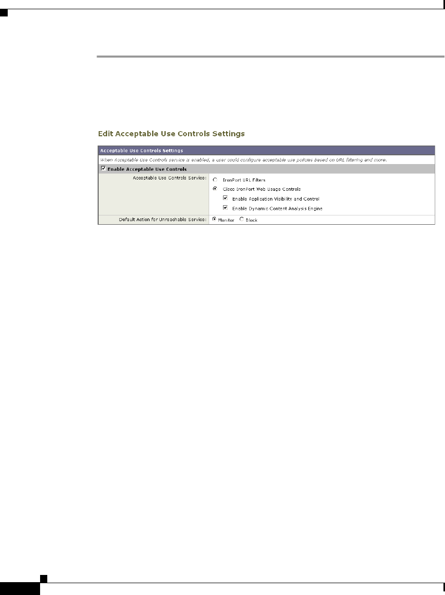
Chapter 17 Understanding Application Visibility and Control
Understanding Application Control Settings
17-4
Cisco IronPort AsyncOS 7.1 for Web User Guide
OL-23207-01
Step 1 Navigate to the Security Services > Acceptable Use Controls page.
Step 2 Click Edit Global Settings.
The Edit Acceptable Use Controls Settings page appears.
Step 3 Verify the Enable Acceptable Use Controls property is enabled.
Step 4 In the Acceptable Use Controls Service area, select Cisco IronPort Web Usage
Controls, and then select Enable Application Visibility and Control.
Step 5 Submit and commit your changes.
Understanding Application Control Settings
Controlling applications involves configuring the following elements:
•Application types. A category that contains one or more applications. For
example, Instant Messaging is an application type that contains Google Talk
and AOL Instant Messenger.
•Applications. Particular applications that belong in an application type. For
example, YouTube is an application in the Media application type.
•Application behaviors. Particular actions or behaviors that users can do
within an application that administrators can control. For example, users can
transfer files while using an application, such as Yahoo Messenger. Not all
applications include application behaviors you can configure.
You can configure application control settings in Access Policy groups. From the
Web Security Manager > Access Policies page, click the Applications link for the
policy group you want to configure. The Access Policies: Applications Visibility
and Control: policyname page appears, or the “Applications Visibility and Control
page” for short.

17-5
Cisco IronPort AsyncOS 7.1 for Web User Guide
OL-23207-01
Chapter 17 Understanding Application Visibility and Control
Understanding Application Control Settings
The Applications Visibility and Control page shows the current applications you
can configure as determined by the current AVC engine signature. Regardless of
the particular applications you can configure, the Applications Visibility and
Control page offers the following views for configuring applications:
•Browse view. You can browse for application types. You might want to use
Browse view to configure applications of a particular type at the same time.
For more information, see Working with Browse View, page 17-5.
•Search view. You can search for applications. You might want to use Search
view when the total list of applications is long and you need to quickly find
and configure a particular application. For more information, see Working
with Search View, page 17-7.
You can configure most of the same control settings in both views. However, you
can only configure the bandwidth control limits for application types in Browse
view.
When configuration applications, you can choose the following actions:
•Block. This action is a final action. Users are prevented from viewing a
webpage and instead an end-user notification page displays.
•Monitor. This action is an intermediary action. The Web Proxy continues
comparing the transaction to the other control settings to determine which
final action to apply. For more information, see Understanding the Monitor
Action, page 8-3.
•Restrict. This action indicates that an application behavior is blocked. For
example, when you block file transfers for a particular instant messaging
application, the action for that application is Restrict.
Working with Browse View
Figure 17-1 shows the Applications Visibility and Control page in Browse view
for a user defined Access Policy.
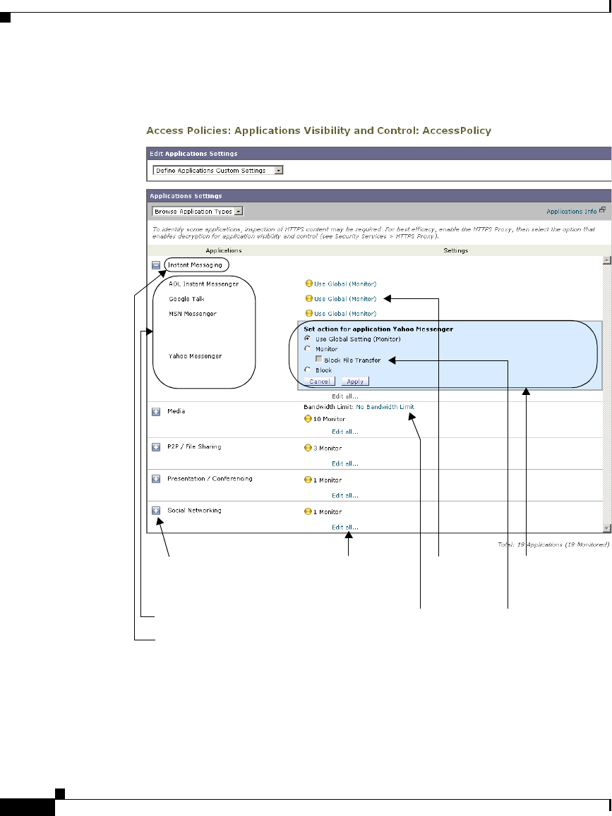
Chapter 17 Understanding Application Visibility and Control
Understanding Application Control Settings
17-6
Cisco IronPort AsyncOS 7.1 for Web User Guide
OL-23207-01
Figure 17-2 shows the Applications Visibility and Control page in Browse view
for the Global Access Policy.
Applications
Click to expand application
type and configure each
application.
Application Type
Click to define the same
action for all applications
in the type.
Click to
configure this
application.
Configure the
settings for this
application.
Application BehaviorClick to define the
bandwidth limit for the
entire application type.
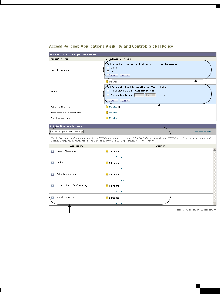
17-7
Cisco IronPort AsyncOS 7.1 for Web User Guide
OL-23207-01
Chapter 17 Understanding Application Visibility and Control
Understanding Application Control Settings
Working with Search View
Figure 17-3 shows the Applications Visibility and Control page in Search view for
a user defined Access Policy.
Define global settings for
each application and
application behavior.
Click to define the default
action for the application
type.
Configure the default
action for the type.
Configure the
bandwidth limit
for the type.
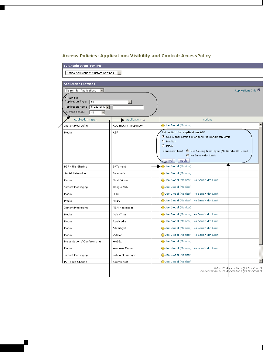
Chapter 17 Understanding Application Visibility and Control
Understanding Application Control Settings
17-8
Cisco IronPort AsyncOS 7.1 for Web User Guide
OL-23207-01
Configure search
criteria.
Click to configure
this application.
Configure the settings
for this application.
Click to column
headers to sort
columns.

17-9
Cisco IronPort AsyncOS 7.1 for Web User Guide
OL-23207-01
Chapter 17 Understanding Application Visibility and Control
Understanding Application Control Settings
Rules and Guidelines
Consider the following rules and guidelines when configuring application control
settings:
•The supported application types, applications, and application behaviors may
change between AsyncOS for Web upgrades during AVC engine updates.
•When an application type is collapsed in Browse view, the summary for the
application type lists the final actions for the applications and does not
indicate whether the actions are inherited from the global policy or
configured in the current Access Policy. To learn more about the action for an
application, expand the application type.
•In the Global Access Policy, you can set the default action for each
application type. You might want to set the default action for each application
type so new applications introduced in an Application Visibility and Control
engine update automatically inherit the default action.
•You can quickly configure the same action for all applications in an
application type by clicking the “edit all” link for the application type in
Browse view. However, you can only configure the application action, not
application behavior actions. To configure application behaviors, you must
edit the application individually instead of editing all applications for a type
at once.
•In Search view, when you sort the table by the action column, the sort order
is by the final action. For example, “Use Global (Block)” comes after “Block”
in the sort order.
•Decryption may cause some applications to fail unless the root certificate for
signing is installed on the client. For more information, see Using Decryption
with the AVC Engine, page 10-19. For more information on the appliance
root certificate, see Working with Root Certificates, page 10-16.
Configuring Application Control Settings
To configure Application settings in an Access Policy group:
Step 1 Navigate to the Web Security Manager > Access Policies page.
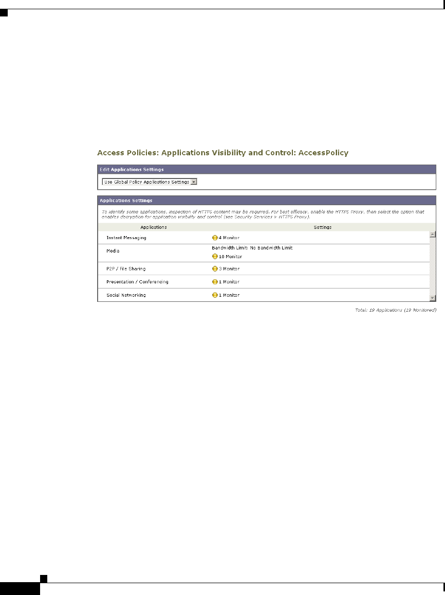
Chapter 17 Understanding Application Visibility and Control
Understanding Application Control Settings
17-10
Cisco IronPort AsyncOS 7.1 for Web User Guide
OL-23207-01
Step 2 Click the link in the policies table under the Applications column for the policy
group you want to edit.
The Applications Visibility and Control page appears.
Step 3 When configuring the Global Access Policy, define the default action for each
application type in the Default Actions for Application Types section. For details
on how to do this, see Figure 17-2 on page 7.
Step 4 When configuring a user defined Access Policy, choose Define Applications
Custom Settings in the Edit Applications Settings section.
Step 5 In the Application Settings area, choose Browse view or Search view from the
drop down menu.
Step 6 Configure the action for each application and application behavior.
For more information on work with each view, see Working with Browse View,
page 17-5 and Working with Search View, page 17-7.
Step 7 Configure the bandwidth controls for each applicable application. For more
information, see Controlling Bandwidth, page 17-11.
Step 8 Submit and commit your changes.

17-11
Cisco IronPort AsyncOS 7.1 for Web User Guide
OL-23207-01
Chapter 17 Understanding Application Visibility and Control
Controlling Bandwidth
Controlling Bandwidth
The AVC engine allows administrators to control the amount of bandwidth used
for particular application types. Not all application types support bandwidth
controls.
You can define the following bandwidth limits:
•Overall bandwidth limit. Define an overall limit for all users on the network
for the supported application types. The overall bandwidth limit affects the
traffic between the Web Security appliance and web servers. It does not limit
traffic served from the web cache. You might want to define an overall
bandwidth limit to restrict the amount of network traffic used for high traffic
sites, such as streaming media sites. For more information, see Configuring
Overall Bandwidth Limits, page 17-11.
•User bandwidth limit. Define a limit for particular users on the network per
application type. User bandwidth limits traffic from web servers as well as
traffic served from the web cache. You might want to define user bandwidth
limits to restrict the amount of traffic consumed by heavy usage users to
enforce acceptable use policies. For more information, see Configuring User
Bandwidth Limits, page 17-12.
When both the overall limit and user limit applies to a transaction, the most
restrictive option applies.
You can define bandwidth limits for particular URL categories by defining an
Identity group for a URL category and using it in an Access Policy that restricts
the bandwidth.
Note Defining bandwidth limits only throttles the data going to users. It does not block
data based on reaching a quota.
Configuring Overall Bandwidth Limits
The overall bandwidth limit affects the traffic between the Web Security appliance
and web servers for all users on the network.
To define an overall bandwidth limit:

Chapter 17 Understanding Application Visibility and Control
Controlling Bandwidth
17-12
Cisco IronPort AsyncOS 7.1 for Web User Guide
OL-23207-01
Step 1 Navigate to the Web Security Manager > Overall Bandwidth Limits page.
Step 2 Select the Limit to option.
Step 3 Enter the amount of traffic to limit in either Megabits per second (Mbps) or
kilobits per second (kbps).
Step 4 Submit and commit your changes.
Configuring User Bandwidth Limits
You define user bandwidth limits by configuring bandwidth control settings on the
Applications Visibility and Control page of Access Policies. You can define the
following types of bandwidth controls for users in Access Policies:
•Default bandwidth limit for an application type. In the Global Access
Policy, you can define the default bandwidth limit for all applications of an
application type. For more information, see Configuring the Default
Bandwidth Limit for an Application Type, page 17-13.
•Bandwidth limit for an application type. In a user defined Access Policy,
you can override the default bandwidth limit for the application type defined
in the Global Access Policy. You can configure no bandwidth limit or a
different bandwidth limit value. For more information, see Overriding the
Default Bandwidth Limit for an Application Type, page 17-13.
•Bandwidth limit for an application. In a user defined or Global Access
Policy, you can choose to apply the application type bandwidth limit or no
limit (exempt the application type limit). You might choose no bandwidth
limit for an application to exempt the application from the bandwidth limit
established that application type. For more information, see Configuring
Bandwidth Controls for an Application, page 17-15.

17-13
Cisco IronPort AsyncOS 7.1 for Web User Guide
OL-23207-01
Chapter 17 Understanding Application Visibility and Control
Controlling Bandwidth
Configuring the Default Bandwidth Limit for an Application Type
To configure the default bandwidth limit for an application type:
Step 1 Navigate to the Web Security Manager > Access Policies page.
Step 2 Click the link in the policies table under the Applications column for the Global
Access Policy.
The Applications Visibility and Control page appears.
Step 3 In the Default Actions for Application Types section, click the link next to
“Bandwidth Limit” for the application type you want to edit.
The Applications Visibility and Control page expands, allowing you to specify the
bandwidth control settings.
Step 4 Select Set Bandwidth Limit and enter the amount of traffic to limit in either
Megabits per second (Mbps) or kilobits per second (kbps). See Figure 17-2 on
page 7 for details on how to do this.
Step 5 Click Done.
Step 6 Submit and commit your changes.
Overriding the Default Bandwidth Limit for an Application Type
You can override the default bandwidth limit defined at the Global Access Policy
group in the user defined Access Policies. You can only do this in Browse view.
To override the default bandwidth limit for an application type:
Step 1 Navigate to the Web Security Manager > Access Policies page.
Step 2 Click the link in the policies table under the Applications column for the user
defined policy group you want to edit.
The Applications Visibility and Control page appears.
Step 3 Choose Define Applications Custom Settings in the Edit Applications Settings
section.
Note Ensure you remain in Browse view. Do not switch to Search view.
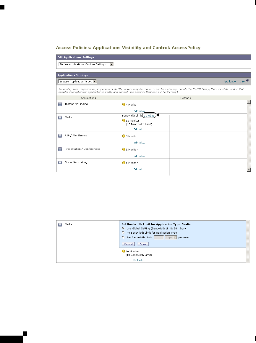
Chapter 17 Understanding Application Visibility and Control
Controlling Bandwidth
17-14
Cisco IronPort AsyncOS 7.1 for Web User Guide
OL-23207-01
Step 4 Click the link next to “Bandwidth Limit” for the application type you want to edit.
The Applications Visibility and Control page expands, allowing you to specify the
bandwidth control settings.
Step 5 To choose a different bandwidth limit value, select Set Bandwidth Limit and enter
the amount of traffic to limit in either Megabits per second (Mbps) or kilobits per
second (kbps). To specify no bandwidth limit, select No Bandwidth Limit for
Application Type.
Step 6 Click Done.
Step 7 Submit and commit your changes.
Click to override default bandwidth limit.
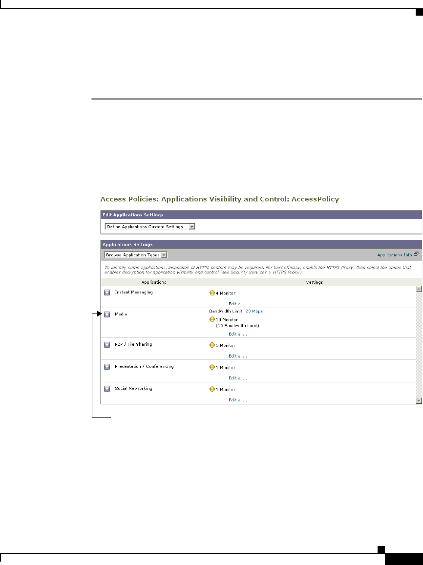
17-15
Cisco IronPort AsyncOS 7.1 for Web User Guide
OL-23207-01
Chapter 17 Understanding Application Visibility and Control
Controlling Bandwidth
Configuring Bandwidth Controls for an Application
To configure bandwidth controls for an application:
Step 1 Navigate to the Web Security Manager > Access Policies page.
Step 2 Click the link in the policies table under the Applications column for the policy
group you want to edit.
The Applications Visibility and Control page appears.
Step 3 Expand the application type that contains the application you want to define.
The Applications Visibility and Control page expands to allow you to configure
each application in the application type.
Click to expand the application type.

Chapter 17 Understanding Application Visibility and Control
Controlling Bandwidth
17-16
Cisco IronPort AsyncOS 7.1 for Web User Guide
OL-23207-01
Step 4 Click the link for the application you want to configure.
The Applications Visibility and Control page expands, allowing you to specify the
bandwidth control settings for the application.
Step 5 Select Monitor, and then choose to use either the bandwidth limit defined for the
application type or no limit.
Note The bandwidth limit setting is not applicable when the application is blocked or
when no bandwidth limit is defined for the application type.
Step 6 Click Done.
Step 7 Submit and commit your changes.

17-17
Cisco IronPort AsyncOS 7.1 for Web User Guide
OL-23207-01
Chapter 17 Understanding Application Visibility and Control
Controlling Instant Messaging Traffic
Controlling Instant Messaging Traffic
You can use the AVC engine to apply control settings to some instant messenger
(IM) traffic that runs on top of HTTP. You can block or monitor the IM traffic, and
depending on the IM service, you can block particular activities (also known as
application behaviors) in an IM session. For example, you can allow an IM session
with a particular IM service provider, but block file transfers within that session.
The AVC engine does not control native IM traffic.
You control IM traffic by configuring Instant Messenger application settings on
the Applications Visibility and Control page of Access Policies.
To control IM traffic:
Step 1 Navigate to the Web Security Manager > Access Policies page.
Step 2 Click the link in the policies table under the Applications column for the policy
group you want to edit.
The Applications Visibility and Control page appears.
Step 3 Expand the Instant Messaging application type.
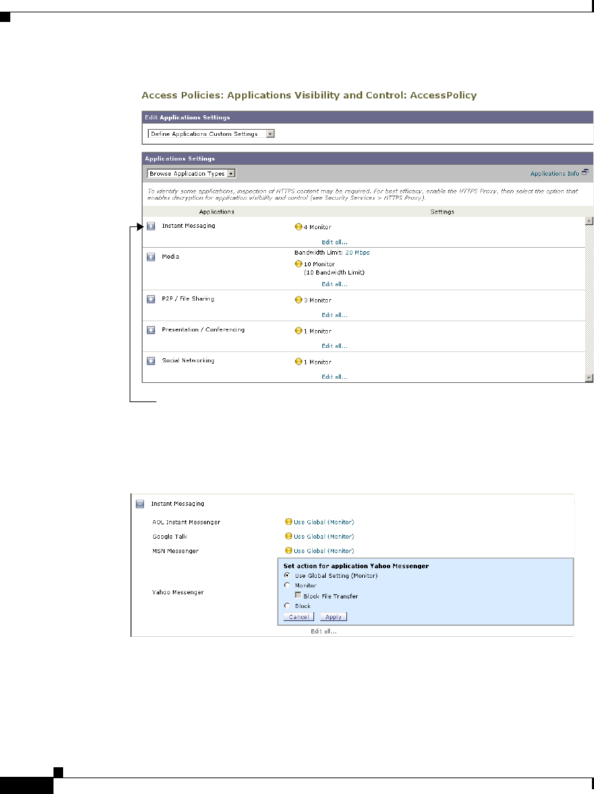
Chapter 17 Understanding Application Visibility and Control
Controlling Instant Messaging Traffic
17-18
Cisco IronPort AsyncOS 7.1 for Web User Guide
OL-23207-01
Step 4 Click the link next to the IM application you want to configure.
The Applications Visibility and Control page expands, allowing you to specify
control settings for the application.
Step 5 To block all traffic for this IM application, select Block.
Step 6 To monitor the IM application, but block particular activities within the
application, select Monitor, and then select the application behavior to block.
Step 7 Click Done.
Click to expand the Instant Messaging application type.

17-19
Cisco IronPort AsyncOS 7.1 for Web User Guide
OL-23207-01
Chapter 17 Understanding Application Visibility and Control
Viewing AVC Activity
Step 8 Submit and commit your changes.
Viewing AVC Activity
The Reporting > Application Visibility page displays information about the top
applications and application types used. It also displays the top applications and
application types blocked. You can click the individual applications and
application types to view more detailed information about each. For detailed
information about monitoring and reporting functionality, see Reporting,
page 22-1.
Access Log File
The access log file records the information returned by the Application Visibility
and Control engine for each transaction. The scanning verdict information section
in the access logs includes the fields listed in Table 17-1.
For more information about the access log, see Access Log File, page 24-19.
Description
Custom Field in Access
Logs
Custom Field in W3C
Logs
Application name %XO x-avc-app
Application type %Xu x-avc-type
Application behavior %Xb x-avc-behavior

Chapter 17 Understanding Application Visibility and Control
Viewing AVC Activity
17-20
Cisco IronPort AsyncOS 7.1 for Web User Guide
OL-23207-01

CHAPTER
18-1
Cisco IronPort AsyncOS 7.1 for Web User Guide
OL-23207-01
18
Web Reputation Filters
This chapter contains the following information:
•Web Reputation Filters Overview, page 18-1
•Web Reputation Scores, page 18-2
•Understanding How Web Reputation Filtering Works, page 18-4
•Configuring Web Reputation Scores, page 18-5
•Viewing Web Reputation Filtering Activity, page 18-9
Web Reputation Filters Overview
IronPort Web Reputation Filters is a security feature that analyzes web server
behavior and assigns a reputation score to a URL to determine the likelihood that
it contains URL-based malware. It helps protect against URL-based malware that
threatens end-user privacy and sensitive corporate information. The Web Security
appliance uses URL reputation scores to identify suspicious activity and stop
malware attacks before they occur.
You can use Web Reputation Filters with both Access and Decryption Policies.
The Web Reputation Database
The Web Security appliance collects information and maintains a filtering
database that contains aggregated traffic statistics, request attributes, and
information about how different types of requests are handled. Additionally, the

Chapter 18 Web Reputation Filters
Web Reputation Scores
18-2
Cisco IronPort AsyncOS 7.1 for Web User Guide
OL-23207-01
appliance can be configured to send web reputation statistics to a SenderBase
server. SenderBase server information is leveraged with data feeds from the
IronPort Common Security Database (SenderBase® Network) and the collective
information is used to produce a Web Reputation Score.
Note For more information, see The SenderBase Network, page 2-5.
Maintaining the Database Tables
The web reputation filtering component periodically receives updates to its
database tables from the IronPort update server
(https://update-manifests.ironport.com). Server updates are automated, and
the update interval is set by the server as opposed to the appliance. Updates to the
database tables occur with a regular degree of frequency, and require no
administrator intervention.
For information about update intervals and the IronPort update server, see
Manually Updating Security Service Components, page 26-51.
Web Reputation Scores
Web Reputation Filters use statistically significant data to assess the reliability of
Internet domains and score the reputation of URLs. Data such as how long a
specific domain has been registered, or where a web site is hosted, or whether a
web server is using a dynamic IP address is used to judge the trustworthiness of a
given URL.
The web reputation calculation associates a URL with network parameters to
determine the probability that malware exists. The aggregate probability that
malware exists is then mapped to a Web Reputation Score between -10 and +10,
with +10 being the least likely to contain malware.
Example parameters include the following:
•URL categorization data
•Presence of downloadable code
•Presence of long, obfuscated End-User License Agreements (EULAs)
•Global volume and changes in volume

18-3
Cisco IronPort AsyncOS 7.1 for Web User Guide
OL-23207-01
Chapter 18 Web Reputation Filters
Enabling Web Reputation Filters
•Network owner information
•History of a URL
•Age of a URL
•Presence on any block lists
•Presence on any allow lists
•URL typos of popular domains
•Domain registrar information
•IP address information
Note IronPort does not collect personally identifiable information such as user names,
passwords, or client IP addresses.
Enabling Web Reputation Filters
To use web reputation in policy groups, you must first enable Web Reputation
Filters. By default, Web Reputation Filters are enabled in the System Setup
Wizard. If it is not enabled in the System Setup Wizard, you can edit them in the
web interface.
To enable Web Reputation Filters in the web interface:
Step 1 Navigate to the Security Services > Web Reputation Filters page.
Step 2 Click Enable.
The Web Reputation Filters License Agreement appears.
Step 3 Read the terms of the Web Reputation Filters License Agreement, and click
Accept.
Step 4 Click Edit Settings.
The Edit Web Reputation Filters Settings page appears.
Step 5 Verify the Enable Web Reputation Filters property is enabled.
Step 6 Submit and commit your changes.

Chapter 18 Web Reputation Filters
Understanding How Web Reputation Filtering Works
18-4
Cisco IronPort AsyncOS 7.1 for Web User Guide
OL-23207-01
Understanding How Web Reputation Filtering Works
Web Reputation Scores are associated with an action to take on a URL request.
The available actions depend on the policy group type that is assigned to the URL
request:
•Access Policies. You can choose to block, scan, or allow.
•Decryption Policies. You can choose to drop, decrypt, or pass through.
You can configure each policy group to correlate an action to a particular Web
Reputation Score.
Web Reputation in Access Policies
Table 18-1 describes the default Web Reputation Scores for Access Policies.
Score Action Description Example
-10 to -6.0 Block Bad site. The request is blocked,
and no further malware scanning
occurs.
•URL downloads information without
user permission.
•Sudden spike in URL volume.
•URL is a typo of a popular domain.
-5.9 to 5.9 Scan Undetermined site. Request is
passed to the DVS engine for
further malware scanning. The
DVS engine scans the request
and server response content.
•Recently created URL that has a
dynamic IP address and contains
downloadable content.
•Network owner IP address that has a
positive Web Reputation Score.
6.0 to 10.0 Allow Good site. Request is allowed.
No malware scanning required.
•URL contains no downloadable
content.
•Reputable, high-volume domain
with long history.
•Domain present on several allow
lists.
•No links to URLs with poor
reputations.

18-5
Cisco IronPort AsyncOS 7.1 for Web User Guide
OL-23207-01
Chapter 18 Web Reputation Filters
Configuring Web Reputation Scores
For example, by default, URLs in an HTTP request that are assigned a Web
Reputation Score of +7 are allowed and require no further scanning. However, a
weaker score for an HTTP request, such as +3, is automatically forwarded to the
IronPort DVS engine where it is scanned for malware. Any URL in an HTTP
request that has a very poor reputation is blocked.
Web Reputation in Decryption Policies
Table 18-2 describes the default Web Reputation Scores for Access Policies.
Configuring Web Reputation Scores
When you install and set up the Web Security appliance, it has default settings for
Web Reputation Scores. However, you can modify threshold settings for web
reputation scoring to fit your organization’s needs.
You configure the web reputation filter settings for each policy group.
Score Action Description
-10 to -9.0 Drop Bad site. The request is dropped with no notice sent
to the end user.
Use this setting with caution.
-8.9 to 5.9 Decrypt Undetermined site. Request is allowed, but the
connection is decrypted and the decrypted traffic is
applied to Access Policies.
For more information about how the appliance
decrypts HTTPS traffic, see Decrypting HTTPS
Traffic, page 10-13.
6.0 to 10.0 Pass through Good site. Request is passed through with no
inspection or decryption.
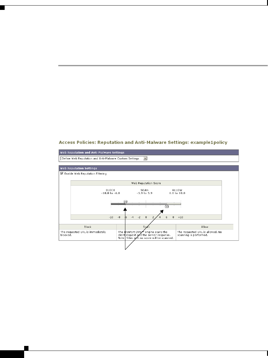
Chapter 18 Web Reputation Filters
Configuring Web Reputation Scores
18-6
Cisco IronPort AsyncOS 7.1 for Web User Guide
OL-23207-01
Configuring Web Reputation for Access Policies
To edit the web reputation filter settings for an Access Policy group:
Step 1 Navigate to the Web Security Manager > Access Policies page.
Step 2 Click the link under the Web Reputation and Anti-Malware Filtering column for
the Access Policy group you want to edit.
Step 3 Under the Web Reputation and Anti-Malware Settings section, choose “Define
Web Reputation and Anti-Malware Custom Settings” from the drop down menu
if it is not selected already.
This allows you to override the web reputation and anti-malware settings
from the Global Policy Group.
Step 4 Verify the Enable Web Reputation Filtering field is enabled.
Step 5 Move the markers to change the range for URL block, scan, and allow actions.
Step 6 Submit and commit your changes.
Move these markers to change the Web
Reputation threshold values.
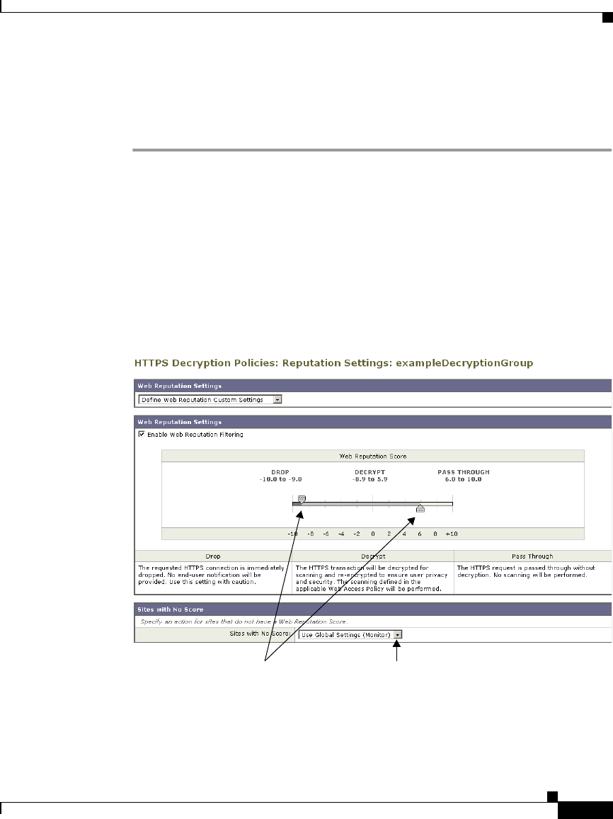
18-7
Cisco IronPort AsyncOS 7.1 for Web User Guide
OL-23207-01
Chapter 18 Web Reputation Filters
Configuring Web Reputation Scores
Configuring Web Reputation for Decryption Policies
To edit the web reputation filter settings for a Decryption Policy group:
Step 1 Navigate to the Web Security Manager > Decryption Policies page.
Step 2 Click the link under the Web Reputation column for the Decryption Policy group
you want to edit.
Step 3 Under the Web Reputation Settings section, choose “Define Web Reputation
Custom Settings” from the drop down menu if it is not selected already.
This allows you to override the override the web reputation settings from the
Global Policy Group.
Step 4 Verify the Enable Web Reputation Filtering field is checked.
Step 5 Move the markers to change the range for URL drop, decrypt, and pass through
actions.
Move these markers to change the
Web Reputation threshold values.
Choose action for sites with no
assigned Web Reputation Score.
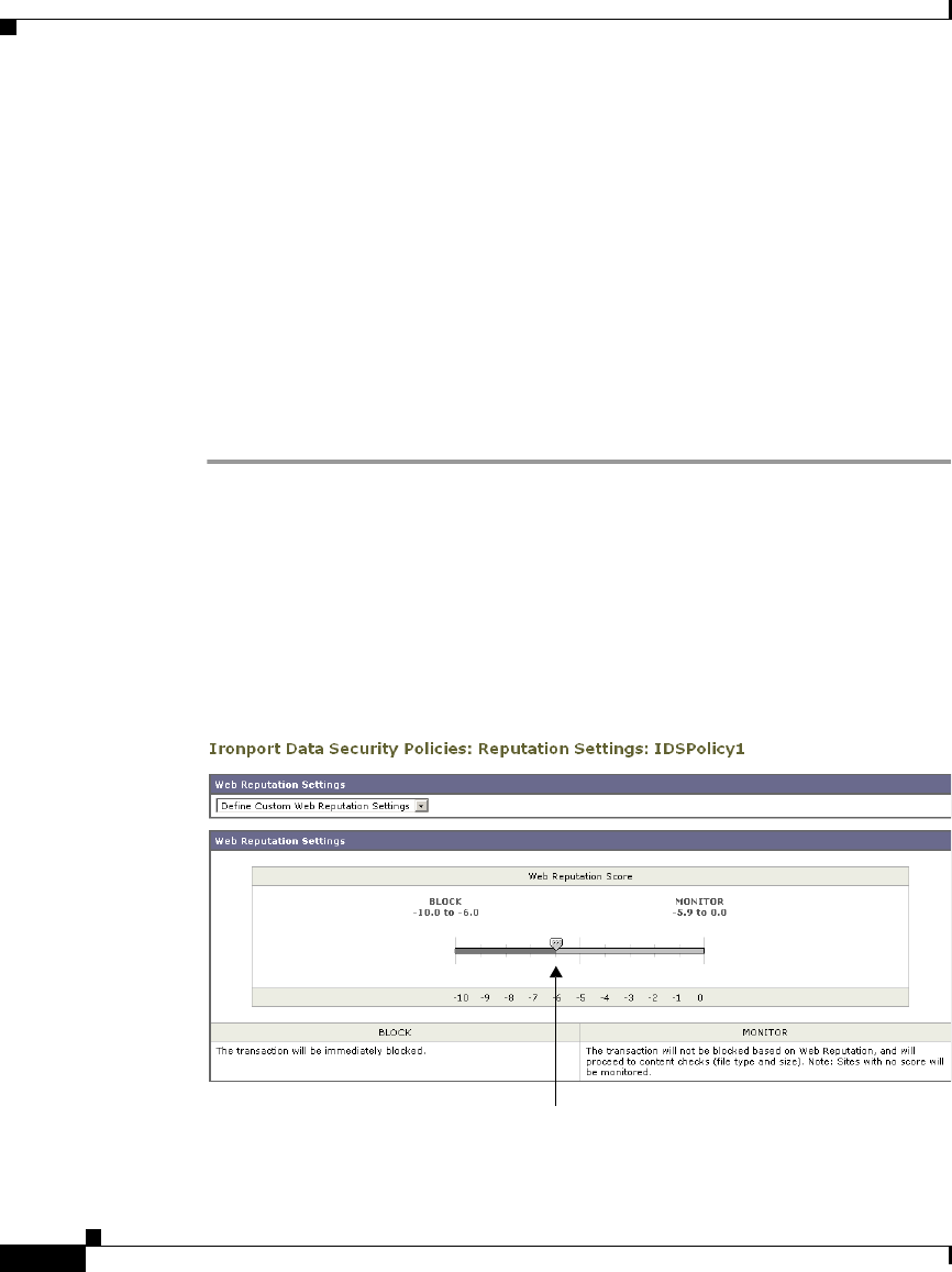
Chapter 18 Web Reputation Filters
Configuring Web Reputation Scores
18-8
Cisco IronPort AsyncOS 7.1 for Web User Guide
OL-23207-01
Step 6 In the Sites with No Score field, choose the action to take on request for sites that
have no assigned Web Reputation Score.
Step 7 Submit and commit your changes.
Configuring Web Reputation for IronPort Data Security Policies
Only negative and zero values can be configured for web reputation threshold
settings for IronPort Data Security Policies. By definition, all positive scores are
monitored.
To edit the web reputation filter settings for a Data Security Policy group:
Step 1 Navigate to the Web Security Manager > IronPort Data Security page.
Step 2 Click the link under the Web Reputation column for the Data Security Policy
group you want to edit.
Step 3 Under the Web Reputation Settings section, choose “Define Web Reputation
Custom Settings” from the drop down menu if it is not selected already.
Move the marker to change the Web Reputation threshold value.

18-9
Cisco IronPort AsyncOS 7.1 for Web User Guide
OL-23207-01
Chapter 18 Web Reputation Filters
Viewing Web Reputation Filtering Activity
This allows you to override the web reputation settings from the Global
Policy Group.
Step 4 Move the marker to change the range for URL block and monitor actions.
For more information on these actions, see Data Security Policy Groups,
page 12-4.
Step 5 Submit and commit your changes.
Viewing Web Reputation Filtering Activity
The S-Series appliance supports several options for generating feature specific
reports, and displays of summary statistics.
Monitoring Filter and Scoring Activity
The Reporting > Web Reputation Filters page provides statistical displays of
filtering activity. You can update these displays by specifying a time range of
hour, day, week or month. Additionally, you have the option to print these display
pages and export the raw data to a file.
You can use the following interactive displays and reporting tools to view the
results of Web Reputation filtering and scoring activity:
To view... See...
Web reputation action and
scoring activity
Reporting > Web Reputation Filters
Web reputation log files System Administration > Log Subscriptions
•WBRS log files
•Access log file

Chapter 18 Web Reputation Filters
Viewing Web Reputation Filtering Activity
18-10
Cisco IronPort AsyncOS 7.1 for Web User Guide
OL-23207-01
Access Log File
The access log file provides a record of filtering activity. You can examine entries
in the access log file and trace web reputation processing specific to individual
requests.
For more information about reading access log files, see Access Log File,
page 24-19. For more an example access log entry that explains web reputation
processing, see Web Reputation Filters Example, page 24-34.

CHAPTER
19-1
Cisco IronPort AsyncOS 7.1 for Web User Guide
OL-23207-01
19
Anti-Malware Services
This chapter contains the following information:
•Anti-Malware Overview, page 19-1
•IronPort DVS™ (Dynamic Vectoring and Streaming) Engine, page 19-4
•Webroot Scanning, page 19-7
•McAfee Scanning, page 19-8
•Sophos Scanning, page 19-10
•Configuring Anti-Malware Scanning, page 19-10
•Viewing Anti-Malware Scanning Activity, page 19-15
Anti-Malware Overview
The Web Security appliance anti-malware feature is a security component that
uses the IronPort DVS™ engine in combination with the Webroot™, McAfee, and
Sophos technologies to identify and stop a broad range of web-based malware
threats.
For more information about the DVS engine, see IronPort DVS™ (Dynamic
Vectoring and Streaming) Engine, page 19-4.
To use the anti-malware component of the appliance, you must first configure
global settings and then apply specific settings to different policies. For more
information about configuring the appliance for anti-malware scanning, see
Configuring Anti-Malware Scanning, page 19-10.

Chapter 19 Anti-Malware Services
Anti-Malware Overview
19-2
Cisco IronPort AsyncOS 7.1 for Web User Guide
OL-23207-01
You can also view the anti-malware scanning activity in reports and in the Web
Security Monitor. For more information, see Viewing Anti-Malware Scanning
Activity, page 19-15.
Malware Category Descriptions
Table 19-1 describes the different categories of malware the Web Security
appliance can block.
Malware Type Description
Adware Adware encompasses all software executables and
plug-ins that direct users towards products for sale. Some
adware applications have separate processes that run
concurrently and monitor each other, ensuring that the
modifications are permanent. Some variants enable
themselves to run each time the machine is started. These
programs may also change security settings making it
impossible for users to make changes to their browser
search options, desktop, and other system settings.
Browser Helper
Object
A browser helper object is a browser plug-in that may
perform a variety of functions related to serving
advertisements or hijacking user settings.
Commercial System
Monitor
A commercial system monitor is a piece of software with
system monitor characteristics that can be obtained with
a legitimate license through legal means.
Dialer A dialer is a program that utilizes your modem or another
type of Internet access to connect you to a phone line or a
site that causes you to accrue long distance charges to
which you did not provide your full, meaningful, and
informed consent.
Hijacker A hijacker modifies system settings or any unwanted
changes to a user’s system that may direct them to a
website or run a program without a user’s full,
meaningful, and informed consent.

19-3
Cisco IronPort AsyncOS 7.1 for Web User Guide
OL-23207-01
Chapter 19 Anti-Malware Services
Anti-Malware Overview
Phishing URL A phishing URL is displayed in the browser address bar.
In some cases, it involves the use of domain names and
resembles those of legitimate domains. Phishing is a form
of online identity theft that employs both social
engineering and technical subterfuge to steal personal
identity data and financial account credentials.
PUA Potentially Unwanted Application. A PUA is an
application that is not malicious, but which may be
considered to be undesirable.
System Monitor A system monitor encompasses any software that
performs one of the following actions:
•Overtly or covertly records system processes and/or
user action.
•Makes those records available for retrieval and
review at a later time.
Trojan Downloader A trojan downloader is a Trojan that, after installation,
contacts a remote host/site and installs packages or
affiliates from the remote host. These installations
usually occur without the user’s knowledge. Additionally,
a Trojan Downloader’s payload may differ from
installation to installation since it obtains downloading
instructions from the remote host/site.
Trojan Horse A trojan horse is a destructive program that masquerades
as a benign application. Unlike viruses, Trojan horses do
not replicate themselves.
Trojan Phisher A trojan phisher may sit on an infected computer waiting
for a specific web page to be visited or may scan the
infected machine looking for user names and passwords
for bank sites, auction sites, or online payment sites.
Malware Type Description

Chapter 19 Anti-Malware Services
IronPort DVS™ (Dynamic Vectoring and Streaming) Engine
19-4
Cisco IronPort AsyncOS 7.1 for Web User Guide
OL-23207-01
IronPort DVS™ (Dynamic Vectoring and Streaming)
Engine
The IronPort Dynamic Vectoring and Streaming (DVS) engine inspects web
traffic to provide protection against the widest variety of web-based malware
ranging from commercially invasive adware applications, to malicious trojans,
system monitors, and phishing attacks.
To configure the DVS engine, and Webroot, McAfee, and Sophos global settings,
see Configuring Anti-Malware Scanning, page 19-10.
The IronPort DVS engine can use one or more scanning engines to determine
malware risk. Depending on the features purchased with the appliance, you can
enable any of the following scanning engines:
•Webroot. Webroot’s automated spyware detection system rapidly identifies
existing and new spyware threats on the Internet by intelligently scanning
millions of sites on a daily basis. Webroot uses a signature database to help
detect threats on the Internet. For more information about the Webroot
scanning engine, see Webroot Scanning, page 19-7.
•McAfee. The McAfee scanning engine can detect existing and new malware
threats by using a signature database of malware information and heuristic
analysis. For more information about the McAfee scanning engine, see
McAfee Scanning, page 19-8.
•Sophos. The Sophos scanning engine detects existing and new malware
threats using a signature database. For more information about the Sophos
scanning engine, see Sophos Scanning, page 19-10.
Virus A virus is a program or piece of code that is loaded onto
your computer without your knowledge and runs against
your wishes.
Worm A worm is program or algorithm that replicates itself over
a computer network and usually performs malicious
actions.
Malware Type Description

19-5
Cisco IronPort AsyncOS 7.1 for Web User Guide
OL-23207-01
Chapter 19 Anti-Malware Services
IronPort DVS™ (Dynamic Vectoring and Streaming) Engine
The scanning engines inspect transactions to determine a malware scanning
verdict to pass to the DVS engine. A malware scanning verdict is a value assigned
to a URL request or server response that determines the probability that it contains
malware. The DVS engine determines whether to monitor or block the request
based on the malware scanning verdicts. For more information about malware
scanning verdicts, see Malware Scanning Verdict Values, page 24-52.
For each Access or Outbound Malware Scanning Policy, you can enable either the
Sophos or McAfee scanning engine, but not both simultaneously. You can also
enable the Webroot scanning engine with either Sophos or McAfee. You might
want to enable the Sophos scanning engine instead of the McAfee scanning
engine if the client machines have McAfee anti-malware software installed.
In some cases, the DVS engine might determine multiple verdicts for a single
URL. For more information about how the DVS handles multiple verdicts, see
Working with Multiple Malware Verdicts, page 19-6.
Maintaining the Database Tables
The Webroot, Sophos, and McAfee databases periodically receive updates from
the IronPort update server (https://update-manifests.ironport.com). Server
updates are automated, and the update interval is set by the server, not the
appliance. Updates to the database tables occur with a regular degree of
frequency, and require no administrator intervention.
For information about update intervals and the IronPort update server, see
Manually Updating Security Service Components, page 26-51.
Understanding How the DVS Engine Works
The DVS engine performs anti-malware scanning on URL transactions that are
forwarded from the Web Reputation Filters. Web Reputation Filters calculate the
probability that a particular URL contains malware, and assign a URL score that
is associated with an action to block, scan, or allow the transaction.
When the assigned web reputation score indicates to scan the transaction, the DVS
engine receives the URL request and server response content. The DVS engine, in
combination with the Webroot and/or Sophos or McAfee scanning engines,

Chapter 19 Anti-Malware Services
IronPort DVS™ (Dynamic Vectoring and Streaming) Engine
19-6
Cisco IronPort AsyncOS 7.1 for Web User Guide
OL-23207-01
returns a malware scanning verdict. The DVS engine uses information from the
malware scanning verdicts and Access Policy settings to determine whether to
block or deliver the content to the client.
When you enable both Webroot and Sophos or McAfee, the DVS engine
determines how to scan the content to optimize performance and efficacy.
Working with Multiple Malware Verdicts
In some cases, the DVS engine might determine multiple malware verdicts for a
single URL. Multiple verdicts can come from one or both enabled scanning
engines:
•Different verdicts from different scanning engines. When you enable both
Webroot and either Sophos or McAfee, each scanning engine might return
different malware verdicts for the same object.
•Different verdicts from the same scanning engine. A scanning engine
might return multiple verdicts for a single object when the object contains
multiple infections. For example, a zip file might contain multiple files, each
infected with a different kind of malware.
When a URL causes multiple verdicts, the appliance takes different action
depending on whether one or both enabled scanning engines return the multiple
malware verdicts.
Different Scanning Engines
When a URL causes multiple verdicts from both enabled scanning engines, the
appliance performs the most restrictive action. For example, if one scanning
engine returns a block verdict and the other a monitor verdict, the DVS engine
always blocks the request. Only the most restrictive verdict is logged and
reported.
Same Scanning Engine
When a URL causes multiple verdicts from the same scanning engine, the
appliance takes action according to the verdict with the highest priority. Only the
highest verdict is logged and reported. The following text lists the possible
malware scanning verdicts from the highest to the lowest priority.

19-7
Cisco IronPort AsyncOS 7.1 for Web User Guide
OL-23207-01
Chapter 19 Anti-Malware Services
Webroot Scanning
•Virus
•Trojan Downloader
•Trojan Horse
•Trojan Phisher
•Hijacker
•System monitor
•Commercial System Monitor
•Dialer
•Worm
•Browser Helper Object
•Phishing URL
•Adware
•Encrypted file
•Unscannable
•Other Malware
Suppose the McAfee scanning engine detects both adware and a virus in the
scanned object, and that the appliance is configured to block adware and monitor
viruses. According to the list above, viruses belong in a higher priority verdict
category than adware. Therefore, the appliance monitors the object and reports the
verdict as virus in the reports and logs. It does not block the object even though it
is configured to block adware.
Webroot Scanning
The Webroot scanning engine inspects objects to determine the malware scanning
verdict to send to the DVS engine. The Webroot scanning engine inspects the
following objects:
•URL request. Webroot evaluates a URL request to determine if the URL is a
malware suspect. If Webroot suspects the response from this URL might
contain malware, the appliance monitors or blocks the request, depending on
how the appliance is configured. If Webroot evaluation clears the request, the
appliance retrieves the URL and scans the server response.

Chapter 19 Anti-Malware Services
McAfee Scanning
19-8
Cisco IronPort AsyncOS 7.1 for Web User Guide
OL-23207-01
•Server response. When the appliance retrieves a URL, Webroot scans the
server response content and compares it to the Webroot signature database.
For more information about how the DVS engine uses malware scanning verdicts
to handle web traffic, see IronPort DVS™ (Dynamic Vectoring and Streaming)
Engine, page 19-4.
For information about Web Reputation Filtering and URL scores, see Web
Reputation Filters, page 18-1.
McAfee Scanning
The McAfee scanning engine inspects objects downloaded from a web server in
HTTP responses. After inspecting the object, it passes a malware scanning verdict
to the DVS engine so the DVS engine can determine whether to monitor or block
the request.
The McAfee scanning engine uses the following methods to determine the
malware scanning verdict:
•Matching virus signature patterns
•Heuristic analysis
For more information about how the DVS engine uses malware scanning verdicts
to handle web traffic, see IronPort DVS™ (Dynamic Vectoring and Streaming)
Engine, page 19-4.
Matching Virus Signature Patterns
McAfee uses virus definitions in its database with the scanning engine to detect
particular viruses, types of viruses, or other potentially unwanted software. It
searches for virus signatures in files.
When you enable McAfee, the McAfee scanning engine always uses this method
to scan server response content.

19-9
Cisco IronPort AsyncOS 7.1 for Web User Guide
OL-23207-01
Chapter 19 Anti-Malware Services
McAfee Scanning
Heuristic Analysis
New threats on the web appear almost daily. Using only virus signatures, the
engine cannot detect a new virus or other malware because its signature is not yet
known. However, by using heuristic analysis, the McAfee scanning engine can
detect new classes of currently unknown viruses and malware in advance.
Heuristic analysis is a technique that uses general rules, rather than specific rules,
to detect new viruses and malware. When the McAfee scanning engine uses
heuristic analysis, it looks at the code of an object, applies generic rules, and
determines how likely the object is to be virus-like.
Using heuristic analysis increases the likelihood of catching viruses and malware
before McAfee updates its virus signature database. However, it also increases the
possibility of reporting false positives (clean content designated as a virus). It also
might impact appliance performance.
When you enable McAfee, you can choose whether or not to also enable heuristic
analysis when scanning objects.
McAfee Categories
Table 19-2 lists the McAfee verdicts and how they correspond to malware
scanning verdict categories.
McAfee Verdict Malware Scanning Verdict Category
Known Virus Virus
Trojan Trojan Horse
Joke File Adware
Test File Virus
Wannabe Virus
Killed Virus
Commercial Application Commercial System Monitor
Potentially Unwanted Object Adware

Chapter 19 Anti-Malware Services
Sophos Scanning
19-10
Cisco IronPort AsyncOS 7.1 for Web User Guide
OL-23207-01
For a list of malware scanning verdicts, see Malware Scanning Verdict Values,
page 24-52.
Sophos Scanning
The Sophos scanning engine inspects objects downloaded from a web server in
HTTP responses. After inspecting the object, it passes a malware scanning verdict
to the DVS engine so the DVS engine can determine whether to monitor or block
the request. You might want to enable the Sophos scanning engine instead of the
McAfee scanning engine if the client machines have McAfee anti-malware
software installed.
For more information about how the DVS engine uses malware scanning verdicts
to handle web traffic, see IronPort DVS™ (Dynamic Vectoring and Streaming)
Engine, page 19-4.
Configuring Anti-Malware Scanning
The DVS engine and Webroot, McAfee, and Sophos are enabled by default during
system setup. Anytime after system setup, you can configure the anti-malware
settings for the Web Security appliance. You configure the following
anti-malware settings:
•Global anti-malware settings. Set object scanning parameters, specify
global settings for URL matching, and control when to block the URL or
allow processing to continue.
•Access Policy anti-malware settings. Enable monitoring or blocking for
malware categories based on malware scanning verdicts.
To configure anti-malware settings:
Potentially Unwanted Software Package Adware
Encrypted File Encrypted File
McAfee Verdict Malware Scanning Verdict Category

19-11
Cisco IronPort AsyncOS 7.1 for Web User Guide
OL-23207-01
Chapter 19 Anti-Malware Services
Configuring Anti-Malware Scanning
Step 1 On the Security Services > Anti-Malware page, click Edit Global Settings.
The Edit Anti-Malware Settings page appears.
Step 2 Configure the anti-malware settings as necessary. Table 19-3 describes the
anti-malware settings you can configure.
Setting Description
Object Scanning
Limits
Specify a maximum request/response size.
The Maximum Object Size value you specify applies to
the entire size of requests and responses that might be
scanned by security components on the Web Security
appliance, such as the IronPort Data Security Filters or the
Webroot scanning engine. When an upload or download
size exceeds this size, the security component may abort
the scan in progress and may not provide a scanning
verdict to the Web Proxy.
Enable Webroot Choose whether or not to enable the Webroot scanning
engine.
Domain Levels for
Malware Request
Detection
This value specifies the number of domain name elements
to match when processing a URL. If the URL matches a
hostname in the Webroot signature database, URL
checking continues to match the number of domain name
elements specified in this parameter.
Valid range for this parameter is 3-100 where a minimum
value of 8 is recommended to avoid a level of matching
that results in inaccurately blocked web sites.
Applies to the Webroot scanning engine only.

Chapter 19 Anti-Malware Services
Configuring Anti-Malware Scanning
19-12
Cisco IronPort AsyncOS 7.1 for Web User Guide
OL-23207-01
Step 3 Submit and commit your changes.
Step 4 Navigate to the Web Security Manager > Access Policies page.
Step 5 Click the Web Reputation and Anti-Malware Filtering link for the Access Policy
you want to configure.
Threat Risk
Threshold
The TRT (Threat Risk Threshold) assigns a numerical
value to the probability that malware exists.
Proprietary algorithms evaluate the result of a URL
matching sequence and assign a TRR (Threat Risk
Rating). This value is associated with the threat risk
threshold setting. If the TRR value is greater than or equal
to the TRT, the URL is considered malware and is passed
on for further processing.
Note: Setting the Threat Risk Threshold to a value lower
than 90 dramatically increases the rate of URL blocking
and denies legitimate requests. IronPort strongly
recommends maintaining the TRT default value of 90. The
minimum value for a TRT setting is 51.
Applies to the Webroot scanning engine only.
Enable McAfee Choose whether or not to enable the McAfee scanning
engine.
Heuristic Scanning Choose whether or not to enable heuristic scanning for the
McAfee scanning engine.
For more information about heuristic scanning, see
McAfee Scanning, page 19-8.
Note: Heuristic analysis increases security protection, but
can result in false positives and decreased performance.
Applies to the McAfee scanning engine only.
Enable Sophos Choose whether or not to enable the Sophos scanning
engine.
Setting Description

19-13
Cisco IronPort AsyncOS 7.1 for Web User Guide
OL-23207-01
Chapter 19 Anti-Malware Services
Configuring Anti-Malware Scanning
On this page, you can enable monitoring or blocking for malware categories
based on malware scanning verdicts.
Step 6 Under the “Web Reputation and Anti-Malware Settings” section, choose Define
Web Reputation and Anti-Malware Custom Settings if it is not chosen already.
This allows you to configure web reputation and anti-malware settings for
this Access Policy that differ from the global policy.
Step 7 Scroll down to the Ironport DVS Anti-Malware Settings section.

Chapter 19 Anti-Malware Services
Configuring Anti-Malware Scanning
19-14
Cisco IronPort AsyncOS 7.1 for Web User Guide
OL-23207-01
Step 8 Configure the anti-malware settings for the policy as necessary. Table 19-4
describes the anti-malware settings you can configure for Access Policies.
Step 9 Submit and commit your changes.
Setting Description
Enable Suspect
User Agent
Scanning
Choose whether or not to enable the appliance to scan traffic
based on the user agent field specified in the HTTP request
header.
When you check this setting, you can choose to monitor or
block suspect user agents in the Additional Scanning
section at the bottom of the page.
Enable Webroot Choose whether or not to enable the appliance to use the
Webroot scanning engine when scanning traffic. When you
enable Webroot scanning, you can choose to monitor or
block some additional categories in the Malware categories
on this page.
Enable Sophos or
McAfee
Choose whether or not to enable the appliance to use either
the Sophos or McAfee scanning engine when scanning
traffic. When you enable Sophos or McAfee scanning, you
can choose to monitor or block some additional categories
in the Malware categories on this page.
Malware
Categories
Choose whether to monitor or block the various malware
categories based on a malware scanning verdict.
The categories listed in this section depend on which
scanning engines you enable above.
Other Categories Choose whether to monitor or block the types of objects and
responses listed in this section.
Note: URL transactions are categorized as unscannable
when the configured maximum time setting is reached or
when the system experiences a transient error condition. For
example, transactions might be categorized as unscannable
during scanning engine updates or AsyncOS upgrades. The
malware scanning verdicts SV_TIMEOUT and
SV_ERROR, are considered unscannable transactions.

19-15
Cisco IronPort AsyncOS 7.1 for Web User Guide
OL-23207-01
Chapter 19 Anti-Malware Services
Viewing Anti-Malware Scanning Activity
Viewing Anti-Malware Scanning Activity
The Web Security appliance supports several options for generating feature
specific reports, and interactive displays of summary statistics.
Monitoring Scanning Activity
The Reporting > Anti-Malware page provides statistical displays of malware
scanning activity. You can update these displays by specifying a time range of
hour, day, week or month. Additionally, you have the option to print these display
pages and export the raw data to a file. You can use the following interactive
displays and reporting tools to view the results of anti-malware scanning and
related activity:
Access Log File
The access log file provides a record of anti-malware scanning activity. You can
examine entries in the access log file and trace the result of malware scanning for
individual requests. For more information about reading access log files, see
Access Log File, page 24-19.
To View... See...
Top anti-malware sites Reporting > Overview
Top malware categories and threats Reporting > Anti-Malware
Anti-malware log files System Administration > Log
Subscriptions
•Webroot log files
•McAfee log files
•Sophos log files
•Access log file

Chapter 19 Anti-Malware Services
Viewing Anti-Malware Scanning Activity
19-16
Cisco IronPort AsyncOS 7.1 for Web User Guide
OL-23207-01

CHAPTER
20-1
Cisco IronPort AsyncOS 7.1 for Web User Guide
OL-23207-01
20
Authentication
This chapter contains the following information:
•Authentication Overview, page 20-1
•Understanding How Authentication Works, page 20-5
•Working with Authentication Realms, page 20-14
•Working with Authentication Sequences, page 20-16
•Appliance Behavior with Multiple Authentication Realms, page 20-19
•Testing Authentication Settings, page 20-20
•Configuring Global Authentication Settings, page 20-23
•Allowing Users to Re-Authenticate, page 20-39
•Tracking Authenticated Users, page 20-42
•LDAP Authentication, page 20-43
•NTLM Authentication, page 20-51
•Supported Authentication Characters, page 20-56
Authentication Overview
Authentication is the act of confirming the identity of a user. By using
authentication in the Web Security appliance, you can control access to the Web
for each user or a group of users. This allows you to enforce the organization’s

Chapter 20 Authentication
Authentication Overview
20-2
Cisco IronPort AsyncOS 7.1 for Web User Guide
OL-23207-01
policies and comply with regulations. When you enable authentication, the Web
Security appliance authenticates clients on the network before allowing them to
connect to a destination server.
The Web Security appliance supports the following authentication protocols:
•Lightweight Directory Access Protocol (LDAP). The appliance supports
standard LDAP server authentication and secure LDAP authentication. You
can use a Basic authentication scheme. For more information about LDAP
configuration options, see LDAP Authentication, page 20-43.
•NT Lan Manager (NTLM). The appliance supports NTLM to enable
authentication between the appliance and a Microsoft Windows domain
controller. You can use either NTLMSSP or Basic authentication schemes.
For more information about NTLM configuration options, see NTLM
Authentication, page 20-51.
To enable authentication, you must create at least one authentication realm. An
authentication realm is a set of authentication servers (or a single server)
supporting a single authentication protocol with a particular configuration. For
more information about authentication realms, see Working with Authentication
Realms, page 20-14.
When you create more than one realm, you can group the realms into an
authentication sequence. An authentication sequence is a group of authentication
realms listed in the order the Web Security appliance uses for authenticating
clients. For more information about authentication sequences, see Working with
Authentication Sequences, page 20-16.
You configure some authentication options at a global level, independent of any
realm. For more information, see Configuring Global Authentication Settings,
page 20-23.
By creating authentication realms and sequences, you can configure the Web
Security appliance to use one or more authentication servers for authenticating
clients on the network. For more information about how the appliance works when
it uses multiple authentication servers, see Appliance Behavior with Multiple
Authentication Realms, page 20-19.
After creating an authentication realm and possibly a sequence, too, you can
create or edit Identities based on authentication realms or sequences. Note,
however, that if you delete an authentication realm or sequence, any Identity
group that depends on the deleted realm or sequence becomes disabled. For more
information about using authentication with Identities, see Understanding How
Authentication Affects Identity Groups, page 7-4.

20-3
Cisco IronPort AsyncOS 7.1 for Web User Guide
OL-23207-01
Chapter 20 Authentication
Authentication Overview
Client Application Support
When the Web Security appliance is deployed in transparent mode and a
transaction requires authentication, the Web Proxy replies to the client application
asking for authentication credentials. However, not all client applications support
authentication, so they have no method for prompting users to provide their user
names and passwords. These applications cannot be used when the Web Security
appliance is deployed in transparent mode.
The following is a partial list of applications that do not work when the appliance
is deployed in transparent mode:
•Mozilla Thunderbird
•Adobe Acrobat Updates
•HttpBridge
•Subversion, by CollabNet
•Microsoft Windows Update
•Microsoft Visual Studio
Note If users need to access a particular URL using one of these client applications,
then create an Identity based on a custom URL category that does not require
authentication and place the Identity above all other Identities that require
authentication. When you do this, the client application will not be asked for
authentication.
Working with Upstream Proxy Servers
When the Web Security appliance is connected to an upstream proxy server, you
can configure the appliance or the upstream proxy to use authentication, but not
both. Cisco recommends configuring the Web Security appliance to use
authentication. This allows you to create policies based on user authentication.
If both the appliance and the upstream proxy use authentication, depending on the
configurations, the appliance and upstream proxy might engage in an infinite loop
of requesting authentication credentials. For example, if the upstream proxy

Chapter 20 Authentication
Authentication Overview
20-4
Cisco IronPort AsyncOS 7.1 for Web User Guide
OL-23207-01
requires Basic authentication, but the appliance requires NTLMSSP
authentication, then the appliance can never successfully pass Basic credentials to
the upstream proxy. This is due to limitations in authentication protocols.
Authenticating Users
When users access the web through the Web Security appliance, they might get
prompted to enter a user name and password. The Web Proxy requires
authentication credentials for some users depending on the configured Identity
and Access Policy groups. Users should enter the user name and password of the
credentials recognized by the organization’s authentication server.
When the Web Proxy uses NTLMSSP authentication with an NTLM
authentication realm, users are typically not prompted to enter a user name and
password if single sign-on is configured correctly. However, if users are prompted
for authentication, they must type the name of their Windows domain before their
user name. For example, if user jsmith is on Windows domain MyDomain, then
the user should type the following text in the user name field:
MyDomain\jsmith
However, if the Web Proxy uses Basic authentication for an NTLM authentication
realm, then entering the Windows domain is optional. If the user does not enter
the Windows domain, then the Web Proxy prepends the default Windows domain.
Note When the Web Proxy uses authentication with an LDAP authentication realm,
ensure users do not enter the Windows domain name.
Working with Failed Authentication
Sometimes users are blocked from the web due to authentication failure. The
following list describes reasons for authentication failure and remedial actions
you can take:
•Client application cannot perform authentication. Some clients cannot
perform authentication or cannot perform the type of authentication that is
required. If a client application causes authentication to fail, you can define
an Identity policy based on the user agent and exclude it from requiring

20-5
Cisco IronPort AsyncOS 7.1 for Web User Guide
OL-23207-01
Chapter 20 Authentication
Understanding How Authentication Works
authentication. Or, you can define an Identity policy based on a custom URL
category to exclude all clients from requiring authentication when accessing
particular URLs.
•Authentication server is unavailable. An authentication server might be
unavailable if the network connection is broken or if the server is
experiencing a problem. To avoid this problem, configure the “Action if
Authentication Service Unavailable” global authentication setting. For more
information, see Configuring Global Authentication Settings, page 20-23.
•Invalid credentials. When a client passes invalid authentication credentials,
the Web Proxy continually requests valid credentials, essentially blocking
access to the web by default. However, you can grant limited access to users
who fail authentication. For more information, see Allowing Guest Access to
Users Who Fail Authentication, page 7-13.
Note You can configure the Web Proxy to request authentication again if an
authenticated user is blocked from a website due to restrictive URL filtering or
being prevented from logging into multiple machines simultaneously. To do this,
enable the “Enable Re-Authentication Prompt If End User Blocked by URL
Category or User Session Restriction” global authentication setting. For more
information, see Allowing Users to Re-Authenticate, page 20-39.
Understanding How Authentication Works
To authenticate users who access the web, the Web Security appliance connects
to an external authentication server. The authentication server contains a list of
users and their corresponding passwords and it organizes the users into a
hierarchy. For users on the network to successfully authenticate, they must
provide valid authentication credentials (user name and password as stored in the
authentication server).
When users access the web through a Web Security appliance that requires
authentication, the Web Proxy asks the client for authentication credentials. The
Web Proxy communicates with both the client and the authentication server to
authenticate the user and process the request.
Figure 20-1 shows how the Web Security appliance communicates with clients
and authentication servers.
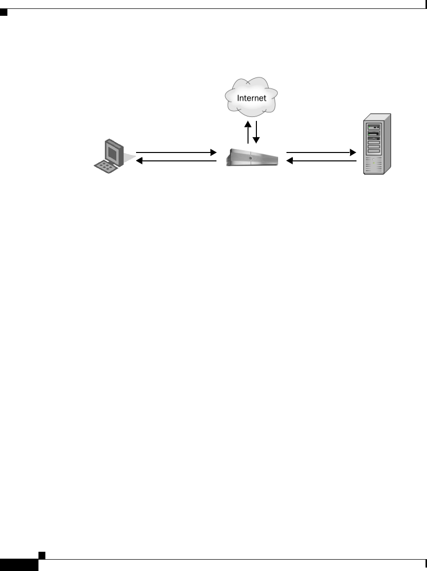
Chapter 20 Authentication
Understanding How Authentication Works
20-6
Cisco IronPort AsyncOS 7.1 for Web User Guide
OL-23207-01
The Web Security appliance supports the following authentication protocols:
•Lightweight Directory Access Protocol (LDAP). The Web Proxy uses the
LDAP Bind operation to query an LDAP-compatible authentication server.
The appliance supports standard LDAP server authentication and secure
LDAP authentication.
For more information about LDAP configuration options, see LDAP
Authentication, page 20-43.
•NT LAN Manager (NTLM). The Web Proxy uses NTLM, a Microsoft
proprietary protocol, to authenticate users which exist in Microsoft Active
Directory. The NTLM protocol uses a challenge-response sequence of
messages between the client and the Active Directory server. You can use
either NTLMSSP or Basic authentication schemes on client side.
For more information about NTLM configuration options, see NTLM
Authentication, page 20-51.
In addition to the preceding protocols, the Web Security appliance supports the
following client side authentication schemes:
•Basic. Allows a client application to provide authentication credentials in the
form of a user name and password when it makes a request. You can use the
Basic authentication scheme with either an LDAP or Active Directory server.
•NTLMSSP. Allows the client application to provide authentication
credentials in the form of a challenge and response. It uses a binary message
format to authenticate clients that use the NTLM protocol to access network
resources. You can use the NTLMSSP authentication scheme only with an
Active Directory server. When the Web Proxy uses NTLMSSP, most client
Client Authentication
Server
Web Security Appliance
Basic or NTLMSSP LDAP or NTLM

20-7
Cisco IronPort AsyncOS 7.1 for Web User Guide
OL-23207-01
Chapter 20 Authentication
Understanding How Authentication Works
applications can use the Windows login credentials for authentication and
users do not need to enter their credentials again. This is called “single
sign-on.”
For more information, see Basic versus NTLMSSP Authentication Schemes,
page 20-7.
Table 20-1 describes the different authentication scenarios you can configure
between the Web Security appliance and the client and between the Web Security
appliance and the authentication server.
Web Proxy deployment also affects how authentication works in each of the
scenarios described in Table 20-1. For more information, see How Web Proxy
Deployment Affects Authentication, page 20-8.
Basic versus NTLMSSP Authentication Schemes
When you configure an Identity group to use authentication, you choose the
authentication scheme, either Basic or NTLMSSP. The authentication scheme
affects the user experience and the security of users’ passwords.
Client to Web Security
Appliance
Web Security Appliance to
Authentication Server
Authentication Server
Type
Basic LDAP LDAP server
Basic LDAP Active Directory server
using LDAP
Basic NTLM Active Directory server
using NTLM
NTLMSSP NTLM Active Directory server
using NTLM

Chapter 20 Authentication
Understanding How Authentication Works
20-8
Cisco IronPort AsyncOS 7.1 for Web User Guide
OL-23207-01
Table 20-2 describes the differences between Basic and NTLMSSP authentication
schemes.
How Web Proxy Deployment Affects Authentication
The Web Proxy communicates with clients and authentication servers differently
depending on the type of Web Proxy deployment and the authentication protocol.
Authentication
Scheme User Experience Security
Basic The client always prompts users for
credentials. After the user enters
credentials, browsers typically offer a
check box to remember the provided
credentials. Each time the user opens the
browser, the client either prompts for
credentials or resends the previously
saved credentials.
Credentials are sent unsecured as clear
text (Base64). A packet capture between
the client and Web Security appliance can
reveal the user name and password.
Note: You can configure the Web Security
appliance so clients send authentication
credentials securely. For more
information, see Sending Authentication
Credentials Securely, page 20-37.
NTLMSSP The client transparently authenticates by
using its Windows login credentials. The
user is not prompted for credentials.
However, the client prompts the user for
credentials under the following
circumstances:
•The Windows credentials failed.
•The client does not trust the Web
Security appliance because of
browser security settings.
Credentials are sent securely using a
three-way handshake (digest style
authentication). The password is never
sent across the connection.
For more information on the three-way
handshake, see Explicit Forward
Deployment, NTLM Authentication,
page 20-12.

20-9
Cisco IronPort AsyncOS 7.1 for Web User Guide
OL-23207-01
Chapter 20 Authentication
Understanding How Authentication Works
Table 20-3 lists the possible methods of authentication for the various
authentication protocols and deployment type.
The following subsections describe these methods of authentication in more
detail.
Explicit Forward Deployment, Basic Authentication
When a client explicitly sends a web page request to a Web Security appliance
deployed in explicit forward mode, the Web Proxy can reply to the client with a
407 HTTP response “Proxy Authentication Required.” This status informs the
client that it must supply valid authentication credentials to access web resources.
The authentication process comprises these steps:
Step 1 Client sends a request to the Web Proxy to connect to a web page.
Step 2 Web Proxy responds with a 407 HTTP response “Proxy Authentication
Required.”
Step 3 User enters credentials, and client application resends the original request with
the credentials encoded in Base64 (not encrypted) in a “Proxy-Authorization”
HTTP header.
Step 4 Web Proxy verifies the credentials and returns the requested web page.
Web Proxy
Deployment
Client to Web Security
Appliance
Web Security Appliance to
Authentication Server
Explicit forward Basic LDAP or NTLM Basic
Transparent Basic LDAP or NTLM Basic
Explicit forward NTLM NTLMSSP
Transparent NTLM NTLMSSP

Chapter 20 Authentication
Understanding How Authentication Works
20-10
Cisco IronPort AsyncOS 7.1 for Web User Guide
OL-23207-01
Table 20-4 lists advantages and disadvantages of using explicit forward Basic
authentication.
Transparent Deployment, Basic Authentication
The 407 HTTP response “Proxy Authentication Required” is allowed from proxy
servers only. However, when the Web Proxy is deployed in transparent mode, its
existence is hidden from client applications on the network. Therefore, the Web
Proxy cannot return a 407 response.
To address this problem, the authentication process comprises these steps:
Step 1 Client sends a request to a web page and the Web Proxy transparently intercepts it.
Step 2 Web Proxy uses a 307 HTTP response to redirect the client to the Web Proxy
which masquerades as a local web server.
Step 3 Client sends a request to the redirected URL.
Step 4 Web Proxy sends a 401 HTTP response “Authorization required.”
Step 5 User is prompted for credentials and enters them.
Step 6 Client sends the request again, but this time with the credentials in an
“Authorization” HTTP header.
Step 7 Web Proxy confirms the credentials, tracks the user by IP address or with a
cookie, and then redirects the client to the originally requested server.
Note You can configure the Web Proxy to use either IP addresses or cookies to
track authenticated users.
Advantages Disadvantages
•RFC-based
•Supported by all browsers and most
other applications
•Minimal overhead
•Works for HTTPS (CONNECT)
requests
•Password sent as clear text
(Base64) for every request
•No single sign-on

20-11
Cisco IronPort AsyncOS 7.1 for Web User Guide
OL-23207-01
Chapter 20 Authentication
Understanding How Authentication Works
Step 8 If the client requests the original web page again, the Web Proxy transparently
intercepts the request, confirms the user by IP address or cookie, and returns the
requested page.
Note If the client tries to connect to another web page and the Web Proxy tracked the
user by IP address, the Web Proxy confirms the user by IP address and returns the
requested page.
Table 20-5 lists advantages and disadvantages of using transparent Basic
authentication and IP-based credential caching.
Advantages Disadvantages
•Works with all major browsers
•With user agents that do not
support authentication, users
only need to authenticate first in
a supported browser
•Relatively low overhead
•Works for HTTPS requests if the
user has previously authenticated
with an HTTP request
•Authentication credentials are
associated with the IP address, not
the user (does not work in Citrix and
RDP environments, or if the user
changes IP address)
•No single sign-on
•Password is sent as clear text
(Base64)

Chapter 20 Authentication
Understanding How Authentication Works
20-12
Cisco IronPort AsyncOS 7.1 for Web User Guide
OL-23207-01
Table 20-6 lists advantages and disadvantages of using transparent Basic
authentication and cookie-based credential caching.
Explicit Forward Deployment, NTLM Authentication
The Web Proxy uses a third party challenge and response system to authenticate
users on the network.
The authentication process comprises these steps:
Step 1 Client sends a request to the Web Proxy to connect to a web page.
Step 2 Web Proxy responds with a 407 HTTP response “Proxy Authentication
Required.”
Step 3 Clients repeats request and includes a “Proxy-Authorization” HTTP header with
an NTLM “negotiate” message.
Step 4 Web Proxy responds with a 407 HTTP response and an NTLM “challenge”
message based on the negotiate message from the client.
Step 5 Client repeats the request and includes a response to the challenge message.
Note The client uses an algorithm based on its password to modify the
challenge and sends the challenge response to the Web Proxy.
Advantages Disadvantages
•Works with all major browsers
•Authentication is associated
with the user rather than the
host or IP address
•Each new web domain requires the
entire authentication process because
cookies are domain specific
•Requires cookies to be enabled
•Does not work for HTTPS requests
•No single sign-on
•Password is sent as clear text (Base64)

20-13
Cisco IronPort AsyncOS 7.1 for Web User Guide
OL-23207-01
Chapter 20 Authentication
Understanding How Authentication Works
Step 6 Web Proxy passes the authentication information to the Active Directory server.
The Active Directory server then verifies that the client used the correct password
based on whether or not it modified the challenge string appropriately.
Step 7 If the challenge response passes, the Web Proxy returns the requested web page.
Note Additional requests on the same TCP connection do not need to be authenticated
again with the Active Directory server.
Table 20-7 lists advantages and disadvantages of using explicit forward NTLM
authentication.
Transparent Deployment, NTLM Authentication
Transparent NTLM authentication is similar to transparent Basic authentication
except that the Web Proxy communicates with clients using NTLMSSP instead of
Basic. However, with transparent NTLM authentication, the authentication
credentials are not sent in the clear to the authentication server.
For more information, see Transparent Deployment, Basic Authentication,
page 20-10.
The advantages and disadvantages of using transparent NTLM authentication are
the same as those of using transparent Basic authentication except that transparent
NTLM authentication is better because the password is not sent to the
authentication server and you can achieve single sign-on when the client
Advantages Disadvantages
•Because the password is not
transmitted to the authentication
server, it is more secure
•Connection is authenticated, not the
host or IP address
•Achieves true single sign-on in an
Active Directory environment when
the client applications are
configured to trust the Web Security
appliance
•Moderate overhead: each new
connection needs to be
re-authenticated
•Primarily supported on Windows
only and with major browsers
only
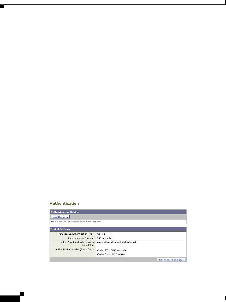
Chapter 20 Authentication
Working with Authentication Realms
20-14
Cisco IronPort AsyncOS 7.1 for Web User Guide
OL-23207-01
applications are configured to trust the Web Security appliance. For more
information on the advantages and disadvantages of transparent Basic
authentication, see Table 20-5 on page 11 Table 20-6 on page 12.
Working with Authentication Realms
An authentication realm is a set of authentication servers (or a single server)
supporting a single authentication protocol with a particular configuration.
You can perform any of the following tasks when configuring authentication:
•Include up to three authentication servers in a realm.
•Create zero or more LDAP realms.
•Create zero or one NTLM realm.
•Include an authentication server in multiple realms.
•Include one or more realms in an authentication sequence.
•Include realms of different protocols in a single authentication sequence.
•Assign a realm or a sequence to an Access Policy group.
You create, edit, and delete authentication realms on the Network >
Authentication page under the Authentication Realms section. Figure 20-2 shows
where you define authentication realms.

20-15
Cisco IronPort AsyncOS 7.1 for Web User Guide
OL-23207-01
Chapter 20 Authentication
Working with Authentication Realms
When you create two or more realms, you can order them in an authentication
sequence. For more information, see Working with Authentication Sequences,
page 20-16.
Creating Authentication Realms
When you first create a realm, you choose the protocol type, either LDAP or
NTLM. You can only create on NTLM realm so therefore, once an NTLM realm
is defined, the appliance only allows you to create LDAP realms. After you enter
the authentication settings, you can test that the parameters you entered are valid
before you submit your changes. For more information about testing the
authentication settings, see Testing Authentication Settings, page 20-20.
To create an authentication realm:
Step 1 On the Network > Authentication page, click Add Realm. The Add Realm page
appears.
Step 2 Enter a name for the authentication realm in the Realm Name field.
Note All sequence and realm names must be unique and only contain
alphanumeric characters or the space character.
Step 3 If no NTLM realm is defined, choose the authentication protocol and scheme in
the Authentication Protocol and Scheme(s) field.
Step 4 Enter the authentication settings as necessary, depending on the protocol type.
•For details on LDAP settings, see Table 20-12 on page 44.
•For details on NTLM settings, see Table 20-15 on page 52.
Step 5 You can test the parameters you entered by clicking Start Test in the Test Current
Settings section.
Step 6 Submit and commit your changes.
Editing Authentication Realms
To edit an authentication realm:

Chapter 20 Authentication
Working with Authentication Sequences
20-16
Cisco IronPort AsyncOS 7.1 for Web User Guide
OL-23207-01
Step 1 On the Network > Authentication page, click the realm name.
Step 2 Change the name of the realm if necessary.
Step 3 Edit the authentication settings as necessary, depending on the protocol type.
•For details on LDAP settings, see Table 20-12 on page 44.
•For details on NTLM settings, see Table 20-15 on page 52.
Step 4 You can test the parameters you entered by clicking Start Test in the Test Current
Settings section.
Step 5 Submit and commit your changes.
Deleting Authentication Realms
When you delete a realm, the Web Security appliance automatically deletes that
realm from any sequence that used it. Also, any Identity policy group that depends
on the deleted realm becomes disabled.
To delete an authentication realm:
Step 1 On the Network > Authentication page, click the trash can icon for the realm
name.
Step 2 Confirm that you want to delete the realm by clicking Delete.
Step 3 Commit your changes.
Working with Authentication Sequences
When you create more than one realm, you can group the realms into an
authentication sequence. An authentication sequence is a group of authentication
realms listed in the order the Web Security appliance uses for authenticating
clients.
You can perform any of the following tasks when configuring authentication
sequences:
•Create multiple authentication sequences.
•Include one or more realms in an authentication sequence.
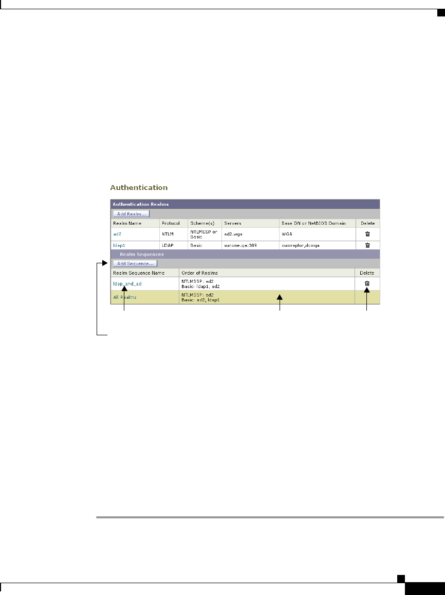
20-17
Cisco IronPort AsyncOS 7.1 for Web User Guide
OL-23207-01
Chapter 20 Authentication
Working with Authentication Sequences
•Include realms of different protocols in a single authentication sequence.
•Assign a realm or a sequence to an Access Policy group.
You create authentication sequences on the Network > Authentication page under
the Realm Sequences section. the Realm Sequences section only appears when
you create two or more realms. Figure 20-3 shows where you create, edit, and
delete authentication sequences Figure 20-3.
After you create the second realm, the appliance automatically displays the Realm
Sequences section and includes a default authentication sequence named All
Realms. The All Realms sequence automatically includes each realm you define.
You can change the order of the realms within the All Realms sequence, but you
cannot delete any of its realms. You cannot delete the All Realms sequence.
Creating Authentication Sequences
You can create an authentication sequence after you create multiple authentication
realms.
To create an authentication sequence:
Step 1 On the Network > Authentication page, click Add Sequence.
The Add Realm Sequence page appears.
Create authentication sequence.
Click sequence name to edit. All Realms default
authentication sequence.
Delete authentication
sequence.
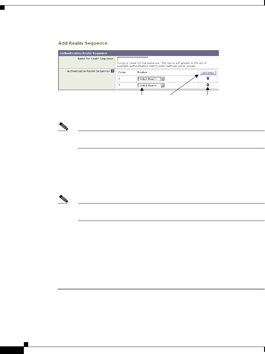
Chapter 20 Authentication
Working with Authentication Sequences
20-18
Cisco IronPort AsyncOS 7.1 for Web User Guide
OL-23207-01
Step 2 Enter a name for the sequence in the Name for Realm Sequence field.
Note All sequence and realm names must be unique and only contain
alphanumeric characters or the space character.
Step 3 In the first row of the Authentication Realm Sequence area, choose the realm
name you want to include in the sequence from the Realms field.
Step 4 If you want to include more realms, click Add Row.
Step 5 Choose the realm name for any additional row you add.
Note You can delete a realm from the sequence by clicking the trash can icon
for that row.
Step 6 When you have entered all realms in the sequence, and they are in the order you
want, submit and commit your changes.
Editing Authentication Sequences
To edit an authentication sequence:
Step 1 On the Network > Authentication page, click the sequence name.
Step 2 Perform any of the following tasks as necessary:
•Change the name of the sequence.
Add a realm to
the sequence.
Choose realm. Delete the
realm.

20-19
Cisco IronPort AsyncOS 7.1 for Web User Guide
OL-23207-01
Chapter 20 Authentication
Appliance Behavior with Multiple Authentication Realms
•Add a new realm by clicking Add Row.
•Delete a realm by clicking the trash can icon.
•Change the order of the realms by clicking the arrow icon in the Order column
for the realm.
Step 3 Submit and commit your changes.
Deleting Authentication Sequences
If you delete an authentication sequence, any Access Policy group that depends
on the deleted sequence becomes disabled.
To delete an authentication sequence:
Step 1 On the Network > Authentication page, click the trash can icon for the sequence
name.
Step 2 Confirm that you want to delete the sequence by clicking Delete.
Step 3 Commit your changes.
Appliance Behavior with Multiple Authentication
Realms
You can configure the Web Security appliance to attempt authenticating clients
against multiple authentication servers, and against authentication servers with
different authentication protocols. When you configure the appliance to
authenticate against multiple authentication servers, it only requests the
credentials from the clients once. This is true even when you configure the
appliance to authenticate against different protocols.
You might want to configure a web policy group to authenticate against different
realms if your organization acquires another organization that has its own
authentication server using the same or a different authentication protocol. That
way, you can create one Access Policy group for all users and assign to the policy
group an authentication sequence that contains a realm for each authentication
server.

Chapter 20 Authentication
Testing Authentication Settings
20-20
Cisco IronPort AsyncOS 7.1 for Web User Guide
OL-23207-01
When you assign an authentication sequence with multiple realms to a policy
group and a client sends a content request, the appliance performs the following
actions:
Step 1 The appliance gets the credentials from the client.
Step 2 The appliance attempts to authenticate the client against the authentication
server(s) defined in the first realm in the sequence.
Step 3 If the client credentials do not match a user in the servers defined in the first
realm, it tries to authenticate against the authentication server(s) in the next realm
in the sequence.
Step 4 The appliance continues trying to authenticate the client against servers in the
next realms until it either succeeds or runs out of authentication realms.
Step 5 When authentication succeeds, the appliance passes the content response to the
client.
Step 6 When the appliance fails to authenticate the client against any authentication
realm in the sequence, the appliance does not allow the client to connect to the
destination server. Instead, it displays an error message to the client.
Tip: For optimal performance, configure clients on a subnet to be authenticated
in a single realm.
Testing Authentication Settings
When you create or edit an authentication realm, you enter a lot of configuration
settings to connect to the authentication server. You can test the settings you enter
before submitting the changes to verify you entered the connection information
correctly.
You can test authentication setting from either the CLI or the web interface:
•Web interface. Use Start Test when you create or edit an authentication
realm. For more information, see Testing Authentication Settings in the Web
Interface, page 20-22.
•CLI command. Use the testauthconfig command. For more information,
see Testing Authentication Settings in the CLI, page 20-23.

20-21
Cisco IronPort AsyncOS 7.1 for Web User Guide
OL-23207-01
Chapter 20 Authentication
Testing Authentication Settings
Testing Process
When you test authentication settings, the Web Security appliance first verifies
that the settings you entered for the realm are in valid formats. For example, if a
field requires a string and it currently contains a numeric value, the appliance
informs you of that error.
If all fields contain valid values, the appliance performs different steps, depending
on the authentication protocol. If the realm contains multiple authentication
servers, the appliance goes through the testing process for each server in turn.
The appliance continues testing all servers in the realm and determines as many
failures as possible for each server. It reports the testing outcome of each server
in the realm.
LDAP Testing
The appliance performs the following steps when you test LDAP authentication
settings:
Step 1 It ensures that the LDAP server is listening on the specified LDAP port.
Step 2 If Secure LDAP is selected, the appliance ensures the LDAP server supports
secure LDAP.
Step 3 It performs an LDAP query using the supplied Base DN, User Name Attribute,
and User Filter Query.
Step 4 If the realm includes Bind Parameters, the appliance validates them by forming an
LDAP query with the Bind Parameters.
Step 5 If Group Authorization is provided, the appliance ensures that the specified group
attributes are valid by fetching the groups from the server.
NTLM Testing
The appliance performs the following steps when you test NTLM authentication
settings:
Step 1 It ensures that the specified Active Directory server is reachable and responds to
queries.
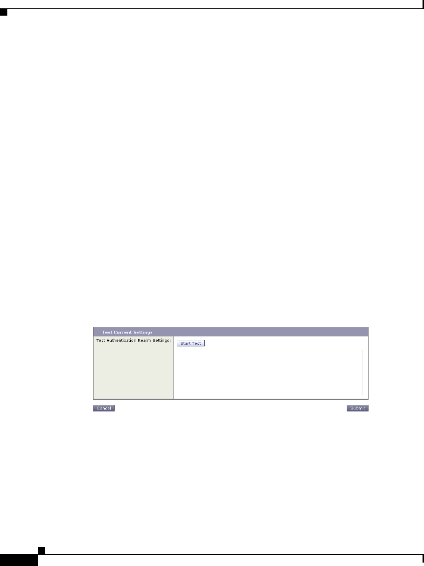
Chapter 20 Authentication
Testing Authentication Settings
20-22
Cisco IronPort AsyncOS 7.1 for Web User Guide
OL-23207-01
Step 2 It ensures that a DNS lookup on the Active Directory domain is successful since
the Active Directory domain must be a DNS domain name and not a WINS
domain name.
Step 3 It ensures the system time of the appliance and the system time of the Active
Directory server are within three minutes of each other.
Step 4 It validates the user credentials by generating a kerberos ticket.
Step 5 It validates whether the user has the proper privileges to add the Web Security
appliance to the Active Directory domain.
Step 6 It validates whether you can fetch the groups within the domain.
Testing Authentication Settings in the Web Interface
You verify the authentication settings in the Test Current Settings section when
you create or edit an authentication realm.
Figure 20-4shows where you verify the authentication settings in the web
interface.
After you enter all settings, click Start Test. The appliance uses the connection
information entered to attempt to connect to the authentication server. It displays
the status of the test below Start Test.
Start Test changes to Stop Test while the appliance tests the settings against the
authentication servers. If the testing takes too much time and you already know it
is going to fail, you can click Stop Test to stop the testing process and edit the
settings.
Figure 20-5 shows the testing results for an LDAP authentication realm.
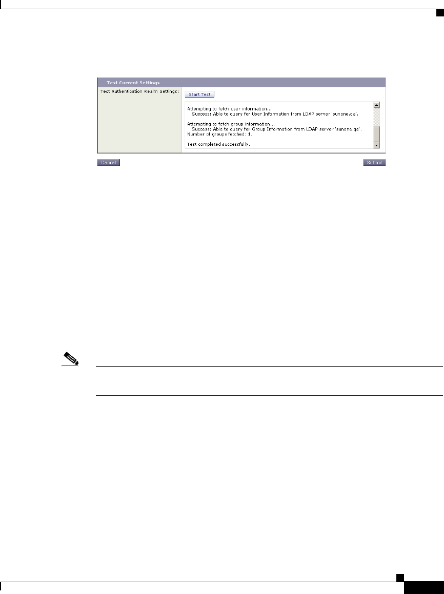
20-23
Cisco IronPort AsyncOS 7.1 for Web User Guide
OL-23207-01
Chapter 20 Authentication
Configuring Global Authentication Settings
Testing Authentication Settings in the CLI
You can use the testauthconfig CLI command to test authentication settings
defined for a given realm. The command syntax is:
testauthconfig [-d level] [realm name]
Running the command without any option causes the appliance to list the
configured authentication realms from which you can make a selection.
The debug flag (-d) controls the level of debug information. The levels can range
between 0-10. If unspecified, the appliance uses a level of 0. With level 0, the
command will return success or failure. If the test settings fail, the command will
list the cause of the failure.
Note Cisco recommends you use level 0. Only use a different debug level when you
need more detailed information to troubleshoot.
For more information about the testauthconfig command, see Web Security
Appliance CLI Commands, page 27-8.
Configuring Global Authentication Settings
Some authentication settings are independent of any realm you define. For
example, you can configure whether or not clients send authentication credentials
to the Web Security appliance securely, even when using Basic authentication
scheme. For more information, see Sending Authentication Credentials Securely,
page 20-37.
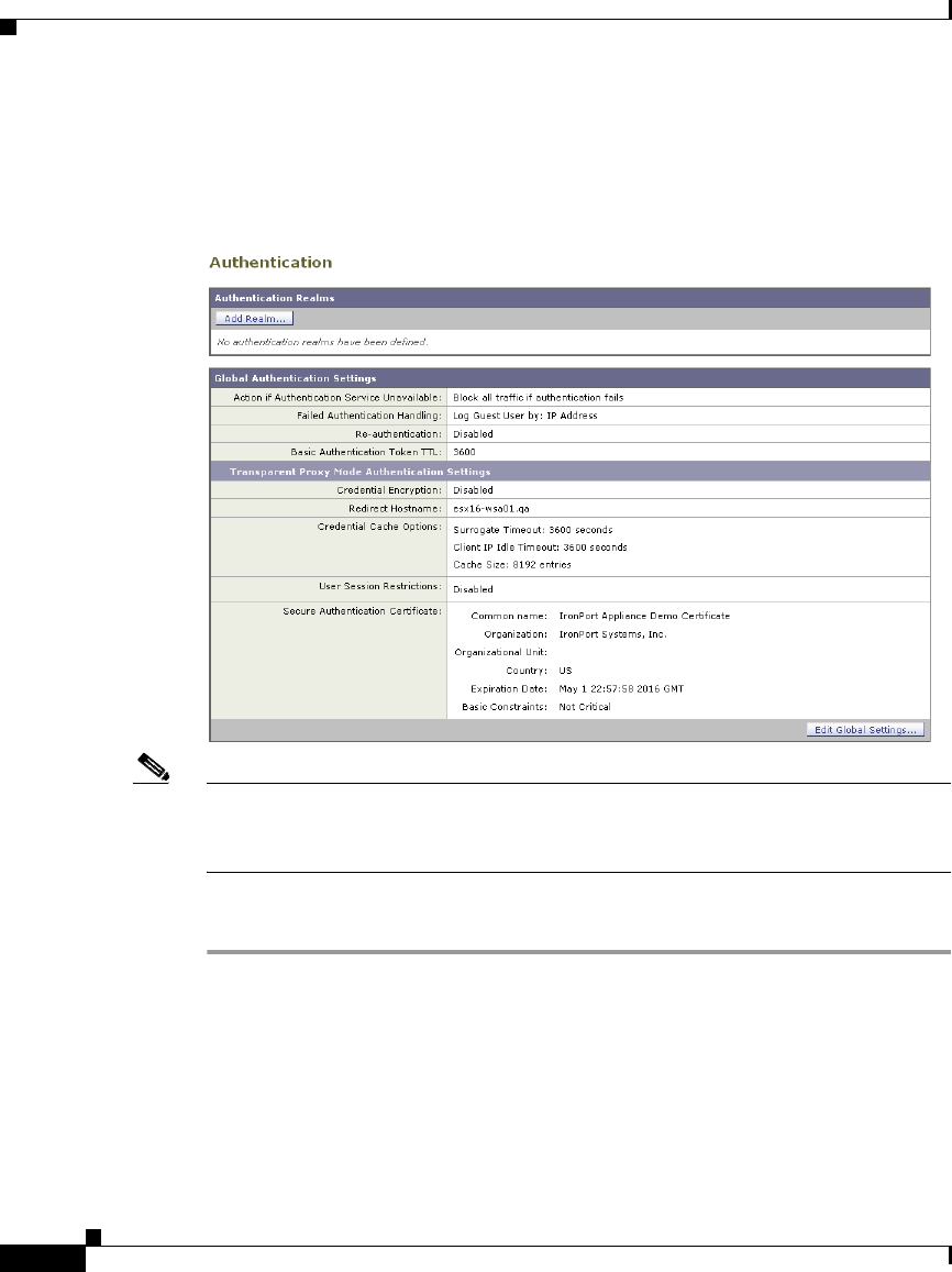
Chapter 20 Authentication
Configuring Global Authentication Settings
20-24
Cisco IronPort AsyncOS 7.1 for Web User Guide
OL-23207-01
Figure 20-6 shows the global authentication settings on the Network >
Authentication page.
Note The global authentication settings you can configure changes according to the
Web Proxy deployment. You can configure more settings when it is deployed in
transparent mode than in explicit forward mode.
To configure global authentication settings:
Step 1 On the Network > Authentication page, click Edit Global Settings.
The Edit Global Authentication Settings page appears with two main sections, one
labeled Global Authentication Settings and the other labeled for the proxy
deployment type, either transparent or forward.
Figure 20-7 on page 25 shows the Global Authentication Settings section.

20-25
Cisco IronPort AsyncOS 7.1 for Web User Guide
OL-23207-01
Chapter 20 Authentication
Configuring Global Authentication Settings
Step 2 Edit the settings in the Global Authentication Settings section as defined in
Table 20-8.
Setting Description
Action if Authentication
Service Unavailable
Choose one of the following values:
•Permit traffic to proceed without
authentication. Processing continues as if the
user was authenticated.
•Block all traffic if user authentication fails.
Processing is discontinued and all traffic is
blocked.
Failed Authentication
Handling
When you grant users guest access in an Identity
policy, this setting determines how the Web Proxy
identifies and logs the user as a guest in the access
logs.
For more information on granting users guest
access, see Allowing Guest Access to Users Who
Fail Authentication, page 7-13.

Chapter 20 Authentication
Configuring Global Authentication Settings
20-26
Cisco IronPort AsyncOS 7.1 for Web User Guide
OL-23207-01
The remaining authentication settings you can configure depends on how the Web
Proxy is deployed, in transparent or explicit forward mode.
Figure 20-8 on page 27 shows where you configure the global authentication
settings when the Web Proxy is deployed in transparent mode.
Re-authentication
(Enable Re-Authentication
Prompt If End User
Blocked by URL Category
or User Session
Restriction)
This setting allows users to authenticate again if
the user is blocked from a website due to a
restrictive URL filtering policy or due to being
restricted from logging into another IP address.
The user sees a block page that includes a link that
allows them to enter new authentication
credentials. If the user enters credentials that allow
greater access, the requested page appears in the
browser.
Note: This setting only applies to authenticated
users who are blocked due to restrictive URL
filtering policies or User Session Restrictions. It
does not apply to blocked transactions by subnet
with no authentication.
For more information, see Allowing Users to
Re-Authenticate, page 20-39.
Basic Authentication
Token TTL
Controls the length of time that user credentials are
stored in the cache before revalidating them with
the authentication server. The default value is the
recommended setting. When the Surrogate
Timeout setting is configured and is greater than
the Basic Authentication Token TTL, then the
Surrogate Timeout value takes precedence and the
Web Proxy contacts the authentication server after
surrogate timeout expires.
Setting Description
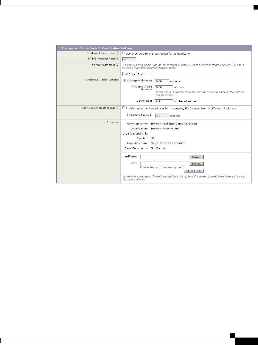
20-27
Cisco IronPort AsyncOS 7.1 for Web User Guide
OL-23207-01
Chapter 20 Authentication
Configuring Global Authentication Settings

Chapter 20 Authentication
Configuring Global Authentication Settings
20-28
Cisco IronPort AsyncOS 7.1 for Web User Guide
OL-23207-01
Step 3 If the Web Proxy is deployed in transparent mode, edit the settings in Table 20-9.
Setting Description
Credential Encryption This setting specifies whether or not the client sends
the login credentials to the Web Proxy through an
encrypted HTTPS connection.
This setting applies to both Basic and NTLMSSP
authentication schemes, but it is particularly useful for
Basic authentication scheme because user credentials
are sent as plain text.
For more information, see Sending Authentication
Credentials Securely, page 20-37.
HTTPS Redirect Port Specify a TCP port to use for redirecting requests for
authenticating users over an HTTPS connection.
This specifies through which port the client will open
a connection to the Web Proxy using HTTPS. This
occurs when credential encryption is enabled or when
using SaaS Access Control and SaaS users are
prompted to authenticate.

20-29
Cisco IronPort AsyncOS 7.1 for Web User Guide
OL-23207-01
Chapter 20 Authentication
Configuring Global Authentication Settings
Redirect Hostname Enter the short hostname of the network interface on
which the Web Proxy listens for incoming connections.
When you configure authentication on an appliance
deployed in transparent mode, the Web Proxy uses this
hostname in the redirection URL sent to clients for
authenticating users.
You can enter either the following values:
•Single word hostname. You can enter the single
word hostname that is DNS resolvable by the
client and the Web Security appliance. This allows
clients to achieve true single sign-on with Internet
Explorer without additional browser side setup.
Be sure to enter the single word hostname that is
DNS resolvable by the client and the Web Security
appliance.
For example, if your clients are in domain
mycompany.com and the interface on which the
Web Proxy is listening has a full hostname of
proxy.mycompany.com, then you should enter
proxy in this field. Clients perform a lookup on
proxy and they should be able to resolve
proxy.mycompany.com.
•Fully qualified domain name (FQDN). You can
also enter the FQDN or IP address in this field.
However, if you do that and want true single
sign-on for Internet Explorer and Firefox
browsers, you must ensure that the FQDN or IP
address is added to the client’s Trusted Sites list in
the client browsers.
The default value is the FQDN of the M1 or P1
interface, depending on which interface is used for
proxy traffic.
Setting Description

Chapter 20 Authentication
Configuring Global Authentication Settings
20-30
Cisco IronPort AsyncOS 7.1 for Web User Guide
OL-23207-01
Credential Cache
Options:
Surrogate Timeout
This setting specifies how long the Web Proxy waits
before asking the client for authentication credentials
again. Until the Web Proxy asks for credentials again,
it uses the value stored in the surrogate (IP address or
cookie).
It is common for user agents, such as browsers, to
cache the authentication credentials so the user will not
be prompted to enter credentials each time.
Credential Cache
Options:
Client IP Idle Timeout
When IP address is used as the authentication
surrogate, this setting specifies how long the Web
Proxy waits before asking the client for authentication
credentials again when the client has been idle.
When this value is greater than the Surrogate Timeout
value, this setting has no effect and clients are
prompted for authentication after the Surrogate
Timeout is reached.
You might want to use this setting to reduce the
vulnerability of users who leave their computers.
Credential Cache
Options:
Cache Size
Specifies the number of entries that are stored in the
authentication cache. Set this value to safely
accommodate the number of users that are actually
using this device. The default value is the
recommended setting.
Setting Description

20-31
Cisco IronPort AsyncOS 7.1 for Web User Guide
OL-23207-01
Chapter 20 Authentication
Configuring Global Authentication Settings
Figure 20-9 on page 32 shows where you configure the global authentication
settings when the Web Proxy is deployed in explicit forward mode.
User Session
Restrictions
This setting specifies whether or not authenticated
users are allowed to access the Internet from multiple
IP addresses simultaneously.
You might want to restrict access to one machine to
prevent users from sharing their authentication
credentials with non-authorized users. When a user is
prevented from logging in at a different machine, an
end-user notification page appears. You can choose
whether or not users can click a button to login as a
different username using the Re-authentication setting
on this page.
When you enable this setting, enter the restriction
timeout value, which determines how long users must
wait before being able to log into a machine with a
different IP address. The restriction timeout value must
be greater than the surrogate timeout value.
You can a specific user or all users from the
authentication cache using the authcache CLI
command.
Advanced When using Credential Encryption or SaaS Access
Control, you can choose whether the appliance uses the
digital certificate and key shipped with the appliance
(the IronPort Appliance Demo Certificate) or a digital
certificate and key you upload here.
To upload a digital certificate and key, click Browse
and navigate to the necessary file on your local
machine. Then click Upload Files after you select the
files you want.
For more information, see Uploading Certificates and
Keys to Use with Credential Encryption and SaaS
Access Control, page 20-38.
Setting Description
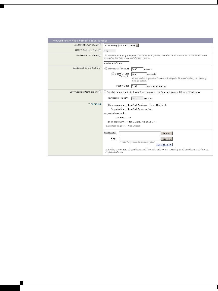

20-33
Cisco IronPort AsyncOS 7.1 for Web User Guide
OL-23207-01
Chapter 20 Authentication
Configuring Global Authentication Settings
Step 4 If the Web Proxy is deployed in explicit forward mode, edit the settings in
Table 20-10.
Setting Description
Credential Encryption This setting specifies whether or not the client sends
the login credentials to the Web Proxy through an
encrypted HTTPS connection. To enable credential
encryption, choose “HTTPS Redirect (Secure)”. When
you enable credential encryption, additional fields
appear to configure how to redirect clients to the Web
Proxy for authentication.
This setting applies to both Basic and NTLMSSP
authentication schemes, but it is particularly useful for
Basic authentication scheme because user credentials
are sent as plain text.
For more information, see Sending Authentication
Credentials Securely, page 20-37.
HTTPS Redirect Port Specify a TCP port to use for redirecting requests for
authenticating users over an HTTPS connection.
This specifies through which port the client will open
a connection to the Web Proxy using HTTPS. This
occurs when credential encryption is enabled or when
using SaaS Access Control and SaaS users are
prompted to authenticate.

Chapter 20 Authentication
Configuring Global Authentication Settings
20-34
Cisco IronPort AsyncOS 7.1 for Web User Guide
OL-23207-01
Redirect Hostname Enter the short hostname of the network interface on
which the Web Proxy listens for incoming connections.
When you enable Authentication Mode above, the Web
Proxy uses this hostname in the redirection URL sent
to clients for authenticating users.
You can enter either the following values:
•Single word hostname. You can enter the single
word hostname that is DNS resolvable by the
client and the Web Security appliance. This allows
clients to achieve true single sign-on with Internet
Explorer without additional browser side setup.
Be sure to enter the single word hostname that is
DNS resolvable by the client and the Web Security
appliance.
For example, if your clients are in domain
mycompany.com and the interface on which the
Web Proxy is listening has a full hostname of
proxy.mycompany.com, then you should enter
proxy in this field. Clients perform a lookup on
proxy and they should be able to resolve
proxy.mycompany.com.
•Fully qualified domain name (FQDN). You can
also enter the FQDN or IP address in this field.
However, if you do that and want true single
sign-on for Internet Explorer and Firefox
browsers, you must ensure that the FQDN or IP
address is added to the client’s Trusted Sites list in
the client browsers.
The default value is the FQDN of the M1 or P1
interface, depending on which interface is used for
proxy traffic.
Setting Description

20-35
Cisco IronPort AsyncOS 7.1 for Web User Guide
OL-23207-01
Chapter 20 Authentication
Configuring Global Authentication Settings
Credential Cache
Options:
Surrogate Timeout
This setting specifies how long the Web Proxy waits
before asking the client for authentication credentials
again. Until the Web Proxy asks for credentials again,
it uses the value stored in the surrogate (IP address or
cookie).
Note that it is common for user agents, such as
browsers, to cache the authentication credentials so the
user will not be prompted to enter credentials each
time.
Credential Cache
Options:
Client IP Idle Timeout
When IP address is used as the authentication
surrogate, this setting specifies how long the Web
Proxy waits before asking the client for authentication
credentials again when the client has been idle.
When this value is greater than the Surrogate Timeout
value, this setting has no effect and clients are
prompted for authentication after the Surrogate
Timeout is reached.
You might want to use this setting to reduce the
vulnerability of users who leave their computers.
Credential Cache
Options:
Cache Size
Specifies the number of entries that are stored in the
authentication cache. Set this value to safely
accommodate the number of users that are actually
using this device. The default value is the
recommended setting.
Setting Description

Chapter 20 Authentication
Configuring Global Authentication Settings
20-36
Cisco IronPort AsyncOS 7.1 for Web User Guide
OL-23207-01
Step 5 Submit and commit your changes.
User Session
Restrictions
This setting specifies whether or not authenticated
users are allowed to access the Internet from multiple
IP addresses simultaneously.
You might want to restrict access to one machine to
prevent users from sharing their authentication
credentials with non-authorized users. When a user is
prevented from logging at a different machine, an
end-user notification page appears. You can choose
whether or not users can click a button to login as a
different username using the Re-authentication setting
on this page.
When you enable this setting, enter the restriction
timeout value, which determines how long users must
wait before being able to log into a machine with a
different IP address. The restriction timeout value must
be greater than the surrogate timeout value.
You can a specific user or all users from the
authentication cache using the authcache CLI
command.
Advanced When using Credential Encryption or SaaS Access
Control, you can choose whether the appliance uses the
digital certificate and key shipped with the appliance
(the IronPort Appliance Demo Certificate) or a digital
certificate and key you upload here.
To upload a digital certificate and key, click Browse
and navigate to the necessary file on your local
machine. Then click Upload Files after you select the
files you want.
For more information, see Uploading Certificates and
Keys to Use with Credential Encryption and SaaS
Access Control, page 20-38.
Setting Description

20-37
Cisco IronPort AsyncOS 7.1 for Web User Guide
OL-23207-01
Chapter 20 Authentication
Configuring Global Authentication Settings
Sending Authentication Credentials Securely
When authentication is used to identify clients using the Web, the client
applications send the authentication credentials to the Web Proxy, which in turn
passes them to the authentication server. How the credentials are passed from the
clients to the Web Proxy depends on the authentication scheme used:
•NTLMSSP. The credentials are always passed to the Web Proxy securely.
They are encrypted using a key specified by the Active Directory server and
sent over HTTP.
•Basic. By default, the credentials are passed to the Web Proxy insecurely.
They are encoded, but not encrypted, and sent over HTTP. However, you can
configure the Web Security appliance so clients send authentication
credentials securely. This works for both LDAP and NTLM Basic
authentication.
When you configure the appliance to use credential encryption for Basic
authentication, the Web Proxy redirects the client back to the Web Proxy, but this
time using an encrypted connection using HTTPS. The client application makes
either a GET or a CONNECT request depending on how the requests are
forwarded to the appliance (explicitly or transparently) and how the client
application is configured to forward HTTPS requests, either using the Web Proxy
or not.
Then, using the secure HTTPS connection, the clients send the authentication
credentials. The appliance uses its own certificate and private key to create an
HTTPS connection with the client by default. Most browsers will warn users that
the certificate is not valid. To prevent users from seeing the invalid certificate
message, you can upload a certificate and key pair your organization uses. When
you upload a certificate and key, the private key must be unencrypted. For
information about uploading a certificate and key, see Uploading Certificates and
Keys to Use with Credential Encryption and SaaS Access Control, page 20-38.
To configure the appliance to use credential encryption, enable the Credential
Encryption setting in the global authentication settings. For more information, see
Configuring Global Authentication Settings, page 20-23. You can also use the
advancedproxyconfig > authentication CLI command. For more information,
see Advanced Proxy Configuration, page 5-30.

Chapter 20 Authentication
Configuring Global Authentication Settings
20-38
Cisco IronPort AsyncOS 7.1 for Web User Guide
OL-23207-01
Uploading Certificates and Keys to Use with Credential Encryption and SaaS
Access Control
When credential encryption is enabled or when using SaaS Access Control, the
appliance uses a digital certificate to securely establish a connection with the
client application. By default, the Web Security appliance uses the “IronPort
Appliance Demo Certificate” that comes installed. However, client applications
are not programmed to recognize this certificate, so you can upload a digital
certificate to the appliance that your applications recognize automatically.
Use the Advanced section on the Network > Authentication page to upload the
certificate and key.
For more information on obtaining a certificate and private key pair to upload, see
Obtaining Certificates, page 26-33.
Note Any certificate and key you upload on the Network > Authentication page is only
used for establishing secure connections with clients for credential encryption and
authenticating SaaS users using SaaS Access Control. The certificate and key are
not used for establishing secure HTTPS sessions when connecting to the Web
Security appliance web interface. For more information on uploading a certificate
and key pair for HTTPS connections to the web interface, see Installing a Server
Digital Certificate, page 26-32.
For more information on SaaS Access Control, see Authenticating SaaS Users,
page 14-4.
Accessing HTTPS and FTP Sites with Credential Encryption Enabled
Credential encryption works because the Web Proxy redirects clients to the Web
Proxy itself for authentication using an HTTPS connection. After successful
authentication, the Web Proxy redirects clients back to the original web site. In
order to continue to identify the user, the Web Proxy must use a surrogate (either
the IP address or a cookie).
However, using a cookie to track users when the client accesses HTTPS sites or
FTP servers using FTP over HTTP does not work.
•HTTPS. The Web Proxy must resolve the user identity before assigning a
Decryption Policy (and therefore, decrypt the transaction), but it cannot
obtain the cookie to identify the user unless it decrypts the transaction.

20-39
Cisco IronPort AsyncOS 7.1 for Web User Guide
OL-23207-01
Chapter 20 Authentication
Allowing Users to Re-Authenticate
•FTP over HTTP. The dilemma with accessing FTP servers using FTP over
HTTP is similar to accessing HTTPS sites. The Web Proxy must resolve the
user identity before assigning an Access Policy, but it cannot set the cookie
from the FTP transaction.
Because of this, you should configure the appliance to use IP addresses as the
surrogate when credential encryption is enabled.
Note Authentication does not work with HTTPS and FTP over HTTP requests when
credential encryption is enabled and configured to use cookies as the surrogate
type. Therefore, with this configuration setup, HTTPS and FTP over HTTP
requests only match Access Policies that do not require authentication. Typically,
they often match the global Access Policy since it never requires authentication.
Allowing Users to Re-Authenticate
AsyncOS for Web can block users from accessing different categories of websites
depending on who is trying to access a website. In these cases, users successfully
authenticate, but they are not authorized to access certain websites due to
configured URL filtering in the applicable Access Policy. You can allow these
authenticated users another opportunity to access the web if they fail
authorization.
Note Only authenticated users are allowed to re-authenticate, not unauthenticated
users.
You might want to do this for shared workstations that have multiple users, but the
default account has limited access. If the default account on the workstation is
blocked from a website due to restrictive URL filtering, the user can enter
different authentication credentials that allow broader, more privileged access.
To do this, enable the “Enable Re-Authentication Prompt If End User Blocked by
URL Category or User Session Restriction” global authentication setting. The
user sees a block page that includes a link that allows them to enter new
authentication credentials. The Web Proxy evaluates those credentials against the

Chapter 20 Authentication
Allowing Users to Re-Authenticate
20-40
Cisco IronPort AsyncOS 7.1 for Web User Guide
OL-23207-01
authentication realms defined in the applicable Identity group, and if the new
credentials allow greater access, the requested page appears in the browser. For
more information, see Configuring Global Authentication Settings, page 20-23.
Note The Web Proxy evaluates the new credentials against the authentication realms
defined in the applicable Identity group only. It does not compare them against all
other Identity groups.
When a more privileged user authenticates and gets access, the Web Proxy caches
the privileged user identity for different amounts of time depending on the
authentication surrogates configured:
•Session cookie. The privileged user identity is used until the browser is
closed or the session times out.
•Persistent cookie. The privileged user identity is used until the surrogate
times out.
•IP address. The privileged user identity is used until the surrogate times out.
•No surrogate. The Web Proxy requests authentication for every new
connection, but most browsers will cache the privileged user credentials and
authenticate without prompting the user until the browser is closed. However,
because the Web Proxy requests authentication for every new connection,
there is an increased impact on the authentication server when using
NTLMSSP.
Note To use the re-authentication feature with user defined end-user notification pages,
the CGI script that parses the redirect URL must parse and use the Reauth_URL
parameter. For more information, see Working with User Defined End-User
Notification Pages, page 15-14.
Using Re-Authentication with Internet Explorer
When you enable re-authentication and clients use Microsoft Internet Explorer,
you need to verify certain settings to ensure re-authentication works properly with
Internet Explorer. Due to a known issue with Internet Explorer, re-authentication
does not work properly under the following circumstances:
•Internet Explorer is configured to use the Web Security appliance as a proxy.

20-41
Cisco IronPort AsyncOS 7.1 for Web User Guide
OL-23207-01
Chapter 20 Authentication
Allowing Users to Re-Authenticate
•The Web Security appliance uses NTLMSSP authentication.
•The Web Security appliance uses cookies for authentication surrogates, but is
not configured for credential encryption.
•The Web Proxy is deployed in explicit forward mode, or it is deployed in
transparent mode and the “Apply same surrogate settings to explicit forward
requests” option is enabled in the applicable Identity group.
Problems occur when authentication is required to access the site, and may occur
either when initially requesting the site or when re-authenticating to try to access
the site.
To work around these problems, enable credential encryption on the Network >
Authentication page.
Using Re-Authentication with PAC Files
When you enable re-authentication and configure client applications to use a PAC
file, you may need to verify certain settings to ensure re-authentication works
properly with the PAC file.
Re-authentication does not work properly under the following circumstances:
•Client browsers are configured to use a PAC file, and the PAC file is designed
to bypass the Web Proxy for internal web servers. Instead of instructing the
browser to explicitly send requests to the Web Proxy, it instructs the browser
to directly send the request to the destination server.
•The Web Security appliance uses IP addresses for authentication surrogates
or no surrogates, and credential encryption is not enabled.
•The Web Proxy is deployed in explicit forward mode, or it is deployed in
transparent mode and the “Apply same surrogate settings to explicit forward
requests” option is enabled for the applicable Identity group.
Problems occur because re-authentication requires clients to be redirected to the
Web Proxy for authentication, but the PAC file bypasses all requests to internal
web servers, including the Web Security appliance.
To work around these problems, edit the PAC file so that the function
FindProxyForURL() returns “PROXY x.x.x.x:80” when the host IP address is
x.x.x.x. The port number you specify in the return should the same port
configured for other destinations.

Chapter 20 Authentication
Tracking Authenticated Users
20-42
Cisco IronPort AsyncOS 7.1 for Web User Guide
OL-23207-01
Note If the Web Security appliance uses cookies for authentication surrogates, Cisco
recommends enabling credential encryption. For more information, see Using
Re-Authentication with Internet Explorer, page 20-40.
Tracking Authenticated Users
Table 20-11 describes which authentication surrogates are supported with other
configurations and different types of requests (explicitly forwarded and
transparently redirected).
* Works after the client makes a request to an HTTP site and is authenticated, or
when the client makes a request to an HTTPS site and the Identity is configured
to decrypt the first HTTPS request for authentication purposes. When the HTTPS
Proxy is configured to deny the first HTTPS request, all requests to HTTPS sites
before authentication happens for a previous request are dropped.
** When cookie-based authentication is used, the Web Proxy cannot authenticate
the user for HTTPS and FTP over HTTP transactions. Due to this limitation, all
HTTPS and FTP over HTTP requests bypass authentication, so authentication is
not requested at all. For more information on how HTTPS requests are assigned
Identity and non-Identity policy groups, see Understanding How Authentication
Affects HTTPS and FTP over HTTP Requests, page 7-6.
Surrogate
Types Explicit Requests Transparent Requests
Credential
Encryption: Disabled Enabled Disabled Enabled
Protocol: HTTP
HTTPS &
FTP over
HTTP HTTP
HTTPS &
FTP over
HTTP HTTP HTTPS HTTP HTTPS
No Surrogate Yes Yes NA NA NA NA NA NA
IP-based Yes Yes Yes Yes Yes No/Yes* Yes No/Yes*
Cookie-based Yes Yes*** Yes No/Yes** Yes No/Yes** Yes No/Yes**

20-43
Cisco IronPort AsyncOS 7.1 for Web User Guide
OL-23207-01
Chapter 20 Authentication
LDAP Authentication
*** No surrogate is used in this case even though cookie-based surrogate is
configured.
LDAP Authentication
The Lightweight Directory Access Protocol (LDAP) server database is a
repository for employee directories. These directories include the names of
employees along with various types of personal data such as a phone number,
email address, and other information that is exclusive to the individual employee.
The LDAP database is composed of objects containing attributes and values. Each
object name is referred to as a distinguished name (DN). The location on the
LDAP server where a search begins is called the Base Distinguished Name or base
DN.
The appliance supports standard LDAP server authentication and Secure LDAP
authentication. Support for LDAP allows established installations to continue
using their LDAP server database to authenticate users.
For Secure LDAP, the appliance supports LDAP connections over SSL. The SSL
protocol is an industry standard for ensuring confidentiality. SSL uses key
encryption algorithms along with Certificate Authority (CA) signed certificates to
provide the LDAP servers a way to verify the identity of the appliance.
Note AsyncOS for Web only supports 7-bit ASCII characters for passwords when using
the Basic authentication scheme. Basic authentication fails when the password
contains characters that are not 7-bit ASCII.
Changing Active Directory Passwords
After Active Directory LDAP users change their account passwords, the Active
Directory LDAP server authenticates them with their current or previous
password, depending on the Active Directory server configuration.
If you want users to only be able to authenticate with their new password, you can
reboot the Active Directory server or, you can wait for the Active Directory server
to time out the old passwords.

Chapter 20 Authentication
LDAP Authentication
20-44
Cisco IronPort AsyncOS 7.1 for Web User Guide
OL-23207-01
LDAP Authentication Settings
Table 20-12 describes the authentication settings you define when you choose
LDAP authentication.
Setting Description
LDAP Version Choose the version of LDAP, and choose whether or not
to use Secure LDAP.
The appliance supports LDAP version 2, and LDAP
version 3 software. Secure LDAP requires LDAP version
3.
Choose whether or not this LDAP server support Novell
eDirectory to use with transparent user identification. For
more information, see Identifying Users Transparently,
page 7-16.
LDAP Server Enter the LDAP server IP address or hostname and its port
number. You can specify up to three servers.
The hostname must be a fully-qualified domain name. For
example, ldap.example.com. An IP address is required
only if the DNS servers configured on the appliance
cannot resolve the LDAP server hostname.
The default port number for Standard LDAP is 389. The
default number for Secure LDAP is 636.
If the LDAP server is an Active Directory server, enter the
hostname or IP address and the port of the domain
controller here. Whenever possible, enter the name of the
Global Catalog Server and use port 3268. However, you
might want to use a local domain controller when the
global catalog server is physically far away and you know
you only need to authenticate users on the local domain
controller.
Note: When you configure multiple authentication
servers in the realm, the appliance attempts to authorize
with up to three authentication servers before failing to
authenticate the transaction within that realm.

20-45
Cisco IronPort AsyncOS 7.1 for Web User Guide
OL-23207-01
Chapter 20 Authentication
LDAP Authentication
LDAP Persistent
Connections
(under the
Advanced section)
Choose one of the following values:
•Use persistent connections (unlimited). Use
existing connections. If no connections are available
a new connection is opened.
•Use persistent connections. Use existing
connections to service the number of requests
specified. When the maximum is reached, establish a
new connection to the LDAP server.
•Do not use persistent connections. Always create a
new connection to the LDAP server.
Setting Description

Chapter 20 Authentication
LDAP Authentication
20-46
Cisco IronPort AsyncOS 7.1 for Web User Guide
OL-23207-01
User Authentication Enter values for the following fields:
Base Distinguished Name (Base DN)
The LDAP database is a tree-type directory structure and
the appliance uses the Base DN to navigate to the correct
location in the LDAP directory tree to begin a search. A
valid Base DN filter string is composed of one or more
components of the form object-value. For example
dc=companyname, dc=com.
User Name Attribute
Choose one of the following values:
•uid, cn, and sAMAccountName. Unique identifiers
in the LDAP directory that specify a username.
•custom. A custom identifier such as UserAccount.
User Filter Query
The User Filter Query is an LDAP search filter that
locates the users Base DN. This is required if the user
directory is in a hierarchy below the Base DN, or if the
login name is not included in the user-specific component
of that users Base DN.
Choose one of the following values:
•none. Filters any user.
•custom. Filters a particular group of users.
Setting Description

20-47
Cisco IronPort AsyncOS 7.1 for Web User Guide
OL-23207-01
Chapter 20 Authentication
LDAP Authentication
LDAP Group Authorization
You can use the user group membership information stored in an LDAP directory
to apply a policy group to a group of users. To do this, enable group authorization
in an LDAP authentication realm and group users by one of the following LDAP
object types:
Query Credentials Choose whether or not the authentication server accepts
anonymous queries.
If the authentication server does accept anonymous
queries, choose Server Accepts Anonymous Queries.
If the authentication server does not accept anonymous
queries, choose Use Bind DN and then enter the following
information:
•Bind DN. The user on the external LDAP server
permitted to search the LDAP directory. Typically,
the bind DN should be permitted to search the entire
directory.
•Password. The password associated with the user you
enter in the Bind DN field.
The following text lists some example users for the Bind
DN field:
cn=administrator,cn=Users,dc=domain,dc=com
sAMAccountName=jdoe,cn=Users,dc=domain,dc=com.
If the Active Directory server is used as an LDAP server,
you may also enter the Bind DN username as
“DOMAIN\username.”
Group
Authorization
Choose whether or not to enable LDAP group
authorization. When you enable LDAP group
authorization, you can group users by group object or user
object.
For more information on configuring this section, see
LDAP Group Authorization, page 20-47.
Setting Description

Chapter 20 Authentication
LDAP Authentication
20-48
Cisco IronPort AsyncOS 7.1 for Web User Guide
OL-23207-01
•Group object. Sometimes, group membership information is stored in the
group object, which has an attribute (such as “member”) to list all users that
belong to the group. Define authorized users by group object when the group
object contains all users you need to define. For more information on how to
define authorized users by group object, see Table 20-13 on page 49.
•User object. Sometimes, group membership information is stored in the user
object, which has an attribute (such as “memberOf”) that lists all groups to
which a user belongs. You might want to define authorized users by user
object when the authentication server does not store the member information
in the group object or if it does not have a group object. For more information
on how to define authorized users by user object, see Table 20-14 on page 50.
Note The user object must not contain any special character.
When you configure group authorization in an LDAP authentication realm, be
sure you uniquely identify a group object in the LDAP server. If the search for a
group DN returns multiple entries, the Web Security appliance only uses the first
entry returned. You uniquely identify a group object using the following fields:
•Base DN
•Attribute that contains the group name
•Query string to determine if object is a group
When you create an LDAP authentication realm with user object based group
authorization against an Active Directory server, the user object does not contain
the primary group that the user is a member of, for example “Domain Users.” It
only contains the other defined groups. Therefore, policy groups might not match
these users under the following conditions:
•An Identity policy group specifies an LDAP realm with user attribute based
group authentication.
•A non-Identity policy group uses the Identity policy group and the primary
group is configured as an authorized group in the Active Directory server.

20-49
Cisco IronPort AsyncOS 7.1 for Web User Guide
OL-23207-01
Chapter 20 Authentication
LDAP Authentication
Table 20-13 describes the group object settings.
Group Object Setting Description
Group Membership
Attribute Within
Group Object
Choose the LDAP attribute which lists all users that
belong to this group.
Choose one of the following values:
•member and uniquemember. Unique identifiers in
the LDAP directory that specify group members.
•custom. A custom identifier such as UserInGroup.
Attribute that
Contains the Group
Name
Choose the LDAP attribute which specifies the group
name that can be used in the policy group configuration.
Choose one of the following values:
•cn. A unique identifier in the LDAP directory that
specifies the name of a group.
•custom. A custom identifier such as FinanceGroup.
Query String to
Determine if Object is
a Group
Choose an LDAP search filter that determines if an
LDAP object represents a user group.
Choose one of the following values:
•objectclass=groupofnames
•objectclass=groupofuniquenames
•objectclass=group
•custom. A custom filter such as
objectclass=person.
Note: The query defines the set of authentication groups
which can be used in policy groups.

Chapter 20 Authentication
LDAP Authentication
20-50
Cisco IronPort AsyncOS 7.1 for Web User Guide
OL-23207-01
Table 20-14 describes the user object settings.
User Object Setting Description
Group Membership
Attribute Within User
Object
Choose the attribute which list all the groups that this
user belongs to.
Choose one of the following values:
•memberOf. Unique identifiers in the LDAP
directory that specify user members.
•custom. A custom identifier such as UserInGroup.
Group Membership
Attribute is a DN
Specify whether the group membership attribute is a
distinguished name (DN) which refers to an LDAP
object. For Active Directory servers, enable this option.
When this is enabled, you must configure the
subsequent settings.
Attribute that
Contains the Group
Name
When the group membership attribute is a DN, this
specifies the attribute that can be used as group name in
policy group configurations.
Choose one of the following values:
•cn. A unique identifier in the LDAP directory that
specifies the name of a group.
•custom. A custom identifier such as FinanceGroup.
Query String to
Determine if Object
is a Group
Choose an LDAP search filter that determines if an
LDAP object represents a user group.
Choose one of the following values:
•objectclass=groupofnames
•objectclass=groupofuniquenames
•objectclass=group
•custom. A custom filter such as
objectclass=person.
Note: The query defines the set of authentication groups
which can be used in Web Security Manager policies.

20-51
Cisco IronPort AsyncOS 7.1 for Web User Guide
OL-23207-01
Chapter 20 Authentication
NTLM Authentication
NTLM Authentication
The NT Lan Manager (NTLM) authenticates users with an encrypted
challenge-response sequence that occurs between the appliance and a Microsoft
Windows domain controller. The NTLM challenge-response handshake occurs
when a web browser attempts to connect to the appliance and before data is
delivered.
When you configure an NTLM authentication realm, you do not specify the
authentication scheme. Instead, you choose the scheme at the Access Policy group
level when you configure the policy member definition. This allows you to choose
different schemes for different policy groups. When you create or edit the policy
group, you can choose one of the following schemes:
•Use NTLMSSP
•Use Basic or NTLMSSP
•Use Basic
Note AsyncOS for Web only supports 7-bit ASCII characters for passwords when using
the Basic authentication scheme. Basic authentication fails when the password
contains characters that are not 7-bit ASCII.
Working with Multiple Active Directory Domains
AsyncOS allows you to create only one NTLM authentication realm. If your
organization has multiple Active Directory domains, you can authenticate users
in all domains if the following conditions exist:
•All Active Directory domains must exist in a single forest.
•There must be a trust relationship among all domains in the forest.
When you define policy group membership by group name, the web interface only
displays Active Directory groups in the domain where AsyncOS created a
computer account when joining the domain. To create a policy group for users in
a different domain in the forest, manually enter the domain and group name in the
web interface.

Chapter 20 Authentication
NTLM Authentication
20-52
Cisco IronPort AsyncOS 7.1 for Web User Guide
OL-23207-01
NTLM Authentication Settings
Table 20-15 describes the authentication settings you define when you choose
NTLM authentication.
Setting Description
Active Directory
Server
Enter the Active Directory server IP address or hostname.
You can specify up to three servers.
The hostname must be a fully-qualified domain name. For
example, ntlm.example.com. An IP address is required only
if the DNS servers configured on the appliance cannot
resolve the Active Directory server hostname.
Note: When multiple authentication servers are configured
in the realm, the appliance attempts to authorize with up to
three authentication servers before failing to authorize the
transaction within this realm.
Active Directory
Account
Enter the following Active Directory account information:
•Active Directory server domain name.
•NetBIOS domain name. You only need to enter the
NetBIOS domain name if the network uses NetBIOS.
This field only appears when the NTLM security mode
is set to “domain” using the setntlmsecuritymode CLI
command.
•Computer account location.
Note: You must click Join Domain to enter an Active
Directory username and password.
For more information about entering the Active Directory
account information, see Joining the Active Directory
Domain, page 20-53.

20-53
Cisco IronPort AsyncOS 7.1 for Web User Guide
OL-23207-01
Chapter 20 Authentication
NTLM Authentication
Joining the Active Directory Domain
When you configure an NTLM realm, you must enter information to join the
Active Directory domain to set up a computer account in the domain. An Active
Directory computer account is an account that uniquely identifies the computer on
the domain. It is also referred to as a machine trust account.
After you enter the Active Directory account information in the authentication
realm, click the Join Domain button to set up a computer account. Use the
Location field to define the organizational directory where AsyncOS should
create the computer account in the Active Directory domain.
Figure 20-10 on page 54 shows where you join an Active Directory domain.
Join Domain
button
(Active Directory
User)
When you click Join Domain, enter the name and password
for the Active Directory user.
If the appliance and the Active Directory server are in the
same domain, any valid user that is a member of User
Domain is allowed.
However, depending on the Active Directory server
configuration, this user might need Domain Admin Group or
Enterprise Admin Group credentials. For example:
•If the appliance and the Active Directory server are not
in the same domain, the Active Directory user must be
a member of the Domain Admin Group.
•If the Active Directory server configuration is a forest,
the Active Directory user must be a member of the
Enterprise Admin Group.
Network Security Configure whether or not the Active Directory server is
configured to require signing. When you enable this check
box, the appliance uses Transport Layer Security (TLS)
when communicating with the Active Directory server.
Setting Description
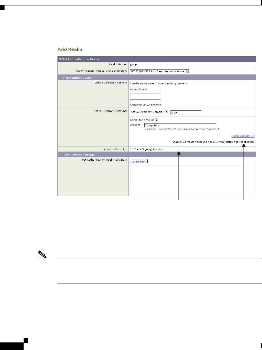
Chapter 20 Authentication
NTLM Authentication
20-54
Cisco IronPort AsyncOS 7.1 for Web User Guide
OL-23207-01
Joining an Active Directory Domain
When you click Join Domain, you are prompted to enter login credentials for the
Active Directory server. The login information is used only to create the Active
Directory computer account and is not saved. Enter the login information and
click Create Account.
Note You must enter the sAMAccountName user name for the Active Directory user.
Also, verify that users enter their sAMAccountName user name when they log in
to their computers.
Once an account is created, the status of the account creation is displayed below
the Join Domain button. If the account creation fails, the status and reason for
error is displayed.
Status tells you whether or not AsyncOS has
created the computer account.
Click to join the Active
Directory domain.
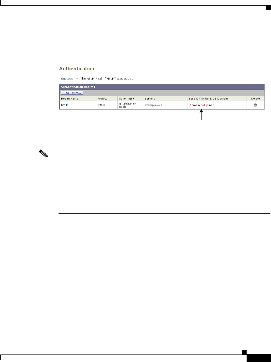
20-55
Cisco IronPort AsyncOS 7.1 for Web User Guide
OL-23207-01
Chapter 20 Authentication
NTLM Authentication
Also, when you view all realms on the Network > Authentication page, the
appliance displays warning text in red saying that the domain was not joined for
any realm that did not create a computer account.
AsyncOS only creates an Active Directory computer account when you edit the
authentication realm Active Directory information or when the appliance reboots.
Note To successfully join the Active Directory domain, the time difference between the
Web Security appliance and the Active Directory server should be less than the
time specified in the “Maximum tolerance for computer clock synchronization”
option on the Active Directory server. When you use Network Time Protocol
(NTP) to specify the current time on the Web Security appliance, remember that
the default time server is time.ironport.com. This may affect the time difference
between the appliance and the Active Directory server.
Some Active Directory environments automatically delete computer objects at
particular intervals for accounts that appear in active in order to clean up old
computer objects. However, AsyncOS does not automatically change the
password for the computer account it creates in an Active Directory server, so the
computer account may appear inactive over time. Therefore, if the Active
Directory environment automatically deletes computer objects at particular
intervals, make sure the Web Security appliance computer account is created in a
container that is exempt from this cleanup process.
Red text indicates that the domain was not joined and no computer account was created.

Chapter 20 Authentication
Supported Authentication Characters
20-56
Cisco IronPort AsyncOS 7.1 for Web User Guide
OL-23207-01
Supported Authentication Characters
This section lists the characters the Web Security appliance supports when it
communicates with LDAP and Active Directory servers. For authentication to
work properly, verify that your authentication servers only use the supported
characters listed in this section.
For example, according to Table 20-16, the appliance can validate users with the
following Active Directory user name:
jsmith#123
And according to Table 20-16, the appliance cannot validate users with the
following Active Directory user name:
jsmith+
Active Directory Server Supported Characters
Table 20-16 lists the characters the Web Security appliance supports for the User
Name field for Active Directory servers.
Note The Web Security appliance supports the percent ( % ) character for end users
browsing the web. However, you cannot use a user name with the percent ( %)
character to join the Active Directory domain when you create an NTLM
authentication realm.
Table 20-16 Supported Active Directory Server Characters — User Name
Field
Supported Characters Characters Not Supported
A...Z a...z
0 1 2 3 4 5 6 7 8 9
` ~ ! # $ % ^ & ( ) _ - { } ' . @
space
/ \ [ ] : ; | = , + * ? < > "

20-57
Cisco IronPort AsyncOS 7.1 for Web User Guide
OL-23207-01
Chapter 20 Authentication
Supported Authentication Characters
Table 20-17 lists the characters the Web Security appliance supports for the
Password field for Active Directory servers.
Table 20-18 lists the characters the Web Security appliance supports for the
Location field for Active Directory servers. You enter the location string in the
Location field when you configure an NTLM authentication realm.
Table 20-19 lists the characters the Web Security appliance supports for the Group
field for Active Directory servers.
Table 20-17 Supported Active Directory Server Characters — Password
Field
Supported Characters Characters Not Supported
A...Z a...z
0 1 2 3 4 5 6 7 8 9
` ~ ! # $ ^ & ( ) _ - { } ' .
/ [ ] : | * ? @ + \ , ; " = < >
space
N/A
Table 20-18 Supported Active Directory Server Characters — Location Field
Supported Characters Characters Not Supported
A...Z a...z
0 1 2 3 4 5 6 7 8 9
` ~ ! # $ ^ & ( ) _ - { } ' .
/ [ ] : | * ? @
space
+ \ , ; " = < >
Note: The appliance does not support
these characters even when they are
escaped with a backslash ( \ )
character.
Table 20-19 Supported Active Directory Server Characters — Group Field
Supported Characters Characters Not Supported
A...Z a...z
0 1 2 3 4 5 6 7 8 9
` ~ ! # $ % ^ & ( ) _ - { } ' . @
space
/ \ [ ] : ; | = , + * ? < > "

Chapter 20 Authentication
Supported Authentication Characters
20-58
Cisco IronPort AsyncOS 7.1 for Web User Guide
OL-23207-01
Note You can only use the backslash ( \ ) character as a separator between the domain
name and a user or group name, or as a separator between organizational units
(OU) in the location string for an Active Directory server. You cannot use it as part
of a domain name, user name, group name, or location name.
LDAP Server Supported Characters
Table 20-20 lists the characters the Web Security appliance supports for the User
Name field for LDAP servers.
Table 20-21 lists the characters the Web Security appliance supports for the
Password field for LDAP servers.
Table 20-20 Supported LDAP Server Characters — User Name Field
Supported Characters Characters Not Supported
A...Z a...z
0 1 2 3 4 5 6 7 8 9
` ~ ! # $ % ^ & ( ) _ - { } ' . @
Note: The appliance only supports the ‘(’ and
‘)’ characters when they are escaped with a
backslash ( \ ) character.
/ \ [ ] : ; | = , + * ? <
> "
Table 20-21 Supported LDAP Server Characters — Password Field
Supported Characters Characters Not Supported
A...Z a...z
0 1 2 3 4 5 6 7 8 9
` ~ ! # $ % ^ & ( ) _ - { } @
' . / \ [ ] : | = * ? < > " , ; +
space
N/A

20-59
Cisco IronPort AsyncOS 7.1 for Web User Guide
OL-23207-01
Chapter 20 Authentication
Supported Authentication Characters
Table 20-22 lists the characters the Web Security appliance supports for the Group
field for LDAP servers.
Table 20-23 lists the characters the Web Security appliance supports for the
Custom User Filter Query Field field for LDAP servers.
Table 20-24 lists the characters the Web Security appliance supports for the
Custom Group Filter Query Field field for LDAP servers.
Table 20-22 Supported LDAP Server Characters — Group Field
Supported Characters Characters Not Supported
A...Z a...z
0 1 2 3 4 5 6 7 8 9
` ~ ! # $ % ^ & ( ) _ - { } @ ' . / \ [ ]
: | = * ? < > "
space
Note: The appliance only supports the ‘(’ and ‘)’
characters when they are escaped with a
backslash ( \ ) character.
, ; +
Table 20-23 Supported LDAP Server Characters — Custom User Filter Query
Field
Supported Characters Characters Not Supported
A...Z a...z
0 1 2 3 4 5 6 7 8 9
` ~ ! # $ % ^ & ( ) _ - { } ' .
space
@ / \ [ ] : | = * ? < > "
, ; +
Table 20-24 Supported LDAP Server Characters — Custom Group Filter
Query Field
Supported Characters Characters Not Supported
A...Z a...z
0 1 2 3 4 5 6 7 8 9
` ~ ! # $ % ^ & ( ) _ - { } @ ' . / \ [
] : | = * ? < > "
space
, ; +

Chapter 20 Authentication
Supported Authentication Characters
20-60
Cisco IronPort AsyncOS 7.1 for Web User Guide
OL-23207-01

CHAPTER
21-1
Cisco IronPort AsyncOS 7.1 for Web User Guide
OL-23207-01
21
L4 Traffic Monitor
This chapter contains the following information:
•About L4 Traffic Monitor, page 21-1
•How the L4 Traffic Monitor Works, page 21-1
•Configuring the L4 Traffic Monitor, page 21-3
•Viewing L4 Traffic Monitor Activity, page 21-9
About L4 Traffic Monitor
The Web Security appliance has an integrated Layer-4 Traffic Monitor that detects
rogue traffic across all network ports and stops malware attempts to bypass port
80. Additionally, when internal clients are infected with malware and attempt to
phone-home across non-standard ports and protocols, the L4 Traffic Monitor
prevents phone-home activity from going outside the corporate network.
How the L4 Traffic Monitor Works
The L4 Traffic Monitor listens to network traffic that comes in over all ports on
the appliance and matches domain names, and IP addresses against entries in its
own database tables to determine whether to allow incoming and outgoing traffic.
All web destinations fall under one of the following categories:

Chapter 21 L4 Traffic Monitor
How the L4 Traffic Monitor Works
21-2
Cisco IronPort AsyncOS 7.1 for Web User Guide
OL-23207-01
•Known allowed address. Any IP address or hostname listed in the Allow List
property. These addresses appear in the log files as “whitelist” addresses.
•Unlisted address. Any IP address that is not known to be a malware site nor
is a known allowed address. They are not listed on the Allow List or
Additional Suspected Malware Addresses properties, nor are they listed in the
L4 Traffic Monitor Database as a known malware site. These addresses do not
appear in the log files.
•Ambiguous address. These addresses appear in the log files as “greylist”
addresses. They include any of the following addresses:
–
Any IP address that is associated with both an unlisted hostname and a
known malware hostname.
–
Any IP address that is associated with both an unlisted hostname and a
hostname from the Additional Suspected Malware Addresses property.
•Known malware address. These addresses appear in the log files as
“blacklist” addresses. They include any of the following addresses:
–
Any IP address or hostname that the L4 Traffic Monitor Database
determines to be a known malware site and not listed in the Allow List.
–
Any IP address that is listed in the Additional Suspected Malware
Addresses property and not listed in the Allow List and not determined
to be ambiguous.
Note You can define the Allow List and the Additional Suspected Malware Addresses
properties on the Web Security Manager > L4 Traffic Monitor Policies page.
The L4 Traffic Monitor listens to and monitors network ports for rogue activity.
It performs one of the following actions on all traffic on your network:
•Allow. It always allows traffic to and from known allowed and unlisted
addresses.
•Monitor. It monitors traffic under the following circumstances:
–
When the Action for Suspected Malware Addresses option is set to
Monitor, it always monitors all traffic that is not to or from a known
allowed address.
–
When the Action for Suspected Malware Addresses option is set to
Block, it monitors traffic to and from ambiguous addresses.

21-3
Cisco IronPort AsyncOS 7.1 for Web User Guide
OL-23207-01
Chapter 21 L4 Traffic Monitor
Configuring the L4 Traffic Monitor
•Block. When the Action for Suspected Malware Addresses option is set to
Block, it blocks traffic to and from known malware addresses.
The L4 Traffic Monitor Database
The L4 Traffic Monitor uses and maintains its own internal database. This
database is continuously updated with matched results for IP addresses and
domain names. Additionally, the database table receives periodic updates from the
IronPort update server at the following location:
https://update-manifests.ironport.com
For information about update intervals and the IronPort update server, see
Manually Updating Security Service Components, page 26-51.
Configuring the L4 Traffic Monitor
The L4 Traffic Monitor can be enabled as part of an initial system setup using the
System Setup Wizard. By default, the L4 Traffic Monitor is enabled and set to
monitor traffic on all ports. This includes DNS and other services.
Note To monitor true client IP addresses, the L4 Traffic Monitor should always be
configured inside the firewall and before network address translation (NAT). For
more information about deploying the L4 Traffic Monitor, see Deploying the L4
Traffic Monitor, page 3-16.
You can configure the following settings:
•Global L4 Traffic Monitor settings. You can enable or disable the L4 Traffic
Monitor after an initial configuration and configure which TCP ports to
monitor. Use the Security Services > L4 Traffic Monitor page. For more
information see Configuring L4 Traffic Monitor Global Settings, page 21-4.
•L4 Traffic Monitor policies. When the L4 Traffic Monitor is enabled, you
configure specific policies for managing traffic. Use the Web Security
Manager > L4 Traffic Monitor Policies page. For more information see
Configuring L4 Traffic Monitor Policies, page 21-5.
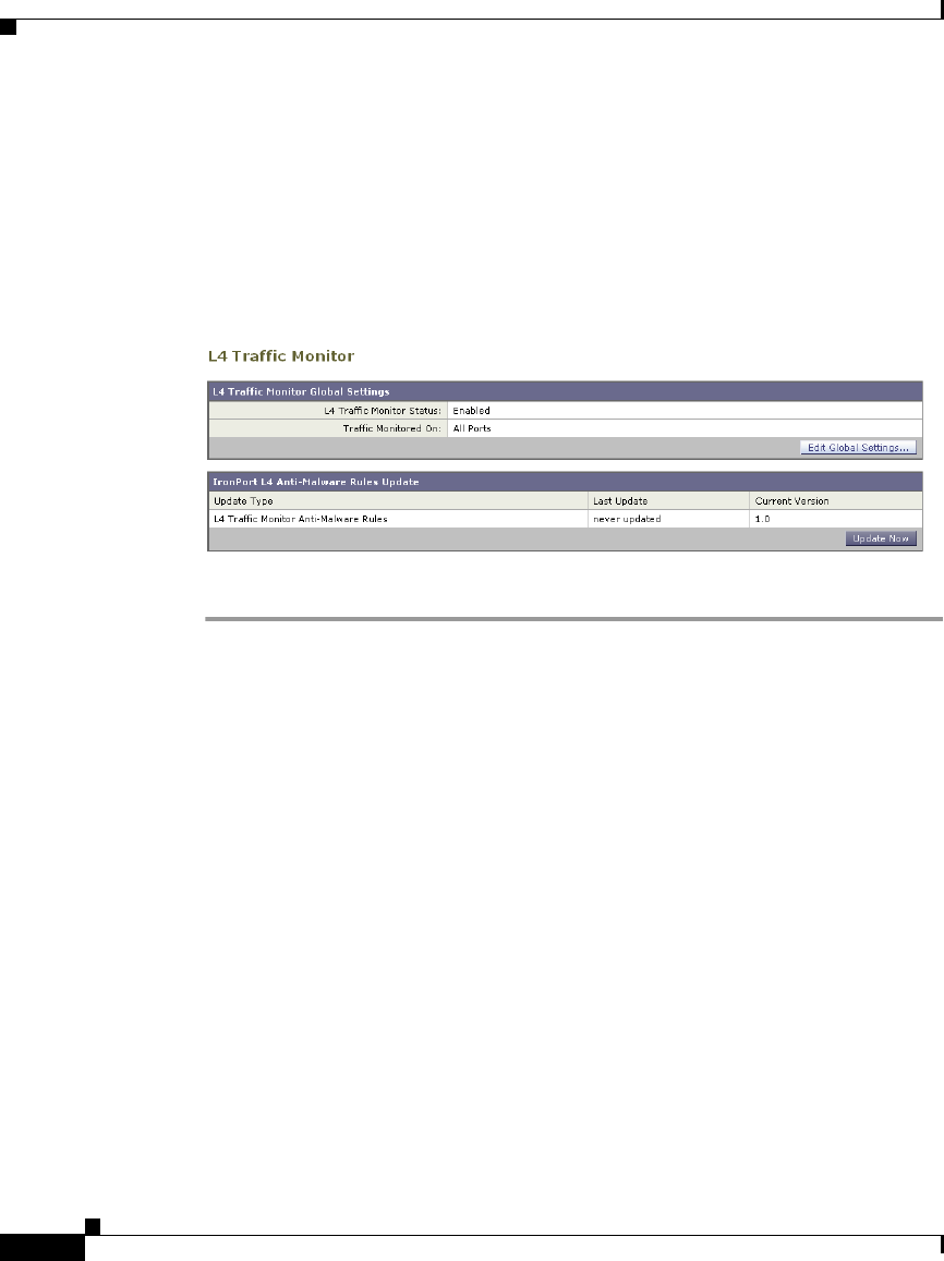
Chapter 21 L4 Traffic Monitor
Configuring the L4 Traffic Monitor
21-4
Cisco IronPort AsyncOS 7.1 for Web User Guide
OL-23207-01
Configuring L4 Traffic Monitor Global Settings
On the Security Services > L4 Traffic Monitor page, you can configure the L4
Traffic Monitor global settings and update the L4 Traffic Monitor anti-malware
rules.
Figure 21-1 Security Services > L4 Traffic Monitor Page
To configure L4 Traffic Monitor global settings:
Step 1 Navigate to the Security Services > L4 Traffic Monitor page.
Step 2 Click Edit Global Settings.
Step 3 Choose whether or not to enable the L4 Traffic Monitor.
Step 4 When you enable the L4 Traffic Monitor, choose which ports it should monitor:
•All ports. Monitors all 65535 TCP ports for rogue activity.
•All ports except proxy ports. Monitors all TCP ports except the following
ports for rogue activity.
–
Ports configured in the “HTTP Ports to Proxy” property on the Security
Services > Web Proxy page (usually port 80).
–
Ports configured in the “Transparent HTTPS Ports to Proxy” property on
the Security Services > HTTPS Proxy page (usually port 443).
Step 5 Submit and commit the changes.
Updating L4 Traffic Monitor Anti-Malware Rules
To update the L4 Traffic Monitor anti-malware rules:

21-5
Cisco IronPort AsyncOS 7.1 for Web User Guide
OL-23207-01
Chapter 21 L4 Traffic Monitor
Configuring the L4 Traffic Monitor
Step 1 Navigate to the Security Services > L4 Traffic Monitor page.
Step 2 Click Update Now.
The Web Security appliance contacts the component update server and
updates the L4 Traffic Monitor anti-malware rules. For more information
about the component update server, see Manually Updating Security Service
Components, page 26-51.
Configuring L4 Traffic Monitor Policies
When the L4 Traffic Monitor is enabled, you can configure how it should manage
traffic over the configured TCP ports. It can perform the following actions on
traffic over the TCP ports:
•Allow
•Monitor
•Block
For more information about how the L4 Traffic Monitor handles traffic, see How
the L4 Traffic Monitor Works, page 21-1.
The actions the L4 Traffic Monitor takes depends on the L4 Traffic Monitor
policies you configure.
To configure L4 Traffic Monitor policies:
Step 1 Navigate to the Web Security Manager > L4 Traffic Monitor page.
Step 2 Click Edit Settings.
Step 3 On the Edit L4 Traffic Monitor Policies page, configure the L4 Traffic Monitor
policies described in Table 21-1.

Chapter 21 L4 Traffic Monitor
Configuring the L4 Traffic Monitor
21-6
Cisco IronPort AsyncOS 7.1 for Web User Guide
OL-23207-01
Ta b l e 2 1- 1 L 4 Tr a ff i c M o n i t o r P o l i c i e s
Property Description
Allow List Enter zero or more address to which the L4 Traffic Monitor
should always allow clients to connect.
Separate multiple entries with a space or comma. For a list
of valid address formats you can use, see Va l id Fo r ma ts ,
page 21-8.
Note: Entering a domain name such as example.com also
matches www.example.com and hostname.example.com.
Connections to all destinations in this list are always
allowed and the traffic is not logged. The appliance does
not check the destinations against the L4 Traffic Monitor
anti-malware rules or the additional suspected malware
addresses listed on the same page.
For example, if IP address 10.1.1.1 appears in both the
Allow List and the Additional Suspected Malware
Addresses fields, then the L4 Traffic Monitor always
allows requests for 10.1.1.1.

21-7
Cisco IronPort AsyncOS 7.1 for Web User Guide
OL-23207-01
Chapter 21 L4 Traffic Monitor
Configuring the L4 Traffic Monitor
Actions for
Suspected Malware
Addresses
Choose whether to monitor or block traffic destined for a
known malware address. For a definition of known
malware address, see How the L4 Traffic Monitor Works,
page 21-1.
•Monitor. Scans all traffic for domains and IP
addresses that match entries in the L4 Traffic Monitor
database. The Monitor option does not block
suspicious traffic. This setting is useful for identifying
infected clients without affecting the user experience.
•Block. Scans all traffic for domains and IP addresses
that match entries in the appliance administrative lists
and the block list database and then blocks any traffic
it finds. This setting is useful for identifying infected
clients and stopping malware attempts through
non-standard ports.
When you choose to block suspected malware traffic, you
can also choose whether or not to always block ambiguous
addresses. By default, ambiguous addresses are
monitored.
For a definition of ambiguous address, see How the L4
Traffic Monitor Works, page 21-1.
Ta b l e 2 1- 1 L 4 Tr a ff i c M o n i t o r P o l i c i e s
Property Description

Chapter 21 L4 Traffic Monitor
Configuring the L4 Traffic Monitor
21-8
Cisco IronPort AsyncOS 7.1 for Web User Guide
OL-23207-01
Note If the L4 Traffic Monitor is configured to block, the L4 Traffic Monitor
and the Web Proxy must be configured on the same network. Use the
Network > Routes page to confirm that all clients are accessible on routes
that are configured for data traffic.
Step 4 Submit and commit your changes.
Valid Formats
When you add addresses to the Allow List or Additional Suspected Malware
Addresses properties, separate multiple entries with whitespace or commas. You
can enter addresses in any of the following formats:
Additional
Suspected Malware
Addresses
(optional)
Enter zero or more known addresses that the L4 Traffic
Monitor should consider as a possible malware. For a list
of valid address formats you can use, see Va l id Fo r ma ts ,
page 21-8.
If you choose to block suspected malware addresses, the
L4 Traffic Monitor will either block or monitor these
addresses depending on whether it determines them to be
known malware addresses or ambiguous addresses. For
definitions of ambiguous and known malware addresses,
see How the L4 Traffic Monitor Works, page 21-1.
If you choose to monitor suspected malware addresses, it
will monitor these addresses.
Note: Adding internal IP addresses to the Additional
Suspected Malware Addresses list causes legitimate
destination URLs to show up as malware in L4 Traffic
Monitor reports. To avoid this type of erroneous reporting,
do not enter internal IP addresses in the “Additional
Suspected Malware Addresses” field on the Web Security
Manager > L4 Traffic Monitor Policies page.
Ta b l e 2 1- 1 L 4 Tr a ff i c M o n i t o r P o l i c i e s
Property Description

21-9
Cisco IronPort AsyncOS 7.1 for Web User Guide
OL-23207-01
Chapter 21 L4 Traffic Monitor
Viewing L4 Traffic Monitor Activity
•IP address. For example, 10.1.1.0.
•CIDR address. For example, 10.1.1.0/24.
•Domain name. For example, example.com. Entering a domain name such as
example.com will also match www.example.com and
hostname.example.com.
•Hostname. For example, crm.example.com.
Viewing L4 Traffic Monitor Activity
The S-Series appliance supports several options for generating feature specific
reports and interactive displays of summary statistics.
Monitoring Activity and Viewing Summary Statistics
The Reporting > L4 Traffic Monitor page provides statistical summaries of
monitoring activity. You can interactively update these displays by specifying a
time range of hour, day, week or month. Additionally, you have the option to print
these display pages and export the raw data to a file.
You can use the following displays and reporting tools to view the results of L4
Traffic Monitor activity:
Table 21-2 L4 Traffic Monitor Scanning Data
To view... See...
Client statistics Reporting > Client Activity
Malware statistics
Port statistics
Reporting > L4 Traffic Monitor
L4 Traffic Monitor log files System Administration > Log Subscriptions
•trafmon_errlogs
•trafmonlogs

Chapter 21 L4 Traffic Monitor
Viewing L4 Traffic Monitor Activity
21-10
Cisco IronPort AsyncOS 7.1 for Web User Guide
OL-23207-01
Note If the Web Proxy is configured as a forward proxy and L4 Traffic Monitor is set
to monitor all ports, the IP address of the proxy’s data port is recorded and
displayed as a client IP address in the client activity report on the Reporting >
Client Activity page. If the Web Proxy is configured as a transparent proxy, enable
IP spoofing to correctly record and display the client IP addresses.
L4 Traffic Monitor Log File Entries
The L4 Traffic Monitor log file provides a detailed record of monitoring activity.
For more information about the L4 Traffic Monitor log, see Traffic Monitor Log,
page 24-53.

CHAPTER
22-1
Cisco IronPort AsyncOS 7.1 for Web User Guide
OL-23207-01
22
Reporting
This chapter contains the following information:
•Reporting Overview, page 22-1
•Using the Reporting Tab, page 22-3
•Enabling Centralized Reporting, page 22-12
•Scheduling Reports, page 22-13
•On-Demand Reports, page 22-15
•Archiving Reports, page 22-16
•SNMP Monitoring, page 22-16
Reporting Overview
Reporting functionality aggregates information from individual security features
and records data that can be used to monitor your web traffic patterns and security
risks. You can run reports in real-time to view an interactive display of system
activity over a specific period of time, or you can schedule reports and run them
at regular intervals.
The Web Security appliance not only generates high-level reports, allowing you
to understand what is happening on the network, but it also allows you to drill
down and see traffic details for a particular domain, user, or category.
Reporting functionality also allows you to export raw data to a file. For more
information see, Printing and Exporting Reports from Report Pages, page 22-10.
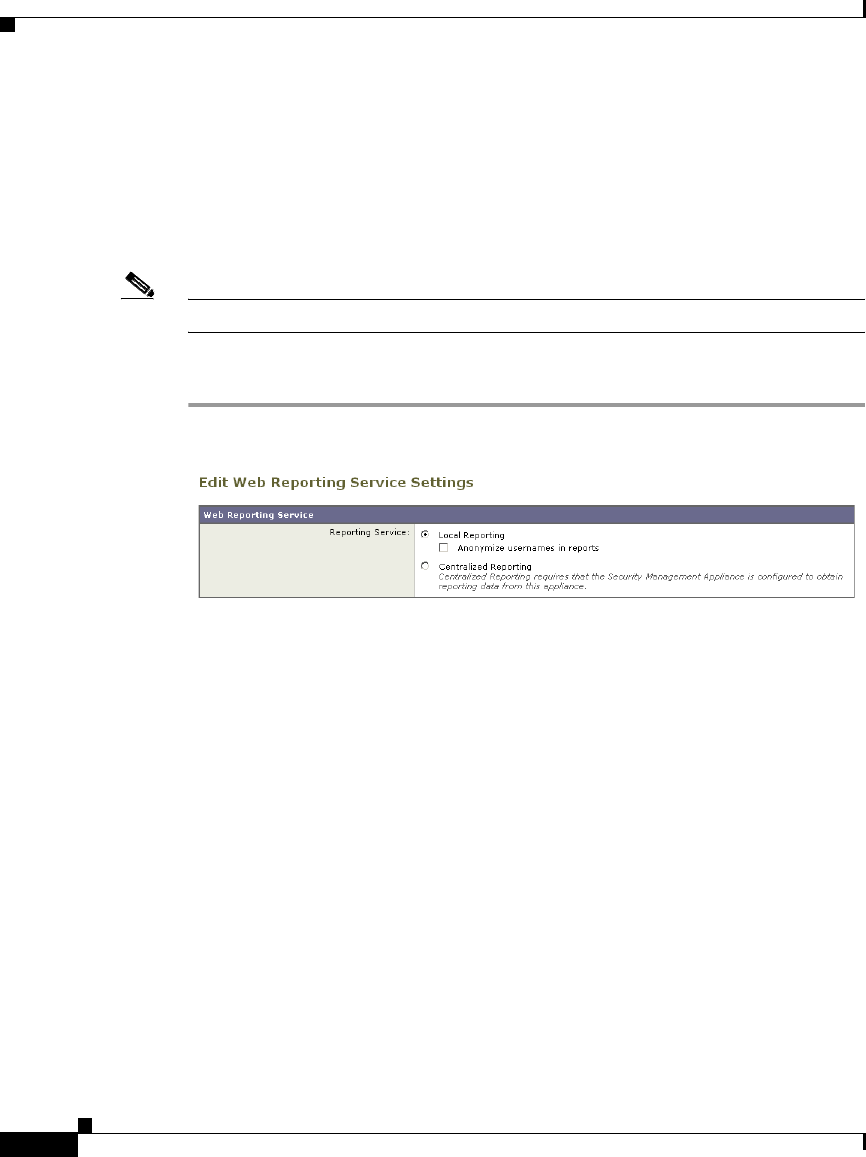
Chapter 22 Reporting
Reporting Overview
22-2
Cisco IronPort AsyncOS 7.1 for Web User Guide
OL-23207-01
Working with Usernames in Reports
When you enable authentication, reports list users by their usernames when they
authenticate with the Web Proxy. By default, usernames are written as they appear
in the authentication server, such as jsmith. However, you can choose to make
usernames unrecognizable in all reports.
Note Administrators always see usernames in reports.
To make usernames unrecognizable in reports:
Step 1 Navigate to the Security Services > Reporting page, and click Edit Settings.
Step 2 Under Local Reporting, select Anonymize usernames in reports.
Step 3 Submit and commit your changes.
Report Pages
The Web Security appliance offers the following reports:
•Overview
•Users
•Web Sites
•URL Categories
•Application Visibility
•Anti-Malware
•Client Malware Risk
•Web Reputation Filters

22-3
Cisco IronPort AsyncOS 7.1 for Web User Guide
OL-23207-01
Chapter 22 Reporting
Using the Reporting Tab
•L4 Traffic Monitor
•Reports by User Location
•Web Tracking
•System Capacity
•System Status
For detailed descriptions of each of these reports, see Web Security Appliance
Reports, page 23-1.
Using the Reporting Tab
The Reporting tab provides several options for viewing system data. This section
describes those options and explains the information displayed on each report
page.
The report pages provide a colorful overview of system activity and support
multiple options for viewing system data. For example, you can update and sort
data to provide real-time visibility into resource utilization and web traffic
activity. You can also search each page for website and client-specific data.
You can perform the following tasks on most reports on the Reporting tab:
•Change the time range displayed in a report. For more information, see
Changing the Time Range, page 22-3.
•Search for specific clients and domains. For more information, see
Searching Data, page 22-5.
•Choose and sort columns. For more information, see Working with Columns
on Report Pages, page 22-5.
•Export reports to external files. For more information, see Printing and
Exporting Reports from Report Pages, page 22-10.
Changing the Time Range
You can update the data displayed for each security component using the Time
Range field. This option allows you to generate updates for predefined time
ranges, such as the last hour or week, and it allows you to define custom time
ranges from a specific start time to a specific end time.
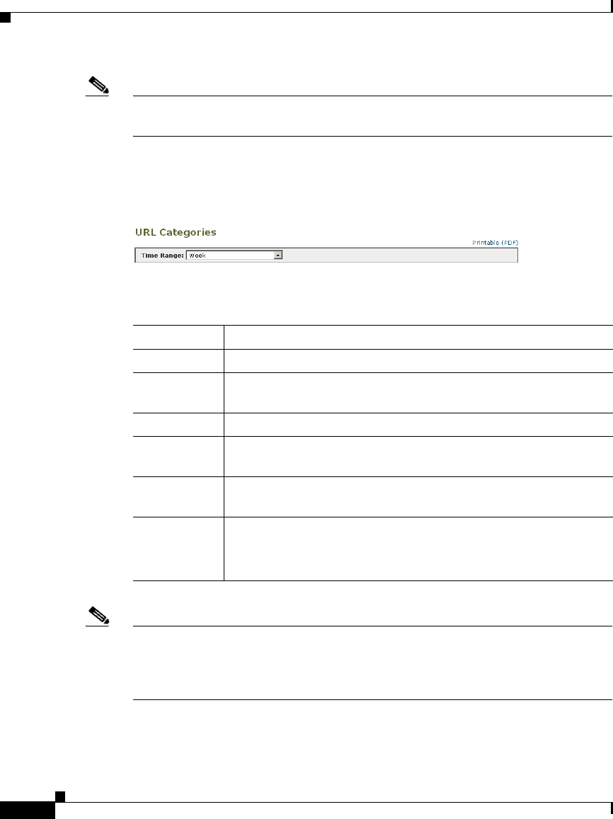
Chapter 22 Reporting
Using the Reporting Tab
22-4
Cisco IronPort AsyncOS 7.1 for Web User Guide
OL-23207-01
Note The time range you select is used throughout all of the report pages until you
select a different value in the Time Range menu.
Figure 22-1 shows the Time Range field for the URL Categories report.
Figure 22-1 Selecting Data Time Range
You can choose any of the time ranges described in Table 22-1.
Note All reports display date and time information based on the systems configured
time zone, shown as a Greenwich Mean Time (GMT) offset. However, data
exports display the time in GMT to accommodate multiple systems in multiple
time zones around the world.
Table 22-1 Configurable Time Ranges
Time Range Data is returned in...
Hour Sixty (60) complete minutes plus up to 5 additional minutes.
Day One hour intervals for the last 24 hours and including the current
partial hour.
Week One day intervals for the last 7 days plus the current partial day.
Month (30
days)
One day intervals for the last 30 days plus the current partial day.
Yesterday The last 24 hours (00:00 to 23:59) using the Web Security
appliance defined time zone.
Custom
Range
The custom time range defined by the user.
When you choose Custom Range, a dialog box appears where
you can enter the start and end times.
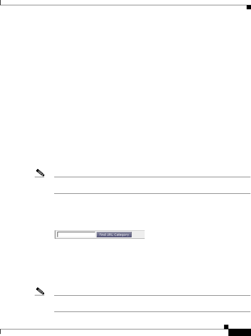
22-5
Cisco IronPort AsyncOS 7.1 for Web User Guide
OL-23207-01
Chapter 22 Reporting
Using the Reporting Tab
Searching Data
Some reports include a field that allow you to search for a particular data points.
For example, on the URL Categories report, you can search for a particular URL
category, and on the Users report, you can search for a particular user by user
name or IP address. When you search for data, the report refines the report data
for the particular data set you are searching.
You can search for values that exactly match of the string you enter, or for values
that start with the string you enter.
The following report pages include search fields:
•Users. Search for a user by user name or client IP address.
•Web Sites. Search for a server by domain or server IP address.
•URL Categories. Search for a URL category.
•Application Visibility. Search for an application name that the AVC engine
monitors and blocks.
•Client Malware Risk. Search for a user by user name or client IP address.
Note You need to configure authentication to view client user IDs as well as client IP
addresses.
Figure 22-2 shows the search field for the URL Categories report.
Figure 22-2 Searching for URL Categories
Working with Columns on Report Pages
Each page has interactive column headings that can be configured to sort the data
in each column specific to your needs for viewing data on that page.
Note Not every column is available for every report page. Click the Columns link for
each report page to view the available columns.

Chapter 22 Reporting
Using the Reporting Tab
22-6
Cisco IronPort AsyncOS 7.1 for Web User Guide
OL-23207-01
Table 22-2 describes the columns available when working with reports.
Table 22-2 Report Column Descriptions
Column Name Description
Domain or Realm The domain or realm of the user displayed in text
format.
User ID or Client IP The username or client IP address of the user
displayed in text format.
Bandwidth Used The amount of bandwidth that is used by a particular
user or action. Bandwidth units are displayed in
Bytes or percentage.
Bandwidth Saved by
Blocking
The amount of bandwidth that has been saved due to
blocking certain transactions. Bandwidth units are
displayed in Bytes

22-7
Cisco IronPort AsyncOS 7.1 for Web User Guide
OL-23207-01
Chapter 22 Reporting
Using the Reporting Tab
Time Spent The amount of time spent on a web page. For
purposes of investigating a user, the time spent by the
user on each URL category. When tracking a URL,
the time spent by each user on that specific URL.
To calculate the time spent, AsyncOS assigns each
active user with 60 seconds of time for activity during
a minute. At the end of the minute, the time spent by
each user is evenly distributed among the different
domains the user visited. For example, if a user goes
to four different domains in an active minute, the user
is considered to have spent 15 seconds at each
domain.
For the purposes of the time spent value, considering
the following notes:
•An active user is defined as a username or IP
address that sends HTTP traffic through the
appliance and has gone to a website that
AsyncOS considers to be a “page view.”
•AsyncOS defines a page view as an HTTP
request initiated by the user, as opposed to a
request initiated by the client application.
AsyncOS uses a heuristic algorithm to make a
best effort guess to identify user page views.
Units displayed in HH:MM format.
Allowed URL Category The number and type of categories that have been
allowed. Units displayed in transaction type.
Monitored URL
Category
The number and type of categories that are being
monitored. Units displayed in transaction type.
Warned URL Category The number and type of categories that have initiated
a warning. Units displayed in transaction type.
Blocked by URL
Category
The transaction that has been blocked due to URL
Category. Units displayed in transaction type.
Table 22-2 Report Column Descriptions (continued)
Column Name Description

Chapter 22 Reporting
Using the Reporting Tab
22-8
Cisco IronPort AsyncOS 7.1 for Web User Guide
OL-23207-01
Configuring Columns on Report Pages
To configure the columns that appear in a report, perform the following steps:
Step 1 On the Security Management appliance page, choose Reporting > Report_Name.
Step 2 Click the Columns link that appears in the lower right corner of a report.
For example, Figure 22-3 shows the Columns link for the URL Categories report.
Blocked by Application
or Application Type
The application that has been blocked due to
application type. Units displayed in transaction type.
Blocked by Web
Reputation
The transaction that has been blocked due to web
reputation. Units displayed in transaction type.
Blocked by
Anti-Malware
The transactions blocked by Anti-Malware. Units
displayed in transaction type.
Other Blocked
Transactions
All other transactions that have been blocked. Units
displayed in transaction type.
Transactions with
Bandwidth Limit
The number of transactions that have a bandwidth
limit.
Transactions without
Bandwidth Limit
The number of transactions that do not have a
bandwidth limit.
Transactions Blocked by
Application
The number of transactions blocked by a specific
application type.
Warned Transactions All transactions that rendered a warning to the user.
Units displayed in transaction type.
Transactions Completed The transactions completed by a user. Units displayed
in transaction type.
Transactions Blocked All transactions that have been blocked. Units
displayed in transaction type.
Total Transactions The total number of transactions that have occurred.
Table 22-2 Report Column Descriptions (continued)
Column Name Description
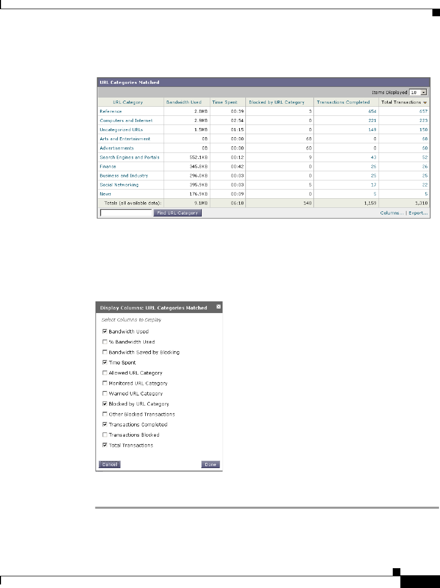
22-9
Cisco IronPort AsyncOS 7.1 for Web User Guide
OL-23207-01
Chapter 22 Reporting
Using the Reporting Tab
Figure 22-3 Columns Link, URL Categories Report
A pop-up window appears that allows you to select the columns you want to
appear in the report. For example, Figure 22-4 shows the columns you can select
for the URL Categories report.
Figure 22-4 Displaying Columns, URL Categories Report
Step 3 Select each column to display by clicking the checkbox next to each column in
the pop-up window, and click Done.

Chapter 22 Reporting
Using the Reporting Tab
22-10
Cisco IronPort AsyncOS 7.1 for Web User Guide
OL-23207-01
Printing and Exporting Reports from Report Pages
You can generate a printer-friendly formatted PDF version of any of the report
pages by clicking the Printable (PDF) link at the top-right corner of the page.
Additionally, you can export graphs and other data to comma-separated values
(CSV) format by clicking the Export link. Most reports allow scheduling of CSV
formatting. However, you cannot schedule an extended report with a CSV format.
Note You can only print to PDF and export data from the Web Tracking page after the
Web Tracking page returns search results. Do this using the Printable Download
link. From this link you can choose to create a PDF that includes data displayed
on the current page or up to 1,000 transactions, or you can export all data to a CSV
file.
Exporting Report Data
Most reports include an Export link that allows you to export raw data to a
comma-separated values (CSV) file. After exporting the data to a CSV file, you
can access and manipulate the data in it using applications such as Microsoft
Excel.
The exported CSV data displays all message tracking and reporting data in
Greenwich Mean Time (GMT) regardless of what is set on the Web Security
appliance. The purpose of the GMT time conversion is to allow data to be used
independently from the appliance or when referencing data from appliances in
multiple time zones.
The following example is an entry from a raw data export of the Anti-Malware
category report, where Pacific Daylight Time (PDT) is displayed as GMT - 7
hours:
Begin Timestamp, End Timestamp, Begin Date, End Date, Name,
Transactions Monitored, Transactions Blocked, Transactions Detected

22-11
Cisco IronPort AsyncOS 7.1 for Web User Guide
OL-23207-01
Chapter 22 Reporting
Using the Reporting Tab
1159772400.0, 1159858799.0, 2006-10-02 07:00 GMT, 2006-10-03 06:59
GMT, Adware, 525, 2100, 2625
Note Category headers are different for each type of report.
Note If you export localized CSV data, the headings may not be rendered properly in
some browsers. This occurs because some browsers may not use the proper
character set for the localized text. To work around this problem, you can save the
file to your local machine, and open the file in any web browser using File >
Open. When you open the file, select the character set to display the localized
text.
Table 22-3 Viewing Raw Data Entries
Category Header Value Description
Begin Timestamp 1159772400.0 Query start time in number of
seconds from epoch.
End Timestamp 1159858799.0 Query end time in number of
seconds from epoch.
Begin Date 2006-10-02 07:00
GMT
Date the query began.
End Date 2006-10-03 06:59
GMT
Date the query ended.
Name Adware Name of the malware category.
Transactions
Monitored
525 Number of transactions monitored.
Transactions
Blocked
2100 Number of transactions blocked.
Transactions
Detected
2625 Total number of transactions:
Number of transactions detected +
Number of transactions blocked.
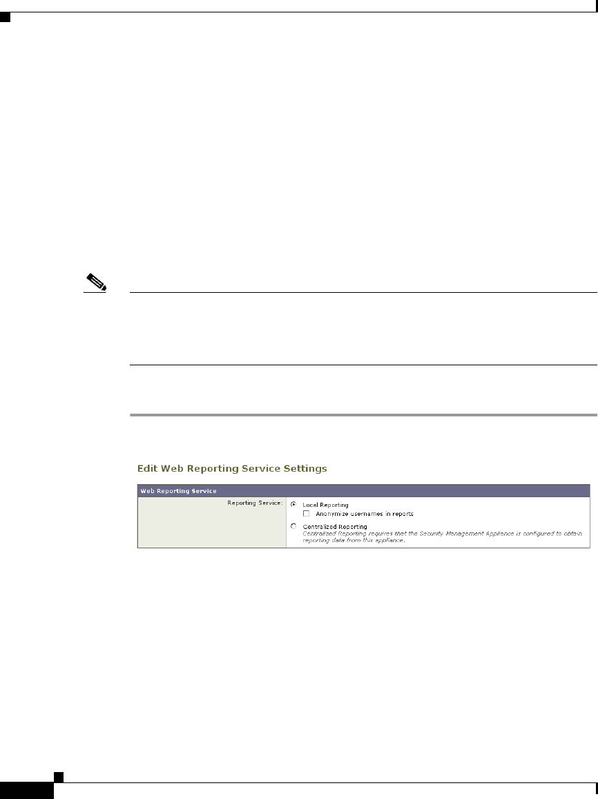
Chapter 22 Reporting
Enabling Centralized Reporting
22-12
Cisco IronPort AsyncOS 7.1 for Web User Guide
OL-23207-01
Enabling Centralized Reporting
When the Web Security appliance is managed by a Security Management
appliance, you can choose which appliance displays reports on the web traffic that
is processed by the Web Security appliance. By default, the Web Security
appliance maintains the reports (Local Reporting). However, you can configure
the Web Security appliance so that the Security Management appliance maintains
the reports by enabling Centralized Reporting. You might want to enable
Centralized Reporting when the Security Management appliance manages
multiple Web Security appliances. This gives you a centralized view of web traffic
across all Web Security appliances.
Note When you enable Centralized Reporting, only the System Capacity and System
Status reports are available on the Web Security appliance. To view the other
reports, connect to the Security Management appliance. The Web Security
appliance no longer stores data for the other reports.
To enable Centralized Reporting:
Step 1 Navigate to the Security Services > Reporting page, and click Edit Settings.
Step 2 Choose Centralized Reporting.
Step 3 Submit and commit your changes.

22-13
Cisco IronPort AsyncOS 7.1 for Web User Guide
OL-23207-01
Chapter 22 Reporting
Scheduling Reports
Scheduling Reports
You can schedule reports to run on a daily, weekly, or monthly basis. Scheduled
reports can be configured to include data for the previous day, previous seven
days, or previous month. Alternatively, you can include data for a custom number
of days (from 2 days to 100 days) or a custom number of months (from 2 months
to 12 months).
Regardless of when you run a report, the data is returned from the previous time
interval (hour, day, week, or month). For example, if you schedule a daily report
to run at 1AM, the report will contain data from the previous day, midnight to
midnight (00:00 to 23:59).
You can schedule reports for the following types of reports:
•Overview
•Users
•Web Sites
•URL Categories
•Application Visibility
•Anti-Malware
•Client Malware Risk
•Web Reputation Filters
•L4 Traffic Monitor
•Reports by User Location
•System Capacity
For more information on the data displayed in each report, see Web Security
Appliance Reports, page 23-1.
Adding a Scheduled Report
Use the Reporting > Scheduled Reports page to schedule reporting for different
reports.
To create a scheduled report:
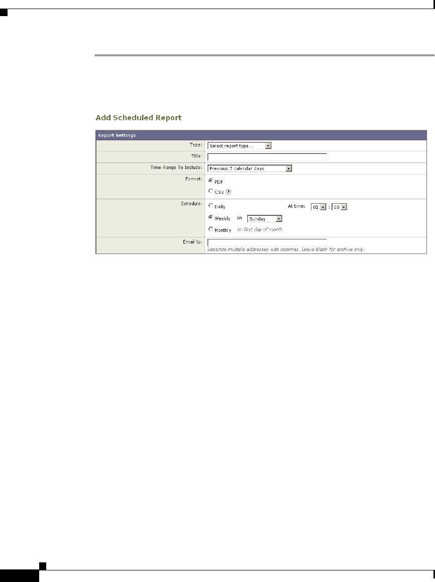
Chapter 22 Reporting
Scheduling Reports
22-14
Cisco IronPort AsyncOS 7.1 for Web User Guide
OL-23207-01
Step 1 Navigate to the Reporting > Scheduled Reports page, and click Add Scheduled
Report.
Figure 22-5 Adding a Scheduled Report
Step 2 Select a report type.
Step 3 Enter a title for the report. To avoid creating multiple reports with the same name,
consider using a descriptive title.
Step 4 Select a time range for the data included in the report.
Step 5 Choose the format for the generated report.
The default format is PDF. Most reports allow scheduling of CSV.
Step 6 Depending on the type of report you configure, you can specify different report
options, such as the number of rows to include and by which column to sort the
data. Configure these options as necessary.
Step 7 In the Schedule section, choose whether to run the report daily, weekly, or
monthly and at what time.
Step 8 In the Email field, enter the email address to where to send the generated report.
If you do not specify an email address, the report is archived only.
Step 9 Submit and commit your changes.

22-15
Cisco IronPort AsyncOS 7.1 for Web User Guide
OL-23207-01
Chapter 22 Reporting
On-Demand Reports
Editing Scheduled Reports
To edit reports, select the report title from the list on the Reporting > Scheduled
Reports page, modify settings then submit and commit your changes.
Deleting Scheduled Reports
To delete reports, go to the Reporting > Scheduled Reports page and select the
check boxes corresponding to the reports that you want to delete. To remove all
scheduled reports, select the All check box, Delete and Commit your changes.
Note that archived versions of deleted reports are not deleted.
On-Demand Reports
The Generate Report Now option on the Reporting > Archived Reports page
allows you to generate on-demand data displays for each report type. To generate
a report:
Step 1 Select Generate Report Now
Figure 22-6 Generating an On-Demand Report
Step 2 Select a report type and edit the title, if necessary. To avoid creating multiple
reports with the same name, consider using a descriptive title.
Step 3 Select a time range for the data included in the report.

Chapter 22 Reporting
Archiving Reports
22-16
Cisco IronPort AsyncOS 7.1 for Web User Guide
OL-23207-01
Step 4 Choose the format for the generated report.
The default format is PDF. Most reports allow scheduling of CSV.
Step 5 Depending on the type of report you configure, you can specify different report
options, such as the number of rows to include and by which column to sort the
data. Configure these options as necessary.
Step 6 Select whether to archive the report (if so, the report will appear on the Archived
Reports page).
Step 7 Specify whether to email the report, and list the email addresses of the recipients.
Step 8 Click Deliver this Report to generate the report.
Step 9 Commit your changes.
Archiving Reports
The Reporting > Archived Reports page lists available archived reports. Report
names in the Report Title column are interactive and link to a view of each report.
The Show menu filters the types of reports that are listed. Additionally, interactive
column headings can be used to sort the data in each column.
The appliance stores up to 12 instances of each scheduled report (up to 1000
reports). Archived reports are stored in the /periodic_reports directory on the
appliance. Archived reports are deleted automatically. As new reports are added,
older reports are removed to keep the number at 1000. The limit of 12 instances
applies to each scheduled report with the same name and time range.
SNMP Monitoring
The IronPort AsyncOS operating system supports system status monitoring via
SNMP (Simple Network Management Protocol). This includes IronPort’s
Enterprise MIB, asyncoswebsecurityappliance-mib.txt. The
asyncoswebsecurityappliance-mib helps administrators better monitor system
health. In addition, this release implements a read-only subset of MIB-II as
defined in RFCs 1213 and 1907. (For more information about SNMP, see RFCs
1065, 1066, and 1067.) Please note:
•SNMP is off by default.

22-17
Cisco IronPort AsyncOS 7.1 for Web User Guide
OL-23207-01
Chapter 22 Reporting
SNMP Monitoring
•SNMP SET operations (configuration) are not implemented.
•AsyncOS supports SNMPv1, v2, and v3.
•The use of SNMPv3 with password authentication and DES Encryption is
mandatory to enable this service. (For more information on SNMPv3, see
RFCs 2571-2575.) You are required to set a SNMPv3 passphrase of at least 8
characters to enable SNMP system status monitoring. The first time you enter
a SNMPv3 passphrase, you must re-enter it to confirm. The snmpconfig
command “remembers” this phrase the next time you run the command.
•The SNMPv3 username is: v3get.
•If you use only SNMPv1 or SNMPv2, you must set a community string. The
community string does not default to public.
•For SNMPv1 and SNMPv2, you must specify a network from which SNMP
GET requests are accepted.
•To use traps, an SNMP manager (not included in AsyncOS) must be running
and its IP address entered as the trap target. (You can use a hostname, but if
you do, traps will only work if DNS is working.)
Use the snmpconfig command to configure SNMP system status for the
appliance. After you choose and configure values for an interface, the appliance
responds to SNMPv3 GET requests. These version 3 requests must include a
matching password. By default, version 1 and 2 requests are rejected. If enabled,
version 1 and 2 requests must have a matching community string.
MIB Files
IronPort Systems provides “enterprise” MIBs for Email and Web Security
appliances as well as a “Structure of Management Information” (SMI) file:
•asyncoswebsecurityappliance-mib.txt — an SNMPv2 compatible description
of the Enterprise MIB for IronPort Web Security appliances.
•ASYNCOS-MAIL-MIB.txt — an SNMPv2 compatible description of the
Enterprise MIB for IronPort Email Security appliances.
> snmpwalk -v 3 -l AuthNoPriv -u v3get -a MD5 ironport
serv.example.com

Chapter 22 Reporting
SNMP Monitoring
22-18
Cisco IronPort AsyncOS 7.1 for Web User Guide
OL-23207-01
•IRONPORT-SMI.txt — defines the role of the
asyncoswebsecurityappliance-mib in IronPort’s SNMP managed products.
These files are available on the documentation CD included with your IronPort
appliance. You can also find these files on the Cisco IronPort Customer Support
site.
Hardware Objects
Hardware sensors conforming to the Intelligent Platform Management Interface
Specification (IPMI) report temperature, fan speed, and power supply status.
Table 22-4 shows what hardware derived objects are available for monitoring on
what models. The number displayed is the number of instances of that object that
can be monitored. For example, you can query the RPMs for 4 fans in the S350
appliance.
Hardware Traps
Table 22-5 lists the temperature and hardware conditions that cause a hardware
trap to be sent:
Table 22-4 Number of Hardware Objects per IronPort Appliance
Model Ambient Temp Fans Power Supply Disk Status NIC Link
S160 121 26
S350 142 66
S360 142 46
S650 142 66
S660 142 66
Table 22-5 Hardware Traps: Temperature and Hardware Conditions
Model
High Temp
(Ambient) Fan Failure Power Supply RAID Link
S160/S350/
S360/S650/
S660
47C 0 RPMs Status Change Status
Change
Status
Change

22-19
Cisco IronPort AsyncOS 7.1 for Web User Guide
OL-23207-01
Chapter 22 Reporting
SNMP Monitoring
Status change traps are sent when the status changes. Fan Failure and high
temperature traps are sent every 5 seconds. The other traps are failure condition
alarm traps — they are sent once when the state changes (healthy to failure). It is
a good idea to poll for the hardware status tables and identify possible hardware
failures before they become critical. Temperatures within 10 per cent of the
critical value may be a cause for concern.
Note that failure condition alarm traps represent a critical failure of the individual
component, but may not cause a total system failure. For example, a single fan or
power supply can fail on a S650 appliance and the appliance will continue to
operate.
SNMP Traps
SNMP provides the ability to send traps, or notifications, to advise an
administration application (an SNMP management console, typically) when one
or more conditions have been met. Traps are network packets that contain data
relating to a component of the system sending the trap. Traps are generated when
a condition has been met on the SNMP agent (in this case, the IronPort appliance).
After the condition has been met, the SNMP agent then forms an SNMP packet
and sends it over port 162, the standard SNMP trap port. In the example below,
the trap target of 10.1.1.29 and the Trap Community string are entered. This is
the host running the SNMP management console software that will receive the
SNMP traps from the IronPort appliance.
You can configure SNMP traps (enable or disable specific traps) when you enable
SNMP for an interface. To specify multiple trap targets: when prompted for the
trap target, you may enter up to 10 comma separated IP addresses.

Chapter 22 Reporting
SNMP Monitoring
22-20
Cisco IronPort AsyncOS 7.1 for Web User Guide
OL-23207-01
CLI Example
In the following example, the snmpconfig command is used to enable SNMP on
the “PublicNet” interface on port 161. A passphrase for version 3 is entered and
then re-entered for confirmation. The system is configured to service version 1
and 2 requests, and the community string public is entered for GET requests from
those versions 1 and 2. The trap target of 10.1.1.29 is entered. Finally, system
location and contact information is entered.
example.com> snmpconfig
Current SNMP settings:
SNMP Disabled.
Choose the operation you want to perform:
- SETUP - Configure SNMP.
[]> setup
Do you want to enable SNMP? [N]> y
Please choose an IP interface for SNMP requests.
1. Management (192.168.1.1/24: wsa01-vmw1-tpub.qa)
[1]>
Enter the SNMPv3 passphrase.
>
Please enter the SNMPv3 passphrase again to confirm.

22-21
Cisco IronPort AsyncOS 7.1 for Web User Guide
OL-23207-01
Chapter 22 Reporting
SNMP Monitoring
>
Which port shall the SNMP daemon listen on?
[161]>
Service SNMP V1/V2c requests? [N]> y
Enter the SNMP V1/V2c community string.
[]> public
From which network shall SNMP V1/V2c requests be allowed?
[192.168.1.1]>
Enter the Trap target as a host name, IP address or list of IP
addresses separated by commas (IP address preferred). Enter “None” to
disable traps.
[None]> 10.1.1.29
Enter the Trap Community string.
[]> tcomm
Enterprise Trap Status
1. CPUUtilizationExceeded Disabled
2. RAIDStatusChange Enabled

Chapter 22 Reporting
SNMP Monitoring
22-22
Cisco IronPort AsyncOS 7.1 for Web User Guide
OL-23207-01
3. connectivityFailure Disabled
4. fanFailure Enabled
5. highTemperature Enabled
6. keyExpiration Enabled
7. linkDown Enabled
8. linkUp Enabled
9. memoryUtilizationExceeded Disabled
10. powerSupplyStatusChange Enabled
11. resourceConservationMode Enabled
12. updateFailure Enabled
13. upstream_proxy_failure Enabled
Do you want to change any of these settings? [N]> y
Do you want to disable any of these traps? [Y]> n
Do you want to enable any of these traps? [Y]> y
Enter number or numbers of traps to enable. Separate multiple numbers
with commas.
[]> 1,3

22-23
Cisco IronPort AsyncOS 7.1 for Web User Guide
OL-23207-01
Chapter 22 Reporting
SNMP Monitoring
What threshold would you like to set for CPU utilization?
[95]>
What URL would you like to check for connectivity failure?
[http://downloads.ironport.com]>
Enterprise Trap Status
1. CPUUtilizationExceeded Enabled
2. RAIDStatusChange Enabled
3. connectivityFailure Enabled
4. fanFailure Enabled
5. highTemperature Enabled
6. keyExpiration Enabled
7. linkDown Enabled
8. linkUp Enabled
9. memoryUtilizationExceeded Disabled
10. powerSupplyStatusChange Enabled
11. resourceConservationMode Enabled
12. updateFailure Enabled
13. upstream_proxy_failure Enabled
Do you want to change any of these settings? [N]>

Chapter 22 Reporting
SNMP Monitoring
22-24
Cisco IronPort AsyncOS 7.1 for Web User Guide
OL-23207-01
Enter the System Location string.
[Unknown: Not Yet Configured]> Network Operations Center - west; rack
#30, position 3
Enter the System Contact string.
[snmp@localhost]> Joe Administrator, x8888
Current SNMP settings:
Listening on interface “Management” 192.168.1.1 port 161.
SNMP v3: Enabled.
SNMP v1/v2: Enabled, accepting requests from subnet 192.168.1.1.
SNMP v1/v2 Community String: public
Trap target: 10.1.1.29
Location: Network Operations Center - west; rack #30, position 3
System Contact: Joe Administrator, x8888
Choose the operation you want to perform:
- SETUP - Configure SNMP.
[]>
example.com>

CHAPTER
23-1
Cisco IronPort AsyncOS 7.1 for Web User Guide
OL-23207-01
23
Web Security Appliance Reports
This chapter contains the following sections:
•Web Security Appliance Reports Overview, page 23-2
•Overview Page, page 23-2
•Users Page, page 23-5
•User Details Page, page 23-7
•Web Sites Page, page 23-10
•URL Categories Page, page 23-12
•Application Visibility Page, page 23-16
•Anti-Malware Page, page 23-18
•Client Malware Risk Page, page 23-22
•Web Reputation Filters Page, page 23-29
•L4 Traffic Monitor Data Page, page 23-31
•Reports by User Location Page, page 23-33
•Web Tracking Page, page 23-35
•System Capacity Page, page 23-40
•System Status Page, page 23-44

Chapter 23 Web Security Appliance Reports
Web Security Appliance Reports Overview
23-2
Cisco IronPort AsyncOS 7.1 for Web User Guide
OL-23207-01
Web Security Appliance Reports Overview
This chapter discusses the report pages available in the Web Security appliance.
For more information on working with reports, such as choosing report columns,
exporting reports to an external file, or scheduling reports, see Reporting,
page 22-1.
This chapter describes the following reports:
•Overview Page, page 23-2
•Users Page, page 23-5
•User Details Page, page 23-7
•Web Sites Page, page 23-10
•URL Categories Page, page 23-12
•Application Visibility Page, page 23-16
•Anti-Malware Page, page 23-18
•Client Malware Risk Page, page 23-22
•Web Reputation Filters Page, page 23-29
•L4 Traffic Monitor Data Page, page 23-31
•Reports by User Location Page, page 23-33
•Web Tracking Page, page 23-35
•System Capacity Page, page 23-40
Overview Page
The Reporting > Overview page provides a synopsis of the activity on your Cisco
IronPort appliances. It includes graphs and summary tables for the incoming and
outgoing messages.
Figure 23-1 shows the Overview page.
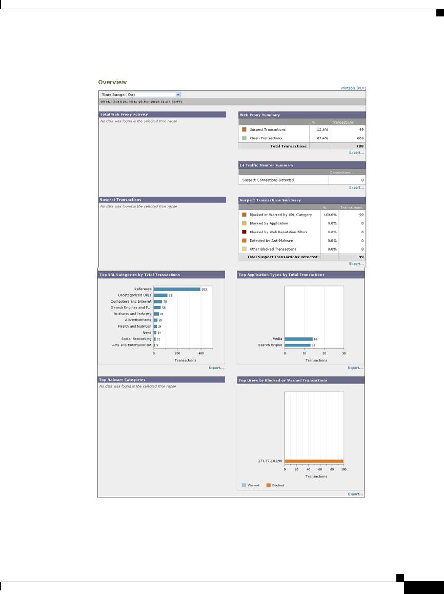
23-3
Cisco IronPort AsyncOS 7.1 for Web User Guide
OL-23207-01
Chapter 23 Web Security Appliance Reports
Overview Page
Figure 23-1 The Overview Page

Chapter 23 Web Security Appliance Reports
Overview Page
23-4
Cisco IronPort AsyncOS 7.1 for Web User Guide
OL-23207-01
At a high level the Overview page shows you statistics about the URL and User
usage, Web Proxy activity, and various transaction summaries. The transaction
summaries gives you further trending details on, for example suspect transactions,
and right across from this graph, how many of those suspect transactions are
blocked and in what manner they are being blocked.
The lower half of the Overview page is about usage. That is, the top URL
categories being viewed, the top application types and categories that are being
blocked, and the top users that are generating these blocks or warnings.
Table 23-1 describes the information on the Overview page.
Table 23-1 Overview Report Page Components
Section Description
Time Range (drop-down list) A menu that allows to choose the time range of the data
contained in the report. For more information, see the
“Changing the Time Range” section on page 22-3.
Total Web Proxy Activity This section displays the Web Proxy activity. This section
displays the actual number of transactions (vertical scale) as
well as the approximate date that the activity occurred
(horizontal timeline).
Web Proxy Summary This section allows you to view the percentage of Web Proxy
activity that are suspect, or clean Web Proxy activity,
including the total number of transactions.
L4 Traffic Monitor Summary This section reports on traffic monitored and blocked by the
L4 Traffic Monitor.
Suspect Transactions This section allows you to view the web transactions that have
been labeled as suspect by the various security components.
This section displays the actual number of transactions
(vertical scale) as well as the approximate date that the
activity occurred (horizontal timeline).
Suspect Transactions Summary This section allows you to view the percentage of blocked or
warned transactions that are suspect. Additionally, you can
see the type of transactions that have been detected and
blocked, and the actual number of times that this transaction
was blocked.

23-5
Cisco IronPort AsyncOS 7.1 for Web User Guide
OL-23207-01
Chapter 23 Web Security Appliance Reports
Users Page
Users Page
The Reporting > Users page provides several links that allows you to view web
traffic information for individual users. You can view how much time users on the
network have spent on the Internet or on a particular website or URL, and how
much bandwidth users have used.
Figure 23-2 shows the Users page.
Top URL Categories by Total Transactions This section displays the top 10 URL categories that have
been blocked. (URL category on the vertical scale by the
number of times requests in that category were blocked on the
horizontal scale.)
Top Application Types by Total Transactions This section displays the top application types that have been
blocked by the AVC engine. (The application type on the
vertical scale by the number of times requests for applications
in that type were blocked on the horizontal scale.)
Top Malware Categories Detected This section displays all malware categories that have been
detected.
Top Users Blocked or Warned Transactions This section displays the users that are generating the blocked
or warned transactions. Authenticated users are displayed
username and unauthenticated users are displayed by IP
address.
You can choose to make usernames unrecognizable in reports.
For more information on how to do this, see the “Working
with Usernames in Reports” section on page 22-2.
Table 23-1 Overview Report Page Components (continued)
Section Description

Chapter 23 Web Security Appliance Reports
Users Page
23-6
Cisco IronPort AsyncOS 7.1 for Web User Guide
OL-23207-01
Figure 23-2 The Users Page
Table 23-2 describes the information on the Users page.
Table 23-2 Users Report Page Components
Section Description
Time Range (drop-down list) A menu that allows to choose the time range of the data contained
in the report. For more information, see the “Changing the Time
Range” section on page 22-3.
Top Users by Transactions Blocked This section lists the users (vertical scale) that have the greatest
number of blocked transactions (horizontal scale).
Authenticated users are displayed username and unauthenticated
users are displayed by IP address. You can choose to make
usernames unrecognizable in reports. For more information on
how to do this, see the “Working with Usernames in Reports”
section on page 22-2.

23-7
Cisco IronPort AsyncOS 7.1 for Web User Guide
OL-23207-01
Chapter 23 Web Security Appliance Reports
Users Page
User Details Page
The User Details page displays information about a specific user selected in the
Users Table on the Reporting > Users page.
The User Details page allows you to investigate individual user’s activity on the
network. You might want to view this information if you need to run user-level
investigations and need to find out, for example, what sites users are visiting, what
malware threats they are encountering, what URL categories they are accessing,
and how much time each user spends at these sites.
To display the User Details page for a user, click on the user from the User Table
on the Reporting > Users page and the following page appears:
Top Users by Bandwidth Used This sections displays the users (vertical scale) that are using the
most bandwidth on the system (horizontal scale represented in
gigabyte usage).
Users Table The Users Table lists individual users and displays multiple
statistics on each user. You can sort the table by clicking the
column headers, and choose which columns of data to display.
For more information, see Working with Columns on Report
Pages, page 22-5.
When the section contains more than 10 users, you can use the
Items Displayed menu to configure the number of users to
display.
You can search for data on a specific user in the Find User ID or
Client IP Address field. For more information, see Searching
Data, page 22-5.
You can click on a user in the table to find more specific
information. This information appears on the User Details page.
For more information, see the “User Details Page” section on
page 23-7.
Table 23-2 Users Report Page Components (continued)
Section Description
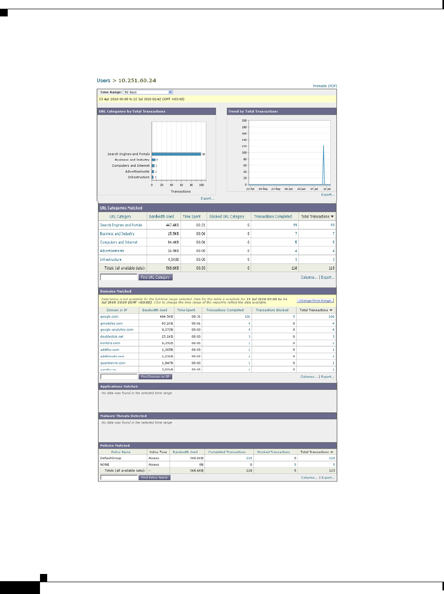
Chapter 23 Web Security Appliance Reports
Users Page
23-8
Cisco IronPort AsyncOS 7.1 for Web User Guide
OL-23207-01
Figure 23-3 User Details Page

23-9
Cisco IronPort AsyncOS 7.1 for Web User Guide
OL-23207-01
Chapter 23 Web Security Appliance Reports
Users Page
Table 23-3 describes the information on the User Details page.
Table 23-3 User > User Details Report Page Components
Section Description
Time Range (drop-down list) A menu that allows to choose the time range of the data contained
in the report. For more information, see the “Changing the Time
Range” section on page 22-3.
URL Categories by Total Transactions This section lists the specific URL categories that a specific user
is using.
Trend by Total Transaction This graph displays at what times the user accessed the web.
For example, this graph will indicate if there is a large spike in
web traffic during certain hours of the day, and when those spikes
occur. Using the Time Range drop-down list, you can expand this
graph to see a more or less granular span of time that this user was
on the web.
URL Categories Matched This section shows all matched URL categories during a
specified time range for both completed and blocked
transactions. You can use column headings to sort data. When the
section contains more than 10 categories, you can use the Items
Displayed menu to configure the number of URL categories to
display.
From this section you can also search for data that applies to a
specific URL category in the Find URL Category field. For
more information, see Searching Data, page 22-5.
Domains Matched From this section you can find out about a specific Domain or IP
address that this user has accessed. You can also see the time
spent on those categories, and various other information that you
have set from the column view. In the text field at the bottom of
the section enter the Domain or IP address and click Find
Domain or IP. The domain or IP address does not need to be an
exact match.

Chapter 23 Web Security Appliance Reports
Web Sites Page
23-10
Cisco IronPort AsyncOS 7.1 for Web User Guide
OL-23207-01
Web Sites Page
The Reporting > Web Sites page is an overall aggregation of the activity that is
happening on the Web Security appliance. From this page you can monitor
high-risk web sites accessed during a specific time range.
Figure 23-4 shows the Web Sites page:
Applications Matched From this section you can find a specific application that a
specific user is using as detected by the AVC engine. For
example, if a user is accessing a site that requires use of a lot of
Flash video, you will see the application type in the Application
column.
In the text field at the bottom of the section enter the application
name and click Find Application. The name of the application
does not need to be an exact match.
Malware Threats Detected From this table you can see the top malware threats that a specific
user is triggering. In the text field at the bottom of the Malware
Threats section, enter the malware threat name and click Find
Malware Threat. The name of the malware threat does not need
to be an exact match.
Policies Matched From this section you can find a specific policy that is being
enforced on this particular user.
From this section you can also search for data that applies to a
specific policy in the Find Policy field. For more information,
see Searching Data, page 22-5.
Table 23-3 User > User Details Report Page Components (continued)
Section Description
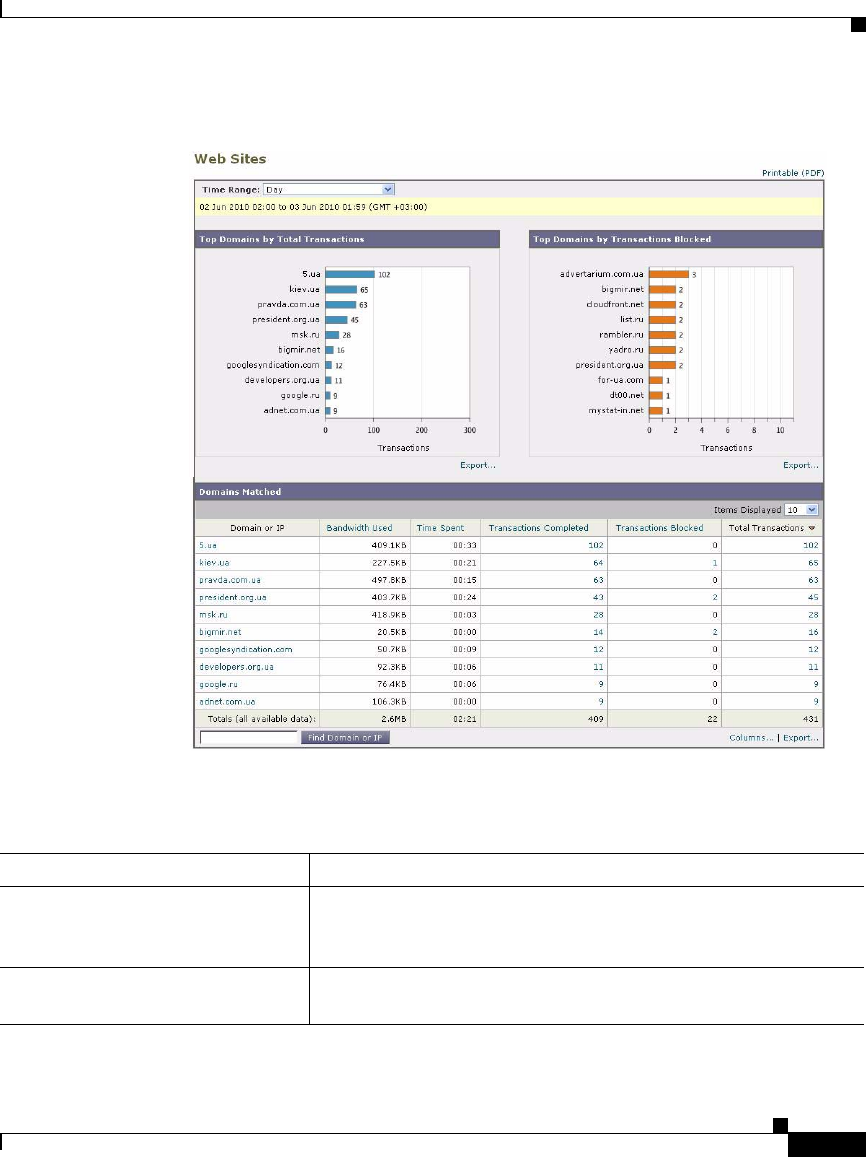
23-11
Cisco IronPort AsyncOS 7.1 for Web User Guide
OL-23207-01
Chapter 23 Web Security Appliance Reports
Web Sites Page
Figure 23-4 Web Sites Page
Table 23-4 describes the information on the Web Sites page:
Table 23-4 Web Sites Report Page Components
Section Description
Time Range (drop-down list) A menu that allows to choose the time range of the data contained
in the report. For more information, see the “Changing the Time
Range” section on page 22-3.
Top Domains by Total Transactions This section lists the top domains that are being visited on the site
in a graph format.

Chapter 23 Web Security Appliance Reports
URL Categories Page
23-12
Cisco IronPort AsyncOS 7.1 for Web User Guide
OL-23207-01
URL Categories Page
The Reporting > URL Categories page can be used to view the URL categories
that are being visited by users on the network.
Figure 23-5 shows the URL Categories page.
Top Domains by Transactions Blocked This section lists the top domains that triggered a block action to
occur per transaction in a graph format. For example, a user went
to a certain domain and because of a specific policy that I have in
place, this triggered a block action. This domain then gets listed
in this graph as a transaction blocked, and the domain site that
triggered the block action is listed.
Domains Matched This section lists the domains that are that are being visited on the
site in an interactive table. From this table you can access more
granular information about a specific domain by clicking on the
specific domain. The Web Tracking page appears and you can see
tracking information and why certain domains were blocked.
You can use column headings to sort data, and you can choose
which columns to display. For more information, see the
“Working with Columns on Report Pages” section on page 22-5.
When the section contains more than 10 domains, you can use the
Items Displayed menu to configure the number of domains to
display.
When you click on a specific domain you can see the top users of
that domain, the top transactions on that domain, the URL
categories matched and the malware threats that have been
detected. This table can be modified using the Time Range
drop-down list so you can see a specific time range, such as hour,
day or week for that domain use.
Table 23-4 Web Sites Report Page Components (continued)
Section Description
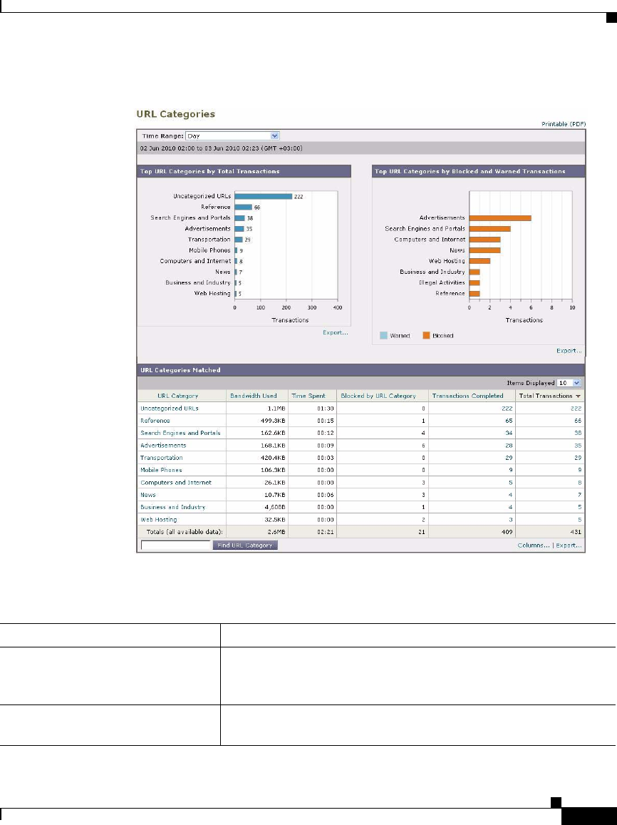
23-13
Cisco IronPort AsyncOS 7.1 for Web User Guide
OL-23207-01
Chapter 23 Web Security Appliance Reports
URL Categories Page
Figure 23-5 URL Categories Page
Table 23-5 describes the information on the URL Categories page.
Table 23-5 URL Categories Report Page Components
Section Description
Time Range (drop-down list) A menu that allows to choose the time range of the data contained
in the report. For more information, see the “Changing the Time
Range” section on page 22-3.
Top URL Categories by Total
Transactions
This section lists the top URL categories that are being visited on
the site in a graph format.

Chapter 23 Web Security Appliance Reports
URL Categories Page
23-14
Cisco IronPort AsyncOS 7.1 for Web User Guide
OL-23207-01
Top URL Categories by Blocked and
Warned Transactions
This section lists the top URL that triggered a block or warning
action to occur per transaction in a graph format. For example, a
user went to a certain URL and because of a specific policy that
is in place, this triggered a block action or a warning. This URL
then gets listed in this graph as a transaction blocked or warning.
Table 23-5 URL Categories Report Page Components (continued)
Section Description

23-15
Cisco IronPort AsyncOS 7.1 for Web User Guide
OL-23207-01
Chapter 23 Web Security Appliance Reports
URL Categories Page
URL Categories Matched The URL Categories Matched section shows all the URL
categories during a specified time range for both completed,
warned and blocked transactions. This is an interactive table with
interactive column headings that you can use to sort data as you
need. The Items Displayed menu changes the number of URL
categories displayed in the list.
You can use column headings to sort data, and you can choose
which columns to display. For more information, see the
“Working with Columns on Report Pages” section on page 22-5.
When the section contains more than 10 URL categories, you can
use the Items Displayed menu to configure the number of URL
categories to display.
From this section you can also search for data that applies to a
specific URL category in the Find URL Category field. For
more information, see Searching Data, page 22-5.
The percentage of uncategorized URLs on the URL Categories
page is typically around 15-20%. If the percentage of
uncategorized URLs is higher than that, consider the following
options:
•For specific localized URLs, you can create custom URL
categories and apply them to specific users or group policies.
For more information, see the “Custom URL Categories”
section on page 16-16.
•You can report misclassified and uncategorized URLs to the
Cisco IronPort Customer Support site at the following URL:
http://www.cisco.com/web/ironport/index.html
These get evaluated for subsequent rule updates.
•Verify Web Reputation Filtering and Anti-Malware Filtering
are enabled. Often times, the correlation between malware
and URLs with suspect content is high and it is likely that
they may get caught by subsequent filters. The system
pipeline is set up to catch malicious traffic with other
downstream filters if URL filtering does not have a verdict.
Table 23-5 URL Categories Report Page Components (continued)
Section Description

Chapter 23 Web Security Appliance Reports
Application Visibility Page
23-16
Cisco IronPort AsyncOS 7.1 for Web User Guide
OL-23207-01
Using The URL Categories Page in Conjunction with Other Reporting Pages
One of the advantages of the URL Categories page is that it can be used in
conjunction with the Application Visibility Page and the Users Page to investigate
a particular user, but also what types of applications or websites that a particular
user is trying to access.
For example, from the URL Categories Page you can generate a high level report
for Human Resources which details all the URL categories that are visited by the
site. From the same page, you can gather further details in the URL Categories
interactive table about the URL category ‘Streaming Media’. By clicking on the
Streaming Media category link, you can view the specific URL Categories report
page. This page not only displays the top users that are visiting streaming media
sites (in the Top Users by Category for Total Transactions section), but also
displays the domains that are visited (in the Domains Matched interactive table)
such as YouTube.com or QuickPlay.com.
At this point, you are getting more and more granular information for a particular
user. Now, let’s say this particular user stands out because of their usage, and you
want to find out exactly what they are accessing. From here you can click on the
user in the Users table. This action takes you to the User Details Page, where you
can view the user trends for that user, and find out exactly what they have been
doing on the web.
If you wanted to go further, you can now get down to web tracking details by
clicking on Transactions Completed link in the interactive table. This brings up
the Web Tracking Page where you can see the actual details about what dates the
user accessed the sites, the full URL, the time spent on that URL, etc.
Application Visibility Page
The Reporting > Application Visibility page shows the applications and
application types used and blocked as detected by the Application Visibility and
Control engine.
Figure 23-6 shows the Application Visibility page.
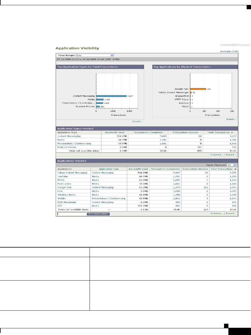
23-17
Cisco IronPort AsyncOS 7.1 for Web User Guide
OL-23207-01
Chapter 23 Web Security Appliance Reports
Application Visibility Page
Figure 23-6 Application Visibility Page
Table 23-6 describes the information on the Application Visibility page.
Table 23-6 Application Visibility Report Page Components
Section Description
Time Range (drop-down list) A menu that allows to choose the time range of the data contained
in the report. For more information, see the “Changing the Time
Range” section on page 22-3.
Top Application Types by Total
Transactions
This section lists the top application types that are being visited
on the site in a graph format. For example, Instant Messenging
tools such as Yahoo Instant Messenger, and Presentation
application types.

Chapter 23 Web Security Appliance Reports
Anti-Malware Page
23-18
Cisco IronPort AsyncOS 7.1 for Web User Guide
OL-23207-01
Anti-Malware Page
The Reporting > Anti-Malware page allows you to monitor and identify
malware detected by the IronPort DVS engine.
Figure 23-7 shows the Anti-Malware page.
Top Applications by Blocked
Transactions
This section lists the top application types that triggered a block
action to occur per transaction in a graph format. For example, a
user has tried to start a certain application, such as Google Talk,
and because of a configured policy, this triggered a block action.
This application then gets listed in this graph as a transaction
blocked or warning.
Application Types Matched The Application Types Matched table allows you to view
granular details about the application types listed in the Top
Applications Type by Total Transactions graph. From the
Applications column you can click on an application to view
details.
Applications Matched The Applications Matched section shows all the application
during a specified time range.
You can sort the table by clicking the column headers, and choose
which columns of data to display. For more information, see
Working with Columns on Report Pages, page 22-5.
When the section contains more than 10 applications, you can use
the Items Displayed menu to configure the number of
applications to display.
You can search for data on a specific application in the Find
Application field. For more information, see Searching Data,
page 22-5.
Table 23-6 Application Visibility Report Page Components (continued)
Section Description
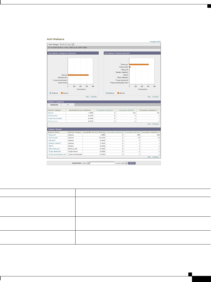
23-19
Cisco IronPort AsyncOS 7.1 for Web User Guide
OL-23207-01
Chapter 23 Web Security Appliance Reports
Anti-Malware Page
Figure 23-7 Anti-Malware Page
Table 23-7 describes the information on the Anti-Malware page.
Table 23-7 Anti-Malware Report Page Components
Section Description
Time Range (drop-down list) A menu that allows to choose the time range of the data contained
in the report. For more information, see the “Changing the Time
Range” section on page 22-3.
Top Malware Categories Detected This section displays the top malware categories detected by the
DVS engine. This information is displayed in graph format.
Top Malware Threats Detected This section displays the top malware threats detected by the
DVS engine. This information is displayed in graph format.

Chapter 23 Web Security Appliance Reports
Anti-Malware Page
23-20
Cisco IronPort AsyncOS 7.1 for Web User Guide
OL-23207-01
Malware Category Report Page
The Malware Category Report page allows you to view detailed information on
an individual Malware Category and what it is doing on your network.
To access the Malware Category report page, perform the following:
Step 1 Navigate to the Reporting > Anti-Malware page.
The Anti-Malware page appears.
Step 2 In the Malware Categories interactive table, click on a category in the Malware
Category column.
The Malware Category report page appears.
Malware Categories The Malware Categories table shows detailed information about
particular malware categories that are displayed in the Top
Malware Categories Detected section.
Clicking on any of the links in this table allows you to view more
granular details about individual malware categories and where
they are on the network.
Malware Threats The Malware Threats table shows detailed information about
particular malware threats that are displayed in the Top Malware
Threats section.
Table 23-7 Anti-Malware Report Page Components (continued)
Section Description
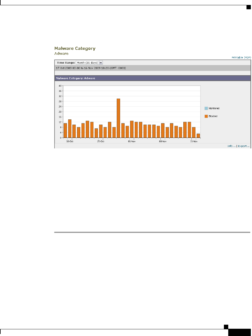
23-21
Cisco IronPort AsyncOS 7.1 for Web User Guide
OL-23207-01
Chapter 23 Web Security Appliance Reports
Anti-Malware Page
Figure 23-8 Malware Category Report Page
Malware Threat Report Page
The Malware Threat Report page report shows clients at risk for a particular
threat, displays a list of potentially infected clients, and links to the Client Detail
page. The trend graph at the top of the report shows monitored and blocked
transactions for a threat during the specified time range. The table at the bottom
shows the actual number of monitored and blocked transactions for a threat during
the specified time range.
To access the Malware Threat report page, perform the following:
Step 1 Navigate to the Reporting > Anti-Malware page.
The Anti-Malware page appears.
Step 2 In the Malware Threat table, click on a category in the Malware Category column.
The Malware Threat report page appears.
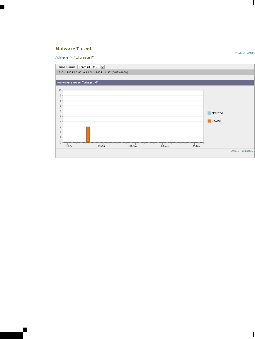
Chapter 23 Web Security Appliance Reports
Client Malware Risk Page
23-22
Cisco IronPort AsyncOS 7.1 for Web User Guide
OL-23207-01
Figure 23-9 Malware Threats Report Page
Client Malware Risk Page
The Reporting > Client Malware Risk page is a security-related reporting page
that can be used to monitor client malware risk activity.
From the Client Malware Risk page, a system administrator can see which of their
users are encountering the most blocks or warnings. Given the information
gathered from this page, the administrator can click on the user link to view what
this user doing on the web that makes them run into so many blocks or warnings
and setting off more detections than the rest of the users on the network.
Additionally, from the Client Malware Risk page you can see L4TM activity for
a specific IP address.
Figure 23-10 shows the Client Malware Risk page.
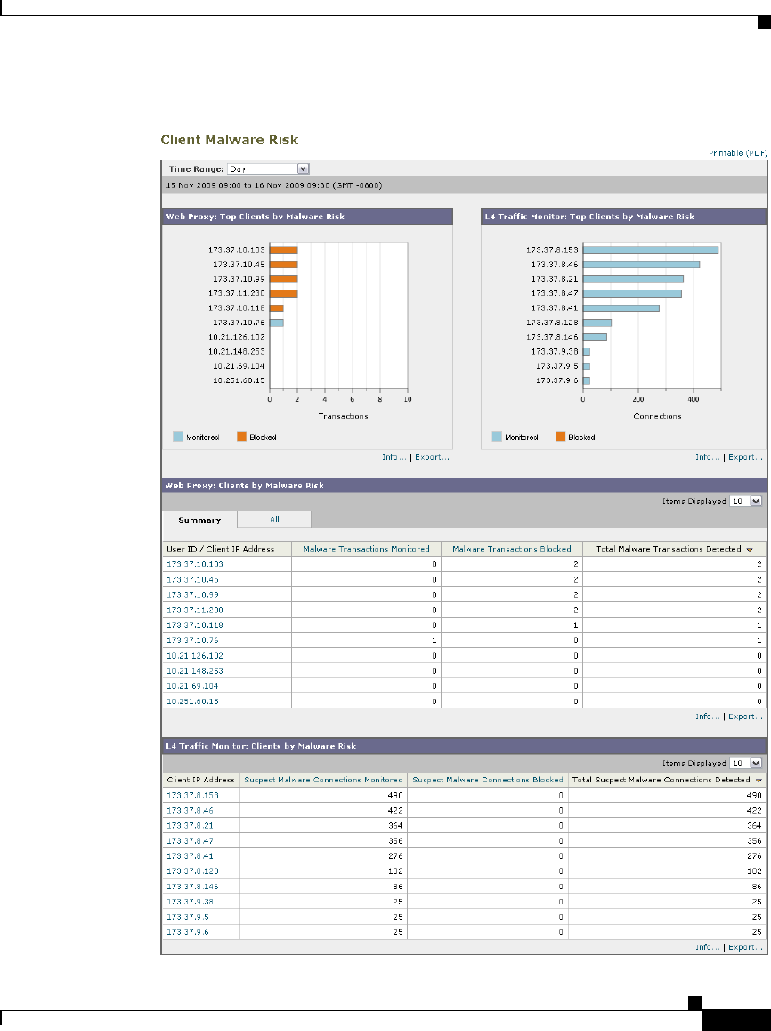
23-23
Cisco IronPort AsyncOS 7.1 for Web User Guide
OL-23207-01
Chapter 23 Web Security Appliance Reports
Client Malware Risk Page
Figure 23-10 Client Malware Risk Page

Chapter 23 Web Security Appliance Reports
Client Malware Risk Page
23-24
Cisco IronPort AsyncOS 7.1 for Web User Guide
OL-23207-01
Table 23-8 describes the information on the Client Malware Risk page.
Client Detail Page
The Client Details page shows all the web activity and malware risk data for a
particular client during the specified time range.
To access the Client Details page, perform the following:
Table 23-8 Client Malware Risk Report Page Components
Section Description
Time Range (drop-down list) A menu that allows to choose the time range of the data contained
in the report. For more information, see the “Changing the Time
Range” section on page 22-3.
Web Proxy: Top Clients by Malware
Risk
This section displays the top ten users that have encountered a
malware risk. This information is displayed in graph format.
L4 Traffic Monitor: Top Clients by
Malware Risk
This section displays the top displays the top ten users that have
encountered a L4 Traffic Monitoring risk. This information is
displayed in graph format.
Web Proxy: Clients by Malware Risk The Web Proxy: Clients by Malware Risk table shows detailed
information about particular clients that are displayed in the Web
Proxy: Top Clients by Malware Risk section.
You can click each user in this table to open the Client Detail
Page that provides detailed information for each user. For more
information, see the “Client Detail Page” section on page 23-24.
Clicking on any of the links in the table allows you to view more
granular details about individual users and what activity they are
performing that is triggering the malware risk. For example,
clicking on the link in the “User ID / Client IP Address” column
takes you to a User page for that user.
L4 Traffic Monitor: Clients by Malware
Risk
The Web Proxy: Clients Malware Risk interactive table shows
detailed information about individual users and what activity they
are performing that is triggering the L4 Traffic Monitoring
malware risk. Clicking on the link in the User/IP address column
will take you to a User page for that IP address.

23-25
Cisco IronPort AsyncOS 7.1 for Web User Guide
OL-23207-01
Chapter 23 Web Security Appliance Reports
Client Malware Risk Page
Step 1 Navigate to the Reporting > Client Malware Risk page.
The Client Malware Risk page appears.
Step 2 In the Web Proxy: Clients by Malware Risk section, click on a user in the “User
ID / Client IP Address” column.
The Client Details page appears.
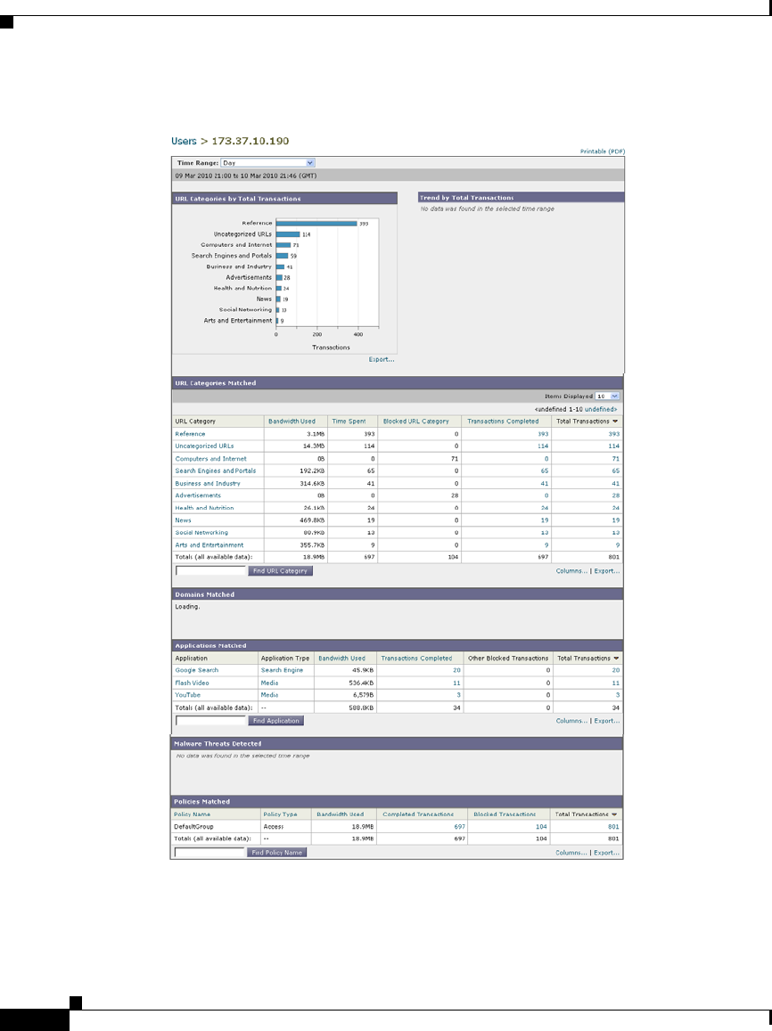
Chapter 23 Web Security Appliance Reports
Client Malware Risk Page
23-26
Cisco IronPort AsyncOS 7.1 for Web User Guide
OL-23207-01
Figure 23-11 Client Details Page
You can sort each table on the Client Details page by clicking the column
headers, and choose which columns of data to display. For more information, see
Working with Columns on Report Pages, page 22-5.

23-27
Cisco IronPort AsyncOS 7.1 for Web User Guide
OL-23207-01
Chapter 23 Web Security Appliance Reports
Client Malware Risk Page
Table 23-9 describes the information on the Client Details page.
Table 23-9 Client Malware Risk > Client Details Report Page Components
Section Description
Time Range (drop-down list) A menu that allows to choose the time range of the data contained
in the report. For more information, see the “Changing the Time
Range” section on page 22-3.
URL Categories by Total Transactions This section lists the specific URL Categories that a specific user
is using.
Trend by Total Transaction This graph displays at what times the user accessed the web.
For example, this graph will indicate if there is a large spike in
web traffic during certain hours of the day, and when those spikes
occur. Using the Time Range drop-down list, you can expand this
graph to see a more or less granular span of time that this user was
on the web.
URL Categories Matched The URL Categories Matched section shows all matched
categories that could potentially be a malware risk during a
specified time range for both completed and blocked
transactions.
You can sort the table by clicking the column headers, and choose
which columns of data to display. For more information, see
Working with Columns on Report Pages, page 22-5.
When the section contains more than 10 categories, you can use
the Items Displayed menu to configure the number of categories
to display.
You can search for data on a specific URL category in the Find
URL Category field. For more information, see Searching Data,
page 22-5.
Domains Matched From the Domains Matched section you can find out about a
specific Domain or IP address that this user has accessed that
could potentially be a malware risk. You can also see the time
spent on those domains, and various other information that you
have set from the column view. You can search for data on a
specific domain in the Find Domain or IP field. For more
information, see Searching Data, page 22-5.

Chapter 23 Web Security Appliance Reports
Client Malware Risk Page
23-28
Cisco IronPort AsyncOS 7.1 for Web User Guide
OL-23207-01
Note The client reports sometimes show a user with an asterisk (*) at the end of the
username. For example, the Client report might show an entry for both “jsmith”
and “jsmith*”. Usernames listed with an asterisk (*) indicate the username
provided by the user, but not confirmed by the authentication server. This happens
when the authentication server was not available at the time and the appliance is
configured to permit traffic when authentication service is unavailable.
Applications Matched From this section you can find a specific application that a
specific user is using that could potentially be a Malware risk.
For example, if a user is accessing a site that requires use of a lot
of Flash video, you will see the application type in the
Application column. As a system administrator, you might have
decided that anything with Flash video poses a malware risk.
Therefore, this application will show up in the Applications
Matched section.
You can search for data on a specific application in the Find
Application field. For more information, see Searching Data,
page 22-5.
Malware Threats Detected From this table you can see the top malware threats that a specific
user is triggering that could potentially be a malware risk.
You can search for data on a specific malware threat name in the
Find Malware Threat field. For more information, see
Searching Data, page 22-5.
Policies Matched From this section you can find the policy groups that applied to
this user when accessing the web.
You can search for policy group names in the Find Policy field.
For more information, see Searching Data, page 22-5.
Table 23-9 Client Malware Risk > Client Details Report Page Components
Section Description

23-29
Cisco IronPort AsyncOS 7.1 for Web User Guide
OL-23207-01
Chapter 23 Web Security Appliance Reports
Web Reputation Filters Page
Web Reputation Filters Page
The Reporting > Web Reputation Filters page is a security-related reporting
page that allows you to view the results of your set Web Reputation Filters for
transactions during a specified time range.
Figure 23-12 shows the Web Reputation Filters page.
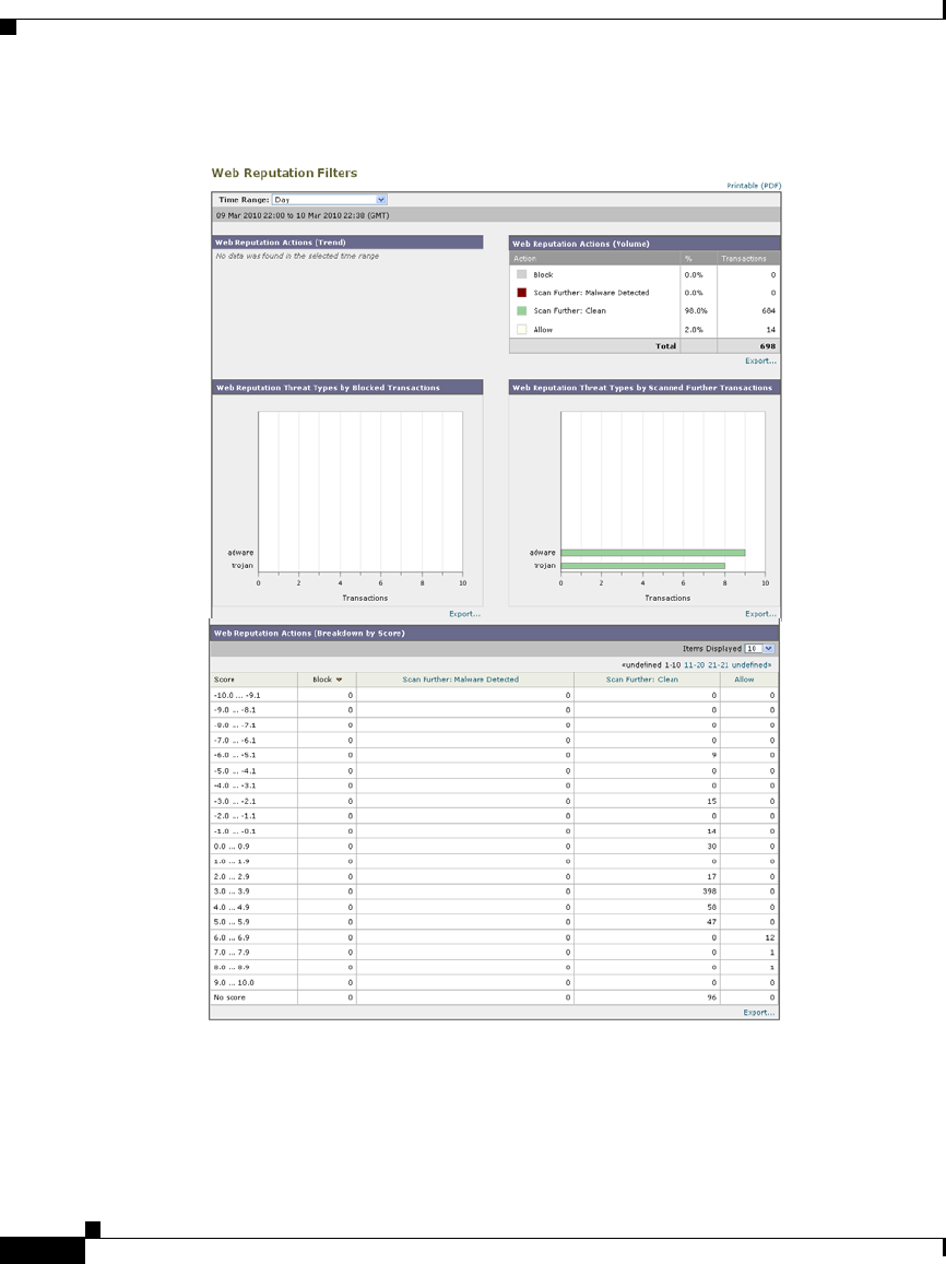
Chapter 23 Web Security Appliance Reports
Web Reputation Filters Page
23-30
Cisco IronPort AsyncOS 7.1 for Web User Guide
OL-23207-01
Figure 23-12 Web Reputation Filter Page

23-31
Cisco IronPort AsyncOS 7.1 for Web User Guide
OL-23207-01
Chapter 23 Web Security Appliance Reports
L4 Traffic Monitor Data Page
Table 23-10 describes the information on the Web Reputation Filters page.
L4 Traffic Monitor Data Page
The Reporting> L4 Traffic Monitor page is a is a security-related reporting page
that displays information about malware ports and malware sites that the L4
Traffic Monitor has detected during the specified time range.
The L4 Traffic Monitor listens to network traffic that comes in over all ports on
the appliance and matches domain names, and IP addresses against entries in its
own database tables to determine whether to allow incoming and outgoing traffic.
The upper part of the report displays the number of connections for each of the
top malware ports and web sites. The lower part of the report displays malware
ports and sites detected.
Figure 23-13 shows the L4 Traffic Monitor Data page.
Table 23-10 Web Reputation Filters Report Page Components
Section Description
Time Range (drop-down list) A menu that allows to choose the time range of the data contained
in the report. For more information, see the “Changing the Time
Range” section on page 22-3.
Web Reputation Actions (Trend) This section, in graph format, displays the total number of web
reputation actions (vertical) against the time specified (horizontal
timeline). From this you can see potential trends over time for
web reputation actions.
Web Reputation Actions (Volume) This section displays the web reputation action volume in
percentages by transactions.
Web Reputation Threat Types by
Blocked Transactions
This section displays the threat types that were blocked due to a
low reputation score.
Web Reputation Threat Types by
Scanned Further Transactions
This section displays the threat types that resulted in a reputation
score that indicated to scan the transaction. It shows both
monitored and blocked transactions.
Web Reputation Actions
(Breakdown by Score)
This interactive table displays the web reputation scores broken
down for each action.
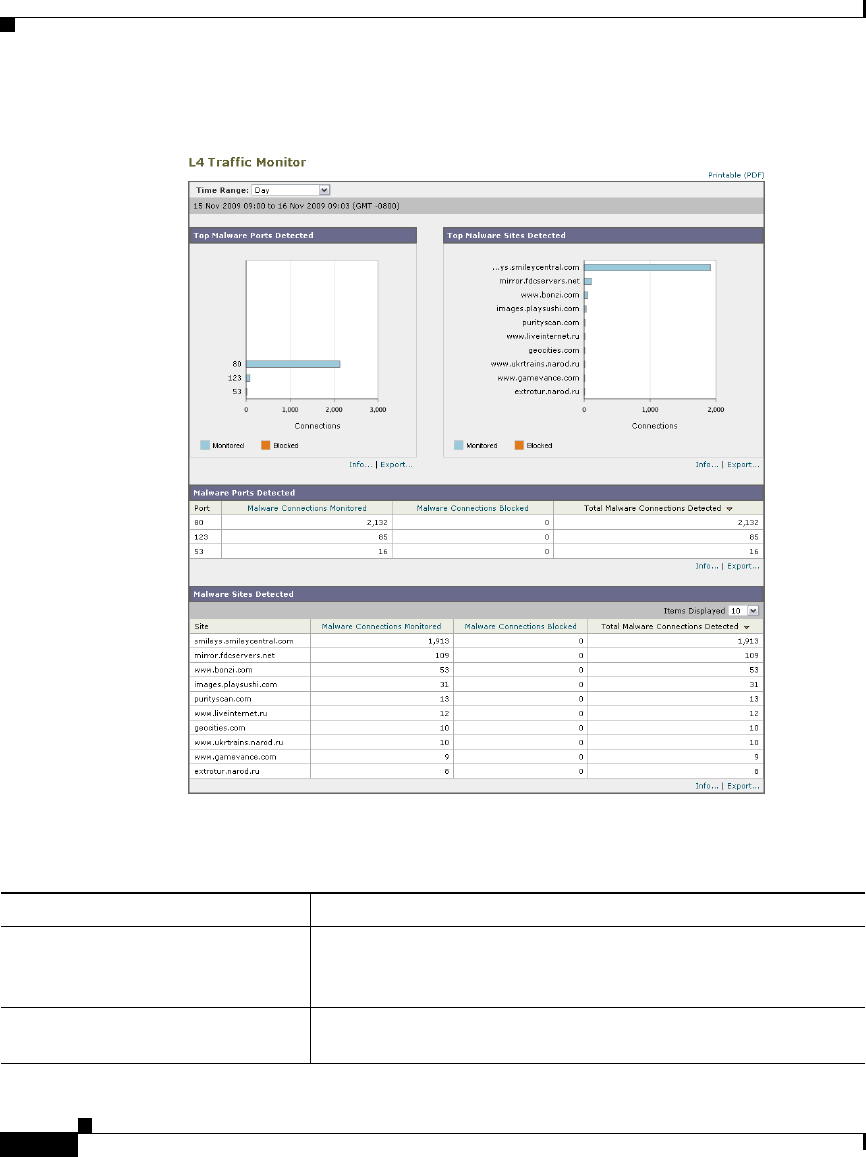
Chapter 23 Web Security Appliance Reports
L4 Traffic Monitor Data Page
23-32
Cisco IronPort AsyncOS 7.1 for Web User Guide
OL-23207-01
Figure 23-13 L4 Traffic Monitor Page
Table 23-11 describes the information on the L4 Traffic Monitor page.
Table 23-11 L4 Traffic Monitor Report Page Components
Section Description
Time Range (drop-down list) A menu that allows to choose the time range of the data contained
in the report. For more information, see the “Changing the Time
Range” section on page 22-3.
Top Malware Ports Detected This section displays, in graph format, the top malware ports
detected by the L4 Traffic Monitor.

23-33
Cisco IronPort AsyncOS 7.1 for Web User Guide
OL-23207-01
Chapter 23 Web Security Appliance Reports
Reports by User Location Page
Reports by User Location Page
The Reporting > Reports by User Location page allows you to find out what
activities your local and remote users are conducting. For more information on
remote and local users, see Working with Remote Users, page 13-2.
Activities include:
•URL categories that are being accessed by the local and remote users.
•Anti-Malware activity that is being triggered by sites the local and remote
users are accessing.
•Web Reputation of the sites being accessed by the local and remote users.
•Applications that are being accessed by the local and remote users.
•Users (local and remote).
•Domains accessed by local and remote users.
Figure 23-14 shows the Reports by User Location page.
Top Malware Sites Detected This section displays, in graph format, the top malware domains
detected by the L4 Traffic Monitor. In this view, the colored graph
displays monitored or blocked domains.
Malware Ports Detected This table displays all of the ports that have been detected by the
L4 Traffic Monitor.
Malware Sites Detected This table displays all of the domains that have been detected by
the L4 Traffic Monitor.
Table 23-11 L4 Traffic Monitor Report Page Components (continued)
Section Description
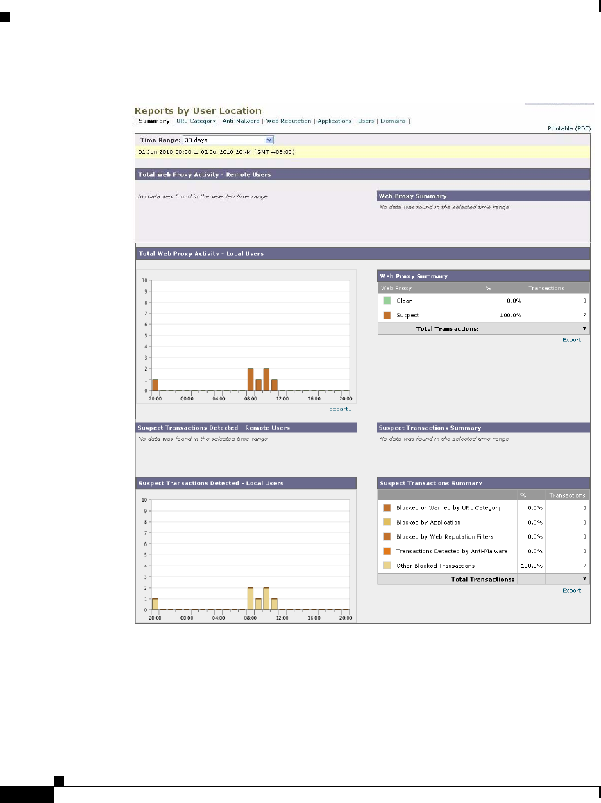
Chapter 23 Web Security Appliance Reports
Reports by User Location Page
23-34
Cisco IronPort AsyncOS 7.1 for Web User Guide
OL-23207-01
Figure 23-14 Reports by User Location Page

23-35
Cisco IronPort AsyncOS 7.1 for Web User Guide
OL-23207-01
Chapter 23 Web Security Appliance Reports
Web Tracking Page
Table 23-12 describes the information on the Reports by User Location page.
From the Reports by User Location page you can generate reports showing the
activity of local and remote users. This allows you to easily compare local and
remote activities of your users.
Web Tracking Page
You can use the Reporting > Web Tracking page to track and report on web
usage for a particular user or all users. Web tracking aggregates information from
individual security components as well as acceptable use enforcement
components and records data that can be used to monitor your web traffic patterns
and security risks.
Table 23-12 Reports by User Location Report Page Components
Section Description
Time Range (drop-down list) A menu that allows to choose the time range of the data contained
in the report. For more information, see the “Changing the Time
Range” section on page 22-3.
Total Web Proxy Activity: Remote Users This section displays, in graph format, the activity of your remote
users (vertical) over the specified time (horizontal).
Web Proxy Summary This section displays a summary of the activities of the local and
remote users on the network.
Total Web Proxy Activity: Local Users This section displays, in graph format, the activity of your remote
users (vertical) over the specified time (horizontal).
Suspect Transactions Detected: Remote
Users
This section displays, in graph format, the suspect transactions
that have been detected due to Access Policies defined for remote
users (vertical) over the specified time (horizontal).
Suspect Transactions Summary This section displays a summary of suspected transactions of the
remote users on the network.
Suspect Transactions Detected: Local
Users
This section displays, in graph format, the suspect transactions
that have been detected due to Access Policies defined for your
remote users (vertical) over the specified time (horizontal).
Suspect Transactions Summary This section displays a summary of suspected transactions of the
local users on the network.

Chapter 23 Web Security Appliance Reports
Web Tracking Page
23-36
Cisco IronPort AsyncOS 7.1 for Web User Guide
OL-23207-01
The Web Tracking page returns results for individual transactions and the results
include the hostname and domain in the URL (such as mail.google.com) instead
of just the domain name (such as google.com).
You might want to use it to assist the following roles:
•HR or Legal manager. Run an investigative report for an employee during a
specific time period.
•Network security administrator. Examine whether the company network is
being exposed to malware threats through employees’ smartphones.
You can view search results for the type of transactions logged (blocked,
monitored, warned, and completed) during a particular time period. You can also
filter the data results using several criteria, such as URL category, malware threat,
and application.
After you search for a set of transactions, you can choose which columns to
display, and you can sort the data by a column. For more information, see the
“Working with Columns on Report Pages” section on page 22-5.
Figure 23-15 shows the Web Tracking page.
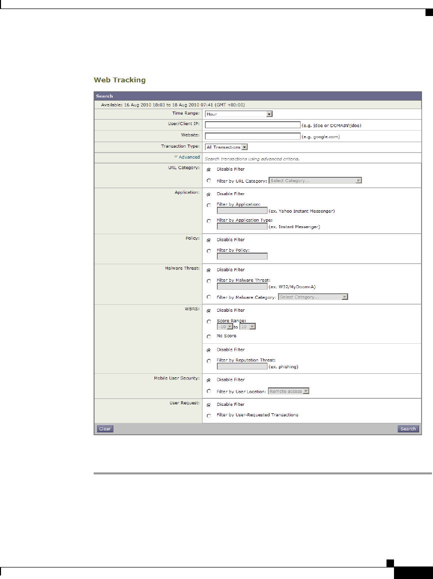
23-37
Cisco IronPort AsyncOS 7.1 for Web User Guide
OL-23207-01
Chapter 23 Web Security Appliance Reports
Web Tracking Page
Figure 23-15 Web Tracking Page
To track web usage for one user or all users, perform the following steps:
Step 1 Navigate to the Reporting > Web Tracking page.
The Web Tracking page appears.

Chapter 23 Web Security Appliance Reports
Web Tracking Page
23-38
Cisco IronPort AsyncOS 7.1 for Web User Guide
OL-23207-01
Step 2 Configure the fields defined in Table 23-13.
Step 3 Optionally, expand the Advanced section and configure the fields defined in
Table 23-14 to filter the web tracking results with more advanced criteria.
Table 23-13 Web Tracking Page Settings
Setting Description
Time Range Choose the time range on which to report. For more
information, see the “Changing the Time Range” section on
page 22-3.
User/Client IP Optionally, enter an authentication username as it appears in
reports or a client IP address that you want to track. When you
leave this field empty, the Web Tracking page returns results
for all users.
Website Optionally, enter a website that you want to track. When you
leave this field empty, the Web Tracking page returns results
for all websites.
Transaction Type Choose the type of transactions that you want to track, either
All Transactions, Completed, Blocked, Monitored, or
Warned.
Table 23-14 Web Tracking Page Advanced Settings
Setting Description
URL Category To filter by a URL category, select Filter by URL Category
and choose a URL category by which to filter.
Application To filter by an application, select Filter by Application and
choose an application by which to filter.
To filter by an application type, select Filter by Application
Type and choose an application type by which to filter.
Policy To filter by a policy group, select Filter by Policy and enter a
policy group name by which to filter.

23-39
Cisco IronPort AsyncOS 7.1 for Web User Guide
OL-23207-01
Chapter 23 Web Security Appliance Reports
Web Tracking Page
Step 4 Click Search.
Results are sorted by time stamp, with the most recent result at the top.
Malware Threat To filter by a particular malware threat, select Filter by
Malware Threat and enter a malware threat name by which
to filter.
To filter by a malware category, select Filter by Malware
Category and choose a malware category by which to filter.
WBRS In the WBRS section, you can filter by web reputation score
and by a particular web reputation threat.
•To filter by web reputation score, select Score Range and
select the upper and lower values by which to filter. Or,
you can filter for websites that have no score by selecting
No Score.
•To filter by web reputation threat, select Filter by
Reputation Threat and enter a web reputation threat by
which to filter.
Mobile User
Security
To filter by the location of users (either remote or local), select
Filter by User Location and choose a user type by which to
filter.
User Request To filter by transactions that were initiated by the client, select
Filter by User-Requested Transactions.
Note: When you enable this filter, the Web Tracking results
include some “best guess” transactions.
Table 23-14 Web Tracking Page Advanced Settings (continued)
Setting Description
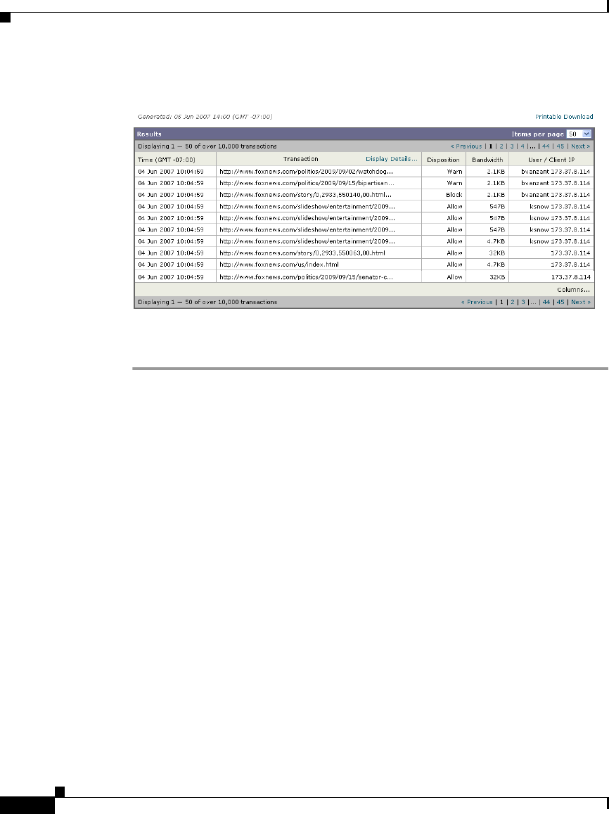
Chapter 23 Web Security Appliance Reports
System Capacity Page
23-40
Cisco IronPort AsyncOS 7.1 for Web User Guide
OL-23207-01
Figure 23-16 Web Tracking Results
Step 5 Optionally, click Display Details in the Transactions column to view more
detailed information about each transaction.
System Capacity Page
The Reporting > System Capacity page displays current and historical
information about resource usage on the Web Security appliance.
You might want to use the System Capacity report to accomplish any of the
following tasks:
•Learn when the Web Security appliance is exceeding the recommended
capacity to help determine when to upgrade or obtain additional appliances.
•Identify historical trends in system behavior which point to upcoming
capacity issues which require planning.
•Identify which part of the system is using the most resources to assist with
troubleshooting.
Figure 23-17 shows the first four graphs on the System Capacity page.
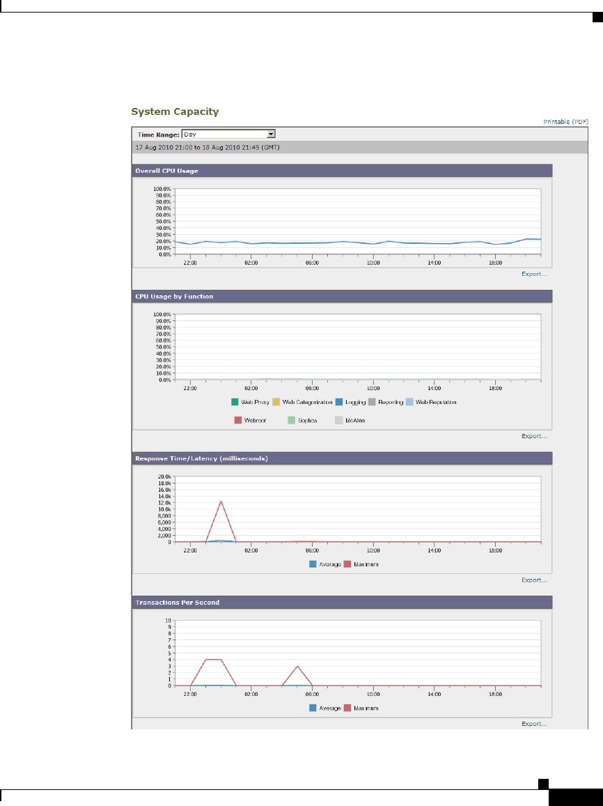
23-41
Cisco IronPort AsyncOS 7.1 for Web User Guide
OL-23207-01
Chapter 23 Web Security Appliance Reports
System Capacity Page
Figure 23-17 System Capacity Page—Upper Graphs

Chapter 23 Web Security Appliance Reports
System Capacity Page
23-42
Cisco IronPort AsyncOS 7.1 for Web User Guide
OL-23207-01
Figure 23-18 shows the last three graphs on the System Capacity page.
Figure 23-18 System Capacity Page—Lower Graphs
The System Capacity report includes graphs that show the overall CPU usage on
the appliance. AsyncOS for Web is optimized to use idle CPU resources to
improve message throughput. High CPU usage may not indicate a system capacity
problem. The CPU Usage by Function graph that displays the percentage of CPU
cycles used by different functions, such as the Web Proxy and Logging. The CPU
Usage by Function graph can indicate which appliance components use the most
resources. If you need to optimize your appliance, this graph can help you
determine which functions may need to be tuned.

23-43
Cisco IronPort AsyncOS 7.1 for Web User Guide
OL-23207-01
Chapter 23 Web Security Appliance Reports
System Capacity Page
The Response Time/Latency and Transactions Per Second graphs shows the
overall response time (in milliseconds), and transactions per second for the date
range specified in the Time Range drop-down menu.
The lower three graphs on the System Capacity report show the outgoing
connections, the bandwidth the appliance uses connecting out to upstream
servers, and the size of the Web Proxy memory buffer.
How to Interpret the Data You See on System Capacity Page
When choosing time ranges for viewing data on the System Capacity page, the
following is important to remember:
•Hour Report. The Hour report queries the minute table and displays the
exact number of items, such as bytes and connection, that have been recorded
by the appliance on an minute by minute basis over a 60 minute period. This
information is gathered from the hour table.
•Day Report. The Day report queries the hour table and displays the exact
number of items, such as bytes and connection, that have been recorded by
the appliance on an hourly basis over a 24 hour period. This information is
gathered from the hour table.
The Week Report and 30 Days Report work similarly to the Hour and Day
Reports.
The “Maximum” value indicator on the System Capacity page is the highest value
seen for the specified period. The “Average” value is the average of all values for
the specified period. The period of aggregation depends on the interval selected
for that report. For example, you can choose to see the Average and Maximum
values for each day if the chart is for a month period.

Chapter 23 Web Security Appliance Reports
System Status Page
23-44
Cisco IronPort AsyncOS 7.1 for Web User Guide
OL-23207-01
System Status Page
Use the Reporting > System Status page to monitor the System Status. This page
displays the current status and configuration of the Web Security appliance.
Table 23-15 describes each section.
Table 23-15 System Status Report Page Components
This Section... Displays
Web Security Appliance
Status
•System uptime
•System resource utilization — CPU usage,
RAM usage, and percentage of disk space used
for reporting and logging.
Proxy Traffic
Characteristics
•Transactions per second
•Bandwidth
•Response time
•Cache hit rate
•Connections
Current Configuration Web Proxy settings:
•Web Proxy Status — enabled or disabled.
•Deployment Topology.
•Web Proxy Mode — forward or transparent.
•IP Spoofing — enabled or disabled.
L4 Traffic Monitor settings:
•L4 Traffic Monitor Status — enabled or
disabled.
•L4 Traffic Monitor Wiring.
•L4 Traffic Monitor Action — monitor or block.
Web Security Appliance Version Information
Hardware information

CHAPTER
24-1
Cisco IronPort AsyncOS 7.1 for Web User Guide
OL-23207-01
24
Logging
This chapter contains the following information:
•Logging Overview, page 24-1
•Working with Log Subscriptions, page 24-9
•Access Log File, page 24-19
•W3C Compliant Access Logs, page 24-36
•Custom Formatting in Access Logs and W3C Logs, page 24-39
•Including HTTP/HTTPS Headers in Log Files, page 24-51
•Malware Scanning Verdict Values, page 24-52
•Traffic Monitor Log, page 24-53
•Troubleshooting, page 24-54
Logging Overview
You can use log files to monitor web traffic. To configure the appliance to create
log files, you create log subscriptions. A log subscription is an appliance
configuration that associates a log file type with a name, logging level, and other
parameters, such as size and destination information. You can subscribe to a
variety of log file types. For more information about log subscriptions, see
Working with Log Subscriptions, page 24-9.
In typical appliance monitoring, the appliance administrator usually reads the
following log files:

Chapter 24 Logging
Logging Overview
24-2
Cisco IronPort AsyncOS 7.1 for Web User Guide
OL-23207-01
•Access log. Records all Web Proxy filtering and scanning activity. For more
information about the access log, see Access Log File, page 24-19.
•Traffic Monitor log. Records all L4 Traffic Monitor activity. For more
information about the traffic monitor log, see Traffic Monitor Log,
page 24-53.
The appliance also creates other log file types, such as the system log file. You
might want to read other log files to troubleshoot appliance errors. For a list of
each type, see Log File Types, page 24-2.
The appliance provides several options for customizing the type of information
recorded in the access log. For more information, see Custom Formatting in
Access Logs and W3C Logs, page 24-39.
Log File Types
The log file type indicates what information is recorded in the generated log, such
as web traffic or system data. By default, the Web Security appliance has log
subscriptions for most log file types already created. However, there are some log
file types that specific to troubleshooting the Web Proxy. Those logs are not
created by default. For more information on those log file types, see Web Proxy
Logging, page 24-8.
Table 24-1 lists the Web Security appliance log file types created by default.
Table 24-1 Default Log File Types
Log File Type Description
Supports
Syslog Push?
Enabled by
Default?
Access Control
Engine Logs
Records messages related to the Web Proxy ACL
(access control list) evaluation engine.
No No
Access Logs Records Web Proxy client history. No Yes
Authentication
Framework Logs
Records authentication history and messages. No Yes
AVC Engine
Framework Logs
Records messages related to communication
between the Web Proxy and the AVC engine.
No No
AVC Engine Logs Records debug messages from the AVC engine. Yes Yes

24-3
Cisco IronPort AsyncOS 7.1 for Web User Guide
OL-23207-01
Chapter 24 Logging
Logging Overview
CLI Audit Logs Records a historical audit of command line
interface activity.
Yes Yes
Configuration Logs Records messages related to the Web Proxy
configuration management system.
No No
Connection
Management Logs
Records messages related to the Web Proxy
connection management system.
No No
Data Security Logs Records client history for upload requests that are
evaluated by the IronPort Data Security Filters.
For more information on the data security log, see
Logging, page 12-27.
Yes Yes
Data Security
Module Logs
Records messages related to the IronPort Data
Security Filters.
No No
DCA Engine
Framework Logs
(Dynamic Content
Analysis)
Records messages related to communication
between the Web Proxy and the Cisco IronPort Web
Usage Controls Dynamic Content Analysis engine.
No No
DCA Engine Logs
(Dynamic Content
Analysis)
Records messages related to the Cisco IronPort
Web Usage Controls Dynamic Content Analysis
engine.
Yes Yes
Default Proxy Logs Records errors related to the Web Proxy.
This is the most basic of all Web Proxy related logs.
To troubleshoot more specific aspects related to the
Web Proxy, create a log subscription for the
applicable Web Proxy module.
For more information about Web Proxy logging,
see Web Proxy Logging, page 24-8.
Yes Yes
Disk Manager Logs Records Web Proxy messages related to writing to
the cache on disk.
No No
Table 24-1 Default Log File Types (continued)
Log File Type Description
Supports
Syslog Push?
Enabled by
Default?

Chapter 24 Logging
Logging Overview
24-4
Cisco IronPort AsyncOS 7.1 for Web User Guide
OL-23207-01
External
Authentication
Logs
Records messages related to using the external
authentication feature, such as communication
success or failure with the external authentication
server.
Even with external authentication is disabled, this
log contains messages about local users
successfully or failing logging in.
For more information on external authentication,
see Using External Authentication, page 26-17.
No Yes
Feedback Logs Records the web users reporting misclassified
pages.
Yes Yes
FTP Proxy Logs Records error and warning messages related to the
FTP Proxy.
No No
FTP Server Logs Records all files uploaded to and downloaded from
the Web Security appliance using FTP.
Yes Yes
GUI Logs
(Graphical User
Interface)
Records history of page refreshes in the web
interface.
Yes Yes
HTTPS Logs Records Web Proxy messages specific to the
HTTPS Proxy (when the HTTPS Proxy is enabled).
No No
License Module
Logs
Records messages related to the Web Proxy’s
license and feature key handling system.
No No
Logging
Framework Logs
Records messages related to the Web Proxy’s
logging system.
No No
Logging Logs Records errors related to log management. Yes Yes
McAfee Integration
Framework Logs
Records messages related to communication
between the Web Proxy and the McAfee scanning
engine.
No No
McAfee Logs Records the status of anti-malware scanning
activity from the McAfee scanning engine.
Yes Yes
Table 24-1 Default Log File Types (continued)
Log File Type Description
Supports
Syslog Push?
Enabled by
Default?

24-5
Cisco IronPort AsyncOS 7.1 for Web User Guide
OL-23207-01
Chapter 24 Logging
Logging Overview
Memory Manager
Logs
Records Web Proxy messages related to managing
all memory including the in-memory cache for the
Web Proxy process.
No No
Miscellaneous
Proxy Modules
Logs
Records Web Proxy messages that are mostly used
by developers or customer support.
No No
Mobile User
Security Daemon
Logs
(Secure Mobility)
Records the interaction between the Web Security
appliance and the AnyConnect client, including the
status check.
Yes Yes
NTP Logs
(Network Time
Protocol)
Records changes to the system time made by the
Network Time Protocol.
Yes Yes
PAC File Hosting
Daemon Logs
Records proxy auto-config (PAC) file usage by
clients.
Yes Yes
Proxy Bypass Logs Records transactions that bypass the Web Proxy. No Yes
Reporting Logs Records a history of report generation. Yes Yes
Reporting Query
Logs
Records errors related to report generation. Yes Yes
Request Debug
Logs
Records very detailed debug information on a
specific HTTP transaction from all Web Proxy
module log types. You might want to create this log
subscription to troubleshoot a proxy issue with a
particular transaction without creating all other
proxy log subscriptions.
Note: You can create this log subscription in the
CLI only.
No No
SaaS Auth Logs Records messages related to the SaaS Access
Control feature.
Yes Yes
Table 24-1 Default Log File Types (continued)
Log File Type Description
Supports
Syslog Push?
Enabled by
Default?

Chapter 24 Logging
Logging Overview
24-6
Cisco IronPort AsyncOS 7.1 for Web User Guide
OL-23207-01
SHD Logs
(System Health
Daemon)
Records a history of the health of system services
and a history of unexpected daemon restarts.
Yes Yes
SNMP Logs Records debug messages related to the SNMP
network management engine.
Yes Yes
SNMP Module
Logs
Records Web Proxy messages related to interacting
with the SNMP monitoring system.
No No
Sophos Integration
Framework Logs
Records messages related to communication
between the Web Proxy and the Sophos scanning
engine.
No No
Sophos Logs Records the status of anti-malware scanning
activity from the Sophos scanning engine.
Yes Yes
Status Logs Records information related to the system, such as
feature key downloads.
Yes Yes
System Logs Records DNS, error, and commit activity. Yes Yes
Traffic Monitor
Error Logs
Records L4TM interface and capture errors. Yes Yes
Traffic Monitor
Logs
Records sites added to the L4TM block and allow
lists.
No Yes
UDS Logs
(User Discovery
Service)
Records data about how the Web Proxy discovers
the user name without doing actual authentication.
It includes information about interacting with the
Cisco adaptive security appliance for the Secure
Mobility Solution as well as integrating with the
Novell eDirectory server for transparent user
identification.
For more information, see Achieving Secure
Mobility Overview, page 13-1 and Identifying
Users Transparently, page 7-16.
Yes Yes
Updater Logs Records a history of WBRS and other updates. Yes Yes
Table 24-1 Default Log File Types (continued)
Log File Type Description
Supports
Syslog Push?
Enabled by
Default?

24-7
Cisco IronPort AsyncOS 7.1 for Web User Guide
OL-23207-01
Chapter 24 Logging
Logging Overview
W3C Logs Records Web Proxy client history in a W3C
compliant format.
For more information, see W3C Compliant Access
Logs, page 24-36.
No No
WBNP Logs
(SenderBase
Network
Participation)
Records a history of SenderBase network
participation uploads to the SenderBase network.
No Yes
WBRS Framework
Logs
(Web Reputation
Score)
Records messages related to communication
between the Web Proxy and the Web Reputation
Filters.
No No
WCCP Module
Logs
Records Web Proxy messages related to
implementing WCCP.
No No
Webcat Integration
Framework Logs
Records messages related to communication
between the Web Proxy and the configured URL
filtering engine, either IronPort URL Filters or
Cisco IronPort Web Usage Controls.
No No
Web Categorization
Logs
Records the status of the IronPort URL Filters
service, such as whether or not the service is
running.
No Yes
Webroot Integration
Framework Logs
Records messages related to communication
between the Web Proxy and the Webroot scanning
engine.
No No
Webroot Logs Records the status of anti-malware scanning
activity from the Webroot scanning engine.
Yes Yes
Welcome Page
Acknowledgement
Logs
Records a history of web clients who click the
Accept button on the end-user acknowledgement
page.
Yes Yes
Table 24-1 Default Log File Types (continued)
Log File Type Description
Supports
Syslog Push?
Enabled by
Default?

Chapter 24 Logging
Logging Overview
24-8
Cisco IronPort AsyncOS 7.1 for Web User Guide
OL-23207-01
Web Proxy Logging
By default, the Web Security appliance has one log subscription created for Web
Proxy logging messages, the “Default Proxy Logs.” The Web Proxy information
stored in this log covers all aspects, or modules, of the Web Proxy. The appliance
also includes log file types for each Web Proxy module so you can read more
specific debug information for each module without cluttering up the Default
Proxy Logs.
If a user or administrator encounters an issue with the Web Proxy behavior, read
the Default Proxy Logs first. If you see a log entry that you suspect might be the
symptom of an issue, then you can create a log subscription for the relevant
specific Web Proxy module. Then read that proxy log to help troubleshoot the
problem.
You can create log subscriptions of these proxy module logs in web interface or
in the CLI. However, you can only create the Request Debug Logs in the CLI.
The following list includes all Web Proxy module log types:
•Access Control Engine Logs
•AVC Engine Framework Logs
•Configuration Logs
•Connection Management Logs
•Data Security Module Logs
•DCA Engine Framework Logs
•Disk Manager Logs
•FTP Proxy Logs
•HTTPS Logs
•License Module Logs
•Logging Framework Logs
•McAfee Integration Framework Logs
•Memory Manager Logs
•Miscellaneous Proxy Modules Logs
•Request Debug Logs
•SNMP Module Logs

24-9
Cisco IronPort AsyncOS 7.1 for Web User Guide
OL-23207-01
Chapter 24 Logging
Working with Log Subscriptions
•Sophos Integration Framework Logs
•WBRS Framework Logs
•WCCP Module Logs
•Webcat Integration Framework Logs
•Webroot Integration Framework Logs
For a description of each log type, see Table 24-1, `Default Log File Types,' on
page 2.
Working with Log Subscriptions
A log subscription is an appliance configuration that specifies the type of log file
to create and other factors, such as the log file name and method of retrieving the
log file. Use the System Administration > Log Subscriptions page to configure log
file subscriptions.
Figure 24-1 shows the Log Subscriptions page where you work with log
subscriptions.
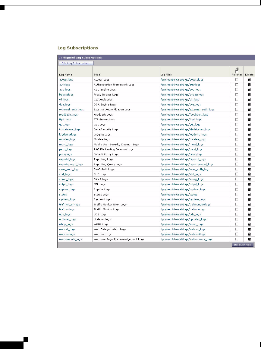
Chapter 24 Logging
Working with Log Subscriptions
24-10
Cisco IronPort AsyncOS 7.1 for Web User Guide
OL-23207-01
Figure 24-1 Log File Subscriptions
By default, the appliance is configured with one log subscription for most log
types. You can add, edit, or delete log subscriptions. You can retrieve log files
from the appliance using SCP, FTP, or Syslog. You can create multiple log
subscriptions for each type of log file.
The appliance includes more options when configuring the access log:
•Include additional information in each log entry. For more information
about customizing the access log, see Custom Formatting in Access Logs and
W3C Logs, page 24-39.

24-11
Cisco IronPort AsyncOS 7.1 for Web User Guide
OL-23207-01
Chapter 24 Logging
Working with Log Subscriptions
•Choose the format of the information. You can choose among the following
format options:
–
Apache
–
Squid
–
Squid Details
•Exclude entries based on HTTP status codes. You can configure the access
log to not include transactions based on particular HTTP status codes to filter
out certain transactions. For example, you might want to filter out
authentication failure requests that have codes of 407 or 401.
Log File Name and Appliance Directory Structure
The appliance creates a directory for each log subscription based on the log
subscription name. The name of the log file in the directory is composed of the
following information:
•Log file name specified in the log subscription
•Timestamp when the log file was started
•A single-character status code, either .c (signifying current) or .s (signifying
saved)
The filename of logs are made using the following formula:
/LogSubscriptionName/LogFilename.@timestamp.statuscode
Note You should only transfer log files with the saved status.
Rolling Over Log Subscriptions
AsyncOS rolls over log subscriptions based on settings you make in each log
subscription. Rolling over a log subscription is an AsyncOS process that
accomplishes the following tasks:
•Creates a new log file with the timestamp of the rollover and designates the
file as current with the letter “c” extension.
•Renames the current log file to have a letter “s” extension signifying saved.

Chapter 24 Logging
Working with Log Subscriptions
24-12
Cisco IronPort AsyncOS 7.1 for Web User Guide
OL-23207-01
•Transfers the newly saved log file to a remote host when the log retrieval
method is push-based. For a list of the log retrieval methods, see Table 24-4
on page 17.
•Transfers any previously unsuccessful log files from the same subscription
when the log retrieval method is push-based.
•Deletes the oldest file in the log subscription if the total number of files to
keep on hand has been exceeded when the log retrieval method is poll-based.
AsyncOS rolls over log subscriptions in the following ways:
•Manually. The appliance administrator can manually roll over log
subscriptions on demand from either the web interface or the CLI. Use the
Rollover Now button on the System Administration > Log Subscriptions
page, or the rollovernow CLI command. The rollovernow command allows
you to roll over all log files at once or select a specific log file from a list.
•Automatically. AsyncOS rolls over log subscriptions based on the first
user-specified limit reached: maximum file size or maximum time. Log
subscriptions based on the FTP poll retrieval method create files and store
them in the FTP directory on the appliance until they are retrieved from a
remote FTP client, or until the system needs to create more space for log files.
To roll over a log subscription in the web interface:
Step 1 Navigate to the System Administration > Log Subscriptions page.
Step 2 Click the check box under the Rollover column for each log subscription you want
to roll over.
Step 3 Click Rollover Now.
Working with Compressed Log Files
To save disk space on the Web Security appliance, log subscriptions can compress
rolled over log files before storing them on the disk. Only rolled over logs are
compressed. The current active log file is not compressed.
Each log subscription has its own log compression setting, so you can choose
which log subscriptions to compress. AsyncOS compresses log files using the
gzip compression format.

24-13
Cisco IronPort AsyncOS 7.1 for Web User Guide
OL-23207-01
Chapter 24 Logging
Working with Log Subscriptions
Viewing the Most Recent Log Files
You can view a the most recent version of a log file from the following locations:
•Web interface. On the System Administration > Log Subscriptions page,
click the name of the log subscription in the Log Files column of the list of
log subscriptions. When you click the link to the log subscription, AsyncOS
prompts you to enter your password. Then it lists the available log files for
that subscription. Click one of the log files to view it in your browser or to
save it to disk.
•Command line interface. Use the tail CLI command. AsyncOS displays
the configured log subscriptions and prompts you to select the log
subscription to view. Use Ctrl+C to exit from the tail command at any time.
Note If a log subscription is compressed, you must download it before you can
decompress and open it.
Configuring Host Keys
Use the logconfig -> hostkeyconfig subcommand to manage host keys for use
with SSH when pushing log files to other servers from the Web Security
appliance. SSH servers must have a pair of host keys, one private and one public.
The private host key resides on the SSH server and cannot be read by remote
machines. The public host key is distributed to any client machine that needs to
interact with the SSH server.
The hostkeyconfig subcommand performs the following functions:
Table 24-2 Managing Host Keys—List of Subcommands
Command Description
New Add a new key.
Scan Automatically download a host key.
Host Display system host keys. This is the value to place in the remote
system’s ‘known_hosts’ file.

Chapter 24 Logging
Working with Log Subscriptions
24-14
Cisco IronPort AsyncOS 7.1 for Web User Guide
OL-23207-01
Adding and Editing Log Subscriptions
To add or edit a log subscription:
Step 1 Navigate to the System Administration > Log Subscriptions page.
Step 2 To add a log subscription, click Add Log Subscription. Or, to edit a log
subscription, click the name of the log file in the Log Name field.
The New Log Subscription page or Edit Log Subscription page appears.
Step 3 Select the type of log to associate with this subscription from the Log Type field.
Step 4 Enter a name for the log subscription in the Log Name field.
The appliance uses this name for the directory on the appliance that will
contain the log file.
Step 5 If you are creating an access log, configure the following options:
Fingerprint Display system host key fingerprints.
User Displays the public key of the system account that pushes the logs
to the remote machine. This is the same key that is displayed
when setting up an SCP push subscription. This is the value to
place in the remote system’s ‘authorized_keys’ file.
Table 24-2 Managing Host Keys—List of Subcommands (continued)
Command Description
Access Log Option Description
Log Style Choose the log format to use, either Squid, Apache, or
Squid Details.
Custom Fields Optionally, enter the other type of information to include
in each access log entry. For more information, see
Custom Formatting in Access Logs and W3C Logs,
page 24-39.

24-15
Cisco IronPort AsyncOS 7.1 for Web User Guide
OL-23207-01
Chapter 24 Logging
Working with Log Subscriptions
Step 6 If you are creating a W3C access log, configure the following options:
Note When you change the log fields included in a W3C log subscription, the
log subscription automatically rolls over. This allows the latest version of
the log file to include the correct new field headers.
Step 7 Enter a name for the log file in the File Name field.
Step 8 Enter the maximum file size in bytes the log file can be in the Maximum File Size
field. After the number, enter “G” to specify Gigabytes, “M” for Megabytes, or
“K” for Kilobytes.
Step 9 Choose whether or not to compress log files after they have been rolled over using
the Log Compression field.
For more information, see Working with Compressed Log Files, page 24-12.
Step 10 If you are creating an access log or a W3C access log, you can optionally choose
to exclude certain transactions based on particular HTTP status codes in the Log
Exclusions field. For example, you might want to filter out authentication failure
requests that have codes of 407 or 401.
Step 11 Choose the amount of detail to include in the log file in the Log Level field.
Access Log Option Description
Log Fields Choose the fields you want to include in the W3C access
log.
Select a field in the Available Fields list, or type a field in
the Custom Field box, and click Add. The order the fields
appear in the Selected Log Fields list determines the order
of fields in the W3C access log file. You can change the
order of fields using the Move Up and Move Down
buttons. You can remove a field by selecting it in the
Selected Log Fields list and clicking Remove.
You can enter multiple user defined fields in the Custom
Fields box and add them simultaneously as long as each
entry is separated by a new line (click Enter) before
clicking Add.
For more information, see W3C Compliant Access Logs,
page 24-36.

Chapter 24 Logging
Working with Log Subscriptions
24-16
Cisco IronPort AsyncOS 7.1 for Web User Guide
OL-23207-01
The Log Level field does not appear for access and W3C access logs
subscriptions
More detailed settings create larger log files and have a greater impact on
system performance. More detailed settings include all the messages
contained in less detailed settings, plus additional messages. As the level of
detail increases, system performance decreases.
Table 24-3 describes the levels of detail you can choose in the Log Level
field.
Step 12 Choose how to retrieve the log file from the appliance in the Retrieval Method
field.
Table 24-3 Logging Levels
Log Level Description
Critical This is the least detailed setting. This level only includes errors.
Using this setting will not allow you to monitor performance and
other important activities. However, the log files will not reach
their maximum size as quickly. This log level is equivalent to the
syslog level “Alert.”
Warning This level includes all errors and warnings created by the system.
Using this setting will not allow you to monitor performance and
other important activities. This log level is equivalent to the
syslog level “Warning.”
Information This level includes the detailed system operations. This is the
default. This log level is equivalent to the syslog level “Info.”
Debug This level includes data useful for debugging system problems.
Use the Debug log level when you are trying to discover the
cause of an error. Use this setting temporarily, and then return to
the default level. This log level is equivalent to the syslog level
“Debug.”
Trace This is the most detailed setting. This level includes a complete
record of system operations and activity. The Trace log level is
recommended only for developers. Using this level causes a
serious degradation of system performance and is not
recommended. This log level is equivalent to the syslog level
“Debug.”

24-17
Cisco IronPort AsyncOS 7.1 for Web User Guide
OL-23207-01
Chapter 24 Logging
Working with Log Subscriptions
Table 24-4 describes the different ways you can retrieve log files:
Table 24-4 Log Transfer Protocols
Retrieval Method Description
FTP on Appliance
(FTP Poll)
This method requires a remote FTP client accessing the
appliance to retrieve log files using an admin or operator
user’s username and password.
When you choose this method, you must enter the
maximum number of log files to store on the appliance.
When the maximum number is reached, the system deletes
the oldest file.
This is the default.
FTP on Remote
Server
(FTP Push)
This method periodically pushes log files to an FTP server
on a remote computer.
When you choose this method, you must enter the
following information:
•Maximum time between file transfers
•FTP server hostname
•Directory on FTP server to store the log file
•Username and password of a user that has permission
to connect to the FTP server
Note: AsyncOS for Web only supports passive mode for
remote FTP servers. It cannot push log files to an FTP
server in active mode.

Chapter 24 Logging
Working with Log Subscriptions
24-18
Cisco IronPort AsyncOS 7.1 for Web User Guide
OL-23207-01
Step 13 Submit and commit your changes.
Step 14 If you chose SCP as the retrieval method, the appliance displays an SSH key to
you must place on the SCP server host.
SCP on Remote
Server
(SCP Push)
This method periodically pushes log files using the secure
copy protocol to an SCP server on a remote computer. This
method requires an SSH SCP server on a remote computer
using the SSH1 or SSH2 protocol. The subscription
requires a user name, SSH key, and destination directory
on the remote computer. Log files are transferred based on
a rollover schedule set by you.
When you choose this method, you must enter the
following information:
•Maximum time between file transfers
•Protocol to use for transmission, either SSH1 or SSH2
•SCP server hostname
•Directory on SCP server to store the log file
•Username of a user that has permission to connect to
the SCP server
Choose whether or not to enable host key checking.
Syslog Push This method sends log messages to a remote syslog server.
This method conforms to RFC 3164. The appliance uses
port 514.
When you choose this method, you must enter the
following information:
•Syslog server hostname
•Protocol to use for transmission, either UDP or TCP
•Facility to use with the log
You can only choose syslog for text-based logs.
Table 24-4 Log Transfer Protocols (continued)
Retrieval Method Description

24-19
Cisco IronPort AsyncOS 7.1 for Web User Guide
OL-23207-01
Chapter 24 Logging
Access Log File
Deleting a Log Subscription
To delete a log subscription:
Step 1 Navigate to the System Administration > Log Subscriptions page.
Step 2 Click the icon under the Delete column for the log subscription you want to delete.
Step 3 Submit and commit your changes.
Access Log File
The access log file provides a descriptive record of all Web Proxy filtering and
scanning activity. Access log file entries display a record of how the appliance
handled each transaction. You can view the access log file from the System
Administration > Log Subscriptions page.
Note The W3C access log also records all Web Proxy filtering and scanning activity,
but in a format that is W3C compliant. For more information, see W3C Compliant
Access Logs, page 24-36.
The following text is an example access log file entry for a single transaction:
Table 24-5 describes the different fields in the access log file entry.
1278096903.150 97 172.xx.xx.xx TCP_MISS/200 8187 GET
http://my.site.com/ - DIRECT/my.site.com text/plain
DEFAULT_CASE_11-AccessOrDecryptionPolicy-Identity-OutboundMalwareScan
ningPolicy-DataSecurityPolicy-ExternalDLPPolicy-RoutingPolicy
<IW_comp,6.9,"Skipped","-",-,-,-,"-","-",-,-,-,"-","-","-","-","-",-,
-,IW_comp,-,"-","-","Unknown","Unknown","-","-",198.34,0,-,"-","-"> -
Table 24-5 Access Log File Entry
Field Value Field Description
1278096903.150 Timestamp since UNIX epoch.
97 Elapsed time (latency) in milliseconds.

Chapter 24 Logging
Access Log File
24-20
Cisco IronPort AsyncOS 7.1 for Web User Guide
OL-23207-01
172.xx.xx.xx Client IP address.
Note: You can choose to mask the IP address in
the access logs using the advancedproxyconfig >
authentication CLI command.
TCP_MISS/ Transaction result code.
For more information, see Transaction Result
Codes, page 24-23.
200 HTTP response code.
8187 Response size (headers + body).
GET http://my.site.com/ First line of the request.
Note: When the first line of the request is for a
native FTP transaction, some special characters
in the file name are URL encoded in the access
logs. For example, the “@” symbol is written as
“%40” in the access logs.
The following characters are URL encoded:
& # % + , : ; = @ ^ { } [ ]
-Authenticated username.
Note: You can choose to mask the username in
the access logs using the advancedproxyconfig >
authentication CLI command.
Table 24-5 Access Log File Entry (continued)
Field Value Field Description

24-21
Cisco IronPort AsyncOS 7.1 for Web User Guide
OL-23207-01
Chapter 24 Logging
Access Log File
DIRECT/my.site.com Code that describes which server was contacted
for the retrieving the request content.
Most common values include:
•NONE. The Web Proxy had the content, so it
did not contact any other server to retrieve
the content.
•DIRECT. The Web Proxy went to the server
named in the request to get the content.
•DEFAULT_PARENT. The Web Proxy went
to its primary parent proxy or an external
DLP server to get the content.
text/plain Response body MIME type.
DEFAULT_CASE_11 ACL decision tag.
Note: The end of the ACL decision tag includes a
dynamically generated number that the Web
Proxy uses internally. You can ignore this
number.
For more information, see ACL Decision Tags,
page 24-24.
AccessOrDecryptionPolicy Access Policy or Decryption Policy group name.
When the transaction matches the global Access
Policy or global Decryption Policy, this value is
“DefaultGroup.”
Any space in the policy group name is replaced
with an underscore ( _ ).
Identity Identity policy group name.
Any space in the policy group name is replaced
with an underscore ( _ ).
OutboundMalwareScanning
Policy
Outbound Malware Scanning Policy group name.
Any space in the policy group name is replaced
with an underscore ( _ ).
Table 24-5 Access Log File Entry (continued)
Field Value Field Description

Chapter 24 Logging
Access Log File
24-22
Cisco IronPort AsyncOS 7.1 for Web User Guide
OL-23207-01
DataSecurityPolicy IronPort Data Security Policy group name. When
the transaction matches the global IronPort Data
Security Policy, this value is “DefaultGroup.”
This policy group name only appears when
IronPort Data Security Filters is enabled.
“NONE” appears when no Data Security Policy
was applied.
Any space in the policy group name is replaced
with an underscore ( _ ).
ExternalDLPPolicy External DLP Policy group name. When the
transaction matches the global External DLP
Policy, this value is “DefaultGroup.” “NONE”
appears when no External DLP Policy was
applied.
Any space in the policy group name is replaced
with an underscore ( _ ).
RoutingPolicy Routing Policy group name as
ProxyGroupName/ProxyServerName.
When the transaction matches the global Routing
Policy, this value is “DefaultRouting.” When no
upstream proxy server is used, this value is
“DIRECT.”
Any space in the policy group name is replaced
with an underscore ( _ ).
<IW_comp,6.9,"Skipped","
-",-,-,-,"-","-",-,-,-,"
-","-","-","-","-",-,-,I
W_comp,-,"-","-","Unknow
n","Unknown","-","-",198
.34,0,-,"-","-">
Scanning verdict information. Inside the angled
brackets, the access logs include verdict
information from various scanning engines.
For more information about the values included
within the angled brackets, see Understanding
Scanning Verdict Information, page 24-30.
- Suspect user agent.
Table 24-5 Access Log File Entry (continued)
Field Value Field Description

24-23
Cisco IronPort AsyncOS 7.1 for Web User Guide
OL-23207-01
Chapter 24 Logging
Access Log File
Transaction Result Codes
Transaction result codes in the access log file describe how the appliance resolves
client requests. For example, if a request for an object can be resolved from the
cache, the result code is TCP_HIT. However, if the object is not in the cache and
the appliance pulls the object from an origin server, the result code is TCP_MISS.
The following table describes transaction result codes.
Table 24-6 Transaction Result Codes
Result Code Description
TCP_HIT The object requested was fetched from the disk cache.
TCP_IMS_HIT The client sent an IMS (If-Modified-Since) request
for an object and the object was found in the cache.
The proxy responds with a 304 response.
TCP_MEM_HIT The object requested was fetched from the memory
cache.
TCP_MISS The object was not found in the cache, so it was
fetched from the origin server.
TCP_REFRESH_HIT The object was in the cache, but had expired. The
proxy sent an IMS (If-Modified-Since) request to the
origin server, and the server confirmed that the object
has not been modified. Therefore, the appliance
fetched the object from either the disk or memory
cache.
TCP_CLIENT_REFRESH_MI
SS
The client sent a “don’t fetch response from cache”
request by issuing the ‘Pragma: no-cache’ header.
Due to this header from the client, the appliance
fetched the object from the origin server.
TCP_DENIED The client request was denied due to Access Policies.
NONE There was an error in the transaction. For example, a
DNS failure or gateway timeout.

Chapter 24 Logging
Access Log File
24-24
Cisco IronPort AsyncOS 7.1 for Web User Guide
OL-23207-01
ACL Decision Tags
An ACL decision tag is a field in an access log entry that indicates how the Web
Proxy handled the transaction. It includes information from the Web Reputation
filters, URL categories, and the scanning engines.
Note The end of the ACL decision tag includes a dynamically generated number that
the Web Proxy uses internally to increase performance. You can ignore this
number.
Table 24-7 describes the ACL decision tag values.
Table 24-7 ACL Decision Tag Values
ACL Decision Tag Description
ALLOW_ADMIN The Web Proxy allowed the transaction
based on Applications settings for the
Access Policy group.
ALLOW_ADMIN_ERROR_PAGE The Web Proxy allowed the transaction to an
IronPort notification page and to any logo
used on that page.
ALLOW_CUSTOMCAT The Web Proxy allowed the transaction
based on custom URL category filtering
settings for the Access Policy group.
ALLOW_WBRS The Web Proxy allowed the transaction
based on the Web Reputation filter settings
for the Access Policy group.
BLOCK_ADMIN The Web Proxy blocked the transaction
based on Applications or Objects settings
for the Access Policy group.
BLOCK_ADMIN_CONNECT The Web Proxy blocked the transaction
based on the TCP port of the destination as
defined in the HTTP CONNECT Ports
setting for the Access Policy group.

24-25
Cisco IronPort AsyncOS 7.1 for Web User Guide
OL-23207-01
Chapter 24 Logging
Access Log File
BLOCK_ADMIN_CUSTOM_USER_AGENT The Web Proxy blocked the transaction
based on the user agent as defined in the
Block Custom User Agents setting for the
Access Policy group.
BLOCK_ADMIN_DLP The Web Proxy blocked the transaction
based on the MIME type of the request body
content as defined in the Data Security
Policy group.
BLOCK_ADMIN_FILE_TYPE The Web Proxy blocked the transaction
based on the file type as defined in the
Access Policy group.
BLOCK_ADMIN_PROTOCOL The Web Proxy blocked the transaction
based on the protocol as defined in the Block
Protocols setting for the Access Policy
group.
BLOCK_ADMIN_SIZE The Web Proxy blocked the transaction
based on the size of the response as defined
in the Object Size settings for the Access
Policy group.
BLOCK_ADMIN_SIZE_DLP The Web Proxy blocked the transaction
based on the size of the request body content
as defined in the Data Security Policy group.
BLOCK_AMW_REQ The Web Proxy blocked the request based on
the Anti-Malware settings for the Outbound
Malware Scanning Policy group. The
request body produced a positive malware
verdict.
BLOCK_AMW_RESP The Web Proxy blocked the response based
on the Anti-Malware settings for the Access
Policy group.
Table 24-7 ACL Decision Tag Values (continued)
ACL Decision Tag Description

Chapter 24 Logging
Access Log File
24-26
Cisco IronPort AsyncOS 7.1 for Web User Guide
OL-23207-01
BLOCK_AMW_RESP_URL The Web Proxy suspects the URL in the
HTTP request might not be safe, so it
blocked the transaction at request time based
on the Anti-Malware settings for the Access
Policy group.
BLOCK_AVC The Web Proxy blocked the transaction
based on the configured Application settings
for the Access Policy group.
BLOCK_CONTENT_UNSAFE The Web Proxy blocked the transaction
based on the site content ratings settings for
the Access Policy group. The client request
was for adult content and the policy is
configured to block adult content.
BLOCK_CONTINUE_CONTENT_UNSAFE The Web Proxy blocked the transaction and
displayed the Warn and Continue page based
on the site content ratings settings in the
Access Policy group. The client request was
for adult content and the policy is configured
to give a warning to users accessing adult
content.
BLOCK_CONTINUE_CUSTOMCAT The Web Proxy blocked the transaction and
displayed the Warn and Continue page based
on a custom URL category in the Access
Policy group configured to “Warn.”
BLOCK_CONTINUE_WEBCAT The Web Proxy blocked the transaction and
displayed the Warn and Continue page based
on a predefined URL category in the Access
Policy group configured to “Warn.”
BLOCK_CUSTOMCAT The Web Proxy blocked the transaction
based on custom URL category filtering
settings for the Access Policy group.
BLOCK_ICAP The Web Proxy blocked the request based on
the verdict of the external DLP system as
defined in the External DLP Policy group.
Table 24-7 ACL Decision Tag Values (continued)
ACL Decision Tag Description

24-27
Cisco IronPort AsyncOS 7.1 for Web User Guide
OL-23207-01
Chapter 24 Logging
Access Log File
BLOCK_SEARCH_UNSAFE The client request included an unsafe search
query and the Access Policy is configured to
enforce safe searches, so the original client
request was blocked.
BLOCK_SUSPECT_USER_AGENT The Web Proxy blocked the transaction
based on the Suspect User Agent setting for
the Access Policy group.
BLOCK_UNSUPPORTED_SEARCH_APP The Web Proxy blocked the transaction
based on the safe search settings for the
Access Policy group. The transaction was
for an unsupported search engine, and the
policy is configured to block unsupported
search engines.
BLOCK_WBRS The Web Proxy blocked the transaction
based on the Web Reputation filter settings
for the Access Policy group.
BLOCK_WBRS_DLP The Web Proxy blocked the upload request
based on the Web Reputation filter settings
for the Data Security Policy group.
BLOCK_WEBCAT The Web Proxy blocked the transaction
based on URL category filtering settings for
the Access Policy group.
BLOCK_WEBCAT_DLP The Web Proxy blocked the upload request
based on the URL category filtering settings
for the Data Security Policy group.
DEFAULT_CASE The Web Proxy allowed the client to access
the server because none of the AsyncOS
services, such as Web Reputation or
anti-malware scanning, took any action on
the transaction.
MONITOR_AMW_RESP The Web Proxy monitored the server
response based on the Anti-Malware settings
for the Access Policy group.
Table 24-7 ACL Decision Tag Values (continued)
ACL Decision Tag Description

Chapter 24 Logging
Access Log File
24-28
Cisco IronPort AsyncOS 7.1 for Web User Guide
OL-23207-01
MONITOR_AMW_RESP_URL The Web Proxy suspects the URL in the
HTTP request might not be safe, but it
monitored the transaction based on the
Anti-Malware settings for the Access Policy
group.
MONITOR_AVC The Web Proxy monitored the transaction
based on the Application settings for the
Access Policy group.
MONITOR_CONTINUE_CONTENT_UNSA
FE
Originally, the Web Proxy blocked the
transaction and displayed the Warn and
Continue page based on the site content
ratings settings in the Access Policy group.
The client request was for adult content and
the policy is configured to give a warning to
users accessing adult content. The user
accepted the warning and continued to the
originally requested site, and no other
scanning engine subsequently blocked the
request.
MONITOR_CONTINUE_CUSTOMCAT Originally, the Web Proxy blocked the
transaction and displayed the Warn and
Continue page based on a custom URL
category in the Access Policy group
configured to “Warn.” The user accepted the
warning and continued to the originally
requested site, and no other scanning engine
subsequently blocked the request.
MONITOR_CONTINUE_WEBCAT Originally, the Web Proxy blocked the
transaction and displayed the Warn and
Continue page based on a predefined URL
category in the Access Policy group
configured to “Warn.” The user accepted the
warning and continued to the originally
requested site, and no other scanning engine
subsequently blocked the request.
Table 24-7 ACL Decision Tag Values (continued)
ACL Decision Tag Description

24-29
Cisco IronPort AsyncOS 7.1 for Web User Guide
OL-23207-01
Chapter 24 Logging
Access Log File
MONITOR_DLP The Web Proxy scanned the upload request
using either a Data Security Policy or an
External DLP Policy, but did not block the
request. It evaluated the request against the
Access Policies.
MONITOR_SUSPECT_USER_AGENT The Web Proxy monitored the transaction
based on the Suspect User Agent setting for
the Access Policy group.
MONITOR_WBRS The Web Proxy monitored the transaction
based on the Web Reputation filter settings
for the Access Policy group.
NO_AUTHORIZATION The Web Proxy did not allow the user access
to the SaaS application because the user was
already authenticated against an
authentication realm, but not against any
authentication realm configured in the SaaS
Application Authentication Policy.
NO_PASSWORD The user failed authentication.
REDIRECT_CUSTOMCAT The Web Proxy redirected the transaction to
a different URL based on a custom URL
category in the Access Policy group
configured to “Redirect.”
SAAS_AUTH The Web Proxy allowed the user access to
the SaaS application because the user was
authenticated transparently against the
authentication realm configured in the SaaS
Application Authentication Policy.
OTHER The Web Proxy did not complete the request
due to an error, such as an authorization
failure, server disconnect, or an abort from
the client.
Table 24-7 ACL Decision Tag Values (continued)
ACL Decision Tag Description

Chapter 24 Logging
Access Log File
24-30
Cisco IronPort AsyncOS 7.1 for Web User Guide
OL-23207-01
Understanding Scanning Verdict Information
The access log file entries aggregate and display the results of the various
scanning engines, such as URL filtering, Web Reputation filtering, and
anti-malware scanning. The appliance displays this information in angled
brackets at the end of each access log entry.
The following text is the scanning verdict information from an access log file
entry. In this example, the Webroot scanning engine found the malware:
Note For an example of a whole access log file entry, see Access Log File, page 24-19.
Table 24-8 describes the different fields in the scanning verdict information
section of each access log file entry.
<IW_infr,ns,"Trojan Phisher","Trojan-Phisher-Gamec",0,354385,12559,
"-","-",-,-,-,"-","-","-","-","-",-,-,IW_infr,-,"Trojan
Phisher","-","Unknown","Unknown","-","-",489.73,0,[Local],"-","-">
Table 24-8 Access Log File Entry — Scanning Verdict Information
Field Value Description
IW_infr The URL category assigned to the transaction, abbreviated. This field shows
“nc” when no category is assigned.
For a list of URL category abbreviations, see URL Category Descriptions,
page 16-32.
ns Web Reputation filters score. This field either shows the score as a number,
“ns” for “no score,” or “dns” when there is a DNS lookup error.
Trojan Phisher The malware scanning verdict Webroot passed to the DVS engine.
Applies to responses detected by Webroot only.
For more information, see Malware Scanning Verdict Values, page 24-52.
Trojan-Phisher-Gamec Name of the spyware that is associated with the object.
Applies to responses detected by Webroot only.

24-31
Cisco IronPort AsyncOS 7.1 for Web User Guide
OL-23207-01
Chapter 24 Logging
Access Log File
0The Webroot specific value associated with the Threat Risk Threshold
(TRT) value that determines the probability that malware exists.
Applies to responses detected by Webroot only.
354385 A value that Webroot uses as a threat identifier. IronPort Customer Support
may use this value when troubleshooting an issue.
Applies to responses detected by Webroot only.
12559 A value that Webroot uses as a trace identifier. IronPort Customer Support
may use this value when troubleshooting an issue.
Applies to responses detected by Webroot only.
-The malware scanning verdict McAfee passed to the DVS engine.
Applies to responses detected by McAfee only.
For more information, see Malware Scanning Verdict Values, page 24-52.
-The name of the file McAfee scanned.
Applies to responses detected by McAfee only.
-A value that McAfee uses as a scan error. IronPort Customer Support may
use this value when troubleshooting an issue.
Applies to responses detected by McAfee only.
-A value that McAfee uses as a detection type. IronPort Customer Support
may use this value when troubleshooting an issue.
Applies to responses detected by McAfee only.
-A value that McAfee uses as a virus type. IronPort Customer Support may
use this value when troubleshooting an issue.
Applies to responses detected by McAfee only.
-The name of the virus that McAfee scanned.
Applies to responses detected by McAfee only.
-The malware scanning verdict Sophos passed to the DVS engine.
Applies to responses detected by Sophos only.
For more information, see Malware Scanning Verdict Values, page 24-52.
Table 24-8 Access Log File Entry — Scanning Verdict Information
Field Value Description

Chapter 24 Logging
Access Log File
24-32
Cisco IronPort AsyncOS 7.1 for Web User Guide
OL-23207-01
-A value that Sophos uses as a scan return code. IronPort Customer Support
may use this value when troubleshooting an issue.
Applies to responses detected by Sophos only.
-The file location where Sophos found the objectionable content. For
non-archive files, this value is the file name itself. For archive file, it is the
object in the archive, such as archive.zip/virus.exe.
Applies to responses detected by Sophos only.
-A value that Sophos uses as the threat name. IronPort Customer Support may
use this value when troubleshooting an issue.
Applies to responses detected by Sophos only.
-The IronPort Data Security scan verdict based on the action in the Content
column of the IronPort Data Security Policy.
The following list describes the possible values for this field:
•0. Allow
•1. Block
•- (hyphen). No scanning was initiated by the IronPort Data Security
Filters. This value appears when the IronPort Data Security Filters is
disabled or when the URL category action is set to Allow.
-The External DLP scan verdict based on the result given in the ICAP
response.
The following list describes the possible values for this field:
•0. Allow
•1. Block
•- (hyphen). No scanning was initiated by the external DLP server. This
value appears when External DLP scanning is disabled or when the
content was not scanned due to an exempt URL category on the External
DLP Policies > Destinations page.
Table 24-8 Access Log File Entry — Scanning Verdict Information
Field Value Description

24-33
Cisco IronPort AsyncOS 7.1 for Web User Guide
OL-23207-01
Chapter 24 Logging
Access Log File
IW_infr The URL category verdict determined during request-side scanning,
abbreviated. Applies to both IronPort URL Filters and Cisco IronPort Web
Usage Controls URL filtering engines.
This field lists a hyphen ( - ) when URL filtering is disabled.
For a list of URL category abbreviations, see URL Category Descriptions,
page 16-32.
-The URL category verdict determined by the Dynamic Content Analysis
engine during response-side scanning, abbreviated. Applies to the Cisco
IronPort Web Usage Controls URL filtering engine only. Only applies when
the Dynamic Content Analysis engine is enabled and when no category is
assigned at request time (a value of “nc” is listed in the request-side
scanning verdict).
For a list of URL category abbreviations, see URL Category Descriptions,
page 16-32.
Trojan Phisher Unified response-side anti-malware scanning verdict independent of which
scanning engines are enabled. Applies to transactions blocked or monitored
due to server response scanning.
-The threat type returned by the Web Reputation filters which resulted in the
target website receiving a poor reputation. Typically, this field is populated
for sites at reputation of -4 and below.
Unknown The application name as returned by the AVC engine, if applicable.
Only applies when the AVC engine is enabled.
Unknown The application type as returned by the AVC engine, if applicable.
Only applies when the AVC engine is enabled.
-The application behavior as returned by the AVC engine, if applicable.
Only applies when the AVC engine is enabled.
-Safe browsing scanning verdict. This value indicates whether or not either
the safe search or site content ratings feature was applied to the transaction.
For a list of the possible values, see Logging Adult Content Access,
page 16-22.
489.73 The average bandwidth consumed serving the request in Kb per second.
Table 24-8 Access Log File Entry — Scanning Verdict Information
Field Value Description

Chapter 24 Logging
Access Log File
24-34
Cisco IronPort AsyncOS 7.1 for Web User Guide
OL-23207-01
Web Reputation Filters Example
In the following example, the URL request was allowed because the URL’s Web
Reputation score was high enough to qualify to be allowed without being scanned
for malware.
In this example, “6.5” is the Web Reputation score. The hyphen “-” values
indicate the request was not forwarded to the DVS engine for anti-malware
scanning. The ACL decision tag “ALLOW_WBRS” indicates that the request was
allowed, and therefore not forwarded for anti-malware scanning, based on this
Web Reputation score.
0A value that indicates whether or not the request was throttled due to
bandwidth limit control settings. “1” indicates the request was throttled, “0”
indicates it was not.
[Local] The type of user making the request, either “local” or “remote.” Only applies
when Mobile User Security is enabled. When it is not enabled, the value is
a hyphen (-).
-Unified request-side anti-malware scanning verdict independent of which
scanning engines are enabled. Applies to transactions blocked or monitored
due to client request scanning when an Outbound Malware Scanning Policy
applies.
-The threat name assigned to the client request that was blocked or monitored
due to an applicable Outbound Malware Scanning Policy.
This threat name is independent of which anti-malware scanning engines are
enabled.
Table 24-8 Access Log File Entry — Scanning Verdict Information
Field Value Description
1278100150.818 1303 172.xx.xx.xx TCP_MISS/200 46578 GET
http://www.cisco.com/ - DIRECT/www.cisco.com -
ALLOW_WBRS_11-AccessPolicy-Identity-NONE-NONE-NONE-DefaultGroup
<IW_comp,6.5,"-","-",-,-,-,"-","-",-,-,-,"-","-","-","-","-",-,-,IW_c
omp,-,"-","-","Unknown","Unknown","-","-",285.97,0,-,"-","-"> -

24-35
Cisco IronPort AsyncOS 7.1 for Web User Guide
OL-23207-01
Chapter 24 Logging
Access Log File
Anti-Malware Request Example
In the following example, the Webroot scanning engine scanned the URL request
and assigned a malware scanning verdict based on the URL request. Webroot is
the only scanning engine that scans a URL request. For more information about
Webroot scanning, see Webroot Scanning, page 19-7.
In this example, “3.4” is the Web Reputation score, indicating to scan the website
for malware. Therefore, the Web Proxy passed the request to the DVS engine for
anti-malware scanning.
The “Adware” value is the malware scanning verdict that Webroot passed to the
DVS engine. The “BLOCK_AMW_RESP_URL” ACL decision tag shows that
Webroot’s request-side checking of the URL produced this verdict. The remainder
of the fields show the malware name (“GAIN - Common Components”), threat
risk rating (“95”), threat ID (“37607”), and trace ID (“10”) values, which Webroot
derived from its evaluation. All of the McAfee and Sophos-related values are
empty (“-”) because neither the McAfee or Sophos scanning engine scanned the
URL request.
Anti-Malware Response Example
In the following example, the McAfee scanning engine scanned the server
response, assigned a malware scanning verdict based on the server response, and
blocked it from the user.
1278106367.381 170 172.xx.xx.xx TCP_DENIED/403 1828 GET
http://www.gator.com/ - NONE/- -
BLOCK_AMW_RESP_URL_11-AccessPolicy-Identity-OMSPolicy-NONE-NONE-NONE
<IW_busi,3.4,"Adware","GAIN - Common
Components",95,37607,10,"-","-",-,-,-,"-","-","-","-","-",-,-,IW_busi
,-,"Adware","-","Unknown","Unknown","-","-",86.02,0,-,"-","-">
1278097193.276 51 172.xx.xx.xx TCP_DENIED/403 3122 GET
http://badsite.com/malware.exe - DIRECT/badsite.com
application/x-dosexec
BLOCK_AMW_RESP_11-AccessPol-Identity-NONE-NONE-NONE-DefaultGroup
<IW_infr,3.0,"Trojan Phisher","Trojan-Phisher-Gamec",0,354385,12559,
"-","-",-,-,-,"-","-","-","-","-",-,-,IW_infr,-,"Trojan
Phisher","-","Unknown","Unknown","-","-",489.73,0,[Local],"-","-"> -

Chapter 24 Logging
W3C Compliant Access Logs
24-36
Cisco IronPort AsyncOS 7.1 for Web User Guide
OL-23207-01
The following list explains the values in this access log entry that show that this
transaction was blocked based on the result of the Webroot scanning engine:
•TCP_DENIED. The website was denied due to Access Policies.
•BLOCK_AMW_RESP_11-AccessPol. This transaction matched the
“AccessPol” Access Policy group, and the due to the settings defined in that
policy group, the server response was blocked due to detected malware.
•3.0 in the angled brackets. The URL received a Web Reputation Score of
3.0, which fell in the score range to scan further.
•“Trojan Phisher” in the angled brackets. The malware scanning verdict
Webroot passed to the DVS engine.
•“Trojan-Phisher-Gamec”. The name of the malware that Webroot scanned.
W3C Compliant Access Logs
The Web Security appliance provides two different log types for recording Web
Proxy transaction information, the access logs and the W3C access logs. The
W3C access logs are W3C compliant, and record transaction history in the W3C
Extended Log File (ELF) Format.
You can create multiple W3C access log subscriptions and define the data to
include in each. You might want to create one W3C access log that includes all
information your organization typically needs, and other, specialized W3C access
logs that can be used for troubleshooting purposes or special analysis. For
example, you might want to create a W3C access log for an HR manager that only
needs access to certain information.
Consider the following rules and guidelines when working with W3C access logs:
•You define what data is recorded in each W3C access log subscription.
•The W3C logs are self-describing. The file format (list of fields) is defined in
a header at the start of each log file.
•Fields in the W3C access logs are separated by a white space.
•If a field contains no data for a particular entry, a hyphen ( - ) is included in
the log file instead.
•Each line in the W3C access log file relates to one transaction, and each line
is terminated by a LF sequence.

24-37
Cisco IronPort AsyncOS 7.1 for Web User Guide
OL-23207-01
Chapter 24 Logging
W3C Compliant Access Logs
•When defining a W3C access log subscription, you can choose from a list of
predefined log fields or enter a custom log field. For more information, see
Working with Log Fields in W3C Access Logs, page 24-38.
•If you want to use a third party log analyzer tool to read and parse the W3C
access logs, you might need to include the “timestamp” field. The timestamp
W3C field displays time since the UNIX epoch, and most log analyzers only
understand time in this format.
•If you want to copy the log fields included in a W3C access log in their order,
use the logconfig > edit CLI command. The CLI displays the log fields in
order, from which you can copy and then paste them into a separate Web
Security appliance web interface.
W3C Log File Headers
Each W3C log file contains header text at the beginning of the file. Each line starts
with the # character and provides information about the Web Security appliance
that created the log file. The W3C log file headers also include the file format (list
of fields), making the log file self-describing.
Table 24-9 describes the header fields listed at the beginning of each W3C log file.
For example, a W3C log file might contain the following header information:
#Version: 1.0
#Date: 2009-06-15 13:55:20
#System: 10.1.1.1 - wsa.qa
Table 24-9 W3C Log File Header Fields
Header Field Description
Version The version of the W3C ELF format used.
Date The date and time at which the entry was added.
System The Web Security appliance that generated the log file in the
format “Management_IP - Management_hostname.”
Software The Software which generated these logs
Fields The fields recorded in the log

Chapter 24 Logging
W3C Compliant Access Logs
24-38
Cisco IronPort AsyncOS 7.1 for Web User Guide
OL-23207-01
#Software: AsyncOS for Web 6.3.0
#Fields: timestamp x-elapsed-time c-ip x-resultcode-httpstatus
sc-bytes cs-method cs-url cs-username x-hierarchy-origin cs-mime-type
x-acltag x-result-code x-suspect-user-agent
Working with Log Fields in W3C Access Logs
When defining a W3C access log subscription, you must choose which log fields
to include, such as the ACL decision tag or the client IP address. You can include
one of the following types of log fields:
•Predefined. The web interface includes a list of fields from which you can
choose. For more information, see Custom Formatting in Access Logs and
W3C Logs, page 24-39.
•User defined. You can type a log field that is not included in the predefined
list. For more information, see Including HTTP/HTTPS Headers in Log Files,
page 24-51.
Most W3C log field names include a prefix that identifies from which header a
value comes, such as the client or server. Log fields without a prefix reference
values that are independent of the computers involved in the transaction.
Table 24-10 on page 38 describes the W3C log fields prefixes.
For example, the W3C log field “cs-method” refers to the method in the request
sent by the client to the server, and “c-ip” refers to the client’s IP address.
Table 24-10 W3C Log Field Prefixes
Prefix Header Description
c Client
s Server
cs Client to server
sc Server to client
x Application specific identifier.

24-39
Cisco IronPort AsyncOS 7.1 for Web User Guide
OL-23207-01
Chapter 24 Logging
Custom Formatting in Access Logs and W3C Logs
Custom Formatting in Access Logs and W3C Logs
You can customize access logs and W3C access logs to include many different
fields to capture comprehensive information about web traffic within the network.
Access logs use format specifiers, and the W3C access logs use W3C log fields.
Table 24-11 describes the W3C log fields you can include in the W3C access logs
and the custom format specifiers (for the access logs) they correspond with.
Table 24-11 Log Fields in W3C Logs and Format Specifiers in Access Logs
W3C Log Field
Format Specifier in
Access Logs Description
bytes %B Total bytes used (request size + response
size, which is %q + %s)
c-ip %a Client IP Address
c-port %F Client source port
CMF %M Cache miss flags, CMF flags
cs(Cookie) %C Cookie header. This field is written with
double-quotes in the access logs.
cs(Referer) %<Referrer: Referrer
cs(User-Agent) %u User agent. This field is written with
double-quotes in the access logs.
cs(X-Forwarded-For) %f X-Forwarded-For header
cs-auth-group %g Authorized group names. This field is written
with double-quotes in the access logs.

Chapter 24 Logging
Custom Formatting in Access Logs and W3C Logs
24-40
Cisco IronPort AsyncOS 7.1 for Web User Guide
OL-23207-01
cs-auth-mechanism %m The authentication mechanism used on the
transaction. Possible values are:
•BASIC. The user name was
authenticated using the Basic
authentication scheme.
•NTLMSSP. The user name was
authenticated using the NTLMSSP
authentication scheme.
•SSO_EDIR. The user name was
obtained by matching the client IP
address to an authenticated user name in
Novell eDirectory.
•SSO_ASA. The user is a remote user and
the user name was obtained from a Cisco
ASA using the Secure Mobility Solution.
•FORM_AUTH. The user entered
authentication credentials in a form in
the web browser when accessing a SaaS
application.
•GUEST. The user failed authentication
and instead was granted guest access.
cs-bytes %q Request size (headers + body)
cs-method %y Method
cs-mime-type %c Response body MIME type. This field is
written with double-quotes in the access logs.
N/A %r Request first line - request method, URI,
HTTP version
cs-uri %U Request URI
cs-url %Y The entire URL
cs-username %A Authenticated user name. This field is written
with double-quotes in the access logs.
Table 24-11 Log Fields in W3C Logs and Format Specifiers in Access Logs
W3C Log Field
Format Specifier in
Access Logs Description

24-41
Cisco IronPort AsyncOS 7.1 for Web User Guide
OL-23207-01
Chapter 24 Logging
Custom Formatting in Access Logs and W3C Logs
cs-version %P Protocol, including the version number when
applicable
date %v Date in YYYY-MM-DD
DCF %j Do not cache response code; DCF flags
s-computerName %N Server name or destination hostname. This
field is written with double-quotes in the
access logs.
s-hierarchy %H Hierarchy retrieval
s-hostname %d Data source or server IP address
s-ip %k Data source IP address (server IP address)
s-port %p Destination port number
sc(Server) %>Server: Server header in the response
sc-body-size %b Bytes sent to the client from the Web Proxy
for the body content.
sc-bytes %s Response size (header + body)
sc-http-status %h HTTP response code
sc-result-code %w Result code
For example: TCP_MISS, TCP_HIT
sc-result-code-denial %W Result code denial
time %V Time in HH:MM:SS
timestamp %t Timestamp in UNIX epoch
Note: If you want to use a third party log
analyzer tool to read and parse the W3C
access logs, you might need to include the
“timestamp” field. Most log analyzers only
understand time in the format provided by
this field.
Table 24-11 Log Fields in W3C Logs and Format Specifiers in Access Logs
W3C Log Field
Format Specifier in
Access Logs Description

Chapter 24 Logging
Custom Formatting in Access Logs and W3C Logs
24-42
Cisco IronPort AsyncOS 7.1 for Web User Guide
OL-23207-01
user-type %l Type of user, either local or remote. For more
information, see Working with Remote
Users, page 13-2.
x-acltag %D ACL decision tag
x-avc-app %XO The web application identified by the AVC
engine.
x-avc-behavior %Xb The web application behavior identified by
the AVC engine.
x-avc-reqbody-scanverdict %XH AVC request body verdict
x-avc-reqbody-scanverdict %XN AVC response body verdict
x-avc-reqhead-scanverdict %XG AVC request header verdict
x-avc-resphead-scanverdict %XM AVC response header verdict
x-avc-type %Xu The web application type identified by the
AVC engine.
x-avg-bw %XB Average bandwidth of the user if bandwidth
limits are defined by the AVC engine.
x-bw-throttled %XT Flag that indicates whether or not bandwidth
limits were applied to the transaction.
x-elapsed-time %e Elapsed time
x-error-code %E Error type
x-hierarchy-origin %H/%d Code that describes which server was
contacted for the retrieving the request
content. (e.g. DIRECT/www.example.com)
x-icap-server %i IP address of the last ICAP server contacted
while processing the request
x-icap-verdict %Xp External DLP server scanning verdict
Table 24-11 Log Fields in W3C Logs and Format Specifiers in Access Logs
W3C Log Field
Format Specifier in
Access Logs Description

24-43
Cisco IronPort AsyncOS 7.1 for Web User Guide
OL-23207-01
Chapter 24 Logging
Custom Formatting in Access Logs and W3C Logs
x-ids-verdict %Xl IronPort Data Security Policy scanning
verdict. If this field is included, it will display
the IDS verdict, or “0” if IDS was active but
the document scanned clean, or "-" if no IDS
policy was active for the request.
x-latency %x Latency
x-local_time %L Request local time in human readable format:
DD/MMM/YYYY : hh:mm:ss +nnnn. This
field is written with double-quotes in the
access logs.
x-mcafee-av-detecttype %Xg McAfee specific identifier: (detect type)
x-mcafee-av-scanerror %Xf McAfee specific identifier: (scan error)
x-mcafee-av-virustype %Xh McAfee specific identifier: (virus type)
x-mcafee-filename %Xe McAfee specific identifier: (File name
yielding verdict) This field is written with
double-quotes in the access logs.
x-mcafee-scanverdict %Xd McAfee specific identifier: (scan verdict)
x-mcafee-virus-name %Xj McAfee specific identifier: (virus name).
This field is written with double-quotes in the
access logs.
x-req-dvs-scanverdict %X2 Request side DVS Scan verdict
x-req-dvs-threat-name %X4 Request side DVS threat name
x-req-dvs-verdictname %X3 Request side DVS verdict name
x-request-rewrite %XS Safe browsing scanning verdict.
Indicates whether or not either the safe
search or site content ratings feature was
applied to the transaction. For more
information, see Logging Adult Content
Access, page 16-22.
x-resp-dvs-scanverdict %X0 Response side DVS scan verdict
Table 24-11 Log Fields in W3C Logs and Format Specifiers in Access Logs
W3C Log Field
Format Specifier in
Access Logs Description

Chapter 24 Logging
Custom Formatting in Access Logs and W3C Logs
24-44
Cisco IronPort AsyncOS 7.1 for Web User Guide
OL-23207-01
x-resp-dvs-threat-name %X1 Response side DVS threat name. This field is
written with double-quotes in the access logs.
x-resp-dvs-verdictname %XZ Response side DVS verdict name
x-result-code %Xr Result code
x-resultcode-httpstatus %w/%h Result code and the HTTP response code,
with a slash (/) in between
x-sophos-file-name %Xy Sophos specific identifier: (threat location)
x-sophos-scanerror %Xx Sophos specific identifier: (scan return code)
x-sophos-virus-name %Xz Sophos specific identifier: (threat name)
x-suspect-user-agent %?BLOCK_SUSPECT
_USER_AGENT,
MONITOR_SUSPECT
_USER_AGENT?%
<User-Agent:%!%-%.
Suspect user agent, if applicable. If the Web
Proxy determines the user agent is suspect, it
will log the user agent in this field.
Otherwise, it logs a hyphen. This field is
written with double-quotes in the access logs.
x-transaction-id %I Transaction ID
x-wbrs-score %XW Decoded WBRS score <-10.0-10.0>
x-wbrs-threat-reason %XK Web reputation threat reason
x-wbrs-threat-type %Xk Web reputation threat type
N/A %Xw Raw numeric WBRS score
N/A %Xc URL category code (numeric) of the URL
category assigned to the transaction.
Applies to both IronPort URL Filters and
Cisco IronPort Web Usage Controls URL
filtering engines.
x-webcat-code-abbr %XC URL category abbreviation for the URL
category assigned to the transaction.
Applies to both IronPort URL Filters and
Cisco IronPort Web Usage Controls URL
filtering engines.
Table 24-11 Log Fields in W3C Logs and Format Specifiers in Access Logs
W3C Log Field
Format Specifier in
Access Logs Description

24-45
Cisco IronPort AsyncOS 7.1 for Web User Guide
OL-23207-01
Chapter 24 Logging
Custom Formatting in Access Logs and W3C Logs
x-webcat-code-full %XF Full name of the URL category assigned to
the transaction. This field is written with
double-quotes in the access logs.
Applies to both IronPort URL Filters and
Cisco IronPort Web Usage Controls URL
filtering engines.
N/A %Xq The URL category code (numeric)
determined during request-side scanning.
Applies to both IronPort URL Filters and
Cisco IronPort Web Usage Controls URL
filtering engines.
x-webcat-req-code-abbr %XQ The URL category verdict determined during
request-side scanning, abbreviated.
Applies to both IronPort URL Filters and
Cisco IronPort Web Usage Controls URL
filtering engines.
x-webcat-req-code-full %XR The URL category verdict determined during
request-side scanning, full name.
Applies to both IronPort URL Filters and
Cisco IronPort Web Usage Controls URL
filtering engines.
N/A %Xa The URL category code (numeric)
determined during response-side scanning.
Applies to the Cisco IronPort Web Usage
Controls URL filtering engine only.
x-webcat-resp-code-abbr %XA The URL category verdict determined during
response-side scanning, abbreviated.
Applies to the Cisco IronPort Web Usage
Controls URL filtering engine only.
Table 24-11 Log Fields in W3C Logs and Format Specifiers in Access Logs
W3C Log Field
Format Specifier in
Access Logs Description

Chapter 24 Logging
Custom Formatting in Access Logs and W3C Logs
24-46
Cisco IronPort AsyncOS 7.1 for Web User Guide
OL-23207-01
x-webcat-resp-code-full %XL The URL category verdict determined during
response-side scanning, full name.
Applies to the Cisco IronPort Web Usage
Controls URL filtering engine only.
x-webroot-scanverdict %Xv Malware scanning verdict from Webroot
x-webroot-spyid %Xs Webroot specific identifier: (Spy ID)
x-webroot-threat-name %Xn Webroot specific identifier: (Threat name)
This field is written with double-quotes in the
access logs.
x-webroot-trace-id %Xi Webroot specific scan identifier: (Trace ID)
x-webroot-trr %Xt Webroot specific identifier: (Threat Risk
Ratio (TRR))
x-s2p-first-byte-time %:>1 Wait-time for first response byte from server
x-c2p-first-byte-time %:1< Wait-time for first request byte from new
client connection
x-p2c-first-byte-time %:1> Wait-time for first byte written to client
x-p2p-auth-wait-time %:<a Wait-time to receive the response from the
Web Proxy authentication process, after the
Web Proxy sent the request.
x-p2p-auth-svc-time %:>a Wait-time to receive the response from the
Web Proxy authentication process, including
the time required for the Web Proxy to send
the request.
x-p2p-avc-svc-time %:A< Wait-time to receive the response from the
AVC process, including the time required for
the Web Proxy to send the request.
x-p2p-avc-wait-time %:A> Wait-time to receive the response from the
AVC process, after the Web Proxy sent the
request.
Table 24-11 Log Fields in W3C Logs and Format Specifiers in Access Logs
W3C Log Field
Format Specifier in
Access Logs Description

24-47
Cisco IronPort AsyncOS 7.1 for Web User Guide
OL-23207-01
Chapter 24 Logging
Custom Formatting in Access Logs and W3C Logs
x-p2s-body-time %:<b Wait-time to write request body to server
after header
x-s2p-body-time %:>b Wait-time for complete response body after
header received
x-c2p-body-time %:b< Wait-time for complete client body
x-p2c-body-time %:b> Wait-time for complete body written to client
x-p2p-fetch-time %:>c Time required for the Web Proxy to read a
response from the disk cache.
x-p2p-dca-resp-wait-time %:C> Wait-time to receive the response from the
Dynamic Content Analysis engine, after the
Web Proxy sent the request.
x-p2p-dca-resp-svc-time %:C< Wait-time to receive the verdict from the
Dynamic Content Analysis engine, including
the time required for the Web Proxy to send
the request.
x-p2p-dns-wait-time %:<d Wait-time to receive the response from the
Web Proxy DNS process, after the Web
Proxy sent the request.
x-p2p-dns-svc-time %:>d Wait-time to receive the response from the
Web Proxy DNS process, including the time
required for the Web Proxy to send the
request.
x-p2s-header-time %:<h Wait-time to write request header to server
after first byte
x-s2p-header-time %:>h Wait-time for server header after first
response byte
x-c2p-header-time %:h< Wait-time for complete client header after
first byte
x-s2p-header-time %:h> Wait-time for complete header written to
client
Table 24-11 Log Fields in W3C Logs and Format Specifiers in Access Logs
W3C Log Field
Format Specifier in
Access Logs Description

Chapter 24 Logging
Custom Formatting in Access Logs and W3C Logs
24-48
Cisco IronPort AsyncOS 7.1 for Web User Guide
OL-23207-01
x-p2p-mcafee-resp-svc-time %:m< Wait-time to receive the verdict from the
McAfee scanning engine, including the time
required for the Web Proxy to send the
request.
x-p2p-mcafee-resp-wait-time %:m> Wait-time to receive the response from the
McAfee scanning engine, after the Web
Proxy sent the request.
x-p2p-sophos-resp-svc-time %: p< Wait-time to receive the verdict from the
Sophos scanning engine, including the time
required for the Web Proxy to send the
request.
x-p2p-sophos-resp-wait-time %: p> Wait-time to receive the response from the
Sophos scanning engine, after the Web Proxy
sent the request.
x-p2p-reputation-wait-time %:<r Wait-time to receive the response from the
Web Reputation Filters, after the Web Proxy
sent the request.
x-p2p-reputation-svc-time %:>r Wait-time to receive the verdict from the Web
Reputation Filters, including the time
required for the Web Proxy to send the
request.
x-p2p-asw-req-wait-time %:<s Wait-time to receive the verdict from the Web
Proxy anti-spyware process, after the Web
Proxy sent the request.
x-p2p-asw-req-svc-time %:>s Wait-time to receive the verdict from the Web
Proxy anti-spyware process, including the
time required for the Web Proxy to send the
request.
Table 24-11 Log Fields in W3C Logs and Format Specifiers in Access Logs
W3C Log Field
Format Specifier in
Access Logs Description
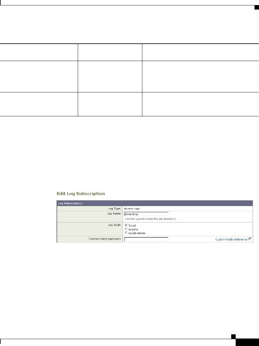
24-49
Cisco IronPort AsyncOS 7.1 for Web User Guide
OL-23207-01
Chapter 24 Logging
Custom Formatting in Access Logs and W3C Logs
Configuring Custom Formatting in Access Logs
Use the System Administration > Log Subscriptions page to configure custom
formatting for access log file entries. Click the access log file name to edit the
access log subscription.
Figure 24-2 Configuring Custom Log Fields in the Access Logs
The syntax for entering format specifiers in the Custom Field is as follows:
<format_specifier1> <format_specifier2>
For example: %a %b %E
You can add tokens before the format specifiers to display descriptive text in the
access log file. For example:
client_IP %a body_bytes %b error_type %E
where client_IP is the description token for log format specifier %a, body_bytes
is the descriptive token for %b, and error_type is the descriptive token for %E.
x-p2p-webroot-resp-svc-time %:w< Wait-time to receive the verdict from the
Webroot scanning engine, including the time
required for the Web Proxy to send the
request.
x-p2p-webroot-resp-wait-tim
e
%:w> Wait-time to receive the response from the
Webroot scanning engine, after the Web
Proxy sent the request.
Table 24-11 Log Fields in W3C Logs and Format Specifiers in Access Logs
W3C Log Field
Format Specifier in
Access Logs Description
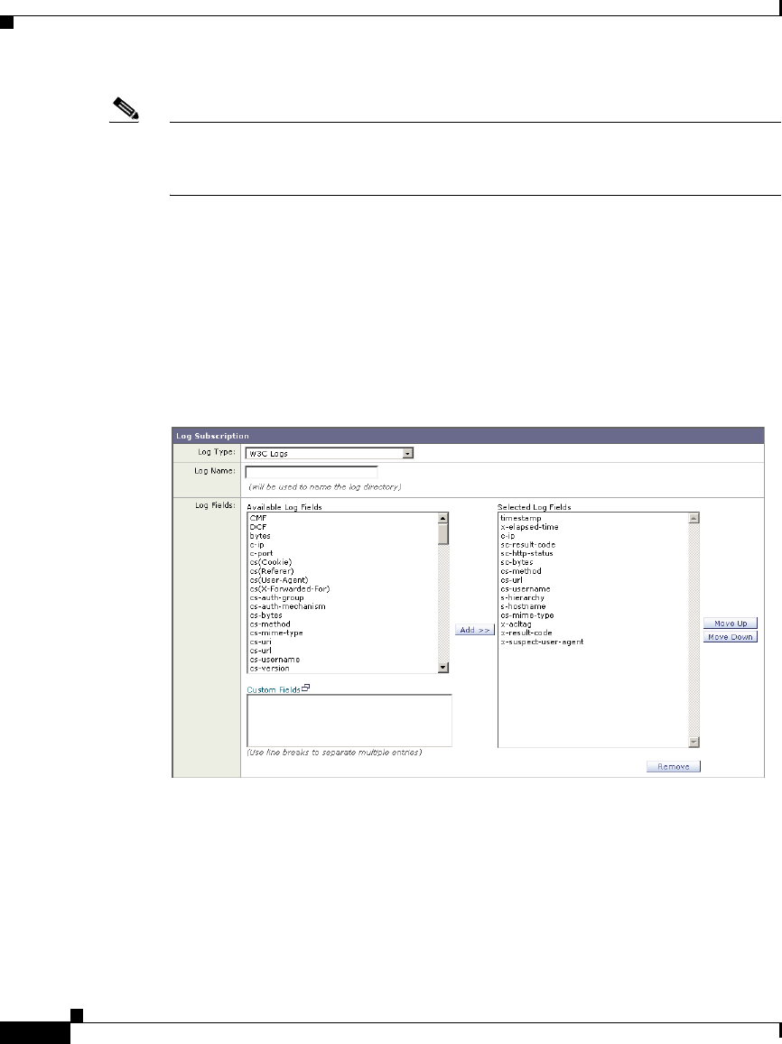
Chapter 24 Logging
Custom Formatting in Access Logs and W3C Logs
24-50
Cisco IronPort AsyncOS 7.1 for Web User Guide
OL-23207-01
Note You can create a custom field for any header in a client request or a server
response. For more information, see Including HTTP/HTTPS Headers in Log
Files, page 24-51.
Configuring Custom Formatting in W3C Logs
Use the System Administration > Log Subscriptions page to configure custom
formatting for W3C log file entries. Click the W3C log file name to edit the W3C
log subscription.
Figure 24-3 Configuring Custom Log Fields in the W3C Logs
Enter the custom fields to add in the Custom Fields text box in the Log Fields
section. You can enter multiple custom fields in the Custom Fields text box and
add them simultaneously as long as each entry is separated by a new line (click
Enter) before clicking Add.

24-51
Cisco IronPort AsyncOS 7.1 for Web User Guide
OL-23207-01
Chapter 24 Logging
Including HTTP/HTTPS Headers in Log Files
Note You can create a custom field for any header in a client request or a server
response. For more information, see Including HTTP/HTTPS Headers in Log
Files, page 24-51.
Including HTTP/HTTPS Headers in Log Files
If the list of predefined access log and W3C log fields does not include all header
information you want to log from HTTP/HTTPS transactions, you can type a user
defined log field in the Custom Fields text box when you configure the access and
W3C log subscriptions.
Custom log fields can be any data from any header sent from the client or the
server. If a request or response does not include the header added to the log
subscription, the log file includes a hyphen as the log field value.
Table 24-12 defines the syntax to use for access and W3C logs.
For example, if you want to log the If-Modified-Since header value in client
requests, enter the following text in the Custom Fields box for a W3C log
subscription:
cs(If-Modified-Since)
Table 24-12 Configuring HTTP/HTTPS Headers in Log Files
Header Type
Access Log Format
Specifier Syntax W3C Log Custom Field Syntax
Header from the
client application
%<ClientHeaderName:cs(ClientHeaderName)
Header from the
server
%<ServerHeaderName: sc(ServerHeaderName)

Chapter 24 Logging
Malware Scanning Verdict Values
24-52
Cisco IronPort AsyncOS 7.1 for Web User Guide
OL-23207-01
Malware Scanning Verdict Values
A malware scanning verdict is a value assigned to a URL request or server
response that determines the probability that it contains malware. The scanning
engines return the malware scanning verdict to the DVS engine so the DVS engine
can determine whether to monitor or block the scanned object.
They are the result of proprietary calculations that associate a numerical value to
the probability that either the URL request or the response content contains
malware. Each malware scanning verdict corresponds to a malware category
listed on the Access Policies > Reputation and Anti-Malware Settings page when
you edit the anti-malware settings for a particular Access Policy.
Both the Webroot and McAfee scanning engines can return malware scanning
verdicts to the DVS engine. For more information about how the DVS engine
handles malware scanning verdicts, see IronPort DVS™ (Dynamic Vectoring and
Streaming) Engine, page 19-4.
Table 24-13 lists the different Malware Scanning Verdict Values and each
malware category with which they correspond.
Table 24-13 Malware Scanning Verdict Values
Malware Scanning Verdict Value Malware Category
-Not set
0 Unknown
1 Not Scanned or Skipped
2Timeout
3 Unscannable
4 Unscannable
5 Freelist Exhaustion
6Bad verdict
7 No Launch Method
10 Other Malware
12 Browser Helper Object
13 Adware
14 System Monitor

24-53
Cisco IronPort AsyncOS 7.1 for Web User Guide
OL-23207-01
Chapter 24 Logging
Traffic Monitor Log
Traffic Monitor Log
The L4 Traffic Monitor log file provides a detailed record of monitoring activity.
You can view L4 Traffic Monitor log file entries and track updates to firewall
block lists and firewall allow lists. Consider the following example log entries:
Example 1
172.xx.xx.xx discovered for blocksite.net (blocksite.net) added to
firewall block list.
In this example, where a match becomes a block list firewall entry. The L4 Traffic
Monitor matched an IP address to a domain name in the block list based on a DNS
request which passed through the appliance. The IP address is then entered into
the block list for the firewall.
18 Commercial System Monitor
19 Dialer
20 Hijacker
21 Phishing URL
22 Trojan Downloader
23 Trojan Horse
24 Trojan Phisher
25 Worm
26 Encrypted File
27 Virus
28 Too Many Outstanding requests
33 Other Malware
34 PUA
Table 24-13 Malware Scanning Verdict Values (continued)
Malware Scanning Verdict Value Malware Category

Chapter 24 Logging
Troubleshooting
24-54
Cisco IronPort AsyncOS 7.1 for Web User Guide
OL-23207-01
Example 2
172.xx.xx.xx discovered for www.allowsite.com (www.allowsite.com)
added to firewall allow list.
In this example, a match becomes an allow list firewall entry. The L4 Traffic
Monitor matched a domain name entry and added it to the appliance allow list.
The IP address is then entered into the allow list for the firewall.
Example 3
Firewall noted data from 172.xx.xx.xx to 209.xx.xx.xx
(allowsite.net):80.
In this example, the L4 Traffic Monitor logs a record of data that passed between
an internal IP address and an external IP address which is on the block list. Also,
the L4 Traffic Monitor is set to monitor, not block.
Troubleshooting
AsyncOS for Web sends a critical email message to the configured alert recipients
when the internal logging process drops web transaction events due to a full
buffer.
By default, when the Web Proxy experiences a very high load, the internal logging
process buffers events to record them later when the Web Proxy load decreases.
When the logging buffer fills completely, the Web Proxy continues to process
traffic, but the logging process does not record some events in the access logs or
in the Web Tracking report. This might occur during a spike in web traffic.
However, a full logging buffer might also occur when the appliance is over
capacity for a sustained period of time. AsyncOS for Web continues to send the
critical email messages every few minutes until the logging process is no longer
dropping data.
The critical message contains the following text:
Reporting Client: The reporting system is unable to maintain the rate
of data being generated. Any new data generated will be lost.
If AsyncOS for Web sends this critical message continuously or frequently, the
appliance might be over capacity. Contact Cisco IronPort Customer Support to
verify whether or not you need additional Web Security appliance capacity.

24-55
Cisco IronPort AsyncOS 7.1 for Web User Guide
OL-23207-01
Chapter 24 Logging
Troubleshooting

Chapter 24 Logging
Troubleshooting
24-56
Cisco IronPort AsyncOS 7.1 for Web User Guide
OL-23207-01

CHAPTER
25-1
Cisco IronPort AsyncOS 7.1 for Web User Guide
OL-23207-01
25
Configuring Network Settings
This chapter contains the following information:
•Changing the System Hostname, page 25-1
•Configuring Network Interfaces, page 25-2
•Configuring TCP/IP Traffic Routes, page 25-7
•Virtual Local Area Networks (VLANs), page 25-9
•Configuring Transparent Redirection, page 25-17
•Configuring SMTP Relay Hosts, page 25-26
•Configuring DNS Server(s), page 25-28
Changing the System Hostname
The hostname parameter is used to identify the system at the CLI prompt. You
must enter a fully-qualified hostname for the system. The hostname parameter is
also used in end-user notification pages, end-user acknowledgement pages, and to
form the machine NetBIOS name when the Web Security appliance joins an
Active Directory domain. It has no direct relationship with the hostname
configured for the interface.

Chapter 25 Configuring Network Settings
Configuring Network Interfaces
25-2
Cisco IronPort AsyncOS 7.1 for Web User Guide
OL-23207-01
Use the sethostname command to change the name of the Web Security
appliance:
Configuring Network Interfaces
You can configure the appliance network interfaces by modifying IP address,
subnet, and hostname information for the Management, Data, and L4 Traffic
Monitor interfaces. Table 25-1 describes the network interface settings you can
configure.
example.com> sethostname
example.com> hostname.com
example.com> commit
Table 25-1 Web Security Appliance Network Interface Settings
Interface Port Number Description
Management M1 By default, the Management interface is used to
administer the appliance and Web Proxy (data)
monitoring. However, you can configure the M1
port for management use only.

25-3
Cisco IronPort AsyncOS 7.1 for Web User Guide
OL-23207-01
Chapter 25 Configuring Network Settings
Configuring Network Interfaces
Note If the Management and Data interfaces are all configured, each must be assigned
IP addresses on different subnets.
You can manage the network interfaces using the following methods:
•Web interface. Use the Network > Interfaces page. For more information, see
Configuring the Network Interfaces from the Web Interface, page 25-5.
•Command line interface. Use the ifconfig CLI command to create, edit,
and delete network interfaces.
Configuring the Data Interfaces
You can configure the Web Security appliance to use any of the following
combinations of network interfaces for data traffic:
•M1 only
Data P1 and P2
(proxy)
The Data interfaces are used for Web Proxy
monitoring and L4 Traffic Monitor blocking
(optional). You can also configure these
interfaces to support outbound services such as
DNS, software upgrades, NTP, and traceroute
data traffic.
For more information about configuring the Data
interfaces, see Configuring the Data Interfaces,
page 25-3.
L4 Traffic
Monitor
T1 and T2 The L4 Traffic Monitor interfaces are used to
configure a duplex or simplex wiring type.
•Duplex. The T1 interface receives incoming
and outgoing traffic.
•Simplex. T1 receives outgoing traffic and T2
receives incoming traffic.
Table 25-1 Web Security Appliance Network Interface Settings (continued)
Interface Port Number Description

Chapter 25 Configuring Network Settings
Configuring Network Interfaces
25-4
Cisco IronPort AsyncOS 7.1 for Web User Guide
OL-23207-01
•M1 and P1
•M1, P1, and P2
•P1 only
•P1 and P2
You can enable the M1 and P1 ports during or after System Setup. However, you
can only enable the P2 port after System Setup in the web interface or using the
ifconfig CLI command.
The Web Proxy listens for client web requests on different network interfaces
depending on how you configure the Web Security appliance:
•M1. The Web Proxy listens for requests on this interface when it is not
configured to be restricted to appliance management services only.
•P1. The Web Proxy listens for requests on this interface when it is enabled.
•P2. By default, the Web Proxy does not listen for requests on this interface,
even when enabled. However, you can configure it to listen for requests on P2
using the advancedproxyconfig > miscellaneous CLI command.
To configure the appliance to use P2 as a second data interface:
Step 1 Configure the appliance to use P1 as the interface for data traffic. You can do this
during System Setup or after initial setup on the Network > Interfaces page.
Step 2 Enable P2 in the web interface (see Configuring the Network Interfaces from the
Web Interface, page 25-5) or using the ifconfig CLI command.
Note If the Management and Data interfaces are all configured, each must be
assigned IP addresses on different subnets.
Step 3 In the web interface, go to the Network > Routes page. Change the Default Route
for data traffic to specify the next IP address that the P2 interface is connected to.
Note If you enable P2 to listen for client requests using the advancedproxyconfig >
miscellaneous CLI command, you can choose whether to use P1 or P2 for
outgoing traffic. To use P1 for outgoing traffic, change the Default Route for data
traffic to specify the next IP address that the P1 interface is connected to.
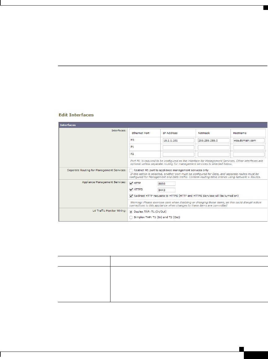
25-5
Cisco IronPort AsyncOS 7.1 for Web User Guide
OL-23207-01
Chapter 25 Configuring Network Settings
Configuring Network Interfaces
Configuring the Network Interfaces from the Web Interface
To configure the network interfaces from the web interface:
Step 1 Navigate to the Network > Interfaces page. Click Edit Settings.
The Edit Interfaces page appears.
Figure 25-1 Editing Network Interfaces
Step 2 Configure interface settings as necessary.
Table 25-2 describes the interface settings you can define for each interface.
Table 25-2 Interface Settings
Interface Setting Description
IP Address Enter the IP address to use to manage the Web Security
appliance.
Enter an IP address that exists on your management
network.

Chapter 25 Configuring Network Settings
Configuring Network Interfaces
25-6
Cisco IronPort AsyncOS 7.1 for Web User Guide
OL-23207-01
Step 3 Specify whether or not to have separate routing for the Management Services
using the “Restrict M1 port to appliance management services only” field.
If this checkbox is selected, the M1 port is used for appliance management
services only and is not used for the data (Web Proxy) traffic. You will need
to configure another port for data traffic as well as separate routes for
management and data traffic. For more information about configuring routes,
see Configuring TCP/IP Traffic Routes, page 25-7.
Step 4 Configure Appliance Management Services.
Choose whether or not to use HTTP or HTTPS to administer AsyncOS
through the web interface. You must specify the port to access AsyncOS with
each protocol you configure.
You can also choose to redirect HTTP requests to HTTPS. When you do this,
AsyncOS automatically enables both HTTP and HTTPS.
Step 5 Choose the type of wired connections plugged into the “T” network interfaces:
–
Duplex TAP. Choose Duplex TAP when the T1 port receives both
incoming and outgoing traffic. You can use half- or full-duplex Ethernet
connections.
–
Simplex TAP. Choose Simplex TAP when you connect the T1 port to the
internal network (traffic flows from the clients to the Internet) and you
connect the T2 port to the external network (traffic flows from the
Internet to the clients).
Note Cisco recommends using simplex when possible because it can increase
performance and security.
Step 6 Submit and commit your changes.
Netmask Enter the network mask to use when managing the Web
Security appliance on this network interface.
Hostname Enter the hostname to use when managing the Web Security
appliance on this network interface.
Table 25-2 Interface Settings (continued)
Interface Setting Description

25-7
Cisco IronPort AsyncOS 7.1 for Web User Guide
OL-23207-01
Chapter 25 Configuring Network Settings
Configuring TCP/IP Traffic Routes
Configuring TCP/IP Traffic Routes
You can administer routes for data and management traffic, add static routes, load
your IP routing tables, and modify the default gateway using the Network >
Routes page or the routeconfig command.
The number of sections on this page is determined by how the “Restrict M1 port
to appliance management services only” check box is configured on the Network
> Interfaces page:
•Separate route configuration sections for Management and Data traffic.
When you use the Management interface for management traffic only
(“Restrict M1 port” is enabled), then this page includes two sections to enter
route table information, one for management traffic and one for data traffic.
AsyncOS uses the management route information for management traffic
only, and data route information for data traffic. Figure 25-3 on page 9 shows
the Routes page when the option is enabled.
•One route configuration section for all traffic (Management and Data).
When you use the Management interface for both management and data
traffic (“Restrict M1 port” is disabled), then this page includes one section to
enter route table information for all traffic that leaves the Web Security
appliance, both management and data traffic.
Note A route gateway must reside on the same subnet as the Management or Data
interface on which it is configured.
Modifying the Default Route
You can modify the default gateway in the web interface or in the CLI using the
setgateway CLI command.
Note The Web Proxy sends out transactions on the data interface that is on the same
network as the default gateway configured for data traffic.
To modify the default gateway in the web interface:
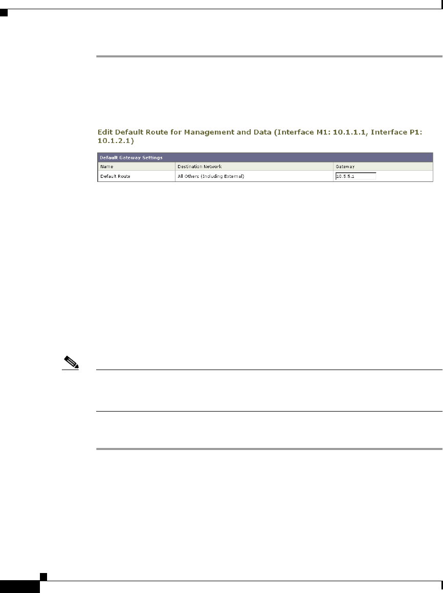
Chapter 25 Configuring Network Settings
Configuring TCP/IP Traffic Routes
25-8
Cisco IronPort AsyncOS 7.1 for Web User Guide
OL-23207-01
Step 1 Navigate to the Network > Routes page, and click on Default Route in the
corresponding table.
Figure 25-2 Editing the Default Route
Step 2 In the Gateway column, enter the IP address of the computer system on the next
hop of the network connected to the network interface you are editing.
Step 3 Submit and commit your changes.
Working With Routing Tables
You can save your current routing table to a file. You can load a previously saved
route table. You can add new routes or delete existing ones.
To save a route table, click Save Route Table and specify where to save the file.
To load a previously saved route table, click Load Route Table, navigate to the
file, and then submit and commit your changes.
Note When the destination address is on the same subnet as one of the physical network
interfaces, AsyncOS sends data using the network interface with the same subnet.
It does not consult the routing tables.
To add a route:
Step 1 Navigate to the Network > Routes page.
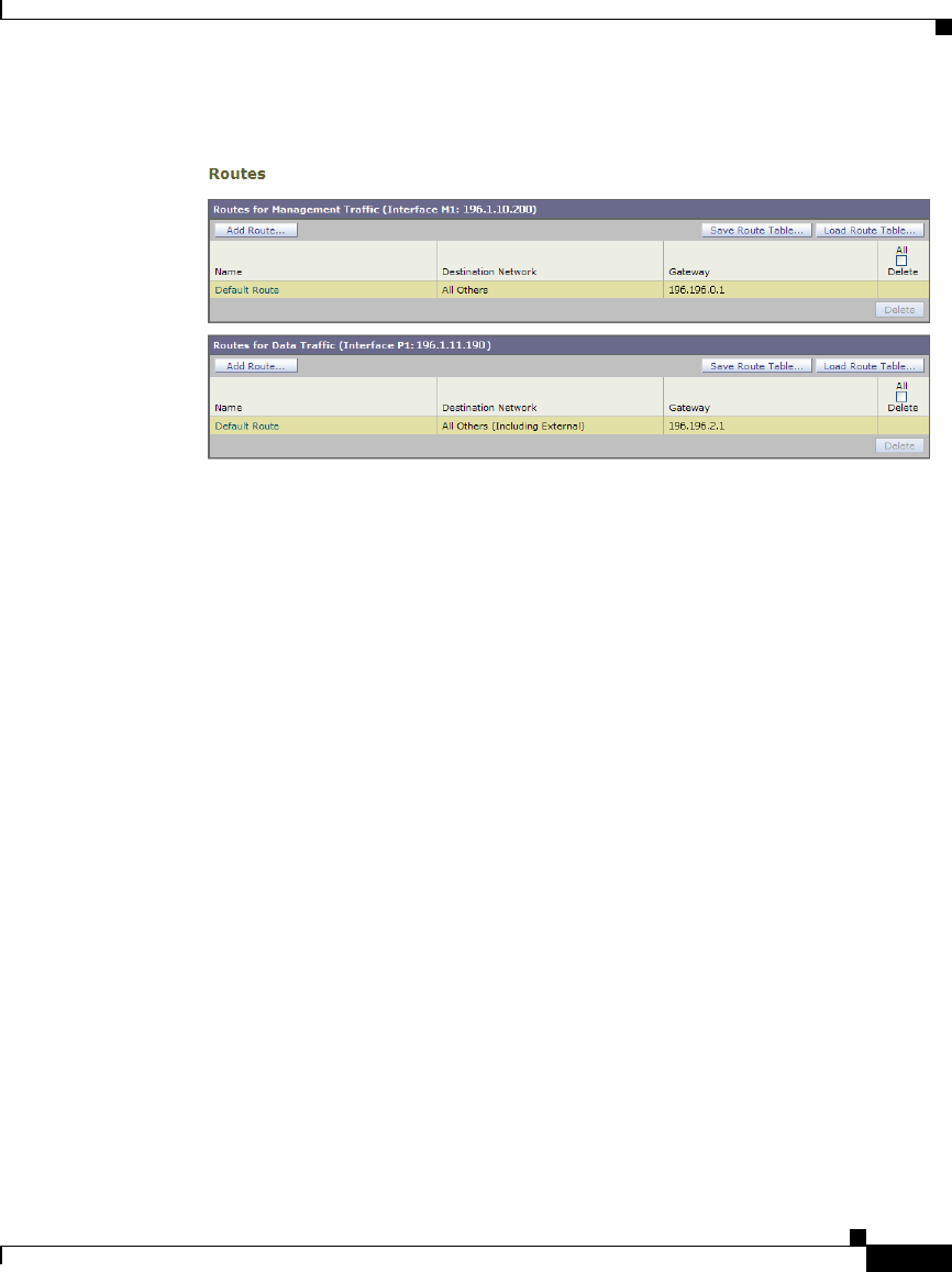
25-9
Cisco IronPort AsyncOS 7.1 for Web User Guide
OL-23207-01
Chapter 25 Configuring Network Settings
Virtual Local Area Networks (VLANs)
Figure 25-3 Adding a Route
Step 2 Click the Add Route button corresponding to the interface for which you are
creating the route. The Add Route page is displayed.
Step 3 Enter a Name, Destination Network, and Gateway.
Step 4 Submit and commit your changes.
Virtual Local Area Networks (VLANs)
VLANs are virtual local area networks bound to physical data ports. You can
configure one or more VLANs to increase the number of networks the IronPort
appliance can connect to beyond the number of physical interfaces included. For
example, a Web Security appliance has two data interfaces available for VLANs:
P1 and Management. VLANs allow more networks to be defined on separate
“ports” on existing interfaces. Figure 25-4 provides an example of configuring
several VLANs on the P1 interface.
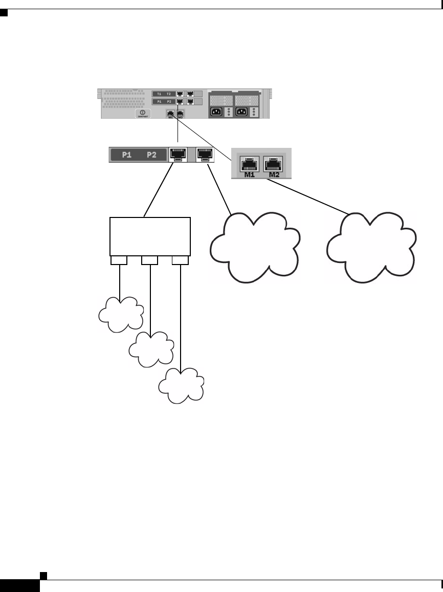
Chapter 25 Configuring Network Settings
Virtual Local Area Networks (VLANs)
25-10
Cisco IronPort AsyncOS 7.1 for Web User Guide
OL-23207-01
Figure 25-4 Using VLANs to Increase the Number of Networks Available on
the Appliance
VLANs can be used to segment networks for security purposes, to ease
administration, or increase bandwidth. For example, create multiple VLANs on
the P1 interface and then apply different policies to each. VLANs appear as
dynamic “Data Ports” labeled in the format of: “VLAN DDDD” where the
“DDDD” is the ID and is an integer up to 4 digits long (VLAN 2, or VLAN 4094
for example). AsyncOS supports up to 30 VLANs. Duplicate VLAN IDs are not
allowed on an IronPort appliance.
NOC
DMZ
VLAN
“Router”
VLAN1
VLAN3
VLAN2
IronPort appliance configured for VLAN1,
VLAN2, and VLAN3

25-11
Cisco IronPort AsyncOS 7.1 for Web User Guide
OL-23207-01
Chapter 25 Configuring Network Settings
Virtual Local Area Networks (VLANs)
VLANs and Physical Ports
A physical port does not need an IP address configured in order to be in a VLAN.
The physical port on which a VLAN is created can have an IP that will receive
non-VLAN traffic, so you can have both VLAN and non-VLAN traffic on the
same interface.
VLANs can only be created on the Management and P1 data ports.
Managing VLANs
You can create, edit and delete VLANs via the etherconfig command. Once
created, a VLAN can be configured via the interfaceconfig command in the
CLI. Remember to commit all changes.
Creating a New VLAN via the etherconfig Command
In this example, two VLANs are created (named VLAN 31 and VLAN 34) on the
P1 port:
Note Do not create VLANs on the T1 or T2 interfaces.
example.com> etherconfig
Choose the operation you want to perform:
- MEDIA - View and edit ethernet media settings.
- VLAN - View and configure VLANs.
- MTU - View and configure MTU.
[]> vlan
VLAN interfaces:

Chapter 25 Configuring Network Settings
Virtual Local Area Networks (VLANs)
25-12
Cisco IronPort AsyncOS 7.1 for Web User Guide
OL-23207-01
Choose the operation you want to perform:
- NEW - Create a new VLAN.
[]> new
VLAN ID for the interface (Ex: "34"):
[]> 34
Enter the name or number of the ethernet interface you wish bind to:
1. Management
2. P1
3. T1
4. T2
[1]> 2
VLAN interfaces:
1. VLAN 34 (P1)
Choose the operation you want to perform:
- NEW - Create a new VLAN.
- EDIT - Edit a VLAN.
- DELETE - Delete a VLAN.

25-13
Cisco IronPort AsyncOS 7.1 for Web User Guide
OL-23207-01
Chapter 25 Configuring Network Settings
Virtual Local Area Networks (VLANs)
Choose the operation you want to perform:
- NEW - Create a new VLAN.
[]> new
VLAN ID for the interface (Ex: "34"):
[]> 34
Enter the name or number of the ethernet interface you wish bind to:
1. Management
2. P1
3. T1
4. T2
[1]> 2
VLAN interfaces:
1. VLAN 34 (P1)
Choose the operation you want to perform:
- NEW - Create a new VLAN.
- EDIT - Edit a VLAN.
- DELETE - Delete a VLAN.

Chapter 25 Configuring Network Settings
Virtual Local Area Networks (VLANs)
25-14
Cisco IronPort AsyncOS 7.1 for Web User Guide
OL-23207-01
[]> new
VLAN ID for the interface (Ex: "34"):
[]> 31
Enter the name or number of the ethernet interface you wish bind to:
1. Management
2. P1
3. T1
4. T2
[1]> 2
VLAN interfaces:
1. VLAN 31 (P1)
2. VLAN 34 (P1)
Choose the operation you want to perform:
- NEW - Create a new VLAN.
- EDIT - Edit a VLAN.
- DELETE - Delete a VLAN.
[]>

25-15
Cisco IronPort AsyncOS 7.1 for Web User Guide
OL-23207-01
Chapter 25 Configuring Network Settings
Virtual Local Area Networks (VLANs)
Creating an IP Interface on a VLAN via the interfaceconfig Command
In this example, a new IP interface is created on the VLAN 34 ethernet interface.
Note Making changes to an interface may close your connection to the appliance.
example.com> interfaceconfig
Currently configured interfaces:
1. Management (10.10.1.10/24 on Management: example.com)
2. P1 (10.10.0.10 on P1: example.com)
Choose the operation you want to perform:
- NEW - Create a new interface.
- EDIT - Modify an interface.
- GROUPS - Define interface groups.
- DELETE - Remove an interface.
[]> new
IP Address (Ex: 10.10.10.10):
[]> 10.10.31.10
Ethernet interface:
1. Management

Chapter 25 Configuring Network Settings
Virtual Local Area Networks (VLANs)
25-16
Cisco IronPort AsyncOS 7.1 for Web User Guide
OL-23207-01
2. P1
3. VLAN 31
4. VLAN 34
[1]> 4
Netmask (Ex: "255.255.255.0" or "0xffffff00"):
[255.255.255.0]>
Hostname:
[]> v.example.com
Currently configured interfaces:
1. Management (10.10.1.10/24 on Management: example.com)
2. P1 (10.10.0.10 on P1: example.com)
3. VLAN 34 (10.10.31.10 on VLAN 34: v.example.com)
Choose the operation you want to perform:
- NEW - Create a new interface.
- EDIT - Modify an interface.
- DELETE - Remove an interface.
[]>
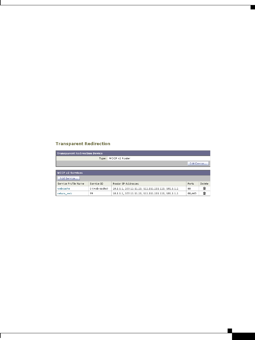
25-17
Cisco IronPort AsyncOS 7.1 for Web User Guide
OL-23207-01
Chapter 25 Configuring Network Settings
Configuring Transparent Redirection
Configuring Transparent Redirection
When you configure the Web Security appliance web proxy service in transparent
mode, you must connect the appliance to an L4 switch or a WCCP v2 router, and
you must configure the appliance so it knows to which device it is connected. You
configure the device on the Network > Transparent Redirection page.
Figure 25-5 Network > Transparent Redirection Page
On this page, you can choose the device that transparently redirects traffic to the
appliance, either an L4 switch or a WCCP router. When you choose an L4 switch
as the device, there is nothing else to configure on this page.
However, when you choose a WCCP router as the device, you must create at least
one WCCP service.
Working with WCCP Services
A WCCP service is an appliance configuration that defines a service group to a
WCCP v2 router. It includes information such as the service ID and ports used.
Service groups allow a web proxy to establish connectivity with a WCCP router
and to handle redirected traffic from the router.
You can create WCCP services that use the following service types:
example.com> commit

Chapter 25 Configuring Network Settings
Configuring Transparent Redirection
25-18
Cisco IronPort AsyncOS 7.1 for Web User Guide
OL-23207-01
•Standard service. The standard service is also known as a well known
service because the characteristics of it are known by both WCCP routers and
the appliance. It redirects traffic on port 80. It is identified as the “web-cache”
service.
•Dynamic service. Dynamic services are any other service a web proxy
creates, but the web proxy must describe the components of the service group
to the router. AsyncOS supports the creation of any dynamic service you
choose to define. To create a dynamic service, you must provide the service
ID number, port numbers, and specify whether to redirect packets based on
the destination or source port and whether to distribute packets based on the
client or server address.
The Web Cache Communication Protocol allows 257 different service IDs.
AsyncOS allows you to create a dynamic WCCP service for each possible service
ID. However, in typical usage, most users create one or two WCCP services,
where one is a standard service and the other a dynamic service.
When you create a WCCP service of any type, you must also specify the following
information:
•Assignment method. For more information, see Working with the
Assignment Method, page 25-18.
•Forwarding and Return method. For more information, see Working with
the Forwarding and Return Method, page 25-19.
If you enable IP spoofing on the appliance, you must create two WCCP services.
For more information, see IP Spoofing when Using WCCP, page 25-20.
Working with the Assignment Method
WCCP defines the assignment method as the method by which redirected packets
are distributed between web proxies. In this case, between one or more Web
Security appliances. The assignment method determines how the router performs
load balancing of packets among multiple Web Security appliances.
You configure the assignment method for a WCCP service in the Load-Balancing
Method field under the Advanced section when you create or edit a WCCP
service.
You can configure WCCP services to use either of the following assignment
methods:

25-19
Cisco IronPort AsyncOS 7.1 for Web User Guide
OL-23207-01
Chapter 25 Configuring Network Settings
Configuring Transparent Redirection
•Mask. This method relies on masking to make redirection decisions. WCCP
routers make decisions using hardware in the router. This method can be very
efficient because the hardware redirects the packets. You might want to
choose mask to reduce CPU cycles on the router which can increase router
performance. You can only use mask with WCCP routers that support mask
assignment.
Note AsyncOS chooses the mask value to use with the router. You cannot
configure the mask value.
•Hash. This method relies on a hash function to make redirection decisions.
You might want to use Hash when the WCCP router does not support
masking.
You can also configure a WCCP service to allow either mask or hash load
balancing. When a WCCP service allows both mask and hash, AsyncOS
communicates with the router to determine whether or not the router supports
mask. If the router supports mask, then AsyncOS uses masking in the service
group, if the router does not support mask, then AsyncOS uses hashing in the
service group.
Working with the Forwarding and Return Method
WCCP defines the forwarding method as the method by which redirected packets
are transported from the router to the web proxy. Conversely, the return method
redirects packets from the web proxy to the router.
You configure the forwarding and return methods for a WCCP service in the
Forwarding Method and Return Method fields under the Advanced section when
you create or edit a WCCP service.
You can configure WCCP services to use either of the following methods:
•Layer 2 (L2). This method redirects traffic at layer 2 by replacing the
packet’s destination MAC address with the MAC address of the target web
proxy. This method requires that the target web proxy be directly connected
to the router at layer 2. WCCP routers only allow L2 negotiation when the
appliance is directly connected to the router at layer 2. The L2 method
redirects traffic at the router hardware level, and typically has better
performance than Generic Routing Encapsulation (GRE). You might want to

Chapter 25 Configuring Network Settings
Configuring Transparent Redirection
25-20
Cisco IronPort AsyncOS 7.1 for Web User Guide
OL-23207-01
choose L2 when the router is directly connected to the appliance and you
want the performance improvement provided by the L2 method. You can only
use the L2 method with WCCP routers that support L2 forwarding.
•Generic Routing Encapsulation (GRE). This method redirects traffic at
layer 3 by encapsulating the IP packet with a GRE header and a redirect
header. This method redirects traffic at the router software level, which can
impact performance. You might want to choose GRE when the appliance is
not directly connected to the router.
You can also configure a WCCP service to allow either the L2 or GRE methods.
When a WCCP service allows both L2 and GRE, the appliance uses the method
that the router says it supports. If both the router and appliance support L2 and
GRE, the appliance uses L2.
Note If the router is not directly connected to the appliance, you must choose GRE.
IP Spoofing when Using WCCP
You can configure the Web Proxy to do IP spoofing. When enabled, requests
originating from a client retain the client’s source address and appear to originate
from the client instead of the Web Proxy.
When you enable IP spoofing, you must create two WCCP services. One WCCP
service must redirect traffic based on the destination port, and another based on
the source port for the return path. The service based on the destination port can
be the standard web-cache service. However, you must still create at least one
dynamic service.
The two WCCP services you define for IP spoofing must have the same values for
the following settings:
•Port numbers
•Router IP addresses
•Router security and password
Note IronPort suggests using a service ID number from 90 to 97 for the WCCP service
used for the return path (based on the source port).
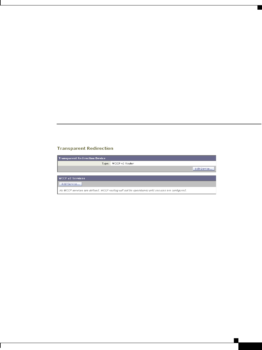
25-21
Cisco IronPort AsyncOS 7.1 for Web User Guide
OL-23207-01
Chapter 25 Configuring Network Settings
Configuring Transparent Redirection
For more information about creating WCCP services, see Adding and Editing a
WCCP Service, page 25-21.
Adding and Editing a WCCP Service
You must create at least one WCCP service when you configure the transparent
redirection device as a WCCP router. If IP spoofing is enabled on the appliance,
you must create two WCCP services. For more information about IP spoofing, see
IP Spoofing when Using WCCP, page 25-20.
To add or edit a WCCP service:
Step 1 Navigate to the Network > Transparent Redirection page.
Step 2 Verify the transparent redirection device is a WCCP v2 router. If it is not, click
Edit Device to change it.
Step 3 To add a WCCP service, click Add Service. Or, to edit a WCCP service, click the
name of the WCCP service in the Service Profile Name column.
The Add WCCP v2 Service page or Edit WCCP v2 Service page appears.
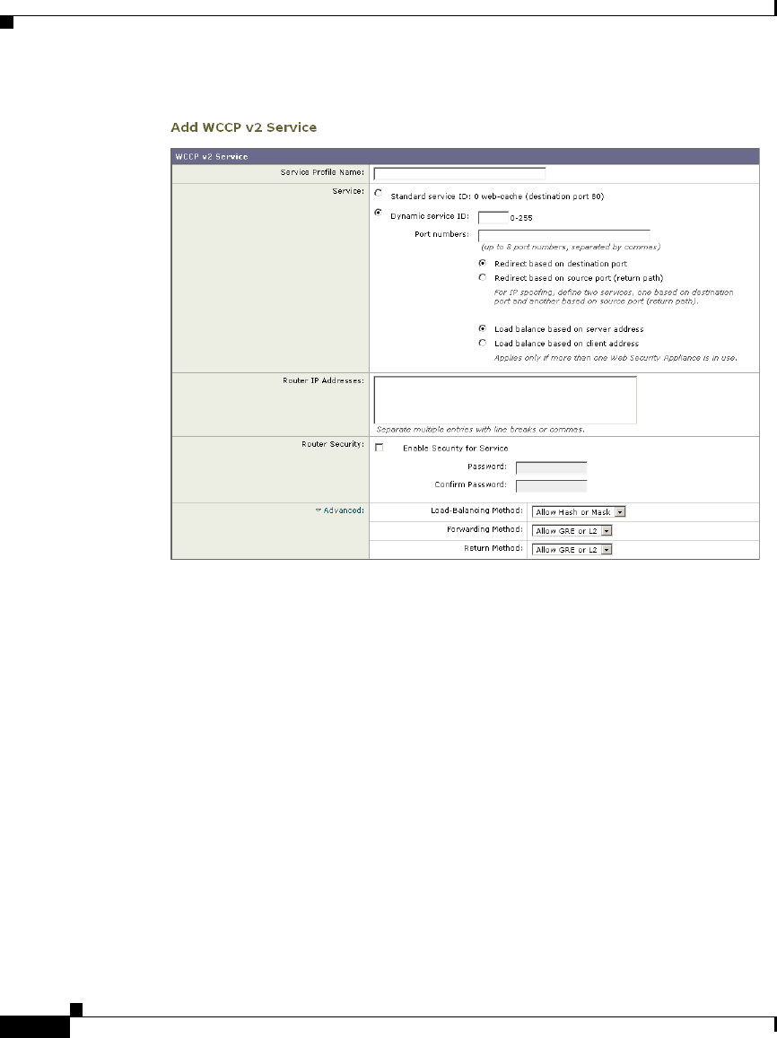
Chapter 25 Configuring Network Settings
Configuring Transparent Redirection
25-22
Cisco IronPort AsyncOS 7.1 for Web User Guide
OL-23207-01
Step 4 Configure the WCCP options.

25-23
Cisco IronPort AsyncOS 7.1 for Web User Guide
OL-23207-01
Chapter 25 Configuring Network Settings
Configuring Transparent Redirection
Table 25-3 describes the WCCP options.
Table 25-3 WCCP Service Options
WCCP Service Option Description
Service Profile Name Enter a name for the WCCP service.
Service Use this section to describe the service group for the
router.
Choose to create either a standard (“well known”) or
dynamic service group.
If you create a dynamic service, enter the following
information:
•Service ID. Enter any number from 0 to 255 in the
Dynamic Service ID field.
•Port number(s). Enter up to eight port numbers
for traffic to redirect in the Port Numbers field.
•Redirection basis. Choose to redirect traffic based
on the source or destination port. Default is
destination port.
•Load balancing basis. When the network uses
multiple Web Security appliances, you can choose
how to distribute packets among the appliances.
You can distribute packets based on the server or
client address. When you choose client address,
packets from a client always get distributed to the
same appliance. Default is server address.
For more information about well known and dynamic
service groups, see Working with WCCP Services,
page 25-17.
Router IP Addresses Enter the IP address for one or more WCCP enabled
routers. You can enter up to 32 routers to the service
group. You must enter the IP address of each router.
You cannot enter a multicast address.

Chapter 25 Configuring Network Settings
Configuring Transparent Redirection
25-24
Cisco IronPort AsyncOS 7.1 for Web User Guide
OL-23207-01
Router Security Choose whether or not to require a password for this
service group. If required, enter the password in the
password fields. The password can contain up to seven
characters.
When you enable security for a service group, every
appliance and WCCP router that uses the service group
must use the same password.
Requiring a password enables you to control which
routers and WCCP-enabled systems, such as the Web
Security appliance, become part of the service group.
WCCP uses the MD5 hash protocol to encrypt the
password.
Note — Each appliance or WCCP router in the service
group authenticate the security component in a
received WCCP packet immediately after validating
the WCCP message header. Packets failing
authentication are discarded.
Table 25-3 WCCP Service Options (continued)
WCCP Service Option Description

25-25
Cisco IronPort AsyncOS 7.1 for Web User Guide
OL-23207-01
Chapter 25 Configuring Network Settings
Configuring Transparent Redirection
Step 5 Submit and commit your changes.
Deleting a WCCP Service
To delete a WCCP service:
Step 1 Navigate to the Network > Transparent Redirection page.
Step 2 Click the icon in the Delete column for the WCCP service you want to delete.
Step 3 Commit your changes.
Advanced Configure the following fields:
•Load-Balancing Method. This is also known as
the assignment method. Choose Mask, Hash, or
both. Default is both.
For more information about load-balancing, see
Working with the Assignment Method,
page 25-18.
•Forwarding Method. Choose L2, GRE, or both.
Default is both.
For more information about the forwarding
method, see Working with the Forwarding and
Return Method, page 25-19.
•Return Method. Choose L2, GRE, or both.
Default is both.
For more information about the return method, see
Working with the Forwarding and Return Method,
page 25-19.
Table 25-3 WCCP Service Options (continued)
WCCP Service Option Description

Chapter 25 Configuring Network Settings
Configuring SMTP Relay Hosts
25-26
Cisco IronPort AsyncOS 7.1 for Web User Guide
OL-23207-01
Configuring SMTP Relay Hosts
AsyncOS periodically sends system-generated email messages, such as
notifications, alerts, and IronPort Customer Support requests. By default,
AsyncOS uses information listed in the MX record on your domain to send email.
However, if the appliance cannot directly reach the mail servers listed in the MX
record, you must configure at least one SMTP relay host on the appliance.
You might want to configure an SMTP relay host in the following scenarios:
•You want the system-generated emails to go to a non-local email address, and
port 25 is blocked to outside networks.
•Your mail servers do not allow direct port 25 traffic from internal hosts.
If no SMTP relay host is defined, AsyncOS delivers directly to the mail server for
each email address.
Note If the Web Security appliance cannot communicate with the mail servers listed in
the MX record or any of the configured SMTP relay hosts, it cannot send email
messages and it writes a message in the log files.
You can configure one or more SMTP relay hosts. You might want to configure
multiple SMTP relay hosts for redundancy in case one system becomes
unavailable. When you configure multiple SMTP relay hosts, AsyncOS uses the
topmost available SMTP relay host. If an SMTP relay host is unavailable, it tries
to use the one below it in the list.
You can configure the SMTP relay host from either the web interface or command
line interface:
•Web interface. Use the Network > Internal SMTP Relay page.
•Command line interface. Use the smtprelay CLI command.
Configuring SMTP from the Web Interface
Use the Network > Internal SMTP Relay page.
To configure the SMTP relay host from the web interface:
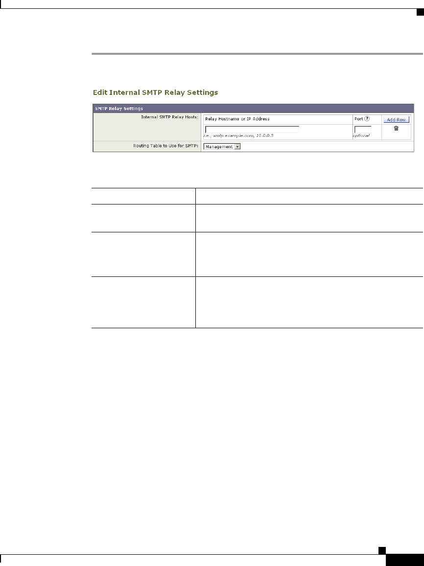
25-27
Cisco IronPort AsyncOS 7.1 for Web User Guide
OL-23207-01
Chapter 25 Configuring Network Settings
Configuring SMTP Relay Hosts
Step 1 Navigate to the Network > Internal SMTP Relay page, and click Edit Settings.
Step 2 Enter the information listed in Table 25-4.
Step 3 Optionally, you can add more SMTP relay host information by clicking Add Row.
Step 4 Submit and commit your changes.
Configuring SMTP from the CLI
Use the smtprelay command to configure SMTP relay hosts.
For example:
Table 25-4 SMTP Relay Host Settings
Property Description
Relay Hostname or IP
Address
Enter the hostname or IP address to use for the SMTP
relay
Port Enter the port for connecting to the SMTP relay. If this
property is empty, the appliance uses port 25.
This property is optional.
Routing Table to Use
for SMTP
Choose the routing table associated with an appliance
network interface, either Management or Data, to use
for connecting to the SMTP relay. Choose whichever
interface is on the same network as the relay system.
example.com> smtprelay
No internal SMTP relay host configured.
Choose the operation you want to perform:

Chapter 25 Configuring Network Settings
Configuring DNS Server(s)
25-28
Cisco IronPort AsyncOS 7.1 for Web User Guide
OL-23207-01
Configuring DNS Server(s)
You can configure the DNS settings for your IronPort appliance using the
Network > DNS page or using the dnsconfig command. Before you configure
DNS, consider the following:
•Whether to use the Internet’s DNS servers or your own, and which specific
server(s) to use.
•Which routing table to use for DNS traffic.
You must use the routing table associated with the interface that faces the
DNS server, either Data or Management.
•The number of seconds to wait before timing out a reverse DNS lookup.
•Clearing the DNS cache.
Specifying DNS Servers
IronPort AsyncOS can use the Internet root DNS servers or your own DNS
servers. When using the Internet root servers, you can specify alternate servers to
use for specific domains. Since an alternate DNS server applies to a single
domain, it must be authoritative (provide definitive DNS records) for that domain.
Split DNS
AsyncOS supports split DNS where internal servers are configured for specific
domains and external or root DNS servers are configured for other domains. If you
are using your own internal server, you can also specify exception domains and
associated DNS servers.
- NEW - Add a new host.
[]> new
Please enter the hostname of your relay host. You may put a colon
after the hostname to indicate a port to use other than 25, such as
“smtp.example.com:547”.

25-29
Cisco IronPort AsyncOS 7.1 for Web User Guide
OL-23207-01
Chapter 25 Configuring Network Settings
Configuring DNS Server(s)
Using the Internet Root Servers
The IronPort AsyncOS DNS resolver is designed to accommodate the large
number of simultaneous DNS connections.
Multiple Entries and Priority
For each DNS server you enter, you can specify a numeric priority. AsyncOS will
attempt to use the DNS server with the priority closest to 0. If that DNS server is
not responding AsyncOS will attempt to use the server at the next priority. If you
specify multiple entries for DNS servers with the same priority, the system
randomizes the list of DNS servers at that priority every time it performs a query.
The system then waits a short amount of time for the first query to expire or “time
out” and then increments with a slightly longer amount of time for subsequent
servers. The amount of time depends on the exact number of DNS servers and
priorities that have been configured. The timeout length is the same for all IP
addresses at any particular priority. The first priority gets the shortest timeout,
each subsequent priority gets a longer timeout. Further, the timeout period is
roughly 60 seconds. If you have one priority, the timeout for each server at that
priority is 60 seconds. If you have two priorities, the timeout for each server at the
first priority is 15 seconds, and each server at the second priority is 45 seconds.
For three priorities, the timeout increments are 5, 10, 45.
For example, four DNS servers with two configured at priority 0, one at priority
1, and one at priority 2:
AsyncOS randomly chooses between the two servers at priority 0. If one of the
priority 0 servers is down, the other is used. If both priority 0 servers are down,
the priority 1 server (1.2.3.6) is used, and finally, the priority 2 (1.2.3.7) server.
The timeout period is the same for both priority 0 servers, longer for the priority
1 server, and longer still for the priority 2 server.
Table 25-5 Example of DNS Servers, Priorities, and Timeout Intervals
Priority Server(s) Timeout (seconds)
0 1.2.3.4, 1.2.3.5 5, 5
1 1.2.3.6 10
2 1.2.3.7 45

Chapter 25 Configuring Network Settings
Configuring DNS Server(s)
25-30
Cisco IronPort AsyncOS 7.1 for Web User Guide
OL-23207-01
DNS Alert
If an alert with the message “Failed to bootstrap the DNS cache” is generated
when an appliance is rebooted, it means that the system was unable to contact its
primary DNS servers. This can happen at boot time if the DNS subsystem comes
online before network connectivity is established. If this message appears at other
times, it could indicate network issues or that the DNS configuration is not
pointing to a valid server.
Clearing the DNS Cache
You can use the Clear DNS Cache button on Network > DNS page, or the
dnsflush command to clear all information in the DNS cache when changes have
been made to your local DNS system. Using this command might cause a
temporary performance degradation while the cache is repopulated.
Configuring DNS
To edit DNS Settings:
Step 1 Navigate to the Network > DNS page.
Step 2 Click Edit Settings. The Edit DNS page appears.
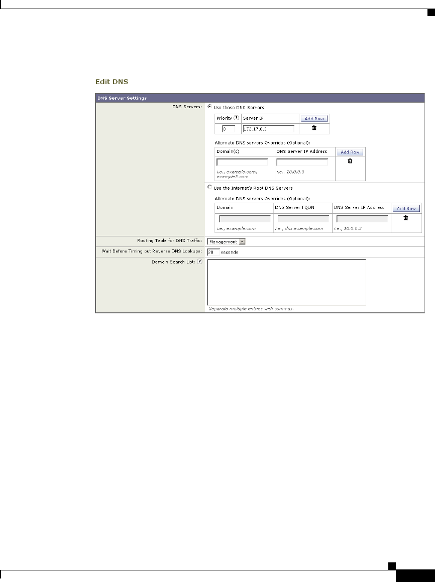
25-31
Cisco IronPort AsyncOS 7.1 for Web User Guide
OL-23207-01
Chapter 25 Configuring Network Settings
Configuring DNS Server(s)
Figure 25-6 Edit DNS Settings
Step 3 Select to use the Internet’s root DNS servers or your own internal DNS server or
the Internet’s root DNS servers and specify authoritative DNS servers.
Step 4 If you use your own DNS server(s), or specify authoritative DNS servers, enter
the server ID, specify a priority, and use the Add Row key to repeat as necessary
for each server.
Step 5 Choose the routing table associated with an appliance network interface type,
either Management or Data, to use for DNS traffic.
Step 6 Enter the number of seconds to wait before cancelling a reverse DNS lookup.
Step 7 Submit and commit to save the changes.

Chapter 25 Configuring Network Settings
Configuring DNS Server(s)
25-32
Cisco IronPort AsyncOS 7.1 for Web User Guide
OL-23207-01

CHAPTER
26-1
Cisco IronPort AsyncOS 7.1 for Web User Guide
OL-23207-01
26
System Administration
This chapter contains the following information:
•Managing the S-Series Appliance, page 26-1
•Support Commands, page 26-3
•Working with Feature Keys, page 26-10
•Administering User Accounts, page 26-12
•Configuring Administrator Settings, page 26-20
•Configuring the Return Address for Generated Messages, page 26-21
•Managing Alerts, page 26-22
•Setting System Time, page 26-30
•Installing a Server Digital Certificate, page 26-32
•Upgrading the System Software, page 26-40
•Configuring Upgrade and Service Update Settings, page 26-42
Managing the S-Series Appliance
The S-Series appliance provides a variety of tools for managing the system.
Functionality on System Administration tab helps you manage the following
tasks:
•Appliance configuration
•Feature keys

Chapter 26 System Administration
Managing the S-Series Appliance
26-2
Cisco IronPort AsyncOS 7.1 for Web User Guide
OL-23207-01
•Adding, editing, and removing user accounts
•AsyncOS software upgrades
•Updates to security components
•System time
Saving and Loading the Appliance Configuration
All configuration settings within the Web Security appliance can be managed
using a single configuration file. The file is maintained in XML (Extensible
Markup Language) format.
To archive the current configuration, you can use the System Administration >
Configuration Summary page to print a summary of appliance settings, and you
can use the System Administration > Configuration File page to create a local
copy of the system configuration file. The system configuration file can be used
to import a complete configuration or to load a unique sub-section and update
specific settings.
When you save the configuration file, you can choose a system-generated name
or define your own file name. You can mask the user’s passwords by clicking a
checkbox. Masking a password causes the original, encrypted password to be
replaced with “*****” in the exported or saved file. Please note, however, that
configuration files with masked passwords cannot be loaded back into AsyncOS
for Web.
Use the Load Configuration section of the System Administration >
Configuration File page to load new configuration information into the Web
Security appliance. You can load information using any of the following methods:
•Place information in the configuration directory and upload it.
•Upload the configuration file directly from your local machine.
•Paste configuration information directly into the web interface.
To load a copy of the configuration file, paste the configuration directly into the
web interface page. At the top of the configuration file you must include the
following tag:
<?xml version=”1.0” encoding=”ISO-8859-1”?> <!DOCTYPE config SYSTEM
“config.dtd”> <config> ... your configuration information in valid XML
</config>

26-3
Cisco IronPort AsyncOS 7.1 for Web User Guide
OL-23207-01
Chapter 26 System Administration
Support Commands
After loading the XML sub-section, submit and commit the update.
Committing Changes to the Appliance Configuration
Each time you modify settings and change appliance behavior using the S-Series
web interface, you must first submit your changes and then commit them to the
active configuration.
For more information about committing changes, see Committing and Clearing
Changes, page 2-14.
Support Commands
The features in this section are useful when you upgrade the appliance or contact
your support provider. You can find the following commands under the Technical
Support section of the Support and Help menu:
•Open a Support Case. For more information, see Open a Support Case,
page 26-3.
•Remote Access. For more information, see Remote Access, page 26-5.
•Packet Capture. For more information, see Packet Capture, page 26-6.
Open a Support Case
You can use the appliance to send an email to IronPort Customer Support asking
for assistance. When the appliance sends the email, it also sends the configuration
of the appliance. You can do this in the following ways:
•CLI. Use the supportrequest command.
•Web interface. Use the Support and Help menu > Open a Support Case page.
When you send a support request, you can enter comments describing the issue
for which you need support. The appliance must be able to send mail to the
Internet to send a support request.
To send a support request in the web interface:
Step 1 From the Support and Help menu, choose Open a Support Case.
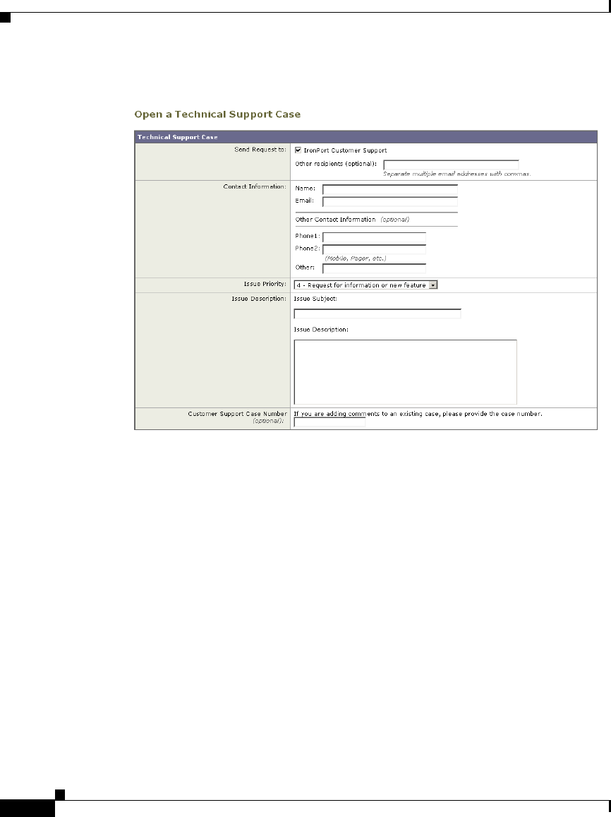
Chapter 26 System Administration
Support Commands
26-4
Cisco IronPort AsyncOS 7.1 for Web User Guide
OL-23207-01
Figure 26-1 Open a Technical Support Case Page
Step 2 In the Other Recipients field, enter other email addresses separated by commas if
you want to send this support request to other people.
By default, the support request (including the configuration file) is sent to
IronPort Customer Support (via the checkbox at the top of the form).
Step 3 Enter your contact information, such as name and email.
Step 4 From the Issue Priority field, select the priority of this support request.
Step 5 In the Issue Subject field, enter the text to use in the subject line of the email that
will be sent.
Step 6 In the Issue Description field, enter a description of the issue.
Step 7 If you have a customer support ticket already for this issue, enter it.
Step 8 Click Send.
A trouble ticket is automatically created with IronPort. For additional
information, see Cisco IronPort Customer Support, page 1-15.
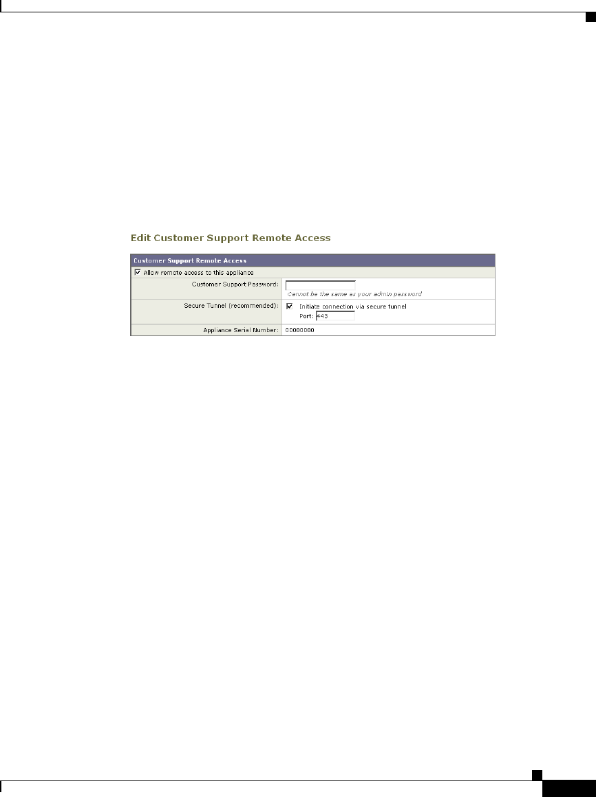
26-5
Cisco IronPort AsyncOS 7.1 for Web User Guide
OL-23207-01
Chapter 26 System Administration
Support Commands
Remote Access
Use the Support and Help menu > Remote Access page to allow IronPort
Customer Support remote access to the Web Security appliance. Click Edit
Remote Access Settings to allow IronPort Customer Support to access the
appliance.
Figure 26-2 Remote Access Page
By enabling Remote Access you are activating a special account used by IronPort
Customer Support for debugging and general access to the system. This is used by
IronPort Customer Support for tasks such as assisting customers in configuring
their systems, understanding configurations, and investigating problem reports.
You can also use the techsupport command in the CLI.
When enabling the “Secure Tunnel,” the appliance creates an SSH tunnel over the
specified port to the server upgrades.ironport.com. By default this connection is
over port 443, which will work in most environments. Once a connection is made
to upgrades.ironport.com, IronPort Customer Support is able to use the SSH
tunnel to obtain access to the appliance. As long as the connection over port 443
is allowed, this will bypass most firewall restrictions. You can also use the
techsupport tunnel command in the CLI.
In both the “Remote Access” and “Tunnel” modes, a password is required. It is
important to understand that this is not the password that will be used to access
the system. Once that password and the system serial number are provided to your
Customer Support representative, a password used to access the appliance is
generated.
Once the techsupport tunnel is enabled, it will remain connected to
upgrades.ironport.com for 7 days. After 7 days, no new connections can be
made using the techsupport tunnel. If there are any existing connections using the
tunnel after 7 days, those connections will continue to exist and work. However,
once those connections are closed, they will not be able to open again because the
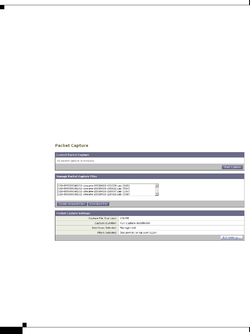
Chapter 26 System Administration
Support Commands
26-6
Cisco IronPort AsyncOS 7.1 for Web User Guide
OL-23207-01
techsupport tunnel will have closed after 7 days. The timeout set on the SSH
tunnel connection does not apply to the Remote Access account; it will remain
active until specifically deactivated.
Packet Capture
Sometimes when you contact IronPort Customer Support with an issue, you may
be asked to provide insight into the network activity going into and out of the Web
Security appliance. The appliance provides the ability to intercept and display
TCP/IP and other packets being transmitted or received over the network to which
the appliance is attached.
You might want to run a packet capture to debug the network setup and to discover
what network traffic is reaching the appliance or leaving the appliance.
The appliance saves the captured packet activity to a file and stores the file locally.
You can configure the maximum packet capture file size, how long to run the
packet capture, and on which network interface to run the capture. You can also
use a filter to limit the number of packets seen by the packet capture which can
make the output more usable on networks with a high volume of traffic. You can
send any stored packet capture file using FTP to IronPort Customer Support for
debugging and troubleshooting purposes.

26-7
Cisco IronPort AsyncOS 7.1 for Web User Guide
OL-23207-01
Chapter 26 System Administration
Support Commands
The Support and Help > Packet Capture page displays the list of complete packet
capture files stored on the hard drive. When a packet capture is running, the web
interface shows the status of the capture in progress by showing the current
statistics, such as file size and time elapsed.
You can download the packet capture files using the Download button in the web
interface, or by connecting to the appliance using FTP and retrieving them from
the captures directory.
In the CLI, use the packetcapture command.
In the web interface, select the Packet Capture option under the Support and Help
menu.
Note The packet capture feature is similar to the Unix tcpdump command.
Starting a Packet Capture
To start a packet capture in the CLI, run the packetcapture > start command.
If you need to stop a running packet capture, run the packetcapture > stop
command.
To start a packet capture in the web interface, select the Packet Capture option
under the Support and Help menu, and then click Start Capture. To stop a
running capture, click Stop Capture.
Note The web interface only displays packet captures started in the web interface, not
from the CLI. Similarly, the CLI only displays the status of a current packet
capture run started in the CLI.
Editing Packet Capture Settings
To edit the packet capture settings in the CLI, run the packetcapture > setup
command.
To edit packet capture settings in the web interface, select the Packet Capture
option under the Support and Help menu, and then click Edit Settings.

Chapter 26 System Administration
Support Commands
26-8
Cisco IronPort AsyncOS 7.1 for Web User Guide
OL-23207-01
Table 26-1 describes the packet capture settings you can configure.
Table 26-1 Packet Capture Configuration Options
Option Description
Capture file size limit The maximum file size for all packet capture files.
Capture duration Choose how long to run the packet capture:
•Run Capture Until File Size Limit Reached.
The packet capture runs until the file size limit is
reached.
•Run Capture Until Time Elapsed Reaches. The
packet capture runs until the configured time has
passed. You can enter the time in seconds (s),
minutes (m), or hours (h). If you enter the amount
of time without specifying the units, AsyncOS
uses seconds by default.
Note: If the file reaches the maximum size limit
before the entire time has elapsed, the existing file
is deleted (the data is discarded) and a new file
starts with the current packet capture data.
•Run Capture Indefinitely. The packet capture
runs until you manually stop it.
Note: If the file reaches the maximum size limit
before you manually stop the packet capture, the
existing file is deleted (the data is discarded) and
a new file starts with the current packet capture
data.
You can always manually stop any packet capture.
Network interface to
capture
Select the network interface on which to run the packet
capture.
Filters Choose whether or not to apply a filter to the packet
capture to reduce the amount of data stored in the
packet capture.
You can use one of the predefined filters to filter by
port, source IP address, or destination IP address, or
you can create a custom filter using any syntax
supported by the Unix tcpdump command.
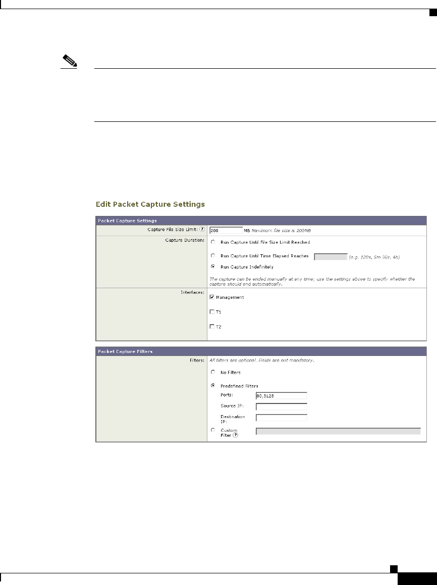
26-9
Cisco IronPort AsyncOS 7.1 for Web User Guide
OL-23207-01
Chapter 26 System Administration
Support Commands
Note When you change the packet capture settings without committing the changes and
then start a packet capture, AsyncOS uses the new settings. This allows you to use
the new settings in the current session without enforcing the settings for future
packet capture runs. The settings remain in effect until you clear them.
Figure 26-3 on page 9 shows where you can edit the packet capture settings in the
web interface.
Figure 26-3 Editing Packet Capture Settings in the Web Interface

Chapter 26 System Administration
Working with Feature Keys
26-10
Cisco IronPort AsyncOS 7.1 for Web User Guide
OL-23207-01
Working with Feature Keys
Occasionally, your support team may provide a key to enable specific
functionality on your system. Use the System Administration > Feature Keys page
in the web interface (or the featurekey command in the CLI) to enter the key and
enable the associated functionality.
Keys are specific to the serial number of your appliance and specific to the feature
being enabled (you cannot re-use a key from one system on another system). If
you incorrectly enter a key, an error message is generated.
Feature keys functionality is split into two pages: Feature Keys and Feature Key
Settings.
Feature Keys Page
The Feature Keys page:
•Lists all active feature keys for the appliance.
•Shows any feature keys that are pending activation.
•Looks for new keys that have been issued (optional, and also can install keys).
A list of the currently enabled features is displayed. The Pending Activation
section is a list of feature keys that have been issued for the appliance but have not
yet been activated. Your appliance may check periodically for new keys
depending on your configuration. You can click Check for New Keys to refresh
the list of pending keys.

26-11
Cisco IronPort AsyncOS 7.1 for Web User Guide
OL-23207-01
Chapter 26 System Administration
Working with Feature Keys
Figure 26-4 The Feature Keys Page
You can also use the featurekey CLI command to accomplish the same tasks as
on the Feature Keys page.
Feature Key Settings Page
The Feature Key Settings page is used to control whether your appliance checks
for and downloads new feature keys, and whether or not those keys are
automatically activated.
Figure 26-5 The Feature Key Settings Page
To add a new feature key manually, paste or type the key into the Feature Key field
and click Submit Key. An error message is displayed if the feature is not added
(if the key is incorrect, etc.), otherwise the feature key is added to the display.

Chapter 26 System Administration
Administering User Accounts
26-12
Cisco IronPort AsyncOS 7.1 for Web User Guide
OL-23207-01
To activate a new feature key from the Pending Activation list, select the key
(mark the “Select” checkbox) and click Activate Selected Keys.
You can configure your IronPort appliance to automatically download and install
new keys as they are issued. In this case, the Pending Activation list will always
be empty. You can tell AsyncOS to look for new keys at any time by clicking the
Check for New Keys button, even if you have disabled the automatic checking
via the Feature Key Settings page.
You can also use the featurekeyconfig CLI command to accomplish the same
tasks as on the Feature Key Settings page.
Expired Feature Keys
If the feature key for the feature you are trying to access (via the web interface)
has expired, please contact your IronPort representative or support organization.
Administering User Accounts
The following types of users can log into the Web Security appliance to manage
the appliance:
•Local users. You can define users locally on the appliance itself. For more
information, see Managing Local Users, page 26-13.
•Users defined in an external system. You can configure the appliance to
connect to an external RADIUS server to authenticate users logging into the
appliance. For information, see Using External Authentication, page 26-17.
You can manage local users and connections to external authentication servers
using the System Administration > Users page in the web interface, or the
userconfig command in the CLI.
Figure 26-6 shows where you manage local users and external authentication.
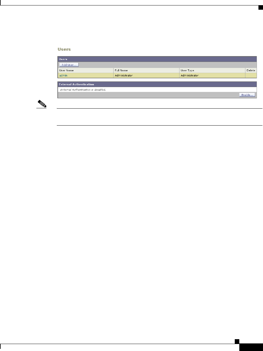
26-13
Cisco IronPort AsyncOS 7.1 for Web User Guide
OL-23207-01
Chapter 26 System Administration
Administering User Accounts
Figure 26-6 System Administration > Users Page
Note Any user you define can log into the appliance using any method, such as logging
into the web interface or using SSH.
Managing Local Users
You can define any number users locally on the Web Security appliance. You can
add, edit, and delete local users. Consider the following rules when defining local
users:
•User names can contain lowercase letters, numbers, and the dash ( - )
character.
•User names cannot start with a dash.
•User names cannot be longer than 16 characters.
•Passwords must be at least 6 characters long.
•User names cannot be special names that are reserved by the system, such as
“operator” or “root.”
The default system admin account has all administrative privileges. You can
change the admin account password, but you cannot edit or delete this account.

Chapter 26 System Administration
Administering User Accounts
26-14
Cisco IronPort AsyncOS 7.1 for Web User Guide
OL-23207-01
To create a new user account, specify a user name and a full name, and then assign
the user to a group. Each group provides a different level of default permissions.
Table 26-2 lists the groups you can assign.
After assigning the user to a group, you must specify a password for the new
account. Passwords are encrypted when they are reported using the showconfig
CLI command.
Note If you have lost the admin user password, contact your support provider.
Adding Local Users
To add a local user:
Step 1 On the System Administration > Users page, click Add User.
The Add Local User page is displayed.
Table 26-2 User Groups
Group Description
Administrator The administrators group allows full access to all system
configuration settings. However, the upgradecheck and
upgradeinstall commands can be issued only from the
system defined “admin” account.
Operator The operators group restricts users from creating, editing, or
removing user accounts. The operators group also restricts the
use of the following commands:
•resetconfig
•upgradecheck
•upgradeinstall
•systemsetup or running the System Setup Wizard
Guest The guests group users can only view system status
information.
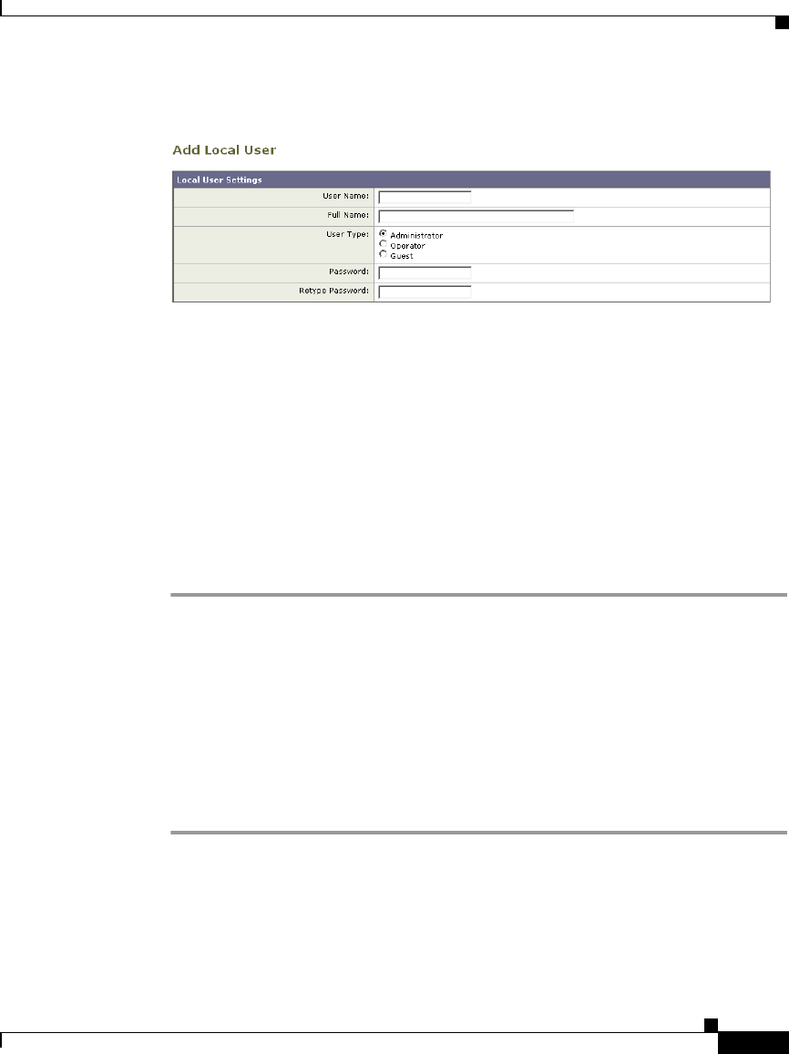
26-15
Cisco IronPort AsyncOS 7.1 for Web User Guide
OL-23207-01
Chapter 26 System Administration
Administering User Accounts
Figure 26-7 Adding a Local User
Step 2 Enter a name for the user. Some words are reserved, such as “operator” and “root”.
Step 3 Enter a full name for the user.
Step 4 Select a user type. See Table 26-2, `User Groups,' on page 14 for more
information about user types.
Step 5 Enter a password and retype it.
Step 6 Submit and commit your changes.
Deleting Users
To delete a user:
Step 1 On the System Administration > Users page, click the trash can icon
corresponding to the listed user name.
Step 2 Confirm the deletion by clicking Delete in the warning dialog that appears.
Step 3 Submit and commit your changes.
Editing Users
To edit a user:
Step 1 On the System Administration > Users page, click the user name.
The Edit User page is displayed.
Step 2 Make changes to the user.
Step 3 Submit and commit your changes.
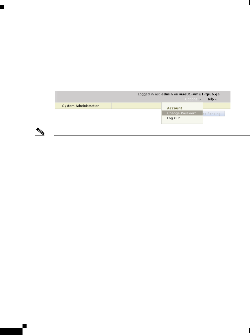
Chapter 26 System Administration
Administering User Accounts
26-16
Cisco IronPort AsyncOS 7.1 for Web User Guide
OL-23207-01
Changing Passwords
Users can change their own passwords using the Change Password option under
the Options menu located on the top right-hand side of the web interface.
Figure 26-8 shows where you can change the current user password.
Figure 26-8 The Change Password Option
Note To change the password for the admin account, use the System Administration >
Users page or use the password or passwd command in the CLI. Password changes
take effect immediately and do not require a commit.
Monitoring Users from the CLI
The who, whoami, and last commands can be used to monitor user access to the
appliance.
•The who command lists users, the time of login, idle time, and the remote host
from which the user is logged in:
example.com> who
Username Login Time Idle Time Remote Host What
======== ========== ========= =========== ====
admin 03:27PM 0s 10.xx.xx.xx cli

26-17
Cisco IronPort AsyncOS 7.1 for Web User Guide
OL-23207-01
Chapter 26 System Administration
Administering User Accounts
•The whoami command displays the user name and group information:
•The last command displays information about users who have recently
logged into the appliance.
Using External Authentication
If you store user information in a RADIUS directory on your network, you can
configure the Web Security appliance to use the RADIUS directory to
authenticate users logging in to the appliance. You can use external authentication
when logging into the appliance using HTTP, HTTPS, SSH, and FTP. To set up
the appliance to use an external directory for authentication, use the System
Administration > Users page in the web interface or the userconfig > external
CLI command.
example.com> whoami
Username: admin
Full Name: Administrator
Groups: admin, operators, config, log, guest
example.com> last
Username Remote Host Login Time Logout Time Total Time
======== =========== ================ ================ ==========
admin 10.xx.xx.xx Sat May 15 23:42 still logged in 15m
admin 10.xx.xx.xx Sat May 15 22:52 Sat May 15 23:42 50m
admin 10.xx.xx.xx Sat May 15 11:02 Sat May 15 14:14 3h 12m
admin 10.xx.xx.xx Fri May 14 16:29 Fri May 14 17:43 1h 13m
shutdown Fri May 14 16:22

Chapter 26 System Administration
Administering User Accounts
26-18
Cisco IronPort AsyncOS 7.1 for Web User Guide
OL-23207-01
Figure 26-9 shows where you enable external authentication on the System
Administration > Users page.
Figure 26-9 Enabling External Authentication
You can configure the appliance to contact multiple external servers for
authentication. You might want to define multiple external servers to allow for
failover in case one server is temporarily unavailable. When you define multiple
external servers, the appliance connects to the servers in the order defined on the
appliance.
When external authentication is enabled and a user logs into the Web Security
appliance, the appliance first determines if the user is the system defined “admin”
account. If not, then the appliance checks the first configured external server to
determine if the user is defined there. If the appliance cannot connect to the first
external server, the appliance checks the next external server in the list. If the user
fails authentication on any external server, the appliance tries to authenticate the
user as a local user defined on the Web Security appliance. If the user does not
exist on any external server or on the appliance, or if the user enters the wrong
password, access to the appliance is denied.
Consider the following rules and guidelines when using external authentication:
•AsyncOS for Web connects to the external server over the M1 interface only.
•The Web Security appliance assigns all users in the RADIUS directory to the
administrator user group. You cannot assign users to other user groups. When
external authentication is enabled and a user successfully authenticates as a
local user, the local user has Administrator user group privileges regardless
of the configured user type.
•Any user with a valid username and password in the RADIUS directory is
granted full access as an administrator on the Web Security appliance. No
authorization is performed on RADIUS users.
To enable external authentication using RADIUS:
Step 1 On the System Administration > Users page, click Enable.
The Edit External Authentication page is displayed.
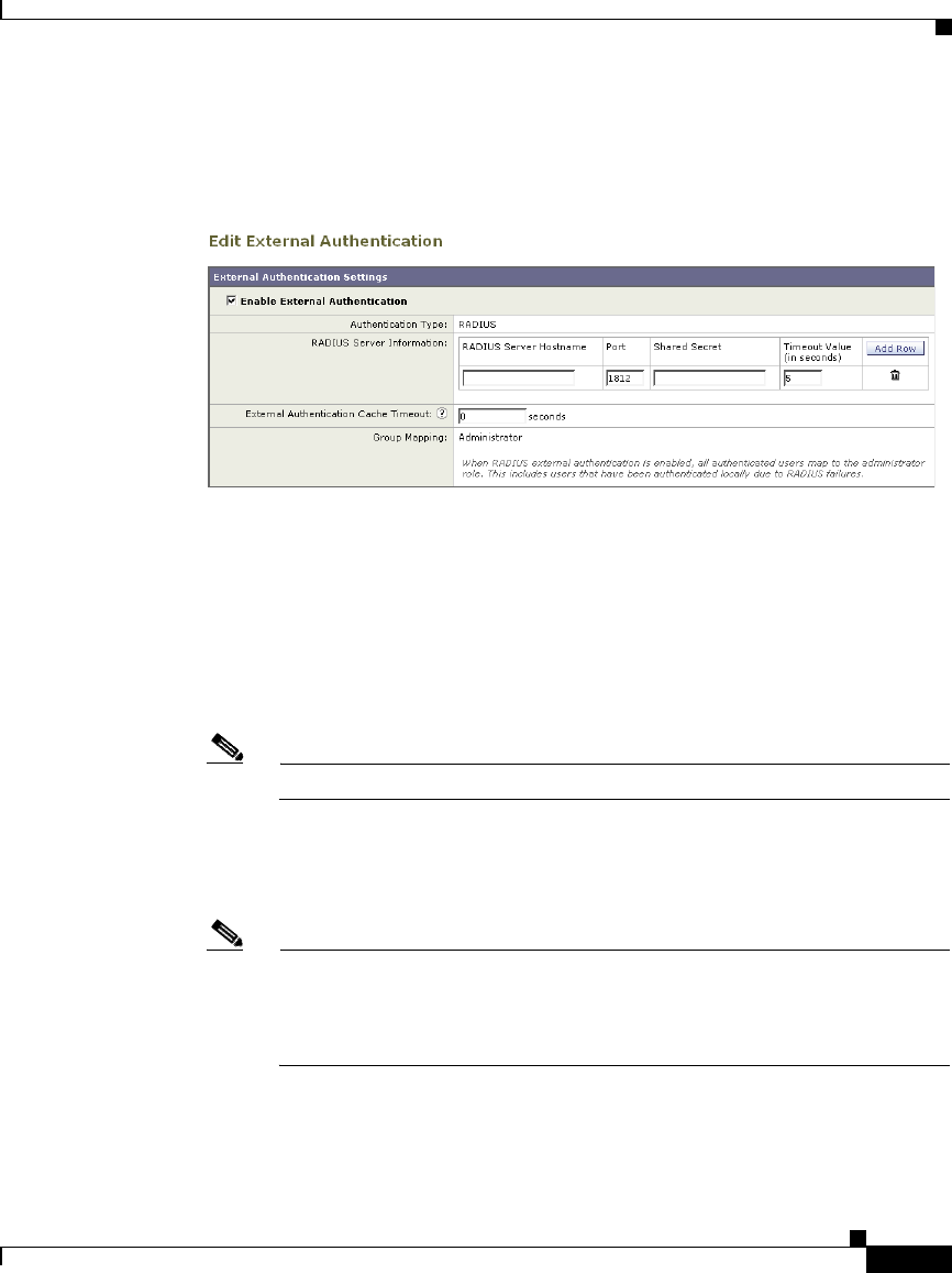
26-19
Cisco IronPort AsyncOS 7.1 for Web User Guide
OL-23207-01
Chapter 26 System Administration
Administering User Accounts
Step 2 Enable the Enable External Authentication option if it is not enabled already.
Figure 26-10 Enabling External Authentication Using RADIUS
Step 3 Enter the hostname for the RADIUS server.
Step 4 Enter the port number for the RADIUS server. The default port number is 1812.
Step 5 Enter the Shared Secret password for the RADIUS server.
Step 6 Enter the number of seconds for the appliance to wait for a response from the
server before timing out.
Step 7 Optionally, click Add Row to add another RADIUS server. Repeat steps 3-6 for
each RADIUS server.
Note You can add up to ten RADIUS servers.
Step 8 Enter the number of seconds AsyncOS stores the external authentication
credentials before contacting the RADIUS server again to authenticate again in
the “External Authentication Cache Timeout” field. Default is zero (0).
Note If the RADIUS server uses one-time passwords, for example passwords
created from a token, enter zero (0). When the value is set to zero,
AsyncOS does not contact the RADIUS server again to authenticate
during the current session.
Step 9 Submit and commit your changes.

Chapter 26 System Administration
Configuring Administrator Settings
26-20
Cisco IronPort AsyncOS 7.1 for Web User Guide
OL-23207-01
Configuring Administrator Settings
You can configure the Web Security appliance to have stricter access requirements
for administrators logging into the appliance. You might want to do this to meet
certain organization requirements.
You configure these settings with the adminaccessconfig CLI command. You can
configure the appliance to:
•Display user-defined text at administrator login.
•Restrict administrator access to certain machines.
•Require stronger SSL ciphers for administrator access.
Configuring Custom Text at Login
Using the adminaccessconfig > banner CLI command, you can configure the
appliance to display any text you specify when an administrator tries to logs in.
You might want to do this to display a banner that informs the user of
organizational policies and conditions. The custom banner text appears when an
administrator tries to access the appliance through all interfaces, such as the web
interface or via FTP.
You can load the custom text by either pasting it into the CLI prompt or by
copying it from a file located on the Web Security appliance. To upload the text
from a file, you must first transfer the file to the configuration directory on the
appliance using FTP.
Configuring IP-Based Administrator Access
Using the adminaccessconfig > ipaccess CLI command, you can control from
which IP addresses administrators access the Web Security appliance.
Administrators can access the appliance from any machine or from machines with
an IP address from a list you specify.
When restrict access to an allow list, you can specify IP addresses, subnets, or
CIDR addresses.

26-21
Cisco IronPort AsyncOS 7.1 for Web User Guide
OL-23207-01
Chapter 26 System Administration
Configuring the Return Address for Generated Messages
By default, when you list the addresses that can access the appliance, the IP
address of your current machine is listed as the first address in the allow list. You
cannot delete the IP address of your current machine from the allow list.
Configuring the SSL Ciphers for Administrator Access
Using the adminaccessconfig > strictssl CLI command, you can configure the
appliance so administrators log into the web interface on port 8443 using stronger
SSL ciphers (greater than 56 bit encryption).
When you configure the appliance to require stronger SSL ciphers, the change
only applies to administrators accessing the appliance using HTTPS to manage
the appliance. It does not apply to other network traffic connected to the Web
Proxy using HTTPS.
Configuring the Return Address for Generated
Messages
You can configure the return address for mail generated by AsyncOS for reports.
You can specify the display, user, and domain names of the return address. You
can also choose to use the Virtual Gateway domain for the domain name.
Configure the return address on the System Administration > Return Addresses
page.
Figure 26-11 Configuring Return Addresses
To configure the return address for system-generated email messages:
Step 1 Navigate to the System Administration > Return Addresses page.
Step 2 Click Edit Settings.
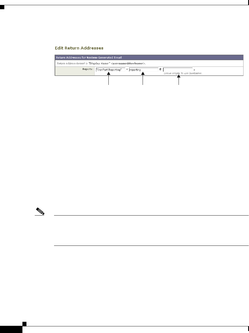
Chapter 26 System Administration
Managing Alerts
26-22
Cisco IronPort AsyncOS 7.1 for Web User Guide
OL-23207-01
Figure 26-12 Editing Return Address Settings
Step 3 For Reports, enter the display name, user name, and domain name in the fields
shown in Figure 26-12.
Step 4 Submit and commit your changes.
Managing Alerts
Alerts are email notifications containing information about events occurring on
the IronPort appliance. These events can be of varying levels of importance (or
severity) from minor (Informational) to major (Critical) and pertain generally to
a specific component or feature on the appliance. Alerts are generated by the
IronPort appliance. You can specify which alert messages are sent to which users
and for which severity of event they are sent. Manage alerts using the System
Administration > Alerts page in the web interface or using the alertconfig
command in the CLI.
Note To receive alerts and email notifications, you must configure the SMTP relay host
that the appliance uses to send the email messages. For information about
configuring the SMTP relay host, see Configuring SMTP Relay Hosts,
page 25-26.
Alerting Overview
The alerting feature consists of two main parts:
•Alerts - consist of an Alert Recipient (email addresses for receiving alerts),
and the alert notification (severity and alert type) sent to the recipient.
Display Name User Name Domain Name

26-23
Cisco IronPort AsyncOS 7.1 for Web User Guide
OL-23207-01
Chapter 26 System Administration
Managing Alerts
•Alert Settings - specify global behavior for the alerting feature, including
alert sender (FROM:) address, seconds to wait between sending duplicate
alerts, and whether to enable AutoSupport (and optionally send weekly
AutoSupport reports).
Alerts: Alert Recipients, Alert Classifications, and Severities
Alerts are email messages or notifications containing information about a specific
function (or alert classification) or functions such as a hardware or anti-virus
problem, sent to an alert- recipient. An alert recipient is simply an email address
to which the alert notifications are sent. The information contained in the
notification is determined by an alert classification and a severity. You can specify
which alert classifications, at which severity, are sent to any alert recipient. The
alerting engine allows for granular control over which alerts are sent to which
alert recipients. For example, you can configure the system to send only specific
alerts to an alert recipient, configuring an alert recipient to receive notifications
only when Critical (severity) information about the System (alert type) is sent.
You can also configure general settings (see Configuring Alert Settings,
page 26-29).
Alert Classifications
AsyncOS sends the following alert classifications:
Severities
Alerts can be sent for the following severities:
Table 26-3 Alert Classifications and Components
Alert Classification Alert Component
System System
Hardware Hardware
Updater Updater
Web Proxy Proxy
DVS™ and Anti-Malware DVS
L4 Traffic Monitor TrafMon

Chapter 26 System Administration
Managing Alerts
26-24
Cisco IronPort AsyncOS 7.1 for Web User Guide
OL-23207-01
•Critical: Requires immediate attention.
•Warning: Problem or error requiring further monitoring and potentially
immediate attention.
•Information: Information generated in the routine functioning of this device.
Alert Settings
Alert settings control the general behavior and configuration of alerts, including:
•The RFC 2822 Header From: when sending alerts (enter an address or use the
default “alert@<hostname>”). You can also set this via the CLI, using the
alertconfig -> from command.
•The initial number of seconds to wait before sending a duplicate alert.
•The maximum number of seconds to wait before sending a duplicate alert.
•The status of AutoSupport (enabled or disabled).
•The sending of AutoSupport’s weekly status reports to alert recipients set to
receive System alerts at the Information level.
Sending Duplicate Alerts
You can specify the initial number of seconds to wait before AsyncOS will send
a duplicate alert. If you set this value to 0, duplicate alert summaries are not sent
and instead, all duplicate alerts are sent without any delay (this can lead to a large
amount of email over a short amount of time). The number of seconds to wait
between sending duplicate alerts (alert interval) is increased after each alert is
sent. The increase is the number of seconds to wait plus twice the last interval. So
a 5 second wait would have alerts sent at 5 seconds, 15, seconds, 35 seconds, 75
seconds, 155 seconds, 315 seconds, etc.
Eventually, the interval could become quite large. You can set a cap on the number
of seconds to wait between intervals via the maximum number of seconds to wait
before sending a duplicate alert field. For example, if you set the initial value to
5 seconds, and the maximum value to 60 seconds, alerts would be sent at 5
seconds, 15 seconds, 35 seconds, 60 seconds, 120 seconds, etc.

26-25
Cisco IronPort AsyncOS 7.1 for Web User Guide
OL-23207-01
Chapter 26 System Administration
Managing Alerts
IronPort AutoSupport
To allow IronPort to better support and design future system changes, the IronPort
appliance can be configured to send IronPort Systems a copy of all alert messages
generated by the system. This feature, called AutoSupport, is a useful way to
allow our team to be proactive in supporting your needs. AutoSupport also sends
weekly reports noting the uptime of the system, the output of the status
command, and the AsyncOS version used.
By default, alert recipients set to receive Information severity level alerts for
System alert types will receive a copy of every message sent to IronPort. This can
be disabled if you do not want to send the weekly alert messages internally. To
enable or disable this feature, see Configuring Alert Settings, page 26-29.
Alert Messages
Alert messages are standard email messages. You can configure the Header From:
address, but the rest of the message is generated automatically.
Alert From Address
You can configure the Header From: address via the Edit Settings... button or via
the CLI.
Alert Subject
An alert email message's subject follows this format:
Subject: [severity]-[hostname]: ([class]) short message

Chapter 26 System Administration
Managing Alerts
26-26
Cisco IronPort AsyncOS 7.1 for Web User Guide
OL-23207-01
Example Alert Message
Date: 23 May 2007 21:10:19 +0000
To: joe@example.com
From: IronPort S650 Alert [alert@example.com]
Subject: Critical <System> example.com: Internal SMTP giving up on
message to jane@company.com with...
The Critical message is:
Internal SMTP giving up on message to jane@company.com with subject
'IronPort Report: Client Web Activity (example.com)': Unrecoverable
error.
Product: IronPort S650 Web Security Appliance
Model: S650
Version: 5.1.0-225
Serial Number: XXXXXXXXXXXX-XXXXXXX
Timestamp: Tue May 10 09:39:24 2007
For more information about this error, please see
http://support.ironport.com
If you desire further information, please contact your support
provider.
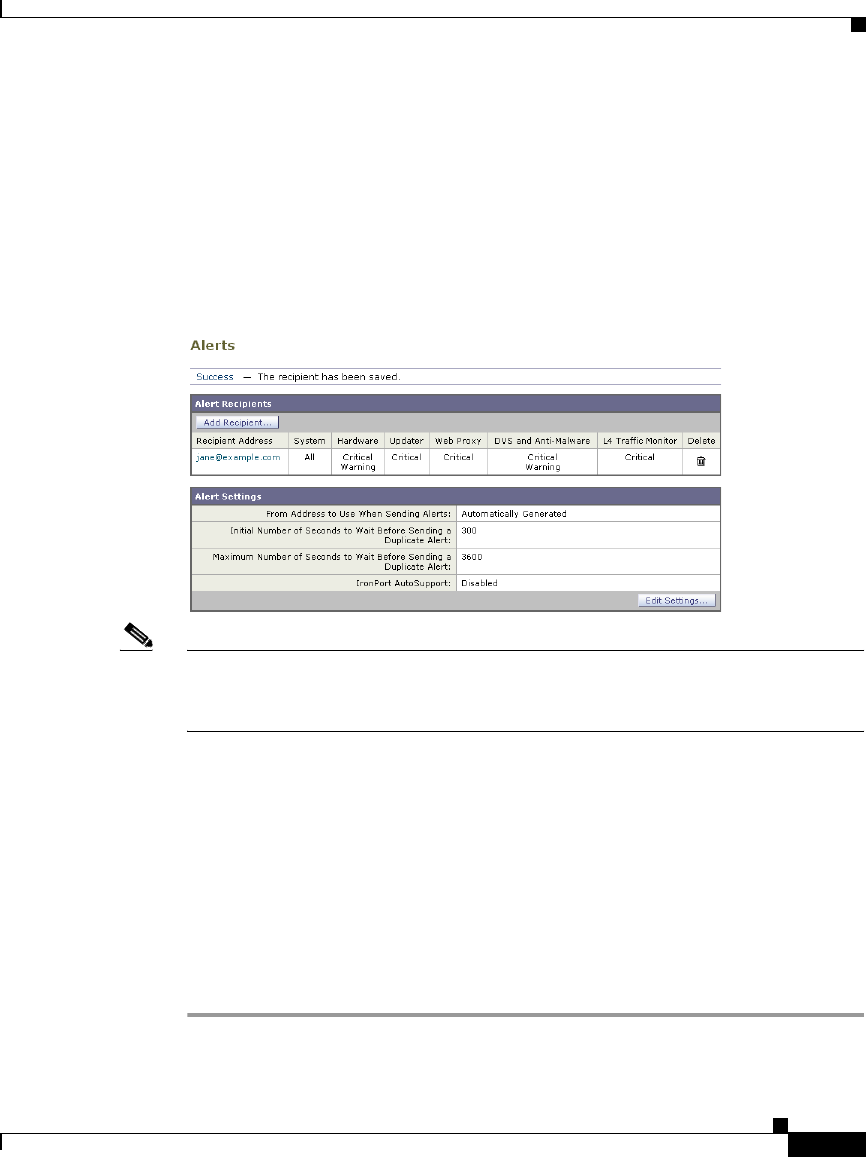
26-27
Cisco IronPort AsyncOS 7.1 for Web User Guide
OL-23207-01
Chapter 26 System Administration
Managing Alerts
Managing Alert Recipients
Log in to the S-Series appliance web interface (GUI) and click the System
Administration tab. Click the Alerts link in the left menu. For information about
how to access the S-Series appliance web interface, see Accessing the Web
Security Appliance, page 2-3.
Figure 26-13 The Alerts Page
Note If you enabled AutoSupport during System Setup, the email address you specified
will receive alerts for all severities and classes by default. You can change this
configuration at any time.
The Alerts page lists the existing alert recipients and alert settings.
From the Alerts page, you can:
•Add, configure, or delete alert recipients
•Modify the alert settings
Adding New Alert Recipients
To add a new alert recipient:
Step 1 Click Add Recipient... on the Alerts page. The Add Alert Recipients page is
displayed:
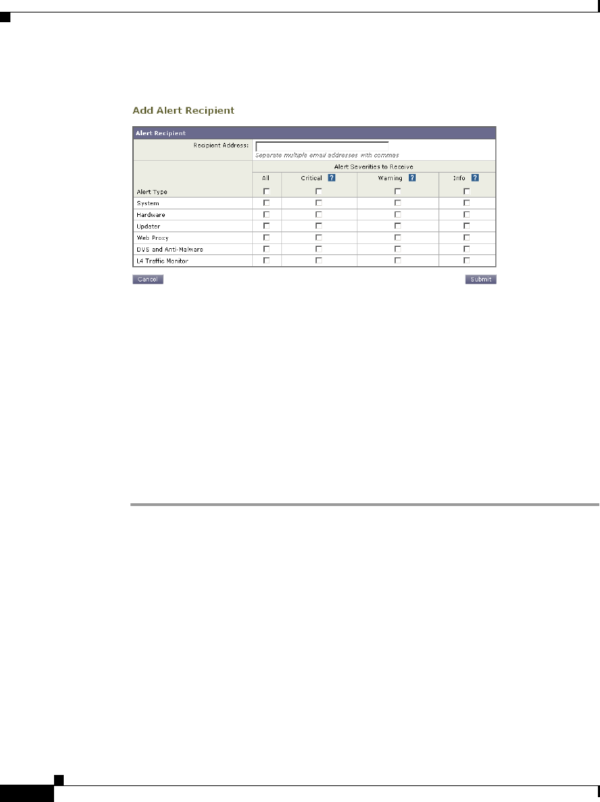
Chapter 26 System Administration
Managing Alerts
26-28
Cisco IronPort AsyncOS 7.1 for Web User Guide
OL-23207-01
Figure 26-14 Adding a New Alert Recipient
Step 2 Enter the recipient’s email address. You can enter multiple addresses, separated
by commas.
Step 3 Select which alert severities to receive.
Step 4 Click Submit to add the alert recipient.
Step 5 Click the Commit Changes button, add an optional comment if necessary, then
click Commit Changes to save the changes.
Configuring Existing Alert Recipients
To edit an existing alert recipient:
Step 1 Click the alert recipient in the Alert Recipients listing. The Configure Alert
Recipient page is displayed.
Step 2 Make changes to the alert recipient.
Step 3 Click Submit to edit the alert recipient.
Step 4 Click the Commit Changes button, add an optional comment if necessary, then
click Commit Changes to save the changes.
Deleting Alert Recipients
To delete an alert recipient:
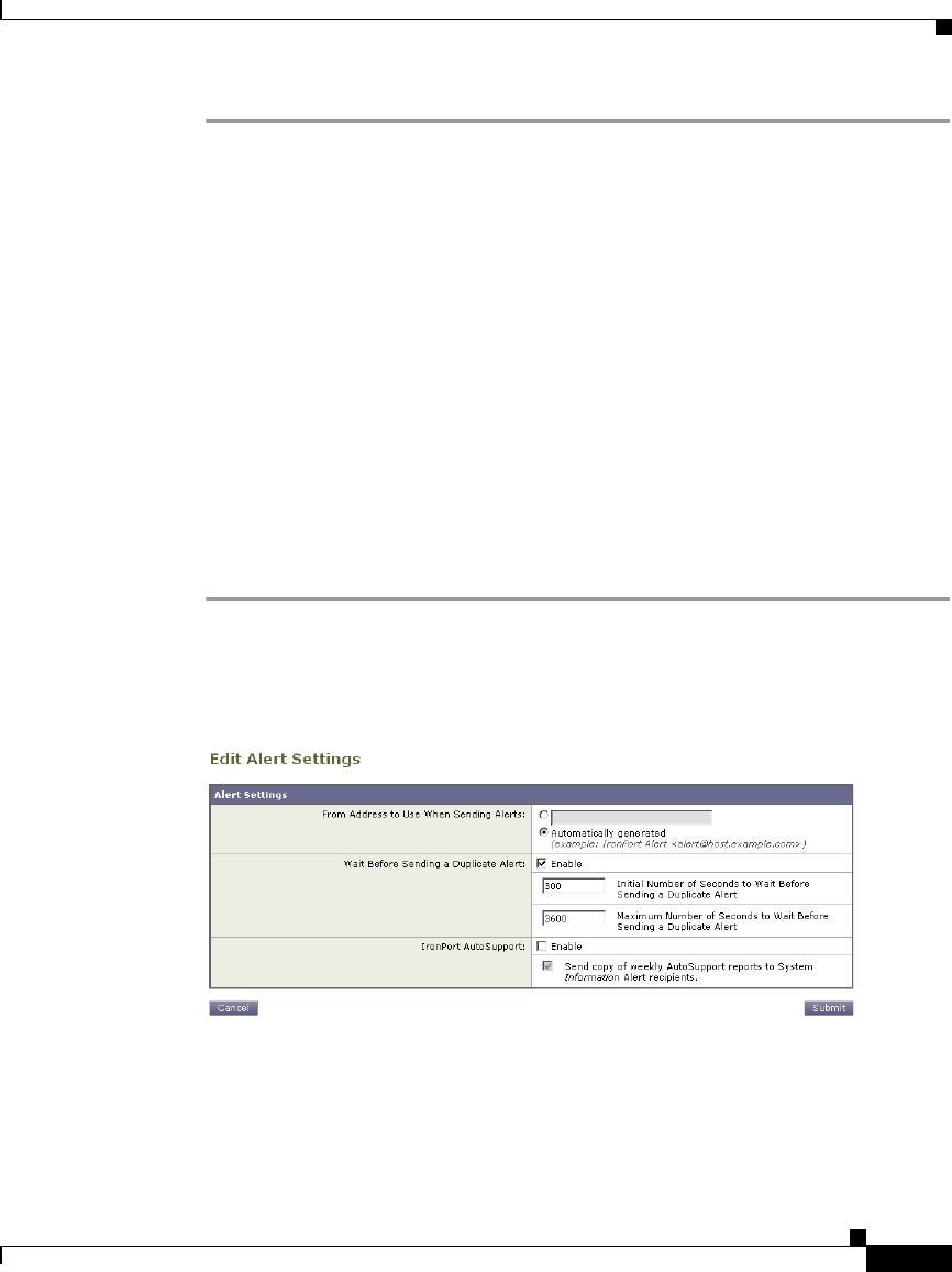
26-29
Cisco IronPort AsyncOS 7.1 for Web User Guide
OL-23207-01
Chapter 26 System Administration
Managing Alerts
Step 1 Click the trash can icon corresponding to the alert recipient in the Alert Recipient
listing.
Step 2 Confirm the deletion by clicking Delete in the warning dialog that appears.
Step 3 Click the Commit Changes button, add an optional comment if necessary, then
click Commit Changes to save the changes.
Configuring Alert Settings
Alert settings are global settings, meaning that they affect how all of the alerts
behave.
Editing Alert Settings
To edit alert settings:
Step 1 Click Edit Settings... on the Alerts page. The Edit Alert Settings page is
displayed:
Figure 26-15 Editing Alert Settings
Step 2 Enter a Header From: address to use when sending alerts, or select Automatically
Generated (“alert@<hostname>”).
Step 3 Mark the checkbox if you want to specify the number of seconds to wait between
sending duplicate alerts. For more information, see Sending Duplicate Alerts,
page 26-24.

Chapter 26 System Administration
Setting System Time
26-30
Cisco IronPort AsyncOS 7.1 for Web User Guide
OL-23207-01
–
Specify the initial number of seconds to wait before sending a duplicate
alert.
–
Specify the maximum number of seconds to wait before sending a
duplicate alert.
Step 4 You can enable AutoSupport by checking the IronPort AutoSupport option. For
more information about AutoSupport, see IronPort AutoSupport, page 26-25.
–
If AutoSupport is enabled, the weekly AutoSupport report is sent to alert
recipients set to receive System alerts at the Information level. You can
disable this via the checkbox.
Step 5 Click Submit to edit the alert settings.
Step 6 Click the Commit Changes button, add an optional comment if necessary, then
click Commit Changes to save the changes.
Setting System Time
To set the system time on your Web Security appliance, set the time zone used, or
select an NTP server and query interface. To set the system time, use the System
Administration > Time Zone or Time Settings page or use the ntpconfig,
settime, and settz commands.
Selecting a Time Zone
To set the time zone use the System Administration > Time Zone page:
Figure 26-16 The Time Zone Page
Select a time zone in the Time Zone area. You can configure the time zone by
specifying the region and country, or by using a GMT offset.
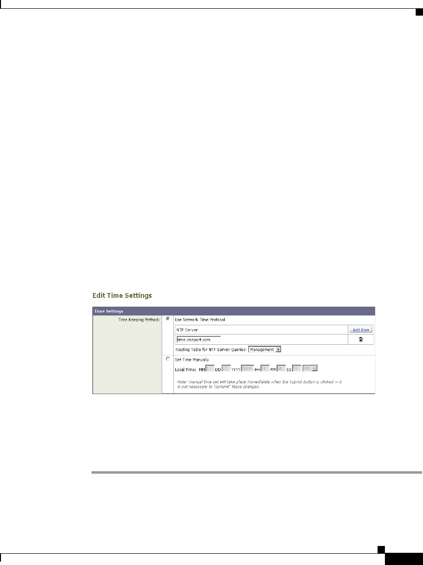
26-31
Cisco IronPort AsyncOS 7.1 for Web User Guide
OL-23207-01
Chapter 26 System Administration
Setting System Time
The web interface uses the POSIX-style method of indicating the time zone using
a GMT offset. This may be different than the offset convention used elsewhere.
The offset refers to the amount of hours that must be added or subtracted to the
local time zone in order to reach GMT (Greenwich Mean Time or the Prime
Meridian). Hours preceded by a minus sign (“-”) are east of the Prime Meridian.
A plus sign (“+”) indicates west of the Prime Meridian.
For example, if the current time in New York is 08:00, then you must add five
hours to get the current time in Greenwich, England, which is 13:00. In this case,
to indicate the time in New York, the GMT offset is GMT+5. The “+5” in the
offset indicates that you must add five hours to the time in New York to reach
Greenwich Mean Time.
Editing System Time
To edit system time, use the System Administration > Time Settings page.
Figure 26-17 The Edit Time Settings Page
Configure NTP (Network Time Protocol)
To edit NTP server settings and use an NTP server to synchronize the system
clock with other computers:
Step 1 Enter an NTP server IP address and use the Add Row key to repeat as necessary
for each NTP server.

Chapter 26 System Administration
Installing a Server Digital Certificate
26-32
Cisco IronPort AsyncOS 7.1 for Web User Guide
OL-23207-01
Step 2 Choose the routing table associated with an appliance network interface type,
either Management or Data, to use for NTP queries. This is the IP address from
which NTP queries should originate.
Step 3 Submit and commit the changes.
Manually Setting System Time
To set the system time manually:
Step 1 Select Set Time Manually.
Step 2 Enter the month, day, year, hour, minutes, and seconds.
Step 3 Select A.M or P.M.
Step 4 Submit and commit to save the changes.
Installing a Server Digital Certificate
When an administrator logs into the Web Security appliance using HTTPS, the
appliance uses a digital certificate to securely establish the connection with the
client application. The Web Security appliance uses the “IronPort Appliance
Demo Certificate” that comes installed by default. However, client applications
are not programmed to recognize this certificate, so you can upload a digital
certificate to the appliance that your applications recognize automatically.
Figure 26-18 shows the warning message that is displayed in Firefox when
accessing the Web Security appliance using the IronPort Appliance Demo
Certificate.
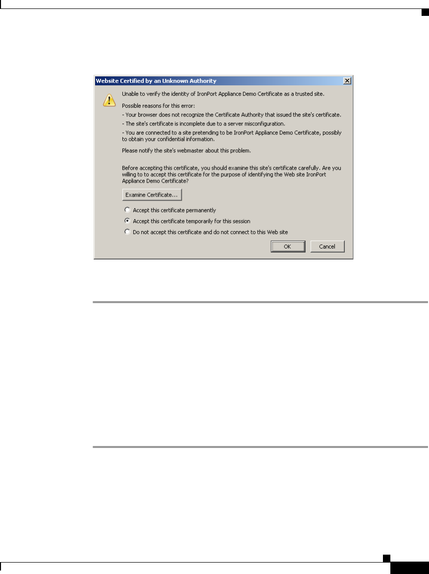
26-33
Cisco IronPort AsyncOS 7.1 for Web User Guide
OL-23207-01
Chapter 26 System Administration
Installing a Server Digital Certificate
Figure 26-18 IronPort Appliance Demo Certificate as an Unknown Authority
To configure the Web Security appliance to use a different digital server
certificate, follow these steps:
Step 1 Obtain a certificate and private key pair to upload. For more information, see
Obtaining Certificates, page 26-33.
Step 2 Upload the certificate and private key pair to the appliance. For more information,
see Uploading Certificates to the Web Security Appliance, page 26-35.
Obtaining Certificates
To obtain a digital certificate to upload to the appliance, you must follow these
steps:
Step 1 Generate a public-private key pair.
Step 2 Generate a Certificate Signing Requests (CSR).
Step 3 Contact a certificate authority (CA) to sign the certificate.
The certificate you upload to the appliance must meet the following requirements:
•It must use the X.509 standard.

Chapter 26 System Administration
Installing a Server Digital Certificate
26-34
Cisco IronPort AsyncOS 7.1 for Web User Guide
OL-23207-01
•It must include a matching private key in PEM format. DER format is not
supported.
•The private key must be unencrypted.
The Web Security appliance cannot generate Certificate Signing Requests (CSR).
Therefore, to have a certificate created for the appliance, you must issue the
signing request from another system. Save the PEM-formatted key from this
system because you will need to install it on the appliance later.
You can use any UNIX machine with a recent version of OpenSSL installed. Be
sure to put the appliance hostname in the CSR. Use the guidelines at the following
location for information on generating a CSR using OpenSSL:
http://www.modssl.org/docs/2.8/ssl_faq.html#ToC28
Once the CSR has been generated, submit it to a certificate authority (CA). The
CA will return the certificate in PEM format.
If you are acquiring a certificate for the first time, search the Internet for
“certificate authority services SSL server certificates,” and choose the service that
best meets the needs of your organization. Follow the service’s instructions for
obtaining an SSL certificate.
Note You can also generate and sign your own certificate. Tools for doing this are
included with OpenSSL, free software from http://www.openssl.org.
Intermediate Certificates
In addition to root certificate authority (CA) certificate verification, AsyncOS
supports the use of intermediate certificate verification. Intermediate certificates
are certificates issued by a trusted root CA which are then used to create
additional certificates. This creates a chained line of trust. For example, a
certificate may be issued by example.com who, in turn, is granted the rights to
issue certificates by a trusted root CA. The certificate issued by example.com
must be validated against example.com’s private key as well as the trusted root
CA’s private key.

26-35
Cisco IronPort AsyncOS 7.1 for Web User Guide
OL-23207-01
Chapter 26 System Administration
Installing a Server Digital Certificate
Uploading Certificates to the Web Security Appliance
To upload a digital certificate to the Web Security appliance, use the certconfig
command.
The following example shows a certificate being uploaded. You can also add
intermediate certificates from this command.
example.com> certconfig
Currently using the demo certificate/key for HTTPS management access.
Choose the operation you want to perform:
- SETUP - Configure security certificate and key.
[]> setup
Management (HTTPS):
paste cert in PEM format (end with '.'):
-----BEGIN CERTIFICATE-----
MIICLDCCAdYCAQAwDQYJKoZIhvcNAQEEBQAwgaAxCzAJBgNVBAYTAlBUMRMwEQYD
VQQIEwpRdWVlbnNsYW5kMQ8wDQYDVQQHEwZMaXNib2ExFzAVBgNVBAoTDk5ldXJv
bmlvLCBMZGEuMRgwFgYDVQQLEw9EZXNlbnZvbHZpbWVudG8xGzAZBgNVBAMTEmJy
dXR1cy5uZXVyb25pby5wdDEbMBkGCSqGSIb3DQEJARYMc2FtcG9AaWtpLmZpMB4X
DTk2MDkwNTAzNDI0M1oXDTk2MTAwNTAzNDI0M1owgaAxCzAJBgNVBAYTAlBUMRMw
EQYDVQQIEwpRdWVlbnNsYW5kMQ8wDQYDVQQHEwZMaXNib2ExFzAVBgNVBAoTDk5l
dXJvbmlvLCBMZGEuMRgwFgYDVQQLEw9EZXNlbnZvbHZpbWVudG8xGzAZBgNVBAMT

Chapter 26 System Administration
Installing a Server Digital Certificate
26-36
Cisco IronPort AsyncOS 7.1 for Web User Guide
OL-23207-01
EmJydXR1cy5uZXVyb25pby5wdDEbMBkGCSqGSIb3DQEJARYMc2FtcG9AaWtpLmZp
MFwwDQYJKoZIhvcNAQEBBQADSwAwSAJBAL7+aty3S1iBA/+yxjxv4q1MUTd1kjNw
L4lYKbpzzlmC5beaQXeQ2RmGMTXU+mDvuqItjVHOK3DvPK7lTcSGftUCAwEAATAN
BgkqhkiG9w0BAQQFAANBAFqPEKFjk6T6CKTHvaQeEAsX0/8YHPHqH/9AnhSjrwuX
9EBc0n6bVGhN7XaXd6sJ7dym9sbsWxb+pJdurnkxjx4=
-----END CERTIFICATE-----
.
paste key in PEM format (end with '.'):
-----BEGIN RSA PRIVATE KEY-----
MIIBPAIBAAJBAL7+aty3S1iBA/+yxjxv4q1MUTd1kjNwL4lYKbpzzlmC5beaQXeQ
2RmGMTXU+mDvuqItjVHOK3DvPK7lTcSGftUCAwEAAQJBALjkK+jc2+iihI98riEF
oudmkNziSRTYjnwjx8mCoAjPWviB3c742eO3FG4/soi1jD9A5alihEOXfUzloenr
8IECIQD3B5+0l+68BA/6d76iUNqAAV8djGTzvxnCxycnxPQydQIhAMXt4trUI3nc
a+U8YL2HPFA3gmhBsSICbq2OptOCnM7hAiEA6Xi3JIQECob8YwkRj29DU3/4WYD7
WLPgsQpwo1GuSpECICGsnWH5oaeD9t9jbFoSfhJvv0IZmxdcLpRcpslpeWBBAiEA
6/5B8J0GHdJq89FHwEG/H2eVVUYu5y/aD6sgcm+0Avg=
-----END RSA PRIVATE KEY-----
.
Do you want add an intermediate certificate? [N]> N
Currently using custom certificate/key for HTTPS management access.
Choose the operation you want to perform:
- SETUP - Configure security certificate and key.
[]>
example.com> commit
Please enter some comments describing your changes:
[]> Installed certificate and key for HTTPS management.
Changes committed: Fri Sep 26 17:59:53 2008 GMT

26-37
Cisco IronPort AsyncOS 7.1 for Web User Guide
OL-23207-01
Chapter 26 System Administration
Installing a Server Digital Certificate
Management (HTTPS):
paste cert in PEM format (end with '.'):
-----BEGIN CERTIFICATE-----
MIICLDCCAdYCAQAwDQYJKoZIhvcNAQEEBQAwgaAxCzAJBgNVBAYTAlBUMRMwEQYD
VQQIEwpRdWVlbnNsYW5kMQ8wDQYDVQQHEwZMaXNib2ExFzAVBgNVBAoTDk5ldXJv
bmlvLCBMZGEuMRgwFgYDVQQLEw9EZXNlbnZvbHZpbWVudG8xGzAZBgNVBAMTEmJy
dXR1cy5uZXVyb25pby5wdDEbMBkGCSqGSIb3DQEJARYMc2FtcG9AaWtpLmZpMB4X
DTk2MDkwNTAzNDI0M1oXDTk2MTAwNTAzNDI0M1owgaAxCzAJBgNVBAYTAlBUMRMw
EQYDVQQIEwpRdWVlbnNsYW5kMQ8wDQYDVQQHEwZMaXNib2ExFzAVBgNVBAoTDk5l
dXJvbmlvLCBMZGEuMRgwFgYDVQQLEw9EZXNlbnZvbHZpbWVudG8xGzAZBgNVBAMT

Chapter 26 System Administration
Installing a Server Digital Certificate
26-38
Cisco IronPort AsyncOS 7.1 for Web User Guide
OL-23207-01
Management (HTTPS):
paste cert in PEM format (end with '.'):
-----BEGIN CERTIFICATE-----
MIICLDCCAdYCAQAwDQYJKoZIhvcNAQEEBQAwgaAxCzAJBgNVBAYTAlBUMRMwEQYD
VQQIEwpRdWVlbnNsYW5kMQ8wDQYDVQQHEwZMaXNib2ExFzAVBgNVBAoTDk5ldXJv
bmlvLCBMZGEuMRgwFgYDVQQLEw9EZXNlbnZvbHZpbWVudG8xGzAZBgNVBAMTEmJy
dXR1cy5uZXVyb25pby5wdDEbMBkGCSqGSIb3DQEJARYMc2FtcG9AaWtpLmZpMB4X
DTk2MDkwNTAzNDI0M1oXDTk2MTAwNTAzNDI0M1owgaAxCzAJBgNVBAYTAlBUMRMw
EQYDVQQIEwpRdWVlbnNsYW5kMQ8wDQYDVQQHEwZMaXNib2ExFzAVBgNVBAoTDk5l
dXJvbmlvLCBMZGEuMRgwFgYDVQQLEw9EZXNlbnZvbHZpbWVudG8xGzAZBgNVBAMT

26-39
Cisco IronPort AsyncOS 7.1 for Web User Guide
OL-23207-01
Chapter 26 System Administration
Installing a Server Digital Certificate
oudmkNziSRTYjnwjx8mCoAjPWviB3c742eO3FG4/soi1jD9A5alihEOXfUzloenr
8IECIQD3B5+0l+68BA/6d76iUNqAAV8djGTzvxnCxycnxPQydQIhAMXt4trUI3nc
a+U8YL2HPFA3gmhBsSICbq2OptOCnM7hAiEA6Xi3JIQECob8YwkRj29DU3/4WYD7
WLPgsQpwo1GuSpECICGsnWH5oaeD9t9jbFoSfhJvv0IZmxdcLpRcpslpeWBBAiEA
6/5B8J0GHdJq89FHwEG/H2eVVUYu5y/aD6sgcm+0Avg=
-----END RSA PRIVATE KEY-----
.
Do you want add an intermediate certificate? [N]> N
Currently using custom certificate/key for HTTPS management access.
Choose the operation you want to perform:
- SETUP - Configure security certificate and key.
[]>
example.com> commit
Please enter some comments describing your changes:
[]> Installed certificate and key for HTTPS management.
Changes committed: Fri Sep 26 17:59:53 2008 GMT

Chapter 26 System Administration
Upgrading the System Software
26-40
Cisco IronPort AsyncOS 7.1 for Web User Guide
OL-23207-01
Upgrading the System Software
Upgrading AsyncOS for Web uses the following two step process:
Step 1 Configure the update and upgrade settings. You can configure settings that
affect how the Web Security appliance downloads the upgrade information. For
example, you can choose from where to download the upgrade images and more.
For more information, see Configuring Upgrade and Service Update Settings,
page 26-42.
Step 2 Upgrade the system software. After you configure the update and upgrade
settings, upgrade the software on the appliance. For more information, see
Upgrading AsyncOS for Web from the Web Interface, page 26-40 and Upgrading
AsyncOS for Web from the CLI, page 26-41.
Consider the following guidelines when you upgrade AsyncOS for Web:
•Before you start the upgrade, save the XML configuration file off the Web
Security appliance from the System Administration > Configuration File
page or by using the saveconfig command. For more information, see Saving
and Loading the Appliance Configuration, page 26-2.
•When upgrading, do not pause for long amounts of time at the various
prompts. If the TCP session times out during the download, the upgrade may
fail.
•Consider saving the configuration information to an XML file after the
upgrade completes, too.
Upgrading AsyncOS for Web from the Web Interface
To upgrade AsyncOS after you configure the update and upgrade settings:
Step 1 On the System Administration > Configuration File page, save the XML
configuration file off the Web Security appliance.
Step 2 On the System Administration > System Upgrade page, click Available
Upgrades.
The Available Upgrades page is displayed.
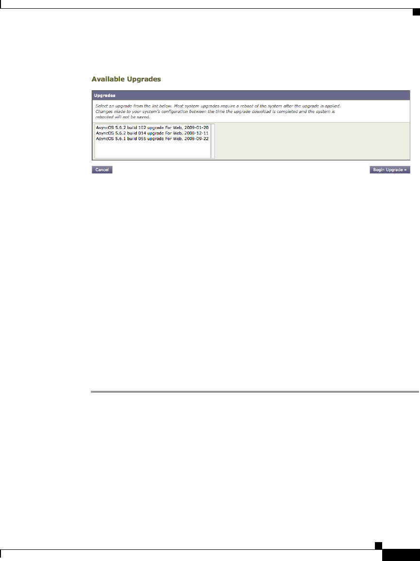
26-41
Cisco IronPort AsyncOS 7.1 for Web User Guide
OL-23207-01
Chapter 26 System Administration
Upgrading the System Software
Figure 26-19 The Available Upgrades Page
Step 3 Select an upgrade from the list of available upgrades, and click Begin Upgrade
to start the upgrade process. Answer the questions as they appear.
Step 4 When the upgrade is complete, click Reboot Now to reboot the Web Security
appliance.
Upgrading AsyncOS for Web from the CLI
Issue the upgrade command from the CLI to show a list of available upgrades.
Select the desired upgrade from the list to install it. You may be asked to confirm
messages or read and agree to license agreements, etc.
Differences from Traditional Upgrading Method
Please note these differences when upgrading AsyncOS from a local server as
opposed to the traditional method:
Step 1 The upgrading installs immediately while downloading.
Step 2 A banner displays for 10 seconds at the beginning of the upgrade process. While
this banner is displayed, you have the option to type Control+C to exit the upgrade
process before downloading starts.

Chapter 26 System Administration
Configuring Upgrade and Service Update Settings
26-42
Cisco IronPort AsyncOS 7.1 for Web User Guide
OL-23207-01
Configuring Upgrade and Service Update Settings
You can configure how the Web Security appliance downloads security services
updates, such as Web Reputation Filters and AsyncOS for Web upgrades. For
example, you can choose which network interface to use when downloading the
files, configure the update interval. or disable automatic updates.
AsyncOS periodically queries the update servers for new updates to all security
service components, but not for new AsyncOS upgrades. To upgrade AsyncOS,
you must manually prompt AsyncOS to query for available upgrades. You can
also manually prompt AsyncOS to query for available security service updates.
For more information, see Manually Updating Security Service Components,
page 26-51.
When AsyncOS queries an update server for an update or upgrade, it performs the
following steps:
1. Contacts the update server.
IronPort allows the following sources for update servers:
–
IronPort update servers. For more information, see Updating and
Upgrading from the IronPort Update Servers, page 26-43.
–
Local server. For more information, see Upgrading from a Local Server,
page 26-44.
2. Receives an XML file that lists the available updates or AsyncOS upgrade
versions. This XML file is known as the “manifest.”
3. Downloads the update or upgrade image files.
By default, AsyncOS contacts the IronPort update servers for both update and
upgrade images and the manifest XML file. However, you can choose from where
to download the upgrade and update images and the manifest file. You might want
to specify a local update server for the images or manifest file for any of the
following reasons:
•You have multiple appliances to upgrade simultaneously. If your
organization has multiple Web Security appliances that need to upgrade, you
can download the upgrade image to a web server inside your network and
serve it to all appliances in your network.
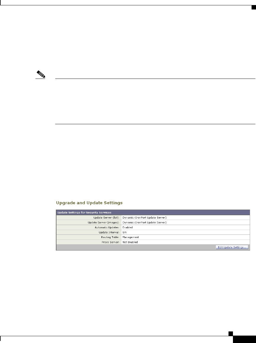
26-43
Cisco IronPort AsyncOS 7.1 for Web User Guide
OL-23207-01
Chapter 26 System Administration
Configuring Upgrade and Service Update Settings
•Your firewall settings require static IP addresses for the IronPort update
servers. The IronPort update servers use dynamic IP addresses. If you have
strict firewall policies, you may need to configure a static location for updates
and AsyncOS upgrades. For more information, see Configuring a Static
Address for the IronPort Update Servers, page 26-44.
Note Only use a local update server for upgrade images, not update images. When you
specify a local update server, the local server does not automatically receive
updated security service updates from IronPort, so the appliances in your network
eventually become out of date. Use a local update server for upgrading AsyncOS,
and then change the update and upgrade settings back to use the IronPort update
servers so the security services update automatically again.
You can configure upgrade and updates settings in the web interface or the CLI.
For more information, see Configuring the Update and Upgrade Settings from the
Web Interface, page 26-46 and Configuring the Update and Upgrade Settings
from the CLI, page 26-51.
Figure 26-20 shows where you configure upgrade and update settings in the web
interface.
Figure 26-20 System Administration > Upgrade and Update Settings Page
Updating and Upgrading from the IronPort Update Servers
The Web Security appliance can connect directly to the IronPort update servers
and download upgrade images and security service updates. Each IronPort
appliance downloads the updates and upgrade images separately.

Chapter 26 System Administration
Configuring Upgrade and Service Update Settings
26-44
Cisco IronPort AsyncOS 7.1 for Web User Guide
OL-23207-01
IronPort Systems uses a distributed update server architecture to make sure
customers can quickly download updates and AsyncOS upgrades wherever in the
world they are located. Because of this distributed server architecture, the
IronPort update servers use dynamic IP addresses. If you have strict firewall
policies, you may need to configure a static location for AsyncOS upgrades. For
more information, see Configuring a Static Address for the IronPort Update
Servers, page 26-44.
Configuring a Static Address for the IronPort Update Servers
The IronPort update servers use dynamic IP addresses. If you have strict firewall
policies, you may need to configure a static location for updates and AsyncOS
upgrades. If you determine that your firewall settings require a static IP address
for updates, complete the following steps:
Step 1 Contact IronPort Customer support to obtain the static URL address.
Step 2 Navigate to the System Administration > Upgrade and Update Settings page, and
click Edit Update Settings.
Step 3 On the Edit Update Settings page, in the “Update Servers (images)” section,
choose Local Update Servers and enter the static URL address received in step 1.
Step 4 Verify that IronPort Update Servers is selected for the “Update Servers (list)”
section.
Step 5 Submit and commit your changes.
Upgrading from a Local Server
The Web Security appliance can download AsyncOS upgrades from a server
within your network instead of obtaining upgrades directly from the IronPort
update servers. When you use this feature, you only download the upgrade image
from IronPort one time, and then serve it to all Web Security appliances in your
network.
Figure 26-21 shows how Web Security appliances download upgrade images from
local servers.
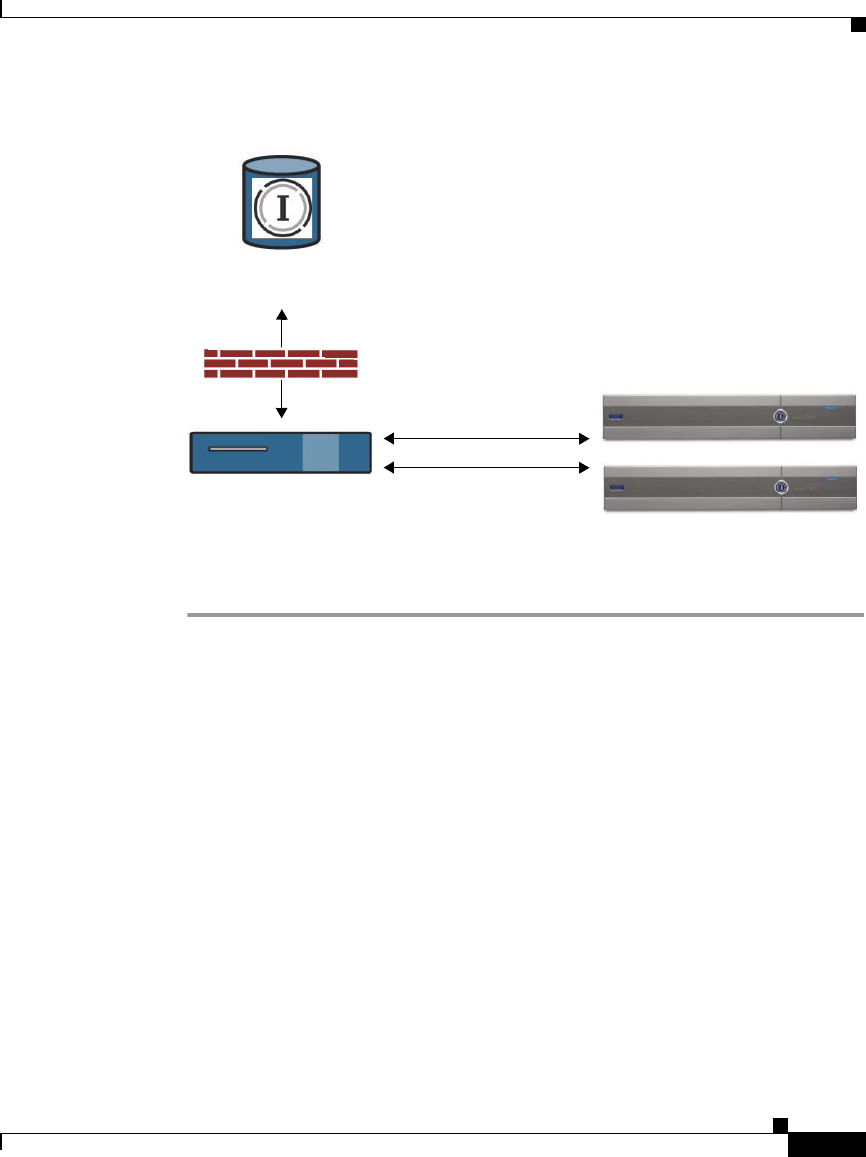
26-45
Cisco IronPort AsyncOS 7.1 for Web User Guide
OL-23207-01
Chapter 26 System Administration
Configuring Upgrade and Service Update Settings
Figure 26-21 Upgrading from a Local Server
To upgrade from a local server, perform the following steps:
Step 1 Configure a local server to retrieve and serve the upgrade files.
Step 2 Download the upgrade zip file.
Using a browser on the local server, go to
http://updates.ironport.com/fetch_manifest.html to download a zip
file of an upgrade image. To download the image, enter your serial number
and the version number of the IronPort appliance. You will then be presented
with a list of available upgrades. Click on the upgrade version that you want
to download.
Step 3 Unzip the zip file in the root directory on the local server while keeping the
directory structure intact.
Step 4 Configure the appliance to use the local server using the System Administration
> Upgrade and Update Settings page or the updateconfig command.
Step 5 On the System Administration > System Upgrade page, click Available
Upgrades or run the upgrade command.
Local web server with
access to the Internet
IronPort Systems Update
Servers
IronPort Appliances
local HTTP connections
HTTP connection to Internet through firewall

Chapter 26 System Administration
Configuring Upgrade and Service Update Settings
26-46
Cisco IronPort AsyncOS 7.1 for Web User Guide
OL-23207-01
Note Cisco recommends changing the update and upgrade settings to use the IronPort
update servers (using dynamic or static addresses) after the upgrade is complete
to ensure the security service components continue to update automatically.
Hardware and Software Requirements for Local Upgrade Servers
For downloading AsyncOS upgrade files, you must have a system in your internal
network that has a web browser (see Browser Requirements, page 2-10) and
Internet access to the IronPort Systems update servers.
Note If you need to configure a firewall setting to allow HTTP access to this address,
you must configure it using the DNS name and not a specific IP address.
For hosting AsyncOS upgrade files, a server on the internal network must have a
web server, such as Microsoft IIS (Internet Information Services) or the Apache
open source server, which has the following features:
•Supports the display of directory or filenames in excess of 24 characters.
•Has directory browsing enabled.
•Is configured for anonymous (no authentication) or Basic (“simple”)
authentication.
•Contains at least 350MB of free disk space for each AsyncOS upgrade image.
Configuring the Update and Upgrade Settings from the Web
Interface
To edit the AsyncOS update and upgrade settings:
Step 1 Navigate to the System Administration > Upgrade and Update Settings page, and
click Edit Update Settings. The Edit Update Settings page is displayed.
Figure 26-22 on page 47 shows the options you can configure on the Edit Update
Settings page.
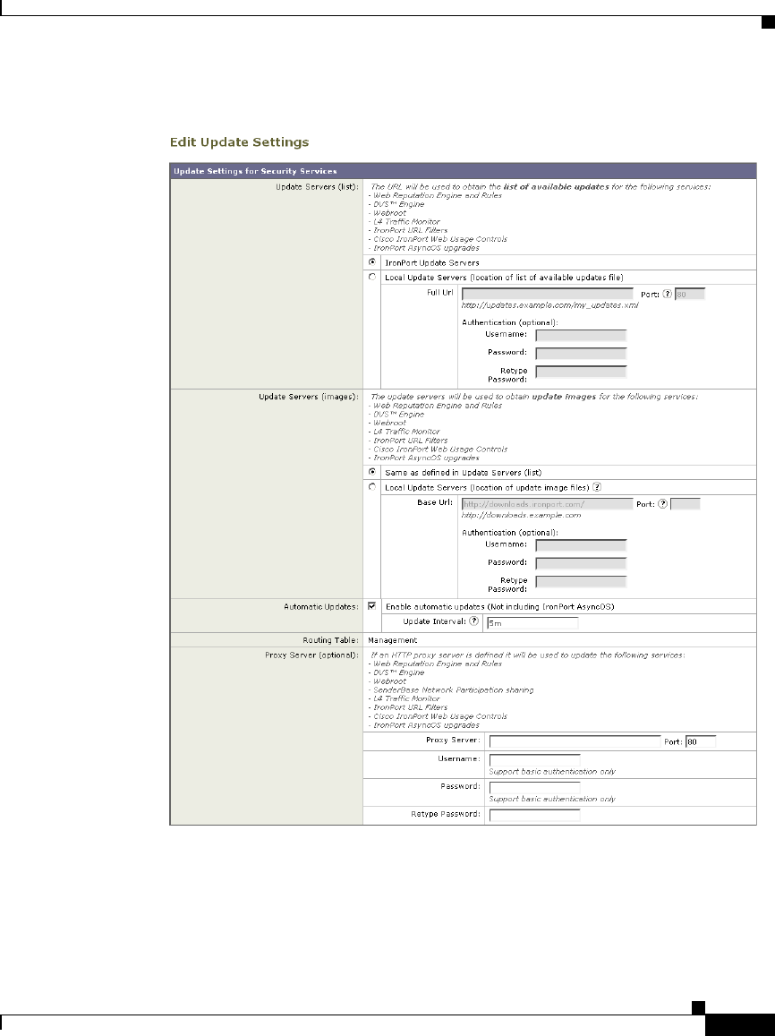
26-47
Cisco IronPort AsyncOS 7.1 for Web User Guide
OL-23207-01
Chapter 26 System Administration
Configuring Upgrade and Service Update Settings
Figure 26-22 Edit Update Settings Page


26-49
Cisco IronPort AsyncOS 7.1 for Web User Guide
OL-23207-01
Chapter 26 System Administration
Configuring Upgrade and Service Update Settings
Table 26-4 Update and Upgrade Settings
Setting Description
Update Servers (list) Choose whether to download the list of available
upgrades and updates (the manifest XML file) from the
IronPort update servers or a local web server.
The default is the IronPort update servers. You might
want to choose a local web server when you want to
temporarily download an upgrade image stored on a
local web server. After you download the image, Cisco
recommends changing this setting back to the IronPort
update servers so that security components continue to
update automatically.
When you choose a local update server, enter the full
path to the manifest XML file for the list including the
file name and port number for the server. If you leave the
port field blank, AsyncOS uses port 80. If the server
requires authentication, you can also enter a valid user
name and password.
For more information, see Upgrading from a Local
Server, page 26-44.

Chapter 26 System Administration
Configuring Upgrade and Service Update Settings
26-50
Cisco IronPort AsyncOS 7.1 for Web User Guide
OL-23207-01
Step 3 Submit and commit your changes.
Update Servers
(images)
Choose whether to download upgrade and update
images from the IronPort update servers or a local web
server. The default is the IronPort update servers. You
might want to choose a local web server under either of
the following circumstances:
•You want to download the upgrade and update
images from IronPort, but you need to enter a static
address provided by IronPort Customer Support.
•You want to temporarily download an upgrade
image stored on a local web server. After you
download the image, Cisco recommends changing
this setting back to the IronPort update servers (or
the static address if you used that) so that security
components continue to update automatically.
When you choose a local update server, enter the base
URL and port number for the server. If you leave the
port field blank, AsyncOS uses port 80. If the server
requires authentication, you can also enter a valid user
name and password.
For more information, see Updating and Upgrading
from the IronPort Update Servers, page 26-43 and
Upgrading from a Local Server, page 26-44.
Automatic Updates Choose whether or not to enable automatic updates of
the security components. If you choose automatic
updates, enter the time interval. The default is enabled
and the update interval is 5 minutes.
Routing Table Choose which network interface’s routing table to use
when contacting the update servers. The available proxy
data interfaces are shown. Default is Management.
Proxy Server
(optional)
If an upstream proxy server exists and requires
authentication, enter the server information and user
name and password here.
Table 26-4 Update and Upgrade Settings (continued)
Setting Description

26-51
Cisco IronPort AsyncOS 7.1 for Web User Guide
OL-23207-01
Chapter 26 System Administration
Configuring Upgrade and Service Update Settings
Configuring the Update and Upgrade Settings from the CLI
The updateconfig command is used to configure update and upgrade settings,
such as where the appliance looks for service updates and AsyncOS upgrades. The
settings you configure using the updateconfig command are the same as you can
define in the web interface. For more information on these settings, see Table 26-4
on page 49.
Note You can use the ping command to ensure that the appliance can contact the local
server. You can also use the telnet CLI command to telnet to port 80 of the local
server to ensure the local server is listening on that port.
Manually Updating Security Service Components
By default, each security service component periodically receives updates to its
database tables from the IronPort update servers. However, you can manually
update the database tables.
Typically, you do not need to manually update to the database tables. In the event
a manual update is required, you can modify default settings and configure an
update using the options on the System Administration > Upgrade and Update
Settings page.
To configure a manual update:
Step 1 Navigate to the System Administration > Upgrade and Update Settings page.
Step 2 Click Edit Update Settings.
The Edit Update Settings page appears.
Step 3 Receive the update files from IronPort and install them on a local server.
Step 4 Specify the location of the update files.
Step 5 Initiate the update using the Update Now function key on the component page
located on the Security Services tab. For example, Security Services > Web
Reputation Filters page.
Step 6 View a record of update activity in the updater log file. Subscribe to the updater
log file on the System Administration > Log Subscriptions page.

Chapter 26 System Administration
Configuring Upgrade and Service Update Settings
26-52
Cisco IronPort AsyncOS 7.1 for Web User Guide
OL-23207-01
Note Updates that are in-progress cannot be interrupted. All in-progress updates must
complete before new changes can be applied.

CHAPTER
27-1
Cisco IronPort AsyncOS 7.1 for Web User Guide
OL-23207-01
27
Command Line Interface
This chapter contains the following information:
•The Command Line Interface Overview, page 27-1
•Using the Command Line Interface, page 27-1
•General Purpose CLI Commands, page 27-6
•Web Security Appliance CLI Commands, page 27-8
The Command Line Interface Overview
The IronPort AsyncOS Command Line Interface (CLI) is an interactive interface
designed to allow you to configure and monitor the Web Security appliance. The
commands are invoked by entering the command name with or without any
arguments. If you enter a command without arguments, the command prompts
you for the required information.
The Command Line Interface is accessible using SSH on IP interfaces that have
been configured with these services enabled, or using terminal emulation software
on the serial port. By default, SSH is configured on the Management port.
Using the Command Line Interface
This section describes the rules and conventions of the AsyncOS Command Line
Interface.

Chapter 27 Command Line Interface
Using the Command Line Interface
27-2
Cisco IronPort AsyncOS 7.1 for Web User Guide
OL-23207-01
Accessing the Command Line Interface
Access to the CLI varies depending on the management connection method
chosen while setting up the appliance. The factory default username and password
are listed next. Initially, only the admin user account has access to the CLI. You
can add other users with differing levels of permission after you have accessed the
CLI for the first time using the admin account. The System Setup Wizard prompts
you to change the password for the admin account.
You can also reset the admin account password at any time using the passwd
command.
You can connect using one of the following methods:
•Ethernet. Start an SSH session with the IP address of the Web Security
appliance. The factory default IP address is 192.168.42.42. SSH is configured
to use port 22.
•Serial connection. Start a terminal session with the communication port on
your personal computer that the serial cable is connected to.
Log in to the appliance by entering the username and password below.
•Username: admin
•Password: ironport
For example:
Working with the Command Prompt
The top-level command prompt consists of the fully qualified hostname, followed
by the greater than (>) symbol, followed by a space. For example:
login: admin
password: ironport
example.com>

27-3
Cisco IronPort AsyncOS 7.1 for Web User Guide
OL-23207-01
Chapter 27 Command Line Interface
Using the Command Line Interface
When running commands, the CLI requires input from you. When the CLI is
expecting input, the prompt displays the default values enclosed in square
brackets ([]) followed by the greater than (>) symbol. When there is no default
value, the brackets are empty.
For example:
When there is a default setting, the setting is displayed within the
command-prompt brackets. For example:
When a default setting is shown, typing Return is equivalent to accepting the
default:
Command Syntax
When operating in the interactive mode, the CLI command syntax consists of
single commands with no white space and no arguments or parameters. For
example:
example.com> routeconfig
Choose a routing table:
- MANAGEMENT - Routes for Management Traffic
- DATA - Routes for Data Traffic
[]>
example.com> setgateway
Warning: setting an incorrect default gateway may cause the current
connection
to be interrupted when the changes are committed.
Enter new default gateway:
[172.xx.xx.xx]>
example.com> logconfig

Chapter 27 Command Line Interface
Using the Command Line Interface
27-4
Cisco IronPort AsyncOS 7.1 for Web User Guide
OL-23207-01
Select Lists
When you are presented with multiple choices for input, some commands use
numbered lists. Enter the number of the selection at the prompt.
For example:
Yes/No Queries
When given a yes or no option, the question is posed with a default in brackets.
You may answer Y, N, Yes, or No. Case is not significant.
For example:
Subcommands
Some commands give you the opportunity to use subcommand directives such as
NEW, EDIT, and DELETE. The EDIT and DELETE functions provide a list of previously
configured values.
For example:
Log level:
1. Critical
2. Warning
3. Information
4. Debug
5. Trace
[3]> 3
Do you want to enable the proxy? [Y]> Y
example.com> interfaceconfig
Currently configured interfaces:
1. Management (172.xxx.xx.xx/xx: example.com)
Choose the operation you want to perform:

27-5
Cisco IronPort AsyncOS 7.1 for Web User Guide
OL-23207-01
Chapter 27 Command Line Interface
Using the Command Line Interface
Within subcommands, typing Enter or Return at an empty prompt returns you to
the main command.
Escaping Subcommands
You can use the Ctrl+C keyboard shortcut at any time within a subcommand to
immediately exit return to the top level of the CLI.
Command History
The CLI keeps a history of all commands entered during a session. Use the Up
and Down arrow keys on your keyboard, or the Ctrl+P and Ctrl+N key
combinations to scroll through a running list of the recently-used commands.
Completing Commands
The IronPort AsyncOS CLI supports command completion. You can enter the first
few letters of some commands followed by the Tab key and the CLI completes the
string. If the letters you entered are not unique among commands, the CLI
“narrows” the set. For example:
- NEW - Create a new interface.
- EDIT - Modify an interface.
- DELETE - Remove an interface.
[]>
example.com> set (type the Tab key)
setgateway, setgoodtable, sethostname, settime, settz
example.com> seth (typing the Tab again completes the entry with sethostname)

Chapter 27 Command Line Interface
General Purpose CLI Commands
27-6
Cisco IronPort AsyncOS 7.1 for Web User Guide
OL-23207-01
Configuration Changes
You can make configuration changes while web operations proceed normally.
Configuration changes do not take effect until you complete the following steps:
Step 1 Issue the commit command at the command prompt.
Step 2 Give the commit command the input required.
Step 3 Receive confirmation of the commit procedure at the CLI.
Changes to configuration that have not been committed are recorded, but do not
go into effect until you run the commit command. However, not all commands
require the commit command to be run.
Exiting the CLI session, system shutdown, reboot, failure, or issuing the clear
command clears changes that have not yet been committed.
General Purpose CLI Commands
This section describes the some basic commands you might use in a typical CLI
session, such as committing and clearing changes. For a full list of commands, see
Web Security Appliance CLI Commands, page 27-8.
Committing Configuration Changes
The commit command allows you to change configuration settings while other
operations proceed normally. Changes are not actually committed until you
receive confirmation and a timestamp. Exiting the CLI session, system shutdown,
reboot, failure, or issuing the clear command clears changes that have not yet
been committed.
Entering comments after the commit command is optional.
example.com> commit
Please enter some comments describing your changes:

27-7
Cisco IronPort AsyncOS 7.1 for Web User Guide
OL-23207-01
Chapter 27 Command Line Interface
General Purpose CLI Commands
Note To successfully commit changes, you must be at the top-level command prompt.
Type Return at an empty prompt to move up one level in the command line
hierarchy.
Clearing Configuration Changes
The clear command clears any changes made to the appliance configuration since
the last commit or clear command was issued.
Exiting the Command Line Interface Session
The exit command logs you out of the CLI application. Configuration changes
that have not been committed are cleared.
[]> Changed “psinet” IP Interface to a different IP address
Changes committed: Wed Jan 01 12:00:01 2007
example.com> clear
Are you sure you want to clear all changes since the last commit?
[Y]> y
Changes cleared: Wed Jan 01 12:00:01 2007
example.com>
example.com> exit
Configuration changes entered but not committed. Exiting will lose
changes.
Type 'commit' at the command prompt to commit changes.
Are you sure you wish to exit? [N]> y

Chapter 27 Command Line Interface
Web Security Appliance CLI Commands
27-8
Cisco IronPort AsyncOS 7.1 for Web User Guide
OL-23207-01
Seeking Help on the Command Line Interface
The help command lists all available CLI commands and gives a brief description
of each command. The help command can be invoked by typing either help or a
single question mark (?) at the command prompt.
Web Security Appliance CLI Commands
The Web Security Appliance CLI supports a set of proxy and UNIX commands to
access, upgrade, and administer the system.
Table 27-1 lists the Web Security appliance Command Line Interface commands.
example.com> help
Table 27-1 Web Security appliance Administrative Commands
Command Description
advancedproxyconfig Configure more advanced Web Proxy configurations,
such as authentication and DNS parameters.
For more information about the
advancedproxyconfig command, see Advanced
Proxy Configuration, page 5-30.
adminaccessconfig You can configure the Web Security appliance to have
stricter access requirements for administrators
logging into the appliance.
For more information about the adminaccessconfig
command, see Configuring Administrator Settings,
page 26-20.
alertconfig Specify alert recipients, and set parameters for
sending system alerts.

27-9
Cisco IronPort AsyncOS 7.1 for Web User Guide
OL-23207-01
Chapter 27 Command Line Interface
Web Security Appliance CLI Commands
authcache Allows you to delete a one or all entries (users) from
the authentication cache. You can also list all users
currently included in the authentication cache.
You might want to clear a user from the authentication
cache so the user can login again from a different
machine before the User session Restrictions values
times out.
bwcontrol Enable bandwidth control debug messages in the
Default Proxy log file.
certconfig Configure security certificates and keys.
clear Clears pending configuration changes since last
commit.
commit Commits pending changes to the system
configuration.
createcomputerobject Creates a computer object at the location you specify.
datasecurityconfig Defines a minimum request body size, below which
upload requests are not scanned by the IronPort Data
Security Filters.
For more information, see Bypassing Upload
Requests Below a Minimum Size, page 12-3.
dnsconfig Configure DNS server parameters.
dnsflush Flush DNS entries on the appliance.
etherconfig Configure Ethernet port connections.
externaldlpconfig Defines a minimum request body size, below which
upload requests are not scanned by the external DLP
server.
For more information, see Bypassing Upload
Requests Below a Minimum Size, page 12-3.
featurekey Submits valid keys to activate licensed features.
For more information, see Feature Keys Page,
page 26-10.
Table 27-1 Web Security appliance Administrative Commands (continued)

Chapter 27 Command Line Interface
Web Security Appliance CLI Commands
27-10
Cisco IronPort AsyncOS 7.1 for Web User Guide
OL-23207-01
featurekeyconfig Automatically check for and update feature keys.
For more information, see Feature Key Settings Page,
page 26-11.
grep Searches named input files for lines containing a
match to the give pattern.
help Returns a list of commands.
iccm_message Clears the message in the web interface and CLI that
indicates when this Web Security appliance is
managed by a Security Management appliance
(M-Series).
ifconfig
or
interfaceconfig
Configure and manage network interfaces including
M1, P1, and P2. Displays currently configured
interfaces, and provides an operations menu to create,
edit, or delete interfaces.
last Lists user-specific user information that includes ttys
and hosts, in reverse time order or lists the users that
are logged in at a specified date and time.
loadconfig Load a system configuration file.
logconfig Configure access to log files.
mailconfig Mail the current configuration file to the address
specified.
musconfig Use this command to enable Secure Mobility Solution
and configure how to identify remote users, either by
IP address or by integrating with one or more Cisco
adaptive security appliances.
Note: Changes made using this command cause the
Web Proxy to restart.
For more information on enabling and configuring
Secure Mobility Solution, see Enabling Secure
Mobility, page 13-3.
Table 27-1 Web Security appliance Administrative Commands (continued)

27-11
Cisco IronPort AsyncOS 7.1 for Web User Guide
OL-23207-01
Chapter 27 Command Line Interface
Web Security Appliance CLI Commands
musstatus Use this command to display information related to
Secure Mobility Solution when the Web Security
appliance is integrated with an adaptive security
appliance.
This command displays the following information:
•The status of the Web Security appliance
connection with each adaptive security appliance.
•The duration of the Web Security appliance
connection with each adaptive security appliance
in minutes.
•The number of remote clients from each adaptive
security appliance.
•The number of remote clients being serviced,
which is defined as the number of remote clients
that have passed traffic through the Web Security
appliance.
•The total number of remote clients.
nslookup Queries Internet domain name servers for information
about specified hosts and domains or to print a list of
hosts in a domain.
ntpconfig Configure NTP servers. Displays currently
configured interfaces, and provides an operations
menu to add, remove, or set the interface from whose
IP address NTP queries should originate.
packetcapture Intercepts and displays TCP/IP and other packets
being transmitted or received over the network to
which the appliance is attached.
For more information, see Packet Capture, page 26-6.
passwd Set the password.
pathmtudiscovery Enables or disables Path MTU Discovery.
You might want to disable Path MTU Discovery if you
need to packet fragmentation.
Table 27-1 Web Security appliance Administrative Commands (continued)

Chapter 27 Command Line Interface
Web Security Appliance CLI Commands
27-12
Cisco IronPort AsyncOS 7.1 for Web User Guide
OL-23207-01
ping Sends an ICMP ECHO REQUEST to the specified
host or gateway.
proxyconfig
<enable | disable>
Enables or disables the Web Proxy.
proxystat Display web proxy statistics.
quit, q, exit Terminates an active process or session.
reboot Flushes the file system cache to disk, halts all running
processes, and restarts the system.
reportingconfig Configure a reporting system.
resetconfig Restores the configuration to factory defaults.
rollovernow Roll over a log file.
routeconfig Configure destination IP addresses and gateways for
traffic. Displays currently configured routes, and
provides an operations menu to create, edit, or delete,
or clear entries.
saveconfig Saves a copy of the current configuration settings to a
file. This file can be used to restore defaults, if
necessary.
setgateway Configure the default gateway for the machine.
sethostname Set the hostname parameter.
setntlmsecuritymode Changes the security setting for the NTLM
authentication realm to either “ads” or “domain.”
When the setting is “domain,” the appliance joins the
Active Directory domain with a domain security trust
account, and when the setting is “ads,” it joins the
domain as a native Active Directory member. Default
is ads.
settime Set system time.
settz Displays the current time zone, and provides an
operations menu to set a local time zone.
showconfig Display all configuration values.
shutdown Terminates connections and shuts down the system.
Table 27-1 Web Security appliance Administrative Commands (continued)

27-13
Cisco IronPort AsyncOS 7.1 for Web User Guide
OL-23207-01
Chapter 27 Command Line Interface
Web Security Appliance CLI Commands
smtprelay Configure SMTP relay hosts for internally generated
email. An SMTP relay host is required to receive
system generated email and alerts. For more
information about configuring SMTP relay hosts, see
Configuring SMTP Relay Hosts, page 25-26.
snmpconfig Configure the local host to listen for SNMP queries
and allow SNMP requests.
sshconfig Configure hostname and host key options for trusted
servers.
status Displays system status.
supportrequest Send the support request email to IronPort customer
care. This includes system information and a copy of
the master configuration. The e-mail address is
“support@ironport.com”.
tail Displays the end of a log file. Command accepts log
file name or number as parameters.
example.com> tail system_logs
example.com> tail 9
techsupport Provides a temporary connection to allow IronPort
Customer Care/Applications Engineering to access
the system and assist in troubleshooting.
telnet Communicates with another host using the TELNET
protocol.
testauthconfig Tests the authentication settings for a given
authentication realm against the authentication
servers defined in the realm.
For more information about testing authentication
settings, see Testing Authentication Settings,
page 20-20.
traceroute Traces IP packets through gateways and along the
path to a destination host.
Table 27-1 Web Security appliance Administrative Commands (continued)

Chapter 27 Command Line Interface
Web Security Appliance CLI Commands
27-14
Cisco IronPort AsyncOS 7.1 for Web User Guide
OL-23207-01
updateconfig Configure update and upgrade settings. For more
information, see Configuring Upgrade and Service
Update Settings, page 26-42.
updatenow Update all components.
upgrade Install an AsyncOS software upgrade.
userconfig Configure system administrators.
version Displays general system information, installed
versions of system software, and rule definitions.
webcache Examine or modify the contents of the proxy cache, or
configure domains and URLs that the appliance never
caches. Allows an administrator to remove a
particular URL from the proxy cache or specify which
domains or URLs to never store in the proxy cache.
For more information, see Web Proxy Cache,
page 5-2.
who Displays who is logged into the system.
whoami Displays user information.
Table 27-1 Web Security appliance Administrative Commands (continued)

A-1
Cisco IronPort AsyncOS 7.1 for Web User Guide
OL-23207-01
APPENDIX
A
IronPort End User License Agreement
This appendix contains the following section:
•Cisco IronPort Systems, LLC Software License Agreement, page A-1
Cisco IronPort Systems, LLC Software License
Agreement
NOTICE TO ALL USERS: CAREFULLY READ THE FOLLOWING LEGAL
AGREEMENT (“AGREEMENT”) FOR THE LICENSE OF THE SOFTWARE
(AS DEFINED BELOW). BY CLICKING THE ACCEPT BUTTON OR
ENTERING “Y” WHEN PROMPTED, YOU (EITHER AN INDIVIDUAL OR A
SINGLE ENTITY, COLLECTIVELY, THE “COMPANY”) CONSENT TO BE
BOUND BY AND BECOME A PARTY TO THE FOLLOWING AGREEMENT
BETWEEN CISCO IRONPORT SYSTEMS, LLC, A DELAWARE
CORPORATION (“IRONPORT”) AND COMPANY (COLLECTIVELY, THE
“PARTIES”). BY CLICKING THE ACCEPT BUTTON OR ENTERING “Y”
WHEN PROMPTED, YOU REPRESENT THAT (A) YOU ARE DULY
AUTHORIZED TO REPRESENT YOUR COMPANY AND (B) YOU ACCEPT
THE TERMS AND CONDITIONS OF THIS AGREEMENT ON BEHALF OF
YOUR COMPANY, AND AS SUCH, AN AGREEMENT IS THEN FORMED. IF
YOU OR THE COMPANY YOU REPRESENT (COLLECTIVELY,
“COMPANY”) DO NOT AGREE TO THE TERMS AND CONDITIONS OF
THIS AGREEMENT, CLICK THE CANCEL BUTTON OR ENTER “N” WHEN
PROMPTED AND PROMPTLY (BUT NO LATER THAT THIRTY (30) DAYS

Appendix A IronPort End User License Agreement
Cisco IronPort Systems, LLC Software License Agreement
A-2
Cisco IronPort AsyncOS 7.1 for Web User Guide
OL-23207-01
OF THE DELIVERY DATE, AS DEFINED BELOW) NOTIFY IRONPORT, OR
THE RESELLER FROM WHOM YOU RECEIVED THE SOFTWARE, FOR A
FULL REFUND OF THE PRICE PAID FOR THE SOFTWARE.
1. DEFINITIONS
1.1 “Company Service” means the Company’s email or internet services provided
to End Users for the purposes of conducting Company’s internal business and
which are enabled via Company’s products as described in the purchase
agreement, evaluation agreement, beta or pre-release agreement, purchase order,
sales quote or other similar agreement between the Company and IronPort or its
reseller (“Agreement”) and the applicable user interface and IronPort’s standard
system guide documentation that outlines the system architecture and its
interfaces (collectively, the “License Documentation”).
1.2 “End User” means the employee, contractor or other agent authorized by
Company to access to the Internet or use email services via the Company Service.
1.3 “Service(s)” means (i) the provision of the Software functionality, including
Updates and Upgrades, and (ii) the provision of support by IronPort or its reseller,
as the case may be.
1.4 “Software” means: (i) IronPort’s proprietary software licensed by IronPort to
Company along with IronPort’s hardware products; (ii) any software provided by
IronPort’s third-party licensors that is licensed to Company to be implemented for
use with IronPort’s hardware products; (iii) any other IronPort software module(s)
licensed by IronPort to Company along with IronPort’s hardware products; and
(iv) any and all Updates and Upgrades thereto.
1.5 “Updates” means minor updates, error corrections and bug fixes that do not
add significant new functions to the Software, and that are released by IronPort or
its third party licensors. Updates are designated by an increase to the Software’s
release number to the right of the decimal point (e.g., Software 1.0 to Software
1.1). The term Updates specifically excludes Upgrades or new software versions
marketed and licensed by IronPort or its third party licensors as a separate
product.
1.6 “Upgrade(s)” means revisions to the Software, which add new enhancements
to existing functionality, if and when it is released by IronPort or its third party
licensors, in their sole discretion. Upgrades are designated by an increase in the
Software’s release number, located to the left of the decimal point (e.g., Software

A-3
Cisco IronPort AsyncOS 7.1 for Web User Guide
OL-23207-01
Appendix A IronPort End User License Agreement
Cisco IronPort Systems, LLC Software License Agreement
1.x to Software 2.0). In no event shall Upgrades include any new versions of the
Software marketed and licensed by IronPort or its third party licensors as a
separate product.
2. LICENSE GRANTS AND CONSENT TO TERMS OF DATA COLLECTION
2.1 License of Software. By using the Software and the License Documentation,
Company agrees to be bound by the terms of this Agreement, and so long as
Company is in compliance with this Agreement, IronPort hereby grants to
Company a non-exclusive, non-sublicensable, non-transferable, worldwide
license during the Term to use the Software only on IronPort’s hardware products,
solely in connection with the provision of the Company Service to End Users. The
duration and scope of this license(s) is further defined in the License
Documentation. Except as expressly provided herein, no right, title or interest in
any Software is granted to the Company by IronPort, IronPort’s resellers or their
respective licensors. This license and any Services are co-terminus.
2.2 Consent and License to Use Data. Subject to Section 8 hereof, and subject to
the IronPort Privacy Statement at http://www.IronPort.com/privacy.html, as the
same may be amended from time to time by IronPort with notice to Company,
Company hereby consents and grants to IronPort a license to collect and use the
data from the Company as described in the License Documentation, as the same
may be updated from time to time by IronPort (“Data”). To the extent that reports
or statistics are generated using the Data, they shall be disclosed only in the
aggregate and no End User identifying information may be surmised from the
Data, including without limitation, user names, phone numbers, unobfuscated file
names, email addresses, physical addresses and file content. Notwithstanding the
foregoing, Company may terminate IronPort’s right to collect and use Data at any
time upon prior written or electronic notification, provided that the Software or
components of the Software may not be available to Company if such right is
terminated.
3. CONFIDENTIALITY. Each Party agrees to hold in confidence all Confidential
Information of the other Party to the same extent that it protects its own similar
Confidential Information (and in no event using less than a reasonable degree of
care) and to use such Confidential Information only as permitted under this
Agreement. For purposes of this Agreement “Confidential Information” means
information of a party marked “Confidential” or information reasonably
considered by the disclosing Party to be of a proprietary or confidential nature;
provided that the Data, the Software, information disclosed in design reviews and
any pre-production releases of the Software provided by IronPort is expressly
designated Confidential Information whether or not marked as such.

Appendix A IronPort End User License Agreement
Cisco IronPort Systems, LLC Software License Agreement
A-4
Cisco IronPort AsyncOS 7.1 for Web User Guide
OL-23207-01
4. PROPRIETARY RIGHTS; OWNERSHIP. Title to and ownership of the
Software and other materials and all associated Intellectual Property Rights (as
defined below) related to the foregoing provided by IronPort or its reseller to
Company will remain the exclusive property of IronPort and/or its superior
licensors. Company and its employees and agents will not remove or alter any
trademarks, or other proprietary notices, legends, symbols, or labels appearing on
or in copies of the Software or other materials delivered to Company by IronPort
or its reseller. Company will not modify, transfer, resell for profit, distribute, copy,
enhance, adapt, translate, decompile, reverse engineer, disassemble, or otherwise
determine, or attempt to derive source code for any Software or any internal data
files generated by the Software or to create any derivative works based on the
Software or the License Documentation, and agrees not to permit or authorize
anyone else to do so. Unless otherwise agreed in writing, any programs,
inventions, concepts, documentation, specifications or other written or graphical
materials and media created or developed by IronPort or its superior licensors
during the course of its performance of this Agreement, or any related consulting
or professional service agreements, including all copyrights, database rights,
patents, trade secrets, trademark, moral rights, or other intellectual property rights
(“Intellectual Property Right(s)”) associated with the performance of such work
shall belong exclusively to IronPort or its superior licensors and shall, in no way
be considered a work made for hire for Company within the meaning of Title 17
of the United States Code (Copyright Act of 1976).
5. LIMITED WARRANTY AND WARRANTY DISCLAIMERS
5.1 Limited Warranty. IronPort warrants to Company that the Software, when
properly installed and properly used, will substantially conform to the
specifications in the License Documentation for a period of ninety (90) days from
the delivery date or the period set forth in the License Documentation, whichever
is longer (“Warranty Period”). FOR ANY BREACH OF THE WARRANTY
CONTAINED IN THIS SECTION, COMPANY’S EXCLUSIVE REMEDY AND
IRONPORT’S ENTIRE LIABILITY, WILL BE PROMPT CORRECTION OF
ANY ERROR OR NONCONFORMITY, PROVIDED THAT THE
NONCONFORMITY HAS BEEN REPORTED TO IRONPORT AND/OR ITS
RESELLER BY COMPANY WITHIN THE WARRANTY PERIOD. THIS
WARRANTY IS MADE SOLELY TO COMPANY AND IS NOT
TRANSFERABLE TO ANY END USER OR OTHER THIRD PARTY. IronPort
shall have no liability for breach of warranty under this Section or otherwise for
breach of this Agreement if such breach arises directly or indirectly out of or in
connection with the following: (i) any unauthorized, improper, incomplete or
inadequate maintenance or calibration of the Software by Company or any third

A-5
Cisco IronPort AsyncOS 7.1 for Web User Guide
OL-23207-01
Appendix A IronPort End User License Agreement
Cisco IronPort Systems, LLC Software License Agreement
party; (ii) any third party hardware software, services or system(s); (iii) any
unauthorized modification or alteration of the Software or Services; (iv) any
unauthorized or improper use or operation of the Software or Company’s failure
to comply with any applicable environmental specification; or (v) a failure to
install and/or use Updates, Upgrades, fixes or revisions provided by IronPort or
its resellers from time to time.
5.2 WARRANTY DISCLAIMER. THE EXPRESS WARRANTIES SET FORTH
IN SECTION 5.1 OF THIS AGREEMENT CONSTITUTE THE ONLY
PERFORMANCE WARRANTIES WITH RESPECT TO THE SOFTWARE OR
SERVICES. TO THE MAXIMUM EXTENT PERMITTED BY APPLICABLE
LAW, IRONPORT LICENSES THE SOFTWARE AND SERVICES
HEREUNDER ON AN “AS IS” BASIS. EXCEPT AS SPECIFICALLY SET
FORTH HEREIN, IRONPORT AND ITS SUPERIOR LICENSORS MAKE NO
REPRESENTATIONS OR WARRANTIES OF ANY KIND, WHETHER
EXPRESS, IMPLIED, OR STATUTORY (EITHER IN FACT OR BY
OPERATION OF LAW), AND EXPRESSLY DISCLAIM ALL OTHER
WARRANTIES, INCLUDING WITHOUT LIMITATION, THE IMPLIED
WARRANTIES OF MERCHANTABILITY OR FITNESS FOR A PARTICULAR
PURPOSE. NEITHER IRONPORT NOR ITS THIRD PARTY LICENSORS
WARRANT THAT THE SOFTWARE OR SERVICES (1) IS FREE FROM
DEFECTS, ERRORS OR BUGS, (2) THAT OPERATION OF THE SOFTWARE
WILL BE UNINTERRUPTED, OR (3) THAT ANY RESULTS OR
INFORMATION THAT IS OR MAY BE DERIVED FROM THE USE OF THE
SOFTWARE WILL BE ACCURATE, COMPLETE, RELIABLE AND/OR
SECURE.
6. LIMITATION OF LIABILITY. TO THE MAXIMUM EXTENT PERMITTED
BY APPLICABLE LAW, IN NO EVENT WILL EITHER PARTY BE LIABLE
TO THE OTHER FOR ANY LOSS OF PROFITS, COSTS OF PROCUREMENT
OF SUBSTITUTE GOODS OR SERVICES, LOSS OF BUSINESS, LOSS OF
USE OR DATA, INTERRUPTION OF BUSINESS, OR FOR INDIRECT,
SPECIAL, INCIDENTAL OR CONSEQUENTIAL DAMAGES OF ANY KIND,
EVEN IF SUCH PARTY RECEIVED ADVANCE NOTICE OF THE
POSSIBILITY OF SUCH DAMAGES. IN NO EVENT SHALL THE LIABILITY
OF EITHER PARTY ARISING UNDER ANY PROVISION OF THIS
AGREEMENT, REGARDLESS OF WHETHER THE CLAIM FOR SUCH
DAMAGES IS BASED IN CONTRACT, TORT, OR OTHER LEGAL THEORY,
EXCEED THE TOTAL AMOUNT PAID FOR THE SOFTWARE OR SERVICES
DURING THE TWELVE (12) MONTHS PRIOR TO THE EVENT GIVING
RISE TO SUCH LIABILITY.

Appendix A IronPort End User License Agreement
Cisco IronPort Systems, LLC Software License Agreement
A-6
Cisco IronPort AsyncOS 7.1 for Web User Guide
OL-23207-01
7. TERM AND TERMINATION. The term of this Agreement shall be as set forth
in the License Documentation (the “Term”). If IronPort defaults in the
performance of any material provision of this Agreement or the License
Documentation, then Company may terminate this Agreement upon thirty (30)
days written notice if the default is not cured during such thirty (30) day period.
If Company defaults in the performance of any material provision of this
Agreement or the License Documentation, IronPort may terminate this
Agreement upon thirty (30) days written notice if the default is not cured during
such thirty (30) day notice and without a refund. This Agreement may be
terminated by one Party immediately at any time, without notice, upon (i) the
institution by or against the other Party of insolvency, receivership or bankruptcy
proceedings or any other proceedings for the settlement of such Party's debts, (ii)
such other Party making a general assignment for the benefit of creditors, or (iii)
such other Party's dissolution. The license granted in Section 2 will immediately
terminate upon this Agreement's termination or expiration. Within thirty (30)
calendar days after termination or expiration of this Agreement, Company will
deliver to IronPort or its reseller or destroy all copies of the Software and any
other materials or documentation provided to Company by IronPort or its reseller
under this Agreement.
8. U.S. GOVERNMENT RESTRICTED RIGHTS; EXPORT CONTROL. The
Software and accompanying License Documentation are deemed to be
“commercial computer software” and “commercial computer software
documentation,” respectively, pursuant to DFAR Section 227.7202 and FAR
Section 12.212, as applicable. Any use, modification, reproduction, release,
performance, display or disclosure of the Software and accompanying License
Documentation by the United States Government shall be governed solely by the
terms of this Agreement and shall be prohibited except to the extent expressly
permitted by the terms of this Agreement. Company acknowledges that the
Software and License Documentation must be exported in accordance with U.S.
Export Administration Regulations and diversion contrary to U.S. laws is
prohibited. Company represents that neither the United States Bureau of Export
Administration nor any other federal agency has suspended, revoked or denied
Company export privileges. Company represents that Company will not use or
transfer the Software for end use relating to any nuclear, chemical or biological
weapons, or missile technology unless authorized by the U.S. Government by
regulation or specific license. Company acknowledges it is Company’s ultimate
responsibility to comply with any and all import and export restrictions, and other
applicable laws, in the U.S. or elsewhere, and that IronPort or its reseller has no
further responsibility after the initial sale to Company within the original country
of sale.

A-7
Cisco IronPort AsyncOS 7.1 for Web User Guide
OL-23207-01
Appendix A IronPort End User License Agreement
Cisco IronPort Systems, LLC Software License Agreement
9. MISCELLANEOUS. This Agreement is governed by the laws of the United
States and the State of California, without reference to conflict of laws principles.
The application of the United Nations Convention of Contracts for the
International Sale of Goods is expressly excluded. Nothing contained herein shall
be construed as creating any agency, partnership, or other form of joint enterprise
between the parties. Neither party shall be liable hereunder by reason of any
failure or delay in the performance of its obligations hereunder (except for the
payment of money) on account of (i) any provision of any present or future law or
regulation of the United States or any applicable law that applies to the subject
hereof, and (ii) interruptions in the electrical supply, failure of the Internet,
strikes, shortages, riots, insurrection, fires, flood, storm, explosions, acts of God,
war, terrorism, governmental action, labor conditions, earthquakes, or any other
cause which is beyond the reasonable control of such party. This Agreement and
the License Documentation set forth all rights for the user of the Software and is
the entire agreement between the parties and supersedes any other
communications with respect to the Software and License Documentation. The
terms and conditions of this Agreement will prevail, notwithstanding any variance
with the License Documentation or any purchase order or other written instrument
submitted by a party, whether formally rejected by the other party or not. This
Agreement may not be modified except by a written addendum issued by a duly
authorized representative of IronPort, except that IronPort may modify the
IronPort Privacy Statement at any time, in its discretion, via notification to
Company of such modification that will be posted at
http://www.IronPort.com/privacy.html. No provision hereof shall be deemed
waived unless such waiver shall be in writing and signed by IronPort or a duly
authorized representative of IronPort. If any provision of this Agreement is held
invalid, the remainder of this Agreement shall continue in full force and effect.
The parties confirm that it is their wish that this Agreement has been written in
the English language only.
10. IRONPORT CONTACT INFORMATION. If Company wants to contact
IronPort for any reason, please write to IronPort Systems, Inc., 950 Elm Avenue,
San Bruno, California 94066, or call or fax us at tel: 650.989.6500 and fax:
650.989.6543.

Appendix A IronPort End User License Agreement
Cisco IronPort Systems, LLC Software License Agreement
A-8
Cisco IronPort AsyncOS 7.1 for Web User Guide
OL-23207-01

IN-1
Cisco IronPort AsyncOS 7.1 for Web User Guide
OL-23207-01
INDEX
A
access log file
see also W3C access logs
ACL decision tags 24-24
anti-malware information 24-30
anti-malware request example entry 24-35
anti-malware response example
entry 24-35
custom formatting 24-39
no category (nc) 24-30
no score (ns) 24-30
overview 24-19
result codes 24-23
URL category abbreviations 16-32
Web Reputation Filters example
entry 24-34
web reputation information 24-30
access logs
custom fields 24-51
variables 24-39
Access Policies
anti-malware 8-17
application filtering 8-15
configuring Web Reputation 18-5
creating 8-7
flow diagram 8-13
guest users 7-13
membership 8-4
Monitor action 8-3
objects 8-16
overview 8-1
protocol of request 8-9
protocols and user agents 8-14
proxy port of request 8-9
redirecting traffic 16-23
subnet of request 8-10
time of request 8-10
URL category of request 8-10
URL filters 8-15
user agent of request 8-11
user location of request 8-11
Web Reputation 8-17
Access Policy groups
see also policy groups
ACL decision tags
access log file 24-24
Active Directory
changing passwords 20-43

Index
IN-2
Cisco IronPort AsyncOS 7.1 for Web User Guide
OL-23207-01
joining the domain 20-53
multiple domains 20-51
active mode
enabling for FTP 5-47
adding
log subscriptions 24-14
WCCP service 25-21
addresses
ambiguous address 21-2
known allowed address 21-2
known malware address 21-2
unlisted address 21-2
adminaccessconfig command
overview 26-20
administering the appliance
connecting to the management
interface 2-3
System Setup Wizard 2-2
administrator access
configuring for IP addresses 26-20
configuring SSL ciphers 26-21
adult content
filtering 16-20
logging usage 16-22
advancedproxyconfig command
overview 5-30
web proxy usage agreement 5-18
alert recipient 26-22
alerts
alert classifications 26-23
recipients 26-22
settings 26-23
severities 26-23
alert settings 26-23
All Identities
overview 6-12
allowing traffic
L4 Traffic Monitor 21-2
ambiguous address
defined 21-2
anonymizing
usernames in reports 22-2
anti-malware
access log file 19-15
access log information 24-30
configuring 19-10
databases 19-5
outbound scanning 11-1
overview 19-1
parameter settings 19-11
rules for L4 Traffic Monitor 21-4
scanning verdicts 24-52
viewing activity 19-15
Anti-Malware report 23-18
anti-malware rules
L4 Traffic Monitor 21-4
anti-malware scanning
bypassing 5-15
outbound 11-1

IN-3
Cisco IronPort AsyncOS 7.1 for Web User Guide
OL-23207-01
Index
AnyConnect Secure Mobility
see Secure Mobility
appliance hostname
DNS support 4-6
application behaviors
defined 17-4
application bypass settings
configuring 5-18
application control
application behaviors 17-4
applications 17-4
application types 17-4
bandwidth 17-11
bypassing application scanning 5-18
configuring 17-4, 17-9
instant messaging traffic 17-17
logging 17-19
overview 17-1
report 23-16
reporting 17-19
rules and guidelines 17-9
applications
blocking 17-9
configuring bandwidth limits 17-15
defined 17-4
application scanning
bypassing 5-18
application types
configuring bandwidth limits 17-13
defined 17-4
overriding bandwidth limits 17-13
Application Visibility and Control
see application control
Application Visibility and Control engine
see AVC engine
Application Visibility report
overview 23-16
archiving reports 22-16
assignment method
WCCP service 25-18
AsyncOS upgrades
overview 26-40
authentication
behavior with multiple realms 20-19
compared to authorization 6-10
configuring global settings 20-23
configuring LDAP 20-43
configuring NTLM 20-51
defined 6-10
entering the domain 20-4
exempting user agents 6-18
failure 20-4
global Identity policy 7-6
guest access 7-13
HTTPS requests 7-6
Identity groups 7-4
LDAP 20-43
MSN Messenger 7-26

Index
IN-4
Cisco IronPort AsyncOS 7.1 for Web User Guide
OL-23207-01
native FTP 5-9
NTLM 20-51
overview 20-1
realms 20-14
re-authenticating users 20-39
SaaS applications 14-4
secure LDAP 20-43
sending credentials securely 20-37
sequences 20-16
special characters 20-56
supported characters for Basic 20-51
surrogates 20-40
surrogates supported 20-42
testing settings 20-20
upstream proxies 20-3
authentication credentials
defined 20-5
invalid 20-4
SaaS Access Control 14-4
sending securely 20-37
authentication realms
behavior with multiple realms 20-19
creating 20-15
deleting 20-16
editing 20-15
overview 20-14
testing settings 20-20
authentication scheme
Identity group 7-9
authentication sequences
behavior with multiple realms 20-19
creating 20-17
deleting 20-19
editing 20-18
overview 20-16
authentication server
unavailable 20-4
authentication surrogates
supported 20-42
authorization
defined 6-10
failing 20-39
AutoSupport feature 26-25
available upgrades 26-40
AVC engine
enabling 17-3
updates 17-3
B
bandwidth
configuring overall limits 17-11
configuring user limits 17-12
limiting 17-11
bandwidth limits
configuring for applications 17-15
configuring for application types 17-13
overall 17-11

IN-5
Cisco IronPort AsyncOS 7.1 for Web User Guide
OL-23207-01
Index
overriding for application types 17-13
overview 17-11
per user 17-12
Basic authentication
securely sending credentials 20-37
blacklist address
see known malware address
blocking
adult content 16-20
applications 8-18, 17-9
file types 8-21
HTTPS traffic 10-12
instant messenger 8-18
objects 8-16, 8-21, 12-17
peer-to-peer 8-20
ports 8-14, 21-5
protocols 8-14
traffic 21-5
upload requests 12-3, 16-26
upload requests due to AVC engine 17-3
upload requests due to malware 11-2
URL categories 8-15, 12-17
user agents 8-14
user experience 11-2, 12-3, 16-26, 17-3
blocking traffic
L4 Traffic Monitor 21-3
browsers
see web browsers
browse view
application control 17-5
bypassing
application scanning 5-18
scanning and filtering 5-15
upload requests from scanning 12-3
C
CA
see certificate authorities
capturing network packets
overview 26-6
case-sensitivity
in CLI 27-4
category filtering
database 16-5
certificate authorities
validating 10-10
certificate authority
defined 10-6
certificate files
see also root certificates
converting formats 10-20
supported formats 10-16
uploading 10-25, 14-10
certificates
generating and signing your own 26-34
installing for credential encryption 20-38

Index
IN-6
Cisco IronPort AsyncOS 7.1 for Web User Guide
OL-23207-01
installing on appliance 26-35
invalid 10-26
overview 10-9
root 10-16
SaaS Access Control 14-4
validating 10-12
validating certificate authorities 10-10
Change Password link 26-16
changing passwords 26-16
cipher
defined 10-6
ciphertext
defined 10-6
Cisco ASA integration
configuring 13-5
overview 13-3
Cisco IronPort Web Usage Controls
overview 16-2
cleartext
defined 10-7
CLI
case-sensitivity in 27-4
clearing changes 2-16
committing changes 2-16
configuring host keys 24-13
overview 2-4, 27-1
rolling over log files 24-12
SSH 27-2
supported languages 2-10
viewing most recent log files 24-13
warning message 26-20
welcome message 26-20
Client Malware Risk 23-22
Client Malware Risk report 23-22
Client Malware Risk report page 23-22
command line interface
see CLI
Commit Changes button
overview 2-14
commit command 2-16, 27-6
committing changes
commit command 2-16
overview 2-14
community string
SNMP 22-17
compressing
log files 24-12
computer account
joining an Active Directory domain 20-53
configuration file 26-2
configuring 25-7
administrator settings 26-20
application control settings 17-4
custom text at login 26-20
data interfaces 25-3
FTP proxy, advanced options 5-30
host keys 24-13
HTTPS Proxy 10-21

IN-7
Cisco IronPort AsyncOS 7.1 for Web User Guide
OL-23207-01
Index
Identities 7-28
proxy cache options 5-30
return addresses 26-21
URL filters 16-6
WCCP router 3-9
web proxy, advanced options 5-30
Web Reputation Filters 18-5
configuring the appliance
anti-malware 19-10
browser requirements 2-10
clearing changes 2-14
committing changes 2-14, 26-3
enabling features 26-10
L4 Traffic Monitor 21-3
log files 24-9
network interfaces 25-2
P2 port 25-3
reporting 22-1
scheduling reports 22-13
submitting changes 26-3
upstream proxies 3-15
Web Proxy settings 5-3
connecting
L4 Traffic Monitor 3-17
web proxy in explicit forward mode 3-7
web proxy in transparent mode 3-8
connecting the appliance
L4 switch 3-5, 4-2
P1 and P2 ports 3-5, 4-2
serial line 2-5
WCCP router 3-5, 4-2
content filtering
IronPort Data Security Policies 12-17
controlling applications
overview 17-1
controlling bandwidth
overall limits 17-11
overview 17-11
user limits 17-12
control settings
Decryption Policies 10-34
creating
Access Policies 8-7
authentication realms 20-15
authentication sequences 20-17
Decryption Policies 10-30
External DLP Policies 12-10
Identities 7-20
IronPort Data Security Policies 12-10
log subscriptions 24-14
Outbound Malware Scanning Policies 11-6
Routing Policies 9-8
time ranges 6-14
user agent based policies 6-16
credential encryption
certificate and key 20-38
HTTPS requests 20-38
overview 20-37

Index
IN-8
Cisco IronPort AsyncOS 7.1 for Web User Guide
OL-23207-01
cryptography
certificate authority 10-6
cipher 10-6
ciphertext 10-6
cleartext 10-7
digital certificate 10-6
digital signature 10-6
key 10-6
overview 10-6
plaintext 10-7
private key 10-7
public key 10-7
public key infrastructure 10-7
root certificate 10-7
self-signed certificate 10-7
symmetric key 10-7
CSS
in end-user notification pages 15-23
custom certificate authority
importing 10-37
custom fields
access and W3C logs 24-51
customizing
log files 24-39
custom text 26-20
at login 26-20
custom URL categories
overview 16-16
redirecting traffic 16-23
custom welcome message
configuring for CLI 26-20
D
data interfaces
configuring 25-3
overview 3-4
data loss prevention
see Data Security Policies
see External DLP Policies
see Outbound Malware Scanning Policies
datasecurityconfig
CLI command 12-3
Data Security logs
overview 12-27
Data Security Policies
configuring 12-15
content 12-17
creating 12-10
flow diagram 12-16
logging 12-27
membership 11-3, 12-7
minimum request size 12-3
Monitor action 12-5
overview 12-1
protocol of request 12-12
proxy port of request 12-12
subnet of request 12-13

IN-9
Cisco IronPort AsyncOS 7.1 for Web User Guide
OL-23207-01
Index
upload request definition 12-4
URL category of request 12-13
URL filters 12-17
user agent of request 12-14
Web Reputation 12-17
Data Security Policy groups
see policy groups
debugging
policy groups 6-18
decrypting
HTTPS traffic 10-1
overview 10-13
decrypting HTTPS traffic
configuring Decryption Policies 10-3
overview 10-13
Decryption Policies
blocking 10-12
controlling traffic 10-34
control settings 10-34
creating 10-30
cryptography 10-6
decrypting traffic 10-3, 10-13
dropping traffic 10-3
enabling 10-21
flow diagram 10-28, 10-36
guest users 7-13
membership 10-27
Monitor action 10-5
overview 10-1
passing through traffic 10-3
proxy port of request 10-32
root certificates 10-16
subnet of request 10-32
time of request 10-33
URL category of request 10-33
user agent of request 10-33
user location of request 10-33
Decryption Policy groups
see also policy groups
default gateway 25-7
default route
configuring 25-7
deleting
a URL from the web proxy cache 5-2
authentication realms 20-16
authentication sequences 20-19
log subscriptions 24-19
WCCP service 25-25
DEM format
converting 10-20
deploying the appliance
L4 Traffic Monitor 3-3, 3-16
multiple appliances and WCCP
routers 3-15
overview 3-1
see also deployment
web proxy 3-2
deployment
connecting to a WCCP router 3-8

Index
IN-10
Cisco IronPort AsyncOS 7.1 for Web User Guide
OL-23207-01
example scenario 3-5
existing proxies 3-15
L4 Traffic Monitor 3-16
overview 3-1
PAC files 3-7
preparing for 3-2
web proxy in explicit forward mode 3-6
web proxy in transparent mode 3-7
depth of appliance 3-18
DHCP
WPAD 5-23
digital certificate
defined 10-6
see also certificates
digital cryptography
see cryptography
digital signature
defined 10-6
dimensions of appliance 3-18
DLP servers
defining 12-20
failover 12-24
DNS
authoritative name servers 25-28
configuring 25-28
installing the appliance 4-6
split 25-28
WPAD 5-23
DNS cache
flushing 25-30
domain
entering for authentication 20-4
dropping traffic
Decryption Policies 10-3
duplex
deploying the L4 Traffic Monitor 3-17
network tap 4-3
DVS engine
how it works 19-5
overview 19-4
working with multiple malware
verdicts 19-6
Dynamic Content Analysis engine
enabling 16-6
overview 16-3
dynamic service
WCCP services 25-18
Dynamic Vectoring and Streaming engine
see DVS engine
E
editing
authentication realms 20-15
authentication sequences 20-18
WCCP service 25-21
editing the appliance
concurrent editing 2-10

IN-11
Cisco IronPort AsyncOS 7.1 for Web User Guide
OL-23207-01
Index
enabling
active mode for FTP 5-47
HTTPS Proxy 10-21
P2 port 25-3
Secure Mobility 13-3
end-user acknowledgement page
configuring 15-20
overview 15-18
end-user notification pages
customizing 15-8
formatting text 15-23
HTML tags 15-23
IronPort notification pages 15-5
native FTP 15-23
overview 15-1
tokens 15-8
user defined notification pages 15-14
variables 15-8
end-user URL category page
configuring 15-21
warning users 16-24
etherconfig command
VLAN 25-11
evaluating Access Policy membership
matching client requests 8-5
evaluating Data Security Policy membership
matching client requests 11-4, 12-8
evaluating Decryption Policy membership
matching client requests 10-28
evaluating External DLP Policy membership
matching client requests 11-4, 12-8
evaluating Identity group membership
authentication 7-4
authentication scheme 7-9
examples 7-31
matching client requests 7-10
overview 7-2
evaluating policy group membership
overview 6-10
evaluating Routing Policy membership
matching client requests 9-6
exempting
user agents from authentication 6-18
expired keys
overview 26-12
exporting
reports 22-10
externaldlpconfig
CLI command 12-3
External DLP Policies
configuring 12-25
creating 12-10
defining external DLP servers 12-20
ICAP 12-2
load balancing 12-24
logging 12-27
membership 11-3, 12-7
minimum request size 12-3

Index
IN-12
Cisco IronPort AsyncOS 7.1 for Web User Guide
OL-23207-01
overview 12-1
protocol of request 12-12
proxy port of request 12-12
subnet of request 12-13
URL category of request 12-13
user agent of request 12-14
user location of request 12-14
External DLP Policy groups
see policy groups
external DLP servers
see DLP servers
F
failed authentication
allowing guest access 7-13
overview 20-4
failing authorization 20-39
failover
DLP servers 12-24
Routing Policies 9-2
feature keys
adding manually 26-11
expired keys 26-12
overview 26-10
settings 26-11
filtering
adult content 16-20
anti-malware 8-17
category 8-15, 12-17
data in IronPort Data Security
Policies 12-17
objects in Access Policies 8-16
protocols 8-14
user agents 8-14
Web Reputation 8-17, 12-17
Firefox
PAC files 5-29
formatting
access log 24-39
end-user acknowledge pages 15-23
end-user notification pages 15-23
forwarding method
GRE 25-20
L2 25-19
WCCP service 25-19
FTP
see also native FTP
active mode 5-8, 5-31
configuring notification messages 15-23
enabling active mode 5-47
FTP over HTTP 5-8
passive mode 5-8
FTP Poll 24-17
FTP Proxy
overview 5-8
FTP proxy
advanced configuration 5-30
FTP Push 24-17

IN-13
Cisco IronPort AsyncOS 7.1 for Web User Guide
OL-23207-01
Index
G
generating
root certificates 10-24
root certificates for HTTPS 10-16
global Identity policy
authentication 7-6
global policy group
overview 6-7
GRE
forwarding method 25-20
greylist address
see ambiguous address
guest access
overview 7-13
GUI
supported languages 2-10
H
hash assignment
WCCP assignment method 25-19
height of appliance 3-18
heuristic analysis
McAfee scanning engine 19-9
hostkeyconfig command 24-13
host keys
configuring 24-13
hostname
appliance 4-6
changing 25-1
HTTP/HTTPS headers
logging 24-51
HTTPS
authentication 7-6
certificate authority definition 10-6
cipher definition 10-6
ciphertext definition 10-6
cleartext definition 10-7
credential encryption 20-38
digital certificate definition 10-6
digital signature definition 10-6
key definition 10-6
overview 10-8
plaintext definition 10-7
private key cryptography definition 10-7
public key cryptography definition 10-7
public key infrastructure definition 10-7
root certificate definition 10-7
self-signed certificate definition 10-7
symmetric key cryptography
definition 10-7
HTTPS Proxy
configuring 10-21
decrypting traffic 10-13
HTTPS requests
authentication 7-6

Index
IN-14
Cisco IronPort AsyncOS 7.1 for Web User Guide
OL-23207-01
I
ICAP
External DLP Policies 12-2
identifying users transparently
see transparent user identification
Identities
about 7-1
authentication 7-4
configuring in policy groups 7-28
creating 7-20
evaluating membership 7-2
guest privileges 7-13
local users 13-2
multiple 7-28
remote users 13-2
Identity groups
proxy port of request 7-3
see also policy groups
URL category of request 7-3
user agent of request 7-3
identity provider
configuring 14-7
defined 14-2
identity provider initiated flow
SaaS Access Control 14-3
importing
trusted root certificates 10-37
installing the appliance
prerequisites 4-1
setup worksheet 4-4
instant messaging traffic
controlling 17-17
interfaceconfig command
VLAN 25-15
interfaces
see network interfaces 25-2
Internet Explorer
re-authentication 20-40
WPAD 5-24
invalid certificates
handling 10-26
IP based access
about 26-20
IPMI
SNMP 22-18
IP spoofing
WCCP service 25-20
IronPort Data Security Filters
overview 12-1
IronPort Data Security Policies
see Data Security Policies
user location of request 12-14
IronPort notification pages
formatting text 15-23
HTML tags 15-23
overview 15-5

IN-15
Cisco IronPort AsyncOS 7.1 for Web User Guide
OL-23207-01
Index
IronPort URL Filters
see URL filters
J
joining
Active Directory domain 20-53
K
key
defined 10-6
key files
see also root certificates
converting formats 10-20
supported formats 10-16
keys
overview 26-10
known allowed address
defined 21-2
known malware address
defined 21-2
L
L2
forwarding method 25-19
L4 Traffic Monitor
allowing traffic 21-2
allow list 21-6
ambiguous addresses 21-2
anti-malware rules 21-4
blocking 21-5
blocking traffic 21-3
configuring 21-3
database 21-3
deploying 3-3, 3-16
how it works 21-1
interfaces 3-5
known allowed addresses 21-2
known malware addresses 21-2
L2 switch 3-17
log files 24-53
monitoring 21-5
monitoring traffic 21-2
overview 21-1
report 23-31
span/mirror port 3-17
unlisted addresses 21-2
viewing activity 21-9
L4 Traffic Monitor interfaces
overview 3-5
languages
supported 2-10
last command 26-17
Layer 4 switch
connecting to the appliance 4-2

Index
IN-16
Cisco IronPort AsyncOS 7.1 for Web User Guide
OL-23207-01
LDAP
overview 20-43
testing settings 20-21
load balancing
traffic to external DLP servers 12-24
traffic to upstream proxies 9-2
load-balancing method
see assignment method
local users
overview 13-2
log fields
W3C access logs 24-38
log files
see also log subscriptions
compressed 24-12
configuring host keys for SSH 24-13
configuring the level of information
recorded 24-15
custom 24-39
extensions in filenames 24-11
formatting access and W3C logs 24-39
HTTP/HTTPS headers 24-51
L4 Traffic Monitor 24-53
naming convention 24-11
overview 24-1
types 24-2
viewing most recent version 24-13
logging
HTTP/HTTPS headers 24-51
Secure Mobility 13-6
logging in
web interface 2-9
login 26-20
login message
configuring for CLI 26-20
logs
see also log files
FTP Poll 24-17
FTP Push 24-17
overview 24-1
rolling over 24-11
SCP Push 24-18
Syslog Push 24-18
log subscriptions
adding 24-14
compressing 24-12
deleting 24-19
editing 24-14
overview 24-9
rolling over 24-11
M
M1 interface
overview 3-4
M1 port
connecting to a laptop 4-2
MAIL FROM
configuring for notifications 26-21

IN-17
Cisco IronPort AsyncOS 7.1 for Web User Guide
OL-23207-01
Index
malware
configuring scanning 19-10
see also anti-malware
malware verdicts
multiple 19-6
management interface
overview 3-4
managing the appliance
connecting to a laptop 4-2
connecting to the management
interface 2-3
System Setup Wizard 2-2
mask assignment
WCCP assignment method 25-19
matching client requests
Access Policies 8-5
Decryption Policies 10-28
External DLP Policies 11-4, 12-8
Identities 7-10
IronPort Data Security Policies 11-4, 12-8
Routing Policies 9-6
McAfee scanning engine
categories 19-9
database 19-5
heuristic analysis 19-9
overview 19-8
membership diagram
Access Policies 8-5
Decryption Policies 10-28
External DLP Policies 11-4, 12-8
Identities 7-10
IronPort Data Security Policies 11-4, 12-8
Routing Policies 9-6
Metadata File for Service Provider
SaaS applications 14-14
MIB file
SNMP 22-17
mirror port
deploying the L4 Traffic Monitor 3-17
misclassified URLs
reporting 15-8
mobile users
overview 13-2
Mobile User Security Daemon log
Secure Mobility 13-6
Monitor
Access Policies 8-3
Decryption Policies 10-5
IronPort Data Security Policies 12-5
monitoring
L4 Traffic Monitor 21-5
ports 21-5
scheduling reports 22-13
summary data 22-1
system activity 23-2
traffic 21-2
users from the CLI 26-16
MSN Messenger
authentication 7-26

Index
IN-18
Cisco IronPort AsyncOS 7.1 for Web User Guide
OL-23207-01
multiple Active Directory domains
overview 20-51
multiple Identities
overview 7-28
musconfig command
overview 13-7
musstatus command
overview 13-7
N
native FTP
authentication 5-9
configuring notification messages 15-23
guidelines 5-8
overview 5-8
transparently redirected connections 5-10
navigating
web interface 2-7
negotiating
SSL session 10-9
Netscape
PAC files 5-29
network interfaces 25-2
appliance ports 3-3
enabling P2 25-3
M1 3-4
P1 and P2 3-4
T1 and T2 3-5
VLANs 25-9
network tap
duplex 3-17, 4-3
simplex 3-17, 4-3
no category (nc) 24-30
no score (ns) 24-30
notification pages
see end-user notification pages
NTLM
computer account 20-53
entering a domain 20-4
joining an Active Directory domain 20-53
overview 20-51
testing settings 20-21
O
object filtering
Access Policies 8-16
objects
blocking 8-16, 12-17
on-demand reports 22-15
outbound malware scanning
overview 11-1
Outbound Malware Scanning Policies
configuring 11-11
creating 11-6
logging 11-14
overview 11-1

IN-19
Cisco IronPort AsyncOS 7.1 for Web User Guide
OL-23207-01
Index
protocol of request 11-8
proxy port of request 11-8
subnet of request 11-9
URL category of request 11-9
user agent of request 11-10
user location of request 11-10
Outbound Malware Scanning Policy groups
see also policy groups
Overview report 23-2
P
P1 and P2 interfaces
overview 3-4
P2 port
configuring 25-3
PAC files
configuring browsers 5-22
deployment 3-7
format 5-21
Netscape and Firefox 5-29
overview 5-19
re-authentication 20-41
storing on the appliance 5-24
WPAD 5-23
packet capture
editing settings 26-7
overview 26-6
starting 26-7
pages in the web interface 2-8
passing through traffic
Decryption Policies 10-3
passwords
Active Directory 20-43
changing 26-16
creating 26-13
special characters 20-56
PDF
reports 22-10
PER format
converting 10-20
physical dimensions of appliance 3-18
pinout
serial connection 2-5
plaintext
defined 10-7
policies table
examples 7-31
overview 6-7
policy group member definition
Access Policies 8-4
Decryption Policies 10-27
External DLP Policies 11-3, 12-7
Identities 7-2
IronPort Data Security Policies 11-3, 12-7
overview 6-10
Routing Policies 9-5
user agent based 6-16

Index
IN-20
Cisco IronPort AsyncOS 7.1 for Web User Guide
OL-23207-01
policy groups
about 6-1
Access Policies 8-1
All Identities 6-12
creating 6-7
custom URL categories 16-16
Decryption Policies 10-3
evaluating group membership 6-10
External DLP Policies 12-1
global policy group 6-7
guidelines 6-12
IronPort Data Security Policies 12-1
Outbound Malware Scanning Policies 11-1
overview 6-6
policies table 6-7
time based 6-13
tracing 6-18
types of policies 6-3
user agent based 6-16
policy types
overview 6-3
ports
Access Policies 8-9
blocking 8-14
Decryption Policies 10-32
External DLP Policies 12-12
Identities 7-3
IronPort Data Security Policies 12-12
Outbound Malware Scanning Policies 11-8
Routing Policies 9-10
see also network interfaces
private key cryptography
defined 10-7
protocol filtering
Access Policies 8-14
protocols
Access Policies 8-9
blocking 8-14
External DLP Policies 12-12
IronPort Data Security Policies 12-12
Outbound Malware Scanning Policies 11-8
Routing Policies 9-10
proxy
see web proxy
proxy bypass list
about 5-15
using with WCCP 5-18
proxy cache
configuring 5-30
proxy groups
creating 9-3
public key cryptography
defined 10-7
public key infrastructure
defined 10-7

IN-21
Cisco IronPort AsyncOS 7.1 for Web User Guide
OL-23207-01
Index
R
realms
see authentication realms
re-authentication
overview 20-39
using with Internet Explorer 20-40
using with PAC files 20-41
redirecting traffic
overview 16-23
Redirect setting
URL categories 16-23
regular expressions
overview 16-28
using in URL filters 16-28
remote upgrades 26-44
remote users
overview 13-2
reporting misclassified URLs 15-8
reports
anonymizing usernames 22-2
Anti-Malware 23-18
Application Visibility 23-16
archiving 22-16
Client Detail 23-24
Client Malware Risk 23-22
Client Malware Risk Page 23-22
custom date ranges 22-3
exporting data 22-10
interactive display 22-1
L4 Traffic Monitor 23-31
making usernames unrecognizable 22-2
Malware Category 23-20
Malware Threat 23-21
on-demand 22-15
Overview 23-2
printing to PDF 22-10
Reports by User Location 23-33
return address 26-21
scheduling 22-13
search option 22-5
System Capacity 23-40
System Status 23-44
time range for scheduled reports 22-13
time ranges 22-3
uncategorized URLs 23-15
URL Categories 23-12
Web Reputation Filters 23-29
Web Sites 23-10
Reports by User Location report
overview 23-33
result codes 24-23
return addresses
configuring 26-21
RFC
1065 22-16
1066 22-16
1067 22-16

Index
IN-22
Cisco IronPort AsyncOS 7.1 for Web User Guide
OL-23207-01
1213 22-16
1907 22-16
2571-2575 22-17
rolling over log files
overview 24-11
rollovernow command 24-12
root certificate
defined 10-7
root certificates
generating 10-24
importing trusted 10-37
uploading 10-24
using 10-16
Routing Policies
creating 9-8
failover 9-2
guest users 7-13
load balancing 9-2
membership 9-5
overview 9-2
protocol of request 9-10
proxy port of request 9-10
subnet of request 9-11
time of request 9-11
URL category of request 9-11
user agent of request 9-12
user location of request 9-12
Routing Policy groups
see also policy groups
routing tables
configuring 25-8
routing traffic 9-2
S
SaaS Access Control
authenticating users 14-4
authentication requirements 14-4
certificate 14-4
configuring identity provider 14-7
enabling 14-5
identity provider 14-2
identity provider initiated flow 14-3
multiple appliances 14-6
overview 14-1
prompting for authentication 14-4
SAML 14-2
service provider 14-3
service provider initiated flow 14-3
single sign-on 14-15
single sign-on URL 14-5
understanding 14-2
zero day revocation 14-2
SaaS Application Authentication Policies
creating 14-11
SaaS applications
see SaaS Application Authentication
Policies
authentication requirements 14-4

IN-23
Cisco IronPort AsyncOS 7.1 for Web User Guide
OL-23207-01
Index
creating SaaS policies 14-11
Metadata File for Service Provider 14-14
single sign-on 14-15
safe search
enforcing 16-20
SAML
identity provider 14-2
SaaS Access Control 14-2
service provider 14-3
scanning verdicts
anti-malware 24-52
SCP Push 24-18
search view
application control 17-7
secure LDAP 20-43
Secure Mobility
configuring from the CLI 13-7
enabling 13-3
logging 13-6
overview 13-1
remote users 13-2
report 23-33
transparent user identification 13-5
see upstream proxies
self-signed certificate
defined 10-7
SenderBase Network 2-5
sequences
see authentication sequences
serial connection
connecting to the appliance 2-5
service provider
defined 14-3
service provider initiated flow
SaaS Access Control 14-3
sethostname command
overview 25-1
setting up the appliance
prerequisites 4-1
Simple Network Management Protocol
see SNMP
simplex
deploying the L4 Traffic Monitor 3-17
network tap 4-3
single sign-on
see also transparent user identification
defined 20-6
SaaS applications 14-15
URL for SaaS access 14-5
site content rating
enforcing 16-20
warning 16-21
SMI file
SNMP 22-17
SNMP
community string 22-17
hardware failure trap conditions 22-18
hardware objects 22-18

Index
IN-24
Cisco IronPort AsyncOS 7.1 for Web User Guide
OL-23207-01
IPMI 22-18
MIB file 22-17
overview 22-16
SMI file 22-17
SNMPv1 22-17
SNMPv2 22-17
SNMPv3 passphrase 22-17
specifying multiple trap targets 22-19
traps 22-19
Sophos scanning engine
overview 19-10
span port
deploying the L4 Traffic Monitor 3-17
special characters
authentication 20-56
splash page
web proxy usage agreement 5-18
SSH
configuring host keys 24-13
using with the CLI 27-2
SSL
negotiating a session 10-9
used in HTTPS 10-8
SSL ciphers
configuring for administrator access 26-21
SSL handshake
overview 10-9
SSO URL
SaaS Access Control 14-5
standard service
WCCP service 25-18
Start Test button
overview 20-22
streaming upgrades 26-43
Submit button 26-3
submitting changes
configuring the appliance 26-3
subnet
Access Policies 8-10
Decryption Policies 10-32
External DLP Policies 12-13
IronPort Data Security Policies 12-13
Outbound Malware Scanning Policies 11-9
Routing Policies 9-11
supported languages
GUI and CLI 2-10
supportrequest command 26-3
surrogates
authentication 20-42
symmetric key cryptography
defined 10-7
Syslog 24-18
System Capacity report
overview 23-40
system configuration file 26-2
System Setup Wizard
logging in 4-8
Network page 4-9

IN-25
Cisco IronPort AsyncOS 7.1 for Web User Guide
OL-23207-01
Index
overview 4-6
password 4-8
Review page 4-26
Security page 4-22
Start page 4-8
URL 4-8
username 4-8
System Status report 23-44
system time 26-30
T
T1 and T2 interfaces
overview 3-5
tabs in web interface 2-7
tail command 24-13
tcpdump
see packet capture
testauthconfig command 20-23
testing authentication settings 20-20
threat risk rating 19-12
threat risk threshold 19-12
time 26-30
time based policies
overview 6-13
time ranges 6-14
URL Filters 16-26
time ranges
Access Policies 8-10
creating 6-14
Decryption Policies 10-33
policy groups 6-13
Routing Policies 9-11
TLS
used in HTTPS 10-8
tokens
see variables
to upstream proxies 9-2
tracing policies
overview 6-18
traffic
redirecting 16-23
transaction result codes 24-23
transparently identifying users
see transparent user identification
transparent mode
native FTP 5-10
transparent redirection 25-17
transparent redirection
adding a WCCP service 25-21
assignment method 25-18
forwarding method 25-19
GRE forwarding method 25-20
hash assignment 25-19
L2 forwarding method 25-19
mask assignment 25-19
overview 25-17
WCCP services 25-17

Index
IN-26
Cisco IronPort AsyncOS 7.1 for Web User Guide
OL-23207-01
transparent user identification
configuring for Novell eDirectory 7-19
overview 7-16
remote users 13-5
rules and guidelines 7-18
SaaS applications 14-15
Secure Mobility 13-5
working with Novell eDirectory 7-17
troubleshooting
policy groups 6-18
TRR (Threat Risk Rating) 19-12
TRT (Threat Risk Threshold) 19-12
trusted root certificates
importing 10-37
tty connection
connecting to the appliance 2-5
U
uncategorized URLs 16-4
in reports 23-15
unlisted address
defined 21-2
unrecognized root authority
invalid certificates 10-26
updates
manual updates 26-51
overview 26-42
upgrades
available 26-40
configuring upgrade settings 26-42
overview 26-40
remote 26-44
requirements for local upgrade
servers 26-46
streaming 26-43
upgrading
AsyncOS 26-40
uploading
certificate files 10-25, 14-10
root certificates 10-24
root certificates for HTTPS 10-16
upload request
defined 12-4
upstream proxies
adding proxy information 9-3
authentication 20-3
creating proxy groups 9-3
deployment 3-15
overview 9-1
routing traffic 9-2
URL
Access Policies 8-10
Decryption Policies 10-33
External DLP Policies 12-13
Identity groups 7-3
IronPort Data Security Policies 12-13
Outbound Malware Scanning Policies 11-9

IN-27
Cisco IronPort AsyncOS 7.1 for Web User Guide
OL-23207-01
Index
Routing Policies 9-11
URL categories 16-24
abbreviations 16-32
blocking 8-15, 12-17
descriptions 16-32
redirecting traffic 16-23
uncategorized URLs 23-15
URL Categories report 23-12
URL Filters
bypassing 5-15
configuring 16-6
custom categories 16-16
database 16-5
Dynamic Content Analysis engine 16-3
enabling 16-5
IronPort URL Filters 16-2
no category 16-4
regular expressions 16-28
time based 16-26
URL category descriptions 16-32
viewing filtering activity 16-27
URL processing
L4 Traffic Monitor 21-1
user accounts
about 26-12
managing 26-13
types of 26-14
user agent
Decryption Policies 10-33
Identity groups 7-3
Routing Policies 9-12
user agent based policies
overview 6-16
user agent filtering
Access Policies 8-14
user agents
Access Policies 8-11
blocking 8-14
creating policies 6-16
exempting from authentication 6-18
External DLP Policies 12-14
file types 8-21
instant messenger 8-18
IronPort Data Security Policies 12-14
objects 8-21
Outbound Malware Scanning
Policies 11-10
peer-to-peer 8-20
user defined notification pages
example 15-17
overview 15-14
parameters 15-15
User Discovery Service log
Secure Mobility 13-6
user location
Access Policies 8-11
Decryption Policies 10-33
External DLP Policies 12-14
IronPort Data Security Policies 12-14

Index
IN-28
Cisco IronPort AsyncOS 7.1 for Web User Guide
OL-23207-01
Outbound Malware Scanning
Policies 11-10
Routing Policies 9-12
user name 26-15
usernames
making unrecognizable in reports 22-2
user password length 26-13
user passwords 26-16
user types 26-14
V
validating
certificates 10-12
validating certificate authorities 10-10
variables
access logs 24-39
end-user notification pages 15-8
VLAN
defined 25-9
etherconfig command 25-11
example use 25-10
interfaceconfig command 25-15
labels 25-10
overview 25-9
W
W3C access logs
custom fields 24-51
custom formatting 24-39
log fields 24-38
overview 24-36
user defined log fields 24-51
warning
accessing adult content 16-21
warning page
end-user URL category page 15-21
warning users 16-24
configuring end-user warning page 15-21
using URL categories 16-24
WBRS
see also Web Reputation Filters
WCCP
bypassing the web proxy 5-18
WCCP cluster
overview 3-15
WCCP configuration
example configuration 3-11
syntax 3-10
WCCP router
cluster 3-15
configuration syntax 3-10
configuring 3-9
connecting to the appliance 4-2

IN-29
Cisco IronPort AsyncOS 7.1 for Web User Guide
OL-23207-01
Index
deploying the appliance 3-8
multiple 3-15
WCCP services 25-17
WCCP services
adding 25-21
assignment method 25-18
deleting 25-25
dynamic service 25-18
editing 25-21
forwarding method 25-19
IP spoofing 25-20
overview 25-17
standard service 25-18
well known service 25-18
web browsers
configuring 5-22
detecting PAC files automatically 5-23
PAC files 5-22
supported 2-10
web interface
browser requirements 2-10
clearing changes 2-14
committing changes 2-14
logging in 2-9
navigating 2-7
pages 2-8
tabs 2-7
user name and password 2-9
web proxy
advanced configuration 5-30
bypassing 5-15
cache 5-2
cache, configuring 5-30
deploying 3-2
deploying in explicit forward mode 3-6
deploying in transparent mode 3-7
existing 3-15
overview 5-1
splash page 5-18
usage agreement 5-18
Web Proxy Autodiscovery Protocol
see WPAD
web proxy cache
modifying 5-2
removing a URL from the cache 5-2
Web Reputation Filters
about 18-1
access log file 18-10
access log information 24-30
bypassing 5-15
configuring Access Policies 18-5
database 18-1
how it works 18-4
report 23-29
scores 18-2
viewing activity 18-9

Index
IN-30
Cisco IronPort AsyncOS 7.1 for Web User Guide
OL-23207-01
Webroot scanning engine
database 19-5
overview 19-7
Web Security appliance
physical dimensions 3-18
user name and password 2-9
Web Sites report 23-10
weight of appliance 3-18
welcome page
web proxy usage agreement 5-18
well known service
WCCP service 25-18
whitelist address
see known allowed address
whoami command 26-17
who command 26-16
width of appliance 3-18
Windows domain
entering for authentication 20-4
WPAD
detecting PAC files 5-23
Internet Explorer 5-24
using with Netscape and Firefox 5-29
using with the appliance 5-24
X
X.509
standard for certificates 10-7
Z
zero day revocation
defined 14-2
